JP6942731B2 - Sounding reference signal with collisions in asymmetric carrier aggregation - Google Patents
Sounding reference signal with collisions in asymmetric carrier aggregation Download PDFInfo
- Publication number
- JP6942731B2 JP6942731B2 JP2018557387A JP2018557387A JP6942731B2 JP 6942731 B2 JP6942731 B2 JP 6942731B2 JP 2018557387 A JP2018557387 A JP 2018557387A JP 2018557387 A JP2018557387 A JP 2018557387A JP 6942731 B2 JP6942731 B2 JP 6942731B2
- Authority
- JP
- Japan
- Prior art keywords
- transmission
- uplink
- srs
- downlink
- uplink transmission
- Prior art date
- Legal status (The legal status is an assumption and is not a legal conclusion. Google has not performed a legal analysis and makes no representation as to the accuracy of the status listed.)
- Active
Links
Images


Classifications
-
- H—ELECTRICITY
- H04—ELECTRIC COMMUNICATION TECHNIQUE
- H04L—TRANSMISSION OF DIGITAL INFORMATION, e.g. TELEGRAPHIC COMMUNICATION
- H04L5/00—Arrangements affording multiple use of the transmission path
- H04L5/003—Arrangements for allocating sub-channels of the transmission path
- H04L5/0044—Arrangements for allocating sub-channels of the transmission path allocation of payload
-
- H—ELECTRICITY
- H04—ELECTRIC COMMUNICATION TECHNIQUE
- H04L—TRANSMISSION OF DIGITAL INFORMATION, e.g. TELEGRAPHIC COMMUNICATION
- H04L5/00—Arrangements affording multiple use of the transmission path
- H04L5/0001—Arrangements for dividing the transmission path
- H04L5/0003—Two-dimensional division
- H04L5/0005—Time-frequency
- H04L5/0007—Time-frequency the frequencies being orthogonal, e.g. OFDM(A), DMT
- H04L5/001—Time-frequency the frequencies being orthogonal, e.g. OFDM(A), DMT the frequencies being arranged in component carriers
-
- H—ELECTRICITY
- H04—ELECTRIC COMMUNICATION TECHNIQUE
- H04L—TRANSMISSION OF DIGITAL INFORMATION, e.g. TELEGRAPHIC COMMUNICATION
- H04L5/00—Arrangements affording multiple use of the transmission path
- H04L5/003—Arrangements for allocating sub-channels of the transmission path
- H04L5/0048—Allocation of pilot signals, i.e. of signals known to the receiver
-
- H—ELECTRICITY
- H04—ELECTRIC COMMUNICATION TECHNIQUE
- H04L—TRANSMISSION OF DIGITAL INFORMATION, e.g. TELEGRAPHIC COMMUNICATION
- H04L5/00—Arrangements affording multiple use of the transmission path
- H04L5/003—Arrangements for allocating sub-channels of the transmission path
- H04L5/0053—Allocation of signaling, i.e. of overhead other than pilot signals
-
- H—ELECTRICITY
- H04—ELECTRIC COMMUNICATION TECHNIQUE
- H04L—TRANSMISSION OF DIGITAL INFORMATION, e.g. TELEGRAPHIC COMMUNICATION
- H04L5/00—Arrangements affording multiple use of the transmission path
- H04L5/14—Two-way operation using the same type of signal, i.e. duplex
-
- H—ELECTRICITY
- H04—ELECTRIC COMMUNICATION TECHNIQUE
- H04W—WIRELESS COMMUNICATION NETWORKS
- H04W56/00—Synchronisation arrangements
-
- H—ELECTRICITY
- H04—ELECTRIC COMMUNICATION TECHNIQUE
- H04W—WIRELESS COMMUNICATION NETWORKS
- H04W72/00—Local resource management
- H04W72/04—Wireless resource allocation
- H04W72/044—Wireless resource allocation based on the type of the allocated resource
- H04W72/0446—Resources in time domain, e.g. slots or frames
Description
関連出願の相互参照
本出願は、2016年5月6日に出願された「SOUNDING REFERENCE SIGNALS WITH COLLISIONS IN ASYMMETRIC CARRIER AGGREGATION」という表題の米国仮出願第62/333,035号、および2017年4月4日に出願された「SOUNDING REFERENCE SIGNALS WITH COLLISIONS IN ASYMMETRIC CARRIER AGGREGATION」という表題の米国特許出願第15/479,113号の利益を主張し、これらは全体が参照によって本明細書に明確に組み込まれる。
Cross-reference to related applications This application was filed on May 6, 2016, entitled "SOUNDING REFERENCE SIGNALS WITH COLLISIONS IN ASYMMETRIC CARRIER AGGREGATION", US Provisional Application No. 62 / 333,035, and on April 4, 2017. Claiming the interests of US Patent Application No. 15 / 479,113 entitled "SOUNDING REFERENCE SIGNALS WITH COLLISIONS IN ASYMMETRIC CARRIER AGGREGATION" filed, these are expressly incorporated herein by reference in their entirety.
本開示は、一般に通信システムに関し、より詳細には、非対称的キャリアアグリゲーション(CA)におけるサウンディング基準信号(SRS)に関する。 The present disclosure relates generally to communication systems, and more specifically to sounding reference signals (SRS) in asymmetric carrier aggregation (CA).
ワイヤレス通信システムは、電話、ビデオ、データ、メッセージング、およびブロードキャストなどの、様々な電気通信サービスを提供するために広く展開されている。典型的なワイヤレス通信システムは、利用可能なシステムリソースを共有することによって複数のユーザとの通信をサポートすることが可能な多元接続技術を採用する場合がある。そのような多元接続技術の例には、符号分割多元接続(CDMA)システム、時分割多元接続(TDMA)システム、周波数分割多元接続(FDMA)システム、直交周波数分割多元接続(OFDMA)システム、シングルキャリア周波数分割多元接続(SC-FDMA)システム、および時分割同期符号分割多元接続(TD-SCDMA)システムが含まれる。 Wireless communication systems are widely deployed to provide a variety of telecommunications services such as telephone, video, data, messaging, and broadcasting. Typical wireless communication systems may employ multiple access techniques that can support communication with multiple users by sharing available system resources. Examples of such multiple access technologies include code division multiple access (CDMA) systems, time division multiple access (TDMA) systems, frequency division multiple access (FDMA) systems, frequency division multiple access (OFDMA) systems, and single carriers. Frequency division multiple access (SC-FDMA) systems and time division synchronous code division multiple access (TD-SCDMA) systems are included.
これらの多元接続技術は、異なるワイヤレスデバイスが都市、国家、地域、さらには地球レベルで通信することを可能にする共通プロトコルを提供するために、様々な電気通信規格において採用されている。例示的な電気通信規格はロングタームエボリューション(LTE)である。LTEは、第3世代パートナーシッププロジェクト(3GPP)によって公表されたユニバーサルモバイルテレコミュニケーションズシステム(UMTS)モバイル規格に対する拡張のセットである。LTEは、ダウンリンク上でOFDMAを使用し、アップリンク上でSC-FDMAを使用し、多入力多出力(MIMO)アンテナ技術を使用して、スペクトル効率の改善、コストの低下、およびサービスの改善を通して、モバイルブロードバンドアクセスをサポートするように設計されている。しかしながら、モバイルブロードバンドアクセスに対する需要が増大し続けるにつれて、LTE技術におけるさらなる改善が必要である。これらの改善はまた、他の多元接続技術、およびこれらの技術を採用する電気通信規格に適用可能であってもよい。 These multiple access technologies have been adopted in various telecommunications standards to provide a common protocol that allows different wireless devices to communicate at the city, national, regional and even global levels. An exemplary telecommunications standard is Long Term Evolution (LTE). LTE is a set of extensions to the Universal Mobile Telecommunications Systems (UMTS) mobile standard published by the 3rd Generation Partnership Project (3GPP). LTE uses OFDMA on the downlink, SC-FDMA on the uplink, and uses multi-input multi-output (MIMO) antenna technology to improve spectral efficiency, reduce costs, and improve service. Designed to support mobile broadband access through. However, as the demand for mobile broadband access continues to grow, further improvements in LTE technology are needed. These improvements may also be applicable to other multiple access technologies and telecommunications standards that employ these technologies.
ワイヤレス通信ネットワークは、いくつかのユーザ機器(UE)のための通信をサポートできるいくつかの基地局を含み得る。UEは、ダウンリンク(DL)およびアップリンク(UL)を介して基地局と通信し得る。DL(または順方向リンク)は基地局からUEへの通信リンクを指し、UL(または逆方向リンク)はUEから基地局への通信リンクを指す。この通信リンクは、単入力単出力(SIMO)、多入力単出力、または多入力多出力(MIMO)システムを介して確立され得る。 A wireless communication network may include several base stations that can support communication for several user devices (UEs). The UE may communicate with the base station via downlink (DL) and uplink (UL). DL (or forward link) refers to the communication link from the base station to the UE, and UL (or reverse link) refers to the communication link from the UE to the base station. This communication link can be established via a single-input single-output (SIMO), multi-input single-output, or multi-input multi-output (MIMO) system.
MIMOシステムは、データ送信のために複数(NT個)の送信アンテナおよび複数(NR個)の受信アンテナを採用する。NT個の送信アンテナおよびNR個の受信アンテナによって形成されるMIMOチャネルは、NS≦min{NT,NR}であるNS個の独立チャネルに分解可能であり、これは空間チャネルとも呼ばれる。NS個の独立チャネルの各々は、1つの次元に対応する。複数の送信アンテナおよび受信アンテナによって創出される追加の次元性が利用される場合、MIMOシステムは、性能の改善(たとえば、スループットの向上および/または信頼性の向上)をもたらすことができる。 MIMO system employs receiving antenna multiple (N T) transmit antennas and multiple (N R) for data transmission. The MIMO channel formed by N T transmitting antennas and N R receiving antennas can be decomposed into N S independent channels with N S ≤ min {N T , N R }, which are spatial channels. Also called. Each of the N S independent channels corresponds to a dimension. MIMO systems can provide improved performance (eg, increased throughput and / or increased reliability) when the additional dimensionality created by multiple transmit and receive antennas is utilized.
さらに、端末は、基地局にSRSを送信することができ、SRSは、たとえば、アップリンクチャネル品質を判断するために利用され得る。基地局は、送信端末にアップリンクリソースを割り振る際にSRSを利用することができる。 In addition, the terminal can transmit SRS to the base station, which can be used, for example, to determine uplink channel quality. Base stations can use SRS when allocating uplink resources to transmitting terminals.
以下で、1つまたは複数の態様の基本的理解を与えるために、そのような態様の簡略化された概要を提示する。この概要は、すべての考えられる態様の包括的な概説ではなく、すべての態様の主要または重要な要素を識別することも、いずれかまたはすべての態様の範囲を定めることも意図していない。その唯一の目的は、後で提示するより詳細な説明の導入として、1つまたは複数の態様のいくつかの概念を簡略化された形で提示することである。 In the following, a simplified overview of such aspects is presented to give a basic understanding of one or more aspects. This overview is not a comprehensive overview of all possible aspects and is not intended to identify the major or important elements of all aspects or to define the scope of any or all aspects. Its sole purpose is to present some concepts in one or more embodiments in a simplified form as an introduction to a more detailed description presented later.
いくつかのUEは、アップリンクコンポーネントキャリアよりも多くのダウンリンクコンポーネントキャリアがある非対称的CAで構成され得る。ダウンリンクCCは、時分割複信(TDD)であってよく、アップリンク部分を含んでよい。UEは、データ送信に使用するようにUEのために構成されたCCのアップリンク部分を有することなく、ダウンリンクCCのうちの1つまたは複数でのダウンリンク送信のためにのみ構成され得る。しかしながら、1つまたは複数のダウンリンクCCに関するSRS送信は依然として有用であることがあり、UEがそのようなCCに関してSRSを送信できることは重要であり得る。 Some UEs may consist of asymmetric CAs that have more downlink component carriers than uplink component carriers. The downlink CC may be Time Division Duplex (TDD) and may include an uplink portion. A UE may only be configured for downlink transmission with one or more of the downlink CCs, without having an uplink portion of the CC configured for the UE to be used for data transmission. However, SRS transmissions for one or more downlink CCs can still be useful, and it can be important for the UE to be able to transmit SRSs for such CCs.
したがって、UEは、基地局にSRSを送信するためにダウンリンク専用CCの非アクティブなアップリンク部分を使用するように別個に構成され得る。時々、そのようなSRS送信と別の構成されたCC上でのアップリンク送信またはダウンリンク送信の受信との間で衝突があり得る。本明細書で提示する態様は、UEがそのような衝突に関連する問題に対処できるようにする。 Therefore, the UE may be configured separately to use the inactive uplink portion of the downlink dedicated CC to send the SRS to the base station. From time to time, there can be a conflict between such an SRS transmission and the reception of an uplink or downlink transmission on another configured CC. The embodiments presented herein allow the UE to address the issues associated with such conflicts.
本開示の一態様では、方法、コンピュータ可読媒体、および装置が提供される。装置は、第1のCCおよび第2のCCに関するCA構成を受信し、第1のCCはTDD CCであり、CA構成は、ダウンリンク部分を含み、アップリンクデータ、たとえばPUSCHを送信するUEによるデータ送信のための第1のCCのアップリンク部分を除く。装置は、サブフレームにおいて第2のCC上でアップリンク送信を送信すること、または第2のCC上でサブフレームにおいてダウンリンク送信を受信することを決定し、第1のCCのアップリンク部分におけるSRSの送信が、アップリンク送信またはダウンリンク送信のいずれかと、サブフレームにおいて少なくとも部分的に衝突することになると判断する。装置は次いで、衝突の判断に基づいて、かつ第1のCCのアップリンク部分においてSRSを送信するための中断時間に基づいて、アップリンク送信、SRS送信、またはダウンリンク送信の受信のうちの少なくとも1つを調整することを決定する。調整することの決定に基づいて、装置は、第2のCC上でアップリンク送信を送信すること、第2のCC上でダウンリンク送信を受信すること、または第1のCCのアップリンク部分においてSRSを送信することのうちの少なくとも1つを実行する。 In one aspect of the disclosure, methods, computer-readable media, and devices are provided. The device receives the CA configuration for the first CC and the second CC, the first CC is the TDD CC, and the CA configuration contains the downlink portion and depends on the UE sending the uplink data, eg PUSCH. Excludes the uplink part of the first CC for data transmission. The device decides to send an uplink transmission on the second CC in the subframe or receive a downlink transmission in the subframe on the second CC and in the uplink portion of the first CC. It is determined that the SRS transmission will at least partially collide with either the uplink transmission or the downlink transmission in the subframe. The device then at least one of the uplink, SRS, or downlink transmissions received, based on the judgment of the collision and based on the interruption time for transmitting the SRS in the uplink portion of the first CC. Decide to adjust one. Based on the decision to tune, the device sends an uplink transmission on the second CC, receives a downlink transmission on the second CC, or in the uplink portion of the first CC. Perform at least one of sending SRS.
本開示の別の態様では、方法、コンピュータ可読媒体、および装置が提供される。装置は、第1のCCおよび第2のCCを含むCA構成をUEに送信し、第1のCCはTDD CCであり、構成は、ダウンリンク部分を含み、UEによるデータ送信のための第1のCCのアップリンク部分を除く。装置は、UEから能力の指示を受信し、第2のCC上でUEからアップリンク送信を受信すること、第2のCC上でUEにダウンリンク送信を送ること、または第2のCC上での受信もしくは送信がサブフレームにおいてSRSと衝突するときに、第1のCCのアップリンク部分においてSRSを受信すること、のうちの少なくとも1つを実行する。 In another aspect of the disclosure, methods, computer-readable media, and devices are provided. The device sends a CA configuration containing a first CC and a second CC to the UE, the first CC is a TDD CC, the configuration contains a downlink portion, and the first for data transmission by the UE. Excludes the CC uplink part of. The device receives a capability instruction from the UE and receives an uplink transmission from the UE on the second CC, sends a downlink transmission to the UE on the second CC, or on the second CC. Performs at least one of receiving the SRS in the uplink portion of the first CC when the reception or transmission of is colliding with the SRS in the subframe.
上記および関係する目的を達成するために、1つまたは複数の態様は、以下で十分に記載され、特に特許請求の範囲において指摘される特徴を備える。以下の説明および添付の図面は、1つまたは複数の態様のいくつかの例示的な特徴を詳細に記載する。しかしながら、これらの特徴は、様々な態様の原理が採用される場合がある様々な方法のほんのいくつかを示すものであり、この説明は、すべてのそのような態様とそれらの均等物とを含むものである。 In order to achieve the above and related objectives, one or more aspects are fully described below and have features specifically pointed out in the claims. The following description and accompanying drawings describe in detail some exemplary features of one or more embodiments. However, these features represent just a few of the various methods in which the principles of various aspects may be adopted, and this description includes all such aspects and their equivalents. It is a nuisance.
添付の図面に関して以下に記載する発明を実施するための形態は、様々な構成について説明するものであり、本明細書で説明する概念が実践され得る唯一の構成を表すものではない。発明を実施するための形態は、様々な概念の完全な理解を与える目的で、具体的な詳細を含む。しかしながら、これらの概念がこれらの具体的な詳細なしに実践されてもよいことが、当業者には明らかであろう。場合によっては、そのような概念を不明瞭にすることを避けるために、よく知られている構造および構成要素がブロック図の形態で示される。 The embodiments for carrying out the invention described below with respect to the accompanying drawings describe various configurations and do not represent the only configuration in which the concepts described herein can be practiced. The embodiments for carrying out the invention include specific details for the purpose of giving a complete understanding of the various concepts. However, it will be apparent to those skilled in the art that these concepts may be practiced without these specific details. In some cases, well-known structures and components are presented in the form of block diagrams to avoid obscuring such concepts.
ここで、様々な装置および方法を参照しながら電気通信システムのいくつかの態様が提示される。これらの装置および方法について、以下の発明を実施するための形態において説明し、(「要素」と総称される)様々なブロック、構成要素、回路、プロセス、アルゴリズムなどによって添付の図面に示す。これらの要素は、電子ハードウェア、コンピュータソフトウェア、またはそれらの任意の組合せを使用して実装されてもよい。そのような要素がハードウェアとして実装されるのか、それともソフトウェアとして実装されるのかは、特定の適用例および全体的なシステムに課された設計制約に依存する。 Here, some aspects of the telecommunications system are presented with reference to various devices and methods. These devices and methods are described in embodiments of the following inventions and are shown in the accompanying drawings by various blocks, components, circuits, processes, algorithms, etc. (collectively referred to as "elements"). These elements may be implemented using electronic hardware, computer software, or any combination thereof. Whether such elements are implemented as hardware or software depends on the specific application and the design constraints imposed on the overall system.
例として、要素、または要素の任意の部分、または要素の任意の組合せは、1つまたは複数のプロセッサを含む「処理システム」として実装される場合がある。プロセッサの例には、マイクロプロセッサ、マイクロコントローラ、グラフィックス処理装置(GPU)、中央処理装置(CPU)、アプリケーションプロセッサ、デジタル信号プロセッサ(DSP)、縮小命令セットコンピューティング(RISC)プロセッサ、システムオンチップ(SoC)、ベースバンドプロセッサ、フィールドプログラマブルゲートアレイ(FPGA)、プログラマブル論理デバイス(PLD)、ステートマシン、ゲート論理、個別ハードウェア回路、および本開示全体にわたって記載される様々な機能を実行するように構成された他の適切なハードウェアが含まれる。処理システム内の1つまたは複数のプロセッサは、ソフトウェアを実行してもよい。ソフトウェアは、ソフトウェア、ファームウェア、ミドルウェア、マイクロコード、ハードウェア記述言語などの名称にかかわらず、命令、命令セット、コード、コードセグメント、プログラムコード、プログラム、サブプログラム、ソフトウェア構成要素、アプリケーション、ソフトウェアアプリケーション、ソフトウェアパッケージ、ルーチン、サブルーチン、オブジェクト、実行ファイル、実行スレッド、プロシージャ、関数などを意味するように広く解釈されるべきである。 As an example, an element, or any part of an element, or any combination of elements may be implemented as a "processing system" that includes one or more processors. Examples of processors include microprocessors, microcontrollers, graphics processors (GPUs), central processing units (CPUs), application processors, digital signal processors (DSPs), reduced instruction set computing (RISC) processors, and system-on-chip. (SoC), Baseband Processors, Field Programmable Gate Arrays (FPGAs), Programmable Logic Devices (PLDs), State Machines, Gate Logic, Individual Hardware Circuits, and Various Functions Described Throughout the Disclosure. Includes other suitable hardware configured. One or more processors in the processing system may run the software. Software is an instruction, instruction set, code, code segment, program code, program, subprogram, software component, application, software application, regardless of the name of software, firmware, middleware, microcode, hardware description language, etc. It should be broadly interpreted to mean software packages, routines, subroutines, objects, executable files, threads of execution, procedures, functions, etc.
したがって、1つまたは複数の例示的な実施形態では、記載される機能は、ハードウェア、ソフトウェア、またはそれらの任意の組合せで実装される場合がある。ソフトウェアで実装される場合、機能は、コンピュータ可読媒体上に記憶されるか、またはコンピュータ可読媒体上に1つもしくは複数の命令もしくはコードとして符号化される場合がある。コンピュータ可読媒体は、コンピュータ記憶媒体を含む。記憶媒体は、コンピュータによってアクセス可能な任意の利用可能な媒体であってもよい。限定ではなく例として、そのようなコンピュータ可読媒体は、ランダムアクセスメモリ(RAM)、読取り専用メモリ(ROM)、電気的消去可能プログラマブルROM(EEPROM)、光ディスクストレージ、磁気ディスクストレージ、他の磁気ストレージデバイス、上述のタイプのコンピュータ可読媒体の組合せ、または、コンピュータによってアクセス可能な命令もしくはデータ構造の形態のコンピュータ実行可能コードを記憶するために使用可能な任意の他の媒体を備えることができる。 Thus, in one or more exemplary embodiments, the functionality described may be implemented in hardware, software, or any combination thereof. When implemented in software, features may be stored on a computer-readable medium or encoded as one or more instructions or codes on a computer-readable medium. Computer-readable media include computer storage media. The storage medium may be any available medium accessible by the computer. As an example, but not limited to, such computer-readable media include random access memory (RAM), read-only memory (ROM), electrically erasable programmable ROM (EEPROM), optical disk storage, magnetic disk storage, and other magnetic storage devices. , A combination of computer-readable media of the types described above, or any other medium that can be used to store computer-executable code in the form of instructions or data structures accessible by a computer.
図1は、ワイヤレス通信システムおよびアクセスネットワーク100の一例を示す図である。(ワイヤレスワイドエリアネットワーク(WWAN)とも呼ばれる)ワイヤレス通信システムは、基地局102と、UE104と、発展型パケットコア(EPC)160とを含む。基地局102は、マクロセル(高電力セルラー基地局)および/またはスモールセル(低電力セルラー基地局)を含む場合がある。マクロセルはeNBを含む。スモールセルは、フェムトセルと、ピコセルと、マイクロセルとを含む。
FIG. 1 is a diagram showing an example of a wireless communication system and an
(発展型ユニバーサルモバイルテレコミュニケーションズシステム(UMTS)地上波無線アクセスネットワーク(E-UTRAN)と総称される)基地局102は、バックホールリンク132(たとえば、S1インターフェース)を介してEPC160とインターフェースする。他の機能に加えて、基地局102は、以下の機能:ユーザデータの転送、無線チャネル暗号化および解読、完全性保護、ヘッダ圧縮、モビリティ制御機能(たとえば、ハンドオーバー、デュアル接続性)、セル間干渉協調、接続セットアップおよび解放、負荷分散、非アクセス層(NAS)メッセージのための分配、NASノード選択、同期、無線アクセスネットワーク(RAN)共有、マルチメディアブロードキャストマルチキャストサービス(MBMS)、加入者および機器トレース、RAN情報管理(RIM)、ページング、測位、ならびに警告メッセージの配信のうちの1つまたは複数を実行してもよい。基地局102は、バックホールリンク134(たとえば、X2インターフェース)上で互いに直接的または(たとえば、EPC160を介して)間接的に通信してもよい。バックホールリンク134は有線またはワイヤレスであってもよい。
Base station 102 (collectively referred to as the Advanced Universal Mobile Telecommunications System (UMTS) Terrestrial Radio Access Network (E-UTRAN)) interfaces with EPC160 via a backhaul link 132 (eg, S1 interface). In addition to other functions,
基地局102はUE104とワイヤレスに通信することができる。基地局102の各々は、それぞれの地理的カバレージエリア110に通信カバレージを提供してもよい。重複する地理的カバレージエリア110が存在する場合がある。たとえば、スモールセル102'は、1つまたは複数のマクロ基地局102のカバレージエリア110と重複するカバレージエリア110'を有する場合がある。スモールセルとマクロセルの両方を含むネットワークは、異種ネットワークとして知られる場合がある。異種ネットワークは、限定加入者グループ(CSG)として知られる限定グループにサービスを提供してもよいホーム発展型ノードB(eNB)(HeNB)を含む場合もある。基地局102とUE104との間の通信リンク120は、UE104から基地局102への(逆方向リンクとも呼ばれる)アップリンク(UL)送信、および/または基地局102からUE104への(順方向リンクとも呼ばれる)ダウンリンク(DL)送信を含む場合がある。通信リンク120は、空間多重化、ビームフォーミング、および/または送信ダイバーシティを含む、MIMOアンテナ技術を使用してもよい。通信リンクは、1つまたは複数のキャリアを介する場合がある。基地局102/UE104は、各方向における送信に使用される合計YxMHz(x個のコンポーネントキャリア)までのキャリアアグリゲーションにおいて割り振られた、キャリア当たりYMHz(たとえば、5、10、15、20MHz)までの帯域幅のスペクトルを使用してもよい。キャリアは、互いに隣接する場合も、隣接しない場合もある。キャリアの割振りは、ダウンリンクおよびアップリンクに対して非対称であってもよい(たとえば、ダウンリンクの場合、アップリンクの場合よりも多いかまたは少ないキャリアが割り振られることがある)。コンポーネントキャリアは、1次コンポーネントキャリアと、1つまたは複数の2次コンポーネントキャリアとを含む場合がある。1次コンポーネントキャリアは1次セル(PCell)と呼ばれる場合があり、2次コンポーネントキャリアは2次セル(SCell)と呼ばれる場合がある。
ワイヤレス通信システムは、5GHz無認可周波数スペクトル内で通信リンク154を介してWi-Fi局(STA)152と通信しているWi-Fiアクセスポイント(AP)150をさらに含む場合がある。無認可周波数スペクトル内で通信するとき、STA152/AP150は、チャネルが利用可能であるかどうかを判断するために、通信するより前にクリアチャネルアセスメント(CCA)を実行してもよい。
The wireless communication system may further include a Wi-Fi access point (AP) 150 communicating with a Wi-Fi station (STA) 152 over a
スモールセル102'は、認可および/または無認可の周波数スペクトル内で動作してもよい。無認可周波数スペクトル内で動作しているとき、スモールセル102'は、LTEを採用し、Wi-Fi AP150によって使用されるのと同じ5GHz無認可周波数スペクトルを使用してもよい。無認可周波数スペクトル内でLTEを採用するスモールセル102'は、アクセスネットワークへのカバレージをブーストすること、および/またはアクセスネットワークの容量を増加させることができる。無認可スペクトルにおけるLTEは、LTE無認可(LTE-U)、認可支援アクセス(LAA)、またはMuLTEfireと呼ばれる場合がある。 The small cell 102'may operate within a licensed and / or unlicensed frequency spectrum. When operating within the unlicensed frequency spectrum, the small cell 102'may employ LTE and use the same 5GHz unlicensed frequency spectrum used by the Wi-Fi AP150. The small cell 102', which employs LTE within the unlicensed frequency spectrum, can boost coverage to the access network and / or increase the capacity of the access network. LTE in the unlicensed spectrum is sometimes referred to as LTE Unlicensed (LTE-U), Licensed Assistance Access (LAA), or MuLTEfire.
ミリメートル波(mmW)基地局180は、UE182と通信するときにmmW周波数および/または準mmW周波数(near mmW frequency)で動作する場合がある。極高周波数(EHF: extremely high frequency)は、電磁スペクトル内のRFの一部である。EHFは、30GHz〜300GHzの範囲および1ミリメートルから10ミリメートルの間の波長を有する。この帯域における電波は、ミリメートル波と呼ばれる場合がある。準mmWは、100ミリメートルの波長を有し、3GHzの周波数まで及ぶ場合がある。超高周波数(SHF: super high frequency)帯域は、センチメートル波とも呼ばれ、3GHzから30GHzの間に及ぶ。mmW/準mmW無線周波数帯域を使用する通信は、極めて高い経路損失および短距離を有する。mmW基地局180は、極めて高い経路損失および短距離を補償するためにUE182に対してビームフォーミング184を利用してもよい。
Millimeter wave (mmW)
EPC160は、モビリティ管理エンティティ(MME)162と、他のMME164と、サービングゲートウェイ166と、マルチメディアブロードキャストマルチキャストサービス(MBMS)ゲートウェイ168と、ブロードキャストマルチキャストサービスセンター(BM-SC)170と、パケットデータネットワーク(PDN)ゲートウェイ172とを含む場合がある。MME162は、ホーム加入者サーバ(HSS)174と通信している場合がある。MME162は、UE104とEPC160との間のシグナリングを処理する制御ノードである。一般に、MME162はベアラおよび接続管理を行う。すべてのユーザインターネットプロトコル(IP)パケットは、サービングゲートウェイ166を介して転送され、サービングゲートウェイ166自体はPDNゲートウェイ172に接続される。PDNゲートウェイ172は、UEのIPアドレス割振りならびに他の機能を提供する。PDNゲートウェイ172およびBM-SC170は、IPサービス176に接続される。IPサービス176は、インターネット、イントラネット、IPマルチメディアサブシステム(IMS)、PSストリーミングサービス(PSS)、および/または他のIPサービスを含む場合がある。BM-SC170は、MBMSユーザサービスのプロビジョニングおよび配信のための機能を提供してもよい。BM-SC170は、コンテンツプロバイダMBMS送信のためのエントリポイントとして働く場合があり、公衆陸上モバイルネットワーク(PLMN)内のMBMSベアラサービスを認可および開始するために使用される場合があり、MBMS送信をスケジュールするために使用される場合がある。MBMSゲートウェイ168は、特定のサービスをブロードキャストするマルチキャストブロードキャスト単一周波数ネットワーク(MBSFN)エリアに属する基地局102にMBMSトラフィックを配信するために使用される場合があり、セッション管理(開始/停止)およびeMBMS関係の課金情報を収集することに関与する場合がある。
The EPC160 includes a mobility management entity (MME) 162, other MME164s, a serving
基地局は、ノードB、発展型ノードB(eNB)、アクセスポイント、トランシーバ基地局、無線基地局、無線トランシーバ、トランシーバ機能、基本サービスセット(BSS)、拡張サービスセット(ESS)、または他の何らかの適切な用語で呼ばれる場合もある。基地局102は、UE104にEPC160へのアクセスポイントを提供する。UE104の例には、セルラーフォン、スマートフォン、セッション開始プロトコル(SIP)電話、ラップトップ、携帯情報端末(PDA)、衛星無線、全地球測位システム、マルチメディアデバイス、ビデオデバイス、デジタルオーディオプレーヤ(たとえば、MP3プレーヤ)、カメラ、ゲーム機、タブレット、スマートデバイス、ウェアラブルデバイス、または任意の他の同様の機能デバイスが含まれる。UE104は、局、移動局、加入者局、モバイルユニット、加入者ユニット、ワイヤレスユニット、リモートユニット、モバイルデバイス、ワイヤレスデバイス、ワイヤレス通信デバイス、リモートデバイス、モバイル加入者局、アクセス端末、モバイル端末、ワイヤレス端末、リモート端末、ハンドセット、ユーザエージェント、モバイルクライアント、クライアント、または他の何らかの適切な用語で呼ばれる場合もある。
A base station is a node B, an advanced node B (eNB), an access point, a transceiver base station, a radio base station, a radio transceiver, a transceiver function, a basic service set (BSS), an extended service set (ESS), or something else. Sometimes referred to by the appropriate term.
再び図1を参照すると、いくつかの態様において、UE104は、SRS送信構成要素(198)で構成され得る。SRS送信構成要素198は、本明細書で説明するように、TDDコンポーネントキャリアの未構成のアップリンク部分またはサブフレームにおけるSRS送信を制御するように動作し得る。いくつかの態様では、SRS送信構成要素198は、そのようなSRS送信と他のCC上でのアップリンク送信との間の切替えを制御し得る。また、以下で説明するように、SRS送信構成要素198は、そのようなSRS送信と他のCC上でのULまたはDL動作との間の衝突を管理し、たとえば、チャネルの優先度付け、制御情報のタイプ、キャリアなどに基づいて調整を行うためのアルゴリズムを実装し得る。
With reference to FIG. 1 again, in some embodiments, the
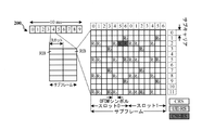
図2Aは、LTEにおけるダウンリンクフレーム構造の一例を示す図200である。図2Bは、LTEにおけるダウンリンクフレーム構造内のチャネルの一例を示す図230である。図2Cは、LTEにおけるULフレーム構造の一例を示す図250である。図2Dは、LTEにおけるアップリンクフレーム構造内のチャネルの一例を示す図280である。他のワイヤレス通信技術は、異なるフレーム構造および/または異なるチャネルを有する場合がある。LTEでは、フレーム(10ms)は、10個の等しいサイズのサブフレームに分割される場合がある。各サブフレームは、2つの連続するタイムスロットを含み得る。2つのタイムスロットを表すためにリソースグリッドが使用される場合があり、各タイムスロットは、1つまたは複数の時間同時の(time concurrent)リソースブロック(RB)(物理RB(PRB)とも呼ばれる)を含む。リソースグリッドは複数のリソース要素(RE)に分割される。LTEでは、ノーマルサイクリックプレフィックスの場合、RBは、合計84個のREについて、周波数領域内に12個の連続するサブキャリアを含んでおり、時間領域内に7つの連続するシンボル(DLの場合、OFDMシンボル、ULの場合、SC-FDMAシンボル)を含んでいる。拡張サイクリックプレフィックスの場合、RBは、合計72個のREについて、周波数領域内に12個の連続するサブキャリアを含んでおり、時間領域内に6個の連続するシンボルを含んでいる。各REによって搬送されるビット数は変調方式に依存する。 FIG. 2A is FIG. 200 showing an example of the downlink frame structure in LTE. FIG. 2B is FIG. 230 showing an example of a channel in the downlink frame structure in LTE. FIG. 2C is FIG. 250 showing an example of the UL frame structure in LTE. FIG. 2D is FIG. 280 showing an example of a channel in an uplink frame structure in LTE. Other wireless communication technologies may have different frame structures and / or different channels. In LTE, a frame (10ms) may be divided into 10 equally sized subframes. Each subframe may contain two consecutive time slots. A resource grid may be used to represent two time slots, where each time slot contains one or more time concurrent resource blocks (RBs) (also known as physical RBs (PRBs)). include. The resource grid is divided into multiple resource elements (REs). In LTE, for normal cyclic prefixes, RB contains 12 consecutive subcarriers in the frequency domain for a total of 84 REs, and 7 consecutive symbols in the time domain (in the case of DL, in the case of DL). Includes OFDM symbol, SC-FDMA symbol in the case of UL). For extended cyclic prefixes, the RB contains 12 consecutive subcarriers in the frequency domain and 6 consecutive symbols in the time domain for a total of 72 REs. The number of bits carried by each RE depends on the modulation method.
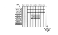
図2Aに示すように、REのうちのいくつかは、UEにおけるチャネル推定のためのダウンリンク基準(パイロット)信号(DL-RS)を搬送する。DL-RSは、セル固有基準信号(CRS)(共通RSと呼ばれることもある)と、UE固有基準信号(UE-RS)と、チャネル状態情報基準信号(CSI-RS)とを含む場合がある。図2Aは、(それぞれ、R0、R1、R2、およびR3として示された)アンテナポート0、1、2、および3のためのCRSと、(R5として示された)アンテナポート5のためのUE-RSと、(Rとして示された)アンテナポート15のためのCSI-RSとを示す。図2Bは、フレームのダウンリンクサブフレーム内の様々なチャネルの一例を示す。物理制御フォーマットインジケータチャネル(PCFICH)はスロット0のシンボル0内にあり、物理ダウンリンク制御チャネル(PDCCH)が1つのシンボルを占有するか、2つのシンボルを占有するか、それとも3つのシンボルを占有するかを示す制御フォーマットインジケータ(CFI)を搬送する(図2Bは、3つのシンボルを占有するPDCCHを示す)。PDCCHは、1つまたは複数の制御チャネル要素(CCE)内でダウンリンク制御情報(DCI)を搬送し、各CCEは9つのREグループ(REG)を含み、各REGはOFDMシンボルに4つの連続するREを含む。UEは、DCIも搬送するUE固有拡張PDCCH(ePDCCH)で構成される場合がある。ePDCCHは、2つ、4つ、または8つのRBペアを有する場合がある(図2Bは2つのRBペアを示し、各サブセットは1つのRBペアを含む)。物理ハイブリッド自動再送要求(ARQ)(HARQ)インジケータチャネル(PHICH)もスロット0のシンボル0内にあり、物理アップリンク共有チャネル(PUSCH)に基づいてHARQ肯定応答(ACK)/否定ACK(NACK)フィードバックを示すHARQインジケータ(HI)を搬送する。1次同期チャネル(PSCH)は、フレームのサブフレーム0および5内のスロット0のシンボル6内にあり、サブフレームタイミングと物理レイヤ識別情報とを決定するためにUEによって使用される1次同期信号(PSS)を搬送する。2次同期チャネル(SSCH)は、フレームのサブフレーム0および5内のスロット0のシンボル5内にあり、物理レイヤセル識別情報グループ番号を決定するためにUEによって使用される2次同期信号(SSS)を搬送する。物理レイヤ識別情報および物理レイヤセル識別情報グループ番号に基づいて、UEは物理セル識別子(PCI)を決定することができる。PCIに基づいて、UEは上述のDL-RSの位置を決定することができる。物理ブロードキャストチャネル(PBCH)は、フレームのサブフレーム0のスロット1のシンボル0、1、2、3内にあり、マスタ情報ブロック(MIB)を搬送する。MIBは、ダウンリンクシステム帯域幅内のRBの数と、PHICH構成と、システムフレーム番号(SFN)とを提供する。物理ダウンリンク共有チャネル(PDSCH)は、ユーザデータと、システム情報ブロック(SIB)などのPBCHを介して送信されないブロードキャストシステム情報と、ページングメッセージとを搬送する。
As shown in Figure 2A, some of the REs carry the downlink reference (pilot) signal (DL-RS) for channel estimation in the UE. The DL-RS may include a cell-specific reference signal (CRS) (sometimes called a common RS), a UE-specific reference signal (UE-RS), and a channel state information reference signal (CSI-RS). .. Figure 2A shows the CRS for
図2Cに示すように、REのうちのいくつかは、eNBにおけるチャネル推定のための復調基準信号(DM-RS)を搬送する。UEは、たとえば、サブフレームの最終シンボルにおいて、サウンディング基準信号(SRS)をさらに送信する場合がある。SRSはコム構造を有する場合があり、UEは、コムのうちの1つの上でSRSを送信する場合がある。SRSは、eNBによって、UL上での周波数依存スケジューリングを可能にするために、チャネル品質推定のために使用される場合がある。図2Dは、フレームのアップリンクサブフレーム内の様々なチャネルの一例を示す。物理ランダムアクセスチャネル(PRACH)は、PRACH構成に基づいてフレーム内の1つまたは複数のサブフレーム内にあってもよい。PRACHは、サブフレーム内に6つの連続するRBペアを含む場合がある。PRACHにより、UEが初期システムアクセスを実行し、アップリンク同期を実現することが可能になる。物理アップリンク制御チャネル(PUCCH)は、アップリンクシステム帯域幅のエッジ上に位置する場合がある。PUCCHは、スケジューリング要求、チャネル品質インジケータ(CQI)、プリコーディング行列インジケータ(PMI)、ランクインジケータ(RI)、およびHARQ ACK/NACKフィードバックなどのアップリンク制御情報(UCI)を搬送する。PUSCHは、データを搬送し、バッファステータス報告(BSR)、パワーヘッドルーム報告(PHR)、および/またはUCIを搬送するためにさらに使用される場合がある。 As shown in Figure 2C, some of the REs carry a demodulation reference signal (DM-RS) for channel estimation in the eNB. The UE may further transmit a sounding reference signal (SRS), for example, at the final symbol of the subframe. The SRS may have a comb structure and the UE may send the SRS over one of the combs. SRS may be used by eNB for channel quality estimation to allow frequency-dependent scheduling on UL. Figure 2D shows an example of the various channels within the frame's uplink subframe. The physical random access channel (PRACH) may be in one or more subframes within a frame based on the PRACH configuration. PRACH may contain 6 consecutive RB pairs within a subframe. PRACH allows the UE to perform initial system access and achieve uplink synchronization. The physical uplink control channel (PUCCH) may be located on the edge of the uplink system bandwidth. PUCCH carries uplink control information (UCI) such as scheduling requests, channel quality indicator (CQI), precoding matrix indicator (PMI), rank indicator (RI), and HARQ ACK / NACK feedback. PUSCH may be further used to carry data and to carry buffer status reports (BSR), power headroom reports (PHR), and / or UCI.
図3は、アクセスネットワークにおいてeNB310がUE350と通信しているブロック図である。ダウンリンクでは、EPC160からのIPパケットがコントローラ/プロセッサ375に提供される場合がある。コントローラ/プロセッサ375はレイヤ3およびレイヤ2の機能を実装する。レイヤ3は無線リソース制御(RRC)レイヤを含み、レイヤ2は、パケットデータコンバージェンスプロトコル(PDCP)レイヤと、無線リンク制御(RLC)レイヤと、媒体アクセス制御(MAC)レイヤとを含む。コントローラ/プロセッサ375は、システム情報(たとえば、MIB、SIB)のブロードキャスティング、RRC接続制御(たとえば、RRC接続ページング、RRC接続確立、RRC接続修正、およびRRC接続解放)、無線アクセス技術(RAT)間モビリティ、ならびにUE測定報告のための測定構成に関連するRRCレイヤ機能と、ヘッダ圧縮/解凍、セキュリティ(暗号化、解読、完全性保護、完全性検証)、およびハンドオーバーサポート機能に関連するPDCPレイヤ機能と、上位レイヤパケットデータユニット(PDU)の転送、ARQを介した誤り訂正、RLCサービスデータユニット(SDU)の連結、セグメンテーション、およびリアセンブリ、RLCデータPDUの再セグメンテーション、ならびにRLCデータPDUの並べ替えに関連するRLCレイヤ機能と、論理チャネルとトランスポートチャネルとの間のマッピング、トランスポートブロック(TB)上へのMAC SDUの多重化、TBからのMAC SDUの逆多重化、スケジューリング情報報告、HARQを介した誤り訂正、優先度処理、および論理チャネル優先度付けに関連するMACレイヤ機能とを提供する。
FIG. 3 is a block diagram of the
送信(TX)プロセッサ316および受信(RX)プロセッサ370は、様々な信号処理機能に関連するレイヤ1機能を実装する。物理(PHY)レイヤを含むレイヤ1は、トランスポートチャネル上の誤り検出と、トランスポートチャネルの前方誤り訂正(FEC)コーディング/復号と、インターリービングと、レートマッチングと、物理チャネル上へのマッピングと、物理チャネルの変調/復調と、MIMOアンテナ処理とを含む場合がある。TXプロセッサ316は、様々な変調方式(たとえば、2位相シフトキーイング(BPSK)、4位相シフトキーイング(QPSK)、M位相シフトキーイング(M-PSK)、M直交振幅変調(M-QAM))に基づく信号コンスタレーションへのマッピングを扱う。コーディングされ変調されたシンボルは、次いで、並列ストリームに分割される場合がある。各ストリームは、次いで、時間領域OFDMシンボルストリームを搬送する物理チャネルを生成するために、OFDMサブキャリアにマッピングされ、時間領域および/または周波数領域内で基準信号(たとえば、パイロット)と多重化され、次いで、逆高速フーリエ変換(IFFT)を使用して一緒に合成される場合がある。OFDMストリームは、複数の空間ストリームを生成するために空間的にプリコーディングされる。チャネル推定器374からのチャネル推定値が、コーディングおよび変調方式を決定するために、ならびに空間処理のために使用される場合がある。チャネル推定値は、UE350によって送信された基準信号および/またはチャネル状態フィードバックから導出される場合がある。各空間ストリームは、次いで、別個の送信機318TXを介して異なるアンテナ320に提供される場合がある。各送信機318TXは、送信のためにそれぞれの空間ストリームでRFキャリアを変調することができる。
The transmit (TX) processor 316 and the receive (RX)
UE350において、各受信機354RXは、受信機のそれぞれのアンテナ352を通して信号を受信する。各受信機354RXは、RFキャリア上に変調された情報を復元し、その情報を受信(RX)プロセッサ356に提供する。TXプロセッサ368およびRXプロセッサ356は、様々な信号処理機能に関連するレイヤ1機能を実装する。RXプロセッサ356は、UE350に宛てられた任意の空間ストリームを復元するために、情報に対して空間処理を実行してもよい。複数の空間ストリームがUE350に宛てられた場合、複数の空間ストリームは、RXプロセッサ356によって単一のOFDMシンボルストリームに合成される場合がある。次いで、RXプロセッサ356は、高速フーリエ変換(FFT)を使用して、OFDMシンボルストリームを時間領域から周波数領域にコンバートする。周波数領域信号は、OFDM信号のサブキャリアごとに別個のOFDMシンボルストリームを備える。各サブキャリア上のシンボルおよび基準信号は、eNB310によって送信された最も可能性の高い信号コンスタレーションポイントを決定することによって復元および復調される。これらの軟判定は、チャネル推定器358によって算出されたチャネル推定値に基づく場合がある。軟判定は、次いで、物理チャネル上でeNB310によって最初に送信されたデータおよび制御信号を復元するために復号およびデインターリーブされる。データおよび制御信号は、次いで、レイヤ3およびレイヤ2の機能を実装するコントローラ/プロセッサ359に提供される。
In UE350, each receiver 354RX receives a signal through its
コントローラ/プロセッサ359は、プログラムコードおよびデータを記憶するメモリ360に関連付けられ得る。メモリ360は、コンピュータ可読媒体と呼ばれることがある。ULでは、コントローラ/プロセッサ359は、EPC160からのIPパケットを復元するために、トランスポートチャネルと論理チャネルとの間の逆多重化と、パケットリアセンブリと、解読と、ヘッダ解凍と、制御信号処理とを行う。コントローラ/プロセッサ359はまた、HARQ動作をサポートするために、ACKおよび/またはNACKプロトコルを使用する誤り検出に関与し、SRS送信構成要素198の部分および以下で説明する関連特徴を実装し得る。
The controller /
eNB310によるダウンリンク送信に関して説明した機能と同様に、コントローラ/プロセッサ359は、システム情報(たとえば、MIB、SIB)収集、RRC接続、および測定報告に関連するRRCレイヤ機能と、ヘッダ圧縮/解凍、およびセキュリティ(暗号化、解読、完全性保護、完全性検証)に関連するPDCPレイヤ機能と、上位レイヤPDUの転送、ARQを介した誤り訂正、RLC SDUの連結、セグメンテーション、およびリアセンブリ、RLCデータPDUの再セグメンテーション、ならびにRLCデータPDUの並べ替えに関連するRLCレイヤ機能と、論理チャネルとトランスポートチャネルとの間のマッピング、TB上へのMAC SDUの多重化、TBからのMAC SDUの逆多重化、スケジューリング情報報告、HARQを介した誤り訂正、優先度処理、および論理チャネル優先度付けに関連するMACレイヤ機能とを提供する。
Similar to the features described for downlink transmission by the eNB310, the controller /
eNB310によって送信された基準信号またはフィードバックから、チャネル推定器358によって導出されたチャネル推定値は、適切なコーディングおよび変調方式を選択するために、ならびに空間処理を容易にするために、TXプロセッサ368によって使用されてもよい。TXプロセッサ368によって生成された空間ストリームは、別個の送信機354TXを介して異なるアンテナ352に提供される場合がある。各送信機354TXは、送信のためにそれぞれの空間ストリームでRFキャリアを変調することができる。
From the reference signal or feedback transmitted by the
UL送信は、UE350における受信機機能に関して説明した方式と同様の方式で、eNB310において処理される。各受信機318RXは、受信機のそれぞれのアンテナ320を介して信号を受信する。各受信機318RXは、RFキャリア上に変調された情報を復元し、その情報をRXプロセッサ370に提供する。
UL transmission is processed by the
コントローラ/プロセッサ375は、プログラムコードおよびデータを記憶するメモリ376に関連付けられ得る。メモリ376は、コンピュータ可読媒体と呼ばれることがある。ULでは、コントローラ/プロセッサ375は、UE350からのIPパケットを復元するために、トランスポートチャネルと論理チャネルとの間の逆多重化と、パケットリアセンブリと、解読と、ヘッダ解凍と、制御信号処理とを行う。コントローラ/プロセッサ375からのIPパケットは、EPC160に提供される場合がある。コントローラ/プロセッサ375はまた、HARQ動作をサポートするために、ACKおよび/またはNACKプロトコルを使用する誤り検出に関与する。
The controller /
キャリアアグリゲーション
ワイヤレス通信システムは、複数のセルまたはキャリア上での動作、すなわち、キャリアアグリゲーション(CA)またはマルチキャリア動作と呼ばれることがある特徴をサポートし得る。アグリゲートされた各キャリアは、コンポーネントキャリア(CC)、レイヤ、チャネルなどと呼ばれることもある。ワイヤレス通信システムは、非競合の認可無線周波数スペクトル帯域および/または競合ベースの共有無線周波数スペクトル帯域上での動作をサポートし得る。
Carrier Aggregation Wireless communication systems can support operations on multiple cells or carriers, a feature sometimes referred to as carrier aggregation (CA) or multicarrier operation. Each aggregated carrier is sometimes referred to as a component carrier (CC), layer, channel, and so on. Wireless communication systems may support operation over non-competitive licensed radio frequency spectrum bands and / or competition-based shared radio frequency spectrum bands.
1つのキャリアは、1次コンポーネントキャリア(PCC)として指定または構成され得る。1つの追加のCCは1次2次CC(pScell)として構成され得る。PcellおよびpScellはPUCCH信号を搬送することができ、Pcellは共通探索空間信号を搬送することができる。したがって、UEは、Pcell上でのみ共通探索空間を監視することになる。他のアグリゲートされたCCは、2次CCである。 One carrier may be designated or configured as a Primary Component Carrier (PCC). One additional CC can be configured as a primary secondary CC (pS cell). Pcell and pScell can carry PUCCH signals, and Pcell can carry common search space signals. Therefore, the UE monitors the common search space only on the Pcell. The other aggregated CC is the secondary CC.
UEは、CAのために複数のCC、たとえば、最大32個のCCで構成され得る。各CCは、最大20MHzであってよく、後方互換性があってよい。たとえば、最大32個のCCで構成され得るUEの場合、UEは、最大640MHzのために構成され得る。CAにおいて、CCは、周波数分割複信(FDD)、TDD、またはFDDとTDDとの組合せであり得る。異なるTDD CCは同じDL/UL構成を有することがあり、または異なるDL/UL構成を有することがある。特殊サブフレームが、異なるTDD CCに対して別様に構成されることもある。 The UE can consist of multiple CCs for the CA, for example up to 32 CCs. Each CC can be up to 20MHz and may be backwards compatible. For example, for a UE that can be configured with up to 32 CCs, the UE can be configured for up to 640MHz. In CA, CC can be Frequency Division Duplex (FDD), TDD, or a combination of FDD and TDD. Different TDD CCs may have the same DL / UL configuration or may have different DL / UL configurations. Special subframes may be configured differently for different TDD CCs.
異なるUEは、CAにおける異なる帯域組合せをサポートすることができ、それらのアップリンクおよびダウンリンク動作に関して異なるCA能力を有し得る。PCCの構成は、たとえば、様々なCC上での負荷ならびに他の関連パラメータに従って、UE固有であり得る。同様に、いくつかのCCは、ダウンリンク専用CCとして1つのUEのために構成され得るが、ダウンリンクおよびアップリンク通信のために異なるUEのために構成され得る。 Different UEs can support different bandwidth combinations in CA and may have different CA capabilities with respect to their uplink and downlink behavior. The configuration of the PCC can be UE-specific, for example, according to the load on various CCs as well as other relevant parameters. Similarly, some CCs can be configured for one UE as downlink-only CCs, but for different UEs for downlink and uplink communications.
一般に、アップリンクではダウンリンクよりも少ないトラフィックが送信されるので、アップリンクスペクトル割振りは、ダウンリンク割振りよりも小さくてよい。たとえば、20Mhzがアップリンクに割り当てられる場合、ダウンリンクは、たとえば100Mhzを割り当てられ得る。これらの非対称的FDD割当ては、スペクトルを節約することができ、ブロードバンド加入者による通常は非対称的な帯域幅の利用にぴったり合う場合がある。したがって、UEは、アップリンクCCよりも多くのダウンリンクCCで構成されるように、キャリアアグリゲーションのために複数のダウンリンクCCおよび1つまたは複数のアップリンクCCで構成され得る。 In general, the uplink spectrum allocation may be smaller than the downlink allocation because the uplink sends less traffic than the downlink. For example, if 20Mhz is assigned to the uplink, the downlink can be assigned, for example, 100Mhz. These asymmetric FDD allocations can save spectrum and may fit perfectly with the normally asymmetric bandwidth utilization by broadband subscribers. Thus, a UE may be composed of multiple downlink CCs and one or more uplink CCs for carrier aggregation so that it is composed of more downlink CCs than uplink CCs.
キャリアアグリゲーションはまた、SRS送信の使用を実現する。UEは、基地局にSRSを送信することができ、SRSは、たとえば、アップリンクチャネル品質を判断するために利用され得る。基地局は、送信端末にアップリンクリソースを割り振る際にSRSを利用することができる。SRSは、アップリンクリンク適応、チャネル相互関係(channel reciprocity)に基づくダウンリンクスケジューリング(特に、TDDシステム、多地点協調(COMP)動作などの場合)などの様々なアクションに使用され得る。特定のセルに関係する最大送信帯域幅、利用可能なサブフレームなど、SRSを送信するためのいくつかのパラメータが、ワイヤレスネットワークの動作中に定義され得る。さらに、特定のUEのためのSRS期間およびサブフレームオフセットの構成インデックス、UEのための帯域幅、送信コム、SRS送信持続時間、基準シーケンスを生成するための巡回シフトなどのようなUE固有のパラメータも、ランタイムにおいて定義され得る。UEは、これらのパラメータによって指定されているようにSRSを送信し得る。 Carrier aggregation also enables the use of SRS transmission. The UE can send the SRS to the base station, which can be used, for example, to determine the uplink channel quality. Base stations can use SRS when allocating uplink resources to transmitting terminals. SRS can be used for various actions such as uplink adaptation, downlink scheduling based on channel reciprocity (especially for TDD systems, multipoint coordination (COMP) operations, etc.). Several parameters for transmitting SRS, such as the maximum transmit bandwidth associated with a particular cell and the available subframes, can be defined during the operation of the wireless network. In addition, UE-specific parameters such as SRS duration and subframe offset configuration index for a particular UE, bandwidth for UE, transmit com, SRS transmit duration, cyclic shift to generate a reference sequence, and so on. Can also be defined at runtime. The UE may send SRS as specified by these parameters.
一般に、キャリアアグリゲーションは、2つ以上のコンポーネントキャリアがSRSを同時に送信し得る並行SRS送信をサポートする。だが、UEは通常、PUCCHまたはPUSCHと同じサブフレーム/シンボルにおいてSRSを送信しない。PUCCH/PUSCHがSRS送信と同じサブフレーム/シンボルにおいてスケジュールされるとき、それは衝突と呼ばれ、UEは、SRS送信、アップリンク送信、および/またはダウンリンク送信に関する決定を行う必要があり得る。 In general, carrier aggregation supports parallel SRS transmission, in which two or more component carriers can transmit SRS simultaneously. However, UEs usually do not send SRS in the same subframes / symbols as PUCCH or PUSCH. When PUCCH / PUSCH is scheduled in the same subframe / symbol as SRS transmission, it is called a collision and the UE may need to make decisions regarding SRS transmission, uplink transmission, and / or downlink transmission.
キャリアアグリゲーションのタイプ
LTEアドバンストモバイルシステムでは、連続CAおよび非連続CAという、2つのタイプのCAの方法が提案されている。これらは、図4Aおよび図4Bに示される。非連続CAは、図4Bの場合のように、複数の利用可能なコンポーネントキャリアが周波数帯域に沿って分離されているときに発生する。一方、連続CAは、図4Aの場合のように、複数の利用可能なコンポーネントキャリアが互いに隣接するときに発生する。非連続CAと連続CAの両方が、複数のLTE/コンポーネントキャリアをアグリゲートして、LTEアドバンストUEの単一のユニットにサービスする。
Types of carrier aggregation
For LTE advanced mobile systems, two types of CA methods have been proposed: continuous CA and discontinuous CA. These are shown in FIGS. 4A and 4B. Discontinuous CA occurs when multiple available component carriers are separated along the frequency band, as in Figure 4B. On the other hand, continuous CA occurs when multiple available component carriers are adjacent to each other, as in Figure 4A. Both non-continuous and continuous CAs aggregate multiple LTE / component carriers to serve a single unit in the LTE Advanced UE.
LTEアドバンストUEでは、キャリアが周波数帯域に沿って分離されるので、複数のRF受信ユニットおよび複数のFFTが非連続CAにより展開され得る。非連続CAは、大きい周波数範囲にわたる複数の分離されたキャリアを介したデータ送信をサポートするので、伝搬経路損失、ドップラーシフトおよび他の無線チャネル特性は、異なる周波数帯域において大幅に変化する場合がある。 In LTE Advanced UE, carriers are separated along the frequency band, so multiple RF receiver units and multiple FFTs can be deployed by discontinuous CAs. Discontinuous CA supports data transmission over multiple isolated carriers over a large frequency range, so propagation path loss, Doppler shift and other radio channel characteristics can vary significantly in different frequency bands. ..
したがって、非連続CA方式でブロードバンドデータ送信をサポートするために、異なるコンポーネントキャリアのコーディング、変調および送信電力を適応可能に調整するための方法が使用され得る。たとえば、拡張NodeB(eNodeB)が各コンポーネントキャリア上で固定送信電力を有するLTEアドバンストシステムでは、各コンポーネントキャリアの有効カバレージまたはサポート可能な変調およびコーディングが異なり得る。 Therefore, methods for adaptably adjusting the coding, modulation and transmission power of different component carriers may be used to support broadband data transmission in discontinuous CA schemes. For example, in an LTE advanced system where the extended NodeB (eNodeB) has a fixed transmit power on each component carrier, the effective coverage or supported modulation and coding of each component carrier may differ.
データアグリゲーション方式
図5は、IMTアドバンストシステムのための、MACレイヤにおける異なるコンポーネントキャリアからの送信ブロックをアグリゲートすることを示す。MACレイヤのデータアグリゲーションでは、各コンポーネントキャリアは、それ自体の独立したHARQエンティティをMACレイヤに有し、それ自体の送信構成パラメータ(たとえば送信電力、変調およびコーディング方式、ならびに複数アンテナ構成)を物理レイヤに有する。同様に、物理レイヤでは、1つのHARQエンティティが、各コンポーネントキャリアに対して提供される。
Data Aggregation Method Figure 5 shows the aggregation of transmit blocks from different component carriers at the MAC layer for IMT advanced systems. In MAC layer data aggregation, each component carrier has its own independent HARQ entity in the MAC layer and has its own transmit configuration parameters (eg transmit power, modulation and coding schemes, and multiple antenna configurations) in the physical layer. Have in. Similarly, at the physical layer, one HARQ entity is provided for each component carrier.
非対称的キャリアアグリゲーション
いくつかのUEは、アップリンクキャリアの数がダウンリンクコンポーネントキャリアの数よりも少ない非対称的CAで構成され得る。たとえば、ダウンリンクコンポーネントキャリアが複数あるが、アップリンクコンポーネントキャリアが1つしかないことがある。図6は、TDD実装形態において非対称的に構成されたキャリアアグリゲーション600を示すブロック図である。図6の送信ストリームは、PCC606およびSCC608の2つの無線フレーム、無線フレーム602、604を示す。PCC606は、ダウンリンクサブフレーム、アップリンクサブフレーム、および特殊(S)サブフレームを含むように、そのサブフレームにわたって時分割複信となっている。SCC608は、ダウンリンクサブフレーム、UEが構成されない非アクティブなアップリンクサブフレーム、およびSサブフレームを含むように、そのサブフレームにわたって時分割複信となっている。SCC608のアップリンクサブフレーム2〜3および7〜8は非アクティブであるので、SCC608のダウンリンクサブフレーム、サブフレーム0、4〜5、および9は不対であり、キャリアアグリゲーション600は非対称的と見なされる。
Asymmetric Carrier Aggregation Some UEs may consist of asymmetric CAs with fewer uplink carriers than downlink component carriers. For example, you may have multiple downlink component carriers, but only one uplink component carrier. FIG. 6 is a block diagram showing a
「ダウンリンク専用」CCとも呼ばれる、非対称的キャリアアグリゲーションにおける不対ダウンリンクCCの場合、SRS送信に使用するようにUEのために構成されたCCのアップリンク部分がない。しかしながら、SRS送信は依然として、動作に有用であり得る。ダウンリンク専用CCでは、SRSの恩恵は通常得られず、ネットワークは、ダウンリンク専用CCに関するCSI報告に依拠しなければならなくなる。しかしながら、CCの数が増大するにつれて、これは著しいオーバーヘッドをもたらし得る。本出願で提示する態様は、TDD、ダウンリンク専用キャリアの未使用の/未構成の/非アクティブなアップリンクサブフレーム上での限定的SRS送信の使用によってこの問題に対処する。本明細書で提示する態様は、構成されたキャリア上での活動による衝突が生じ得るときに、ダウンリンク専用CC上でのそのようなSRS限定的送信を管理する方法を提供する。本明細書で提示する態様はまた、いくつかのSRS信号またはSRSを送信するいくつかのUEに関する報告効率を改善する。 For unpaired downlink CCs in asymmetric carrier aggregation, also known as "downlink-only" CCs, there is no uplink portion of the CC configured for the UE to use for SRS transmission. However, SRS transmission can still be useful in operation. Downlink-only CCs usually do not benefit from SRS, and networks will have to rely on CSI reports on downlink-only CCs. However, as the number of CCs increases, this can result in significant overhead. The aspects presented in this application address this issue by using TDD, limited SRS transmission on unused / unconfigured / inactive uplink subframes of downlink dedicated carriers. The embodiments presented herein provide a method of managing such SRS-restricted transmissions on a downlink-only CC when conflicts due to activity on the configured carriers can occur. The embodiments presented herein also improve reporting efficiency for some SRS signals or some UEs transmitting SRS.
これらの状況の各々において、SRSは有用となるが、不対ダウンリンクコンポーネントキャリアと対にされるアクティブなアップリンクコンポーネントキャリアがなければ、SRSは、通常の機構に従って提供されないことがある。 In each of these situations, SRS is useful, but without an active uplink component carrier paired with an unpaired downlink component carrier, SRS may not be provided according to normal mechanisms.
そのようなダウンリンクCCにSRSシグナリングを提供するために、SRSがダウンリンクCCに対して有効化され得る一方、UE能力を上回る数のCCを介した同時送信を防ぐために、一度に単一または少数のCC送信を維持し得る。たとえば、UEによって一度に単一のアップリンクCCがサポートされ得る。より低い送信複雑性を維持するために、単一のCC送信のための単一のキャリア波形を維持することが望ましい場合がある。SRS送信は、異なるCCで時分割多重化(TDM)され得る。さらに、さらなる複雑性という犠牲を払って、たとえば、2つ以上のCCを介した並行アップリンク送信を可能にすることによって、1つまたは複数のCCを介した非単一キャリア波形送信を実現することが可能であり得る。 To provide SRS signaling to such downlink CCs, SRS can be enabled for downlink CCs, while single or at a time to prevent simultaneous transmission over more CCs than UE capability. A small number of CC transmissions can be maintained. For example, a UE may support a single uplink CC at a time. In order to maintain lower transmission complexity, it may be desirable to maintain a single carrier waveform for a single CC transmission. SRS transmissions can be time division multiplexing (TDM) at different CCs. In addition, it enables non-single carrier waveform transmission over one or more CCs, for example by allowing parallel uplink transmissions over two or more CCs, at the expense of additional complexity. It can be possible.
図7Aは、本開示の一態様に従って構成されたSRSシグナリングを伴うキャリアアグリゲーション700を示すブロック図である。キャリアアグリゲーション700は、TDD PCC702およびTDDコンポーネントキャリア704を含む。SRS送信は、コンポーネントキャリア、TDD PCC702とTDDコンポーネントキャリア704との間で分割され得る。たとえば、SRS706は、TDD PCC702上で無線フレーム714のサブフレーム2において送信され、SRS708は、TDDコンポーネントキャリア704上で無線フレーム714のサブフレーム7において送信され、SRS710は、TDD PCC702上で無線フレーム716のサブフレーム2において送信され、SRS712は、TDDコンポーネントキャリア704上で無線フレーム716のサブフレーム7において送信される。このようにして、SRS708および712は、不対ダウンリンクコンポーネントキャリアに関するチャネル品質を判断するために使用され得る。
FIG. 7A is a block diagram showing a
したがって、UEは、eNBにSRSを送信するために、ダウンリンクCC、たとえばCC2の非アクティブなアップリンク部分を使用し得る。「eNB」という用語を使用して例について説明するが、eNBは基地局の一例にすぎない。本明細書で説明する態様は、5G基地局、たとえば、gNBの場合に適用されることもある。CC2に関するキャリアアグリゲーション構成は、ダウンリンク部分を含み、UEによる使用のためのCC2のアップリンク部分を除くか、または構成しない。たとえば、CC2は、PUSCH上でのデータ送信のために構成されなくてよい。したがって、UEがCC2上でのアップリンクデータ送信のために構成されることなく、CC2上でのダウンリンクのために構成されているので、CC2は、ダウンリンク専用CCと呼ばれることもある。しかしながら、UEは、SRSを送信するためにCC2の非アクティブな、または未構成のアップリンク部分の少なくとも一部分を使用するようにさらに構成され得る。UEは、たとえば、CC2上でPUSCH、CSIなどを送信することなくSRS送信のために、CC2のこの非アクティブなアップリンク部分を使用し得る。そのような追加送信は、利用可能なリソースに対して過度の負担をかける可能性がある。SRSを送信することで、最小量のオーバーヘッドを使用してチャネルに関する情報をeNBに提供し得る。SRSは、eNBによってUEのために画定されたエリアにおいてほんのいくつかのシンボルの幅があり得る。 Therefore, the UE may use the inactive uplink portion of the downlink CC, eg CC2, to send the SRS to the eNB. The term "eNB" is used to describe an example, but eNB is just one example of a base station. The embodiments described herein may also apply in the case of 5G base stations, such as gNB. The carrier aggregation configuration for CC2 includes the downlink portion and excludes or does not configure the uplink portion of CC2 for use by the UE. For example, CC2 does not have to be configured for data transmission over PUSCH. Therefore, CC2 is sometimes referred to as a downlink-only CC because the UE is configured for downlink on CC2 rather than for uplink data transmission on CC2. However, the UE may be further configured to use at least a portion of the inactive or unconfigured uplink portion of CC2 to transmit the SRS. The UE may use this inactive uplink portion of CC2 for SRS transmission, for example, without transmitting PUSCH, CSI, etc. on CC2. Such additional transmissions can overwhelm the available resources. Sending SRS can provide eNB with information about the channel with minimal overhead. The SRS can have only a few symbol widths in the area defined for the UE by the eNB.
CC2上でのSRS送信は、別のアップリンクCCにおいて中断をもたらし得る。たとえば、CC2の非アクティブな部分上でのSRS送信は、異なるCC上での別のスケジュールされたアップリンク送信と少なくとも部分的に重複し得る。これは衝突と呼ばれることがある。UEは、一度に1つのCCを使用して送信または受信することだけが可能であり得る。 SRS transmission on CC2 can cause interruptions in another uplink CC. For example, an SRS transmission on an inactive portion of CC2 can at least partially overlap with another scheduled uplink transmission on a different CC. This is sometimes called a collision. The UE may only be able to send or receive using one CC at a time.
一例では、衝突は、同じサブフレームにおける2つ以上の送信と定義されることがある。別の例では、衝突は、同じシンボルにおける2つ以上の送信として定義されることもある。前者の場合、それは、送信が同じサブフレームにおける異なるシンボルで発生し、各シンボル内で同じサブフレームにおいてたった1つの送信がある場合でも、2つ以上のコンポーネントキャリアを介した同時送信が許容されないことを暗示する。後者の場合、それは、各シンボル内で同じサブフレームにおいてたった1つの送信がある限り、同じサブフレームにおいて2つ以上の送信を有することが可能であることを暗示する。たとえば、PUSCH/PUCCH718は、CC1 702上で無線フレーム714のサブフレーム7に対してスケジュールされる。一方、SRS708も、無線フレーム714の同じサブフレーム7において、ただしTDD CC704上で送信のためにスケジュールされる。両方の送信を進めることが許容される場合、2つの別個のCC上でUEからの同時送信があることになる。そのような衝突イベントが識別されたとき、UEは、無線フレーム714のサブフレーム7における単一送信を維持するために、SRS708またはPUSCH/PDCCH718の送信を調整し、それによって、同じサブフレーム内のアップリンクコンポーネントキャリア送信の動的切替えを回避することができる。
In one example, a collision may be defined as more than one transmission in the same subframe. In another example, a collision may be defined as more than one transmission on the same symbol. In the former case, it means that transmissions occur on different symbols in the same subframe, and even if there is only one transmission in the same subframe within each symbol, simultaneous transmission through two or more component carriers is not allowed. Imply. In the latter case, it implies that it is possible to have more than one transmission in the same subframe, as long as there is only one transmission in the same subframe within each symbol. For example, PUSCH /
UEがCC1上でアップリンク送信を送信することとCC2上でSRSを送信することとの間の衝突を示して本例について説明しているが、衝突は、UEが、たとえば、708または712においてCC2上でSRSを送信することとダウンリンク送信を受信することとの間でも同様に発生し得る。これが発生する場合、UEは、衝突に対処するためにSRSの送信を調整するか、それともダウンリンク送信の受信を調整するかを決定し得る。 This example is described by showing a conflict between the UE sending an uplink transmission on CC1 and sending an SRS on CC2, but the conflict is in the UE, for example, at 708 or 712. The same can occur between sending an SRS over CC2 and receiving a downlink transmission. When this happens, the UE may decide whether to coordinate the transmission of the SRS or the reception of the downlink transmission to deal with the conflict.
SRS送信は、コンポーネントキャリア間で任意の数の分割で分けられ得る。SRS送信の構成および/またはアクティブ化は、コンポーネントキャリアの間で共同でまたは別個に管理され得る。一例として、2つのコンポーネントキャリアに関してユーザ機器にSRS送信の2つの別個の構成が提供されてよく、2つの構成は、重複するSRS送信インスタンスを有すること、または有しないことがある。キャリアアグリゲーション700は、コンポーネントキャリアの間での均一な分割を示す。だが、様々な代替態様では不均一な分割も考えられる。図7Bは、本開示の一態様に従って構成されたSRSシグナリングを伴うキャリアアグリゲーション701を示すブロック図である。キャリアアグリゲーション701は、コンポーネントキャリアTDD PCC 702およびTDDコンポーネントキャリア704の2つの無線フレーム、無線フレーム714および716を示す。SRS送信は、TDD PCC702上でより頻繁にサウンディングする不均一な分割でスケジュールされる。TDD PCC702上でのSRS送信720、722、724は、無線フレーム714のサブフレーム2および7において、また無線フレーム716のサブフレーム2において行われる。TDDコンポーネントキャリア704は、無線フレーム716のサブフレーム7におけるSRS送信726によりサウンディングされる。
SRS transmissions can be split between component carriers in any number of divisions. The configuration and / or activation of SRS transmissions can be managed jointly or separately among component carriers. As an example, the user equipment may be provided with two separate configurations of SRS transmissions for the two component carriers, the two configurations with or without overlapping SRS transmission instances.
DL CC2の非アクティブなアップリンク部分の間にSRSを送信するために、UEは、異なるCCから切り替える(本明細書では「再チューニングする」と呼ばれることもある)必要があり得る。切替えは、たとえば、CC1上でのアップリンク送信からのものであること、または場合によっては、他の送信の中断につながるSRSをUEが送信することになる時間期間の間にダウンリンク送信を受信するように構成された異なるCCからの切替えであることがある。 In order to send SRS between the inactive uplink parts of DL CC2, the UE may need to switch from a different CC (sometimes referred to herein as "retune"). The switch is, for example, from an uplink transmission on CC1 or, in some cases, receives a downlink transmission during a period of time during which the UE will transmit an SRS that would lead to interruptions in other transmissions. It may be a switch from a different CC configured to do so.
図7Bは、第3のCC、CC3 730上でのアップリンク送信と衝突する可能性をSRS送信726が有することも示す。これが発生するとき、UEは、SRSを送信するためにCC1、CC3のどちらのCCを中断するかを決定する必要があり得る。
Figure 7B also shows that the
中断時間
アップリンクキャリアよりも多くのダウンリンクキャリアをサポートする能力を有するUEは、SRSの送信を容易にするために、ダウンリンク専用動作のためにキャリアアグリゲーションにおいて構成されたTDD CCの非アクティブな、または未構成のアップリンク部分を使用するように構成され得る。UEは、ダウンリンク専用TDD CCの未構成のアップリンク部分においてSRS送信を送信するために、あるCCから切り替える必要があり得る。たとえば、図7Aでは、UEは、CC2の未構成のアップリンク部分上でSRS708、712を送信するために、CC1から離れる形でその送信機を切り替えるか、またはチューニングすることがある。これは、CC1に中断をもたらし、CC1上のPUCCH、PUSCHなどの中断に起因してダウンリンクトラフィックとアップリンクトラフィックの両方に影響を与えることがある。そのような中断は、CC1におけるデータレートおよび制御送信ならびに他のCCのダウンリンクデータレートに影響を与える可能性がある。中断時間は、たとえば、UEが帯域間切替えを実行する必要があるか、それとも帯域内切替えを実行する必要があるかに応じて異なり得る。
Suspension time UEs capable of supporting more downlink carriers than uplink carriers are inactive in TDD CC configured in carrier aggregation for downlink-only operation to facilitate transmission of SRS. , Or may be configured to use an unconfigured uplink portion. The UE may need to switch from one CC to send SRS transmissions in the unconfigured uplink portion of the downlink-only TDD CC. For example, in Figure 7A, the UE may switch or tune its transmitter away from CC1 in order to transmit SRS708,712 on the unconfigured uplink portion of CC2. This causes interruptions in CC1 and can affect both downlink traffic and uplink traffic due to interruptions in PUCCH, PUSCH, etc. on CC1. Such interruptions can affect the data rate and control transmission in CC1 as well as the downlink data rate in other CCs. The downtime can vary, for example, depending on whether the UE needs to perform interband switching or intraband switching.
UEは、CC2のアップリンク部分におけるSRSの送信が別のCC上でのアップリンク送信および/またはダウンリンク送信の受信と少なくとも部分的に衝突することになると判断し得る。たとえば、UEは、図7AにおいてPUSCH/PDCCH718とSRS708の送信が衝突することになると判断し得る。別の例では、UEは、eNBからのスケジュールされたダウンリンク送信の受信とSRSの送信が衝突することになると判断し得る。たとえば、TDDキャリア、CC1およびCC2が帯域内CAにおいて構成され、各々が異なるUL/DLサブフレーム構成を有する場合、CC1の未構成の部分上でのSRSの送信は、CC2上でダウンリンク送信を受信する能力を低下させる可能性がある。UEが衝突を識別したとき、UEは、衝突の判断に基づいて、かつCC1の未構成のアップリンク部分においてSRSを送信するための中断時間に基づいて、アップリンク送信、SRS送信、またはダウンリンク送信の受信のうちの少なくとも1つを調整することを決定し得る。 The UE may determine that the transmission of the SRS in the uplink portion of CC2 will at least partially conflict with the reception of the uplink transmission and / or the downlink transmission on another CC. For example, the UE may determine that the transmissions of PUSCH / PDCCH718 and SRS708 will collide in Figure 7A. In another example, the UE may determine that the reception of the scheduled downlink transmission from the eNB and the transmission of the SRS will conflict. For example, if the TDD carriers, CC1 and CC2 are configured in an in-band CA and each has a different UL / DL subframe configuration, then SRS transmissions on the unconfigured portion of CC1 will result in downlink transmissions on CC2. It may reduce the ability to receive. When the UE identifies a collision, the UE will perform an uplink transmission, SRS transmission, or downlink based on the judgment of the collision and the suspension time for transmitting the SRS in the unconfigured uplink part of CC1. You may decide to adjust at least one of the incoming transmissions.
UEは、SRS送信が別のCC上でのPUCCH送信と衝突する可能性があるときにSRS送信をドロップすることによってSRS送信を調整することをUEが決定するドロップルールを適用し得る。UEはその場合、SRSを送信するために切り替えることなく、PUCCH送信を送信することに進むことができる。 The UE may apply a drop rule in which the UE determines to adjust the SRS transmission by dropping the SRS transmission when the SRS transmission may conflict with the PUCCH transmission on another CC. The UE can then proceed to send a PUCCH send without switching to send an SRS.
UEは、SRSがダウンリンク送信と少なくとも部分的に衝突することになるとUEが判断したときに、ダウンリンク送信の少なくとも一部分を受信するのを控えることを決定し得る。UEは、第2のCC上でSRSを送信するために、UEがダウンリンク送信を受信する第1のCCから切り替え得る。UEは、ダウンリンク送信の受信を続けるために、第1のCCに切り替え復帰し得る。 The UE may decide to refrain from receiving at least a portion of the downlink transmission when the UE determines that the SRS will at least partially conflict with the downlink transmission. The UE may switch from the first CC to which the UE receives the downlink transmission in order to transmit the SRS over the second CC. The UE may switch back to the first CC to continue receiving downlink transmissions.
UEがSRSと別のCC上でのアップリンク送信との間の衝突を識別したとき、UEは、SRSとアップリンク送信との間の衝突を回避するために、他方のCC上でのアップリンク送信を、サブフレームのアップリンクシンボルのサブセットに調整することを決定し得る。 When the UE identifies a conflict between an SRS and an uplink transmission on another CC, the UE will uplink on the other CC to avoid a conflict between the SRS and the uplink transmission. It may be decided to coordinate the transmission to a subset of the uplink symbols of the subframe.
SRSとPUCCHの衝突を回避するために、UEは、PUCCH送信をアップリンクサブフレームのサブセットに制限し得る。たとえば、UEは、PUCCH送信のために基準サブフレーム構成を使用することができ、基準サブフレーム構成は、拡張型干渉軽減およびトラフィック適応(eIMTA: enhanced interference mitigation and traffic adaptation)構成と同じであるか、またはかかる構成とは別個のものであり得る。たとえば、eIMTAが構成される場合、UEは、eIMTA基準サブフレーム構成に従うことができる。eIMTAが構成されない場合、異なるサブフレーム構成が別個にシグナリングされ得る。 To avoid SRS and PUCCH collisions, the UE may limit PUCCH transmission to a subset of uplink subframes. For example, the UE can use a reference subframe configuration for PUCCH transmission, and is the reference subframe configuration the same as the enhanced interference mitigation and traffic adaptation (eIMTA) configuration? , Or it may be separate from such a configuration. For example, if eIMTA is configured, the UE can follow the eIMTA reference subframe configuration. If eIMTA is not configured, different subframe configurations can be signaled separately.
UEが2つのCC上で同時に送信すること、たとえば、CC2上でSRS、CC1上でアップリンク送信を送信することが必要となり、UEが2つのCC上での同時送信が可能ではないとき、UEは、少なくとも1つの優先度付けルールに基づいてSRSを送信するか、それともアップリンク送信を送信するかを決定し得る。 When the UE needs to transmit on two CCs at the same time, for example, SRS on CC2, uplink transmission on CC1, and UE is not capable of simultaneous transmission on two CCs, UE Can decide whether to send an SRS or an uplink send based on at least one prioritization rule.
第1の例では、送信において送られる情報に基づいてそれぞれの優先度レベルを提供する優先度ルールが確立され得る。たとえば、優先度付けルールは、Pcell PRACHがScell PRACHよりも高い優先度を有し、Scell PRACHがACK/NACK/SRよりも高い優先度を有することを示し得る。優先度付けルールは、周期的か非周期的かを問わず、CSIを上回る優先度をACK/NACK/SRが有することを示し得る。別の例では、CSIのタイプは、CSIの優先度レベルに影響を与え得る。優先度付けルールは、CSIがPUSCHよりも高い優先度を有し、PUSCHがSRSよりも高い優先度を有することを示し得る。一例では、優先度付けルールは、情報の優先度レベルを以下のように示し得る。
優先度=Pcell PRACH>Scell PRACH>Ack/Nack/SR>CSI>PUSCH>SRS
In the first example, priority rules can be established that provide each priority level based on the information sent in the transmission. For example, prioritization rules can indicate that Pcell PRACH has a higher priority than Scell PRACH and Scell PRACH has a higher priority than ACK / NACK / SR. Prioritization rules can indicate that an ACK / NACK / SR has a priority above the CSI, whether periodic or aperiodic. In another example, the type of CSI can affect the priority level of the CSI. Prioritization rules can indicate that CSI has a higher priority than PUSCH and PUSCH has a higher priority than SRS. In one example, a prioritization rule could indicate the priority level of information as follows:
Priority = Pcell PRACH> Scell PRACH> Ack / Nack / SR>CSI>PUSCH> SRS
優先度付けルールは、チャネルごとに異なり得る。たとえば、異なるチャネルの場合、異なる優先度付けルールは以下であり得る。
優先度=Pcell PRACH>Scell PRACH>PUCCH>PUSCH>SRS
Prioritization rules can vary from channel to channel. For example, for different channels, the different prioritization rules could be:
Priority = Pcell PRACH> Scell PRACH>PUCCH>PUSCH> SRS
第2の例では、UEは、SRSとアップリンク送信の両方を送信することを決定し得る。UEは、あるCCから別のCCに切り替えるために必要とされる時間量に応じて、切替えを容易にするためにアップリンク送信のシンボルの少なくとも一部分をパンクチャリングまたはレートマッチングすることによって、アップリンク送信を調整し得る。たとえば、UEがSRSを送信するためにアップリンク送信から切り替えるとき、切替えを容易にするために、たとえば、PUSCHまたはPUCCHのために、アップリンク送信のシンボルの一部分が利用可能ではないことがある。 In the second example, the UE may decide to send both SRS and uplink transmissions. The UE uplinks by puncturing or rate matching at least a portion of the uplink transmission symbols to facilitate the switch, depending on the amount of time required to switch from one CC to another. The transmission can be adjusted. For example, when a UE switches from an uplink send to send an SRS, some of the uplink send symbols may not be available to facilitate the switch, for example for PUSCH or PUCCH.
UEは、たとえば、SRSの送信のために当該CCに切り替えるための中断または切替え時間がしきい値量を下回るときに、アップリンク送信の一部分をパンクチャリングまたはレートマッチングすることを決定し得る。アップリンク送信をパンクチャリングすることに関する決定はまた、アップリンク送信のタイプに基づき得る。たとえば、1つのシンボルが切替えに必要とされ、アップリンク送信がPUSCHを含む場合、PUSCH送信を短縮し、SRS送信および切替え時間によりPUSCHをパンクチャリングすることによって、SRS送信が送信され得る。より長い時間が切替えに必要とされる場合(たとえば、1サブフレーム)、PUSCH全体がドロップされ得る。
The UE may decide to puncture or rate match a portion of the uplink transmission, for example, when the interruption or switching time to switch to the CC for SRS transmission is below the threshold amount. Decisions regarding puncturing uplink transmissions can also be based on the type of uplink transmission. For example, if one symbol is required for switching and the uplink transmission includes PUSCH, the SRS transmission may be transmitted by shortening the PUSCH transmission and puncturing the PUSCH with the SRS transmission and switching time. If a longer time is required for switching (
PUCCHが影響を受けるとき、短縮されたフォーマットが使用され得る。したがって、PUCCHは、短縮されたフォーマットを使用してSRSと同じサブフレームにおいて送信され得る。SRSは、図8Aおよび図8Bに示すように、サブフレームの最終シンボルにおいて送信され得る。PUCCHの短縮されたフォーマットは、サブフレームにおいて全14個よりも少ないシンボルを占有し得る。SRS送信に干渉しないように構成されるとき、短縮された形態のPUCCHは、SRS送信と同じサブフレームにおいて送信され得る。たとえば、短縮されたフォーマットが、PUCCHの第1のスロットに使用され得る。別の例では、PUCCHは、送信に1スロットのみを使用し得る。 When PUCCH is affected, a shortened format can be used. Therefore, PUCCH can be transmitted in the same subframe as SRS using the shortened format. The SRS can be transmitted at the final symbol of the subframe, as shown in FIGS. 8A and 8B. PUCCH's shortened format can occupy less than 14 symbols in all subframes. When configured so as not to interfere with SRS transmission, the shortened form of PUCCH can be transmitted in the same subframe as SRS transmission. For example, the shortened format may be used for the first slot of PUCCH. In another example, PUCCH may use only one slot for transmission.
図8Aおよび図8Bは、SRS送信によりPUSCHがパンクチャリングされる例を示す。図8Aでは、SRSの送信のためにCC2に切り替えるか、または再チューニングすることを可能にするために、PUSCHがシンボル12においてパンクチャリングされる。PUSCHのためにCC2からCC1に戻る形で切り替えるか、または再チューニングすることを容易にするために、別のPUSCHがシンボル0においてパンクチャリングされる。図8Aはまた、SRS送信のためのCC2から再チューニングすることを可能にするために、PUCCHが第1のスロットにおいて短縮されたフォーマットを使用するように調整され得ることを示す。図8Aでは、再チューニング時間は1シンボルである。図8Bは、1シンボル未満の再チューニング時間を伴う例を示す。たとえば、再チューニング時間は20μs前後であり得る。図8Bでは、CC2におけるSRS送信は、シンボルの一部分がUEによって送信されないように、20μs後に送信を開始し得る。
Figures 8A and 8B show examples of PUSCH being punctured by SRS transmission. In Figure 8A, PUSCH is punctured at
第3の例では、UEは、優先度付けルールを使用することとパンクチャリングを使用することとの間で選択し得る。選択は、必要とされる中断時間の量に基づき得る。選択は、UEの能力に基づき得る。選択は、eNBから受信された指示に基づき得る。選択は、再チューニングが帯域内切替えを伴うか、それとも帯域間切替えを伴うかに基づき得る。 In the third example, the UE can choose between using prioritization rules and using puncturing. The choice may be based on the amount of interruption time required. The choice can be based on the capabilities of the UE. The choice may be based on the instructions received from the eNB. The choice may be based on whether the retuning involves in-band switching or inter-band switching.
たとえば、再チューニングが帯域内である場合、UEは、1シンボル以下が再チューニングに必要とされると判断することができ、アップリンク送信のパンクチャリングシンボルを使用することを決定することができる。再チューニングが帯域間である場合、UEは、1つよりも多くのシンボルが再チューニングに必要とされると判断することができ、SRSを送信するか、それともアップリンク送信を送信するかを決定するために優先度付けルールを使用することを決定することができる。 For example, if the retuning is in-band, the UE can determine that less than one symbol is needed for the retuning and can decide to use the punctured symbol of the uplink transmission. If the retuning is between bands, the UE can determine that more than one symbol is needed for the retuning and decides whether to send an SRS or an uplink send. You can decide to use prioritization rules to do this.
異なるUEは、異なる中断時間につながる異なる能力を有し得る。異なるUEの実装形態は異なる切替え時間につながり得るので、中断時間はUEごとに異なることがある。中断時間は、同じUEの場合に、切替えに関わる2つのCCの帯域/周波数ロケーションに応じて異なることがある。したがって、たとえば、優先度付けルール、パンクチャリングなどを使用して、SRSまたはアップリンク送信を調整する方法に関する決定は、UEの能力または関わるCCの帯域/周波数に依存し得る。 Different UEs can have different abilities leading to different interruption times. Since different UE implementations can lead to different switching times, the downtime may vary from UE to UE. The interruption time may vary depending on the band / frequency location of the two CCs involved in the switch for the same UE. Thus, decisions about how to tune SRS or uplink transmissions, for example using prioritization rules, puncturing, etc., may depend on the UE's capabilities or the bandwidth / frequency of the CC involved.
UEはまた、eNBにUE能力などの報告情報を送信し得る。eNBは、SRS送信またはアップリンク送信を調整する方法を決定する際に使用するための指示をUEに送信し得る。たとえば、UEが長い切替え時間または短い切替え時間を必要とすることを、UEはeNBに示すことがある。この指示に基づいて、eNBは、SRSを送信するかどうか、および/またはどのように送信するかを決定するために、UEが優先度付けルールおよび/またはパンクチャリングを使用すべきかどうかについて、UE[に指示を返信し得る。 The UE may also send reporting information such as UE capability to the eNB. The eNB may send instructions to the UE for use in deciding how to coordinate SRS or uplink transmissions. For example, the UE may indicate to the eNB that the UE requires a long or short switch time. Based on this instruction, the eNB will determine whether the UE should use prioritization rules and / or puncturing to determine whether and / or how to send the SRS. You can reply to [instructions.
たとえば、UE能力および/または切替えに関わる帯域/チャネルに従って、仕様において切替え時間のセットが定義され得る。UEはその場合、UE能力のシグナリングおよび切替えに関わることになるCCに基づいて切替え時間を適用し得る。 For example, a set of switching times may be defined in the specification according to the UE capability and / or the bandwidth / channel involved in the switching. The UE may then apply the switching time based on the CC that will be involved in signaling and switching the UE capability.
コンポーネントキャリアの間での中断決定
UEは、複数のCCを使用して送信または受信することが可能であり得る。たとえば、UEは、同時に2つのCC上でのアップリンク送信が可能であり得る。図7Bは、UEがCC1とCC3の両方でのアップリンク送信のために構成される一例を示す。UEは、複数のCC上で同時に送信することが可能であり得る。たとえば、UEは、2つのCC上で同時に送信することが可能であり得る。この例では、CC2上のSRSがCC1とCC3の両方でのアップリンク送信の少なくとも一部と衝突することになるとき、UEは、CC2上でSRSを送信するために、どちらのCCを中断するかを決定する必要があり得る。UEは、いくつかの方法のいずれかでこの選択を行うことができる。
Suspension decision between component carriers
The UE may be able to send or receive using multiple CCs. For example, a UE may be able to transmit uplinks on two CCs at the same time. Figure 7B shows an example in which the UE is configured for uplink transmission on both CC1 and CC3. The UE may be able to transmit on multiple CCs at the same time. For example, a UE could be able to transmit on two CCs at the same time. In this example, when the SRS on CC2 would collide with at least some of the uplink transmissions on both CC1 and CC3, the UE would suspend either CC to send the SRS on CC2. It may be necessary to decide. The UE can make this choice in any of several ways.
第1のオプションでは、UEは、本明細書ではCCインデックスとも呼ばれるキャリア番号に基づいて、CC1上でのアップリンク送信を中断するか、それともCC3上でのアップリンク送信を中断するかを決定し得る。より小さいキャリア番号は、より高い優先度を有し得る。したがって、UEは、より大きいキャリア番号を有するキャリアを中断することを決定し得る。3つ以上のCCが決定に関わる場合、UEは、最も大きいキャリア番号を有するキャリアを中断することを決定し得る。たとえば、UEがキャリア番号「CC0」(Pcell)および「CC1」(Scell)で構成されており、SRSを送信するために第3のキャリアに切り替えることになる場合、CCインデックス1は0よりも大きいので、UEは、SRSの送信のために第3のキャリアに切り替えるためにCC1を中断することを決定し得る。UEはまた、UE能力とともに、またはUE能力無しで、この情報をeNBに送信し得る。UEは、この決定を行う際にUE能力も考慮し得る。たとえば、UEがダウンリンクCC上でSRSを送信することになっていて、アップリンクCCのサブセットから切替えが可能である場合、UEはサブセット内から、より小さいCCインデックス番号を有するCCを選択し得る。
In the first option, the UE determines whether to suspend the uplink transmission on CC1 or CC3 based on the carrier number, also referred to herein as the CC index. obtain. Lower carrier numbers may have higher priority. Therefore, the UE may decide to suspend carriers with higher carrier numbers. If more than one CC is involved in the decision, the UE may decide to suspend the carrier with the highest carrier number. For example, if the UE consists of carrier numbers "CC0" (Pcell) and "CC1" (Scell) and you want to switch to a third carrier to send SRS,
第2のオプションでは、UEは、チャネルまたは送られる情報に基づいて、CC1上でのアップリンク送信を中断するか、それともCC3上でのアップリンク送信を中断するかを決定し得る。UEは、アップリンク送信を送信するか、それともSRSを送信するか決定する際に、提示されたものと同様の優先度付けルールを適用し得る。だが、優先度付けルールは、どの情報がより高い優先度を有し、したがってSRSを送信するために中断されるべきではないかを判断するために適用されることがある。その場合、SRSを送信するためにCC2に切り替えるために、より低い優先度の情報を有するCCが選択され得る。たとえば、ACKがCC1において送信される予定であり、PUSCHがCC3において送信されることになっている場合、UEは、CC2上でSRSを送信するためにCC3のPUSCHを中断することを決定し得る。同じタイプの情報が両方のCC上で送信される予定である場合、UEは、第1のオプションにおいて説明したように、キャリア番号に基づいて2つのCCの間で選択し得る。たとえば、CC1とCC3の両方がPUSCHを送信することになっている場合、UEは、より大きいインデックス番号を有するキャリアを中断し得る。 In the second option, the UE may decide whether to suspend the uplink transmission on CC1 or the uplink transmission on CC3 based on the channel or the information sent. The UE may apply the same prioritization rules as presented when deciding whether to send an uplink transmission or an SRS. However, prioritization rules may be applied to determine which information has a higher priority and therefore should not be interrupted to send an SRS. In that case, a CC with lower priority information may be selected to switch to CC2 to send the SRS. For example, if an ACK is to be sent on CC1 and the PUSCH is to be sent on CC3, the UE may decide to suspend the PUSCH on CC3 to send an SRS on CC2. .. If the same type of information is to be transmitted on both CCs, the UE may choose between the two CCs based on the carrier number, as described in the first option. For example, if both CC1 and CC3 are supposed to send PUSCHs, the UE may suspend carriers with higher index numbers.
第3のオプションでは、UEは、UEとeNBとの間のメッセージの交換に基づいて、CC1上でのアップリンク送信を中断するか、それともCC3上でのアップリンク送信を中断するかを決定し得る。UEは、そのCA能力を示す情報をeNBに送信し得る。この情報は、UEが切り替え得るCCを含み得る。たとえば、UEは、図7BのCC1とCC2との間で切り替えることが可能であるが、CC3とCC2との間で切り替えることは可能ではない場合がある。eNBは、切替えのためにソースCCおよびターゲットCCでUEを構成するために、UEのCA能力および追加情報を使用し得る。たとえば、eNBは、CC1とCC2との間およびCC3とCC4との間で切り替えるようにUEを構成する場合があり、CC1およびCC3はアップリンクCCであり、CC2およびCC4は、SRSの送信に使用されるダウンリンクCCである。eNBはまた、UEが切り替えることを決定すべきCCのサブセットを返信し得る。したがって、UEは、UEにシグナリングされた指示に基づいて、キャリアの間でどのように/いつ切り替えるかを決定し得る。 In the third option, the UE decides whether to suspend the uplink transmission on CC1 or CC3 based on the exchange of messages between the UE and eNB. obtain. The UE may send information indicating its CA capability to the eNB. This information may include CCs that the UE can switch to. For example, the UE may be able to switch between CC1 and CC2 in Figure 7B, but not between CC3 and CC2. The eNB may use the UE's CA capabilities and additional information to configure the UE on the source CC and target CC for switching. For example, the eNB may configure the UE to switch between CC1 and CC2 and between CC3 and CC4, CC1 and CC3 are uplink CCs, and CC2 and CC4 are used to send SRS. Downlink CC to be done. The eNB may also return a subset of CCs that the UE should decide to switch. Therefore, the UE can determine how / when to switch between carriers based on the instructions signaled to the UE.
複数のコンポーネントキャリアのサウンディング
UEは、いくつかのキャリアをサウンディングする必要があり得る。上記で説明したように、UEは、アップリンクCCよりも多くの数のダウンリンクCCで構成され得る。一例では、UEは、1つのアップリンクCCに対する5つのダウンリンクCCの比率で構成され得る。UEにとって、低減された時間量で複数のダウンリンクCCをサウンディングできることが有益であり得る。たとえば、UEは、1msで6つのCCをサウンディングすることを望むことがある。このサウンディングは、複数のキャリアの間で切り替えることを必要とし得る。UEがサブフレーム当たり1つのSRSに限定される場合、キャリアのすべてをサウンディングするために望ましくない時間量が必要になり得る。
Sounding of multiple component carriers
UEs may need to sound some careers. As described above, a UE can consist of a larger number of downlink CCs than an uplink CC. In one example, a UE can consist of a ratio of 5 downlink CCs to 1 uplink CC. It can be beneficial for UEs to be able to sound multiple downlink CCs in a reduced amount of time. For example, a UE may want to sound 6 CCs in 1ms. This sounding may require switching between multiple carriers. If the UE is limited to one SRS per subframe, an undesired amount of time may be required to sound all of the carriers.
電力制限のあるUEの場合、広帯域サウンディングが実行され得るが、それによりSNRが望ましくないほど低下し得る。狭帯域SRS送信が使用され得る一方、そのような狭帯域SRSは、全帯域幅をサウンディングするために、UEによる複数の切替えおよび/またはキャリア当たり複数の送信を必要とし得る。したがって、複数の切替えを伴う狭帯域SRSは効率的ではない可能性がある。 For power-limited UEs, wideband sounding can be performed, which can result in an undesirably low SNR. While narrowband SRS transmissions can be used, such narrowband SRSs may require multiple switching by the UE and / or multiple transmissions per carrier to sound the full bandwidth. Therefore, narrowband SRS with multiple switches may not be efficient.
これらの問題を克服するために、UEは、サブフレーム当たり複数のSRSを送信し得る。SRS送信は、異なるCCにおけるものであり得、そのため再チューニングを必要とし得る。SRS送信は、同じCCの異なるサブバンドにおけるものであり得る。SRS送信は、同じCCの同じサブバンドにおける繰り返しであり得る。SRS送信の構成は異なり得る。たとえば、帯域幅、周波数、ロケーション、巡回シフト、コムなどは、同じサブフレーム内のSRS送信ごとに異なり得る。SRS送信は、サブバンドにわたって、またはキャリアにわたってスタッガードにされ得る。eNBは、SRS送信をスタッガードにするようにUEを構成し得る。eNBは複数のUEを、UEが再チューニング時間を効率的に再使用できるように、スタッガードSRS送信で構成し得る。 To overcome these problems, the UE may send multiple SRSs per subframe. SRS transmissions can be in different CCs and therefore may require retuning. The SRS transmission can be in different subbands of the same CC. SRS transmissions can be repeats in the same subband of the same CC. The configuration of SRS transmission can be different. For example, bandwidth, frequency, location, cyclic shift, comb, etc. can vary from SRS transmission within the same subframe. SRS transmissions can be staggered across subbands or across carriers. The eNB may configure the UE to stagger SRS transmissions. The eNB may configure multiple UEs with staggered SRS transmissions so that the UEs can efficiently reuse the retuning time.
図9は、複数のUEの各々が3つのCCに関してスタッガードパターンでSRSを送信する狭帯域サウンディングのスタッガードパターンを示す図900を示す。eNBはUEを、あるUEのSRS送信が異なるUEの再チューニングと整合するように構成していることがある。これにより、複数のUEが効率的な方法で3つのCCをサウンディングできるようになる。eNBはUEを、UEが次のCCに対して再チューニングする間に送信リソースが浪費されないように構成している。 FIG. 9 shows FIG. 900 showing a narrowband sounding staggered pattern in which each of the plurality of UEs transmits SRS in a staggered pattern for three CCs. The eNB may configure a UE so that the SRS transmission of one UE is consistent with the retuning of another UE. This allows multiple UEs to sound three CCs in an efficient way. The eNB configures the UE so that transmit resources are not wasted while the UE retunes for the next CC.
再チューニングが必要とされないとき、UEは、異なる方法でスタッガードにされ得る。図10は、再チューニングが必要とされないときの3つのサブバンドに関する狭帯域サウンディングの例示的な図1000を示す。この例では、UE1は、サブバンド1に関してシンボル7において、サブバンド2に関してシンボル8において、かつサブバンド3に関してシンボル9においてSRSを送信し得る。同様に、UE2およびUE3も、次のサブバンドに関して隣接するシンボルにおいてスタッガードでそれらのSRSを送信し得る。UE1、UE2、およびUE3によって使用されるスタッガードパターンは、eNBによって構成され得る。
UEs can be staggered in different ways when retuning is not required. FIG. 10 shows an exemplary Figure 1000 of narrowband sounding for the three subbands when retuning is not required. In this example, UE1 may transmit SRS at
図11は、広帯域サウンディングの図1100を示す。広帯域サウンディングの場合、UEは、同じ広帯域SRSを繰り返すことによって、サブフレームにおいて2つ以上のSRSを送信し得る。この例は、広帯域SRSの繰り返しを示すが、繰り返しはサブバンドSRSの場合もある。 FIG. 11 shows FIG. 1100 for broadband sounding. For wideband sounding, the UE may transmit two or more SRSs in a subframe by repeating the same wideband SRS. This example shows a repeat of a wideband SRS, but the repeat may be a subband SRS.
UEは、カバーコードを使用してSRSを送信するように構成され得る。これは、より多くのUEが広帯域/サブバンドをサウンディングできるように複数のUEを多重化することを可能にする。たとえば、繰り返しは、第1のUEに関して[1,1]で、また第2のUEに関して[1,-1]で乗算され得る。異なるシンボルにおいてUEによって異なるシフト/コムが使用されてもよい。 The UE can be configured to send SRS using a cover code. This allows multiple UEs to be multiplexed so that more UEs can sound wideband / subband. For example, the iteration can be multiplied by [1,1] for the first UE and [1, -1] for the second UE. Different shifts / coms may be used by the UE for different symbols.
図12は、ワイヤレス通信の方法のフローチャート1200である。方法は、UE(たとえば、UE104、350、装置1602/1602')によって実行され得る。1202において、UEは、第1のCCおよび第2のCCに関するCA構成を受信し、第1のCCはTDD CCであり、CA構成は、ダウンリンク部分を含み、UEによるデータ送信のための第1のCCのアップリンク部分を除く。したがって、第1のCCは、ダウンリンク専用CCと呼ばれることがあり、UEがアップリンクの部分のために構成されないCC、またはアップリンク部分が非アクティブであるCCである。
FIG. 12 is a
1204において、UEは、サブフレームにおいて第2のCC上でアップリンク送信を送信するかどうかを決定し、1206において、UEは、第2のCC上でサブフレームにおいてダウンリンク送信を受信するかどうかを決定する。 At 1204, the UE determines whether to send the uplink transmission on the second CC in the subframe, and at 1206, the UE receives the downlink transmission on the subframe on the second CC. To determine.
UEが1204においてアップリンク送信を送信すること、または1206においてダウンリンク送信を受信することを決定したとき、UEは1208において、第1のCCのアップリンク部分におけるSRSの送信が、1204からのアップリンク送信または1206からのダウンリンク送信のうちの1つと、サブフレームにおいて少なくとも部分的に衝突することになるかどうかを判断する。衝突が発生することになるとUEが判断しない場合、UEは、1209においてアップリンク送信を送信するか、または1211においてダウンリンク送信を受信する。 When the UE decides to send an uplink transmission at 1204 or receive a downlink transmission at 1206, the UE will at 1208 that the SRS transmission at the uplink portion of the first CC will be up from 1204. Determine if there will be at least a partial conflict in the subframe with one of the link transmissions or the downlink transmission from 1206. If the UE does not determine that a collision will occur, the UE either sends an uplink transmission at 1209 or receives a downlink transmission at 1211.
第1のCCのアップリンク部分におけるSRSの送信がアップリンク送信またはダウンリンク送信の受信と少なくとも部分的に衝突することになるとUEが判断したとき、UEは1210において、衝突の判断および第1のCCのアップリンク部分においてSRSを送信するための中断時間に基づいて、アップリンク送信、SRS送信、またはダウンリンク送信の受信のうちの少なくとも1つを調整することを決定する。中断時間は、たとえば、SRSを送信するために第2のCCから第1のCCに切り替えるために必要とされる時間量を含み得る。 When the UE determines that the transmission of SRS in the uplink portion of the first CC will at least partially conflict with the reception of the uplink transmission or downlink transmission, the UE determines in 1210 and the first Decide to adjust at least one of the uplink, SRS, or downlink transmission receptions based on the interruption time for transmitting the SRS in the uplink portion of the CC. The downtime may include, for example, the amount of time required to switch from the second CC to the first CC to send the SRS.
行われる調整を決定した後、UEは、調整することの決定に基づいて、1212において第2のCC上でアップリンク送信を送信すること、1214において第2のCC上でダウンリンク送信を受信すること、または第1のCCのアップリンク部分において1216においてSRSを送信することのうちの少なくとも1つを実行する。1216における第1のCCのアップリンク部分におけるSRSの送信は、1218において、第2のCCから第1のCCに切り替えることを含み得る。したがって、中断時間は、SRSを送信するために第2のCCから第1のCCに切り替えることに起因する中断時間に基づき得る。 After deciding which adjustments to be made, the UE sends the uplink transmissions on the second CC at 1212 and receives the downlink transmissions on the second CC at 1214, based on the decision to make the adjustments. That, or at least one of sending SRS at 1216 in the uplink portion of the first CC. Transmission of SRS in the uplink portion of the first CC in 1216 may include switching from the second CC to the first CC in 1218. Therefore, the interruption time can be based on the interruption time resulting from switching from the second CC to the first CC to transmit the SRS.
UEは、第1のCCのアップリンク部分におけるSRSの送信を、SRSが第2のCC上でのアップリンク送信と少なくとも部分的に衝突することになるときに1220においてSRSの送信をドロップすることによって調整し得る。UEは次いで、第2のCC上でアップリンク送信を送信し得る。 The UE should drop the SRS transmission on the uplink portion of the first CC at 1220 when the SRS will at least partially conflict with the uplink transmission on the second CC. Can be adjusted by. The UE may then send an uplink transmission on the second CC.
第1のCCのアップリンク部分におけるSRS送信が第2のCC上でのアップリンク送信と少なくとも部分的に衝突することになるとき、かつ中断時間がしきい値を満たすとき、UEは、1222において第2のCC上でのアップリンク送信をサブフレームのアップリンクシンボルのサブセットまたはサブフレームのサブセットに短縮することによって、アップリンク送信を調整し得る。UEは、次いで1216においてSRSを送信し、1212において調整済み/限定的アップリンク送信を送信し得る。中断時間がしきい値を満たすとき、UEは1228において、第1のCCのアップリンク部分におけるSRS送信により、第2のCC上でのアップリンク送信をパンクチャリングし得る。1212における第2のCC上でのアップリンク送信は、サブフレームにおけるSRSのパンクチャリング送信に適応するように、短縮されたアップリンクフォーマットを含み得る。PUSCH送信がサブフレームのアップリンクシンボルのサブセットに限定されるように、アップリンク送信はPUSCHを含み得る。PUSCHはまた、第2のCCのサブフレーム構成または制限に少なくとも部分的に基づいて調整され得る。したがって、PUSCHは、第2のCCの選択された、構成されたサブフレームに制限されてよく、またはPUSCHは、中断時間がしきい値を下回るときに、短縮されたUCIフォーマットを使用してよい。 When the SRS transmission in the uplink portion of the first CC will at least partially collide with the uplink transmission on the second CC, and the interruption time meets the threshold, the UE will be at 1222. Uplink transmission can be coordinated by shortening the uplink transmission on the second CC to a subset of the subframe's uplink symbols or a subset of the subframe. The UE may then send an SRS at 1216 and a tuned / limited uplink transmission at 1212. When the downtime meets the threshold, the UE may puncture the uplink transmission on the second CC at 1228 by SRS transmission in the uplink portion of the first CC. The uplink transmission on the second CC in 1212 may include a shortened uplink format to accommodate the puncturing transmission of SRS in subframes. Uplink transmissions can include PUSCHs so that PUSCH transmissions are limited to a subset of the uplink symbols in the subframe. PUSCH can also be adjusted, at least in part, based on the subframe configuration or limitations of the second CC. Therefore, PUSCH may be restricted to selected, configured subframes of the second CC, or PUSCH may use the shortened UCI format when the interruption time falls below the threshold. ..
UEは、SRSが第2のCC上でのアップリンク送信と少なくとも部分的に衝突することになるとき、SRSを送信するために第1のCCに切り替えるのを控えることができ、実行することは、第2のCC上でアップリンク送信を送信することを含む。 The UE can refrain from switching to the first CC to send the SRS when the SRS will at least partially conflict with the uplink transmission on the second CC, and can do so. Includes sending uplink transmissions on the second CC.
UEは、ダウンリンク送信がSRSと少なくとも部分的に衝突することになるときに、1224において第2のCC上でダウンリンク送信の少なくとも一部分を受信するのを控えることによってダウンリンク送信の受信を調整し得る。UEは次いで、1216において第1のCCのアップリンク部分においてSRSを送信し得る。 The UE adjusts the reception of downlink transmissions by refraining from receiving at least part of the downlink transmissions on the second CC at 1224 when the downlink transmissions will at least partially collide with the SRS. Can be done. The UE may then send an SRS at the uplink portion of the first CC in 1216.
1210において調整することを決定する際に、UEは、1226において少なくとも1つの優先度付けルールに基づいて、第1のCCのアップリンク部分においてSRSを送信するか、それとも第2のCC上でアップリンク送信を送信するかを決定する。少なくとも1つの優先度付けルールは、SRS送信が周期的SRS送信であるか、それとも非周期的SRSであるか、第2のCCのチャネルタイプ、または第2のCC上で送信される制御情報のタイプのうちの少なくとも1つを考慮し得る。チャネルタイプは、たとえば、PUCCH、PUSCH、PRACHなどであり得る。制御情報のタイプは、ACK/NACK、CSIなどであり得る。 In deciding to make adjustments in 1210, the UE either sends an SRS in the uplink portion of the first CC or ups on the second CC, based on at least one prioritization rule in 1226. Decide whether to send the link transmission. At least one prioritization rule is whether the SRS transmission is a periodic SRS transmission or an aperiodic SRS, the channel type of the second CC, or the control information transmitted on the second CC. At least one of the types can be considered. The channel type can be, for example, PUCCH, PUSCH, PRACH, and the like. The type of control information can be ACK / NACK, CSI, and so on.
UEは、1230においてeNBにUEの能力を随意に送信することができ、UEの能力は、たとえば、その切替え時間および/または無線能力の指示を含み得る。1232において、UEは、SRSの送信に関する命令を受信し得る。UEは、1210において、衝突の判断に基づいてアップリンク送信、SRS送信、またはダウンリンク送信の受信のうちの少なくとも1つを調整することを決定する際に、たとえば、図13の1238においてeNBから受信された命令を適用し得る。 The UE may optionally transmit the UE's capabilities to the eNB at 1230, and the UE's capabilities may include, for example, indications of its switching time and / or radio capabilities. At 1232, the UE may receive instructions regarding the transmission of SRS. In 1210, when the UE decides to adjust at least one of the receptions of the uplink, SRS, or downlink transmissions based on the judgment of the collision, for example, from the eNB in 1238 in FIG. The received instruction may be applied.
図13は、1210における調整することの決定の一部として含まれ得る可能な追加の詳細を示す。図13に示すように、1210における決定の一部として、UEは1236において、第2のCCと第1のCCとの間で切り替えるための中断時間およびUEの能力のうちの少なくとも1つに基づいて、優先度付けルールを適用するか、それともアップリンク送信のパンクチャリングを適用するかを決定し得る。 FIG. 13 shows possible additional details that may be included as part of the adjustment decision in 1210. As part of the decision in 1210, as shown in Figure 13, the UE is based on at least one of the interruption time and the UE's ability to switch between the second CC and the first CC in 1236. You can decide whether to apply the prioritization rule or the puncturing of the uplink transmission.
別の例では、1236において受信される命令は、UEがPUCCHを送信すべきサブフレームを第2のCCのアップリンクサブフレームのサブセットに制限するための指示を含み得る。この例では、アップリンク送信を調整するか、ダウンリンク送信を調整するか、それともSRSを調整するかを決定する際、UEは、指示に基づいてPUCCH送信を第2のCCのアップリンクサブフレームのサブセットに制限することによって、1236において受信された命令を適用し得る。 In another example, the instruction received in 1236 may include instructions for limiting the subframes to which the UE should transmit PUCCH to a subset of the uplink subframes of the second CC. In this example, when deciding whether to tune the uplink transmission, downlink transmission, or SRS, the UE will instruct the PUCCH transmission to be the uplink subframe of the second CC. The instructions received in 1236 may be applied by limiting to a subset of.
UEは、たとえば1228において、第1のCCから第2のCCへの切替えが帯域内であるときに、SRSを送信するためにアップリンク送信をパンクチャリングし得る。UEは、たとえば1234において、行う調整を決定するために優先度付けルールを使用し得る。たとえば、UEは、第1のCCから第2のCCへの切替えが帯域間であるときに、SRSを送信するか、それともアップリンク送信を送信するかを決定するために優先度付けルールを使用し得る。 The UE may puncture the uplink transmission to transmit the SRS, for example in 1228, when the switch from the first CC to the second CC is in-band. The UE may use prioritization rules to determine which adjustments to make, for example in 1234. For example, the UE uses prioritization rules to determine whether to send an SRS or an uplink send when the switch from the first CC to the second CC is between bands. Can be done.
UEが1208において、第1のCCのアップリンク部分におけるSRSの送信が第2のCC上でのアップリンク送信と少なくとも部分的に衝突することになると判断した場合、UEは、SRSを送信するために第2のCCから切り替えるか、それとも第3のCCから切り替えるかを決定する必要があり得る。図14に示すように、UEは1402において、第3のCC上で第2のアップリンク送信を送信することを決定し得る。UEは1404において、第1のCCのアップリンク部分におけるSRSの送信が第3のCC上での第2のアップリンク送信と少なくとも部分的に衝突することになると判断し得る。UEがSRSと第2のアップリンク送信との間の衝突を識別しない場合、UEは1406において、第2のアップリンク送信を送信し得る。衝突が発生することになるとUEが判断したとき、UEは1408において、第1のCCのアップリンク部分においてSRSを送信するために、第2のCC上でのアップリンク送信から切り替えるか、それとも第3のCC上での第2のアップリンク送信から切り替えるかを決定し得る。1408における決定は、第2のCCのCCインデックスおよび第3のCCのCCインデックス、第1のアップリンク送信の内容および第2のアップリンク送信の内容、ならびにeNBから受信された指示のうちの少なくとも1つに基づき得る。たとえば、第1のCCのアップリンク部分においてSRSを送信するために、第2のCCから切り替えるか、それとも第3のCCから切り替えるかの決定は、1412においてeNBから受信された指示に基づき得る。UEは、1410においてeNBにUEの能力を送信することができ、eNBから受信される指示は、UEの能力に基づき得る。1410における送信および1412における命令の受信は、SRSと第2のアップリンク送信との間で衝突が発生することになるとUEが判断する前に発生するものとして示されているが、これは、そのような通信が発生し得る順序の一例である。UEは、衝突の識別後ならびに1402において第2のアップリンク送信を送信することを決定する前に、その能力および他の情報をeNBに送信することができ、かつ/またはeNBから命令を受信することができる。図14の態様は、図12に示す方法の一部として実行され得る。 If the UE determines in 1208 that the transmission of SRS in the uplink portion of the first CC will at least partially conflict with the uplink transmission on the second CC, the UE will transmit the SRS. It may be necessary to decide whether to switch from the second CC or from the third CC. As shown in FIG. 14, the UE may decide at 1402 to send a second uplink transmission on the third CC. The UE may determine in 1404 that the transmission of the SRS in the uplink portion of the first CC will at least partially conflict with the second uplink transmission on the third CC. If the UE does not identify a conflict between the SRS and the second uplink transmission, the UE may transmit a second uplink transmission at 1406. When the UE determines that a collision will occur, in 1408 the UE either switches from the uplink transmission on the second CC to transmit the SRS on the uplink portion of the first CC, or the second. You can decide whether to switch from the second uplink transmission on the CC of 3. The decision in 1408 is at least of the CC index of the second CC and the CC index of the third CC, the content of the first uplink transmission and the content of the second uplink transmission, and the instructions received from the eNB. Get based on one. For example, the decision to switch from the second CC or from the third CC to transmit the SRS in the uplink portion of the first CC can be based on the instructions received from the eNB at 1412. The UE may transmit the UE's capabilities to the eNB at 1410, and the instructions received from the eNB may be based on the UE's capabilities. The transmission at 1410 and the reception of instructions at 1412 are shown to occur before the UE determines that a conflict will occur between the SRS and the second uplink transmission. This is an example of the order in which such communication can occur. The UE may send its capabilities and other information to and / or receive instructions from the eNB after identifying the collision and before deciding to send a second uplink transmission in 1402. be able to. The aspect of FIG. 14 can be performed as part of the method shown in FIG.
時々、UEは2つ以上のSRSを送信する必要があり得る。図15は、たとえば、複数のCCをサウンディングするために、第1のCCの複数のサブバンドをサウンディングするために、または第1のCCの同じサブバンドの繰り返しをサウンディングするために、UEが複数のSRSを送信し得る態様を示す。UEは、UEがアップリンク送信のために構成されていない少なくとも1つのTDD CCのアップリンク部分において複数のSRSを送信することによって、CC/サブバンドをサウンディングする。UEは1502において、eNBから複数のSRSを送信するための構成を受信し得る。受信された構成に基づいて、UEは、1504における複数のCC、1506における第1のCCにおける複数のサブバンド、および1508におけるSRS繰り返しを使用する第1のCCの同じサブバンドのうちの少なくとも1つのアップリンク部分において複数のSRSを送信し得る。UEは、図9〜図11に関して説明したように、スタッガード送信として複数のSRSを送信し得る。UEの複数のSRSは、たとえば、1つのシンボル内で送信され得る。図15の態様は、図12に示す方法の一部として実行され得る。 From time to time, the UE may need to send more than one SRS. FIG. 15 shows multiple UEs, for example, to sound multiple CCs, to sound multiple subbands of the first CC, or to sound repetitions of the same subband of the first CC. The mode in which SRS can be transmitted is shown. The UE sounds CC / subband by transmitting multiple SRSs in the uplink portion of at least one TDD CC where the UE is not configured for uplink transmission. At 1502, the UE may receive a configuration for transmitting multiple SRSs from the eNB. Based on the received configuration, the UE shall have at least one of multiple CCs in 1504, multiple subbands in the first CC in 1506, and the same subband in the first CC using SRS iterations in 1508. Multiple SRSs can be sent in one uplink part. The UE may transmit multiple SRSs as staggered transmissions, as described with respect to FIGS. 9-11. Multiple SRSs in the UE can be transmitted, for example, within a single symbol. The aspect of FIG. 15 can be performed as part of the method shown in FIG.
図16は、例示的な装置1602中の異なる手段/構成要素間のデータフローを示す概念データフロー図1600である。装置はUEであり得る。装置は、基地局、たとえば、eNB1650、gNBなどからダウンリンク通信を受信する受信構成要素1604を含む。そのようなダウンリンク通信は、CA構成などの構成情報、SRSを送信することに関する命令、および/または他のダウンリンク送信を含み得る。装置は、eNB1650にアップリンク通信を送信する送信構成要素1606を含む。アップリンク通信は、SRS、UEの能力、および/または他のアップリンク送信を含み得る。装置は、第1のCCおよび第2のCCに関するCA構成を受信するCA構成構成要素1608、たとえば、第2のCC上でアップリンク送信を送信することを決定するアップリンク構成要素1610、および第2のCC上でeNB1650からダウンリンク送信を受信することを決定するダウンリンク構成要素1612を含む。装置は、第1のCCのアップリンク部分上でSRSを送信することを決定するSRS構成要素1614を含むことができ、装置は、第1のCC上でのダウンリンク通信のために構成される。装置は、第1のCCのアップリンク部分におけるSRSの送信が第2のCC上でのアップリンク送信またはダウンリンク送信の受信と少なくとも部分的に衝突することになると判断する衝突検出構成要素1616を含む。装置は、衝突の判断に基づいてアップリンク送信、SRS送信、またはダウンリンク送信の受信のうちの少なくとも1つを調整することを決定する調整構成要素1618を含む。調整構成要素1618によって行われた決定に基づいて、送信構成要素は、第2のCC上でアップリンク送信を送信し、かつ/もしくは第1のCC上でSRSを送信し、かつ/または受信構成要素は、第2のCC上でダウンリンク送信を受信する。装置は、eNB1650にUEの能力を送信するように構成されたUE能力構成要素1620を含み得る。応答して、UEは、SRSの送信、切替えなどに関するeNBからの指示または命令を受信し得る。
FIG. 16 is a conceptual data flow diagram 1600 showing a data flow between different means / components in an
装置は、図12〜図15の上述のフローチャート中のアルゴリズムのブロックの各々を実行する追加の構成要素を含む場合がある。したがって、図12〜図15の上述のフローチャート中の各ブロックは、1つの構成要素によって実行される場合があり、装置は、それらの構成要素のうちの1つまたは複数を含む場合がある。構成要素は、述べられたプロセス/アルゴリズムを遂行するように具体的に構成された1つもしくは複数のハードウェア構成要素であるか、述べられたプロセス/アルゴリズムを実行するように構成されたプロセッサによって実装されるか、プロセッサによる実装のためにコンピュータ可読媒体内に記憶されるか、またはそれらの何らかの組合せであってもよい。 The device may include additional components that execute each of the blocks of the algorithm in the above flowchart of FIGS. 12-15. Therefore, each block in the above flowchart of FIGS. 12-15 may be executed by one component, and the device may include one or more of those components. A component may be one or more hardware components specifically configured to perform the described process / algorithm, or by a processor configured to perform the described process / algorithm. It may be implemented, stored in computer-readable media for processor implementation, or any combination thereof.
図17は、処理システム1714を採用する装置1602'のためのハードウェア実装形態の一例を示す図1700である。処理システム1714は、バス1724によって全体的に表されたバスアーキテクチャで実装され得る。バス1724は、処理システム1714の特定の適用例および全体的な設計制約に応じて、任意の数の相互接続するバスおよびブリッジを含み得る。バス1724は、プロセッサ1704によって表される1つまたは複数のプロセッサおよび/またはハードウェア構成要素と、構成要素1604、1606、1608、1610、1612、1614、1616、1618、および1620と、コンピュータ可読媒体/メモリ1706とを含む様々な回路を互いにリンクする。また、バス1724は、タイミングソース、周辺機器、電圧レギュレータ、および電力管理回路などの様々な他の回路をリンクし得るが、これらの回路は当技術分野でよく知られており、したがって、これらの回路についてはこれ以上説明しない。
FIG. 17 is FIG. 1700 showing an example of a hardware implementation for the device 1602'which employs the
処理システム1714は、トランシーバ1710に結合されてもよい。トランシーバ1710は1つまたは複数のアンテナ1720に結合される。トランシーバ1710は、伝送媒体を介して様々な他の装置と通信するための手段を提供する。トランシーバ1710は、1つまたは複数のアンテナ1720から信号を受信し、受信された信号から情報を抽出し、抽出された情報を処理システム1714、特に受信構成要素1604に提供する。さらに、トランシーバ1710は、処理システム1714、特に送信構成要素1606から情報を受信し、受信された情報に基づいて、1つまたは複数のアンテナ1720に印加されるべき信号を生成する。処理システム1714は、コンピュータ可読媒体/メモリ1706に結合されたプロセッサ1704を含む。プロセッサ1704は、コンピュータ可読媒体/メモリ1706に記憶されたソフトウェアの実行を含む、一般的な処理に関与する。ソフトウェアは、プロセッサ1704によって実行されると、任意の特定の装置に関して上記で説明した様々な機能を処理システム1714に実行させる。コンピュータ可読媒体/メモリ1706は、ソフトウェアを実行するときにプロセッサ1704によって操作されるデータを記憶するためにも使用される場合がある。処理システム1714は、構成要素1604、1606、1608、1610、1612、1614、1616、1618、および1620のうちの少なくとも1つをさらに含む。それらの構成要素は、プロセッサ1704内で動作し、コンピュータ可読媒体/メモリ1706に存在する/記憶されたソフトウェア構成要素、プロセッサ1704に結合された1つもしくは複数のハードウェア構成要素、またはそれらの何らかの組合せであってもよい。処理システム1714は、UE350の構成要素であってよく、メモリ360、ならびに/または、TXプロセッサ368、RXプロセッサ356、およびコントローラ/プロセッサ359のうちの少なくとも1つを含んでよい。
The
一構成では、ワイヤレス通信のための装置1602/1602'は、第1のCCおよび第2のCCに関するCA構成を受信するための手段であって、第1のCCはTDD CCであり、CA構成は、ダウンリンク部分を含み、UEによる使用のための第1のCCのアップリンク部分を除く、手段、サブフレームにおいて第2のCC上でアップリンク送信を送信すること、または第2のCC上でサブフレームにおいてダウンリンク送信を受信することのうちの1つを決定するための手段、第1のCCのアップリンク部分におけるSRSの送信が、アップリンク送信またはダウンリンク送信のうちの1つと、サブフレームにおいて少なくとも部分的に衝突することになると判断するための手段、衝突の判断および第1のCCのアップリンク部分においてSRSを送信するための中断時間に基づいて、アップリンク送信、SRS送信、またはダウンリンク送信の受信のうちの少なくとも1つを調整することを決定するための手段、調整することの決定に基づいて、第2のCC上でアップリンク送信を送信すること、第2のCC上でダウンリンク送信を受信すること、または第1のCC上でSRSを送信することのうちの少なくとも1つを実行するための手段、SRSの送信をドロップするための手段、アップリンク送信を短縮するための手段、ダウンリンク送信を受信するのを控えるための手段、アップリンク送信をパンクチャリングするための手段、切り替えるのを控えるための手段、送信するための手段、受信するための手段、eNBにUEの能力を送信するための手段、SRSの送信に関する命令を受信するための手段、eNBから受信された命令を適用するための手段、ならびに第2のCC上でのアップリンク送信から切り替えるか、それとも第3のCC上での第2のアップリンク送信から切り替えるかを決定するための手段、ならびに複数のSRSをサウンディングするための手段を含む。
In one configuration,
上述の手段は、上述の手段によって列挙された機能を実行するように構成された装置1602および/または装置1602'の処理システム1714の上述の構成要素のうちの1つまたは複数であってもよい。上記で説明したように、処理システム1714は、TXプロセッサ368、RXプロセッサ356、およびコントローラ/プロセッサ359を含む場合がある。そのため、一構成では、上述の手段は、上述の手段によって列挙された機能を実行するように構成されたTXプロセッサ368、RXプロセッサ356、およびコントローラ/プロセッサ359であってもよい。
The above-mentioned means may be one or more of the above-mentioned components of
図18は、ワイヤレス通信の方法のフローチャート1800である。方法は、eNB、gNBなど(たとえば、eNB102、310、装置1902/1902')、基地局によって実行され得る。1802において、eNBは、第1のダウンリンクCCおよび第2のCCを含むキャリアアグリゲーション構成をUEに送信し、第1のCCはTDD CCであり、構成は、ダウンリンク部分を含み、UEによるデータ送信のための第1のCCのアップリンク部分を除く。1804において、eNBはUEから能力の指示を受信する。能力の指示は、UEが同時に送信することができるアップリンクキャリアの数の指示を含み得る。能力の指示は、第1のCC上でのアップリンク送信と第2のCC上でのアップリンク送信との間で移行するときのUEの切替え時間の指示を含み得る。
FIG. 18 is a
次いで、eNBは、1806において第2のCC上でUEからアップリンク送信を受信すること、1808において第2のCC上でUEにダウンリンク送信を送信すること、または1810において第1のCCのアップリンク部分においてSRSを受信することのうちの少なくとも1つを実行する。 The eNB then receives an uplink transmission from the UE on the second CC in 1806, sends a downlink transmission to the UE on the second CC in 1808, or uplinks the first CC in 1810. Perform at least one of receiving SRS on the link part.
第2のCC上でUEからアップリンク送信を受信することから第1のCCのアップリンク部分においてUEからSRS送信を受信することの間、または第2のCC上でUEにダウンリンク送信を送信することから第1のCCのアップリンク部分においてSRSを受信することの間の切替え時間があり得る。eNBは、UEからアップリンク通信もしくはSRS送信を受信するとき、またはUEにダウンリンク通信を送信するときに、切替え時間を考慮し得る。したがって、eNBによって実行することは、切替え時間に基づき得る。切替え時間は、中断時間に対応し得る。 Sending a downlink transmission to the UE between receiving an uplink transmission from the UE on the second CC and receiving an SRS transmission from the UE in the uplink portion of the first CC, or on the second CC Therefore, there may be a switching time between receiving the SRS in the uplink portion of the first CC. The eNB may consider the switching time when receiving the uplink communication or SRS transmission from the UE, or when transmitting the downlink communication to the UE. Therefore, the execution by eNB can be based on the switching time. The switching time may correspond to the interruption time.
1812において、eNBはUEに命令を送信し得る。命令は、SRS構成、UEがPUCCHを送信すべきサブフレームを第2のCCのアップリンクサブフレームのサブセットに制限するための指示、第1のCC上でSRSを送信するか、第2のCC上でアップリンク送信を送信するか、それとも第2のCC上でダウンリンク送信を受信するかを決定するための少なくとも1つの優先度付けルールの使用に関するUEに対する指示、SRSの送信により第2のCC上でのアップリンク送信をパンクチャリングすることに関するUEに対する指示、またはSRSを送信するために中断する複数のCCのうちの1つを選択することに関する指示のうちの少なくとも1つを含み得る。 At 1812, the eNB may send instructions to the UE. The instructions are an SRS configuration, instructions for limiting the subframes the UE should send PUCCH to a subset of the uplink subframes of the second CC, sending SRS over the first CC, or a second CC. Instructions to the UE regarding the use of at least one prioritization rule to determine whether to send the uplink transmission on or receive the downlink transmission on the second CC, the second by sending the SRS It may include at least one of the instructions to the UE regarding puncturing the uplink transmission on the CC, or the instruction to select one of the multiple CCs to suspend to transmit the SRS.
1812において、eNBは、UEがダウンリンク部分のために構成され、アップリンク部分に関して除外される少なくとも1つのTDD CCのアップリンク部分において複数のSRSを送信することによって、複数のCCまたは第1のCCの複数のサブバンドをサウンディングするようUEに命令することができ、複数のSRSは、複数のCC、同じCCにおける複数のサブバンド、およびSRS繰り返しを使用する同じCCの同じサブバンドのうちの1つにおいて送信される。1820における命令は、複数のUEが、複数のUEによる送信をスタッガードにすることによって複数のCCをそれぞれサウンディングすることであり得る。eNBは、第1のUEの第1のSRS送信を第2のUEの再チューニング期間と整合させることができる。命令は、SRSを繰り返すこと、および/またはSRSにカバーコードを適用することを行うよう、UEに命令し得る。 In 1812, the eNB is a plurality of CCs or a first by transmitting multiple SRSs in the uplink portion of at least one TDD CC in which the UE is configured for the downlink portion and is excluded with respect to the uplink portion. You can instruct the UE to sound multiple subbands of a CC, and multiple SRSs are of multiple CCs, multiple subbands in the same CC, and the same subband of the same CC using SRS iterations. Sent in one. The instruction in 1820 could be for multiple UEs to sound multiple CCs, respectively, by staggering transmissions by multiple UEs. The eNB can align the first SRS transmission of the first UE with the retuning period of the second UE. The instruction may instruct the UE to repeat the SRS and / or apply the cover code to the SRS.
図19は、例示的な装置1902中の異なる手段/構成要素間のデータフローを示す概念データフロー図1900である。装置はeNBであり得る。装置は、SRSを含むeNBへのアップリンク通信、UE能力、および他のアップリンク送信を受信する受信構成要素1904、ならびに少なくとも1つのUE1950にダウンリンク通信を送信する送信構成要素1906を含む。送信構成要素1906は、第1のCCに関する、CA構成要素1908によって提供されたキャリアアグリゲーション構成をUEに送信することができ、第1のCCはTDD CCであり、構成は、ダウンリンク部分を含み、UEによる使用のための第1のCCのアップリンク部分を除く。
FIG. 19 is a conceptual data flow diagram 1900 showing a data flow between different means / components in an
受信構成要素1904は、UEから能力の指示を受信し得る。CA構成要素1908は、たとえば、CA構成および/またはUEによって提供された情報に基づいて、第2のCC上でUEからアップリンク送信を受信すること、第2のCC上でUEにダウンリンク送信を送信すること、または第1のCCのアップリンク部分においてSRSを受信することのうちの少なくとも1つをeNBに実行させ得る。装置はまた、たとえば、図18の1812に関して説明したように、UEに命令を送信する命令構成要素1910を含み得る。
装置は、図18の上述のフローチャート中のアルゴリズムのブロックの各々を実行する追加の構成要素を含む場合がある。したがって、図18の上述のフローチャート中の各ブロックは、1つの構成要素によって実行される場合があり、装置は、それらの構成要素のうちの1つまたは複数を含む場合がある。構成要素は、述べられたプロセス/アルゴリズムを遂行するように具体的に構成された1つもしくは複数のハードウェア構成要素であるか、述べられたプロセス/アルゴリズムを実行するように構成されたプロセッサによって実装されるか、プロセッサによる実装のためにコンピュータ可読媒体内に記憶されるか、またはそれらの何らかの組合せであってもよい。 The device may include additional components that execute each of the blocks of the algorithm in the above flowchart of FIG. Therefore, each block in the above flowchart of FIG. 18 may be executed by one component, and the device may include one or more of those components. A component may be one or more hardware components specifically configured to perform the described process / algorithm, or by a processor configured to perform the described process / algorithm. It may be implemented, stored in computer-readable media for processor implementation, or any combination thereof.
図20は、処理システム2014を採用する装置1902'のためのハードウェア実装形態の一例を示す図2000である。処理システム2014は、バス2024によって全体的に表されたバスアーキテクチャで実装され得る。バス2024は、処理システム2014の特定の適用例および全体的な設計制約に応じて、任意の数の相互接続するバスおよびブリッジを含み得る。バス2024は、プロセッサ2004によって表される1つまたは複数のプロセッサおよび/またはハードウェア構成要素と、構成要素1904、1906、1908、1910と、コンピュータ可読媒体/メモリ2006とを含む様々な回路を互いにリンクする。また、バス2024は、タイミングソース、周辺機器、電圧レギュレータ、および電力管理回路などの様々な他の回路をリンクし得るが、これらの回路は当技術分野でよく知られており、したがって、これらの回路についてはこれ以上説明しない。
FIG. 20 is a diagram 2000 showing an example of a hardware implementation for the apparatus 1902'adopting the
処理システム2014は、トランシーバ2010に結合されてもよい。トランシーバ2010は1つまたは複数のアンテナ2020に結合される。トランシーバ2010は、伝送媒体を介して様々な他の装置と通信するための手段を提供する。トランシーバ2010は、1つまたは複数のアンテナ2020から信号を受信し、受信された信号から情報を抽出し、抽出された情報を処理システム2014、特に受信構成要素1904に提供する。さらに、トランシーバ2010は、処理システム2014、特に送信構成要素1906から情報を受信し、受信された情報に基づいて、1つまたは複数のアンテナ2020に印加されるべき信号を生成する。処理システム2014は、コンピュータ可読媒体/メモリ2006に結合されたプロセッサ2004を含む。プロセッサ2004は、コンピュータ可読媒体/メモリ2006に記憶されたソフトウェアの実行を含む、一般的な処理に関与する。ソフトウェアは、プロセッサ2004によって実行されると、任意の特定の装置に関して上記で説明した様々な機能を処理システム2014に実行させる。コンピュータ可読媒体/メモリ2006は、ソフトウェアを実行するときにプロセッサ2004によって操作されるデータを記憶するためにも使用される場合がある。処理システム2014は、構成要素1904、1906、1908、1910のうちの少なくとも1つをさらに含む。それらの構成要素は、プロセッサ2004内で動作し、コンピュータ可読媒体/メモリ2006に存在する/記憶されたソフトウェア構成要素、プロセッサ2004に結合された1つもしくは複数のハードウェア構成要素、またはそれらの何らかの組合せであってもよい。処理システム2014は、eNB310の構成要素であってよく、メモリ376、ならびに/または、TXプロセッサ316、RXプロセッサ370、およびコントローラ/プロセッサ375のうちの少なくとも1つを含んでよい。
The
一構成では、ワイヤレス通信のための装置1902/1902'は、構成を送信するための手段、受信するための手段、実行するための手段、UEに命令を送信するための手段、およびUEに命令するための手段を含む。上述の手段は、上述の手段によって列挙された機能を実行するように構成された装置1902および/または装置1902'の処理システム2014の上述の構成要素のうちの1つまたは複数であってもよい。上記で説明したように、処理システム2014は、TXプロセッサ316、RXプロセッサ370、およびコントローラ/プロセッサ375を含む場合がある。そのため、一構成では、上述の手段は、上述の手段によって列挙された機能を実行するように構成されたTXプロセッサ316、RXプロセッサ370、およびコントローラ/プロセッサ375であってもよい。
In one configuration,
開示されたプロセス/フローチャートにおけるブロックの特定の順序または階層が例示的な手法の一例であることを理解されたい。設計上の選好に基づいて、プロセス/フローチャートにおけるブロックの特定の順序または階層が再構成される場合があることを理解されたい。さらに、いくつかのブロックは組み合わされてもよく、または省略されてもよい。添付の方法クレームは、様々なブロックの要素を例示的な順序で提示したものであり、提示された特定の順序または階層に限定されるものではない。 It should be understood that the particular order or hierarchy of blocks in the disclosed process / flowchart is an example of an exemplary approach. It should be understood that a particular order or hierarchy of blocks in a process / flowchart may be restructured based on design preferences. In addition, some blocks may be combined or omitted. Attachment Method Claims present the elements of the various blocks in an exemplary order and are not limited to the particular order or hierarchy presented.
上述の説明は、本明細書で説明した様々な態様を当業者が実践できるようにするために提供される。これらの態様への様々な変更は当業者に容易に明らかになり、本明細書で定義する一般原理は他の態様に適用されてもよい。したがって、特許請求の範囲は、本明細書に示す態様に限定されるものではなく、クレーム文言と一致するすべての範囲を与えられるべきであり、単数形での要素への言及は、そのように明記されていない限り、「唯一無二の」ではなく、「1つまたは複数の」を意味するものとする。「例示的」という単語は、本明細書では「例、事例、または例示としての働きをすること」を意味するために使用される。本明細書で「例示的」と記載されている任意の態様は、必ずしも他の態様よりも好ましいまたは有利であると解釈されるべきではない。別段に明記されていない限り、「いくつかの」という用語は、1つまたは複数を指す。「A、B、またはCのうちの少なくとも1つ」、「A、B、またはCのうちの1つまたは複数」、「A、B、およびCのうちの少なくとも1つ」、「A、B、およびCのうちの1つまたは複数」、「A、B、C、またはそれらの任意の組合せ」などの組合せは、A、B、および/またはCの任意の組合せを含み、複数のA、複数のB、または複数のCを含んでもよい。具体的には、「A、B、またはCのうちの少なくとも1つ」、「A、B、またはCのうちの1つまたは複数」、「A、B、およびCのうちの少なくとも1つ」、「A、B、およびCのうちの1つまたは複数」、「A、B、C、またはそれらの任意の組合せ」などの組合せは、Aのみ、Bのみ、Cのみ、AおよびB、AおよびC、BおよびC、またはAおよびBおよびCであってもよく、任意のそのような組合せは、A、B、またはCのうちの1つまたは複数のメンバーを含んでもよい。当業者に知られているか、または後に知られることになる、本開示全体を通じて説明した様々な態様の要素に対するすべての構造的および機能的均等物が、参照により本明細書に明確に組み込まれ、特許請求の範囲によって包含されることが意図される。さらに、本明細書で開示したものは、そのような開示が特許請求の範囲に明示的に列挙されているかどうかにかかわらず、公に供されるものではない。「モジュール」、「機構」、「要素」、「デバイス」などの単語は、「手段」という単語の代用ではない場合が
ある。したがって、いかなるクレーム要素も、その要素が「のための手段」という語句を使用して明確に列挙されていない限り、ミーンズプラスファンクションとして解釈されるべきではない。
The above description is provided to allow one of ordinary skill in the art to practice the various aspects described herein. Various changes to these embodiments will be readily apparent to those of skill in the art and the general principles defined herein may apply to other embodiments. Therefore, the scope of claims is not limited to the aspects shown herein, but should be given the full scope consistent with the wording of the claim, and references to elements in the singular form are such. Unless otherwise stated, it shall mean "one or more" rather than "unique". The word "exemplary" is used herein to mean "act as an example, case, or example." Any aspect described herein as "exemplary" should not necessarily be construed as preferred or advantageous over other aspects. Unless otherwise stated, the term "several" refers to one or more. "At least one of A, B, or C", "one or more of A, B, or C", "at least one of A, B, and C", "A, B , And a combination such as "one or more of C", "A, B, C, or any combination thereof" includes any combination of A, B, and / or C, and multiple A, It may contain a plurality of Bs or a plurality of Cs. Specifically, "at least one of A, B, or C", "one or more of A, B, or C", "at least one of A, B, and C". , "One or more of A, B, and C", "A, B, C, or any combination thereof", etc. are A only, B only, C only, A and B, A And C, B and C, or A and B and C, and any such combination may include one or more members of A, B, or C. All structural and functional equivalents to the elements of the various aspects described throughout this disclosure, which will be known to those of skill in the art or will be known later, are expressly incorporated herein by reference. It is intended to be included by the scope of claims. Moreover, what is disclosed herein is not publicly available, whether or not such disclosure is explicitly listed in the claims. Words such as "module,""mechanism,""element," and "device" may not be a substitute for the word "means." Therefore, no claim element should be construed as a means plus function unless the element is explicitly listed using the phrase "means for".
100 ワイヤレス通信システムおよびアクセスネットワーク
102 基地局、マクロ基地局、eNB
102' スモールセル
104 UE
110 地理的カバレージエリア、カバレージエリア
110' カバレージエリア
120 通信リンク
132 バックホールリンク
134 バックホールリンク
150 Wi-Fiアクセスポイント(AP)
152 Wi-Fi局(STA)
154 通信リンク
160 発展型パケットコア(EPC)
162 モビリティ管理エンティティ(MME)
164 他のMME
166 サービングゲートウェイ
168 マルチメディアブロードキャストマルチキャストサービス(MBMS)ゲートウェイ
170 ブロードキャストマルチキャストサービスセンター(BM-SC)
172 パケットデータネットワーク(PDN)ゲートウェイ
174 ホーム加入者サーバ(HSS)
176 IPサービス
180 ミリメートル波(mmW)基地局
182 UE
184 ビームフォーミング
198 SRS送信構成要素
200 図
230 図
250 図
280 図
310 eNB
316 送信(TX)プロセッサ
318 送信機、受信機
320 アンテナ
350 UE
352 アンテナ
354 受信機、送信機
356 受信(RX)プロセッサ
358 チャネル推定器
359 コントローラ/プロセッサ
360 メモリ
368 TXプロセッサ
370 受信(RX)プロセッサ
374 チャネル推定器
375 コントローラ/プロセッサ
376 メモリ
600 キャリアアグリゲーション
602 無線フレーム
604 無線フレーム
606 PCC
608 SCC
700 キャリアアグリゲーション
701 キャリアアアグリゲーション
702 TDD PCC、CC1、コンポーネントキャリアTDD PCC
704 TDDコンポーネントキャリア、TDD CC
706 SRS
708 SRS
710 SRS
712 SRS
714 無線フレーム
716 無線フレーム
718 PUSCH/PDCCH
720 SRA送信
722 SRS送信
724 SRS送信
726 SRS送信
730 CC3
900 図
1000 図
1100 図
1200 フローチャート
1600 概念データフロー図
1602 装置
1602' 装置
1604 受信構成要素、構成要素
1606 送信構成要素、構成要素
1608 CA構成構成要素、構成要素
1610 アップリンク構成要素、構成要素
1612 ダウンリンク構成要素、構成要素
1614 SRS構成要素、構成要素
1616 衝突検出構成要素、構成要素
1618 調整構成要素、構成要素
1620 UE能力構成要素、構成要素
1650 eNB
1700 図
1704 プロセッサ
1706 コンピュータ可読媒体/メモリ
1710 トランシーバ
1714 処理システム
1720 アンテナ
1724 バス
1800 フローチャート
1900 概念データフロー図
1902 装置
1902' 装置
1904 受信構成要素、構成要素
1906 送信構成要素、構成要素
1908 CA構成要素、構成要素
1910 命令構成要素、構成要素
1950 UE
2000 図
2004 プロセッサ
2006 コンピュータ可読媒体/メモリ
2010 トランシーバ
2014 処理システム
2020 アンテナ
2024 バス
100 Wireless communication systems and access networks
102 base station, macro base station, eNB
102'Small cell
104 UE
110 Geographic coverage area, coverage area
110'Coverage area
120 communication link
132 Backhaul link
134 Backhaul link
150 Wi-Fi Access Point (AP)
152 Wi-Fi station (STA)
154 Communication link
160 Advanced Packet Core (EPC)
162 Mobility Management Entity (MME)
164 Other MME
166 Serving gateway
168 Multimedia Broadcast Multicast Service (MBMS) Gateway
170 Broadcast Multicast Service Center (BM-SC)
172 Packet Data Network (PDN) Gateway
174 Home Subscriber Server (HSS)
176 IP services
180 mm wave (mmW) base station
182 UE
184 Beamforming
198 SRS transmission component
200 Figure
230 Figure
250 Figure
280 Figure
310 eNB
316 transmit (TX) processor
318 Transmitter, receiver
320 antenna
350 UE
352 antenna
354 Receiver, Transmitter
356 Receive (RX) Processor
358 channel estimator
359 Controller / Processor
360 memory
368 TX processor
370 Receive (RX) Processor
374 channel estimator
375 controller / processor
376 memory
600 Carrier Aggregation
602 wireless frame
604 wireless frame
606 PCC
608 SCC
700 Carrier Aggregation
701 Carrier Aggregation
702 TDD PCC, CC1, component carrier TDD PCC
704 TDD Component Carrier, TDD CC
706 SRS
708 SRS
710 SRS
712 SRS
714 wireless frame
716 wireless frame
718 PUSCH / PDCCH
720 SRA transmission
722 SRS transmission
724 SRS transmission
726 SRS transmission
730 CC3
900 Figure
1000 Figure
Figure 1100
1200 flowchart
1600 Conceptual data flow diagram
1602 equipment
1602'equipment
1604 Receive component, component
1606 Transmission component, component
1608 CA components, components
1610 Uplink components, components
1612 Downlink components, components
1614 SRS components, components
1616 Collision detection component, component
1618 Adjustment component, component
1620 UE capability component, component
1650 eNB
Figure 1700
1704 processor
1706 Computer-readable medium / memory
1710 transceiver
1714 processing system
1720 antenna
1724 bus
1800 Flow chart
1900 Conceptual data flow diagram
1902 equipment
1902'equipment
1904 Receive component, component
1906 Transmission component, component
1908 CA component, component
1910 Instruction component, component
1950 UE
2000 Figure
2004 processor
2006 Computer-readable medium / memory
2010 transceiver
2014 processing system
2020 antenna
2024 bus
Claims (15)
第1のコンポーネントキャリア(CC)および第2のCCに関するキャリアアグリゲーション構成を受信するステップであって、前記第1のCCは時分割複信(TDD)CCであり、前記キャリアアグリゲーション構成は、ダウンリンク部分を含み、前記UEによるデータ送信のための前記第1のCCのアップリンク部分を除く、ステップと、
サブフレームにおいて前記第2のCC上でアップリンク送信を送信すること、または前記第2のCC上で前記サブフレームにおいてダウンリンク送信を受信することのうちの1つを決定するステップと、
前記第1のCCのアップリンク部分におけるサウンディング基準信号(SRS)送信が、前記アップリンク送信または前記ダウンリンク送信のうちの1つと、前記サブフレームにおいて少なくとも部分的に衝突することになると判断するステップと、
衝突の前記判断および前記第1のCCの前記アップリンク部分において前記SRSを送信するための中断時間に基づいて、前記アップリンク送信、前記SRS送信、または前記ダウンリンク送信の受信のうちの少なくとも1つを調整することを決定するステップであって、
調整することを前記決定することは、優先度付けルールを適用するか、それとも前記アップリンク送信のパンクチャリングを適用するかを決定することを含み、
前記中断時間は前記UEの能力と関連付けられる、ステップと、
調整することの前記決定に基づいて、前記第2のCC上で前記アップリンク送信を送信すること、前記第2のCC上で前記ダウンリンク送信を受信すること、または前記第1のCCの前記アップリンク部分において前記SRSを送信することのうちの少なくとも1つを実行するステップと
を含む方法。 A method of wireless communication in a user device (UE)
A step of receiving carrier aggregation configurations for a first component carrier (CC) and a second CC, wherein the first CC is a Time Division Duplex (TDD) CC and the carrier aggregation configuration is downlink. A step and a section comprising a portion and excluding the uplink portion of the first CC for data transmission by the UE.
A step of determining one of transmitting an uplink transmission on the second CC in the subframe or receiving a downlink transmission on the second CC in the subframe.
A step of determining that the sounding reference signal (SRS) transmission in the uplink portion of the first CC will at least partially collide with one of the uplink transmission or the downlink transmission in the subframe. When,
At least one of the uplink transmission, the SRS transmission, or the reception of the downlink transmission, based on the determination of the collision and the interruption time for transmitting the SRS in the uplink portion of the first CC. It ’s a step in deciding to adjust
Wherein the determining that the adjustment is to apply the prioritization rules, or include determining whether to apply the puncturing grayed of the uplink transmission,
The interruption time is associated with the ability of the UE,
Based on the determination of adjustment, transmitting the uplink transmission on the second CC, receiving the downlink transmission on the second CC, or said of the first CC. A method comprising the step of performing at least one of transmitting the SRS in the uplink portion.
をさらに含み、
前記中断時間が前記しきい値を満たすときに、前記SRS送信により前記第2のCC上での前記短縮されたアップリンク送信をパンクチャリングするステップ
をさらに含み、
前記アップリンク送信は、物理アップリンク共有チャネル(PUSCH)を含む、請求項1に記載の方法。 When the SRS transmission will at least partially collide with the uplink transmission on the second CC and when the interruption time meets the threshold, the said on the second CC. Further including a step of shortening the uplink transmission to a subset of the uplink symbols or a subset of the subframes of said subframe.
It further comprises the step of puncturing the shortened uplink transmission on the second CC by the SRS transmission when the interruption time meets the threshold.
The method of claim 1, wherein the uplink transmission comprises a physical uplink shared channel (PUSCH).
をさらに含むか、または
前記第2のCC上で前記ダウンリンク送信の少なくとも一部分を受信するのを控えるステップであって、前記実行するステップは、前記第1のCCの前記アップリンク部分において前記SRSを送信するステップを含む、ステップ
をさらに含む、請求項1に記載の方法。 A step of refraining from switching to the first CC to transmit the SRS when the SRS will at least partially collide with the uplink transmission on the second CC. The step to be performed comprises further including the step of transmitting the uplink transmission on the second CC, or receiving at least a portion of the downlink transmission on the second CC. The method of claim 1, further comprising a step of refraining, wherein the step to be performed includes a step of transmitting the SRS in the uplink portion of the first CC.
少なくとも1つの優先度付けルールに基づいて、前記第1のCCの前記アップリンク部分において前記SRSを送信するか、それとも前記第2のCC上で前記アップリンク送信を送信するかを決定するステップであって、前記少なくとも1つの優先度付けルールは、前記SRS送信が周期的SRS送信であるか、それとも非周期的SRSであるか、前記第2のCCのチャネルタイプ、または前記第2のCCに関する情報のうちの少なくとも1つを考慮する、ステップ
を含む、請求項1に記載の方法。 The step of determining to adjust is
In the step of deciding whether to transmit the SRS in the uplink portion of the first CC or the uplink transmission on the second CC based on at least one prioritization rule. The at least one prioritization rule relates to whether the SRS transmission is a periodic SRS transmission or an aperiodic SRS, the channel type of the second CC, or the second CC. The method of claim 1, comprising a step that considers at least one of the information.
前記第1のCCから前記第2のCCへの前記切替えが帯域間であるときに、前記SRSを送信するか、それとも前記アップリンク送信を送信するかを決定するために前記優先度付けルールを使用するステップと
をさらに含む、請求項1に記載の方法。 A step of puncturing the uplink transmission to transmit the SRS when the switch from the first CC to the second CC is in band.
The prioritization rule is used to determine whether to transmit the SRS or the uplink transmission when the switch from the first CC to the second CC is between bands. The method of claim 1, further comprising steps to be used.
前記SRSの送信に関する命令を受信するステップと、
前記衝突の前記判断に基づいて前記アップリンク送信、前記SRS送信、または前記ダウンリンク送信の受信のうちの少なくとも1つを調整することを前記決定する際に、前記eNBから受信された前記命令を適用するステップと
をさらに含むか、または
前記UEが物理アップリンク制御チャネル(PUCCH)を送信すべきサブフレームを前記第2のCCのアップリンクサブフレームのサブセットに制限するための指示を受信するステップと、
前記指示に基づいて、PUCCH送信を前記第2のCCのアップリンクサブフレームの前記サブセットに制限するステップと
をさらに含む、請求項1に記載の方法。 The step of transmitting the capability of the UE to the evolving node B (eNB), and
The step of receiving the instruction regarding the transmission of the SRS, and
The instruction received from the eNB in determining to adjust at least one of the reception of the uplink transmission, the SRS transmission, or the downlink transmission based on the determination of the collision. A step that further includes a step to apply or receives an instruction to limit the subframe to which the UE should transmit a physical uplink control channel (PUCCH) to a subset of the uplink subframes of the second CC. When,
The method of claim 1, further comprising limiting PUCCH transmission to said subset of the uplink subframes of the second CC based on the instructions.
発展型ノードB(eNB)に前記UEの能力を送信するステップと、
前記SRSの前記送信が第3のCC上での第2のアップリンク送信と少なくとも部分的に衝突することになると判断するステップと、
前記eNBから受信された指示に基づいて、前記第1のCCの前記アップリンク部分において前記SRSを送信するために、前記第2のCC上での前記アップリンク送信から切り替えるか、それとも前記第3のCC上での前記第2のアップリンク送信から切り替えるかを決定するステップと
をさらに含む、請求項1に記載の方法。 The UE determines that the transmission of the SRS in the uplink portion of the first CC will at least partially collide with the uplink transmission on the second CC, and the method.
The step of transmitting the capability of the UE to the evolving node B (eNB), and
The step of determining that the transmission of the SRS will at least partially collide with the second uplink transmission on the third CC.
Based on the instructions received from the eNB, switch from the uplink transmission on the second CC or switch from the uplink transmission on the second CC to transmit the SRS in the uplink portion of the first CC, or the third. The method of claim 1, further comprising the step of determining whether to switch from the second uplink transmission on the CC.
前記複数のCC、
前記第1のCCにおける前記複数のサブバンド、または
SRS繰り返しを使用する前記第1のCCの同じサブバンド
のうちの少なくとも1つにおいて送信される、請求項1に記載の方法。 By transmitting multiple SRSs in the uplink portion of at least one TDD CC where the UE is not configured for uplink communication, multiple CCs, multiple subbands of said first CC, or said first. The plurality of SRSs include the step of sounding the repetition of the same subband of one CC.
Said multiple CCs,
The plurality of subbands in the first CC, or
The method of claim 1, wherein the method is transmitted in at least one of the same subbands of the first CC using SRS repetition.
前記複数のSRSは、1つのシンボル内で送信される、請求項10に記載の方法。 10. The method of claim 10, wherein the plurality of SRSs are transmitted as staggered transmissions, or the plurality of SRSs are transmitted within a single symbol.
メモリと、
前記メモリに結合された少なくとも1つのプロセッサと
を備え、前記少なくとも1つのプロセッサは、
第1のコンポーネントキャリア(CC)および第2のCCに関するキャリアアグリゲーション構成を受信することであって、前記第1のCCは時分割複信(TDD)CCであり、前記キャリアアグリゲーション構成は、ダウンリンク部分を含み、UEによるデータ送信のための前記第1のCCのアップリンク部分を除く、受信することと、
サブフレームにおいて前記第2のCC上でアップリンク送信を送信すること、または前記第2のCC上で前記サブフレームにおいてダウンリンク送信を受信することのうちの1つを決定することと、
前記第1のCCのアップリンク部分におけるサウンディング基準信号(SRS)送信が、前記アップリンク送信または前記ダウンリンク送信のうちの1つと、前記サブフレームにおいて少なくとも部分的に衝突することになると判断することと、
衝突の前記判断および前記第1のCCの前記アップリンク部分において前記SRSを送信するための中断時間に基づいて、前記アップリンク送信、前記SRS送信、または前記ダウンリンク送信の受信のうちの少なくとも1つを調整することを決定することとであって、
調整することを前記決定することは、優先度付けルールを適用するか、それとも前記アップリンク送信のパンクチャリングを適用するかを決定することを含み、
前記中断時間は前記UEの能力と関連付けられる、決定することと、
調整することの前記決定に基づいて、前記第2のCC上で前記アップリンク送信を送信すること、前記第2のCC上で前記ダウンリンク送信を受信すること、または前記第1のCCの前記アップリンク部分において前記SRSを送信することのうちの少なくとも1つを実行することと
を行うように構成される、装置。 A device for wireless communication
With memory
With at least one processor coupled to said memory, said at least one processor
Receiving carrier aggregation configurations for a first component carrier (CC) and a second CC, the first CC being a Time Division Duplex (TDD) CC and the carrier aggregation configuration being downlink. Receiving and receiving, including the portion, excluding the uplink portion of the first CC for data transmission by the UE.
Determining to send an uplink transmission on the second CC in a subframe or to receive a downlink transmission in the subframe on the second CC.
Determining that the sounding reference signal (SRS) transmission in the uplink portion of the first CC will at least partially collide with one of the uplink transmissions or the downlink transmissions in the subframe. When,
At least one of the uplink transmission, the SRS transmission, or the reception of the downlink transmission, based on the determination of the collision and the interruption time for transmitting the SRS in the uplink portion of the first CC. To decide to adjust one,
Wherein the determining that the adjustment is to apply the prioritization rules, or include determining whether to apply the puncturing grayed of the uplink transmission,
The interruption time is associated with the ability of the UE to determine and
Based on the determination of adjustment, transmitting the uplink transmission on the second CC, receiving the downlink transmission on the second CC, or said of the first CC. A device configured to perform at least one of transmitting said SRS in the uplink portion.
前記SRS送信が前記第2のCC上での前記アップリンク送信と少なくとも部分的に衝突することになるとき、かつ前記中断時間がしきい値を満たすときに、前記第2のCC上での前記アップリンク送信を前記サブフレームのアップリンクシンボルのサブセットまたはサブフレームのサブセットに短縮し、前記SRS送信により前記第2のCC上での短縮されたアップリンク送信をパンクチャリングする
ようにさらに構成される、請求項12に記載の装置。 The at least one processor
When the SRS transmission will at least partially collide with the uplink transmission on the second CC and when the interruption time meets the threshold, the said on the second CC. The uplink transmission is shortened to a subset of the uplink symbols or subframes of the subframe, and the SRS transmission is further configured to puncture the shortened uplink transmission on the second CC. , The apparatus according to claim 12.
発展型ノードB(eNB)に前記UEの能力を送信することと、
前記SRSの前記送信が第3のCC上での第2のアップリンク送信と少なくとも部分的に衝突することになると判断することと、
前記eNBから受信された指示に基づいて、前記第1のCCの前記アップリンク部分において前記SRSを送信するために、前記第2のCC上での前記アップリンク送信から切り替えるか、それとも前記第3のCC上での前記第2のアップリンク送信から切り替えるかを決定することと
を行うようにさらに構成される、請求項12に記載の装置。 When the apparatus determines that the transmission of the SRS in the uplink portion of the first CC will at least partially collide with the uplink transmission on the second CC, the at least 1 One processor
Sending the UE's capabilities to the evolving node B (eNB)
Determining that the transmission of the SRS would at least partially collide with the second uplink transmission on the third CC.
Based on the instructions received from the eNB, switch from the uplink transmission on the second CC or switch from the uplink transmission on the second CC to transmit the SRS in the uplink portion of the first CC, or the third. 12. The apparatus of claim 12, further configured to determine whether to switch from said second uplink transmission on the CC.
Applications Claiming Priority (5)
| Application Number | Priority Date | Filing Date | Title |
|---|---|---|---|
| US201662333035P | 2016-05-06 | 2016-05-06 | |
| US62/333,035 | 2016-05-06 | ||
| US15/479,113 US10333670B2 (en) | 2016-05-06 | 2017-04-04 | Sounding reference signals with collisions in asymmetric carrier aggregation |
| US15/479,113 | 2017-04-04 | ||
| PCT/US2017/026166 WO2017192232A1 (en) | 2016-05-06 | 2017-04-05 | Sounding reference signals with collisions in asymmetric carrier aggregation |
Publications (3)
| Publication Number | Publication Date |
|---|---|
| JP2019519135A JP2019519135A (en) | 2019-07-04 |
| JP2019519135A5 JP2019519135A5 (en) | 2020-04-30 |
| JP6942731B2 true JP6942731B2 (en) | 2021-09-29 |
Family
ID=58632611
Family Applications (1)
| Application Number | Title | Priority Date | Filing Date |
|---|---|---|---|
| JP2018557387A Active JP6942731B2 (en) | 2016-05-06 | 2017-04-05 | Sounding reference signal with collisions in asymmetric carrier aggregation |
Country Status (9)
| Country | Link |
|---|---|
| US (2) | US10333670B2 (en) |
| EP (2) | EP3453132B1 (en) |
| JP (1) | JP6942731B2 (en) |
| KR (2) | KR20230003383A (en) |
| CN (2) | CN109478965B (en) |
| AU (1) | AU2017260641B2 (en) |
| BR (1) | BR112018072792A2 (en) |
| ES (1) | ES2886113T3 (en) |
| WO (1) | WO2017192232A1 (en) |
Families Citing this family (40)
| Publication number | Priority date | Publication date | Assignee | Title |
|---|---|---|---|---|
| US10333670B2 (en) | 2016-05-06 | 2019-06-25 | Qualcomm Incorporated | Sounding reference signals with collisions in asymmetric carrier aggregation |
| JP6325597B2 (en) * | 2016-05-10 | 2018-05-16 | 株式会社Nttドコモ | User terminal, radio base station, and radio communication method |
| EP3843466B1 (en) | 2016-05-13 | 2022-10-26 | Huawei Technologies Co., Ltd. | Power control method and apparatus |
| EP3476074A1 (en) * | 2016-06-22 | 2019-05-01 | Intel IP Corporation | Uplink sounding reference signal (srs) transmission in carrier aggregation system |
| US10588141B2 (en) | 2016-06-29 | 2020-03-10 | Qualcomm Incorporated | Multiple antennas and interruption time values for sounding reference signal (SRS) switching |
| US10517021B2 (en) | 2016-06-30 | 2019-12-24 | Evolve Cellular Inc. | Long term evolution-primary WiFi (LTE-PW) |
| CN114866209A (en) * | 2016-07-19 | 2022-08-05 | 日本电气株式会社 | Method and apparatus for performing communication |
| PL3488552T3 (en) | 2016-07-20 | 2021-01-25 | Telefonaktiebolaget Lm Ericsson (Publ) | Srs carrier based switching on unlicensed bands |
| WO2018084777A1 (en) * | 2016-11-04 | 2018-05-11 | Telefonaktiebolaget Lm Ericsson (Publ) | Methods and devices for acquiring system information |
| US10362571B2 (en) * | 2016-11-04 | 2019-07-23 | Qualcomm Incorporated | Power control and triggering of sounding reference signal on multiple component carriers |
| US20190357222A1 (en) | 2017-01-06 | 2019-11-21 | Idac Holdings, Inc. | Collision mitigation procedures for grant-less uplink multiple access |
| WO2018173438A1 (en) * | 2017-03-22 | 2018-09-27 | パナソニック インテレクチュアル プロパティ コーポレーション オブ アメリカ | Terminal and communication method |
| US10873911B2 (en) * | 2017-03-23 | 2020-12-22 | Ofinno, LCC | Uplink transmission power adjustment |
| US11165546B2 (en) * | 2017-05-08 | 2021-11-02 | Lg Electronics Inc. | Method for receiving SRS configuration information in wireless communication system and terminal therefor |
| US10736074B2 (en) | 2017-07-31 | 2020-08-04 | Qualcomm Incorporated | Systems and methods to facilitate location determination by beamforming of a positioning reference signal |
| CN109600208B (en) * | 2017-09-30 | 2021-06-04 | 电信科学技术研究院 | Uplink transmission and configuration method, terminal and base station |
| US11863315B2 (en) * | 2017-12-04 | 2024-01-02 | Qualcomm Incorporated | Techniques and apparatuses for avoiding collisions on an uplink data channel and a cell-specific or UE-specific uplink control channel |
| CN109962750A (en) * | 2017-12-25 | 2019-07-02 | 普天信息技术有限公司 | Signal processing method and system when a kind of reverse link traffic channel and control channel conflict |
| CN110351867B (en) * | 2018-04-04 | 2022-01-14 | 华为技术有限公司 | Communication method and communication device |
| EP3815281A4 (en) * | 2018-06-28 | 2021-11-03 | ZTE Corporation | Transmission link configuration using reference signal mapping |
| US11672027B2 (en) * | 2018-08-03 | 2023-06-06 | Qualcomm Incorporated | Managing an overlap between downlink reference signals |
| US20200099505A1 (en) * | 2018-09-24 | 2020-03-26 | Phazr, Inc. | Methods of Data Multiplexing Using Dual Frequency Asymmetric Time Division Duplexing |
| EP3915320A4 (en) * | 2019-02-14 | 2022-08-17 | MediaTek Singapore Pte Ltd | Electronic devices and methods for sounding reference signal (srs) transmission switching |
| WO2020198416A1 (en) * | 2019-03-26 | 2020-10-01 | Apple Inc. | Scheduling restriction for carrier aggregation or dual connectivity |
| WO2020197258A1 (en) * | 2019-03-27 | 2020-10-01 | 엘지전자 주식회사 | Method and apparatus for transmitting/receiving physical uplink shared channel in wireless communication system |
| US11777764B2 (en) | 2019-03-28 | 2023-10-03 | Qualcomm Incorporated | Sounding reference signal waveform design for wireless communications |
| US11239967B2 (en) | 2019-05-02 | 2022-02-01 | Qualcomm Incorporated | Patterns for reference signals used for positioning in a wireless communications system |
| EP4013145A4 (en) * | 2019-08-08 | 2023-03-22 | Ntt Docomo, Inc. | Terminal and wireless communication method |
| US11082183B2 (en) | 2019-09-16 | 2021-08-03 | Qualcomm Incorporated | Comb shift design |
| CN114667780A (en) * | 2019-11-08 | 2022-06-24 | 华为技术有限公司 | Method and device for sending and receiving reference signal |
| CN112929137B (en) * | 2019-12-06 | 2022-12-02 | 大唐移动通信设备有限公司 | Uplink channel transmission method, terminal and base station |
| WO2021158023A1 (en) * | 2020-02-05 | 2021-08-12 | 엘지전자 주식회사 | Method and device for transmitting uplink in wireless communication system |
| CN115104359A (en) * | 2020-02-25 | 2022-09-23 | 高通股份有限公司 | Mitigating RF chain collisions between radio access technologies in wireless communications |
| TWI770884B (en) * | 2020-03-27 | 2022-07-11 | 聯發科技股份有限公司 | Ue capability signaling for supporting reference signal based measurements in 5g new radio unlicensed spectrum (nr-u) |
| US11770696B2 (en) | 2020-03-27 | 2023-09-26 | Mediatek Inc. | UE capability signaling for supporting reference signal based measurements in 5G new radio unlicensed spectrum (NR-U) |
| WO2022051375A1 (en) * | 2020-09-04 | 2022-03-10 | Qualcomm Incorporated | Reference signal dropping with regards to high priority channel collisions |
| WO2022120834A1 (en) * | 2020-12-11 | 2022-06-16 | 北京小米移动软件有限公司 | Data transmission method and apparatus, and storage medium |
| US11722275B2 (en) * | 2021-05-07 | 2023-08-08 | Qualcomm Incorporated | Techniques for sounding reference signal carrier switching |
| EP4331161A1 (en) * | 2021-05-08 | 2024-03-06 | Apple Inc. | Time constraints for scheduling sounding reference signal (srs) transmission in multiple component carriers (ccs) |
| CN115333704A (en) * | 2021-05-10 | 2022-11-11 | 维沃移动通信有限公司 | Transmission control method, device, terminal and readable storage medium |
Family Cites Families (23)
| Publication number | Priority date | Publication date | Assignee | Title |
|---|---|---|---|---|
| CN101771463B (en) * | 2009-01-05 | 2012-12-12 | 电信科学技术研究院 | Method, device and system for sending uplink sounding reference signal |
| CN101594683B (en) * | 2009-06-19 | 2014-03-19 | 中兴通讯股份有限公司南京分公司 | Signal transmission method and system under carrier aggregation |
| SI2556617T1 (en) * | 2010-04-08 | 2017-01-31 | Nokia Solutions And Networks Oy | Component carrier configuration |
| US20110249581A1 (en) | 2010-04-08 | 2011-10-13 | Yu-Chih Jen | Method of Handling Sounding Reference Signal Transmission and Related Communication Device |
| US8780729B2 (en) * | 2010-05-03 | 2014-07-15 | Nokia Corporation | Monitoring pattern separation between component carriers based on user equipment RF layout |
| WO2012008812A2 (en) * | 2010-07-16 | 2012-01-19 | 엘지전자 주식회사 | Method and apparatus for transmitting aperiodic sounding reference signals in a wireless communication system |
| WO2012057578A2 (en) * | 2010-10-28 | 2012-05-03 | 엘지전자 주식회사 | Method and apparatus for transmitting a sounding reference signal |
| CN102638325A (en) * | 2011-02-14 | 2012-08-15 | 上海贝尔股份有限公司 | Method and device for triggering sending of aperiodic sounding reference signals (A-SRS) |
| US20130010659A1 (en) * | 2011-07-08 | 2013-01-10 | Qualcomm Incorporated | Sounding reference signals in asymmetric carrier aggregation |
| US9001780B2 (en) | 2012-01-27 | 2015-04-07 | Qualcomm Incorporated | Physical layer issues related to multi-TA group support |
| US9461794B2 (en) * | 2012-04-03 | 2016-10-04 | Lg Electronics Inc. | Method and apparatus for transmitting sounding reference signals in wireless communication systems |
| KR20140032545A (en) * | 2012-08-31 | 2014-03-17 | 삼성전자주식회사 | Method and apparatus for sounding in wireless communication system with dynamic change of uplink control channel resources |
| WO2014051254A1 (en) | 2012-09-28 | 2014-04-03 | 엘지전자 주식회사 | Uplink transmission method and uplink transmission device |
| WO2014109686A1 (en) | 2013-01-14 | 2014-07-17 | Telefonaktiebolaget L M Ericsson (Publ) | A user equipment, a network node and respective method therein for transmitting sounding reference signals |
| EP2816853A1 (en) * | 2013-06-21 | 2014-12-24 | Panasonic Intellectual Property Corporation of America | Uplink switching of communication links for mobile stations in dual connectivity |
| US10149258B2 (en) * | 2013-07-09 | 2018-12-04 | Sharp Kabushiki Kaisha | Terminal apparatus, base station apparatus, communication method and integrated circuit |
| US9985756B2 (en) * | 2014-01-29 | 2018-05-29 | Samsung Electronics Co., Ltd. | Multicarrier-based data transmission method and apparatus in mobile communication system |
| CN106688292B (en) * | 2014-09-10 | 2020-05-15 | 夏普株式会社 | Terminal, base station, and communication method |
| WO2016048227A2 (en) * | 2014-09-25 | 2016-03-31 | Telefonaktiebolaget L M Ericsson (Publ) | Method and apparatus for enhanced uplink reference signal in listen-before-talk systems |
| WO2016053164A1 (en) * | 2014-09-29 | 2016-04-07 | Telefonaktiebolaget L M Ericsson (Publ) | Network node, communication device and methods therein for handling dynamic subframe configurations |
| WO2016164306A1 (en) * | 2015-04-05 | 2016-10-13 | Ofinno Technologies, Llc | Sounding reference signal in a wireless network |
| JP6651650B2 (en) * | 2016-04-01 | 2020-02-19 | 華為技術有限公司Huawei Technologies Co.,Ltd. | System and method for SRS switching, transmission and extension |
| US10333670B2 (en) | 2016-05-06 | 2019-06-25 | Qualcomm Incorporated | Sounding reference signals with collisions in asymmetric carrier aggregation |
-
2017
- 2017-04-04 US US15/479,113 patent/US10333670B2/en active Active
- 2017-04-05 CN CN201780027534.5A patent/CN109478965B/en active Active
- 2017-04-05 EP EP17719413.1A patent/EP3453132B1/en active Active
- 2017-04-05 KR KR1020227044251A patent/KR20230003383A/en not_active Application Discontinuation
- 2017-04-05 JP JP2018557387A patent/JP6942731B2/en active Active
- 2017-04-05 AU AU2017260641A patent/AU2017260641B2/en active Active
- 2017-04-05 EP EP21185580.4A patent/EP3917063A1/en active Pending
- 2017-04-05 KR KR1020187032009A patent/KR102479624B1/en active IP Right Grant
- 2017-04-05 BR BR112018072792A patent/BR112018072792A2/en unknown
- 2017-04-05 WO PCT/US2017/026166 patent/WO2017192232A1/en unknown
- 2017-04-05 CN CN202110941209.8A patent/CN113612594B/en active Active
- 2017-04-05 ES ES17719413T patent/ES2886113T3/en active Active
-
2019
- 2019-06-21 US US16/449,249 patent/US11159289B2/en active Active
Also Published As
| Publication number | Publication date |
|---|---|
| KR102479624B1 (en) | 2022-12-20 |
| EP3453132B1 (en) | 2021-08-18 |
| JP2019519135A (en) | 2019-07-04 |
| AU2017260641B2 (en) | 2022-02-10 |
| AU2017260641A1 (en) | 2018-10-11 |
| CN113612594A (en) | 2021-11-05 |
| US10333670B2 (en) | 2019-06-25 |
| CN109478965A (en) | 2019-03-15 |
| US20190312704A1 (en) | 2019-10-10 |
| KR20230003383A (en) | 2023-01-05 |
| WO2017192232A1 (en) | 2017-11-09 |
| US11159289B2 (en) | 2021-10-26 |
| CN113612594B (en) | 2023-07-25 |
| EP3917063A1 (en) | 2021-12-01 |
| ES2886113T3 (en) | 2021-12-16 |
| CN109478965B (en) | 2021-08-20 |
| BR112018072792A2 (en) | 2019-03-12 |
| KR20190004283A (en) | 2019-01-11 |
| US20170324528A1 (en) | 2017-11-09 |
| EP3453132A1 (en) | 2019-03-13 |
Similar Documents
| Publication | Publication Date | Title |
|---|---|---|
| JP6942731B2 (en) | Sounding reference signal with collisions in asymmetric carrier aggregation | |
| TWI753247B (en) | Method of wireless communication of user equipment and apparatus and computer-readable medium | |
| US11611461B2 (en) | On PDCCH DMRS mapping and coreset resource allocation | |
| TWI704821B (en) | User equipments and methods of wireless communication | |
| KR102647457B1 (en) | Configurable intra-slot frequency hopping for variable length uplink control channels | |
| CN114175847A (en) | Enhancement of beam failure recovery procedure using multi-transmit receive point operation | |
| US20180270835A1 (en) | Techniques of cross-link interference mitigation in flexible duplex | |
| CN115918009A (en) | CSI resource and reporting configuration for full duplex channel | |
| TWI704790B (en) | User equipments and methods of wireless communication | |
| KR20220075333A (en) | Default Spatial Relationship for SRS/PUCCH | |
| US20210091897A1 (en) | Flexible spectrum usage with carrier aggregation | |
| CN116158184A (en) | Sensing bandwidth adjusted energy detection threshold |
Legal Events
| Date | Code | Title | Description |
|---|---|---|---|
| A521 | Request for written amendment filed |
Free format text: JAPANESE INTERMEDIATE CODE: A523 Effective date: 20200317 |
|
| A621 | Written request for application examination |
Free format text: JAPANESE INTERMEDIATE CODE: A621 Effective date: 20200317 |
|
| A977 | Report on retrieval |
Free format text: JAPANESE INTERMEDIATE CODE: A971007 Effective date: 20210323 |
|
| A131 | Notification of reasons for refusal |
Free format text: JAPANESE INTERMEDIATE CODE: A131 Effective date: 20210412 |
|
| A521 | Request for written amendment filed |
Free format text: JAPANESE INTERMEDIATE CODE: A523 Effective date: 20210712 |
|
| TRDD | Decision of grant or rejection written | ||
| A01 | Written decision to grant a patent or to grant a registration (utility model) |
Free format text: JAPANESE INTERMEDIATE CODE: A01 Effective date: 20210810 |
|
| A61 | First payment of annual fees (during grant procedure) |
Free format text: JAPANESE INTERMEDIATE CODE: A61 Effective date: 20210908 |
|
| R150 | Certificate of patent or registration of utility model |
Ref document number: 6942731 Country of ref document: JP Free format text: JAPANESE INTERMEDIATE CODE: R150 |