EP3843466B1 - Power control method and apparatus - Google Patents
Power control method and apparatus Download PDFInfo
- Publication number
- EP3843466B1 EP3843466B1 EP20200054.3A EP20200054A EP3843466B1 EP 3843466 B1 EP3843466 B1 EP 3843466B1 EP 20200054 A EP20200054 A EP 20200054A EP 3843466 B1 EP3843466 B1 EP 3843466B1
- Authority
- EP
- European Patent Office
- Prior art keywords
- srs
- power control
- carrier
- power
- control parameter
- Prior art date
- Legal status (The legal status is an assumption and is not a legal conclusion. Google has not performed a legal analysis and makes no representation as to the accuracy of the status listed.)
- Active
Links
- 238000000034 method Methods 0.000 title claims description 65
- 230000011664 signaling Effects 0.000 claims description 123
- 230000005540 biological transmission Effects 0.000 claims description 81
- 230000004044 response Effects 0.000 claims description 2
- 238000004590 computer program Methods 0.000 claims 2
- 238000012545 processing Methods 0.000 description 23
- 238000010586 diagram Methods 0.000 description 12
- 230000000694 effects Effects 0.000 description 7
- 238000009482 thermal adhesion granulation Methods 0.000 description 6
- 230000002776 aggregation Effects 0.000 description 4
- 238000004220 aggregation Methods 0.000 description 4
- 239000000969 carrier Substances 0.000 description 4
- 238000004891 communication Methods 0.000 description 3
- 238000005516 engineering process Methods 0.000 description 2
- 230000007774 longterm Effects 0.000 description 2
- 239000011159 matrix material Substances 0.000 description 2
- 238000005259 measurement Methods 0.000 description 2
- 230000001413 cellular effect Effects 0.000 description 1
- 230000006870 function Effects 0.000 description 1
- 238000012986 modification Methods 0.000 description 1
- 230000004048 modification Effects 0.000 description 1
- 230000003287 optical effect Effects 0.000 description 1
- 230000008569 process Effects 0.000 description 1
- 230000001960 triggered effect Effects 0.000 description 1
Images


Classifications
-
- H—ELECTRICITY
- H04—ELECTRIC COMMUNICATION TECHNIQUE
- H04W—WIRELESS COMMUNICATION NETWORKS
- H04W52/00—Power management, e.g. TPC [Transmission Power Control], power saving or power classes
- H04W52/04—TPC
- H04W52/30—TPC using constraints in the total amount of available transmission power
- H04W52/32—TPC of broadcast or control channels
- H04W52/325—Power control of control or pilot channels
-
- H—ELECTRICITY
- H04—ELECTRIC COMMUNICATION TECHNIQUE
- H04L—TRANSMISSION OF DIGITAL INFORMATION, e.g. TELEGRAPHIC COMMUNICATION
- H04L5/00—Arrangements affording multiple use of the transmission path
- H04L5/003—Arrangements for allocating sub-channels of the transmission path
- H04L5/0048—Allocation of pilot signals, i.e. of signals known to the receiver
- H04L5/0051—Allocation of pilot signals, i.e. of signals known to the receiver of dedicated pilots, i.e. pilots destined for a single user or terminal
-
- H—ELECTRICITY
- H04—ELECTRIC COMMUNICATION TECHNIQUE
- H04W—WIRELESS COMMUNICATION NETWORKS
- H04W52/00—Power management, e.g. TPC [Transmission Power Control], power saving or power classes
- H04W52/04—TPC
- H04W52/06—TPC algorithms
- H04W52/08—Closed loop power control
-
- H—ELECTRICITY
- H04—ELECTRIC COMMUNICATION TECHNIQUE
- H04W—WIRELESS COMMUNICATION NETWORKS
- H04W52/00—Power management, e.g. TPC [Transmission Power Control], power saving or power classes
- H04W52/04—TPC
- H04W52/06—TPC algorithms
- H04W52/10—Open loop power control
-
- H—ELECTRICITY
- H04—ELECTRIC COMMUNICATION TECHNIQUE
- H04W—WIRELESS COMMUNICATION NETWORKS
- H04W52/00—Power management, e.g. TPC [Transmission Power Control], power saving or power classes
- H04W52/04—TPC
- H04W52/06—TPC algorithms
- H04W52/14—Separate analysis of uplink or downlink
-
- H—ELECTRICITY
- H04—ELECTRIC COMMUNICATION TECHNIQUE
- H04W—WIRELESS COMMUNICATION NETWORKS
- H04W52/00—Power management, e.g. TPC [Transmission Power Control], power saving or power classes
- H04W52/04—TPC
- H04W52/06—TPC algorithms
- H04W52/14—Separate analysis of uplink or downlink
- H04W52/143—Downlink power control
-
- H—ELECTRICITY
- H04—ELECTRIC COMMUNICATION TECHNIQUE
- H04W—WIRELESS COMMUNICATION NETWORKS
- H04W52/00—Power management, e.g. TPC [Transmission Power Control], power saving or power classes
- H04W52/04—TPC
- H04W52/06—TPC algorithms
- H04W52/14—Separate analysis of uplink or downlink
- H04W52/146—Uplink power control
-
- H—ELECTRICITY
- H04—ELECTRIC COMMUNICATION TECHNIQUE
- H04W—WIRELESS COMMUNICATION NETWORKS
- H04W52/00—Power management, e.g. TPC [Transmission Power Control], power saving or power classes
- H04W52/04—TPC
- H04W52/18—TPC being performed according to specific parameters
-
- H—ELECTRICITY
- H04—ELECTRIC COMMUNICATION TECHNIQUE
- H04W—WIRELESS COMMUNICATION NETWORKS
- H04W52/00—Power management, e.g. TPC [Transmission Power Control], power saving or power classes
- H04W52/04—TPC
- H04W52/18—TPC being performed according to specific parameters
- H04W52/24—TPC being performed according to specific parameters using SIR [Signal to Interference Ratio] or other wireless path parameters
- H04W52/242—TPC being performed according to specific parameters using SIR [Signal to Interference Ratio] or other wireless path parameters taking into account path loss
-
- H—ELECTRICITY
- H04—ELECTRIC COMMUNICATION TECHNIQUE
- H04W—WIRELESS COMMUNICATION NETWORKS
- H04W72/00—Local resource management
- H04W72/20—Control channels or signalling for resource management
- H04W72/23—Control channels or signalling for resource management in the downlink direction of a wireless link, i.e. towards a terminal
-
- H—ELECTRICITY
- H04—ELECTRIC COMMUNICATION TECHNIQUE
- H04L—TRANSMISSION OF DIGITAL INFORMATION, e.g. TELEGRAPHIC COMMUNICATION
- H04L5/00—Arrangements affording multiple use of the transmission path
- H04L5/0001—Arrangements for dividing the transmission path
- H04L5/0003—Two-dimensional division
- H04L5/0005—Time-frequency
- H04L5/0007—Time-frequency the frequencies being orthogonal, e.g. OFDM(A), DMT
- H04L5/001—Time-frequency the frequencies being orthogonal, e.g. OFDM(A), DMT the frequencies being arranged in component carriers
-
- H—ELECTRICITY
- H04—ELECTRIC COMMUNICATION TECHNIQUE
- H04L—TRANSMISSION OF DIGITAL INFORMATION, e.g. TELEGRAPHIC COMMUNICATION
- H04L5/00—Arrangements affording multiple use of the transmission path
- H04L5/0091—Signaling for the administration of the divided path
- H04L5/0096—Indication of changes in allocation
- H04L5/0098—Signalling of the activation or deactivation of component carriers, subcarriers or frequency bands
-
- H—ELECTRICITY
- H04—ELECTRIC COMMUNICATION TECHNIQUE
- H04W—WIRELESS COMMUNICATION NETWORKS
- H04W52/00—Power management, e.g. TPC [Transmission Power Control], power saving or power classes
- H04W52/04—TPC
- H04W52/30—TPC using constraints in the total amount of available transmission power
- H04W52/34—TPC management, i.e. sharing limited amount of power among users or channels or data types, e.g. cell loading
-
- H—ELECTRICITY
- H04—ELECTRIC COMMUNICATION TECHNIQUE
- H04W—WIRELESS COMMUNICATION NETWORKS
- H04W8/00—Network data management
- H04W8/26—Network addressing or numbering for mobility support
Definitions
- Embodiments of the present invention relate to communications technologies, and in particular, to a power control method, an apparatus and a computer readable storage medium.
- LTE-A Long Term Evolution Advanced
- UE User Equipment
- UE User Equipment
- channel non-reciprocity for measurement of some downlink channels, measurement of the downlink channel is obtained by using a channel non-reciprocity feature, for example, a precoding matrix index (precoding matrix index, PMI for short) and an uplink sounding reference signal (Sounding Reference Symbol, SRS for short).
- a channel non-reciprocity feature for example, a precoding matrix index (precoding matrix index, PMI for short) and an uplink sounding reference signal (Sounding Reference Symbol, SRS for short).
- carrier switching is required. For example, in a first subframe, a carrier 1 and a carrier 2 are used for downlink transmission. When SRS transmission is required in a second subframe, carrier switching is performed. The carrier 2 is changed to a carrier 3 and the carrier 3 is used to transmit the SRS. In addition, transmit power for the SRS needs to be controlled to ensure that the SRS is received correctly.
- Parameter setting of a prior-art SRS power control solution depends on some parameters related to physical uplink shared channel (Physical Uplink Shared Channel, PUSCH for short) power control, while the UE cannot obtain the parameters related to PUSCH power control on the switched-to carrier used for SRS transmission. As a result, SRS power control is not possible, and the SRS cannot be received correctly.
- physical Uplink shared channel Physical Uplink Shared Channel, PUSCH for short
- Rl-163055 discloses that power control should be supported for SRS CC with no PUSCH transmission, and the downlink grants which comprise the SRS trigger field can be sent in the same CC or in a different CC.
- US 2015/223213 A1 discloses the TPC command can be transmitted through DCI scrambled by TPC-PUSCH-RNTI. And the terminal can determine transmit power of SRS based on the TPC command.
- EP 3430763 A2 falling under Art. 54(3) EPC discloses the UE can obtain corresponding closed loop transmit power control configuration in DCI.
- Embodiments of the present invention provide a power control method, apparatus and computer readable storage medium as defined in the claims, so that an SRS is transmitted at optimal transmit power on a switched-to carrier, ensuring that the SRS is received correctly.
- FIG. 1 is a schematic diagram of an application scenario of a power control method according to an embodiment of the present invention.
- the method is applied to a wireless communications system, for example, an LTE-A system.
- the scenario includes a network device 1, a user terminal 2, and a user terminal 3.
- the power control method provided in this application is mainly used for data transmission between the network device and the user terminal. It should be noted that the scenario may further include other network devices and other user terminals.
- FIG. 1 is merely an example for description and imposes no limitation.
- the user terminal used in this embodiment of the present invention may be a device that provides voice and/or data connectivity for a user, a handheld device with a wireless connection function, or another processing device connected to a wireless modem.
- a wireless terminal may communicate with one or more core networks through a radio access network (Radio Access Network, RAN for short).
- the wireless terminal may be a mobile terminal, such as a mobile phone (also referred to as a "cellular" phone) or a computer provided with a mobile terminal, and for example, may be a portable mobile apparatus, a pocket-sized mobile apparatus, a handheld mobile apparatus, a computer built-in mobile apparatus, or an in-vehicle mobile apparatus, which exchanges voice and/or data with the radio access network.
- the network device used in this embodiment of the present invention may be a base station, an access point, or a device in communication with a wireless terminal via one or more sectors at an over-the-air interface in an access network.
- the base station may be configured to convert a received over-the-air frame to an IP packet and convert a received IP packet to an over-the-air frame, and serve as a router between the wireless terminal and a rest portion of the access network, where the rest portion of the access network may include an Internet protocol (IP) network.
- IP Internet protocol
- the base station may coordinate attribute management of the air interface.
- the base station may be a base station in GSM or CDMA (Base Transceiver Station, BTS for short), may be a base station in WCDMA (NodeB), or may be an evolved NodeB in LTE (NodeB, eNB, or e-NodeB, evolutional Node B). This is not limited in this application.
- GSM Global System for Mobile Communications
- CDMA Code Division Multiple Access
- NodeB NodeB
- eNB evolved NodeB in LTE
- e-NodeB evolutional Node B
- FIG. 2 is a flowchart of a power control method according to Embodiment 1 of the present invention, where the method is executed by user equipment UE. As shown in FIG. 2 , the method includes the following steps.
- Step 101 Obtain a power control parameter for a sounding reference signal SRS, where the power control parameter for the SRS includes at least one of a target power parameter value for the SRS, a path loss compensation factor, and a closed-loop power control parameter value for the SRS.
- the UE may obtain the power control parameter for the SRS in different manners.
- a base station transmits a preconfigured power control parameter for the SRS to the UE by using a switching-from or switched-to carrier for SRS transmission.
- the base station sends a target power parameter value for the SRS and a path loss compensation factor to the UE by using radio resource control signaling, and then indicates a closed-loop power control parameter value for the SRS to the UE by using transmission power control (Transmission power control, TPC) information.
- TPC transmission power control
- various values in the power control parameter for the SRS may be obtained in other manners.
- Step 102 Determine transmit power for the SRS on a first carrier based on the power control parameter for the SRS.
- the first carrier is a switched-to carrier after SRS-based carrier switching, and also referred to as a non-uplink carrier, in order that SRS transmission is performed on the carrier.
- the UE may calculate the transmit power for the SRS on the first carrier based on the power control parameter for the SRS, so that the SRS is sent on the first carrier at appropriate transmit power.
- the UE obtains the power control parameter for the SRS, where the power control parameter includes at least one of the target power parameter value for the SRS, the path loss compensation factor, and the closed-loop power control parameter value for the SRS, and determines the transmit power for the SRS on the first carrier based on the power control parameter for the SRS.
- the UE can calculate transmit power for the SRS on a switched-to carrier based on a newly configured power control parameter for the SRS, so that the SRS is transmitted at optimal transmit power on a switched-to carrier, ensuring that the SRS is received correctly.
- the first carrier is a carrier on which no physical uplink shared channel (Physical Uplink Shared Channel, PUSCH for short) is sent. That is, the first carrier is used for SRS sending, but not for PUSCH sending.
- Physical Uplink Shared Channel Physical Uplink Shared Channel
- FIG. 3 is a flowchart of a power control method according to Embodiment 2 of the present invention, and the method shown in FIG. 3 is a specific implementation process of step 101. As shown in FIG. 3 , the method includes the following steps.
- Step 201 Receive power control signaling or cross-carrier power control signaling sent by a base station, where the power control signaling includes open-loop power control signaling and/or closed-loop power control signaling.
- the base station may deliver the power control signaling to UE by using power control signaling on a switched-to carrier to UE, or may indicate the power control signaling to the UE by using the cross-carrier power control signaling.
- the cross-carrier power control signaling includes signaling that is received on a switching-from carrier on which the SRS is located or any carrier other than the switched-to carrier, and that is used for notification about related power configuration for SRS transmission on the switched-to carrier after SRS-based carrier switching.
- the cross-carrier power control signaling is signaling sent by the base station on a switching-from carrier or any carrier other than the switched-to carrier, and the signaling includes the power control parameter for the SRS on the switched-to carrier.
- the open-loop power control signaling may include the target power parameter value for the SRS and the path loss compensation factor.
- the closed-loop power control signaling may include the target power parameter value for the SRS, the path loss compensation factor, and the closed-loop power control parameter value for the SRS.
- the power control signaling or the cross-carrier power control signaling includes radio resource control (Radio Resource Control, RRC) signaling or physical layer signaling.
- RRC Radio Resource Control
- Step 202 Obtain the power control parameter for the SRS from the power control signaling or the cross-carrier power control signaling.
- the UE parses the power control signaling or the cross-carrier power control signaling, to obtain the power control parameter for the SRS.
- the target power parameter value for the SRS is a parameter value obtained based on a preamble initial received target power value; or the target power parameter value for the SRS is a parameter value obtained based on a preamble initial received target power value and a power adjustment value.
- the base station may send the preamble initial received target power value to the UE by using the power control signaling or the cross-carrier power control signaling, and the UE calculates the target power parameter value for the SRS based on the preamble initial received target power value.
- the base station may calculate the target power parameter value for the SRS by adding the preamble initial received target power value and the power adjustment value, and then send the calculated target power parameter value for the SRS to the UE by using the power control signaling or the cross-carrier power control signaling.
- the power adjustment value may alternatively be obtained from a response message of a specially defined random access channel (Random Access Channel, RACH for short).
- the power adjustment value is also referred to as a power offset or a power offset (power offset).
- the obtaining the power control parameter from the power control signaling or the cross-carrier control signaling includes: parsing out the power control parameter for the SRS from the power control signaling or the cross-carrier power control signaling based on a first radio network temporary identifier (Radio Network Temporary Identity, RNTI for short).
- RNTI Radio Network Temporary Identity
- the first RNTI is different from a prior-art TPC-RNTI.
- the first RNTI is an RNTI that is redefined in this application, and the first RNTI may be named TPC-SRS-RNTI.
- the first RNTI is used to scramble (scramble) or mask (mask) the power control parameter for the SRS, and the scrambled parameter is carried in the physical layer signaling for indication to the UE.
- the UE receives the power control signaling or the cross-carrier power control signaling sent by the base station, and obtains the power control parameter for the SRS from the power control signaling or the cross-carrier power control signaling.
- the base station may indicate the power control parameter for the SRS to the UE by using RRC signaling, MAC signaling, or physical layer signaling, and may further scramble the power control parameter for the SRS by using the newly defined RNTI.
- the base station indicates the power control parameter for the SRS to the UE in different manners. The method is flexible, and features ease of operation.
- the determining transmit power for the SRS based on the power control parameter for the SRS includes: obtaining the transmit power for the SRS based on at least one of maximum transmit power of the user equipment UE, a transmit power adjustment value for the SRS, transmission bandwidth for the SRS, the target power parameter value for the SRS, the path loss compensation factor, and an estimated downlink path loss value.
- ⁇ SRS,c 1 ( j ) may be fixed to 1, and for P O_SRS,c1 ( j ), usually j equals 2.
- P O_SRS,c1 ( j ) is a semi-persistent scheduling transmit power
- P O_SRS,c1 ( j ) is a dynamic scheduling transmit power
- P O_SRS,c1 ( j ) is a random access scheduling transmit power.
- the method further includes: determining whether the SRS is configured periodically or configured aperiodically.
- the UE may determine whether the SRS is configured periodically or configured aperiodically, and then determine the transmit power for the SRS based on a periodical configuration characteristic of the SRS and the power control parameter for the SRS, to ensure that the SRS can be received correctly in various circumstances.
- the closed-loop power control parameter value for the SRS is an absolute value or a relative adjustment value.
- the absolute value may be directly used to calculate the transmit power for the SRS; if the closed-loop power control parameter value for the SRS is a relative adjustment value, the closed-loop power control parameter value for the SRS needs to be calculated first based on the relative adjustment value, and then the closed-loop power control parameter value for the SRS obtained through calculation is used to calculate the transmit power for the SRS.
- the method further includes: determining the closed-loop power control parameter value for the SRS based on at least one of closed-loop power control information or a relative adjustment value for an SRS in a previous subframe.
- the determining transmit power for the SRS based on the power control parameter for the SRS includes: obtaining the transmit power for the SRS based on at least one of maximum transmit power of the user equipment UE, a transmit power adjustment value for the SRS, transmission bandwidth for the SRS, the target power parameter value for the SRS, the path loss compensation factor, an estimated downlink path loss value, and the closed-loop power control parameter for the SRS.
- ⁇ SRS,c 1 ( j ) may be fixed to 1, and for P O_SRS,c1 ( j ), usually j equals 2.
- P O_SRS,c1 ( j ) is a semi-persistent scheduling transmit power
- P O_SRS,c1 ( j ) is a dynamic scheduling transmit power
- P O_SRS,c1 ( j ) is a random access scheduling transmit power.
- the method further includes: obtaining transmission power control TPC information, where the TPC information is information scrambled or masked with the first RNTI.
- the obtaining the power control parameter for the SRS includes: parsing out the closed-loop power control parameter value for the SRS from the TPC information based on the first RNTI.
- the closed-loop power control parameter value for the SRS may be included in the TPC information scrambled with the first RNTI, and the first RNTI is indicated to the UE in advance.
- the UE may descramble the TPC information based on the first RNTI, to obtain the closed-loop power control parameter value for the SRS.
- the method further includes: obtaining downlink control information (Downlink Control Information, DCI for short).
- DCI Downlink Control Information
- the obtaining the power control parameter for the SRS includes: obtaining the closed-loop power control parameter value for the SRS based on the DCI.
- a first DCI format if the DCI is control information obtained on a second carrier, the DCI includes at least a first carrier index, where the second carrier is a switching-from carrier or any carrier other than a switched-to carrier, and the first carrier is the switched-to carrier.
- the obtaining the closed-loop power control parameter value for the SRS based on the DCI includes: obtaining the closed-loop power control parameter value for the SRS on a carrier corresponding to the first carrier index.
- DCI obtained on a switching-from carrier needs to include at least an index of a switched-to carrier, so that the UE obtains, based on the first carrier index, the closed-loop power control parameter value for the SRS on a carrier corresponding to the carrier index.
- a second DCI format if the DCI is control information obtained on the first carrier, the obtaining the closed-loop power control parameter value for the SRS based on the DCI includes: obtaining the closed-loop power control parameter value for the SRS from the DCI.
- the closed-loop power control parameter value for the SRS in the new DCI format is used directly to perform SRS transmission power control.
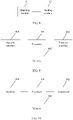
- FIG. 4 is a flowchart of a power control method.
- the method relates to how power control is performed when SRS-based carrier switching is triggered, if symbols of two subframes overlap and transmit power in an overlapping portion exceeds maximum transmit power of UE. As shown in FIG. 4 , the method includes the following steps.
- Step 301 Obtain transmit power in a symbol overlapping portion of a first subframe and a second subframe, where the first subframe is a subframe in which a sounding reference signal SRS is transmitted on a first carrier, and the second subframe is a subframe in which an SRS or a physical channel is transmitted on a second carrier.
- the transmit power in the symbol overlapping portion needs to be calculated.
- TAG Timing Advance Group
- Step 302 If the transmit power is greater than maximum transmit power of UE, control transmit power for a to-be-transmitted signal, where the to-be-transmitted signal includes the SRS and/or the physical channel.
- the transmit power for the to-be-transmitted signal is controlled. For example, if the transmit power is greater than the maximum transmit power of the UE, a portion of the to-be-transmitted signal is appropriately dropped, or power scaling is performed on the to-be-transmitted signal.
- the UE obtains the transmit power in the symbol overlapping portion of the first subframe in which the sounding reference signal SRS is transmitted on the first carrier and the second subframe in which the SRS or the physical channel is transmitted on the second carrier, and if the transmit power is greater than the maximum transmit power of the UE, controls the transmit power for the to-be-transmitted signal, so that the to-be-transmitted signal is transmitted at appropriate power, ensuring transmission efficiency of the to-be-transmitted signal.
- the method before the controlling transmit power for a to-be-transmitted signal, the method further includes: determining whether the SRS is configured periodically or configured aperiodically.
- controlling transmit power for a to-be-transmitted signal includes: controlling the transmit power for the to-be-transmitted signal based on a periodical configuration of the SRS; or controlling the transmit power for the to-be-transmitted signal based on an aperiodical configuration of the SRS.
- dropping a portion of the to-be-transmitted signal or performing power scaling for a portion of the to-be-transmitted signal may be selected based on a periodical characteristic of the SRS.
- the controlling transmit power for a to-be-transmitted signal includes: dropping the SRS or performing power scaling for the SRS.
- the controlling transmit power for a to-be-transmitted signal includes: dropping the PUSCH or performing power scaling for the PUSCH.
- the controlling transmit power for a to-be-transmitted signal includes: dropping the SRS or performing power scaling for the SRS.
- the controlling transmit power for a to-be-transmitted signal includes: dropping the SRS or performing power scaling for the SRS; or dropping the PUCCH or performing power scaling for the PUCCH.
- the controlling transmit power for a to-be-transmitted signal includes: dropping the SRS or performing power scaling for the SRS; or dropping the PUCCH or performing power scaling for the PUCCH.
- the controlling transmit power for a to-be-transmitted signal includes: dropping the SRS or performing power scaling for the SRS.
- the following describes the method of "controlling the transmit power for the to-be-transmitted signal based on a periodical characteristic of the SRS" in detail based on different UE configurations.
- the UE transmits a physical random access channel (Physical Random Access Channel, PRACH for short) on a secondary serving carrier/cell, and the PRACH is concurrent in a symbol in a subframe used for SRS transmission on a different serving carrier/cell, if the transmit power in the symbol overlapping portion exceeds the maximum transmit power of the UE, the following cases apply:
- PRACH Physical Random Access Channel
- FIG. 5 is a flowchart of a power control method.
- the method is executed by a base station. As shown in FIG. 5 , the method includes the following steps.
- Step 401 Obtain a power control parameter for a sounding reference signal SRS on a first carrier, where the power control parameter for the SRS includes at least one of a target power parameter value for the SRS, a path loss compensation factor, and a closed-loop power control parameter value for the SRS.
- the power control parameter for the SRS is specially configured, in order to calculate transmit power for the SRS on a switched-to carrier.
- Step 402 Send the power control parameter for the SRS to user equipment UE, so that the UE determines transmit power for the SRS on the first carrier based on the power control parameter for the SRS.
- the base station may send the power control parameter for the SRS in different manners. For example, the base station transmits a preconfigured power control parameter for the SRS to the UE by using a switched-to carrier for SRS transmission. Alternatively, the base station sends a target power parameter value for the SRS and a path loss compensation factor to the UE by using physical layer signaling or control signaling, and then indicates a closed-loop power control parameter value for the SRS to the UE by using transmission power control (Transmission power control, TPC) information. Alternatively, the base station sends various values in the power control parameter for the SRS to the UE in other manners. The UE may calculate the transmit power for the SRS on the first carrier based on the power control parameter for the SRS, so that the SRS is sent on the first carrier at appropriate transmit power.
- TPC transmission power control
- the base station obtains the power control parameter for the SRS on the first carrier, where the power control parameter includes at least one of the target power parameter value for the SRS, the path loss compensation factor, and the closed-loop power control parameter value for the SRS, sends the power control parameter for the SRS to the user equipment UE, so that the UE determines the transmit power for the SRS on the first carrier based on the power control parameter for the SRS.
- the UE can calculate transmit power for the SRS on a switched-to carrier based on a newly configured power control parameter for the SRS, so that the SRS is transmitted on the switched-to carrier at optimal transmit power, ensuring that the SRS is received correctly.
- the first carrier is a carrier on which no PUSCH is sent.
- the sending the power control parameter for the SRS to user equipment UE includes: sending the power control parameter for the SRS to the UE by using power control signaling or cross-carrier power control signaling.
- the power control signaling includes open-loop power control signaling and/or closed-loop power control signaling.
- the power control signaling or the cross-carrier power control signaling includes radio resource control RRC signaling or physical layer signaling.
- the target power parameter value for the SRS is a parameter value obtained based on a preamble initial received target power value; or the target power parameter value for the SRS is a parameter value obtained based on a preamble initial received target power value and a power adjustment value.
- the sending the power control parameter for the SRS to the UE by using power control signaling or cross-carrier power control signaling includes: scrambling the power control parameter for the SRS based on a first radio network temporary identifier RNTI, to generate the power control signaling or the cross-carrier power control signaling; and sending the power control signaling or the cross-carrier power control signaling to the UE.
- the SRS is configured periodically or configured aperiodically.
- the closed-loop power control parameter value for the SRS is an absolute value or a relative adjustment value.
- the method further includes: sending TPC information to the UE, so that the UE parses out the closed-loop power control parameter value for the SRS from the TPC information, where the TPC information is information scrambled with the first radio network temporary identifier RNTI.
- the method further includes: sending downlink control information DCI to the UE, so that the UE obtains the closed-loop power control parameter value for the SRS based on the DCI.
- the DCI is control information obtained on a second carrier
- the DCI includes at least a first carrier index
- the DCI is used to instruct the UE to obtain the closed-loop power control parameter value for the SRS on a carrier corresponding to the first carrier index.
- the second carrier is a switching-from carrier or any carrier other than a switched-to carrier, and the first carrier is the switched-to carrier.
- the DCI is used to instruct the UE to obtain the closed-loop power control parameter value for the SRS from the DCI.
- the power control method provided in this embodiment is implemented by a base station and is corresponding to the UE-side power control method.
- a base station is corresponding to the UE-side power control method.
- the UE-side power control method in the embodiments in FIG. 2 to Fig. 4 . Details are not described herein again.
- FIG. 6 is a structural diagram of a power control apparatus.
- the apparatus includes an obtaining module 11 and a determining module 12.
- the obtaining module 11 is configured to obtain a power control parameter for a sounding reference signal SRS, where the power control parameter for the SRS includes at least one of a target power parameter value for the SRS, a path loss compensation factor, and a closed-loop power control parameter value for the SRS.
- the determining module 12 is configured to determine transmit power for the SRS on a first carrier based on the power control parameter for the SRS.
- the apparatus may be configured to execute the technical solution of the method embodiment shown in FIG. 2 .
- Their implementation principles and technical effects are similar, and no more details are provided herein.
- the first carrier is a carrier on which no physical uplink shared channel PUSCH is sent.
- the obtaining module 11 is specifically configured to obtain power control signaling or cross-carrier power control signaling sent by a base station.
- the power control signaling includes open-loop power control signaling and/or closed-loop power control signaling.
- the obtaining module 11 is specifically further configured to obtain the power control parameter for the SRS from the power control signaling or the cross-carrier power control signaling.
- the power control signaling or the cross-carrier power control signaling includes radio resource control RRC signaling or physical layer signaling.
- the target power parameter value for the SRS is a parameter value obtained based on a preamble initial received target power value; or the target power parameter value for the SRS is a parameter value obtained based on a preamble initial received target power value and a power adjustment value.
- the obtaining module 11 obtains the power control parameter from the power control signaling or the cross-carrier power control signaling includes that the obtaining module 11 parses out the power control parameter for the SRS from the power control signaling or the cross-carrier power control signaling based on a first radio network temporary identifier RNTI.
- the determining module 12 is specifically configured to obtain the transmit power for the SRS based on at least one of maximum transmit power of user equipment UE, a transmit power adjustment value for the SRS, transmission bandwidth for the SRS, the target power parameter value for the SRS, the path loss compensation factor, and an estimated downlink path loss value.
- the determining module 12 is further configured to determine whether the SRS is configured periodically or configured aperiodically.
- the closed-loop power control parameter value for the SRS is an absolute value or a relative adjustment value.
- the obtaining module 11 is further configured to obtain transmission power control TPC information, where the TPC information is information scrambled with the first radio network temporary identifier RNTI.
- the obtaining module 11 obtains the power control parameter for the SRS includes that the obtaining module 11 parses out the closed-loop power control parameter value for the SRS from the TPC information based on the first RNTI.
- the obtaining module 11 is further configured to obtain downlink control information DCI.
- that the obtaining module 11 obtains the power control parameter for the SRS includes that the obtaining module 11 obtains the closed-loop power control parameter value for the SRS based on the DCI.
- the DCI includes at least a first carrier index.
- the second carrier is a switching-from carrier or any carrier other than a switched-to carrier
- the first carrier is the switched-to carrier
- that the obtaining module 11 obtains the closed-loop power control parameter value for the SRS based on the DCI includes that the obtaining module 11 obtains the closed-loop power control parameter value for the SRS on a carrier corresponding to the first carrier index.
- that the obtaining module 11 obtains the closed-loop power control parameter value for the SRS based on the DCI includes that the obtaining module 11 obtains the closed-loop power control parameter value for the SRS from the DCI.
- the determining module 12 is further configured to determine the closed-loop power control parameter value for the SRS based on at least one of closed-loop power control information or a relative adjustment value for an SRS in a previous subframe.
- the determining module 12 determines transmit power for the SRS based on the power control parameter for the SRS includes that the determining module 12 obtains the transmit power for the SRS based on at least one of maximum transmit power of the user equipment UE, a transmit power adjustment value for the SRS, transmission bandwidth for the SRS, the target power parameter value for the SRS, the path loss compensation factor, the estimated downlink path loss value, and a closed-loop power control parameter for the SRS.
- the apparatus in this embodiment may be configured to execute the technical solution of the method embodiment shown in FIG. 2 or FIG. 3 .
- Their implementation principles and technical effects are similar, and no more details are provided herein.
- FIG. 7 is a structural diagram of a power control apparatus.
- the apparatus includes an obtaining module 21 and a processing module 22.
- the obtaining module 21 is configured to obtain transmit power in a symbol overlapping portion of a first subframe and a second subframe, where the first subframe is a subframe in which a sounding reference signal SRS is transmitted on a first carrier, and the second subframe is a subframe in which an SRS or a physical channel is transmitted on a second carrier.
- the processing module 22 is configured to, if the transmit power is greater than maximum transmit power of user equipment UE, control transmit power for a to-be-transmitted signal, where the to-be-transmitted signal includes the SRS and/or the physical channel.
- the processing module 22 is further configured to determine whether the SRS is configured periodically or configured aperiodically.
- processing module 22 controls transmit power for a to-be-transmitted signal includes that the processing module 22 controls the transmit power for the to-be-transmitted signal based on a periodical configuration of the SRS; or that the processing module 22 controls the transmit power for the to-be-transmitted signal based on an aperiodical configuration of the SRS.
- that the processing module 22 controls transmit power for a to-be-transmitted signal includes that the processing module 22 drops the SRS or performs power scaling for the SRS.
- the physical channel is a physical uplink shared channel PUSCH
- the PUSCH does not include uplink control information UCI
- that the processing module 22 controls transmit power for a to-be-transmitted signal includes that the processing module 22 drops the PUSCH or performs power scaling for the PUSCH.
- the physical channel is a physical uplink shared channel PUSCH, and the PUSCH includes uplink control information UCI, that the processing module 22 controls transmit power for a to-be-transmitted signal includes that the processing module 22 drops the SRS or performs power scaling for the SRS.
- the processing module 22 controls transmit power for a to-be-transmitted signal includes that the processing module 22 drops the SRS or performs power scaling for the SRS; or that the processing module 22 drops the PUCCH or performs power scaling for the PUCCH.
- the physical channel is a physical uplink control channel PUCCH
- the PUCCH includes a hybrid automatic repeat request HARQ
- that the processing module 22 controls transmit power for a to-be-transmitted signal includes that the processing module 22 drops the SRS or performs power scaling for the SRS.
- the physical channel is a physical uplink control channel PUCCH, and the PUCCH includes only channel state information CSI, that the processing module 22 controls transmit power for a to-be-transmitted signal that the processing module 22 drops the SRS or performs power scaling for the SRS; or that the processing module 22 drops the PUCCH or performs power scaling for the PUCCH.
- the processing module 22 controls transmit power for a to-be-transmitted signal includes that the processing module 22 drops the SRS or performs power scaling for the SRS.
- the apparatus may be configured to execute the technical solution of the method shown in FIG. 4 .
- Their implementation principles and technical effects are similar, and no more details are provided herein.
- FIG. 8 is a structural diagram of a power control apparatus.
- the apparatus includes an obtaining module 31 and a sending module 32.
- the obtaining module 31 is configured to obtain a power control parameter for a sounding reference signal SRS on a first carrier, where the power control parameter for the SRS includes at least one of a target power parameter value for the SRS, a path loss compensation factor, and a closed-loop power control parameter value for the SRS.
- the sending module 32 is configured to send the power control parameter for the SRS to user equipment UE, so that the UE determines transmit power for the SRS on the first carrier based on the power control parameter for the SRS.
- the first carrier is a carrier on which no physical uplink shared channel PUSCH is sent.
- the sending module is specifically configured to send the power control parameter for the SRS to the UE by using power control signaling or cross-carrier power control signaling.
- the power control signaling or the cross-carrier power control signaling includes radio resource control RRC signaling or physical layer signaling.
- the sending module sends the power control parameter for the SRS to the UE by using power control signaling or cross-carrier power control signaling includes that the sending module scrambles the power control parameter for the SRS based on a first radio network temporary identifier RNTI, to generate the power control signaling or the cross-carrier power control signaling; and sends the power control signaling or the cross-carrier power control signaling to the UE.
- the SRS is configured periodically or configured aperiodically.
- the closed-loop power control parameter value for the SRS is an absolute value or a relative adjustment value.
- the sending module is further configured to send transmission power control TPC information to the UE, so that the UE parses out the closed-loop power control parameter value for the SRS from the TPC information, where the TPC information is information scrambled with the first radio network temporary identifier RNTI.
- the sending module is further configured to send downlink control information DCI to the UE, so that the UE obtains the closed-loop power control parameter value for the SRS based on the DCI.
- the DCI is control information obtained on a second carrier
- the DCI includes at least a first carrier index
- the DCI is used to instruct the UE to obtain the closed-loop power control parameter value for the SRS on a carrier corresponding to the first carrier index.
- the second carrier is a switching-from carrier or any carrier other than a switched-to carrier
- the first carrier is the switched-to carrier
- the DCI is used to instruct the UE to obtain the closed-loop power control parameter value for the SRS from the DCI.
- the apparatus may be configured to execute the technical solution of the method shown in FIG. 5 .
- Their implementation principles and technical effects are similar, and no more details are provided herein.
- FIG. 9 is a structural diagram of UE of the present invention
- the UE may include a processor 401 and a memory 402.
- the apparatus may further include a transmit interface 403 and a receive interface 404.
- the transmit interface 403 and the receive interface 404 may be connected to the processor 401.
- the transmit interface 403 is used to send data or information, and the transmit interface 403 may be a radio transmitting apparatus.
- the receive interface 404 is used to receive data or information, and the receive interface 404 may be a radio receiving apparatus.
- the memory 402 stores an executable instruction. When the apparatus runs, the processor 401 communicates with the memory 402, and the processor 401 call the executable instruction in the memory 402 to perform the following operations:
- the first carrier is a carrier on which no physical uplink shared channel PUSCH is sent.
- that the processor 401 obtains a power control parameter for a sounding reference signal SRS includes that the processor 401 receives power control signaling or cross-carrier power control signaling sent by a base station.
- the power control signaling includes open-loop power control signaling and/or closed-loop power control signaling.
- the power control signaling or the cross-carrier power control signaling includes radio resource control RRC signaling or physical layer signaling.
- the target power parameter value for the SRS is a parameter value obtained based on a preamble initial received target power value; or the target power parameter value for the SRS is a parameter value obtained based on a preamble initial received target power value and a power adjustment value.
- that the processor 401 obtains the power control parameter from the power control signaling or the cross-carrier power control signaling includes that the processor 401 parses out the power control parameter for the SRS from the power control signaling or the cross-carrier power control signaling based on a first radio network temporary identifier RNTI.
- the processor 401 determines transmit power for the SRS based on the power control parameter for the SRS includes that the processor 401 obtains the transmit power for the SRS based on at least one of maximum transmit power of user equipment UE, a transmit power adjustment value for the SRS, transmission bandwidth for the SRS, the target power parameter value for the SRS, the path loss compensation factor, and an estimated downlink path loss value.
- the processor 401 is further configured to determine whether the SRS is configured periodically or configured aperiodically.
- the processor 401 is further configured to obtain transmission power control TPC information, where the TPC information is information scrambled with the first radio network temporary identifier RNTI.
- the processor 401 is further configured to parse out the closed-loop power control parameter value for the SRS from the TPC information based on the first RNTI.
- the processor 401 is further configured to obtain downlink control information DCI.
- that the processor 401 obtains the power control parameter for the SRS includes that the processor 401 obtains the closed-loop power control parameter value for the SRS based on the DCI.
- the second carrier is a switching-from carrier or any carrier other than a switched-to carrier
- the first carrier is the switched-to carrier
- that the processor 401 obtains the closed-loop power control parameter value for the SRS based on the DCI includes that the processor 401 obtains the closed-loop power control parameter value for the SRS on a carrier corresponding to the first carrier index.
- that the processor 401 obtains the closed-loop power control parameter value for the SRS based on the DCI includes that the processor 401 obtains the closed-loop power control parameter value for the SRS from the DCI.
- the processor 401 is further configured to determine the closed-loop power control parameter value for the SRS based on at least one of closed-loop power control information or a relative adjustment value for an SRS in a previous subframe.
- the processor 401 determines transmit power for the SRS based on the power control parameter for the SRS includes that the processor 401 obtains the transmit power for the SRS based on at least one of maximum transmit power of the user equipment UE, a transmit power adjustment value for the SRS, transmission bandwidth for the SRS, the target power parameter value for the SRS, the path loss compensation factor, the estimated downlink path loss value, and a closed-loop power control parameter for the SRS.
- the UE may be configured to execute the technical solution of the method embodiment shown in FIG. 2 or FIG. 3 . Their implementation principles and technical effects are similar, and no more details are provided herein.
- An example of this application further provides UE, where a structure of the UE is the same as a structure of the UE shown in FIG. 9 .
- a processor communicates with a memory, and the processor calls an executable instruction in the memory to perform the following operations:
- the processor is further configured to determine whether the SRS is configured periodically or configured aperiodically.
- the processor controls transmit power for a to-be-transmitted signal includes that the processor controls the transmit power for the to-be-transmitted signal based on a periodical configuration of the SRS; or that the processor controls the transmit power for the to-be-transmitted signal based on an aperiodical configuration of the SRS.
- that the processor controls transmit power for a to-be-transmitted signal includes that dropping the SRS or performing power scaling for the SRS.
- the physical channel is a physical uplink shared channel PUSCH
- the PUSCH does not include uplink control information UCI
- that the processor controls transmit power for a to-be-transmitted signal includes that the processor drops the PUSCH or performs power scaling for the PUSCH.
- the physical channel is a physical uplink shared channel PUSCH
- the PUSCH includes uplink control information UCI
- that the processor controls transmit power for a to-be-transmitted signal includes that the processor drops the SRS or performs power scaling for the SRS.
- the processor controls transmit power for a to-be-transmitted signal includes that the processor drops the SRS or performs power scaling for the SRS; or that the processor drops the PUCCH or performs power scaling for the PUCCH.
- the physical channel is a physical uplink control channel PUCCH
- the PUCCH includes a hybrid automatic repeat request HARQ
- that the processor controls transmit power for a to-be-transmitted signal includes that the processor drops the SRS or performs power scaling for the SRS.
- the physical channel is a physical uplink control channel PUCCH
- the PUCCH includes only channel state information CSI
- that the processor controls transmit power for a to-be-transmitted signal includes that the processor drops the SRS or performs power scaling for the SRS; or that the processor drops the PUCCH or performs power scaling for the PUCCH.
- the processor controls transmit power for a to-be-transmitted signal includes that the processor drops the SRS or performs power scaling for the SRS.
- the UE may be configured to execute the technical solution of the method shown in FIG. 4 . Their implementation principles and technical effects are similar, and no more details are provided herein.
- FIG. 10 is a structural diagram of a base station.
- the base station includes a processor 501 and a transmitter 502
- the processor 501 is configured to obtain a power control parameter for a sounding reference signal SRS on a first carrier, where the power control parameter for the SRS includes at least one of a target power parameter value for the SRS, a path loss compensation factor, and a closed-loop power control parameter value for the SRS.
- the transmitter 502 is configured to send the power control parameter for the SRS to user equipment UE, so that the UE determines transmit power for the SRS on the first carrier based on the power control parameter for the SRS.
- the first carrier is a carrier on which no physical uplink shared channel PUSCH is sent.
- that the transmitter 502 sends the power control parameter for the SRS to user equipment UE includes that the transmitter 502 sends the power control parameter for the SRS to the UE by using power control signaling or cross-carrier power control signaling.
- the power control signaling includes open-loop power control signaling and/or closed-loop power control signaling.
- the power control signaling or the cross-carrier power control signaling includes radio resource control RRC signaling or physical layer signaling.
- the target power parameter value for the SRS is a parameter value obtained based on a preamble initial received target power value; or the target power parameter value for the SRS is a parameter value obtained based on a preamble initial received target power value and a power adjustment value.
- that the transmitter 502 sends the power control parameter for the SRS to the UE by using power control signaling or cross-carrier power control signaling includes that the transmitter 502 scrambles the power control parameter for the SRS based on an RNTI, to generate the power control signaling or the cross-carrier power control signaling; and sending the power control signaling or the cross-carrier power control signaling to the UE.
- the SRS is configured periodically or configured aperiodically.
- the closed-loop power control parameter value for the SRS is an absolute value or a relative adjustment value.
- the transmitter 502 is further configured to send transmission power control TPC information to the UE, so that the UE parses out the closed-loop power control parameter value for the SRS from the TPC information, where the TPC information is information scrambled with the first radio network temporary identifier RNTI.
- the transmitter 502 is further configured to send downlink control information DCI to the UE, so that the UE obtains the closed-loop power control parameter value for the SRS based on the DCI.
- the DCI is control information obtained on a second carrier
- the DCI includes at least a first carrier index
- the DCI is used to instruct the UE to obtain the closed-loop power control parameter value for the SRS on a carrier corresponding to the first carrier index.
- the DCI is used to instruct the UE to obtain the closed-loop power control parameter value for the SRS from the DCI.
- the base station may further include a memory 503 and a receiver 504.
- the memory 503 is configured to store an instruction and data
- the receiver 504 is configured to receive data or information.
- the apparatus may be configured to execute the technical solution of the method shown in FIG. 5 .
- Their implementation principles and technical effects are similar, and no more details are provided herein.
- the program may be stored in a computer-readable storage medium.
- the foregoing storage medium includes: any medium that can store program code, such as a read-only memory (Read-Only Memory, ROM for short), a random access memory (random access memory, RAM for short), a magnetic disk, or an optical disc.
Description
- Embodiments of the present invention relate to communications technologies, and in particular, to a power control method, an apparatus and a computer readable storage medium.
- In order to increase system transmission bandwidth, a carrier aggregation technology is introduced into a Long Term Evolution Advanced (Long Term Evolution- Advance, LTE-A for short) system.
- During carrier aggregation, user equipment (User Equipment, UE for short) usually can aggregate a larger quantity of downlink carriers, while a much smaller quantity of uplink carriers. Generally, based on channel non-reciprocity, for measurement of some downlink channels, measurement of the downlink channel is obtained by using a channel non-reciprocity feature, for example, a precoding matrix index (precoding matrix index, PMI for short) and an uplink sounding reference signal (Sounding Reference Symbol, SRS for short). Because UE's downlink carrier aggregation capacity is greater than its uplink carrier aggregation capacity, no uplink transmission is present on some time division duplex (time division duplex, TDD for short) carriers for downlink transmission of the UE. To ensure timely SRS transmission, carrier switching is required. For example, in a first subframe, a
carrier 1 and acarrier 2 are used for downlink transmission. When SRS transmission is required in a second subframe, carrier switching is performed. Thecarrier 2 is changed to acarrier 3 and thecarrier 3 is used to transmit the SRS. In addition, transmit power for the SRS needs to be controlled to ensure that the SRS is received correctly. - Parameter setting of a prior-art SRS power control solution depends on some parameters related to physical uplink shared channel (Physical Uplink Shared Channel, PUSCH for short) power control, while the UE cannot obtain the parameters related to PUSCH power control on the switched-to carrier used for SRS transmission. As a result, SRS power control is not possible, and the SRS cannot be received correctly.
- Rl-163055 discloses that power control should be supported for SRS CC with no PUSCH transmission, and the downlink grants which comprise the SRS trigger field can be sent in the same CC or in a different CC.
-
US 2015/223213 A1 discloses the TPC command can be transmitted through DCI scrambled by TPC-PUSCH-RNTI. And the terminal can determine transmit power of SRS based on the TPC command. -
EP 3430763 A2 falling under Art. 54(3) EPC discloses the UE can obtain corresponding closed loop transmit power control configuration in DCI. - Embodiments of the present invention provide a power control method, apparatus and computer readable storage medium as defined in the claims, so that an SRS is transmitted at optimal transmit power on a switched-to carrier, ensuring that the SRS is received correctly.
- To describe the technical solutions in the embodiments of the present invention or in the prior art more clearly, the following briefly describes the accompanying drawings required for describing the embodiments or the prior art. Apparently, the accompanying drawings in the following description show some embodiments of the present invention, and persons of ordinary skill in the art may still derive other drawings from these accompanying drawings without creative efforts.
-
FIG. 1 is a schematic diagram of an application scenario of a power control method according to an embodiment of the present invention; -
FIG. 2 is a flowchart of a power control method according toEmbodiment 1 of the present invention; -
FIG. 3 is a flowchart of a power control method according toEmbodiment 2 of the present invention; -
FIG. 4 is a flowchart of a power control method; -
FIG. 5 is a flowchart of a power control method; -
FIG. 6 is a structural diagram of a power control apparatus; -
FIG. 7 is a structural diagram of a power control apparatus; -
FIG. 8 is a structural diagram of a power control apparatus; -
FIG. 9 is a structural diagram of a UE and -
FIG. 10 is a structural diagram of a base station. -
FIG. 1 is a schematic diagram of an application scenario of a power control method according to an embodiment of the present invention. The method is applied to a wireless communications system, for example, an LTE-A system. As shown inFIG. 1 , the scenario includes anetwork device 1, auser terminal 2, and auser terminal 3. The power control method provided in this application is mainly used for data transmission between the network device and the user terminal. It should be noted that the scenario may further include other network devices and other user terminals.FIG. 1 is merely an example for description and imposes no limitation. - The user terminal used in this embodiment of the present invention may be a device that provides voice and/or data connectivity for a user, a handheld device with a wireless connection function, or another processing device connected to a wireless modem. A wireless terminal may communicate with one or more core networks through a radio access network (Radio Access Network, RAN for short). The wireless terminal may be a mobile terminal, such as a mobile phone (also referred to as a "cellular" phone) or a computer provided with a mobile terminal, and for example, may be a portable mobile apparatus, a pocket-sized mobile apparatus, a handheld mobile apparatus, a computer built-in mobile apparatus, or an in-vehicle mobile apparatus, which exchanges voice and/or data with the radio access network.
- The network device used in this embodiment of the present invention may be a base station, an access point, or a device in communication with a wireless terminal via one or more sectors at an over-the-air interface in an access network. The base station may be configured to convert a received over-the-air frame to an IP packet and convert a received IP packet to an over-the-air frame, and serve as a router between the wireless terminal and a rest portion of the access network, where the rest portion of the access network may include an Internet protocol (IP) network. The base station may coordinate attribute management of the air interface. For example, the base station may be a base station in GSM or CDMA (Base Transceiver Station, BTS for short), may be a base station in WCDMA (NodeB), or may be an evolved NodeB in LTE (NodeB, eNB, or e-NodeB, evolutional Node B). This is not limited in this application.
-
FIG. 2 is a flowchart of a power control method according toEmbodiment 1 of the present invention, where the method is executed by user equipment UE. As shown inFIG. 2 , the method includes the following steps. - Step 101: Obtain a power control parameter for a sounding reference signal SRS, where the power control parameter for the SRS includes at least one of a target power parameter value for the SRS, a path loss compensation factor, and a closed-loop power control parameter value for the SRS.
- In this embodiment, the UE may obtain the power control parameter for the SRS in different manners. For example, a base station transmits a preconfigured power control parameter for the SRS to the UE by using a switching-from or switched-to carrier for SRS transmission. In this embodiment, the base station sends a target power parameter value for the SRS and a path loss compensation factor to the UE by using radio resource control signaling, and then indicates a closed-loop power control parameter value for the SRS to the UE by using transmission power control (Transmission power control, TPC) information. Alternatively, various values in the power control parameter for the SRS may be obtained in other manners.
- Step 102: Determine transmit power for the SRS on a first carrier based on the power control parameter for the SRS.
- The first carrier is a switched-to carrier after SRS-based carrier switching, and also referred to as a non-uplink carrier, in order that SRS transmission is performed on the carrier. The UE may calculate the transmit power for the SRS on the first carrier based on the power control parameter for the SRS, so that the SRS is sent on the first carrier at appropriate transmit power.
- In the power control method provided in this embodiment, the UE obtains the power control parameter for the SRS, where the power control parameter includes at least one of the target power parameter value for the SRS, the path loss compensation factor, and the closed-loop power control parameter value for the SRS, and determines the transmit power for the SRS on the first carrier based on the power control parameter for the SRS. The UE can calculate transmit power for the SRS on a switched-to carrier based on a newly configured power control parameter for the SRS, so that the SRS is transmitted at optimal transmit power on a switched-to carrier, ensuring that the SRS is received correctly.
- In the embodiment shown in
Fig. 2 , the first carrier is a carrier on which no physical uplink shared channel (Physical Uplink Shared Channel, PUSCH for short) is sent. That is, the first carrier is used for SRS sending, but not for PUSCH sending. -
FIG. 3 is a flowchart of a power control method according toEmbodiment 2 of the present invention, and the method shown inFIG. 3 is a specific implementation process ofstep 101. As shown inFIG. 3 , the method includes the following steps. - Step 201: Receive power control signaling or cross-carrier power control signaling sent by a base station, where the power control signaling includes open-loop power control signaling and/or closed-loop power control signaling.
- In this embodiment, the base station may deliver the power control signaling to UE by using power control signaling on a switched-to carrier to UE, or may indicate the power control signaling to the UE by using the cross-carrier power control signaling. The cross-carrier power control signaling includes signaling that is received on a switching-from carrier on which the SRS is located or any carrier other than the switched-to carrier, and that is used for notification about related power configuration for SRS transmission on the switched-to carrier after SRS-based carrier switching. In other words, the cross-carrier power control signaling is signaling sent by the base station on a switching-from carrier or any carrier other than the switched-to carrier, and the signaling includes the power control parameter for the SRS on the switched-to carrier. The open-loop power control signaling may include the target power parameter value for the SRS and the path loss compensation factor. The closed-loop power control signaling may include the target power parameter value for the SRS, the path loss compensation factor, and the closed-loop power control parameter value for the SRS.
- The power control signaling or the cross-carrier power control signaling includes radio resource control (Radio Resource Control, RRC) signaling or physical layer signaling.
- Step 202: Obtain the power control parameter for the SRS from the power control signaling or the cross-carrier power control signaling.
- In this embodiment, after the UE receives the power control signaling or the cross-carrier power control signaling delivered by the base station, the UE parses the power control signaling or the cross-carrier power control signaling, to obtain the power control parameter for the SRS.
- Optionally, the target power parameter value for the SRS is a parameter value obtained based on a preamble initial received target power value; or the target power parameter value for the SRS is a parameter value obtained based on a preamble initial received target power value and a power adjustment value.
- In this embodiment, the base station may send the preamble initial received target power value to the UE by using the power control signaling or the cross-carrier power control signaling, and the UE calculates the target power parameter value for the SRS based on the preamble initial received target power value. Alternatively, the base station may calculate the target power parameter value for the SRS by adding the preamble initial received target power value and the power adjustment value, and then send the calculated target power parameter value for the SRS to the UE by using the power control signaling or the cross-carrier power control signaling. The power adjustment value may alternatively be obtained from a response message of a specially defined random access channel (Random Access Channel, RACH for short). The power adjustment value is also referred to as a power offset or a power offset (power offset).
- Further, the obtaining the power control parameter from the power control signaling or the cross-carrier control signaling includes: parsing out the power control parameter for the SRS from the power control signaling or the cross-carrier power control signaling based on a first radio network temporary identifier (Radio Network Temporary Identity, RNTI for short).
- In this embodiment, the first RNTI is different from a prior-art TPC-RNTI. The first RNTI is an RNTI that is redefined in this application, and the first RNTI may be named TPC-SRS-RNTI. The first RNTI is used to scramble (scramble) or mask (mask) the power control parameter for the SRS, and the scrambled parameter is carried in the physical layer signaling for indication to the UE.
- In the power control method provided in this embodiment, the UE receives the power control signaling or the cross-carrier power control signaling sent by the base station, and obtains the power control parameter for the SRS from the power control signaling or the cross-carrier power control signaling. The base station may indicate the power control parameter for the SRS to the UE by using RRC signaling, MAC signaling, or physical layer signaling, and may further scramble the power control parameter for the SRS by using the newly defined RNTI. The base station indicates the power control parameter for the SRS to the UE in different manners. The method is flexible, and features ease of operation.
- Optionally, the determining transmit power for the SRS based on the power control parameter for the SRS includes: obtaining the transmit power for the SRS based on at least one of maximum transmit power of the user equipment UE, a transmit power adjustment value for the SRS, transmission bandwidth for the SRS, the target power parameter value for the SRS, the path loss compensation factor, and an estimated downlink path loss value.
- Specifically, in an open-loop case, the determining transmit power for the SRS based on the power control parameter for the SRS includes: calculating the transmit power PSRS,c1(i) for the SRS according to a formula P SRS,c1(i) = min { P CMAX,c1(i), P SRS_OFFSET,c1(m) + 10log10(M SRS,c1)+ PO_SRS,c1(j) + α SRS,c1(j) · PL c1 }, where P CMAX,c1(i) is maximum transmit power of the user equipment UE in an ith subframe; P SRS_OFFSET,c1(m) is the transmit power adjustment value for the SRS, where m equals 0 or 1, M SRS,c1 is the transmission bandwidth for the SRS; P O_SRS,c1(j) is the target power parameter value for the SRS, where j equals 0, 1, or 2; α SRS,c1(j) is the path loss compensation factor; and PL c1 is the estimated downlink path loss value. α SRS,c1(j) may be fixed to 1, and for P O_SRS,c1(j), usually j equals 2. When j equals 0, P O_SRS,c1(j) is a semi-persistent scheduling transmit power; when j equals 1, P O_SRS,c1(j) is a dynamic scheduling transmit power; and when j equals 2, P O_SRS,c1(j) is a random access scheduling transmit power.
- Further, before the determining transmit power for the SRS based on the power control parameter for the SRS, the method further includes: determining whether the SRS is configured periodically or configured aperiodically.
- In this embodiment, the UE may determine whether the SRS is configured periodically or configured aperiodically, and then determine the transmit power for the SRS based on a periodical configuration characteristic of the SRS and the power control parameter for the SRS, to ensure that the SRS can be received correctly in various circumstances.
- Optionally, in a closed-loop circumstance, if the power control parameter for the SRS includes the closed-loop power control parameter value for the SRS, the closed-loop power control parameter value for the SRS is an absolute value or a relative adjustment value.
- In this embodiment, if the closed-loop power control parameter value for the SRS is an absolute value, the absolute value may be directly used to calculate the transmit power for the SRS; if the closed-loop power control parameter value for the SRS is a relative adjustment value, the closed-loop power control parameter value for the SRS needs to be calculated first based on the relative adjustment value, and then the closed-loop power control parameter value for the SRS obtained through calculation is used to calculate the transmit power for the SRS.
- Optionally, if the closed-loop power control parameter value for the SRS is a relative adjustment value, the method further includes: determining the closed-loop power control parameter value for the SRS based on at least one of closed-loop power control information or a relative adjustment value for an SRS in a previous subframe.
- Specifically, the determining the closed-loop power control parameter value for the SRS based on at least one of closed-loop power control information or a relative adjustment value for an SRS in a previous subframe includes: calculating the closed-loop power control parameter value f c1(i) for the SRS according to a formula f c1(i) = f c1(i -1) + δ SRS,c1(i- K SRS), where f c1(i -1) is the closed-loop power control information for the SRS in the previous subframe; δ SRS,c1(i - K SRS) is the relative adjustment value; and if the SRS is configured periodically, K SRS is a subframe periodicity of the SRS, or if the SRS is configured aperiodically, i-K SRS is a subframe number of the previous subframe.
- Further, the determining transmit power for the SRS based on the power control parameter for the SRS includes: obtaining the transmit power for the SRS based on at least one of maximum transmit power of the user equipment UE, a transmit power adjustment value for the SRS, transmission bandwidth for the SRS, the target power parameter value for the SRS, the path loss compensation factor, an estimated downlink path loss value, and the closed-loop power control parameter for the SRS.
- Specifically, the determining transmit power for the SRS based on the power control parameter for the SRS includes: calculating the transmit power P SRS,c1(i) for the SRS according to a formula P SRS,c1(i) = min { P CMAX,c1(i), P SRS_OFFSET,c1(m) +10log10(M SRS,c1) + P O_SRS,c1(j) +α SRS,c1(j) ·PL c1 + f SRS,c1(i)} , where P CMAX,c1(i) is maximum transmit power of the user equipment UE in an ith subframe on a switched-to carrier C1; P SRS_OFFSET,c1(m) is the transmit power adjustment value for the SRS, where m equals 0 or 1; MSRS,c1 is the transmission bandwidth for the SRS; PO_SRS,c1(j) is the target power parameter value for the SRS; α SRS,c1(j) is the path loss compensation factor; PL c1 is the estimated downlink path loss value; and f c1(i) is the closed-loop power control parameter value for the SRS. α SRS,c1(j) may be fixed to 1, and for P O_SRS,c1(j), usually j equals 2. When j equals 0, P O_SRS,c1(j) is a semi-persistent scheduling transmit power; when j equals 1, P O_SRS,c1(j) is a dynamic scheduling transmit power; and when j equals 2, P O_SRS,c1(j) is a random access scheduling transmit power.
- Further, before the obtaining the power control parameter for the SRS, the method further includes: obtaining transmission power control TPC information, where the TPC information is information scrambled or masked with the first RNTI.
- Still further, the obtaining the power control parameter for the SRS includes: parsing out the closed-loop power control parameter value for the SRS from the TPC information based on the first RNTI.
- In this embodiment, the closed-loop power control parameter value for the SRS may be included in the TPC information scrambled with the first RNTI, and the first RNTI is indicated to the UE in advance. The UE may descramble the TPC information based on the first RNTI, to obtain the closed-loop power control parameter value for the SRS.
- Still further, if the power control parameter for the SRS includes the closed-loop power control parameter value for the SRS, before the obtaining the power control parameter for the SRS, the method further includes: obtaining downlink control information (Downlink Control Information, DCI for short).
- Still further, the obtaining the power control parameter for the SRS includes: obtaining the closed-loop power control parameter value for the SRS based on the DCI.
- In this embodiment, different formats of DCI may be defined specifically as follows:
A first DCI format: if the DCI is control information obtained on a second carrier, the DCI includes at least a first carrier index, where the second carrier is a switching-from carrier or any carrier other than a switched-to carrier, and the first carrier is the switched-to carrier. - Correspondingly, in this embodiment, the obtaining the closed-loop power control parameter value for the SRS based on the DCI includes: obtaining the closed-loop power control parameter value for the SRS on a carrier corresponding to the first carrier index.
- In this embodiment, in the case of cross-carrier notification, DCI obtained on a switching-from carrier needs to include at least an index of a switched-to carrier, so that the UE obtains, based on the first carrier index, the closed-loop power control parameter value for the SRS on a carrier corresponding to the carrier index.
- A second DCI format: if the DCI is control information obtained on the first carrier, the obtaining the closed-loop power control parameter value for the SRS based on the DCI includes: obtaining the closed-loop power control parameter value for the SRS from the DCI.
- In this embodiment, when the DCI is control information obtained on a switched-to carrier, the closed-loop power control parameter value for the SRS in the new DCI format is used directly to perform SRS transmission power control.
-
FIG. 4 is a flowchart of a power control method. - The method relates to how power control is performed when SRS-based carrier switching is triggered, if symbols of two subframes overlap and transmit power in an overlapping portion exceeds maximum transmit power of UE. As shown in
FIG. 4 , the method includes the following steps. - Step 301: Obtain transmit power in a symbol overlapping portion of a first subframe and a second subframe, where the first subframe is a subframe in which a sounding reference signal SRS is transmitted on a first carrier, and the second subframe is a subframe in which an SRS or a physical channel is transmitted on a second carrier.
- In this method, if a symbol of a subframe in which the sounding reference signal SRS is transmitted on the first carrier overlaps a symbol of a subframe in which the SRS or the physical channel is transmitted on the second carrier, the transmit power in the symbol overlapping portion needs to be calculated. For example, when a plurality of timing advance groups (Timing Advance Group, TAG for short) are configured for UE, when a symbol in subframe i for SRS transmission of the UE on one assumed serving carrier/cell in one TAG overlaps a symbol in a subframe i or a subframe i+1 used for PUCCH transmission on another serving carrier/cell, transmit power in the symbol overlapping portion is calculated.
- Step 302: If the transmit power is greater than maximum transmit power of UE, control transmit power for a to-be-transmitted signal, where the to-be-transmitted signal includes the SRS and/or the physical channel.
- In this method, if the transmit power is greater than the maximum transmit power of the UE, the transmit power for the to-be-transmitted signal is controlled. For example, if the transmit power is greater than the maximum transmit power of the UE, a portion of the to-be-transmitted signal is appropriately dropped, or power scaling is performed on the to-be-transmitted signal.
- In the power control method provided, the UE obtains the transmit power in the symbol overlapping portion of the first subframe in which the sounding reference signal SRS is transmitted on the first carrier and the second subframe in which the SRS or the physical channel is transmitted on the second carrier, and if the transmit power is greater than the maximum transmit power of the UE, controls the transmit power for the to-be-transmitted signal, so that the to-be-transmitted signal is transmitted at appropriate power, ensuring transmission efficiency of the to-be-transmitted signal.
- Optionally, before the controlling transmit power for a to-be-transmitted signal, the method further includes: determining whether the SRS is configured periodically or configured aperiodically.
- Further, the controlling transmit power for a to-be-transmitted signal includes: controlling the transmit power for the to-be-transmitted signal based on a periodical configuration of the SRS; or controlling the transmit power for the to-be-transmitted signal based on an aperiodical configuration of the SRS.
- In this method, dropping a portion of the to-be-transmitted signal or performing power scaling for a portion of the to-be-transmitted signal may be selected based on a periodical characteristic of the SRS.
- Optionally, if the SRS is configured periodically, the controlling transmit power for a to-be-transmitted signal includes: dropping the SRS or performing power scaling for the SRS.
- Optionally, if the SRS is configured aperiodically, the physical channel is a physical uplink shared channel PUSCH, and the PUSCH does not include uplink control information UCI, the controlling transmit power for a to-be-transmitted signal includes: dropping the PUSCH or performing power scaling for the PUSCH.
- Optionally, if the SRS is configured aperiodically, the physical channel is a physical uplink shared channel PUSCH, and the PUSCH includes uplink control information UCI, the controlling transmit power for a to-be-transmitted signal includes: dropping the SRS or performing power scaling for the SRS.
- Optionally, if the SRS is configured aperiodically, and the physical channel is a physical uplink control channel PUCCH, the controlling transmit power for a to-be-transmitted signal includes: dropping the SRS or performing power scaling for the SRS; or dropping the PUCCH or performing power scaling for the PUCCH.
- Optionally, if the SRS is configured aperiodically, the physical channel is a physical uplink control channel PUCCH, and the PUCCH includes a hybrid automatic repeat request HARQ, the controlling transmit power for a to-be-transmitted signal includes: dropping the SRS or performing power scaling for the SRS.
- Optionally, if the SRS is configured aperiodically, the physical channel is a PUCCH, and the PUCCH includes only channel state information (Channel State Information, CSI for short), the controlling transmit power for a to-be-transmitted signal includes: dropping the SRS or performing power scaling for the SRS; or dropping the PUCCH or performing power scaling for the PUCCH.
- In this method, when the SRS is configured aperiodically, the physical channel is a PUCCH, the PUCCH includes only CSI, and the PUCCH does not include a hybrid automatic repeat request (Hybrid Automatic Repeat reQuest, HARQ for short), the controlling transmit power for a to-be-transmitted signal includes: dropping the SRS or performing power scaling for the SRS; or dropping the PUCCH or performing power scaling for the PUCCH.
- Optionally, if the SRS is configured aperiodically, the physical channel is a packet random access channel PRACH, and the PRACH is concurrent, the controlling transmit power for a to-be-transmitted signal includes: dropping the SRS or performing power scaling for the SRS.
- The following describes the method of "controlling the transmit power for the to-be-transmitted signal based on a periodical characteristic of the SRS" in detail based on different UE configurations.
- When a plurality of TAGs are configured for the UE, when a symbol in a subframe i used for SRS transmission of the UE on one assumed serving carrier/cell in one TAG overlaps a symbol in a subframe i or a subframe i+1 used for PUCCH/PUSCH transmission on another serving carrier/cell, if the transmit power in the symbol overlapping portion exceeds the maximum transmit power of the UE, the following cases apply:
- (1) When the SRS is configured periodically, if transmit power in any overlapping symbol exceeds the maximum transmit power of the UE, the UE drops SRS transmission or performs power scaling for SRS transmission.
- (2) When the SRS is configured aperiodically, if transmit power in any overlapping symbol exceeds the maximum transmit power of the UE, only a PUSCH is present, and the PUSCH does not include uplink control information (uplink control information, UCI for short), the UE drops PUSCH transmission or performs power scaling for PUSCH transmission; or the UE drops SRS transmission or performs power scaling for SRS transmission.
- (3) When the SRS is configured aperiodically, if transmit power in any overlapping symbol exceeds the maximum transmit power of the UE, only a PUSCH is present, and the PUSCH includes UCI, the UE drops SRS transmission or performs power scaling for SRS transmission.
- (4) When the SRS is configured aperiodically, if transmit power in any overlapping symbol exceeds the maximum transmit power of the UE, and a PUCCH is present, the UE drops SRS transmission or performs power scaling for SRS transmission; or the UE drops PUSCH transmission or performs power scaling for PUSCH transmission.
- (5) When the SRS is configured aperiodically, if transmit power in any overlapping symbol exceeds the maximum transmit power of the UE, a PUCCH is present, and the PUCCH includes a hybrid automatic repeat request (Hybrid Automatic Repeat reQuest, HARQ for short), the UE drops SRS transmission or performs power scaling for SRS transmission.
- (6) When the SRS is configured aperiodically, if transmit power in any overlapping symbol exceeds the maximum transmit power of the UE, a PUCCH is present, and the PUCCH includes only CSI, the UE drops SRS transmission or the PUCCH; or the UE performs power scaling for SRS transmission or performs power scaling for the PUCCH.
- When a plurality of TAGs and more than two serving carriers/cells are configured for the UE, when a symbol in a subframe i used for SRS transmission on one serving carrier/cell overlaps a symbol in a subframe i used for SRS transmission on another serving carrier/cell, and/or overlaps a symbol in a subframe i or a subframe i+1 used for PUCCH/PUSCH transmission on another serving carrier/cell, if transmit power for the symbol overlapping portion exceeds the maximum transmit power of the UE, the following cases apply:
- (1) When the SRS is configured periodically, if transmit power in any overlapping symbol exceeds the maximum transmit power of the UE, the UE drops SRS transmission or performs power scaling for SRS transmission.
- (2) When the SRS is configured aperiodically, if transmit power in any overlapping symbol exceeds the maximum transmit power of the UE, only a PUSCH is present, and the PUSCH does not include uplink control information UCI, the UE drops PUSCH transmission or performs power scaling for PUSCH transmission; or the UE drops SRS transmission or performs power scaling for SRS transmission.
- (3) When the SRS is configured aperiodically, if transmit power in any overlapping symbol exceeds the maximum transmit power of the UE, only a PUSCH is present, and the PUSCH includes uplink control information UCI (uplink control information), the UE drops SRS transmission or performs power scaling for SRS transmission.
- (4) When the SRS is configured aperiodically, if transmit power in any overlapping symbol exceeds the maximum transmit power of the UE, and a PUCCH is present, the UE drops SRS transmission or performs power scaling for SRS transmission; or the UE drops PUSCH transmission or performs power scaling for PUSCH transmission.
- (5) When the SRS is configured aperiodically, if transmit power in any overlapping symbol exceeds the maximum transmit power of the UE, a PUCCH is present, and the PUCCH includes HARQ, the UE drops SRS transmission or performs power scaling for SRS transmission.
- (6) When the SRS is configured aperiodically, if transmit power in any overlapping symbol exceeds the maximum transmit power of the UE, a PUCCH is present, and the PUCCH includes only CSI, the UE drops SRS transmission or the PUCCH; or the UE performs power scaling for SRS transmission or performs power scaling for the PUCCH.
- When a plurality of TAGs are configured for the UE, the UE transmits a physical random access channel (Physical Random Access Channel, PRACH for short) on a secondary serving carrier/cell, and the PRACH is concurrent in a symbol in a subframe used for SRS transmission on a different serving carrier/cell, if the transmit power in the symbol overlapping portion exceeds the maximum transmit power of the UE, the following cases apply:
- (1) When the SRS is configured periodically, if transmit power in any overlapping symbol exceeds the maximum transmit power of the UE, the UE drops SRS transmission or performs power scaling for SRS transmission.
- (2) When the SRS is configured periodically, if transmit power in any overlapping symbol exceeds the maximum transmit power of the UE, and a PRACH is concurrent, the UE drops SRS transmission or performs power scaling for SRS transmission.
-
FIG. 5 is a flowchart of a power control method. - The method is executed by a base station. As shown in
FIG. 5 , the method includes the following steps. - Step 401: Obtain a power control parameter for a sounding reference signal SRS on a first carrier, where the power control parameter for the SRS includes at least one of a target power parameter value for the SRS, a path loss compensation factor, and a closed-loop power control parameter value for the SRS.
- In this method, the power control parameter for the SRS is specially configured, in order to calculate transmit power for the SRS on a switched-to carrier.
- Step 402: Send the power control parameter for the SRS to user equipment UE, so that the UE determines transmit power for the SRS on the first carrier based on the power control parameter for the SRS.
- In this method, the base station may send the power control parameter for the SRS in different manners. For example, the base station transmits a preconfigured power control parameter for the SRS to the UE by using a switched-to carrier for SRS transmission. Alternatively, the base station sends a target power parameter value for the SRS and a path loss compensation factor to the UE by using physical layer signaling or control signaling, and then indicates a closed-loop power control parameter value for the SRS to the UE by using transmission power control (Transmission power control, TPC) information. Alternatively, the base station sends various values in the power control parameter for the SRS to the UE in other manners. The UE may calculate the transmit power for the SRS on the first carrier based on the power control parameter for the SRS, so that the SRS is sent on the first carrier at appropriate transmit power.
- In the power control method provided, the base station obtains the power control parameter for the SRS on the first carrier, where the power control parameter includes at least one of the target power parameter value for the SRS, the path loss compensation factor, and the closed-loop power control parameter value for the SRS, sends the power control parameter for the SRS to the user equipment UE, so that the UE determines the transmit power for the SRS on the first carrier based on the power control parameter for the SRS. In this way, the UE can calculate transmit power for the SRS on a switched-to carrier based on a newly configured power control parameter for the SRS, so that the SRS is transmitted on the switched-to carrier at optimal transmit power, ensuring that the SRS is received correctly.
- Optionally, the first carrier is a carrier on which no PUSCH is sent.
- Optionally, the sending the power control parameter for the SRS to user equipment UE includes: sending the power control parameter for the SRS to the UE by using power control signaling or cross-carrier power control signaling.
- The power control signaling includes open-loop power control signaling and/or closed-loop power control signaling.
- The power control signaling or the cross-carrier power control signaling includes radio resource control RRC signaling or physical layer signaling.
- Optionally, the target power parameter value for the SRS is a parameter value obtained based on a preamble initial received target power value; or the target power parameter value for the SRS is a parameter value obtained based on a preamble initial received target power value and a power adjustment value.
- Further, the sending the power control parameter for the SRS to the UE by using power control signaling or cross-carrier power control signaling includes: scrambling the power control parameter for the SRS based on a first radio network temporary identifier RNTI, to generate the power control signaling or the cross-carrier power control signaling; and sending the power control signaling or the cross-carrier power control signaling to the UE.
- Optionally, the SRS is configured periodically or configured aperiodically.
- Further, if the power control parameter for the SRS includes the closed-loop power control parameter value for the SRS, the closed-loop power control parameter value for the SRS is an absolute value or a relative adjustment value.
- Still further, the method further includes: sending TPC information to the UE, so that the UE parses out the closed-loop power control parameter value for the SRS from the TPC information, where the TPC information is information scrambled with the first radio network temporary identifier RNTI.
- Still further, if the power control parameter for the SRS includes the closed-loop power control parameter for the SRS, the method further includes: sending downlink control information DCI to the UE, so that the UE obtains the closed-loop power control parameter value for the SRS based on the DCI.
- Optionally, if the DCI is control information obtained on a second carrier, the DCI includes at least a first carrier index, and the DCI is used to instruct the UE to obtain the closed-loop power control parameter value for the SRS on a carrier corresponding to the first carrier index.
- The second carrier is a switching-from carrier or any carrier other than a switched-to carrier, and the first carrier is the switched-to carrier.
- Optionally, if the DCI is control information obtained on the first carrier, the DCI is used to instruct the UE to obtain the closed-loop power control parameter value for the SRS from the DCI.
- The power control method provided in this embodiment is implemented by a base station and is corresponding to the UE-side power control method. For detailed descriptions about an implementation principle and specific technical features of the method, refer to the UE-side power control method in the embodiments in
FIG. 2 to Fig. 4 . Details are not described herein again. -
FIG. 6 is a structural diagram of a power control apparatus. As shown inFIG. 6 , the apparatus includes an obtainingmodule 11 and a determiningmodule 12. The obtainingmodule 11 is configured to obtain a power control parameter for a sounding reference signal SRS, where the power control parameter for the SRS includes at least one of a target power parameter value for the SRS, a path loss compensation factor, and a closed-loop power control parameter value for the SRS. The determiningmodule 12 is configured to determine transmit power for the SRS on a first carrier based on the power control parameter for the SRS. - The apparatus may be configured to execute the technical solution of the method embodiment shown in
FIG. 2 . Their implementation principles and technical effects are similar, and no more details are provided herein. - Optionally, the first carrier is a carrier on which no physical uplink shared channel PUSCH is sent.
- Optionally, the obtaining
module 11 is specifically configured to obtain power control signaling or cross-carrier power control signaling sent by a base station. - Optionally, the power control signaling includes open-loop power control signaling and/or closed-loop power control signaling.
- Optionally, the obtaining
module 11 is specifically further configured to obtain the power control parameter for the SRS from the power control signaling or the cross-carrier power control signaling. - Optionally, the power control signaling or the cross-carrier power control signaling includes radio resource control RRC signaling or physical layer signaling.
- Optionally, the target power parameter value for the SRS is a parameter value obtained based on a preamble initial received target power value; or the target power parameter value for the SRS is a parameter value obtained based on a preamble initial received target power value and a power adjustment value.
- Optionally, that the obtaining
module 11 obtains the power control parameter from the power control signaling or the cross-carrier power control signaling includes that the obtainingmodule 11 parses out the power control parameter for the SRS from the power control signaling or the cross-carrier power control signaling based on a first radio network temporary identifier RNTI. - Optionally, the determining
module 12 is specifically configured to obtain the transmit power for the SRS based on at least one of maximum transmit power of user equipment UE, a transmit power adjustment value for the SRS, transmission bandwidth for the SRS, the target power parameter value for the SRS, the path loss compensation factor, and an estimated downlink path loss value. - Optionally, the determining
module 12 is specifically configured to calculate the transmit power P SRS,c1(i) for the SRS according to a formula P SRS,c1(i) = min { P CMAX,c1(i), P SRS_OFFSET,c1(m) +10log10(M SRS,c1) + P O_SRS,c1(j) + α SRS,c1(j) ·PL SRS,c1}, where P CMAX,c1(i) is maximum transmit power of the user equipment UE in an ith subframe; PSRS_OFFSET,c1(m) is the transmit power adjustment value for the SRS, where m equals 0 or 1; M SRS,c1 is the transmission bandwidth for the SRS; P O_SRS,c1(j) is the target power parameter value for the SRS, where j equals 0, 1, or 2; α SRS,c1(j) is the path loss compensation factor; and PL SRS,c1 is the estimated downlink path loss value. - Optionally, the determining
module 12 is further configured to determine whether the SRS is configured periodically or configured aperiodically. - Optionally, if the power control parameter for the SRS includes the closed-loop power control parameter value for the SRS, the closed-loop power control parameter value for the SRS is an absolute value or a relative adjustment value.
- Optionally, the obtaining
module 11 is further configured to obtain transmission power control TPC information, where the TPC information is information scrambled with the first radio network temporary identifier RNTI. - Optionally, that the obtaining
module 11 obtains the power control parameter for the SRS includes that the obtainingmodule 11 parses out the closed-loop power control parameter value for the SRS from the TPC information based on the first RNTI. - Optionally, if the power control parameter for the SRS includes the closed-loop power control parameter value for the SRS, the obtaining
module 11 is further configured to obtain downlink control information DCI. - Optionally, that the obtaining
module 11 obtains the power control parameter for the SRS includes that the obtainingmodule 11 obtains the closed-loop power control parameter value for the SRS based on the DCI. - Optionally, if the DCI is control information obtained on a second carrier, the DCI includes at least a first carrier index.
- Optionally, the second carrier is a switching-from carrier or any carrier other than a switched-to carrier, and the first carrier is the switched-to carrier.
- Optionally, that the obtaining
module 11 obtains the closed-loop power control parameter value for the SRS based on the DCI includes that the obtainingmodule 11 obtains the closed-loop power control parameter value for the SRS on a carrier corresponding to the first carrier index. - Optionally, if the DCI is control information obtained on the first carrier, that the obtaining
module 11 obtains the closed-loop power control parameter value for the SRS based on the DCI includes that the obtainingmodule 11 obtains the closed-loop power control parameter value for the SRS from the DCI. - Optionally, if the closed-loop power control parameter value for the SRS is a relative adjustment value, the determining
module 12 is further configured to determine the closed-loop power control parameter value for the SRS based on at least one of closed-loop power control information or a relative adjustment value for an SRS in a previous subframe. - Optionally, that the determining
module 12 determines the closed-loop power control parameter for the SRS based on at least one of closed-loop power control information or a relative adjustment value for an SRS in a previous subframe includes that the determiningmodule 12 calculates the closed-loop power control parameter value f SRS,c1(i) for the SRS according to a formula f SRS,c1(i) = f SRS,c1(i -1) + δ SRS,c1(i - K SRS), where f SRS,c1(i -1) is the closed-loop power control information for the SRS in the previous subframe; δ SRS,c1(i - K SRS) is the relative adjustment value; and if the SRS is configured periodically, K SRS is a subframe periodicity of the SRS, or if the SRS is configured aperiodically, i-K SRS is a subframe number of the previous subframe. - Optionally, that the determining
module 12 determines transmit power for the SRS based on the power control parameter for the SRS includes that the determiningmodule 12 obtains the transmit power for the SRS based on at least one of maximum transmit power of the user equipment UE, a transmit power adjustment value for the SRS, transmission bandwidth for the SRS, the target power parameter value for the SRS, the path loss compensation factor, the estimated downlink path loss value, and a closed-loop power control parameter for the SRS. - Optionally, that the determining
module 12 determines transmit power for the SRS based on the power control parameter for the SRS includes that the determiningmodule 12 calculates the transmit power P SRS,c1(i) for the SRS according to a formula P SRS,c1(i) = min { P CMAX,c1(i), P SRS_OFFSET,c1(m) + 10log10(M SRS,c1) +P O_SRS,c1(j) + α SRS,c1(j)·PL SRS,c1 + f SRS,c1(i) } where P CMAX,c1(i) is maximum transmit power of the user equipment UE in an ith subframe; P SRS_OFFSET,c1(m) is the transmit power adjustment value for the SRS, where m equals 0 or 1, M SRS,c1 is the transmission bandwidth for the SRS; P O_SRS,c1(j) is the target power parameter value for the SRS; α SRS,c1(j) is the path loss compensation factor; PL SRS,c1 is the estimated downlink path loss value; and f SRS,c1(i) is the closed-loop power control parameter value for the SRS. - The apparatus in this embodiment may be configured to execute the technical solution of the method embodiment shown in
FIG. 2 orFIG. 3 . Their implementation principles and technical effects are similar, and no more details are provided herein. -
FIG. 7 is a structural diagram of a power control apparatus. As shown inFIG. 7 , the apparatus includes an obtainingmodule 21 and aprocessing module 22. The obtainingmodule 21 is configured to obtain transmit power in a symbol overlapping portion of a first subframe and a second subframe, where the first subframe is a subframe in which a sounding reference signal SRS is transmitted on a first carrier, and the second subframe is a subframe in which an SRS or a physical channel is transmitted on a second carrier. Theprocessing module 22 is configured to, if the transmit power is greater than maximum transmit power of user equipment UE, control transmit power for a to-be-transmitted signal, where the to-be-transmitted signal includes the SRS and/or the physical channel. - Optionally, the
processing module 22 is further configured to determine whether the SRS is configured periodically or configured aperiodically. - Optionally, that the
processing module 22 controls transmit power for a to-be-transmitted signal includes that theprocessing module 22 controls the transmit power for the to-be-transmitted signal based on a periodical configuration of the SRS; or that theprocessing module 22 controls the transmit power for the to-be-transmitted signal based on an aperiodical configuration of the SRS. - Optionally, if the SRS is configured periodically, that the
processing module 22 controls transmit power for a to-be-transmitted signal includes that theprocessing module 22 drops the SRS or performs power scaling for the SRS. - Optionally, if the SRS is configured aperiodically, the physical channel is a physical uplink shared channel PUSCH, and the PUSCH does not include uplink control information UCI, that the
processing module 22 controls transmit power for a to-be-transmitted signal includes that theprocessing module 22 drops the PUSCH or performs power scaling for the PUSCH. - Optionally, if the SRS is configured aperiodically, the physical channel is a physical uplink shared channel PUSCH, and the PUSCH includes uplink control information UCI, that the
processing module 22 controls transmit power for a to-be-transmitted signal includes that theprocessing module 22 drops the SRS or performs power scaling for the SRS. - Optionally, if the SRS is configured aperiodically, and the physical channel is a physical uplink control channel PUCCH, that the
processing module 22 controls transmit power for a to-be-transmitted signal includes that theprocessing module 22 drops the SRS or performs power scaling for the SRS; or that theprocessing module 22 drops the PUCCH or performs power scaling for the PUCCH. - Optionally, if the SRS is configured aperiodically, the physical channel is a physical uplink control channel PUCCH, and the PUCCH includes a hybrid automatic repeat request HARQ, that the
processing module 22 controls transmit power for a to-be-transmitted signal includes that theprocessing module 22 drops the SRS or performs power scaling for the SRS. - Optionally, if the SRS is configured aperiodically, the physical channel is a physical uplink control channel PUCCH, and the PUCCH includes only channel state information CSI, that the
processing module 22 controls transmit power for a to-be-transmitted signal that theprocessing module 22 drops the SRS or performs power scaling for the SRS; or that theprocessing module 22 drops the PUCCH or performs power scaling for the PUCCH. - Optionally, if the SRS is configured aperiodically, the physical channel is a packet random access channel PRACH, and the PRACH is concurrent, that the
processing module 22 controls transmit power for a to-be-transmitted signal includes that theprocessing module 22 drops the SRS or performs power scaling for the SRS. - The apparatus may be configured to execute the technical solution of the method shown in
FIG. 4 . Their implementation principles and technical effects are similar, and no more details are provided herein. -
FIG. 8 is a structural diagram of a power control apparatus. - As shown in
FIG. 8 , the apparatus includes an obtainingmodule 31 and a sendingmodule 32. The obtainingmodule 31 is configured to obtain a power control parameter for a sounding reference signal SRS on a first carrier, where the power control parameter for the SRS includes at least one of a target power parameter value for the SRS, a path loss compensation factor, and a closed-loop power control parameter value for the SRS. The sendingmodule 32 is configured to send the power control parameter for the SRS to user equipment UE, so that the UE determines transmit power for the SRS on the first carrier based on the power control parameter for the SRS. - Optionally, the first carrier is a carrier on which no physical uplink shared channel PUSCH is sent.
- Optionally, the sending module is specifically configured to send the power control parameter for the SRS to the UE by using power control signaling or cross-carrier power control signaling.
- Optionally, the power control signaling includes open-loop power control signaling and/or closed-loop power control signaling.
- Optionally, the power control signaling or the cross-carrier power control signaling includes radio resource control RRC signaling or physical layer signaling.
- Optionally, the target power parameter value for the SRS is a parameter value obtained based on a preamble initial received target power value; or the target power parameter value for the SRS is a parameter value obtained based on a preamble initial received target power value and a power adjustment value.
- Optionally, that the sending module sends the power control parameter for the SRS to the UE by using power control signaling or cross-carrier power control signaling includes that the sending module scrambles the power control parameter for the SRS based on a first radio network temporary identifier RNTI, to generate the power control signaling or the cross-carrier power control signaling; and sends the power control signaling or the cross-carrier power control signaling to the UE.
- Optionally, the SRS is configured periodically or configured aperiodically.
- Optionally, if the power control parameter for the SRS includes the closed-loop power control parameter value for the SRS, the closed-loop power control parameter value for the SRS is an absolute value or a relative adjustment value.
- Optionally, the sending module is further configured to send transmission power control TPC information to the UE, so that the UE parses out the closed-loop power control parameter value for the SRS from the TPC information, where the TPC information is information scrambled with the first radio network temporary identifier RNTI.
- Optionally, if the power control parameter for the SRS includes the closed-loop power control parameter for the SRS, the sending module is further configured to send downlink control information DCI to the UE, so that the UE obtains the closed-loop power control parameter value for the SRS based on the DCI.
- Optionally, if the DCI is control information obtained on a second carrier, the DCI includes at least a first carrier index, and the DCI is used to instruct the UE to obtain the closed-loop power control parameter value for the SRS on a carrier corresponding to the first carrier index.
- Optionally, the second carrier is a switching-from carrier or any carrier other than a switched-to carrier, and the first carrier is the switched-to carrier.
- Optionally, if the DCI is control information obtained on the first carrier, the DCI is used to instruct the UE to obtain the closed-loop power control parameter value for the SRS from the DCI.
- The apparatus may be configured to execute the technical solution of the method shown in
FIG. 5 . Their implementation principles and technical effects are similar, and no more details are provided herein. -
FIG. 9 is a structural diagram of UE of the present invention The UE may include aprocessor 401 and amemory 402. The apparatus may further include a transmitinterface 403 and a receiveinterface 404. The transmitinterface 403 and the receiveinterface 404 may be connected to theprocessor 401. The transmitinterface 403 is used to send data or information, and the transmitinterface 403 may be a radio transmitting apparatus. The receiveinterface 404 is used to receive data or information, and the receiveinterface 404 may be a radio receiving apparatus. Thememory 402 stores an executable instruction. When the apparatus runs, theprocessor 401 communicates with thememory 402, and theprocessor 401 call the executable instruction in thememory 402 to perform the following operations: - obtaining a power control parameter for a sounding reference signal SRS, where the power control parameter for the SRS includes at least one of a target power parameter value for the SRS, a path loss compensation factor, and a closed-loop power control parameter value for the SRS; and
- determining transmit power for the SRS on a first carrier based on the power control parameter for the SRS.
- Optionally, the first carrier is a carrier on which no physical uplink shared channel PUSCH is sent.
- Optionally, that the
processor 401 obtains a power control parameter for a sounding reference signal SRS includes that theprocessor 401 receives power control signaling or cross-carrier power control signaling sent by a base station. - Optionally, the power control signaling includes open-loop power control signaling and/or closed-loop power control signaling.
- Optionally, that the
processor 401 obtains a power control parameter for a sounding reference signal SRS includes that theprocessor 401 obtains the power control parameter for the SRS from the power control signaling or the cross-carrier power control signaling. - Optionally, the power control signaling or the cross-carrier power control signaling includes radio resource control RRC signaling or physical layer signaling.
- Optionally, the target power parameter value for the SRS is a parameter value obtained based on a preamble initial received target power value; or the target power parameter value for the SRS is a parameter value obtained based on a preamble initial received target power value and a power adjustment value.
- Optionally, that the
processor 401 obtains the power control parameter from the power control signaling or the cross-carrier power control signaling includes that theprocessor 401 parses out the power control parameter for the SRS from the power control signaling or the cross-carrier power control signaling based on a first radio network temporary identifier RNTI. - Optionally, that the
processor 401 determines transmit power for the SRS based on the power control parameter for the SRS includes that theprocessor 401 obtains the transmit power for the SRS based on at least one of maximum transmit power of user equipment UE, a transmit power adjustment value for the SRS, transmission bandwidth for the SRS, the target power parameter value for the SRS, the path loss compensation factor, and an estimated downlink path loss value. - Optionally, that the
processor 401 determines transmit power for the SRS based on the power control parameter for the SRS includes that theprocessor 401 calculates the transmit power P SRS,c1(i) for the SRS according to a formula P SRS,c1(i) = min { P CMAX,c1(i), P SRS_OFFSET,c1(m) + 10log10(M SRS,c1) + P O_SRS,c1(j) + α SRS,c1(j)·PL SRS,c1 } , where P CMAX,c1 (i) is maximum transmit power of the user equipment UE in an ith subframe; P SRS_OFFSET,c1(m) is the transmit power adjustment value for the SRS, where m equals 0 or 1; M SRS,c1 is the transmission bandwidth for the SRS; P O_SRS,c1(j) is the target power parameter value for the SRS, where j equals 0, 1, or 2; αSRS,c1(j) is the path loss compensation factor; and PL SRS,c1 is the estimated downlink path loss value. - Optionally, the
processor 401 is further configured to determine whether the SRS is configured periodically or configured aperiodically. - Optionally, if the power control parameter for the SRS includes the closed-loop power control parameter value for the SRS, the closed-loop power control parameter value for the SRS is an absolute value or a relative adjustment value.
- Optionally, the
processor 401 is further configured to obtain transmission power control TPC information, where the TPC information is information scrambled with the first radio network temporary identifier RNTI. - Optionally, the
processor 401 is further configured to parse out the closed-loop power control parameter value for the SRS from the TPC information based on the first RNTI. - Optionally, if the power control parameter for the SRS includes the closed-loop power control parameter value for the SRS, the
processor 401 is further configured to obtain downlink control information DCI. - Optionally, that the
processor 401 obtains the power control parameter for the SRS includes that theprocessor 401 obtains the closed-loop power control parameter value for the SRS based on the DCI. - Optionally, if the DCI is control information obtained on a second carrier, the DCI includes at least a first carrier index.
- Optionally, the second carrier is a switching-from carrier or any carrier other than a switched-to carrier, and the first carrier is the switched-to carrier.
- Optionally, that the
processor 401 obtains the closed-loop power control parameter value for the SRS based on the DCI includes that theprocessor 401 obtains the closed-loop power control parameter value for the SRS on a carrier corresponding to the first carrier index. - Optionally, if the DCI is control information obtained on the first carrier, that the
processor 401 obtains the closed-loop power control parameter value for the SRS based on the DCI includes that theprocessor 401 obtains the closed-loop power control parameter value for the SRS from the DCI. - Optionally, if the closed-loop power control parameter value for the SRS is a relative adjustment value, the
processor 401 is further configured to determine the closed-loop power control parameter value for the SRS based on at least one of closed-loop power control information or a relative adjustment value for an SRS in a previous subframe. - Optionally, that the
processor 401 determines the closed-loop power control parameter for the SRS based on at least one of closed-loop power control information or a relative adjustment value for an SRS in a previous subframe includes that theprocessor 401 calculates the closed-loop power control parameter value f SRS,c1(i) for the SRS according to a formula f SRS,c1(i) = f SRS,c1(i-1) + δSRS,c1(i -K SRS), where fSRS,c1 (i -1) is the closed-loop power control information for the SRS in the previous subframe; δ SRS,c1(i - K SRS) is the relative adjustment value; and if the SRS is configured periodically, K SRS is a subframe periodicity of the SRS, or if the SRS is configured aperiodically, i-K SRS is a subframe number of the previous subframe. - Optionally, that the
processor 401 determines transmit power for the SRS based on the power control parameter for the SRS includes that theprocessor 401 obtains the transmit power for the SRS based on at least one of maximum transmit power of the user equipment UE, a transmit power adjustment value for the SRS, transmission bandwidth for the SRS, the target power parameter value for the SRS, the path loss compensation factor, the estimated downlink path loss value, and a closed-loop power control parameter for the SRS. - Optionally, that the
processor 401 determines transmit power for the SRS based on the power control parameter for the SRS includes that theprocessor 401 calculates the transmit power P SRS,c1(i) for the SRS according to a formula P SRS,c1(i) = min { P CMAX,c1(i), P SRS_OFFSET,c1(m) + 10log10(M SRS,c1)+ P O_SRS,c1(j)+ α SRS,c1(j)·PL SRS,c1+f SRS,c1(i)} where P CMAX,c1(i) is maximum transmit power of the user equipment UE in an ith subframe; P SRS_OFFSET,c1(m) is the transmit power adjustment value for the SRS, where m equals 0 or 1; M SRS,c1 is the transmission bandwidth for the SRS; P O_SRS,c1(j) is the target power parameter value for the SRS; α SRS,c1(j) is the path loss compensation factor; PL SRS,c1 is the estimated downlink path loss value; and f SRS,c1(i) is the closed-loop power control parameter value for the SRS. - The UE may be configured to execute the technical solution of the method embodiment shown in
FIG. 2 orFIG. 3 . Their implementation principles and technical effects are similar, and no more details are provided herein. - An example of this application further provides UE, where a structure of the UE is the same as a structure of the UE shown in
FIG. 9 . When the UE runs, a processor communicates with a memory, and the processor calls an executable instruction in the memory to perform the following operations: - obtaining transmit power in a symbol overlapping portion of a first subframe and a second subframe, where the first subframe is a subframe in which a sounding reference signal SRS is transmitted on a first carrier, and the second subframe is a subframe in which an SRS or a physical channel is transmitted on a second carrier; and
- if the transmit power is greater than maximum transmit power of the UE, controlling transmit power for a to-be-transmitted signal, where the to-be-transmitted signal includes the SRS and/or the physical channel.
- Optionally, the processor is further configured to determine whether the SRS is configured periodically or configured aperiodically.
- Optionally, that the processor controls transmit power for a to-be-transmitted signal includes that the processor controls the transmit power for the to-be-transmitted signal based on a periodical configuration of the SRS; or that the processor controls the transmit power for the to-be-transmitted signal based on an aperiodical configuration of the SRS.
- Optionally, if the SRS is configured periodically, that the processor controls transmit power for a to-be-transmitted signal includes that dropping the SRS or performing power scaling for the SRS.
- Optionally, if the SRS is configured aperiodically, the physical channel is a physical uplink shared channel PUSCH, and the PUSCH does not include uplink control information UCI, that the processor controls transmit power for a to-be-transmitted signal includes that the processor drops the PUSCH or performs power scaling for the PUSCH.
- Optionally, if the SRS is configured aperiodically, the physical channel is a physical uplink shared channel PUSCH, and the PUSCH includes uplink control information UCI, that the processor controls transmit power for a to-be-transmitted signal includes that the processor drops the SRS or performs power scaling for the SRS.
- Optionally, if the SRS is configured aperiodically, and the physical channel is a physical uplink control channel PUCCH, that the processor controls transmit power for a to-be-transmitted signal includes that the processor drops the SRS or performs power scaling for the SRS; or that the processor drops the PUCCH or performs power scaling for the PUCCH.
- Optionally, if the SRS is configured aperiodically, the physical channel is a physical uplink control channel PUCCH, and the PUCCH includes a hybrid automatic repeat request HARQ, that the processor controls transmit power for a to-be-transmitted signal includes that the processor drops the SRS or performs power scaling for the SRS.
- Optionally, if the SRS is configured aperiodically, the physical channel is a physical uplink control channel PUCCH, and the PUCCH includes only channel state information CSI, that the processor controls transmit power for a to-be-transmitted signal includes that the processor drops the SRS or performs power scaling for the SRS; or that the processor drops the PUCCH or performs power scaling for the PUCCH.
- Optionally, if the SRS is configured aperiodically, the physical channel is a packet random access channel PRACH, and the PRACH is concurrent, that the processor controls transmit power for a to-be-transmitted signal includes that the processor drops the SRS or performs power scaling for the SRS.
- The UE may be configured to execute the technical solution of the method shown in
FIG. 4 . Their implementation principles and technical effects are similar, and no more details are provided herein. -
FIG. 10 is a structural diagram of a base station. - As shown in
FIG. 10 , the base station includes aprocessor 501 and atransmitter 502 Theprocessor 501 is configured to obtain a power control parameter for a sounding reference signal SRS on a first carrier, where the power control parameter for the SRS includes at least one of a target power parameter value for the SRS, a path loss compensation factor, and a closed-loop power control parameter value for the SRS. Thetransmitter 502 is configured to send the power control parameter for the SRS to user equipment UE, so that the UE determines transmit power for the SRS on the first carrier based on the power control parameter for the SRS. - Optionally, the first carrier is a carrier on which no physical uplink shared channel PUSCH is sent.
- Optionally, that the
transmitter 502 sends the power control parameter for the SRS to user equipment UE includes that thetransmitter 502 sends the power control parameter for the SRS to the UE by using power control signaling or cross-carrier power control signaling. - Optionally, the power control signaling includes open-loop power control signaling and/or closed-loop power control signaling.
- Optionally, the power control signaling or the cross-carrier power control signaling includes radio resource control RRC signaling or physical layer signaling.
- Optionally, the target power parameter value for the SRS is a parameter value obtained based on a preamble initial received target power value; or the target power parameter value for the SRS is a parameter value obtained based on a preamble initial received target power value and a power adjustment value.
- Optionally, that the
transmitter 502 sends the power control parameter for the SRS to the UE by using power control signaling or cross-carrier power control signaling includes that thetransmitter 502 scrambles the power control parameter for the SRS based on an RNTI, to generate the power control signaling or the cross-carrier power control signaling; and sending the power control signaling or the cross-carrier power control signaling to the UE. - Optionally, the SRS is configured periodically or configured aperiodically.
- Optionally, if the power control parameter for the SRS includes the closed-loop power control parameter value for the SRS, the closed-loop power control parameter value for the SRS is an absolute value or a relative adjustment value.
- Optionally, the
transmitter 502 is further configured to send transmission power control TPC information to the UE, so that the UE parses out the closed-loop power control parameter value for the SRS from the TPC information, where the TPC information is information scrambled with the first radio network temporary identifier RNTI. - Optionally, if the power control parameter for the SRS includes the closed-loop power control parameter for the SRS, the
transmitter 502 is further configured to send downlink control information DCI to the UE, so that the UE obtains the closed-loop power control parameter value for the SRS based on the DCI. - Optionally, if the DCI is control information obtained on a second carrier, the DCI includes at least a first carrier index, and the DCI is used to instruct the UE to obtain the closed-loop power control parameter value for the SRS on a carrier corresponding to the first carrier index.
- Optionally, the second carrier is a switching-from carrier or any carrier other than a switched-to carrier, and the first carrier is the switched-to carrier.
- Optionally, if the DCI is control information obtained on the first carrier, the DCI is used to instruct the UE to obtain the closed-loop power control parameter value for the SRS from the DCI.
- Optionally, as shown in
FIG. 10 , the base station may further include amemory 503 and areceiver 504. Thememory 503 is configured to store an instruction and data, and thereceiver 504 is configured to receive data or information. - The apparatus may be configured to execute the technical solution of the method shown in
FIG. 5 . Their implementation principles and technical effects are similar, and no more details are provided herein. - Persons of ordinary skill in the art may understand that all or some of the steps of the method embodiments may be implemented by a program instructing relevant hardware. The program may be stored in a computer-readable storage medium. When the program runs, the steps of the method embodiments are performed. The foregoing storage medium includes: any medium that can store program code, such as a read-only memory (Read-Only Memory, ROM for short), a random access memory (random access memory, RAM for short), a magnetic disk, or an optical disc.
- Finally, it should be noted that the foregoing embodiments are merely intended for describing the technical solutions of the present invention, but not for limiting the present invention. Although the present invention is described in detail with reference to the foregoing embodiments, persons of ordinary skill in the art should understand that they may still make modifications to the technical solutions described in the foregoing embodiments, without departing from the scope of the technical solutions of the embodiments of the present invention.
Claims (8)
- A power control method, comprising:obtaining (101, 202) radio resource control RRC signaling, wherein the RRC signaling comprises a target power parameter value for a sounding reference signal, SRS, and a path loss compensation factor; andobtaining downlink control information, DCI;obtaining a closed-loop power control parameter value for the SRS based on the DCI; anddetermining (102) transmit power for the SRS on a first carrier based on the target power parameter value for the SRS, the path loss compensation factor, and the closed-loop power control parameter for the SRS;wherein the first carrier is a carrier on which no physical uplink shared channel PUSCH is sent.
- The method according to claim 1, wherein the first carrier is a switched-to carrier after SRS-based carrier switching.
- The method according to claim 1 or 2, wherein the obtaining the closed-loop power control parameter value for the SRS based on the DCI comprises:obtaining transmission power control TPC information, wherein the TPC information is information scrambled with the first radio network temporary identifier RNTI;wherein the first RNTI is TPC-SRS-RNTI;parsing out the closed-loop power control parameter value for the SRS from the TPC information based on the first RNTI.
- The method according to claim 1, wherein the first RNTI is used to scramble or mask the power control parameter for the SRS, and the scrambled parameter is carried in the physical layer signaling for indication to the UE.
- The method according to claim 1, wherein before the determining transmit power for the SRS on a first carrier based on the target power parameter value for the SRS, the path loss compensation factor, and the closed-loop power control parameter for the SRS, the method further comprises:
determining whether the SRS is configured periodically or configured aperiodically. - The method according to claim 1, wherein the closed-loop power control parameter value for the SRS corresponds to a first carrier index, wherein the first carrier index identifies a first carrier on which no physical uplink shared channel, PUSCH, is sent.
- An apparatus, comprising:
A processor, configured to invoke a computer program from a memory and execute the computer program to cause the apparatus to implement the method according to any one of claims 1 to 6. - A computer readable storage medium having computer-readable program code stored therein that, in response to execution by a processor of an apparatus, cause the apparatus to implement the method according to any one of claims 1 to 6.
Priority Applications (3)
| Application Number | Priority Date | Filing Date | Title |
|---|---|---|---|
| ES20200054T ES2935186T3 (en) | 2016-05-13 | 2016-05-13 | Power control method and device |
| EP20200054.3A EP3843466B1 (en) | 2016-05-13 | 2016-05-13 | Power control method and apparatus |
| EP22188692.2A EP4152837A1 (en) | 2016-05-13 | 2016-05-13 | Power control method and apparatus |
Applications Claiming Priority (3)
| Application Number | Priority Date | Filing Date | Title |
|---|---|---|---|
| EP16901353.9A EP3454608B1 (en) | 2016-05-13 | 2016-05-13 | Power control method and device |
| EP20200054.3A EP3843466B1 (en) | 2016-05-13 | 2016-05-13 | Power control method and apparatus |
| PCT/CN2016/082122 WO2017193398A1 (en) | 2016-05-13 | 2016-05-13 | Power control method and device |
Related Parent Applications (2)
| Application Number | Title | Priority Date | Filing Date |
|---|---|---|---|
| EP16901353.9A Division EP3454608B1 (en) | 2016-05-13 | 2016-05-13 | Power control method and device |
| EP16901353.9A Division-Into EP3454608B1 (en) | 2016-05-13 | 2016-05-13 | Power control method and device |
Related Child Applications (2)
| Application Number | Title | Priority Date | Filing Date |
|---|---|---|---|
| EP22188692.2A Division EP4152837A1 (en) | 2016-05-13 | 2016-05-13 | Power control method and apparatus |
| EP22188692.2A Division-Into EP4152837A1 (en) | 2016-05-13 | 2016-05-13 | Power control method and apparatus |
Publications (3)
| Publication Number | Publication Date |
|---|---|
| EP3843466A2 EP3843466A2 (en) | 2021-06-30 |
| EP3843466A3 EP3843466A3 (en) | 2021-07-21 |
| EP3843466B1 true EP3843466B1 (en) | 2022-10-26 |
Family
ID=60266023
Family Applications (3)
| Application Number | Title | Priority Date | Filing Date |
|---|---|---|---|
| EP16901353.9A Active EP3454608B1 (en) | 2016-05-13 | 2016-05-13 | Power control method and device |
| EP20200054.3A Active EP3843466B1 (en) | 2016-05-13 | 2016-05-13 | Power control method and apparatus |
| EP22188692.2A Pending EP4152837A1 (en) | 2016-05-13 | 2016-05-13 | Power control method and apparatus |
Family Applications Before (1)
| Application Number | Title | Priority Date | Filing Date |
|---|---|---|---|
| EP16901353.9A Active EP3454608B1 (en) | 2016-05-13 | 2016-05-13 | Power control method and device |
Family Applications After (1)
| Application Number | Title | Priority Date | Filing Date |
|---|---|---|---|
| EP22188692.2A Pending EP4152837A1 (en) | 2016-05-13 | 2016-05-13 | Power control method and apparatus |
Country Status (10)
| Country | Link |
|---|---|
| US (4) | US10506520B2 (en) |
| EP (3) | EP3454608B1 (en) |
| JP (1) | JP6710781B2 (en) |
| KR (2) | KR102376071B1 (en) |
| CN (2) | CN107637143B (en) |
| AU (1) | AU2016406586B2 (en) |
| BR (1) | BR112018073317A2 (en) |
| ES (1) | ES2935186T3 (en) |
| RU (1) | RU2701380C1 (en) |
| WO (1) | WO2017193398A1 (en) |
Families Citing this family (16)
| Publication number | Priority date | Publication date | Assignee | Title |
|---|---|---|---|---|
| CN108365930B (en) | 2017-01-26 | 2021-08-31 | 华为技术有限公司 | Power control method of uplink measurement reference signal, network equipment and terminal equipment |
| EP3879890A1 (en) * | 2017-05-05 | 2021-09-15 | Huawei Technologies Co., Ltd. | Method of power control for uplink transmission |
| CN116669161A (en) | 2017-06-15 | 2023-08-29 | 三星电子株式会社 | Method and apparatus for controlling transmit power of terminal in beamforming system |
| KR102379822B1 (en) * | 2017-06-15 | 2022-03-30 | 삼성전자 주식회사 | Method and apparatus for controlling transmission power of a terminal in a beamforming system |
| CN110351040B (en) * | 2018-04-03 | 2020-08-14 | 维沃移动通信有限公司 | Sounding reference signal transmission method, sounding reference signal configuration method, user equipment and network side equipment |
| US11350416B2 (en) * | 2018-07-20 | 2022-05-31 | Qualcomm Incorporated | Physical uplink control channel repetition configuration |
| CN110859004B (en) * | 2018-08-23 | 2023-12-08 | 维沃移动通信有限公司 | Method and apparatus for determining transmission power of physical uplink shared channel |
| CN110881218A (en) * | 2018-09-05 | 2020-03-13 | 维沃移动通信有限公司 | Sounding reference signal transmission method and terminal equipment |
| CN110972246B (en) * | 2018-09-28 | 2023-09-22 | 维沃移动通信有限公司 | Power control method, transmission power control parameter determining method and related equipment |
| CN111263430B (en) * | 2019-04-30 | 2021-11-09 | 维沃移动通信有限公司 | SRS power control method and device |
| US11490402B2 (en) * | 2019-07-05 | 2022-11-01 | Qualcomm Incorporated | Power control based on semi-static direction for dual connectivity |
| CN111800861A (en) * | 2019-07-12 | 2020-10-20 | 维沃移动通信有限公司 | Power control method and equipment |
| WO2021027761A1 (en) * | 2019-08-12 | 2021-02-18 | Guangdong Oppo Mobile Telecommunications Corp., Ltd. | Method and apparatus for determining transmit power |
| EP3829076A3 (en) | 2019-11-28 | 2021-08-04 | Samsung Electronics Co., Ltd. | Transmission power control of sounding reference signals in wireless communication system and device |
| KR20220086260A (en) * | 2020-12-16 | 2022-06-23 | 삼성전자주식회사 | Electronic device and method for transmitting a reference signal in the electronic device |
| US20240098650A1 (en) * | 2022-09-16 | 2024-03-21 | Qualcomm Incorporated | Transmitting secondary cell transmissions using transmit power control adjustment values associated with a primary cell |
Citations (1)
| Publication number | Priority date | Publication date | Assignee | Title |
|---|---|---|---|---|
| EP3430763B1 (en) * | 2016-03-14 | 2020-04-29 | Samsung Electronics Co., Ltd. | Apparatus and method for transmitting sounding reference signals in communication systems |
Family Cites Families (18)
| Publication number | Priority date | Publication date | Assignee | Title |
|---|---|---|---|---|
| CN104202811B (en) * | 2009-03-17 | 2018-08-28 | 交互数字专利控股公司 | For detection reference signal(SRS)The method and apparatus of the power control of transmission |
| US9055535B2 (en) | 2010-04-30 | 2015-06-09 | Panasonic Intellectual Property Corporation Of America | Wireless communication device and method for controlling transmission power |
| EP2744277A4 (en) * | 2011-08-12 | 2014-12-24 | Fujitsu Ltd | Uplink power control method and device |
| US9198141B2 (en) * | 2011-09-27 | 2015-11-24 | Samsung Electronics Co., Ltd | Method and apparatus for transmission power control for a sounding reference signal |
| WO2013049769A1 (en) * | 2011-09-30 | 2013-04-04 | Interdigital Patent Holdings, Inc. | Multipoint transmission in wireless communication |
| CN104902555B (en) | 2011-12-19 | 2018-04-20 | 华为技术有限公司 | A kind of method for controlling uplink transmission power and user equipment |
| WO2013114799A1 (en) * | 2012-01-30 | 2013-08-08 | パナソニック株式会社 | Wireless communication terminal device and method for controlling transmission power |
| CN103312484B (en) * | 2012-03-16 | 2017-12-29 | 中兴通讯股份有限公司 | Control method, user equipment and the base station of detection reference signal transmission power |
| CN103369654A (en) | 2012-04-09 | 2013-10-23 | 电信科学技术研究院 | Power-control parameter indication and power-control methods and device |
| JP6073073B2 (en) * | 2012-05-10 | 2017-02-01 | シャープ株式会社 | Terminal apparatus, base station apparatus, and communication method |
| KR20140009902A (en) * | 2012-07-12 | 2014-01-23 | 주식회사 케이티 | Method, terminal and transmission/reception point for controlling transmit power of uplink sounding reference signal |
| DK2739080T3 (en) * | 2012-08-01 | 2018-07-23 | Sun Patent Trust | TERMINAL DEVICE FOR WIRELESS COMMUNICATION, BASIC STATION FOR WIRELESS COMMUNICATION AND PROCEDURE FOR WIRELESS COMMUNICATION |
| US10159052B2 (en) | 2012-08-03 | 2018-12-18 | Qualcomm Incorporated | Method and apparatus for sounding reference signal triggering and power control for coordinated multi-point operations |
| CN108200641B (en) | 2012-08-24 | 2021-06-29 | 华为技术有限公司 | Uplink power control method and device of user equipment in carrier aggregation scene |
| KR102004544B1 (en) * | 2013-02-06 | 2019-07-26 | 노키아 테크놀로지스 오와이 | Method and apparatus for channel sounding reference signal transmission in wireless communication system |
| US9414335B2 (en) * | 2014-02-06 | 2016-08-09 | Electronics And Telecommunications Research Instit | Method and apparatus for transmitting uplink signal or uplink channel |
| CN105099632B (en) | 2014-04-23 | 2019-12-13 | 北京三星通信技术研究有限公司 | Method and equipment for transmitting uplink sounding reference signal |
| US10333670B2 (en) | 2016-05-06 | 2019-06-25 | Qualcomm Incorporated | Sounding reference signals with collisions in asymmetric carrier aggregation |
-
2016
- 2016-05-13 BR BR112018073317-2A patent/BR112018073317A2/en unknown
- 2016-05-13 US US16/301,102 patent/US10506520B2/en active Active
- 2016-05-13 AU AU2016406586A patent/AU2016406586B2/en active Active
- 2016-05-13 ES ES20200054T patent/ES2935186T3/en active Active
- 2016-05-13 KR KR1020217009276A patent/KR102376071B1/en active IP Right Grant
- 2016-05-13 EP EP16901353.9A patent/EP3454608B1/en active Active
- 2016-05-13 KR KR1020187036269A patent/KR102235543B1/en active IP Right Grant
- 2016-05-13 EP EP20200054.3A patent/EP3843466B1/en active Active
- 2016-05-13 CN CN201680030409.5A patent/CN107637143B/en active Active
- 2016-05-13 CN CN201811432127.5A patent/CN109640385B/en active Active
- 2016-05-13 EP EP22188692.2A patent/EP4152837A1/en active Pending
- 2016-05-13 WO PCT/CN2016/082122 patent/WO2017193398A1/en unknown
- 2016-05-13 RU RU2018143936A patent/RU2701380C1/en active
- 2016-05-13 JP JP2018560030A patent/JP6710781B2/en active Active
-
2019
- 2019-10-17 US US16/656,238 patent/US10631249B2/en active Active
-
2020
- 2020-04-08 US US16/842,922 patent/US11026179B2/en active Active
-
2021
- 2021-05-24 US US17/328,106 patent/US11419057B2/en active Active
Patent Citations (1)
| Publication number | Priority date | Publication date | Assignee | Title |
|---|---|---|---|---|
| EP3430763B1 (en) * | 2016-03-14 | 2020-04-29 | Samsung Electronics Co., Ltd. | Apparatus and method for transmitting sounding reference signals in communication systems |
Non-Patent Citations (2)
| Title |
|---|
| HUAWEI ET AL: "Considerations on DL and UL DCI for CoMP", 3GPP DRAFT; R1-121952, 3RD GENERATION PARTNERSHIP PROJECT (3GPP), MOBILE COMPETENCE CENTRE ; 650, ROUTE DES LUCIOLES ; F-06921 SOPHIA-ANTIPOLIS CEDEX ; FRANCE, vol. RAN WG1, no. Prague, Czech Republic; 20120521 - 20120525, 12 May 2012 (2012-05-12), XP050600253 * |
| HUAWEI ET AL: "TPC enhancements for SRS power control for CoMP", vol. RAN WG1, no. Qingdao, China; 20120813 - 20120817, 5 August 2012 (2012-08-05), XP050661008, Retrieved from the Internet <URL:http://www.3gpp.org/ftp/tsg_ran/WG1_RL1/TSGR1_70/Docs/> [retrieved on 20120805] * |
Also Published As
| Publication number | Publication date |
|---|---|
| KR102235543B1 (en) | 2021-04-01 |
| RU2701380C1 (en) | 2019-09-26 |
| EP3843466A2 (en) | 2021-06-30 |
| US20210352591A1 (en) | 2021-11-11 |
| US20190191382A1 (en) | 2019-06-20 |
| AU2016406586A1 (en) | 2018-12-13 |
| EP4152837A1 (en) | 2023-03-22 |
| CN107637143B (en) | 2020-12-18 |
| EP3454608B1 (en) | 2020-11-18 |
| WO2017193398A1 (en) | 2017-11-16 |
| EP3454608A4 (en) | 2019-04-24 |
| JP6710781B2 (en) | 2020-06-17 |
| US20200236629A1 (en) | 2020-07-23 |
| CN109640385A (en) | 2019-04-16 |
| US10506520B2 (en) | 2019-12-10 |
| BR112018073317A2 (en) | 2019-02-19 |
| AU2016406586B2 (en) | 2020-02-13 |
| US20200053654A1 (en) | 2020-02-13 |
| US10631249B2 (en) | 2020-04-21 |
| KR20210037025A (en) | 2021-04-05 |
| CN107637143A (en) | 2018-01-26 |
| JP2019521575A (en) | 2019-07-25 |
| KR20190006002A (en) | 2019-01-16 |
| EP3843466A3 (en) | 2021-07-21 |
| US11026179B2 (en) | 2021-06-01 |
| KR102376071B1 (en) | 2022-03-17 |
| CN109640385B (en) | 2020-03-20 |
| US11419057B2 (en) | 2022-08-16 |
| EP3454608A1 (en) | 2019-03-13 |
| ES2935186T3 (en) | 2023-03-02 |
Similar Documents
| Publication | Publication Date | Title |
|---|---|---|
| US11419057B2 (en) | Power control method and apparatus | |
| CN109152085B (en) | Random access method, equipment and system | |
| US20200374807A1 (en) | Power control method and device | |
| US20210227586A1 (en) | Method and apparatus for random access channel (rach)-based small data transmission procedure in a wireless communication system | |
| US20160037530A1 (en) | Method, network device, and system for transmit power control during device-to-device communication | |
| US10560947B2 (en) | Terminal device, network device, uplink reference signal sending method, and uplink reference signal receiving method | |
| CN107005945B (en) | Uplink transmission power control method and apparatus | |
| US9491719B2 (en) | Method, system and apparatus for power headroom report | |
| EP3113552B1 (en) | Method for controlling uplink power, user equipment, and base stations | |
| JP6992124B2 (en) | Power control method and equipment | |
| US20230354338A1 (en) | Simultaneous uplink transmission on multiple panels in wireless communication | |
| CN112399538B (en) | Power control method and device | |
| WO2023164891A1 (en) | Methods and apparatuses of physical sidelink feedback channel (psfch) transmission | |
| WO2022041036A1 (en) | Updating traffic flows using a discontinuous reception cycle time message | |
| WO2023030884A1 (en) | Selective uplink transmission power boosting for user equipment | |
| CN114071571A (en) | Transmission method, device and storage medium for uplink channel conflict |
Legal Events
| Date | Code | Title | Description |
|---|---|---|---|
| PUAI | Public reference made under article 153(3) epc to a published international application that has entered the european phase |
Free format text: ORIGINAL CODE: 0009012 |
|
| STAA | Information on the status of an ep patent application or granted ep patent |
Free format text: STATUS: REQUEST FOR EXAMINATION WAS MADE |
|
| PUAL | Search report despatched |
Free format text: ORIGINAL CODE: 0009013 |
|
| 17P | Request for examination filed |
Effective date: 20201005 |
|
| AC | Divisional application: reference to earlier application |
Ref document number: 3454608 Country of ref document: EP Kind code of ref document: P |
|
| AK | Designated contracting states |
Kind code of ref document: A2 Designated state(s): AL AT BE BG CH CY CZ DE DK EE ES FI FR GB GR HR HU IE IS IT LI LT LU LV MC MK MT NL NO PL PT RO RS SE SI SK SM TR |
|
| AK | Designated contracting states |
Kind code of ref document: A3 Designated state(s): AL AT BE BG CH CY CZ DE DK EE ES FI FR GB GR HR HU IE IS IT LI LT LU LV MC MK MT NL NO PL PT RO RS SE SI SK SM TR |
|
| RIC1 | Information provided on ipc code assigned before grant |
Ipc: H04W 52/14 20090101AFI20210616BHEP Ipc: H04W 52/08 20090101ALI20210616BHEP Ipc: H04W 52/24 20090101ALI20210616BHEP Ipc: H04W 52/32 20090101ALI20210616BHEP Ipc: H04W 72/04 20090101ALI20210616BHEP Ipc: H04L 5/00 20060101ALI20210616BHEP Ipc: H04W 8/26 20090101ALI20210616BHEP Ipc: H04W 52/34 20090101ALI20210616BHEP |
|
| GRAP | Despatch of communication of intention to grant a patent |
Free format text: ORIGINAL CODE: EPIDOSNIGR1 |
|
| STAA | Information on the status of an ep patent application or granted ep patent |
Free format text: STATUS: GRANT OF PATENT IS INTENDED |
|
| INTG | Intention to grant announced |
Effective date: 20220506 |
|
| GRAS | Grant fee paid |
Free format text: ORIGINAL CODE: EPIDOSNIGR3 |
|
| GRAA | (expected) grant |
Free format text: ORIGINAL CODE: 0009210 |
|
| STAA | Information on the status of an ep patent application or granted ep patent |
Free format text: STATUS: THE PATENT HAS BEEN GRANTED |
|
| AC | Divisional application: reference to earlier application |
Ref document number: 3454608 Country of ref document: EP Kind code of ref document: P |
|
| AK | Designated contracting states |
Kind code of ref document: B1 Designated state(s): AL AT BE BG CH CY CZ DE DK EE ES FI FR GB GR HR HU IE IS IT LI LT LU LV MC MK MT NL NO PL PT RO RS SE SI SK SM TR |
|
| REG | Reference to a national code |
Ref country code: GB Ref legal event code: FG4D |
|
| REG | Reference to a national code |
Ref country code: CH Ref legal event code: EP |
|
| REG | Reference to a national code |
Ref country code: DE Ref legal event code: R096 Ref document number: 602016075999 Country of ref document: DE |
|
| REG | Reference to a national code |
Ref country code: AT Ref legal event code: REF Ref document number: 1528006 Country of ref document: AT Kind code of ref document: T Effective date: 20221115 |
|
| REG | Reference to a national code |
Ref country code: IE Ref legal event code: FG4D |
|
| REG | Reference to a national code |
Ref country code: NL Ref legal event code: FP |
|
| REG | Reference to a national code |
Ref country code: LT Ref legal event code: MG9D |
|
| REG | Reference to a national code |
Ref country code: ES Ref legal event code: FG2A Ref document number: 2935186 Country of ref document: ES Kind code of ref document: T3 Effective date: 20230302 |
|
| REG | Reference to a national code |
Ref country code: AT Ref legal event code: MK05 Ref document number: 1528006 Country of ref document: AT Kind code of ref document: T Effective date: 20221026 |
|
| PG25 | Lapsed in a contracting state [announced via postgrant information from national office to epo] |
Ref country code: SE Free format text: LAPSE BECAUSE OF FAILURE TO SUBMIT A TRANSLATION OF THE DESCRIPTION OR TO PAY THE FEE WITHIN THE PRESCRIBED TIME-LIMIT Effective date: 20221026 Ref country code: PT Free format text: LAPSE BECAUSE OF FAILURE TO SUBMIT A TRANSLATION OF THE DESCRIPTION OR TO PAY THE FEE WITHIN THE PRESCRIBED TIME-LIMIT Effective date: 20230227 Ref country code: NO Free format text: LAPSE BECAUSE OF FAILURE TO SUBMIT A TRANSLATION OF THE DESCRIPTION OR TO PAY THE FEE WITHIN THE PRESCRIBED TIME-LIMIT Effective date: 20230126 Ref country code: LT Free format text: LAPSE BECAUSE OF FAILURE TO SUBMIT A TRANSLATION OF THE DESCRIPTION OR TO PAY THE FEE WITHIN THE PRESCRIBED TIME-LIMIT Effective date: 20221026 Ref country code: FI Free format text: LAPSE BECAUSE OF FAILURE TO SUBMIT A TRANSLATION OF THE DESCRIPTION OR TO PAY THE FEE WITHIN THE PRESCRIBED TIME-LIMIT Effective date: 20221026 Ref country code: AT Free format text: LAPSE BECAUSE OF FAILURE TO SUBMIT A TRANSLATION OF THE DESCRIPTION OR TO PAY THE FEE WITHIN THE PRESCRIBED TIME-LIMIT Effective date: 20221026 |
|
| PG25 | Lapsed in a contracting state [announced via postgrant information from national office to epo] |
Ref country code: RS Free format text: LAPSE BECAUSE OF FAILURE TO SUBMIT A TRANSLATION OF THE DESCRIPTION OR TO PAY THE FEE WITHIN THE PRESCRIBED TIME-LIMIT Effective date: 20221026 Ref country code: PL Free format text: LAPSE BECAUSE OF FAILURE TO SUBMIT A TRANSLATION OF THE DESCRIPTION OR TO PAY THE FEE WITHIN THE PRESCRIBED TIME-LIMIT Effective date: 20221026 Ref country code: LV Free format text: LAPSE BECAUSE OF FAILURE TO SUBMIT A TRANSLATION OF THE DESCRIPTION OR TO PAY THE FEE WITHIN THE PRESCRIBED TIME-LIMIT Effective date: 20221026 Ref country code: IS Free format text: LAPSE BECAUSE OF FAILURE TO SUBMIT A TRANSLATION OF THE DESCRIPTION OR TO PAY THE FEE WITHIN THE PRESCRIBED TIME-LIMIT Effective date: 20230226 Ref country code: HR Free format text: LAPSE BECAUSE OF FAILURE TO SUBMIT A TRANSLATION OF THE DESCRIPTION OR TO PAY THE FEE WITHIN THE PRESCRIBED TIME-LIMIT Effective date: 20221026 Ref country code: GR Free format text: LAPSE BECAUSE OF FAILURE TO SUBMIT A TRANSLATION OF THE DESCRIPTION OR TO PAY THE FEE WITHIN THE PRESCRIBED TIME-LIMIT Effective date: 20230127 |
|
| PGFP | Annual fee paid to national office [announced via postgrant information from national office to epo] |
Ref country code: GB Payment date: 20230330 Year of fee payment: 8 |
|
| P01 | Opt-out of the competence of the unified patent court (upc) registered |
Effective date: 20230511 |
|
| PGFP | Annual fee paid to national office [announced via postgrant information from national office to epo] |
Ref country code: NL Payment date: 20230417 Year of fee payment: 8 |
|
| REG | Reference to a national code |
Ref country code: DE Ref legal event code: R097 Ref document number: 602016075999 Country of ref document: DE |
|
| PG25 | Lapsed in a contracting state [announced via postgrant information from national office to epo] |
Ref country code: SM Free format text: LAPSE BECAUSE OF FAILURE TO SUBMIT A TRANSLATION OF THE DESCRIPTION OR TO PAY THE FEE WITHIN THE PRESCRIBED TIME-LIMIT Effective date: 20221026 Ref country code: RO Free format text: LAPSE BECAUSE OF FAILURE TO SUBMIT A TRANSLATION OF THE DESCRIPTION OR TO PAY THE FEE WITHIN THE PRESCRIBED TIME-LIMIT Effective date: 20221026 Ref country code: EE Free format text: LAPSE BECAUSE OF FAILURE TO SUBMIT A TRANSLATION OF THE DESCRIPTION OR TO PAY THE FEE WITHIN THE PRESCRIBED TIME-LIMIT Effective date: 20221026 Ref country code: DK Free format text: LAPSE BECAUSE OF FAILURE TO SUBMIT A TRANSLATION OF THE DESCRIPTION OR TO PAY THE FEE WITHIN THE PRESCRIBED TIME-LIMIT Effective date: 20221026 Ref country code: CZ Free format text: LAPSE BECAUSE OF FAILURE TO SUBMIT A TRANSLATION OF THE DESCRIPTION OR TO PAY THE FEE WITHIN THE PRESCRIBED TIME-LIMIT Effective date: 20221026 |
|
| PGFP | Annual fee paid to national office [announced via postgrant information from national office to epo] |
Ref country code: IT Payment date: 20230412 Year of fee payment: 8 Ref country code: FR Payment date: 20230411 Year of fee payment: 8 Ref country code: ES Payment date: 20230605 Year of fee payment: 8 Ref country code: DE Payment date: 20230331 Year of fee payment: 8 |
|
| PG25 | Lapsed in a contracting state [announced via postgrant information from national office to epo] |
Ref country code: SK Free format text: LAPSE BECAUSE OF FAILURE TO SUBMIT A TRANSLATION OF THE DESCRIPTION OR TO PAY THE FEE WITHIN THE PRESCRIBED TIME-LIMIT Effective date: 20221026 Ref country code: AL Free format text: LAPSE BECAUSE OF FAILURE TO SUBMIT A TRANSLATION OF THE DESCRIPTION OR TO PAY THE FEE WITHIN THE PRESCRIBED TIME-LIMIT Effective date: 20221026 |
|
| PLBE | No opposition filed within time limit |
Free format text: ORIGINAL CODE: 0009261 |
|
| STAA | Information on the status of an ep patent application or granted ep patent |
Free format text: STATUS: NO OPPOSITION FILED WITHIN TIME LIMIT |
|
| 26N | No opposition filed |
Effective date: 20230727 |
|
| PG25 | Lapsed in a contracting state [announced via postgrant information from national office to epo] |
Ref country code: SI Free format text: LAPSE BECAUSE OF FAILURE TO SUBMIT A TRANSLATION OF THE DESCRIPTION OR TO PAY THE FEE WITHIN THE PRESCRIBED TIME-LIMIT Effective date: 20221026 |
|
| REG | Reference to a national code |
Ref country code: CH Ref legal event code: PL |
|
| PG25 | Lapsed in a contracting state [announced via postgrant information from national office to epo] |
Ref country code: MC Free format text: LAPSE BECAUSE OF FAILURE TO SUBMIT A TRANSLATION OF THE DESCRIPTION OR TO PAY THE FEE WITHIN THE PRESCRIBED TIME-LIMIT Effective date: 20221026 |
|
| REG | Reference to a national code |
Ref country code: BE Ref legal event code: MM Effective date: 20230531 |
|
| PG25 | Lapsed in a contracting state [announced via postgrant information from national office to epo] |
Ref country code: MC Free format text: LAPSE BECAUSE OF FAILURE TO SUBMIT A TRANSLATION OF THE DESCRIPTION OR TO PAY THE FEE WITHIN THE PRESCRIBED TIME-LIMIT Effective date: 20221026 Ref country code: LU Free format text: LAPSE BECAUSE OF NON-PAYMENT OF DUE FEES Effective date: 20230513 Ref country code: LI Free format text: LAPSE BECAUSE OF NON-PAYMENT OF DUE FEES Effective date: 20230531 Ref country code: CH Free format text: LAPSE BECAUSE OF NON-PAYMENT OF DUE FEES Effective date: 20230531 |
|
| REG | Reference to a national code |
Ref country code: IE Ref legal event code: MM4A |
|
| PG25 | Lapsed in a contracting state [announced via postgrant information from national office to epo] |
Ref country code: IE Free format text: LAPSE BECAUSE OF NON-PAYMENT OF DUE FEES Effective date: 20230513 |