JP6941983B2 - Pachinko machine - Google Patents
Pachinko machine Download PDFInfo
- Publication number
- JP6941983B2 JP6941983B2 JP2017126420A JP2017126420A JP6941983B2 JP 6941983 B2 JP6941983 B2 JP 6941983B2 JP 2017126420 A JP2017126420 A JP 2017126420A JP 2017126420 A JP2017126420 A JP 2017126420A JP 6941983 B2 JP6941983 B2 JP 6941983B2
- Authority
- JP
- Japan
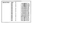
- Prior art keywords
- lottery
- game
- shows
- state
- flag
- Prior art date
- Legal status (The legal status is an assumption and is not a legal conclusion. Google has not performed a legal analysis and makes no representation as to the accuracy of the status listed.)
- Active
Links
Images


Landscapes
- Slot Machines And Peripheral Devices (AREA)
- Game Rules And Presentations Of Slot Machines (AREA)
Description
本発明は、遊技機に関する。 The present invention relates to a gaming machine.
従来、複数の図柄がそれぞれの表面に設けられた複数のリールと、スタートスイッチと、ストップスイッチと、各リールに対応して設けられたステッピングモータと、制御部とを備えた、パチスロと呼ばれる遊技機が知られている。スタートスイッチは、メダルやコインなどの遊技媒体が遊技機に投入された後、スタートレバーが遊技者により操作されたこと(以下、「開始操作」ともいう)を検出し、全てのリールの回転の開始を要求する信号を出力する。ストップスイッチは、各リールに対応して設けられたストップボタンが遊技者により押されたこと(以下、「停止操作」ともいう)を検出し、該当するリールの回転の停止を要求する信号を出力する。ステッピングモータは、その駆動力を対応するリールに伝達する。また、制御部は、スタートスイッチ及びストップスイッチにより出力された信号に基づいて、ステッピングモータの動作を制御し、各リールの回転動作及び停止動作を行う。 Conventionally, a game called pachislot, which is provided with a plurality of reels having a plurality of symbols provided on their respective surfaces, a start switch, a stop switch, a stepping motor provided corresponding to each reel, and a control unit. The machine is known. The start switch detects that the start lever is operated by the player (hereinafter, also referred to as "start operation") after the game medium such as a medal or coin is inserted into the game machine, and the rotation of all reels is rotated. Outputs a signal requesting a start. The stop switch detects that the stop button provided corresponding to each reel is pressed by the player (hereinafter, also referred to as "stop operation"), and outputs a signal requesting that the rotation of the corresponding reel be stopped. do. The stepping motor transmits its driving force to the corresponding reels. Further, the control unit controls the operation of the stepping motor based on the signals output by the start switch and the stop switch, and performs the rotation operation and the stop operation of each reel.
このような遊技機では、開始操作が検出されると、プログラム上で乱数を用いた抽籤処理(以下、「内部抽籤処理」という)が行われ、その抽籤の結果(以下、「内部当籤役」という)と停止操作のタイミングとに基づいてリールの回転の停止を行う。そして、全てのリールの回転が停止され、入賞の成立に係る図柄の組合せ(表示役)が表示されると、その図柄の組合せに対応する特典が遊技者に付与される。なお、遊技者に付与される特典の例としては、遊技媒体(メダル等)の払い出し、遊技媒体を消費することなく再度、内部抽籤処理を行う再遊技(以下、「リプレイ」ともいう)の作動、遊技媒体の払い出し機会が増加するボーナスゲームの作動等を挙げることができる。 In such a gaming machine, when a start operation is detected, a lottery process using random numbers (hereinafter referred to as "internal lottery process") is performed on the program, and the result of the lottery (hereinafter, "internal winning combination") is performed. The rotation of the reel is stopped based on the timing of the stop operation. Then, when the rotation of all the reels is stopped and the combination of symbols (display combination) related to the establishment of the winning is displayed, the player is given a privilege corresponding to the combination of the symbols. As an example of the privilege given to the player, the payout of the game medium (medals, etc.) and the operation of the re-game (hereinafter, also referred to as "replay") in which the internal lottery process is performed again without consuming the game medium. , The operation of a bonus game that increases the chances of paying out game media can be mentioned.
また、従来、上記構成の遊技機において、特定の小役(遊技媒体の払い出しに係る役)の成立をランプ等でナビゲートする機能、すなわち、アシストタイム(以下、「AT」という)の機能を備える遊技機が開発されている。また、従来、特定の図柄組合せが表示された場合にリプレイの当籤確率が通常時より高い遊技状態が作動する機能、すなわち、リプレイタイム(以下、「RT」という)の機能を備える遊技機も開発されている。さらに、従来、ATとRTとが同時に作動するアシストリプレイタイム(以下、「ART」という)の機能を備えたパチスロが開発されている。 Further, conventionally, in a gaming machine having the above configuration, a function of navigating the establishment of a specific small winning combination (a winning combination related to payout of a game medium) with a lamp or the like, that is, an assist time (hereinafter referred to as "AT") function has been provided. A game machine to be equipped is being developed. In addition, conventionally, we have also developed a gaming machine equipped with a function that activates a gaming state in which the winning probability of replay is higher than normal when a specific symbol combination is displayed, that is, a function of replay time (hereinafter referred to as "RT"). Has been done. Further, conventionally, a pachislot machine having an assist replay time (hereinafter referred to as "ART") function in which AT and RT operate at the same time has been developed.
上述した遊技機は、通常、内部当籤役の決定、各リールの回転及び停止、入賞の有無の判定等の遊技機の主な遊技動作を制御する回路(主制御回路)が実装された主制御基板と、映像の表示等による演出動作を制御する回路(副制御回路)が実装された副制御基板とを備える。そして、遊技動作は、主制御回路に搭載されたCPU(Central Processing Unit)により制御される。この際、CPUの制御により、主制御回路のROM(Read Only Memory)に記憶されたプログラム及び各種テーブルデータ等が主制御回路のRAM(Random Access Memory)に展開され、各種遊技動作に関する処理が実行される。 The above-mentioned gaming machine is usually a main control equipped with a circuit (main control circuit) for controlling the main gaming operation of the gaming machine such as determination of an internal winning combination, rotation and stop of each reel, and determination of presence / absence of winning. It includes a board and a sub-control board on which a circuit (sub-control circuit) for controlling an effect operation by displaying an image or the like is mounted. The game operation is controlled by a CPU (Central Processing Unit) mounted on the main control circuit. At this time, under the control of the CPU, the program stored in the ROM (Read Only Memory) of the main control circuit, various table data, etc. are expanded in the RAM (Random Access Memory) of the main control circuit, and processing related to various game operations is executed. Will be done.
また、従来、上述した構成の遊技機において、遊技の進行を遅延(一時的に停止)させるフリーズ(遊技ロック)の待機期間で所定の抽籤結果が得られ、有効ラインに所定の図柄組合せが停止された場合に、フリーズの予約条件に基づいて、フリーズを実行する遊技機が知られている(例えば、特許文献1参照)。 Further, conventionally, in the gaming machine having the above-described configuration, a predetermined lottery result is obtained during a freeze (game lock) waiting period for delaying (temporarily stopping) the progress of the game, and a predetermined symbol combination is stopped on the effective line. A gaming machine that executes a freeze based on the reservation conditions for the freeze is known (see, for example, Patent Document 1).
ところで、近年の遊技機では、遊技ロックを用いた演出が盛んに行われ、この遊技ロックの抽籤テーブルや抽籤処理プログラムは、主制御基板に設けられたROMに保存されている。しかしながら、主制御基板のROM容量は規則により小容量に制限されているので、遊技ロックの抽籤に係るテーブル及びプログラムにより、主制御基板のROM容量が圧迫される可能性がある。 By the way, in recent game machines, the production using the game lock is actively performed, and the lottery table and the lottery processing program of the game lock are stored in the ROM provided on the main control board. However, since the ROM capacity of the main control board is limited to a small capacity by the rules, the ROM capacity of the main control board may be squeezed by the table and the program related to the lottery of the game lock.
本発明は上記状況を鑑みなされたものであり、本発明の目的は、遊技ロック機能を備えた遊技機において、主制御基板側(以下、「メイン側」ともいう)に設けられたROMの空き容量を増やし、遊技ロックの抽籤に係るテーブル及びプログラムによるROM容量の圧迫を抑制することである。 The present invention has been made in view of the above circumstances, and an object of the present invention is a free ROM provided on the main control board side (hereinafter, also referred to as "main side") in a gaming machine having a game lock function. It is to increase the capacity and suppress the pressure on the ROM capacity by the table and the program related to the lottery of the game lock.
上記課題を解決するために、本発明では、以下のような構成の遊技機を提供する。 In order to solve the above problems, the present invention provides a gaming machine having the following configuration.
第1のレジスタ(例えば、後述のAレジスタ)と、
第2のレジスタ(例えば、後述のEレジスタ)と、
第3のレジスタ(例えば、後述のHLレジスタ)と、
遊技の進行を一時的に停止する遊技ロックを実行するロック実行手段(例えば、後述の遊技ロック設定処理)と、
判定フラグ(例えば、後述の遊技ロック判定フラグ)及び予約フラグ(例えば、後述の遊技ロック予約フラグ)で構成されたフラグ格納領域と、
遊技ロックを行うか否かを抽籤により決定し、前記判定フラグ又は前記予約フラグに遊技ロック情報を格納可能な遊技ロック抽籤手段(例えば、後述のスタート時出玉関連抽籤処理)と、を備え、
前記ロック実行手段は、
前記フラグ格納領域のアドレスを前記第3のレジスタにセットし、
所定の指定レジスタロード命令(例えば、後述のINLD命令)を実行して、前記判定フラグを前記第1のレジスタにセットする処理、前記予約フラグを前記第2のレジスタにセットする処理、及び、前記第3のレジスタにセットされたアドレスを更新する処理を一括して行い、
前記所定の指定レジスタロード命令の実行後、前記フラグ格納領域の前記判定フラグに前記第2のレジスタにセットされているデータを格納し、その後、前記予約フラグに格納されているデータをクリアし、
前記第1のレジスタに前記遊技ロック情報が格納されている場合には、当該遊技ロック情報に対応する遊技ロックを実行する
ことを特徴とする遊技機。
The first register (for example, the A register described later) and
The second register (for example, the E register described later) and
A third register (for example, the HL register described later) and
A lock execution means (for example, a game lock setting process described later) for executing a game lock that temporarily stops the progress of the game, and
A flag storage area composed of a determination flag (for example, a game lock determination flag described later) and a reservation flag (for example, a game lock reservation flag described later), and
It is provided with a game lock lottery means (for example, a lottery process related to ball ejection at the start, which will be described later), which can determine whether or not to lock the game by lottery and can store the game lock information in the determination flag or the reservation flag.
The lock execution means is
The address of the flag storage area is set in the third register,
A process of executing a predetermined designated register load instruction (for example, an INLD instruction described later) to set the determination flag in the first register, a process of setting the reservation flag in the second register, and the process of setting the reservation flag in the second register. The process of updating the address set in the third register is performed in a batch, and
After executing the predetermined designated register load instruction, the data set in the second register is stored in the determination flag in the flag storage area, and then the data stored in the reserved flag is cleared.
A gaming machine characterized in that when the game lock information is stored in the first register, the game lock corresponding to the game lock information is executed.
上記構成の本発明の遊技機によれば、遊技ロック機能を備えた遊技機において、メイン側に設けられたROMの空き容量を増やし、遊技ロックの抽籤に係るテーブル及びプログラムによるROM容量の圧迫を抑制することができる。 According to the gaming machine of the present invention having the above configuration, in the gaming machine having the gaming lock function, the free space of the ROM provided on the main side is increased, and the ROM capacity is compressed by the table and the program related to the lottery of the gaming lock. It can be suppressed.
以下、本発明の各種実施形態に係る遊技機としてパチスロを例に挙げ、図面を参照しながら、その構成及び動作について説明する。なお、本実施形態では、ボーナス作動機能及びART機能を備えたパチスロについて説明する。 Hereinafter, a pachi-slot machine will be taken as an example of a gaming machine according to various embodiments of the present invention, and its configuration and operation will be described with reference to the drawings. In this embodiment, a pachi-slot machine having a bonus operation function and an ART function will be described.
1.第1実施形態
<機能フロー>
まず、図1を参照して、パチスロの機能フローについて説明する。本実施形態のパチスロでは、遊技を行うための遊技媒体としてメダルを用いる。なお、遊技媒体としては、メダル以外にも、例えば、コイン、遊技球、遊技用のポイントデータ又はトークン等を適用することもできる。
1. 1. 1st Embodiment <Functional flow>
First, the functional flow of the pachislot machine will be described with reference to FIG. In the pachislot machine of the present embodiment, a medal is used as a game medium for playing a game. In addition to medals, coins, game balls, point data for games, tokens, and the like can also be applied as the game medium.
遊技者によりパチスロにメダルが投入され、スタートレバーが操作されると、予め定められた数値範囲(例えば、0〜65535)の乱数から1つの値(以下、乱数値という)が抽出される。 When a medal is inserted into the pachislot machine by the player and the start lever is operated, one value (hereinafter referred to as a random number value) is extracted from random numbers in a predetermined numerical range (for example, 0 to 65535).
内部抽籤手段は、抽出された乱数値に基づいて抽籤を行い、内部当籤役を決定する。この内部抽籤手段は、後述の主制御回路が備える各種処理手段(処理機能)の一つである。内部当籤役の決定により、後述の有効ライン(入賞判定ライン)に沿って表示を行うことを許可する図柄の組合せが決定される。なお、図柄の組合せの種別としては、メダルの払い出し、再遊技(リプレイ)の作動、ボーナスの作動等といった特典が遊技者に与えられる「入賞」に係るものと、それ以外のいわゆる「はずれ」に係るものとが設けられる。なお、以下では、メダルの払い出しに係る役を「小役」と称し、再遊技(リプレイ)の作動に係る役を「リプレイ役」と称する。また、ボーナスの作動(ボーナスゲーム)に係る役を「ボーナス役」ともいう。 The internal lottery means draws a lot based on the extracted random number value, and determines the internal winning combination. This internal lottery means is one of various processing means (processing functions) included in the main control circuit described later. By determining the internal winning combination, the combination of symbols that are allowed to be displayed along the valid line (winning determination line) described later is determined. The types of symbol combinations include those related to "winning" in which benefits such as medal payout, replay operation, bonus operation, etc. are given to the player, and other so-called "missing". Such things are provided. In the following, the role related to the payout of medals will be referred to as a "small role", and the role related to the operation of the replay (replay) will be referred to as a "replay role". In addition, the role related to the operation of the bonus (bonus game) is also referred to as a "bonus role".
また、スタートレバーが操作されると、複数のリールの回転が行われる。その後、遊技者により所定のリールに対応するストップボタンが押されると、リール停止制御手段は、内部当籤役とストップボタンが押されたタイミングとに基づいて、該当するリールの回転を停止する制御を行う。このリール停止制御手段は、後述の主制御回路が備える各種処理手段(処理機能)の一つである。 Further, when the start lever is operated, a plurality of reels are rotated. After that, when the stop button corresponding to the predetermined reel is pressed by the player, the reel stop control means controls to stop the rotation of the corresponding reel based on the internal winning combination and the timing when the stop button is pressed. conduct. This reel stop control means is one of various processing means (processing functions) included in the main control circuit described later.
パチスロでは、基本的に、ストップボタンが押されたときから規定時間(190msec)内に、該当するリールの回転を停止する制御が行われる。本実施形態では、この規定時間内にリールの回転に伴って移動する図柄の数を「滑り駒数」という。そして、本実施形態では、規定期間が190msecである場合には、滑り駒数の最大数(最大滑り駒数)を図柄4個分に定める。 In pachislot, basically, control is performed to stop the rotation of the corresponding reel within a specified time (190 msec) from the time when the stop button is pressed. In the present embodiment, the number of symbols that move with the rotation of the reel within this specified time is referred to as the "number of sliding pieces". Then, in the present embodiment, when the specified period is 190 msec, the maximum number of sliding pieces (maximum number of sliding pieces) is set for four symbols.
リール停止制御手段は、入賞に係る図柄の組合せ表示を許可する内部当籤役が決定されているときは、通常、190msec(図柄4駒分)の規定時間内に、その図柄の組合せが有効ラインに沿って極力表示されるようにリールの回転を停止させる。また、リール停止制御手段は、規定時間を利用して、内部当籤役によってその表示が許可されていない図柄の組合せが有効ラインに沿って表示されないようにリールの回転を停止させる。 When the internal winning combination that allows the combination display of the symbols related to the winning is determined, the reel stop control means usually sets the combination of the symbols to the effective line within the specified time of 190 msec (for 4 symbols). Stop the rotation of the reel so that it is displayed as much as possible along the line. Further, the reel stop control means uses a predetermined time to stop the rotation of the reel so that the combination of symbols whose display is not permitted by the internal winning combination is not displayed along the effective line.
このようにして、複数のリールの回転がすべて停止されると、入賞判定手段は、有効ラインに沿って表示された図柄の組合せが、入賞に係るものであるか否かの判定を行う。この入賞判定手段もまた、後述の主制御回路が備える各種処理手段(処理機能)の一つである。そして、表示された図柄の組合せが、入賞判定手段により入賞に係るものであると判定されると、メダルの払い出し等の特典が遊技者に与えられる。パチスロでは、以上のような一連の流れが1回の遊技(単位遊技)として行われる。 In this way, when all the rotations of the plurality of reels are stopped, the winning determination means determines whether or not the combination of symbols displayed along the effective line is related to winning. This winning determination means is also one of various processing means (processing functions) included in the main control circuit described later. Then, when it is determined by the winning determination means that the combination of the displayed symbols is related to the winning, a privilege such as a medal payout is given to the player. In pachislot, the above series of flows is performed as one game (unit game).
また、パチスロでは、前述した一連の遊技動作の流れの中で、表示装置などによる映像の表示、各種ランプによる光の出力、スピーカによる音の出力、或いは、これらの組合せを利用して様々な演出が行われる。 Further, in pachislot, in the flow of the above-mentioned series of game operations, various effects are produced by displaying an image by a display device, outputting light by various lamps, outputting sound by a speaker, or a combination of these. Is done.
具体的には、スタートレバーが操作されると、上述した内部当籤役の決定に用いられた乱数値とは別に、演出用の乱数値が抽出される。演出用の乱数値が抽出されると、演出内容決定手段は、内部当籤役に対応づけられた複数種類の演出内容の中から今回実行する演出を抽籤により決定する。この演出内容決定手段は、後述の副制御回路が備える各種処理手段(処理機能)の一つである。 Specifically, when the start lever is operated, a random value for production is extracted in addition to the random value used for determining the internal winning combination described above. When the random value for the effect is extracted, the effect content determining means determines the effect to be executed this time from a plurality of types of effect contents associated with the internal winning combination by lottery. This effect content determining means is one of various processing means (processing functions) included in the sub-control circuit described later.
次いで、演出内容決定手段により演出内容が決定されると、演出実行手段は、リールの回転開始時、各リールの回転停止時、入賞の有無の判定時等の各契機に連動させて対応する演出を実行する。このように、パチスロでは、例えば、内部当籤役に対応づけられた演出内容を実行することによって、決定された内部当籤役(言い換えると、狙うべき図柄の組合せ)を知る機会又は予想する機会が遊技者に提供され、遊技者の興味の向上を図ることができる。 Next, when the effect content is determined by the effect content determining means, the effect execution means responds in conjunction with each opportunity such as when the reel starts rotating, when each reel stops rotating, and when it is determined whether or not there is a prize. To execute. In this way, in pachislot, for example, by executing the production content associated with the internal winning combination, the opportunity to know or anticipate the determined internal winning combination (in other words, the combination of symbols to be aimed at) is a game. It is provided to the player and can improve the interest of the player.
<パチスロの構造>
次に、図2〜図4を参照して、本発明の第1実施形態に係るパチスロの構造について説明する。
<Structure of pachislot>
Next, the structure of the pachislot machine according to the first embodiment of the present invention will be described with reference to FIGS. 2 to 4.
[外観構造]
図2は、パチスロ1の外部構造を示す斜視図である。
[Appearance structure]
FIG. 2 is a perspective view showing the external structure of the
パチスロ1は、図2に示すように、外装体(遊技機本体)2を備える。外装体2は、リールや回路基板等を収容するキャビネット2aと、キャビネット2aの開口を開閉可能に取り付けられるフロントドア2bとを有する。
As shown in FIG. 2, the
キャビネット2aの内部には、3つのリール3L,3C,3R(変動表示手段、表示列)が横一列に並べて設けられている。以下、各リール3L,3C,3R(メインリール)を、それぞれ左リール3L、中リール3C、右リール3Rともいう。各リール3L,3C,3Rは、円筒状に形成されたリール本体と、リール本体の周面に装着された透光性のシート材を有する。そして、シート材の表面には、複数(例えば20個)の図柄が周方向(リールの回転方向)に沿って所定の間隔をあけて描かれている。
Inside the
フロントドア2bは、ドア本体9と、フロントパネル10と、腰部パネル12と、台座部13とを備える。ドア本体9は、ヒンジ(不図示)を用いてキャビネット2aに開閉可能に取り付けられる。ヒンジは、パチスロ1の前方側(遊技者側)から見て、ドア本体9の左側の側端部に設けられる。
The
フロントパネル10は、ドア本体9の上部に設けられている。このフロントパネル10は、開口10aを有する枠状部材で構成される。フロントパネル10の開口10aは、表示装置カバー30によって塞がれ、表示装置カバー30は、キャビネット2aの内部に配置された後述の表示装置11と対向して配置される。
The
表示装置カバー30は、黒色の半透明な合成樹脂により形成される。それゆえ、遊技者は、後述の表示装置11により表示された映像(画像)を、表示装置カバー30を介して視認することができる。また、本実施形態では、表示装置カバー30を黒色の半透明な合成樹脂で形成することにより、キャビネット2a内への外光の入り込みを抑制して、表示装置11により表示された映像(画像)を鮮明に視認できるようにしている。
The
フロントパネル10には、ランプ群21が設けられている。ランプ群21は、例えば、遊技者側から見て、フロントパネル10の上部に設けられたランプ21a、21bを含む。ランプ群21を構成する各ランプは、LED(Light Emitting Diode)等で構成され(後述の図7中のLED群85参照)、演出内容に対応するパターンで、光を点灯及び消灯する。
A
腰部パネル12は、ドア本体9の略中央部に設けられる。腰部パネル12は、任意の画像が描かれた装飾パネルと、この装飾パネルを背面側から照明するための光を出射する光源(後述のLED群85に含まれるLED)とを有する。
The
台座部13は、フロントパネル10と腰部パネル12との間に設けられる。台座部13には、図柄表示領域4と、遊技者による操作の対象となる各種装置(メダル投入口14、MAXベットボタン15a、1ベットボタン15b、スタートレバー16、3つのストップボタン17L,17C,17R、精算ボタン(不図示)等)とが設けられる。
The
図柄表示領域4は、正面から見て、3つのリール3L,3C,3Rに重畳する領域で、かつ、3つのリール3L,3C,3Rより遊技者側の位置に配置されており、3つのリール3L,3C,3Rを視認可能にするサイズを有する。この図柄表示領域4は、表示窓としての機能を果たすものであり、その背後に設けられた各リール3L,3C,3Rを視認することが可能な構成になっている。以下、図柄表示領域4を、リール表示窓4という。
The
リール表示窓4は、その背後に設けられた3つのリール3L,3C,3Rの回転が停止されたとき、各リールの周面に設けられた複数の図柄のうち、連続して配置された3つの図柄がその枠内に表示されるように構成されている。すなわち、3つのリール3L,3C,3Rの回転が停止されたとき、リール表示窓4の枠内には、リール毎に上段、中段及び下段の各領域にそれぞれ1個の図柄(合計で3個)が表示される(リール表示窓4の枠内には、3行×3列の態様で図柄が表示される)。そして、本実施形態では、リール表示窓4の枠内において、左リール3Lの中段領域、中リール3Cの中段領域、及び、右リール3Rの中段領域を結ぶ擬似的なライン(センターライン)を、入賞か否かの判定を行う有効ラインとして定義する。
The
リール表示窓4は、台座部13に設けられた枠部材31の開口により形成される。また、リール表示窓4を画成する枠部材31の下方には、略水平面の台座領域が設けられる。そして、遊技者側から見て、台座領域の右側にはメダル投入口14が設けられ、左側にはMAXベットボタン15a及び1ベットボタン15bが設けられる。
The
メダル投入口14は、遊技者によって外部からパチスロ1に投下されるメダルを受け入れるために設けられる。メダル投入口14から受け入れられたメダルは、予め設定された所定枚数(例えば3枚)を上限として1回の遊技に使用され、所定枚数を超えたメダルの枚数分は、パチスロ1の内部に預けることができる(いわゆるクレジット機能(遊技媒体貯留手段))。
The
MAXベットボタン15a及び1ベットボタン15bは、キャビネット2aの内部に預けられているメダルから1回の遊技に使用する枚数を決定するために設けられる。なお、MAXベットボタン15aの内部には、メダル投入が可能な時に点灯するベットボタンLED(不図示)が設けられている。また、精算ボタンは、パチスロ1の内部に預けられているメダルを外部に引き出す(排出する)ために設けられる。
The
なお、遊技者がMAXベットボタン15aを押下操作すると、単位遊技のベット枚数(3枚)のメダルが投入され、有効ラインが有効化される。一方、1ベットボタン15bが1回、押下操作される度に1枚のメダルが投入される。1ベットボタン15bが3回操作されると、単位遊技のベット枚数(3枚)のメダルが投入され、有効ラインが有効化される。
When the player presses the
なお、以下では、MAXベットボタン15aの操作、1ベットボタン15bの操作及びメダル投入口14にメダルを投入する操作(遊技を行うためにメダルを投入する操作)をいずれも「投入操作」という。
In the following, the operation of the
スタートレバー16は、全てのリール(3L,3C,3R)の回転を開始するために設けられる。ストップボタン17L,17C,17Rは、それぞれ、左リール3L、中リール3C、右リール3Rに対応づけて設けられ、各ストップボタンは対応するリールの回転を停止するために設けられる。以下、ストップボタン17L,17C,17Rを、それぞれ左ストップボタン17L、中ストップボタン17C、右ストップボタン17Rともいう。
The
また、リール表示窓4の下方の略水平面の台座領域の略中央には、情報表示器6が設けられる。なお、情報表示器6は、透明の窓カバー(不図示)によって覆われている。
Further, an
情報表示器6には、特典として遊技者に対して払い出されるメダルの枚数(以下、「払出枚数」という)の情報を遊技者に対してデジタル表示(報知)するための2桁の7セグメントLED(以下、「7セグLED」という)や、パチスロ1の内部に預けられているメダルの枚数(以下、「クレジット枚数」という)などの情報を遊技者に対してデジタル表示(報知)するための2桁の7セグLEDが設けられる。なお、本実施形態では、メダルの払出枚数表示用の2桁の7セグLEDは、エラー発生及びエラー種別の情報を遊技者に対してデジタル表示(報知)するための2桁の7セグLEDとしても用いられる。それゆえ、エラー発生時には、メダルの払出枚数表示用の2桁の7セグLEDの表示態様は、払出枚数の表示態様からエラー種別の情報の表示態様に切り替わる。
The
さらに、情報表示器6には、内部当籤役として決定された役に応じた図柄組合せを有効ラインに沿って表示するために必要な停止操作の情報を報知する指示モニタ(不図示)が設けられている。指示モニタ(指示表示器)は、例えば、2桁の7セグメントLEDにより構成される。そして、指示モニタでは、報知する停止操作の情報と一義的に対応する態様で、2桁の7セグLEDが点灯、点滅又は消灯することにより、遊技者に対して必要な停止操作の情報を報知する。
Further, the
なお、ここでいう、報知する停止操作の情報と一義的に対応する態様とは、例えば、押し順「1st(第1停止操作を左リール3Lに対して行うこと)」を報知する場合には指示モニタに数値「1」を表示し、押し順「2nd(第1停止操作を中リール3Cに対して行うこと)」を報知する場合には指示モニタに数値「2」を表示し、押し順「3rd(第1停止操作を右リール3Rに対して行うこと)」を報知する場合には指示モニタに数値「3」を表示するなどの態様のことである。なお、指示モニタにおける停止操作の情報の報知態様(後述のメイン側で決定されるナビデータ)については、後述の図63を参照しながら後で詳述する。
The mode that uniquely corresponds to the information of the stop operation to be notified here is, for example, in the case of notifying the push order "1st (performing the first stop operation on the
情報表示器6は、後述の図7に示すように、ドア中継端子板68及び遊技動作表示基板81を介して主制御基板71に電気的に接続され、情報表示器6の表示動作は、主制御基板71内の後述の主制御回路90により制御される。また、上述した各種7セグLEDの制御方式は、ダイナミック点灯制御である。
As shown in FIG. 7, which will be described later, the
なお、本実施形態のパチスロ1では、主制御基板71により制御される指示モニタに加えて、副制御基板72により制御される他の手段を用いて停止操作の情報を報知する構成を設ける。具体的には、後述のプロジェクタ機構211及び表示ユニット212(図3及び後述の図7参照)により構成される後述の表示装置11により停止操作の情報を報知する。
In the pachi-
このような構成を適用した場合、指示モニタにおける報知の態様と、副制御基板72により制御されるその他の手段における報知の態様とは、互いに異なる態様であってもよい。すなわち、指示モニタでは、報知する停止操作の情報と一義的に対応する態様で報知すればよく、必ずしも、停止操作の情報を直接的に報知する必要はない(例えば、指示モニタにおいて数値「1」が表示されたとしても、遊技者によっては報知内容を特定できない可能性もあり、直接的な報知とは言えない)。一方、後述の表示装置11等のその他の手段によるサブ側(副制御基板側)での報知では、停止操作の情報を直接的に報知してもよい。例えば、押し順「1st」を報知する場合、指示モニタでは報知する押し順と一義的に対応する数値「1」を表示するが、その他の手段(例えば、表示装置11等)では、左リール3Lに対して第1停止操作を行わせるための指示情報を直接的に報知してもよい。
When such a configuration is applied, the mode of notification in the instruction monitor and the mode of notification in other means controlled by the
このような構成のパチスロ1では、副制御基板72の制御だけでなく、主制御基板71の制御によっても、内部当籤役に応じた必要な停止操作の情報を報知することができる。また、このような停止操作の情報の報知の有無は、遊技状態に応じて制御されるようにしてもよい。例えば、後述の一般遊技状態(非ART遊技状態)では停止操作の情報を報知せずに、後述のART遊技状態(後述の図14参照)において停止操作の情報を報知するようにしてもよい。
In the pachi-
また、遊技者側から見て、リール表示窓4の左方には、サブ表示装置18が設けられる。サブ表示装置18は、図2に示すように、ドア本体9の前面部のうち、台座部13の略水平面の台座領域から略垂直に立設するように設けられる。サブ表示装置18は、液晶ディスプレイや有機EL(Electro-Luminescence)ディスプレイで構成され、各種情報を表示する。
Further, a
また、サブ表示装置18の表示面上には、タッチセンサ19が設けられている(後述の図7参照)。タッチセンサ19は、静電容量方式などの所定の動作原理に従い動作し、遊技者の操作を受け付けると、タッチ入力情報として当該操作に応じた信号を出力する。そして、本実施形態のパチスロ1は、タッチセンサ19を介して受け付けた遊技者の操作(タッチセンサ19から出力されるタッチ入力情報)に応じて、サブ表示装置18の表示を切り替え可能にする機能を有する。なお、サブ表示装置18は、タッチセンサ19から出力されるタッチ入力情報に基づいて後述の副制御基板72(後述の図7参照)により制御される。
Further, a
ドア本体9の下部には、メダル払出口24、メダル受皿25、2つのスピーカ用孔20L,20R等が設けられる。メダル払出口24は、後述のメダル払出装置51の駆動により排出されるメダルを外部に導く。メダル受皿25は、メダル払出口24から排出されたメダルを貯める。また、2つのスピーカ用孔20L,20Rからは、演出内容に対応する効果音や楽曲等の音声が出力される。
At the lower part of the
[内部構造]
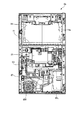
次に、パチスロ1の内部構造を、図3及び図4を参照しながら説明する。図3は、キャビネット2aの内部構造を示す図であり、図4は、フロントドア2bの裏面側の内部構造を示す図である。
[Internal structure]
Next, the internal structure of the
キャビネット2aは、図3に示すように、上面板27aと、底面板27bと、左右の側面板27c,27dと、背面板27eとを有する。そして、キャビネット2a内の上部には、表示装置11が配設される。
As shown in FIG. 3, the
表示装置11は、プロジェクタ機構211と、プロジェクタ機構211から投射された映像光が投影される箱状の被投影部材212aとを有し、プロジェクションマッピングによる映像表示を行う。具体的には、表示装置11では、立体物となる被投影部材212aの位置(投影距離や角度など)や形状に基づいて映像光を生成し、その映像光が、プロジェクタ機構211により被投影部材212aの表面に投影される。このような演出機能を設けることにより、高度で且つ迫力のある演出を行うことができる。また、図3には示さないが、箱状の被投影部材212aの裏側には、表示面が湾曲した別の被投影部材が設けられ、遊技状態に応じて、どちらか一方の被投影部材が、映像光が投影されるスクリーンとして使用される。それゆえ、キャビネット2a内は、遊技状態に応じて、被投影部材を切り換える機能(不図示)も設けられる。
The
キャビネット2a内の下部には、メダル払出装置(以下、ホッパー装置という)51と、メダル補助収納庫52と、電源装置53とが配設される。
A medal payout device (hereinafter referred to as a hopper device) 51, a medal
ホッパー装置51は、キャビネット2aにおける底面板27bの中央部に取り付けられる。このホッパー装置51は、多量のメダルを収容可能で、それらを1枚ずつ排出可能な構造を有する。ホッパー装置51は、貯留されたメダルが例えば50枚を超えたとき、又は、精算ボタンが押下されてメダルの精算が実行されるときに、メダルを払い出す。そして、ホッパー装置51によって払い出されたメダルは、メダル払出口24(図2参照)から排出される。
The
メダル補助収納庫52は、ホッパー装置51から溢れ出たメダルを収納する。このメダル補助収納庫52は、キャビネット2a内部を正面から見て、ホッパー装置51の右側に配置される。また、メダル補助収納庫52は、キャビネット2aの底面板27bに対して着脱可能に取り付けられている。
The medal
電源装置53は、電源スイッチ53aと、電源基板53b(電源供給手段)とを有している(後述の図7参照)。この電源装置53は、キャビネット2a内部を正面から見て、ホッパー装置51の左側に配置されており、左側面板27cに取り付けられている。電源装置53は、サブ電源装置(不図示)から供給された交流電圧100Vの電力を各部で必要な直流電圧の電力に変換して、変換した電力を各部へ供給する。
The
また、キャビネット2a内の電源装置53の上方には、副制御基板72(後述の図7参照)を収容する副制御基板ケース57が配設される。副制御基板ケース57に収納された副制御基板72には、後述の副制御回路200(後述の図10参照)が搭載されている。この副制御回路200は、映像の表示等による演出の実行を制御する回路である。副制御回路200の具体的な構成については後述する。
Further, above the
キャビネット2a内の副制御基板ケース57の上方には、副中継基板61が配設される。この副中継基板61は、副制御基板72と後述の主制御基板71とを接続する配線が実装された中継基板である。また、副中継基板61は、副制御基板72と副制御基板72の周辺に配設された基板や各種装置部(ユニット)などとを接続する配線が実装された中継基板である。
The
また、図3には示さないが、キャビネット2a内には、キャビネット側中継基板44(後述の図7参照)が配設される。このキャビネット側中継基板44は、主制御基板71(後述の図7参照)と、ホッパー装置51、遊技メダル補助収納庫スイッチ77(後述の図7参照)及びメダル払出カウントスイッチ(不図示)のそれぞれとを接続する配線が実装された中継基板である。
Further, although not shown in FIG. 3, a cabinet-side relay board 44 (see FIG. 7 described later) is arranged in the
フロントドア2bの裏面側の中央部には、図4に示すように、ミドルドア41が、配設され、リール表示窓4(図2参照)を裏側から開閉可能に取り付けられている。また、図4には示さないが、ミドルドア41のリール表示窓4側には、3つのリール3L,3C,3Rが取り付けられ、ミドルドア41のリール表示窓4側とは反対側には、主制御基板71(後述の図7参照)が収納された主制御基板ケース55が取り付けられている。なお、3つのリール3L,3C,3Rには、所定の減速比をもったギアを介してステッピングモータ(不図示)が接続されている。
As shown in FIG. 4, a
主制御基板ケース55に収納された主制御基板71は、後述する主制御回路90(後述の図9参照)を有する。主制御回路90(主制御手段)は、内部当籤役の決定、各リール3L,3C,3Rの回転及び停止、入賞の有無の判定といった、パチスロ1における遊技の主な流れを制御する回路である。また、本実施形態では、例えば、ARTの決定の有無の抽籤処理、ナビ情報の指示モニタへの表示処理、各種試験信号の送信処理などの制御も主制御回路90により行われる。なお、主制御回路90の具体的な構成は後述する。
The
フロントドア2bの裏面側において、ミドルドア41の下方には、スピーカ65L,65Rが配設される。スピーカ65L,65Rは、それぞれスピーカ用孔20L,20R(図2参照)と対向する位置に配置されている。
また、スピーカ65Lの上方には、セレクタ66と、ドア開閉監視スイッチ67とが配設される。セレクタ66は、メダルの材質や形状等が適正であるか否かを選別する装置であり、メダル投入口14に投入された適正なメダルをホッパー装置51へ案内する。セレクタ66内においてメダルが通過する経路上には、適正なメダルが通過したことを検出するメダルセンサ(遊技媒体検出手段:不図示)が設けられている。
A
ドア開閉監視スイッチ67は、フロントドア2bを裏面側から見て、セレクタ66の左斜め下に配置される。このドア開閉監視スイッチ67は、フロントドア2bの開閉を報知するためのセキュリティ信号をパチスロ1の外部に出力する。
The door open /
また、図4には示さないが、フロントドア2bを裏面において、ミドルドア41により開閉された領域であり且つリール表示窓4の下方には、ドア中継端子板68が配設される(後述の図7参照)。このドア中継端子板68は、主制御基板ケース55内の主制御基板71と、各種のボタンやスイッチ、副中継基板61、セレクタ66、遊技動作表示基板81、試験機用第1インターフェースボード301及び試験機用第2インターフェースボード302のそれぞれとを接続する配線が実装された中継基板である。なお、各種のボタン及びスイッチとしては、例えば、MAXベットボタン15a、1ベットボタン15b、ドア開閉監視スイッチ67、後述のBETスイッチ77、スタートスイッチ79等が挙げられる。
Further, although not shown in FIG. 4, a door
<サブ表示装置の表示例>
ここで、図5A〜図5Eを参照して、サブ表示装置18に表示される各種表示画面について説明する。なお、図5Aは、サブ表示装置18に表示されるトップ画面221を示す図であり、図5Bは、サブ表示装置18に表示されるメニュー画面222を示す図である。また、図5C〜図5Eは、サブ表示装置18に表示される遊技情報画面223,224,225を示す図である。
<Display example of sub-display device>
Here, various display screens displayed on the
サブ表示装置18には、遊技者のタッチ操作により様々な表示画面が表示され、図5A〜図5Eに示すように、トップ画面221、メニュー画面222及び遊技情報画面223,224,225を含む各種表示画面が表示される。これらの表示画面は、タッチセンサ19を介して受け付けた遊技者の操作信号に基づいて切り替えられる。
Various display screens are displayed on the
トップ画面221は、サブ表示装置18に表示される表示画面のうちの初期画面であり、トップ画面221では、「MENU」ボタン221aと、概要遊技履歴221bとが表示される。「MENU」ボタン221aは、図5Bに示すメニュー画面222を呼び出すための操作ボタンであり、「MENU」ボタン221aに対して遊技者による所定操作(例えばタップ)が行われると、メニュー画面222が呼び出される。また、トップ画面221では、概要遊技履歴221bとして、パチスロ1の一部の遊技履歴(概要遊技履歴)を表示する。本実施形態では、概要遊技履歴221bとして、例えば、ボーナス回数、ART回数及びゲーム数(遊技回数)が表示される。
The
メニュー画面222は、サブ表示装置18で表示可能なメニューを表示する画面であり、メニュー画面222では、「戻る」ボタン222a、「登録」ボタン222b、「説明」ボタン222c、「配列配当」ボタン222d、「リーチ目」ボタン222e、「WEBサイト」ボタン222f及び「音量」ボタン222gが表示される。「戻る」ボタン222aは、トップ画面221を呼び出すための操作ボタンであり、「戻る」ボタン222aに対して遊技者による操作が行われると、トップ画面221が呼び出される。また、「登録」ボタン222b〜「音量」ボタン222gは、対応するメニュー内容の表示画面を呼び出すための操作ボタンであり、各ボタンに対して遊技者による操作が行われると、対応するメニュー内容の表示画面が呼び出される。
The
例えば、メニュー画面222において「登録」ボタン222bが遊技者により操作された場合、遊技中の遊技者を登録するための登録画面(不図示)がサブ表示装置18の表示画面に呼び出される。近年のパチスロでは、機種ごとに遊技者を登録しておき、当該遊技者のこれまでの遊技履歴から、定められたミッションの達成状況などの様々な情報を管理するサービスが広く行われている。「登録」ボタン222bにより呼び出される登録画面は、このサービスの提供を受ける際に遊技者を登録するための表示画面である。
For example, when the "register" button 222b is operated by the player on the
また、例えば、メニュー画面222において「説明」ボタン222cが遊技者により操作された場合、パチスロ1の説明画面(不図示)がサブ表示装置18の表示画面に呼び出される。説明画面で表示される情報には、例えば、設定値ごとのボーナス当籤確率やART当籤確率などのパチスロ1の仕様に関する説明や、パチスロ1の演出に登場するキャラクタの紹介説明などが含まれる。
Further, for example, when the "explanation"
また、例えば、メニュー画面222において「配列配当」ボタン222dが遊技者により操作された場合、パチスロ1の配列配当画面(不図示)がサブ表示装置18の表示画面に呼び出される。配列配当画面には、例えば、パチスロ1において入賞と判定される図柄の組合せと、入賞と判定された際の特典との対応関係(配当表)や、各リール3L,3C,3Rに描かれた図柄列(リール配列)などが表示される。
Further, for example, when the “array payout”
また、例えば、メニュー画面222において「リーチ目」ボタン222eが遊技者により操作された場合、パチスロ1のリーチ目画面(不図示)がサブ表示装置18の表示画面に呼び出される。リーチ目画面には、パチスロ1で設定されている「リーチ目」と称される図柄組合せの情報が表示される。なお、「リーチ目」と称する図柄組合せは、該図柄組合せが有効ラインに沿って表示されることにより、特別な特典が付与される図柄組合せであり、本実施形態のパチスロ1では、後述の図28〜図30の入賞作動フラグ格納領域の内容欄に示す略称「リーチ目リプ」に対応する図柄組合せが該当する。そして、本実施形態では、「リーチ目リプ」に係る図柄組合せが有効ラインに沿って表示された場合、その後、遊技者にとって有利な状態(例えば、ボーナス状態、通常ART又はCT(後述の図14参照))に移行することが確定する。
Further, for example, when the "reach eye" button 222e is operated by the player on the
また、例えば、メニュー画面222において「WEBサイト」ボタン222fが遊技者により操作された場合、パチスロ1のWEB紹介画面(不図示)がサブ表示装置18の表示画面に呼び出される。WEB紹介画面には、例えば、パチスロ1の機種ごとに設けられた特設WEBサイトやパチスロ1のメーカーのWEBサイトなど任意のWEBサイトのURLを示す二次元コード(例えば、QRコード(登録商標))が表示される。遊技者は、携帯電話などでWEB紹介画面に表示される二次元コードを読み込むことにより、対応するWEBサイトにアクセスすることができる。
Further, for example, when the "WEB site"
また、例えば、メニュー画面222において「音量」ボタン222gが遊技者により操作された場合、スピーカ65L,65Rから出力する音の音量を調整することが可能な音量調整画面(不図示)がサブ表示装置18の表示画面に呼び出される。遊技者は、音量調整画面を介してパチスロ1の演出音の音量を調整することができる。
Further, for example, when the "volume"
なお、サブ表示装置18は、上述した表示装置11(プロジェクタ機構211及び表示ユニット212)とは別体に設けられるため、表示装置11とは別個に制御することができる。それゆえ、本実施形態のパチスロ1では、遊技中(表示装置11による演出の実行中)であっても、サブ表示装置18の表示画面を遊技者の操作により切り替えることができる。その結果、例えば、遊技者が、表示装置11の演出において登場するキャラクタのことを知りたいと思った場合、遊技者は、「説明」ボタン222cを操作して説明画面を呼び出すことにより、キャラクタ間の関係性などの情報を遊技中に把握することができる。また、例えば、遊技者が、遊技中に、いわゆる「レア役」が当籤した場合のリール回転中にレア役を入賞させるために目安とすべき図柄を把握したいと思った場合、遊技者は、「配列配当」ボタン222dを操作して配列配当画面を呼び出すことにより、リール配列を把握することができる。
Since the
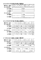
遊技情報画面223,224,225は、パチスロ1の遊技履歴のうちのトップ画面221に表示する概要遊技履歴を含む詳細遊技履歴情報を表示する表示画面である。
The game information screens 223, 224, and 225 are display screens that display detailed game history information including an outline game history to be displayed on the
遊技情報画面223には、「戻る」ボタン223aと、「MENU」ボタン223bと、「前へ」ボタン223cと、「次へ」ボタン223dと、遊技履歴223eとが表示される。「戻る」ボタン223a及び「MENU」ボタン223bは、それぞれトップ画面221及びメニュー画面222をサブ表示装置18の表示画面に呼び出すための操作ボタンであり、各ボタンを遊技者が操作することにより、対応する表示画面が呼び出される。また、「前へ」ボタン223c及び「次へ」ボタン223dは、遊技情報画面を所定の順序で切り替えるための操作ボタンであり、「前へ」ボタン223cが遊技者により操作されると、表示画面が遊技情報画面223から遊技情報画面225に切り替わり、「次へ」ボタン223dが遊技者により操作されると、表示画面が遊技情報画面223から遊技情報画面224に切り替わる。また、遊技履歴223eとしては、図5Cに示すように、ゲーム数(遊技回数)、ボーナス回数、ART回数及びCZ(チャンスゾーン)回数が表示される。
On the
遊技情報画面224には、「戻る」ボタン224aと、「MENU」ボタン224bと、「前へ」ボタン224cと、「次へ」ボタン224dと、遊技履歴214eとが表示される。「戻る」ボタン224a及び「MENU」ボタン224bは、それぞれトップ画面221及びメニュー画面222をサブ表示装置18の表示画面に呼び出すための操作ボタンであり、各ボタンを遊技者が操作することにより、対応する表示画面が呼び出される。また、「前へ」ボタン224c及び「次へ」ボタン224dは、遊技情報画面を所定の順序で切り替える操作ボタンであり、「前へ」ボタン224cが遊技者に操作されると、表示画面が遊技情報画面224から遊技情報画面223に切り替わり、「次へ」ボタン224dが遊技者により操作されると、表示画面が遊技情報画面224から遊技情報画面225に切り替わる。また、遊技履歴224eとしては、後述のCZ(チャンスゾーン)の突入回数及び成功回数が表示される。なお、後述するように、本実施形態では、CZとして、CZ1,CZ2,CZ3の3種類のCZが設けられる。それゆえ、遊技履歴224eとしては、図5Dに示すように、CZ1〜CZ3のそれぞれの突入回数及び成功回数が表示される。
On the
遊技情報画面225には、「戻る」ボタン225aと、「MENU」ボタン225bと、「前へ」ボタン225cと、「次へ」ボタン225dと、遊技履歴225eとが表示される。「戻る」ボタン225a及び「MENU」ボタン225bは、それぞれトップ画面221及びメニュー画面222をサブ表示装置18の表示画面に呼び出すための操作ボタンであり、各ボタンを遊技者が操作することにより、対応する表示画面が呼び出される。また、「前へ」ボタン225c及び「次へ」ボタン225dは、所定の順序で遊技情報画面を切り替えるための操作ボタンであり、「前へ」ボタン225cが遊技者に操作されると、表示画面が遊技情報画面225から遊技情報画面224に切り替わり、「次へ」ボタン225dが遊技者により操作されると、表示画面が遊技情報画面225から遊技情報画面223に切り替わる。また、遊技履歴225eとしては、図5Eに示すように、小役の当籤回数及び当籤確率(分子が1の分数)が表示される。
On the
なお、サブ表示装置18に表示される表示画面の切り替え手法としては、例えば、それぞれの表示画面に表示される操作ボタンに対するタップ操作に基づいて切り替える手法を採用してもよいし、また、例えば、表示画面に対するスワイプ操作に基づいて切り替える手法を採用してもよい。
As a display screen switching method displayed on the
<サブ表示装置の表示画面の各種切り替え機能>
次に、本実施形態のパチスロ1におけるサブ表示装置18の表示画面の各種切り替え機能について説明する。
<Various switching functions of the display screen of the sub display device>
Next, various switching functions of the display screen of the
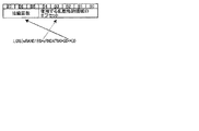
[サブ表示装置の表示画面の遷移例]
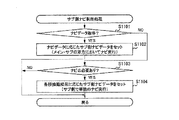
まず、図6A及び6Bを参照して、本実施形態のパチスロ1におけるサブ表示装置18の表示画面の遷移例(切り替え態様)について説明する。なお、図6Aは、遊技者登録状態がセットされていない状況におけるサブ表示装置18の表示画面の遷移例を示す図であり、図6Bは、遊技者登録状態がセットされている状況におけるサブ表示装置18の表示画面の遷移例を示す図である。
[Example of transition of display screen of sub display device]
First, a transition example (switching mode) of the display screen of the
遊技者登録状態がセットされていない状況では、図6Aに示すように、サブ表示装置18の表示画面は、トップ画面221とメニュー画面222との間、並びに、メニュー画面222とメニュー画面222から遷移可能な各種表示画面との間でのみ遷移可能であり、これらの表示画面間の遷移は副制御基板72(後述のサブCPU201)により制御される。例えば、副制御基板72は、タッチセンサ19を介して取得したタッチ操作(例えば、所定のボタンに対するタップ操作や、表示画面上におけるスワイプ操作)に基づいて、トップ画面221及びメニュー画面222間で、表示画面を切り替える。しかしながら、遊技者登録状態がセットされていない状況では、副制御基板72は、遊技情報画面223,224,225の表示が不可能となるように制御する。すなわち、遊技者登録状態がセットされていない状況では、遊技者は、サブ表示装置18に遊技情報画面223,224,225を表示することができない。
In the situation where the player registration state is not set, as shown in FIG. 6A, the display screen of the
一方、遊技者登録状態がセットされている状況では、図6Bに示すように、サブ表示装置18の表示画面は、トップ画面221とメニュー画面222との間、並びに、メニュー画面222とメニュー画面222から遷移可能な各種表示画面との間に加え、メニュー画面222と遊技情報画面223,224,225との間においても遷移可能となり、これらの表示画面間の遷移は副制御基板72(後述のサブCPU201)により制御される。すなわち、副制御基板72は、タッチセンサ19を介して取得したタッチ操作に基づいて、トップ画面221とメニュー画面222との間だけでなく、トップ画面221及びメニュー画面222のそれぞれと、遊技情報画面223,224,225との間においても表示画面を切り替えることができる。それゆえ、本実施形態において、遊技者登録状態がセットされている場合、遊技者は、サブ表示装置18に遊技情報画面223,224,225を表示することができる。
On the other hand, in the situation where the player registration state is set, as shown in FIG. 6B, the display screen of the
なお、図6Bに示すように、トップ画面221、メニュー画面222及び遊技情報画面223,224,225間における表示画面の遷移順序は任意である。それゆえ、例えば、トップ画面221から遊技情報画面223,224,225に直接遷移可能となる構成にしてもよいし、トップ画面221からメニュー画面222を介してのみ遊技情報画面223,224,225に遷移可能となる構成にしてもよい。
As shown in FIG. 6B, the transition order of the display screens between the
本実施形態のパチスロ1では、トップ画面221からメニュー画面222を介してのみ遊技情報画面223,224,225に遷移可能な構成(トップ画面221から遊技情報画面223,224,225に直接遷移できない構成)を採用している。なお、本実施形態のパチスロ1では、メニュー画面222において、遊技者が表示画面に対してスワイプ操作(メニュー選択操作ではない)を行うことにより、表示画面をメニュー画面222から遊技情報画面223,224,225に遷移させることができる。
In the
なお、本実施形態では、遊技情報画面223,224,225は、メニュー画面222とは完全に独立して設けられた表示画面である。すなわち、本実施形態のパチスロ1では、遊技履歴という、遊技者が遊技中に強い関心を抱く遊技の結果を示す情報を、配当配列や音量調節などの遊技の結果とは関係のない情報として独立して表示する。そして、本実施形態では、遊技者登録状態がセットされている状況において、メニュー画面222に対して遊技者がメニュー選択操作を行うことなく、遊技情報画面223,224,225を表示可能にしている。それゆえ、本実施形態では、遊技者登録状態がセットされている場合、遊技者が所望する情遊技履歴情報へのアクセスを容易に行うことができる。
In the present embodiment, the game information screens 223, 224, and 225 are display screens provided completely independently of the
また、本実施形態では、メニュー画面222に対するメニュー選択操作では、表示画面を遊技情報画面223,224,225に遷移させることができず、メニュー画面222に対してスワイプ操作(メニュー表示では指定されていない操作)を行わなければ、表示画面を遊技情報画面223,224,225に遷移させることができない。それゆえ、本実施形態のパチスロ1では、表示画面を遊技情報画面223,224,225に遷移させるためのスワイプ操作を、遊技者登録状態がセットされている状況における隠しコマンドとして扱うことができる。この場合、遊技者にとってみれば、パチスロ1に対する自身の知識により、知識の少ない他の遊技者では見ることのできない、より詳細な遊技履歴情報を見ることができるため、当該他の遊技者よりも有利に遊技を行うことができ、結果、遊技者が積極的に遊技を行うことを期待することができる。
Further, in the present embodiment, in the menu selection operation for the
[遊技情報画面からトップ画面への表示切り替え機能]
本実施形態のパチスロ1は、サブ表示装置18の表示画面を、遊技情報画面223,224,225から、遊技者の手動により、又は、自動的に、トップ画面221に遷移させる機能を有する。具体的には、本実施形態では、遊技情報画面223,224,225において「戻る」ボタンが操作されると、表示画面が遊技情報画面223,224,225からトップ画面221に遷移する(手動遷移機能)。また、本実施形態では、遊技情報画面223,224,225が表示されている状態において所定の条件を満たした場合には、遊技者の操作とは関係なく自動的に表示画面がトップ画面221に遷移する(自動遷移機能)。
[Display switching function from the game information screen to the top screen]
The pachi-
より具体的には、パチスロ1では、遊技情報画面223,224,225が表示されている状態において、投入操作(MAXベットボタン15aへの操作、1ベットボタン15bへの操作及びメダル投入口14にメダルを投入する操作)が行われると、サブ表示装置18の表示画面が自動的にトップ画面221に遷移する。なお、ART遊技状態のように、リプレイ役が内部当籤役として決定される確率が高い遊技状態(高リプ状態)では、リプレイ役入賞に伴う再遊技の作動によりメダルが自動的に投入されてしまう結果、高リプ状態では、遊技情報画面223,224,225を表示する機会が制限されてしまう可能性がある。そこで、本実施形態のパチスロ1では、再遊技の作動によりメダルが自動的に投入された場合には、メダルの投入操作ではなく、開始操作を契機として、自動的に表示画面が遊技情報画面223,224,225からトップ画面221に遷移する。
More specifically, in the
すなわち、本実施形態では、再遊技が作動し、かつ、遊技情報画面223,224,225が表示されている場合には、開始操作を契機として、自動的に表示画面が遊技情報画面223,224,225からトップ画面221に遷移する。一方、再遊技の作動が行われていない場合には、投入操作を契機として、自動的に表示画面が遊技情報画面223,224,225からトップ画面221に遷移する。
That is, in the present embodiment, when the re-game is activated and the game information screens 223, 224, 225 are displayed, the display screen is automatically changed to the game information screens 223, 224, triggered by the start operation. , 225 transitions to the
[メニュー内容表示画面からトップ画面(又はメニュー画面)への表示切り替え機能]
本実施形態のパチスロ1は、サブ表示装置18の表示画面を、メニュー画面222に対するメニュー選択操作により遷移可能な各種メニュー内容表示画面(登録画面、説明画面、配列配当画面、リーチ目画面、WEB紹介画面及び音量調整画面)から、遊技者の手動により、又は、自動的に、トップ画面221(又はメニュー画面222)に遷移させる機能を有する。具体的には、本実施形態では、メニュー内容表示画面において所定のボタン(例えば、「TOPへ戻る」ボタン)が操作されると、表示画面が当該メニュー内容表示画面からトップ画面221に遷移する(手動遷移機能)。また、本実施形態では、メニュー内容表示画面において特定のボタン(例えば、「戻る」ボタン)が操作されると、表示画面が当該メニュー内容表示画面からメニュー画面222に表示画面を遷移する(手動遷移機能)。
[Display switching function from the menu content display screen to the top screen (or menu screen)]
In the pachi-
さらに、本実施形態では、メニュー内容表示画面が表示されている状態において所定の時間が経過すると、遊技者の操作とは関係なく、自動的に表示画面がトップ画面221(又はメニュー画面222)に遷移する(自動遷移機能)。なお、この際、トップ画面221(又はメニュー画面222)に自動遷移する契機となる所定の時間は、現在表示しているメニュー内容表示画面の種類に応じて異なる。例えば、パチスロ1から出力する音量の調整を行う音量調整画面を長時間表示していると、音量が誤操作により意図しない音量に調整されてしまうおそれがあるだけでなく、誤操作により他の遊技者を不快にしてしまうおそれもある。それゆえ、音量調整画面では、他のメニュー内容表示画面よりも短い時間で、自動的にトップ画面221(又はメニュー画面222)に遷移するように設定されている。一方、登録画面は、遊技者の登録を行い易くするために、他のメニュー内容表示画面よりも長い時間で、自動的にトップ画面221(又はメニュー画面222)に遷移するように設定されている。
Further, in the present embodiment, when a predetermined time elapses while the menu content display screen is displayed, the display screen automatically changes to the top screen 221 (or menu screen 222) regardless of the operation of the player. Transition (automatic transition function). At this time, the predetermined time that triggers the automatic transition to the top screen 221 (or the menu screen 222) differs depending on the type of the menu content display screen currently displayed. For example, if the volume adjustment screen for adjusting the volume output from the
すなわち、各メニュー内容表示画面には、トップ画面221(又はメニュー画面222)に自動遷移する契機となる経過時間(自動遷移時間)が、当該メニュー内容表示画面の種別に応じて適宜設定されており、音量調整画面には、他のメニュー内容表示画面よりも短い自動遷移時間が設定され、登録画面には、他のメニュー内容表示画面よりも長い自動遷移時間が設定されている。 That is, on each menu content display screen, an elapsed time (automatic transition time) that triggers an automatic transition to the top screen 221 (or menu screen 222) is appropriately set according to the type of the menu content display screen. , The volume adjustment screen is set with an automatic transition time shorter than that of other menu content display screens, and the registration screen is set with an automatic transition time longer than that of other menu content display screens.
[メニューの操作可否の選択機能]
本実施形態のパチスロ1では、サブ表示装置18の表示画面を、メニュー画面222から、登録画面、説明画面、配列配当画面、リーチ目画面、WEB紹介画面及び音量調整画面に遷移させることにより、遊技者が、これらのメニュー内容表示画面に応じた各種操作を行うことができ、また、各種情報を確認することができる。なお、このような遊技者がメニュー選択できる機能を遊技店側の設定に応じて制限できるような機能(メニューの操作可否の選択機能)を設けてもよい。
[Menu operation enable / disable selection function]
In the pachi-
例えば、遊技店側の設定により、表示画面をメニュー画面222から音量調節画面に遷移不可能にする(例えば、メニュー画面222に「音量」ボタン222gを表示しない)ようにしてもよい。この場合、遊技者による音量調節を不可能にすることができる。
For example, the display screen may be made incapable of transitioning from the
<パチスロが備える制御系>
次に、パチスロ1が備える制御系について、図7を参照して説明する。図7は、パチスロ1の制御系の構成を示す回路ブロック図である。
<Control system provided by pachislot>
Next, the control system included in the pachi-
パチスロ1は、ミドルドア41に設けられた主制御基板71と、フロントドア2bに設けられた副制御基板72とを有する。また、パチスロ1は、主制御基板71に接続された、リール中継端子板74、設定用鍵型スイッチ54(設定スイッチ)及びキャビネット側中継基板44を有する。さらに、パチスロ1は、キャビネット側中継基板44を介して主制御基板71に接続された外部集中端子板47、ホッパー装置51、メダル補助収納庫スイッチ75、リセットスイッチ76及び電源装置53を有する。なお、ホッパー装置51の構成については上述したので、ここでは、その説明を省略する。
The pachi-
リール中継端子板74は、各リール3L,3C,3Rのリール本体の内側に配設されている。リール中継端子板74は、各リール3L,3C,3Rのステッピングモータ(不図示)に電気的に接続されており、主制御基板71からステッピングモータに出力される信号を中継する。
The reel
設定用鍵型スイッチ54は、主制御基板ケース55に設けられる。設定用鍵型スイッチ54は、パチスロ1の設定(設定1〜設定6)を変更するとき、若しくは、パチスロ1の設定を確認するときに使用される。
The setting
キャビネット側中継基板44は、主制御基板71と、外部集中端子板47、ホッパー装置51、メダル補助収納庫スイッチ75、リセットスイッチ76及び電源装置53のそれぞれとを接続する配線が実装された中継基板である。外部集中端子板47は、メダル投入信号、メダル払出信号及びセキュリティ信号などの信号をパチスロ1の外部へ出力するために設けられる。メダル補助収納庫スイッチ75は、メダル補助収納庫52に設けられ、メダル補助収納庫52がメダルで満杯になっているか否かを検出する。リセットスイッチ76は、例えば、パチスロ1の設定を変更する際に用いられる。
The cabinet-
電源装置53は、電源基板53bと、電源基板53bに接続された電源スイッチ53aとを有する。電源スイッチ53aは、パチスロ1に必要な電源を供給するときに押下される。電源基板53bは、キャビネット側中継基板44を介して主制御基板71に接続されるとともに、副中継基板61を介して副制御基板72にも接続される。
The
また、パチスロ1は、ドア中継端子板68、並びに、該ドア中継端子板68を介して、主制御基板71に接続された、セレクタ66、ドア開閉監視スイッチ67、BETスイッチ77、精算スイッチ78、スタートスイッチ79、ストップスイッチ基板80、遊技動作表示基板81、副中継基板61、試験機用第1インターフェースボード301及び試験機用第2インターフェースボード302を有する。なお、セレクタ66、ドア開閉監視スイッチ67及び副中継基板61については、上述したので、ここでは、それらの説明を省略する。
Further, the pachi-
BETスイッチ77(投入操作検出手段)は、MAXベットボタン15a又は1ベットボタン15bが遊技者により押下されたことを検出する。精算スイッチ78は、精算ボタン(不図示)が遊技者により押下されたことを検出する。スタートスイッチ79(開始操作検出手段)は、スタートレバー16が遊技者により操作されたこと(開始操作)を検出する。
The BET switch 77 (throwing operation detecting means) detects that the
ストップスイッチ基板80(停止操作検出手段)は、回転しているメインリールを停止させるための回路と、停止可能なメインリールをLEDなどにより表示するための回路とを備える。また、ストップスイッチ基板80には、ストップスイッチ(不図示)が設けられる。ストップスイッチは、各ストップボタン17L,17C,17Rが遊技者により押下されたこと(停止操作)を検出する。
The stop switch board 80 (stop operation detecting means) includes a circuit for stopping the rotating main reel and a circuit for displaying the stoptable main reel by an LED or the like. Further, the
遊技動作表示基板81は、情報表示器(7セグ表示器)6及びLED82に接続される。LED82には、例えば、今回の遊技に投入されたメダルの枚数(以下、「投入枚数」という)に対応して点灯する、メダル投入枚数表示用の3つのLED(以下、「第1LED」〜「第3LED」という)や、遊技動作表示基板81から入力される信号に基づいて、メダル投入が可能であることを表示するマーク、遊技開始を表示するマーク、再遊技を行うマークなどを点灯させるLEDなどが含まれる。第1LED〜第3LED(表示手段)では、メダルが1枚投入されると、第1LEDが点灯し、メダルが2枚投入されると、第1及び第2LEDが点灯し、メダルが3枚(遊技開始可能枚数)投入されると、第1LED〜第3LEDが点灯する。なお、情報表示器6については、上述したので、ここでは、それらの説明を省略する。
The game
試験機用第1インターフェースボード301及び試験機用第2インターフェースボード302はともに、パチスロ1の検定試験(試射試験)において、遊技に関する各種信号を試験機に出力する際に用いられる中継基板である(なお、販売用のリリース製品としてのパチスロ1にはこれらの中継基板は搭載されていないので、販売用の主制御基板71の主制御回路90には、試験機用第1インターフェースボード301及び試験機用第2インターフェースボード302に接続するために必要な各種電子部品もまた実装されていない)。例えば、遊技に係る主要な動作(例えば、内部抽籤、リール停止制御等)を制御するための試験信号は、試験機用第1インターフェースボード301を介して出力され、例えば、主制御基板71で決定された押し順ナビに係る試験信号などは、試験機用第2インターフェースボード302を介して出力される。
Both the first interface board 301 for the testing machine and the
副制御基板72は、ドア中継端子板68及び副中継基板61を介して主制御基板71に接続される。また、パチスロ1は、副中継基板61を介して副制御基板72に接続された、スピーカ群84、LED群85、24hドア開閉監視ユニット63、タッチセンサ19及び表示ユニット212を有する。なお、タッチセンサ19については、上述したので、ここでは、その説明を省略する。
The
スピーカ群84は、スピーカ65L,65Rや図示しない各種スピーカを含んで構成される。LED群85は、フロントパネル10に設けられたランプ群21や、腰部パネル12の装飾パネルを背面側から照明するための光を出射する光源などを含んで構成される。24hドア開閉監視ユニット63は、ミドルドア41の開閉の履歴情報を保存する。また、24hドア開閉監視ユニット63は、ミドルドア41が開放されたときに、表示装置11によりエラー表示を行うための信号を副制御基板72(副制御回路200)に出力する。表示ユニット212は、例えば、表示装置11を構成する被投影部材212a、及び、被投影部材212aの裏側に設けられた表示面が湾曲した別の被投影部材を含んで構成される。
The
また、パチスロ1は、副制御基板72に接続された、ロムカートリッジ基板86及び液晶中継基板87を有する。なお、ロムカートリッジ基板86及び液晶中継基板87は、副制御基板72とともに副制御基板ケース57に収納されている。
Further, the pachi-
ロムカートリッジ基板86は、サブCPU201により実行される各種制御プログラムと、演出用の画像(映像)、音声(スピーカ群84)、光(LED群85)及び通信のデータを管理するための基板である。液晶中継基板87は、副制御基板72と、表示装置11を構成するプロジェクタ機構211、及び、サブ表示装置18との間の接続配線を中継する基板である。なお、プロジェクタ機構211及びサブ表示装置18については、上述したので、ここでは、それらの説明を省略する。
The
<主制御回路>
次に、図8を参照して、主制御基板71に実装される主制御回路90の構成について説明する。図8は、パチスロ1の主制御回路90の構成例を示すブロック図である。
<Main control circuit>
Next, the configuration of the
主制御回路90は、マイクロプロセッサ91と、クロックパルス発生回路92と、電源管理回路93と、スイッチングレギュレータ94(電源供給手段)とを備える。
The
マイクロプロセッサ91は、遊技機用のセキュリティ機能付きマイクロプロセッサである。なお、本実施形態のマイクロプロセッサ91では、後述するように、ソースプログラム上で規定可能な該マイクロプロセッサ91に特有の様々な命令コード(例えば、後述の「LDQ」命令等:以下、「メインCPU101専用命令コード」という)が設けられている。本実施形態では、このメインCPU101専用命令コードを用いることにより、処理の効率化やプログラム容量の削減などを実現している。マイクロプロセッサ91の内部構成については、後述の図9を参照して詳述し、マイクロプロセッサ91に設けられているメインCPU101専用命令コードについては、後述の主制御回路が実行する各種処理において詳述する。
The
クロックパルス発生回路92は、メインCPU作動用のクロックパルス信号を生成し、該生成したクロックパルス信号をマイクロプロセッサ91に出力する。マイクロプロセッサ91は、入力されたクロックパルス信号に基づいて、制御プログラムを実行する。
The clock
電源管理回路93は、電源基板53b(図7参照)から供給される直流12Vの電源電圧の変動を管理する。そして、電源管理回路93は、例えば、電源が投入された際(電源電圧が0Vから起動電圧値(10V)を上回った際)には、リセット信号をマイクロプロセッサ91の「XSRST」端子に出力し、電断が発生した際(電源電圧が12Vから停電電圧値(10.5V)を下回った際)には、電断検知信号をマイクロプロセッサ91の「XINT」端子に出力する。すなわち、電源管理回路93は、電源投入時に、マイクロプロセッサ91にリセット信号(起動信号)を出力する手段(起動手段)、及び、電断発生時に、マイクロプロセッサ91に電断検知信号(停電信号)を出力する手段(停電手段)も兼ねる。
The power
スイッチングレギュレータ94は、DC/DC変換回路であり、マイクロプロセッサ91の直流駆動電圧(直流5Vの電源電圧)を生成し、該生成した直流駆動電圧をマイクロプロセッサ91の「VCC」端子に出力する。
The switching
<マイクロプロセッサ>
次に、図9を参照して、マイクロプロセッサ91の内部構成について説明する。図9は、マイクロプロセッサ91の内部構成を示すブロック図である。
<Microprocessor>
Next, the internal configuration of the
マイクロプロセッサ91は、メインCPU101と、メインROM102(第1記憶手段)と、メインRAM103(第2記憶手段)と、外部バスインターフェース104と、クロック回路105と、リセットコントローラ106と、演算回路107と、乱数回路110(乱数発生回路)と、パラレルポート111と、割込みコントローラ112と、タイマー回路113と、第1シリアル通信回路114と、第2シリアル通信回路115と、を有する。そして、マイクロプロセッサ91を構成するこれらの各部は信号バス116を介して互いに接続されている。
The
メインCPU101は、クロック回路105で生成されたクロックパルスに基づいて、各種制御プログラムを実行して、遊技動作全般に係る制御を行う。ここで、メインCPU101の制御動作の一例としてリール停止制御について説明する。
The
メインCPU101は、リールインデックスを検出してから各リール3L,3C,3L(メインリール)のステッピングモータに対してパルスを出力した回数をカウントする。これにより、メインCPU101は、各リールの回転角度(主に、リールが図柄何個分だけ回転したか)を管理する。なお、リールインデックスとは、リールが一回転したことを示す情報である。このリールインデックスは、例えば、発光部及び受光部を有する光センサと、各リールの所定の位置に設けられ、各メインリールの回転により発光部と受光部との間に介在される検知片とを備えたリール位置検出部(不図示)により検出される。
The
ここで、各リール3L,3C,3L(メインリール)の回転角度の管理について、具体的に説明する。ステッピングモータに対して出力されたパルスの数は、メインRAM103に設けられたパルスカウンタによって計数される。そして、図柄1つ分の回転に必要な所定回数のパルスの出力がパルスカウンタで計数される毎に、メインRAM103に設けられた図柄カウンタが1ずつ加算される。図柄カウンタは、各リールに応じて設けられている。図柄カウンタの値は、リール位置検出部(不図示)によってリールインデックスが検出されるとクリアされる。
Here, the management of the rotation angle of each
すなわち、本実施形態では、図柄カウンタを管理することにより、リールインデックスが検出されてから図柄何個分の回転が行われたのかを管理する。したがって、各リールの各図柄の位置は、リールインデックスが検出される位置を基準として検出される。 That is, in the present embodiment, by managing the symbol counter, it is possible to manage how many symbols have been rotated since the reel index was detected. Therefore, the position of each symbol on each reel is detected with reference to the position where the reel index is detected.
メインROM102には、メインCPU101により実行される各種制御プログラム、各種データテーブル、副制御回路200に対して各種制御指令(コマンド)を送信するためのデータ等が記憶される。メインRAM103には、制御プログラムの実行により決定された内部当籤役等の各種データを格納する格納領域が設けられる。なお、メインROM102及びメインRAM103の内部構成(メモリーマップ)については、後述の図12を参照して詳述する。
The
外部バスインターフェース104は、マイクロプロセッサ91の外部に設けられた各種構成部(例えば、各リール等)が接続された外部信号バス(不図示)と、マイクロプロセッサ91とを電気的に接続するためのインターフェース回路である。クロック回路105は、例えば分周器(不図示)等を含んで構成され、クロックパルス発生回路92から入力されたCPU作動用のクロックパルス信号を、その他の構成部(例えば、タイマー回路113)で使用される周波数のクロックパルス信号に変換する。なお、クロック回路105で生成されたクロックパルス信号は、リセットコントローラ106にも出力される。
The
リセットコントローラ106は、電源管理回路93から入力されたリセット信号に基づいて、IAT(Illegal Address Trap)やWDT(watchdog timer)のリセットを行う。演算回路107は、乗算回路及び除算回路を含んで構成される。例えば、ソースプログラム上において、後述する「MUL(乗算)」命令(後述の図93B参照)を実行するときには、演算回路107がこの「MUL」命令に基づく乗算処理を実行する。
The
乱数回路110は、予め定められた範囲の乱数(例えば、0〜65535又は0〜255)を発生させる。また、図示しないが、乱数回路110は、2バイトのハードラッチ乱数を得るための乱数レジスタ0と、2バイトのソフトラッチ乱数を得るための乱数レジスタ1〜3と、1バイトのソフトラッチ乱数を得るための乱数レジスタ4〜7とで構成されている。なお、メインCPU101は、乱数回路110で発生させた所定範囲の乱数の中から1つの値を、例えば内部抽籤用の乱数値として抽出する。パラレルポート111は、マイクロプロセッサ91と、マイクロプロセッサ91の外部に設けられた各種回路(例えば、電源管理回路93等)との間で入出力される信号のポート(メモリーマップI/O)である。また、パラレルポート111は、乱数回路110及び割込みコントローラ112にも接続される。スタートスイッチ79はパラレルポート111のPI0〜PI4のいずれかの入力ポートに接続され、スタートスイッチ79がオン状態になったタイミング(オンエッジ)で、パラレルポート111から乱数回路110の乱数レジスタ0へラッチ信号が出力される。そして、乱数回路110では、ラッチ信号が入力されることにより乱数レジスタ0がラッチされ、2バイトのハードラッチ乱数が取得される。
The
割込みコントローラ112は、パラレルポート111を介して電源管理回路93から入力される電断検知信号、又は、タイマー回路113から1.1172ms周期で入力されるタイムアウト信号に基づいて、メインCPU101による割込処理の実行タイミングを制御する。電源管理回路93から電断検知信号が入力された場合、又は、タイマー回路113からタイムアウト信号が入力された場合には、割込みコントローラ112は、割込処理開始指令を示す割込要求信号をメインCPU101に出力する。メインCPU101は、タイマー回路113からのタイムアウト信号に応じて割込みコントローラ112から入力される割込要求信号に基づいて、入力ポートチェック処理、リール制御処理、通信データ送信処理、7セグLED駆動処理、タイマー更新処理等の各種割込処理(後述の図158参照)を行う。
The interrupt
タイマー回路113(PTC)は、クロック回路105で生成されたクロックパルス信号(メインCPU作動用のクロックパルス信号を分周器(不図示)で分周された周波数のクロックパルス信号)で動作する(経過時間をカウントする)。そして、タイマー回路113は、1.1172msecの周期で割込みコントローラ112にタイムアウト信号(トリガー信号)を出力する。
The timer circuit 113 (PTC) operates with a clock pulse signal generated by the clock circuit 105 (a clock pulse signal having a frequency obtained by dividing the clock pulse signal for operating the main CPU by a divider (not shown)) ( Count the elapsed time). Then, the
第1シリアル通信回路114は、主制御基板71から副制御基板72にデータ(各種制御指令(コマンド))を送信する際のシリアル送信動作を制御する回路である。第2シリアル通信回路115は、主制御基板71から試験機用第2インターフェースボード302にデータを送信する際のシリアル送信動作を制御する回路である。
The first
<副制御回路>
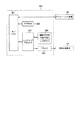
次に、図10を参照して、副制御基板72に実装される副制御回路200(副制御手段)の構成について説明する。図10は、パチスロ1の副制御回路200の構成例を示すブロック図である。
<Sub-control circuit>
Next, the configuration of the sub-control circuit 200 (sub-control means) mounted on the
副制御回路200は、主制御回路90と電気的に接続されており、主制御回路90から送信されるコマンドに基づいて演出内容の決定や実行等の処理を行う。副制御回路200は、基本的に、サブCPU201、サブRAM202、レンダリングプロセッサ203、描画用RAM204、ドライバ205を含んで構成される。
The
なお、サブCPU201は、ロムカートリッジ基板86に接続される。ドライバ205は、液晶中継基板87に接続される。すなわち、ドライバ205は、液晶中継基板87を介してプロジェクタ機構211及びサブ表示装置18に接続される。
The
サブCPU201は、主制御回路90から送信されたコマンドに応じて、ロムカートリッジ基板86に記憶されている制御プログラムに従い、映像、音、光の出力の制御を行う。ロムカートリッジ基板86は、基本的に、プログラム記憶領域とデータ記憶領域とによって構成される。
The
プログラム記憶領域には、サブCPU201が実行する制御プログラムが記憶される。例えば、制御プログラムには、主制御回路90との通信を制御するための主基板通信タスクや、演出用の乱数値を抽出し、演出内容(演出データ)の決定及び登録を行うための演出登録タスクを実行するための各種プログラムが含まれる。また、制御プログラムには、決定した演出内容に基づいて表示装置11による映像の表示を制御する描画制御タスク、LED群85等の光源による光の出力を制御するランプ制御タスク、スピーカ群84による音の出力を制御する音声制御タスク等を実行するための各種プログラムも含まれる。
The control program executed by the
データ記憶領域には、各種データテーブルを記憶する記憶領域、各演出内容を構成する演出データを記憶する記憶領域、映像の作成に関するアニメーションデータを記憶する記憶領域が含まれる。また、データ記憶領域には、BGMや効果音に関するサウンドデータを記憶する記憶領域、光の点消灯のパターンに関するランプデータを記憶する記憶領域等も含まれる。 The data storage area includes a storage area for storing various data tables, a storage area for storing effect data constituting each effect content, and a storage area for storing animation data related to video creation. The data storage area also includes a storage area for storing sound data related to BGM and sound effects, a storage area for storing lamp data related to a pattern of turning on and off light, and the like.
サブRAM202には、決定された演出内容や演出データを登録する格納領域や、主制御回路90から送信されるサブフラグ(内部当籤役)等の各種データを格納する格納領域が設けられる。
The
サブCPU201、レンダリングプロセッサ203、描画用RAM(フレームバッファを含む)204及びドライバ205は、演出内容により指定されたアニメーションデータに従って映像を作成し、作成した映像を表示装置11(プロジェクタ機構211)及び/又はサブ表示装置18に表示させる。なお、表示装置11(プロジェクタ機構211)及びサブ表示装置18は、副制御基板72により、それぞれ個別に制御される。
The
また、サブCPU201は、演出内容により指定されたサウンドデータに従ってBGMなどの音をスピーカ群84により出力させる。また、サブCPU201は、演出内容により指定されたランプデータに従ってLED群85の点灯及び消灯を制御する。
Further, the
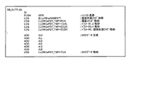
<メインCPUが有する各種レジスタ>
次に、図11を参照しながら、メインCPU101が有する各種レジスタについて説明する。なお、図11は、メインCPU101に含まれる各種レジスタの概略構成図である。
<Various registers of the main CPU>
Next, various registers included in the
メインCPU101は、メイン・レジスタとして、アキュームレータA(以下、「Aレジスタ」という)、フラグ・レジスタF(フラグレジスタ)、汎用レジスタB(以下、「Bレジスタ」という)、汎用レジスタC(以下、「Cレジスタ」という)、汎用レジスタD(以下、「Dレジスタ」という)、汎用レジスタE(以下、「Eレジスタ」という)、汎用レジスタH(以下、「Hレジスタ」という)及び汎用レジスタL(以下、「Lレジスタ」という)を有する。また、メインCPU101は、サブ・レジスタとして、アキュームレータA′、フラグ・レジスタF′、汎用レジスタB′、汎用レジスタC′、汎用レジスタD′、汎用レジスタE′、汎用レジスタH′及び汎用レジスタL′を汎用レジスタとして有する。なお、各レジスタは、1バイトのレジスタで構成される。
As the main register, the
また、本実施形態では、BレジスタとCレジスタとをペアレジスタ(以下、「BCレジスタ」という)として用い、DレジスタとEレジスタとをペアレジスタ(以下、「DEレジスタ」という)として用いる。さらに、本実施形態では、HレジスタとLレジスタとをペアレジスタ(以下、「HLレジスタ」という)として用いる。 Further, in the present embodiment, the B register and the C register are used as a pair register (hereinafter, referred to as “BC register”), and the D register and the E register are used as a pair register (hereinafter, referred to as “DE register”). Further, in the present embodiment, the H register and the L register are used as a pair register (hereinafter, referred to as "HL register").
フラグ・レジスタF,F′の各ビットには、図11に示すように、演算処理の結果等を示す所定のフラグ情報がセットされる。例えばビット6(D6)には、演算結果の判定処理において演算結果が「0」であるか否かを示すデータ(ゼロフラグ)がセットされる。具体的には、演算結果が「0」である場合、ビット6にデータ「1」がセットされ、演算結果が「0」でない場合には、ビット6にデータ「0」がセットされる。そして、演算結果の判定処理では、メインCPU101は、ビット6のデータ「0」/「1」を参照して判定(YES/NO)を行う。
As shown in FIG. 11, predetermined flag information indicating the result of arithmetic processing and the like is set in each bit of the flag registers F and F'. For example, bit 6 (D6) is set with data (zero flag) indicating whether or not the calculation result is "0" in the calculation result determination process. Specifically, when the calculation result is "0", the data "1" is set in the
また、メインCPU101は、拡張レジスタQ(以下、「Qレジスタ」という)を有する。Qレジスタは、1バイトのレジスタで構成される。なお、本実施形態では、後述の各種処理フローの中で説明するように、ソースプログラム上において、このQレジスタを用いてアドレス指定を行う各種メインCPU101専用命令コードが設けられており、この命令コードの使用により、処理の効率化やメインROM102の容量削減などを実現している。なお、Qレジスタを用いてアドレス指定を行う各種メインCPU101専用命令コードでは、Qレジスタには、アドレスの上位側のアドレスデータ(アドレス値)が格納される。なお、Qレジスタには、メインCPU101のリセット直後に、初期値として「F0H」がセットされる。また、Qレジスタを用いた「LD Q,n(8ビットデータ)」命令において、「n」に任意の1バイトのデータをセットして該命令を実行することにより、Qレジスタの値を変更することができる。
Further, the
さらに、メインCPU101は、1バイトのレジスタで構成された、インタラプト・ページアドレス・レジスタI及びメモリ・リフレッシュ・レジスタR、並びに、2バイトのレジスタで構成された、インデックス・レジスタIX、インデックス・レジスタIY、スタックポインタSP及びプログラムカウンタPCを専用レジスタとして有する。
Further, the
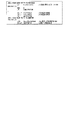
<メインROM及びメインRAMの内部構成(メモリマップ)>
次に、図12A〜図12Cを参照しながら、主制御回路90(マイクロプロセッサ91)に含まれるメインROM102及びメインRAM103の内部構成(以下「メモリマップ」という)について説明する。なお、図12Aは、メモリ全体のメモリマップを示す図であり、図12Bは、メインROM102のメモリマップを示す図であり、図12Cは、メインRAM103のメモリマップを示す図である。
<Internal configuration of main ROM and main RAM (memory map)>
Next, the internal configurations (hereinafter referred to as “memory maps”) of the
主制御回路90(マイクロプロセッサ91)が備えるメモリ全体のメモリマップでは、図12Aに示すように、アドレスの先頭(0000H)側から、メインROM102のメモリ領域、メインRAM103のメモリ領域、内蔵レジスタエリア及びXCSデコードエリアが、不使用領域を間に挟んでこの順で、それぞれ所定のアドレスに配置される。
In the memory map of the entire memory included in the main control circuit 90 (microprocessor 91), as shown in FIG. 12A, from the head (0000H) side of the address, the memory area of the
メインROM102のメモリマップでは、図12Bに示すように、メインROM102のアドレスの先頭(0000H)側から、プログラムエリア、データエリア、規定外エリア、商標記録エリア、プログラム管理エリア及びセキュリティ設定エリアが、この順で、それぞれ所定のアドレスに配置される。
In the memory map of the
なお、プログラムエリアには、遊技者により実施される遊技の遊技性に関連する各種制御処理において、メインCPU101により実行される各種処理の制御プログラムが記憶される。データエリアには、遊技者により実施される遊技の遊技性に関連する各種制御処理において、メインCPU101により使用される各種データ(例えば、内部抽籤テーブル等のデータテーブル、副制御回路42に対して各種制御指令(コマンド)を送信するためのデータ等)が記憶される。すなわち、プログラムエリアとデータエリアとからなる遊技用ROM領域(遊技用記憶領域)には、遊技店で遊技者が実際に行う遊技の遊技性に関連する制御処理(遊技性に関する処理)に必要な各種プログラム及び各種データが格納される。
In the program area, control programs for various processes executed by the
また、規定外エリアには、遊技者により実施される遊技の遊技性に直接関与しない各種処理(遊技性に影響を与えない処理)の制御プログラム及びデータが記憶される。例えば、パチスロ1の検定試験(試射試験)で使用されるプログラム及びデータ、電断時のチェックサム生成処理や電源復帰時のサムチェック処理などで使用される制御プログラム及びデータ、並びに、不正対策プログラム及びそれに必要なデータ等が、規定外エリアに格納される。
Further, in the non-standard area, control programs and data of various processes (processes that do not affect the playability) that are not directly related to the playability of the game performed by the player are stored. For example, programs and data used in the
メインRAM103のメモリマップでは、図12Cに示すように、メインRAM103のアドレスの先頭(F000H)側から、遊技用RAM領域(所定格納領域、遊技用一時記憶領域)及び規定外RAM領域(規定外一時記憶領域)が、この順で、それぞれ所定のアドレスに配置される。
In the memory map of the
遊技用RAM領域には、遊技者により実施される遊技の遊技性に関連する制御プログラムの実行により決定された例えば内部当籤役等の各種データを一時的に格納する作業領域及びスタックエリアが設けられる。そして、各種データのそれぞれは、遊技用RAM領域内の所定アドレスの作業領域に格納される。 The game RAM area is provided with a work area and a stack area for temporarily storing various data such as an internal winning combination determined by executing a control program related to the game playability performed by the player. .. Then, each of the various data is stored in the work area of a predetermined address in the game RAM area.
また、規定外RAM領域には、遊技者により実施される遊技の遊技性に直接関与しない各種処理の作業領域となる規定外作業領域と、規定外スタックとが設けられる。本実施形態では、この規定外RAM領域を使用して、例えばサムチェック処理等の遊技者により実施される遊技の遊技性に直接関与しない各種処理が実行される。 Further, the non-standard RAM area is provided with a non-standard work area that is a work area for various processes that are not directly related to the playability of the game performed by the player, and a non-standard stack. In the present embodiment, various processes that are not directly related to the playability of the game performed by the player, such as a thumb check process, are executed using this non-standard RAM area.
上述のように、本実施形態のパチスロ1では、メインROM102内において、遊技者により実施される遊技の遊技性に直接関与しない各種処理に使用される各種プログラム及び各種データ(テーブル)を、遊技用ROM領域とは異なるアドレスに配置された規定外ROM領域(規定外記憶領域)に格納する。また、そのような遊技者により実施される遊技の遊技性に直接関与しない各種処理は、メインRAM103内において、遊技用RAM領域とは異なるアドレスに配置された規定外RAM領域を使用して行われる。
As described above, in the pachi-
このようなメインROM102の構成では、従来の規則上においてプログラム等の配置不可とされていたROM領域(規定外ROM領域)に、遊技者が実際に行う遊技そのものには不要なプログラム及びデータを配置することができる。それゆえ、本実施形態では、遊技用ROM領域の容量の圧迫を回避することができる。
In such a configuration of the
<遊技状態の遷移フロー>
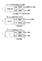
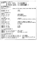
次に、図13及び図14を参照しながら、本実施形態のパチスロ1の主制御回路90(メインCPU101)により管理される各種遊技状態及びその遷移フローについて説明する。なお、図13Aは、パチスロ1の基本的な遊技状態の遷移フロー図であり、図13Bは、その遊技状態の移行条件をまとめた表である。また、図14Aは、報知(ART)機能の作動の有無を考慮した遊技状態の遷移フロー図であり、図14Bは、その遊技状態の移行条件をまとめた表である。
<Transition flow of game state>
Next, various gaming states managed by the main control circuit 90 (main CPU 101) of the
[基本的な遊技状態の遷移フロー]
本実施形態のパチスロ1では、ボーナスゲームの種類として、ビッグボーナス(以下、「BB」と記す)が設けられる。BBは、第1種特別役物と呼ばれるレギュラーボーナス(以下、「RB」と記す)に係る役物連続作動装置であり、RBを連続して作動させる。
[Basic game state transition flow]
In the
それゆえ、本実施形態では、主制御回路90は、ボーナス役の当籤/作動(入賞)の有無に基づいて遊技状態を管理する。具体的には、図13Aに示すように、主制御回路90は、ボーナス役(後述の名称「F_BB1」,「F_BB2」の内部当籤役)の当籤/作動(入賞)の有無に基づいて、「ボーナス非当籤状態」、「フラグ間状態」及び「ボーナス状態」と称する3種類の遊技状態を管理する。
Therefore, in the present embodiment, the
なお、ボーナス非当籤状態は、ボーナスに非当籤であり、かつ、ボーナスが作動(入賞)していない状態であり、ボーナス状態は、ボーナスが作動している状態である。また、本実施形態では、ボーナス役が内部当籤役として決定されると、ボーナスが入賞するまで複数回の遊技に渡りボーナス役が内部当籤役として持ち越された状態が発生する。フラグ間状態は、ボーナス役が内部当籤役として持ち越されている状態、すなわち、ボーナス役が当籤し、かつ、ボーナスが作動していない状態である。 The bonus non-winning state is a state in which the bonus is not winning and the bonus is not activated (winning), and the bonus state is a state in which the bonus is activated. Further, in the present embodiment, when the bonus combination is determined as the internal winning combination, the bonus combination is carried over as the internal winning combination over a plurality of games until the bonus is won. The inter-flag state is a state in which the bonus combination is carried over as an internal winning combination, that is, a state in which the bonus combination is won and the bonus is not activated.
なお、ボーナス役の当籤の有無は、メインRAM103に設けられる後述の当り要求フラグ格納領域(後述の図28〜図30参照)及び持越役格納領域(後述の図31参照)に格納されるデータに基づいて管理される。また、ボーナスの作動(入賞)の有無は、メインRAM103に設けられる後述の遊技状態フラグ格納領域(後述の図32参照)に格納されるデータに基づいて管理される。
Whether or not the bonus combination is won is determined by the data stored in the hit request flag storage area (see FIGS. 28 to 30 described later) and the carry-over combination storage area (see FIG. 31 described later) provided in the
また、本実施形態では、図13Aに示すように、ボーナスが作動していない遊技状態(ボーナス非当籤状態及びフラグ間状態)において、リプレイに係る内部当籤役の種別及びその当籤確率が互いに異なる、RT0遊技状態〜RT5遊技状態の6種類の状態(以下、それぞれ「RT0状態」〜「RT5状態」という)が設けられる。なお、RT0状態、RT2状態及びRT5状態は、リプレイ役が内部当籤役として決定される確率が低確率となる遊技状態であり、RT1状態はリプレイ役が内部当籤役として決定される確率が中程度の中確率となる遊技状態である。また、RT3状態及びRT4状態は、リプレイ役が内部当籤役として決定される確率が高確率となる遊技状態である。なお、本実施形態では、ボーナス非当籤状態のRT状態は、RT0状態〜RT4状態のいずれかとなり、フラグ間状態のRT状態はRT5状態となる。 Further, in the present embodiment, as shown in FIG. 13A, in the gaming state in which the bonus is not activated (bonus non-winning state and inter-flag state), the types of internal winning combinations related to replay and the winning probabilities thereof are different from each other. Six types of states from the RT0 gaming state to the RT5 gaming state (hereinafter, referred to as "RT0 state" to "RT5 state", respectively) are provided. The RT0 state, RT2 state, and RT5 state are gaming states in which the probability that the replay combination is determined as the internal winning combination is low, and the RT1 state has a medium probability that the replay combination is determined as the internal winning combination. It is a gaming state with a medium probability. Further, the RT3 state and the RT4 state are gaming states in which the probability that the replay combination is determined as the internal winning combination is high. In the present embodiment, the RT state in the bonus non-winning state is any of the RT0 state to the RT4 state, and the RT state in the inter-flag state is the RT5 state.
それゆえ、本実施形態では、主制御回路90は、ボーナスが作動していない遊技状態(ボーナス非当籤状態及びフラグ間状態)において、さらに、リプレイに係る内部当籤役の種別及びその当籤確率に基づいて、RT1状態〜RT5状態の6種類の状態も管理する。
Therefore, in the present embodiment, the
なお、RT0状態〜RT5状態は、メインRAM103に設けられる後述の遊技状態フラグ格納領域(後述の図32参照)に格納されるデータに基づいて管理される。具体的には、本実施形態のパチスロ1では、RT1状態フラグ〜RT5状態フラグの5つのRT状態を示すフラグが設けられ、これらのフラグのオン/オフ状態をメインRAM103により管理することによりRT状態が管理される。そして、主制御回路90は、オン状態であるRT状態フラグに対応するRT状態を現在のRT状態として特定する。なお、全てのRT状態フラグがオフ状態である場合には、主制御回路90は、現在のRT状態がRT0状態であると特定する。
The RT0 state to the RT5 state are managed based on the data stored in the game state flag storage area (see FIG. 32 described later) provided in the
図13A及び13Bに示すように、ボーナス非当籤状態においてボーナス役(後述の名称「F_BB1」,「F_BB2」の内部当籤役)が内部当籤役として決定されると(移行条件(1)が成立すると)、主制御回路90は、遊技状態をボーナス非当籤状態からフラグ間状態に移行させる。また、フラグ間状態においてボーナス役が入賞すると(移行条件(2)が成立すると)、主制御回路90は、遊技状態をフラグ間状態からボーナス状態に移行させる。
As shown in FIGS. 13A and 13B, when the bonus combination (internal winning combination of the names "F_BB1" and "F_BB2" described later) is determined as the internal winning combination in the bonus non-winning state (when the transition condition (1) is satisfied). ), The
また、ボーナス状態において規定枚数(216枚)を超えるメダルが払い出され、ボーナス状態が終了すると(移行条件(3)が成立すると)、主制御回路90は、遊技状態をボーナス状態からRT1状態(ボーナス非当籤状態)に移行させる。
Further, when the number of medals exceeding the specified number (216) is paid out in the bonus state and the bonus state ends (when the transition condition (3) is satisfied), the
RT1状態において、20ゲームが経過すると(移行条件(4)が成立すると)、主制御回路90は、遊技状態をRT1状態からRT0状態に移行させる。また、RT1状態において、20ゲームが経過する前に、略称「ベルこぼし目」に係る図柄組合せ(後述の図28参照)が有効ライン上に表示されると(移行条件(5)が成立すると)、主制御回路90は、遊技状態をRT1状態からRT2状態に移行させる。
When 20 games have elapsed in the RT1 state (when the transition condition (4) is satisfied), the
RT0状態において、略称「ベルこぼし目」に係る図柄組合せが有効ライン上に表示されると(移行条件(5)が成立すると)、主制御回路90は、遊技状態をRT0状態からRT2状態に移行させる。RT2状態において、略称「RT3移行リプ」に係る図柄組合せ(後述の図28参照)が有効ライン上に表示されると(移行条件(6)が成立すると)、主制御回路90は、遊技状態をRT2状態からRT3状態に移行させる。
In the RT0 state, when the symbol combination related to the abbreviation "bell spilled eye" is displayed on the valid line (when the transition condition (5) is satisfied), the
RT3状態において、略称「RT4移行リプ」に係る図柄組合せ(後述の図28参照)が有効ライン上に表示されると(移行条件(7)が成立すると)、主制御回路90は、遊技状態をRT3状態からRT4状態に移行させる。また、RT3状態において、略称「ベルこぼし目」又は「RT2移行リプ」に係る図柄組合せ(後述の図28参照)が有効ライン上に表示されると(移行条件(8)が成立すると)、主制御回路90は、遊技状態をRT3状態からRT2状態に遊技状態を移行させる。さらに、RT4状態において、略称「ベルこぼし目」又は「RT2移行リプ」に係る図柄組合せが有効ライン上に表示されると(移行条件(8)が成立すると)、主制御回路90は、遊技状態をRT4状態からRT2状態に遊技状態を移行させる。
In the RT3 state, when the symbol combination related to the abbreviation "RT4 transition lip" (see FIG. 28 described later) is displayed on the valid line (when the transition condition (7) is satisfied), the
なお、略称「ベルこぼし目」に係る図柄組合せは、後述の名称「F_3択ベル_1st」、「F_3択ベル_2nd」又は「F_3択ベル_3rd」に係る内部当籤役(小役)が決定され、かつ、停止操作の順序が該小役の種別ごとに定められた押し順に対して不正解であるときに表示される図柄の組合せである(後述の図24参照)。略称「RT2移行リプ」に係る図柄組合せは、後述の名称「F_維持リプ_1st」、「F_維持リプ_2nd」又は「F_維持リプ_3rd」に係る内部当籤役(リプレイ役)が決定され、かつ、停止操作の順序が該リプレイ役の種別ごとに定められた押し順に対して不正解であるときに表示される図柄の組合せである。 As for the symbol combination related to the abbreviation "bell spilled eyes", the internal winning combination (small combination) related to the names "F_3 selection bell_1st", "F_3 selection bell_2nd" or "F_3 selection bell_3rd" described later is determined. Moreover, it is a combination of symbols displayed when the order of the stop operation is incorrect with respect to the push order determined for each type of the small winning combination (see FIG. 24 described later). As for the symbol combination related to the abbreviation "RT2 transition lip", the internal winning combination (replay combination) related to the names "F_maintenance lip_1st", "F_maintenance lip_2nd" or "F_maintenance lip_3rd" described later is determined, and This is a combination of symbols displayed when the order of stop operations is incorrect with respect to the push order determined for each type of replay combination.
略称「RT3移行リプ」に係る図柄組合せは、後述の名称「F_RT3リプ_1st」、「F_RT3リプ_213」、「F_RT3リプ_231」又は「F_RT3リプ_3rd」に係る内部当籤役(リプレイ役)が決定され、かつ、停止操作の順序が該リプレイ役の種別ごとに定められた押し順に対して正解であるときに表示される図柄の組合せである。また、略称「RT4移行リプ」に係る図柄組合せは、後述の名称「F_RT4リプ_123」、「F_RT4リプ_132」、「F_RT4リプ_2nd」又は「F_RT4リプ_3rd」に係る内部当籤役(リプレイ役)が決定され、かつ、停止操作の順序が該リプレイ役の種別ごとに定められた押し順に対して正解であるときに表示される図柄の組合せである。 As for the symbol combination related to the abbreviation "RT3 transition lip", the internal winning combination (replay combination) related to the names "F_RT3 lip_1st", "F_RT3 lip_213", "F_RT3 lip_231" or "F_RT3 lip_3rd" described later is determined. Moreover, it is a combination of symbols displayed when the order of the stop operation is the correct answer for the push order determined for each type of the replay combination. In addition, the symbol combination related to the abbreviation "RT4 transition lip" has an internal winning combination (replay role) related to the names "F_RT4 lip_123", "F_RT4 lip_132", "F_RT4 lip_2nd" or "F_RT4 lip_3rd" described later. It is a combination of symbols that are determined and displayed when the order of stop operations is the correct answer for the push order determined for each type of replay combination.
[報知(ART)機能の作動の有無を考慮した遊技状態の遷移フロー]
本実施形態では、主制御回路90(メインCPU101)により、遊技者にとって有利な停止操作を報知する機能(ART機能)の作動の有無が決定される。それゆえ、本実施形態では、ボーナス非作動状態においてART機能の作動/非作動状態も遊技状態として管理する。
[Transition flow of game state considering whether or not the notification (ART) function is activated]
In the present embodiment, the main control circuit 90 (main CPU 101) determines whether or not a function (ART function) for notifying a stop operation advantageous to the player is activated. Therefore, in the present embodiment, the activated / non-activated state of the ART function is also managed as the gaming state in the bonus non-operating state.
本実施形態のパチスロ1では、図14Aに示すように、主制御回路90は、非ボーナス作動状態において、報知(ART)の有無に基づいて「一般遊技状態」と「ART遊技状態」とを別個の遊技状態として管理する。すなわち、報知(ART)の有無を考慮した遊技状態の管理では、図14Aに示すように、主制御回路90は、大きな分類として、「ボーナス状態」、「一般遊技状態」及び「ART遊技状態」の3種類の遊技状態を管理する。
In the pachi-
なお、一般遊技状態は、基本的には、遊技者にとって有利な停止操作の情報を報知しない遊技状態(非ART)であり、遊技者にとって不利な遊技状態である。また、一般遊技状態は、RT0〜RT4状態のいずれかの状態であり、かつ、ART非当籤の遊技状態である。 The general gaming state is basically a gaming state (non-ART) that does not notify information on a stop operation that is advantageous to the player, and is a gaming state that is disadvantageous to the player. Further, the general gaming state is any of the RT0 to RT4 states, and is an ART non-winning gaming state.
一方、ART遊技状態は、遊技者にとって有利な停止操作の情報を報知する遊技状態であり、遊技者にとって有利な遊技状態である。また、ART遊技状態は、基本的には、RT4状態であり、かつ、ART当籤中の遊技状態である。なお、本実施形態では、ART当籤後、RT状態がRT4状態まで移行すると、ART遊技が開始される。 On the other hand, the ART gaming state is a gaming state that notifies information on a stop operation that is advantageous to the player, and is a gaming state that is advantageous to the player. Further, the ART gaming state is basically the RT4 state and the gaming state during the ART winning. In the present embodiment, when the RT state shifts to the RT4 state after winning the ART, the ART game is started.
また、本実施形態では、図14Aに示すように、一般遊技状態として、「通常遊技状態」及び「CZ(チャンスゾーン)」と称する2種類の状態が設けられる。 Further, in the present embodiment, as shown in FIG. 14A, two types of states called "normal gaming state" and "CZ (chance zone)" are provided as general gaming states.
通常遊技状態は、遊技者にとって最も不利な遊技状態であるが、通常遊技状態の遊技ではCZへの移行抽籤を行っている。そして、図14A及び14Bに示すように、通常遊技状態の遊技において、CZへの移行抽籤に当籤すると(移行条件(A)が成立すると)、主制御回路90は、遊技状態を、通常遊技状態からCZに移行させる。
The normal game state is the most disadvantageous game state for the player, but in the game in the normal game state, a lottery for transition to CZ is performed. Then, as shown in FIGS. 14A and 14B, in the game in the normal game state, when the lottery for transition to CZ is won (when the transition condition (A) is satisfied), the
CZは、ART遊技状態への移行に対する期待度が高い遊技状態(チャンスゾーン)であり、CZ中の遊技ではARTへの移行抽籤が行われている。そして、図14A及び14Bに示すように、CZ中の遊技において、ARTへの移行抽籤に非当籤である場合には(移行条件(B)が成立すると)、主制御回路90は、遊技状態を、CZから通常遊技状態に移行させる。一方、CZ中の遊技において、ARTへの移行抽籤に当籤すると(移行条件(C)が成立すると)、主制御回路90は、遊技状態を、CZからART遊技状態に移行させる。この際、図14Aには示さないが、主制御回路90は、遊技状態を、CZから後述のART準備状態を経由してART遊技状態(後述の通常ART又はCT)に移行させる。
The CZ is a gaming state (chance zone) in which the expectation for the transition to the ART gaming state is high, and a lottery for the transition to the ART is performed in the game during the CZ. Then, as shown in FIGS. 14A and 14B, in the game during CZ, when the lottery for transition to ART is not won (when the transition condition (B) is satisfied), the
ART遊技状態は、上述のように、ART当籤後にRT状態がRT4状態まで移行すると開始される。なお、図13Aで示したように、RT4状態は、RT0〜RT2状態からRT3状態を経由して移行するので、ART当籤後であってもすぐにART遊技状態が開始されない。そこで、本実施形態のパチスロ1では、ART当籤後からRT状態がRT4状態に移行するまでの期間の遊技状態をART準備状態とする。そして、このART準備状態の遊技では、RT状態をRT4状態に移行させるために必要な停止操作の情報が報知される。
As described above, the ART gaming state is started when the RT state shifts to the RT4 state after winning the ART. As shown in FIG. 13A, since the RT4 state shifts from the RT0 to RT2 states via the RT3 state, the ART gaming state is not started immediately even after winning the ART. Therefore, in the pachi-
また、本実施形態では、図14Aに示すように、ART遊技状態として、遊技性が互いに異なる、「通常ART」及び「CT(上乗せチャンス)」と称する2種類の状態が設けられる。 Further, in the present embodiment, as shown in FIG. 14A, two types of ART gaming states, called "normal ART" and "CT (additional chance)", in which the playability is different from each other, are provided.
通常ARTは、所定ゲーム数の期間、遊技者にとって有利な停止操作(例えば、払い出されるメダルの枚数が多い図柄組合せを表示させるための停止操作や、RT4状態を維持するために必要な停止操作)が報知される遊技状態である。また、通常ART中の遊技では、CTへの移行抽籤が行われる。 Normally, ART is a stop operation that is advantageous for the player for a predetermined number of games (for example, a stop operation for displaying a symbol combination with a large number of medals to be paid out, or a stop operation necessary for maintaining the RT4 state). Is the game state in which is notified. In addition, in a game during normal ART, a lottery for transition to CT is performed.
CTは、遊技者にとって有利な停止操作が報知されるとともに、特定期間(1セット8ゲームの期間)、通常ARTの継続期間を上乗せすることが可能となる遊技状態であり、上乗せチャンスゾーンとして機能する遊技状態である。また、CT中では、通常ARTの継続期間を消化せずに遊技が行われる。なお、CT中の遊技性については、後述の図52A〜52Cを参照して後で詳述する。 CT is a gaming state in which a player is notified of an advantageous stop operation and can add a normal ART duration for a specific period (a period of 8 games per set), and functions as an additional chance zone. It is a game state to play. Also, during CT, the game is usually played without digesting the duration of ART. The playability during CT will be described in detail later with reference to FIGS. 52A to 52C described later.
図14A及び14Bに示すように、通常ART中の遊技において、CTへの移行抽籤に当籤すると(移行条件(D)が成立すると)、主制御回路90は、遊技状態を、通常ARTからCTに遊技状態を移行させる。また、通常ARTにおいて、当該通常ARTの継続期間が終了すると(移行条件(E)が成立すると)、主制御回路90は、遊技状態を、通常ARTから一般遊技状態(通常遊技状態又はCZ)に移行させる。なお、本実施形態では、ゲーム数により通常ARTの継続期間を管理するが、本発明はこれに限定されず、通常ARTの継続期間の管理方法は任意である。例えば、通常ARTの継続期間を、通常ART中に払い出されるメダルの枚数や差枚数により管理してもよいし、通常ART中にメダルの払い出しに影響を与える報知を行った回数(ナビ回数)により管理してもよい。
As shown in FIGS. 14A and 14B, in a game during normal ART, when the lottery for transition to CT is won (when the transition condition (D) is satisfied), the
図14A及び14Bに示すように、CT中の遊技において、CTの継続期間(1セット8ゲーム)が終了すると(移行条件(F)が成立すると)、主制御回路90は、遊技状態を、CTから通常ARTに移行させる。
As shown in FIGS. 14A and 14B, in the game during CT, when the duration of CT (8 games per set) ends (when the transition condition (F) is satisfied), the
また、図14Aに示すように、一般遊技状態(通常遊技状態又はCZ)又はART遊技状態(通常ART又はCT)において、ボーナス役が入賞すると(図13A及び13B中で説明した移行条件(2)が成立すると)、主制御回路90は、遊技状態を、一般遊技状態又はART遊技状態からボーナス状態に移行させる。
Further, as shown in FIG. 14A, when the bonus combination is won in the general gaming state (normal gaming state or CZ) or ART gaming state (normal ART or CT) (transition condition (2) described in FIGS. 13A and 13B). When is established), the
ボーナス状態の遊技では、上述のように、ARTへの移行抽籤を行っており、ボーナス状態の遊技において、ARTへの移行抽籤が非当籤である場合には(移行条件(G)が成立すると)、主制御回路90は、遊技状態を、ボーナス状態から一般遊技状態(通常遊技状態又はCZ)に移行させる。ただし、ART遊技状態(通常ART又はCT)からボーナス状態に移行していた場合には、ボーナス状態の遊技においてARTの移行抽籤に非当籤であっても、主制御回路90は、遊技状態を、ボーナス状態からART遊技状態(通常ART又はCT)に移行させる。一方、ボーナス状態の遊技において、ARTへの移行抽籤に当籤すると(移行条件(H)が成立すると)、主制御回路90は、遊技状態を、ボーナス状態からART遊技状態(通常ART又はCT)に移行させる。なお、上述のように、ボーナス状態の終了時には、RT状態がRT1状態に移行するので、ボーナス状態からART遊技状態に遊技状態を移行する場合には、主制御回路90は、遊技状態を、ART準備状態を経由してART遊技状態に移行させる。
In the game in the bonus state, as described above, the lottery for transition to ART is performed, and in the game in the bonus state, if the lottery for transition to ART is non-winning (when the transition condition (G) is satisfied). , The
<メインROMに記憶されているデータテーブルの構成>
次に、図15〜図27を参照して、メインROM102に記憶されている各種データテーブルの構成について説明する。なお、一般遊技状態中及びART遊技状態中の遊技性(CZ、通常ART,CTの遊技性)に係る各種抽籤で用いられる各種データテーブルについては、別途、各遊技性の説明と一緒に後述する。
<Structure of data table stored in main ROM>
Next, the configurations of various data tables stored in the
[図柄配置テーブル]
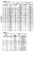
まず、図15を参照して、図柄配置テーブルについて説明する。図柄配置テーブルは、左リール3L、中リール3C及び右リール3Rのそれぞれの回転方向における各図柄の位置と、各位置に配置された図柄の種類を特定するデータ(以下、図柄コード(図15中の図柄コード表を参照)という)との対応関係を規定する。
[Design arrangement table]
First, the symbol arrangement table will be described with reference to FIG. The symbol arrangement table is data that specifies the position of each symbol in each rotation direction of the
図柄配置テーブルでは、リールインデックスが検出されたときに、リール表示窓4の枠内における各リールの中段領域に位置する図柄の位置を「0」と規定する。そして、各リールにおいて、図柄位置「0」を基準としてリールの回転方向(図15中の図柄位置「19」から図柄位置「0」に向かう方向)に進む順に、図柄カウンタの値に対応する「0」〜「19」が、図柄位置として、各図柄に割り当てられる。
In the symbol arrangement table, when the reel index is detected, the position of the symbol located in the middle region of each reel in the frame of the
すなわち、図柄カウンタの値(「0」〜「19」)と、図柄配置テーブルとを参照することにより、リール表示窓4の枠内における各リールの上段領域、中段領域及び下段領域に表示されている図柄の種類を特定することができる。なお、本実施形態では、図柄として、「白7」、「青7」、「チリ上1」、「チリ上2」、「チリ下」、「リプレイ」、「帽子」、「サボテン1」、「サボテン2」及び「サボテン3」の10種類の図柄を用いる。
That is, by referring to the values of the symbol counters (“0” to “19”) and the symbol arrangement table, they are displayed in the upper region, the middle region, and the lower region of each reel in the frame of the
また、本実施形態では、図柄コード表に示すように、図柄「白7」(図柄コード1)には、データとして「00000001」が割り当てられ、図柄「青7」(図柄コード2)には、データとして「00000010」が割り当てられている。図柄「チリ上1」(図柄コード3)には、データとして「00000011」が割り当てられ、図柄「チリ上2」(図柄コード4)には、データとして「00000100」が割り当てられている。
Further, in the present embodiment, as shown in the symbol code table, "00000001" is assigned as data to the symbol "white 7" (symbol code 1), and the symbol "blue 7" (symbol code 2) is assigned. "00000010" is assigned as the data. "00000011" is assigned as data to the symbol "
図柄「チリ下」(図柄コード5)には、データとして「00000101」が割り当てられ、図柄「リプレイ」(図柄コード6)には、データとして「00000110」が割り当てられている。図柄「帽子」(図柄コード7)には、データとして「00000111」が割り当てられ、図柄「サボテン1」(図柄コード8)には、データとして「00001000」が割り当てられている。また、図柄「サボテン2」(図柄コード9)には、データとして「00001001」が割り当てられ、図柄「サボテン3」(図柄コード10)には、データとして「00001010」が割り当てられている。
"00000011" is assigned as data to the symbol "Chile bottom" (symbol code 5), and "00000011" is assigned as data to the symbol "replay" (symbol code 6). The symbol "hat" (symbol code 7) is assigned "000000111" as data, and the symbol "
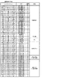
[内部抽籤テーブル]
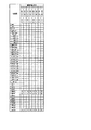
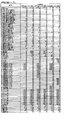
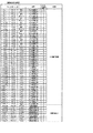
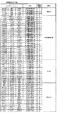
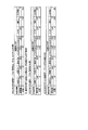
次に、図16及び図17を参照して、内部当籤役を決定する際に参照される内部抽籤テーブルについて説明する。なお、図16は、RT0状態〜RT4状態のそれぞれにおいて参照される内部抽籤テーブルである。また、図17Aは、RT5状態において参照される内部抽籤テーブルであり、図17Bは、ボーナス状態において参照される内部抽籤テーブルである。
[Internal lottery table]
Next, the internal lottery table referred to when determining the internal winning combination will be described with reference to FIGS. 16 and 17. Note that FIG. 16 is an internal lottery table referred to in each of the RT0 state to the RT4 state. Further, FIG. 17A is an internal lottery table referred to in the RT5 state, and FIG. 17B is an internal lottery table referenced in the bonus state.
内部抽籤テーブルは、遊技状態毎に設けられ、各種内部当籤役と、各内部当籤役が決定されるときの抽籤値との対応関係を規定する。なお、抽籤値は、予め設定されたボーナス役や小役等の内部当籤の期待値を調整するための設定(設定1〜6)毎に規定される。この設定は、例えば、リセットスイッチ76及び設定用鍵型スイッチ54(図7参照)を用いて変更される。
The internal lottery table is provided for each game state, and defines the correspondence between various internal winning combinations and the lottery value when each internal winning combination is determined. The lottery value is defined for each setting (
本実施形態の内部抽籤処理では、まず、乱数回路110の乱数レジスタ0により、予め定められた数値の範囲(例えば、0〜65535)から抽出される乱数値を、各内部当籤役に対応して規定された抽籤値で順次加算する。次いで、抽籤結果(抽籤値+乱数値)が65535を超えたか否か(抽籤結果がオーバーフローしたか否か)の判定を行う。そして、所定の内部当籤役において、抽籤結果が65535を超えた場合、該内部当籤役が当籤したと判定される。なお、本実施形態の内部抽籤処理では、抽出した乱数値に抽籤値を加算して抽籤を行う例を説明したが、本発明はこれに限定されず、乱数値から抽籤値を減算して、減算結果(抽籤結果)が「0」を下回ったか否か(抽籤結果がアンダーフローしたか否か)を判定して、内部抽籤の当籤/非当籤を決定してもよい。
In the internal lottery process of the present embodiment, first, the
それゆえ、本実施形態の内部抽籤処理では、抽籤値として規定されている数値が大きい内部当籤役ほど、決定される確率が高い。なお、各内部当籤役の当籤確率は、「各当籤番号に規定された抽籤値/抽出される可能性のある全ての乱数値の個数(乱数分母:65536)」によって表すことができる。 Therefore, in the internal lottery process of the present embodiment, the larger the numerical value defined as the lottery value, the higher the probability that the internal lottery combination will be determined. The winning probability of each internal winning combination can be expressed by "the lottery value specified in each winning number / the number of all random number values that may be extracted (random number denominator: 65536)".
RT0状態〜RT4状態のそれぞれにおいて参照される内部抽籤テーブルでは、図16に示すように、基本的には、RT状態の種別に応じて、内部当籤役として決定されるリプレイ役の種別及び当籤確率が変化する。例えば、名称「F_チリリプ(No.25)」〜「F_リーチ目リプD(No.31)」に係るリプレイ役は、RT0状態〜RT3状態では内部当籤役として決定されることなく、RT4状態でのみ内部当籤役として決定される。なお、本実施形態のパチスロ1では、RT4状態中に、名称「F_チリリプ(No.25)」〜「F_リーチ目リプD(No.31)」に係るリプレイ役が内部当籤役として決定された場合、特有の制御(後述のフラグ変換)を行う。このフラグ変換については、後で詳述する。
In the internal lottery table referred to in each of the RT0 state to the RT4 state, as shown in FIG. 16, basically, the type and winning probability of the replay combination determined as the internal winning combination according to the type of the RT state. Changes. For example, the replay combination related to the names "F_chili lip (No. 25)" to "F_reach eye lip D (No. 31)" is not determined as an internal winning combination in the RT0 state to RT3 state, and is in the RT4 state. Only determined as an internal winning role. In the
また、図16に示すように、RT0状態〜RT3状態では、名称「F_リーチ目リプA」〜「F_リーチ目リプD」のそれぞれの内部当籤役は、名称「F_BB1」又は「F_BB2」に係るボーナス役と重複して決定されることはあるが(No.3〜6、15〜18参照)、名称「F_リーチ目リプA」〜「F_リーチ目リプD」のそれぞれの内部当籤役(リプレイ役)が単独で内部当籤役として決定されることはない。それゆえ、本実施形態において、RT0状態〜RT3状態中に名称「F_リーチ目リプA」〜「F_リーチ目リプD」に係るリプレイ役が内部当籤役として決定された場合(遊技者からすると名称「F_リーチ目リプA」〜「F_リーチ目リプD」に係るリプレイ役に応じた図柄組合せが表示された場合)、ボーナス役(名称「F_BB1」又は「F_BB2」)が同時に内部当籤役として決定されていることになる。 Further, as shown in FIG. 16, in the RT0 state to the RT3 state, the respective internal winning combinations of the names "F_reach eye lip A" to "F_reach eye lip D" are related to the names "F_BB1" or "F_BB2". Although it may be decided in duplicate with the bonus combination (see Nos. 3 to 6 and 15 to 18), each internal winning combination (replay) of the names "F_reach eye lip A" to "F_reach eye lip D" The role) is not determined as an internal winning role alone. Therefore, in the present embodiment, when the replay combination related to the names "F_reach eye lip A" to "F_reach eye lip D" is determined as the internal winning combination during the RT0 state to the RT3 state (name from the player's point of view). When the symbol combination corresponding to the replay combination related to "F_reach eye lip A" to "F_reach eye lip D" is displayed), the bonus combination (name "F_BB1" or "F_BB2") is determined as the internal winning combination at the same time. It will be done.
また、フラグ間状態であるRT5状態は、上述のようにボーナス役を内部当籤役として持ち越す遊技状態である。それゆえ、図17Aに示すように、RT5状態において参照される内部抽籤テーブルでは、持ち越しているボーナス役が必ず内部当籤役として決定されるようになっている。また、図17Bに示すように、ボーナス状態において参照される内部抽籤テーブルでは、名称「F_RB役1」〜「F_RB役4」のいずれかに係る内部当籤役が必ず当籤する構成になっている(「はずれ」が当籤することはない)。
Further, the RT5 state, which is the inter-flag state, is a gaming state in which the bonus combination is carried over as the internal winning combination as described above. Therefore, as shown in FIG. 17A, in the internal lottery table referred to in the RT5 state, the carry-over bonus combination is always determined as the internal winning combination. Further, as shown in FIG. 17B, in the internal lottery table referred to in the bonus state, the internal winning combination according to any of the names "
[内部当籤役と図柄組合せ(入賞役)との対応表(図柄組合せ決定テーブル)]
次に、図18〜図23を参照して、内部当籤役と図柄組合せとの対応表(図柄組合せ決定テーブル)について説明する。図柄組合せ決定テーブルは、各種内部当籤役と、各内部当籤役に対応付けられた、有効ライン(センターライン)上に表示可能な図柄組合せ(コンビネーション)との対応関係を規定する。すなわち、内部当籤役が決定されると、有効ライン上に表示可能な図柄組合せの種別(入賞可能な表示役の種別)が一義的に決定される。
[Correspondence table between internal winning combination and symbol combination (winning combination) (symbol combination determination table)]
Next, with reference to FIGS. 18 to 23, a correspondence table (symbol combination determination table) between the internal winning combination and the symbol combination will be described. The symbol combination determination table defines the correspondence between various internal winning combinations and symbol combinations (combinations) that can be displayed on the effective line (center line) associated with each internal winning combination. That is, when the internal winning combination is determined, the type of symbol combination that can be displayed on the valid line (type of display combination that can win a prize) is uniquely determined.
各図柄組合せ決定テーブル中の図柄組合せ欄に記載の各種データは、左リール3L、中リール3C及び右リール3Rに渡って設定された有効ラインに沿って表示を許可する図柄組合せを識別するためのデータである。なお、図柄組合せ(表示役)欄に記載の各名称と、具体的な図柄組合せとの関係は、後述の図28〜図30の入賞作動フラグ格納領域に示す。
The various data described in the symbol combination column in each symbol combination determination table is for identifying the symbol combination that is permitted to be displayed along the effective line set over the
また、図柄組合せ決定テーブル中に記載の「○」印は、決定された内部当籤役において、有効ライン上に表示可能な図柄組合せ(コンビネーション)、すなわち、入賞可能となる表示役を示す。例えば、内部当籤役「F_チリリプ」が決定された場合、図18及び図19に示すように、コンビネーション名称「C_維持リプA_01」〜「C_維持リプG_01」、「C_チリリプA_01」〜「C_チリリプD_01」に係る図柄組合せが停止表示可能となる。なお、図柄組合せ決定テーブルには、「内部当籤役」が「はずれ」となる場合が規定されていないが、これは、図18〜図23に示した図柄組合せテーブルにより規定されている全ての図柄組合せの表示が許可されないことを示す。 Further, the "○" mark described in the symbol combination determination table indicates a symbol combination (combination) that can be displayed on the effective line in the determined internal winning combination, that is, a display combination that can win a prize. For example, when the internal winning combination "F_chili lip" is determined, as shown in FIGS. 18 and 19, the combination names "C_maintenance lip A_01" to "C_maintenance lip G_01" and "C_chili lip A_01" to "C_chili lip" are determined. The symbol combination related to "D_01" can be stopped and displayed. It should be noted that the symbol combination determination table does not specify the case where the "internal winning combination" is "off", but this is all the symbols defined by the symbol combination tables shown in FIGS. 18 to 23. Indicates that the display of combinations is not allowed.
本実施形態のパチスロ1では、主制御回路90(メインCPU101)は、内部当籤役及び遊技状態に応じて停止制御を異ならせ、所定の役が内部当籤役として決定された場合に、図18〜図23に示す対応関係の図柄組合せ(コンビネーション)を表示可能とするように左リール3L、中リール3C及び右リール3Rの回転停止制御を行う。なお、図18〜図23に示す対応表では、決定された内部当籤役に対して表示可能な全ての図柄組合せを「○」印で列挙しているが、「○」印が付された図柄組合せであっても、表示されないことがある。
In the
本実施形態では、停止表示可能な図柄組合せや現在の遊技状態に応じて停止制御(例えば、優先して引き込む図柄)を異ならせる機能を有し、優先して引き込む図柄の関係上、「○」印が付された図柄組合せであっても表示されないことがある。内部当籤役の種別と実際に表示される図柄組合せとの対応関係については、後述の図24及び図25を参照して説明する。 In the present embodiment, there is a function of making the stop control (for example, the symbol to be preferentially drawn in) different according to the combination of symbols that can be stopped and displayed and the current game state, and because of the symbol to be preferentially drawn in, "○" Even the marked combination of symbols may not be displayed. The correspondence between the types of internal winning combinations and the actually displayed symbol combinations will be described with reference to FIGS. 24 and 25 described later.
[非フラグ間状態中の当籤役と停止表示される図柄組合せとの対応関係]
ここで、図24を参照して、フラグ間状態を除く遊技状態(非フラグ間状態)における内部当籤役と停止表示される図柄組合せとの対応関係について説明する。なお、図24は、非フラグ間状態において決定され得る各種内部当籤役と、各内部当籤役決定時に停止表示される図柄組合せ(略称)との対応関係(一部の役については省略)を示す図である。なお、図24中に記載の図柄組合せの名称は、後述の図28〜図30の入賞作動フラグ格納領域に示す内容欄に記載の「略称」である。
[Correspondence between the winning combination in the non-flag state and the symbol combination displayed as stopped]
Here, with reference to FIG. 24, the correspondence between the internal winning combination and the symbol combination displayed as stopped in the game state (non-flag state) excluding the flag state will be described. Note that FIG. 24 shows the correspondence between various internal winning combinations that can be determined in the non-flag state and a symbol combination (abbreviation) that is stopped and displayed when each internal winning combination is determined (some combinations are omitted). It is a figure. The name of the symbol combination described in FIG. 24 is the “abbreviation” described in the content column shown in the winning operation flag storage area of FIGS. 28 to 30 described later.
本実施形態のパチスロ1では、遊技者の停止操作の順序(押し順)に応じて表示される図柄組合せが異なる役、いわゆる「押し順役」を設ける。なお、図24に記載の「押し順正解」に対応付けられた図柄組合せは、押し順に応じて表示される図柄組合せのうち、遊技者にとって有利な図柄組合せであり、「押し順不正解」に対応付けられた図柄組合せは、押し順に応じて表示される図柄組合せのうち、遊技者にとって不利な図柄組合せである。遊技者にとって有利な停止操作を報知する場合、正解となる押し順が報知され、その報知に従って停止操作が行われれば、「押し順正解」に対応付けられた図柄組合せが表示される。また、ART遊技状態であっても、不正解となる押し順が報知されることもあるが、その内容については、後で詳述する。
In the pachi-
なお、本実施形態では、押し順役の一部に対しては、その名称の末尾に、正解となる押し順を示す。具体的には、内部当籤役の名称の末尾「1st」は、正解となる押し順が、第1停止操作(1番目に行われる停止操作)が左リール3Lに対するものであることを意味し、内部当籤役の名称の末尾「2nd」は、正解となる押し順が、第1停止操作が中リール3Cに対するものであることを意味し、内部当籤役の名称の末尾「3rd」は、正解となる押し順が、第1停止操作が右リール3Rに対するものであることを意味する。また、内部当籤役の名称の末尾「123」は、正解となる押し順が「左、中、右」の順であることを意味し、内部当籤役の名称の末尾「132」は、正解となる押し順が「左、右、中」の順であることを意味し、内部当籤役の名称の末尾「213」は、正解となる押し順が「中、左、右」の順であることを意味し、内部当籤役の名称の末尾「231」は、正解となる押し順が「左、右、中」の順であることを意味する。
In addition, in this embodiment, for a part of the push order combination, the push order that is the correct answer is shown at the end of the name. Specifically, the last "1st" in the name of the internal winning combination means that the correct push order is that the first stop operation (the first stop operation performed) is for the
また、以下では、第1停止操作が左リール3Lに対して行われた場合の停止操作順序、具体的には、「左、中、右」及び「左、右、中」の押し順を「順押し」ともいう。さらに、以下では、第1停止操作が中リール3C又は右リール3Rに対して行われた場合の停止操作順序、具体的には、「中、左、右」、「中、右、左」、「右、中、左」、及び、「右、左、中」の押し順を、「変則押し」ともいう。
Further, in the following, the stop operation order when the first stop operation is performed on the
本実施形態では、図24に示すように、内部当籤役「F_チリリプ」は、押し順に応じて表示される図柄組合せが異なる押し順役であり、押し順が正解である場合には、略称「チリリプ」に係る図柄組合せ(後述の図28参照)のうちの図18〜図23に示した表示可能な図柄組合せのいずれかが有効ラインに沿って表示される。一方、押し順が正解でない場合には、略称「リプレイ」に係る図柄組合せ(後述の図28参照)のうちの図18〜図23に示した表示可能な図柄組合せのいずれかが有効ラインに沿って表示される。なお、内部当籤役「F_チリリプ」が決定された場合、図18〜図23に示すように、コンビネーション名称「C_チリリプA_01」、「C_チリリプB_01」又は「C_チリリプC_01」(略称「単チリリプ」又は「2連チリリプ」:後述の図28中の略称「チリリプ(否3連)」に対応)に係る図柄組合せは表示できるが、コンビネーション名称「C_チリリプD_01」〜「C_1確チリリプD_01」(略称「3連チリリプ」:後述の図28中の略称「チリリプ(3連)」に対応)に係る図柄組合せを表示できない。すなわち、内部当籤役「F_チリリプ」は、略称「3連チリリプ」に係る図柄組合せを表示できない役である。 In the present embodiment, as shown in FIG. 24, the internal winning combination “F_Chillilip” is a pressing order combination in which the symbol combinations displayed according to the pressing order are different, and when the pressing order is the correct answer, the abbreviation “F_Chillilip” is used. Any of the displayable symbol combinations shown in FIGS. 18 to 23 among the symbol combinations related to "Chillilip" (see FIG. 28 described later) is displayed along the effective line. On the other hand, if the pressing order is not correct, one of the displayable symbol combinations shown in FIGS. 18 to 23 among the symbol combinations related to the abbreviation "replay" (see FIG. 28 described later) is along the effective line. Is displayed. When the internal winning combination "F_chililip" is determined, as shown in FIGS. 18 to 23, the combination names "C_chililip A_01", "C_chililip B_01" or "C_chililip C_01" (abbreviation "single chili lip") Alternatively, "double chili lip": corresponding to the abbreviation "chili lip (no triple)" in FIG. 28 described later) can be displayed, but the combination names "C_chili lip D_01" to "C_1 certain chili lip D_01" (abbreviation). "Triple chili lip": Corresponding to the abbreviation "chili lip (triple)" in FIG. 28, which will be described later), the symbol combination cannot be displayed. That is, the internal winning combination "F_chili lip" is a combination that cannot display the symbol combination related to the abbreviation "triple chili lip".
また、内部当籤役「F_確チリリプ」及び「F_1確チリリプ」はともに、押し順に応じて表示される図柄組合せが異なる押し順役であり、押し順が正解である場合には、略称「チリリプ」に係る図柄組合せ(後述の図28参照)のうちの図18〜図23に示した表示可能な図柄組合せのいずれかが有効ラインに沿って表示される。一方、押し順が正解でない場合には、略称「リプレイ」に係る図柄組合せ(後述の図28参照)のうちの図18〜図23に示した表示可能な図柄組合せのいずれかが有効ラインに沿って表示される。なお、内部当籤役「F_確チリリプ」又は「F_1確チリリプ」が決定された場合、図18〜図23に示すように、略称「3連チリリプ」に係る図柄組合せを表示できる。すなわち、内部当籤役「F_確チリリプ」及び「F_1確チリリプ」は、略称「3連チリリプ」に係る図柄組合せを表示できる役である。 In addition, both the internal winning combinations "F_certain chili lip" and "F_1 certain chili lip" are push order combinations with different symbol combinations displayed according to the push order, and if the push order is correct, the abbreviation "chili lip" is used. Any of the displayable symbol combinations shown in FIGS. 18 to 23 among the symbol combinations (see FIG. 28 described later) according to the above is displayed along the effective line. On the other hand, if the pressing order is not correct, one of the displayable symbol combinations shown in FIGS. 18 to 23 among the symbol combinations related to the abbreviation "replay" (see FIG. 28 described later) is along the effective line. Is displayed. When the internal winning combination "F_certain chili lip" or "F_1 certain chili lip" is determined, the symbol combination related to the abbreviation "triple chili lip" can be displayed as shown in FIGS. 18 to 23. That is, the internal winning combinations "F_certain chili lip" and "F_1 certain chili lip" are roles that can display the symbol combination related to the abbreviation "triple chili lip".
また、内部当籤役「F_リーチ目リプA」〜「F_リーチ目リプD」は、押し順に応じて表示される図柄組合せが異なる押し順役であり、押し順が正解である場合には、略称「リーチ目リプ」に係る図柄組合せ(後述の図28及び図29参照)のうちの図18〜図23に示した表示可能な図柄組合せのいずれかが有効ラインに沿って表示される。一方、押し順が正解でない場合には、略称「リプレイ」に係る図柄組合せ(後述の図28参照)のうちの図18〜図23に示した表示可能な図柄組合せのいずれかが有効ラインに沿って表示される。 In addition, the internal winning combinations "F_reach eye lip A" to "F_reach eye lip D" are push order combinations in which the symbol combinations displayed according to the push order are different, and if the push order is correct, they are abbreviated. Any of the displayable symbol combinations shown in FIGS. 18 to 23 among the symbol combinations (see FIGS. 28 and 29 described later) related to the "reach eye lip" is displayed along the effective line. On the other hand, if the pressing order is not correct, one of the displayable symbol combinations shown in FIGS. 18 to 23 among the symbol combinations related to the abbreviation "replay" (see FIG. 28 described later) is along the effective line. Is displayed.
なお、本実施形態では、内部当籤役「F_チリリプ」、「F_確チリリプ」、「F_1確チリリプ」及び「F_リーチ目リプA」〜「F_リーチ目リプD」の当籤時における正解の押し順は、左リール3Lに対して第1停止操作を行うものである。それゆえ、例えば、内部当籤役「F_リーチ目リプA」が決定されている遊技において、遊技者が左リール3Lに対して第1停止操作を行った場合には、略称「リーチ目リプ」に係る図柄組合せが停止表示される。なお、本発明はこれに限定されず、内部当籤役「F_チリリプ」、「F_確チリリプ」、「F_1確チリリプ」及び「F_リーチ目リプA」〜「F_リーチ目リプD」の当籤時における正解の押し順は、任意に設定することができる。
In this embodiment, the order of pressing the correct answers at the time of winning the internal winning roles "F_chili lip", "F_certain chili lip", "F_1 certain chili lip" and "F_reach eye lip A" to "F_reach eye lip D" Is to perform the first stop operation on the
また、内部当籤役「F_維持リプA」及び「F_維持リプB」はともに、押し順役ではなく、押し順に関わらず略称「リプレイ」に係る図柄組合せ(後述の図28参照)のうちの図18〜図23に示した表示可能な図柄組合せのいずれかが有効ラインに沿って表示される。 In addition, both the internal winning combinations "F_maintenance lip A" and "F_maintenance lip B" are not push order combinations, and are shown in the symbol combinations related to the abbreviation "replay" regardless of the push order (see FIG. 28 described later). Any of the displayable symbol combinations shown in FIGS. 18 to 23 is displayed along the effective line.
また、内部当籤役「F_維持リプ_1st」〜「F_維持リプ_3rd」はいずれも、押し順に応じて表示される図柄組合せが異なる押し順役であり、押し順が正解である場合には、略称「リプレイ」に係る図柄組合せ(後述の図28参照)のうちの図18〜図23に示した表示可能な図柄組合せのいずれかが有効ラインに沿って表示される。一方、押し順が正解でない場合には、略称「RT2移行リプ」に係る図柄組合せ(後述の図28参照)のうちの図18〜図23に示した表示可能な図柄組合せのいずれかが有効ラインに沿って表示される。 In addition, the internal winning combinations "F_maintenance lip_1st" to "F_maintenance lip_3rd" are all push order combinations in which the symbol combinations displayed according to the push order are different, and if the push order is correct, they are abbreviated. Among the symbol combinations related to "replay" (see FIG. 28 described later), any of the displayable symbol combinations shown in FIGS. 18 to 23 is displayed along the effective line. On the other hand, if the pressing order is not correct, one of the displayable symbol combinations shown in FIGS. 18 to 23 among the symbol combinations (see FIG. 28 described later) related to the abbreviation "RT2 transition lip" is an effective line. It is displayed along with.
また、内部当籤役「F_RT3リプ_1st」〜「F_RT3リプ_3rd」はいずれも、押し順に応じて表示される図柄組合せが異なる押し順役であり、押し順が正解である場合には、略称「RT3移行リプ」に係る図柄組合せ(後述の図28参照)が有効ラインに沿って表示される。一方、押し順が正解でない場合には、略称「リプレイ」に係る図柄組合せ(後述の図28参照)のうちの図18〜図23に示した表示可能な図柄組合せのいずれかが有効ラインに沿って表示される。 In addition, the internal winning combinations "F_RT3 rip_1st" to "F_RT3 rip_3rd" are all push order combinations in which the symbol combinations displayed according to the push order are different, and when the push order is correct, the abbreviation "RT3" is used. The symbol combination related to "Transition Lip" (see FIG. 28 described later) is displayed along the effective line. On the other hand, if the pressing order is not correct, one of the displayable symbol combinations shown in FIGS. 18 to 23 among the symbol combinations related to the abbreviation "replay" (see FIG. 28 described later) is along the effective line. Is displayed.
また、内部当籤役「F_RT4リプ_123」〜「F_RT4リプ_3rd」はいずれも、押し順に応じて表示される図柄組合せが異なる押し順役であり、押し順が正解である場合には、略称「RT4移行リプ」に係る図柄組合せ(後述の図28参照)が有効ラインに沿って表示される。一方、押し順が正解でない場合には、略称「リプレイ」に係る図柄組合せ(後述の図28参照)のうちの図18〜図23に示した表示可能な図柄組合せのいずれかが有効ラインに沿って表示される。 In addition, the internal winning combinations "F_RT4 rip_123" to "F_RT4 rip_3rd" are all push order combinations in which the symbol combinations displayed according to the push order are different, and when the push order is correct, the abbreviation "RT4" is used. The symbol combination related to "Transition Lip" (see FIG. 28 described later) is displayed along the effective line. On the other hand, if the pressing order is not correct, one of the displayable symbol combinations shown in FIGS. 18 to 23 among the symbol combinations related to the abbreviation "replay" (see FIG. 28 described later) is along the effective line. Is displayed.
また、内部当籤役「F_3択ベル_1st」〜「F_3択ベル_3rd」はいずれも、押し順に応じて表示される図柄組合せが異なる押し順役であり、押し順が正解である場合には、略称「ベル」に係る図柄組合せ(後述の図19参照)が有効ラインに沿って表示される。一方、押し順が正解でない場合には、略称「ベルこぼし目」に係る図柄組合せ(後述の図28参照)、又は、略称「1枚出目」に係る図柄組合せ(後述の図30参照)が表示される。 In addition, the internal winning combinations "F_3 choice bell_1st" to "F_3 choice bell_3rd" are all push order combinations in which the symbol combinations displayed according to the push order are different, and if the push order is correct, they are abbreviated. The symbol combination related to the "bell" (see FIG. 19 described later) is displayed along the effective line. On the other hand, if the pressing order is not correct, the symbol combination related to the abbreviation "bell spilled eyes" (see FIG. 28 described later) or the symbol combination related to the abbreviation "first piece" (see FIG. 30 described later) is used. Is displayed.
また、内部当籤役「F_共通ベル」は、押し順役ではなく、押し順に関わらず略称「ベル」に係る図柄組合せ(後述の図29参照)のうちの図18〜図23に示した表示可能な図柄組合せのいずれかが有効ラインに沿って表示される。また、内部当籤役「F_サボ1」及び「F_サボ2」はいずれも、押し順役ではなく、押し順に関わらず略称「サボテン」に係る図柄組合せ(後述の図30参照)のうちの図18〜図23に示した表示可能な図柄組合せのいずれかが有効ラインに沿って表示される。
Further, the internal winning combination "F_common bell" is not a pressing order combination, and can be displayed as shown in FIGS. 18 to 23 of the symbol combinations (see FIG. 29 described later) related to the abbreviation "bell" regardless of the pressing order. Any of the various symbol combinations is displayed along the effective line. Further, neither of the internal winning combinations "
また、内部当籤役「弱チェリー」は、押し順役ではなく、押し順に関わらず略称「弱チェリー」に係る図柄組合せ(後述の図30参照)のうちの図18〜図23に示した表示可能な図柄組合せのいずれかが有効ラインに沿って表示される。また、内部当籤役「F_強チリ1」及び「F_強チリ2」はいずれも、押し順役ではなく、押し順に関わらず略称「強チェリー」に係る図柄組合せ(後述の図30参照)のうちの図18〜図23に示した表示可能な図柄組合せのいずれかが有効ラインに沿って表示される。
Further, the internal winning combination "weak cherry" is not a pressing order, and can be displayed as shown in FIGS. 18 to 23 of the symbol combinations (see FIG. 30 described later) related to the abbreviation "weak cherry" regardless of the pressing order. Any of the various symbol combinations is displayed along the effective line. In addition, the internal winning combinations "
[フラグ間状態中の当籤役と停止表示される図柄組合せとの対応関係]
次に、図25を参照して、フラグ間状態における、内部当籤役と停止表示される図柄組合せとの対応関係について説明する。なお、図25は、フラグ間状態における、内部当籤役と停止表示される図柄組合せとの対応関係(一部の役については省略)を示す図であり、特に、フラグ間状態中にボーナス役(BB役)に係る図柄組合せ(コンビネーション名称「C_BB1」又は「C_BB2」)を表示可能であるか否を示す図である。
[Correspondence between the winning combination in the inter-flag state and the symbol combination displayed as stopped]
Next, with reference to FIG. 25, the correspondence between the internal winning combination and the symbol combination displayed as stopped in the inter-flag state will be described. Note that FIG. 25 is a diagram showing the correspondence between the internal winning combination and the symbol combination displayed as stopped in the inter-flag state (some combinations are omitted), and in particular, the bonus combination (some combinations are omitted) during the inter-flag state. It is a figure which shows whether or not it is possible to display the symbol combination (combination name "C_BB1" or "C_BB2") which concerns on BB combination).
図25の対応表中の「BBの成立可否」欄に記載の「○」印は、BB役に係る図柄組み合わせが表示可能であることを示し、「×」印は、BB役に係る図柄組合せが表示不可能であることを示す。なお、BB役に係る図柄組合せが表示不可能である場合には、内部当籤役としてボーナス役と重複して決定されている役に係る図柄組合せが表示される。例えば、内部当籤役「F_BB1+F_チリリプ」が当籤した場合(内部当籤役「F_BB1」と、内部当籤役「F_チリリプ」とが重複当籤した場合)、図25に示すように、内部当籤役「F_BB1」に係る図柄組合せを停止表示することはできす、内部当籤役「F_チリリプ」に係る図柄組合せが停止表示される。 In the correspondence table of FIG. 25, the "○" mark in the "whether or not BB is established" column indicates that the symbol combination related to the BB combination can be displayed, and the "x" mark indicates the symbol combination related to the BB combination. Indicates that is not displayable. If the symbol combination related to the BB combination cannot be displayed, the symbol combination related to the combination determined to overlap with the bonus combination as the internal winning combination is displayed. For example, when the internal winning combination "F_BB1 + F_Chillilip" is won (when the internal winning combination "F_BB1" and the internal winning combination "F_Chillilip" are duplicated), as shown in FIG. 25, the internal winning combination "F_BB1" It is possible to stop and display the symbol combination related to, and the symbol combination related to the internal winning combination "F_Chillilip" is stopped and displayed.
また、フラグ間状態中において、BB役に係る図柄組合せが表示不可能であり、かつ、ボーナス役と重複して決定されている役に係る図柄組合せが表示される場合、図24で説明した押し順正解時の図柄組合せのみを表示可能にしてもよいし、押し順不正解時の図柄組合せのみを表示可能にしてもよい。 Further, in the inter-flag state, when the symbol combination related to the BB combination cannot be displayed and the symbol combination related to the combination determined to overlap with the bonus combination is displayed, the push described with reference to FIG. 24 Only the symbol combination at the time of correct answer may be displayed, or only the symbol combination at the time of incorrect answer may be displayed.
例えば、内部当籤役「F_BB1+F_3択ベル_1st」が当籤した場合、図25に示すように、内部当籤役「F_BB1」に係る図柄組合せを停止表示することはできないので、内部当籤役「F_3択ベル_1st」に係る図柄組合せが停止表示されるが、この際、押し順正解時に表示される略称「ベル」に係る図柄組合せのみを表示可能にし、押し順不正解時に表示される略称「ベルこぼし目」又は「1枚出目」に係る図柄組合せを表示不可能にしてもよい(図24参照)。また、例えば、内部当籤役「F_BB1+F_RT3リプ_1st」が当籤した場合に、押し順不正解時に表示される略称「リプレイ」に係る図柄組合せのみを表示可能にし、押し順正解時に表示される略称「RT3移行リプ」に係る図柄組合せを表示不可能にしてもよい(図24参照)。 For example, when the internal winning combination "F_BB1 + F_3 selection bell_1st" is won, as shown in FIG. 25, the symbol combination related to the internal winning combination "F_BB1" cannot be stopped and displayed, so that the internal winning combination "F_3 selection bell_1st" cannot be stopped and displayed. The symbol combination related to "" is stopped and displayed, but at this time, only the symbol combination related to the abbreviation "bell" displayed when the push order is correct is displayed, and the abbreviation "bell spilled eye" displayed when the push order is incorrect is displayed. Alternatively, the symbol combination related to the "first piece" may not be displayed (see FIG. 24). Further, for example, when the internal winning combination "F_BB1 + F_RT3 rip_1st" is won, only the symbol combination related to the abbreviation "replay" displayed when the push order is incorrect can be displayed, and the abbreviation "RT3" displayed when the push order is correct is displayed. The symbol combination related to the "transition lip" may be disabled (see FIG. 24).
なお、フラグ間状態では、図25に示すように、ボーナス役(BB役)と、内部当籤役「はずれ」、「F_特殊1」、「F_特殊2」及び「F_特殊3」のいずれかとが重複して決定された場合、BB役に係る図柄組合せを停止表示することができる。
In the inter-flag state, as shown in FIG. 25, one of the bonus combination (BB combination) and the internal winning combination "off", "
[リール停止初期設定テーブル]
次に、図26を参照して、リール停止初期設定テーブルについて説明する。リール停止初期設定テーブルは、内部当籤役と、後述のリール停止制御処理で用いられる各種データとの対応関係を規定する。
[Reel stop initialization table]
Next, the reel stop initial setting table will be described with reference to FIG. The reel stop initial setting table defines the correspondence between the internal winning combination and various data used in the reel stop control process described later.
図26に示すリール停止初期設定テーブルは、内部当籤役(小役当籤番号)と、引込優先順位テーブル選択テーブル番号、引込優先順位テーブル番号及び停止テーブル番号との対応関係を規定する。なお、図26には、参照される遊技状態、及び、内部当籤役の名称も併せて記載する。 The reel stop initial setting table shown in FIG. 26 defines the correspondence between the internal winning combination (small winning combination winning number) and the attraction priority table selection table number, attraction priority table number, and stop table number. In addition, in FIG. 26, the reference game state and the name of the internal winning combination are also shown.
引込優先順位テーブル選択テーブル番号、及び、引込優先順位テーブル番号は、引込優先順位テーブルの選択処理で用いられるデータである。例えば、リール停止初期設定テーブルにおいて、停止テーブル番号に対応する引込優先順位テーブル番号が規定されていれば、引込優先順位テーブル(後述の図27参照)に規定された引込優先順位テーブル番号に対応する表示役の優先順位に関するデータを取得することができる。一方、リール停止初期設定テーブルにおいて、停止テーブル番号に対応する引込優先順位テーブル番号が規定されていなければ、引込優先順位テーブル選択テーブル(不図示)を参照して、引込優先順位テーブル選択テーブル番号に対応する引込優先順位テーブル番号が決定される。 The pull-in priority table selection table number and the pull-in priority table number are data used in the selection process of the pull-in priority table. For example, if the pull-in priority table number corresponding to the stop table number is specified in the reel stop initial setting table, it corresponds to the pull-in priority table number specified in the pull-in priority table (see FIG. 27 described later). Data related to the priority of the display combination can be acquired. On the other hand, if the attraction priority table number corresponding to the stop table number is not specified in the reel stop initialization table, the attraction priority table selection table (not shown) is referred to and the attraction priority table selection table number is set. The corresponding pull-in priority table number is determined.
ここで、本実施形態のパチスロ1におけるリールの停止制御(停止図柄位置の決定手法)について簡単に説明する。本実施形態では、ストップスイッチにより停止操作が検出された後、該当するリールの回転が190msec以内に停止するようにリールの停止制御が行われる。具体的には、停止操作が検出されたときの該当りルに応じた図柄カウンタの値に、滑り駒数「0」〜「4」のうちの何れかを加算し、得られた値に対応する図柄位置を、リールの回転が停止する図柄位置(以下、「停止予定位置」という)として決定する。なお、停止操作が検出されたときの該当りルに応じた図柄カウンタの値に対応する図柄位置は、リールの回転の停止が開始される図柄位置(以下、「停止開始位置」という)である。
Here, the reel stop control (method for determining the stop symbol position) in the pachi-
すなわち、滑り駒数は、ストップスイッチにより停止操作が検出されてから該当するリールの回転が停止するまでのリールの回転量である。言い換えれば、ストップスイッチにより停止操作が検出されてから該当するリールの回転が停止するまでの期間において、リール表示窓4の該当するリールの中段領域を通過する図柄の数である。これは、ストップスイッチにより停止操作が検出されてから更新された図柄カウンタの値により把握される。
That is, the number of sliding pieces is the amount of rotation of the reel from the time when the stop operation is detected by the stop switch until the rotation of the corresponding reel is stopped. In other words, it is the number of symbols that pass through the middle region of the corresponding reel of the
図示しない停止テーブルを参照すると、各リールの停止開始位置に応じて滑り駒数が取得される。なお、本実施形態では、停止テーブルに基づいて滑り駒数が取得されるが、これは仮のものであり、取得した滑り駒数が直ちにリールの停止予定位置が決定されるものではない。本実施形態では、停止テーブルに基づいて取得された滑り駒数(以下、「滑り駒数決定データ」という)より適切な滑り駒数が存在する場合には、後述する引込優先順位テーブル(後述の図27参照)を参照して滑り駒数を変更する。そして、滑り駒数決定データは、停止開始位置から最大滑り駒数である4個先の図柄位置までの各図柄について、優先順位の比較を行う際の検索順序を決定するために参照される。 With reference to a stop table (not shown), the number of sliding pieces is acquired according to the stop start position of each reel. In the present embodiment, the number of sliding pieces is acquired based on the stop table, but this is tentative, and the acquired number of sliding pieces does not immediately determine the scheduled stop position of the reel. In the present embodiment, if there is a more appropriate number of sliding pieces than the number of sliding pieces acquired based on the stop table (hereinafter, referred to as “sliding piece number determination data”), the pull-in priority table (described later) will be described later. Refer to FIG. 27) to change the number of sliding pieces. Then, the sliding piece number determination data is referred to for determining the search order when comparing the priorities of each symbol from the stop start position to the symbol position four ahead, which is the maximum number of sliding pieces.
[引込優先順位テーブル]
次に、図27を参照して、引込優先順位テーブルについて説明する。引込優先順位テーブルは、引込優先順位テーブル番号「00」〜「05」のそれぞれにおける、後述の入賞作動フラグ格納領域(後述の図28〜図30参照)の種別毎の引込データ(入賞作動フラグデータ)と、予め定められたその優先順位との対応関係を規定する。
[Pull-in priority table]
Next, the pull-in priority table will be described with reference to FIG. 27. The attraction priority table is the attraction data (winning operation flag data) for each type of the winning operation flag storage area (see FIGS. 28 to 30 described later) in each of the drawing priority table numbers “00” to “05”. ) And its predetermined priority.
引込優先順位テーブルは、停止テーブル(不図示)に基づいて得られた滑り駒数の他に、より適切な滑り駒数が存在するか否かを検索するために使用される。優先順位は、入賞に係る図柄組合せ(入賞作動フラグ)の種別間で優先的に停止表示される(引き込まれる)順位を規定するデータである。また、図27では、説明の便宜上、引込データ(入賞作動フラグデータ)の欄には、入賞作動フラグのコンビネーション名称を記載するが、実際の引込優先順位テーブルでは、各引込データは、後述の入賞作動フラグ格納領域(後述の図28〜図30参照)に示すように、1バイトのデータで表され、該1バイトデータ中の各ビットに対して固有の図柄組合せ(入賞作動フラグ)が割り当てられる。 The pull-in priority table is used to search whether or not a more appropriate number of sliding pieces exists in addition to the number of sliding pieces obtained based on the stop table (not shown). The priority order is data that defines the order in which the symbols are preferentially stopped and displayed (pulled in) among the types of symbol combinations (winning operation flags) related to winning. Further, in FIG. 27, for convenience of explanation, the combination name of the winning operation flag is described in the column of the drawing data (winning operation flag data), but in the actual drawing priority table, each drawing data is the winning prize described later. As shown in the operation flag storage area (see FIGS. 28 to 30 described later), it is represented by 1-byte data, and a unique symbol combination (winning operation flag) is assigned to each bit in the 1-byte data. ..
本実施形態のリール停止制御では、まず、停止テーブル(不図示)に基づいて滑り駒数が取得される。しかしながら、優先順位に基づいて、この滑り駒数の他に、より適切な滑り駒数が存在する場合には、その適切な滑り駒数に変更する。すなわち、本実施形態では、停止テーブルにより取得された滑り駒数に関係なく、内部当籤役によって停止表示を許可する図柄組合せの優先順位に基づいて、より適切な滑り駒数を決定する。 In the reel stop control of the present embodiment, first, the number of sliding pieces is acquired based on the stop table (not shown). However, if there is a more appropriate number of sliding pieces in addition to the number of sliding pieces based on the priority, the number of sliding pieces is changed to the appropriate number. That is, in the present embodiment, the more appropriate number of sliding pieces is determined based on the priority of the symbol combination that allows the stop display by the internal winning combination, regardless of the number of sliding pieces acquired by the stop table.
本実施形態では、優先順位が上位である図柄組合せの停止表示(引き込み)が、優先順位が下位である図柄組合せの停止表示よりも優先的に行われる。 In the present embodiment, the stop display (pull-in) of the symbol combination having the higher priority is performed with priority over the stop display of the symbol combination having the lower priority.
また、本実施形態では、図27に示すように、引込優先順位テーブル番号に応じて図柄組合せ(入賞作動フラグ)の優先順位が異なるだけでなく、優先順位の区分数も異なる。具体的には、引込優先順位テーブル番号が「00」である場合には、優先順位の区分数を5とし、引込優先順位テーブル番号が「01」又は「04」である場合には、優先順位の区分数を4とする。また、引込優先順位テーブル番号が「02」又は「03」である場合には、優先順位の区分数を2とし、引込優先順位テーブル番号が「05」である場合には、優先順位の区分数を3とする。 Further, in the present embodiment, as shown in FIG. 27, not only the priority of the symbol combination (winning operation flag) is different according to the attraction priority table number, but also the number of priority divisions is different. Specifically, when the attraction priority table number is "00", the number of priority divisions is 5, and when the attraction priority table number is "01" or "04", the priority is given. Let the number of divisions be 4. If the pull-in priority table number is "02" or "03", the number of priority divisions is 2, and if the pull-in priority table number is "05", the number of priority divisions is set. Let be 3.
ここでは、引込優先順位テーブル番号が「00」である場合の優先順位について説明し、それ以外の引込優先順位テーブル番号における優先順位の説明は省略する。引込優先順位テーブル番号が「00」である場合の優先順位「1」(最上位の優先順位)には、コンビネーション名称「C_9枚A_01」、「C_1確チリリプC_01」、「C_1確チリリプD_01」及び「C_RT3リプ_01」に対応する引込データが規定される。 Here, the priority when the pull-in priority table number is "00" will be described, and the description of the priority in the other pull-in priority table numbers will be omitted. When the pull-in priority table number is "00", the priority "1" (highest priority) includes the combination names "C_9 sheets A_01", "C_1 certain chili lip C_01", "C_1 certain chili lip D_01" and The pull-in data corresponding to "C_RT3 lip_01" is specified.
引込優先順位テーブル番号が「00」である場合の優先順位「2」には、コンビネーション名称「C_強2枚C_01」〜「C_強2枚C_09」、「C_弱2枚B_01」〜「C_弱2枚B_03」、「C_3枚E_01」、「C_3枚E_02」、「C_9枚F_01」〜「C_9枚F_03」、「C_1確チリリプB_01」、「C_チリリプD_01」及び「C_チリリプC_01」に対応する引込データが規定される。
When the pull-in priority table number is "00", the priority "2" includes the combination names "
引込優先順位テーブル番号が「00」である場合の優先順位「3」には、コンビネーション名称「C_1確チリリプA_01」、「C_チリリプA_01」、「C_チリリプB_01」及び「C_維持リプE_01」〜「C_維持リプE_04」に対応する引込データが規定される。 When the pull-in priority table number is "00", the priority "3" includes the combination names "C_1 sure chili lip A_01", "C_chili lip A_01", "C_chili lip B_01" and "C_maintenance lip E_01" to "C_maintenance lip E_01". The pull-in data corresponding to "C_maintenance lip E_04" is specified.
引込優先順位テーブル番号が「00」である場合の優先順位「4」には、コンビネーション名称「C_SP1_01」、「C_SP2_01」、「C_リーチ目リプP_01」、「C_リーチ目リプP_02」、「C_リーチ目リプO_01」、「C_リーチ目リプO_02」、「C_リーチ目リプN_01」、「C_リーチ目リプN_02」、「C_リーチ目リプM_01」、「C_リーチ目リプM_02」、「C_リーチ目リプL_01」〜「C_リーチ目リプL_03」、「C_リーチ目リプK_01」〜「C_リーチ目リプK_03」、「C_リーチ目リプJ_01」、「C_リーチ目リプI_01」〜「C_リーチ目リプI_09」、「C_リーチ目リプH_01」〜「C_リーチ目リプH_03」、「C_リーチ目リプG_01」、「C_リーチ目リプF_01」、「C_リーチ目リプF_02」、「C_リーチ目リプE_01」、「C_リーチ目リプD_01」、「C_リーチ目リプD_02」、「C_リーチ目リプC_01」〜「C_リーチ目リプC_03」、「C_リーチ目リプB_01」、「C_リーチ目リプB_02」、「C_リーチ目リプA_01」、「C_維持リプF_01」、「C_維持リプF_02」、「C_維持リプD_01」〜「C_維持リプD_04」、「C_維持リプC_01」〜「C_維持リプC_03」、「C_維持リプB_01」、「C_維持リプB_02」及び「C_維持リプA_01」に対応する引込データが規定される。 When the pull-in priority table number is "00", the priority "4" includes the combination names "C_SP1_01", "C_SP2_01", "C_reach eye lip P_01", "C_reach eye lip P_02", and "C_reach". Eye Lip O_01 "," C_Reach Eye Lip O_02 "," C_Reach Eye Lip N_01 "," C_Reach Eye Lip N_02 "," C_Reach Eye Lip M_01 "," C_Reach Eye Lip M_02 "," C_Reach Eye Lip N_02 " L_01 "to" C_reach eye lip L_03 "," C_reach eye lip K_01 "to" C_reach eye lip K_03 "," C_reach eye lip J_01 "," C_reach eye lip I_01 "to" C_reach eye lip I_09 " , "C_reach eye lip H_01" to "C_reach eye lip H_03", "C_reach eye lip G_01", "C_reach eye lip F_01", "C_reach eye lip F_02", "C_reach eye lip E_01", " C_reach eye lip D_01 "," C_reach eye lip D_02 "," C_reach eye lip C_01 "to" C_reach eye lip C_03 "," C_reach eye lip B_01 "," C_reach eye lip B_02 "," C_reach Eye Lip A_01 "," C_Maintenance Lip F_01 "," C_Maintenance Lip F_02 "," C_Maintenance Lip D_01 "to" C_Maintenance Lip D_04 "," C_Maintenance Lip C_01 "to" C_Maintenance Lip C_03 "," C_Maintenance Lip C_03 " The pull-in data corresponding to "Rip B_01", "C_Maintenance Lip B_02" and "C_Maintenance Lip A_01" is specified.
また、引込優先順位テーブル番号が「00」である場合の優先順位「5」(最下位の優先順位)には、コンビネーション名称「C_BB1」及び「C_BB2」に対応する引込データが規定される。 Further, the attraction data corresponding to the combination names "C_BB1" and "C_BB2" are defined in the priority "5" (lowest priority) when the attraction priority table number is "00".
<メインRAMに設けられている格納領域の構成>
次に、図28〜図35を参照して、メインRAM103に設けられる各種格納領域の構成について説明する。
<Structure of storage area provided in main RAM>
Next, the configurations of various storage areas provided in the
[当り要求フラグ格納領域及び入賞作動フラグ格納領域]
まず、図28〜図30を参照して、当り要求フラグ格納領域(内部当籤役格納領域)及び入賞作動フラグ格納領域(表示役格納領域)の構成について説明する。なお、本実施形態では、当り要求フラグ格納領域(フラグデータ格納領域、当籤フラグデータ格納領域)と、入賞作動フラグ格納領域(入賞フラグデータ格納領域)とは、互いに同じ構成を有する。
[Hit request flag storage area and winning operation flag storage area]
First, the configuration of the winning request flag storage area (internal winning combination storage area) and the winning operation flag storage area (display combination storage area) will be described with reference to FIGS. 28 to 30. In the present embodiment, the hit request flag storage area (flag data storage area, winning flag data storage area) and the winning operation flag storage area (winning flag data storage area) have the same configuration.
本実施形態では、当り要求フラグ格納領域は、それぞれ1バイトのデータにより表される当り要求格納領域0〜11で構成され、入賞作動フラグ格納領域は、それぞれ1バイトのデータにより表される入賞作動格納領域0〜11で構成される。なお、当り要求フラグ格納領域及び入賞作動フラグ格納領域の各格納領域に格納されるデータは、図28〜図30中の「データ」欄の1バイトデータのみであるが、図28〜図30では、説明の便宜上、各格納領域のビットに対応付けられた、各リールの図柄組合せ(図中では、左リール3Lの図柄、中リール3Cの図柄及び右リール3Rの図柄の順で記載)、その名称(コンビネーション名称)及び略称、並びに、メダルの払出枚数も併せて記載する。
In the present embodiment, the hit request flag storage area is composed of the hit
当り要求フラグ格納領域0〜11のそれぞれにおいて、所定のビットに「1」が格納されているとき、その所定のビットに対応する内部当籤役が内部当籤したことを示す。また、入賞作動格納領域0〜11のそれぞれにおいて、所定のビットに「1」が格納されているとき、その所定のビットに対応する表示役(入賞作動フラグ)が入賞したことを示す。すなわち、所定のビットに「1」が格納されているとき、その所定のビットに対応する内部当籤役の各種図柄組合せが有効ライン上に表示されたことを示す。
When "1" is stored in a predetermined bit in each of the hit request
また、当り要求フラグ格納領域及び入賞作動フラグ格納領域では、図28〜図30に示すように、各格納領域内の一つのビット(フラグ)に対して、複数の図柄組合せ(コンビネーション)が割り当てられているものもある。すなわち、そのようなフラグに対しては、停止表示可能な図柄組合せ(入賞可能なコンビネーション)が複数存在することを意味する。 Further, in the hit request flag storage area and the winning operation flag storage area, as shown in FIGS. 28 to 30, a plurality of symbol combinations (combinations) are assigned to one bit (flag) in each storage area. Some are. That is, for such a flag, it means that there are a plurality of symbol combinations (combinations that can win a prize) that can be stopped and displayed.
例えば、当り要求格納領域5及び入賞作動格納領域5のビット5には、図柄組合せ「サボテン2」−「白7」−「帽子」(コンビネーション名称「C_維持リプC_01」)、図柄組合せ「サボテン2」−「チリ上1」−「帽子」(コンビネーション名称「C_維持リプC_02」)、及び、図柄組合せ「サボテン2」−「サボテン2」−「帽子」(コンビネーション名称「C_維持リプC_03」)の3つの図柄組合せが割り当てられている。それゆえ、当り要求格納領域5のビット5に「1」が格納されている場合には、この3つの図柄組合せが有効ライン上に停止表示可能であることを示す。また、入賞作動格納領域5のビット5に「1」が格納されている場合には、この3つの図柄組合せのいずれかが有効ライン上に表示されたことを示す。
For example, the winning
[持越役格納領域]
次に、図31を参照して、持越役格納領域の構成について説明する。本実施形態では、持越役格納領域は、1バイトのデータ格納領域で構成される。
[Carryover storage area]
Next, the configuration of the carry-over combination storage area will be described with reference to FIG. 31. In the present embodiment, the carry-over combination storage area is composed of a 1-byte data storage area.
内部抽籤の結果、内部当籤役「F_BB1」又は「F_BB2」が決定されたときには、その内部当籤役(BB役)は、持越役として持越役格納領域に格納される。持越役格納領域に格納された持越役は、対応する図柄組合せが有効ライン上に表示されるまでクリアされずに保持される。また、持越役格納領域に持越役が格納されている間、内部抽籤によって決定された内部当籤役に加えて、持越役が当り要求格納領域に格納される。 When the internal winning combination "F_BB1" or "F_BB2" is determined as a result of the internal lottery, the internal winning combination (BB combination) is stored in the carry-over combination storage area as a carry-over combination. The carry-over combination stored in the carry-over combination storage area is retained without being cleared until the corresponding symbol combination is displayed on the valid line. Further, while the carry-over combination is stored in the carry-over combination storage area, the carry-over combination is stored in the winning request storage area in addition to the internal winning combination determined by the internal lottery.
[遊技状態フラグ格納領域]
次に、図32を参照して、遊技状態フラグ格納領域の構成について説明する。遊技状態フラグ格納領域は、1バイトのデータ格納領域で構成される。本実施形態では、図32に示すように、遊技状態フラグ格納領域の各ビットに対して固有のボーナスの種別又はRTの種別が割り当てられる。
[Game status flag storage area]
Next, the configuration of the game state flag storage area will be described with reference to FIG. 32. The game state flag storage area is composed of a 1-byte data storage area. In the present embodiment, as shown in FIG. 32, a unique bonus type or RT type is assigned to each bit in the game state flag storage area.
遊技状態フラグ格納領域において、所定のビットに「1」が格納されているとき、その所定のビットに該当するボーナスゲーム又はRTの作動が行われていることを示す。例えば、遊技状態フラグ格納領域のビット0に「1」が格納されているときには、ビッグボーナス「BB」の作動が行われており、遊技状態がBB遊技状態であることを示す。また、例えば、遊技状態フラグ格納領域のビット3に「1」が格納されているときは、遊技状態がRT3状態であることを示す。
When "1" is stored in a predetermined bit in the game state flag storage area, it indicates that the bonus game or RT corresponding to the predetermined bit is being operated. For example, when "1" is stored in
[作動ストップボタン格納領域]
次に、図33を参照して、作動ストップボタン格納領域の構成について説明する。作動ストップボタン格納領域は、1バイトのデータ格納領域で構成され、1バイトからなる作動ストップボタンフラグを格納する。作動ストップボタンフラグにおいて、各ビットには、ストップボタンの操作状態が割り当てられる。
[Operation stop button storage area]
Next, the configuration of the operation stop button storage area will be described with reference to FIG. 33. The operation stop button storage area is composed of a 1-byte data storage area, and stores an operation stop button flag consisting of 1 byte. In the operation stop button flag, the operation state of the stop button is assigned to each bit.
例えば、左ストップボタン17Lが今回押されたストップボタン、つまり、作動ストップボタンである場合には、作動ストップボタン格納領域のビット0に「1」が格納される。また、例えば、左ストップボタン17Lが未だに押されていないストップボタン、つまり、有効ストップボタンである場合には、ビット4に「1」が格納される。メインCPU101は、作動ストップボタン格納領域に格納されているデータに基づいて、今回押されたストップボタンと未だに押されていないストップボタンとを識別する。
For example, when the left stop button 17L is the stop button pressed this time, that is, the operation stop button, "1" is stored in
[押下順序格納領域]
次に、図34を参照して、押下順序格納領域の構成について説明する。押下順序格納領域は、1バイトのデータ格納領域で構成され、1バイトからなる押下順序フラグを格納する。
[Press order storage area]
Next, the configuration of the pressing order storage area will be described with reference to FIG. 34. The press order storage area is composed of a 1-byte data storage area, and stores a press order flag consisting of 1 byte.
押下順序フラグにおいて、各ビットには、ストップボタンの押下順序の種別が割り当てられる。例えば、ストップボタンの押下順序が「左、中、右」である場合には、押下順序格納領域のビット0に「1」が格納される。
In the pressing order flag, each bit is assigned the type of pressing order of the stop button. For example, when the pressing order of the stop button is "left, middle, right", "1" is stored in
[図柄コード格納領域]
次に、図35を参照して、図柄コード格納領域の構成について説明する。本実施形態では、図柄コード格納領域は、それぞれ1バイトのデータにより表される図柄コード格納領域0〜11で構成される。なお、図柄コード格納領域は、当り要求フラグ格納領域及び入賞作動フラグ格納領域(図28〜図30参照)と同様の構成となる。
[Design code storage area]
Next, the configuration of the symbol code storage area will be described with reference to FIG. 35. In the present embodiment, each of the symbol code storage areas is composed of symbol
図柄コード格納領域では、有効ライン上に停止可能な図柄組合せ(コンビネーション)に対応するビットに「1」が格納される。なお、全てのリールが停止後、図柄コード格納領域0〜11には、表示役(入賞作動フラグ)に対応する図柄コードが格納される。
In the symbol code storage area, "1" is stored in the bit corresponding to the symbol combination (combination) that can be stopped on the effective line. After all the reels are stopped, the symbol code corresponding to the display combination (winning operation flag) is stored in the symbol
[内部当籤役と各種サブフラグとの関係]
一般遊技状態やART遊技状態において、主制御回路90による各種抽籤では各種データテーブルを参照するが、この際に用いるパラメータとして、本実施形態では、内部当籤役だけでなく、内部当籤役に対応する別の名称の各種パラメータ(以下、「サブフラグ(第1のサブフラグ)」、「サブフラグEX(第2のサブフラグ)」及び「サブフラグD」という)も用いる。それゆえ、本実施形態では、主制御回路90により、内部当籤役を各種サブフラグに変換する処理を行う(後述の図104中のサブフラグ変換処理、フラグ変換処理、サブフラグ圧縮処理参照)。なお、本実施形態では、内部当籤役に関する情報(通信パラメータ)として、サブフラグがスタートコマンドにセットされ、主制御回路90から副制御回路200に送信される。
[Relationship between internal winning combination and various sub-flags]
In the general game state and the ART game state, various data tables are referred to in various lottery by the
ここで、図36及び図37を参照して、内部当籤役と各種サブフラグとの対応関係について説明する。図36は、内部当籤役(小役当籤番号)と各種サブフラグとの対応関係を示す図であり、図37は、内部当籤役(特賞当籤番号)とサブフラグとの対応関係を示す図である。 Here, with reference to FIGS. 36 and 37, the correspondence between the internal winning combination and various sub-flags will be described. FIG. 36 is a diagram showing the correspondence relationship between the internal winning combination (small winning combination winning number) and various sub-flags, and FIG. 37 is a diagram showing the correspondence relationship between the internal winning combination (special prize winning number) and the sub-flags.
本実施形態のフラグ変換処理では、まず、同じ種別に属する複数の内部当籤役を一つのサブフラグにまとめる。本実施形態では、このフラグ変換処理により、図36に示すように、小役及びリプレイ役に関する32種類の内部当籤役(小役当籤番号)が、18種類のサブフラグ(「01」〜「18」:フラグデータ)に変換される。例えば、内部当籤役「F_維持リプ_1st(10:小役当籤番号)」〜「F_維持リプ_3rd(12)」は、サブフラグ「押し順リプ1(09:フラグデータ)」にまとめられる。なお、内部当籤役「はずれ」に対しては、サブフラグ「ハズレ(00)」が割り当てられる。 In the flag conversion process of the present embodiment, first, a plurality of internal winning combinations belonging to the same type are combined into one sub-flag. In the present embodiment, as shown in FIG. 36, by this flag conversion process, 32 types of internal winning combinations (small winning combination winning numbers) related to the small winning combination and the replay winning combination are converted into 18 types of sub-flags (“01” to “18”. : Flag data) is converted. For example, the internal winning combination "F_maintenance rip_1st (10: small winning combination number)" to "F_maintenance rip_3rd (12)" are grouped into the sub-flag "pushing order rip 1 (09: flag data)". The sub-flag "Loss (00)" is assigned to the internal winning combination "Loss".
また、本実施形態のフラグ変換処理では、図36に示すように、サブフラグ「ハズレ(00)」を含む19種類のサブフラグ(「00」〜「18」)が、9種類のサブフラグEX(「00」〜「08」:フラグデータ)に変換される。それゆえ、この変換処理では、サブフラグデータをさらに圧縮することができる。なお、この際、本実施形態では、抽籤(フラグ変換抽籤)によりサブフラグをサブフラグEXに変換する。具体的には、次のように変換される。 Further, in the flag conversion process of the present embodiment, as shown in FIG. 36, 19 types of sub-flags ("00" to "18") including the sub-flag "loss (00)" are replaced with 9 types of sub-flag EX ("00"). "-" 08 ": flag data). Therefore, in this conversion process, the sub-flag data can be further compressed. At this time, in the present embodiment, the sub flag is converted into the sub flag EX by lottery (flag conversion lottery). Specifically, it is converted as follows.
サブフラグ「ハズレ(00)」は、フラグ変換抽籤の結果に関係なく、サブフラグEX「ハズレ(00)」に変換され、サブフラグ「2連チリリプ(01)」は、フラグ変換抽籤の結果に関係なく、サブフラグEX「リプレイ(01)」に変換される。 The sub-flag "Loss (00)" is converted to the sub-flag EX "Loss (00)" regardless of the result of the flag conversion lottery, and the sub-flag "Double chili lip (01)" is converted to the sub-flag "Double chili lip (01)" regardless of the result of the flag conversion lottery. It is converted to the sub-flag EX "replay (01)".
サブフラグ「3連チリリプA(02)」及びサブフラグ「3連チリリプB(03)」は、フラグ変換抽籤に当籤した場合(後述の「変換有り」の場合)、サブフラグEX「確定役(06)」又は「3連チリリプ(07)」に変換され、フラグ変換抽籤に非当籤であった場合(後述の「変換無し」の場合)には、サブフラグEX「リプレイ(01)」に変換される。 When the sub-flag "triple chili lip A (02)" and the sub-flag "triple chili lip B (03)" are won in the flag conversion lottery (in the case of "with conversion" described later), the sub-flag EX "fixed combination (06)" Or, it is converted to "triple chili lip (07)", and if it is not won in the flag conversion lottery (in the case of "no conversion" described later), it is converted to the sub flag EX "replay (01)".
サブフラグ「リーチ目リプ1(04)」〜「リーチ目リプ4(07)」は、フラグ変換抽籤に当籤した場合、サブフラグEX「確定役(06)」又は「リーチ目リプ(08)」に変換され、フラグ変換抽籤に非当籤であった場合には、サブフラグEX「リプレイ(01)」に変換される。 The sub-flags "reach-eye lip 1 (04)" to "reach-eye lip 4 (07)" are converted to the sub-flag EX "fixed combination (06)" or "reach-eye lip (08)" when the flag conversion lottery is won. If the flag conversion lottery is not won, it is converted to the sub-flag EX "replay (01)".
サブフラグ「リプレイ(08)」及び「押し順リプ1(09)」〜「押し順リプ3(11)」は、フラグ変換抽籤の結果に関係なく、サブフラグEX「リプレイ(01)」に変換され、サブフラグ「押し順ベル(12)」及び「共通ベル(13)」は、フラグ変換抽籤の結果に関係なく、サブフラグEX「ベル(02)」に変換される。 The sub-flags "replay (08)" and "push order rip 1 (09)" to "push order rip 3 (11)" are converted to the sub-flag EX "replay (01)" regardless of the result of the flag conversion lottery. The sub-flags "push order bell (12)" and "common bell (13)" are converted to the sub-flag EX "bell (02)" regardless of the result of the flag conversion lottery.
サブフラグ「サボテン(14)」、「弱チェリー(15)」及び「強チェリー(16)」は、フラグ変換抽籤の結果に関係なく、それぞれサブフラグEX「サボテン(03)」、「弱チェリー(04)」及び「強チェリー(05)」に変換される。また、サブフラグ「リーチ目1(17)」及び「リーチ目2(18)」は、フラグ変換抽籤の結果に関係なく、サブフラグEX「ハズレ(00)」に変換される。 The sub-flags "cactus (14)", "weak cherry (15)" and "strong cherry (16)" are the sub-flags EX "cactus (03)" and "weak cherry (04)" regardless of the result of the flag conversion lottery, respectively. "And" strong cherry (05) ". Further, the sub-flags "reach-eye 1 (17)" and "reach-eye 2 (18)" are converted to the sub-flag EX "loss (00)" regardless of the result of the flag conversion lottery.
上述のように、本実施形態では、実質、サブフラグ「3連チリリプA(02)」、「3連チリリプB(03)」及び「リーチ目リプ1(04)」〜「リーチ目リプ4(07)」のみがフラグ変換抽籤の対象となる。なお、上述したフラグ変換抽籤に用いられる抽籤テーブルについては、後で詳述する。 As described above, in the present embodiment, the sub-flags "triple chili lip A (02)", "triple chili lip B (03)" and "reach eye lip 1 (04)" to "reach eye lip 4 (07)" are substantially used. ) ”Is the target of the flag conversion lottery. The lottery table used for the above-mentioned flag conversion lottery will be described in detail later.
さらに、本実施形態のフラグ変換処理では、図36に示すように、9種類のサブフラグEX(「00」〜「08」)が7種類のサブフラグD(「00」〜「06」)に変換される。それゆえ、この変換処理では、より一層、サブフラグデータを圧縮することができる。なお、この変換処理では抽籤を行わず、次のようにして、サブフラグEXとサブフラグDとを対応付けて変換を行う。 Further, in the flag conversion process of the present embodiment, as shown in FIG. 36, nine types of sub-flags EX (“00” to “08”) are converted into seven types of sub-flags D (“00” to “06”). NS. Therefore, in this conversion process, the sub-flag data can be further compressed. In this conversion process, the lottery is not performed, and the sub-flag EX and the sub-flag D are associated with each other for conversion as follows.
サブフラグEX「ハズレ(00)」、「リプレイ(01)」及び「ベル(02)」は、サブフラグD「ハズレ(00)」に変換される。サブフラグEX「サボテン(03)」は、サブフラグD「サボテン(01)」に変換され、サブフラグEX「弱チェリー(04)」は、サブフラグD「弱チェリー(02)」に変換され、サブフラグEX「強チェリー(05)」は、サブフラグD「強チェリー(03)」に変換される。 The sub-flag EX "loss (00)", "replay (01)" and "bell (02)" are converted into the sub-flag D "loss (00)". The sub-flag EX "cactus (03)" is converted to the sub-flag D "cactus (01)", the sub-flag EX "weak cherry (04)" is converted to the sub-flag D "weak cherry (02)", and the sub-flag EX "strong". "Cherry (05)" is converted to subflag D "strong cherry (03)".
また、サブフラグEX「確定役(06)」は、サブフラグD「確定役(04)」に変換され、サブフラグEX「3連チリリプ(07)」は、サブフラグD「3連チリリプ(05)」に変換され、サブフラグEX「リーチ目リプ(08)」は、サブフラグD「リーチ目リプ(06)」に変換される。 Further, the sub flag EX "fixed combination (06)" is converted to the sub flag D "fixed combination (04)", and the sub flag EX "triple chili lip (07)" is converted to the sub flag D "triple chili lip (05)". Then, the sub flag EX "reach eye lip (08)" is converted into the sub flag D "reach eye lip (06)".
また、本実施形態のフラグ変換処理では、図37に示すように、内部当籤役「F_BB1(01:特賞当籤番号)」及び「F_BB2(02)」はいずれも、サブフラグ「BB」に変換される。 Further, in the flag conversion process of the present embodiment, as shown in FIG. 37, both the internal winning combination "F_BB1 (01: special prize winning number)" and "F_BB2 (02)" are converted into the sub-flag "BB". ..
[サブフラグEX変換時の遊技性]
ここで、上述した内部当籤役をサブフラグ及びサブフラグEXに変換する処理の過程、及び、サブフラグEX変換時の遊技性の一例を、図38A及び38Bを参照して説明する。図38Aは、内部当籤役「F_確チリリプ」又は「F_1確チリリプ」が決定された場合のフラグ変換過程を示す図であり、図38Bは、内部当籤役「F_リーチ目リプA」〜「F_リーチ目リプD」のいずれかが決定された場合のフラグ変換過程を示す図である。
[Gameability at the time of sub-flag EX conversion]
Here, an example of the process of converting the above-mentioned internal winning combination into the sub-flag and the sub-flag EX and the playability at the time of sub-flag EX conversion will be described with reference to FIGS. 38A and 38B. FIG. 38A is a diagram showing a flag conversion process when the internal winning combination “F_certain chili lip” or “F_1 certain chili lip” is determined, and FIG. 38B is a diagram showing the internal winning combination “F_reach eye lip A” to “F_”. It is a figure which shows the flag conversion process when any of "reach eyes lip D" is determined.
なお、本実施形態のパチスロ1では、RT4遊技状態中に内部当籤役「F_確チリリプ」、「F_1確チリリプ」及び「F_リーチ目リプA」〜「F_リーチ目リプD」のいずれかが単独で内部当籤役として決定されると、フラグ変換抽籤を行う。そして、本実施形態では、このフラグ変換抽籤に当籤した場合、特別な特典(例えば、ARTゲーム数の上乗せやCT当籤)が付与される。
In the
例えば、内部当籤役「F_確チリリプ」又は「F_1確チリリプ」が決定された場合、図38Aに示すように、内部当籤役「F_確チリリプ」及び「F_1確チリリプ」は、それぞれサブフラグ「3連チリリプA(02)」及び「3連チリリプB(03)」に変換される。 For example, when the internal winning combination "F_certain chili lip" or "F_1 certain chili lip" is determined, as shown in FIG. 38A, the internal winning combination "F_certain chili lip" and "F_1 certain chili lip" are each sub-flag "3 consecutive". It is converted into "chili lip A (02)" and "triple chili lip B (03)".
次いで、サブフラグ「3連チリリプA(02)」及び「3連チリリプB(03)」は、フラグ変換抽籤に当籤すると、サブフラグEX「3連チリリプ(07)」又は「確定役(06)」に変換される。一方、フラグ変換抽籤に非当籤であった場合には、サブフラグ「3連チリリプA(02)」及び「3連チリリプB(03)」はともに、サブフラグEX「リプレイ(01)」に変換される。 Next, when the sub-flags "triple chili lip A (02)" and "triple chili lip B (03)" win the flag conversion lottery, they become sub-flag EX "triple chili lip (07)" or "fixed combination (06)". Will be converted. On the other hand, if the flag conversion lottery is not won, both the sub-flags "triple chili lip A (02)" and "triple chili lip B (03)" are converted to the sub-flag EX "replay (01)". ..
なお、図24で説明したように、内部当籤役「F_確チリリプ」又は「F_1確チリリプ」が当籤した場合、押し順正解時には略称「3連チリリプ」に係る図柄組合せが表示され、押し順不正解時には略称「リプレイ」に係る図柄組合せが表示される。それゆえ、本実施形態では、内部当籤役「F_確チリリプ」又は「F_1確チリリプ」が決定され、かつ、フラグ変換抽籤に当籤した場合、内部当籤役「F_確チリリプ」及び「F_1確チリリプ」はいずれも、サブフラグEX「3連チリリプ(07)」又は「確定役(06)」の役として扱われる。 As described in FIG. 24, when the internal winning combination "F_certain chili lip" or "F_1 certain chili lip" is won, the symbol combination related to the abbreviation "triple chili lip" is displayed when the push order is correct, and the push order is irregular. When the answer is correct, the symbol combination related to the abbreviation "Replay" is displayed. Therefore, in the present embodiment, when the internal winning combination "F_certain chili lip" or "F_1 certain chili lip" is determined and the flag conversion lottery is won, the internal winning combination "F_certain chili lip" and "F_1 certain chili lip" Are all treated as the combination of the sub-flag EX "triple chili lip (07)" or "fixed combination (06)".
そして、このフラグ変換過程によって内部当籤役「F_確チリリプ」又は「F_1確チリリプ」がサブフラグEX「3連チリリプ(07)」又は「確定役(06)」に変換されると、略称「3連チリリプ」に係る図柄組合せを表示するための情報が報知される(例えば、遊技者に対して順押しでチリ図柄を狙わせる旨の情報が報知される)。一方、このフラグ変換過程において、フラグ変換抽籤が非当籤となり、内部当籤役「F_確チリリプ」又は「F_1確チリリプ」がサブフラグEX「リプレイ(01)」に変換されると、略称「リプレイ」に係る図柄組合せを表示するための情報が報知される(例えば、順押し以外の押し順(変則押し)が報知される)。 Then, when the internal winning combination "F_certain chili lip" or "F_1 certain chili lip" is converted into the sub-flag EX "triple chili lip (07)" or "fixed combination (06)" by this flag conversion process, the abbreviation "triple chili lip" is abbreviated. Information for displaying the symbol combination related to the "chili lip" is notified (for example, information to the player to aim at the chili symbol by pushing forward is notified). On the other hand, in this flag conversion process, when the flag conversion lottery becomes non-winning and the internal winning combination "F_certain chili lip" or "F_1 certain chili lip" is converted to the sub-flag EX "replay (01)", the abbreviation is changed to "replay". Information for displaying the symbol combination is notified (for example, a pressing order other than forward pressing (irregular pressing) is notified).
また、例えば、内部当籤役「F_リーチ目リプA」〜「F_リーチ目リプD」のいずれかが決定された場合、図38Bに示すように、内部当籤役「F_リーチ目リプA」〜「F_リーチ目リプD」は、それぞれサブフラグ「リーチ目リプ1(04)」〜「リーチ目リプ4(07)」に変換される。 Further, for example, when any of the internal winning combinations “F_reach eye lip A” to “F_reach eye lip D” is determined, as shown in FIG. 38B, the internal winning combinations “F_reach eye lip A” to “F_reach eye lip A” to “ "F_reach eye lip D" is converted into subflags "reach eye lip 1 (04)" to "reach eye lip 4 (07)", respectively.
次いで、サブフラグ「リーチ目リプ1(04)」〜「リーチ目リプ4(07)」は、フラグ変換抽籤に当籤すると、サブフラグEX「リーチ目リプ(08)」又は「確定役(06)」に変換される。一方、フラグ変換抽籤に非当籤であった場合には、サブフラグ「リーチ目リプ1(04)」〜「リーチ目リプ4(07)」は、サブフラグEX「リプレイ(01)」に変換される。 Next, when the sub-flags "reach-eye lip 1 (04)" to "reach-eye lip 4 (07)" are won in the flag conversion lottery, they become the sub-flag EX "reach-eye lip (08)" or "fixed combination (06)". Will be converted. On the other hand, when the flag conversion lottery is not won, the sub-flags "reach-eye lip 1 (04)" to "reach-eye lip 4 (07)" are converted into the sub-flag EX "replay (01)".
なお、図24で説明したように、内部当籤役「F_リーチ目リプA」〜「F_リーチ目リプD」のいずれかが当籤した場合、押し順正解時には略称「リーチ目リプ」に係る図柄組合せが表示され、押し順不正解時には略称「リプレイ」に係る図柄組合せが表示される。それゆえ、本実施形態では、内部当籤役「F_リーチ目リプA」〜「F_リーチ目リプD」のいずれかが決定され、かつ、フラグ変換抽籤に当籤した場合、内部当籤役「F_リーチ目リプA」〜「F_リーチ目リプD」はいずれも、サブフラグEX「リーチ目リプ(08)」又は「確定役(06)」の役として扱われる。 As described in FIG. 24, when any of the internal winning combinations "F_reach eye lip A" to "F_reach eye lip D" is won, the symbol combination related to the abbreviation "reach eye lip" is used when the push order is correct. Is displayed, and when the push order is incorrect, the symbol combination related to the abbreviation "replay" is displayed. Therefore, in the present embodiment, when any one of the internal winning combination "F_reach eye lip A" to "F_reach eye lip D" is determined and the flag conversion lottery is won, the internal winning combination "F_reach eye" is determined. All of "Rip A" to "F_Reach-eye lip D" are treated as the roles of the sub-flag EX "Reach-eye lip (08)" or "Definite combination (06)".
そして、このフラグ変換過程によって内部当籤役「F_リーチ目リプA」〜「F_リーチ目リプD」が例えばサブフラグEX「リーチ目リプ(08)」又は「確定役(06)」に変換されると、略称「リーチ目リプ」に係る図柄組合せを表示するための情報が報知される(例えば、遊技者に対して順押しで図柄「白7」を狙わせる旨の情報が報知される)。一方、このフラグ変換過程において、フラグ変換抽籤が非当籤となり、内部当籤役「F_リーチ目リプA」〜「F_リーチ目リプD」がサブフラグEX「リプレイ(01)」に変換されると、略称「リプレイ」に係る図柄組合せを表示するための情報が報知される(例えば、順押し以外の押し順(変則押し)が報知される)。 Then, when the internal winning combinations "F_reach eye lip A" to "F_reach eye lip D" are converted into, for example, the sub-flag EX "reach eye lip (08)" or "fixed combination (06)" by this flag conversion process. , Information for displaying the symbol combination related to the abbreviation "reach eye lip" is notified (for example, information to the player to aim at the symbol "white 7" by pushing forward is notified). On the other hand, in this flag conversion process, when the flag conversion lottery becomes non-winning and the internal winning combinations "F_reach eye lip A" to "F_reach eye lip D" are converted to the sub-flag EX "replay (01)", it is abbreviated. Information for displaying the symbol combination related to "replay" is notified (for example, a pressing order other than forward pressing (irregular pressing) is notified).
また、本実施形態では、図38A又は38Bに示すフラグ変換過程において、フラグ変換抽籤に当籤して報知に従い遊技者が停止操作を行うと、略称「3連チリリプ」又は「リーチ目リプ」に係る図柄組合せが有効ライン上に停止表示され、特別な特典が付与される。この付与処理は、実質的には処理上において、パチスロ1がフラグ変換抽籤に当籤したことに応じて特別な特典を遊技者に付与することになるが、遊技者に対しては、略称「3連チリリプ」に係る図柄組合せが表示されたことにより、特別な特典が付与されたと感じさせることができる。
Further, in the present embodiment, in the flag conversion process shown in FIG. 38A or 38B, when the player wins the flag conversion lottery and performs the stop operation according to the notification, it relates to the abbreviation "triple chili lip" or "reach eye lip". The symbol combination is stopped and displayed on the valid line, and a special privilege is given. In this granting process, a special privilege is given to the player according to the fact that the
パチスロの遊技性を高めるためには、特典が付与される図柄組合せの出現頻度が一定であるよりも、状態に応じて異なる方が好ましい場合がある。停止制御(表示される図柄組合せ)は、内部当籤役の種類によって異なるため、特典が付与される図柄組合せの出現頻度を状態に応じて異ならせる手法としては、内部当籤役の当籤確率を異ならせる手法も考えられる(パチスロ1では、内部当籤役の当籤確率は、ボーナスの作動の有無やRT状態に応じて異ならせることができるため、例えば、ART遊技状態に対応するRT状態として、RT4状態だけでなく、RT6状態やRT7状態などの他のRT状態を設けるという手法も考えられる)。しかしながら、内部当籤役の当籤確率を異ならせる契機(RT状態の移行契機)は限定されているため、遊技性(興趣)の向上という観点では、この手法は柔軟性に欠けている。
In order to enhance the playability of pachislot, it may be preferable that the appearance frequency of the symbol combination to which the privilege is given is different depending on the state rather than being constant. Since the stop control (displayed symbol combination) differs depending on the type of internal winning combination, as a method of changing the appearance frequency of the symbol combination to which the privilege is given depending on the state, the winning probability of the internal winning combination is changed. A method is also conceivable (in
それに対して、本実施形態のパチスロ1では、内部当籤役の当籤確率を変えることなく、内部当籤役を決定するための内部抽籤に加え、フラグ変換抽籤及びその抽籤結果に基づく報知を行うことにより、特典が付与される図柄組合せの出現頻度を状態に応じて柔軟に異ならせることができる。すなわち、フラグ変換抽籤に当籤し易い状態では、特典が付与される図柄組合せの出現頻度を上げることができ、逆に、フラグ変換抽籤に当籤し難い状態では、特典が付与される図柄組合せの出現頻度を下げることができる。
On the other hand, in the
<一般遊技状態中の遊技性>
次に、図39A〜39Cを参照して、一般遊技状態中の遊技の流れについて説明する。本実施形態のパチスロ1では、一般遊技状態中において、遊技状態が通常遊技状態からCZに移行し、その後、遊技状態がCZからART遊技状態に移行することにより、一般遊技状態(非ART遊技状態)からART遊技状態への移行が行われる(図14A及び14B参照)。
<Gameability during general game state>
Next, the flow of the game during the general game state will be described with reference to FIGS. 39A to 39C. In the
図39Aは、一般遊技状態中において、遊技状態が通常遊技状態からCZに移行する際の遊技の流れを示す図である。通常遊技状態は、図39Aに示すように、CZの抽籤状態として低確率状態と高確率状態とを有する。この低確率状態及び高確率状態は、通常遊技状態中に行われるCZ抽籤に当籤する期待度が互いに異なる状態であり、低確率状態はCZ抽籤に当籤し難い状態であり、高確率状態はCZ抽籤に当籤し易い状態である。そして、通常遊技状態中の遊技において行われるCZ抽籤に当籤した場合には、遊技状態が通常遊技状態からCZに移行する。 FIG. 39A is a diagram showing a flow of a game when the game state shifts from the normal game state to the CZ in the general game state. As shown in FIG. 39A, the normal gaming state has a low probability state and a high probability state as a lottery state of CZ. The low-probability state and the high-probability state are states in which the expectation of winning the CZ lottery performed during the normal game state is different from each other, the low-probability state is the state in which it is difficult to win the CZ lottery, and the high-probability state is the CZ. It is in a state where it is easy to win a lottery. Then, when the CZ lottery performed in the game during the normal game state is won, the game state shifts from the normal game state to the CZ.
なお、本実施形態のパチスロ1では、CZ(チャンスゾーン)として、「CZ1」、「CZ2」及び「CZ3」の複数のチャンスゾーンを設ける。CZ1〜CZ3は、CZ中の遊技で行われるART抽籤に当籤する期待度が互いに異なるチャンスゾーンであり、CZ3は、ART抽籤に必ず当籤するチャンスゾーンであり、CZ1及びCZ2は、所定の確率でART抽籤に当籤するチャンスゾーンである。通常遊技状態中の遊技で行われるCZ抽籤では、CZの当籤/非当籤だけでなく、当籤時に移行するCZの種別(CZ1〜CZ3のいずれか)も決定される(後述の図41参照)。
In the
図39Bは、遊技状態が一般遊技状態のCZ1及びCZ2からART遊技状態に移行する際の遊技の流れを示す図である。CZ1及びCZ2はともに、前半部と後半部とから構成される。前半部は、CZ中の遊技で行われるART抽籤に当籤する期待度のランクを昇格させる期間であり、後半部は、ランクに基づくART抽籤の抽籤結果を所定の演出(本実施形態では、キャラクタによるバトル演出)により報知する期間である。 FIG. 39B is a diagram showing a flow of the game when the game state shifts from the general game state CZ1 and CZ2 to the ART game state. Both CZ1 and CZ2 are composed of a first half portion and a second half portion. The first half is a period for promoting the rank of the expectation of winning the ART lottery performed in the game during the CZ, and the second half is a predetermined production of the lottery result of the ART lottery based on the rank (in this embodiment, the character). It is a period to be notified by (battle production by).
CZ1中では、ランクとして6段階のモード(モード1〜6)が用意され、モードが上がるほど、ART抽籤に当籤する期待度が高くなる。CZ1の前半部では、第1の所定ゲーム数(例えば、最大で12ゲーム)の期間、継続して遊技が行われ、内部当籤役に基づいてモードの昇格抽籤が行われる。そして、CZ1の後半部の1ゲーム目では、前半部で昇格させたモード(前半部終了時点のモード)に基づいてART抽籤が行われる。
In CZ1, six modes (
また、CZ2中では、ランクとして10段階のポイントが用意され、ポイントが上がるほど、ART抽籤に当籤する期待度が高くなる。CZ2の前半部では、第2の所定ゲーム数(例えば、最大で15ゲーム)の期間、継続して遊技が行われ、内部当籤役に基づいてポイントの昇格抽籤が行われる。そして、CZ2の後半部の1ゲーム目では、前半部で昇格させたポイント(前半部終了時点のポイント)に基づいてART抽籤が行われる。 In addition, in CZ2, points of 10 levels are prepared as ranks, and the higher the points, the higher the expectation of winning the ART lottery. In the first half of CZ2, games are continuously played for a period of a second predetermined number of games (for example, a maximum of 15 games), and points are promoted by lottery based on the internal winning combination. Then, in the first game of the second half of CZ2, the ART lottery is performed based on the points promoted in the first half (points at the end of the first half).
CZ1の後半部では、味方キャラクタと敵キャラクタAとが対戦するバトル演出が行われ、CZ2の後半部では、味方キャラクタと敵キャラクタBとが対戦するバトル演出が行われる。このバトル演出は、第3の所定ゲーム数(例えば、最大で4ゲーム)の期間の遊技に渡って行われる。また、バトル演出の勝敗は、ART抽籤の結果に基づいて管理(決定)され、ART抽籤に当籤している場合には、バトル演出で味方キャラクタが勝利し、非当籤である場合には、バトル演出で敵キャラクタが勝利する。 In the latter half of CZ1, a battle effect in which the ally character and the enemy character A play against each other is performed, and in the latter half of CZ2, a battle effect in which the ally character and the enemy character B play against each other is performed. This battle effect is performed over a period of a third predetermined number of games (for example, a maximum of 4 games). In addition, the victory or defeat of the battle production is managed (determined) based on the result of the ART lottery, and if the ART lottery is won, the ally character wins in the battle production, and if it is not the ART lottery, the battle The enemy character wins in the production.
また、CZ1及びCZ2の各後半部(バトル演出中)では、毎ゲーム、内部当籤役に基づいてART抽籤が行われる。そして、このART抽籤に当籤すると、バトル演出の結果が書き換えられる。例えば、バトル演出中にいわゆる「レア」役が内部当籤役として決定されると、ART抽籤が行われ、その結果に基づいてバトル演出の結果が書き換えられる。 Further, in each latter half of CZ1 and CZ2 (during the battle production), an ART lottery is performed every game based on the internal winning combination. Then, when the ART lottery is won, the result of the battle effect is rewritten. For example, if a so-called "rare" role is determined as an internal winning role during a battle production, an ART lottery is performed, and the result of the battle production is rewritten based on the result.
CZ1及びCZ2において、ARTに非当籤の場合には、後半部のバトル演出で敗北し、基本的には、その後、遊技状態が通常遊技状態に移行する。一方、CZ1及びCZ2において、ARTに当籤している場合には、後半部のバトル演出で勝利し、その後、遊技状態がCZからART準備状態を経由して通常ARTに移行する。なお、本実施形態では、CZ1及びCZ2の前半部の遊技において、フリーズが発生する場合があり、その場合には、遊技状態がCZからART準備状態を経由して、通常ARTではなくCT(上乗せチャンスゾーン)に移行する。 In CZ1 and CZ2, if the ART is not won, the player is defeated in the battle effect in the latter half, and basically, the game state shifts to the normal game state after that. On the other hand, in CZ1 and CZ2, when the ART is won, the battle effect in the latter half is won, and then the game state shifts from the CZ to the normal ART via the ART preparation state. In addition, in this embodiment, a freeze may occur in the game of the first half of CZ1 and CZ2, and in that case, the game state is changed from CZ via the ART preparation state to CT (additional addition) instead of normal ART. Move to the chance zone).
図39Cは、遊技状態が一般遊技状態のCZ3からART遊技状態に移行する際の遊技の流れを示す図である。CZ3は、第4の所定ゲーム数(例えば、最大で17ゲーム)の期間、継続して遊技が行われる。そして、CZ3では、毎ゲーム、内部当籤役に基づいてART抽籤が行われる。 FIG. 39C is a diagram showing the flow of the game when the game state shifts from the general game state CZ3 to the ART game state. The CZ3 is continuously played for a period of a fourth predetermined number of games (for example, 17 games at the maximum). Then, in CZ3, ART lottery is performed every game based on the internal winning combination.
CZ3は、ART抽籤に当籤した時点で終了し、その次のゲーム以降、遊技状態がCZ3からART準備状態を経由してCT(上乗せチャンスゾーン)に移行する。また、CZ3では、フリーズが発生する場合があり、その場合にも、次ゲーム以降、遊技状態がCZ3からART準備状態を経由してCT(上乗せチャンスゾーン)に移行する。一方、CZ3において、ART抽籤に当籤せずにCZ3の遊技期間(第4の所定ゲーム数)が経過した場合、遊技状態がCZ3からART準備状態を経由して通常ARTに移行する。すなわち、本実施形態では、CZ3は、ART遊技状態への移行が確定しているチャンスゾーンである。 The CZ3 ends when the ART lottery is won, and after the next game, the game state shifts from the CZ3 to the CT (additional chance zone) via the ART preparation state. Further, in CZ3, a freeze may occur, and even in that case, the game state shifts from CZ3 to CT (additional chance zone) via the ART preparation state after the next game. On the other hand, in CZ3, when the game period (fourth predetermined number of games) of CZ3 elapses without winning the ART lottery, the game state shifts from CZ3 to normal ART via the ART preparation state. That is, in the present embodiment, CZ3 is a chance zone in which the transition to the ART gaming state is confirmed.
<一般遊技状態中に用いる各種データテーブル>
続いて、図40〜図45を参照して、一般遊技状態中に行われる遊技性に関する抽籤処理で用いられる各種データテーブルについて説明する。なお、以下に説明する各種データテーブルは、メインROM102に格納される。
<Various data tables used during the general game state>
Subsequently, with reference to FIGS. 40 to 45, various data tables used in the lottery process relating to the playability performed during the general game state will be described. The various data tables described below are stored in the
また、以下に示す各種データテーブルでは、抽籤値の情報を概念的に示す。データテーブル中の「0」は、当籤確率「0%」に相当する抽籤値が規定されていることを意味し、「極々低」は、当籤確率「0%〜1%未満」に相当する抽籤値が規定されていることを意味し、「極低」は、当籤確率「1%〜10%未満」に相当する抽籤値が規定されていることを意味する。また、データテーブル中の「低」は、当籤確率「10%〜30%未満」に相当する抽籤値が規定されていることを意味し、「中」は、当籤確率「30%〜60%未満」に相当する抽籤値が規定されていることを意味し、「高」は、当籤確率「60%〜80%未満」に相当する抽籤値が規定されていることを意味する。さらに、データテーブル中の「極高」は、当籤確率「80%〜99%未満」に相当する抽籤値が規定されていることを意味し、「極々高」は、当籤確率「99%〜100%未満」に相当する抽籤値が規定されていることを意味し、「確定」は、当籤確率「100%」に相当する抽籤値が規定されていることを意味する。 Further, in the various data tables shown below, the lottery value information is conceptually shown. "0" in the data table means that the lottery value corresponding to the winning probability "0%" is specified, and "extremely low" means the lottery corresponding to the winning probability "0% to less than 1%". It means that the value is specified, and "extremely low" means that the lottery value corresponding to the winning probability "1% to less than 10%" is specified. Further, "low" in the data table means that a lottery value corresponding to a winning probability of "10% to less than 30%" is specified, and "medium" means a winning probability of "30% to less than 60%". It means that the lottery value corresponding to "" is specified, and "high" means that the lottery value corresponding to the winning probability "60% to less than 80%" is specified. Further, "extremely high" in the data table means that a lottery value corresponding to a winning probability of "80% to less than 99%" is specified, and "extremely high" means a winning probability of "99% to less than 99%". It means that the lottery value corresponding to "less than%" is specified, and "confirmed" means that the lottery value corresponding to the winning probability "100%" is specified.
そして、以下に示す各種データテーブルでは、乱数回路110の乱数レジスタ1により、予め定められた数値の範囲(0〜65535)から抽出される抽籤用乱数値を、規定された抽籤値で順次減算し、減算の結果が負となったか否か(いわゆる「桁かり」が生じたか否か)の判定を行うことによって内部的な抽籤が行われる。なお、本実施形態では、一般遊技状態中に行われる遊技性に関する抽籤処理において抽籤用乱数値から抽籤値を減算して当籤/非当籤を判定する例を説明したが、本発明はこれに限定されず、抽出した抽籤用乱数値に抽籤値を加算し、加算結果が65536を超えたか否か(いわゆる「桁あふれ」が生じたか否か)を判定して、当籤/非当籤を決定してもよい。
Then, in the various data tables shown below, the
[通常中高確率抽籤テーブル]
まず、図40A及び40Bを参照して、CZの抽籤状態(低確率及び高確率)の移行抽籤で用いられる通常中高確率抽籤テーブルについて説明する。なお、本実施形態のパチスロ1では、毎ゲーム、内部当籤役に基づいてCZの抽籤状態の移行抽籤が行われるだけでなく、例えばボーナス終了時やCZ,ART終了時などの場合にもCZの抽籤状態の移行抽籤が行われる。図40Aは、通常遊技状態中に毎ゲーム参照される通常中高確率抽籤テーブルの構成図であり、図40Bは、例えば設定変更時、ボーナス終了時又はCZ,ART終了時等に参照される通常中高確率抽籤テーブルの構成図である。なお、図40Aに示す内部当籤役の名称は、上述したサブフラグの名称に対応する。
[Normal medium and high probability lottery table]
First, the normal medium-high probability lottery table used in the transition lottery of the CZ lottery state (low probability and high probability) will be described with reference to FIGS. 40A and 40B. In the
図40Aに示す通常中高確率抽籤テーブルは、現在のCZの抽籤状態と内部当籤役との各組合せと、移行後のCZの抽籤状態の抽籤結果(低確率/高確率)と、各抽籤結果に対応付けられた抽籤値の情報との対応関係を規定する。 The normal medium- and high-probability lottery table shown in FIG. 40A shows each combination of the current CZ lottery state and the internal winning combination, the lottery result (low probability / high probability) of the CZ lottery state after the transition, and each lottery result. Define the correspondence with the associated lottery value information.
図40Aに示す通常中高確率抽籤テーブルから明らかなように、現在のCZの抽籤状態が低確率である場合には、内部当籤役がサブフラグ「弱チェリー」に対応する役であるときに、CZの抽籤状態が高確率に移行し易くなる。一方、現在のCZの抽籤状態が高確率である場合には、内部当籤役がサブフラグ「共通ベル」、「サボテン」、「弱チェリー」及び「強チェリー」のいずれかに対応する役であるときに、CZの抽籤状態が高確率に維持される。 As is clear from the normal medium-high probability lottery table shown in FIG. 40A, when the current lottery state of CZ is low probability, when the internal winning combination is the combination corresponding to the sub-flag "weak cherry", the CZ The lottery state is likely to shift to a high probability. On the other hand, when the current CZ lottery state has a high probability, when the internal winning combination corresponds to any of the sub-flags "common bell", "cactus", "weak cherry" and "strong cherry". In addition, the lottery state of CZ is maintained with high probability.
図40Bに示す通常中高確率抽籤テーブルは、該テーブルを参照する際の各状況と、移行後のCZの抽籤状態の抽籤結果(低確率/高確率)と、各抽籤結果に対応付けられた抽籤値の情報との対応関係を規定する。図40Bに示す通常中高確率抽籤テーブルから明らかなように、ボーナス終了時にはCZの抽籤状態が必ず高確率に移行する。 In the normal medium-high probability lottery table shown in FIG. 40B, each situation when referring to the table, the lottery result (low probability / high probability) of the lottery state of CZ after the transition, and the lottery associated with each lottery result. Define the correspondence with the value information. As is clear from the normal medium-high probability lottery table shown in FIG. 40B, the lottery state of CZ always shifts to a high probability at the end of the bonus.
[CZ抽籤テーブル]
次に、図41A及び41Bを参照して、CZ抽籤で用いられるCZ抽籤テーブルについて説明する。図41Aは、通常遊技状態中に内部当籤役に基づいてCZ抽籤を行う際に用いられるCZ抽籤テーブルの構成図であり、図41Bは、例えばCZ失敗時やART終了時などにおいて、CZの引き戻しを行うか否かのCZ抽籤を行う際に用いられるCZ抽籤テーブルの構成図である。なお、図41Aに示す内部当籤役の名称は、上述したサブフラグの名称に対応する。
[CZ lottery table]
Next, the CZ lottery table used in the CZ lottery will be described with reference to FIGS. 41A and 41B. FIG. 41A is a configuration diagram of a CZ lottery table used when performing a CZ lottery based on an internal winning combination during a normal game state, and FIG. 41B shows a CZ pullback at the time of CZ failure or ART end, for example. It is a block diagram of the CZ lottery table used when performing the CZ lottery whether or not to perform. The name of the internal winning combination shown in FIG. 41A corresponds to the name of the sub-flag described above.
図41Aに示すCZ抽籤テーブルは、現在のCZの抽籤状態と内部当籤役との各組合せと、CZ1、CZ2,CZ3の当籤/非当籤(抽籤結果)と、各抽籤結果に対応付けられた抽籤値の情報との対応関係を規定する。図41Aに示すCZ抽籤テーブルから明らかなように、現在のCZの抽籤状態が高確率中である場合には、現在のCZの抽籤状態が低確率中である場合よりも、CZ抽籤に当籤する確率が高くなる。 The CZ lottery table shown in FIG. 41A shows each combination of the current CZ lottery state and the internal winning combination, the winning / non-winning (lottery result) of CZ1, CZ2, and CZ3, and the lottery associated with each lottery result. Define the correspondence with the value information. As is clear from the CZ lottery table shown in FIG. 41A, when the current CZ lottery state is in the high probability, the CZ lottery is won more than in the case where the current CZ lottery state is in the low probability. The probability is high.
図41Bに示すCZ抽籤テーブルは、CZ失敗時やART終了時における、CZ1、CZ2,CZ3の当籤/非当籤(抽籤結果)と、各抽籤結果に対応付けられた抽籤値の情報との対応関係を規定する。CZ失敗時(CZ1、CZ2中のART抽籤に非当籤時)やART遊技状態の終了時には、このCZ抽籤テーブルを用いてCZの引き戻し抽籤が行われる。 In the CZ lottery table shown in FIG. 41B, the correspondence between the winning / non-winning (lottery result) of CZ1, CZ2, and CZ3 at the time of CZ failure or the end of ART and the information of the lottery value associated with each lottery result. To specify. At the time of CZ failure (when the ART lottery in CZ1 and CZ2 is not won) or at the end of the ART game state, the CZ pull-back lottery is performed using this CZ lottery table.
[CZ1中モードアップ抽籤テーブル]
次に、図42を参照して、CZ1の前半部において行われるCZ1のモードアップ抽籤で用いられるCZ1中モードアップ抽籤テーブルについて説明する。図42は、CZ1中モードアップ抽籤テーブルの構成図である。なお、図42に示す内部当籤役の名称は、上述したサブフラグの名称に対応する。
[CZ1 medium mode up lottery table]
Next, with reference to FIG. 42, the CZ1 medium mode-up lottery table used in the CZ1 mode-up lottery performed in the first half of CZ1 will be described. FIG. 42 is a configuration diagram of a mode-up lottery table in CZ1. The name of the internal winning combination shown in FIG. 42 corresponds to the name of the sub-flag described above.
CZ1中モードアップ抽籤テーブルは、現在のモードと内部当籤役との各組合せと、モードアップ抽籤の結果(当籤/非当籤)と、各抽籤結果に対応付けられた抽籤値の情報との対応関係を規定する。後述の図44Aに示すように、CZ1では、モードが上がる(モードの値が高くなる)ほどART抽籤に当籤する確率が上がり、モードがモード6まで上がると、ART抽籤に必ず当籤する。
The CZ1 medium mode-up lottery table has a correspondence relationship between each combination of the current mode and the internal winning combination, the mode-up lottery result (winning / non-winning), and the lottery value information associated with each lottery result. To specify. As shown in FIG. 44A described later, in CZ1, the higher the mode (the higher the value of the mode), the higher the probability of winning the ART lottery, and when the mode goes up to the
なお、図42中の抽籤結果「モード1UP」とは、CZ1のモードが1段階上がることを意味し、抽籤結果「モード2UP」とは、CZ1のモードが2段階上がることを意味する。それゆえ、例えば、現在のモードがモード2である状況において、抽籤結果「モード2UP」に当籤すると、CZ1のモードはモード2からモード4に上がる。また、例えば、抽籤結果「モード6UP_フリーズ発生」に当籤すると、フリーズが発生し、ART抽籤の当籤及びCTの付与が決定される。
The lottery result "
[CZ2中ポイント抽籤テーブル]
次に、図43を参照して、CZ2の前半部において行われるCZ2のポイントアップ抽籤で用いられるCZ2中ポイント抽籤テーブルについて説明する。図43は、CZ2中ポイント抽籤テーブルの構成図である。なお、図43に示す内部当籤役の名称は、上述したサブフラグの名称に対応する。
[CZ2 middle point lottery table]
Next, the CZ2 middle point lottery table used in the CZ2 point-up lottery performed in the first half of the CZ2 will be described with reference to FIG. 43. FIG. 43 is a configuration diagram of a CZ2 middle point lottery table. The name of the internal winning combination shown in FIG. 43 corresponds to the name of the sub-flag described above.
CZ2中ポイント抽籤テーブルは、現在のポイントと内部当籤役との各組合せと、ポイントアップ抽籤の結果(当籤/非当籤)と、各抽籤結果に対応付けられた抽籤値の情報との対応関係を規定する。後述の図44Bに示すように、CZ2では、ポイントが上がるほどART抽籤に当籤する確率が上がり、ポイントが「ポイント10」まで上がると、ART抽籤に必ず当籤する。なお、図43中の抽籤結果「ポイント2UP」とは、現在のCZ2のポイントに「2」が加算されることを意味し、例えば、現在のポイントが「2」である状況において、抽籤結果「ポイント2UP」に当籤すると、CZ2のポイントは「2」から「4」に上がる。また、例えば、抽籤結果の「ポイント10UP_フリーズ発生」に当籤すると、フリーズが発生し、ART抽籤の当籤及びCTの付与が決定される。
The CZ2 middle point lottery table shows the correspondence between each combination of the current points and the internal winning combination, the result of the point-up lottery (winning / non-winning), and the lottery value information associated with each lottery result. Prescribe. As shown in FIG. 44B, which will be described later, in CZ2, the higher the points, the higher the probability of winning the ART lottery, and when the points rise to "
[CZ中ART抽籤テーブル]
次に、図44A〜44C及び図45を参照して、CZ中に実行されるART抽籤で用いられるCZ中ART抽籤テーブルについて説明する。なお、図44Aは、CZ1の後半部の1ゲーム目で用いられるCZ中ART抽籤テーブル(CZ1用)の構成図であり、図44Bは、CZ2の後半部の1ゲーム目で用いられるCZ中ART抽籤テーブル(CZ2用)の構成図であり、図44Cは、CZ1,CZ2の後半部で用いられるCZ中ART抽籤テーブル(CZ1,CZ2共通 後半バトル中用)の構成図である。また、図45は、CZ3中に実行されるART抽籤で用いられるCZ中ART抽籤テーブル(CZ3用)の構成図である。なお、図44C及び図45に示す内部当籤役の名称は、上述したサブフラグの名称に対応する。
[ART lottery table in CZ]
Next, the ART lottery table in CZ used in the ART lottery performed during CZ will be described with reference to FIGS. 44A-44C and 45. Note that FIG. 44A is a block diagram of the CZ medium ART lottery table (for CZ1) used in the first game of the latter half of CZ1, and FIG. 44B is a configuration diagram of the CZ medium ART used in the first game of the latter half of CZ2. It is a block diagram of the lottery table (for CZ2), and FIG. 44C is the block diagram of the ART lottery table in CZ (common to CZ1, CZ2 for the latter half of the battle) used in the latter half of CZ1 and CZ2. Further, FIG. 45 is a block diagram of an ART lottery table (for CZ3) in CZ used in an ART lottery executed in CZ3. The names of the internal winning combinations shown in FIGS. 44C and 45 correspond to the names of the sub-flags described above.
図44Aに示すCZ中ART抽籤テーブル(CZ1用)は、現在のモードと、ART抽籤の結果(当籤の有無)と、各抽籤結果に対応付けられた抽籤値の情報との対応関係を規定する。また、図44Bに示すCZ中ART抽籤テーブル(CZ2用)は、現在のポイントと、ART抽籤の結果(当籤の有無)と、各抽籤結果に対応付けられた抽籤値の情報との対応関係を規定する。 The ART lottery table in CZ (for CZ1) shown in FIG. 44A defines the correspondence between the current mode, the result of the ART lottery (presence or absence of winning), and the lottery value information associated with each lottery result. .. Further, the ART lottery table (for CZ2) in CZ shown in FIG. 44B shows the correspondence between the current points, the result of the ART lottery (presence or absence of winning), and the lottery value information associated with each lottery result. Prescribe.
CZ中ART抽籤テーブル(CZ1用)及びCZ中ART抽籤テーブル(CZ2用)から明らかなように、CZ1及びCZ2では前半部のランク(モード又はポイント)が上がるほど、ART抽籤に当籤し易くなる。 As is clear from the ART lottery table in CZ (for CZ1) and the ART lottery table in CZ (for CZ2), in CZ1 and CZ2, the higher the rank (mode or point) of the first half, the easier it is to win the ART lottery.
図44Cに示すCZ中ART抽籤テーブル(CZ1,CZ2共通 後半バトル中用)は、内部当籤役と、ART抽籤の結果(当籤の有無)と、各抽籤結果に対応付けられた抽籤値の情報との対応関係を規定する。CZ中ART抽籤テーブル(CZ1,CZ2共通 後半バトル中用)から明らかなように、CZ1及びCZ2の後半部において、レア役(サブフラグ「弱チェリー」、「サボテン」又は「強チェリー」に対応する役)が内部当籤役として決定されると、所定の確率でART抽籤に当籤する。 The ART lottery table in CZ (common to CZ1 and CZ2 for the latter half of the battle) shown in FIG. 44C includes the internal winning combination, the result of the ART lottery (presence or absence of winning), and the lottery value information associated with each lottery result. Prescribe the correspondence of. As is clear from the ART lottery table in CZ (common to CZ1 and CZ2 for the latter half of the battle), in the latter half of CZ1 and CZ2, the role corresponding to the rare role (sub-flags "weak cherry", "cactus" or "strong cherry". ) Is determined as the internal winning combination, and the ART lottery is won with a predetermined probability.
図45に示すCZ中ART抽籤テーブル(CZ3用)は、CZ3の消化ゲーム数と内部当籤役との各組合せと、ART抽籤の結果(当籤の有無)と、各抽籤結果に対応付けられた抽籤値の情報との対応関係を規定する。CZ中ART抽籤テーブル(CZ3用)から明らかなように、本実施形態では、CZ3中においてART抽籤に当籤すると必ずCTにも当籤する。 The ART lottery table in CZ (for CZ3) shown in FIG. 45 shows each combination of the number of digestion games of CZ3 and the internal winning combination, the result of ART lottery (presence or absence of winning), and the lottery associated with each lottery result. Define the correspondence with the value information. As is clear from the ART lottery table in CZ (for CZ3), in the present embodiment, when the ART lottery is won in CZ3, the CT is always won.
<通常ART中の遊技性>
次に、図46A及び46Bを参照して、遊技ART中の遊技の流れについて説明する。本実施形態のパチスロ1では、上述のように、ART遊技状態として、通常ARTとCTとが設けられ(図14A及び14B参照)、CT中を上乗せチャンスゾーンとしている。それゆえ、本実施形態では、遊技者は、通常ART中の遊技において、CTへの移行を目指して遊技を行うことになる。
<Playability during normal ART>
Next, the flow of the game during the game ART will be described with reference to FIGS. 46A and 46B. In the pachi-
[通常ARTからCTへの移行態様]
図46Aは、通常ARTからCTへの遊技状態の移行態様を示す図である。本実施形態のパチスロ1では、図46Aに示すように、通常ART中に行われるCT抽籤に当籤した場合、遊技状態が通常ARTからCTに移行する。なお、本実施形態のパチスロ1は、図46Aに示すように、通常ART中に行われる様々な抽籤に影響を与えるパラメータとして、ARTレベル及びCT抽籤状態が設けられる。
[Mode of transition from normal ART to CT]
FIG. 46A is a diagram showing a mode of transition of the gaming state from normal ART to CT. In the
ARTレベルとしては、レベル1〜レベル4の4段階のレベルが設けられ、このARTレベルは、主に通常ART中の継続(消化)ゲーム数に基づいて制御(決定)される。そして、ARTレベルは、CT抽籤状態の決定や後述する通常ART中のフラグ変換抽籤などに対して影響を与える。
As the ART level, four levels of
CT抽籤状態としては、低確率、通常、高確率及び超高確率の4段階の状態が設けられ、CT抽籤状態は、主に、ARTレベルや通常ART中の内部当籤役などに基づいて制御(決定)される。そして、CT抽籤状態は、通常ART中に行うCT抽籤や後述する通常ART中のフラグ変換抽籤などに対して影響を与える。 The CT lottery state is provided with four stages of low probability, normal, high probability, and ultra-high probability, and the CT lottery state is controlled mainly based on the ART level and the internal winning combination during normal ART ( It is determined. Then, the CT lottery state affects the CT lottery performed during the normal ART, the flag conversion lottery during the normal ART, which will be described later, and the like.
[通常ART中のフラグ変換]
上述のように、本実施形態のパチスロ1では、RT4状態中、すなわち、ART遊技状態中に、内部当籤役「F_確チリリプ」、「F_1確チリリプ」及び「F_リーチ目リプA」〜「F_リーチ目リプD」のいずれかが単独で内部当籤役として決定されると、フラグ変換抽籤を行い、その抽籤結果に応じて特別な特典(例えば、ARTゲーム数の上乗せやCT当籤)を付与する。図46Bは、通常ART中に行われるフラグ変換抽籤の手法の概要を示す図である。
[Flag conversion during normal ART]
As described above, in the
本実施形態では、図46Bに示すように、通常ART中において、ARTレベル及びCT抽籤状態を参照して、フラグ変換抽籤が行われる。その結果、フラグ変換抽籤に当籤した場合には、特別な特典を付与するとともに、略称「3連チリリプ」に係る図柄組合せや略称「リーチ目リプ」に係る図柄組合せなどを有効ライン上に停止表示させるためのナビ(例えば、順押しで所定の図柄を狙わせる旨の情報の報知)が行われる。一方、フラグ変換抽籤に非当籤であった場合には、略称「リプレイ」に係る図柄組合せを有効ライン上に停止表示させるためのナビ(例えば、順押し以外の押し順の報知)が行われる。 In the present embodiment, as shown in FIG. 46B, the flag conversion lottery is performed in the normal ART with reference to the ART level and the CT lottery state. As a result, when the flag conversion lottery is won, a special privilege is given, and the symbol combination related to the abbreviation "triple chili lip" and the symbol combination related to the abbreviation "reach eye lip" are stopped and displayed on the effective line. Navigation (for example, notification of information to aim at a predetermined symbol by pushing forward) is performed. On the other hand, if the flag conversion lottery is not won, navigation (for example, notification of the push order other than forward push) is performed to stop and display the symbol combination related to the abbreviation "replay" on the effective line.
そして、遊技者がこの報知(ナビ)に従い停止操作を行うと、報知内容に応じた図柄組合せが有効ライン上に停止表示される。具体的には、フラグ変換抽籤に当籤した場合には略称「3連チリリプ」に係る図柄組合せや略称「リーチ目リプ」に係る図柄組合せなどが有効ライン上に停止表示され、フラグ変換抽籤に非当籤であった場合には略称「リプレイ」に係る図柄組合せが有効ライン上に停止表示される。 Then, when the player performs a stop operation according to this notification (navigation), the symbol combination according to the notification content is stopped and displayed on the effective line. Specifically, when the flag conversion lottery is won, the symbol combination related to the abbreviation "triple chili lip" and the symbol combination related to the abbreviation "reach eye lip" are stopped and displayed on the effective line and are not displayed in the flag conversion lottery. In the case of winning, the symbol combination related to the abbreviation "replay" is stopped and displayed on the effective line.
<通常ART中に用いる各種データテーブル>
次に、図47〜図51を参照して、通常ART中の抽籤処理で用いられる各種データテーブルについて説明する。なお、以下に説明する各種データテーブルは、メインROM102に格納される。
<Various data tables normally used during ART>
Next, with reference to FIGS. 47 to 51, various data tables usually used in the lottery process during ART will be described. The various data tables described below are stored in the
[ART中フラグ変換抽籤テーブル]
図47A及び47Bは、通常ART中に行われるフラグ変換抽籤で用いられるART中フラグ変換抽籤テーブルの構成図である。
[Flag conversion lottery table during ART]
FIGS. 47A and 47B are block diagrams of a flag conversion lottery table during ART, which is usually used in a flag conversion lottery performed during ART.
本実施形態に係るパチスロ1では、通常ART中のフラグ変換抽籤を2段階で行う。具体的には、内部当籤役「F_確チリリプ」又は「F_1確チリリプ」が当籤した場合、まず、1段階目のフラグ変換抽籤が行われ、この1段階目のフラグ変換抽籤に当籤すると、その後、2段階目のフラグ変換抽籤が行われる。そして、この2段階目のフラグ変換抽籤に当籤すると、内部当籤役「F_確チリリプ」又は「F_1確チリリプ」がサブフラグEX「3連チリリプ」に変換される。一方、1段階目のフラグ変換抽籤又は2段階目のフラグ変換抽籤が非当籤であった場合には、内部当籤役「F_確チリリプ」又は「F_1確チリリプ」はサブフラグEX「リプレイ」に変換される(通常のリプレイ役として扱う)。なお、内部当籤役「F_リーチ目リプA」〜「F_リーチ目リプD」のいずれかが当籤した場合には、2段階目のフラグ変換抽籤のみが行われる。
In the
図47Aは、1段階目のフラグ変換抽籤で用いられるART中フラグ変換抽籤テーブルの構成図であり、図47Bは、2段階目のフラグ変換抽籤で用いられるART中フラグ変換抽籤テーブルの構成図である。 FIG. 47A is a configuration diagram of an ART flag conversion lottery table used in the first stage flag conversion lottery, and FIG. 47B is a configuration diagram of an ART flag conversion lottery table used in the second stage flag conversion lottery. be.
図47Aに示すART中フラグ変換抽籤テーブルは、内部当籤役(「F_確チリリプ」又は「F_1確チリリプ」)と、1段階目のフラグ変換抽籤の抽籤結果(変換無し/変換有り(仮))と、各抽籤結果に対応付けられた抽籤値の情報との対応関係を規定する。 The ART flag conversion lottery table shown in FIG. 47A has an internal winning combination (“F_certain chili lip” or “F_1 certain chili lip”) and a lottery result of the first stage flag conversion lottery (no conversion / with conversion (provisional)). And the correspondence relationship with the lottery value information associated with each lottery result is defined.
図47Bに示すART中フラグ変換抽籤テーブルは、内部当籤役とARTレベルとCT抽籤状態との各組合せと、2段階目のフラグ変換抽籤の抽籤結果(変換無し/変換有り)と、各抽籤結果に対応付けられた抽籤値の情報との対応関係を規定する。なお、通常ARTにおいて1回、CTに当籤するまでの遊技では、図47B中の項目「ARTレベル」の「初回(一度CTに当籤するまで)」欄のテーブルが参照される。 The ART flag conversion lottery table shown in FIG. 47B shows each combination of the internal winning combination, the ART level, and the CT lottery state, the lottery result of the second stage flag conversion lottery (without conversion / with conversion), and each lottery result. The correspondence with the lottery value information associated with is specified. In the game until the CT is won once in the normal ART, the table in the "First time (until the CT is won once)" column of the item "ART level" in FIG. 47B is referred to.
本実施形態において、図47A及び47Bに示すように、ART中フラグ変換抽籤テーブルのそれぞれを用いた段階目及び2段階目のフラグ変換抽籤では、確率分母が「256」となる乱数値(0〜255)を用いて抽籤が行われる。それゆえ、本実施形態では、上述した2段階のフラグ変換抽籤は、確率分母が「65536」となる乱数値を用いて一回抽籤を行う場合と実質同一の抽籤であるとみなすことができる。 In the present embodiment, as shown in FIGS. 47A and 47B, in the first and second stage flag conversion lottery using each of the flag conversion lottery tables during ART, a random number value (0 to 0) having a probability denominator of "256". A lottery is carried out using 255). Therefore, in the present embodiment, the above-mentioned two-step flag conversion lottery can be regarded as substantially the same lottery as the case where one lottery is performed using a random number value having a probability denominator of "65536".
近年のパチスロでは、従来、副制御基板72側(以下、「サブ側」という)で行っていた出玉に関する抽籤(ART抽籤など)を主制御基板71側(以下、「メイン側」という)で行うことが求められている。しかしながら、メイン側の記憶手段(メインROM102)の容量が小容量に制限されているため、処理容量の増加を抑えつつ遊技性を損なうことのない抽籤を可能にする仕組みが求められている。
In recent pachislot machines, lottery (ART lottery, etc.) related to ball ejection, which was conventionally performed on the
この点に関して、本実施形態のパチスロ1では、確率分母が「256」となる抽籤を2段階で行うことにより、確率分母が「65536」となる抽籤を行うことができるので、抽籤処理に係るメイン側の容量の増加を抑えることができる。また、2段階目の抽籤では、ARTレベルやCT抽籤状態などを参照するので、内部当籤役だけでなく現在の状態に応じたフラグ変換抽籤を行うことができ、その結果、多様な遊技性を持ったフラグ変換抽籤を行うことができる。
Regarding this point, in the
[ARTレベル決定テーブル]
図48A及び48Bは、ARTレベルを決定する際に用いられるARTレベル決定テーブルの構成図である。なお、ARTレベルの決定処理は、ART遊技状態への移行が決まったART当籤時、及び、通常ART中に行われる。図48Aは、ART当籤時に用いられるARTレベル決定テーブルの構成図であり、図48Bは、通常ART中に用いられるARTレベル決定テーブルの構成図である。
[ART level determination table]
FIGS. 48A and 48B are block diagrams of an ART level determination table used when determining an ART level. The ART level determination process is performed at the time of winning the ART when the transition to the ART gaming state is decided, and during the normal ART. FIG. 48A is a configuration diagram of an ART level determination table used at the time of winning ART, and FIG. 48B is a configuration diagram of an ART level determination table normally used during ART.
図48Aに示すARTレベル決定テーブルは、ARTレベル1〜4(抽籤結果)と、各ARTレベルに対応付けられた抽籤値の情報との対応関係を規定する。なお、本実施形態では、ART当籤時にフリーズが発生している場合には、ARTレベルとしてARTレベル2が決定される。
The ART level determination table shown in FIG. 48A defines the correspondence between the
図48Bに示すARTレベル決定テーブルは、現在のARTレベルと通常ARTの経過(消化)ゲーム数との各組合せと、移行先の各種ARTレベルと、移行先の各ARTレベルに対応付けられた抽籤値の情報との対応関係を規定する。また、図48Bに示すARTレベル決定テーブルは、現在のARTレベルとCT突入時の通常ARTの経過ゲーム数との各組合せと、移行先の各種ARTレベルと、移行先の各ARTレベルに対応付けられた抽籤値の情報との対応関係を規定する。すなわち、通常ART中では、通常ARTの経過(消化)ゲーム数が所定ゲーム数に到達したタイミングでARTレベルが移行可能となるだけでなく、通常ART中においてCTに突入したタイミングにおいてもARTレベルが移行可能となる。 The ART level determination table shown in FIG. 48B is a lottery associated with each combination of the current ART level and the number of elapsed (digested) games of the normal ART, various ART levels of the migration destination, and each ART level of the migration destination. Define the correspondence with the value information. Further, the ART level determination table shown in FIG. 48B corresponds to each combination of the current ART level and the number of elapsed games of the normal ART at the time of CT entry, various ART levels of the migration destination, and each ART level of the migration destination. The correspondence with the information of the lottery value obtained is specified. That is, during normal ART, not only the ART level can be shifted when the number of elapsed (digested) games of normal ART reaches a predetermined number of games, but also the ART level can be changed at the timing of entering CT during normal ART. It can be migrated.
[通常ART中高確率抽籤テーブル]
図49は、通常ART中においてCT抽籤状態を決定する際に用いられる通常ART中高確率抽籤テーブルの構成図である。
[Normal ART medium and high probability lottery table]
FIG. 49 is a block diagram of a normal ART medium-high probability lottery table used when determining a CT lottery state during normal ART.
通常ART中高確率抽籤テーブルは、現在のCT抽籤状態と内部当籤役との各組合せと、移行先の各種CT抽籤状態と、各CT抽籤状態に対応付けられた抽籤値の情報との対応関係を規定する。なお、図49に示す内部当籤役の名称は、上述したサブフラグの名称に対応する。 The normal ART medium-high probability lottery table has a correspondence relationship between each combination of the current CT lottery state and the internal winning combination, various CT lottery states of the migration destination, and lottery value information associated with each CT lottery state. Prescribe. The name of the internal winning combination shown in FIG. 49 corresponds to the name of the sub-flag described above.
通常ART中高確率抽籤テーブルから明らかなように、サブフラグ「3連チリリプ(3連チリリプA及び3連チリリプB)」やサブフラグ「リーチ目リプ(リーチ目リプ1〜4)」に対応する内部当籤役が当籤している場合、CT抽籤状態が「低確率」に移行(転落)し易くなる。ただし、後述の図50に示すように、サブフラグ「3連チリリプ」や「リーチ目リプ」に対応する内部当籤役が当籤している場合には、CT抽籤状態が転落しても、CT抽籤に必ず当籤する構成になっている。 As is clear from the normal ART medium and high probability lottery table, the internal winning combination corresponding to the sub-flag "triple chili lip (triple chili lip A and triple chili lip B)" and the sub-flag "reach eye lip (reach eye lip 1-4)". If is a win, the CT lottery state is likely to shift (fall) to a "low probability". However, as shown in FIG. 50 described later, when the internal winning combination corresponding to the sub-flags "triple chili lip" and "reach eye lip" is won, even if the CT lottery state falls, the CT lottery will be performed. The structure is such that it always wins.
[ART中CT抽籤テーブル]
図50は、通常ART中に行われるCT抽籤で用いられるART中CT抽籤テーブルの構成図である。
[CT lottery table during ART]
FIG. 50 is a block diagram of a CT lottery table during ART used in a CT lottery normally performed during ART.
ART中CT抽籤テーブルは、現在のCT抽籤状態と内部当籤役との各組合せと、CT抽籤の各種抽籤結果(非当籤/通常CT/高確率CT)と、各抽籤結果に対応付けられた抽籤値の情報との対応関係を規定する。なお、図50に示す内部当籤役の名称は、上述したサブフラグの名称に対応する。 The CT lottery table during ART shows each combination of the current CT lottery state and the internal winning combination, various lottery results of the CT lottery (non-winning / normal CT / high probability CT), and a lottery associated with each lottery result. Define the correspondence with the value information. The name of the internal winning combination shown in FIG. 50 corresponds to the name of the sub-flag described above.
本実施形態において、内部当籤役として、サブフラグ「サボテン」、「弱チェリー」、「強チェリー」、「3連チリリプ(3連チリリプA及び3連チリリプB)」、「リーチ目リプ(リーチ目リプ1〜4)」又は「BB」に対応する役が決定されている場合、ART中CT抽籤テーブルを用いたCT抽籤処理では、確率分母が「256」となる範囲の乱数値を用いたCT抽籤が行われる。また、内部当籤役としてこれらの役以外の内部当籤役(例えば、サブフラグ「リプレイ」、「共通ベル」、「押し順ベル」などに対応する役)が決定されている場合には、ART中CT抽籤テーブルを用いたCT抽籤処理において、確率分母が「65536」となる範囲の乱数値を用いたCT抽籤が行われる。 In the present embodiment, the sub-flags "cactus", "weak cherry", "strong cherry", "triple chili lip (triple chili lip A and triple chili lip B)", and "reach eye lip (reach eye lip)" are used as internal winning roles. When the combination corresponding to "1 to 4)" or "BB" is determined, in the CT lottery processing using the CT lottery table during ART, the CT lottery using the random value in the range where the probability denominator is "256" Is done. In addition, if an internal winning combination other than these roles (for example, a combination corresponding to the sub-flags "replay", "common bell", "pushing order bell", etc.) is determined as the internal winning combination, CT during ART In the CT lottery process using the lottery table, CT lottery using random values in the range where the probability denominator is "65536" is performed.
なお、本実施形態のパチスロ1では、CTとして「通常CT」及び「高確率CT」と称する2種類のCTを設ける。通常CTと高確率CTとでは、CT(上乗せチャンスゾーン)中に上乗せされるARTゲーム数の期待度が互いに異なり、高確率CTは、通常CTに比べて多くのARTゲーム数が上乗せされ易いCTである(後述の図55参照)。
In the
[通常ART中上乗せ抽籤テーブル]
図51は、通常ART中に行われるARTゲーム数の上乗せ抽籤で用いられる通常ART中上乗せ抽籤テーブルの構成図である。なお、図51に示す内部当籤役の名称は、上述したサブフラグの名称に対応する。
[Normal ART extra lottery table]
FIG. 51 is a configuration diagram of an additional lottery table during normal ART, which is used in an additional lottery for the number of ART games performed during normal ART. The name of the internal winning combination shown in FIG. 51 corresponds to the name of the sub-flag described above.
通常ART中上乗せ抽籤テーブルは、内部当籤役と、上乗せ抽籤の各種抽籤結果(非当籤/上乗せ10G〜300G)と、各抽籤結果に対応付けられた抽籤値の情報との対応関係を規定する。 Normally, the additional lottery table during ART defines the correspondence between the internal winning combination, various lottery results of the additional lottery (non-winning / additional 10G to 300G), and the lottery value information associated with each lottery result.
<CT中の遊技性>
次に、図52A〜52Cを参照して、CT中の遊技の流れについて説明する。なお、図52A及び52Bは、主に、サブフラグEX「3連チリリプ」当籤時におけるCT中の遊技フローの概要を示す図であり、図52Cは、CT中に行われるフラグ変換処理の概要を示す図である。
<Playability during CT>
Next, the flow of the game during CT will be described with reference to FIGS. 52A to 52C. It should be noted that FIGS. 52A and 52B are mainly diagrams showing an outline of the game flow during CT at the time of winning the sub-flag EX "triple chili lip", and FIG. 52C shows an outline of the flag conversion process performed during CT. It is a figure.
[CT中の遊技内容]
本実施形態のパチスロ1において、CTでは、1セット8回(8ゲーム)の遊技が行われる。CT期間中には、毎ゲーム、内部当籤役に基づいて、ARTゲーム数の上乗せ抽籤が行われる。そして、その上乗せ抽籤に当籤した場合には、CT遊技の単位遊技数(ゲーム数)の減算は行われず、一方、上乗せ抽籤が非当籤であった場合には、CT遊技の単位遊技数(ゲーム数)の減算が行われる。それゆえ、CT期間中において、ARTゲーム数が上乗せされた遊技では、CTが終了することはなく、同一のセット内でARTゲーム数が上乗せされない遊技が8回実施されると、CTが終了する。
[Game content during CT]
In the
また、本実施形態では、図52A及び52Bに示すように、CT期間中にサブフラグEX「3連チリリプ」が当籤した場合、すなわち、内部当籤役「F_確チリリプ」又は「F_1確チリリプ」が当籤し、かつ、フラグ変換抽籤に当籤した場合、1セット8回のCT遊技が再セット(ストック)される。そして、この再セット(ストック)されたCT遊技のセットは、当該CT遊技のセットが終了した後に開始される。
Further, in the present embodiment, as shown in FIGS. 52A and 52B, when the sub-flag EX "triple chili lip" is won, that is, the internal winning combination "F_certain chili lip" or "F_1 certain chili lip" is won. However, if the flag conversion lottery is won, the
例えば、同一セット内でARTゲーム数の上乗せ抽籤に非当籤である単位遊技が7回行われた後、ARTゲーム数が上乗せされないCT遊技が1回行われるとCTが終了するが、このゲームにおいてサブフラグEX「3連チリリプ」が当籤していると、CT遊技の再セットが行われる。その結果、CT遊技が再セットされた後、ARTゲーム数の上乗せ抽籤に非当籤である単位遊技が8回行われるまでCTが終了しないことになる。それゆえ、CTの遊技期間は、サブフラグEX「3連チリリプ」が当籤するほど長くなる。 For example, in the same set, after the unit game that is not a winning lottery is played 7 times in the lottery for adding the number of ART games, the CT ends when the CT game in which the number of ART games is not added is played once. If the sub-flag EX "Triple Chili Lip" is won, the CT game will be reset. As a result, after the CT game is reset, the CT will not end until the unit game, which is a non-winning lottery, is performed eight times in the additional lottery for the number of ART games. Therefore, the game period of CT becomes long enough to win the sub-flag EX "triple chili lip".
[CT中のフラグ変換]
次に、図52Cを参照して、CT中に行われるフラグ変換抽籤の手法について説明する。上述のように、本実施形態では、CT期間中にサブフラグEX「3連チリリプ」が当籤すると(内部当籤役「F_確チリリプ」又は「F_1確チリリプ」が当籤し、かつ、フラグ変換抽籤に当籤すると)、CTが再セット(ストック)される。また、後述の図54のCT中フラグ変換抽籤テーブルに示すように、CT中に内部当籤役「F_確チリリプ」又は「F_1確チリリプ」が当籤すると、フラグ変換抽籤に必ず当籤する(サブフラグEX「3連チリリプ」に必ず変換される)。すなわち、本実施形態では、CT中において、内部当籤役「F_確チリリプ」又は「F_1確チリリプ」が当籤すると、CTが必ず再セットされる。
[Flag conversion during CT]
Next, with reference to FIG. 52C, a method of flag conversion lottery performed during CT will be described. As described above, in the present embodiment, when the sub-flag EX "triple chili lip" is won during the CT period (internal winning combination "F_certain chili lip" or "F_1 certain chili lip" is won, and the flag conversion lottery is won. Then), the CT is reset (stocked). Further, as shown in the CT flag conversion lottery table of FIG. 54, which will be described later, if the internal winning combination “F_certain chili lip” or “F_1 certain chili lip” is won during CT, the flag conversion lottery is always won (sub-flag EX “sub-flag EX”. It will always be converted to "triple chili lip"). That is, in the present embodiment, when the internal winning combination "F_certain chili lip" or "F_1 certain chili lip" is won during CT, the CT is always reset.
また、内部当籤役「F_リーチ目リプA」〜「F_リーチ目リプD」のいずれかが当籤した場合におけるフラグ変換抽籤では、3種類のフラグ変換テーブル(テーブル0〜2)に基づいて、フラグ変換抽籤の当籤確率が制御される。具体的には、図52Cに示すように、テーブル0はサブフラグEX「リーチ目リプ」に変換される確率が最も低いフラグ変換テーブルであり、テーブル1はサブフラグEX「リーチ目リプ」に変換される確率が次に低いフラグ変換テーブルであり、テーブル2はサブフラグEX「リーチ目リプ」に変換される確率が最も高いフラグ変換テーブルである。なお、CT中にサブフラグEX「リーチ目リプ」に当籤すると、後述の図56のCT中セット数上乗せ抽籤テーブルに示すように、CTが新たに付与される。 Further, in the flag conversion lottery when any of the internal winning combinations "F_reach eye lip A" to "F_reach eye lip D" is won, the flags are based on three types of flag conversion tables (tables 0 to 2). The winning probability of the conversion lottery is controlled. Specifically, as shown in FIG. 52C, table 0 is a flag conversion table having the lowest probability of being converted to the sub-flag EX "reach eye lip", and table 1 is converted to the sub-flag EX "reach eye lip". It is a flag conversion table having the next lowest probability, and table 2 is a flag conversion table having the highest probability of being converted to the sub-flag EX “reach eye lip”. If the sub-flag EX "reach eye lip" is won during CT, CT is newly added as shown in the lottery table for adding the number of sets in CT described later in FIG. 56.
また、本実施形態において、通常CTでは、図52Cに示すように、ARTレベルに基づいてフラグ変換テーブルが決定される。一方、高確率CTでは、ARTレベルに関係なく、フラグ変換テーブルとして、テーブル0が必ず決定される。 Further, in the present embodiment, in normal CT, as shown in FIG. 52C, the flag conversion table is determined based on the ART level. On the other hand, in high-probability CT, table 0 is always determined as the flag conversion table regardless of the ART level.
<CT中に用いる各種データテーブル>
次に、図53〜図56を参照して、CT中に行われる抽籤処理で用いられる各種データテーブルについて説明する。なお、以下に説明する各種データテーブルは、メインROM102に格納される。
<Various data tables used during CT>
Next, various data tables used in the lottery process performed during CT will be described with reference to FIGS. 53 to 56. The various data tables described below are stored in the
[CT中テーブル抽籤テーブル]
図53は、3段階のフラグ変換テーブル(テーブル0〜2)の中からフラグ変換抽籤に用いるテーブルを決定する際に用いられるCT中テーブル抽籤テーブルの構成図である。
[Table during CT lottery table]
FIG. 53 is a configuration diagram of a CT table lottery table used when determining a table to be used for the flag conversion lottery from the three-stage flag conversion tables (tables 0 to 2).
CT中テーブル抽籤テーブルは、ARTレベルやこれから実行するCTの種別などの各状態と、フラグ変換テーブル(テーブル0〜2)の種別と、各種別に対応付けられた抽籤値の情報との対応関係を規定する。なお、CT中テーブル抽籤テーブルは、CT抽籤に当籤してCTに移行することが決定された時、又は、CTの開始時に参照される。 The lottery table during CT shows the correspondence between each state such as the ART level and the type of CT to be executed, the type of the flag conversion table (tables 0 to 2), and the lottery value information associated with each type. Prescribe. The table lottery table during CT is referred to when it is decided to win the CT lottery and shift to CT, or at the start of CT.
[CT中フラグ変換抽籤テーブル]
図54は、CT中に行われるフラグ変換抽籤で用いられるCT中フラグ変換抽籤テーブルの構成図である。
[Cut flag conversion lottery table]
FIG. 54 is a configuration diagram of a flag conversion lottery table during CT used in a flag conversion lottery performed during CT.
CT中フラグ変換抽籤テーブルは、内部当籤役(「F_確チリリプ」、「F_1確チリリプ」及び「F_リーチ目リプA」〜「F_リーチ目リプD」のいずれか)と、各フラグ変換テーブル(テーブル0〜2)におけるフラグ変換抽籤の抽籤結果(変換無し/変換有り)と、各抽籤結果に対応付けられた抽籤値の情報との対応関係を規定する。CT中フラグ変換抽籤テーブルから明らかなように、CT中に内部当籤役「F_確チリリプ」又は「F_1確チリリプ」が当籤すると、フラグ変換抽籤に必ず当籤する(サブフラグEX「3連チリリプ」に必ず変換される)。 The CT flag conversion lottery table includes an internal winning combination (one of "F_certain chili lip", "F_1 certain chili lip" and "F_reach eye lip A" to "F_reach eye lip D") and each flag conversion table ( The correspondence between the lottery result (without conversion / with conversion) of the flag conversion lottery in Tables 0 to 2) and the lottery value information associated with each lottery result is defined. As is clear from the flag conversion lottery table during CT, if the internal winning combination "F_certain chili lip" or "F_1 certain chili lip" is won during CT, the flag conversion lottery is always won (sub-flag EX "triple chili lip" is always won). Will be converted).
[CT中上乗せ抽籤テーブル]
図55は、CT中に行われるARTゲーム数の上乗せ抽籤で用いられるCT中上乗せ抽籤テーブルの構成図である。
[Additional lottery table during CT]
FIG. 55 is a configuration diagram of an additional lottery table during CT used in an additional lottery for the number of ART games performed during CT.
CT中上乗せ抽籤テーブルは、現在のCT状態と内部当籤役との各組合せと、上乗せ抽籤の各種抽籤結果(非当籤/上乗せ10ゲーム/…/上乗せ300ゲーム)と、各抽籤結果に対応付けられた抽籤値の情報との対応関係を規定する。なお、図55に示す内部当籤役の名称は、上述したサブフラグの名称に対応し、図55に示す内部当籤役(サブフラグ)以外の役が内部当籤した場合には、CT中の上乗せ抽籤に当籤することはない。 The extra lottery table during CT is associated with each combination of the current CT state and the internal winning combination, various lottery results of the additional lottery (non-winning / additional 10 games / ... / additional 300 games), and each lottery result. The correspondence with the lottery value information is specified. The name of the internal winning combination shown in FIG. 55 corresponds to the name of the sub-flag described above, and when a combination other than the internal winning combination (sub-flag) shown in FIG. 55 is internally won, the additional lottery during CT is won. There is nothing to do.
また、本実施形態の通常CT中における上乗せ抽籤では、サブフラグ「3連チリリプ」(内部当籤役「F_確チリリプ」又は「F_1確チリリプ」)の当籤回数に応じて上乗せゲーム数の付与形態が変化する。 Further, in the additional lottery during the normal CT of the present embodiment, the form of granting the number of additional games changes according to the number of wins of the sub-flag "triple chili lip" (internal winning combination "F_certain chili lip" or "F_1 certain chili lip"). do.
具体的には、同一のCTセット中におけるサブフラグ「3連チリリプ」の当籤回数が1〜8回である場合には、図55中に示す抽籤結果「上乗せ_10G」及び「上乗せ_20G」で付与される上乗せゲーム数はそれぞれ10ゲーム及び20ゲームとなる。それゆえ、この場合には、ARTの上乗せゲーム数として10ゲームが決定され易くなる。また、同一のCTセット中におけるサブフラグ「3連チリリプ」の当籤回数が9〜16回である場合には、図55中に示す抽籤結果「上乗せ_10G」及び「上乗せ_20G」で付与される上乗せゲーム数はともに20ゲームとなる。すなわち、図55中のサブフラグ「3連チリリプ」の抽籤値「極高」に対応する上乗せゲーム数(抽籤結果)が20ゲームに昇格する。それゆえ、この場合には、ARTの上乗せゲーム数として20ゲームが決定され易くなる。 Specifically, when the number of winnings of the sub-flag "triple chili lip" in the same CT set is 1 to 8, it is given by the lottery results "addition_10G" and "addition_20G" shown in FIG. 55. The number of additional games will be 10 games and 20 games, respectively. Therefore, in this case, 10 games can be easily determined as the number of additional games of ART. Further, when the number of winnings of the sub-flag "triple chili lip" in the same CT set is 9 to 16 times, the additional game given by the lottery results "addition_10G" and "addition_20G" shown in FIG. 55. Both numbers will be 20 games. That is, the number of additional games (lottery result) corresponding to the lottery value "extremely high" of the sub-flag "triple chili lip" in FIG. 55 is promoted to 20 games. Therefore, in this case, 20 games can be easily determined as the number of additional games for ART.
また、同一のCTセット中におけるサブフラグ「3連チリリプ」の当籤回数が17〜24回である場合には、図55中に示す抽籤結果「上乗せ_10G」及び「上乗せ_20G」で付与される上乗せゲーム数はともに30ゲームとなる。すなわち、図55中のサブフラグ「3連チリリプ」の抽籤値「極高」及び「極低」に対応する上乗せゲーム数(抽籤結果)が30ゲームに昇格する。それゆえ、この場合には、ARTの上乗せゲーム数として「30ゲーム」が決定され易くなる。さらに、同一のCTセット中におけるサブフラグ「3連チリリプ」の当籤回数が25回以上である場合には、図55中に示す抽籤結果「上乗せ_10G」及び「上乗せ_20G」で付与される上乗せゲーム数はともに50ゲームとなる。すなわち、図55中のサブフラグ「3連チリリプ」の抽籤値「極高」及び「極低」に対応する上乗せゲーム数(抽籤結果)が50ゲームに昇格する。それゆえ、この場合には、ARTの上乗せゲーム数として「50ゲーム」が決定され易くなる。 Further, when the number of winnings of the sub-flag "triple chili lip" in the same CT set is 17 to 24 times, the additional game given by the lottery results "addition_10G" and "addition_20G" shown in FIG. 55. Both numbers will be 30 games. That is, the number of additional games (lottery result) corresponding to the lottery values "extremely high" and "extremely low" of the sub-flag "triple chili lip" in FIG. 55 is promoted to 30 games. Therefore, in this case, "30 games" can be easily determined as the number of additional games for ART. Further, when the number of winnings of the sub-flag "triple chili lip" in the same CT set is 25 times or more, the number of additional games given by the lottery results "addition_10G" and "addition_20G" shown in FIG. 55. Will both be 50 games. That is, the number of additional games (lottery result) corresponding to the lottery values "extremely high" and "extremely low" of the sub-flag "triple chili lip" in FIG. 55 is promoted to 50 games. Therefore, in this case, "50 games" can be easily determined as the number of additional games for ART.
上述のように、本実施形態のパチスロ1では、CT中のサブフラグ「3連チリリプ」の当籤回数に応じて1回の上乗せ抽籤により上乗せできるARTゲーム数を増やすことが可能になる。また、上述のように、本実施形態では、ARTゲーム数の上乗せが行われている限り、CTは終了することなく、さらに、サブフラグEX「3連チリリプ」に当籤するとCTの再セット(ストック)が行われる。それゆえ、本実施形態では、遊技者に対して、CTが継続するほど、1ゲーム当りの上乗せ量の増加に対する期待を抱かせることができ、CT中の興趣を向上させることができる。また、1ゲーム当りの上乗せ量を増やす契機となるサブフラグ「3連チリリプ」の当籤回数は、CT1セット分の基本遊技回数(8回)よりも多い回数(9回以上)であるため、遊技者に対して過大な利益を与えてしまうことを防止でき、遊技者及び遊技店間において、利益のバランスをとることができる。
As described above, in the
なお、本実施形態では、上述したサブフラグ「3連チリリプ」(内部当籤役「F_確チリリプ」又は「F_1確チリリプ」)の当籤回数は、同一のCTセット中において計数された回数とするが、本発明はこれに限定されない。例えば、CT中に行われるセット数上乗せ抽籤に当籤した場合に付与される新たなCTも「同一のCTセット中」に含めるようにしてもよい。 In the present embodiment, the number of winnings of the above-mentioned sub-flag "triple chili lip" (internal winning combination "F_certain chili lip" or "F_1 certain chili lip") is the number of times counted in the same CT set. The present invention is not limited to this. For example, a new CT given when a lottery for adding the number of sets performed during CT is won may be included in "in the same CT set".
[CT中セット数上乗せ抽籤テーブル]
図56は、CT中に行われるCTセットの上乗せ抽籤で用いられるCT中セット数上乗せ抽籤テーブルの構成図である。
[Lottery table with additional sets during CT]
FIG. 56 is a configuration diagram of a lottery table for adding the number of sets in CT used in the lottery for adding CT sets performed during CT.
CT中セット数上乗せ抽籤テーブルは、現在のCT状態と内部当籤役(サブフラグ「リーチ目リプ(リーチ目リプ1〜4)」)との各組合せと、上乗せ抽籤の各種抽籤結果(非当籤/通常CT当籤/高確率CT当籤)と、各抽籤結果に対応付けられた抽籤値の情報との対応関係を規定する。 The lottery table for adding the number of sets during CT is a combination of the current CT state and the internal winning combination (sub-flag "reach-eye rip (reach-eye rips 1 to 4)"), and various lottery results of the additional lottery (non-winning / normal). The correspondence between the CT winning / high-probability CT winning) and the lottery value information associated with each lottery result is defined.
CT中セット数上乗せ抽籤テーブルから明らかなように、CT中に内部当籤役「F_リーチ目リプA」〜「F_リーチ目リプD」のいずれかに当籤すると、CTセットの上乗せ抽籤に必ず当籤する(CTのセットが必ずストックされる)。なお、ストックされたCTのセットは、現在作動中のCTのセットが終了した後に開始される。 As is clear from the additional lottery table for the number of sets during CT, if you win any of the internal winning roles "F_reach eye lip A" to "F_reach eye lip D" during CT, you will definitely win the additional lottery for the CT set. (CT sets are always stocked). The stocked CT set is started after the currently operating CT set is completed.
<ボーナス状態中の遊技性>
次に、図57A〜57Cを参照して、ボーナス状態中の遊技の流れについて説明する。図57Aは、一般遊技状態(ART非当籤)中に遊技状態がボーナス状態に移行した場合における遊技の流れを示す図であり、図57Bは、通常ART中に遊技状態がボーナス状態に移行した場合における遊技の流れを示す図であり、図57Cは、CT中に遊技状態がボーナス状態に移行した場合における遊技の流れを示す図である。
<Playability in bonus state>
Next, the flow of the game in the bonus state will be described with reference to FIGS. 57A to 57C. FIG. 57A is a diagram showing the flow of the game when the gaming state shifts to the bonus state during the general gaming state (ART non-winning), and FIG. 57B shows the case where the gaming state shifts to the bonus state during normal ART. It is a figure which shows the flow of the game in FIG. 57C, and FIG. 57C is a figure which shows the flow of the game when the game state shifts to the bonus state during CT.
なお、本実施形態のパチスロ1では、図57A〜57Cに示すように、遊技性の面において、ボーナスの種別として通常BBと特殊BBとを設け、ボーナス状態への移行時にこのボーナスの種別が決定される。この際、特殊BBが決定された場合には、ボーナス状態の終了後、遊技状態はART準備状態を経由してCTに移行する。一方、通常BBが決定された場合には、移行先の遊技状態は、ボーナス状態に移行する前の状態に応じて異なる。
In the
遊技状態が一般遊技状態から通常BBに移行した場合、図57Aに示すように、通常BB中の遊技では、内部当籤役に基づいてART抽籤が行われる。そして、このART抽籤に当籤すると、ボーナス状態の終了後、遊技状態がART準備状態を経由して通常ARTに移行する。なお、この場合、ART抽籤に当籤した後のボーナス状態中の遊技では、ARTゲーム数の上乗せ抽籤が行われる。 When the gaming state shifts from the general gaming state to the normal BB, as shown in FIG. 57A, in the game during the normal BB, the ART lottery is performed based on the internal winning combination. Then, when the ART lottery is won, the game state shifts to the normal ART via the ART preparation state after the end of the bonus state. In this case, in the game in the bonus state after winning the ART lottery, the number of ART games is added to the lottery.
遊技状態が通常ARTから通常BBに移行した場合、図57Bに示すように、通常BBの終了時にCT抽籤が行われる。このCT抽籤の当籤確率は50%であり、当籤するとボーナス状態の終了後に、遊技状態はART準備状態を経由してCTに移行する。一方、CT抽籤に非当籤である場合には、ボーナス状態の終了後に、遊技状態はART準備状態を経由して通常ARTに移行する。なお、通常ARTから移行したボーナス状態中の遊技では、ARTゲーム数の上乗せ抽籤も行われる。 When the gaming state shifts from the normal ART to the normal BB, as shown in FIG. 57B, a CT lottery is performed at the end of the normal BB. The winning probability of this CT lottery is 50%, and when the winning is done, the game state shifts to CT via the ART preparation state after the end of the bonus state. On the other hand, when the CT lottery is not won, the game state shifts to the normal ART via the ART preparation state after the end of the bonus state. In addition, in the game in the bonus state that has been transferred from the normal ART, an additional lottery for the number of ART games is also performed.
遊技状態がCTから通常BB又は特殊BBに移行した場合、図57Cに示すように、ボーナス状態の終了後に、遊技状態はART準備状態を経由してCTに移行する。なお、CTから移行したボーナス状態中の遊技では、ARTゲーム数の上乗せ抽籤も行われる。 When the gaming state shifts from CT to normal BB or special BB, as shown in FIG. 57C, the gaming state shifts to CT via the ART preparation state after the end of the bonus state. In addition, in the game in the bonus state transferred from CT, an additional lottery for the number of ART games is also performed.
<ボーナス状態中の遊技で用いる各種データテーブル>
続いて、図58〜図60を参照して、ボーナス状態中の遊技で行われる抽籤処理で用いられる各種データテーブルについて説明する。なお、以下に説明する各種データテーブルは、メインROM102に格納される。
<Various data tables used in games in the bonus state>
Subsequently, with reference to FIGS. 58 to 60, various data tables used in the lottery process performed in the game in the bonus state will be described. The various data tables described below are stored in the
[ボーナス種別抽籤テーブル]
図58は、ボーナス種別(通常BB、特殊BB)を決定する際に用いられるボーナス種別抽籤テーブルの構成図である。
[Bonus type lottery table]
FIG. 58 is a configuration diagram of a bonus type lottery table used when determining a bonus type (normal BB, special BB).
ボーナス種別抽籤テーブルは、ボーナス状態に移行する前の各遊技状態(CT及びそれ以外)と、各種抽籤結果(ボーナス種別:通常BB/特殊BB)と、各抽籤結果に対応付けられた抽籤値の情報との対応関係を規定する。なお、ボーナス種別抽籤テーブルを参照したボーナス種別の決定処理は、ボーナス状態の開始時に行われる。 The bonus type lottery table shows each game state (CT and others) before shifting to the bonus state, various lottery results (bonus type: normal BB / special BB), and a lottery value associated with each lottery result. Define the correspondence with information. The bonus type determination process with reference to the bonus type lottery table is performed at the start of the bonus state.
[ボーナス中ARTゲーム数上乗せ抽籤テーブル]
図59は、ボーナス状態中の遊技で行われるART抽籤及びARTゲーム数の上乗せ抽籤で用いられるボーナス中ARTゲーム数上乗せ抽籤テーブルの構成図である。
[Bonus lottery table with the number of ART games added]
FIG. 59 is a configuration diagram of a lottery table for adding the number of ART games in the bonus used in the ART lottery and the lottery for adding the number of ART games performed in the game in the bonus state.
ボーナス中ARTゲーム数上乗せ抽籤テーブルは、現在のボーナス種別と内部当籤役との各組合せと、上乗せ抽籤の各種抽籤結果(非当籤/5ゲーム/…/300ゲーム)と、各抽籤結果に対応付けられた抽籤値の情報との対応関係を規定する。 The lottery table for adding the number of ART games in the bonus is associated with each combination of the current bonus type and the internal winning combination, various lottery results of the additional lottery (non-winning / 5 games / ... / 300 games), and each lottery result. The correspondence with the information of the lottery value obtained is specified.
本実施形態では、ART非当籤の状態(一般遊技状態から移行した通常BBにおいて、ART抽籤に当籤するまでの状態)では、ボーナス中ARTゲーム数上乗せ抽籤テーブルは、ART抽籤に用いられる。具体的には、ART非当籤の状態において、ボーナス中ARTゲーム数上乗せ抽籤テーブルを用いた抽籤により1ゲーム以上(図59に示す例では50ゲーム以上)の上乗せゲーム数が決定されると、ART抽籤に当籤するとともに、対応するゲーム数がARTゲーム数として付与される。一方、ART当籤後の状態では、ボーナス中ARTゲーム数上乗せ抽籤テーブルは、ARTゲーム数の上乗せ抽籤のみに用いられる。 In the present embodiment, in the ART non-winning state (the state until the ART lottery is won in the normal BB shifted from the general game state), the lottery table for adding the number of ART games during the bonus is used for the ART lottery. Specifically, in the ART non-winning state, when the number of additional games of 1 game or more (50 games or more in the example shown in FIG. 59) is determined by lottery using the lottery table for adding the number of ART games during the bonus, ART Along with winning the lottery, the corresponding number of games is given as the number of ART games. On the other hand, in the state after winning the ART, the lottery table for adding the number of ART games during the bonus is used only for the lottery for adding the number of ART games.
[ボーナス終了時CT抽籤テーブル]
図60は、ボーナス状態の終了時に行われるCT抽籤で用いられるボーナス終了時CT抽籤テーブルの構成図である。
[CT lottery table at the end of bonus]
FIG. 60 is a configuration diagram of a CT lottery table at the end of the bonus used in the CT lottery performed at the end of the bonus state.
ボーナス終了時CT抽籤テーブルは、ボーナス種別(通常BB、特殊BB)とボーナス状態に移行する前の遊技状態(通常CT中、高確率CT中)との各組合せと、CT抽籤の各種抽籤結果(非当籤/通常CT当籤/高確率CT当籤)と、各抽籤結果に対応付けられた抽籤値の情報との対応関係を規定する。ボーナス終了時CT抽籤テーブルから明らかなように、例えば、通常ART中に通常BBが行われると、ボーナス状態の終了時に50%の確率でCTに当籤する。 The CT lottery table at the end of the bonus shows each combination of the bonus type (normal BB, special BB) and the game state (during normal CT, high probability CT) before shifting to the bonus state, and various lottery results of the CT lottery (during normal CT, high probability CT). The correspondence between the non-winning / normal CT winning / high-probability CT winning) and the lottery value information associated with each lottery result is defined. As is clear from the CT lottery table at the end of the bonus, for example, if a normal BB is performed during a normal ART, there is a 50% chance of winning the CT at the end of the bonus state.
<一般遊技状態中の例外的な遊技性>
次に、図61を参照して、一般遊技状態中の例外的な遊技の流れについて説明する。
<Exceptional playability during general game state>
Next, with reference to FIG. 61, an exceptional game flow during the general game state will be described.
本実施形態のパチスロ1における基本的な遊技状態の流れでは、一般遊技状態中に遊技状態が通常遊技状態からCZに移行し、CZにおいてART抽籤に当籤することにより遊技状態がART遊技状態に移行する。そして、本実施形態では、RT4状態において報知を行うことによりART遊技状態を実現している。また、本実施形態では、図61に示すように、停止表示される図柄組合せに応じてRT状態の移行制御を行う。
In the basic flow of the gaming state in the
なお、RT状態を移行させるための図柄組合せは、遊技者の停止操作の順序(押し順)に応じて停止表示されるもの(図24参照)であるので、報知が行われない場合であっても偶然、RT状態がRT4状態に移行することもある。また、RT4状態では、内部当籤役「F_リーチ目リプA」〜「F_リーチ目リプD」のいずれかが決定される可能性があるので、一般遊技状態(非ART)中であっても、特別な特典が付与されるリーチ目(略称「リーチ目リプ」に係る図柄組合せ)を表示することができる。 It should be noted that the symbol combination for shifting the RT state is a stop display according to the player's stop operation order (push order) (see FIG. 24), so that the notification may not be performed. By chance, the RT state may shift to the RT4 state. Further, in the RT4 state, one of the internal winning combinations "F_reach eye lip A" to "F_reach eye lip D" may be determined, so that even during the general gaming state (non-ART), It is possible to display a reach eye (a symbol combination related to the abbreviation "reach eye lip") to which a special privilege is given.
そこで、本実施形態のパチスロ1では、図61に示すように、一般遊技状態(非ART)中に偶然、RT状態がRT4状態に移行し、略称「リーチ目リプ」に係る図柄組合せが表示可能な状態になると、CZを経由することなく、遊技状態をART遊技状態(通常ART)に移行可能にする。
Therefore, in the
より具体的には、一般遊技状態で、かつ、RT4状態中に内部当籤役「F_リーチ目リプA」〜「F_リーチ目リプD」のいずれかが決定されると、フラグ変換抽籤を行い、このフラグ変換抽籤に当籤すると、略称「リーチ目リプ」に係る図柄組合せを表示するための報知(ナビ)が行われるとともに、ARTの権利が付与される。一方、一般遊技状態で、かつ、RT4状態中に内部当籤役「F_リーチ目リプA」〜「F_リーチ目リプD」のいずれかが決定された場合において、フラグ変換抽籤に非当籤となると、略称「リプレイ」に係る図柄組合せを表示するための報知が行われ、略称「リーチ目リプ」に係る図柄組合せが表示されないような制御が行われる。 More specifically, when any of the internal winning combinations "F_reach eye lip A" to "F_reach eye lip D" is determined in the general game state and in the RT4 state, a flag conversion lottery is performed. When this flag conversion lottery is won, notification (navigation) for displaying the symbol combination related to the abbreviation "reach eye lip" is performed, and the right of ART is granted. On the other hand, when any of the internal winning combinations "F_reach eye lip A" to "F_reach eye lip D" is determined in the general game state and in the RT4 state, the flag conversion lottery is not won. Notification is performed to display the symbol combination related to the abbreviation "replay", and control is performed so that the symbol combination related to the abbreviation "reach eye lip" is not displayed.
<一般遊技状態中の例外的な遊技制御で用いる各種データテーブル>
次に、図62を参照して、上述した一般遊技状態中の例外的な遊技制御で行われる抽籤処理で用いるデータテーブルについて説明する。なお、以下に説明するデータテーブルは、メインROM102に格納される。
<Various data tables used for exceptional game control during the general game state>
Next, with reference to FIG. 62, a data table used in the lottery process performed in the exceptional game control in the general game state described above will be described. The data table described below is stored in the
[非ART中フラグ変換抽籤テーブル]
図62は、一般遊技状態で、かつ、RT4状態中の遊技で行われるフラグ変換抽籤で用いられる非ART中フラグ変換抽籤テーブルの構成図である。
[Non-ART flag conversion lottery table]
FIG. 62 is a configuration diagram of a non-ART flag conversion lottery table used in a flag conversion lottery performed in a game in the general game state and in the RT4 state.
非ART中フラグ変換抽籤テーブルは、内部当籤役(「F_リーチ目リプA」〜「F_リーチ目リプD」)と、フラグ変換抽籤の抽籤結果(変換無し/変換あり)と、各抽籤結果に対応付けられた抽籤値の情報との対応関係を規定する。 The non-ART flag conversion lottery table has an internal winning combination ("F_reach eye lip A" to "F_reach eye lip D"), a lottery result of the flag conversion lottery (without conversion / with conversion), and each lottery result. Define the correspondence with the associated lottery value information.
<メイン側の制御による報知機能>
従来のパチスロでは、ART中にサブ(副制御基板72)側の制御により、リールの停止操作の情報(押し順など)の報知(ナビ)を行っていた。しかしながら、この報知の有無が遊技者の利益(いわゆる、出玉)に影響を与えるため、近年では、遊技者の利益を管理するメイン(主制御基板71)側で報知を行うことが求められている。そこで、本実施形態のパチスロ1では、上述のように、メイン側で制御される情報表示器6に停止操作の情報を報知するための指示モニタ(不図示)を設け、メイン側の制御により、リールの停止操作の情報を報知する機能が設けられている。
<Notification function controlled by the main side>
In the conventional pachislot machine, information (navigation) of reel stop operation information (pushing order, etc.) is performed by controlling the sub (sub-control board 72) side during ART. However, since the presence or absence of this notification affects the profit of the player (so-called ball ejection), in recent years, it has been required to perform the notification on the main (main control board 71) side that manages the profit of the player. There is. Therefore, in the pachi-
ここで、図63A〜63Dに、本実施形態のパチスロ1において、メイン側で行う報知(ナビ)とサブ側で行う報知(ナビ)との対応関係を示す。なお、図63Aは、ART準備状態における、メイン側で行う報知(ナビ)とサブ側で行う報知(ナビ)との対応関係を示す図であり、図63Bは、ART(通常ART又はCT)中における、メイン側で行う報知(ナビ)とサブ側で行う報知(ナビ)との対応関係を示す図である。また、図63Cは、RT5状態中(BB1フラグ間)における、メイン側で行う報知(ナビ)とサブ側で行う報知(ナビ)との対応関係を示す図であり、図63Dは、RT5状態中(BB2フラグ間)における、メイン側で行う報知(ナビ)とサブ側で行う報知(ナビ)との対応関係を示す図である。
Here, FIGS. 63A to 63D show the correspondence between the notification (navigation) performed on the main side and the notification (navigation) performed on the sub side in the
本実施形態では、図63A〜63Dに示すように、メイン(主制御基板71)側では、指示モニタに「1」〜「11」の数値を表示することにより、リールの停止操作の情報を報知する。なお、指示モニタに表示されるこの「1」〜「11」の数値は、それぞれが報知する停止操作の内容に一義的に対応している。 In the present embodiment, as shown in FIGS. 63A to 63D, on the main (main control board 71) side, the information of the reel stop operation is notified by displaying the numerical values of "1" to "11" on the instruction monitor. do. The numerical values of "1" to "11" displayed on the instruction monitor uniquely correspond to the contents of the stop operation notified by each.
具体的には、数値「1」〜「3」はそれぞれ、第1停止操作を行うリールの種別を示しており、数値「1」は第1停止操作を左リール3Lに対して行うことを意味し、数値「2」は第1停止操作を中リール3Cに対して行うことを意味し、数値「3」は第1停止操作を右リール3Rに対して行うことを意味する。
Specifically, the numerical values "1" to "3" indicate the types of reels that perform the first stop operation, and the numerical values "1" mean that the first stop operation is performed on the
また、数値「4」〜「9」はそれぞれ、報知する押し順を示しており、数値「4」は押し順が「左、中、右」の順であることを意味し、数値「5」は押し順が「左、右、中」の順であることを意味し、数値「6」は押し順が「中、左、右」の順であることを意味し、数値「7」は押し順が「中、右、左」の順であることを意味し、数値「8」は押し順が「右、左、中」の順であることを意味し、数値「9」は押し順が「右、中、左」の順であることを意味する。 Further, the numerical values "4" to "9" indicate the push order to be notified, and the numerical value "4" means that the push order is "left, middle, right", and the numerical value "5". Means that the push order is "left, right, middle", the numerical value "6" means that the push order is "middle, left, right", and the numerical value "7" is the push order. The order is "middle, right, left", the numerical value "8" means that the pushing order is "right, left, middle", and the numerical value "9" is the pushing order. It means that the order is "right, middle, left".
また、数値「10」及び「11」はそれぞれ、ボーナス役を報知するものであり、数値「10」は、コンビネーション名称「C_BB1」に係る図柄組合せ(図柄「白7」−図柄「白7」−図柄「白7」)を意味し、数値「11」は、コンビネーション名称「C_BB2」に係る図柄組合せ(図柄「青7」−図柄「青7」−図柄「青7」)を意味する。 In addition, the numerical values "10" and "11" respectively notify the bonus combination, and the numerical value "10" is a symbol combination related to the combination name "C_BB1" (design "white 7" -design "white 7"-. The symbol "white 7") is meant, and the numerical value "11" means a symbol combination (symbol "blue 7" -symbol "blue 7" -symbol "blue 7") related to the combination name "C_BB2".
なお、メイン側(指示モニタ)で報知する数値「1」〜「11」は、報知する停止操作の内容に一義的に対応しているものの、全ての遊技者が、その数値に基づいて、明確に報知内容を把握できるとは限らない。例えば、メイン側で指示モニタに数値「6」を表示しただけでは、遊技者によっては報知内容を把握できない可能性もある。 Although the numerical values "1" to "11" notified on the main side (instruction monitor) uniquely correspond to the content of the stop operation to be notified, all players are clear based on the numerical values. It is not always possible to grasp the content of the notification. For example, it may not be possible for some players to grasp the content of the notification simply by displaying the numerical value "6" on the instruction monitor on the main side.
そこで、本実施形態のパチスロ1では、メイン側の報知と併せてサブ側でもストップボタンの停止操作に係る情報を報知する。具体的には、サブ側で制御される表示装置11(プロジェクタ機構211及び表示ユニット212)を用いて、サブ側の制御により停止操作に係る情報の報知を行う。
Therefore, in the pachi-
例えば、第1停止操作を左リール3Lに対して行う押し順を報知する場合、メイン側で指示モニタに数値「1」を表示するとともに、サブ側では、表示装置11の表示画面内の左リール3Lの上方に数値「1」と表示し、左リール3Lが第1停止操作の対象であることを報知する。また、押し順「中、左、右」を報知する場合、メイン側で指示モニタに数値「6」を表示するとともに、サブ側では、表示装置11の表示画面内の中リール3Cの上方に数値「1」を表示し、左リール3Lの上方に数値「2」を表示し、右リール3Rの上方に数値「3」を表示し、この表示により押し順が「中、左、右」の順であることを報知する。また、内部当籤役「F_BB1」が決定されている場合、メイン側で指示モニタに数値「10」を表示するとともに、サブ側では、表示装置11の表示画面に「白7」−「白7」−「白7」の図柄組合せに関する情報を表示し、遊技者に対して狙うべき図柄を報知する。
For example, when notifying the push order in which the first stop operation is performed on the
なお、メイン側で報知を行うタイミングは、少なくとも報知を行う一遊技の期間であれば任意のタイミングに設定することができる。例えば、遊技者の開始操作を検知した(受け付けた)タイミングでメイン側の報知を行ってもよいし、リールの回転開始時にメイン側の報知を行ってもよいし、第1停止操作〜第3停止操作のいずれかを検知したタイミングでメイン側の報知を行ってもよい。一方、サブ側で報知を行うタイミングは、少なくとも第1停止操作よりも前のタイミングであることが好ましい。それゆえ、本実施形態のパチスロ1では、開始操作を検知したタイミング、又は、リールの回転開始時のタイミングで、メイン側及びサブ側の双方において報知(ナビ)を行う。これにより、遊技者が停止操作を行う前に、メイン側の指示モニタ及びサブ側の表示装置11の双方において停止操作の情報が報知される。
The timing of notification on the main side can be set to any timing as long as it is at least the period of one game in which notification is performed. For example, the main side may be notified at the timing when the player's start operation is detected (accepted), the main side may be notified at the start of reel rotation, and the first stop operation to the third stop operation may be performed. The main side may be notified at the timing when any of the stop operations is detected. On the other hand, the timing of performing the notification on the sub side is preferably at least a timing before the first stop operation. Therefore, in the pachi-
ART準備状態では、図63Aに示すように、メイン側の制御により、「ベルナビ」、「維持リプナビ」、「RT3移行リプナビ」及び「RT4移行リプナビ」と称する報知(ナビ)が行われる。「ベルナビ」では、内部当籤役「F_3択ベル_1st」〜「F_3択ベル_3rd」が決定された際に、略称「ベル」に係る図柄組合せ(図29参照)を有効ライン上に停止表示させるための押し順が報知される。「維持リプナビ」では、内部当籤役「F_維持リプ_1st」〜「F_維持リプ_3rd」が決定された際に、略称「リプレイ」に係る図柄組合せ(図28参照)を有効ライン上に停止表示させるための押し順が報知される。「RT3移行リプナビ」では、内部当籤役「F_RT3移行リプ_1st」〜「F_RT3移行リプ_3rd」が決定された際に、略称「RT3移行リプ」に係る図柄組合せ(図28参照)を有効ライン上に停止表示させるための押し順が報知される。また、「RT4移行リプナビ」では、内部当籤役「F_RT4移行リプ_123」〜「F_RT4移行リプ_3rd」が決定された際に、略称「RT4移行リプ」に係る図柄組合せ(図28参照)を有効ライン上に停止表示させるための押し順が報知される。 In the ART preparation state, as shown in FIG. 63A, notifications (navigation) called "bell navigation", "maintenance lip navigation", "RT3 transition lip navigation" and "RT4 transition lip navigation" are performed by the control of the main side. In "Bell Navi", when the internal winning combination "F_3 choice bell_1st" to "F_3 choice bell_3rd" is decided, the symbol combination (see FIG. 29) related to the abbreviation "bell" is stopped and displayed on the effective line. The push order of is notified. In "Maintenance Lip Navi", when the internal winning combination "F_Maintenance Lip_1st" to "F_Maintenance Lip_3rd" is determined, the symbol combination (see FIG. 28) related to the abbreviation "Replay" is stopped and displayed on the effective line. The push order for is notified. In the "RT3 transition lip navigation", when the internal winning combinations "F_RT3 transition lip_1st" to "F_RT3 transition lip_3rd" are determined, the symbol combination (see FIG. 28) related to the abbreviation "RT3 transition lip" is placed on the effective line. The push order for displaying the stop is notified. Further, in the "RT4 transition lip navigation", when the internal winning combinations "F_RT4 transition lip_123" to "F_RT4 transition lip_3rd" are determined, the symbol combination (see FIG. 28) related to the abbreviation "RT4 transition lip" is effective. The push order for displaying the stop display on the top is notified.
また、ART遊技状態(通常ART又はCT)中では、図63Bに示すように、メイン側の制御により、「ベルナビ」、「維持リプナビ」、「RT3移行リプナビ」及び「RT4移行リプナビ」と称する報知(ナビ)が行われる。なお、ART遊技状態(RT4状態)中の遊技は、フラグ変換抽籤が行われ、この抽籤結果に基づいて略称「3連チリリプ」、「リーチ目リプ」又は「リプレイ」に係る図柄組合せを表示させるための押し順が報知されるが、この報知は、サブ側のみで行われ、メイン側では行われない。 Further, in the ART gaming state (normal ART or CT), as shown in FIG. 63B, the notifications referred to as "Bell Navi", "Maintenance Lip Navi", "RT3 Transition Lip Navi" and "RT4 Transition Lip Navi" are controlled by the main side. (Navigation) is performed. In the game in the ART game state (RT4 state), a flag conversion lottery is performed, and based on the lottery result, a symbol combination related to the abbreviations "triple chili lip", "reach eye lip" or "replay" is displayed. The push order is notified, but this notification is performed only on the sub side, not on the main side.
上述のように、略称「3連チリリプ」又は「リーチ目リプ」に係る図柄組合せは、特別な特典の付与に関係しているため、報知の有無が遊技者の利益(出玉)に影響を与えるように見えるが、実際には、本実施形態のパチスロ1では、特別な特典は、フラグ変換抽籤の抽籤結果に基づいて付与されるものであるので、表示される図柄組合せは付与する特典に対して影響を与えない。それゆえ、例えば、フラグ変換抽籤に当籤している状態において、仮に、略称「リプレイ」に係る図柄組合せが停止表示されてしまっても、特別な特典が付与される。一方、フラグ変換抽籤に当籤していない状態において、仮に、略称「3連チリリプ」又は「リーチ目リプ」に係る図柄組合せを停止表示できたとしても、特別な特典は付与されない。本実施形態のパチスロ1では、このように表示される図柄組合せが遊技者の利益(出玉)に影響を与えない場合、メイン側の指示モニタでの報知を行わずに、サブ側で制御される表示装置11でのみ報知を行う。
As mentioned above, since the symbol combination related to the abbreviation "triple chili lip" or "reach eye lip" is related to the granting of special benefits, the presence or absence of notification affects the player's profit (ball output). Although it seems to be given, in reality, in the
また、RT5状態(フラグ間状態)中では、図63C及び63Dに示すように、内部当籤役として持ち越されているボーナス役に係る図柄組合せを遊技者に狙わせる旨の情報が報知される。例えば、内部当籤役「F_BB1」が持ち越されている場合には、図63Cに示すように、メイン側の制御により、「白7ナビ」と称する報知(ナビ)が行われ、内部当籤役「F_BB2」が持ち越されている場合には、図63Dに示すように、メイン側の制御により、「青7ナビ」と称する報知(ナビ)が行われる。 Further, in the RT5 state (inter-flag state), as shown in FIGS. 63C and 63D, information is notified to the player to aim at the symbol combination related to the bonus combination carried over as the internal winning combination. For example, when the internal winning combination "F_BB1" is carried over, as shown in FIG. 63C, a notification (navigation) called "white 7 navigation" is performed by the control of the main side, and the internal winning combination "F_BB2" is performed. "Is carried over, as shown in FIG. 63D, a notification (navigation) called" blue 7 navigation "is performed by the control of the main side.
「白7ナビ」では、内部当籤役「F_BB1」に対応する図柄組合せ、すなわち、コンビネーション名称「C_BB1」に係る図柄組合せ(「白7」−「白7」−「白7」:図28参照)を有効ライン上に停止表示させるための停止操作の情報が報知される。また、「青7ナビ」では、内部当籤役「F_BB2」に対応する図柄組合せ、すなわち、コンビネーション名称「C_BB2」に係る図柄組合せ(「青7」−「青7」−「青7」:図28参照)を有効ライン上に停止表示させるための停止操作の情報が報知される。
In "
フラグ間状態において、ボーナス役と、内部当籤役「はずれ」、「F_特殊1」、「F_特殊2」及び「F_特殊3」のいずれかとが決定されている場合、図24で説明したように、ボーナス役(BB役)に係る図柄組合せを有効ライン上に停止表示することができる。しかしながら、内部当籤役「はずれ」、「F_特殊1」、「F_特殊2」及び「F_特殊3」以外の内部当籤役とボーナス役とが当籤している場合には、ボーナス役に係る図柄組合せを有効ライン上に停止表示することができない。それゆえ、本実施形態では、図63C及び63Dに示すように、持ち越されているボーナス役と、内部当籤役「はずれ」、「F_特殊役1」、「F_特殊役2」及び「F_特殊役3」のいずれかとが当籤としている場合に限り、メイン側の制御による「白7ナビ」又は「青7ナビ」と称する報知が行われる。それゆえ、本実施形態では、メイン側の制御による「白7ナビ」又は「青7ナビ」と称する報知(ナビ)を、ボーナス役を入賞させることのできる適切なタイミングで行うことができる。
In the inter-flag state, when the bonus combination and any of the internal winning combinations "off", "
なお、本実施形態のパチスロ1には、例えば、ボーナス確定画面を表示することや、ボーナス確定ランプを点灯させることなどにより、ボーナス告知を行う機能も設けられている。そこで、メイン側では、ボーナス役が内部当籤役として決定されていることを告知(ボーナス告知)した後にのみ、「白7ナビ」又は「青7ナビ」と称するナビを行うようにしてもよい。
The pachi-
ボーナス告知としては、例えば、複数回の遊技期間に渡って行われる演出(いわゆる連続演出)を行い、この連続演出の結果に応じてボーナス確定画面を表示するような演出が一般的に行われている。このような連続演出の最中にメイン側で「白7ナビ」などを行うと、連続演出の結果が途中で分かってしまうので、興趣を損ねてしまう可能性がある。そこで、本実施形態では、主制御基板71は、ボーナス告知が行われた後に、メイン側の制御による「白7ナビ」又は「青7ナビ」と称する報知(ナビ)が行われる。
As a bonus notification, for example, an effect that is performed over a plurality of game periods (so-called continuous effect) is generally performed, and a bonus confirmation screen is displayed according to the result of this continuous effect. There is. If "
なお、ボーナス告知が行われたタイミングをメイン側で把握可能にする手法は任意である。その一手法として、ボーナス役が内部当籤役として決定されると、主制御基板71がボーナス告知終了までに要するゲーム数を決定し、このゲーム数の遊技を消化した後に、「白7ナビ」又は「青7ナビ」と称する報知(ナビ)を行う手法が考えられる。より具体的には、主制御基板71は、ボーナス告知終了までに要するゲーム数を決定すると、このゲーム数を副制御基板72に通知する。副制御基板72は、このゲーム数に従い演出の制御を行い、該ゲーム数の遊技が消化されたタイミングでボーナス確定画面を表示することにより、メイン側においてボーナス告知が行われたタイミングを把握することができる。すなわち、主制御基板71は、ボーナス役が持ち越されていない状態でボーナス役を内部当籤役として決定してからの単位遊技の回数を計数し、その計数結果が所定回数に達した後、ボーナス役と、内部当籤役「はずれ」、「F_特殊役1」、「F_特殊役2」及び「F_特殊役3」のいずれかとが内部当籤役として決定された場合に、「白7ナビ」又は「青7ナビ」を行う。
The method of making it possible for the main side to grasp the timing of the bonus announcement is arbitrary. As one of the methods, when the bonus combination is determined as the internal winning combination, the
また、他の手法としては、ボーナス告知をサブ側ではなくメイン側において制御する手法が考えられる。より具体的には、主制御基板71は、ボーナス役が持ち越されていない状態でボーナス役を内部当籤役として決定すると、表示装置11で実行する演出(少なくとも演出に要するゲーム数)を決定し、副制御基板72に通知する。副制御基板72が通知された演出を実行し、ボーナス確定画面を表示することにより、メイン側においてボーナス告知が行われたタイミングを把握することができる。
Further, as another method, a method of controlling the bonus notification on the main side instead of the sub side can be considered. More specifically, when the
なお上述した2つの手法以外の他の手法によりボーナス告知が行われたタイミングをメイン側で把握可能にする構成にしてもよい。この場合、主制御基板71は、副制御基板72などからの信号を受け付けることができないため、主制御基板71が受け付け可能な信号に基づいてボーナス告知が行われたタイミングを把握する必要がある。例えば、停止操作に伴う信号は、主制御基板71が受け付け可能であるため、ボーナス役が内部当籤役として決定されている状態で、所定の停止操作(例えば、順押し以外)が行われた場合に、ボーナス告知を行う手法も考えられる。具体的には、副制御基板72は、主制御基板71から内部当籤役に関する情報と停止操作に関する情報とを取得し、これらの情報の組合せが所定の組合せである場合にボーナス告知を行う。このようなボーナス告知の手法を採用することにより、ボーナス告知の契機を主制御基板71でも把握することができるため、メイン側においてボーナス告知が行われたタイミングを把握することができる。
It should be noted that the main side may be configured to be able to grasp the timing at which the bonus notification is made by a method other than the above two methods. In this case, since the
<主制御回路の動作説明>
次に、図64〜図170を参照して、主制御回路90のメインCPU101が、プログラムを用いて実行する各種処理の内容について説明する。
<Explanation of operation of main control circuit>
Next, with reference to FIGS. 64 to 170, the contents of various processes executed by the
[電源投入(リセット割込)時処理]
まず、メインCPU101の制御により行われるパチスロ1の電源投入(リセット割込)時処理を、図64及び図65を参照して説明する。図64は、電源投入(リセット割込)時処理の手順を示すフローチャートであり、図65A〜65Cは、それぞれ、該フローチャート中のS2、S7及びS8、並びに、S13の処理を実行するためのソースプログラムの一例を示す図である。なお、図64に示す電源投入(リセット割込)時処理は、電源管理回路93が、マイクロプロセッサ91に電源電圧の供給が開始されたことを検知した際に、リセット信号をマイクロプロセッサ91の「XSRST」端子に出力し、それにより、マイクロプロセッサ91の割込みコントローラ112からメインCPU101に出力される割込要求信号に基づいて、実行される。
[Processing when power is turned on (reset interrupt)]
First, the power-on (reset interrupt) processing of the pachi-
まず、メインCPU101は、電源監視ポート(電源監視手段)がオン状態であるか否かを判別する(S1)。
First, the
S1において、メインCPU101が、電源監視ポートがオン状態であると判別したとき(S1がYES判定の場合)、メインCPU101は、S1の処理を繰り返す。なお、ここでいう、電源監視ポートがオン状態とは、メインCPU101に供給されている電源電圧(DC+5V)が安定していない状態のことである。
In S1, when the
一方、S1において、メインCPU101が、電源監視ポートがオン状態でないと判別したとき(S1がNO判定の場合)、メインCPU101は、タイマー回路113(PTC)の初期化処理を行う(S2)。この処理では、メインCPU101は、タイマー回路113の初期設定を行う。具体的には、メインCPU101は、タイマー用プリスケーラレジスタ(不図示)に分周比をセットし、タイマー用制御レジスタ(不図示)に割り込み可等の設定を行い、タイマー用カウンタ(不図示)の初期カウント値を設定する。
On the other hand, when the
次いで、メインCPU101は、主制御回路90及び副制御回路200間用の第1シリアル通信回路114(SCU1)の初期化処理、及び、第2インターフェースボード用の第2シリアル通信回路115(SCU2)の初期化処理を行う(S3)。次いで、メインCPU101は、乱数回路110(RDG)の初期化処理を行う(S4)。次いで、メインCPU101は、メインRAM103の書き込みテストを行う(S5)。
Next, the
次いで、メインCPU101は、書き込みテストの結果、メインRAM103への書き込みが正常に行われたか否かを判別する(S6)。
Next, the
S6において、メインCPU101が、メインRAM103への書き込みが正常に行われなかったと判別したとき(S6がNO判定の場合)、メインCPU101は、後述のS13の処理を行う。一方、S6において、メインCPU101が、メインRAM103への書き込みが正常に行われたと判別したとき(S6がYES判定の場合)、メインCPU101は、タイマー回路113のタイマー用制御レジスタ(不図示)の状態を取得する(S7)。
In S6, when the
次いで、メインCPU101は、取得したタイマー用制御レジスタの状態に基づいて、現在の状態が割込処理の発生タイミングであるか否かを判別する(S8)。具体的には、メインCPU101は、取得したタイマー用制御レジスタの状態に基づいて、タイマーカウント開始後から1.1172ms経過したか否かを判別する。
Next, the
なお、本実施形態では、S2のタイマー回路113の初期化処理によりタイマー時間1.1172msがセットされると、CPU内蔵タイマーのカウント処理が開始される。その後、タイマー用制御レジスタ(不図示)の情報を読み込むことによりタイマー回路113のステータスを取得することができる。そして、本実施形態では、タイマー用制御レジスタに、現在の状態が割込処理の発生タイミングであるか否か(タイマー割込状態であるか否か)を判別(参照)可能なビット(判別ビット)が設けられる。
In the present embodiment, when the timer time 1.1172 ms is set by the initialization process of the
それゆえ、上記S7の処理では、メインCPU101は、タイマー用制御レジスタ(不図示)の情報を読み込み、上記S8の処理では、メインCPU101は、タイマー用制御レジスタ内の判別ビットのオン/オフ状態(「1」/「0」)を参照することにより、現在の状態が割込処理の発生タイミングであるか否かを判別する。なお、タイマー回路113によるカウント開始から1.1172ms経過したとき(タイマー回路113のカウント値が0であれば)、該判別ビットはオン状態となる。
Therefore, in the process of S7, the
S8において、メインCPU101が、現在の状態が割込処理の発生タイミングでないと判別したとき(S8がNO判定の場合)、メインCPU101は、処理をS7の処理に戻し、S7以降の処理を繰り返す。
In S8, when the
一方、S8において、メインCPU101が、現在の状態が割込処理の発生タイミングであると判別したとき(S8がYES判定の場合)、メインCPU101は、サムチェック処理(規定外)を行う(S9)。この処理では、メインCPU101は、メインRAM103のサムチェック処理を行うが、この処理の作業は、メインRAM103内の規定外作業領域(図12C参照)で行われる。また、このサムチェック処理で用いられるプログラムはメインROM102内の規定外エリアに格納されている(図12B参照)。なお、サムチェック処理の詳細については、後述の図79及び図80を参照しながら後で説明する。
On the other hand, in S8, when the
また、S8において、メインCPU101が、現在の状態が割込処理の発生タイミングであると判別したとき(S8がYES判定の場合)には、メインCPU101は、S9の処理の前に、後述の割込処理(後述の図158参照)を実行する。そして、この割込処理により、主制御回路90(主制御基板71)から副制御回路200(副制御基板72)には、無操作コマンドが送信される。
Further, in S8, when the
S9の処理後、メインCPU101は、設定用鍵型スイッチ54がオン状態であるか否かを判別する(S10)。
After the process of S9, the
S10において、メインCPU101が、設定用鍵型スイッチ54がオン状態であると判別したとき(S10がYES判定の場合)、メインCPU101は、後述のS15の処理を行う。一方、S10において、メインCPU101が、設定用鍵型スイッチ54がオン状態でないと判別したとき(S10がNO判定の場合)、メインCPU101は、S9のサムチェック処理の結果に基づいて、サムチェック判定結果が正常であったか否かを判別する(S11)。
In S10, when the
S11において、メインCPU101が、サムチェック判定結果が正常でないと判別したとき(S11がNO判定の場合)、メインCPU101は、後述のS13の処理を行う。一方、S11において、メインCPU101が、サムチェック判定結果が正常であると判別したとき(S11がYES判定の場合)、メインCPU101は、遊技復帰処理を行う(S12)。この処理では、メインCPU101は、遊技の状態を電断検知前の状態に戻す処理を行う。なお、遊技復帰処理の詳細については、後述の図66を参照しながら後で説明する。
In S11, when the
S6又はS11がNO判定の場合、メインCPU101は、情報表示器6(7セグLED表示器)に、エラー発生を意味する文字列「rr」を表示する(S13)。その後、メインCPU101は、WDTのクリア処理を繰り返す(S14)。
When the determination in S6 or S11 is NO, the
ここで再度、S10の処理に戻って、S10がYES判定の場合、メインCPU101は、設定変更確認処理を行う(S15)。この処理では、メインCPU101は、主に、設定変更開始時における設定変更コマンドの生成格納処理を行う。なお、設定変更確認処理の詳細については、後述の図68を参照しながら後で説明する。
Here, returning to the process of S10 again, if S10 is a YES determination, the
次いで、メインCPU101は、RAM初期化処理を行う(S16)。この処理では、メインCPU101は、図12Cに示すメインRAM103の遊技用RAM領域内の「RAM異常時又は設定変更開始時」のアドレスを、初期化開始の先頭アドレスとして設定し、該先頭アドレスから遊技用RAM領域の最終アドレスまでの情報を消去(クリア)する。そして、S16の処理後、メインCPU101は、後述のメイン処理(後述の図82参照)を開始する。
Next, the
本実施形態では、上述のようにして電源投入(リセット割込)時処理が行われる。そして、上述した電源投入(リセット割込)時処理中のS2の処理は、メインCPU101が、図65Aのソースプログラムで規定されている各ソースコードを順次実行することにより行われる。
In the present embodiment, the power-on (reset interrupt) processing is performed as described above. Then, the processing of S2 during the power-on (reset interrupt) processing described above is performed by the
図65Aのソースプログラムでは、CPUクロックとして10MHz(供給クロックは20MHz)が設定され、プリスケーラレジスタ設定値として228が設定され、初期カウント値として49が設定される。この結果、割り込み処理のタイマー時間(実行周期)として、1.1172ms(=1/(10MHz/288)×49)が算出される。 In the source program of FIG. 65A, 10 MHz (supply clock is 20 MHz) is set as the CPU clock, 228 is set as the prescaler register set value, and 49 is set as the initial count value. As a result, 1.1172 ms (= 1 / (10 MHz / 288) × 49) is calculated as the timer time (execution cycle) of the interrupt process.
また、上述した電源投入(リセット割込)時処理中のS7及びS8の処理は、メインCPU101が、図65Bのソースプログラムで規定されている各ソースコードを順次実行することにより行われる。具体的には、S7のタイマー用制御レジスタの状態の取得処理は、図65B中の「LD」命令により実行され、S8の判定処理は、図65B中の「JBIT」命令により実行される。そして、タイマー回路113によるカウント開始から1.1172ms経過するまで、図65B中の「LD」命令及び図65B中の「JBIT」命令が繰り返し行われ、タイマー回路113によるカウント開始から1.1172ms経過すると、タイマー回路113から割込みコントローラ112を介してメインCPU101に割込要求信号が出力される。メインCPU101は、この割込要求信号の入力を契機として、電源復帰後の最初の1.1172ms周期の割込処理を開始する。
Further, the processes of S7 and S8 during the above-mentioned power-on (reset interrupt) process are performed by the
なお、この電源復帰直後(電源投入時の初期化後)の最初の1.1172ms周期の割込処理では、遊技動作に関するコマンドはセットされていないので、主制御回路90から副制御回路200には無操作コマンドが送信される。このように電源復帰直後に割込処理を許可することにより、電源復帰後、最短時間で無操作コマンドが送信され、主制御回路90及び副制御回路200間の通信接続を確立することができ、主制御回路90及び副制御回路200間の通信動作を安定化させることができる。
Since the command related to the game operation is not set in the first 1.1172 ms cycle interrupt process immediately after the power is restored (after initialization when the power is turned on), the
また、この通信動作で送信される無操作コマンドを構成する通信パラメータ1〜5には、電源復帰時に、それぞれLレジスタ、Hレジスタ、Eレジスタ、Dレジスタ及びCレジスタに格納されているデータがセットされる。それゆえ、本実施形態では、電源復帰後の最初の割込処理で送信される無操作コマンドの通信パラメータ1〜5にそれぞれセットされるデータを、電源復帰毎に異ならせる(不定にする)ことができる。すなわち、電源復帰直後(電源投入時の初期化後)の割込処理で送信される無操作コマンドのサム値(BCC)を、電源復帰毎に異ならせることができる。この場合、ゴト等の不正行為を抑制することができる。
Further, the data stored in the L register, the H register, the E register, the D register, and the C register are set in the
また、上述した電源投入(リセット割込)時処理中のS13の処理(割込み禁止処理)は、メインCPU101が、図65Cのソースプログラムで規定されている各ソースコードを順次実行することにより行われる。そして、エラーコード「rr」を、情報表示器6内の2桁の7セグLEDに表示する際の制御では、図65Cに示すように、まず、ソースコード「LD HL,cPA_SEGCOM」が実行されることにより、7セグLEDへの出力のための2バイトのアドレスが指定され、次いで、ソースコード「LDW (HL),100H*cZCHRAR+cBX_PAYSEG」が実行され、2桁の7セグLEDへの7セグコモン出力データの出力動作と7セグカソード出力データの出力動作とが同時に行われる。
Further, the processing (interrupt prohibition processing) of S13 during the power-on (reset interrupt) processing described above is performed by the
すなわち、本実施形態のパチスロ1では、2桁の7セグLEDをダイナミック点灯制御する際に、7セグコモン出力データと、7セグカソード出力データとが同時に出力される。この場合、ソースプログラム上において、7セグLEDのダイナミック点灯制御に必要な命令コード数を減らすことができ、ソースプログラムの容量(メインROM102の使用容量)を低減することができる。それゆえ、本実施形態では、メインROM102において、空き容量を確保する(増大させる)ことができ、増えた空き容量を活用して、遊技性を高めることができる。
That is, in the pachi-
なお、ここでいう、「7セグコモン出力データ」は、7セグLEDをダイナミック制御する際に、7セグLEDのコモン(共通)端子に出力されるLED駆動データであり、「7セグカソード出力データ」は、7セグLEDをダイナミック点灯制御する際に、7セグLEDの各カソード端子に出力されるLED駆動データである。 The "7-segment common output data" referred to here is LED drive data output to the common (common) terminal of the 7-segment LED when the 7-segment LED is dynamically controlled, and the "7-segment cathode output data" is , This is LED drive data output to each cathode terminal of the 7-segment LED when the 7-segment LED is dynamically lit and controlled.
また、7セグLEDの各カソード端子及びコモン端子は、ドア中継端子板68及び遊技動作表示基板81を介して主制御基板71に配置されたマイクロプロセッサ91の外部バスインターフェース104に接続され、これにより、7セグLEDがメインCPU101により制御されている。ラベル「cPA_SEGCOM」は、7セグコモン出力データ及び7セグカソード出力データを7セグLEDに出力するための外部インターフェース104のアドレスを定義(指定)している。なお、メインCPU101がパラレルポート111のPOP(図9参照)を使用して外部に信号を出力し、PIPを使用して外部から信号の入力を行う入出力方式は、ポート(I/O)マップドI/O(主に、「OUT」、「IN」等の命令を使用する方式)と呼ばれ、メインCPU101が外部バスインターフェース104を使用して外部と信号の入出力を行う入出力方式は、メモリマップドI/O(「LD」、「LDW」等の命令を使用して、あたかもRAMへのデータの読み書きを行うように、ポートの入出力を行う方式)と呼ばれている。
Further, each cathode terminal and common terminal of the 7-segment LED are connected to the
[遊技復帰処理]
次に、図66及び図67を参照して、電源投入(リセット割込)時処理(図64参照)中のS12で行う遊技復帰処理について説明する。なお、図66は、遊技復帰処理の手順を示すフローチャートであり、図67は、該フローチャート中のS25〜S32の処理を実行するためのソースプログラムの一例を示す図である。
[Game return processing]
Next, with reference to FIGS. 66 and 67, the game return process performed in S12 during the power-on (reset interrupt) process (see FIG. 64) will be described. Note that FIG. 66 is a flowchart showing the procedure of the game return process, and FIG. 67 is a diagram showing an example of a source program for executing the processes of S25 to S32 in the flowchart.
まず、メインCPU101は、スタックポインタ(SP)に、電断時のスタックポインタをセットする(S21)。次いで、メインCPU101は、入力ポートの1割込処理前のオンエッジデータ、及び、現在セットされているオンエッジデータをクリア(オフ)する(S22)。次いで、メインCPU101は、出力ポートのバックアップデータを出力ポートにセットする(S23)。次いで、メインCPU101は、入力ポートのデータを読み込み、該データを、入力ポートの現在及び1割込処理前のデータ格納領域に保存する(S24)。
First, the
次いで、メインCPU101は、回胴制御データ格納領域のアドレスをセットする(S25)。次いで、メインCPU101は、チェックするリール数(本実施形態では「3」)をセットする(S26)。
Next, the
次いで、メインCPU101は、セットされた回胴制御データ格納領域のアドレスに基づいて、所定のリールのリール制御管理情報(電断発生時の表示列の変動制御に関するデータ)を取得する(S27)。なお、リール制御管理情報(表示列の変動制御管理情報)は、各リールの制御状態(回転状況)に関する情報であり、電断時には、バックアップされて保存される。
Next, the
次いで、メインCPU101は、リール制御管理情報がリールの加速中、定速待ち又は定速中の回転状況に対応する情報であるか否かを判別する(S28)。
Next, the
S28において、メインCPU101が、S28の条件を満たさないと判別したとき(S28がNO判定の場合)、メインCPU101は、後述のS31の処理を行う。一方、S28において、メインCPU101が、S28の条件を満たすと判別したとき(S28がYES判定の場合)、メインCPU101は、回胴制御データ(リール制御管理情報)をクリアする(S29)。この処理により、遊技復帰後、リールの回転制御が加速処理から開始される。次いで、メインCPU101は、リールの作動タイミング値(回胴制御データの実行開始タイミング「1」)をセットする(S30)。なお、リールの作動タイミングに「1」がセットされると、リール制御処理(後述の図158中のS903参照)内で、励磁変更タイミングとなるため、メインCPU101は、リールの回転制御を加速処理から開始する。
In S28, when the
S30の処理後又はS28がNO判定の場合、メインCPU101は、リール数の値を1減算する(S31)。次いで、メインCPU101は、減算後のリール数の値が「0」であるか否かを判別する(S32)。
After the processing of S30 or when the determination in S28 is NO, the
S32において、メインCPU101が、減算後のリール数の値が「0」でないと判別したとき(S32がNO判定の場合)、メインCPU101は、チェック対象のリールを変えて、処理をS27の処理に戻し、S27以降の処理を繰り返す。
In S32, when the
一方、S32において、メインCPU101が、減算後のリール数の値が「0」であると判別したとき(S32がYES判定の場合)、メインCPU101は、RAM初期化処理を行う(S33)。この処理では、メインCPU101は、図12Cに示すメインRAM103の遊技用RAM領域内の「電源復帰時」のアドレスを、初期化開始の先頭アドレスとして設定し、該先頭アドレスから遊技用RAM領域の最終アドレスまでの情報を消去(クリア)する。
On the other hand, in S32, when the
次いで、メインCPU101は、電断検知時に退避させた全てのレジスタのデータを全てのレジスタに復帰させる(S34)。そして、S34の処理後、メインCPU101は、遊技復帰処理を終了し、処理を電断検知時の処理に戻す。
Next, the
本実施形態では、上述のようにして遊技復帰処理が行われる。本実施形態の遊技復帰処理では、上述のように、電断発生時の各ポートの入出力状態を電源復帰時に担保するとともに、電断時にリール回転中の場合には、電源復帰時にリール制御管理情報を取得してリールの再回転開始に必要な処理も行う(S25〜S32の処理参照)。それゆえ、本実施形態では、回胴回転中の電断から復帰したときであっても、安定して、リールの再回転制御を行うことができ、遊技者に不快感を与えることが無くなる。 In the present embodiment, the game return process is performed as described above. In the game return processing of the present embodiment, as described above, the input / output state of each port at the time of power failure is secured at the time of power recovery, and when the reel is rotating at the time of power failure, reel control management is performed at the time of power recovery. The processing necessary for starting the re-rotation of the reel by acquiring the information is also performed (see the processing of S25 to S32). Therefore, in the present embodiment, the reel re-rotation control can be stably performed even when the reel is recovered from the electric power failure during the rotation of the cylinder, and the player is not discomforted.
また、上述した遊技復帰処理中のS25〜S32の処理は、メインCPU101が、図67のソースプログラムで規定されている各ソースコードを順次実行することにより行われる。なお、上述のように、本実施形態のパチスロ1で用いられている遊技機用セキュリティ機能付きのマイクロプロセッサ91では、メインCPU101専用の各種命令コードが設けられている。例えば、図67中の「LDQ」命令(所定の読み出し命令)は、メインCPU101専用命令コードの一つである。
Further, the processes S25 to S32 during the game return process described above are performed by the
ソースプログラム上において、例えば、ソースコード「LDQ HL,k」が実行されると、Qレジスタの内容(格納データ)と、1バイトの整数k(直値)とで指定されたアドレスが、HLレジスタにロードされる。この際、Qレジスタの内容が指定先アドレスの上位側のアドレス値となり、整数k(直値)が指定先アドレスの下位側のアドレス値となる。それゆえ、図67中のソースコード「LDQ HL,.LOW.wR1_CTRL」が実行されると、Qレジスタの内容(回胴制御データ格納領域のアドレスの上位側のアドレス値)と、整数値「.LOW.wR1_CTRL」(回胴制御データ格納領域のアドレスの下位側のアドレス値)とで指定されるアドレス(回胴制御データ格納領域のアドレス)が、HLレジスタにロードされる。なお、「.LOW.」は、実際の命令ではなく、擬似命令と呼ばれるものである。この疑似命令の機能では、「.LOW.」に続いて規定される格納領域のアドレスの下位側アドレスのみが有効にされる。また、疑似命令は、実際のROMに格納される命令ではなく、ソースファイルをROMに格納するための形式に変換する際に、変換プログラム(アセンブラ)が参照するための命令である。 For example, when the source code "LDQ HL, k" is executed on the source program, the address specified by the contents of the Q register (stored data) and the 1-byte integer k (direct value) becomes the HL register. Loaded into. At this time, the content of the Q register becomes the address value on the upper side of the designated destination address, and the integer k (direct value) becomes the address value on the lower side of the designated destination address. Therefore, when the source code "LDQ HL, .LOW.wR1_CTRL" in FIG. 67 is executed, the contents of the Q register (the address value on the upper side of the address of the rotation control data storage area) and the integer value ". The address (address of the rotation control data storage area) specified by "LOW.wR1_CTRL" (address value on the lower side of the address of the rotation control data storage area) is loaded into the HL register. Note that ".LOW." Is not an actual instruction but a pseudo instruction. In this pseudo-instruction function, only the lower address of the address of the storage area specified after ".LOW." Is enabled. Further, the pseudo instruction is not an instruction stored in the actual ROM, but an instruction for the conversion program (assembler) to refer to when converting the source file into a format for storing in the ROM.
上述のように、本実施形態では、Qレジスタ(拡張レジスタ)を用いてアドレス指定を行うメインCPU101専用命令コードを使用することにより、直値により、メインROM102、メインRAM103やメモリーマップI/Oにアクセスすることができる。この場合、ソースプログラム上において、アドレス設定に係る命令コードを省略することができ、その分、ソースプログラムの容量(メインROM102の使用容量)を低減することができる。この結果、本実施形態では、メインROM102において、空き容量を確保する(増大させる)ことができ、増えた空き容量を活用して、遊技性を高めることが可能になる。
As described above, in the present embodiment, by using the instruction code dedicated to the
[設定変更確認処理]
次に、図68及び図69を参照して、電源投入(リセット割込)時処理(図64参照)中のS15で行う設定変更確認処理について説明する。なお、図68は、設定変更確認処理の手順を示すフローチャートであり、図69Aは、該フローチャート中のS44〜S47の処理を実行するためのソースプログラムの一例を示す図であり、図69Bは、該フローチャート中のS57の処理を実行するためのソースプログラムの一例を示す図である。
[Setting change confirmation process]
Next, the setting change confirmation process performed in S15 during the power-on (reset interrupt) process (see FIG. 64) will be described with reference to FIGS. 68 and 69. Note that FIG. 68 is a flowchart showing the procedure of the setting change confirmation process, FIG. 69A is a diagram showing an example of a source program for executing the processes of S44 to S47 in the flowchart, and FIG. 69B is a diagram. It is a figure which shows an example of the source program for executing the process of S57 in the flowchart.
まず、メインCPU101は、メインRAM103内の規定外RAM領域の初期化処理を行う(S41)。次いで、メインCPU101は、1割り込み待ち処理を行う(S42)。この処理では、メインCPU101は、割込処理による無操作コマンドの副制御回路200への送信処理が終了するまで待機する。
First, the
次いで、メインCPU101は、RAM初期化処理を行う(S43)。この処理では、メインCPU101は、図12Cに示すメインRAM103の遊技用RAM領域内の「RAM異常時又は設定変更開始時」のアドレスを、初期化開始の先頭アドレスとして設定し、該先頭アドレスから遊技用RAM領域の最終アドレスまでの情報を消去(クリア)する。
Next, the
次いで、メインCPU101は、設定用鍵型スイッチ54がオン状態であるか否かを判別する(S44)。なお、設定用鍵型スイッチ54に差し込まれる設定キー(不図示)は、パチスロ1の設定(設定1〜6)を操作するための操作キーであり、設定キーがオンされていると、設定用鍵型スイッチ54がオン状態となる。
Next, the
S44において、メインCPU101が、設定用鍵型スイッチ54がオン状態でないと判別したとき(S44がNO判定の場合)、メインCPU101は、設定変更確認処理を終了し、処理を電源投入(リセット割込)時処理(図64参照)のS16の処理に移す。一方、S44において、メインCPU101が、設定用鍵型スイッチ54がオン状態であると判別したとき(S44がYES判定の場合)、メインCPU101は、メダル受付禁止の処理を行う(S45)。この処理により、セレクタ66(図7参照)のソレノイドの駆動が行われず、投入されたメダルがメダル払出口24(図2参照)から排出される。
In S44, when the
次いで、メインCPU101は、Lレジスタに設定変更開始又は設定確認開始の情報(005H:第1の値)をセットし、設定変更コマンド(設定変更/設定確認開始)の生成格納処理を行う(S46)。この処理では、メインCPU101は、設定変更処理又は設定確認処理の開始時に主制御回路90から副制御回路200に送信される設定変更コマンドデータ(第1のコマンドデータ)を生成し、該コマンドデータをメインRAM103に設けられた通信データ格納領域に保存する。なお、設定変更コマンド生成格納処理の詳細については、後述の図70を参照しながら後で説明する。また、通信データ格納領域に保存された設定変更コマンド(設定変更/設定確認開始)は、後述の図158で説明する割込処理内の通信データ送信処理により、主制御回路90から副制御回路200に送信される。
Next, the
次いで、メインCPU101は、エラーカウントリレーをオン状態にセットする(S47)。次いで、メインCPU101は、設定変更及び設定確認のいずれが行われたかを判別する(S48)。
Next, the
S48において、メインCPU101が、設定変更が行われていない(設定確認が行われた)と判別したとき(S48がNO判定の場合)、メインCPU101は、後述のS55の処理を行う。
In S48, when the
一方、S48において、メインCPU101が、設定変更が行われた(設定確認が行われていない)と判別したとき(S48がYES判定の場合)、メインCPU101は、設定値の更新処理を行う(S49)。次いで、メインCPU101は、設定値の7セグ表示設定処理を行う(S50)。この処理により、更新後の設定値が情報表示器6内の7セグLEDで表示可能になる。
On the other hand, in S48, when the
次いで、メインCPU101は、リセットスイッチ76がオン状態であるか否かを判別する(S51)。
Next, the
S51において、メインCPU101が、リセットスイッチ76がオン状態であると判別したとき(S51がYES判定の場合)、メインCPU101は、処理をS49の処理に戻し、S49以降の処理を繰り返す。一方、S51において、メインCPU101が、リセットスイッチ76がオン状態でないと判別したとき(S51がNO判定の場合)、メインCPU101は、スタートスイッチ79がオン状態であるか否かを判別する(S52)。
When the
S52において、メインCPU101が、スタートスイッチ79がオン状態でないと判別したとき(S52がNO判定の場合)、メインCPU101は、処理をS51の処理に戻し、S51以降の処理を繰り返す。一方、S52において、メインCPU101が、スタートスイッチ79がオン状態であると判別したとき(S52がYES判定の場合)、メインCPU101は、メインRAM103に設けられた設定値格納領域(不図示)に設定値を格納する(S53)。
When the
次いで、メインCPU101は、設定用鍵型スイッチ54がオフ状態であるか否かを判別する(S54)。
Next, the
S54において、メインCPU101が、設定用鍵型スイッチ54がオフ状態でないと判別したとき(S54がNO判定の場合)、メインCPU101は、S54の処理を繰り返す。一方、S54において、メインCPU101が、設定用鍵型スイッチ54がオフ状態であると判別したとき(S54がYES判定の場合)、メインCPU101は、後述のS55の処理を行う。
In S54, when the
S48がNO判定の場合又はS54がYES判定の場合、メインCPU101は、設定変更及び設定確認のいずれが行われたか否かを判別する(S55)。
When the determination in S48 is NO or the determination in S54 is YES, the
S55において、メインCPU101が、設定変更が行われていない(設定確認が行われた)と判別したとき(S55がNO判定の場合)、メインCPU101は、後述のS57の処理を行う。一方、S55において、メインCPU101が、設定変更が行われた(設定確認が行われていない)と判別したとき(S55がYES判定の場合)、メインCPU101は、RAM初期化処理を行う(S56)。この処理では、メインCPU101は、図12Cに示すメインRAM103の遊技用RAM領域内の図示しない「設定変更終了時」のアドレス(設定値格納領域の次のアドレス)を、初期化開始の先頭アドレスとして設定し、該先頭アドレスから遊技用RAM領域の最終アドレスまでの情報を消去(クリア)する。
In S55, when the
S56の処理後又はS55がNO判定の場合、メインCPU101は、Lレジスタに設定変更終了又は設定確認終了の情報(004H:第2の値)をセットし、設定変更コマンド(設定変更/設定確認終了)の生成格納処理を行う(S57)。この処理では、メインCPU101は、設定変更処理又は設定確認処理の終了時に主制御回路90から副制御回路200に送信される設定変更コマンドデータ(第2のコマンドデータ)を生成し、該コマンドデータをメインRAM103に設けられた通信データ格納領域に保存する。なお、設定変更コマンド生成格納処理の詳細については、後述の図70を参照しながら後で説明する。また、通信データ格納領域に保存された設定変更コマンド(設定変更/設定確認終了)は、後述の図158で説明する割込処理内の通信データ送信処理により、主制御回路90から副制御回路200に送信される。そして、S57の処理後、メインCPU101は、設定変更確認処理を終了し、処理を電源投入(リセット割込)時処理(図64参照)のS16の処理に移す。
After processing S56 or when S55 determines NO, the
本実施形態では、上述のようにして、設定変更確認処理が行われる。上述した設定変更確認処理中のS44〜S47の処理は、メインCPU101が、図69Aのソースプログラムで規定されている各ソースコードを順次実行することにより行われる。その中で、例えば、S44の設定キーの状態判定処理は、図69A中のソースコード「BITQ 7,(.LOW.(wIBUF+4))」により実行され、S47のエラーカウントリレーをオン状態にセットする処理は、図69A中のソースコード「SETQ 1,(.LOW.wECRREQ)」により実行される。
In the present embodiment, the setting change confirmation process is performed as described above. The processes S44 to S47 during the above-mentioned setting change confirmation process are performed by the
「BITQ」命令及び「SETQ」命令はともに、Qレジスタ(拡張レジスタ)を用いてアドレス指定を行うメインCPU101専用命令コードである。
Both the "BITQ" instruction and the "SETQ" instruction are instruction codes dedicated to the
ソースプログラム上において、例えば、ソースコード「BITQ b,(k)」が実行されると、Qレジスタの格納データ(上位側アドレス値)と、1バイトの整数値k(直値:下位側アドレス値)とで指定されるアドレスのメモリのビットbがチェックされ、該ビットbに「1」が格納されていれば、フラグ・レジスタFのゼロフラグ(ビット6:図11参照)に「0」がセットされ、該ビットbに「0」が格納されていれば、フラグ・レジスタFのゼロフラグ(所定のビット領域)に「1」がセットされる。それゆえ、図69A中のソースコード「BITQ 7,(.LOW.(wIBUF+4)」が実行されると、Qレジスタの格納データと、整数値「.LOW.(wIBUF+4)」とで指定されるアドレスのメモリのビット7がチェックされ、該ビット7に「1」が格納されていれば、フラグ・レジスタFのゼロフラグに「0」がセットされ、該ビット7に「0」が格納されていれば、フラグ・レジスタFのゼロフラグに「1」がセットされる。
When, for example, the source code "BITQ b, (k)" is executed on the source program, the stored data (upper address value) of the Q register and the 1-byte integer value k (direct value: lower address value) are executed. ), And if bit b of the memory at the address specified by) is checked and "1" is stored in the bit b, "0" is set in the zero flag (bit 6: see FIG. 11) of the flag register F. If "0" is stored in the bit b, "1" is set in the zero flag (predetermined bit area) of the flag register F. Therefore, when the source code "
また、ソースプログラム上において、例えば、ソースコード「SETQ b,(k)」が実行されると、Qレジスタの格納データ(上位側アドレス値)と、1バイトの整数値k(直値:下位側アドレス値)とで指定されるアドレスのメモリのビットbに「1」がセットされる。それゆえ、図69A中のソースコード「SETQ 1,(.LOW.wECRREQ)」が実行されると、Qレジスタの格納データと、整数値「.LOW.wECRREQ」とで指定されるアドレスのメモリのビット1に「1」がセットされる。
Further, for example, when the source code "SETQ b, (k)" is executed on the source program, the stored data (upper address value) of the Q register and the 1-byte integer value k (direct value: lower side) are executed. "1" is set in the memory bit b of the address specified by (address value). Therefore, when the source code "
すなわち、本実施形態の設定変更確認処理では、上述のようなQレジスタ(拡張レジスタ)を用いた各種メインCPU101専用命令コードが使用されており、これらのメインCPU101専用命令コードの使用により、直値で、メインROM102、メインRAM103やメモリーマップI/Oにアクセスすることができる。この場合、アドレス設定に係る命令コードを省略することができ、その分、ソースプログラムの容量(メインROM102の使用容量)を低減することができる。この結果、本実施形態では、メインROM102の空き容量を増やすことが可能となるとともに、処理の高速化も図ることができる。
That is, in the setting change confirmation process of the present embodiment, various
また、上述した設定変更確認処理中のS46の設定変更/設定確認開始時に行う設定変更コマンド(初期化コマンド)の生成格納処理は、メインCPU101が図69A中の「CALLF」命令を実行することにより行われ、上述したS57の設定変更/設定確認終了時に行う設定変更コマンド(初期化コマンド)の生成格納処理は、メインCPU101が図69B中の「CALLF」命令を実行することにより行われる。なお、「CALLF」命令もまた、メインCPU101専用命令コードである。
Further, the generation and storage process of the setting change command (initialization command) performed at the start of the setting change / setting confirmation of S46 during the setting change confirmation process described above is performed by the
ソースプログラム上において、例えば、ソースコード「CALLF mn」が実行されると、現在のPCレジスタ(プログラム・カウンタPC:図11参照)の値(格納データ)がスタックポインタ(SP)で指定されているメモリに保存され、スタックポインタが−2更新され、「mn」がPCレジスタに格納されて、「mn」で指定されているアドレスに処理がジャンプする。ただし、「CALLF」命令は、2バイト命令であり、ジャンプできるアドレス範囲は、0000H〜11FFHの範囲となる。それゆえ、例えば、図69A中のソースコード「CALLF SB_PCINIT_00」が実行されると、現在のPCレジスタの値がスタックポインタ(SP)で指定されているメモリに保存され、スタックポインタが−2更新され、「SB_PCINIT_00」のアドレスがPCレジスタに格納されて、「SB_PCINIT_00」で指定されているアドレスに処理がジャンプする。 For example, when the source code "CALLF mn" is executed on the source program, the value (stored data) of the current PC register (program counter PC: see FIG. 11) is specified by the stack pointer (SP). It is saved in the memory, the stack pointer is updated by -2, "mn" is stored in the PC register, and the process jumps to the address specified by "mn". However, the "CALLF" instruction is a 2-byte instruction, and the jumpable address range is in the range of 0000H to 11FFH. Therefore, for example, when the source code "CALLF SB_PCIIT_00" in FIG. 69A is executed, the current value of the PC register is saved in the memory specified by the stack pointer (SP), and the stack pointer is updated by -2. , The address of "SB_PCIIT_00" is stored in the PC register, and the process jumps to the address specified by "SB_PCIIT_00".
なお、本実施形態では、「CALLF」命令と同種の命令コードとして、「CALL」命令と呼ばれる命令コードも用意されている。そして、ソースプログラム上において、例えば、ソースコード「CALL mn」が実行されると、「CALLF」命令と同様に、現在のPCレジスタ(プログラム・カウンタPC:図11参照)の値(格納データ)がスタックポインタ(SP)で指定されているメモリに保存され、スタックポインタが−2更新され、「mn」がPCレジスタに格納されて、「mn」で指定されているアドレスに処理がジャンプする。ただし、「CALL」命令は、3バイト命令であり、ジャンプできるアドレス範囲が、「CALLF」命令のそれと異なり、ジャンプできるアドレス範囲は、0000H〜FFFFHの範囲である。なお、「CALLF」命令は、「CALL」命令に比べてバイト数の少ない命令コードであるので、ソースプログラムの容量(メインROM102の使用容量)を低減することができるとともに、処理の効率化も図ることができる。 In the present embodiment, an instruction code called a "CALL" instruction is also prepared as an instruction code of the same type as the "CALLF" instruction. Then, for example, when the source code "CALL mn" is executed on the source program, the value (stored data) of the current PC register (program counter PC: see FIG. 11) is changed as in the "CALLF" instruction. It is saved in the memory specified by the stack pointer (SP), the stack pointer is updated by -2, "mn" is stored in the PC register, and the process jumps to the address specified by "mn". However, the "CALL" instruction is a 3-byte instruction, and the jumpable address range is different from that of the "CALLF" instruction, and the jumpable address range is in the range of 0000H to FFFFH. Since the "CALLF" instruction is an instruction code having a smaller number of bytes than the "CALL" instruction, the capacity of the source program (the capacity used by the main ROM 102) can be reduced and the processing efficiency can be improved. be able to.
また、本実施形態の設定変更確認処理では、図69A及び69Bに示すように、S46の「CALLF」命令で指定するジャンプ先のアドレス「SB_PCINIT_00」は、S57の「CALLF」命令で指定するジャンプ先のアドレスと同じである。すなわち、本実施形態では、設定変更時(遊技機起動時)、設定確認開始時(通常動作中)及び設定確認終了時に副制御回路200に送信する設定変更コマンド(初期化コマンド)の生成格納処理を実行するためのソースプログラムが、互いに同じであり、S46及びS57の両処理において用いられる、設定変更コマンド生成格納処理のソースプログラムが共有化(モジュール化)されている。
Further, in the setting change confirmation process of the present embodiment, as shown in FIGS. 69A and 69B, the jump destination address “SB_PCIT_00” specified by the “CALLF” instruction in S46 is the jump destination specified by the “CALLF” instruction in S57. It is the same as the address of. That is, in the present embodiment, the setting change command (initialization command) to be transmitted to the
この場合、S46及びS57の両処理において、それぞれ別個に設定変更コマンド生成格納処理のソースプログラムを設ける必要が無くなるので、その分、ソースプログラムの容量(メインROM102の使用容量)を低減することができる。この結果、本実施形態では、メインROM102において、空き容量を確保する(増大させる)ことができ、増えた空き容量を活用して、遊技性を高めることが可能になる。
In this case, since it is not necessary to separately provide the source program for the setting change command generation and storage processing in both the S46 and S57 processes, the capacity of the source program (the capacity used by the main ROM 102) can be reduced accordingly. .. As a result, in the present embodiment, the free space can be secured (increased) in the
[設定変更コマンド生成格納処理]
次に、図70及び図71を参照して、設定変更確認処理(図68参照)中のS46及びS57で行う設定変更コマンド生成格納処理について説明する。なお、図70は、設定変更コマンド生成格納処理の手順を示すフローチャートであり、図71は、設定変更コマンド生成格納処理を実行するためのソースプログラムの一例を示す図である。
[Setting change command generation and storage processing]
Next, the setting change command generation / storage process performed in S46 and S57 during the setting change confirmation process (see FIG. 68) will be described with reference to FIGS. 70 and 71. Note that FIG. 70 is a flowchart showing the procedure of the setting change command generation / storage process, and FIG. 71 is a diagram showing an example of a source program for executing the setting change command generation / storage process.
まず、メインCPU101は、設定値(1〜6)の情報をEレジスタにセットする(S61)。次いで、メインCPU101は、RT状態の情報をCレジスタにセットする(S62)。次いで、メインCPU101は、設定変更コマンドのコマンド種別情報(02H)をAレジスタにセットする(S63)。
First, the
次いで、メインCPU101は、通信データ格納処理を行う(S64)。この処理では、メインCPU101は、S61〜S63で各レジスタにセットされた情報と、S46又はS57(図68参照)でDレジスタにセットされた情報(設定ステータスである設定変更開始/設定変更終了/設定確認開始/設定確認終了)とを用いて、設定変更コマンドデータを生成し、該生成されたコマンドデータを通信データ格納領域に保存する。なお、通信データ格納処理の詳細については、後述の図72を参照しながら後で説明する。
Next, the
S64の処理後、メインCPU101は、設定変更コマンド生成格納処理を終了する。なお、設定変更確認処理(図68参照)中のS46で行う設定変更コマンド生成格納処理を終了する際には、メインCPU101は、S64の処理後、処理を設定変更確認処理(図68参照)のS47の処理に移す。また、設定変更確認処理(図68参照)中のS57で行う設定変更コマンド生成格納処理を終了する際には、メインCPU101は、S64の処理後、設定変更コマンド生成格納処理を終了するとともに、設定変更確認処理(図68参照)も終了する。
After the process of S64, the
本実施形態では、上述のようにして設定変更コマンド生成格納処理が行われる。なお、上述した設定変更コマンド生成格納処理は、メインCPU101が、図71のソースプログラムで規定されている各ソースコードを順次実行することにより行われる。
In the present embodiment, the setting change command generation / storage process is performed as described above. The above-mentioned setting change command generation / storage process is performed by the
上述のように、設定変更コマンド生成格納処理では、設定変更コマンド生成格納処理が実行される直前に設定ステータスが通信パラメータ4としてDレジスタに格納され、設定変更コマンド生成格納処理の実行中に設定値が通信パラメータ3としてEレジスタに格納され、RT情報が通信パラメータ5としてCレジスタに格納される。すなわち、設定変更コマンド(初期化コマンド)を構成する通信パラメータ1〜5のうち、通信パラメータ3〜5は副制御回路200側で使用(解析)される通信パラメータ(使用パラメータ)であり、これらの通信パラメータには新たな情報がセットされる。一方、設定変更コマンド(初期化コマンド)を構成するその他の通信パラメータ1及び2は、副制御回路200側で使用(解析)されない通信パラメータ(未使用パラメータ)であり、通信パラメータ1及び2に対しては、現時点でLレジスタ及びHレジスタにそれぞれ格納されている値がセットされる。それゆえ、設定変更コマンド(初期化コマンド)送信時における通信パラメータ1及び2の値は不定値となる。この場合、設定変更コマンドのサム値(BCC)を送信毎に不定値にすることができ、ゴト等の不正行為を抑制することができる。
As described above, in the setting change command generation and storage process, the setting status is stored in the D register as
[通信データ格納処理]
次に、図72及び図73を参照して、例えば、設定変更コマンド生成格納処理(図70参照)中のS64で行う通信データ格納処理について説明する。なお、通信データ格納処理は、設定変更コマンド生成時だけでなく、他のコマンド生成時にも実行される。図72は、通信データ格納処理の手順を示すフローチャートであり、図73は、通信データ格納処理中のS71〜S76の処理を実行するためのソースプログラムの一例を示す図である。
[Communication data storage process]
Next, with reference to FIGS. 72 and 73, for example, the communication data storage process performed in S64 during the setting change command generation / storage process (see FIG. 70) will be described. The communication data storage process is executed not only when the setting change command is generated but also when other commands are generated. FIG. 72 is a flowchart showing the procedure of the communication data storage process, and FIG. 73 is a diagram showing an example of a source program for executing the processes of S71 to S76 during the communication data storage process.
まず、メインCPU101は、Aレジスタにセットされているデータを通信コマンド種別のデータとして、メインRAM103内の通信データ一時格納領域(不図示)に格納する(S71)。次いで、メインCPU101は、Hレジスタ及びLレジスタにセットされているデータを、それぞれ通信コマンドのパラメータ1及び2として、メインRAM103内の通信データ一時格納領域(所定の格納領域)に格納する(S72)。
First, the
次いで、メインCPU101は、Dレジスタ及びEレジスタにセットされているデータを、それぞれ通信コマンドのパラメータ3及び4として、メインRAM103内の通信データ一時格納領域に格納する(S73)。次いで、メインCPU101は、Bレジスタ及びCレジスタにセットされているデータを、それぞれ通信コマンドのパラメータ5及びRT状態のデータとして、メインRAM103内の通信データ一時格納領域に格納する(S74)。
Next, the
次いで、メインCPU101は、Aレジスタ〜Lレジスタにセットされているデータ値から通信コマンドのBCCデータ(サム値)を生成する(S75)。次いで、メインCPU101は、生成したBCCデータをメインRAM103内の通信データ一時格納領域に格納する(S76)。
Next, the
S76の処理後、メインCPU101は、メインRAM103内の通信データ格納領域に空きがあるか否かを判別する(S77)。なお、本実施形態では、通信データ格納領域に最大9個のコマンドデータが格納可能である(後述の図75B参照)。
After the processing of S76, the
S77において、メインCPU101が、通信データ格納領域に空きがないと判別したとき(S77がNO判定の場合)、メインCPU101は、通信データ格納処理を終了するとともに、例えば、設定変更コマンド生成格納処理(図70参照)も終了する。
In S77, when the
一方、S77において、メインCPU101が、通信データ格納領域に空きがあると判別したとき(S77がYES判定の場合)、メインCPU101は、上述したS71〜S76の処理により通信データ一時格納領域に格納された通信データを通信コマンドデータとして、通信データ格納領域に格納する(S78)。
On the other hand, in S77, when the
次いで、メインCPU101は、通信データポインタ更新処理を行う(S79)。この処理では、メインCPU101は、主に、通信データ格納領域内における通信データの格納アドレスを示す通信データポインタの更新処理を行う。なお、通信データポインタ更新処理の詳細については、後述の図74を参照しながら後で説明する。
Next, the
そして、S79の処理後、メインCPU101は、通信データ格納処理を終了するとともに、例えば、設定変更コマンド生成格納処理(図70参照)も終了する。
Then, after the process of S79, the
本実施形態では、上述のようにして通信データ格納処理が行われる。なお、上述した通信データ格納処理中のS71〜S76の処理は、メインCPU101が、図73のソースプログラムで規定されている各ソースコードを順次実行することにより行われる。そして、この一連の処理において、コマンドデータに含まれる、通信コマンドの種別データ、各種通信パラメータ、遊技状態フラグデータ及びBCCデータの格納処理は、図73に示すように、ソースプログラム上では、Qレジスタ(拡張レジスタ)を用いてアドレス指定を行うメインCPU101専用命令コードである、「LDQ」命令を用いて実行される。
In the present embodiment, the communication data storage process is performed as described above. The processes S71 to S76 during the above-mentioned communication data storage process are performed by the
具体的には、ソースコード「LDQ (.LOW.(wPDT_TMP+0)),A」の実行により、Aレジスタに格納された通信コマンドの種別データが、Qレジスタの格納データ(上位側アドレス値)と1バイトの整数値「.LOW.(wPDT_TMP+0)」(下位側アドレス値)とで指定されたアドレスの通信データ一時格納領域に格納される。また、ソースコード「LDQ (.LOW.(wPDT_TMP+1)),HL」の実行により、Lレジスタに格納された通信パラメータ1が、Qレジスタの格納データと1バイトの整数値「.LOW.(wPDT_TMP+1)」とで指定されたアドレスの通信データ一時格納領域に格納され、Hレジスタに格納された通信パラメータ2が、その次のアドレスの通信データ一時格納領域に格納される。また、ソースコード「LDQ (.LOW.(wPDT_TMP+3)),DE」の実行により、Eレジスタに格納された通信パラメータ3が、Qレジスタの格納データと1バイトの整数値「.LOW.(wPDT_TMP+3)」とで指定されたアドレスの通信データ一時格納領域に格納され、Dレジスタに格納された通信パラメータ4が、その次のアドレスの通信データ一時格納領域に格納される。そして、ソースコード「LDQ (.LOW.(wPDT_TMP+5)),BC」の実行により、Cレジスタに格納された通信パラメータ5が、Qレジスタの格納データと1バイトの整数値「.LOW.(wPDT_TMP+5)」とで指定されたアドレスの通信データ一時格納領域に格納され、Bレジスタに格納された遊技状態フラグデータが、その次のアドレスの通信データ一時格納領域に格納される。
Specifically, by executing the source code "LDQ (.LOW. (WPDT_TMP + 0)), A", the type data of the communication command stored in the A register becomes 1 with the stored data (upper address value) in the Q register. It is stored in the communication data temporary storage area of the address specified by the integer value ".LOW. (WPDT_TMP + 0)" (lower address value) of the byte. Further, by executing the source code "LDQ (.LOW. (WPDT_TPP + 1)), HL", the
さらに、通信データ格納処理でセットされたコマンドデータのサム値となるBCCデータは、一連のソースコード「ADD(加算命令コード) A,H」〜「ADD A,B」の実行により算出され、Aレジスタに格納される。そして、ソースコード「LDQ (.LOW.(wPDT_TMP+7)),A」の実行により、Aレジスタに格納されたBCCデータが、Qレジスタの格納データと1バイトの整数値「.LOW.(wPDT_TMP+7)」とで指定されたアドレスの通信データ一時格納領域に格納される。 Further, the BCC data which is the sum value of the command data set in the communication data storage process is calculated by executing a series of source codes "ADD (additional instruction code) A, H" to "ADD A, B", and A. Stored in a register. Then, by executing the source code "LDQ (.LOW. (WPDT_TPP + 7)), A", the BCC data stored in the A register becomes the stored data in the Q register and the 1-byte integer value ".LOW. (WPDT_TPP + 7)". It is stored in the communication data temporary storage area of the address specified in.
上述のように、本実施形態では、1パケット(8バイト)の通信データ(コマンドデータ)を作成する際に、各種パラメータをレジスタから転送して通信データ一時格納領域(通信バッファ)に格納する。このようなコマンドデータの作成手法では、コマンド生成時に各レジスタに格納されているデータがそのままコマンドデータの各種パラメータとして通信データ一時格納領域に格納される。それゆえ、未使用パラメータを含むコマンドデータを作成した時には、作成時毎に、未使用パラメータの値が不定値となる。この場合、同じ種別のコマンドデータあり、かつ、使用パラメータの値が同一であっても、コマンド作成毎に、コマンドデータのサム値(BCCデータ)が可変可能となる。また、本実施形態では、誤り符号の一つであるサム値の計算をADD(加算命令コード)により算出したが、加算命令コードに換えて、SUB(減算命令コード)、XOR(排他的論理和命令コード)により誤り符号を算出しても同様の効果が得られる。さらに、メインCPU101専用命令である、MUL(乗算命令コード)又はDIV(除算命令コード)を使用して誤り符号を算出しても同様の効果が得られる。
As described above, in the present embodiment, when creating one packet (8 bytes) of communication data (command data), various parameters are transferred from the register and stored in the communication data temporary storage area (communication buffer). In such a command data creation method, the data stored in each register at the time of command generation is stored as it is in the communication data temporary storage area as various parameters of the command data. Therefore, when command data including unused parameters is created, the value of the unused parameters becomes an indefinite value each time it is created. In this case, even if there is command data of the same type and the values of the parameters used are the same, the sum value (BCC data) of the command data can be changed each time the command is created. Further, in the present embodiment, the calculation of the sum value, which is one of the error codes, is calculated by ADD (addition instruction code), but instead of the addition instruction code, SUB (subtraction instruction code) and XOR (exclusive OR). The same effect can be obtained by calculating the error code using the instruction code). Further, the same effect can be obtained by calculating the error code using the MUL (multiplication instruction code) or DIV (division instruction code), which is an instruction dedicated to the
それゆえ、本実施形態では、未使用パラメータを不定値とすることにより、通信データの解析を困難にしてゴト等の不正行為を抑止することができるとともに、不必要なゴト対策処理を加える必要がないため、ゴト対策処理の追加による、主制御回路90のプログラム容量の圧迫を抑制することができる。
Therefore, in the present embodiment, by setting the unused parameter to an indefinite value, it is possible to make it difficult to analyze the communication data and suppress fraudulent acts such as goto, and it is necessary to add unnecessary goto countermeasure processing. Therefore, it is possible to suppress the pressure on the program capacity of the
[通信データポインタ更新処理]
次に、図74及び図75を参照して、通信データ格納処理(図72参照)中のS79で行う通信データポインタ更新処理について説明する。なお、図74は、通信データポインタ更新処理の手順を示すフローチャートであり、図75Aは、通信データポインタ更新処理を実行するためのソースプログラムの一例を示す図であり、図75Bは、通信データポインタ更新処理のソースプログラム上で実際にセットされる通信データ格納領域の構成を示す図である。
[Communication data pointer update process]
Next, the communication data pointer update process performed in S79 during the communication data storage process (see FIG. 72) will be described with reference to FIGS. 74 and 75. 74 is a flowchart showing the procedure of the communication data pointer update process, FIG. 75A is a diagram showing an example of a source program for executing the communication data pointer update process, and FIG. 75B is a diagram showing an example of a source program for executing the communication data pointer update process. It is a figure which shows the structure of the communication data storage area which is actually set on the source program of an update process.
まず、メインCPU101は、現在、セットされている通信データポインタの値を取得する(S81)。
First, the
次いで、メインCPU101は、通信データポインタの値を1パケット分(8バイト)加算更新する(S82)。なお、この処理において、更新後の通信データポインタの値が、通信データ格納領域(図75B参照)の上限サイズ以上となる場合には、メインCPU101は、更新後の通信データポインタの値を「0」にセットし、これにより、通信データ格納領域に格納されているコマンドデータを全て無効にする(破棄した状態と同様の状態にする)。
Next, the
本実施形態では、1回の送信動作で送信されるデータ量(1パケット)は8バイトである。すなわち、本実施形態では、一つの送信動作で一つのコマンドデータを送信することができる。また、本実施形態では、通信データ格納領域に最大9個のコマンドデータを格納可能であるので(図75B参照)、通信データ格納領域の上限サイズは、72バイト(=8バイト×9)となる。それゆえ、本実施形態では、通信データポインタの範囲を「0」〜「71」とし、S82の処理において、更新後(通信データポインタを+8更新した場合)の通信データポインタの値が「71(上限値)」を超えるような値となる場合には、更新後の通信データポインタの値を「0」にセットして(通信データの格納先のアドレスを先頭アドレスに戻して)、通信データ格納領域に格納されているコマンドデータを全て無効にする(破棄した状態と同様の状態にする)。なお、通信データポインタの値を「0」にセットすると、次にコマンドデータを通信データ格納領域に格納する場合には、通信データ格納領域の先頭アドレスから格納されるので、その前に格納されていたコマンドデータは新たなコマンドデータで上書きされることになる。それゆえ、本実施形態では、通信データポインタの値が「71(上限値)」を超えた場合に、通信データ格納領域を初期化(クリア)する必要はない。 In the present embodiment, the amount of data (1 packet) transmitted in one transmission operation is 8 bytes. That is, in the present embodiment, one command data can be transmitted by one transmission operation. Further, in the present embodiment, since a maximum of 9 command data can be stored in the communication data storage area (see FIG. 75B), the upper limit size of the communication data storage area is 72 bytes (= 8 bytes × 9). .. Therefore, in the present embodiment, the range of the communication data pointer is set to "0" to "71", and in the process of S82, the value of the communication data pointer after the update (when the communication data pointer is updated by +8) is "71 (when the communication data pointer is updated by +8). If the value exceeds "upper limit value)", set the updated communication data pointer value to "0" (return the communication data storage destination address to the start address) and store the communication data. Disable all command data stored in the area (make it the same as the discarded state). If the value of the communication data pointer is set to "0", the next time the command data is stored in the communication data storage area, it is stored from the start address of the communication data storage area, so it is stored before that. The command data will be overwritten with new command data. Therefore, in the present embodiment, it is not necessary to initialize (clear) the communication data storage area when the value of the communication data pointer exceeds "71 (upper limit value)".
そして、S82の処理後、メインCPU101は、通信データポインタ更新処理を終了するとともに、通信データ格納処理(図72参照)も終了する。
Then, after the process of S82, the
本実施形態では、上述のようにして通信データポインタ更新処理が行われる。そして、上述した通信データポインタ更新処理は、メインCPU101が、図75Aのソースプログラムで規定されている各ソースコードを順次実行することにより行われる。その中で、S82の通信データポインタの更新処理は、図75A中の「ADD」命令及び「ICPLD」命令(所定の更新命令)により実行されるが、この「ICPLD」命令もまた、メインCPU101専用命令コードである。
In the present embodiment, the communication data pointer update process is performed as described above. Then, the communication data pointer update process described above is performed by the
ソースプログラム上において、例えば、ソースコード「ICPLD A,n」が実行されると、Aレジスタの内容(格納データ)と整数nとが比較され、Aレジスタの内容が整数n未満である場合には、Aレジスタの内容に「1」が加算され、Aレジスタの内容が整数n以上である場合には、Aレジスタに「0」がセットされる。 For example, when the source code "ICPLD A, n" is executed on the source program, the contents (stored data) of the A register and the integer n are compared, and when the contents of the A register are less than the integer n, the contents of the A register are compared. , "1" is added to the contents of the A register, and when the contents of the A register are an integer n or more, "0" is set in the A register.
それゆえ、S82の通信データポインタの更新処理を実行する場合、図75Aのソースプログラム上では、まず、ソースコード「ADD A,7」が実行され、Aレジスタの内容(更新前の通信データポインタの値)に「7」が加算され、該加算結果がAレジスタに格納される。次いで、ソースコード「ICPLD A,71」が実行され、Aレジスタの内容(7加算後の通信データポインタの値)と整数「71」とを比較し、Aレジスタの内容が整数「71」未満である場合には、Aレジスタの内容に「1」を加算し、Aレジスタの内容が整数「71」以上である場合には、Aレジスタに「0」をセットする。すなわち、S82の処理において、通信データポインタの値を+7更新したときに、更新後の通信データポインタの値が上限値「71」を超えるような場合には、通信データポインタをゼロクリアする処理(通信データの格納アドレスを通信データ格納領域の先頭アドレスに戻す処理)が行われる。一方、更新後の通信データポインタの値が上限値「71」を超えない場合には、「ICPLD」命令でさらに通信データポインタに「1」を加算することにより、トータルで通信データポインタの値を+8更新する。
Therefore, when the communication data pointer update process of S82 is executed, the source code "ADD A, 7" is first executed on the source program of FIG. 75A, and the contents of the A register (the communication data pointer before the update) are executed. "7" is added to the value), and the addition result is stored in the A register. Next, the source code "ICPLD A, 71" is executed, the contents of the A register (the value of the communication data pointer after adding 7) are compared with the integer "71", and the contents of the A register are less than the integer "71". If there is, "1" is added to the contents of the A register, and if the contents of the A register are an integer "71" or more, "0" is set in the A register. That is, in the process of S82, when the value of the communication data pointer is updated by +7, if the value of the updated communication data pointer exceeds the upper limit value "71", the process of clearing the communication data pointer to zero (communication). The process of returning the data storage address to the start address of the communication data storage area) is performed. On the other hand, if the updated communication data pointer value does not exceed the upper limit value "71", the communication data pointer value is totaled by adding "1" to the communication data pointer with the "ICPLD" instruction.
上述のように、本実施形態では、通信データポインタ更新処理において、一つの「ICPLD」命令コード(送信バッファの上限判定命令と、判断分岐命令とが一体になっている命令コード)により、通信データポインタの更新(1加算)処理、更新後の通信データポインタの判定チェック処理及び通信データポインタのクリア処理をまとめて実行することができる。この場合、各処理を別個に実行するための命令コードを設ける必要がなくなる。例えば、更新後の通信データポインタの値がその上限値「71」を超えるか否かの判断分岐命令コードを省略することができる。 As described above, in the present embodiment, in the communication data pointer update process, the communication data is transmitted by one "ICPLD" instruction code (an instruction code in which the upper limit determination instruction of the transmission buffer and the determination branch instruction are integrated). It is possible to collectively execute the pointer update (1 addition) process, the communication data pointer determination check process after the update, and the communication data pointer clear process. In this case, it is not necessary to provide an instruction code for executing each process separately. For example, the branch instruction code for determining whether or not the updated communication data pointer value exceeds the upper limit value "71" can be omitted.
それゆえ、通信データポインタ更新処理等において、メインCPU101専用の「ICPLD」命令コードを用いることにより、ソースプログラムの容量(メインROM102の使用容量)を低減することができる。この結果、本実施形態では、メインROM102において、空き容量を確保する(増大させる)ことができ、増えた空き容量を活用して、遊技性を高めることが可能になる。
Therefore, the capacity of the source program (the capacity used by the main ROM 102) can be reduced by using the "ICPLD" instruction code dedicated to the
[電断時(外部)処理]
次に、メインCPU101の制御により行われるパチスロ1の電断時(外部)処理を、図76を参照して説明する。図76は、電断時(外部)処理の手順を示すフローチャートである。なお、図76に示す電断時(外部)処理は、電源管理回路93が、マイクロプロセッサ91に供給される電源電圧の低下(電断)を検知した際に、電断検知信号をマイクロプロセッサ91の「XINT」端子に出力し、これにより、マイクロプロセッサ91の割込みコントローラ112からメインCPU101に出力される割込要求信号に基づいて、実行される。
[Processing at the time of power failure (external)]
Next, the power failure (external) processing of the pachi-
まず、メインCPU101は、全てのレジスタにセットされているデータを退避させる(S91)。次いで、メインCPU101は、電断検知ポートにセットされているデータを読み込む(S92)。
First, the
次いで、メインCPU101は、電断検知ポートがオン状態であるか否かを判別する(S93)。
Next, the
S93において、メインCPU101が、電断検知ポートがオン状態でないと判別したとき(S93がNO判定の場合)、メインCPU101は、割込処理許可をセットする(S94)。そして、S94の処理後、メインCPU101は、電断時(外部)処理を終了する。なお、S93がNO判定である場合に行われるこれらの処理は、電源管理回路93が瞬間的に電断を検知した場合等に発生する瞬停対策の処理に対応する。
In S93, when the
一方、S93において、メインCPU101が、電断検知ポートがオン状態であると判別したとき(S93がYES判定の場合)、メインCPU101は、メダル投入不可を設定し、ホッパー装置51の停止を設定する(S95)。
On the other hand, in S93, when the
次いで、メインCPU101は、現在セットされているスタックポインタ(SP)の値をメインRAM103内の遊技用RAM領域のスタックエリアに保存する(S96)。
Next, the
次いで、メインCPU101は、メインRAM103のチェックサム生成処理を行う(S97)。なお、この処理は、メインRAM103内の規定外作業領域(図12C参照)で行われる。また、このチェックサム生成処理で用いられるプログラムはメインROM102内の規定外エリアに格納されている(図12B参照)。なお、チェックサム生成処理の詳細については、後述の図77を参照しながら後で説明する。
Next, the
次いで、メインCPU101は、メインRAM103へのアクセス禁止を設定する(S98)。そして、S98の処理後、電源が停止するまで(電源電圧が、メインCPU101が動作できない電圧に達するまで)無限ループ処理が行われる。
Next, the
[チェックサム生成処理(規定外)]
次に、図77及び図78を参照して、電断時(外部)処理(図76参照)中のS97で行うチェックサム生成処理について説明する。なお、図77は、チェックサム生成処理の手順を示すフローチャートであり、図78Aは、チェックサム生成処理を実行するためのソースプログラムの一例を示す図であり、図78Bは、チェックサム生成処理で実行されるスタックポインタの更新動作及びメインRAM103からレジスタへのデータの読み出し動作の様子を示す図である。
[Checksum generation process (non-standard)]
Next, the checksum generation process performed in S97 during the power failure (external) process (see FIG. 76) will be described with reference to FIGS. 77 and 78. 77 is a flowchart showing the procedure of the checksum generation process, FIG. 78A is a diagram showing an example of a source program for executing the checksum generation process, and FIG. 78B is a checksum generation process. It is a figure which shows the state of the update operation of the stack pointer and the operation of reading data from a
まず、メインCPU101は、現在のスタックポインタ(SP)の値(遊技用RAM領域のスタックエリアの使用中アドレス)をメインRAM103の規定外RAM領域の規定外スタックエリアに保存する(S101)。次いで、メインCPU101は、スタックポインタに規定外スタックエリアのアドレスをセットする(S102)。次いで、メインCPU101は、RAMアドレス(規定外スタックエリアのアドレス)の上位側のアドレス値(F0H)をQレジスタにセットする(S103)。次いで、メインCPU101は、電断発生フラグを設定する(S104)。
First, the
次いで、メインCPU101は、スタックポインタに、遊技用RAM領域内のサム値の計算開始アドレスをセットし、サム算出カウンタに、サム値の算出対象格納領域のバイト数を「2」で除算した値をセットする(S105)。なお、サム算出カウンタは、サム値算出の終了契機を判定するためのカウンタであり、メインRAM103に設けられる。そして、S105で設定されたサム算出カウンタが「0」になれば、メインRAM103の遊技用RAM領域のサム値算出処理を終了する。
Next, the
次いで、メインCPU101は、HLレジスタを0クリア(値「0」をセット)する(S106)。この処理により、サム値の初期値「0」がセットされる。
Next, the
次いで、メインCPU101は、「POP命令」(特定の命令)と呼ばれる命令コード(図78A中に記載のソースコード「POP DE」)を実行し、スタックポインタ(SP)にセットされたメインRAM103の格納領域のアドレスから2バイト分の領域のデータ(保存値)をDEレジスタに読み出す(S107)。
Next, the
なお、「POP」命令が実行されると、スタックポインタで指定されたアドレスの1バイト領域に保存されているデータ(メモリ内容)が、ペアレジスタの下位側のレジスタにロードされ、スタックポインタで指定されたアドレスを1更新したアドレスの1バイト領域に保存されているデータ(メモリ内容)が、ペアレジスタの上位側のレジスタにロードされる。また、「POP」命令が実行されると、スタックポインタ(SP)にセットされたアドレスに対して2バイト分のアドレス更新処理(アドレスを「2」加算する処理)が行われる。 When the "POP" instruction is executed, the data (memory contents) stored in the 1-byte area of the address specified by the stack pointer is loaded into the lower register of the pair register and specified by the stack pointer. The data (memory contents) stored in the 1-byte area of the address where the updated address is updated by 1 is loaded into the register on the upper side of the pair register. When the "POP" instruction is executed, an address update process for 2 bytes (a process of adding "2" to the address) is performed on the address set in the stack pointer (SP).
それゆえ、S107の処理では、スタックポインタで指定されたアドレスに保存されているデータ(メモリ内容)がEレジスタにロードされ、スタックポインタで指定されたアドレスに「1」を加算したアドレスに保存されているデータ(メモリ内容)がDレジスタにロードされる。 Therefore, in the processing of S107, the data (memory contents) stored at the address specified by the stack pointer is loaded into the E register and saved at the address specified by the stack pointer plus "1". The data (memory contents) is loaded into the D register.
図78Bには、「POP」命令実行時における、DEレジスタへのデータの読み込み動作、及び、スタックポインタにセットされるアドレスの更新動作の様子を示す。サム値の算出開始時に、スタックポインタ(SP)にセットされているアドレスが「F010h」である場合には、アドレス「F010h」に保存されているデータ(メモリ内容)がEレジスタにロードされ、アドレス「F011h」に保存されているデータ(メモリ内容)がDレジスタにロードされる。また、この際、スタックポインタ(SP)にセットされているアドレスに2加算する更新処理が行われ、スタックポインタ(SP)にセットされているアドレスが「F010h」から「F012h」に変更される。次いで、再度、「POP」命令が実行されると、アドレス「F012h」に保存されているデータ(メモリ内容)がEレジスタにロードされ、アドレス「F013h」に保存されているデータ(メモリ内容)がDレジスタにロードされる。また、この際、スタックポインタ(SP)にセットされているアドレスの更新処理が行われ、スタックポインタ(SP)にセットされているアドレスが「F012h」から「F014h」に変更される。その後、「POP」命令が実行される度に上述した、DEレジスタへのデータの読み込み動作及びスタックポンタにセットされるアドレスの更新動作が繰り返される。 FIG. 78B shows a state of reading data to the DE register and updating the address set in the stack pointer when the “POP” instruction is executed. If the address set in the stack pointer (SP) is "F010h" at the start of calculation of the sum value, the data (memory contents) stored in the address "F010h" is loaded into the E register and the address. The data (memory contents) stored in "F011h" is loaded into the D register. Further, at this time, an update process of adding 2 to the address set in the stack pointer (SP) is performed, and the address set in the stack pointer (SP) is changed from "F010h" to "F012h". Then, when the "POP" instruction is executed again, the data (memory contents) stored in the address "F012h" is loaded into the E register, and the data (memory contents) stored in the address "F013h" is loaded. It is loaded into the D register. At this time, the address set in the stack pointer (SP) is updated, and the address set in the stack pointer (SP) is changed from "F012h" to "F014h". After that, every time the "POP" instruction is executed, the above-mentioned operation of reading data to the DE register and the operation of updating the address set in the stack ponter are repeated.
S107の処理後、メインCPU101は、サム値の算出処理を行う(S108)。具体的には、メインCPU101は、HLレジスタに格納されている値にDEレジスタに格納されている値を加算し、該加算された値をサム値としてHLレジスタに格納する。
After the process of S107, the
次いで、メインCPU101は、サム算出カウンタの値を1減算する(S109)。次いで、メインCPU101は、更新後のサム算出カウンタの値が「0」であるか否かを判別する(S110)。
Next, the
S110において、メインCPU101が、サム算出カウンタの値が「0」でないと判別したとき(S110がNO判定の場合)、メインCPU101は、処理をS107の処理に戻し、S107以降の処理を繰り返す。すなわち、メインRAM103の遊技用RAM領域のサム値算出処理が終了するまで、S107〜S110の処理が繰り返される。
In S110, when the
一方、S110において、メインCPU101が、サム算出カウンタの値が「0」であると判別したとき(S110がYES判定の場合)、メインCPU101は、DEレジスタに、メインRAM103内の規定外RAM領域のサム値の計算開始アドレスをセットし、サム算出カウンタに、規定外用サムカウント値をセットする(S111)。なお、規定外用サムカウント値は、規定外用格納領域のバイト数となる。それゆえ、S111で設定されたサム算出カウンタが「0」になれば、メインRAM103の規定外RAM領域のサム値算出処理、すなわち、メインRAM103全体のサム値算出処理が終了する。
On the other hand, in S110, when the
次いで、メインCPU101は、DEレジスタにセットされた規定外RAM領域のアドレスから1バイト分の領域のデータ(保存値)をAレジスタに読み出す(S112)。
Next, the
次いで、メインCPU101は、サム値の算出処理を行う(S113)。具体的には、メインCPU101は、HLレジスタに格納されている値にAレジスタに格納されている値を加算し、該加算された値をサム値としてHLレジスタに格納する。
Next, the
次いで、メインCPU101は、DEレジスタに格納されているアドレスを1加算し、サム算出カウンタの値を1減算する(S114)。次いで、メインCPU101は、更新後のサム算出カウンタの値が「0」であるか否かを判別する(S115)。
Next, the
S115において、メインCPU101が、サム算出カウンタの値が「0」でないと判別したとき(S115がNO判定の場合)、メインCPU101は、処理をS112の処理に戻し、S112以降の処理を繰り返す。すなわち、メインRAM103の規定外RAM領域のサム値を遊技用RAM領域のサム値に加算する処理が終了するまで、S112〜S115の処理が繰り返される。
In S115, when the
一方、S115において、メインCPU101が、サム算出カウンタの値が「0」であると判別したとき(S115がYES判定の場合)、メインCPU101は、HLレジスタに格納されている値を電断発生時のサム値として、メインRAM103内のサム値格納領域(不図示)に保存する(S116)。次いで、メインCPU101は、S101で規定外スタックエリアに保存されたスタックポインタ(SP)の値をスタックポインタにセットする(S117)。そして、S117の処理後、メインCPU101は、チェックサム生成処理を終了し、処理を電断時(外部)処理(図76参照)のS98の処理に移す。
On the other hand, in S115, when the
本実施形態では、上述のようにしてチェックサム生成処理が行われる。そして、上述したチェックサム生成処理は、メインCPU101が、図78Aのソースプログラムで規定されている各ソースコードを順次実行することにより行われる。上述のように、本実施形態では、電断発生時のメインRAM103のチェックサムは、加算式で算出される。この際、遊技用RAM領域のサム値算出では、2バイト単位で加算処理(図78A中のソースコード「ADD HL,DE」参照)が行われ、規定外RAM領域では、1バイト単位で加算処理(図78A中のソースコード「ADDWB HL,A」参照)が行われる。
In the present embodiment, the checksum generation process is performed as described above. Then, the checksum generation process described above is performed by the
[サムチェック処理(規定外)]
次に、図79〜図81を参照して、電源投入時処理(図64参照)中のS9で行うサムチェック処理について説明する。なお、図79及び図80は、サムチェック処理の手順を示すフローチャートであり、図81は、サムチェック処理中のS122〜S132の処理を実行するためのソースプログラムの一例を示す図である。
[Sum check processing (non-standard)]
Next, the thumb check process performed in S9 during the power-on processing (see FIG. 64) will be described with reference to FIGS. 79 to 81. 79 and 80 are flowcharts showing the procedure of the thumb check process, and FIG. 81 is a diagram showing an example of a source program for executing the processes of S122 to S132 during the checksum check process.
まず、メインCPU101は、現在のスタックポインタ(SP)の値を規定外スタックエリアに保存する(S121)。次いで、メインCPU101は、スタックポインタにサム値格納領域のアドレスをセットし、サム算出カウンタに、サム値の算出対象格納領域のバイト数を「2」で除算した値をセットする(S122)。なお、ここでセットされるサム算出カウンタは、サム値算出(サム値の減算処理)の終了契機を判定するためのカウンタであり、メインRAM103に設けられる。次いで、メインCPU101は、サム値格納領域からサム値(チェックサム)を取得する(S123)。この処理により、電断発生時に生成されたチェックサム(減算前の初期値)がHLレジスタに格納される。
First, the
次いで、メインCPU101は、「POP」命令を実行し、スタックポインタ(SP)にセットされたメインRAM103の格納領域のアドレスから2バイト分の領域のデータ(保存値)をDEレジスタに読み出す(S124)。なお、この際、「POP」命令の実行により、スタックポインタで指定されたアドレスの1バイト領域に保存されているデータ(メモリ内容)が、Eレジスタにロードされ、スタックポインタで指定されたアドレスを1更新したアドレスの1バイト領域に保存されているデータ(メモリ内容)が、Dレジスタにロードされる(図78B参照)。また、「POP」命令が実行されると、スタックポインタ(SP)にセットされたアドレスに対して2バイト分のアドレス更新処理(アドレスを2加算する処理)が行われる。
Next, the
次いで、メインCPU101は、サム値の算出(減算)処理を行う(S125)。具体的には、メインCPU101は、HLレジスタに格納されている値(サム値の初期値又は前回の減算処理後のサム値)からDEレジスタに格納されている値を減算し、該減算された値をサム値としてHLレジスタに格納する。
Next, the
次いで、メインCPU101は、サム算出カウンタの値を1減算する(S126)。次いで、メインCPU101は、更新後のサム算出カウンタの値が「0」であるか否かを判別する(S127)。
Next, the
S127において、メインCPU101が、サム算出カウンタの値が「0」でないと判別したとき(S127がNO判定の場合)、メインCPU101は、処理をS124の処理に戻し、S124以降の処理を繰り返す。すなわち、メインRAM103の遊技用RAM領域の全域に渡ってサム値の減算処理が終了するまで、S124〜S127の処理が繰り返される。
In S127, when the
一方、S127において、メインCPU101が、サム算出カウンタの値が「0」であると判別したとき(S127がYES判定の場合)、メインCPU101は、DEレジスタに、メインRAM103内の規定外RAM領域のサム値の計算開始アドレスをセットし、サム算出カウンタに、規定外用サムカウント値をセットする(S128)。なお、規定外用サムカウント値は、規定外RAM領域のバイト数となる。
On the other hand, in S127, when the
次いで、メインCPU101は、DEレジスタにセットされた規定外RAM領域のアドレスから1バイト分の領域のデータ(保存値)をAレジスタに読み出す(S129)。
Next, the
次いで、メインCPU101は、サム値の算出(減算)処理を行う(S130)。具体的には、メインCPU101は、HLレジスタに格納されている値からAレジスタに格納されている値を減算し、該減算された値をサム値としてHLレジスタに格納する。
Next, the
次いで、メインCPU101は、DEレジスタに格納されているアドレスを1加算し、サム算出カウンタの値を1減算する(S131)。次いで、メインCPU101は、更新後のサム算出カウンタの値が「0」であるか否かを判別する(S132)。
Next, the
S132において、メインCPU101が、サム算出カウンタの値が「0」でないと判別したとき(S132がNO判定の場合)、メインCPU101は、処理をS129の処理に戻し、S129以降の処理を繰り返す。すなわち、メインRAM103の規定外RAM領域の全域に渡ってサム値の減算処理が終了するまで、S129〜S132の処理が繰り返される。
In S132, when the
一方、S132において、メインCPU101が、サム算出カウンタの値が「0」であると判別したとき(S132がYES判定の場合)、メインCPU101は、サムチェック処理の判定結果に「サム異常」をセットする(S133)。次いで、メインCPU101は、算出されたサム値が「0」であるか否かを判別する(S134)。
On the other hand, in S132, when the
なお、この処理では、メインCPU101は、フラグ・レジスタFのゼロフラグ(ビット6)の状態(1/0)を参照して、サム値が「0」であるか否かを判別する。本実施形態では、S128でセットされたサム算出カウンタの値が「0」になった時点、すなわち、メインRAM103の全域に渡ってサム値の減算処理が終了した時点において、サム値が「0」である場合には、フラグ・レジスタFのゼロフラグには「1」がセットされ、サム値が「0」でない場合には、フラグ・レジスタFのゼロフラグには「0」がセットされている。それゆえ、S134の処理の時点において、フラグ・レジスタFのゼロフラグに「1(オン状態)」がセットされていれば、メインCPU101はサム値が「0」であると判定する。
In this process, the
S134において、メインCPU101が、算出されたサム値が「0」でないと判別したとき(S134がNO判定の場合)、メインCPU101は、後述のS139の処理を行う。一方、S134において、メインCPU101が、算出されたサム値が「0」であると判別したとき(S134がYES判定の場合)、メインCPU101は、判定結果に「電断異常」をセットする(S135)。
In S134, when the
次いで、メインCPU101は、電断発生フラグを取得する(S136)。次いで、メインCPU101は、電断発生フラグが電断なしの状態(オフ状態)であるか否かを判別する(S137)。
Next, the
S137において、メインCPU101が、電断発生フラグが電断なしの状態であると判別したとき(S137がYES判定の場合)、メインCPU101は、後述のS139の処理を行う。一方、S137において、メインCPU101が、電断発生フラグが電断なしの状態でないと判別したとき(S137がNO判定の場合)、メインCPU101は、判定結果に「正常」をセットする(S138)。
In S137, when the
S138の処理後、S134がNO判定の場合、又は、S137がYES判定の場合、メインCPU101は、サムチェック判定結果に判定結果を保存し、電断発生フラグをクリア(オフ)する(S139)。次いで、メインCPU101は、S121で規定外スタックエリアに保存されたスタックポインタ(SP)の値をスタックポインタにセットする(S140)。そして、S140の処理後、メインCPU101は、サムチェック処理を終了し、処理を電源投入時処理(図64参照)のS10の処理に移す。
After the processing of S138, if S134 is a NO determination or S137 is a YES determination, the
本実施形態では、上述のようにしてサムチェック処理が行われる。そして、上述したサムチェック処理中のS122〜S132の処理は、メインCPU101が、図81のソースプログラムで規定されている各ソースコードを順次実行することにより行われる。
In the present embodiment, the sum check process is performed as described above. Then, the processes S122 to S132 during the above-mentioned checksum check process are performed by the
上述のように、本実施形態における、メインRAM103のサムチョックの判定処理では、まず、電断発生時に生成されたチェックサムの値を、電源復帰時のメインRAM103に格納されたデータで順次減算する。この際、遊技用RAM領域では、2バイト単位で減算処理(図81中のソースコード「SUB HL,DE」参照)が行われ、規定外RAM領域では、1バイト単位で減算処理(図81中のソースコード「SUBWB HL,A」参照)が行われる。次いで、最終的な減算結果が「0」であるか否か(ゼロフラグがオン状態であるか否か)に基づいて、異常の発生の有無を判定する。そして、減算結果が「0」である場合(ゼロフラグがオン状態である場合)には、正常と判定され、減算結果が「0」でない場合(ゼロフラグがオフ状態である場合)には、異常と判定される。
As described above, in the thumbchock determination process of the
すなわち、本実施形態では、電断発生時のチェックサムの生成処理は加算方式で行われ、電源復帰時のチェックサムの判定処理は減算方式で行われる。そして、チェックサムの最終的な減算結果に基づいて、正常/異常の判定が行われる。このようなチェックサムの生成処理及び判定処理を行った場合、電源復帰時に再度チェックサムを生成して、該チェックサムを電断発生時のチェックサムと照合する処理が不要となる。この場合、ソースプログラム上において、照合命令コードを省略することができ、ソースプログラムの容量を低減することができる。この結果、本実施形態では、メインROM102において、照合命令コードの省略分に対応する空き容量を確保することができ、増えた空き容量を活用して、遊技性を高めることが可能になる。なお、上述の電断発生時のチェックサムの生成処理、及び、電源復帰時のチェックサムの判定処理で実行される「POP」命令は、スタックポインタ(SP)操作専用命令であり、ソースコード「POP DE」以外にもソースコード「POP HL」、「POP AF」等が存在する。
That is, in the present embodiment, the checksum generation process when a power failure occurs is performed by an addition method, and the checksum determination process when the power is restored is performed by a subtractive method. Then, normal / abnormal determination is performed based on the final subtraction result of the checksum. When such a checksum generation process and determination process are performed, it is not necessary to generate a checksum again when the power is restored and to collate the checksum with the checksum when a power failure occurs. In this case, the collation instruction code can be omitted on the source program, and the capacity of the source program can be reduced. As a result, in the present embodiment, it is possible to secure a free space corresponding to the omitted portion of the collation instruction code in the
[メインCPUの制御によるパチスロのメイン処理]
次に、図82を参照して、メインCPU101の制御により実行されるパチスロ1のメイン処理(主要動作処理)について説明する。なお、図82は、メイン処理の手順を示すフローチャート(以下、メインフローという)である。
[Main processing of pachislot under the control of the main CPU]
Next, with reference to FIG. 82, the main processing (main operation processing) of the pachi-
まず、メインCPU101は、RAM初期化処理を行う(S201)。この処理では、メインCPU101は、図12Cに示すメインRAM103の遊技用RAM領域内の「一遊技終了時」のアドレスを、初期化開始の先頭アドレスとして設定し、該先頭アドレスから遊技用RAM領域の最終アドレスまでの情報を消去(クリア)する。なお、この範囲の格納領域は、例えば、内部当籤役格納領域や表示役格納領域などの1回の単位遊技(ゲーム)ごとにデータの消去が必要な格納領域である。
First, the
次いで、メインCPU101は、メダル受付・スタートチェック処理を行う(S202)。この処理では、メインCPU101は、メダルセンサ(不図示)やスタートスイッチ79などの入力チェック処理等を行う。なお、メダル受付・スタートチェック処理の詳細については、後述の図83を参照しながら後で説明する。
Next, the
次いで、メインCPU101は、乱数取得処理を行う(S203)。この処理では、メインCPU101は、内部当籤役抽籤用の乱数値(0〜65535:ハードラッチ乱数となる乱数回路110の乱数レジスタ0の値)やART関連の各種抽籤で用いられる演出用乱数値(0〜65535:ソフトラッチ乱数となる乱数回路110の乱数レジスタ1〜3の各値、0〜255:ソフトラッチ乱数となる乱数回路110の乱数レジスタ4〜7の各値)などを抽出し、該抽出した各種乱数値をメインRAM103に設けられた乱数値格納領域(不図示)に格納する。なお、乱数取得処理の詳細については、後述の図91を参照しながら後で説明する。
Next, the
次いで、メインCPU101は、内部抽籤処理を行う(S204)。この処理では、メインCPU101は、S203で抽出した乱数値(ハードラッチ乱数)に基づいた抽籤により内部当籤役の決定処理を行う。なお、内部抽籤処理の詳細については、後述の図92を参照しながら後で説明する。
Next, the
次いで、メインCPU101は、図柄設定処理を行う(S205)。この処理では、メインCPU101は、例えば、当り要求フラグステータス(フラグステータス情報)から内部当籤役を生成する処理、当り要求フラグデータの展開処理、当り要求フラグデータを当り要求フラグ格納領域を格納する処理等を行う。なお、図柄設定処理の詳細については、後述の図97を参照しながら後で説明する。
Next, the
次いで、メインCPU101は、スタートコマンド生成格納処理を行う(S206)。この処理では、メインCPU101は、副制御回路200に送信するスタートコマンドのデータを生成し、該コマンドデータをメインRAM103に設けられた通信データ格納領域(図75B参照)に保存する。通信データ格納領域に保存されたスタートコマンドは、後述の図158で説明する割込処理内の通信データ送信処理により、主制御回路90から副制御回路200に送信される。なお、スタートコマンドは、内部当籤役等を特定するパラメータ(サブフラグ等)を含んで構成される。
Next, the
次いで、メインCPU101は、第2インターフェースボード制御処理を行う(S207)。なお、第2インターフェースボード制御処理は、メインRAM103の規定外用作業領域で実行される。第2インターフェースボード制御処理の詳細については、後述の図102を参照しながら後で説明する。
Next, the
次いで、メインCPU101は、状態別制御処理を行う(S208)。この処理では、メインCPU101は、主に、遊技状態に応じた遊技開始時処理(スタート処理)を行う。なお、状態別制御処理の詳細については、後述の図104を参照しながら後で説明する。
Next, the
次いで、メインCPU101は、リール停止初期設定処理を行う(S209)。この処理では、メインCPU101は、リール停止初期設定テーブル(図26参照)を参照し、内部当籤役及び遊技状態に基づいて、引込優先順位テーブル選択テーブル番号、引込優先順位テーブル番号、停止テーブル番号を取得する処理や、ストップボタン未作動カウンタに「3」を格納する処理などを行う。
Next, the
次いで、メインCPU101は、リール回転開始処理を行う(S210)。この処理では、メインCPU101は、全リールの回転開始を要求する。そして、全リールの回転開始が要求されると、一定の周期(1.1172msec)で実行される後述の割込処理(後述の図158参照)により、3つのステッピングモータ(不不図示)の駆動が制御され、左リール3L、中リール3C及び右リール3Rの回転が開始される。次いで、各リールは、その回転速度が定速度に達するまで加速制御され、その後、該定速度が維持されるように制御される。
Next, the
次いで、メインCPU101は、リール回転開始コマンド生成格納処理を行う(S211)。この処理では、メインCPU101は、副制御回路200に送信するリール回転開始コマンドのデータを生成し、該コマンドデータをメインRAM103に設けられた通信データ格納領域(図75B参照)に保存する。通信データ格納領域に保存されたリール回転開始コマンドは、後述の図158で説明する割込処理内の通信データ送信処理により、主制御回路90から副制御回路200に送信される。なお、リール回転開始コマンドは、リールの回転開始動作開始されたことを示すパラメータを含んで構成される。
Next, the
次いで、メインCPU101は、引込優先順位格納処理を行う(S212)。この処理では、メインCPU101は、引込優先順位データを取得して、引込優先順位データ格納領域に格納する。なお、引込優先順位格納処理の詳細については、後述の図126を参照しながら後で説明する。
Next, the
次いで、メインCPU101は、リール停止制御処理を行う(S213)。この処理では、メインCPU101は、左ストップボタン17L、中ストップボタン17C及び右ストップボタン17Rがそれぞれ押されたタイミングと内部当籤役とに基づいて該当するリールの回転の停止制御を行う。なお、リール停止制御処理の詳細については、後述の図138を参照しながら後で説明する。
Next, the
次いで、メインCPU101は、入賞検索処理を行う(S214)。この処理では、メインCPU101は、図柄コード格納領域(図35参照)のデータを入賞作動フラグ格納領域(図28〜図30参照)に格納する。また、この処理では、メインCPU101は、有効ラインに表示役が表示されたか否かを判定し、その判定結果に基づいて、メダルの払出枚数をセットする。なお、入賞検索処理の詳細については、後述の図145を参照しながら後で説明する。
Next, the
次いで、メインCPU101は、イリーガルヒットチェック処理を行う(S215)。この処理では、メインCPU101は、当り要求フラグ(内部当籤役)と入賞作動フラグ(表示役)とを合成し、その合成結果に基づいてイリーガルヒットエラーの有無を判定する。なお、イリーガルヒットチェック処理の詳細については、後述の図148を参照しながら後で説明する。
Next, the
次いで、メインCPU101は、入賞チェック・メダル払出処理を行う(S216)。この処理では、メインCPU101は、入賞作動コマンドの生成処理を行う。また、この処理では、メインCPU101は、S214において決定された表示役の払出枚数に基づいて、ホッパー装置51の駆動やクレジット枚数の更新を行い、メダルの払い出し処理を行う。なお、入賞チェック・メダル払出処理の詳細については、後述の図150を参照しながら後で説明する。
Next, the
次いで、メインCPU101は、BBチェック処理を行う(S217)。この処理では、メインCPU101は、ボーナス状態の作動及び終了を制御する。なお、BBチェック処理の詳細については、後述の図154を参照しながら後で説明する。
Next, the
次いで、メインCPU101は、RTチェック処理を行う(S218)。この処理では、メインCPU101は、有効ライン上に停止表示された図柄組合せに基づいてRT状態の移行制御を行う。なお、RTチェック処理の詳細については、後述の図155及び図156を参照しながら後で説明する。
Next, the
次いで、メインCPU101は、CZ・ART終了時処理を行う(S219)。この処理では、メインCPU101は、主に、CZの引き戻し抽籤処理を行う。なお、CZ・ART終了時処理の詳細については、後述の図157を参照しながら後で説明する。そして、S219の処理後(一遊技終了後)、メインCPU101は、処理をS201の処理に戻す。
Next, the
[メダル受付・スタートチェック処理]
次に、図83及び図84を参照して、メインフロー(図82参照)中のS202で行うメダル受付・スタートチェック処理について説明する。なお、図83は、メダル受付・スタートチェック処理の手順を示すフローチャートであり、図84は、メダル受付・スタートチェック処理中のS231〜S233の処理を実行するためのソースプログラムの一例を示す図である。
[Medal reception / start check processing]
Next, the medal acceptance / start check process performed in S202 in the main flow (see FIG. 82) will be described with reference to FIGS. 83 and 84. FIG. 83 is a flowchart showing the procedure of the medal acceptance / start check process, and FIG. 84 is a diagram showing an example of a source program for executing the processes of S231 to S233 during the medal acceptance / start check process. be.
まず、メインCPU101は、自動投入メダルカウンタの値が「0」であるか否か(自動投入要求はあるか否か)を判別する(S221)。なお、この処理において、自動投入メダルカウンタが「1」以上であるときは、メインCPU101は、自動投入要求があると判別する。また、自動投入メダルカウンタは、前回の単位遊技において再遊技(リプレイ)に係る表示役が成立したか否かを識別するためのデータである。再遊技に係る表示役が成立したときには、前回の単位遊技において投入された枚数分のメダルが自動投入メダルカウンタに自動的に投入される。
First, the
S221において、メインCPU101が、自動投入メダルカウンタの値が「0」であると判別したとき(S221がYES判定の場合)、メインCPU101は、後述のS225の処理を行う。
In S221, when the
一方、S221において、メインCPU101が、自動投入メダルカウンタの値が「0」でないと判別したとき(S221がNO判定の場合)、メインCPU101は、メダル投入処理を行う(S222)。この処理では、メインCPU101は、メダル投入コマンドの生成格納処理やメダル投入枚数のLED点灯制御処理などを行う。なお、メダル投入処理の詳細については、後述の図85を参照しながら後で説明する。
On the other hand, in S221, when the
次いで、メインCPU101は、自動投入メダルカウンタの値を1減算する(S223)。次いで、減算後の自動投入メダルカウンタの値が「0」であるか否かを判別する(S224)。
Next, the
S224において、メインCPU101が、自動投入メダルカウンタの値が「0」でないと判別したとき(S224がNO判定の場合)、メインCPU101は、処理をS222の処理に戻し、S222以降の処理を繰り返す。
In S224, when the
一方、S224において、メインCPU101が、自動投入メダルカウンタの値が「0」であると判別したとき(S224がYES判定の場合)、又は、S221がYES判定の場合、メインCPU101は、メダル補助収納庫スイッチチェック処理を行う(S225)。この処理では、メインCPU101は、メダル補助収納庫スイッチ75のオン/オフ状態に基づいて、メダル補助収納庫52がメダルで満杯になっているか否かを検出する。
On the other hand, in S224, when the
次いで、メインCPU101は、メダル投入状態チェック処理を行う(S226)。次いで、メインCPU101は、メダル投入状態チェック処理の結果に基づいて、メダル投入可能な状態であるか否かを判別する(S227)。
Next, the
S227において、メインCPU101が、メダル投入可能な状態でないと判別したとき(S227がNO判定の場合)、メインCPU101は、後述のS231の処理を行う。
When the
一方、S227において、メインCPU101が、メダル投入可能な状態であると判別したとき(S227がYES判定の場合)、メインCPU101は、メダル投入チェック処理を行う(S228)。この処理では、メインCPU101は、例えば、メダルセンサ入力状態に基づいて、メダルが正常に通過したか否かの判定処理や、規定数を超えてメダル投入が行われた場合に該メダルをクレジットする処理などを行う。なお、メダル投入チェック処理の詳細については、後述の図87を参照しながら後で説明する。
On the other hand, in S227, when the
次いで、メインCPU101は、メダル投入チェック処理の結果に基づいて、メダル投入又はクレジット可能な状態であるか否かを判別する(S229)。
Next, the
S229において、メインCPU101が、メダル投入又はクレジット可能な状態であると判別したとき(S229がYES判定の場合)、メインCPU101は、後述のS231の処理を行う。一方、S229において、メインCPU101が、メダル投入又はクレジット可能な状態でないと判別したとき(S229がNO判定の場合)、メインCPU101は、メダル受付禁止の処理を行う(S230)。この処理により、セレクタ66(図4参照)のソレノイドの駆動が行われず、投入されたメダルがメダル払出口24から排出される。
When the
S230の処理後、S227がNO判定の場合、又は、S229がYES判定の場合、メインCPU101は、現在のメダルの投入枚数が遊技可能開始枚数であるか否かを判別する(S231)。なお、本実施形態では、遊技開始可能枚数は3枚である(図28〜図30参照)。
After the processing of S230, if S227 is a NO determination or S229 is a YES determination, the
S231において、メインCPU101が、現在のメダルの投入枚数が遊技可能開始枚数であると判別したとき(S231がYES判定の場合)、メインCPU101は、後述のS234の処理を行う。一方、S231において、メインCPU101が、現在のメダルの投入枚数が遊技可能開始枚数でないと判別したとき(S231がNO判定の場合)、メインCPU101は、メダル投入があるか否かを判別する(S232)。
In S231, when the
S232において、メインCPU101が、メダル投入があると判別したとき(S232がYES判定の場合)、メインCPU101は、処理をS226に戻し、S226以降の処理を繰り返す。一方、S232において、メインCPU101が、メダル投入がないと判別したとき(S232がNO判定の場合)、メインCPU101は、図68で説明した設定変更確認処理を行う(S233)。この処理では、メインCPU101は、設定確認開始時の設定変更コマンドの生成格納処理などを行う。
In S232, when the
S233の処理後又はS231がYES判定の場合、メインCPU101は、スタートスイッチ79がオン状態であるか否かを判別する(S234)。
After the processing of S233 or when the determination in S231 is YES, the
S234において、メインCPU101が、スタートスイッチ79がオン状態でないと判別したとき(S234がNO判定の場合)、メインCPU101は、処理をS226に戻し、S226以降の処理を繰り返す。
When the
一方、S234において、メインCPU101が、スタートスイッチ79がオン状態であると判別したとき(S234がYES判定の場合)、メインCPU101は、メダル受付禁止の処理を行う(S235)。この処理により、セレクタ66(図4参照)のソレノイドの駆動が行われず、投入されたメダルがメダル払出口24から排出される。そして、S235の処理後、メインCPU101は、メダル受付・スタートチェック処理を終了し、処理をメインフロー(図82参照)のS203に移す。
On the other hand, in S234, when the
本実施形態では、上述のようにしてメダル受付・スタートチェック処理が行われる。そして、上述したメダル受付・スタートチェック処理中のS231〜S233の処理は、メインCPU101が、図84のソースプログラムで規定されている各ソースコードを順次実行することにより行われる。その中でも、S233の処理では、メインCPU101専用命令コードである「CALLF」命令により、処理を設定変更確認処理の実行プログラムのアドレス「SB_WVSC_00」にジャンプさせ、図68及び図69で説明した設定変更確認処理を行う。
In the present embodiment, the medal acceptance / start check process is performed as described above. Then, the processes of S231 to S233 during the above-mentioned medal acceptance / start check process are performed by the
そして、上述したメダル受付・スタートチェック処理中のS233の処理、すなわち、設定変更確認処理は、遊技状態に関係なく実行される。それゆえ、本実施形態では、遊技状態に関係なく、すなわち、遊技状態がボーナス状態(特賞作動状態)であっても、設定値及びホールメニュー(各種履歴データ(エラー、電断履歴等))を確認することができ、ゴト等の不正行為を抑制することができる。 Then, the process of S233 during the above-mentioned medal acceptance / start check process, that is, the setting change confirmation process, is executed regardless of the game state. Therefore, in the present embodiment, regardless of the game state, that is, even if the game state is the bonus state (special prize operation state), the set value and the hall menu (various history data (error, power failure history, etc.)) are displayed. It can be confirmed, and fraudulent acts such as goto can be suppressed.
[メダル投入処理]
次に、図85及び図86を参照して、メダル受付・スタートチェック処理(図83参照)中のS222で行うメダル投入処理について説明する。なお、図85は、メダル投入処理の手順を示すフローチャートであり、図86は、メダル投入処理を実行するためのソースプログラムの一例を示す図である。
[Medal insertion process]
Next, with reference to FIGS. 85 and 86, the medal insertion process performed in S222 during the medal acceptance / start check process (see FIG. 83) will be described. FIG. 85 is a flowchart showing the procedure of the medal insertion process, and FIG. 86 is a diagram showing an example of a source program for executing the medal insertion process.
まず、メインCPU101は、メダルカウンタの値に「1」を加算する(S241)。なお、メダルカウンタは、メダルの投入枚数をカウント(計数)するためのカウンタであり、メインRAM103に設けられる。
First, the
次いで、メインCPU101は、メダル投入コマンド生成格納処理を行う(S242)。この処理では、メインCPU101は、副制御回路200に送信するメダル投入コマンドのデータを生成し、該コマンドデータをメインRAM103に設けられた通信データ格納領域(図75B参照)に保存する。通信データ格納領域に保存されたメダル投入コマンドは、後述の図158で説明する割込処理内の通信データ送信処理により、主制御回路90から副制御回路200に送信される。すなわち、メダル投入コマンドは、メダルが1枚投入される度に、主制御回路90から副制御回路200に送信される。なお、メダル投入コマンドは、投入枚数等を特定するためのパラメータを含んで構成される。
Next, the
次いで、メインCPU101は、LED82(図7参照)に含まれるメダル投入枚数表示用の第1〜第3LEDを消灯させる(S243)。次いで、メインCPU101は、メダル投入枚数(メダルカウンタの値)に基づいて、該メダル投入枚数に対応するLED点灯データ(点灯制御データ)を算出する(S244)。この処理において、例えば、メダル投入枚数が1枚である場合には、メダル投入枚数表示用の第1LEDのみを点灯させるLED点灯データが算出され、また、例えば、メダル投入枚数が3枚である場合には、メダル投入枚数表示用の第1〜第3LEDの全てを点灯させるLED点灯データが算出される。なお、このLED点灯データの算出手法については、後で詳述する。
Next, the
次いで、メインCPU101は、算出されたLED点灯データを用いて、対応するメダル投入枚数表示用のLEDを点灯させる(S245)。そして、S245の処理後、メインCPU101は、メダル投入処理を終了し、処理をメダル受付・スタートチェック処理(図83参照)のS223に移す。
Next, the
本実施形態では、上述のようにしてメダル投入処理が行われる。なお、上述したメダル投入処理は、メインCPU101が、図86のソースプログラムで規定されている各ソースコードを順次実行することにより行われる。その中でS244の処理では、メダル投入枚数表示用のLED点灯データがテーブルを参照したループ処理でなく、演算処理により生成される。この演算処理は、メインCPU101が図86に示すソースプログラム中のソースコード「LD A,L」〜「OR L」を順次実行することにより行われる。
In the present embodiment, the medal insertion process is performed as described above. The medal insertion process described above is performed by the
この演算処理では、まず、ソースコード「LD A,L」の実行により、Lレジスタに格納されたメダル投入枚数のデータがAレジスタに格納される。例えば、メダル投入枚数が3枚である場合には、「00000011B」(10進数で「3」)がAレジスタに格納される。なお、本実施形態において、1バイトデータを「********B」と記すが、最後の文字「B」は、文字「B」の前に示された「0」又は「1」がビットデータであることを意味する。 In this arithmetic processing, first, by executing the source code "LDA, L", the data of the number of inserted medals stored in the L register is stored in the A register. For example, when the number of inserted medals is 3, "00000011B" ("3" in decimal) is stored in the A register. In the present embodiment, the 1-byte data is described as "***** B", but the last character "B" is "0" or "1" indicated before the character "B". Means that it is bit data.
次いで、ソースコード「ADD A,A」の実行により、Aレジスタに格納されたデータにAレジスタに格納されたデータが加算され、該加算結果がAレジスタに格納される。例えば、この「ADD」命令の実行前の時点でAレジスタに格納されているデータが「00000011B」である場合(メダル投入枚数が3枚である場合)、この「ADD」命令により、加算結果となる「00000110B」がAレジスタに格納される。 Next, by executing the source code "ADD A, A", the data stored in the A register is added to the data stored in the A register, and the addition result is stored in the A register. For example, when the data stored in the A register before the execution of this "ADD" instruction is "00000011B" (when the number of inserted medals is 3), this "ADD" instruction causes the addition result. "00000011B" is stored in the A register.
次いで、ソースコード「DEC A」の実行により、Aレジスタに格納されているデータが1減算され、該減算結果がAレジスタに格納される。例えば、この「DEC」命令の実行前の時点でAレジスタに格納されているデータが「00000110B」である場合、この「DEC」命令により、減算結果となる「00000101B」がAレジスタに格納される。 Next, by executing the source code "DEC A", the data stored in the A register is subtracted by 1, and the subtraction result is stored in the A register. For example, if the data stored in the A register before the execution of the "DEC" instruction is "0000001110B", the subtraction result "000000101B" is stored in the A register by this "DEC" instruction. ..
次いで、ソースコード「OR L」の実行により、Lレジスタに格納されているデータ(メダル投入枚数)とAレジスタに格納されているデータとの論理和演算が行われ、該演算結果がAレジスタに格納される。例えば、この「OR」命令の実行前の時点でAレジスタに格納されているデータが「00000101B」であり、Lレジスタに格納されているデータが「00000011B」である場合(メダル投入枚数が3枚である場合)、この「OR」命令により、両データの論理和演算の結果となる「00000111B」がAレジスタに格納される。そして、「OR」命令の実行によりAレジスタに格納されたデータが、メダル投入枚数表示用のLED点灯データ(メダル投入LEDの点灯状態を示すデータ)となる。 Next, by executing the source code "OR L", a logical sum operation is performed between the data stored in the L register (the number of medals inserted) and the data stored in the A register, and the calculation result is stored in the A register. Stored. For example, when the data stored in the A register is "000000101B" and the data stored in the L register is "00000011B" before the execution of this "OR" instruction (the number of medals inserted is three). In this case, the "OR" instruction stores "000000111B", which is the result of the OR operation of both data, in the A register. Then, the data stored in the A register by executing the "OR" command becomes the LED lighting data for displaying the number of inserted medals (data indicating the lighting state of the inserted medal LED).
例えば、メダル投入枚数が3枚である場合には、上述のように、S244のメダル投入枚数表示用のLED点灯データの算出処理により、最終的な算出結果「00000111B」がメダル投入枚数表示用のLED点灯データとなる。そして、本実施形態では、最終的に算出されたLED点灯データのビット0の「1/0」が1枚目のメダル投入枚数表示用のLED(第1LED)への出力ポートの「オン/オフ」状態に対応し、ビット1の「1/0」が2枚目のメダル投入枚数表示用のLED(第2LED)への出力ポートの「オン/オフ」状態に対応し、ビット2の「1/0」が3枚目のメダル投入枚数表示用のLED(第3LED)への出力ポートの「オン/オフ」状態に対応する。それゆえ、メダル投入枚数が3枚である場合には、上述のように、LED点灯データとして「00000111B」が生成されるので、メダル投入枚数表示用の第1〜第3LEDの全ての出力ポートがオン状態にセットされ、メダル投入枚数表示用の第1〜第3LEDが全て点灯状態となる。
For example, when the number of inserted medals is 3, as described above, the final calculation result "000000111B" is for displaying the number of inserted medals by the calculation process of the LED lighting data for displaying the number of inserted medals in S244. It becomes LED lighting data. Then, in the present embodiment, "1/0" of
上述のようにしてメダル投入枚数表示用のLED点灯データを演算処理により生成した場合、メダル投入枚数表示用のLED点灯データを生成する際に参照するテーブルデータが不要となるのでメインROM102のテーブル領域の空き容量を増やすことができるとともに、プログラムの容量増を最小限に抑えることができる。すなわち、本実施形態の上述したメダル投入処理では、メダル投入LED表示の処理を効率化することができるとともに、メインROM102の空き容量を確保し(増やし)、該増えた空き領域を活用して、遊技性を高めることが可能になる。
When the LED lighting data for displaying the number of inserted medals is generated by arithmetic processing as described above, the table data referred to when generating the LED lighting data for displaying the number of inserted medals is not required, so that the table area of the
[メダル投入チェック処理]
次に、図87及び図88を参照して、メダル受付・スタートチェック処理(図83参照)中のS228で行うメダル投入チェック処理について説明する。なお、図87は、メダル投入チェック処理の手順を示すフローチャートであり、図88は、メダル投入チェック処理中のS255〜S258の処理を実行するためのソースプログラムの一例を示す図である。
[Medal insertion check process]
Next, the medal insertion check process performed in S228 during the medal acceptance / start check process (see FIG. 83) will be described with reference to FIGS. 87 and 88. FIG. 87 is a flowchart showing the procedure of the medal insertion check process, and FIG. 88 is a diagram showing an example of a source program for executing the processes of S255 to S258 during the medal insertion check process.
まず、メインCPU101は、再遊技中であるか否かを判別する(S251)。
First, the
S251において、メインCPU101が、再遊技中であると判別したとき(S251がYES判定の場合)、メインCPU101は、メダル投入チェック処理を終了し、処理をメダル受付・スタートチェック処理(図83参照)のS229に移す。
When the
一方、S251において、メインCPU101が、再遊技中でないと判別したとき(S251がNO判定の場合)、メインCPU101は、メダル受付許可を行う(S252)。この処理では、セレクタ66(図4参照)のソレノイドの駆動が行われ、メダル投入口14から投入されたメダルが受け入れられる。受け入れられたメダルは計数されてからホッパー装置51へ案内される。
On the other hand, in S251, when the
次いで、メインCPU101は、ベットボタンチェック処理を行う(S253)。この処理では、メインCPU101は、BETスイッチ77のオン/オフ状態に基づいて、ベットボタン(MAXベットボタン15a又は1ベットボタン15b)の操作が行われたか否かを判別する。次いで、メインCPU101は、S253のベットボタンチェック処理の結果に基づいて、ベット動作が完了したか否かを判別する(S254)。
Next, the
S254において、メインCPU101が、ベット動作が完了したと判別したとき(S254がYES判定の場合)、メインCPU101は、メダル投入チェック処理を終了し、処理をメダル受付・スタートチェック処理(図83参照)のS229に移す。
When the
一方、S254において、メインCPU101が、ベット動作が完了していないと判別したとき(S254がNO判定の場合)、メインCPU101は、現処理時のメダルセンサ入力状態(遊技媒体の受付状態)と、前回処理時のメダルセンサ入力状態とを取得する(S255)。なお、メダルセンサ入力状態は、メダル投入口14に受け入れられたメダルのセレクタ66内の通過状況を示す情報であり、セレクタ66に入口及び出口に設けられた各メダルセンサ(不図示)の検知結果により生成される。
On the other hand, in S254, when the
本実施形態では、メダルセンサ入力状態は、1バイト(8ビット)のデータで表され、セレクタ66の出口にメダルの通過方向に並んで設けられた上流側の第1メダルセンサ(不図示)の検知結果がビット0の情報(「0」又は「1」)に対応し、下流側の第2メダルセンサ(不図示)の検知結果がビット1の情報(「0」又は「1」)に対応する。第1メダルセンサによりメダルの通過が検知された場合には、ビット0に「1」がセットされ、第2メダルセンサによりメダルの通過が検知された場合には、ビット1に「1」がセットされる。それゆえ、メダルセンサ入力状態「00000000B」は、メダル通過前又は通過後(通過時)の状態を示し、メダルセンサ入力状態「00000001B」は、メダル通過開始時の状態を示し、メダルセンサ入力状態「00000011B」は、メダル通過中の状態を示し、メダルセンサ入力状態「00000010B」は、メダル通過完了直前の状態を示す。
In the present embodiment, the medal sensor input state is represented by 1 byte (8 bits) of data, and the upstream first medal sensor (not shown) provided at the exit of the
次いで、メインCPU101は、現処理時のメダルセンサ入力状態が前回処理時のメダルセンサ入力状態から変化したか否かを判別する(S256)。
Next, the
S256において、メインCPU101が、現処理時のメダルセンサ入力状態が前回処理時のメダルセンサ入力状態から変化していないと判別したとき(S256がNO判定の場合)、メインCPU101は、後述のS261の処理を行う。
In S256, when the
一方、S256において、メインCPU101が、現処理時のメダルセンサ入力状態が前回処理時のメダルセンサ入力状態から変化したと判別したとき(S256がYES判定の場合)、メインCPU101は、前回処理時のメダルセンサ入力状態に基づいて、演算処理により、現処理時で得られるメダルセンサ入力状態の正常値(正常変化値)を生成する(S257)。
On the other hand, in S256, when the
なお、この処理において、前回処理時のメダルセンサ入力状態が「00000000B」である場合(第1及び第2メダルセンサがともにメダル未検知である場合)には、メダルセンサ入力状態の正常変化値として「00000001B」(第1メダルセンサがメダル検知であり、第2メダルセンサがメダル未検知である場合)が生成され、前回処理時のメダルセンサ入力状態が「00000001B」である場合には、メダルセンサ入力状態の正常変化値として「00000011B」(第1及び第2メダルセンサがともにメダル検知である場合)が生成される。また、この処理において、前回処理時のメダルセンサ入力状態が「00000011B」である場合には、メダルセンサ入力状態の正常変化値として「00000010B」(第1メダルセンサがメダル未検知であり、第2メダルセンサがメダル検知である場合)が生成され、前回処理時のメダルセンサ入力状態が「00000010B」である場合には、メダルセンサ入力状態の正常変化値として「00000000B」(第1及び第2メダルセンサがともにメダル未検知である場合)が生成される。なお、メダルセンサ入力状態の正常変化値の生成(算出)手法については後で詳述する。 In this process, when the medal sensor input state at the time of the previous process is "00000000000B" (when both the first and second medal sensors have not detected medals), it is regarded as a normal change value of the medal sensor input state. When "00000001B" (when the first medal sensor detects medals and the second medal sensor does not detect medals) is generated and the medal sensor input state at the time of the previous processing is "00000001B", the medal sensor "00000011B" (when both the first and second medal sensors are medal detection) is generated as a normal change value of the input state. Further, in this process, when the medal sensor input state at the time of the previous process is "00000011B", the normal change value of the medal sensor input state is "00000010B" (the first medal sensor has not detected a medal, and the second (When the medal sensor is medal detection) is generated, and when the medal sensor input state at the time of the previous processing is "00000010B", the normal change value of the medal sensor input state is "0000000000B" (first and second medals). If both sensors do not detect medals) is generated. The method of generating (calculating) the normal change value of the medal sensor input state will be described in detail later.
次いで、メインCPU101は、現処理時のメダルセンサ入力状態がS257で生成された正常変化値と同じであるか否かを判別する(S258)。なお、この判定処理では、メダル逆行エラーの発生の有無が判定され、S258の判定条件が満たされない場合には、メインCPU101は、メダル逆行エラーが発生したと判定する。
Next, the
S258において、メインCPU101が、現処理時のメダルセンサ入力状態がS257で生成された正常変化値と同じでないと判別したとき(S258がNO判定の場合)、メインCPU101は、後述のS262の処理を行う。
In S258, when the
一方、S258において、メインCPU101が、現処理時のメダルセンサ入力状態がS257で生成された正常変化値と同じであると判別したとき(S258がYES判定の場合)、メインCPU101は、現処理時のメダルセンサ入力状態がメダル通過時の状態(「00000000B」)であるか否かを判別する(S259)。S259において、メインCPU101が、現処理時のメダルセンサ入力状態がメダル通過時の状態であると判別したとき(S259がYES判定の場合)、メインCPU101は、後述のS263の処理を行う。
On the other hand, in S258, when the
S259において、メインCPU101が、現処理時のメダルセンサ入力状態がメダル通過時の状態でないと判別したとき(S259がNO判定の場合)、メインCPU101は、メダル通過チェックタイマーをセットする(S260)。この処理でメダル通過チェックタイマーにセットされる時間は、メダルがセレクタ66を通過したか否かを判別可能な時間であれば、任意の時間に設定することができる。また、この処理でセットされるタイマー値は、例えば、現処理時のメダルセンサ入力状態に応じて変化させてもよい。
In S259, when the
S260の処理後又はS256がNO判定の場合、メインCPU101は、現処理時のメダルセンサ入力状態がメダル通過中の状態(「00000011B」)であり、かつ、メダル通過チェックタイマーが停止しているか否かを判別する(S261)。この判定処理では、メダル通過エラー(投入メダル通過時間エラー)の発生の有無が判定され、S261の判定条件が満たされた場合、メインCPU101は、メダル通過エラーが発生したと判定する。
After the processing of S260 or when the determination of S256 is NO, whether or not the medal sensor input state at the time of the current processing is the medal passing state (“000000111B”) and the medal passing check timer is stopped. (S261). In this determination process, it is determined whether or not a medal passing error (inserted medal passing time error) has occurred, and if the determination condition of S261 is satisfied, the
S261において、メインCPU101が、S261の判定条件が満たされないと判別したとき(S261がNO判定の場合)、メインCPU101は、処理をS253の処理に戻し、S253以降の処理を繰り返す。
In S261, when the
一方、S261において、メインCPU101が、S261の判定条件が満たされると判別したとき(S261がYES判定の場合)、又は、S258がNO判定の場合、すなわち、メダル通過エラー又はメダル逆行エラーが発生したと判定された場合、メインCPU101は、エラー処理を行う(S262)。この処理では、メインCPU101は、例えば、エラーコマンド生成格納処理等のエラー発生時の各種処理を行う。なお、エラー処理の詳細については、後述の図89を参照しながら後で説明する。そして、S262の処理後、メインCPU101は、処理をS253の処理に戻し、S253以降の処理を繰り返す。
On the other hand, in S261, when the
ここで再度、S259の処理に戻って、S259がYES判定の場合、メインCPU101は、規定数(本実施形態では3枚)のメダルが投入済みの状態であるか否かを判別する(S263)。
Here, returning to the process of S259 again, if S259 is a YES determination, the
S263において、メインCPU101が、規定数のメダルが投入済みの状態でないと判別したとき(S263がNO判定の場合)、メインCPU101は、図85で説明したメダル投入処理を行う(S264)。そして、S264の処理後、メインCPU101は、処理をS253の処理に戻し、S253以降の処理を繰り返す。
In S263, when the
一方、S263において、メインCPU101が、規定数のメダルが投入済みの状態であると判別したとき(S263がYES判定の場合)、メインCPU101は、クレジットカウンタの値に「1」を加算する(S265)。次いで、メインCPU101は、メダル投入コマンド生成格納処理を行う(S266)。この処理では、メインCPU101は、副制御回路200に送信するメダル投入コマンドのデータを生成し、該コマンドデータをメインRAM103に設けられた通信データ格納領域(図75B参照)に保存する。通信データ格納領域に保存されたメダル投入コマンドは、後述の図158で説明する割込処理内の通信データ送信処理により、主制御回路90から副制御回路200に送信される。
On the other hand, in S263, when the
次いで、メインCPU101は、クレジットカウンタの値に基づいて、メダルのクレジット枚数が上限値(本実施形態では50枚)であるか否かを判別する(S267)。
Next, the
S267において、メインCPU101が、メダルのクレジット枚数が上限値でないと判別したとき(S267がNO判定の場合)、メインCPU101は、処理をS253の処理に戻し、S253以降の処理を繰り返す。一方、S267において、メインCPU101が、メダルのクレジット枚数が上限値であると判別したとき(S267がYES判定の場合)、メインCPU101は、メダル投入チェック処理を終了し、処理をメダル受付・スタートチェック処理(図83参照)のS229に移す。
In S267, when the
本実施形態では、上述のようにしてメダル投入チェック処理が行われる。そして、上述したメダル投入チェック処理中のS255〜S258の処理は、メインCPU101が、図88のソースプログラムで規定されている各ソースコードを順次実行することにより行われる。その中で、S257のメダルセンサ入力状態の正常変化値の生成処理は、テーブルを参照して取得する処理ではなく、演算処理により行われる。具体的には、正常変化値の生成処理は、メインCPU101が図88に示すソースプログラム中のソースコード「RLA」及び「AND cBX_MDINSW」をこの順で実行することにより行われる。
In the present embodiment, the medal insertion check process is performed as described above. Then, the processes of S255 to S258 during the above-mentioned medal insertion check process are performed by the
「RLA」命令は、Aレジスタに格納された1バイトのデータを、左(ビット0からビット7に向かう方向)に1回(1ビット分)シフトさせる命令コードである。図88に示す例では、「RLA」命令より前に実行されるソースコード「LD A,B」によりAレジスタに格納された前回のメダルセンサ入力状態を示す1バイトのデータが、「RLA」命令により、左に1回シフトされる。この際、ビット0に新たに格納されるビットデータは、「RLA」命令より前に実行されるソースコード「CP cBX_MDISW2」の実行結果に基づいて決定される。
The "RLA" instruction is an instruction code that shifts the 1-byte data stored in the A register to the left (in the direction from
「CP」命令は比較動作を実行する命令コードである。また、「cBX_MDISW2」は、1バイトのデータであり、本実施形態では「00000010B」である。ソースコード「CP cBX_MDISW2」が実行されると、Aレジスタに格納された前回のメダルセンサ入力状態を示す1バイトのデータが、「cBX_MDISW2(00000010B)」と比較される。 The "CP" instruction is an instruction code that executes a comparison operation. Further, "cBX_MDISW2" is 1 byte of data, and is "00000010B" in this embodiment. When the source code "CP cBX_MDISW2" is executed, 1-byte data indicating the previous medal sensor input state stored in the A register is compared with "cBX_MDISW2 (00000010B)".
そして、ソースコード「CP cBX_MDISW2」を実行した結果、前回のメダルセンサ入力状態を示す1バイトのデータが「cBX_MDISW2(00000010B)」未満であるという結果が得られた場合にはフラグ・レジスタFのキャリーフラグ(図11参照)に「1」がセットされ、「RLA」命令の実行時に、Aレジスタのビット0にフラグ・レジスタFのキャリーフラグの「1」が格納される。一方、ソースコード「CP cBX_MDISW2」を実行した結果、前回のメダルセンサ入力状態を示す1バイトのデータが「cBX_MDISW2(00000010B)」以上であるという結果が得られた場合にはフラグ・レジスタFのキャリーフラグ(図11参照)に「0」がセットされ、「RLA」命令の実行時により、Aレジスタのビット0にフラグ・レジスタFのキャリーフラグの「0」が格納される。
Then, as a result of executing the source code "CP cBX_MDISW2", if the result that the 1-byte data indicating the previous medal sensor input state is less than "cBX_MDISW2 (00000010B)" is obtained, the carry of the flag register F is obtained. The flag (see FIG. 11) is set to "1", and when the "RLA" instruction is executed, the carry flag "1" of the flag register F is stored in
それゆえ、例えば、前回のメダルセンサ入力状態を示す1バイトのデータが「00000000B(メダル通過前又は通過後(通過時)の状態)」(<「cBX_MDISW2」)であれば、「RLA」命令の実行により、「00000001B」が生成され、前回のメダルセンサ入力状態を示す1バイトのデータが「00000001B(メダル通過開始時の状態)」(<「cBX_MDISW2」)であれば、「RLA」命令の実行により、「00000011B」が生成される。一方、例えば、前回のメダルセンサ入力状態を示す1バイトのデータが「00000011B(メダル通過中の状態)」(>「cBX_MDISW2」)であれば、「RLA」命令の実行により、「00000110B」が生成され、前回のメダルセンサ入力状態を示す1バイトのデータが「00000010B(メダル通過完了直前の状態)」(=「cBX_MDISW2」)であれば、「RLA」命令の実行により、「00000100B」が生成される。 Therefore, for example, if the 1-byte data indicating the previous medal sensor input state is "0000000000B (state before or after passing the medal (when passing))" (<"cBX_MDISW2"), the "RLA" command is issued. By execution, "00000001B" is generated, and if the 1-byte data indicating the previous medal sensor input state is "00000001B (state at the start of medal passage)" (<"cBX_MDISW2"), the "RLA" instruction is executed. Will generate "00000011B". On the other hand, for example, if the 1-byte data indicating the previous medal sensor input state is "000000111B (state during medal passing)" (> "cBX_MDISW2"), "00000011B" is generated by executing the "RLA" instruction. If the 1-byte data indicating the previous medal sensor input state is "00000010B (state immediately before the completion of medal passage)" (= "cBX_MDISW2"), "00000100B" is generated by executing the "RLA" command. NS.
次いで、ソースコード「AND cBX_MDINSW」が実行されると、「RLA」命令の実行により生成された1バイトデータ(Aレジスタの格納データ)が、1バイトのデータ「cBX_MDINSW」と論理積され、メダルセンサ入力状態の正常変化値が算出される。なお、1バイトのデータ「cBX_MDISW」は、本実施形態では「00000011B」である。それゆえ、ソースコード「AND cBX_MDINSW」が実行されれば、Aレジスタの格納データ中のビット0及びビット1のデータだけがマスクされ、その他のビットデータが「0」になる。
Next, when the source code "AND cBX_MDINSW" is executed, the 1-byte data (stored data in the A register) generated by executing the "RLA" instruction is logically ANDed with the 1-byte data "cBX_MDINSW", and the medal sensor. The normal change value of the input state is calculated. The 1-byte data "cBX_MDISW" is "00000011B" in this embodiment. Therefore, when the source code "AND cBX_MDINSW" is executed, only the data of
その結果、例えば、前回のメダルセンサ入力状態を示す1バイトのデータが「00000000B(メダル通過前の状態)」であれば、メダルセンサ入力状態の正常変化値として「00000001B(メダル通過開始時の状態)」が生成され、前回のメダルセンサ入力状態を示す1バイトのデータが「00000001B(メダル通過開始時の状態)」であれば、メダルセンサ入力状態の正常変化値として「00000011B(メダル通過中の状態)」が生成される。一方、例えば、前回のメダルセンサ入力状態を示す1バイトのデータが「00000011B(メダル通過中の状態)」であれば、メダルセンサ入力状態の正常変化値として「00000010B(メダル通過完了直前の状態)」が生成され、前回のメダルセンサ入力状態を示す1バイトのデータが「00000010B」(メダル通過完了直前の状態)であれば、メダルセンサ入力状態の正常変化値として「00000000B(メダル通過後(通過時)の状態)」が生成される。 As a result, for example, if the 1-byte data indicating the previous medal sensor input state is "00000000000B (state before passing the medal)", the normal change value of the medal sensor input state is "00000001B (state at the start of passing the medal)". ) ”Is generated, and if the 1-byte data indicating the previous medal sensor input state is“ 00000001B (state at the start of medal passage) ”, the normal change value of the medal sensor input state is“ 000000111B (during medal passing). State) ”is generated. On the other hand, for example, if the 1-byte data indicating the previous medal sensor input state is "000000111B (state during medal passing)", the normal change value of the medal sensor input state is "00000010B (state immediately before the completion of medal passage)". Is generated, and if the 1-byte data indicating the previous medal sensor input state is "00000010B" (the state immediately before the completion of passing the medal), the normal change value of the medal sensor input state is "0000000000B (after passing the medal (passing)). Time) state) ”is generated.
上述のようにして、メダルセンサ入力状態の変化態様の検知処理をテーブル参照処理から演算処理に変更することにより、メインROM102のテーブル格納領域の空き容量を増やすことができるとともに、プログラムの容量増を最小限に抑えることができる。それゆえ、上述した手法を採用することにより、メダル投入センサ状態の検知処理を効率化することができるとともに、メインROM102において増えた空き容量を活用して、遊技性を高めることが可能となる。
As described above, by changing the detection process of the change mode of the medal sensor input state from the table reference process to the arithmetic process, the free space of the table storage area of the
[エラー処理]
次に、図89及び図90を参照して、例えば、メダル投入チェック処理(図87参照)中のS262で行うエラー処理について説明する。図89は、エラー処理の手順を示すフローチャートであり、図90は、エラー処理のソースプログラム上で、実際に参照されるエラーテーブルの構成の一例を示す図である。
[Error handling]
Next, with reference to FIGS. 89 and 90, for example, the error processing performed in S262 during the medal insertion check processing (see FIG. 87) will be described. FIG. 89 is a flowchart showing an error processing procedure, and FIG. 90 is a diagram showing an example of the configuration of an error table actually referred to on the error processing source program.
なお、図90に示すエラーテーブルでは、エラー要因の種別を示すポートのオン/オフ状態を表す1バイトデータ(図90中の例えばアドレス「dERR_HE」に格納されている1バイトデータ等)毎に、エラー表示データ(図90中の例えばアドレス「dERR_HE+1」及び「dERR_HE+2」に格納されている1バイトデータ等)が規定される。このエラー表示データは、情報表示器6に含まれる2桁の7セグLED(払出枚数表示用及びエラー表示用兼用)に出力される。
In the error table shown in FIG. 90, for each 1-byte data (for example, 1-byte data stored in the address “dERR_HE” in FIG. 90) indicating the on / off state of the port indicating the type of the error factor, Error display data (for example, 1-byte data stored in the addresses "dERR_HE + 1" and "dERR_HE + 2" in FIG. 90) is defined. This error display data is output to the 2-digit 7-segment LED (both for displaying the number of payouts and for displaying the error) included in the
まず、メインCPU101は、メダルソレノイドのオフ処理を行う(S271)。具体的には、メインCPU101は、セレクタ66(図7参照)のソレノイドの駆動を停止する。次いで、メインCPU101は、メダルの払出枚数表示データの退避処理を行う(S272)。
First, the
次いで、メインCPU101は、エラーテーブルのセット処理を行う(S273)。この処理により、図90に示すエラーテーブルの先頭アドレスがソースプログラム上にセットされる。
Next, the
次いで、メインCPU101は、エラー要因を取得する(S274)。なお、この処理で取得されるエラー要因は、現在処理中のエラー処理を読み出した処理に応じて変化する。なお、本実施形態で対象とするエラー要因としては、図90に示すように、「ホッパーエンプティエラー」、「ホッパージャムエラー」、「投入メダル通過カウントエラー」、「投入メダル通過チェックエラー」、「投入メダル通過チェックエラー」、「投入メダル通過時間エラー」、「投入メダル逆行エラー」、「投入メダル補助収納庫満杯エラー」、「イリーガルヒットエラー」が規定される。例えば、メダル投入チェック処理中のS258の処理後にエラー処理が読み出された場合には、この処理において、エラー要因として図90中の「投入メダル逆行エラー(Cr)」が取得される。また、例えば、メダル投入チェック処理中のS261の処理後にエラー処理が読み出された場合には、この処理において、エラー要因として図90中の「投入メダル通過時間エラー(CE)」が取得される。
Next, the
次いで、メインCPU101は、エラーテーブルとエラー要因とから、エラー表示データを取得する(S275)。例えば、エラー要因が「投入メダル逆行エラー(Cr)」である場合、この処理において、2桁の7セグLEDのうち、上位桁の7セグLEDに出力するエラー表示データとして、図90に示すエラーテーブル中のアドレス「dERR_CR+1」に格納されている1バイトデータ「01001110B」が取得され、下位桁の7セグLEDに出力するエラー表示データとして、アドレス「dERR_CR+2」に格納されている1バイトデータ「00001001B」が取得される。この場合、2桁の7セグLEDには、「Cr」の2文字がエラー情報として表示される。
Next, the
次いで、メインCPU101は、エラーコマンド(発生)生成格納処理を行う(S276)。この処理では、メインCPU101は、副制御回路200に送信する、エラー発生時のエラーコマンドのデータを生成し、該コマンドデータをメインRAM103に設けられた通信データ格納領域(図75B参照)に保存する。通信データ格納領域に保存されたエラー発生時のエラーコマンドは、後述の図158で説明する割込処理内の通信データ送信処理により、主制御回路90から副制御回路200に送信される。なお、エラー発生時のエラーコマンドには、エラー発生を示すパラメータを含んで構成される。
Next, the
次いで、メインCPU101は、1割込時間(1.1172ms)の待機処理を行う(S277)。次いで、メインCPU101は、エラーが解除されたか否かを判別する(S278)。
Next, the
S278において、メインCPU101が、エラーが解除されていないと判別したとき(S278がNO判定の場合)、メインCPU101は、処理をS277の処理に戻し、S277以降の処理を繰り返す。
When the
一方、S278において、メインCPU101が、エラーが解除されたと判別したとき(S278がYES判定の場合)、メインCPU101は、エラー要因のクリア処理を行う(S279)。なお、この処理は、メインRAM103の規定外作業領域で行われる。次いで、メインCPU101は、S272で退避させたメダルの払出枚数表示データの復帰処理を行う(S280)。
On the other hand, in S278, when the
次いで、メインCPU101は、エラーコマンド(解除)生成格納処理を行う(S281)。この処理では、メインCPU101は、副制御回路200に送信する、エラー解除時のエラーコマンドのデータを生成し、該コマンドデータをメインRAM103に設けられた通信データ格納領域(図75B参照)に保存する。通信データ格納領域に保存されたエラー解除時のエラーコマンドは、後述の図158で説明する割込処理内の通信データ送信処理により、主制御回路90から副制御回路200に送信される。なお、エラー解除時のエラーコマンドには、エラー解除を示すパラメータを含んで構成される。そして、S281の処理後、メインCPU101は、エラー処理を終了し、処理を例えばメダル投入チェック処理(図87参照)中のS253に移す。なお、エラー解除では、発生したエラー要因が解除され、リセットスイッチ76が押下されることにより、エラー状態が解除される。
Next, the
[乱数取得処理]
次に、図91を参照して、メインフロー(図82参照)中のS203で行う乱数取得処理について説明する。なお、図91は、乱数取得処理の手順を示すフローチャートである。
[Random number acquisition process]
Next, with reference to FIG. 91, the random number acquisition process performed in S203 in the main flow (see FIG. 82) will be described. Note that FIG. 91 is a flowchart showing the procedure of the random number acquisition process.
まず、メインCPU101は、乱数回路の乱数レジスタ0のハードラッチ乱数(0〜65535)を取得し、取得した乱数値を内部当籤役抽籤用の乱数値として、メインRAM103内の乱数値格納領域(不図示)に保存する(S291)。
First, the
次いで、メインCPU101は、乱数回路の乱数レジスタ1〜7のソフトラッチ乱数(0〜65535:ART関連の抽籤処理で用いられる演出用乱数値、0〜255:1バイト抽籤処理で乱数値)を生成するためのソフトラッチ乱数取得レジスタのセット処理を行う(S292)。次いで、メインCPU101は、ソフトラッチ乱数の取得個数(例えば、7)をセットする(S293)。
Next, the
次いで、メインCPU101は、取得個数分のソフトラッチ乱数を一括で取得し、取得個数分のソフトラッチ乱数を乱数値格納領域に保存する(S294)。なお、この際、乱数回路110の乱数レジスタ1から取得されるソフトラッチ乱数(演出用乱数値、2バイト乱数値)は、乱数値格納領域内において、乱数回路の乱数レジスタ0から取得されるハードラッチ乱数(内部当籤役抽籤用の乱数値)が格納された領域とは異なる領域に保存される。そして、S294の処理後、メインCPU101は、乱数取得処理を終了し、処理をメインフロー(図82参照)のS204に移す。なお、本実施形態では、4つの2バイト乱数と、4つの1バイト乱数を格納するために、メインRAM103に12バイトの格納領域が乱数格納領域として割り当てられている。
Next, the
[内部抽籤処理]
次に、図92〜図96を参照して、メインフロー(図82参照)中のS204で行う内部抽籤処理について説明する。なお、図92は、内部抽籤処理の手順を示すフローチャートであり、図93Aは、内部抽籤処理中のS302〜S305の処理を実行するためのソースプログラムの一例を示す図であり、図93Bは、内部抽籤処理中のS308〜S309の処理を実行するためのソースプログラムの一例を示す図である。
[Internal lottery processing]
Next, the internal lottery process performed in S204 in the main flow (see FIG. 82) will be described with reference to FIGS. 92 to 96. 92 is a flowchart showing the procedure of the internal lottery process, FIG. 93A is a diagram showing an example of a source program for executing the processes of S302 to S305 during the internal lottery process, and FIG. 93B is a diagram. It is a figure which shows an example of the source program for executing the process of S308-S309 in the internal lottery process.
また、図94は、内部抽籤処理のソースプログラム上で、実際に参照される内部抽籤テーブル(一般遊技中用)の構成の一例を示す図であり、図95は、内部抽籤処理のソースプログラム上で、実際に参照されるRT状態別抽籤値選択テーブルの構成の一例を示す図である。さらに、図96は、内部抽籤処理のソースプログラム上で、実際に参照される、内部抽籤値テーブル選択テーブル、1バイト内部抽籤値テーブル、2バイト内部抽籤値テーブル、1バイト設定別内部抽籤値テーブル及び2バイト設定別内部抽籤値テーブルの構成の一例を示す図である。なお、本実施形態では、RB(BB)中用の内部抽籤テーブルも設けられているが、ここでは、内部抽籤処理のソースプログラム上で参照されるRB中用の内部抽籤テーブルの構成の図示は省略する。 Further, FIG. 94 is a diagram showing an example of the configuration of an internal lottery table (for general game) actually referred to on the source program of the internal lottery process, and FIG. 95 is a diagram showing an example of the configuration of the internal lottery table (for general game). It is a figure which shows an example of the structure of the lottery value selection table by RT state which is actually referred. Further, FIG. 96 shows an internal lottery value table selection table, a 1-byte internal lottery value table, a 2-byte internal lottery value table, a 2-byte internal lottery value table, and an internal lottery value table for each 1-byte setting that are actually referred to on the source program of the internal lottery process. It is a figure which shows an example of the structure of the internal lottery value table by 2 byte setting. In the present embodiment, an internal lottery table for RB (BB) is also provided, but here, the configuration of the internal lottery table for RB referred to on the source program of the internal lottery process is shown. Omit.
まず、メインCPU101は、設定値・メダル投入枚数チェック処理を行う(S301)。この処理では、メインCPU101は、現遊技の設定値(1〜6のいずれか)及びメダル投入枚数(本実施形態では3枚)のチェック処理を行う。
First, the
次いで、メインCPU101は、一般遊技中用の内部抽籤テーブル及び抽籤回数(本実施形態では53回)をセットする(S302)。この処理では、図94に示す内部抽籤テーブル(一般遊技中用)中の「特賞当籤番号+小役当籤番号」の値(当り要求フラグステータス)がCレジスタにセットされ、「抽籤値選択テーブルor抽籤係数テーブル」の値(判定データ:アドレスに関するデータ)がAレジスタにセットされる。なお、当り要求フラグステータスは、図94に示すように、特賞当籤番号(「00H(はずれ)」、「01H(BB1)」、「02H(BB2)」:10進数で0、1、2)に「25H(16進数:10進数では37(後述の特賞番号))」が乗算された値に、小役当籤番号(「00H」〜「24H」:10進数で0〜36)を加算した値である。
Next, the
次いで、メインCPU101は、RB作動中であるか否かを判別する(S303)。S303において、メインCPU101が、RB作動中でないと判別したとき(S303がNO判定の場合)、メインCPU101は、後述のS305の処理を行う。
Next, the
一方、S303において、メインCPU101が、RB作動中であると判別したとき(S303がYES判定の場合)、メインCPU101は、RB中用の内部抽籤テーブル及び抽籤回数(本実施形態では5回)をセットする(S304)。この処理では、S302でセットされた一般遊技中用の内部抽籤テーブル及び抽籤回数をRB中用の内部抽籤テーブル及び抽籤回数で上書きする。
On the other hand, when the
S304の処理後又はS303がNO判定の場合、メインCPU101は、セットされている内部抽籤テーブルから抽籤対象役の判定データ(アドレスに関するデータ)を取得し、抽籤テーブルアドレスを更新する(S305)。
After the processing of S304 or when the determination in S303 is NO, the
次いで、メインCPU101は、判定データがRT状態別データであるか否かを判別する(S306)。この処理では、メインCPU101は、現在取得されている抽籤対象役がRT状態に応じて抽籤値が変化する内部当籤役であるか否かを判別する。具体的には、メインCPU101は、現在取得されている抽籤対象役の判定データに規定されているアドレスが、図95に示すRT状態別抽籤値選択テーブル内のアドレスであるか否かを判別する。
Next, the
例えば、図94の内部抽籤テーブルにおいて内部当籤役「F_チリリプ」に対応付けられている判定データ「(dRPPTR01−dRTRB_SEL)*2+001H」では、図95に示すRT状態別抽籤値選択テーブル内の内部当籤役「F_チリリプ」のアドレス「dRPPTR01」が規定されているので、内部当籤役「F_チリリプ」に対応付けられている判定データは、RT状態別データに対応する。それゆえ、現在取得されている抽籤対象役が内部当籤役「F_チリリプ」である場合には、S306の処理において、メインCPU101は、判定データがRT状態別データであると判定する。
For example, in the determination data "(dRPPTR01-dRTRB_SEL) * 2 + 001H" associated with the internal winning combination "F_chililip" in the internal lottery table of FIG. 94, the internal winning in the lottery value selection table for each RT state shown in FIG. 95 Since the address "dRPPTR01" of the combination "F_chililip" is defined, the determination data associated with the internal winning combination "F_chililip" corresponds to the RT state-specific data. Therefore, when the currently acquired lottery target combination is the internal winning combination “F_Chillilip”, the
S306において、メインCPU101が、判定データがRT状態別データでないと判別したとき(S306がNO判定の場合)、メインCPU101は、後述のS308の処理を行う。一方、S306において、メインCPU101が、判定データがRT状態別データであると判別したとき(S306がYES判定の場合)、メインCPU101は、判定データに基づいて、図95に示すRT状態抽籤値選択テーブルから選択データを取得し、該取得した選択データを判定データにセットする(S307)。
In S306, when the
S307の処理後又はS306がNO判定の場合、メインCPU101は、抽籤対象役の判定データが設定別データであるか否かを判別する(S308)。この処理では、メインCPU101は、現在取得されている抽籤対象役が、設定値に応じて抽籤値が変化する内部当籤役であるか否かを判別する。具体的には、メインCPU101は、現在取得されている抽籤対象役の判定データに規定されているアドレスが、図96に示す1バイト設定別内部抽籤値テーブル又は2バイト設定別内部抽籤値テーブル内のアドレスであるか否かを判別する。
After the processing of S307 or when the determination in S306 is NO, the
例えば、図94の内部抽籤テーブルにおいて内部当籤役「F_強チリ1」に対応付けられている判定データ「((dNMLB00F289−dPRB_DB_WV)/06H)*2+080H」では、図96に示す1バイト設定別内部抽籤値テーブル内の内部当籤役「F_強チリ1」のアドレス「dNMLB00F289」が規定されているので、内部当籤役「F_強チリ1」に対応付けられている判定データは、設定別データに対応する。それゆえ、現在取得されている抽籤対象役が内部当籤役「F_強チリ1」である場合には、S308の処理において、メインCPU101は、判定データが設定別データであると判定する。
For example, in the determination data "((dNMLB00F289-dPRB_DB_WV) / 06H) * 2 + 080H" associated with the internal winning combination "
S308において、メインCPU101が、判定データが設定別データでないと判別したとき(S308がNO判定の場合)、メインCPU101は、後述のS310の処理を行う。一方、S308において、メインCPU101が、判定データが設定別データであると判別したとき(S308がYES判定の場合)、メインCPU101は、判定データに設定値データ(0〜5にいずれか)を加算し、該加算した値を判定データにセットする(S309)。なお、この処理で判定データに加算される設定値データは、設定値に対応付けられたデータであるが、設定値そのものの値ではなく、設定値データ「0」〜「5」は、それぞれ「設定1」〜「設定6」に対応するデータである。
In S308, when the
S309の処理後又はS308がNO判定の場合、メインCPU101は、セットされている判定データ(アドレスデータ)に基づいて、抽籤対象役の抽籤値が格納された領域のアドレスを算出し、該アドレスに格納された抽籤値を取得する(S310)。
After the processing of S309 or when the determination in S308 is NO, the
S310の処理において、例えば、抽籤対象役が、その抽籤値がRT状態及び設定値の両方に依存しない内部当籤役「F_サボ2」である場合には、図96に示す1バイト内部抽籤値テーブルからアドレス「dNM_B00F26」に格納された抽籤値「128」が取得される。また、例えば、抽籤対象役が、その抽籤値がRT状態により変化する内部当籤役「F_RT3リプ_1st」であり、RT状態がRT2状態である場合には、図96に示す2バイト内部抽籤値テーブルからアドレス「dRT2B00F13456」に格納された抽籤値「1800」が取得される。
In the process of S310, for example, when the lottery target combination is the internal winning combination “
また、S310の処理において、例えば、抽籤対象役が、その抽籤値が設定値により変化する内部当籤役「F_強チリ1」である場合には、図96に示す1バイト設定別内部抽籤値テーブルに規定されている6種類の抽籤値「150(設定1),150(設定2),150(設定3),150(設定4),160(設定5),170(設定6)」の中から設定値に対応する抽籤値が取得される。この際、設定値に対応する抽籤値の取得は、判定データに設定値データを加算(S309の処理)して求められたアドレスを指定することにより取得される。それゆえ、例えば、抽籤対象役が「F_強チリ1」であり、設定値が「6」(設定値データが「5」)である場合には、アドレス「dNMLB00F289+5」に格納された抽籤値「170」が取得される。
Further, in the processing of S310, for example, when the lottery target combination is the internal winning combination “
なお、本実施形態では、例えば内部当籤役「F_維持リプA」のように、その抽籤値がRT状態及び設定値の両方に依存する役の場合には、内部抽籤値テーブル及び設定別内部抽籤値テーブルの両方を参照して、抽籤値が取得される。 In the present embodiment, in the case of a combination whose lottery value depends on both the RT state and the set value, such as the internal winning combination "F_maintenance lip A", the internal lottery value table and the internal lottery by setting are used. The lottery value is obtained by referring to both of the value tables.
次いで、メインCPU101は、乱数格納領域に格納された内部当籤役抽籤用の乱数値(0〜65535のいずれか)を取得する(S311)。
Next, the
次いで、メインCPU101は、抽籤実行処理を行う(S312)。この処理では、メインCPU101は、S310で取得された抽籤値に、S311で取得された乱数値を加算し、その加算結果を抽籤結果(抽籤対象役の当籤/非当籤)とする。なお、この抽籤実行処理において、抽籤値と乱数値との和が65535を超えた場合(オーバーフローした場合)、抽籤対象役が当籤した(抽籤対象役が内部当籤役として決定された)と判定される。
Next, the
次いで、メインCPU101は、乱数値に抽籤値を加算した値(抽籤実行後の乱数値)を新たな乱数値として、乱数格納領域に保存する(S313)。次いで、メインCPU101は、抽籤実行処理で当籤したか否か(オーバーフローが発生したか否か)を判別する(S314)。
Next, the
S314において、メインCPU101が、抽籤実行処理で当籤したと判別したとき(S314がYES判定の場合)、メインCPU101は、内部抽籤テーブルを参照して当籤した内部当籤役に対応する当り要求フラグステータス(「特賞当籤番号+小役当籤番号」の値)を取得する(S315)。例えば、一般遊技中において、抽籤対象役が「F_確チリリプ」であるときの抽籤実行処理で当籤した場合、S315の処理では、当り要求フラグステータス「(00H*25H)+02H」(特賞当籤番号=0、小役当籤番号=2)が取得される。そして、S315の処理後、メインCPU101は、内部抽籤処理を終了し、処理をメインフロー(図82参照)のS205に移す。
In S314, when the
一方、S314において、メインCPU101が、抽籤実行処理で当籤していないと判別したとき(S314がNO判定の場合)、メインCPU101は、内部抽籤テーブルにおいて抽籤対象役を次の役に更新し、抽籤回数を1減算する(S316)。次いで、メインCPU101は、減算後の抽籤回数が「0」であるか否かを判別する(S317)。
On the other hand, in S314, when the
S317において、メインCPU101が、減算後の抽籤回数が「0」でないと判別したとき(S317がNO判定の場合)、メインCPU101は、処理をS305の処理に戻し、S305以降の処理を繰り返す。
In S317, when the
一方、S317において、メインCPU101が、減算後の抽籤回数が「0」であると判別したとき(S317がYES判定の場合)、すなわち、内部当籤役が「はずれ」である場合、メインCPU101は、ハズレステータスをセットする(S318)。なお、「ハズレステータス」は、特賞当籤番号及び小役当籤番号のいずれもが「0」となる当り要求フラグステータスに対応する。そして、S318の処理後、メインCPU101は、内部抽籤処理を終了し、処理をメインフロー(図82参照)のS205に移す。
On the other hand, in S317, when the
本実施形態では、上述のようにして内部抽籤処理が行われる。なお、上述した内部抽籤処理中のS302〜S305の処理は、メインCPU101が、図93Aのソースプログラムで規定されている各ソースコードを順次実行することにより行われる。その中でも、S305の判定データの取得処理は、図93A中のソースコード「LDIN AC,(HL)」により実行される。
In the present embodiment, the internal lottery process is performed as described above. The processes S302 to S305 during the internal lottery process described above are performed by the
ソースプログラム上において、例えば、ソースコード「LDIN ss,(HL)」が実行されると、HLレジスタ(ペアレジスタ)にセットされたアドレス及び該アドレスに「1」を加算したアドレスで指定されるメモリの内容(データ)が、ss(BC、DE、AC、AE又はBD)ペアレジスタにロードされるとともに、HLレジスタにセットされているアドレスが+2更新(2加算)される。それゆえ、図93A中のソースコード「LDIN AC,(HL)」が実行されると、HLレジスタ(ペアレジスタ)にセットされたアドレス及び該アドレスに1加算したアドレスで指定されるメモリの内容(データ)が、ACレジスタにロードされるとともに、HLレジスタにセットされているアドレスが+2更新(2加算)される。なお、S305の判定データの取得処理では、上述のように、この「LDIN」命令(所定の読み出し命令)により、Aレジスタに、判定データ(「抽籤値選択テーブルor抽籤係数テーブル」の値)が格納され、Cレジスタに当り要求フラグステータス(「特賞当籤番号+小役当籤番号」の値)が格納される。 On the source program, for example, when the source code "LDIN ss, (HL)" is executed, the memory specified by the address set in the HL register (pair register) and the address obtained by adding "1" to the address. The contents (data) of are loaded into the ss (BC, DE, AC, AE or BD) pair register, and the address set in the HL register is updated by +2 (2 addition). Therefore, when the source code "LDIN AC, (HL)" in FIG. 93A is executed, the contents of the memory specified by the address set in the HL register (pair register) and the address obtained by adding 1 to the address ( Data) is loaded into the AC register, and the address set in the HL register is updated by +2 (addition of 2). In the determination data acquisition process of S305, as described above, the determination data (value of "lottery value selection table or lottery coefficient table") is stored in the A register by this "LDIN" instruction (predetermined read instruction). It is stored, and the request flag status (value of "special prize winning number + small winning combination winning number") is stored in the C register.
上述のように、内部抽籤処理中のS305の判定データの取得処理では、一つの命令コード(「LDIN」命令)により、データのロード処理及びアドレスの更新処理の両方を行うことができる。この場合、ソースプログラム上において、アドレス設定に係る命令コードを省略することができ、その分、ソースプログラムの容量(メインROM102の使用容量)を低減することができる。この結果、本実施形態では、メインROM102において、空き容量を確保する(増大させる)ことができ、増えた空き容量を活用して、遊技性を高めることが可能になる。
As described above, in the determination data acquisition process of S305 during the internal lottery process, both the data load process and the address update process can be performed by one instruction code (“LDIN” instruction). In this case, the instruction code related to the address setting can be omitted on the source program, and the capacity of the source program (the capacity used by the main ROM 102) can be reduced accordingly. As a result, in the present embodiment, the free space can be secured (increased) in the
また、上述した内部抽籤処理中のS308及びS309の処理は、メインCPU101が、図93Bのソースプログラムで規定されている各ソースコードを順次実行することにより行われる。その中で、S309の設定値データ(0〜5のいずれか)の加算処理は、メインCPU101が図93B中のソースコード「MUL A,6」及び「ADDQ A,(.LOW.wWAVENUM)」をこの順で実行することにより行われる。なお、「MUL」命令及び「ADDQ」命令はともに、メインCPU101専用命令コードであり、「ADDQ」命令は、Qレジスタ(拡張レジスタ)を用いてアドレス指定を行うメインCPU101専用命令コードである。
Further, the processes of S308 and S309 during the above-mentioned internal lottery process are performed by the
ソースプログラム上において、例えば、ソースコード「MUL A,n」が実行されると、Aレジスタの格納データと、1バイトの整数nとを乗算し、その乗算結果をAレジスタに格納する。それゆえ、図93B中のソースコード「MUL A,6」では、Aレジスタの内容(格納データ)に、1バイトの整数6が乗算され、その乗算結果がAレジスタに格納される。なお、この乗算処理は、マイクロプロセッサ91に含まれる演算回路107(図9参照)により実行される。すなわち、本実施形態のパチスロ1では、ソースプログラム上における乗算処理及び除算処理を実行するための演算専用回路(演算回路107)が設けられているので、乗算処理及び除算処理の効率化を図ることができる。
When, for example, the source code "MUL A, n" is executed on the source program, the stored data in the A register is multiplied by the 1-byte integer n, and the multiplication result is stored in the A register. Therefore, in the source code "MUL A, 6" in FIG. 93B, the contents (stored data) of the A register are multiplied by a 1-
また、ソースプログラム上において、例えば、ソースコード「ADDQ r,(k)」が実行されると、Qレジスタの格納データ(上位側アドレス値)及び1バイトの整数k(直値:下位側アドレス値)で指定されたアドレスのメモリの内容(格納データ)に、rレジスタ(A、B、C、D、E、H又はLレジスタ)の格納データが加算され、該加算結果がrレジスタに格納される。それゆえ、図93B中のソースコード「ADDQ A,(.LOW.wWAVENUM)」が実行されると、Qレジスタの格納データ及び1バイトの整数値「.LOW.wWAVENUM」で指定されたアドレスのメモリの内容(設定値データ)にAレジスタの内容(格納データ)が加算され、該加算結果がAレジスタに格納される。 Further, for example, when the source code "ADDQ r, (k)" is executed on the source program, the stored data (upper address value) of the Q register and the 1-byte integer k (direct value: lower address value) are executed. The stored data of the r register (A, B, C, D, E, H or L register) is added to the memory contents (stored data) of the address specified by), and the addition result is stored in the r register. NS. Therefore, when the source code "ADDQ A, (.LOW.wWAVENUM)" in FIG. 93B is executed, the stored data of the Q register and the memory of the address specified by the 1-byte integer value ".LOW.wWAVENUM". The contents (stored data) of the A register are added to the contents (set value data) of, and the addition result is stored in the A register.
すなわち、図93Bに示す例では、S309の設定値の加算処理において、抽籤テーブル選択用相対値に係数「6」を乗算して、その乗算値に設定値データを加算することにより、抽籤対象役の抽籤値が格納された抽籤テーブルのアドレスを算出している。 That is, in the example shown in FIG. 93B, in the addition process of the set value in S309, the lottery target combination is obtained by multiplying the relative value for lottery table selection by the coefficient "6" and adding the set value data to the multiplied value. The address of the lottery table in which the lottery value of is stored is calculated.
上述のように、本実施形態では、内部抽籤処理において、Qレジスタ(拡張レジスタ)を用いたメインCPU101専用命令コード(「ADDQ」命令)が用いられており、この命令コードを用いれば、直値により、メインROM102、メインRAM103やメモリーマップI/Oにアクセスすることができる。それゆえ、内部抽籤処理のソースプログラム上において、アドレス設定に係る命令を省略することができ、その分、ソースプログラムの容量(メインROM102の使用容量)を低減することができる。この結果、本実施形態では、メインROM102において、空き容量を確保する(増大させる)ことができ、増えた空き容量を活用して、遊技性を高めることが可能になる。
As described above, in the present embodiment, the
[図柄設定処理]
次に、図97〜図100を参照して、メインフロー(図82参照)中のS205で行う図柄設定処理について説明する。
[Design setting process]
Next, the symbol setting process performed in S205 in the main flow (see FIG. 82) will be described with reference to FIGS. 97 to 100.
図97は、図柄設定処理の手順を示すフローチャートである。図98は、特賞(ボーナス)当籤番号及び小役当籤番号と、内部当籤役との対応表である。なお、図98では、「はずれ(00)」に対応する特賞当籤番号及び小役当籤番号の図示は省略している。また、図99は、図柄設定処理中のS324〜S330の処理を実行するためのソースプログラムの一例を示す図であり、図100は、図柄設定処理のソースプログラム上で、実際に参照される当り要求フラグテーブル(フラグデータテーブル、当籤フラグテーブルデータ)の構成の一例を示す図である。 FIG. 97 is a flowchart showing the procedure of the symbol setting process. FIG. 98 is a correspondence table between the special prize (bonus) winning number and the small winning combination winning number and the internal winning combination. In FIG. 98, the special prize winning number and the small winning combination winning number corresponding to "missing (00)" are not shown. Further, FIG. 99 is a diagram showing an example of a source program for executing the processes of S324 to S330 during the symbol setting process, and FIG. 100 is a hit actually referred to on the source program of the symbol setting process. It is a figure which shows an example of the structure of the request flag table (flag data table, winning flag table data).
まず、メインCPU101は、内部抽籤処理で取得された当り要求フラグステータスに基づいて、特賞当籤番号及び小役当籤番号を抽出し、該抽出された特賞当籤番号及び小役当籤番号をメインRAM103内の当籤番号格納領域(不図示)に保存する(S321)。
First, the
本実施形態では、図98に示すように、特賞(ボーナス)当籤番号「1」及び「2」には、それぞれ、内部当籤役「F_BB1」及び「F_BB2」が対応付けられている。また、小役当籤番号「1」〜「36」には、それぞれ、内部当籤役「F_チリリプ」〜「F_RB役4」が対応付けられている。そして、図94で説明したように、当り要求フラグステータスの値は、特賞当籤番号に特賞番号(本実施形態では「37(16進数では25H)」)を乗算した値に、小役当籤番号を加算した値である。それゆえ、S321の処理において、当り要求フラグステータスの値から特賞当籤番号及び小役当籤番号を抽出するため、本実施形態では、メインCPU101は、当り要求フラグステータスの値を特賞番号(「37」)で除算する。その結果、除算処理により生成された、商の値が特賞当籤番号(10進数で0〜2のいずれか)となり、余りの値が小役当籤番号(10進数で0〜36のいずれか)となる。
In the present embodiment, as shown in FIG. 98, the special prize (bonus) winning numbers “1” and “2” are associated with the internal winning combinations “F_BB1” and “F_BB2”, respectively. Further, the small winning combination "1" to "36" are associated with the internal winning combination "F_chili lip" to "
次いで、メインCPU101は、抽出された小役当籤番号に基づいて、小役が当籤したか否かを判別する(S322)。この処理において、小役当籤番号が1〜36のいずれかである場合には、メインCPU101は、小役が当籤したと判定し、小役当籤番号が0である場合には、メインCPU101は、小役が当籤しなかったと判定する。
Next, the
S322において、メインCPU101が、小役が当籤していないと判別したとき(S322がNO判定の場合)、メインCPU101は、後述のS331の処理を行う。一方、S322において、メインCPU101が、小役が当籤したと判別したとき(S322がYES判定の場合)、メインCPU101は、小役当籤番号を減算結果の初期値としてセットする(S323)。
In S322, when the
次いで、メインCPU101は、当り要求フラグテーブル(図100参照)をセットする(S324)。次いで、メインCPU101は、減算結果を1減算し、該減算結果を更新する(S325)。次いで、メインCPU101は、減算結果が「0」未満であるか否かを判別する(S326)。
Next, the
S326において、メインCPU101が、減算結果が「0」未満でないと判別したとき(S326がNO判定の場合)、メインCPU101は、ビット数算出処理を行う(S327)。なお、S327のビット数算出処理では、当り要求フラグテーブルに規定されている、小役当籤番号に対応する当り要求フラグデータの格納領域のブロック数を取得する。
In S326, when the
なお、本実施形態では、当り要求フラグ格納領域(内部当籤役格納領域)において、当り要求格納領域0〜7のブロックと、当り要求格納領域8〜11のブロックとが設けられている。それゆえ、S327のビット数算出処理で取得される当り要求フラグデータの格納領域のブロック数の最大値は「2」となる。例えば、内部当籤役が「F_確チリリプ」である場合には、当り要求フラグテーブル(図100参照)に示すように、当り要求格納領域0〜7のブロックに含まれる格納領域7と、当り要求格納領域8〜11のブロックに含まれる格納領域9にそれぞれ当り要求フラグデータが規定されているので、S327のビット数算出処理で取得される当り要求フラグデータの格納領域のブロック数は「2」となる。
In the present embodiment, the hit request flag storage area (internal winning combination storage area) is provided with blocks of hit
次いで、メインCPU101は、ビット数算出処理を行う(S328)。なお、S328のビット数算出処理では、当り要求フラグテーブル(図100参照)において規定されるブロック単位の当り要求フラグデータのバイト数を算出する。例えば、内部当籤役が「F_確チリリプ」である場合には、当り要求フラグテーブル(図100参照)に示すように格納領域7及び格納領域9ではともに1バイトの当り要求フラグデータが格納されるので、S328のビット数算出処理で取得されるブロック単位の当り要求フラグデータのバイト数は1バイトとなる。なお、図100に記載のテーブルにおいて、格納領域7に格納される当り要求フラグデータには「10000000B |01000000B」と記載されているが、これは、格納領域7に格納される当り要求フラグデータが「10000000B」又は(「|」は論理和の記号)「01000000B」であることを意味する。
Next, the
なお、上述したS325〜S328の処理は、小役当籤番号の回数だけ繰り返される。例えば、内部当籤役が「F_確チリリプ」(小役当籤番号が「2」)である場合には、上述したS325〜S328の処理は、2回繰り返される。また、S325〜S328の処理が複数回繰り返される場合には、S327及びS328のビット数算出処理でそれぞれ取得されるブロック数及びブロック単位の当り要求フラグデータのバイト数は、別の格納領域に保存される。また、上述したS325〜S328の処理により得られたブロック数及びブロック単位の当り要求フラグデータのバイト数は、当り要求フラグデータの格納先を指定する情報(オンビット情報)となる。 The above-mentioned processing of S325 to S328 is repeated as many times as the number of small winning combination winning numbers. For example, when the internal winning combination is "F_certain winning combination" (small winning combination number is "2"), the above-mentioned processing of S325 to S328 is repeated twice. When the processing of S325 to S328 is repeated a plurality of times, the number of blocks acquired in the bit number calculation processing of S327 and S328 and the number of bytes of the hit request flag data for each block are stored in another storage area. Will be done. Further, the number of blocks obtained by the above-mentioned processing of S325 to S328 and the number of bytes of the hit request flag data in the block unit are information (on-bit information) for designating the storage destination of the hit request flag data.
ここで再度、S326の処理に戻って、S326において、メインCPU101が、減算結果が「0」未満であると判別したとき(S326がYES判定の場合)、メインCPU101は、当り要求フラグ格納領域(内部当籤役格納領域)のセット処理を行う(S329)。この際、メインCPU101は、上述したS325〜S328の処理により得られたブロック数及びブロック単位の当り要求フラグデータのバイト数(オンビット情報)に基づいて、チェック(更新)対象となる当り要求フラグ格納領域のみをセットする。具体的には、チェック(更新)対象となる当り要求フラグ格納領域のアドレスをDEレジスタに格納する(図99参照)。
Here, returning to the processing of S326 again, when the
次いで、メインCPU101は、圧縮データ格納処理を行う(S330)。この処理では、メインCPU101は、主に、当り要求フラグデータをチェック(更新)対象となる当り要求フラグ格納領域内の所定の格納領域に転送(展開)する処理を行う。圧縮データ格納処理の詳細については、後述の図101を参照しながら後で説明する。
Next, the
S330の処理後又はS322がNO判定の場合、メインCPU101は、持越役格納領域(図31参照)を参照して、持越役があるか否かを判別する(S331)。S331において、メインCPU101が、持越役があると判別したとき(S331がYES判定の場合)、メインCPU101は、後述のS334の処理を行う。
After the processing of S330 or when the determination in S322 is NO, the
一方、S331において、メインCPU101が、持越役がないと判別したとき(S331がNO判定の場合)、メインCPU101は、S321の処理で抽出された特賞当籤番号に基づいて、ボーナス役(BB1又はBB2)が当籤したか否かを判別する(S332)。
On the other hand, in S331, when the
S332において、メインCPU101が、ボーナス役が当籤していないと判別したとき(S332がNO判定の場合)、メインCPU101は、図柄判定処理を終了し、処理をメインフロー(図82参照)のS206に移す。
In S332, when the
一方、S332において、メインCPU101が、ボーナス役が当籤したと判別したとき(S332がYES判定の場合)、メインCPU101は、当籤した特賞当籤番号を持越役格納領域に格納する(S333)。
On the other hand, in S332, when the
S333の処理後又はS331がNO判定の場合、メインCPU101は、特賞当籤番号を当籤番号格納領域(不図示)にセットし、当り要求フラグ格納領域に当り要求フラグデータをセットし、RT状態をRT5状態にセットし、RT遊技数(RT1状態の消化ゲーム数)をクリア(「0」)する(S334)。そして、S334の処理後、メインCPU101は、図柄設定処理を終了し、処理をメインフロー(図82参照)のS206に移す。
After the processing of S333 or when the determination in S331 is NO, the
本実施形態では、上述のようにして図柄設定処理が行われる。上述した図柄設定処理中のS324〜S330の処理(入賞に係るデータの圧縮・展開処理)は、メインCPU101が、図99のソースプログラムで規定されている各ソースコードを順次実行することにより行われる。その中で、S330の圧縮データ格納処理は、メインCPU101が図99中のソースコード「CALLF SB_BTEP_00」を実行することにより行われる。
In the present embodiment, the symbol setting process is performed as described above. The processing of S324 to S330 (compression / decompression processing of data related to winning) during the above-mentioned symbol setting processing is performed by sequentially executing each source code defined by the source program of FIG. 99 by the
「CALLF」命令は、上述のようにメインCPU101専用の2バイト命令コードであり、図99中のソースコード「CALLF SB_BTEP_00」が実行されると、「SB_BTEP_00」で指定されているアドレスに、処理をジャンプさせ、圧縮データ格納処理が開始される。なお、S330の圧縮データ格納処理では、上述のように、当り要求フラグテーブルに格納された当り要求フラグデータ(圧縮データ)が、対応する当り要求フラグ格納領域に展開(コピー)される。
The "CALLF" instruction is a 2-byte instruction code dedicated to the
また、上述した図柄設定処理中のS329の当り要求フラグ格納領域のアドレスのセット処理は、メインCPU101が図99中のソースコード「LDQ DE,.LOW.wWAVEBIT」を実行することにより行われる。すなわち、図柄設定処理中のS329の処理は、Qレジスタ(拡張レジスタ)を用いてアドレス指定を行うメインCPU101専用の「LDQ」命令により行われる。この場合、図柄設定処理のソースプログラム上において、アドレス設定に係る命令コードを省略することができ、その分、図柄設定処理のソースプログラムの容量(メインROM102の使用容量)を低減することができる。この結果、本実施形態では、メインROM102において、空き容量を確保する(増大させる)ことができ、増えた空き容量を活用して、遊技性を高めることが可能になる。
Further, the setting process of the address of the hit request flag storage area of S329 during the symbol setting process described above is performed by the
さらに、本実施形態では、上述した図柄設定処理中のS324〜S330で説明した処理手順で入賞に係るデータの圧縮・展開処理を行い、かつ、その処理の中で上述したメインCPU101専用命令コードを用いることにより、入賞に係るデータの圧縮・展開処理の効率化を図ることができるとともに、限られたメインRAM103の容量を有効活用することができる。
Further, in the present embodiment, the data related to the winning is compressed / decompressed by the processing procedure described in S324 to S330 during the symbol setting process described above, and the command code dedicated to the
[圧縮データ格納処理]
次に、図101を参照して、例えば、図柄判定処理(図97参照)中のS330で行う圧縮データ処理について説明する。図101は、圧縮データ格納処理の手順を示すフローチャートである。
[Compressed data storage process]
Next, with reference to FIG. 101, for example, the compressed data processing performed in S330 during the symbol determination processing (see FIG. 97) will be described. FIG. 101 is a flowchart showing the procedure of the compressed data storage process.
なお、図101に示す圧縮データ格納処理は、図柄判定処理(図97参照)中のS330だけでなく、後述の図柄コード取得処理(後述の図128参照)中のS649においても実行される。図柄判定処理(図97参照)中のS330で実行される圧縮データ格納処理では、処理対象となるフラグデータは当り要求フラグデータ(当籤役に係るフラグデータ)となるが、後述の図柄コード取得処理(後述の図128参照)中のS649で実行される圧縮データ格納処理では、処理対象となるフラグデータは入賞作動フラグデータ(入賞役に係るフラグデータ)である。そして、処理対象となるフラグデータの種別が異なること以外は、両者の処理は同じ処理になる。 The compressed data storage process shown in FIG. 101 is executed not only in S330 during the symbol determination process (see FIG. 97) but also in S649 during the symbol code acquisition process (see FIG. 128 described later) described later. In the compressed data storage process executed in S330 during the symbol determination process (see FIG. 97), the flag data to be processed is the hit request flag data (flag data related to the winning combination), but the symbol code acquisition process described later In the compressed data storage process executed in S649 (see FIG. 128 described later), the flag data to be processed is the winning operation flag data (flag data related to the winning combination). Then, both processes are the same except that the types of flag data to be processed are different.
それゆえ、図101のフローチャートでは、処理対象とするフラグデータを「処理対象フラグデータ」と記し、処理対象となるフラグテーブルを「処理対象フラグテーブル」と記す。また、この記載に合わせて、以下の圧縮データ格納処理の説明においても、当り要求フラグデータ又は入賞作動フラグデータを「処理対象フラグデータ」と称し、当り要求フラグテーブル(図100参照)又は後述の図柄対応入賞作動テーブル(例えば、後述の図130A等参照)を「処理対象フラグテーブル」と称す。 Therefore, in the flowchart of FIG. 101, the flag data to be processed is referred to as "process target flag data", and the flag table to be processed is referred to as "process target flag table". In addition, in accordance with this description, in the following description of the compressed data storage process, the hit request flag data or the winning operation flag data is referred to as "process target flag data", and the hit request flag table (see FIG. 100) or described later. The symbol-corresponding winning operation table (see, for example, FIG. 130A described later) is referred to as a “processing target flag table”.
まず、メインCPU101は、格納先チェックビットをセットする(S341)。この処理では、格納先チェックビットはAレジスタ以外のレジスタに格納される。
First, the
格納先チェックビットは、処理対象フラグデータの格納先(転送先)となるブロックを指定するための1バイトのデータである。本実施形態では、当り要求フラグ格納領域及び入賞作動フラグ格納領域はともに、2つのブロック(格納領域0〜7のブロック及び格納領域8〜11のブロック)で構成される。そして、例えば、内部当籤役「F_確チリリプ」が決定された場合には、図100の当り要求フラグテーブルに示すように格納領域7及び格納領域9のそれぞれに当り要求フラグデータが格納されるので(格納先のブロック数が「2」になるので)、S341の処理では、格納先チェックビットとして、「00000011B」がセットされる。なお、この1バイトのデータのビット0の値(1/0)が格納領域0〜7のブロック内の格納先の有無に対応し、ビット1の値(1/0)が格納領域8〜11のブロック内の格納先の有無に対応する。
The storage destination check bit is 1-byte data for designating a block that is a storage destination (transfer destination) of the processing target flag data. In the present embodiment, the hit request flag storage area and the winning operation flag storage area are both composed of two blocks (blocks of
次いで、メインCPU101は、バイト単位の転送カウンタの値を「8」にセットする(S342)。本実施形態では、各ブロックのバイト数が「8」であるので、転送カウンタの初期値には「8」がセットされる。
Next, the
次いで、格納先チェックビットから転送指示ビットの値を抽出する(S343)。なお、転送指示ビットは、格納先チェックビット内のビット0のデータに対応し、S343の処理では、1バイトのレジスタに格納されている格納先チェックビットを1回(1ビット分)右シフトすることにより、転送指示ビットが抽出される。具体的には、格納先チェックビットが格納された1バイトのレジスタ(Aレジスタ以外のレジスタ)を1回右シフトすると、ビット7〜ビット1に格納されているデータがそれぞれビット6〜ビット0に移動するとともに、シフト前のビット0のデータが出力される。そして、このシフト処理により出力されたデータが転送指示ビットの値となる。
Next, the value of the transfer instruction bit is extracted from the storage destination check bit (S343). The transfer instruction bit corresponds to the data of
次いで、メインCPU101は、抽出された転送指示ビットの値に基づいて、転送指示があるか否かを判別する(S344)。この処理では、メインCPU101は、抽出された転送指示ビットの値が「1」である場合に転送指示があると判定する。例えば、格納先チェックビットとして、「00000011B」がセットされた場合、1回目(格納領域の1ブロック目に対応)及び2回目(格納領域の2ブロック目に対応)のS344の判定処理では、転送指示ありの判定となるが、3回目以降のS344の判定処理では、転送指示なしの判定となる。
Next, the
S344において、メインCPU101が、転送指示がないと判別したとき(S344がNO判定の場合)、メインCPU101は、後述のS354の処理を行う。
In S344, when the
一方、S344において、メインCPU101が、転送指示があると判別したとき(S344がYES判定の場合)、メインCPU101は、処理対象フラグテーブルからバイト単位格納先指定情報を取得する(S345)。この処理では、バイト単位格納先指定情報として、処理対象フラグテーブル内の処理対象役(当籤役又は入賞役)のフラグデータが格納された領域の先頭アドレスに格納されている、転送先を示す1バイトのデータが取得される。例えば、内部当籤役が「F_確チリリプ」である場合には、図100に示す当り要求フラグテーブル内の「F_確チリリプ」のフラグデータが格納された領域の先頭アドレスに格納されている、格納領域7を転送先として指定する1バイトデータ「10000000B」がバイト単位格納先指定情報として取得される。
On the other hand, in S344, when the
次いで、メインCPU101は、処理対象フラグテーブル内で参照するアドレスの更新処理(アドレスを1加算する処理)を行う(S346)。また、この処理では、メインCPU101は、処理対象フラグデータの格納(転送)先となるブロックの先頭格納領域を指定するアドレスを初期アドレスとしてセットする。例えば、1ブロック目の処理では、S346の処理において、初期アドレスとして格納領域0のアドレスがセットされ、2ブロック目の処理では、S346の処理において、初期アドレスとして格納領域8のアドレスがセットされる。
Next, the
次いで、メインCPU101は、バイト単位格納先指定情報から転送指示ビットの値を抽出する(S347)。なお、ここでいう転送指示ビットは、バイト単位格納先指定情報のビット0に対応し、S347の処理では、1バイトのレジスタに格納されているバイト単位格納先指定情報を1回右シフトすることにより、転送指示ビットの値を抽出する(ビット0のデータを出力する)。
Next, the
次いで、メインCPU101は、S347の処理で抽出された転送指示ビットの値に基づいて、転送指示があるか否かを判別する(S348)。この処理では、メインCPU101は、抽出された転送指示ビットの値が「1」である場合、転送指示があると判定する。例えば、バイト単位格納先指定情報として、「00000010B」がセットされた場合、2回目(1ブロック目の格納領域1又は2ブロック目の格納領域9)のS347の処理でビット1のデータ「1」が転送指示ビットの値として出力され転送指示ありの判定となるが、1回目及び3〜8回目のS347の処理では、転送指示なしの判定となる。
Next, the
S348において、メインCPU101が、転送指示がないと判別したとき(S348がNO判定の場合)、メインCPU101は、後述のS351の処理を行う。
In S348, when the
一方、S348において、メインCPU101が、転送指示があると判別したとき(S348がYES判定の場合)、メインCPU101は、現在セットされている処理対象フラグテーブル内のアドレスに格納されている処理対象フラグデータ(当り要求フラグデータ又は入賞作動フラグデータ)を、指定された格納領域に転送(コピー)する(S349)。
On the other hand, in S348, when the
例えば、内部当籤役が「F_確チリリプ」であり、現在の処理が1ブロック目の格納領域(格納領域0〜7)に対して行われている場合には、バイト単位格納先指定情報が「10000000B」(格納領域7を格納先として指定するデータ)となるので、8回目のS347の処理で転送指示があると判定され、その後のS349の処理で、当り要求フラグデータ「10000000B」、「01000000B」、「00100000B」及び「00010000B」のいずれかが、当り要求フラグ格納領域の格納領域7に転送(コピー)される。
For example, when the internal winning combination is "F_certain chili lip" and the current processing is performed for the storage area (
次いで、メインCPU101は、処理対象フラグテーブル内で参照するアドレスの更新処理(アドレスを1加算する処理)を行う(S350)。
Next, the
S350の処理後又はS348がNO判定の場合、メインCPU101は、処理対象フラグデータの格納先となる格納領域を指定するアドレスの更新処理(アドレスを1加算する処理)を行う(S351)。次いで、メインCPU101は、転送カウンタの値を1減算する(S352)。
After the processing of S350 or when the determination in S348 is NO, the
次いで、メインCPU101は、転送カウンタの値が「0」であるか否かを判別する(S353)。S353において、メインCPU101が、転送カウンタの値が「0」でないと判別したとき(S353がNO判定の場合)、メインCPU101は、処理をS347の処理に戻し、S347以降の処理を繰り返す。
Next, the
一方、S353において、メインCPU101が、転送カウンタの値が「0」であると判別したとき(S353がYES判定の場合)、メインCPU101は、現在の格納先チェックビットに転送指示対象が残っているか否かを判別する(S354)。この処理では、メインCPU101は、現処理時点において、格納先チェックビット内に「1」が格納されているビットが残っているか否かを判別する。そして、メインCPU101は、格納先チェックビット内に「1」が格納されているビットが残っている場合、すなわち、処理対象となるブロックが存在する場合には、現在の格納先チェックビットに転送指示対象が残っていると判定する。
On the other hand, in S353, when the
S354において、メインCPU101が、現在の格納先チェックビットに転送指示対象が残っていると判別したとき(S354がYES判定の場合)、メインCPU101は、処理をS342の処理に戻し、S342以降の処理を繰り返す。一方、S354において、メインCPU101が、現在の格納先チェックビットに転送指示対象が残っていないと判別したとき(S354がNO判定の場合)、メインCPU101は、圧縮データ格納処理を終了し、処理を例えば図柄判定処理(図97参照)中のS331に移す。
In S354, when the
[第2インターフェースボード制御処理(規定外)]
次に、図102を参照して、メインフロー(図82参照)中のS207で行う第2インターフェースボード制御処理について説明する。図102は、第2インターフェースボード制御処理の手順を示すフローチャートである。なお、この処理は、メインRAM103内の規定外作業領域(図12C参照)で行われる。また、この第2インターフェースボード制御処理で用いられるプログラムはメインROM102内の規定外エリアに格納されている(図12B参照)。
[Second interface board control process (non-standard)]
Next, the second interface board control process performed in S207 in the main flow (see FIG. 82) will be described with reference to FIG. 102. FIG. 102 is a flowchart showing the procedure of the second interface board control process. This process is performed in the non-standard work area (see FIG. 12C) in the
まず、メインCPU101は、スタックポインタ(SP)にセットされているメインRAM103内のスタックエリアのアドレスデータを退避させる(S361)。次いで、メインCPU101は、メインRAM103内の規定外スタックエリアのアドレスデータをスタックポインタ(SP)にセットする(S362)。
First, the
次いで、メインCPU101は、ナビデータを取得する(S363)。次いで、メインCPU101は、ナビ変換テーブルをメインRAM103内の規定外作業領域にセットする(S364)。
Next, the
次いで、メインCPU101は、ナビ変換テーブルを参照して第2インターフェース用押し順番号を取得する(S365)。次いで、メインCPU101は、取得した第2インターフェース用押し順番号を、規定外作業領域に設けられた規定外押し順番号格納領域(不図示)に格納する(S366)。次いで、メインCPU101は、規定外作業領域に設けられた押下位置テーブル選択カウンタの値に「0」をセットする(S367)。
Next, the
次いで、メインCPU101は、取得したナビデータが押し順ナビ(押し順小役用のナビデータ)であるか否かを判別する(S368)。S368において、メインCPU101が、取得したナビデータが押し順ナビであると判別したとき(S368がYES判定の場合)、メインCPU101は、後述のS372の処理を行う。
Next, the
一方、S368において、メインCPU101が、取得したナビデータが押し順ナビでないと判別したとき(S368がNO判定の場合)、メインCPU101は、取得したナビデータがBB1停止操作用のナビデータ(10)であるか否かを判別する(S369)。
On the other hand, in S368, when the
S369において、メインCPU101が、取得したナビデータがBB1停止操作用のナビデータであると判別したとき(S369がYES判定の場合)、メインCPU101は、後述のS371の処理を行う。一方、S369において、メインCPU101が、取得したナビデータがBB1停止操作用のナビデータでないと判別したとき(S369がNO判定の場合)、メインCPU101は、押下位置テーブル選択カウンタの値に「1」を加算する(S370)。S370において、押下位置テーブル選択カウンタの値に「1」を加算する処理は、押下位置テーブル(不図示)からBB2の押下位置を取得するために行われる処理である。
In S369, when the
S370の処理後又はS369がYES判定の場合、メインCPU101は、押下位置テーブル選択カウンタの値に「1」を加算する(S371)。S371において、押下位置テーブル選択カウンタの値に「1」を加算する処理は、押下位置テーブル(不図示)からBB1又はBB2の押下位置を取得するために行われる処理である。
After the processing of S370 or when the determination in S369 is YES, the
S371の処理後又はS368がYES判定の場合、メインCPU101は、押下位置テーブル選択カウンタの値に基づいて、押下位置テーブル(不図示)を選択する(S372)。次いで、メインCPU101は、選択した押下位置テーブルを参照して、3リール分(左リール3L、中リール3C及び右リール3R)の押下位置データを取得する(S373)。次いで、メインCPU101は、取得した押下位置データを規定外作業領域に設けられた規定外押下位置格納領域(不図示)に格納する(S374)。S367〜S371の処理により、ナビデータが押し順ナビであれば、押下位置テーブル選択カウンタの値は「0」となり、ナビデータがBB1停止操作用のナビデータであれば、押下位置テーブル選択カウンタの値は「1」となり、ナビデータがBB2停止操作用のナビデータであれば、押下位置テーブル選択カウンタの値は「2」となる。すなわち、ナビデータに基づいて、押下位置データが取得される。
After the processing of S371 or when the determination in S368 is YES, the
次いで、メインCPU101は、第2インターフェースボード出力処理を行う(S375)。なお、第2インターフェースボード出力処理の詳細については、後述の図103を参照しながら後で説明する。
Next, the
次いで、メインCPU101は、全レジスタの復帰処理を行う(S376)。次いで、メインCPU101は、S361で退避させたスタックエリアのアドレスデータをスタックポインタ(SP)にセットする(S377)。そして、S377の処理後、メインCPU101は、第2インターフェースボード制御処理を終了し、処理をメインフロー(図82参照)のS208に移す。
Next, the
[第2インターフェースボード出力処理]
次に、図103を参照して、第2インターフェースボード制御処理(図102参照)中のS375で行う第2インターフェースボード出力処理について説明する。図103は、第2インターフェースボード出力処理の手順を示すフローチャートである。なお、この第2インターフェースボード出力処理は、メインRAM103の規定外作業領域で行われる。
[Second interface board output processing]
Next, the second interface board output process performed in S375 during the second interface board control process (see FIG. 102) will be described with reference to FIG. 103. FIG. 103 is a flowchart showing the procedure of the second interface board output processing. The second interface board output process is performed in the non-standard work area of the
まず、メインCPU101は、第2インターフェース用シリアル回線(第2シリアル通信回路115:SCU2)を介して送信動作が行われているか否かを判別する(S381)。S381において、メインCPU101が、第2インターフェース用シリアル回線を介して送信動作が行われていると判別したとき(S381がYES判定の場合)、メインCPU101は、第2インターフェースボード出力処理を終了し、処理を第2インターフェースボード制御処理(図102参照)のS376に移す。
First, the
一方、S381において、メインCPU101が、第2インターフェース用シリアル回線を介して送信動作が行われていないと判別したとき(S381がNO判定の場合)、メインCPU101は、規定外作業領域に設けられたループカウンタの値に「3」(リールの個数)をセットし、シリアル通信用サム値に初期値「1」をセットする(S382)。次いで、メインCPU101は、第2インターフェース用シリアル回線(第2シリアル通信回路115:SCU2)を介して、送信開始データを送信する(S383)。
On the other hand, in S381, when the
次いで、メインCPU101は、所定のリール(回胴)の規定外押下位置格納領域を参照し、所定のリールの押下位置データを取得する(S384)。次いで、メインCPU101は、参照する規定外押下位置格納領域を次の対象リール(回胴)のそれに更新する(S385)。
Next, the
次いで、メインCPU101は、パルス変換データ(不図示)及び取得した押下位置データに基づいて、押下位置データ(図柄位置)に対応するパルス数データを取得する(S386)。なお、押下位置データ(図柄位置)とパルス数データとの対応関係の詳細については省略するが、例えば、取得した押下位置データ(図柄位置)が「3」(左リール3Lでは図柄「白7」)である場合には、パルス数データとして「38」が取得され、押下位置データ(図柄位置)が「10」(左リール3Lでは図柄「リプレイ」)である場合には、パルス数データとして「155」が取得される。また、例えば、取得した押下位置データ(図柄位置)が「12」(左リール3Lでは図柄「青7」)である場合には、パルス数データとして「189」が取得され、押下位置データ(図柄位置)が「15」(左リール3Lでは図柄「リプレイ」)である場合には、パルス数データとして「239」が取得される。
Next, the
次いで、メインCPU101は、取得したパルス数データを、第2インターフェース用シリアル回線(第2シリアル通信回路115:SCU2)を介して送信する(S387)。次いで、メインCPU101は、シリアル通信用サム値にパルス数データを加算する(S388)。次いで、メインCPU101は、ループカウンタの値を1減算する(S389)。
Next, the
次いで、メインCPU101は、ループカウンタの値が「0」であるか否かを判別する(S390)。S390において、メインCPU101が、ループカウンタの値が「0」でないと判別したとき(S390がNO判定の場合)、メインCPU101は、対象リールを次のリールに変更するとともに、処理をS384に戻し、S384以降の処理を繰り返す。
Next, the
一方、S390において、メインCPU101が、ループカウンタの値が「0」であると判別したとき(S390がYES判定の場合)、メインCPU101は、シリアル通信用サム値を、第2インターフェース用シリアル回線(第2シリアル通信回路115:SCU2)を介して送信する(S391)。そして、S391の処理後、メインCPU101は、第2インターフェースボード出力処理を終了し、処理を第2インターフェースボード制御処理(図102参照)のS376に移す。
On the other hand, in S390, when the
[状態別制御処理]
次に、図104を参照して、メインフロー(図82参照)中のS208で行う状態別制御処理について説明する。図104は、状態別制御処理の手順を示すフローチャートである。
[Control processing by state]
Next, with reference to FIG. 104, the state-specific control processing performed in S208 in the main flow (see FIG. 82) will be described. FIG. 104 is a flowchart showing the procedure of the state-specific control process.
まず、メインCPU101は、サブフラグ変換処理を行う(S401)。この処理では、メインCPU101は、内部当籤役をサブフラグ(図36及び図37参照)に変換する処理を行う。なお、サブフラグ変換処理の詳細については、後述の図105を参照しながら後で説明する。
First, the
次いで、メインCPU101は、ナビセット処理を行う(S402)。この処理では、メインCPU101は、RT状態、遊技状態及び小役当籤番号に基づいてナビデータを取得する。なお、ナビセット処理の詳細については、後述の図108を参照しながら後で説明する。
Next, the
次いで、メインCPU101は、現在のRT状態がRT4状態であるか否かを判別する(S403)。S403において、メインCPU101が、現在のRT状態がRT4状態でないと判別したとき(S403がNO判定の場合)、メインCPU101は、後述のS406の処理を行う。
Next, the
一方、S403において、メインCPU101が、現在のRT状態がRT4状態であると判別したとき(S403がYES判定の場合)、メインCPU101は、フラグ変換処理を行う(S404)。この処理では、メインCPU101は、サブフラグをサブフラグEX(図36参照)に変換するためのフラグ変換抽籤処理(サブフラグデータの圧縮処理)を行う。このフラグ変換処理により、19種類(ハズレも含む)のサブフラグが、9種類(ハズレも含む)のサブフラグEXに変換(圧縮)される。なお、フラグ変換処理の詳細については、後述の図111を参照しながら後で説明する。
On the other hand, in S403, when the
次いで、メインCPU101は、サブフラグ圧縮処理を行う(S405)。この処理では、メインCPU101は、サブフラグEXをサブフラグD(図36参照)に変換し、サブフラグデータのさらなる圧縮処理を行う。このサブフラグ圧縮処理により、9種類(ハズレも含む)のサブフラグEXが、7種類(ハズレも含む)のサブフラグDに変換(圧縮)される。
Next, the
S405の処理後又はS403がNO判定の場合、メインCPU101は、現在の遊技状態が通常遊技状態であるか否かを判別する(S406)。
After the processing of S405 or when the determination in S403 is NO, the
S406において、メインCPU101が、現在の遊技状態が通常遊技状態であると判別したとき(S406がYES判定の場合)、メインCPU101は、通常中スタート時処理を行う(S407)。なお、通常中スタート時処理の詳細については、後述の図112を参照しながら後で説明する。そして、S407の処理後、メインCPU101は、状態別制御処理を終了し、処理をメインフロー(図82参照)のS209に移す。
In S406, when the
一方、S406において、メインCPU101が、現在の遊技状態が通常遊技状態でないと判別したとき(S406がNO判定の場合)、メインCPU101は、現在の遊技状態がCZであるか否かを判別する(S408)。
On the other hand, in S406, when the
S408において、メインCPU101が、現在の遊技状態がCZであると判別したとき(S408がYES判定の場合)、メインCPU101は、CZ中スタート時処理を行う(S409)。なお、CZ中スタート時処理の詳細については、後述の図113を参照しながら後で説明する。そして、S409の処理後、メインCPU101は、状態別制御処理を終了し、処理をメインフロー(図82参照)のS209に移す。
In S408, when the
一方、S408において、メインCPU101が、現在の遊技状態がCZでないと判別したとき(S408がNO判定の場合)、メインCPU101は、現在の遊技状態が通常ARTであるか否かを判別する(S410)。
On the other hand, in S408, when the
S410において、メインCPU101が、現在の遊技状態が通常ARTであると判別したとき(S410がYES判定の場合)、メインCPU101は、通常ART中スタート時処理を行う(S411)。なお、通常ART中スタート時処理の詳細については、後述の図117を参照しながら後で説明する。そして、S411の処理後、メインCPU101は、状態別制御処理を終了し、処理をメインフロー(図82参照)のS209に移す。
In S410, when the
一方、S410において、メインCPU101が、現在の遊技状態が通常ARTでないと判別したとき(S410がNO判定の場合)、メインCPU101は、現在の遊技状態がCTであるか否かを判別する(S412)。
On the other hand, in S410, when the
S412において、メインCPU101が、現在の遊技状態がCTであると判別したとき(S412がYES判定の場合)、メインCPU101は、CT中スタート時処理を行う(S413)。なお、CT中スタート時処理の詳細については、後述の図118を参照しながら後で説明する。そして、S413の処理後、メインCPU101は、状態別制御処理を終了し、処理をメインフロー(図82参照)のS209に移す。
In S412, when the
一方、S412において、メインCPU101が、現在の遊技状態がCTでないと判別したとき(S412がNO判定の場合)、メインCPU101は、現在の遊技状態がボーナス状態であるか否かを判別する(S414)。
On the other hand, in S412, when the
S414において、メインCPU101が、現在の遊技状態がボーナス状態であると判別したとき(S414がYES判定の場合)、メインCPU101は、BB中スタート時処理を行う(S415)。なお、BB中スタート時処理の詳細については、後述の図125を参照しながら後で説明する。そして、S415の処理後、メインCPU101は、状態別制御処理を終了し、処理をメインフロー(図82参照)のS209に移す。
In S414, when the
一方、S414において、メインCPU101が、現在の遊技状態がボーナス状態でないと判別したとき(S414がNO判定の場合)、メインCPU101は、その他処理を行う(S416)。この処理では、メインCPU101は、上記各種判定処理で対象となった遊技状態以外の遊技状態に応じた処理を行う。例えば、現在の遊技状態がART準備状態である場合には、ART準備状態に対応した処理を行う。そして、S416の処理後、メインCPU101は、状態別制御処理を終了し、処理をメインフロー(図82参照)のS209に移す。
On the other hand, in S414, when the
[サブフラグ変換処理]
次に、図105〜図107を参照して、状態別制御処理(図104参照)中のS401で行うサブフラグ変換処理について説明する。図105は、サブフラグ変更処理の手順を示すフローチャートである。また、図106は、サブフラグ変更処理を実行するためのソースプログラムの一例を示す図であり、図107は、サブフラグ変換処理のソースプログラム上で、実際に参照されるサブフラグ変換テーブル(変換テーブル)の構成の一例を示す図である。
[Sub-flag conversion process]
Next, the sub-flag conversion process performed in S401 during the state-specific control process (see FIG. 104) will be described with reference to FIGS. 105 to 107. FIG. 105 is a flowchart showing the procedure of the sub-flag change processing. Further, FIG. 106 is a diagram showing an example of a source program for executing the sub-flag change process, and FIG. 107 is a diagram of a sub-flag conversion table (conversion table) actually referred to on the source program of the sub-flag conversion process. It is a figure which shows an example of the structure.
まず、メインCPU101は、小役当籤番号(0〜36)を取得する(S421)。次いで、メインCPU101は、現在、ボーナス作動中であるか否かを判別する(S422)。
First, the
S422において、メインCPU101が、現在、ボーナス作動中であると判別したとき(S422がYES判定の場合)、メインCPU101は、小役当籤番号をボーナス作動中のサブフラグに変換して保存する(S423)。この小役当籤番号をボーナス作動中のサブフラグに変換する処理は、メインCPU101が図106中のソースコード「SUB(減算命令) cNHT_RBST−c7HT1_FLA」を実行することにより行われる。そして、本実施形態では、この「SUB」命令の実行により、一律、小役当籤番号をサブフラグ「サボテン(14)」に変換する。そして、S423の処理後、メインCPU101は、サブフラグ変換処理を終了し、処理を状態別制御処理(図104参照)のS402に移す。
In S422, when the
一方、S422において、メインCPU101が、現在、ボーナス作動中でないと判別したとき(S422がNO判定の場合)、メインCPU101は、図107に示すサブフラグ変換テーブルをセットする(S424)。この処理では、判定対象とするサブフラグの初期値を「ハズレ(00)」にセットするとともの参照対象とする図107に示すサブフラグ変換テーブル内のブロックの初期アドレスとして、サブフラグ「ハズレ(00)」が格納されているアドレス(「dSBCVTB+1」)をセットする。
On the other hand, in S422, when it is determined that the
次いで、メインCPU101は、現在、参照対象となっているサブフラグ変換テーブル内のブロックに規定されている小役当籤番号のデータが、現ゲームで取得された小役当籤番号に対応するデータであるか否かを判別する(S425)。
Next, in the
S425において、メインCPU101が、参照対象となっているサブフラグ変換テーブル内のブロックに規定されている小役当籤番号のデータが、現ゲームで取得された小役当籤番号に対応するデータでないと判別したとき(S425がNO判定の場合)、メインCPU101は、参照対象とするサブフラグ変換テーブル内のブロックを次のアドレスのブロックに更新する(S426)。次いで、メインCPU101は、サブフラグの値に「1」を加算する(S427)。そして、S427の処理後、メインCPU101は、処理をS425の処理に戻し、S425以降の処理を繰り返す。
In S425, the
一方、S425において、メインCPU101が、参照対象となっているサブフラグ変換テーブル内のブロックに規定されている小役当籤番号のデータが、現ゲームで取得された小役当籤番号に対応するデータであると判別したとき(S425がYES判定の場合)、メインCPU101は、図107に示すサブフラグ変換テーブルを参照して、小役当籤番号に対応付けられたサブフラグ変換制御データ(小役当籤番号のアドレスの次のアドレスに格納された1バイトデータ)を取得し、該サブフラグ変換制御データをメインRAM103に設けられたサブフラグ変換制御データ格納領域(不図示)に格納する(S428)。この処理において、例えば、現ゲームで取得された小役当籤番号が「03」(内部当籤役「F_3連チリリプ」)である場合には、図107に示すサブフラグ変換テーブルを参照して、サブフラグ変換制御データ「00000011B」が取得される。そして、S428の処理後、メインCPU101は、サブフラグ変換処理を終了し、処理を状態別制御処理(図104参照)のS402に移す。
On the other hand, in S425, the data of the small winning combination winning number defined in the block in the sub-flag conversion table to be referenced by the
本実施形態では、上述のようにしてサブフラグ変換処理が行われる。なお、上述したサブフラグ変換処理は、メインCPU101が、図106のソースプログラムで規定されている各ソースコードを順次実行することにより行われる。また、サブフラグ変換処理のソースプログラム上で実際に参照される、図107に示すサブフラグ変換テーブルでは、各サブフラグに対してサブフラグ変換制御データ(制御ステータス)が対応付けられている。この際、同種のサブフラグに対しては、同じサブフラグ変換制御データ(制御ステータス)が対応付けられている。
In the present embodiment, the sub-flag conversion process is performed as described above. The above-mentioned sub-flag conversion process is performed by the
例えば、サブフラグ「3連チリリプA」及び「3連チリリプB」に対しては、サブフラグ変換制御データ(制御ステータス)「00000011B」が共通して割り付けられている。また、例えば、サブフラグ「リーチ目リプ1」〜「リーチ目リプ4」に対しては、サブフラグ変換制御データ(制御ステータス)「00000001B」が共通して割り付けられている。そして、上述した内部当籤役(サブフラグ)をサブフラグEXに変換する際のフラグ変換抽籤処理では、サブフラグ変換制御データ格納領域に格納されたサブフラグ変換制御データ(制御ステータス)に基づいて、抽籤が行われる。
For example, the sub-flag conversion control data (control status) "00000011B" is commonly assigned to the sub-flags "triple chili lip A" and "triple chili lip B". Further, for example, the sub-flag conversion control data (control status) "00000001B" is commonly assigned to the sub-flags "reach-
メイン側で管理するフラグ(内部当籤役)をサブ側で管理可能なフラグに変換するためのサブフラグ変換テーブルにおいて、同種の内部当籤役(サブフラグ)に対して共通のサブフラグ変換制御データを設けることにより、該変換テーブルの汎用性が高くなり、機種変更に伴う変換プログラムの変更も軽微な変更で対応可能となるので、開発コストの増大を抑制することができる。 By providing common sub-flag conversion control data for the same type of internal winning combination (sub-flag) in the sub-flag conversion table for converting the flag managed on the main side (internal winning combination) to a flag manageable on the sub side. The versatility of the conversion table is increased, and changes in the conversion program due to a model change can be handled with minor changes, so that an increase in development cost can be suppressed.
[ナビセット処理]
次に、図108〜図110を参照して、状態別制御処理(図104参照)中のS402で行うナビセット処理について説明する。図108は、ナビセット処理の手順を示すフローチャートである。また、図109は、ナビセット処理中の後述のS434〜S436の処理を実行するためのソースプログラムの一例を示す図であり、図110は、ナビセット処理のソースプログラム上で、実際に参照されるナビデータテーブルの構成の一例を示す図である。
[Naviset processing]
Next, with reference to FIGS. 108 to 110, the navigation set process performed in S402 during the state-based control process (see FIG. 104) will be described. FIG. 108 is a flowchart showing the procedure of the navigation set process. Further, FIG. 109 is a diagram showing an example of a source program for executing the processes of S434 to S436 described later during the navigation set processing, and FIG. 110 is a diagram actually referred to on the source program of the navigation set processing. It is a figure which shows an example of the structure of the navigation data table.
まず、メインCPU101は、サブフラグ変換制御データ格納領域(不図示)にナビセットフラグがセットされているか否かを判別する(S431)。具体的には、メインCPU101は、サブフラグ変換制御データ格納領域を参照し、セットされているサブフラグ変換制御データが、押し順ナビを発生させる小役当籤番号(10〜23)に対応するデータであるか否かを判別する。S431において、メインCPU101が、サブフラグ変換制御データ格納領域にナビセットフラグがセットされていないと判別したとき(S431がNO判定の場合)、メインCPU101は、ナビセット処理を終了し、処理を状態別制御処理(図104参照)のS403に移す。
First, the
一方、S431において、メインCPU101が、サブフラグ変換制御データ格納領域にナビセットフラグがセットされていると判別したとき(S431がYES判定の場合)、メインCPU101は、RT状態がRT0又はRT1状態であるか否かを判別する(S432)。S432において、メインCPU101が、RT状態がRT0又はRT1状態でないと判別したとき(S432がNO判定の場合)、メインCPU101は、ナビセット処理を終了し、処理を状態別制御処理(図104参照)のS403に移す。
On the other hand, in S431, when the
一方、S432において、メインCPU101が、RT状態がRT0又はRT1状態であると判別したとき(S432がYES判定の場合)、メインCPU101は、遊技状態が一般遊技状態であるか否かを判別する(S433)。S433において、メインCPU101が、遊技状態が一般遊技状態であると判別したとき(S433がYES判定の場合)、メインCPU101は、ナビセット処理を終了し、処理を状態別制御処理(図104参照)のS403に移す。
On the other hand, in S432, when the
一方、S433において、メインCPU101が、遊技状態が一般遊技状態でないと判別したとき(S433がNO判定の場合)、メインCPU101は、小役当籤番号を取得する(S434)。次いで、メインCPU101は、図110に示すナビデータテーブルを参照し、小役当籤番号に基づいて、ナビデータ(1〜9のいずれか)を取得する(S435)。
On the other hand, in S433, when the
次いで、メインCPU101は、取得したナビデータ(複数の表示列の変動表示の停止操作に関する情報)をメインRAM103内の図示しないナビデータ格納領域(停止操作指示情報格納領域)に格納する(S436)。そして、S436の処理後、メインCPU101は、ナビセット処理を終了し、処理を状態別制御処理(図104参照)のS403に移す。
Next, the
本実施形態では、上述のようにしてナビセット処理が行われる。なお、上述したナビセット処理中のS434〜S436の処理は、メインCPU101が、図109のソースプログラムで規定されている各ソースコードを順次実行することにより行われる。この一連の処理では、図109に示すように、ソースプログラム上において、Qレジスタ(拡張レジスタ)を用いてアドレス指定を行うメインCPU101専用の「LDQ」命令が用いられる。
In this embodiment, the navigation set process is performed as described above. The processing of S434 to S436 during the navigation set processing described above is performed by the
ソースプログラム上において、例えば、ソースコード「LDQ A,(k)」が実行されると、Qレジスタの格納データ(上位側アドレス値)と、1バイトの整数k(直値:下位側アドレス値)とで指定されたアドレスのメモリの内容(格納データ)がAレジスタにロードされる。それゆえ、例えば、図109中のソースコード「LDQ A,(wHITFRT)」が実行されると、Qレジスタの格納データと、整数値「wHITFRT」とで指定されるアドレスのメモリの内容がAレジスタにロードされる。 For example, when the source code "LDQ A, (k)" is executed on the source program, the stored data in the Q register (upper address value) and the 1-byte integer k (direct value: lower address value). The contents (stored data) of the memory at the address specified in and are loaded into the A register. Therefore, for example, when the source code "LDQ A, (wHITFRT)" in FIG. 109 is executed, the stored data of the Q register and the contents of the memory of the address specified by the integer value "wHITFRT" are stored in the A register. Loaded into.
また、ソースプログラム上において、例えば、ソースコード「LDQ (k),A」が実行されると、Aレジスタの格納データが、Qレジスタの格納データ(上位側アドレス値)と、1バイトの整数k(直値:下位側アドレス値)とで指定されたアドレスのメモリにロードされる。それゆえ、例えば、図109中のソースコード「LDQ (wNAVIPTN),A」の実行により、Aレジスタに格納されたデータ(ナビデータ)が、Qレジスタの格納データ(上位側アドレス値)と1バイトの整数値「wNAVIPTN」(下位側アドレス値)とで指定されたアドレスのナビデータ格納領域に格納される。 Further, for example, when the source code "LDQ (k), A" is executed on the source program, the stored data of the A register is the stored data of the Q register (upper address value) and the 1-byte integer k. It is loaded into the memory of the address specified by (direct value: lower address value). Therefore, for example, by executing the source code "LDQ (wNAVIPTN), A" in FIG. 109, the data (navigation data) stored in the A register becomes 1 byte with the stored data (upper address value) in the Q register. It is stored in the navigation data storage area of the address specified by the integer value "wNAVIPTN" (lower address value) of.
上述のように、本実施形態では、ナビセット処理において、Qレジスタ(拡張レジスタ)を用いたメインCPU101専用命令コードが用いられ、直値により、メインROM102、メインRAM103やメモリーマップI/Oにアクセスすることができる。この場合、ナビセット処理のソースプログラム上において、アドレス設定に係る命令を省略することができ、その分、ソースプログラムの容量(メインROM102の使用容量)を低減することができる。この結果、本実施形態では、メインROM102において、空き容量を確保する(増大させる)ことができ、増えた空き容量を活用して、遊技性を高めることが可能になる。
As described above, in the present embodiment, the
[フラグ変換処理]
次に、図111を参照して、状態別制御処理(図104参照)中のS404で行うフラグ変換処理について説明する。なお、図111は、フラグ変換処理の手順を示すフローチャートである。
[Flag conversion process]
Next, with reference to FIG. 111, the flag conversion process performed in S404 during the state-based control process (see FIG. 104) will be described. Note that FIG. 111 is a flowchart showing the procedure of the flag conversion process.
まず、メインCPU101は、CT開始時であるか否かを判別する(S441)。
First, the
S441において、メインCPU101が、CT開始時でないと判別したとき(S441がNO判定の場合)、メインCPU101は、後述のS443の処理を行う。一方、S441において、メインCPU101が、CT開始時であると判別したとき(S441がYES判定の場合)、メインCPU101は、CT中のフラグ変換抽籤に用いるフラグ変換抽籤テーブルのテーブル番号を抽籤で決定し、セットする(S442)。
When the
S442の処理後又はS441がNO判定の場合、メインCPU101は、現在の状態に応じたフラグ変換抽籤テーブルをセットする(S443)。例えば、現在の状態が非ART中のRT4状態である場合には、非ART中フラグ変換抽籤テーブル(図62参照)がセットされ、現在の状態が通常ART中のRT4状態である場合には、ART中フラグ変換抽籤テーブル(図47A及び47B参照)がセットされ、現在の状態がCT中のRT4状態である場合には、CT中フラグ変換抽籤テーブル(図54参照)がセットされる。
After the processing of S442 or when the determination in S441 is NO, the
次いで、メインCPU101は、セットされたフラグ変換抽籤テーブルを参照し、内部当籤役に基づいてフラグ変換抽籤処理を行う(S444)。なお、実際、この処理では、メインCPU101は、内部当籤役に対応するサブフラグに基づいて、図107に示すサブフラグ変換テーブルから取得されるサブフラグ変換制御データを用いてフラグ変換抽籤処理を行う。
Next, the
次いで、メインCPU101は、S444のフラグ変換抽籤に当籤したか否かを判別する(S445)。
Next, the
S445において、メインCPU101が、フラグ変換抽籤に当籤したと判別したとき(S445がYES判定の場合)、メインCPU101は、サブフラグ変換処理を行う(S446)。この処理において、例えば、内部当籤役が「F_1確チリリプ」である場合、すなわち、サブフラグが「3連チリリプB(03)」である場合、フラグ変換抽籤処理に当籤すると、S446のサブフラグ変換処理により、サブフラグ「3連チリリプB(03)」が、サブフラグEX「確定役(06)」又はサブフラグEX「3連チリリプ(07)」に変換される(図36参照)。
In S445, when the
S446の処理後、メインCPU101は、現在の遊技状態が非ART状態であるか否かを判別する(S447)。S447において、メインCPU101が、現在の遊技状態が非ART状態でないと判別したとき(S447がNO判定の場合)、メインCPU101は、フラグ変換処理を終了し、処理を状態別制御処理(図104参照)のS405に移す。
After the process of S446, the
一方、S447において、メインCPU101が、現在の遊技状態が非ART状態であると判別したとき(S447がYES判定の場合)、メインCPU101は、ARTセット数に「1」を加算する(S448)。次いで、メインCPU101は、次遊技の遊技状態にART準備状態をセットする(S449)。そして、S449の処理後、メインCPU101は、フラグ変換処理を終了し、処理を状態別制御処理(図104参照)のS405に移す。
On the other hand, in S447, when the
ここで再度、S445の処理に戻って、S445において、メインCPU101が、フラグ変換抽籤に当籤しなかったと判別したとき(S445がNO判定の場合)、メインCPU101は、サブフラグ維持処理を行う(S450)。この処理において、例えば、内部当籤役が「F_1確チリリプ」である場合、すなわち、サブフラグが「3連チリリプB(03)」である場合、フラグ変換抽籤に非当籤であると、S450のサブフラグ維持処理により、サブフラグ「3連チリリプB(03)」が、サブフラグEX「リプレイ(01)」に変換(維持)される。そして、S450の処理後、メインCPU101は、フラグ変換処理を終了し、処理を状態別制御処理(図104参照)のS405に移す。
Here, returning to the process of S445 again, when the
[通常中スタート時処理]
次に、図112を参照して、状態別制御処理(図104参照)中のS407で行う通常中スタート時処理について説明する。なお、図112は、通常中スタート時処理の手順を示すフローチャートである。
[Normal start processing]
Next, with reference to FIG. 112, the normal middle start process performed in S407 during the state-based control process (see FIG. 104) will be described. Note that FIG. 112 is a flowchart showing the procedure of the normal start processing.
まず、メインCPU101は、CZ抽籤テーブル(図41A参照)を参照し、現在のCZの抽籤状態及び内部当籤役(サブフラグ)に基づいてCZ抽籤処理を行う(S461)。次いで、メインCPU101は、S461のCZ抽籤に当籤したか否かを判別する(S462)。
First, the
S462において、メインCPU101が、CZ抽籤に当籤しなかったと判別したとき(S462がNO判定の場合)、メインCPU101は、後述のS465の処理を行う。
In S462, when the
一方、S462において、メインCPU101が、CZ抽籤に当籤したと判別したとき(S462がYES判定の場合)、メインCPU101は、次遊技の遊技状態に当籤した種別のCZをセットする(S463)。次いで、メインCPU101は、当籤した種別のCZゲーム数をCZゲーム数カウンタにセットする(S464)。なお、CZゲーム数カウンタは、CZの継続期間を計数するカウンタであり、メインRAM103に設けられる。S464の処理において、例えば、CZ1が当籤している場合には、CZゲーム数カウンタ(前半部)に第1の所定ゲーム数(例えば、「12」)がセットされ、CZ2が当籤している場合には、CZゲーム数カウンタ(前半部)に第2の所定ゲーム数(例えば、「15」)がセットされ、CZ3が当籤している場合には、CZゲーム数カウンタに第4の所定ゲーム数(例えば、「17」)がセットされる。
On the other hand, in S462, when the
S464の処理後又はS462がNO判定の場合、メインCPU101は、通常中高確率抽籤テーブル(図40A参照)を参照し、内部当籤役(サブフラグ)に基づいてCZの抽籤状態の移行抽籤を行う(S465)。次いで、メインCPU101は、移行抽籤の結果に基づいて、CZの抽籤状態を更新する(S466)。そして、S466の処理後、メインCPU101は、通常中スタート時処理を終了するとともに、状態別制御処理(図104参照)も終了する。
After the processing of S464 or when the determination in S462 is NO, the
[CZ中スタート時処理]
次に、図113を参照して、状態別制御処理(図104参照)中のS409で行うCZ中スタート時処理について説明する。なお、図113は、CZ中スタート時処理の手順を示すフローチャートである。
[Processing at start during CZ]
Next, with reference to FIG. 113, the CZ middle start process performed in S409 during the state-specific control process (see FIG. 104) will be described. Note that FIG. 113 is a flowchart showing the procedure of the CZ middle start processing.
まず、メインCPU101は、現在の遊技状態がCZ1であるか否かを判別する(S471)。
First, the
S471において、メインCPU101が、現在の遊技状態がCZ1であると判別したとき(S471がYES判定の場合)、メインCPU101は、CZ1(CZ2)中処理を行う(S472)。なお、CZ1(CZ2)中処理の詳細については、後述の図114及び図115を参照しながら後で説明する。そして、S472の処理後、メインCPU101は、CZ中スタート時処理を終了するとともに、状態別制御処理(図104参照)も終了する。
In S471, when the
一方、S471において、メインCPU101が、現在の遊技状態がCZ1でないと判別したとき(S471がNO判定の場合)、メインCPU101は、現在の遊技状態がCZ2であるか否かを判別する(S473)。
On the other hand, in S471, when the
S473において、メインCPU101が、現在の遊技状態がCZ2であると判別したとき(S473がYES判定の場合)、メインCPU101は、CZ1(CZ2)中処理を行う(S474)。CZ1(CZ2)中処理の詳細については、後述の図114及び図115を参照しながら後で説明する。そして、S474の処理後、メインCPU101は、CZ中スタート時処理を終了するとともに、状態別制御処理(図104参照)も終了する。なお、本実施形態では、CZ1中処理とCZ2中処理との間ではART抽籤に当籤する期待度を示すランク(モード又はポイント)が異なるだけであり、基本的な処理内容は同じである。そこで、本実施形態では、CZ1中処理及びCZ2中処理をCZ1(CZ2)中処理として一つの処理で説明する。
In S473, when the
一方、S473において、メインCPU101が、現在の遊技状態がCZ2でないと判別したとき(S473がNO判定の場合)、メインCPU101は、CZ3中処理を行う(S475)。なお、CZ3中処理の詳細については、後述の図116を参照しながら後で説明する。そして、S475の処理後、メインCPU101は、CZ中スタート時処理を終了するとともに、状態別制御処理(図104参照)も終了する。
On the other hand, in S473, when the
[CZ1(CZ2)中処理]
次に、図114及び図115を参照して、CZ中スタート時処理(図113参照)中のS472又はS474で行うCZ1(CZ2)中処理について説明する。なお、図114及び図115は、CZ1(CZ2)中処理の手順を示すフローチャートである。
[Processing during CZ1 (CZ2)]
Next, with reference to FIGS. 114 and 115, the CZ1 (CZ2) intermediate processing performed in S472 or S474 during the CZ intermediate start processing (see FIG. 113) will be described. It should be noted that FIGS. 114 and 115 are flowcharts showing the procedure of processing during CZ1 (CZ2).
まず、メインCPU101は、現遊技がCZ1(又はCZ2)の前半部の遊技であるか否かを判別する(S481)。S481において、メインCPU101が、現遊技がCZ1(又はCZ2)の前半部の遊技でないと判別したとき(S481がNO判定の場合)、メインCPU101は、後述のS490の処理を行う。
First, the
一方、S481において、メインCPU101が、現遊技がCZ1の前半部の遊技であると判別したとき(S481がYES判定の場合)、メインCPU101は、CZ1中モードアップ抽籤テーブル(図42参照)を参照し、内部当籤役(サブフラグ)に基づいてモードアップ抽籤処理を行う(S482)。また、S481において、メインCPU101が、現遊技がCZ2の前半部の遊技であると判別したとき(S481がYES判定の場合)、メインCPU101は、CZ2中ポイント抽籤テーブル(図43参照)を参照し、内部当籤役(サブフラグ)に基づいてポイントアップ抽籤を行う(S482)。
On the other hand, in S481, when the
次いで、メインCPU101は、S482の抽籤結果に基づいて、ランク(モード又はポイント)を更新する(S483)。次いで、メインCPU101は、S482の抽籤においてフリーズに当籤したか否かを判別する(S484)。
Next, the
S484において、メインCPU101が、フリーズに当籤したと判別したとき(S484がYES判定の場合)、メインCPU101は、遊技の進行を一時的に停止するフリーズ処理を行うとともに、ARTセット数及びCTセット数に「1」を加算する(S485)。また、この処理では、メインCPU101は、ARTレベル決定テーブル(図48A参照)を参照してARTレベルを決定し、セットする。なお、フリーズ発生時には、ARTレベルとして「ARTレベル2」が決定される。
In S484, when the
次いで、メインCPU101は、次遊技の遊技状態にART準備状態をセットする(S486)。そして、S486の処理後、メインCPU101は、CZ1(CZ2)中処理を終了するとともに、CZ中スタート時処理(図113参照)も終了する。
Next, the
ここで再度、S484の処理に戻って、S484において、メインCPU101が、フリーズに当籤しなかったと判別したとき(S484がNO判定の場合)、メインCPU101は、CZゲーム数カウンタ(前半部)の値を1減算する(S487)。次いで、メインCPU101は、CZゲーム数カウンタ(前半部)の値が「0」であるか否かを判別する(S488)。
Here, returning to the processing of S484 again, when it is determined in S484 that the
S488において、メインCPU101が、CZゲーム数カウンタ(前半部)の値が「0」でないと判別したとき(S488がNO判定の場合)、メインCPU101は、CZ1(CZ2)中処理を終了するとともに、CZ中スタート時処理(図113参照)も終了する。
In S488, when the
一方、S488において、メインCPU101が、CZゲーム数カウンタ(前半部)の値が「0」であると判別したとき(S488がYES判定の場合)、メインCPU101は、次遊技の遊技状態にCZ1又はCZ2の後半部をセットする(S489)。そして、S489の処理後、メインCPU101は、CZ1(CZ2)中処理を終了するとともに、CZ中スタート時処理(図113参照)も終了する。
On the other hand, in S488, when the
ここで再度、S481の処理に戻って、S481がNO判定の場合、メインCPU101は、現ゲームがCZ1又はCZ2の後半部の1ゲーム目であるか否かを判別する(S490)。S490において、メインCPU101が、現ゲームがCZ1又はCZ2の後半部の1ゲーム目でないと判別したとき(S490がNO判定の場合)、メインCPU101は、後述のS495の処理を行う。
Here, returning to the process of S481 again, when the determination in S481 is NO, the
一方、S490において、メインCPU101が、現ゲームがCZ1又はCZ2の後半部の1ゲーム目であると判別したとき(S490がYES判定の場合)、メインCPU101は、CZ中ART抽籤テーブル(図44A及び44B参照)を参照し、前半部のランク(モード又はポイント)に基づいてART抽籤処理を行う(S491)。
On the other hand, in S490, when the
次いで、メインCPU101は、ART抽籤に当籤したか否かを判別する(S492)。S492において、メインCPU101が、ART抽籤に当籤しなかったと判別したとき(S492がNO判定の場合)、メインCPU101は、後述のS494の処理を行う。
Next, the
一方、S492において、メインCPU101が、ART抽籤に当籤したと判別したとき(S492がYES判定の場合)、メインCPU101は、ARTセット数に「1」を加算し、ARTレベル決定テーブル(図48A参照)を参照してARTレベルの抽籤を行い、その抽籤結果をセットする(S493)。
On the other hand, in S492, when the
S493の処理後又はS492がNO判定の場合、メインCPU101は、CZゲーム数カウンタ(後半部)に所定値をセットする(S494)。なお、S494の処理において、例えば、ART抽籤に当籤している場合には、CZゲーム数カウンタ(後半部)に「4」がセットされ、ART抽籤に非当籤である場合には、CZゲーム数カウンタ(後半部)に「3」がセットされる。
After the processing of S493 or when the determination in S492 is NO, the
S494の処理後又はS490がNO判定の場合、メインCPU101は、CZ中ART抽籤テーブル(図44C参照)を参照して、内部当籤役(サブフラグ)に基づいてART抽籤処理を行う(S495)。
After the processing of S494 or when the determination in S490 is NO, the
次いで、メインCPU101は、ART抽籤に当籤したか否かを判別する(S496)。S496において、メインCPU101が、ART抽籤に当籤しなかったと判別したとき(S496がNO判定の場合)、メインCPU101は、後述のS498の処理を行う。
Next, the
一方、S496において、メインCPU101が、ART抽籤に当籤したと判別したとき(S496がYES判定の場合)、メインCPU101は、ARTセット数に「1」を加算し、ARTレベル決定テーブル(図48A参照)を参照してARTレベルの抽籤を行い、その抽籤結果をセットする(S497)。
On the other hand, in S496, when the
S497の処理後又はS496がNO判定の場合、メインCPU101は、CZゲーム数カウンタ(後半部)の値を1減算する(S498)。次いで、メインCPU101は、CZゲーム数カウンタ(後半部)の値が「0」であるか否かを判別する(S499)。
After the processing of S497 or when the determination in S496 is NO, the
S499において、メインCPU101が、CZゲーム数カウンタ(後半部)の値が「0」でないと判別したとき(S499がNO判定の場合)、メインCPU101は、CZ1(CZ2)中処理を終了するとともに、CZ中スタート時処理(図113参照)も終了する。
In S499, when the
一方、S499において、メインCPU101が、CZゲーム数カウンタ(後半部)の値が「0」であると判別したとき(S499がYES判定の場合)、メインCPU101は、ARTセット数が「1」以上であるか否かを判別する(S500)。
On the other hand, in S499, when the
S500において、メインCPU101が、ARTセット数が「1」以上であると判別したとき(S500がYES判定の場合)、メインCPU101は、次遊技の遊技状態にART準備状態をセットする(S501)。そして、S501の処理後、メインCPU101は、CZ1(CZ2)中処理を終了するとともに、CZ中スタート時処理(図113参照)も終了する。
In S500, when the
一方、S500において、メインCPU101が、ARTセット数が「1」以上でないと判別したとき(S500がNO判定の場合)、メインCPU101は、次遊技の遊技状態にCZ失敗時の状態をセットする(S502)。そして、S502の処理後、メインCPU101は、CZ1(CZ2)中処理を終了するとともに、CZ中スタート時処理(図113参照)も終了する。
On the other hand, in S500, when the
[CZ3中処理]
次に、図116を参照して、CZ中スタート時処理(図113参照)中のS475で行うCZ3中処理について説明する。なお、図116は、CZ3中処理の手順を示すフローチャートである。
[Processing during CZ3]
Next, with reference to FIG. 116, the CZ3 intermediate processing performed in S475 during the CZ intermediate start processing (see FIG. 113) will be described. Note that FIG. 116 is a flowchart showing the procedure of processing during CZ3.
まず、メインCPU101は、CZ中ART抽籤テーブル(図45参照)を参照し、内部当籤役(サブフラグ)に基づいてART抽籤処理を行う(S511)。
First, the
次いで、メインCPU101は、ART抽籤に当籤したか否かを判別する(S512)。S512において、メインCPU101が、ART抽籤に当籤しなかったと判別したとき(S512がNO判定の場合)、メインCPU101は、後述のS518の処理を行う。
Next, the
一方、S512において、メインCPU101が、ART抽籤に当籤したと判別したとき(S512がYES判定の場合)、メインCPU101は、ARTセット数に「1」を加算し、CTセット数に「1」を加算する(S513)。次いで、メインCPU101は、S512のART抽籤においてフリーズに当籤したか否かを判別する(S514)。
On the other hand, in S512, when the
S514において、メインCPU101が、フリーズに当籤しなかったと判別したとき(S514がNO判定の場合)、メインCPU101は、後述のS516の処理を行う。一方、S514において、メインCPU101が、フリーズに当籤したと判別したとき(S514がYES判定の場合)、メインCPU101は、遊技の進行を一時的に停止するフリーズ処理を行う(S515)。
In S514, when the
S515の処理後又はS514がNO判定の場合、メインCPU101は、ARTレベル決定テーブル(図48A参照)を参照してARTレベルの抽籤処理を行い、その抽籤結果(ARTレベル)をセットする(S516)。次いで、メインCPU101は、次遊技の遊技状態にART準備状態をセットする(S517)。そして、S517の処理後、メインCPU101は、CZ3中処理を終了するとともに、CZ中スタート時処理(図113参照)も終了する。
After the processing of S515 or when the determination in S514 is NO, the
ここで再度、S512の処理に戻って、S512がNO判定の場合、メインCPU101は、CZゲーム数カウンタの値を1減算する(S518)。次いで、メインCPU101は、CZゲーム数カウンタの値が「0」であるか否かを判別する(S519)。
Here, returning to the process of S512 again, when the determination in S512 is NO, the
S519において、メインCPU101が、CZゲーム数カウンタの値が「0」でないと判別したとき(S519がNO判定の場合)、メインCPU101は、CZ3中処理を終了するとともに、CZ中スタート時処理(図113参照)も終了する。
In S519, when the
一方、S519において、メインCPU101が、CZゲーム数カウンタの値が「0」であると判別したとき(S519がYES判定の場合)、メインCPU101は、ARTセット数に「1」を加算し、ARTレベル決定テーブル(図48A参照)を参照してARTレベルの抽籤を行い、その抽籤結果をセットする(S520)。次いで、メインCPU101は、次遊技の遊技状態にART準備状態をセットする(S521)。そして、S521の処理後、メインCPU101は、CZ3中処理を終了するとともに、CZ中スタート時処理(図113参照)も終了する。
On the other hand, in S519, when the
[通常ART中スタート時処理]
次に、図117を参照して、状態別制御処理(図104参照)中のS411で行う通常ART中スタート時処理について説明する。なお、図117は、通常ART中スタート時処理の手順を示すフローチャートである。
[Processing at start during normal ART]
Next, with reference to FIG. 117, the process at the start of normal ART performed in S411 during the state-specific control process (see FIG. 104) will be described. Note that FIG. 117 is a flowchart showing the procedure of the normal start processing during ART.
まず、メインCPU101は、ART継続ゲーム数カウンタの値に「1」を加算する(S531)。なお、ART継続ゲーム数カウンタは、通常ARTが継続したゲーム数(消化ゲーム数)を計数するカウンタである。また、本実施形態では、ART継続ゲーム数カウンタの他に、通常ARTが継続可能なゲーム数を計数するART終了ゲーム数カウンタも設ける。そして、本実施形態のパチスロ1では、ART継続ゲーム数カウンタの値とART終了ゲーム数カウンタの値とを比較し、ART継続ゲーム数カウンタの値がART終了ゲーム数カウンタの値に到達すると、ART遊技状態が終了する。
First, the
次いで、メインCPU101は、ART中CT抽籤テーブル(図50参照)を参照し、現在のCT抽籤状態及び内部当籤役(サブフラグ)に基づいてCT抽籤処理を行う(S532)。次いで、メインCPU101は、CT抽籤に当籤したか否かを判別する(S533)。S533において、メインCPU101が、CT抽籤に当籤しなかったと判別したとき(S533がNO判定の場合)、メインCPU101は、後述のS536の処理を行う。
Next, the
一方、S533において、メインCPU101が、CT抽籤に当籤したと判別したとき(S533がYES判定の場合)、メインCPU101は、CTセット数に「1」を加算し、CTゲーム数カウンタの値に「8」をセットする(S534)。次いで、メインCPU101は、次遊技の遊技状態に当籤した種別のCTをセットする(S535)。
On the other hand, in S533, when the
S535の処理後又はS533がNO判定の場合、メインCPU101は、ARTレベル決定テーブル(図48B参照)を参照し、ART継続ゲーム数カウンタの値に基づいてARTレベルを抽籤し、その抽籤結果をセットする(S536)。次いで、メインCPU101は、通常ART中高確率抽籤テーブル(図49参照)を参照し、現在のCT抽籤状態及び内部当籤役(サブフラグ)に基づいて、移行先のCT抽籤状態を抽籤し、その抽籤結果をセットする(S537)。
After the processing of S535 or when the determination in S533 is NO, the
次いで、メインCPU101は、通常ART中上乗せ抽籤テーブル(図51参照)を参照し、内部当籤役(サブフラグ)に基づいてARTゲーム数の上乗せ抽籤処理を行う(S538)。次いで、メインCPU101は、上乗せ抽籤に当籤したか否かを判別する(S539)。
Next, the
S539において、メインCPU101が、上乗せ抽籤に当籤しなかったと判別したとき(S539がNO判定の場合)、メインCPU101は、後述のS541の処理を行う。一方、S539において、メインCPU101が、上乗せ抽籤に当籤したと判別したとき(S539がYES判定の場合)、メインCPU101は、当籤結果をART終了ゲーム数カウンタに加算する(S540)。
In S539, when the
S540の処理後又はS539がNO判定の場合、メインCPU101は、ART継続ゲーム数カウンタの値が、ART終了ゲーム数カウンタの値に達したか否かを判定する(S541)。S541において、メインCPU101が、ART継続ゲーム数カウンタの値が、ART終了ゲーム数カウンタの値に達していないと判別したとき(S541がNO判定の場合)、メインCPU101は、通常ART中スタート時処理を終了するとともに、状態別制御処理(図104参照)も終了する。
After the processing of S540 or when the determination in S539 is NO, the
一方、S541において、メインCPU101が、ART継続ゲーム数カウンタの値が、ART終了ゲーム数カウンタの値に達したと判別したとき(S541がYES判定の場合)、メインCPU101は、ARTセット数を1減算する(S542)。次いで、メインCPU101は、ART終了時の状態をセットする(S543)。そして、S543の処理後、メインCPU101は、通常ART中スタート時処理を終了するとともに、状態別制御処理(図104参照)も終了する。
On the other hand, in S541, when the
[CT中スタート時処理]
次に、図118を参照して、状態別制御処理(図104参照)中のS413で行うCT中スタート時処理について説明する。なお、図118は、CT中スタート時処理の手順を示すフローチャートである。
[Processing at start during CT]
Next, with reference to FIG. 118, the process at the start of CT performed in S413 during the state-specific control process (see FIG. 104) will be described. Note that FIG. 118 is a flowchart showing the procedure of the start processing during CT.
まず、メインCPU101は、CT中上乗せ抽籤テーブル(図55参照)を参照し、内部当籤役(サブフラグ)に基づいてARTゲーム数の上乗せ抽籤を行う(S551)。次いで、メインCPU101は、上乗せ抽籤に当籤したか否かを判別する(S552)。
First, the
S552において、メインCPU101が、上乗せ抽籤に当籤しなかったと判別したとき(S552がNO判定の場合)、メインCPU101は、後述のS556の処理を行う。一方、S552において、メインCPU101が、上乗せ抽籤に当籤したと判別したとき(S552がYES判定の場合)、メインCPU101は、当籤結果をART終了ゲーム数カウンタに加算する(S553)。なお、上述したように、本実施形態のパチスロ1では、同一のCT中にサブフラグ「3連チリリプ(3連チリリプA又は3連チリリプB)」に当籤した回数が増えるほど、1回の抽籤当りの上乗せ量が増える。
In S552, when the
S553の処理後、メインCPU101は、内部当籤役がサブフラグEX「3連チリリプ」(又は「確定役」)に対応する役であるか否か、すなわち、内部当籤役「F_確チリリプ」又は「F_1確チリリプ」であり、かつ、図111中のS444のフラグ変換抽籤処理に当籤したか否かを判別する(S554)。
After the processing of S553, the
S554において、メインCPU101が、内部当籤役がサブフラグEX「3連チリリプ」に対応する役でないと判別したとき(S554がNO判定の場合)、メインCPU101は、CT中スタート時処理を終了するとともに、状態別制御処理(図104参照)も終了する。
In S554, when the
一方、S554において、メインCPU101が、内部当籤役がサブフラグEX「3連チリリプ」に対応する役であると判別したとき(S554がYES判定の場合)、メインCPU101は、CTゲーム数カウンタの値に「1」を加算する(S555)。そして、S555の処理後、メインCPU101は、CT中スタート時処理を終了するとともに、状態別制御処理(図104参照)も終了する。
On the other hand, in S554, when the
ここで再度、S552の処理に戻って、S552がNO判定の場合、メインCPU101は、CT中CT抽籤処理を行う(S556)。この処理では、メインCPU101は、主に、CTセット数の上乗せ抽籤を行う。なお、CT中CT抽籤処理の詳細については、後述の図119を参照しながら後で説明する。
Here, returning to the process of S552 again, when the determination in S552 is NO, the
次いで、メインCPU101は、CTゲーム数カウンタの値を1減算する(S557)。次いで、メインCPU101は、CTゲーム数カウンタの値が「0」であるか否かを判別する(S558)。
Next, the
S558において、メインCPU101が、CTゲーム数カウンタの値が「0」でないと判別したとき(S558がNO判定の場合)、メインCPU101は、CT中スタート時処理を終了するとともに、状態別制御処理(図104参照)も終了する。一方、S558において、メインCPU101が、CTゲーム数カウンタの値が「0」であると判別したとき(S558がYES判定の場合)、メインCPU101は、CTセット数が「1」以上であるか否かを判別する(S559)。
In S558, when the
S559において、メインCPU101が、CTセット数が「1」以上であると判別したとき(S559がYES判定の場合)、メインCPU101は、CTセット数を1減算する(S560)。次いで、メインCPU101は、CTゲーム数カウンタの値に「8」をセットする(S561)。そして、S561の処理後、メインCPU101は、CT中スタート時処理を終了するとともに、状態別制御処理(図104参照)も終了する。
In S559, when the
一方、S559において、メインCPU101が、CTセット数が「1」以上でないと判別したとき(S559がNO判定の場合)、メインCPU101は、次遊技の遊技状態に通常ARTをセットする(S562)。そして、S562の処理後、メインCPU101は、CT中スタート時処理を終了するとともに、状態別制御処理(図104参照)も終了する。
On the other hand, in S559, when the
[CT中CT抽籤処理]
次に、図119を参照して、CT中スタート時処理(図118参照)中のS556で行うCT中CT抽籤処理について説明する。なお、図119は、CT中CT抽籤処理の手順を示すフローチャートである。
[CT lottery processing during CT]
Next, with reference to FIG. 119, the CT lottery process during CT performed in S556 during the start process during CT (see FIG. 118) will be described. Note that FIG. 119 is a flowchart showing the procedure of the CT lottery process during CT.
まず、メインCPU101は、CT中CT抽籤テーブルをセットする(S571)。なお、ここで、セットされるCT中CT抽籤テーブルは、上記図56で説明したCT中セット数上乗せ抽籤テーブルであるが、ソースプログラム上で実際にセットされるCT中CT抽籤テーブル(CT中セット数上乗せ抽籤テーブル)の構成については、後述の図122を参照しながら後で説明する。
First, the
次いで、メインCPU101は、テーブルデータ取得処理を行う(S572)。この処理では、メインCPU101は、CT中CT抽籤処理で参照する抽籤テーブルのアドレスを取得する。なお、テーブルデータ取得処理の詳細については、後述の図120を参照しながら後で説明する。
Next, the
次いで、メインCPU101は、1バイト抽籤処理を行う(S573)。この処理では、メインCPU101は、CTセットの上乗せ抽籤を行う。なお、1バイト抽籤処理の詳細については、後述の図123を参照しながら後で説明する。
Next, the
次いで、メインCPU101は、1バイト抽籤処理に当籤したか否かを判別する(S574)。S574において、メインCPU101が、1バイト抽籤処理に当籤しなかったと判別したとき(S574がNO判定の場合)、メインCPU101は、CT中CT抽籤処理を終了し、処理をCT中スタート時処理(図118参照)のS557に移す。
Next, the
一方、S574において、メインCPU101が、1バイト抽籤処理に当籤したと判別したとき(S574がYES判定の場合)、メインCPU101は、CTセット数に「1」を加算する(S575)。そして、S575の処理後、メインCPU101は、CT中CT抽籤処理を終了し、処理をCT中スタート時処理(図118参照)のS557に移す。
On the other hand, in S574, when the
[テーブルデータ取得処理]
次に、図120〜図122を参照して、CT中CT抽籤処理(図119参照)中のS572で行うテーブルデータ取得処理について説明する。図120は、テーブルデータ取得処理の手順を示すフローチャートである。また、図121は、テーブルデータ取得処理を実行するためのソースプログラムの一例を示す図であり、図122は、CT中CT抽籤処理及びテーブルデータ取得処理のソースプログラム上で、実際に参照されるCT中CT抽籤テーブル(図56で説明したCT中セット数上乗せ抽籤テーブルに対応)の構成の一例を示す図である。なお、図122に示すCT中CT抽籤テーブルに格納されている具体的な各種抽籤値は一例である。
[Table data acquisition process]
Next, the table data acquisition process performed in S572 during the CT lottery process during CT (see FIG. 119) will be described with reference to FIGS. 120 to 122. FIG. 120 is a flowchart showing the procedure of the table data acquisition process. Further, FIG. 121 is a diagram showing an example of a source program for executing the table data acquisition process, and FIG. 122 is a diagram actually referred to on the source program of the CT lottery process and the table data acquisition process during CT. It is a figure which shows an example of the structure of the CT lottery table in CT (corresponding to the lottery table which added the number of sets in CT explained with FIG. 56). The specific lottery values stored in the CT lottery table during CT shown in FIG. 122 are examples.
なお、本実施形態において、CT中CT抽籤処理で参照する抽籤値を取得する際、2段階のアドレス算出処理(1段階目及び2段階目のテーブルデータ取得処理)を経て、抽籤値が格納されているアドレスを算出する。まず、1段階目のテーブルデータ取得処理(後述のS582及びS583の処理)では、内部当籤役(実際にはサブフラグD)に対応付けられた「選択値(1バイト)」が取得される。なお、選択値には、内部当籤役の種別毎に設けられ、内部当籤役が抽籤対象であるか否かが判別可能であり且つ内部当籤役に対応付けられた抽籤テーブルの配置先を指定可能な値(相対値)が規定される。また、本実施形態では、CT中CT抽籤処理の抽籤結果が非当籤となる内部当籤役(実際にはサブフラグD)に対して予め選択値「0」を規定し、それらの内部当籤役を1段階目のテーブルデータ取得処理の時点で「ハズレ」として扱う。そして、2段階目のテーブルデータ取得処理(後述のS585〜S587の処理)では、「0」以外の選択値が規定された内部当籤役の抽籤値が格納されたアドレスが算出される(抽籤テーブルの基準アドレス(2バイト)から相対値(選択値)を加算したアドレスが算出される)。 In the present embodiment, when the lottery value referred to in the CT lottery process during CT is acquired, the lottery value is stored through the two-step address calculation process (first-step and second-step table data acquisition process). Calculate the address. First, in the first-stage table data acquisition process (processes S582 and S583 described later), a "selection value (1 byte)" associated with the internal winning combination (actually, the sub flag D) is acquired. The selected value is provided for each type of internal winning combination, it is possible to determine whether or not the internal winning combination is a lottery target, and it is possible to specify the placement destination of the lottery table associated with the internal winning combination. Value (relative value) is specified. Further, in the present embodiment, the selection value "0" is defined in advance for the internal winning combination (actually, the sub-flag D) in which the lottery result of the CT lottery processing during CT is non-winning, and the internal winning combination is set to 1. It is treated as "miss" at the time of the table data acquisition process of the stage. Then, in the second stage table data acquisition processing (processing of S585 to S587 described later), an address in which the lottery value of the internal winning combination in which the selection value other than "0" is defined is stored is calculated (lottery table). The address is calculated by adding the relative value (selected value) from the reference address (2 bytes) of.
まず、メインCPU101は、CT中CT抽籤選択テーブル(不図示)を参照して、CT中CT抽籤テーブルのアドレスを算出するための1段階目及び2段階目の加算選択データのアドレス、並びに、CT抽籤の抽籤回数(本実施形態では、2回)を取得する(S581)。次いで、メインCPU101は、1段階目の加算選択データのアドレスをCT中CT抽籤テーブルのアドレスに加算して、1段階目の選択アドレスを算出する(S582)。
First, the
次いで、メインCPU101は、算出した1段階目の選択アドレスに格納されている選択値を取得する(S583)。次いで、メインCPU101は、選択値が「0」であるか否かを判別する(S584)。
Next, the
S584において、メインCPU101が、選択値が「0」であると判別したとき(S584がYES判定の場合)、メインCPU101は、テーブルデータ取得処理を終了し、処理をCT中CT抽籤処理(図119参照)のS573に移す。
In S584, when the
一方、S584において、メインCPU101が、選択値が「0」でないと判別したとき(S584がNO判定の場合)、メインCPU101は、選択アドレスに選択値を加算して、2段階目の選択アドレスを算出する(S585)。次いで、メインCPU101は、2段階目の選択アドレスに2段階目の加算選択データのアドレスを加算して、選択アドレスを算出する(S586)。
On the other hand, in S584, when the
次いで、メインCPU101は、S586で算出した選択アドレスに格納されている選択値を取得し、該選択値を選択アドレスに加算して、CT中CT抽籤テーブル内において参照するアドレスを算出する(S587)。そして、S587の処理後、メインCPU101は、テーブルデータ取得処理を終了し、処理をCT中CT抽籤処理(図119参照)のS573に移す。
Next, the
本実施形態では、上述のようにしてテーブルデータ取得処理が行われる。そして、上述したテーブルデータ取得処理は、メインCPU101が、図121のソースプログラムで規定されている各ソースコードを順次実行することにより行われる。
In the present embodiment, the table data acquisition process is performed as described above. Then, the above-mentioned table data acquisition process is performed by the
その中で、1段階目のテーブルデータ取得処理(S581〜S584の処理)では、図122に示すCT中CT当籤抽籤テーブル中のアドレス「dCTCTSTTB」〜「dCTCTS_RER−1」までの領域に格納されたテーブル(当籤役別テーブル選択相対テーブル)が参照される。また、当籤役別テーブル選択相対テーブル(抽籤テーブル選択テーブル)内において、CT当籤がハズレとなる各役(サブフラグD「ハズレ」、「サボテン」、「弱チェリー」、「強チェリー」、「確定役」、「3連チリリプ」)の選択テーブルのアドレスには、上述した選択値(相対値)として「0」が格納される。そして、1段階目のテーブルデータ取得処理(アドレス算出処理)では、選択値が「0」である場合には、抽籤結果を「ハズレ」にする(上記S584の判定処理参照)。 Among them, in the first stage table data acquisition processing (processing of S581 to S584), the data was stored in the areas from the addresses "dCTCTSTTB" to "dCTCTS_RER-1" in the CT winning lottery table during CT shown in FIG. 122. The table (table selection relative table by winning combination) is referred to. In addition, in the table selection relative table for each winning combination (lottery table selection table), each combination in which the CT winning is lost (sub-flag D "loss", "cactus", "weak cherry", "strong cherry", "fixed role" , "Triple chili lip"), "0" is stored as the selection value (relative value) described above. Then, in the first stage table data acquisition process (address calculation process), when the selected value is "0", the lottery result is set to "miss" (see the determination process in S584 above).
上記構成のCT中CT当籤抽籤テーブルでは、1段階目のテーブルデータ取得処理で参照する当籤役別テーブル選択相対テーブルにおいて、役の種別だけで「ハズレ」を設定することができるので、抽籤テーブルに「ハズレ」役の抽籤値を規定する必要がなくなる。それゆえ、本実施形態では、CT中CT当籤抽籤テーブルにおいて、「ハズレ」役の抽籤値データ(「0」)を格納する必要が無くなり、メインROM102のテーブル領域の容量を節約することができる。
In the CT-in-CT winning lottery table having the above configuration, in the winning combination table selection relative table referred to in the first stage table data acquisition process, "loss" can be set only by the combination type, so that the lottery table can be set. It is no longer necessary to specify the lottery value for the "lost" role. Therefore, in the present embodiment, it is not necessary to store the lottery value data (“0”) of the “missing” role in the CT winning lottery table during CT, and the capacity of the table area of the
また、2段階目(サブフラグD「リーチ目リプ」取得時)のテーブルデータ取得処理(S585〜S587の処理)中のS587の処理では、算出された抽籤テーブルアドレスに基づいて、図122に示すCT中CT当籤抽籤テーブル(図56のCT中セット数上乗せ抽籤テーブルに対応)内から、通常CT状態時に用いる抽籤テーブル(先頭アドレス「dNMCTCTS_RER」)又は高確率CT状態の抽籤テーブル(先頭アドレス「dSPCTCTS_RER」)の一方が選択される。 Further, in the process of S587 during the table data acquisition process (process of S585 to S587) in the second stage (when the sub flag D “reach eye lip” is acquired), the CT shown in FIG. 122 is based on the calculated lottery table address. From the medium CT winning lottery table (corresponding to the lottery table with the number of sets added during CT in FIG. 56), the lottery table (starting address "dNMCTTS_RR") used in the normal CT state or the lottery table in the high probability CT state (starting address "dSPCTTS_RR"). ) Is selected.
高確率CT状態時に用いる抽籤テーブルでは、図122に示すように、先頭アドレス「dSPCTCTS_RER」の次のアドレス領域に1バイトデータからなる「判定ビット」(判定データ)が格納される。判定ビットには、抽籤対象の抽籤値が格納されたアドレスの範囲を示すデータが格納される。図122に示す例のように、高確率CT状態の抽籤テーブルの「判定ビット」の格納領域の次のアドレスにのみ抽籤対象(高確CT)の抽籤値が格納されている場合には、判定ビットの格納領域には、ビット0にのみ「1」が格納された1バイトデータ「00000001B」が判定ビットとして格納される。一方、通常CT状態時に用いる抽籤テーブルのように、判定ビットの格納領域の次のアドレス及び次々アドレスに抽籤対象(高確CT及び通常CT)の抽籤値が格納されている場合には、図122に示すように、判定ビットの格納領域には、ビット0及び1にのみ「1」が格納された1バイトデータ「00000011B」が判定ビットとして格納される。このような判定ビットを設けた場合、抽籤テーブルにおいて、判定ビットにおいてビットデータが「0」となるアドレスの領域に抽籤対象外の抽籤値データを格納する必要が無くなる。
In the lottery table used in the high-probability CT state, as shown in FIG. 122, a "judgment bit" (judgment data) composed of 1-byte data is stored in the address area next to the start address "dSPCTCTS_RER". In the determination bit, data indicating a range of addresses in which the lottery value to be drawn is stored is stored. As in the example shown in FIG. 122, when the lottery value of the lottery target (high accuracy CT) is stored only at the next address of the storage area of the "determination bit" of the lottery table in the high probability CT state, the determination is made. In the bit storage area, 1-byte data "00000001B" in which "1" is stored only in
さらに、高確率CT状態時に用いる抽籤テーブルでは、図122に示すように、「判定ビット」の次のアドレス「dSPCTCTS_RER+2」に高確率CT当籤の抽籤値が格納され、高確率CT当籤の抽籤値としてアドレス「cABS_HIT」に規定されたデータが格納される。本実施形態では、このアドレス「cABS_HIT」に規定されているデータは、当籤確定(100%当籤)を示すデータ(以下、「確定データ」という)である。また、本実施形態では、CT中CT当籤抽籤テーブルにおいてハズレ用の抽籤値データ(「0」)を設ける必要がないので、図122に示すように、アドレス「cABS_HIT」に規定されている確定データに「0」を規定することができる。すなわち、上記構成のCT中CT当籤抽籤テーブルでは、抽籤値「0」を確定データとして使用することができる。 Further, in the lottery table used in the high-probability CT state, as shown in FIG. 122, the lottery value of the high-probability CT win is stored in the address "dSPCTCTS_RER + 2" next to the "judgment bit", and is used as the lottery value of the high-probability CT win. The data specified in the address "cABS_HIT" is stored. In the present embodiment, the data defined in this address "cABS_HIT" is data indicating winning confirmation (100% winning) (hereinafter, referred to as "confirmed data"). Further, in the present embodiment, since it is not necessary to provide the lottery value data (“0”) for loss in the CT winning lottery table during CT, as shown in FIG. 122, the definite data defined in the address “cABS_HIT”. Can be specified as "0". That is, in the CT winning lottery table during CT having the above configuration, the lottery value "0" can be used as definite data.
なお、図56のCT中セット数上乗せ抽籤テーブルに説明したように、本実施形態では、高確率CT状態時のCT中セット数上乗せ抽籤では、必ず、「高確率CT当籤」が決定される。それゆえ、本実施形態では、ソースプログラム上では、図122に示すCT中CT当籤抽籤テーブルにおいて、高確率CT当籤の抽籤値として確定データを格納することができる。 As described in the lottery table for adding the number of sets during CT in FIG. 56, in the present embodiment, the “high probability CT winning” is always determined in the lottery for adding the number of sets during CT in the high probability CT state. Therefore, in the present embodiment, on the source program, the confirmed data can be stored as the lottery value of the high-probability CT win in the CT winning lottery table during CT shown in FIG. 122.
上述した2段階目(サブフラグD「リーチ目リプ」取得時)の抽籤テーブルのように、判定ビットを構成する各ビットデータの値により、CT抽籤の抽籤対象役及び抽籤対象外の役(サブフラグD)を判別することにより、抽籤対象外の役の抽籤値データ(ハズレデータ)をテーブルに格納する必要が無くなる。また、抽籤対象役の当籤確率が100%である確定データとしては、抽籤値「0」を用いることができる。これらのことから、本実施形態では、CT中CT当籤抽籤テーブル(CT中セット数上乗せ抽籤テーブル)の容量を圧縮することができ、メインROM102において、空き容量を確保する(増大させる)ことができ、増えた空き容量を活用して、遊技性を高めることが可能になる。また、本実施形態では、この技術をCT中CT当籤処理で使用する例を説明したが、本発明はこれに限定されず、ART抽籤(図115参照)、ARTゲーム数上乗せ抽籤(図117参照)、後述のCT抽籤(後述の図154参照)及び後述のCZの引き戻し抽籤(後述の図157参照)等で使用してもよい。
As in the lottery table of the second stage (when the sub-flag D "reach eye lip" is acquired) described above, the lottery target combination and the non-lottery target combination of the CT lottery are determined according to the value of each bit data constituting the determination bit (sub flag D). ) Is determined, so that it is not necessary to store the lottery value data (loss data) of the winning combination that is not subject to the lottery in the table. Further, the lottery value "0" can be used as the definite data in which the winning probability of the lottery target combination is 100%. From these facts, in this embodiment, the capacity of the CT winning lottery table during CT (the lottery table with the number of sets added during CT) can be compressed, and the free space can be secured (increased) in the
[1バイト抽籤処理]
次に、図123及び図124を参照して、CT中CT抽籤処理(図119参照)中のS573で行う1バイト抽籤処理について説明する。図123は、1バイト抽籤処理の手順を示すフローチャートである。また、図124は、1バイト抽籤処理を実行するためのソースプログラムの一例を示す図である。
[1 byte lottery process]
Next, with reference to FIGS. 123 and 124, the 1-byte lottery process performed in S573 during the CT lottery process during CT (see FIG. 119) will be described. FIG. 123 is a flowchart showing the procedure of the 1-byte lottery process. Further, FIG. 124 is a diagram showing an example of a source program for executing the 1-byte lottery process.
まず、メインCPU101は、メインRAM103内の乱数格納領域(不図示)に格納されているCT中CT抽籤用の1バイト乱数値(0〜255:乱数回路110の乱数レジスタ4のソフトラッチ乱数)をセットする(S591)。次いで、メインCPU101は、テーブルデータ取得処理中のS587で算出したアドレスに基づいて、CT中CT抽籤テーブルから抽籤判定データ(図122の2段階目に規定されている抽籤テーブル中の判定ビット)を取得する(S592)。また、この処理では、メインCPU101は、抽籤回数の初期値として、判定ビットのビット数「8」をセットする。
First, the
次いで、メインCPU101は、抽籤判定データが抽籤対象であるか否かを判別する(S593)。この判定処理では、メインCPU101は、現在の抽籤回数に対応付けられた判定ビット内のビットデータを参照し、該ビットデータが「1」であれば、抽籤対象であると判定する。なお、本実施形態では、判定ビット内のビット0〜ビット7が、抽籤回数「8」〜「1」にそれぞれ対応付けられている。
Next, the
S593において、メインCPU101が、抽籤判定データが抽籤対象でないと判別したとき(S593がNO判定の場合)、メインCPU101は、後述のS599の処理を行う。一方、S593において、メインCPU101が、抽籤判定データが抽籤対象であると判別したとき(S593がYES判定の場合)、メインCPU101は、CT中CT抽籤テーブルから抽籤値を取得する(S594)。
In S593, when the
次いで、メインCPU101は、抽籤値が「0」(当籤確定データ)であるか否かを判別する(S595)。
Next, the
S595において、メインCPU101が、抽籤値が「0」であると判別したとき(S595がYES判定の場合)、メインCPU101は、1バイト抽籤処理を終了し、処理をCT中CT抽籤処理(図119参照)のS574に移す。一方、S595において、メインCPU101が、抽籤値が「0」でないと判別したとき(S595がNO判定の場合)、メインCPU101は、CT抽籤(CTセット数の上乗せ抽籤)処理を行う(S596)。具体的には、メインCPU101は、乱数値(1バイト乱数値)から抽籤値を減算し、その減算結果を乱数値とする。
In S595, when the
次いで、メインCPU101は、S596のCT抽籤に当籤したか否かを判別する(S597)。なお、S596のCT抽籤では、メインCPU101は、S596の減算結果が「0」以下となった場合(いわゆる「桁かり」が生じた場合)に、当籤したと判定する。
Next, the
S597において、メインCPU101が、CT抽籤に当籤したと判別したとき(S597がYES判定の場合)、メインCPU101は、1バイト抽籤処理を終了し、処理をCT中CT抽籤処理(図119参照)のS574に移す。一方、S597において、メインCPU101が、CT抽籤に当籤しなかったと判別したとき(S597がNO判定の場合)、メインCPU101は、CT中CT抽籤テーブル内において参照する抽籤値の格納アドレス(抽籤アドレス)を次の抽籤アドレスに更新する(S598)。
In S597, when the
S598の処理後又はS593がNO判定の場合、メインCPU101は、抽籤回数を1減算する(S599)。次いで、メインCPU101は、抽籤回数が「0」であるか否かを判別する(S600)。
After the processing of S598 or when the determination in S593 is NO, the
S600において、メインCPU101が、抽籤回数が「0」でないと判別したとき(S600がNO判定の場合)、メインCPU101は、処理をS593に戻し、S593以降の処理を繰り返す。一方、S600において、メインCPU101が、抽籤回数が「0」であると判別したとき(S600がYES判定の場合)、メインCPU101は、1バイト抽籤処理を終了し、処理をCT中CT抽籤処理(図119参照)のS574に移す。
In S600, when the
本実施形態では、上述のようにして1バイト抽籤処理が行われる。なお、上述した1バイト抽籤処理は、メインCPU101が、図124のソースプログラムで規定されている各ソースコードを順次実行することにより行われる。
In the present embodiment, the 1-byte lottery process is performed as described above. The 1-byte lottery process described above is performed by the
1バイト抽籤処理中のS591の乱数取得処理では、図124に示すように、ソースプログラム上において、Qレジスタ(拡張レジスタ)を用いてアドレス指定を行うメインCPU101専用命令コードである「LDQ」命令が用いられる。それゆえ、本実施形態では、1バイト抽籤処理においても、Qレジスタ(拡張レジスタ)を用いた命令コードが用いることにより、直値により、メインROM102、メインRAM103やメモリーマップI/Oにアクセスすることができるので、アドレス設定に係る命令コードを省略することができ、その分、ソースプログラムの容量(メインROM102の使用容量)を低減することができる。この結果、本実施形態では、メインROM102において、空き容量を確保する(増大させる)ことができ、増えた空き容量を活用して、遊技性を高めることが可能になる。
In the random number acquisition process of S591 during the 1-byte lottery process, as shown in FIG. 124, an "LDQ" instruction, which is an instruction code dedicated to the
[BB中スタート時処理]
次に、図125を参照して、状態別制御処理(図104参照)中のS415で行うBB中スタート時処理について説明する。なお、図125は、BB中スタート時処理の手順を示すフローチャートである。
[Processing at start during BB]
Next, with reference to FIG. 125, the BB start-time processing performed in S415 during the state-specific control processing (see FIG. 104) will be described. Note that FIG. 125 is a flowchart showing the procedure of the start processing during BB.
まず、メインCPU101は、ボーナス中ARTゲーム数上乗せ抽籤テーブル(図59参照)を参照し、内部当籤役に基づいてARTゲーム数の上乗せ抽籤処理を行う(S611)。次いで、メインCPU101は、上乗せ抽籤に当籤したか否かを判別する(S612)。
First, the
S612において、メインCPU101が、上乗せ抽籤に当籤しなかったと判別したとき(S612がNO判定の場合)、メインCPU101は、BB中スタート時処理を終了するとともに、状態別制御処理(図104参照)も終了する。一方、S612において、メインCPU101が、上乗せ抽籤に当籤したと判別したとき(S612がYES判定の場合)、メインCPU101は、当籤結果(上乗せゲーム数)をART終了ゲーム数カウンタに加算する(S613)。
In S612, when the
次いで、メインCPU101は、ARTセット数が「0」であるか否かを判別する(S614)。S614において、メインCPU101が、ARTセット数が「0」でないと判別したとき(S614がNO判定の場合)、メインCPU101は、BB中スタート時処理を終了するとともに、状態別制御処理(図104参照)も終了する。
Next, the
一方、S614において、メインCPU101が、ARTセット数が「0」であると判別したとき(S614がYES判定の場合)、メインCPU101は、ARTセット数に「1」を加算する(S615)。そして、S615の処理後、メインCPU101は、BB中スタート時処理を終了するとともに、状態別制御処理(図104参照)も終了する。
On the other hand, in S614, when the
[引込優先順位格納処理]
次に、図126及び図127を参照して、メインフロー(図82参照)中のS212で行う引込優先順位格納処理について説明する。図126は、引込優先順位格納処理の手順を示すフローチャートである。また、図127は、引込優先順位格納処理中の後述のS625及びS626の処理を実行するためのソースプログラムの一例を示す図である。
[Pull-in priority storage process]
Next, with reference to FIGS. 126 and 127, the pull-in priority storage process performed in S212 in the main flow (see FIG. 82) will be described. FIG. 126 is a flowchart showing the procedure of the pull-in priority storage process. Further, FIG. 127 is a diagram showing an example of a source program for executing the processes of S625 and S626 described later during the attraction priority storage process.
まず、メインCPU101は、検索リール数に「3」をセットする(S621)。次いで、メインCPU101は、引込優先順位テーブル選択処理を行う(S622)。この処理では、内部当籤役及び作動ストップボタンに基づいて、引込優先順位テーブル(図27参照)が選択される。
First, the
次いで、メインCPU101は、引込優先順位格納領域選択処理を行う(S623)。この処理では、検索対象のリールの引込優先順位データ格納領域が選択される。次いで、メインCPU101は、図柄チェック数(回数)として「20」をセットする(S624)。
Next, the
次いで、メインCPU101は、図柄コード取得処理を行う(S625)。この処理では、図柄チェック数に対応した入賞作動フラグ格納領域及び図柄コード格納領域を参照して、図柄コードを取得する。なお、図柄コード取得処理の詳細については、後述の図128を参照しながら後で説明する。
Next, the
次いで、メインCPU101は、論理積演算処理を行う(S626)。この処理では、メインCPU101は、入賞作動フラグデータの生成処理を行う。論理積演算処理の詳細については、後述の図133を参照しながら後で説明する。
Next, the
次いで、メインCPU101は、引込優先順位取得処理を行う(S627)。この処理では、メインCPU101は、入賞作動フラグ(入賞役)格納領域(図28〜図30参照)内においてビットが「1」にセットされており、かつ、当り要求フラグ格納領域でビットが「1」にされている役について、引込優先順位テーブル(図27参照)を参照して、引込優先順位データを取得する。なお、引込優先順位取得処理の詳細については、後述の図134及び図135を参照しながら後で説明する。
Next, the
次いで、メインCPU101は、取得した引込優先順位データをメインRAM103内の引込優先順位データ格納領域(不図示)に格納する(S628)。この際、引込優先順位データは、各優先順位の値と、格納領域のビットとが対応するように引込優先順位データ格納領域に格納される。
Next, the
なお、引込優先順位データ格納領域には、メインリールの種類毎に優先順位データの格納領域が設けられる。各引込優先順位データ格納領域には、対応するメインリールの各図柄位置「0」〜「19」に応じて決定された引込優先順位データが格納される。本実施形態では、この引込優先順位データ格納領域を参照することにより、停止テーブルに基づいて決定された滑り駒数の他に、より適切な滑り駒数が存在するか否かを検索する。 The pull-in priority data storage area is provided with a priority data storage area for each type of main reel. In each attraction priority data storage area, the attraction priority data determined according to each symbol position "0" to "19" of the corresponding main reel is stored. In the present embodiment, by referring to this attraction priority data storage area, it is searched whether or not a more appropriate number of sliding pieces exists in addition to the number of sliding pieces determined based on the stop table.
引込優先順位データ格納領域に格納される優先順位引込データの内容は、引込優先順位データを決定する際に参照された引込優先順位テーブル内の引込優先順位テーブル番号の種類によって異なる。また、引込優先順位データは、その値が大きいほど優先順位が高いことを表す。引込優先順位データを参照することにより、メインリールの周面に配された各図柄間における優先順位の相対的な評価が可能となる。すなわち、引込優先順位データとして最も大きい値が決定されている図柄が最も優先順位の高い図柄となる。したがって、引込優先順位データは、メインリールの周面に配された各図柄間の順位を示すものともいえる。なお、引込優先順位データの値が等しい図柄が複数存在する場合には、優先順序テーブルが規定する優先順序に従って1つの図柄が決定される。 The content of the priority pull-in data stored in the pull-in priority data storage area differs depending on the type of the pull-in priority table number in the pull-in priority table referred to when determining the pull-in priority data. Further, the pull-in priority data indicates that the larger the value, the higher the priority. By referring to the pull-in priority data, it is possible to relatively evaluate the priority among the symbols arranged on the peripheral surface of the main reel. That is, the symbol whose highest value is determined as the attraction priority data is the symbol having the highest priority. Therefore, it can be said that the pull-in priority data indicates the order between the symbols arranged on the peripheral surface of the main reel. If there are a plurality of symbols having the same value of the pull-in priority data, one symbol is determined according to the priority order defined by the priority order table.
次いで、メインCPU101は、引込優先順位格納領域の更新処理を行う(S629)。この処理では、メインCPU101は、次のチェック図柄の引込優先順位データ格納領域をセットする。次いで、メインCPU101は、図柄チェック数を1減算する(S630)。次いで、メインCPU101は、図柄チェック数が「0」であるか否かを判別する(S631)。
Next, the
S631において、メインCPU101が、図柄チェック数が「0」でないと判別したとき(S631がNO判定の場合)、メインCPU101は、処理をS625の処理に戻し、S625以降の処理を繰り返す。一方、S631において、メインCPU101が、図柄チェック数が「0」であると判別したとき(S631がYES判定の場合)、メインCPU101は、検索対象リールの変更処理を行う(S632)。
In S631, when the
次いで、メインCPU101は、検索リール数を1減算する(S633)。次いで、メインCPU101は、検索リール数が「0」であるか否か、すなわち、全てのメインリールに対して上述した一連の処理が行われたか否かを判別する(S634)。
Next, the
S634において、メインCPU101が、検索リール数が「0」でないと判別したとき(S634がNO判定の場合)、メインCPU101は、処理をS622の処理に戻し、S622以降の処理を繰り返す。一方、S634において、メインCPU101が、検索リール数が「0」であると判別したとき(S634がYES判定の場合)、メインCPU101は、引込優先順位格納処理を終了し、処理をメインフロー(図82参照)のS213に移す。
In S634, when the
本実施形態では、上述のようにして引込優先順位格納処理が行われる。上述した引込優先順位格納処理中のS625及びS626の処理は、メインCPU101が、図127のソースプログラムで規定されている各ソースコードを順次実行することにより行われる。
In the present embodiment, the attraction priority storage process is performed as described above. The processing of S625 and S626 during the above-described attraction priority storage processing is performed by the
その中で、S626の論理積演算処理は、メインCPU101が図127中のソースコード「CALLF SB_DAND_00」を実行することにより行われる。「CALLF」命令は、上述のようにメインCPU101専用の2バイト命令コードであり、図127中のソースコード「CALLF SB_DAND_00」が実行されると、「SB_DAND_00」で指定されているアドレスに、処理をジャンプさせ、論理積演算処理が開始される。
Among them, the logical product calculation process of S626 is performed by the
[図柄コード取得処理]
次に、図128〜図132を参照して、引込優先順位格納処理(図126参照)中のS625で行う図柄コード取得処理について説明する。図128は、図柄コード取得処理の手順を示すフローチャートであり、図129は、図柄コード取得処理を実行するためのソースプログラムの一例を示す図である。図130Aは、図柄コード取得処理のソースプログラム上で、実際に参照される第1リール(左リール)図柄配置テーブルの構成の一例を示す図であり、図130Bは、第1リール図柄配置テーブルセット時に参照される図柄対応入賞作動テーブルの構成の一例を示す図である。図131Aは、図柄コード取得処理のソースプログラム上で、実際に参照される第2リール(中リール)図柄配置テーブルの構成の一例を示す図であり、図131Bは、第2リール図柄配置テーブルセット時に参照される図柄対応入賞作動テーブルの構成の一例を示す図である。また、図132Aは、図柄コード取得処理のソースプログラム上で、実際に参照される第3リール(右リール)図柄配置テーブルの構成の一例を示す図であり、図132Bは、第3リール図柄配置テーブルセット時に参照される図柄対応入賞作動テーブルの構成の一例を示す図である。
[Design code acquisition process]
Next, the symbol code acquisition process performed in S625 during the attraction priority storage process (see FIG. 126) will be described with reference to FIGS. 128 to 132. FIG. 128 is a flowchart showing the procedure of the symbol code acquisition process, and FIG. 129 is a diagram showing an example of a source program for executing the symbol code acquisition process. FIG. 130A is a diagram showing an example of the configuration of the first reel (left reel) symbol arrangement table actually referred to on the source program of the symbol code acquisition process, and FIG. 130B is a diagram showing a first reel symbol arrangement table set. It is a figure which shows an example of the structure of the symbol correspondence winning operation table which is sometimes referred. FIG. 131A is a diagram showing an example of the configuration of the second reel (middle reel) symbol arrangement table actually referred to on the source program of the symbol code acquisition process, and FIG. 131B is a diagram of the second reel symbol arrangement table set. It is a figure which shows an example of the structure of the symbol correspondence winning operation table which is sometimes referred. Further, FIG. 132A is a diagram showing an example of the configuration of the third reel (right reel) symbol arrangement table actually referred to on the source program of the symbol code acquisition process, and FIG. 132B is a diagram showing the third reel symbol arrangement. It is a figure which shows an example of the structure of the symbol correspondence winning operation table which is referred to at the time of table setting.
まず、メインCPU101は、入賞作動フラグ格納領域のクリア処理を行う(S641)。この処理では、メインCPU101は、入賞作動フラグ格納領域(図28〜図30参照)内の全ての格納領域に「0」をセットする。次いで、メインCPU101は、第1リール図柄配置テーブル(図130A参照)をセットする(S642)。
First, the
次いで、メインCPU101は、第1リール(左リール3L)の停止時であるか否かを判別する(S643)。
Next, the
S643において、メインCPU101が、第1リール(左リール3L)の停止時であると判別したとき(S643がYES判定の場合)、メインCPU101は、後述のS647の処理を行う。一方、S643において、メインCPU101が、第1リール(左リール3L)の停止時でないと判別したとき(S643がNO判定の場合)、メインCPU101は、第2リール図柄配置テーブル(図131A参照)をセットする(S644)。この処理では、S642の処理でセットされた第1リール図柄配置テーブルが、第2リール図柄配置テーブルで上書きされる。
In S643, when the
次いで、メインCPU101は、第2リール(中リール3C)の停止時であるか否かを判別する(S645)。
Next, the
S645において、メインCPU101が、第2リール(中リール3C)の停止時であると判別したとき(S645がYES判定の場合)、メインCPU101は、後述のS647の処理を行う。一方、S645において、メインCPU101が、第2リール(中リール3C)の停止時でないと判別したとき(S645がNO判定の場合)、メインCPU101は、第3リール図柄配置テーブル(図132A参照)をセットする(S646)。この処理では、S644の処理でセットされた第2リール図柄配置テーブルが、第3リール図柄配置テーブルで上書きされる。
In S645, when the
S646の処理後、又は、S643或いはS645がYES判定の場合、メインCPU101は、停止制御対象のリールに対する停止操作実行時の図柄チェック処理を行い、図柄チェック処理により取得された図柄に対応する図柄対応入賞作動テーブルを取得する(S647)。例えば、第1リール(左リール3L)停止時であり、停止操作時に有効ライン上に位置する図柄が「白7」である場合、メインCPU101は、図130B中のアドレス「dR1_SVN1」〜アドレス「dR1_SVN2−1」の範囲のブロックに規定された図柄対応入賞作動テーブルの先頭アドレスを取得する。
After the processing of S646, or when S643 or S645 is a YES determination, the
次いで、メインCPU101は、入賞作動フラグ格納領域をセットする(S648)。次いで、メインCPU101は、図101で説明した圧縮データ格納処理を行う(S649)。この処理では、メインCPU101は、主に、図柄対応入賞作動テーブルに格納された入賞可能な入賞作動フラグデータを、入賞作動フラグ格納領域内の対応する格納領域に転送(展開)する処理を行う。
Next, the
例えば、第1リール(左リール3L)停止時であり、停止操作時に有効ライン上に位置する図柄が「白7」である場合には、入賞可能な図柄組合せ(コンビネーション)は、図28〜図30に示すように、第2格納領域に規定されるコンビネーション名称「C_2nd_A_01」、「C_2nd_A_01」及び「C_SP1_01」、第3格納領域に規定されるコンビネーション名称「C_9枚C_01」〜「C_9枚C_03」、「C_9枚C_07」〜「C_9枚C_09」及び「C_9枚E_01」、第4格納領域に規定されるコンビネーション名称「C_RB役A_01」、「C_RB役A_02」、「C_RB役B_01」〜「C_RB役B_04」、「C_RB役C_01」及び「C_RB役C_02」、第6格納領域に規定されるコンビネーション名称「C_リーチ目リプC_01」〜「C_リーチ目リプC_03」、「C_リーチ目リプD_01」、「C_リーチ目リプD_02」及び「C_リーチ目リプE_01」、並びに、第10格納領域に規定されるコンビネーション名称「C_BB1」である。
For example, when the first reel (left
この場合、図柄対応入賞作動テーブルに格納された入賞可能な入賞作動フラグデータの第1ブロック(第0〜第7格納領域)の格納先は、図130Bに示すテーブル内のアドレス「dR1_SVN1+1」に格納されている1バイトの指定データ「01011100B」により指定される(図130B中のコメント「格納領域 +2, +3, +4, +6」欄参照)。また、図柄対応入賞作動テーブルに格納された入賞可能な入賞作動フラグデータの第2ブロック(第8〜第11格納領域)の格納先は、図130Bに示すテーブル内のアドレス「dR1_SVN1+6」に格納されている1バイトの指定データ「10000000B」により指定される(図130B中のコメント「格納領域 +10」欄参照)。
In this case, the storage destination of the first block (the 0th to 7th storage areas) of the winning operation flag data stored in the symbol-corresponding winning operation table is stored in the address "dR1_SVN1 + 1" in the table shown in FIG. 130B. It is designated by the 1-byte designated data "01011100B" (see the comment "
なお、本実施形態では、第1ブロックの指定データのビット0〜ビット7が、格納先として、それぞれ第1ブロックの第0〜第7格納領域を指定するビットであり、第2ブロックの指定データのビット0〜ビット3が、格納先として、それぞれ第2ブロックの第8〜第11格納領域を指定するビットである。そして、各ブロックの1バイトの指定データでは、入賞作動フラグデータの格納先となる入賞作動フラグ格納領域内の格納領域に対応するビットに「1」が格納される。
In the present embodiment, the
それゆえ、例えば、第1リール(左リール3L)停止時であり、停止操作時に有効ライン上に位置する図柄が「白7」である場合、S649の処理において、図130Bに示すテーブル内のアドレス「dR1_SVN1+2」に格納されている入賞作動フラグデータ「00010000B」又は「00000100B」が、図柄対応入賞作動テーブルから入賞作動フラグ格納領域内の第2格納領域に転送され、アドレス「dR1_SVN1+3」に格納されている入賞作動フラグデータ「00100000B」又は「00000100B」が、図柄対応入賞作動テーブルから入賞作動フラグ格納領域内の第3格納領域に転送される。また、この場合、S649の処理において、図130Bに示すテーブル内のアドレス「dR1_SVN1+4」に格納されている入賞作動フラグデータ「10000000B」、「01000000B」又は「00100000B」が、図柄対応入賞作動テーブルから入賞作動フラグ格納領域内の第4格納領域に転送され、アドレス「dR1_SVN1+5」に格納されている入賞作動フラグデータ「00100000B」、「00010000B」又は「00001000B」が、図柄対応入賞作動テーブルから入賞作動フラグ格納領域内の第6格納領域に転送される。さらに、この場合、S649の処理において、図130Bに示すテーブル内のアドレス「dR1_SVN1+8」に格納されている入賞作動フラグデータ「10000000B」が、図柄対応入賞作動テーブルから入賞作動フラグ格納領域内の第10格納領域に転送される。
Therefore, for example, when the first reel (left
S649の処理後、メインCPU101は、圧縮データ格納処理により更新された入賞作動フラグ格納領域をセットし、図柄コード格納領域をセットし、入賞作動フラグ格納領域のデータ長(本実施形態では12バイト)をセットする(S650)。そして、S650の処理後、メインCPU101は、図柄コード取得処理を終了し、処理を引込優先順位格納処理(図126参照)のS626に移す。
After the processing of S649, the
本実施形態では、上述のようにして図柄コード取得処理が行われる。なお、上述した図柄コード取得処理は、メインCPU101が、図129のソースプログラムで規定されている各ソースコードを順次実行することにより行われる。その中でも、S649の圧縮データ格納処理は、メインCPU101が図129中のソースコード「CALLF SB_BTEP_00」を実行することにより行われる。
In the present embodiment, the symbol code acquisition process is performed as described above. The symbol code acquisition process described above is performed by the
「CALLF」命令は、上述のようにメインCPU101専用の2バイト命令コードであり、図129中のソースコード「CALLF SB_BTEP_00」が実行されると、「SB_BTEP_00」で指定されているアドレスに、処理をジャンプさせ、圧縮データ格納処理が開始される。そして、この圧縮データ格納処理では、上述のように、各リールの図柄対応入賞作動フラグテーブルに格納された入賞作動フラグデータ(圧縮データ)が、入賞作動フラグ格納領域に展開(コピー)される。
The "CALLF" instruction is a 2-byte instruction code dedicated to the
なお、本実施形態では、上述した図柄コード取得処理中のS647〜S649で説明した処理手順で入賞に係るデータの圧縮・展開処理を行い、かつ、その処理の中で上述したメインCPU101専用命令コードを用いることにより、入賞に係るデータの圧縮・展開処理の効率化を図ることができるとともに、限られたメインRAM103の容量を有効活用することができる。
In this embodiment, the data related to the winning is compressed / decompressed by the processing procedure described in S647 to S649 during the symbol code acquisition process described above, and the command code dedicated to the
また、本実施形態では、図柄コード取得処理中のS649の圧縮データ格納処理において、「CALLF」命令で指定するジャンプ先のアドレス「SB_BTEP_00」は、図97で説明した図柄設定処理中のS330の圧縮データ格納処理において、「CALLF」命令で指定するジャンプ先のアドレスと同じである。すなわち、本実施形態では、図柄コード取得処理で行う圧縮データ格納処理を実行するためのソースプログラムが、図柄設定処理で行う圧縮データ格納処理を実行するためのソースプログラムと同じであり、S649及びS330の両処理において、圧縮データ格納処理のソースプログラムが共有化(モジュール化)されている。この場合、S649及びS330の両処理において、それぞれ別個に圧縮データ格納処理のソースプログラムを設ける必要が無くなるので、その分、ソースプログラムの容量(メインROM102の使用容量)を低減することができる。この結果、本実施形態では、メインROM102において、空き容量を確保する(増大させる)ことができ、増えた空き容量を活用して、遊技性を高めることが可能になる。
Further, in the present embodiment, in the compressed data storage process of S649 during the symbol code acquisition process, the jump destination address “SB_BTEP_00” specified by the “CALLF” instruction is the compression of S330 during the symbol setting process described with reference to FIG. 97. In the data storage process, it is the same as the jump destination address specified by the "CALLF" instruction. That is, in the present embodiment, the source program for executing the compressed data storage process performed in the symbol code acquisition process is the same as the source program for executing the compressed data storage process performed in the symbol setting process, and is S649 and S330. In both processes, the source program for the compressed data storage process is shared (modularized). In this case, in both the processes of S649 and S330, it is not necessary to separately provide the source program for the compressed data storage process, so that the capacity of the source program (the capacity used by the main ROM 102) can be reduced accordingly. As a result, in the present embodiment, the free space can be secured (increased) in the
[論理積演算処理]
次に、図133を参照して、例えば、引込優先順位格納処理(図126参照)中のS626で行う論理積演算処理について説明する。図133は、論理積演算処理の手順を示すフローチャートである。なお、図133に示す論理積演算処理は、引込優先順位格納処理(図126参照)中のS626だけでなく、後述の引込優先順位取得処理(後述の図134及び図135参照)中のS687においても実行される。
[Logical product operation processing]
Next, with reference to FIG. 133, for example, the logical product calculation process performed in S626 during the attraction priority storage process (see FIG. 126) will be described. FIG. 133 is a flowchart showing the procedure of the logical product calculation process. The logical product calculation process shown in FIG. 133 is performed not only in S626 in the attraction priority storage process (see FIG. 126) but also in S687 in the attraction priority acquisition process (see FIGS. 134 and 135 described later). Is also executed.
引込優先順位格納処理(図126参照)中のS626で実行される論理積演算処理において、論理積演算される2つのデータは、上述した図柄コード取得処理中のS650でセットされた入賞作動フラグ格納領域のデータ、及び、図柄コード格納領域のデータである。そして、前者のデータが後述の「論理積先データ」に対応し、後者のデータが後述の「論理積元データ」に対応する。また、この場合、上述した図柄コード取得処理中のS650でセットされたデータ長(12バイト)のバイト数「12」が後述の「論理積回数」に対応する。 In the logical product operation process executed in S626 during the attraction priority storage process (see FIG. 126), the two data to be ANDed are stored in the winning operation flag set in S650 during the above-mentioned symbol code acquisition process. It is the data of the area and the data of the symbol code storage area. The former data corresponds to the "logical product destination data" described later, and the latter data corresponds to the "logical product source data" described later. Further, in this case, the number of bytes "12" of the data length (12 bytes) set in S650 during the above-mentioned symbol code acquisition process corresponds to the "number of logical products" described later.
一方、後述の引込優先順位取得処理(後述の図134及び図135参照)中のS687で実行される論理積演算処理において、論理積演算される2つのデータは、当り(引込)要求フラグ格納領域のデータ、及び、入賞作動フラグ格納領域のデータである。そして、前者のデータが後述の「論理積先データ」に対応し、後者のデータが後述の「論理積元データ」に対応する。また、この場合、後述の図136B中に記載のRT作動組み合わせ表示フラグのデータ長(1バイト)のバイト数「1」が後述の「論理積回数」に対応する。 On the other hand, in the logical product operation process executed in S687 in the attraction priority acquisition process (see FIGS. 134 and 135 described later), the two data to be ANDed are the hit (retract) request flag storage area. Data and data of the winning operation flag storage area. The former data corresponds to the "logical product destination data" described later, and the latter data corresponds to the "logical product source data" described later. Further, in this case, the number of bytes “1” of the data length (1 byte) of the RT operation combination display flag described in FIG. 136B described later corresponds to the “number of logical products” described later.
まず、メインCPU101は、論理積元データ(例えば、図柄コード格納領域のデータ)を取得する(S661)。次いで、メインCPU101は、論理積元データと論理積先データ(例えば、入賞作動フラグ格納領域のデータ)との論理積演算を行い、その演算結果を論理積先データとして保存する(S662)。
First, the
次いで、メインCPU101は、取得する論理積元データのアドレスを1加算する(S663)。次いで、メインCPU101は、参照する論理積先データのアドレスを1加算する(S664)。
Next, the
次いで、メインCPU101は、論理積回数を1減算する(S665)。次いで、メインCPU101は、論理積回数が「0」であるか否かを判別する(S666)。
Next, the
S666において、メインCPU101が、論理積回数が「0」でないと判別したとき(S666がNO判定の場合)、メインCPU101は、処理をS661の処理に戻し、S661以降の処理を繰り返す。一方、S666において、メインCPU101が、論理積回数が「0」であると判別したとき(S666がYES判定の場合)、メインCPU101は、論理積演算処理を終了し、処理を例えば引込優先順位格納処理(図126参照)のS627に移す。
In S666, when the
[引込優先順位取得処理]
次に、図134〜図137を参照して、引込優先順位格納処理(図126参照)中のS627で行う引込優先順位取得処理について説明する。なお、図134及び図135は、引込優先順位取得処理の手順を示すフローチャートである。図136Aは、引込優先順位取得処理中の後述のS680〜S683の処理を実行するためのソースプログラムの一例を示す図であり、図136Bは、引込優先順位取得処理中の後述のS686の処理を実行するためのソースプログラムの一例を示す図であり、図136Cは、引込優先順位取得処理中の後述のS687の処理を実行するためのソースプログラムの一例を示す図である。また、図137は、引込優先順位取得処理のソースプログラム上で、実際に参照される引込優先順位テーブルの構成の一例を示す図である。
[Pull-in priority acquisition process]
Next, the attraction priority acquisition process performed in S627 during the attraction priority storage process (see FIG. 126) will be described with reference to FIGS. 134 to 137. Note that FIGS. 134 and 135 are flowcharts showing the procedure of the attraction priority acquisition process. FIG. 136A is a diagram showing an example of a source program for executing the process of S680 to S683 described later during the attraction priority acquisition process, and FIG. 136B shows the process of S686 described later during the attraction priority acquisition process. FIG. 136C is a diagram showing an example of a source program for execution, and FIG. 136C is a diagram showing an example of a source program for executing the process of S687 described later during the pull-in priority acquisition process. Further, FIG. 137 is a diagram showing an example of the configuration of the attraction priority table that is actually referred to on the source program of the attraction priority acquisition process.
まず、メインCPU101は、右リール3R(特定の表示列)のチェック時であるか否かを判別する(S671)。
First, the
S671において、メインCPU101が、右リール3Rのチェック時でないと判別したとき(S671がNO判定の場合)、メインCPU101は、後述のS674の処理を行う。一方、S671において、メインCPU101が、右リール3Rのチェック時であると判別したとき(S671がYES判定の場合)、メインCPU101は、内部当籤役に係る図柄組合せ(入賞役)に「ANY役」(所定の図柄の組合せ)が含まれるか否かを判別する(S672)。なお、ここでいう「ANY役」とは、少なくとも右リール3Rの停止図柄に関係なく入賞が確定する役(少なくとも右リール3Rの停止図柄が任意の図柄である入賞役)のことをいう。
When the
S672において、メインCPU101が、内部当籤役に係る図柄組合せに「ANY役」が含まれないと判別したとき(S672がNO判定の場合)、メインCPU101は、後述のS674の処理を行う。一方、S672において、メインCPU101が、内部当籤役に係る図柄組合せに「ANY役」が含まれると判別したとき(S672がYES判定の場合)、メインCPU101は、入賞作動フラグ格納領域内の「ANY役」に対応する格納領域をマスクする(S673)。具体的には、メインCPU101は、入賞作動フラグ格納領域内の「ANY役」に対応するビットに「1」をセットする。
In S672, when the
S673の処理後、又は、S671或いはS672がNO判定の場合、メインCPU101は、入賞作動フラグ格納領域(図28〜図30参照)のアドレスとして、その最後尾の格納領域のアドレスに「1」を加算したアドレスをセットし、停止禁止データをセットし、入賞作動フラグデータ長(入賞作動フラグ格納領域のデータ長:本実施形態では、12バイト)をセットする(S674)。次いで、メインCPU101は、ストックボタン作動カウンタの値、及び、ストップボタン作動状態を取得する(S675)。なお、ストップボタン作動カウンタは、停止操作が検出されているストップボタンの数を管理するためのカウンタである。また、ストップボタン作動状態は、作動ストップボタン格納領域(図33参照)を参照することにより取得される。
After the processing of S673, or when S671 or S672 is determined to be NO, the
次いで、メインCPU101は、セットされている入賞作動フラグ格納領域のアドレスを1減算(−1更新)する(S676)。次いで、メインCPU101は、セットされている入賞作動フラグ格納領域とそれに対応する当り要求フラグ格納領域(図28〜図30参照)とから当り要求フラグデータを生成し、該生成された当り要求フラグデータに基づいて禁止入賞作動位置を生成する(S677)。
Next, the
次いで、メインCPU101は、停止操作位置が禁止入賞作動位置であるか否かを判別する(S678)。
Next, the
S678において、メインCPU101が、停止操作位置が禁止入賞作動位置でないと判別したとき(S678がNO判定の場合)、メインCPU101は、後述のS684の処理を行う。一方、S678において、メインCPU101が、停止操作位置が禁止入賞作動位置であると判別したとき(S678がYES判定の場合)、メインCPU101は、ストップボタン作動カウンタの値が第3停止の値であるか否かを判別する(S679)。
In S678, when the
S679において、メインCPU101が、ストップボタン作動カウンタの値が第3停止の値であると判別したとき(S679がYES判定の場合)、メインCPU101は、後述のS705の処理を行う。一方、S679において、メインCPU101が、ストップボタン作動カウンタの値が第3停止の値でないと判別したとき(S679がNO判定の場合)、メインCPU101は、ストップボタン作動カウンタの値が第2停止の値であるか否かを判別する(S680)。
In S679, when the
S680において、メインCPU101が、ストップボタン作動カウンタの値が第2停止の値でないと判別したとき(S680がNO判定の場合)、メインCPU101は、後述のS684の処理を行う。一方、S680において、メインCPU101が、ストップボタン作動カウンタの値が第2停止の値であると判別したとき(S680がYES判定の場合)、メインCPU101は、右リール3Rの停止後であるか否かを判別する(S681)。
In S680, when the
S681において、メインCPU101が、右リール3Rの停止後であると判別したとき(S681がYES判定の場合)、メインCPU101は、後述のS684の処理を行う。一方、S681において、メインCPU101が、右リール3Rの停止後でないと判別したとき(S681がNO判定の場合)、メインCPU101は、当り要求フラグが「ANY役」の干渉を受ける可能性があるフラグでないか否か(内部当籤役に係る図柄組合せ(入賞役)に「ANY役」が含まれないか否か)を判別する(S682)。
In S681, when the
S682において、メインCPU101が、当り要求フラグが「ANY役」の干渉を受ける可能性があるフラグでないと判別したとき(S682がYES判定の場合)、メインCPU101は、後述のS684の処理を行う。一方、S682において、メインCPU101が、当り要求フラグが「ANY役」の干渉を受ける可能性があるフラグであると判別したとき(S682がNO判定の場合)、メインCPU101は、現チェックが「ANY役」を含む当り要求フラグのチェック時であるか否かを判別する(S683)。
In S682, when the
S683において、メインCPU101が、現チェックが「ANY役」を含む当り要求フラグのチェック時であると判別したとき(S683がYES判定の場合)、メインCPU101は、後述のS705の処理を行う。
In S683, when the
一方、S683において、メインCPU101が、現チェックが「ANY役」を含む当り要求フラグのチェック時でないと判別したとき(S683がNO判定の場合)、S678或いはS680がNO判定の場合、又は、S681或いはS682がYES判定の場合、メインCPU101は、入賞作動フラグデータ長を1減算する(S684)。次いで、メインCPU101は、入賞作動フラグデータ長が「0」であるか否かを判別する(S685)。
On the other hand, in S683, when the
S685において、メインCPU101が、入賞作動フラグデータ長が「0」でないと判別したとき(S685がNO判定の場合)、メインCPU101は、処理をS676の処理に戻し、S676以降の処理を繰り返す。
In S685, when the
一方、S685において、メインCPU101が、入賞作動フラグデータ長が「0」であると判別したとき(S685がYES判定の場合)、メインCPU101は、停止制御用引込要求フラグ設定処理を行う(S686)。この処理は、メインCPU101により、図136Bのソースプログラムで規定されている各処理が順次実行されることにより行われる。それゆえ、この処理の中では、図133で説明した論理積演算処理が行われる。なお、S686の処理内で実行される論理積演算処理では、上述のように、当り(引込)要求フラグ格納領域のデータが「論理積先データ」にセットされ、入賞作動フラグ格納領域のデータが「論理積元データ」にセットされ、「論理積回数」には、RT作動組み合わせ表示フラグのデータ長(1バイト)のバイト数「1」がセットされる。RT作動組み合わせ表示フラグは、入賞作動フラグ格納領域において、RT移行に係る図柄組合せが規定された格納領域のことであり、本実施形態では、図28〜図30に示すように格納領域11のみとなる。
On the other hand, in S685, when the
次いで、メインCPU101は、引込優先順位テーブルアドレス格納領域を参照して、引込優先順位テーブルを取得する(S687)。この処理は、メインCPU101により、図136Cのソースプログラムで規定されている各処理が順次実行されることにより行われる。それゆえ、この処理では、現在セットされているアドレスに、引込優先順位データの初期値「1(001H)」が設定されるとともに、図137に示す、先頭アドレスが「dPLVLTB00」〜「dPLVLTB05」のいずれかとなるブロックに格納された引込優先順位テーブルが取得される。なお、図137に示す、先頭アドレスが「dPLVLTB00」〜「dPLVLTB05」となるブロックに格納された引込優先順位テーブルは、それぞれ、図27に記載の引込優先順位テーブル番号「00」〜「05」の引込優先順位テーブルに対応する。
Next, the
次いで、メインCPU101は、現在セットされているアドレスに格納されている引込優先順位テーブルのデータが、エンドコード(000H)であるか否かを判別する(S688)。
Next, the
S688において、メインCPU101が、現在セットされているアドレスに格納されている引込優先順位テーブルのデータが、エンドコードであると判別したとき(S688がYES判定の場合)、メインCPU101は、後述のS705の処理を行う。一方、S688において、メインCPU101が、現在セットされているアドレスに格納されている引込優先順位テーブルのデータが、エンドコードでないと判別したとき(S688がNO判定の場合)、メインCPU101は、入賞作動フラグ格納領域をセットする(S689)。
In S688, when the
次いで、メインCPU101は、現在セットされているアドレスに基づいて、引込優先順位テーブルから引込優先順位データを取得する(S690)。次いで、メインCPU101は、引込優先順位テーブルのブロックカウンタをセットする(S691)。本実施形態では、この処理において、メインCPU101は、引込優先順位テーブルのブロックカウンタの値に「2」をセットする。
Next, the
次いで、メインCPU101は、引込優先順位テーブルのチェック回数をセットし、参照する引込優先順位テーブルのアドレスを1加算(+1更新)する(S692)。本実施形態では、この処理において、メインCPU101は、引込優先順位テーブルのチェック回数に「8」(図137に示す引込優先順位テーブルに規定されているチェックデータのビット数)をセットする。
Next, the
次いで、メインCPU101は、更新された引込優先順位テーブルのアドレスに基づいて、チェックデータ(図137参照)を取得し、チェックデータからチェックビットを抽出する(S693)。なお、本実施形態では、ここで抽出するチェックビットは、チェックデータのビット0に対応する。例えば、S690の処理において、先頭アドレスが「dPLVLTB00」であるブロックに規定された引込優先順位テーブルから引込優先順位データ「03EH」が取得された場合、S693の処理では、チェックデータとして「10001000B」が取得され、チェックビットの値として「0」が抽出される。
Next, the
次いで、メインCPU101は、抽出されたチェックビットの値が「1」であるか否かを判別する(S694)。
Next, the
S694において、メインCPU101が、抽出されたチェックビットの値が「1」でないと判別したとき(S694がNO判定の場合)、メインCPU101は、後述のS699の処理を行う。一方、S694において、メインCPU101が、抽出されたチェックビットの値が「1」であると判別したとき(S694がYES判定の場合)、メインCPU101は、参照する引込優先順位テーブルのアドレスを1加算(+1更新)し、更新後のアドレスに基づいて、引込優先順位テーブルから判定データ(図137中の「フラグ判定データ」)を取得する(S695)。
In S694, when the
次いで、メインCPU101は、S695で取得した判定データに基づいて、現在取得されている入賞作動フラグデータが判定対象であるか否かを判別する(S696)。この処理では、メインCPU101は、現在取得されている入賞作動フラグデータと、判定データとを比較し、前者が後者に対応するものである否かを判定し、前者が後者に対応するものである場合には、現在取得されている入賞作動フラグデータが判定対象であると判定する。
Next, the
S696において、メインCPU101が、入賞作動フラグデータが判定対象でないと判別したとき(S696がNO判定の場合)、メインCPU101は、後述のS699の処理を行う。一方、S696において、メインCPU101が、入賞作動フラグデータが判定対象であると判別したとき(S696がYES判定の場合)、メインCPU101は、引込優先順位データの更新処理を行う(S697)。この処理では、メインCPU101は、S697で取得した判定データに対応付けられた引込優先順位データで、現在セットされている引込優先順位データを更新(上書き)する。
In S696, when the
次いで、メインCPU101は、チェックデータの更新処理を行う(S698)。この処理では、メインCPU101は、チェックデータを1ビットだけ右方向(ビット7からビット0に向かう方向)にシフトする。なお、この処理において、シフト後のチェックデータのビット7には、「0」がセットされる。
Next, the
S698の処理後、又は、S694或いはS696がNO判定の場合、メインCPU101は、チェックデータにチェック対象のビット(「1」がセットされているビット)があるか否かを判別する(S699)。
After the processing of S698, or when S694 or S696 is determined to be NO, the
S699において、メインCPU101が、チェックデータにチェック対象のビットがないと判別したとき(S699がNO判定の場合)、メインCPU101は、後述のS702の処理を行う。一方、S699において、メインCPU101が、チェックデータにチェック対象のビットがあると判別したとき(S699がYES判定の場合)、メインCPU101は、チェックする入賞作動フラグ格納領域のアドレスを1加算(+1更新)し、チェック回数を1減算する(S700)。
In S699, when the
次いで、メインCPU101は、チェック回数が「0」であるか否かを判別する(S701)。S701において、メインCPU101が、チェック回数が「0」でないと判別したとき(S701がNO判定の場合)、メインCPU101は、処理をS698の処理に戻し、S698以降の処理を繰り返す。
Next, the
一方、S701において、メインCPU101が、チェック回数が「0」であると判別したとき(S701がYES判定の場合)、メインCPU101は、現在参照している入賞作動フラグ格納領域のアドレスにチェック回数の初期値「8」を加算して入賞作動フラグ格納領域のアドレスを更新し、ブロックカウンタの値を1減算する(S702)。次いで、メインCPU101は、ブロックカウンタの値が「0」であるか否かを判別する(S703)。
On the other hand, in S701, when the
S703において、メインCPU101が、ブロックカウンタの値が「0」でないと判別したとき(S703がNO判定の場合)、メインCPU101は、処理をS692の処理に戻し、S692以降の処理を繰り返す。
In S703, when the
一方、S703において、メインCPU101が、ブロックカウンタの値が「0」であると判別したとき(S703がYES判定の場合)、メインCPU101は、参照する引込優先順位テーブルのアドレスを1加算(+1更新)する(S704)。例えば、現在参照している引込優先順位テーブルが、先頭アドレスが「dPLVLTB00」であるブロックに規定された引込優先順位テーブルである場合、この処理により、参照する引込優先順位テーブルが、先頭アドレスが「dPLVLTB01」であるブロックに規定された引込優先順位テーブルに変更される。そして、S704の処理後、メインCPU101は、処理をS688の処理に戻し、S688以降の処理を繰り返す。
On the other hand, in S703, when the
ここで再度、S679、S683又はS688の処理に戻って、S679、S683又はS688がYES判定の場合、メインCPU101は、この時点でセットされている引込順位データを、最終的な引込優先順位データとしてセットする(S705)。なお、S679又はS683がYES判定の場合、メインCPU101は、最終的な引込優先順位データとして「0(00H)」をセットする。この場合、引込優先順位データ「0(00H)」にはエンドコードが割り付けられているので、引込データ無し(停止禁止)がセットされる。そして、S705の処理後、メインCPU101は、引込優先順位取得処理を終了し、処理を引込優先順位格納処理(図126参照)のS628に移す。
Here, returning to the processing of S679, S683 or S688 again, if S679, S683 or S688 is a YES determination, the
本実施形態では、上述のようにして引込優先順位取得処理が行われる。なお、上述した引込優先順位取得処理中のS680〜S683の「ANY役」の引込優先対応処理は、メインCPU101が、図136Aのソースプログラムで規定されている各ソースコードを順次実行することにより行われる。その中で、例えば、S683の判定処理は、ソースプログラム上において、「JCP」命令(所定の判定命令)により実行される。なお、「JCP」命令は、比較命令相当の動作を実行する命令であり、メインCPU101専用命令コードである。
In the present embodiment, the attraction priority acquisition process is performed as described above. In addition, the pull-in priority correspondence process of the “ANY combination” of S680 to S683 during the above-mentioned pull-in priority acquisition process is performed by the
ソースプログラム上において、例えば、ソースコード「JCP cc,A,n,e」が実行されると、Aレジスタの内容(格納データ)と、整数nとを比較し、その比較結果が、ccの条件となれば、処理をeで指定されるアドレスにジャンプさせる。なお、「JCP」命令の「ccの条件」には、フラグ・レジスタF内のキャリーフラグの状態及びゼロフラグの状態の一方が指定される(図11参照)。例えば、ccに「C」が指定されていれば、ccの条件はキャリーフラグが「1」(オン状態)であることを意味し、ccに「NC」が指定されていれば、ccの条件はキャリーフラグが「0」(オフ状態)であることを意味する。また、例えば、ccに「Z」が指定されていれば、ccの条件はゼロフラグが「1」(オン状態)であることを意味し、ccに「NZ」が指定されていれば、ccの条件はゼロフラグが「0」(オフ状態)であることを意味する。 When, for example, the source code "JCP cc, A, n, e" is executed on the source program, the contents (stored data) of the A register are compared with the integer n, and the comparison result is the condition of cc. If so, the process is jumped to the address specified by e. In the "cc condition" of the "JCP" instruction, one of the carry flag state and the zero flag state in the flag register F is specified (see FIG. 11). For example, if "C" is specified for cc, the condition of cc means that the carry flag is "1" (on state), and if "NC" is specified for cc, the condition of cc. Means that the carry flag is "0" (off state). Further, for example, if "Z" is specified for cc, the condition of cc means that the zero flag is "1" (on state), and if "NZ" is specified for cc, cc The condition means that the zero flag is "0" (off state).
「ANY役」の引込優先対応処理のソースプログラム上において、図136Aに示すように、「JCP」命令を用いた場合、アドレス設定に係る命令を省略することができる(アドレス設定に係る命令を別途設ける必要がなくなる)ので、「ANY役」の引込優先対応処理の処理効率を高めることができるとともに、ソースプログラムの容量(メインROM102の使用容量)を低減することができる。 As shown in FIG. 136A, when the "JCP" instruction is used on the source program of the pull-in priority correspondence process of the "ANY combination", the instruction related to the address setting can be omitted (the instruction related to the address setting is separately provided). Therefore, it is possible to improve the processing efficiency of the pull-in priority handling process of the "ANY combination" and reduce the capacity of the source program (the capacity used by the main ROM 102).
また、上述した引込優先順位取得処理中のS686の停止制御用引込要求フラグ設定処理は、メインCPU101が、図136Bのソースプログラムで規定されている各ソースコードを順次実行することにより行われる。S686の停止制御用引込要求フラグ設定処理では、図136Bに示すように、メインCPU101専用命令コードである、Qレジスタ(拡張レジスタ)を用いてアドレス指定を行う「LDQ」命令、及び、「CALLF」命令が利用される。
Further, the stop control pull-in request flag setting process of S686 during the above-mentioned pull-in priority acquisition process is performed by the
それゆえ、S686の停止制御用引込要求フラグ設定処理において、Qレジスタ(拡張レジスタ)を用いた「LDQ」命令を用いることにより、直値により、メインROM102、メインRAM103やメモリーマップI/Oにアクセスすることができる。この場合、ソースプログラム上において、アドレス設定に係る命令を省略することができ、ソースプログラムの容量(メインROM102の使用容量)を低減することができる。また、「CALLF」命令は、上述のように、2バイトの命令コードである。それゆえ、停止制御用引込要求フラグ設定処理において、これらのメインCPU101専用命令コードを使用することにより、処理の効率化を図ることができ、限られたメインRAM103の容量を有効活用することができる。
Therefore, by using the "LDQ" instruction using the Q register (extension register) in the stop control pull-in request flag setting process of S686, the
さらに、本実施形態では、優先引込順位取得処理中のS686の停止制御用引込要求フラグ設定処理において、「CALLF」命令で指定するジャンプ先の論理積演算処理のアドレス「SB_DAND_00」は、上記図126で説明した引込優先順位格納処理中のS626の論理積演算処理において「CALLF」命令で指定するジャンプ先のアドレスと同じである(図127参照)。すなわち、本実施形態では、優先引込順位取得処理中のS686の停止制御用引込要求フラグ設定処理で行う論理積演算処理を実行するためのソースプログラムが、引込優先順位格納処理中のS626で行う論理積演算処理を実行するためのソースプログラムと同じであり、S686及びS626の両処理において、論理積演算処理のソースプログラムが共有化(モジュール化)されている。この場合、S686及びS626の両処理において、それぞれ別個に論理積演算処理のソースプログラムを設ける必要が無くなるので、その分、ソースプログラムの容量(メインROM102の使用容量)を低減することができる。この結果、本実施形態では、メインROM102において、空き容量を確保する(増大させる)ことができ、増えた空き容量を活用して、遊技性を高めることが可能になる。
Further, in the present embodiment, in the stop control pull-in request flag setting process of S686 during the priority pull-in order acquisition process, the address "SB_DAND_00" of the jump destination logical product operation process specified by the "CALLF" instruction is the above-mentioned FIG. 126. It is the same as the jump destination address specified by the "CALLF" instruction in the logical product operation processing of S626 during the attraction priority storage processing described in (see FIG. 127). That is, in the present embodiment, the source program for executing the AND operation processing performed in the stop control pull-in request flag setting process of S686 during the priority pull-in order acquisition process is the logic performed in S626 during the pull-in priority storage process. It is the same as the source program for executing the AND operation, and the source program for the AND operation is shared (modularized) in both the S686 and S626 processes. In this case, in both the processes of S686 and S626, it is not necessary to separately provide the source program for the AND operation processing, so that the capacity of the source program (the capacity used by the main ROM 102) can be reduced accordingly. As a result, in the present embodiment, the free space can be secured (increased) in the
また、上述した引込優先順位取得処理中のS687の引込優先順位テーブル(図137参照)の取得処理は、メインCPU101が、図136Cのソースプログラムで規定されている各ソースコードを順次実行することにより行われる。そして、S687の引込優先順位テーブルの取得処理では、図136Cに示すように、メインCPU101専用命令コードである、Qレジスタ(拡張レジスタ)を用いてアドレス指定を行う「LDQ」命令が利用される。
Further, in the acquisition process of the attraction priority table (see FIG. 137) of S687 during the above-mentioned attraction priority acquisition process, the
それゆえ、S687の引込優先順位テーブルの取得処理においても、「LDQ」命令の使用により、ソースプログラム上において、アドレス設定に係る命令を省略することができる。その結果、引込優先順位テーブルの取得処理の効率化を図ることができるとともに、ソースプログラムの容量(メインROM102の使用容量)を低減することができる。 Therefore, even in the acquisition process of the pull-in priority table of S687, the instruction related to the address setting can be omitted on the source program by using the "LDQ" instruction. As a result, the efficiency of the acquisition process of the pull-in priority table can be improved, and the capacity of the source program (the capacity used by the main ROM 102) can be reduced.
上述のように、本実施形態の優先引込順位取得処理中の上記各種処理では、上述したメインCPU101専用の各種命令コードが適宜用いられ、対応する処理の効率化及びソースプログラムの容量の削減を実現している。その結果、本実施形態では、主制御回路90のプログラム処理速度の効率化と容量の削減とを図ることができ、削減した容量に対応する空き領域を活用して、遊技性を高めることが可能となる。
As described above, in the various processes during the priority attraction order acquisition process of the present embodiment, the various instruction codes dedicated to the
[リール停止制御処理]
次に、図138〜図140を参照して、メインフロー(図82参照)中のS213で行うリール停止制御処理について説明する。なお、図138は、リール停止制御処理の手順を示すフローチャートである。図139は、リール停止制御処理中の後述のS711〜S716の処理を実行するためのソースプログラムの一例を示す図であり、図140は、リール停止制御処理中の後述のS726の処理を実行するためのソースプログラムの一例を示す図である。
[Reel stop control process]
Next, the reel stop control process performed in S213 in the main flow (see FIG. 82) will be described with reference to FIGS. 138 to 140. Note that FIG. 138 is a flowchart showing the procedure of the reel stop control process. FIG. 139 is a diagram showing an example of a source program for executing the processes of S711 to S716 described later during the reel stop control process, and FIG. 140 is a diagram showing the process of S726 described later during the reel stop control process. It is a figure which shows an example of the source program for this.
まず、メインCPU101は、リール停止可能信号OFF処理を行う(S711)。この処理では、メインCPU101は、主に、リール停止可能信号OFFデータのポート出力処理を行う。また、この処理は、メインRAM103の規定外作業領域を使用して行われる。なお、リール停止可能信号OFF処理の詳細については、後述の図141を参照しながら後で説明する。
First, the
次いで、メインCPU101は、全リールの回転速度が所定の一定速度に到達したか否か(「定速」になったか否か)を判別する(S712)。S712において、メインCPU101が、全リールの回転速度が「定速」になっていないと判別したとき(S712がNO判定の場合)、メインCPU101は、S712の処理を繰り返す。
Next, the
一方、S712において、メインCPU101が、全リールの回転速度が「定速」になったと判別したとき(S712がYES判定の場合)、メインCPU101は、リール停止可能信号ON処理を行う(S713)。この処理では、メインCPU101は、主に、リール停止可能信号ONデータのポート出力処理を行う。また、この処理は、メインRAM103の規定外作業領域を使用して行われる。なお、リール停止可能信号ON処理の詳細については、後述の図142を参照しながら後で説明する。
On the other hand, in S712, when the
次いで、メインCPU101は、有効なストップボタンが押されたか否かを判別する(S714)。
Next, the
S714において、メインCPU101が、有効なストップボタンが押されていないと判別したとき(S714がNO判定の場合)、メインCPU101は、処理をS713の処理に戻し、S713以降の処理を繰り返す。一方、S714において、メインCPU101が、有効なストップボタンが押されたと判別したとき(S714がYES判定の場合)、メインCPU101は、作動ストップボタン格納領域(図33参照)を更新し、ストップボタン未作動カウンタの値を1減算する(S715)。
In S714, when the
次いで、メインCPU101は、作動ストップボタンから検索対象リールを決定する(S716)。また、この処理では、検索対象リールのリール制御管理情報が格納される回胴制御データ格納領域のアドレス(先頭アドレス)セット処理も行われる(図139中のソースコード「LDQ IX,wR1_CTRL−(wR2_CTRL−wR1_CTRL)」参照)。
Next, the
次いで、メインCPU101は、リール停止可能信号OFF処理を行う(S717)。この処理は、上記S711と同様に、メインRAM103の規定外作業領域を使用して行われる。なお、リール停止可能信号OFF処理の詳細については、後述の図141を参照しながら後で説明する。次いで、メインCPU101は、図柄カウンタの値に基づいて停止開始位置をメインRAM103に格納する(S718)。
Next, the
次いで、メインCPU101は、リール停止選択処理を行う(S719)。詳細な説明は省略するが、この処理では、メインCPU101は、滑り駒数の選択処理を行う。
Next, the
次いで、メインCPU101は、停止開始位置と、S719で決定された滑り駒数とに基づいて停止予定位置を決定し、該決定した停止予定位置をメインRAM103に格納する(S720)。この処理では、メインCPU101は、停止開始位置に滑り駒数を加算し、その加算結果を停止予定位置とする。
Next, the
次いで、メインCPU101は、図柄コード格納処理を実行する(S721)。この処理では、停止予定位置に対応する図柄コードが図柄コード格納領域に格納される。次いで、メインCPU101は、制御対象のリールが最終停止(第3停止)のリールであるか否かを判別する(S722)。この処理では、メインCPU101は、ストップボタン未作動カウンタの値に基づいて、制御対象のリールが最終停止(第3停止)のリールであるか否かを判別し、ストップボタン未作動カウンタの値が「0」であるときには、制御対象のリールが最終停止のリールであると判定する。
Next, the
S722において、メインCPU101が、制御対象のリールが最終停止のリールでないと判別したとき(S722がNO判定の場合)、メインCPU101は、制御変更処理を行う(S723)。この処理では、特定の停止位置にあった場合に、リールの停止に用いる停止情報群が更新される。次いで、メインCPU101は、図126で説明した引込優先順位格納処理を行う(S724)。
In S722, when the
次いで、メインCPU101は、停止間隔残時間待機処理を行う(S725)。この処理では、メインCPU101は、予め設定された所定のリール停止間隔時間が経過するまで、待機処理を行う。そして、S725の処理後、メインCPU101は、処理をS711の処理に戻し、S711以降の処理を繰り返す。
Next, the
ここで再度、S722の処理に戻って、S722において、メインCPU101が、制御対象のリールが最終停止のリールであると判別したとき(S722がYES判定の場合)、メインCPU101は、全リールの励磁が停止状態であるか否かを判別する(S726)。S726において、メインCPU101が、全リールの励磁が停止状態でないと判別したとき(S726がNO判定の場合)、メインCPU101は、S726の処理を繰り返す。
Here, returning to the process of S722 again, when the
一方、S726において、メインCPU101が、全リールの励磁が停止状態であると判別したとき(S726がYES判定の場合)、メインCPU101は、第3停止操作されたストップボタンがオン状態のままである(ストップボタンが放されていない)か否かを判別する(S727)。S727において、メインCPU101が、第3停止操作されたストップボタンがオン状態のままであると判別したとき(S727がYES判定の場合)、メインCPU101は、S727の処理を繰り返す。一方、S727において、メインCPU101が、第3停止操作されたストップボタンがオン状態のままでないと判別したとき(S727がNO判定の場合)、メインCPU101は、リール停止制御処理を終了し、処理をメインフロー(図82参照)のS214に移す。
On the other hand, in S726, when the
本実施形態では、上述のようにしてリール停止制御処理が行われる。なお、上述したリール停止制御処理中のS711〜S716の処理は、メインCPU101が、図139のソースプログラムで規定されている各ソースコードを順次実行することにより行われる。図139に示すように、本実施形態のリール停止制御処理のソースプログラムでは、メインCPU101専用命令コードである、例えば、Qレジスタ(拡張レジスタ)を用いてアドレス指定を行う「LDQ」命令や、「CALLF」命令が用いられる。
In the present embodiment, the reel stop control process is performed as described above. The processes S711 to S716 during the reel stop control process described above are performed by the
それゆえ、リール停止制御処理において、このようなメインCPU101専用命令コードを用いることにより、リール制御処理のソースプログラムの容量を削減することができるともに、リール停止制御処理の処理効率を向上させることができる。すなわち、本実施形態では、主制御回路90におけるプログラム処理速度の効率化と容量の削減とを行うことが可能となり、削減した容量に応じて増加したメインROM102の空き領域を活用して、遊技性を高めることが可能となる。
Therefore, by using such a
また、上述したリール停止制御処理中のS726の判定処理は、メインCPU101が、図140のソースプログラムで規定されている各ソースコードを順次実行することにより行われる。この処理は、図140に示すように、ソースプログラム上では、「LDQ」命令、「ORQ」命令(所定の論理和演算命令)を用いて実行される。
Further, the determination process of S726 during the reel stop control process described above is performed by the
なお、「ORQ」命令は、論理和演算を行う命令コードであり、Qレジスタ(拡張レジスタ)を用いてアドレス指定を行うメインCPU101専用命令コードである。そして、ソースプログラム上において、例えば、ソースコード「ORQ (k)」が実行されると、Qレジスタの格納データ(上位側アドレス値)及び1バイトの整数k(直値:下位側アドレス値)で指定されたアドレスのメモリの内容(格納データ)と、Aレジスタの内容(格納データ)との論理和演算が行われ、その演算結果がAレジスタに記憶される。
The "ORQ" instruction is an instruction code that performs a logical sum operation, and is an instruction code dedicated to the
それゆえ、リール停止制御処理中のS726の判定処理において、まず、図140中のソースコード「LDQ A,(.LOW.wR1_TIM)」が実行されると、Qレジスタの格納データと、整数値「.LOW.wR1_TIM」とで指定されるアドレスのメモリの内容(第1リールの励磁タイマー値)がAレジスタにロードされる。なお、本実施形態では、メインRAM103内における第1リールの励磁タイマー値が格納された領域のアドレスは、「F032h」である。そして、上述したS726の判定処理では、LDQ命令実行時に予めQレジスタに、アドレス「wR1_TIM(F032h)」の上位側アドレス値「F0h」がセットされ、kの値(直値)には、下位側アドレス値(「.LOW.wR2_TIM」=32h)が代入される。
Therefore, in the determination process of S726 during the reel stop control process, when the source code "LDQ A, (.LOW.wR1_TIM)" in FIG. 140 is first executed, the stored data of the Q register and the integer value ". The contents of the memory (excitation timer value of the first reel) at the address specified by ".LOW.wR1_TIM" are loaded into the A register. In the present embodiment, the address of the area in the
次いで、図140中のソースコード「ORQ (.LOW.wR2_TIM)」が実行されると、Qレジスタの格納データ(F0h)と、第2リールの励磁タイマー値が格納された領域のアドレス「wR2_TIM(F03Dh)」の下位側アドレス値(3Dh)で指定されたアドレスのメモリの内容(第2リールの励磁タイマー値)と、Aレジスタの内容(第1リールの励磁タイマー値)との論理和演算が行われ、その演算結果(第1リールの励磁タイマー値と第2リールの励磁タイマー値との合成結果)がAレジスタに記憶される。次いで、図140中のソースコード「ORQ (.LOW.wR3_TIM)」が実行されると、Qレジスタの格納データ(F0h)と、第3リールの励磁タイマー値が格納された領域のアドレス「wR3_TIM(F048h)」の下位側アドレス値(48h)で指定されたアドレスのメモリの内容(第3リールの励磁タイマー値)と、Aレジスタの内容(第1リールの励磁タイマー値と第2リールの励磁タイマー値との合成結果)との論理和演算が行われ、その演算結果(第1〜第3リールの励磁タイマー値の合成結果)がAレジスタに記憶される。 Next, when the source code "ORQ (.LOW.wR2_TIM)" in FIG. 140 is executed, the address "wR2_TIM" of the area in which the stored data (F0h) of the Q register and the excitation timer value of the second reel are stored is executed. The logical sum operation of the memory contents (excitation timer value of the second reel) of the address specified by the lower address value (3Dh) of "F03Dh)" and the contents of the A register (excitation timer value of the first reel) is performed. The calculation result (combined result of the excitation timer value of the first reel and the excitation timer value of the second reel) is stored in the A register. Next, when the source code "ORQ (.LOW.wR3_TIM)" in FIG. 140 is executed, the address "wR3_TIM" of the area in which the stored data (F0h) of the Q register and the excitation timer value of the third reel are stored is executed. The contents of the memory of the address specified by the lower address value (48h) of "F048h)" (excitation timer value of the third reel) and the contents of the A register (excitation timer value of the first reel and the excitation timer of the second reel). A logical sum operation with the value (combination result with the value) is performed, and the operation result (combination result of the excitation timer values of the first to third reels) is stored in the A register.
上述のように、本実施形態では、リール(回胴)の停止状態のチェック処理において、Qレジスタ(拡張レジスタ)を用いた各種メインCPU101専用命令コードが用いられる。それゆえ、これらのメインCPU101専用命令コードを用いることにより、直値により、メインROM102、メインRAM103やメモリーマップI/Oにアクセスすることができ、ソースプログラム上において、アドレス設定に係る命令を省略することができ、その分、ソースプログラムの容量(メインROM102の使用容量)を低減することができる。この結果、本実施形態では、メインROM102において、空き容量を確保する(増大させる)ことができ、増えた空き容量を活用して、遊技性を高めることが可能になる。
As described above, in the present embodiment, various
上述のように、本実施形態のリール停止制御処理中の上記各種処理では、上述したメインCPU101専用の各種命令コードが適宜用いられ、対応する処理の効率化及びソースプログラムの容量の削減を実現している。その結果、本実施形態では、主制御回路90のプログラム処理速度の効率化と容量の削減とを図ることができ、削減した容量に対応する空き領域を活用して、遊技性を高めることが可能となる。
As described above, in the various processes during the reel stop control process of the present embodiment, the various instruction codes dedicated to the
[リール停止可能信号OFF処理]
次に、図141を参照して、リール停止制御処理(図138参照)中のS711又はS717で行うリール停止可能信号OFF処理について説明する。なお、図141は、リール停止可能信号OFF処理の手順を示すフローチャートである。
[Reel stoptable signal OFF processing]
Next, with reference to FIG. 141, the reel stop enable signal OFF process performed in S711 or S717 during the reel stop control process (see FIG. 138) will be described. Note that FIG. 141 is a flowchart showing a procedure for turning off the reel stop enable signal.
まず、メインCPU101は、スタックポインタ(SP)にセットされているメインRAM103のスタックエリア(図12C参照)のアドレスを退避させる(S731)。次いで、メインCPU101は、スタックポインタ(SP)に規定外スタックエリアのアドレスをセットする(S732)。
First, the
次いで、メインCPU101は、全てのレジスタにセットされているデータを退避させる(S733)。次いで、メインCPU101は、リール停止可能信号OFFデータのセット処理を行う(S734)。
Next, the
次いで、メインCPU101は、規定外ポート出力処理を行う(S735)。この処理では、メインCPU101は、リール停止可能信号OFFデータに基づいて、後述のOFF出力データ(出力オフモードデータ)の生成及び出力処理を行う。なお、この処理は、メインRAM103の規定外作業領域を使用して行われる。規定外ポート出力処理の詳細については、後述の図143を参照しながら後で説明する。
Next, the
次いで、メインCPU101は、S733で退避させた全レジスタのデータを復帰させる(S736)。次いで、メインCPU101は、S731で退避させたスタックエリアのアドレスをスタックポインタ(SP)にセットする(S737)。
Next, the
そして、S737の処理後、メインCPU101は、リール停止可能信号OFF処理を終了する。この際、実行したリール停止可能信号OFF処理がリール停止制御処理(図138参照)中のS711の処理である場合には、メインCPU101は、処理をリール停止制御処理中のS712の処理に移す。一方、実行したリール停止可能信号OFF処理がリール停止制御処理(図138参照)中のS717の処理である場合には、メインCPU101は、処理をリール停止制御処理中のS718の処理に移す。
Then, after the processing of S737, the
[リール停止可能信号ON処理]
次に、図142を参照して、リール停止制御処理(図138参照)中のS713で行うリール停止可能信号ON処理について説明する。なお、図142は、リール停止可能信号ON処理の手順を示すフローチャートである。
[Reel stoptable signal ON processing]
Next, with reference to FIG. 142, the reel stop enable signal ON process performed in S713 during the reel stop control process (see FIG. 138) will be described. Note that FIG. 142 is a flowchart showing the procedure of the reel stop enable signal ON processing.
まず、メインCPU101は、スタックポインタ(SP)にセットされているメインRAM103のスタックエリア(図12C参照)のアドレスを退避させる(S741)。次いで、メインCPU101は、スタックポインタ(SP)に規定外スタックエリアのアドレスをセットする(S742)。
First, the
次いで、メインCPU101は、全てのレジスタにセットされているデータを退避させる(S743)。次いで、メインCPU101は、作動ストップボタン格納領域(図33参照)を参照し、ストップボタン状態を取得する(S744)。次いで、メインCPU101は、リール停止可能信号ONデータのセット処理を行う(S745)。
Next, the
次いで、メインCPU101は、規定外ポート出力処理を行う(S746)。この処理では、メインCPU101は、リール停止可能信号ONデータに基づいて、後述のON出力データ(出力オンモードデータ)の生成及び出力処理を行う。なお、この処理は、メインRAM103の規定外作業領域を使用して行われる。規定外ポート出力処理の詳細については、後述の図143を参照しながら後で説明する。
Next, the
次いで、メインCPU101は、S743で退避させた全レジスタのデータを復帰させる(S747)。次いで、メインCPU101は、S741で退避させたスタックエリアのアドレスをスタックポインタ(SP)にセットする(S748)。そして、S748の処理後、メインCPU101は、リール停止可能信号ON処理を終了し、処理をリール停止制御処理(図138参照)中のS714の処理に移す。
Next, the
[規定外ポート出力処理]
次に、図143及び図144を参照して、リール停止可能信号OFF処理(図141参照)中のS735及びリール停止可能信号ON処理(図142参照)中のS746で行う規定外ポート出力処理について説明する。なお、図143は、規定外ポート出力処理の手順を示すフローチャートである。また、図144は、規定外ポート出力処理を実行するためのソースプログラムの一例を示す図である。
[Non-standard port output processing]
Next, with reference to FIGS. 143 and 144, the non-standard port output process performed in S735 during the reel stoptable signal OFF process (see FIG. 141) and S746 during the reel stoptable signal ON process (see FIG. 142). explain. Note that FIG. 143 is a flowchart showing the procedure of the non-standard port output process. Further, FIG. 144 is a diagram showing an example of a source program for executing the non-standard port output process.
まず、メインCPU101は、ポート出力設定がON出力モードであるか否かを判別する(S751)。この処理において、メインCPU101は、リール停止可能信号ONデータがセットされている場合には、ポート出力設定がON出力モードであると判定し、リール停止可能信号OFFデータがセットされている場合には、ポート出力設定がON出力モードでないと判定する。
First, the
S751において、メインCPU101が、ポート出力設定がON出力モードであると判別したとき(S751がYES判定の場合)、メインCPU101は、後述のS753の処理を行う。一方、S751において、メインCPU101が、ポート出力設定がON出力モードでないと判別したとき(S751がNO判定の場合)、メインCPU101は、OFF出力データ(出力オフモードデータ)の生成処理を行う(S752)。この処理では、現在、出力オン状態となっているポート(ビット)のうち、オフ状態にしたいポート(ビット)をオフ状態にするとともに、現在、出力オフ状態となっているポート(ビット)をオフ状態に維持するためのOFF出力データが生成される。
In S751, when the
S752の処理後又はS751がNO判定の場合、メインCPU101は、ON出力データ(出力オンモードデータ)の生成処理を行う(S753)。この処理では、現在、出力オフ状態となっているポート(ビット)のうち、オン状態にしたいポート(ビット)をオン状態にするとともに、現在、出力オン状態となっているポート(ビット)をオン状態に維持するためのON出力データが生成される。次いで、メインCPU101は、生成された出力データを指定ポートから出力する(S754)。
After the processing of S752 or when the determination in S751 is NO, the
そして、S754の処理後、メインCPU101は、規定外ポート出力処理を終了する。この際、実行した規定外ポート出力処理がリール停止可能信号OFF処理(図141参照)中のS735の処理である場合には、メインCPU101は、処理をリール停止可能信号OFF処理中のS736の処理に移す。一方、実行した規定外ポート出力処理がリール停止可能信号ON処理(図142参照)中のS746の処理である場合には、メインCPU101は、処理をリール停止可能信号ON処理中のS747の処理に移す。
Then, after the processing of S754, the
本実施形態では、上述のようにして規定外ポート出力処理が行われる。そして、上述した規定外ポート出力処理は、メインCPU101が、図144のソースプログラムで規定されている各ソースコードを順次実行することにより行われる。
In the present embodiment, the non-standard port output process is performed as described above. Then, the above-mentioned non-standard port output processing is performed by the
その中で、上述した規定外ポート出力処理中のS752のOFF出力データの生成処理は、図144中のソースコード「XOR (HL)」及び「AND (HL)」をこの順で実行することに行われる。また、上述した規定外ポート出力処理中のS753のON出力データの生成処理は、図144中のソースコード「OR (HL)」を実行することに行われる。 Among them, in the process of generating the OFF output data of S752 during the above-mentioned non-standard port output process, the source codes "XOR (HL)" and "AND (HL)" in FIG. 144 are executed in this order. Will be done. Further, the process of generating the ON output data of S753 during the above-mentioned non-standard port output process is performed by executing the source code "OR (HL)" in FIG. 144.
ソースプログラム上において、このような各出力データの生成処理を行うことにより、S752のOFF出力データの生成処理後に、S753のON出力データの生成処理が行われてもS752で生成されたOFF出力データは変化しない。 By performing such output data generation processing on the source program, the OFF output data generated in S752 is generated even if the ON output data generation processing of S753 is performed after the OFF output data generation processing of S752. Does not change.
例えば、ポート出力設定がOFF出力モードであり、今回の処理でオフ状態にしたい規定外ポートを示す出力データが「00010111」(「1」がオフ状態にしたいビット)であり、現在、規定外ポートに出力されている出力データ(バックアップデータ)が「01010011」(「1」が現在、オン状態のビット)である場合、バックアップデータのビット0、ビット1及びビット5のデータを「1」から「0」にするためのOFF出力データが生成される。この場合、まず、図144中のソースコード「XOR (HL)」が実行されると、出力データ「00010111」と、バックアップデータ「01010011」との排他的論理和演算が行われ、演算結果として「01000100」が得られる。次いで、図144中のソースコード「AND (HL)」が実行されると、演算結果「01000100」とバックアップデータ「01010011」との論理積演算が行われ、演算結果「01000000」がOFF出力データとして生成される。
For example, the port output setting is the OFF output mode, and the output data indicating the non-standard port that you want to turn off in this process is "00010111" ("1" is the bit that you want to turn off), and the non-standard port is currently When the output data (backup data) output to is "0100011" ("1" is the bit currently on), the data of
その後、S753のON出力データの生成処理が(図144中のソースコード「OR (HL)」)が実行されると、演算結果「01000000」(OFF出力データ)と、今回の処理でオン状態にしたい規定外ポートを示す出力データ「00000000」(ポート出力設定がOFF出力モードであるので、出力データの各ビットには「0」がセットされる)との論理和演算が行われ、演算結果として「01000000」が得られ、OFF出力データは変化しない。定性的には、ポート出力設定がOFF出力モードである場合、S753のON出力データの生成処理では、OFF出力データにおいて出力オン状態となっているポート(ビット)をオン状態に維持するための出力データが生成されるので、S752のOFF出力データの生成処理後に、S753のON出力データの生成処理が行われてもS752で生成されたOFF出力データは変化しない。 After that, when the ON output data generation process of S753 (source code "OR (HL)" in FIG. 144) is executed, the calculation result "01000000" (OFF output data) is turned on by this process. A logical sum operation is performed with the output data "00000000000" indicating the non-standard port to be desired (since the port output setting is the OFF output mode, "0" is set for each bit of the output data), and the calculation result is “01000000” is obtained, and the OFF output data does not change. Qualitatively, when the port output setting is the OFF output mode, in the ON output data generation process of S753, the output for keeping the port (bit) that is in the output ON state in the OFF output data in the ON state. Since the data is generated, the OFF output data generated in S752 does not change even if the ON output data generation process of S753 is performed after the OFF output data generation process of S752.
[入賞検索処理]
次に、図145〜図147を参照して、メインフロー(図82参照)中のS214で行う入賞検索処理について説明する。なお、図145は、入賞検索処理の手順を示すフローチャートである。図146は、入賞検索処理を実行するためのソースプログラムの一例を示す図である。また、図147は、入賞検索処理のソースプログラム上で、実際に参照される払出枚数データテーブルの構成の一例を示す図である。
[Prize search process]
Next, the winning search process performed in S214 in the main flow (see FIG. 82) will be described with reference to FIGS. 145 to 147. Note that FIG. 145 is a flowchart showing the procedure of the winning search process. FIG. 146 is a diagram showing an example of a source program for executing the winning search process. Further, FIG. 147 is a diagram showing an example of the configuration of the payout number data table that is actually referred to on the source program of the winning search process.
まず、メインCPU101は、図柄コード格納領域(図35参照)に格納された各格納領域のデータを、入賞作動フラグ格納領域(図28〜図30参照)の対応する格納領域に転送して保存する(S761)。そして、この処理終了時点では、DEレジスタに入賞作動フラグ格納領域の最後尾のアドレスがセットされる。
First, the
次いで、メインCPU101は、払出枚数データテーブルのアドレス(図147に示す払出枚数データテーブルの先頭アドレス「dPAYNUMTB」)をHLレジスタにセットする(S762)。次いで、メインCPU101は、払出枚数テーブル数(本実施形態では「5」)を入賞検索カウンタの初期値とし、該初期値をBレジスタにセットする(S763)。
Next, the
次いで、メインCPU101は、HLレジスタにセットされたアドレスに基づいて、メダルの払出枚数(本実施形態では、1枚、2枚、3枚及び9枚のいずれか)のデータをCレジスタにセットし、判定対象データをAレジスタにセットし、HLレジスタにセットされているアドレスに「2」を加算(+2更新)する(S764)。なお、図147に示す払出枚数データテーブルにおいて、メダルの払出枚数のデータは、「払出枚数(1,2,3又は9)*2+0」であり、判定対象データは、払出枚数のデータの次のアドレスに格納されている1バイトのデータ(例えば「11111000B」等)である。また、以下では、Cレジスタにセットされたメダルの払出枚数のデータ「払出枚数(1,2,3又は9)*2+0」内のデータ「0」を「判定ビット」という。この判定ビットは入賞検索の判定対象ブロックであるか否かを示す情報である。
Next, the
次いで、メインCPU101は、Cレジスタにセットされたメダルの払出枚数のデータから判定ビットの値を抽出する(S765)。次いで、メインCPU101は、抽出した判定ビットの値に基づいて、判定対象ブロックであるか否かを判別する(S766)。この処理において、メインCPU101は、抽出した判定ビットの値が「1」である場合に、判定対象ブロックであると判定する。なお、本実施形態では、図147に示すように、メダルの払出枚数に関係なく、判定ビットの値は、常に「0」であるので、S766の処理は必ずNO判定となる。
Next, the
S766において、メインCPU101が、判定対象ブロックでないと判別したとき(S766がNO判定の場合)、メインCPU101は、後述のS768の処理を行う。一方、S766において、メインCPU101が、判定対象ブロックであると判別したとき(S766がYES判定の場合)、メインCPU101は、DEレジスタにセットされている入賞作動フラグ格納領域のアドレスを1減算(−1更新)する(S767)。
In S766, when the
S767の処理後又はS766がNO判定の場合、メインCPU101は、DEレジスタにセットされた入賞作動フラグ格納領域のアドレスで指定される格納領域のデータを判定データとして抽出する(S768)。
After the processing of S767 or when the determination in S766 is NO, the
次いで、メインCPU101は、S764でAレジスタにセットされた判定対象データと、S768で抽出した判定データとに基づいて、判定の結果が入賞であるか否かを判別する(S769)。この処理において、メインCPU101は、S764でAレジスタにセットされた判定対象データが、S768で抽出した判定データと同じであれば、判定の結果が入賞であると判定する。
Next, the
S769において、メインCPU101が、判定の結果が入賞でないと判別したとき(S769がNO判定の場合)、メインCPU101は、後述のS776の処理を行う。一方、S769において、メインCPU101が、判定の結果が入賞であると判別したとき(S769がYES判定の場合)、メインCPU101は、現遊技が3枚遊技(メダルのベット枚数が3枚である遊技)であるか否かを判別する(S770)。
In S769, when the
S770において、メインCPU101が、現遊技が3枚遊技であると判別したとき(S770がYES判定の場合)、メインCPU101は、後述のS772の処理を行う。一方、S770において、メインCPU101が、現遊技が3枚遊技でないと判別したとき(S770がNO判定の場合)、メインCPU101は、2枚遊技(メダルのベット枚数が2枚である遊技)の払出枚数(2枚)をCレジスタにセットする(S771)。
In S770, when the
S771の処理後又はS770がYES判定の場合、メインCPU101は、払出枚数の更新処理を行う(S772)。具体的には、メインCPU101は、現在の入賞枚数カウンタの値に、Cレジスタにセットされたメダルの払出枚数を加算し、加算後の値を払出枚数にセットする。
After the processing of S771 or when the determination in S770 is YES, the
次いで、メインCPU101は、払出枚数の値が最大払出枚数「10」未満であるか否かを判別する(S773)。
Next, the
S773において、メインCPU101が、払出枚数の値が最大払出枚数「10」未満であると判別したとき(S773がYES判定の場合)、メインCPU101は、後述のS775の処理を行う。一方、S773において、メインCPU101が、払出枚数の値が最大払出枚数「10」未満でないと判別したとき(S773がNO判定の場合)、メインCPU101は、払出枚数に最大払出枚数「10」をセットする(S774)。
In S773, when the
S774の処理後又はS773がYES判定の場合、メインCPU101は、払出枚数を入賞枚数カウンタに保存する(S775)。
After the processing of S774 or when the determination in S773 is YES, the
S775の処理後又はS769がNO判定の場合、メインCPU101は、他の入賞があるか否かを判別する(S776)。S776において、メインCPU101が、他の入賞があると判別したとき(S776がYES判定の場合)、メインCPU101は、処理をS769の処理に戻し、S769以降の処理を繰り返す。
After the processing of S775 or when the determination in S769 is NO, the
一方、S776において、メインCPU101が、他の入賞がないと判別したとき(S776がNO判定の場合)、メインCPU101は、入賞検索カウンタの値を1減算(−1更新)する(S777)。なお、本実施形態のように、有効ラインが1本である場合には、複数の小役が重複して入賞することがないので、S776の判定処理は必ずNO判定となる。
On the other hand, in S7776, when the
次いで、メインCPU101は、入賞検索カウンタの値が「0」であるか否かを判別する(S778)。
Next, the
S778において、メインCPU101が、入賞検索カウンタの値が「0」でないと判別したとき(S778がNO判定の場合)、メインCPU101は、処理をS764の処理に戻し、S764以降の処理を繰り返す。一方、S778において、メインCPU101が、入賞検索カウンタの値が「0」であると判別したとき(S778がYES判定の場合)、メインCPU101は、入賞検索処理を終了し、処理をメインフロー(図82参照)中のS215の処理に移す。
In S778, when the
本実施形態では、上述のようにして入賞検索処理が行われる。そして、上述した入賞検索処理は、メインCPU101が、図146のソースプログラムで規定されている各ソースコードを順次実行することにより行われる。その中でも、S764の払出枚数及び判定対象データのセット処理は、メインCPU101がソースコード「LDIN AC,(HL)」を実行することにより行われる。
In the present embodiment, the winning search process is performed as described above. Then, the above-mentioned winning search process is performed by the
ソースプログラム上において、例えば、ソースコード「LDIN ss,(HL)」が実行されると、HLレジスタ(ペアレジスタ)にセットされたアドレス及び該アドレスに1加算したアドレスで指定されるメモリの内容(データ)がss(BC、DE、AC、AE又はBD)ペアレジスタにロードされるとともに、HLレジスタにセットされているアドレスが+2更新(2加算)される。それゆえ、図146中のソースコード「LDIN AC,(HL)」が実行されると、HLレジスタ(ペアレジスタ)にセットされたアドレス及び該アドレスに1加算したアドレスで指定されるメモリの内容(払出枚数及び判定対象データ)が、ACレジスタにロードされるとともに、HLレジスタにセットされているアドレスが+2更新(2加算)される。なお、S764の処理では、この「LDIN」命令により、Aレジスタに払出枚数のデータが格納され、Cレジスタに判定対象データが格納され、HLレジスタにセットされているアドレスが+2更新される。 When, for example, the source code "LDIN ss, (HL)" is executed on the source program, the contents of the memory specified by the address set in the HL register (pair register) and the address obtained by adding 1 to the address ( Data) is loaded into the ss (BC, DE, AC, AE or BD) pair register, and the address set in the HL register is updated by +2 (2 addition). Therefore, when the source code "LDIN AC, (HL)" in FIG. 146 is executed, the contents of the memory specified by the address set in the HL register (pair register) and the address obtained by adding 1 to the address ( The number of payouts and the data to be determined) are loaded into the AC register, and the address set in the HL register is updated by +2 (2 additions). In the process of S764, by this "LDIN" instruction, the data of the number of payouts is stored in the A register, the determination target data is stored in the C register, and the address set in the HL register is updated by +2.
上述のように、本実施形態の入賞検索処理では、一つの「LDIN」命令により、データのロード処理及びアドレスの更新処理の両方を行うことができる。この場合、ソースプログラム上において、アドレス設定に係る命令を省略することができ、その分、ソースプログラムの容量(メインROM102の使用容量)を低減することができる。この結果、本実施形態では、メインROM102において、空き容量を確保する(増大させる)ことができ、増えた空き容量を活用して、遊技性を高めることが可能になる。
As described above, in the winning search process of the present embodiment, both the data load process and the address update process can be performed by one "LDIN" command. In this case, the instruction related to the address setting can be omitted on the source program, and the capacity of the source program (the capacity used by the main ROM 102) can be reduced accordingly. As a result, in the present embodiment, the free space can be secured (increased) in the
また、上述した入賞検索処理中のS770の判定処理で参照するメダルカウンタの値の取得処理、S772の処理で参照する入賞枚数カウンタの値の取得処理、及び、S775の処理で行う入賞枚数カウンタの保存(更新)処理はいずれも、図146に示すように、Qレジスタ(拡張レジスタ)を用いてアドレス指定を行う「LDQ」命令(メインCPU101専用命令コード)により実行される。それゆえ、本実施形態の入賞検索処理では、「LDQ」命令を用いることにより、直値により、メインROM102、メインRAM103やメモリーマップI/Oにアクセスすることができるので、ソースプログラム上において、アドレス設定に係る命令を省略することができ(アドレス設定に係る命令を別途設ける必要がなくなる)、その分、ソースプログラムの容量(メインROM102の使用容量)を低減することができる。この結果、本実施形態では、メインROM102において、空き容量を確保する(増大させる)ことができ、増えた空き容量を活用して、遊技性を高めることが可能になる。
Further, the acquisition process of the value of the medal counter referred to in the determination process of S770 during the above-mentioned winning search process, the acquisition process of the value of the winning number counter referred to in the processing of S772, and the winning number counter performed in the processing of S775. As shown in FIG. 146, all the save (update) processes are executed by the "LDQ" instruction (instruction code dedicated to the main CPU 101) that specifies the address using the Q register (extension register). Therefore, in the winning search process of the present embodiment, the
また、上述した入賞検索処理中のS769の判定処理は、図146に示すように、ソースプログラム上において、「JSLAA」命令(所定の判定命令)により実行される。なお、「JSLAA」命令は、左シフト(SLA)命令相当の動作を実行する命令である。 Further, as shown in FIG. 146, the determination process of S769 during the winning search process described above is executed by the "JSLAA" instruction (predetermined determination instruction) on the source program. The "JSLAA" instruction is an instruction that executes an operation equivalent to a left shift (SLA) instruction.
ソースプログラム上において、例えば、ソースコード「JSLAA cc,e」が実行されると、ccの条件が成立すれば、処理をeで指定されるアドレスにジャンプさせる。なお、「JSLAA」命令で規定される「ccの条件」には、フラグ・レジスタF内のキャリーフラグの状態が指定される。例えば、ccに「C」が指定されていれば、ccの条件はキャリーフラグが「1」(オン状態)であることを意味し、ccに「NC」が指定されていれば、ccの条件はキャリーフラグが「0」(オフ状態)であることを意味する。それゆえ、図146中のソースコード「JSLAA NC,MN_CKLN_06」では、キャリーフラグが「0」(オフ状態)であれば、「MN_CKLN_06」で指定されるアドレスに処理がジャンプする。 For example, when the source code "JSLAA cc, e" is executed on the source program, if the condition of cc is satisfied, the process is jumped to the address specified by e. The state of the carry flag in the flag register F is specified in the "cc condition" specified by the "JSLAA" instruction. For example, if "C" is specified for cc, the condition of cc means that the carry flag is "1" (on state), and if "NC" is specified for cc, the condition of cc. Means that the carry flag is "0" (off state). Therefore, in the source code "JSLAA NC, MN_CKLN_06" in FIG. 146, if the carry flag is "0" (off state), the process jumps to the address specified by "MN_CKLN_06".
また、上述した入賞検索処理中のS770及びS773の判定処理は、図146に示すように、ソースプログラム上において、「JCP」命令により実行される。なお、「JCP」命令は、上述のように、比較命令相当の動作を実行する命令であり、メインCPU101専用命令コードである。
Further, as shown in FIG. 146, the determination processing of S770 and S773 during the winning search processing described above is executed by the "JCP" instruction on the source program. As described above, the "JCP" instruction is an instruction that executes an operation equivalent to a comparison instruction, and is an instruction code dedicated to the
それゆえ、入賞検索処理のソースプログラム上において、上述した「JSLAA」命令及び「JCP」命令を用いた場合、アドレス設定に係る命令を省略することができ(アドレス設定に係る命令を別途設ける必要がなくなる)、その分、ソースプログラムの容量(メインROM102の使用容量)を低減することができる。この結果、本実施形態では、メインROM102において、空き容量を確保する(増大させる)ことができ、増えた空き容量を活用して、遊技性を高めることが可能になる。
Therefore, when the above-mentioned "JSLAA" instruction and "JCP" instruction are used on the source program of the winning search process, the instruction related to the address setting can be omitted (it is necessary to separately provide the instruction related to the address setting). The capacity of the source program (the capacity used by the main ROM 102) can be reduced accordingly. As a result, in the present embodiment, the free space can be secured (increased) in the
[イリーガルヒットチェック処理]
次に、図148及び図149を参照して、メインフロー(図82参照)中のS215で行うイリーガルヒットチェック処理について説明する。なお、図148は、イリーガルヒットチェック処理の手順を示すフローチャートである。また、図149は、イリーガルヒットチェック処理を実行するためのソースプログラムの一例を示す図である。なお、イリーガルヒットとは、内部抽籤処理(図92参照)で抽籤され、図柄設定処理(図97参照)で当籤番号格納領域に格納されたBB当籤番号及び小役当籤番号(内部当籤役)に基づいて、左リール3L、中リール3C及び右リール3Rが、成立しえない図柄の組合せで有効ライン上に停止(図柄組合せ不成立)したことを示す用語である。
[Illegal hit check processing]
Next, the illegal hit check process performed in S215 in the main flow (see FIG. 82) will be described with reference to FIGS. 148 and 149. Note that FIG. 148 is a flowchart showing the procedure of the illegal hit check process. Further, FIG. 149 is a diagram showing an example of a source program for executing the illegal hit check process. An illegal hit is a BB winning number and a small winning combination (internal winning combination) that are drawn by the internal lottery process (see FIG. 92) and stored in the winning number storage area by the symbol setting process (see FIG. 97). Based on this, it is a term indicating that the
まず、メインCPU101は、入賞作動フラグ格納領域(図28〜図30参照)のアドレスをセットする(S781)。次いで、メインCPU101は、入賞作動フラグ格納領域のサイズ(バイト数、本実施形態では「12」)を、チェックカウンタの値にセットする(S782)。
First, the
次いで、メインCPU101は、現在セットされている入賞作動フラグ格納領域のアドレスに基づいて、該アドレスに対応する当り要求フラグ格納領域(内部当籤役格納領域)内の格納領域に格納された内部当籤役のデータ(当り要求フラグデータ)を取得する(S783)。次いで、メインCPU101は、現在セットされている入賞作動フラグ格納領域のアドレスに格納された入賞役のデータ(入賞作動フラグデータ)と、内部当籤役のデータ(当り要求フラグデータ)とを合成する(S784)。
Next, the
なお、この合成処理では、まず、メインCPU101は、入賞役のデータ(入賞作動フラグデータ)と内部当籤役のデータ(当り要求フラグデータ)との排他的論理和を求める(図149に示すソースプログラム中のソースコード「XOR (HL)」)。次いで、メインCPU101は、求められた排他的論理和の算出結果と入賞役のデータ(入賞作動フラグデータ)との論理積を求め(図149に示すソースプログラム中のソースコード「AND (HL)」)、論理積の算出結果を合成結果とする。なお、イリーガルヒットエラーが発生していない場合、この合成結果の値は「0」となる。
In this synthesis process, the
次いで、メインCPU101は、S784の合成処理の結果に基づいて、イリーガルヒットエラーが発生しているか否かを判別する(S785)。
Next, the
S785において、メインCPU101が、イリーガルヒットエラーが発生していないと判別したとき(S785がNO判定の場合)、メインCPU101は、参照する入賞作動フラグ格納領域のアドレスを+1更新する(S786)。次いで、メインCPU101は、チェックカウンタの値を1減算する(S787)。次いで、メインCPU101は、チェックカウンタの値が「0」であるか否かを判別する(S788)。
In S785, when the
S788において、メインCPU101が、チェックカウンタの値が「0」でないと判別したとき(S788がNO判定の場合)、メインCPU101は、処理をS783の処理に戻し、S783以降の処理を繰り返す。一方、S788において、メインCPU101が、チェックカウンタの値が「0」であると判別したとき(S788がYES判定の場合)、メインCPU101は、イリーガルヒットチェック処理を終了し、処理をメインフロー(図82参照)中のS216の処理に移す。
In S788, when the
ここで再度、S785の処理に戻って、S785において、メインCPU101が、イリーガルヒットエラーが発生していると判別したとき(S785がYES判定の場合)、メインCPU101は、図89で説明したエラー処理を行う(S789)。この処理により、情報表示器6に含まれる2桁の7セグLED(払出枚数表示用及びエラー表示用兼用)に、イリーガルヒットエラーの発生を示す2文字「EE」をエラー情報として表示するためのエラー表示データが出力される。なお、イリーガルヒットエラーの発生状態(エラー状態)は、リセットスイッチ76(図7参照)を押下することにより解除される。
Here, returning to the processing of S785 again, when the
次いで、メインCPU101は、入賞枚数カウンタの値及び当り要求フラグ格納領域のデータをクリアする(S790)。そして、S790の処理後、メインCPU101は、イリーガルヒットチェック処理を終了し、処理をメインフロー(図82参照)中のS216の処理に移す。
Next, the
本実施形態では、上述のようにしてイリーガルヒットチェック処理が行われる。そして、上述したイリーガルヒットチェック処理は、メインCPU101が、図149のソースプログラムで規定されている各ソースコードを順次実行することにより行われる。
In the present embodiment, the illegal hit check process is performed as described above. Then, the above-mentioned illegal hit check process is performed by the
なお、本実施形態では、図28〜図30に示すように、入賞作動フラグ格納領域(表示役格納領域)の構成が当り要求フラグ格納領域(内部当籤役格納領域)のそれと同じであるので、入賞作動フラグ格納領域の役と内部当籤役との合成処理時にメインRAM103に配置される当り要求フラグ格納領域と入賞作動フラグ格納領域とを同一構成にすることができる。それゆえ、本実施形態のイリーガルヒットチェック処理におけるS784の演算結果(入賞役のデータと内部当籤役のデータとを合成結果)は、上述のように、ソースプログラム上において、入賞役のデータと内部当籤役のデータとを単純に論理積(「AND」命令で実行する)することにより求められる。その結果、本実施形態では、イリーガルヒットチェック処理を効率化及び簡略化することができ、主制御プログラムの空き容量を確保する(増やす)ことができ、増えた空き容量を使用して遊技性を高めることが可能になる。
In this embodiment, as shown in FIGS. 28 to 30, the configuration of the winning operation flag storage area (display combination storage area) is the same as that of the hit request flag storage area (internal winning combination storage area). The winning request flag storage area and the winning operation flag storage area arranged in the
[入賞チェック・メダル払出処理]
次に、図150及び図151を参照して、メインフロー(図82参照)中のS216で行う入賞チェック・メダル払出処理について説明する。なお、図150は、入賞チェック・メダル払出処理の手順を示すフローチャートである。また、図151は、入賞チェック・メダル払出処理中の後述のS804〜S808の処理を実行するためのソースプログラムの一例を示す図である。
[Prize check / medal payout process]
Next, the winning check / medal payout process performed in S216 in the main flow (see FIG. 82) will be described with reference to FIGS. 150 and 151. Note that FIG. 150 is a flowchart showing the procedure of winning check / medal payout processing. Further, FIG. 151 is a diagram showing an example of a source program for executing the processes of S804 to S808 described later during the winning check / medal payout process.
まず、メインCPU101は、入賞作動コマンド生成処理を行う(S801)。この処理では、メインCPU101は、副制御回路200に送信する入賞作動コマンドに含まれる、種別データ及び各種通信パラメータを生成する。なお、入賞作動コマンドは、入賞作動フラグ(表示役)等を特定するパラメータを含んで構成される。
First, the
次いで、メインCPU101は、図72で説明した通信データ格納処理を行う(S802)。この処理により、入賞作動コマンドデータがメインRAM103に設けられた通信データ格納領域(図75B参照)に保存される。なお、入賞作動コマンドは、後述の図158で説明する割込処理内の通信データ送信処理により、主制御回路90から副制御回路200に送信される。
Next, the
次いで、メインCPU101は、入賞枚数カウンタの値が「0」であるか否かを判別する(S803)。S803において、メインCPU101が、入賞枚数カウンタの値が「0」であると判別したとき(S803がYES判定の場合)、メインCPU101は、入賞チェック・メダル払出処理を終了し、処理をメインフロー(図82参照)中のS217の処理に移す。
Next, the
一方、S803において、メインCPU101が、入賞枚数カウンタの値が「0」でないと判別したとき(S803がNO判定の場合)、メインCPU101は、メダルのクレジット枚数(貯留枚数)がその上限枚数(本実施形態では50枚)以上であるか否かを判別する(S804)。
On the other hand, in S803, when the
S804において、メインCPU101が、メダルのクレジット枚数がその上限枚数以上でないと判別したとき(S804がNO判定の場合)、メインCPU101は、クレジットカウンタの値に「1」を加算(+1更新)する(S805)。加算されたクレジットカウンタの値は、情報表示器6に含まれる貯留枚数表示用の2桁の7セグLED(不図示)により表示される。次いで、メインCPU101は、メダル払出枚数チェック処理を行う(S806)。なお、メダル払出枚数チェック処理の詳細については、後述の図152を参照しながら後で説明する。
In S804, when the
次いで、メインCPU101は、メダルの払い出しが終了したか否かを判別する(S807)。S807において、メインCPU101が、メダルの払い出しが終了したと判別したとき(S807がYES判定の場合)、メインCPU101は、入賞チェック・メダル払出処理を終了し、処理をメインフロー(図82参照)中のS217の処理に移す。
Next, the
一方、S807において、メインCPU101が、メダルの払い出しが終了していないと判別したとき(S807がNO判定の場合)、メインCPU101は、払出間隔待機処理を行う(S808)。この処理では、メインCPU101は、予め設定されたメダル払出間隔時間(本実施形態では60.33msec:後述の図158で説明する割込処理(1.1172msec周期)の54周期分)が経過するまでウェイトする。そして、S808の処理後、メインCPU101は、処理をS803の処理に戻し、S803以降の処理を繰り返す。
On the other hand, in S807, when the
ここで再度、S804の処理に戻って、S804において、メインCPU101が、メダルのクレジット枚数がその上限枚数(50枚)以上であると判別したとき(S804がYES判定の場合)、メインCPU101は、メダルの払出処理を行う(S809)。この処理により、メダルが1枚、払い出される。そして、S809の処理後、メインCPU101は、入賞チェック・メダル払出処理を終了し、処理をメインフロー(図82参照)中のS217の処理に移す。
Here, returning to the process of S804 again, when the
本実施形態では、上述のようにして入賞チェック・メダル払出処理が行われる。なお、上述した入賞チェック・メダル払出処理中のS804〜S808の処理は、メインCPU101が、図151のソースプログラムで規定されている各ソースコードを順次実行することにより行われる。
In the present embodiment, the winning check and the medal payout process are performed as described above. The processes S804 to S808 during the winning check / medal payout process described above are performed by the
なお、本実施形態では、クレジットカウンタの更新(+1)後、払出動作を継続する場合、メインCPU101は、S808の処理で60.33ms間のウェイト(払出間隔待ち)処理を行うが、この処理は、ソースプログラム上では、メインCPU101がソースコード「LD BC,cTM_PAYC」及び「RST SB_W1BC_00」をこの順で実行することにより実現されている。このように、入賞チェック・メダル払出処理において、クレジットカウンタの更新(+1)後、払出動作を継続するときに60.33ms間のウェイト(払出間隔待ち)を行った場合、無駄な待ち時間を減らすことができ、遊技者の精神的負担を軽減することができる。
In the present embodiment, when the payout operation is continued after the credit counter is updated (+1), the
[メダル払出枚数チェック処理]
次に、図152及び図153を参照して、入賞チェック・メダル払出処理(図150参照)中のS806で行うメダル払出枚数チェック処理について説明する。なお、図152は、メダル払出枚数チェック処理の手順を示すフローチャートである。また、図153Aは、メダル払出枚数チェック処理中の後述のS811〜S814の処理を実行するためのソースプログラムの一例を示す図であり、図153Bは、メダル払出枚数チェック処理中の後述のS816及びS817の処理を実行するためのソースプログラムの一例を示す図である。
[Check process for paying out medals]
Next, with reference to FIGS. 152 and 153, the medal payout number check process performed in S806 during the winning check / medal payout process (see FIG. 150) will be described. Note that FIG. 152 is a flowchart showing the procedure of the medal payout number check process. Further, FIG. 153A is a diagram showing an example of a source program for executing the processes of S811 to S814 described later during the medal payout number check process, and FIG. 153B shows S816 and S816 described later during the medal payout number check process. It is a figure which shows an example of the source program for executing the process of S817.
まず、メインCPU101は、メダルOUTカウンタの値に「1」を加算(+1更新)する(S811)。なお、メダルOUTカウンタは、メダルの払出回数を計数するためのカウンタである。次いで、メインCPU101は、払出枚数カウンタの値に「1」を加算(+1更新)する(S812)。なお、払出枚数カウンタは、メダルの払出枚数を計数するためのカウンタである。
First, the
次いで、メインCPU101は、払出枚数7SEG表示処理を行う(S813)。この処理では、メインCPU101は、払出枚数カウンタの値を、情報表示器6に含まれる払出枚数表示用の2桁の7セグLED(不図示)により表示させる制御処理を行う。
Next, the
次いで、メインCPU101は、役連終了枚数カウンタの更新処理を行う(S814)。なお、役連終了枚数カウンタは、入賞役に対応するメダルの払出枚数の残り枚数を計数するためのカウンタである。この処理では、メインCPU101は、役連終了枚数カウンタの値とその下限値「0」とを比較し、役連終了枚数カウンタの値が下限値「0」より大きい場合には、役連終了枚数カウンタの値を1減算(−1更新)し、役連終了枚数カウンタの値が下限値「0」以下である場合には、役連終了枚数カウンタの値を「0」に保持する。
Next, the
次いで、メインCPU101は、入賞枚数カウンタの値を1減算(−1更新)する(S815)。
Next, the
次いで、メインCPU101は、クレジット情報コマンド生成処理を行う(S816)。この処理では、メインCPU101は、副制御回路200に送信するクレジット情報コマンドに含まれる、種別データ及び各種通信パラメータを生成する。なお、クレジット情報コマンドは、メダルのクレジット枚数を特定するパラメータを含んで構成される。
Next, the
次いで、メインCPU101は、図72で説明した通信データ格納処理を行う(S817)。この処理により、クレジット情報コマンドデータがメインRAM103に設けられた通信データ格納領域(図75B参照)に保存される。なお、クレジット情報コマンドは、後述の図158で説明する割込処理内の通信データ送信処理により、主制御回路90から副制御回路200に送信される。そして、S817の処理後、メインCPU101は、メダル払出枚数チェック処理を終了し、処理を入賞チェック・メダル払出処理(図150参照)中のS807の処理に移す。
Next, the
本実施形態では、上述のようにしてメダル払出枚数チェック処理が行われる。なお、上述したメダル払出枚数チェック処理中のS811〜S814の処理は、メインCPU101が、図153Aのソースプログラムで規定されている各ソースコードを順次実行することにより行われる。その中で、S814の役連終了枚数カウンタの更新処理は、図153A中の「DCPLD」命令(所定の更新命令)により実行される。なお、「DCPLD」命令は、メインCPU101専用命令コードである。
In the present embodiment, the medal payout number check process is performed as described above. The processes of S811 to S814 during the above-mentioned medal payout number check process are performed by the
ソースプログラム上において、例えば、ソースコード「DCPLD (HL),n」が実行されると、HLレジスタで指定されたアドレスのメモリの内容(格納データ)と整数nとが比較され、メモリの内容が整数nより大きい場合には、メモリの内容が1減算され、メモリの内容が整数n以下である場合には、HLレジスタで指定されたアドレスのメモリに整数nが格納される。それゆえ、図153A中のソースコード「DCPLD (HL),0」が実行されると、HLレジスタで指定されたアドレスのメモリの内容(役連終了枚数カウンタの値)と整数0(下限値)とが比較され、メモリの内容(役連終了枚数カウンタの値)が整数0より大きい場合には、メモリの内容が1減算され、メモリの内容が整数0以下である場合には、メモリの内容(役連終了枚数カウンタの値)に「0」がセットされる。すなわち、現時点の役連終了枚数カウンタの値が「0」より大きい場合には、役連終了枚数カウンタの更新処理が行われ、現時点の役連終了枚数カウンタの値が「0」以下であれば、役連終了枚数カウンタの値を「0」に保持する処理が行われる。
When, for example, the source code "DCPLD (HL), n" is executed on the source program, the memory contents (stored data) of the address specified by the HL register are compared with the integer n, and the memory contents are changed. If it is larger than the integer n, the contents of the memory are subtracted by 1, and if the contents of the memory are not more than the integer n, the integer n is stored in the memory at the address specified by the HL register. Therefore, when the source code "DCPLD (HL), 0" in FIG. 153A is executed, the contents of the memory at the address specified by the HL register (value of the winning combination end number counter) and an integer 0 (lower limit value) If the memory content (value of the winning combination end number counter) is greater than an
上述のように、メダル払出枚数チェック処理中のS814の処理では、一つの「DCPLD」命令(枚数管理カウンタの下限判定命令と、判断分岐命令が一体になっている命令)により、役連終了枚数カウンタの更新(減算)処理及び連終了枚数カウンタの値を「0」に保持する処理の両方を実行することができる。この場合、両処理を別個に実行するための命令コードを設ける必要がなくなる。例えば、連終了枚数カウンタの値が「0」であるか否かを判別するための判断分岐命令コードを省略することができる。それゆえ、本実施形態のメダル払出枚数チェック処理では、ソースプログラムの容量(メインROM102の使用容量)を低減することができ、メインROM102において、空き容量を確保する(増大させる)ことができ、増えた空き容量を活用して、遊技性を高めることが可能になる。
As described above, in the process of S814 during the medal payout number check process, one "DCPLD" command (a command in which the lower limit judgment command of the number management counter and the judgment branch command are integrated) is used to complete the number of consecutive combinations. Both the counter update (subtraction) process and the process of holding the value of the continuous end number counter at "0" can be executed. In this case, it is not necessary to provide an instruction code for executing both processes separately. For example, the determination branch instruction code for determining whether or not the value of the continuous end number counter is "0" can be omitted. Therefore, in the medal payout number check process of the present embodiment, the capacity of the source program (the capacity used by the main ROM 102) can be reduced, and the free space can be secured (increased) in the
また、上述したメダル払出枚数チェック処理中のS816及びS817の処理は、メインCPU101が、図153Bのソースプログラムで規定されている各ソースコードを順次実行することにより行われる。
Further, the processes of S816 and S817 during the above-mentioned medal payout number check process are performed by the
その中で、S816の処理では、図153Bに示すように、クレジット情報コマンドの通信パラメータ1にはLレジスタを介して払出枚数カウンタの値がセットされ、通信パラメータ5にはCレジスタを介してクレジットカウンタの値がセットされる。しかしながら、クレジット情報コマンドを構成するその他の通信パラメータ2〜4には、現時点においてHレジスタ、Eレジスタ及びDレジスタにそれぞれ格納されている値(不定値)がセットされる。それゆえ、クレジット情報コマンド送信時における通信パラメータ2〜4の値は不定値となる。その結果、本実施形態では、クレジット情報コマンドのサム値(BCC)を送信毎に不定値にすることができ、ゴト等の不正行為を抑制することができる。
Among them, in the process of S816, as shown in FIG. 153B, the value of the payout counter is set in the
[BBチェック処理]
次に、図154を参照して、メインフロー(図82参照)中のS217で行うBBチェック処理について説明する。なお、図154は、BBチェック処理の手順を示すフローチャートである。
[BB check process]
Next, the BB check process performed in S217 in the main flow (see FIG. 82) will be described with reference to FIG. 154. Note that FIG. 154 is a flowchart showing the procedure of the BB check process.
まず、メインCPU101は、現在の遊技状態がボーナス状態であるか否かを判別する(S821)。S821において、メインCPU101が、現在の遊技状態がボーナス状態でないと判別したとき(S821がNO判定の場合)、メインCPU101は、後述のS832の処理を行う。
First, the
一方、S821において、メインCPU101が、現在の遊技状態がボーナス状態であると判別したとき(S821がYES判定の場合)、メインCPU101は、ボーナス状態中に払い出し可能なメダルの枚数を計数するためのBB中払出枚数カウンタの値から、入賞チェック・メダル払出処理において払い出されたメダルの払出枚数を減算する(S822)。
On the other hand, in S821, when the
次いで、メインCPU101は、BB中払出枚数カウンタの値が「0」未満であるか否かを判別する(S823)。S823において、メインCPU101が、BB中払出枚数カウンタの値が「0」未満でないと判別したとき(S823がNO判定の場合)、メインCPU101は、BBチェック処理を終了し、処理をメインフロー(図82参照)中のS218の処理に移す。
Next, the
一方、S823において、メインCPU101が、BB中払出枚数カウンタの値が「0」未満であると判別したとき(S823がYES判定の場合)、メインCPU101は、ボーナス終了時処理を行う(S824)。この処理では、メインCPU101は、ボーナス状態中の各種情報をクリアするとともに、RT1状態フラグをオン状態にセットする。
On the other hand, in S823, when the
次いで、メインCPU101は、ボーナス終了時CT抽籤テーブル(図60参照)を参照して、ボーナス終了時のCT抽籤を行う(S825)。次いで、メインCPU101は、ボーナス終了時のCT抽籤に当籤したか否かを判別する(S826)。
Next, the
S826において、メインCPU101が、CT抽籤に当籤しなかったと判別したとき(S826がNO判定の場合)、メインCPU101は、後述のS828の処理を行う。一方、S826において、メインCPU101が、CT抽籤に当籤したと判別したとき(S826がYES判定の場合)、メインCPU101は、CTセット数に「1」を加算する(S827)。なお、ARTセット数が「0」であるときにCT抽籤に当籤した場合には、S827の処理において、CTセット数に「1」を加算するとともに、ARTセット数にも「1」を加算する。
In S826, when the
S827の処理後又はS826がNO判定の場合、メインCPU101は、ARTセット数又はCTセット数が「1」以上であるか否かを判別する(S828)。
After the processing of S827 or when the determination in S826 is NO, the
S828おいて、メインCPU101が、ARTセット数又はCTセット数が「1」以上であると判別したとき(S828がYES判定の場合)、メインCPU101は、次遊技の遊技状態にART準備状態をセットする(S829)。そして、S829の処理後、メインCPU101は、BBチェック処理を終了し、処理をメインフロー(図82参照)中のS218の処理に移す。
In S828, when the
一方、S828において、メインCPU101が、ARTセット数又はCTセット数が「1」以上でないと判別したとき(S828がNO判定の場合)、メインCPU101は、次遊技の遊技状態に通常遊技状態をセットする(S830)。次いで、メインCPU101は、通常中高確率抽籤テーブル(図40B参照)を参照して、CZの抽籤状態を抽籤し、抽籤結果をセットする(S831)。そして、S831の処理後、メインCPU101は、BBチェック処理を終了し、処理をメインフロー(図82参照)中のS218の処理に移す。
On the other hand, in S828, when the
ここで再度、S821の処理に戻って、S821がNO判定の場合、メインCPU101は、BB役に係る図柄組合せ(コンビネーション「C_BB1」又は「C_BB2」の図柄組合せ)が表示されたか否かを判定する(S832)。S832において、メインCPU101が、BB役に係る図柄組合せが表示されなかったと判別したとき(S832がNO判定の場合)、メインCPU101は、BBチェック処理を終了し、処理をメインフロー(図82参照)中のS218の処理に移す。
Here, returning to the process of S821 again, when the determination in S821 is NO, the
一方、S832において、メインCPU101が、BB役に係る図柄組合せが表示されたと判別したとき(S832がYES判定の場合)、メインCPU101は、ボーナス種別抽籤テーブル(図58参照)を参照して、ボーナス種別を抽籤し、抽籤結果をセットする(S833)。次いで、メインCPU101は、BB中払出枚数カウンタの値に所定値(ボーナス終了契機となる払出枚数:本実施形態では、「216」)をセットする(S834)。
On the other hand, in S832, when the
次いで、メインCPU101は、ボーナス開始時処理を行う(S835)。この処理では、メインCPU101は、例えば、次遊技の遊技状態にボーナス状態をセットするなどのボーナスの作動開始に必要な各種処理を行う。そして、S835の処理後、メインCPU101は、BBチェック処理を終了し、処理をメインフロー(図82参照)中のS218の処理に移す。
Next, the
[RTチェック処理]
次に、図155及び図156を参照して、メインフロー(図82参照)中のS218で行うRTチェック処理について説明する。なお、図155及び図156は、RTチェック処理の手順を示すフローチャートである。
[RT check processing]
Next, the RT check process performed in S218 in the main flow (see FIG. 82) will be described with reference to FIGS. 155 and 156. Note that FIGS. 155 and 156 are flowcharts showing the procedure of RT check processing.
まず、メインCPU101は、RT状態がRT5状態であるか否かを判別する(S841)。S841において、メインCPU101が、RT状態がRT5状態であると判別したとき(S841がYES判定の場合)、メインCPU101は、RTチェック処理を終了し、処理をメインフロー(図82参照)中のS219の処理に移す。
First, the
一方、S841において、メインCPU101が、RT状態がRT5状態でないと判別したとき(S841がNO判定の場合)、メインCPU101は、RT状態がRT0状態であるか否かを判別する(S842)。S842において、メインCPU101が、RT状態がRT0状態でないと判別したとき(S842がNO判定の場合)、メインCPU101は、後述のS845の処理を行う。
On the other hand, in S841, when the
一方、S842において、メインCPU101が、RT状態がRT0状態であると判別したとき(S842がYES判定の場合)、メインCPU101は、略称「ベルこぼし目」の図柄組合せ(図28参照)が表示されたか否かを判別する(S843)。S843において、メインCPU101が、略称「ベルこぼし目」の図柄組合せが表示されなかったと判別したとき(S843がNO判定の場合)、メインCPU101は、RTチェック処理を終了し、処理をメインフロー(図82参照)中のS219の処理に移す。
On the other hand, in S842, when the
一方、S843において、メインCPU101が、略称「ベルこぼし目」の図柄組合せが表示されたと判別したとき(S843がYES判定の場合)、メインCPU101は、RT2状態フラグをオン状態にセットする(S844)。この処理により、RT状態がRT0状態からRT2状態に移行する。そして、S844の処理後、メインCPU101は、RTチェック処理を終了し、処理をメインフロー(図82参照)中のS219の処理に移す。
On the other hand, in S843, when the
ここで再度、S842の処理に戻って、S842がNO判定の場合、メインCPU101は、RT状態がRT1状態であるか否かを判別する(S845)。S845において、メインCPU101が、RT状態がRT1状態でないと判別したとき(S845がNO判定の場合)、メインCPU101は、後述のS850の処理を行う。
Here, returning to the process of S842 again, when the determination in S842 is NO, the
一方、S845において、メインCPU101が、RT状態がRT1状態であると判別したとき(S845がYES判定の場合)、メインCPU101は、略称「ベルこぼし目」の図柄組合せが表示されたか否かを判別する(S846)。
On the other hand, in S845, when the
S846において、メインCPU101が、略称「ベルこぼし目」の図柄組合せが表示されたと判別したとき(S846がYES判定の場合)、メインCPU101は、RT1状態フラグをオフ状態にセットするとともに、RT2状態フラグをオン状態にセットする(S847)。この処理により、RT状態がRT1状態からRT2状態に移行する。そして、S847の処理後、メインCPU101は、RTチェック処理を終了し、処理をメインフロー(図82参照)中のS219の処理に移す。
In S846, when the
一方、S846において、メインCPU101が、略称「ベルこぼし目」の図柄組合せが表示されなかったと判別したとき(S846がNO判定の場合)、メインCPU101は、RT1状態の遊技が20ゲーム経過したか否かを判別する(S848)。
On the other hand, in S846, when the
S848において、メインCPU101が、RT1状態の遊技が20ゲーム経過していないと判別したとき(S848がNO判定の場合)、メインCPU101は、RTチェック処理を終了し、処理をメインフロー(図82参照)中のS219の処理に移す。一方、S848において、メインCPU101が、RT1状態の遊技が20ゲーム経過したと判別したとき(S848がYES判定の場合)、メインCPU101は、RT1状態フラグをオフ状態にセットする(S849)。この処理により、RT状態がRT1状態からRT0状態に移行する。そして、S849の処理後、メインCPU101は、RTチェック処理を終了し、処理をメインフロー(図82参照)中のS219の処理に移す。
In S848, when the
ここで再度、S845の処理に戻って、S845がNO判定の場合、メインCPU101は、RT状態がRT2状態であるか否かを判別する(S850)。S850において、メインCPU101が、RT状態がRT2状態でないと判別したとき(S850がNO判定の場合)、メインCPU101は、後述のS853の処理を行う。
Here, returning to the process of S845 again, when S845 is a NO determination, the
一方、S850において、メインCPU101が、RT状態がRT2状態であると判別したとき(S850がYES判定の場合)、メインCPU101は、略称「RT3移行リプ」の図柄組合せ(図28参照)が表示されたか否かを判別する(S851)。S851において、メインCPU101が、略称「RT3移行リプ」の図柄組合せが表示されなかったと判別したとき(S851がNO判定の場合)、メインCPU101は、RTチェック処理を終了し、処理をメインフロー(図82参照)中のS219の処理に移す。
On the other hand, in S850, when the
一方、S851において、メインCPU101が、略称「RT3移行リプ」の図柄組合せが表示されたと判別したとき(S851がYES判定の場合)、メインCPU101は、RT2状態フラグをオフ状態にセットするとともに、RT3状態フラグをオン状態にセットする(S852)。この処理により、RT状態がRT2状態からRT3状態に移行する。そして、S852の処理後、メインCPU101は、RTチェック処理を終了し、処理をメインフロー(図82参照)中のS219の処理に移す。
On the other hand, in S851, when the
ここで再度、S850の処理に戻って、S850がNO判定の場合、メインCPU101は、RT状態がRT3状態であるか否かを判別する(S853)。S853において、メインCPU101が、RT状態がRT3状態でないと判別したとき(S853がNO判定の場合)、メインCPU101は、後述のS862の処理を行う。
Here, returning to the process of S850 again, when the determination in S850 is NO, the
一方、S853において、メインCPU101が、RT状態がRT3状態であると判別したとき(S853がYES判定の場合)、メインCPU101は、略称「ベルこぼし目」又は「RT2移行リプ」の図柄組合せが表示されたか否かを判別する(S854)。
On the other hand, in S853, when the
S854において、メインCPU101が、略称「ベルこぼし目」又は「RT2移行リプ」の図柄組合せが表示されたと判別したとき(S854がYES判定の場合)、メインCPU101は、RT3状態フラグをオフ状態にセットするとともに、RT2状態フラグをオン状態にセットする(S855)。この処理により、RT状態がRT3状態からRT2状態に移行する。そして、S855の処理後、メインCPU101は、RTチェック処理を終了し、処理をメインフロー(図82参照)中のS219の処理に移す。
In S854, when the
一方、S854において、メインCPU101が、略称「ベルこぼし目」又は「RT2移行リプ」の図柄組合せが表示されていないと判別したとき(S854がNO判定の場合)、メインCPU101は、略称「RT4移行リプ」の図柄組合せ(図28参照)が表示されたか否かを判別する(S856)。
On the other hand, in S854, when the
S856において、メインCPU101が、略称「RT4移行リプ」の図柄組合せが表示されていないと判別したとき(S856がNO判定の場合)、メインCPU101は、RTチェック処理を終了し、処理をメインフロー(図82参照)中のS219の処理に移す。一方、S856において、メインCPU101が、略称「RT4移行リプ」の図柄組合せが表示されたと判別したとき(S856がYES判定の場合)、メインCPU101は、RT3状態フラグをオフ状態にセットするとともに、RT4状態フラグをオン状態にセットする(S857)。この処理により、RT状態がRT3状態からRT4状態に移行する。
In S856, when the
S857の処理後、メインCPU101は、遊技状態がART準備状態であるか否かを判別する(S858)。S858において、メインCPU101が、遊技状態がART準備状態でないと判別したとき(S858がNO判定の場合)、メインCPU101は、RTチェック処理を終了し、処理をメインフロー(図82参照)中のS219の処理に移す。
After the process of S857, the
一方、S858において、メインCPU101が、遊技状態がART準備状態であると判別したとき(S858がYES判定の場合)、メインCPU101は、CTセット数が「1」以上であるか否かを判別する(S859)。
On the other hand, in S858, when the
S859において、メインCPU101が、CTセット数が「1」以上であると判別したとき(S859がYES判定の場合)、メインCPU101は、次遊技の遊技状態にCTをセットし、CTゲーム数カウンタに「8」をセットする(S860)。そして、S860の処理後、メインCPU101は、RTチェック処理を終了し、処理をメインフロー(図82参照)中のS219の処理に移す。
In S859, when the
一方、S859において、メインCPU101が、CTセット数が「1」以上でないと判別したとき(S859がNO判定の場合)、メインCPU101は、次遊技の遊技状態に通常ARTをセットし、ART終了ゲーム数カウンタに所定値をセットする(S861)。そして、S861の処理後、メインCPU101は、RTチェック処理を終了し、処理をメインフロー(図82参照)中のS219の処理に移す。
On the other hand, in S859, when the
ここで再度、S853の処理に戻って、S853がNO判定の場合、メインCPU101は、略称「ベルこぼし目」又は「RT2移行リプ」の図柄組合せが表示されたか否かを判別する(S862)。S862において、メインCPU101が、略称「ベルこぼし目」又は「RT2移行リプ」の図柄組合せが表示されていないと判別したとき(S862がNO判定の場合)、メインCPU101は、RTチェック処理を終了し、処理をメインフロー(図82参照)中のS219の処理に移す。
Here, returning to the process of S853 again, when the determination in S853 is NO, the
一方、S862において、メインCPU101が、略称「ベルこぼし目」又は「RT2移行リプ」の図柄組合せが表示されたと判別したとき(S862がYES判定の場合)、メインCPU101は、RT4状態フラグをオフ状態にセットするとともに、RT2状態フラグをオン状態にセットする(S863)。この処理により、RT状態がRT4状態からRT2状態に移行する。そして、S863の処理後、メインCPU101は、RTチェック処理を終了し、処理をメインフロー(図82参照)中のS219の処理に移す。
On the other hand, in S862, when the
[CZ・ART終了時処理]
次に、図157を参照して、メインフロー(図82参照)中のS219で行うCZ・ART終了時処理について説明する。なお、図157は、CZ・ART終了時処理の手順を示すフローチャートである。
[Processing at the end of CZ / ART]
Next, with reference to FIG. 157, the processing at the end of CZ / ART performed in S219 in the main flow (see FIG. 82) will be described. Note that FIG. 157 is a flowchart showing a procedure for processing at the end of CZ / ART.
まず、メインCPU101は、現在の遊技状態がCZ失敗時及びART終了時のいずれかであるか否かを判別する(S871)。S871において、メインCPU101が、現在の遊技状態がCZ失敗時及びART終了時のいずれかでないと判別したとき(S871がNO判定の場合)、メインCPU101は、CZ・ART終了時処理を終了し、処理をメインフロー(図82参照)中のS201の処理に移す。
First, the
一方、S871において、メインCPU101が、現在の遊技状態がCZ失敗時及びART終了時のいずれかであると判別したとき(S871がYES判定の場合)、メインCPU101は、CZ抽籤テーブル(図41B参照)を参照して、CZの引き戻し抽籤を行う(S872)。次いで、メインCPU101は、CZの引き戻し抽籤に当籤したか否かを判別す(S873)。
On the other hand, in S871, when the
S873において、メインCPU101が、CZの引き戻し抽籤に当籤したと判別したとき(S873がYES判定の場合)、メインCPU101は、次遊技の遊技状態に当籤した種別のCZをセットする(S874)。次いで、メインCPU101は、当籤した種別のCZに応じた値をCZゲーム数カウンタにセットする(S875)。そして、S875の処理後、メインCPU101は、CZ・ART終了時処理を終了し、処理をメインフロー(図82参照)中のS201の処理に移す。
In S873, when the
一方、S873において、メインCPU101が、CZの引き戻し抽籤に当籤しなかったと判別したとき(S873がNO判定の場合)、メインCPU101は、次遊技の遊技状態に通常遊技状態をセットする(S876)。次いで、メインCPU101は、通常中高確率抽籤テーブル(図40B参照)を参照して、CZの抽籤状態を抽籤し、抽籤結果をセットする(S877)。そして、S877の処理後、メインCPU101は、CZ・ART終了時処理を終了し、処理をメインフロー(図82参照)中のS201の処理に移す。
On the other hand, in S873, when the
[メインCPUの制御による割込処理(1.1172msec)]
次に、図158を参照して、1.1172msec周期で、メインCPU101が行う割込処理について説明する。なお、図158は、割込処理の手順を示すフローチャートである。1.1172msec周期で繰り返し実行される割込処理は、タイマー回路113(PTC)の初期化処理(図64中のS2参照)で設定されたタイマー回路113のタイムアウト信号の出力タイミングに基づいて発生する割込みコントローラ112からの割込要求信号がメインCPU101に入力された際に実行される処理である。
[Interrupt processing controlled by the main CPU (1.1172 msec)]
Next, with reference to FIG. 158, the interrupt process performed by the
まず、メインCPU101は、レジスタの退避処理を行う(S901)。次いで、メインCPU101は、入力ポートチェック処理を行う(S902)。この処理では、ストップスイッチ等の各種スイッチから入力される信号がチェックされる。
First, the
次いで、メインCPU101は、リール制御処理を行う(S903)。この処理では、メインCPU101は、全リールの回転開始が要求されたときに、左リール3L、中リール3C及び右リール3Rの回転を開始し、その後、各リールが一定速度で回転するように、3つのステッピングモータを駆動制御する。また、滑り駒数が決定されたときは、メインCPU101は、該当するリールの図柄カウンタを滑り駒数分だけ更新する。そして、メインCPU101は、更新された図柄カウンタが停止予定位置に対応する値に一致する(停止予定位置の図柄が表示窓の有効ライン上の領域に到達する)のを待って、該当するリールの回転の減速及び停止が行われるように、対応するステッピングモータを駆動制御する。
Next, the
次いで、メインCPU101は、通信データ送信処理を行う(S904)。この処理では、主に、通信データ格納領域に格納された各種コマンドを主制御回路90の第1シリアル通信回路114(図9参照)を介して副制御回路200に送信する。メインCPU101は、副制御回路200にコマンドを送信した後、通信データポインタを1パケット分減算更新し(不図示)、通信データ格納領域の送信済みのコマンドデータをクリアする。なお、通信データ格納領域に複数のコマンドデータが格納されている場合には、格納された古い順で、コマンドデータを副制御回路200に送信する。また、通信データ格納領域にコマンドデータが格納されていない場合、すなわち、通信データポインタの値が「0」である場合には、無操作コマンドを生成して副制御回路200に送信する。次いで、メインCPU101は、投入メダル通過チェック処理を行う(S905)。この処理では、メインCPU101は、メダルセンサ(不図示)の検出結果(メダルセンサ入力状態)に基づいて、投入メダルがセレクタ66を通過したか否かのチェック処理を行う。次いで、メインCPU101は、WDTのリスタート処理を行う(S906)。
Next, the
次いで、メインCPU101は、7セグLED駆動処理を行う(S907)。この処理では、メインCPU101は、情報表示器6に含まれる各種7セグLEDを駆動制御して、例えば、メダルの払出枚数やクレジット枚数、ストップボタンの押し順データなどを表示する。なお、7セグLED駆動処理の詳細については、後述の図159を参照しながら後で説明する。
Next, the
次いで、メインCPU101は、タイマー更新処理を行う(S908)。この処理では、メインCPU101は、セットされた各種タイマーのカウント(減算)処理を行う。なお、タイマー更新処理の詳細については、後述の図164を参照しながら後で説明する。
Next, the
次いで、メインCPU101は、エラー検知処理を行う(S909)。次いで、メインCPU101は、ドア開閉チェック処理を行う(S910)。ドア開閉チェック処理では、メインCPU101は、ドア開閉監視スイッチ67のオン(ドア閉)/オフ(ドア開)状態をチェックすることにより、フロントドア2b(図2参照)の開閉状態をチェックする。
Next, the
次いで、メインCPU101は、試射試験信号制御処理を行う(S911)。この処理では、第2インターフェースボート等を介して試験機に各種試験信号の出力する際の制御処理が行われる。また、この処理は、メインRAM103の規定外作業領域(図12C参照)を用いて実行される。なお、本実施形態では、この処理は、試射試験時以外のとき(パチスロ1が遊技店に設置された後)にも行われるが、この時には、主制御基板71が第2インターフェースボート等を介して試験機に接続されていないので、各種試験信号は生成されても出力はされない。試射試験信号制御処理の詳細については、後述の図166を参照しながら後で説明する。
Next, the
次いで、メインCPU101は、レジスタの復帰処理を行う(S912)。そして、S912の処理後、メインCPU101は、割込処理を終了する。
Next, the
[7セグLED駆動処理]
次に、図159及び図160を参照して、割込処理(図158参照)中のS907で行う7セグLED駆動処理について説明する。なお、図159は、7セグLED駆動処理の手順を示すフローチャートである。また、図160Aは、7セグLED駆動処理中の後述のS923〜S925の処理を実行するためのソースプログラムの一例を示す図であり、図160Bは、7セグLED駆動処理中の後述のS931〜S936の処理を実行するためのソースプログラムの一例を示す図である。
[7-segment LED drive processing]
Next, the 7-segment LED drive process performed in S907 during the interrupt process (see FIG. 158) will be described with reference to FIGS. 159 and 160. Note that FIG. 159 is a flowchart showing the procedure of the 7-segment LED drive process. Further, FIG. 160A is a diagram showing an example of a source program for executing the processes of S923 to S925 described later during the 7-segment LED drive process, and FIG. 160B is a diagram showing S931 to be described later during the 7-segment LED drive process. It is a figure which shows an example of the source program for executing the process of S936.
まず、メインCPU101は、割込カウンタの値に「1」を加算(+1更新)する(S921)。次いで、メインCPU101は、割込カウンタの値が奇数であるか否かを判別する(S922)。
First, the
S922において、メインCPU101が、割込カウンタの値が奇数でないと判別したとき(S922がNO判定の場合)、メインCPU101は、7セグLED駆動処理を終了し、処理を割込処理(図158参照)中のS908の処理に移す。すなわち、本実施形態では、2回の割込周期毎に、7セグLED駆動処理が行われる。なお、本実施形態では、7セグLED駆動処理を割込みカウンタの値が偶数の場合に実行する例を説明したが、本発明はこれに限定されず、割込みカウンタの値が奇数の場合に7セグLED駆動処理を実行してもよいし、また、任意の整数で割込みカウンタの値を除算したときの商又は余りを用いて、7セグLED駆動処理の実行タイミングを決定してもよい。
In S922, when the
一方、S922において、メインCPU101が、割込カウンタの値が奇数であると判別したとき(S922がYES判定の場合)、メインCPU101は、ナビデータ格納領域からナビデータを取得する(S923)。次いで、メインCPU101は、7セグLEDの各カソードに出力される押し順表示データを格納するための押し順表示データ格納領域のアドレスをセットする(S924)。
On the other hand, in S922, when the
次いで、メインCPU101は、7セグ表示データ生成処理を行う(S925)。この処理では、メインCPU101は、ナビデータに基づいて、押し順表示データ(7セグ表示データ)を作成し、生成された押し順表示データを押し順表示データ格納領域に格納する。なお、7セグ表示データ生成処理の詳細については、後述の図161を参照しながら後で説明する。
Next, the
次いで、メインCPU101は、クレジットカウンタの値を取得する(S926)。次いで、メインCPU101は、7セグLEDの各カソードに出力されるクレジット表示データを格納するためのクレジット表示データ格納領域のアドレスをセットする(S927)。
Next, the
次いで、メインCPU101は、7セグ表示データ生成処理を行う(S928)。この処理では、メインCPU101は、クレジットカウンタの値に基づいて、クレジット表示データ(7セグ表示データ)を生成し、生成されたクレジット表示データをクレジット表示データ格納領域に格納する。なお、7セグ表示データ生成処理の詳細については、後述の図161を参照しながら後で説明する。
Next, the
次いで、メインCPU101は、後述の7セグコモンカウンタの値を格納するための7セグコモンカウンタ格納領域のアドレスをセットする(S929)。次いで、メインCPU101は、7セグコモンカウンタの値に「1」を加算(+1更新)する(S930)。なお、この処理において、更新後の7セグコモンカウンタの値が「8」となった場合には、メインCPU101は、7セグコモンカウンタの値に「0」をセットする。本実施形態では、7セグLEDをダイナミック制御するため、8回周期で7セグコモンカウンタの値が更新される。
Next, the
次いで、メインCPU101は、7セグコモンカウンタの値に基づいて、コモン選択データを作成し、対象のカソードデータ格納領域(押し順表示データ格納領域又はクレジット表示データ格納領域内の対象格納領域)のアドレスをセットする(S931)。次いで、メインCPU101は、7セグLEDのカソードにクリアデータを出力する(S932)。この処理は、7セグLEDを一旦消灯して、残像の影響を無くすために行われる。
Next, the
次いで、メインCPU101は、対象のカソードデータ格納領域から7セグカソード出力データを取得してセットする(S933)。次いで、メインCPU101は、7セグコモンバックアップデータとコモン選択データとから、7セグコモン出力データを生成する(S934)。
Next, the
次いで、メインCPU101は、7セグコモンバックアップデータ及び7セグカソードバックアップデータにそれぞれ7セグコモン出力データ及び7セグカソード出力データを保存する(S935)。次いで、メインCPU101は、7セグカソード出力データ及び7セグコモン出力データを出力する(S936)。そして、S936の処理後、メインCPU101は、7セグLED駆動処理を終了し、処理を割込処理(図158参照)中のS908の処理に移す。
Next, the
本実施形態では、上述のようにして7セグLED駆動処理が行われる。なお、上述した7セグLED駆動処理中のS923〜S925の処理は、メインCPU101が、図160Aのソースプログラムで規定されている各ソースコードを順次実行することにより行われる。また、上述した7セグLED駆動処理中のS931〜S936の処理は、メインCPU101が、図160Bのソースプログラムで規定されている各ソースコードを順次実行することにより行われる。
In this embodiment, the 7-segment LED drive process is performed as described above. The processing of S923 to S925 during the above-mentioned 7-segment LED drive processing is performed by the
その中で、S936の各7セグ出力データの出力処理は、図160Bに示すように、一つのソースコード「LD (cPA_SEGCOM),BC」により実行される。それゆえ、本実施形態の7セグLED駆動処理では、2桁の7セグLEDをダイナミック点灯制御する際に、7セグコモン出力(選択)データと、7セグカソード出力データとが同時に出力される。すなわち、指示モニタで押し順ナビを実施する際の7セグLEDをダイナミック点灯制御、及び、2桁の7セグLEDでクレジット情報を表示する際の7セグLEDをダイナミック点灯制御では、7セグコモン出力(選択)データと、7セグカソード出力データとが同時に出力される。 Among them, the output processing of each 7-segment output data of S936 is executed by one source code "LD (cPA_SEGCOM), BC" as shown in FIG. 160B. Therefore, in the 7-segment LED drive process of the present embodiment, the 7-segment common output (selection) data and the 7-segment cathode output data are output at the same time when the 2-digit 7-segment LED is dynamically lit and controlled. That is, in the dynamic lighting control of the 7-segment LED when performing push order navigation on the instruction monitor, and the 7-segment common output (7-segment common output) in the dynamic lighting control of the 7-segment LED when displaying credit information with the 2-digit 7-segment LED. (Selection) data and 7-segment cathode output data are output at the same time.
この場合、ソースプログラム上において、7セグLEDのダイナミック点灯制御に必要な命令コード数を減らすことができる。それゆえ、本実施形態では、ソースプログラムの容量(メインROM102の使用容量)を低減することができ、メインROM102において、空き容量を確保する(増大させる)ことができ、増えた空き容量を活用して、遊技性を高めることが可能になる。また、本実施形態では、7セグLED駆動処理を行う7セグ駆動回路(不図示)をカソードコモン回路で構成し、カソードで制御する例を説明したが、本発明はこれに限定されず、7セグ駆動回路をアノードコモン回路で構成し、アノードで7セグLEDの制御を行ってもよい。
In this case, the number of instruction codes required for the dynamic lighting control of the 7-segment LED can be reduced on the source program. Therefore, in the present embodiment, the capacity of the source program (the capacity used by the main ROM 102) can be reduced, the free space can be secured (increased) in the
また、上述した7セグLED駆動処理中のS923のナビデータの取得処理及びS924の押し表示データ格納領域のアドレスセット処理はいずれも、図160Aに示すように、Qレジスタ(拡張レジスタ)を用いてアドレス指定を行う「LDQ」命令(メインCPU101専用命令コード)により実行される。それゆえ、本実施形態の7セグLED駆動処理では、「LDQ」命令を用いることにより、直値により、メインROM102、メインRAM103やメモリーマップI/Oにアクセスすることができるので、ソースプログラム上において、アドレス設定に係る命令を省略することができ(アドレス設定に係る命令を別途設ける必要がなくなる)、その分、ソースプログラムの容量(メインROM102の使用容量)を低減することができる。この結果、本実施形態では、メインROM102において、空き容量を確保する(増大させる)ことができ、増えた空き容量を活用して、遊技性を高めることが可能になる。
Further, as shown in FIG. 160A, the Q register (extension register) is used for both the acquisition process of the navigation data of S923 and the address set process of the push display data storage area of S924 during the 7-segment LED drive process described above. It is executed by the "LDQ" instruction (instruction code dedicated to the main CPU 101) that specifies the address. Therefore, in the 7-segment LED drive process of the present embodiment, the
[7セグ表示データ生成処理]
次に、図161〜図163を参照して、7セグLED駆動処理(図159参照)中のS925及びS928で行う7セグ表示データ生成処理について説明する。なお、図161は、7セグ表示データ生成処理の手順を示すフローチャートである。図162は、7セグ表示データ生成処理を実行するためのソースプログラムの一例を示す図である。また、図163は、7セグ表示データ生成処理のソースプログラム上で、実際に参照される7セグカソードテーブルの構成の一例を示す図である。
[7-segment display data generation process]
Next, the 7-segment display data generation process performed in S925 and S928 in the 7-segment LED drive process (see FIG. 159) will be described with reference to FIGS. 161 to 163. Note that FIG. 161 is a flowchart showing the procedure of the 7-segment display data generation process. FIG. 162 is a diagram showing an example of a source program for executing the 7-segment display data generation process. Further, FIG. 163 is a diagram showing an example of the configuration of the 7-segment cathode table that is actually referred to on the source program of the 7-segment display data generation processing.
なお、7セグLED駆動処理(図159参照)中のS925で行われる7セグ表示データ生成処理で生成される後述の「表示データ」は押し順表示データに対応し、7セグLED駆動処理(図159参照)中のS928で行われる7セグ表示データ生成処理で生成される後述の「表示データ」はクレジット表示データに対応する。 The "display data" described later generated by the 7-segment display data generation process performed in S925 during the 7-segment LED drive process (see FIG. 159) corresponds to the push-order display data, and the 7-segment LED drive process (FIG. 159). The "display data" described later generated in the 7-segment display data generation process performed in S928 in (see 159) corresponds to the credit display data.
まず、メインCPU101は、カソードデータ格納領域にセットされた表示データを「10」で除算し、その除算結果の商の値を、2桁の7セグLEDの上位桁の表示データとして取得し、除算結果の余の値を下位桁の表示データとして取得する(S941)。次いで、メインCPU101は、取得した上位桁の表示データに基づいて、上位桁表示を行うか否かを判別する(S942)。
First, the
S942において、メインCPU101が、上位桁表示を行うと判別したとき(S942がYES判定の場合)、メインCPU101は、後述のS944の処理を行う。一方、S942において、メインCPU101が、上位桁表示を行わないと判別したとき(S942がNO判定の場合)、メインCPU101は、上位桁の表示無しをセットする(S943)。
In S942, when the
S943の処理後又はS942がYES判定の場合、メインCPU101は、7セグカソードテーブル(図163参照)を参照して、上位桁の表示データを取得する(S944)。次いで、メインCPU101は、上位桁の表示データ格納領域(不図示)に取得した上位桁の表示データを保存する(S945)。
After the processing of S943 or when the determination in S942 is YES, the
次いで、メインCPU101は、7セグカソードテーブル(図163参照)を参照して、下位桁の表示データを取得する(S946)。次いで、メインCPU101は、下位桁の表示データ格納領域(不図示)に取得した下位桁の表示データを保存する(S947)。
Next, the
そして、S947の処理後、メインCPU101は、7セグ表示データ生成処理を終了する。この際、実行した7セグ表示データ生成処理が7セグLED駆動処理(図158参照)中のS925の処理である場合には、メインCPU101は、処理を7セグLED駆動処理中のS926の処理に移す。一方、実行した7セグ表示データ生成処理が7セグLED駆動処理(図158参照)中のS928の処理である場合には、メインCPU101は、処理を7セグLED駆動処理中のS929の処理に移す。
Then, after the processing of S947, the
本実施形態では、上述のようにして7セグ表示データ生成処理が行われる。なお、上述した7セグ表示データ生成処理は、メインCPU101が、図162のソースプログラムで規定されている各ソースコードを順次実行することにより行われる。
In the present embodiment, the 7-segment display data generation process is performed as described above. The 7-segment display data generation process described above is performed by the
[タイマー更新処理]
次に、図164及び図165を参照して、割込処理(図158参照)中のS908で行うタイマー更新処理について説明する。なお、図164は、タイマー更新処理の手順を示すフローチャートである。また、図165は、タイマー更新処理中の後述のS951〜S954の処理を実行するためのソースプログラムの一例を示す図である。
[Timer update process]
Next, the timer update process performed in S908 during the interrupt process (see FIG. 158) will be described with reference to FIGS. 164 and 165. Note that FIG. 164 is a flowchart showing the procedure of the timer update process. Further, FIG. 165 is a diagram showing an example of a source program for executing the processes of S951 to S954 described later during the timer update process.
まず、メインCPU101は、HLレジスタに2バイトタイマー格納領域(不図示)の更新開始アドレスをセットし、Bレジスタに2バイトタイマー数をセットする(S951)。
First, the
次いで、メインCPU101は、2バイトタイマー数とその下限値「0」とを比較し、2バイトタイマー数が下限値「0」より大きい場合には、2バイトタイマー数を1減算(−1更新)し、2バイトタイマー数が下限値「0」以下である場合には、2バイトタイマー数を「0」に保持する(S952)。さらに、S952の処理では、メインCPU101は、HLレジスタにセットされている2バイトタイマー格納領域の更新開始アドレスを2減算(−2更新)する。
Next, the
次いで、メインCPU101は、Bレジスタにセットされた2バイトタイマー数を1減算(−1更新)する(S953)。次いで、メインCPU101は、Bレジスタにセットされた2バイトタイマー数が「0」であるか否かを判別する(S954)。
Next, the
S954において、メインCPU101が、Bレジスタにセットされた2バイトタイマー数が「0」でないと判別したとき(S954がNO判定の場合)、メインCPU101は、処理をS952の処理に戻し、S952以降の処理を繰り返す。
In S954, when the
一方、S954において、メインCPU101が、Bレジスタにセットされた2バイトタイマー数が「0」であると判別したとき(S954がYES判定の場合)、メインCPU101は、HLレジスタに1バイトタイマー格納領域の更新開始アドレスをセットし、Bレジスタに1バイトタイマー数をセットする(S955)。
On the other hand, in S954, when the
次いで、メインCPU101は、1バイトタイマー数とその下限値「0」とを比較し、1バイトタイマー数が下限値「0」より大きい場合には、1バイトタイマー数を1減算(−1更新)し、1バイトタイマー数が下限値「0」以下である場合には、1バイトタイマー数を「0」に保持する(S956)。さらに、S956の処理では、メインCPU101は、HLレジスタにセットされている1バイトタイマー格納領域の更新開始アドレスを1減算(−1更新)する。
Next, the
次いで、メインCPU101は、Bレジスタにセットされた1バイトタイマー数を1減算(−1更新)する(S957)。次いで、メインCPU101は、Bレジスタにセットされた1バイトタイマー数が「0」であるか否かを判別する(S958)。
Next, the
S958において、メインCPU101が、Bレジスタにセットされた1バイトタイマー数が「0」でないと判別したとき(S958がNO判定の場合)、メインCPU101は、処理をS956の処理に戻し、S956以降の処理を繰り返す。
In S958, when the
一方、S958において、メインCPU101が、Bレジスタにセットされた1バイトタイマー数が「0」であると判別したとき(S958がYES判定の場合)、メインCPU101は、電磁カウンタ制御処理を行う(S959)。この処理では、メダルのIN/OUTを示す信号を外部集中端子板47に出力する際の出力制御処理が行われる。そして、S959の処理後、メインCPU101は、タイマー更新処理を終了し、処理を割込処理(図158参照)中のS909の処理に移す。
On the other hand, in S958, when the
本実施形態では、上述のようにしてタイマー更新処理が行われる。なお、上述したタイマー更新処理中のS951〜S954の処理(2バイトタイマーの更新処理)は、メインCPU101が、図165のソースプログラムで規定されている各ソースコードを順次実行することにより行われる。
In the present embodiment, the timer update process is performed as described above. The processes S951 to S954 (two-byte timer update process) during the timer update process described above are performed by the
その中で、S952の処理(2バイトタイマーの更新処理)は、図165中の「DCPWLD」命令(所定の更新命令)により実行される。なお、「DCPWLD」命令は、メインCPU101専用命令コードである。
Among them, the process of S952 (update process of the 2-byte timer) is executed by the "DCPWLD" instruction (predetermined update instruction) in FIG. 165. The "DCPWLD" instruction is an instruction code dedicated to the
ソースプログラム上において、例えば、ソースコード「DCPWLD (HL),n」が実行されると、HLレジスタで指定されたアドレスから2バイト分のメモリの内容(格納データ)と整数nとが比較され、2バイト分のメモリの内容が整数nより大きい場合には、2バイト分のメモリの内容が1減算され、2バイト分のメモリの内容が整数n以下である場合には、HLレジスタで指定されたアドレスから2バイト分のメモリに整数nが格納される。 When, for example, the source code "DCPWLD (HL), n" is executed on the source program, the contents (stored data) of the memory for 2 bytes from the address specified in the HL register are compared with the integer n. If the contents of the memory for 2 bytes are larger than the integer n, the contents of the memory for 2 bytes are subtracted by 1, and if the contents of the memory for 2 bytes are less than or equal to the integer n, they are specified in the HL register. The integer n is stored in the memory for 2 bytes from the address.
それゆえ、図165中のソースコード「DCPWLD (HL),0」では、HLレジスタで指定されたアドレスから2バイト分のメモリの内容(2バイトタイマー数)と整数「0」(下限値)とが比較され、2バイト分のメモリの内容が整数「0」より大きい場合には、2バイト分のメモリの内容が1減算され、2バイト分のメモリの内容が整数「0」以下である場合には、2バイト分のメモリの内容に「0」がセットされる。すなわち、現時点の2バイトタイマー数が「0」より大きい場合には、2バイトタイマーの更新処理が行われ、現時点の2バイトタイマー数が「0」以下であれば、2バイトタイマー数が「0」に保持される。 Therefore, in the source code "DCPWLD (HL), 0" in FIG. 165, the contents of the memory for 2 bytes (the number of 2-byte timers) and the integer "0" (lower limit value) from the address specified by the HL register. When the contents of the memory for 2 bytes are larger than the integer "0", the contents of the memory for 2 bytes are subtracted by 1, and the contents of the memory for 2 bytes are equal to or less than the integer "0". Is set to "0" in the contents of the memory for 2 bytes. That is, if the current number of 2-byte timers is larger than "0", the 2-byte timer update process is performed, and if the current number of 2-byte timers is "0" or less, the number of 2-byte timers is "0". Is held in.
上述のように、本実施形態のタイマー更新処理では、メインCPU101専用命令コードである「DCPWLD」命令により、タイマー数の更新(減算)処理及びタイマー数を「0」に保持する処理の両方を実行することができる。この場合、両処理を別個に実行するための命令コードを設ける必要がなくなる。また、タイマー数が「0」であるか否かを判別するための判断分岐命令コードも省略することができる。それゆえ、本実施形態では、ソースプログラムの容量(メインROM102の使用容量)を低減することができ、メインROM102において、空き容量を確保する(増大させる)ことができ、増えた空き容量を活用して、遊技性を高めることが可能になる。なお、本実施形態では、2バイトタイマーの更新処理においてのみ「DCPWLD」命令を使用する例を説明したが、本発明はこれに限定されず、1バイトタイマーの更新処理においても「DCPWLD」命令を使用してもよい。
As described above, in the timer update process of the present embodiment, both the process of updating (subtracting) the number of timers and the process of holding the number of timers at "0" are executed by the "DCPWLD" instruction which is the instruction code dedicated to the
[試射試験信号制御処理(規定外)]
次に、図166を参照して、割込処理(図158参照)中のS911で行う試射試験信号制御処理について説明する。なお、図166は、試射試験信号制御処理の手順を示すフローチャートである。
[Test firing test signal control processing (non-standard)]
Next, with reference to FIG. 166, the test firing test signal control process performed in S911 during the interrupt process (see FIG. 158) will be described. Note that FIG. 166 is a flowchart showing the procedure of the test firing test signal control process.
まず、メインCPU101は、メインRAM103のスタックエリアのアドレスを退避させる(S961)。次いで、メインCPU101は、スタックポインタ(SP)に規定外スタックエリアのアドレスをセットする(S962)。次いで、メインCPU101は、全レジスタのデータを退避させる(S963)。
First, the
次いで、メインCPU101は、回胴制動信号生成処理を行う(S964)。この処理では、メインCPU101は、第2インターフェースボート等を介して試験機に出力される、各リールの回転制御信号(駆動信号)の生成及び出力処理を行う。なお、回胴制動信号生成処理の詳細については、後述の図167を参照しながら後で説明する。
Next, the
次いで、メインCPU101は、特賞信号制御処理を行う(S965)。この処理では、メインCPU101は、試験機に出力される、ボーナス(特賞)のON/OFF信号(試験信号)の出力処理を行う。なお、特賞信号制御処理の詳細については、後述の図168を参照しながら後で説明する。
Next, the
次いで、メインCPU101は、条件装置信号制御処理を行う(S966)。この処理では、メインCPU101は、条件装置信号制御フラグの状態に対応する制御信号の出力処理を行う。なお、条件装置信号制御処理の詳細については、後述の図169及び図170を参照しながら後で説明する。
Next, the
次いで、メインCPU101は、S963の処理で退避させた全レジスタのデータの復帰処理を行う(S967)。次いで、メインCPU101は、S961の処理で退避させたスタックエリアのアドレスをスタックポインタ(SP)にセットする(S968)。そして、S968の処理後、メインCPU101は、試射試験信号制御処理を終了し、処理を割込処理(図158参照)中のS912の処理に移す。
Next, the
[回胴制動信号生成処理]
次に、図167を参照して、試射試験信号制御処理(図166参照)中のS964で行う回胴制動信号生成処理について説明する。なお、図167は、回胴制動信号生成処理の手順を示すフローチャートである。
[Turso braking signal generation processing]
Next, with reference to FIG. 167, the rotating cylinder braking signal generation process performed in S964 during the test firing test signal control process (see FIG. 166) will be described. Note that FIG. 167 is a flowchart showing the procedure of the rotating cylinder braking signal generation processing.
まず、メインCPU101は、規定外作業領域に回胴制御データ格納領域(不図示)をセットする(S971)。次いで、メインCPU101は、リール数に「3」をセットし、回胴制動信号及びその生成状態(1バイトデータ)をクリアする(S972)。
First, the
次いで、メインCPU101は、回胴制御データが「停止中未満」のデータであるか否かを判別する(S973)。なお、ここでいう「停止中未満」の回胴制御データとは、リールを停止するための回胴制御データ以外の回胴制御データ、すなわち、リールを回転駆動するための回胴制御データ(加速準備、加速中、定速待ち、定速中及び停止開始位置待ちのいずれかの状態)のことである。
Next, the
S973において、メインCPU101が、回胴制御データが「停止中未満」のデータであると判別したとき(S973がYES判定の場合)、メインCPU101は、後述のS975の処理を行う。一方、S973において、メインCPU101が、回胴制御データが「停止中未満」のデータでないと判別したとき(S973がNO判定の場合)、メインCPU101は、回胴制御データが「静定ホールド制御終了」のデータであるか否かを判別する(S974)。なお、ここでいう「静定ホールド制御終了」の回胴制御データとは、リールの全相全停止状態を示す回胴制御データのことである。
In S973, when the
S974において、メインCPU101が、回胴制御データが「静定ホールド制御終了」のデータであると判別したとき(S974がYES判定の場合)、メインCPU101は、後述のS976の処理を行う。一方、S974において、メインCPU101が、回胴制御データが「静定ホールド制御終了」のデータでないと判別したとき(S974がNO判定の場合)、又は、S973がYES判定の場合、メインCPU101は、回胴制動信号の生成状態(1バイトデータ)のビット3をオン状態(「1」)にする(S975)。
In S974, when the
S975の処理後又はS974がNO判定の場合、メインCPU101は、生成状態の各ビットのデータを1ビット分、右(ビット7からビット0に向かう方向)にシフトする(S976)。次いで、メインCPU101は、回胴制御データ格納領域のアドレスを次の制御対象のリールのアドレスに更新する(S977)。
After the processing of S975 or when the determination in S974 is NO, the
次いで、メインCPU101は、リール数を1減算する(S978)。次いで、メインCPU101は、リール数が「0」であるか否かを判別する(S979)。
Next, the
S979において、メインCPU101が、リール数が「0」でないと判別したとき(S979がNO判定の場合)、メインCPU101は、処理をS973の処理に戻し、S973以降の処理を繰り返す。
In S979, when the
一方、S979において、メインCPU101が、リール数が「0」であると判別したとき(S979がYES判定の場合)、メインCPU101は、生成状態のデータを、回胴制動信号出力ポートを介して試験機用第1インターフェースボード301(図7参照)へ出力する(S980)。そして、S980の処理後、メインCPU101は、回胴制動信号生成処理を終了し、処理を試射試験信号制御処理(図166参照)中のS965の処理に移す。
On the other hand, in S979, when the
[特賞信号制御処理]
次に、図168を参照して、試射試験信号制御処理(図166参照)中のS965で行う特賞信号制御処理について説明する。なお、図168は、特賞信号制御処理の手順を示すフローチャートである。
[Special prize signal control processing]
Next, with reference to FIG. 168, the special prize signal control process performed in S965 during the test firing test signal control process (see FIG. 166) will be described. Note that FIG. 168 is a flowchart showing the procedure of the special prize signal control process.
まず、メインCPU101は、遊技状態フラグ格納領域(図32参照)を参照して、遊技状態フラグを取得する(S991)。次いで、メインCPU101は、遊技状態がRB遊技状態であるか否かを判別する(S992)。
First, the
S992において、メインCPU101が、遊技状態がRB遊技状態であると判別したとき(S992がYES判定の場合)、メインCPU101は、試験信号用のRB中信号ポートからON信号を試験機用第1インターフェースボード301(図7参照)へ出力する(S993)。一方、S992において、メインCPU101が、遊技状態がRB遊技状態でないと判別したとき(S992がNO判定の場合)、メインCPU101は、試験信号用のRB中信号ポートからOFF信号を試験機用第1インターフェースボード301(図7参照)へ出力する(S994)。
In S992, when the
S993又はS994の処理後、メインCPU101は、遊技状態フラグ格納領域(図32参照)を参照して、遊技状態がBB遊技状態であるか否かを判別する(S995)。
After the processing of S993 or S994, the
S995において、メインCPU101が、遊技状態がBB遊技状態であると判別したとき(S995がYES判定の場合)、メインCPU101は、試験信号用のBB中信号ポートからON信号を試験機用第1インターフェースボード301(図7参照)へ出力する(S996)。一方、S995において、メインCPU101が、遊技状態がBB遊技状態でないと判別したとき(S995がNO判定の場合)、メインCPU101は、試験信号用のBB中信号ポートからOFF信号を試験機用第1インターフェースボード301(図7参照)へ出力する(S997)。
In S995, when the
そして、S996又はS997の処理後、メインCPU101は、特賞信号制御処理を終了し、処理を試射試験信号制御処理(図166参照)中のS966の処理に移す。
Then, after the processing of S996 or S997, the
[条件装置信号制御処理]
次に、図169及び図170を参照して、試射試験信号制御処理(図166参照)中のS966で行う条件装置信号制御処理について説明する。なお、図169及び図170は、条件装置信号制御処理の手順を示すフローチャートである。
[Condition device signal control processing]
Next, the condition device signal control process performed in S966 during the test firing test signal control process (see FIG. 166) will be described with reference to FIGS. 169 and 170. Note that FIGS. 169 and 170 are flowcharts showing the procedure of the condition device signal control process.
まず、メインCPU101は、条件装置信号制御フラグが初期状態であるか否かを判別する(S1001)。S1001において、メインCPU101が、条件装置信号制御フラグが初期状態であると判別したとき(S1001がYES判定の場合)、メインCPU101は、条件装置信号制御処理を終了し、処理を試射試験信号制御処理(図166参照)中のS967の処理に移す。
First, the
一方、S1001において、メインCPU101が、条件装置信号制御フラグが初期状態でないと判別したとき(S1001がNO判定の場合)、メインCPU101は、条件装置信号制御フラグが再遊技状態識別信号のオン状態を示すものであるか否かを判別する(S1002)。
On the other hand, in S1001, when the
S1002において、メインCPU101が、条件装置信号制御フラグが再遊技状態識別信号のオン状態を示すものであると判別したとき(S1002がYES判定の場合)、メインCPU101は、条件装置信号制御状態に役物条件装置信号のオン状態をセットする(S1003)。次いで、メインCPU101は、条件装置1〜6信号ポートからRT状態の情報を試験機用第1インターフェースボード301(図7参照)へ出力する(S1004)。そして、S1004の処理後、メインCPU101は、条件装置信号制御処理を終了し、処理を試射試験信号制御処理(図166参照)中のS967の処理に移す。
In S1002, when the
一方、S1002において、メインCPU101が、条件装置信号制御フラグが再遊技状態識別信号のオン状態を示すものでないと判別したとき(S1002がNO判定の場合)、メインCPU101は、条件装置信号制御フラグが再遊技状態識別信号のオフ状態を示すものであるか否かを判別する(S1005)。
On the other hand, in S1002, when the
S1005において、メインCPU101が、条件装置信号制御フラグが再遊技状態識別信号のオフ状態を示すものであると判別したとき(S1005がYES判定の場合)、メインCPU101は、条件装置1〜8信号ポートからOFF信号を試験機用第1インターフェースボード301(図7参照)へ出力する(S1006)。そして、S1006の処理後、メインCPU101は、条件装置信号制御処理を終了し、処理を試射試験信号制御処理(図166参照)中のS967の処理に移す。
In S1005, when the
一方、S1005において、メインCPU101が、条件装置信号制御フラグが再遊技状態識別信号のオフ状態を示すものでないと判別したとき(S1005がNO判定の場合)、メインCPU101は、条件装置信号制御状態が役物条件装置信号のオン状態であるか否かを判別する(S1007)。
On the other hand, in S1005, when the
S1007において、メインCPU101が、条件装置信号制御状態が役物条件装置信号のオン状態であると判別したとき(S1007がYES判定の場合)、メインCPU101は、条件装置1〜8信号ポートから特賞当籤番号の情報を試験機用第1インターフェースボード301(図7参照)へ出力し、この際、条件装置8信号ポートからON信号を試験機用第1インターフェースボード301(図7参照)へ出力する(S1008)。次いで、メインCPU101は、条件装置信号出力待ちタイマーに所定の待ち時間(本実施形態では、24.58ms)をセットする(S1009)。次いで、メインCPU101は、条件装置信号制御状態に条件装置信号出力待ちの状態をセットする(S1010)。そして、S1010の処理後、メインCPU101は、条件装置信号制御処理を終了し、処理を試射試験信号制御処理(図166参照)中のS967の処理に移す。
In S1007, when the
一方、S1007において、メインCPU101が、条件装置信号制御状態が役物条件装置信号のオン状態でないと判別したとき(S1007がNO判定の場合)、メインCPU101は、条件装置信号制御状態が条件装置信号出力待ちの状態であるか否かを判別する(S1011)。
On the other hand, in S1007, when the
S1011において、メインCPU101が、条件装置信号制御状態が条件装置信号出力待ちの状態であると判別したとき(S1011がYES判定の場合)、メインCPU101は、条件装置信号出力待ちタイマーの値が「0」であるか否かを判別する(S1012)。
In S1011, when the
S1012において、メインCPU101が、条件装置信号出力待ちタイマーの値が「0」でないと判別したとき(S1012がNO判定の場合)、メインCPU101は、条件装置信号制御処理を終了し、処理を試射試験信号制御処理(図166参照)中のS967の処理に移す。一方、S1012において、メインCPU101が、条件装置信号出力待ちタイマーの値が「0」であると判別したとき(S1012がYES判定の場合)、メインCPU101は、条件装置信号制御状態に小役条件装置信号のオン状態又は条件装置信号のオフ状態をセットする(S1013)。そして、S1013の処理後、メインCPU101は、条件装置信号制御処理を終了し、処理を試射試験信号制御処理(図166参照)中のS967の処理に移す。
In S1012, when the
ここで再度、S1011の処理に戻って、S1011において、メインCPU101が、条件装置信号制御状態が条件装置信号出力待ちの状態でないと判別したとき(S1011がNO判定の場合)、メインCPU101は、条件装置信号制御状態が小役条件装置信号のオン状態であるか否かを判別する(S1014)。
Here, returning to the processing of S1011 again, when the
S1014において、メインCPU101が、条件装置信号制御状態が小役条件装置信号のオン状態であると判別したとき(S1014がYES判定の場合)、メインCPU101は、条件装置1〜8信号ポートから小役当籤番号の情報を試験機用第1インターフェースボード301(図7参照)へ出力し、この際、条件装置7信号ポートからON信号を試験機用第1インターフェースボード301(図7参照)へ出力する(S1015)。次いで、条件装置信号出力待ちタイマーに所定の待ち時間(本実施形態では、24.58ms)をセットする(S1016)。次いで、メインCPU101は、条件装置信号制御状態に条件装置信号出力待ちの状態をセットする(S1017)。そして、S1017の処理後、メインCPU101は、条件装置信号制御処理を終了し、処理を試射試験信号制御処理(図166参照)中のS967の処理に移す。
In S1014, when the
一方、S1014において、メインCPU101が、条件装置信号制御状態が小役条件装置信号のオン状態でないと判別したとき(S1014がNO判定の場合)、メインCPU101は、条件装置1〜8信号ポートからOFF信号を試験機用第1インターフェースボード301(図7参照)へ出力する(S1018)。そして、S1018の処理後、メインCPU101は、条件装置信号制御処理を終了し、処理を試射試験信号制御処理(図166参照)中のS967の処理に移す。
On the other hand, in S1014, when the
<副制御回路の動作説明>
次に、図171〜図173を参照して、副制御回路200のサブCPU201が、プログラムを用いて実行する各種処理の内容について説明する。
<Explanation of operation of sub-control circuit>
Next, with reference to FIGS. 171 to 173, the contents of various processes executed by the
[サブ側ナビ制御処理]
最初に、図171を参照して、サブ側ナビ制御処理について説明する。なお、図171は、サブ側ナビ制御処理の手順を示すフローチャートである。
[Sub-side navigation control processing]
First, the sub-side navigation control process will be described with reference to FIG. 171. Note that FIG. 171 is a flowchart showing the procedure of the sub-side navigation control process.
まず、サブCPU201は、ナビデータを取得したか否かを判定する(S1101)。サブCPU201は、主制御基板71から受信したスタートコマンドデータの中から主制御基板71で決定されたナビデータを取得する。それゆえ、S1101の処理では、サブCPU201は、受信したスタートコマンドデータの中にナビデータが含まれていたか否かを判定する。
First, the
S1101において、サブCPU201が、ナビデータを取得したと判別したとき(S1101がYES判定の場合)、サブCPU201は、ナビデータに応じたサブ側ナビデータをセットする(S1102)。例えば、サブCPU201がナビデータ「4」を取得した場合、図63に示すように、サブ側ナビデータとして押し順「左、中、右」を報知するためのナビデータが、この処理でセットされる。この結果、メイン側及びサブ側の双方において停止操作の内容を報知することができる。そして、S1102の処理後、サブCPU201は、サブ側ナビ制御処理を終了する。
When the
一方、S1101において、サブCPU201が、ナビデータを取得していないと判別したとき(S1101がNO判定の場合)、サブCPU201は、ナビ(停止操作の報知)の必要があるか否かを判定する(S1103)。本実施形態では、サブCPU201は、例えば、主制御基板71においてフラグ変換抽籤が行われた場合や、主制御基板71において所定の役が内部当籤役として決定された場合に、ナビの必要があると判定する。なお、フラグ変換抽籤の結果や、内部当籤役の種別は、スタートコマンドデータに含まれている。それゆえ、S1103の処理では、サブCPU201は、スタートコマンドデータに含まれるこれらの各種情報に基づいて、ナビの必要があるか否かを判定する。
On the other hand, in S1101, when the
S1103において、サブCPU201が、ナビの必要がないと判別したとき(S1103がNO判定の場合)、サブCPU201は、サブ側ナビ制御処理を終了する。
When the
一方、S1103において、サブCPU201が、ナビの必要があると判別したとき(S1103がYES判定の場合)、サブCPU201は、各種抽籤結果に応じたサブ側ナビデータをセットする(S1104)。例えば、内部当籤役「F_確チリリプ」が決定され、かつ、フラグ変換抽籤に当籤している場合、サブCPU201は、この処理において、略称「3連チリリプ」に係る図柄組合せを表示するためのナビデータ(例えば、順押しでチリ図柄を狙わせるナビデータ)をセットする。また、例えば、内部当籤役「F_確チリリプ」が決定され、かつ、フラグ変換抽籤に非当籤であった場合、サブCPU201は、この処理において、略称「リプレイ」に係る図柄組合せを表示するためのナビデータ(例えば、順押し以外の押し順を示すナビデータ)をセットする。これらの処理により、メイン側で停止操作の内容を報知しない場合であっても、サブ側単独で停止操作の内容を報知することができる。そして、S1104の処理後、サブCPU201は、サブ側ナビ制御処理を終了する。
On the other hand, in S1103, when the
[遊技者登録処理]
次に、図172を参照して、遊技者登録処理について説明する。なお、図172は、遊技者登録処理の手順を示すフローチャートである。
[Player registration process]
Next, the player registration process will be described with reference to FIG. 172. Note that FIG. 172 is a flowchart showing the procedure of the player registration process.
まず、サブCPU201は、登録操作を受け付けたか否かを判別する(S1111)。例えば、サブ表示装置18のメニュー画面222(図5B参照)において登録ボタン222bの操作を受け付け、その場合に表示される登録画面(不図示)において所定の操作を受け付けると、サブCPU201は、登録操作を受け付けたと判定する。
First, the
S1111において、サブCPU201が、登録操作を受け付けたと判別したとき(S1111がYES判定の場合)、サブCPU201は、遊技者登録状態をセットする(S1112)。なお、遊技者登録状態がセットされている状況では、サブCPU201は、サブ表示装置18に遊技情報画面223,224,225(図5C〜5E参照)が表示可能となるようにサブ表示装置18の表示画面を制御する。そして、S1112の処理後、サブCPU201は、遊技者登録処理を終了する。
When the
一方、S1111において、サブCPU201が、登録操作を受け付けていないと判別したとき(S1111がNO判定の場合)、サブCPU201は、登録削除操作を受け付けたか否かを判別する(S1113)。例えば、サブ表示装置18の登録画面において特定の操作を受け付けると、サブCPU201は、登録削除操作を受け付けたと判定する。
On the other hand, when it is determined in S1111 that the
S1113において、サブCPU201が、登録削除操作を受け付けていないと判別したとき(S1113がNO判定の場合)、サブCPU201は、遊技者登録処理を終了する。
When the
一方、S1113において、サブCPU201が、登録削除操作を受け付けたと判別したとき(S1113がYES判定の場合)、サブCPU201は、遊技者登録状態をクリアする(S1114)。なお、遊技者登録状態がクリアされている状況では、サブCPU201は、サブ表示装置18に遊技情報画面223,224,225(図5C〜5E参照)が表示不可能となるようにサブ表示装置18の表示画面を制御する。そして、S1114の処理後、サブCPU201は、遊技者登録処理を終了する。
On the other hand, in S1113, when it is determined that the
[履歴管理処理]
次に、図173を参照して、履歴管理処理について説明する。なお、図173は、履歴管理処理の手順を示すフローチャートである。
[History management process]
Next, the history management process will be described with reference to FIG. 173. Note that FIG. 173 is a flowchart showing the procedure of the history management process.
まず、サブCPU201は、主制御基板71から受信した各種コマンドデータから遊技結果を取得する(S1121)。例えば、サブCPU201は、この処理において、スタートコマンドデータから内部当籤役として決定された役の種類を把握することができる。また、例えば、サブCPU201は、この処理において、入賞作動コマンドデータから表示された図柄組合せ(すなわち、内部当籤役として決定された役の入賞の有無)を把握することができる。さらに、例えば、サブCPU201は、この処理において、スタートコマンドデータなどから現在の遊技状態や遊技状態の移行状況を把握することができる。
First, the
次いで、サブCPU201は、取得した遊技結果に基づいて、遊技履歴の更新処理を行う(S1122)。この処理により、サブCPU201は、各種コマンドデータから取得した遊技結果に基づいて、例えば、ボーナス回数、ART回数、ゲーム数(遊技回数)、CZ回数、CZ成功回数、それぞれの役の当籤回数及び当籤確率などの様々な遊技履歴を管理することができる。そして、S1122の処理後、サブCPU201は、履歴管理処理を終了する。
Next, the
<各種効果>
本実施形態のパチスロ1では、その遊技性において、次のような各種効果が得られる。
<Various effects>
In the
[CT中の継続期間の管理]
本実施形態のパチスロ1では、通常ARTの継続期間を延長可能な上乗せチャンスゾーンとしてCTを設け、このCT中の内部当籤役(サブフラグ)に基づいてARTゲーム数の上乗せを行う。なお、CTでは、1セット8回の遊技が行われるが、CT中にARTゲーム数の上乗せを行うことができた場合には遊技回数の減算を行わずに、上乗せできない場合に限り遊技回数を減算する。それゆえ、遊技者にとってみれば、CTがいつまで続くか分からず、また、上乗せが行われている限りCTが終了することがないため、CT中の遊技の興趣を高めることができる。
[Management of duration during CT]
In the
また、本実施形態において、CT中にサブフラグEX「3連チリリプ」に当籤(サブフラグ変換抽籤に当籤)して上乗せが行われた場合には、1セット8回のCT遊技も再セット(ストック)される。この場合、例えば、CTの遊技期間が終了直前になっても、サブフラグEX「3連チリリプ」当籤時には、上乗せが行われ、CTが初めから再開されることになるので、CT中の遊技に対して強い関心を抱くことになり、退屈することなく遊技を継続できるとともに、CT中の遊技の興趣を高めることができる。
Further, in the present embodiment, when the sub-flag EX "triple chili lip" is won (winned in the sub-flag conversion lottery) and added during CT, the
また、サブフラグEX「3連チリリプ」当籤時の上乗せは、内部当籤役「F_確チリリプ」又は「F_1確チリリプ」が内部当籤役として決定され、かつ、フラグ変換抽籤に当籤した場合に限り行われる。それゆえ、遊技者に対して過大な利益を与えてしまうことを防止することができ、遊技者と遊技店との間の利益のバランスをとることができる。なお、本実施形態では、CT中に、内部当籤役「F_確チリリプ」又は「F_1確チリリプ」が決定された際にはフラグ変換抽籤に必ず当籤する例(図54参照)を説明したが、本発明はこれに限定されず、フラグ変換抽籤の当籤確率は、遊技者及び遊技店間の利益のバランスに応じて適宜設定することができる。 In addition, the addition of the sub-flag EX "triple chili lip" at the time of winning is performed only when the internal winning combination "F_certain chili lip" or "F_1 certain chili lip" is determined as the internal winning combination and the flag conversion lottery is won. .. Therefore, it is possible to prevent giving an excessive profit to the player, and it is possible to balance the profit between the player and the game store. In the present embodiment, an example (see FIG. 54) in which the flag conversion lottery is always won when the internal winning combination “F_certain chili lip” or “F_1 certain chili lip” is determined during CT has been described. The present invention is not limited to this, and the winning probability of the flag conversion lottery can be appropriately set according to the balance of profits between the player and the game store.
[CT中の「3連チリリプ」当籤時の上乗せゲーム数]
本実施形態のパチスロ1では、CT中にサブフラグ「3連チリリプ」に当籤し、該サブフラグ「3連チリリプ」に基づく上乗せが行われた回数が所定回数を超えると、1回の上乗せ抽籤あたりに当籤するARTの上乗せゲーム数が増加する(図55参照)。また、上述のように、ARTゲーム数の上乗せが行われている限り、CTは終了することなく、また、サブフラグEX「3連チリリプ」に当籤するとCTの再セットが行われる。それゆえ、遊技者からすると、CTが継続するほど1回(1ゲーム)当りの上乗せ量が増えることについての期待を持つことができ、CT中の興趣が向上する。さらに、1回(1ゲーム)当りの上乗せ量を増やす契機となる回数は、CTの1セット分の基本遊技回数(8回)よりも多い回数(9回以上)であるため、遊技者に対して過大な利益を与えてしまうことを防止でき、遊技者及び遊技店間の利益のバランスをとる(良好に保つ)ことができる。
[Number of additional games at the time of winning the "triple chili lip" during CT]
In the
[メイン側で行うボーナス報知]
本実施形態のパチスロ1では、情報表示器6の指示モニタ(不図示)に、ボーナス役(BB役)に係る図柄組合せを表示させるための停止操作の情報に一義的に対応付けた数値「10」(又は「11」)を表示することにより、メイン側でボーナス報知を行う(図63参照)。しかしながら、通常、パチスロでは、有効ライン上に引き込む(停止表示する)図柄の優先順位が定められており、ボーナス役とその他の役とが重複して内部当籤役として決定されている場合、優先順位により、ボーナス役に係る図柄組合せを引き込めることもあれば、引き込めないこともある。
[Bonus notification performed on the main side]
In the pachi-
例えば、本実施形態のパチスロ1において、ボーナス役と、内部当籤役「はずれ」、「F_特殊役1」、「F_特殊役2」及び「F_特殊役3」のいずれかとが重複して決定されている場合には、ボーナス役に係る図柄組合せを引き込むことができるが、ボーナス役と、内部当籤役「はずれ」、「F_特殊役1」、「F_特殊役2」及び「F_特殊役3」以外の役とが重複して決定されている場合には、ボーナス役に係る図柄組合せを引き込むことができない。それゆえ、本実施形態において、ボーナス役と、内部当籤役「はずれ」、「F_特殊役1」、「F_特殊役2」及び「F_特殊役3」のいずれかとが重複して決定されている場合に限り、指示モニタに数値「10」(又は「11」)を表示する。この場合、メイン側のナビ(ボーナス報知)を、ボーナス役を入賞させることのできる適切なタイミングで行うことができる。
For example, in the
また、本実施形態のパチスロ1において、ボーナス役と、内部当籤役「はずれ」、「F_特殊役1」、「F_特殊役2」及び「F_特殊役3」のいずれかとが重複して決定されたとしても、ボーナス役が最初に当籤してから所定回数の遊技が経過するまでは、指示モニタに数値「10」(又は「11」)を表示せず(ナビをせず)、所定回数の遊技が経過したことを条件に、指示モニタに数値「10」(又は「11」)を表示する。
Further, in the
なお、例えば、ボーナス役に当籤したことを契機として複数回の遊技にわたり行われる演出(いわゆる連続演出)が行われた場合、この連続演出の最中に、指示モニタに数値「10」(又は「11」)を表示すると、連続演出の意味が薄れてしまい、興趣を損ねてしまう可能性がある。それゆえ、本実施形態のパチスロ1では、所定回数の遊技が経過するまでは、指示モニタによる表示を行わず、所定回数の遊技が経過した後に、指示モニタによる表示を行う。その結果、演出効果を損ねることなく、メイン側でのボーナス報知を行うことができる。
In addition, for example, when a production (so-called continuous production) performed over a plurality of games is performed with the winning of the bonus role as an opportunity, the numerical value "10" (or "or" If 11 ") is displayed, the meaning of the continuous production is diminished, and there is a possibility that the interest is spoiled. Therefore, in the pachi-
[メイン側及びサブ側の両方で行う報知とサブ側単独で行う報知]
本実施形態のパチスロ1では、停止操作の態様(押し順)に応じて表示される図柄組合せが異なる役を複数種類設けるとともに(図24参照)、これら複数種類の役には、表示される図柄組合せによって異なる特典が付与される役と、表示される図柄組合せが異なったとしても同一の特典が付与される役とが含まれる。
[Notification performed on both the main side and sub side and notification performed on the sub side alone]
In the pachi-
例えば、略称「ベル」に係る図柄組合せが表示された場合と略称「ベルこぼし目」に係る図柄組合せが表示された場合とでは払い出されるメダルの枚数が異なり、これらの役は、表示される図柄組合せによって異なる特典が付与される役である。また、略称「リプレイ」に係る図柄組合せが表示された場合と略称「RT2移行リプ」に係る図柄組合せが表示された場合とでは再遊技の作動に加えてRT状態の移行が行われるか否かが異なるため、内部当籤役「F_3択ベル_1st」や「F_維持リプ_1st」もまた、表示される図柄組合せによって異なる特典が付与される役である。 For example, the number of medals to be paid out differs depending on whether the symbol combination related to the abbreviation "bell" is displayed or the symbol combination related to the abbreviation "bell spilled eye" is displayed, and these combinations are displayed symbols. It is a role in which different benefits are given depending on the combination. In addition, whether or not the RT state is changed in addition to the operation of the replay between the case where the symbol combination related to the abbreviation "Replay" is displayed and the case where the symbol combination related to the abbreviation "RT2 transition lip" is displayed. Therefore, the internal winning combinations "F_3 selection bell_1st" and "F_maintenance lip_1st" are also roles in which different benefits are given depending on the displayed symbol combination.
一方、略称「3連チリリプ」に係る図柄組合せが表示された場合と略称「リプレイ」に係る図柄組合せが表示された場合とでは、両者ともに再遊技の作動が行われるだけである。それゆえ、内部当籤役「F_確チリリプ」又は「F_1確チリリプ」は、表示される図柄組合せが異なったとしても同一の特典が付与される役である。なお、内部当籤役「F_確チリリプ」又は「F_1確チリリプ」は、上述のように、フラグ変換抽籤の結果に応じて付与する特典が異なる役であるが、表示される図柄組合せが付与する特典に影響を与える役ではない。 On the other hand, in both the case where the symbol combination related to the abbreviation "triple chili lip" is displayed and the case where the symbol combination related to the abbreviation "replay" is displayed, the replay operation is only performed. Therefore, the internal winning combination "F_certain chili lip" or "F_1 certain chili lip" is a role in which the same privilege is given even if the displayed symbol combinations are different. As described above, the internal winning combination "F_certain chili lip" or "F_1 certain chili lip" has different benefits depending on the result of the flag conversion lottery, but the benefits given by the displayed symbol combination. It is not a role that affects.
本実施形態のパチスロ1では、表示される図柄組合せによって異なる特典が付与される役に対して、メイン側及びサブ側の両方で報知を行うが、表示される図柄組合せが異なったとしても同一の特典が付与される役に対しては、メイン側の指示モニタでは報知を行わずに、サブ側の表示装置11のみで報知を行う。このような報知機能を設けることにより、特典に影響する報知は、特典を管理するメイン側の指示モニタで適切に行いつつ、特典に影響しない報知は、サブ側の表示装置11で多様性のあるナビで行うことができる。
In the
[遊技履歴の表示機能]
本実施形態のパチスロ1では、表示装置11(プロジェクタ機構211及び表示ユニット212)とは別にサブ表示装置18を設け、このサブ表示装置18により遊技者に役立つ様々な情報を表示する。例えば、図5A〜5Eに示すように、概要遊技履歴を表すトップ画面221、パチスロ1に対する様々な操作が可能なメニュー画面222、詳細遊技履歴を表す遊技情報画面223,224,225をサブ表示装置18に表示することができる。
[Game history display function]
In the pachi-
また、本実施形態のパチスロ1は、サブ表示装置18を介して、遊技を行う遊技者を登録可能にする機能、及び、登録された遊技者に対して固有のサービスを提供する機能を備える。例えば、本実施形態では、遊技者の登録を受け付けていない場合には、詳細遊技履歴を表す遊技情報画面223,224,225をサブ表示装置18に表示不可能にするが、遊技者の登録を受け付けている場合には、詳細遊技履歴を表す遊技情報画面223,224,225をサブ表示装置18に表示可能にする。より詳細な遊技履歴を確認できるようにすることは、遊技者の利便性の向上につながるので、本実施形態では、遊技者の登録を受け付けている場合に、利便性を向上させることができる。
Further, the pachi-
また、本実施形態のパチスロ1では、サブ表示装置18は、演出を行う表示装置11とは別体に設けられる。サブ表示装置18は、液晶中継基板87を介して副制御基板72(サブCPU201)により制御される。また、表示装置11を構成する表示ユニット212は、役物中継基板(不図示せ)を介して副制御基板72(サブCPU201)により制御される。それゆえ、本実施形態では、サブ表示装置18を、表示装置11とは別個に制御することができる。具体的には、遊技中(すなわち、表示装置11による演出の実行中)であっても、サブ表示装置18の表示画面を切り替えることができる。それゆえ、遊技中であっても、表示装置11により実行されている演出を邪魔することなく、サブ表示装置18の表示を切り替えることにより、遊技者は様々な情報を取得することができる。
Further, in the pachi-
また、本実施形態のパチスロ1の表示装置11では、プロジェクタ機構211からの照射光の照射により映像を出現させる複数のスクリーン機構(表示ユニット212)を切り替えることにより、平面状の映像表示を用いた演出、奥行き感(立体感)のある映像表示を用いた演出、及び、湾曲した映像表示を用いた演出を実行する場合、演出効果を著しく高めることができる。しかしながら、このような情報の表示形態は、演出中に遊技履歴などの演出とは関係ない情報を表示することには適さない。それゆえ、本実施形態のパチスロ1では、表示装置11とは別個に設けられたサブ表示装置18に演出とは関係ない情報を表示することができるので、演出効果を損なうことなく、かつ、遊技履歴などの各種情報を適切に表示することができる。
Further, in the
ところで、一般的なパチスロでは、遊技者側から見て、台座部13の右側にメダル投入口14が設けられ、台座部13の左側にベットボタン15a,15bやスタートレバー16が設けられる。それゆえ、通常、遊技を進行させる際、遊技者は台座部13の右側又は左側(側方)の操作部を操作することになる。
By the way, in a general pachislot machine, a
それに対して、本実施形態のパチスロ1では、台座部13から略垂直に立設する面の側方(左側)にサブ表示装置18を設け、このサブ表示装置18の画面上にサブ表示装置18の表示画面を切り替えるためのタッチセンサ19が設けられる。それゆえ、本実施形態では、遊技中に遊技者の手が位置する場所にサブ表示装置18やその表示を制御する入力装置(タッチセンサ19)が設けられることになるので、遊技者の操作性を向上させることができる。特に、本実施形態のように、タッチセンサ19付きのサブ表示装置18を、台座部13の水平面から立設する面に設けた場合には、遊技者は、台座部13に自身の手を置きながら、サブ表示装置18を操作することができる。この場合、遊技者の操作性が向上するだけでなく、操作に伴う遊技者の疲労も軽減することができ、この結果、稼働率の向上も期待することができる。
On the other hand, in the pachi-
[規定外ROM領域及び規定外RAM領域]
本実施形態のパチスロ1では、図12Bに示すように、遊技者により実施される遊技の遊技性に直接関与しない各種処理(遊技性に影響を与えない各種処理)に使用される各種プログラム及び各種データ(テーブル)を、メインROM102内において、遊技用ROM領域とは異なるアドレスに配置された規定外ROM領域に格納する。
[Non-standard ROM area and non-standard RAM area]
In the pachi-
このようなメインROM102の構成では、従来の規則上では、プログラム等の配置不可とされていたROM領域(規定外ROM領域)に、遊技者が実際に行う遊技そのものに不要なプログラム及びデータを配置することができる。それゆえ、本実施形態では、主制御基板71のメインROM102内において、遊技用ROM領域の容量の圧迫を回避することができるとともに、メインROM102内におけるプログラム及びテーブルの拡張性を高めることができる。
In such a configuration of the
[電源投入(リセット割込)時処理により得られる効果]
本実施形態のパチスロ1の電源投入(リセット割込)時処理では、図64に示すように、電源復帰直後(サムチェック前)に最初の1.1172ms周期の割込処理を行い(S7及びS8)、主制御回路90から副制御回路200に無操作コマンドが送信される。このように電源復帰直後に割込処理を許可することにより、電源復帰後、最短時間で無操作コマンドが送信され、主制御回路90及び副制御回路200間の通信接続を確立することができ、主制御回路90及び副制御回路200間の通信動作を安定化させることができる。
[Effects obtained by processing when the power is turned on (reset interrupt)]
In the power-on (reset interrupt) process of the pachi-
また、電源復帰直後に送信される無操作コマンドを構成する通信パラメータ1〜5には、電源復帰時に、それぞれLレジスタ、Hレジスタ、Eレジスタ、Dレジスタ及びCレジスタに格納されているデータがセットされる。それゆえ、本実施形態では、電源復帰直後の割込処理で送信される無操作コマンドのサム値(BCC)を、電源復帰毎に異ならせることができ、ゴト等の不正行為を抑制することができる。
Further, the
さらに、電源投入(リセット割込)時処理中のS13の処理において行われる、エラーコード「rr」を情報表示器6内の2桁の7セグLEDに表示する際の制御は、一つの「LDW」命令(所定の読み出し命令)により実行され、2桁の7セグLEDへの7セグコモン出力(選択)データの出力動作と7セグカソード出力データの出力動作とが同時に行われる(図65C参照)。すなわち、本実施形態のパチスロ1では、電源投入(リセット割込)時処理において、2桁の7セグLEDをダイナミック点灯制御する際に、7セグコモン出力(選択)データと、7セグカソード出力データとが同時に出力される。
Further, the control for displaying the error code "rr" on the 2-digit 7-segment LED in the
この場合、ソースプログラム上において、7セグLEDのダイナミック点灯制御に必要な命令コード数を減らすことができる。それゆえ、本実施形態では、ソースプログラムの容量(メインROM102の使用容量)を低減することができ、メインROM102において、空き容量を確保する(増大させる)ことができ、増えた空き容量を活用して、遊技性を高めることができる。
In this case, the number of instruction codes required for the dynamic lighting control of the 7-segment LED can be reduced on the source program. Therefore, in the present embodiment, the capacity of the source program (the capacity used by the main ROM 102) can be reduced, the free space can be secured (increased) in the
[遊技復帰処理で得られる効果]
本実施形態のパチスロ1の遊技復帰処理では、図66に示すように、電断発生時の各ポートの入出力状態を電源復帰時に担保するとともに、電断時に回胴回転中の場合には、電源復帰時にリール制御管理情報を取得してリールの再回転開始に必要な処理も行う(S25〜S32参照)。それゆえ、本実施形態では、リール回転中の電断から復帰したときであっても、安定して、リールの再回転制御を行うことが可能となり、遊技者に不快感を与えることが無くなる。
[Effects obtained by game return processing]
In the game return processing of the
また、本実施形態のパチスロ1は、上述のように、遊技機用のセキュリティ機能付きマイクロプロセッサ91を備える。そして、このマイクロプロセッサ91には、ソースプログラム上において規定可能な該マイクロプロセッサ91に特有の命令コード(メインCPU101専用命令コード)が各種設けられており、このメインCPU101専用命令コードを各種処理において用いることにより、処理の効率化やプログラム容量の削減などを可能にしている。
Further, as described above, the pachi-
例えば、遊技復帰処理では、図67に示すように、ソースプログラム上において、メインCPU101専用命令コードの一つである「LDQ」命令が用いられる。「LDQ」命令は、Qレジスタ(拡張レジスタ)を用いてアドレス指定を行う命令コードであり、上述のように、直値でメインROM102、メインRAM103やメモリーマップI/Oにアクセスすることができる。この場合、アドレス設定に係る命令コードを省略することができ、その分、遊技復帰処理のソースプログラムの容量(メインROM102の使用容量)を低減することができる。この結果、本実施形態では、メインROM102において、空き容量を確保する(増大させる)ことができ、増えた空き容量を活用して、遊技性を高めることができる。
For example, in the game return process, as shown in FIG. 67, the “LDQ” instruction, which is one of the instruction codes dedicated to the
[設定変更確認処理で得られる効果]
本実施形態のパチスロ1の設定変更確認処理では、図69Aに示すように、ソースプログラム上において、メインCPU101専用命令コードである、「BITQ」命令及び「SETQ」命令(所定の命令)が用いられる。「BITQ」命令及び「SETQ」命令はいずれも、Qレジスタ(拡張レジスタ)を用いてアドレス指定を行う命令コードであり、これらの命令コードを使用した場合、上述のように、直値でメインRAM103やメモリーマップI/Oにアクセスすることができる。この場合、アドレス設定に係る命令コードを省略することができ、その分、ソースプログラムの容量(メインROM102の使用容量)を低減することができる。この結果、本実施形態では、メインROM102の空き容量を増やすことが可能となるとともに、処理の高速化も図ることができる。
[Effects obtained by setting change confirmation processing]
In the setting change confirmation process of the pachi-
また、設定変更確認処理中のS46の設定変更/設定確認開始時及びS57の設定変更/設定確認終了時で行う設定変更コマンド(初期化コマンド)の生成格納処理は、図69A及び69Bに示すように、ソースプログラム上において、メインCPU101専用命令コードである「CALLF」命令により実行される。そして、S46の「CALLF」命令で指定するジャンプ先のアドレスは、S57の「CALLF」命令で指定するジャンプ先のアドレスと同じである。すなわち、本実施形態では、設定変更時(遊技機起動時)、設定確認開始時(通常動作中)及び設定確認終了時に副制御回路200に送信する設定変更コマンド(初期化コマンド)の生成格納処理を実行するためのソースプログラムが、互いに同じであり、S46及びS57の両処理において、そのソースプログラムが共有化(モジュール化)されている。
Further, the generation and storage processing of the setting change command (initialization command) performed at the time of setting change / setting confirmation start of S46 and at the end of setting change / setting confirmation of S57 during the setting change confirmation processing is as shown in FIGS. 69A and 69B. In addition, it is executed by the "CALLF" instruction which is the instruction code dedicated to the
この場合、S46及びS57の両処理において、それぞれ別個に設定変更コマンドの生成格納処理のソースプログラムを設ける必要が無くなるので、その分、ソースプログラムの容量(メインROM102の使用容量)を低減することができる。この結果、本実施形態では、メインROM102において、空き容量を確保する(増大させる)ことができ、増えた空き容量を活用して、遊技性を高めることができる。
In this case, in both the processes of S46 and S57, it is not necessary to separately provide the source program for the generation and storage process of the setting change command, so that the capacity of the source program (the capacity used by the main ROM 102) can be reduced accordingly. can. As a result, in the present embodiment, the free space can be secured (increased) in the
[設定変更コマンド生成格納処理で得られる効果]
本実施形態のパチスロ1の設定変更コマンド生成格納処理では、図70に示すように、設定値が通信パラメータ3としてEレジスタに格納され、RT情報が通信パラメータ5としてCレジスタに格納される。すなわち、設定変更コマンド(初期化コマンド)を構成する通信パラメータ1〜5のうち、通信パラメータ3及び5は副制御回路200側で使用(解析)される通信パラメータ(使用パラメータ)であり、これらの通信パラメータには新たな情報がセットされる。一方、設定変更コマンド(初期化コマンド)を構成するその他の通信パラメータ1,2及び4は、副制御回路200側で使用(解析)されない通信パラメータ(未使用パラメータ)であり、通信パラメータ1,2及び4に対しては、現時点でLレジスタ、Hレジスタ及びDレジスタにそれぞれ格納されている値がセットされる。それゆえ、設定変更コマンド(初期化コマンド)送信時における通信パラメータ1,2及び4の値は不定値となる。この場合、設定変更コマンドのサム値(BCC)を送信毎に不定値にすることができ、ゴト等の不正行為を抑制することができる。
[Effects obtained by setting change command generation and storage processing]
In the setting change command generation and storage process of the
[通信データ格納処理で得られる効果]
本実施形態のパチスロ1の通信データ格納処理では、図72に示すように、Aレジスタに格納されたデータが通信コマンドの種別データとしてセットされ、Lレジスタ、Hレジスタ、Eレジスタ、Dレジスタ及びCレジスタに格納されたデータがそれぞれ通信コマンドの通信パラメータ1〜5としてセットされ、Bレジスタに格納されたデータが通信コマンドの遊技状態フラグデータとしてセットされる。すなわち、本実施形態では、1パケット(8バイト)の通信データ(コマンドデータ)を作成する際に、各種パラメータをレジスタから転送して通信データ一時格納領域(通信バッファ)に格納する。
[Effects obtained by communication data storage processing]
In the communication data storage process of the
この場合、未使用パラメータを含むコマンドデータを作成した時には、作成時毎に、未使用パラメータの値が不定値となる。すなわち、未使用パラメータを含むコマンドデータでは、同じ種別のコマンドデータあり、かつ、使用パラメータの値が同一であっても、コマンド作成毎に、コマンドデータのサム値(BCCデータ)が可変可能となる。それゆえ、本実施形態では、未使用パラメータを不定値とすることにより、通信データの解析を困難にしてゴト等の不正行為を抑止することができるとともに、不必要なゴト対策処理を加える必要がないため、ゴト対策処理の追加による、主制御回路90のプログラム容量の圧迫を抑制することができる。
In this case, when command data including unused parameters is created, the value of the unused parameters becomes an indefinite value each time it is created. That is, in the command data including unused parameters, even if there is command data of the same type and the values of the used parameters are the same, the sum value (BCC data) of the command data can be changed for each command creation. .. Therefore, in the present embodiment, by setting the unused parameter to an indefinite value, it is possible to make it difficult to analyze the communication data and suppress fraudulent acts such as goto, and it is necessary to add unnecessary goto countermeasure processing. Therefore, it is possible to suppress the pressure on the program capacity of the
[通信データポインタ更新処理で得られる効果]
本実施形態のパチスロ1の通信データポインタ更新処理では、図75Aに示すように、ソースプログラム上において、メインCPU101専用命令コードである、「ICPLD」命令が用いられる。
[Effects obtained by updating the communication data pointer]
In the communication data pointer update process of the
通信データポインタ更新処理において、「ICPLD」命令は、送信バッファの上限判定命令と、判断分岐命令とが一体になっている命令コードであるので、各命令処理を別個に実行するための命令コードを設ける必要がなくなる。それゆえ、「ICPLD」命令を用いることにより、通信データポインタ更新処理のソースプログラムの容量(メインROM102の使用容量)を低減することができる。この結果、本実施形態では、メインROM102において、空き容量を確保する(増大させる)ことができ、増えた空き容量を活用して、遊技性を高めることができる。
In the communication data pointer update process, the "ICPLD" instruction is an instruction code in which the upper limit determination instruction of the transmission buffer and the determination branch instruction are integrated. There is no need to provide it. Therefore, by using the "ICPLD" instruction, the capacity of the source program for the communication data pointer update process (the capacity used by the main ROM 102) can be reduced. As a result, in the present embodiment, the free space can be secured (increased) in the
[チェックサム生成処理及びサムチェック処理で得られる効果]
本実施形態のパチスロ1において、電断時に行われるチェックサム生成処理(規定外)では、図77に示すように、メインRAM103のデータを順次加算することにより、チェックサムが算出される。一方、電源投入時(電源復帰時)に行われるサムチェック処理(規定外)では、図79に示すように、電断発生時に生成されたチェックサムの値を、電源復帰時のメインRAM103に格納されたデータで順次減算し、最終的な減算結果が「0」であるか否かに基づいて、異常の発生の有無を判定する。すなわち、本実施形態では、電断発生時のチェックサムの生成処理は加算方式で行われ、電源復帰時のチェックサムの判定処理は減算方式で行われる。
[Effects obtained by checksum generation process and checksum check process]
In the checksum generation process (non-standard) performed at the time of power failure in the pachi-
このようなチェックサムの生成処理及び判定処理を採用した場合、電源復帰時に再度チェックサムを生成して、該チェックサムを電断発生時のチェックサムと照合する処理が不要となる。この場合、ソースプログラム上において、照合命令コードを省略することができ、ソースプログラムの容量を低減することができる。この結果、本実施形態では、メインROM102において、照合命令コードの省略分に対応する空き容量を確保する(増やす)ことができ、増えた空き容量を活用して、遊技性を高めることが可能になる。
When such a checksum generation process and determination process are adopted, it is not necessary to generate a checksum again when the power is restored and to collate the checksum with the checksum when a power failure occurs. In this case, the collation instruction code can be omitted on the source program, and the capacity of the source program can be reduced. As a result, in the present embodiment, in the
[メダル受付・スタートチェック処理で得られる効果]
本実施形態のパチスロ1のメダル受付・スタートチェック処理では、図83に示すように、設定変更確認処理(S233の処理)が行われるが、この処理は、遊技状態に関係なく実行される。それゆえ、本実施形態では、遊技状態がボーナス状態(特賞作動状態)であっても、設定値及びホールメニュー(各種履歴データ(エラー、電断履歴等))を確認することができ、ゴト等の不正行為を抑制することができる。
[Effects obtained by medal reception / start check processing]
In the medal acceptance / start check process of the
[メダル投入処理で得られる効果]
本実施形態のパチスロ1のメダル投入処理では、図85に示すように、S244の処理において、メダル投入枚数表示用のLED点灯データが、テーブルを参照したループ処理でなく、演算処理により生成される。具体的には、図86に示すソースプログラム中の一連のソースコード「LD A,L」〜「OR L」が順次実行されるにより、メダル投入枚数表示用のLED点灯データが生成される。
[Effects obtained by inserting medals]
In the medal insertion process of the
メダル投入枚数表示用のLED点灯データを演算処理により生成した場合、メインROM102のテーブル領域の空き容量を増やすことができるとともに、プログラムの容量増を最小限に抑えることができる。すなわち、本実施形態のメダル投入処理では、メダル投入LED表示の処理を効率化することができるとともに、メインROM102の空き容量を確保し(増やし)、増えた空き領域を活用して、遊技性を高めることができる。
When the LED lighting data for displaying the number of inserted medals is generated by arithmetic processing, the free space of the table area of the
[メダル投入チェック処理で得られる効果]
本実施形態のパチスロ1のメダル投入チェック処理(図87参照)において、S257のメダルセンサ入力状態の正常変化値の生成処理は、テーブルを参照して取得する処理ではなく、演算処理により行われる。具体的には、図88に示すソースプログラム中のソースコード「RLA」及び「AND cBX_MDINSW」が順次実行されることにより、メダルセンサ入力状態正常変化値が算出される。
[Effects obtained by medal insertion check processing]
In the medal insertion check process (see FIG. 87) of the pachi-
メダルセンサ入力状態の変化態様の検知処理をテーブル参照処理から演算処理に変更することにより、メインROM102のテーブル格納領域の空き容量を増やすことができるとともに、プログラムの容量増を最小限に抑えることができる。それゆえ、上述した処理手法を採用することにより、メダル投入センサ状態の変化態様の検知処理を効率化することができるとともに、メインROM102において増えた空き容量を活用して、遊技性を高めることができる。
By changing the detection process of the change mode of the medal sensor input state from the table reference process to the arithmetic process, the free space of the table storage area of the
[内部抽籤処理で得られる効果]
本実施形態のパチスロ1の内部抽籤処理(図92参照)において、S305の判定データの取得処理は、図93A中のソースコード「LDIN AC,(HL)」により実行される。この「LDIN」命令の実行により、S305の処理では、Aレジスタに、判定データ(「抽籤値選択テーブルor抽籤計数テーブル」の値)が格納され、Cレジスタに当り要求フラグステータス(「特賞当籤番号+小役当籤番号」の値)が格納される。また、「LDIN」命令の実行により、HLレジスタにセットされているアドレスが+2更新(2加算)される。
[Effects obtained by internal lottery processing]
In the internal lottery process of the pachi-
すなわち、内部抽籤処理中のS305の判定データの取得処理では、一つの命令コード(「LDIN」命令)により、データのロード処理及びアドレスの更新処理の両方を行うことができる。この場合、ソースプログラム上において、アドレス設定に係る命令コードを省略することができ、その分、ソースプログラムの容量(メインROM102の使用容量)を低減することができる。この結果、本実施形態では、メインROM102において、空き容量を確保する(増大させる)ことができ、増えた空き容量を活用して、遊技性を高めることができる。
That is, in the determination data acquisition process of S305 during the internal lottery process, both the data load process and the address update process can be performed by one instruction code (“LDIN” instruction). In this case, the instruction code related to the address setting can be omitted on the source program, and the capacity of the source program (the capacity used by the main ROM 102) can be reduced accordingly. As a result, in the present embodiment, the free space can be secured (increased) in the
また、内部抽籤処理のS309の設定値データ(0〜5のいずれか)の加算処理は、メインCPU101が図93B中のソースコード「MUL A,6」及びを「ADDQ A,(.LOW.wWAVENUM)」をこの順で実行することにより行われる。
Further, in the addition processing of the set value data (any of 0 to 5) of S309 of the internal lottery processing, the
「MUL」命令は、メインCPU101専用の乗算処理の命令コードであり、この命令の実行は、マイクロプロセッサ91に含まれる演算回路107(図9参照)により実行される。すなわち、本実施形態のパチスロ1では、ソースプログラム上における乗算処理及び除算処理を実行するための演算専用回路(演算回路107)が設けられているので、乗算処理及び除算処理の効率化を図ることができる。
The "MUL" instruction is an instruction code for multiplication processing dedicated to the
また、「ADDQ」命令(所定の加算命令)は、メインCPU101専用命令コードであり、Qレジスタ(拡張レジスタ)を用いてアドレス指定を行う命令コードである。そして、この「ADDQ」命令を用いれば、直値により、メインROM102、メインRAM103やメモリマップI/Oにアクセスすることができる。それゆえ、「ADDQ」命令の使用により、内部抽籤処理のソースプログラム上において、アドレス設定に係る命令を省略することができ、その分、ソースプログラムの容量(メインROM102の使用容量)を低減することができる。この結果、本実施形態では、メインROM102において、空き容量を確保する(増大させる)ことができ、増えた空き容量を活用して、遊技性を高めることができる。
Further, the "ADDQ" instruction (predetermined addition instruction) is an instruction code dedicated to the
[図柄設定処理で得られる効果]
本実施形態のパチスロ1の図柄設定処理(図97参照)において、S330の圧縮データ格納処理は、メインCPU101が図99中のソースコード「CALLF SB_BTEP_00」を実行することにより行われる。「CALLF」命令は、上述のようにメインCPU101専用の2バイト命令コードであり、図99中のソースコード「CALLF SB_BTEP_00」が実行されると、「SB_BTEP_00」で指定されているアドレスに、処理をジャンプさせ、圧縮データ格納処理が開始される。
[Effects obtained by design setting process]
In the symbol setting process (see FIG. 97) of the pachi-
また、図柄設定処理中のS329の当り要求フラグ格納領域のアドレスのセット処理は、メインCPU101が図99中のソースコード「LDQ DE,.LOW.wWAVEBIT」を実行することにより行われる。すなわち、S329の処理は、Qレジスタ(拡張レジスタ)を用いたメインCPU101専用の「LDQ」命令により行われる。この場合、図柄設定処理のソースプログラム上において、アドレス設定に係る命令コードを省略することができ、その分、図柄設定処理のソースプログラムの容量(メインROM102の使用容量)を低減することができる。この結果、本実施形態では、メインROM102において、空き容量を確保する(増大させる)ことができ、増えた空き容量を活用して、遊技性を高めることができる。
Further, the setting process of the address of the hit request flag storage area of S329 during the symbol setting process is performed by the
また、本実施形態では、上述した図柄設定処理中のS324〜S330で説明した処理手順で入賞に係るデータの圧縮・展開処理を行い、かつ、その処理の中で上述したメインCPU101専用命令コードを用いることにより、入賞に係るデータの圧縮・展開処理の効率化を図ることができるとともに、限られたメインRAM103の容量を有効活用することができる。
Further, in the present embodiment, the data related to the winning is compressed / decompressed by the processing procedure described in S324 to S330 during the symbol setting process described above, and the command code dedicated to the
[サブフラグ変換処理で得られる効果]
本実施形態のパチスロ1において、サブフラグ変換処理のソースプログラム上で実際に参照される、図107に示すサブフラグ変換テーブルでは、各サブフラグに対してサブフラグ変換制御データ(制御ステータス)が対応付けられている。この際、同種のサブフラグに対しては、同じサブフラグ変換制御データ(制御ステータス)が対応付けられている。
[Effects obtained by sub-flag conversion processing]
In the sub-flag conversion table shown in FIG. 107, which is actually referred to on the source program of the sub-flag conversion process in the pachi-
例えば、サブフラグ「3連チリリプA」及び「3連チリリプB」に対しては、サブフラグ変換制御データ(制御ステータス)「00000011B」が共通して割り付けられている。そして、内部当籤役(サブフラグ)をサブフラグEXに変換する際のフラグ変換抽籤処理では、サブフラグに対応付けられたサブフラグ変換制御データ(制御ステータス)に基づいて、抽籤が行われる。 For example, the sub-flag conversion control data (control status) "00000011B" is commonly assigned to the sub-flags "triple chili lip A" and "triple chili lip B". Then, in the flag conversion lottery process when converting the internal winning combination (sub-flag) to the sub-flag EX, the lottery is performed based on the sub-flag conversion control data (control status) associated with the sub-flag.
このように、メイン側で管理するサブフラグ変換テーブルにおいて、同種の内部当籤役(サブフラグ)に対して共通のサブフラグ変換制御データを設けることにより、該変換テーブルの汎用性が高くなり、機種変更に伴う変換プログラムの変更も軽微な変更で対応可能となるので、開発コストの増大を抑制することができる。 In this way, in the sub-flag conversion table managed on the main side, by providing common sub-flag conversion control data for the same type of internal winning combination (sub-flag), the versatility of the conversion table is increased, and the conversion table is changed. Since changes in the conversion program can be handled with minor changes, it is possible to suppress an increase in development costs.
[ナビセット処理で得られる効果]
本実施形態のパチスロ1のナビセット処理では、図109に示すように、ソースプログラム上において、Qレジスタ(拡張レジスタ)を用いてアドレス指定を行う「LDQ」命令(メインCPU101専用命令コード)が用いられる。
[Effects obtained by navigation set processing]
In the navigation set processing of the
それゆえ、本実施形態のナビセット処理では、ソースプログラム上において、アドレス設定に係る命令を省略することができ、その分、ソースプログラムの容量(メインROM102の使用容量)を低減することができる。この結果、本実施形態では、メインROM102において、空き容量を確保する(増大させる)ことができ、増えた空き容量を活用して、遊技性を高めることができる。
Therefore, in the navigation set processing of the present embodiment, the instruction related to the address setting can be omitted on the source program, and the capacity of the source program (the capacity used by the main ROM 102) can be reduced accordingly. As a result, in the present embodiment, the free space can be secured (increased) in the
[テーブルデータ取得処理で得られる効果]
本実施形態のパチスロ1のテーブルデータ取得処理(図120参照)において、S581〜S584の1段階目のテーブルデータ取得処理では、CT中CT当籤抽籤テーブル(図122参照)中の当籤役別テーブル選択相対テーブルが参照される。そして、この1段階目のテーブルデータ取得処理で参照する当籤役別テーブル選択相対テーブルでは、内部当籤役(サブフラグD)の種別毎に設けられた選択値によりCT抽籤の「ハズレ」が設定されているので、抽籤テーブルに「ハズレ」役の抽籤値を規定する必要がなくなる。それゆえ、本実施形態では、CT中CT当籤抽籤テーブルにおいて、「ハズレ」役の抽籤値データを格納する必要が無くなり、メインROM102のテーブル領域の容量を節約することができる。
[Effects obtained by table data acquisition processing]
In the table data acquisition process of the
また、CT中CT当籤抽籤テーブル内の2段階目(サブフラグD「リーチ目リプ」取得時)の抽籤テーブルでは、判定ビットを構成する各ビットの値により抽籤対象役又は抽籤対象外の役を判別することができ、抽籤対象外の役に対して抽籤値データ(ハズレデータ)をテーブルに格納する必要が無くなる。さらに、CT中CT当籤抽籤テーブル内では、抽籤対象役の当籤確率が100%である確定データとしては、抽籤値「0」を用いることができる。これらのことから、本実施形態では、CT中CT当籤抽籤テーブル(CT中セット数上乗せ抽籤テーブル)の容量を圧縮することができ、メインROM102において、空き容量を確保する(増大させる)ことができ、増えた空き容量を活用して、遊技性を高めることができる。
Further, in the lottery table of the second stage (when subflag D "reach eye lip" is acquired) in the CT winning lottery table during CT, the lottery target combination or the non-lottery target combination is determined by the value of each bit constituting the determination bit. This eliminates the need to store lottery value data (loss data) in a table for a combination that is not subject to lottery. Further, in the CT winning lottery table during CT, the lottery value "0" can be used as the definite data in which the winning probability of the lottery target combination is 100%. From these facts, in this embodiment, the capacity of the CT winning lottery table during CT (the lottery table with the number of sets added during CT) can be compressed, and the free space can be secured (increased) in the
[図柄コード取得処理で得られる効果]
本実施形態のパチスロ1の図柄コード取得処理(図128参照)では、S647〜S649で説明した処理手順で入賞に係るデータの圧縮・展開処理を行い、かつ、その処理の中のメインCPU101専用命令コード(「CALLF」命令等)を用いることにより、入賞に係るデータの圧縮・展開処理の効率化を図ることができるとともに、限られたメインRAM103の容量を有効活用することができる。
[Effects obtained by design code acquisition processing]
In the symbol code acquisition process (see FIG. 128) of the pachi-
また、本実施形態では、図柄コード取得処理中のS649の圧縮データ格納処理において、「CALLF」命令で指定するジャンプ先のアドレスは、図柄設定処理(図97参照)中のS330の圧縮データ格納処理において、「CALLF」命令で指定するジャンプ先のアドレスと同じである。すなわち、本実施形態では、図柄コード取得処理及び図柄設定処理の両処理において、圧縮データ格納処理を実行するためのソースプログラムが共有化(モジュール化)されている。この場合、各処理において、それぞれ別個に圧縮データ格納処理のソースプログラムを設ける必要が無くなるので、その分、ソースプログラムの容量(メインROM102の使用容量)を低減することができる。この結果、本実施形態では、メインROM102において、空き容量を確保する(増大させる)ことができ、増えた空き容量を活用して、遊技性を高めることができる。
Further, in the present embodiment, in the compressed data storage process of S649 during the symbol code acquisition process, the jump destination address specified by the "CALLF" command is the compressed data storage process of S330 during the symbol setting process (see FIG. 97). Is the same as the jump destination address specified by the "CALLF" instruction. That is, in the present embodiment, the source program for executing the compressed data storage process is shared (modularized) in both the symbol code acquisition process and the symbol setting process. In this case, since it is not necessary to separately provide the source program for the compressed data storage process in each process, the capacity of the source program (the capacity used by the main ROM 102) can be reduced accordingly. As a result, in the present embodiment, the free space can be secured (increased) in the
[引込優先順位取得処理で得られる効果]
本実施形態のパチスロ1の引込優先順位取得処理(図134及び図135参照)において、「ANY役」の引込優先対応処理中のS683の判定処理は、ソースプログラム上において、メインCPU101専用命令コードである「JCP」命令(比較命令)により実行される(図136A参照)。
[Effects obtained by pull-in priority acquisition processing]
In the pull-in priority order acquisition process of the pachi-
「ANY役」の引込優先対応処理のソースプログラム上において、「JCP」命令を用いた場合、上述のように、アドレス設定に係る命令を省略することができので、「ANY役」の引込優先対応処理の処理効率を高めることができるとともに、ソースプログラムの容量(メインROM102の使用容量)を低減することができる。 When the "JCP" command is used on the source program of the "ANY role" pull-in priority processing, the command related to the address setting can be omitted as described above, so the "ANY role" pull-in priority support The processing efficiency of the processing can be increased, and the capacity of the source program (the capacity used by the main ROM 102) can be reduced.
また、引込優先順位取得処理中のS686の停止制御用引込要求フラグ設定処理では、ソースプログラム上において、図136Bに示すように、メインCPU101専用命令コードである、Qレジスタ(拡張レジスタ)を用いてアドレス指定を行う「LDQ」命令、及び、「CALLF」命令が利用される。
Further, in the stop control pull-in request flag setting process of S686 during the pull-in priority acquisition process, as shown in FIG. 136B, the Q register (extension register), which is the instruction code dedicated to the
それゆえ、S686の停止制御用引込要求フラグ設定処理では、「LDQ」命令を用いることにより、ソースプログラム上において、アドレス設定に係る命令を省略することができ、ソースプログラムの容量(メインROM102の使用容量)を低減することができる。また、「CALLF」命令は、上述のように、2バイトの命令コードである。それゆえ、停止制御用引込要求フラグ設定処理において、これらのメインCPU101専用命令コードを使用することにより、処理の効率化を図ることができ、限られたメインRAM103の容量を有効活用することができる。
Therefore, in the stop control pull-in request flag setting process of S686, by using the "LDQ" instruction, the instruction related to the address setting can be omitted on the source program, and the capacity of the source program (use of the main ROM 102). Capacity) can be reduced. Further, the "CALLF" instruction is a 2-byte instruction code as described above. Therefore, by using these
さらに、本実施形態では、優先引込順位取得処理中のS686の停止制御用引込要求フラグ設定処理において、「CALLF」命令で指定するジャンプ先の論理積演算処理のアドレスは、引込優先順位格納処理(図126参照)中のS626の論理積演算処理において「CALLF」命令で指定するジャンプ先のアドレスと同じである(図127参照)。すなわち、本実施形態では、優先引込順位取得処理及び引込優先順位格納処理の両処理において、論理積演算処理を実行するためのソースプログラムが共有化(モジュール化)されている。 Further, in the present embodiment, in the stop control pull-in request flag setting process of S686 during the priority pull-in order acquisition process, the address of the jump destination logical product operation process specified by the "CALLF" instruction is the pull-in priority order storage process ( It is the same as the jump destination address specified by the "CALLF" instruction in the logical product operation processing of S626 in (see FIG. 126) (see FIG. 127). That is, in the present embodiment, the source program for executing the AND operation processing is shared (modularized) in both the priority attraction order acquisition process and the attraction priority order storage process.
この場合、優先引込順位取得処理及び引込優先順位格納処理の両処理において、それぞれ別個に論理積演算処理のソースプログラムを設ける必要が無くなるので、その分、ソースプログラムの容量(メインROM102の使用容量)を低減することができる。この結果、本実施形態では、メインROM102において、空き容量を確保する(増大させる)ことができ、増えた空き容量を活用して、遊技性を高めることができる。
In this case, since it is not necessary to separately provide the source program for the logical product operation processing in both the priority attraction order acquisition process and the attraction priority order storage process, the capacity of the source program (the capacity used by the main ROM 102) is increased accordingly. Can be reduced. As a result, in the present embodiment, the free space can be secured (increased) in the
また、引込優先順位取得処理中のS687の引込優先順位テーブル(図137参照)の取得処理では、図136Cに示すように、「LDQ」命令(メインCPU101専用命令コード)が利用される。それゆえ、S687の引込優先順位テーブルの取得処理においても、ソースプログラム上において、アドレス設定に係る命令を省略することができる。その結果、引込優先順位テーブルの取得処理の効率化を図ることができるとともに、ソースプログラムの容量(メインROM102の使用容量)を低減することができる。 Further, in the acquisition process of the attraction priority table (see FIG. 137) of S687 during the attraction priority acquisition process, as shown in FIG. 136C, the "LDQ" instruction (instruction code dedicated to the main CPU 101) is used. Therefore, even in the acquisition process of the pull-in priority table in S687, the instruction related to the address setting can be omitted on the source program. As a result, the efficiency of the acquisition process of the pull-in priority table can be improved, and the capacity of the source program (the capacity used by the main ROM 102) can be reduced.
[リール停止制御処理で得られる効果]
本実施形態のパチスロ1のリール停止制御処理(図138参照)において、S711〜S715の処理では、図139に示すように、ソースプログラム上において、Qレジスタ(拡張レジスタ)を用いてアドレス指定を行う「LDQ」命令、及び、「CALLF」命令が利用される。
[Effects obtained by reel stop control processing]
In the reel stop control process of the
それゆえ、本実施形態では、これらのメインCPU101専用命令コードを用いることにより、リール制御処理のソースプログラムの容量を削減することができるともに、リール停止制御処理の処理効率を向上させることができる。すなわち、本実施形態では、主制御回路90におけるプログラム処理速度の効率化と容量の削減を行うことが可能となり、削減した容量に応じて増加したメインROM102の空き領域を活用して、遊技性を高めることができる。
Therefore, in the present embodiment, by using these
また、リール停止制御処理中のS726の判定処理(リール(回胴)の停止状態のチェック処理)では、図140に示すように、ソースプログラム上において、「LDQ」命令及び「ORQ」命令(Qレジスタ(拡張レジスタ)を用いてアドレス指定を行うメインCPU101専用命令コード)が用いられる。
Further, in the determination process of S726 during the reel stop control process (check process of the stop state of the reel (rotary cylinder)), as shown in FIG. 140, the "LDQ" instruction and the "ORQ" instruction (Q) are displayed on the source program. A
それゆえ、本実施形態では、リール停止制御処理のソースプログラム上において、アドレス設定に係る命令を省略することができ、その分、ソースプログラムの容量(メインROM102の使用容量)を低減することができる。この結果、本実施形態では、メインROM102において、空き容量を確保する(増大させる)ことができ、増えた空き容量を活用して、遊技性を高めることができる。
Therefore, in the present embodiment, the instruction related to the address setting can be omitted on the source program of the reel stop control process, and the capacity of the source program (the capacity used by the main ROM 102) can be reduced accordingly. .. As a result, in the present embodiment, the free space can be secured (increased) in the
[入賞検索処理で得られる効果]
本実施形態のパチスロ1の入賞検索処理(図145参照)において、S764の払出枚数及び判定対象データのセット処理では、図146に示すように、ソースプログラム上において、「LDIN」命令が用いられる。
[Effects obtained by winning search processing]
In the winning search process of the
それゆえ、本実施形態の入賞検索処理では、一つの「LDIN」命令により、データのロード処理及びアドレスの更新処理の両方を行うことができる。この場合、入賞検索処理のソースプログラム上において、アドレス設定に係る命令を省略することができ、その分、ソースプログラムの容量(メインROM102の使用容量)を低減することができる。この結果、本実施形態では、メインROM102において、空き容量を確保する(増大させる)ことができ、増えた空き容量を活用して、遊技性を高めることができる。
Therefore, in the winning search process of the present embodiment, both the data load process and the address update process can be performed by one "LDIN" command. In this case, the instruction related to the address setting can be omitted on the source program of the winning search process, and the capacity of the source program (the capacity used by the main ROM 102) can be reduced accordingly. As a result, in the present embodiment, the free space can be secured (increased) in the
また、入賞検索処理中のS770の判定処理で参照するメダルカウンタの値の取得処理、S772の処理で参照する入賞枚数カウンタの値の取得処理、及び、S775の処理で行う入賞枚数カウンタの保存(更新)処理では、いずれも、図146に示すように、Qレジスタ(拡張レジスタ)を用いてアドレス指定を行う「LDQ」命令が用いられる。それゆえ、本実施形態の入賞検索処理では、ソースプログラム上において、アドレス設定に係る命令を省略することができ、その分、ソースプログラムの容量(メインROM102の使用容量)を低減することができる。この結果、本実施形態では、メインROM102において、空き容量を確保する(増大させる)ことができ、増えた空き容量を活用して、遊技性を高めることができる。
Further, the acquisition process of the value of the medal counter referred to in the determination process of S770 during the winning search process, the acquisition process of the value of the winning number counter referred to in the processing of S772, and the saving of the winning number counter performed in the processing of S775 ( In each of the (update) processes, as shown in FIG. 146, the "LDQ" instruction for specifying the address using the Q register (extension register) is used. Therefore, in the winning search process of the present embodiment, the instruction related to the address setting can be omitted on the source program, and the capacity of the source program (the capacity used by the main ROM 102) can be reduced accordingly. As a result, in the present embodiment, the free space can be secured (increased) in the
さらに、入賞検索処理中のS769の判定処理では、図146に示すように、ソースプログラム上において、「JSLAA」命令が用いられ、S770及びS773の判定処理では、「JCP」命令が用いられる。入賞検索処理のソースプログラム上において、「JSLAA」命令及び「JCP」命令を用いた場合、上述のように、アドレス設定に係る命令を省略することができ、その分、ソースプログラムの容量(メインROM102の使用容量)を低減することができる。この結果、本実施形態では、メインROM102において、空き容量を確保する(増大させる)ことができ、増えた空き容量を活用して、遊技性を高めることができる。
Further, in the determination process of S769 during the winning search process, as shown in FIG. 146, the "JSLAA" instruction is used on the source program, and in the determination process of S770 and S773, the "JCP" instruction is used. When the "JSLAA" command and the "JCP" command are used on the source program of the winning search process, the command related to the address setting can be omitted as described above, and the capacity of the source program (main ROM 102) can be omitted accordingly. (Capacity used) can be reduced. As a result, in the present embodiment, the free space can be secured (increased) in the
[イリーガルヒットチェック処理で得られる効果]
本実施形態では、図28〜図30に示すように、入賞作動フラグ格納領域(表示役格納領域)の構成が当り要求フラグ格納領域(内部当籤役格納領域)のそれと同じである。それゆえ、本実施形態のイリーガルヒットチェック処理におけるS784の演算処理では、ソースプログラム(図149参照)上において、入賞役のデータと内部当籤役のデータとを単純に論理積(「AND」命令で実行する)するだけで、入賞役のデータと内部当籤役のデータとの合成結果を得ることができる。
[Effects obtained by illegal hit check processing]
In the present embodiment, as shown in FIGS. 28 to 30, the configuration of the winning operation flag storage area (display combination storage area) is the same as that of the hit request flag storage area (internal winning combination storage area). Therefore, in the arithmetic processing of S784 in the illegal hit check processing of the present embodiment, the data of the winning combination and the data of the internal winning combination are simply ANDed on the source program (see FIG. 149) by a logical product (“AND” instruction). You can get the result of combining the winning combination data and the internal winning combination data just by executing).
それゆえ、本実施形態では、イリーガルヒットチェック処理を効率化及び簡略化することができ、その結果、主制御プログラムの空き容量を確保することができ、該空き容量を使用して遊技性を高めることができる。 Therefore, in the present embodiment, the illegal hit check process can be made more efficient and simplified, and as a result, the free space of the main control program can be secured, and the free space can be used to enhance the game playability. be able to.
[入賞チェック・メダル払出処理で得られる効果]
本実施形態のパチスロ1の入賞チェック・メダル払出処理(図150参照)では、クレジットカウンタの更新(+1)後、払出動作を継続する場合、S808の処理において、60.33ms間のウェイト(払出間隔待ち)処理が行われる。この場合、無駄な待ち時間を減らすことができ、遊技者の精神的負担を軽減することができる。
[Effects obtained by winning check / medal payout processing]
In the winning check / medal payout process (see FIG. 150) of the
[メダル払出枚数チェック処理で得られる効果]
本実施形態のパチスロ1のメダル払出枚数チェック処理(図152参照)中のS814の役連終了枚数カウンタの更新処理では、図153Aに示すように、ソースプログラム上において、メインCPU101専用命令コードである「DCPLD」命令が用いられる。
[Effects obtained by checking the number of medals paid out]
In the update process of the winning combination end number counter of S814 during the medal payout number check process (see FIG. 152) of the
S814の処理において、「DCPLD」命令は、枚数管理カウンタの下限判定命令と、判断分岐命令とが一体になった命令コードでなるので、役連終了枚数カウンタの更新(減算)処理及び連終了枚数カウンタの値を「0」に保持する処理の両方を実行することができる。この場合、両処理を別個に実行するための命令コードを設ける必要がなくなる。それゆえ、本実施形態のメダル払出枚数チェック処理では、ソースプログラムの容量(メインROM102の使用容量)を低減することができ、メインROM102において、空き容量を確保する(増大させる)ことができ、増えた空き容量を活用して、遊技性を高めることができる。
In the processing of S814, the "DCPLD" instruction is an instruction code in which the lower limit determination instruction of the number management counter and the determination branch instruction are integrated. Both processes of holding the counter value at "0" can be executed. In this case, it is not necessary to provide an instruction code for executing both processes separately. Therefore, in the medal payout number check process of the present embodiment, the capacity of the source program (the capacity used by the main ROM 102) can be reduced, and the free space can be secured (increased) in the
また、メダル払出枚数チェック処理中のS816の処理では、図153Bに示すように、クレジット情報コマンドの通信パラメータ1には払出枚数カウンタの値がセットされ、通信パラメータ5にはクレジットカウンタの値がセットされる。しかしながら、クレジット情報コマンドを構成するその他の通信パラメータ2〜4(未使用パラメータ)には、現時点においてHレジスタ、Eレジスタ及びDレジスタにそれぞれ格納されている値がセットされる。それゆえ、クレジット情報コマンド送信時における通信パラメータ2〜4の値は不定値となる。その結果、本実施形態では、クレジット情報コマンドのサム値(BCC)を送信毎に不定値にすることができ、ゴト等の不正行為を抑制することができる。
Further, in the process of S816 during the medal payout number check process, as shown in FIG. 153B, the value of the payout counter is set in the
[7セグLED駆動処理で得られる効果]
本実施形態のパチスロ1の7セグLED駆動処理(図159参照)中のS936で行われる7セグコモン出力(選択)データ及び7セグカソード出力データの出力処理は、図160Bに示すように、一つのソースコード「LD (cPA_SEGCOM),BC」により実行される。すなわち、本実施形態では、7セグLED駆動処理において、2桁の7セグLEDをダイナミック点灯制御する際に、7セグコモン出力データと、7セグカソード出力データとが同時に出力される。この出力制御は、情報表示器6内の指示モニタに押し順表示データを表示する際にも行われる。
[Effects obtained by 7-segment LED drive processing]
As shown in FIG. 160B, the output processing of the 7-segment common output (selection) data and the 7-segment cathode output data performed in S936 in the 7-segment LED drive processing (see FIG. 159) of the
この場合、7セグLED駆動処理のソースプログラム上において、7セグLEDのダイナミック点灯制御に必要な命令コード数を減らすことができる。それゆえ、本実施形態では、ソースプログラムの容量(メインROM102の使用容量)を低減することができ、メインROM102において、空き容量を確保する(増大させる)ことができ、増えた空き容量を活用して、遊技性を高めることができる。
In this case, the number of instruction codes required for the dynamic lighting control of the 7-segment LED can be reduced on the source program of the 7-segment LED drive process. Therefore, in the present embodiment, the capacity of the source program (the capacity used by the main ROM 102) can be reduced, the free space can be secured (increased) in the
[タイマー更新処理で得られる効果]
本実施形態のパチスロ1のタイマー更新処理(図164参照)中のS952の処理(2バイトタイマーの更新処理)では、図165に示すように、ソースプログラム上において、メインCPU101専用命令コードである「DCPWLD」命令が用いられる。
[Effects obtained by timer update processing]
In the process of S952 (update process of the 2-byte timer) in the timer update process of the
タイマー更新処理において、「DCPWLD」命令を実行した場合、上述のように、タイマー数(2バイトタイマー数)の更新(減算)処理及びタイマー数を「0」に保持する処理の両方を実行することができる。この場合、両処理を別個に実行するための命令コードを設ける必要がなくなる。それゆえ、本実施形態では、ソースプログラムの容量(メインROM102の使用容量)を低減することができ、メインROM102において、空き容量を確保する(増大させる)ことができ、増えた空き容量を活用して、遊技性を高めることができる。
When the "DCPWLD" instruction is executed in the timer update process, both the process of updating (subtracting) the number of timers (the number of 2-byte timers) and the process of holding the number of timers at "0" are executed as described above. Can be done. In this case, it is not necessary to provide an instruction code for executing both processes separately. Therefore, in the present embodiment, the capacity of the source program (the capacity used by the main ROM 102) can be reduced, the free space can be secured (increased) in the
<第1実施形態における各種変形例>
以上、本発明の第1実施形態に係る遊技機の構成及び動作について、その作用効果も含めて説明した。しかしながら、本発明は、上述した第1実施形態に限定されるものではなく、特許請求の範囲に記載した本発明の要旨を逸脱しない限り、その他の種々の実施形態及び変形例が含まれる。
<Various modifications in the first embodiment>
The configuration and operation of the gaming machine according to the first embodiment of the present invention have been described above, including their effects. However, the present invention is not limited to the first embodiment described above, and includes various other embodiments and modifications as long as it does not deviate from the gist of the present invention described in the claims.
[変形例1:通常ART中のCT前兆遊技と報知抽籤]
上記第1実施形態のパチスロ1では、理解を容易にするために、遊技者にとって有利な状態(例えば、CT)に当籤した場合に、遊技状態を次遊技(次ゲーム)から有利な状態に移行させる例を説明したが、本発明はこれに限定されない。例えば、遊技者に対して有利な状態の遊技制御を行う場合に、いわゆる「前兆遊技」などと呼ばれている、所定回数の遊技を行った後に当該有利な状態の遊技制御を行ってもよい。
[Modification example 1: CT precursor game and notification lottery during normal ART]
In the pachi-
ここでは、図174A及び174Bを参照して、その一例として、遊技状態が、通常ARTから所定回数の前兆遊技を介してCTに移行する例を説明する。なお、図174Aは、変形例1におけるCT抽籤当籤時の遊技フローを示す図であり、図174Bは、前兆遊技中に行われるフラグ変換抽籤で用いられるフラグ変換抽籤テーブルの構成図である。 Here, with reference to FIGS. 174A and 174B, as an example thereof, an example in which the gaming state shifts from the normal ART to the CT via a predetermined number of precursor games will be described. Note that FIG. 174A is a diagram showing a game flow at the time of winning the CT lottery in the first modification, and FIG. 174B is a configuration diagram of a flag conversion lottery table used in the flag conversion lottery performed during the precursory game.
この例の通常ART中の遊技では、まず、図174Aに示すように、上記第1実施形態と同様に、ART中CT抽籤テーブル(図50参照)を用い、内部当籤役(サブフラグ)に基づいてCT抽籤を行う。このCT抽籤に当籤すると、遊技状態が、CT(上乗せチャンスゾーン)という遊技者にとって有利な状態に移行することが決定されるので、CTに当籤するまでの期間において、CT抽籤のための各種抽籤は、メイン側(主制御基板71)で行われる。例えば、主制御基板71(メインCPU101)は、内部当籤役を決めるための内部抽籤を行うとともに、内部当籤役として内部当籤役「F_確チリリプ」、「F_1確チリリプ」及び「F_リーチ目リプA」〜「F_リーチ目リプD」のいずれかが決定された場合には、ART中フラグ変換抽籤テーブル(図47A及び47B参照)を用いてフラグ変換抽籤を行う。 In the game during the normal ART of this example, first, as shown in FIG. 174A, the CT lottery table during the ART (see FIG. 50) is used and the internal winning combination (sub flag) is used as in the first embodiment. Perform a CT lottery. When the CT lottery is won, it is determined that the gaming state shifts to a state advantageous for the player called CT (additional chance zone). Therefore, various lottery for the CT lottery during the period until the CT is won. Is performed on the main side (main control board 71). For example, the main control board 71 (main CPU101) performs an internal lottery for determining the internal winning combination, and also as the internal winning combination, the internal winning combination “F_certain chili lip”, “F_1 certain chili lip”, and “F_reach eye lip A”. When any of "F_reach eye lip D" is determined, the flag conversion lottery is performed using the flag conversion lottery table during ART (see FIGS. 47A and 47B).
次いで、通常ART中の遊技においてCT抽籤に当籤すると、この例では、CT移行前に所定期間の前兆遊技(CT前兆遊技)が行われる。なお、この例では、CT前兆遊技において、例えば、フラグ変換抽籤により決定されたサブフラグEX(「3連チリリプ」、「リーチ目リプ」、「リプレイ」等)に基づくCT抽籤などの遊技者にとって特典を付与するような抽籤を行わないこととする。しかしながら、この例では、CT前兆遊技において、例えば、図174Bに示すフラグ変換抽籤テーブルを用いたフラグ変換抽籤をサブ側(副制御基板72側)で行い、このサブ側で行ったフラグ変換抽籤の結果に基づいて、サブ側で行う報知内容が制御(決定)される。例えば、サブ側で行ったフラグ変換抽籤に当籤した場合には、略称「リーチ目リプ」に係る図柄組合せを表示するための情報を表示装置11(プロジェクタ機構211及び表示ユニット212)で報知し、フラグ変換抽籤に非当籤であった場合には、略称「リプレイ」に係る図柄組合せを表示するための情報を表示装置11で報知する。
Next, when a CT lottery is won in a game during normal ART, in this example, a precursory game (CT precursory game) for a predetermined period is performed before the transition to CT. In this example, in the CT precursor game, for example, a privilege for a player such as a CT lottery based on a sub-flag EX (“triple chili lip”, “reach eye lip”, “replay”, etc.) determined by a flag conversion lottery. We will not do lottery to give. However, in this example, in the CT precursor game, for example, a flag conversion lottery using the flag conversion lottery table shown in FIG. 174B is performed on the sub side (
上述のように近年のパチスロでは、遊技者の利益(出玉)に影響を与える抽籤をメイン側で行うことが求められているが、この例のパチスロ1では、フラグ変換抽籤の抽籤結果が遊技者の利益に何ら影響を与えない期間(CT前兆遊技の期間)を設け、この期間に限り、サブ側でフラグ変換抽籤を行う。それゆえ、この例では、例えば、CT前兆中という特典の付与が決まっている状況において、例えば、略称「リーチ目リプ」に係る図柄組合せ等の特別な図柄組合せを表示する機会を増やすことができるとともに、図柄組合せの見せ方のバリエーションも増加させることができる。その結果、この例の構成によれば、遊技性をより向上させることが可能になる。
As described above, in recent pachislot machines, it is required that the main side perform a lottery that affects the profit (ball output) of the player, but in the
なお、図174Bに示す抽籤テーブルは、サブ側で行うフラグ変換抽籤に用いられるCT前兆中のフラグ変換抽籤テーブルであり、ロムカートリッジ基板86に記憶されている。CT前兆中のフラグ変換抽籤テーブルは、内部当籤役「F_リーチ目リプA」〜「F_リーチ目リプD」と、サブ側で行うフラグ変換抽籤の抽籤結果(非当籤/当籤)と、各抽籤結果に対応付けられた抽籤値の情報との対応関係を規定する。
The lottery table shown in FIG. 174B is a flag conversion lottery table in the CT precursor used for the flag conversion lottery performed on the sub side, and is stored in the
図174Bに示すフラグ変換抽籤テーブルから明らかなように、この例では、CT前兆遊技において、内部当籤役「F_リーチ目リプA」〜「F_リーチ目リプD」が非常に高い確率でサブフラグEX「リーチ目リプ」に変換される(フラグ変換抽籤に当籤する)。すなわち、CT前兆遊技において、内部当籤役「F_リーチ目リプA」〜「F_リーチ目リプD」のいずれかが決定されると、高い確率で略称「リーチ目リプ」の図柄組合せが停止表示されることになり、遊技者に対して、現在の遊技がCT前兆遊技中であることを示唆することができる。この際、上述のように、CT前兆遊技においてサブ側で行うフラグ変換抽籤に当籤した場合、略称「リーチ目リプ」に係る図柄組合せを表示するための報知は行われるものの、特典を付与することはない。 As is clear from the flag conversion lottery table shown in FIG. 174B, in this example, in the CT precursor game, the internal winning combinations “F_reach eye lip A” to “F_reach eye lip D” have a very high probability of sub-flag EX “ It is converted to "reach eye lip" (wins the flag conversion lottery). That is, in the CT precursor game, when any of the internal winning combinations "F_reach eye lip A" to "F_reach eye lip D" is determined, the symbol combination of the abbreviation "reach eye lip" is stopped and displayed with high probability. Therefore, it is possible to suggest to the player that the current game is in the CT precursor game. At this time, as described above, when the flag conversion lottery performed on the sub side in the CT precursor game is won, the notification for displaying the symbol combination related to the abbreviation "reach eye lip" is performed, but the privilege is given. There is no.
なお、この例において、CT前兆遊技中のフラグ変換抽籤をメイン側で行ってもよい。しかしながら、図174A及び174Bで説明した例のように、遊技者の利益に何ら影響を与えない期間における抽籤をサブ側で行うことにより、メイン側のデータ容量や処理負荷を軽減することができる。 In this example, the flag conversion lottery during the CT precursor game may be performed on the main side. However, as in the example described with reference to FIGS. 174A and 174B, the data capacity and processing load on the main side can be reduced by performing the lottery on the sub side during a period that does not affect the profit of the player.
[変形例2:3連チリリプ表示用の押し順の別例]
上記第1実施形態のパチスロ1では、内部当籤役「F_確チリリプ」又は「F_1確チリリプ」が決定された場合、ストップボタンの押し順が正解であると、略称「3連チリリプ」に係る図柄組合せが表示され、押し順が不正解であると、略称「リプレイ」に係る図柄組合せが表示される例を説明した(図24参照)。また、上記第1実施形態では、内部当籤役「F_確チリリプ」及び「F_1確チリリプ」に対応付けられた正解の押し順が「順押し」である例を説明した。しかしながら、本発明はこれに限定されない。
[Modification example 2: Another example of push order for triple chili lip display]
In the
例えば、内部当籤役「F_確チリリプ」又は「F_1確チリリプ」が決定された場合における、押し順が不正解である場合に表示される図柄組合せの種類を増やすとともに、内部当籤役「F_確チリリプ」が決定された際の正解の押し順を、内部当籤役「F_1確チリリプ」が決定された場合のそれと異ならせてもよい。その一例(変形例2)を、図175A及び175Bを参照して説明する。なお、図175Aは、変形例2における、内部当籤役と停止表示される図柄組合せ(停止図柄(略称))との対応関係を示す図であり、図175Bは、変形例2における、通常ART中のフラグ変換抽籤の結果とサブ側で行われるナビ種別との対応関係を示す図である。 For example, when the internal winning combination "F_certain chili lip" or "F_1 certain chili lip" is determined, the types of symbol combinations displayed when the pressing order is incorrect are increased, and the internal winning combination "F_certain chili lip" is increased. The correct push order when "" is determined may be different from that when the internal winning combination "F_1 certainty lip" is determined. An example thereof (modification example 2) will be described with reference to FIGS. 175A and 175B. Note that FIG. 175A is a diagram showing a correspondence relationship between the internal winning combination and the symbol combination (stop symbol (abbreviation)) displayed as a stop in the modified example 2, and FIG. 175B is a diagram showing the correspondence between the internal winning combination and the symbol combination (stop symbol (abbreviation)) displayed in the stop. It is a figure which shows the correspondence relationship between the result of the flag conversion lottery of, and the navigation type performed on the sub side.
この例では、図175Aに示すように、内部当籤役「F_確チリリプ」が決定された場合における、正解の押し順は「順押し(左リール3Lを第1停止)」とし、不正解の押し順は「中リール3Cを第1停止(以下「中押し」という)又は右リール3Rを第1停止(以下、「逆押し」という)」、すなわち、「変則押し」とする。そして、この例では、内部当籤役「F_確チリリプ」が決定された場合に、順押しされると、略称「3連チリリプ」に係る図柄組合せが表示され、中押しされると、略称「リプレイ」に係る図柄組合せが表示され、逆押しされると、略称「2連チリリプ」に係る図柄組合せが表示される。
In this example, as shown in FIG. 175A, when the internal winning combination "F_certain chili lip" is determined, the correct push order is "forward push (left
また、この例では、内部当籤役「F_1確チリリプ」が決定された場合における、正解の押し順は逆押しとし、不正解の押し順は順押し及び中押しとする。そして、この例では、内部当籤役「F_1確チリリプ」が決定された場合に、逆押しされると、略称「3連チリリプ」に係る図柄組合せが表示され、中押しされると、略称「リプレイ」に係る図柄組合せが表示され、順押しされると、略称「2連チリリプ」に係る図柄組合せが表示される。 Further, in this example, when the internal winning combination "F_1 certainty lip" is determined, the correct answer is pushed in the reverse order, and the incorrect answer is pushed in the forward and middle push orders. Then, in this example, when the internal winning combination "F_1 certain chili lip" is determined, when it is pressed backward, the symbol combination related to the abbreviation "triple chili lip" is displayed, and when it is pressed in the middle, the abbreviation "replay" is displayed. The symbol combination according to is displayed, and when it is pushed forward, the symbol combination related to the abbreviation "double chili lip" is displayed.
この例のパチスロ1では、内部当籤役「F_確チリリプ」及び「F_1確チリリプ」のいずれかが決定された場合、順押しすると、内部当籤役の種類に応じて、略称「3連チリリプ」又は「2連チリリプ」に係る図柄組合せが表示される。また、内部当籤役「F_確チリリプ」及び「F_1確チリリプ」のいずれかが決定された場合に、逆押しすると、内部当籤役の種類に応じて、略称「3連チリリプ」又は「2連チリリプ」に係る図柄組合せが表示される。さらに、この例では、内部当籤役「F_確チリリプ」及び「F_1確チリリプ」のいずれかが決定された場合に、中押しすると、内部当籤役の種類に関係なく、略称「リプレイ」に係る図柄組合せが表示される。
In the
内部当籤役と停止表示される図柄組合せ(停止図柄(略称))との対応関係を図175Aに示す関係に設定すると、例えば、内部当籤役「F_確チリリプ」又は「F_1確チリリプ」が決定された場合に、遊技者にチリ図柄を狙わせるための様々なナビ(報知)を実施することが可能になる。 When the correspondence between the internal winning combination and the symbol combination displayed as stopped (stop symbol (abbreviation)) is set to the relationship shown in FIG. 175A, for example, the internal winning combination “F_certain chili lip” or “F_1 certain chili lip” is determined. In that case, it becomes possible to carry out various navigations (notifications) for the player to aim at the Chilean pattern.
例えば、「順押しでチリ図柄を狙わせるナビ」と「逆押しでチリ図柄を狙わせるナビ」との双方を行うことができる。なお、内部当籤役「F_確チリリプ」が決定されている場合には、「順押しでチリ図柄を狙わせるナビ」は略称「3連チリリプ」に係る図柄組合せを表示させるためのナビとなり、「逆押しでチリ図柄を狙わせるナビ」は略称「3連チリリプ」に係る図柄組合せを表示させないためのナビ(略称「2連チリリプ」に係る図柄組合せが表示されるナビ)となる。一方、内部当籤役「F_1確チリリプ」が決定されている場合には、「順押しでチリ図柄を狙わせるナビ」は略称「3連チリリプ」に係る図柄組合せを表示させないためのナビ(略称「2連チリリプ」に係る図柄組合せが表示されるナビ)となり、「逆押しでチリ図柄を狙わせるナビ」は略称「3連チリリプ」に係る図柄組合せを表示させるためのナビとなる。 For example, both "navigation that aims at the chili symbol by pushing forward" and "navigation that aims at the chili symbol by pushing backward" can be performed. In addition, when the internal winning role "F_certain chili lip" is decided, "navigation that aims at the chili symbol by pushing forward" becomes a navigation for displaying the symbol combination related to the abbreviation "triple chili lip", and " "Navi that aims at the chili symbol by pushing back" is a navigation for not displaying the symbol combination related to the abbreviation "triple chili lip" (navigation that displays the symbol combination related to the abbreviation "double chili lip"). On the other hand, when the internal winning combination "F_1 certain chili lip" is decided, the "navigation that aims at the chili symbol by pushing forward" is a navigation for not displaying the symbol combination related to the abbreviation "triple chili lip" (abbreviation "navigation"). The navigation that displays the symbol combination related to "double chili lip"), and the "navigation that aims at the chili symbol by reverse pressing" is the navigation for displaying the symbol combination related to the abbreviation "triple chili lip".
この例において、上述したナビを行うか否かの決定は、メイン側で行うフラグ変換抽籤により管理され、このメイン側のフラグ変換抽籤の結果に基づいて、サブ側の制御によりナビが実行される。この際、通常ART中にメイン側で行われるフラグ変換抽籤の抽籤結果と、サブ側で制御されるナビ種別との対応関係は、図175Bに示す対応関係となる。 In this example, the decision as to whether or not to perform the above-mentioned navigation is managed by the flag conversion lottery performed on the main side, and the navigation is executed by the control of the sub side based on the result of the flag conversion lottery on the main side. .. At this time, the correspondence between the lottery result of the flag conversion lottery normally performed on the main side during ART and the navigation type controlled on the sub side is the correspondence relationship shown in FIG. 175B.
この例においても、通常ART中の遊技において内部当籤役「F_確チリリプ」又は「F_1確チリリプ」が決定されると、主制御基板71(メインCPU101)は、2段階のフラグ変換抽籤を行う(図47参照)。一方、サブ側では、この2段階のフラグ変換抽籤の結果を、スタートコマンドデータから取得し、2段階のフラグ変換抽籤の結果に基づいて、表示装置11で行うナビを決定する。
Also in this example, when the internal winning combination "F_certain chili lip" or "F_1 certain chili lip" is determined in the game during normal ART, the main control board 71 (main CPU 101) performs a two-step flag conversion lottery ( See FIG. 47). On the other hand, on the sub side, the result of the two-step flag conversion lottery is acquired from the start command data, and the navigation to be performed by the
そこで、この例において、1段階目のフラグ変換抽籤の時点で抽籤結果が非当籤であった場合には、副制御基板72(サブCPU201)は、図175Bに示すように、「リプレイナビ」と称するナビを行う。なお、「リプレイナビ」では、遊技者に対して中押しするように指示する情報が報知される。この例では、図174Aに示すように、内部当籤役が「F_確チリリプ」及び「F_1確チリリプ」のいずれであっても、中押し時には略称「リプレイ」に係る図柄組合せが表示されることになる。 Therefore, in this example, when the lottery result is non-winning at the time of the first stage flag conversion lottery, the sub control board 72 (sub CPU201) is referred to as "replay navigation" as shown in FIG. 175B. Perform the so-called navigation. In the "replay navigation", information instructing the player to press the button is notified. In this example, as shown in FIG. 174A, regardless of whether the internal winning combination is "F_certain chili lip" or "F_1 certain chili lip", the symbol combination related to the abbreviation "replay" is displayed at the time of middle pressing. ..
また、この例において、1段階目のフラグ変換抽籤に当籤し、かつ、2段階目のフラグ変換抽籤の抽籤結果が非当籤である場合には、副制御基板72(サブCPU201)は、図175Bに示すように、「チリリプ煽りナビ」と称するナビを行う。なお、「チリリプ煽りナビ」では、内部当籤役「F_確チリリプ」が決定されている場合、遊技者に対して逆押しでチリ図柄を狙わせるような指示情報が報知される。一方、「チリリプ煽りナビ」では、内部当籤役「F_1確チリリプ」が決定されている場合、遊技者に対して順押しでチリ図柄を狙わせるような指示情報が報知される。そして、このような「チリリプ煽りナビ」では、図174Aに示すように、内部当籤が「F_確チリリプ」である場合には、逆押し時に略称「2連チリリプ」に係る図柄組合せが表示され、内部当籤役が「F_1確チリリプ」である場合には、順押し時に略称「2連チリリプ」に係る図柄組合せが表示されることになる。 Further, in this example, when the first stage flag conversion lottery is won and the lottery result of the second stage flag conversion lottery is non-winning, the sub control board 72 (sub CPU201) is shown in FIG. 175B. As shown in, the navigation called "Chililip fan navigation" is performed. In addition, in the "chili lip fan navigation", when the internal winning combination "F_certain chili lip" is determined, instruction information for causing the player to aim at the chili symbol by pushing backward is notified. On the other hand, in the "chili lip fan navigation", when the internal winning combination "F_1 certain chili lip" is determined, the player is notified of the instruction information to aim the chili symbol by pushing forward. Then, in such a "chili lip fan navigation", as shown in FIG. 174A, when the internal winning is "F_certain chili lip", the symbol combination related to the abbreviation "double chili lip" is displayed at the time of reverse pressing. When the internal winning combination is "F_1 certain chili lip", the symbol combination related to the abbreviation "double chili lip" is displayed at the time of forward pressing.
また、この例において、1段階目及び2段階目のフラグ変換抽籤の両方に当籤した場合には、副制御基板72(サブCPU201)は、図175Bに示すように、「チリリプ揃いナビ」と称するナビを行う。なお、「チリリプ揃いナビ」では、内部当籤役「F_確チリリプ」が決定されている場合、遊技者に対して順押しでチリ図柄を狙わせるような指示情報が報知される。一方、「チリリプ揃いナビ」では、内部当籤役「F_1確チリリプ」が決定されている場合、遊技者に対して逆押しでチリ図柄を狙わせるような指示情報が報知される。そして、このような「チリリプ揃いナビ」では、図174Aに示すように、内部当籤が「F_確チリリプ」である場合には、順押し時に略称「3連チリリプ」に係る図柄組合せが表示され、内部当籤役が「F_1確チリリプ」である場合には、逆押し時に略称「3連チリリプ」に係る図柄組合せが表示されることになる。 Further, in this example, when both the first stage and the second stage flag conversion lottery are won, the sub control board 72 (sub CPU201) is referred to as a "chili lip aligned navigation" as shown in FIG. 175B. Navigating. In addition, in the "chili lip matching navigation", when the internal winning combination "F_certain chili lip" is determined, instruction information for causing the player to aim at the chili symbol by pushing forward is notified. On the other hand, in the "chili lip matching navigation", when the internal winning combination "F_1 certain chili lip" is determined, instruction information for causing the player to aim at the chili symbol by pushing backward is notified. Then, in such a "chili lip matching navigation", as shown in FIG. 174A, when the internal winning is "F_certain chili lip", the symbol combination related to the abbreviation "triple chili lip" is displayed at the time of forward pressing. When the internal winning combination is "F_1 certain chili lip", the symbol combination related to the abbreviation "triple chili lip" is displayed at the time of reverse pressing.
この例における、上述したフラグ変換抽籤の抽籤結果に基づく報知は、利益に影響を与えるものではない(フラグ変換抽籤自体は利益に影響を与えるものの、結果として表示される図柄組合せは利益に影響を与えない)ので、この例の上記報知動作は、メイン側(指示モニタ)では行わず、サブ側(表示装置11)でのみ行う。また、この例では、上述のように、「チリリプ揃いナビ」だけでなく、「チリリプ煽りナビ」も併せて行うことで、利益に影響しないナビを多様な態様でサブ側により制御することができる。その結果、遊技の興趣を向上させることができる。 In this example, the notification based on the lottery result of the flag conversion lottery described above does not affect the profit (the flag conversion lottery itself affects the profit, but the symbol combination displayed as a result affects the profit. Therefore, the above notification operation of this example is not performed on the main side (instruction monitor), but is performed only on the sub side (display device 11). Further, in this example, as described above, by performing not only the "chili lip matching navigation" but also the "chili lip fanning navigation", the navigation that does not affect the profit can be controlled by the sub side in various modes. .. As a result, the interest of the game can be improved.
[変形例3:フラグ間中及び非フラグ間中のベルナビ態様の別例]
上記第1実施形態のパチスロ1では、上述のように、リールの停止操作の情報と一義的に対応する数値を、指示モニタ(不図示)に表示することにより、メイン側での報知を行う。この際、図63A〜63Dで説明したナビデータの対応関係が参照される。そして、上記第1実施形態では、BBフラグ間状態(RT5状態)中に「白7ナビ」や「青7ナビ」を行うが、「ベルナビ」などを行わない例を説明したが、本発明はこれに限定されない。BBフラグ間状態(RT5)中に、「白7ナビ」や「青7ナビ」以外に「ベルナビ」などを行う構成にしてもよい。
[Modification 3: Another example of the bell navigation mode between flags and between non-flags]
In the pachi-
この場合、指示モニタに表示する数値は、BBフラグ間状態中と非BBフラグ間状態中とで互いに異ならせることとしてもよい。ここで、図176A及び176Bに、変形例3における、BBフラグ間状態中にメイン側で行う報知(ナビ)とサブ側で行う報知(ナビ)との対応関係を示す。なお、図176Aは、RT5状態中(BB1フラグ間)における、メイン側で行う報知(ナビ)とサブ側で行う報知(ナビ)との対応関係を示す図であり、図176Bは、RT5状態中(BB2フラグ間)における、メイン側で行う報知(ナビ)とサブ側で行う報知(ナビ)との対応関係を示す図である。 In this case, the numerical values displayed on the instruction monitor may be different from each other in the state between the BB flags and the state between the non-BB flags. Here, FIGS. 176A and 176B show the correspondence between the notification (navigation) performed on the main side and the notification (navigation) performed on the sub side during the state between the BB flags in the modified example 3. Note that FIG. 176A is a diagram showing a correspondence relationship between the notification (navigation) performed on the main side and the notification (navigation) performed on the sub side during the RT5 state (between the BB1 flags), and FIG. It is a figure which shows the correspondence relationship between the notification (navigation) performed on the main side and the notification (navigation) performed on the sub side in (between BB2 flags).
また、この例において、非BBフラグ間状態中にメイン側で行う報知(ナビ)とサブ側で行う報知(ナビ)との対応関係は、上記第1実施形態と同様である(図63A及び63B参照)。それゆえ、非BBフラグ間状態において「ベルナビ」が行われる場合、指示モニタには「1」〜「3」の数値(押し順役第2指示情報)が表示される。 Further, in this example, the correspondence between the notification (navigation) performed on the main side and the notification (navigation) performed on the sub side during the non-BB flag state is the same as that in the first embodiment (FIGS. 63A and 63B). reference). Therefore, when "Bell Navi" is performed in the non-BB flag state, numerical values "1" to "3" (pushing order second instruction information) are displayed on the instruction monitor.
この例では、図176A及び176Bに示すように、BBフラグ間状態において「ベルナビ」が行われる場合、指示モニタに「12」〜「14」の数値(押し順役第1指示情報)が表示される。なお、本発明はこれに限定されず、BBフラグ間状態において「ベルナビ」が行われる場合に、指示モニタに表示される数値は適宜変更することができる。なお、この例において、表示装置11を用いて行うサブ側のナビは、BBフラグ間状態及び非BBフラグ間状態の両方において共通のものが設けられていてもよい。
In this example, as shown in FIGS. 176A and 176B, when "Bell Navi" is performed in the state between BB flags, numerical values "12" to "14" (pushing order first instruction information) are displayed on the instruction monitor. NS. The present invention is not limited to this, and the numerical value displayed on the instruction monitor can be appropriately changed when "Bell Navi" is performed in the state between the BB flags. In this example, the navigation on the sub side performed by using the
[変形例4:特典付与の別例]
上記第1実施形態のパチスロ1では、メイン側で行われるフラグ変換抽籤の結果に基づいて報知内容が制御されるので、報知に従い停止操作を行った場合には表示される図柄組合せが異なる。すなわち、上記第1実施形態では、メイン側で行われるフラグ変換抽籤の結果に基づいて特典を付与するか否かが決定される例を説明したが、本発明はこれに限定されない。例えば、メイン側(主制御基板71)において、実際に表示された図柄組合せに基づいて特典を付与する構成にしてもよい。
[Modification 4: Another example of granting benefits]
In the pachi-
この場合、主制御基板71(メインCPU101)は、フラグ変換抽籤の結果に応じて行われる報知に従って所定の図柄組合せが表示された場合には、特典を付与し、報知に従わなかった場合には、所定の図柄組合せが表示されても特典を付与しない構成にしてもよい。上記第1実施形態のパチスロ1では、押し順に応じて表示される図柄組合せが異なるが、遊技者が報知を無視して停止操作を行ってしまった場合にも、略称「3連チリリプ」に係る図柄組合せ等の特別な図柄組合せが表示されてしまう可能性がある。それゆえ、この例では、報知を無視して特別な図柄組合せが表示されたとしても、特典を付与することなく、報知に従って特別な図柄組合せが表示された場合に限り、特典を付与するようにしてもよい。
In this case, the main control board 71 (main CPU 101) gives a privilege when a predetermined symbol combination is displayed according to the notification performed according to the result of the flag conversion lottery, and when the notification is not followed, the main control board 71 (main CPU 101) gives a privilege. , Even if a predetermined symbol combination is displayed, the privilege may not be given. In the
[変形例5:利益(特典)に影響を与えない報知制御の別例]
上記変形例1(図174A及び174B参照)のパチスロ1では、利益に影響を与える報知を行うか否かは、メイン側での報知抽籤(フラグ変換抽籤)により決定され、利益に影響を与えない報知を行うか否かは、サブ側での報知抽籤で決定される例を説明した。そして、この利益に影響を与えない報知の一例として、前兆遊技中に略称「リーチ目リプ」に係る図柄組合せを表示するための報知を行う例を説明したが、利益に影響を与えない報知は、この例に限定されるものではない。
[Modification 5: Another example of notification control that does not affect profits (privileges)]
In the
近年のパチスロでは、停止操作の順序に応じて遊技ロックを行い易い(難い)状態に遷移させることがある。例えば、「左、中、右」の押し順である場合に遊技ロックを行い易い状態に遷移し、「右、中、左」の押し順である場合に遊技ロックを行い難い状態に遷移することがある。このようなパチスロでは、押し順を報知することで、遊技ロックを行い易い(難い)状態に遷移させることができる。しかしながら、遊技ロックを行うか否かが利益に対して影響を与える場合には、この報知をメイン側で制御する必要がある。なお、遊技ロックを行うか否かが利益に対して影響を与えない場合には、この報知をサブ側で制御してもよい。 In recent pachislot machines, the game may be changed to a state in which it is easy (difficult) to lock the game according to the order of stop operations. For example, transitioning to a state where it is easy to lock the game when the pressing order is "left, middle, right", and transitioning to a state where it is difficult to lock the game when the pressing order is "right, middle, left". There is. In such a pachislot machine, it is possible to shift to a state in which it is easy (difficult) to lock the game by notifying the pushing order. However, if whether or not to lock the game affects the profit, it is necessary to control this notification on the main side. If whether or not to lock the game does not affect the profit, this notification may be controlled on the sub side.
また、遊技ロックを行うか否かが利益に対して影響を与える場合としては、例えば、遊技ロックが行われることで、ART抽籤に当籤するといった場合が考えられる。一方、遊技ロックを行うか否かが利益に対して影響を与えない場合は、遊技ロックを演出として行う場合である。例えば、利益(特典)を付与することが決まっている前兆遊技中に遊技ロックを頻繁に行うようにすることにより、この後の遊技において利益が付与されることを演出で示すことが可能になる。 Further, as a case where whether or not to perform the game lock affects the profit, for example, it is conceivable that the game lock is performed to win the ART lottery. On the other hand, when whether or not to perform the game lock does not affect the profit, it is the case where the game lock is performed as an effect. For example, by frequently performing the game lock during the precursory game in which it is decided to give a profit (privilege), it becomes possible to show in the production that the profit will be given in the subsequent game. ..
ここで、図177A及び117Bを参照して、変形例5における、押し順とロック状態とを対応付ける構成例を説明する。なお、図177Aは、押し順とロック状態との対応関係を示す図であり、図177Bは、遊技ロックによる利益への影響の有無と、報知態様との関係を示す図である。 Here, with reference to FIGS. 177A and 117B, a configuration example in which the push order and the locked state are associated with each other in the modified example 5 will be described. It should be noted that FIG. 177A is a diagram showing the correspondence relationship between the push order and the locked state, and FIG. 177B is a diagram showing the relationship between the presence or absence of the influence of the game lock on the profit and the notification mode.
図177Aに示す例では、内部当籤役「F_維持リプA」が決定された時に「左、中、右」の押し順で停止操作が行われると、ロック状態が「0」(ロックし難い状態)から「1」(ロックし易い状態)に遷移し、「左、右、中」、「中、左、右」又は「中、右、左」の押し順で停止操作が行われると、現在のロック状態が維持され、「右、左、中」又は「右、中、左」の押し順で停止操作が行われると、ロック状態が「1」から「0」に遷移する。また、内部当籤役「F_維持リプB」が決定された時には、「中、左、右」の押し順で停止操作が行われると、ロック状態が「0」(ロックし難い状態)から「1」(ロックし易い状態)に遷移し、それ以外の押し順で停止操作が行われると、現在のロック状態が維持される。 In the example shown in FIG. 177A, when the internal winning combination “F_maintenance lip A” is determined and the stop operation is performed in the pressing order of “left, middle, right”, the lock state is “0” (a state in which it is difficult to lock). ) To "1" (easy to lock), and when the stop operation is performed in the pressing order of "left, right, middle", "middle, left, right" or "middle, right, left", the current When the locked state of is maintained and the stop operation is performed in the pressing order of "right, left, middle" or "right, middle, left", the locked state changes from "1" to "0". In addition, when the internal winning combination "F_maintenance lip B" is determined, if the stop operation is performed in the pressing order of "middle, left, right", the lock state changes from "0" (a state in which it is difficult to lock) to "1". "(Easy to lock state), and when the stop operation is performed in any other pressing order, the current locked state is maintained.
なお、図117Aに示す例では、説明を単純にするために、ロック状態を「0(ロックし難い状態)」及び「1(ロックし易い状態)」の2段階にする例を説明するが、本発明はこれに限定されない。例えば、3段階以上のロック状態を設けてもよい。また、この場合には、ロック状態が1段階ずつ遷移するのではなく、多段階を1回で遷移する構成にしてもよい。 In the example shown in FIG. 117A, in order to simplify the explanation, an example in which the lock state is set to two stages of "0 (difficult to lock state)" and "1 (easy to lock state)" will be described. The present invention is not limited to this. For example, a locked state of three or more stages may be provided. Further, in this case, the lock state may not be changed step by step, but may be changed in multiple steps at one time.
そして、この例では、図117Bに示すように、遊技ロックが利益に影響を与える場合には、報知を行うか否かの報知抽籤をメイン(主制御基板71)側で行うとともに、その抽籤結果に基づいてメイン側及びサブ側の両方で所定の押し順を報知する。一方、遊技ロックが利益に影響を与えない場合には、報知を行うか否かの報知抽籤をサブ(副制御基板72)側で行うとともに、その抽籤結果に基づいてサブ側で所定の押し順を報知する。 Then, in this example, as shown in FIG. 117B, when the game lock affects the profit, the main (main control board 71) side performs a notification lottery as to whether or not to perform the notification, and the lottery result. The predetermined push order is notified on both the main side and the sub side based on. On the other hand, when the game lock does not affect the profit, a lottery for notifying whether or not to perform the notification is performed on the sub (sub-control board 72) side, and a predetermined push order is performed on the sub side based on the lottery result. Is notified.
なお、パチスロとしては、遊技の全期間にわたり遊技ロックが利益に影響を与えるパチスロもあれば、遊技の全期間にわたり遊技ロックが利益に影響を与えないパチスロもある。また、パチスロとしては、遊技の所定期間では遊技ロックが利益に影響を与えるが、遊技の特定期間では遊技ロックが利益に影響を与えないパチスロもある。それゆえ、遊技ロックが利益に影響を与える期間では、報知を行うか否かの報知抽籤をメイン側で行い、その抽籤結果に基づいてメイン側及びサブ側の両方で所定の押し順を報知し、一方、遊技ロックが利益に影響を与えない期間では、報知を行うか否かの報知抽籤をサブ側で行い、その抽籤結果に基づいてサブ側で所定の押し順を報知するようにしてもよい。 As pachislot, there are pachislots in which the game lock affects the profit for the entire period of the game, and there are pachislots in which the game lock does not affect the profit for the entire period of the game. Further, as a pachislot, there is a pachislot in which the game lock affects the profit during a predetermined period of the game, but the game lock does not affect the profit during a specific period of the game. Therefore, during the period when the game lock affects the profit, the main side performs a notification lottery as to whether or not to notify, and based on the lottery result, both the main side and the sub side notify the predetermined push order. On the other hand, during the period when the game lock does not affect the profit, the sub side may perform a notification lottery as to whether or not to notify, and the sub side may notify the predetermined push order based on the lottery result. good.
なお、遊技ロックの制御は、通常、メイン側(主制御基板71)で行われるので、図117Aに示す押し順に応じてロック状態を遷移する機能は、主制御基板71に設けられる。すなわち、主制御基板71は、検出した停止操作の順序に基づいてロック状態を設定するロック状態設定手段、ロック状態設定手段が設定したロック状態に応じた確率で遊技ロックを行うか否かを抽籤により決定する遊技ロック判定手段、及び、遊技ロック判定手段が遊技ロックを行うと判定すると、遊技の進行を一時的に停止するロック実行手段、としても機能する。また、主制御基板71及び/又は副制御基板72は、遊技ロックし易い(し難い)ロック状態をロック状態設定手段が設定する際に、押し順を報知するか否かの報知抽籤を行う報知抽籤手段、及び、報知抽籤手段の抽籤結果に基づいて所定の押し順を報知する報知手段としても機能する。
Since the game lock is normally controlled on the main side (main control board 71), the
[変形例6:通常ARTやCTの終了条件の別例]
通常ARTやCTの終了条件は、上記第1実施形態で説明した例に限定されず、任意の終了条件を採用することができる。例えば、通常ART中やCT中に付与されたメダルの枚数、通常ART中やCT中の単位遊技の消化回数、通常ART中やCT中に行われた遊技者にとって有利な情報の報知の回数、所定ゲーム数(例えば50ゲーム)を1セットとする場合のセット数、1セット終了時の継続率等の終了条件を採用することができる。
[Modification 6: Another example of normal ART and CT termination conditions]
Normally, the termination conditions for ART and CT are not limited to the examples described in the first embodiment, and any termination conditions can be adopted. For example, the number of medals awarded during normal ART or CT, the number of times a unit game is digested during normal ART or CT, the number of times information is notified that is advantageous to the player during normal ART or CT, When the predetermined number of games (for example, 50 games) is set as one set, the end condition such as the number of sets and the continuation rate at the end of one set can be adopted.
また、通常ART中やCT中に付与されたメダルの枚数の計数手法としては、例えば、単位遊技において払い出されたメダルの枚数を計数する手法を採用してもよいし、単位遊技において払い出されたメダルの枚数から当該単位遊技に用いられたメダルのベット(掛け)枚数を減算した差枚数(純増枚数)を計数する手法を採用してもよい。また、通常ART中やCT中に付与されたメダルの枚数の計数手法としては、実際に増加したメダルに基づき算出する手法(実値による算出)を採用してもよいし、実際に増加したか否かに関わらず、報知に従った場合に増加する予定のメダルの枚数に基づき算出する手法(理想値による算出)を採用してもよい。 Further, as a method for counting the number of medals given during normal ART or CT, for example, a method for counting the number of medals paid out in a unit game may be adopted, or a method of counting the number of medals paid out in a unit game may be adopted. A method of counting the difference number (net increase number) obtained by subtracting the number of bets (multiplications) of the medals used in the unit game from the number of medals played may be adopted. Further, as a method for counting the number of medals given during normal ART or CT, a method of calculating based on the actually increased medals (calculation based on the actual value) may be adopted, or has the number actually increased? Regardless of whether or not, a method of calculating based on the number of medals scheduled to increase when following the notification (calculation based on an ideal value) may be adopted.
また、内部当籤役の種別によって、付与されたメダルの枚数を増加しない構成、すなわち、付与されたメダルの枚数の終了条件となるメダルの枚数又は差枚数にはカウントしない構成を採用してもよい。例えば、内部当籤役として決定される確率が低い一部の役(レア役)や、停止操作のタイミングに応じて図柄組合せの表示/非表示が切り替わる役などが内部当籤役として決定されたとしても、付与されたメダルの枚数の増減(カウント)を行わないようにしてもよい。 Further, depending on the type of internal winning combination, a configuration in which the number of medals granted is not increased, that is, a configuration in which the number of medals that is the end condition of the number of medals granted or the difference is not counted may be adopted. .. For example, even if a part of the winning combination (rare role) with a low probability of being determined as the internal winning combination or a combination in which the display / non-display of the symbol combination is switched according to the timing of the stop operation is determined as the internal winning combination. , The number of medals granted may not be increased or decreased (counted).
[変形例7]
また、上記第1実施形態及び各種変形例では、遊技機としてパチスロを例に挙げて説明したが、本発明はこれに限定されない。上記第1実施形態及び各種変形例で採用したリール制御に係る特徴や設定変更及び確認に係る特徴などのパチスロ1に特有の特徴以外の特徴は、「パチンコ」と呼ばれる遊技機にも適用可能であり、同様の効果が得られる。例えば、チェックサムの生成及び判定処理、メインCPU101専用命令コードを使用した各種処理(Qレジスタを用いたアドレスの指定処理、ソフトタイマーの更新処理、7セグLED駆動処理、通信データの生成格納処理等)、規定外ROM領域及び規定外RAM領域を使用した各種処理などの特徴は、「パチンコ」にも適用可能である。
[Modification 7]
Further, in the first embodiment and various modifications, the pachi-slot machine has been described as an example, but the present invention is not limited thereto. Features other than the features peculiar to
<主制御基板及び副制御基板が有する各種機能>
以上、本発明に係るパチスロ1の第1実施形態及び各種変形例について説明した。ここで、本発明の第1実施形態及び上記各種変形例に係るパチスロ1の主制御基板71(主制御回路90,メインCPU101)及び副制御基板72(副制御回路200,サブCPU201)が有する各種機能をまとめて説明する。
<Various functions of the main control board and sub control board>
The first embodiment of the pachi-
主制御基板71は、スタートスイッチ79やストップスイッチ基板80と接続され、図1に示す遊技の進行を制御する。それゆえ、主制御基板72は、開始操作検出手段、図柄変動手段、内部当籤役決定手段、停止操作検出手段、リール停止制御手段(停止制御手段)及び入賞判定手段として機能する。
The
また、主制御基板71は、通常ART中に内部当籤役「F_確チリリプ」又は「F_1確チリリプ」が決定されると、フラグ変換抽籤を行い、このフラグ変換抽籤の結果やその他の内部当籤役に基づくCT抽籤に当籤すると、通常ARTの継続期間を延長するCTを開始する。それゆえ、主制御基板71は、変換抽籤手段及び上乗せ遊技開始手段としても機能する。
Further, when the internal winning combination "F_certain chili lip" or "F_1 certain chili lip" is determined during normal ART, the
また、主制御基板71は、CT中に内部当籤役に応じて通常ARTの継続期間を示すARTゲーム数を上乗せ(延長)する。具体的には、主制御基板71は、サブフラグ「サボテン」、「弱チェリー」又は「強チェリー」に対応する内部当籤役が決定された場合に、通常ARTのARTゲーム数を所定量上乗せし、サブフラグ「3連チリリプ(3連チリリプA又は3連チリリプB)」に対応する内部当籤役が決定された場合に、通常ARTのARTゲーム数を特定量上乗せする。さらに、主制御基板71は、サブフラグ「3連チリリプ」に基づくARTゲーム数の上乗せが行われた回数が、CTの1セットの基本ゲーム数である8回を超える9回以上になると、上乗せ1回あたりの上乗せ量を増加する。それゆえ、主制御基板71は、上乗せ制御手段としても機能する。
Further, the
また、主制御基板71は、CT中にARTゲーム数が上乗せされない遊技の回数を、CTゲーム数カウンタを用いて計数し、CTゲーム数カウンタが「8」を計数すると、CTを終了する。このとき、サブフラグEX「3連チリリプ」が当籤(すなわち、フラグ変換抽籤に当籤)すると、主制御基板71は、1セット8回(8ゲーム)のCT遊技を再セットする(CTゲーム数カウンタの値を初期値に戻す)。それゆえ、主制御基板71は、計数手段及び上乗せ遊技終了手段としても機能する。
Further, the
また、主制御基板71は、ボーナス役(内部当籤役「F_BB1」,「F_BB2」)が内部当籤役として決定されると、遊技状態をBBフラグ間状態(RT5状態)に移行させるとともに、BBフラグ間状態ではボーナスが作動するまで(ボーナス役が入賞するまで)ボーナス役を内部当籤役として持ち越す。それゆえ、主制御基板71は、ボーナス持越手段としても機能する。また、主制御基板71は、BBフラグ間状態においてボーナス役が入賞すると、ボーナスを作動させ、遊技状態をボーナス状態に移行させる。それゆえ、主制御基板71は、ボーナス開始手段及び有利遊技手段としても機能する。
Further, when the bonus combination (internal winning combination "F_BB1", "F_BB2") is determined as the internal winning combination, the
また、主制御基板71は、図25に示すように、BBフラグ間状態において、ボーナス役と所定の内部当籤定役(「はずれ」、「F_特殊1」〜「F_特殊3」)とが重複して決定されている場合には、ボーナス役に係る図柄組合せ(「C_BB1」,「C_BB2」)を表示可能となるように停止制御を行い、ボーナス役と所定の内部当籤役以外の内部当籤役とが重複して決定されている場合には、ボーナス役に係る図柄組合せを表示不可能となるように停止制御を行う。そして、BBフラグ間状態中にボーナス役に係る図柄組合せが表示可能な場合には、主制御基板71は、情報表示器6の指示モニタ(不図示)を制御して、ボーナス役を入賞させるための停止操作の態様を一義的に示す数値「10」又は「11」を表示してボーナス指示情報を報知する。一方、BBフラグ間状態中にボーナス役に係る図柄組合せが表示不可能な場合には、主制御基板71は、指示モニタに数値「10」及び「11」を表示(報知)しない。それゆえ、主制御基板71及び情報表示器6の指示モニタは、指示情報報知手段として機能する。
Further, as shown in FIG. 25, in the
また、この際、主制御基板71は、ボーナス告知をした後に限り指示モニタを介して数値「10」又は「11」を報知する。具体的には、主制御基板71は、ボーナス役を持ち越していない状態でボーナス役を内部当籤役として決定すると、その後の遊技の回数を計数して、当該計数結果が所定回数になった後にボーナス役と所定の内部当籤役(「はずれ」、「F_特殊1」〜「F_特殊3」)とが重複して決定されると、指示モニタを介して数値「10」又は「11」を報知する。それゆえ、主制御基板71は、ボーナス役を内部当籤役として決定してからの単位遊技の回数を計数する計数手段としても機能する。
Further, at this time, the
副制御基板72は、主制御基板71から受信した各種コマンドデータに基づいて遊技履歴を管理するとともに、遊技者からの登録操作を受け付けると、遊技を行う遊技者の登録を受け付ける。それゆえ、副制御基板72は、履歴管理手段及び登録受付手段として機能する。
The
また、本発明に係るパチスロ1は、遊技の進行に応じた演出を行う表示装置11と、表示装置11とは別個に設けられ、トップ画面221や遊技情報画面223,224,225などを含む複数の表示画面を表示するサブ表示装置18と、サブ表示装置18の表示部上に設けられたタッチセンサ19とを有し、副制御基板72は、表示装置11及びサブ表示装置18の動作を制御する。具体的には、副制御基板72は、遊技者の登録を受け付けている場合には、サブ表示装置18に遊技情報画面223,224,225を表示可能となるようにサブ表示装置18を制御し、遊技者の登録を受け付けていない場合には、サブ表示装置18に遊技情報画面223,224,225を表示不可能とするよう制御する。それゆえ、副制御基板72は、制御手段としても機能する。
Further, the
また、主制御基板71は、遊技の結果に応じて様々な特典を付与するため、特典付与手段としても機能する。具体的には、主制御基板71は、有効ラインに沿って表示された図柄組合せに応じて特典を付与する。
Further, since the
例えば、内部当籤役「F_3択ベル_1st」が決定された遊技において、略称「ベル」に係る図柄組合せが有効ライン上に表示されると、主制御基板71は、9枚のメダルを付与し、略称「ベルこぼし目」に係る図柄組合せが有効ライン上に表示されると、主制御基板71は、0枚のメダルを付与する。また、例えば、内部当籤役「F_確チリリプ」が決定された遊技において、略称「3連チリリプ」又は略称「リプレイ」に係る図柄組合せが有効ライン上に表示されると、主制御基板71は、再遊技の作動という同一の特典を付与する。また、主制御基板71は、有効ラインに沿って表示された図柄組合せではなく、フラグ変換抽籤の結果に基づいても特典を付与する。例えば、主制御基板71は、内部当籤役「F_確チリリプ」が決定されるとフラグ変換抽籤を行い、フラグ変換抽籤に当籤すると、CT抽籤に当籤するなどの特典を付与する。
For example, in a game in which the internal winning combination "F_3 choice bell_1st" is determined, when the symbol combination related to the abbreviation "bell" is displayed on the effective line, the
また、副制御基板72は、表示装置11を介して停止操作の態様に応じた演出を実行する。それゆえ、副制御基板72及び表示装置11は、演出実行手段としても機能する。この際、有効ラインに沿って表示された図柄組合せによって付与する特典が異なる場合には、主制御基板71は、指示モニタを介して遊技者にとって有利な停止操作の態様を一義的に示す情報を報知し、有効ラインに沿って表示された図柄組合せによって付与する特典が同一である場合には、遊技者にとって有利な停止操作の態様を報知しない。これに対して、副制御基板72は、表示された図柄組合せによって付与する特典が同一/異なるかに関係なく、停止操作の順序を示す演出を実行する。
Further, the
また、主制御基板71は、CTを開始するか否かのCT抽籤を行い、CT抽籤に当籤した場合には、当籤してから例えば所定回数の前兆遊技が行われた後にCTを開始する。それゆえ、主制御基板71は、有利状態抽籤手段及び有利状態開始手段としても機能する。さらに、この際、CT前兆遊技中に内部当籤役「F_確チリリプ」又は「F_1確チリリプ」が決定されると、副制御基板72は、サブ側でのフラグ変換抽籤を行う。それゆえ、副制御基板72は、報知抽籤手段としても機能する。
Further, the
また、本発明に係るパチスロ1では、フラグ変換抽籤の結果に基づいて、主制御基板71は特典を付与するとともに、主制御基板71及び副制御基板72は、指示モニタ及び表示装置11を介して押し順を報知する。それゆえ、主制御基板71は、特典付与手段としても機能する。また、主制御基板71、副制御基板72、指示モニタ及び表示装置11は、報知手段としても機能する。
Further, in the pachi-
さらに、本発明に係るパチスロ1では、主制御基板71(主制御回路90、メインCPU101)は、遊技動作全般に渡って、各種制御処理を行う。それゆえ、主制御基板71は演算制御手段としても機能する。また、本発明に係るパチスロ1では、主制御基板71(主制御回路90、メインCPU101)は、以下に示す各種処理の実行手段としても機能する。
Further, in the pachi-
主制御基板71(主制御回路90、メインCPU101)は、電断発生時のチェックサム生成処理(図77参照)及び電源復帰時のサムチェック処理(図79及び図80参照)を行う。それゆえ、主制御基板71はサム値算出手段、サム値減算手段及びサム値判定手段としても機能する。
The main control board 71 (
主制御基板71(主制御回路90、メインCPU101)は、入賞検索処理(図145参照)を行う。それゆえ、主制御基板71は、特典付与判定手段及び入賞役決定手段としても機能する。
The main control board 71 (
主制御基板71(主制御回路90、メインCPU101)は、通信データ送信処理(図158の割込処理中のS904)を行う。それゆえ、主制御基板71は、データ送信手段としても機能する。
The main control board 71 (
主制御基板71(主制御回路90、メインCPU101)は、設定変更確認処理(図68参照)を行う。それゆえ、主制御基板71は設定変更確認手段、開始時コマンド生成手段及び終了時コマンド生成手段としても機能する。
The main control board 71 (
主制御基板71(主制御回路90、メインCPU101)は、通信データ格納処理(図72参照)及び通信データポインタ更新処理(図74参照)を行う。それゆえ、主制御基板71は、通信データ生成手段及び通信データ生成格納手段としても機能する。
The main control board 71 (
主制御基板71(主制御回路90、メインCPU101)は、7セグLED駆動処理(図159参照)を行う。それゆえ、主制御基板71は、7セグLED駆動手段、LED駆動制御手段としても機能する。
The main control board 71 (
主制御基板71(主制御回路90、メインCPU101)は、遊技復帰処理(図68参照)を行う。それゆえ、主制御基板71は、遊技復帰手段としても機能する。
The main control board 71 (
主制御基板71(主制御回路90、メインCPU101)は、メダル受付・スタートチェック処理(図83参照)を行う。それゆえ、主制御基板71は、遊技開始判定手段及び設定確認手段(S233)としても機能する。
The main control board 71 (
主制御基板71(主制御回路90、メインCPU101)は、メダル投入チェック処理(図87参照)を行う。それゆえ、主制御基板71は、遊技媒体受付状態判別手段(S255〜S258)としても機能する。
The main control board 71 (
主制御基板71(主制御回路90、メインCPU101)は、1.1172msec周期で割込処理(図158参照)を繰り返し実行する。それゆえ、主制御基板71は、割込処理実行手段、定周期処理手段としても機能する。
The main control board 71 (
主制御基板71(主制御回路90、メインCPU101)は、電源投入時処理(図64参照)を行う。それゆえ、主制御基板71は、電源復帰処理実行手段としても機能する。
The main control board 71 (
主制御基板71(主制御回路90、メインCPU101)は、内部抽籤処理(図92参照)を行う。それゆえ、主制御基板71は、内部抽籤手段としても機能する。
The main control board 71 (
主制御基板71(主制御回路90、メインCPU101)は、図柄設定処理(図97参照)を行う。それゆえ、主制御基板71は、内部当籤役生成手段(S321)、フラグテーブル展開手段,当籤フラグテーブル展開手段(S324)、フラグ格納領域指定手段,当籤フラグ格納領域指定手段(S329)及びフラグデータ格納手段,当籤フラグデータ格納手段(S330)としても機能する。
The main control board 71 (
主制御基板71(主制御回路90、メインCPU101)は、図柄コード取得処理(図28参照)を行う。それゆえ、主制御基板71は、入賞フラグ格納領域指定手段(S648)及び図柄コード格納領域設定手段(S650)としても機能する。
The main control board 71 (
主制御基板71(主制御回路90、メインCPU101)は、リール停止制御処理(図139参照)を行う。それゆえ、主制御基板71は、停止操作検出結果取得手段(S714)及び停止制御データ格納領域設定手段(図139中のソースコード「LDQ IX,wR1_CTRL−(wR2_CTRL−wR1_CTRL)」)としても機能する。
The main control board 71 (
主制御基板71(主制御回路90、メインCPU101)は、引込優先順位取得処理(図134及び図135参照)を行う。それゆえ、主制御基板71は、優先停止図柄決定手段、任意役対応処理手段(S680〜S683)、当籤フラグ格納領域指定手段(S686)、入賞フラグ格納領域指定手段(S686)、論理積演算手段(S686)及び優先順位データテーブル取得手段(S687)としても機能する。
The main control board 71 (
主制御基板71(主制御回路90、メインCPU101)は、イリーガルヒットチェック処理(図148参照)を行う。それゆえ、主制御基板71は、エラー検出手段、エラー処理手段、入賞フラグ格納領域指定手段(S781)、論理積演算手段(S784)及びエラー判定手段(S785)としても機能する。
The main control board 71 (
主制御基板71(主制御回路90、メインCPU101)は、入賞チェック・メダル払出処理(図150参照)を行う。それゆえ、主制御基板71は、遊技媒体払出手段、遊技媒体加算手段(S805)、払出終了判定手段(S807)及びウェイト発生手段(S808)としても機能する。
The main control board 71 (
主制御基板71(主制御回路90、メインCPU101)は、CT中CT抽籤処理(図119参照)を行う。それゆえ、主制御基板71は、特典付与決定手段としても機能する。
The main control board 71 (
主制御基板71(主制御回路90、メインCPU101)は、サブフラグ変換処理(図105参照)を行う。それゆえ、主制御基板71は、第1サブフラグ変換手段としても機能する。
The main control board 71 (
また、主制御基板71(主制御回路90、メインCPU101)は、フラグ変換処理(図111参照)を行う。それゆえ、主制御基板71は、第2サブフラグ変換手段としても機能する。
Further, the main control board 71 (
2.第2実施形態
次に、本発明の第2実施形態に係るパチスロ1について説明する。なお、以下に示す第2実施形態のパチスロ1では、上記第1実施形態や上記各種変形例で説明したパチスロ1と遊技性が異なる。しかしながら、第2実施形態における例えばデータの圧縮・展開などデータの処理制御や各種処理内容などについては、基本的には、上記第1実施形態や上記各種変形例で説明した技術を同様に適用することができる。それゆえ、以下の第2実施形態の説明では、上記第1実施形態と同様の構成及び処理動作については、その説明を省略し、上記第1実施形態と異なる構成(遊技性等)、動作、処理制御等についてのみ説明する。また、以下の説明において、上記第1実施形態と同様の構成には同じ符号を付して説明する。
2. Second Embodiment Next, the
第2実施形態のパチスロ1では、リール表示窓4の枠内に表示される3行×3列の図柄を結ぶ擬似的なラインのうち、クロスダウンラインを有効ラインとして用い、その他のラインを疑似ラインとして用いる。すなわち、パチスロ1は、リール表示窓4において各リールの一つの図柄を表示する3行×3列の単位図柄表示領域のうちの、左のリール3Lの上段の単位図柄表示領域、中のリール3Cの中段の単位図柄表示領域、及び右のリール3Rの下段の単位図柄表示領域を夫々結ぶことにより形成されるクロスダウンラインを有効ラインとして用い、それ以外の単位図柄表示領域を結ぶことにより形成されるラインを疑似ラインとして用いる。なお、疑似ラインとしては、例えば、各リールの上段の単位図柄表示領域を結ぶトップライン、各リールの中段の単位図柄表示領域を結ぶセンターライン、各リールの下段の単位図柄表示領域を結ぶボトムライン、及びリール3Lの下段、リール3Cの中段及びリール3Rの上段の単位図柄表示領域を結ぶクロスアップラインがある。
In the pachi-
<遊技状態の遷移フロー>
初めに、図178を参照しながら、第2実施形態のパチスロ1の主制御回路90(メインCPU101)により管理される各種遊技状態及びその遷移フローについて説明する。
<Transition flow of game state>
First, various gaming states managed by the main control circuit 90 (main CPU 101) of the pachi-
[基本的な遊技状態の遷移フロー]
本実施形態のパチスロ1では、ボーナスゲームの種類として、ビッグボーナス(以下、「BB」と記す)が設けられる。BBは、第1種特別役物と呼ばれるレギュラーボーナス(以下、「RB」と記す)に係る役物連続作動装置であり、RBを連続して作動させる。
[Basic game state transition flow]
In the
それゆえ、本実施形態では、主制御回路90は、ボーナス役の当籤/作動(入賞)の有無に基づいて遊技状態を管理する。具体的には、図178に示すように、主制御回路90は、ボーナス役(後述の名称「F_クラウンBB」「F_赤BB」「F_青BB」の内部当籤役)の当籤/作動(入賞)の有無に基づいて、「ボーナス非当籤状態」、「フラグ間状態」及び「ボーナス状態」と称する3種類の遊技状態を管理する。
Therefore, in the present embodiment, the
なお、ボーナス非当籤状態は、ボーナスに非当籤であり、かつ、ボーナスが作動(入賞)していない状態であり、ボーナス状態は、ボーナスが作動している状態である。また、本実施形態では、ボーナス役が内部当籤役として決定されると、ボーナスが入賞するまで複数回の遊技に渡りボーナス役が内部当籤役として持ち越された状態が発生する。フラグ間状態は、ボーナス役が内部当籤役として持ち越されている状態、すなわち、ボーナス役が当籤し、かつ、ボーナスが作動していない状態である。 The bonus non-winning state is a state in which the bonus is not winning and the bonus is not activated (winning), and the bonus state is a state in which the bonus is activated. Further, in the present embodiment, when the bonus combination is determined as the internal winning combination, the bonus combination is carried over as the internal winning combination over a plurality of games until the bonus is won. The inter-flag state is a state in which the bonus combination is carried over as an internal winning combination, that is, a state in which the bonus combination is won and the bonus is not activated.
また、本実施形態では、リプレイに係る内部当籤役の種別及びその当籤確率が互いに異なる、RT0遊技状態〜RT7遊技状態の8種類の状態(以下、それぞれ「RT0状態」〜「RT7状態」という)が設けられる。本実施形態では、ボーナス非当籤状態のRT状態は、RT0状態〜RT5状態のいずれかとなり、フラグ間状態のRT状態は、RT6状態又はRT7状態となる。 Further, in the present embodiment, eight types of states from the RT0 gaming state to the RT7 gaming state in which the types of internal winning combinations related to the replay and the winning probabilities thereof are different from each other (hereinafter, referred to as "RT0 state" to "RT7 state", respectively). Is provided. In the present embodiment, the RT state in the bonus non-winning state is any of the RT0 state to the RT5 state, and the RT state in the inter-flag state is the RT6 state or the RT7 state.
なお、RT0状態及びRT1状態は、リプレイに係る内部当籤役の当籤確率が低いRT状態であり、また、RT2状態、RT3状態、RT6状態及びRT7状態は、リプレイに係る内部当籤役の当籤確率が(RT0状態及びRT1状態よりは高い)中程度のRT状態であり、RT4状態及びRT5状態は、リプレイに係る内部当籤役の当籤確率が高いRT状態である。以下では、RT4状態及びRT5状態を「高RT状態」と呼ぶことがあり、また、RT0状態〜RT3状態を「低RT状態」と呼ぶことがある。なお、後述するようにRT3状態は、特別なRT状態であるため、「低RT状態」と呼ぶ場合、RT0状態〜RT2状態を示し、RT3状態を含まないこととしてもよい。 The RT0 state and RT1 state are RT states in which the winning probability of the internal winning combination related to the replay is low, and the RT2 state, RT3 state, RT6 state and RT7 state have the winning probability of the internal winning combination related to the replay. It is a medium RT state (higher than the RT0 state and the RT1 state), and the RT4 state and the RT5 state are RT states in which the winning probability of the internal winning combination related to the replay is high. Hereinafter, the RT4 state and the RT5 state may be referred to as a “high RT state”, and the RT0 state to the RT3 state may be referred to as a “low RT state”. Since the RT3 state is a special RT state as described later, when it is called a "low RT state", it may indicate the RT0 state to the RT2 state and may not include the RT3 state.
また、RT0状態〜RT7状態は、リプレイに係る内部当籤役の当籤確率だけでなく、自身から他のRT状態に移行することになる移行契機に応じて、無限RT状態又は有限RT状態に区別される。無限RT状態は、他のRT状態への移行契機として遊技回数を用いることのないRT状態であり、本実施形態では、RT0状態、RT2状態、RT4状態〜RT7状態が該当する。有限RT状態は、他のRT状態への移行契機として遊技回数を用いるRT状態であり、本実施形態では、RT1状態及びRT2状態が該当する。 Further, the RT0 state to the RT7 state are classified into an infinite RT state or a finite RT state according to not only the winning probability of the internal winning combination related to the replay but also the transition trigger from the self to another RT state. NS. The infinite RT state is an RT state in which the number of games is not used as a trigger for transition to another RT state, and in the present embodiment, the RT0 state, the RT2 state, and the RT4 state to the RT7 state correspond to each other. The finite RT state is an RT state in which the number of games is used as a trigger for transition to another RT state, and in the present embodiment, the RT1 state and the RT2 state correspond to each other.
図178に示すように、RT1状態又はRT3状態において、規定回数の遊技が行われると(移行条件(1)が成立すると)、主制御回路90は、遊技状態をRT1状態又はRT3状態からRT0状態に移行させる。なお、RT1状態の規定回数は、10回であり、また、RT3状態の規定回数は、20回である。
As shown in FIG. 178, when a predetermined number of games are played in the RT1 state or the RT3 state (when the transition condition (1) is satisfied), the
また、RT2状態、RT4状態又はRT5状態において、略称「RT0移行図柄」に係る図柄組合せ(後述の図197〜図204参照)が有効ライン上に表示されると(移行条件(2)が成立すると)、主制御回路90は、遊技状態をRT2状態、RT4状態又はRT5状態からRT0状態に移行させる。
Further, in the RT2 state, RT4 state, or RT5 state, when the symbol combination related to the abbreviation "RT0 transition symbol" (see FIGS. 197 to 204 described later) is displayed on the valid line (when the transition condition (2) is satisfied). ), The
また、RT0状態、RT2状態又はRT4状態において、略称「RT1移行図柄」に係る図柄組合せ(後述の図197〜図204参照)が有効ライン上に表示されると(移行条件(3)が成立すると)、主制御回路90は、遊技状態をRT0状態、RT2状態又はRT4状態からRT1状態に移行させる。
Further, in the RT0 state, RT2 state, or RT4 state, when the symbol combination related to the abbreviation "RT1 transition symbol" (see FIGS. 197 to 204 described later) is displayed on the valid line (when the transition condition (3) is satisfied). ), The
また、RT0状態、RT4状態又はRT5状態において、略称「RT2移行図柄」に係る図柄組合せ(後述の図197〜図204参照)が有効ライン上に表示されると(移行条件(4)が成立すると)、主制御回路90は、遊技状態をRT0状態、RT4状態又はRT5状態からRT2状態に移行させる。
Further, in the RT0 state, RT4 state, or RT5 state, when the symbol combination related to the abbreviation "RT2 transition symbol" (see FIGS. 197 to 204 described later) is displayed on the valid line (when the transition condition (4) is satisfied). ), The
また、RT2状態において、略称「RT3移行図柄」に係る図柄組合せ(後述の図197〜図204参照)が有効ライン上に表示されると(移行条件(5)が成立すると)、主制御回路90は、遊技状態をRT2状態からRT3状態に移行させる。
Further, in the RT2 state, when the symbol combination related to the abbreviation "RT3 transition symbol" (see FIGS. 197 to 204 described later) is displayed on the effective line (when the transition condition (5) is satisfied), the
また、RT2状態又はRT5状態において、略称「RT4移行図柄」に係る図柄組合せ(後述の図197〜図204参照)が有効ライン上に表示されると(移行条件(6)が成立すると)、主制御回路90は、遊技状態をRT2状態又はRT5状態からRT4状態に移行させる。
Further, in the RT2 state or the RT5 state, when the symbol combination related to the abbreviation "RT4 transition symbol" (see FIGS. 197 to 204 described later) is displayed on the valid line (when the transition condition (6) is satisfied), the main The
また、RT4状態において、略称「RT5移行図柄」に係る図柄組合せ(後述の図197〜図204参照)が有効ライン上に表示されると(移行条件(7)が成立すると)、主制御回路90は、遊技状態をRT4状態からRT5状態に移行させる。
Further, in the RT4 state, when the symbol combination related to the abbreviation "RT5 transition symbol" (see FIGS. 197 to 204 described later) is displayed on the effective line (when the transition condition (7) is satisfied), the
ここで、パチスロ1では、他のRT状態への移行条件として、有効ライン上に表示される図柄組合せを用いる場合、無限RT状態中は、当該図柄組合せが有効ライン上に表示されると、対応するRT状態に移行させなければならない。略称「RT0移行図柄」〜「RT5移行図柄」は、無限RT状態中に有効ライン上に表示されると、対応するRT状態に移行することになる図柄組合せである。
Here, in
一方、有限RT状態では、略称「RT0移行図柄」〜「RT5移行図柄」が有効ライン上に表示されても、対応するRT状態に移行させない制御が可能である。そのため、本実施形態のパチスロ1では、有限RT状態であるRT1状態又はRT3状態では、略称「RT0移行図柄」〜「RT5移行図柄」が有効ライン上に表示されてもRT状態を移行させることなく、規定回数の遊技が行われることを契機にRT状態を移行させることで、図178に示す遊技状態の遷移フローを実現している。
On the other hand, in the finite RT state, even if the abbreviations "RT0 transition symbol" to "RT5 transition symbol" are displayed on the effective line, it is possible to control not to shift to the corresponding RT state. Therefore, in the
一方で、無限RT状態では、対応する図柄組合せが有効ライン上に表示されると他のRT状態に移行しなければならないため、遊技性の観点から移行させたくないRT状態が存在する場合には、対応するRT状態中に、当該移行させたくないRT状態への移行契機となっている図柄組合せが有効ライン上に表示されないように制御することで、図178に示す遊技状態の遷移フローを実現している。例えば、本実施形態では、RT4状態及びRT5状態(より詳細には、更にRT0状態も含む)では、RT3状態に移行することになる略称「RT3移行図柄」が有効ライン上に表示されないように制御することで、RT3状態への移行がRT2状態からしか行われないようにしている。 On the other hand, in the infinite RT state, when the corresponding symbol combination is displayed on the valid line, it is necessary to shift to another RT state, so if there is an RT state that you do not want to shift from the viewpoint of playability, , The transition flow of the gaming state shown in FIG. 178 is realized by controlling so that the symbol combination that triggers the transition to the RT state that is not desired to be shifted is not displayed on the effective line during the corresponding RT state. doing. For example, in the present embodiment, in the RT4 state and the RT5 state (more specifically, the RT0 state is also included), the abbreviation "RT3 transition symbol" that shifts to the RT3 state is controlled so as not to be displayed on the effective line. By doing so, the transition to the RT3 state is performed only from the RT2 state.
また、ボーナス非当籤状態においてボーナス役が内部当籤役として決定されると、主制御回路90は、遊技状態をボーナス非当籤状態からフラグ間状態に移行させる。具体的には、ボーナス役として名称「F_クラウンBB」又は「F_青BB」に係る内部当籤役が決定されると(移行条件(8)が成立すると)、主制御回路90は、遊技状態をボーナス非当籤状態からフラグ間状態のRT6状態に移行させる。また、ボーナス役として名称「F_赤BB」に係る内部当籤役が決定されると(移行条件(9)が成立すると)、主制御回路90は、遊技状態をボーナス非当籤状態からフラグ間状態のRT7状態に移行させる。
Further, when the bonus combination is determined as the internal winning combination in the bonus non-winning state, the
また、フラグ間状態においてボーナス役が入賞すると、主制御回路90は、遊技状態をフラグ間状態からボーナス状態に移行させる。本実施形態のパチスロ1では、ボーナス状態としてCBBとNBBとを有しており、名称「F_クラウンBB」が入賞する(略称「クラウンBB」に係る図柄組合せ(後述の図197〜図204参照)が有効ライン上に表示される)と(移行条件(10)が成立すると)、主制御回路90は、遊技状態をフラグ間状態からCBBに移行させる。また、名称「F_赤BB」又は「F_青BB」が入賞する(略称「BB」に係る図柄組合せ(後述の図197〜図204参照)が有効ライン上に表示される)と(移行条件(11)が成立すると)、主制御回路90は、遊技状態をフラグ間状態からNBBに移行させる。
Further, when the bonus combination is won in the inter-flag state, the
また、ボーナス状態において規定枚数を超えるメダルが払い出され、ボーナス状態が終了すると(移行条件(12)が成立すると)、主制御回路90は、遊技状態をボーナス状態からボーナス非当籤状態のRT0状態に移行させる。ここで、本実施形態では、ボーナス状態の終了契機となる規定枚数は、CBBにおいては「396枚」であり、NBBにおいては「232枚」である。
Further, when the number of medals exceeding the specified number is paid out in the bonus state and the bonus state ends (when the transition condition (12) is satisfied), the
<メインROMに記憶されているデータテーブルの構成>
次に、メインROM102に記憶されている各種データテーブルの構成について説明する。
<Structure of data table stored in main ROM>
Next, the configurations of various data tables stored in the
[図柄配置テーブル]
まず、図179を参照して、図柄配置テーブルについて説明する。図柄配置テーブルは、左リール3L、中リール3C及び右リール3Rのそれぞれの回転方向における各図柄の位置と、各位置に配置された図柄の種類を特定するデータ(以下、図柄コード(図179中の図柄コード表を参照)という)との対応関係を規定する。
[Design arrangement table]
First, the symbol arrangement table will be described with reference to FIG. 179. The symbol arrangement table is data that specifies the position of each symbol in each rotation direction of the
なお、第2実施形態のパチスロ1では、図柄コード表に示すように、各リールには、図柄「赤7」「青7」「BAR」「リプレイ」「ベル1」「ベル2」「ベル3」「スイカ1」「スイカ2」及び「チェリー」の10種類の図柄が表示されている。
In the
[内部抽籤テーブル]
次に、図180〜図182を参照して、内部当籤役を決定する際に参照される内部抽籤テーブルについて説明する。内部抽籤テーブルは、遊技状態毎に設けられ、各種内部当籤役と、各内部当籤役が決定されるときの抽籤値との対応関係を規定する。なお、ボーナス非当籤状態のRT0状態中は、RT0用の内部抽籤テーブルが参照され、ボーナス非当籤状態のRT1状態中は、RT1用の内部抽籤テーブルが参照され、ボーナス非当籤状態のRT2状態中は、RT2用の内部抽籤テーブルが参照され、ボーナス非当籤状態のRT3状態中は、RT3用の内部抽籤テーブルが参照され、ボーナス非当籤状態のRT4状態中は、RT4用の内部抽籤テーブルが参照され、ボーナス非当籤状態のRT5状態中は、RT5用の内部抽籤テーブルが参照される。
[Internal lottery table]
Next, the internal lottery table referred to when determining the internal winning combination will be described with reference to FIGS. 180 to 182. The internal lottery table is provided for each game state, and defines the correspondence between various internal winning combinations and the lottery value when each internal winning combination is determined. In the RT0 state in the bonus non-winning state, the internal lottery table for RT0 is referred to, and in the RT1 state in the bonus non-winning state, the internal lottery table for RT1 is referred to, and in the RT2 state in the bonus non-winning state. Refers to the internal lottery table for RT2, refers to the internal lottery table for RT3 during the RT3 state in the bonus non-winning state, and refers to the internal lottery table for RT4 during the RT4 state in the bonus non-winning state. Then, during the RT5 state in which the bonus is not won, the internal lottery table for RT5 is referred to.
また、内部当籤役「F_クラウンBB」を持ち越しているフラグ間状態のRT6状態中は、クラウンBBフラグ間用(RT6)の内部抽籤テーブルが参照され、内部当籤役「F_赤BB」を持ち越しているフラグ間状態のRT7状態中は、赤BBフラグ間用(RT7)の内部抽籤テーブルが参照され、内部当籤役「F_青BB」を持ち越しているフラグ間状態のRT6状態中は、青BBフラグ間用(RT6)の内部抽籤テーブルが参照される。また、CBBのボーナス状態中は、CBB用の内部抽籤テーブルが参照され、NBBのボーナス状態中は、NBB用の内部抽籤テーブルが参照される。 Further, during the RT6 state in the inter-flag state in which the internal winning combination "F_crown BB" is carried over, the internal lottery table for the crown BB inter-flag (RT6) is referred to, and the internal winning combination "F_red BB" is carried over. During the RT7 state of the inter-flag state, the internal lottery table for the red BB inter-flag (RT7) is referred to, and during the RT6 state of the inter-flag state carrying over the internal winning combination "F_blue BB", the blue BB flag The internal lottery table for interim (RT6) is referenced. Further, during the CBB bonus state, the internal lottery table for CBB is referred to, and during the NBB bonus state, the internal lottery table for NBB is referred to.
[内部当籤役と図柄組合せとの対応表(図柄組合せ決定テーブル)]
次に、図183〜図196を参照して、内部当籤役と図柄組合せとの対応表(図柄組合せ決定テーブル)について説明する。図柄組合せ決定テーブルは、各種内部当籤役と、各内部当籤役に対応付けられた、有効ライン上に表示可能な図柄組合せ(コンビネーション)との対応関係を規定する。すなわち、内部当籤役が決定されると、有効ライン上に表示可能な図柄組合せの種別(入賞可能な表示役の種別)が一義的に決定される。
[Correspondence table between internal winning combination and symbol combination (symbol combination determination table)]
Next, with reference to FIGS. 183 to 196, a correspondence table (symbol combination determination table) between the internal winning combination and the symbol combination will be described. The symbol combination determination table defines the correspondence between various internal winning combinations and symbol combinations (combinations) that can be displayed on the effective line and are associated with each internal winning combination. That is, when the internal winning combination is determined, the type of symbol combination that can be displayed on the valid line (type of display combination that can win a prize) is uniquely determined.
各図柄組合せ決定テーブル中の図柄組合せ欄に記載の各種データは、左リール3L、中リール3C及び右リール3Rに渡って設定された有効ラインに沿って表示を許可する図柄組合せを識別するためのデータである。なお、図柄組合せ(表示役)欄に記載の各名称と、具体的な図柄組合せとの関係は、後述の図197〜図204において説明する。
The various data described in the symbol combination column in each symbol combination determination table is for identifying the symbol combination that is permitted to be displayed along the effective line set over the
また、図柄組合せ決定テーブル中に記載の「○」印は、決定された内部当籤役において、有効ライン上に表示可能な図柄組合せ(コンビネーション)、すなわち、入賞可能となる表示役を示す。なお、図柄組合せ決定テーブルには、「内部当籤役」が「はずれ」となる場合が規定されていないが、これは、図183〜図196に示した図柄組合せテーブルにより規定されている全ての図柄組合せの表示が許可されないことを示す。 Further, the "○" mark described in the symbol combination determination table indicates a symbol combination (combination) that can be displayed on the effective line in the determined internal winning combination, that is, a display combination that can win a prize. It should be noted that the symbol combination determination table does not specify the case where the "internal winning combination" is "off", but this is all the symbols defined by the symbol combination tables shown in FIGS. 183 to 196. Indicates that the display of combinations is not allowed.
本実施形態のパチスロ1では、主制御回路90(メインCPU101)は、内部当籤役及び遊技状態に応じて停止制御を異ならせ、所定の役が内部当籤役として決定された場合に、図183〜図196に示す対応関係の図柄組合せ(コンビネーション)を表示可能とするように左リール3L、中リール3C及び右リール3Rの回転停止制御を行う。なお、図183〜図196に示す対応表では、決定された内部当籤役に対して表示可能な全ての図柄組合せを「○」印で列挙しているが、優先して引き込む図柄の関係上、「○」印が付された図柄組合せであっても表示されないことがある。
In the pachi-
[図柄組合せの内容]
次に、図197〜図204を参照して、図柄組合せの具体的な内容について説明する。図197〜図204において、コンビネーション欄は、各リール3L、3C、3Rが停止した場合に、有効ラインに沿って表示される各リール3L、3C、3Rの図柄を示し、名称欄は、コンビネーション欄が示す図柄の組合せの名称を意味する。また、払出欄は、対応する図柄の組合せ(コンビネーション)が表示された際に払い出されるメダルの枚数を規定する。また、略称欄は、それぞれの図柄の組合せの役割や、それぞれの図柄の組合せの特徴からつけられた略称を示す。
[Contents of symbol combination]
Next, the specific contents of the symbol combination will be described with reference to FIGS. 197 to 204. In FIGS. 197 to 204, the combination column indicates the symbol of each
コンビネーション名「R_3rd移行_01」〜「R_1st移行_18」は、略称「RT2移行図柄」に係る図柄組合せであり、有効ラインに沿って表示されると、0枚のメダルが払い出される。また、上述したように、略称「RT2移行図柄」に係る図柄組合せは、無限RT状態中に有効ラインに沿って表示されると、遊技状態がRT2状態に移行する(図178参照)。 The combination names "R_3rd transition_01" to "R_1st transition_18" are symbol combinations related to the abbreviation "RT2 transition symbol", and when displayed along the valid line, 0 medals are paid out. Further, as described above, when the symbol combination according to the abbreviation "RT2 transition symbol" is displayed along the effective line during the infinite RT state, the gaming state shifts to the RT2 state (see FIG. 178).
また、コンビネーション名「T_停止制御A」〜「T_停止制御L_02」は、略称「制御用出目」であり、有効ラインに沿って表示されると、0枚のメダルが払い出される。 Further, the combination names "T_stop control A" to "T_stop control L_02" are abbreviations "control rolls", and when displayed along the valid line, 0 medals are paid out.
また、コンビネーション名「C_7RBR_01」「C_7RBR_02」は、第一種特別役物の連続作動装置(BB)に係る図柄組合せであり、略称を「クラウンBB」とする。略称「クラウンBB」の図柄組合せが有効ラインに沿って表示されると、遊技状態がボーナス状態(CBB)に移行する(図178参照)。 Further, the combination names "C_7RBR_01" and "C_7RBR_02" are symbol combinations related to the continuous operation device (BB) of the first-class special accessory, and the abbreviation is "crown BB". When the symbol combination of the abbreviation "crown BB" is displayed along the valid line, the gaming state shifts to the bonus state (CBB) (see FIG. 178).
また、コンビネーション名「C_7RRR」〜「C_7BBB_02」は、第一種特別役物の連続作動装置(BB)に係る図柄組合せであり、略称を「BB」とする。略称「BB」の図柄組合せが有効ラインに沿って表示されると、遊技状態がボーナス状態(NBB)に移行する(図178参照)。 Further, the combination names "C_7RRR" to "C_7BBB_02" are symbol combinations related to the continuous operation device (BB) of the first-class special accessory, and the abbreviation is "BB". When the symbol combination of the abbreviation "BB" is displayed along the valid line, the gaming state shifts to the bonus state (NBB) (see FIG. 178).
また、コンビネーション名「C_CDリプ」〜「C_CUリプ_09」は、略称「斜めリプレイ」に係る図柄組合せであり、有効ラインに沿って表示されると、再遊技の作動が行われる。なお、略称「斜めリプレイ」に係る図柄組合せは、3行×3列の図柄を結ぶ擬似的なラインのうちの斜めのライン(クロスダウンライン又はクロスアップライン)に図柄「リプレイ」が表示される図柄組合せである。 Further, the combination names "C_CD rip" to "C_CU rip_09" are symbol combinations related to the abbreviation "diagonal replay", and when they are displayed along the effective line, the replay operation is performed. In the symbol combination related to the abbreviation "diagonal replay", the symbol "replay" is displayed on the diagonal line (cross-down line or cross-up line) among the pseudo lines connecting the symbols of 3 rows x 3 columns. It is a symbol combination.
また、コンビネーション名「C_RT4リプ_01」〜「C_RT4リプ_03」は、略称「小山リプレイ」(別名を略称「RT4移行図柄」という)に係る図柄組合せであり、有効ラインに沿って表示されると、再遊技の作動が行われる。また、上述したように、略称「小山リプレイ(=RT4移行図柄)」に係る図柄組合せは、無限RT状態中に有効ラインに沿って表示されると、遊技状態がRT4状態に移行する(図178参照)。なお、略称「小山リプレイ」に係る図柄組合せは、左のリール3Lの下段の単位図柄表示領域、中のリール3Cの中段の単位図柄表示領域、及び右のリール3Rの下段の単位図柄表示領域に図柄「リプレイ」が表示される図柄組合せである。
Further, the combination names "C_RT4 Lip_01" to "C_RT4 Lip_03" are symbol combinations related to the abbreviation "Koyama Replay" (also known as the abbreviation "RT4 transition symbol"), and when displayed along the valid line, The re-game is activated. Further, as described above, when the symbol combination related to the abbreviation "Koyama Replay (= RT4 transition symbol)" is displayed along the effective line during the infinite RT state, the gaming state shifts to the RT4 state (FIG. 178). reference). The symbol combinations related to the abbreviation "Koyama Replay" are in the lower unit symbol display area of the
また、コンビネーション名「C_RT3リプA_01」〜「C_RT3リプD_04」は、略称「弱チェリプ」(別名を略称「RT3移行図柄」という)に係る図柄組合せであり、有効ラインに沿って表示されると、再遊技の作動が行われる。また、上述したように、略称「弱チェリプ(=RT3移行図柄)」に係る図柄組合せは、無限RT状態中に有効ラインに沿って表示されると、遊技状態がRT3状態に移行する(図178参照)。なお、略称「弱チェリプ」に係る図柄組合せは、停止操作のタイミングが適切である場合に、左のリール3Lの上段又は下段の単位図柄表示領域に図柄「チェリー」が表示される図柄組合せである。
Further, the combination names "C_RT3 lip A_01" to "C_RT3 lip D_04" are symbol combinations related to the abbreviation "weak chelip" (also known as the abbreviation "RT3 transition symbol"), and when displayed along the valid line, The re-game is activated. Further, as described above, when the symbol combination related to the abbreviation "weak chelip (= RT3 transition symbol)" is displayed along the effective line during the infinite RT state, the gaming state shifts to the RT3 state (FIG. 178). reference). The symbol combination related to the abbreviation "weak chelip" is a symbol combination in which the symbol "cherry" is displayed in the upper or lower unit symbol display area of the
また、コンビネーション名「C_BBリプ_01」〜「C_BBリプ_18」は、略称「BB中リプレイ」に係る図柄組合せである。略称「BB中リプレイ」の図柄組合せが有効ラインに沿って表示されると、再遊技の作動が行われる。 Further, the combination names "C_BB Lip_01" to "C_BB Lip_18" are symbol combinations related to the abbreviation "BB Medium Replay". When the symbol combination of the abbreviation "BB medium replay" is displayed along the effective line, the replay operation is performed.
また、コンビネーション名「C_BTリプ_01」〜「C_TPリプ_03」は、略称「平行リプレイ」(別名を略称「RT1移行図柄」という)に係る図柄組合せであり、有効ラインに沿って表示されると、再遊技の作動が行われる。また、上述したように、略称「平行リプレイ(=RT1移行図柄)」に係る図柄組合せは、無限RT状態中に有効ラインに沿って表示されると、遊技状態がRT1状態に移行する(図178参照)。なお、略称「平行リプレイ」に係る図柄組合せは、3行×3列の図柄を結ぶ擬似的なラインのうちの平行なライン(ボトムライン、センターライン又はトップライン)に図柄「リプレイ」が表示される図柄組合せである。 Further, the combination names "C_BT lip_01" to "C_TP lip_03" are symbol combinations related to the abbreviation "parallel replay" (also known as the abbreviation "RT1 transition symbol"), and when displayed along the valid line, The re-game is activated. Further, as described above, when the symbol combination according to the abbreviation "parallel replay (= RT1 transition symbol)" is displayed along the effective line during the infinite RT state, the gaming state shifts to the RT1 state (FIG. 178). reference). In addition, in the symbol combination related to the abbreviation "parallel replay", the symbol "replay" is displayed on the parallel line (bottom line, center line or top line) of the pseudo lines connecting the symbols of 3 rows × 3 columns. It is a combination of symbols.
また、コンビネーション名「C_RT5_01」〜「C_RT5リプ_09」は、略称「強チャンスリプ」(別名を略称「RT5移行図柄」という)に係る図柄組合せであり、有効ラインに沿って表示されると、再遊技の作動が行われる。また、上述したように、略称「強チャンスリプ(=RT5移行図柄)」に係る図柄組合せは、無限RT状態中に有効ラインに沿って表示されると、遊技状態がRT5状態に移行する(図178参照)。なお、略称「強チャンスリプ」に係る図柄組合せは、左のリール3Lの中段の単位図柄表示領域、中のリール3Cの中段の単位図柄表示領域、及び右のリール3Rの上段の単位図柄表示領域に図柄「リプレイ」が表示される図柄組合せである。
Further, the combination names "C_RT5_01" to "C_RT5 Lip_09" are symbol combinations related to the abbreviation "strong chance lip" (also known as the abbreviation "RT5 transition symbol"), and when they are displayed along the valid line, they are displayed again. The operation of the game is performed. Further, as described above, when the symbol combination related to the abbreviation "strong chance lip (= RT5 transition symbol)" is displayed along the effective line during the infinite RT state, the gaming state shifts to the RT5 state (Fig.). See 178). The symbol combinations related to the abbreviation "strong chance lip" include the middle unit symbol display area of the
また、コンビネーション名「C_CD7リプA_01」〜「C_CU7リプC_04」は、略称「7揃いリプ」(別名を略称「RT5移行図柄」という)に係る図柄組合せであり、有効ラインに沿って表示されると、再遊技の作動が行われる。また、上述したように、略称「7揃いリプ(=RT5移行図柄)」に係る図柄組合せは、無限RT状態中に有効ラインに沿って表示されると、遊技状態がRT5状態に移行する(図178参照)。なお、略称「7揃いリプ」に係る図柄組合せは、停止操作のタイミングが適切である場合に、3行×3列の図柄を結ぶ擬似的なラインのうちの何れかに図柄「赤7」又は図柄「青7」が表示される図柄組合せである。 Further, the combination names "C_CD7 lip A_01" to "C_CU7 lip C_04" are symbol combinations related to the abbreviation "7 matching lip" (also known as the abbreviation "RT5 transition symbol"), and are displayed along the valid line. , The re-game is activated. Further, as described above, when the symbol combination related to the abbreviation "7-matched lip (= RT5 transition symbol)" is displayed along the effective line during the infinite RT state, the gaming state shifts to the RT5 state (Fig.). See 178). In addition, in the symbol combination related to the abbreviation "7-matched lip", when the timing of the stop operation is appropriate, the symbol "red 7" or the symbol "red 7" or one of the pseudo lines connecting the symbols of 3 rows × 3 columns It is a symbol combination in which the symbol "blue 7" is displayed.
また、コンビネーション名「C_CUBARリプA」〜「C_BTBARリプC_02」は、略称「BAR揃いリプ」(別名を略称「RT5移行図柄」という)に係る図柄組合せであり、有効ラインに沿って表示されると、再遊技の作動が行われる。また、上述したように、略称「BAR揃いリプ(=RT5移行図柄)」に係る図柄組合せは、無限RT状態中に有効ラインに沿って表示されると、遊技状態がRT5状態に移行する(図178参照)。なお、略称「BAR揃いリプ」に係る図柄組合せは、停止操作のタイミングが適切である場合に、3行×3列の図柄を結ぶ擬似的なラインのうちの何れかに図柄「BAR」が表示される図柄組合せである。 Further, the combination names "C_CUBAR Lip A" to "C_BTBAR Lip C_02" are symbol combinations related to the abbreviation "BAR matching lip" (also known as the abbreviation "RT5 transition symbol"), and are displayed along the valid line. , The re-game is activated. Further, as described above, when the symbol combination related to the abbreviation "BAR matching lip (= RT5 transition symbol)" is displayed along the effective line during the infinite RT state, the gaming state shifts to the RT5 state (Fig.). See 178). In the symbol combination related to the abbreviation "BAR alignment lip", the symbol "BAR" is displayed on any of the pseudo lines connecting the symbols of 3 rows x 3 columns when the timing of the stop operation is appropriate. It is a symbol combination to be performed.
また、コンビネーション名「C_フェイクA_01」〜「C_フェイクG_04」は、略称「フェイクリプ」に係る図柄組合せであり、有効ラインに沿って表示されると、再遊技の作動が行われる。また、コンビネーション名「C_特殊リプA_01」〜「C_特殊リプD_02」は、略称「リーチ目リプ」に係る図柄組合せであり、有効ラインに沿って表示されると、再遊技の作動が行われる。 Further, the combination names "C_fake A_01" to "C_fake G_04" are symbol combinations related to the abbreviation "fake clip", and when they are displayed along the effective line, the re-game operation is performed. Further, the combination names "C_special lip A_01" to "C_special lip D_02" are symbol combinations related to the abbreviation "reach eye lip", and when they are displayed along the effective line, the replay operation is performed.
また、コンビネーション名「C_CDベルAAA_01」〜「C_BTベル_09」は、略称「ベル」に係る図柄組合せであり、有効ラインに沿って表示されると、8枚のメダルが払い出される。なお、略称「ベル」に係る図柄組合せのうち、「C_CDベルAAA_01」〜「C_CDベルBBB」に係る図柄組合せは、3行×3列の図柄を結ぶ擬似的なラインのうちのクロスダウン(CD)ラインに図柄「ベル」が表示される図柄組合せであり、以下では、「CDベル」と呼ぶことがある。同様に、略称「ベル」に係る図柄組合せのうち、「C_TPベル_01」〜「C_TPベル_18」に係る図柄組合せは、トップ(TP)ラインに図柄「ベル」が表示される図柄組合せであり、以下では、「TPベル」と呼ぶことがあり、「C_CTベル_01」〜「C_CTベル_06」に係る図柄組合せは、センター(CT)ラインに図柄「ベル」が表示される図柄組合せであり、以下では、「CTベル」と呼ぶことがあり、「C_CUベル_01」〜「C_CUベル_18」に係る図柄組合せは、クロスアップ(CU)ラインに図柄「ベル」が表示される図柄組合せであり、以下では、「CUベル」と呼ぶことがあり、「C_BTベル_01」〜「C_BTベル_09」に係る図柄組合せは、ボトム(BT)ラインに図柄「ベル」が表示される図柄組合せであり、以下では、「BTベル」と呼ぶことがある。 Further, the combination names "C_CD bell AAA_01" to "C_BT bell_09" are symbol combinations related to the abbreviation "bell", and when displayed along the valid line, eight medals are paid out. Of the symbol combinations related to the abbreviation "bell", the symbol combinations related to "C_CD bell AAA_01" to "C_CD bell BBB" are crossdowns (CDs) among pseudo lines connecting the symbols of 3 rows x 3 columns. ) This is a symbol combination in which the symbol "bell" is displayed on the line, and may be referred to as "CD bell" in the following. Similarly, among the symbol combinations related to the abbreviation "bell", the symbol combinations related to "C_TP bell_01" to "C_TP bell_18" are symbol combinations in which the symbol "bell" is displayed on the top (TP) line. Hereinafter, it may be referred to as "TP bell", and the symbol combination relating to "C_CT bell_01" to "C_CT bell_06" is a symbol combination in which the symbol "bell" is displayed on the center (CT) line. Then, it may be called "CT bell", and the symbol combination related to "C_CU bell_01" to "C_CU bell_18" is a symbol combination in which the symbol "bell" is displayed on the cross-up (CU) line. Then, it may be called "CU bell", and the symbol combination related to "C_BT bell_01" to "C_BT bell_09" is a symbol combination in which the symbol "bell" is displayed on the bottom (BT) line. , Sometimes called "BT bell".
また、コンビネーション名「C_左1枚役A_01」〜「C_右1枚役B_06」は、略称「1枚出目」に係る図柄組合せであり、有効ラインに沿って表示されると、1枚のメダルが払い出される。 Further, the combination names "C_left one piece combination A_01" to "C_right one piece combination B_06" are symbol combinations related to the abbreviation "first piece appearance", and when displayed along the effective line, one piece. The medal will be paid out.
また、コンビネーション名「C_左移行役_01」〜「C_右移行役_06」は、略称「RT0移行図柄」に係る図柄組合せであり、有効ラインに沿って表示されると、1枚のメダルが払い出されるとともに、遊技状態がRT0状態に移行する(図178参照)。 In addition, the combination names "C_left transition combination_01" to "C_right transition combination_06" are symbol combinations related to the abbreviation "RT0 transition symbol", and when displayed along the valid line, one medal is paid out. At the same time, the gaming state shifts to the RT0 state (see FIG. 178).
また、コンビネーション名「C_スイカA_01」〜「C_スイカF_02」は、略称「スイカ」に係る図柄組合せであり、有効ラインに沿って表示されると、3枚のメダルが払い出される。また、コンビネーション名「C_チェリーA_01」〜「C_チェリーE_02」は、略称「チェリー」に係る図柄組合せであり、有効ラインに沿って表示されると、3枚のメダルが払い出される。 Further, the combination names "C_watermelon A_01" to "C_watermelon F_02" are symbol combinations related to the abbreviation "watermelon", and when displayed along the valid line, three medals are paid out. Further, the combination names "C_cherry A_01" to "C_cherry E_02" are symbol combinations related to the abbreviation "cherry", and when displayed along the valid line, three medals are paid out.
また、コンビネーション名「C_SP役A_01」〜「C_SP役G」は、略称「確定出目」に係る図柄組合せであり、有効ラインに沿って表示されると、1枚のメダルが払い出される。また、コンビネーション名「C_Vベル_01」〜「C_Vベル_18」は、略称「CBB中ベル」に係る図柄組合せであり、有効ラインに沿って表示されると、12枚のメダルが払い出される。 Further, the combination names "C_SP combination A_01" to "C_SP combination G" are symbol combinations related to the abbreviation "fixed roll", and when displayed along the valid line, one medal is paid out. Further, the combination names "C_V bell_01" to "C_V bell_18" are symbol combinations related to the abbreviation "CBB middle bell", and when displayed along the valid line, 12 medals are paid out.
[当籤役と停止表示される図柄組合せとの対応関係]
続いて、図205を参照して、内部当籤役と停止表示される図柄組合せとの対応関係について説明する。なお、図205は、決定され得る各種内部当籤役と、各内部当籤役決定時に停止表示される図柄組合せ(略称)との対応関係を示す図である。
[Correspondence between winning combination and symbol combination displayed as stopped]
Subsequently, with reference to FIG. 205, the correspondence between the internal winning combination and the symbol combination displayed as a stop will be described. Note that FIG. 205 is a diagram showing a correspondence relationship between various internal winning combinations that can be determined and a symbol combination (abbreviation) that is stopped and displayed when each internal winning combination is determined.
本実施形態のパチスロ1では、遊技者の停止操作の順序(押し順)に応じて表示される図柄組合せが異なる役、いわゆる「押し順役」を設ける。本実施形態のパチスロ1では、「F_6択維持リプ123」〜「F_6択維持リプ321」、「F_6択突入リプ123」〜「F_6択突入リプ321」、「F_6択転落リプ123」〜「F6択転落リプ321」、「F_3択昇格リプ1xx」〜「F_3択昇格リプ3xx」、及び「F_123ベルA」〜「F_321ベルB」が押し順役である。なお、以下では、「F_6択維持リプ123」〜「F_6択維持リプ321」を「6択維持リプ」と呼ぶことがあり、「F_6択突入リプ123」〜「F_6択突入リプ321」を「6択突入リプ」と呼ぶことがあり、「F_6択転落リプ123」〜「F6択転落リプ321」を「6択転落リプ」と呼ぶことがあり、「F_3択昇格リプ1xx」〜「F_3択昇格リプ3xx」を「3択昇格リプ」と呼ぶことがあり、「F_123ベルA」〜「F_321ベルB」を「押し順ベル」と呼ぶことがある。
In the pachi-
上述した通り、押し順役には、その名称の一部に、正解となる押し順を示す。例えば、名称の一部に「1xx」とある内部当籤役は、正解となる押し順が、第1停止操作が左リール3Lに対するものであることを意味し、名称の一部に「2xx」とある内部当籤役は、正解となる押し順が、第1停止操作が中リール3Cに対するものであることを意味し、名称の一部に「3xx」とある内部当籤役は、正解となる押し順が、第1停止操作が右リール3Rに対するものであることを意味する。また、内部当籤役の名称の一部に「123」とある内部当籤役は、正解となる押し順が「左、中、右」の順であることを意味し、内部当籤役の名称の一部に「132」とある内部当籤役は、正解となる押し順が「左、右、中」の順であることを意味し、内部当籤役の名称の一部に「213」とある内部当籤役は、正解となる押し順が「中、左、右」の順であることを意味し、内部当籤役の名称の一部に「231」とある内部当籤役は、正解となる押し順が「左、右、中」の順であることを意味し、内部当籤役の名称の一部に「312」とある内部当籤役は、正解となる押し順が「右、左、中」の順であることを意味し、内部当籤役の名称の一部に「321」とある内部当籤役は、正解となる押し順が「右、中、左」の順であることを意味する。
As described above, the push order combination indicates the correct push order as part of its name. For example, an internal winning combination with "1xx" in a part of the name means that the correct push order is that the first stop operation is for the
図205(A)は、表示される図柄組合せが押し順に関係のない役(非押し順役)における内部当籤役と停止表示される図柄組合せとの対応関係である。パチスロ1では、非押し順役が内部当籤役として決定されると、図205(A)において対応付けられた図柄組合せの略称のうち、図183〜図196に示した表示可能な図柄組合せのいずれかが有効ラインに沿って表示される。なお、非押し順役のうち内部当籤役「F_クラウンBB」「F_赤BB」及び「F_青BB」は、所謂取りこぼしが生じる当籤役であり、停止操作のタイミングが正確である場合(所謂、目押しが正確である場合)に、図205(A)に示す図柄組合せの略称のうちの、図183〜図196に示した表示可能な図柄組合せのいずれかが有効ラインに沿って表示される。
FIG. 205 (A) shows the correspondence between the internal winning combination and the symbol combination that is stopped and displayed in the combination in which the displayed symbol combination is irrelevant to the pressing order (non-pressing order combination). In
図205(B)は、表示される図柄組合せが押し順に関係のある役(押し順役)における内部当籤役と停止表示される図柄組合せとの対応関係である。なお、図205(B)では、「押し順ベル」の対応関係は省略しているが、「押し順ベル」が内部当籤役として決定された場合の表示される図柄組合せについては、後に後述する。 FIG. 205 (B) shows the correspondence between the internal winning combination and the symbol combination that is stopped and displayed in the combination in which the displayed symbol combination is related to the pushing order (pushing order combination). Although the correspondence of the "pushing order bell" is omitted in FIG. 205 (B), the symbol combination displayed when the "pushing order bell" is determined as the internal winning combination will be described later. ..
図205(B)に示すように、内部当籤役「6択維持リプ」は、押し順に応じて表示される図柄組合せが異なり、押し順が正解である場合には、コンビネーション名「C_CUリプ」に係る図柄組合せのうちの図183〜図196に示した表示可能な図柄組合せのいずれかが有効ラインに沿って表示される。一方、押し順が正解でない場合には、コンビネーション名「C_BTリプ」又は「C_CTリプ」に係る図柄組合せのうちの図183〜図196に示した表示可能な図柄組合せのいずれかが有効ラインに沿って表示される。 As shown in FIG. 205 (B), the internal winning combination "6 choice maintenance lip" has different symbol combinations displayed according to the pressing order, and when the pressing order is correct, the combination name is "C_CU lip". Among the symbol combinations, any of the displayable symbol combinations shown in FIGS. 183 to 196 is displayed along the effective line. On the other hand, if the pressing order is not correct, one of the displayable symbol combinations shown in FIGS. 183 to 196 among the symbol combinations related to the combination name "C_BT lip" or "C_CT lip" is along the valid line. Is displayed.
なお、コンビネーション名「C_CUリプ」とは、略称「斜めリプレイ」のうちのコンビネーション名「C_CDリプ」以外の「C_CUリプ_01」〜「C_CUリプ_09」をいう(図197〜図204参照)。また、コンビネーション名「C_BTリプ」とは、略称「平行リプレイ(RT1移行図柄)」のうちのコンビネーション名「C_BTリプ_01」〜「C_BTリプ_09」をいい、また、コンビネーション名「C_CTリプ」とは、略称「平行リプレイ(RT1移行図柄)」のうちのコンビネーション名「C_CTリプ_01」〜「C_BTリプ_06」をいう。 The combination name "C_CU lip" means "C_CU lip_01" to "C_CU lip_09" other than the combination name "C_CD lip" in the abbreviation "diagonal replay" (see FIGS. 197 to 204). Further, the combination name "C_BT lip" means the combination names "C_BT lip_01" to "C_BT lip_09" in the abbreviation "parallel replay (RT1 transition symbol)", and the combination name "C_CT lip" is , The combination names "C_CT rip_01" to "C_BT rip_06" in the abbreviation "parallel replay (RT1 transition symbol)".
内部当籤役「6択維持リプ」において押し順が正解の場合に有効ラインに沿って表示されるコンビネーション名「C_CUリプ」に係る図柄組合せは、RT状態の移行契機とはならない図柄組合せであるため、「6択維持リプ」が内部当籤役として決定され、かつ、押し順が正解の場合には、RT状態が移行することなく維持される。反対に、押し順が正解でない場合に有効ラインに沿って表示されるコンビネーション名「C_BTリプ」又は「C_CTリプ」に係る図柄組合せは、RT1移行図柄であるため、無限RT中に「6択維持リプ」が内部当籤役として決定され、かつ、押し順が不正解の場合には、RT状態がRT1状態に移行することになる。 Because the symbol combination related to the combination name "C_CU lip" displayed along the valid line when the push order is correct in the internal winning combination "6 choice maintenance lip" is a symbol combination that does not trigger the transition to the RT state. , "6 choice maintenance lip" is determined as an internal winning combination, and if the push order is correct, the RT state is maintained without shifting. On the contrary, the symbol combination related to the combination name "C_BT lip" or "C_CT lip" displayed along the valid line when the pressing order is not correct is the RT1 transition symbol, so "6 choices are maintained during infinite RT". If "rip" is determined as the internal winning combination and the push order is incorrect, the RT state shifts to the RT1 state.
また、内部当籤役「6択突入リプ」は、押し順に応じて表示される図柄組合せが異なり、押し順が正解である場合には、略称「小山リプレイ」に係る図柄組合せのうちの図183〜図196に示した表示可能な図柄組合せのいずれかが有効ラインに沿って表示される。一方、押し順が正解でない場合には、コンビネーション名「C_BTリプ」又は「C_CTリプ」に係る図柄組合せのうちの図183〜図196に示した表示可能な図柄組合せのいずれかが有効ラインに沿って表示される。 In addition, the internal winning combination "6 choice rush lip" has different symbol combinations displayed according to the pressing order, and if the pressing order is correct, the symbol combinations related to the abbreviation "Koyama Replay" are shown in FIGS. 183 to 183. Any of the displayable symbol combinations shown in FIG. 196 is displayed along the valid line. On the other hand, if the pressing order is not correct, one of the displayable symbol combinations shown in FIGS. 183 to 196 among the symbol combinations related to the combination name "C_BT lip" or "C_CT lip" is along the valid line. Is displayed.
内部当籤役「6択突入リプ」において押し順が正解の場合に有効ラインに沿って表示される略称「小山リプレイ」に係る図柄組合せは、RT4移行図柄であり、また、押し順が正解でない場合に有効ラインに沿って表示されるコンビネーション名「C_BTリプ」又は「C_CTリプ」に係る図柄組合せは、RT1移行図柄である。そのため、無限RT中に「6択突入リプ」が内部当籤役として決定され、かつ、押し順が正解の場合には、RT状態がRT4状態に移行することになり、反対に、押し順が不正解の場合には、RT状態がRT1状態に移行することになる。 When the push order is correct in the internal winning combination "6 choice rush lip", the symbol combination related to the abbreviation "Koyama replay" displayed along the valid line is the RT4 transition symbol, and when the push order is not correct. The symbol combination related to the combination name "C_BT lip" or "C_CT lip" displayed along the valid line is the RT1 transition symbol. Therefore, if "6 choice rush lip" is determined as the internal winning combination during infinite RT and the push order is correct, the RT state shifts to the RT4 state, and conversely, the push order is incorrect. If the answer is correct, the RT state shifts to the RT1 state.
また、内部当籤役「6択転落リプ」は、押し順に応じて表示される図柄組合せが異なり、押し順が正解である場合には、略称「C_CUリプ」に係る図柄組合せのうちの図183〜図196に示した表示可能な図柄組合せのいずれかが有効ラインに沿って表示される。一方、押し順が正解でない場合には、コンビネーション名「小山リプレイ」に係る図柄組合せのうちの図183〜図196に示した表示可能な図柄組合せのいずれかが有効ラインに沿って表示される。 In addition, the internal winning combination "6 choice falling lip" has different symbol combinations displayed according to the pressing order, and when the pressing order is correct, FIGS. 183 to 183 of the symbol combinations related to the abbreviation "C_CU lip". Any of the displayable symbol combinations shown in FIG. 196 is displayed along the valid line. On the other hand, if the pressing order is not correct, one of the displayable symbol combinations shown in FIGS. 183 to 196 among the symbol combinations related to the combination name "Koyama Replay" is displayed along the effective line.
内部当籤役「6択転落リプ」において押し順が正解の場合に有効ラインに沿って表示されるコンビネーション名「C_CUリプ」に係る図柄組合せは、RT状態の移行契機とはならない図柄組合せであり、押し順が正解でない場合に有効ラインに沿って表示されるコンビネーション名「小山リプレイ」に係る図柄組合せは、RT4移行図柄である。そのため、無限RT中に「6択転落リプ」が内部当籤役として決定され、かつ、押し順が正解の場合には、RT状態が移行することなく維持されることになり、反対に、押し順が不正解の場合には、RT状態がRT4状態に移行することになる。 The symbol combination related to the combination name "C_CU lip" displayed along the valid line when the push order is correct in the internal winning combination "6 choice fall lip" is a symbol combination that does not trigger the transition to the RT state. The symbol combination related to the combination name "Koyama Replay" displayed along the effective line when the pressing order is not correct is the RT4 transition symbol. Therefore, if the "6 choice fall lip" is determined as the internal winning combination during infinite RT and the push order is correct, the RT state will be maintained without shifting, and conversely, the push order will be maintained. If is incorrect, the RT state shifts to the RT4 state.
また、内部当籤役「3択昇格リプ」は、押し順に応じて表示される図柄組合せが異なり、押し順が正解である場合には、略称「強チャンスリプ」に係る図柄組合せのうちの図183〜図196に示した表示可能な図柄組合せのいずれかが有効ラインに沿って表示される。一方、押し順が正解でない場合には、コンビネーション名「C_CUリプ」又は「C_BTリプ」に係る図柄組合せのうちの図183〜図196に示した表示可能な図柄組合せのいずれかが有効ラインに沿って表示される。 In addition, the internal winning combination "3 choice promotion lip" has different symbol combinations displayed according to the pressing order, and if the pressing order is correct, FIG. 183 of the symbol combinations related to the abbreviation "strong chance lip". ~ Any of the displayable symbol combinations shown in FIG. 196 is displayed along the effective line. On the other hand, if the pressing order is not correct, one of the displayable symbol combinations shown in FIGS. 183 to 196 among the symbol combinations related to the combination name "C_CU lip" or "C_BT lip" is along the valid line. Is displayed.
内部当籤役「3択昇格リプ」において押し順が正解の場合に有効ラインに沿って表示される略称「強チャンスリプ」に係る図柄組合せは、RT5移行図柄であるため、無限RT中に「3択昇格リプ」が内部当籤役として決定され、かつ、押し順が正解の場合には、RT状態がRT5状態に移行する。一方、押し順が正解でない場合に有効ラインに沿って表示される図柄組合せのうち、コンビネーション名「C_CUリプ」に係る図柄組合せは、RT状態の移行契機とはならない図柄組合せであり、また、コンビネーション名「C_BTリプ」又は「C_CTリプ」に係る図柄組合せは、RT1移行図柄である。そのため、無限RT中に「3択昇格リプ」が内部当籤役として決定され、かつ、押し順が不正解の場合には、RT状態が維持されることもあり、また、RT状態がRT1状態に移行することもある。 Since the symbol combination related to the abbreviation "strong chance lip" displayed along the valid line when the push order is correct in the internal winning combination "3 choice promotion lip" is the RT5 transition symbol, "3" during infinite RT. If the "selective promotion lip" is determined as the internal winning combination and the push order is correct, the RT state shifts to the RT5 state. On the other hand, among the symbol combinations displayed along the effective line when the pressing order is not correct, the symbol combination related to the combination name "C_CU lip" is a symbol combination that does not trigger the transition to the RT state, and is also a combination. The symbol combination according to the name "C_BT lip" or "C_CT lip" is an RT1 transition symbol. Therefore, if the "3-choice promotion lip" is determined as the internal winning combination during infinite RT and the push order is incorrect, the RT state may be maintained, and the RT state becomes the RT1 state. It may be migrated.
[報知(ART)機能の作動の有無を考慮した遊技状態の遷移フロー]
続いて、図206及び図207を参照して、報知(ART)機能の作動の有無を考慮した遊技状態の遷移フローについて説明する。本実施形態では、主制御回路90(メインCPU101)により、遊技者にとって有利な停止操作を報知する機能(ART機能)の作動の有無が決定される。それゆえ、本実施形態では、ボーナス非作動状態においてART機能の作動/非作動状態も遊技状態として管理する。
[Transition flow of game state considering whether or not the notification (ART) function is activated]
Subsequently, with reference to FIGS. 206 and 207, a transition flow of the gaming state in consideration of whether or not the notification (ART) function is activated will be described. In the present embodiment, the main control circuit 90 (main CPU 101) determines whether or not a function (ART function) for notifying a stop operation advantageous to the player is activated. Therefore, in the present embodiment, the activated / non-activated state of the ART function is also managed as the gaming state in the bonus non-operating state.
本実施形態のパチスロ1では、主制御回路90は、非ボーナス作動状態において、報知(ART)の有無に基づいて「通常状態」「CZ(チャンスゾーン)」及び「ART状態」を別個の遊技状態として管理する(より詳細には、図206に示すように、それぞれの遊技状態への前兆期間や準備期間も別個の遊技状態として管理する)。
In the pachi-
通常状態は、遊技者にとって有利な停止操作の情報を報知しない遊技状態(非ナビ区間)であり、遊技者にとって不利な遊技状態である。通常状態は、RT0〜RT5状態のいずれかの状態である。 The normal state is a gaming state (non-navigation section) in which information on a stop operation that is advantageous to the player is not notified, and is a gaming state that is disadvantageous to the player. The normal state is any of the RT0 to RT5 states.
CZ(チャンスゾーン)は、通常状態に比べてART抽籤に当籤する確率が高い遊技状態であり、通常状態に比べると遊技者にとって有利な遊技状態である。本実施形態のパチスロ1において、CZは、「初当りCZ」と「継続CZ」とからなり、また、継続CZは、更に「CZ(ART後)」と「特殊CZ」とからなる。
The CZ (chance zone) is a gaming state in which the probability of winning the ART lottery is higher than in the normal state, and is an advantageous gaming state for the player as compared with the normal state. In the
CZは、1セット10ゲームの遊技期間であるが、CZからART状態に移行すると、残りの遊技期間が最低5ゲーム延長される。後述するようにパチスロ1では、CZ中にART抽籤に当籤すると、CZを一時中断してART状態に移行する。そして、その後ART状態が終了すると、中断していたCZを再開する。また、この再開したCZにおいてART抽籤に当籤すると、CZを一時中断してART状態に移行し、ART状態の終了後に中断していたCZを再開する。
CZ is a game period of 10 games per set, but when the CZ shifts to the ART state, the remaining game period is extended by at least 5 games. As will be described later, in the
このときCZからART状態に移行するたびに、CZの残り遊技期間が延長されるため、パチスロ1では、CZ中のART抽籤に当籤する限り、CZとART状態とがループする。初当りCZは、このようなCZとART状態とのループにおける最初のCZであり、継続CZは、CZとART状態とのループ中に用いられるCZである。すなわち、CZとART状態とのループは、初当りCZから始まり、初当りCZ中にART抽籤に当籤すると、ART状態に移行し、このART状態が終了すると、その後、継続CZとART状態とがループすることになる。
At this time, each time the CZ shifts to the ART state, the remaining game period of the CZ is extended. Therefore, in the
初当りCZは、通常状態から(CZ前兆を介して)移行するCZであり、遊技者にとって有利な停止操作の情報を報知しない遊技状態(非ナビ区間)である。初当りCZは、RT0〜RT5状態のいずれかの状態である。 The first hit CZ is a CZ that shifts from the normal state (via a CZ precursor), and is a gaming state (non-navigation section) that does not notify information on a stop operation that is advantageous to the player. The first hit CZ is any of the RT0 to RT5 states.
継続CZは、ART状態から(前兆を介さずに)移行するCZであり、遊技者にとって有利な停止操作の情報を報知する遊技状態(ナビ区間)である。継続CZは、基本的には、RT4状態又はRT5状態のいずれかの状態である。継続CZのうち、CZ(ART後)と特殊CZとは、ART抽籤に当籤する確率がそれぞれ異なる状態であり、後述するように、特殊CZの方がCZ(ART後)よりもART抽籤に当籤する確率が高い。 The continuous CZ is a CZ that shifts from the ART state (without going through a precursor), and is a gaming state (navigation section) that notifies information on a stop operation that is advantageous to the player. The continuous CZ is basically either the RT4 state or the RT5 state. Of the continuous CZs, CZ (after ART) and special CZ have different probabilities of winning the ART lottery, and as will be described later, the special CZ wins the ART lottery more than the CZ (after ART). There is a high probability of doing it.
また、ART状態は、遊技者にとって有利な停止操作の情報を報知する遊技状態(ナビ区間)であり、遊技者にとって有利な遊技状態である。また、ART状態は、基本的には、RT4状態又はRT5状態のいずれかの状態である。なお、本実施形態では、ARTに当籤している状態で前兆遊技が終了し、RT状態がRT4状態又はRT4状態まで移行すると、ART状態が開始される。 Further, the ART state is a gaming state (navigation section) for notifying information on a stop operation that is advantageous to the player, and is a gaming state that is advantageous to the player. The ART state is basically either the RT4 state or the RT5 state. In the present embodiment, when the precursory game ends in the state of winning the ART and the RT state shifts to the RT4 state or the RT4 state, the ART state is started.
図206に示すように、ART状態は、「通常ART」と「EP(エピソード)」と「ランク決めART」とからなる。通常ARTは、1セットを30ゲームとするART状態であり、1セット終了後は必ずCZ(継続CZ)に再突入する。EPは、所謂上乗せ特化ゾーンであり、ART状態の継続期間の延長が通常ARTよりも高確率で行われる状態である。なお、本実施形態のパチスロ1では、基本的には、セット数によりART状態の継続期間を管理しているため、EP中は、高確率でART状態の権利が付与されることになる(なお、ART状態の権利は、メインRAM103に記憶されており、ART状態の権利が付与されると、付与された数の権利がメインRAM103に記憶され、また、遊技状態がCZや通常状態からART状態に移行すると、メインRAM103に記憶されているART状態の権利が1つ消去される)。
As shown in FIG. 206, the ART state includes "normal ART", "EP (episode)", and "ranking ART". Normally, ART is an ART state in which one set is 30 games, and after one set is completed, it always re-enters CZ (continuous CZ). The EP is a so-called additional special zone, and is a state in which the duration of the ART state is extended with a higher probability than the normal ART. In the
ランク決めARTは、CZからART状態に移行した後の最初の1ゲームで完結する遊技状態であり、その後に行われる通常ART中のランクを決定する。なお、詳細は後述するが、通常ART中のランクは、通常ART中における各種上乗せ(例えば、ART状態のセット数の上乗せやCZのゲーム数の上乗せ)に影響を与える情報であり、高ランクであるほど各種上乗せが優遇されている。 The ranking determination ART is a gaming state that is completed in the first game after the transition from the CZ to the ART state, and determines the rank during the normal ART that is performed thereafter. Although the details will be described later, the rank during normal ART is information that affects various additions during normal ART (for example, addition of the number of sets in the ART state and addition of the number of CZ games), and is a high rank. The more you have, the more preferential treatment you have.
図206及び図207に示すように、通常状態において後述するCZ抽籤に当籤し、かつ、1ゲーム以上のCZ前兆ゲーム数が決定されると(移行条件(A1)が成立すると)、主制御回路90は、遊技状態を通常状態からCZ前兆に移行させる。CZ前兆は、CZに移行する前に行われる前兆期間であり、CZ前兆においてCZ前兆ゲーム数が消化されると(移行条件(A2)が成立すると)、主制御回路90は、遊技状態をCZ前兆から初当りCZに移行させる。
As shown in FIGS. 206 and 207, when the CZ lottery described later is won in the normal state and the number of CZ precursor games of one or more games is determined (when the transition condition (A1) is satisfied), the
また、初当りCZにおいて後述するART抽籤に当籤すると、当籤した遊技におけるRT状態が低RT状態(RT0〜RT3状態)である場合には(移行条件(B1)が成立すると)、主制御回路90は、遊技状態を初当りCZからART準備中に移行させる。ART準備中は、ART抽籤に当籤した後に遊技状態をART状態に移行させるための準備期間であり、RT状態を高RT状態(RT4又はRT5状態)に移行させるために必要な停止操作の情報が報知される。この報知の結果、RT状態が高RT状態まで移行すると(移行条件(B2)が成立すると)、主制御回路90は、遊技状態をART準備中からランク決めARTに移行させる。
Further, when the ART lottery described later is won in the first hit CZ, if the RT state in the winning game is a low RT state (RT0 to RT3 state) (when the transition condition (B1) is satisfied), the
一方、初当りCZにおいて、ART抽籤に当籤した遊技におけるRT状態が高RT状態である場合には(移行条件(B3)が成立すると)、主制御回路90は、遊技状態を初当りCZからランク決めARTに移行させる。また、初当りCZがART抽籤に当籤することなく終了すると(移行条件(B4)が成立すると)、主制御回路90は、遊技状態を初当りCZから通常状態に移行させる。
On the other hand, in the first hit CZ, when the RT state in the game won by the ART lottery is a high RT state (when the transition condition (B3) is satisfied), the
また、通常状態中もART抽籤を行っており、通常状態においてART抽籤に当籤し、かつ、1ゲーム以上のART前兆ゲーム数が決定されると(移行条件(C1)が成立すると)、主制御回路90は、遊技状態を通常状態からART前兆に移行させる。ART前兆は、ART状態に移行する前に行われる前兆期間である。ART前兆においてART前兆ゲーム数が消化されると、ART前兆ゲーム数が消化された遊技におけるRT状態が低RT状態である場合には(移行条件(C2)が成立すると)、主制御回路90は、遊技状態をART前兆からART準備中に移行させ、ART前兆ゲーム数が消化された遊技におけるRT状態が高RT状態である場合には(移行条件(C3)が成立すると)、主制御回路90は、遊技状態をART前兆からランク決めARTに移行させる。
In addition, the ART lottery is performed even in the normal state, and when the ART lottery is won in the normal state and the number of ART precursor games of one or more games is determined (when the transition condition (C1) is satisfied), the main control is performed. The
なお、図206及び図207に示すように、本実施形態のパチスロ1では、CZ前兆及びART前兆は、通常状態からCZ又はART状態に移行する際に経由することがある一方で、CZからART状態、又はART状態からCZに移行する場合には経由することがない。
As shown in FIGS. 206 and 207, in the
続いて、ランク決めARTは、1ゲームで完結し、1ゲームが行われるとランク決めART中に決定した通常ART中のランクに基づいて他の遊技状態に移行する。具体的には、ランク決めART中に決定したランクが3以下である場合には(移行条件(D)が成立すると)、主制御回路90は、遊技状態をランク決めARTから通常ARTに移行させる。
Subsequently, the rank determination ART is completed in one game, and when one game is performed, the game shifts to another game state based on the rank in the normal ART determined during the rank determination ART. Specifically, when the rank determined during the rank determination ART is 3 or less (when the transition condition (D) is satisfied), the
また、ランク決めART中に決定したランクが4であり、かつ、ランク決めART終了時のRT状態がRT4状態である場合には(移行条件(E1)が成立すると)、主制御回路90は、遊技状態をランク決めARTからEP準備中に移行させる。EP準備中は、ランク決めARTからEPに移行させる際にRT状態をRT5状態に移行させるための準備期間(なお、EPは、RT5状態中に行われる遊技状態である)であり、EP準備中にRT状態がRT5状態まで移行すると(移行条件(E2)が成立すると)、主制御回路90は、遊技状態をEP準備中からEPに移行させる。一方、ランク決めART中に決定したランクが4であり、かつ、ランク決めART終了時のRT状態がRT5状態である場合には(移行条件(E3)が成立すると)、主制御回路90は、遊技状態をランク決めARTからEPに移行させる。
Further, when the rank determined during the rank determination ART is 4 and the RT state at the end of the rank determination ART is the RT4 state (when the transition condition (E1) is satisfied), the
また、通常ARTにおいて、ナビ高確中に「3択昇格リプ」が内部当籤役として決定され、かつ、当該遊技においてRT5状態に移行すると(移行条件(F)が成立すると)、主制御回路90は、遊技状態を通常ARTからEPに移行させる。なお、「3択昇格リプ」が内部当籤役として決定された遊技では、押し順正解時に略称「強チャンスリプ(RT5移行図柄)」に係る図柄組合せが有効ラインに沿って表示され、RT状態がRT5状態に移行する一方で、押し順不正解時には、RT状態がRT5状態に移行しない。後述するように、通常ART中は、ナビ高確中は、「3択昇格リプ」が内部当籤役として決定された場合に正解の押し順を報知する一方で、非ナビ高確中は、「3択昇格リプ」が内部当籤役として決定された場合には不正解の押し順(コンビネーション名「C_CUリプ」に係る図柄組合せが表示される押し順)を報知する。そのため、ART状態中の押し順の報知に従う限り、非ナビ高確中にRT状態がRT5状態に移行することがなく、また、非ナビ高確中に押し順の報知に従わずにRT5状態に移行してしまった場合には、ナビ高確中ではないため移行条件(F)が成立することないため、非ナビ高確中に遊技状態がEPに移行することがない。
Further, in the normal ART, when the "three-choice promotion lip" is determined as the internal winning combination during the navigation high accuracy and the game shifts to the RT5 state (when the transition condition (F) is satisfied), the
また、EPにおいて、保証なし時の「6択転落リプ」が内部当籤役として決定され、かつ、当該遊技においてRT4状態に移行すると(移行条件(G)が成立すると)、主制御回路90は、遊技状態をEPから通常ARTに移行させる。なお、「6択転落リプ」が内部当籤役として決定された遊技では、押し順不正解時に略称「小山リプレイ(RT4移行図柄)」に係る図柄組合せが有効ラインに沿って表示され、RT状態がRT4状態に移行する一方で、押し順正解時には、RT状態がRT4状態に移行しない。後述するように、EP中は、RT4状態への転落回避の保証がある場合には、「6択転落リプ」の当籤時に正解の押し順を報知する一方で、保証がない場合には、「6択転落リプ」の当籤時に正解及び不正解の何れの押し順も報知しない(すなわち、押し順自体を報知しない)。そのため、保証なし時のEP中は、「6択転落リプ」の当籤時に自力で正解の押し順を当てることでEPを継続することができ、反対に押し順が不正解になってしまうと、EPから通常ARTに遊技状態が移行してしまう。
Further, in the EP, when the "six-choice fall lip" at the time of no guarantee is determined as the internal winning combination and the game shifts to the RT4 state (when the transition condition (G) is satisfied), the
また、通常ARTのゲーム数が消化され、1セットの通常ARTが終了すると(移行条件(H)が成立すると)、主制御回路90は、遊技状態を通常ARTから継続CZに移行させる。
Further, when the number of games of the normal ART is exhausted and one set of normal ART is completed (when the transition condition (H) is satisfied), the
また、継続CZにおいて移行条件(I)が成立すると、主制御回路90は、遊技状態を継続CZから通常ARTに移行させる。ここで、継続CZ中はART抽籤を行っており、このART抽籤に当籤した場合に移行条件(I)が成立することになる。また、後述するように、本実施形態のパチスロ1では、ART状態のセット数を上乗せ(ストック)することがあり、継続CZの終了時にセット数のストックが残っている場合には、ストックの放出を行い、遊技状態が継続CZから通常ARTに移行する。そのため、継続CZから通常ARTに移行することになる移行条件(I)は、継続CZ中のART抽籤に当籤すること、又は、ART状態のセット数のストックが放出されること、の何れかが満たされた場合に成立する。
Further, when the transition condition (I) is satisfied in the continuous CZ, the
一方で、移行条件(I)が成立することなく継続CZのゲーム数が消化してしまった場合には(移行条件(J)が成立すると)、主制御回路90は、遊技状態を継続CZから通常状態に移行させる。なお、本実施形態のパチスロ1では、継続CZ(初当りCZも同様)から通常状態に移行する際に特殊な遊技性を有しており、この点の詳細は、図210で後述する。
On the other hand, if the number of games in the continuous CZ is exhausted without satisfying the transition condition (I) (when the transition condition (J) is satisfied), the
また、特定状態中にボーナスに係る役(「F_クラウンBB」「F_赤BB」又は「F_青BB」)が内部当籤役として決定されると(移行条件(K1)が成立すると)、主制御回路90は、遊技状態を特定状態から通常フラグ間に移行させる。なお、特定状態とは、通常状態、CZ前兆状態又はART前兆状態の何れかである。また、通常フラグ間において、ボーナスに係る役が入賞しボーナスが作動すると(移行条件(K2)が成立すると)、主制御回路90は、遊技状態を通常フラグ間から通常BBに移行させる。そして、通常BBにおいて規定枚数のメダルが払い出されボーナスの作動が終了すると(移行条件(K3)が成立すると)、主制御回路90は、遊技状態を通常BBから特定状態に移行させる。なお、通常BBから移行する特定状態は、移行条件(K1)が満たされたときに滞在していた遊技状態である。
In addition, when the combination related to the bonus (“F_crown BB”, “F_red BB” or “F_blue BB”) is determined as the internal winning combination during the specific state (when the transition condition (K1) is satisfied), the main control The
また、通常フラグ間において後述するART抽籤に当籤すると(移行条件(L)が成立すると)、主制御回路90は、遊技状態を通常フラグ間からART中フラグ間に移行させる。同様に、通常BBにおいて後述するART抽籤に当籤すると(移行条件(M)が成立すると)、主制御回路90は、遊技状態を通常BBからART中BBに移行させる。
Further, when the ART lottery described later is won between the normal flags (when the transition condition (L) is satisfied), the
また、所定状態中にボーナスに係る役が内部当籤役として決定されると(移行条件(N1)が成立すると)、主制御回路90は、遊技状態を所定状態からART中フラグ間に移行させる。なお、所定状態とは、CZ(初当りCZ及び継続CZ)、ART準備中、ランク決めART、通常ART、EP前兆及びEPの何れかである。また、ART中フラグ間において、ボーナスに係る役が入賞しボーナスが作動すると(移行条件(N2)が成立すると)、主制御回路90は、遊技状態をART中フラグ間からART中BBに移行させる。そして、ART中BBにおいて規定枚数のメダルが払い出されボーナスの作動が終了すると(移行条件(N3)が成立すると)、主制御回路90は、遊技状態をART中BBからART準備中に移行させる。
Further, when the winning combination related to the bonus is determined as the internal winning combination during the predetermined state (when the transition condition (N1) is satisfied), the
なお、図206に示すように、複数の遊技状態のうちの、通常状態、CZ前兆、ART前兆及び初当りCZは、遊技者に対して停止操作の情報を報知しない遊技状態(非ナビ区間)であり、また、ART準備中、ランク決めART、通常ART、EP前兆及び継続CZは、遊技者に対して停止操作の情報を報知する遊技状態(ナビ区間)である。また、EP中は、基本的にはナビ区間であるが、保証がない場合の「6択転落リプ」の当籤時に限り、非ナビ区間として扱われる。 As shown in FIG. 206, of the plurality of gaming states, the normal state, the CZ precursor, the ART precursor, and the first hit CZ are gaming states (non-navigation sections) in which the player is not notified of the stop operation information. Further, during the preparation for ART, the rank determination ART, the normal ART, the EP precursor and the continuous CZ are game states (navigation sections) for notifying the player of the stop operation information. In addition, during EP, it is basically a navigation section, but it is treated as a non-navigation section only when the "6 choice fall lip" is won when there is no guarantee.
ここで、図205(B)を参照して、ナビ区間では、「6択維持リプ」又は「6択突入リプ」が内部当籤役として決定されると、遊技者に対して正解の押し順が報知される。一方、ナビ区間であっても「3択昇格リプ」が内部当籤役として決定された場合は、ナビ高確中であるか非ナビ高確中であるかに応じて報知する停止操作の情報が異なる。具体的には、ナビ区間中のナビ高確中は、「3択昇格リプ」が内部当籤役として決定されると、正解の押し順を報知し略称「強チャンスリプ」に係る図柄組合せの表示を促し、ナビ区間中の非ナビ高確中は、「3択昇格リプ」が内部当籤役として決定されると、不正解の押し順のうちのコンビネーション名「C_CUリプ」に係る図柄組合せが表示される押し順を報知する。 Here, referring to FIG. 205 (B), in the navigation section, when the "6-choice maintenance lip" or the "6-choice rush lip" is determined as the internal winning combination, the correct push order is given to the player. Be notified. On the other hand, even in the navigation section, if the "three-choice promotion lip" is determined as the internal winning combination, the stop operation information that notifies depending on whether the navigation is highly accurate or non-navigating is provided. different. Specifically, during the navigation high accuracy in the navigation section, when "3 choice promotion lip" is determined as the internal winning role, the correct push order is notified and the symbol combination related to the abbreviation "strong chance lip" is displayed. In the non-navigation high accuracy in the navigation section, when "3 choice promotion lip" is decided as the internal winning role, the symbol combination related to the combination name "C_CU lip" in the incorrect answer push order is displayed. Notify the push order to be performed.
また、「6択転落リプ」当籤時に報知する押し順は、EP中の転落回避の保証の有無に応じて異なり、保証あり時(ナビ区間)では、正解の押し順を報知しコンビネーション名「C_CUリプ」に係る図柄組合せの表示を促し、保証なし時(非ナビ区間)では、何らの押し順も報知しない。なお、EP中の転落回避の保証の有無は、後述する転落モードに基づき管理される。 In addition, the push order notified at the time of winning the "6 choice fall lip" differs depending on whether or not there is a guarantee of fall avoidance during EP, and when there is a guarantee (navigation section), the correct push order is notified and the combination name "C_CU" is notified. It prompts the display of the symbol combination related to "Rip", and does not notify any push order when there is no guarantee (non-navigation section). Whether or not there is a guarantee of fall avoidance during EP is managed based on the fall mode described later.
[内部当籤役と抽籤用フラグとの対応関係]
続いて、本実施形態のパチスロ1における遊技の流れの詳細について説明する。ここで、パチスロ1では、内部当籤役などに基づき各種の抽籤を行うが、以下では、内部当籤役を抽籤用フラグに変換した上で各種の抽籤を行う。図208は、内部当籤役と抽籤用フラグとの対応関係を示す図である。なお、本実施形態のパチスロ1では、各種抽籤をリール回転開始時(スタート時)又はリール停止時に行うことがある。図208(A)は、スタート時に行う各種抽籤に用いる抽籤用フラグと内部当籤役との対応関係を示し、図208(B)は、スタート時又はリール停止時に行う各種抽籤に用いる抽籤用フラグと内部当籤役との対応関係を示す。
[Correspondence between internal winning combination and lottery flag]
Subsequently, the details of the flow of the game in the pachi-
図208(A)に示すように、スタート時に行う各種抽籤に用いる抽籤用フラグは、内部当籤役から決定される。例えば、内部当籤役「押し順ベル」及び「F_共通ベル」は、抽籤用フラグ「ベル」に対応する。また、「BB(CBB又はNBB)中のはずれ」は、抽籤用フラグ「ベルはずれA」に対応し、内部当籤役「F_BB中弱チェリプ」は、抽籤用フラグ「ベルはずれB」に対応する。 As shown in FIG. 208 (A), the lottery flag used for various lottery performed at the start is determined from the internal winning combination. For example, the internal winning combination "pushing order bell" and "F_common bell" correspond to the lottery flag "bell". Further, "out of BB (CBB or NBB)" corresponds to the lottery flag "bell out of A", and the internal winning combination "F_BB medium weak chelip" corresponds to the lottery flag "bell out of B".
続いて、図208(B)に示すように、リール停止時に行う各種抽籤に用いる抽籤用フラグは、リール停止時に有効ラインに沿って表示された図柄組合せから決定される。上述したように、本実施形態のパチスロ1では、押し順に応じて表示される図柄組合せが異なる押し順役を設けており、このような押し順役では、遊技者が実際に停止操作を行うまで、パチスロ1側において表示される図柄組合せを把握することができない。そこで、パチスロ1では、押し順役の一部については、表示された図柄組合せ(言い換えると、押し順の正解の有無)に応じて抽籤用フラグを異ならせている。
Subsequently, as shown in FIG. 208 (B), the lottery flags used for various lottery performed when the reels are stopped are determined from the symbol combinations displayed along the effective line when the reels are stopped. As described above, the
なお、ART状態などのナビ区間中は、遊技者に対して停止操作の情報(押し順)が報知されるため、押し順役の当籤時に表示されるべき図柄組合せを、パチスロ1側において予め把握することができる。そこで、図208(B)に示すように、パチスロ1では、押し順役の一部と対応する抽籤用フラグとを、ナビ区間と非ナビ区間とで異ならせている。なお、パチスロ1では、表示される(表示されるべき)図柄組合せをパチスロ1側で予め把握できない非ナビ区間中は、各種抽籤をリール停止時に行い、パチスロ1側で予め把握できるナビ区間中は、各種抽籤をスタート時に行う。
During the navigation section such as the ART state, the player is notified of the stop operation information (pushing order), so that the
図208(B)に示すように、内部当籤役「6択突入リプ」は、非ナビ区間では、押し順正解時に抽籤用フラグ「弱チャンスリプ」が対応し、また、押し順不正解時に抽籤用フラグ「通常リプ」が対応する。また、内部当籤役「6択突入リプ」は、ナビ区間では、抽籤用フラグ「弱チャンスリプ」が対応する。なお、後述するように、各種抽籤では、抽籤用フラグ「通常リプ」よりも抽籤用フラグ「弱チャンスリプ」の方が抽籤結果が優遇されている。 As shown in FIG. 208 (B), in the non-navigation section, the internal winning combination "6 choice rush lip" corresponds to the lottery flag "weak chance lip" when the push order is correct, and the lottery is done when the push order is incorrect. Flag "normal lip" corresponds. In addition, the internal winning role "6 choice rush rip" corresponds to the lottery flag "weak chance rip" in the navigation section. As will be described later, in various lottery, the lottery result is given preferential treatment to the lottery flag "weak chance lip" rather than the lottery flag "normal lip".
ここで、内部当籤役「6択突入リプ」は、押し順正解時にRT2状態からRT4状態に移行する契機となる当籤役であるが、各種抽籤に用いる抽籤用フラグは、押し順正解時(RT4状態に移行)には「弱チャンスリプ」、押し順不正解時(RT2状態のまま維持)には「通常リプ」が対応するため、対応する抽籤用フラグもRT状態も押し順正解時の方が優遇されている。 Here, the internal winning combination "6 choice rush lip" is a winning combination that triggers a transition from the RT2 state to the RT4 state when the push order is correct, but the lottery flag used for various lottery is when the push order is correct (RT4). "Weak chance rip" corresponds to (shift to state), and "normal rip" corresponds to when the push order is incorrect (maintains in RT2 state), so the corresponding lottery flag and RT state are those when the push order is correct. Is given preferential treatment.
また、内部当籤役「6択転落リプ」は、非ナビ区間では、押し順正解時に抽籤用フラグ「通常リプ」が対応し、また、押し順不正解時に抽籤用フラグ「弱チャンスリプ」が対応する。また、内部当籤役「6択転落リプ」は、ナビ区間では、抽籤用フラグ「弱チャンスリプ」が対応する。 In addition, in the non-navigation section, the internal winning combination "6 choice fall lip" corresponds to the lottery flag "normal lip" when the push order is correct, and the lottery flag "weak chance lip" corresponds to the push order incorrect answer. do. In addition, the internal winning role "6 choice fall lip" corresponds to the lottery flag "weak chance lip" in the navigation section.
ここで、内部当籤役「6択転落リプ」は、押し順不正解時にRT5状態からRT4状態に移行(転落)する契機となる当籤役であるが、各種抽籤に用いる抽籤用フラグは、押し順正解時(RT5状態のまま維持)には「通常リプ」、押し順不正解時(RT4状態に転落)には「弱チャンスリプ」が対応するため、対応する抽籤用フラグとしては、押し順不正解時の方が押し順正解時よりも優遇されている。一方で、RT状態がRT5状態からRT4状態に転落してしまうため、RT状態の観点からは、押し順正解時の方が押し順不正解時よりも優遇されている。 Here, the internal winning combination "6 selection fall lip" is a winning combination that triggers a transition (fall) from the RT5 state to the RT4 state when the push order is incorrect, but the lottery flags used for various lottery are the push order. When the answer is correct (maintained in RT5 state), "normal rip" corresponds, and when the answer is incorrect (falls to RT4 state), "weak chance rip" corresponds. The correct answer is given preferential treatment over the correct answer. On the other hand, since the RT state falls from the RT5 state to the RT4 state, from the viewpoint of the RT state, the correct answer in the push order is given preferential treatment over the incorrect answer in the push order.
続いて、内部当籤役「3択昇格リプ」は、非ナビ区間では、押し順正解時に抽籤用フラグ「強チャンスリプ」が対応し、また、押し順不正解時に抽籤用フラグ「通常リプ」が対応する。また、内部当籤役「3択昇格リプ」は、ナビ区間中は、ナビ高確又は非ナビ高確に応じて対応する抽籤用フラグが異なり、ナビ区間中のナビ高確時は、抽籤用フラグ「強チャンスリプ」が対応し、また、ナビ区間中の非ナビ高確時は、抽籤用フラグ「通常リプ」が対応する。なお、後述するように、各種抽籤では、抽籤用フラグ「通常リプ」よりも抽籤用フラグ「強チャンスリプ」の方が抽籤結果が優遇されている。 Next, in the non-navigation section, the internal winning role "3 choice promotion lip" corresponds to the lottery flag "strong chance lip" when the push order is correct, and the lottery flag "normal lip" when the push order is incorrect. handle. In addition, the internal winning combination "3 choice promotion lip" has different lottery flags depending on whether the navigation is highly accurate or non-navigation high accuracy during the navigation section, and the lottery flag is used when the navigation is highly accurate during the navigation section. "Strong chance lip" corresponds, and when the non-navigation is highly accurate during the navigation section, the lottery flag "normal lip" corresponds. As will be described later, in various lottery, the lottery result is given preferential treatment to the lottery flag "strong chance lip" rather than the lottery flag "normal lip".
ここで、内部当籤役「3択昇格リプ」は、押し順正解時にRT4状態からRT5状態に移行(昇格)する契機となる当籤役であるが、各種抽籤に用いる抽籤用フラグは、押し順正解時(RT5状態に昇格)には「強チャンスリプ」、押し順不正解時(RT4状態のまま維持)には「通常リプ」が対応するため、対応する抽籤用フラグもRT状態も押し順正解時の方が優遇されている。 Here, the internal winning combination "3-choice promotion lip" is a winning combination that triggers a transition (promotion) from the RT4 state to the RT5 state when the push order is correct, but the lottery flag used for various lottery is the push order correct answer. Since "strong chance rip" corresponds to the time (promoted to RT5 state) and "normal rip" corresponds to the wrong answer in the push order (maintain in the RT4 state), both the corresponding lottery flag and the RT state are the correct answer in the push order. Time is given preferential treatment.
<各遊技状態中の遊技性>
続いて、図209〜図214を参照して、パチスロ1における代表的な遊技状態中の遊技の流れについて説明する。
<Playability during each game state>
Subsequently, with reference to FIGS. 209 to 214, the flow of the game during the typical game state in the
[通常状態中の遊技性]
初めに、図209を参照して、通常状態中の遊技の流れについて説明する。本実施形態のパチスロ1では、通常状態中はART状態を目指して遊技を行うことになる。通常状態からART状態への移行は、通常状態からCZを経由してART状態に移行するパターン(図209(A)参照)と、通常状態から直接ART状態に移行するパターン(図209(B)参照)との2パターンがある。
[Playability in normal state]
First, the flow of the game in the normal state will be described with reference to FIG. 209. In the
図209(A)を参照して、通常状態からCZを経由してART状態に移行するパターンでは、主制御回路90は、通常状態中にCZ抽籤を行い、CZ抽籤に当籤すると遊技状態を通常状態から(CZ前兆を介して)CZに移行させ、CZ抽籤に当籤しないと遊技状態を通常状態のまま維持する。パチスロ1では、主制御回路90は通常状態中に、抽籤用フラグ「ベル」に基づくCZ抽籤(図209(A−1)参照)、及びベル以外の抽籤用フラグに基づくCZ抽籤(図209(A−2)参照)を行う。
With reference to FIG. 209 (A), in the pattern of shifting from the normal state to the ART state via the CZ, the
図209(A−1)に示すように、パチスロ1では、通常状態中のモードとして、モード1、モード2、モード3及びモード4の4段階のモードを有しており、主制御回路90は、抽籤用フラグが「ベル」である場合に、現在のモードに基づいてCZ抽籤を行う。なお、4段階のモードのうち、抽籤用フラグ「ベル」に基づくCZ抽籤に当籤する確率は、モード1が最も低く、モード2が次に低く、モード3が次に低く、モード4が最も高い。
As shown in FIG. 209 (A-1), the pachi-
また、図209(A−2)に示すように、パチスロ1では、通常状態中の抽籤状態として低確、高確及び超高確の3段階の抽籤状態を有しており、主制御回路90は、抽籤用フラグがベル以外である場合に、抽籤用フラグ及び現在の抽籤状態に基づいてCZ抽籤を行う。なお、3段階の抽籤状態のうち、ベル以外の抽籤用フラグに基づくCZ抽籤に当籤する確率は、低確が最も低く、高確が次に低く、超高確が最も高い。
Further, as shown in FIG. 209 (A-2), the pachi-
主制御回路90は、通常状態中にモード及び抽籤状態を様々な契機で移行させつつ、抽籤用フラグとモード又は抽籤状態とに基づきCZ抽籤を行う。その結果、通常状態中にCZ抽籤に当籤すると遊技状態を通常状態から(CZ前兆を介して)CZに移行させ、CZ抽籤に当籤しないと遊技状態を通常状態のまま維持する。
The
また、通常状態から直接ART状態に移行するパターンも、図209(B−1)(B−2)に示すように、2つのパターンが設けられている。直接ART状態に移行する一つ目のパターンは、図209(B−1)に示すように、主制御回路90は、通常状態中に抽籤用フラグと抽籤状態等とに基づきART抽籤を行い、その結果、ART抽籤に当籤すると、遊技状態を通常状態から(ART前兆及びART準備中を介して)ART状態に移行させ、ART抽籤に当籤しないと遊技状態を通常状態のまま維持する。
Further, as shown in FIGS. 209 (B-1) and (B-2), two patterns are provided for the pattern of directly shifting from the normal state to the ART state. In the first pattern of directly shifting to the ART state, as shown in FIG. 209 (B-1), the
一方、直接ART状態に移行する二つ目のパターンでは、主制御回路90は、ART抽籤を行うことなく、RT状態がRT3状態に移行するとART状態のストックを付与して、その後、遊技状態を通常状態から(ART前兆及びART準備中を介して)ART状態に移行させる。
On the other hand, in the second pattern of directly shifting to the ART state, the
ここで、上述のようにRT3状態へは、無限RT状態中にRT3移行図柄である略称「チェリプ」に係る図柄組合せが表示されると、移行する。図205を参照すると、略称「チェリプ」に係る図柄組合せは、内部当籤役として「F_弱チェリプ」が遊技において表示され、その他の役が内部当籤役として決定された場合には表示されない。また、図180を参照すると、無限RT状態では、「F_弱チェリプ」はRT2状態中に低い確率(32/65536)で内部当籤役として決定され、その他の無限RT状態(RT0状態、RT4状態及びRT5状態)中は、内部当籤役として決定されることがないため、RT3状態へは、RT2状態からのみ移行することがあり、その他のRT状態から移行することがない(図178参照)。 Here, as described above, the RT3 state is shifted to the RT3 state when the symbol combination related to the abbreviation "Cherip", which is the RT3 transition symbol, is displayed during the infinite RT state. Referring to FIG. 205, the symbol combination related to the abbreviation "Cherip" is not displayed when "F_weak Chelip" is displayed as the internal winning combination in the game and the other combination is determined as the internal winning combination. Further, referring to FIG. 180, in the infinite RT state, "F_weak chelip" is determined as an internal winning combination with a low probability (32/65536) during the RT2 state, and other infinite RT states (RT0 state, RT4 state and During the RT5 state), since it is not determined as an internal winning combination, the RT3 state may shift only from the RT2 state, and does not shift from the other RT states (see FIG. 178).
そのため、直接ART状態に移行する二つ目のパターンでは、主制御回路90は、RT状態がRT2状態からRT3状態に移行すると、遊技状態を通常状態からART状態に移行させることになる。なお、有限RT状態であるRT1状態中は、「F_弱チェリプ」が中程度の確率(874/65536)で内部当籤役として決定されるが(図180参照)、RT1状態中に略称「弱チェリプ」に係る図柄組合せが表示されても、RT1状態は有限RT状態であるため、RT3状態に移行することはない。
Therefore, in the second pattern of directly shifting to the ART state, the
また、RT3状態中は、「F_弱チェリプ」が高確率(18752/65536)で内部当籤役として決定される(図180参照)。そのため、RT3状態に移行できた場合には略称「弱チェリプ」に係る図柄組合せが頻繁に表示されることになる。遊技者にとってみれば、略称「弱チェリプ」に係る図柄組合せが頻繁に表示されることで、RT3状態中であること、すなわち、ART状態のストックが付与されていることについて期待感を抱くことになる。このように本実施形態のパチスロ1では、特定の図柄組合せが頻繁に表示されると、ART状態のストックという特典が付与されている期待感を抱くことができる。
Further, in the RT3 state, "F_weak chelip" is determined as an internal winning combination with a high probability (18752/65536) (see FIG. 180). Therefore, when the RT3 state can be entered, the symbol combination related to the abbreviation "weak chelip" is frequently displayed. For the player, the frequent display of the symbol combination related to the abbreviation "weak chelip" gives the player a sense of expectation that he / she is in the RT3 state, that is, that the stock in the ART state is given. Become. As described above, in the
なお、RT3状態に移行したことに伴いART状態に移行する場合の、ART前兆の開始タイミングは任意である。すなわち、RT3状態に移行した時点で遊技状態を通常状態からART前兆に移行することとしてもよく、また、RT3状態中に任意のゲーム数が経過した時点で遊技状態を通常状態からART前兆に移行することとしてもよく、また、RT3状態からRT0状態に移行した時点で遊技状態を通常状態からART前兆に移行することとしてもよい。 It should be noted that the start timing of the ART precursor is arbitrary when the state shifts to the ART state as a result of the shift to the RT3 state. That is, the game state may be changed from the normal state to the ART precursor when the RT3 state is entered, and the game state is changed from the normal state to the ART precursor when an arbitrary number of games elapses during the RT3 state. Alternatively, the game state may be changed from the normal state to the ART precursor when the RT3 state is changed to the RT0 state.
[CZ中の遊技性]
続いて、図210及び図211を参照して、CZ中の遊技の流れについて説明する。
[Playability in CZ]
Subsequently, the flow of the game in the CZ will be described with reference to FIGS. 210 and 211.
図210(A)に示すように、本実施形態のパチスロ1では、CZ中にART抽籤を行っており、このART抽籤に当籤すると、CZを一時中断してART状態に移行する。そして、その後ART状態が終了すると、中断していたCZを再開し、再びART抽籤を行う。このようにパチスロ1では、CZ中は、CZゲーム数が残っている限りCZとART状態とがループする。
As shown in FIG. 210 (A), in the pachi-
また、CZの最終ゲームにおいてART抽籤に非当籤の場合には、CZは終了することになるが、ART状態のセット数のストック状況によっては、CZの最終ゲーム終了時にストックが残っていることがある。パチスロ1では、CZの最終ゲームにおいてART抽籤に非当籤の場合であっても、ART状態のセット数のストックが有るときは、ストックを1つ放出し、ART状態に遊技状態を移行する。このとき、CZからART状態への移行に伴い、CZの残りゲーム数が最低5ゲーム延長される結果、その後、CZとART状態とがループすることになり、また、ART状態のセット数のストックが残っている限り、CZの最終ゲーム終了時にストックの放出が行われる結果、CZとART状態とがループすることになる。
In addition, in the final game of CZ, if the ART lottery is not won, the CZ will end, but depending on the stock status of the number of sets in the ART state, the stock may remain at the end of the final game of the CZ. be. In
一方で、CZの最終ゲームにおいてART抽籤に非当籤であり、かつ、ART状態のセット数のストックがない場合には、CZが終了し、遊技状態が通常状態に移行する。このとき、本実施形態のパチスロ1では、CZ終了後の通常状態の1ゲーム目に限り、2ゲーム目以降よりも高い確率で当籤するART抽籤(泣きの1回)を行う。このCZ終了後の1ゲーム目に行うART抽籤に当籤すると、ART状態に遊技状態を移行し、非当籤すると、通常状態のまま遊技状態を維持する。また、このCZ終了後の1ゲーム目に行うART抽籤に当籤することによりART状態に移行した場合にも、CZの残りゲーム数が最低5ゲーム延長され、結果、その後、CZとART状態とがループすることになり、また、その後のCZの最終ゲームのストック放出や、泣きの1回のART抽籤が行われる結果、CZとART状態とがループすることになる。
On the other hand, in the final game of CZ, if the ART lottery is not won and there is no stock of the number of sets in the ART state, the CZ ends and the game state shifts to the normal state. At this time, in the
ここで、上述したように、本実施形態では、通常状態から移行したCZを初当りCZと呼び、CZとART状態とのループ中にART状態から戻った後のCZを継続CZと呼ぶ。続いて、初当りCZの概要と継続CZの概要とについて説明する。 Here, as described above, in the present embodiment, the CZ shifted from the normal state is referred to as the first hit CZ, and the CZ after returning from the ART state during the loop between the CZ and the ART state is referred to as the continuous CZ. Next, the outline of the first hit CZ and the outline of the continuous CZ will be described.
図210(B)に示すように、初当りCZ中は、CZの残りゲーム数に応じてART状態への移行契機が異なり、初当りCZは、CZの残りゲーム数が1以上の場合の抽籤フェーズAと、CZの残りゲーム数が0である場合の抽籤フェーズBと、から構成される。また、図210(C)に示すように、継続CZは、ART抽籤によるART状態への移行とストックの放出によるART状態への移行という移行契機を有しており、継続CZは、継続CZ中に行う抽籤フェーズAと、CZの残りゲーム数が0である場合の放出フェーズDと、から構成される。 As shown in FIG. 210 (B), during the first hit CZ, the opportunity to shift to the ART state differs depending on the number of remaining games of the CZ, and the first hit CZ is a lottery when the number of remaining games of the CZ is 1 or more. It is composed of a phase A and a lottery phase B when the number of remaining games in the CZ is 0. Further, as shown in FIG. 210 (C), the continuous CZ has a transition opportunity of shifting to the ART state by ART lottery and shifting to the ART state by releasing the stock, and the continuous CZ is in the continuous CZ. It is composed of a lottery phase A to be performed in 1 and a release phase D when the number of remaining games in CZ is 0.
なお、CZ終了後の1ゲーム目には泣きの1回のART抽籤が行われるが、この泣きの1回のART抽籤を便宜上、抽籤フェーズCと呼ぶ(抽籤フェーズCは、通常状態中のART抽籤であり、CZを構成するものではない)。 In the first game after the end of CZ, one ART lottery of crying is performed, and this one ART lottery of crying is called a lottery phase C for convenience (the lottery phase C is ART in the normal state). It is a lottery and does not constitute a CZ).
続いて、図211(D)を参照して、これら各フェーズの概要について説明する。抽籤フェーズA,B,Cは、それぞれ抽籤用フラグなどに基づいてART抽籤を行うフェーズであり、このART抽籤に当籤した場合には、遊技状態がART状態に移行するとともに、CZの残りゲーム数を最低5ゲーム延長(加算)する。一方で、このART抽籤に非当籤の場合には、CZゲーム数が残っている限りCZが継続し、CZゲーム数が残っていない場合には通常状態に移行する。なお、本実施形態のパチスロ1では、抽籤フェーズC(CZ終了後の泣きの1回)においてART抽籤に当籤した場合にも、CZの残りゲーム数を最低5ゲーム延長(加算)する。その結果、抽籤フェーズCでART抽籤に当籤した場合には、その後、CZとART状態とのループが継続することになる。
Subsequently, the outline of each of these phases will be described with reference to FIG. 211 (D). The lottery phases A, B, and C are phases in which the ART lottery is performed based on the lottery flag and the like, and when the ART lottery is won, the game state shifts to the ART state and the number of remaining games in the CZ. Is extended (added) by at least 5 games. On the other hand, in the case of non-winning in this ART lottery, CZ continues as long as the number of CZ games remains, and when the number of CZ games does not remain, the state shifts to the normal state. In the
また、放出フェーズDは、継続CZの最終ゲームにおいてART抽籤に非当籤であり、かつ、ART状態のセット数のストックがある場合に、保有するストックを1つ放出するフェーズである。放出フェーズDでは、ART状態のセット数のストックが残っている場合には、ART状態に遊技状態を移行するとともに、CZの残りゲーム数を最低5ゲーム延長(加算)する。一方で、放出フェーズDにおいて、ART状態のセット数のストックが残っていない場合には(CZの残りゲーム数が0であるため)、次遊技に、泣きの1回の抽籤フェーズCに基づくART抽籤が行われる。 Further, the release phase D is a phase in which one stock is released when the ART lottery is not won in the final game of the continuous CZ and there is a stock of the number of sets in the ART state. In the release phase D, when the stock of the number of sets in the ART state remains, the game state is shifted to the ART state, and the number of remaining games in the CZ is extended (added) by at least 5 games. On the other hand, in the release phase D, if there is no stock of the number of sets in the ART state (because the number of remaining games in the CZ is 0), the ART based on one lottery phase C of crying is performed in the next game. A lottery will be held.
なお、本実施形態のパチスロ1では、抽籤フェーズA,B,Cにおいて一度の当籤でART状態のセット数を複数ストックすることがある。この場合、一つ目のストックのみがART抽籤の当籤に応じて放出され、残りのストックは、放出フェーズDで放出されることになる。
In the pachi-
続いて、図211(E)を参照して、継続CZの種別の決定方法について説明する。上述したようにパチスロ1では、継続CZとして、CZ(ART後)と特殊CZとを有する。主制御回路90は、CZからART状態に移行した際に(より詳細には、ランク決めART中に(後述の図255参照))、当該ART状態から戻った後の継続CZの種別を抽籤する。その結果、特殊CZに非当籤すると、ART状態から戻った後の継続CZがCZ(ART後)となり、特殊CZに当籤すると、ART状態から戻った後の継続CZが特殊CZとなる。
Subsequently, a method of determining the type of continuous CZ will be described with reference to FIG. 211 (E). As described above, the
ここで、CZは、CZゲーム数分継続することになるが、特殊CZに当籤し、継続CZが特殊CZになった場合、主制御回路90は、それまでの残りCZゲーム数を特殊CZの残りCZゲーム数としてセットする。特殊CZ中は、CZ(ART後)よりも高い確率でART抽籤に当籤するため、パチスロ1では、継続CZの種別の抽籤において特殊CZに当籤すると、残りCZゲーム数の価値が上がることになる。
Here, the CZ continues for the number of CZ games, but when the special CZ is won and the continuous CZ becomes the special CZ, the
なお、特殊CZに当籤した場合の「それまでの残りCZゲーム数を特殊CZの残りCZゲーム数としてセットする」とは、それまでの残りCZゲーム数を特殊CZの残りCZゲーム数としてセットした場合に、それまでの残りCZゲーム数をクリア(0にする)することであってもよく、それまでの残りCZゲーム数を維持しつつ、当該CZゲーム数を特殊CZの残りCZゲーム数としてセットすることであってもよい。前者の場合には、それまでの残りCZゲーム数をクリアされるため、特殊CZ当籤時のCZ全体の残りゲーム数は、特殊CZのCZゲーム数だけになり、後者の場合には、それまでの残りCZゲーム数も維持されるため、特殊CZ当籤時のCZ全体の残りゲーム数は、通常(CZ(ART後))のCZゲーム数と、特殊CZのCZゲーム数との和になる。 In addition, when the special CZ is won, "the number of remaining CZ games up to that point is set as the number of remaining CZ games of the special CZ" means that the number of remaining CZ games up to that point is set as the number of remaining CZ games of the special CZ. In this case, the number of remaining CZ games up to that point may be cleared (set to 0), and the number of CZ games remaining up to that point may be used as the number of remaining CZ games of the special CZ while maintaining the number of remaining CZ games up to that point. It may be set. In the former case, the number of remaining CZ games up to that point is cleared, so the total number of remaining games in the CZ at the time of winning the special CZ is only the number of CZ games in the special CZ, and in the latter case, until then. Since the number of remaining CZ games is also maintained, the total number of remaining CZ games at the time of winning the special CZ is the sum of the number of normal (CZ (after ART)) CZ games and the number of special CZ CZ games.
続いて、図211(F)は、特殊CZ中の流れを示す図である。上述したように、継続CZは、抽籤フェーズAと放出フェーズDとから構成される。CZとART状態とのループ中に一度、特殊CZに移行すると、図211(F)に示すように、その後の特殊CZにおいて抽籤フェーズAのART抽籤に伴いART状態に移行している限りは、継続CZが特殊CZのまま維持される。なお、特殊CZ中に抽籤フェーズAのART抽籤に伴いART状態に移行している場合、CZゲーム数の上乗せ(最低5ゲーム)は、特殊CZの残りゲーム数に対して行われる。 Subsequently, FIG. 211 (F) is a diagram showing a flow in the special CZ. As described above, the continuous CZ is composed of a lottery phase A and a release phase D. Once the special CZ is entered during the loop between the CZ and the ART state, as shown in FIG. 211 (F), as long as the special CZ is changed to the ART state due to the ART lottery of the lottery phase A in the subsequent special CZ. The continuous CZ is maintained as a special CZ. When the ART state is entered due to the ART lottery of the lottery phase A during the special CZ, the number of CZ games is added (at least 5 games) to the remaining number of games of the special CZ.
一方で、特殊CZにおいて放出フェーズDのストック放出に伴いART状態に移行した場合には、特殊CZが終了し、継続CZがCZ(ART後)に書き換わる。このように特殊CZ中に放出フェーズDのストック放出に伴いART状態に移行した場合、CZゲーム数の上乗せ(最低5ゲーム)は、通常(CZ(ART後))の残りCZゲーム数に対して行われる。 On the other hand, when the special CZ shifts to the ART state due to the stock release in the release phase D, the special CZ ends and the continuous CZ is rewritten to CZ (after ART). In this way, when the ART state is entered due to the stock release of the release phase D during the special CZ, the addition of the number of CZ games (minimum 5 games) is relative to the normal (CZ (after ART)) number of remaining CZ games. Will be done.
[ART中の遊技性]
続いて、図212及び図213を参照して、ART状態中の遊技の流れについて説明する。
[Playability during ART]
Subsequently, the flow of the game in the ART state will be described with reference to FIGS. 212 and 213.
図212(A)に示すように、ART状態は、ランク決めARTと通常ARTとEPとから構成される。ランク決めARTは、1ゲームで完結する遊技状態であり、通常ARTは、30ゲームを1セットとする遊技状態であり、EPは、所謂上乗せ特化ゾーンであり、RT4状態に転落するまで継続する遊技状態である。ART状態中は、ARTゲーム数が残っている間、通常ARTからEPへの移行を目指して遊技を行うことになる。一方で、ARTゲーム数を消化してしまうと、遊技状態は、ART状態(通常ART)から継続CZに移行することになる。 As shown in FIG. 212 (A), the ART state is composed of a ranking ART, a normal ART, and an EP. The ranking ART is a game state that is completed in one game, the normal ART is a game state in which 30 games are set as one set, and the EP is a so-called additional special zone, which continues until it falls to the RT4 state. It is in a game state. During the ART state, while the number of ART games remains, the game is usually played with the aim of shifting from ART to EP. On the other hand, when the number of ART games is exhausted, the game state shifts from the ART state (normal ART) to the continuous CZ.
通常ART中は、ART中の抽籤状態として「低確」「高確」「超高確」が設けられており、これらART中の抽籤状態に応じてEPへの移行し易さが制御される。図212(B)に示すように、ART中の抽籤状態は、ランク決めARTにおいて決めるランクに応じて一義的に定まる。ここで、図212(B)を参照して、ART中の抽籤状態、すなわち、ARTのランクの決定方法について説明する。 Normally, during ART, "low accuracy", "high accuracy", and "ultra-high accuracy" are provided as the lottery state during ART, and the ease of transition to EP is controlled according to the lottery state during these ARTs. .. As shown in FIG. 212 (B), the lottery state during ART is uniquely determined according to the rank determined in the rank determination ART. Here, with reference to FIG. 212 (B), a lottery state during ART, that is, a method of determining the rank of ART will be described.
図212(B)に示すように、主制御回路90は、ART抽籤の当籤時にARTのランクを仮決めする。ART当籤時のランクの仮決めは、ART抽籤に当籤した際の抽籤用フラグ(内部当籤役)に基づいて行われ、例えば、内部当籤役として決定される確率の低い抽籤用フラグ(所謂、強レア役)に基づいてART抽籤に当籤した場合には、高いランクが決定され易くなっている。
As shown in FIG. 212 (B), the
上述のように、本実施形態のパチスロ1では、一度の当籤でART状態のセット数を複数ストックすることがある。主制御回路90は、一度の当籤でART状態のセット数を複数のストックした場合、それぞれのストックに対してランクを決定する。なお、後述するように、主制御回路90は、一つ目のストックについては、ART当籤時の抽籤用フラグに基づいてランクを決定し、二つ目以降のストックについては、抽籤用フラグを用いることなくランクを決定するが、これに限られるものではなく、二つ目以降のストックについても、ART当籤時の抽籤用フラグに基づいてランクを決定することとしてもよい。
As described above, in the
ART当籤時にそれぞれのストックに対してランクを決定(仮決め)すると、主制御回路90は、当該ストックの放出時に移行するランク決めARTにおいて、当籤時に仮決めしたランクの昇格抽籤を行い、ARTのランクを確定する。このランクの昇格抽籤は、1ゲームで完結するランク決めART中の抽籤用フラグに基づいて行われ、例えば、内部当籤役として決定される確率の低い抽籤用フラグ(所謂、強レア役)に基づいてART抽籤に当籤した場合には、ランクの昇格が行われ易くなっている。
When the rank is determined (tentatively determined) for each stock at the time of winning the ART, the
ランク決めART中の昇格抽籤は、「ランク維持」「ランク+1」「ランク+2」「ランク+3」の何れかが決定され、主制御回路90は、ART当籤時に仮決めしていたランクを昇格抽籤の抽籤結果に応じて更新する。なお、本実施形態では、ランクの最大は「ランク4」であるため、昇格抽籤の結果が「ランク4」以上である場合は「ランク4」とする。
The promotion lottery during the rank determination ART is determined to be one of "Rank maintenance", "Rank +1", "Rank +2", and "Rank +3", and the
このように本実施形態のパチスロ1では、ART当籤時にARTのランクを仮決めしておき、ART状態の開始1ゲーム目(ランク決めART)に、仮決めしたランクからART中のランク(ART中の抽籤状態)を確定させる。言い換えると、本実施形態のパチスロ1では、ART当籤時は、ART中のランクとして幅を持たせたランクを決めておき、その後、ART状態の開始1ゲーム目に幅を持ったランクから具体的なランクを決定する。なお、ランク決めART中の昇格抽籤では、最低でも「ランク維持」が決定されるため、ART当籤時に仮決めされるランクは、本実施形態では、上方向のみの幅を持つことになる。もちろん、昇格抽籤においてランクを下げる抽籤結果(例えば、「ランク−1」など)を採用すれば、ART当籤時に仮決めされるランクに、下方向の幅も持たせることができる。
In this way, in the
ランク決めART中の昇格抽籤の結果、ART中のランクが確定すると、確定したランクからART中の抽籤状態が一義的に定まる。具体的には、確定したランクが「ランク1」である場合はART中の抽籤状態が「低確」となり、確定したランクが「ランク2」である場合はART中の抽籤状態が「高確」となり、確定したランクが「ランク3」である場合はART中の抽籤状態が「超高確」となり、確定したランクが「ランク4」である場合はART中の抽籤状態が「超高確」、かつ、EPのストックが1つ付与される。なお、確定したランクが「ランク4」である場合には、ランク決めARTの後にEPに移行することになる(図206の移行条件(E1)(E2)又は(E3)参照)。
Rank determination As a result of the promotion lottery during ART, when the rank during ART is confirmed, the lottery state during ART is uniquely determined from the confirmed rank. Specifically, when the confirmed rank is "
なお、本実施形態のパチスロ1では、ARTのランクや抽籤状態を示唆し、遊技者に対して、その後の遊技(1セットの通常ART)に興味を抱かせることとしている。この点、図212(C)を参照して、ARTのランクや抽籤状態を示唆する演出の概要について説明する。
In the
パチスロ1では、副制御回路200は、ART状態への移行時に武器ランクに応じた武器を表示することで、ART当籤時の幅を持ったランクを示唆する。具体的には、本実施形態では、武器ランクに応じた武器として、武器ランクが高い順に「武器S」「武器A」「武器B」「武器C」「武器D」に応じた映像データを有しており、ART当籤時のランクから武器ランクを決定し、当該武器ランクに応じた画像を表示する。なお、ART当籤時のランクと武器ランクとの対応関係の詳細は省略するが、副制御回路200は、ART当籤時のランクに応じた確率で、武器ランクを抽籤し、当籤した武器ランクに応じた映像を表示することで、ART当籤時ランクをART状態への移行時に示唆する。
In
例えば、副制御回路200は、ART当籤時に「ランク1」が仮決定されている場合には、武器ランクの低い「武器C」又は「武器D」を高い確率で抽籤し、また、ART当籤時に「ランク4」が仮決定されている場合には、反対に武器ランクの高い「武器S」を高い確率で抽籤する。
For example, the
また、図212(C)に示すように、示唆するランクが不明な武器ランク「武器?」及び「武器?」に応じた映像データを設け、ART当籤時のランクを「武器?」で表示する(すなわち、ART当籤時のランクを示唆しない)こととしてもよい。 In addition, as shown in FIG. 212 (C), video data corresponding to the weapon ranks "weapon?" And "weapon?" (That is, it does not suggest the rank at the time of winning ART).
この点、本実施形態のパチスロ1では、副制御回路200は、ART抽籤に当籤することを契機にART状態に移行(抽籤フェーズA,B,CからART状態に移行)する場合、「武器S」〜「武器D」に応じた画像を表示することで、ART当籤時のランクを示唆し、ストックの放出を契機にART状態に移行(放出フェーズDからART状態に移行)する場合は、「武器?」に応じた画像を表示することで、ART当籤時のランクを示唆しない。なお、放出フェーズDで放出されるART状態のストックは、CZ中に一度の当籤で複数ストックがなされた場合の2つ目以降のストックやART状態中のストック抽籤において当籤した分のストック等である。
In this regard, in the pachi-
また、副制御回路200は、ART中の抽籤状態を通常ART中の演出ステージに基づいて示唆する。具体的には、副制御回路200は、抽籤状態が「低確(ランク1)」である場合には、通常ART中の演出ステージとしてステージ1(昼間ステージ)を採用し、抽籤状態が「高確(ランク2)」である場合には、通常ART中の演出ステージとしてステージ2(夕方ステージ)を採用し、抽籤状態が「超高確(ランク3,4)」である場合には、通常ART中の演出ステージとしてステージ3(夜間ステージ)を採用する。
Further, the
続いて、図212(D)を参照して、通常ARTからEPへの移行方法について説明する。上述したように、通常ART中は、「3択昇格リプ」が内部当籤役として決定された場合に、正解の押し順(略称「強チャンスリプ(RT5移行図柄)」に係る図柄組合せが表示される押し順)を報知するナビ高確中と、不正解の押し順(コンビネーション名「C_CUリプ」に係る図柄組合せが表示される押し順)を報知する非ナビ高確中があり、通常ARTのナビ高確中に「3択昇格リプ」が内部当籤役として決定され、かつ、報知される押し順に従い略称「強チャンスリプ」に係る図柄組合せが表示されると、通常ARTからEPに遊技状態が移行する(図206の移行条件(F)参照)。 Subsequently, a method of transitioning from normal ART to EP will be described with reference to FIG. 212 (D). As described above, during normal ART, when the "three-choice promotion lip" is determined as the internal winning combination, the symbol combination related to the correct push order (abbreviation "strong chance lip (RT5 transition symbol)" is displayed. There are two types of high-accuracy navigation, one is high-accuracy navigation, and the other is high-accuracy navigation. When "3 choice promotion lip" is determined as an internal winning role during navigation high accuracy and the symbol combination related to the abbreviation "strong chance lip" is displayed according to the notified push order, the game state is usually changed from ART to EP. (See the transition condition (F) in FIG. 206).
ここで、ナビ高確中と非ナビ高確中とは、ナビ高確ゲーム数に基づき制御される。具体的には、主制御回路90は、通常ART中にART中の抽籤状態及び抽籤用フラグに応じてナビ高確ゲーム数の付与抽籤(獲得抽籤)を行っており(後述の図243参照)、この抽籤でナビ高確ゲーム数が付与されると、付与されたゲーム数の間、ナビ高確中になる。なお、ナビ高確ゲーム数は、ナビ高確中の遊技毎に1減算され、ナビ高確ゲーム数が0になると、非ナビ高確中になる。
Here, the navigation high accuracy middle and the non-navigation high accuracy middle are controlled based on the number of navigation high accuracy games. Specifically, the
ここで、通常ARTの期間もナビ高確中の期間もともにゲーム数により管理されるため、通常ARTの終了時にナビ高確ゲーム数が残っている場合がある。例えば、通常ARTの残りゲーム数が3ゲームのときに、ナビ高確ゲーム数として5ゲームが付与されると、通常ARTの終了後にナビ高確ゲーム数が2ゲーム残っている。パチスロ1では、このような場合に、ナビ高確ゲーム数を、通常ARTから継続CZに持ち越すことがある。すなわち、継続CZ中もナビ高確中になることがある。このようなナビ高確中の持ち越しや、ナビ高確ゲーム数の管理方法の詳細は、後述する。
Here, since both the normal ART period and the navigation high accuracy period are managed by the number of games, the number of navigation high accuracy games may remain at the end of the normal ART. For example, if 5 games are given as the number of navigation high-accuracy games when the number of remaining games of the normal ART is 3, the number of navigation high-accuracy games remains 2 games after the end of the normal ART. In
続いて、図213(E)を参照して、EP中の遊技の流れについて説明する。図213(E)に示すように、EP中は、抽籤用フラグが「7揃い」又は「BAR揃い」である場合に、ART状態のセット数が付与(ストック)され、また、抽籤用フラグが「フェイク7」である場合は、ART状態のセット数が付与されない(なお、他の抽籤フラグの場合、ART抽籤を行い、その結果に基づきART状態のセット数を付与する(後述の図233参照))。ここで、EPは、RT5状態であり、RT5状態では、他のRT状態に比べて高い確率で抽籤用フラグが「7揃い」又は「BAR揃い」となるため(言い換えると「F_7リプA」「F_7リプB」「F_BARリプ」が内部当籤役として決定される確率が高いため(図180参照))、EP中は、ART状態のセット数がストックされ易い状態である。 Subsequently, the flow of the game during the EP will be described with reference to FIG. 213 (E). As shown in FIG. 213 (E), during the EP, when the lottery flag is "7 sets" or "BAR set", the number of sets in the ART state is given (stocked), and the lottery flag is set. In the case of "fake 7", the number of sets in the ART state is not given (in the case of other lottery flags, the ART lottery is performed, and the number of sets in the ART state is given based on the result (see FIG. 233 described later). )). Here, EP is in the RT5 state, and in the RT5 state, the lottery flags are set to "7 alignment" or "BAR alignment" with a higher probability than in other RT states (in other words, "F_7 lip A" and "BAR alignment". Since there is a high probability that "F_7 lip B" and "F_BAR lip" are determined as internal winning combinations (see FIG. 180)), the number of sets in the ART state is likely to be stocked during EP.
また、EP中は、転落モードによりEPから通常ARTへの転落が管理され、転落モード「保証なし」時は、「6択転落リプ」の当籤時に自力で正解の押し順を当てなければ、(RT状態がRT4状態に転落してしまう結果)EPから通常ARTに遊技状態が移行してしまう。一方で、転落モード「ショート」又は「ロング」時は、「6択転落リプ」の当籤時に正解の押し順が報知されるため、通常ARTに転落することなくEPが継続する。 Also, during EP, the fall mode manages the fall from EP to normal ART, and in the fall mode "no guarantee", if you do not guess the correct answer by yourself when you win the "6 choice fall lip" ( As a result of the RT state falling to the RT4 state) The gaming state shifts from EP to normal ART. On the other hand, in the fall mode "short" or "long", the EP is normally continued without falling to ART because the correct push order is notified at the time of winning the "6 choice fall lip".
後述するように、転落モード「ショート」又は「ロング」は、抽籤用フラグが「7揃い」「BAR揃い」又は「フェイク7」である場合に、転落モード「保証なし」に移行することがあり、その他の抽籤用フラグである場合には、転落モード「保証なし」に移行することはない(後述の図247参照)。ただし、EP中に抽籤用フラグが一度「7揃い」又は「BAR揃い」となるまでは、転落モード「保証なし」に移行することはない(すなわち、EPに移行すると、抽籤用フラグ「7揃い」又は「BAR揃い」に基づくART状態のストックの付与が少なくとも一度は行われる)。また、後述するように、転落モードは、所謂レア役や転落モード「保証なし」時の自力の押し順正解時に昇格することもある(後述の図247参照)。 As will be described later, the fall mode "short" or "long" may shift to the fall mode "no guarantee" when the lottery flag is "7 set", "BAR set" or "fake 7". , Other lottery flags do not shift to the fall mode "no guarantee" (see FIG. 247 described later). However, until the lottery flag is once set to "7 sets" or "BAR set" during EP, the fall mode "no guarantee" will not be entered (that is, when the EP is set, the lottery flag "7 sets" will not be set. "Or" BAR alignment "is used to grant the stock in ART state at least once). Further, as will be described later, the fall mode may be promoted when the so-called rare role or the correct answer in the push order of one's own force in the fall mode "no guarantee" (see FIG. 247 described later).
[BB中の遊技性]
続いて、図214を参照して、BB中の遊技の流れについて説明する。図214に示すように、BB中において主制御回路90は、抽籤用フラグが「7揃い」又は「BAR揃い」である場合に、各種ストックを付与し、また、抽籤用フラグが「ベルはずれA」又は「ベルはずれB」である場合に各種抽籤を行い、当籤すると各種ストックを付与し、非当籤するとストックを付与しない。なお、抽籤用フラグ「7揃い」又は「BAR揃い」に基づく各種ストックの付与は、CBB中に行い、また、抽籤用フラグ「ベルはずれA」又は「ベルはずれB」に基づく各種抽籤は、NBB中に行う。また、主制御回路90は、BB中に規定枚数のメダルが払い出されると、BBを終了する。
[Playability in BB]
Subsequently, the flow of the game in the BB will be described with reference to FIG. 214. As shown in FIG. 214, in the BB, the
ここで、抽籤用フラグ「ベルはずれA」又は「ベルはずれB」に基づく各種抽籤の種別、及び、抽籤用フラグ「7揃い」又は「BAR揃い」に基づき付与するストックの種別は、状態に応じて異なる。具体的には、主制御回路90は、通常BB(図206参照)中は、抽籤用フラグ「ベルはずれA」又は「ベルはずれB」に基づきCZ抽籤及びART抽籤を行い、また、抽籤用フラグ「7揃い」又は「BAR揃い」に基づきART状態のセット数を付与(ストック)する。また、主制御回路90は、ART中BB(図206参照)中は、抽籤用フラグ「ベルはずれA」又は「ベルはずれB」に基づきART抽籤及びEPの付与抽籤を行い、また、抽籤用フラグ「7揃い」又は「BAR揃い」に基づきART状態のセット数及びEPを付与(ストック)する(後述の図249参照)。なお、ART中BBにおいて、EPが付与された場合には、BB終了後にART準備中(及び必要に応じてランク決めART)を経由して、EP準備中に移行する。
Here, the types of various lottery based on the lottery flag "Bell off A" or "Bell off B" and the type of stock to be given based on the lottery flag "7 set" or "BAR set" depend on the state. Is different. Specifically, during normal BB (see FIG. 206), the
<各種データテーブル>
続いて、図215〜図249を参照して、メインROM102に記憶される各種のデータテーブルについて説明する。なお、主制御回路90は、0〜255の範囲の乱数値(すなわち、確率分母256)を用いて以下に示すデータテーブルを用いた抽籤を行う。
<Various data tables>
Subsequently, various data tables stored in the
[モード移行抽籤テーブル]
図215は、通常状態中のモードを決定するために用いるモード移行抽籤テーブルである。上述したように通常状態中は、抽籤用フラグが「ベル」である場合に現在のモードに基づきCZ抽籤を行う(図209(A−1)参照)。モード移行抽籤テーブルは、CZ抽籤に用いる通常状態中のモードを決定するためのテーブルであり、図215(A)は、NBBの終了時にモードを決定するためのモード移行抽籤テーブルであり、図215(B)は、CBBの終了時にモードを決定するためのモード移行抽籤テーブルであり、図215(C)は、ART状態に移行することなく終了した初当りCZの終了(初当りCZから通常状態に移行)時にモードを決定するためのモード移行抽籤テーブルであり、図215(D)は、継続CZの終了(継続CZから通常状態に移行)時にモードを決定するためのモード移行抽籤テーブルであり、図215(E)は、設定変更時にモードを決定するためのモード移行抽籤テーブルである。
[Mode transition lottery table]
FIG. 215 is a mode transition lottery table used to determine the mode in the normal state. As described above, in the normal state, when the lottery flag is "bell", CZ lottery is performed based on the current mode (see FIG. 209 (A-1)). The mode transition lottery table is a table for determining the mode in the normal state used for the CZ lottery, and FIG. 215 (A) is a mode transition lottery table for determining the mode at the end of NBB, FIG. 215. (B) is a mode transition lottery table for determining a mode at the end of CBB, and FIG. 215 (C) shows the end of the first hit CZ that ended without shifting to the ART state (from the first hit CZ to the normal state). It is a mode transition lottery table for determining a mode at the time of (shifting to), and FIG. 215 (D) is a mode transition lottery table for determining a mode at the end of continuous CZ (shifting from continuous CZ to a normal state). , FIG. 215 (E) is a mode transition lottery table for determining a mode when a setting is changed.
モード移行抽籤テーブルは、移行先のモード(抽籤結果)を決定するための抽籤値の情報を規定する。主制御回路90は、モード移行抽籤テーブルを参照して、移行先のモードを決定する。なお、NBB、CBB又は初当りCZの終了時は、移行前のモード(モード1〜4)に応じて移行先のモードを決定し(図215(A)〜(C)参照)、継続CZの終了時又は設定変更時は、移行前のモードに関係なく移行先のモードを決定する(図215(D),(E)参照)。
The mode transition lottery table defines information on the lottery value for determining the mode (lottery result) of the transition destination. The
また、モード移行抽籤テーブルで規定される抽籤値は、図215(A)〜(E)に示すように、設定値の偶奇情報に応じて異なる。本実施形態のパチスロ1では、設定値(遊技者にとっての有利度合)として、「1」、「2」、「5」及び「6」の4段階の設定値が設けられている。なお、内部的には、設定値「1」、「2」、「5」及び「6」はそれぞれ、値「0」、「1」、「2」及び「3」(以下、「設定値の内部値」という)で管理される。ただし、設定値の内部値(「0」〜「3」)は、本発明に係る設定値に関する情報の一具体例を示すものである。
Further, as shown in FIGS. 215 (A) to 215 (E), the lottery value defined in the mode transition lottery table differs depending on the even / odd information of the set value. In the
本実施形態のモード移行抽籤テーブルでは、設定値が偶数設定(「2」又は「6」)である場合におけるモードの昇格確率(移行前のモードより移行先のモードが高くなる確率)は、設定値が奇数設定(「1」又は「5」)である場合のそれにより高くなる。なお、設定値の偶奇情報は、後述するように、予め、設定変更時において設定値の内部値(「0」〜「3」)に対して所定の演算を施すことにより算出され、メインRAM103内の所定領域(後述の設定値偶奇格納領域)に格納されている(後述の図282及び図283参照)。
In the mode transition lottery table of the present embodiment, the mode promotion probability (probability that the transition destination mode is higher than the mode before the transition) when the set value is an even number setting (“2” or “6”) is set. If the value is an odd setting ("1" or "5"), it will be higher. As will be described later, the even / odd information of the set value is calculated in advance by performing a predetermined calculation on the internal value (“0” to “3”) of the set value when the setting is changed, and is in the
ここで、図216に、ソースプログラム上において実際に参照される、図215(D)の継続CZ終了時用のモード移行抽籤テーブル及び図215(E)の設定変更時用のモード移行抽籤テーブルの一構成例を示す。なお、図216に示すモード移行抽籤テーブルでは、図215(D)に示す継続CZ終了時用のモード移行抽籤テーブルと図215(E)に示す設定変更時用のモード移行抽籤テーブルとが一つのテーブルで構成される。 Here, FIG. 216 shows the mode transition lottery table for the end of the continuous CZ of FIG. 215 (D) and the mode transition lottery table for the setting change of FIG. 215 (E), which are actually referred to on the source program. An example of configuration is shown. In the mode transition lottery table shown in FIG. 216, the mode transition lottery table for the end of continuous CZ shown in FIG. 215 (D) and the mode transition lottery table for setting change shown in FIG. 215 (E) are one. It consists of a table.
ソースプログラム上において実際に参照される、図216のモード移行抽籤テーブル内では、データ「.LOW.wDDMPAR_X」が遊技状況(継続CZ終了時又は設定変更時)に関するパラメータであり、データ「.LOW.wEVN_ODD」が設定値の偶奇情報である。そして、このモード移行抽籤テーブルを用いた抽籤処理では、データ「.LOW.wDDMPAR_X」(遊技状況)及びデータ「.LOW.wEVN_ODD」(設定値の偶奇情報)を含む各種抽籤選択情報(モード移行抽籤テーブルの先頭アドレスから8バイト先のアドレスまでの領域に格納されている各種データ)に基づいて、所定の抽籤値群が選択される。
In the mode transition lottery table of FIG. 216, which is actually referred to on the source program, the data ".LOW.wDDMPAR_X" is a parameter related to the game status (at the end of continuous CZ or at the time of setting change), and the data ".LOW. "wEVN_ODD" is the even / odd information of the set value. Then, in the lottery process using this mode transition lottery table, various lottery selection information (mode transition lottery) including data ".LOW.wDDMPAR_X" (game status) and data ".LOW.wEVN_ODD" (even / odd information of set values) A predetermined lottery value group is selected based on various data stored in the area from the start address of the table to the
例えば、遊技状況が設定変更時であり且つ設定値が奇数設定(「1」又は「5」)である場合には、データ「(80H)+dVCMD1_16−$」(遊技状況が設定変更時であり且つ設定値が奇数設定である場合に使用される抽籤値群の格納領域の先頭アドレス)を参照し、ラベル「dVCMD_16」が付された先頭アドレスから2バイト先のアドレスまでの領域(3バイトの領域)に格納されている抽籤値群(この例では、抽籤値「16」及び「64」)が選択される。なお、本実施形態では、遊技状況が設定変更時であり且つ設定値が奇数設定である場合のモード移行抽籤において、モード2及びモード3に非当籤となると、自動的にモード1が当籤することになる(図215(E)参照)ので、このときには、モード1の当否を抽籤により決定する必要がない。それゆえ、ラベル「dVCMD_16」が付された先頭アドレスから始まる抽籤値群の格納領域には、モード1に対する抽籤値が格納されない。
For example, when the game status is when the setting is changed and the set value is an odd number setting ("1" or "5"), the data "(80H) + dVCMD1_16- $" (the game status is when the setting is changed and Refer to the start address of the storage area of the lottery value group used when the set value is an odd number setting), and the area from the start address with the label "dVCMD_16" to the
[状態移行抽籤テーブル]
図217及び図218は、通常状態中の抽籤状態を決定するために用いる状態移行抽籤テーブルである。通常状態中は、抽籤用フラグが「ベル」以外である場合に現在の抽籤状態及び抽籤用フラグに基づきCZ抽籤を行う(図209(A−2)参照)。状態移行抽籤テーブルは、CZ抽籤に用いる通常状態中の抽籤状態を決定するためのテーブルであり、図217(A)は、現在の抽籤状態が「低確」である場合に移行先の抽籤状態を決定するための状態移行抽籤テーブルであり、図217(B)は、現在の抽籤状態が「高確」であり、かつ、後述する高確保証ゲーム数が10未満である場合に移行先の抽籤状態を決定するための状態移行抽籤テーブルであり、図217(C)は、現在の抽籤状態が「高確」であり、かつ、後述する高確保証ゲーム数が10以上である場合に移行先の抽籤状態を決定するための状態移行抽籤テーブルであり、図218(D)は、現在の抽籤状態が「超高確」である場合に移行先の抽籤状態を決定するための状態移行抽籤テーブルである。また、図218(E)は、BB終了時に移行先の抽籤状態を決定するための状態移行抽籤テーブルであり、図218(F)は、設定変更時に移行先の抽籤状態を決定するための状態移行抽籤テーブルであり、図218(G)は、CZ終了時に移行先の抽籤状態を決定するための状態移行抽籤テーブルである。
[State transition lottery table]
217 and 218 are state transition lottery tables used to determine the lottery state during the normal state. During the normal state, when the lottery flag is other than "bell", CZ lottery is performed based on the current lottery state and the lottery flag (see FIG. 209 (A-2)). The state transition lottery table is a table for determining the lottery state in the normal state used for CZ lottery, and FIG. 217 (A) shows the lottery state of the transition destination when the current lottery state is “low probability”. It is a state transition lottery table for determining, and FIG. 217 (B) shows the transition destination when the current lottery state is “high accuracy” and the number of high security certificate games described later is less than 10. It is a state transition lottery table for determining a lottery state, and FIG. 217 (C) shifts when the current lottery state is "high accuracy" and the number of high security certificate games described later is 10 or more. It is a state transition lottery table for determining the previous lottery state, and FIG. 218 (D) is a state transition lottery for determining the lottery state of the transition destination when the current lottery state is "ultra-high accuracy". It is a table. Further, FIG. 218 (E) is a state transition lottery table for determining the lottery state of the migration destination at the end of BB, and FIG. 218 (F) is a state for determining the lottery state of the migration destination when the setting is changed. It is a transition lottery table, and FIG. 218 (G) is a state transition lottery table for determining the lottery state of the transition destination at the end of CZ.
状態移行抽籤テーブルは、移行先の抽籤状態(抽籤結果)を決定するための抽籤値の情報を規定する。主制御回路90は、状態移行抽籤テーブルを参照して、移行先の抽籤状態を決定する。なお、移行先の抽籤状態として「高確A」又は「高確B」が決定された場合、後述する高確保証ゲーム数抽籤テーブル(後述の図219)を参照して、高確保証ゲーム数が付与される。この高確保証ゲーム数が「1」以上である場合、図217(B)に示す状態移行抽籤テーブルにおいて、移行先の抽籤状態として「低確」が決定されても、抽籤状態は移行せずに「高確」のまま維持される。一方で、移行先の抽籤状態として「高確保証なし」が決定された場合には、移行先の抽籤状態は「高確」になるものの、高確保証ゲーム数は付与されない。
The state transition lottery table defines information on the lottery value for determining the lottery state (lottery result) of the transition destination. The
また、高確保証ゲーム数が残っている状態で移行先の抽籤状態として「超高確」が決定された場合、高確保証ゲーム数は、クリア(0にする)こととしてもよく、また、保持することとしてもよい。なお、図218(D)に示す「超高確」時用の状態移行抽籤テーブルによると、移行先の抽籤状態として「低確」が決定されることがあるが、高確保証ゲーム数を保持する場合には、移行前の「超高確」から移行先の抽籤状態として「低確」が決定されても、「低確」に移行させることなく「超高確」のまま維持することとしてもよく、また、「低確」の代わりに「高確」に移行させることとしてもよい。 In addition, if "ultra-high accuracy" is determined as the lottery state of the migration destination while the number of high security certificate games remains, the number of high security certificate games may be cleared (set to 0), and the number of high security certificate games may be cleared (set to 0). It may be held. According to the state transition lottery table for "ultra-high accuracy" shown in FIG. 218 (D), "low accuracy" may be determined as the lottery state of the transition destination, but the number of high security certificate games is retained. In that case, even if "low accuracy" is determined as the lottery state of the migration destination from "ultra-high accuracy" before the transition, it will be maintained as "ultra-high accuracy" without shifting to "low accuracy". It is also possible to shift to "high accuracy" instead of "low accuracy".
図217(A)〜図218(D)を参照すると、通常状態中に毎ゲーム参照される状態移行抽籤テーブルでは、移行前の抽籤状態と抽籤用フラグとに基づいて移行先の抽籤状態が決定され、また、他の遊技状態から通常状態に移行した時などに参照される状態移行抽籤テーブル(図218(E)〜(G))では、抽籤用フラグを用いることなく移行先の抽籤状態が決定される。 With reference to FIGS. 217 (A) to 218 (D), in the state transition lottery table referred to every game during the normal state, the lottery state of the transition destination is determined based on the lottery state before the transition and the lottery flag. In the state transition lottery table (FIGS. 218 (E) to (G)), which is referred to when the game transitions from another gaming state to the normal state, the lottery status of the transition destination is displayed without using the lottery flag. It is determined.
[高確保証ゲーム数抽籤テーブル]
図219は、移行先の抽籤状態として「高確A」又は「高確B」が決定された場合に、高確保証ゲーム数を決定するために用いる高確保証ゲーム数抽籤テーブルである。高確保証ゲーム数抽籤テーブルは、移行先の抽籤状態として決定された高確の種別毎に、付与する高確保証ゲーム数の抽籤結果についての抽籤値の情報を規定する。主制御回路90は、移行先の抽籤状態として「高確A」又は「高確B」を決定すると、高確保証ゲーム数抽籤テーブルを参照して、高確保証ゲーム数を決定し、付与する。
[High security certificate game number lottery table]
FIG. 219 is a high-security certificate game number lottery table used to determine the number of high-security certificate games when "high-accuracy A" or "high-accuracy B" is determined as the lottery state of the transition destination. The high security certificate game number lottery table defines information on the lottery value for the lottery result of the number of high security certificate games to be given for each type of high accuracy determined as the lottery state of the migration destination. When the
[モード別CZ抽籤テーブル]
図220は、通常状態中にモードに基づき行うCZ抽籤に用いるモード別CZ抽籤テーブルである。モード別CZ抽籤テーブルは、現在のモード毎に、CZ抽籤の抽籤結果についての抽籤値の情報を規定する。主制御回路90は、通常状態において抽籤用フラグが「ベル」である場合、モード別CZ抽籤テーブルを参照して、現在のモードに基づきCZ抽籤を行い、このCZ抽籤に当籤した場合には、遊技状態を(CZ前兆を介して)CZに移行させる。なお、同遊技において行う通常状態中のART抽籤に当籤している場合には、CZ抽籤は行わない。
[CZ lottery table by mode]
FIG. 220 is a mode-specific CZ lottery table used for the CZ lottery performed based on the mode during the normal state. The mode-specific CZ lottery table defines lottery value information for the lottery result of the CZ lottery for each current mode. When the lottery flag is "bell" in the normal state, the
また、モード別CZ抽籤テーブルで規定される抽籤値は、図220に示すように、設定値の高低情報に応じて異なる。本実施形態のモード別CZ抽籤テーブルでは、設定値が高設定(「5」又は「6」)である場合におけるCZ抽籤の当籤確率は、設定値が低設定(「1」又は「2」)である場合のそれにより若干高くなる。具体的には、設定値が高設定(「5」又は「6」)である場合におけるモード2時のCZ抽籤の当籤確率が、設定値が低設定(「1」又は「2」)である場合のそれにより若干高くなる。その他のモード時では、CZ抽籤の当籤確率は、設定値の高低に応じて変化しない。なお、設定値の高低情報は、後述するように、予め、設定変更時において設定値の内部値(「0」〜「3」)に対して所定の演算を施すことにより算出され、メインRAM103内の特定領域(後述の設定値高低格納領域)に格納されている(後述の図282及び図283参照)。
Further, as shown in FIG. 220, the lottery value defined in the mode-specific CZ lottery table differs depending on the high / low information of the set value. In the mode-specific CZ lottery table of the present embodiment, the set value is set low ("1" or "2") for the winning probability of the CZ lottery when the set value is set high ("5" or "6"). If it is, it will be slightly higher. Specifically, when the set value is set high (“5” or “6”), the winning probability of the CZ lottery in
ここで、図221に、ソースプログラム上において実際に参照されるモード別CZ抽籤テーブルの一構成例を示す。 Here, FIG. 221 shows a configuration example of a mode-specific CZ lottery table that is actually referred to on the source program.
ソースプログラム上において実際に参照される図221のモード別CZ抽籤テーブル内では、データ「.LOW.wLOW_HIH」が設定値の高低情報であり、データ「.LOW.wVC_MODE」が現在のモード情報である。そして、このモード別CZ抽籤テーブルを用いた抽籤処理では、データ「.LOW.wLOW_HIH」(高低情報)及びデータ「.LOW.wVC_MODE」(現在のモード情報)を含む各種抽籤選択情報(モード別CZ抽籤テーブルの先頭アドレスから4バイト先のアドレスまでの領域に格納されている各種データ)に基づいて、所定の抽籤値群が選択される。
In the mode-specific CZ lottery table of FIG. 221 that is actually referred to on the source program, the data ".LOW.wLOW_HIH" is the high / low information of the set value, and the data ".LOW.wVC_MODE" is the current mode information. .. Then, in the lottery process using this mode-specific CZ lottery table, various lottery selection information (mode-specific CZ) including data ".LOW.wLOW_HIH" (high / low information) and data ".LOW.wVC_MODE" (current mode information) A predetermined lottery value group is selected based on various data stored in the area from the start address of the lottery table to the
例えば、設定値が高設定(「5」又は「6」)であり且つ現在のモードがモード3である場合には、まず、データ「(80H)+dNRMVC_H−$」(設定値が高設定である場合に使用される抽籤値群の格納領域の先頭アドレス)を参照し、ラベル「dNRMVC_H」で示される先頭アドレスから3バイト先のアドレスまでの領域(4バイトの領域)に格納されている抽籤値群が選択される。次いで、その選択された抽籤値群の中からモード3に対応するデータ「cPRB_6」が選択される。なお、データ「cPRB_6」は、抽籤値「6」が格納されている領域のアドレスに対応付けられたラベルデータであり、このデータが選択されると、抽籤値「6」が取得される。
For example, when the set value is a high setting (“5” or “6”) and the current mode is
[BB当籤時状態別CZ抽籤テーブル及び状態別CZ抽籤テーブル]
続いて、図222及び図223は、通常状態中に抽籤状態に基づき行うCZ抽籤に用いる状態別CZ抽籤テーブルであり、図222は、通常状態中のBB当籤時にBBと重複して当籤した当籤役に応じた抽籤用フラグを参照してCZ抽籤を行うためのBB当籤時状態別CZ抽籤テーブルであり、図223は、通常状態中のBB非当籤時に抽籤用フラグを参照してCZ抽籤を行うための状態別CZ抽籤テーブルである。
[CZ lottery table by state at the time of BB winning and CZ lottery table by state]
Subsequently, FIGS. 222 and 223 are state-specific CZ lottery tables used for CZ lottery performed based on the lottery state during the normal state, and FIG. 222 shows the winnings that overlap with the BB when the BBs are won in the normal state. It is a CZ lottery table according to the state at the time of BB winning for performing CZ lottery by referring to the lottery flag according to the combination, and FIG. It is a CZ lottery table according to the state to perform.
図222のBB当籤時状態別CZ抽籤テーブルは、現在の抽籤確率毎(低確、高確、超高確)に設けられ、抽籤用フラグ毎にCZ抽籤の抽籤結果についての抽籤値の情報を規定する。また、図223の状態別CZ抽籤テーブルは、現在の抽籤確率と設定値の高低情報との組み合わせ毎に設けられ、抽籤用フラグ毎にCZ抽籤の抽籤結果についての抽籤値の情報を規定する。主制御回路90は、通常状態中に、現在の抽籤確率(抽籤状態)及び抽籤用フラグ及び設定値に基づいてCZ抽籤を行い、このCZ抽籤に当籤した場合には、遊技状態を(CZ前兆を介して)CZに移行させる。なお、同遊技において行う通常状態中のART抽籤に当籤している場合には、CZ抽籤は行わない。
The CZ lottery table for each state at the time of BB winning in FIG. 222 is provided for each current lottery probability (low accuracy, high accuracy, ultra-high accuracy), and information on the lottery value for the lottery result of the CZ lottery is provided for each lottery flag. Prescribe. Further, the CZ lottery table for each state of FIG. 223 is provided for each combination of the current lottery probability and the high / low information of the set value, and defines the lottery value information for the lottery result of the CZ lottery for each lottery flag. The
なお、図223の状態別CZ抽籤テーブルを用いたCZ抽籤において、設定値が高設定(「5」又は「6」)であり且つ抽籤用フラグが「強スイカ」、「強レア(強チェリー、強チャンスリプ又は強ベル)」である場合におけるCZ抽籤の当籤確率は、設定値が低設定(「1」又は「2」)であり且つ抽籤用フラグが「強スイカ」、「強レア」である場合のそれより高くなる。 In the CZ lottery using the state-specific CZ lottery table of FIG. 223, the set value is set high (“5” or “6”) and the lottery flags are “strong watermelon” and “strong rare (strong cherry, strong cherry,” The winning probability of CZ lottery in the case of "strong chance lip or strong bell)" is set when the set value is low ("1" or "2") and the lottery flag is "strong watermelon" or "strong rare". It will be higher than that in some cases.
[CZ前兆ゲーム数抽籤テーブル]
続いて、図224は、通常状態中のCZ抽籤に当籤した際に、通常状態からCZに移行するまでの期間(CZ前兆ゲーム数)を抽籤するために用いるCZ前兆ゲーム数抽籤テーブルである。CZ前兆ゲーム数抽籤テーブルは、CZ抽籤に当籤した際のBB当籤の有無に応じてCZ前兆ゲーム数の範囲(抽籤結果)についての抽籤値の情報を規定する。主制御回路90は、通常状態中にCZ抽籤に当籤すると、CZ前兆ゲーム数の抽籤を行い、当籤したCZ前兆ゲーム数をセットし、遊技状態をCZ前兆に移行する。
[CZ precursor game number lottery table]
Subsequently, FIG. 224 is a CZ precursor game number lottery table used for drawing the period (the number of CZ precursor games) from the normal state to the transition to CZ when the CZ lottery in the normal state is won. The CZ precursor game number lottery table defines information on the lottery value for the range of the CZ precursor game number (lottery result) according to the presence or absence of the BB win when the CZ lottery is won. When the
なお、CZ前兆ゲーム数抽籤テーブルでは、CZ前兆ゲーム数の抽籤結果として一定の範囲を持たせているが、主制御回路90は、当籤した範囲の中から均等にCZ前兆ゲーム数を決定する。また、BB当籤時にCZ抽籤に当籤していた場合には、主制御回路90は、BBの終了後に当籤したCZ前兆ゲーム数をセットする。すなわち、通常状態中にCZ抽籤に当籤し、かつ、CZ前兆ゲーム数として「1」以上が決定された場合、BB非当籤時のCZ当籤時は、その後、通常状態からCZ前兆に遊技状態を移行し、また、BB当籤時のCZ当籤時は、その後、BBが終了した後にCZ前兆に遊技状態を移行する。
In the CZ precursor game number lottery table, the lottery result of the CZ precursor game number has a certain range, but the
[BB当籤時ART抽籤テーブル及び通常時ART抽籤テーブル]
続いて、図225及び図226は、通常状態中に抽籤用フラグ等に基づき行うART抽籤に用いるART抽籤テーブルであり、図225は、通常状態中のBB当籤時にBBと重複して当籤した当籤役に応じた抽籤用フラグを参照してART抽籤を行うためのBB当籤時ART抽籤テーブルであり、図226は、通常状態中のBB非当籤時に抽籤用フラグを参照してART抽籤を行うための通常時ART抽籤テーブルである。
[BAR lottery table at the time of BB winning and ART lottery table at the time of normal]
Subsequently, FIGS. 225 and 226 are ART lottery tables used for ART lottery performed based on a lottery flag or the like during the normal state, and FIG. 225 shows the winnings that overlap with the BB at the time of winning the BB in the normal state. It is an ART lottery table at the time of BB winning for performing an ART lottery with reference to a lottery flag according to a combination, and FIG. 226 is for performing an ART lottery with reference to a lottery flag at the time of BB non-winning in a normal state. It is a normal ART lottery table.
なお、BB当籤時は、NBB当籤、かつ、抽籤状態が「通常」又は「高確」である場合に、図225(A)に示すBB当籤時ART抽籤テーブルが参照され、また、CBB当籤、かつ、抽籤状態が「通常」又は「高確」である場合に、図225(B)に示すBB当籤時ART抽籤テーブルが参照され、また、抽籤状態が「超高確率」又は遊技状態が「CZ前兆」「ART前兆中」の何れかである場合に、BB(CBB又はNBB)の種別に関わらず、図225(C)に示すBB当籤時ART抽籤テーブルが参照される。 At the time of BB winning, when the NBB winning and the lottery state is "normal" or "high accuracy", the BB winning ART lottery table shown in FIG. 225 (A) is referred to, and the CBB winning, When the lottery state is "normal" or "high accuracy", the BB winning ART lottery table shown in FIG. 225 (B) is referred to, and the lottery state is "ultra-high probability" or the game state is "ultra-high probability". In the case of either "CZ precursor" or "ART precursor", the ART lottery table at the time of winning the BB shown in FIG. 225 (C) is referred to regardless of the type of BB (CBB or NBB).
また、BB非当籤時において、抽籤状態が「低確」又は「高確」であり且つ設定値が低設定(「1」又は「2」)である場合には、図226(A)に示す通常時ART抽籤テーブルが参照され、また、抽籤状態が「超高確率」又は遊技状態が「CZ前兆」及び「ART前兆中」のいずれかであり且つ設定値が低設定である場合には、図226(B)に示す通常時ART抽籤テーブルが参照され、また、通常フラグ間中であり且つ設定値が低設定である場合には、図226(C)に示す通常時ART抽籤テーブルが参照される。さらに、BB非当籤時において、抽籤状態が「低確」又は「高確」であり且つ設定値が高設定(「5」又は「6」)である場合には、図226(D)に示す通常時ART抽籤テーブルが参照され、また、抽籤状態が「超高確率」又は遊技状態が「CZ前兆」及び「ART前兆中」のいずれかであり且つ設定値が高設定である場合には、図226(E)に示す通常時ART抽籤テーブルが参照され、また、通常フラグ間中であり且つ設定値が高設定である場合には、図226(F)に示す通常時ART抽籤テーブルが参照される。 Further, when the lottery state is "low probability" or "high probability" and the set value is low setting ("1" or "2") at the time of BB non-winning, it is shown in FIG. 226 (A). When the normal ART lottery table is referred to, and the lottery state is either "ultra-high probability" or the game state is either "CZ precursor" or "ART precursor" and the set value is low, the setting value is low. The normal ART lottery table shown in FIG. 226 (B) is referred to, and when the normal flags are set and the set value is low, the normal ART lottery table shown in FIG. 226 (C) is referred to. Will be done. Further, when the lottery state is "low accuracy" or "high accuracy" and the set value is high setting ("5" or "6") at the time of BB non-winning, it is shown in FIG. 226 (D). The normal ART lottery table is referred to, and when the lottery state is either "ultra-high probability" or the game state is either "CZ precursor" or "ART precursor" and the set value is high. The normal ART lottery table shown in FIG. 226 (E) is referred to, and when the normal flags are in between and the set value is set high, the normal ART lottery table shown in FIG. 226 (F) is referred to. Will be done.
BB当籤時ART抽籤テーブルは、現在の抽籤状態や遊技状態に応じて設けられ、抽籤用フラグ毎にART抽籤の抽籤結果についての抽籤値の情報を規定する。また、通常時ART抽籤テーブルは、現在の抽籤状態や遊技状態と設定値の高低情報との組み合わせ毎に設けられ、抽籤用フラグ毎にART抽籤の抽籤結果についての抽籤値の情報を規定する。なお、主制御回路90は、通常状態中に抽籤用フラグ等に基づいてART抽籤を行い、このART抽籤に当籤した場合には、遊技状態を(ART前兆を介して)ART状態に移行させる。また、本実施形態の通常時ART抽籤テーブルを用いたART抽籤では、設定値が高設定であり且つ抽籤用フラグが「強スイカ」、「強レア(強チェリー、強チャンスリプ又は強ベル)」である場合におけるART抽籤の当籤確率は、設定値が低設定であり且つ抽籤用フラグが「強スイカ」、「強レア」である場合のそれより高くなる。
The BB winning ART lottery table is provided according to the current lottery state and the game state, and the lottery value information regarding the lottery result of the ART lottery is defined for each lottery flag. Further, the normal ART lottery table is provided for each combination of the current lottery state or game state and the high / low information of the set value, and the lottery value information for the lottery result of the ART lottery is defined for each lottery flag. The
[ART前兆ゲーム数抽籤テーブル]
続いて、図227は、通常状態中のART抽籤に当籤した際に、通常状態からART状態に移行するまでの期間(ART前兆ゲーム数)を抽籤するために用いるART前兆ゲーム数抽籤テーブルである。ART前兆ゲーム数抽籤テーブルは、ART前兆ゲーム数の範囲(抽籤結果)についての抽籤値の情報を規定する。主制御回路90は、通常状態中にART抽籤に当籤すると、ART前兆ゲーム数の抽籤を行い、当籤したART前兆ゲーム数をセットし、遊技状態をART前兆に移行する。
[ART precursor game number lottery table]
Subsequently, FIG. 227 is an ART precursor game number lottery table used for drawing the period (the number of ART precursor games) from the normal state to the transition to the ART state when the ART lottery in the normal state is won. .. The ART precursor game number lottery table defines information on the lottery value for the range of the ART precursor game number (lottery result). When the
なお、ART前兆ゲーム数抽籤テーブルでは、ART前兆ゲーム数の抽籤結果として一定の範囲を持たせているが、主制御回路90は、当籤した範囲の中から均等にART前兆ゲーム数を決定する。なお、BB当籤時や通常フラグ間中にART抽籤に当籤した場合には、遊技状態がART中フラグ間に移行し、ART中BB終了後にART準備中に移行することから(図206参照)、この場合、主制御回路90は、ART前兆ゲーム数を抽籤しない。すなわち、主制御回路90は、図226(A)(B)に示す通常時ART抽籤テーブルを用いたART抽籤に当籤した場合に、ART前兆ゲーム数を抽籤し、図225(A)〜(C)に示すBB当籤時ART抽籤テーブル、及び図226(C)に示す通常時ART抽籤テーブルを用いたART抽籤に当籤した場合には、ART前兆ゲーム数を抽籤しない。
In the ART precursor game number lottery table, a certain range is provided as the lottery result of the ART precursor game number, but the
[CZ中ART抽籤テーブル]
続いて、図228及び図229は、CZ中のART抽籤に用いるCZ中ART抽籤テーブルである。図228(A)は、初当りCZ、かつ、CZの残りゲーム数が1以上である場合に参照されるCZ中ART抽籤テーブルであり、図228(B)は、初当りCZ、かつ、CZの残りゲーム数が0である場合に参照されるCZ中ART抽籤テーブルであり、図228(C)は、初当りCZの終了の次遊技(泣きの1回)に参照されるCZ中ART抽籤テーブル(なお、初当りCZの終了の次遊技は、詳細には通常状態中である)である。また、図228(D)は、CZ(ART後)、かつ、非ナビ高確時に参照されるCZ中ART抽籤テーブルであり、図229(E)は、CZ(ART後)、かつ、ナビ高確時に参照されるCZ中ART抽籤テーブルであり、図229(F)は、CZ(ART後)の終了の次遊技(泣きの1回)に参照されるCZ中ART抽籤テーブル(なお、CZ(ART後)の終了の次遊技は、詳細には通常状態中である)であり、図229(G)は、特殊CZ、かつ、非ナビ高確時に参照されるCZ中ART抽籤テーブルであり、図229(H)は、特殊CZ、かつ、ナビ高確時に参照されるCZ中ART抽籤テーブルである。
[ART lottery table in CZ]
Subsequently, FIGS. 228 and 229 are the ART lottery tables in the CZ used for the ART lottery in the CZ. FIG. 228 (A) is an ART lottery table in CZ that is referred to when the first hit CZ and the number of remaining games in the CZ is 1 or more, and FIG. 228 (B) is the first hit CZ and the CZ. It is an ART lottery table in CZ which is referred to when the number of remaining games of is 0, and FIG. It is a table (note that the next game at the end of the first hit CZ is in a normal state in detail). Further, FIG. 228 (D) is an ART lottery table in CZ that is referred to when CZ (after ART) and non-navigation high accuracy, and FIG. 229 (E) is CZ (after ART) and navigation height. It is an ART lottery table in CZ referred to at a certain time, and FIG. 229 (F) shows an ART lottery table in CZ (note that CZ (note that CZ (after ART)) referred to in the next game (one crying) at the end of CZ (after ART). The next game at the end of (after ART) is in the normal state in detail), and FIG. 229 (G) is a special CZ and an ART lottery table in CZ that is referred to at the time of non-navigation high accuracy. FIG. 229 (H) is a special CZ and an ART lottery table in CZ that is referred to when the navigation is highly accurate.
CZ中ART抽籤テーブルは、CZの種別など毎に設けられ、抽籤用フラグ毎にART抽籤の抽籤結果についての抽籤値の情報を規定する。主制御回路90は、CZ中に抽籤用フラグ等に基づいてART抽籤を行い、このART抽籤に当籤した場合には、遊技状態を(必要に応じてART準備中を介して)ART状態に移行させる。なお、CZ中のBB当籤時は、図228及び図229に示すCZ中ART抽籤テーブルではなく、後述のART中BB当籤時ストック抽籤テーブル(後述の図233(D))を参照して、ART抽籤(必ず当籤)を行う。
The ART lottery table in CZ is provided for each type of CZ and the like, and the lottery value information about the lottery result of the ART lottery is defined for each lottery flag. The
[ART中ストック抽籤テーブル]
続いて、図230〜図232は、ART状態中に行うART状態のセット数の上乗せ抽籤に用いるART中ストック抽籤テーブルである。図230(A)は、通常ART、かつ、ART中の抽籤状態「低確」又は「高確」、かつ、非ナビ高確中に参照されるART中ストック抽籤テーブルであり、図230(B)は、通常ART、かつ、ART中の抽籤状態「低確」又は「高確」、かつ、ナビ高確中に参照されるART中ストック抽籤テーブルであり、図230(C)は、通常ART、かつ、ART中の抽籤状態「超高確」、かつ、非ナビ高確中に参照されるART中ストック抽籤テーブルであり、図230(D)は、通常ART、かつ、ART中の抽籤状態「超高確」、かつ、ナビ高確中に参照されるART中ストック抽籤テーブルである。また、図231(E)は、EP中、かつ、転落モード「保証なし」時に参照されるART中ストック抽籤テーブルであり、図231(F)は、EP中、かつ、転落モード「ショート」時に参照されるART中ストック抽籤テーブルであり、図231(G)は、EP中、かつ、転落モード「ロング」時に参照されるART中ストック抽籤テーブルである。また、図232(H)は、ランク決めART又はEP準備中、かつ、非ナビ高確中に参照されるART中ストック抽籤テーブルであり、図232(I)は、ランク決めART又はEP準備中、かつ、ナビ高確中に参照されるART中ストック抽籤テーブルである。また、図232(J)は、ART準備中に参照されるART中ストック抽籤テーブルであり、図232(K)は、ART中フラグ間に参照されるART中ストック抽籤テーブルである。
[Stock lottery table during ART]
Subsequently, FIGS. 230 to 232 are ART stock lottery tables used for the additional lottery of the number of sets in the ART state performed during the ART state. FIG. 230 (A) is a stock lottery table during ART that is referred to during normal ART, lottery state “low accuracy” or “high accuracy” during ART, and non-navigation high accuracy, and FIG. 230 (B). ) Is a stock lottery table during ART that is normally ART and the lottery state during ART is “low accuracy” or “high accuracy” and is referred to during navigation high accuracy, and FIG. 230 (C) is a normal ART. The lottery state during ART is "ultra-high accuracy", and the stock lottery table during ART is referred to during non-navigation high accuracy. FIG. 230 (D) shows the normal ART and the lottery state during ART. It is a stock lottery table during ART that is "ultra-high accuracy" and is referred to during navigation high accuracy. Further, FIG. 231 (E) is a stock lottery table during EP and during ART referred to when the fall mode is “no guarantee”, and FIG. 231 (F) is during EP and during the fall mode “short”. It is a stock lottery table in ART that is referred to, and FIG. 231 (G) is a stock lottery table in ART that is referred to during EP and in the fall mode “long”. Further, FIG. 232 (H) is a stock lottery table during ART that is referred to during rank determination ART or EP preparation and during non-navigation high accuracy, and FIG. 232 (I) is during rank determination ART or EP preparation. Moreover, it is a stock lottery table during ART that is referred to during navigation high accuracy. Further, FIG. 232 (J) is an ART stock lottery table referenced during ART preparation, and FIG. 232 (K) is an ART stock lottery table referenced between the ART flags.
ART中ストック抽籤テーブルは、現在の遊技状態など毎に設けられ、抽籤用フラグ毎にART状態のセット数の上乗せ抽籤の抽籤結果についての抽籤値の情報を規定する。主制御回路90は、対応する遊技状態中に抽籤用フラグ等に基づいて上乗せ抽籤を行い、このART抽籤に当籤した場合には、ART状態のセット数を所定数だけ上乗せする。
The stock lottery table during ART is provided for each current game state and the like, and the lottery value information for the lottery result of the additional lottery in the ART state is defined for each lottery flag. The
[ART中BB当籤時ストック抽籤テーブル]
続いて、図233は、ART状態中のBB当籤時に行うART状態のセット数の上乗せ抽籤に用いるART中BB当籤時ストック抽籤テーブルである。図233(A)は、通常ART中の抽籤状態「低確」若しくは「高確」時、又は、EP中の転落モード「保証なし」時に参照されるART中BB当籤時ストック抽籤テーブルであり、図233(B)は、通常ART中の抽籤状態「超高確」時、又は、EP中の転落モード「ショート」時に参照されるART中BB当籤時ストック抽籤テーブルであり、図233(C)は、ランク決めART中、又は、EP準備中に参照されるART中BB当籤時ストック抽籤テーブルであり、図233(D)は、CZ若しくはCZ終了の次遊技、又は、EP中の転落モード「ロング」時に参照されるART中BB当籤時ストック抽籤テーブルであり、図233(E)は、ART準備中に参照されるART中BB当籤時ストック抽籤テーブルである。
[Stock lottery table at the time of BB winning during ART]
Subsequently, FIG. 233 is a stock lottery table at the time of BB winning during ART used for the additional lottery of the number of sets in the ART state performed at the time of winning BB during the ART state. FIG. 233 (A) is a stock lottery table at the time of BB winning during ART, which is referred to when the lottery state is "low accuracy" or "high accuracy" during normal ART, or when the fall mode is "no guarantee" during EP. FIG. 233 (B) is a stock lottery table at the time of BB winning during ART, which is referred to when the lottery state is “ultra-high accuracy” during normal ART or when the fall mode is “short” during EP, and FIG. 233 (C) is shown in FIG. Is a stock lottery table at the time of BB winning during ART or during EP preparation, and FIG. 233 (D) shows the next game at the end of CZ or CZ, or the fall mode during EP ". It is a stock lottery table at the time of BB winning during ART referred to at the time of "long", and FIG. 233 (E) is a stock lottery table at the time of BB winning during ART referred to during ART preparation.
ART中BB当籤時ストック抽籤テーブルは、現在の遊技状態など毎に設けられ、抽籤用フラグ毎にART状態のセット数の上乗せ抽籤の抽籤結果についての抽籤値の情報を規定する。主制御回路90は、対応する遊技状態中に抽籤用フラグ等に基づいて上乗せ抽籤を行い、このART抽籤に当籤した場合には、ART状態のセット数を所定数だけ上乗せする。
The stock lottery table at the time of winning the BB during ART is provided for each current game state and the like, and the lottery value information regarding the lottery result of the additional lottery of the number of sets in the ART state is defined for each lottery flag. The
[ART当籤時ストック数抽籤テーブル]
続いて、図234は、ART抽籤や、ART状態のセット数の上乗せ抽籤に当籤した場合(すなわち、ART当籤時)に、付与するART状態のセット数を抽籤するために用いるART当籤時ストック数抽籤テーブルである。ART当籤時ストック数抽籤テーブルは、ART当籤時の当籤契機毎に、付与するART状態のセット数についての抽籤値の情報を規定する。主制御回路90は、ART当籤時に対応する当籤契機に基づいてART状態のセット数を抽籤し、当籤したセット数を付与する。
[A lottery table for the number of stocks at the time of ART winning]
Subsequently, FIG. 234 shows the number of stocks at the time of winning the ART used for drawing the number of sets in the ART state to be given when the lottery is won or the number of sets in the ART state is added to the lottery (that is, at the time of winning the ART). It is a lottery table. The lottery table for the number of stocks at the time of winning the ART defines the information of the lottery value for the number of sets of the ART state to be given for each winning opportunity at the time of winning the ART. The
なお、当籤契機「初当り」とは、通常状態中にART抽籤に当籤した場合(通常状態中にRT3状態への移行に伴うART状態のストック付与を含む)、ART前兆中にART抽籤に当籤した場合、初当りCZ中にART抽籤に当籤した場合、通常BBフラグ間中にART抽籤に当籤した場合、又は通常BB中にART抽籤に当籤した場合の何れかをいい、また、当籤契機「上乗せA」とは、EP中にART状態のセット数の上乗せ抽籤に当籤した場合をいい、また、当籤契機「上乗せB」とは、継続CZ中にART抽籤に当籤した場合をいい、また、当籤契機「上乗せC」とは、当籤契機「初当り」「上乗せA」「上乗せB」以外の状況でART抽籤や、ART状態のセット数の上乗せ抽籤に当籤した場合をいう。 In addition, the winning opportunity "first hit" means that when the ART lottery is won during the normal state (including the stocking of the ART state accompanying the transition to the RT3 state during the normal state), the ART lottery is won during the ART precursor. If this is the case, it means either the case of winning the ART lottery during the first hit CZ, the case of winning the ART lottery during the normal BB flag, or the case of winning the ART lottery during the normal BB. "Additional A" refers to the case where the number of sets in the ART state is won in the additional lottery during the EP, and the winning opportunity "additional B" refers to the case where the number of sets in the ART state is won in the ART lottery during the continuous CZ. The winning opportunity "additional C" refers to the case where the winning opportunity is an ART lottery or an additional lottery of the number of sets in the ART state in a situation other than the winning opportunity "first hit", "addition A", and "addition B".
また、ART当籤時ストック数抽籤テーブルで規定される抽籤値は、図234に示すように、設定値の高低情報に応じて異なる。本実施形態のART当籤時ストック数抽籤テーブルでは、設定値が高設定(「5」又は「6」)である場合に、より多くのART状態のセット数が当籤するような構成になっている。具体的には、当籤契機が「初当り」時であり且つ設定値が高設定(「5」又は「6」)である場合に3セットのART状態が上乗せされる確率は、当籤契機が「初当り」時であり且つ設定値が低設定(「1」又は「2」)である場合のそれより高くなる。また、その他の当籤契機では、高設定時における2セットのART状態の上乗せ確率が、低設定時のそれより高くなる。 Further, as shown in FIG. 234, the lottery value defined in the ART winning stock number lottery table differs depending on the high / low information of the set value. In the ART winning stock number lottery table of the present embodiment, when the set value is set high (“5” or “6”), a larger number of sets in the ART state is configured to win. .. Specifically, when the winning opportunity is the "first hit" and the set value is high ("5" or "6"), the probability that three sets of ART states will be added is that the winning opportunity is ". It is higher than that at the time of "first hit" and when the set value is a low setting ("1" or "2"). Further, in other winning opportunities, the probability of adding the two sets of ART states at the high setting is higher than that at the low setting.
[特殊CZ移行抽籤テーブル]
続いて、図235は、継続CZとして特殊CZを用いるか否かを抽籤するために用いる特殊CZ移行抽籤テーブルである。特殊CZ移行抽籤テーブルは、ART状態のセット数のストックの有無毎に、抽籤結果についての抽籤値の情報を規定する。主制御回路90は、ランク決めARTの開始時にART状態のセット数のストックの有無に応じて特殊CZを用いるか否かを抽籤し、当籤した場合には、次の継続CZを特殊CZとする一方で、非当籤した場合には、次の継続CZをCZ(ART後)とする。
[Special CZ transition lottery table]
Subsequently, FIG. 235 is a special CZ transition lottery table used for drawing whether or not to use the special CZ as the continuous CZ. The special CZ transition lottery table defines lottery value information about the lottery result for each presence or absence of stock of the number of sets in the ART state. The
なお、主制御回路90は、次の継続CZを特殊CZとした後は、特殊CZが終了するまで特殊CZ移行抽籤テーブルを用いた抽籤を行わない。また、ART状態のセット数のストックがない状況で、本抽籤に当籤した場合には、主制御回路90は、ART状態のセット数を1つ付与する。
After the next continuous CZ is set to the special CZ, the
[ART当籤時ランク抽籤テーブル]
続いて、図236〜図240は、ART当籤時に当籤したART状態のランクを決定するために用いるART当籤時ランク抽籤テーブルである。なお、ART当籤時には、ART状態のセット数が複数付与されることがあるが、2つ目以降のART状態のランクは、図240(O)に示すART当籤時ランク抽籤テーブルにより決定され、図236(A)〜図240(N)に示すART当籤時ランク抽籤テーブルは、1つ目のART状態のランクを決定するために用いられる。
[Rank lottery table at the time of ART winning]
Subsequently, FIGS. 236 to 240 are ART winning rank lottery tables used for determining the rank of the ART state won at the time of ART winning. At the time of winning ART, a plurality of sets of ART states may be given, but the ranks of the second and subsequent ART states are determined by the ART winning rank lottery table shown in FIG. 240 (O). The ART winning rank lottery table shown in 236 (A) to 240 (N) is used to determine the rank of the first ART state.
図236(A)は、ART当籤の当籤タイミングが通常状態、CZ前兆、ART前兆、又はEP以外のART状態中であり、かつ、BB非当籤時に用いられるART当籤時ランク抽籤テーブルであり、図236(B)は、ART当籤の当籤タイミングが通常状態、CZ前兆、ART前兆、又はEP以外のART状態中であり、かつ、NBBの当籤時に用いられるART当籤時ランク抽籤テーブルであり、図236(C)は、ART当籤の当籤タイミングが通常状態、CZ前兆、ART前兆、又はEP以外のART状態中であり、かつ、CBBの当籤時に用いられるART当籤時ランク抽籤テーブルである。 FIG. 236 (A) is an ART winning rank lottery table used when the winning timing of the ART winning is in the normal state, the CZ precursor, the ART precursor, or the ART state other than EP, and is used when the BB is not won. 236 (B) is an ART winning rank lottery table used at the time of winning the NBB, in which the winning timing of the ART winning is in the normal state, the CZ precursor, the ART precursor, or the ART state other than EP, and FIG. 236 is shown in FIG. (C) is an ART winning rank lottery table used when the winning timing of the ART winning is in the normal state, the CZ precursor, the ART precursor, or the ART state other than EP, and is used at the time of winning the CBB.
また、図237(D)は、ART当籤の当籤タイミングがART準備中であり、かつ、BB非当籤時に用いられるART当籤時ランク抽籤テーブルであり、図237(E)は、ART当籤の当籤タイミングがART準備中であり、かつ、NBB当籤時に用いられるART当籤時ランク抽籤テーブルであり、図237(F)は、ART当籤の当籤タイミングがART準備中であり、かつ、CBB当籤時に用いられるART当籤時ランク抽籤テーブルである。 Further, FIG. 237 (D) is an ART winning rank lottery table used when the ART winning timing is in preparation for ART and the BB is not winning, and FIG. 237 (E) is an ART winning timing. Is an ART preparation and is an ART winning rank lottery table used at the time of NBB winning. FIG. 237 (F) shows an ART in which the winning timing of the ART winning is in preparation for ART and is used at the time of CBB winning. It is a rank lottery table at the time of winning.
また、図238(G)は、ART当籤の当籤タイミングがEP中であり、かつ、BB非当籤時に用いられるART当籤時ランク抽籤テーブルであり、図238(H)は、ART当籤の当籤タイミングがEP中であり、かつ、NBB当籤時に用いられるART当籤時ランク抽籤テーブルであり、図238(I)は、ART当籤の当籤タイミングがEP中であり、かつ、CBB当籤時に用いられるART当籤時ランク抽籤テーブルである。 Further, FIG. 238 (G) is an ART winning rank lottery table used when the winning timing of the ART winning is in EP and is used when the BB is not winning, and FIG. 238 (H) shows the winning timing of the ART winning. It is an ART winning rank lottery table that is in EP and is used at the time of NBB winning. In FIG. 238 (I), the winning timing of ART winning is in EP and the ART winning rank used at the time of CBB winning. It is a lottery table.
また、図239(J)は、ART当籤の当籤タイミングがCZ中であり、かつ、BB非当籤時に用いられるART当籤時ランク抽籤テーブルであり、図239(K)は、ART当籤の当籤タイミングがCZ中であり、かつ、NBB当籤時に用いられるART当籤時ランク抽籤テーブルであり、図239(L)は、ART当籤の当籤タイミングがCZ中であり、かつ、CBB当籤時に用いられるART当籤時ランク抽籤テーブルである。 Further, FIG. 239 (J) is an ART winning rank lottery table used when the winning timing of the ART winning is in CZ and the BB is not winning, and FIG. 239 (K) shows the winning timing of the ART winning. It is an ART winning rank lottery table used at the time of NBB winning in CZ, and FIG. 239 (L) shows the ART winning rank used at the time of CBB winning when the winning timing of ART winning is in CZ. It is a lottery table.
また、図240(M)は、ART当籤の当籤タイミングがフラグ間状態(通常フラグ間又はART中フラグ間)である場合に用いられるART当籤時ランク抽籤テーブルであり、図240(N)は、ART当籤の当籤タイミングがBB中である場合に用いられるART当籤時ランク抽籤テーブルであり、図240(O)は、複数ストック時の2つ目以降のART状態のランクを決定するために用いられるART当籤時ランク抽籤テーブルである。 Further, FIG. 240 (M) is an ART winning rank lottery table used when the winning timing of the ART winning is an inter-flag state (between normal flags or between flags during ART), and FIG. 240 (N) is shown in FIG. 240 (N). It is an ART winning rank lottery table used when the winning timing of the ART winning is in BB, and FIG. 240 (O) is used to determine the rank of the second and subsequent ART states at the time of multiple stocks. It is a rank lottery table at the time of ART winning.
ART当籤時ランク抽籤テーブルは、ART当籤時の遊技状態毎に設けられ、ART当籤時の抽籤用フラグ毎に、抽籤結果についての抽籤値の情報を規定する。主制御回路90は、ART抽籤や、ART状態のセット数の上乗せ抽籤に当籤した場合、当籤契機となった抽籤用フラグを用いて、当籤したART状態のランクを決定する。ART当籤時ランク抽籤テーブルを用いて決定されたランクは、ランク決めART中の昇格抽籤に基づき昇格し、通常ART中のランク(抽籤状態)となる(図212(B)参照)。
The ART winning rank lottery table is provided for each game state at the time of ART winning, and the lottery value information regarding the lottery result is defined for each lottery flag at the time of ART winning. When the
[ストック放出順序抽籤テーブル]
続いて、図241は、上述の放出フェーズDにおいて放出するART状態のストックの順序を抽籤するために用いるストック放出順序抽籤テーブルである。ストック放出順序抽籤テーブルは、放出するART状態のランクの順序(抽籤結果)についての抽籤値の情報を規定する。主制御回路90は、放出フェーズDでは、ストック放出順序抽籤テーブルを参照して決定した順序に応じて、保有するART状態のストックの中から1つのストックを放出する。例えば、放出順序「4,3,2,1」である場合、主制御回路90は、放出フェーズDになると、保有するストックの中のランク4のストックを最も優先して放出し、ランク3のストックを次に優先して放出し、ランク2のストックを次に優先して放出し、ランク1のストックを次に優先して放出する。
[Stock release order lottery table]
Subsequently, FIG. 241 is a stock release order lottery table used for drawing the order of the stocks in the ART state to be released in the above-mentioned release phase D. The stock release order lottery table defines lottery value information for the order of ranks of the ART state to be released (lottery result). In the release phase D, the
なお、放出順序の抽籤は、CZとART状態とのループ中に一度のみ行うこととしてもよく、また、放出フェーズDになるたびに行うこととしてもよい。また、放出順序の抽籤を、CZとART状態とのループ中に一度のみ行う場合の抽籤タイミングは任意であり、例えば、ループ中に初めて放出フェーズDになったタイミングでもよく、また、CZから初めてART状態に移行したタイミングであってもよい。 The lottery of the release order may be performed only once during the loop between the CZ and the ART state, or may be performed each time the release phase D is reached. Further, the lottery timing when the lottery of the release order is performed only once during the loop between the CZ and the ART state is arbitrary. For example, it may be the timing when the release phase D is first entered during the loop, or the first time from the CZ. It may be the timing when the state shifts to the ART state.
[ランク決めART中ランク昇格抽籤テーブル]
続いて、図242は、ランク決めART中の昇格抽籤に用いるランク決めART中ランク昇格抽籤テーブルであり、図242(A)は、非ナビ高確時のランク決めART中に参照されるランク決めART中ランク昇格抽籤テーブルであり、図242(B)は、ナビ高確時のランク決めART中に参照されるランク決めART中ランク昇格抽籤テーブルであり、図242(C)は、1ゲームで完結するランク決めART中にBBに当籤した場合に参照されるランク決めART中ランク昇格抽籤テーブルである。
[Ranking ART middle rank promotion lottery table]
Subsequently, FIG. 242 is a rank determination ART medium rank promotion lottery table used for promotion lottery during rank determination ART, and FIG. 242 (A) is a rank determination referred to during rank determination ART at the time of non-navigation high accuracy. It is an ART medium rank promotion lottery table, FIG. 242 (B) is a rank determination ART medium rank promotion lottery table referred to during the ranking determination ART at the time of navigation high accuracy, and FIG. 242 (C) is one game. It is a rank promotion lottery table in the rank determination ART that is referred to when the BB is won during the complete rank determination ART.
ランク決めART中ランク昇格抽籤テーブルは、ランク決めART中の状況毎に設けられ、抽籤用フラグ毎に昇格抽籤の抽籤結果についての抽籤値の情報を規定する。主制御回路90は、ART当籤時に決定していたランクを、昇格抽籤の抽籤結果に基づいて更新する。なお、昇格抽籤の結果ランク4以上になる場合には、主制御回路90は、更新後のランクをランク4とする。
The rank promotion lottery table during the rank determination ART is provided for each situation during the rank determination ART, and defines the lottery value information regarding the lottery result of the promotion lottery for each lottery flag. The
[ナビ高確ゲーム数獲得抽籤テーブル]
続いて、図243は、通常ART中のナビ高確ゲーム数の獲得抽籤に用いるナビ高確ゲーム数獲得抽籤テーブルであり、図243(A)は、ART状態中の抽籤状態が「低確(ランク1)」時の通常ART中に参照されるナビ高確ゲーム数獲得抽籤テーブルであり、図243(B)は、ART状態中の抽籤状態が「高確(ランク2)」時の通常ART中に参照されるナビ高確ゲーム数獲得抽籤テーブルであり、図243(C)は、ART状態中の抽籤状態が「超高確(ランク3、4)」時の通常ART中に参照されるナビ高確ゲーム数獲得抽籤テーブルである。
[Navigation high-accuracy game number acquisition lottery table]
Subsequently, FIG. 243 is a lottery table for acquiring the number of navigation high-accuracy games that is normally used for the lottery for acquiring the number of navigation high-accuracy games during ART, and FIG. It is a lottery table for acquiring the number of navigation high-accuracy games referred to during the normal ART at "rank 1)", and FIG. 243 (B) shows the normal ART when the lottery state during the ART state is "high accuracy (rank 2)". It is a lottery table for acquiring the number of navigation high-accuracy games referred to therein, and FIG. 243 (C) is referred to during a normal ART when the lottery state in the ART state is "ultra-high accuracy (ranks 3 and 4)". It is a lottery table for acquiring the number of highly accurate navigation games.
ナビ高確ゲーム数獲得抽籤テーブルは、ART状態中の抽籤状態毎に設けられ、抽籤用フラグ毎にナビ高確ゲーム数の獲得抽籤の抽籤結果についての抽籤値の情報を規定する。主制御回路90は、通常ART中に抽籤状態及び抽籤用フラグに基づいてナビ高確ゲーム数を付与する。その結果、ナビ高確ゲーム数が1以上になるとナビ高確中となる。ナビ高確ゲーム数は、通常ART中の1回の遊技毎に更新(1減算)されることになるが、この点は後述する。
The navigation high-accuracy game number acquisition lottery table is provided for each lottery state in the ART state, and the lottery value information regarding the lottery result of the navigation high-accuracy game number acquisition lottery is defined for each lottery flag. The
[CZゲーム数獲得抽籤テーブル]
続いて、図244は、CZゲーム数の上乗せ抽籤に用いるCZゲーム数獲得抽籤テーブルであり、図244(A)は、ART準備中に参照されるCZゲーム数獲得抽籤テーブルであり、図244(B)は、通常ART、かつ、非ナビ高確時に参照されるCZゲーム数獲得抽籤テーブルであり、図244(C)は、通常ART、かつ、ナビ高確時に参照されるCZゲーム数獲得抽籤テーブルである。また、図244(D)は、CZ中の抽籤フェーズA〜CにおいてART抽籤に当籤した場合、又は、CZ中の放出フェーズDにおいてART状態のストックの放出が行われた場合に参照されるCZゲーム数獲得抽籤テーブルである。
[CZ game number acquisition lottery table]
Subsequently, FIG. 244 is a CZ game number acquisition lottery table used for the additional lottery of the number of CZ games, and FIG. 244 (A) is a CZ game number acquisition lottery table referred to during ART preparation. B) is a CZ game number acquisition lottery table that is normally referred to when ART and non-navigation high accuracy, and FIG. 244 (C) is a CZ game number acquisition lottery that is referred to when normal ART and navigation high accuracy. It's a table. Further, FIG. 244 (D) is referred to when the ART lottery is won in the lottery phases A to C in the CZ, or when the stock in the ART state is released in the release phase D in the CZ. It is a lottery table for acquiring the number of games.
図244(A)〜(C)に示すCZゲーム数獲得抽籤テーブルは、遊技状態や抽籤用フラグ毎に上乗せするCZゲーム数の抽籤結果についての抽籤値の情報を規定する。また、図244(D)に示すCZゲーム数獲得抽籤テーブルは、(抽籤用フラグに関わらず)上乗せするCZゲーム数の抽籤結果についての抽籤値の情報を規定する。主制御回路90は、通常ART中に、抽籤用フラグに基づいてCZゲーム数の上乗せを行うとともに、CZからART状態への移行時にCZゲーム数の上乗せを行う。なお、図244(D)に示すように、CZからART状態への移行時には、最低でも5ゲームの上乗せが行われる。
The CZ game number acquisition lottery table shown in FIGS. 244 (A) to 244 (C) defines information on the lottery value for the lottery result of the number of CZ games added for each game state and lottery flag. Further, the CZ game number acquisition lottery table shown in FIG. 244 (D) defines information on the lottery value for the lottery result of the number of CZ games to be added (regardless of the lottery flag). The
[ARTゲーム数獲得抽籤テーブル]
続いて、図245は、ARTゲーム数の上乗せ抽籤に用いるARTゲーム数獲得抽籤テーブルである。ARTゲーム数獲得抽籤テーブルは、ART状態(ランク決めART、通常ART、EP準備又はEP)、ART準備中又は継続CZ中に抽籤用フラグとして「NBB」又は「CBB」が決定された場合に参照され、抽籤用フラグ毎に上乗せするARTゲーム数の抽籤結果についての抽籤値の情報を規定する。なお、図244に示すCZゲーム数獲得抽籤テーブルと図245に示すARTゲーム数獲得抽籤テーブルとを比較すると分かるように、本実施形態のパチスロ1では、通常ART中等は、BB以外の抽籤用フラグに基づいてCZゲーム数の上乗せを行い、BBの抽籤用フラグに基づいてARTゲーム数の上乗せを行う。
[Lottery table for acquiring the number of ART games]
Subsequently, FIG. 245 is a lottery table for acquiring the number of ART games used for the lottery for adding the number of ART games. The ART game number acquisition lottery table is referred to when "NBB" or "CBB" is determined as the lottery flag during the ART state (ranking ART, normal ART, EP preparation or EP), ART preparation or continuous CZ. The lottery value information about the lottery result of the number of ART games to be added for each lottery flag is specified. As can be seen by comparing the CZ game number acquisition lottery table shown in FIG. 244 with the ART game number acquisition lottery table shown in FIG. 245, in the
主制御回路90は、ART状態、ART準備中又は継続CZ中にBBが当籤すると、ARTゲーム数の上乗せを行う。その結果、BB終了後に移行することになる通常ARTの遊技期間が延長されることになる。
The
[転落モード抽籤テーブル]
続いて、図246は、EP当籤時に転落モードを抽籤するための転落モード抽籤テーブルである。転落モード抽籤テーブルは、EPの当籤タイミング毎に設けられ、転落モードの抽籤結果についての抽籤値の情報を規定する。なお、EPは、ランク決めARTにおいてランク4が決定されたタイミング、ナビ高確中の通常ART中に「3択昇格リプ」が内部当籤役として決定されたタイミング、ART中BB中のEPストック抽籤に当籤したタイミングにおいてストックが付与され、ランク決めARTにおいてランク4が決定された場合は「ランク決めART中」欄の抽籤値を用いて転落モードを抽籤し、それ以外の場合は「ランク決めART中以外」欄の抽籤値を用いて転落モードを抽籤する。
[Fall mode lottery table]
Subsequently, FIG. 246 is a fall mode lottery table for drawing the fall mode at the time of winning the EP. The fall mode lottery table is provided for each EP winning timing, and defines the lottery value information about the lottery result of the fall mode. In addition, EP is the timing when
主制御回路90は、EPのストックが付与されると、そのタイミングに応じて転落モードを抽籤し、セットする。なお、セットした転落モードは、後述の図247の転落モード移行抽籤テーブルに示すように、EP中に移行することになる。
When the stock of EP is given, the
[転落モード移行抽籤テーブル]
続いて、図247は、EP中に転落モードを移行させるために用いる転落モード移行抽籤テーブルであり、図247(A)は、移行前の転落モードが「保証なし」である場合に参照される転落モード移行抽籤テーブルであり、図247(B)は、移行前の転落モードが「ショート」である場合に参照される転落モード移行抽籤テーブルであり、図247(C)は、移行前の転落モードが「ロング」である場合に参照される転落モード移行抽籤テーブルである。
[Fall mode transition lottery table]
Subsequently, FIG. 247 is a fall mode transition lottery table used to shift the fall mode during EP, and FIG. 247 (A) is referred to when the fall mode before the transition is “no guarantee”. It is a fall mode transition lottery table, FIG. 247 (B) is a fall mode transition lottery table referred to when the fall mode before transition is "short", and FIG. 247 (C) is a fall before transition. A fall mode transition lottery table that is referenced when the mode is "long".
転落モード移行抽籤テーブルは、現在の転落モード毎に設けられ、抽籤用フラグ毎に移行先の転落モードについての抽籤値の情報を規定する。主制御回路90は、EP中は現在の転落モード及び抽籤用フラグに基づいて、転落モードを移行させる。なお、図247(A)に示す「保証なし」時の転落モード移行抽籤テーブルでは、「EP継続時」という欄がある。この「EP継続時」は、「6択転落リプ」当籤時に自力で押し順に正解したときに参照される。
The fall mode transition lottery table is provided for each current fall mode, and the lottery value information for the fall mode of the transition destination is specified for each lottery flag. The
また、転落モード「ショート」又は「ロング」時に抽籤用フラグが「フェイク7」である場合、所定の確率で転落モード「保証なし」に移行することがある。しかしながら、上述したように、EP中は、少なくとも抽籤用フラグが1回「7揃い」又は「BAR揃い」になるまでは継続するため、EP中に抽籤用フラグ「7揃い」又は「BAR揃い」が一度も当籤していない場合には、抽籤用フラグ「フェイク7」が当籤しても転落モードの移行を行わない。 In addition, when the lottery flag is "fake 7" in the fall mode "short" or "long", the fall mode may shift to "no guarantee" with a predetermined probability. However, as described above, during the EP, the lottery flag continues until at least once "7 sets" or "BAR set", so that the lottery flags "7 sets" or "BAR set" during the EP. If has never won, the fall mode is not changed even if the lottery flag "fake 7" is won.
[EP中BB当籤時転落モード移行抽籤テーブル]
続いて、図248は、EP中のBB当籤時に転落モードの移行を行うために用いるEP中BB当籤時転落モード移行抽籤テーブルである。EP中BB当籤時転落モード移行抽籤テーブルは、EP中に当籤したBBの種別、及び、移行前の転落モード毎に、移行先の転落モードについての抽籤値の情報を規定する。主制御回路90は、EP中にBBが当籤すると、当籤したBBの種別、及び、現在の転落モード及び抽籤用フラグに基づいて移行先の転落モードを決定する。EP中にBBに当籤すると、BBの終了後にEPに復帰するが、決定した転落モードは、BBの終了後に復帰したEPにおいて用いられる。
[During EP BB Winning fall mode transition lottery table]
Subsequently, FIG. 248 is a lottery table for shifting to the falling mode at the time of winning the BB during the EP, which is used to shift the falling mode at the time of winning the BB during the EP. The fall mode transition lottery table at the time of winning the BB during EP defines the lottery value information for the fall mode of the transition destination for each type of BB won during EP and the fall mode before the transition. When the BB wins during the EP, the
[BB中の各種抽籤テーブル]
続いて、図249は、BB中の各種抽籤に用いる抽籤テーブルであり、図249(A)は、通常BB又はART中BB中に抽籤用フラグに基づいてART抽籤を行うためのBB中ART抽籤テーブルであり、図249(B)は、通常BB中に抽籤用フラグに基づいてCZ抽籤を行うためのBB中CZ抽籤テーブルであり、図249(C)は、ART中BB中に抽籤用フラグに基づいてEPストック抽籤を行うためのBB中EPストック抽籤テーブルである。
[Various lottery tables in BB]
Subsequently, FIG. 249 is a lottery table used for various lottery in the BB, and FIG. 249 (A) is an ART lottery in the BB for performing an ART lottery in the normal BB or the BB during the ART based on the lottery flag. FIG. 249 (B) is a CZ lottery table in BB for performing CZ lottery based on a lottery flag during normal BB, and FIG. 249 (C) is a lottery flag in BB during ART. It is an EP stock lottery table in BB for performing an EP stock lottery based on.
図249に示すように、これら各種の抽籤テーブルは、抽籤用フラグ毎に抽籤結果についての抽籤値の情報を規定する。主制御回路90は、BB中のART抽籤に当籤した場合、ART状態のセット数のストックを所定数付与し、BB終了後に遊技状態をART準備中に移行する。また、主制御回路90は、BB中のCZ抽籤に当籤した場合、CZのストックを1つ付与し、BB終了後に遊技状態をCZ前兆又はCZに移行する。また、主制御回路90は、BB中のEPストック抽籤に当籤した場合、EPのストックを1つ付与し、BB終了後に遊技状態を(ART準備及びEP準備中を介して)EPに移行する。
As shown in FIG. 249, these various lottery tables define lottery value information for the lottery result for each lottery flag. When the
<遊技状態毎の抽籤内容>
次に、図250〜図263を参照して各遊技状態において行われる各種抽籤の内容について説明する。なお、以下に説明する抽籤は、主制御回路90のメインCPU101により実行される後述のスタート時出玉関連抽籤処理及び停止時出玉関連抽籤処理(後述の図286参照)において行われる。また、本実施形態では、主制御回路90は、内部当籤役(抽籤用フラグ)に応じて、リール回転開始時(スタート時)又はリール停止時に各種抽籤を行うが、各種抽籤を行うタイミングは既に説明しているため(図208参照)、以下では、抽籤を行うタイミングについての詳細は省略する。
<Lottery content for each game state>
Next, the contents of various lottery performed in each game state will be described with reference to FIGS. 250 to 263. The lottery described below is performed in the later-described start-time ball ejection-related lottery process and stop-time ball ejection-related lottery process (see FIG. 286 described later) executed by the
[通常状態中に行う抽籤内容]
初めに、図250を参照して、主制御回路90のメインCPU101が通常状態中に行う各種の抽籤の詳細について説明する。
[Contents of lottery performed during normal conditions]
First, with reference to FIG. 250, details of various lottery performed by the
通常状態中では、内部当籤役や押し順に基づいて抽籤用フラグが決まると(図208参照)、メインCPU101は、(A)のART抽籤を行う。この抽籤では、メインCPU101は、BB当籤時には図225に示すBB当籤時ART抽籤テーブルを参照して、BBと重複して当籤した内部当籤役に対応する抽籤用フラグ、及び現在の抽籤状態に基づきART抽籤を行う。また、BB非当籤時には、メインCPU101は、通常状態中の抽籤状態が「低確」又は「高確」である場合には、図226(A)に示す通常時ART抽籤テーブルを参照して、抽籤用フラグに基づきART抽籤を行い、また、通常状態中の抽籤状態が「超高確」である場合には、図226(B)に示す通常時ART抽籤テーブルを参照して、抽籤用フラグに基づきART抽籤を行う。
In the normal state, when the lottery flag is determined based on the internal winning combination and the pushing order (see FIG. 208), the
ここで、通常時ART抽籤テーブルを参照すると、抽籤用フラグが「7揃い」又は「BAR揃い」である場合、通常状態中のART抽籤に必ず当籤することが分かり、また、図180の内部抽籤テーブル及び図208の内部当籤役と抽籤用フラグとの対応関係を参照すると、RT5状態中は、通常状態中のART抽籤に必ず当籤する抽籤用フラグ「7揃い」又は「BAR揃い」に対応する「F_7リプA」「F_7リプB」又は「F_BARリプ」が内部当籤役として決定される確率が、他のRT状態に比べて非常に高いことが分かる。 Here, referring to the normal ART lottery table, it can be seen that when the lottery flag is "7 set" or "BAR set", the ART lottery in the normal state is always won, and the internal lottery in FIG. 180 is shown. With reference to the correspondence between the internal winning combination and the lottery flag in the table and FIG. 208, it corresponds to the lottery flag "7 alignment" or "BAR alignment" that always wins the ART lottery in the normal state during the RT5 state. It can be seen that the probability that "F_7 lip A", "F_7 lip B" or "F_BAR lip" is determined as the internal winning combination is much higher than in other RT states.
そのため、本実施形態のパチスロ1では、非ナビ区間である通常状態中にRT状態がRT5状態に移行すると、その後のRT5状態中の遊技においてART抽籤に当籤する期待を持つことができる。
Therefore, in the pachi-
また、通常時ART抽籤テーブルを参照すると、抽籤用フラグが「強チャンスリプ」である場合、通常状態中のART抽籤に所定の確率で当籤することが分かり、また、図208を参照すると、通常状態(非ナビ区間)では、内部当籤役として「強チェリプ」が決定された場合の他、内部当籤役として「3択昇格リプ」が決定され、かつ、押し順が正解である場合に、抽籤用フラグが「強チャンスリプ」となることが分かる。そして、内部当籤役として「強チェリプ」が決定された場合、又は、「3択昇格リプ」当籤時の押し順に正解した場合は、略称「強チェリプ(RT5移行図柄)」に係る図柄組合せが表示され、RT状態がRT5状態に移行するが分かる(図205参照)。 Further, referring to the normal ART lottery table, it can be seen that when the lottery flag is "strong chance lip", the ART lottery in the normal state is won with a predetermined probability, and when referring to FIG. 208, it is normal. In the state (non-navigation section), in addition to the case where "strong chelip" is decided as the internal winning role, "3 choice promotion lip" is decided as the internal winning role, and the lottery is done when the push order is correct. It can be seen that the flag for is "strong chance lip". Then, if "strong chelip" is determined as the internal winning combination, or if the correct answer is given in the order of pressing the "three-choice promotion lip", the symbol combination related to the abbreviation "strong chelip (RT5 transition symbol)" is displayed. It can be seen that the RT state shifts to the RT5 state (see FIG. 205).
そのため、本実施形態のパチスロ1では、非ナビ区間である通常状態中にRT状態を自力でRT5状態まで移行できた場合には、RT5状態に移行した遊技でもART抽籤の当籤に期待を持てることになる。すなわち、本実施形態のパチスロ1では、通常状態中は、抽籤用フラグとして「7揃い」又は「BAR揃い」が決定される確率が高いRT5状態中だけでなく、RT5状態に移行したタイミング、言い換えると、抽籤用フラグ「7揃い」又は「BAR揃い」のチャンス期間であるRT5状態中だけでなく、そのチャンス期間の入り口でも、ART抽籤の当籤に期待を持てることになる。
Therefore, in the
また、上述のように通常状態中にRT状態がRT3状態に移行した場合には、ART状態のセット数が付与される(図209(B−2)参照)。ここで、通常状態中にRT3状態へ移行した場合には、メインCPU101は、(A)のART抽籤に当籤したものとして続く抽籤を行う。
Further, when the RT state shifts to the RT3 state during the normal state as described above, the number of sets of the ART state is given (see FIG. 209 (B-2)). Here, when the RT3 state is entered during the normal state, the
図250に戻り、(A)のART抽籤が非当籤の場合、メインCPU101は、続いて、(B)のCZ抽籤を行う。この抽籤では、メインCPU101は、BB当籤時には図222に示すBB当籤時状態別CZ抽籤テーブルを参照して、BBと重複して当籤した内部当籤役に対応する抽籤用フラグ、及び現在の抽籤状態に基づきCZ抽籤を行う。一方で、BB非当籤時には、メインCPU101は、抽籤用フラグが「ベル」である場合には、図220に示すモード別CZ抽籤テーブルを参照して、現在のモードに基づきCZ抽籤を行う。また、BB非当籤時、かつ、抽籤用フラグが「ベル」以外の場合は、メインCPU101は、図223に示す状態別CZ抽籤テーブルを参照して、抽籤用フラグ及び現在の抽籤状態に基づきCZ抽籤を行う。
Returning to FIG. 250, when the ART lottery of (A) is non-winning, the
なお、BB当籤時、かつ、抽籤用フラグが「ベル」である場合、本実施形態では、図220に示すモード別CZ抽籤テーブルを参照したCZ抽籤のみを行うが、これに限られるものではなく、メインCPU101は、BB当籤時、かつ、抽籤用フラグが「ベル」である場合に、図220に示すモード別CZ抽籤テーブルを参照したCZ抽籤と、図220に示すモード別CZ抽籤テーブルを参照したCZ抽籤の双方を行うこととしてもよい。
When the BB is won and the lottery flag is "bell", in the present embodiment, only the CZ lottery with reference to the mode-specific CZ lottery table shown in FIG. 220 is performed, but the present invention is not limited to this. , The
続いて、(B)のCZ抽籤が非当籤の場合、メインCPU101は、続いて、(C)の状態移行抽籤を行う。この抽籤では、メインCPU101は、図217(A)〜図218(D)に示す状態移行抽籤テーブルを参照して、現在(移行前)の抽籤状態及び抽籤用フラグに基づいて移行先の抽籤状態を決定し、次遊技の抽籤状態としてセットする。
Subsequently, when the CZ lottery of (B) is non-winning, the
続いて、(C)の状態移行抽籤において移行先の抽籤状態として「高確A」又は「高確B」を決定すると、メインCPU101は、続いて、(D)の高確保証ゲーム数抽籤を行う。この抽籤では、メインCPU101は、図219に示す高確保証ゲーム数抽籤テーブルを参照して、移行先として決定した抽籤状態に基づき高確保証ゲーム数を決定し、付与する。
Subsequently, when "high accuracy A" or "high accuracy B" is determined as the lottery state of the transition destination in the state transition lottery of (C), the
(A)のART抽籤及び(B)のCZ抽籤の双方が非当籤の場合には、(C)の状態移行抽籤及び(D)の高確保証ゲーム数抽籤を行うと、今回の遊技において行うべき抽籤が終了する。なお、次遊技の遊技状態(報知の有無を考慮した遊技状態)は、それぞれの抽籤結果に応じて異なるが、詳しくは後述する。 If both the ART lottery of (A) and the CZ lottery of (B) are non-winning, the state transition lottery of (C) and the high security certificate game number lottery of (D) will be performed in this game. The lottery to be done is over. The game state of the next game (the game state in consideration of the presence or absence of notification) differs depending on the lottery result, but details will be described later.
また、(B)のCZ抽籤に当籤した場合、メインCPU101は、続いて、(E)の前兆ゲーム数抽籤を行う。この抽籤では、メインCPU101は、図224に示すCZ前兆ゲーム数抽籤テーブルを参照して、BB当籤の有無に基づきCZの前兆ゲーム数を決定、かつ、セットし、今回の遊技において行うべき抽籤を終了する。
Further, when the CZ lottery of (B) is won, the
また、(A)のART抽籤に当籤した場合、メインCPU101は、続いて、(F)のARTストック数抽籤を行う。この抽籤では、メインCPU101は、図234に示すART当籤時ストック数抽籤テーブルを参照して、ART抽籤の当籤契機に基づきART状態のセット数を決定し、付与する。なお、図234に示すART当籤時ストック数抽籤テーブルを参照すると、通常状態中のART抽籤に当籤した場合には、ART状態のセット数として2つ以上が決定されることが分かる。
Further, when the ART lottery of (A) is won, the
メインCPU101は、続いて、(G)のランク抽籤を行う。この抽籤では、メインCPU101は、図236〜図240に示すART当籤時ランク抽籤テーブルを参照して、当籤したART状態のランクを決定する。具体的には、メインCPU101は、1つ目のART状態のストックについては、図236(A)〜(C)に示すART当籤時ランク抽籤テーブルを参照して、ART当籤時の抽籤用フラグに基づいてART状態のランクを決定し、2つ目以降のART状態のストックについては、図240(O)に示すART当籤時ランク抽籤テーブルを参照して、ART状態のランクを決定する。
Subsequently, the
メインCPU101は、続いて、(H)の前兆ゲーム数抽籤を行う。この抽籤では、メインCPU101は、図227に示すART前兆ゲーム数抽籤テーブルを参照して、ART状態の前兆ゲーム数を決定、かつ、セットし、今回の遊技において行うべき抽籤を終了する。
Subsequently, the
[通常状態から移行する遊技状態]
メインCPU101は、通常状態中にこれらの抽籤を行うと、その抽籤結果に応じて次遊技の遊技状態(報知の有無を考慮した遊技状態)をセットする。なお、報知の有無を考慮した遊技状態の移行は、図206及び図207において既に説明しているが、通常状態から移行可能な遊技状態の種別、及びその条件を図250にも示している。
[Game state that shifts from the normal state]
When these lottery are performed during the normal state, the
具体的には、通常状態中に(A)のART抽籤に当籤し、かつ、今回の遊技においてBBが作動した場合(すなわち、今回の遊技においてBBに当籤し、かつ、BB当籤時のART抽籤に当籤し、かつ、BBに応じた図柄組合せが有効ラインに沿って表示された場合)、メインCPU101は、次遊技の遊技状態としてART中BBをセットする。なお、この場合、メインCPU101は、通常状態中に用いるモード及び抽籤状態をクリアする。
Specifically, when the ART lottery of (A) is won during the normal state and the BB is activated in the current game (that is, the BB is won in the current game and the ART lottery at the time of the BB winning is won). (When the symbol combination corresponding to the BB is displayed along the valid line), the
また、通常状態中に(A)のART抽籤に非当籤し、かつ、今回の遊技においてBBが作動した場合(すなわち、今回の遊技においてBBに当籤し、かつ、BB当籤時のART抽籤に非当籤し、かつ、BBに応じた図柄組合せが有効ラインに沿って表示された場合)、メインCPU101は、次遊技の遊技状態として通常BBをセットする。
In addition, when the ART lottery of (A) is not won during the normal state and the BB is activated in the current game (that is, the BB is won in the current game and the ART lottery at the time of the BB winning is not won). When the winning and the symbol combination corresponding to the BB are displayed along the effective line), the
また、通常状態中にBBに当籤したもののBBが作動しない場合、メインCPU101は、次遊技の遊技状態として通常フラグ間をセットする。また、通常状態中に(A)のART抽籤に当籤した場合、メインCPU101は、次遊技の遊技状態としてART前兆をセットする。なお、この場合、メインCPU101は、通常状態中に用いるモード及び抽籤状態をクリアする。また、通常状態中に(B)のCZ抽籤に当籤した場合、メインCPU101は、次遊技の遊技状態としてCZ前兆をセットする。なお、この場合、メインCPU101は、通常状態中に用いる抽籤状態をクリアする。
If the BB is hit during the normal state but the BB does not operate, the
[CZ前兆中に行う抽籤内容]
続いて、図251を参照して、主制御回路90のメインCPU101がCZ前兆中に行う各種の抽籤の詳細について説明する。
[Contents of lottery performed during CZ precursor]
Subsequently, with reference to FIG. 251, details of various lottery performed by the
CZ前兆中では、内部当籤役や押し順に基づいて抽籤用フラグが決まると(図208参照)、メインCPU101は、(A)のART抽籤を行う。この抽籤では、メインCPU101は、BB当籤時には図225(C)に示すBB当籤時ART抽籤テーブルを参照して、BBと重複して当籤した内部当籤役に対応する抽籤用フラグに基づきART抽籤を行う。また、BB非当籤時には、メインCPU101は、図226(B)に示す通常時ART抽籤テーブルを参照して、抽籤用フラグに基づきART抽籤を行う。
In the CZ precursor, when the lottery flag is determined based on the internal winning combination and the pushing order (see FIG. 208), the
(A)のART抽籤が非当籤の場合、メインCPU101は、BB当籤の有無に基づいて処理を異ならせ、BB(「F_クラウンBB」「F_赤BB」又は「F_青BB」)が内部当籤役として決定されていない場合には、今回の遊技において行うべき抽籤を終了する。一方で、BBが内部当籤役として決定されている場合には、メインCPU101は、続いて、(B)のCZの前兆ゲーム数の抽籤を行う。この抽籤では、メインCPU101は、図224に示すCZ前兆ゲーム数抽籤テーブルの「BB当籤時」欄を参照して、CZの前兆ゲーム数を決定し、現在セットされているCZの前兆ゲーム数を決定したCZの前兆ゲーム数に書き換え、今回の遊技において行うべき抽籤を終了する。
When the ART lottery of (A) is non-winning, the
また、(A)のART抽籤に当籤した場合、メインCPU101は、続いて、(C)のARTストック数抽籤を行う。この抽籤では、メインCPU101は、図234に示すART当籤時ストック数抽籤テーブルを参照して、ART抽籤の当籤契機に基づきART状態のセット数を決定し、付与する。続いて、メインCPU101は、(D)のランク抽籤を行う。この抽籤では、メインCPU101は、図236〜図240に示すART当籤時ランク抽籤テーブルを参照して、当籤したART状態のランクを決定する。続いて、メインCPU101は、CZの前兆ゲーム数をARTの前兆ゲーム数に書き換えて、今回の遊技において行うべき抽籤を終了する。
Further, when the ART lottery of (A) is won, the
[CZ前兆から移行する遊技状態]
CZ前兆中に(A)のART抽籤に当籤し、かつ、今回の遊技においてBBが作動した場合(すなわち、今回の遊技においてBBに当籤し、かつ、BB当籤時のART抽籤に当籤し、かつ、BBに応じた図柄組合せが有効ラインに沿って表示された場合)、メインCPU101は、次遊技の遊技状態としてART中BBをセットする。なお、この場合、メインCPU101は、モードをクリアするとともに、CZの前兆ゲーム数をARTの前兆ゲーム数に書き換える。
[Game state transitioning from CZ precursor]
If the ART lottery of (A) is won during the CZ precursor and the BB is activated in this game (that is, the BB is won in this game, and the ART lottery at the time of BB winning is won, and , When the symbol combination corresponding to the BB is displayed along the valid line), the
また、CZ前兆中に(A)のART抽籤に非当籤し、かつ、今回の遊技においてBBが作動した場合(すなわち、今回の遊技においてBBに当籤し、かつ、BB当籤時のART抽籤に非当籤し、かつ、BBに応じた図柄組合せが有効ラインに沿って表示された場合)、メインCPU101は、次遊技の遊技状態として通常BBをセットする。
In addition, when the ART lottery of (A) is not won during the CZ precursor and the BB is activated in this game (that is, the BB is won in this game and the ART lottery at the time of BB winning is not won). When the winning and the symbol combination corresponding to the BB are displayed along the effective line), the
また、CZ前兆中にBBに当籤したもののBBが作動しない場合、メインCPU101は、次遊技の遊技状態として通常フラグ間をセットする。また、CZ前兆中に、(A)のART抽籤に当籤し、かつ、前兆ゲーム数が今回の遊技で0に更新され、かつ、RT状態が高RT状態(RT4状態又はRT5状態)である場合、メインCPU101は、次遊技の遊技状態としてランク決めARTをセットする。なお、この場合、メインCPU101は、モードをクリアする。
Further, when the BB is hit during the CZ precursor but the BB does not operate, the
また、CZ前兆中に(A)のART抽籤に当籤し、かつ、前兆ゲーム数が今回の遊技で0に更新され、かつ、RT状態が低RT状態(RT0状態〜RT3状態)である場合、メインCPU101は、次遊技の遊技状態としてART準備中をセットする。なお、この場合、メインCPU101は、モードをクリアする。
In addition, when the ART lottery of (A) is won during the CZ precursor, the number of precursor games is updated to 0 in this game, and the RT state is a low RT state (RT0 state to RT3 state). The
また、CZ前兆中に(A)のART抽籤に当籤し、かつ、前兆ゲーム数が今回の遊技の更新後においても1以上である場合には、メインCPU101は、次遊技の遊技状態としてART前兆をセットする。なお、この場合、メインCPU101は、モードをクリアする。
Further, if the ART lottery of (A) is won during the CZ precursor and the number of precursor games is 1 or more even after the update of this game, the
また、CZ前兆中に(A)のART抽籤に当籤することなく、CZの前兆ゲーム数が0に更新された場合、メインCPU101は、次遊技の遊技状態として初当りCZをセットする。
Further, when the number of precursor games of CZ is updated to 0 without winning the ART lottery of (A) during the precursor of CZ, the
[ART前兆中に行う抽籤内容]
続いて、図252を参照して、主制御回路90のメインCPU101がART前兆中に行う各種の抽籤の詳細について説明する。
[Details of lottery performed during ART precursors]
Subsequently, with reference to FIG. 252, details of various lottery performed by the
ART前兆中では、内部当籤役や押し順に基づいて抽籤用フラグが決まると(図208参照)、メインCPU101は、(A)のART抽籤を行う。この抽籤では、メインCPU101は、BB当籤時には図225(C)に示すBB当籤時ART抽籤テーブルを参照して、BBと重複して当籤した内部当籤役に対応する抽籤用フラグに基づきART抽籤を行う。また、BB非当籤時には、メインCPU101は、図226(B)に示す通常時ART抽籤テーブルを参照して、抽籤用フラグに基づきART抽籤を行う。
In the ART precursor, when the lottery flag is determined based on the internal winning combination and the pushing order (see FIG. 208), the
(A)のART抽籤が非当籤の場合、メインCPU101は、今回の遊技において行うべき抽籤を終了する。一方で、(A)のART抽籤に当籤した場合、メインCPU101は、続いて、(B)のARTストック数抽籤を行う。この抽籤では、メインCPU101は、図234に示すART当籤時ストック数抽籤テーブルを参照して、ART抽籤の当籤契機に基づきART状態のセット数を決定し、付与する。続いて、メインCPU101は、(C)のランク抽籤を行う。この抽籤では、メインCPU101は、図236〜図240に示すART当籤時ランク抽籤テーブルを参照して、当籤したART状態のランクを決定し、今回の遊技において行うべき抽籤を終了する。
When the ART lottery of (A) is non-winning, the
[ART前兆から移行する遊技状態]
ART前兆中にBBが作動した場合(すなわち、今回の遊技においてBBに当籤し、かつ、BBに応じた図柄組合せが有効ラインに沿って表示された場合)、メインCPU101は、次遊技の遊技状態としてART中BBをセットする。また、ART前兆中にBBに当籤したもののBBが作動しない場合、メインCPU101は、次遊技の遊技状態として通常フラグ間をセットする。
[Game state transitioning from ART precursor]
When the BB is activated during the ART precursor (that is, when the BB is won in this game and the symbol combination corresponding to the BB is displayed along the valid line), the
また、ART前兆中にARTの前兆ゲーム数が0に更新され、かつ、RT状態が高RT状態(RT4状態又はRT5状態)である場合、メインCPU101は、次遊技の遊技状態としてランク決めARTをセットし、また、ART前兆中にARTの前兆ゲーム数が0に更新され、かつ、RT状態が低RT状態(RT0状態〜RT3状態)である場合、メインCPU101は、次遊技の遊技状態としてART準備中をセットする。なお、これらの場合、メインCPU101は、CZゲーム数に10をセットする。
Further, when the number of precursor games of ART is updated to 0 during the precursor of ART and the RT state is a high RT state (RT4 state or RT5 state), the
通常、ART状態とCZとのループは、初当りCZから始まるため、ART状態に移行した時点でCZゲーム数が既にセットされているが、ART前兆からART状態に移行(すなわち、通常状態からART前兆を介してART状態に移行)した場合、CZを経由していないためCZゲーム数がセットされていない。そこで、ART前兆中にARTの前兆ゲーム数が0に更新された場合には、CZゲーム数として10をセットし、その後のART状態とCZとのループを可能にしている。 Normally, the loop between the ART state and the CZ starts from the first hit CZ, so the number of CZ games is already set at the time of transition to the ART state, but the transition from the ART precursor to the ART state (that is, from the normal state to ART). When the game shifts to the ART state via a precursor), the number of CZ games is not set because the game does not go through the CZ. Therefore, when the number of precursor games of ART is updated to 0 during the precursor of ART, 10 is set as the number of CZ games, and the subsequent loop between the ART state and CZ is enabled.
[初当りCZ、及び、初当りCZ終了の次遊技に行う抽籤内容]
続いて、図253を参照して、主制御回路90のメインCPU101が初当りCZ、及び、初当りCZ終了の次遊技に行う各種の抽籤の詳細について説明する。
[First hit CZ and lottery contents to be performed in the next game after the first hit CZ]
Subsequently, with reference to FIG. 253, details of various lottery performed by the
初当りCZ、及び、初当りCZ終了の次遊技では、内部当籤役や押し順に基づいて抽籤用フラグが決まると(図208参照)、メインCPU101は、(A)のART抽籤を行う。この抽籤では、メインCPU101は、BB当籤時には、図233(D)に示すART中BB当籤時ストック抽籤テーブルを参照して、BBと重複して当籤した内部当籤役に対応する抽籤用フラグに基づきART抽籤を行い、また、BB非当籤時には、図228(A)〜(C)に示すCZ中ART抽籤テーブルを参照して、抽籤用フラグに基づきART抽籤を行う。
In the first hit CZ and the next game after the first hit CZ ends, when the lottery flag is determined based on the internal winning combination and the pushing order (see FIG. 208), the
(A)のART抽籤が非当籤の場合、メインCPU101は、今回の遊技において行うべき抽籤を終了する。一方で、(A)のART抽籤に当籤した場合、メインCPU101は、続いて、(B)のARTストック数抽籤を行う。この抽籤では、メインCPU101は、図234に示すART当籤時ストック数抽籤テーブルを参照して、ART抽籤の当籤契機に基づきART状態のセット数を決定し、付与する。続いて、メインCPU101は、(C)のランク抽籤を行う。この抽籤では、メインCPU101は、図236〜図240に示すART当籤時ランク抽籤テーブルを参照して、当籤したART状態のランクを決定する。
When the ART lottery of (A) is non-winning, the
続いて、メインCPU101は、(D)のCZゲーム数の獲得抽籤を行う。この抽籤では、メインCPU101は、図244(D)に示すCZゲーム数獲得抽籤テーブルを参照して、上乗せするCZゲーム数を決定し、当該上乗せするゲーム数を現在のCZゲーム数に加算し、今回の遊技において行うべき抽籤を終了する。
Subsequently, the
[初当りCZ、及び、初当りCZ終了の次遊技から移行する遊技状態]
初当りCZ、及び、初当りCZ終了の次遊技にBBが作動した場合、メインCPU101は、次遊技の遊技状態としてART中BBをセットする。また、ART前兆中にBBに当籤したもののBBが作動しない場合、メインCPU101は、次遊技の遊技状態としてART中フラグ間をセットする。なお、これらの場合、メインCPU101は、モードをクリアする。
[Game state that shifts from the next game of the first hit CZ and the end of the first hit CZ]
When the BB is activated in the first hit CZ and the next game after the first hit CZ ends, the
また、初当りCZ、及び、初当りCZ終了の次遊技において、ART抽籤に当籤し、かつ、RT状態が高RT状態(RT4状態又はRT5状態)である場合、メインCPU101は、次遊技の遊技状態としてランク決めARTをセットし、また、ART抽籤に当籤し、かつ、RT状態が低RT状態(RT4状態又はRT5状態)である場合、メインCPU101は、次遊技の遊技状態としてART準備中をセットする。なお、これらの場合、メインCPU101は、モードをクリアする。
Further, in the next game of the first hit CZ and the end of the first hit CZ, when the ART lottery is won and the RT state is the high RT state (RT4 state or RT5 state), the
また、初当りCZ終了の次遊技において、ART抽籤に非当籤し、かつ、CZのストックがある場合には、メインCPU101は、次遊技の遊技状態としてCZ前兆をセットする。なお、この場合、メインCPU101は、モード及びCZの前兆ゲーム数を抽籤し、セットする。
Further, in the next game after the first hit CZ ends, if the ART lottery is not won and there is a stock of CZ, the
また、初当りCZ終了の次遊技において、ART抽籤に非当籤し、かつ、CZのストックがない場合には、メインCPU101は、次遊技の遊技状態として通常状態をセットする。なお、この場合、メインCPU101は、モード、通常状態中の抽籤状態、及び高確保証ゲーム数を抽籤し、セットする。
Further, in the next game after the first hit CZ is completed, if the ART lottery is not won and there is no stock of CZ, the
[ART準備中に行う抽籤内容]
続いて、図254を参照して、主制御回路90のメインCPU101がART準備中に行う各種の抽籤の詳細について説明する。
[Contents of lottery during ART preparation]
Subsequently, with reference to FIG. 254, the details of various lottery performed by the
ART準備中では、内部当籤役や押し順に基づいて抽籤用フラグが決まると(図208参照)、メインCPU101は、(A)のART抽籤を行う。この抽籤では、メインCPU101は、BB当籤時には、図233(E)に示すART中BB当籤時ストック抽籤テーブルを参照して、BBと重複して当籤した内部当籤役に対応する抽籤用フラグに基づきART抽籤を行い、また、BB非当籤時には、図232(J)に示すART中ストック抽籤テーブルを参照して、抽籤用フラグに基づきART抽籤を行う。
During the preparation for ART, when the lottery flag is determined based on the internal winning combination and the pushing order (see FIG. 208), the
(A)のART抽籤に当籤した場合、メインCPU101は、続いて、(B)のARTストック数抽籤を行う。この抽籤では、メインCPU101は、図234に示すART当籤時ストック数抽籤テーブルを参照して、ART抽籤の当籤契機に基づきART状態のセット数を決定し、付与する。続いて、メインCPU101は、(C)のランク抽籤を行う。この抽籤では、メインCPU101は、図236〜図240に示すART当籤時ランク抽籤テーブルを参照して、当籤したART状態のランクを決定する。
When the ART lottery of (A) is won, the
(A)のART抽籤が非当籤の場合、又は、(C)のランク抽籤に続いて、メインCPU101は、(D)のCZゲーム数の獲得抽籤を行う。この抽籤では、メインCPU101は、図244(A)に示すCZゲーム数獲得抽籤テーブルを参照して、抽籤用フラグに基づき上乗せするCZゲーム数を決定し、当該上乗せするゲーム数を現在のCZゲーム数に加算する。
When the ART lottery of (A) is non-winning, or following the rank lottery of (C), the
続いて、メインCPU101は、(E)のARTゲーム数の獲得抽籤を行う。この抽籤では、メインCPU101は、図245に示すARTゲーム数獲得抽籤テーブルを参照して、当籤したBBの種別に応じて上乗せするARTゲーム数を決定し、当該上乗せするゲーム数を現在のARTゲーム数に加算し、今回の遊技において行うべき抽籤を終了する。
Subsequently, the
[ART準備から移行する遊技状態]
ART準備中にBBが作動した場合、メインCPU101は、次遊技の遊技状態としてART中BBをセットする。また、ART前兆中にBBに当籤したもののBBが作動しない場合、メインCPU101は、次遊技の遊技状態としてART中フラグ間をセットする。
[Game state transitioning from ART preparation]
If the BB is activated during the ART preparation, the
また、ART準備中にRT状態がRT4状態に移行すると、メインCPU101は、次遊技の遊技状態として以下の遊技状態をセットする。具体的には、通常ART又はランク決めART中に当籤したBBの終了後のART準備中にRT状態がRT4状態に移行した場合、メインCPU101は、次遊技の遊技状態として通常ARTをセットする。また、EP中に当籤したBBの終了後のART準備中にRT状態がRT4状態に移行した場合、メインCPU101は、次遊技の遊技状態としてEPをセットする。また、EPのストックが有るART準備中にRT状態がRT4状態に移行した場合、メインCPU101は、次遊技の遊技状態としてEPをセットする(なお、この場合、メインCPU101は、初回EP処理も行う)。また、メインCPU101は、これ以外の状況でART準備中にRT状態がRT4状態に移行すると、次遊技の遊技状態としてランク決めARTをセットする。
Further, when the RT state shifts to the RT4 state during the preparation for ART, the
なお、以下において、初回EP処理とは、EP中の転落モードを抽籤し、セットすること、及び、ナビ高確ゲーム数をクリア(0にする)すること、のうちの未だ終了していない処理を行うことをいう。すなわち、メインCPU101は、いずれの処理も未だ終了していない場合には、初回EP処理において両処理を行い、いずれか一方の処理が終了している場合には、初回EP処理において終了していない処理を行い、いずれの処理も終了している場合には、初回EP処理においていずれの処理も行わない。
In the following, the initial EP processing is the processing of drawing and setting the fall mode during EP and clearing (setting to 0) the number of navigation high-accuracy games, which have not been completed yet. To do. That is, the
[ランク決めART中に行う抽籤内容]
続いて、図255を参照して、主制御回路90のメインCPU101がランク決めART中に行う各種の抽籤の詳細について説明する。
[Contents of lottery performed during rank determination ART]
Subsequently, with reference to FIG. 255, details of various lottery performed by the
ランク決めART中では、内部当籤役や押し順に基づいて抽籤用フラグが決まると(図208参照)、メインCPU101は、(A)のランク昇格抽籤を行う。この抽籤では、メインCPU101は、図242に示すランク決めART中ランク昇格抽籤テーブルを参照して、抽籤用フラグやナビ高確中か否か等に基づきART状態のランクの昇格抽籤を行い、その抽籤結果に基づきART当籤時に仮決めしておいたランクを更新する。
During the rank determination ART, when the lottery flag is determined based on the internal winning combination and the pushing order (see FIG. 208), the
このランク昇格抽籤の結果、ART状態のランクがランク4まで昇格した場合、メインCPU101は、続いて、(B)の転落モード抽籤を行う。この抽籤では、メインCPU101は、図246に示す転落モード抽籤テーブルを参照して、転落モードの初期値を決定し、セットする。
As a result of this rank promotion lottery, when the rank in the ART state is promoted to rank 4, the
続いて、メインCPU101は、(C)のART抽籤を行う。この抽籤では、メインCPU101は、BB当籤時には、図233(C)に示すART中BB当籤時ストック抽籤テーブルを参照して、BBと重複して当籤した内部当籤役に対応する抽籤用フラグに基づきART抽籤を行い、また、BB非当籤時には、図232(H)(I)に示すART中ストック抽籤テーブルを参照して、抽籤用フラグ及びナビ高確中か否かに基づきART抽籤を行う。
Subsequently, the
(C)のART抽籤に当籤した場合、メインCPU101は、続いて、(D)のARTストック数抽籤を行う。この抽籤では、メインCPU101は、図234に示すART当籤時ストック数抽籤テーブルを参照して、ART抽籤の当籤契機に基づきART状態のセット数を決定し、付与する。続いて、メインCPU101は、(E)のランク抽籤を行う。この抽籤では、メインCPU101は、図236〜図240に示すART当籤時ランク抽籤テーブルを参照して、当籤したART状態のランクを決定する。
When the ART lottery of (C) is won, the
(C)のART抽籤が非当籤の場合、又は、(E)のランク抽籤に続いて、メインCPU101は、(F)ARTゲーム数の獲得抽籤を行う。この抽籤では、メインCPU101は、図245に示すARTゲーム数獲得抽籤テーブルを参照して、当籤したBBの種別に応じて上乗せするARTゲーム数を決定し、当該上乗せするゲーム数を現在のARTゲーム数に加算する。
When the ART lottery of (C) is non-winning, or following the rank lottery of (E), the
続いて、メインCPU101は、(G)の特殊CZの発動抽籤を行う。この抽籤では、メインCPU101は、図235に示す特殊CZ移行抽籤テーブルを参照して、通常ARTの終了後に移行する継続CZとして特殊CZを用いるか否かを抽籤し、今回の遊技において行うべき抽籤を終了する。
Subsequently, the
[ランク決めARTから移行する遊技状態]
ランク決めART中にBBが作動した場合、メインCPU101は、次遊技の遊技状態としてART中BBをセットする。また、ランク決めART中にBBに当籤したもののBBが作動しない場合、メインCPU101は、次遊技の遊技状態としてART中フラグ間をセットする。
[Game state to shift from rank determination ART]
When the BB is activated during the ranking determination ART, the
また、ランク決めART中の(A)のランク昇格抽籤でランク4まで昇格し、かつ、RT状態がRT5状態である場合、メインCPU101は、次遊技の遊技状態としてEPをセットする。また、ランク決めART中の(A)のランク昇格抽籤でランク4まで昇格し、かつ、RT5状態以外のRT状態である場合、メインCPU101は、次遊技の遊技状態としてEP準備中をセットする。なお、これらの場合、メインCPU101は、初回EP処理を行う。
Further, when the rank is promoted to rank 4 by the rank promotion lottery of (A) during the rank determination ART and the RT state is the RT5 state, the
また、上述した状況以外の場合、メインCPU101は、次遊技の遊技状態として通常ARTをセットする。
In addition, in cases other than the above-mentioned situations, the
[通常ART中に行う抽籤内容]
続いて、図256を参照して、主制御回路90のメインCPU101が通常ART中に行う各種の抽籤の詳細について説明する。
[Contents of lottery normally performed during ART]
Subsequently, with reference to FIG. 256, details of various lottery performed by the
通常ART中では、内部当籤役や押し順に基づいて抽籤用フラグが決まると(図208参照)、メインCPU101は、(A)のART抽籤を行う。この抽籤では、メインCPU101は、BB当籤時には、図233(A)(B)に示すART中BB当籤時ストック抽籤テーブルを参照して、BBと重複して当籤した内部当籤役に対応する抽籤用フラグ及びART状態中の抽籤状態に基づきART抽籤を行い、また、BB非当籤時には、図230に示すART中ストック抽籤テーブルを参照して、抽籤用フラグ、ART状態中の抽籤状態及びナビ高確中か否かに基づきART抽籤を行う。
During normal ART, when the lottery flag is determined based on the internal winning combination and the pushing order (see FIG. 208), the
(A)のART抽籤に当籤した場合、メインCPU101は、続いて、(B)のARTストック数抽籤を行う。この抽籤では、メインCPU101は、図234に示すART当籤時ストック数抽籤テーブルを参照して、ART抽籤の当籤契機に基づきART状態のセット数を決定し、付与する。続いて、メインCPU101は、(C)のランク抽籤を行う。この抽籤では、メインCPU101は、図236〜図240に示すART当籤時ランク抽籤テーブルを参照して、当籤したART状態のランクを決定する。
When the ART lottery of (A) is won, the
(A)のART抽籤が非当籤の場合、又は、(C)のランク抽籤に続いて、メインCPU101は、(D)CZゲーム数の獲得抽籤を行う。この抽籤では、メインCPU101は、図244(B)(C)に示すCZゲーム数獲得抽籤テーブルを参照して、抽籤用フラグ及びナビ高確中か否かに基づき上乗せするCZゲーム数を決定し、当該上乗せするゲーム数を現在のCZゲーム数に加算する。
When the ART lottery of (A) is non-winning, or following the rank lottery of (C), the
続いて、メインCPU101は、(E)のARTゲーム数の獲得抽籤を行う。この抽籤では、メインCPU101は、図245に示すARTゲーム数獲得抽籤テーブルを参照して、当籤したBBの種別に応じて上乗せするARTゲーム数を決定する。メインCPU101は、ARTゲーム数の獲得抽籤に当籤した場合(通常ART中のBB当籤時には、必ずARTゲーム数の獲得抽籤に当籤するため、通常ART中のBB当籤時と同じである)、当該上乗せするゲーム数を現在のARTゲーム数に加算し、今回の遊技において行うべき抽籤を終了する。
Subsequently, the
一方で、(E)のARTゲーム数の獲得抽籤に非当籤した場合(BB当籤時以外は必ず非当籤であるため、通常ART中のBB非当籤時と同じである)、メインCPU101は、続いて、(F)のナビ高確ゲーム数の獲得抽籤を行う。この抽籤では、メインCPU101は、図243に示すナビ高確ゲーム数獲得抽籤テーブルを参照して、抽籤用フラグ及び(ART状態のランクから一義的に定まる)ART状態中の抽籤状態に基づき、上乗せするナビ高確ゲーム数を決定し、当該上乗せするゲーム数を現在のナビ高確ゲーム数に加算する。
On the other hand, when the lottery for acquiring the number of ART games in (E) is not won (because it is always non-winning except when winning BB, it is the same as when not winning BB during normal ART), the
続いて、今回の遊技がナビ高確中であり、かつ、今回の遊技において「3択昇格リプ」が内部当籤役として決定された場合には、メインCPU101は、続いて、(G)の転落モード抽籤を行う。この抽籤では、メインCPU101は、図246に示す転落モード抽籤テーブルを参照して、転落モードの初期値を決定し、セットし、今回の遊技において行うべき抽籤を終了する。一方で、上述の何れかの条件を満たさない場合には、メインCPU101は、今回の遊技において行うべき抽籤を終了する。
Subsequently, if the current game is highly accurate in navigation and the "3-choice promotion lip" is determined as the internal winning role in this game, the
[通常ARTから移行する遊技状態]
通常ART中にBBが作動した場合、メインCPU101は、次遊技の遊技状態としてART中BBをセットする。また、通常ART中にBBに当籤したもののBBが作動しない場合、メインCPU101は、次遊技の遊技状態としてART中フラグ間をセットする。
[Game state that shifts from normal ART]
When the BB is activated during the normal ART, the
また、通常ART中のナビ高確中にRT状態がRT5状態に移行すると、メインCPU101は、次遊技の遊技状態としてEPをセットする。なお、この場合、メインCPU101は、初回EP処理を行う。
Further, when the RT state shifts to the RT5 state during the navigation high accuracy during the normal ART, the
また、通常ART中にART状態の残りゲーム数が0に更新され、かつ、特殊CZに非当籤の場合、メインCPU101は、次遊技の遊技状態としてCZ(ART後)をセットする。また、通常ART中にART状態の残りゲーム数が0に更新され、かつ、特殊CZに当籤している場合、メインCPU101は、次遊技の遊技状態として特殊CZをセットする。
Further, when the number of remaining games in the ART state is updated to 0 during normal ART and the special CZ is not won, the
[EP準備中に行う抽籤内容]
続いて、図257を参照して、主制御回路90のメインCPU101がEP準備中に行う各種の抽籤の詳細について説明する。
[Lottery content during EP preparation]
Subsequently, with reference to FIG. 257, details of various lottery performed by the
EP準備中では、内部当籤役や押し順に基づいて抽籤用フラグが決まると(図208参照)、メインCPU101は、(A)のART抽籤を行う。この抽籤では、メインCPU101は、BB当籤時には、図233(C)に示すART中BB当籤時ストック抽籤テーブルを参照して、BBと重複して当籤した内部当籤役に対応する抽籤用フラグに基づきART抽籤を行い、また、BB非当籤時には、図232(H)(I)に示すART中ストック抽籤テーブルを参照して、抽籤用フラグ及びナビ高確中か否かに基づきART抽籤を行う。
During EP preparation, when the lottery flag is determined based on the internal winning combination and the pushing order (see FIG. 208), the
(A)のART抽籤に当籤した場合、メインCPU101は、続いて、(B)のARTストック数抽籤を行う。この抽籤では、メインCPU101は、図234に示すART当籤時ストック数抽籤テーブルを参照して、ART抽籤の当籤契機に基づきART状態のセット数を決定し、付与する。続いて、メインCPU101は、(C)のランク抽籤を行う。この抽籤では、メインCPU101は、図236〜図240に示すART当籤時ランク抽籤テーブルを参照して、当籤したART状態のランクを決定する。
When the ART lottery of (A) is won, the
(A)のART抽籤が非当籤の場合、又は、(C)のランク抽籤に続いて、メインCPU101は、(D)のARTゲーム数の獲得抽籤を行う。この抽籤では、メインCPU101は、図245に示すARTゲーム数獲得抽籤テーブルを参照して、当籤したBBの種別に応じて上乗せするARTゲーム数を決定する。この抽籤に当籤した場合には、メインCPU101は、上乗せするゲーム数を現在のARTゲーム数に加算し、今回の遊技において行うべき抽籤を終了する一方で、この抽籤に非当籤した場合には、メインCPU101は、今回の遊技において行うべき抽籤を終了する。
When the ART lottery of (A) is non-winning, or following the rank lottery of (C), the
[EP準備から移行する遊技状態]
EP準備中にBBが作動した場合、メインCPU101は、次遊技の遊技状態としてART中BBをセットする。また、EP準備中にBBに当籤したもののBBが作動しない場合、メインCPU101は、次遊技の遊技状態としてART中フラグ間をセットする。
[Game state transitioning from EP preparation]
If the BB is activated during EP preparation, the
また、EP準備中にRT状態がRT5状態に移行すると、メインCPU101は、次遊技の遊技状態としてEPをセットする。なお、この場合、メインCPU101は、初回EP処理を行う。
Further, when the RT state shifts to the RT5 state during EP preparation, the
[EP中に行う抽籤内容]
続いて、図258を参照して、主制御回路90のメインCPU101がEP中に行う各種の抽籤の詳細について説明する。
[Details of lottery performed during EP]
Subsequently, with reference to FIG. 258, the details of various lottery performed by the
EP中では、内部当籤役や押し順に基づいて抽籤用フラグが決まると(図208参照)、メインCPU101は、(A)のART抽籤を行う。この抽籤では、メインCPU101は、BB当籤時には、図233(A)(B)(D)に示すART中BB当籤時ストック抽籤テーブルを参照して、BBと重複して当籤した内部当籤役に対応する抽籤用フラグ、及びEP中の転落モードに基づきART抽籤を行い、また、BB非当籤時には、図231に示すART中ストック抽籤テーブルを参照して、抽籤用フラグ及びEP中の転落モードに基づきART抽籤を行う。
In the EP, when the lottery flag is determined based on the internal winning combination and the pushing order (see FIG. 208), the
(A)のART抽籤に当籤した場合、メインCPU101は、続いて、(B)のARTストック数抽籤を行う。この抽籤では、メインCPU101は、図234に示すART当籤時ストック数抽籤テーブルを参照して、ART抽籤の当籤契機に基づきART状態のセット数を決定し、付与する。続いて、メインCPU101は、(C)のランク抽籤を行う。この抽籤では、メインCPU101は、図236〜図240に示すART当籤時ランク抽籤テーブルを参照して、当籤したART状態のランクを決定する。
When the ART lottery of (A) is won, the
(A)のART抽籤が非当籤の場合、又は、(C)のランク抽籤に続いて、メインCPU101は、(D)のARTゲーム数の獲得抽籤を行う。この抽籤では、メインCPU101は、図245に示すARTゲーム数獲得抽籤テーブルを参照して、当籤したBBの種別に応じて上乗せするARTゲーム数を決定する。
When the ART lottery of (A) is non-winning, or following the rank lottery of (C), the
(C)のARTゲーム数の獲得抽籤に非当籤した場合、メインCPU101は、(E)の転落モード移行抽籤を行う。この抽籤では、メインCPU101は、図247に示す転落モード移行抽籤テーブルを参照して、抽籤用フラグ及び現在の転落モードに基づき移行先の転落モードを決定し、セットする。続いて、メインCPU101は、今回の遊技において行うべき抽籤を終了する。
If the lottery for acquiring the number of ART games in (C) is not won, the
一方で、(C)のARTゲーム数の獲得抽籤に当籤した場合、メインCPU101は、上乗せするゲーム数を現在のARTゲーム数に加算し、続いて、(F)の転落モード移行抽籤を行う。この抽籤では、メインCPU101は、図248に示すEP中BB当籤時転落モード移行抽籤テーブルを参照して、EP中に当籤したBBの種別、及び、移行前の転落モードに基づき、移行先の転落モードを決定し、セットする。続いて、メインCPU101は、今回の遊技において行うべき抽籤を終了する。
On the other hand, when the lottery for acquiring the number of ART games in (C) is won, the
[EPから移行する遊技状態]
EP中にBBが作動した場合、メインCPU101は、次遊技の遊技状態としてART中BBをセットする。また、EP中にBBに当籤したもののBBが作動しない場合、メインCPU101は、次遊技の遊技状態としてART中フラグ間をセットする。
[Game state transitioned from EP]
When the BB is activated during the EP, the
また、EP中にRT5状態以外のRT状態に移行し、かつ、EPのストックがある場合、メインCPU101は、次遊技の遊技状態としてEP準備中をセットする。また、EP中にRT5状態以外のRT状態に移行し、かつ、EPのストックがない場合、メインCPU101は、次遊技の遊技状態として通常ARTをセットする。
Further, when the state shifts to the RT state other than the RT5 state during the EP and the EP is in stock, the
[CZ(ART後)、CZ(ART後)終了の次遊技、及び特殊CZ中に行う抽籤内容]
続いて、図259を参照して、主制御回路90のメインCPU101がCZ(ART後)、CZ(ART後)終了の次遊技、及び特殊CZ中に行う各種の抽籤の詳細について説明する。
[CZ (after ART), next game after CZ (after ART), and lottery contents to be performed during special CZ]
Subsequently, with reference to FIG. 259, the details of the next game in which the
CZ(ART後)、CZ(ART後)終了の次遊技、及び特殊CZ中では、内部当籤役や押し順に基づいて抽籤用フラグが決まると(図208参照)、メインCPU101は、(A)のART抽籤を行う(上述の抽籤フェーズA〜C)。この抽籤では、メインCPU101は、BB当籤時には、図233(D)に示すART中BB当籤時ストック抽籤テーブルを参照して、BBと重複して当籤した内部当籤役に対応する抽籤用フラグに基づきART抽籤を行い、また、BB非当籤時には、図228(D)〜図229(H)に示すCZ中ART抽籤テーブルを参照して、抽籤用フラグ、CZの種別(CZ(ART後)、CZ(ART後)終了の次遊技、又は特殊CZ)、及びナビ高確中か否かに基づきART抽籤を行う。
In the next game after CZ (after ART), CZ (after ART), and special CZ, when the lottery flag is determined based on the internal winning combination and the push order (see FIG. 208), the
(A)のART抽籤が非当籤の場合、メインCPU101は、ART状態のストックの放出があるか否かに応じてその後の処理を異ならせる。上述のように、ART状態のストックの放出は、継続CZ中のCZの残りゲーム数が0になったタイミングで行われるため(上述の放出フェーズD)、今回の遊技がCZ(ART後)終了の次遊技、又はCZの残りゲーム数が1以上のCZ(ART後)若しくは特殊CZ中は、ART状態のストックの放出は行わず、今回の遊技において行うべき抽籤を終了する。また、ART状態のストックがない場合にはストックを放出することができないため、CZの残りゲーム数が0のCZ(ART後)中であっても、ART状態のストックがない場合には、ART状態のストックの放出は行わず、今回の遊技において行うべき抽籤を終了する(なお、特殊CZは、放出フェーズDのストックが放出されると終了するため、特殊CZ中は常にART状態のセット数が1つ以上ストックされている)。
When the ART lottery of (A) is non-winning, the
一方で、CZの残りゲーム数が0のCZ(ART後)又は特殊CZにおいてART状態のストックがある場合、メインCPU101は、続いて、(B)の放出順序抽籤を行う。この抽籤では、メインCPU101は、図241に示すストック放出順序抽籤テーブルを参照して、ストックしているART状態に対して設定されたランクに基づいて、ストックしているART状態の中から、放出フェーズDで放出するストック分のART状態を決定する。この抽籤の後、メインCPU101は、決定したART状態を、ART状態のストックの中から消し去るとともに、決定したART状態に対して設定されたランクに基づいて、次遊技のランク決めART中に昇格抽籤を行う。
On the other hand, when there is a stock in the ART state in the CZ (after ART) or the special CZ in which the number of remaining games in the CZ is 0, the
一方で、(A)のART抽籤に当籤した場合、メインCPU101は、続いて、(C)のARTストック数抽籤を行う。この抽籤では、メインCPU101は、図234に示すART当籤時ストック数抽籤テーブルを参照して、ART抽籤の当籤契機に基づきART状態のセット数を決定し、付与する。続いて、メインCPU101は、(D)のランク抽籤を行う。この抽籤では、メインCPU101は、図236〜図240に示すART当籤時ランク抽籤テーブルを参照して、当籤したART状態のランクを決定する。
On the other hand, when the ART lottery of (A) is won, the
(B)の放出順序抽籤、又は(D)のランク抽籤に続いて、メインCPU101は、(E)のCZゲーム数の獲得抽籤を行う。この抽籤では、メインCPU101は、図244(D)に示すCZゲーム数獲得抽籤テーブルを参照して、上乗せするCZゲーム数を決定し、当該上乗せするゲーム数を現在のCZゲーム数に加算し、今回の遊技において行うべき抽籤を終了する。
Following the release order lottery of (B) or the rank lottery of (D), the
[CZ(ART後)、CZ(ART後)終了の次遊技、及び特殊CZから移行する遊技状態]
CZ(ART後)、CZ(ART後)終了の次遊技、及び特殊CZ中にBBが作動した場合、メインCPU101は、次遊技の遊技状態としてART中BBをセットする。また、ART前兆中にBBに当籤したもののBBが作動しない場合、メインCPU101は、次遊技の遊技状態としてART中フラグ間をセットする。
[CZ (after ART), next game after CZ (after ART), and game state to shift from special CZ]
When the BB is activated during the next game after CZ (after ART), the end of CZ (after ART), and the special CZ, the
また、CZ(ART後)、CZ(ART後)終了の次遊技、及び特殊CZ中に、ART抽籤に当籤、又はART状態のストックの放出が行われると、メインCPU101は、次遊技の遊技状態としてランク決めARTをセットする。
Further, when the next game at the end of CZ (after ART), CZ (after ART), and the special CZ are selected for the ART lottery or the stock in the ART state is released, the
また、CZ(ART後)の次遊技において、ART抽籤に非当籤し、かつ、CZのストックがある場合には、メインCPU101は、次遊技の遊技状態としてCZ前兆をセットする。なお、この場合、メインCPU101は、モード及びCZの前兆ゲーム数を抽籤し、セットする。
Further, in the next game of CZ (after ART), if the ART lottery is not won and there is a stock of CZ, the
また、CZ(ART後)の次遊技において、ART抽籤に非当籤し、かつ、CZのストックがない場合には、メインCPU101は、次遊技の遊技状態として通常状態をセットする。なお、この場合、メインCPU101は、モード、通常状態中の抽籤状態、及び高確保証ゲーム数を抽籤し、セットする。
Further, in the next game of CZ (after ART), if the ART lottery is not won and there is no stock of CZ, the
[通常フラグ間中に行う抽籤内容]
続いて、図260を参照して、主制御回路90のメインCPU101が通常フラグ間中に行う各種の抽籤の詳細について説明する。
[Details of lottery performed during normal flags]
Subsequently, with reference to FIG. 260, details of various lottery performed by the
通常フラグ間中では、内部当籤役や押し順に基づいて抽籤用フラグが決まると(図208参照)、メインCPU101は、(A)のART抽籤を行う。この抽籤では、メインCPU101は、図226(C)に示す通常時ART抽籤テーブルを参照して、持ち越しているBBと重複して当籤した内部当籤役に対応する抽籤用フラグに基づきART抽籤を行う。(A)のART抽籤に非当籤した場合、メインCPU101は、今回の遊技において行うべき抽籤を終了する。
Among the normal flags, when the lottery flag is determined based on the internal winning combination and the pressing order (see FIG. 208), the
一方で、(A)のART抽籤に当籤した場合、メインCPU101は、続いて、(B)のARTストック数抽籤を行う。この抽籤では、メインCPU101は、図234に示すART当籤時ストック数抽籤テーブルを参照して、ART抽籤の当籤契機に基づきART状態のセット数を決定し、付与する。続いて、メインCPU101は、(C)のランク抽籤を行う。この抽籤では、メインCPU101は、図236〜図240に示すART当籤時ランク抽籤テーブルを参照して、当籤したART状態のランクを決定し、今回の遊技において行うべき抽籤を終了する。
On the other hand, when the ART lottery of (A) is won, the
[通常フラグ間から移行する遊技状態]
通常フラグ間中にBBが作動し、かつ、BBの作動時にART状態のセット数のストックがない場合、メインCPU101は、次遊技の遊技状態として通常BBをセットする。また、通常フラグ間中にBBが作動し、かつ、BBの作動時にART状態のセット数のストックがある場合、メインCPU101は、次遊技の遊技状態としてART中BBをセットする。
[Game state that shifts from between normal flags]
If the BB operates during the normal flag and there is no stock of the number of sets in the ART state when the BB operates, the
[通常BB中に行う抽籤内容]
続いて、図261を参照して、主制御回路90のメインCPU101が通常BB中に行う各種の抽籤の詳細について説明する。
[Contents of lottery normally performed during BB]
Subsequently, with reference to FIG. 261, details of various lottery performed by the
通常BB中では、内部当籤役や押し順に基づいて抽籤用フラグが決まると(図208参照)、メインCPU101は、(A)のART抽籤を行う。この抽籤では、メインCPU101は、図249(A)に示すBB中ART抽籤テーブルを参照して、抽籤用フラグに基づきART抽籤を行う。
Normally, in the BB, when the lottery flag is determined based on the internal winning combination and the pushing order (see FIG. 208), the
(A)のART抽籤に非当籤した場合、メインCPU101は、続いて、(B)のCZ抽籤を行う。この抽籤では、メインCPU101は、図249(B)に示すBB中CZ抽籤テーブルを参照して、抽籤用フラグに基づきCZ抽籤を行い、今回の遊技において行うべき抽籤を終了する。なお、このCZ抽籤に当籤した場合には、メインCPU101は、CZの権利を1つ付与(ストック)する。
If the ART lottery of (A) is not won, the
一方で、(A)のART抽籤に当籤した場合、メインCPU101は、続いて、(C)のARTストック数抽籤を行う。この抽籤では、メインCPU101は、図234に示すART当籤時ストック数抽籤テーブルを参照して、ART抽籤の当籤契機に基づきART状態のセット数を決定し、付与する。続いて、メインCPU101は、(D)のランク抽籤を行う。この抽籤では、メインCPU101は、図236〜図240に示すART当籤時ランク抽籤テーブルを参照して、当籤したART状態のランクを決定し、今回の遊技において行うべき抽籤を終了する。
On the other hand, when the ART lottery of (A) is won, the
[通常BBから移行する遊技状態]
通常BB中に(A)のART抽籤に当籤すると、メインCPU101は、次遊技の遊技状態としてART中BBをセットする。また、通常BB中に払い出されたメダルの枚数が規定枚数に達し、BBの作動が終了すると、メインCPU101は、各種のストックの有無に応じて次遊技の遊技状態をセットする。具体的には、ART状態のセット数のストックがあり、かつ、ART状態の前兆ゲーム数がない場合には、メインCPU101は、次遊技の遊技状態としてART準備をセットする。
[Game state that shifts from normal BB]
When the ART lottery of (A) is won during the normal BB, the
また、CZのストックがあり、かつ、CZの前兆ゲーム数がない場合には、メインCPU101は、次遊技の遊技状態として初当りCZをセットする。なお、この場合、メインCPU101は、モード、及び通常状態中の抽籤状態をセットする。また、CZのストックがあり、かつ、CZの前兆ゲーム数がある場合には、メインCPU101は、次遊技の遊技状態としてCZ前兆をセットする。なお、この場合、メインCPU101は、モード、及び通常状態中の抽籤状態をセットする。また、ART状態及びCZのいずれのストックもない場合には、メインCPU101は、次遊技の遊技状態として通常状態をセットする。なお、この場合、メインCPU101は、モード、及び通常状態中の抽籤状態をセットする。
Further, when there is a stock of CZ and there is no precursor game number of CZ, the
[ART中フラグ間中に行う抽籤内容]
続いて、図262を参照して、主制御回路90のメインCPU101がART中フラグ間中に行う各種の抽籤の詳細について説明する。
[Details of lottery performed during ART flag]
Subsequently, with reference to FIG. 262, details of various lottery performed by the
ART中フラグ間中では、内部当籤役や押し順に基づいて抽籤用フラグが決まると(図208参照)、メインCPU101は、(A)のART抽籤を行う。この抽籤では、メインCPU101は、図232(K)に示すART中ストック抽籤テーブルを参照して、持ち越しているBBと重複して当籤した内部当籤役に対応する抽籤用フラグに基づきART抽籤を行う。(A)のART抽籤に非当籤した場合、メインCPU101は、今回の遊技において行うべき抽籤を終了する。
When the lottery flag is determined based on the internal winning combination and the pressing order (see FIG. 208), the
一方で、(A)のART抽籤に当籤した場合、メインCPU101は、続いて、(B)のARTストック数抽籤を行う。この抽籤では、メインCPU101は、図234に示すART当籤時ストック数抽籤テーブルを参照して、ART抽籤の当籤契機に基づきART状態のセット数を決定し、付与する。続いて、メインCPU101は、(C)のランク抽籤を行う。この抽籤では、メインCPU101は、図236〜図240に示すART当籤時ランク抽籤テーブルを参照して、当籤したART状態のランクを決定し、今回の遊技において行うべき抽籤を終了する。
On the other hand, when the ART lottery of (A) is won, the
[ART中フラグ間から移行する遊技状態]
ART中フラグ間中にBBが作動すると、メインCPU101は、次遊技の遊技状態としてART中BBをセットする。
[Game state that shifts from between flags during ART]
When the BB is activated during the ART during flag, the
[ART中BB中に行う抽籤内容]
続いて、図263を参照して、主制御回路90のメインCPU101がART中BB中に行う各種の抽籤の詳細について説明する。
[Contents of lottery during ART and BB]
Subsequently, with reference to FIG. 263, details of various lottery performed by the
ART中BB中では、内部当籤役や押し順に基づいて抽籤用フラグが決まると(図208参照)、メインCPU101は、(A)のART抽籤を行う。この抽籤では、メインCPU101は、図249(A)に示すBB中ART抽籤テーブルを参照して、抽籤用フラグに基づきART抽籤を行う。
During ART and BB, when the lottery flag is determined based on the internal winning combination and the pushing order (see FIG. 208), the
(A)のART抽籤に当籤した場合、メインCPU101は、続いて、(B)のARTストック数抽籤を行う。この抽籤では、メインCPU101は、図234に示すART当籤時ストック数抽籤テーブルを参照して、ART抽籤の当籤契機に基づきART状態のセット数を決定し、付与する。続いて、メインCPU101は、(C)のランク抽籤を行う。この抽籤では、メインCPU101は、図236〜図240に示すART当籤時ランク抽籤テーブルを参照して、当籤したART状態のランクを決定し、今回の遊技において行うべき抽籤を終了する。
When the ART lottery of (A) is won, the
また、(A)のART抽籤に非当籤した場合、又は(C)のランク抽籤に続いて、メインCPU101は、(D)のEPストック抽籤を行う。この抽籤では、メインCPU101は、図249(C)に示すBB中EPストック抽籤テーブルを参照して、抽籤用フラグに基づきEPのストック抽籤を行う。(D)のEPストック抽籤に非当籤した場合には、メインCPU101は、今回の遊技において行うべき抽籤を終了する。
Further, when the ART lottery of (A) is not won, or following the rank lottery of (C), the
一方、(D)のEPストック抽籤に当籤した場合には、メインCPU101は、続いて、(E)の転落モード抽籤を行う。この抽籤では、メインCPU101は、図246に示す転落モード抽籤テーブルを参照して、EP中の転落モードを抽籤し、セットし、今回の遊技において行うべき抽籤を終了する。
On the other hand, when the EP stock lottery of (D) is won, the
[ART中BBから移行する遊技状態]
ART中BB中に払い出されたメダルの枚数が規定枚数に達し、BBの作動が終了すると、メインCPU101は、次遊技の遊技状態としてART準備をセットする。
[Game state transitioning from BB during ART]
When the number of medals paid out during the BB during the ART reaches the specified number and the operation of the BB ends, the
<パチスロ1に特有な制御>
以上、本実施形態のパチスロ1の遊技性に関して説明した。続いて、本実施形態のパチスロ1に特有の制御に関して個別に説明する。
<Control peculiar to
The playability of the pachi-
[ART抽籤及びランク抽籤]
本実施形態のパチスロ1では、図228(A)(B)のCZ中ART抽籤テーブルに示すように、CZ中のART抽籤は、CZの残りゲーム数に応じて当籤する確率が異なるものの、図239のART当籤時ランク抽籤テーブルに示すように、CZ中のランク抽籤は、決定されるランクの傾向は、CZの残りゲーム数に関わらず同一であるが、これに限られるものではない。すなわち、CZ(初当りCZ及び継続CZ)中に行うART抽籤及びランク抽籤の双方ともに、CZの残りゲーム数に応じて異ならせることとしてもよい。
[ART lottery and rank lottery]
In
ここで、図264及び図265は、CZ中に行うART抽籤とランク抽籤との概念図であり、図264(A)(B)は、CZの残りゲーム数とCZ中に行う各抽籤との関係例を示している。また、図264及び図265に概念的に示すテーブルのうち、ART抽籤に用いるテーブルは、図228等に示すCZ中ART抽籤テーブルに相当するテーブルであり、また、ランク抽籤に用いるテーブルは、図236等に示すART当籤時ランク抽籤テーブルに相当するテーブルである。 Here, FIGS. 264 and 265 are conceptual diagrams of ART lottery and rank lottery performed during CZ, and FIGS. 264 (A) and 264 show the number of remaining games in CZ and each lottery performed during CZ. A related example is shown. Further, among the tables conceptually shown in FIGS. 264 and 265, the table used for ART lottery is a table corresponding to the ART lottery table in CZ shown in FIG. 228 and the like, and the table used for rank lottery is shown in FIG. It is a table corresponding to the ART winning rank lottery table shown in 236 and the like.
パチスロ1において主制御回路90は、CZの残りゲーム数に応じて異なる確率で当籤するART抽籤を行うこととしてもよい。具体的には、図264(A)に示すように、ART抽籤に用いる抽籤テーブルを、CZの残りゲーム数毎に有することで、CZの残りゲーム数に応じて異なる確率で当籤するART抽籤を行うことができる。
In the
なお、図264(A)に示す例では、CZの残りゲーム数が「7,8ゲーム」である場合には、テーブルAを用いてART抽籤を行い、CZの残りゲーム数が「5,6ゲーム」である場合には、テーブルBを用いてART抽籤を行い、CZの残りゲーム数が「3,4ゲーム」である場合には、テーブルCを用いてART抽籤を行い、CZの残りゲーム数が「1,2ゲーム」である場合には、テーブルDを用いてART抽籤を行い、CZの残りゲーム数が「0ゲーム」である場合には、テーブルEを用いてART抽籤を行うこととしている。 In the example shown in FIG. 264 (A), when the number of remaining games in CZ is "7,8 games", ART lottery is performed using table A, and the number of remaining games in CZ is "5,6". In the case of "game", ART lottery is performed using table B, and when the number of remaining games in CZ is "3, 4 games", ART lottery is performed using table C, and the remaining games in CZ are performed. If the number is "1, 2 games", the ART lottery is performed using the table D, and if the number of remaining games in the CZ is "0 games", the ART lottery is performed using the table E. It is supposed to be.
この場合において、CZの残りゲーム数とART抽籤に当籤する確率との関係は、参照するテーブルに応じて任意に設定することができ、例えば、CZの残りゲーム数が長いほどART抽籤に当籤する確率を高くしてもよく、また、反対にCZの残りゲーム数が短いほどART抽籤に当籤する確率を高くしてもよい。このようにすることで、CZ中は、CZの消化に伴い残りゲーム数が減ることで、ART抽籤に当籤する確率が徐々に低く又は高くなっていくことになる。なお、図264(A)に示す例の場合、テーブルA,B,C,D,Eの順で、ART抽籤に当籤する確率を高く又は低くすることで実現することができる。 In this case, the relationship between the number of remaining games in CZ and the probability of winning the ART lottery can be arbitrarily set according to the table to be referred to. For example, the longer the number of remaining games in the CZ, the more the ART lottery is won. The probability may be increased, and conversely, the shorter the number of remaining games in CZ, the higher the probability of winning the ART lottery. By doing so, during CZ, the number of remaining games decreases as the CZ is digested, so that the probability of winning the ART lottery gradually decreases or increases. In the case of the example shown in FIG. 264 (A), it can be realized by increasing or decreasing the probability of winning the ART lottery in the order of tables A, B, C, D, and E.
また、特定の残りゲーム数において、ART抽籤に当籤する確率を高く又は低くしてもよい。図264(A)に示す例の場合、例えば、テーブルBをART抽籤に当籤する確率が最も高く設定し、テーブルDをART抽籤に当籤する確率が次に高く設定し、テーブルEをART抽籤に当籤する確率が次に高く設定し、テーブルAをART抽籤に当籤する確率が次に高く設定し、テーブルBをART抽籤に当籤する確率が次に高く設定することで、ART抽籤に当籤する確率が高いゲーム数と低いゲーム数とを混在させることができる。 In addition, the probability of winning the ART lottery may be increased or decreased in a specific number of remaining games. In the case of the example shown in FIG. 264 (A), for example, the probability of winning the table B in the ART lottery is set to the highest, the probability of winning the table D in the ART lottery is set to the next highest, and the table E is set to the ART lottery. The probability of winning the ART lottery is set to the next highest, the probability of winning the table A to the ART lottery is set to the next highest, and the probability of winning the table B to the ART lottery is set to the next highest. It is possible to mix a high number of games and a low number of games.
また、パチスロ1において主制御回路90は、CZの残りゲーム数に応じてランク抽籤の抽籤結果を異ならせることとしてもよい。具体的には、図264(A)に示すように、ランク抽籤に用いる抽籤テーブルを、CZの残りゲーム数毎に有することで、CZの残りゲーム数に応じてランク抽籤の抽籤結果を異ならせることができる。
Further, in the pachi-
なお、図264(A)に示す例では、CZの残りゲーム数が「7,8ゲーム」である場合には、テーブルVを用いてランク抽籤を行い、CZの残りゲーム数が「5,6ゲーム」である場合には、テーブルWを用いてランク抽籤を行い、CZの残りゲーム数が「3,4ゲーム」である場合には、テーブルXを用いてランク抽籤を行い、CZの残りゲーム数が「1,2ゲーム」である場合には、テーブルYを用いてランク抽籤を行い、CZの残りゲーム数が「0ゲーム」である場合には、テーブルZを用いてランク抽籤を行うこととしている。 In the example shown in FIG. 264 (A), when the number of remaining games in CZ is "7,8 games", a rank lottery is performed using the table V, and the number of remaining games in CZ is "5,6". In the case of "game", rank lottery is performed using table W, and when the number of remaining games in CZ is "3,4 games", rank lottery is performed using table X, and the remaining games in CZ are performed. If the number is "1, 2 games", rank lottery is performed using table Y, and if the number of remaining games in CZ is "0 games", rank lottery is performed using table Z. It is supposed to be.
この場合において、CZの残りゲーム数とランク抽籤の抽籤結果との関係は、参照するテーブルに応じて任意に設定することができ、例えば、CZの残りゲーム数が長いほどART当籤時のART状態のランクとして高ランクが決定され易くしてもよく、また、反対にCZの残りゲーム数が短いほどART当籤時のART状態のランクとして高ランクが決定され易くしてもよい。このようにすることで、CZ中は、CZの消化に伴い残りゲーム数が減ることで、ART当籤時のART状態のランクが徐々に低く又は高くなっていくことになる。なお、図264(A)に示す例の場合、テーブルV,W,X,Y,Zの順で、ART状態のランクとして高ランクが決定され易く又は決定され難くすることで実現することができる。 In this case, the relationship between the number of remaining games in CZ and the lottery result of rank lottery can be arbitrarily set according to the table to be referred to. For example, the longer the number of remaining games in CZ, the more the ART state at the time of winning ART. A high rank may be easily determined as the rank of the game, and conversely, the shorter the number of remaining games in the CZ, the easier it is to determine the high rank as the rank of the ART state at the time of winning the ART. By doing so, during CZ, the number of remaining games decreases as the CZ is digested, so that the rank of the ART state at the time of winning the ART gradually becomes lower or higher. In the case of the example shown in FIG. 264 (A), it can be realized by making it easy or difficult to determine the high rank as the rank of the ART state in the order of the tables V, W, X, Y, Z. ..
また、特定の残りゲーム数では、ART状態のランクとして高ランクが決定され易く又は決定され難くしてもよい。図264(A)に示す例の場合、例えば、テーブルX,W,Z,V,Yの順で、ART状態のランクとして高ランクが決定され易く又は決定され難くすることで、ART当籤時にART状態のランクとして高ランクが決定され易いゲーム数と決定され難いゲーム数とを混在させることができる。 Further, with a specific number of remaining games, a high rank may be easily or difficult to be determined as the rank of the ART state. In the case of the example shown in FIG. 264 (A), for example, by making it easy or difficult to determine the high rank as the rank of the ART state in the order of the tables X, W, Z, V, Y, ART is performed at the time of winning the ART. It is possible to mix the number of games for which a high rank is easily determined and the number of games for which a high rank is difficult to be determined as the rank of the state.
なお、図264(A)では、CZ中に行うART抽籤とランク抽籤との間で、CZの残りゲーム数を揃えているが、これに限られるものではない。例えば、図264(B)に示すように、CZ中のART抽籤は、CZの残りゲーム数「7,8ゲーム」「5,6ゲーム」「3,4ゲーム」「1,2ゲーム」「0ゲーム」に応じて異ならせる一方で、CZ中のランク抽籤は、CZの残りゲーム数「6,7,8ゲーム」「4,5ゲーム」「0,1,2,3ゲーム」に応じて異ならせている。このようにすることで、CZ中の各種抽籤をより多様化することができ、遊技性に富んだものにすることができる。 In FIG. 264 (A), the number of remaining games in the CZ is the same between the ART lottery and the rank lottery performed during the CZ, but the number is not limited to this. For example, as shown in FIG. 264 (B), the ART lottery in the CZ has the remaining number of games in the CZ "7,8 games", "5,6 games", "3,4 games", "1,2 games", "0". While different depending on the "game", the rank lottery in the CZ is different depending on the number of remaining games in the CZ "6,7,8 games", "4,5 games", "0,1,2,3 games". I'm letting you. By doing so, various lottery in the CZ can be further diversified, and the lottery can be made rich in playability.
また、パチスロ1において主制御回路90は、ART状態のセット数のストックの有無に応じて、CZ中のART抽籤及びランク抽籤を行うこととしてもよい。具体的には、図265(A)に示すように、ART抽籤に用いる抽籤テーブル及びランク抽籤に用いる抽籤テーブルを、ART状態のセット数のストックの有無毎に有することで、CZ中に主制御回路90は、ART状態のセット数のストックの有無に応じて抽籤結果が異なるART抽籤及びランク抽籤を行うことができる。
Further, in the pachi-
なお、図265(A)に示す例では、ART状態のセット数のストックがある場合には、テーブルAを用いてART抽籤を行い、また、テーブルZを用いてランク抽籤を行い、ART状態のセット数のストックがない場合には、テーブルBを用いてART抽籤を行い、また、テーブルYを用いてランク抽籤を行うこととしている。 In the example shown in FIG. 265 (A), when there is a stock of the number of sets in the ART state, the ART lottery is performed using the table A, and the rank lottery is performed using the table Z to perform the ART state. When there is no stock of the number of sets, the ART lottery is performed using the table B, and the rank lottery is performed using the table Y.
この場合において、ART状態のセット数のストックの有無と、ART抽籤及びランク抽籤の抽籤結果との関係は、参照するテーブルに応じて任意に設定することができ、例えば、ART状態のセット数のストックがある場合にはストックがない場合に比べて、ART抽籤に当籤する確率が低く、ART状態のランクとして低いランクが決定され易くしてもよく、また反対に、ART抽籤に当籤する確率が高く、ART状態のランクとして高いランクが決定され易くしてもよい。また、例えば、ART状態のセット数のストックがある場合にはストックがない場合に比べて、ART抽籤に当籤する確率は低いものの、ART状態のランクとしては高いランクが決定され易くしてもよく、また反対に、ART抽籤に当籤する確率は高いものの、ART状態のランクとしては低いランクが決定され易くしてもよい。 In this case, the relationship between the presence or absence of stock of the number of sets in the ART state and the lottery result of the ART lottery and the rank lottery can be arbitrarily set according to the table to be referred to, for example, the number of sets in the ART state. When there is stock, the probability of winning the ART lottery is lower than when there is no stock, and it may be easier to determine a lower rank as the rank of the ART state, and conversely, the probability of winning the ART lottery is high. It may be easy to determine a high rank as a high rank in the ART state. Further, for example, when there is a stock of the number of sets in the ART state, the probability of winning the ART lottery is lower than when there is no stock, but a high rank may be easily determined as the rank of the ART state. On the contrary, although the probability of winning the ART lottery is high, a low rank may be easily determined as the rank of the ART state.
なお、ART状態のセット数のストックの有無に応じてART抽籤及びランク抽籤の抽籤結果を異ならせる制御は、CZ中に限るものではなく、通常状態、ART状態又はBB中のいずれの状態であっても適用することができる。 It should be noted that the control for making the lottery results of the ART lottery and the rank lottery different depending on the presence or absence of stock of the number of sets in the ART state is not limited to the CZ, and is any of the normal state, the ART state, and the BB state. Can also be applied.
また、パチスロ1において主制御回路90は、CZの残りゲーム数と、ART状態のセット数のストックの有無との双方を考慮して、CZ中のART抽籤及びランク抽籤を行うこととしてもよい。具体的には、図265(B)に示すように、ART抽籤に用いる抽籤テーブル及びランク抽籤に用いる抽籤テーブルを、CZの残りゲーム数及びART状態のセット数のストックの有無毎に有することで、CZ中に主制御回路90は、CZの残りゲーム数及びART状態のセット数のストックの有無に応じて抽籤結果が異なるART抽籤及びランク抽籤を行うことができる。
Further, in the
なお、図265(B)に示す例では、ART状態のセット数のストックがあるときは、CZの残りゲーム数が「7,8ゲーム」である場合に、テーブルAを用いてART抽籤を行うとともにテーブルVを用いてランク抽籤を行い、CZの残りゲーム数が「5,6ゲーム」である場合に、テーブルBを用いてART抽籤を行うとともにテーブルWを用いてランク抽籤を行い、CZの残りゲーム数が「3,4ゲーム」である場合には、テーブルCを用いてART抽籤を行うとともにテーブルXを用いてランク抽籤を行い、CZの残りゲーム数が「1,2ゲーム」である場合には、テーブルDを用いてART抽籤を行うとともにテーブルYを用いてランク抽籤を行い、CZの残りゲーム数が「0ゲーム」である場合には、テーブルEを用いてART抽籤を行うとともにテーブルZを用いてランク抽籤を行うこととしている。 In the example shown in FIG. 265 (B), when there is a stock of the number of sets in the ART state, the ART lottery is performed using the table A when the number of remaining games in the CZ is "7,8 games". When the number of remaining games in the CZ is "5, 6 games", the ART lottery is performed using the table B and the rank lottery is performed using the table W, and the rank lottery is performed using the table W. When the number of remaining games is "3,4 games", the ART lottery is performed using the table C and the rank lottery is performed using the table X, and the remaining number of games in the CZ is "1,2 games". In that case, the ART lottery is performed using the table D and the rank lottery is performed using the table Y, and when the number of remaining games in the CZ is "0 games", the ART lottery is performed using the table E. The rank lottery will be performed using the table Z.
一方で、ART状態のセット数のストックがないときは、CZの残りゲーム数が「7,8ゲーム」である場合に、テーブルFを用いてART抽籤を行うとともにテーブルQを用いてランク抽籤を行い、CZの残りゲーム数が「5,6ゲーム」である場合に、テーブルGを用いてART抽籤を行うとともにテーブルRを用いてランク抽籤を行い、CZの残りゲーム数が「3,4ゲーム」である場合には、テーブルHを用いてART抽籤を行うとともにテーブルSを用いてランク抽籤を行い、CZの残りゲーム数が「1,2ゲーム」である場合には、テーブルIを用いてART抽籤を行うとともにテーブルTを用いてランク抽籤を行い、CZの残りゲーム数が「0ゲーム」である場合には、テーブルJを用いてART抽籤を行うとともにテーブルUを用いてランク抽籤を行うこととしている。 On the other hand, when there is no stock of the number of sets in the ART state, when the number of remaining games in CZ is "7,8 games", the ART lottery is performed using the table F and the rank lottery is performed using the table Q. When the number of remaining games in CZ is "5, 6 games", the ART lottery is performed using table G and the rank lottery is performed using table R, and the number of remaining games in CZ is "3, 4 games". If the number of games remaining in the CZ is "1, 2 games", the ART lottery is performed using the table H and the rank lottery is performed using the table S. If the number of remaining games in the CZ is "1, 2 games", the table I is used. ART lottery is performed and rank lottery is performed using table T. If the number of remaining games in CZ is "0 games", ART lottery is performed using table J and rank lottery is performed using table U. It is supposed to be.
この場合においても、CZの残りゲーム数及びART状態のセット数のストックの有無と、ART抽籤に当籤する確率との関係、並びに、CZの残りゲーム数及びART状態のセット数のストックの有無と、ランク抽籤の抽籤結果との関係を参照するテーブルに応じて任意に設定できる点は、上述の通りである。なお、図264の例に比べて図265の例では、ART状態のセット数のストックの有無を更に考慮することとしているため、ART状態のセット数のストックがある場合とストックがない場合とで、ART抽籤及びランク抽籤の傾向も異ならせることができる。 In this case as well, the relationship between the number of remaining games in CZ and the number of sets in the ART state and the probability of winning the ART lottery, and the presence or absence of stock in the number of remaining games in CZ and the number of sets in the ART state. As described above, the rank lottery can be arbitrarily set according to the table that refers to the relationship with the lottery result. In the example of FIG. 265 as compared with the example of FIG. 264, the presence or absence of stock of the number of sets in the ART state is further considered. Therefore, there are cases where there is stock of the number of sets in the ART state and cases where there is no stock. , ART lottery and rank lottery tendencies can also be different.
例えば、ART状態のセット数のストックがある場合は、CZの消化に伴い残りゲーム数が減るにつれて、ART抽籤に当籤する確率が低く(又は高く)なる一方で、ART状態のセット数のストックがない場合は、CZの消化に伴い残りゲーム数が減るにつれて、ART抽籤に当籤する確率が高く(又は低く)なるように設定することもできる。また、例えば、ART状態のセット数のストックがある場合とない場合とで、ART抽籤に当籤し易いゲーム数を異ならせることもできる。 For example, if there is a stock of the number of sets in the ART state, the probability of winning the ART lottery becomes low (or high) as the number of remaining games decreases with the digestion of CZ, while the stock of the number of sets in the ART state becomes low (or high). If not, it can be set so that the probability of winning the ART lottery increases (or decreases) as the number of remaining games decreases as the CZ is exhausted. Further, for example, the number of games that are likely to win the ART lottery can be different depending on whether or not there is a stock of the number of sets in the ART state.
もちろん、ART状態のランク抽籤も同様であり、例えば、ART状態のセット数のストックがある場合は、CZの消化に伴い残りゲーム数が減るにつれて、ART状態のランクとして低い(又は高い)ランクが決定され易くなる一方で、ART状態のセット数のストックがない場合は、CZの消化に伴い残りゲーム数が減るにつれて、ART状態のランクとして高い(又は低い)ランクが決定され易くなるように設定することもできる。また、例えば、ART状態のセット数のストックがある場合とない場合とで、ART状態のランクとして高いランクが決定され易いゲーム数を異ならせることもできる。 Of course, the same applies to the rank lottery in the ART state. For example, if there is a stock of the number of sets in the ART state, the lower (or higher) rank as the rank in the ART state decreases as the number of remaining games decreases with the digestion of CZ. On the other hand, if there is no stock of the number of sets in the ART state, it is set so that the higher (or lower) rank as the rank of the ART state becomes easier to be determined as the number of remaining games decreases with the digestion of CZ. You can also do it. Further, for example, the number of games in which a high rank can be easily determined as the rank in the ART state can be different depending on whether or not there is a stock of the number of sets in the ART state.
また、図265(A)(B)では、CZ中に行うART抽籤とランク抽籤との間で、CZの残りゲーム数を揃えているが、これに限られるものではなく、図264(B)に例示するように、CZ中に行うART抽籤とランク抽籤との間で、CZの残りゲーム数を異ならせることとしてもよい。 Further, in FIGS. 265 (A) and 265 (B), the number of remaining games in the CZ is the same between the ART lottery and the rank lottery performed during the CZ, but the number is not limited to this, and FIG. 264 (B) shows. As illustrated in the above, the number of remaining games in the CZ may be different between the ART lottery performed during the CZ and the rank lottery.
同様に、図265(A)(B)では、ART状態のストックがある場合に行うART抽籤と、ART状態のストックがない場合に行うART抽籤との間でCZの残りゲーム数を揃え、同様に、ART状態のストックがある場合に行うランク抽籤と、ART状態のストックがない場合に行うランク抽籤との間でCZの残りゲーム数を揃えているが、これに限られるものではない。 Similarly, in FIGS. 265 (A) and 265 (B), the number of remaining games of CZ is aligned between the ART lottery performed when there is stock in the ART state and the ART lottery performed when there is no stock in the ART state. The number of remaining games in the CZ is the same between the rank lottery performed when there is stock in the ART state and the rank lottery performed when there is no stock in the ART state, but the present invention is not limited to this.
例えば、図265(C)に示すように、ART状態のストックがない場合には、CZ中のART抽籤は、CZの残りゲーム数「7,8ゲーム」「5,6ゲーム」「3,4ゲーム」「1,2ゲーム」「0ゲーム」に応じて異ならせる一方で、CZ中のランク抽籤は、CZの残りゲーム数「6,7,8ゲーム」「4,5ゲーム」「0,1,2,3ゲーム」に応じて異ならせ、また、ART状態のストックがある場合には、CZ中のART抽籤は、CZの残りゲーム数「5,6,7,8ゲーム」「2,3,4ゲーム」「0,1ゲーム」に応じて異ならせる一方で、CZ中のランク抽籤は、CZの残りゲーム数「6,7,8ゲーム」「3,4,5ゲーム」「0,1,2ゲーム」に応じて異ならせることとしてもよい。このようにすることで、CZ中の各種抽籤をより多様化することができ、遊技性に富んだものにすることができる。 For example, as shown in FIG. 265 (C), when there is no stock in the ART state, the ART lottery in the CZ is the number of remaining games in the CZ "7,8 games", "5,6 games", "3,4". While making the difference according to "games", "1,2 games", and "0 games", the rank lottery in CZ is the number of remaining games in CZ "6,7,8 games", "4,5 games", "0,1". , 2,3 games ”, and if there is stock in the ART state, the ART lottery in the CZ will be the number of remaining games in the CZ“ 5,6,7,8 games ”“ 2,3 , 4 games ”“ 0,1 games ”, while the rank lottery in CZ is the number of remaining games in CZ“ 6,7,8 games ”“ 3,4,5 games ”“ 0,1 , 2 games ”may be different. By doing so, various lottery in the CZ can be further diversified, and the lottery can be made rich in playability.
以上説明したように本実施形態のパチスロ1では、ART抽籤に当籤するとランク抽籤を行い、ART状態中のランクを決定する。なお、ART状態中は、このランク(より詳細には、ランクから定まる抽籤状態)に基づき、CZゲーム数の上乗せやEPへの移行(より詳細には、ナビ高確ゲーム数の付与)といった特典が付与されることになるため、低いランクは小さな特典しか付与されず、反対に高いランクは大きな特典が付与されることになる。そのため、ART状態のランクは、遊技者に対して付与する特典の大きさということができる。
As described above, in the
このとき、パチスロ1では、ART状態のセット数のストックの有無に応じてランク抽籤の抽籤結果を異ならせる。例えば、ART状態のセット数のストックがある場合には、ランク抽籤において低いランクを決定し易く、反対に、ART状態のセット数のストックがない場合には、ランク抽籤において高いランクを決定し易くすることができる。これにより、ART状態のセット数のストックがある状態で更にART抽籤に当籤した場合には、ART状態のセット数のストックがない状態でART抽籤に当籤した場合よりも、低いランクが期待できることになり、その後のART状態における特典への期待が抑制される。
At this time, in the pachi-
このようにパチスロ1では、ART状態のセット数のストックがある場合には、ART状態のランクを相対的に低く決定するため、ストックがある状態での更なるART当籤時に遊技者に対して過度な利益を付与してしまうことを抑制することができる。
In this way, in
なお、ART状態のセット数のストックがある場合には、ランク抽籤において高いランクを決定し易く、反対に、ART状態のセット数のストックがない場合には、ランク抽籤において低いランクを決定し易くすることもできる。このような場合であっても、2つ目以降のストック分のランクは高くなってしまうものの、1つ目のストック分のランクは低く抑えることができるため、遊技者に対して過度な利益を付与してしまうことを抑制することができる。 If there is a stock of the number of sets in the ART state, it is easy to determine a high rank in the rank lottery, and conversely, if there is no stock of the number of sets in the ART state, it is easy to determine a low rank in the rank lottery. You can also do it. Even in such a case, the rank of the second and subsequent stocks will be high, but the rank of the first stock can be kept low, which will result in excessive profit for the player. It is possible to suppress the granting.
また、パチスロ1では、ART状態のセット数のストックの有無に応じてART抽籤の抽籤結果も異ならせる。例えば、ART状態のセット数のストックがある場合にART抽籤に当籤し易くすることで、ストックがある場合には、ART抽籤に当籤し易いものの低いランクが決定され易くすることができ、また、ART状態のセット数のストックがある場合にART抽籤に当籤し難くすることで、ストックがある場合には、ART抽籤に当籤し難く、かつ、当籤しても低いランクが決定され易くすることができる。これにより、CZ中の各種抽籤をより多様化することができ、遊技性に富んだものにすることができる。
Further, in the pachi-
また、パチスロ1では、CZ中の残りゲーム数に応じてART抽籤及びランク抽籤の抽籤結果を異ならせる。これにより、CZ中の各種抽籤をより多様化することができ、遊技性に富んだものにすることができる。
Further, in
なお、パチスロ1において、ART状態のランクは、CZゲーム数の上乗せに影響を与える情報であるため、高いランクが決定された場合には、CZゲーム数の上乗せに期待でき、結果、CZとART状態とのループが継続することが期待でき、遊技性が向上する。
In
[主制御基板及び副制御基板が有する各種機能]
以上のような本実施形態のパチスロ1に特有の制御を実現するために、本実施形態のパチスロ1の主制御基板(主制御回路90,メインCPU101)及び副制御基板(副制御回路200,サブCPU201)は、次のような機能を有する。
[Various functions of the main control board and sub control board]
In order to realize the control peculiar to the pachi-
主制御基板71は、スタートスイッチ79やストップスイッチ基板80と接続され、図1に示す遊技の進行を制御する。それゆえ、主制御基板71は、開始操作検出手段、図柄変動手段、内部当籤役決定手段、停止操作検出手段、リール停止制御手段(停止制御手段)及び入賞判定手段として機能する。
The
また、主制御基板71は、ART抽籤を行いART状態に移行するか否か、及びART状態に移行する場合にART状態中の有利度合(すなわち、ART状態中のランク)を決定するため、特典決定手段、移行決定手段及びモード決定手段として機能する。
なお、上述のようにART状態中のランクは、ART状態中に付与する特典(例えば、CZゲーム数の上乗せなど)に影響を与える情報であるため、ART状態という特典を付与する遊技機においては、ART状態のランクを決定することは、ART状態という特典の大きさを決定することと同じである(すなわち、ランクが高いほど、有利なART状態になるため、付与する特典も大きくなる)。
Further, the
As described above, the rank in the ART state is information that affects the privilege given during the ART state (for example, the addition of the number of CZ games). Determining the rank of the ART state is the same as determining the size of the privilege of the ART state (that is, the higher the rank, the more advantageous the ART state is, and therefore the larger the privilege to be given).
また、主制御基板71は、ART抽籤に当籤すると、遊技状態をART状態に移行させるとともに、このART状態中の遊技を、ランク抽籤で決定したランクに基づき制御(すなわち、ランクに基づいてCZゲーム数の上乗せなどの特典を付与)するため、特典付与手段及び有利状態制御手段として機能する。
Further, when the
また、主制御基板71は、ART抽籤に当籤すると、付与するART状態の権利数を決定して、メインRAM103に記憶するとともに、遊技状態をART状態に移行させると、メインRAM103に記憶されているART状態の権利を1つ消し去るため、権利管理手段として機能する。
Further, when the
また、主制御基板71は、CZ中の遊技を制御するため、状態制御手段及び高確率状態制御手段として機能する。なお、主制御基板71は、CZ中にART抽籤に当籤すると、CZを中断して遊技状態をART状態に移行させ、その後、このART状態が終了すると、中断していたCZを再開することで、CZとART状態とのループを実現する。
Further, the
[CZ終了後の泣きの1回のART抽籤]
本実施形態のパチスロ1では、通常状態中であっても、CZが終了した次の1ゲームでは、当籤する確率が高いART抽籤を行う(図228、図229参照)。遊技者にとってみると、CZが終了した後にもART状態への移行の期待度を持つことができるため、遊技の興趣の低下を抑制することができる。
[One ART lottery of crying after the end of CZ]
In the
特に、本実施形態のパチスロ1では、CZからART状態に移行すると、CZの残りゲーム数が上乗せされるが、CZが終了した次の1ゲームにおいてART抽籤に当籤した場合にも、CZの残りゲーム数が上乗せされ、結果、CZの終了に伴い終了したCZとART状態とのループが再開することになるため、遊技の興趣が向上する。なお、CZの最終ゲーム(残りゲーム数「0」)に遊技状態がART状態に移行し、かつ、CZゲーム数に「5ゲーム」が上乗せされた場合、ART状態終了時のCZゲーム数の残りは「5ゲーム」である。また、CZが終了した次の1ゲームにおいてART抽籤に当籤し、遊技状態がART状態に移行し、かつ、CZゲーム数に「5ゲーム」が上乗せされた場合も、ART状態終了時のCZゲーム数の残りは「5ゲーム」である。
In particular, in the
また、CZが終了した次の1ゲームにおける演出内容は、任意である。例えば、CZが終了した次の1ゲームでは、CZとART状態とのループによる有利区間の結果を表示する終了画面を表示しておき、CZが終了した次の1ゲームにおけるART抽籤に当籤した場合には、この終了画面から逆転させる形で演出画面を切り替えることとしてもよい。また、CZとART状態とのループによる有利区間の結果は、CZの最終ゲームにおいて表示しておき、次のゲーム(CZが終了した次の1ゲーム)のスタート時には、通常状態中の通常の演出画面を表示しておくこととしてもよい。この場合、CZが終了した次の1ゲームにおいてART抽籤に当籤すると、例えば、第1停止操作〜第3停止操作等の任意のタイミングで、通常の演出画面が確定画面に演出画面を切り替えることとしてもよい。 Further, the production content in the next one game in which CZ is completed is arbitrary. For example, in the next one game in which the CZ ends, an end screen for displaying the result of the advantageous section due to the loop between the CZ and the ART state is displayed, and the ART lottery in the next one game in which the CZ ends is won. Alternatively, the effect screen may be switched in a reverse manner from the end screen. In addition, the result of the advantageous section due to the loop between the CZ and the ART state is displayed in the final game of the CZ, and at the start of the next game (the next one game in which the CZ ends), the normal production in the normal state is performed. The screen may be displayed. In this case, if the ART lottery is won in the next game after the CZ is completed, the normal effect screen is switched to the confirmation screen at any timing such as the first stop operation to the third stop operation. May be good.
また、本実施形態のパチスロ1では、CZが終了した次の1ゲームにおいて当籤確率の高いART抽籤を行うこととしているが、これに限られるものではない。継続CZ及びART状態は、高RT状態中に行われるため、例えば、CZが終了した後の低RT状態に移行したタイミングの1ゲームに限り、当籤確率の高いART抽籤を行うこととしてもよい。すなわち、主制御回路90は、継続CZの終了時は、RT状態がRT0〜RT2状態の何れかに移行した次の1ゲームに限り、当籤確率の高いART抽籤を行い、また、初当りCZの終了時には、初当りCZの終了時のRT状態が既にRT0〜RT2状態である場合は初当りCZが終了した次の1ゲームにおいて当籤確率の高いART抽籤を行い、また、初当りCZの終了時のRT状態がRT4状態又はRT5状態である場合は、初当りCZが終了した後にRT状態がRT0〜RT2状態の何れかに移行した次の1ゲームに限り、当籤確率の高いART抽籤を行うこととしてもよい。
Further, in the pachi-
また、ART抽籤は、抽籤フラグに基づいて行われるところ、抽籤用フラグは、内部当籤役とナビ区間の有無とに応じて決定されるため(図208(B)参照)、CZが終了した次の1ゲームをナビ区間とするか否かに応じて、CZが終了した次の1ゲームにおけるART抽籤の抽籤結果が異なることになる。この点、CZが終了した次の1ゲームをナビ区間としてもよく、また、非ナビ区間としてもよく、更には、ナビ高確中のナビ区間としてもよく、また非ナビ高確中のナビ区間としてもよい。 Further, the ART lottery is performed based on the lottery flag, and the lottery flag is determined according to the internal winning combination and the presence / absence of the navigation section (see FIG. 208 (B)). The lottery result of the ART lottery in the next one game in which the CZ is completed will be different depending on whether or not one game is set as the navigation section. In this regard, the next game after CZ may be used as a navigation section, a non-navigation section, a navigation section during non-navigation high accuracy, or a navigation section during non-navigation high accuracy. May be.
[主制御基板及び副制御基板が有する各種機能]
以上のような本実施形態のパチスロ1に特有の制御を実現するために、本実施形態のパチスロ1の主制御基板(主制御回路90,メインCPU101)及び副制御基板(副制御回路200,サブCPU201)は、次のような機能を有する。
[Various functions of the main control board and sub control board]
In order to realize the control peculiar to the pachi-
主制御基板71は、スタートスイッチ79やストップスイッチ基板80と接続され、図1に示す遊技の進行を制御する。それゆえ、主制御基板71は、開始操作検出手段、図柄変動手段、内部当籤役決定手段、停止操作検出手段、リール停止制御手段(停止制御手段)及び入賞判定手段として機能する。
The
また、主制御基板71は、ART抽籤を行い、ART抽籤に当籤すると、遊技状態をART状態に移行させるため、付与決定手段及び特典付与手段として機能する。
また、主制御基板71は、ART抽籤に当籤すると、付与するART状態の権利数を決定して、メインRAM103に記憶するとともに、遊技状態をART状態に移行させると、メインRAM103に記憶されているART状態の権利を1つ消し去るため、特典管理手段として機能する。
Further, the
Further, when the
また、主制御基板71は、CZ中の遊技を制御するため、状態制御手段として機能する。なお、主制御基板71は、CZ中にART抽籤に当籤すると、CZを中断して遊技状態をART状態に移行させ、その後、このART状態が終了すると、中断していたCZを再開することで、CZとART状態とのループを実現するが、この際、CZからART状態への移行に伴いCZゲーム数の上乗せを行うため、高確率状態加算手段として機能する。
Further, the
[ART当籤時のランク抽籤]
本実施形態のパチスロ1では、ART抽籤に当籤した場合に、ランク抽籤を行う。例えば、主制御回路90は、ART抽籤において当籤したART状態の1つ目のストックについては、図236(A)〜図240(N)に示すART当籤時ランク抽籤テーブルを参照して、ART当籤時の内部当籤役(より詳細には、抽籤用フラグ)に基づいてART当籤時のランクを決定し、また、2つ目以降のストックについては、図240(O)に示すART当籤時ランク抽籤テーブルを参照してART当籤時のランクを決定する。
[Rank lottery at the time of ART winning]
In the
ART当籤時のランクは、ART状態の抽籤状態を決定するために参照されることから、ART当籤時に高ランクが決定されている場合には、その後のART状態においてCZゲーム数の上乗せ等が行われ易く、反対にART当籤時に低ランクが決定されている場合には、その後のART状態においてCZゲーム数の上乗せ等が行われ難くなる可能性があり、ART状態中の遊技が画一化してしまうことを防止できる。また、ART当籤時のランクは、ART当籤時の内部当籤役に基づいて決定されることから、CZ中に強い役を契機にART抽籤に当籤した場合には、その後のART状態に期待を持つことができ、遊技の興趣が向上する。 Since the rank at the time of winning the ART is referred to for determining the lottery state of the ART state, if a high rank is determined at the time of winning the ART, the number of CZ games is added in the subsequent ART state, etc. On the contrary, if a low rank is determined at the time of winning the ART, it may be difficult to add the number of CZ games in the subsequent ART state, and the games in the ART state are standardized. It can be prevented from being stowed. In addition, since the rank at the time of ART winning is determined based on the internal winning combination at the time of ART winning, if the ART lottery is won with a strong role during CZ, there is an expectation for the subsequent ART state. It can be done and the interest of the game is improved.
また、このART当籤時のランクは、副制御回路200の制御により表示装置11を介して示唆される(図212(C)参照)。具体的には、副制御回路200は、1つ目のストック(すなわち、内部当籤役に基づいてART当籤時のランクが決定されるストック)については、「武器S」「武器A」「武器B」「武器C」「武器D」に応じた映像を表示することで、当該1つ目のストック分のART当籤時のランクを示唆する演出を行う。一方で、2つ目以降のストック分については、副制御回路200は、「武器?」に応じた映像を表示することで、ART当籤時のランクを示唆しない。
Further, the rank at the time of winning the ART is suggested via the
なお、副制御回路200がART当籤時のランクを示唆する又は示唆しない演出を行うタイミングは、主制御回路90がART状態のストックを放出するタイミング(すなわち、付与したART状態のストックに基づき、遊技状態をART状態に移行させるタイミング)である。ここで、CZ中のART抽籤において一度に複数のART状態のストックが付与された場合、主制御回路90は、ART当籤後に遊技状態を一度CZからART状態に移行させることで、1つ目のストックの放出を行い、また、その後、CZの残りゲーム数がなくなったタイミングで、遊技状態をCZからART状態に移行させることで、2つ目のストックを放出する。そのため、副制御回路200は、1つ目のストック分は、ART当籤時に武器ランクに応じた映像を表示することで、ランクを示唆し、2つ目以降のストック分は、CZの残りゲーム数がなくなった時(放出フェーズD)に「武器?」に応じた映像を表示することで、ART当籤時のランクを示唆しない。
The timing at which the
また、ART状態のランク(抽籤状態)は、ART当籤時のランク抽籤と、ランク決めART中の昇格抽籤という2段階の抽籤を経て決定される。副制御回路200は、ART当籤時の(仮の)ランクを、武器ランクに応じた映像を表示して示唆する一方で、ART状態中に抽籤状態に応じた演出ステージを用いて演出を行うことで、昇格抽籤後の確定したランク(抽籤状態)を報知する(図212(C)参照)。遊技者にとってみれば、ART状態中の演出ステージから、今回のART状態の有利度合を把握できるため、その後の遊技に対して様々期待を持つことができ、興趣が向上する。
In addition, the rank of the ART state (lottery state) is determined through a two-stage lottery of a rank lottery at the time of winning the ART and a promotion lottery during the rank determination ART. The
[主制御基板及び副制御基板が有する各種機能]
以上のような本実施形態のパチスロ1に特有の制御を実現するために、本実施形態のパチスロ1の主制御基板(主制御回路90,メインCPU101)及び副制御基板(副制御回路200,サブCPU201)は、次のような機能を有する。
[Various functions of the main control board and sub control board]
In order to realize the control peculiar to the pachi-
主制御基板71は、スタートスイッチ79やストップスイッチ基板80と接続され、図1に示す遊技の進行を制御する。それゆえ、主制御基板71は、開始操作検出手段、図柄変動手段、内部当籤役決定手段、停止操作検出手段、リール停止制御手段(停止制御手段)及び入賞判定手段として機能する。
The
また、主制御基板71は、ART抽籤を行いART状態に移行するか否かを決定し、ART抽籤に当籤した場合に遊技状態をART状態に移行するため、移行決定手段、有利状態制御手段、特典決定手段及び特典付与手段として機能する。また、主制御基板71は、ART抽籤に当籤した場合にランク抽籤を行い、ART当籤時の内部当籤役から定まる抽籤用フラグに基づきART当籤時のランクを決定するとともに、ランク決めART中に昇格抽籤を行うことでART当籤時のランクからART状態の抽籤状態を決定するため、モード決定手段、モード決定情報決定手段及び特典決定手段(なお、この場合における特典は、ART状態への移行という特典を意味する)として機能する。
Further, the
また、主制御基板71は、ART状態中に、ART当籤時のランク(より詳細には、当該ランクから決定される抽籤状態)に基づき、ART状態中にCZゲーム数の上乗せなどの特典を付与するため、特典付与手段として機能する。
In addition, the
また、主制御基板71は、ART抽籤に当籤すると、付与するART状態の権利数を決定して、メインRAM103に記憶するとともに、遊技状態をART状態に移行させると、メインRAM103に記憶されているART状態の権利を1つ消し去るため、権利管理手段として機能する。
Further, when the
また、主制御基板71は、CZ中の遊技を管理してCZの残りゲーム数が0になるとCZを終了することから、高確率状態制御手段及び状態制御手段として機能する。
Further, since the
また、副制御基板200及び表示装置11は、ART当籤時のランクを示唆する演出を行うとともに、一度のART当籤時に複数ストックした場合に、1つ目のストック分のART当籤時のランクは示唆する一方で、2つ目以降のストック分のART当籤時のランクは示唆しないため、演出手段として機能する。
Further, the
[ランク決めART中のランク昇格抽籤]
本実施形態のパチスロ1では、ART状態に移行した最初の遊技(ランク決めART)において、ART当籤時に決定していたランクを昇格して、ART状態中の抽籤状態を決定する。そして、パチスロ1では、ART状態中に、この抽籤状態に応じてCZゲーム数の上乗せやナビ高確ゲーム数を付与するため、抽籤状態に応じてART状態中の遊技性が異なることになる。
[Rank promotion lottery during rank determination ART]
In the
ここで、パチスロ1では、抽籤状態を、ART当籤時のランク抽籤と、ランク決めART中の昇格抽籤という二段階の抽籤を経て決定するため、例えば、ランク抽籤の抽籤結果が好ましくない場合であっても、昇格抽籤の抽籤結果により好ましい結果となることがあり、ART状態中の遊技性を多様化することができる。また、ART当籤時のランク抽籤は、ART当籤時の内部当籤役(より詳細には、内部当籤役から定まる抽籤用フラグ)に基づき行われ、昇格抽籤は、ランク決めART中の内部当籤役(より詳細には、内部当籤役から定まる抽籤用フラグ)に基づき行われるため、例えば、強い役を契機にART抽籤に当籤した場合には、その後のART状態に期待を持てるだけでなく、弱い役を契機にART抽籤に当籤した場合であっても、ランク決めART中に強い役が当籤することでその後のART状態に期待を持てることができ、遊技の興趣が向上する。
Here, in
また、ART状態中に抽籤状態に基づいてCZゲーム数の上乗せといった特典が付与された場合には、その後、CZとART状態とのループが期待でき、遊技の興趣が更に向上する。 Further, when a privilege such as adding the number of CZ games is given based on the lottery state during the ART state, a loop between the CZ and the ART state can be expected thereafter, and the interest of the game is further improved.
[主制御基板及び副制御基板が有する各種機能]
以上のような本実施形態のパチスロ1に特有の制御を実現するために、本実施形態のパチスロ1の主制御基板(主制御回路90,メインCPU101)及び副制御基板(副制御回路200,サブCPU201)は、次のような機能を有する。
[Various functions of the main control board and sub control board]
In order to realize the control peculiar to the pachi-
主制御基板71は、スタートスイッチ79やストップスイッチ基板80と接続され、図1に示す遊技の進行を制御する。それゆえ、主制御基板71は、開始操作検出手段、図柄変動手段、内部当籤役決定手段、停止操作検出手段、リール停止制御手段(停止制御手段)及び入賞判定手段として機能する。
The
また、主制御基板71は、ART抽籤を行いART状態に移行するか否かを決定し、ART抽籤に当籤した場合に遊技状態をART状態に移行するため、移行決定手段及び有利状態制御手段として機能する。また、主制御基板71は、ART抽籤に当籤した場合にランク抽籤を行い、ART当籤時の内部当籤役から定まる抽籤用フラグに基づきART当籤時のランクを決定するため、モード決定情報決定手段として機能する。
Further, the
また、主制御基板71は、ランク決めART中に内部当籤役から定まる抽籤用フラグに基づき昇格抽籤を行い、ART当籤時のランクを昇格させてART状態中の抽籤状態を決定するため、モード決定手段として機能する。なお、本実施形態のパチスロ1では、ART状態の最初の1ゲームをランク決めARTとして昇格抽籤を行っているが、これに限られるものではなく、ART抽籤に当籤した遊技よりも後の遊技において昇格抽籤を行うこととしてもよい。
Further, the
また、主制御基板71は、ART状態中に、昇格抽籤において決定された抽籤状態に基づき、CZゲーム数の上乗せなどの特典を付与するため、特典付与手段として機能する。
Further, the
[通常状態中の自力RT5移行時のART抽籤]
本実施形態のパチスロ1では、RT移行図柄に基づきRT状態を移行しており、通常状態中に押し順に正解した場合、通常状態中であっても高RT状態であるRT4状態やRT5状態に移行することがある。例えば、図266(A)に示すようにRT4状態において「3択昇格リプ」が内部当籤役として決定された場合に、当籤した「3択昇格リプ」の押し順に正解すると、略称「強チャンスリプ(RT5移行図柄)」に係る図柄組合せが停止表示され(図205参照)、RT状態がRT4状態からRT5状態に移行する。
[ART lottery at the time of self-help RT5 transition in the normal state]
In the
ここで、図226に示す通常時ART抽籤テーブルを参照すると、略称「強チャンスリプ(RT5移行図柄)」に係る図柄組合せが停止表示されたときの抽籤用フラグ「強チャンスリプ」は、通常時のART抽籤に当籤し易い抽籤用フラグであることが分かる。 Here, referring to the normal ART lottery table shown in FIG. 226, the lottery flag "strong chance lip" when the symbol combination related to the abbreviation "strong chance lip (RT5 transition symbol)" is stopped and displayed is the normal time. It can be seen that it is a lottery flag that is easy to win in the ART lottery.
また、RT5状態では、通常時のART抽籤に必ず当籤する抽籤用フラグ「7揃い」「BAR揃い」に対応する「F_7リプA」「F_7リプB」「F_BARリプ」が内部当籤役として決定される確率が高い(図180参照)。そのため、通常状態中のRT5状態は、通常状態中のRT4状態に比べてART抽籤に当籤する確率が高い状態であるといえる。 Further, in the RT5 state, "F_7 lip A", "F_7 lip B", and "F_BAR lip" corresponding to the lottery flags "7 set" and "BAR set" that are always won in the normal ART lottery are determined as internal winning roles. High probability (see FIG. 180). Therefore, it can be said that the RT5 state in the normal state has a higher probability of winning the ART lottery than the RT4 state in the normal state.
また、図266(A)に示すようにRT5状態において「6択転落リプ」が内部当籤役として決定された場合に、当籤した「6択転落リプ」の押し順に不正解すると、略称「小山リプレイ(RT4移行図柄)」に係る図柄組合せが停止表示され、RT状態がRT5状態からRT4状態に移行(転落)してしまうが、当籤した「6択転落リプ」の押し順に正解するとコンビネーション名「C_CUリプ」に係る図柄組合せが停止表示され(図205参照)、結果、RT状態がRT5状態のまま維持される。 Further, as shown in FIG. 266 (A), when the "6 choice fall lip" is determined as the internal winning combination in the RT5 state, if the winning "6 choice fall lip" is incorrectly answered in the pressing order, the abbreviation "Koyama replay" is used. (RT4 transition symbol) ”is stopped and displayed, and the RT state shifts (falls) from the RT5 state to the RT4 state. The symbol combination related to "Rip" is stopped and displayed (see FIG. 205), and as a result, the RT state is maintained in the RT5 state.
RT状態をRT5状態のまま維持できた場合には、RT5状態中の高確率で当籤するART抽籤をその後も受けることができ好適であるが、RT状態がRT4状態に転落してしまった場合であっても、図223の状態別CZ抽籤テーブルを参照すると、転落時に表示される略称「小山リプレイ」に係る図柄組合せに対応する抽籤用フラグ「弱チャンスリプ」は、RT状態の維持時に表示されるコンビネーション名「C_CUリプ」に係る図柄組合せに対応する「通常リプ」よりも通常時のCZ抽籤に当籤し易い。 If the RT state can be maintained in the RT5 state, it is preferable to be able to receive the ART lottery that wins with a high probability in the RT5 state, but when the RT state falls to the RT4 state. Even if there is, referring to the CZ lottery table by state in FIG. 223, the lottery flag "weak chance lip" corresponding to the symbol combination related to the abbreviation "Koyama replay" displayed at the time of falling is displayed when the RT state is maintained. It is easier to win the CZ lottery at the normal time than the "normal lip" corresponding to the symbol combination related to the combination name "C_CU lip".
このように本実施形態のパチスロ1では、RT4状態からRT5状態に移行したタイミング(すなわち、RT5状態の入り口)でART抽籤の当籤に期待を持つことができ、また、RT5状態からRT4状態に転落したタイミング(すなわち、RT5状態の出口)でCZ抽籤の当籤に期待を持つことができる。言い換えると、パチスロ1では、ART抽籤に高確率で当籤するRT5状態への入り口と出口との双方において、特典(ART状態やCZ)の付与が期待できる。
As described above, in the
なお、本実施形態のパチスロ1では、通常状態中は何らの報知(ナビ)を行わない例を示しているが、通常状態中も所定の報知を行うこととしてもよい。図266(B)は、通常状態中のナビ制御の一例を示す図である。図266(B)に示すように、パチスロ1は、通常状態中のナビ状態として、通常ナビ状態と非ナビ状態とを備えることができる。
Although the pachi-
通常ナビ状態とは、一定の範囲で遊技者に対して押し順を報知する状態であり、非ナビ状態とは、何らの報知も行わない状態である。一定の範囲は任意であるが、パチスロ1では、例えば、RT5状態に移行するための「3択昇格リプ」の当籤時に正解の押し順を報知することができる。このようにすることで、通常ナビ状態中は、ART抽籤に高確率で当籤するRT5状態への移行が容易になる。
The normal navigation state is a state in which the player is notified of the push order within a certain range, and the non-navigation state is a state in which no notification is performed. A certain range is arbitrary, but in
また、通常ナビ状態中は、「3択昇格リプ」の当籤時の報知に代えて又は加えて、RT4状態への転落を回避するための「6択転落リプ」の当籤時に正解の押し順を報知することとしてもよい。このようにすることで、通常ナビ状態中は、一度RT5状態に移行できると、その後、RT4状態への転落を回避しつつ、RT5状態のART抽籤を受けることができる。 In addition, during the normal navigation state, instead of or in addition to the notification at the time of winning the "3-choice promotion lip", the correct push order at the time of winning the "6-choice fall lip" to avoid falling to the RT4 state is displayed. It may be notified. By doing so, once the RT5 state can be entered during the normal navigation state, it is possible to receive the ART lottery in the RT5 state while avoiding the fall to the RT4 state.
なお、通常状態中に非ナビ状態から通常ナビ状態に移行させるための方法は任意であり、例えば、抽籤用フラグに基づいて抽籤により決定することとしてもよく、また、RT5状態へ唯一移行することができるRT4状態に移行したタイミングで所定の確率で通常ナビ状態にすることとしてもよい。ここで、図178を参照すると、RT4状態へは、RT2状態中の「6択突入リプ」の当籤時に押し順に正解することで(略称「小山リプレイ」に係る図柄組合せが停止表示され)移行する。そのため、例えば、パチスロ1の主制御回路90は、RT2状態からRT4状態に移行したタイミングで通常ナビ状態に移行するか否かを決定することとしてもよい。
The method for shifting from the non-navigation state to the normal navigation state during the normal state is arbitrary. For example, it may be determined by lottery based on the lottery flag, and the only transition to the RT5 state is performed. It may be possible to enter the normal navigation state with a predetermined probability at the timing of shifting to the RT4 state where the flag can be set. Here, referring to FIG. 178, the RT4 state is shifted to the RT4 state by correctly answering in the pressing order at the time of winning the "6 choice rush lip" in the RT2 state (the symbol combination related to the abbreviation "Koyama replay" is stopped and displayed). .. Therefore, for example, the
また、通常ナビ状態から非ナビ状態に移行させるための方法も任意であり、例えば、抽籤用フラグに基づいて抽籤により決定することとしてもよく、また、通常ナビ状態中の遊技が所定回数行われることを条件に通常ナビ状態から非ナビ状態に移行させることとしてもよく、また、通常ナビ状態中に行った報知の回数が特定回数に達することを条件に通常ナビ状態から非ナビ状態に移行させることとしてもよい。 Further, the method for shifting from the normal navigation state to the non-navigation state is also arbitrary. For example, it may be determined by lottery based on the lottery flag, and the game in the normal navigation state is performed a predetermined number of times. It may be possible to shift from the normal navigation state to the non-navigation state on the condition that the normal navigation state is changed to the non-navigation state on the condition that the number of notifications performed during the normal navigation state reaches a specific number of times. It may be that.
また、本実施形態のパチスロ1では、「F_7リプA」「F_7リプB」「F_BARリプ」が内部当籤役として決定されると、停止操作の態様に関わらず略称「7揃いリプ」「BAR揃いリプ」に係る図柄組合せが停止表示される(図205参照)が、これに限られるものではない。すなわち、「F_7リプA」「F_7リプB」「F_BARリプ」が内部当籤役として決定された場合に、停止操作の態様が予め定められた態様である場合(例えば、押し順に正解すると)略称「7揃いリプ」「BAR揃いリプ」に係る図柄組合せが停止表示され、停止操作の態様が予め定められた態様ではない場合(例えば、押し順に不正解すると)略称「7揃いリプ」「BAR揃いリプ」に係る図柄組合せが停止表示されない(例えば、略称「フェイクリプ」に係る図柄組合せが停止表示される)こととしてもよい。
Further, in the
この場合、RT5状態中に「F_7リプA」「F_7リプB」「F_BARリプ」が内部当籤役として決定されると、リール停止時に抽籤用フラグを決定し、当該抽籤用フラグによりART抽籤を行うことになる。すなわち、主制御回路90は、RT5状態中に「F_7リプA」「F_7リプB」「F_BARリプ」が内部当籤役として決定された場合、略称「7揃いリプ」「BAR揃いリプ」に係る図柄組合せが停止表示されると、抽籤用フラグ「7揃い」「BAR揃い」に基づいてART抽籤を行う。
In this case, if "F_7 Lip A", "F_7 Lip B", and "F_BAR Lip" are determined as internal winning combinations during the RT5 state, a lottery flag is determined when the reels are stopped, and ART lottery is performed by the lottery flag. It will be. That is, in the
また、このように「F_7リプA」「F_7リプB」「F_BARリプ」を押し順役として用いる場合、上述の通常ナビ状態中に正解の押し順を報知することとしてもよい。これにより、通常ナビ状態中は、RT5状態中に高確率でART抽籤に当籤することになるが、非ナビ状態中は、RT5状態中に押し順に正解しないとART抽籤に当籤しなくなり、遊技性が多様化する。 Further, when the "F_7 lip A", "F_7 lip B", and "F_BAR lip" are used as the push order in this way, the correct push order may be notified during the above-mentioned normal navigation state. As a result, in the normal navigation state, the ART lottery will be won with a high probability during the RT5 state, but in the non-navigation state, the ART lottery will not be won unless the correct answer is given in the push order during the RT5 state. Diversify.
なお、本実施形態のパチスロ1では、通常状態中にART抽籤に当籤すると、遊技状態をART前兆に移行し、その後、ART準備中を経て遊技状態をART状態に移行することにしている。この点、RT5状態は、ART状態が行われる高RT状態であるため、RT5状態の入り口である、抽籤用フラグ「強チャンスリプ」に基づく通常時のART抽籤に当籤した場合、又はRT5状態中に抽籤用フラグ「7揃い」「BAR揃い」に基づく通常所のART抽籤に当籤した場合には、ART前兆に移行することなく、ART状態に移行させることとしてもよい。
In the pachi-
[主制御基板及び副制御基板が有する各種機能]
以上のような本実施形態のパチスロ1に特有の制御を実現するために、本実施形態のパチスロ1の主制御基板(主制御回路90,メインCPU101)及び副制御基板(副制御回路200,サブCPU201)は、次のような機能を有する。
[Various functions of the main control board and sub control board]
In order to realize the control peculiar to the pachi-
主制御基板71は、スタートスイッチ79やストップスイッチ基板80と接続され、図1に示す遊技の進行を制御する。それゆえ、主制御基板71は、開始操作検出手段、図柄変動手段、内部当籤役決定手段、停止操作検出手段、リール停止制御手段(停止制御手段)及び入賞判定手段として機能する。
The
また、主制御基板71は、RT4状態中に略称「強チャンスリプ(RT5移行図柄)」に係る図柄組合せが停止表示されると、RT状態をRT5状態に移行させ、RT5状態中に略称「小山リプレイ(RT4移行図柄)」に係る図柄組合せが停止表示されると、RT状態をRT4状態に移行させるため、RT移行手段として機能する。
Further, the
また、主制御基板71は、抽籤用フラグに基づきART抽籤やCZ抽籤を行っており、この抽籤に当籤すると、遊技状態をART状態やCZ状態に移行するため、付与決定手段及び特典付与手段として機能する。なお、主制御基板71が行うART抽籤は、「3択昇格リプ」の当籤時に略称「強チャンスリプ」に係る図柄組合せが停止表示されると、所定の確率で当籤し、また、「F_7リプA」「F_7リプB」「F_BARリプ」の当籤時(押し順役として用いる場合には、略称「7揃いリプ」「BAR揃いリプ」に係る図柄組合せの停止表示時)には、必ず当籤する。また、主制御基板71が行うCZ抽籤は、「6択転落リプ」当籤時に略称「小山リプ」に係る図柄組合せが停止表示されると、コンビネーション名「C_CUリプ」に係る図柄組合せが停止表示された場合よりも高い確率で当籤する。
Further, the
また、主制御基板71は、通常状態中に通常ナビ状態に移行するか否かを決定し、通常ナビ状態中は、一定の範囲で押し順を報知するため、報知決定手段、通常時報知制御手段及び報知手段として機能する。なお、押し順の報知は、液晶などのサブ側で制御する装置により行うこともでき、この場合には、副制御基板72も報知手段として機能する。
Further, the
[RT3状態への移行を契機としたART状態への移行]
本実施形態のパチスロ1では、RT移行図柄に基づきRT状態を移行しており、RT2状態に略称「弱チェリプ(RT3移行図柄)」に係る図柄組合せが停止表示されると、RT状態がRT3状態に移行し、また、ART状態のセット数のストックという特典が付与される(図209(B−2)参照)。なお、略称「弱チェリプ(RT3移行図柄)」に係る図柄組合せは、「F_弱チェリプ」が内部当籤役として決定された場合に停止表示されるため、RT状態がRT3状態に移行することと、RT2状態中に略称「弱チェリプ(RT3移行図柄)」に係る図柄組合せが停止表示されることと、RT2状態中に「F_弱チェリプ」が内部当籤役として決定されることとは、同じことを意味する。
[Transition to ART state triggered by transition to RT3 state]
In the
また、本実施形態では、RT状態がRT3状態に移行することを契機に、必ずART状態のセット数を付与することとしているが、これに限られるものではなく、RT状態がRT3状態に移行した場合に、所定の確率でART状態のセット数を付与することとしてもよい。 Further, in the present embodiment, the number of sets of the ART state is always given when the RT state shifts to the RT3 state, but the present invention is not limited to this, and the RT state shifts to the RT3 state. In this case, the number of sets in the ART state may be given with a predetermined probability.
ここで、RT3状態中は、「F_弱チェリプ」が高確率(18752/65536)で内部当籤役として決定されるため(図180参照)、RT3状態に移行できた場合には略称「弱チェリプ」に係る図柄組合せが頻繁に表示されることになる。遊技者にとってみれば、略称「弱チェリプ」に係る図柄組合せが頻繁に表示されることで、RT3状態中であること、すなわち、ART状態のストックが付与されていることについて期待感を抱くことになる。このように本実施形態のパチスロ1では、「F_弱チェリプ」が連続して内部当籤役として決定されている場合に、ART状態のストックという特典が付与されている期待感を抱くことができる。
Here, during the RT3 state, "F_weak chelip" is determined as an internal winning combination with a high probability (18752/65536) (see FIG. 180), so if it is possible to shift to the RT3 state, the abbreviation "weak chelip" is used. The symbol combination according to is frequently displayed. For the player, the frequent display of the symbol combination related to the abbreviation "weak chelip" gives the player a sense of expectation that he / she is in the RT3 state, that is, that the stock in the ART state is given. Become. As described above, in the
また、パチスロ1では、「F_弱チェリプ」を所定の確率で内部当籤役として決定するものの、略称「弱チェリプ」に係る図柄組合せが停止表示されても、他のRT状態に移行しないRT状態として、RT1状態を有する。ここで、このようなRT1状態を有しない場合、略称「弱チェリプ」に係る図柄組合せが停止表示されると、RT3状態に移行してしまうことになるため、「F_弱チェリプ」が連続して当籤するか否かに関わらず、一度の略称「弱チェリプ」に係る図柄組合せの停止表示から、ART状態のストックという特典が付与されている期待感を抱くことができてしまう。これに対して、略称「弱チェリプ」に係る図柄組合せが停止表示されてもRT3状態に移行しないRT状態を設けることで、「F_弱チェリプ」の連続当籤から初めてRT3状態に滞在中であることを期待できるようになり、結果、「F_弱チェリプ」の連続当籤から初めてART状態のストックという特典が付与されている期待感を抱くことができる。
Further, in
また、RT3状態への移行を契機に付与される特典は、高RT状態中に行うART状態であるところ、高RT状態中は、略称「弱チェリプ」に係る図柄組合せが停止表示されることになる「F_弱チェリプ」を内部当籤役として決定することがなく(図180参照)、パチスロ1では、高RT状態からRT3状態に移行することがない。これにより、それぞれのRT状態の役割を明確にすることができる。
In addition, the privilege given when shifting to the RT3 state is the ART state performed during the high RT state, but during the high RT state, the symbol combination related to the abbreviation "weak chelip" is stopped and displayed. The "F_weak chelip" is not determined as the internal winning combination (see FIG. 180), and the
なお、RT3状態中は、「F_弱チェリプ」が内部当籤役として決定される確率が高いが、RT3状態中の「F_弱チェリプ」当籤に伴う各種の抽籤は、任意に設定することができる。すなわち、RT3状態中の「F_弱チェリプ」の当籤時には、ART抽籤及びCZ抽籤に必ず非当籤(又は抽籤自体を行わない)することとしてもよく、また、RT3状態中であっても「F_弱チェリプ」の当籤時にART抽籤及びCZ抽籤に所定の確率で当籤することとしてもよい。なお、RT3状態中の「F_弱チェリプ」の当籤時におけるART抽籤及びCZ抽籤の当籤確率は、図223に示す状態別CZ抽籤テーブル又は図226に示す通常時ART抽籤テーブルにおける抽籤用フラグ「弱チェリー」に対応する抽籤値を規定することで、任意に設定することができる。 In the RT3 state, there is a high probability that "F_weak chelip" is determined as an internal winning combination, but various lottery associated with the "F_weak chelip" winning in the RT3 state can be arbitrarily set. That is, at the time of winning the "F_weak chelip" in the RT3 state, the ART lottery and the CZ lottery may always be non-winning (or the lottery itself is not performed), and even in the RT3 state, the "F_weak" may be won. At the time of winning the "Cherip", the ART lottery and the CZ lottery may be won with a predetermined probability. The winning probability of the ART lottery and the CZ lottery at the time of winning the "F_weak chelip" in the RT3 state is the lottery flag "weak" in the state-specific CZ lottery table shown in FIG. 223 or the normal ART lottery table shown in FIG. 226. By specifying the lottery value corresponding to "cherry", it can be set arbitrarily.
[主制御基板及び副制御基板が有する各種機能]
以上のような本実施形態のパチスロ1に特有の制御を実現するために、本実施形態のパチスロ1の主制御基板(主制御回路90,メインCPU101)及び副制御基板(副制御回路200,サブCPU201)は、次のような機能を有する。
[Various functions of the main control board and sub control board]
In order to realize the control peculiar to the pachi-
主制御基板71は、スタートスイッチ79やストップスイッチ基板80と接続され、図1に示す遊技の進行を制御する。それゆえ、主制御基板71は、開始操作検出手段、図柄変動手段、内部当籤役決定手段、停止操作検出手段、リール停止制御手段(停止制御手段)及び入賞判定手段として機能する。
The
また、主制御基板71は、無限RT状態中に略称「弱チェリプ(RT3移行図柄)」に係る図柄組合せが停止表示されると、RT状態をRT3状態に移行させる一方で、有限RT状態中に略称「弱チェリプ(RT3移行図柄)」に係る図柄組合せが停止表示されても、RT状態を移行させずに維持し、また、RT3状態中に20回の遊技が行われると、RT状態をRT3状態からRT0状態に移行させるため、RT移行手段として機能する。
Further, when the symbol combination related to the abbreviation "weak chelip (RT3 transition symbol)" is stopped and displayed during the infinite RT state, the
また、主制御基板71は、RT状態がRT3状態に移行すると、ART状態のセット数を付与するとともに、その後、RT状態がRT3状態から高RT状態に移行すると遊技状態をART状態に移行することから、付与決定手段及び特典付与手段として機能する。
Further, the
[押し順ベル当籤時の制御]
本実施形態のパチスロ1では、押し順ベルの当籤時に停止操作の順序(押し順)に応じて有効ライン上に停止表示する図柄組合せを異ならせる。通常のART機では、押し順ベル当籤時の押し順が不正解である場合、何らかの不利益(例えば、RT状態の移行)を受けることになるが、本実施形態のパチスロ1では、押し順が不正解の場合であっても、何らの不利益も受けないことがある。以下、図267〜図269を参照して、本実施形態のパチスロ1における押し順ベル当籤時の制御について説明する。
[Control when the push order bell is won]
In the pachi-
なお、以下において「1停ミス」とは、第1停止操作で操作すべきストップボタンの種別を間違えること(言い換えると、1番目の押し順を間違えること)をいい、同様に「2停ミス」は、第2停止操作で操作すべきストップボタンの種別を間違えること(言い換えると、2番目の押し順を間違えること)をいい、また、「3停ミス」は、第3停止操作で操作すべきストップボタンの種別を間違えること(言い換えると、3番目の押し順を間違えること)をいう。また、反対に、第1停止操作で操作すべきストップボタンの種別が正しいこと(言い換えると、1番目の押し順が正しいこと)を、「1停正解」といい、第2停止操作で操作すべきストップボタンの種別が正しいこと(言い換えると、2番目の押し順が正しいこと)を、「2停正解」といい、第3停止操作で操作すべきストップボタンの種別が正しいこと(言い換えると、3番目の押し順が正しいこと)を、「3停正解」という。 In the following, "1 stop mistake" means that the type of the stop button to be operated in the first stop operation is wrong (in other words, the first push order is wrong), and similarly, "2 stop mistake". Means that the type of stop button to be operated in the second stop operation is wrong (in other words, the second pressing order is wrong), and "3 stop mistake" should be operated in the third stop operation. It means that the type of stop button is wrong (in other words, the third pressing order is wrong). On the contrary, the fact that the type of stop button to be operated in the first stop operation is correct (in other words, the first pressing order is correct) is called "1 stop correct answer" and is operated in the second stop operation. The correct type of stop button to be operated (in other words, the correct second pressing order) is called "2 stop correct answer", and the correct type of stop button to be operated in the 3rd stop operation (in other words, correct). The third push order is correct) is called "three stop correct answer".
また、図267において、コンビネーション名「C_TPベル」とは、略称「ベル」に係る図柄組合せのうちのコンビネーション名「C_TPベル_01」〜「C_TPベル_18」をいい、コンビネーション名「C_CTベル」とは、略称「ベル」に係る図柄組合せのうちのコンビネーション名「C_CTベル_01」〜「C_CTベル_06」をいい、コンビネーション名「C_CUベル」とは、略称「ベル」に係る図柄組合せのうちのコンビネーション名「C_CUベル_01」〜「C_CUベル_18」をいい、コンビネーション名「C_BTベル」とは、略称「ベル」に係る図柄組合せのうちのコンビネーション名「C_BTベル_01」〜「C_BTベル_09」をいい、コンビネーション名「C_CDベル」とは、略称「ベル」に係る図柄組合せのうちのコンビネーション名「C_CDベルAAA_01」〜「C_CDベルBBB」をいう。 Further, in FIG. 267, the combination name "C_TP bell" means the combination names "C_TP bell_01" to "C_TP bell_18" among the symbol combinations related to the abbreviation "bell", and the combination name "C_CT bell" is , The combination name "C_CT bell_01" to "C_CT bell_06" among the symbol combinations related to the abbreviation "bell", and the combination name "C_CU bell" is the combination name among the symbol combinations related to the abbreviation "bell". It means "C_CU bell_01" to "C_CU bell_18", and the combination name "C_BT bell" means the combination name "C_BT bell_01" to "C_BT bell_09" among the symbol combinations related to the abbreviation "bell". The combination name "C_CD bell" means the combination names "C_CD bell AAA_01" to "C_CD bell BBB" among the symbol combinations related to the abbreviation "bell".
また、コンビネーション名「C_左移行役」とは、略称「RT0移行図柄」に係る図柄組合せのうちのコンビネーション名「C_左移行役_01」〜「C_左移行役_03」をいい、コンビネーション名「C_中移行役」とは、略称「RT0移行図柄」に係る図柄組合せのうちのコンビネーション名「C_中移行役A_01」〜「C_中移行役B_06」をいい、コンビネーション名「C_右移行役」とは、略称「RT0移行図柄」に係る図柄組合せのうちのコンビネーション名「C_右移行役_01」〜「C_右移行役_06」をいう。 Further, the combination name "C_left transition combination" refers to the combination names "C_left transition combination_01" to "C_left transition combination_03" among the symbol combinations related to the abbreviation "RT0 transition symbol", and the combination name "C_left transition combination_03". The "middle transition combination" refers to the combination names "C_middle transition combination A_01" to "C_middle transition combination B_06" among the symbol combinations related to the abbreviation "RT0 transition symbol", and the combination name "C_right transition combination" is , The combination names "C_right shift combination_01" to "C_right shift combination_06" among the symbol combinations related to the abbreviation "RT0 transition symbol".
また、コンビネーション名「R_3rd移行」とは、略称「RT2移行図柄」に係る図柄組合せのうちのコンビネーション名「R_3rd移行_01」〜「R_3rd移行_18」をいい、コンビネーション名「R_2nd移行」とは、略称「RT2移行図柄」に係る図柄組合せのうちのコンビネーション名「R_2nd移行_01」〜「R_2nd移行_09」をいい、コンビネーション名「R_1st移行」とは、略称「RT2移行図柄」に係る図柄組合せのうちのコンビネーション名「R_1st移行_01」〜「R_1st移行_18」をいう(図197〜図204参照)。 Further, the combination name "R_3rd transition" refers to the combination names "R_3rd transition_01" to "R_3rd transition_18" among the symbol combinations related to the abbreviation "RT2 transition symbol", and the combination name "R_2nd transition" is an abbreviation. The combination names "R_2nd transition_01" to "R_2nd transition_09" among the symbol combinations related to "RT2 transition symbol" are referred to, and the combination name "R_1st transition" is the abbreviation "RT2 transition symbol" among the symbol combinations. The combination names are "R_1st transition_01" to "R_1st transition_18" (see FIGS. 197 to 204).
図267は、押し順ベル当籤時の押し順と停止表示される図柄組合せとの対応関係を示す図である。図267に示すように、内部当籤役「押し順ベル(「F_123ベルA」〜「F_321ベルB」)」は、押し順に応じて表示される図柄組合せが異なり、押し順が正解である場合には、コンビネーション名「C_TPベル」に係る図柄組合せのうちの図183〜図196に示した表示可能な図柄組合せのいずれかが有効ラインに沿って表示される。 FIG. 267 is a diagram showing a correspondence relationship between the push order when the push order bell is won and the symbol combination displayed as a stop. As shown in FIG. 267, the internal winning combination "pushing order bells (" F_123 bell A "to" F_321 bell B ")" has different symbol combinations displayed according to the pushing order, and the pushing order is correct. Is displayed along the effective line in any of the displayable symbol combinations shown in FIGS. 183 to 196 among the symbol combinations related to the combination name "C_TP bell".
一方、押し順が正解でない場合には、押し順を間違えた順番に応じて停止表示される図柄組合せが異なり、1停ミス時には、コンビネーション名「C_CDベル」又は略称「RT2移行図柄(「R_3rd移行」「R_2nd移行」「R_1st移行」)」に係る図柄組合せのうちの、図267に示す図柄組合せが停止表示される。例えば、内部当籤役が「F_123ベルA」〜「F_132ベルB」である場合、1番目の正解の押し順は、左であるため、押し順が「123」「132」であるときは1停正解となり、押し順が「213」「231」「312」「321」であるときは1停ミスとなる。 On the other hand, if the push order is not correct, the combination of symbols that are stopped and displayed differs according to the order in which the push order is incorrect. Of the symbol combinations related to "R_2nd transition" and "R_1st transition") ", the symbol combination shown in FIG. 267 is stopped and displayed. For example, when the internal winning combination is "F_123 Bell A" to "F_132 Bell B", the push order of the first correct answer is left, so when the push order is "123" or "132", one stop. The answer is correct, and when the push order is "213", "231", "312", or "321", one stop error occurs.
また、2停ミス時には、略称「RT0移行図柄(「C_左移行役」「C_中移行役」「C_右移行役」)」に係る図柄組合せのうちの、図267に示す図柄組合せが停止表示される。例えば、内部当籤役が「F_123ベルA」「F_123ベルB」である場合、2番目の正解の押し順は、中であるため、押し順が「123」であるときは2停正解となり、押し順が「132」であるときは2停ミスとなり、押し順が「213」「231」「312」「321」であるときは1停ミスとなる。 Further, when two stops are missed, the symbol combination shown in FIG. 267 among the symbol combinations related to the abbreviation "RT0 transition symbol (" C_left transition combination "," C_middle transition combination "," C_right transition combination ")" is stopped and displayed. Will be done. For example, when the internal winning combination is "F_123 Bell A" or "F_123 Bell B", the push order of the second correct answer is medium, so when the push order is "123", the correct answer is 2 stops and push. When the order is "132", there is a 2-stop miss, and when the push order is "213", "231", "312", "321", there is a 1-stop miss.
このように本実施形態のパチスロ1では、押し順ベル当籤時の押し順に不正解の場合、1停ミス時には、コンビネーション名「C_CDベル」又は略称「RT2移行図柄」に係る図柄組合せが停止表示され、また、2停ミス時には、略称「RT0移行図柄」に係る図柄組合せが停止表示される。なお、コンビネーション名「C_CDベル」は、RT移行図柄ではないため、本実施形態のパチスロ1では、押し順不正解時であってもRT状態が移行しないことがある。また、略称「RT2移行図柄」と略称「RT0移行図柄」とでは、移行先のRT状態が異なるため、本実施形態のパチスロ1では、押し順不正解時の移行先のRT状態が異なることになる。一方で、略称「ベル」は、RT移行図柄ではないため、略称「ベル」に係る図柄組合せが停止表示されてもRT状態は移行しない(すなわち、主制御回路90は、RT状態を現在のRT状態のまま維持する)。
As described above, in the
また、1停ミス時には、コンビネーション名「C_CDベル」又は略称「RT2移行図柄」に係る図柄組合せが停止表示されることになるが、本実施形態のパチスロ1では、停止操作のタイミングに応じて停止表示する図柄組合せを異ならせている。ここで、図267を参照すると、パチスロ1では、4つの押し順ベルを1つのグループにしていることが分かる。具体的には、パチスロ1では、「F_123ベルA」「F_123ベルB」「F_132ベルA」「F_132ベルB」を1番目の正解の押し順が左である押し順ベルのグループとし、同様に、「F_213ベルA」「F_213ベルB」「F_231ベルA」「F_231ベルB」を1番目の正解の押し順が中である押し順ベルのグループとし、「F_312ベルA」「F_312ベルB」「F_321ベルA」「F_321ベルB」を1番目の正解の押し順が右である押し順ベルのグループとしている。
Further, when one stop is missed, the symbol combination related to the combination name "C_CD bell" or the abbreviation "RT2 transition symbol" is stopped and displayed, but in the
パチスロ1では、これら4つの押し順ベルのそれぞれにおいて、1停ミス時にコンビネーション名「C_CDベル」に係る図柄組合せが停止表示されることになる停止操作のタイミングを異ならせている。一例として、「F_123ベルA」〜「F_132ベルB」のグループにおける1停ミス時の停止制御について説明すると、内部当籤役が「F_123ベルA」である場合、有効ライン上に図柄位置「0」〜「4」の図柄が位置しているタイミングで停止操作が行われるとコンビネーション名「C_CDベル」に係る図柄組合せが停止表示され、有効ライン上に図柄位置「5」〜「20」の図柄が位置しているタイミングで停止操作が行われると略称「RT2移行図柄」が停止表示される。また、内部当籤役が「F_123ベルB」である場合、有効ライン上に図柄位置「5」〜「9」の図柄が位置しているタイミングで停止操作が行われるとコンビネーション名「C_CDベル」に係る図柄組合せが停止表示され、有効ライン上に図柄位置「0」〜「4」「10」〜「20」の図柄が位置しているタイミングで停止操作が行われると略称「RT2移行図柄」が停止表示される。
In
また、内部当籤役が「F_132ベルA」である場合、有効ライン上に図柄位置「10」〜「14」の図柄が位置しているタイミングで停止操作が行われるとコンビネーション名「C_CDベル」に係る図柄組合せが停止表示され、有効ライン上に図柄位置「0」〜「9」「15」〜「20」の図柄が位置しているタイミングで停止操作が行われると略称「RT2移行図柄」が停止表示される。また、内部当籤役が「F_132ベルB」である場合、有効ライン上に図柄位置「15」〜「20」の図柄が位置しているタイミングで停止操作が行われるとコンビネーション名「C_CDベル」に係る図柄組合せが停止表示され、有効ライン上に図柄位置「0」〜「14」の図柄が位置しているタイミングで停止操作が行われると略称「RT2移行図柄」が停止表示される。 Further, when the internal winning combination is "F_132 bell A", the combination name "C_CD bell" is changed when the stop operation is performed at the timing when the symbols of the symbol positions "10" to "14" are located on the effective line. When the symbol combination is stopped and displayed, and the stop operation is performed at the timing when the symbols at the symbol positions "0" to "9", "15" to "20" are located on the effective line, the abbreviation "RT2 transition symbol" is displayed. Stop is displayed. In addition, when the internal winning combination is "F_132 bell B", the combination name "C_CD bell" is changed when the stop operation is performed at the timing when the symbols of the symbol positions "15" to "20" are located on the effective line. When the symbol combination is stopped and displayed, and the stop operation is performed at the timing when the symbols of the symbol positions "0" to "14" are located on the effective line, the abbreviation "RT2 transition symbol" is stopped and displayed.
このようにすることで、本実施形態のパチスロ1では、1停ミス時であって4分の1の確率でRT状態が移行しないコンビネーション名「C_CDベル」に係る図柄組合せを停止表示することができる。
By doing so, in the
ここで、押し順ベル当籤時に表示される図柄組合せとRT制御の概念図を図268及び図269に示す。図268(A)は、本実施形態のパチスロ1における押し順ベル当籤時に表示される図柄組合せとRT制御を示し、図268(B)〜図269(D)は、変形例に係るパチスロ1における押し順ベル当籤時に表示される図柄組合せとRT制御を示す。
Here, FIG. 268 and FIG. 269 show conceptual diagrams of the symbol combination and RT control displayed when the push order bell is won. FIG. 268 (A) shows the symbol combination and RT control displayed at the time of winning the push order bell in the pachi-
図268(A)に示すように、本実施形態のパチスロ1において、主制御回路90は、押し順正解時には、略称「ベル」に係る図柄組合せが停止表示されるように停止制御を行い、結果、8枚のメダルを払い出す。また、主制御回路90は、1停ミス時は、停止操作のタイミングに応じて図柄組合せを異ならせ、4分の1の確率でコンビネーション名「C_CDベル」に係る図柄組合せが停止表示されるように停止制御を行い、結果、8枚のメダルを払い出し、4分の3の確率で略称「RT2移行図柄」に係る図柄組合せが停止表示されるように停止制御を行い、結果、RT状態をRT2状態に移行する。また、主制御回路90は、2停ミス時は、停止操作のタイミングに関わらず略称「RT0移行図柄」に係る図柄組合せが停止表示されるように製紙制御を行い、結果、RT状態をRT0状態に移行する。
As shown in FIG. 268 (A), in the
なお、本実施形態のパチスロ1(以下に説明する別例のパチスロ1も同様)では、押し順不正解時に停止操作のタイミングに応じて停止表示される図柄組合せを異ならせる場合に、4分の1の確率を採用しているが、4分の1に限られるものではなく、グループ化する押し順ベルの数を任意に設定することで、2分の1、3分の1又は5分の1等の任意の確率を採用することができる。
In the pachi-
また、本実施形態のパチスロ1(以下に説明する別例のパチスロ1も同様)では、1停ミス時と2停ミス時とを比較した停止制御の例について説明しているが、これに限られるものではなく、1停ミス時と3停ミス時とを比較することとしてもよく、また、2停ミス時と3停ミス時とを比較することとしてもよく、また、停止対象のリールの数が4つ以上である場合には、更に任意の順序を比較することとしてもよい。また、比較する順序も2つに限るものではなく、3つ以上の順序を比較して停止制御を行うこととしてもよい。すなわち、パチスロ1では、所定番目の押し順の正否と所定番目よりも後の特定番目の押し順の正否とを比較して停止制御を行うものである。
Further, in the pachi-
また、本実施形態のパチスロ1(以下に説明する別例のパチスロ1も同様)では、1停ミス時はRT2状態に移行し、2停ミス時はRT0状態に移行するというように、1停ミス時と2停ミス時とで移行するRT状態を異ならせているが、移行先のRT状態は任意に設定することができる。また、移行先のRT状態は、必ずしも異なるRT状態である必要もなく、同じRT状態であってもよい。
Further, in the pachi-
また、本実施形態のパチスロ1(以下に説明する別例のパチスロ1も同様)では、押し順不正解時に停止操作のタイミングに応じて停止表示される図柄組合せを異ならせている。ここで、上述の例では、停止操作のタイミングを参照する対象となる停止操作の種別を省略しているが、パチスロ1では、任意の順序の停止操作のタイミングを参照して、上述の停止制御を行うことができる。
Further, in the pachi-
例えば、本実施形態のパチスロ1のように、1停ミス時に停止操作のタイミングに応じて停止表示される図柄組合せを異ならせる場合、押し順をミスした第1停止操作のタイミングに応じて停止表示される図柄組合せを異ならせることとしてもよく、また、押し順をミスした第1停止操作よりも後の第2停止操作(又は第3停止操作)のタイミングに応じて停止表示される図柄組合せを異ならせることとしてもよい。また、後述するように、2停ミス時に停止操作のタイミングに応じて停止表示される図柄組合せを異ならせる場合には、押し順をミスした第2停止操作のタイミングに応じて停止表示される図柄組合せを異ならせることとしてもよく、また、押し順をミスした第2停止操作よりも後の第3停止操作のタイミングに応じて停止表示される図柄組合せを異ならせることとしてもよい。
For example, as in the case of the
続いて、押し順ベル当籤時の制御の別例について説明する。本実施形態のパチスロ1では、上述のように1停ミス時に停止操作のタイミングに応じて停止表示される図柄組合せを異ならせ、2停ミス時には停止操作のタイミングに関わらず同じ図柄組合せを停止表示させている。この点、図268(B)に示す別例1のように、1停ミス時には停止操作のタイミングに関わらず同じ図柄組合せを停止表示させ、2停ミス時に停止操作のタイミングに応じて停止表示される図柄組合せを異ならせることとしてもよい。
Next, another example of control at the time of winning the push order bell will be described. In the
図267と考え方は同じであるため図示は省略するが、この別例1では、押し順正解時には、略称「ベル」に係る図柄組合せが停止表示され、また、1停ミス時には、略称「RT0移行図柄」に係る図柄組合せが停止表示され、また、2停ミス時には停止操作のタイミングに応じて略称「ベル」又は略称「RT2移行図柄」に係る図柄組合せが停止表示される。 Since the concept is the same as that of FIG. 267, the illustration is omitted. However, in this alternative example 1, the symbol combination related to the abbreviation "bell" is stopped and displayed when the push order is correct, and the abbreviation "RT0 shift" is displayed when one stop is missed. The symbol combination related to "symbol" is stopped and displayed, and when two stops are missed, the symbol combination related to the abbreviation "bell" or the abbreviation "RT2 transition symbol" is stopped and displayed according to the timing of the stop operation.
ここで、図268(B)に示すように、この別例1では、2停ミス時に停止表示される図柄組合せを異ならせるために、押し順ベルとして「F_123ベルC」「F_123ベルD」等を新たに追加して、それぞれの押し順毎に対応する押し順ベルを4つ設ける。そして、この4つの押し順ベル「F_123ベルA」「F_123ベルB」「F_123ベルC」「F_123ベルD」を1つのグループにしている。 Here, as shown in FIG. 268 (B), in this alternative example 1, in order to make the symbol combination that is stopped and displayed at the time of two stop mistakes different, "F_123 bell C", "F_123 bell D", etc. are used as the push order bells. Is newly added, and four push order bells corresponding to each push order are provided. The four push order bells "F_123 bell A", "F_123 bell B", "F_123 bell C", and "F_123 bell D" are grouped together.
押し順ベル「F_123ベルA」〜「F_123ベルD」では、押し順「132」の場合に2停ミスとなり、押し順「213」「231」「312」「321」の場合に1停ミスとなるため、上述のように押し順「132」の場合の停止制御を押し順ベル「F_123ベルA」〜「F_123ベルD」において異ならせることで、2停ミス時に4分の1の確率で略称「ベル」に係る図柄組合せが停止表示され、4分の3の確率で略称「RT2移行図柄」に係る図柄組合せが停止表示されるように制御することができる。 In the push order bells "F_123 bell A" to "F_123 bell D", two stop mistakes are made when the push order is "132", and one stop mistake is made when the push order is "213", "231", "312", and "321". Therefore, as described above, by making the stop control in the case of the push order "132" different in the push order bells "F_123 bell A" to "F_123 bell D", the abbreviation is abbreviated with a probability of 1/4 when two stops are missed. It is possible to control so that the symbol combination related to the "bell" is stopped and displayed, and the symbol combination related to the abbreviation "RT2 transition symbol" is stopped and displayed with a probability of three-quarters.
図268(B)に示すように、別例1の停止制御によると、主制御回路90は、押し順正解時には、略称「ベル」に係る図柄組合せが停止表示されるように停止制御を行い、結果、8枚のメダルを払い出す。また、主制御回路90は、1停ミス時は、停止操作のタイミングに関わらず略称「RT0移行図柄」に係る図柄組合せが停止表示されるように停止制御を行い、結果、RT状態をRT0状態に移行する。また、主制御回路90は、2停ミス時は、停止操作のタイミングに応じて図柄組合せを異ならせ、4分の1の確率で略称「ベル」に係る図柄組合せが停止表示されるように停止制御を行い、結果、8枚のメダルを払い出し、4分の3の確率で略称「RT2移行図柄」に係る図柄組合せが停止表示されるように停止制御を行い、結果、RT状態をRT2状態に移行する。
As shown in FIG. 268 (B), according to the stop control of the first embodiment, the
続いて、押し順ベル当籤時の制御の別例2について説明する。本実施形態のパチスロ1及び別例1のパチスロ1では、1停ミス時又は2停ミス時の何れか一方に限り、停止操作のタイミングに応じて停止表示される図柄組合せを異ならせ、もう一方は、停止操作のタイミングに関わらず同じ図柄組合せを停止表示させている。この点、図269(C)に示す別例2では、1停ミス時も2停ミス時も停止操作のタイミングに応じて停止表示される図柄組合せを異ならせる。
Next, another example 2 of the control at the time of winning the push order bell will be described. In the pachi-
基本的な考え方は本実施形態のパチスロ1及び別例のパチスロ1と同じであるため詳細な説明は説明する。
図269(C)に示すように、別例2の停止制御によると、主制御回路90は、押し順正解時には、略称「ベル」に係る図柄組合せが停止表示されるように停止制御を行い、結果、8枚のメダルを払い出す。また、主制御回路90は、1停ミス時は停止操作のタイミングに応じて図柄組合せを異ならせ、4分の1の確率で略称「ベル」に係る図柄組合せが停止表示されるように停止制御を行い、結果、8枚のメダルを払い出し、4分の3の確率で略称「RT0移行図柄」に係る図柄組合せが停止表示されるように停止制御を行い、結果、RT状態をRT0状態に移行する。また、主制御回路90は、2停ミス時も停止操作のタイミングに応じて図柄組合せを異ならせ、4分の1の確率で略称「ベル」に係る図柄組合せが停止表示されるように停止制御を行い、結果、8枚のメダルを払い出し、4分の3の確率で略称「RT2移行図柄」に係る図柄組合せが停止表示されるように停止制御を行い、結果、RT状態をRT2状態に移行する。
Since the basic idea is the same as that of the pachi-
As shown in FIG. 269 (C), according to the stop control of the second example, the
なお、別例2では、1停ミス時と2停ミス時の双方において、4分の1の確率で略称「ベル」に係る図柄組合せを停止表示させることとしているが、1停ミス時に略称「ベル」に係る図柄組合せを停止表示可能な確率(すなわち、1停ミス時に略称「ベル」に係る図柄組合せを停止表示するために要求される停止操作のタイミング)と、2停ミス時に略称「ベル」に係る図柄組合せを停止表示可能な確率(すなわち、2停ミス時に略称「ベル」に係る図柄組合せを停止表示するために要求される停止操作のタイミング)とを異ならせることとしてもよい。 In another example 2, the symbol combination related to the abbreviation "bell" is stopped and displayed with a probability of 1/4 in both the case of 1 stop mistake and the time of 2 stop mistakes. The probability that the symbol combination related to "bell" can be stopped and displayed (that is, the timing of the stop operation required to stop and display the symbol combination related to the abbreviation "bell" when one stop is missed) and the abbreviation "bell" when two stops are missed. The probability that the symbol combination related to "" can be stopped and displayed (that is, the timing of the stop operation required to stop and display the symbol combination related to the abbreviation "bell" when two stops are missed) may be different.
続いて、押し順ベル当籤時の制御の別例3について説明する。第2停止操作で操作すべきストップボタンの種別を間違えた場合(2停ミス)や、第3停止操作で操作すべきストップボタンの種別を間違えた場合(3停ミス)、それ以前の停止操作の順序は正しいこともあれば、それ以前の停止操作の順序も間違っていることもある。例えば、正解の押し順が「123」である場合、第2停止操作で操作すべきストップボタンの種別が中のストップボタン17C以外のストップボタンである場合に2停ミスとなるため、押し順「132」「213」「231」「312」の何れも2停ミスとなる。このうち押し順「132」は、第1停止操作で操作すべきストップボタンの種別は正しく、また、それ以外の押し順「213」「231」「312」は、第1停止操作及び第2停止操作のいずれも操作すべきストップボタンの種別が正しくない。 Next, another example 3 of the control at the time of winning the push order bell will be described. If you make a mistake in the type of stop button that should be operated in the second stop operation (2 stop mistakes), or if you make a mistake in the type of stop button that should be operated in the 3rd stop operation (3 stop mistakes), the stop operation before that The order of is correct, and the order of the previous stop operations may be incorrect. For example, if the correct answer is "123" and the type of stop button to be operated in the second stop operation is a stop button other than the middle stop button 17C, a two-stop mistake will occur. All of 132, 213, 231 and 312 will be missed by two stops. Of these, the push order "132" is the correct type of stop button to be operated in the first stop operation, and the other push orders "213", "231", and "312" are the first stop operation and the second stop. The type of stop button to be operated is incorrect in any of the operations.
別例3では、2停ミス時の第1停止操作の種別に応じて停止制御を異ならせる制御について説明する。なお、別例3では、2停ミス時に着目して例示しているが、これに限られるものではなく、所定番目の押し順よりも後の特定番目の押し順不正解時における、所定番目の押し順の正否に応じて停止制御を異ならせることを含むものである。 In another example 3, the control that makes the stop control different depending on the type of the first stop operation at the time of the second stop mistake will be described. In another example 3, the example is focused on the case of two stop mistakes, but the example is not limited to this, and is the predetermined number at the time of incorrect answer of the specific th push order after the predetermined th push order. This includes making the stop control different depending on whether the push order is correct or not.
基本的な考え方は本実施形態のパチスロ1及び別例のパチスロ1と同じであるため詳細な説明は説明する。
図269(D)に示すように、別例3の停止制御によると、主制御回路90は、押し順正解時には、略称「ベル」に係る図柄組合せが停止表示されるように停止制御を行い、結果、8枚のメダルを払い出す。また、主制御回路90は、1停ミス、かつ、2停ミス時(すなわち、正解の押し順「123」に対する押し順「213」「231」「312」)は停止操作のタイミングに応じて図柄組合せを異ならせ、4分の1の確率で略称「ベル」に係る図柄組合せが停止表示されるように停止制御を行い、結果、8枚のメダルを払い出し、4分の3の確率で略称「RT0移行図柄」に係る図柄組合せが停止表示されるように停止制御を行い、結果、RT状態をRT0状態に移行する。また、主制御回路90は、1停正解、かつ、2停ミス時(すなわち、正解の押し順「123」に対する押し順「132」)も停止操作のタイミングに応じて図柄組合せを異ならせ、2分の1の確率で略称「ベル」に係る図柄組合せが停止表示されるように停止制御を行い、結果、8枚のメダルを払い出し、2分の1の確率で略称「RT2移行図柄」に係る図柄組合せが停止表示されるように停止制御を行い、結果、RT状態をRT2状態に移行する。また、主制御回路90は、1停ミス、かつ、2停正解時(すなわち、正解の押し順「123」に対する押し順「321」)は、停止操作のタイミングに関わらず略称「1枚出目」に係る図柄組合せが停止表示されるように停止制御を行い、結果、1枚のメダルを払い出す。
Since the basic idea is the same as that of the pachi-
As shown in FIG. 269 (D), according to the stop control of the third example, the
なお、別例3では、1停ミス、かつ、2停ミス時と、1停正解、かつ、2停ミス時とで、略称「ベル」に係る図柄組合せを停止表示するために要求される停止操作のタイミングを異ならせているが、これに限られるものではなく、両ケースにおいて略称「ベル」に係る図柄組合せを停止表示するために要求される停止操作のタイミングを同じにしてもよい。また、別例3では、1停正解、かつ、2停ミス時よりも、1停ミス、かつ、2停ミス時の方が、略称「ベル」に係る図柄組合せを停止表示するために要求される停止操作のタイミングが厳しい(2分の1と4分の1)が、これに限られるものではない。主制御回路90は、1停正解、かつ、2停ミス時に4分の1の確率で略称「ベル」に係る図柄組合せが停止表示されるように停止制御を行い、4分の3の確率で略称「RT0移行図柄」に係る図柄組合せが停止表示されるように停止制御を行い、また、1停ミス、かつ、2停ミス時に2分の1の確率で略称「ベル」に係る図柄組合せが停止表示されるように停止制御を行い、2分の1の確率で略称「RT2移行図柄」に係る図柄組合せが停止表示されるように停止制御を行うこととしてもよい。
In another example 3, the stop required to stop and display the symbol combination related to the abbreviation "bell" at the time of 1 stop mistake and 2 stop mistakes and at the time of 1 stop correct answer and 2 stop mistakes. The timing of the operation is different, but the timing is not limited to this, and the timing of the stop operation required to stop and display the symbol combination related to the abbreviation "bell" may be the same in both cases. Further, in another example 3, the one-stop miss and the two-stop miss are required to stop and display the symbol combination related to the abbreviation "bell" than the one-stop correct answer and the two-stop miss. The timing of the stop operation is strict (1/2 and 1/4), but it is not limited to this. The
[主制御基板及び副制御基板が有する各種機能]
以上のようなパチスロ1に特有の制御を実現するために、パチスロ1の主制御基板(主制御回路90,メインCPU101)及び副制御基板(副制御回路200,サブCPU201)は、次のような機能を有する。
[Various functions of the main control board and sub control board]
In order to realize the control peculiar to the pachi-
主制御基板71は、スタートスイッチ79やストップスイッチ基板80と接続され、図1に示す遊技の進行を制御する。それゆえ、主制御基板71は、開始操作検出手段、図柄変動手段、内部当籤役決定手段、停止操作検出手段、リール停止制御手段(停止制御手段)及び入賞判定手段として機能する。
The
また、主制御基板71は、無限RT状態中にRT移行図柄が停止表示されると、RT状態を移行させるため、RT移行手段として機能する。
Further, when the RT transition symbol is stopped and displayed during the infinite RT state, the
[ART状態中のナビ高確]
また、本実施形態のパチスロ1では、通常ART中にナビ高確ゲーム数が付与されるとナビ高確中の通常ARTになり、「3択昇格リプ」が内部当籤役として決定された場合に、略称「強チャンスリプ(RT5移行図柄)」に係る図柄組合せを停止表示するための報知を行う。その結果、ナビ高確中の通常ARTでは、「3択昇格リプ」の当籤時にRT5状態に移行し、遊技状態が通常ARTからEPに移行する。なお、非ナビ高確中の通常ARTでは、「3択昇格リプ」が内部当籤役として決定された場合に、略称「斜めリプレイ(C_CUリプ)」に係る図柄組合せを停止表示するための報知を行うため、RT5状態に移行することがない。
[Navigation high accuracy in ART state]
Further, in the
ここで、図270を参照して、ナビ高確ゲーム数の管理方法について説明する。ナビ高ゲーム数は、メインRAM103の所定領域に記憶されており、通常ART中のみ行われる獲得抽籤(図243参照)に当籤すると、当籤したナビ高確ゲーム数が加算される。図270(A)に示すように、ナビ高確ゲーム数は、通常ART中に毎ゲーム1ずつ減算される。図270(A)に示す例では、2ゲーム目の抽籤用フラグ「強チェリー」に基づきナビ高確ゲーム数「5ゲーム」が付与され、続く3〜5ゲーム目において、1ずつ減算されている。また、ナビ高確ゲーム数は、上乗せが可能であり、図270(A)に示す例では、6ゲーム目の抽籤用フラグ「強チェリー」に基づき「5ゲーム」上乗せされている。
Here, a method of managing the number of highly accurate navigation games will be described with reference to FIG. 270. The number of navigation high-accuracy games is stored in a predetermined area of the
主制御回路90は、ナビ高確ゲーム数が0である場合、非ナビ高確中として遊技を制御し、ナビ高確ゲーム数が1以上である場合、ナビ高確中として遊技を制御する。そのため、ナビ高確ゲーム数が0である状況でナビ高確ゲーム数が付与されると、主制御回路90は、次遊技をナビ高確中として管理し、また、ナビ高確ゲーム数が0になると、主制御回路90は、次遊技を非ナビ高確中として管理する。
The
続いて、図270(B)に示すように、主制御回路90は、ナビ高確中に遊技状態が通常ARTからEPに移行すると、ナビ高確ゲーム数をクリア(0にする)する。図270(B)に示す例では、4ゲーム目(ナビ高確中)に「3択昇格リプ」が内部当籤役として決定されている。ナビ高確中は、「3択昇格リプ」当籤時に正解の押し順を報知するため、図270(B)に示す例では、4ゲーム目に略称「強チャンスリプ」に係る図柄組合せが表示され、結果、遊技状態が通常ARTからEPに移行している。図270(B)に示す例では、4ゲーム目の時点でナビ高確ゲーム数の残りが「4ゲーム」であったのが、遊技状態がEPに移行したことから、ナビ高確ゲーム数がクリアされている。
Subsequently, as shown in FIG. 270 (B), the
また、上述のように、パチスロ1では、ナビ高確ゲーム数の付与は通常ART中しか行わないものの、ナビ高確ゲーム数を継続CZやランク決めARTに持ち越すことがある。図270(C)に示す例では、2ゲーム目に付与されたナビ高確ゲーム数が、4ゲーム目の継続CZに持ち越されている。主制御回路90は、ナビ高確ゲーム数を継続CZに持ち越した場合、継続CZ中もナビ高確ゲーム数を毎ゲーム1ずつ減算する。一方で、遊技状態が継続CZからランク決めARTに移行した場合、主制御回路90は、ランク決めARTの終了後(すなわち、ランク決めART中はナビ高確中)にナビ高確ゲーム数をクリア(0にする)する。
Further, as described above, in
なお、主制御回路90は、RT5状態中は、ナビ高確ゲーム数を減算しないこととしてもよい。RT5状態中は、ナビ高確中に特有のRT5状態に移行するための押し順報知を行う機会がないため、せっかく付与されたナビ高確ゲーム数を無駄にせずに済む。ここで、RT5状態へは、基本的には「3択昇格リプ」の押し順正解時に移行し、この場合、遊技状態がEPに移行する結果、ナビ高確ゲーム数がクリアされるが、ナビ高確中の通常ART(RT4状態)において「F_強チェリー」「F_7リプA」「F_7リプB」「F_BARリプ」が内部当籤役として決定されたことに基づきRT5状態に移行することもあり、また、ナビ高確ゲーム数を持ち越した継続CZ中にRT5状態に移行し、その後の非ナビ高確中の通常ART(RT5状態)中に、ナビ高確ゲーム数が付与されることもある。このような場合には、ナビ高確中の通常ART(RT5状態)になるため、主制御回路90は、RT5状態中にナビ高確ゲーム数を減算しない。
The
続いて、図271を参照して、ナビ高確ゲーム数を継続CZやランク決めARTに持ち越した場合の各種抽籤について説明する。図271(A)は、継続CZにおいて「3択昇格リプ」が内部当籤役として決定された場合の継続CZ中のART抽籤の概要を示す図である。非ナビ高確中の継続CZでは「3択昇格リプ」に対応する抽籤用フラグが「通常リプ」であるため(図208参照)、継続CZ中のART抽籤に当籤する確率は低い(図228(D)参照)。一方で、ナビ高確中の継続CZでは「3択昇格リプ」に対応する抽籤用フラグが「強チャンスリプ」であるため(図208参照)、継続CZ中のART抽籤に必ず当籤する(図229(E)参照)。なお、ナビ高確中の「3択昇格リプ」当籤時には、正解の押し順が報知されるため、ナビ高確中の継続CZにおいて「3択昇格リプ」が内部当籤役として決定された場合、ART抽籤に必ず当籤するとともに、次遊技(ランク決めART)のRT状態がRT5状態になる。 Subsequently, with reference to FIG. 271, various lottery when the number of highly accurate navigation games is carried over to the continuous CZ or the ranking ART will be described. FIG. 271 (A) is a diagram showing an outline of the ART lottery during the continuous CZ when the “three-choice promotion lip” is determined as the internal winning combination in the continuous CZ. In the continuous CZ during non-navigation high accuracy, the lottery flag corresponding to the "three-choice promotion lip" is "normal lip" (see FIG. 208), so the probability of winning the ART lottery during the continuous CZ is low (Fig. 228). (D)). On the other hand, in the continuous CZ during the continuous CZ, the lottery flag corresponding to the "three-choice promotion lip" is "strong chance lip" (see Fig. 208), so the ART lottery during the continuous CZ must be won (Fig.). See 229 (E)). In addition, when the "3 choice promotion lip" is won during the navigation high accuracy, the order of pressing the correct answer is notified, so if the "3 choice promotion lip" is decided as the internal winning role in the continuous CZ during the navigation high accuracy, Be sure to win the ART lottery, and the RT state of the next game (rank determination ART) will be the RT5 state.
また、図271(B)(C)は、ランク決めARTにおける昇格抽籤の概要を示す図である。図271(B)に示すように、ランク決めART中も「3択昇格リプ」が内部当籤役として場合、非ナビ高確中の抽籤用フラグ「通常リプ」に基づく昇格抽籤よりも、ナビ高確中の抽籤用フラグ「強チャンスリプ」に基づく昇格抽籤の方がランクが昇格し易い(図242参照)。また、図271(C)に示すように、内部当籤役が「はずれ」である場合も、非ナビ高確中の昇格抽籤よりも、ナビ高確中の昇格抽籤の方がランクが昇格し易い(図242参照)。 Further, FIGS. 271 (B) and 271 (C) are diagrams showing an outline of the promotion lottery in the ranking determination ART. As shown in FIG. 271 (B), when the "3-choice promotion lip" is used as the internal winning role even during the rank determination ART, the navigation height is higher than the promotion lottery based on the lottery flag "normal lip" during non-navigation high accuracy. The rank of the promotion lottery based on the lottery flag "Strong Chance Lip" is easier to be promoted (see FIG. 242). Further, as shown in FIG. 271 (C), even when the internal winning combination is "off", the promotion lottery during non-navigation high accuracy is easier to promote the rank than the promotion lottery during non-navigation high accuracy. (See FIG. 242).
また、継続CZにナビ高確ゲーム数を持ち越した場合、ランク決めART中のRT状態がRT5状態になることがある。図271(D)は、RT4状態のランク決めART中の昇格抽籤と、RT5状態のランク決めART中の昇格抽籤とを比較した図である。図242に示すランク決めART中ランク昇格抽籤テーブルを参照すると抽籤用フラグ「フェイク7」「7揃い」「BAR揃い」では、ART当籤時のランクが昇格し易いことが分かる。また、図180の内部抽籤テーブルを参照すると、RT4状態とRT5状態とでは、この抽籤用フラグ「フェイク7」「7揃い」「BAR揃い」に対応する「F_フェイクリプ」「F_7リプA」「F_7リプB」「F_BARリプ」が内部当籤役として決定される確率は、RT4状態よりもRT5状態の方が高いことが分かる。そのため、RT5状態のランク決めART中は、RT4状態のランク決めARTよりもART当籤時のランクが昇格し易くなる。 In addition, when the number of highly accurate navigation games is carried over to the continuous CZ, the RT state during the rank determination ART may become the RT5 state. FIG. 271 (D) is a diagram comparing the promotion lottery during the ranking determination ART in the RT4 state and the promotion lottery during the ranking determination ART in the RT5 state. When referring to the rank determination ART middle rank promotion lottery table shown in FIG. 242, it can be seen that the rank at the time of winning the ART is easily promoted by the lottery flags "fake 7", "7 alignment", and "BAR alignment". Further, referring to the internal lottery table of FIG. 180, in the RT4 state and the RT5 state, "F_fake lip", "F_7 lip A", and "F_7" corresponding to the lottery flags "fake 7", "7 alignment", and "BAR alignment". It can be seen that the probability that "Rip B" and "F_BAR Lip" are determined as the internal winning combination is higher in the RT5 state than in the RT4 state. Therefore, during the ranking determination ART in the RT5 state, the rank at the time of winning the ART is more likely to be promoted than the ranking determination ART in the RT4 state.
図271(A)〜(D)に例示するように、ナビ高確ゲーム数を継続CZやランク決めARTに持ち越した場合、継続CZ中のART抽籤、及びランク決めART中の昇格抽籤のいずれも遊技者にとって好ましい結果になり易い。特に、「3択昇格リプ」という1つの役に基づくART抽籤及び昇格抽籤の抽籤結果がナビ高確中であるか否かに応じて異なることから、遊技性が多様になる。また、ナビ高確中の通常ARTにおいて「3択昇格リプ」が内部当籤役として決定されなかった場合であっても、ナビ高確ゲーム数が残っている場合には、その後の継続CZやランク決めARTが有利になることから、遊技者が不満を感じることがない。 As illustrated in FIGS. 271 (A) to 271 (D), when the number of highly accurate navigation games is carried over to the continuous CZ or the ranking ART, both the ART lottery during the continuous CZ and the promotion lottery during the ranking ART It tends to be a favorable result for the player. In particular, the playability is diversified because the lottery results of the ART lottery and the promotion lottery based on one role of "three-choice promotion lip" differ depending on whether or not the navigation is highly accurate. In addition, even if the "3-choice promotion lip" is not determined as the internal winning role in the normal ART during the navigation high accuracy, if the number of navigation high accuracy games remains, the subsequent continuous CZ or rank Since the decision ART is advantageous, the player does not feel dissatisfied.
[主制御基板及び副制御基板が有する各種機能]
以上のような本実施形態のパチスロ1に特有の制御を実現するために、本実施形態のパチスロ1の主制御基板(主制御回路90,メインCPU101)及び副制御基板(副制御回路200,サブCPU201)は、次のような機能を有する。
[Various functions of the main control board and sub control board]
In order to realize the control peculiar to the pachi-
主制御基板71は、スタートスイッチ79やストップスイッチ基板80と接続され、図1に示す遊技の進行を制御する。それゆえ、主制御基板71は、開始操作検出手段、図柄変動手段、内部当籤役決定手段、停止操作検出手段、リール停止制御手段(停止制御手段)及び入賞判定手段として機能する。
The
また、主制御基板71は、ART抽籤を行いART状態に移行するか否かを決定し、ART抽籤に当籤した場合に遊技状態をART状態に移行するため、移行決定手段及び有利状態制御手段として機能する。また、主制御基板71は、CZ中の遊技を管理してCZの残りゲーム数が0になるとCZを終了することから、高確率状態制御手段として機能する。
Further, the
また、主制御基板71は、ナビ高確中のART状態中に「3択昇格リプ」が内部当籤役として決定され、かつ、ナビ高確中の報知に従い略称「強チャンスリプ」に係る図柄組合せが表示されると、遊技状態を通常ARTからEPに移行させるため、特典付与手段として機能する。
Further, in the
また、主制御基板71は、ナビ高確ゲーム数に基づいてナビ高確又は非ナビ高確を制御し、また、ナビ高確中に遊技状態がEPに移行するとナビ高確から非ナビ高確に切り替えるため、報知モード制御手段として機能する。
Further, the
[継続CZの昇格制御]
また、本実施形態のパチスロ1では、CZ中のART抽籤に当籤し、CZからART状態に移行する際に(より詳細には、ランク決めART中に)、継続CZとして特殊CZを用いるか否か抽籤し、この抽籤に当籤した場合には、その後の継続CZとして特殊CZを用いる(図235参照)。これにより、CZとART状態とのループ中にCZの種別が切り替わることがあるため、CZ中の遊技が単調になることを防止できる。
[Continuous CZ promotion control]
Further, in the pachi-
また、本実施形態のパチスロ1では、特殊CZへの移行に当籤したときのART状態のセット数のストックがない場合、ART状態のセット数が1つ付与される。これにより、特殊CZに移行した場合には、必ずART状態に移行することになるため、安心して遊技を行うことができる。なお、特殊CZ移行時に付与するART状態のストック数は任意であり、主制御回路90は、2つ以上のストックを付与することとしてもよい。また、特殊CZへの移行時に固定数のストックを付与するのではなく、ART状態のセット数のストックが所定数に達するまでに必要な数のストックを付与することとしてもよい。例えば、特殊CZへの移行時にART状態のセット数のストックが3つになるまでART状態のセット数のストックを付与する場合、特殊CZへの移行時に保有しているストック数が0である場合には3つのストックを付与し、特殊CZへの移行時に保有しているストック数が1である場合には2つのストックを付与し、特殊CZへの移行時に保有しているストック数が2である場合には1つのストックを付与し、特殊CZへの移行時に保有しているストック数が3以上である場合にはストックを付与しないこととしてもよい。
Further, in the pachi-
また、継続CZの遊技期間は、CZゲーム数により管理されるが、このCZゲーム数として、特殊CZ用のCZゲーム数とCZ(ART後)用のCZゲーム数とを別々に設けることとしてもよく、また、共通のCZゲーム数を用いることとしてもよい。別々のCZゲーム数を用いる場合、特殊CZに移行すると、主制御回路90は、CZ(ART後)用のCZゲーム数を、特殊CZ用のCZゲーム数としてセットする。このとき、主制御回路90は、CZ(ART後)用のCZゲーム数を維持したままとしてもよく、また、クリア(0にする)することとしてもよい。
Further, the continuous CZ game period is managed by the number of CZ games, and the number of CZ games for special CZ and the number of CZ games for CZ (after ART) may be separately provided as the number of CZ games. Often, a common number of CZ games may be used. When different numbers of CZ games are used, when shifting to the special CZ, the
また、別々のCZゲーム数を用いる場合、主制御回路90は、CZ(ART後)からART状態に移行すると、CZ(ART後)用のCZゲーム数を上乗せし、また、特殊CZ中にART抽籤に当籤したことに応じてART状態に移行すると、特殊CZ用のCZゲーム数を上乗せする。一方で、特殊CZ中に放出フェーズDに基づきART状態に移行した場合には、CZ(ART後)用のCZゲーム数を上乗せする。
Further, when different numbers of CZ games are used, the
一方で、共通のCZゲーム数を用いる場合には、主制御回路90は、CZの種別を考慮することなく、ART状態への移行時にCZゲーム数の上乗せを行えばよい。なお、別々のCZゲーム数を用いる場合であっても、共通のCZゲーム数を用いる場合であっても、CZゲーム数は、メインRAM103において管理される。
On the other hand, when a common number of CZ games is used, the
[主制御基板及び副制御基板が有する各種機能]
以上のような本実施形態のパチスロ1に特有の制御を実現するために、本実施形態のパチスロ1の主制御基板(主制御回路90,メインCPU101)及び副制御基板(副制御回路200,サブCPU201)は、次のような機能を有する。
[Various functions of the main control board and sub control board]
In order to realize the control peculiar to the pachi-
主制御基板71は、スタートスイッチ79やストップスイッチ基板80と接続され、図1に示す遊技の進行を制御する。それゆえ、主制御基板71は、開始操作検出手段、図柄変動手段、内部当籤役決定手段、停止操作検出手段、リール停止制御手段(停止制御手段)及び入賞判定手段として機能する。
The
また、主制御基板71は、ART抽籤を行いART状態に移行するか否かを決定し、ART抽籤に当籤した場合に遊技状態をART状態に移行するため、付与決定手段及び特典付与手段として機能する。
In addition, the
また、主制御基板71は、ART抽籤に当籤すると、付与するART状態の権利数を決定して、メインRAM103に記憶するとともに、遊技状態をART状態に移行させると、メインRAM103に記憶されているART状態の権利を1つ消し去るため、権利管理手段として機能する。
Further, when the
また、主制御基板71は、CZ中の遊技を管理してCZの残りゲーム数が0になるとCZを終了することから、第1高確率状態制御手段及び第2高確率状態制御手段として機能する。
Further, since the
また、主制御基板71は、CZ(ART後)と特殊CZとで共通のCZゲーム数を用いる場合には、期間管理手段として機能し、別々のCZゲーム数を用いる場合には、特殊CZの移行時にCZ(ART後)用のCZゲーム数を特殊CZ用のCZゲーム数としてセットすることから、期間設定手段として機能する。
また、主制御基板71は、CZ中にART状態に移行すると、CZゲーム数の上乗せを行うため、高確率状態加算手段として機能する。
Further, the
Further, when the
<乱数値格納領域の構成>
次に、図272及び図273を参照して、各種抽籤処理に用いられる各種乱数値の格納領域の構成を説明する。図272は、本実施形態におけるメインRAM103のメモリマップを示す図であり、図273は、メインRAM103内に設けられた乱数格納領域の構成を説明するためにクロスリファレンスファイルから乱数格納領域が記載された部分を抜粋した図である。なお、クロスリファレンスファイルとは、プログラムソースファイルをメインROM102に格納するための変換(アセンブル等と呼ばれる)を行った際に出力される、アドレスやデータが16進数で付加されたファイルのことである。
<Structure of random value storage area>
Next, with reference to FIGS. 272 and 273, the configuration of the storage area for various random numbers used in the various lottery processes will be described. FIG. 272 is a diagram showing a memory map of the
本実施形態のメインRAM103(書き換え可能な不揮発性格納領域)のメモリマップでは、図272に示すように、上記第1実施形態と同様に、メインRAM103の先頭アドレス(F000H)側から、遊技用RAM領域(所定格納領域、遊技用一時記憶領域)及び規定外RAM領域(規定外一時記憶領域)が、この順で、それぞれ所定のアドレスに配置される。そして、乱数値格納領域は、メインRAM103内において、「設定変更開始時」の初期化開始アドレスと、「ボーナス終了時」の初期化開始アドレスとの間の領域に配置される。
In the memory map of the main RAM 103 (rewritable non-volatile storage area) of the present embodiment, as shown in FIG. 272, the gaming RAM is started from the start address (F000H) side of the
具体的には、図272及び図273に示すように、乱数値格納領域は、アドレス「F009H」(ラベル「wRANDOMX」が付されたアドレス)〜「F016H」(ラベル「wRANDOMS」が付されたアドレス)の範囲(所定のアドレス範囲)に配置される。なお、アドレス「F009H」(ラベル「wRANDOMX」が付されたアドレス)の乱数値X格納領域には、内部当籤役抽籤用乱数(ハードラッチ乱数:第1の乱数値)が格納され、アドレス「F00BH」(ラベル「wRAND1BS」及び「wRANDOMY」が付されたアドレス)の乱数値Y格納領域〜「F016H」(ラベル「wRANDOMS」が付されたアドレス)の乱数値S格納領域にはそれぞれ、ART等の出玉(演出)関連抽籤用の12種類の乱数値(ソフトラッチ乱数:第2の乱数値)が格納される。 Specifically, as shown in FIGS. 272 and 273, the random number value storage area has addresses "F009H" (addresses with the label "wRANDOMX") to "F016H" (addresses with the label "wRANDOMS"). ) Range (predetermined address range). In addition, the random number value X storage area of the address "F009H" (the address with the label "wRANDOMX") stores the random number for the internal winning combination lottery (hard latch random number: first random number value), and the address "F00BH". (Addresses with labels "wRANDOMS" and "wRANDOMY") Random number value Y storage area to "F016H" (addresses with label "wRANDOMS") Random number value S storage area, respectively, such as ART Twelve types of random numbers (soft-latch random numbers: second random numbers) for lottery related to payout (directing) are stored.
<ソースプログラム上での各種抽籤テーブルの構成>
本実施形態のパチスロ1のメインROM102のデータエリア(図12B参照)に格納された各種抽籤テーブルでは、テーブルやプログラムのデータ容量を減らすための様々な工夫が施されている。以下では、そのような工夫が施された抽籤テーブルの構成例を説明する。
<Structure of various lottery tables on the source program>
In the various lottery tables stored in the data area (see FIG. 12B) of the
[状態移行抽籤テーブル(BB終了時用)]
図274は、ソースプログラム上で実際に参照される、図218(E)の状態移行抽籤テーブル(BB終了時用)の構成例を示す図である。なお、図215、図217、図218(A)〜218(D)、図218(F)、図218(G)、図219、図224、図234、図236〜図240、図242〜図248の抽籤テーブルの構成も図274に示す構成と同様となる。
[State transition lottery table (for BB end)]
FIG. 274 is a diagram showing a configuration example of the state transition lottery table (for the end of BB) of FIG. 218 (E) that is actually referred to on the source program. It should be noted that FIGS. 215, 217, 218 (A) to 218 (D), 218 (F), 218 (G), 219, 224, 234, 236 to 240, and 242 to FIG. The configuration of the lottery table of 248 is also the same as the configuration shown in FIG. 274.
ソースプログラム上で実際に参照される状態移行抽籤テーブル(BB終了時用)は、図274に示すように、ラベル「dBBDMCGTB」が付された先頭アドレスから9バイト先のアドレスまでの格納領域(10バイトの格納領域)に配置される。この状態移行抽籤テーブル(BB終了時用)内において、先頭アドレスから9バイト先のアドレスまでの各アドレスには、データ「.LOW.(wRAND1BS+cRNDAT04)+20H*(3)」、「.LOW.wDDM_STS」、「(80H)+dBDMC_L−$」、「(80H)+dBDMC_H−$」、「00000101B」、「124」、「3」、「00000101B」、「224」及び「cHITABS」がそれぞれ格納される。なお、各データ(「DB」はデータバイトを表す疑似命令)は1バイト(8ビット)のデータで構成される。以下、各データの内容を説明する。
As shown in FIG. 274, the state transition lottery table (for the end of BB) actually referred to on the source program is a storage area (10) from the start address with the label "dBBDMCGTB" to the
(1)複合データの構成
状態移行抽籤テーブル(BB終了時用)の先頭アドレスに格納されているデータ「.LOW.(wRAND1BS+cRNDAT04)+20H*(3)」は、状態移行抽籤の抽籤回数(この例では3回)と、状態移行抽籤で使用する出玉抽籤用乱数値が格納された乱数格納領域のアドレスを指定するためのオフセット値(乱数格納領域の先頭アドレスからのオフセット値)とが格納された1バイトの複合データ(複合情報)である。
(1) Structure of composite data The data ".LOW. (WRAND1BS + cRNDAT04) + 20H * (3)" stored in the start address of the state transition lottery table (for the end of BB) is the number of lottery of the state transition lottery (this example). 3 times) and the offset value (offset value from the start address of the random number storage area) for specifying the address of the random number storage area where the random number value for the payout lottery used in the state transition lottery is stored are stored. It is a 1-byte composite data (composite information).
ここで、図275に、複合データ「.LOW.(wRAND1BS+cRNDAT04)+20H*(3)」のビット構成を示す。複合データ「.LOW.(wRAND1BS+cRNDAT04)+20H*(3)」では、抽籤回数(3回)に「20H」が乗算されているので、抽籤回数の情報は、複合データのビット5〜ビット7に格納され、2バイトラベル「wRAND1BS+cRNDAT04」の下位側1バイトの値(乱数格納領域の先頭アドレスからのオフセット値)が複合データのビット0〜ビット4に格納される。
Here, FIG. 275 shows the bit configuration of the composite data “.LOW. (WRAND1BS + cRNDAT04) + 20H * (3)”. In the composite data ".LOW. (WRAND1BS + cRNDAT04) + 20H * (3)", the lottery count (3 times) is multiplied by "20H", so that the lottery count information is stored in
なお、この例の2バイトラベル「wRAND1BS+cRNDAT04」のうち、ラベル「wRAND1BS」は、図273に示すように、出玉関連抽籤用の乱数値格納領域の先頭アドレス「F00BH」を示す。また、ラベル「cRNDAT04」は、乱数指定用オフセット番号を示す。 In the 2-byte label "wRAND1BS + cRNDAT04" of this example, the label "wRAND1BS" indicates the start address "F00BH" of the random number value storage area for the lottery related to payout, as shown in FIG. 273. Further, the label "cRNDAT04" indicates an offset number for specifying a random number.
ここで、図276に、ソースプログラム上で実際に参照される乱数指定用オフセット番号の値とラベルとの対応テーブルを示す。例えば、ラベル「cRNDAT04」の乱数指定用オフセット番号の値は「0000H」となる。それゆえ、2バイトラベル「wRAND1BS+cRNDAT04」の値は「F00BH(=「F00BH」+「0000H」)」となり、複合データのビット0〜ビット4には、この2バイトラベルの下位側1バイトの値「0BH」が格納される。したがって、メインROM102には、複合データ「.LOW.(wRAND1BS+cRNDAT04)+20H*(3)」として、1バイトの値「01101011B」=「6BH」が格納される。
Here, FIG. 276 shows a table of correspondence between the value of the random number designation offset number actually referred to on the source program and the label. For example, the value of the random number designation offset number of the label "cRNDAT04" is "0000H". Therefore, the value of the 2-byte label "wRAND1BS + cRNDAT04" is "F00BH (=" F00BH "+" 0000H ")", and the value of the lower 1-byte of the 2-byte label is set to
なお、抽籤処理において、上述した複合データに含まれる抽籤回数及びオフセット値を使用する際には、複合データから抽籤回数及びオフセット値をそれぞれ別個に分離する処理が施され、これにより各データが複合データから抽出される。この分離(抽出)処理は、図示しないが、ソースプログラム上においてメインCPU101により実行される。
When the lottery count and offset value included in the above-mentioned composite data are used in the lottery process, the lottery count and offset value are separately separated from the composite data, so that each data is composited. Extracted from the data. Although not shown, this separation (extraction) process is executed by the
(2)出玉ステータスデータの構成
状態移行抽籤テーブル(BB終了時用)の先頭アドレス(複合データの格納アドレス)から1バイト先のアドレスに格納されているデータ「.LOW.wDDM_STS」は、現在の通常状態中の抽籤状態に関するデータ(出玉ステータスデータ)である。具体的には、データ「.LOW.wDDM_STS」は、現在の抽籤状態に対応する状態移行抽籤テーブルを指定するためのデータである。なお、現在の抽籤状態が「低確」である場合には、「wDDM_STS」は「0」となり、現在の抽籤状態が「高確」である場合には、「wDDM_STS」は「1」となり、現在の抽籤状態が「超高確」である場合には、「wDDM_STS」は「2」なる。
(2) Configuration of payout status data The data ".LOW.wDDM_STS" stored at the address one byte ahead of the start address (composite data storage address) of the status transition lottery table (for the end of BB) is currently It is the data (ball ejection status data) about the lottery state in the normal state of. Specifically, the data ".LOW.wDDM_STS" is data for designating a state transition lottery table corresponding to the current lottery state. When the current lottery state is "low accuracy", "wDDM_STS" becomes "0", and when the current lottery state is "high accuracy", "wDDM_STS" becomes "1". When the current lottery state is "ultra-high accuracy", "wDDM_STS" becomes "2".
例えば、現在の抽籤状態が「低確」である場合には、データ「.LOW.wDDM_STS」として、1バイト先(先頭アドレスから2バイト先)のアドレスに格納されたデータ「(80H)+dBDMC_L−$」を指定するためのデータが格納される。また、現在の抽籤状態が「高確」である場合には、データ「.LOW.wDDM_STS」として、2バイト先(先頭アドレスから3バイト先)のアドレスに格納されているデータ「(80H)+dBDMC_H−$」を指定するためのデータが格納される。
For example, when the current lottery state is "low accuracy", the data "(80H) + dBDMC_L-" stored at the
(3)低確時用抽籤値格納領域の指定データの構成
状態移行抽籤テーブル(BB終了時用)の先頭アドレスから2バイト先のアドレスに格納されているデータ「(80H)+dBDMC_L−$」は、現在の抽籤状態が低確時である場合に参照される抽籤値(抽籤係数)群が格納されている領域(以下、「低確時用抽籤値格納領域」という)の先頭アドレス、及び、抽籤指定有りを指定するためのデータである。
(3) Configuration of specified data of lottery value storage area for low accuracy The data "(80H) + dBDMC_L- $" stored in the
データ「(80H)+dBDMC_L−$」では、「(80H)」により、ビット7に「1」を格納され、これにより抽籤指定有りが示され、このデータは、上述した複合データに含まれる抽籤回数分(この例では、3回)の抽籤が実行されることを示す指定データとなる。本実施形態では、複合データに含まれる抽籤回数が1以上であれば、抽籤指定が有りとなる。そして、抽籤指定有りがセットされている場合には、抽籤回数分の抽籤処理の中で実際に抽籤値データを取得して抽籤を行うタイミングが指定される。この実際に抽籤が行われるタイミングは、後述の1バイトの抽籤指定データにより指定される。具体的には、抽籤処理毎に抽籤指定データのビット0からビット7に向かって各ビットの値が順次検索され、検索対象のビットに「1」が格納されていれば、抽籤値データを取得して抽籤を実行する。なお、抽籤指定無しの場合には、低確時用抽籤値格納領域の指定データ内において、「(80H)」が規定されない(ビット7には「0」が格納される)。
In the data "(80H) + dBDMC_L-$", "1" is stored in
また、データ「(80H)+dBDMC_L−$」内の「dBDMC_L−$」には、低確時用抽籤値格納領域の先頭アドレス(ラベル「dBDMC_L」が付されたアドレス)を示すデータが格納される。なお、本実施形態では、データ「(80H)+dBDMC_L−$」が格納されているアドレスから1バイト先のアドレス(ラベル「dBDMC_L」が付されたアドレス)から3バイト分の領域に低確時用抽籤値格納領域が配置される。
Further, in "dBDMC_L- $" in the data "(80H) + dBDMC_L- $", data indicating the start address (address with the label "dBDMC_L") of the lottery value storage area for low probability is stored. .. In this embodiment, the area of 3 bytes from the
(4)高確時用抽籤値格納領域の指定データの構成
状態移行抽籤テーブル(BB終了時用)の先頭アドレスから3バイト先のアドレスに格納されているデータ「(80H)+dBDMC_H−$」は、現在の抽籤状態が高確時である場合に参照される抽籤値(抽籤係数)群が格納されている領域(以下、「高確時用抽籤値格納領域」という)の先頭アドレス、及び、抽籤指定有りを指定するためのデータである。
(4) Configuration of designated data of lottery value storage area for high accuracy The data "(80H) + dBDMC_H- $" stored in the
データ「(80H)+dBDMC_H−$」においても、「(80H)」により、ビット7に「1」を格納され、これにより抽籤指定有りが示される。また、データ「(80H)+dBDMC_H−$」内の「dBDMC_H−$」には、高確時用抽籤値格納領域の先頭アドレス(ラベル「dBDMC_H」が付されたアドレス)を示すデータが格納される。なお、本実施形態では、データ「(80H)+dBDMC_H−$」が格納されているアドレスから4バイト先のアドレス(ラベル「dBDMC_H」が付されたアドレス)から3バイト分の領域に高確時用抽籤値格納領域が配置される。
Also in the data "(80H) + dBDMC_H- $", "1" is stored in the
なお、状態移行抽籤テーブル(BB終了時用)内に格納されている複合データ「.LOW.(wRAND1BS+cRNDAT04)+20H*(3)」、データ「.LOW.wDDM_STS」、データ「(80H)+dBDMC_L−$」及びデータ「(80H)+dBDMC_H−$」は、本発明に係る抽籤選択情報の一具体例を示すものである。また、これらのデータが格納されている領域は、本発明に係る抽籤選択格納領域の一具体例を示すものである。また、複合データに含まれる抽籤回数及びオフセット値はそれぞれ、本発明に係る抽籤回数情報及び乱数選択情報の一具体例を示すものである。さらに、これらのデータに基づく抽籤処理は、主制御基板71(メインCPU101)により実行されるので、主制御基板71(メインCPU101)は、抽籤手段及び出玉抽籤手段としても機能する。 The composite data ".LOW. (WRAND1BS + cRNDAT04) + 20H * (3)", the data ".LOW.wDDM_STS", and the data "(80H) + dBDMC_L-$" stored in the state transition lottery table (for the end of BB). And the data "(80H) + dBDMC_H- $" show a specific example of the lottery selection information according to the present invention. Further, the area in which these data are stored shows a specific example of the lottery selection storage area according to the present invention. Further, the lottery count and the offset value included in the composite data indicate specific examples of the lottery count information and the random number selection information according to the present invention, respectively. Further, since the lottery process based on these data is executed by the main control board 71 (main CPU 101), the main control board 71 (main CPU 101) also functions as a lottery means and a ball ejection means.
(5)低確時用抽籤値格納領域の構成
状態移行抽籤テーブル(BB終了時用)内において、ラベル「dBDMC_L」が付された低確時用抽籤値格納領域の先頭アドレスには、抽籤指定データ「00000101B」が格納される。この例では、抽籤回数が3回であるので、抽籤処理毎に抽籤指定データのビット0からビット2まで各ビットの値が順次検索され、検索対象のビットに「1」が格納されていれば、抽籤値データを用いた抽籤を実行し、検索対象のビットに「0」が格納されていれば、抽籤を行わない。それゆえ、この例の低確時用の状態移行抽籤テーブル(BB終了時用)を用いた状態移行抽籤では、1回目及び3回目の抽籤処理において抽籤値データを用いた抽籤が実行される。
(5) Configuration of lottery value storage area for low probability In the state transition lottery table (for the end of BB), a lottery is specified for the start address of the lottery value storage area for low probability with the label "dBDMC_L". The data "00000011B" is stored. In this example, since the number of lottery is 3 times, the value of each bit is sequentially searched from
ここで、図277に、BB終了時の状態移行抽籤で参照される抽籤指定データの各ビットと、該ビットに対応する抽籤の内容との関係を示す。この例では、抽籤指定データのビット0が抽籤結果「高確B」が決定されるか否かの抽籤の有無を表し、ビット1が抽籤結果「高確A」が決定されるか否かの抽籤の有無を表し、ビット2が抽籤結果「超高確」が決定されるか否かの抽籤の有無を表す。この例の低確時用の状態移行抽籤テーブル(BB終了時用)では、抽籤結果「高確B」及び「超高確」に対して1以上の抽籤値が規定されているので(図218(E)参照)、抽籤指定データのビット0及びビット2に「1」がセットされる。一方、この例の低確時用の状態移行抽籤テーブル(BB終了時用)では、抽籤結果「高確A」に対して抽籤値「0」が規定されている(非当籤が確定している)ので(図218(E)参照)、抽籤指定データのビット1に「0」がセットされ、抽籤結果「高確A」が決定されるか否かの抽籤は行われない。
Here, FIG. 277 shows the relationship between each bit of the lottery designation data referred to in the state transition lottery at the end of BB and the content of the lottery corresponding to the bit. In this example,
低確時用抽籤値格納領域の先頭アドレス(ラベル「dBDMC_L」が付されたアドレス)から1バイト先のアドレスに格納されるデータ「124」は、1回目の状態移行抽籤(抽籤指定データのビット0に対応する抽籤:抽籤結果「高確B」が決定されるか否かの抽籤)で使用される抽籤値データである。また、低確時用抽籤値格納領域の先頭アドレスから2バイト先のアドレスに格納されるデータ「3」は、3回目の状態移行抽籤(抽籤指定データのビット2に対応する抽籤:抽籤結果「超高確」が決定されるか否かの抽籤)で使用される抽籤値データである。
The data "124" stored at the address one byte ahead of the start address (address with the label "dBDMC_L") of the lottery value storage area for low probability is the bit of the first state transition lottery (lottery specified data bit). Lottery corresponding to 0: Lottery value data used in the lottery (lottery of whether or not the lottery result “high accuracy B” is determined). Further, the data "3" stored in the
なお、図218(E)に示す低確時用の状態移行抽籤テーブル(BB終了時用)では、抽籤結果「低確」に対して抽籤値「128」が設定されているが、この抽籤値と、抽籤結果「高確B」及び「超高確」の抽籤値とを加算すると「256」となる。それゆえ、BB終了時であり且つ現在の抽籤状態が低確時である場合の状態移行抽籤において、抽籤結果「高確B」及び「超高確」に対するいずれの抽籤においても非当籤が決定された時には、抽籤をしなくても自動的に、抽籤結果「低確」が決定される。したがって、この例では、抽籤指定データ内で抽籤結果「低確」が決定されるか否かの抽籤の有無を表すビットを設けず、抽籤結果「低確」に対する状態移行抽籤は行われない。また、低確時用抽籤値格納領域には、抽籤結果「低確」の抽籤値も格納されない。 In the state transition lottery table for low probability (for the end of BB) shown in FIG. 218 (E), a lottery value "128" is set for the lottery result "low probability". And the lottery results of the lottery results "high accuracy B" and "ultra-high accuracy" are added to obtain "256". Therefore, in the state transition lottery at the end of BB and when the current lottery state is low probability, non-winning is determined in both lottery for the lottery results "high accuracy B" and "ultra high accuracy". At that time, the lottery result "low accuracy" is automatically determined without lottery. Therefore, in this example, a bit indicating whether or not the lottery result "low probability" is determined is not provided in the lottery designation data, and the state transition lottery for the lottery result "low probability" is not performed. Further, the lottery value of the lottery result "low probability" is not stored in the lottery value storage area for low probability.
(6)高確時用抽籤値格納領域の構成
状態移行抽籤テーブル(BB終了時用)内において、ラベル「dBDMC_H」が付された高確時用抽籤値格納領域の先頭アドレスには、抽籤指定データ「00000101B」が格納される。それゆえ、この例の高確時用の状態移行抽籤テーブル(BB終了時用)を用いた状態移行抽籤では、1回目及び3回目の抽籤処理において抽籤値データを用いた抽籤が実行される。
(6) Configuration of lottery value storage area for high accuracy In the state transition lottery table (for the end of BB), a lottery is specified for the start address of the lottery value storage area for high accuracy with the label "dBDMC_H". The data "00000011B" is stored. Therefore, in the state transition lottery using the state transition lottery table (for the end of BB) for high accuracy in this example, the lottery using the lottery value data is executed in the first and third lottery processes.
なお、図218(E)に示す高確時用の状態移行抽籤テーブル(BB終了時用)では、抽籤結果「高確B」及び「超高確」に対して1以上の抽籤値が規定されているので、抽籤指定データのビット0及びビット2に「1」がセットされる。一方、この例の高確時用の状態移行抽籤テーブル(BB終了時用)では、抽籤結果「高確A」に対して抽籤値「0」が規定されている(非当籤が確定している)ので(図218(E)参照)、抽籤指定データのビット1に「0」がセットされ、抽籤結果「高確A」が決定されるか否かの抽籤は行われない。
In the state transition lottery table for high accuracy (for the end of BB) shown in FIG. 218 (E), a lottery value of 1 or more is defined for the lottery results "high accuracy B" and "ultra-high accuracy". Therefore, "1" is set in
また、図218(E)に示す高確時用の状態移行抽籤テーブル(BB終了時用)では、抽籤結果「低確」に対して抽籤値「0」が規定されているので、抽籤結果「低確」に対する状態移行抽籤を行わなくても、非当籤が確定している。それゆえ、BB終了時であり且つ現在の抽籤状態が高確時である場合の状態移行抽籤では、ソースプログラム上において、抽籤結果「低確」に対する状態移行抽籤は行われず、高確時用抽籤値格納領域にも抽籤結果「低確」の抽籤値は格納されない。 Further, in the state transition lottery table for high accuracy (for the end of BB) shown in FIG. 218 (E), the lottery value "0" is defined for the lottery result "low accuracy", so that the lottery result " The non-winning is confirmed even if the state transition lottery for "low probability" is not performed. Therefore, in the state transition lottery at the end of BB and when the current lottery state is high accuracy, the state transition lottery for the lottery result "low accuracy" is not performed on the source program, and the lottery for high accuracy is performed. The lottery value of the lottery result "low probability" is not stored in the value storage area.
高確時用抽籤値格納領域の先頭アドレス(ラベル「dBDMC_H」が付されたアドレス)から1バイト先のアドレスに格納されるデータ「124」は、1回目の状態移行抽籤(抽籤指定データのビット0に対応する抽籤:抽籤結果「高確B」が決定されるか否かの抽籤)で使用される抽籤値データである。また、高確時用抽籤値格納領域の先頭アドレスから2バイト先のアドレスに格納されるデータ「cHITABS」は、3回目の状態移行抽籤(抽籤指定データのビット2に対応する抽籤:抽籤結果「超高確」が決定されるか否かの抽籤)で使用される抽籤値データであり、抽籤結果「超高確」が無条件で当籤確定となることを示すデータである。
The data "124" stored in the address one byte ahead of the start address (address with the label "dBDMC_H") of the lottery value storage area for high accuracy is the bit of the first state transition lottery (lottery specified data bit). Lottery corresponding to 0: Lottery value data used in the lottery (lottery of whether or not the lottery result “high accuracy B” is determined). In addition, the data "cHITABS" stored at the
なお、図218(E)に示す高確時用の状態移行抽籤テーブル(BB終了時用)では、抽籤結果「高確B」及び「超高確」に対してのみ抽籤値が割り振られており、両抽籤値を加算すると「256」となる。それゆえ、高確時用の状態移行抽籤テーブルを用いた状態移行抽籤(1回目の抽籤)において、抽籤結果「高確B」が決定されなかった場合には、抽籤をしなくても自動的に、抽籤結果「超高確」が決定される。それゆえ、この例では、3回目の状態移行抽籤(抽籤結果「超高確」に対する抽籤)で使用される抽籤値データの格納領域には、無条件で当籤が確定するデータ「cHITABS」が格納され、3回目の状態移行抽籤は実際には行われない。 In the state transition lottery table for high accuracy (for the end of BB) shown in FIG. 218 (E), lottery values are assigned only to the lottery results "high accuracy B" and "ultra-high accuracy". , When both lottery values are added, it becomes "256". Therefore, if the lottery result "high accuracy B" is not determined in the state transition lottery (first lottery) using the state transition lottery table for high accuracy, it is automatically done without lottery. In addition, the lottery result "ultra-high accuracy" is determined. Therefore, in this example, the data "cHITABS" for which the winning is unconditionally determined is stored in the lottery value data storage area used in the third state transition lottery (lottery for the lottery result "ultra-high accuracy"). However, the third state transition lottery is not actually performed.
また、本実施形態では、図218(E)の状態移行抽籤テーブル(BB終了時用)に示すように、現在の抽籤状態が「超高確」である場合には、状態移行抽籤の結果として必ず「超高確」が決定され、抽籤状態が「超高確」に維持される(抽籤状態が移行しない)。それゆえ、現在の抽籤状態が「超高確」である場合には、ソースプログラム上では、状態移行抽籤は行われず、状態移行抽籤テーブル(BB終了時用)内にも、超高確時用の抽籤値群の格納領域及びそれを指定するための各種データは格納されない。 Further, in the present embodiment, as shown in the state transition lottery table (for the end of BB) in FIG. 218 (E), when the current lottery state is "ultra-high accuracy", as a result of the state transition lottery. "Ultra-high accuracy" is always determined, and the lottery state is maintained at "ultra-high accuracy" (the lottery state does not shift). Therefore, when the current lottery state is "ultra-high accuracy", the state transition lottery is not performed on the source program, and the state transition lottery table (for the end of BB) is also used for ultra-high accuracy. The storage area of the lottery value group and various data for designating it are not stored.
なお、状態移行抽籤テーブル(BB終了時用)内で規定されている低確時用抽籤値格納領域及び高確時用抽籤値格納領域は、本発明に係る抽籤値格納領域の一具体例を示すものである。 The low probability lottery value storage area and the high probability lottery value storage area defined in the state transition lottery table (for the end of BB) are specific examples of the lottery value storage area according to the present invention. It shows.
上述した状態移行抽籤テーブル(BB終了時用)の構成では、次のような効果が得られる。ソースプログラム上で実際に参照される状態移行抽籤テーブル(BB終了時用)において、図218(E)に示す構成の抽籤テーブルを忠実に構成しようとすると、現在の抽籤状態毎に5つの抽籤値をテーブル内に格納しなければならない。それゆえ、この場合には、15バイトの格納領域が必要となる。それに対して、図274に示すような態様、すなわち、抽籤結果が確定している抽籤対象の抽籤値(抽籤係数)を格納しない態様で、状態移行抽籤テーブル(BB終了時用)を構成した場合には、上述のように、10バイトの格納領域で状態移行抽籤テーブル(BB終了時用)を構成することができる。それゆえ、図274に示す構成の抽籤テーブルを用いることにより、メインROM102に格納されるテーブルデータの容量を低減することができる。
In the configuration of the state transition lottery table (for the end of BB) described above, the following effects can be obtained. In the state transition lottery table (for the end of BB) actually referred to on the source program, if the lottery table having the configuration shown in FIG. 218 (E) is to be faithfully configured, five lottery values are used for each current lottery state. Must be stored in the table. Therefore, in this case, a storage area of 15 bytes is required. On the other hand, when the state transition lottery table (for the end of BB) is configured in a mode as shown in FIG. 274, that is, in a mode in which the lottery value (lottery coefficient) of the lottery target whose lottery result is fixed is not stored. As described above, a state transition lottery table (for the end of BB) can be configured with a storage area of 10 bytes. Therefore, by using the lottery table having the configuration shown in FIG. 274, the capacity of the table data stored in the
[BB中ART抽籤テーブル(通常BB又はART中BB中用)]
図278は、ソースプログラム上で実際に参照される、図249(A)のBB中ART抽籤テーブル(通常BB又はART中BB中用)の構成例を示す図である。なお、図220、図223、図225、図228〜図233、図235、図241、図249(B)、図249(C)の抽籤テーブルの構成も図278に示す構成と同様となる。
[ART lottery table in BB (normally for BB or BB in ART)]
FIG. 278 is a diagram showing a configuration example of the ART lottery table in BB (usually for BB or BB in ART) of FIG. 249 (A), which is actually referred to on the source program. The lottery table configurations of FIGS. 220, 223, 225, 228 to 233, 235, 241, 249 (B), and 249 (C) are the same as those shown in FIG. 278.
ソースプログラム上で実際に参照されるBB中ART抽籤テーブル(通常BB又はART中BB中用)は、図278に示すように、ラベル「dBBSVOTB」が付された先頭アドレスから4バイト先のアドレスまでの格納領域(5バイトの格納領域)に配置される。このBB中ART抽籤テーブル(通常BB又はART中BB中用)内において、先頭アドレスから4バイト先のアドレスまでの各アドレスには、データ「.LOW.(wRAND1BS+cRNDAT15)+20H*(0)」、「.LOW.wDDMFLG_C」、「cPRB_0」、「cPRB_4」及び「cPRB_HIT」がそれぞれ格納される。なお、各データ(DB)は1バイト(8ビット)のデータで構成される。以下、各データの内容を説明する。
As shown in FIG. 278, the ART lottery table in BB actually referred to on the source program (usually for BB or BB in ART) is from the start address with the label "dBBSVOTB" to the
(1)複合データの構成
BB中ART抽籤テーブル(通常BB又はART中BB中用)の先頭アドレスに格納されているデータ「.LOW.(wRAND1BS+cRNDAT15)+20H*(0)」は、通常BB又はART中BB中時のART抽籤の抽籤回数と、ART抽籤で使用する出玉抽籤用乱数値が格納された乱数格納領域のアドレスを指定するためのオフセット値とが格納された1バイトの複合データである。
(1) Structure of composite data The data ".LOW. (WRAND1BS + cRNDAT15) + 20H * (0)" stored at the start address of the ART lottery table in BB (normally for BB or BB in ART) is usually BB or ART. It is a 1-byte composite data that stores the number of lottery of ART lottery during the middle BB and the offset value for specifying the address of the random number storage area where the random number value for lottery used in ART lottery is stored. be.
この例では、抽籤回数として「0」が複合データのビット5〜ビット7に格納され、2バイトラベル「wRAND1BS+cRNDAT15」の下位側1バイトの値(オフセット値「10H」(「F010H」の下位側1バイトの値))がビット0〜ビット4に格納される。なお、ここでいう、「抽籤回数が0回」とは、抽籤を行わないという意味ではなく、抽籤指定を行わない(上述した抽籤指定データを用いた抽籤を行わない)という意味であり、この場合には、指定されたアドレスに格納された抽籤値データを用いて1回抽籤が行われる。
In this example, "0" is stored in
(2)フラググループ種別の指定データの構成
BB中ART抽籤テーブル(通常BB又はART中BB中用)の先頭アドレスから1バイト先のアドレスに格納されているデータ「.LOW.wDDMFLG_C」は、現ゲームで取得された抽籤用フラグの種別に対応するフラググループ(フラググループC)の種別に関するデータ(フラググループCの指定データ)である。
(2) Structure of designated data for flag group type The data ".LOW.wDDMFLG_C" stored in the address one byte ahead of the start address of the ART lottery table in BB (normally for BB or BB in ART) is currently displayed. This is data (designated data of the flag group C) related to the type of the flag group (flag group C) corresponding to the type of the lottery flag acquired in the game.
なお、本実施形態では、図249(A)に示すように、BB中ART抽籤テーブル(通常BB又はART中BB中用)で用いられる抽籤用フラグの種別は、「CBBベル」、「中段ベル」、「斜めベル」、「ベルハズレA」、「ベルハズレB」、「フェイク7」、「7揃い」及び「BAR揃い」の8種類が設けられているが、ソースプログラム上では、これらの抽籤用フラグが3種類のフラググループCに振り分けられる。そして、BB中ART抽籤テーブル(通常BB又はART中BB中用)を使用したART抽籤では、ソースプログラム上において、8種類の抽籤用フラグの代わりに3種類のフラググループCが抽籤パラメータとして用いられる。
In this embodiment, as shown in FIG. 249 (A), the types of the lottery flag used in the ART lottery table in BB (normally for BB or BB in ART) are "CBB bell" and "middle bell". , "Slanting bell", "Bell lost A", "Bell lost B", "
具体的には、当籤の抽籤値が「0」である抽籤用フラグ「CBBベル」、「中段ベル」、「斜めベル」及び「フェイク7」が「ハズレ」と称するフラググループCでまとめられ、当籤の抽籤値が「4」である抽籤用フラグ「ベルハズレA」及び「ベルハズレB」が「EP役」と称するフラググループCでまとめられ、当籤の抽籤値が「256」である抽籤用フラグ「7揃い」及び「BAR揃い」が「プレミア系」と称するフラググループCでまとめられる。 Specifically, the lottery flags "CBB bell", "middle bell", "diagonal bell" and "fake 7" whose lottery value is "0" are grouped in a flag group C called "missing". The lottery flags "Bell Loss A" and "Bell Loss B" whose lottery value is "4" are grouped in a flag group C called "EP role", and the lottery flag "256" whose lottery value is "256". "7 sets" and "BAR sets" are grouped together in a flag group C called "premier".
そして、データ「.LOW.wDDMFLG_C」には、フラググループCの種別に対応する抽籤値データが格納された領域を指定するためのデータが格納される。具体的には、フラググループCが「ハズレ」である場合には、データ「.LOW.wDDMFLG_C」として、1バイト先に格納されているデータ「cPRB_0」(非当籤確定を指定するラベルデータ)を指定するためのデータが規定される。また、フラググループCが「EP役」である場合には、データ「.LOW.wDDMFLG_C」として、2バイト先に格納されているデータ「cPRB_4」(抽籤値「4」の格納領域を指定するラベルデータ)を指定するためのデータが規定される。さらに、フラググループCが「プレミア系」である場合には、データ「.LOW.wDDMFLG_C」として、3バイト先に格納されているデータ「cPRB_HIT」(当籤確定を指定するラベルデータ)を指定するためのデータが規定される。 Then, in the data ".LOW.wDDMFLG_C", data for designating an area in which the lottery value data corresponding to the type of the flag group C is stored is stored. Specifically, when the flag group C is "missing", the data "cPRB_0" (label data that specifies non-winning confirmation) stored one byte ahead is used as the data ".LOW.wDDMFLG_C". Data to specify is specified. When the flag group C is "EP combination", the data ".LOW.wDDMFLG_C" is a label that specifies the storage area of the data "cPRB_4" (lottery value "4"" stored two bytes ahead. Data for specifying) is specified. Further, when the flag group C is "premier system", the data "cPRB_HIT" (label data for specifying the winning confirmation) stored 3 bytes ahead is specified as the data ".LOW.wDDMFLG_C". Data is specified.
なお、フラググループCが「ハズレ」である場合には、「wDDMFLG_C」は「0」となり、フラググループCが「EP役」である場合には、「wDDMFLG_C」は「1」になり、フラググループCが「プレミア系」である場合には、「wDDMFLG_C」は「2」となる。 When the flag group C is "missing", "wDDMFLG_C" becomes "0", and when the flag group C is "EP combination", "wDDMFLG_C" becomes "1", and the flag group When C is "premier system", "wDDMFLG_C" is "2".
(3)抽籤値のラベルデータの構成
BB中ART抽籤テーブル(通常BB又はART中BB中用)の先頭アドレスから2バイト先のアドレスに格納されているデータ「cPRB_0」は、フラググループCが「ハズレ」である場合に参照される非当籤確定データ(後述の当否要求有りで且つ非当籤決定を示すデータ:抽籤値「0」とは異なる値が割り当てられる)が格納されているアドレスを指定するためのラベルデータである。BB中ART抽籤テーブル(通常BB又はART中BB中用)の先頭アドレスから3バイト先のアドレスに格納されているデータ「cPRB_4」は、フラググループCが「EP役」である場合に用いられる抽籤値「4」が格納されているアドレスを指定するためのラベルデータである。また、BB中ART抽籤テーブル(通常BB又はART中BB中用)の先頭アドレスから4バイト先のアドレスに格納されているデータ「cPRB_HIT」は、フラググループCが「プレミア系」である場合に参照される当籤確定データ(後述の当否要求有りで且つ当籤決定を示すデータ:抽籤値「256」とは異なる値が割り当てられる)が格納されているアドレスを指定するためのラベルデータである。
(3) Structure of label data of lottery value The data "cPRB_0" stored in the
ここで、図279に、ソースプログラム上で参照される、上述したデータ「cPRB_0」等のラベルデータと、該ラベルデータに対応付けられた抽籤値データとの対応を規定した当否判定用係数テーブルの構成を示す。なお、本実施形態において、当否判定用係数テーブルは、BB中ART抽籤だけでなく、当籤/非当籤を決定する他の抽籤においても共通で用いられる。 Here, FIG. 279 shows a coefficient table for determining whether or not the result is defined as the correspondence between the label data such as the above-mentioned data “cPRB_0” referred to on the source program and the lottery value data associated with the label data. The configuration is shown. In the present embodiment, the winning / failing coefficient table is commonly used not only in the ART lottery in BB but also in other lottery for determining the winning / non-winning.
当否判定用係数テーブルで規定されている抽籤値データの種別を大きく分類すると、当否要求有りの抽籤値データと当否要求無しの抽籤値データとに分けられる。当否要求有りの抽籤値データは、抽籤の当籤又は非当籤が、抽籤を行わなくても確定しているデータのことである。当否要求無しの抽籤値データは、抽籤処理を行ってはじめて当籤/非当籤が確定するデータである。 The types of lottery value data defined in the coefficient table for winning / failing can be roughly classified into lottery value data with a winning / fail request and lottery value data without a winning / failing request. The lottery value data for which there is a request for success or failure is data in which the winning or non-winning of the lottery is confirmed without performing the lottery. The lottery value data without a winning / failing request is data in which the winning / non-winning is determined only after the lottery processing is performed.
当否要求の有無の情報は、抽籤値データを構成する1バイト(8ビット)データ内のビット0に格納され、当否要求有りの場合にはビット0に「1」が格納され、当否要求無しの場合には、ビット0に「0」が格納される。また、当否要求有りの抽籤値データにおいて当籤確定/非当籤確定の情報は、抽籤値データ(1バイト)のビット1に格納され、当籤確定の場合にはビット1に「1」が格納され、非当籤確定の場合には、ビット1に「0」が格納される。なお、実際の処理では、抽籤値データのビット0の値を検出し、ビット0に「1」が格納されている場合(当否要求有りの場合)には、抽籤処理が行われず、ビット0に「0」が格納されている場合(当否要求無しの場合)には、抽籤処理が行われる。
Information on the presence or absence of a pass / fail request is stored in
図279の当否判定用係数テーブル中において、ラベル「cPRB_HIT」で指定される値(1*2+(1))及びラベル「cPRB_0」で指定される値(0*2+(1))が当否要求有りの抽籤値データである。なお、前者(当籤確定)の抽籤値データには「256」とは異なる値(「3(00000011B)」)が割り当てられ、後者(非当籤確定)の抽籤値データには「0」とは異なる値(「1(00000001B)」)が割り当てられる。 In the coefficient table for determining whether or not the result is shown in FIG. 279, the value (1 * 2 + (1)) specified by the label "cPRB_HIT" and the value (0 * 2 + (1)) specified by the label "cPRB_0" are requested to be correct or not. It is the lottery value data of. The former (winning confirmed) lottery value data is assigned a value different from "256" ("3 (00000011B)"), and the latter (non-winning confirmed) lottery value data is different from "0". A value (“1 (00000001B)”) is assigned.
一方、図279の当否判定用係数テーブル中において、ラベル「cPRB_1」〜「cPRB_192」で指定されるアドレスに格納された抽籤値データが当否要求無しの抽籤値データである。なお、本実施形態では、ラベル「cPRB_###」で指定されるアドレスには、抽籤値「###」が格納される。 On the other hand, in the coefficient table for determining whether or not the result is shown in FIG. 279, the lottery value data stored at the addresses designated by the labels "cPRB_1" to "cPRB_192" is the lottery value data without a request for success or failure. In the present embodiment, the lottery value "####" is stored in the address specified by the label "cPRB_####".
それゆえ、図278に示すBB中ART抽籤テーブル(通常BB又はART中BB中用)を用いたART抽籤において、抽籤値データとして、BB中ART抽籤テーブルの先頭アドレスから2バイト先のアドレスに格納されているデータ「cPRB_0」が選択された場合には、抽籤は行われず、非当籤が確定する。図278に示すBB中ART抽籤テーブル(通常BB又はART中BB中用)を用いたART抽籤において、抽籤値データとして、BB中ART抽籤テーブルの先頭アドレスから3バイト先のアドレスに格納されているデータ「cPRB_4」が選択された場合には、抽籤値「4」が取得され、該抽籤値と出玉抽籤用乱数値とに基づいてART抽籤が行われる。また、図278に示すBB中ART抽籤テーブル(通常BB又はART中BB中用)を用いたART抽籤において、抽籤値データとして、BB中ART抽籤テーブルの先頭アドレスから4バイト先のアドレスに格納されているデータ「cPRB_HIT」が選択された場合には、抽籤は行われず、当籤が確定する。
Therefore, in the ART lottery using the ART lottery table in BB (normally for BB or BB in ART) shown in FIG. 278, the lottery value data is stored in the
[BB当籤時状態別CZ抽籤テーブル(A)〜(C)]
図280は、ソースプログラム上で実際に参照される、図222(A)〜222(C)のBB当籤時状態別CZ抽籤テーブルの構成例を示す図である。なお、ソースプログラム上では、図222(A)のBB当籤時状態別CZ抽籤テーブル(低確時用)、図222(B)のBB当籤時状態別CZ抽籤テーブル(高確時用)、及び、図222(C)のBB当籤時状態別CZ抽籤テーブル(超高確時用)が一つのテーブルで構成される。
[CB lottery table (A) to (C) according to state at the time of winning BB]
FIG. 280 is a diagram showing a configuration example of a CZ lottery table according to the BB winning state of FIGS. 222 (A) to 222 (C), which is actually referred to on the source program. In the source program, the CZ lottery table according to the BB winning state (for low accuracy) in FIG. 222 (A), the CZ lottery table according to the BB winning state (for high accuracy) in FIG. 222 (B), and , The CZ lottery table (for ultra-high accuracy) according to the state at the time of winning the BB of FIG. 222 (C) is composed of one table.
ソースプログラム上で実際に参照されるBB当籤時状態別CZ抽籤テーブルは、図280に示すように、ラベル「dBHSVCTB」が付された先頭アドレスから16バイト先のアドレスまでの格納領域(17バイトの格納領域)に配置される。
As shown in FIG. 280, the BB winning state-specific CZ lottery table actually referred to on the source program is a storage area (17 bytes) from the start address with the label "dBHSVCTB" to the
BB当籤時状態別CZ抽籤テーブルの先頭アドレスには、抽籤回数と、CZ抽籤で使用する出玉抽籤用乱数値が格納された乱数格納領域のアドレスを指定するためのオフセット値とが格納された1バイトの複合データ「.LOW.(wRAND1BS+cRNDAT09)+20H*(0)」が格納される。なお、この複合データでは、抽籤回数は0回であり(抽籤指定無し)、オフセット値は「0FH」(「F00FH」の下位側1バイトの値)となる。 At the start address of the CZ lottery table according to the state at the time of BB winning, the number of lottery and the offset value for specifying the address of the random number storage area in which the random number value for the payout lottery used in the CZ lottery is stored are stored. 1-byte composite data ".LOW. (WRAND1BS + cRNDAT09) + 20H * (0)" is stored. In this composite data, the number of lottery is 0 (no lottery is specified), and the offset value is "0 FH" (the value of the lower 1 byte of "F00FH").
複合データの格納アドレス(BB当籤時状態別CZ抽籤テーブルの先頭アドレス)の次のアドレスに格納されているデータ「.LOW.wDDM_STS」は、現在の抽籤状態(低確、高確又は超高確)に関するデータ(出玉ステータスデータ)である。 The data ".LOW.wDDM_STS" stored in the address next to the storage address of the composite data (the start address of the CZ lottery table according to the state at the time of BB winning) is the current lottery state (low accuracy, high accuracy or ultra-high accuracy). ) Is the data (ball ejection status data).
出玉ステータスデータの格納アドレスの次のアドレスに格納されているデータ「.LOW.wDDMFLG_A」は、現ゲームで取得された抽籤用フラグの種別に対応するフラググループ(フラググループA)の種別に関するデータ(フラググループAの指定データ)である。具体的には、データ「.LOW.wDDMFLG_A」は、フラググループAの種別に対応する抽籤値群が格納された領域を指定するためのデータである。 The data ".LOW.wDDMFLG_A" stored in the address next to the storage address of the payout status data is the data related to the type of the flag group (flag group A) corresponding to the type of the lottery flag acquired in the current game. (Designated data of flag group A). Specifically, the data ".LOW.wDDMFLG_A" is data for designating an area in which the lottery value group corresponding to the type of the flag group A is stored.
なお、本実施形態では、図222(A)〜222(C)に示すように、BB当籤時状態別CZ抽籤テーブルで用いられる抽籤用フラグの種別は、「通常リプ、ベル」、「弱スイカ」、「弱チェリー」、「弱チャンスリプ」、「強スイカ」、「強チェリー」、「強チャンスリプ」、「強ベル」、「リーチ目リプ」及び「確定チェリー」の10種類が設けられているが、ソースプログラム上では、これらの抽籤用フラグが4種類のフラググループ(フラググループA)に振り分けられる。そして、BB当籤時状態別CZ抽籤テーブルを使用したCZ抽籤では、ソースプログラム上において、10種類の抽籤用フラグの代わりに4種類のフラググループAが抽籤パラメータとして用いられる。 In this embodiment, as shown in FIGS. 222 (A) to 222 (C), the types of the lottery flags used in the CZ lottery table according to the state at the time of winning the BB are "normal lip, bell" and "weak watermelon". , "Weak Cherry", "Weak Chance Lip", "Strong Watermelon", "Strong Cherry", "Strong Chance Lip", "Strong Bell", "Reach Eye Lip" and "Confirmed Cherry" However, on the source program, these lottery flags are distributed into four types of flag groups (flag group A). Then, in the CZ lottery using the BB winning state-specific CZ lottery table, four types of flag groups A are used as lottery parameters instead of the ten types of lottery flags on the source program.
具体的には、抽籤用フラグ「通常リプ、ベル」及び「確定チェリー」が「ハズレ&プレミア系」と称するフラググループAでまとめられ、抽籤用フラグ「弱スイカ」、「弱チェリー」及び「弱チャンスリプ」が「弱レア&弱スイカ」と称するフラググループAでまとめられ、抽籤用フラグ「強スイカ」が「強スイカ」と称するフラググループAでまとめられ、抽籤用フラグ「強チェリー」、「強チャンスリプ」、「強ベル」及び「リーチ目リプ」が「強レア&EP役」と称するフラググループAでまとめられる。 Specifically, the lottery flags "normal lip, bell" and "confirmed cherry" are grouped in flag group A called "missing & premier system", and the lottery flags "weak watermelon", "weak cherry" and "weak". "Chance Lip" is grouped in a flag group A called "Weak Rare & Weak Watermelon", and the lottery flag "Strong Watermelon" is grouped in a flag group A called "Strong Watermelon". "Strong Chance Lip", "Strong Bell" and "Reach Eye Lip" are put together in Flag Group A called "Strong Rare & EP Role".
フラググループAの指定データの格納アドレスの次のアドレスから2バイト先のアドレスまでの領域(3バイトの格納領域)には、1バイトの領域毎に、各抽籤状態(低確、高確又は超高確)における抽籤値(抽籤係数)群の格納領域の先頭アドレスを指定するためのデータが格納される。例えば、データ「.LOW.wDDMFLG_A」の格納アドレスの次のアドレスに格納されているデータ「(80H)+dBBH_LOW−$」は、抽籤状態が「低確」である場合に使用される抽籤値(抽籤係数)群の格納領域の先頭アドレス(ラベル「dBBH_LOW」が付されたアドレス)を指定するためのデータである。
In the area from the address next to the storage address of the specified data of the flag group A to the
なお、上述したBB当籤時状態別CZ抽籤テーブルの先頭アドレスから5バイト先のアドレスまでの格納領域(6バイトの格納領域)に格納された各種データは、本発明に係る抽籤選択情報の一具体例を示すものである。また、これらのデータが格納されている領域(6バイトの格納領域)は、本発明に係る抽籤選択格納領域の一具体例を示すものである。
The various data stored in the storage area (6-byte storage area) from the start address of the CZ lottery table according to the BB winning state to the
そして、BB当籤時状態別CZ抽籤テーブル内において、ラベル「dBBH_LOW」が付されたアドレスから10バイト先のアドレスまでの格納領域(11バイトの格納領域)に、抽籤状態毎の抽籤値(抽籤係数)群の格納領域が配置される。この抽籤値群の格納領域内では、ラベル「dBBH_LOW」が付されたアドレスから2バイト先のアドレスまでの格納領域(3バイトの格納領域)に低確時用の抽籤値群が格納され、ラベル「dBBH_HIG」が付されたアドレスから3バイト先のアドレスまでの格納領域(4バイトの格納領域)に高確時用の抽籤値群が格納され、ラベル「dBBH_SPH」が付されたアドレスから3バイト先のアドレスまでの格納領域(4バイトの格納領域)に超高確時用の抽籤値群が格納される。なお、上述したBB当籤時状態別CZ抽籤テーブルで規定されている抽籤状態毎の抽籤値(抽籤係数)群の格納領域は、本発明に係る抽籤値格納領域の一具体例を示すものである。
Then, in the CZ lottery table according to the state at the time of BB winning, the lottery value (lottery coefficient) for each lottery state is set in the storage area (11-byte storage area) from the address with the label "dBBH_LOW" to the
本実施形態では、図280に示すように、抽籤値群の格納領域内において、ラベル「dBBH_HIG」が付されたアドレス(高確時用の抽籤値格納領域の先頭アドレス)には、抽籤状態が高確であり且つフラググループAが「ハズレ&プレミア系」である場合に使用される抽籤値データ(非当籤確定データ)を指定するためのラベルデータ「cPRB_0」が格納される。また、本実施形態では、BB当籤時状態別CZ抽籤テーブルを使用したCZ抽籤において、抽籤状態が低確であり且つフラググループAが「強レア&EP役」(抽籤用フラグが「強チェリー」、「強チャンスリプ」、「強ベル」又は「リーチ目リプ」)である場合にも、非当籤が確定する(図222(A)〜222(C)参照)。 In the present embodiment, as shown in FIG. 280, in the storage area of the lottery value group, the address with the label "dBBH_HIG" (the start address of the lottery value storage area for high accuracy) has a lottery state. Label data "cPRB_0" for designating lottery value data (non-winning confirmation data) used when the flag group A is "missing & premier system" with high accuracy is stored. Further, in the present embodiment, in the CZ lottery using the CZ lottery table according to the state at the time of BB winning, the lottery state is low and the flag group A is "strong rare & EP role" (the lottery flag is "strong cherry", The non-winning is also confirmed in the case of "strong chance lip", "strong bell" or "reach eye lip") (see FIGS. 222 (A) to 222 (C)).
それゆえ、抽籤状態が低確であり且つフラググループAが「強レア&EP役」である場合に使用される抽籤値データ(非当籤確定データ)は、抽籤状態が高確であり且つフラググループが「ハズレ&プレミア系」である場合に使用される抽籤値データ(非当籤確定データ)と同じになる。そして、図280に示すBB当籤時状態別CZ抽籤テーブル内において、前者の抽籤値データと後者の抽籤値データとを別個に規定すると、両者は隣り合うアドレスに格納されることになる。 Therefore, the lottery value data (non-winning confirmation data) used when the lottery state is low and the flag group A is "strong rare & EP combination" has a high lottery state and the flag group is It will be the same as the lottery value data (non-winning confirmation data) used in the case of "missing & premier system". Then, if the former lottery value data and the latter lottery value data are separately defined in the BB winning state-specific CZ lottery table shown in FIG. 280, both are stored at adjacent addresses.
そこで、本実施形態では、テーブルデータの容量を節約するため、図280に示すように、高確時用の抽籤値格納領域の先頭アドレス(ラベル「dBBH_HIG」が付されたアドレス)に格納されるデータ(ラベルデータ「cPRB_0」)を、抽籤状態が低確であり且つフラググループAが「強レア&EP役」である場合のデータとしても用いる(兼用する)。すなわち、ソースプログラム上で参照されるBB当籤時状態別CZ抽籤テーブル内では、配置位置が互いに隣り合う2つの抽籤値群の格納領域間(ラベル「dBBH_LOW」が付されたアドレスから始まる低確時用の抽籤値群の格納領域とラベル「dBBH_HIG」が付されたアドレスから始まる高確時用の抽籤値群の格納領域との間)において、抽籤値に関するデータ(ラベルデータ)の一部が兼用されている。 Therefore, in the present embodiment, in order to save the capacity of the table data, as shown in FIG. 280, it is stored at the start address (address with the label "dBBH_HIG") of the lottery value storage area for high accuracy. The data (label data "cPRB_0") is also used (also used) as data when the lottery state is low and the flag group A is "strong rare & EP combination". That is, in the BB winning state-specific CZ lottery table referred to on the source program, between the storage areas of two lottery value groups whose placement positions are adjacent to each other (when the probability starts from the address with the label "dBBH_LOW"). A part of the lottery value data (label data) is also used in the storage area of the lottery value group for high accuracy and the storage area of the lottery value group for high accuracy starting from the address with the label "dBBH_HIG". Has been done.
[CZ中ART抽籤テーブル(A)〜(H)]
図281は、ソースプログラム上で実際に参照される、図226(A)〜226(D)及び図227(E)〜227(H)のCZ中ART抽籤テーブルの構成例を示す図である。なお、ソースプログラム上では、遊技状況毎に分けられた図226(A)〜226(D)及び図227(E)〜227(H)の8種類のCZ中ART抽籤テーブルが一つのテーブルで構成される。
[ART lottery table (A) to (H) in CZ]
FIG. 281 is a diagram showing a configuration example of the ART lottery table in CZ of FIGS. 226 (A) to 226 (D) and FIGS. 227 (E) to 227 (H), which are actually referred to on the source program. In the source program, eight types of ART lottery tables in CZ shown in FIGS. 226 (A) to 226 (D) and FIGS. 227 (E) to 227 (H), which are divided according to the game situation, are composed of one table. Will be done.
ソースプログラム上で実際に参照されるCZ中ART抽籤テーブルは、図281に示すように、ラベル「dVCSVOTB」が付された先頭アドレスから30バイト先のアドレスまでの格納領域(31バイトの格納領域)に配置される。
As shown in FIG. 281, the ART lottery table in CZ that is actually referred to on the source program has a storage area (31-byte storage area) from the start address with the label "dVCSVOTB" to the
CZ中ART抽籤テーブルの先頭アドレスには、抽籤回数と、ART抽籤で使用する出玉抽籤用乱数値が格納された乱数格納領域のアドレスを指定するためのオフセット値とが格納された1バイトの複合データ「.LOW.(wRAND1BS+cRNDAT12)+20H*(0)」が格納される。なお、この複合データでは、抽籤回数は0回であり(抽籤指定無し)、オフセット値は「10H」(「F010H」の下位側1バイトの値)となる。 At the start address of the ART lottery table in CZ, the number of lottery and the offset value for specifying the address of the random number storage area in which the random number value for lottery used in the ART lottery is stored are stored in 1 byte. The composite data ".LOW. (WRAND1BS + cRNDAT12) + 20H * (0)" is stored. In this composite data, the number of lottery is 0 (no lottery is specified), and the offset value is "10H" (the value of the lower 1 byte of "F010H").
複合データの格納アドレス(CZ中ART抽籤テーブルの先頭アドレス)の次のアドレスに格納されているデータ「.LOW.wDDMFLG_D」は、現ゲームで取得された抽籤用フラグの種別に対応するフラググループ(フラググループD)の種別に関するデータ(フラググループDの指定データ)である。具体的には、データ「.LOW.wDDMFLG_D」は、フラググループDの種別に対応する抽籤値群が格納された領域を指定するためのデータである。 The data ".LOW.wDDMFLG_D" stored at the address next to the storage address of the composite data (the start address of the ART lottery table in CZ) is a flag group (flag group corresponding to the type of the lottery flag acquired in the current game). This is data related to the type of the flag group D) (designated data of the flag group D). Specifically, the data ".LOW.wDDMFLG_D" is data for designating an area in which the lottery value group corresponding to the type of the flag group D is stored.
なお、本実施形態では、図226(A)〜226(D)及び図227(E)〜227(H)に示すように、CZ中ART抽籤テーブルで用いられる抽籤用フラグの種別は、「はずれ」、「通常リプ、ベル」、「弱スイカ」、「弱チェリー」、「弱チャンスリプ」、「強スイカ」、「強チェリー」、「強チャンスリプ」、「強ベル」、「フェイク7」、「7揃い」及び「BAR揃い」の12種類が設けられているが、ソースプログラム上では、これらの抽籤用フラグが4種類のフラググループ(フラググループD)に振り分けられる。そして、CZ中ART抽籤テーブルを使用したART抽籤では、ソースプログラム上において、12種類の抽籤用フラグの代わりに4種類のフラググループDが抽籤パラメータとして用いられる。
In the present embodiment, as shown in FIGS. 226 (A) to 226 (D) and FIGS. 227 (E) to 227 (H), the type of the lottery flag used in the ART lottery table in CZ is "missing". , "Normal Lip, Bell", "Weak Watermelon", "Weak Cherry", "Weak Chance Lip", "Strong Watermelon", "Strong Cherry", "Strong Chance Lip", "Strong Bell", "
具体的には、抽籤用フラグ「はずれ」及び「通常リプ、ベル」が「ハズレ」と称するフラググループDでまとめられ、「弱チェリー」及び「フェイク7」が「弱レアB」と称するフラググループDでまとめられ、「弱スイカ」、「弱チャンスリプ」、「強スイカ」及び「強チェリー」、「強チャンスリプ」、「強ベル」が「その他レア役系」と称するフラググループDでまとめられ、「7揃い」及び「BAR揃い」が「プレミア系」と称するフラググループDでまとめられる。ただし、本実施形態では、詳細な説明は省略するが、抽籤用フラグ「はずれ」は、遊技状況が「初当たりCZ」である場合には、フラググループD「ハズレ」に属するが、その他の遊技状況(「CZ(ART後)」、「特殊CZ」)では、その遊技状況に応じて属するフラググループDが適宜変更される。 Specifically, the lottery flags "missing" and "normal lip, bell" are grouped in a flag group D called "missing", and "weak cherry" and "fake 7" are called "weak rare B". Summarized in D, "Weak Watermelon", "Weak Chance Lip", "Strong Watermelon" and "Strong Cherry", "Strong Chance Lip", "Strong Bell" are summarized in Flag Group D called "Other Rare Roles" Then, "7 sets" and "BAR sets" are put together in a flag group D called "premier system". However, in the present embodiment, although detailed description is omitted, the lottery flag "missing" belongs to the flag group D "missing" when the game situation is "first hit CZ", but other games. In the situation (“CZ (after ART)”, “special CZ”), the flag group D to which the flag group D belongs is appropriately changed according to the game situation.
フラググループDの指定データの格納アドレスの次のアドレスに格納されているデータ「.LOW.wDDMPAR_X」は、現在の遊技状況を示すデータ(0(NVC 終了次遊技)〜8(VCR):遊技状況指定データ)である。なお、図281に示すCZ中ART抽籤テーブルに格納されているラベル「wDDMPAR_X」で指定される領域は、図216(モード移行抽籤テーブル(D),(E))で説明したラベル「wDDMPAR_X」で指定される領域と同じ領域である。しかしながら、この領域に格納されるデータは抽籤の種類により異なり、この領域は汎用的に使用される。 The data ".LOW.wDDMPAR_X" stored in the address next to the storage address of the designated data of the flag group D is the data indicating the current game status (0 (NVC end next game) to 8 (VCR): game status. Specified data). The area specified by the label "wDDMPAR_X" stored in the ART lottery table in CZ shown in FIG. 281 is represented by the label "wDDMPAR_X" described in FIG. 216 (mode transition lottery tables (D) and (E)). It is the same area as the specified area. However, the data stored in this area differs depending on the type of lottery, and this area is used for general purposes.
遊技状況指定データの格納アドレスの次のアドレスから3バイト先のアドレスまでの格納領域(4バイトの格納領域)には、1バイトの領域毎に、フラググループDの種別に対応付けられた抽籤値(抽籤係数)群の格納領域の先頭アドレスを指定するためのデータが格納される。例えば、データ「.LOW.wDDMPAR_X」の格納アドレスの次のアドレスに格納されているデータ「(80H)+dVCVO_0−$」は、フラググループDの種別が「ハズレ」である場合に使用される抽籤値(抽籤係数)群の格納領域の先頭アドレス(ラベル「dVCVO_0」が付されたアドレス)を指定するためのデータである。
In the storage area (4-byte storage area) from the address next to the storage address of the game status specification data to the
なお、上述したCZ中ART抽籤テーブルの先頭アドレスから6バイト先のアドレスまでの格納領域(7バイトの格納領域)に格納された各種データは、本発明に係る抽籤選択情報の一具体例を示すものである。また、これらのデータが格納されている格納領域(7バイトの格納領域)は、本発明に係る抽籤選択格納領域の一具体例を示すものである。
The various data stored in the storage area (7-byte storage area) from the start address of the ART lottery table in CZ to the
そして、CZ中ART抽籤テーブル内において、ラベル「dVCVO_0」が付されたアドレスから23バイト先のアドレスまでの格納領域に、フラググループDの種別毎の抽籤値(抽籤係数)群の格納領域が配置される。なお、CZ中ART抽籤テーブルで規定されているフラググループDの種別毎の抽籤値(抽籤係数)群の格納領域は、本発明に係る抽籤値格納領域の一具体例を示すものである。
Then, in the ART lottery table in CZ, the storage area of the lottery value (lottery coefficient) group for each type of the flag group D is arranged in the storage area from the address with the label "dVCVO_0" to the
この抽籤値群の格納領域内では、ラベル「dVCVO_0」が付されたアドレスから8バイト先のアドレスまでの格納領域(9バイトの格納領域)にフラググループDの種別が「ハズレ」である場合の抽籤値群が格納される。
In the storage area of this lottery value group, when the type of the flag group D is "missing" in the storage area (9-byte storage area) from the address with the label "dVCVO_0" to the
フラググループDの種別が「ハズレ」である場合の抽籤値群の格納領域の次のアドレス、すなわち、ラベル「dVCVO_2」及び「dVCVO_3」が付されたアドレスから5バイト先のアドレスまでの格納領域(6バイトの格納領域)には、フラググループDの種別が「その他レア役系」及び「プレミア系」である場合の抽籤値群が格納される。本実施形態では、図226(A)〜226(D)及び図227(E)〜227(H)に示すように、フラググループDの種別が「その他レア役系」である場合の遊技状況毎の抽籤値(「256」)は、フラググループDの種別が「プレミア系」である場合のそれと同じであるので、ソースプログラム上では、同じ抽籤値群の格納領域が使用される(兼用される)。
The storage area next to the storage area of the lottery value group when the type of the flag group D is "missing", that is, the storage area from the address with the labels "dVCVO_2" and "dVCVO_3" to the
また、フラググループDの種別が「その他レア役系」及び「プレミア系」である場合の抽籤値群の格納領域の次のアドレス、すなわち、ラベル「dVCVO_1」が付されたアドレスから8バイト先のアドレスまでの格納領域(9バイトの格納領域)には、フラググループDの種別が「弱レアB」である場合の抽籤値群が格納される。 Further, 8 bytes ahead of the address next to the storage area of the lottery value group when the type of the flag group D is "other rare role system" and "premier system", that is, the address with the label "dVCVO_1". In the storage area up to the address (9-byte storage area), a lottery value group when the type of the flag group D is "weak rare B" is stored.
なお、本実施形態では、抽籤値群の格納領域内において、ラベル「dVCVO_1」が付されたアドレスから2バイト先のアドレスまでの領域には、フラググループDの種別が「弱レアB」であり且つ遊技状況の値が「0(NVC 終了次遊技)」〜「2(NVC 遊技数1以上)」である場合に使用される抽籤値データ(当籤確定データ)を指定するためのラベルデータ「cPRB_HIT」が格納される。また、本実施形態では、CZ中ART抽籤テーブルを使用したART抽籤において、フラググループDの種別が「その他レア役系」又は「プレミア系」であり且つ遊技状況の値が「6(AVC2 遊技数 0)」〜「8(VCR)」である場合にも、当籤が確定する。それゆえ、フラググループDの種別が「その他レア役系」又は「プレミア系」であり且つ遊技状況の値が「6」〜「8」である場合に使用される抽籤値データ(当籤確定データ)は、フラググループDの種別が「弱レアB」であり且つ遊技状況の値が「0」〜「2」である場合に使用される抽籤値データと同じになる。
In the present embodiment, in the storage area of the lottery value group, the type of the flag group D is "weak rare B" in the area from the address with the label "dVCVO_1" to the
そこで、本実施形態では、テーブルデータの容量を節約するため、図281に示すように、CZ中ART抽籤テーブルの抽籤値群の格納領域内において、先頭アドレス側から、ラベル「dVCVO_0」、「dVCVO_1」、「dVCVO_2」(「dVCVO_3」)の順(フラググループDの種別を示す数値の小さい順)で各格納領域を配置せずに、ラベル「dVCVO_0」、「dVCVO_2」(「dVCVO_3」)、「dVCVO_1」の順で各格納領域を配置する。そして、ラベル「dVCVO_1」が付されたアドレスから2バイト先のアドレスまでの領域に格納されるデータ(ラベルデータ「cPRB_HIT」)を、フラググループの種別が「その他レア役系」又は「プレミア系」であり且つ遊技状況の値が「6」〜「8」である場合のデータとしても用いる(兼用する)。すなわち、ソースプログラム上で参照されるCZ中ART抽籤テーブル内では、フラググループ毎の抽籤値群の格納領域の配置順序を適宜調整して、配置位置が隣り合う2つの抽籤値群の格納領域間(ラベル「dVCVO_2」及び「dVCVO_3」が付されたアドレスから始まる抽籤値群の格納領域とラベル「dVCVO_1」が付されたアドレスから始まる高確時用の抽籤値群の格納領域との間)において、抽籤値に関するデータ(ラベルデータ)の一部が兼用されている。
Therefore, in the present embodiment, in order to save the capacity of the table data, as shown in FIG. 281, the labels "dVCVO_0" and "dVCVO_1" are displayed from the start address side in the storage area of the lottery value group of the ART lottery table in CZ. , "DVCVO_2" ("dVCVO_3") (in ascending order of the numerical value indicating the type of the flag group D), without arranging each storage area, the labels "dVCVO_0", "dVCVO_2" ("dVCVO_3"), " Each storage area is arranged in the order of "dVCVO_1". Then, the data (label data "cPRB_HIT") stored in the area from the address with the label "dVCVO_1" to the
[各種効果]
上述のように、本実施形態では、ソースプログラム上で使用される抽籤テーブルにおいて、抽籤回数と、抽籤で使用する出玉抽籤用乱数値が格納された乱数格納領域のアドレスを指定するためのオフセット値とが格納された1バイトの複合データが規定される。この場合、2つのデータを別個に規定する必要が無くなるので、その分、テーブルデータの容量(メインROM102の使用容量)を低減することができる。その結果、メインROM102内のプログラム領域の空き容量を増やし、ROM容量が圧迫されること抑制することができるとともに、処理の高速化も図ることができる。さらに、本実施形態では、メインROM102の空き容量を増大させることができるので、遊技性能や出玉性能に関するデータやプログラムを格納するための容量を確保することができる。すなわち、メインROM102の増えた空き容量を活用して、遊技性を高めることが可能になる。
[Various effects]
As described above, in the present embodiment, in the lottery table used on the source program, the number of lottery and the offset for designating the address of the random number storage area in which the random number value for the lottery used in the lottery is stored. One-byte composite data in which the value and the value are stored is specified. In this case, since it is not necessary to specify the two data separately, the capacity of the table data (the capacity used by the main ROM 102) can be reduced accordingly. As a result, the free space of the program area in the
また、本実施形態では、抽籤テーブル内で上述した構成の複合データを規定することにより、異なる種別の乱数を用いた抽籤処理が多くなっても、効率よく、使用する乱数を指定することができる。それゆえ、本実施形態では、処理のさらなる高速化が可能になる。 Further, in the present embodiment, by defining the composite data having the above-described configuration in the lottery table, it is possible to efficiently specify the random numbers to be used even if the lottery processing using different types of random numbers increases. .. Therefore, in the present embodiment, the processing speed can be further increased.
さらに、本実施形態では、上述のように、ソースプログラム上で使用される抽籤テーブル内において、配置位置が隣り合う2つの抽籤値群の格納領域間で抽籤値群の格納領域の一部又は全部を兼用することができるので、抽籤テーブルで規定するデータ量を減らすことができる。それゆえ、本実施形態では、メインROM102内のプログラム領域の空き容量をより一層増やすことが可能になる。
Further, in the present embodiment, as described above, in the lottery table used on the source program, a part or all of the lottery value group storage areas are located between the storage areas of the two lottery value groups whose placement positions are adjacent to each other. Therefore, the amount of data specified in the lottery table can be reduced. Therefore, in the present embodiment, it is possible to further increase the free space of the program area in the
<主制御回路の動作説明>
次に、図282〜図303を参照して、主制御回路90のメインCPU101が、プログラムを用いて実行する各種処理の内容について説明する。なお、上記第1実施形態のパチスロ1と同様の処理については、その説明を省略又は簡略して説明する。
<Explanation of operation of main control circuit>
Next, with reference to FIGS. 282 to 303, the contents of various processes executed by the
[設定変更確認処理]
まず、図282及び図283を参照して、電源投入(リセット割込)時処理(図64参照)中のS15で行う、本実施形態の設定変更確認処理について説明する。なお、図282は、設定変更確認処理の手順を示すフローチャートであり、図283は、該フローチャート中のS1513の処理を実行するためのソースプログラムの一例を示す図である。
[Setting change confirmation process]
First, with reference to FIGS. 282 and 283, the setting change confirmation process of the present embodiment to be performed in S15 during the power-on (reset interrupt) process (see FIG. 64) will be described. Note that FIG. 282 is a flowchart showing the procedure of the setting change confirmation process, and FIG. 283 is a diagram showing an example of a source program for executing the process of S1513 in the flowchart.
まず、メインCPU101は、メインRAM103内の規定外RAM領域の初期化処理を行う(S1501)。次いで、メインCPU101は、1割り込み待ち処理を行う(S1502)。この処理は、上記第1実施形態(図68中のS42の処理)と同様にして行われる。
First, the
次いで、メインCPU101は、RAM初期化処理を行う(S1503)。この処理では、メインCPU101は、図272に示す本実施形態のメインRAM103の遊技用RAM領域内の「RAM異常時」又は「設定変更開始時」のアドレスを、初期化開始の先頭アドレスとして設定し、該先頭アドレスから遊技用RAM領域の最終アドレスまでの情報を消去(クリア)する。
Next, the
次いで、メインCPU101は、設定用鍵型スイッチ54がオン状態であるか否かを判別する(S1504)。なお、設定用鍵型スイッチ54に差し込まれる設定キー(不図示)は、本実施形態のパチスロ1の設定(設定値「1」、「2」、「5」、「6」(設定値の内部値は「0」〜「3」))を操作するための操作キーであり、設定キーがオンされていると、設定用鍵型スイッチ54がオン状態となる。
Next, the
S1504において、メインCPU101が、設定用鍵型スイッチ54がオン状態でないと判別したとき(S1504がNO判定の場合)、メインCPU101は、設定変更確認処理を終了し、処理を電源投入(リセット割込)時処理(図64参照)のS16の処理に移す。一方、S1504において、メインCPU101が、設定用鍵型スイッチ54がオン状態であると判別したとき(S1504がYES判定の場合)、メインCPU101は、メダル受付禁止の処理を行う(S1505)。
In S1504, when the
次いで、メインCPU101は、Lレジスタに設定変更開始又は設定確認開始の情報(005H)をセットし、図70で説明した設定変更コマンド(設定変更/設定確認開始)の生成格納処理を行う(S1506)。次いで、メインCPU101は、エラーカウントリレーをオン状態にセットする(S1507)。
Next, the
次いで、メインCPU101は、設定変更及び設定確認のいずれが行われたかを判別する(S1508)。
Next, the
S1508において、メインCPU101が、設定変更が行われていない(設定確認が行われた)と判別したとき(S1508がNO判定の場合)、メインCPU101は、後述のS1515の処理を行う。一方、S1508において、メインCPU101が、設定変更が行われた(設定確認が行われていない)と判別したとき(S1508がYES判定の場合)、メインCPU101は、設定値の更新処理を行う(S1509)。なお、この処理では、更新後の設定値(内部値)は、Aレジスタに一旦格納される。
In S1508, when the
次いで、メインCPU101は、設定値7セグ表示設定処理を行う(S1510)。この処理により、更新後の設定値が情報表示器6内の7セグLEDで表示可能になる。設定値7セグ表示設定処理の詳細については、後述の図284を参照しながら後で説明する。なお、図示しないが、設定値7セグ表示設定処理の前には、Aレジスタに一旦格納された設定値(内部値)をスタックポインタSPに退避させる処理が行われ、設定値7セグ表示設定処理の後には、スタックポインタSPに退避させていた設定値(内部値)をAレジスタに戻す処理が行われる。
Next, the
次いで、メインCPU101は、リセットスイッチ76がオン状態であるか否かを判別する(S1511)。
Next, the
S1511において、メインCPU101が、リセットスイッチ76がオン状態であると判別したとき(S1511がYES判定の場合)、メインCPU101は、処理をS1509の処理に戻し、S1509以降の処理を繰り返す。一方、S1511において、メインCPU101が、リセットスイッチ76がオン状態でないと判別したとき(S1511がNO判定の場合)、メインCPU101は、スタートスイッチ79がオン状態であるか否かを判別する(S1512)。
In S1511, when the
S1512において、メインCPU101が、スタートスイッチ79がオン状態でないと判別したとき(S1512がNO判定の場合)、メインCPU101は、処理をS1511の処理に戻し、S1511以降の処理を繰り返す。
When the
一方、S1512において、メインCPU101が、スタートスイッチ79がオン状態であると判別したとき(S1512がYES判定の場合)、メインCPU101は、設定値(内部値)の格納処理、並びに、設定値の高低情報及び偶奇情報の算出格納処理を行う(S1513)。
On the other hand, in S1512, when the
このS1513の処理では、メインCPU101は、更新後の設定値(内部値)をメインRAM103に設けられた設定値格納領域(不図示)に格納するとともに、更新後の設定値(内部値)に対して所定の演算を行い、該設定値の高低情報及び偶奇情報を生成(算出)する。なお、本実施形態では、所定の演算として設定値の内部値を「2」で除算する演算を行い、該除算結果として得られる、商の値を設定値の高低情報とし、余りの値を設定値の偶奇情報とする。そして、メインCPU101は、生成(算出)された設定値の高低情報及び偶奇情報を、それぞれメインRAM103に設けられた図示しない設定値高低格納領域(高低情報格納領域)及び設定値偶奇格納領域(偶奇情報格納領域)に格納する。
In the process of S1513, the
次いで、メインCPU101は、設定用鍵型スイッチ54がオフ状態であるか否かを判別する(S1514)。
Next, the
S1514において、メインCPU101が、設定用鍵型スイッチ54がオフ状態でないと判別したとき(S1514がNO判定の場合)、メインCPU101は、S1514の処理を繰り返す。一方、S1514において、メインCPU101が、設定用鍵型スイッチ54がオフ状態であると判別したとき(S1514がYES判定の場合)、メインCPU101は、後述のS1515の処理を行う。
In S1514, when the
S1508がNO判定の場合又はS1514がYES判定の場合、メインCPU101は、設定変更及び設定確認のいずれが行われたか否かを判別する(S1515)。
When the determination in S1508 is NO or the determination in S1514 is YES, the
S1515において、メインCPU101が、設定変更が行われていない(設定確認が行われた)と判別したとき(S1515がNO判定の場合)、メインCPU101は、後述のS1517の処理を行う。一方、S1515において、メインCPU101が、設定変更が行われた(設定確認が行われていない)と判別したとき(S1515がYES判定の場合)、メインCPU101は、RAM初期化処理を行う(S1516)。この処理では、メインCPU101は、図272に示すメインRAM103の遊技用RAM領域内の図示しない「設定変更終了時」のアドレス(設定値格納領域の次のアドレス)を、初期化開始の先頭アドレスとして設定し、該先頭アドレスから遊技用RAM領域の最終アドレスまでの情報を消去(クリア)する。
In S1515, when the
S1516の処理後又はS1515がNO判定の場合、メインCPU101は、Lレジスタに設定変更終了又は設定確認終了の情報(004H)をセットし、図70で説明した設定変更コマンド(設定変更/設定確認終了)の生成格納処理を行う(S1517)。そして、S1517の処理後、メインCPU101は、設定変更確認処理を終了し、処理を電源投入(リセット割込)時処理(図64参照)のS16の処理に移す。
After the processing of S1516 or when the determination in S1515 is NO, the
本実施形態では、上述のようにして、設定変更確認処理が行われる。なお、本実施形態のパチスロ1では、上述のように、主制御基板71(メインCPU101)は、上記S1513の処理において、設定値に対して所定の演算を施し、設定値の高低情報及び偶奇情報を算出(生成)する。それゆえ、主制御基板71(メインCPU101)は、設定値種別算出手段としても機能する。
In the present embodiment, the setting change confirmation process is performed as described above. In the pachi-
上述した設定変更確認処理中のS1513の処理(設定値の内部値の格納処理、並びに、設定値の高低情報及び偶奇情報の算出格納処理)は、メインCPU101が、図283のソースプログラムで規定されている各ソースコードを順次実行することにより行われる。具体的には、次のような処理が行われる。
In the processing of S1513 during the setting change confirmation processing described above (the processing of storing the internal value of the set value and the processing of calculating and storing the high / low information and the even / odd information of the set value), the
まず、メインCPU101がソースコード「LDQ (wWAVENUM),A」を実行すると、Aレジスタに格納された更新後の設定値の内部値(「0」〜「3」)が、Qレジスタの格納データ(上位側アドレス値)と整数値「wWAVENUM」(下位側アドレス値)とで指定されるメインRAM103内のアドレス(先頭アドレス)に配置された設定値格納領域に格納される。次いで、メインCPU101がソースコード「DIV E,A,2」を実行すると、Aレジスタにセットされているデータ値(設定値の内部値「0」〜「3」)が「2」で除算され、該除算結果で得られる、商の値が設定値の高低情報としてAレジスタに格納され、余りの値が設定値の偶奇情報としてEレジスタに格納される。
First, when the
この演算処理(除算処理)において、設定値が「1」(設定値の内部値が「0」)である場合には、商の値が「0」となり、余りの値が「0」となる。設定値が「2」(設定値の内部値が「1」)である場合には、商の値が「0」となり、余りの値が「1」となる。設定値が「5」(設定値の内部値が「2」)である場合には、商の値が「1」となり、余りの値が「0」となる。また、設定値が「6」(設定値の内部値が「3」)である場合には、商の値が「1」となり、余りの値が「1」となる。すなわち、設定値が低値(「1」又は「2」)である場合に設定値の内部値に対して上記演算(除算)が行われると、Aレジスタに「0」がセットされ、設定値が高値(「5」又は「6」)である場合に設定値の内部値に対して上記演算(除算)が行われると、Aレジスタに「1」がセットされる。また、設定値が奇数(「1」又は「5」)である場合に設定値の内部値に対して上記演算(除算)が行われると、Eレジスタに「0」がセットされ、設定値が偶数(「2」又は「6」)である場合に設定値の内部値に対して上記演算(除算)が行われると、Eレジスタに「1」がセットされる。 In this calculation process (division process), when the set value is "1" (the internal value of the set value is "0"), the quotient value is "0" and the remainder value is "0". .. When the set value is "2" (the internal value of the set value is "1"), the quotient value is "0" and the remainder value is "1". When the set value is "5" (the internal value of the set value is "2"), the quotient value is "1" and the remainder value is "0". When the set value is "6" (the internal value of the set value is "3"), the quotient value is "1" and the remainder value is "1". That is, when the set value is a low value (“1” or “2”) and the above operation (division) is performed on the internal value of the set value, “0” is set in the A register and the set value is set. When the above calculation (division) is performed on the internal value of the set value when is a high value (“5” or “6”), “1” is set in the A register. If the above operation (division) is performed on the internal value of the set value when the set value is an odd number ("1" or "5"), "0" is set in the E register and the set value is set. When the above operation (division) is performed on the internal value of the set value in the case of an even number (“2” or “6”), “1” is set in the E register.
次いで、メインCPU101がソースコード「LDQ (wLOW_HIH),A」を実行すると、Aレジスタに格納された設定値の高低情報(1又は0)が、Qレジスタの格納データ(上位側アドレス値)と整数値「wLOW_HIH」(下位側アドレス値)とで指定されるメインRAM103内のアドレス(先頭アドレス)に配置された設定値高低格納領域(不図示)に格納される。
Next, when the
次いで、メインCPU101がソースコード「LDQ (wEVN_ODD),E」が実行されると、Eレジスタに格納された設定値の偶奇情報(1又は0)が、Qレジスタの格納データ(上位側アドレス値)と整数値「wEVN_ODD」(下位側アドレス値)とで指定されるメインRAM103内のアドレス(先頭アドレス)に配置された設定値偶奇格納領域(不図示)に格納される。なお、本実施形態では、設定値の高低情報の格納処理を設定値の偶奇情報の格納処理より先に行う例を説明したが、本発明はこれに限定されず、設定値の高低情報の格納処理が設定値の偶奇情報の格納処理の後に行われてもよい。また、設定値が第1実施形態のように、「1」〜「6」(内部値が「0」〜「5」)であれば、設定値の高中低情報(「2」、「1」又は「0」)が、設定値高低格納領域に格納されてもよい。
Next, when the source code "LDQ (wEVN_ODD), E" is executed by the
上述した設定変更確認処理中のS1513の処理において、設定値の高低情報及び偶奇情報を所定の演算処理により予め生成(算出)し、それぞれを対応する格納領域に格納した場合、次のような効果が得られる。 In the process of S1513 during the setting change confirmation process described above, when the high / low information and the even / odd information of the set value are generated (calculated) in advance by a predetermined arithmetic process and stored in the corresponding storage area, the following effects are obtained. Is obtained.
本実施形態では、上述のように、設定値の高低情報又は偶奇情報に応じて抽籤値(抽籤係数)が変化する抽籤テーブル(例えば、図215のモード移行抽籤テーブル、図220のモード別CZ抽籤テーブル等)を用いて抽籤処理を行う場合がある。このような場合、本実施形態では、設定値高低格納領域及び設定値偶奇格納領域にそれぞれ予め格納されている設定値の高低情報及び偶奇情報を参照するだけで所望の抽籤値(抽籤テーブル)を選択して抽籤処理を実行することができる。 In the present embodiment, as described above, a lottery table in which the lottery value (lottery coefficient) changes according to the high / low information of the set value or the even / odd information (for example, the mode transition lottery table of FIG. 215 and the mode-specific CZ lottery of FIG. 220). A lottery process may be performed using a table, etc.). In such a case, in the present embodiment, a desired lottery value (lottery table) can be obtained simply by referring to the high / low information and the even / odd information of the set values stored in advance in the set value high / low storage area and the set value even / odd storage area, respectively. You can select and execute the lottery process.
それゆえ、本実施形態では、抽籤処理毎に設定値の高低及び/又は偶奇を判定する処理が必要無くなり、その処理分の処理命令(ソースコード)を省略することができ、ソースプログラムの容量(メインROM102の使用容量)を低減することができる。この結果、本実施形態では、メインROM102の空き容量を増やし、ROM容量が圧迫されることを抑制することができるとともに、処理の高速化も図ることができる。さらに、本実施形態では、メインROM102の空き容量を増やすことができるので、遊技性能や出玉性能に関するデータやプログラムを格納するための容量を確保することができる。それゆえ、本実施形態では、メインROM102の増えた空き容量を活用して、遊技性を高めることも可能になる。
Therefore, in the present embodiment, the process of determining the high / low and / or even / oddness of the set value is not required for each lottery process, the processing instruction (source code) for the process can be omitted, and the capacity of the source program (source program capacity). The capacity used by the main ROM 102) can be reduced. As a result, in the present embodiment, the free space of the
[設定値7セグ表示処理]
次に、図284及び図285を参照して、設定変更確認処理(図282参照)中のS1510で行う、設定値7セグ表示処理について説明する。なお、図284は、設定値7セグ表示処理の手順を示すフローチャートであり、図285は、該フローチャート中のS1521及びS1522の処理を実行するためのソースプログラムの一例を示す図である。
[Set value 7-segment display processing]
Next, the set value 7-segment display process performed in S1510 during the setting change confirmation process (see FIG. 282) will be described with reference to FIGS. 284 and 285. Note that FIG. 284 is a flowchart showing the procedure of the set value 7-segment display process, and FIG. 285 is a diagram showing an example of a source program for executing the processes of S1521 and S1522 in the flowchart.
まず、メインCPU101は、設定値(内部値)の奇数化処理を行う(S1521)。この処理では、メインCPU101は、設定値の内部値(「0」〜「3」)のデータ(8ビットデータ)のビット0に「1」をセット(所定のビットセット処理)して、設定値の内部値を奇数にする。なお、この奇数化処理前の設定値の内部値が奇数(「1」又は「3」)である場合には、設定値(内部値)のビット0の値がすでに「1」であるので、この奇数化処理において、設定値のビット0の値(「1」)が維持される。
First, the
次いで、メインCPU101は、7セグ表示用設定値の生成処理(S1522)。この処理では、メインCPU101は、設定値の内部値「0」、「1」、「2」及び「3」を、それぞれ、情報表示器6内の7セグLEDで表示される設定値の数値(7セグ表示用設定値)「1」、「2」、「5」及び「6」を変換する。具体的には、メインCPU101は、奇数化処理前の設定値の内部値に奇数化処理後の設定値の内部値を加算して、奇数化処理前の設定値の内部値に対応する7セグ表示用設定値を生成する。
Next, the
次いで、メインCPU101は、7セグ表示用設定値を表示データ格納領域(不図示)に格納する(S1523)。次いで、メインCPU101は、図161で説明した7セグ表示データ生成処理を行う(S1524)。この処理では、メインCPU101は、7セグ表示用設定値に基づいて、設定値表示データ(7セグ表示データ)を生成する。そして、S1524の処理後、メインCPU101は、設定値7セグ表示処理を終了し、処理を設定変更確認処理(図282参照)のS1511の処理に移す。
Next, the
本実施形態では、上述のようにして、設定値7セグ表示処理が行われる。なお、設定値を表示する7セグLEDは、本発明に係る表示器の一具体例を示すものである。また、本実施形態のパチスロ1では、上述のように、主制御基板71(メインCPU101)は、設定値7セグ表示処理において、設定値表示データ(7セグ表示データ)を生成する。それゆえ、主制御基板71(メインCPU101)は、設定値表示手段としても機能する。さらに、主制御基板71(メインCPU101)は、設定値7セグ表示処理において、設定値の内部値を、対応する7セグ表示用設定値に変換する。それゆえ、主制御基板71(メインCPU101)は、設定値変換手段としても機能する。
In the present embodiment, the set value 7-segment display process is performed as described above. The 7-segment LED that displays the set value shows a specific example of the display according to the present invention. Further, in the pachi-
上述した設定値7セグ表示処理中のS1521及びS1522の処理(設定値の内部値の奇数化処理及び7セグ表示用設定値の生成処理)は、メインCPU101が、図285のソースプログラムで規定されている各ソースコードを順次実行することにより行われる。具体的には、次のような処理が行われる。
In the processing of S1521 and S1522 during the above-mentioned 7-segment display processing of the set value (the processing of odd-numbering the internal value of the setting value and the processing of generating the setting value for the 7-segment display), the
まず、メインCPU101がソースコード「LD E,A」を実行すると、Aレジスタにセットされているデータ値(設定値の内部値「0」〜「3」)がEレジスタに格納される。この処理により、奇数化処理前の設定値の内部値をEレジスタに退避させる。
First, when the
次いで、メインCPU101がソースコード「SET 0,A」(SET命令:ビットセット処理)を実行すると、Aレジスタのビット0に「1」がセットされる。すなわち、このSET命令により、Aレジスタに格納されている設定値の内部値に対して奇数化処理が実行される。そして、このSET命令では、奇数化処理後の設定値の内部値は、Aレジスタに格納される。
Next, when the
例えば、設定値の内部値が「0」(偶数)である場合において上記SET命令が実行されると、Aレジスタに格納されている奇数化処理前の設定値の内部値「0000000B」が奇数化処理より、「00000001B」(設定値の内部値=「1」)に変換され、奇数化処理後の設定値の内部値「00000001B」がAレジスタに格納される。設定値の内部値が「1」(奇数)である場合において上記SET命令が実行されると、Aレジスタに格納されている奇数化処理前の設定値の内部値「0000001B」は、奇数化処理より変化せず、奇数化処理後の設定値の内部値「00000001B」がAレジスタに格納される。設定値の内部値が「2」(偶数)である場合において上記SET命令が実行されると、Aレジスタに格納されている奇数化処理前の設定値の内部値「0000010B」が奇数化処理より、「00000011B」(設定値の内部値=「3」)に変換され、奇数化処理後の設定値の内部値「00000011B」がAレジスタに格納される。また、設定値の内部値が「3」(奇数)である場合において上記SET命令が実行されると、Aレジスタに格納されている奇数化処理前の設定値の内部値「0000011B」は、奇数化処理より変化せず、奇数化処理後の設定値の内部値「00000011B」がAレジスタに格納される。 For example, when the SET instruction is executed when the internal value of the set value is "0" (even number), the internal value "0000000B" of the set value before the odd numbering process stored in the A register is odd-numbered. From the processing, it is converted to "00000001B" (internal value of the set value = "1"), and the internal value "00000001B" of the set value after the odd numbering process is stored in the A register. When the SET instruction is executed when the internal value of the set value is "1" (odd number), the internal value "0000001B" of the set value before the odd numbering process stored in the A register is odd-numbered. The internal value "00000001B" of the set value after the odd numbering process is stored in the A register without changing more. When the SET instruction is executed when the internal value of the set value is "2" (even number), the internal value "000010B" of the set value before the odd numbering process stored in the A register is changed from the odd numbering process. , "00000011B" (internal value of the set value = "3"), and the internal value "00000011B" of the set value after the odd numbering process is stored in the A register. If the SET instruction is executed when the internal value of the set value is "3" (odd number), the internal value "00000011B" of the set value before the odd numbering process stored in the A register is odd. The internal value "00000011B" of the set value after the odd numbering process is stored in the A register without changing from the conversion process.
その後、メインCPU101がソースコード「ADD A,E」(ADD命令)を実行すると、Aレジスタに格納されている奇数化処理後の設定値の内部値と、Eレジスタに格納されている奇数化処理前の設定値の内部値とが加算され、該加算結果がAレジスタに格納される。このADD命令により、奇数化処理前の設定値の内部値に対応する7セグ表示用設定値(「1」,「2」,「5」又は「6」:加算結果)が生成される。
After that, when the
例えば、奇数化処理前の設定値の内部値が「0」である場合において上記ADD命令が実行されると、Aレジスタに格納されている奇数化処理後の設定値の内部値「1(0000001B)」と、Eレジスタに格納されている奇数化処理前の設定値の内部値「0(0000000B)」とが加算され、奇数化処理前の設定値の内部値「0」に対応する7セグ表示用設定値「1(0000001B)」が生成される。奇数化処理前の設定値の内部値が「1」である場合において上記ADD命令が実行されると、Aレジスタに格納されている奇数化処理後の設定値の内部値「1(0000001B)」と、Eレジスタに格納されている奇数化処理前の設定値の内部値「1(0000001B)」とが加算され、奇数化処理前の設定値の内部値「1」に対応する7セグ表示用設定値「2(0000010B)」が生成される。奇数化処理前の設定値の内部値が「2」である場合において上記ADD命令が実行されると、Aレジスタに格納されている奇数化処理後の設定値の内部値「3(0000011B)」と、Eレジスタに格納されている奇数化処理前の設定値の内部値「2(0000010B)」とが加算され、奇数化処理前の設定値の内部値「2」に対応する7セグ表示用設定値「5(0000101B)」が生成される。また、奇数化処理前の設定値の内部値が「3」である場合において上記ADD命令が実行されると、Aレジスタに格納されている奇数化処理後の設定値の内部値「3(0000011B)」と、Eレジスタに格納されている奇数化処理前の設定値の内部値「3(0000011B)」とが加算され、奇数化処理前の設定値の内部値「3」に対応する7セグ表示用設定値「6(0000111B)」が生成される。 For example, when the ADD instruction is executed when the internal value of the set value before the odd numbering process is "0", the internal value "1 (0000001B)" of the set value after the odd numbering process stored in the A register is executed. ) ”And the internal value“ 0 (0000000000B) ”of the set value before the odd-numbering process stored in the E register are added, and the 7-segment corresponding to the internal value“ 0 ”of the set value before the odd-numbering process is added. The display setting value "1 (0000001B)" is generated. When the above ADD instruction is executed when the internal value of the set value before the odd numbering process is "1", the internal value "1 (0000001B)" of the set value after the odd numbering process stored in the A register is executed. And the internal value "1 (0000001B)" of the set value before the odd numbering process stored in the E register are added, and for 7-segment display corresponding to the internal value "1" of the set value before the odd numbering process. The set value "2 (000010B)" is generated. When the above ADD instruction is executed when the internal value of the set value before the odd numbering process is "2", the internal value "3 (00000011B)" of the set value after the odd numbering process stored in the A register is executed. And the internal value "2 (000010B)" of the set value before the odd numbering process stored in the E register are added, and for 7-segment display corresponding to the internal value "2" of the set value before the odd numbering process. The set value "5 (0000011B)" is generated. Further, when the ADD instruction is executed when the internal value of the set value before the odd numbering process is "3", the internal value "3 (000011B") of the set value after the odd numbering process stored in the A register is executed. ) ”And the internal value“ 3 (00000011B) ”of the set value before the odd numbering process stored in the E register are added, and the 7-segment corresponding to the internal value“ 3 ”of the set value before the odd numbering process. The display setting value "6 (0000111B)" is generated.
上述のように、設定値の内部値に対応する7セグ表示用設定値を特定の演算処理(本実施形態では、ビットセット処理と加算処理との組み合わせ)により生成することにより、次のような効果が得られる。 As described above, by generating the 7-segment display setting value corresponding to the internal value of the setting value by a specific arithmetic processing (in this embodiment, a combination of the bit set processing and the addition processing), the following The effect is obtained.
一般的に、設定値の内部値を対応する7セグ表示用設定値を変換する手法としては、例えば、設定値の内部値を7セグ表示用設定値に変換するための表示変換用テーブルを用意する手法が用いられる。しかしながら、この手法では、メインROM102に、表示変換用テーブルを格納するとともに、変換処理において、該表示変換用テーブルにアクセスするための処理をソースプログラム上で規定する必要がある。
Generally, as a method of converting the internal value of the set value to the corresponding 7-segment display setting value, for example, a display conversion table for converting the internal value of the set value to the 7-segment display setting value is prepared. Method is used. However, in this method, it is necessary to store the display conversion table in the
それに対して、上述した本実施形態の手法では、設定値の内部値に対応する7セグ表示用設定値を特定の演算処理により生成するので、表示変換用テーブル、及び、該表示変換用テーブルにアクセスするための処理が不要となり、その分、データテーブル及びソースプログラムの容量(メインROM102の使用容量)を低減することができる。それゆえ、本実施形態では、メインROM102内のプログラム領域及びデータテーブル領域の空き容量を増やし、ROM容量が圧迫されること抑制することができるとともに、処理の高速化も図ることができる。さらに、本実施形態では、メインROM102の空き容量を増やすことができるので、遊技性能や出玉性能に関するデータやプログラムを格納するための容量を確保することができる。それゆえ、本実施形態では、メインROM102の増えた空き容量を活用して、遊技性を高めることが可能になる。
On the other hand, in the method of the present embodiment described above, since the 7-segment display setting value corresponding to the internal value of the setting value is generated by a specific arithmetic process, the display conversion table and the display conversion table can be used. The processing for accessing is not required, and the capacity of the data table and the source program (the capacity used by the main ROM 102) can be reduced accordingly. Therefore, in the present embodiment, the free space of the program area and the data table area in the
[メインCPUの制御によるパチスロのメイン処理]
次に、図286を参照して、メインCPU101の制御により実行される本実施形態のパチスロ1のメイン処理(主要動作処理)について説明する。なお、図286は、メイン処理の手順を示すフローチャート(メインフロー)である。
[Main processing of pachislot under the control of the main CPU]
Next, the main process (main operation process) of the pachi-
まず、メインCPU101は、RAM初期化処理(一遊技終了時アドレス)を行う(S2001)。この処理は、上記第1実施形態(図82中のS201の処理)と同様にして行われる。次いで、メインCPU101は、図83で説明したメダル受付・スタートチェック処理を行う(S2002)。
First, the
次いで、メインCPU101は、図91で説明した乱数取得処理を行う(S2003)。この処理では、メインCPU101は、内部当籤役抽籤用の乱数値(ハードラッチ乱数:0〜65535)及びART関連の各種出玉抽籤で用いられる各種出玉抽籤用乱数値(ソフトラッチ乱数:0〜65535、0〜255)を抽出し、該抽出した各乱数値を、メインRAM103内の対応する乱数値格納領域(図272及び図273参照)に格納する。
Next, the
次いで、メインCPU101は、S2003で抽出した内部当籤役抽籤用の乱数値を用いて、図92で説明した内部抽籤処理を行う(S2004)。なお、この処理で決定される内部当籤役の種類、ボーナスに係る役が内部当籤役として決定された場合に移行するRT状態の種類、処理の制御パラメータ(ループ回数)などは、本実施形態のパチスロ1の仕様に対応するものに適宜変更される。
Next, the
次いで、メインCPU101は、図柄設定処理を行う(S2005)。この処理では、メインCPU101は、例えば、当り要求フラグステータス(フラグステータス情報)から内部当籤役を生成する処理、当り要求フラグデータの展開処理、当り要求フラグデータを当り要求フラグ格納領域を格納する処理等を行う。なお、図柄設定処理の詳細については、後述の図287及び図288を参照しながら後で説明する。
Next, the
次いで、メインCPU101は、ゲーム数更新処理を行う(S2006)。この処理では、メインCPU101は、今回の遊技のスタートに伴い各種遊技状態のゲーム数(残りゲーム数)を更新する。例えば、メインCPU101は、RT1状態やRT3状態中のゲーム数、CZ前兆やART前兆中の前兆ゲーム数、CZ中のゲーム数、又は、通常ART中のゲーム数を更新(1減算)する。
Next, the
次いで、メインCPU101は、スタートコマンド生成格納処理を行う(S2007)。この処理は、上記第1実施形態(図82中のS206の処理)と同様にして行われる。次いで、メインCPU101は、図102で説明した第2インターフェースボード制御処理を行う(S2008)。なお、第2インターフェースボード制御処理は、メインRAM103の規定外用作業領域で実行される。
Next, the
次いで、メインCPU101は、スタート時出玉関連抽籤処理を行う(S2009)。この処理では、メインCPU101は、主に、S2003で抽出した各種出玉抽籤用乱数値を用い、図250〜図263で説明した遊技開始時に遊技状態に応じて行われるART関連の各種出玉抽籤を行う。また、この処理では、メインCPU101は、遊技ロックの抽籤処理も行う。なお、本実施形態では、例えば、遊技者にとって有利な遊技状態への移行が確定した場合に遊技ロックが発生し、これにより、有利な遊技状態への移行確定が遊技者に報知される。
Next, the
次いで、メインCPU101は、遊技ロック設定処理を行う(S2010)。この処理では、メインCPU101は、S2009で行われた遊技ロック抽籤の結果に応じて、遊技開始時の遊技ロックを実行する。なお、遊技ロック設定処理の詳細については、後述の図292を参照しながら後で説明する。
Next, the
次いで、メインCPU101は、リール停止初期設定処理を行う(S2011)。次いで、メインCPU101は、リール回転開始処理を行う(S2012)。次いで、メインCPU101は、リール回転開始コマンド生成格納処理を行う(S2013)。このS2011〜S2013の処理は、上記第1実施形態(図82中のS209〜S211の処理)と同様にして行われる。
Next, the
次いで、メインCPU101は、図134及び図135で説明した引込優先順位格納処理を行う(S2014)。次いで、メインCPU101は、図138で説明したリール停止制御処理を行う(S2015)。次いで、メインCPU101は、図145で説明した入賞検索処理を行う(S2016)。なお、これらの各処理において、設定される処理の各種制御パラメータ(ループ回数、チェック回数等)は、本実施形態のパチスロ1の仕様に対応するものに適宜変更される。
Next, the
次いで、メインCPU101は、図148で説明したイリーガルヒットチェック処理を行う(S2017)。次いで、メインCPU101は、図150で入賞チェック・メダル払出処理を行う(S2018)。なお、これらの各処理において、設定される処理の各種制御パラメータ(チェック回数等)は、本実施形態のパチスロ1の仕様に対応するものに適宜変更される。
Next, the
次いで、メインCPU101は、遊技ロック設定処理を行う(S2019)。この処理では、メインCPU101は、S2009で行われた遊技ロック抽籤の結果に応じて、遊技終了時の遊技ロックを実行する。なお、遊技ロック設定処理の詳細については、後述の図292を参照しながら後で説明する。
Next, the
次いで、メインCPU101は、停止時出玉関連抽籤処理を行う(S2020)。この処理では、メインCPU101は、主に、遊技状態に応じて、図250〜図263で説明したリール停止時の各種抽籤を行う。
Next, the
次いで、メインCPU101は、BBチェック処理を行う(S2021)。この処理では、メインCPU101は、ボーナス状態の作動及び終了を制御する。具体的には、メインCPU101は、略称「クラウンBB」に係る図柄組合せが有効ラインに沿って表示されるとCBBを作動させ、また、略称「BB」に係る図柄組合せが有効ラインに沿って表示されるとNBBを作動させる。また、メインCPU101は、BB(CBB又はNBB)の作動中に払い出されたメダルの枚数が規定枚数に達すると、BBの作動を終了する。
Next, the
次いで、メインCPU101は、RTチェック処理を行う(S2022)。この処理では、メインCPU101は、図178に示す移行条件に応じて、RT状態の移行制御を行う。なお、メインCPU101は、通常状態中にRT状態をRT3状態に移行させた場合には、ART状態のセット数を付与する(図209(B−2)参照)。
Next, the
次いで、メインCPU101は、報知状態移行処理を行う(S2023)。この処理では、メインCPU101は、図206及び図207に示す移行条件に応じて、報知(ART)機能の作動の有無を考慮した遊技状態の移行制御を行う。そして、S2023の処理後(一遊技終了後)、メインCPU101は、処理をS2001の処理に戻し、S2001以降の処理を繰り返す。
Next, the
[図柄設定処理]
次に、図287〜図291を参照して、メインフロー(図286参照)中のS2005で行う本実施形態の図柄設定処理について説明する。なお、図287及び図288は、図柄設定処理の手順を示すフローチャートであり、図289は、図柄設定処理のソースプログラム上で、実際に参照されるボーナス作動中小役当籤番号変換テーブルの構成を示す図であり、図290は、図柄設定処理で補正対象となる小役当籤番号の補正後(変換後)の小役当籤番号を示す図であり、図291は、該フローチャート中のS2033〜S2035の処理を実行するためのソースプログラムの一例を示す図である。
[Design setting process]
Next, the symbol setting process of the present embodiment performed in S2005 in the main flow (see FIG. 286) will be described with reference to FIGS. 287 to 291. Note that FIGS. 287 and 288 are flowcharts showing the procedure of the symbol setting process, and FIG. 289 shows the configuration of the bonus operation small / small winning combination number conversion table actually referred to on the source program of the symbol setting process. FIG. 290 is a diagram showing the corrected (converted) small winning combination winning numbers of the small winning combination winning numbers to be corrected in the symbol setting process, and FIG. 291 is a diagram showing the small winning combination winning numbers of S2033 to S2035 in the flowchart. It is a figure which shows an example of the source program for executing a process.
まず、メインCPU101は、内部抽籤処理で取得された当り要求フラグステータスに基づいて、特賞当籤番号及び小役当籤番号を抽出し、該抽出された特賞当籤番号及び小役当籤番号をメインRAM103内の当籤番号格納領域(不図示)に保存する(S2031)。この処理は、上記第1実施形態(図97中のS321の処理)と同様にして行われ、除算処理により生成された、商の値が特賞(ボーナス)当籤番号となり、余りの値が小役当籤番号となる。また、この際、生成された小役当籤番号はAレジスタ(アキュームレータ)に格納される。なお、図示しないが、本実施形態における当籤番号格納領域の構成は、本実施形態のパチスロ1の仕様に対応した構成となる。
First, the
次いで、メインCPU101は、ボーナス(有利な特別遊技)作動中であるか否かを判別する(S2032)。この判定処理は、遊技状態フラグ格納領域を参照して行われる。なお、図示しないが、本実施形態における遊技状態フラグ格納領域の構成は、本実施形態のパチスロ1の仕様に対応した構成となる。
Next, the
S2032において、メインCPU101が、ボーナス作動中でないと判別したとき(S2032がNO判定の場合)、メインCPU101は、後述のS2038の処理を行う。一方、S2032において、メインCPU101が、ボーナス作動中であると判別したとき(S2032がYES判定の場合)、メインCPU101は、ボーナス作動中小役当籤番号変換テーブルをセットする(S2033)。この処理では、メインCPU101は、ボーナス作動中小役当籤番号変換テーブルの格納領域の先頭アドレスをHLレジスタ(第1ペアレジスタ)にセットする。
In S2032, when the
なお、本実施形態の図柄設定処理において、小役当籤番号の変換対象となる小役当籤番号は、「46」(強ベル)、「45」(共通ベル)、「3」(弱チェリプ)及び「0」(ハズレ)の4種類である。そして、ボーナス作動中小役当籤番号変換テーブルは、図289に示すように、先頭アドレス「dBBFRTSLTB」〜アドレス「dBBFRTSLTB+3」までの領域(4バイト)に配置され、変換前の小役当籤番号「46」(強ベル)は、アドレス「dBBFRTSLTB」の領域に格納され、変換前の小役当籤番号「45」(共通ベル)は、アドレス「dBBFRTSLTB+1」の領域に格納され、変換前の小役当籤番号「3」(弱チェリプ)は、アドレス「dBBFRTSLTB+2」の領域に格納され、変換前の小役当籤番号「0」(ハズレ)は、アドレス「dBBFRTSLTB+3」の領域に格納される。なお、これらの変換対象となる小役当籤番号では、例えば、リールの停止制御等が、ボーナス作動時と非作動時とで異なる。 In the symbol setting process of the present embodiment, the small winning combination winning numbers to be converted are "46" (strong bell), "45" (common bell), "3" (weak chelip) and There are four types of "0" (loss). Then, as shown in FIG. 289, the bonus operating small / medium winning combination winning number conversion table is arranged in the area (4 bytes) from the start address "dBBFRTSLTB" to the address "dBBFRTSLTB + 3", and the small winning combination winning number "46" before conversion. (Strong bell) is stored in the area of the address "dBBFRTSLTB", and the small winning combination number "45" (common bell) before conversion is stored in the area of the address "dBBFRTSLTB + 1", and the small winning combination number "45" before conversion is stored. "3" (weak chelip) is stored in the area of the address "dBBFRTSLTB + 2", and the small winning combination number "0" (loss) before conversion is stored in the area of the address "dBBFRTSLTB + 3". It should be noted that, in the small winning combination winning numbers to be converted, for example, the reel stop control and the like are different between when the bonus is activated and when the bonus is not activated.
次いで、メインCPU101は、検索カウンタ(検索値)に「4」をセットする(S2034)。なお、この処理で検索カウンタにセットされる値は、変換対象の小役の種別数、すなわち、ボーナス作動中小役当籤番号変換テーブルのバイト数である。また、この処理では、検索カウンタはBCレジスタ(第2ペアレジスタ)で構成される。
Next, the
次いで、メインCPU101は、変換対象検索処理を行う(S2035)。この処理では、メインCPU101は、S2031で取得された小役当籤番号と、ボーナス作動中小役当籤番号変換テーブルに格納された変換対象となる小役当籤番号とが一致するか否かを順次、チェックする。また、この処理では、このチェック処理が一回実施される度に、検索カウンタの値を1減算するとともに、チェック対象(変換対象)の小役当籤番号を変更する(参照するボーナス作動中小役当籤番号変換テーブル内のアドレスを+1更新する)。そして、このチェック処理は、検索カウンタの値が「0」になるまで繰り返される。すなわち、本実施形態の変換対象検索処理では、このチェック処理が4回繰り返される。なお、後述するように、この変換対象検索処理は、一つの命令コード(CPIR命令)により一括して実行される。
Next, the
次いで、メインCPU101は、S2035の変換対象検索処理において、S2031で取得された小役当籤番号と一致する小役当籤番号がボーナス作動中小役当籤番号変換テーブル内にあったか否かを判別する(S2036)。
Next, in the conversion target search process of S2035, the
S2036において、メインCPU101が、S2031で取得された小役当籤番号と一致する小役当籤番号がボーナス作動中小役当籤番号変換テーブル内になかったと判別したとき(S2036がNO判定の場合)、メインCPU101は、後述のS2038の処理を行う。
In S2036, when the
一方、S2036において、メインCPU101が、S2031で取得された小役当籤番号と一致する小役当籤番号がボーナス作動中小役当籤番号変換テーブル内にあったと判別したとき(S2036がYES判定の場合)、メインCPU101は、小役当籤番号の変換(補正)処理を行う(S2037)。この処理では、メインCPU101は、S2031で取得された小役当籤番号とボーナス作動中小役当籤番号変換テーブル内の変換対象の小役当籤番号とが一致したときの検索カウンタの値(検索値0〜3)に「52」(補正値)を加算した値を変換後の小役当籤番号とする。
On the other hand, in S2036, when the
具体的には、図290に示すように、S2031で取得された小役当籤番号が「46」(強ベル)である時には、検索値が「3」となるので、変換後の小役当籤番号は、「55(=3+52)」となり、小役当籤番号が「46」から「55」(BB中強ベル)に変換される。S2031で取得された小役当籤番号が「45」(共通ベル)である時には、検索値が「2」となるので、変換後の小役当籤番号は、「54(=2+52)」となり、小役当籤番号が「45」から「54」(BB中共通ベル)に変換される。S2031で取得された小役当籤番号が「3」(弱チェリプ)である時には、検索値が「1」となるので、変換後の小役当籤番号は、「53(=1+52)」となり、小役当籤番号が「3」から「53」(BB中弱チェリプ)に変換される。また、S2031で取得された小役当籤番号が「0」(ハズレ)である時には、検索値が「0」となるので、変換後の小役当籤番号は、「52(=0+52)」となり、小役当籤番号が「0」から「52」(BB中ハズレ)に変換される。 Specifically, as shown in FIG. 290, when the small winning combination winning number acquired in S2031 is "46" (strong bell), the search value is "3", so the converted small winning combination winning number. Is "55 (= 3 + 52)", and the small winning combination winning number is converted from "46" to "55" (BB medium-strength bell). When the small winning combination number acquired in S2031 is "45" (common bell), the search value is "2", so the converted small winning combination number is "54 (= 2 + 52)", which is small. The winning combination number is converted from "45" to "54" (common bell in BB). When the small winning combination number acquired in S2031 is "3" (weak chelip), the search value is "1", so the converted small winning combination number is "53 (= 1 + 52)", which is small. The winning combination number is converted from "3" to "53" (BB medium weak chelip). Further, when the small winning combination winning number acquired in S2031 is "0" (missing), the search value is "0", so that the converted small winning combination winning number is "52 (= 0 + 52)". The small winning combination number is converted from "0" to "52" (missing in BB).
S2037の処理後、又は、S2032或いはS2036がNO判定の場合、メインCPU101は、抽出された小役当籤番号に基づいて、小役が当籤したか否かを判別する(S2038)。この処理は、上記第1実施形態(図97中のS322の処理)と同様にして行われる。
After the processing of S2037, or when S2032 or S2036 is determined to be NO, the
S2038において、メインCPU101が、小役が当籤していないと判別したとき(S2038がNO判定の場合)、メインCPU101は、後述のS2047の処理を行う。一方、S2038において、メインCPU101が、小役が当籤したと判別したとき(S2038がYES判定の場合)、メインCPU101は、小役当籤番号を減算結果の初期値としてセットする(S2039)。
In S2038, when the
次いで、メインCPU101は、当り要求フラグテーブル(不図示)をセットする(S2040)。なお、この処理では、本実施形態のパチスロ1の仕様に対応する当り要求フラグテーブルがセットされる。次いで、メインCPU101は、減算結果を1減算し、該減算結果を更新する(S2041)。次いで、メインCPU101は、減算結果が「0」未満であるか否かを判別する(S2042)。上述したS2039〜S2042の処理は、上記第1実施形態(図97中のS323〜S326の処理)と同様にして行われる。
Next, the
S2042において、メインCPU101が、減算結果が「0」未満でないと判別したとき(S2042がNO判定の場合)、メインCPU101は、ビット数算出処理を行う(S2043)。次いで、メインCPU101は、ビット数算出処理を行う(S2044)。なお、S2043及びS2044の処理は、上記第1実施形態(図97中のS327及びS328の処理)と同様にして行われる。そして、上述したS2041〜S2043の処理は、小役当籤番号の回数だけ繰り返される。
In S2042, when the
一方、S2042において、メインCPU101が、減算結果が「0」未満であると判別したとき(S2042がYES判定の場合)、メインCPU101は、当り要求フラグ格納領域(内部当籤役格納領域)のセット処理を行う(S2045)。なお、この処理は、上記第1実施形態(図97中のS329の処理)と同様にして行われる。また、図示しないが、本実施形態における当り要求フラグ格納領域の構成は、本実施形態のパチスロ1の仕様に対応した構成となる。次いで、メインCPU101は、図101で説明した圧縮データ格納処理を行う(S2046)。
On the other hand, in S2042, when the
S2046の処理後又はS2038がNO判定の場合、メインCPU101は、持越役格納領域を参照して、持越役があるか否かを判別する(S2047)。なお、図示しないが、本実施形態における持越格納領域の構成は、本実施形態のパチスロ1の仕様に対応した構成となる。
After the processing of S2046 or when the determination in S2038 is NO, the
S2047において、メインCPU101が、持越役があると判別したとき(S2047がYES判定の場合)、メインCPU101は、後述のS2050の処理を行う。一方、S2047において、メインCPU101が、持越役がないと判別したとき(S2047がNO判定の場合)、メインCPU101は、S2031の処理で抽出された特賞当籤番号に基づいて、BB(CBB又はNBB)が当籤したか否かを判別する(S2048)。
In S2047, when the
S2048において、メインCPU101が、BBが当籤していないと判別したとき(S2048がNO判定の場合)、メインCPU101は、図柄判定処理を終了し、処理をメインフロー(図286参照)のS2006に移す。一方、S2048において、メインCPU101が、BBが当籤したと判別したとき(S2048がYES判定の場合)、メインCPU101は、当籤した特賞当籤番号を持越役格納領域に格納する(S2049)。
In S2048, when the
S2049の処理後又はS2047がYES判定の場合、メインCPU101は、特賞当籤番号を当籤番号格納領域(不図示)にセットし、当り要求フラグ格納領域(不図示)に当り要求フラグデータをセットし、RT状態をRT6状態又はRT7状態にセットする(S2050)。そして、S2050の処理後、メインCPU101は、図柄設定処理を終了し、処理をメインフロー(図286参照)のS2006に移す。
After the processing of S2049 or when the determination in S2047 is YES, the
本実施形態では、上述のようにして、図柄設定処理が行われる。なお、本実施形態のパチスロ1では、上述のように、主制御基板71(メインCPU101)は、図柄設定処理において、ボーナス作動中小役当籤番号変換テーブルに基づいて、小役当籤番号を変換(補正)する。それゆえ、主制御基板71(メインCPU101)は、内部当籤役変換手段としても機能する。また、図柄設定処理において参照されるボーナス作動中小役当籤番号変換テーブルは、本発明に係る特定情報格納領域及び特定当籤番号格納領域の一具体例を示すものである。
In the present embodiment, the symbol setting process is performed as described above. In the
上述した図柄設定処理中のS2033〜S2036の処理(小役当籤番号の変換(補正)対象検索処理)は、メインCPU101が、図291のソースプログラムで規定されている各ソースコードを順次実行することにより行われる。具体的には、次のような処理が行われる。
In the processes of S2033 to S2036 (small winning combination winning number conversion (correction) target search process) during the symbol setting process described above, the
まず、メインCPU101がソースコード「LD HL,dBBFRTSLTB」を実行すると、HLレジスタに整数値「dBBFRTSLTB」で表されるアドレス(ボーナス作動中小役当籤番号変換テーブルの格納領域の先頭アドレス)が格納される(S2033の処理が実行される)。次いで、メインCPU101がソースコード「LD BC,4」を実行すると、BCレジスタに、「4」(検索カウンタ(検索値)の初期値)が格納される(S2034の処理が実行される)。
First, when the
次いで、メインCPU101がCPIR命令を実行する(S2035及びS2036の処理が実行される)。CPIR命令は、メインCPU101専用のブロックサーチ(検索)命令であり、この命令が実行されると、次の処理が行われる。
Next, the
まず、HLレジスタで指定されるメモリ(メインROM102/メインRAM103)に格納されているデータ(本実施形態では、ボーナス作動中小役当籤番号変換テーブルにセットされている変換対象の小役当籤番号)と、Aレジスタに格納されているデータ(本実施形態では、S2031で取得された小役当籤番号)とが比較される。次いで、HLレジスタの値(ボーナス作動中小役当籤番号変換テーブル内のアドレス)が1加算される(チェックする変換対象の小役当籤番号が更新される)。次いで、BCレジスタの値(検索カウンタの値)が1減算される。
First, with the data stored in the memory (
そして、上述した比較処理の結果として、HLレジスタで指定されるメモリに格納されているデータ(現在チェックされている変換対象の小役当籤番号)と、Aレジスタに格納されているデータ(S2031で取得された小役当籤番号)とが一致するという結果が得られた場合、又は、BCレジスタの値(本実施形態では、検索カウンタの値)が「0」である場合(CPIR命令の終了条件が成立した場合)、上述の一連の処理が終了する(CPIR命令による処理が終了する)。一方、CPIR命令の終了条件が成立していない場合には、上述した、HLレジスタで指定されるメモリに格納されているデータとAレジスタに格納されているデータとの比較処理、HLレジスタの値の更新(1加算)処理、BCレジスタの値の更新(1減算)処理、及び、比較結果の判定処理が、CPIR命令の終了条件が成立するまで繰り返し実行される。 Then, as a result of the above-mentioned comparison processing, the data stored in the memory specified by the HL register (currently checked small winning combination number to be converted) and the data stored in the A register (in S2031). When the result that the acquired small winning combination winning number matches is obtained, or when the value of the BC register (the value of the search counter in this embodiment) is "0" (the end condition of the CPIR instruction). When is satisfied), the above-mentioned series of processing is completed (processing by the CPIR instruction is completed). On the other hand, when the end condition of the CPIR instruction is not satisfied, the above-mentioned comparison processing between the data stored in the memory specified by the HL register and the data stored in the A register and the value of the HL register are performed. The update (1 addition) process, the BC register value update (1 subtraction) process, and the comparison result determination process are repeatedly executed until the end condition of the CPIR instruction is satisfied.
上述した小役当籤番号の変換(補正)対象検索処理において、CPIR命令を使用した場合、次のような効果が得られる。CPIR命令では、上述のように、HLレジスタで指定されるメモリに格納されているデータとAレジスタに格納されているデータとの比較処理、HLレジスタの値の更新(1加算)処理、BCレジスタの値の更新(1減算)処理、及び、比較結果の判定処理の4つの処理を1つの命令コードで一括して実行することができる。すなわち、CPIR命令では、従来、4つの命令コードにより実行されていたこの4つの処理を1つの命令コードで実行することができる。 When the CPIR instruction is used in the conversion (correction) target search process of the small winning combination winning number described above, the following effects can be obtained. In the CPIR instruction, as described above, the data stored in the memory specified by the HL register is compared with the data stored in the A register, the HL register value is updated (1 addition), and the BC register is used. It is possible to collectively execute four processes of updating (1 subtraction) of the value of and the process of determining the comparison result with one instruction code. That is, in the CPIR instruction, these four processes, which were conventionally executed by four instruction codes, can be executed by one instruction code.
それゆえ、メインCPU101専用のCPIR命令(ブロックサーチ命令)を用いることにより、ソースプログラムの容量(メインROM102の使用容量)を低減することができる。その結果、メインROM102内のプログラム領域の空き容量を増やし、ROM容量が圧迫されること抑制することができるとともに、処理の高速化も図ることができる。さらに、本実施形態では、メインROM102の空き容量を増やすことができるので、遊技性能や出玉性能に関するデータやプログラムを格納するための容量を確保することができる。それゆえ、本実施形態では、メインROM102の増えた空き容量を活用して、遊技性を高めることが可能になる。
Therefore, the capacity of the source program (capacity used by the main ROM 102) can be reduced by using the CPIR instruction (block search instruction) dedicated to the
[遊技ロック設定処理]
次に、図292及び図293を参照して、メインフロー(図286参照)中のS2010及びS2019で行う遊技ロック設定処理について説明する。なお、図292は、遊技ロック設定処理の手順を示すフローチャートであり、図293は、該フローチャート中のS2061〜S2064の処理を実行するためのソースプログラムの一例を示す図である。
[Game lock setting process]
Next, the game lock setting process performed in S2010 and S2019 in the main flow (see FIG. 286) will be described with reference to FIGS. 292 and 293. Note that FIG. 292 is a flowchart showing the procedure of the game lock setting process, and FIG. 293 is a diagram showing an example of a source program for executing the processes of S2061 to S2064 in the flowchart.
まず、メインCPU101は、遊技ロック情報の取得処理を行う(S2061)。本実施形態では、S2009の処理内で実行される遊技ロック抽籤に当籤すると、メインRAM103に設けられた遊技ロック判定フラグ(判定フラグ)又は遊技ロック予約フラグ(予約フラグ)の格納領域(不図示:フラグ格納領域)に遊技ロック情報(遊技ロックの実行の有無やロック内容など)が格納される。この際、遊技開始時の遊技ロックに当籤した場合には、遊技ロック情報が遊技ロック判定フラグに格納され、遊技終了時(リールの全停止後)の遊技ロックに当籤した場合には、遊技ロック情報が遊技ロック予約フラグに格納される。一方、遊技ロック抽籤に当籤しなかった場合(遊技ロックが発生しない場合)には、遊技ロック判定フラグ及び遊技ロック予約フラグのいずれにも遊技ロック情報は格納されない。そして、S2061の処理では、メインCPU101は、遊技ロック判定フラグから遊技ロック情報を取得する(読み出す)。
First, the
次いで、メインCPU101は、遊技ロック予約フラグに格納されているデータを遊技ロック判定フラグに格納する(S2062)。遊技終了時(リールの全停止後)の遊技ロック抽籤に当籤した場合には、この処理により、遊技ロック判定フラグに遊技ロック情報が格納され、遊技終了時(リールの全停止後)の遊技ロック設定処理(S2019)において、遊技ロックが実行される。次いで、メインCPU101は、遊技ロック予約フラグに格納されているデータをクリアする(S2063)。
Next, the
次いで、メインCPU101は、S2061の処理において遊技ロック情報が取得されたか否かを判別する(S2064)。なお、遊技開始時の遊技ロック設定処理(S2010)では、遊技ロック抽籤に当籤しなかった場合だけでなく、遊技終了時(リールの全停止後)の遊技ロックに当籤して遊技ロック予約フラグに遊技ロック情報が格納されている場合にも、S2064の判定結果はNO判定となる。ただし、遊技終了時(リールの全停止後)の遊技ロックに当籤した場合、遊技開始時の遊技ロック設定処理(S2010)中のS2062の処理において、遊技ロック予約フラグに格納されているデータが遊技ロック判定フラグにコピーされるので、遊技終了時(リールの全停止後)の遊技ロック設定処理(S2019)では、S2064の判定結果はYES判定となる。
Next, the
S2064において、メインCPU101が、遊技ロック情報が取得されなかったと判別したとき(S2064がNO判定の場合)、メインCPU101は、遊技ロック設定処理を終了する。一方、S2064において、メインCPU101が、遊技ロック情報が取得されたと判別したとき(S2064がYES判定の場合)、メインCPU101は、取得された遊技ロック情報に基づいて遊技停止(遊技ロック)実行処理を行う(S2065)。そして、S2065の処理後、メインCPU101は、遊技ロック設定処理を終了する。
When the
なお、実行中の遊技ロック設定処理が遊技開始時の遊技ロック設定処理(S2010)である場合には、メインCPU101は、遊技ロック設定処理の終了後、処理をメインフロー(図286参照)のS2011に移す。一方、実行中の遊技ロック設定処理が、遊技終了時(リールの全停止後)の遊技ロック設定処理(S2019)である場合には、メインCPU101は、遊技ロック設定処理の終了後、処理をメインフロー(図286参照)のS2020に移す。
When the game lock setting process being executed is the game lock setting process (S2010) at the start of the game, the
本実施形態では、上述のようにして、遊技ロック設定処理が行われる。なお、本実施形態のパチスロ1では、上述のように、主制御基板71(メインCPU101)は、遊技ロック設定処理を行う。それゆえ、主制御基板71(メインCPU101)は、ロック実行手段としても機能する。また、主制御基板71(メインCPU101)は、スタート時出玉関連抽籤処理内において、遊技ロック抽籤を行う。それゆえ、主制御基板71(メインCPU101)は、遊技ロック抽籤手段としても機能する。
In the present embodiment, the game lock setting process is performed as described above. In the pachi-
上述した遊技ロック設定処理中のS2061〜S2064の処理は、メインCPU101が、図293のソースプログラムで規定されている各ソースコードを順次実行することにより行われる。具体的には、次のような処理が行われる。
The processing of S2061 to S2064 during the game lock setting processing described above is performed by the
まず、メインCPU101がソースコード「LDQ HL,wLOCK_RSV−1」(所定の読み出し命令)を実行すると、Qレジスタ(拡張レジスタ)の内容(遊技ロック予約フラグのアドレスの上位側のアドレス値)と、整数値「wLOCK_RSV−1」(遊技ロック予約フラグのアドレスの下位側のアドレス値から1減算した値)とで指定されるアドレスが、HLレジスタ(ペアレジスタ,第3のレジスタ)に格納される。なお、本実施形態では、次のINLD命令実行時に、HLレジスタの値に「1」及び「2」が加算されるので、ソースコード「LDQ HL,wLOCK_RSV−1」では、遊技ロック予約フラグのアドレス「wLOCK_RSV」から予め「1」が減算されている。また、本実施形態では、遊技ロック予約フラグのアドレス「wLOCK_RSV」の次のアドレスが遊技ロック判定フラグのアドレス「wLOCK_FLG」となる。
First, when the
次いで、メインCPU101がソースコード「INLD AE,(HL)」を実行する。INLD命令は、メインCPU101専用の指定レジスタロード命令であり、この命令が実行されると、次の処理が行われる。
Next, the
まず、HLレジスタに格納されている値(アドレス「wLOCK_RSV−1」)に「1」を加算した値(遊技ロック予約フラグのアドレス「wLOCK_RSV」)で指定されるアドレスに格納されているデータと、HLレジスタに格納されている値に「2」を加算した値(遊技ロック判定フラグのアドレス「wLOCK_FLG」)で指定されるアドレスに格納されているデータとが、AEレジスタに読み出される。この際、Aレジスタ(第1のレジスタ)に遊技ロック判定フラグのアドレス「wLOCK_FLG」に格納されているデータが格納され、Eレジスタ(第2のレジスタ)に遊技ロック予約フラグのアドレス「wLOCK_RSV」に格納されているデータが格納される。その後、HLレジスタの値に「2」が加算され、HLレジスタには、遊技ロック予約フラグのアドレス「wLOCK_FLG」が格納される。本実施形態では、このINLD命令を実行することにより、S2061の処理が実行され、遊技ロック判定フラグに遊技ロック情報が格納されていれば、その遊技ロック情報がAレジスタに読み出される。 First, the data stored in the address specified by the value (address "wLOCK_RSV-1" of the game lock reservation flag) obtained by adding "1" to the value stored in the HL register (address "wLOCK_RSV-1"), and The data stored in the address specified by the value obtained by adding "2" to the value stored in the HL register (address "wLOCK_FLG" of the game lock determination flag) is read into the AE register. At this time, the data stored in the game lock determination flag address "wLOCK_FLG" is stored in the A register (first register), and the game lock reservation flag address "wLOCK_RSV" is stored in the E register (second register). The stored data is stored. After that, "2" is added to the value of the HL register, and the address "wLOCK_FLG" of the game lock reservation flag is stored in the HL register. In the present embodiment, by executing this INLD instruction, the process of S2061 is executed, and if the game lock information is stored in the game lock determination flag, the game lock information is read into the A register.
次いで、メインCPU101がソースコード「LD (HL),E」を実行すると、Eレジスタに格納されたデータ(遊技ロック予約フラグに格納されているデータ)がHLレジスタで指定されるアドレス(遊技ロック判定フラグのアドレス「wLOCK_FLG」)に格納される。本実施形態では、このLD命令を実行することにより、S2062の処理が実行される。
Next, when the
次いで、メインCPU101がソースコード「CRLQ (wLOCK_RSV)」を実行すると、Qレジスタの内容(遊技ロック予約フラグの上位側のアドレス値)と、整数値「wLOCK_RSV」(遊技ロック予約フラグの下位側のアドレス値)とで指定されるアドレスに格納されたデータ(遊技ロック予約フラグに格納されているデータ)がクリアされる。本実施形態では、このCRLQ命令を実行することにより、S2063の処理が実行される。
Next, when the
そして、メインCPU101がソースコード「RT Z,A」が実行されると、Aレジスタに格納されているデータ(遊技ロック判定フラグのデータ;遊技ロック情報)の有無の判定処理が行われ、Aレジスタに格納されているデータ(遊技ロック情報)が無ければ(ゼロフラグ(Z)が「1」(ON状態)であれば)、処理が終了し(リターン)、Aレジスタに格納されているデータ(遊技ロック情報)が有れば(ゼロフラグ(Z)が「0」(OFF状態)であれば)、図示しない次のソースコードが実行される。本実施形態では、このRT命令を実行することにより、S2064の判定処理が実行される。
Then, when the source code "RT Z, A" is executed by the
ここで、本実施形態における遊技ロックの具体的な動作例を説明する。例えば、遊技ロック抽籤で、遊技開始時の遊技ロック(例えば10秒ロック)に当籤し、且つ、遊技終了時の遊技ロック(例えば20秒ロック)にも当籤した場合には、遊技ロック判定フラグに遊技開始時の遊技ロック情報(10秒ロック)が格納され、遊技ロック予約フラグに遊技終了時の遊技ロック情報(20秒ロック)が格納される。次いで、S2010の処理において遊技ロック設定処理が行われると、S2062の処理で遊技ロック予約フラグに格納された遊技ロック情報が遊技ロック判定フラグに格納されるが、S2065の遊技停止実行処理では10秒ロック(10秒間の遊技停止、又は、10秒間の操作無効化)が実行される。そして、10秒ロックの終了後、処理がメインフロー(図286参照)のS2011の処理に移る。その後、S2019の処理において遊技ロック設定処理が行われると、この時点では、遊技ロック判定フラグに遊技終了時の遊技ロック情報(20秒ロック)が格納されているので、S2065の遊技停止実行処理では20秒ロック(20秒間の遊技停止、又は、20秒間の操作無効化)が実行される。そして、20秒ロックの終了後、処理がメインフロー(図286参照)のS2020の処理に移る。 Here, a specific operation example of the game lock in the present embodiment will be described. For example, in the game lock lottery, if the game lock at the start of the game (for example, 10-second lock) is won and the game lock at the end of the game (for example, 20-second lock) is also won, the game lock determination flag is set. The game lock information (10-second lock) at the start of the game is stored, and the game lock information (20-second lock) at the end of the game is stored in the game lock reservation flag. Next, when the game lock setting process is performed in the process of S2010, the game lock information stored in the game lock reservation flag in the process of S2062 is stored in the game lock determination flag, but in the game stop execution process of S2065, 10 seconds. Locking (stopping the game for 10 seconds or disabling the operation for 10 seconds) is executed. Then, after the 10-second lock is completed, the processing shifts to the processing of S2011 in the main flow (see FIG. 286). After that, when the game lock setting process is performed in the process of S2019, at this point, the game lock information (20-second lock) at the end of the game is stored in the game lock determination flag. A 20-second lock (20-second game stop or 20-second operation invalidation) is executed. Then, after the 20-second lock is completed, the processing shifts to the processing of S2020 in the main flow (see FIG. 286).
上述した遊技ロック情報の取得処理において、INLD命令を使用した場合、次のような効果が得られる。INLD命令では、上述のように、遊技ロック判定フラグのアドレス指定処理、遊技ロック判定フラグに格納されているデータ(1バイト)の読み出し処理、及び、遊技ロック予約フラグに格納されているデータ(1バイト)の読み出し処理の3つの処理を1つの命令コードで実行することができる。すなわち、本実施形態では、従来、2バイトのデータを読み出す際に、3つの命令コードにより実行されていたこの3つの処理を1つの命令コードで一括して実行することができる。 When the INLD command is used in the game lock information acquisition process described above, the following effects can be obtained. In the INLD command, as described above, the address designation process of the game lock determination flag, the read process of the data (1 byte) stored in the game lock determination flag, and the data (1) stored in the game lock reservation flag. It is possible to execute three processes of reading (bytes) with one instruction code. That is, in the present embodiment, when reading 2-byte data, these three processes, which were conventionally executed by three instruction codes, can be collectively executed by one instruction code.
それゆえ、メインCPU101専用のINLD命令(指定レジスタロード命令)を用いて遊技ロック情報を読み出すことにより、ソースプログラムの容量(メインROM102の使用容量)を低減することができる。その結果、メインROM102内のプログラム領域の空き容量を増やし、ROM容量が圧迫されること抑制することができるとともに、処理の高速化も図ることができる。さらに、本実施形態では、メインROM102の空き容量を増やすことができるので、遊技性能や出玉性能に関するデータやプログラムを格納するための容量を確保することができる。それゆえ、本実施形態では、メインROM102の増えた空き容量を活用して、遊技性を高めることが可能になる。
Therefore, the capacity of the source program (the capacity used by the main ROM 102) can be reduced by reading the game lock information using the INLD instruction (designated register load instruction) dedicated to the
[試射試験信号制御処理(規定外)]
次に、図294〜図296を参照して、割込処理(図158参照)中のS911で行う、本実施形態の試射試験信号制御処理(規定外)について説明する。なお、図294は、試射試験信号制御処理(規定外)のソースプログラム上で、実際に参照される規定外出力ポート格納領域の構成を示す図であり、図295は、規定外出力ポート格納領域に格納される各規定外出力ポートの出力データの各ビットと、各ビットに割り付けられる情報内容との関係を示した図であり、図296は、試射試験信号制御処理(規定外)の手順を示すフローチャートである。
[Test firing test signal control processing (non-standard)]
Next, with reference to FIGS. 294 to 296, the test firing test signal control process (non-standard) of the present embodiment to be performed in S911 during the interrupt process (see FIG. 158) will be described. Note that FIG. 294 is a diagram showing the configuration of the non-standard output port storage area actually referred to on the source program of the test firing test signal control process (non-standard), and FIG. 295 is a diagram showing the non-standard output port storage area. It is a figure which showed the relationship between each bit of the output data of each non-standard output port stored in, and the information content assigned to each bit, and FIG. 296 shows the procedure of the test firing test signal control processing (non-standard). It is a flowchart which shows.
試射試験信号制御処理(規定外)の具体的な処理を説明する前に、図294及び図295を参照して、規定外出力ポートの種別と、各規定外出力ポートの出力データの各ビットに割り付けられる情報との関係について説明する。本実施形態では、試験信号の出力ポートとしては、条件装置1〜8のON/OFF信号(条件装置信号)が出力される出力ポート、ボーナス(特賞)のON/OFF信号(特賞信号)が出力される出力ポート、及び、各リールの回胴制動信号が出力される出力ポートの3種類が設けられる。そして、生成された各試験信号は、8ビットで構成され、規定外RAM領域に設けられた規定外出力ポート格納領域にそれぞれ別個に格納される。
Before explaining the specific processing of the test firing test signal control processing (non-standard), refer to FIGS. 294 and 295 for the types of non-standard output ports and each bit of the output data of each non-standard output port. The relationship with the assigned information will be explained. In the present embodiment, as the output port of the test signal, an output port for outputting the ON / OFF signal (condition device signal) of the
具体的には、図294に示すように、規定外RAM領域内において、アドレス「F216」(ラベル「woXOUT0」)に規定外出力ポート格納領域が配置される。なお、図294中の「DS 3」は、規定外出力ポート格納領域として3バイトの領域が確保されていることを示す(「DS」はデータストレージを表す疑似命令)。また、図294中の「条件装置1〜8(条件装置信号)」の前に記載の「0F4H」は、条件装置信号の出力ポートのポート番号を示し、「特賞信号」の前に記載の「0F5H」は、特賞信号の出力ポートのポート番号を示し、「回胴制動信号」の前に記載の「0F6H」は、各リールの回胴制動信号の出力ポートのポート番号を示す。また、これらの3つの出力ポートは、マイクロプロセッサ91内の外部バスインターフェース104の端子に接続された出力ICのポートに対応する。すなわち、これらの3つの出力ポートは、外部バスインターフェース104を介してメインCPU101に接続される。そして、これらの3つの出力ポートにセットされた試験信号は、試験機用第1インターフェースボード301を介して試験機にポート(I/O)マップドI/O方式で出力される。
Specifically, as shown in FIG. 294, the non-standard output port storage area is arranged at the address “F216” (label “woXOUT0”) in the non-standard RAM area. Note that "
また、図295に示すように、条件装置信号(条件装置1〜8のON/OFF信号)のビット0(B0)〜ビット7(B7)には、それぞれ条件装置1〜条件装置8のON/OFF情報がセットされる。そして、条件装置信号では、ON状態となる条件装置のビットには「1」がセットされ、OFF状態となる条件装置のビットには「0」がセットされる。
Further, as shown in FIG. 295, bit 0 (B0) to bit 7 (B7) of the condition device signals (ON / OFF signals of the
特賞信号のビット3(B3)には、図295に示すように、BBの作動/非作動情報がセットされ、ビット4(B4)にはRBの作動/非作動情報がセットされ、ビット5(B5)にはMBの作動/非作動情報がセットされ、ビット6(B6)にはCBの作動/非作動情報がセットされ、ビット7(B7)にはSBの作動/非作動情報がセットされる。そして、特賞信号では、作動中のボーナス種別のビットに「1」がセットされ、その他のボーナス種別のビットには「0」がセットされる。なお、特賞信号のビット0(B0)〜ビット2(B2)は未使用となる。 As shown in FIG. 295, the operation / non-operation information of the BB is set in the bit 3 (B3) of the prize signal, the operation / non-operation information of the RB is set in the bit 4 (B4), and the bit 5 ( MB operation / non-operation information is set in B5), CB operation / non-operation information is set in bit 6 (B6), and SB operation / non-operation information is set in bit 7 (B7). NS. Then, in the special bonus signal, "1" is set in the bit of the bonus type during operation, and "0" is set in the bit of the other bonus type. Bits 0 (B0) to 2 (B2) of the special prize signal are unused.
また、各リールの回胴制動信号のビット0(B0)には、図295に示すように、左リール3L(R1)の回胴制御情報がセットされ、ビット1(B1)には中リール3C(R2)の回胴制御情報がセットされ、ビット2(B2)には右リール3R(R3)の回胴制御情報がセットされる。なお、回胴制動信号のビット3(B3)〜ビット7(B7)は未使用となる。
Further, as shown in FIG. 295, the turning cylinder control information of the
次に、図296を参照して、本実施形態の試射試験信号制御処理(規定外)について説明する。
まず、メインCPU101は、メインRAM103のスタックエリアのアドレスを退避させる(S2071)。次いで、メインCPU101は、スタックポインタ(SP)に規定外スタックエリアのアドレスをセットする(S2072)。次いで、メインCPU101は、全レジスタのデータを退避させる(S2073)。
Next, with reference to FIG. 296, the test firing test signal control process (non-standard) of the present embodiment will be described.
First, the
次いで、メインCPU101は、回胴制動信号生成処理を行う(S2074)。この処理では、メインCPU101は、試験機用第1インターフェースボード301等を介して試験機に出力される、各リールの回胴制動信号(試験信号)の生成、及び、該回胴制動信号(試験信号)の規定外出力ポート格納領域へのセット処理を行う。なお、回胴制動信号生成処理の詳細については、後述の図297を参照しながら後で説明する。
Next, the
次いで、メインCPU101は、特賞信号制御処理を行う(S2075)。この処理では、メインCPU101は、試験機に出力される特賞信号(試験信号)の規定外出力ポート格納領域へのセット処理を行う。なお、特賞信号制御処理の詳細については、後述の図298及び図299を参照しながら後で説明する。
Next, the
次いで、メインCPU101は、条件装置信号制御処理を行う(S2076)。この処理では、メインCPU101は、条件装置信号制御フラグの状態に対応する条件装置信号(条件装置1〜8のON/OFF信号:試験信号)の規定外出力ポート格納領域へのセット処理を行う。なお、条件装置信号制御処理の詳細については、後述の図300及び図301を参照しながら後で説明する。
Next, the
次いで、メインCPU101は、試験信号出力処理を行う(S2077)。この処理では、メインCPU101は、規定外出力ポート格納領域に格納された各試験信号の出力信号の一括出力処理を行う。なお、試験信号出力処理の詳細については、後述の図302を参照しながら後で説明する。
Next, the
次いで、メインCPU101は、S2073の処理で退避させた全レジスタのデータの復帰処理を行う(S2078)。次いで、メインCPU101は、S2071の処理で退避させたスタックエリアのアドレスをスタックポインタ(SP)にセットする(S2079)。そして、S2079の処理後、メインCPU101は、試射試験信号制御処理を終了し、処理を割込処理(図158参照)中のS912の処理に移す。
Next, the
[回胴制動信号生成処理]
次に、図297を参照して、試射試験信号制御処理(図296参照)中のS2074で行う本実施形態の回胴制動信号生成処理について説明する。なお、図297は、回胴制動信号生成処理の手順を示すフローチャートである。
[Turso braking signal generation processing]
Next, with reference to FIG. 297, the rotating cylinder braking signal generation process of the present embodiment performed in S2074 during the test firing test signal control process (see FIG. 296) will be described. Note that FIG. 297 is a flowchart showing the procedure of the rotating cylinder braking signal generation processing.
まず、メインCPU101は、規定外作業領域に回胴制御データ格納領域(不図示)をセットする(S2081)。次いで、メインCPU101は、リール数に「3」をセットし、回胴制動信号及びその生成状態(1バイトデータ)をクリアする(S2082)。
First, the
次いで、メインCPU101は、回胴制御データが「停止中未満」のデータであるか否かを判別する(S2083)。
Next, the
S2083において、メインCPU101が、回胴制御データが「停止中未満」のデータであると判別したとき(S2083がYES判定の場合)、メインCPU101は、後述のS2085の処理を行う。一方、S2083において、メインCPU101が、回胴制御データが「停止中未満」のデータでないと判別したとき(S2083がNO判定の場合)、メインCPU101は、回胴制御データが「静定ホールド制御終了」のデータであるか否かを判別する(S2084)。
In S2083, when the
S2084において、メインCPU101が、回胴制御データが「静定ホールド制御終了」のデータであると判別したとき(S2084がYES判定の場合)、メインCPU101は、後述のS2086の処理を行う。一方、S2084において、メインCPU101が、回胴制御データが「静定ホールド制御終了」のデータでないと判別したとき(S2084がNO判定の場合)、又は、S2083がYES判定の場合、メインCPU101は、回胴制動信号の生成状態(1バイトデータ)のビット3をオン状態(「1」)にする(S2085)。
In S2084, when the
S2085の処理後又はS2084がYES判定の場合、メインCPU101は、生成状態の各ビットのデータを1ビット分、右(ビット7からビット0に向かう方向)にシフトする(S2086)。次いで、メインCPU101は、回胴制御データ格納領域のアドレスを次の制御対象のリールのアドレスに更新する(S2087)。
After the processing of S2085 or when the determination in S2084 is YES, the
次いで、メインCPU101は、リール数を1減算する(S2088)。次いで、メインCPU101は、リール数が「0」であるか否かを判別する(S2089)。
Next, the
S2089において、メインCPU101が、リール数が「0」でないと判別したとき(S2089がNO判定の場合)、メインCPU101は、処理をS2083の処理に戻し、S2083以降の処理を繰り返す。
When the
一方、S2089において、メインCPU101が、リール数が「0」であると判別したとき(S2089がYES判定の場合)、メインCPU101は、生成状態のデータを規定外出力ポート格納領域内の回胴制動信号の格納領域にセットする(S2090)。そして、S2090の処理後、メインCPU101は、回胴制動信号生成処理を終了し、処理を試射試験信号制御処理(図296参照)中のS2075の処理に移す。
On the other hand, in S2089, when the
[特賞信号制御処理]
次に、図298及び図299を参照して、試射試験信号制御処理(図296参照)中のS2075で行う本実施形態の特賞信号制御処理について説明する。なお、図298及び図299は、特賞信号制御処理の手順を示すフローチャートである。
[Special prize signal control processing]
Next, with reference to FIGS. 298 and 299, the special prize signal control process of the present embodiment performed in S2075 during the test firing test signal control process (see FIG. 296) will be described. Note that FIGS. 298 and 299 are flowcharts showing the procedure of the special prize signal control process.
まず、メインCPU101は、遊技状態フラグ格納領域(不図示)を参照して、遊技状態フラグを取得する(S2101)。次いで、メインCPU101は、遊技状態がRB遊技状態であるか否かを判別する(S2102)。
First, the
S2102において、メインCPU101が、遊技状態がRB遊技状態であると判別したとき(S2102がYES判定の場合)、メインCPU101は、規定外出力ポート格納領域内の特賞信号のRB情報格納ビット(ビット4)に「1」(オン状態)をセットする(S2103)。一方、S2102において、メインCPU101が、遊技状態がRB遊技状態でないと判別したとき(S2102がNO判定の場合)、メインCPU101は、規定外出力ポート格納領域内の特賞信号のRB情報格納ビット(ビット4)に「0」(オフ状態)をセットする(S2104)。
In S2102, when the
S2103又はS2104の処理後、メインCPU101は、遊技状態がBB遊技状態であるか否かを判別する(S2105)。
After the processing of S2103 or S2104, the
S2105において、メインCPU101が、遊技状態がBB遊技状態であると判別したとき(S2105がYES判定の場合)、メインCPU101は、規定外出力ポート格納領域内の特賞信号のBB情報格納ビット(ビット3)に「1」(オン状態)をセットする(S2106)。一方、S2105において、メインCPU101が、遊技状態がBB遊技状態でないと判別したとき(S2105がNO判定の場合)、メインCPU101は、規定外出力ポート格納領域内の特賞信号のBB情報格納ビット(ビット3)に「0」(オフ状態)をセットする(S2107)。
In S2105, when the
S2106又はS2107の処理後、メインCPU101は、遊技状態がCB遊技状態であるか否かを判別する(S2108)。
After the processing of S2106 or S2107, the
S2108において、メインCPU101が、遊技状態がCB遊技状態であると判別したとき(S2108がYES判定の場合)、メインCPU101は、規定外出力ポート格納領域内の特賞信号のCB情報格納ビット(ビット6)に「1」(オン状態)をセットする(S2109)。一方、S2108において、メインCPU101が、遊技状態がCB遊技状態でないと判別したとき(S2108がNO判定の場合)、メインCPU101は、規定外出力ポート格納領域内の特賞信号のCB情報格納ビット(ビット6)に「0」(オフ状態)をセットする(S2110)。
In S2108, when the
S2109又はS2110の処理後、メインCPU101は、遊技状態がMB遊技状態であるか否かを判別する(S2111)。
After the processing of S2109 or S2110, the
S2111において、メインCPU101が、遊技状態がMB遊技状態であると判別したとき(S2111がYES判定の場合)、メインCPU101は、規定外出力ポート格納領域内の特賞信号のMB情報格納ビット(ビット5)に「1」(オン状態)をセットする(S2112)。一方、S2111において、メインCPU101が、遊技状態がMB遊技状態でないと判別したとき(S2111がNO判定の場合)、メインCPU101は、規定外出力ポート格納領域内の特賞信号のMB情報格納ビット(ビット5)に「0」(オフ状態)をセットする(S2113)。
In S2111, when the
S2112又はS2113の処理後、メインCPU101は、遊技状態がSB遊技状態であるか否かを判別する(S2114)。
After the processing of S2112 or S2113, the
S2114において、メインCPU101が、遊技状態がSB遊技状態であると判別したとき(S2114がYES判定の場合)、メインCPU101は、規定外出力ポート格納領域内の特賞信号のSB情報格納ビット(ビット7)に「1」(オン状態)をセットする(S2115)。一方、S2114において、メインCPU101が、遊技状態がSB遊技状態でないと判別したとき(S2114がNO判定の場合)、メインCPU101は、規定外出力ポート格納領域内の特賞信号のSB情報格納ビット(ビット7)に「0」(オフ状態)をセットする(S2116)。
In S2114, when the
そして、S2115又はS2116の処理後、メインCPU101は、特賞信号制御処理を終了し、処理を試射試験信号制御処理(図296参照)中のS2076の処理に移す。なお、本実施形態のパチスロ1では、ボーナス種別としてBBのみが設けられているので、S2108〜S2116の処理を省略してもよい。
Then, after the processing of S2115 or S2116, the
[条件装置信号制御処理]
次に、図300及び図301を参照して、試射試験信号制御処理(図296参照)中のS2076で行う本実施形態の条件装置信号制御処理について説明する。なお、図300及び図301は、条件装置信号制御処理の手順を示すフローチャートである。
[Condition device signal control processing]
Next, the condition device signal control process of the present embodiment performed in S2076 in the test firing test signal control process (see FIG. 296) will be described with reference to FIGS. 300 and 301. 300 and 301 are flowcharts showing the procedure of the condition device signal control process.
まず、メインCPU101は、条件装置信号制御フラグが初期状態であるか否かを判別する(S2121)。S2121において、メインCPU101が、条件装置信号制御フラグが初期状態であると判別したとき(S2121がYES判定の場合)、メインCPU101は、条件装置信号制御処理を終了し、処理を試射試験信号制御処理(図296参照)中のS2077の処理に移す。
First, the
一方、S2121において、メインCPU101が、条件装置信号制御フラグが初期状態でないと判別したとき(S2121がNO判定の場合)、メインCPU101は、条件装置信号制御フラグが再遊技状態識別信号のオン状態を示すものであるか否かを判別する(S2122)。
On the other hand, in S2121, when the
S2122において、メインCPU101が、条件装置信号制御フラグが再遊技状態識別信号のオン状態を示すものであると判別したとき(S2122がYES判定の場合)、メインCPU101は、条件装置信号制御状態に役物条件装置信号のオン状態をセットする(S2123)。次いで、メインCPU101は、規定外出力ポート格納領域内の条件装置1〜6の情報格納ビット(条件装置信号のビット0〜ビット5)にRT遊技状態の情報をセットする(S2124)。そして、S2124の処理後、メインCPU101は、条件装置信号制御処理を終了し、処理を試射試験信号制御処理(図296参照)中のS2077の処理に移す。
In S2122, when the
一方、S2122において、メインCPU101が、条件装置信号制御フラグが再遊技状態識別信号のオン状態を示すものでないと判別したとき(S2122がNO判定の場合)、メインCPU101は、条件装置信号制御フラグが再遊技状態識別信号のオフ状態を示すものであるか否かを判別する(S2125)。
On the other hand, in S2122, when the
S2125において、メインCPU101が、条件装置信号制御フラグが再遊技状態識別信号のオフ状態を示すものであると判別したとき(S2125がYES判定の場合)、メインCPU101は、規定外出力ポート格納領域内の条件装置1〜8の情報格納ビット(条件装置信号のビット0〜ビット7)に「0」(オフ状態)をセットする(S2126)。そして、S2126の処理後、メインCPU101は、条件装置信号制御処理を終了し、処理を試射試験信号制御処理(図296参照)中のS2077の処理に移す。
In S2125, when the
一方、S2125において、メインCPU101が、条件装置信号制御フラグが再遊技状態識別信号のオフ状態を示すものでないと判別したとき(S2125がNO判定の場合)、メインCPU101は、条件装置信号制御状態が役物条件装置信号のオン状態であるか否かを判別する(S2127)。
On the other hand, in S2125, when the
S2127において、メインCPU101が、条件装置信号制御状態が役物条件装置信号のオン状態であると判別したとき(S2127がYES判定の場合)、メインCPU101は、規定外出力ポート格納領域内の条件装置1〜6の情報格納ビット(条件装置信号のビット0〜ビット5)に特賞当籤番号の情報をセットし、条件装置8の情報格納ビット(条件装置信号のビット7)に「1」(オン状態)をセットする(S2128)。次いで、メインCPU101は、条件装置信号出力待ちタイマーに所定の待ち時間(本実施形態では、24.58ms)をセットする(S2129)。次いで、メインCPU101は、条件装置信号制御状態に条件装置信号出力待ちの状態をセットする(S2130)。そして、S2130の処理後、メインCPU101は、条件装置信号制御処理を終了し、処理を試射試験信号制御処理(図296参照)中のS2077の処理に移す。
In S2127, when the
一方、S2127において、メインCPU101が、条件装置信号制御状態が役物条件装置信号のオン状態でないと判別したとき(S2127がNO判定の場合)、メインCPU101は、条件装置信号制御状態が条件装置信号出力待ちの状態であるか否かを判別する(S2131)。
On the other hand, in S2127, when the
S2131において、メインCPU101が、条件装置信号制御状態が条件装置信号出力待ちの状態であると判別したとき(S2131がYES判定の場合)、メインCPU101は、条件装置信号出力待ちタイマーの値が「0」であるか否かを判別する(S2132)。
In S2131, when the
S2132において、メインCPU101が、条件装置信号出力待ちタイマーの値が「0」でないと判別したとき(S2132がNO判定の場合)、メインCPU101は、条件装置信号制御処理を終了し、処理を試射試験信号制御処理(図296参照)中のS2077の処理に移す。一方、S2132において、メインCPU101が、条件装置信号出力待ちタイマーの値が「0」であると判別したとき(S2132がYES判定の場合)、メインCPU101は、条件装置信号制御状態に小役条件装置信号のオン状態又は条件装置信号のオフ状態をセットする(S2133)。そして、S2133の処理後、メインCPU101は、条件装置信号制御処理を終了し、処理を試射試験信号制御処理(図296参照)中のS2077の処理に移す。
In S2132, when the
ここで再度、S2131の処理に戻って、S2131において、メインCPU101が、条件装置信号制御状態が条件装置信号出力待ちの状態でないと判別したとき(S2131がNO判定の場合)、メインCPU101は、条件装置信号制御状態が小役条件装置信号のオン状態であるか否かを判別する(S2134)。
Here, returning to the processing of S2131 again, when the
S2134において、メインCPU101が、条件装置信号制御状態が小役条件装置信号のオン状態であると判別したとき(S2134がYES判定の場合)、メインCPU101は、規定外出力ポート格納領域内の条件装置1〜6の情報格納ビット(条件装置信号のビット0〜ビット5)に小役当籤番号の情報をセットし、条件装置7の情報格納ビット(条件装置信号のビット6)に「1」(オン状態)をセットする(S2135)。次いで、条件装置信号出力待ちタイマーに所定の待ち時間(本実施形態では、24.58ms)をセットする(S2136)。次いで、メインCPU101は、条件装置信号制御状態に条件装置信号出力待ちの状態をセットする(S2137)。そして、S2137の処理後、メインCPU101は、条件装置信号制御処理を終了し、処理を試射試験信号制御処理(図296参照)中のS2077の処理に移す。
In S2134, when the
一方、S2134において、メインCPU101が、条件装置信号制御状態が小役条件装置信号のオン状態でないと判別したとき(S2134がNO判定の場合)、メインCPU101は、規定外出力ポート格納領域内の条件装置1〜8の情報格納ビット(条件装置信号のビット0〜ビット7)に「0」(オフ状態)をセットする(S2138)。そして、S2138の処理後、メインCPU101は、条件装置信号制御処理を終了し、処理を試射試験信号制御処理(図296参照)中のS2077の処理に移す。
On the other hand, in S2134, when the
[試験信号出力処理]
次に、図302及び図303を参照して、試射試験信号制御処理(図296参照)中のS2077で行う試験信号出力処理について説明する。なお、図302は、試験信号出力処理の手順を示すフローチャートであり、図303は、試験信号出力処理を実行するためのソースプログラムの一例を示す図である。
[Test signal output processing]
Next, the test signal output process performed in S2077 during the test firing test signal control process (see FIG. 296) will be described with reference to FIGS. 302 and 303. Note that FIG. 302 is a flowchart showing the procedure of the test signal output processing, and FIG. 303 is a diagram showing an example of a source program for executing the test signal output processing.
まず、メインCPU101は、規定外出力ポート格納領域のアドレス(「woXOUT0」:図294参照)をセットする(S2141)。次いで、メインCPU101は、出力ポートの初期出力ポート番号(本実施形態では、「0F4H」:図294参照)をセットする(S2142)。次いで、メインCPU101は、出力ポートのポート数(本実施形態では、「3」)をセットする(S2143)。なお、S2141〜S2143の処理の順序は、この例に限定されず、任意に設定することができる。
First, the
次いで、メインCPU101は、一括ポート出力命令(後述のOTICR命令)を実行する(S2144)。この処理により、ポート番号「0F4H」〜「0F6H」の3つの出力ポートのそれぞれに、対応する試験信号(条件装置信号、特賞信号、回胴制動信号)が連続して出力される。そして、S2144の処理後、メインCPU101は、試験信号出力処理を終了し、処理を試射試験信号制御処理(図296参照)中のS2078の処理に移す。
Next, the
本実施形態では、上述のようにして、試験信号出力処理が行われる。本実施形態のパチスロ1では、上述のように、主制御基板71(メインCPU101)は、試験信号出力処理を行う。それゆえ、主制御基板71(メインCPU101)は、信号出力手段としても機能する。また、本実施形態における規定外出力ポート格納領域は、本発明に係る出力データ格納領域の一具体例を示すものである。
In this embodiment, the test signal output process is performed as described above. In the pachi-
上述した試験信号出力処理は、メインCPU101が、図303のソースプログラムで規定されている各ソースコードを順次実行することにより行われる。具体的には、次のような処理が行われる。
The test signal output process described above is performed by the
まず、メインCPU101がソースコード「LD HL,woXOUT0」を実行すると、ラベル「woXOUT0」で指定されるアドレス(規定外出力ポート格納領域の先頭アドレス「F216」)がHLレジスタ(ペアレジスタ)に読み出される。本実施形態では、このLD命令を実行することにより、S2141の処理が実行される。
First, when the
次いで、メインCPU101がソースコード「LD BC,100H*3+0F4H」を実行すると、出力ポートの初期ポート番号「0F4H」及びポート数「3」がBCレジスタに読み出される。この際、Bレジスタ(第2のレジスタ)にポート数「3」が格納され、Cレジスタ(第1のレジスタ)に初期ポート番号「0F4H」が格納される。本実施形態では、このLD命令により、S2142及びS2143の処理が一括して実行される。
Next, when the
次いで、メインCPU101がソースコード「OTICR」を実行する。OTICR命令は、メインCPU101専用の一括ポート出力命令(連続出力命令)であり、この命令が実行されると、次の処理が行われる。
Next, the
まず、HLレジスタで指定されるメモリのアドレスに格納されている値(試験信号)が、Cレジスタで指定されているポート番号の出力ポートにセット(出力)される(第1の処理)。次いで、Bレジスタの値(ポート数)が1減算され、Cレジスタの値(ポート番号)が1加算され、HLレジスタの値(試験信号の格納領域のアドレス)が1加算される(第2の処理)。そして、更新後のBレジスタの値(ポート数)が「0」である場合には、OTICR命令の処理を終了し、更新後のBレジスタの値(ポート数)が「0」でない場合には、HLレジスタで指定されるメモリに格納されている更新後の値(試験信号)の更新後の出力ポートへのセット処理、Bレジスタの更新(1減算)処理、Cレジスタの更新(1加算)処理、及び、HLレジスタの更新(1加算)処理が繰り返される(第3の処理)。 First, the value (test signal) stored in the memory address specified in the HL register is set (output) in the output port of the port number specified in the C register (first process). Next, the value of the B register (number of ports) is subtracted by 1, the value of the C register (port number) is added by 1, and the value of the HL register (address of the storage area of the test signal) is added by 1 (second). process). Then, when the updated B register value (number of ports) is "0", the processing of the OTICR instruction is terminated, and when the updated B register value (number of ports) is not "0", the processing is terminated. , Set processing of the updated value (test signal) stored in the memory specified by the HL register to the updated output port, B register update (1 subtraction) processing, C register update (1 addition) The process and the HL register update (1 addition) process are repeated (third process).
それゆえ、試験信号出力処理において、上記OTICR命令が実行されると、条件装置信号(条件装置1〜8のON/OFF信号)のポート番号「0F4H」の出力ポートへの出力処理、特賞信号のポート番号「0F5H」の出力ポートへの出力処理、及び、回胴制動信号のポート番号「0F6H」の出力ポートへの出力処理がこの順で連続して実行される。本実施形態では、このOTICR命令を実行することにより、S2144の処理が実行される。
Therefore, when the OTICR command is executed in the test signal output processing, the output processing of the condition device signal (ON / OFF signal of the
上述した試験信号出力処理において、OTICR命令を使用した場合、次のような効果が得られる。OTICR命令(一括ポート出力命令)では、上述のように、規定外出力ポート格納領域に格納された試験信号の読み出し処理、読み出された試験信号の対応する出力ポートへの出力処理、出力ポート(ポート番号)の更新処理、出力対象の試験信号の更新処理(規定外出力ポート格納領域内における試験信号の格納領域のアドレス更新処理)、及び、これらの一連の処理を終了するか否かの判定処理(ループ処理)の5つの処理を1つの命令コードで一括して実行することができる。すなわち、本実施形態では、従来、複数種の試験信号を複数種の出力ポートに出力(セット)する処理において、5つの命令コードにより実行されていたこの5つの処理を1つの命令コードで実行することができる。 When the OTICR instruction is used in the test signal output processing described above, the following effects can be obtained. In the OTICR instruction (batch port output instruction), as described above, the test signal read processing stored in the non-standard output port storage area, the output processing of the read test signal to the corresponding output port, and the output port ( Update processing of (port number), update processing of test signal to be output (address update processing of test signal storage area in non-standard output port storage area), and determination of whether to end a series of these processes Five processes (loop process) can be collectively executed by one instruction code. That is, in the present embodiment, in the process of outputting (setting) a plurality of types of test signals to a plurality of types of output ports, these five processes, which were conventionally executed by five instruction codes, are executed by one instruction code. be able to.
それゆえ、メインCPU101専用のOTICR命令を用いて複数種の試験信号の複数種の出力ポートへの出力処理を行うことにより、ソースプログラムの容量(メインROM102の使用容量)を低減することができる。その結果、メインROM102内のプログラム領域の空き容量を増やし、ROM容量が圧迫されること抑制することができるとともに、処理の高速化も図ることができる。さらに、本実施形態では、メインROM102の空き容量を増やすことができるので、遊技性能や出玉性能に関するデータやプログラムを格納するための容量を確保することができる。それゆえ、本実施形態では、メインROM102の増えた空き容量を活用して、遊技性を高めることが可能になる。なお、OTICR命令は、上記第1実施形態で説明したポートI/OマップドI/O形式で、信号をメインCPU101の外部に出力するための「OUT」命令の拡張命令である。
Therefore, the capacity of the source program (capacity used by the main ROM 102) can be reduced by performing output processing of the plurality of types of test signals to the plurality of types of output ports by using the OTICR instruction dedicated to the
[第2実施形態における各種変形例]
上記第2実施形態では、ART状態に移行すると、ART状態の1ゲーム目にランク決めARTを行い、ART当籤時のランクを昇格させることとしているが、これに限られるものではなく、ランク決めART(昇格抽籤)は行わないこととしてもよい。この場合には、ART状態中は、ART当籤時のランクから定まる抽籤状態に基づき、各種の抽籤を行うことになる。
[Various modifications in the second embodiment]
In the second embodiment described above, when the game shifts to the ART state, the rank determination ART is performed in the first game of the ART state, and the rank at the time of winning the ART is promoted. (Promotion lottery) may not be performed. In this case, during the ART state, various lottery will be performed based on the lottery state determined from the rank at the time of winning the ART.
また、上記第2実施形態では、各種の抽籤を抽籤用フラグに応じて行うこととしているが、抽籤用フラグは、内部当籤役から決定されるため、各種の抽籤は内部当籤役に応じて行っているということができる。すなわち、主制御回路90は、内部当籤役に応じて各種の抽籤を行うことができる。
Further, in the second embodiment, various lottery is performed according to the lottery flag, but since the lottery flag is determined from the internal winning combination, various lottery is performed according to the internal winning combination. It can be said that it is. That is, the
また、上記第2実施形態では、BB終了時にART状態のストックがある場合には(すなわち、ART中BB終了時には)、遊技状態がART準備中に移行し、その後、ART準備中においてRT状態がRT4状態に移行すると、遊技状態がART状態に移行する。ここで、BB終了時はRT状態がRT0状態に移行するため、ART準備中は、RT0状態からRT4状態までRT状態を移行させることになる。このとき、RT0状態からRT2状態への移行は、押し順ベル当籤時の、押し順ミスに伴い略称「RT2移行図柄」に係る図柄組合せが停止表示されることで行われるため、主制御回路90は、ART準備中に押し順ベルに当籤すると、RT0状態に滞在中は、正解の押し順を報知しない(なお、他のRT状態に滞在中は、正解の押し順を報知することとしてもよく、また、報知しないこととしてもよい)。
Further, in the second embodiment, if there is stock in the ART state at the end of BB (that is, at the end of BB during ART), the game state shifts to during ART preparation, and then the RT state changes during ART preparation. When the state shifts to the RT4 state, the game state shifts to the ART state. Here, since the RT state shifts to the RT0 state at the end of BB, the RT state shifts from the RT0 state to the RT4 state during ART preparation. At this time, the transition from the RT0 state to the RT2 state is performed by stopping and displaying the symbol combination related to the abbreviation "RT2 transition symbol" due to a mistake in the push order when the push order bell is won. Therefore, the
また、上記第2実施形態では、ART準備中にRT状態がRT1状態やRT3状態に移行することがあり、主制御回路90は、ART準備中にRT状態がRT1状態やRT3状態に移行した場合に、後述する特典を付与することとしてもよい。なお、ART準備中(すなわち、RT4状態に移行する前)にRT状態がRT1状態に移行する場合としては、RT0状態からRT1状態に移行する場合と、RT2状態からRT1状態に移行する場合とがあるが(図178参照)、RT2状態からRT1状態に移行する場合とは、報知された押し順を無視して押し順ミスした場合であるため、主制御回路90は、ART準備中にRT2状態からRT1状態に移行した場合には特典を付与することなく、ART準備中にRT0状態からRT1状態に移行した場合には特典を付与することとしてもよい(なお、図180に示す内部抽籤テーブルでは、RT0状態では、「F_通常リプ」が単独で内部当籤役として決定されることがないが、「F_通常リプ」に対して所定の抽籤値を割り振ることで、RT0状態からRT1状態に移行可能にすることができる)。
また、特典の付与は、ART準備中にRT状態がRT1状態又はRT3状態に移行したことを契機として行うだけでなく、当該契機に加えて(又は代えて)、RT1状態又はRT3状態中の内部当籤役(抽籤用フラグ)に応じて特典を付与することとしてもよい。例えば、RT1状態又はRT3状態中は、「F_弱チェリプ」が内部当籤役として決定される確率が高く、また、RT1状態やRT3状態は、固定ゲーム数が消化されるまで継続するため、ART準備中が長引くほど特典付与の期待度を上げることができる。
Further, in the second embodiment, the RT state may shift to the RT1 state or the RT3 state during the ART preparation, and the
In addition, the privilege is given not only when the RT state shifts to the RT1 state or the RT3 state during the preparation for ART, but also in addition to (or instead of) the trigger, the inside in the RT1 state or the RT3 state. Benefits may be given according to the winning combination (lottery flag). For example, during the RT1 state or the RT3 state, there is a high probability that "F_weak chelip" is determined as the internal winning combination, and the RT1 state and the RT3 state continue until the fixed number of games is exhausted, so that ART preparation is performed. The longer the inside, the higher the expectation of granting benefits.
また、上記第2実施形態では、CZからART状態に移行する場合に、CZの残りゲーム数を保持したままとし、ART状態の終了後に保持した残りゲーム数に対して、ART状態への移行に伴い上乗せされたゲーム数を加算したゲーム数分だけCZを行うこととしているが、これに限られるものではない。主制御回路90は、例えば、CZからART状態に移行する場合にCZの残りゲーム数を破棄するとともに、ART状態の終了後には、所定ゲーム数分のCZを行うこととしてもよい。この所定ゲーム数は任意であるが、例えば、終了したART状態に用いたランク(当籤時のランクであってもよく、昇格抽籤後のランクであってもよい)に応じて決定することとしてもよい。また、所定ゲーム数を決定するタイミングは、CZからART状態へ移行したタイミング(CZの中断時)であってもよく、また、ランク決めARTから通常ARTへ移行したタイミング(ランク決めARTの終了時)であってもよく、また、ART状態からCZへ移行したタイミング(通常ARTの終了時)であってもよい。
Further, in the second embodiment, when shifting from the CZ to the ART state, the number of remaining games in the CZ is kept, and the number of remaining games held after the end of the ART state is changed to the ART state. CZ is performed for the number of games obtained by adding the number of added games, but the CZ is not limited to this. For example, the
また、上記第2実施形態及び各種変形例では、遊技機としてパチスロを例に挙げて説明したが、本発明はこれに限定されない。上記第2実施形態及び各種変形例で採用したリール制御に係る特徴や設定変更及び確認に係る特徴などのパチスロ1に特有の特徴以外の特徴は、「パチンコ」と呼ばれる遊技機にも適用可能であり、同様の効果が得られる。例えば、ソースプログラム上における各種プログラム及び抽籤テーブルで適用されているデータ容量の各種節約技術や、メインCPU101専用命令コードを使用した各種処理(Qレジスタを用いたアドレスの指定命令、CPIR命令、OTICR命令、INLD命令を用いた各種処理)、規定外ROM領域及び規定外RAM領域を使用した各種処理などの特徴は、「パチンコ」にも適用可能である。
Further, in the second embodiment and various modifications, the pachi-slot machine has been described as an example, but the present invention is not limited thereto. Features other than the features peculiar to
<第1及び第2実施形態で使用されるソースコード上のラベルの説明>
上記第1及び第2実施形態のパチスロ1のソースプログラムで使用されているラベルは、所定の法則に従い定義されている。例えば、図65Cに記載のラベル「cPA_SEGCOM」等のように先頭文字が小文字「c」であれば、それは定数(const、又はconstantの「c」)を表し、図67に記載のラベル「w1_CTRL」等のように、先頭文字が小文字「w」であれば、それはメインRAM103(workRAMの「w」)を表し、図95Aのラベル「dSDTR_NR」のように先頭文字が小文字「d」であれば、それはメインROM102(dataROMの「d」)を表す。なお、小文字「c」の意味は定数であるため、小文字「c」の使用法が幅広い範囲で適用可能となっている。例えば、図65Cに示すソースコードで説明した例ではラベル「cPA_SEGCOM」をアドレス値として使用するが、例えば、図88に示すソースコードで説明した例のように、ラベル「cERR_CR」を単に数値(この例ではエラーコード値)として使用することもできる。
<Explanation of labels on source code used in the first and second embodiments>
The labels used in the source programs of the
<第1及び第2実施形態におけるその他の各種変形例>
上記実施形態のパチスロ1では、様々な特典を付与することとしているが、遊技者に付与する特典は任意である。例えば、遊技者に付与される出玉に関する特典(例えば、ART状態への移行、ART状態の継続期間の上乗せ、CZへの移行、CZの継続期間の上乗せ)だけでなく、出玉以外の特典(例えば、特典映像の開放や、パチスロ1のカスタム開放など)であってもよい。
<Other various modifications in the first and second embodiments>
In the pachi-
また、ART状態中(第1実施形態ではCT状態中も含む)に行われる報知の内容は上述した例に限定されず、任意である。例えば、遊技者にとって有利な状態となる特別な図柄組合せが表示される停止操作の順序(押し順)を報知してもよいし、当該図柄組合せが表示されるために必要な停止操作のタイミング(狙うべき図柄)を報知するようにしてもよい。 Further, the content of the notification performed during the ART state (including the CT state in the first embodiment) is not limited to the above-mentioned example, and is arbitrary. For example, the order of stop operations (pushing order) in which a special symbol combination that is advantageous to the player is displayed may be notified, or the timing of the stop operation required for displaying the symbol combination ( The symbol to be aimed at) may be notified.
遊技者にとって有利な状態としては、再遊技に係る内部当籤役の当籤確率は変化しない(又は遊技性に影響を与えない程度の範囲で変化する)が、遊技者にとって有利な停止操作の態様を報知する機能、すなわち、AT機能が作動する遊技状態であってもよい。また、遊技者にとって有利な状態としては、再遊技に係る内部当籤役の当籤確率が高くなる再遊技高確率状態(リプレイタイム)が作動するとともに、遊技者にとって有利な停止操作の態様を報知する機能が作動する、すなわち、ART機能が作動する遊技状態であってもよい。 As an advantageous state for the player, the winning probability of the internal winning combination related to the re-game does not change (or changes within a range that does not affect the game playability), but the mode of the stop operation that is advantageous for the player. It may be in a gaming state in which the notification function, that is, the AT function is activated. Further, as an advantageous state for the player, a re-game high probability state (replay time) in which the winning probability of the internal winning combination related to the re-game is high is activated, and a mode of the stop operation advantageous for the player is notified. It may be in a gaming state in which the function is activated, that is, the ART function is activated.
また、ART状態の継続期間の管理方法も任意である。例えば、ゲーム数により継続期間を管理することとしてもよく、また、セット数により継続期間を管理することとしてもよく、また、ART状態中に払い出されるメダルの枚数や差枚数により継続期間を管理することとしてもよく、また、ART状態中にメダルの払い出しに影響を与える報知を行った回数(ナビ回数)により継続期間を管理することとしてもよく、また、ART状態中の任意のタイミングで行う継続判定により継続期間を管理することとしてもよく、また、ART状態中に特定の図柄組合せが表示されるとART状態を終了させることとしてもよい。
この場合、上乗せの対象は、ゲーム数、セット数、ナビ回数、差枚数などのようにART状態の継続期間の管理方法によって適宜調整される。
In addition, the method of managing the duration of the ART state is also arbitrary. For example, the duration may be managed by the number of games, the duration may be managed by the number of sets, and the duration may be managed by the number of medals paid out during the ART state or the difference number. It may be possible to manage the duration by the number of notifications (number of navigations) that affect the payout of medals during the ART state, and the continuation performed at any timing during the ART state. The duration may be managed by the determination, or the ART state may be terminated when a specific symbol combination is displayed during the ART state.
In this case, the target of addition is appropriately adjusted according to the management method of the duration of the ART state, such as the number of games, the number of sets, the number of navigations, and the number of differences.
また、CZの継続期間の管理も任意である。ゲーム数により継続期間を管理することとしてもよく、また、セット数により継続期間を管理することとしてもよく、また、CZ中の任意のタイミングで行う継続判定により継続期間を管理することとしてもよく、また、CZ中に特定の図柄組合せが表示されるとCZを終了させることとしてもよく、また、CZ中に行ったART抽籤の回数により継続期間を管理することとしてもよく、また、CZ中にART状態に移行した回数により継続期間を管理することとしてもよい。
この場合、上乗せの対象は、ゲーム数、セット数、抽籤回数などのようにCZの継続期間の管理方法によって適宜調整される。
In addition, management of the duration of CZ is also optional. The duration may be managed by the number of games, the duration may be managed by the number of sets, or the duration may be managed by the continuation judgment performed at an arbitrary timing in the CZ. Further, the CZ may be terminated when a specific symbol combination is displayed in the CZ, the duration may be managed by the number of ART lottery performed during the CZ, and the duration may be managed during the CZ. The duration may be managed according to the number of transitions to the ART state.
In this case, the target of addition is appropriately adjusted according to the management method of the duration of CZ such as the number of games, the number of sets, and the number of lottery.
また、上記実施形態のパチスロ1では、遊技者側から見て、リール表示窓4の左側に設けたサブ表示装置18において各種表示画面を表示する例を説明したが、本発明はこれに限定されない。例えば、遊技者側から見て、リール表示窓4の右側にも別のサブ表示装置を設け、このサブ表示装置においても各種表示画面を表示する構成にしてもよい。この場合、リール表示窓4の右側に設けられたサブ表示装置の表示面上にタッチセンサを設け、このタッチセンサから出力されるタッチ入力情報に基づいて、当該サブ表示装置の表示画面を切り替える構成にしてもよい。
Further, in the pachi-
また、上記実施形態のパチスロ1では、報知(ART)機能の作動を、メイン(主制御基板71)側の制御の下に行うこととしているが、これに限られるものではなく、サブ(副制御基板72)側の制御により報知(ART)機能の作動を行うこととしてもよい。
Further, in the pachi-
また、上記実施形態のパチスロ1では、CZやART状態へは、通常状態中に行う移行抽籤に当籤することで移行する。ここで、上記実施形態のパチスロ1では、この移行抽籤に対して設定差を持たせることもあり得るが、この移行抽籤を「設定値に差のない情報」に基づいて行うこととしてもよい。なお、「設定値に差のない情報」とは、内部抽籤処理において全ての設定値において同一の確率で内部当籤役として決定される役(設定不問役)や、全リールの停止時に全ての設定値において同一の確率で表示されることになる図柄組合せ(設定差のない図柄組合せ)を少なくとも含むものである。
Further, in the pachi-
すなわち、上記変形例のパチスロ1では、設定不問役が内部当籤役として決定された場合に、CZやART状態への移行抽籤を行い、設定差のある役(設定差役)が内部当籤役として決定された場合には、CZやART状態への移行抽籤を行わない。また、パチスロ1では、全リールの停止時に設定差のない図柄組合せが表示された場合に、CZやART状態への移行抽籤を行い、設定差のある図柄組合せが表示された場合には、CZやART状態への移行抽籤を行わない。
なお、本明細書において、抽籤を行わないとは、抽籤自体を行わないことだけでなく、抽籤はするものの必ず非当籤となることを含むものである。
That is, in the
In addition, in this specification, not performing a lottery includes not only not performing the lottery itself, but also including the fact that the lottery is done but the lottery is always non-winning.
また、CZやART状態への移行抽籤は、予め定められており一切変動しない完全確率に基づき行われることとしてもよい。「予め定められており一切変動しない完全確率」とは、少なくとも設定値に基づいて変動することのない確率(すなわち、設定値に関わらず当籤する確率が同一の確率)を意味する。
なお、「予め定められており一切変動しない完全確率」として、更に、「設定値に差のない情報」に対して一義的に定められた確率であることを含めることとしてもよい。近年の遊技機では、移行抽籤に当籤し易い状態と当籤し難い状態とを設けることがある。このような場合に、「設定値に差のない情報に対して一義的に定められた確率」で移行抽籤を行う場合には、例えば、設定不問役の当籤時には、いかなる遊技状態であっても同一の確率で当籤する移行抽籤を行うことになる。反対に、「設定値に差のない情報に対して一義的に定められた確率ではない確率(すなわち、変動する確率)」で移行抽籤を行う場合には、例えば、設定不問役の当籤時に、現在の遊技状態に応じた確率で当籤する移行抽籤、すなわち、現在の遊技状態が高確率状態である場合には、高い確率で当籤する移行抽籤を行い、現在の遊技状態が低確率状態である場合には、低い確率で当籤する移行抽籤、を行うことになる。
In addition, the lottery for transition to the CZ or ART state may be performed based on a predetermined perfect probability that does not fluctuate at all. The "predetermined perfect probability that does not fluctuate at all" means at least a probability that does not fluctuate based on the set value (that is, the probability that the winning probability is the same regardless of the set value).
It should be noted that the "perfect probability that is predetermined and does not fluctuate at all" may be further included as the probability that is uniquely determined for "information that does not differ in the set value". In recent game machines, a state in which it is easy to win a transition lottery and a state in which it is difficult to win may be provided. In such a case, when the transition lottery is performed with the "probability uniquely determined for the information having no difference in the set value", for example, at the time of winning the setting unquestioned role, in any gaming state. The transition lottery that wins with the same probability will be performed. On the contrary, when the transition lottery is performed with a "probability that is not a uniquely determined probability (that is, a probability that fluctuates) for information that does not have a difference in the set value", for example, when the setting unquestioned role is won, A transition lottery that wins with a probability according to the current gaming state, that is, if the current gaming state is a high probability state, a transition lottery that wins with a high probability is performed, and the current gaming state is a low probability state. In that case, a transition lottery, which wins with a low probability, will be performed.
このように「設定値に差のない情報」に基づいて行う移行抽籤を、設定値に関わらず当籤する確率が同一の確率で行うことで、変形例のパチスロ1では、CZやART状態への移行に関する期待度を各設定値に対して同一にすることができ、出玉性能の差を、設定差のある設定差役の当籤確率に抑えることができる。 In this way, the transition lottery performed based on "information with no difference in the set value" is performed with the same probability of winning regardless of the set value. The degree of expectation regarding the transition can be made the same for each set value, and the difference in ball ejection performance can be suppressed to the winning probability of the setting difference combination with the setting difference.
また、CZやART状態へ移行するための抽籤としては、(1)内部当籤役を決定するための内部抽籤、(2)移行を行うか否かの移行抽籤、(3)移行する場合の移行先を決定するための有利区間種別抽籤の3つの抽籤が考えられる。パチスロ1では、これら3つの抽籤を、それぞれ個別の乱数値を用いて行うこととしてもよく、また、全ての抽籤を共通の乱数値を用いて行うこととしてもよく、また、2つの抽籤を共通の乱数値を用いて行い、残り1つの抽籤を個別の乱数値を用いて行うこととしてもよい。なお、共通の乱数値を用いるとは、例えば、(1)内部抽籤において「0〜128」の乱数範囲において所定の設定不問役が決定される場合に、(2)「0〜64」を移行抽籤に非当籤の乱数範囲、「65〜128」を移行抽籤に当籤の乱数範囲とし、また、(3)「65〜83」を移行先がCZ1である乱数範囲、「83〜99」を移行先がCZ2である乱数範囲、「99〜115」を移行先がCZ3である乱数範囲、「115〜128」を移行先がART状態である乱数範囲とすることである。言い換えると、一つの抽籤において当籤する乱数範囲の一部に、他の抽籤の抽籤結果を割り当てることである。
The lottery for transitioning to the CZ or ART state includes (1) an internal lottery for determining the internal winning combination, (2) a transition lottery for whether or not to perform the transition, and (3) a transition for the transition. Three lottery of advantageous section type lottery for determining the destination can be considered. In
[その他、本発明に係る遊技機の拡張性]
上記第1及び第2実施形態のパチスロ1では、遊技者のメダルの投入操作(すなわち、手持ちのメダルをメダル投入口14に対して投入する操作、又は、クレジットされたメダルをMAXベットボタン15a或いは1ベットボタン15bを操作して投入する操作)により遊技が開始され、遊技が終了したときにメダルの払い出しがある場合には、ホッパー装置51を駆動してメダル払出口24からメダルが払い出され、又は、クレジットされる形態について説明したが、本発明はこれに限定されるものではない。
[Other expandability of gaming machines according to the present invention]
In the
例えば、遊技者によって遊技に必要な遊技媒体が投入され、それに基づいて遊技が行われ、その遊技の結果に基づいて特典が付与される(例えば、メダルが払い出される)形態の全てに対して、本発明を適用することができる。すなわち、物理的な遊技者の動作によって遊技媒体が投入され(掛けられ)、遊技媒体が払い出される形態のみならず、主制御回路90(主制御基板71)自体が、遊技者が保有する遊技媒体を電磁的に管理し、メダルレスで遊技を可能にする形態であってもよい。なお、この場合、遊技者が保有する遊技媒体を電磁的に管理するのは、主制御回路90(主制御基板71)に装着され(接続され)且つ遊技媒体を管理する遊技媒体管理装置であってもよい。 For example, for all forms in which a player inputs a game medium necessary for a game, a game is performed based on the game medium, and a privilege is given based on the result of the game (for example, a medal is paid out). The present invention can be applied. That is, not only the game medium is input (hanged) and the game medium is paid out by the physical movement of the player, but also the main control circuit 90 (main control board 71) itself is the game medium owned by the player. May be in the form of electromagnetically managing the game and enabling the game without medals. In this case, it is the game medium management device that is mounted (connected) to the main control circuit 90 (main control board 71) and manages the game medium that electromagnetically manages the game medium owned by the player. You may.
この場合、遊技媒体管理装置は、ROM及びRWM(あるいは、RAM)を有し、遊技機に設けられる装置であって、図示しない外部の遊技媒体取扱装置と所定のインターフェースを介して双方向通信可能に接続されるものであり、遊技媒体の貸出動作(すなわち、遊技者が遊技媒体の投入操作を行う上で、必要な遊技媒体を提供する動作)或いは遊技媒体の払い出しに係る役に入賞(当該役が成立)した場合における遊技媒体の払出動作(すなわち、遊技者に対して遊技媒体の払い出しを行う上で、必要な遊技媒体を獲得させる動作)、又は、遊技の用に供する遊技媒体を電磁的に記録する動作を行い得るものとすればよい。また、遊技媒体管理装置は、実際の遊技媒体数の管理のみならず、例えば、その遊技媒体数の管理結果に基づいて、保有する遊技媒体数を表示する保有遊技媒体数表示装置(不図示)をパチスロ1の前面に設け、この保有遊技媒体数表示装置に表示される遊技媒体数を管理するものであってもよい。すなわち、遊技媒体管理装置は、遊技者が遊技の用に供することができる遊技媒体の総数を電磁的方法により記録し、表示することができるものとすればよい。
In this case, the game medium management device has a ROM and RWM (or RAM), and is a device provided in the game machine, and is capable of bidirectional communication with an external game medium handling device (not shown) via a predetermined interface. (That is, the operation of providing the game medium necessary for the player to perform the operation of inserting the game medium) or the winning role related to the payout of the game medium (that is, the operation of lending the game medium). When the winning combination is established), the game medium is paid out (that is, the player is made to acquire the game medium necessary for paying out the game medium), or the game medium used for the game is electromagnetically used. It suffices that the operation of recording is possible. Further, the game medium management device not only manages the actual number of game media, but also, for example, a possessed game medium number display device (not shown) that displays the number of game media possessed based on the management result of the number of game media. May be provided on the front surface of the pachi-
また、この場合、遊技媒体管理装置は、遊技者が、記録された遊技媒体数を示す信号を、外部の遊技媒体取扱装置に対して自由に送信させることができる性能(機能)を有することが望ましい。また、遊技媒体管理装置は、遊技者が直接操作する場合以外の場合には、記録された遊技媒体数を減ずることができない性能を有することが望ましい。また、遊技媒体管理装置と外部の遊技媒体取扱装置との間に外部接続端子板(不図示)が設けられる場合には、遊技媒体管理装置は、その外部接続端子板を介してでなければ、遊技者が、記録された遊技媒体数を示す信号を送信できない性能を有することが望ましい。 Further, in this case, the game medium management device may have a performance (function) capable of allowing the player to freely transmit a signal indicating the number of recorded game media to an external game medium handling device. desirable. Further, it is desirable that the game medium management device has a performance that the number of recorded game media cannot be reduced except when the player directly operates the game medium management device. Further, when an external connection terminal plate (not shown) is provided between the game medium management device and the external game medium handling device, the game medium management device must be via the external connection terminal plate. It is desirable that the player has the ability to not transmit a signal indicating the number of recorded game media.
遊技機には、上記の他、遊技者が操作可能な貸出操作手段、返却(精算)操作手段、外部接続端子板が設けられ、遊技媒体取扱装置には、紙幣等の有価価値の投入口、記録媒体(例えばICカード)の挿入口、携帯端末から電子マネー等の入金を行うための非接触通信アンテナ等、その他貸出操作手段、返却操作手段等の各種操作手段、遊技媒体取扱装置側外部接続端子板が設けられるようにしてもよい(いずれも不図示)。 In addition to the above, the gaming machine is provided with a lending operating means, a return (settlement) operating means, and an external connection terminal plate that can be operated by the player. Insertion port for recording media (for example, IC card), non-contact communication antenna for depositing electronic money from mobile terminals, other various operation means such as lending operation means, return operation means, external connection on the gaming medium handling device side A terminal plate may be provided (neither is shown).
その際の遊技の流れとしては、例えば、遊技者が遊技媒体取扱装置に対し、上記いずれかの方法で有価価値を入金し、上記いずれかの貸出操作手段の操作に基づいて所定数の有価価値を減算し、遊技媒体取扱装置から遊技媒体管理装置に対し、減算した有価価値に対応する遊技媒体を増加させる。そして、遊技者は遊技を行い、さらに遊技媒体が必要な場合には上記操作を繰り返し行う。その後、遊技の結果、所定数の遊技媒体を獲得し、遊技を終了する際には、上記いずれかの返却操作手段を操作することにより遊技媒体管理装置から遊技媒体取扱装置に対し、遊技媒体数を送信し、遊技媒体取扱装置はその遊技媒体数を記録した記録媒体を排出する。また、遊技媒体管理装置は遊技媒体数を送信したときに、自身が記憶する遊技媒体数をクリアする。遊技者は排出された記録媒体を景品交換するために景品カウンター等に持って行くか、又は、記録された遊技媒体に基づいて他の遊技台で遊技を行うために遊技台を移動する。 As a flow of the game at that time, for example, the player deposits valuable value into the game medium handling device by any of the above methods, and a predetermined number of valuable values are based on the operation of any of the above lending operation means. Is subtracted, and the game medium corresponding to the subtracted valuable value is increased from the game medium handling device to the game medium management device. Then, the player plays a game, and if a game medium is required, the above operation is repeated. After that, as a result of the game, a predetermined number of game media are acquired, and when the game is ended, the number of game media is increased from the game media management device to the game media handling device by operating any of the above return operation means. Is transmitted, and the game medium handling device discharges the recording medium on which the number of the game media is recorded. Further, when the game medium management device transmits the number of game media, the game medium management device clears the number of game media stored by itself. The player takes the discharged recording medium to a prize counter or the like for exchanging prizes, or moves the game counter to play a game on another game table based on the recorded game medium.
なお、上記例では、遊技媒体管理装置から全遊技媒体数を遊技媒体取扱装置に対して送信したが、遊技機又は遊技媒体取扱装置側で遊技者が所望する遊技媒体数のみを送信し、遊技者が所持する遊技媒体を分割して処理することとしてもよい。また、上記例では、遊技媒体取扱装置が記録媒体を排出することとしたが、現金又は現金等価物を排出するようにしてもよいし、携帯端末等に記憶させるようにしてもよい。また、遊技媒体取扱装置は遊技場の会員記録媒体を挿入可能とし、遊技媒体を会員記録媒体に貯留して、後日、該貯留された遊技媒体を用いて再遊技可能とするようにしてもよい。 In the above example, the total number of gaming media is transmitted from the gaming media management device to the gaming media handling device, but only the number of gaming media desired by the player is transmitted on the gaming machine or the gaming media handling device side, and the game is played. The gaming medium possessed by the person may be divided and processed. Further, in the above example, the game medium handling device discharges the recording medium, but cash or a cash equivalent may be discharged, or may be stored in a mobile terminal or the like. Further, the game medium handling device may be capable of inserting a member recording medium of the game hall, storing the game medium in the member recording medium, and making it possible to replay the game using the stored game medium at a later date. ..
また、遊技機又は遊技媒体取扱装置において、図示しない所定の操作手段を操作することにより遊技媒体取扱装置又は遊技媒体管理装置に対し、遊技媒体又は有価価値のデータ通信をロックするロック操作を実行可能としてもよい。その際には、ワンタイムパスワード等の遊技者にしか知り得ない情報を設定することや遊技機又は遊技媒体取扱装置に設けられた撮像手段により遊技者を記憶するようにしてもよい。 Further, in the game machine or the game medium handling device, a lock operation for locking the game medium or valuable value data communication can be executed on the game medium handling device or the game medium management device by operating a predetermined operating means (not shown). May be. In that case, the player may be stored by setting information such as a one-time password that only the player can know, or by an imaging means provided in the game machine or the game medium handling device.
なお、遊技媒体管理装置は、上述のように、メダルレスでのみ遊技を可能とするものであってもよいし、物理的な遊技者の動作によって遊技媒体が投入され(掛けられ)、遊技媒体が払い出される形態、及び、メダルレスで遊技を可能とする形態の両方の形態で遊技を可能とするものであってもよい。後者の場合には、遊技媒体管理装置が、上述のセレクタ66やホッパー装置51を直接的に制御する方式を採用することもできるし、これらが主制御回路90(主制御基板71)によって制御され、その制御結果が送信されることに基づいて、遊技者が遊技の用に供することができる遊技媒体の総数を電磁的方法により記録し且つ表示する制御を行い得る方式を採用することもできる。
As described above, the game medium management device may be capable of playing games only without medals, or the game medium is inserted (hanged) by the physical movement of the player, and the game medium is loaded. It may be possible to play in both a form in which the game is paid out and a form in which the game is possible without a medal. In the latter case, the game medium management device may adopt a method of directly controlling the
また、上記例では、遊技媒体管理装置を、パチスロ1に適用する場合について説明しているが、例えば、遊技球を用いるスロットマシンや封入式遊技機においても同様に遊技媒体管理装置を設け、遊技者の遊技媒体が管理されるようにすることもできる。
Further, in the above example, the case where the game medium management device is applied to the pachi-
上述した遊技媒体管理装置を設けた場合には、遊技媒体が物理的に遊技に供される場合に比べて、遊技機内部のセレクタ66やホッパー装置51などの装置を減らすことができ、遊技機の原価及び製造コストを削減できるのみならず、遊技者が直接遊技媒体に接触しないようにすることもでき、遊技環境が改善され、騒音も減らすことができるとともに、装置を減らしたことにより遊技機の消費電力を減らすことも可能になる。また、上述した遊技媒体管理装置を設けた場合には、遊技媒体や遊技媒体の投入口や払出口を介した不正行為を防止することができる。すなわち、上述した遊技媒体管理装置を設けた場合には、遊技機をとりまく種々の環境を改善可能な遊技機を提供することが可能になる。
When the above-mentioned game medium management device is provided, the number of devices such as the
<付記(本発明のまとめ)>
[第1の遊技機]
従来、上述した構成の遊技機において、電断時にRAMに記憶されているデータのチェックサムを求め、電源復帰時に、電断時に求めたチェックサムの判定処理を行う遊技機が知られている(例えば、特開2009−011375号公報参照)。特開2009−011375号公報の遊技機では、電源復帰時のチェックサムの判定処理において、電源復帰時に求めたチェックサムが電断時に求めたチェックサムが一致しない場合にエラー報知が行われる。
<Supplementary note (summary of the present invention)>
[First gaming machine]
Conventionally, in a gaming machine having the above-described configuration, there is known a gaming machine that obtains a checksum of data stored in a RAM when a power is cut off and performs a checksum determination process when the power is restored. For example, see Japanese Patent Application Laid-Open No. 2009-011375). In the gaming machine of JP-A-2009-011375, in the checksum determination process at the time of power restoration, an error notification is performed when the checksum obtained at the time of power restoration does not match the checksum obtained at the time of power failure.
ところで、従来、上述した遊技機特有の制限として、主制御回路のプログラム容量が、規則により小容量に制限されている。さらに、近年、遊技性の複雑化により主制御回路のROMの容量が圧迫されており、主制御回路で管理する遊技性以外の処理プログラムやテーブルなどの容量削減が求められている。 By the way, conventionally, as a limitation peculiar to the above-mentioned gaming machine, the program capacity of the main control circuit is limited to a small capacity by a rule. Further, in recent years, the capacity of the ROM of the main control circuit has been compressed due to the complexity of the game playability, and it is required to reduce the capacity of processing programs and tables other than the game playability managed by the main control circuit.
本発明は、上記第1の課題を解決するためになされたものであり、本発明の第1の目的は、主制御回路で管理する遊技性以外の処理プログラムやテーブルなどの容量を削減して主制御回路のROMの空き容量を増やし、該増えた容量分のROMの空き領域を利用して遊技性を高めることが可能な遊技機を提供することである。 The present invention has been made to solve the above-mentioned first problem, and the first object of the present invention is to reduce the capacity of processing programs, tables, etc. other than playability managed by the main control circuit. It is an object of the present invention to provide a gaming machine capable of increasing the free capacity of the ROM of the main control circuit and enhancing the game playability by utilizing the free space of the ROM corresponding to the increased capacity.
上記第1の課題を解決するために、本発明では、以下のような構成の第1の遊技機を提供する。 In order to solve the first problem, the present invention provides a first gaming machine having the following configuration.
遊技動作を制御するための演算処理を行う演算処理手段(例えば、メインCPU101)と、
前記演算処理手段による前記演算処理の実行に必要な情報が記憶された第1記憶手段(例えば、メインROM102)と、
前記演算処理手段による前記演算処理の実行に必要な情報が記憶される第2記憶手段(例えば、メインRAM103)と、
電源電圧を供給する電源供給手段(例えば、電源基板53b及びスイッチングレギュレータ94)と、
前記電源電圧が予め定められた起動電圧値(例えば、10V)を上回った場合に、前記演算処理手段に起動信号を出力する起動手段(例えば、電源管理回路93のリセット信号の出力処理)と、
前記電源電圧が予め定められた停電電圧値(例えば、10.5V)を下回った場合に、前記演算処理手段に停電信号を出力する停電手段(例えば、電源管理回路93の電断検知信号の出力処理)と、を備え、
前記演算処理手段は、
演算処理の結果に対応するデータを格納するフラグレジスタ(例えば、フラグ・レジスタF)と、
前記停電手段が前記停電信号を出力したことを契機として、前記第2記憶手段内の所定格納領域(例えば、遊技用RAM領域)に記憶された全ての情報を累積加算してサム値を算出するサム値算出手段(例えば、チェックサム生成処理)と、
前記起動手段が前記起動信号を出力したことを契機として、直近の電断発生時に前記サム値算出手段により生成された前記サム値から、前記所定格納領域に記憶された情報を順次減算するサム値減算手段(例えば、サムチェック処理中のS122〜S131)と、
前記所定格納領域に記憶された全ての情報に対して、前記サム値減算手段による減算処理が終了したときに、前記フラグレジスタ内の所定のビット領域(例えば、ゼロフラグ)にセットされた減算結果に対応するデータに基づいて、異常の発生の有無を判定するサム値判定手段(例えば、サムチェック処理中のS134)と、を有する
ことを特徴とする遊技機。
Arithmetic processing means (for example, main CPU 101) that performs arithmetic processing for controlling game operation, and
A first storage means (for example, main ROM 102) in which information necessary for executing the calculation process by the calculation processing means is stored, and
A second storage means (for example, main RAM 103) in which information necessary for executing the calculation process by the calculation processing means is stored, and
A power supply means for supplying a power supply voltage (for example, a power supply board 53b and a switching regulator 94) and
When the power supply voltage exceeds a predetermined start-up voltage value (for example, 10 V), a start-up means for outputting a start-up signal to the arithmetic processing means (for example, output processing of a reset signal of the power supply management circuit 93).
Output of a power failure detection signal of the power management circuit 93 (for example, output of a power failure detection signal) that outputs a power failure signal to the arithmetic processing means when the power supply voltage falls below a predetermined power failure voltage value (for example, 10.5 V). Processing), and equipped with
The arithmetic processing means
A flag register (for example, flag register F) that stores data corresponding to the result of arithmetic processing, and
When the power failure means outputs the power failure signal, all the information stored in the predetermined storage area (for example, the game RAM area) in the second storage means is cumulatively added to calculate the sum value. Sum value calculation means (for example, checksum generation processing),
A sum value that sequentially subtracts information stored in the predetermined storage area from the sum value generated by the sum value calculating means when the latest power failure occurs when the activation means outputs the activation signal. Subtraction means (for example, S122 to S131 during the thumb check process) and
When the subtraction process by the checksum value subtracting means is completed for all the information stored in the predetermined storage area, the subtraction result set in the predetermined bit area (for example, zero flag) in the flag register is set. A gaming machine characterized by having a sum value determining means (for example, S134 during a thumb check process) for determining the presence or absence of an abnormality based on the corresponding data.
また、前記本発明の第1の遊技機では、前記サム値算出手段は、前記所定格納領域に記憶された情報を加算するときに、特定の命令(例えば、POP命令)を実行することにより、連続して記憶された2バイト分の情報を取得して加算するとともに、前記情報の読み出し開始アドレスの情報を2バイト分更新し、
前記サム値減算手段は、電断発生時に生成された前記サム値から前記所定格納領域に記憶された情報を減算するときに、前記特定の命令を実行することにより、連続して記憶された2バイト分の情報を取得して減算するとともに、前記情報の読み出し開始アドレスの情報を2バイト分更新するようにしてもよい。
Further, in the first gaming machine of the present invention, the sum value calculating means executes a specific instruction (for example, a POP instruction) when adding information stored in the predetermined storage area. The information of 2 bytes stored continuously is acquired and added, and the information of the read start address of the information is updated by 2 bytes.
The sum value subtracting means continuously stores the sum value by executing the specific command when subtracting the information stored in the predetermined storage area from the sum value generated when the power failure occurs. The information for bytes may be acquired and subtracted, and the information at the read start address of the information may be updated for 2 bytes.
さらに、前記本発明の第1の遊技機では、前記演算処理手段は、前記第2記憶手段の前記所定格納領域のアドレスを設定可能なスタックポインタを有し、
前記サム値算出手段が前記所定格納領域に記憶された情報を加算するときに実行する前記特定の命令は、前記スタックポインタを操作するための専用命令(例えば、POP命令)であるようにしてもよい。
Further, in the first gaming machine of the present invention, the arithmetic processing means has a stack pointer capable of setting the address of the predetermined storage area of the second storage means.
Even if the specific instruction executed when the sum value calculating means adds the information stored in the predetermined storage area is a dedicated instruction (for example, a POP instruction) for operating the stack pointer. good.
上記構成の本発明の第1の遊技機によれば、遊技性以外の処理プログラムやテーブルなどの容量を削減して主制御回路のROM(第1記憶手段)の空き容量を増やし、該増えた容量分のROMの空き領域を利用して遊技性を高めることができる。 According to the first gaming machine of the present invention having the above configuration, the capacity of processing programs and tables other than game playability is reduced to increase the free capacity of the ROM (first storage means) of the main control circuit, and the capacity is increased. The playability can be improved by using the free area of the ROM corresponding to the capacity.
[第2〜第5の遊技機]
従来、上述した構成の遊技機において、スタックポインタを操作命令で使用して、数値データを処理する主制御装置が搭載された遊技機が提案されている(例えば、特開2005−237737号公報参照)。
[2nd to 5th gaming machines]
Conventionally, in a gaming machine having the above-described configuration, a gaming machine equipped with a main control device that processes numerical data by using a stack pointer as an operation command has been proposed (see, for example, Japanese Patent Application Laid-Open No. 2005-237737). ).
ところで、従来、上述した遊技機特有の制限として、主制御回路のプログラム容量が、規則により小容量に制限されている。さらに、近年、遊技性の複雑化により主制御回路のROMの容量が圧迫されており、主制御回路で管理する処理プログラムやテーブルなどの容量削減が求められている。 By the way, conventionally, as a limitation peculiar to the above-mentioned gaming machine, the program capacity of the main control circuit is limited to a small capacity by a rule. Further, in recent years, the capacity of the ROM of the main control circuit has been squeezed due to the complexity of game playability, and there is a demand for reducing the capacity of processing programs and tables managed by the main control circuit.
本発明は、上記第2の課題を解決するためになされたものであり、本発明の第2の目的は、主制御回路で管理する処理プログラムやテーブルなどの容量を削減して主制御回路のROMの空き容量を増やし、該増えた容量分のROMの空き領域を利用して遊技性を高めることが可能な遊技機を提供することである。 The present invention has been made to solve the above-mentioned second problem, and a second object of the present invention is to reduce the capacity of a processing program, a table, etc. managed by the main control circuit to reduce the capacity of the main control circuit. It is an object of the present invention to provide a gaming machine capable of increasing the free space of the ROM and enhancing the game playability by utilizing the free area of the ROM corresponding to the increased capacity.
上記第2の課題を解決するために、本発明では、以下のような構成の第2の遊技機を提供する。 In order to solve the second problem, the present invention provides a second gaming machine having the following configuration.
遊技動作を制御するための演算処理を行う演算処理手段(例えば、メインCPU101)と、
前記演算処理手段による前記演算処理の実行に必要な情報が記憶された第1記憶手段(例えば、メインROM102)と、
前記演算処理手段による前記演算処理の実行に必要な情報が記憶される第2記憶手段(例えば、メインRAM103)と、を備え、
前記演算処理手段は、
前記演算処理手段による前記演算処理の実行時にデータが格納される汎用レジスタと、
前記演算処理手段による前記演算処理の実行時にデータが格納される専用レジスタと、
前記演算処理手段による前記演算処理の実行時にデータが格納され、該格納されたデータにより前記第1記憶手段又は前記第2記憶手段内のアドレスの一部を指定可能な拡張レジスタ(例えば、Qレジスタ)と、を有し、
前記演算処理手段は、前記拡張レジスタを用いて前記第2記憶手段内のアドレス指定を行うことができる所定の命令(例えば、「BITQ」命令、「SETQ」命令、「LDQ」命令等)を実行可能である
ことを特徴とする遊技機。
Arithmetic processing means (for example, main CPU 101) that performs arithmetic processing for controlling game operation, and
A first storage means (for example, main ROM 102) in which information necessary for executing the calculation process by the calculation processing means is stored, and
A second storage means (for example, main RAM 103) for storing information necessary for executing the calculation process by the calculation processing means is provided.
The arithmetic processing means
A general-purpose register in which data is stored when the arithmetic processing is executed by the arithmetic processing means, and
A dedicated register in which data is stored when the arithmetic processing is executed by the arithmetic processing means, and
Data is stored when the arithmetic processing is executed by the arithmetic processing means, and an expansion register (for example, a Q register) capable of designating a part of an address in the first storage means or the second storage means by the stored data. ) And,
The arithmetic processing means executes a predetermined instruction (for example, "BITQ" instruction, "SETQ" instruction, "LDQ" instruction, etc.) capable of designating an address in the second storage means by using the expansion register. A gaming machine characterized by being possible.
また、前記本発明の第2の遊技機では、前記拡張レジスタで指定可能な前記アドレスの一部が、前記アドレスを構成する上位側のアドレス値であるようにしてもよい。 Further, in the second gaming machine of the present invention, a part of the address that can be specified by the expansion register may be an upper address value that constitutes the address.
また、上記第2の課題を解決するために、本発明では、以下のような構成の第3の遊技機を提供する。 Further, in order to solve the second problem, the present invention provides a third gaming machine having the following configuration.
遊技媒体の投入操作を検出する投入操作検出手段(例えば、BETスイッチ77)と、
前記投入操作検出手段による投入操作の検出された後、遊技者による開始操作を検出する開始操作検出手段(例えば、スタートスイッチ79)と、
前記開始操作検出手段による開始操作の検出に基づいて予め定められた確率で内部当籤役を決定する内部当籤役決定手段(例えば、内部抽籤処理)と、
複数の表示列を含み、前記開始操作検出手段による開始操作の検出に基づいて、各表示列に設けられた図柄を変動表示する変動表示手段(例えば、3つのリール3L,3C,3R)と、
遊技者による停止操作の検出を行う停止操作検出手段(例えば、ストップスイッチ基板80)と、
前記内部当籤役決定手段の決定結果と前記停止操作検出手段による停止操作の検出とに基づいて、前記図柄の変動表示を停止させる停止制御手段(例えば、リール停止制御処理)と、
前記停止制御手段による前記表示列の停止動作を制御するための演算処理を行う演算処理手段(例えば、メインCPU101)と、
前記演算処理手段による前記演算処理の実行に必要な情報が記憶された第1記憶手段(例えば、メインROM102)と、
前記演算処理手段による前記演算処理の実行に必要な情報が記憶される第2記憶手段(例えば、メインRAM103)と、を備え、
前記演算処理手段は、
前記演算処理手段による前記演算処理の実行時にデータが格納される汎用レジスタと、
前記演算処理手段による前記演算処理の実行時にデータが格納される専用レジスタと、
前記演算処理手段による前記演算処理の実行時にデータが格納され、該格納されたデータにより前記第1記憶手段又は前記第2記憶手段内のアドレスの一部を指定可能な拡張レジスタ(例えば、Qレジスタ)と、を有し、
前記演算処理手段は、
前記表示列の停止状態をチェックする処理において、
前記拡張レジスタを用いて前記第2記憶手段内のアドレス指定を行うことができる所定の読み出し命令(例えば、「LDQ」命令)を実行して、前記第2記憶手段に記憶されている所定の前記表示列の変動表示の状態を示す情報を読み出し、
次いで、前記拡張レジスタを用いて前記第2記憶手段内のアドレス指定を行うことができる所定の論理和演算命令(例えば、「ORQ」命令)を実行して、前記第2記憶手段に記憶されている他の一つの表示列の変動表示の状態を示す情報を読み出すとともに、当該情報と、前記所定の前記表示列の変動表示の状態を示す情報との論理和演算を行い、
その後、前記所定の論理和演算命令の実行を繰り返して、論理和演算の結果と、残りの各表示列の変動表示の状態を示す情報との論理和演算を繰り返し、全ての表示列に対する論理和演算が終了した際に得られる演算和演算の結果に基づいて、全ての表示列が停止状態にあるか否かを判定する
ことを特徴とする遊技機。
Insertion operation detection means (for example, BET switch 77) for detecting the insertion operation of the game medium, and
A start operation detecting means (for example, a start switch 79) that detects a start operation by the player after the throwing operation is detected by the throwing operation detecting means,
An internal winning combination determining means (for example, an internal lottery process) that determines an internal winning combination with a predetermined probability based on the detection of the start operation by the start operation detecting means.
A variable display means (for example, three
A stop operation detection means (for example, a stop switch board 80) that detects a stop operation by the player, and
A stop control means (for example, a reel stop control process) for stopping the variation display of the symbol based on the determination result of the internal winning combination determining means and the detection of the stop operation by the stop operation detecting means.
An arithmetic processing means (for example, the main CPU 101) that performs arithmetic processing for controlling the stop operation of the display column by the stop control means, and
A first storage means (for example, main ROM 102) in which information necessary for executing the calculation process by the calculation processing means is stored, and
A second storage means (for example, main RAM 103) for storing information necessary for executing the calculation process by the calculation processing means is provided.
The arithmetic processing means
A general-purpose register in which data is stored when the arithmetic processing is executed by the arithmetic processing means, and
A dedicated register in which data is stored when the arithmetic processing is executed by the arithmetic processing means, and
Data is stored when the arithmetic processing is executed by the arithmetic processing means, and an expansion register (for example, a Q register) capable of designating a part of an address in the first storage means or the second storage means by the stored data. ) And,
The arithmetic processing means
In the process of checking the stopped state of the display column,
The predetermined read instruction (for example, the "LDQ" instruction) that can specify the address in the second storage means is executed by using the expansion register, and the predetermined read instruction stored in the second storage means is executed. Read the information indicating the variable display status of the display column,
Next, a predetermined OR operation instruction (for example, an "ORQ" instruction) capable of designating an address in the second storage means is executed using the expansion register, and the information is stored in the second storage means. Information indicating the state of the variable display of the other display column is read, and a logical sum operation is performed between the information and the information indicating the state of the variable display of the predetermined display column.
After that, the execution of the predetermined OR operation instruction is repeated, and the OR operation of the result of the OR operation and the information indicating the variable display state of each of the remaining display columns is repeated, and the OR is performed on all the display columns. A gaming machine characterized in that it is determined whether or not all display columns are in a stopped state based on the result of an OR operation obtained when the operation is completed.
また、前記本発明の第3の遊技機では、前記拡張レジスタで指定可能な前記アドレスの一部が、前記アドレスを構成する上位側のアドレス値であるようにしてもよい。 Further, in the third gaming machine of the present invention, a part of the address that can be specified by the expansion register may be an upper address value that constitutes the address.
また、上記第2の課題を解決するために、本発明では、以下のような構成の第4の遊技機を提供する。 Further, in order to solve the second problem, the present invention provides a fourth gaming machine having the following configuration.
遊技媒体の投入操作を検出する投入操作検出手段(例えば、BETスイッチ77)と、
前記投入操作検出手段による投入操作の検出された後、遊技者による開始操作を検出する開始操作検出手段(例えば、スタートスイッチ79)と、
前記開始操作検出手段による開始操作の検出に基づいて予め定められた確率で内部当籤役を決定する内部当籤役決定手段(例えば、内部抽籤処理)と、
複数の表示列を含み、前記開始操作検出手段による開始操作の検出に基づいて、各表示列に設けられた図柄を変動表示する変動表示手段(例えば、3つのリール3L,3C,3R)と、
遊技者による停止操作の検出を行う停止操作検出手段(例えば、ストップスイッチ基板80)と、
前記内部当籤役決定手段の決定結果と前記停止操作検出手段による停止操作の検出とに基づいて、前記図柄の変動表示を停止させる停止制御手段(例えば、リール停止制御処理)と、
前記内部当籤役決定手段による前記内部当籤役の決定動作を制御するための演算処理を行う演算処理手段(例えば、メインCPU101)と、
前記演算処理手段による前記演算処理の実行に必要な情報が記憶された第1記憶手段(例えば、メインROM102)と、
前記演算処理手段による前記演算処理の実行に必要な情報が記憶される第2記憶手段(例えば、メインRAM103)と、を備え、
前記演算処理手段は、
前記演算処理手段による前記演算処理の実行時にデータが格納される汎用レジスタと、
前記演算処理手段による前記演算処理の実行時にデータが格納される専用レジスタと、
前記演算処理手段による前記演算処理の実行時にデータが格納され、該格納されたデータにより前記第1記憶手段又は前記第2記憶手段内のアドレスの一部を指定可能な拡張レジスタ(例えば、Qレジスタ)と、を有し、
前記内部当籤役決定手段により決定される前記内部当籤役には、特典付与に係る内部当籤役が決定される期待値を調整するための設定値に応じて当籤確率が変化する設定別内部当籤役が設けられ、
前記演算処理手段は、
前記内部当籤役を決定する処理において、
前記拡張レジスタを用いて前記第2記憶手段内のアドレス指定を行うことができる所定の加算命令(例えば、「ADDQ」命令)を実行することにより、抽籤対象となる前記設定別内部当籤役の設定値毎の抽籤値が格納された領域の先頭アドレスに現在の設定値を加算して、現在の設定値に対応付けられた前記設定別内部当籤役の抽籤値が格納されたアドレスを指定し、当該抽籤値を取得する
ことを特徴とする遊技機。
Insertion operation detection means (for example, BET switch 77) for detecting the insertion operation of the game medium, and
A start operation detecting means (for example, a start switch 79) that detects a start operation by the player after the throwing operation is detected by the throwing operation detecting means,
An internal winning combination determining means (for example, an internal lottery process) that determines an internal winning combination with a predetermined probability based on the detection of the start operation by the start operation detecting means.
A variable display means (for example, three
A stop operation detection means (for example, a stop switch board 80) that detects a stop operation by the player, and
A stop control means (for example, a reel stop control process) for stopping the variation display of the symbol based on the determination result of the internal winning combination determining means and the detection of the stop operation by the stop operation detecting means.
An arithmetic processing means (for example, the main CPU 101) that performs arithmetic processing for controlling the determination operation of the internal winning combination by the internal winning combination determining means, and
A first storage means (for example, main ROM 102) in which information necessary for executing the calculation process by the calculation processing means is stored, and
A second storage means (for example, main RAM 103) for storing information necessary for executing the calculation process by the calculation processing means is provided.
The arithmetic processing means
A general-purpose register in which data is stored when the arithmetic processing is executed by the arithmetic processing means, and
A dedicated register in which data is stored when the arithmetic processing is executed by the arithmetic processing means, and
Data is stored when the arithmetic processing is executed by the arithmetic processing means, and an expansion register (for example, a Q register) capable of designating a part of an address in the first storage means or the second storage means by the stored data. ) And,
For the internal winning combination determined by the internal winning combination determining means, the winning probability changes according to the set value for adjusting the expected value for determining the internal winning combination related to the privilege grant. Is provided,
The arithmetic processing means
In the process of determining the internal winning combination,
By executing a predetermined addition instruction (for example, "ADDQ" instruction) that can specify an address in the second storage means using the expansion register, the setting of the internal winning combination according to the setting to be a lottery target. The current set value is added to the start address of the area where the lottery value for each value is stored, and the address where the lottery value of the internal winning combination for each setting associated with the current set value is stored is specified. A game machine characterized by acquiring the lottery value.
また、前記本発明の第4の遊技機では、前記拡張レジスタで指定可能な前記アドレスの一部が、前記アドレスを構成する上位側のアドレス値であるようにしてもよい。 Further, in the fourth gaming machine of the present invention, a part of the address that can be specified by the expansion register may be an upper address value that constitutes the address.
また、上記第2の課題を解決するために、本発明では、以下のような構成の第5の遊技機を提供する。 Further, in order to solve the second problem, the present invention provides a fifth gaming machine having the following configuration.
遊技媒体の投入操作を検出する投入操作検出手段(例えば、BETスイッチ77)と、
前記投入操作検出手段による投入操作の検出された後、遊技者による開始操作を検出する開始操作検出手段(例えば、スタートスイッチ79)と、
前記開始操作検出手段による開始操作の検出に基づいて予め定められた確率で内部当籤役を決定する内部当籤役決定手段(例えば、内部抽籤処理)と、
複数の表示列を含み、前記開始操作検出手段による開始操作の検出に基づいて、各表示列に設けられた図柄を変動表示する変動表示手段(例えば、3つのリール3L,3C,3R)と、
遊技者による停止操作の検出を行う停止操作検出手段(例えば、ストップスイッチ基板80)と、
前記内部当籤役決定手段の決定結果と前記停止操作検出手段による停止操作の検出とに基づいて、前記図柄の変動表示を停止させる停止制御手段(例えば、リール停止制御処理)と、
前記停止制御手段により前記複数の表示列の変動表示が停止された場合に、前記複数の表示列に跨って設定された判定ライン上に、前記遊技媒体の払い出しに係る内部当籤役に対応する図柄の組合せが停止表示されたか否かを判定する特典付与判定手段(例えば、入賞検索処理)と、
前記特典付与判定手段による判定動作を制御するための演算処理を行う演算処理手段(例えば、メインCPU101)と、
前記演算処理手段による前記演算処理の実行に必要な情報が記憶された第1記憶手段(例えば、メインROM102)と、
前記演算処理手段による前記演算処理の実行に必要な情報が記憶される第2記憶手段(例えば、メインRAM103)と、を備え、
前記演算処理手段は、前記演算処理手段による前記演算処理の実行時にデータが格納される汎用レジスタを有し、
前記演算処理手段は、
前記遊技媒体の払い出しに係る内部当籤役に対応する図柄の組合せが前記判定ライン上に停止表示されたか否かを判定する処理において、
所定の読み出し命令(例えば、「LDIN」命令)を実行して、前記遊技媒体の払い出しに係る内部当籤役に対応する図柄の組合せが前記判定ライン上に停止表示された場合に付与され得る前記遊技媒体の払出数のデータと、該払出数のデータに対応付けられた、前記遊技媒体の払い出しに係る内部当籤役に対応する図柄の組合せの種別を示す判定データとを同時に取得する
ことを特徴とする遊技機。
Insertion operation detection means (for example, BET switch 77) for detecting the insertion operation of the game medium, and
A start operation detecting means (for example, a start switch 79) that detects a start operation by the player after the throwing operation is detected by the throwing operation detecting means,
An internal winning combination determining means (for example, an internal lottery process) that determines an internal winning combination with a predetermined probability based on the detection of the start operation by the start operation detecting means.
A variable display means (for example, three
A stop operation detection means (for example, a stop switch board 80) that detects a stop operation by the player, and
A stop control means (for example, a reel stop control process) for stopping the variation display of the symbol based on the determination result of the internal winning combination determining means and the detection of the stop operation by the stop operation detecting means.
When the variable display of the plurality of display columns is stopped by the stop control means, a symbol corresponding to the internal winning combination related to the payout of the game medium is placed on the determination line set across the plurality of display columns. A privilege grant determination means (for example, a prize search process) for determining whether or not the combination of
An arithmetic processing means (for example, the main CPU 101) that performs arithmetic processing for controlling the determination operation by the privilege grant determination means, and
A first storage means (for example, main ROM 102) in which information necessary for executing the calculation process by the calculation processing means is stored, and
A second storage means (for example, main RAM 103) for storing information necessary for executing the calculation process by the calculation processing means is provided.
The arithmetic processing means has a general-purpose register in which data is stored when the arithmetic processing is executed by the arithmetic processing means.
The arithmetic processing means
In the process of determining whether or not the combination of symbols corresponding to the internal winning combination related to the payout of the game medium is stopped and displayed on the determination line.
The game that can be given when a predetermined read command (for example, "LDIN" command) is executed and a combination of symbols corresponding to the internal winning combination related to the payout of the game medium is stopped and displayed on the determination line. The feature is that the data of the number of payouts of the medium and the judgment data corresponding to the data of the number of payouts indicating the type of the combination of the symbols corresponding to the internal winning combination related to the payout of the game medium are simultaneously acquired. A game machine to play.
また、前記本発明の第5の遊技機では、前記演算処理手段は、
前記遊技媒体の払い出しに係る内部当籤役に対応する図柄の組合せが前記判定ライン上に停止表示されたか否かを判定する処理において、
判定命令、処理のジャンプ先アドレスの指定命令及び処理のジャンプ動作命令を一つの命令で実行可能な所定の判定命令(例えば、「JSLAA」命令)を実行して、前記遊技媒体の払い出しに係る内部当籤役に対応する図柄の組合せが停止表示されたか否かを判定するようにしてもよい。
Further, in the fifth gaming machine of the present invention, the arithmetic processing means is
In the process of determining whether or not the combination of symbols corresponding to the internal winning combination related to the payout of the game medium is stopped and displayed on the determination line.
The inside related to the payout of the game medium by executing a predetermined judgment command (for example, "JSLAA" command) that can execute the judgment command, the process jump destination address designation command, and the process jump operation command with one command. It may be determined whether or not the combination of symbols corresponding to the winning combination is stopped and displayed.
上記構成の本発明の第2〜第5の遊技機によれば、主制御回路で管理する処理プログラムやテーブルなどの容量を削減して主制御回路のROM(第1記憶手段)の空き容量を増やし、該増えた容量分のROMの空き領域を利用して遊技性を高めることができる。 According to the second to fifth gaming machines of the present invention having the above configuration, the capacity of processing programs and tables managed by the main control circuit is reduced to reduce the free capacity of the ROM (first storage means) of the main control circuit. It is possible to increase the number and improve the playability by utilizing the free area of the ROM corresponding to the increased capacity.
[第6及び第7の遊技機]
従来、上述した構成の遊技機において、メイン制御部のRAMに記憶されているデータに異常が生じた場合に、RAM異常エラー状態に制御され、ゲームの進行が不能化されるとともに、設定変更モードに移行し、設定変更操作に基づいて設定値が新たに選択・設定されたときには、ゲームの進行の不能化状態を解除し、ゲームの進行が可能な状態にする遊技機が提案されている(例えば、特開2007−209810号公報参照)。
[6th and 7th gaming machines]
Conventionally, in a gaming machine having the above-described configuration, when an abnormality occurs in the data stored in the RAM of the main control unit, the RAM abnormality error state is controlled, the progress of the game is disabled, and the setting change mode is performed. When a new setting value is selected / set based on the setting change operation, a gaming machine has been proposed that releases the disabled state of the progress of the game and makes the progress of the game possible (the game machine is proposed. For example, see Japanese Patent Application Laid-Open No. 2007-209810).
ところで、従来、上述した遊技機特有の制限として、主制御回路のプログラム容量が、規則により小容量に制限されている。さらに、近年、遊技性の複雑化により主制御回路のROMの容量が圧迫されており、主制御回路で管理する処理プログラムやテーブルなどの容量削減が求められている。 By the way, conventionally, as a limitation peculiar to the above-mentioned gaming machine, the program capacity of the main control circuit is limited to a small capacity by a rule. Further, in recent years, the capacity of the ROM of the main control circuit has been squeezed due to the complexity of game playability, and there is a demand for reducing the capacity of processing programs and tables managed by the main control circuit.
本発明は、上記第3の課題を解決するためになされたものであり、本発明の第3の目的は、主制御回路で管理する処理プログラムやテーブルなどの容量を削減して主制御回路のROMの空き容量を増やし、該増えた容量分のROMの空き領域を利用して遊技性を高めることが可能な遊技機を提供することである。 The present invention has been made to solve the above-mentioned third problem, and a third object of the present invention is to reduce the capacity of a processing program, a table, etc. managed by the main control circuit to reduce the capacity of the main control circuit. It is an object of the present invention to provide a gaming machine capable of increasing the free space of the ROM and enhancing the game playability by utilizing the free area of the ROM corresponding to the increased capacity.
上記第3の課題を解決するために、本発明では、以下のような構成の第6の遊技機を提供する。 In order to solve the third problem, the present invention provides a sixth gaming machine having the following configuration.
遊技媒体の投入操作を検出する投入操作検出手段(例えば、BETスイッチ77)と、
前記投入操作検出手段による投入操作の検出された後、遊技者による開始操作を検出する開始操作検出手段(例えば、スタートスイッチ79)と、
前記開始操作検出手段による開始操作の検出に基づいて予め定められた確率で内部当籤役を決定する内部当籤役決定手段(例えば、内部抽籤処理)と、
複数の表示列を含み、前記開始操作検出手段による開始操作の検出に基づいて、各表示列に設けられた図柄を変動表示する変動表示手段(例えば、3つのリール3L,3C,3R)と、
遊技者による停止操作の検出を行う停止操作検出手段(例えば、ストップスイッチ基板80)と、
前記内部当籤役決定手段の決定結果と前記停止操作検出手段による停止操作の検出とに基づいて、前記図柄の変動表示を停止させる停止制御手段(例えば、リール停止制御処理)と、
前記遊技動作に関するコマンドデータを送信するデータ送信手段(例えば、割込処理中のS904(通信データ送信処理))と、
特典付与に係る内部当籤役が決定される期待値を調整するための設定値の変更処理及び設定値の確認処理を実行可能な設定変更確認手段(例えば、設定変更確認処理)と、
前記設定変更確認手段による設定値の変更動作又は確認動作を制御するための演算処理を行う演算処理手段(例えば、メインCPU101)と、
前記演算処理手段による前記演算処理の実行に必要な情報が記憶された第1記憶手段(例えば、メインROM102)と、
前記演算処理手段による前記演算処理の実行に必要な情報が記憶される第2記憶手段(例えば、メインRAM103)と、を備え、
前記演算処理手段は、
前記設定値の変更処理又は設定値の確認処理の開始時において、第1のコマンドデータを生成する開始時コマンド生成手段(例えば、設定変更確認処理中のS43)と、
前記設定値の変更処理又は設定値の確認処理の終了時において、第2のコマンドデータを生成する終了時コマンド生成手段(例えば、設定変更確認処理中のS57)と、を有し、
前記開始時コマンド生成手段により実行される前記第1のコマンドデータの生成処理と、前記終了時コマンド生成手段により実行される前記第2のコマンドデータの生成処理とは、共有化されている
ことを特徴とする遊技機。
Insertion operation detection means (for example, BET switch 77) for detecting the insertion operation of the game medium, and
A start operation detecting means (for example, a start switch 79) that detects a start operation by the player after the throwing operation is detected by the throwing operation detecting means,
An internal winning combination determining means (for example, an internal lottery process) that determines an internal winning combination with a predetermined probability based on the detection of the start operation by the start operation detecting means.
A variable display means (for example, three
A stop operation detection means (for example, a stop switch board 80) that detects a stop operation by the player, and
A stop control means (for example, a reel stop control process) for stopping the variation display of the symbol based on the determination result of the internal winning combination determining means and the detection of the stop operation by the stop operation detecting means.
A data transmission means for transmitting command data related to the game operation (for example, S904 (communication data transmission process) during interrupt processing) and
A setting change confirmation means (for example, a setting change confirmation process) that can execute a setting value change process and a set value confirmation process for adjusting an expected value for which an internal winning combination related to privilege grant is determined.
An arithmetic processing means (for example, main CPU 101) that performs arithmetic processing for controlling a setting value change operation or confirmation operation by the setting change confirmation means, and
A first storage means (for example, main ROM 102) in which information necessary for executing the calculation process by the calculation processing means is stored, and
A second storage means (for example, main RAM 103) for storing information necessary for executing the calculation process by the calculation processing means is provided.
The arithmetic processing means
At the start of the set value change process or the set value confirmation process, the start command generation means for generating the first command data (for example, S43 during the setting change confirmation process) and
At the end of the set value change process or the set value confirmation process, the command generation means at the end of generating the second command data (for example, S57 during the setting change confirmation process) is provided.
The first command data generation process executed by the start command generation means and the second command data generation process executed by the end command generation means are shared. A featured gaming machine.
また、前記本発明の第6の遊技機では、前記演算処理手段は、前記演算処理手段による前記演算処理の実行時にデータが格納される汎用レジスタを有し、
前記演算処理手段は、
前記第1のコマンドデータを生成する場合には、前記汎用レジスタの所定のレジスタ(例えば、Lレジスタ)に第1の値(例えば、「005H」)を設定して、前記生成処理を実行し、
前記第2のコマンドデータを生成する場合には、前記汎用レジスタの所定のレジスタに第2の値(例えば、「004H」)を設定して、前記生成処理を実行するようにしてもよい。
Further, in the sixth gaming machine of the present invention, the arithmetic processing means has a general-purpose register in which data is stored when the arithmetic processing is executed by the arithmetic processing means.
The arithmetic processing means
When generating the first command data, a first value (for example, "005H") is set in a predetermined register (for example, L register) of the general-purpose register, and the generation process is executed.
When generating the second command data, a second value (for example, "004H") may be set in a predetermined register of the general-purpose register to execute the generation process.
また、上記第3の課題を解決するために、本発明では、以下のような構成の第7の遊技機を提供する。 Further, in order to solve the third problem, the present invention provides a seventh gaming machine having the following configuration.
遊技媒体の投入操作を検出する投入操作検出手段(例えば、BETスイッチ77)と、
前記投入操作検出手段による投入操作の検出された後、遊技者による開始操作を検出する開始操作検出手段(例えば、スタートスイッチ79)と、
前記開始操作検出手段による開始操作の検出に基づいて予め定められた確率で内部当籤役を決定する内部当籤役決定手段(例えば、内部抽籤処理)と、
複数の表示列を含み、前記開始操作検出手段による開始操作の検出に基づいて、各表示列に設けられた図柄を変動表示する変動表示手段(例えば、3つのリール3L,3C,3R)と、
遊技者による停止操作の検出を行う停止操作検出手段(例えば、ストップスイッチ基板80)と、
前記内部当籤役決定手段の決定結果と前記停止操作検出手段による停止操作の検出とに基づいて、前記図柄の変動表示を停止させる停止制御手段(例えば、リール停止制御処理)と、
前記遊技動作に関するコマンドデータを送信するデータ送信手段(例えば、割込処理中のS904(通信データ送信処理))と、
前記コマンドデータを作成する通信データ生成手段(例えば、設定変更コマンド生成格納処理及び通信データ格納処理)と、
特典付与に係る内部当籤役が決定される期待値を調整するための設定値の変更処理及び設定値の確認処理を実行可能な設定変更確認手段(例えば、設定変更確認処理)と、
前記通信データ生成手段によるコマンドデータの生成動作、及び、前記設定変更確認手段による設定値の変更動作又は確認動作を制御するための演算処理を行う演算処理手段(例えば、メインCPU101)と、
前記演算処理手段による前記演算処理の実行に必要な情報が記憶された第1記憶手段(例えば、メインROM102)と、
前記演算処理手段による前記演算処理の実行に必要な情報が記憶される第2記憶手段(例えば、メインRAM103)と、を備え、
前記演算処理手段は、前記設定値の変更処理又は設定値の確認処理の開始時において、開始時コマンドデータを生成する開始時コマンド生成手段(例えば、設定変更確認処理中のS43)と、
前記設定値の変更処理又は設定値の確認処理の終了時において、終了時コマンドデータを生成する終了時コマンド生成手段(例えば、設定変更確認処理中のS57)と、を有し、
前記開始時コマンド生成手段により実行される前記開始時コマンドデータの生成処理と、前記終了時コマンド生成手段により実行される前記終了時コマンドデータの生成処理とは、共有化されており、
前記演算処理手段は、前記演算処理手段による前記演算処理の実行時に複数種のデータがそれぞれ格納される複数の汎用レジスタを有し、
前記演算処理手段は、
前記コマンドデータの生成処理において、
前記コマンドデータを構成する複数種の通信パラメータのうち、使用される通信パラメータを、前記複数の汎用レジスタのうちの対応する汎用レジスタにセットし、
前記汎用レジスタにセットされた使用される通信パラメータを、前記第2記憶手段内の所定の格納領域(例えば、通信データ一時格納領域)に格納し、
前記複数種の通信パラメータのうち、使用されない通信パラメータがある場合には、前記コマンドデータの生成時に当該未使用の通信パラメータに対応付けられた汎用レジスタに格納されているデータを通信パラメータとして前記所定の格納領域に格納し、
通信パラメータに対応付けられた前記汎用レジスタに格納されたデータに基づいて、前記コマンドデータのサム値を生成する
ことを特徴とする遊技機。
Insertion operation detection means (for example, BET switch 77) for detecting the insertion operation of the game medium, and
A start operation detecting means (for example, a start switch 79) that detects a start operation by the player after the throwing operation is detected by the throwing operation detecting means,
An internal winning combination determining means (for example, an internal lottery process) that determines an internal winning combination with a predetermined probability based on the detection of the start operation by the start operation detecting means.
A variable display means (for example, three
A stop operation detection means (for example, a stop switch board 80) that detects a stop operation by the player, and
A stop control means (for example, a reel stop control process) for stopping the variation display of the symbol based on the determination result of the internal winning combination determining means and the detection of the stop operation by the stop operation detecting means.
A data transmission means for transmitting command data related to the game operation (for example, S904 (communication data transmission process) during interrupt processing) and
Communication data generation means for creating the command data (for example, setting change command generation / storage process and communication data storage process),
A setting change confirmation means (for example, a setting change confirmation process) that can execute a setting value change process and a set value confirmation process for adjusting an expected value for which an internal winning combination related to privilege grant is determined.
An arithmetic processing means (for example, main CPU 101) that performs arithmetic processing for controlling a command data generation operation by the communication data generation means and a setting value change operation or confirmation operation by the setting change confirmation means.
A first storage means (for example, main ROM 102) in which information necessary for executing the calculation process by the calculation processing means is stored, and
A second storage means (for example, main RAM 103) for storing information necessary for executing the calculation process by the calculation processing means is provided.
The arithmetic processing means includes a start command generation means (for example, S43 during the setting change confirmation process) that generates start command data at the start of the set value change process or the set value confirmation process.
At the end of the set value change process or the set value confirmation process, it has an end command generation means (for example, S57 during the setting change confirmation process) that generates end command data.
The start-time command data generation process executed by the start-time command generation means and the end-time command data generation process executed by the end-time command generation means are shared.
The arithmetic processing means has a plurality of general-purpose registers in which a plurality of types of data are stored when the arithmetic processing means executes the arithmetic processing.
The arithmetic processing means
In the command data generation process
The communication parameter used among the plurality of types of communication parameters constituting the command data is set in the corresponding general-purpose register among the plurality of general-purpose registers.
The used communication parameters set in the general-purpose register are stored in a predetermined storage area (for example, a communication data temporary storage area) in the second storage means.
When there is an unused communication parameter among the plurality of types of communication parameters, the data stored in the general-purpose register associated with the unused communication parameter at the time of generating the command data is used as the communication parameter. Store in the storage area of
A gaming machine characterized in that a sum value of the command data is generated based on the data stored in the general-purpose register associated with a communication parameter.
また、前記本発明の第7の遊技機において、前記コマンドデータの生成処理では、前記汎用レジスタのアキュームレータに格納された値に、通信パラメータに対応付けられた前記汎用レジスタに格納された値を加算することにより、前記コマンドデータのサム値を生成し、該生成したサム値を前記所定の格納領域に格納するようにしてもよい。 Further, in the seventh game machine of the present invention, in the command data generation process, the value stored in the general-purpose register associated with the communication parameter is added to the value stored in the accumulator of the general-purpose register. By doing so, the sum value of the command data may be generated, and the generated sum value may be stored in the predetermined storage area.
上記構成の本発明の第6及び第7の遊技機によれば、主制御回路で管理する処理プログラムやテーブルなどの容量を削減して主制御回路のROMの空き容量を増やし、該増えた容量分のROMの空き領域を利用して遊技性を高めることができる。 According to the sixth and seventh gaming machines of the present invention having the above configuration, the capacity of the processing program and the table managed by the main control circuit is reduced to increase the free capacity of the ROM of the main control circuit, and the increased capacity is increased. It is possible to improve the playability by using the free area of the ROM of the minute.
[第8及び第9の遊技機]
従来、上述した構成の遊技機において、遊技制御基板(主制御回路)から演出制御基板(副制御回路)にコマンドを送信する遊技機が知られている(例えば、特開2002−360766号公報参照)。
[8th and 9th gaming machines]
Conventionally, in a gaming machine having the above-described configuration, a gaming machine that transmits a command from a game control board (main control circuit) to an effect control board (sub control circuit) is known (see, for example, Japanese Patent Application Laid-Open No. 2002-360766). ).
ところで、従来、上述した遊技機特有の制限として、主制御回路のプログラム容量が、規則により小容量に制限されている。さらに、近年、遊技性の複雑化により主制御回路のROMの容量が圧迫されており、主制御回路で管理する処理プログラムやテーブルなどの容量削減が求められている。 By the way, conventionally, as a limitation peculiar to the above-mentioned gaming machine, the program capacity of the main control circuit is limited to a small capacity by a rule. Further, in recent years, the capacity of the ROM of the main control circuit has been squeezed due to the complexity of game playability, and there is a demand for reducing the capacity of processing programs and tables managed by the main control circuit.
本発明は、上記第4の課題を解決するためになされたものであり、本発明の第4の目的は、主制御回路で管理する処理プログラムやテーブルなどの容量を削減して主制御回路のROMの空き容量を増やし、該増えた容量分のROMの空き領域を利用して遊技性を高めることが可能な遊技機を提供することである。 The present invention has been made to solve the above-mentioned fourth problem, and a fourth object of the present invention is to reduce the capacity of a processing program, a table, etc. managed by the main control circuit to reduce the capacity of the main control circuit. It is an object of the present invention to provide a gaming machine capable of increasing the free space of the ROM and enhancing the game playability by utilizing the free area of the ROM corresponding to the increased capacity.
上記第4の課題を解決するために、本発明では、以下のような構成の第8の遊技機を提供する。 In order to solve the fourth problem, the present invention provides an eighth gaming machine having the following configuration.
遊技動作を制御するための演算処理を行う演算処理手段(例えば、メインCPU101)と、
前記演算処理手段による前記演算処理の実行に必要な情報が記憶された第1記憶手段(例えば、メインROM102)と、
前記演算処理手段による前記演算処理の実行に必要な情報が記憶される第2記憶手段(例えば、メインRAM103)と、
遊技動作に関する通信データを送信するデータ送信手段(例えば、割込処理中のS904(通信データ送信処理))と、
前記通信データを作成して、該生成した通信データを前記第2記憶手段内の所定のアドレス範囲に設けられた通信データ格納領域に格納する通信データ生成格納手段(例えば、通信データ格納処理及び通信データポインタ更新処理)と、を備え、
前記通信データ生成格納手段は、
前記所定のアドレス範囲の先頭アドレスの格納領域から最後尾アドレスの格納領域に向かって順次、前記通信データを前記通信データ格納領域に格納する際に、更新命令、上限判定命令及び判断分岐命令を一つの命令で実行可能な所定の更新命令(例えば、「ICPLD」命令)を実行することにより、前記通信データ格納領域内のアドレス指定に関するパラメータである通信データポインタの現在の値と、前記最後尾アドレスに対応する前記通信データポインタの上限値とを比較するとともに、現在の前記通信データポインタが前記上限値未満であれば、前記通信データポインタを加算更新し、現在の前記通信データポインタが前記上限値以上であれば、前記通信データポインタを前記先頭アドレスに対応する前記通信データポインタの下限値に変更する
ことを特徴とする遊技機。
Arithmetic processing means (for example, main CPU 101) that performs arithmetic processing for controlling game operation, and
A first storage means (for example, main ROM 102) in which information necessary for executing the calculation process by the calculation processing means is stored, and
A second storage means (for example, main RAM 103) in which information necessary for executing the calculation process by the calculation processing means is stored, and
Data transmission means for transmitting communication data related to the game operation (for example, S904 (communication data transmission processing) during interrupt processing) and
Communication data generation and storage means (for example, communication data storage processing and communication) that creates the communication data and stores the generated communication data in a communication data storage area provided in a predetermined address range in the second storage means. Data pointer update process)
The communication data generation / storage means is
When the communication data is sequentially stored in the communication data storage area from the storage area of the start address of the predetermined address range toward the storage area of the last address, an update instruction, an upper limit determination instruction, and a determination branch instruction are issued. By executing a predetermined update instruction (for example, "ICPLD" instruction) that can be executed by one instruction, the current value of the communication data pointer, which is a parameter related to address specification in the communication data storage area, and the last address. When the current communication data pointer is less than the upper limit value, the communication data pointer is added and updated, and the current communication data pointer is the upper limit value. If the above is the case, the gaming machine is characterized in that the communication data pointer is changed to the lower limit value of the communication data pointer corresponding to the start address.
また、前記本発明の第8の遊技機では、前記通信データ生成格納手段は、前記通信データポインタを前記先頭アドレスに対応する前記通信データポインタの下限値に変更した場合に、前記通信データ格納領域に格納された前記通信データを無効にするようにしてもよい。 Further, in the eighth game machine of the present invention, when the communication data generation and storage means changes the communication data pointer to the lower limit value of the communication data pointer corresponding to the start address, the communication data storage area The communication data stored in may be invalidated.
また、上記第4の課題を解決するために、本発明では、以下のような構成の第9の遊技機を提供する。 Further, in order to solve the fourth problem, the present invention provides a ninth gaming machine having the following configuration.
遊技動作を制御するための演算処理を行う演算処理手段(例えば、メインCPU101)と、
前記演算処理手段による前記演算処理の実行に必要な情報が記憶された第1記憶手段(例えば、メインROM102)と、
前記演算処理手段による前記演算処理の実行に必要な情報が記憶される第2記憶手段(例えば、メインRAM103)と、を備え、
前記演算処理手段は、
遊技動作の進行に関連する所定のデータの値の計数処理(例えば、メダル払出枚数チェック処理)において、
前記所定のデータの値を更新する際に、更新命令、下限判定命令及び判断分岐命令を一つの命令で実行可能な所定の更新命令(例えば、「DCPLD」命令)を実行することにより、現在の前記所定のデータの値と前記所定のデータの値の下限値とを比較するとともに、現在の前記所定のデータの値が前記所定のデータの値の下限値より大きければ、前記所定のデータの値を減算更新し、現在の前記所定のデータの値が前記所定のデータの値の下限値以下であれば、前記所定のデータの値を前記下限値に保持する
ことを特徴とする遊技機。
Arithmetic processing means (for example, main CPU 101) that performs arithmetic processing for controlling game operation, and
A first storage means (for example, main ROM 102) in which information necessary for executing the calculation process by the calculation processing means is stored, and
A second storage means (for example, main RAM 103) for storing information necessary for executing the calculation process by the calculation processing means is provided.
The arithmetic processing means
In the counting process (for example, the medal payout number check process) of the value of predetermined data related to the progress of the game operation,
When updating the value of the predetermined data, the current update instruction (for example, "DCPLD" instruction) that can execute the update instruction, the lower limit determination instruction, and the determination branch instruction with one instruction is executed. The value of the predetermined data is compared with the lower limit of the value of the predetermined data, and if the current value of the predetermined data is larger than the lower limit of the value of the predetermined data, the value of the predetermined data Is subtracted and updated, and if the current value of the predetermined data is equal to or less than the lower limit of the value of the predetermined data, the value of the predetermined data is held at the lower limit.
また、前記本発明の第9の遊技機では、前記所定のデータが、前記遊技媒体の払出数であるようにしてもよい。 Further, in the ninth gaming machine of the present invention, the predetermined data may be the number of payouts of the gaming medium.
上記構成の本発明の第8及び第9の遊技機によれば、主制御回路で管理する処理プログラムやテーブルなどの容量を削減して主制御回路のROM(第1記憶手段)の空き容量を増やし、該増えた容量分のROMの空き領域を利用して遊技性を高めることができる。 According to the eighth and ninth gaming machines of the present invention having the above configuration, the capacity of processing programs and tables managed by the main control circuit is reduced to reduce the free capacity of the ROM (first storage means) of the main control circuit. It is possible to increase the number and improve the playability by utilizing the free area of the ROM corresponding to the increased capacity.
[第10の遊技機]
従来、上述した構成の遊技機において、ソフトウエアによるタイマー減算処理で制御される遊技機が知られている(例えば、特開2004−041261号公報参照)。
[10th game machine]
Conventionally, in the gaming machines having the above-described configuration, there are known gaming machines controlled by timer subtraction processing by software (see, for example, Japanese Patent Application Laid-Open No. 2004-041261).
ところで、従来、上述した遊技機特有の制限として、主制御回路のプログラム容量が、規則により小容量に制限されている。さらに、近年、遊技性の複雑化により主制御回路のROMの容量が圧迫されており、主制御回路で管理する処理プログラムやテーブルなどの容量削減が求められている。 By the way, conventionally, as a limitation peculiar to the above-mentioned gaming machine, the program capacity of the main control circuit is limited to a small capacity by a rule. Further, in recent years, the capacity of the ROM of the main control circuit has been squeezed due to the complexity of game playability, and there is a demand for reducing the capacity of processing programs and tables managed by the main control circuit.
本発明は、上記第5の課題を解決するためになされたものであり、本発明の第5の目的は、主制御回路で管理する処理プログラムやテーブルなどの容量を削減して主制御回路のROMの空き容量を増やし、該増えた容量分のROMの空き領域を利用して遊技性を高めることが可能な遊技機を提供することである。 The present invention has been made to solve the above-mentioned fifth problem, and a fifth object of the present invention is to reduce the capacity of a processing program, a table, etc. managed by the main control circuit to reduce the capacity of the main control circuit. It is an object of the present invention to provide a gaming machine capable of increasing the free space of the ROM and enhancing the game playability by utilizing the free area of the ROM corresponding to the increased capacity.
上記第5の課題を解決するために、本発明では、以下のような構成の第10の遊技機を提供する。 In order to solve the fifth problem, the present invention provides a tenth gaming machine having the following configuration.
遊技動作を制御するための演算処理を行う演算処理手段(例えば、メインCPU101)と、
前記演算処理手段による前記演算処理の実行に必要な情報が記憶された第1記憶手段(例えば、メインROM102)と、
前記演算処理手段による前記演算処理の実行に必要な情報が記憶される第2記憶手段(例えば、メインRAM103)と、を備え、
前記演算処理手段は、
ソフトタイマーのタイマー数の計数処理(例えば、タイマー更新処理)において、
更新命令、下限判定命令及び判断分岐命令を一つの命令で実行可能な所定の更新命令(例えば、「DCPWLD」命令)を実行することにより、現在の前記ソフトタイマーのタイマー数と前記タイマー数の下限値とを比較するとともに、現在の前記ソフトタイマーのタイマー数が前記下限値より大きければ、前記ソフトタイマーのタイマー数を減算更新し、現在の前記ソフトタイマーのタイマー数が前記下限値以下であれば、前記ソフトタイマーのタイマー数を前記下限値に保持する
ことを特徴とする遊技機。
Arithmetic processing means (for example, main CPU 101) that performs arithmetic processing for controlling game operation, and
A first storage means (for example, main ROM 102) in which information necessary for executing the calculation process by the calculation processing means is stored, and
A second storage means (for example, main RAM 103) for storing information necessary for executing the calculation process by the calculation processing means is provided.
The arithmetic processing means
In the counting process of the number of timers of the soft timer (for example, timer update process)
By executing a predetermined update instruction (for example, "DCPWLD" instruction) that can execute the update instruction, the lower limit determination instruction, and the determination branch instruction with one instruction, the current number of timers of the soft timer and the lower limit of the number of timers. While comparing with the value, if the current number of timers of the soft timer is larger than the lower limit value, the number of timers of the soft timer is subtracted and updated, and if the current number of timers of the soft timer is equal to or less than the lower limit value. , A gaming machine characterized in that the number of timers of the soft timer is held at the lower limit value.
前記本発明の第10の遊技機では、前記ソフトタイマーが、2バイトのソフトタイマーであるようにしてもよい。 In the tenth gaming machine of the present invention, the soft timer may be a 2-byte soft timer.
また、前記本発明の第10の遊技機では、前記演算処理手段は、一定の周期で処理を行う定周期処理手段(例えば、1.1172msec周期で繰り返し実行される割込処理)を有し、
前記ソフトタイマーによる前記タイマー数の計数処理は、前記定周期処理手段により実行され、
前記定周期処理手段が処理を行う周期と前記タイマー数とに基づいて、前記ソフトタイマーの経過時間が決定されるようにしてもよい。
Further, in the tenth gaming machine of the present invention, the arithmetic processing means has a fixed cycle processing means (for example, an interrupt process repeatedly executed at a cycle of 1.1172 msec) that performs processing at a fixed cycle.
The counting process of the number of timers by the soft timer is executed by the fixed cycle processing means.
The elapsed time of the soft timer may be determined based on the cycle of processing by the fixed cycle processing means and the number of timers.
さらに、前記本発明の第10の遊技機では、前記定周期処理手段による処理は、前記演算処理手段に内蔵されたタイマー機能(例えば、タイマー回路113)が発生する割込信号に基づいて実行されるようにしてもよい。 Further, in the tenth gaming machine of the present invention, the processing by the constant cycle processing means is executed based on the interrupt signal generated by the timer function (for example, the timer circuit 113) built in the arithmetic processing means. You may do so.
上記構成の本発明の第10の遊技機によれば、主制御回路で管理する処理プログラムやテーブルなどの容量を削減して主制御回路のROM(第1記憶手段)の空き容量を増やし、該増えた容量分のROMの空き領域を利用して遊技性を高めることが可能な遊技機を提供することができる。 According to the tenth gaming machine of the present invention having the above configuration, the capacity of processing programs and tables managed by the main control circuit is reduced to increase the free capacity of the ROM (first storage means) of the main control circuit. It is possible to provide a gaming machine capable of enhancing game playability by utilizing the free area of the ROM corresponding to the increased capacity.
[第11及び第12の遊技機]
従来、上述した構成の遊技機において、主制御回路の制御により内部抽籤結果を7セグメントLEDで表示する遊技機が知られている(例えば、特開2008−237337号公報参照)。
[11th and 12th gaming machines]
Conventionally, in the gaming machines having the above-described configuration, there are known gaming machines that display the internal lottery result with a 7-segment LED by controlling the main control circuit (see, for example, Japanese Patent Application Laid-Open No. 2008-237337).
ところで、従来、上述した遊技機特有の制限として、主制御回路のプログラム容量が、規則により小容量に制限されている。さらに、近年、遊技性の複雑化により主制御回路のROMの容量が圧迫されており、主制御回路で管理する処理プログラムやテーブルなどの容量削減が求められている。 By the way, conventionally, as a limitation peculiar to the above-mentioned gaming machine, the program capacity of the main control circuit is limited to a small capacity by a rule. Further, in recent years, the capacity of the ROM of the main control circuit has been squeezed due to the complexity of game playability, and there is a demand for reducing the capacity of processing programs and tables managed by the main control circuit.
本発明は、上記第6の課題を解決するためになされたものであり、本発明の第6の目的は、主制御回路で管理する処理プログラムやテーブルなどの容量を削減して主制御回路のROMの空き容量を増やし、該増えた容量分のROMの空き領域を利用して遊技性を高めることが可能な遊技機を提供することである。 The present invention has been made to solve the above-mentioned sixth problem, and a sixth object of the present invention is to reduce the capacity of a processing program, a table, etc. managed by the main control circuit to reduce the capacity of the main control circuit. It is an object of the present invention to provide a gaming machine capable of increasing the free space of the ROM and enhancing the game playability by utilizing the free area of the ROM corresponding to the increased capacity.
上記第6の課題を解決するために、本発明では、以下のような構成の第11の遊技機を提供する。 In order to solve the sixth problem, the present invention provides an eleventh gaming machine having the following configuration.
遊技動作を制御するための演算処理を行う演算処理手段(例えば、メインCPU101)と、
遊技に関する特定の情報を報知する複数の7セグLEDと、前記複数の7セグLEDを駆動する7セグLED駆動手段(例えば、7セグLED駆動処理)と、
前記7セグLED駆動手段による前記複数の7セグLEDの駆動動作の制御を行うLED駆動制御手段と、
前記演算処理手段による前記演算処理の実行に必要な情報が記憶された第1記憶手段(例えば、メインROM102)と、
前記演算処理手段による前記演算処理の実行に必要な情報が記憶される第2記憶手段(例えば、メインRAM103)と、を備え、
前記LED駆動制御手段は、前記複数の7セグLEDに対してダイナミック駆動制御を行い、所定の読み出し命令(例えば、「LDW」命令)を実行して、前記複数の7セグLEDに対してコモン選択データ及びカソードデータを同時に出力する
ことを特徴とする遊技機。
Arithmetic processing means (for example, main CPU 101) that performs arithmetic processing for controlling game operation, and
A plurality of 7-segment LEDs for notifying specific information regarding the game, a 7-segment LED driving means for driving the plurality of 7-segment LEDs (for example, a 7-segment LED driving process), and
An LED drive control means that controls the drive operation of the plurality of 7-segment LEDs by the 7-segment LED drive means, and
A first storage means (for example, main ROM 102) in which information necessary for executing the calculation process by the calculation processing means is stored, and
A second storage means (for example, main RAM 103) for storing information necessary for executing the calculation process by the calculation processing means is provided.
The LED drive control means performs dynamic drive control on the plurality of 7-segment LEDs, executes a predetermined read command (for example, "LDW" command), and performs common selection for the plurality of 7-segment LEDs. A gaming machine characterized by outputting data and cathode data at the same time.
また、前記本発明の第11の遊技機では、前記演算処理手段は、一定の周期で処理を行う定周期処理手段(例えば、1.1172msec周期で繰り返し実行される割込処理)を有し、
前記定周期処理手段は、前記定周期処理手段による処理の実行回数をカウントし、前記カウントされた値が偶数である場合に、前記LED駆動制御手段による制御処理が実行されるようにしてもよい。
Further, in the eleventh gaming machine of the present invention, the arithmetic processing means has a fixed cycle processing means (for example, an interrupt process repeatedly executed at a cycle of 1.1172 msec) that performs processing at a fixed cycle.
The constant cycle processing means may count the number of times the process is executed by the fixed cycle processing means, and when the counted value is an even number, the control process by the LED drive control means may be executed. ..
また、上記第6の課題を解決するために、本発明では、以下のような構成の第12の遊技機を提供する。 Further, in order to solve the sixth problem, the present invention provides a twelfth gaming machine having the following configuration.
遊技媒体の投入操作を検出する投入操作検出手段(例えば、BETスイッチ77)と、
前記投入操作検出手段による投入操作の検出された後、遊技者による開始操作を検出する開始操作検出手段(例えば、スタートスイッチ79)と、
前記開始操作検出手段による開始操作の検出に基づいて予め定められた確率で内部当籤役を決定する内部当籤役決定手段(例えば、内部抽籤処理)と、
複数の表示列を含み、前記開始操作検出手段による開始操作の検出に基づいて、各表示列に設けられた図柄を変動表示する変動表示手段(例えば、3つのリール3L,3C,3R)と、
遊技者による停止操作の検出を行う停止操作検出手段(例えば、ストップスイッチ基板80)と、
前記内部当籤役決定手段の決定結果と前記停止操作検出手段による停止操作の検出とに基づいて、前記図柄の変動表示を停止させる停止制御手段(例えば、リール停止制御処理)と、
前記複数の表示列の変動表示の停止操作に関する情報を報知する複数の7セグLEDを含む指示表示器(例えば、指示モニタ)と、
前記複数の7セグLEDを駆動する7セグLED駆動手段(例えば、7セグLED駆動処理)と、
前記7セグLED駆動手段による前記複数の7セグLEDの駆動動作を制御するための演算処理を行う演算処理手段(例えば、メインCPU101)と、
前記演算処理手段による前記演算処理の実行に必要な情報が記憶された第1記憶手段(例えば、メインROM102)と、
前記演算処理手段による前記演算処理の実行に必要な情報が記憶される第2記憶手段(例えば、メインRAM103)と、を備え、
前記演算処理手段は、
前記複数の7セグLEDに対してダイナミック駆動制御を行い、所定の読み出し命令(例えば、「LDW」命令)を実行して、前記複数の7セグLEDに対してコモン選択データ及びカソードデータを同時に出力する
ことを特徴とする遊技機。
Insertion operation detection means (for example, BET switch 77) for detecting the insertion operation of the game medium, and
A start operation detecting means (for example, a start switch 79) that detects a start operation by the player after the throwing operation is detected by the throwing operation detecting means,
An internal winning combination determining means (for example, an internal lottery process) that determines an internal winning combination with a predetermined probability based on the detection of the start operation by the start operation detecting means.
A variable display means (for example, three
A stop operation detection means (for example, a stop switch board 80) that detects a stop operation by the player, and
A stop control means (for example, a reel stop control process) for stopping the variation display of the symbol based on the determination result of the internal winning combination determining means and the detection of the stop operation by the stop operation detecting means.
An instruction display (for example, an instruction monitor) including a plurality of 7-segment LEDs for notifying information regarding a stop operation of the variable display of the plurality of display columns, and an instruction display (for example, an instruction monitor).
A 7-segment LED driving means for driving the plurality of 7-segment LEDs (for example, a 7-segment LED driving process) and
An arithmetic processing means (for example, main CPU 101) that performs arithmetic processing for controlling the driving operation of the plurality of 7-segment LEDs by the 7-segment LED driving means, and
A first storage means (for example, main ROM 102) in which information necessary for executing the calculation process by the calculation processing means is stored, and
A second storage means (for example, main RAM 103) for storing information necessary for executing the calculation process by the calculation processing means is provided.
The arithmetic processing means
Dynamic drive control is performed on the plurality of 7-segment LEDs, a predetermined read instruction (for example, "LDW" instruction) is executed, and common selection data and cathode data are simultaneously output to the plurality of 7-segment LEDs. A game machine characterized by doing.
また、前記本発明の第12の遊技機では、前記演算処理手段は、
前記演算処理手段による前記演算処理の実行時にデータが格納される汎用レジスタと、
前記演算処理手段による前記演算処理の実行時にデータが格納され、該格納されたデータにより前記第2記憶手段内のアドレスの一部を指定可能な拡張レジスタ(例えば、Qレジスタ)と、有し、
前記演算処理手段は、前記拡張レジスタを用いて前記第2記憶手段内のアドレス指定を行うことができる所定の読み出し命令(例えば、「LDQ」命令)を実行することにより、前記第2記憶手段内に配置され且つ前記複数の表示列の変動表示の停止操作に関する情報を格納する停止操作指示情報格納領域(例えば、ナビデータ格納領域)のアドレスを指定するとともに、前記複数の表示列の変動表示の停止操作に関する情報を前記停止操作指示情報格納領域に格納するようにしてもよい。
Further, in the twelfth gaming machine of the present invention, the arithmetic processing means is
A general-purpose register in which data is stored when the arithmetic processing is executed by the arithmetic processing means, and
Data is stored when the arithmetic processing is executed by the arithmetic processing means, and the stored data has an expansion register (for example, a Q register) capable of designating a part of an address in the second storage means.
The arithmetic processing means in the second storage means by executing a predetermined read instruction (for example, "LDQ" instruction) capable of designating an address in the second storage means using the expansion register. The address of the stop operation instruction information storage area (for example, the navigation data storage area) that is arranged in and stores the information related to the stop operation of the variation display of the plurality of display columns is specified, and the variation display of the plurality of display columns is displayed. Information about the stop operation may be stored in the stop operation instruction information storage area.
上記構成の本発明の第11及び第12の遊技機によれば、主制御回路で管理する処理プログラムやテーブルなどの容量を削減して主制御回路のROM(第1記憶手段)の空き容量を増やし、該増えた容量分のROMの空き領域を利用して遊技性を高めることができる。 According to the eleventh and twelfth gaming machines of the present invention having the above configuration, the capacity of processing programs and tables managed by the main control circuit is reduced to reduce the free capacity of the ROM (first storage means) of the main control circuit. It is possible to increase the number and improve the playability by utilizing the free area of the ROM corresponding to the increased capacity.
[第13の遊技機]
従来、上述した構成の遊技機において、遊技制御基板(主制御基板)が、リールユニットを制御する遊技機が知られている(例えば、特開2012−034914号公報参照)。
[13th game machine]
Conventionally, in a gaming machine having the above-described configuration, a gaming machine in which a gaming control board (main control board) controls a reel unit is known (see, for example, Japanese Patent Application Laid-Open No. 2012-034914).
ところで、リール(回胴)の回転制御において、リールの回転動作の安定感の欠如は、遊技者(特に熟練者)にとって不快感を与えることとなり、不快感から遊技の興趣が削がれる可能性がある。この場合、遊技店の不利益となるとともに、遊技機自体の販売にも影響を及ぼすおそれがある。 By the way, in the rotation control of the reel (rotating cylinder), the lack of stability of the rotation operation of the reel causes discomfort to the player (especially a skilled person), and there is a possibility that the discomfort may reduce the interest of the game. There is. In this case, the game store may be disadvantaged and the sales of the game machine itself may be affected.
本発明は、上記第7の課題を解決するためになされたものであり、本発明の第7の目的は、リールの回転動作の安定感の欠如を抑制し、遊技者に不快感を与えないようにすることが可能な遊技機を提供することである。 The present invention has been made to solve the above-mentioned seventh problem, and a seventh object of the present invention is to suppress a lack of stability in the rotation operation of the reel and not to give a player discomfort. It is to provide a gaming machine capable of doing so.
上記第7の課題を解決するために、本発明では、以下のような構成の第13の遊技機を提供する。 In order to solve the seventh problem, the present invention provides a thirteenth gaming machine having the following configuration.
遊技媒体の投入操作を検出する投入操作検出手段(例えば、BETスイッチ77)と、
前記投入操作検出手段による投入操作の検出された後、遊技者による開始操作を検出する開始操作検出手段(例えば、スタートスイッチ79)と、
複数の表示列を含み、前記開始操作検出手段による開始操作の検出に基づいて、各表示列に設けられた図柄を変動表示する変動表示手段(例えば、3つのリール3L,3C,3R)と、
遊技者による停止操作の検出を行う停止操作検出手段(例えば、ストップスイッチ基板80)と、
遊技動作を制御するための演算処理を行う演算処理手段(例えば、メインCPU101)と、
前記演算処理手段による前記演算処理の実行に必要な情報が記憶された第1記憶手段(例えば、メインROM102)と、
前記演算処理手段による前記演算処理の実行に必要な情報が記憶される第2記憶手段(例えば、メインRAM103)と、
前記第2記憶手段の所定の領域を初期化するための設定スイッチ(例えば、設定用鍵型スイッチ54)と、を備え、
前記演算処理手段は、
前記開始操作検出手段による開始操作の検出に基づいて予め定められた確率で内部当籤役を決定する内部当籤役決定手段(例えば、内部抽籤処理)と、
前記内部当籤役決定手段の決定結果と前記停止操作検出手段による停止操作の検出とに基づいて、前記図柄の変動表示を停止させる停止制御手段(例えば、リール停止制御処理)と、
電源復帰時に電断発生時の入力ポートの入力状態及び出力ポートの出力状態をセットするとともに、電断発生時に前記表示列が変動中であった場合には、前記第2記憶手段に格納された電断発生時の前記表示列の変動制御管理情報(例えば、リール制御管理情報)をクリアするとともに、前記表示列の変動制御管理情報に前記表示列の変動開始を指示する情報をセットする遊技復帰手段(例えば、遊技復帰処理)と、を有する
ことを特徴とする遊技機。
Insertion operation detection means (for example, BET switch 77) for detecting the insertion operation of the game medium, and
A start operation detecting means (for example, a start switch 79) that detects a start operation by the player after the throwing operation is detected by the throwing operation detecting means,
A variable display means (for example, three
A stop operation detection means (for example, a stop switch board 80) that detects a stop operation by the player, and
Arithmetic processing means (for example, main CPU 101) that performs arithmetic processing for controlling game operation, and
A first storage means (for example, main ROM 102) in which information necessary for executing the calculation process by the calculation processing means is stored, and
A second storage means (for example, main RAM 103) in which information necessary for executing the calculation process by the calculation processing means is stored, and
A setting switch (for example, a setting key type switch 54) for initializing a predetermined area of the second storage means is provided.
The arithmetic processing means
An internal winning combination determining means (for example, an internal lottery process) that determines an internal winning combination with a predetermined probability based on the detection of the start operation by the start operation detecting means.
A stop control means (for example, a reel stop control process) for stopping the variation display of the symbol based on the determination result of the internal winning combination determining means and the detection of the stop operation by the stop operation detecting means.
When the power is restored, the input state of the input port and the output state of the output port at the time of power failure are set, and if the display column is fluctuating at the time of power failure, it is stored in the second storage means. A game return in which the fluctuation control management information (for example, reel control management information) of the display row when a power failure occurs is cleared, and information instructing the fluctuation start of the display row is set in the fluctuation control management information of the display row. A gaming machine characterized by having means (for example, game return processing).
また、前記本発明の第13の遊技機では、前記演算処理手段は、
前記設定スイッチがオフ状態である場合には、前記遊技復帰手段による処理を実行し、
前記設定スイッチがオン状態である場合には、前記遊技復帰手段による処理を実行することなく、前記第2記憶手段の所定の領域を初期化するようにしてもよい。
Further, in the thirteenth gaming machine of the present invention, the arithmetic processing means is
When the setting switch is in the off state, the process by the game return means is executed, and the process is executed.
When the setting switch is in the ON state, a predetermined area of the second storage means may be initialized without executing the process by the game return means.
上記構成の本発明の第13の遊技機によれば、リールの回転動作(表示列の変動表示動作)の安定感の欠如を抑制し、遊技者に不快感を与えないようにすることができる。 According to the thirteenth gaming machine of the present invention having the above configuration, it is possible to suppress the lack of stability of the reel rotation operation (variation display operation of the display row) so as not to give the player discomfort. ..
[第14の遊技機]
従来、上述した構成の遊技機において、設定変更スイッチを操作することにより、設定値(1〜6)を表示可能な遊技機が知られている(例えば、特開2008−245704号公報及び特開2013−042870号公報参照)。
[14th game machine]
Conventionally, in a gaming machine having the above-described configuration, a gaming machine capable of displaying a set value (1 to 6) by operating a setting change switch is known (for example, JP-A-2008-245704 and JP-A-2008-245704). (See 2013-042870).
ところで、従来、例えばボーナス遊技中、ART遊技中等の、遊技者に有利な遊技状態で遊技が行われている最中では、設定値の確認が行えない遊技機が主流である。このような遊技機では、「ゴト」と呼ばれる不正行為直後にボーナス遊技やART遊技が開始された場合、その不正行為を確認することができず、遊技店に不利益を与えてしまう可能性がある。 By the way, conventionally, while a game is being played in a gaming state that is advantageous to the player, such as during a bonus game or an ART game, a gaming machine whose set value cannot be confirmed is the mainstream. In such a gaming machine, if a bonus game or an ART game is started immediately after a fraudulent act called "goto", the fraudulent act cannot be confirmed, which may be disadvantageous to the game store. be.
本発明は、上記第8の課題を解決するためになされたものであり、本発明の第8の目的は、遊技者に有利な遊技状態で遊技が行われている最中であっても、設定値等の情報を確認することができ、ゴト等の不正行為を抑止することが可能な遊技機を提供することである。 The present invention has been made to solve the above-mentioned eighth problem, and an eighth object of the present invention is to play a game even while the game is being played in a gaming state which is advantageous to the player. It is to provide a gaming machine capable of confirming information such as set values and deterring fraudulent acts such as goto.
上記第8の課題を解決するために、本発明では、以下のような構成の第14の遊技機を提供する。 In order to solve the eighth problem, the present invention provides a fourteenth gaming machine having the following configuration.
遊技機本体内部の所定の位置に配置された設定スイッチと、
遊技動作を制御するための演算処理を行う演算処理手段(例えば、メインCPU101)と、
前記演算処理手段による前記演算処理の実行に必要な情報が記憶された第1記憶手段(例えば、メインROM102)と、
前記演算処理手段による前記演算処理の実行に必要な情報が記憶される第2記憶手段(例えば、メインRAM103)と、
遊技媒体の投入操作を検出する投入操作検出手段(例えば、BETスイッチ77)と、
前記投入操作検出手段による投入操作の検出された後、遊技者による開始操作を検出する開始操作検出手段(例えば、スタートスイッチ79)と、
前記開始操作検出手段による開始操作の検出に基づいて予め定められた確率で内部当籤役を決定する内部当籤役決定手段(例えば、内部抽籤処理)と、
前記内部当籤役決定手段により決定された内部当籤役に基づいて、遊技者にとって有利な遊技状態を実行する有利遊技手段(例えば、後述のボーナスゲーム)と、
前記設定スイッチの操作に応じて、内部当籤役が決定される確率に係る設定値を変更又は確認可能な設定変更確認手段(例えば、メダル受付・スタートチェック処理中のS233)と、
複数の表示列を含み、前記開始操作検出手段による開始操作の検出に基づいて、各表示列に設けられた図柄を変動表示する変動表示手段(例えば、3つのリール3L,3C,3R)と、
遊技者による停止操作の検出を行う停止操作検出手段(例えば、ストップスイッチ基板80)と、
前記内部当籤役決定手段の決定結果と前記停止操作検出手段による停止操作の検出とに基づいて、前記図柄の変動表示を停止させる停止制御手段(例えば、リール停止制御処理)と、
遊技が開始可能であるか否かを判定する遊技開始判定手段(例えば、メダル受付・スタートチェック処理)と、を備え、
前記設定変更確認手段は、電源投入時に前記設定スイッチの操作に応じて、内部当籤役が決定される確率に係る設定値を変更可能であり、
前記遊技開始判定手段により遊技が開始可能であると判定され且つ前記設定スイッチを操作された場合には、遊技状態に関係なく、内部当籤役が決定される確率に係る設定値を前記設定変更確認手段による処理により確認可能にする
ことを特徴とする遊技機。
A setting switch located at a predetermined position inside the main body of the gaming machine,
Arithmetic processing means (for example, main CPU 101) that performs arithmetic processing for controlling game operation, and
A first storage means (for example, main ROM 102) in which information necessary for executing the calculation process by the calculation processing means is stored, and
A second storage means (for example, main RAM 103) in which information necessary for executing the calculation process by the calculation processing means is stored, and
Insertion operation detection means (for example, BET switch 77) for detecting the insertion operation of the game medium, and
A start operation detecting means (for example, a start switch 79) that detects a start operation by the player after the throwing operation is detected by the throwing operation detecting means,
An internal winning combination determining means (for example, an internal lottery process) that determines an internal winning combination with a predetermined probability based on the detection of the start operation by the start operation detecting means.
An advantageous game means (for example, a bonus game described later) that executes a game state advantageous to the player based on the internal winning combination determined by the internal winning combination determining means.
A setting change confirmation means (for example, S233 during the medal reception / start check process) that can change or confirm the setting value related to the probability that the internal winning combination is determined according to the operation of the setting switch, and
A variable display means (for example, three
A stop operation detection means (for example, a stop switch board 80) that detects a stop operation by the player, and
A stop control means (for example, a reel stop control process) for stopping the variation display of the symbol based on the determination result of the internal winning combination determining means and the detection of the stop operation by the stop operation detecting means.
It is equipped with a game start determination means (for example, medal reception / start check processing) for determining whether or not the game can be started.
The setting change confirmation means can change the setting value related to the probability that the internal winning combination is determined according to the operation of the setting switch when the power is turned on.
When it is determined by the game start determination means that the game can be started and the setting switch is operated, the setting change confirmation of the setting value related to the probability that the internal winning combination is determined regardless of the game state is confirmed. A gaming machine characterized in that it can be confirmed by processing by means.
また、前記本発明の第14の遊技機では、前記設定変更確認手段は、前記設定スイッチが操作された状態で遊技機に電源投入された場合には、前記第2記憶手段の所定の記憶領域を初期化するとともに、前記設定値を変更し、該変更した前記設定値を前記第2記憶手段に格納するようにしてもよい。 Further, in the fourteenth gaming machine of the present invention, when the power is turned on to the gaming machine while the setting switch is operated, the setting change confirmation means has a predetermined storage area of the second storage means. May be initialized, the set value may be changed, and the changed set value may be stored in the second storage means.
上記構成の本発明の第14の遊技機によれば、例えばボーナス遊技中、ART遊技中等の、遊技者に有利な遊技状態で遊技が行われている最中であっても、設定値等の情報を確認することができ、ゴト等の不正行為を抑止することができる。 According to the fourteenth gaming machine of the present invention having the above configuration, even during a game being played in a gaming state advantageous to the player, such as during a bonus game or an ART game, the set value and the like can be set. Information can be confirmed, and fraudulent acts such as goto can be deterred.
[第15及び第16の遊技機]
従来、上述した構成の遊技機において、メダルの投入枚数を表示するための表示装置を備えた遊技機が知られている(例えば、特開1999−178983号公報参照)。
[15th and 16th gaming machines]
Conventionally, in the gaming machines having the above-described configuration, there are known gaming machines provided with a display device for displaying the number of inserted medals (see, for example, Japanese Patent Application Laid-Open No. 1999-197883).
ところで、従来、上述した遊技機特有の制限として、主制御回路のプログラム容量が、規則により小容量に制限されている。さらに、近年、遊技性の複雑化により主制御回路のROMの容量が圧迫されており、主制御回路で管理する処理プログラムやテーブルなどの容量削減が求められている。 By the way, conventionally, as a limitation peculiar to the above-mentioned gaming machine, the program capacity of the main control circuit is limited to a small capacity by a rule. Further, in recent years, the capacity of the ROM of the main control circuit has been squeezed due to the complexity of game playability, and there is a demand for reducing the capacity of processing programs and tables managed by the main control circuit.
本発明は、上記第9の課題を解決するためになされたものであり、本発明の第9の目的は、主制御回路で管理する処理プログラムやテーブルなどの容量を削減して主制御回路のROMの空き容量を増やし、該増えた容量分のROMの空き領域を利用して遊技性を高めることが可能な遊技機を提供することである。 The present invention has been made to solve the ninth problem, and a ninth object of the present invention is to reduce the capacity of a processing program or table managed by the main control circuit to reduce the capacity of the main control circuit. It is an object of the present invention to provide a gaming machine capable of increasing the free space of the ROM and enhancing the game playability by utilizing the free area of the ROM corresponding to the increased capacity.
上記第9の課題を解決するために、本発明では、以下のような構成の第15の遊技機を提供する。 In order to solve the ninth problem, the present invention provides a fifteenth gaming machine having the following configuration.
遊技媒体の投入操作を検出する投入操作検出手段(例えば、BETスイッチ77)と、
前記投入操作検出手段による投入操作の検出された後、遊技者による開始操作を検出する開始操作検出手段(例えば、スタートスイッチ79)と、
前記開始操作検出手段による開始操作の検出に基づいて予め定められた確率で内部当籤役を決定する内部当籤役決定手段(例えば、内部抽籤処理)と、
複数の表示列を含み、前記開始操作検出手段による開始操作の検出に基づいて、各表示列に設けられた図柄を変動表示する変動表示手段(例えば、3つのリール3L,3C,3R)と、
遊技者による停止操作の検出を行う停止操作検出手段(例えば、ストップスイッチ基板80)と、
前記内部当籤役決定手段の決定結果と前記停止操作検出手段による停止操作の検出とに基づいて、前記図柄の変動表示を停止させる停止制御手段(例えば、リール停止制御処理)と、
前記遊技媒体の受付状態(例えば、メダルセンサ入力状態)を検出する遊技媒体検出手段(例えば、メダルセンサ)と、
前記遊技媒体検出手段により検出されている現在の前記遊技媒体の受付状態の変化態様が正常であるか否かを、前回処理で検出された前記遊技媒体の受付状態に基づいて、演算処理により判別する遊技媒体受付状態判別手段(例えば、メダル投入チェック処理中のS255〜S258)と、を備える
遊技機。
Insertion operation detection means (for example, BET switch 77) for detecting the insertion operation of the game medium, and
A start operation detecting means (for example, a start switch 79) that detects a start operation by the player after the throwing operation is detected by the throwing operation detecting means,
An internal winning combination determining means (for example, an internal lottery process) that determines an internal winning combination with a predetermined probability based on the detection of the start operation by the start operation detecting means.
A variable display means (for example, three
A stop operation detection means (for example, a stop switch board 80) that detects a stop operation by the player, and
A stop control means (for example, a reel stop control process) for stopping the variation display of the symbol based on the determination result of the internal winning combination determining means and the detection of the stop operation by the stop operation detecting means.
A game medium detecting means (for example, a medal sensor) that detects a reception state (for example, a medal sensor input state) of the game medium, and
Whether or not the current change mode of the reception state of the game medium detected by the game medium detection means is normal is determined by arithmetic processing based on the reception state of the game medium detected in the previous process. A gaming machine including a game medium reception state determination means (for example, S255 to S258 during a medal insertion check process).
前記本発明の第15の遊技機では、前記遊技媒体受付状態判別手段は、前回処理で検出された前記遊技媒体の受付状態に基づいて今回処理で検出され得る前記遊技媒体の受付状態の正常値を論理演算で算出し、前記正常値と、現在の前記遊技媒体の受付状態とを比較して、前記遊技媒体の受付状態の変化態様が正常であるか否かを判別するようにしてもよい。 In the fifteenth gaming machine of the present invention, the game medium reception state determining means is a normal value of the reception state of the game medium that can be detected in the current process based on the reception state of the game medium detected in the previous process. Is calculated by a logical operation, and the normal value is compared with the current reception state of the game medium to determine whether or not the change mode of the reception state of the game medium is normal. ..
また、前記本発明の第15の遊技機では、前記遊技媒体受付状態判別手段は、1バイトの情報内の2ビットにより、前記遊技媒体の受付状態の変化態様が正常である否かを判別するようにしてもよい。 Further, in the fifteenth gaming machine of the present invention, the game medium reception state determination means determines whether or not the change mode of the reception state of the game medium is normal by two bits in the 1-byte information. You may do so.
上記第9の課題を解決するために、本発明では、以下のような構成の第16の遊技機を提供する。 In order to solve the ninth problem, the present invention provides a sixteenth gaming machine having the following configuration.
遊技媒体の投入操作を検出する投入操作検出手段(例えば、BETスイッチ77)と、
前記投入操作検出手段による投入操作の検出された後、遊技者による開始操作を検出する開始操作検出手段(例えば、スタートスイッチ79)と、
前記開始操作検出手段による開始操作の検出に基づいて予め定められた確率で内部当籤役を決定する内部当籤役決定手段(例えば、内部抽籤処理)と、
複数の表示列を含み、前記開始操作検出手段による開始操作の検出に基づいて、各表示列に設けられた図柄を変動表示する変動表示手段(例えば、3つのリール3L,3C,3R)と、
遊技者による停止操作の検出を行う停止操作検出手段(例えば、ストップスイッチ基板80)と、
前記内部当籤役決定手段の決定結果と前記停止操作検出手段による停止操作の検出とに基づいて、前記図柄の変動表示を停止させる停止制御手段(例えば、リール停止制御処理)と、
前記遊技媒体の投入数を示す情報を、前記遊技媒体の投入数に対応する表示態様で報知する表示手段(例えば、第1LED〜第3LED)と、
前記表示手段による報知動作を制御するための演算処理を行う演算処理手段(例えば、メインCPU101、メダル投入処理)と、
前記演算処理手段による前記演算処理の実行に必要な情報が記憶された第1記憶手段(例えば、メインROM102)と、
前記演算処理手段による前記演算処理の実行に必要な情報が記憶される第2記憶手段(例えば、メインRAM103)と、を備え、
前記演算処理手段は、
前記遊技媒体の投入数を示す情報を前記遊技媒体の投入数に対応する表示態様で報知するための点灯制御データを、前記遊技媒体の投入数に基づいて論理演算処理により生成する
ことを特徴とする遊技機。
Insertion operation detection means (for example, BET switch 77) for detecting the insertion operation of the game medium, and
A start operation detecting means (for example, a start switch 79) that detects a start operation by the player after the throwing operation is detected by the throwing operation detecting means,
An internal winning combination determining means (for example, an internal lottery process) that determines an internal winning combination with a predetermined probability based on the detection of the start operation by the start operation detecting means.
A variable display means (for example, three
A stop operation detection means (for example, a stop switch board 80) that detects a stop operation by the player, and
A stop control means (for example, a reel stop control process) for stopping the variation display of the symbol based on the determination result of the internal winning combination determining means and the detection of the stop operation by the stop operation detecting means.
Display means (for example, first LED to third LED) that notifies information indicating the number of input of the game medium in a display mode corresponding to the number of input of the game medium.
An arithmetic processing means (for example,
A first storage means (for example, main ROM 102) in which information necessary for executing the calculation process by the calculation processing means is stored, and
A second storage means (for example, main RAM 103) for storing information necessary for executing the calculation process by the calculation processing means is provided.
The arithmetic processing means
It is characterized in that lighting control data for notifying information indicating the number of input of the game medium in a display mode corresponding to the number of input of the game medium is generated by a logical operation process based on the number of input of the game medium. A game machine to play.
また、前記本発明の第16の遊技機において、前記論理演算処理では、前記遊技媒体の点灯制御データは、1バイト内の情報の3ビットのデータから生成されるようにしてもよい。 Further, in the sixteenth gaming machine of the present invention, in the logical operation processing, the lighting control data of the gaming medium may be generated from three-bit data of information within one byte.
上記構成の本発明の第15及び第16の遊技機によれば、主制御回路で管理する処理プログラムやテーブルなどの容量を削減して主制御回路のROMの空き容量を増やし、該増えた容量分のROMの空き領域を利用して遊技性を高めることができる。 According to the fifteenth and sixteenth gaming machines of the present invention having the above configuration, the capacity of processing programs and tables managed by the main control circuit is reduced to increase the free capacity of the ROM of the main control circuit, and the increased capacity is increased. It is possible to improve the playability by using the free area of the ROM of the minute.
[第17及び第18の遊技機]
従来、上述した構成の遊技機において、メイン基板(主制御基板)とサブ基板(副制御基板)とが通信により接続され、メイン基板からサブ基板へコマンドが送信される遊技機が知られている(例えば、特許第5725590号公報参照)。
[17th and 18th gaming machines]
Conventionally, in a gaming machine having the above-described configuration, a gaming machine in which a main board (main control board) and a sub board (sub control board) are connected by communication and a command is transmitted from the main board to the sub board is known. (See, for example, Japanese Patent No. 5725590).
ところで、従来、遊技に係る制御を行う主制御基板と演出に係る制御を行う副制御基板との間における通信は、主制御基板から副制御基板への一方向通信であり、また、電源投入時における主制御基板の起動時間と副制御基板のそれとの間には大きな隔たりがある。それゆえ、電源投入時における主制御基板及び副制御基板間の通信接続が不安定になるおそれがある。 By the way, conventionally, the communication between the main control board that controls the game and the sub-control board that controls the effect is one-way communication from the main control board to the sub-control board, and when the power is turned on. There is a large gap between the start-up time of the main control board and that of the sub-control board. Therefore, the communication connection between the main control board and the sub control board at the time of turning on the power may become unstable.
本発明は、上記第10の課題を解決するためになされたものであり、本発明の第10の目的は、電源投入時における主制御基板(主制御手段)及び副制御基板(副制御手段)間の通信を安定動作させることが可能な遊技機を提供することである。 The present invention has been made to solve the tenth problem, and a tenth object of the present invention is a main control board (main control means) and a sub control board (sub control means) at the time of turning on the power. The purpose of the present invention is to provide a gaming machine capable of stably operating communication between the two.
上記第10の課題を解決するために、本発明では、以下のような構成の第17の遊技機を提供する。 In order to solve the tenth problem, the present invention provides a seventeenth gaming machine having the following configuration.
遊技動作に関する通信データを送信する主制御手段(例えば、主制御回路90)を備え、
前記主制御手段は、
前記主制御手段による制御処理中に、所定周期で割込処理を実行し、割込処理実行時に、遊技動作に関する通信データが無い場合には、無操作コマンドを送信する割込処理実行手段(例えば、割込処理)と、
電源復帰時に所定の電源復帰処理を実行する電源復帰処理実行手段(例えば、電源投入時処理)と、を有し、
前記電源復帰処理実行手段は、前記電源復帰処理開始後、前記割込処理実行手段による前記割込処理の実行が可能になるまで待機する処理(例えば、電源投入時処理中のS7及びS8)を行い、
前記割込処理実行手段は、前記電源復帰処理実行手段による前記待機の終了時に、前記割込処理を実行して前記無操作コマンドを前記副制御手段に送信する
ことを特徴とする遊技機。
A main control means (for example, a main control circuit 90) for transmitting communication data related to a game operation is provided.
The main control means
During the control process by the main control means, the interrupt process is executed at a predetermined cycle, and when the interrupt process is executed, if there is no communication data related to the game operation, the interrupt process execution means (for example,) that transmits a non-operation command. , Interrupt processing),
It has a power restoration processing execution means (for example, a power-on processing) that executes a predetermined power restoration processing when the power is restored.
After the power restoration process is started, the power restoration processing executing means waits until the interrupt processing can be executed by the interrupt processing executing means (for example, S7 and S8 during the power-on processing). Do,
The interrupt processing execution means is a gaming machine characterized in that, at the end of the standby by the power recovery processing execution means, the interrupt processing is executed and the non-operation command is transmitted to the sub-control means.
また、前記本発明の第17の遊技機では、前記主制御手段は、
前記所定周期を計測するタイマー回路(例えば、タイマー回路113)と、
前記タイマー回路のタイムアウト信号に基づいて前記割込処理を実行させるための割込信号を発生させる割込回路(例えば、割込みコントローラ112)と、を有し、
前記電源復帰処理実行手段は、
前記所定周期で前記タイムアウト信号を発生させるための初期設定を前記タイマー回路に設定した後、前記割込処理実行手段による前記割込処理の実行が可能になるまで待機する処理を行い、
前記待機の終了を、前記タイマー回路の前記タイムアウト信号の発生の有無に基づいて判断するようにしてもよい。
Further, in the seventeenth gaming machine of the present invention, the main control means is
A timer circuit (for example, timer circuit 113) that measures the predetermined cycle, and
It has an interrupt circuit (for example, an interrupt controller 112) that generates an interrupt signal for executing the interrupt process based on the timeout signal of the timer circuit.
The power recovery processing execution means
After setting the initial setting for generating the timeout signal in the timer circuit at the predetermined cycle, a process of waiting until the interrupt process can be executed by the interrupt process executing means is performed.
The end of the standby may be determined based on the presence or absence of the occurrence of the timeout signal in the timer circuit.
また、上記第10の課題を解決するために、本発明では、以下のような構成の第18の遊技機を提供する。 Further, in order to solve the tenth problem, the present invention provides an eighteenth gaming machine having the following configuration.
遊技動作を制御するための演算処理を行う演算処理手段(例えば、メインCPU101)と、
遊技動作に関するコマンドデータを作成する通信データ生成手段(例えば、設定変更コマンド生成格納処理及び通信データ格納処理)と、
前記演算処理手段による制御処理中に、所定周期で割込処理を実行し、割込処理実行時に、遊技動作に関するコマンドデータが無い場合には、無操作コマンドを送信する割込処理実行手段(例えば、割込処理)と、
電源復帰時に所定の電源復帰処理を実行する電源復帰処理実行手段(例えば、電源投入時処理)と、
前記演算処理手段による前記演算処理の実行に必要な情報が記憶された第1記憶手段(例えば、メインROM102)と、
前記演算処理手段による前記演算処理の実行に必要な情報が記憶される第2記憶手段(例えば、メインRAM103)と、を備え、
前記電源復帰処理実行手段は、前記電源復帰処理開始後、前記割込処理実行手段による前記割込処理の実行が可能になるまで待機する処理(例えば、電源投入時処理中のS7及びS8)を行い、
前記割込処理実行手段は、前記電源復帰処理実行手段による前記待機の終了時に、前記割込処理を実行して前記無操作コマンドを送信し、
前記演算処理手段は、
前記演算処理手段による前記演算処理の実行時に複数種のデータがそれぞれ格納される複数の汎用レジスタを有し、
前記コマンドデータは、コマンド種別と複数の通信パラメータとサム値とにより構成され、
複数の前記通信パラメータは、それぞれ複数の前記汎用レジスタに割り当てられ、
前記通信データ生成手段は、
前記コマンドデータの前記コマンド種別に応じて、前記通信パラメータに割り当てられた前記汎用レジスタに通信パラメータをセットした後、前記汎用レジスタにセットされた通信パラメータを、前記第2記憶手段内の所定の格納領域(例えば、通信データ一時格納領域)に格納し、
前記複数の通信パラメータのうち、前記コマンドデータの前記コマンド種別に基づいて使用されない通信パラメータがある場合にも、当該未使用の通信パラメータに対応付けられた汎用レジスタに格納されているデータを通信パラメータとして前記所定の格納領域に格納し、
前記コマンド種別と、通信パラメータに割り当てられた前記汎用レジスタに格納されているデータとに基づいて、前記コマンドデータのサム値を生成する
ことを特徴とする遊技機。
Arithmetic processing means (for example, main CPU 101) that performs arithmetic processing for controlling game operation, and
Communication data generation means for creating command data related to game operations (for example, setting change command generation and storage processing and communication data storage processing),
During the control process by the arithmetic processing means, the interrupt processing is executed at a predetermined cycle, and when the interrupt processing is executed, if there is no command data related to the game operation, the interrupt processing execution means (for example,) that transmits a non-operation command. , Interrupt processing),
Power restoration processing execution means (for example, power-on processing) that executes a predetermined power restoration processing when the power is restored, and
A first storage means (for example, main ROM 102) in which information necessary for executing the calculation process by the calculation processing means is stored, and
A second storage means (for example, main RAM 103) for storing information necessary for executing the calculation process by the calculation processing means is provided.
After the power restoration process is started, the power restoration processing executing means waits until the interrupt processing can be executed by the interrupt processing executing means (for example, S7 and S8 during the power-on processing). Do,
The interrupt processing execution means executes the interrupt processing and transmits the no-operation command at the end of the standby by the power recovery processing execution means.
The arithmetic processing means
It has a plurality of general-purpose registers in which a plurality of types of data are stored when the arithmetic processing is executed by the arithmetic processing means.
The command data is composed of a command type, a plurality of communication parameters, and a sum value.
The plurality of communication parameters are each assigned to the plurality of general-purpose registers, and the plurality of communication parameters are assigned to the plurality of general-purpose registers.
The communication data generation means is
After setting the communication parameter in the general-purpose register assigned to the communication parameter according to the command type of the command data, the communication parameter set in the general-purpose register is stored in a predetermined storage in the second storage means. Store in an area (for example, communication data temporary storage area),
Even if there is a communication parameter that is not used based on the command type of the command data among the plurality of communication parameters, the data stored in the general-purpose register associated with the unused communication parameter is used as the communication parameter. Stored in the predetermined storage area as
A gaming machine characterized in that a sum value of the command data is generated based on the command type and the data stored in the general-purpose register assigned to the communication parameter.
また、前記本発明の第18の遊技機では、電源電圧の状態を監視する電源監視手段(例えば、電源監視ポート)を備え、
前記演算処理手段は、
前記電源電圧の状態が安定していない場合には、前記電源電圧の状態が安定するまで待機し、
前記電源電圧の状態が安定していることを条件に、前記演算処理手段のタイマー回路、シリアル通信回路及び乱数回路を初期化した後、前記第2記憶手段の所定の領域を使用して前記第2記憶手段が正常であるか否かを確認し、
前記第2記憶手段が正常であることを条件に、前記無操作コマンドを送信するようにしてもよい。
Further, the eighteenth gaming machine of the present invention includes a power supply monitoring means (for example, a power supply monitoring port) for monitoring the state of the power supply voltage.
The arithmetic processing means
If the power supply voltage state is not stable, wait until the power supply voltage state stabilizes, and then wait until the power supply voltage state stabilizes.
After initializing the timer circuit, serial communication circuit, and random number circuit of the arithmetic processing means on the condition that the state of the power supply voltage is stable, the predetermined area of the second storage means is used. 2 Check if the storage means is normal and check
The no-operation command may be transmitted on condition that the second storage means is normal.
上記構成の本発明の第17及び第18の遊技機によれば、電源投入時における主制御基板及び副制御基板間の通信を安定動作させることができる。 According to the 17th and 18th gaming machines of the present invention having the above configuration, it is possible to stably operate the communication between the main control board and the sub control board when the power is turned on.
[第19及び第20の遊技機]
従来、上述した構成の遊技機において、抽籤結果に基づいて、例えば、リールの入賞図柄の引き込み制御と呼ばれる制御や、リールの入賞図柄の蹴飛ばし制御と呼ばれる制御を実行する遊技機が知られている(例えば、特開2002−219213号公報参照)。
[19th and 20th gaming machines]
Conventionally, in a gaming machine having the above-described configuration, there are known gaming machines that execute, for example, a control called pull-in control of a winning symbol on a reel or a kicking control of a winning symbol on a reel based on a lottery result. (See, for example, Japanese Patent Application Laid-Open No. 2002-219213).
ところで、従来、上述した遊技機特有の制限として、主制御回路のプログラム容量が、規則により小容量に制限されている。さらに、近年、遊技性が複雑になるとともに、成立役(入賞役)の図柄組合せパターンが増大したため、主制御回路のRAM容量が圧迫されており、主制御回路で実行する処理の効率化を図り、主制御回路の限られたRAM容量を有効活用可能な技術の開発が求められている。 By the way, conventionally, as a limitation peculiar to the above-mentioned gaming machine, the program capacity of the main control circuit is limited to a small capacity by a rule. Furthermore, in recent years, as the playability has become complicated and the pattern combination pattern of the winning combination (winning combination) has increased, the RAM capacity of the main control circuit has been squeezed, and the efficiency of the processing executed by the main control circuit has been improved. , Development of technology that can effectively utilize the limited RAM capacity of the main control circuit is required.
本発明は、上記第11の課題を解決するためになされたものであり、本発明の第11の目的は、主制御回路で実行する処理の効率化を図り、主制御回路のRAM容量を有効活用することが可能な遊技機を提供することである。 The present invention has been made to solve the eleventh problem, and the eleventh object of the present invention is to improve the efficiency of processing executed by the main control circuit and to make the RAM capacity of the main control circuit effective. It is to provide a game machine that can be utilized.
上記第11の課題を解決するために、本発明では、以下のような構成の第19の遊技機を提供する。 In order to solve the eleventh problem, the present invention provides a nineteenth gaming machine having the following configuration.
遊技動作を制御するための演算処理を行う演算処理手段(例えば、メインCPU101)と、
前記演算処理手段による前記演算処理の実行に必要な情報が記憶された第1記憶手段(例えば、メインROM102)と、
前記演算処理手段による前記演算処理の実行に必要な情報が記憶される第2記憶手段(例えば、メインRAM103)と、を備え、
前記演算処理手段は、
予め定められた確率で、内部当籤役に関するフラグステータス情報(例えば、当り要求フラグステータス)を決定する内部抽籤手段(例えば、内部抽籤処理)と、
前記内部抽籤手段により取得された前記フラグステータス情報から内部当籤役を生成する内部当籤役生成手段(例えば、図柄設定処理中のS321)と、
前記内部当籤役と、それに対応するフラグデータと、前記第2記憶手段内の前記フラグデータの格納先を指定する格納先データとの対応関係を規定し且つ前記第1記憶手段に記憶されたフラグデータテーブル(例えば、当り要求フラグテーブル)を前記第2記憶手段内に展開するフラグテーブル展開手段(例えば、図柄設定処理中のS324)と、
前記第2記憶手段内に配置され且つ前記フラグデータを格納するフラグデータ格納領域(例えば、当り要求フラグ格納領域)のアドレスを指定するフラグ格納領域指定手段(例えば、図柄設定処理中のS329)と、
前記内部当籤役生成手段により生成された前記内部当籤役に対応する前記フラグデータを、対応する前記格納先データに基づいて、前記フラグテーブルから前記フラグデータ格納領域内に転送して格納するフラグデータ格納手段(例えば、図柄設定処理中のS330)と、を有する
ことを特徴とする遊技機。
Arithmetic processing means (for example, main CPU 101) that performs arithmetic processing for controlling game operation, and
A first storage means (for example, main ROM 102) in which information necessary for executing the calculation process by the calculation processing means is stored, and
A second storage means (for example, main RAM 103) for storing information necessary for executing the calculation process by the calculation processing means is provided.
The arithmetic processing means
Internal lottery means (for example, internal lottery processing) that determines flag status information (for example, winning request flag status) regarding the internal winning combination with a predetermined probability, and
An internal winning combination generating means (for example, S321 during the symbol setting process) that generates an internal winning combination from the flag status information acquired by the internal lottery means, and
A flag that defines the correspondence between the internal winning combination, the flag data corresponding to the internal winning combination, and the storage destination data that specifies the storage destination of the flag data in the second storage means, and is stored in the first storage means. A flag table expanding means (for example, S324 during the symbol setting process) that expands a data table (for example, a hit request flag table) in the second storage means, and
With the flag storage area designating means (for example, S329 during the symbol setting process) that is arranged in the second storage means and specifies the address of the flag data storage area (for example, the hit request flag storage area) that stores the flag data. ,
Flag data that transfers and stores the flag data corresponding to the internal winning combination generated by the internal winning combination generating means from the flag table into the flag data storage area based on the corresponding storage destination data. A gaming machine characterized by having a storage means (for example, S330 during a symbol setting process).
また、前記本発明の第19の遊技機では、前記演算処理手段は、前記フラグデータテーブルの前記格納先データを示すオンビット情報を算出して、転送対象となる前記オンビット情報に設定されている前記フラグデータを前記フラグデータ格納領域に転送するようにしてもよい。 Further, in the nineteenth game machine of the present invention, the arithmetic processing means calculates on-bit information indicating the storage destination data of the flag data table and sets it to the on-bit information to be transferred. The flag data may be transferred to the flag data storage area.
また、上記第11の課題を解決するために、本発明では、以下のような構成の第20の遊技機を提供する。 Further, in order to solve the eleventh problem, the present invention provides a twentieth gaming machine having the following configuration.
遊技媒体の投入操作を検出する投入操作検出手段(例えば、BETスイッチ77)と、
前記投入操作検出手段による投入操作の検出された後、遊技者による開始操作を検出する開始操作検出手段(例えば、スタートスイッチ79)と、
複数の表示列を含み、前記開始操作検出手段による開始操作の検出に基づいて、各表示列に設けられた図柄を変動表示する変動表示手段(例えば、3つのリール3L,3C,3R)と、
遊技者による停止操作の検出を行う停止操作検出手段(例えば、ストップスイッチ基板80)と、
遊技動作を制御するための演算処理を行う演算処理手段(例えば、メインCPU101)と、
前記演算処理手段による前記演算処理の実行に必要な情報が記憶された第1記憶手段(例えば、メインROM102)と、
前記演算処理手段による前記演算処理の実行に必要な情報が記憶される第2記憶手段(例えば、メインRAM103)と、を備え、
前記演算処理手段は、
前記演算処理手段による前記演算処理の実行時にデータが格納される汎用レジスタと、
前記演算処理手段による前記演算処理の実行時にデータが格納され、該格納されたデータにより前記第1記憶手段又は前記第2記憶手段内のアドレスの一部を指定可能な拡張レジスタ(例えば、Qレジスタ)と、
予め定められた確率で、内部当籤役に関するフラグステータス情報(例えば、当り要求フラグステータス)を決定する内部抽籤手段(例えば、内部抽籤処理)と、
前記内部抽籤手段により取得された前記フラグステータス情報から内部当籤役を生成する内部当籤役生成手段(例えば、図柄設定処理中のS321)と、
前記内部当籤役と、それに対応する当籤フラグデータと、前記第2記憶手段内の前記当籤フラグデータの格納先を指定する格納先データとの対応関係を規定した当籤フラグデータテーブル(例えば、当り要求フラグテーブル)を前記第2記憶手段内に展開する当籤フラグテーブル展開手段(例えば、図柄設定処理中のS324)と、
前記拡張レジスタを用いて前記第2記憶手段内のアドレス指定を行うことができる所定の読み出し命令(例えば、「LDQ」命令)を実行することにより、前記第2記憶手段内に配置され且つ前記当籤フラグデータを格納する当籤フラグデータ格納領域(例えば、当り要求フラグ格納領域)のアドレスを指定する当籤フラグ格納領域指定手段(例えば、図柄設定処理中のS329)と、
前記内部当籤役生成手段により生成された前記内部当籤役に対応する前記当籤フラグデータを、対応する前記格納先データに基づいて、前記当籤フラグテーブルから前記当籤フラグデータ格納領域内に転送して格納する当籤フラグデータ格納手段(例えば、図柄設定処理中のS330)と、
前記内部抽籤手段の決定結果と前記停止操作検出手段による停止操作の検出とに基づいて、前記図柄の変動表示を停止させる停止制御手段(例えば、リール停止制御処理)と、前記停止制御手段により前記複数の表示列の変動表示が停止された場合に、前記複数の表示列に跨って設定された判定ライン上に、前記内部当籤役に対応する図柄の組合せが停止表示されたか否かを判定する入賞役決定手段(例えば、入賞検索処理)と、
前記所定の読み出し命令を実行することにより、前記第2記憶手段内に配置され且つ前記判定ライン上に停止表示された図柄の組合せに対応する入賞フラグデータを格納する入賞フラグデータ格納領域(例えば、入賞作動フラグ格納領域)のアドレスを指定する入賞フラグ格納領域指定手段(例えば、図柄コード取得処理中のS648)と、
前記所定の読み出し命令を実行することにより、前記第2記憶手段内に配置され且つ前記判定ライン上に停止表示された図柄の組合せに対応する図柄コードデータを格納する図柄コード格納領域のアドレスを指定する図柄コード格納領域設定手段(例えば、図柄コード取得処理中のS650)と、を有する
ことを特徴とする遊技機。
Insertion operation detection means (for example, BET switch 77) for detecting the insertion operation of the game medium, and
A start operation detecting means (for example, a start switch 79) that detects a start operation by the player after the throwing operation is detected by the throwing operation detecting means,
A variable display means (for example, three
A stop operation detection means (for example, a stop switch board 80) that detects a stop operation by the player, and
Arithmetic processing means (for example, main CPU 101) that performs arithmetic processing for controlling game operation, and
A first storage means (for example, main ROM 102) in which information necessary for executing the calculation process by the calculation processing means is stored, and
A second storage means (for example, main RAM 103) for storing information necessary for executing the calculation process by the calculation processing means is provided.
The arithmetic processing means
A general-purpose register in which data is stored when the arithmetic processing is executed by the arithmetic processing means, and
Data is stored when the arithmetic processing is executed by the arithmetic processing means, and an expansion register (for example, a Q register) capable of designating a part of an address in the first storage means or the second storage means by the stored data. )When,
Internal lottery means (for example, internal lottery processing) that determines flag status information (for example, winning request flag status) regarding the internal winning combination with a predetermined probability, and
An internal winning combination generating means (for example, S321 during the symbol setting process) that generates an internal winning combination from the flag status information acquired by the internal lottery means, and
A winning flag data table (for example, a winning request) that defines the correspondence between the internal winning combination, the corresponding winning flag data, and the storage destination data that specifies the storage destination of the winning flag data in the second storage means. The winning flag table expanding means (for example, S324 during the symbol setting process) that expands the flag table) in the second storage means, and
By executing a predetermined read instruction (for example, "LDQ" instruction) capable of specifying an address in the second storage means using the expansion register, the second storage means is arranged and the winning is obtained. The winning flag storage area specifying means (for example, S329 during the symbol setting process) that specifies the address of the winning flag data storage area (for example, the hit request flag storage area) for storing the flag data, and
The winning flag data corresponding to the internal winning combination generated by the internal winning combination generating means is transferred from the winning flag table to the winning flag data storage area based on the corresponding storage destination data and stored. Winning flag data storage means (for example, S330 during symbol setting processing) and
Based on the determination result of the internal lottery means and the detection of the stop operation by the stop operation detection means, the stop control means (for example, reel stop control processing) for stopping the variation display of the symbol and the stop control means are used. When the variable display of a plurality of display columns is stopped, it is determined whether or not the combination of symbols corresponding to the internal winning combination is stopped and displayed on the determination line set across the plurality of display columns. Winning combination determination means (for example, winning search processing),
A winning flag data storage area (for example,) for storing winning flag data corresponding to a combination of symbols arranged in the second storage means and stopped and displayed on the determination line by executing the predetermined reading command (for example, The winning flag storage area designation means (for example, S648 during the symbol code acquisition process) that specifies the address of the winning operation flag storage area), and
By executing the predetermined read command, the address of the symbol code storage area for storing the symbol code data corresponding to the combination of the symbols arranged in the second storage means and stopped and displayed on the determination line is designated. A gaming machine characterized by having a symbol code storage area setting means (for example, S650 during a symbol code acquisition process).
また、前記本発明の第20の遊技機では、前記拡張レジスタで指定可能な前記アドレスの一部が、前記アドレスを構成する上位側のアドレス値であるようにしてもよい。 Further, in the twentieth gaming machine of the present invention, a part of the address that can be specified by the expansion register may be an upper address value that constitutes the address.
上記構成の本発明の第19及び第20の遊技機によれば、主制御回路で実行する処理の効率化を図り、主制御回路のRAM(第2記憶手段)容量を有効活用することができる。 According to the 19th and 20th gaming machines of the present invention having the above configuration, it is possible to improve the efficiency of the processing executed by the main control circuit and effectively utilize the RAM (second storage means) capacity of the main control circuit. ..
[第21及び第22の遊技機]
従来、上述した構成の遊技機において、内部当籤役と遊技者の停止操作とに基づきリール図柄の可変表示の停止制御を行い、図柄の組合せにより入賞判定を行い、入賞判定の結果に基づいてホッパー(メダル払出装置)を制御して、メダルの払出制御を行う遊技機が知られている(例えば、特開2008−119498号公報参照)。
[21st and 22nd gaming machines]
Conventionally, in the gaming machine having the above-described configuration, the stop control of the variable display of the reel symbol is performed based on the internal winning combination and the stop operation of the player, the winning judgment is made by the combination of the symbols, and the hopper is determined based on the result of the winning judgment. A gaming machine that controls (medal payout device) to control medal payout is known (see, for example, Japanese Patent Application Laid-Open No. 2008-119498).
ところで、従来、上述した遊技機特有の制限として、主制御回路のプログラム容量が、規則により小容量に制限されている。さらに、近年、遊技性の複雑化により主制御回路のROMの容量が圧迫されており、主制御回路で管理する処理プログラムやテーブルなどの容量削減が求められている。 By the way, conventionally, as a limitation peculiar to the above-mentioned gaming machine, the program capacity of the main control circuit is limited to a small capacity by a rule. Further, in recent years, the capacity of the ROM of the main control circuit has been squeezed due to the complexity of game playability, and there is a demand for reducing the capacity of processing programs and tables managed by the main control circuit.
本発明は、上記第12の課題を解決するためになされたものであり、本発明の第12の目的は、主制御回路で管理する処理プログラムやテーブルなどの容量を削減して主制御回路のROMの空き容量を増やし、該増えた容量分のROMの空き領域を利用して遊技性を高めることが可能な遊技機を提供することである。 The present invention has been made to solve the twelfth problem, and a twelfth object of the present invention is to reduce the capacity of a processing program, a table, etc. managed by the main control circuit to reduce the capacity of the main control circuit. It is an object of the present invention to provide a gaming machine capable of increasing the free space of the ROM and enhancing the game playability by utilizing the free area of the ROM corresponding to the increased capacity.
上記第12の課題を解決するために、本発明では、以下のような構成の第21の遊技機を提供する。 In order to solve the twelfth problem, the present invention provides a twenty-first gaming machine having the following configuration.
遊技媒体の投入操作を検出する投入操作検出手段(例えば、BETスイッチ77)と、
前記投入操作検出手段による投入操作の検出された後、遊技者による開始操作を検出する開始操作検出手段(例えば、スタートスイッチ79)と、
前記開始操作検出手段による開始操作の検出に基づいて予め定められた確率で内部当籤役を決定する内部当籤役決定手段(例えば、内部抽籤処理)と、
複数の表示列を含み、前記開始操作検出手段による開始操作の検出に基づいて、各表示列に設けられた図柄を変動表示する変動表示手段(例えば、3つのリール3L,3C,3R)と、
遊技者による停止操作の検出を行う停止操作検出手段(例えば、ストップスイッチ基板80)と、
前記内部当籤役決定手段の決定結果と前記停止操作検出手段による停止操作の検出とに基づいて、前記図柄の変動表示を停止させる停止制御手段(例えば、リール停止制御処理)と、
前記停止制御手段による前記表示列の停止動作を制御するための演算処理を行う演算処理手段(例えば、メインCPU101)と、
前記演算処理手段による前記演算処理の実行に必要な情報が記憶された第1記憶手段(例えば、メインROM102)と、
前記演算処理手段による前記演算処理の実行に必要な情報が記憶される第2記憶手段(例えば、メインRAM103)と、を備え、
前記演算処理手段は、
前記演算処理手段による前記演算処理の実行時にデータが格納される汎用レジスタと、
前記演算処理手段による前記演算処理の実行時にデータが格納され、該格納されたデータにより前記第2記憶手段内のアドレスの一部を指定可能な拡張レジスタ(例えば、Qレジスタ)と、
前記拡張レジスタを用いて前記第2記憶手段内のアドレス指定を行うことができる所定の読み出し命令(例えば、「LDQ」命令)を実行することにより、前記停止操作検出手段による停止操作の検出結果を取得する停止操作検出結果取得手段(例えば、リール停止制御処理中のS714)と、
前記停止操作検出手段により所定の表示列に対する遊技者の停止操作が検出された場合に、前記所定の読み出し命令を実行することにより、前記第2記憶手段内に配置され且つ前記所定の表示列の変動表示の停止制御データを格納する停止制御データ格納領域のアドレスを指定する停止制御データ格納領域設定手段(例えば、図139中のソースコード「LDQ IX,wR1_CTRL−(wR2_CTRL−wR1_CTRL)」)と、を有する
ことを特徴とする遊技機。
Insertion operation detection means (for example, BET switch 77) for detecting the insertion operation of the game medium, and
A start operation detecting means (for example, a start switch 79) that detects a start operation by the player after the throwing operation is detected by the throwing operation detecting means,
An internal winning combination determining means (for example, an internal lottery process) that determines an internal winning combination with a predetermined probability based on the detection of the start operation by the start operation detecting means.
A variable display means (for example, three
A stop operation detection means (for example, a stop switch board 80) that detects a stop operation by the player, and
A stop control means (for example, a reel stop control process) for stopping the variation display of the symbol based on the determination result of the internal winning combination determining means and the detection of the stop operation by the stop operation detecting means.
An arithmetic processing means (for example, the main CPU 101) that performs arithmetic processing for controlling the stop operation of the display column by the stop control means, and
A first storage means (for example, main ROM 102) in which information necessary for executing the calculation process by the calculation processing means is stored, and
A second storage means (for example, main RAM 103) for storing information necessary for executing the calculation process by the calculation processing means is provided.
The arithmetic processing means
A general-purpose register in which data is stored when the arithmetic processing is executed by the arithmetic processing means, and
An expansion register (for example, a Q register) in which data is stored when the arithmetic processing is executed by the arithmetic processing means and a part of an address in the second storage means can be specified by the stored data.
By executing a predetermined read instruction (for example, "LDQ" instruction) capable of specifying an address in the second storage means using the expansion register, the detection result of the stop operation by the stop operation detection means can be obtained. The stop operation detection result acquisition means to be acquired (for example, S714 during the reel stop control process) and
When the player's stop operation with respect to the predetermined display row is detected by the stop operation detecting means, by executing the predetermined read command, the player is arranged in the second storage means and the predetermined display row is displayed. A stop control data storage area setting means for designating the address of the stop control data storage area for storing the stop control data of the variation display (for example, the source code "LDQ IX, wR1_CTRL- (wR2_CTRL-wR1_CTRL)" in FIG. 139) and A gaming machine characterized by having.
また、前記本発明の第21の遊技機では、前記拡張レジスタで指定可能な前記アドレスの一部が、前記アドレスを構成する上位側のアドレス値であるようにしてもよい。 Further, in the 21st gaming machine of the present invention, a part of the address that can be specified by the expansion register may be a higher-level address value that constitutes the address.
また、上記第12の課題を解決するために、本発明では、以下のような構成の第22の遊技機を提供する。 Further, in order to solve the twelfth problem, the present invention provides a 22nd gaming machine having the following configuration.
遊技媒体の投入操作を検出する投入操作検出手段(例えば、BETスイッチ77)と、
前記投入操作検出手段による投入操作の検出された後、遊技者による開始操作を検出する開始操作検出手段(例えば、スタートスイッチ79)と、
前記開始操作検出手段による開始操作の検出に基づいて予め定められた確率で内部当籤役を決定する内部当籤役決定手段(例えば、内部抽籤処理)と、
複数の表示列を含み、前記開始操作検出手段による開始操作の検出に基づいて、各表示列に設けられた図柄を変動表示する変動表示手段(例えば、3つのリール3L,3C,3R)と、
遊技者による停止操作の検出を行う停止操作検出手段(例えば、ストップスイッチ基板80)と、
前記内部当籤役決定手段の決定結果と前記停止操作検出手段による停止操作の検出とに基づいて、前記図柄の変動表示を停止させる停止制御手段(例えば、リール停止制御処理)と、
前記内部当籤役決定手段により複数種の内部当籤役が決定された場合に、前記複数種の内部当籤役にそれぞれ対応する複数種の図柄の組合せの中なら、前記複数の表示列に跨って設定された判定ライン上に、優先して停止表示させる図柄の組合せを決定する優先停止図柄決定手段(例えば、引込優先順位取得処理)と、
前記停止制御手段による前記表示列の停止動作、及び、前記優先停止図柄決定手段による停止表示させる図柄の組合せの決定動作を制御するための演算処理を行う演算処理手段(例えば、メインCPU101)と、
前記演算処理手段による前記演算処理の実行に必要な情報が記憶された第1記憶手段(例えば、メインROM102)と、
前記演算処理手段による前記演算処理の実行に必要な情報が記憶される第2記憶手段(例えば、メインRAM103)と、を備え、
前記演算処理手段は、
前記演算処理手段による前記演算処理の実行時にデータが格納される汎用レジスタと、
前記演算処理手段による前記演算処理の実行時にデータが格納され、該格納されたデータにより前記第2記憶手段内のアドレスの一部を指定可能な拡張レジスタ(例えば、Qレジスタ)と、
前記拡張レジスタを用いて前記第2記憶手段内のアドレス指定を行うことができる所定の読み出し命令(例えば、「LDQ」命令)を実行することにより、前記停止操作検出手段による停止操作の検出結果を取得する停止操作検出結果取得手段(例えば、リール停止制御処理中のS714)と、
前記停止操作検出手段により所定の表示列に対する遊技者の停止操作が検出された場合に、前記所定の読み出し命令を実行することにより、前記第2記憶手段内に配置され且前記所定の表示列の変動表示の停止制御データを格納する停止制御データ格納領域のアドレスを指定する停止制御データ格納領域設定手段(例えば、図139中のソースコード「LDQ IX,wR1_CTRL−(wR2_CTRL−wR1_CTRL)」)と、
前記優先停止図柄決定手段により、優先して、前記判定ライン上に停止表示させる図柄の組合せを決定する処理において、比較判定命令、処理のジャンプ先アドレスの指定命令及び処理のジャンプ動作命令を一つの命令で実行可能な所定の判定命令(例えば、「JCP」命令)を実行することにより、判定対象となる前記内部当籤役に対応する図柄の組合せに、現在判定対象中の特定の表示列(例えば、右リール3R)における前記判定ライン上の停止図柄が任意となる所定の図柄の組合せ(例えば、「ANY」役)が含まれるか否かを判定するとともに、判定対象となる前記内部当籤役に対応する図柄の組合せに前記所定の図柄の組合せが含まれると判定された場合に、判定対象となる前記内部当籤役に対応する図柄の組合せの停止表示を禁止する任意役対応処理手段(例えば、引込優先順位取得処理中のS683)と、を有する
ことを特徴とする遊技機。
Insertion operation detection means (for example, BET switch 77) for detecting the insertion operation of the game medium, and
A start operation detecting means (for example, a start switch 79) that detects a start operation by the player after the throwing operation is detected by the throwing operation detecting means,
An internal winning combination determining means (for example, an internal lottery process) that determines an internal winning combination with a predetermined probability based on the detection of the start operation by the start operation detecting means.
A variable display means (for example, three
A stop operation detection means (for example, a stop switch board 80) that detects a stop operation by the player, and
A stop control means (for example, a reel stop control process) for stopping the variation display of the symbol based on the determination result of the internal winning combination determining means and the detection of the stop operation by the stop operation detecting means.
When a plurality of types of internal winning combinations are determined by the internal winning combination determining means, the combination of a plurality of types of symbols corresponding to the plurality of types of internal winning combinations is set across the plurality of display columns. Priority stop symbol determination means (for example, pull-in priority acquisition process) for determining a combination of symbols to be preferentially stopped and displayed on the determined determination line,
An arithmetic processing means (for example, the main CPU 101) that performs arithmetic processing for controlling the stop operation of the display column by the stop control means and the determination operation of the combination of symbols to be stopped and displayed by the priority stop symbol determination means.
A first storage means (for example, main ROM 102) in which information necessary for executing the calculation process by the calculation processing means is stored, and
A second storage means (for example, main RAM 103) for storing information necessary for executing the calculation process by the calculation processing means is provided.
The arithmetic processing means
A general-purpose register in which data is stored when the arithmetic processing is executed by the arithmetic processing means, and
An expansion register (for example, a Q register) in which data is stored when the arithmetic processing is executed by the arithmetic processing means and a part of an address in the second storage means can be specified by the stored data.
By executing a predetermined read instruction (for example, "LDQ" instruction) capable of specifying an address in the second storage means using the expansion register, the detection result of the stop operation by the stop operation detection means can be obtained. The stop operation detection result acquisition means to be acquired (for example, S714 during the reel stop control process) and
When the player's stop operation with respect to the predetermined display row is detected by the stop operation detecting means, by executing the predetermined read command, the player is arranged in the second storage means and the predetermined display row is displayed. A stop control data storage area setting means for designating the address of the stop control data storage area for storing the stop control data of the variation display (for example, the source code "LDQ IX, wR1_CTRL- (wR2_CTRL-wR1_CTRL)" in FIG. 139) and
In the process of preferentially determining the combination of symbols to be stopped and displayed on the determination line by the priority stop symbol determining means, one comparison determination instruction, a process jump destination address designation instruction, and a process jump operation instruction. By executing a predetermined determination command (for example, a "JCP" instruction) that can be executed by the command, a specific display column (for example, a "JCP" command) currently being determined is combined with a combination of symbols corresponding to the internal winning combination to be determined. ,
また、前記本発明の第22の遊技機では、前記拡張レジスタで指定可能な前記アドレスの一部が、前記アドレスを構成する上位側のアドレス値であるようにしてもよい。 Further, in the 22nd gaming machine of the present invention, a part of the address that can be specified by the expansion register may be an upper address value that constitutes the address.
上記構成の本発明の第21及び第22の遊技機によれば、主制御回路で管理する処理プログラムやテーブルなどの容量を削減して主制御回路のROMの空き容量を増やし、該増えた容量分のROMの空き領域を利用して遊技性を高めることができる。 According to the 21st and 22nd gaming machines of the present invention having the above configuration, the capacity of processing programs and tables managed by the main control circuit is reduced to increase the free capacity of the ROM of the main control circuit, and the increased capacity is increased. It is possible to improve the playability by using the free area of the ROM of the minute.
[第23〜第25の遊技機]
従来、上述した構成の遊技機において、図柄の停止制御時に引込優先順位テーブルを使用して図柄の停止制御を行う遊技機が知られている(例えば、特開2007−175450号公報参照)。
[23rd to 25th gaming machines]
Conventionally, in the gaming machine having the above-described configuration, there is known a gaming machine that controls the stop of a symbol by using a pull-in priority table at the time of stopping control of a symbol (see, for example, Japanese Patent Application Laid-Open No. 2007-175450).
ところで、従来、上述した遊技機特有の制限として、主制御回路のプログラム容量が、規則により小容量に制限されている。さらに、近年、遊技性の複雑化により主制御回路のROMの容量が圧迫されており、主制御回路で管理する処理プログラムやテーブルなどの容量削減が求められている。 By the way, conventionally, as a limitation peculiar to the above-mentioned gaming machine, the program capacity of the main control circuit is limited to a small capacity by a rule. Further, in recent years, the capacity of the ROM of the main control circuit has been squeezed due to the complexity of game playability, and there is a demand for reducing the capacity of processing programs and tables managed by the main control circuit.
本発明は、上記第13の課題を解決するためになされたものであり、本発明の第13の目的は、主制御回路で管理する処理プログラムやテーブルなどの容量を削減して主制御回路のROMの空き容量を増やし、該増えた容量分のROMの空き領域を利用して遊技性を高めることが可能な遊技機を提供することである。 The present invention has been made to solve the thirteenth problem, and the thirteenth object of the present invention is to reduce the capacity of a processing program, a table, etc. managed by the main control circuit to reduce the capacity of the main control circuit. It is an object of the present invention to provide a gaming machine capable of increasing the free space of the ROM and enhancing the game playability by utilizing the free area of the ROM corresponding to the increased capacity.
上記第13の課題を解決するために、本発明では、以下のような構成の第23の遊技機を提供する。 In order to solve the thirteenth problem, the present invention provides a twenty-third gaming machine having the following configuration.
遊技媒体の投入操作を検出する投入操作検出手段(例えば、BETスイッチ77)と、
前記投入操作検出手段による投入操作の検出された後、遊技者による開始操作を検出する開始操作検出手段(例えば、スタートスイッチ79)と、
前記開始操作検出手段による開始操作の検出に基づいて予め定められた確率で内部当籤役を決定する内部当籤役決定手段(例えば、内部抽籤処理)と、
複数の表示列を含み、前記開始操作検出手段による開始操作の検出に基づいて、各表示列に設けられた図柄を変動表示する変動表示手段(例えば、3つのリール3L,3C,3R)と、
遊技者による停止操作の検出を行う停止操作検出手段(例えば、ストップスイッチ基板80)と、
前記内部当籤役決定手段の決定結果と前記停止操作検出手段による停止操作の検出とに基づいて、前記図柄の変動表示を停止させる停止制御手段(例えば、リール停止制御処理)と、
前記内部当籤役決定手段により複数種の内部当籤役が決定された場合に、前記複数種の内部当籤役にそれぞれ対応する複数種の図柄の組合せの中なら、前記複数の表示列に跨って設定された判定ライン上に、優先して停止表示させる図柄の組合せを決定する優先停止図柄決定手段(例えば、引込優先順位取得処理)と、
前記優先停止図柄決定手段による優先して停止表示させる図柄の組合せの決定動作を制御するための演算処理を行う演算処理手段(例えば、メインCPU101)と、
前記演算処理手段による前記演算処理の実行に必要な情報が記憶された第1記憶手段(例えば、メインROM102)と、
前記演算処理手段による前記演算処理の実行に必要な情報が記憶される第2記憶手段(例えば、メインRAM103)と、を備え、
前記演算処理手段は、
前記演算処理手段による前記演算処理の実行時にデータが格納される汎用レジスタと、
前記演算処理手段による前記演算処理の実行時にデータが格納され、該格納されたデータにより前記第2記憶手段内のアドレスの一部を指定可能な拡張レジスタ(例えば、Qレジスタ)と、を有し、
前記優先停止図柄決定手段により、優先して停止表示させる図柄の組合せを決定する処理において、
前記演算処理手段は、
前記拡張レジスタを用いて前記第2記憶手段内のアドレス指定を行うことができる所定の読み出し命令(例えば、「LDQ」命令)を実行することにより、前記第2記憶手段内に配置され且つ前記内部当籤役に対応する当籤フラグデータを格納する当籤フラグデータ格納領域(例えば、当り要求フラグ格納領域)のアドレスを指定する当籤フラグ格納領域指定手段(例えば、引込優先順位取得処理中のS686)と、
前記所定の読み出し命令を実行することにより、前記第2記憶手段内に配置され且つ前記判定ライン上に停止表示された図柄の組合せに対応する入賞フラグデータを格納する入賞フラグデータ格納領域(例えば、入賞作動フラグ格納領域)のアドレスを指定する入賞フラグ格納領域指定手段(例えば、引込優先順位取得処理中のS686)と、
前記当籤フラグデータとそれに対応する前記入賞フラグデータとの論理積演算を行う論理積演算手段(例えば、引込優先順位取得処理中のS686)と、を有する
ことを特徴とする遊技機。
Insertion operation detection means (for example, BET switch 77) for detecting the insertion operation of the game medium, and
A start operation detecting means (for example, a start switch 79) that detects a start operation by the player after the throwing operation is detected by the throwing operation detecting means,
An internal winning combination determining means (for example, an internal lottery process) that determines an internal winning combination with a predetermined probability based on the detection of the start operation by the start operation detecting means.
A variable display means (for example, three
A stop operation detection means (for example, a stop switch board 80) that detects a stop operation by the player, and
A stop control means (for example, a reel stop control process) for stopping the variation display of the symbol based on the determination result of the internal winning combination determining means and the detection of the stop operation by the stop operation detecting means.
When a plurality of types of internal winning combinations are determined by the internal winning combination determining means, the combination of a plurality of types of symbols corresponding to the plurality of types of internal winning combinations is set across the plurality of display columns. Priority stop symbol determination means (for example, pull-in priority acquisition process) for determining a combination of symbols to be preferentially stopped and displayed on the determined determination line,
An arithmetic processing means (for example, the main CPU 101) that performs arithmetic processing for controlling the operation of determining the combination of symbols to be preferentially stopped and displayed by the priority stop symbol determining means, and
A first storage means (for example, main ROM 102) in which information necessary for executing the calculation process by the calculation processing means is stored, and
A second storage means (for example, main RAM 103) for storing information necessary for executing the calculation process by the calculation processing means is provided.
The arithmetic processing means
A general-purpose register in which data is stored when the arithmetic processing is executed by the arithmetic processing means, and
It has an extension register (for example, a Q register) in which data is stored when the arithmetic processing is executed by the arithmetic processing means and a part of an address in the second storage means can be specified by the stored data. ,
In the process of determining the combination of symbols to be preferentially stopped and displayed by the priority stop symbol determining means.
The arithmetic processing means
By executing a predetermined read instruction (for example, "LDQ" instruction) capable of specifying an address in the second storage means using the expansion register, the second storage means is arranged and inside the second storage means. The winning flag storage area specifying means (for example, S686 during the pull-in priority acquisition process) that specifies the address of the winning flag data storage area (for example, the winning request flag storage area) that stores the winning flag data corresponding to the winning combination, and
A winning flag data storage area (for example,) for storing winning flag data corresponding to a combination of symbols arranged in the second storage means and stopped and displayed on the determination line by executing the predetermined reading command (for example, The winning flag storage area specifying means (for example, S686 during the attraction priority acquisition process) that specifies the address of the winning operation flag storage area), and
A gaming machine characterized by having a logical product calculation means (for example, S686 during a pull-in priority acquisition process) that performs a logical product calculation of the winning flag data and the corresponding winning flag data.
また、前記本発明の第23の遊技機では、前記優先停止図柄決定手段により、優先して停止表示させる図柄の組合せを決定する処理において、判定対象となる前記内部当籤役に対応する図柄の組合せに、現在判定対象中の特定の表示列(例えば、右リール3R)における前記判定ライン上の停止図柄が任意となる所定の図柄の組合せ(例えば、「ANY」役)が含まれる場合には、
前記演算処理手段は、前記当籤フラグ格納領域指定手段による前記当籤フラグデータ格納領域のアドレス指定処理、前記入賞フラグ格納領域指定手段による前記入賞フラグデータ格納領域のアドレス指定処理、及び、前記論理積演算手段による論理積演算処理が実行されないようにしてもよい。
Further, in the 23rd gaming machine of the present invention, in the process of determining the combination of symbols to be preferentially stopped and displayed by the priority stop symbol determining means, the combination of symbols corresponding to the internal winning combination to be determined. Includes a combination of predetermined symbols (for example, "ANY" combination) in which the stop symbol on the determination line in the specific display column (for example, the
The arithmetic processing means includes an address designation process of the winning flag data storage area by the winning flag storage area designating means, an address designation process of the winning flag data storage area by the winning flag storage area designating means, and a logical product operation. The logical product operation processing by the means may not be executed.
また、上記第13の課題を解決するために、本発明では、以下のような構成の第24の遊技機を提供する。 Further, in order to solve the thirteenth problem, the present invention provides a twenty-fourth gaming machine having the following configuration.
遊技媒体の投入操作を検出する投入操作検出手段(例えば、BETスイッチ77)と、
前記投入操作検出手段による投入操作の検出された後、遊技者による開始操作を検出する開始操作検出手段(例えば、スタートスイッチ79)と、
前記開始操作検出手段による開始操作の検出に基づいて予め定められた確率で内部当籤役を決定する内部当籤役決定手段(例えば、内部抽籤処理)と、
複数の表示列を含み、前記開始操作検出手段による開始操作の検出に基づいて、各表示列に設けられた図柄を変動表示する変動表示手段(例えば、3つのリール3L,3C,3R)と、
遊技者による停止操作の検出を行う停止操作検出手段(例えば、ストップスイッチ基板80)と、
前記内部当籤役決定手段の決定結果と前記停止操作検出手段による停止操作の検出とに基づいて、前記図柄の変動表示を停止させる停止制御手段(例えば、リール停止制御処理)と、
前記内部当籤役決定手段により複数種の内部当籤役が決定された場合に、前記複数種の内部当籤役にそれぞれ対応する複数種の図柄の組合せの中なら、前記複数の表示列に跨って設定された判定ライン上に、優先して停止表示させる図柄の組合せを決定する優先停止図柄決定手段(例えば、引込優先順位取得処理)と、
前記優先停止図柄決定手段による優先して停止表示させる図柄の組合せの決定動作を制御するための演算処理を行う演算処理手段(例えば、メインCPU101)と、
前記演算処理手段による前記演算処理の実行に必要な情報が記憶された第1記憶手段(例えば、メインROM102)と、
前記演算処理手段による前記演算処理の実行に必要な情報が記憶される第2記憶手段(例えば、メインRAM103)と、を備え、
前記演算処理手段は、
前記演算処理手段による前記演算処理の実行時にデータが格納される汎用レジスタと、
前記演算処理手段による前記演算処理の実行時にデータが格納され、該格納されたデータにより前記第1記憶手段又は前記第2記憶手段内のアドレスの一部を指定可能な拡張レジスタ(例えば、Qレジスタ)と、を有し、
前記優先停止図柄決定手段により、優先して停止表示させる図柄の組合せを決定する処理において、
前記演算処理手段は、
前記拡張レジスタを用いて前記第2記憶手段内のアドレス指定を行うことができる所定の読み出し命令(例えば、「LDQ」命令)を実行することにより、前記第2記憶手段内に配置され且つ前記内部当籤役に対応する当籤フラグデータを格納する当籤フラグデータ格納領域(例えば、当り要求フラグ格納領域)のアドレスを指定する当籤フラグ格納領域指定手段(例えば、引込優先順位取得処理中のS686)と、
前記所定の読み出し命令を実行することにより、前記第2記憶手段内に配置され且つ前記判定ライン上に停止表示された図柄の組合せに対応する入賞フラグデータを格納する入賞フラグデータ格納領域(例えば、入賞作動フラグ格納領域)のアドレスを指定する入賞フラグ格納領域指定手段(例えば、引込優先順位取得処理中のS686)と、
前記当籤フラグデータとそれに対応する前記入賞フラグデータとの論理積演算を行う論理積演算手段(例えば、引込優先順位取得処理中のS686)と、
前記所定の読み出し命令を実行することにより、前記複数種の図柄の組合せ間における、停止表示させる図柄の組合せの優先順位を規定したデータテーブルを取得する優先順位データテーブル取得手段(例えば、引込優先順位取得処理中のS687)と、を有する
ことを特徴とする遊技機。
Insertion operation detection means (for example, BET switch 77) for detecting the insertion operation of the game medium, and
A start operation detecting means (for example, a start switch 79) that detects a start operation by the player after the throwing operation is detected by the throwing operation detecting means,
An internal winning combination determining means (for example, an internal lottery process) that determines an internal winning combination with a predetermined probability based on the detection of the start operation by the start operation detecting means.
A variable display means (for example, three
A stop operation detection means (for example, a stop switch board 80) that detects a stop operation by the player, and
A stop control means (for example, a reel stop control process) for stopping the variation display of the symbol based on the determination result of the internal winning combination determining means and the detection of the stop operation by the stop operation detecting means.
When a plurality of types of internal winning combinations are determined by the internal winning combination determining means, the combination of a plurality of types of symbols corresponding to the plurality of types of internal winning combinations is set across the plurality of display columns. Priority stop symbol determination means (for example, pull-in priority acquisition process) for determining a combination of symbols to be preferentially stopped and displayed on the determined determination line,
An arithmetic processing means (for example, the main CPU 101) that performs arithmetic processing for controlling the operation of determining the combination of symbols to be preferentially stopped and displayed by the priority stop symbol determining means, and
A first storage means (for example, main ROM 102) in which information necessary for executing the calculation process by the calculation processing means is stored, and
A second storage means (for example, main RAM 103) for storing information necessary for executing the calculation process by the calculation processing means is provided.
The arithmetic processing means
A general-purpose register in which data is stored when the arithmetic processing is executed by the arithmetic processing means, and
Data is stored when the arithmetic processing is executed by the arithmetic processing means, and an expansion register (for example, a Q register) capable of designating a part of an address in the first storage means or the second storage means by the stored data. ) And,
In the process of determining the combination of symbols to be preferentially stopped and displayed by the priority stop symbol determining means.
The arithmetic processing means
By executing a predetermined read instruction (for example, "LDQ" instruction) capable of specifying an address in the second storage means using the expansion register, the second storage means is arranged and inside the second storage means. The winning flag storage area specifying means (for example, S686 during the pull-in priority acquisition process) that specifies the address of the winning flag data storage area (for example, the winning request flag storage area) that stores the winning flag data corresponding to the winning combination, and
A winning flag data storage area (for example,) for storing winning flag data corresponding to a combination of symbols arranged in the second storage means and stopped and displayed on the determination line by executing the predetermined reading command (for example, The winning flag storage area specifying means (for example, S686 during the attraction priority acquisition process) that specifies the address of the winning operation flag storage area), and
A logical product calculation means (for example, S686 during the attraction priority acquisition process) that performs a logical product operation of the winning flag data and the corresponding winning flag data, and
Priority data table acquisition means (for example, pull-in priority) for acquiring a data table that defines the priority of the combination of symbols to be stopped and displayed among the combinations of the plurality of types of symbols by executing the predetermined read command. A gaming machine characterized by having S687) during acquisition processing.
また、前記本発明の第24の遊技機では、前記優先停止図柄決定手段により、優先して停止表示させる図柄の組合せを決定する処理において、判定対象となる前記内部当籤役に対応する図柄の組合せに、現在判定対象中の特定の表示列(例えば、右リール3R)における前記判定ライン上の停止図柄が任意となる所定の図柄の組合せ(例えば、「ANY」役)が含まれる場合には、
前記演算処理手段は、前記当籤フラグ格納領域指定手段による前記当籤フラグデータ格納領域のアドレス指定処理、前記入賞フラグ格納領域指定手段による前記入賞フラグデータ格納領域のアドレス指定処理、及び、前記論理積演算手段による論理積演算処理が実行されないようにしてもよい。
Further, in the 24th gaming machine of the present invention, in the process of determining the combination of symbols to be preferentially stopped and displayed by the priority stop symbol determining means, the combination of symbols corresponding to the internal winning combination to be determined. Includes a combination of predetermined symbols (for example, "ANY" combination) in which the stop symbol on the determination line in the specific display column (for example, the
The arithmetic processing means includes an address designation process of the winning flag data storage area by the winning flag storage area designating means, an address designation process of the winning flag data storage area by the winning flag storage area designating means, and a logical product operation. The logical product operation processing by the means may not be executed.
また、上記第13の課題を解決するために、本発明では、以下のような構成の第25の遊技機を提供する。 Further, in order to solve the thirteenth problem, the present invention provides a twenty-fifth gaming machine having the following configuration.
遊技媒体の投入操作を検出する投入操作検出手段(例えば、BETスイッチ77)と、
前記投入操作検出手段による投入操作の検出された後、遊技者による開始操作を検出する開始操作検出手段(例えば、スタートスイッチ79)と、
前記開始操作検出手段による開始操作の検出に基づいて予め定められた確率で内部当籤役を決定する内部当籤役決定手段(例えば、内部抽籤処理)と、
複数の表示列を含み、前記開始操作検出手段による開始操作の検出に基づいて、各表示列に設けられた図柄を変動表示する変動表示手段(例えば、3つのリール3L,3C,3R)と、
遊技者による停止操作の検出を行う停止操作検出手段(例えば、ストップスイッチ基板80)と、
前記内部当籤役決定手段の決定結果と前記停止操作検出手段による停止操作の検出とに基づいて、前記図柄の変動表示を停止させる停止制御手段(例えば、リール停止制御処理)と、
イリーガルヒットエラーの発生の有無を判定するエラー検出手段(例えば、イリーガルヒットチェック処理)と、
前記エラー検出手段による判定動作を制御するための演算処理を行う演算処理手段(例えば、メインCPU101)と、
前記演算処理手段による前記演算処理の実行に必要な情報が記憶された第1記憶手段(例えば、メインROM102)と、
前記演算処理手段による前記演算処理の実行に必要な情報が記憶される第2記憶手段(例えば、メインRAM103)と、を備え、
前記演算処理手段は、
前記演算処理手段による前記演算処理の実行時にデータが格納される汎用レジスタと、
前記演算処理手段による前記演算処理の実行時にデータが格納され、該格納されたデータにより前記第2記憶手段内のアドレスの一部を指定可能な拡張レジスタ(例えば、Qレジスタ)と、を有し、
前記エラー検出手段により、イリーガルヒットエラーの発生の有無を判定処理において、
前記演算処理手段は、
前記拡張レジスタを用いて前記第2記憶手段内のアドレス指定を行うことができる所定の読み出し命令(例えば、「LDQ」命令)を実行することにより、前記第2記憶手段内に配置され且つ前記複数の表示列に跨って設定された判定ライン上に停止表示された図柄の組合せに対応する入賞フラグデータを格納する入賞フラグデータ格納領域(例えば、入賞作動フラグ格納領域)のアドレスを指定する入賞フラグ格納領域指定手段(例えば、イリーガルヒットチェック処理中のS781)と、
前記入賞フラグデータ格納領域に格納された前記入賞フラグデータと、それに対応する前記内部当籤役を示す当籤フラグデータとの論理積演算を行う論理積演算手段(例えば、イリーガルヒットチェック処理中のS784)と、
前記論理積演算手段による演算結果に基づいて、イリーガルヒットエラーの発生の有無を判定するエラー判定手段(例えば、イリーガルヒットチェック処理中のS785)と、を有し、
前記当籤フラグデータが格納される当籤フラグデータ格納領域(例えば、当り要求フラグ格納領域)の構成が、前記入賞フラグデータ格納領域の構成と同一である
ことを特徴とする遊技機。
Insertion operation detection means (for example, BET switch 77) for detecting the insertion operation of the game medium, and
A start operation detecting means (for example, a start switch 79) that detects a start operation by the player after the throwing operation is detected by the throwing operation detecting means,
An internal winning combination determining means (for example, an internal lottery process) that determines an internal winning combination with a predetermined probability based on the detection of the start operation by the start operation detecting means.
A variable display means (for example, three
A stop operation detection means (for example, a stop switch board 80) that detects a stop operation by the player, and
A stop control means (for example, a reel stop control process) for stopping the variation display of the symbol based on the determination result of the internal winning combination determining means and the detection of the stop operation by the stop operation detecting means.
Error detection means (for example, illegal hit check processing) that determines whether or not an illegal hit error has occurred, and
An arithmetic processing means (for example, main CPU 101) that performs arithmetic processing for controlling a determination operation by the error detecting means, and
A first storage means (for example, main ROM 102) in which information necessary for executing the calculation process by the calculation processing means is stored, and
A second storage means (for example, main RAM 103) for storing information necessary for executing the calculation process by the calculation processing means is provided.
The arithmetic processing means
A general-purpose register in which data is stored when the arithmetic processing is executed by the arithmetic processing means, and
It has an extension register (for example, a Q register) in which data is stored when the arithmetic processing is executed by the arithmetic processing means and a part of an address in the second storage means can be specified by the stored data. ,
In the process of determining whether or not an illegal hit error has occurred by the error detecting means,
The arithmetic processing means
By executing a predetermined read instruction (for example, "LDQ" instruction) capable of designating an address in the second storage means using the expansion register, the second storage means is arranged and the plurality. Winning flag that specifies the address of the winning flag data storage area (for example, the winning operation flag storage area) that stores the winning flag data corresponding to the combination of symbols that are stopped and displayed on the judgment line set across the display column of Storage area designation means (for example, S781 during illegal hit check processing) and
A logical product calculation means (for example, S784 during illegal hit check processing) that performs a logical product operation of the winning flag data stored in the winning flag data storage area and the winning flag data indicating the corresponding internal winning combination. When,
It has an error determining means (for example, S785 during the illegal hit check process) for determining whether or not an illegal hit error has occurred based on the calculation result of the AND calculation means.
A gaming machine characterized in that the configuration of the winning flag data storage area (for example, the winning request flag storage area) in which the winning flag data is stored is the same as the configuration of the winning flag data storage area.
また、前記本発明の第25の遊技機では、前記拡張レジスタで指定可能な前記アドレスの一部が、前記アドレスを構成する上位側のアドレス値であるようにしてもよい。 Further, in the 25th gaming machine of the present invention, a part of the address that can be specified by the expansion register may be an upper address value that constitutes the address.
さらに、前記本発明の第25の遊技機では、前記演算処理手段は、前記エラー検出手段により、イリーガルヒットエラーが有ると判定された場合には、エラー処理を行うエラー処理手段を有し、
前記エラー処理手段は、前記イリーガルヒットエラーを視認可能に報知するとともに、前記イリーガルヒットエラーが解除されるまで、遊技を停止するようにしてもよい。
Further, in the 25th gaming machine of the present invention, the arithmetic processing means has an error processing means for performing error processing when it is determined by the error detecting means that there is an illegal hit error.
The error processing means may visually notify the illegal hit error and stop the game until the illegal hit error is cleared.
上記構成の本発明の第23〜第25の遊技機によれば、主制御回路で管理する処理プログラムやテーブルなどの容量を削減して主制御回路のROMの空き容量を増やし、該増えた容量分のROMの空き領域を利用して遊技性を高めることができる。 According to the 23rd to 25th gaming machines of the present invention having the above configuration, the capacity of processing programs and tables managed by the main control circuit is reduced to increase the free capacity of the ROM of the main control circuit, and the increased capacity is increased. It is possible to improve the playability by using the free area of the ROM of the minute.
[第26の遊技機]
従来、上述した構成の遊技機において、遊技制御基板(主制御基板)から演出制御基板(副制御基板)にコマンドデータを送信する遊技機が知られている(例えば、特開2013−027655号公報及び特開2014−033751号公報参照)。
[26th game machine]
Conventionally, in a gaming machine having the above-described configuration, a gaming machine that transmits command data from a game control board (main control board) to an effect control board (sub-control board) is known (for example, Japanese Patent Application Laid-Open No. 2013-027655). And Japanese Patent Application Laid-Open No. 2014-033751).
ところで、近年、遊技性の多様化に伴い、副制御回路による演出制御において遊技性に係る処理が増える傾向がある。そのため、主制御回路から副制御回路に送信される通信データを改ざんする、「ゴト」と呼ばれる不正行為が発生しており、遊技店に損害を与えている。それに対して、従来、例えば上記特開2014−033751号公報等で提案されているように、主制御回路において送信データにゴト防止処理を施す対策も実施されている。しかしながら、このようなゴト防止処理の追加により、主制御回路のプログラム容量が圧迫されるという課題が発生している。 By the way, in recent years, with the diversification of playability, there is a tendency that the processing related to playability increases in the effect control by the sub-control circuit. Therefore, a fraudulent act called "goto" that falsifies the communication data transmitted from the main control circuit to the sub control circuit has occurred, causing damage to the amusement store. On the other hand, conventionally, as proposed in, for example, Japanese Patent Application Laid-Open No. 2014-033751 and the like, measures have been taken to prevent the transmission data from being lumped in the main control circuit. However, the addition of such anti-goto processing causes a problem that the program capacity of the main control circuit is squeezed.
本発明は、上記第14の課題を解決するためになされたものであり、本発明の第14の目的は、送信データに不正(ゴト)防止処理を施すことなく、不正行為を抑止するとともに、不正防止処理による主制御回路のプログラム容量の圧迫を無くすことが可能な遊技機を提供することである。 The present invention has been made to solve the above-mentioned fourteenth problem, and the fourteenth object of the present invention is to suppress fraudulent acts without performing fraud prevention processing on transmitted data, and at the same time. It is to provide a gaming machine capable of eliminating the pressure on the program capacity of the main control circuit due to fraud prevention processing.
上記第14の課題を解決するために、本発明では、以下のような構成の第26の遊技機を提供する。 In order to solve the 14th problem, the present invention provides a 26th gaming machine having the following configuration.
前記遊技動作に関する通信データを送信するデータ送信手段(例えば、主制御回路90)と、
前記通信データを作成する通信データ生成手段(例えば、通信データ格納処理)と、
前記通信データ生成手段による通信データの生成動作を制御するための演算処理を行う演算処理手段(例えば、メインCPU101)と、
前記演算処理手段による前記演算処理の実行に必要な情報が記憶された第1記憶手段(例えば、メインROM102)と、
前記演算処理手段による前記演算処理の実行に必要な情報が記憶される第2記憶手段(例えば、メインRAM103)と、を備え、
前記演算処理手段は、
前記演算処理手段による前記演算処理の実行時に複数種のデータがそれぞれ格納される複数の汎用レジスタを有し、
前記演算処理手段は、
前記通信データ生成手段による通信データの生成処理において、
前記通信データを構成する複数種の通信パラメータをそれぞれ前記複数の汎用レジスタに割り当て、
前記通信データを構成する複数種の通信パラメータのうち、前記通信データの種別に基づいて通信パラメータを、前記複数の汎用レジスタのうちの対応する汎用レジスタにセットし、
前記汎用レジスタにセットされた通信パラメータを、前記第2記憶手段内の所定の格納領域(通信データ一時格納領域)に格納し、
前記複数種の通信パラメータのうち、通信データの生成時に未使用の通信パラメータに対応付けられた汎用レジスタに格納されているデータを通信パラメータとして前記所定の格納領域に格納し、
前記複数種の通信パラメータに応じて前記複数の汎用レジスタにセットされたデータに基づいて、前記通信データのサム値を生成する
ことを特徴とする遊技機。
A data transmission means (for example, a main control circuit 90) for transmitting communication data related to the game operation, and
A communication data generation means (for example, communication data storage process) for creating the communication data, and
An arithmetic processing means (for example, main CPU 101) that performs arithmetic processing for controlling a communication data generation operation by the communication data generation means, and
A first storage means (for example, main ROM 102) in which information necessary for executing the calculation process by the calculation processing means is stored, and
A second storage means (for example, main RAM 103) for storing information necessary for executing the calculation process by the calculation processing means is provided.
The arithmetic processing means
It has a plurality of general-purpose registers in which a plurality of types of data are stored when the arithmetic processing is executed by the arithmetic processing means.
The arithmetic processing means
In the communication data generation process by the communication data generation means.
A plurality of types of communication parameters constituting the communication data are assigned to the plurality of general-purpose registers, respectively.
Among the plurality of types of communication parameters constituting the communication data, the communication parameter is set in the corresponding general-purpose register among the plurality of general-purpose registers based on the type of the communication data.
The communication parameters set in the general-purpose register are stored in a predetermined storage area (communication data temporary storage area) in the second storage means.
Among the plurality of types of communication parameters, the data stored in the general-purpose register associated with the unused communication parameter at the time of generating the communication data is stored as the communication parameter in the predetermined storage area.
A gaming machine characterized in that a sum value of the communication data is generated based on data set in the plurality of general-purpose registers according to the plurality of types of communication parameters.
また、前記本発明の第26の遊技機では、前記通信データ生成手段は、前記第2記憶手段内の所定の格納領域に空きが無い場合には、前記複数の汎用レジスタにセットされた前記通信パラメータを前記第2記憶手段内の所定の格納領域に格納することなく通信データの生成処理を終了するようにしてもよい。 Further, in the 26th gaming machine of the present invention, the communication data generating means is set in the plurality of general-purpose registers when there is no space in a predetermined storage area in the second storage means. The communication data generation process may be terminated without storing the parameters in the predetermined storage area in the second storage means.
上記構成の本発明の第26の遊技機によれば、送信データ(通信データ)に不正防止処理を施すことなく、不正行為を抑止することができるとともに、不正防止処理による主制御回路のプログラム容量の圧迫も無くすことができる。 According to the 26th gaming machine of the present invention having the above configuration, fraudulent activity can be suppressed without performing fraud prevention processing on the transmitted data (communication data), and the program capacity of the main control circuit by the fraud prevention processing. The pressure on the machine can be eliminated.
[第27の遊技機]
従来、上述した構成の遊技機において、主制御回路の制御により払い出されたメダルの枚数に応じて、クレジット数を更新する機能を備えた遊技機が知られている(例えば、特開2009−077977号公報参照)。
[27th game machine]
Conventionally, among the gaming machines having the above-described configuration, there are known gaming machines having a function of updating the number of credits according to the number of medals paid out under the control of the main control circuit (for example, JP-A-2009-). 077977 (see).
ところで、従来、ART中やボーナス中の遊技では、メダルの払い出しが発生する頻度が高くなるが、この際、メダル1枚単位の払出間隔は一律(一定)で制御されることが多い。この場合、メダル払出期間において無駄な待ち時間が発生する。それゆえ、例えば、ARTのように長時間の遊技では、遊技期間が無駄に長くなり、遊技者にとって精神的負担となる可能性がある。 By the way, conventionally, in games during ART or bonus, medals are paid out more frequently, but at this time, the payout interval for each medal is often controlled uniformly (constantly). In this case, a wasteful waiting time occurs during the medal payout period. Therefore, for example, in a long-time game such as ART, the game period becomes unnecessarily long, which may be a mental burden on the player.
本発明は、上記第15の課題を解決するためになされたものであり、本発明の第15の目的は、メダル払出期間において、無駄な待ち時間を減らし、遊技者の精神的負担を軽減することが可能な遊技機を提供することである。 The present invention has been made to solve the above fifteenth problem, and the fifteenth object of the present invention is to reduce unnecessary waiting time and reduce the mental burden on the player during the medal payout period. It is to provide a game machine capable of being able to do so.
上記第15の課題を解決するために、本発明では、以下のような構成の第27の遊技機を提供する。 In order to solve the fifteenth problem, the present invention provides a 27th gaming machine having the following configuration.
遊技媒体の投入操作を検出する投入操作検出手段(例えば、BETスイッチ77)と、
前記投入操作検出手段による投入操作の検出された後、遊技者による開始操作を検出する開始操作検出手段(例えば、スタートスイッチ79)と、
前記開始操作検出手段による開始操作の検出に基づいて予め定められた確率で内部当籤役を決定する内部当籤役決定手段(例えば、内部抽籤処理)と、
複数の表示列を含み、前記開始操作検出手段による開始操作の検出に基づいて、各表示列に設けられた図柄を変動表示する変動表示手段(例えば、3つのリール3L,3C,3R)と、
遊技者による停止操作の検出を行う停止操作検出手段(例えば、ストップスイッチ基板80)と、
前記内部当籤役決定手段の決定結果と前記停止操作検出手段による停止操作の検出とに基づいて、前記図柄の変動表示を停止させる停止制御手段(例えば、リール停止制御処理)と、
前記停止制御手段により前記複数の表示列の変動表示が停止された場合に、前記複数の表示列に跨って設定された判定ライン上に、前記遊技媒体の払い出しに係る内部当籤役に対応する図柄の組合せが停止表示されたか否かを判定する特典付与判定手段(例えば、入賞検索処理)と、
前記特典付与判定手段により前記遊技媒体の払い出しに係る内部当籤役に対応する図柄の組合せが前記判定ライン上に停止表示されたと判定された場合に、前記遊技媒体を払い出す遊技媒体払出手段(例えば、入賞チェック・メダル払出処理)と、
前記遊技媒体を貯留する遊技媒体貯留手段(例えば、クレジット機能)と、
前記遊技媒体払出手段による前記遊技媒体の払出動作を制御するための演算処理を行う演算処理手段(例えば、メインCPU101)と、を備え、
前記演算処理手段は、
前記特典付与判定手段により前記遊技媒体の払い出しに係る内部当籤役に対応する図柄の組合せが前記判定ライン上に停止表示されたと判定され、且つ、前記遊技媒体貯留手段に貯留されている前記遊技媒体の貯留数がその上限値未満である場合には、前記遊技媒体の貯留数に1を加算する遊技媒体加算手段(例えば、入賞チェック・メダル払出処理中のS805)と、
前記遊技媒体加算手段により前記遊技媒体の貯留数に前記遊技媒体が1加算された後、前記遊技媒体の払い出しに係る内部当籤役に対応する図柄の組合せが停止表示された際に付与される前記遊技媒体の全払出数の払い出しが終了したか否かを判定する払出終了判定手段(例えば、入賞チェック・メダル払出処理中のS807)と、
前記払出終了判定手段により前記遊技媒体の全払出数の払い出しが終了していないと判定された場合に、所定期間、遊技に関する操作が無効になるウェイトを発生させるウェイト発生手段(例えば、入賞チェック・メダル払出処理中のS808)と、を有する
ことを特徴とする遊技機。
Insertion operation detection means (for example, BET switch 77) for detecting the insertion operation of the game medium, and
A start operation detecting means (for example, a start switch 79) that detects a start operation by the player after the throwing operation is detected by the throwing operation detecting means,
An internal winning combination determining means (for example, an internal lottery process) that determines an internal winning combination with a predetermined probability based on the detection of the start operation by the start operation detecting means.
A variable display means (for example, three
A stop operation detection means (for example, a stop switch board 80) that detects a stop operation by the player, and
A stop control means (for example, a reel stop control process) for stopping the variation display of the symbol based on the determination result of the internal winning combination determining means and the detection of the stop operation by the stop operation detecting means.
When the variable display of the plurality of display columns is stopped by the stop control means, a symbol corresponding to the internal winning combination related to the payout of the game medium is placed on the determination line set across the plurality of display columns. A privilege grant determination means (for example, a prize search process) for determining whether or not the combination of
When it is determined by the privilege grant determination means that the combination of symbols corresponding to the internal winning combination related to the payout of the game medium is stopped and displayed on the determination line, the game medium payout means (for example, the game medium payout means) for paying out the game medium. , Winning check, medal payout processing),
A game medium storage means (for example, a credit function) for storing the game medium, and
A calculation processing means (for example, main CPU 101) that performs calculation processing for controlling the payout operation of the game medium by the game medium payout means is provided.
The arithmetic processing means
It is determined by the privilege grant determination means that the combination of symbols corresponding to the internal winning combination related to the payout of the game medium is stopped and displayed on the determination line, and the game medium stored in the game medium storage means. When the number of stored games is less than the upper limit, the game medium adding means (for example, S805 during the winning check / medal payout process) that adds 1 to the number of stored game media is used.
The game medium is given when the combination of symbols corresponding to the internal winning combination related to the payout of the game medium is stopped and displayed after the game medium is added to the number of stored game media by the game medium adding means. A payout end determination means (for example, S807 during the winning check / medal payout process) for determining whether or not the total number of game media payouts has been paid out, and
When it is determined by the payout end determination means that the payout of the total number of payouts of the game medium has not been completed, the weight generation means (for example, a winning check) that generates a weight that invalidates the operation related to the game for a predetermined period. A gaming machine characterized by having S808) in the process of paying out medals.
また、前記本発明の第27の遊技機では、前記演算処理手段は、所定周期で割込処理を実行する割込処理実行手段を有し、
前記ウェイト発生手段による遊技に関する操作が無効となる前記ウェイトでは、前記割込処理実行手段による割込処理が予め定められた回数実行されるようにしてもよい。
Further, in the 27th gaming machine of the present invention, the arithmetic processing means has an interrupt processing executing means for executing an interrupt processing at a predetermined cycle.
In the wait in which the operation related to the game by the wait generating means is invalid, the interrupt processing by the interrupt processing executing means may be executed a predetermined number of times.
上記構成の本発明の第27の遊技機によれば、メダル(遊技媒体)払出期間において、無駄な待ち時間を減らし、遊技者の精神的負担を軽減することができる。 According to the 27th gaming machine of the present invention having the above configuration, it is possible to reduce unnecessary waiting time and reduce the mental burden on the player during the medal (game medium) payout period.
[第28及び第29の遊技機]
従来、上述した構成の遊技機において、内部当籤役やAT遊技を決定するための抽籤テーブルがROMに記憶された遊技機が知られている(例えば、特開2009−125459号公報参照)。
[28th and 29th gaming machines]
Conventionally, among the gaming machines having the above-described configuration, there is known a gaming machine in which a lottery table for determining an internal winning combination or an AT game is stored in a ROM (see, for example, Japanese Patent Application Laid-Open No. 2009-125459).
ところで、上記特開2009−125459号公報に記載の遊技機では、AT遊技の抽籤テーブルや抽籤処理プログラムは、記憶容量に余裕のある、副制御基板に設けられたROMに保存されている。しかしながら、近年の遊技機業界に特有の理由から、AT遊技の抽籤に係るテーブル及びプログラムも主制御基板に設けられたROMに記憶する必要がある。このため、小容量に制限されている主制御基板のROM容量が圧迫されることになる。 By the way, in the gaming machine described in JP-A-2009-125459, the lottery table and lottery processing program for AT games are stored in a ROM provided on a sub-control board having a sufficient storage capacity. However, for reasons peculiar to the gaming machine industry in recent years, it is necessary to store the table and the program related to the lottery of the AT game in the ROM provided on the main control board. Therefore, the ROM capacity of the main control board, which is limited to a small capacity, is compressed.
本発明は、上記第16の課題を解決するためになされたものであり、本発明の第16の目的は、主制御回路の処理で用いるデータの容量を削減し、主制御回路のROMの空き容量を増やすことが可能な遊技機を提供することである。 The present invention has been made to solve the above 16th problem, and the 16th object of the present invention is to reduce the amount of data used in the processing of the main control circuit and to free the ROM of the main control circuit. It is to provide a game machine capable of increasing the capacity.
上記第16の課題を解決するために、本発明では、以下のような構成の第28の遊技機を提供する。 In order to solve the 16th problem, the present invention provides a 28th gaming machine having the following configuration.
遊技者による開始操作を検出する開始操作検出手段(例えば、スタートスイッチ79)と、
前記開始操作検出手段による開始操作の検出に基づいて予め定められた確率で内部当籤役を決定する内部当籤役決定手段(例えば、内部抽籤処理)と、
前記内部当籤役決定手段により決定された内部当籤役に基づいて、遊技者にとって有利な遊技状態を特典として付与するか否かを抽籤により決定する特典付与決定手段(例えば、CT中CT抽籤処理)と、
前記特典付与決定手段により参照される抽籤テーブル(例えば、CT中CT当籤抽籤テーブル)と、を備え、
前記抽籤テーブルでは、
抽籤対象となる前記内部当籤役の種別を指定する判定データ(例えば、判定ビット)と、前記判定データで指定される抽籤対象の前記内部当籤役の抽籤値とが規定され、
抽籤対象外となる前記内部当籤役の抽籤値は規定されず、
当籤確率が100%未満である抽籤対象の前記内部当籤役の抽籤値には0以外の値が規定され、当籤確率が100%である抽籤対象の前記内部当籤役の抽籤値には0が規定されている
ことを特徴とする遊技機。
A start operation detecting means (for example, a start switch 79) for detecting a start operation by a player, and
An internal winning combination determining means (for example, an internal lottery process) that determines an internal winning combination with a predetermined probability based on the detection of the start operation by the start operation detecting means.
Based on the internal winning combination determined by the internal winning combination determining means, the privilege granting determining means (for example, CT lottery processing during CT) determines by lottery whether or not to grant a gaming state advantageous to the player as a privilege. When,
A lottery table referred to by the privilege granting determination means (for example, a CT winning lottery table during CT) is provided.
At the lottery table
Judgment data (for example, determination bit) that specifies the type of the internal winning combination to be the lottery target and the lottery value of the internal winning combination to be the lottery target specified by the determination data are defined.
The lottery value of the internal winning combination that is not subject to lottery is not specified.
A value other than 0 is specified for the lottery value of the internal winning combination of the lottery target having a winning probability of less than 100%, and 0 is specified for the lottery value of the internal winning combination of the lottery target having a winning probability of 100%. A game machine characterized by being played.
また、前記本発明の第28の遊技機では、前記特典付与決定手段は、
ソフトラッチ乱数から1バイトの乱数値を取得し、
取得した前記乱数値と前記抽籤値とを用いて抽籤することにより、前記遊技者にとって有利な遊技状態を特典として付与するか否かを決定するようにしてもよい。
Further, in the 28th gaming machine of the present invention, the privilege granting determination means is
Obtain a 1-byte random number value from a soft latch random number and obtain it.
By drawing using the acquired random number value and the lottery value, it may be determined whether or not to give a gaming state advantageous to the player as a privilege.
上記第16の課題を解決するために、本発明では、以下のような構成の第29の遊技機を提供する。 In order to solve the 16th problem, the present invention provides a 29th gaming machine having the following configuration.
遊技者による開始操作を検出する開始操作検出手段(例えば、スタートスイッチ79)と、
前記開始操作検出手段による開始操作の検出に基づいて予め定められた確率で内部当籤役を決定する内部当籤役決定手段(例えば、内部抽籤処理)と、
前記内部当籤役決定手段により決定された内部当籤役に基づいて、遊技者にとって有利な遊技状態を特典として付与するか否かを抽籤により決定する特典付与決定手段(例えば、CT中CT抽籤処理)と、
前記特典付与決定手段により参照され、前記内部当籤役の種別毎に設けられた抽籤テーブル(例えば、CT中CT当籤抽籤テーブル)と、
現在決定されている内部当籤役に対応付けられた前記抽籤テーブルを選択するための抽籤テーブル選択テーブル(例えば、当籤役別テーブル選択相対テーブル)と、を備え、
前記抽籤テーブル選択テーブルでは、
前記内部当籤役の種別毎に、該種別の内部当籤役が抽籤対象であるか否かを判別可能であり且つ該種別の内部当籤役に対応付けられた前記抽籤テーブルの配置先を指定可能な選択値が規定され、
抽籤対象外となる前記内部当籤役の前記選択値には、前記特典付与決定手段による抽籤結果をハズレ扱いとする0が規定され、
抽籤対象となる前記内部当籤役の前記選択値には、0以外のデータが規定されている
ことを特徴とする遊技機。
A start operation detecting means (for example, a start switch 79) for detecting a start operation by a player, and
An internal winning combination determining means (for example, an internal lottery process) that determines an internal winning combination with a predetermined probability based on the detection of the start operation by the start operation detecting means.
Based on the internal winning combination determined by the internal winning combination determining means, the privilege granting determining means (for example, CT lottery processing during CT) determines by lottery whether or not to grant a gaming state advantageous to the player as a privilege. When,
A lottery table (for example, a CT winning lottery table during CT), which is referred to by the privilege granting determining means and is provided for each type of the internal winning combination,
A lottery table selection table for selecting the lottery table associated with the currently determined internal winning combination (for example, a table selection relative table for each winning combination) is provided.
In the lottery table selection table,
For each type of the internal winning combination, it is possible to determine whether or not the internal winning combination of the type is a lottery target, and it is possible to specify the placement destination of the lottery table associated with the internal winning combination of the type. The selection value is specified,
The selection value of the internal winning combination that is not subject to lottery is defined as 0, which treats the lottery result by the privilege granting determination means as a loss.
A gaming machine characterized in that data other than 0 is specified in the selected value of the internal winning combination to be drawn.
また、前記本発明の第29の遊技機では、前記抽籤テーブル選択テーブルの前記選択値は、選択する前記抽籤テーブルまでの相対値であり、該相対値が1バイトの値であるようにしてもよい。 Further, in the 29th gaming machine of the present invention, the selected value of the lottery table selection table is a relative value to the selected lottery table, and even if the relative value is a value of 1 byte. good.
上記構成の本発明の第28及び第29の遊技機によれば、主制御回路の処理で用いるデータの容量を削減し、主制御回路のROMの空き容量を増やすことができる。 According to the 28th and 29th gaming machines of the present invention having the above configuration, the amount of data used in the processing of the main control circuit can be reduced, and the free space of the ROM of the main control circuit can be increased.
[第30の遊技機]
従来、上述した構成の遊技機では、主制御基板に搭載されたROM内の決まった領域にプログラム及びテーブルがそれぞれ配置されている(例えば、特開2012−110635号公報参照)。
[30th gaming machine]
Conventionally, in a gaming machine having the above-described configuration, a program and a table are arranged in a fixed area in a ROM mounted on a main control board (see, for example, Japanese Patent Application Laid-Open No. 2012-110635).
ところで、上記特開2012−110635号公報に記載の遊技機のように、主制御基板のROMに配置可能なプログラム及びテーブルは、遊技機業界の規則上、制限されており、主制御基板のROM内におけるプログラム及びテーブルの拡張性は著しく乏しい。 By the way, the programs and tables that can be arranged in the ROM of the main control board like the gaming machine described in JP2012-110635A are limited by the rules of the gaming machine industry, and the ROM of the main control board. The extensibility of programs and tables within is extremely poor.
本発明は、上記第17の課題を解決するためになされたものであり、本発明の第17の目的は、主制御基板のROM内におけるプログラム及びテーブルの拡張性を高めることが可能な遊技機を提供することである。 The present invention has been made to solve the above-mentioned seventeenth problem, and the seventeenth object of the present invention is a gaming machine capable of enhancing the expandability of programs and tables in the ROM of the main control board. Is to provide.
上記第17の課題を解決するために、本発明では、以下のような構成の第30の遊技機を提供する。 In order to solve the 17th problem, the present invention provides a 30th gaming machine having the following configuration.
遊技動作を制御するための演算処理を行う演算処理手段(例えば、メインCPU101)と、
前記演算処理手段による前記演算処理の実行に必要な情報が記憶された第1記憶手段(例えば、メインROM102)と、
前記演算処理手段による前記演算処理の実行に必要な情報が記憶される第2記憶手段(例えば、メインRAM103)と、を備え、
前記第1記憶手段には、遊技者により実施される遊技の遊技性に関与する処理の実行に必要な情報が記憶された遊技用記憶領域(例えば、遊技用ROM領域)と、前記遊技用記憶領域とは異なる領域に配置され且つ遊技者により実施される遊技の遊技性に関与しない処理の実行に必要な情報が記憶された規定外記憶領域(例えば、規定外ROM領域)とが設けられている
ことを特徴とする遊技機。
Arithmetic processing means (for example, main CPU 101) that performs arithmetic processing for controlling game operation, and
A first storage means (for example, main ROM 102) in which information necessary for executing the calculation process by the calculation processing means is stored, and
A second storage means (for example, main RAM 103) for storing information necessary for executing the calculation process by the calculation processing means is provided.
The first storage means includes a game storage area (for example, a game ROM area) in which information necessary for executing a process related to the game playability of the game performed by the player is stored, and the game memory. An out-of-specification storage area (for example, an out-of-specification ROM area) that is arranged in an area different from the area and stores information necessary for executing a process that is not related to the playability of the game performed by the player is provided. A gaming machine characterized by being.
また、前記本発明の第30の遊技機では、前記第2記憶手段には、遊技者により実施される遊技の遊技性に関与する処理の実行に必要な情報が一時的に記憶される遊技用作業領域及び遊技用スタック領域を含む遊技用一時記憶領域(例えば、遊技用RAM領域)と、前記遊技用一時記憶領域とは異なる領域に配置され、且つ、遊技者により実施される遊技の遊技性に関与しない処理の実行に必要な情報が一時的に記憶される規定外作業領域及び規定外スタック領域を含む規定外一時記憶領域(例えば、規定外RAM領域)とが設けられているようにしてもよい。 Further, in the thirtieth gaming machine of the present invention, the second storage means is for gaming in which information necessary for executing a process related to the playability of the game performed by the player is temporarily stored. The game playability of the game, which is arranged in an area different from the game temporary storage area (for example, the game RAM area) including the work area and the game stack area and the game temporary storage area, and is performed by the player. An out-of-specification work area for temporarily storing information necessary for executing processing that is not related to the above and an out-of-specification temporary storage area (for example, an out-of-specification RAM area) including an out-of-specification stack area are provided. May be good.
さらに、前記本発明の第30の遊技機では、前記演算処理手段は、専用レジスタとしてスタックポインタを有し、
前記演算処理手段は、
前記第1記憶手段の前記規定外記憶領域に記憶されたプログラムを実行する場合には、前記スタックポインタに前記第2記憶手段の規定外スタック領域のアドレスを設定し、
前記第1記憶手段の前記規定外記憶領域に記憶されたプログアムを終了する場合には、前記規定外記憶領域に記憶されたプログラムを実行するときに退避させた前記第2記憶手段の前記遊技用スタック領域のアドレスを前記スタックポインタに設定して、前記第1記憶領域の前記遊技用記憶領域に記憶されたプログラムに戻すようにしてもよい。
Further, in the thirtieth gaming machine of the present invention, the arithmetic processing means has a stack pointer as a dedicated register.
The arithmetic processing means
When executing a program stored in the non-standard storage area of the first storage means, the address of the non-standard stack area of the second storage means is set in the stack pointer.
When terminating the program stored in the non-specified storage area of the first storage means, the game of the second storage means saved when executing the program stored in the non-standard storage area. The address of the stack area may be set in the stack pointer to return to the program stored in the game storage area of the first storage area.
上記構成の本発明の第30の遊技機によれば、主制御基板のROM内におけるプログラム及びテーブルの拡張性を高めることができる。 According to the thirtieth gaming machine of the present invention having the above configuration, the expandability of the program and the table in the ROM of the main control board can be enhanced.
[第31の遊技機]
従来、上述した構成の遊技機において、主制御回路で決定された内部当籤役の情報を副制御回路の演出制御で用いるために、内部当籤役を、その種別をグループ単位でまとめるサブフラグに変換する機能を備えた遊技機が知られている(例えば、特開2010−051471号公報参照)。
[31st game machine]
Conventionally, in a gaming machine having the above-described configuration, in order to use the information of the internal winning combination determined by the main control circuit in the production control of the sub-control circuit, the internal winning combination is converted into a sub-flag that summarizes the types in group units. A gaming machine having a function is known (see, for example, Japanese Patent Application Laid-Open No. 2010-051471).
上記特開2010−051471号公報に記載の遊技機では、内部当籤役をサブフラグに変換するための変換テーブルや変換処理プログラムは、記憶容量に余裕のある、副制御基板に設けられたROMに保存されている。しかしながら、近年の遊技機業界に特有の理由から、主制御回路で決定された内部当籤役の情報を副制御回路に送信できなくなり、サブフラグに係る変換テーブルや変換処理プログラムも主制御基板に設けられたROMに記憶する必要がある。この場合、これらのテーブルやプログラムにより、小容量に制限されている主制御基板のROM容量が圧迫されることになる。そこで、サブフラグに係る変換テーブルや変換処理プログラムによる主制御基板のROM容量への圧迫を抑制するとともに、遊技機の機種、企画、仕様等の変更への対応を効率良く行える技術の開発が求められている。 In the gaming machine described in JP-A-2010-051471, the conversion table and the conversion processing program for converting the internal winning combination into sub-flags are stored in a ROM provided on the sub-control board having a sufficient storage capacity. Has been done. However, for reasons peculiar to the gaming machine industry in recent years, it is no longer possible to transmit the information of the internal winning combination determined by the main control circuit to the sub control circuit, and a conversion table and a conversion processing program related to the sub flag are also provided on the main control board. It is necessary to store it in the ROM. In this case, these tables and programs put pressure on the ROM capacity of the main control board, which is limited to a small capacity. Therefore, it is required to develop a technology that can suppress the pressure on the ROM capacity of the main control board by the conversion table and conversion processing program related to the sub-flags and efficiently respond to changes in the model, planning, specifications, etc. of the gaming machine. ing.
本発明は、上記第18の課題を解決するためになされたものであり、本発明の第18の目的は、主制御基板のROM容量の圧迫を抑制するとともに、遊技機の機種、企画、仕様等の変更への対応を効率良く行えることが可能な遊技機を提供することである。 The present invention has been made to solve the above-mentioned eighteenth problem, and the eighteenth object of the present invention is to suppress pressure on the ROM capacity of the main control board, and to obtain a model, plan, and specification of a gaming machine. It is to provide a gaming machine capable of efficiently responding to such changes.
上記第18の課題を解決するために、本発明では、以下のような構成の第31の遊技機を提供する。 In order to solve the 18th problem, the present invention provides a 31st gaming machine having the following configuration.
遊技者による開始操作を検出する開始操作検出手段(例えば、スタートスイッチ79)と、
前記開始操作検出手段による開始操作の検出に基づいて予め定められた確率で内部当籤役を決定する内部当籤役決定手段(例えば、内部抽籤処理)と、
前記内部当籤役決定手段により決定された内部当籤役を、変換テーブルを参照して、第1のサブフラグ(例えば、サブフラグ)に変換する第1サブフラグ変換手段(例えば、サブフラグ変換処理)と、
前記第1サブフラグ変換手段による変換処理で得られた前記第1のサブフラグを、抽籤テーブル(例えば、各種フラグ変換抽籤テーブル)を参照して、抽籤により第2のサブフラグ(例えば、サブフラグEX)に変換する第2サブフラグ変換手段(例えば、フラグ変換処理)と、を備え、
前記変換テーブルでは、前記内部当籤役と、前記内部当籤役に対応付けられた制御ステータスデータと、前記第1のサブフラグとの対応関係が規定され、同じ種別の前記第1のサブフラグに対して、同じ値の前記制御ステータスデータが割り付けられ、
前記第2サブフラグ変換手段による抽籤は、前記制御ステータスデータに基づいて行われることを特徴とする遊技機。
A start operation detecting means (for example, a start switch 79) for detecting a start operation by a player, and
An internal winning combination determining means (for example, an internal lottery process) that determines an internal winning combination with a predetermined probability based on the detection of the start operation by the start operation detecting means.
A first sub-flag conversion means (for example, sub-flag conversion process) that converts the internal winning combination determined by the internal winning combination determining means into a first sub-flag (for example, a sub-flag) with reference to a conversion table.
The first sub-flag obtained by the conversion process by the first sub-flag conversion means is converted into a second sub-flag (for example, sub-flag EX) by lottery with reference to a lottery table (for example, various flag conversion lottery tables). A second sub-flag conversion means (for example, flag conversion processing) is provided.
In the conversion table, the correspondence between the internal winning combination, the control status data associated with the internal winning combination, and the first sub-flag is defined, and the correspondence between the first sub-flag of the same type is defined. The control status data with the same value is assigned and
A gaming machine characterized in that the lottery by the second sub-flag conversion means is performed based on the control status data.
また、前記本発明の第31の遊技機では、前記遊技動作に関するコマンドデータを送信するデータ送信手段を備え、
前記データ送信手段は、前記開始操作検出手段が開始操作を検出したことを契機として、前記第1のサブフラグをコマンドデータの通信パラメータとして送信するようにしてもよい。
Further, the 31st gaming machine of the present invention includes a data transmitting means for transmitting command data related to the gaming operation.
The data transmitting means may transmit the first sub-flag as a communication parameter of command data when the start operation detecting means detects a start operation.
上記構成の本発明の第31の遊技機によれば、主制御基板のROM容量の圧迫を抑制するとともに、遊技機の機種、企画、仕様等の変更への対応を効率良く行えることができる。 According to the 31st gaming machine of the present invention having the above configuration, it is possible to suppress the pressure on the ROM capacity of the main control board and efficiently respond to changes in the model, planning, specifications, etc. of the gaming machine.
[第32〜第35の遊技機]
また、近年、内部当籤役に決定された役を取りこぼすことがないように、内部当籤役を成立させるための情報など、遊技者にとって有利な情報を、遊技者に対して報知する遊技機が知られている。なお、このように遊技者が有利となるような情報を報知することを、一般にナビする(ナビを行う)などといい、ナビが行われる期間をAT(assist time)といい、AT機能を備える遊技機をAT機やART機と呼ぶ。
[32nd to 35th gaming machines]
Further, in recent years, a gaming machine that notifies a player of information advantageous to the player, such as information for establishing an internal winning combination, so as not to miss the role determined as the internal winning combination. Are known. It should be noted that the notification of information that gives the player an advantage in this way is generally referred to as navigating (navigating), and the period during which the navigating is performed is referred to as AT (assist time), and has an AT function. Game machines are called AT machines and ART machines.
このようなAT(ART)機として、特開2014−036725号公報には、ATに当籤する期待度が高いATの高確率当籤ゾーン(以下、「チャンスゾーン」と呼ぶ)を設けた遊技機が記載されている。このような遊技機によれば、非チャンスゾーン中の遊技とチャンスゾーン中の遊技との間でATの当籤確率に差を設けることができ、ATの当籤確率が画一的にならず遊技の興趣を高めることができた。 As such an AT (ART) machine, Japanese Patent Application Laid-Open No. 2014-036725 describes a gaming machine provided with a high-probability winning zone (hereinafter referred to as “chance zone”) of an AT having a high expectation of winning an AT. Have been described. According to such a gaming machine, it is possible to set a difference in the winning probability of the AT between the game in the non-chance zone and the game in the chance zone, and the winning probability of the AT is not uniform and the game I was able to enhance the interest.
しかしながら、上述の遊技機では、ATの当籤が既に確定しているか否かに関わらず、同一の抽籤テーブルを用いてATの抽籤を行っているため、その結果、ATの当籤が既に確定している状況においても、ATの当籤が確定していない状態と同じ当籤確率でのATの抽籤を行ってしまい、過度な利益を遊技者に対して与えてしまうおそれがあった。 However, in the above-mentioned gaming machine, the AT lottery is performed using the same lottery table regardless of whether or not the AT winning has already been decided. As a result, the AT winning has already been decided. Even in such a situation, there is a risk that the AT will be drawn with the same winning probability as in the state where the winning of the AT has not been determined, and an excessive profit will be given to the player.
本発明は、上記第19の課題を解決するためになされたものであり、本発明の第19の目的は、遊技者に対して過度な利益を付与してしまうことを抑制可能な遊技機を提供することである。 The present invention has been made to solve the above-mentioned nineteenth problem, and the nineteenth object of the present invention is to provide a gaming machine capable of suppressing giving an excessive benefit to a player. To provide.
上記第19の課題を解決するために、本発明では、以下のような構成の第32の遊技機を提供する。 In order to solve the 19th problem, the present invention provides a 32nd gaming machine having the following configuration.
複数の図柄が表示された複数のリール(例えば、リール3L,3C,3R)と、
前記リールに表示された複数の図柄の一部を表示する図柄表示手段(例えば、リール表示窓4)と、
遊技者による開始操作を検出する開始操作検出手段(例えば、主制御回路90、スタートスイッチ79)と、
前記開始操作検出手段による開始操作の検出に応じて、前記リールを回転させることにより前記図柄を変動させる図柄変動手段(例えば、主制御回路90、ステッピングモータ)と、
前記開始操作検出手段による開始操作の検出に応じて複数の役の中から所定の確率で内部当籤役を決定する内部当籤役決定手段(例えば、主制御回路90)と、
前記複数のリールに対応して設けられ、各リールを停止させるための停止操作を検出する停止操作検出手段(例えば、主制御回路90、ストップスイッチ基板80)と、
前記内部当籤役決定手段により決定された内部当籤役と前記停止操作検出手段により停止操作が検出されたタイミングとに応じて、前記リールの回転を停止させることにより前記図柄表示手段に表示されている図柄の変動を停止させるリール停止制御手段(例えば、主制御回路90、ステッピングモータ)と、
遊技者に対して特典(例えば、ART状態のセット数のストック)を付与するか否か、及び付与する場合の前記特典の大きさ(例えば、ART状態のランク)を決定する特典決定手段(例えば、主制御回路90)と、
前記特典決定手段が前記特典を付与すると決定すると、決定した大きさの前記特典を付与する特典付与手段(例えば、主制御回路90)と、
前記特典決定手段が前記特典を付与すると決定すると、前記特典の付与を受ける権利を記憶するとともに、前記特典付与手段が前記特典を付与すると、前記権利を一つ消し去る権利管理手段(例えば、主制御回路90、メインRAM103)と、
所定の条件を満たすと、前記特典決定手段が前記特典を付与すると決定する確率が高い高確率状態(例えば、CZ)に遊技状態を移行し、前記高確率状態中に終了条件を満たすと、前記高確率状態を終了する状態制御手段(例えば、主制御回路90)と、を備え、
前記特典決定手段は、前記権利管理手段に前記権利が記憶されている前記高確率状態中に前記特典を付与すると決定した場合よりも、前記権利管理手段に前記権利が記憶されていない前記高確率状態中に前記特典を付与すると決定した場合の方が、付与する前記特典の大きさを相対的に大きく決定する
ことを特徴とする遊技機。
A plurality of reels (for example,
A symbol display means (for example, a reel display window 4) for displaying a part of a plurality of symbols displayed on the reel, and
A start operation detection means (for example, a
A symbol changing means (for example, a
An internal winning combination determining means (for example, a main control circuit 90) that determines an internal winning combination with a predetermined probability from a plurality of combinations according to the detection of the start operation by the start operation detecting means.
A stop operation detecting means (for example, a
It is displayed on the symbol display means by stopping the rotation of the reel according to the internal winning combination determined by the internal winning combination determining means and the timing at which the stop operation is detected by the stop operation detecting means. Reel stop control means (for example,
A privilege determining means (for example, an ART state rank) for determining whether or not a privilege (for example, a stock of a set number of ART states) is given to a player, and the size of the privilege (for example, the rank of the ART state) when the privilege is given. , Main control circuit 90),
When the privilege determining means determines to grant the privilege, the privilege granting means (for example, the main control circuit 90) that grants the privilege of the determined size and
When the privilege determining means decides to grant the privilege, the right to receive the privilege is stored, and when the privilege granting means grants the privilege, one of the rights is erased (for example, the main).
When a predetermined condition is satisfied, the gaming state is shifted to a high probability state (for example, CZ) in which the probability that the privilege determining means determines to grant the privilege is high, and when the end condition is satisfied during the high probability state, the above A state control means (for example, a main control circuit 90) that terminates a high-probability state is provided.
The privilege determining means has a higher probability that the right is not stored in the right management means than when it is determined to grant the privilege during the high probability state in which the right is stored in the right managing means. A gaming machine characterized in that when it is determined to grant the privilege during the state, the size of the privilege to be granted is determined to be relatively large.
また、前記本発明の第32の遊技機では、前記特典決定手段は、一度の決定で一又は複数の前記特典を付与すると決定可能であり、
前記状態制御手段は、前記高確率状態中に前記特典決定手段が前記特典を付与すると決定すると、前記特典の付与が行われるまで(例えば、ART状態が終了するまで)前記高確率状態を中断するとともに、前記特典の付与が行われた後(例えば、ART状態の終了後)に前記高確率状態を再開し、
前記特典付与手段は、前記高確率状態中の前記終了条件を満たしたときに前記権利管理手段に前記権利が記憶されている場合、前記権利に応じて前記特典を付与することとしてもよい。
Further, in the 32nd gaming machine of the present invention, the privilege determining means can determine that one or a plurality of the privileges are given by one determination.
When the privilege determining means determines to grant the privilege during the high probability state, the state control means interrupts the high probability state until the privilege is granted (for example, until the ART state ends). At the same time, after the privilege is granted (for example, after the end of the ART state), the high probability state is restarted.
If the right is stored in the right management means when the termination condition in the high probability state is satisfied, the privilege granting means may grant the privilege according to the right.
上記第19の課題を解決するために、本発明では、以下のような構成の第33の遊技機を提供する。 In order to solve the 19th problem, the present invention provides a 33rd gaming machine having the following configuration.
複数の図柄が表示された複数のリール(例えば、リール3L,3C,3R)と、
前記リールに表示された複数の図柄の一部を表示する図柄表示手段(例えば、リール表示窓4)と、
遊技者による開始操作を検出する開始操作検出手段(例えば、主制御回路90、スタートスイッチ79)と、
前記開始操作検出手段による開始操作の検出に応じて、前記リールを回転させることにより前記図柄を変動させる図柄変動手段(例えば、主制御回路90、ステッピングモータ)と、
前記開始操作検出手段による開始操作の検出に応じて複数の役の中から所定の確率で内部当籤役を決定する内部当籤役決定手段(例えば、主制御回路90)と、
前記複数のリールに対応して設けられ、各リールを停止させるための停止操作を検出する停止操作検出手段(例えば、主制御回路90、ストップスイッチ基板80)と、
前記内部当籤役決定手段により決定された内部当籤役と前記停止操作検出手段により停止操作が検出されたタイミングとに応じて、前記リールの回転を停止させることにより前記図柄表示手段に表示されている図柄の変動を停止させるリール停止制御手段(例えば、主制御回路90、ステッピングモータ)と、
遊技者に対して特典(例えば、ART状態のセット数のストック)を付与するか否か、及び付与する場合の前記特典の大きさ(例えば、ART状態のランク)を決定する特典決定手段(例えば、主制御回路90)と、前記特典決定手段が前記特典を付与すると決定すると、決定した大きさの前記特典を付与する特典付与手段(例えば、主制御回路90)と、
前記特典決定手段が前記特典を付与すると決定すると、前記特典の付与を受ける権利を記憶するとともに、前記特典付与手段が前記特典を付与すると、前記権利を一つ消し去る権利管理手段(例えば、主制御回路90、メインRAM103)と、を備え、
前記特典決定手段は、前記権利管理手段に前記権利が記憶されている場合と、前記権利管理手段に前記権利が記憶されていない場合とで異なる確率で前記特典を付与すると決定し、また、前記権利管理手段に前記権利が記憶されている場合よりも、前記権利管理手段に前記権利が記憶されていない場合の方が、付与する前記特典の大きさを相対的に大きく決定する
ことを特徴とする遊技機。
A plurality of reels (for example,
A symbol display means (for example, a reel display window 4) for displaying a part of a plurality of symbols displayed on the reel, and
A start operation detection means (for example, a
A symbol changing means (for example, a
An internal winning combination determining means (for example, a main control circuit 90) that determines an internal winning combination with a predetermined probability from a plurality of combinations according to the detection of the start operation by the start operation detecting means.
A stop operation detecting means (for example, a
It is displayed on the symbol display means by stopping the rotation of the reel according to the internal winning combination determined by the internal winning combination determining means and the timing at which the stop operation is detected by the stop operation detecting means. Reel stop control means (for example,
A privilege determining means (for example, an ART state rank) for determining whether or not a privilege (for example, a stock of a set number of ART states) is given to a player, and the size of the privilege (for example, the rank of the ART state) when the privilege is given. , The main control circuit 90), and the privilege granting means (for example, the main control circuit 90) that grants the privilege of the determined size when the privilege determining means determines to grant the privilege.
When the privilege determining means decides to grant the privilege, the right to receive the privilege is stored, and when the privilege granting means grants the privilege, one of the rights is erased (for example, the main). It is equipped with a
The privilege determining means determines that the privilege is granted with different probabilities depending on whether the right is stored in the right management means and the right is not stored in the right management means. The feature is that the size of the privilege to be granted is determined relatively larger when the right is not stored in the right management means than when the right is stored in the right management means. A game machine to play.
また、前記本発明の第33の遊技機では、前記特典決定手段は、前記権利管理手段に前記権利が記憶されている場合よりも、前記権利管理手段に前記権利が記憶されていない場合の方が、相対的に高い確率で前記特典を付与すると決定することとしてもよい。 Further, in the 33rd gaming machine of the present invention, the privilege determining means is a case where the right is not stored in the right management means rather than a case where the right is stored in the right management means. However, it may be decided that the privilege is granted with a relatively high probability.
また、前記本発明の第33の遊技機では、前記特典決定手段は、前記権利管理手段に前記権利が記憶されていない場合よりも、前記権利管理手段に前記権利が記憶されている場合の方が、相対的に高い確率で前記特典を付与すると決定することとしてもよい。 Further, in the 33rd gaming machine of the present invention, the privilege determining means is a case where the right is stored in the right management means rather than a case where the right is not stored in the right management means. However, it may be decided that the privilege is granted with a relatively high probability.
上記第19の課題を解決するために、本発明では、以下のような構成の第34の遊技機を提供する。 In order to solve the 19th problem, the present invention provides a 34th gaming machine having the following configuration.
複数の図柄が表示された複数のリール(例えば、リール3L,3C,3R)と、
前記リールに表示された複数の図柄の一部を表示する図柄表示手段(例えば、リール表示窓4)と、
遊技者による開始操作を検出する開始操作検出手段(例えば、主制御回路90、スタートスイッチ79)と、
前記開始操作検出手段による開始操作の検出に応じて、前記リールを回転させることにより前記図柄を変動させる図柄変動手段(例えば、主制御回路90、ステッピングモータ)と、
前記開始操作検出手段による開始操作の検出に応じて複数の役の中から所定の確率で内部当籤役を決定する内部当籤役決定手段(例えば、主制御回路90)と、
前記複数のリールに対応して設けられ、各リールを停止させるための停止操作を検出する停止操作検出手段(例えば、主制御回路90、ストップスイッチ基板80)と、
前記内部当籤役決定手段により決定された内部当籤役と前記停止操作検出手段により停止操作が検出されたタイミングとに応じて、前記リールの回転を停止させることにより前記図柄表示手段に表示されている図柄の変動を停止させるリール停止制御手段(例えば、主制御回路90、ステッピングモータ)と、
遊技者に対して特典(例えば、ART状態のセット数のストック)を付与するか否か、及び付与する場合の前記特典の大きさ(例えば、ART状態のランク)を決定する特典決定手段(例えば、主制御回路90)と、
前記特典決定手段が前記特典を付与すると決定すると、決定した大きさの前記特典を付与する特典付与手段(例えば、主制御回路90)と、
前記特典決定手段が前記特典を付与すると決定すると、前記特典の付与を受ける権利を記憶するとともに、前記特典付与手段が前記特典を付与すると、前記権利を一つ消し去る権利管理手段(例えば、主制御回路90、メインRAM103)と、
所定の条件を満たすと、前記特典決定手段が前記特典を付与すると決定する確率が高い高確率状態(例えば、CZ)に遊技状態を移行し、前記高確率状態の残り遊技期間が閾値に達すると、前記高確率状態を終了する状態制御手段(例えば、主制御回路90)と、を備え、
前記特典決定手段は、前記高確率状態の残り遊技期間に応じて異なる確率で前記特典を付与すると決定し、また、前記権利管理手段に前記権利が記憶されている前記高確率状態中に前記特典を付与すると決定した場合と、前記権利管理手段に前記権利が記憶されていない前記高確率状態中に前記特典を付与すると決定した場合とで、付与すると決定する前記特典の大きさの傾向が異なる
ことを特徴とする遊技機。
A plurality of reels (for example,
A symbol display means (for example, a reel display window 4) for displaying a part of a plurality of symbols displayed on the reel, and
A start operation detection means (for example, a
A symbol changing means (for example, a
An internal winning combination determining means (for example, a main control circuit 90) that determines an internal winning combination with a predetermined probability from a plurality of combinations according to the detection of the start operation by the start operation detecting means.
A stop operation detecting means (for example, a
It is displayed on the symbol display means by stopping the rotation of the reel according to the internal winning combination determined by the internal winning combination determining means and the timing at which the stop operation is detected by the stop operation detecting means. Reel stop control means (for example,
A privilege determining means (for example, an ART state rank) for determining whether or not a privilege (for example, a stock of a set number of ART states) is given to a player, and the size of the privilege (for example, the rank of the ART state) when the privilege is given. , Main control circuit 90),
When the privilege determining means determines to grant the privilege, the privilege granting means (for example, the main control circuit 90) that grants the privilege of the determined size and
When the privilege determining means decides to grant the privilege, the right to receive the privilege is stored, and when the privilege granting means grants the privilege, one of the rights is erased (for example, the main).
When a predetermined condition is satisfied, the gaming state shifts to a high probability state (for example, CZ) in which the probability that the privilege determining means determines to grant the privilege is high, and the remaining gaming period of the high probability state reaches the threshold value. A state control means (for example, a main control circuit 90) for terminating the high probability state is provided.
The privilege determining means determines that the privilege is given with a different probability according to the remaining gaming period of the high probability state, and the privilege is stored in the right management means during the high probability state. The tendency of the size of the privilege to be granted differs between the case where it is decided to grant the privilege and the case where it is decided to grant the privilege during the high probability state in which the right is not stored in the right management means. A game machine characterized by that.
また、前記本発明の第34の遊技機では、前記特典決定手段は、前記高確率状態の残り遊技期間が所定期間よりも長い場合よりも、前記高確率状態の残り遊技期間が前記所定期間よりも短い場合の方が、相対的に高い確率で前記特典を付与すると決定することとしてもよい。 Further, in the 34th gaming machine of the present invention, in the privilege determining means, the remaining gaming period in the high probability state is longer than the predetermined period than in the case where the remaining gaming period in the high probability state is longer than the predetermined period. It may be decided that the above-mentioned privilege is given with a relatively high probability when the value is short.
また、前記本発明の第34の遊技機では、前記特典決定手段は、前記高確率状態の残り遊技期間が所定期間よりも短い場合よりも、前記高確率状態の残り遊技期間が前記所定期間よりも長い場合の方が、相対的に高い確率で前記特典を付与すると決定することとしてもよい。 Further, in the 34th gaming machine of the present invention, in the privilege determining means, the remaining gaming period in the high probability state is shorter than the predetermined period than in the case where the remaining gaming period in the high probability state is shorter than the predetermined period. It may be decided that the above-mentioned privilege is given with a relatively high probability when the length is longer.
上記第19の課題を解決するために、本発明では、以下のような構成の第35の遊技機を提供する。 In order to solve the 19th problem, the present invention provides a 35th gaming machine having the following configuration.
通常状態(例えば、通常状態)と、前記通常状態に比べて遊技者にとって有利な有利状態(例えば、ART状態)と、前記通常状態に比べて前記有利状態に移行する確率が高い高確率状態(例えば、CZ)とを有する遊技機であって、
複数の図柄が表示された複数のリール(例えば、リール3L,3C,3R)と、
前記リールに表示された複数の図柄の一部を表示する図柄表示手段(例えば、リール表示窓4)と、
遊技者による開始操作を検出する開始操作検出手段(例えば、主制御回路90、スタートスイッチ79)と、
前記開始操作検出手段による開始操作の検出に応じて、前記リールを回転させることにより前記図柄を変動させる図柄変動手段(例えば、主制御回路90、ステッピングモータ)と、
前記開始操作検出手段による開始操作の検出に応じて複数の役の中から所定の確率で内部当籤役を決定する内部当籤役決定手段(例えば、主制御回路90)と、
前記複数のリールに対応して設けられ、各リールを停止させるための停止操作を検出する停止操作検出手段(例えば、主制御回路90、ストップスイッチ基板80)と、
前記内部当籤役決定手段により決定された内部当籤役と前記停止操作検出手段により停止操作が検出されたタイミングとに応じて、前記リールの回転を停止させることにより前記図柄表示手段に表示されている図柄の変動を停止させるリール停止制御手段(例えば、主制御回路90、ステッピングモータ)と、
前記有利状態に移行するか否かを決定する移行決定手段(例えば、主制御回路90)と、
前記移行決定手段が前記有利状態に移行すると決定すると、特典を付与する確率が異なる複数のモード(例えば、ART状態のランクや当該ランクから決まる抽籤状態)の中から一のモードを決定するモード決定手段(例えば、主制御回路90)と、
前記移行決定手段が前記有利状態に移行すると決定すると、遊技状態を前記有利状態に移行し、前記有利状態中に第1終了条件を満たすと、前記有利状態を終了する有利状態制御手段(例えば、主制御回路90)と、
前記モード決定手段が決定した前記一のモードに応じて、前記有利状態中に特典(例えば、CZのゲーム数の上乗せやナビ高確ゲーム数の付与)を付与する特典付与手段(例えば、主制御回路90)と、
前記移行決定手段が前記有利状態に移行すると決定すると、前記有利状態に移行する権利を記憶するとともに、前記有利状態制御手段が前記有利状態に遊技状態を移行すると、前記権利を一つ消し去る権利管理手段(例えば、主制御回路90、メインRAM103)と、
所定の条件を満たすと遊技状態を前記高確率状態に移行し、前記高確率状態中に第2終了条件を満たすと、前記高確率状態を終了する高確率状態制御手段(例えば、主制御回路90)と、を備え、
前記モード決定手段は、前記権利管理手段に前記権利が記憶されている前記高確率状態中に前記移行決定手段が前記有利状態に移行すると決定した場合よりも、前記権利管理手段に前記権利が記憶されていない前記高確率状態中に前記移行決定手段が前記有利状態に移行すると決定した場合の方が、相対的に特典を付与する確率が高いモードを前記一のモードとして決定する
ことを特徴とする遊技機。
A normal state (for example, a normal state), an advantageous state (for example, an ART state) that is more advantageous for the player than the normal state, and a high probability state (for example, an ART state) that has a higher probability of shifting to the advantageous state than the normal state (for example). For example, a gaming machine having a CZ).
A plurality of reels (for example,
A symbol display means (for example, a reel display window 4) for displaying a part of a plurality of symbols displayed on the reel, and
A start operation detection means (for example, a
A symbol changing means (for example, a
An internal winning combination determining means (for example, a main control circuit 90) that determines an internal winning combination with a predetermined probability from a plurality of combinations according to the detection of the start operation by the start operation detecting means.
A stop operation detecting means (for example, a
It is displayed on the symbol display means by stopping the rotation of the reel according to the internal winning combination determined by the internal winning combination determining means and the timing at which the stop operation is detected by the stop operation detecting means. Reel stop control means (for example,
A transition determination means (for example, the main control circuit 90) for determining whether or not to transition to the advantageous state, and
When the transition determination means determines to transition to the advantageous state, a mode determination for determining one mode from a plurality of modes having different probabilities of granting benefits (for example, the rank of the ART state or the lottery state determined from the rank). Means (eg, main control circuit 90) and
When the transition determining means determines to shift to the advantageous state, the gaming state shifts to the advantageous state, and when the first end condition is satisfied during the advantageous state, the advantageous state control means (for example, the advantageous state controlling means) ends the advantageous state. Main control circuit 90) and
A privilege granting means (for example, main control) that grants a privilege (for example, adding a number of CZ games or granting a number of highly accurate navigation games) during the advantageous state according to the one mode determined by the mode determining means. Circuit 90) and
When the transition determining means decides to shift to the advantageous state, the right to shift to the advantageous state is stored, and when the advantageous state control means shifts to the advantageous state, the right to erase one of the rights. Management means (for example,
A high-probability state control means (for example, a main control circuit 90) that shifts the gaming state to the high-probability state when a predetermined condition is satisfied and ends the high-probability state when the second end condition is satisfied during the high-probability state. ) And,
The mode determining means stores the right in the right management means more than when the transition determining means determines to shift to the advantageous state during the high probability state in which the right is stored in the right managing means. When the transition determination means determines to transition to the advantageous state during the high probability state that has not been performed, a mode having a relatively high probability of granting a privilege is determined as the one mode. A game machine to play.
また、前記本発明の第35の遊技機では、前記有利状態制御手段は、前記高確率状態中に前記移行決定手段が前記有利状態に移行すると決定すると、遊技状態を前記高確率状態から前記有利状態に移行し、
前記高確率状態制御手段は、前記高確率状態中に遊技状態が前記有利状態に移行すると、前記有利状態が終了するまで前記高確率状態を中断するとともに、前記有利状態の終了に伴い前記高確率状態を再開し、
前記高確率状態が終了する条件である前記第2終了条件は、前記高確率状態の残り遊技期間が閾値に達することであり、
前記特典付与手段は、前記有利状態中に前記一のモードに応じて、前記高確率状態の残り遊技期間を所定期間延長するという特典を付与することとしてもよい。
Further, in the 35th gaming machine of the present invention, when the advantageous state control means determines that the transition determining means shifts to the advantageous state during the high probability state, the gaming state is changed from the high probability state to the advantageous state. Move to state,
When the gaming state shifts to the advantageous state during the high-probability state, the high-probability state control means interrupts the high-probability state until the advantageous state ends, and the high-probability state with the end of the advantageous state. Resume the state,
The second end condition, which is the condition for ending the high probability state, is that the remaining gaming period of the high probability state reaches the threshold value.
The privilege granting means may grant a privilege of extending the remaining gaming period of the high probability state by a predetermined period according to the one mode during the advantageous state.
上記構成の本発明の第32〜第35の遊技機によれば、遊技者に対して過度な特典を付与してしまうことを抑制することができる。 According to the 32nd to 35th gaming machines of the present invention having the above configuration, it is possible to prevent the player from being given an excessive privilege.
[第36及び第37の遊技機]
AT(ART)機として、特開2014−036725号公報には、ATに当籤する期待度が高いATの高確率当籤ゾーン(以下、「チャンスゾーン」と呼ぶ)を設けた遊技機が記載されている。このような遊技機によれば、非チャンスゾーン中の遊技とチャンスゾーン中の遊技との間でATの当籤確率に差を設けることができ、ATの当籤確率が画一的にならず遊技の興趣を高めることができた。
[36th and 37th gaming machines]
As an AT (ART) machine, Japanese Patent Application Laid-Open No. 2014-036725 describes a gaming machine provided with a high-probability winning zone (hereinafter referred to as "chance zone") of an AT having a high expectation of winning an AT. There is. According to such a gaming machine, it is possible to set a difference in the winning probability of the AT between the game in the non-chance zone and the game in the chance zone, and the winning probability of the AT is not uniform and the game I was able to enhance the interest.
しかしながら、上述の遊技機では、ATに当籤した場合、その後、高RT状態に移行しAT遊技が開始されるため、チャンスゾーンゲーム数が残っている状態でATに当籤すると残りのチャンスゾーンがなかったものとして扱われ、残りのチャンスゾーンのゲーム数分の有利な抽籤を受けることができず、遊技者に損失感を与えてしまい、遊技の興趣を低下させるおそれがあった。 However, in the above-mentioned gaming machine, when the AT is won, the AT game is started after the transition to the high RT state. Therefore, if the AT is won with the number of chance zone games remaining, there is no remaining chance zone. It was treated as a game, and it was not possible to receive an advantageous lottery for the number of games in the remaining chance zone, which gave the player a sense of loss and could reduce the interest of the game.
本発明は、上記第20の課題を解決するためになされたものであり、本発明の第20の目的は、遊技の興趣の低下を抑制可能な遊技機を提供することである。 The present invention has been made to solve the twentieth problem, and a twentieth object of the present invention is to provide a gaming machine capable of suppressing a decrease in the interest of a game.
上記第20の課題を解決するために、本発明では、以下のような構成の第36の遊技機を提供する。 In order to solve the twentieth problem, the present invention provides a thirty-sixth gaming machine having the following configuration.
通常状態(例えば、通常状態)と、前記通常状態よりも遊技者に対して特典を付与すると決定する確率が高い高確率状態(例えば、CZ)と、を有する遊技機であって、
複数の図柄が表示された複数のリール(例えば、リール3L,3C,3R)と、
前記リールに表示された複数の図柄の一部を表示する図柄表示手段(例えば、リール表示窓4)と、
遊技者による開始操作を検出する開始操作検出手段(例えば、主制御回路90、スタートスイッチ79)と、
前記開始操作検出手段による開始操作の検出に応じて、前記リールを回転させることにより前記図柄を変動させる図柄変動手段(例えば、主制御回路90、ステッピングモータ)と、
前記開始操作検出手段による開始操作の検出に応じて複数の役の中から所定の確率で内部当籤役を決定する内部当籤役決定手段(例えば、主制御回路90)と、
前記複数のリールに対応して設けられ、各リールを停止させるための停止操作を検出する停止操作検出手段(例えば、主制御回路90、ストップスイッチ基板80)と、
前記内部当籤役決定手段により決定された内部当籤役と前記停止操作検出手段により停止操作が検出されたタイミングとに応じて、前記リールの回転を停止させることにより前記図柄表示手段に表示されている図柄の変動を停止させるリール停止制御手段(例えば、主制御回路90、ステッピングモータ)と、
遊技者に対して前記特典(例えば、ART状態のセット数のストック)を付与するか否かを決定する付与決定手段(例えば、主制御回路90)と、
前記付与決定手段が前記特典を付与すると決定すると、前記特典を付与する特典付与手段(例えば、主制御回路90)と、
前記付与決定手段が前記特典を付与すると決定すると、前記特典の付与を受ける権利を記憶するとともに、前記特典付与手段が前記特典を付与すると、前記権利を一つ消し去る特典管理手段(例えば、主制御回路90、メインRAM103)と、
所定の条件を満たすと遊技状態を前記高確率状態に移行し、前記高確率状態中に終了条件を満たすと、前記高確率状態を終了する状態制御手段(例えば、主制御回路90)と、を備え、
前記状態制御手段は、前記高確率状態中に前記付与決定手段が前記特典を付与すると決定すると、前記特典の付与が行われるまで(例えば、ART状態が終了するまで)前記高確率状態を中断するとともに、前記特典の付与が行われた後(例えば、ART状態の終了後)に前記高確率状態を再開し、
前記付与決定手段は、前記高確率状態中に前記終了条件を満たしたときに前記特典管理手段に前記権利が記憶されていない場合、前記高確率状態が終了した遊技の次の遊技において前記通常状態よりも高い確率で前記特典を付与すると決定する
ことを特徴とする遊技機。
A gaming machine having a normal state (for example, a normal state) and a high probability state (for example, CZ) in which it is more likely to determine that a privilege is given to a player than in the normal state.
A plurality of reels (for example,
A symbol display means (for example, a reel display window 4) for displaying a part of a plurality of symbols displayed on the reel, and
A start operation detection means (for example, a
A symbol changing means (for example, a
An internal winning combination determining means (for example, a main control circuit 90) that determines an internal winning combination with a predetermined probability from a plurality of combinations according to the detection of the start operation by the start operation detecting means.
A stop operation detecting means (for example, a
It is displayed on the symbol display means by stopping the rotation of the reel according to the internal winning combination determined by the internal winning combination determining means and the timing at which the stop operation is detected by the stop operation detecting means. Reel stop control means (for example,
A granting determination means (for example, the main control circuit 90) for determining whether or not to grant the privilege (for example, a stock of the number of sets in the ART state) to the player, and
When the grant determination means determines to grant the privilege, the privilege granting means for granting the privilege (for example, the main control circuit 90) and
When the grant determination means decides to grant the privilege, the right to receive the privilege is stored, and when the privilege granting means grants the privilege, one of the rights is erased (for example, the main).
A state control means (for example, the main control circuit 90) that shifts the gaming state to the high-probability state when a predetermined condition is satisfied and ends the high-probability state when the end condition is satisfied during the high-probability state. Prepare,
When the grant determining means determines to grant the privilege during the high probability state, the state control means interrupts the high probability state until the privilege is granted (for example, until the ART state ends). At the same time, after the privilege is granted (for example, after the end of the ART state), the high probability state is restarted.
If the privilege management means does not store the right when the end condition is satisfied during the high probability state, the grant determination means is in the normal state in the next game of the game in which the high probability state ends. A gaming machine characterized in that it is determined to grant the above-mentioned privilege with a higher probability.
上記第20の課題を解決するために、本発明では、以下のような構成の第37の遊技機を提供する。 In order to solve the twentieth problem, the present invention provides a thirty-seventh gaming machine having the following configuration.
通常状態(例えば、通常状態)と、前記通常状態よりも遊技者に対して特典を付与すると決定する確率が高い高確率状態(例えば、CZ)と、を有する遊技機であって、
複数の図柄が表示された複数のリール(例えば、リール3L,3C,3R)と、
前記リールに表示された複数の図柄の一部を表示する図柄表示手段(例えば、リール表示窓4)と、
遊技者による開始操作を検出する開始操作検出手段(例えば、主制御回路90、スタートスイッチ79)と、
前記開始操作検出手段による開始操作の検出に応じて、前記リールを回転させることにより前記図柄を変動させる図柄変動手段(例えば、主制御回路90、ステッピングモータ)と、
前記開始操作検出手段による開始操作の検出に応じて複数の役の中から所定の確率で内部当籤役を決定する内部当籤役決定手段(例えば、主制御回路90)と、
前記複数のリールに対応して設けられ、各リールを停止させるための停止操作を検出する停止操作検出手段(例えば、主制御回路90、ストップスイッチ基板80)と、
前記内部当籤役決定手段により決定された内部当籤役と前記停止操作検出手段により停止操作が検出されたタイミングとに応じて、前記リールの回転を停止させることにより前記図柄表示手段に表示されている図柄の変動を停止させるリール停止制御手段(例えば、主制御回路90、ステッピングモータ)と、
遊技者に対して前記特典(例えば、ART状態のセット数のストック)を付与するか否かを決定する付与決定手段(例えば、主制御回路90)と、
前記付与決定手段が前記特典を付与すると決定すると、前記特典を付与する特典付与手段(例えば、主制御回路90)と、
所定の条件を満たすと遊技状態を前記高確率状態に移行し、前記高確率状態の残り遊技期間が閾値に達すると前記高確率状態を終了する状態制御手段(例えば、主制御回路90)と、
前記特典付与手段が前記特典を付与すると、前記高確率状態の残り遊技期間として所定期間を加算する高確率状態加算手段(例えば、主制御回路90)と、を備え、
前記付与決定手段は、前記高確率状態が終了した遊技の次の遊技において前記通常状態よりも高い確率で前記特典を付与すると決定し、
前記状態制御手段は、前記高確率状態中に前記付与決定手段が前記特典を付与すると決定すると、前記特典の付与が行われるまで(例えば、ART状態が終了するまで)前記高確率状態を中断するとともに、前記特典の付与が行われた後(例えば、ART状態の終了後)に前記高確率状態を再開し、また、前記高確率状態が終了した遊技の次の遊技において前記付与決定手段が前記特典を付与すると決定したことに伴い前記特典が付与された場合、当該特典の付与が行われた後に、前記高確率状態加算手段が加算した前記所定期間を残り遊技期間とする前記高確率状態を開始する
ことを特徴とする遊技機。
A gaming machine having a normal state (for example, a normal state) and a high probability state (for example, CZ) in which it is more likely to determine that a privilege is given to a player than in the normal state.
A plurality of reels (for example,
A symbol display means (for example, a reel display window 4) for displaying a part of a plurality of symbols displayed on the reel, and
A start operation detection means (for example, a
A symbol changing means (for example, a
An internal winning combination determining means (for example, a main control circuit 90) that determines an internal winning combination with a predetermined probability from a plurality of combinations according to the detection of the start operation by the start operation detecting means.
A stop operation detecting means (for example, a
It is displayed on the symbol display means by stopping the rotation of the reel according to the internal winning combination determined by the internal winning combination determining means and the timing at which the stop operation is detected by the stop operation detecting means. Reel stop control means (for example,
A granting determination means (for example, the main control circuit 90) for determining whether or not to grant the privilege (for example, a stock of the number of sets in the ART state) to the player, and
When the grant determination means determines to grant the privilege, the privilege granting means for granting the privilege (for example, the main control circuit 90) and
A state control means (for example, the main control circuit 90) that shifts the gaming state to the high-probability state when a predetermined condition is satisfied and ends the high-probability state when the remaining gaming period of the high-probability state reaches a threshold value.
When the privilege granting means grants the privilege, the high probability state adding means (for example, the main control circuit 90) that adds a predetermined period as the remaining gaming period of the high probability state is provided.
The grant determining means determines that the privilege is granted with a higher probability than the normal state in the next game after the game in which the high probability state has ended.
When the grant determining means determines to grant the privilege during the high probability state, the state control means interrupts the high probability state until the privilege is granted (for example, until the ART state ends). At the same time, after the privilege has been granted (for example, after the ART state has ended), the high-probability state is restarted, and in the next game of the game in which the high-probability state has ended, the grant determination means is said. When the privilege is granted due to the decision to grant the privilege, after the privilege is granted, the high-probability state in which the predetermined period added by the high-probability state adding means is the remaining gaming period is set. A gaming machine characterized by starting.
上記構成の本発明の第36及び第37の遊技機によれば、遊技の興趣の低下を抑制することができる。 According to the 36th and 37th gaming machines of the present invention having the above configuration, it is possible to suppress a decrease in the interest of the game.
[第38〜第40の遊技機]
AT(ART)機として、ATに当籤する期待度が高いATの高確率当籤ゾーン(以下、「チャンスゾーン」と呼ぶ)を設けた遊技機が知られており、例えば、特開2015−000141号公報には、チャンスゾーン中は、弱いレア役(弱スイカや弱チェリー)が内部当籤役として決定された場合に比べて、強いレア役(強スイカや強チェリー)が内部当籤役として決定された場合の方がATに当籤する確率が高くなる遊技機が記載されている。このような遊技機によれば、チャンスゾーン中に強いレア役が当籤することで、AT抽籤に当籤する期待を持つことができるため、遊技の興趣を高めることができた。
[38th-40th gaming machines]
As an AT (ART) machine, a gaming machine provided with a high-probability winning zone (hereinafter referred to as “chance zone”) of an AT having a high expectation of winning an AT is known. For example, Japanese Patent Application Laid-Open No. 2015-000141. In the official gazette, during the chance zone, a strong rare role (strong watermelon or strong cherry) was determined as an internal winning role compared to a case where a weak rare role (weak watermelon or weak cherry) was determined as an internal winning role. A game machine in which the probability of winning the AT is higher in the case is described. According to such a gaming machine, by winning a strong rare role in the chance zone, it is possible to expect to win the AT lottery, so that the interest of the game can be enhanced.
しかしながら、上述の遊技機では、当籤役の強弱によりAT抽籤の当籤確率に差が設けられているものの、AT自体の性能は、AT当籤時の当籤役に関わらず同一であることから、AT当籤後の遊技が画一化してしまい、遊技の興趣の低下をもたらすおそれがあった。 However, in the above-mentioned gaming machines, although there is a difference in the winning probability of the AT lottery depending on the strength of the winning combination, the performance of the AT itself is the same regardless of the winning combination at the time of the AT winning. There was a risk that the later games would be standardized, which would reduce the interest of the games.
本発明は、上記第21の課題を解決するためになされたものであり、本発明の第21の目的は、遊技の興趣の低下を抑制可能な遊技機を提供することである。 The present invention has been made to solve the above-mentioned 21st problem, and a 21st object of the present invention is to provide a gaming machine capable of suppressing a decrease in the interest of a game.
上記第21の課題を解決するために、本発明では、以下のような構成の第38の遊技機を提供する。 In order to solve the 21st problem, the present invention provides a 38th gaming machine having the following configuration.
通常状態(例えば、通常状態)と、前記通常状態に比べて遊技者にとって有利な有利状態(例えば、ART状態)と、前記通常状態に比べて前記有利状態に移行する確率が高い高確率状態(例えば、CZ)とを有する遊技機であって、
複数の図柄が表示された複数のリール(例えば、リール3L,3C,3R)と、
前記リールに表示された複数の図柄の一部を表示する図柄表示手段(例えば、リール表示窓4)と、
遊技者による開始操作を検出する開始操作検出手段(例えば、主制御回路90、スタートスイッチ79)と、
前記開始操作検出手段による開始操作の検出に応じて、前記リールを回転させることにより前記図柄を変動させる図柄変動手段(例えば、主制御回路90、ステッピングモータ)と、
前記開始操作検出手段による開始操作の検出に応じて複数の役の中から所定の確率で内部当籤役を決定する内部当籤役決定手段(例えば、主制御回路90)と、
前記複数のリールに対応して設けられ、各リールを停止させるための停止操作を検出する停止操作検出手段(例えば、主制御回路90、ストップスイッチ基板80)と、
前記内部当籤役決定手段により決定された内部当籤役と前記停止操作検出手段により停止操作が検出されたタイミングとに応じて、前記リールの回転を停止させることにより前記図柄表示手段に表示されている図柄の変動を停止させるリール停止制御手段(例えば、主制御回路90、ステッピングモータ)と、
前記有利状態に移行するか否かを決定する移行決定手段(例えば、主制御回路90)と、
前記有利状態に移行するか否かを決定する移行決定手段(例えば、主制御回路90)と、
前記移行決定手段が前記有利状態に移行すると決定すると、特典を付与する確率が異なる複数のモード(例えば、ART状態の抽籤状態やランク)の中から一のモードを決定するモード決定手段(例えば、主制御回路90)と、
前記移行決定手段が前記有利状態に移行すると決定すると、遊技状態を前記有利状態に移行し、前記有利状態中に第1終了条件を満たすと、前記有利状態を終了する有利状態制御手段(例えば、主制御回路90)と、
前記モード決定手段が決定した前記一のモードに応じて、前記有利状態中に特典(例えば、CZのゲーム数の上乗せやナビ高確ゲーム数の付与)を付与する特典付与手段(例えば、主制御回路90)と、
所定の条件を満たすと遊技状態を前記高確率状態に移行し、前記高確率状態中に第2終了条件を満たすと、前記高確率状態を終了する高確率状態制御手段(例えば、主制御回路90)と、を備え、
前記移行決定手段は、前記高確率状態中に、前記内部当籤役決定手段が決定した前記内部当籤役に応じて、前記有利状態に移行するか否かを決定し、
前記モード決定手段は、前記移行決定手段が前記有利状態に移行すると決定した遊技における前記内部当籤役に応じて、前記一のモードを決定する
ことを特徴とする遊技機。
A normal state (for example, a normal state), an advantageous state (for example, an ART state) that is more advantageous for the player than the normal state, and a high probability state (for example, an ART state) that has a higher probability of shifting to the advantageous state than the normal state (for example). For example, a gaming machine having a CZ).
A plurality of reels (for example,
A symbol display means (for example, a reel display window 4) for displaying a part of a plurality of symbols displayed on the reel, and
A start operation detection means (for example, a
A symbol changing means (for example, a
An internal winning combination determining means (for example, a main control circuit 90) that determines an internal winning combination with a predetermined probability from a plurality of combinations according to the detection of the start operation by the start operation detecting means.
A stop operation detecting means (for example, a
It is displayed on the symbol display means by stopping the rotation of the reel according to the internal winning combination determined by the internal winning combination determining means and the timing at which the stop operation is detected by the stop operation detecting means. Reel stop control means (for example,
A transition determination means (for example, the main control circuit 90) for determining whether or not to transition to the advantageous state, and
A transition determination means (for example, the main control circuit 90) for determining whether or not to transition to the advantageous state, and
When the transition determining means determines to transition to the advantageous state, the mode determining means (for example, the mode determining means for determining one mode from a plurality of modes (for example, a lottery state or rank in the ART state) having different probabilities of granting the privilege). Main control circuit 90) and
When the transition determining means determines to shift to the advantageous state, the gaming state shifts to the advantageous state, and when the first end condition is satisfied during the advantageous state, the advantageous state control means (for example, the advantageous state controlling means) ends the advantageous state. Main control circuit 90) and
A privilege granting means (for example, main control) that grants a privilege (for example, adding a number of CZ games or granting a number of highly accurate navigation games) during the advantageous state according to the one mode determined by the mode determining means. Circuit 90) and
A high-probability state control means (for example, a main control circuit 90) that shifts the gaming state to the high-probability state when a predetermined condition is satisfied and ends the high-probability state when the second end condition is satisfied during the high-probability state. ) And,
During the high probability state, the transition determining means determines whether or not to shift to the advantageous state according to the internal winning combination determined by the internal winning combination determining means.
The mode determining means is a gaming machine characterized in that the mode determining means determines the one mode according to the internal winning combination in the game determined by the transition determining means to shift to the advantageous state.
また、前記本発明の第38の遊技機では、前記有利状態制御手段は、前記高確率状態中に前記移行決定手段が前記有利状態に移行すると決定すると、遊技状態を前記高確率状態から前記有利状態に移行し、
前記高確率状態制御手段は、前記高確率状態中に遊技状態が前記有利状態に移行すると、前記有利状態が終了するまで前記高確率状態を中断するとともに、前記有利状態の終了に伴い前記高確率状態を再開し、
前記高確率状態が終了する条件である前記第2終了条件は、前記高確率状態の残り遊技期間が閾値に達することであり、
前記特典付与手段は、前記有利状態中に前記一のモードに応じて、前記高確率状態の残り遊技期間を所定期間延長するという特典を付与することを特徴とすることとしてもよい。
Further, in the 38th gaming machine of the present invention, when the advantageous state control means determines that the transition determining means shifts to the advantageous state during the high probability state, the gaming state is changed from the high probability state to the advantageous state. Move to state,
When the gaming state shifts to the advantageous state during the high-probability state, the high-probability state control means interrupts the high-probability state until the advantageous state ends, and the high-probability state with the end of the advantageous state. Resume the state,
The second end condition, which is the condition for ending the high probability state, is that the remaining gaming period of the high probability state reaches the threshold value.
The privilege granting means may be characterized in that during the advantageous state, the privilege of extending the remaining gaming period of the high probability state by a predetermined period is given according to the one mode.
上記第21の課題を解決するために、本発明では、以下のような構成の第39の遊技機を提供する。 In order to solve the 21st problem, the present invention provides a 39th gaming machine having the following configuration.
通常状態(例えば、通常状態)と、前記通常状態に比べて遊技者にとって有利な有利状態(例えば、ART状態)と、前記通常状態に比べて前記有利状態に移行する確率が高い高確率状態(例えば、CZ)とを有する遊技機であって、
複数の図柄が表示された複数のリール(例えば、リール3L,3C,3R)と、
前記リールに表示された複数の図柄の一部を表示する図柄表示手段(例えば、リール表示窓4)と、
遊技者による開始操作を検出する開始操作検出手段(例えば、主制御回路90、スタートスイッチ79)と、
前記開始操作検出手段による開始操作の検出に応じて、前記リールを回転させることにより前記図柄を変動させる図柄変動手段(例えば、主制御回路90、ステッピングモータ)と、
前記開始操作検出手段による開始操作の検出に応じて複数の役の中から所定の確率で内部当籤役を決定する内部当籤役決定手段(例えば、主制御回路90)と、
前記複数のリールに対応して設けられ、各リールを停止させるための停止操作を検出する停止操作検出手段(例えば、主制御回路90、ストップスイッチ基板80)と、
前記内部当籤役決定手段により決定された内部当籤役と前記停止操作検出手段により停止操作が検出されたタイミングとに応じて、前記リールの回転を停止させることにより前記図柄表示手段に表示されている図柄の変動を停止させるリール停止制御手段(例えば、主制御回路90、ステッピングモータ)と、
前記有利状態に移行するか否かを決定する移行決定手段(例えば、主制御回路90)と、
前記移行決定手段が前記有利状態に移行すると決定すると、前記有利状態中のモード(例えば、ART状態中の抽籤状態)を決定するための複数のモード決定情報(例えば、ART当籤時のランク)の中から一のモード決定情報を決定するモード決定情報決定手段(例えば、主制御回路90)と、
前記移行決定手段が前記有利状態に移行すると決定すると、遊技状態を前記有利状態に移行し、前記有利状態中に第1終了条件を満たすと、前記有利状態を終了する有利状態制御手段(例えば、主制御回路90)と、
遊技状態が前記有利状態に移行した最初の遊技において、前記モード決定情報決定手段が決定した前記一のモード決定情報に応じて、特典を付与する確率が異なる複数のモードの中から一のモードを決定するモード決定手段(例えば、主制御回路90)と、
前記モード決定手段が決定した前記一のモードに応じて、前記有利状態中に特典(例えば、CZのゲーム数の上乗せやナビ高確ゲーム数の付与)を付与する特典付与手段(例えば、主制御回路90)と、
所定の条件を満たすと遊技状態を前記高確率状態に移行し、前記高確率状態中に第2終了条件を満たすと、前記高確率状態を終了する高確率状態制御手段(例えば、主制御回路90)と、
モード決定情報決定手段が前記一のモード決定情報を決定すると、当該遊技において決定した前記一のモード決定情報を示唆する演出を行う演出手段(例えば、表示装置11、副制御回路200)と、を備え、
前記移行決定手段は、前記高確率状態中に、前記内部当籤役決定手段が決定した前記内部当籤役に応じて、前記有利状態に移行するか否かを決定し、
前記モード決定情報決定手段は、前記移行決定手段が前記有利状態に移行すると決定した遊技における前記内部当籤役に応じて、前記一のモード決定情報を決定する
ことを特徴とする遊技機。
A normal state (for example, a normal state), an advantageous state (for example, an ART state) that is more advantageous for the player than the normal state, and a high probability state (for example, an ART state) that has a higher probability of shifting to the advantageous state than the normal state (for example). For example, a gaming machine having a CZ).
A plurality of reels (for example,
A symbol display means (for example, a reel display window 4) for displaying a part of a plurality of symbols displayed on the reel, and
A start operation detection means (for example, a
A symbol changing means (for example, a
An internal winning combination determining means (for example, a main control circuit 90) that determines an internal winning combination with a predetermined probability from a plurality of combinations according to the detection of the start operation by the start operation detecting means.
A stop operation detecting means (for example, a
It is displayed on the symbol display means by stopping the rotation of the reel according to the internal winning combination determined by the internal winning combination determining means and the timing at which the stop operation is detected by the stop operation detecting means. Reel stop control means (for example,
A transition determination means (for example, the main control circuit 90) for determining whether or not to transition to the advantageous state, and
When the transition determining means determines to transition to the advantageous state, a plurality of mode determination information (for example, rank at the time of winning ART) for determining the mode in the advantageous state (for example, the lottery state in the ART state) A mode determination information determining means (for example, the main control circuit 90) for determining one of the mode determination information, and
When the transition determining means determines to shift to the advantageous state, the gaming state shifts to the advantageous state, and when the first end condition is satisfied during the advantageous state, the advantageous state control means (for example, the advantageous state controlling means) ends the advantageous state. Main control circuit 90) and
In the first game in which the game state shifts to the advantageous state, one mode is selected from a plurality of modes having different probabilities of granting benefits according to the one mode determination information determined by the mode determination information determining means. A mode determining means for determining (for example, the main control circuit 90) and
A privilege granting means (for example, main control) that grants a privilege (for example, adding a number of CZ games or granting a number of highly accurate navigation games) during the advantageous state according to the one mode determined by the mode determining means. Circuit 90) and
A high-probability state control means (for example, a main control circuit 90) that shifts the gaming state to the high-probability state when a predetermined condition is satisfied and ends the high-probability state when the second end condition is satisfied during the high-probability state. )When,
When the mode determination information determining means determines the one mode determination information, the effect means (for example, the
During the high probability state, the transition determining means determines whether or not to shift to the advantageous state according to the internal winning combination determined by the internal winning combination determining means.
The mode determination information determining means is a gaming machine characterized in that the one mode determination information is determined according to the internal winning combination in the game in which the transition determination means has determined to transition to the advantageous state.
上記第21の課題を解決するために、本発明では、以下のような構成の第40の遊技機を提供する。 In order to solve the 21st problem, the present invention provides a 40th gaming machine having the following configuration.
複数の図柄が表示された複数のリール(例えば、リール3L,3C,3R)と、
前記リールに表示された複数の図柄の一部を表示する図柄表示手段(例えば、リール表示窓4)と、
遊技者による開始操作を検出する開始操作検出手段(例えば、主制御回路90、スタートスイッチ79)と、
前記開始操作検出手段による開始操作の検出に応じて、前記リールを回転させることにより前記図柄を変動させる図柄変動手段(例えば、主制御回路90、ステッピングモータ)と、
前記開始操作検出手段による開始操作の検出に応じて複数の役の中から所定の確率で内部当籤役を決定する内部当籤役決定手段(例えば、主制御回路90)と、
前記複数のリールに対応して設けられ、各リールを停止させるための停止操作を検出する停止操作検出手段(例えば、主制御回路90、ストップスイッチ基板80)と、
前記内部当籤役決定手段により決定された内部当籤役と前記停止操作検出手段により停止操作が検出されたタイミングとに応じて、前記リールの回転を停止させることにより前記図柄表示手段に表示されている図柄の変動を停止させるリール停止制御手段(例えば、主制御回路90、ステッピングモータ)と、
遊技者に対して特典(例えば、ART状態)を付与するか否か、及び付与する場合の前記特典の大きさ(例えば、ART状態中の抽籤状態やランク)を決定する特典決定手段(例えば、主制御回路90)と、
前記特典決定手段が前記特典を付与すると決定すると、決定した大きさの前記特典を付与する特典付与手段(例えば、主制御回路90)と、
前記特典決定手段が前記特典を付与すると決定すると、前記特典の付与を受ける権利を記憶するとともに、前記特典付与手段が前記特典を付与すると、前記権利を一つ消し去る権利管理手段(例えば、主制御回路90、メインRAM103)と、
所定の条件を満たすと、前記特典決定手段が前記特典を付与すると決定する確率が高い高確率状態(例えば、CZ)に遊技状態を移行し、前記高確率状態中に終了条件を満たすと、前記高確率状態を終了する状態制御手段(例えば、主制御回路90)と、
所定の演出を行う演出手段(例えば、表示装置11、副制御回路200)と、を備え、
前記特典決定手段は、前記高確率状態中に、前記内部当籤役決定手段が決定した前記内部当籤役に応じて、前記特典を付与するか否かを決定するとともに、一度の決定で一又は複数の前記特典を付与すると決定可能であり、
前記特典決定手段は、複数の前記特典を付与すると決定した場合に、当該複数の前記特典のそれぞれに対して付与する前記特典の大きさを決定するとともに、少なくとも一の前記特典については、前記特典を付与すると決定した遊技における前記内部当籤役に応じて、前記特典の大きさを決定し、
前記演出手段は、前記特典決定手段が複数の前記特典を付与すると決定した場合に、当該遊技における前記内部当籤役に応じて前記特典の大きさを決定した前記一の前記特典については、当該特典の大きさを示唆する演出を行い、他の前記特典については、当該他の前記特典の大きさを示唆する演出を行わないことを特徴とする遊技機。
A plurality of reels (for example,
A symbol display means (for example, a reel display window 4) for displaying a part of a plurality of symbols displayed on the reel, and
A start operation detection means (for example, a
A symbol changing means (for example, a
An internal winning combination determining means (for example, a main control circuit 90) that determines an internal winning combination with a predetermined probability from a plurality of combinations according to the detection of the start operation by the start operation detecting means.
A stop operation detecting means (for example, a
It is displayed on the symbol display means by stopping the rotation of the reel according to the internal winning combination determined by the internal winning combination determining means and the timing at which the stop operation is detected by the stop operation detecting means. Reel stop control means (for example,
A privilege determining means (for example, a lottery state or rank during the ART state) for determining whether or not to grant a privilege (for example, ART state) to a player and the size of the privilege (for example, a lottery state or rank during the ART state). Main control circuit 90) and
When the privilege determining means determines to grant the privilege, the privilege granting means (for example, the main control circuit 90) that grants the privilege of the determined size and
When the privilege determining means decides to grant the privilege, the right to receive the privilege is stored, and when the privilege granting means grants the privilege, one of the rights is erased (for example, the main).
When a predetermined condition is satisfied, the gaming state is shifted to a high probability state (for example, CZ) in which the probability that the privilege determining means determines to grant the privilege is high, and when the end condition is satisfied during the high probability state, the above A state control means (for example, main control circuit 90) that terminates a high-probability state, and
It is provided with an effect means (for example, a
The privilege determining means determines whether or not to grant the privilege according to the internal winning combination determined by the internal winning combination determining means during the high probability state, and one or more in one determination. It can be decided to grant the above benefits of
When it is determined that a plurality of the above-mentioned benefits are to be given, the above-mentioned privilege determining means determines the size of the above-mentioned privilege to be given to each of the plurality of the above-mentioned benefits, and for at least one of the above-mentioned benefits, the above-mentioned privilege. The size of the privilege is determined according to the internal winning combination in the game determined to be granted.
The effect means, when the privilege determining means determines to grant a plurality of the benefits, the privilege is determined for the size of the privilege according to the internal winning combination in the game. A gaming machine characterized in that an effect suggesting the size of the above-mentioned privilege is performed, and the effect suggesting the size of the other above-mentioned privilege is not performed.
また、前記本発明の第40の遊技機では、前記状態制御手段は、前記高確率状態中に前記特典決定手段が複数の前記特典を付与すると決定すると、前記一の前記特典の付与が行われるまで(例えば、ART状態が終了するまで)前記高確率状態を中断するとともに、当該一の前記特典の付与が行われた後(例えば、ART状態の終了後)に前記高確率状態を再開し、
前記特典付与手段は、前記高確率状態の前記終了条件を満たしたときに未だ付与していない前記特典がある場合、当該付与していない前記特典を付与することとしてもよい。
Further, in the 40th gaming machine of the present invention, when the state control means determines that the privilege determining means grants a plurality of the benefits during the high probability state, the one said privilege is granted. The high-probability state is interrupted until (for example, until the ART state ends), and the high-probability state is restarted after the one said privilege is granted (for example, after the ART state ends).
If there is a privilege that has not yet been granted when the end condition of the high probability state is satisfied, the privilege granting means may grant the privilege that has not been granted.
上記構成の本発明の第38〜第40の遊技機によれば、遊技の興趣の低下を抑制可能な遊技機を提供することができる。 According to the 38th to 40th gaming machines of the present invention having the above configuration, it is possible to provide a gaming machine capable of suppressing a decrease in the interest of the game.
[第41及び第42の遊技機]
AT(ART)機として、ATに当籤する期待度が高いATの高確率当籤ゾーン(以下、「チャンスゾーン」と呼ぶ)を設けた遊技機が知られており、例えば、特開2015−000141号公報には、チャンスゾーン中は、弱いレア役(弱スイカや弱チェリー)が内部当籤役として決定された場合に比べて、強いレア役(強スイカや強チェリー)が内部当籤役として決定された場合の方がATに当籤する確率が高くなる遊技機が記載されている。このような遊技機によれば、チャンスゾーン中に強いレア役が当籤することで、AT抽籤に当籤する期待を持つことができるため、遊技の興趣を高めることができた。
[41st and 42nd gaming machines]
As an AT (ART) machine, a gaming machine provided with a high-probability winning zone (hereinafter referred to as “chance zone”) of an AT having a high expectation of winning an AT is known. For example, Japanese Patent Application Laid-Open No. 2015-000141. In the official gazette, during the chance zone, a strong rare role (strong watermelon or strong cherry) was determined as an internal winning role compared to a case where a weak rare role (weak watermelon or weak cherry) was determined as an internal winning role. A game machine in which the probability of winning the AT is higher in the case is described. According to such a gaming machine, by winning a strong rare role in the chance zone, it is possible to expect to win the AT lottery, so that the interest of the game can be enhanced.
しかしながら、上述の遊技機では、当籤役の強弱によりAT抽籤の当籤確率に差が設けられているものの、AT自体の性能は、AT当籤時の当籤役に関わらず同一であることから、AT当籤後の遊技が画一化してしまい、遊技の興趣の低下をもたらすおそれがあった。 However, in the above-mentioned gaming machines, although there is a difference in the winning probability of the AT lottery depending on the strength of the winning combination, the performance of the AT itself is the same regardless of the winning combination at the time of the AT winning. There was a risk that the later games would be standardized, which would reduce the interest of the games.
本発明は、上記第22の課題を解決するためになされたものであり、本発明の第22の目的は、遊技の興趣の低下を抑制可能な遊技機を提供するである。 The present invention has been made to solve the 22nd problem, and a 22nd object of the present invention is to provide a gaming machine capable of suppressing a decrease in the interest of a game.
上記第22の課題を解決するために、本発明では、以下のような構成の第41の遊技機を提供する。 In order to solve the 22nd problem, the present invention provides a 41st gaming machine having the following configuration.
通常状態(例えば、通常状態)と、前記通常状態に比べて遊技者にとって有利な有利状態(例えば、ART状態)とを有する遊技機であって、
複数の図柄が表示された複数のリール(例えば、リール3L,3C,3R)と、
前記リールに表示された複数の図柄の一部を表示する図柄表示手段(例えば、リール表示窓4)と、
遊技者による開始操作を検出する開始操作検出手段(例えば、主制御回路90、スタートスイッチ79)と、
前記開始操作検出手段による開始操作の検出に応じて、前記リールを回転させることにより前記図柄を変動させる図柄変動手段(例えば、主制御回路90、ステッピングモータ)と、
前記開始操作検出手段による開始操作の検出に応じて複数の役の中から所定の確率で内部当籤役を決定する内部当籤役決定手段(例えば、主制御回路90)と、
前記複数のリールに対応して設けられ、各リールを停止させるための停止操作を検出する停止操作検出手段(例えば、主制御回路90、ストップスイッチ基板80)と、
前記内部当籤役決定手段により決定された内部当籤役と前記停止操作検出手段により停止操作が検出されたタイミングとに応じて、前記リールの回転を停止させることにより前記図柄表示手段に表示されている図柄の変動を停止させるリール停止制御手段(例えば、主制御回路90、ステッピングモータ)と、
前記有利状態に移行するか否かを決定する移行決定手段(例えば、主制御回路90)と、
前記移行決定手段が前記有利状態に移行すると決定すると、前記有利状態中のモード(例えば、ART状態中の抽籤状態)を決定するための複数のモード決定情報の中から一のモード決定情報(例えば、ART当籤時のランク)を決定するモード決定情報決定手段(例えば、主制御回路90)と、
前記移行決定手段が前記有利状態に移行すると決定すると、遊技状態を前記有利状態に移行し、前記有利状態中に終了条件を満たすと、前記有利状態を終了する有利状態制御手段(例えば、主制御回路90)と、
遊技状態が前記有利状態に移行した最初の遊技(例えば、ランク決めART中)において、前記モード決定情報決定手段が決定した前記一のモード決定情報に応じて、特典(例えば、CZのゲーム数の上乗せやナビ高確ゲーム数の付与)を付与する確率が異なる複数のモードの中から一のモードを決定するモード決定手段(例えば、主制御回路90)と、
前記モード決定手段が決定した前記一のモードに応じて、前記有利状態中に特典を付与する特典付与手段(例えば、主制御回路90)と、を備える
ことを特徴とする遊技機。
A gaming machine having a normal state (for example, a normal state) and an advantageous state (for example, an ART state) that is more advantageous to the player than the normal state.
A plurality of reels (for example,
A symbol display means (for example, a reel display window 4) for displaying a part of a plurality of symbols displayed on the reel, and
A start operation detection means (for example, a
A symbol changing means (for example, a
An internal winning combination determining means (for example, a main control circuit 90) that determines an internal winning combination with a predetermined probability from a plurality of combinations according to the detection of the start operation by the start operation detecting means.
A stop operation detecting means (for example, a
It is displayed on the symbol display means by stopping the rotation of the reel according to the internal winning combination determined by the internal winning combination determining means and the timing at which the stop operation is detected by the stop operation detecting means. Reel stop control means (for example,
A transition determination means (for example, the main control circuit 90) for determining whether or not to transition to the advantageous state, and
When the transition determining means determines to shift to the advantageous state, one mode determination information (for example, for example) from a plurality of mode determination information for determining the mode in the advantageous state (for example, the lottery state in the ART state) is determined. , The mode determination information determining means (for example, the main control circuit 90) for determining the ART winning rank),
When the transition determining means determines to shift to the advantageous state, the gaming state shifts to the advantageous state, and when the end condition is satisfied during the advantageous state, the advantageous state control means (for example, main control) ends the advantageous state. Circuit 90) and
In the first game in which the game state shifts to the advantageous state (for example, during the rank determination ART), the privilege (for example, the number of CZ games) depends on the one mode determination information determined by the mode determination information determining means. A mode determining means (for example, main control circuit 90) for determining one mode from a plurality of modes having different probabilities of giving an addition or a number of highly accurate navigation games), and
A gaming machine comprising: a privilege giving means (for example, a main control circuit 90) for giving a privilege during the advantageous state according to the one mode determined by the mode determining means.
また、前記本発明の第41の遊技機では、前記モード決定情報決定手段は、前記移行決定手段が前記有利状態に移行すると決定した遊技において、前記内部当籤役決定手段が決定した前記内部当籤役に応じて、前記一のモード決定情報を決定し、
前記モード決定手段は、遊技状態が前記有利状態に移行した最初の遊技において、前記内部当籤役決定手段が決定した前記内部当籤役に応じて、前記一のモードを決定することとしてもよい。
Further, in the 41st gaming machine of the present invention, the mode determination information determining means determines the internal winning combination determined by the internal winning combination determining means in the game in which the transition determining means determines to shift to the advantageous state. The mode determination information of the above one is determined according to the above.
The mode determining means may determine the one mode according to the internal winning combination determined by the internal winning combination determining means in the first game in which the gaming state shifts to the advantageous state.
上記第22の課題を解決するために、本発明では、以下のような構成の第42の遊技機を提供する。 In order to solve the 22nd problem, the present invention provides a 42nd gaming machine having the following configuration.
通常状態(例えば、通常状態)と、前記通常状態に比べて遊技者にとって有利な有利状態(例えば、ART状態)と、前記通常状態に比べて前記有利状態に移行する確率が高い高確率状態(例えば、CZ)とを有する遊技機であって、
複数の図柄が表示された複数のリール(例えば、リール3L,3C,3R)と、
前記リールに表示された複数の図柄の一部を表示する図柄表示手段(例えば、リール表示窓4)と、
遊技者による開始操作を検出する開始操作検出手段(例えば、主制御回路90、スタートスイッチ79)と、
前記開始操作検出手段による開始操作の検出に応じて、前記リールを回転させることにより前記図柄を変動させる図柄変動手段(例えば、主制御回路90、ステッピングモータ)と、
前記開始操作検出手段による開始操作の検出に応じて複数の役の中から所定の確率で内部当籤役を決定する内部当籤役決定手段(例えば、主制御回路90)と、
前記複数のリールに対応して設けられ、各リールを停止させるための停止操作を検出する停止操作検出手段(例えば、主制御回路90、ストップスイッチ基板80)と、
前記内部当籤役決定手段により決定された内部当籤役と前記停止操作検出手段により停止操作が検出されたタイミングとに応じて、前記リールの回転を停止させることにより前記図柄表示手段に表示されている図柄の変動を停止させるリール停止制御手段(例えば、主制御回路90、ステッピングモータ)と、
前記有利状態に移行するか否かを決定する移行決定手段(例えば、主制御回路90)と、
前記移行決定手段が前記有利状態に移行すると決定すると、前記有利状態中のモード(例えば、ART状態中の抽籤状態)を決定するための複数のモード決定情報の中から一のモード決定情報(例えば、ART当籤時のランク)を決定するモード決定情報決定手段(例えば、主制御回路90)と、
前記移行決定手段が前記有利状態に移行すると決定すると、遊技状態を前記有利状態に移行し、前記有利状態中に終了条件を満たすと、前記有利状態を終了する有利状態制御手段(例えば、主制御回路90)と、
前記モード決定情報決定手段が前記一のモード決定情報を決定した遊技よりも後の遊技(例えば、ランク決めART中)において、特典(例えば、CZのゲーム数の上乗せやナビ高確ゲーム数の付与)を付与する確率が異なる複数のモードの中から一のモードを、前記一のモード決定情報に応じて決定するモード決定手段(例えば、主制御回路90)と、
前記モード決定手段が決定した前記一のモードに応じて、前記有利状態中に特典を付与する特典付与手段(例えば、主制御回路90)と、
所定の条件を満たすと遊技状態を前記高確率状態に移行し、前記高確率状態の残り遊技期間が閾値に達すると、前記高確率状態を終了する高確率状態制御手段(例えば、主制御回路90)と、を備え、
前記有利状態制御手段は、前記高確率状態中に前記移行決定手段が前記有利状態に移行すると決定すると、遊技状態を前記高確率状態から前記有利状態に移行し、
前記高確率状態制御手段は、前記高確率状態中に遊技状態が前記有利状態に移行すると、前記有利状態が終了するまで前記高確率状態を中断するとともに、前記有利状態の終了に伴い前記高確率状態を再開し、
前記特典付与手段は、前記有利状態中に前記一のモードに応じて、前記有利状態中に前記高確率状態の残り遊技期間を所定期間延長するという特典(例えば、CZのゲーム数の上乗せ)を付与する
ことを特徴とする遊技機。
A normal state (for example, a normal state), an advantageous state (for example, an ART state) that is more advantageous for the player than the normal state, and a high probability state (for example, an ART state) that has a higher probability of shifting to the advantageous state than the normal state (for example). For example, a gaming machine having a CZ).
A plurality of reels (for example,
A symbol display means (for example, a reel display window 4) for displaying a part of a plurality of symbols displayed on the reel, and
A start operation detection means (for example, a
A symbol changing means (for example, a
An internal winning combination determining means (for example, a main control circuit 90) that determines an internal winning combination with a predetermined probability from a plurality of combinations according to the detection of the start operation by the start operation detecting means.
A stop operation detecting means (for example, a
It is displayed on the symbol display means by stopping the rotation of the reel according to the internal winning combination determined by the internal winning combination determining means and the timing at which the stop operation is detected by the stop operation detecting means. Reel stop control means (for example,
A transition determination means (for example, the main control circuit 90) for determining whether or not to transition to the advantageous state, and
When the transition determining means determines to shift to the advantageous state, one mode determination information (for example, for example) from a plurality of mode determination information for determining the mode in the advantageous state (for example, the lottery state in the ART state) is determined. , The mode determination information determining means (for example, the main control circuit 90) for determining the ART winning rank),
When the transition determining means determines to shift to the advantageous state, the gaming state shifts to the advantageous state, and when the end condition is satisfied during the advantageous state, the advantageous state control means (for example, main control) ends the advantageous state. Circuit 90) and
In a game after the game in which the mode determination information determining means determines the one mode determination information (for example, during the rank determination ART), a privilege (for example, an addition of the number of CZ games or a grant of a navigation high probability game number) A mode determining means (for example, the main control circuit 90) that determines one mode from a plurality of modes having different probabilities of giving) according to the one mode determining information.
A privilege granting means (for example, the main control circuit 90) that grants a privilege during the advantageous state according to the one mode determined by the mode determining means.
When a predetermined condition is satisfied, the gaming state shifts to the high-probability state, and when the remaining gaming period of the high-probability state reaches a threshold value, the high-probability state control means (for example, the main control circuit 90) ends the high-probability state. ) And,
When the advantageous state control means determines that the transition determining means shifts to the advantageous state during the high probability state, the gaming state shifts from the high probability state to the advantageous state.
When the gaming state shifts to the advantageous state during the high-probability state, the high-probability state control means interrupts the high-probability state until the advantageous state ends, and the high-probability state with the end of the advantageous state. Resume the state,
The privilege-giving means provides a privilege (for example, an addition of the number of CZ games) to extend the remaining gaming period of the high-probability state by a predetermined period during the advantageous state according to the one mode. A gaming machine characterized by giving.
また、前記本発明の第42の遊技機では、前記モード決定情報決定手段は、前記移行決定手段が前記有利状態に移行すると決定した遊技において、前記内部当籤役決定手段が決定した前記内部当籤役に応じて、前記一のモード決定情報を決定し、
前記モード決定手段は、前記モード決定情報決定手段が前記一のモード決定情報を決定した遊技よりも後の遊技において、前記内部当籤役決定手段が決定した前記内部当籤役に応じて、前記一のモードを決定することとしてもよい。
Further, in the 42nd gaming machine of the present invention, the mode determination information determining means determines the internal winning combination determined by the internal winning combination determining means in the game in which the transition determining means determines to shift to the advantageous state. The mode determination information of the above one is determined according to the above.
In a game after the game in which the mode determination information determining means determines the mode determination information, the mode determining means is described in accordance with the internal winning combination determined by the internal winning combination determining means. The mode may be determined.
上記構成の本発明の第41及び第42の遊技機によれば、遊技の興趣の低下を抑制することができる。 According to the 41st and 42nd gaming machines of the present invention having the above configuration, it is possible to suppress a decrease in the interest of the game.
[第43〜第45の遊技機]
また、近年、リプレイが低確率で成立する低RT状態と高確率で成立する高RT状態とを有し、高RT状態において遊技者にとって有利な情報を報知する、所謂ART機能を備える遊技機が知られている。このようなART機能を備える遊技機として、特開2012−176104号公報には、昇格リプレイの入賞によってRT状態を高RT状態へと移行させ、高RT状態において低RT状態へ転落してしまう不利益図柄の入賞を回避するための情報を報知することで、高RT状態を維持しつつ、メダルの払い出しを受けることが可能な遊技機が記載されている。このような遊技機によれば、ART遊技と非ART遊技とでメダルの払い出しに差を設けることで、遊技の興趣を高めることができる。
[43rd to 45th gaming machines]
Further, in recent years, a gaming machine having a low RT state in which replay is established with a low probability and a high RT state in which a replay is established with a high probability, and having a so-called ART function for notifying information advantageous to the player in the high RT state has been introduced. Are known. As a gaming machine having such an ART function, Japanese Patent Application Laid-Open No. 2012-176104 states that the RT state is shifted to the high RT state by winning a promotion replay, and the machine does not fall to the low RT state in the high RT state. A gaming machine that can receive medals while maintaining a high RT state by notifying information for avoiding winning of a profit symbol is described. According to such a gaming machine, it is possible to enhance the interest of the game by providing a difference in the payout of medals between the ART game and the non-ART game.
このような遊技機では、ARTに当籤していない状況であっても自力で昇格リプレイを入賞できた場合には、高RT状態に移行するものの、非ART遊技では、不利益図柄の入賞を回避することが困難であるため、すぐに低RT状態に転落してしまうため、自力でRT状態を移行できた場合に興趣を高めることができなかった。 In such a gaming machine, even if the player does not win the ART, if he / she can win the promotion replay by himself / herself, he / she will shift to the high RT state, but in the non-ART game, he / she avoids winning the disadvantageous symbol. Because it is difficult to do so, it immediately falls to a low RT state, so if it was possible to shift to the RT state on its own, it was not possible to enhance the interest.
本発明は、上記第23の課題を解決するためになされたものであり、本発明の第23の目的は、RT状態の移行に伴い遊技の興趣を高めることができる遊技機を提供することである。 The present invention has been made to solve the above-mentioned 23rd problem, and a 23rd object of the present invention is to provide a gaming machine capable of enhancing the interest of the game with the transition of the RT state. be.
上記第23の課題を解決するために、本発明では、以下のような構成の第43の遊技機を提供する。 In order to solve the 23rd problem, the present invention provides a 43rd gaming machine having the following configuration.
再遊技に係るリプレイが内部当籤役として決定される確率が異なるRT状態として、第1RT状態(例えば、RT4状態)と第2RT状態(例えば、RT5状態)とを少なくとも有する遊技機であって、
複数の図柄が表示された複数のリール(例えば、リール3L,3C,3R)と、
前記リールに表示された複数の図柄の一部を表示する図柄表示手段(例えば、リール表示窓4)と、
遊技者による開始操作を検出する開始操作検出手段(例えば、主制御回路90、スタートスイッチ79)と、
前記開始操作検出手段による開始操作の検出に応じて、前記リールを回転させることにより前記図柄を変動させる図柄変動手段(例えば、主制御回路90、ステッピングモータ)と、
前記開始操作検出手段による開始操作の検出に応じて複数の役の中から所定の確率で内部当籤役を決定する内部当籤役決定手段(例えば、主制御回路90)と、
前記複数のリールに対応して設けられ、各リールを停止させるための停止操作を検出する停止操作検出手段(例えば、主制御回路90、ストップスイッチ基板80)と、
前記内部当籤役決定手段により決定された内部当籤役と前記停止操作検出手段により停止操作が検出されたタイミングとに応じて、前記リールの回転を停止させることにより前記図柄表示手段に表示されている図柄の変動を停止させるリール停止制御手段(例えば、主制御回路90、ステッピングモータ)と、
前記第1RT状態において、前記リールの回転停止に伴い前記図柄表示手段に第1の図柄組合せ(例えば、略称「強チャンスリプ(RT5移行図柄)」)が停止表示されると、前記RT状態を前記第2RT状態に移行させるRT移行手段(例えば、主制御回路90)と、
遊技者に対して特典(例えば、ART状態)を付与するか否かを決定する付与決定手段(例えば、主制御回路90)と、
前記付与決定手段が前記特典を付与すると決定すると、遊技者に対して前記特典を付与する特典付与手段(例えば、主制御回路90)と、を備え、
前記複数の役には、内部当籤役として決定された際に停止操作検出手段が検出した停止操作の態様に応じて前記第1の図柄組合せ又は第2の図柄組合せ(例えば、「C_CUリプ」)を停止表示可能な第1役(例えば、「F_3択昇格リプ」)、及び内部当籤役として決定された際に第3の図柄組合せ(例えば、略称「7揃いリプ」)を停止表示可能な第2役(例えば、「F_7リプ」)が含まれ、
前記内部当籤役決定手段は、前記第2RT状態では前記第1RT状態よりも高い確率で前記第2役を内部当籤役として決定可能であり、
前記付与決定手段は、前記第2役が内部当籤役として決定された際に前記第3の図柄組合せが停止表示されると、遊技者に対して前記特典を付与すると決定するとともに、前記第1役が内部当籤役として決定された際に前記第1の図柄組合せが停止表示されると、所定の確率で遊技者に対して前記特典を付与すると決定する
ことを特徴とする遊技機。
A gaming machine having at least a first RT state (for example, RT4 state) and a second RT state (for example, RT5 state) as RT states in which the probability that the replay related to the replay is determined as the internal winning combination is different.
A plurality of reels (for example,
A symbol display means (for example, a reel display window 4) for displaying a part of a plurality of symbols displayed on the reel, and
A start operation detection means (for example, a
A symbol changing means (for example, a
An internal winning combination determining means (for example, a main control circuit 90) that determines an internal winning combination with a predetermined probability from a plurality of combinations according to the detection of the start operation by the start operation detecting means.
A stop operation detecting means (for example, a
It is displayed on the symbol display means by stopping the rotation of the reel according to the internal winning combination determined by the internal winning combination determining means and the timing at which the stop operation is detected by the stop operation detecting means. Reel stop control means (for example,
In the first RT state, when the first symbol combination (for example, abbreviated as "strong chance lip (RT5 transition symbol)") is stopped and displayed on the symbol display means as the rotation of the reel is stopped, the RT state is displayed. An RT transition means (for example, the main control circuit 90) for transitioning to the second RT state, and
Granting determination means (for example, main control circuit 90) for determining whether or not to grant a privilege (for example, ART state) to the player, and
When the grant determination means determines to grant the privilege, the privilege granting means (for example, the main control circuit 90) for granting the privilege to the player is provided.
The plurality of combinations include the first symbol combination or the second symbol combination (for example, "C_CU lip") depending on the mode of the stop operation detected by the stop operation detecting means when the internal winning combination is determined. The first combination (for example, "F_3 selection promotion lip") that can be stopped and displayed, and the third symbol combination (for example, the abbreviation "7-matched lip") that can be stopped and displayed when determined as the internal winning combination. Two roles (for example, "F_7 lip") are included,
The internal winning combination determining means can determine the second winning combination as the internal winning combination in the second RT state with a higher probability than in the first RT state.
The grant determining means determines that the privilege is granted to the player when the third symbol combination is stopped and displayed when the second combination is determined as the internal winning combination, and the first A gaming machine characterized in that when the first symbol combination is stopped and displayed when a combination is determined as an internal winning combination, it is determined that the privilege is given to the player with a predetermined probability.
また、前記本発明の第43の遊技機では、前記第2役は、内部当籤役として決定された際に停止操作検出手段が検出した停止操作の態様に応じて前記第3の図柄組合せ又は第4の図柄組合せ(例えば、略称「フェイクリプ」)を停止表示可能であり、
遊技者に対して停止操作の態様を報知する報知状態を開始するか否かを決定する報知決定手段(例えば、主制御回路90)と、
前記報知決定手段が前記報知状態を開始すると決定すると、前記報知状態を開始する通常時報知制御手段(例えば、主制御回路90)と、
前記報知状態中に、前記第1役が内部当籤役として決定されると、前記第1の図柄組合せが停止表示されるために必要な停止操作の態様を報知し、また、前記報知状態中に前記第2役が内部当籤役として決定されると、前記第3の図柄組合せが停止表示されるために必要な停止操作の態様を報知する報知手段(例えば、主制御回路90、副制御回路200)とを更に備えることとしてもよい。
Further, in the 43rd gaming machine of the present invention, the second combination is the third symbol combination or the third symbol combination or the third combination depending on the mode of the stop operation detected by the stop operation detection means when the internal winning combination is determined. It is possible to stop and display the combination of 4 symbols (for example, the abbreviation "Fake Lip").
A notification determining means (for example, the main control circuit 90) for determining whether or not to start a notification state for notifying the player of the mode of the stop operation, and
When the notification determining means determines to start the notification state, the normal time notification control means (for example, the main control circuit 90) that starts the notification state, and
When the first combination is determined as the internal winning combination during the notification state, the mode of the stop operation necessary for the first symbol combination to be stopped and displayed is notified, and during the notification state, the mode of the stop operation is notified. When the second combination is determined as the internal winning combination, the notification means (for example, the
上記第23の課題を解決するために、本発明では、以下のような構成の第44の遊技機を提供する。 In order to solve the 23rd problem, the present invention provides a 44th gaming machine having the following configuration.
再遊技に係るリプレイが内部当籤役として決定される確率が異なるRT状態として、第1RT状態(例えば、RT4状態)と第2RT状態(例えば、RT5状態)とを少なくとも有する遊技機であって、
複数の図柄が表示された複数のリール(例えば、リール3L,3C,3R)と、
前記リールに表示された複数の図柄の一部を表示する図柄表示手段(例えば、リール表示窓4)と、
遊技者による開始操作を検出する開始操作検出手段(例えば、主制御回路90、スタートスイッチ79)と、
前記開始操作検出手段による開始操作の検出に応じて、前記リールを回転させることにより前記図柄を変動させる図柄変動手段(例えば、主制御回路90、ステッピングモータ)と、
前記開始操作検出手段による開始操作の検出に応じて複数の役の中から所定の確率で内部当籤役を決定する内部当籤役決定手段(例えば、主制御回路90)と、
前記複数のリールに対応して設けられ、各リールを停止させるための停止操作を検出する停止操作検出手段(例えば、主制御回路90、ストップスイッチ基板80)と、
前記内部当籤役決定手段により決定された内部当籤役と前記停止操作検出手段により停止操作が検出されたタイミングとに応じて、前記リールの回転を停止させることにより前記図柄表示手段に表示されている図柄の変動を停止させるリール停止制御手段(例えば、主制御回路90、ステッピングモータ)と、
前記第1RT状態において、前記リールの回転停止に伴い前記図柄表示手段に第1の図柄組合せ(例えば、略称「強チャンスリプ(RT5移行図柄)」)が停止表示されると、前記RT状態を前記第2RT状態に移行させるRT移行手段(例えば、主制御回路90)と、
遊技者に対して特典(例えば、ART状態)を付与するか否かを決定する付与決定手段(例えば、主制御回路90)と、
前記付与決定手段が前記特典を付与すると決定すると、遊技者に対して前記特典を付与する特典付与手段(例えば、主制御回路90)と、を備え、
前記複数の役には、内部当籤役として決定された際に前記停止操作検出手段が検出した停止操作の態様に応じて前記第1の図柄組合せ又は第2の図柄組合せ(例えば、「C_CUリプ」)を停止表示可能な第1役(例えば、「F_3択昇格リプ」)、及び内部当籤役として決定された際に前記停止操作の態様に関わらず必ず第3の図柄組合せ(例えば、略称「7揃いリプ」)が停止表示される第2役(例えば、「F_7リプ」)が含まれ、
前記内部当籤役決定手段は、前記第2RT状態では前記第1RT状態よりも高い確率で前記第2役を内部当籤役として決定可能であり、
前記付与決定手段は、前記第2役が内部当籤役として決定されると、遊技者に対して前記特典を付与すると決定するとともに、前記第1役が内部当籤役として決定された際に前記第1の図柄組合せが停止表示されると、所定の確率で遊技者に対して前記特典を付与すると決定することを特徴とする遊技機。
A gaming machine having at least a first RT state (for example, RT4 state) and a second RT state (for example, RT5 state) as RT states in which the probability that the replay related to the replay is determined as the internal winning combination is different.
A plurality of reels (for example,
A symbol display means (for example, a reel display window 4) for displaying a part of a plurality of symbols displayed on the reel, and
A start operation detection means (for example, a
A symbol changing means (for example, a
An internal winning combination determining means (for example, a main control circuit 90) that determines an internal winning combination with a predetermined probability from a plurality of combinations according to the detection of the start operation by the start operation detecting means.
A stop operation detecting means (for example, a
It is displayed on the symbol display means by stopping the rotation of the reel according to the internal winning combination determined by the internal winning combination determining means and the timing at which the stop operation is detected by the stop operation detecting means. Reel stop control means (for example,
In the first RT state, when the first symbol combination (for example, abbreviated as "strong chance lip (RT5 transition symbol)") is stopped and displayed on the symbol display means as the rotation of the reel is stopped, the RT state is displayed. An RT transition means (for example, the main control circuit 90) for transitioning to the second RT state, and
Granting determination means (for example, main control circuit 90) for determining whether or not to grant a privilege (for example, ART state) to the player, and
When the grant determination means determines to grant the privilege, the privilege granting means (for example, the main control circuit 90) for granting the privilege to the player is provided.
The plurality of combinations include the first symbol combination or the second symbol combination (for example, "C_CU lip") depending on the mode of the stop operation detected by the stop operation detecting means when the internal winning combination is determined. ) Can be stopped and displayed as a first combination (for example, "F_3 selection promotion lip") and a third symbol combination (for example, abbreviation "7") regardless of the mode of the stop operation when determined as an internal winning combination. Includes a second role (eg, "F_7 rip") in which the "matching rip") is stopped and displayed.
The internal winning combination determining means can determine the second winning combination as the internal winning combination in the second RT state with a higher probability than in the first RT state.
The grant determination means determines that the privilege is given to the player when the second combination is determined as the internal winning combination, and when the first combination is determined as the internal winning combination, the first combination is determined. A gaming machine characterized in that when the symbol combination of 1 is stopped and displayed, it is determined that the privilege is given to the player with a predetermined probability.
また、前記本発明の第44の遊技機では、遊技者に対して停止操作の態様を報知する報知状態を開始するか否かを決定する報知決定手段(例えば、主制御回路90)と、
前記報知決定手段が前記報知状態を開始すると決定すると、前記報知状態を開始する通常時報知制御手段(例えば、主制御回路90)と、
前記報知状態中に、前記第1役が内部当籤役として決定されると、前記第1の図柄組合せが停止表示されるために必要な停止操作の態様を報知する報知手段(例えば、主制御回路90、副制御回路200)とを更に備えることとしてもよい。
Further, in the 44th gaming machine of the present invention, a notification determining means (for example, the main control circuit 90) for determining whether or not to start a notification state for notifying the player of the mode of the stop operation is used.
When the notification determining means determines to start the notification state, the normal time notification control means (for example, the main control circuit 90) that starts the notification state, and
When the first combination is determined as the internal winning combination during the notification state, the notification means (for example, the main control circuit) for notifying the mode of the stop operation required for the first symbol combination to be stopped and displayed. 90, the sub-control circuit 200) may be further provided.
上記第23の課題を解決するために、本発明では、以下のような構成の第45の遊技機を提供する。 In order to solve the 23rd problem, the present invention provides a 45th gaming machine having the following configuration.
再遊技に係るリプレイが内部当籤役として決定される確率が異なるRT状態として、第1RT状態(例えば、RT4状態)と第2RT状態(例えば、RT5状態)とを少なくとも有する遊技機であって、
複数の図柄が表示された複数のリール(例えば、リール3L,3C,3R)と、
前記リールに表示された複数の図柄の一部を表示する図柄表示手段(例えば、リール表示窓4)と、
遊技者による開始操作を検出する開始操作検出手段(例えば、主制御回路90、スタートスイッチ79)と、
前記開始操作検出手段による開始操作の検出に応じて、前記リールを回転させることにより前記図柄を変動させる図柄変動手段(例えば、主制御回路90、ステッピングモータ)と、
前記開始操作検出手段による開始操作の検出に応じて複数の役の中から所定の確率で内部当籤役を決定する内部当籤役決定手段(例えば、主制御回路90)と、
前記複数のリールに対応して設けられ、各リールを停止させるための停止操作を検出する停止操作検出手段(例えば、主制御回路90、ストップスイッチ基板80)と、
前記内部当籤役決定手段により決定された内部当籤役と前記停止操作検出手段により停止操作が検出されたタイミングとに応じて、前記リールの回転を停止させることにより前記図柄表示手段に表示されている図柄の変動を停止させるリール停止制御手段(例えば、主制御回路90、ステッピングモータ)と、
前記第1RT状態において、前記リールの回転停止に伴い前記図柄表示手段に第1の図柄組合せ(例えば、略称「強チャンスリプ(RT5移行図柄)」)が停止表示されると、前記RT状態を前記第2RT状態に移行させ、前記第2RT状態において前記図柄表示手段に第3の図柄組合せ(例えば、略称「小山リプレイ(RT4移行図柄)」)が停止表示されると、RT状態を前記第1RT状態に移行させるRT移行手段(例えば、主制御回路90)と、
遊技者に対して特典(例えば、ART状態又はCZ)を付与するか否かを決定する付与決定手段(例えば、主制御回路90)と、
前記付与決定手段が前記特典を付与すると決定すると、遊技者に対して前記特典を付与する特典付与手段(例えば、主制御回路90)と、を備え、
前記複数の役には、内部当籤役として決定された際に停止操作検出手段が検出した停止操作の態様に応じて前記第1の図柄組合せ又は第2の図柄組合せ(例えば、「C_CUリプ」)を停止表示可能な第1役(例えば、「F_3択昇格リプ」)、及び、内部当籤役として決定された際に停止操作検出手段が検出した停止操作の態様に応じて前記第3の図柄組合せ又は第4の図柄組合せ(例えば、「C_CUリプ」)を停止表示可能な第2役(例えば、「F_6択転落リプ」)が含まれ、
前記付与決定手段は、前記第2RT状態中は、前記第1RT状態に比べて高い確率で遊技者に対して前記特典を付与すると決定し、また、前記第1役が内部当籤役として決定された際に前記第1の図柄組合せが停止表示されると、所定の確率で遊技者に対して前記特典を付与すると決定し、また、前記第2役が内部当籤役として決定された際に前記第3の図柄組合せが停止表示されると前記第4の図柄組合せが停止表示される場合よりも高い確率で遊技者に対して前記特典を付与すると決定する
ことを特徴とする遊技機。
A gaming machine having at least a first RT state (for example, RT4 state) and a second RT state (for example, RT5 state) as RT states in which the probability that the replay related to the replay is determined as the internal winning combination is different.
A plurality of reels (for example,
A symbol display means (for example, a reel display window 4) for displaying a part of a plurality of symbols displayed on the reel, and
A start operation detection means (for example, a
A symbol changing means (for example, a
An internal winning combination determining means (for example, a main control circuit 90) that determines an internal winning combination with a predetermined probability from a plurality of combinations according to the detection of the start operation by the start operation detecting means.
A stop operation detecting means (for example, a
It is displayed on the symbol display means by stopping the rotation of the reel according to the internal winning combination determined by the internal winning combination determining means and the timing at which the stop operation is detected by the stop operation detecting means. Reel stop control means (for example,
In the first RT state, when the first symbol combination (for example, abbreviated as "strong chance lip (RT5 transition symbol)") is stopped and displayed on the symbol display means as the rotation of the reel is stopped, the RT state is displayed. When the second RT state is shifted and the third symbol combination (for example, abbreviated as "Koyama replay (RT4 transition symbol)") is stopped and displayed on the symbol display means in the second RT state, the RT state is changed to the first RT state. RT transition means (for example, main control circuit 90) and
Granting determination means (for example, main control circuit 90) for determining whether or not to grant a privilege (for example, ART state or CZ) to the player, and
When the grant determination means determines to grant the privilege, the privilege granting means (for example, the main control circuit 90) for granting the privilege to the player is provided.
The plurality of combinations include the first symbol combination or the second symbol combination (for example, "C_CU lip") depending on the mode of the stop operation detected by the stop operation detecting means when the internal winning combination is determined. The first combination (for example, "F_3 selection promotion lip") capable of stopping and displaying, and the third symbol combination according to the mode of the stop operation detected by the stop operation detecting means when determined as the internal winning combination. Alternatively, a second combination (for example, "F_6 selective fall lip") capable of stopping and displaying the fourth symbol combination (for example, "C_CU lip") is included.
The grant determination means determines that the privilege is granted to the player during the second RT state with a higher probability than that of the first RT state, and the first combination is determined as an internal winning combination. When the first symbol combination is stopped and displayed, it is determined that the privilege is given to the player with a predetermined probability, and when the second combination is determined as the internal winning combination, the first combination is determined. A gaming machine characterized in that when the symbol combination of 3 is stopped and displayed, it is determined that the privilege is given to the player with a higher probability than when the fourth symbol combination is stopped and displayed.
また、前記本発明の第45の遊技機では、遊技者に対して停止操作の態様を報知する報知状態を開始するか否かを決定する報知決定手段(例えば、主制御回路90)と、
前記報知決定手段が前記報知状態を開始すると決定すると、前記報知状態を開始する通常時報知制御手段(例えば、主制御回路90)と、
前記報知状態中に、前記第1役が内部当籤役として決定されると、前記第1の図柄組合せが停止表示されるために必要な停止操作の態様を報知し、また、前記報知状態中に前記第2役が内部当籤役として決定されると、前記第4の図柄組合せが停止表示されるために必要な停止操作の態様を報知する報知手段(例えば、主制御回路90、副制御回路200)とを更に備えることとしてもよい。
Further, in the 45th gaming machine of the present invention, a notification determining means (for example, the main control circuit 90) for determining whether or not to start a notification state for notifying the player of the mode of the stop operation is used.
When the notification determining means determines to start the notification state, the normal time notification control means (for example, the main control circuit 90) that starts the notification state, and
When the first combination is determined as the internal winning combination during the notification state, the mode of the stop operation necessary for the first symbol combination to be stopped and displayed is notified, and during the notification state, the mode of the stop operation is notified. When the second combination is determined as the internal winning combination, the notification means (for example, the
上記構成の本発明の第43〜第45の遊技機によれば、RT状態の移行に伴い遊技の興趣を高めることができる。 According to the 43rd to 45th gaming machines of the present invention having the above configuration, the interest of the game can be enhanced with the transition of the RT state.
[第46〜第48の遊技機]
AT(ART)機として、特開2014−036725号公報には、ATに当籤する期待度が高いATの高確率当籤ゾーン(以下、「チャンスゾーン」と呼ぶ)を設けた遊技機が記載されている。この遊技機では、非チャンスゾーン中は、特定役(スイカやチェリー等のレア役)の当籤時に低確率でART抽籤に当籤し、チャンスゾーン中は、特定役の当籤時に高確率でART抽籤に当籤するため、特定役の成立時にART抽籤に当籤することについての期待を持つことができる。
[46th to 48th gaming machines]
As an AT (ART) machine, Japanese Patent Application Laid-Open No. 2014-036725 describes a gaming machine provided with a high-probability winning zone (hereinafter referred to as "chance zone") of an AT having a high expectation of winning an AT. There is. In this gaming machine, during the non-chance zone, there is a low probability of winning the ART lottery when winning a specific role (rare role such as watermelon or cherry), and during the chance zone, there is a high probability of winning the ART lottery when winning the specific role. Since it is a winning, it is possible to have an expectation that the ART lottery will be won when a specific combination is established.
しかしながら、上述の遊技機では、特定役が短期間のうちに頻繁に当籤しても、特定役の当籤毎に単にART抽籤を行うだけであり、特定役が頻繁に当籤すること自体には何らの期待感を持つこともできなかった。 However, in the above-mentioned gaming machines, even if a specific winning combination is frequently won in a short period of time, the ART lottery is simply performed for each winning of the specific combination, and the fact that the specific combination is frequently won is nothing. I couldn't have the expectation of.
本発明は、上記第24の課題を解決するためになされたものであり、本発明の第24の目的は、特定役が連続したときに期待感を持つことができる遊技機を提供することである。 The present invention has been made to solve the above-mentioned twenty-fourth problem, and a twelfth object of the present invention is to provide a gaming machine capable of having a sense of expectation when a specific combination is consecutive. be.
上記第24の課題を解決するために、本発明では、以下のような構成の第46の遊技機を提供する。 In order to solve the 24th problem, the present invention provides a 46th gaming machine having the following configuration.
再遊技に係るリプレイが内部当籤役として決定される確率が異なるRT状態として、第1RT状態(例えば、RT2状態)と第2RT状態(例えば、RT3状態)とを少なくとも有する遊技機であって、
複数の図柄が表示された複数のリール(例えば、リール3L,3C,3R)と、
前記リールに表示された複数の図柄の一部を表示する図柄表示手段(例えば、リール表示窓4)と、
遊技者による開始操作を検出する開始操作検出手段(例えば、主制御回路90、スタートスイッチ79)と、
前記開始操作検出手段による開始操作の検出に応じて、前記リールを回転させることにより前記図柄を変動させる図柄変動手段(例えば、主制御回路90、ステッピングモータ)と、
前記開始操作検出手段による開始操作の検出に応じて複数の役の中から所定の確率で内部当籤役を決定する内部当籤役決定手段(例えば、主制御回路90)と、
前記複数のリールに対応して設けられ、各リールを停止させるための停止操作を検出する停止操作検出手段(例えば、主制御回路90、ストップスイッチ基板80)と、
前記内部当籤役決定手段により決定された内部当籤役と前記停止操作検出手段により停止操作が検出されたタイミングとに応じて、前記リールの回転を停止させることにより前記図柄表示手段に表示されている図柄の変動を停止させるリール停止制御手段(例えば、主制御回路90、ステッピングモータ)と、
前記第1RT状態において前記リールの回転停止に伴い前記図柄表示手段に特定の図柄組合せ(例えば、略称「弱チェリプ」に係る図柄組合せ)が停止表示されると、前記RT状態を前記第2RT状態に移行させ、また、前記第2RT状態では、前記図柄表示手段に停止表示された図柄組合せでは他のRT状態に移行させることなく、所定回数の遊技が行われると他のRT状態に移行させるRT移行手段(例えば、主制御回路90)と、
遊技者に対して特典(例えば、ART状態)を付与するか否かを決定する付与決定手段(例えば、主制御回路90)と、
前記付与決定手段が前記特典を付与すると決定すると、遊技者に対して前記特典を付与する特典付与手段(例えば、主制御回路90)と、を備え、
前記複数の役には、内部当籤役として決定された際に前記特定の図柄組合せを停止表示可能な特定役(例えば、「F_弱チェリプ」)が含まれ、
前記付与決定手段は、前記第1RT状態中に前記特定役が内部当籤役として決定されると、遊技者に対して特典を付与すると決定し、
前記特典付与手段は、前記第1RT状態中の前記特定役に応じて前記付与決定手段が前記特典を付与すると決定すると、前記RT移行手段が前記第2RT状態から他のRT状態にRT状態を移行させた後に、遊技者に対して前記特典を付与し、
前記内部当籤役決定手段は、前記第2RT状態では、前記第1RT状態中に前記特定役を内部当籤役として決定する確率よりも高い確率で、前記特定役を内部当籤役として決定可能である
ことを特徴とする遊技機。
A gaming machine having at least a first RT state (for example, RT2 state) and a second RT state (for example, RT3 state) as RT states in which the probability that the replay related to the replay is determined as the internal winning combination is different.
A plurality of reels (for example,
A symbol display means (for example, a reel display window 4) for displaying a part of a plurality of symbols displayed on the reel, and
A start operation detection means (for example, a
A symbol changing means (for example, a
An internal winning combination determining means (for example, a main control circuit 90) that determines an internal winning combination with a predetermined probability from a plurality of combinations according to the detection of the start operation by the start operation detecting means.
A stop operation detecting means (for example, a
It is displayed on the symbol display means by stopping the rotation of the reel according to the internal winning combination determined by the internal winning combination determining means and the timing at which the stop operation is detected by the stop operation detecting means. Reel stop control means (for example,
When a specific symbol combination (for example, a symbol combination related to the abbreviation "weak chelip") is stopped and displayed on the symbol display means as the rotation of the reel is stopped in the first RT state, the RT state is changed to the second RT state. In the second RT state, the symbol combination stopped and displayed on the symbol display means does not shift to another RT state, but shifts to another RT state when a predetermined number of games are played. Means (eg, main control circuit 90) and
Granting determination means (for example, main control circuit 90) for determining whether or not to grant a privilege (for example, ART state) to the player, and
When the grant determination means determines to grant the privilege, the privilege granting means (for example, the main control circuit 90) for granting the privilege to the player is provided.
The plurality of combinations include a specific combination (for example, "F_weak chelip") capable of stopping and displaying the specific symbol combination when determined as an internal winning combination.
The granting determination means determines that when the specific combination is determined as an internal winning combination during the first RT state, a privilege is given to the player.
When the privilege granting means determines that the privilege granting means grants the privilege according to the specific combination in the first RT state, the RT transition means shifts the RT state from the second RT state to another RT state. After that, the above privilege is given to the player,
In the second RT state, the internal winning combination determining means can determine the specific combination as the internal winning combination with a higher probability than the probability of determining the specific combination as the internal winning combination during the first RT state. A gaming machine featuring.
また、前記本発明の第46の遊技機では、前記付与決定手段は、前記第2RT状態中に前記特定役が内部当籤役として決定された場合、遊技者に対して特典を付与しないと決定することとしてもよい。 Further, in the 46th gaming machine of the present invention, the granting determination means determines that the privilege is not granted to the player when the specific combination is determined as the internal winning combination during the second RT state. It may be that.
また、前記本発明の第46の遊技機では、前記第2RT状態中に前記特定役が内部当籤役として決定された場合、特定の確率で遊技者に対して特典を付与すると決定することとしてもよい。 Further, in the 46th gaming machine of the present invention, if the specific combination is determined as an internal winning combination during the second RT state, it may be determined that a privilege is given to the player with a specific probability. good.
上記第24の課題を解決するために、本発明では、以下のような構成の第47の遊技機を提供する。 In order to solve the 24th problem, the present invention provides a 47th gaming machine having the following configuration.
再遊技に係るリプレイが内部当籤役として決定される確率が異なるRT状態として、第1RT状態(例えば、RT1状態)と第2RT状態(例えば、RT2状態)と第3RT状態(例えば、RT3状態)とを少なくとも有する遊技機であって、
複数の図柄が表示された複数のリール(例えば、リール3L,3C,3R)と、
前記リールに表示された複数の図柄の一部を表示する図柄表示手段(例えば、リール表示窓4)と、
遊技者による開始操作を検出する開始操作検出手段(例えば、主制御回路90、スタートスイッチ79)と、
前記開始操作検出手段による開始操作の検出に応じて、前記リールを回転させることにより前記図柄を変動させる図柄変動手段(例えば、主制御回路90、ステッピングモータ)と、
前記開始操作検出手段による開始操作の検出に応じて複数の役の中から所定の確率で内部当籤役を決定する内部当籤役決定手段(例えば、主制御回路90)と、
前記複数のリールに対応して設けられ、各リールを停止させるための停止操作を検出する停止操作検出手段(例えば、主制御回路90、ストップスイッチ基板80)と、
前記内部当籤役決定手段により決定された内部当籤役と前記停止操作検出手段により停止操作が検出されたタイミングとに応じて、前記リールの回転を停止させることにより前記図柄表示手段に表示されている図柄の変動を停止させるリール停止制御手段(例えば、主制御回路90、ステッピングモータ)と、
前記第2RT状態において、前記リールの回転停止に伴い前記図柄表示手段に特定の図柄組合せ(例えば、略称「弱チェリプ」に係る図柄組合せ)が停止表示されると、前記RT状態を前記第3RT状態に移行させる一方で、前記第1RT状態において、前記リールの回転停止に伴い前記図柄表示手段に前記特定の図柄組合せが停止表示されても前記RT状態を前記第1RT状態のまま維持し、また、前記第3RT状態では、前記図柄表示手段に停止表示された図柄組合せでは他のRT状態に移行させることなく、所定回数の遊技が行われると他のRT状態に移行させるRT移行手段(例えば、主制御回路90)と、
前記RT移行手段が前記第2RT状態から前記第3RT状態にRT状態を移行させたことに応じて、遊技者に対して特典(例えば、ART状態)を付与するか否かを決定する付与決定手段(例えば、主制御回路90)と、
前記付与決定手段が前記特典を付与すると決定すると、遊技者に対して前記特典を付与する特典付与手段(例えば、主制御回路90)と、を備え、
前記複数の役には、内部当籤役として決定された際に前記特定の図柄組合せを停止表示可能な特定役(例えば、「F_弱チェリプ」)が含まれ、
前記内部当籤役決定手段は、前記第3RT状態では、前記第1RT状態中に前記特定役を内部当籤役として決定する確率、及び前記第2RT状態中に前記特定役を内部当籤役として決定する確率の何れよりも高い確率で、前記特定役を内部当籤役として決定可能である
ことを特徴とする遊技機。
The RT states in which the probability that the replay related to the replay is determined as the internal winning combination are different are the first RT state (for example, RT1 state), the second RT state (for example, RT2 state), and the third RT state (for example, RT3 state). A gaming machine that has at least
A plurality of reels (for example,
A symbol display means (for example, a reel display window 4) for displaying a part of a plurality of symbols displayed on the reel, and
A start operation detection means (for example, a
A symbol changing means (for example, a
An internal winning combination determining means (for example, a main control circuit 90) that determines an internal winning combination with a predetermined probability from a plurality of combinations according to the detection of the start operation by the start operation detecting means.
A stop operation detecting means (for example, a
It is displayed on the symbol display means by stopping the rotation of the reel according to the internal winning combination determined by the internal winning combination determining means and the timing at which the stop operation is detected by the stop operation detecting means. Reel stop control means (for example,
In the second RT state, when a specific symbol combination (for example, a symbol combination related to the abbreviation "weak chelip") is stopped and displayed on the symbol display means as the rotation of the reel is stopped, the RT state is changed to the third RT state. On the other hand, in the first RT state, the RT state is maintained as the first RT state even if the specific symbol combination is stopped and displayed on the symbol display means due to the rotation stop of the reel. In the third RT state, the RT transition means (for example, mainly) that shifts to another RT state when a predetermined number of games are played without shifting to another RT state in the symbol combination stopped and displayed on the symbol display means. Control circuit 90) and
Grant determining means for determining whether or not to grant a privilege (for example, ART state) to a player in response to the RT transition means shifting the RT state from the second RT state to the third RT state. (For example, main control circuit 90)
When the grant determination means determines to grant the privilege, the privilege granting means (for example, the main control circuit 90) for granting the privilege to the player is provided.
The plurality of combinations include a specific combination (for example, "F_weak chelip") capable of stopping and displaying the specific symbol combination when determined as an internal winning combination.
In the third RT state, the internal winning combination determining means determines the probability that the specific combination is determined as the internal winning combination during the first RT state, and the probability that the specific combination is determined as the internal winning combination during the second RT state. A gaming machine characterized in that the specific combination can be determined as an internal winning combination with a higher probability than any of the above.
また、前記本発明の第47の遊技機では、前記付与決定手段は、前記第3RT状態中に前記特定役が内部当籤役として決定された場合、遊技者に対して特典を付与しないと決定することとしてもよい。 Further, in the 47th gaming machine of the present invention, the granting determination means determines that the privilege is not granted to the player when the specific combination is determined as the internal winning combination during the third RT state. It may be that.
また、前記本発明の第47の遊技機では、前記付与決定手段は、前記第3RT状態中に前記特定役が内部当籤役として決定された場合、特定の確率で遊技者に対して特典を付与すると決定することとしてもよい。 Further, in the 47th gaming machine of the present invention, when the specific combination is determined as an internal winning combination during the third RT state, the grant determination means grants a privilege to the player with a specific probability. Then, it may be decided.
上記第24の課題を解決するために、本発明では、以下のような構成の第48の遊技機を提供する。 In order to solve the 24th problem, the present invention provides a 48th gaming machine having the following configuration.
再遊技に係るリプレイが内部当籤役として決定される確率が異なるRT状態として、第1RT状態(例えば、RT2状態)と第2RT状態(例えば、RT3状態)と第3RT状態(例えば、RT4状態)とを少なくとも有する遊技機であって、
複数の図柄が表示された複数のリール(例えば、リール3L,3C,3R)と、
前記リールに表示された複数の図柄の一部を表示する図柄表示手段(例えば、リール表示窓4)と、
遊技者による開始操作を検出する開始操作検出手段(例えば、主制御回路90、スタートスイッチ79)と、
前記開始操作検出手段による開始操作の検出に応じて、前記リールを回転させることにより前記図柄を変動させる図柄変動手段(例えば、主制御回路90、ステッピングモータ)と、
前記開始操作検出手段による開始操作の検出に応じて複数の役の中から所定の確率で内部当籤役を決定する内部当籤役決定手段(例えば、主制御回路90)と、
前記複数のリールに対応して設けられ、各リールを停止させるための停止操作を検出する停止操作検出手段(例えば、主制御回路90、ストップスイッチ基板80)と、
前記内部当籤役決定手段により決定された内部当籤役と前記停止操作検出手段により停止操作が検出されたタイミングとに応じて、前記リールの回転を停止させることにより前記図柄表示手段に表示されている図柄の変動を停止させるリール停止制御手段(例えば、主制御回路90、ステッピングモータ)と、を備え、
前記第3RT状態は、第1RT状態及び前記第2RT状態に比べて前記リプレイが内部当籤役として決定される確率が高い高RT状態であり、
前記第1RT状態及び前記第3RT状態は、前記リールの回転停止に伴い前記図柄表示手段に停止表示された図柄組合せに応じて他のRT状態に移行する図柄移行RT状態であり、
前記第2RT状態は、前記図柄表示手段に停止表示された図柄組合せでは他のRT状態に移行することなく、所定回数の遊技が行われると他のRT状態に移行する遊技数移行RT状態であり、
前記図柄移行RT状態において、前記図柄表示手段に特定の図柄組合せ(例えば、略称「弱チェリプ」に係る図柄組合せ)が停止表示されると、前記RT状態を前記第2RT状態に移行させ、また、前記図柄移行RT状態において、前記図柄表示手段に所定の図柄組合せ(例えば、略称「小山リプレイ」に係る図柄組合せ)が停止表示されると、前記RT状態を前記第3RT状態に移行させ、また、遊技数移行RT状態において、所定回数の遊技が行われると前記RT状態を他のRT状態に移行させるRT移行手段(例えば、主制御回路90)と、
前記RT移行手段が前記第2RT状態にRT状態を移行させたことに応じて、遊技者に対して特典(例えば、ART状態)を付与するか否かを決定する付与決定手段(例えば、主制御回路90)と、
前記付与決定手段が前記特典を付与すると決定すると、前記RT移行手段が前記高RT状態である前記第3RT状態にRT状態を移行させたことに応じて、遊技者に対して前記特典を付与する特典付与手段(例えば、主制御回路90)と、を更に備え、
前記複数の役には、内部当籤役として決定された際に前記特定の図柄組合せを停止表示可能な特定役(例えば、「F_弱チェリプ」)が含まれ、
前記内部当籤役決定手段は、前記第2RT状態では、前記第1RT状態中に前記特定役を内部当籤役として決定する確率よりも高い確率で、前記特定役を内部当籤役として決定可能であり、また、前記第3RT状態では、前記特定役を内部当籤役として決定不可能である
ことを特徴とする遊技機。
The RT states in which the probability that the replay related to the replay is determined as the internal winning combination are different are the first RT state (for example, RT2 state), the second RT state (for example, RT3 state), and the third RT state (for example, RT4 state). A gaming machine that has at least
A plurality of reels (for example,
A symbol display means (for example, a reel display window 4) for displaying a part of a plurality of symbols displayed on the reel, and
A start operation detection means (for example, a
A symbol changing means (for example, a
An internal winning combination determining means (for example, a main control circuit 90) that determines an internal winning combination with a predetermined probability from a plurality of combinations according to the detection of the start operation by the start operation detecting means.
A stop operation detecting means (for example, a
It is displayed on the symbol display means by stopping the rotation of the reel according to the internal winning combination determined by the internal winning combination determining means and the timing at which the stop operation is detected by the stop operation detecting means. A reel stop control means (for example, a
The third RT state is a high RT state in which the probability that the replay is determined as an internal winning combination is higher than that of the first RT state and the second RT state.
The first RT state and the third RT state are symbol transition RT states that shift to another RT state according to the symbol combination stopped and displayed on the symbol display means when the reel rotation is stopped.
The second RT state is a game number shift RT state in which the symbol combination stopped and displayed on the symbol display means does not shift to another RT state, but shifts to another RT state when a predetermined number of games are played. ,
In the symbol transition RT state, when a specific symbol combination (for example, a symbol combination related to the abbreviation "weak chelip") is stopped and displayed on the symbol display means, the RT state is shifted to the second RT state, and the symbol combination is also changed. In the symbol transition RT state, when a predetermined symbol combination (for example, the symbol combination according to the abbreviation "Koyama Replay") is stopped and displayed on the symbol display means, the RT state is shifted to the third RT state, and the symbol combination is also changed. In the game number transfer RT state, the RT transition means (for example, the main control circuit 90) that shifts the RT state to another RT state when a predetermined number of games are played, and
Grant determining means (eg, main control) that determines whether or not to grant a privilege (for example, ART state) to the player in response to the RT transition means shifting the RT state to the second RT state. Circuit 90) and
When the grant determination means determines to grant the privilege, the privilege is granted to the player in response to the RT transition means shifting the RT state to the third RT state, which is the high RT state. Further equipped with a privilege giving means (for example, a main control circuit 90),
The plurality of combinations include a specific combination (for example, "F_weak chelip") capable of stopping and displaying the specific symbol combination when determined as an internal winning combination.
In the second RT state, the internal winning combination determining means can determine the specific combination as the internal winning combination with a higher probability than the probability of determining the specific combination as the internal winning combination during the first RT state. Further, in the third RT state, the gaming machine is characterized in that the specific winning combination cannot be determined as an internal winning combination.
また、前記本発明の第48の遊技機では、前記付与決定手段は、前記第2RT状態中に前記特定役が内部当籤役として決定された場合、遊技者に対して特典を付与しないと決定することとしてもよい。 Further, in the 48th gaming machine of the present invention, the granting determination means determines that the privilege is not granted to the player when the specific combination is determined as the internal winning combination during the second RT state. It may be that.
また、前記本発明の第48の遊技機では、前記付与決定手段は、前記第2RT状態中に前記特定役が内部当籤役として決定された場合、特定の確率で遊技者に対して特典を付与すると決定することとしてもよい。 Further, in the 48th gaming machine of the present invention, when the specific combination is determined as an internal winning combination during the second RT state, the grant determination means grants a privilege to the player with a specific probability. Then, it may be decided.
上記構成の本発明の第46〜第48の遊技機によれば、特定役が連続したときに期待感を持つことができる。 According to the 46th to 48th gaming machines of the present invention having the above configuration, it is possible to have a sense of expectation when specific combinations are consecutive.
[第49〜第52の遊技機]
また、近年、リプレイが低確率で成立する低RT状態と高確率で成立する高RT状態とを有し、高RT状態において遊技者にとって有利な情報を報知する、所謂ART機能を備える遊技機が知られている。このようなART機能を備える遊技機として、特開2012−176104号公報には、昇格リプレイの入賞によってRT状態を高RT状態へと移行させ、高RT状態において低RT状態へ転落してしまう不利益図柄の入賞を回避するための情報を報知することで、高RT状態を維持しつつ、メダルの払い出しを受けることが可能な遊技機が記載されている。このような遊技機によれば、ART遊技と非ART遊技とでメダルの払い出しに差を設けることで、遊技の興趣を高めることができる。
[49th to 52nd gaming machines]
Further, in recent years, a gaming machine having a low RT state in which replay is established with a low probability and a high RT state in which a replay is established with a high probability, and having a so-called ART function for notifying information advantageous to the player in the high RT state has been introduced. Are known. As a gaming machine having such an ART function, Japanese Patent Application Laid-Open No. 2012-176104 states that the RT state is shifted to the high RT state by winning a promotion replay, and the machine does not fall to the low RT state in the high RT state. A gaming machine that can receive medals while maintaining a high RT state by notifying information for avoiding winning of a profit symbol is described. According to such a gaming machine, it is possible to enhance the interest of the game by providing a difference in the payout of medals between the ART game and the non-ART game.
ところで、このような遊技機では、非AT期間中の高RT状態は、押し順に不正解すると不利益図柄が表示されて、RT状態が低RT状態へ移行してしまう。ここで、押し順は、6択や3択等のように基本的には正解する可能性が低いため、非AT期間中に高RT状態に移行できた場合であっても、その後すぐに低RT状態に転落してしまい、押し順不正解時の遊技が単調になってしまっていた。 By the way, in such a gaming machine, in the high RT state during the non-AT period, if the pressing order is incorrect, a disadvantageous symbol is displayed and the RT state shifts to the low RT state. Here, the push order is basically unlikely to be correct, such as 6 choices or 3 choices, so even if it is possible to shift to a high RT state during the non-AT period, it will be low immediately thereafter. I fell into the RT state, and the game when the push order was incorrect was monotonous.
本発明は、上記第25の課題を解決するためになされたものであり、本発明の第25の目的は、押し順不正解時に多様な制御が可能な遊技機を提供することである。 The present invention has been made to solve the above-mentioned 25th problem, and a 25th object of the present invention is to provide a gaming machine capable of various controls when a push order is incorrect.
上記第25の課題を解決するために、本発明では、以下のような構成の第49の遊技機を提供する。 In order to solve the 25th problem, the present invention provides a 49th gaming machine having the following configuration.
再遊技に係るリプレイが内部当籤役として決定される確率が異なる複数のRT状態を有する遊技機であって、
複数の図柄が表示された複数のリール(例えば、リール3L,3C,3R)と、
前記リールに表示された複数の図柄の一部を表示する図柄表示手段(例えば、リール表示窓4)と、
遊技者による開始操作を検出する開始操作検出手段(例えば、主制御回路90、スタートスイッチ79)と、
前記開始操作検出手段による開始操作の検出に応じて、前記リールを回転させることにより前記図柄を変動させる図柄変動手段(例えば、主制御回路90、ステッピングモータ)と、
前記開始操作検出手段による開始操作の検出に応じて複数の役の中から所定の確率で内部当籤役を決定する内部当籤役決定手段(例えば、主制御回路90)と、
前記複数のリールに対応して設けられ、各リールを停止させるための停止操作を検出する停止操作検出手段(例えば、主制御回路90、ストップスイッチ基板80)と、
前記内部当籤役決定手段により決定された内部当籤役と前記停止操作検出手段により停止操作が検出されたタイミングとに応じて、前記リールの回転を停止させることにより前記図柄表示手段に表示されている図柄の変動を停止させるリール停止制御手段(例えば、主制御回路90、ステッピングモータ)と、
所定の条件に応じて、複数の前記RT状態を移行させるRT移行手段(例えば、主制御回路90)と、を備え、
前記複数の役の中には、前記リール停止制御手段が複数の前記リールを停止させる順序である停止操作の順序に応じて第1の図柄組合せ(例えば、略称「RT2移行図柄」に係る図柄組合せ)、第2の図柄組合せ(例えば、略称「RT0移行図柄」に係る図柄組合せ)、及び第3の図柄組合せ(例えば、略称「ベル」に係る図柄組合せ)を含む複数の図柄組合せを停止表示可能な複数の押し順役(例えば、押し順ベル)が含まれ、
前記リール停止制御手段は、前記内部当籤役決定手段により前記押し順役が内部当籤役として決定されると、前記停止操作検出手段が検出した前記停止操作の順序が当該押し順役に対して予め定められた順序である場合に(例えば、押し順正解)、第3の図柄組合せが前記図柄表示手段に停止表示されるように図柄の変動を停止させ、前記停止操作検出手段が所定番目に検出した前記停止操作が停止対象とする前記リールの種別が、前記予め定められた順序において前記所定番目に停止する対象の前記リールの種別ではない場合(例えば、1停ミス)、前記停止操作検出手段により前記停止操作が検出されたタイミングに応じて、前記第1の図柄組合せ又は前記第3の図柄組合せが前記図柄表示手段に停止表示されるように図柄の変動を停止させ、前記停止操作検出手段が前記所定番目よりも後の特定番目に検出した前記停止操作が停止対象とする前記リールの種別が、前記予め定められた順序において前記特定番目に停止する対象の前記リールの種別ではない場合に(例えば、2停ミス)、前記第2の図柄組合せが前記図柄表示手段に停止表示されるように図柄の変動を停止させ、
前記RT移行手段は、前記リールの回転停止に伴い前記図柄表示手段に前記第1の図柄組合せが停止表示されると、前記RT状態を第1RT状態(例えば、RT2状態)に移行させ、また、前記リールの回転停止に伴い前記図柄表示手段に前記第2の図柄組合せが停止表示されると、前記RT状態を第2RT状態(例えば、RT0状態)に移行させ、前記リールの回転停止に伴い前記図柄表示手段に前記第3の図柄組合せが停止表示されると、前記RT状態を維持する
ことを特徴とする遊技機。
A gaming machine having a plurality of RT states having different probabilities that a replay related to a replay is determined as an internal winning combination.
A plurality of reels (for example,
A symbol display means (for example, a reel display window 4) for displaying a part of a plurality of symbols displayed on the reel, and
A start operation detection means (for example, a
A symbol changing means (for example, a
An internal winning combination determining means (for example, a main control circuit 90) that determines an internal winning combination with a predetermined probability from a plurality of combinations according to the detection of the start operation by the start operation detecting means.
A stop operation detecting means (for example, a
It is displayed on the symbol display means by stopping the rotation of the reel according to the internal winning combination determined by the internal winning combination determining means and the timing at which the stop operation is detected by the stop operation detecting means. Reel stop control means (for example,
An RT transition means (for example, a main control circuit 90) for transitioning a plurality of the RT states according to a predetermined condition is provided.
Among the plurality of combinations, the symbol combination according to the first symbol combination (for example, the abbreviation "RT2 transition symbol") according to the order of the stop operation, which is the order in which the reel stop control means stops the plurality of reels. ), A second symbol combination (for example, a symbol combination related to the abbreviation "RT0 transition symbol"), and a third symbol combination (for example, a symbol combination related to the abbreviation "bell") can be stopped and displayed. Includes multiple push order combinations (eg push order bells),
In the reel stop control means, when the push order combination is determined as the internal winning combination by the internal winning combination determining means, the order of the stopping operations detected by the stopping operation detecting means is predetermined with respect to the pushing order combination. When the order is determined (for example, the correct answer in the push order), the fluctuation of the symbols is stopped so that the third symbol combination is stopped and displayed on the symbol display means, and the stop operation detecting means detects the predetermined order. When the type of the reel to be stopped by the stop operation is not the type of the reel to be stopped at the predetermined order in the predetermined order (for example, one stop error), the stop operation detection means. According to the timing at which the stop operation is detected, the fluctuation of the symbol is stopped so that the first symbol combination or the third symbol combination is stopped and displayed on the symbol display means, and the stop operation detection means When the type of the reel to be stopped by the stop operation detected at the specific th after the predetermined th is not the type of the reel to be stopped at the specific th in the predetermined order. (For example, two stop mistakes), the fluctuation of the symbol is stopped so that the second symbol combination is stopped and displayed on the symbol display means.
When the first symbol combination is stopped and displayed on the symbol display means when the rotation of the reel is stopped, the RT transition means shifts the RT state to the first RT state (for example, RT2 state), and also When the second symbol combination is stopped and displayed on the symbol display means when the reel rotation is stopped, the RT state is shifted to the second RT state (for example, RT0 state), and the reel rotation is stopped. A gaming machine characterized in that when the third symbol combination is stopped and displayed on the symbol display means, the RT state is maintained.
また、前記本発明の第49の遊技機では、前記リール停止制御手段は、前記内部当籤役決定手段により前記押し順役が内部当籤役として決定されると、前記停止操作検出手段が前記所定番目に検出した前記停止操作が停止対象とする前記リールの種別が、前記予め定められた順序において前記所定番目に停止する対象の前記リールの種別ではない場合、前記所定番目の前記停止操作が検出されたタイミングに応じて、前記第1の図柄組合せ又は前記第3の図柄組合せが前記図柄表示手段に停止表示されるように図柄の変動を停止させることとしてもよい。 Further, in the 49th gaming machine of the present invention, in the reel stop control means, when the push order combination is determined as the internal winning combination by the internal winning combination determining means, the stopping operation detecting means is the predetermined number. When the type of the reel whose stop operation is to be stopped is not the type of the reel to be stopped at the predetermined order in the predetermined order, the stop operation of the predetermined order is detected. Depending on the timing, the fluctuation of the symbol may be stopped so that the first symbol combination or the third symbol combination is stopped and displayed on the symbol display means.
また、前記本発明の第49の遊技機では、前記リール停止制御手段は、前記内部当籤役決定手段により前記押し順役が内部当籤役として決定されると、前記停止操作検出手段が前記所定番目に検出した前記停止操作が停止対象とする前記リールの種別が、前記予め定められた順序において前記所定番目に停止する対象の前記リールの種別ではない場合、前記所定番目よりも後に停止する前記リールに対する前記停止操作が検出されたタイミングに応じて、前記第1の図柄組合せ又は前記第3の図柄組合せが前記図柄表示手段に停止表示されるように図柄の変動を停止させることとしてもよい。 Further, in the 49th gaming machine of the present invention, in the reel stop control means, when the push order combination is determined as the internal winning combination by the internal winning combination determining means, the stopping operation detecting means is the predetermined number. If the type of the reel to be stopped by the stop operation detected in is not the type of the reel to be stopped at the predetermined order in the predetermined order, the reel to be stopped after the predetermined order. Depending on the timing at which the stop operation is detected, the symbol variation may be stopped so that the first symbol combination or the third symbol combination is stopped and displayed on the symbol display means.
上記第25の課題を解決するために、本発明では、以下のような構成の第50の遊技機を提供する。 In order to solve the 25th problem, the present invention provides a 50th gaming machine having the following configuration.
再遊技に係るリプレイが内部当籤役として決定される確率が異なる複数のRT状態を有する遊技機であって、
複数の図柄が表示された複数のリール(例えば、リール3L,3C,3R)と、
前記リールに表示された複数の図柄の一部を表示する図柄表示手段(例えば、リール表示窓4)と、
遊技者による開始操作を検出する開始操作検出手段(例えば、主制御回路90、スタートスイッチ79)と、
前記開始操作検出手段による開始操作の検出に応じて、前記リールを回転させることにより前記図柄を変動させる図柄変動手段(例えば、主制御回路90、ステッピングモータ)と、
前記開始操作検出手段による開始操作の検出に応じて複数の役の中から所定の確率で内部当籤役を決定する内部当籤役決定手段(例えば、主制御回路90)と、
前記複数のリールに対応して設けられ、各リールを停止させるための停止操作を検出する停止操作検出手段(例えば、主制御回路90、ストップスイッチ基板80)と、
前記内部当籤役決定手段により決定された内部当籤役と前記停止操作検出手段により停止操作が検出されたタイミングとに応じて、前記リールの回転を停止させることにより前記図柄表示手段に表示されている図柄の変動を停止させるリール停止制御手段(例えば、主制御回路90、ステッピングモータ)と、
所定の条件に応じて、複数の前記RT状態を移行させるRT移行手段(例えば、主制御回路90)と、を備え、
前記複数の役の中には、前記リール停止制御手段が複数の前記リールを停止させる順序である停止操作の順序に応じて第1の図柄組合せ(例えば、略称「RT0移行図柄」に係る図柄組合せ)、第2の図柄組合せ(例えば、略称「RT2移行図柄」に係る図柄組合せ)、及び第3の図柄組合せ(例えば、略称「ベル」に係る図柄組合せ)を含む複数の図柄組合せを停止表示可能な複数の押し順役(例えば、押し順ベル)が含まれ、
前記リール停止制御手段は、前記内部当籤役決定手段により前記押し順役が内部当籤役として決定されると、前記停止操作検出手段が検出した前記停止操作の順序が当該押し順役に対して予め定められた順序である場合に(例えば、押し順正解)、第3の図柄組合せが前記図柄表示手段に停止表示されるように図柄の変動を停止させ、前記停止操作検出手段が所定番目に検出した前記停止操作が停止対象とする前記リールの種別が、前記予め定められた順序において前記所定番目に停止する対象の前記リールの種別ではない場合に(例えば、1停ミス)、前記第1の図柄組合せが前記図柄表示手段に停止表示されるように図柄の変動を停止させ、前記停止操作検出手段が前記所定番目よりも後の特定番目に検出した前記停止操作が停止対象とする前記リールの種別が、前記予め定められた順序において前記特定番目に停止する対象の前記リールの種別ではない場合(例えば、2停ミス)、前記停止操作検出手段により前記停止操作が検出されたタイミングに応じて、前記第2の図柄組合せ又は前記第3の図柄組合せが前記図柄表示手段に停止表示されるように図柄の変動を停止させ、
前記RT移行手段は、前記リールの回転停止に伴い前記図柄表示手段に前記第1の図柄組合せが停止表示されると、前記RT状態を第1RT状態(例えば、RT0状態)に移行させ、また、前記リールの回転停止に伴い前記図柄表示手段に前記第2の図柄組合せが停止表示されると、前記RT状態を第2RT状態(例えば、RT2状態)に移行させ、前記リールの回転停止に伴い前記図柄表示手段に前記第3の図柄組合せが停止表示されると、前記RT状態を維持する
ことを特徴とする遊技機。
A gaming machine having a plurality of RT states having different probabilities that a replay related to a replay is determined as an internal winning combination.
A plurality of reels (for example,
A symbol display means (for example, a reel display window 4) for displaying a part of a plurality of symbols displayed on the reel, and
A start operation detection means (for example, a
A symbol changing means (for example, a
An internal winning combination determining means (for example, a main control circuit 90) that determines an internal winning combination with a predetermined probability from a plurality of combinations according to the detection of the start operation by the start operation detecting means.
A stop operation detecting means (for example, a
It is displayed on the symbol display means by stopping the rotation of the reel according to the internal winning combination determined by the internal winning combination determining means and the timing at which the stop operation is detected by the stop operation detecting means. Reel stop control means (for example,
An RT transition means (for example, a main control circuit 90) for transitioning a plurality of the RT states according to a predetermined condition is provided.
Among the plurality of combinations, the symbol combination according to the first symbol combination (for example, the abbreviation "RT0 transition symbol") according to the order of the stop operation, which is the order in which the reel stop control means stops the plurality of reels. ), A second symbol combination (for example, a symbol combination related to the abbreviation "RT2 transition symbol"), and a plurality of symbol combinations including a third symbol combination (for example, a symbol combination related to the abbreviation "bell") can be stopped and displayed. Includes multiple push order combinations (eg push order bells),
In the reel stop control means, when the push order combination is determined as the internal winning combination by the internal winning combination determining means, the order of the stopping operations detected by the stopping operation detecting means is predetermined with respect to the pushing order combination. When the order is determined (for example, the correct answer in the push order), the fluctuation of the symbols is stopped so that the third symbol combination is stopped and displayed on the symbol display means, and the stop operation detecting means detects the predetermined order. When the type of the reel to be stopped by the stop operation is not the type of the reel to be stopped at the predetermined order in the predetermined order (for example, one stop error), the first stop operation is performed. The fluctuation of the symbol is stopped so that the symbol combination is stopped and displayed on the symbol display means, and the stop operation detected by the stop operation detecting means at a specific th after the predetermined th is the stop target of the reel. When the type is not the type of the reel to be stopped at the specific order in the predetermined order (for example, 2 stop mistakes), depending on the timing when the stop operation is detected by the stop operation detecting means. , The fluctuation of the symbol is stopped so that the second symbol combination or the third symbol combination is stopped and displayed on the symbol display means.
When the first symbol combination is stopped and displayed on the symbol display means as the rotation of the reel is stopped, the RT transition means shifts the RT state to the first RT state (for example, RT0 state), and also When the second symbol combination is stopped and displayed on the symbol display means when the rotation of the reel is stopped, the RT state is shifted to the second RT state (for example, the RT2 state), and the rotation of the reel is stopped. A gaming machine characterized in that when the third symbol combination is stopped and displayed on the symbol display means, the RT state is maintained.
また、前記本発明の第50の遊技機では、前記リール停止制御手段は、前記内部当籤役決定手段により前記押し順役が内部当籤役として決定されると、前記停止操作検出手段が前記特定番目に検出した前記停止操作が停止対象とする前記リールの種別が、前記予め定められた順序において前記特定番目に停止する対象の前記リールの種別ではない場合、前記特定番目の前記停止操作が検出されたタイミングに応じて、前記第2の図柄組合せ又は前記第3の図柄組合せが前記図柄表示手段に停止表示されるように図柄の変動を停止させることとしてもよい。 Further, in the 50th gaming machine of the present invention, in the reel stop control means, when the push order combination is determined as the internal winning combination by the internal winning combination determining means, the stopping operation detecting means is the specific number. When the type of the reel whose stop operation is to be stopped is not the type of the reel to be stopped at the specific order in the predetermined order, the specific stop operation is detected. Depending on the timing, the fluctuation of the symbols may be stopped so that the second symbol combination or the third symbol combination is stopped and displayed on the symbol display means.
また、前記本発明の第50の遊技機では、前記リール停止制御手段は、前記内部当籤役決定手段により前記押し順役が内部当籤役として決定されると、前記停止操作検出手段が前記特定番目に検出した前記停止操作が停止対象とする前記リールの種別が、前記予め定められた順序において前記特定番目に停止する対象の前記リールの種別ではない場合、前記特定番目よりも後に停止する前記リールに対する前記停止操作が検出されたタイミングに応じて、前記第2の図柄組合せ又は前記第3の図柄組合せが前記図柄表示手段に停止表示されるように図柄の変動を停止させることとしてもよい。 Further, in the 50th gaming machine of the present invention, in the reel stop control means, when the push order combination is determined as the internal winning combination by the internal winning combination determining means, the stopping operation detecting means is the specific number. If the type of the reel to be stopped by the stop operation detected in the above is not the type of the reel to be stopped at the specific order in the predetermined order, the reel stops after the specific order. Depending on the timing at which the stop operation is detected, the symbol variation may be stopped so that the second symbol combination or the third symbol combination is stopped and displayed on the symbol display means.
上記第25の課題を解決するために、本発明では、以下のような構成の第51の遊技機を提供する。 In order to solve the 25th problem, the present invention provides a 51st gaming machine having the following configuration.
再遊技に係るリプレイが内部当籤役として決定される確率が異なる複数のRT状態を有する遊技機であって、
複数の図柄が表示された複数のリール(例えば、リール3L,3C,3R)と、
前記リールに表示された複数の図柄の一部を表示する図柄表示手段(例えば、リール表示窓4)と、
遊技者による開始操作を検出する開始操作検出手段(例えば、主制御回路90、スタートスイッチ79)と、
前記開始操作検出手段による開始操作の検出に応じて、前記リールを回転させることにより前記図柄を変動させる図柄変動手段(例えば、主制御回路90、ステッピングモータ)と、
前記開始操作検出手段による開始操作の検出に応じて複数の役の中から所定の確率で内部当籤役を決定する内部当籤役決定手段(例えば、主制御回路90)と、
前記複数のリールに対応して設けられ、各リールを停止させるための停止操作を検出する停止操作検出手段(例えば、主制御回路90、ストップスイッチ基板80)と、
前記内部当籤役決定手段により決定された内部当籤役と前記停止操作検出手段により停止操作が検出されたタイミングとに応じて、前記リールの回転を停止させることにより前記図柄表示手段に表示されている図柄の変動を停止させるリール停止制御手段(例えば、主制御回路90、ステッピングモータ)と、
所定の条件に応じて、複数の前記RT状態を移行させるRT移行手段(例えば、主制御回路90)と、を備え、
前記複数の役の中には、前記リール停止制御手段が複数の前記リールを停止させる順序である停止操作の順序に応じて第1の図柄組合せ(例えば、略称「RT0移行図柄」に係る図柄組合せ)、第2の図柄組合せ(例えば、略称「RT2移行図柄」に係る図柄組合せ)、及び第3の図柄組合せ(例えば、略称「ベル」に係る図柄組合せ)を含む複数の図柄組合せを停止表示可能な複数の押し順役(例えば、押し順ベル)が含まれ、
前記リール停止制御手段は、前記内部当籤役決定手段により前記押し順役が内部当籤役として決定されると、前記停止操作検出手段が検出した前記停止操作の順序が当該押し順役に対して予め定められた順序である場合に(例えば、押し順正解)、第3の図柄組合せが前記図柄表示手段に停止表示されるように図柄の変動を停止させ、前記停止操作検出手段が所定番目に検出した前記停止操作が停止対象とする前記リールの種別が、前記予め定められた順序において前記所定番目に停止する対象の前記リールの種別ではない場合に(例えば、1停ミス)、前記停止操作検出手段により前記停止操作が検出されたタイミングに応じて、前記第1の図柄組合せ又は前記第3の図柄組合せが前記図柄表示手段に停止表示されるように図柄の変動を停止させ、前記停止操作検出手段が前記所定番目よりも後の特定番目に検出した前記停止操作が停止対象とする前記リールの種別が、前記予め定められた順序において前記特定番目に停止する対象の前記リールの種別ではない場合(例えば、2停ミス)、前記停止操作検出手段により前記停止操作が検出されたタイミングに応じて、前記第2の図柄組合せ又は前記第3の図柄組合せが前記図柄表示手段に停止表示されるように図柄の変動を停止させ、
前記RT移行手段は、前記リールの回転停止に伴い前記図柄表示手段に前記第1の図柄組合せが停止表示されると、前記RT状態を第1RT状態(例えば、RT0状態)に移行させ、また、前記リールの回転停止に伴い前記図柄表示手段に前記第2の図柄組合せが停止表示されると、前記RT状態を第2RT状態(例えば、RT2状態)に移行させ、前記リールの回転停止に伴い前記図柄表示手段に前記第3の図柄組合せが停止表示されると、前記RT状態を維持する
ことを特徴とする遊技機。
A gaming machine having a plurality of RT states having different probabilities that a replay related to a replay is determined as an internal winning combination.
A plurality of reels (for example,
A symbol display means (for example, a reel display window 4) for displaying a part of a plurality of symbols displayed on the reel, and
A start operation detection means (for example, a
A symbol changing means (for example, a
An internal winning combination determining means (for example, a main control circuit 90) that determines an internal winning combination with a predetermined probability from a plurality of combinations according to the detection of the start operation by the start operation detecting means.
A stop operation detecting means (for example, a
It is displayed on the symbol display means by stopping the rotation of the reel according to the internal winning combination determined by the internal winning combination determining means and the timing at which the stop operation is detected by the stop operation detecting means. Reel stop control means (for example,
An RT transition means (for example, a main control circuit 90) for transitioning a plurality of the RT states according to a predetermined condition is provided.
Among the plurality of combinations, the symbol combination according to the first symbol combination (for example, the abbreviation "RT0 transition symbol") according to the order of the stop operation, which is the order in which the reel stop control means stops the plurality of reels. ), A second symbol combination (for example, a symbol combination related to the abbreviation "RT2 transition symbol"), and a plurality of symbol combinations including a third symbol combination (for example, a symbol combination related to the abbreviation "bell") can be stopped and displayed. Includes multiple push order combinations (eg push order bells),
In the reel stop control means, when the push order combination is determined as the internal winning combination by the internal winning combination determining means, the order of the stopping operations detected by the stopping operation detecting means is predetermined with respect to the pushing order combination. When the order is determined (for example, the correct answer in the push order), the fluctuation of the symbols is stopped so that the third symbol combination is stopped and displayed on the symbol display means, and the stop operation detecting means detects the predetermined order. When the type of the reel to be stopped by the stop operation is not the type of the reel to be stopped at the predetermined order in the predetermined order (for example, one stop error), the stop operation is detected. According to the timing at which the stop operation is detected by the means, the fluctuation of the symbol is stopped so that the first symbol combination or the third symbol combination is stopped and displayed on the symbol display means, and the stop operation is detected. When the type of the reel to be stopped by the stop operation detected at the specific th after the predetermined th by means is not the type of the reel to be stopped at the specific th in the predetermined order. (For example, two stop mistakes), the second symbol combination or the third symbol combination is stopped and displayed on the symbol display means according to the timing when the stop operation is detected by the stop operation detecting means. Stop the fluctuation of the design,
When the first symbol combination is stopped and displayed on the symbol display means as the rotation of the reel is stopped, the RT transition means shifts the RT state to the first RT state (for example, RT0 state), and also When the second symbol combination is stopped and displayed on the symbol display means when the rotation of the reel is stopped, the RT state is shifted to the second RT state (for example, the RT2 state), and the rotation of the reel is stopped. A gaming machine characterized in that when the third symbol combination is stopped and displayed on the symbol display means, the RT state is maintained.
また、前記本発明の第51の遊技機では、前記リール停止制御手段は、前記内部当籤役決定手段により前記押し順役が内部当籤役として決定されると、前記停止操作検出手段が前記所定番目に検出した前記停止操作が停止対象とする前記リールの種別が、前記予め定められた順序において前記所定番目に停止する対象の前記リールの種別ではない場合、前記所定番目の前記停止操作が検出されたタイミングに応じて、前記第1の図柄組合せ又は前記第3の図柄組合せが前記図柄表示手段に停止表示されるように図柄の変動を停止させることとしてもよい。 Further, in the 51st gaming machine of the present invention, in the reel stop control means, when the push order combination is determined as the internal winning combination by the internal winning combination determining means, the stopping operation detecting means is the predetermined number. When the type of the reel whose stop operation is to be stopped is not the type of the reel to be stopped at the predetermined order in the predetermined order, the stop operation of the predetermined order is detected. Depending on the timing, the fluctuation of the symbol may be stopped so that the first symbol combination or the third symbol combination is stopped and displayed on the symbol display means.
また、前記本発明の第51の遊技機では、前記リール停止制御手段は、前記内部当籤役決定手段により前記押し順役が内部当籤役として決定されると、前記停止操作検出手段が前記特定番目に検出した前記停止操作が停止対象とする前記リールの種別が、前記予め定められた順序において前記特定番目に停止する対象の前記リールの種別ではない場合、前記特定番目の前記停止操作が検出されたタイミングに応じて、前記第2の図柄組合せ又は前記第3の図柄組合せが前記図柄表示手段に停止表示されるように図柄の変動を停止させることとしてもよい。 Further, in the 51st gaming machine of the present invention, in the reel stop control means, when the push order combination is determined as the internal winning combination by the internal winning combination determining means, the stopping operation detecting means is the specific number. When the type of the reel whose stop operation is to be stopped is not the type of the reel to be stopped at the specific order in the predetermined order, the specific stop operation is detected. Depending on the timing, the fluctuation of the symbols may be stopped so that the second symbol combination or the third symbol combination is stopped and displayed on the symbol display means.
また、前記本発明の第51の遊技機では、前記リール停止制御手段は、前記内部当籤役決定手段により前記押し順役が内部当籤役として決定されると、前記停止操作検出手段が前記所定番目に検出した前記停止操作が停止対象とする前記リールの種別が、前記予め定められた順序において前記所定番目に停止する対象の前記リールの種別ではない場合、前記所定番目よりも後に停止する前記リールに対する前記停止操作が検出されたタイミングに応じて、前記第1の図柄組合せ又は前記第3の図柄組合せが前記図柄表示手段に停止表示されるように図柄の変動を停止させることとしてもよい。 Further, in the 51st gaming machine of the present invention, in the reel stop control means, when the push order combination is determined as the internal winning combination by the internal winning combination determining means, the stopping operation detecting means is the predetermined number. If the type of the reel to be stopped by the stop operation detected in is not the type of the reel to be stopped at the predetermined order in the predetermined order, the reel to be stopped after the predetermined order. Depending on the timing at which the stop operation is detected, the symbol variation may be stopped so that the first symbol combination or the third symbol combination is stopped and displayed on the symbol display means.
また、前記本発明の第51の遊技機では、前記リール停止制御手段は、前記内部当籤役決定手段により前記押し順役が内部当籤役として決定されると、前記停止操作検出手段が前記特定番目に検出した前記停止操作が停止対象とする前記リールの種別が、前記予め定められた順序において前記特定番目に停止する対象の前記リールの種別ではない場合、前記特定番目よりも後に停止する前記リールに対する前記停止操作が検出されたタイミングに応じて、前記第2の図柄組合せ又は前記第3の図柄組合せが前記図柄表示手段に停止表示されるように図柄の変動を停止させることとしてもよい。 Further, in the 51st gaming machine of the present invention, in the reel stop control means, when the push order combination is determined as the internal winning combination by the internal winning combination determining means, the stopping operation detecting means is the specific number. If the type of the reel to be stopped by the stop operation detected in the above is not the type of the reel to be stopped at the specific order in the predetermined order, the reel stops after the specific order. Depending on the timing at which the stop operation is detected, the symbol variation may be stopped so that the second symbol combination or the third symbol combination is stopped and displayed on the symbol display means.
上記第25の課題を解決するために、本発明では、以下のような構成の第52の遊技機を提供する。 In order to solve the 25th problem, the present invention provides a 52nd gaming machine having the following configuration.
再遊技に係るリプレイが内部当籤役として決定される確率が異なる複数のRT状態を有する遊技機であって、
複数の図柄が表示された複数のリール(例えば、リール3L,3C,3R)と、
前記リールに表示された複数の図柄の一部を表示する図柄表示手段(例えば、リール表示窓4)と、
遊技者による開始操作を検出する開始操作検出手段(例えば、主制御回路90、スタートスイッチ79)と、
前記開始操作検出手段による開始操作の検出に応じて、前記リールを回転させることにより前記図柄を変動させる図柄変動手段(例えば、主制御回路90、ステッピングモータ)と、
前記開始操作検出手段による開始操作の検出に応じて複数の役の中から所定の確率で内部当籤役を決定する内部当籤役決定手段(例えば、主制御回路90)と、
前記複数のリールに対応して設けられ、各リールを停止させるための停止操作を検出する停止操作検出手段(例えば、主制御回路90、ストップスイッチ基板80)と、
前記内部当籤役決定手段により決定された内部当籤役と前記停止操作検出手段により停止操作が検出されたタイミングとに応じて、前記リールの回転を停止させることにより前記図柄表示手段に表示されている図柄の変動を停止させるリール停止制御手段(例えば、主制御回路90、ステッピングモータ)と、
所定の条件に応じて、複数の前記RT状態を移行させるRT移行手段(例えば、主制御回路90)と、を備え、
前記複数の役の中には、前記リール停止制御手段が複数の前記リールを停止させる順序である停止操作の順序に応じて第1の図柄組合せ(例えば、略称「RT2移行図柄」に係る図柄組合せ)、第2の図柄組合せ(例えば、略称「RT1移行図柄」に係る図柄組合せ)、及び第3の図柄組合せ(例えば、略称「ベル」に係る図柄組合せ)を含む複数の図柄組合せを停止表示可能な複数の押し順役(例えば、押し順ベル)が含まれ、
前記リール停止制御手段は、前記内部当籤役決定手段により前記押し順役が内部当籤役として決定されると、前記停止操作検出手段が検出した前記停止操作の順序が当該押し順役に対して予め定められた順序である場合に(例えば、押し順正解)、第3の図柄組合せが前記図柄表示手段に停止表示されるように図柄の変動を停止させ、前記停止操作検出手段が所定番目に検出した前記停止操作が停止対象とする前記リールの種別が、前記予め定められた順序において前記所定番目に停止する対象の前記リールの種別であり、かつ、前記所定番目よりも後の特定番目に検出した前記停止操作が停止対象とする前記リールの種別が、前記予め定められた順序において前記特定番目に停止する対象の前記リールの種別ではない場合に(例えば、1停正解、かつ、2停ミス)、前記停止操作検出手段により前記停止操作が検出されたタイミングに応じて、前記第1の図柄組合せ又は前記第3の図柄組合せが前記図柄表示手段に停止表示されるように図柄の変動を停止させ、前記停止操作検出手段が前記所定番目に検出した前記停止操作が停止対象とする前記リールの種別が、前記予め定められた順序において前記所定番目に停止する対象の前記リールの種別ではなく、かつ、前記特定番目に検出した前記停止操作が停止対象とする前記リールの種別が、前記予め定められた順序において前記特定番目に停止する対象の前記リールの種別ではない場合に(例えば、1停ミス、かつ、2停ミス)、前記停止操作検出手段により前記停止操作が検出されたタイミングに応じて、前記第2の図柄組合せ又は前記第3の図柄組合せが前記図柄表示手段に停止表示されるように図柄の変動を停止させ、
前記RT移行手段は、前記リールの回転停止に伴い前記図柄表示手段に第1の図柄組合せが停止表示されると、前記RT状態を第1RT状態(例えば、RT2状態)に移行させ、また、前記リールの回転停止に伴い前記図柄表示手段に第2の図柄組合せが停止表示されると、前記RT状態を第2RT状態(例えば、RT0状態)に移行させ、前記リールの回転停止に伴い前記図柄表示手段に第3の図柄組合せが停止表示されると、前記RT状態を維持する
ことを特徴とする遊技機。
A gaming machine having a plurality of RT states having different probabilities that a replay related to a replay is determined as an internal winning combination.
A plurality of reels (for example,
A symbol display means (for example, a reel display window 4) for displaying a part of a plurality of symbols displayed on the reel, and
A start operation detection means (for example, a
A symbol changing means (for example, a
An internal winning combination determining means (for example, a main control circuit 90) that determines an internal winning combination with a predetermined probability from a plurality of combinations according to the detection of the start operation by the start operation detecting means.
A stop operation detecting means (for example, a
It is displayed on the symbol display means by stopping the rotation of the reel according to the internal winning combination determined by the internal winning combination determining means and the timing at which the stop operation is detected by the stop operation detecting means. Reel stop control means (for example,
An RT transition means (for example, a main control circuit 90) for transitioning a plurality of the RT states according to a predetermined condition is provided.
Among the plurality of combinations, the symbol combination according to the first symbol combination (for example, the abbreviation "RT2 transition symbol") according to the order of the stop operation, which is the order in which the reel stop control means stops the plurality of reels. ), A second symbol combination (for example, a symbol combination related to the abbreviation "RT1 transition symbol"), and a third symbol combination (for example, a symbol combination related to the abbreviation "bell") can be stopped and displayed. Includes multiple push order combinations (eg push order bells),
In the reel stop control means, when the push order combination is determined as the internal winning combination by the internal winning combination determining means, the order of the stopping operations detected by the stopping operation detecting means is predetermined with respect to the pushing order combination. When the order is determined (for example, the correct answer in the push order), the fluctuation of the symbols is stopped so that the third symbol combination is stopped and displayed on the symbol display means, and the stop operation detecting means detects the predetermined order. The type of the reel to be stopped by the stop operation is the type of the reel to be stopped at the predetermined order in the predetermined order, and is detected at a specific order after the predetermined order. When the type of the reel to be stopped by the stop operation is not the type of the reel to be stopped at the specific order in the predetermined order (for example, 1 stop correct answer and 2 stop mistakes). ), The fluctuation of the symbol is stopped so that the first symbol combination or the third symbol combination is stopped and displayed on the symbol display means according to the timing when the stop operation is detected by the stop operation detecting means. The type of the reel to be stopped by the stop operation detected by the stop operation detecting means at the predetermined order is not the type of the reel to be stopped at the predetermined order in the predetermined order. In addition, when the type of the reel to be stopped by the stop operation detected at the specific order is not the type of the reel to be stopped at the specific order in the predetermined order (for example, one stop). The second symbol combination or the third symbol combination is stopped and displayed on the symbol display means according to the timing when the stop operation is detected by the stop operation detecting means. To stop the fluctuation of the design,
When the first symbol combination is stopped and displayed on the symbol display means as the rotation of the reel is stopped, the RT transition means shifts the RT state to the first RT state (for example, the RT2 state), and also When the second symbol combination is stopped and displayed on the symbol display means when the reel rotation is stopped, the RT state is shifted to the second RT state (for example, RT0 state), and the symbol display is performed when the reel rotation is stopped. A gaming machine characterized in that the RT state is maintained when the third symbol combination is stopped and displayed on the means.
また、前記本発明の第52の遊技機では、前記特定番目に検出した前記停止操作が停止対象とする前記リールの種別が前記予め定められた順序において前記特定番目に停止する対象の前記リールの種別ではない場合に、前記リール停止制御手段が前記第3の図柄組合せを停止表示可能な前記停止操作が検出されるタイミングは、前記所定番目に検出した前記停止操作が停止対象とする前記リールの種別が、前記予め定められた順序において前記所定番目に停止する対象の前記リールの種別である場合と、前記予め定められた順序において前記所定番目に停止する対象の前記リールの種別ではない場合と、で異なることとしてもよい。 Further, in the 52nd gaming machine of the present invention, the type of the reel whose stop operation detected at the specific order is the target to be stopped is the reel whose type is the target to be stopped at the specific order in the predetermined order. When the reel stop control means is not of a type, the timing at which the stop operation capable of stopping and displaying the third symbol combination is detected is the timing at which the stop operation detected at the predetermined order is the target of the stop. When the type is the type of the reel to be stopped at the predetermined order in the predetermined order, and when the type is not the type of the reel to be stopped at the predetermined order in the predetermined order. , May be different.
上記構成の本発明の第49〜第52の遊技機によれば、押し順不正解時に多様な制御が可能な遊技機を提供することができる。 According to the 49th to 52nd gaming machines of the present invention having the above configuration, it is possible to provide a gaming machine capable of various controls when the push order is incorrect.
[第53〜第55の遊技機]
AT(ART)機として、特開2014−036725号公報には、ATに当籤する期待度が高いATの高確率当籤ゾーン(以下、「チャンスゾーン」と呼ぶ)を設けた遊技機が記載されている。この遊技機では、非チャンスゾーン中は、特定役(スイカやチェリー等のレア役)の当籤時に低確率でART抽籤に当籤し、チャンスゾーン中は、特定役の当籤時に高確率でART抽籤に当籤するため、特定役の成立時にART抽籤に当籤することについての期待を持つことができる。
[53rd to 55th gaming machines]
As an AT (ART) machine, Japanese Patent Application Laid-Open No. 2014-036725 describes a gaming machine provided with a high-probability winning zone (hereinafter referred to as "chance zone") of an AT having a high expectation of winning an AT. There is. In this gaming machine, during the non-chance zone, there is a low probability of winning the ART lottery when winning a specific role (rare role such as watermelon or cherry), and during the chance zone, there is a high probability of winning the ART lottery when winning the specific role. Since it is a winning, it is possible to have an expectation that the ART lottery will be won when a specific combination is established.
しかしながら、上述の遊技機では、チャンスゾーン中のART抽籤が当籤役に応じた確率で行われるため、ART抽籤に当籤する確率が高い役が当籤しない限り、ART抽籤に当籤することについての期待を持つことができず、ART抽籤の結果が画一的になり易く、遊技の興趣の低下をもたらすおそれがあった。 However, in the above-mentioned gaming machine, since the ART lottery in the chance zone is performed with a probability according to the winning combination, it is expected that the ART lottery will be won unless the winning combination has a high probability of winning the ART lottery. It was not possible to have it, and the result of the ART lottery tended to be uniform, which could lead to a decrease in the interest of the game.
本発明は、上記第26の課題を解決するためになされたものであり、本発明の第26の目的は、遊技の興趣の低下を抑制可能な遊技機を提供することである。 The present invention has been made to solve the above-mentioned 26th problem, and a 26th object of the present invention is to provide a gaming machine capable of suppressing a decrease in the interest of a game.
上記第26の課題を解決するために、本発明では、以下のような構成の第53の遊技機を提供する。 In order to solve the 26th problem, the present invention provides a 53rd gaming machine having the following configuration.
通常状態(例えば、通常状態)と、前記通常状態に比べて遊技者にとって有利な有利状態(例えば、ART状態)と、前記通常状態に比べて前記有利状態に移行する確率が高い高確率状態(例えば、CZ)とを有する遊技機であって、
複数の図柄が表示された複数のリール(例えば、リール3L,3C,3R)と、
前記リールに表示された複数の図柄の一部を表示する図柄表示手段(例えば、リール表示窓4)と、
遊技者による開始操作を検出する開始操作検出手段(例えば、主制御回路90、スタートスイッチ79)と、
前記開始操作検出手段による開始操作の検出に応じて、前記リールを回転させることにより前記図柄を変動させる図柄変動手段(例えば、主制御回路90、ステッピングモータ)と、
前記開始操作検出手段による開始操作の検出に応じて複数の役の中から所定の確率で内部当籤役を決定する内部当籤役決定手段(例えば、主制御回路90)と、
前記複数のリールに対応して設けられ、各リールを停止させるための停止操作を検出する停止操作検出手段(例えば、主制御回路90、ストップスイッチ基板80)と、
前記内部当籤役決定手段により決定された内部当籤役に応じて、前記リールの回転を停止させることにより前記図柄表示手段に表示されている図柄の変動を停止させるリール停止制御手段(例えば、主制御回路90、ステッピングモータ)と、
前記有利状態に移行するか否かを決定する移行決定手段(例えば、主制御回路90)と、
前記移行決定手段が前記有利状態に移行すると決定すると、遊技状態を前記有利状態に移行し、前記有利状態中に第1終了条件を満たすと、前記有利状態を終了する有利状態制御手段(例えば、主制御回路90)と、
第1の条件を満たすと、遊技状態を前記高確率状態に移行し、前記高確率状態中に第2終了条件を満たすと、前記高確率状態を終了する高確率状態制御手段(例えば、主制御回路90)と、
遊技者に特典(例えば、EPへの移行)を付与する特典付与手段(例えば、主制御回路90)と、を備え、
前記複数の役の中には、前記停止操作検出手段が検出する前記停止操作の態様に応じて、第1の図柄組合せ(例えば、略称「強チャンスリプ」に係る図柄組合せ)又は第2の図柄組合せ(例えば、略称「斜めリプレイ」に係る図柄組合せ)を停止表示可能な特定役(例えば、「3択昇格リプ」)が含まれ、
前記有利状態及び前記高確率状態中に、遊技者に対して停止操作の態様を報知する報知モードとして、前記特定役が内部当籤役として決定された場合に前記第1の図柄組合せを停止表示させるために必要な停止操作の態様を報知する第1報知モード(例えば、ナビ高確中)と、前記特定役が内部当籤役として決定された場合に前記第2の図柄組合せを停止表示させるために必要な停止操作の態様を報知する第2報知モード(例えば、非ナビ高確中)とを有し、
前記第2報知モード中に第2の条件を満たすと(例えば、ナビ高確ゲーム数が付与されると)、前記第2報知モードから前記第1報知モードに報知モードを切り替えるとともに、前記第1報知モード中に第3の条件を満たすと(例えば、ナビ高確ゲーム数が0になると)、前記第1報知モードから前記第2報知モードに報知モードを切り替える報知モード制御手段(例えば、主制御回路90)、を更に備え、
前記報知モード制御手段は、前記第1報知モード中の前記有利状態が前記第3の条件を満たすことなく終了した場合、当該有利状態の終了後に再開する前記高確率状態においても前記第1報知モードを維持可能(例えば、ナビ高確を継続CZに持越可能)であり、
前記特典付与手段は、前記有利状態中に前記第1の図柄組合せが停止表示されることに応じて、遊技者に前記特典を付与し、
前記移行決定手段は、前記高確率状態において、前記第1報知モード中に前記特定役が内部当籤役として決定された場合には、前記第2報知モード中に前記特定役が内部当籤役として決定された場合よりも高い確率で、前記有利状態に移行すると決定する
ことを特徴とする遊技機。
A normal state (for example, a normal state), an advantageous state (for example, an ART state) that is more advantageous for the player than the normal state, and a high probability state (for example, an ART state) that has a higher probability of shifting to the advantageous state than the normal state (for example). For example, a gaming machine having a CZ).
A plurality of reels (for example,
A symbol display means (for example, a reel display window 4) for displaying a part of a plurality of symbols displayed on the reel, and
A start operation detection means (for example, a
A symbol changing means (for example, a
An internal winning combination determining means (for example, a main control circuit 90) that determines an internal winning combination with a predetermined probability from a plurality of combinations according to the detection of the start operation by the start operation detecting means.
A stop operation detecting means (for example, a
Reel stop control means (for example, main control) that stops the fluctuation of the symbol displayed on the symbol display means by stopping the rotation of the reel according to the internal winning combination determined by the internal winning combination determining means.
A transition determination means (for example, the main control circuit 90) for determining whether or not to transition to the advantageous state, and
When the transition determining means determines to shift to the advantageous state, the gaming state shifts to the advantageous state, and when the first end condition is satisfied during the advantageous state, the advantageous state control means (for example, the advantageous state controlling means) ends the advantageous state. Main control circuit 90) and
When the first condition is satisfied, the gaming state shifts to the high-probability state, and when the second end condition is satisfied during the high-probability state, the high-probability state control means (for example, main control) ends the high-probability state. Circuit 90) and
A privilege giving means (for example, a main control circuit 90) for giving a privilege (for example, transition to EP) to a player is provided.
Among the plurality of combinations, a first symbol combination (for example, a symbol combination according to the abbreviation "strong chance lip") or a second symbol is used depending on the mode of the stop operation detected by the stop operation detecting means. A specific combination (for example, "three-choice promotion lip") capable of stopping and displaying a combination (for example, a symbol combination related to the abbreviation "diagonal replay") is included.
As a notification mode for notifying the player of the mode of the stop operation during the advantageous state and the high probability state, the first symbol combination is stopped and displayed when the specific combination is determined as the internal winning combination. In order to stop and display the first notification mode (for example, during navigation high probability) for notifying the mode of the stop operation required for the purpose and the second symbol combination when the specific combination is determined as the internal winning combination. It has a second notification mode (for example, during non-navigation high accuracy) that notifies the mode of the necessary stop operation.
When the second condition is satisfied during the second notification mode (for example, when the number of navigation high-accuracy games is given), the notification mode is switched from the second notification mode to the first notification mode, and the first notification mode is switched. When the third condition is satisfied during the notification mode (for example, when the number of navigation high-accuracy games becomes 0), the notification mode control means for switching the notification mode from the first notification mode to the second notification mode (for example, main control). Circuit 90), further equipped,
When the advantageous state in the first notification mode ends without satisfying the third condition, the notification mode control means also restarts after the end of the advantageous state in the first notification mode. Can be maintained (for example, navigation high accuracy can be carried over to continuous CZ),
The privilege granting means grants the privilege to the player in response to the stop display of the first symbol combination during the advantageous state.
In the high probability state, when the specific combination is determined as the internal winning combination during the first notification mode, the transition determining means determines the specific combination as the internal winning combination during the second notification mode. A gaming machine characterized in that it is determined to shift to the advantageous state with a higher probability than when the game is played.
上記第26の課題を解決するために、本発明では、以下のような構成の第54の遊技機を提供する。 In order to solve the 26th problem, the present invention provides a 54th gaming machine having the following configuration.
通常状態(例えば、通常状態)と、前記通常状態に比べて遊技者にとって有利な有利状態(例えば、ART状態)と、前記通常状態に比べて前記有利状態に移行する確率が高い高確率状態(例えば、CZ)とを有する遊技機であって、
複数の図柄が表示された複数のリール(例えば、リール3L,3C,3R)と、前記リールに表示された複数の図柄の一部を表示する図柄表示手段(例えば、リール表示窓4)と、
遊技者による開始操作を検出する開始操作検出手段(例えば、主制御回路90、スタートスイッチ79)と、
前記開始操作検出手段による開始操作の検出に応じて、前記リールを回転させることにより前記図柄を変動させる図柄変動手段(例えば、主制御回路90、ステッピングモータ)と、
前記開始操作検出手段による開始操作の検出に応じて複数の役の中から所定の確率で内部当籤役を決定する内部当籤役決定手段(例えば、主制御回路90)と、
前記複数のリールに対応して設けられ、各リールを停止させるための停止操作を検出する停止操作検出手段(例えば、主制御回路90、ストップスイッチ基板80)と、
前記内部当籤役決定手段により決定された内部当籤役に応じて、前記リールの回転を停止させることにより前記図柄表示手段に表示されている図柄の変動を停止させるリール停止制御手段(例えば、主制御回路90、ステッピングモータ)と、
前記有利状態に移行するか否かを決定する移行決定手段(例えば、主制御回路90)と、
前記移行決定手段が前記有利状態に移行すると決定すると、遊技状態を前記有利状態に移行し、前記有利状態中に第1終了条件を満たすと、前記有利状態を終了する有利状態制御手段(例えば、主制御回路90)と、
第1の条件を満たすと、遊技状態を前記高確率状態に移行し、前記高確率状態中に第2終了条件を満たすと、前記高確率状態を終了する高確率状態制御手段(例えば、主制御回路90)と、
遊技者に特典(例えば、EPへの移行)を付与する特典付与手段(例えば、主制御回路90)と、を備え、
前記複数の役の中には、前記停止操作検出手段が検出する前記停止操作の態様に応じて、第1の図柄組合せ(例えば、略称「強チャンスリプ」に係る図柄組合せ)又は第2の図柄組合せ(例えば、略称「斜めリプレイ」に係る図柄組合せ)を停止表示可能な特定役(例えば、「3択昇格リプ」)が含まれ、
前記有利状態及び前記高確率状態中に、遊技者に対して停止操作の態様を報知する報知モードとして、前記特定役が内部当籤役として決定された場合に前記第1の図柄組合せを停止表示させるために必要な停止操作の態様を報知する第1報知モード(例えば、ナビ高確中)と、前記特定役が内部当籤役として決定された場合に前記第2の図柄組合せを停止表示させるために必要な停止操作の態様を報知する第2報知モード(例えば、非ナビ高確中)とを有し、
前記第2報知モード中に第2の条件を満たすと(例えば、ナビ高確ゲーム数が付与されると)、前記第2報知モードから前記第1報知モードに報知モードを切り替えるとともに、前記第1報知モード中に第3の条件を満たすと(例えば、ナビ高確ゲーム数が0になると)、前記第1報知モードから前記第2報知モードに報知モードを切り替える報知モード制御手段(例えば、主制御回路90)、を更に備え、
前記報知モード制御手段は、前記第1報知モード中の前記有利状態が前記第3の条件を満たすことなく終了した場合、当該有利状態の終了後に再開する前記高確率状態においても前記第1報知モードを維持可能(例えば、ナビ高確を継続CZに持越可能)であり、
前記特典付与手段は、前記有利状態中に前記第1の図柄組合せが停止表示されることに応じて、遊技者に前記特典を付与し、
前記移行決定手段は、前記高確率状態において、前記第1報知モード中に前記特定役が内部当籤役として決定された場合には、前記第2報知モード中に前記特定役が内部当籤役として決定された場合よりも高い確率で、前記有利状態に移行すると決定し、
前記報知モード制御手段が前記第2報知モードから前記第1報知モードに報知モードを切り替える前記第2の条件は、前記高確率状態中は成立することなく、前記有利状態中にのみ成立し、
前記報知モード制御手段が前記第1報知モードから前記第2報知モードに報知モードを切り替える前記第3の条件は、前記特典付与手段により前記特典が付与されること、又は、前記第1報知モードの残り遊技期間が閾値に達することに応じて成立する
ことを特徴とする遊技機。
A normal state (for example, a normal state), an advantageous state (for example, an ART state) that is more advantageous for the player than the normal state, and a high probability state (for example, an ART state) that has a higher probability of shifting to the advantageous state than the normal state (for example). For example, a gaming machine having a CZ).
A plurality of reels on which a plurality of symbols are displayed (for example,
A start operation detection means (for example, a
A symbol changing means (for example, a
An internal winning combination determining means (for example, a main control circuit 90) that determines an internal winning combination with a predetermined probability from a plurality of combinations according to the detection of the start operation by the start operation detecting means.
A stop operation detecting means (for example, a
Reel stop control means (for example, main control) that stops the fluctuation of the symbol displayed on the symbol display means by stopping the rotation of the reel according to the internal winning combination determined by the internal winning combination determining means.
A transition determination means (for example, the main control circuit 90) for determining whether or not to transition to the advantageous state, and
When the transition determining means determines to shift to the advantageous state, the gaming state shifts to the advantageous state, and when the first end condition is satisfied during the advantageous state, the advantageous state control means (for example, the advantageous state controlling means) ends the advantageous state. Main control circuit 90) and
When the first condition is satisfied, the gaming state shifts to the high-probability state, and when the second end condition is satisfied during the high-probability state, the high-probability state control means (for example, main control) ends the high-probability state. Circuit 90) and
A privilege giving means (for example, a main control circuit 90) for giving a privilege (for example, transition to EP) to a player is provided.
Among the plurality of combinations, a first symbol combination (for example, a symbol combination according to the abbreviation "strong chance lip") or a second symbol is used depending on the mode of the stop operation detected by the stop operation detecting means. A specific combination (for example, "three-choice promotion lip") capable of stopping and displaying a combination (for example, a symbol combination related to the abbreviation "diagonal replay") is included.
As a notification mode for notifying the player of the mode of the stop operation during the advantageous state and the high probability state, the first symbol combination is stopped and displayed when the specific combination is determined as the internal winning combination. In order to stop and display the first notification mode (for example, during navigation high probability) for notifying the mode of the stop operation required for the purpose and the second symbol combination when the specific combination is determined as the internal winning combination. It has a second notification mode (for example, during non-navigation high accuracy) that notifies the mode of the necessary stop operation.
When the second condition is satisfied during the second notification mode (for example, when the number of navigation high-accuracy games is given), the notification mode is switched from the second notification mode to the first notification mode, and the first notification mode is switched. When the third condition is satisfied during the notification mode (for example, when the number of navigation high-accuracy games becomes 0), the notification mode control means for switching the notification mode from the first notification mode to the second notification mode (for example, main control). Circuit 90), further equipped,
When the advantageous state in the first notification mode ends without satisfying the third condition, the notification mode control means also restarts after the end of the advantageous state in the first notification mode. Can be maintained (for example, navigation high accuracy can be carried over to continuous CZ),
The privilege granting means grants the privilege to the player in response to the stop display of the first symbol combination during the advantageous state.
In the high probability state, when the specific combination is determined as the internal winning combination during the first notification mode, the transition determining means determines the specific combination as the internal winning combination during the second notification mode. It is determined that there is a higher probability of transitioning to the above-mentioned advantageous state than if it was done.
The second condition for switching the notification mode from the second notification mode to the first notification mode by the notification mode control means is not satisfied during the high probability state, but is satisfied only during the advantageous state.
The third condition that the notification mode control means switches the notification mode from the first notification mode to the second notification mode is that the privilege is given by the privilege giving means, or that the first notification mode is used. A gaming machine characterized in that it is established when the remaining gaming period reaches a threshold value.
上記第26の課題を解決するために、本発明では、以下のような構成の第55の遊技機を提供する。 In order to solve the 26th problem, the present invention provides a 55th gaming machine having the following configuration.
通常状態(例えば、通常状態)と、前記通常状態に比べて遊技者にとって有利な有利状態(例えば、ART状態)と、前記通常状態に比べて前記有利状態に移行する確率が高い高確率状態(例えば、CZ)とを有する遊技機であって、
複数の図柄が表示された複数のリール(例えば、リール3L,3C,3R)と、
前記リールに表示された複数の図柄の一部を表示する図柄表示手段(例えば、リール表示窓4)と、
遊技者による開始操作を検出する開始操作検出手段(例えば、主制御回路90、スタートスイッチ79)と、
前記開始操作検出手段による開始操作の検出に応じて、前記リールを回転させることにより前記図柄を変動させる図柄変動手段(例えば、主制御回路90、ステッピングモータ)と、
前記開始操作検出手段による開始操作の検出に応じて複数の役の中から所定の確率で内部当籤役を決定する内部当籤役決定手段(例えば、主制御回路90)と、
前記複数のリールに対応して設けられ、各リールを停止させるための停止操作を検出する停止操作検出手段(例えば、主制御回路90、ストップスイッチ基板80)と、
前記内部当籤役決定手段により決定された内部当籤役に応じて、前記リールの回転を停止させることにより前記図柄表示手段に表示されている図柄の変動を停止させるリール停止制御手段(例えば、主制御回路90、ステッピングモータ)と、
前記有利状態に移行するか否かを決定する移行決定手段(例えば、主制御回路90)と、
前記移行決定手段が前記有利状態に移行すると決定すると、遊技状態を前記有利状態に移行し、前記有利状態中に第1終了条件を満たすと、前記有利状態を終了する有利状態制御手段(例えば、主制御回路90)と、第1の条件を満たすと、遊技状態を前記高確率状態に移行し、前記高確率状態中に第2終了条件を満たすと、前記高確率状態を終了する高確率状態制御手段(例えば、主制御回路90)と、
遊技者に特典(例えば、EPへの移行)を付与する特典付与手段(例えば、主制御回路90)と、を備え、
前記複数の役の中には、前記停止操作検出手段が検出する前記停止操作の態様に応じて、第1の図柄組合せ(例えば、略称「強チャンスリプ」に係る図柄組合せ)又は第2の図柄組合せ(例えば、略称「斜めリプレイ」に係る図柄組合せ)を停止表示可能な特定役(例えば、「3択昇格リプ」)が含まれ、
前記有利状態及び前記高確率状態中に、遊技者に対して停止操作の態様を報知する報知モードとして、前記特定役が内部当籤役として決定された場合に前記第1の図柄組合せを停止表示させるために必要な停止操作の態様を報知する第1報知モード(例えば、ナビ高確中)と、前記特定役が内部当籤役として決定された場合に前記第2の図柄組合せを停止表示させるために必要な停止操作の態様を報知する第2報知モード(例えば、非ナビ高確中)とを有し、
再遊技に係るリプレイが内部当籤役として決定される確率が異なる複数のRT状態として、特殊リプレイ(例えば、「F_7リプA」「F_7リプB」「F_BARリプ」)が内部当籤役として決定される確率が他のRT状態よりも高い特殊RT状態(例えば、RT5状態)を少なくとも有し、
前記第2報知モード中に第2の条件を満たすと(例えば、ナビ高確ゲーム数が付与されると)、前記第2報知モードから前記第1報知モードに報知モードを切り替えるとともに、前記第1報知モード中に第3の条件を満たすと(例えば、ナビ高確ゲーム数が0になると)、前記第1報知モードから前記第2報知モードに報知モードを切り替える報知モード制御手段と、
遊技状態が前記有利状態に移行した最初の遊技において、前記第2の条件を満たす確率が異なる複数の有利状態モード(例えば、ART状態中のランクや抽籤状態)の中から今回の前記有利状態に用いる一の有利状態モードを決定する有利状態モード決定手段(例えば、主制御回路90)と、
前記リールの回転停止に伴い前記図柄表示手段に前記第1の図柄組合せが停止表示されると、前記RT状態を特殊RT状態に移行させるRT移行手段(例えば、主制御回路90)と、を更に備え、
前記報知モード制御手段は、前記第1報知モード中の前記有利状態が前記第3の条件を満たすことなく終了した場合、当該有利状態の終了後に再開する前記高確率状態においても前記第1報知モードを維持可能(例えば、ナビ高確を継続CZに持越可能)であり、
前記特典付与手段は、前記有利状態中に前記第1の図柄組合せが停止表示されることに応じて、遊技者に前記特典を付与し、
前記移行決定手段は、前記高確率状態において、前記第1報知モード中に前記特定役が内部当籤役として決定された場合には、前記第2報知モード中に前記特定役が内部当籤役として決定された場合よりも高い確率で、前記有利状態に移行すると決定し、
前記有利状態モード決定手段は、遊技状態が前記有利状態に移行した最初の遊技において、前記特殊リプレイが内部当籤役として決定されると、前記一の有利状態モードとして前記第2の条件を満たす確率が高い有利状態モードを決定する(例えば、ランク決めART中の昇格抽籤でランクを大きく昇格させる)、
ことを特徴とする遊技機。
A normal state (for example, a normal state), an advantageous state (for example, an ART state) that is more advantageous for the player than the normal state, and a high probability state (for example, an ART state) that has a higher probability of shifting to the advantageous state than the normal state (for example). For example, a gaming machine having a CZ).
A plurality of reels (for example,
A symbol display means (for example, a reel display window 4) for displaying a part of a plurality of symbols displayed on the reel, and
A start operation detection means (for example, a
A symbol changing means (for example, a
An internal winning combination determining means (for example, a main control circuit 90) that determines an internal winning combination with a predetermined probability from a plurality of combinations according to the detection of the start operation by the start operation detecting means.
A stop operation detecting means (for example, a
Reel stop control means (for example, main control) that stops the fluctuation of the symbol displayed on the symbol display means by stopping the rotation of the reel according to the internal winning combination determined by the internal winning combination determining means.
A transition determination means (for example, the main control circuit 90) for determining whether or not to transition to the advantageous state, and
When the transition determining means decides to shift to the advantageous state, the gaming state shifts to the advantageous state, and when the first end condition is satisfied during the advantageous state, the advantageous state control means (for example, the advantageous state controlling means) ends the advantageous state. When the main control circuit 90) and the first condition are satisfied, the gaming state shifts to the high probability state, and when the second end condition is satisfied during the high probability state, the high probability state ends. Control means (for example, main control circuit 90) and
A privilege giving means (for example, a main control circuit 90) for giving a privilege (for example, transition to EP) to a player is provided.
Among the plurality of combinations, a first symbol combination (for example, a symbol combination according to the abbreviation "strong chance lip") or a second symbol is used depending on the mode of the stop operation detected by the stop operation detecting means. A specific combination (for example, "three-choice promotion lip") capable of stopping and displaying a combination (for example, a symbol combination related to the abbreviation "diagonal replay") is included.
As a notification mode for notifying the player of the mode of the stop operation during the advantageous state and the high probability state, the first symbol combination is stopped and displayed when the specific combination is determined as the internal winning combination. In order to stop and display the first notification mode (for example, during navigation high probability) for notifying the mode of the stop operation required for the purpose and the second symbol combination when the specific combination is determined as the internal winning combination. It has a second notification mode (for example, during non-navigation high accuracy) that notifies the mode of the necessary stop operation.
Special replays (for example, "F_7 rip A", "F_7 rip B", "F_BAR rip") are determined as the internal winning combination as a plurality of RT states having different probabilities that the replay related to the replay is determined as the internal winning combination. Have at least a special RT state (eg, RT5 state) with a higher probability than other RT states,
When the second condition is satisfied during the second notification mode (for example, when the number of navigation high-accuracy games is given), the notification mode is switched from the second notification mode to the first notification mode, and the first notification mode is switched. When the third condition is satisfied during the notification mode (for example, when the number of navigation high-accuracy games becomes 0), the notification mode control means for switching the notification mode from the first notification mode to the second notification mode, and
In the first game in which the gaming state shifts to the advantageous state, the advantageous state mode (for example, the rank in the ART state or the lottery state) having different probabilities of satisfying the second condition is changed to the advantageous state this time. Advantageous state mode determining means (for example, main control circuit 90) for determining one advantageous state mode to be used, and
When the first symbol combination is stopped and displayed on the symbol display means when the rotation of the reel is stopped, the RT transition means (for example, the main control circuit 90) that shifts the RT state to the special RT state is further added. Prepare,
When the advantageous state in the first notification mode ends without satisfying the third condition, the notification mode control means also restarts after the end of the advantageous state in the first notification mode. Can be maintained (for example, navigation high accuracy can be carried over to continuous CZ),
The privilege granting means grants the privilege to the player in response to the stop display of the first symbol combination during the advantageous state.
In the high probability state, when the specific combination is determined as the internal winning combination during the first notification mode, the transition determining means determines the specific combination as the internal winning combination during the second notification mode. It is determined that there is a higher probability of transitioning to the above-mentioned advantageous state than if it was done.
The advantageous state mode determining means has a probability of satisfying the second condition as the one advantageous state mode when the special replay is determined as an internal winning combination in the first game in which the gaming state shifts to the advantageous state. Determines a high advantage mode (for example, a promotion lottery during a ranking ART will greatly promote the rank),
A gaming machine characterized by that.
上記構成の本発明の第53〜第55の遊技機によれば、遊技の興趣の低下を抑制可能な遊技機を提供することができる。 According to the 53rd to 55th gaming machines of the present invention having the above configuration, it is possible to provide a gaming machine capable of suppressing a decrease in the interest of the game.
[第56〜第58の遊技機]
AT(ART)機として、ATに当籤する期待度が高いATの高確率当籤ゾーン(以下、「チャンスゾーン」と呼ぶ)を設けた遊技機が知られており、例えば、特開2017−051798号公報には、チャンスゾーンとしてATに当籤する期待度が異なる複数のチャンスゾーンを設け、チャンスゾーン中に黒BARが揃うとAT(疑似ボーナス)を付与する遊技機が記載されている。このような遊技機によれば、期待度が異なるチャンスゾーンを設けることで多様な遊技性を実現することができる。
[56th to 58th gaming machines]
As an AT (ART) machine, a gaming machine provided with a high-probability winning zone (hereinafter referred to as "chance zone") of an AT having a high expectation of winning an AT is known. For example, Japanese Patent Application Laid-Open No. 2017-051798. The publication describes a gaming machine in which a plurality of chance zones having different expectations for winning an AT are provided as chance zones, and an AT (pseudo-bonus) is given when black BARs are aligned in the chance zones. According to such a gaming machine, various playability can be realized by providing chance zones having different expectations.
しかしながら、上述の遊技機では、チャンスゾーンの種別が一度決まると、当該チャンスゾーンが終了するまでチャンスゾーンの種別が変わらないため、チャンスゾーン中の遊技が単調になってしまうおそれがあった。 However, in the above-mentioned gaming machine, once the type of the chance zone is determined, the type of the chance zone does not change until the end of the chance zone, so that the game in the chance zone may become monotonous.
本発明は、上記第27の課題を解決するためになされたものであり、本発明の第27の目的は、特典付与の期待が高い状態中の遊技の興趣の低下を抑制可能な遊技機を提供することである。 The present invention has been made to solve the above-mentioned 27th problem, and the 27th object of the present invention is to provide a gaming machine capable of suppressing a decrease in the interest of a game in a state where there is a high expectation of granting benefits. To provide.
上記第27の課題を解決するために、本発明では、以下のような構成の第56の遊技機を提供する。 In order to solve the 27th problem, the present invention provides a 56th gaming machine having the following configuration.
通常状態(例えば、通常状態)と、前記通常状態よりも遊技者に対して特典(例えば、ART状態)を付与すると決定する確率が高い第1高確率状態(例えば、CZ(ART後))と、前記第1高確率状態よりも遊技者に対して特典を付与すると決定する確率が高い第2高確率状態(例えば、特殊CZ)と、を有する遊技機であって、
複数の図柄が表示された複数のリール(例えば、リール3L,3C,3R)と、
前記リールに表示された複数の図柄の一部を表示する図柄表示手段(例えば、リール表示窓4)と、
遊技者による開始操作を検出する開始操作検出手段(例えば、主制御回路90、スタートスイッチ79)と、
前記開始操作検出手段による開始操作の検出に応じて、前記リールを回転させることにより前記図柄を変動させる図柄変動手段(例えば、主制御回路90、ステッピングモータ)と、
前記開始操作検出手段による開始操作の検出に応じて複数の役の中から所定の確率で内部当籤役を決定する内部当籤役決定手段(例えば、主制御回路90)と、
前記複数のリールに対応して設けられ、各リールを停止させるための停止操作を検出する停止操作検出手段(例えば、主制御回路90、ストップスイッチ基板80)と、
前記内部当籤役決定手段により決定された内部当籤役と前記停止操作検出手段により停止操作が検出されたタイミングとに応じて、前記リールの回転を停止させることにより前記図柄表示手段に表示されている図柄の変動を停止させるリール停止制御手段(例えば、主制御回路90、ステッピングモータ)と、
遊技者に対して前記特典を付与するか否かを決定する付与決定手段(例えば、主制御回路90)と、
前記付与決定手段が前記特典を付与すると決定すると、前記特典を付与する特典付与手段(例えば、主制御回路90)と、
前記付与決定手段が前記特典を付与すると決定すると、前記特典の付与を受ける権利を記憶するとともに、前記特典付与手段が前記特典を付与すると、前記権利を一つ消し去る権利管理手段(例えば、主制御回路90、メインRAM103)と、
第1の条件を満たすと(例えば、ART状態が終了すると)、前記第1高確率状態に遊技状態を移行し、前記第1高確率状態の残り遊技期間が閾値に達すると、前記第1高確率状態を終了する第1高確率状態制御手段(例えば、主制御回路90)と、
第2の条件を満たすと(例えば、ランク決めART中の抽籤に当籤すると)、前記第1高確率状態から前記第2高確率状態に遊技状態を移行し、前記第2高確率状態の残り遊技期間が閾値に達すると、前記第2高確率状態を終了する第2高確率状態制御手段(例えば、主制御回路90)と、
前記第2高確率状態制御手段が前記第2高確率状態に遊技状態を移行させると、移行前の前記第1高確率状態の残り遊技期間を前記第2高確率状態の残り遊技期間としてセットする期間設定手段(例えば、主制御回路90)と、を備え、
前記権利管理手段は、前記第2の条件が満たされた際に記憶している前記権利が所定数未満である場合、記憶する前記権利が前記所定数になるように、前記権利の記憶数を加算する
ことを特徴とする遊技機。
A normal state (for example, a normal state) and a first high probability state (for example, CZ (after ART)) in which a player is more likely to decide to give a privilege (for example, an ART state) than the normal state. A gaming machine having a second high-probability state (for example, special CZ), which has a higher probability of determining that a privilege is given to a player than the first high-probability state.
A plurality of reels (for example,
A symbol display means (for example, a reel display window 4) for displaying a part of a plurality of symbols displayed on the reel, and
A start operation detection means (for example, a
A symbol changing means (for example, a
An internal winning combination determining means (for example, a main control circuit 90) that determines an internal winning combination with a predetermined probability from a plurality of combinations according to the detection of the start operation by the start operation detecting means.
A stop operation detecting means (for example, a
It is displayed on the symbol display means by stopping the rotation of the reel according to the internal winning combination determined by the internal winning combination determining means and the timing at which the stop operation is detected by the stop operation detecting means. Reel stop control means (for example,
Granting determination means (for example, main control circuit 90) for determining whether or not to grant the privilege to the player, and
When the grant determination means determines to grant the privilege, the privilege granting means for granting the privilege (for example, the main control circuit 90) and
When the grant determining means decides to grant the privilege, the right to receive the privilege is stored, and when the privilege granting means grants the privilege, one of the rights is erased (for example, the main).
When the first condition is satisfied (for example, when the ART state ends), the gaming state shifts to the first high probability state, and when the remaining gaming period of the first high probability state reaches the threshold value, the first high probability state is reached. A first high-probability state control means (eg, main control circuit 90) that terminates the probabilistic state,
When the second condition is satisfied (for example, when the lottery during the rank determination ART is won), the game state is shifted from the first high probability state to the second high probability state, and the remaining game in the second high probability state is performed. When the period reaches the threshold value, the second high-probability state control means (for example, the main control circuit 90) that ends the second high-probability state, and
When the second high-probability state control means shifts the gaming state to the second high-probability state, the remaining gaming period of the first high-probability state before the shift is set as the remaining gaming period of the second high-probability state. A period setting means (for example, main control circuit 90) is provided.
When the number of the rights stored when the second condition is satisfied is less than a predetermined number, the right management means stores the number of the rights so that the number of the rights to be stored becomes the predetermined number. A game machine characterized by adding.
また、前記本発明の第56の遊技機では、前記期間設定手段は、移行前の前記第1高確率状態の残り遊技期間を前記第2高確率状態の残り遊技期間の残り遊技期間としてセットすると、移行前の前記第1高確率状態の残り遊技期間をクリアすることとしてもよい。 Further, in the 56th gaming machine of the present invention, the period setting means sets the remaining gaming period of the first high probability state before the transition as the remaining gaming period of the remaining gaming period of the second high probability state. , The remaining gaming period of the first high probability state before the transition may be cleared.
上記第27の課題を解決するために、本発明では、以下のような構成の第57の遊技機を提供する。 In order to solve the 27th problem, the present invention provides a 57th gaming machine having the following configuration.
通常状態(例えば、通常状態)と、前記通常状態よりも遊技者に対して特典(例えば、ART状態)を付与すると決定する確率が高い第1高確率状態(例えば、CZ(ART後))と、前記第1高確率状態よりも遊技者に対して特典を付与すると決定する確率が高い第2高確率状態(例えば、特殊CZ)と、を有する遊技機であって、
複数の図柄が表示された複数のリール(例えば、リール3L,3C,3R)と、
前記リールに表示された複数の図柄の一部を表示する図柄表示手段(例えば、リール表示窓4)と、
遊技者による開始操作を検出する開始操作検出手段(例えば、主制御回路90、スタートスイッチ79)と、
前記開始操作検出手段による開始操作の検出に応じて、前記リールを回転させることにより前記図柄を変動させる図柄変動手段(例えば、主制御回路90、ステッピングモータ)と、
前記開始操作検出手段による開始操作の検出に応じて複数の役の中から所定の確率で内部当籤役を決定する内部当籤役決定手段(例えば、主制御回路90)と、
前記複数のリールに対応して設けられ、各リールを停止させるための停止操作を検出する停止操作検出手段(例えば、主制御回路90、ストップスイッチ基板80)と、
前記内部当籤役決定手段により決定された内部当籤役と前記停止操作検出手段により停止操作が検出されたタイミングとに応じて、前記リールの回転を停止させることにより前記図柄表示手段に表示されている図柄の変動を停止させるリール停止制御手段(例えば、主制御回路90、ステッピングモータ)と、
遊技者に対して前記特典を付与するか否かを決定する付与決定手段(例えば、主制御回路90)と、
前記付与決定手段が前記特典を付与すると決定すると、前記特典を付与する特典付与手段(例えば、主制御回路90)と、
前記第1高確率状態又は前記第2高確率状態の残り遊技期間を管理する期間管理手段(例えば、主制御回路90)と、
第1の条件を満たすと(例えば、ART状態が終了すると)、前記第1高確率状態に遊技状態を移行し、前記第1高確率状態中に前記期間管理手段が管理する前記残り遊技期間が閾値に達すると、前記第1高確率状態を終了する第1高確率状態制御手段(例えば、主制御回路90)と、
第2の条件を満たすと(例えば、ランク決めART中の抽籤に当籤すると)、前記第1高確率状態から前記第2高確率状態に遊技状態を移行し、前記第2高確率状態中に前記期間管理手段が管理する前記残り遊技期間が閾値に達すると、前記第2高確率状態を終了する第2高確率状態制御手段(例えば、主制御回路90)と、
前記第1高確率状態又は前記第2高確率状態中に前記特典付与手段が前記特典を付与すると、前記期間管理手段が管理する前記遊技期間を所定期間を加算する高確率状態加算手段(例えば、主制御回路90)と、を備える
ことを特徴とする遊技機。
A normal state (for example, a normal state) and a first high probability state (for example, CZ (after ART)) in which a player is more likely to decide to give a privilege (for example, an ART state) than the normal state. A gaming machine having a second high-probability state (for example, special CZ), which has a higher probability of determining that a privilege is given to a player than the first high-probability state.
A plurality of reels (for example,
A symbol display means (for example, a reel display window 4) for displaying a part of a plurality of symbols displayed on the reel, and
A start operation detection means (for example, a
A symbol changing means (for example, a
An internal winning combination determining means (for example, a main control circuit 90) that determines an internal winning combination with a predetermined probability from a plurality of combinations according to the detection of the start operation by the start operation detecting means.
A stop operation detecting means (for example, a
It is displayed on the symbol display means by stopping the rotation of the reel according to the internal winning combination determined by the internal winning combination determining means and the timing at which the stop operation is detected by the stop operation detecting means. Reel stop control means (for example,
Granting determination means (for example, main control circuit 90) for determining whether or not to grant the privilege to the player, and
When the grant determination means determines to grant the privilege, the privilege granting means for granting the privilege (for example, the main control circuit 90) and
A period management means (for example, the main control circuit 90) that manages the remaining gaming period of the first high probability state or the second high probability state, and
When the first condition is satisfied (for example, when the ART state ends), the gaming state shifts to the first high probability state, and the remaining gaming period managed by the period management means during the first high probability state When the threshold is reached, the first high-probability state control means (for example, the main control circuit 90) that ends the first high-probability state, and
When the second condition is satisfied (for example, when a lottery is won during the rank determination ART), the gaming state is shifted from the first high probability state to the second high probability state, and the game state is shifted to the second high probability state. When the remaining game period managed by the period management means reaches the threshold value, the second high-probability state control means (for example, the main control circuit 90) that ends the second high-probability state, and
When the privilege granting means grants the privilege during the first high probability state or the second high probability state, the high probability state adding means (for example, for example, adding a predetermined period to the gaming period managed by the period management means). A gaming machine characterized by having a main control circuit 90).
上記第27の課題を解決するために、本発明では、以下のような構成の第58の遊技機を提供する。 In order to solve the 27th problem, the present invention provides a 58th gaming machine having the following configuration.
通常状態(例えば、通常状態)と、前記通常状態よりも遊技者に対して特典(例えば、ART状態)を付与すると決定する確率が高い第1高確率状態(例えば、CZ(ART後))と、前記第1高確率状態よりも遊技者に対して特典を付与すると決定する確率が高い第2高確率状態(例えば、特殊CZ)と、を有する遊技機であって、
複数の図柄が表示された複数のリール(例えば、リール3L,3C,3R)と、
前記リールに表示された複数の図柄の一部を表示する図柄表示手段(例えば、リール表示窓4)と、
遊技者による開始操作を検出する開始操作検出手段(例えば、主制御回路90、スタートスイッチ79)と、
前記開始操作検出手段による開始操作の検出に応じて、前記リールを回転させることにより前記図柄を変動させる図柄変動手段(例えば、主制御回路90、ステッピングモータ)と、
前記開始操作検出手段による開始操作の検出に応じて複数の役の中から所定の確率で内部当籤役を決定する内部当籤役決定手段(例えば、主制御回路90)と、
前記複数のリールに対応して設けられ、各リールを停止させるための停止操作を検出する停止操作検出手段(例えば、主制御回路90、ストップスイッチ基板80)と、
前記内部当籤役決定手段により決定された内部当籤役と前記停止操作検出手段により停止操作が検出されたタイミングとに応じて、前記リールの回転を停止させることにより前記図柄表示手段に表示されている図柄の変動を停止させるリール停止制御手段(例えば、主制御回路90、ステッピングモータ)と、
遊技者に対して前記特典を付与するか否かを決定する付与決定手段(例えば、主制御回路90)と、
前記付与決定手段が前記特典を付与すると決定すると、前記特典を付与する特典付与手段(例えば、主制御回路90)と、
第1の条件を満たすと(例えば、ART状態が終了すると)、前記第1高確率状態に遊技状態を移行し、前記第1高確率状態の残り遊技期間が閾値に達すると、前記第1高確率状態を終了する第1高確率状態制御手段(例えば、主制御回路90)と、
第2の条件を満たすと(例えば、ランク決めART中の抽籤に当籤すると)、前記第1高確率状態から前記第2高確率状態に遊技状態を移行し、前記第2高確率状態の残り遊技期間が閾値に達すると、前記第2高確率状態を終了する第2高確率状態制御手段(例えば、主制御回路90)と、
前記第2高確率状態制御手段が前記第2高確率状態に遊技状態を移行させると、移行前の前記第1高確率状態の残り遊技期間を前記第2高確率状態の残り遊技期間としてセットする期間設定手段(例えば、主制御回路90)と、
前記第1高確率状態中に前記特典付与手段が前記特典を付与すると、前記第1高確率状態の残り遊技期間として所定期間を加算するとともに、前記第2高確率状態中に前記特典付与手段が前記特典を付与すると、前記第2高確率状態の残り遊技期間として前記所定期間を加算する高確率状態加算手段(例えば、主制御回路90)と、を備え、
前記特典付与手段は、前記第2高確率状態の残り遊技期間が前記閾値に達すると、前記特典を付与し、
前記高確率状態加算手段は、前記第2高確率状態の残り遊技期間が前記閾値に達したことに応じて前記特典付与手段が前記特典を付与すると、前記第1高確率状態の残り遊技期間として所定期間を加算し、
前記第1高確率状態制御手段は、前記第2高確率状態の残り遊技期間が前記閾値に達したことに応じて前記特典付与手段が前記特典を付与すると、当該特典の付与が行われた後に、前記第1高確率状態に遊技状態を移行する
ことを特徴とする遊技機。
A normal state (for example, a normal state) and a first high probability state (for example, CZ (after ART)) in which a player is more likely to decide to give a privilege (for example, an ART state) than the normal state. A gaming machine having a second high-probability state (for example, special CZ), which has a higher probability of determining that a privilege is given to a player than the first high-probability state.
A plurality of reels (for example,
A symbol display means (for example, a reel display window 4) for displaying a part of a plurality of symbols displayed on the reel, and
A start operation detection means (for example, a
A symbol changing means (for example, a
An internal winning combination determining means (for example, a main control circuit 90) that determines an internal winning combination with a predetermined probability from a plurality of combinations according to the detection of the start operation by the start operation detecting means.
A stop operation detecting means (for example, a
It is displayed on the symbol display means by stopping the rotation of the reel according to the internal winning combination determined by the internal winning combination determining means and the timing at which the stop operation is detected by the stop operation detecting means. Reel stop control means (for example,
Granting determination means (for example, main control circuit 90) for determining whether or not to grant the privilege to the player, and
When the grant determination means determines to grant the privilege, the privilege granting means for granting the privilege (for example, the main control circuit 90) and
When the first condition is satisfied (for example, when the ART state ends), the gaming state shifts to the first high probability state, and when the remaining gaming period of the first high probability state reaches the threshold value, the first high probability state is reached. A first high-probability state control means (eg, main control circuit 90) that terminates the probabilistic state,
When the second condition is satisfied (for example, when the lottery during the rank determination ART is won), the game state is shifted from the first high probability state to the second high probability state, and the remaining game in the second high probability state is performed. When the period reaches the threshold value, the second high-probability state control means (for example, the main control circuit 90) that ends the second high-probability state, and
When the second high-probability state control means shifts the gaming state to the second high-probability state, the remaining gaming period of the first high-probability state before the shift is set as the remaining gaming period of the second high-probability state. Period setting means (for example, main control circuit 90) and
When the privilege granting means grants the privilege during the first high probability state, a predetermined period is added as the remaining gaming period of the first high probability state, and the privilege granting means receives the privilege during the second high probability state. When the privilege is given, the high-probability state adding means (for example, the main control circuit 90) for adding the predetermined period as the remaining gaming period of the second high-probability state is provided.
When the remaining gaming period in the second high-probability state reaches the threshold value, the privilege-giving means grants the privilege.
When the privilege granting means grants the privilege in response to the remaining game period of the second high probability state reaching the threshold value, the high probability state adding means sets the remaining game period of the first high probability state as the remaining game period. Add the specified period and
In the first high-probability state control means, when the privilege-giving means grants the privilege in response to the remaining gaming period of the second high-probability state reaching the threshold value, the privilege is granted after the privilege is granted. , A gaming machine characterized in that the gaming state is shifted to the first high probability state.
また、前記本発明の第58の遊技機では、前記期間設定手段は、移行前の前記第1高確率状態の残り遊技期間を前記第2高確率状態の残り遊技期間の残り遊技期間としてセットすると、移行前の前記第1高確率状態の残り遊技期間をクリアすることとしてもよい。 Further, in the 58th gaming machine of the present invention, the period setting means sets the remaining gaming period of the first high probability state before the transition as the remaining gaming period of the remaining gaming period of the second high probability state. , The remaining gaming period of the first high probability state before the transition may be cleared.
上記構成の本発明の第56〜第58の遊技機によれば、特典付与の期待が高い状態中の遊技の興趣の低下を抑制することができる。 According to the 56th to 58th gaming machines of the present invention having the above configuration, it is possible to suppress a decrease in the interest of the game while the expectation of granting the privilege is high.
[第59〜第64の遊技機]
従来、上述した構成の遊技機において、例えば内部当籤役やAT遊技を決定するための抽籤テーブルがROMに記憶された遊技機が知られている(例えば、特開2009−125459号公報参照)。
[59th to 64th gaming machines]
Conventionally, among the gaming machines having the above-described configuration, for example, a gaming machine in which a lottery table for determining an internal winning combination or an AT game is stored in a ROM is known (see, for example, Japanese Patent Application Laid-Open No. 2009-125459).
ところで、従来、AT遊技の抽籤テーブルや抽籤処理プログラムは、副制御基板に設けられたROMに保存されている。しかしながら、近年、遊技機業界に特有の理由から、AT遊技の抽籤に係るテーブル及びプログラムも主制御基板に設けられたROMに記憶する必要がある。このため、規則により小容量に制限されている主制御基板のROM容量が圧迫されることになる。 By the way, conventionally, a lottery table and a lottery processing program for AT games are stored in a ROM provided on a sub-control board. However, in recent years, for reasons peculiar to the gaming machine industry, it is necessary to store the table and the program related to the lottery of the AT game in the ROM provided on the main control board. Therefore, the ROM capacity of the main control board, which is limited to a small capacity by the rules, is squeezed.
本発明は上記第28の課題を解決するためになされたものであり、本発明の第28の目的は、主制御基板側(メイン側)に設けられたROMの空き容量を増やし、ROM容量が圧迫されることを抑制することが可能な遊技機を提供することである。 The present invention has been made to solve the 28th problem, and the 28th object of the present invention is to increase the free space of the ROM provided on the main control board side (main side) and increase the ROM capacity. It is to provide a gaming machine capable of suppressing being oppressed.
上記第28の課題を解決するために、本発明では、以下のような構成の第59の遊技機を提供する。 In order to solve the 28th problem, the present invention provides a 59th gaming machine having the following configuration.
遊技者にとっての有利度合を定めた設定値に関する情報(例えば、設定値の内部値「0」〜「3」)を格納する設定値格納領域と、
前記設定値格納領域に格納された前記設定値に関する情報に対応する設定値の高低種別を示す高低情報を格納する高低情報格納領域と、
前記設定値格納領域に格納された前記設定値に関する情報に対応する設定値の偶数又は奇数の種別を示す偶奇情報を格納する偶奇情報格納領域と、
前記設定値格納領域に格納された前記設定値に関する情報に基づいて、前記設定値の前記高低情報及び前記偶奇情報を算出する設定値種別算出手段(例えば、設定変更確認処理のS1513)と、を備え、
前記設定値種別算出手段は、前記設定値格納領域に格納された前記設定値に関する情報に対して所定の演算を施すことにより、前記高低情報及び前記偶奇情報を算出し、該算出した前記高低情報及び前記偶奇情報をそれぞれ前記高低情報格納領域及び前記偶奇情報格納領域に格納する
ことを特徴とする遊技機。
A set value storage area for storing information on a set value that determines the degree of advantage for the player (for example, internal values "0" to "3" of the set value), and
A high-low information storage area that stores high-low information indicating the high-low type of the set value corresponding to the information related to the set value stored in the set value storage area, and a high-low information storage area.
An even / odd information storage area for storing even / odd information indicating an even or odd type of the set value corresponding to the information related to the set value stored in the set value storage area.
Based on the information about the set value stored in the set value storage area, the set value type calculation means (for example, S1513 of the setting change confirmation process) for calculating the high / low information of the set value and the even / odd information. Prepare,
The set value type calculating means calculates the height information and the even / odd information by performing a predetermined calculation on the information related to the set value stored in the set value storage area, and the calculated height information. A gaming machine characterized by storing the even / odd information in the high / low information storage area and the even / odd information storage area, respectively.
また、前記本発明の第59の遊技機では、前記設定値種別算出手段が行う前記所定の演算は、前記設定値に関する情報を1以上の整数で除算する演算であり、
前記除算の結果として得られる、商が前記高低情報であり、余りが前記偶奇情報であるようにしてもよい。
Further, in the 59th gaming machine of the present invention, the predetermined calculation performed by the set value type calculation means is an operation of dividing the information related to the set value by an integer of 1 or more.
The quotient obtained as a result of the division may be the high-low information, and the remainder may be the even-odd information.
上記第28の課題を解決するために、本発明では、以下のような構成の第60の遊技機を提供する。 In order to solve the 28th problem, the present invention provides a 60th gaming machine having the following configuration.
遊技者にとっての有利度合を定めた設定値に関する情報(例えば、設定内部値「0」〜「3」)を格納する設定値格納領域と、
前記設定値格納領域に格納された前記設定値に関する情報に基づいて、前記設定値の高低種別を示す高低情報と、前記設定値の偶数又は奇数の種別を示す偶奇情報とを算出する設定値種別算出手段(例えば、設定変更確認処理のS1513)と、を備え、
前記設定値種別算出手段は、前記設定値格納領域に格納された前記設定値に関する情報に対して所定の演算を施すことにより、前記高低情報及び前記偶奇情報を算出する
ことを特徴とする遊技機。
A set value storage area for storing information on a set value that determines the degree of advantage for the player (for example, set internal values "0" to "3"), and
Based on the information about the set value stored in the set value storage area, the set value type that calculates the high / low information indicating the high / low type of the set value and the even / odd information indicating the even or odd type of the set value. A calculation means (for example, S1513 of the setting change confirmation process) is provided.
The game machine characterized in that the set value type calculating means calculates the height information and the even / odd information by performing a predetermined calculation on the information related to the set value stored in the set value storage area. ..
上記第28の課題を解決するために、本発明では、以下のような構成の第61の遊技機を提供する。 In order to solve the 28th problem, the present invention provides a 61st gaming machine having the following configuration.
遊技者にとっての有利度合を定めた設定値に関する情報(例えば、設定内部値「0」〜「3」)を格納する設定値格納領域と、
前記設定値格納領域に格納された前記設定値に関する情報に基づいて、前記設定値の高低種別を示す高低情報と、前記設定値の偶数又は奇数の種別を示す偶奇情報とを算出する設定値種別算出手段(例えば、設定変更確認処理のS1513)と、を備え、
前記設定値種別算出手段は、前記設定値格納領域に格納された前記設定値に関する情報に対して所定の演算を施すことにより、前記高低情報及び前記偶奇情報を算出し、
前記所定の演算は、前記設定値に関する情報を2で除算する演算であり、前記除算の結果として得られる、商が前記高低情報であり、余りが前記偶奇情報である
ことを特徴とする遊技機。
A set value storage area for storing information on a set value that determines the degree of advantage for the player (for example, set internal values "0" to "3"), and
Based on the information about the set value stored in the set value storage area, the set value type that calculates the high / low information indicating the high / low type of the set value and the even / odd information indicating the even or odd type of the set value. A calculation means (for example, S1513 of the setting change confirmation process) is provided.
The set value type calculating means calculates the height information and the even / odd information by performing a predetermined calculation on the information related to the set value stored in the set value storage area.
The predetermined operation is an operation of dividing the information related to the set value by 2, and the gaming machine characterized in that the quotient is the high-low information and the remainder is the even-odd information obtained as a result of the division. ..
上記第28の課題を解決するために、本発明では、以下のような構成の第62の遊技機を提供する。 In order to solve the 28th problem, the present invention provides a 62nd gaming machine having the following configuration.
複数の乱数値を発生可能な乱数発生回路(例えば、乱数回路110)と、
遊技者にとっての有利度合を定めた設定値を格納する設定値格納領域と、
前記乱数発生回路が発生させた複数の乱数値を格納する乱数値格納領域と、
抽籤に使用される複数の抽籤値群が格納された抽籤値格納領域と、
抽籤に使用される複数の抽籤選択情報が格納された抽籤選択格納領域と、
前記抽籤選択格納領域に格納された前記複数の抽籤選択情報に基づいて抽籤処理を行う抽籤手段(例えば、メインCPU101)と、を備え、
前記抽籤選択情報には、前記抽籤値格納領域に格納された前記複数の抽籤値群の中から抽籤に必要な抽籤値群を選択するための情報が含まれるとともに、少なくとも、前記乱数値格納領域に格納された前記複数の乱数値の中から抽籤に必要な乱数値を選択するための乱数選択情報(例えば、オフセット値)と前記抽籤処理における抽籤回数を示す抽籤回数情報(例えば、抽籤回数)とが一つの情報として構成された複合情報(例えば、複合データ)が含まれ、
前記抽籤手段は、
前記抽籤選択格納領域に格納された前記複合情報から前記乱数選択情報と前記抽籤回数情報とを分離して抽出し、
前記抽出された前記乱数選択情報に基づいて前記乱数値格納領域から所定の乱数値を選択し、
前記抽籤選択格納領域に格納された前記抽籤選択情報に基づいて前記抽籤値格納領域から所定の抽籤値群を選択し、
前記抽出された前記抽籤回数情報、前記所定の乱数値及び前記所定の抽籤値群に基づいて抽籤処理を実行する
ことを特徴とする遊技機。
A random number generation circuit capable of generating a plurality of random number values (for example, a random number circuit 110) and
A setting value storage area for storing a setting value that determines the degree of advantage for the player, and
A random number value storage area for storing a plurality of random number values generated by the random number generation circuit, and
A lottery value storage area in which a plurality of lottery value groups used for lottery are stored, and
A lottery selection storage area in which a plurality of lottery selection information used for lottery is stored, and
A lottery means (for example, main CPU 101) that performs a lottery process based on the plurality of lottery selection information stored in the lottery selection storage area is provided.
The lottery selection information includes information for selecting a lottery value group required for lottery from the plurality of lottery value groups stored in the lottery value storage area, and at least the random number value storage area. Random number selection information (for example, offset value) for selecting a random number value required for lottery from the plurality of random number values stored in, and lottery number information (for example, lottery number) indicating the number of lottery in the lottery process. Contains complex information (for example, complex data) composed of and as one piece of information,
The lottery means
The random number selection information and the lottery number information are separated and extracted from the composite information stored in the lottery selection storage area.
A predetermined random number value is selected from the random number value storage area based on the extracted random number selection information.
A predetermined lottery value group is selected from the lottery value storage area based on the lottery selection information stored in the lottery selection storage area.
A gaming machine characterized in that a lottery process is executed based on the extracted lottery number information, the predetermined random number value, and the predetermined lottery value group.
また、前記本発明の第62の遊技機では、前記乱数値格納領域は、書き換え可能な不揮発性格納領域内において、所定のアドレス範囲内(例えば、「F009H」〜「F016H」)に配置され、
前記所定のアドレス範囲内の先頭アドレス(例えば、「F000H」)は、前記不揮発性格納領域の先頭アドレスから予め定められたアドレス分離れているようにしてもよい。
Further, in the 62nd gaming machine of the present invention, the random number value storage area is arranged within a predetermined address range (for example, "F009H" to "F016H") in the rewritable non-volatile storage area.
The start address (for example, “F000H”) within the predetermined address range may be separated from the start address of the non-volatile storage area by a predetermined address.
上記第28の課題を解決するために、本発明では、以下のような構成の第63の遊技機を提供する。 In order to solve the 28th problem, the present invention provides a 63rd gaming machine having the following configuration.
複数の乱数値を発生可能な乱数発生回路(例えば、乱数回路110)と、
前記乱数発生回路が発生させた複数の乱数値を格納する乱数値格納領域と、
抽籤に使用される複数の抽籤値群が格納された抽籤値格納領域と、
抽籤に使用される複数の抽籤選択情報が格納された抽籤選択格納領域と、
前記抽籤選択格納領域に格納された前記複数の抽籤選択情報に基づいて抽籤処理を行う抽籤手段(例えば、メインCPU101)と、を備え、
前記抽籤選択情報には、前記抽籤値格納領域に格納された前記複数の抽籤値群の中から抽籤に必要な抽籤値群を選択するための情報が含まれるとともに、少なくとも、前記乱数値格納領域に格納された前記複数の乱数値の中から抽籤に必要な乱数値を選択するための乱数選択情報(例えば、オフセット値)と前記抽籤処理における抽籤回数を示す抽籤回数情報(例えば、抽籤回数)とが一つの情報として構成された複合情報(例えば、複合データ)が含まれ、
前記抽籤手段は、前記抽籤選択格納領域に格納された、前記抽籤選択情報、前記乱数選択情報及び前記抽籤回数情報に基づいて抽籤処理を実行する
ことを特徴とする遊技機。
A random number generation circuit capable of generating a plurality of random number values (for example, a random number circuit 110) and
A random number value storage area for storing a plurality of random number values generated by the random number generation circuit, and
A lottery value storage area in which a plurality of lottery value groups used for lottery are stored, and
A lottery selection storage area in which a plurality of lottery selection information used for lottery is stored, and
A lottery means (for example, main CPU 101) that performs a lottery process based on the plurality of lottery selection information stored in the lottery selection storage area is provided.
The lottery selection information includes information for selecting a lottery value group required for lottery from the plurality of lottery value groups stored in the lottery value storage area, and at least the random number value storage area. Random number selection information (for example, offset value) for selecting a random number value required for lottery from the plurality of random number values stored in, and lottery number information (for example, lottery number) indicating the number of lottery in the lottery process. Contains complex information (for example, complex data) composed of and as one piece of information,
The lottery means is a gaming machine that executes a lottery process based on the lottery selection information, the random number selection information, and the lottery number information stored in the lottery selection storage area.
上記第28の課題を解決するために、本発明では、以下のような構成の第64の遊技機を提供する。 In order to solve the 28th problem, the present invention provides a 64th gaming machine having the following configuration.
複数の乱数値を発生可能な乱数発生回路(例えば、乱数回路110)と、
前記乱数発生回路が発生させた複数の乱数値を格納する乱数値格納領域と、
抽籤に使用される複数の抽籤値群が格納された抽籤値格納領域と、
抽籤に使用される複数の抽籤選択情報が格納された抽籤選択格納領域と、
前記抽籤選択格納領域に格納された前記複数の抽籤選択情報に基づいて出玉抽籤処理を行う出玉抽籤手段(例えば、メインCPU101)と、
遊技開始時に抽籤により内部当籤役を決定する内部当籤役決定手段(例えば、内部抽籤処理)と、を備え、
前記乱数値格納領域には、前記内部当籤役決定手段による抽籤で使用される第1の乱数値と、前記出玉抽籤手段による前記出玉抽籤処理で使用可能な複数の第2の乱数値とが別個に格納され、
前記抽籤選択情報には、前記抽籤値格納領域に格納された前記複数の抽籤値群の中から前記出玉抽籤処理で必要な抽籤値群を選択するための情報が含まれるとともに、少なくとも、前記乱数値格納領域に格納された前記複数の第2の乱数値の中から前記出玉抽籤処理で必要な所定の第2の乱数値を選択するための乱数選択情報(例えば、オフセット値)と前記出玉抽籤処理における抽籤回数を示す抽籤回数情報(例えば、抽籤回数)とが一つの情報として構成された複合情報(例えば、複合データ)が含まれ、
前記出玉抽籤手段は、前記抽籤選択格納領域に格納された、前記抽籤選択情報、前記乱数選択情報及び前記抽籤回数情報に基づいて抽籤処理を実行する
ことを特徴とする遊技機。
A random number generation circuit capable of generating a plurality of random number values (for example, a random number circuit 110) and
A random number value storage area for storing a plurality of random number values generated by the random number generation circuit, and
A lottery value storage area in which a plurality of lottery value groups used for lottery are stored, and
A lottery selection storage area in which a plurality of lottery selection information used for lottery is stored, and
A ball-drawing lottery means (for example, main CPU 101) that performs a ball-drawing lottery process based on the plurality of lottery selection information stored in the lottery selection storage area.
It is equipped with an internal winning combination determining means (for example, internal lottery processing) that determines an internal winning combination by lottery at the start of the game.
In the random number value storage area, a first random number value used in the lottery by the internal winning combination determining means, and a plurality of second random number values that can be used in the ball-drawing lottery process by the ball-drawing lottery means. Is stored separately,
The lottery selection information includes information for selecting a lottery value group required for the payout lottery process from the plurality of lottery value groups stored in the lottery value storage area, and at least the above. Random selection information (for example, offset value) for selecting a predetermined second random value required in the payout lottery process from the plurality of second random values stored in the random value storage area, and the above. A compound information (for example, composite data) in which the lottery number information (for example, the number of lottery) indicating the number of lottery in the payout lottery process is configured as one piece of information is included.
The ball-drawing lottery means is a gaming machine that executes a lottery process based on the lottery selection information, the random number selection information, and the lottery number information stored in the lottery selection storage area.
上記構成の本発明の第59〜第64の遊技機によれば、メイン側に設けられたROMの空き容量を増やし、ROM容量が圧迫されることを抑制することができる。 According to the 59th to 64th gaming machines of the present invention having the above configuration, it is possible to increase the free capacity of the ROM provided on the main side and suppress the pressure on the ROM capacity.
[第65〜第67の遊技機]
従来、上述した構成の遊技機において、遊技機に設けられた設定キーを操作することにより、設定値(例えば1〜6)を7セグLED(Light Emitting Diode)で表示する遊技機が知られている(例えば、特開2013−042870号公報参照)。
[65th to 67th gaming machines]
Conventionally, in a gaming machine having the above-described configuration, a gaming machine that displays a set value (for example, 1 to 6) with a 7-segment LED (Light Emitting Diode) by operating a setting key provided on the gaming machine has been known. (For example, see Japanese Patent Application Laid-Open No. 2013-042870).
ところで、従来、AT遊技の抽籤テーブルや抽籤処理プログラムは、副制御基板に設けられたROMに保存されている。しかしながら、近年、遊技機業界に特有の理由から、AT遊技の抽籤に係るテーブル及びプログラムも主制御基板に設けられたROMに記憶する必要がある。このため、規則により小容量に制限されている主制御基板のROM容量が圧迫されることになる。 By the way, conventionally, a lottery table and a lottery processing program for AT games are stored in a ROM provided on a sub-control board. However, in recent years, for reasons peculiar to the gaming machine industry, it is necessary to store the table and the program related to the lottery of the AT game in the ROM provided on the main control board. Therefore, the ROM capacity of the main control board, which is limited to a small capacity by the rules, is squeezed.
本発明は上記第29の課題を解決するためになされたものであり、本発明の第29の目的は、主制御基板側(メイン側)に設けられたROMの空き容量を増やし、ROM容量が圧迫されることを抑制することが可能な遊技機を提供することである。 The present invention has been made to solve the 29th problem, and a 29th object of the present invention is to increase the free space of the ROM provided on the main control board side (main side) and increase the ROM capacity. It is to provide a gaming machine capable of suppressing being oppressed.
上記第29の課題を解決するために、本発明では、以下のような構成の第65の遊技機を提供する。 In order to solve the 29th problem, the present invention provides a 65th gaming machine having the following configuration.
遊技者にとっての有利度合を定めた設定値に関する情報(例えば、設定値の内部値「0」〜「3」)を格納する設定値格納領域と、
表示器(例えば、7セグLED)と、
前記設定値格納領域に格納された前記設定値に関する情報に対応する設定値(例えば、設定値「1」,「2」,「5」,「6」)を前記表示器に表示するための表示データを生成する設定値表示手段(例えば、設定値7セグ表示処理)と、を備え、
前記設定値格納領域に格納される前記設定値に関する情報としては、0以上の所定の整数範囲内において、該所定の整数範囲内の最小整数値及び最大整数値を含む所定数の整数が設定され、
前記表示器に表示される前記設定値としては、1以上の特定の整数範囲内において該特定の整数範囲内の最小整数値及び最大整数値を含む前記所定数の整数が設定され、
前記設定値表示手段は、前記設定値格納領域に格納された前記設定値に関する情報に対して特定の演算を施して、当該設定値に関する情報を対応する設定値に変換し、該変換された設定値の表示データを生成する
ことを特徴とする遊技機。
A set value storage area for storing information on a set value that determines the degree of advantage for the player (for example, internal values "0" to "3" of the set value), and
Display (for example, 7-segment LED) and
Display for displaying the set value (for example, set value "1", "2", "5", "6") corresponding to the information about the set value stored in the set value storage area on the display. It is equipped with a set value display means for generating data (for example, a set value 7-segment display process).
As the information regarding the set value stored in the set value storage area, a predetermined number of integers including the minimum integer value and the maximum integer value within the predetermined integer range are set within a predetermined integer range of 0 or more. ,
As the set value displayed on the display, the predetermined number of integers including the minimum integer value and the maximum integer value within the specific integer range within one or more specific integer ranges are set.
The set value display means performs a specific operation on the information related to the set value stored in the set value storage area, converts the information related to the set value into the corresponding set value, and the converted setting. A gaming machine characterized by generating value display data.
また、前記本発明の第65の遊技機では、前記設定値表示手段は、前記特定の演算において、前記設定値格納領域に格納された前記設定値に関する情報に対して所定のビットセット処理を施し、該所定のビットセット処理が施された前記設定値に関する情報を、該所定のビットセット処理が施される前の前記設定値に関する情報に加算して対応する設定値を生成するようにしてもよい。 Further, in the 65th gaming machine of the present invention, the set value display means performs a predetermined bit set process on the information related to the set value stored in the set value storage area in the specific calculation. , Even if the information about the set value to which the predetermined bit set process is applied is added to the information about the set value before the predetermined bit set process is applied to generate the corresponding set value. good.
上記第29の課題を解決するために、本発明では、以下のような構成の第66の遊技機を提供する。 In order to solve the 29th problem, the present invention provides a 66th gaming machine having the following configuration.
遊技者にとっての有利度合を定めた設定値に関する情報(例えば、設定値の内部値「0」〜「3」)を格納する設定値格納領域と、
表示器(例えば、7セグLED)と、
前記設定値格納領域に格納された前記設定値に関する情報を前記表示器に表示される設定値(例えば、設定値「1」,「2」,「5」,「6」)に変換する設定値変換手段(例えば、設定値7セグ表示処理のS1521,S1522)と、を備え、
前記設定値格納領域に格納される前記設定値に関する情報としては、0以上の所定の整数範囲内において、該所定の整数範囲内の最小整数値及び最大整数値を含む所定数の整数が設定され、
前記表示器に表示される前記設定値としては、1以上の特定の整数範囲内において該特定の整数範囲内の最小整数値及び最大整数値を含む前記所定数の整数が設定され、
前記設定値変換手段は、前記設定値格納領域に格納された前記設定値に関する情報に対して特定の演算を施して、当該設定値に関する情報を対応する設定値に変換し、
前記所定の整数範囲は、前記特定の整数範囲より小さい
ことを特徴とする遊技機。
A set value storage area for storing information on a set value that determines the degree of advantage for the player (for example, internal values "0" to "3" of the set value), and
Display (for example, 7-segment LED) and
A setting value for converting information about the setting value stored in the setting value storage area into a setting value (for example, setting value "1", "2", "5", "6") displayed on the display. A conversion means (for example, S1521 and S1522 for setting value 7-segment display processing) is provided.
As the information regarding the set value stored in the set value storage area, a predetermined number of integers including the minimum integer value and the maximum integer value within the predetermined integer range are set within a predetermined integer range of 0 or more. ,
As the set value displayed on the display, the predetermined number of integers including the minimum integer value and the maximum integer value within the specific integer range within one or more specific integer ranges are set.
The set value conversion means performs a specific operation on the information related to the set value stored in the set value storage area, converts the information related to the set value into the corresponding set value, and converts the information.
A gaming machine characterized in that the predetermined integer range is smaller than the specific integer range.
上記第29の課題を解決するために、本発明では、以下のような構成の第67の遊技機を提供する。 In order to solve the 29th problem, the present invention provides a 67th gaming machine having the following configuration.
遊技者にとっての有利度合を定めた設定値に関する情報(例えば、設定値の内部値「0」〜「3」)を格納する設定値格納領域と、
表示器(例えば、7セグLED)と、
前記設定値格納領域に格納された前記設定値に関する情報に対応する設定値(例えば、設定値「1」,「2」,「5」,「6」)を前記表示器に表示するための表示データを生成する設定値表示手段(例えば、設定値7セグ表示処理)と、を備え、
前記設定値格納領域に格納される前記設定値に関する情報としては、0以上の所定の整数範囲内において、該所定の整数範囲内の最小整数値及び最大整数値を含む所定数の整数が設定され、
前記表示器に表示される前記設定値としては、1以上の特定の整数範囲内において該特定の整数範囲内の最小整数値及び最大整数値を含む前記所定数の整数が設定され、
前記設定値表示手段は、前記設定値格納領域に格納された前記設定値に関する情報に対して特定の演算を施して、当該設定値に関する情報を対応する設定値に変換し、該変換された設定値の表示データを生成し、
前記設定値表示手段は、前記特定の演算において、前記設定値格納領域に格納された前記設定値に関する情報に対して所定のビットセット処理を施し、該所定のビットセット処理が施された前記設定値に関する情報を、該所定のビットセット処理が施される前の前記設定値に関する情報に加算して対応する設定値を生成し、
前記設定値に関する情報及び前記設定値はともに、8ビットのデータで構成され、
前記設定値表示手段は、前記所定のビットセット処理において、前記設定値格納領域に格納された前記設定値に関する情報のデータのビット0に1をセットする
ことを特徴とする遊技機。
A set value storage area for storing information on a set value that determines the degree of advantage for the player (for example, internal values "0" to "3" of the set value), and
Display (for example, 7-segment LED) and
Display for displaying the set value (for example, set value "1", "2", "5", "6") corresponding to the information about the set value stored in the set value storage area on the display. It is equipped with a set value display means for generating data (for example, a set value 7-segment display process).
As the information regarding the set value stored in the set value storage area, a predetermined number of integers including the minimum integer value and the maximum integer value within the predetermined integer range are set within a predetermined integer range of 0 or more. ,
As the set value displayed on the display, the predetermined number of integers including the minimum integer value and the maximum integer value within the specific integer range within one or more specific integer ranges are set.
The set value display means performs a specific operation on the information related to the set value stored in the set value storage area, converts the information related to the set value into the corresponding set value, and the converted setting. Generate display data of values and
In the specific operation, the set value display means performs a predetermined bit set process on the information related to the set value stored in the set value storage area, and the set is subjected to the predetermined bit set process. The information about the value is added to the information about the set value before the predetermined bit set processing is performed to generate the corresponding set value.
Both the information regarding the set value and the set value are composed of 8-bit data.
The set value display means is a gaming machine characterized in that, in the predetermined bit set process, 1 is set in
上記構成の本発明の第65〜第67の遊技機によれば、メイン側に設けられたROMの空き容量を増やし、ROM容量が圧迫されることを抑制することができる。 According to the 65th to 67th gaming machines of the present invention having the above configuration, it is possible to increase the free capacity of the ROM provided on the main side and suppress the pressure on the ROM capacity.
[第68〜第70の遊技機]
従来、上述した構成の遊技機において、停止操作によって停止表示された図柄のコードナンバーが主制御回路から副制御回路へ送信されると、サブCPUは、図柄番号変換テーブルを参照して、各図柄のコードナンバーを図柄番号に変換し、この図柄番号の組合せから図柄組合せテーブルに基づいて役情報番号を検出し、内部当籤役を判別する遊技機が知られている(例えば、特開2004−254718号公報参照)。
[68th to 70th gaming machines]
Conventionally, in the gaming machine having the above-described configuration, when the code number of the symbol displayed as stopped by the stop operation is transmitted from the main control circuit to the sub control circuit, the sub CPU refers to the symbol number conversion table and each symbol. There is known a gaming machine that converts the code number of the above into a symbol number, detects a combination information number from the combination of the symbol numbers based on a symbol combination table, and determines an internal winning combination (for example, Japanese Patent Application Laid-Open No. 2004-254718). See Gazette).
特開2004−254718号公報で開示されている当籤役の変換処理や成立役の検出処理は、ROMの容量制限が無い副制御回路で行われている。しかしながら、例えば、当籤役の変換処理や成立役の検出処理などは、通常、ループ処理で構成されるので、これらの処理を、規則によりROM容量が小容量に制限されている主制御回路で実行すると、主制御側のROM容量が圧迫されることになる。 The conversion process of the winning combination and the detecting process of the winning combination disclosed in Japanese Patent Application Laid-Open No. 2004-254718 are performed by a sub-control circuit having no ROM capacity limitation. However, for example, the conversion process of the winning combination and the detection process of the winning combination are usually composed of loop processing, so these processes are executed by the main control circuit whose ROM capacity is limited to a small capacity by the rules. Then, the ROM capacity on the main control side will be compressed.
本発明は上記第30の課題を解決するためになされたものであり、本発明の第30の目的は、例えば、当籤役の変換処理や成立役の検出処理などのループ処理を必要とする処理を主制御基板側(メイン側)で行っても、メイン側のROM容量の圧迫を抑制することが可能な遊技機を提供することである。 The present invention has been made to solve the thirtieth problem, and the thirtieth object of the present invention is, for example, a process requiring a loop process such as a winning combination conversion process or a winning combination detection process. This is to provide a gaming machine capable of suppressing pressure on the ROM capacity on the main side even if the main control board side (main side) is used.
上記第30の課題を解決するために、本発明では、以下のような構成の第68の遊技機を提供する。 In order to solve the thirtieth problem, the present invention provides a 68th gaming machine having the following configuration.
アキュームレータ(例えば、Aレジスタ)と、
第1ペアレジスタ(例えば、HLレジスタ)と、
第2ペアレジスタ(例えば、BCレジスタ)と、
所定の確率で内部当籤役を決定する内部当籤役決定手段(例えば、内部抽籤処理)と、
所定の条件が成立しているときに、前記内部当籤役決定手段により決定された前記内部当籤役に関する情報を、特定の内部当籤役に関する情報に変換可能にする内部当籤役変換手段(例えば、図柄設定処理のS2033〜S2037)と、
前記特定の内部当籤役への変換対象となる所定の内部当籤役に関する情報が格納された特定情報格納領域(例えば、ボーナス作動中小役当籤番号変換テーブル)と、を備え、
前記内部当籤役変換手段は、
前記内部当籤役決定手段により決定された前記内部当籤役に関する情報を前記アキュームレータにセットし、
前記特定情報格納領域の先頭アドレスの情報を前記第1ペアレジスタにセットし、
前記特定情報格納領域のバイト数を前記第2ペアレジスタにセットし、
前記アキュームレータ、前記第1ペアレジスタ及び前記第2ペアレジスタへのデータのセット処理の終了後、所定のブロックサーチ命令(例えば、CPIR命令)を実行することにより、前記内部当籤役決定手段により決定された前記内部当籤役が前記所定の内部当籤役であるか否かを検出する
ことを特徴とする遊技機。
With an accumulator (eg, A register),
The first pair register (eg, HL register) and
A second pair register (eg BC register) and
Internal winning combination determining means (for example, internal lottery processing) that determines the internal winning combination with a predetermined probability,
When a predetermined condition is satisfied, the internal winning combination converting means (for example, a symbol) that enables the information regarding the internal winning combination determined by the internal winning combination determining means to be converted into the information regarding a specific internal winning combination. S2033-S2037) of the setting process and
It is provided with a specific information storage area (for example, a bonus operating small and medium-sized winning combination winning number conversion table) in which information about a predetermined internal winning combination to be converted to the specific internal winning combination is stored.
The internal winning combination conversion means
Information about the internal winning combination determined by the internal winning combination determining means is set in the accumulator, and the information is set in the accumulator.
The information of the start address of the specific information storage area is set in the first pair register, and the information is set.
The number of bytes in the specific information storage area is set in the second pair register, and the number of bytes is set in the second pair register.
After the processing of setting data in the accumulator, the first pair register, and the second pair register is completed, a predetermined block search instruction (for example, CPIR instruction) is executed, and the determination is made by the internal winning combination determining means. A gaming machine characterized in that it detects whether or not the internal winning combination is the predetermined internal winning combination.
上記第30の課題を解決するために、本発明では、以下のような構成の第69の遊技機を提供する。 In order to solve the thirtieth problem, the present invention provides a 69th gaming machine having the following configuration.
アキュームレータ(例えば、Aレジスタ)と、
第1ペアレジスタ(例えば、HLレジスタ)と、
第2ペアレジスタ(例えば、BCレジスタ)と、
所定の確率で内部当籤役を決定する内部当籤役決定手段(例えば、内部抽籤処理)と、
遊技者にとって有利な特別遊技(例えば、ボーナス)が作動中であるときに、前記内部当籤役決定手段により決定された前記内部当籤役に関する情報を、特定の内部当籤役に関する情報に変換可能にする内部当籤役変換手段(例えば、図柄設定処理のS2033〜S2037)と、
前記特定の内部当籤役への変換対象となる所定の内部当籤役に関する情報が格納された特定情報格納領域(例えば、ボーナス作動中小役当籤番号変換テーブル)と、を備え、
前記内部当籤役変換手段は、
前記内部当籤役決定手段により決定された前記内部当籤役に関する情報を前記アキュームレータにセットし、
前記特定情報格納領域の先頭アドレスの情報を前記第1ペアレジスタにセットし、
前記特定情報格納領域のバイト数を前記第2ペアレジスタにセットし、
前記アキュームレータ、前記第1ペアレジスタ及び前記第2ペアレジスタへのデータのセット処理の終了後、所定のブロックサーチ命令(例えば、CPIR命令)を実行することにより、前記内部当籤役決定手段により決定された前記内部当籤役が前記所定の内部当籤役であるか否かを検出する
ことを特徴とする遊技機。
With an accumulator (eg, A register),
The first pair register (eg, HL register) and
A second pair register (eg BC register) and
Internal winning combination determining means (for example, internal lottery processing) that determines the internal winning combination with a predetermined probability,
When a special game (for example, a bonus) that is advantageous to the player is in operation, the information about the internal winning combination determined by the internal winning combination determining means can be converted into information about a specific internal winning combination. Internal winning combination conversion means (for example, S2033 to S2037 in the symbol setting process) and
It is provided with a specific information storage area (for example, a bonus operating small and medium-sized winning combination winning number conversion table) in which information about a predetermined internal winning combination to be converted to the specific internal winning combination is stored.
The internal winning combination conversion means
Information about the internal winning combination determined by the internal winning combination determining means is set in the accumulator, and the information is set in the accumulator.
The information of the start address of the specific information storage area is set in the first pair register, and the information is set.
The number of bytes in the specific information storage area is set in the second pair register, and the number of bytes is set in the second pair register.
After the processing of setting data in the accumulator, the first pair register, and the second pair register is completed, a predetermined block search instruction (for example, CPIR instruction) is executed, and the determination is made by the internal winning combination determining means. A gaming machine characterized in that it detects whether or not the internal winning combination is the predetermined internal winning combination.
上記第30の課題を解決するために、本発明では、以下のような構成の第70の遊技機を提供する。 In order to solve the thirtieth problem, the present invention provides a 70th gaming machine having the following configuration.
アキュームレータ(例えば、Aレジスタ)と、
第1ペアレジスタ(例えば、HLレジスタ)と、
第2ペアレジスタ(例えば、BCレジスタ)と、
所定の確率で内部当籤役を決定する内部当籤役決定手段(例えば、内部抽籤処理)と、
所定の条件が成立しているときに、前記内部当籤役決定手段により決定された前記内部当籤役に係る当籤番号を、特定の内部当籤役に係る当籤番号に変換可能にする内部当籤役変換手段(例えば、図柄設定処理のS2033〜S2037)と、
前記特定の内部当籤役への変換対象となる所定の内部当籤役に係る当籤番号が格納された特定当籤番号格納領域(例えば、ボーナス作動中小役当籤番号変換テーブル)と、を備え、
前記内部当籤役変換手段は、
前記内部当籤役決定手段により決定された前記内部当籤役に係る当籤番号を前記アキュームレータにセットし、
前記特定当籤番号格納領域の先頭アドレスの情報を前記第1ペアレジスタにセットし、
前記特定当籤番号格納領域のバイト数を前記第2ペアレジスタにセットし、
前記アキュームレータ、前記第1ペアレジスタ及び前記第2ペアレジスタへのデータのセット処理の終了後、所定のブロックサーチ命令(例えば、CPIR命令)を実行することにより、前記内部当籤役決定手段により決定された前記内部当籤役が前記所定の内部当籤役であるか否かを検出する
ことを特徴とする遊技機。
With an accumulator (eg, A register),
The first pair register (eg, HL register) and
A second pair register (eg BC register) and
Internal winning combination determining means (for example, internal lottery processing) that determines the internal winning combination with a predetermined probability,
Internal winning combination conversion means that enables conversion of the winning number related to the internal winning combination determined by the internal winning combination determining means into a winning number related to a specific internal winning combination when a predetermined condition is satisfied. (For example, S2033 to S2037 of the symbol setting process) and
It is provided with a specific winning number storage area (for example, a bonus operating small and medium winning combination winning number conversion table) in which a winning number related to a predetermined internal winning combination to be converted to the specific internal winning combination is stored.
The internal winning combination conversion means
The winning number related to the internal winning combination determined by the internal winning combination determining means is set in the accumulator, and the accumulator is set.
The information of the start address of the specific winning number storage area is set in the first pair register, and the information is set in the first pair register.
The number of bytes in the specific winning number storage area is set in the second pair register, and the number of bytes is set in the second pair register.
After the processing of setting data in the accumulator, the first pair register, and the second pair register is completed, a predetermined block search instruction (for example, CPIR instruction) is executed, and the determination is made by the internal winning combination determining means. A gaming machine characterized in that it detects whether or not the internal winning combination is the predetermined internal winning combination.
上記構成の本発明の第68〜第70の遊技機によれば、例えば、当籤役の変換処理や成立役の検出処理などのループ処理を必要とする処理をメイン側で行っても、メイン側のROM容量の圧迫を抑制することができる。 According to the 68th to 70th gaming machines of the present invention having the above configuration, even if the main side performs a process requiring a loop process such as a winning combination conversion process or a winning combination detection process, the main side It is possible to suppress the pressure on the ROM capacity of the machine.
[第71〜第73の遊技機]
従来、上述した構成の遊技機において、遊技機に関する試験を行うための試験端子基板が図柄制御基板(主制御基板)に接続された遊技機が知られている(例えば、特開2003−144630号公報参照)。
[71st to 73rd gaming machines]
Conventionally, in a gaming machine having the above-described configuration, a gaming machine in which a test terminal board for performing a test related to the gaming machine is connected to a symbol control board (main control board) is known (for example, Japanese Patent Application Laid-Open No. 2003-144630). See publication).
ところで、従来、遊技機を試験するための試験装置に接続される試験端子基板は、主制御基板に接続される試験端子基板と、副制御基板に接続される試験端子基板とで構成されている。しかしながら、近年、試験仕様の変更により、副制御基板に接続されていた試験端子基板も主制御基板に接続して、遊技機の試験を行うようになった。この場合、試験関連の処理を主制御基板側で行うことになるので、規則により小容量に制限されている主制御基板のROM容量が圧迫されることになる。 By the way, conventionally, a test terminal board connected to a test device for testing a gaming machine is composed of a test terminal board connected to a main control board and a test terminal board connected to a sub control board. .. However, in recent years, due to changes in test specifications, the test terminal board that has been connected to the sub-control board has also been connected to the main control board to test the gaming machine. In this case, since the test-related processing is performed on the main control board side, the ROM capacity of the main control board, which is limited to a small capacity by the rules, is compressed.
本発明は上記第31の課題を解決するためになされたものであり、本発明の第31の目的は、主制御基板側(メイン側)に設けられたROMの空き容量を増やし、ROM容量が圧迫されることを抑制することが可能な遊技機を提供することである。 The present invention has been made to solve the thirty-first problem, and the thirty-first object of the present invention is to increase the free space of the ROM provided on the main control board side (main side) and increase the ROM capacity. It is to provide a gaming machine capable of suppressing being oppressed.
上記第31の課題を解決するために、本発明では、以下のような構成の第71の遊技機を提供する。 In order to solve the 31st problem, the present invention provides a 71st gaming machine having the following configuration.
第1のレジスタ(例えば、Cレジスタ)と、
第2のレジスタ(例えば、Bレジスタ)と、
ペアレジスタ(例えば、HLレジスタ)と、
1以上の出力ポートを使用して、各出力ポートから対応する信号を出力する信号出力手段(例えば、試験信号出力処理)と、
前記信号出力手段から信号を出力するための出力データが格納された出力データ格納領域(例えば、規定外出力ポート格納領域)と、を備え、
前記信号出力手段は、
最初に信号が出力される前記出力ポートのポート番号を前記第1のレジスタにセットし、
使用する前記出力ポートの数を前記第2のレジスタにセットし、
前記出力データ格納領域の先頭アドレスを前記ペアレジスタにセットし、
前記第1のレジスタ、前記第2のレジスタ及び前記ペアレジスタへのデータのセット処理の終了後、所定の連続出力命令(例えば、OTICR命令)を実行することにより、各出力ポートに対応する信号を連続して出力する
ことを特徴とする遊技機。
The first register (eg, C register) and
A second register (eg, B register) and
Pair registers (eg HL registers) and
A signal output means (eg, test signal output processing) that outputs a corresponding signal from each output port using one or more output ports.
An output data storage area (for example, a non-standard output port storage area) in which output data for outputting a signal from the signal output means is stored is provided.
The signal output means
The port number of the output port from which the signal is first output is set in the first register.
Set the number of output ports to be used in the second register and set
The start address of the output data storage area is set in the pair register, and the pair register is set.
After the processing of setting data in the first register, the second register, and the pair register is completed, a predetermined continuous output instruction (for example, an OTICR instruction) is executed to output a signal corresponding to each output port. A game machine characterized by continuous output.
上記第31の課題を解決するために、本発明では、以下のような構成の第72の遊技機を提供する。 In order to solve the 31st problem, the present invention provides a 72nd gaming machine having the following configuration.
第1のレジスタ(例えば、Cレジスタ)と、
第2のレジスタ(例えば、Bレジスタ)と、
ペアレジスタ(例えば、HLレジスタ)と、
1以上の出力ポートを使用して、各出力ポートから対応する信号を出力する信号出力手段(例えば、試験信号出力処理)と、
前記信号出力手段から信号を出力するための出力データが格納された出力データ格納領域(例えば、規定外出力ポート格納領域)と、を備え、
前記信号出力手段は、
最初に信号が出力される前記出力ポートのポート番号を前記第1のレジスタにセットし、
使用する前記出力ポートの数を前記第2のレジスタにセットし、
前記出力データ格納領域の先頭アドレスを前記ペアレジスタにセットし、
前記第1のレジスタ、前記第2のレジスタ及び前記ペアレジスタへのデータのセット処理の終了後、所定の連続出力命令(例えば、OTICR命令)を実行することにより、各出力ポートに対応する信号を連続して出力し、
前記信号出力手段から出力される信号が、外部の試験機に出力される試験信号であり、出力ポート毎に出力される試験信号の種別が異なる
ことを特徴とする遊技機。
The first register (eg, C register) and
A second register (eg, B register) and
Pair registers (eg HL registers) and
A signal output means (eg, test signal output processing) that outputs a corresponding signal from each output port using one or more output ports.
An output data storage area (for example, a non-standard output port storage area) in which output data for outputting a signal from the signal output means is stored is provided.
The signal output means
The port number of the output port from which the signal is first output is set in the first register.
Set the number of output ports to be used in the second register and set
The start address of the output data storage area is set in the pair register, and the pair register is set.
After the processing of setting data in the first register, the second register, and the pair register is completed, a predetermined continuous output instruction (for example, an OTICR instruction) is executed to output a signal corresponding to each output port. Output continuously,
A gaming machine characterized in that the signal output from the signal output means is a test signal output to an external testing machine, and the type of the test signal output is different for each output port.
上記第31の課題を解決するために、本発明では、以下のような構成の第73の遊技機を提供する。 In order to solve the 31st problem, the present invention provides a 73rd gaming machine having the following configuration.
第1のレジスタ(例えば、Cレジスタ)と、
第2のレジスタ(例えば、Bレジスタ)と、
ペアレジスタ(例えば、HLレジスタ)と、
1以上の出力ポートを使用して、各出力ポートから対応する信号を出力する信号出力手段(例えば、試験信号出力処理)と、
前記信号出力手段から信号を出力するための出力データが格納された出力データ格納領域(例えば、規定外出力ポート格納領域)と、を備え、
前記信号出力手段は、
最初に信号が出力される前記出力ポートのポート番号を前記第1のレジスタにセットし、
使用する前記出力ポートの数を前記第2のレジスタにセットし、
前記出力データ格納領域の先頭アドレスを前記ペアレジスタにセットし、
前記第1のレジスタ、前記第2のレジスタ及び前記ペアレジスタへのデータのセット処理の終了後、所定の連続出力命令(例えば、OTICR命令)を実行することにより、各出力ポートに対応する信号を連続して出力し、
前記所定の連続出力命令では、
前記ペアレジスタにセットされているアドレスに格納されているデータを前記第1のレジスタにセットされているポート番号の出力ポートにセットする第1の処理、
前記第1の処理後、前記第2のレジスタにセットされている前記出力ポートの数を1減算し、前記第1のレジスタにセットされているポート番号の値を1加算し、前記ペアレジスタにセットされているアドレスの値を1加算する第2の処理、及び、
前記第2の処理後、前記第1のレジスタにセットされているポート番号の値が0であるか否かを判定し、ポート番号の値が0である場合には処理を終了し、ポート番号の値が0以外である場合には、前記第1の処理以降の処理を繰り返す第3の処理が、一括して実行される
ことを特徴とする遊技機。
The first register (eg, C register) and
A second register (eg, B register) and
Pair registers (eg HL registers) and
A signal output means (eg, test signal output processing) that outputs a corresponding signal from each output port using one or more output ports.
An output data storage area (for example, a non-standard output port storage area) in which output data for outputting a signal from the signal output means is stored is provided.
The signal output means
The port number of the output port from which the signal is first output is set in the first register.
Set the number of output ports to be used in the second register and set
The start address of the output data storage area is set in the pair register, and the pair register is set.
After the processing of setting data in the first register, the second register, and the pair register is completed, a predetermined continuous output instruction (for example, an OTICR instruction) is executed to output a signal corresponding to each output port. Output continuously,
In the predetermined continuous output command,
The first process of setting the data stored in the address set in the pair register to the output port of the port number set in the first register,
After the first processing, the number of the output ports set in the second register is subtracted by 1, the value of the port number set in the first register is added by 1, and the pair register is added. The second process of adding 1 to the value of the set address, and
After the second processing, it is determined whether or not the value of the port number set in the first register is 0, and if the value of the port number is 0, the processing is terminated and the port number. When the value of is other than 0, the gaming machine is characterized in that the third process, which repeats the processes after the first process, is executed all at once.
上記構成の本発明の第71〜第73の遊技機によれば、メイン側に設けられたROMの空き容量を増やし、ROM容量が圧迫されることを抑制することができる。 According to the 71st to 73rd gaming machines of the present invention having the above configuration, it is possible to increase the free capacity of the ROM provided on the main side and suppress the pressure on the ROM capacity.
[第74〜第76の遊技機]
従来、上述した構成の遊技機において、遊技の進行を遅延(一時的に停止)させるフリーズ(遊技ロック)の待機期間で所定の抽籤結果が得られ、有効ラインに所定の図柄組合せが停止された場合に、フリーズの予約条件に基づいて、フリーズを実行する遊技機が知られている(例えば、特開2015−003186号公報参照)。
[74th to 76th gaming machines]
Conventionally, in the gaming machine having the above-described configuration, a predetermined lottery result is obtained during a freeze (game lock) waiting period for delaying (temporarily stopping) the progress of the game, and a predetermined symbol combination is stopped on the effective line. In some cases, a gaming machine that executes a freeze based on the reservation conditions for the freeze is known (see, for example, Japanese Patent Application Laid-Open No. 2015-003186).
ところで、近年の遊技機では、遊技ロックを用いた演出が盛んに行われ、この遊技ロックの抽籤テーブルや抽籤処理プログラムは、主制御基板に設けられたROMに保存されている。しかしながら、主制御基板のROM容量は規則により小容量に制限されているので、遊技ロックの抽籤に係るテーブル及びプログラムにより、主制御基板のROM容量が圧迫される可能性がある。 By the way, in recent game machines, the production using the game lock is actively performed, and the lottery table and the lottery processing program of the game lock are stored in the ROM provided on the main control board. However, since the ROM capacity of the main control board is limited to a small capacity by the rules, the ROM capacity of the main control board may be squeezed by the table and the program related to the lottery of the game lock.
本発明は上記第32の課題を解決するためになされたものであり、本発明の第32の目的は、遊技ロック機能を備えた遊技機において、主制御基板側(メイン側)に設けられたROMの空き容量を増やし、遊技ロックの抽籤に係るテーブル及びプログラムによるROM容量の圧迫を抑制することである。 The present invention has been made to solve the 32nd problem, and a 32nd object of the present invention is provided on the main control board side (main side) of a gaming machine having a game lock function. This is to increase the free space of the ROM and suppress the pressure on the ROM capacity by the table and the program related to the lottery of the game lock.
上記第32の課題を解決するために、本発明では、以下のような構成の第74の遊技機を提供する。 In order to solve the 32nd problem, the present invention provides a 74th gaming machine having the following configuration.
第1のレジスタ(例えば、Aレジスタ)と、
第2のレジスタ(例えば、Eレジスタ)と、
ペアレジスタ(例えば、HLレジスタ)と、
遊技の進行を一時的に停止する遊技ロックを実行するロック実行手段(例えば、遊技ロック設定処理)と、
判定フラグ(例えば、遊技ロック判定フラグ)及び予約フラグ(例えば、遊技ロック予約フラグ)が格納されたフラグ格納領域と、
遊技ロックを行うか否かを抽籤により決定し、前記判定フラグ又は前記予約フラグに遊技ロック情報を格納可能な遊技ロック抽籤手段(例えば、スタート時出玉関連抽籤処理)と、を備え、
前記ロック実行手段は、
前記フラグ格納領域のアドレスを前記ペアレジスタにセットし、
所定の指定レジスタロード命令(例えば、INLD命令)を実行して、前記判定フラグを前記第1のレジスタにセットする処理、前記予約フラグを前記第2のレジスタにセットする処理、及び、前記ペアレジスタにセットされたアドレスを更新する処理を一括して行い、
前記第1のレジスタに前記遊技ロック情報が格納されている場合には、当該遊技ロック情報に対応する遊技ロックを実行する
ことを特徴とする遊技機。
The first register (eg, A register) and
A second register (eg, E register) and
Pair registers (eg HL registers) and
A lock execution means (for example, a game lock setting process) for executing a game lock that temporarily stops the progress of the game, and
A flag storage area in which a determination flag (for example, a game lock determination flag) and a reservation flag (for example, a game lock reservation flag) are stored, and
It is provided with a game lock lottery means (for example, a lottery process related to ball ejection at the start) capable of determining whether or not to perform a game lock by lottery and storing game lock information in the determination flag or the reservation flag.
The lock execution means is
The address of the flag storage area is set in the pair register,
A process of executing a predetermined designated register load instruction (for example, an INLD instruction) to set the determination flag in the first register, a process of setting the reservation flag in the second register, and the pair register. Performs the process of updating the address set in all at once,
A gaming machine characterized in that when the game lock information is stored in the first register, the game lock corresponding to the game lock information is executed.
また、前記本発明の第74の遊技機では、前記遊技ロック実行手段は、前記所定の指定レジスタロード命令が実行された後、前記フラグ格納領域の前記判定フラグに前記第2のレジスタにセットされているデータを格納するようにしてもよい。 Further, in the 74th game machine of the present invention, the game lock execution means is set in the second register in the determination flag of the flag storage area after the predetermined designated register load instruction is executed. Data may be stored.
上記第32の課題を解決するために、本発明では、以下のような構成の第75の遊技機を提供する。 In order to solve the 32nd problem, the present invention provides a 75th gaming machine having the following configuration.
第1のレジスタ(例えば、Aレジスタ)と、
第2のレジスタ(例えば、Eレジスタ)と、
ペアレジスタ(例えば、HLレジスタ)と、
格納されたデータによりアドレスの一部を指定可能な拡張レジスタ(例えば、Qレジスタ)と、
遊技の進行を一時的に停止する遊技ロックを実行するロック実行手段(例えば、遊技ロック設定処理)と、
判定フラグ(例えば、遊技ロック判定フラグ)及び予約フラグ(例えば、遊技ロック予約フラグ)が格納されたフラグ格納領域と、
遊技ロックを行うか否かを抽籤により決定し、前記判定フラグ又は前記予約フラグに遊技ロック情報を格納可能な遊技ロック抽籤手段(例えば、スタート時出玉関連抽籤処理)と、を備え、
前記ロック実行手段は、
前記拡張レジスタを用いてアドレス指定を行うことができる所定の読み出し命令(例えば、LDQ命令)を実行することにより、前記フラグ格納領域のアドレスを前記ペアレジスタにセットし、
所定の指定レジスタロード命令(例えば、INLD命令)を実行して、前記判定フラグを前記第1のレジスタにセットする処理、前記予約フラグを前記第2のレジスタにセットする処理、及び、前記ペアレジスタにセットされたアドレスを更新する処理を一括して行い、
前記第1のレジスタに前記遊技ロック情報が格納されている場合には、当該遊技ロック情報に対応する遊技ロックを実行する
ことを特徴とする遊技機。
The first register (eg, A register) and
A second register (eg, E register) and
Pair registers (eg HL registers) and
An extension register (for example, Q register) that can specify a part of the address by the stored data,
A lock execution means (for example, a game lock setting process) for executing a game lock that temporarily stops the progress of the game, and
A flag storage area in which a determination flag (for example, a game lock determination flag) and a reservation flag (for example, a game lock reservation flag) are stored, and
It is provided with a game lock lottery means (for example, a lottery process related to ball ejection at the start) capable of determining whether or not to perform a game lock by lottery and storing game lock information in the determination flag or the reservation flag.
The lock execution means is
By executing a predetermined read instruction (for example, LDQ instruction) capable of specifying an address using the expansion register, the address of the flag storage area is set in the pair register.
A process of executing a predetermined designated register load instruction (for example, an INLD instruction) to set the determination flag in the first register, a process of setting the reservation flag in the second register, and the pair register. Performs the process of updating the address set in all at once,
A gaming machine characterized in that when the game lock information is stored in the first register, the game lock corresponding to the game lock information is executed.
上記第32の課題を解決するために、本発明では、以下のような構成の第76の遊技機を提供する。 In order to solve the 32nd problem, the present invention provides a 76th gaming machine having the following configuration.
第1のレジスタ(例えば、Aレジスタ)と、
第2のレジスタ(例えば、Eレジスタ)と、
第3のレジスタ(例えば、HLレジスタ)と、
遊技の進行を一時的に停止する遊技ロックを実行するロック実行手段(例えば、遊技ロック設定処理)と、
判定フラグ(例えば、遊技ロック判定フラグ)及び予約フラグ(例えば、遊技ロック予約フラグ)が格納されたフラグ格納領域と、
遊技ロックを行うか否かを抽籤により決定し、前記判定フラグ又は前記予約フラグに遊技ロック情報を格納可能な遊技ロック抽籤手段(例えば、スタート時出玉関連抽籤処理)と、を備え、
前記ロック実行手段は、
前記フラグ格納領域のアドレスを前記第3のレジスタにセットし、
所定の指定レジスタロード命令(例えば、INLD命令)を実行して、前記判定フラグを前記第1のレジスタにセットする処理、前記予約フラグを前記第2のレジスタにセットする処理、及び、前記第3のレジスタにセットされたアドレスを更新する処理を一括して行い、
前記所定の指定レジスタロード命令の実行後、前記フラグ格納領域の前記判定フラグに前記第2のレジスタにセットされているデータを格納し、その後、前記第2のレジスタにセットされているデータをクリアし、
前記第1のレジスタに前記遊技ロック情報が格納されている場合には、当該遊技ロック情報に対応する遊技ロックを実行する
ことを特徴とする遊技機。
The first register (eg, A register) and
A second register (eg, E register) and
A third register (eg, HL register) and
A lock execution means (for example, a game lock setting process) for executing a game lock that temporarily stops the progress of the game, and
A flag storage area in which a determination flag (for example, a game lock determination flag) and a reservation flag (for example, a game lock reservation flag) are stored, and
It is provided with a game lock lottery means (for example, a lottery process related to ball ejection at the start) capable of determining whether or not to perform a game lock by lottery and storing game lock information in the determination flag or the reservation flag.
The lock execution means is
The address of the flag storage area is set in the third register,
A process of executing a predetermined designated register load instruction (for example, an INLD instruction) to set the determination flag in the first register, a process of setting the reservation flag in the second register, and the third. The process of updating the address set in the register of
After executing the predetermined designated register load instruction, the data set in the second register is stored in the determination flag in the flag storage area, and then the data set in the second register is cleared. death,
A gaming machine characterized in that when the game lock information is stored in the first register, the game lock corresponding to the game lock information is executed.
上記構成の本発明の第74〜第76の遊技機によれば、遊技ロック機能を備えた遊技機において、メイン側に設けられたROMの空き容量を増やし、遊技ロックの抽籤に係るテーブル及びプログラムによるROM容量の圧迫を抑制することができる。 According to the 74th to 76th gaming machines of the present invention having the above configuration, in the gaming machine having the game lock function, the free space of the ROM provided on the main side is increased, and the table and the program related to the lottery of the game lock are performed. It is possible to suppress the pressure on the ROM capacity due to the above.
1…パチスロ、3L,3C,3R…リール、4…リール表示窓、6…情報表示器、11…表示装置、17L,17C,17R…ストップボタン、18…サブ表示装置、71…主制御基板、72…副制御基板、90…主制御回路、91…マイクロプロセッサ、101…メインCPU、102…メインROM、103…メインRAM、107…演算回路、114…第1シリアル通信回路、115…第2シリアル通信回路、200…副制御回路、201…サブCPU201、301…第1インターフェースボード、302…第2インターフェースボード
1 ... Pachislot, 3L, 3C, 3R ... Reel, 4 ... Reel display window, 6 ... Information display, 11 ... Display device, 17L, 17C, 17R ... Stop button, 18 ... Sub display device, 71 ... Main control board, 72 ... Sub control board, 90 ... Main control circuit, 91 ... Microprocessor, 101 ... Main CPU, 102 ... Main ROM, 103 ... Main RAM, 107 ... Arithmetic circuit, 114 ... First serial communication circuit, 115 ... Second serial Communication circuit, 200 ... Sub control circuit, 201 ...
Claims (1)
第2のレジスタと、
第3のレジスタと、
遊技の進行を一時的に停止する遊技ロックを実行するロック実行手段と、
判定フラグ及び予約フラグで構成されたフラグ格納領域と、
遊技ロックを行うか否かを抽籤により決定し、前記判定フラグ又は前記予約フラグに遊技ロック情報を格納可能な遊技ロック抽籤手段と、を備え、
前記ロック実行手段は、
前記フラグ格納領域のアドレスを前記第3のレジスタにセットし、
所定の指定レジスタロード命令を実行して、前記判定フラグを前記第1のレジスタにセットする処理、前記予約フラグを前記第2のレジスタにセットする処理、及び、前記第3のレジスタにセットされたアドレスを更新する処理を一括して行い、
前記所定の指定レジスタロード命令の実行後、前記フラグ格納領域の前記判定フラグに前記第2のレジスタにセットされているデータを格納し、その後、前記予約フラグに格納されているデータをクリアし、
前記第1のレジスタに前記遊技ロック情報が格納されている場合には、当該遊技ロック情報に対応する遊技ロックを実行する
ことを特徴とする遊技機。 The first register and
The second register and
The third register and
A lock execution means for executing a game lock that temporarily stops the progress of the game,
A flag storage area composed of a judgment flag and a reservation flag,
It is provided with a game lock lottery means capable of determining whether or not to perform a game lock by lottery and storing game lock information in the determination flag or the reservation flag.
The lock execution means is
The address of the flag storage area is set in the third register,
A process of executing a predetermined designated register load instruction to set the determination flag in the first register, a process of setting the reservation flag in the second register, and a process of setting the reservation flag in the third register. Performs the process of updating the address all at once,
After executing the predetermined designated register load instruction, the data set in the second register is stored in the determination flag in the flag storage area, and then the data stored in the reserved flag is cleared.
A gaming machine characterized in that when the game lock information is stored in the first register, the game lock corresponding to the game lock information is executed.
Priority Applications (3)
| Application Number | Priority Date | Filing Date | Title |
|---|---|---|---|
| JP2017126420A JP6941983B2 (en) | 2017-06-28 | 2017-06-28 | Pachinko machine |
| JP2021145505A JP7217050B2 (en) | 2017-06-28 | 2021-09-07 | game machine |
| JP2023004216A JP7449002B2 (en) | 2017-06-28 | 2023-01-16 | gaming machine |
Applications Claiming Priority (1)
| Application Number | Priority Date | Filing Date | Title |
|---|---|---|---|
| JP2017126420A JP6941983B2 (en) | 2017-06-28 | 2017-06-28 | Pachinko machine |
Related Child Applications (1)
| Application Number | Title | Priority Date | Filing Date |
|---|---|---|---|
| JP2021145505A Division JP7217050B2 (en) | 2017-06-28 | 2021-09-07 | game machine |
Publications (2)
| Publication Number | Publication Date |
|---|---|
| JP2019005488A JP2019005488A (en) | 2019-01-17 |
| JP6941983B2 true JP6941983B2 (en) | 2021-09-29 |
Family
ID=65026361
Family Applications (3)
| Application Number | Title | Priority Date | Filing Date |
|---|---|---|---|
| JP2017126420A Active JP6941983B2 (en) | 2017-06-28 | 2017-06-28 | Pachinko machine |
| JP2021145505A Active JP7217050B2 (en) | 2017-06-28 | 2021-09-07 | game machine |
| JP2023004216A Active JP7449002B2 (en) | 2017-06-28 | 2023-01-16 | gaming machine |
Family Applications After (2)
| Application Number | Title | Priority Date | Filing Date |
|---|---|---|---|
| JP2021145505A Active JP7217050B2 (en) | 2017-06-28 | 2021-09-07 | game machine |
| JP2023004216A Active JP7449002B2 (en) | 2017-06-28 | 2023-01-16 | gaming machine |
Country Status (1)
| Country | Link |
|---|---|
| JP (3) | JP6941983B2 (en) |
Family Cites Families (8)
| Publication number | Priority date | Publication date | Assignee | Title |
|---|---|---|---|---|
| JP4856606B2 (en) * | 2007-09-07 | 2012-01-18 | 株式会社大都技研 | Amusement stand |
| JP5923766B2 (en) | 2012-07-31 | 2016-05-25 | 株式会社大都技研 | Amusement stand |
| JP6516508B2 (en) | 2015-02-26 | 2019-05-22 | 株式会社三共 | Gaming machine |
| JP6083835B1 (en) * | 2016-03-31 | 2017-02-22 | サミー株式会社 | Game machine |
| JP6353495B2 (en) | 2016-08-15 | 2018-07-04 | 株式会社ユニバーサルエンターテインメント | Game machine |
| JP6931560B2 (en) | 2017-06-28 | 2021-09-08 | 株式会社ユニバーサルエンターテインメント | Pachinko machine |
| JP6935130B2 (en) * | 2017-06-28 | 2021-09-15 | 株式会社ユニバーサルエンターテインメント | Pachinko machine |
| JP6866053B2 (en) | 2020-05-12 | 2021-04-28 | 株式会社ユニバーサルエンターテインメント | Pachinko machine |
-
2017
- 2017-06-28 JP JP2017126420A patent/JP6941983B2/en active Active
-
2021
- 2021-09-07 JP JP2021145505A patent/JP7217050B2/en active Active
-
2023
- 2023-01-16 JP JP2023004216A patent/JP7449002B2/en active Active
Also Published As
| Publication number | Publication date |
|---|---|
| JP2019005488A (en) | 2019-01-17 |
| JP7449002B2 (en) | 2024-03-13 |
| JP7217050B2 (en) | 2023-02-02 |
| JP2023029638A (en) | 2023-03-03 |
| JP2021191464A (en) | 2021-12-16 |
Similar Documents
| Publication | Publication Date | Title |
|---|---|---|
| JP2021137670A (en) | Game machine | |
| JP2021142381A (en) | Game machine | |
| JP2021164858A (en) | Game machine | |
| JP6931560B2 (en) | Pachinko machine | |
| JP2021142382A (en) | Game machine | |
| JP2021106966A (en) | Game machine | |
| JP2022028042A (en) | Game machine | |
| JP2021142383A (en) | Game machine | |
| JP2021137620A (en) | Game machine | |
| JP2021192890A (en) | Game machine | |
| JP2021166940A (en) | Game machine | |
| JP2021106967A (en) | Game machine | |
| JP2021106965A (en) | Game machine | |
| JP2021104419A (en) | Game machine | |
| JP2021164857A (en) | Game machine | |
| JP6935130B2 (en) | Pachinko machine | |
| JP6932465B2 (en) | Pachinko machine | |
| JP6932463B2 (en) | Pachinko machine | |
| JP6932466B2 (en) | Pachinko machine | |
| JP6952658B2 (en) | Pachinko machine | |
| JP6932460B2 (en) | Pachinko machine | |
| JP2021102123A (en) | Game machine | |
| JP6858464B2 (en) | Game machine | |
| JP6941983B2 (en) | Pachinko machine | |
| JP6938245B2 (en) | Pachinko machine |
Legal Events
| Date | Code | Title | Description |
|---|---|---|---|
| A621 | Written request for application examination |
Free format text: JAPANESE INTERMEDIATE CODE: A621 Effective date: 20200521 |
|
| A977 | Report on retrieval |
Free format text: JAPANESE INTERMEDIATE CODE: A971007 Effective date: 20210428 |
|
| A131 | Notification of reasons for refusal |
Free format text: JAPANESE INTERMEDIATE CODE: A131 Effective date: 20210518 |
|
| A521 | Written amendment |
Free format text: JAPANESE INTERMEDIATE CODE: A523 Effective date: 20210706 |
|
| TRDD | Decision of grant or rejection written | ||
| A01 | Written decision to grant a patent or to grant a registration (utility model) |
Free format text: JAPANESE INTERMEDIATE CODE: A01 Effective date: 20210824 |
|
| A61 | First payment of annual fees (during grant procedure) |
Free format text: JAPANESE INTERMEDIATE CODE: A61 Effective date: 20210907 |
|
| R150 | Certificate of patent or registration of utility model |
Ref document number: 6941983 Country of ref document: JP Free format text: JAPANESE INTERMEDIATE CODE: R150 |