JP6941369B2 - Excretion of electrical substances from the brain - Google Patents
Excretion of electrical substances from the brain Download PDFInfo
- Publication number
- JP6941369B2 JP6941369B2 JP2018521586A JP2018521586A JP6941369B2 JP 6941369 B2 JP6941369 B2 JP 6941369B2 JP 2018521586 A JP2018521586 A JP 2018521586A JP 2018521586 A JP2018521586 A JP 2018521586A JP 6941369 B2 JP6941369 B2 JP 6941369B2
- Authority
- JP
- Japan
- Prior art keywords
- electrode
- csf
- brain
- control circuit
- substance
- Prior art date
- Legal status (The legal status is an assumption and is not a legal conclusion. Google has not performed a legal analysis and makes no representation as to the accuracy of the status listed.)
- Active
Links
- 210000004556 brain Anatomy 0.000 title claims description 260
- 239000000126 substance Substances 0.000 title claims description 91
- 230000029142 excretion Effects 0.000 title description 8
- 210000001175 cerebrospinal fluid Anatomy 0.000 claims description 270
- 238000004381 surface treatment Methods 0.000 claims description 86
- 210000003625 skull Anatomy 0.000 claims description 69
- 210000002330 subarachnoid space Anatomy 0.000 claims description 56
- 210000000798 superior sagittal sinus Anatomy 0.000 claims description 50
- 210000004289 cerebral ventricle Anatomy 0.000 claims description 44
- 108010090849 Amyloid beta-Peptides Proteins 0.000 claims description 35
- 102000013455 Amyloid beta-Peptides Human genes 0.000 claims description 35
- 230000002490 cerebral effect Effects 0.000 claims description 26
- 239000000463 material Substances 0.000 claims description 24
- 201000010099 disease Diseases 0.000 claims description 17
- 208000037265 diseases, disorders, signs and symptoms Diseases 0.000 claims description 17
- 108010026424 tau Proteins Proteins 0.000 claims description 14
- 102000013498 tau Proteins Human genes 0.000 claims description 14
- 230000002861 ventricular Effects 0.000 claims description 6
- 238000012546 transfer Methods 0.000 claims description 4
- 238000000034 method Methods 0.000 description 77
- 210000003128 head Anatomy 0.000 description 28
- 208000005145 Cerebral amyloid angiopathy Diseases 0.000 description 20
- 239000012530 fluid Substances 0.000 description 18
- 208000024827 Alzheimer disease Diseases 0.000 description 17
- 210000001519 tissue Anatomy 0.000 description 9
- 238000002474 experimental method Methods 0.000 description 8
- 210000003140 lateral ventricle Anatomy 0.000 description 8
- 238000009825 accumulation Methods 0.000 description 7
- 210000000576 arachnoid Anatomy 0.000 description 6
- WABPQHHGFIMREM-UHFFFAOYSA-N lead(0) Chemical compound [Pb] WABPQHHGFIMREM-UHFFFAOYSA-N 0.000 description 6
- 230000033001 locomotion Effects 0.000 description 6
- 229910021645 metal ion Inorganic materials 0.000 description 6
- 230000000638 stimulation Effects 0.000 description 6
- 210000004885 white matter Anatomy 0.000 description 6
- 239000001045 blue dye Substances 0.000 description 5
- UDSAIICHUKSCKT-UHFFFAOYSA-N bromophenol blue Chemical compound C1=C(Br)C(O)=C(Br)C=C1C1(C=2C=C(Br)C(O)=C(Br)C=2)C2=CC=CC=C2S(=O)(=O)O1 UDSAIICHUKSCKT-UHFFFAOYSA-N 0.000 description 5
- 239000000975 dye Substances 0.000 description 5
- 230000006870 function Effects 0.000 description 5
- 238000003384 imaging method Methods 0.000 description 5
- 238000012986 modification Methods 0.000 description 5
- 230000004048 modification Effects 0.000 description 5
- 238000012404 In vitro experiment Methods 0.000 description 4
- 241001465754 Metazoa Species 0.000 description 4
- 230000005684 electric field Effects 0.000 description 4
- 210000004884 grey matter Anatomy 0.000 description 4
- 238000002513 implantation Methods 0.000 description 4
- 239000012528 membrane Substances 0.000 description 4
- 238000004458 analytical method Methods 0.000 description 3
- 210000005013 brain tissue Anatomy 0.000 description 3
- 238000011161 development Methods 0.000 description 3
- 238000006073 displacement reaction Methods 0.000 description 3
- 238000005868 electrolysis reaction Methods 0.000 description 3
- 238000011156 evaluation Methods 0.000 description 3
- 238000002599 functional magnetic resonance imaging Methods 0.000 description 3
- 230000004899 motility Effects 0.000 description 3
- 239000000243 solution Substances 0.000 description 3
- 210000000211 third ventricle Anatomy 0.000 description 3
- 241001269524 Dura Species 0.000 description 2
- 241000699670 Mus sp. Species 0.000 description 2
- 230000002238 attenuated effect Effects 0.000 description 2
- 210000003855 cell nucleus Anatomy 0.000 description 2
- 230000001419 dependent effect Effects 0.000 description 2
- 238000010586 diagram Methods 0.000 description 2
- 238000009792 diffusion process Methods 0.000 description 2
- 238000010790 dilution Methods 0.000 description 2
- 239000012895 dilution Substances 0.000 description 2
- 230000000694 effects Effects 0.000 description 2
- 238000010292 electrical insulation Methods 0.000 description 2
- 230000005284 excitation Effects 0.000 description 2
- 210000003722 extracellular fluid Anatomy 0.000 description 2
- 210000001723 extracellular space Anatomy 0.000 description 2
- 238000002347 injection Methods 0.000 description 2
- 239000007924 injection Substances 0.000 description 2
- 230000001537 neural effect Effects 0.000 description 2
- 230000002265 prevention Effects 0.000 description 2
- 210000005241 right ventricle Anatomy 0.000 description 2
- 210000000278 spinal cord Anatomy 0.000 description 2
- 230000005641 tunneling Effects 0.000 description 2
- 239000002699 waste material Substances 0.000 description 2
- 208000037259 Amyloid Plaque Diseases 0.000 description 1
- 241000239290 Araneae Species 0.000 description 1
- 208000000094 Chronic Pain Diseases 0.000 description 1
- 208000006561 Cluster Headache Diseases 0.000 description 1
- 238000000116 DAPI staining Methods 0.000 description 1
- 206010012289 Dementia Diseases 0.000 description 1
- 208000031124 Dementia Alzheimer type Diseases 0.000 description 1
- 208000012661 Dyskinesia Diseases 0.000 description 1
- 208000015592 Involuntary movements Diseases 0.000 description 1
- 208000016285 Movement disease Diseases 0.000 description 1
- 241000699666 Mus <mouse, genus> Species 0.000 description 1
- 238000012879 PET imaging Methods 0.000 description 1
- 208000002193 Pain Diseases 0.000 description 1
- 208000018737 Parkinson disease Diseases 0.000 description 1
- 229910002835 Pt–Ir Inorganic materials 0.000 description 1
- 208000000323 Tourette Syndrome Diseases 0.000 description 1
- 208000016620 Tourette disease Diseases 0.000 description 1
- 206010044565 Tremor Diseases 0.000 description 1
- 230000002159 abnormal effect Effects 0.000 description 1
- 230000036982 action potential Effects 0.000 description 1
- 230000003213 activating effect Effects 0.000 description 1
- 150000001413 amino acids Chemical class 0.000 description 1
- 108010064539 amyloid beta-protein (1-42) Proteins 0.000 description 1
- 125000000129 anionic group Chemical group 0.000 description 1
- 230000008901 benefit Effects 0.000 description 1
- 238000009534 blood test Methods 0.000 description 1
- 230000008859 change Effects 0.000 description 1
- 230000001684 chronic effect Effects 0.000 description 1
- 208000018912 cluster headache syndrome Diseases 0.000 description 1
- 238000001514 detection method Methods 0.000 description 1
- 230000026058 directional locomotion Effects 0.000 description 1
- 239000006185 dispersion Substances 0.000 description 1
- 230000005611 electricity Effects 0.000 description 1
- 239000003792 electrolyte Substances 0.000 description 1
- 238000005370 electroosmosis Methods 0.000 description 1
- 238000001962 electrophoresis Methods 0.000 description 1
- 206010015037 epilepsy Diseases 0.000 description 1
- 210000001061 forehead Anatomy 0.000 description 1
- 210000004055 fourth ventricle Anatomy 0.000 description 1
- 208000003906 hydrocephalus Diseases 0.000 description 1
- 230000002045 lasting effect Effects 0.000 description 1
- 210000005240 left ventricle Anatomy 0.000 description 1
- 238000002595 magnetic resonance imaging Methods 0.000 description 1
- 208000024714 major depressive disease Diseases 0.000 description 1
- 238000005259 measurement Methods 0.000 description 1
- 230000005012 migration Effects 0.000 description 1
- 238000013508 migration Methods 0.000 description 1
- 230000003278 mimic effect Effects 0.000 description 1
- 230000017311 musculoskeletal movement, spinal reflex action Effects 0.000 description 1
- 230000004770 neurodegeneration Effects 0.000 description 1
- 208000015122 neurodegenerative disease Diseases 0.000 description 1
- 230000000422 nocturnal effect Effects 0.000 description 1
- 230000009871 nonspecific binding Effects 0.000 description 1
- 238000001543 one-way ANOVA Methods 0.000 description 1
- 230000001151 other effect Effects 0.000 description 1
- 239000002245 particle Substances 0.000 description 1
- 230000037361 pathway Effects 0.000 description 1
- 239000008363 phosphate buffer Substances 0.000 description 1
- 239000000049 pigment Substances 0.000 description 1
- 230000004044 response Effects 0.000 description 1
- 230000035807 sensation Effects 0.000 description 1
- 238000000926 separation method Methods 0.000 description 1
- 238000007920 subcutaneous administration Methods 0.000 description 1
- 239000004094 surface-active agent Substances 0.000 description 1
- 238000001356 surgical procedure Methods 0.000 description 1
- 238000012360 testing method Methods 0.000 description 1
- 230000001225 therapeutic effect Effects 0.000 description 1
Images


Classifications
-
- A—HUMAN NECESSITIES
- A61—MEDICAL OR VETERINARY SCIENCE; HYGIENE
- A61N—ELECTROTHERAPY; MAGNETOTHERAPY; RADIATION THERAPY; ULTRASOUND THERAPY
- A61N1/00—Electrotherapy; Circuits therefor
- A61N1/18—Applying electric currents by contact electrodes
- A61N1/32—Applying electric currents by contact electrodes alternating or intermittent currents
- A61N1/36—Applying electric currents by contact electrodes alternating or intermittent currents for stimulation
- A61N1/3605—Implantable neurostimulators for stimulating central or peripheral nerve system
- A61N1/3606—Implantable neurostimulators for stimulating central or peripheral nerve system adapted for a particular treatment
- A61N1/36082—Cognitive or psychiatric applications, e.g. dementia or Alzheimer's disease
-
- A—HUMAN NECESSITIES
- A61—MEDICAL OR VETERINARY SCIENCE; HYGIENE
- A61N—ELECTROTHERAPY; MAGNETOTHERAPY; RADIATION THERAPY; ULTRASOUND THERAPY
- A61N1/00—Electrotherapy; Circuits therefor
- A61N1/02—Details
- A61N1/04—Electrodes
- A61N1/05—Electrodes for implantation or insertion into the body, e.g. heart electrode
- A61N1/0526—Head electrodes
- A61N1/0529—Electrodes for brain stimulation
-
- A—HUMAN NECESSITIES
- A61—MEDICAL OR VETERINARY SCIENCE; HYGIENE
- A61N—ELECTROTHERAPY; MAGNETOTHERAPY; RADIATION THERAPY; ULTRASOUND THERAPY
- A61N1/00—Electrotherapy; Circuits therefor
- A61N1/18—Applying electric currents by contact electrodes
- A61N1/32—Applying electric currents by contact electrodes alternating or intermittent currents
- A61N1/327—Applying electric currents by contact electrodes alternating or intermittent currents for enhancing the absorption properties of tissue, e.g. by electroporation
-
- A—HUMAN NECESSITIES
- A61—MEDICAL OR VETERINARY SCIENCE; HYGIENE
- A61N—ELECTROTHERAPY; MAGNETOTHERAPY; RADIATION THERAPY; ULTRASOUND THERAPY
- A61N1/00—Electrotherapy; Circuits therefor
- A61N1/02—Details
- A61N1/04—Electrodes
- A61N1/05—Electrodes for implantation or insertion into the body, e.g. heart electrode
- A61N1/0504—Subcutaneous electrodes
-
- A—HUMAN NECESSITIES
- A61—MEDICAL OR VETERINARY SCIENCE; HYGIENE
- A61N—ELECTROTHERAPY; MAGNETOTHERAPY; RADIATION THERAPY; ULTRASOUND THERAPY
- A61N1/00—Electrotherapy; Circuits therefor
- A61N1/02—Details
- A61N1/04—Electrodes
- A61N1/05—Electrodes for implantation or insertion into the body, e.g. heart electrode
- A61N1/0526—Head electrodes
- A61N1/0529—Electrodes for brain stimulation
- A61N1/0534—Electrodes for deep brain stimulation
-
- A—HUMAN NECESSITIES
- A61—MEDICAL OR VETERINARY SCIENCE; HYGIENE
- A61N—ELECTROTHERAPY; MAGNETOTHERAPY; RADIATION THERAPY; ULTRASOUND THERAPY
- A61N1/00—Electrotherapy; Circuits therefor
- A61N1/18—Applying electric currents by contact electrodes
- A61N1/20—Applying electric currents by contact electrodes continuous direct currents
- A61N1/30—Apparatus for iontophoresis, i.e. transfer of media in ionic state by an electromotoric force into the body, or cataphoresis
- A61N1/303—Constructional details
- A61N1/306—Arrangements where at least part of the apparatus is introduced into the body
Description
[関連出願の相互参照]
本出願は、本出願の譲受人に譲渡され、参照により本明細書に組み込まれる、2015年10月29日に出願された米国特許出願第14/926、705号の優先権を主張し、その継続出願である。
[Cross-reference of related applications]
This application claims the priority of US Patent Application Nos. 14/926, 705, filed October 29, 2015, which is assigned to the assignee of this application and incorporated herein by reference. It is a continuation application.
本発明は一般に、アルツハイマー病及び/又は脳アミロイド血管障害(CAA)の治療及び予防に関し、特にアルツハイマー病及び/又はCAAの進行の治療、予防、又は遅延のための電気的技術に関する。 The present invention generally relates to the treatment and prevention of Alzheimer's disease and / or cerebral amyloid angiopathy (CAA), and particularly to electrical techniques for the treatment, prevention, or delay of progression of Alzheimer's disease and / or CAA.
アルツハイマー病は、認知症を引き起こす慢性神経変性疾患である。脳におけるアミロイドβ及び/又はタウタンパク質のような物質の蓄積は、アルツハイマー病発症の一因になると広く考えられている。 Alzheimer's disease is a chronic neurodegenerative disease that causes dementia. Accumulation of substances such as amyloid β and / or tau protein in the brain is widely believed to contribute to the development of Alzheimer's disease.
本出願の譲受人に譲渡され、参照により本明細書に組み込まれる、Grossへの米国特許出願公開第2014/0324128号は、被験体の第1の解剖学的部位と第2の解剖学的部位間で流体を駆動する装置を記載している。この装置は、(1)被験体の第1の解剖学的部位に結合されるように構成された第1の電極と、(2)被験体の第2の解剖学的部位に結合されるように構成された第2の電極と、(3)(i)第1の解剖学的部位と第2の解剖学的部位間の圧力差を検出するように構成され、また(ii)検出された圧力差に応じて、第1の解剖学的部位と第2の解剖学的部位間に治療用の電圧を印加することによって、第1の解剖学的部位と第2の解剖学的部位間で流体を駆動する制御ユニットと、を備えている。他の実施形態も記載されている。 US Patent Application Publication No. 2014/0324128 to Gross, transferred to the assignee of this application and incorporated herein by reference, is a first anatomical site and a second anatomical site of the subject. A device that drives a fluid between them is described. The device is configured to (1) be attached to a first electrode configured to be attached to the subject's first anatomical site and (2) to be attached to the subject's second anatomical site. And (3) (i) configured to detect the pressure difference between the first anatomical site and the second anatomical site, and (ii) detected. By applying a therapeutic voltage between the first and second anatomical sites, depending on the pressure difference, between the first anatomical site and the second anatomical site. It is equipped with a control unit that drives the fluid. Other embodiments are also described.
本発明の幾つかの実施形態は、アルツハイマー病及び/又は脳アミロイド血管障害(CAA)を治療するための技術を提供する。本発明の幾つかの用途では、脳実質に脳実質電極が埋め込まれ、脳脊髄液(CSF)電極が、例えば脳室系及びクモ膜下腔から選択された脳のCFS充填腔に埋め込まれる。制御回路が作動されて、脳実質電極及びCSF電極を駆動し、アミロイドβ及び/又はタウタンパク質などの物質を脳実質から脳のCFF充填腔内に排出する。 Some embodiments of the present invention provide techniques for treating Alzheimer's disease and / or cerebral amyloid angiopathy (CAA). In some uses of the invention, brain parenchymal electrodes are implanted in the brain parenchyma and cerebrospinal fluid (CSF) electrodes are implanted in the CFS-filled cavity of the brain selected from, for example, the ventricular system and the subarachnoid space. A control circuit is activated to drive the cerebral parenchymal and CSF electrodes to expel substances such as amyloid β and / or tau protein from the cerebral parenchyma into the CFF-filled cavity of the brain.
幾つかの用途では、本発明の技術は、脳実質からの物質の排出に加えて、物質をCFS充填腔から脳の上矢状静洞に物質を排出する。 In some applications, the techniques of the invention expel substances from the CFS-filled cavity into the upper sagittal sinus of the brain, in addition to excreting the substance from the brain parenchyma.
したがって、本発明の発明的概念1に従い、
疾患の危険性があり、又は疾患に罹患していると認定された対象者の脳実質に埋め込まれるように構成された脳実質電極と、
脳室系とクモ膜下腔とからなる群から選択される前記対象者の脳のCSF充填腔に埋め込まれるように構成された脳脊髄液(CSF)電極と、
前記脳実質電極及び前記CSF電極を駆動して、前記脳実質から前記脳の前記CSF充填腔に物質を排出するように構成された制御回路と、を備える装置が提供される。
Therefore, according to the invention concept 1 of the present invention.
With brain parenchymal electrodes configured to be implanted in the brain parenchyma of a subject at risk of disease or identified as suffering from disease,
Cerebrospinal fluid (CSF) electrodes configured to be implanted in the CSF-filled cavity of the subject's brain, selected from the group consisting of the ventricular system and the subarachnoid space.
Provided is a device comprising a control circuit configured to drive the brain parenchyma electrode and the CSF electrode to expel a substance from the brain parenchyma into the CSF filling cavity of the brain.
更に、本発明の発明的概念2に従い、
疾患の危険性があり、又は疾患に罹患していると認定された対象者の脳実質と電気的に接触して埋め込まれるように構成された脳実質電極と、
脳室系とクモ膜下腔とからなる群から選択される前記対象者の脳のCSF充填腔に埋め込まれるように構成された脳脊髄液(CSF)電極と、
前記脳実質電極及び前記CSF電極を駆動して、前記脳実質から前記脳の前記CSF充填腔に物質を排出するように構成された制御回路と、を備える装置が提供される。
Further, according to the invention concept 2 of the present invention.
A brain parenchymal electrode configured to be implanted in electrical contact with the brain parenchyma of a subject at risk of disease or identified as suffering from the disease.
Cerebrospinal fluid (CSF) electrodes configured to be implanted in the CSF-filled cavity of the subject's brain, selected from the group consisting of the ventricular system and the subarachnoid space.
Provided is a device comprising a control circuit configured to drive the brain parenchyma electrode and the CSF electrode to expel a substance from the brain parenchyma into the CSF filling cavity of the brain.
<発明的概念3>
前記疾患がアルツハイマー病であり、前記脳実質電極が、アルツハイマー病の危険性があり、又はアルツハイマー病に罹患していると認定された前記対象者に埋め込まれるように構成される、発明的概念1又は2に記載の装置。
<Inventive concept 3>
An Inventive Concept 1 configured such that the disease is Alzheimer's disease and the brain parenchymal electrodes are implanted in the subject who is at risk for Alzheimer's disease or is identified as suffering from Alzheimer's disease. Or the device according to 2.
<発明的概念4>
前記疾患が脳アミロイド血管障害(CAA)であり、前記脳実質電極が、CAAの危険性があり、又はCAAに罹患していると認定された前記対象者に埋め込まれるように構成される、発明的概念1又は2に記載の装置。
<Inventive concept 4>
The invention, wherein the disease is cerebral amyloid angiopathy (CAA) and the brain parenchymal electrodes are configured to be implanted in the subject identified as at risk of CAA or suffering from CAA. The device according to the concept 1 or 2.
<発明的概念5>
前記脳の前記CSF充填腔が脳室系であり、前記CSF電極が前記脳室系に埋め込まれるように構成された脳室電極である、発明的概念1又は2に記載の装置。
<
The device according to the invention concept 1 or 2, wherein the CSF filling cavity of the brain is a ventricular system, and the CSF electrode is a ventricular electrode configured to be embedded in the ventricular system.
<発明的概念6>
前記脳の前記CSF充填腔がクモ膜下腔であり、前記CSF電極が、前記クモ膜下腔内に埋め込まれるように構成されるクモ膜下電極である、発明的概念1又は2に記載の装置。
<Inventive concept 6>
The invention description 1 or 2, wherein the CSF filling cavity of the brain is a subarachnoid space, and the CSF electrode is a subarachnoid electrode configured to be embedded in the subarachnoid space. Device.
<発明的概念7>
前記物質はアミロイドβを含み、前記制御回路は、前記脳実質電極及び前記CSF電極を駆動して、前記アミロイドβを前記脳実質から前記脳の前記CSF充填洞に排出するようにするように構成される、発明的概念1又は2に記載の装置。
<Inventive concept 7>
The substance comprises amyloid β, and the control circuit is configured to drive the cerebral parenchymal electrode and the CSF electrode to expel the amyloid β from the cerebral parenchyma into the CSF-filled sinus of the brain. The device according to the invention concept 1 or 2.
<発明的概念8>
前記物質は金属イオンを含み、前記制御回路は、前記脳実質電極及び前記CSF電極を駆動して、前記金属イオンを前記脳実質から前記脳の前記CSF充填洞に排出するように構成される、発明的概念1又は2に記載の装置。
<
The substance comprises metal ions, and the control circuit is configured to drive the brain parenchymal electrode and the CSF electrode to expel the metal ions from the brain parenchyma into the CSF-filled sinus of the brain. The device according to the invention concept 1 or 2.
<発明的概念9>
前記物質がタウタンパク質を含み、前記制御回路は、前記脳実質電極及び前記CSF電極を駆動して、前記タウタンパク質を前記脳実質から前記脳の前記CSF充填に排出するように構成される、発明的概念1又は2に記載の装置。
<Inventive concept 9>
The invention comprises the substance comprising tau protein, the control circuit driving the brain parenchymal electrode and the CSF electrode to expel the tau protein from the brain parenchyma into the CSF filling of the brain. The device according to the concept 1 or 2.
<発明的概念10>
前記脳実質電極が、前記脳の白質に埋め込まれるように構成される、発明的概念1又は2に記載の装置。
<
The device according to Invention Concept 1 or 2, wherein the brain parenchymal electrodes are configured to be implanted in the white matter of the brain.
<発明的概念11>
前記制御回路は、前記脳実質電極を陽極として構成し、前記CSF電極を陰極として構成するように構成される、発明的概念1又は2に記載の装置。
<Inventive concept 11>
The device according to the invention concept 1 or 2, wherein the control circuit is configured such that the brain parenchymal electrode is configured as an anode and the CSF electrode is configured as a cathode.
<発明的概念12>
前記制御回路は、前記脳実質電極を陰極として構成し、前記CSF電極を陽極として構成するように構成される、発明的概念1又は2に記載の装置。
<
The device according to the invention concept 1 or 2, wherein the control circuit is configured such that the brain parenchymal electrode is configured as a cathode and the CSF electrode is configured as an anode.
<発明的概念13>
前記制御回路は、前記脳実質電極を用いて深部脳刺激を付加的に印加するように構成される、発明的概念1又は2に記載の装置。
<Inventive concept 13>
The device according to the invention concept 1 or 2, wherein the control circuit is configured to additionally apply deep brain stimulation using the brain parenchymal electrodes.
<発明的概念14>
前記制御回路は、前記対象者の皮膚下に埋め込まれるように構成される、発明的概念1又は2に記載の装置。
<Inventive concept 14>
The device according to Invention Concept 1 or 2, wherein the control circuit is configured to be implanted under the skin of the subject.
<発明的概念15>
前記制御回路は、前記脳実質性電極と前記CSF電極との間に非励起電流を印加することによって、前記脳実質性電極及び前記CSF電極を駆動して前記物質を排出するように構成される、発明的概念1又は2に記載の装置。
<
The control circuit is configured to drive the brain parenchymal electrode and the CSF electrode by applying a non-excitation current between the brain parenchymal electrode and the CSF electrode to discharge the substance. , The apparatus according to the invention concept 1 or 2.
<発明的概念16>
前記制御回路は、前記脳実質電極と前記CSF電極との間に直流を印加することによって、前記脳実質電極及び前記CSF電極を駆動して前記物質を排出するように構成される、発明的概念1又は2に記載の装置。
<
An invention concept in which the control circuit is configured to drive the brain parenchymal electrode and the CSF electrode by applying a direct current between the brain parenchymal electrode and the CSF electrode to discharge the substance. The device according to 1 or 2.
<発明的概念17>
前記制御回路は、1〜5mAの平均振幅を有する直流を印加するように構成される、発明的概念16に記載の装置。
<Inventive concept 17>
The device according to the
<発明的概念18>
前記制御回路は、1.2V未満の平均振幅を有する直流を印加するように構成される、発明的概念16に記載の装置。
<Inventive concept 18>
The device according to the
<発明的概念19>
前記制御回路は、前記直流を一連のパルスとして印加するように構成される、発明的概念16に記載の装置。
<Inventive concept 19>
The device according to the
<発明的概念20>
前記制御回路は、100ミリ秒〜300秒の平均パルス持続時間を有する一連のパルスとして前記直流を印加するように構成される、発明的概念19に記載の装置。
<
The device according to Invention Concept 19, wherein the control circuit is configured to apply the direct current as a series of pulses having an average pulse duration of 100 ms to 300 seconds.
<発明的概念21>
前記制御回路は、1%〜50%のデューティサイクルを有する一連のパルスとして前記直流を印加するように構成される、発明的概念19に記載の装置。
<Inventive concept 21>
The device according to Invention Concept 19, wherein the control circuit is configured to apply the direct current as a series of pulses having a duty cycle of 1% to 50%.
<発明的概念22>
前記制御ユニットは、前記各パルス中に前記脳実質電極と前記CSF電極との間に電圧を印加することによって、前記物質を排出するように前記脳実質電極及び前記CSF電極を駆動し、
前記電圧を印加しつつ、前記パルス中に前記電圧を印加することによって生じる電流を測定し、
前記測定された電流が閾値を下回ると前記パルスを終了させるように構成される、発明的概念19に記載の装置。
<Inventive concept 22>
The control unit drives the brain parenchyma electrode and the CSF electrode so as to discharge the substance by applying a voltage between the brain parenchymal electrode and the CSF electrode during each pulse.
While applying the voltage, the current generated by applying the voltage during the pulse is measured.
The device of Invention Concept 19, wherein the pulse is terminated when the measured current falls below a threshold.
<発明的概念23>
前記閾値は、前記パルスの開始時に測定される初期電流の大きさに基づく値である、発明的概念22に記載の装置。
<Inventive concept 23>
The device according to the invention concept 22, wherein the threshold is a value based on the magnitude of the initial current measured at the start of the pulse.
<発明的概念24>
上矢状洞内、又はその上方に配置されるように適合された中間面処置電極を更に備え、前記制御回路は、前記中間面処置電極と前記CSF電極との間に処置電流を印加することによって、前記物質を前記CSF充填腔から前記上矢状洞に排出するように構成される、発明的概念1又は2に記載の装置。
<Inventive concept 24>
Further comprising an intermediate surface treatment electrode adapted to be located in or above the upper sagittal sinus, the control circuit applies a treatment current between the intermediate surface treatment electrode and the CSF electrode. The device according to the invention concept 1 or 2, wherein the substance is configured to be discharged from the CSF filling cavity into the upper sagittal sinus.
<発明的概念25>
前記中間面処置電極は、前記上矢状洞の上方に配置されるように適合される、発明的概念24に記載の装置。
<Inventive concept 25>
The device according to Inventive Concept 24, wherein the intermediate surface treated electrode is adapted to be located above the upper sagittal sinus.
<発明的概念26>
前記中間面処置電極は、前記対象者の頭の頭蓋骨の外側に、かつ前記頭蓋骨と電気的に接触して前記上矢状洞の上方に配置されることを特徴とする発明的概念25に記載の装置。
<Inventive concept 26>
Described in Invention Concept 25, wherein the intermediate surface treatment electrode is arranged outside the skull of the subject's head and above the superior sagittal sinus in electrical contact with the skull. Equipment.
<発明的概念27>
前記中間面処置電極は、前記対象者の頭の頭蓋骨の下で上矢状洞の上方に配置されるように適合される、発明的概念25に記載の装置。
<Inventive concept 27>
25. The device of Invention Concept 25, wherein the intermediate surface treated electrodes are adapted to be positioned below the skull of the subject's head and above the superior sagittal sinus.
<発明的概念28>
前記中間面処置電極は、前記上矢状洞に埋め込まれるように構成される、発明的概念24に記載の装置。
<Inventive concept 28>
The device according to the invention concept 24, wherein the intermediate surface treatment electrode is configured to be embedded in the upper sagittal sinus.
<発明的概念29>
前記CSF電極は、前記対象者の頭蓋骨の矢状面から1cm〜12cmの位置に配置されるように適合していることを特徴とする発明的概念24に記載の装置。
<Inventive concept 29>
The device according to the invention concept 24, wherein the CSF electrode is adapted to be arranged at a position of 1 cm to 12 cm from the sagittal plane of the subject's skull.
<発明的概念30>
脳のCSF充填腔はクモ膜下腔であり、
前記CSF電極は、前記クモ膜下腔内に埋め込まれるように構成されたクモ膜下電極であり、
前記制御回路は、前記物質を前記クモ膜下腔から前記上矢状洞へと排出するように構成される、発明的概念24に記載の装置。
<
The CSF filling space of the brain is the subarachnoid space,
The CSF electrode is a subarachnoid electrode configured to be embedded in the subarachnoid space.
The device according to the invention concept 24, wherein the control circuit is configured to expel the substance from the subarachnoid space into the superior sagittal sinus.
<発明的概念31>
前記制御回路は、流体を前記脳の前記CSF充填腔から前記上矢状洞へと電気浸透的に駆動することによって前記物質を排出するように構成される、発明的概念24に記載の装置。
<Inventive concept 31>
The device according to the invention concept 24, wherein the control circuit is configured to expel the substance by electroosmoticly driving a fluid from the CSF filling cavity of the brain into the upper sagittal sinus.
<発明的概念32>
前記制御回路は、前記中間面処置電極を陰極として構成し、前記CSF電極を陽極として構成することによって、前記流体を前記脳の前記CSF充填腔から前記上矢状洞へと駆動するように構成される、発明的概念31に記載の装置。
<
The control circuit is configured to drive the fluid from the CSF filling cavity of the brain to the superior sagittal sinus by configuring the intermediate surface treatment electrode as a cathode and the CSF electrode as an anode. The device according to the invention concept 31.
<発明的概念33>
前記制御回路は、前記物質を前記脳の前記CSF充填腔から前記上矢状洞へと電気泳動的に駆動することによって排出するように構成される、発明的概念24に記載の装置。
<Inventive concept 33>
The device according to the invention concept 24, wherein the control circuit is configured to expel the substance by electrophoretically driving it from the CSF filling cavity of the brain into the upper sagittal sinus.
<発明的概念34>
前記制御回路は、前記処置電流を直流として印加するように構成される、発明的概念24に記載の装置。
<
The device according to the invention concept 24, wherein the control circuit is configured to apply the treatment current as direct current.
<発明的概念35>
前記制御回路は、同時に、
(a)前記脳実質電極及び前記CSF電極を駆動して、前記物質を前記脳実質から前記脳のCSF充填腔へと排出し、
(b)前記中間面処置電極と前記CSF電極との間に前記処置電流を印加して前記物質を前記CSF充填腔から前記上矢状洞へと排出する
ように構成される、発明的概念24に記載の装置。
<Inventive concept 35>
The control circuit is simultaneously
(A) By driving the brain parenchyma electrode and the CSF electrode, the substance is discharged from the brain parenchyma into the CSF filling cavity of the brain.
(B) An invention concept 24 configured to apply the treatment current between the intermediate surface treatment electrode and the CSF electrode to discharge the substance from the CSF filling cavity into the upper sagittal sinus. The device described in.
<発明的概念36>
前記制御回路は、前記脳実質電極、前記CSF電極、前記中間面処置電極にそれぞれ第1、第2、第3の電圧を印加するように構成され、前記第3の電圧は、前記第1の電圧よりも正である前記第2の電圧よりも正である、発明的概念35に記載の装置。
<
The control circuit is configured to apply first, second, and third voltages to the brain parenchymal electrode, the CSF electrode, and the intermediate surface treatment electrode, respectively, and the third voltage is the first voltage. The device according to Inventive Concept 35, which is more positive than the second voltage, which is more positive than the voltage.
<発明的概念37>
前記制御回路は、交互に、
(a)前記脳実質電極及び前記CSF電極を駆動して、前記脳実質から前記脳の前記CSF充填腔に前記物質を排出し、
(b)前記中間面処置電極と前記CSF電極との間に前記処置電流を印加して前記物質を前記CSF充填腔から上矢状洞へと排出する
ように構成される、発明的概念24に記載の装置。
<Inventive concept 37>
The control circuits alternate,
(A) The substance is discharged from the brain parenchyma into the CSF filling cavity of the brain by driving the brain parenchymal electrode and the CSF electrode.
(B) Inventive concept 24 configured to apply the treatment current between the intermediate surface treatment electrode and the CSF electrode to discharge the substance from the CSF filling cavity into the upper sagittal sinus. The device described.
<発明的概念38>
前記脳脊髄液(CSF)電極が第1の脳脊髄液(CSF)電極であり、
前記装置は更に、
上矢状洞内又はその上方に配置されるように適合された中間面処置電極と、
脳室系及びクモ膜下腔からなる群から選択される前記対象者の脳のCSF充填腔に埋め込まれるように構成される第2の脳脊髄液(CSF)電極と、を備え、
前記制御回路は、(a)前記中間面処置電極と(b)前記第2のCSF電極との間に処置電流を印加することによって、前記物質を前記脳の前記CSF充填腔から前記上矢状洞へと排出するように構成される、発明的概念1又は2に記載の装置。
<
The cerebrospinal fluid (CSF) electrode is the first cerebrospinal fluid (CSF) electrode.
The device further
An intermediate surface treated electrode adapted to be located in or above the superior sagittal sinus,
It comprises a second cerebrospinal fluid (CSF) electrode configured to be implanted in the CSF filling cavity of the subject's brain, selected from the group consisting of the ventricular system and the subarachnoid space.
The control circuit applies a treatment current between (a) the intermediate surface treatment electrode and (b) the second CSF electrode to bring the substance from the CSF filling cavity of the brain into the upper sagittal shape. The device according to Inventional Concepts 1 or 2, configured to drain into a cave.
<発明的概念39>
前記中間面処置電極は、前記上矢状洞の上方に配置されるように適合される、発明的概念38に記載の装置。
<
The device according to
<発明的概念40>
前記中間面処置電極は、前記対象者の頭の頭蓋骨の外側で前記頭蓋骨と電気的に接触して前記上矢状洞の上方に配置される発明的概念39に記載の装置。
<Inventive concept 40>
The device according to the
<発明的概念41>
前記中間面処置電極は、前記対象者の頭部の頭蓋骨の下で前記上矢状洞の上方に配置されるように適合される、発明的概念39に記載の装置。
<Inventive concept 41>
The device of
<発明的概念42>
前記中間面処置電極は、前記上矢状洞に埋め込まれるように構成される、発明的概念38に記載の装置。
<Inventive concept 42>
The device according to the
<発明的概念43>
上矢状洞の上方に配置されるように適合された中間面処置電極と、
前記対象者の頭部の頭蓋骨の矢状中間面から1cm〜12cmの位置に配置されるように適合された側方処置電極と、を備え、
前記制御回路は、(a)の1つ又は複数の前記中間面処置電極と(b)1つ又は複数の前記側方処置電極の間に1つ又は複数の処置電流を印加することによって、前記物質を前記クモ膜下腔から前記上矢状洞へと排出するように構成される、発明的概念1又は2に記載の装置。
<Inventive concept 43>
An intermediate surface treated electrode adapted to be located above the superior sagittal sinus,
Provided with a lateral treatment electrode adapted to be located 1 cm to 12 cm from the sagittal plane of the skull of the subject's head.
The control circuit said by applying one or more treatment currents between one or more of the intermediate surface treatment electrodes of (a) and (b) one or more of the lateral treatment electrodes. The device according to Invention Concept 1 or 2, configured to expel a substance from the subarachnoid space into the superior sagittal sinus.
<発明的概念44>
前記中間面処置電極は、前記対象者の頭の頭蓋骨の外側で前記頭蓋骨と電気的に接触して前記上矢状洞の上方に配置されるように適合される発明的概念43に記載の装置。
<Inventive concept 44>
The device according to Inventive Concept 43, wherein the intermediate surface treatment electrode is adapted to be placed outside the skull of the subject's head in electrical contact with the skull and above the superior sagittal sinus. ..
<発明的概念45>
前記中間面処置電極は、前記対象者の頭の頭蓋骨の下で前記上矢状洞の上方に配置されるように適合される、発明的概念43に記載の装置。
<Inventive concept 45>
The device of Invention Concept 43, wherein the intermediate surface treatment electrode is adapted to be placed below the skull of the subject's head and above the superior sagittal sinus.
<発明的概念46>
前記制御回路は、流体を前記クモ膜下腔から前記上矢状洞へと電気浸透的に駆動することによって前記物質を排出するように適合される、発明的概念43に記載の装置。
<Inventive concept 46>
The device according to Invention Concept 43, wherein the control circuit is adapted to expel the substance by electroosmotically driving a fluid from the subarachnoid space into the upper sagittal sinus.
<発明的概念47>
前記制御回路は、前記中間面処置電極を陰極として構成し、前記側方処置電極を陽極として構成するように構成される、発明的概念46に記載の装置。
<Inventive concept 47>
The device according to the invention concept 46, wherein the control circuit is configured such that the intermediate surface treated electrode is used as a cathode and the side treated electrode is used as an anode.
<発明的概念48>
前記側方処置電極は、(a)前記頭蓋骨の矢状中間面の左に配置されるように適合された左側方処置電極と、(b)前記頭蓋骨の矢状中間面の右に配置されるように適合された右側方処置電極と、を備え、
前記制御回路は、前記中間面処置電極を陰極として構成し、前記左側方処置電極及び前記右側方処置電極をそれぞれ左右の陽極として構成するように構成される発明的概念46に記載の装置。
<Inventive concept 48>
The lateral treatment electrodes are (a) arranged to the left of the sagittal plane of the skull and (b) to the right of the sagittal plane of the skull. With a right-sided treatment electrode adapted so that
The device according to the invention concept 46, wherein the control circuit is configured such that the intermediate surface treated electrode is formed as a cathode and the left side treated electrode and the right side treated electrode are formed as left and right anodes, respectively.
<発明的概念49>
前記制御回路は、前記物質を前記クモ膜下腔から前記上矢状洞へと電気泳動的に駆動することによって前記物質を排出するように構成される、発明的概念43に記載の装置。
<Inventive concept 49>
The device according to the invention concept 43, wherein the control circuit is configured to expel the substance by electrophoretically driving the substance from the subarachnoid space to the upper sagittal sinus.
<発明的概念50>
前記側方処置電極は、(a)前記頭蓋骨の矢状中間面の左に配置されるように適合された左側方処置電極と、(b)前記頭蓋骨の矢状中間面の右に配置されるように適合される右側方処置電極と、を備え、
前記制御回路は、前記中間面処置電極を陽極として構成し、前記左側方処置電極及び前記右側方処置電極をそれぞれ左右の陰極として構成するように構成される、発明的概念49に記載の装置。
<
The lateral treatment electrodes are (a) arranged to the left of the sagittal plane of the skull and (b) to the right of the sagittal plane of the skull. With a right-sided treatment electrode, which is adapted so that
The device according to the invention concept 49, wherein the control circuit is configured such that the intermediate surface treated electrode is formed as an anode and the left side treated electrode and the right side treated electrode are formed as left and right cathodes, respectively.
<発明的概念51>
前記側方処置電極は、前記対象者のクモ膜の下に埋め込まれるように適合される、発明的概念43に記載の装置。
<Inventive concept 51>
The device according to Inventive Concept 43, wherein the lateral treatment electrode is adapted to be embedded under the subject's arachnoid membrane.
<発明的概念52>
前記側方処置電極は、前記クモ膜下腔内に配置されるように適合される、発明的概念51に記載の装置。
<
The device of Invention Concept 51, wherein the lateral treatment electrode is adapted to be disposed within the subarachnoid space.
<発明的概念53>
前記側方処置電極は、前記対象者の脳の灰白質又は白質に配置されるように適合される、発明的概念51に記載の装置。
<Inventive concept 53>
The device of Invention Concept 51, wherein the lateral treatment electrodes are adapted to be placed in the gray matter or white matter of the subject's brain.
<発明的概念54>
前記制御回路は、前記1つ又は複数の処置電流を直流として印加するように構成される、発明的概念43に記載の装置。
<
The device according to the invention concept 43, wherein the control circuit is configured to apply the one or more treatment currents as direct current.
更に、本発明の発明的概念55に従い、
疾患の危険性があり、又は疾患に罹患していると認定された対象者の脳実質に脳実質電極を埋め込むステップと、
脳室系とクモ膜下腔とからなる群から選択される前記対象者の脳のCSF充填腔に脳脊髄液(CSF)電極を埋め込むステップと、
前記脳実質電極及び前記CSF電極を駆動して、前記脳実質から前記脳の前記CSF充填腔に物質を排出するように制御回路を駆動するステップを有する方法が提供される。
Further, according to the
The step of implanting brain parenchymal electrodes in the brain parenchyma of a subject who is at risk of disease or has been identified as suffering from the disease,
A step of implanting a cerebrospinal fluid (CSF) electrode in the CSF filling cavity of the subject's brain selected from the group consisting of the ventricular system and the subarachnoid space,
Provided is a method comprising driving the brain parenchyma electrode and the CSF electrode to drive a control circuit to expel a substance from the brain parenchyma into the CSF filling cavity of the brain.
<発明的概念56>
前記疾患がアルツハイマー病であり、脳実質電極を埋め込むステップが、アルツハイマー病の危険性があり、又はアルツハイマー病に罹患していると認定された前記対象者に脳実質電極を埋め込むステップを有する、発明的概念55に記載の装置。
<
The invention comprises the step of implanting the brain parenchymal electrode in the subject who has Alzheimer's disease and the step of implanting the brain parenchymal electrode is at risk of Alzheimer's disease or is determined to be suffering from Alzheimer's disease. The device according to the
<発明的概念57>
前記疾患が脳アミロイド血管障害(CAA)であり、脳実質電極を埋め込むステップが、CAAのリスクがあり、又はCAAに罹患していると認定された前記対象者に脳実質電極を埋め込むステップを有する、発明的概念55に記載の装置。
<
The disease is cerebral amyloid angiopathy (CAA) and the step of implanting the cerebral parenchymal electrode has the step of implanting the cerebral parenchymal electrode in the subject who has been identified as at risk of CAA or suffering from CAA. , The apparatus according to the
<発明的概念58>
前記脳の前記CSF充填腔が脳室系であり、前記CSF電極が脳室電極であり、前記制御装置を駆動するステップが、前記脳実質電極及び前記脳室系電極を駆動して、前記脳実質から前記脳室系に物質を排出するするステップを有する、発明的概念55に記載の方法。
<
The CSF filling cavity of the brain is the ventricular system, the CSF electrode is the ventricular electrode, and the step of driving the control device drives the cerebrospinal fluid electrode and the ventricular system electrode to drive the brain. The method according to
<発明的概念59>
前記脳の前記CSF充填腔がクモ膜下腔であり、前記CSF電極がクモ膜下電極であり、前記制御装置を駆動するステップが、前記脳実質電極及び前記クモ膜下電極を駆動して、前記脳実質から前記クモ膜下腔に物質を排出するステップを有する、発明的概念55に記載の方法。
<
The CSF filling space of the brain is the subarachnoid space, the CSF electrode is the subarachnoid electrode, and the step of driving the control device drives the cerebrospinal fluid electrode and the subarachnoid electrode. The method of
<発明的概念60>
前記物質はアミロイドβを含み、前記制御装置を駆動するステップが、前記脳実質電極及び前記CSF電極を駆動して、前記アミロイドβを前記脳実質から前記脳の前記CSF充填洞に排出するように前記制御装置を駆動するステップを有する、発明的概念55に記載の方法。
<Inventive concept 60>
The substance comprises amyloid β so that the step driving the control device drives the cerebral parenchymal electrode and the CSF electrode to expel the amyloid β from the cerebral parenchyma into the CSF-filled sinus of the brain. The method of
<発明的概念61>
前記物質は金属イオンを含み、前記制御装置を駆動するステップが、前記脳実質電極及び前記CSF電極を駆動して、前記金属イオンを前記脳実質から前記脳の前記CSF充填洞に排出するように前記制御装置を駆動するステップを有する、発明的概念55に記載の方法。
<Inventive concept 61>
The substance comprises metal ions so that the step driving the control device drives the brain parenchyma electrode and the CSF electrode to expel the metal ions from the brain parenchyma into the CSF-filled sinus of the brain. The method of
<発明的概念62>
前記物質がタウタンパク質を含み、前記制御装置を駆動するステップが、前記脳実質電極及び前記CSF電極を駆動して、前記タウタンパク質を前記脳実質から前記脳の前記CSF充填に排出するように前記制御装置を駆動するステップを有する、発明的概念55に記載の方法。
<Inventive concept 62>
The substance comprises tau protein, and the step of driving the control device drives the brain parenchyma electrode and the CSF electrode so that the tau protein is discharged from the brain parenchyma into the CSF filling of the brain. The method of
<発明的概念63>
脳実質に前記脳実質電極を埋め込むステップが、前記脳の白質に脳実質電極を埋め込むステップを有する、発明的概念55に記載の方法。
<Inventive concept 63>
The method according to the
<発明的概念64>
脳実質に前記脳実質電極を埋め込むステップが、前記脳の灰白質に脳実質電極を埋め込むステップを有する、発明的概念63に記載の方法。
<Inventive concept 64>
The method according to Invention Concept 63, wherein the step of implanting the brain parenchymal electrode in the brain parenchyma comprises the step of implanting the brain parenchymal electrode in the gray matter of the brain.
<発明的概念65>
脳実質に前記脳実質電極及び前記CSF電極を埋め込むステップが、前記物質の蓄積領域が前記脳実質電極及び前記CSF電極の間であるように前記脳実質電極及び前記CSF電極を埋め込むステップを有する、発明的概念63に記載の方法。
<Inventive concept 65>
The step of embedding the brain parenchyma electrode and the CSF electrode in the brain parenchyma has a step of embedding the brain parenchymal electrode and the CSF electrode so that the storage region of the substance is between the brain parenchymal electrode and the CSF electrode. The method according to Inventive Concept 63.
<発明的概念66>
脳実質に前記脳実質電極及び前記CSF電極を埋め込むステップが、前記脳実質電極及び前記CSF電極を埋め込む前に、前記脳実質における前記物質の蓄積領域を特定するステップを有する、発明的概念65に記載の方法。
<Inventive concept 66>
Inventive Concept 65, wherein the step of embedding the brain parenchyma electrode and the CSF electrode in the brain parenchyma comprises a step of identifying a storage region of the substance in the brain parenchyma before implanting the brain parenchymal electrode and the CSF electrode. The method described.
<発明的概念67>
前記物質の蓄積領域を特定するステップが、前記脳の画像化を実行するステップを有する、発明的概念66に記載の方法。
<Inventive concept 67>
The method of Inventional Concept 66, wherein the step of identifying the storage area of the substance comprises the step of performing the imaging of the brain.
<発明的概念68>
前記脳の画像化を実行するステップが、機能的MRI(fMRI)を実行するステップを有する、発明的概念67に記載の方法。
<Inventive concept 68>
The method of Invention Concept 67, wherein the step of performing the imaging of the brain comprises the step of performing a functional MRI (fMRI).
<発明的概念69>
前記脳実質電極を埋め込むステップが、前記物質の蓄積領域が、前記脳実質電極と前記蓄積領域に最も近い前記脳の前記CSF充填腔の間になるように前記脳実質電極を埋め込むステップを有する、発明的概念63に記載の方法。
<Inventive concept 69>
The step of implanting the brain parenchymal electrode comprises embedding the brain parenchymal electrode so that the storage region of the substance is between the brain parenchymal electrode and the CSF filling cavity of the brain closest to the storage region. The method according to the invention concept 63.
<発明的概念70>
前記脳実質電極を埋め込むステップが、前記脳実質電極を埋め込む前に、前記脳実質における前記物質の前記蓄積領域を特定するステップを有する、発明的概念69に記載の方法。
<Inventive concept 70>
The method of invention 69, wherein the step of implanting the brain parenchymal electrode comprises the step of identifying the accumulation region of the substance in the brain parenchyma prior to implanting the brain parenchymal electrode.
<発明的概念71>
前記物質の前記蓄積領域を特定するステップが、前記脳の画像化を実行するステップを有する、発明的概念70に記載の方法。
<Inventive concept 71>
The method according to the invention concept 70, wherein the step of identifying the accumulation region of the substance comprises the step of performing the imaging of the brain.
<発明的概念72>
前記脳の画像化を実行するステップが、機能的MRI(fMRI)を実行するステップを有する、発明的概念71に記載の方法。
<Inventive concept 72>
The method of Invention Concept 71, wherein the step of performing the imaging of the brain comprises the step of performing a functional MRI (fMRI).
<発明的概念73>
制御回路を駆動するステップが、前記脳実質電極を陽極として構成し、前記CSF電極を陰極と構成するように制御回路を駆動するステップを有する、発明的概念55に記載の方法。
<Inventive concept 73>
The method according to the
<発明的概念74>
制御回路を駆動するステップが、前記脳実質電極を陰極として構成し、前記CSF電極を陽極と構成するように制御回路を駆動するステップを有する、発明的概念55に記載の方法。
<Inventive concept 74>
The method according to the
<発明的概念75>
前記脳実質電極を用いて深部脳刺激を付加的に印加するステップを更に有する、発明的概念55に記載の方法。
<Inventive concept 75>
The method according to
<発明的概念76>
前記制御回路を前記対象者の皮膚下に埋め込むステップを更に有する、発明的概念55に記載の方法。
<Inventive concept 76>
The method of
<発明的概念77>
前記脳実質電極及び前記CSF電極を駆動するように前記制御回路を駆動するステップは、前記脳実質性電極と前記CSF電極との間に非励起電流を印加することによって、前記物質を排出するように前記脳実質性電極及び前記CSF電極を駆動するように前記制御回路を駆動するステップを有する、発明的概念55に記載の方法。
<Inventive concept 77>
The step of driving the control circuit to drive the brain parenchymal electrode and the CSF electrode is such that the substance is discharged by applying a non-excitation current between the brain parenchymal electrode and the CSF electrode. 55. The method of
<発明的概念78>
前記脳実質電極及び前記CSF電極を駆動するように前記制御回路を駆動するステップは、前記脳実質電極と前記CSF電極との間に直流を印加することによって、前記物質を排出するように前記脳実質電極及び前記CSF電極を駆動するように前記制御回路を駆動するステップを有する、発明的概念55に記載の方法。
<Inventive concept 78>
The step of driving the control circuit to drive the brain parenchymal electrode and the CSF electrode is such that the substance is discharged by applying a direct current between the brain parenchymal electrode and the CSF electrode. The method according to
<発明的概念79>
直流電流を印加するように前記制御回路を駆動するステップは、1〜5mAの平均振幅を有する直流を印加するように前記制御回路を駆動するステップを有する、発明的概念78に記載の方法。
<Inventive concept 79>
The method according to the invention concept 78, wherein the step of driving the control circuit to apply a direct current has a step of driving the control circuit to apply a direct current having an average amplitude of 1 to 5 mA.
<発明的概念80>
直流電流を印加するように前記制御回路を駆動するステップは、1.2V未満の平均振幅を有する直流を印加するように前記制御回路を駆動するステップを有する、発明的概念78に記載の方法。
<
The method according to the invention concept 78, wherein the step of driving the control circuit to apply a direct current has a step of driving the control circuit to apply a direct current having an average amplitude of less than 1.2 V.
<発明的概念81>
直流電流を印加するように前記制御回路を駆動するステップは、直流を一連のパルスとして印加するように前記制御回路を駆動するステップを有する、発明的概念78に記載の方法。
<Inventive concept 81>
The method according to the invention concept 78, wherein the step of driving the control circuit to apply a direct current includes a step of driving the control circuit to apply a direct current as a series of pulses.
<発明的概念82>
直流を一連のパルスとして印加するように前記制御回路を駆動するステップは、100ミリ秒〜300秒の平均パルス持続時間を有する一連のパルスとして直流を印加するよう前記制御回路を駆動するステップを有する、発明的概念81に記載の方法。
<Inventive concept 82>
The step of driving the control circuit to apply direct current as a series of pulses has a step of driving the control circuit to apply direct current as a series of pulses having an average pulse duration of 100 ms to 300 seconds. , The method according to the invention concept 81.
<発明的概念83>
直流を一連のパルスとして印加するように前記制御回路を駆動するステップは、1%〜50%のデューティサイクルを有する一連のパルスとして前記直流を印加するように前記制御回路を駆動するステップを有する発明的概念81に記載の方法。
<Inventive concept 83>
The invention having a step of driving the control circuit to apply the direct current as a series of pulses has a step of driving the control circuit to apply the direct current as a series of pulses having a duty cycle of 1% to 50%. The method according to the conceptual concept 81.
<発明的概念84>
前記脳実質電極及び前記CSF電極を駆動するように前記制御回路を駆動するステップは、
前記各パルス中に前記脳実質電極と前記CSF電極との間に電圧を印加することによって、前記物質を排出するように前記脳実質電極及び前記CSF電極を駆動し、
前記電圧を印加しつつ、前記パルス中に前記電圧を印加することによって生じる電流を測定し、
前記測定された電流が閾値を下回ると前記パルスを終了させる
ように前記制御回路を駆動するステップを有する、発明的概念81に記載の方法。
<Inventive concept 84>
The step of driving the control circuit to drive the brain parenchymal electrode and the CSF electrode is
By applying a voltage between the brain parenchymal electrode and the CSF electrode during each pulse, the brain parenchymal electrode and the CSF electrode are driven so as to discharge the substance.
While applying the voltage, the current generated by applying the voltage during the pulse is measured.
The method of invention 81, wherein the control circuit is driven so that the pulse is terminated when the measured current falls below a threshold.
<発明的概念85>
前記閾値は、前記パルスの開始時に測定される初期電流の大きさに基づく値である、発明的概念84に記載の方法。
<Inventive Concept 85>
The method of Invention 84, wherein the threshold is a value based on the magnitude of the initial current measured at the start of the pulse.
<発明的概念86>
上矢状洞内、又はその上方に中間面処置電極を配置するステップを更に備え、
前記制御回路を駆動するステップは、前記中間面処置電極と前記CSF電極との間に処置電流を印加することによって、前記物質を前記CSF充填腔から前記上矢状洞に排出するように前記制御回路を駆動するステップを有する、発明的概念55に記載の方法。
<Inventive concept 86>
Further provided with a step of placing an intermediate surface treatment electrode in or above the superior sagittal sinus
The step of driving the control circuit is such that the substance is discharged from the CSF filling cavity into the upper sagittal sinus by applying a treatment current between the intermediate surface treatment electrode and the CSF electrode. The method of
<発明的概念87>
中間面処置電極を配置するステップは、前記上矢状洞の上方に中間面処置電極を配置するステップを含む、発明的概念86に記載の方法。
<Inventive concept 87>
The method according to Inventive Concept 86, wherein the step of arranging the intermediate surface treatment electrode includes a step of arranging the intermediate surface treatment electrode above the upper sagittal sinus.
<発明的概念88>
中間面処置電極を配置するステップは、前記対象者の頭の頭蓋骨の外側で前記頭蓋骨と電気的に接触して前記上矢状洞の上方に中間面処置電極を配置するステップを有することを特徴とする発明的概念87に記載の方法。
<Inventive concept 88>
The step of arranging the intermediate surface treatment electrode is characterized by having a step of electrically contacting the skull outside the skull of the subject's head and arranging the intermediate surface treatment electrode above the superior sagittal sinus. The method according to the invention concept 87.
<発明的概念89>
中間面処置電極を配置するステップは、前記対象者の頭の頭蓋骨の下で上矢状洞の上方に中間面処置電極を配置するステップを有する、発明的概念87に記載の方法。
<Inventive concept 89>
The method of Invention Concept 87, wherein the step of placing the intermediate surface treated electrode comprises the step of placing the intermediate surface treated electrode below the skull of the subject's head and above the superior sagittal sinus.
<発明的概念90>
中間面処置電極を配置するステップは、前記上矢状洞に前記中間面処置電極を埋め込むステップを有する、発明的概念86に記載の方法。
<Inventive concept 90>
The method according to the invention concept 86, wherein the step of arranging the intermediate surface treatment electrode includes a step of embedding the intermediate surface treatment electrode in the upper sagittal sinus.
<発明的概念91>
前記CSF電極を埋め込むステップは、前記対象者の頭蓋骨の矢状面から1cm〜12cmの位置に前記CSF電極を埋め込むステップを有することを特徴とする発明的概念86に記載の方法。
<Inventive concept 91>
The method according to the invention concept 86, wherein the step of embedding the CSF electrode includes a step of embedding the CSF electrode at a position 1 cm to 12 cm from the sagittal plane of the skull of the subject.
<発明的概念92>
脳のCSF充填腔はクモ膜下腔であり、
前記CSF電極は、クモ膜下電極であり、
前記制御回路を駆動するステップは、前記物質を前記クモ膜下腔から前記上矢状洞へと排出するように前記制御回路を駆動するステップを有する、発明的概念86に記載の方法。
<Inventive concept 92>
The CSF filling space of the brain is the subarachnoid space,
The CSF electrode is a subarachnoid electrode and
The method according to the invention concept 86, wherein the step of driving the control circuit includes a step of driving the control circuit so as to discharge the substance from the subarachnoid space to the upper sagittal sinus.
<発明的概念93>
前記制御回路を駆動するステップは、流体を前記脳の前記CSF充填腔から前記上矢状洞へと電気浸透的に駆動することによって前記物質を排出するように前記制御回路を駆動するステップを有する、発明的概念86に記載の方法。
<Inventive concept 93>
The step of driving the control circuit includes a step of driving the control circuit so as to expel the substance by electroosmoticly driving the fluid from the CSF filling cavity of the brain to the upper sagittal sinus. , The method according to Inventive Concept 86.
<発明的概念94>
前記制御回路を駆動するステップは、前記中間面処置電極を陰極として構成し、前記CSF電極を陽極として構成することによって、前記流体を前記脳の前記CSF充填腔から前記上矢状洞へと駆動するように前記制御回路を駆動するステップを有する、発明的概念93に記載の方法。
<Inventive Concept 94>
The step of driving the control circuit drives the fluid from the CSF filling cavity of the brain to the upper sagittal sinus by configuring the intermediate surface treatment electrode as a cathode and the CSF electrode as an anode. The method according to the invention concept 93, which comprises a step of driving the control circuit so as to.
<発明的概念95>
前記制御回路を駆動するステップは、前記物質を前記脳の前記CSF充填腔から前記上矢状洞へと電気泳動的に駆動することによって排出するように前記制御回路を駆動するステップを有する、発明的概念86に記載の方法。
<Inventive Concept 95>
The invention comprises a step of driving the control circuit to expel the substance by electrophoretically driving it from the CSF filling cavity of the brain into the upper sagittal sinus. The method according to the conceptual concept 86.
<発明的概念96>
前記制御回路を駆動するステップは、前記処置電流を直流として印加するように前記制御回路を駆動するステップを有する、発明的概念86に記載の方法。
<Inventive Concept 96>
The method according to the invention concept 86, wherein the step of driving the control circuit includes a step of driving the control circuit so as to apply the treatment current as direct current.
<発明的概念97>
前記制御回路を駆動するステップは、同時に、(a)前記脳実質電極及び前記CSF電極を駆動して、前記物質を前記脳実質から前記脳のCSF充填腔へと排出し、(b)前記中間面処置電極と前記CSF電極との間に前記処置電流を印加して前記物質を前記CSF充填腔から前記上矢状洞へと排出するように前記制御回路を駆動するステップを有する、発明的概念86に記載の方法。
<Inventive Concept 97>
The steps of driving the control circuit simultaneously drive (a) the brain parenchyma electrode and the CSF electrode to expel the substance from the brain parenchyma into the CSF filling cavity of the brain, and (b) the intermediate. An inventive concept comprising the step of applying the treatment current between the surface treatment electrode and the CSF electrode to drive the control circuit so that the substance is discharged from the CSF filling cavity into the upper sagittal cavity. 86.
<発明的概念98>
前記制御回路を駆動するステップは、前記脳実質電極、前記CSF電極、前記中間面処置電極にそれぞれ第1、第2、第3の電圧を印加するように前記制御回路を駆動するステップを有し、前記第3の電圧は、前記第1の電圧よりも正である前記第2の電圧よりも正である、発明的概念97に記載の方法。
<Inventive Concept 98>
The step of driving the control circuit includes a step of driving the control circuit so as to apply first, second, and third voltages to the brain parenchymal electrode, the CSF electrode, and the intermediate surface treatment electrode, respectively. The method according to the invention concept 97, wherein the third voltage is more positive than the first voltage and more positive than the second voltage.
<発明的概念99>
前記制御回路を駆動するステップは、交互に、(a)前記脳実質電極及び前記CSF電極を駆動して、前記脳実質から前記脳の前記CSF充填腔に前記物質を排出し、(b)前記中間面処置電極と前記CSF電極との間に前記処置電流を印加して前記物質を前記CSF充填腔から上矢状洞へと排出するように前記制御回路を駆動するステップを有する、発明的概念86に記載の方法。
<Inventive concept 99>
The steps of driving the control circuit alternately (a) drive the brain parenchyma electrode and the CSF electrode to expel the substance from the brain parenchyma into the CSF filling cavity of the brain, and (b) the said. An inventive concept comprising the step of applying the treatment current between the intermediate surface treatment electrode and the CSF electrode to drive the control circuit to expel the substance from the CSF filling cavity into the superior sagittal cavity. 86.
<発明的概念100>
前記脳脊髄液(CSF)電極が第1の脳脊髄液(CSF)電極であり、
前記方法は更に、
上矢状洞内又はその上方に中間面処置電極を配置するステップと、
脳室系及びクモ膜下腔からなる群から選択される前記対象者の脳のCSF充填腔に第2の脳脊髄液(CSF)電極を埋め込むステップとを備え、
前記制御回路を駆動するステップは、(a)前記中間面処置電極と(b)前記第2のCSF電極との間に処置電流を印加することによって、前記物質を前記脳の前記CSF充填腔から前記上矢状洞へと排出するように前記制御回路を駆動するステップを有する、発明的概念55に記載の方法。
<Inventive concept 100>
The cerebrospinal fluid (CSF) electrode is the first cerebrospinal fluid (CSF) electrode.
The method further
The step of placing the intermediate surface treatment electrode in or above the upper sagittal sinus,
A step of implanting a second cerebrospinal fluid (CSF) electrode in the CSF-filled cavity of the subject's brain selected from the group consisting of the ventricular system and the subarachnoid space.
The step of driving the control circuit is to apply a treatment current between (a) the intermediate surface treatment electrode and (b) the second CSF electrode to bring the substance out of the CSF filling cavity of the brain. The method of
<発明的概念101>
前記中間面処置電極を配置するステップは、前記上矢状洞の上方に前記中間面処置電極を配置するステップを有する、発明的概念100に記載の方法。
<Inventive concept 101>
The method according to the invention concept 100, wherein the step of arranging the intermediate surface treatment electrode includes a step of arranging the intermediate surface treatment electrode above the upper sagittal sinus.
<発明的概念102>
前記中間面処置電極を配置するステップは、前記対象者の頭の頭蓋骨の外側で前記頭蓋骨と電気的に接触して前記上矢状洞の上方に前記中間面処置電極を配置するステップを有する、発明的概念101に記載の方法。
<Inventive concept 102>
The step of arranging the intermediate surface treatment electrode includes a step of electrically contacting the skull outside the skull of the subject's head and arranging the intermediate surface treatment electrode above the upper sagittal sinus. The method according to the invention concept 101.
<発明的概念103>
前記中間面処置電極を配置するステップは、前記対象者の頭部の頭蓋骨の下で前記上矢状洞の上方に前記中間面処置電極を配置するステップを有する、発明的概念101に記載の方法。
<Inventive Concept 103>
The method according to the invention concept 101, wherein the step of arranging the intermediate surface treatment electrode includes a step of arranging the intermediate surface treatment electrode below the skull of the subject's head and above the upper sagittal sinus. ..
<発明的概念104>
前記中間面処置電極を配置するステップは、前記上矢状洞に前記中間面処置電極を埋め込むステップを有する、発明的概念100に記載の方法。
<Inventive Concept 104>
The method according to the invention concept 100, wherein the step of arranging the intermediate surface treatment electrode includes a step of embedding the intermediate surface treatment electrode in the upper sagittal sinus.
<発明的概念105>
上矢状洞の上方に前記中間面処置電極を配置するステップと、
前記対象者の頭部の頭蓋骨の矢状中間面から1cm〜12cmの位置に側方処置電極を配置するステップを備え、
前記制御回路を駆動するステップは、(a)の1つ又は複数の前記中間面処置電極と(b)1つ又は複数の前記側方処置電極の間に1つ又は複数の処置電流を印加することによって、前記物質を前記クモ膜下腔から前記上矢状洞へと排出するように前記制御回路を駆動するステップを有する、発明的概念55に記載の方法。
<Inventive Concept 105>
The step of arranging the intermediate surface treatment electrode above the upper sagittal sinus, and
A step of arranging the lateral treatment electrode at a position 1 cm to 12 cm from the sagittal intermediate surface of the skull of the subject's head is provided.
The step of driving the control circuit applies one or more treatment currents between (a) one or more of the intermediate surface treatment electrodes and (b) one or more of the lateral treatment electrodes. The method of
<発明的概念106>
前記中間面処置電極を配置するステップは、前記対象者の頭の頭蓋骨の外側で前記頭蓋骨と電気的に接触して前記上矢状洞の上方に前記中間面処置電極を配置するステップを有する、発明的概念105に記載の方法。
<Inventive Concept 106>
The step of arranging the intermediate surface treatment electrode includes a step of electrically contacting the skull outside the skull of the subject's head and arranging the intermediate surface treatment electrode above the upper sagittal sinus. The method according to the invention concept 105.
<発明的概念107>
前記中間面処置電極を配置するステップは、前記対象者の頭の頭蓋骨の下で前記上矢状洞の上方に前記中間面処置電極を配置するステップを有する、発明的概念105に記載の方法。
<Inventive concept 107>
The method of Invention Concept 105, wherein the step of placing the intermediate surface treated electrode comprises the step of placing the intermediate surface treated electrode below the skull of the subject's head and above the superior sagittal sinus.
<発明的概念108>
前記制御回路を駆動するステップは、流体を前記クモ膜下腔から前記上矢状洞へと電気浸透的に駆動することによって前記物質を排出するように前記制御回路を駆動するステップを有する、発明的概念105に記載の方法。
<Inventive concept 108>
The invention comprises a step of driving the control circuit so as to expel the substance by electroosmoticly driving the fluid from the subarachnoid space to the superior sagittal sinus. The method according to the conceptual concept 105.
<発明的概念109>
前記制御回路を駆動するステップは、前記中間面処置電極を陰極として構成し、前記側方処置電極を陽極として構成するように前記制御回路を駆動するステップを有する、発明的概念108に記載の方法。
<Inventive concept 109>
The method according to the invention concept 108, wherein the step of driving the control circuit includes a step of driving the control circuit so that the intermediate surface treatment electrode is configured as a cathode and the side treatment electrode is configured as an anode. ..
<発明的概念110>
前記側方処置電極は、左側方処置電極及び右側方処置電極を有し、
前記側方処置電極を配置するステップは、前記左側方処置電極を前記頭蓋骨の矢状中間面の左に配置するステップと、前記右側方処置電極を前記頭蓋骨の矢状中間面の右に配置するステップを有し、
前記制御回路を駆動するステップは、前記中間面処置電極を陰極として構成し、前記左側方処置電極及び前記右側方処置電極をそれぞれ左右の陽極として構成するよう前記制御回路を駆動するステップを有する、発明的概念108に記載の方法。
<Inventive concept 110>
The lateral treatment electrode has a left side treatment electrode and a right side treatment electrode.
The step of arranging the lateral treatment electrode is a step of arranging the left side treatment electrode to the left of the sagittal intermediate surface of the skull and a step of arranging the right side treatment electrode to the right of the sagittal intermediate surface of the skull. Have steps
The step of driving the control circuit includes a step of driving the control circuit so that the intermediate surface treatment electrode is formed as a cathode and the left side treatment electrode and the right side treatment electrode are formed as left and right anodes, respectively. The method according to the invention concept 108.
<発明的概念111>
前記制御回路を駆動するステップは、前記物質を前記クモ膜下腔から前記上矢状洞へと電気泳動的に駆動することによって前記物質を排出するよう前記制御回路を駆動するステップを有する、発明的概念105に記載の方法。
<Inventive concept 111>
The invention comprises a step of driving the control circuit to expel the substance by electrophoretically driving the substance from the subarachnoid space to the superior sagittal sinus. The method according to the conceptual concept 105.
<発明的概念112>
前記側方処置電極は、左側方処置電極及び右側方処置電極を有し、
前記側方処置電極を配置するステップは、前記左側方処置電極を前記頭蓋骨の矢状中間面の左に配置するステップと、前記右側方処置電極を前記頭蓋骨の矢状中間面の右に配置するステップを有し、
前記制御回路を駆動するステップは、前記中間面処置電極を陽極として構成し、前記左側方処置電極及び前記右側方処置電極をそれぞれ左右の陰極として構成するよう前記制御回路を駆動するステップを有する、発明的概念1111に記載の方法。
<Inventive concept 112>
The lateral treatment electrode has a left side treatment electrode and a right side treatment electrode.
The step of arranging the lateral treatment electrode is a step of arranging the left side treatment electrode to the left of the sagittal intermediate surface of the skull and a step of arranging the right side treatment electrode to the right of the sagittal intermediate surface of the skull. Have steps
The step of driving the control circuit includes a step of driving the control circuit so that the intermediate surface treatment electrode is formed as an anode and the left side treatment electrode and the right side treatment electrode are formed as left and right cathodes, respectively. The method according to the invention concept 1111.
<発明的概念113>
前記側方処置電極を配置するステップは、前記対象者のクモ膜の下に埋め込むステップを有する、発明的概念105に記載の方法。
<Inventive concept 113>
The method of Invention Concept 105, wherein the step of arranging the lateral treatment electrodes comprises embedding under the arachnoid membrane of the subject.
<発明的概念114>
前記側方処置電極を配置するステップは、前記クモ膜下腔内に前記側方処置電極を配置するステップを有する、発明的概念113に記載の方法。
<Inventive concept 114>
The method according to the invention concept 113, wherein the step of arranging the side treatment electrode comprises a step of arranging the side treatment electrode in the subarachnoid space.
<発明的概念115>
前記側方処置電極を配置するステップは、前記対象者の脳の灰白質又は白質に前記側方処置電極を配置するステップを有する、発明的概念113に記載の方法。
<Inventive concept 115>
The method according to the invention concept 113, wherein the step of arranging the lateral treatment electrode comprises the step of arranging the lateral treatment electrode in the gray matter or white matter of the subject's brain.
<発明的概念116>
前記制御回路を駆動するステップは、前記1つ又は複数の処置電流を直流として印加するように前記制御回路を駆動するステップを有する、発明的概念105に記載の方法。
<Inventive concept 116>
The method according to the invention concept 105, wherein the step of driving the control circuit includes a step of driving the control circuit so as to apply the one or more treatment currents as direct current.
本発明は、図面とともに、以下に述べるその実施形態の詳細な説明からより完全に理解されるであろう。 The present invention, along with the drawings, will be more fully understood from the detailed description of its embodiments described below.
図1A〜1C 本発明のそれぞれの用途に応じて、アルツハイマー病を治療するためのシステムの概略図である。
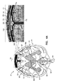
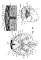
図2A〜2B 本発明の用途に応じて実施された動物実験の結果を示す、ラット脳の断面の概略図である。
図3 本発明の用途に応じて実施されたインビトロ実験の結果を示すグラフである。
図4A〜4G 本発明の用途に応じて実施された図1A〜1Cから図4のシステムの代替構成の概略図である。
1A-1C FIG. 1C is a schematic diagram of a system for treating Alzheimer's disease according to each use of the present invention.
2A-2B are schematic cross-sectional views of a rat brain showing the results of animal experiments carried out according to the uses of the present invention.
FIG. 3 is a graph showing the results of in vitro experiments carried out according to the uses of the present invention.
4A-4G FIG. 4A is a schematic diagram of an alternative configuration of the system of FIGS. 1A-1C to 4 implemented according to the application of the present invention.
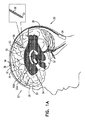
図1A〜1Cは、本発明のそれぞれの用途に応じて、アルツハイマー病及び/又は脳アミロイド血管障害(CAA)を治療するためのシステム20の概略図である。システム20は、脳実質電極30及び脳脊髄液(CSF)電極32と、通常は脳実質電極及びCSF電極のリード線36及び38によってそれぞれ脳実質電極30及びCSF電極32に電気的に結合された制御回路34とを含む。
1A-1C are schematic representations of a
本発明の幾つかの用途では、図1Aに示された2つの脳実質電極30について示されるように、脳実質電極30は、例えば深部脳刺激の電極用の埋め込みに使用されるものと類似する外科技術を用いて、アルツハイマー病、又はCAAの危険性があるか、又はこれに罹患していると認定された対象者の脳52の実質50に埋め込まれる。あるいは、脳実質電極30は、図1Aに示される中間の脳実質電極30について示されるように、例えば脳の外表面上の、またこれに接触する、対象者の脳の脳実質に電気的に接触する他の部位に埋め込まれる。CSF電極32は、脳52の脳室系54又はクモ膜下腔144(図4A〜4Gに表示される)(例えば、クモ膜下腔144の槽)などの、脳のCSF充填腔に埋め込まれる。例えば、CSF電極32は、然るべき変更を加えた上で、水頭症シャントを埋め込むための既知の技術を用いて埋め込まれ得る。特許請求の範囲を含む本出願で用いられる脳室系54は、側脳室55(左右側方脳室55A及び55B)、第3脳室56、第4脳室57、(図4A〜図4Gで表示される)中脳水道59、脳室間孔、第4脳室正中口、及び左右外側口を含み、かつこれらに限定される。
In some uses of the invention, as shown for the two
制御回路34が作動されて、脳実質電極30及びCSF電極32を駆動し、脳実質50から脳室系54などのCSF充填腔内に物質を排出する。幾つかの用途では、この物質は、アミロイドβ、金属イオン、タウタンパク質、及び/又は廃棄物を含む。特許請求の範囲を含む本出願で用いられる、脳実質からの物質の排出は、物質の全てを排出するのではなく、物質の一部を排出することを含むものとして理解されるべきである。一般的には、物質を排出するために、制御回路34は、脳実質電極30とCSF電極32との間に電圧又は電流を印加する(すなわち、制御回路34が電圧又は電流を調整する)。
The
一般的には、医師などの医療従事者は、制御回路34を作動して本明細書に記載される機能を提供する。制御ユニットを作動させることは、(例えば、別個のプログラマ又は外部コントローラの使用など)制御回路のパラメータ及び/又は機能を構成すること、又は制御ユニットを作動させて、制御回路に事前にプログラムされた機能を実施することを含み得る。制御回路34は、一般的には、本明細書に記載の制御回路の機能を提供するように構成された適切なメモリ、プロセッサ、及びハードウェア実施ソフトウェアを備えている。
Generally, a healthcare professional, such as a doctor, activates the
電流は一般に、脳実質電極30とCFS電極32との間に位置する組織を流れ得る。代替として、又は追加として、電流の少なくとも一部は、(a)脳実質電極30と(b)CSF充填腔の脳実質電極30に最も近い領域(例えば脳室系54)との間を流れ得る。発明者らは、脳室系54などのCSF充填腔における脳脊髄液(CSF)の電気抵抗が低いため、脳室はある程度まで電気的に単一の実体であると考えた。したがって、CSF電極32が脳実質電極30から離れた脳室に埋め込まれたとしても、電流の大部分は脳室系54の最も近い部分に流れる。例えば、図1Bに示すように、脳実質電極30Aが脳の右の半球52に埋め込まれると、CSF電極32が左脳室55Aに埋め込まれているとしても、電流の大部分は脳実質電極30Aと右脳室の脳実質電極30Aに最も近い領域との間を流れ得る。
The current can generally flow through the tissue located between the
幾つかの用途では、物質の粒子の表面と周囲の脳組織液との間の正又は負の電荷帯電界面により、電極間に印加された電圧が電気泳動的に物質を排出し得る。これらの用途では、電極間に印加された電圧は、脳実質50と脳室系54などのCSF充填腔の間の電位差を引き起こし、それによって、脳実質50から、脳室系54などのCSF充填腔への物質の移動を引き起こす。その代替として、又は追加として、幾つかの用途では、電極間に印加された電圧は、脳実質内の流体の正又は負の電荷のために、物質を電気浸透的に排出し得る。これらの用途では、電極間に印加される電圧は、脳実質50と脳室系54などのCSF充填腔の間の電位差を引き起こし、それによって、脳実質50から、脳室系54などのCSF充填腔への物質の移動を引き起こし、ひいては脳実質50から脳室系54などのCSF充填腔への物質の移送が増加する。
In some applications, the voltage applied between the electrodes can electrophoretically expel the material due to the positive or negative charge-charged interface between the surface of the particles of the material and the surrounding brain tissue fluid. In these applications, the voltage applied between the electrodes causes a potential difference between the
幾つかの用途では、システム20は、複数の脳実質電極30及び/又は複数のCSF電極32を備えている。脳実質電極30は、脳52の一方又は両方の半球に、及び/又は各々の半球の1つ又は複数の部位に埋め込まれ得る。図1A〜1Cに示されるような幾つかの用途では、システム20は複数の脳実質電極30と、正確に1つのCFS電極32とを備えている。例えば、単一のCSF電極32は、上述のように、かなりの程度まで他の脳室との電気的接続性が良好な側方脳室55又は第3の脳室56のうちの1つに埋め込まれ得る。他の用途(構成は図示せず)では、システム20は、(a)それぞれ左右側方脳室55A及び55Bに埋め込まれる正確に2つのCSF電極32、又は(b)それぞれ左右側方脳室55A及び55B及び第3の脳室56に埋め込まれる正確に3つのCSF電極32を備えている。
In some applications, the
システム20が複数の脳実質電極30及び/又は複数のCSF電極32を含む用途では、システム20は通常、対応する複数の脳実質電極リード線36及び/又は対応する複数のCSF電極リード線38を含む。各リード線は、別個の電気的絶縁を備え、かつ/又はリード線の一部は、図1A〜1Cに示すように、脳実質電極30のリード線に接合されて共通の電気絶縁を共有し得る。制御回路34は、例えば、別個の回路を使用して脳実質電極30を独立して駆動するように作動され得る。あるいは、脳実質電極30の1つ又は複数を互いに短絡させて、制御回路が短絡した電極を一緒に駆動するようにし得る。制御回路34は、脳実質電極30を同時に、又は別の時間に駆動するように作動され得る。
In applications where the
幾つかの用途では、脳実質電極30が埋め込まれる脳実質56は、脳の白質を含む。
In some applications, the
特許請求の範囲を含む本出願で用いられる「治療する(処置する/treat)」とは、既にアルツハイマー病及び/又はCAAと診断された対象者を(例えば、初期段階で診断された患者の疾患の進行を遅延、遅滞、又は反転させることなどによって)治療することと、疾患と診断されておらず、及び/又は無症候性の対象者のアルツハイマー病及び/又はCAAの発症を予防することの両方を含む。例えば、本明細書に記載の技術は、血液検査又は脊髄穿刺の使用などによる異常なレベルのアミロイドβの検出に応答して、アルツハイマー病及び/又はCAAの発症を予防又は遅延させるために使用され得る。 As used in this application, including the scope of the patent claim, "treat" refers to a subject who has already been diagnosed with Alzheimer's disease and / or CAA (eg, a disease of a patient diagnosed at an early stage). To treat (by delaying, delaying, or reversing the progression of the disease, etc.) and to prevent the development of Alzheimer's disease and / or CAA in undiagnosed and / or asymptomatic subjects. Includes both. For example, the techniques described herein have been used to prevent or delay the development of Alzheimer's disease and / or CAA in response to the detection of abnormal levels of amyloid β, such as by the use of blood tests or spinal cord punctures. obtain.
幾つかの用途では、制御回路34は、制御回路を含むハウジングが小さい場合は、対象者の頭蓋骨の皮下などの皮下に、又は制御回路のハウジングが(例えばバッテリを含むため)大きい場合は、上部胸部などの対象者の身体の他の場所に、頸部を通して、又は必要に応じて頭部内にリード線を配して埋め込まれるように構成される。これらの用途では、制御回路34は、一般的には、制御回路34と無線又は有線通信する外部コントローラによって駆動される。幾つかの用途では、外部コントローラは、対象者のベッドに取り付けられ(例えば、マットレス内に配置され)、夜間にのみ、及び/又は対象者が眠っているときにのみ、制御回路34を作動するように構成される。そのような夜間作動は、細胞外腔が覚醒時よりも広くなる睡眠中の物質(例えば、アミロイドβ又はタウタンパク質)排出の自然なタイミングをある程度模倣する場合があり、それによってより多くの間質液(ISF/interstitial fluid)が脳内を流れることが可能になる。他の用途では、制御回路34は対象者の外部に配置されるように適合される。
In some applications, the
幾つかの用途では、制御回路34が作動されて、脳実質電極30とCSF電極32間に非励起電流を印加することによって脳実質電極30及びCSF電極32を駆動し、物質を排出する。すなわち電流は活動電位の伝播を引き起こさない。したがって、これらの用途では、電流が神経活動に影響を与えないか、又は最小限にしか影響しないように電流のパラメータを設定するように制御回路34が作動される。あるいは、印加された電流は、脳組織をわずかに刺激する。
In some applications, the
幾つかの用途では、制御回路34が作動されて、脳実質電極30とCSF電極32との間に直流(DC)を印加することによって脳実質電極30及びCSF電極32を駆動し、物質を排出する。特許請求の範囲を含む本出願で用いられる直流は一定の極性を有する電流を意味する。直流の振幅は経時的に変化しても変化しなくてもよく、場合によってはゼロであってもよい。
In some applications, the
幾つかの用途では、制御回路34が作動されて、少なくとも1mA、5mA以下、及び/又は1〜5mAの平均振幅を有する直流を印加する。代替として、又は追加として、幾つかの用途では、制御回路34が作動されて、1.2V以下の平均振幅(このような振幅は電極の一方又は両方の近傍での電気分解を避け得る)を有する直流を印加する。
In some applications, the
物質がアミロイドβであるような幾つかの用途では、制御回路34が作動されて、脳実質電極30が陰極であり、CSF電極32が陽極であるように構成する。あるいは、制御回路34が作動されて、脳実質電極30が陽極であり、CSF電極32が陰極であるように構成する。電極間に印加された電圧が物質を電気泳動的に排出する用途の場合、電極の選択された極性は一般に、物質が正又は負の実効電荷を有するかどうかに依存する。同様に、電極間に印加された電圧が電気浸透的に物質を除去する用途では、電極の選択された極性は一般に、流体が正又は負の実効電荷(有効電荷/effective charge)を有するかどうかに依存する。
In some applications where the substance is amyloid β, the
幾つかの用途では、制御回路34が作動されて、一連のパルスとして直流を印加する。幾つかの用途では、一連のパルスは、(a)少なくとも10ミリ秒、100ミリ秒以下、及び/又は10ミリ秒と100ミリ秒の間(b)少なくとも100ミリ秒、300秒以下(例えば、500ミリ秒以下)、及び/又は100ミリ秒と300秒の間(例えば、100ミリ秒と500ミリ秒の間)、(c)少なくとも500ミリ秒、5秒以下、及び/又は500ミリ秒と5秒の間、(d)少なくとも5秒、10秒以下、及び/又は5秒と10秒の間、又は(e)少なくとも10秒、100秒以下、及び/又は10秒と100秒の間などの、少なくとも10ミリ秒、300秒以下、及び/又は10ミリ秒と300秒の間の平均パルス持続時間を有する。幾つかの用途では、パルスは、(a)少なくとも100Hz、1KHz以下、及び/又は100Hzと1KHzの間、(b)少なくとも20Hz、100Hz以下、及び/又は20Hzと100Hzの間、又は(c)少なくとも1Hz、10Hz以下、及び/又は1Hzから10Hzの間などの、少なくとも0.001Hz、1KHz以下、及び/又は0、001KHzと1KHzの間の周波数で印加される。代替として、又は追加として、幾つかの用途では、一連のパルスは、(a)少なくとも1%、5%以下、及び/又は1%と5%の間、(b)少なくとも5%、10%以下、及び/又は5%と10%の間、(c)少なくとも10%、25%以下、及び/又は10%と25%の間、又は(d)少なくとも25%、50%以下、及び/又は25%と50%の間などの、 少なくとも1%、50%以下、及び/又は1%と50%の間のデューティサイクルを有する。必ずしもそうとは限らないが、一般的には、組織内のキャパシタンスがパルス間で放電可能である場合には、所与レベルの印加電圧が組織内でより高い電流を生成するので、デューティサイクルは90%以下である。
In some applications, the
制御回路34が脳実質電極とCSF電極30、32との間に一連のDCパルスで電圧を印加する幾つかの用途では、結果として生じる電流は組織電解質の影響により減衰する。電流は、各パルスの印加開始後の数十ミリ秒以内に、その初期の大きさの約3分の2だけ減衰し得る。この静電容量効果を克服するために、パルス間の期間(この期間の間にキャパシタンスが放電する)を提供するために断続的に電圧を印加するように制御回路34が作動される。
In some applications where the
幾つかの用途では、制御回路34が作動されて、予めプログラムされた周波数及び/又はデューティサイクルで間欠的に電圧を印加する。これらのパラメータは、(a)全患者又は患者サブグループに適用可能であり、(b)電極が埋め込まれると較正手順の間に設定され、又は(c)脳実質電極30及び/又はCSF電極32の配置の幾何学的形状に基づいて設定され得る。あるいは、制御回路34は、印加電圧から生じる電流を検出することによって、これらのパラメータをリアルタイムで設定するように構成される。
In some applications, the
幾つかの用途では、制御回路34が作動されて、印加された各々のパルスの間に印加電圧から生じる電流を測定し、測定された電流の大きさが閾値を下回ったときに印加された各々のパルスを終了させる。例えば、閾値は、予めプログラムされた定数であってもよく、又はそれぞれのパルスの開始時に測定される初期電流の大きさ(例えば、そのパーセンテージ)に基づく値でもよい。制御回路34は放電期間中待機してから次のパルスを印加する。
In some applications, the
幾つかの用途では、制御回路34が作動されて、脳実質電極30とCSF電極32との間に、
・一次電圧で、また一次平均パルス持続時間に物質を電気泳動的に及び/又は電気浸透的に排出するように選択された一次極性のパルスの一次サブセットの交流(AC)、及び、
・1次電圧未満の2次電圧で、また1次平均パルス持続時間より長い二次平均パルス持続時間に一次極性とは反対の二次極性のパルスの二次サブセットの交流を印加する。
In some applications, the
Alternating current (AC), a primary subset of primary polar pulses selected to electrophoretically and / or electroosmotically eject material at the primary voltage and at the primary average pulse duration, and
• Apply alternating current of a secondary subset of pulses of secondary polarity opposite to the primary polarity to a secondary voltage less than the primary voltage and to a secondary average pulse duration longer than the primary average pulse duration.
二次電圧が低いため、パルスの二次サブセットは、パルスの一次サブセットの印加中に達成される物質の排出を大幅には逆転させない。この技術はまた、一次電圧が、そうでなければ電気分解を引き起こす可能性がある閾値DC電圧(例えば、1.2V)よりも高い場合であっても、電極の一方又は両方の近傍での電気分解を回避するのに役立ち得る。 Due to the low secondary voltage, the secondary subset of pulses does not significantly reverse the material emissions achieved during application of the primary subset of pulses. This technique also provides electricity in the vicinity of one or both of the electrodes, even if the primary voltage is higher than the threshold DC voltage (eg, 1.2V) that would otherwise cause electrolysis. Can help avoid disassembly.
図1Cに示されるような幾つかの用途では、脳実質電極30を蓄積領域に埋め込むのではなく、脳実質電極30及びCSF電極32は、脳内脳実質50内の物質の1つ又は複数の蓄積領域64が電極の間にあるように埋め込まれる。例えば、蓄積領域(1つ又は複数)は、アミロイドプラーク及び/又はタウタンパク質関連の神経組織のもつれを含み得る。この目的のために、一般的には、例えばMRI(例えば、機能的MRI(FMRI))又は脳52のPETイメージングなどの脳52のイメージングを行うことによって、蓄積領域が最初に特定される。上述のように、物質の蓄積領域64が2つ以上存在する場合のように、脳実質電極30及び/又は複数のCSF電極32を埋め込まれ得る。
In some applications, as shown in FIG. 1C, instead of implanting the
図1Cにも示されるような幾つかの用途では、1つ又は複数の蓄積64の領域が脳実質電極30Aと、蓄積64の最も近い領域である脳室系54などのCSF充填腔のそれぞれの領域80との間にあるように、1つ又は複数の脳実質電極が埋め込まれる。CSF電極32は、領域80の近くに埋め込まれてもよく、近くに埋め込まれなくてもよい。領域80の近くにCSF電極32が埋め込まれない用途では、最も近い領域8が、上述のように脳室系54などのCSF充填腔のCSFを介してCSF電極32と流体連通しているため蓄積64の領域の物質は依然として、脳室系54などのCSF充填腔の最も近い領域80に駆動され得る。上述のように、1つ以上の物質蓄積領域64が存在する場合に、より一般的には、物質のより良好な排出を提供するために、複数の脳実質電極30及び/又は複数のCSF電極32が埋め込まれ得る。
In some applications, as also shown in FIG. 1C, one or more regions of the accumulation 64 are the cerebral
幾つかの用途では、脳実質電極30は更に、当技術分野で周知のような深部脳刺激を適用するために使用される。例えば、深部脳刺激は、脳室系などのCSF充填腔に物質を運ぶために電極が駆動されていない場合に適用され得る。当技術分野で周知のように、深部脳刺激は、パーキンソン病などの運動障害のある患者の振戦を減少させ、不随意運動をブロックするため、又はてんかん、クラスター頭痛、トゥレット症候群、慢性疼痛又は大鬱病を治療するために適用され得る。脳実質電極30の埋め込み位置は、特定の状態の治療並びに物質の排出に適するように選択され得る。
In some applications, the
幾つかの用途では、セッションで脳実質電極32及びCSF電極32を駆動するように制御回路34が作動され、各セッションの持続時間は、数秒又は数分である、又はより長い期間(例えば、30分)連続する。幾つかの用途では、電極は少なくとも1時間の期間は駆動されない。必要ならば、細胞外腔の広がりを利用するように、及び/又は駆動に関連する何らかの感覚を抑制するために、対象者が眠っているときにのみ電極を駆動するように制御回路34が作動される。例えば、制御回路34は、睡眠を検知するために、1つ又は複数の電極をEEG電極として使用するように作動され得る。幾つかの用途では、制御回路34を作動及び/又は充電するための電力は、帽子などの頭部に装着される機器内の無線エネルギ送信機から、又は上述したようなマットレスの中、下、又は上の無線エネルギ送信機から送信される。幾つかの用途では、制御回路34が作動されて、1日に数時間などのデューティサイクルなど、予め選択されたスケジュールに従って電極を駆動する。例えば、制御回路34は、対象者のベッドの中及び/又はその近傍に配置された無線送信機を含む制御回路などの体外制御回路によって制御及び/又は給電されるように構成され得る。幾つかの用途では、制御回路が電極を駆動しない1つ又は複数の休止期間が予め選択されたスケジュールに設けられる。
In some applications, the
明細書に記載されるどの用途でも、CSF電極32は、脳室系54ではなく、以下の部位のうちの1つに埋め込まれ得る:
・(脳室系54と流体連通する)脊髄の中心管、又は、
・(CSFは脳室系54の孔を経てクモ膜下腔144の槽に排出するため、脳室系54と流体連通する)(図4Aから図Gに標示されている)クモ膜下腔144。
For any application described herein, the
The central canal of the spinal cord (which communicates fluidly with the ventricular system 54) or
(Since CSF is discharged into the tank of the
幾つかの用途では、CSF電極32を脳室系54に埋め込む代わりに、電極は上矢状洞142に埋め込まれる(図4Aから図4Gに標示)。
In some applications, instead of implanting the
本明細書に記載されているどの用途でも、脳実質電極30は、脳の脳実質組織50ではなく上矢状洞142に埋め込まれ得る(一般的には、これらの用途では、CSF電極32は脳室系54に埋め込まれる)。
In any of the applications described herein, the
再び図1A〜1Cを参照する。幾つかの用途では、制御回路34は、脳実質50とCSF充填腔間の電圧差を検出し、検出された電圧差に応じて脳実質電極30と脳脊髄液(CSF)と電極32間に印加される電圧のレベルを設定するように構成される。
Refer to FIGS. 1A to 1C again. In some applications, the
次に、本発明の適用に従い実施された動物実験の結果を示す、ラット脳の断面の概略図である図2A〜Bを参照する。ラットが麻酔され、第1の電極130(小型コネクタにはんだ付けされたPT−Irワイヤ)が穴から矢状洞に挿入され、第2の電極132(小型電子コネクタにはんだ付けされたPT−Irワイヤ)が硬膜の穴から右脳室に挿入された。 Next, reference is made to FIGS. 2A to 2B which are schematic views of a cross section of a rat brain showing the results of animal experiments carried out according to the application of the present invention. The rat was anesthetized, the first electrode 130 (PT-Ir wire soldered to the small connector) was inserted through the hole into the sagittal sinus, and the second electrode 132 (PT-Ir soldered to the small electronic connector). A wire) was inserted into the right ventricle through a hole in the dural membrane.
図2Aに示されるように、ブロモフェノールブルー染料が、指定の座標120及び122でラット脳の両半球に定位的に送達された。拡散コントロール(対比例)として左半球を使用することにより、この実験装置は同じ動物内での一対比較を可能にし、それによって脳内での色素の方向性のある運動に影響する可能性のある他の作用を排除する。
As shown in FIG. 2A, the bromophenol blue dye was stereotactically delivered to both hemispheres of the rat brain at designated
制御回路は、ブロモフェノールブルー染料が実効的に(負帯電性)アニオン性分子を含むため、第1の電極130を陰極として構成し、第2の電極132を陽極として構成して、第1の電極120と第2の電極132間に右半球のみに一定極性(DC)電流を印加するように制御回路が作動された。電流は、(a)電流が1〜2mAの大きさで5分間連続して印加される第1のモードと、(b)電流が1〜2mAの大きさで、1秒当たり1パルス(すなわち、1Hzのパルス周波数)で10m秒持続するパルスで印加される第2のモードとを反復的に交代して印加された。
In the control circuit, since the bromophenol blue dye effectively contains (negatively charged) anionic molecules, the
図2Bは、電流を右半球に印加した後のブロモフェノールブルー色素の変位を示す。図から分かるように、左半球のブロムフェノール青色染料は、分散が最小であり、方向性のある変位を生じなかった。対照的に、右半球では、印加電流はブロムフェノール青色染料を側脳室に向かって移動させた。この色素は平均速度0.28±0.006mm/分で移動し、これは左半球で観察された拡散速度の14倍以上であった。右半球では、色素プロファイル中心の線形変位は約1.9±0.08mmであり、色素プロファイルの前面は注入点の中心から最大で約2.81±0.07mmの距離に達した。 FIG. 2B shows the displacement of the bromophenol blue dye after applying an electric current to the right hemisphere. As can be seen from the figure, the bromphenol blue dye in the left hemisphere had minimal dispersion and did not cause directional displacement. In contrast, in the right hemisphere, the applied current moved the bromphenol blue dye towards the lateral ventricles. The dye traveled at an average rate of 0.28 ± 0.006 mm / min, which was more than 14 times the diffusion rate observed in the left hemisphere. In the right hemisphere, the linear displacement of the dye profile center was about 1.9 ± 0.08 mm, and the anterior surface of the dye profile reached a maximum distance of about 2.81 ± 0.07 mm from the center of the injection point.
この実験の結果は、脳内に埋め込まれた2つの電極を使用してDC電流を印加することによって、色素の分子が脳組織内で移動可能であり、そのような場合は、自然な移動経路が脳室に向かうことを示した。発明者らは、電極間に電流を印加することにより、色素を電気泳動的に移動させることができると確信する。発明者らはまた、実験中に収集されたデータに基づいて、脳実質界面の抵抗が脳実質内で測定された抵抗よりも2倍大きいと計算されたため、第1の電極を上矢状洞ではなく脳実質に直接的に埋め込むことにより、分子の電流駆動運動を更に良好にすることができると確信する。 The results of this experiment show that by applying a DC current using two electrodes embedded in the brain, dye molecules can move within the brain tissue, in which case a natural migration pathway. Showed that he was heading to the ventricles. The inventors are convinced that the dye can be moved electrophoretically by applying an electric current between the electrodes. The inventors also calculated that the resistance at the brain parenchymal interface was twice as high as the resistance measured within the brain parenchyma, based on the data collected during the experiment, so the first electrode was placed in the upper sagittal sinus. We are convinced that the current-driven movement of the molecule can be further improved by implanting it directly into the brain parenchyma rather than.
アミロイドβの運動性及び方向性評価
ここで、本発明の適用に従い実施されたインビトロ実験の結果を示すグラフである図3を参照する。この実験は、直流(DC)の印加が、(リン酸緩衝液(PBS)を含む)人工脳脊髄液(aCSF)溶液からアミロイドβペプチドを除去する程度を評価した。Pt−Ir電極がaCSF溶液充填区画に挿入された。フルオロフォア標識アミロイドβペプチドを3つの異なる希釈レベル(2:500,5:500及び10:500)で溶解した。3つの異なる持続時間(5、10、及び15分)の一定DC電流が、1.5Vのアルカリ電池から、フルオロフォア標識アミロイドβペプチドを含むaCSF溶液に印加された。電気泳動を受けるアミロイドβの方向性、及び総合的能力が、各電極の蛍光濃度解析によって評価された。
Motility and Directional Evaluation of Amyloid β Here, refer to FIG. 3, which is a graph showing the results of in vitro experiments performed according to the application of the present invention. This experiment evaluated the extent to which DC (DC) application removed amyloid β peptide from artificial cerebrospinal fluid (aCSF) solution (including phosphate buffer (PBS)). A Pt-Ir electrode was inserted into the aCSF solution filling compartment. Fluorophore-labeled amyloid β peptide was dissolved at three different dilution levels (2: 500, 5: 500 and 10: 500). Constant DC currents of three different durations (5, 10, and 15 minutes) were applied from a 1.5 V alkaline battery to the aCSF solution containing the fluorophore-labeled amyloid β peptide. The directionality and overall ability of amyloid β to undergo electrophoresis were evaluated by fluorescence concentration analysis of each electrode.
両方の電極で蛍光強度が測定され、蛍光強度比をとって、負に帯電した電極(陰極)に対して正に帯電した電極(陽極)で蛍光強度が正規化された。全ての測定値からデータが平均され、これは図3に平均値及び標準誤差として示されている。 The fluorescence intensity was measured at both electrodes, the fluorescence intensity ratio was taken, and the fluorescence intensity was normalized at the electrode (anode) positively charged with respect to the negatively charged electrode (cathode). Data are averaged from all measurements, which are shown in FIG. 3 as averages and standard errors.
図3から分かるように、正の電荷を帯びた電極(陽極)(2:500の希釈レベル)の近傍で、電流−持続時間−依存性の蛍光増強が観察された。陽極と陰極との間の蛍光の差は電流‐持続時間依存の解析にとって統計的に有意であった(片側T検定:P<10Λ−15;t=12.17)。電流持続時間に依存する正に荷電した電極上の蛍光増強の傾向はまた、15分間の電流印加と5分間及び10分間の電流印加を対比して統計的に有意であった(一方向ANOVA:P<0.001、F=8.92;Holm−Sidakポストホック解析:非特異的結合により、15分間と5分間を対比してP=0.01、T=3.37、及び15分間と10分間を対比してT=3.889)。全ての濃度において、対陰極での陽極へのアミロイドβの有意な誘引性が認められた。 As can be seen in FIG. 3, a current-duration-dependent fluorescence enhancement was observed in the vicinity of the positively charged electrode (anode) (dilution level of 2:500). The difference in fluorescence between the anode and the cathode was statistically significant for current-duration-dependent analysis (one-sided T-test: P <10 Λ- 15; t = 12.17). The tendency of fluorescence enhancement on positively charged electrodes, which depends on current duration, was also statistically significant in contrast to 15 minutes of current application and 5 and 10 minutes of current application (one-way ANOVA: P <0.001, F = 8.92; Holm-Sidak post-hook analysis: by non-specific binding, P = 0.01, T = 3.37, and 15 minutes contrasting 15 and 5 minutes. Compare 10 minutes with T = 3.889). Significant attraction of amyloid β to the anode at the anti-cathode was observed at all concentrations.
これらの実験結果は、可溶性の単量体アミロイドβが負の構造でaCSF中で負に荷電され、アミロイドβに負電荷を与えるために両親媒性の界面活性剤を添加する必要なく電界内を移動することができることを実証している。 These experimental results show that soluble monomeric amyloid β is negatively charged in aCSF with a negative structure and does not require the addition of an amphipathic surfactant to give the amyloid β a negative charge in the electric field. It demonstrates that it can move.
野生型マウス脳実質におけるアミロイドβの電気泳動移動度の評価
本発明の用途に応じて動物実験が実施された。20匹の生後3ヶ月の野生型マウスに麻酔し、可溶性フルオロフォア標識アミロイドβ(1−42)、HiLyte(登録商標)フルオル488標識ヒト(AnaSpec、USA)が脳実質に注入された(AP=−2、ML=0.84、DV=1.2)。脳実質に第1のPT−IR電極を埋め込み(AP=−2.8、ML=0.84、DV=1.5)、第2のPT−IR電極を側脳室に埋め込んだ(AP=−0.5、ML=0.84、DV=1.6)。電極間の電流によって生成された電界が、アミロイドβの注入焦点を覆った。電流印加は、単一パルスの繰り返しによって行われた。以下のパラメータが使用された:電圧:70V;周波数:1Hz。電流印加プロトコルは以下の通りである:(a)1ミリ秒のパルス持続時間で15分間;(b)10ミリ秒のパルス持続時間で15分間;(c)100ミリ秒のパルス持続時間で15分間。周波数は一定に保たれたが、デューティサイクルは増加された。
Evaluation of Electrophoretic Mobility of Amyloid β in Wild-Type Mouse Brain Parenchyma Animal experiments were performed according to the uses of the present invention. Twenty 3-month-old wild-type mice were anesthetized and soluble fluorophore-labeled amyloid β (1-42), HiLite® Fluol 488-labeled human (AnaSpec, USA) were injected into the brain parenchyma (AP =). -2, ML = 0.84, DV = 1.2). The first PT-IR electrode was implanted in the brain parenchyma (AP = -2.8, ML = 0.84, DV = 1.5), and the second PT-IR electrode was implanted in the lateral ventricle (AP = -0.5, ML = 0.84, DV = 1.6). The electric field generated by the current between the electrodes covered the injection focus of amyloid β. The current application was performed by repeating a single pulse. The following parameters were used: voltage: 70V; frequency: 1Hz. The current application protocol is as follows: (a) 1 ms pulse duration for 15 minutes; (b) 10 ms pulse duration for 15 minutes; (c) 100 ms pulse duration for 15 minutes. Minutes. The frequency was kept constant, but the duty cycle was increased.
電界中のアミロイドβペプチドの痕跡を視覚化するために、6E10の1−16アミノ酸ストリップ(カタログ番号SIG−39320)に対して向けられた抗体を使用することにより、電界におけるアミロイドβ運動方向性の評価が行われた。DAPI染色により、組織構造及び細胞核が可視化された。アミロイドβ運動軌道が異なる倍率(4倍及び10倍)で評価された。矢状切片が細胞核(青色)及びアミロイドΒ(6E10、緑色)に対する抗体で染色され、蛍光顕微鏡で画像化された。 To visualize the traces of amyloid β peptide in the electric field, by using an antibody directed against the 1-16 amino acid strip of 6E10 (Catalog No. SIG-39320), the direction of amyloid β motion in the electric field Evaluation was done. Tissue structure and cell nuclei were visualized by DAPI staining. Amyloid β motion orbits were evaluated at different magnifications (4x and 10x). Sachets were stained with antibodies against cell nuclei (blue) and amyloid Β (6E10, green) and imaged under a fluorescence microscope.
アミロイドβ運動は、電流が印加されたマウスの脳内で視覚化された。側脳室内に挿入された電極は正に帯電されており、図3を参照して上で説明したインビトロ実験と同様に、印加電流はアミロイドβ運動を誘導することができた。 Amyloid β motility was visualized in the brain of energized mice. The electrodes inserted into the lateral ventricles were positively charged, and the applied current was able to induce amyloid β motility, similar to the in vitro experiment described above with reference to FIG.
これらの実験結果は、アミロイドβペプチドの電気泳動運動が実験で用いられた電流印加プロトコルを用いて脳実質内で可能であることを実証している。アミロイドβペプチドの運動方向性は、図3を参照して上に記載したインビトロ実験で観察されたものと同様であった。 These experimental results demonstrate that the electrophoretic movement of amyloid β peptide is possible within the brain parenchyma using the current application protocol used in the experiment. The kinetic orientation of the amyloid β peptide was similar to that observed in the in vitro experiments described above with reference to FIG.
本発明のそれぞれの用途に応じた、システム20の代替構成の概略図である図4A〜4Gを参照する。これらの図は、脳52の前面図を示す。これらの用途において、システム20は、物質(例えば、アミロイドβ、金属イオン、タウタンパク質、及び/又は廃棄物質)を脳実質50からCSF充填腔内に排出することに加えて、CSF充填腔(例えば、クモ膜下腔144)から上矢状洞142に物質を排出するように構成される。これらの技術は、上記の技術のいずれかと組み合わせて使用され得る。これらの技術の幾つかでは、制御回路34は、処置電流を直流として印加するように構成される。
See FIGS. 4A-4G, which are schematic views of alternative configurations of the
図4A〜4Gを参照して説明した幾つかの用途では、制御回路34は、(a)脳実質部50からCSF充填腔への物質の排出、及び(b)CSF充填腔から上矢状洞142への物質の排出の両方のために、電極を同時に駆動するように構成される。例えば、制御回路34は、後述する脳実質電極30、CSF電極32、及び中間面処置電極150に異なるそれぞれの電圧を印加するように構成され得る。例えば、制御回路34は、脳実質電極30、CSF電極32、及び中間面処置電極150にそれぞれ第1、第2及び第3の電圧を印加するように構成され、第3の電極は第2の電圧よりも正であり、第2の電圧は第1の電圧よりも正である。第1の電圧と第3の電圧間の電位差は、電極の一方又は両方の近傍での電気分解を避けるため、一般的には1.2Vより大きくない。
In some applications described with reference to FIGS. 4A-4G, the
図4A〜4Gを参照して説明した他の用途では、制御回路34は、(a)脳実質50からの物質をCSF充填腔内に排出するために、複数の第1の期間中に脳実質電極30及びCSF電極32を駆動し、(b)CSF充填腔から物質を上矢状洞内に排出するために、通常は第1の期間と重ならない複数の第2の期間中に、中間面処置電極150及びCSF電極32又は(後述の)別の電極を駆動するなど、電極のセットを交互に駆動するように構成される。
In other applications described with reference to FIGS. 4A-4G, the control circuit 34 (a) brain parenchyma during a plurality of first periods to expel material from the
図4A〜4Gを参照して説明される幾つかの用途では、制御回路34は、流体をCSF充填腔(例えば、クモ膜下腔144)から上矢状洞142へと電気浸透的に駆動することによって、物質を上矢状洞142に排出するように構成される。幾つかの用途では、制御回路34は、中間面処置電極150を陰極として、またCSF電極32を陽極として構成することによって、流体を脳のCSF充填腔から上矢状洞142へと駆動するように構成される。
In some applications described with reference to FIGS. 4A-4G, the
図4A〜4Gを参照して説明される幾つかの用途では、制御回路34は、物質をCFS充填腔(例えばクモ膜下腔144)から上矢状洞へと電気泳動的に駆動することによって物質を排出するように構成される。幾つかの用途では、処置電流の印加はCSF充填腔と上矢状洞142の電位差を引き起こし、これがCSF充填腔から上矢状洞142への物質の移動を引き起こす。
In some applications described with reference to FIGS. 4A-4G, the
図4Aに示されるような幾つかの用途では、脳実質電極30は脳実質50に埋め込まれ、CSF電極32はCSF充填腔、例えば脳室系54又はクモ膜下腔144に埋め込まれる。中間面処置電極150は、(a)(図4Aに示されるように)上矢状洞142内、又は(b)上矢状洞142の上方(図4Aには示されていないが、図4B〜4Gに示される構成)のいずれかに配置される。第2のCSF電極152は、脳室系54(図4Aには示されていない構成)又は(図4Aに示されるような)クモ膜下腔144などのCSF充填腔に埋め込まれる。制御回路34が作動されて、(a)脳実質電極30とCSF電極32との間に第1の電圧を印加して物質を脳実質50からCSF充填腔へと排出し、(b)中間面処置電極150と第2のCSF電極152との間に第2の電圧を印加して物質をCSF充填腔から上矢状洞142へと排出する。この技術は、然るべき変更を加えた上で、4B〜4G図を参照して以下に記載される技術と組み合わせて使用され得る。
In some applications, as shown in FIG. 4A, the cerebral
あるいは、図4Bに示されるような幾つかの用途では、脳実質電極30は脳実質50に埋め込まれ、CSF電極32は、脳室系54又はクモ膜下腔144などのCSF充填洞に埋め込まれる。中間面処置電極150は、(a)(図4Aに示されるように)上矢状洞142内に、又は(図4B〜4Gに示されるように)上矢状洞142の上方に埋め込まれる。制御回路34が起動されて、(a)脳実質電極30とCSF電極32との間に第1の電圧を印加して、物質を脳実質50からCSF充填腔へと排出し、また(b)CSF電極32と中間面処置電極150との間に第2の電圧を印加して、物質をCSF充填腔から上矢状洞142へと排出する。
Alternatively, in some applications as shown in FIG. 4B, the cerebral
図4B〜4Cに示されるような幾つかの用途では、中間面処置電極150は、上矢状洞142の上方に配置されるようにされる。これらの用途の幾つかでは、中間面処置電極150は、例えば(硬膜の下の、又は硬膜の外面と接触する)上矢状洞142の外面と接触して、対象者の頭部174の頭蓋骨168の下に配置される。これらの用途の他の例では、中間面処置電極150は、頭蓋骨168の外部で頭蓋骨168と電気的に接触するように配置される。特許請求の範囲を含む本出願で使用される「上矢状洞の上方」という用語は、上矢状洞よりも浅い位置で、すなわち頭部の中心からより遠い位置で上矢状洞と位置合わせされることを意味する。図4B及び4Cに示される構成では、制御回路34は、中間面処置電極150とCSF電極32との間に処置電流を印加することによって、物質をCSF充填腔から上矢状洞142に排出するように構成される。あるいは、図4B及び図4Cに示される中間面処置電極150の配置は、図4Aを参照して上述した構成と組み合わせて使用される。
In some applications, as shown in FIGS. 4B-4C, the intermediate
図4Dに示されるような幾つかの用途では、システム20は、少なくとも5個、20個以下、及び/又は5個から20個の中間面処置電極150などの複数の中間面処置電極150を備えている。中間面処置電極は、(a)上矢状洞142内(図4Dには示されていないが、図4Aに示されている構成)、又は(b)(図4D又は図4Bに示されるように)上矢状洞142の上方に配置される。
In some applications as shown in FIG. 4D, the
これらに限定されるものではないが、図4A〜4Gを参照して本明細書に記載されたどの用途でも、CSF電極32は、頭蓋骨168の中間矢状面164から1cm〜12cm位置に配置され得る。幾つかの用途では、方法は、CSF電極32を頭蓋骨168の中間矢状面164から1cm〜12cmの位置に埋め込むステップを含み得る。
For any application described herein with reference to FIGS. 4A-4G, but not limited to these, the
これらに限定されるものではないが、図4A〜4Gを参照して本明細書に記載されたどの用途でも、CSF充填腔はクモ膜下腔144であってよく、CSF電極32は、クモ膜下腔144に埋め込まれるように構成されたクモ膜下電極であってよく、制御回路34は、物質をクモ膜下腔144から上矢状洞142へと排出するように構成され得る。
For any application described herein with reference to FIGS. 4A-4G, the CSF filling space may be the
図4Eから図4Gに示されるような幾つかの用途では、システム20は、(a)頭骨洞142の外部で頭蓋骨168と電気的に接触するように上矢状洞142の上方に配置された中間面処置電極150と、(b)頭蓋骨168の中間矢状面164から1〜12cmの距離に配置されるように適合された側方処置電極162とを備えている(距離は、頭蓋骨の湾曲に沿ってではなく、各処置電極の最も近い部分から中間矢状面164まで直線で測定されている)。制御回路34は、1つ又は複数の処置電流を(a)1つ又は複数の中間面処置電極150と(b)1つ又は複数の側方処置電極162間に印加することによって、物質をクモ膜下腔144から上矢状洞142へと排出するように構成される(各々の処置電流は図中の複数の電流線190によって概略的に示されている)。
In some applications, as shown in FIGS. 4E-4G, the
幾つかの用途では、システム20は、5個から20個の側方処置電極162、又は10個から40個の側方処置電極など、少なくとも5個、40個以下、及び/又は20個の側方処置電極162を備えている。幾つかの用途では、各タイプの処置電極の数は、対象者の頭部174のサイズに基づいて決定される。幾つかの用途では、システム20は、中間面処置電極150の2倍の側方処置電極162を備えている。
In some applications, the
幾つかの用途では、中間面処置電極150及び側部処置電極162を使用して印加される1つ又は複数の処置電流は、上矢状洞142の下外側面170を経てクモ膜下腔144と上矢状洞142との間を通過する。これらの用途の幾つかでは、処置電流の少なくとも40%、例えば少なくとも75%又は少なくとも90%が、上矢状洞142の下外側面170を経てクモ膜下腔144と上矢状洞142との間を通過する。直前に説明した用途では、中間面処置電極150及び/又は側部処置電極162の位置は、一般的には、1つ又は複数の処置電流が下外側面170を通過するように選択される。例えば、図4C〜4Gを参照して説明したように、側方処置電極162が頭蓋骨168の外側に、頭蓋骨168と電気的に接触して配置される構成では、側方処置電極162は、頭蓋骨168の中間矢状面164から少なくとも4cm、12cm以下、及び/又は4〜12cmの距離に配置され得る。図4Cから4Gを参照して説明されるように、側方処置電極162が対象者のクモ膜172の下に埋め込まれる構成の場合には、側方処置電極162は、頭蓋骨168の中間矢状面164の少なくとも1cm、3cm以下、及び/又は1〜3cmの位置に配置され得る。
In some applications, one or more treatment currents applied using the intermediate
幾つかの用途では、少なくとも5個の中間面処置電極162が上矢状洞142の上方に配置される。代替として、又は追加として、幾つかの用途では、少なくとも5個の側方処置電極162が、頭蓋骨の中間矢状面中間面164から1cm〜12cmの位置に配置される。幾つかの用途では、各々の側方処置電極162は、中間面処置電極150の少なくとも1個から1cm〜12cmの位置に配置される。
In some applications, at least five intermediate surface treatment electrodes 162 are located above the superior sagittal sinus 142. Alternatively or additionally, in some applications, at least five lateral treatment electrodes 162 are located 1 cm to 12 cm from the intermediate
幾つか用途では、中間面処置電極150は、頭蓋骨168の中間矢状面164から10mm内に配置される。代替として、又は追加として、幾つかの用途では、中間面処置電極150は、中間面処置電極150の少なくとも1個が別の中間面処置電極150から少なくとも5mm、別の中間面処置電極150から20mm以下、及び/又は別の中間面処置電極150から5mm〜150mmであるように配置される。幾つかの用途では、側方処置電極162は、側方処置電極162の別の1個から少なくとも5mmに配置される。
In some applications, the intermediate
図4Eに示されるような幾つかの用途では、中間面処置電極150は頭部174の皮膚176の下に埋め込まれる。図4Fに示されるような他の用途では、中間面処置電極150は、頭部174の外面178上などの頭部174の外側に配置される。
In some applications, as shown in FIG. 4E, the intermediate
幾つかの用途では、システム20は、中間面リード線180を更に備え、これに沿って中間面処置電極150が配置(例えば、固定)される。中間面リード線180は、上矢状洞142の上方に中間面処置電極150を配置するように、頭蓋骨168の外側に配置される。中間面処置電極150が皮膚176の下に埋め込まれる幾つかの用途では、埋め込みは、一般的には頭部の後部部位にある皮膚176を切開し、頭部の前部に向かって、前額の近くに中間面のリード線をトンネリングすることによって実施される。必要があれば、各々の中間面処置電極150は、皮膚176内のそれぞれの切開によって挿入され、中間面のリード線180に接続される。
In some applications, the
図4E〜4Fに示されるような幾つかの用途では、側方処置電極162は、頭蓋骨168の外部に、頭蓋骨168と電気的に接触して配置される。これらの用途の幾つかでは、例えば図4Eに示されるように、側方処置電極162は、頭部174の皮膚176に埋め込まれる。あるいは、図4Fに示されるように、側方処置電極162は、頭部174の外側表面178などの頭部174の外側に配置される。これらの用途の幾つかでは、側方処置電極162は、頭蓋骨168の中間矢状面164から少なくとも4cm、12cm以下、及び/又は4〜12cmmの位置に配置され得る。(特許請求の範囲を含む本出願では、指定された範囲は全てそれらの端点を含む)そのような位置決めは、上述のように、上矢状洞142の下外側170を経てクモ膜下腔144と上矢状洞142間を通過する1つ又は複数の処置電流を生成し得る。
In some applications, as shown in FIGS. 4E-4F, the lateral treatment electrode 162 is located outside the
幾つかの用途では、システム20は側方リード182を更に含み、側方処置電極162がそれに沿って配置(例えば、固定)される。側方の処置電極162を配置するために、側方のリード線182は、頭蓋骨168の外側、一般的には頭蓋骨168の中間矢状面164から1cm〜12cmの範囲内に配置される。側方処置電極162が皮膚176の下に埋め込まれる幾つかの用途では、埋め込みは、一般的には頭部の後部部位にある皮膚176を切開し、前頭部の近傍などの頭部の前部に向かって、側方のリード線をトンネリングすることによって実施される。必要に応じて、各々の側方処置電極162は、皮膚176内のそれぞれの切開によって挿入され、中間面のリード線182に接続される。幾つかの用途では、側方リード182を設ける代わりに、側方処置電極162が中間面リード線180に結合される。中間面リード線180は、側方電極が拘束された(折り畳んだ)状態で導入され、側方電極は、解放されると一般的には自動的に、側方に延びるように構成される。この構成は、以下に説明するように、左右の両方の側方電極が設けられている用途にも使用され得る。
In some applications, the
幾つかの用途では、それぞれの対の中間面処置電極150と側方処置電極162との間に処置電流を別個に印加するように制御回路34が作動される。このような別個の電流の印加は、(例えば、解剖学的変化により)低い抵抗が対の一方の電極間に生じるべきときでも、システム20の継続的な実効的動作を可能にする。これらの用途の幾つかでは、このような別個の電流印加を可能にするために、中間面リード180は、中間面処置電極150の数に対応する複数の導電性ワイヤを含み、中間面リード182は、側方処置電極162の数に対応する複数の導電性ワイヤを含む。あるいは、制御回路34及び電極は、周知のような電気的多重化を実施し、この場合、各々のリードは、単一の導電性ワイヤのみを含むだけでよい。あるいは、幾つかの用途では、中間面処置電極150の全てが(例えば中間面のリード線内の単一の導電性ワイヤによって)互いに電気的に結合され、側方処置電極162の全てが(例えば側方リード線によって)互いに電気的に結合される)。
In some applications, the
図4Fに示す構成の幾つかの用途では、システム20は、中間面電極と側方電極間の適切な離間と位置合わせとを行うために、側方リード182を中間面リード180に結合する1つ又は複数の細長い支持要素184を更に含む。支持要素184は、一般的には非導電性である。
In some applications of the configuration shown in FIG. 4F, the
図4A〜4Gを参照して説明した幾つかの用途では、制御回路34は、平均振幅が1〜3ミリアンペアの1つ又は複数の処置電流を印加するように構成される。(結果として得られる電圧は、図4E〜4Fに示される構成では、1つ又は複数の処置電流が頭蓋骨168を2回通過するため、一般的には図4Gに示される構成での電圧よりも高い。)
In some applications described with reference to FIGS. 4A-4G, the
図4A〜4Gを参照して説明した幾つかの用途では、参照すると、制御回路34が作動されて、1つ又は複数の処置電流を直流として、一般的には、例えば500Hz超及び/又は2KHz未満、例えば1KHzで、複数のパルスとして印加する。幾つかの用途では、パルスのデューティサイクルは90%超であり、用途によってはパルスが使用されず、代わりに100%の実効デューティサイクルが利用される。組織内のキャパシタンスがパルス間で放電可能である場合、所定レベルの印加電圧が組織内でより大きな電流を生成するため、デューティサイクルは必ずしもそうとは限らないが、一般的には90%以下である。他の用途では、制御回路34が作動されて、1つ又は複数の処置電流を直流オフセット及び一定の極性を有する交流として印加する。例えば、周波数は少なくとも1Hz、100Hz以下(例えば10Hz)、及び/又は1Hz〜100Hz(例えば1Hz〜10Hz)であってよい。
In some applications described with reference to FIGS. 4A-4G, reference is made that the
上述したように、幾つかの用途では、制御回路34は、流体をクモ膜下腔144から上矢状静脈洞142へと電気浸透駆動することにより物質を排出するように構成される。幾つかの用途では、制御回路34は、中間面処置電極150を陰極として、また側方処置電極162を陽極として構成するように構成される。代替として、又は追加として、印加電圧の結果としてのクモ膜下腔144を介した脳の脳室系からの脳脊髄液(CSF)の流れの増加は、それ自体がβアミロイドの直接的な排出とは独立に、アルツハイマー病及び/又はCAAを治療し得る。
As mentioned above, in some applications, the
幾つかの用途では、側方処置電極162は、(a)頭蓋骨168の中間矢状面164の左に配置されるように適合された左側方処置電極162A、及び(b)頭蓋骨168の中間矢状面164の右に配置されるように適合された右側方処置電極162Bを含む。幾つかの用途では、制御回路34は、中間面処置電極150を陰極として構成し、左右の側方処置電極162A及び162Bをそれぞれ左右の陽極として構成するように構成される。
In some applications, the lateral treatment electrodes 162 are (a) the left side treatment electrodes 162A adapted to be located to the left of the intermediate
上述のように、幾つかの用途では、制御回路34は、物質をクモ膜下腔144から上矢状洞142に電気泳動的に駆動することによって物質を排出するように構成される。幾つかの用途では、側方処置電極162は、(a)頭蓋骨168の中間矢状面164の左に配置されるように適合された左側方処置電極162Aと、(b)頭蓋骨168の中間矢状面164の右に配置されるように適合された右側方処置電極162Bとを含む。これらの用途の幾つかでは、制御回路34は、中間面処置電極150を陽極として、また左右の側方処置電極162A及び162Bを、左右の陰極としてそれぞれ構成するように構成される。発明者のために実施された実験では、アミロイドβが正の電極(陽極)に誘引されることが判明した。
As mentioned above, in some applications, the
幾つかの用途では、側方処置電極162は、図4Gに示されるように脳実質115(灰白質、又は白質)内など、又は図4Aに示されるようにクモ膜下腔内などの対象者のクモ膜下172の下に埋め込まれるように適合される。幾つかの用途では、同じ電極が脳実質電極30及び側部処置電極162の両方として機能し、制御回路34によって同時に又は異なる時間のいずれかで駆動される。例えば、側方処置電極162は、当技術分野で知られているような針電極を含んでもよく、必要に応じて、側方処置電極162は、それぞれの近位アンカ188を備えよい。この構成は、然るべき変更を加えた上で、図4A〜4Fを参照して上述した技術のいずれかを実施し得る。
In some applications, the lateral treatment electrode 162 is a subject, such as in the brain parenchyma 115 (gray matter or white matter) as shown in FIG. 4G, or in the subarachnoid space as shown in FIG. 4A. It is adapted to be embedded under the subarachnoid 172 of the arachnoid. In some applications, the same electrode functions as both the
これらの用途の幾つかでは、側方処置電極162は、頭蓋骨168の中間矢状面164から少なくとも1cm、3cm以下、及び/又は1〜3cmの位置に配置される。このような配置は、上述のように、上矢状洞142の外側面170を経てクモ膜下腔腔144と上矢状洞142との間を通過する処置電流を生成し得る。幾つかの用途では、各々の側方処置電極162は、中間面処置電極150の少なくとも1つから1〜3cmの位置に配置される。いくつかの用途では、各側方処置電極162は、側方処置電極から最も近い中間面処置電極150の少なくとも1つから1〜3cmの位置に配置される。
In some of these applications, the lateral treatment electrode 162 is located at least 1 cm, 3 cm or less, and / or 1-3 cm from the intermediate
上述のように、幾つかの用途では、システム20は中間面リード180を更に含み、これに沿って中間面処置電極150が配置(例えば、固定)される。中間面処置電極150を配置するために、中間線リード線180は頭蓋骨168外側に配置される。幾つかの用途では、システム20は、(a)左側方処置電極162Aがこれに沿って配置(例えば、固定)される左側方処置電極182Aと、(b)右側方処置電極162Bがこれに沿って配置(例えば、固定)される右側方リード線182Bとを更に含む。左側方リード186Aは、左側方処置電極162Aを配置するために、頭蓋骨168の外側、一般的には頭蓋骨168の中間矢状面164から1cm〜12cmの範囲内に配置される。右側方リード186Bは、右側方処置電極162Bを配置するために、頭蓋骨168の外側、一般的には、頭蓋骨168の中間矢状面164から1cm〜12cmの範囲内に配置される。
As mentioned above, in some applications, the
再び図4A〜4Gを参照する。幾つかの用途では、制御回路34は、クモ膜下腔144と上矢状洞142との間の電圧差を検出し、検出された電圧差に応じて1つ又は複数の処置電流のレベルを設定するように構成される。
See again FIGS. 4A-4G. In some applications, the
上述の技術の幾つかは、流体をクモ膜下腔144から上矢状洞142へと電気浸透的に駆動することによって対象者を治療するものとして説明されてきたが、これらの技術は代替として、又は追加として電気浸透を用いなくても使用され得る。
Some of the techniques described above have been described as treating subjects by electroosmotic driving fluid from the
本発明の範囲は、本出願の譲受人に譲渡され、参照として本明細書に組み込まれる以下の出願に記載の実施形態を含む。ある実施形態では、以下の出願の1つ又は複数に木佐愛の技術及び装置は、本明細書に記載の技術及び装置と組みあわされる:
・米国特許出願公開第1024/0324128号として公開されている、2013年
4月20日に出願された米国特許出願第13/872、794号;
・2015年7月8日に出願された米国特許出願第14/794、739号;
・2016年7月7日に出願された国際出願 PCT/IL第2016/050728
号; 及び
・2015年10月29日に出願された米国特許出願第14/926、705号
The scope of the invention includes the embodiments described in the following applications that are assigned to the assignee of this application and incorporated herein by reference. In certain embodiments, the techniques and devices of Ai Kisa in one or more of the following applications are combined with the techniques and devices described herein:
U.S. Patent Application Publication Nos. 1024/0324128, U.S. Patent Application Nos. 13/872, 794 filed on April 20, 2013;
U.S. Patent Application No. 14/794,739 filed on July 8, 2015;
-International application filed on July 7, 2016 PCT / IL 2016/050728
No .; and ・ U.S. Patent Application Nos. 14/926, 705 filed on October 29, 2015.
当業者には、本発明が上に特に示され、説明された発明に限定されないことが理解されよう。むしろ、本発明の範囲は、上述の様々な特徴の組み合わせと準組み合わせの両方、並びに上の説明を読めば当業者が想到する筈の先行技術ではない変更及び修正を含むものである。
Those skilled in the art will appreciate that the invention is not limited to the inventions specifically shown and described above. Rather, the scope of the invention includes both combinations and quasi-combinations of the various features described above, as well as non-prior art modifications and modifications that one of ordinary skill in the art would have come up with after reading the above description.
Claims (30)
クモ膜下腔(144)からなる前記対象者の脳のCSF充填腔に埋め込まれるように構成されたクモ膜下電極を有する脳脊髄液(CSF)電極(32)と、
前記脳実質電極及び前記CSF電極(30,32)を駆動して、前記脳実質(50)から前記脳の前記CSF充填腔内に物質を排出するように構成された制御回路(34)と、を備える装置。 (A) the risk of disease, or configured as Ru embedded in the brain parenchyma (50) of the certified subject as suffering from a disease, or of (b) the brain parenchyma (50) A brain parenchymal electrode (30) configured to be implanted on the outer surface or at a site in contact with the brain parenchyma (50).
Click mode subintimal space (144) Tona Ru before Symbol cerebrospinal fluid with subarachnoid electrode configured to be implanted in the CSF filled space of the subject's brain and (CSF) electrode (32),
A control circuit (34) configured to drive the brain parenchyma electrode and the CSF electrode (30, 32) to expel a substance from the brain parenchyma (50) into the CSF filling cavity of the brain. A device equipped with.
脳室系(54)とクモ膜下腔(144)とからなる群から選択される前記対象者の脳のCSF充填腔に埋め込まれるように構成された脳脊髄液(CSF)電極(32)と、
上矢状静脈洞(142)内、又はその上方に配置されるように適合された中間面処置電極(150)と、
前記脳実質電極及び前記CSF電極(30,32)を駆動して、前記脳実質(50)から前記脳の前記CSF充填腔内に物質を排出し、前記中間面処置電極(150)と前記CSF電極(32)の間に処置電流を印加することによって、前記物質を前記脳の前記CSF充填腔から前記上矢状静脈洞(142)に排出するように構成された制御回路(34)と、を備える装置。
(A) configured to be implanted in the brain parenchyma (50) of a subject at risk of disease or identified as suffering from the disease, or (b) outside the brain parenchyma (50). A brain parenchymal electrode (30) configured to be implanted on the surface or at a site in contact with the brain parenchyma (50).
With a cerebrospinal fluid (CSF) electrode (32) configured to be implanted in the CSF filling cavity of the subject's brain selected from the group consisting of the ventricular system (54) and the subarachnoid space (144). ,
With an intermediate surface treated electrode (150) adapted to be located within or above the superior sagittal sinus (142),
The brain parenchyma electrode and the CSF electrode (30, 32) are driven to discharge a substance from the brain parenchyma (50) into the CSF filling cavity of the brain, and the intermediate surface treatment electrode (150) and the CSF are discharged. by applying a treatment current between the electrodes (32), configured control circuit so as to discharge the material into the superior sagittal sinus from the CSF-filled lumen of the brain (142) and (34) A device equipped with.
前記各パルス中に前記脳実質電極と前記CSF電極(30,32)の間に電圧を印加することによって、前記物質を排出するように前記脳実質電極及び前記CSF電極(30,32)を駆動し、
前記電圧を印加しつつ、前記パルス中に前記電圧を印加することによって生じる電流を測定し、
前記測定された電流が閾値を下回ると前記パルスを終了させるように構成される、請求項13に記載の装置。 The control circuit
By applying a voltage between the brain parenchyma electrode and the CSF electrode (30, 32) during each pulse, the brain parenchymal electrode and the CSF electrode (30, 32) are driven so as to discharge the substance. death,
While applying the voltage, the current generated by applying the voltage during the pulse is measured.
13. The device of claim 13 , configured to terminate the pulse when the measured current falls below a threshold.
脳室系(54)とクモ膜下腔(144)とからなる群から選択される前記対象者の脳のCSF充填腔に埋め込まれるように構成された第1の脳脊髄液(CSF)電極と、
上矢状静脈洞(142)内又はその上方に配置されるように適合された中間面処置電極(150)と、
前記脳室系(54)及び前記クモ膜下腔(144)からなる群から選択される前記対象者の脳のCSF充填腔に埋め込まれるように構成される第2の脳脊髄液(CSF)電極と、を備え、
前記脳実質電極及び前記第1のCSF電極(30,32)を駆動して、前記脳実質(50)から前記脳の前記CSF充填腔内に物質を排出し、(a)前記中間面処置電極(150)と(b)前記第2のCSF電極の間に処置電流を印加することによって、前記物質を前記脳の前記CSF充填腔から前記上矢状静脈洞へと排出するように構成された制御回路(34)と、を備える装置。 (A) configured to be implanted in the brain parenchyma (50) of a subject at risk of disease or identified as suffering from the disease, or (b) outside the brain parenchyma (50). A brain parenchymal electrode (30) configured to be implanted on the surface or at a site in contact with the brain parenchyma (50).
A first cerebrospinal fluid (CSF) electrode configured to be implanted in the CSF filling cavity of the subject's brain selected from the group consisting of the ventricular system (54) and the subarachnoid space (144). ,
With an intermediate surface treated electrode (150) adapted to be located within or above the superior sagittal sinus (142),
A second cerebrospinal fluid (CSF) electrode configured to be implanted in the CSF filling cavity of the subject's brain selected from the group consisting of the ventricular system (54) and the subarachnoid space (144). And with
The cerebral parenchymal electrode and the first CSF electrode (30, 32) are driven to discharge a substance from the cerebral parenchyma (50) into the CSF filling cavity of the brain, and (a) the intermediate surface treatment electrode. (150) and (b) By applying a treatment current between the second CSF electrode, the substance was configured to be expelled from the CSF filling cavity of the brain into the superior sagittal sinus . control device comprising a control circuit (34), the.
前記各パルス中に前記脳実質電極と前記CSF電極(30,32)の間に電圧を印加することによって、前記物質を排出するように前記脳実質電極及び前記CSF電極(30,32)を駆動し、 By applying a voltage between the brain parenchyma electrode and the CSF electrode (30, 32) during each pulse, the brain parenchymal electrode and the CSF electrode (30, 32) are driven so as to discharge the substance. death,
前記電圧を印加しつつ、前記パルス中に前記電圧を印加することによって生じる電流を測定し、 While applying the voltage, the current generated by applying the voltage during the pulse is measured.
前記測定された電流が閾値を下回ると前記パルスを終了させるように構成される、請求項28に記載の装置。 28. The apparatus of claim 28, configured to terminate the pulse when the measured current falls below a threshold.
Applications Claiming Priority (3)
| Application Number | Priority Date | Filing Date | Title |
|---|---|---|---|
| US14/926,705 US9724515B2 (en) | 2015-10-29 | 2015-10-29 | Electrical substance clearance from the brain for treatment of Alzheimer's disease |
| US14/926,705 | 2015-10-29 | ||
| PCT/IL2016/051161 WO2017072769A1 (en) | 2015-10-29 | 2016-10-27 | Electrical substance clearance from the brain |
Publications (3)
| Publication Number | Publication Date |
|---|---|
| JP2018531729A JP2018531729A (en) | 2018-11-01 |
| JP2018531729A5 JP2018531729A5 (en) | 2019-11-21 |
| JP6941369B2 true JP6941369B2 (en) | 2021-09-29 |
Family
ID=57321376
Family Applications (1)
| Application Number | Title | Priority Date | Filing Date |
|---|---|---|---|
| JP2018521586A Active JP6941369B2 (en) | 2015-10-29 | 2016-10-27 | Excretion of electrical substances from the brain |
Country Status (4)
| Country | Link |
|---|---|
| US (2) | US9724515B2 (en) |
| EP (1) | EP3368147B1 (en) |
| JP (1) | JP6941369B2 (en) |
| WO (1) | WO2017072769A1 (en) |
Families Citing this family (20)
| Publication number | Priority date | Publication date | Assignee | Title |
|---|---|---|---|---|
| ES2462759T3 (en) | 2008-10-01 | 2014-05-26 | Sherwin Hua | System for pedicle screw stabilization guided by column vertebrae wire |
| US9731122B2 (en) | 2013-04-29 | 2017-08-15 | Rainbow Medical Ltd. | Electroosmotic tissue treatment |
| US9919146B2 (en) | 2013-05-01 | 2018-03-20 | Sherwin Hua | Methods and systems for intraventricular brain stimulation |
| US9616221B2 (en) | 2015-07-08 | 2017-04-11 | Rainbow Medical Ltd. | Electrical treatment of Alzheimer's disease |
| US9724515B2 (en) | 2015-10-29 | 2017-08-08 | Rainbow Medical Ltd. | Electrical substance clearance from the brain for treatment of Alzheimer's disease |
| US10898716B2 (en) | 2015-10-29 | 2021-01-26 | Rainbow Medical Ltd. | Electrical substance clearance from the brain |
| US9950156B2 (en) | 2016-09-13 | 2018-04-24 | Rainbow Medical Ltd. | Disc therapy |
| US10518085B2 (en) | 2015-12-29 | 2019-12-31 | Rainbow Medical Ltd. | Disc therapy |
| US9770591B2 (en) | 2015-12-29 | 2017-09-26 | Rainbow Medical Ltd. | Disc therapy |
| US11484706B2 (en) | 2015-12-29 | 2022-11-01 | Discure Technologies Ltd | Disc therapy |
| WO2018039602A1 (en) * | 2016-08-26 | 2018-03-01 | Wisconsin Alumni Research Foundation | Neuromodulation to modulate glymphatic clearance |
| US10569086B2 (en) | 2017-01-11 | 2020-02-25 | Rainbow Medical Ltd. | Electrical microglial cell activation |
| US10758722B2 (en) | 2017-05-03 | 2020-09-01 | Rainbow Medical Ltd. | Electrical treatment of Parkinson's disease |
| EP3765141A1 (en) * | 2018-03-14 | 2021-01-20 | Rainbow Medical Ltd. | Electrical substance clearance from the brain |
| US20210267523A1 (en) * | 2018-05-01 | 2021-09-02 | Wyss Center For Bio And Neuro Engineering | Neural Interface System |
| US11123197B2 (en) | 2019-09-03 | 2021-09-21 | Rainbow Medical Ltd. | Hydropneumatic artificial intervertebral disc |
| US10881858B1 (en) | 2019-09-18 | 2021-01-05 | Rainbow Medical Ltd. | Electrical substance clearance from the brain |
| US11298530B1 (en) | 2021-05-03 | 2022-04-12 | Discure Technologies Ltd. | Synergistic therapies for intervertebral disc degeneration |
| US11344721B1 (en) | 2021-08-16 | 2022-05-31 | Rainbow Medical Ltd. | Cartilage treatment |
| US11413455B1 (en) | 2022-02-08 | 2022-08-16 | Rainbow Medical Ltd. | Electrical treatment of Alzheimer's disease |
Family Cites Families (88)
| Publication number | Priority date | Publication date | Assignee | Title |
|---|---|---|---|---|
| US4044774A (en) | 1976-02-23 | 1977-08-30 | Medtronic, Inc. | Percutaneously inserted spinal cord stimulation lead |
| US4503863A (en) | 1979-06-29 | 1985-03-12 | Katims Jefferson J | Method and apparatus for transcutaneous electrical stimulation |
| US5088977A (en) | 1988-12-21 | 1992-02-18 | Drug Delivery Systems Inc. | Electrical transdermal drug applicator with counteractor and method of drug delivery |
| US5121754A (en) | 1990-08-21 | 1992-06-16 | Medtronic, Inc. | Lateral displacement percutaneously inserted epidural lead |
| US5529574A (en) | 1992-08-21 | 1996-06-25 | Frackelton; James P. | Method and apparatus for treatment of the prostate |
| WO1994005369A1 (en) | 1992-08-28 | 1994-03-17 | Cortrak Medical, Inc. | Internal iontophoresis electrical circuit and waveforms |
| US5433739A (en) | 1993-11-02 | 1995-07-18 | Sluijter; Menno E. | Method and apparatus for heating an intervertebral disc for relief of back pain |
| US6602248B1 (en) | 1995-06-07 | 2003-08-05 | Arthro Care Corp. | Methods for repairing damaged intervertebral discs |
| US5735817A (en) | 1995-05-19 | 1998-04-07 | Shantha; T. R. | Apparatus for transsphenoidal stimulation of the pituitary gland and adjoining brain structures |
| US6041252A (en) | 1995-06-07 | 2000-03-21 | Ichor Medical Systems Inc. | Drug delivery system and method |
| US20050004634A1 (en) | 1995-06-07 | 2005-01-06 | Arthrocare Corporation | Methods for electrosurgical treatment of spinal tissue |
| US5938690A (en) | 1996-06-07 | 1999-08-17 | Advanced Neuromodulation Systems, Inc. | Pain management system and method |
| US7357798B2 (en) | 1996-07-16 | 2008-04-15 | Arthrocare Corporation | Systems and methods for electrosurgical prevention of disc herniations |
| US6620155B2 (en) | 1996-07-16 | 2003-09-16 | Arthrocare Corp. | System and methods for electrosurgical tissue contraction within the spine |
| US5911223A (en) | 1996-08-09 | 1999-06-15 | Massachusetts Institute Of Technology | Introduction of modifying agents into skin by electroporation |
| US6126682A (en) | 1996-08-13 | 2000-10-03 | Oratec Interventions, Inc. | Method for treating annular fissures in intervertebral discs |
| US7033598B2 (en) | 1996-11-19 | 2006-04-25 | Intrabrain International N.V. | Methods and apparatus for enhanced and controlled delivery of a biologically active agent into the central nervous system of a mammal |
| US6146380A (en) | 1998-01-09 | 2000-11-14 | Radionics, Inc. | Bent tip electrical surgical probe |
| US6161047A (en) | 1998-04-30 | 2000-12-12 | Medtronic Inc. | Apparatus and method for expanding a stimulation lead body in situ |
| US7277758B2 (en) | 1998-08-05 | 2007-10-02 | Neurovista Corporation | Methods and systems for predicting future symptomatology in a patient suffering from a neurological or psychiatric disorder |
| US6055456A (en) | 1999-04-29 | 2000-04-25 | Medtronic, Inc. | Single and multi-polar implantable lead for sacral nerve electrical stimulation |
| US6567702B1 (en) | 1999-10-15 | 2003-05-20 | The Board Of Trustees Of The Leland Stanford Junior University | Eliciting analgesia by transcranial electrical stimulation |
| AU2702301A (en) | 2000-01-21 | 2001-07-31 | Impulse Dynamics N.V. | Blood flow controller |
| WO2001085027A2 (en) | 2000-05-08 | 2001-11-15 | Image-Guided Neurologics, Inc. | Drug deliver catheter device with active electrode |
| CN1440256A (en) | 2000-05-08 | 2003-09-03 | 布雷恩斯盖特有限公司 | Method and apparatus for stimulating sphenopalatine ganglion to modify properties of BBB and cerebral blood flow |
| US7640062B2 (en) | 2000-05-08 | 2009-12-29 | Brainsgate Ltd. | Methods and systems for management of alzheimer's disease |
| US7146209B2 (en) | 2000-05-08 | 2006-12-05 | Brainsgate, Ltd. | Stimulation for treating eye pathologies |
| US6591138B1 (en) | 2000-08-31 | 2003-07-08 | Neuropace, Inc. | Low frequency neurostimulator for the treatment of neurological disorders |
| US20040210209A1 (en) | 2001-02-13 | 2004-10-21 | Yeung Jeffrey E. | Treating back pain by re-establishing the exchange of nutrient & waste |
| US20020189947A1 (en) | 2001-06-13 | 2002-12-19 | Eksigent Technologies Llp | Electroosmotic flow controller |
| AU2002362310A1 (en) | 2001-09-14 | 2003-04-01 | Arthrocare Corporation | Methods and apparatus for treating intervertebral discs |
| NZ532402A (en) | 2001-10-31 | 2005-11-25 | Transcutaneous Tech Inc | Iontophoresis device |
| US7010353B2 (en) | 2002-01-07 | 2006-03-07 | Ebi, L.P. | Non-invasive capacitively coupled electrical stimulation device for treatment of soft tissue wounds |
| US7819826B2 (en) | 2002-01-23 | 2010-10-26 | The Regents Of The University Of California | Implantable thermal treatment method and apparatus |
| US6904322B2 (en) | 2002-02-15 | 2005-06-07 | Kalaco Scientific, Inc. | Transcranial electrostimulation apparatus and method |
| US7162303B2 (en) | 2002-04-08 | 2007-01-09 | Ardian, Inc. | Renal nerve stimulation method and apparatus for treatment of patients |
| WO2004037341A2 (en) | 2002-05-07 | 2004-05-06 | Schroeppel Edward A | Method and device for treating concer with electrical therapy in conjunction with chemotherapeutic agents and radiation therapy |
| WO2003095026A1 (en) | 2002-05-13 | 2003-11-20 | Pflueger D Russell | Spinal disc therapy system |
| US7357799B2 (en) | 2002-06-27 | 2008-04-15 | Depuy Acromed, Inc. | Thermal coagulation using hyperconductive fluids |
| US6941172B2 (en) | 2002-11-18 | 2005-09-06 | Zvi Nachum | Method and device for restoring kidney function using electromagnetic stimulation |
| US7069083B2 (en) | 2002-12-13 | 2006-06-27 | Advanced Neuromodulation Systems, Inc. | System and method for electrical stimulation of the intervertebral disc |
| US8353853B1 (en) | 2003-01-24 | 2013-01-15 | Boston Scientific Scimed, Inc. | Encephalic insonication |
| JP2004321242A (en) * | 2003-04-21 | 2004-11-18 | Matsushita Electric Works Ltd | Apparatus and method for promoting circulation of cerebrospinal fluid and dementia delaying device |
| WO2005011805A2 (en) * | 2003-08-01 | 2005-02-10 | Northstar Neuroscience, Inc. | Apparatus and methods for applying neural stimulation to a patient |
| US7217351B2 (en) | 2003-08-29 | 2007-05-15 | Beta Micropump Partners Llc | Valve for controlling flow of a fluid |
| US8190248B2 (en) | 2003-10-16 | 2012-05-29 | Louisiana Tech University Foundation, Inc. | Medical devices for the detection, prevention and/or treatment of neurological disorders, and methods related thereto |
| US7708733B2 (en) | 2003-10-20 | 2010-05-04 | Arthrocare Corporation | Electrosurgical method and apparatus for removing tissue within a bone body |
| US7769461B2 (en) | 2003-12-19 | 2010-08-03 | Boston Scientific Neuromodulation Corporation | Skull-mounted electrical stimulation system and method for treating patients |
| US8060207B2 (en) | 2003-12-22 | 2011-11-15 | Boston Scientific Scimed, Inc. | Method of intravascularly delivering stimulation leads into direct contact with tissue |
| US20050137646A1 (en) | 2003-12-22 | 2005-06-23 | Scimed Life Systems, Inc. | Method of intravascularly delivering stimulation leads into brain |
| US20050277996A1 (en) | 2004-05-28 | 2005-12-15 | Podhajsky Ronald J | Method of reducing pressure in a nucleus pulposus |
| WO2005120696A1 (en) | 2004-06-07 | 2005-12-22 | Nano Fusion Technologies, Inc. | Electroosmotic flow pump system and electroosmotic flow pump |
| US8082038B2 (en) | 2004-07-09 | 2011-12-20 | Ebi, Llc | Method for treating degenerative disc disease using noninvasive capacitively coupled electrical stimulation device |
| US7286879B2 (en) | 2004-07-16 | 2007-10-23 | Boston Scientific Scimed, Inc. | Method of stimulating fastigium nucleus to treat neurological disorders |
| US20060106430A1 (en) | 2004-11-12 | 2006-05-18 | Brad Fowler | Electrode configurations for reducing invasiveness and/or enhancing neural stimulation efficacy, and associated methods |
| US20080009927A1 (en) | 2005-01-11 | 2008-01-10 | Vilims Bradley D | Combination Electrical Stimulating and Infusion Medical Device and Method |
| US7894902B2 (en) | 2005-02-28 | 2011-02-22 | Rami Rom | Adaptive cardiac resyncronization therapy and vagal stimulation system |
| JP2006275016A (en) | 2005-03-30 | 2006-10-12 | Science Solutions International Laboratory Inc | Liquid transport device and liquid transport system |
| US7627380B2 (en) | 2005-03-31 | 2009-12-01 | Covidien Ag | Method and apparatus for monitoring disc pressure during heat treatment of an intervertebral disc |
| US7509171B2 (en) | 2005-04-27 | 2009-03-24 | Codman & Shurtleff, Inc. | Method of removing deleterious charged molecules from brain tissue |
| ATE464076T1 (en) | 2005-08-26 | 2010-04-15 | Synthes Gmbh | HYDROGEL BALLOON PROSTHESIS FOR NUCLEUS PULPOSUS |
| US7691101B2 (en) | 2006-01-06 | 2010-04-06 | Arthrocare Corporation | Electrosurgical method and system for treating foot ulcer |
| WO2008007369A2 (en) | 2006-07-12 | 2008-01-17 | Yossi Gross | Iontophoretic and electroosmotic disc treatment |
| US20080119907A1 (en) | 2006-11-22 | 2008-05-22 | Cardiac Pacemakers, Inc. | Renal function modulation via application of electrical energy stimulation |
| US7860569B2 (en) | 2007-10-18 | 2010-12-28 | Brainsgate, Ltd. | Long-term SPG stimulation therapy for prevention of vascular dementia |
| US20090112278A1 (en) | 2007-10-30 | 2009-04-30 | Neuropace, Inc. | Systems, Methods and Devices for a Skull/Brain Interface |
| US20090125080A1 (en) | 2007-11-12 | 2009-05-14 | Montgomery Jr Erwin B | Intraventricular electrodes for electrical stimulation of the brain |
| US7887503B2 (en) | 2007-11-20 | 2011-02-15 | Mark Geiger | Method and apparatus for removing harmful proteins from a mammalian's ventricular cerebrospinal fluid |
| CA2747264A1 (en) | 2008-01-30 | 2009-08-06 | Great Lakes Biosciences, Llc | Brain-related chronic pain disorder treatment method and apparatus |
| US8682449B2 (en) | 2008-04-10 | 2014-03-25 | ElectroCore, LLC | Methods and apparatus for transcranial stimulation |
| US20100217369A1 (en) | 2009-01-07 | 2010-08-26 | Raibow Medical Ltd. | Hat for hair loss treatment |
| AU2010204957B2 (en) | 2009-01-14 | 2014-02-27 | Cardiac Pacemakers, Inc. | Promoting diuresis and natriuresis by applying electric field |
| US10232178B2 (en) | 2009-03-20 | 2019-03-19 | Electrocore, Inc. | Non-invasive magnetic or electrical nerve stimulation to treat or prevent dementia |
| EP2470255A4 (en) * | 2009-08-24 | 2013-02-06 | Ron L Alterman | Apparatus for trans-cerebral electrophoresis and methods of use thereof |
| US9724513B2 (en) * | 2009-08-28 | 2017-08-08 | Boston Scientific Neuromodulation Corporation | Methods to avoid frequency locking in a multi-channel neurostimulation system using pulse shifting |
| US20110160797A1 (en) | 2009-12-28 | 2011-06-30 | Boston Scientific Neuromodulation Corporation | Methods to concurrently stimulate different brain targets |
| US8231563B2 (en) | 2009-12-30 | 2012-07-31 | Codman Neuro Sciences Sarl | Electrokinetic actuator to titrate fluid flow |
| US8583237B2 (en) | 2010-09-13 | 2013-11-12 | Cranial Medical Systems, Inc. | Devices and methods for tissue modulation and monitoring |
| US20130166006A1 (en) | 2011-06-21 | 2013-06-27 | Michael S. Williams | Neuromodulation Systems and Methods for Treating Epilepsy |
| GB201117061D0 (en) | 2011-10-04 | 2011-11-16 | Renishaw Ireland Ltd | Neurosurgical apparatus |
| US20140058189A1 (en) | 2012-02-20 | 2014-02-27 | William F. Stubbeman | Systems and methods using brain stimulation for treating disorders |
| CA2869612A1 (en) | 2012-04-05 | 2013-10-10 | Antonio A. F. Desalles | Subcutaneous electrodes for cranial nerve stimulation |
| US9731122B2 (en) | 2013-04-29 | 2017-08-15 | Rainbow Medical Ltd. | Electroosmotic tissue treatment |
| US9919146B2 (en) | 2013-05-01 | 2018-03-20 | Sherwin Hua | Methods and systems for intraventricular brain stimulation |
| US20160331970A1 (en) * | 2015-05-11 | 2016-11-17 | Functional Neuroscience Inc. | Regulation of Protein Levels in Neural Tissue |
| US9616221B2 (en) | 2015-07-08 | 2017-04-11 | Rainbow Medical Ltd. | Electrical treatment of Alzheimer's disease |
| EP3341073B1 (en) | 2015-08-26 | 2023-07-26 | Boston Scientific Neuromodulation Corporation | Machine learning to optimize spinal cord stimulation |
| US9724515B2 (en) | 2015-10-29 | 2017-08-08 | Rainbow Medical Ltd. | Electrical substance clearance from the brain for treatment of Alzheimer's disease |
-
2015
- 2015-10-29 US US14/926,705 patent/US9724515B2/en active Active
-
2016
- 2016-10-27 WO PCT/IL2016/051161 patent/WO2017072769A1/en active Application Filing
- 2016-10-27 EP EP16795440.3A patent/EP3368147B1/en active Active
- 2016-10-27 JP JP2018521586A patent/JP6941369B2/en active Active
-
2017
- 2017-06-29 US US15/637,330 patent/US10173063B2/en active Active
Also Published As
| Publication number | Publication date |
|---|---|
| EP3368147B1 (en) | 2020-03-04 |
| JP2018531729A (en) | 2018-11-01 |
| EP3368147A1 (en) | 2018-09-05 |
| US20170120053A1 (en) | 2017-05-04 |
| US10173063B2 (en) | 2019-01-08 |
| WO2017072769A1 (en) | 2017-05-04 |
| US9724515B2 (en) | 2017-08-08 |
| US20170296821A1 (en) | 2017-10-19 |
Similar Documents
| Publication | Publication Date | Title |
|---|---|---|
| JP6941369B2 (en) | Excretion of electrical substances from the brain | |
| US10569086B2 (en) | Electrical microglial cell activation | |
| US11141588B2 (en) | Electrical substance clearance from the brain | |
| US10758722B2 (en) | Electrical treatment of Parkinson's disease | |
| JP4311904B2 (en) | Method and apparatus for stimulating wing-palate ganglia to improve blood brain barrier and cerebral blood flow properties | |
| US8126562B2 (en) | Apparatus and methods for applying neural stimulation to a patient | |
| US11202905B2 (en) | Electrical substance clearance from the brain | |
| JP2007524463A (en) | Method and apparatus for achieving sustained changes in a patient's neural function | |
| Lee et al. | Micro-coil design influences the spatial extent of responses to intracortical magnetic stimulation | |
| US10881858B1 (en) | Electrical substance clearance from the brain | |
| US20220331594A1 (en) | Electrical substance clearance from the brain | |
| US11413455B1 (en) | Electrical treatment of Alzheimer's disease | |
| Aplin et al. | Implantable Direct Current Neural Modulation |
Legal Events
| Date | Code | Title | Description |
|---|---|---|---|
| A521 | Request for written amendment filed |
Free format text: JAPANESE INTERMEDIATE CODE: A523 Effective date: 20191011 |
|
| A621 | Written request for application examination |
Free format text: JAPANESE INTERMEDIATE CODE: A621 Effective date: 20191011 |
|
| A977 | Report on retrieval |
Free format text: JAPANESE INTERMEDIATE CODE: A971007 Effective date: 20200814 |
|
| A131 | Notification of reasons for refusal |
Free format text: JAPANESE INTERMEDIATE CODE: A131 Effective date: 20200825 |
|
| A521 | Request for written amendment filed |
Free format text: JAPANESE INTERMEDIATE CODE: A523 Effective date: 20201102 |
|
| A521 | Request for written amendment filed |
Free format text: JAPANESE INTERMEDIATE CODE: A523 Effective date: 20201130 |
|
| A131 | Notification of reasons for refusal |
Free format text: JAPANESE INTERMEDIATE CODE: A131 Effective date: 20210317 |
|
| A521 | Request for written amendment filed |
Free format text: JAPANESE INTERMEDIATE CODE: A523 Effective date: 20210325 |
|
| TRDD | Decision of grant or rejection written | ||
| A01 | Written decision to grant a patent or to grant a registration (utility model) |
Free format text: JAPANESE INTERMEDIATE CODE: A01 Effective date: 20210803 |
|
| A61 | First payment of annual fees (during grant procedure) |
Free format text: JAPANESE INTERMEDIATE CODE: A61 Effective date: 20210830 |
|
| R150 | Certificate of patent or registration of utility model |
Ref document number: 6941369 Country of ref document: JP Free format text: JAPANESE INTERMEDIATE CODE: R150 |