JP6941082B2 - High bandwidth memory system - Google Patents
High bandwidth memory system Download PDFInfo
- Publication number
- JP6941082B2 JP6941082B2 JP2018152980A JP2018152980A JP6941082B2 JP 6941082 B2 JP6941082 B2 JP 6941082B2 JP 2018152980 A JP2018152980 A JP 2018152980A JP 2018152980 A JP2018152980 A JP 2018152980A JP 6941082 B2 JP6941082 B2 JP 6941082B2
- Authority
- JP
- Japan
- Prior art keywords
- hbm
- host device
- pim
- command
- instruction word
- Prior art date
- Legal status (The legal status is an assumption and is not a legal conclusion. Google has not performed a legal analysis and makes no representation as to the accuracy of the status listed.)
- Active
Links
Images


Classifications
-
- G—PHYSICS
- G06—COMPUTING; CALCULATING OR COUNTING
- G06F—ELECTRIC DIGITAL DATA PROCESSING
- G06F13/00—Interconnection of, or transfer of information or other signals between, memories, input/output devices or central processing units
- G06F13/14—Handling requests for interconnection or transfer
- G06F13/16—Handling requests for interconnection or transfer for access to memory bus
- G06F13/1668—Details of memory controller
- G06F13/1678—Details of memory controller using bus width
-
- G—PHYSICS
- G06—COMPUTING; CALCULATING OR COUNTING
- G06F—ELECTRIC DIGITAL DATA PROCESSING
- G06F3/00—Input arrangements for transferring data to be processed into a form capable of being handled by the computer; Output arrangements for transferring data from processing unit to output unit, e.g. interface arrangements
- G06F3/06—Digital input from, or digital output to, record carriers, e.g. RAID, emulated record carriers or networked record carriers
- G06F3/0601—Interfaces specially adapted for storage systems
- G06F3/0628—Interfaces specially adapted for storage systems making use of a particular technique
- G06F3/0655—Vertical data movement, i.e. input-output transfer; data movement between one or more hosts and one or more storage devices
- G06F3/0661—Format or protocol conversion arrangements
-
- G—PHYSICS
- G06—COMPUTING; CALCULATING OR COUNTING
- G06F—ELECTRIC DIGITAL DATA PROCESSING
- G06F3/00—Input arrangements for transferring data to be processed into a form capable of being handled by the computer; Output arrangements for transferring data from processing unit to output unit, e.g. interface arrangements
- G06F3/06—Digital input from, or digital output to, record carriers, e.g. RAID, emulated record carriers or networked record carriers
- G06F3/0601—Interfaces specially adapted for storage systems
- G06F3/0602—Interfaces specially adapted for storage systems specifically adapted to achieve a particular effect
- G06F3/061—Improving I/O performance
- G06F3/0611—Improving I/O performance in relation to response time
-
- G—PHYSICS
- G06—COMPUTING; CALCULATING OR COUNTING
- G06F—ELECTRIC DIGITAL DATA PROCESSING
- G06F12/00—Accessing, addressing or allocating within memory systems or architectures
- G06F12/02—Addressing or allocation; Relocation
-
- G—PHYSICS
- G06—COMPUTING; CALCULATING OR COUNTING
- G06F—ELECTRIC DIGITAL DATA PROCESSING
- G06F13/00—Interconnection of, or transfer of information or other signals between, memories, input/output devices or central processing units
- G06F13/14—Handling requests for interconnection or transfer
- G06F13/16—Handling requests for interconnection or transfer for access to memory bus
- G06F13/1605—Handling requests for interconnection or transfer for access to memory bus based on arbitration
- G06F13/161—Handling requests for interconnection or transfer for access to memory bus based on arbitration with latency improvement
- G06F13/1615—Handling requests for interconnection or transfer for access to memory bus based on arbitration with latency improvement using a concurrent pipeline structrure
-
- G—PHYSICS
- G06—COMPUTING; CALCULATING OR COUNTING
- G06F—ELECTRIC DIGITAL DATA PROCESSING
- G06F13/00—Interconnection of, or transfer of information or other signals between, memories, input/output devices or central processing units
- G06F13/14—Handling requests for interconnection or transfer
- G06F13/16—Handling requests for interconnection or transfer for access to memory bus
- G06F13/1668—Details of memory controller
- G06F13/1689—Synchronisation and timing concerns
-
- G—PHYSICS
- G06—COMPUTING; CALCULATING OR COUNTING
- G06F—ELECTRIC DIGITAL DATA PROCESSING
- G06F13/00—Interconnection of, or transfer of information or other signals between, memories, input/output devices or central processing units
- G06F13/38—Information transfer, e.g. on bus
- G06F13/42—Bus transfer protocol, e.g. handshake; Synchronisation
- G06F13/4204—Bus transfer protocol, e.g. handshake; Synchronisation on a parallel bus
- G06F13/4234—Bus transfer protocol, e.g. handshake; Synchronisation on a parallel bus being a memory bus
- G06F13/4243—Bus transfer protocol, e.g. handshake; Synchronisation on a parallel bus being a memory bus with synchronous protocol
-
- G—PHYSICS
- G06—COMPUTING; CALCULATING OR COUNTING
- G06F—ELECTRIC DIGITAL DATA PROCESSING
- G06F15/00—Digital computers in general; Data processing equipment in general
- G06F15/76—Architectures of general purpose stored program computers
- G06F15/78—Architectures of general purpose stored program computers comprising a single central processing unit
- G06F15/7807—System on chip, i.e. computer system on a single chip; System in package, i.e. computer system on one or more chips in a single package
- G06F15/7821—Tightly coupled to memory, e.g. computational memory, smart memory, processor in memory
-
- G—PHYSICS
- G06—COMPUTING; CALCULATING OR COUNTING
- G06F—ELECTRIC DIGITAL DATA PROCESSING
- G06F3/00—Input arrangements for transferring data to be processed into a form capable of being handled by the computer; Output arrangements for transferring data from processing unit to output unit, e.g. interface arrangements
- G06F3/06—Digital input from, or digital output to, record carriers, e.g. RAID, emulated record carriers or networked record carriers
- G06F3/0601—Interfaces specially adapted for storage systems
- G06F3/0602—Interfaces specially adapted for storage systems specifically adapted to achieve a particular effect
- G06F3/061—Improving I/O performance
-
- G—PHYSICS
- G06—COMPUTING; CALCULATING OR COUNTING
- G06F—ELECTRIC DIGITAL DATA PROCESSING
- G06F3/00—Input arrangements for transferring data to be processed into a form capable of being handled by the computer; Output arrangements for transferring data from processing unit to output unit, e.g. interface arrangements
- G06F3/06—Digital input from, or digital output to, record carriers, e.g. RAID, emulated record carriers or networked record carriers
- G06F3/0601—Interfaces specially adapted for storage systems
- G06F3/0602—Interfaces specially adapted for storage systems specifically adapted to achieve a particular effect
- G06F3/0625—Power saving in storage systems
-
- G—PHYSICS
- G06—COMPUTING; CALCULATING OR COUNTING
- G06F—ELECTRIC DIGITAL DATA PROCESSING
- G06F3/00—Input arrangements for transferring data to be processed into a form capable of being handled by the computer; Output arrangements for transferring data from processing unit to output unit, e.g. interface arrangements
- G06F3/06—Digital input from, or digital output to, record carriers, e.g. RAID, emulated record carriers or networked record carriers
- G06F3/0601—Interfaces specially adapted for storage systems
- G06F3/0628—Interfaces specially adapted for storage systems making use of a particular technique
- G06F3/0655—Vertical data movement, i.e. input-output transfer; data movement between one or more hosts and one or more storage devices
- G06F3/0659—Command handling arrangements, e.g. command buffers, queues, command scheduling
-
- G—PHYSICS
- G06—COMPUTING; CALCULATING OR COUNTING
- G06F—ELECTRIC DIGITAL DATA PROCESSING
- G06F3/00—Input arrangements for transferring data to be processed into a form capable of being handled by the computer; Output arrangements for transferring data from processing unit to output unit, e.g. interface arrangements
- G06F3/06—Digital input from, or digital output to, record carriers, e.g. RAID, emulated record carriers or networked record carriers
- G06F3/0601—Interfaces specially adapted for storage systems
- G06F3/0668—Interfaces specially adapted for storage systems adopting a particular infrastructure
- G06F3/0671—In-line storage system
- G06F3/0673—Single storage device
- G06F3/068—Hybrid storage device
Description
本発明は、高帯域メモリ(HBM)システムに関し、より詳細には、ホスト装置とインターフェースするためのメモリ動作において、決定論的及び非決定論的処理を含む高帯域メモリシステムに関する。 The present invention relates to a high band memory (HBM) system, and more particularly to a high band memory system that includes deterministic and non-deterministic processing in memory operation for interfacing with a host device.
ディープ神経網(Deep Neural Net)のような新しい応用プログラムは、膨大な計算及びメモリ機能を使用して他のデータセットを学習し、高い正確度で学習する。また、高性能コンピューティング(HPC)、グラフィックアルゴリズムなどのような応用プログラムがデータ及び演算集約的に変わることによって、エネルギーの効率性と低遅延(latency)が重要な特性となる。プロセッシングインメモリ(Processing In Memory:PIM)は、DRAMロジックダイ(logic dies)の複雑な作業をスケジューリングして低電力技術プロセスで追加コンピューティング機能を提供し、データのあるところにより近くPIMを配置することによって、このような問題を解決する。 New application programs such as Deep Neuronal Net use vast computational and memory capabilities to learn other datasets and learn with high accuracy. In addition, energy efficiency and low latency become important characteristics due to data and computationally intensive changes in application programs such as high performance computing (HPC) and graphic algorithms. Processing In Memory (PIM) schedules complex tasks in DRAM logic dies to provide additional computing capabilities in low-power technology processes, placing PIMs closer to where the data is. By doing so, such a problem is solved.
本発明は、上記従来の問題点に鑑みてなされたものであって、本発明の目的は、ホスト装置とインターフェースするためのメモリ動作において、決定論的及び非決定論的処理を含む高帯域メモリシステムを提供することにある。 The present invention has been made in view of the above-mentioned conventional problems, and an object of the present invention is a high-band memory system including deterministic and non-deterministic processing in memory operation for interface with a host device. Is to provide.
上記目的を達成するためになされた本発明の一態様による高帯域メモリ(HBM)システムは、高帯域メモリ(HBM)装置と、ホスト装置に連結された第1インターフェース及び前記HBM装置に連結された第2インターフェースを含み、前記第1インターフェースを介して前記ホスト装置から第1命令語を受信し、前記受信された第1命令語を、前記第2インターフェースを介して前記HBM装置に伝送される第1PIM(Processing−In−Memory)命令語に変換する論理回路と、を備え、前記第1命令語が前記ホスト装置から受信された時点と前記HBMシステムが前記ホスト装置から他の命令語を受信する準備ができた時点との間の時間は、決定論的である。 The high-bandwidth memory (HBM) system according to one aspect of the present invention made to achieve the above object is connected to a high-bandwidth memory (HBM) device, a first interface connected to a host device, and the HBM device. A second interface that includes a second interface, receives a first command word from the host device via the first interface, and transmits the received first command word to the HBM device via the second interface. It includes a logic circuit that converts 1 PIM (Processing-In-Memory) command word, and when the first command word is received from the host device and the HBM system receives another command word from the host device. The time between the time of preparation is deterministic.
前記第1PIM命令語は、完了のための決定論的遅延を有し得る。前記論理回路は、前記第1インターフェースを介して前記ホスト装置から第2命令語を受信し、前記受信された第2命令語を、前記第2インターフェースを介して前記HBM装置に伝送される第2PIM命令語に変換し、前記第2PIM命令語は、完了のための非決定論的遅延を有する。前記論理回路は、前記ホスト装置から受信された前記第1命令語に応答して前記HBM装置を制御し、前記HBM装置のチャンネルから少なくとも一つの選択されたバンクをプリチャージし得る。前記第2命令語が前記ホスト装置から前記論理回路によって受信された時点と前記HBMシステムが前記ホスト装置から他の命令語を受信する準備ができた時点との間の時間は、決定論的である。 The first PIM instruction word may have a deterministic delay for completion. The logic circuit receives a second instruction word from the host device via the first interface, and the received second instruction word is transmitted to the HBM device via the second interface. Converted to a command word, the second PIM command word has a non-deterministic delay for completion. The logic circuit may control the HBM device in response to the first instruction word received from the host device and precharge at least one selected bank from the channel of the HBM device. The time between the time when the second instruction word is received from the host device by the logic circuit and the time when the HBM system is ready to receive another instruction word from the host device is deterministic. be.
上記目的を達成するためになされた本発明の他の態様による高帯域メモリ(HBM)システムは、高帯域メモリ(HBM)装置と、ホスト装置に連結された命令語/アドレスバス及びデータバスを含む第1インターフェース、前記HBM装置に連結された第2インターフェース、及び前記ホスト装置に連結されたトランザクションバス(transaction bus)を含み、前記第1インターフェースを介して前記ホスト装置から一つ以上の命令語を受信し、受信されたそれぞれの命令語を、前記第2インターフェースを介して前記HBM装置に伝送される少なくとも一つの対応するPIM(Processing−In−Memory)命令語に変換する論理回路と、を備え、前記論理回路は、前記ホスト装置から前記HBM装置内におけるPIM動作のための第1命令語を受信し、前記受信された第1命令語を前記HBM装置に伝送される第1PIM命令語に変換し、前記ホスト装置から前記第1命令語に続く第2命令語を更に受信し、前記第2命令語は、前記第2命令語が前記ホストから受信された時点と前記HBMシステムが前記ホスト装置から他の命令語を受信する準備ができた時点との間の時間に関する、決定論的期間及び非決定論的期間を含む時間推定情報を要求する。 A high-bandwidth memory (HBM) system according to another aspect of the invention made to achieve the above object includes a high-bandwidth memory (HBM) device and a command / address bus and data bus connected to a host device. A first interface, a second interface connected to the HBM device, and a transaction bus connected to the host device, and one or more command words from the host device via the first interface. It includes a logic circuit that converts each received command word into at least one corresponding PIM (Processing-In-Memory) command word transmitted to the HBM device via the second interface. , The logic circuit receives a first command word for PIM operation in the HBM device from the host device, and converts the received first command word into a first PIM command word transmitted to the HBM device. Then, the second command word following the first command word is further received from the host device, and the second command word is the time when the second command word is received from the host and the HBM system is the host device. Requests time estimation information, including deterministic and non-deterministic periods, regarding the time between the time when other commands are ready to be received from.
前記第1PIM命令語は、完了のための非決定論的遅延を有し得る。前記論理回路は、前記第1PIM命令語の変換が完了した場合、前記トランザクションバスを介して前記ホスト装置に指示を伝送し得る。前記第1命令語に対応する第1命令語パケットは、前記ホスト装置からデータバスを介して前記論理回路で受信され、前記第1命令語が前記ホスト装置から受信された時点と前記HBMシステムが前記ホスト装置から他の命令語を受信する準備ができた時点との間の時間は、非決定論的であり得る。 The first PIM instruction word may have a non-deterministic delay for completion. When the conversion of the first PIM instruction word is completed, the logic circuit may transmit an instruction to the host device via the transaction bus. The first instruction word packet corresponding to the first instruction word is received from the host device via the data bus in the logic circuit, and the time when the first instruction word is received from the host device and the HBM system The time between the time when another instruction word is ready to be received from the host device can be non-deterministic.
本発明によると、ホスト装置とインターフェースするためのメモリ動作において、決定論的及び非決定論的処理を可能にする高帯域メモリシステム及びそのプロトコルを具現することができる。 According to the present invention, it is possible to embody a high-bandwidth memory system and its protocol that enable deterministic and non-deterministic processing in the memory operation for interfacing with a host device.
以下、本発明を実施するための形態の具体例を、図面を参照しながら詳細に説明する。発明の詳細な説明において、本発明の完全な理解を提供するために多数の特定の細部事項を説明する。しかし、当業者は開示された態様がこのような特定の細部事項無しで実施され得ることを理解するはずである。他の例において、公知された方法、手順、構成要素、及び回路は、ここに開示する主題を曖昧にしないために詳細に説明しない。 Hereinafter, specific examples of embodiments for carrying out the present invention will be described in detail with reference to the drawings. In the detailed description of the invention, a number of specific details will be described to provide a complete understanding of the invention. However, one of ordinary skill in the art should understand that the disclosed embodiments can be implemented without such specific details. In other examples, known methods, procedures, components, and circuits are not described in detail in order not to obscure the subject matter disclosed herein.
本明細書の全体に亘って「一実施形態」又は「実施形態」は、本実施形態に関連して説明する特定の特徴、構造、又は特性が本明細書に開示する少なくとも一つの実施形態に含まれるということを意味する。従って、本発明の全体に亘って「一実施形態において」又は「実施形態において」又は「一実施形態によって」(又は類似の意味を有する他の文句)という表現は、全てが必ずしも同一の実施形態を示すものではない。なお、特定のフィーチャー(feature)、構造、又は特性は、一つ以上の実施形態において任意の適した方式に連結される。これに関連して、本明細書で使用するように、「例示的な」という単語は、「例示、実例、又は例示を提供する」ということを意味する。「例示的な」ものと本明細書に記載する任意の実施形態は、必ずしも他の実施形態よりも好ましく、且つ有利なものと解釈してはならない。更に、論議の文脈によって、単数は対応する複数の形態を含むことがあり、複数の用語は相応する単数の形態を含むことがある。本明細書に図示し、論議する多様な図面(構成要素も含む)は、単に例示的な目的のためのものであり、一定の比率で描かれるものではない。同様に、多様な波形及びタイミング図を、単に例示的な目的のために示す。例えば、一部の要素の寸法は、明確性のために他の要素に比べて誇張され得る。更に、適切なものとして考慮される場合、参照符号は、相応するか又は類似の要素を示すために図面の間で繰り返される。 Throughout the specification, "one embodiment" or "embodiment" refers to at least one embodiment in which a particular feature, structure, or property described in connection with this embodiment is disclosed herein. It means that it is included. Thus, throughout the invention, the expressions "in one embodiment" or "in an embodiment" or "by one embodiment" (or other phrase having a similar meaning) are not necessarily all the same embodiment. Does not indicate. It should be noted that a particular feature, structure, or property is linked to any suitable method in one or more embodiments. In this regard, as used herein, the word "exemplary" means "provides an example, an example, or an example." Any embodiment described herein as "exemplary" should not necessarily be construed as preferable and advantageous over other embodiments. Moreover, depending on the context of the debate, the singular may include the corresponding forms, and the terms may include the corresponding singular forms. The various drawings (including components) illustrated and discussed herein are for illustrative purposes only and are not drawn in a fixed proportion. Similarly, various waveforms and timing diagrams are shown solely for illustrative purposes. For example, the dimensions of some elements can be exaggerated compared to other elements for clarity. Further, when considered as appropriate, reference numerals are repeated between drawings to indicate corresponding or similar elements.
本明細書で使用する用語は、単に特定の実施形態を説明するためのものであり、特許請求の範囲を限定するものではない。本明細書で使用する単数の形態「a」、「an」、及び「the」は、文脈上別に指示しない限り、複数の形態を含むものとする。本明細書で使用する「〜含む」又は「含む〜」という用語は、明示する特徴、整数、段階、動作、要素、構成要素、又は構成要素の存在を示すが、存在を排除しないということが理解されるはずであり、或いは一つ以上の他の特徴、整数、段階、動作、構成要素、又はグループの追加を含む。本明細書で使用する「第一」、「第二」などの用語は、前に明示した名詞のラベルとして使用され、明示的に定義されない限り、全ての類型の順序(例えば、空間的、時間的、論理的など)を暗示しない。なお、同一且つ類似の機能を有する部品(parts)、コンポーネント(components)、ブロック、回路、ユニット、又はモジュールを示すために二つ以上の図面に亘って同一の参照番号を使用する。しかし、このような使用方法は、説明の簡素化及び論議の容易さのためだけに使用される。このような構成要素又はユニットの構成若しくは構造的細部事項が全ての実施形態に亘って同一であるということを意味しないか、或いは共通して参照する部品/モジュールが本明細書に開示する特徴の実施形態の教示を具現する唯一の方法であることを意味しない。 The terms used herein are merely for the purpose of describing a particular embodiment and are not intended to limit the scope of the claims. As used herein, the singular forms "a," "an," and "the" shall include more than one form, unless otherwise specified in context. As used herein, the term "contains" or "contains" refers to an explicit feature, integer, stage, action, element, component, or existence of a component, but does not preclude its existence. It should be understood, or includes the addition of one or more other features, integers, steps, behaviors, components, or groups. Terms such as "first" and "second" as used herein are used as labels for previously specified nouns and are in the order of all types (eg, spatial, temporal) unless explicitly defined. Does not imply (target, logical, etc.). It should be noted that the same reference number is used across two or more drawings to indicate parts, components, blocks, circuits, units, or modules that have the same and similar function. However, such usage is used only for simplification of explanation and ease of discussion. Features that do not mean that the configuration or structural details of such components or units are the same across all embodiments, or that parts / modules commonly referred to are disclosed herein. It does not mean that it is the only way to embody the teachings of the embodiments.
別に定義しない限り、本明細書で使用する全ての用語(技術用語及び科学用語を含む)は、本発明の技術分野における当業者が一般的に理解するものと同一の意味を有する。なお、一般的に使用される辞書で定義された用語と同一の用語は、関連技術の脈絡における意味に一致する意味を有するものと解釈すべきであり、理想的又は過度に形式的な意味として解釈されない限り、明示的にここに定義される。 Unless otherwise defined, all terms used herein, including technical and scientific terms, have the same meaning as those commonly understood by those skilled in the art of the present invention. It should be noted that the same terms as those defined in commonly used dictionaries should be interpreted as having a meaning that matches the meaning in the context of related technology, and as an ideal or overly formal meaning. Unless interpreted, it is explicitly defined here.
本発明は、高帯域PIM(本明細書では、PIM(Processing−In−Memory)機能を支援する高帯域メモリ(HBM)を「HBM+」若しくは単に「HBM」と呼称する)システムのための準同期インターフェースプロトコルに関するものである。即ち、本発明は、HBM+システムとホスト装置との間のインターフェースとして、決定論的(deterministic)遅延(latency)及び非決定論的(non−deterministic)遅延の両方を含むのであり、従って、準同期式(quasi−synchronous)インターフェースプロトコルである。本明細書に開示する準同期プロトコルを用いる通信は、一つ以上のクロック信号に同期化されるが、PIM動作のような特定の動作に関連する特定の遅延は、完了のための決定論的遅延又は非決定論的遅延を有する。決定論的遅延を決定するPIM動作は1段階HBM+プロトコルを使用して遂行されるが,非決定論的遅延を提供するPIM動作は2段階HBM+プロトコルを使用して遂行される。 The present invention is quasi-synchronous for high band PIM (here, high band memory (HBM) supporting PIM (Processing-In-Memory) function is referred to as "HBM +" or simply "HBM") system. It is about the interface protocol. That is, the present invention includes both deterministic and non-deterministic delays as an interface between the HBM + system and the host device, and is therefore semi-synchronous. (Quasi-system) An interface protocol. Communication using the quasi-synchronous protocols disclosed herein is synchronized to one or more clock signals, but certain delays associated with certain operations, such as PIM operations, are deterministic for completion. Has a delay or non-deterministic delay. The PIM action that determines the deterministic delay is performed using the one-step HBM + protocol, while the PIM action that provides the non-deterministic delay is performed using the two-step HBM + protocol.
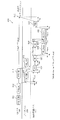
図1は、一実施形態によるHBM+システム100の一例の一部の断面図である。HBM+システム100は、ホスト装置101、インターポーザー(interposer)102、及びHBM+スタック(stack)103を含む。HBM+スタック103は、ロジックダイ(die)(又は論理回路)104、及び複数のHBM+メモリ装置(105a〜105d)を含む。ホスト装置101及びHBM+スタック103は、インターポーザー102の上部表面に固定される。
FIG. 1 is a partial cross-sectional view of an example of the HBM +
一実施形態において、ホスト装置101は、中央処理装置(CPU)、グラフィック処理装置(GPU)、グラフィック加速器、又はFPGA(Field Programmable Gate Array)であるが、これに限定されるものではない。 In one embodiment, the host device 101 is, but is not limited to, a central processing unit (CPU), a graphics processing unit (GPU), a graphics accelerator, or an FPGA (Field Programmable Gate Array).
HBM+メモリ装置105は、チャンネル当たり16個のバンクを有する二つのチャンネルに分割される。また、一つ以上のHBM+メモリ装置(105a〜105d)は、従来の判読及び記録動作のようなPIM機能及び規則的なデータ貯蔵機能を含む。HBM+メモリ装置に提供されるPIM機能は、ホスト装置101によってより効率的に提供される。ロジックダイ104は、HBM+メモリデバイス105内のPIM機能を制御するためのロジック機能を含む。HBM+内部バス111は、ロジックダイ104をHBM+メモリ装置105の各々に接続させる。HBM+内部バス111は、複数のアドレスライン、複数の命令語(コマンド)ライン、複数のデータライン、及び一つ以上の他の信号線を含む。4個のHBM+メモリ装置105をHBM+スタック103に示しているが、任意の数のHBM+メモリ装置105がHBM+スタック103を形成することはよく理解されるはずである。HBM+システム100の一部のみを図1に示しているが、インターポーザー102の上部表面に取り付けられる追加的なHBM+スタック103が有り得ることを理解すべきである。
The HBM + memory device 105 is divided into two channels with 16 banks per channel. Also, one or more HBM + memory devices (105a-105d) include PIM functions such as conventional reading and recording operations and regular data storage functions. The PIM function provided to the HBM + memory device is more efficiently provided by the host device 101. The logic die 104 includes a logic function for controlling the PIM function in the HBM + memory device 105. The HBM +
インターポーザー102は、基板106の上部表面に固定される。基板106は、他の装置(図示せず)に電気接続を提供するために使用される端子107を含む。インターポーザー102は、ホスト装置101及びHBM+スタック103に対する構造的基盤を提供する以外に、ホスト装置101とHBM+スタック103との間の電気的連結を提供する。本実施形態において、インターポーザー102は、ホスト装置101とHBM+スタック103との間に電気的に連結される命令語(コマンド)/アドレス(CA)バス108、データバス109、及びトランザクションバス110を含む。インターポーザー102は、図示していない追加的な電気的連結を含む。
The interposer 102 is fixed to the upper surface of the
CAバス108、データバス109、及びトランザクションバス110のそれぞれは、複数のライン及び/又はビットを含む。本実施形態において、トランザクションバス110は、トランザクション応答信号(RSP_R)及びトランザクションエラー信号(RSP_E)を含む。CAバス108、データバス109、及びトランザクションバス110は、HBM+システム100内において同期式方式で動作する。即ち、CAバス108、データバス109、及びトランザクションバス110は、一つ以上のクロック信号に同期して動作する。
Each of the
本実施形態において、HBM+システム100は、例えば命令語又はトランザクションの発行と応答出力との間のタイミングで、ホスト装置101とHBM+スタック103との間で命令語及びデータを通信するための1段階HBM+プロトコルを含み、正規のデータ貯蔵機能及び/又はPIM機能に基づくか、或いはHBM+スタック103が他の命令語又はトランザクションの準備をする時点は決定論的である。また、HBM+システム110は、例えば命令語又はトランザクションの発行と応答出力との間のタイミングで、ホスト装置101とHBM+スタック103との間で命令語及びデータを通信するための2段階HBM+プロトコルを含み、正規のデータ貯蔵機能及び/又はPIM機能に基づくか、或いはHBM+スタック103が他の命令語又はトランザクションの準備をする時点は非決定論的である。本明細書で使用する「準同期インターフェース(quasi−synchronous interface)」という用語は、決定論的通信及び非決定論的通信又はトランザクションの両方を経て通過するインターフェースを意味する。
In this embodiment, the HBM +
1段階HBM+プロトコルは、一般的にホスト装置101が結果を待たない比較的に規則的なデータ貯蔵及び簡単なPIM動作のためのものである。即ち、命令語の発行と応答出力との間の時間又は遅延は決定論的であるから、ホスト装置101は、命令語の発行と応答出力との間に他の動作を遂行する。代案として、ホスト装置101は、決定論的遅延の終端で、正規のトランザクションを再開するようにスケジューリングされる。一般的に簡単なPIM動作には、一つ又は二つのソース及び/又は対象アドレスが含まれ、ストライド媒介変数(parameter)は含まれない。 The one-step HBM + protocol is for relatively regular data storage and simple PIM operation, where the host device 101 generally does not wait for results. That is, since the time or delay between the issuance of the instruction word and the response output is deterministic, the host device 101 performs another operation between the issuance of the instruction word and the response output. Alternatively, the host device 101 is scheduled to resume a legitimate transaction at the end of the deterministic delay. Generally, a simple PIM operation includes one or two source and / or target addresses and does not include stride parameters.
2段階HBM+プロトコルは、一般的にホスト装置101が結果を要求する多数のソース及び/又は目的地アドレス、マトリックス動作、ストライドを含む動作のような、しかしこれに限定されないより複雑なPIM動作のためのものである。命令語の発行と応答出力との間の時間又は遅延は非決定論的であるから、ホスト装置101は、命令語の発行と応答出力との間、或いは命令語の発行とHBM+スタック103が他の命令語又はトランザクションを受信する準備ができた時点との間に他の動作を遂行する。後述の表2は、HBM+PIM命令語のカテゴリ及びタイミング推定の例を示す。
The two-step HBM + protocol is for more complex PIM operations, such as, but not limited to, operations that generally include, but are not limited to, a large number of source and / or destination addresses, matrix operations, strides for which the host device 101 requires results. belongs to. Since the time or delay between the issuance of the instruction word and the response output is non-deterministic, the host device 101 may be between the issuance of the instruction word and the response output, or the issuance of the instruction word and the HBM +
図2は、一実施形態による1段階HBM+プロトコル命令語の一例のタイミング図200である。タイミング図200は、縮尺通りではなく、単に例示的なPIM命令語に対する1段階(one−step)HBM+プロトコルの相対的なシーケンスを描写するものであることを理解すべきである。タイミング図200は、一般的に特定のバスの単方向性又は両方向性を示すために異なるバスに関連する矢印を含む。特に、左側から右側に向かう矢印は、ホスト装置101からHBM+スタック103に伝送される通信、トランザクション、又は信号を示す。一方、右側から左側に向かう矢印は、HBM+スタック103からホスト装置101に伝送される通信、トランザクション、又は信号を示す。本明細書に開示する全てのタイミング図において、HBM+内部バス111を介して発生するものとして示したトランザクション及び動作は、HBM+スタック103の外部の装置には見えない。
FIG. 2 is a timing diagram 200 of an example of a one-step HBM + protocol instruction word according to an embodiment. It should be understood that the timing diagram 200 does not depict the scale, but merely the relative sequence of the one-step HBM + protocol to the exemplary PIM instructions. Timing diagram 200 generally includes arrows associated with different buses to indicate unidirectional or bidirectionality of a particular bus. In particular, the arrows from left to right indicate communications, transactions, or signals transmitted from the host device 101 to the HBM +
図2の201で、ホスト装置101はCAバス108を介してPIM_CHRG命令語を発行する。PIM_CHRG命令語は、発行されるPIM_CMDに対するバンク及びチャンネル識別情報を含む。ロジックダイ104は、PIM_CHRG命令語に応答して一つ以上の選択されたチャンネルの関連バンクをプリチャージし、一つ以上の選択されたチャンネルの関連バンクを固定(lock)して、ホスト装置101及び後続のPIM_CMDに対する関連バンクの所有権を保証する。PIM_CHRG命令語の直後に、ホスト装置101は、202でCAバス108を介してPIM_WR命令語を発行する。表1は、PIM_CHRG命令語及びPIM_WR命令語に対する例示的な物理的信号パラメータを示す。
In 201 of FIG. 2, the host device 101 issues the PIM_CHRG instruction word via the

表1には、現在のJEDEC HBM標準に基づく一つのピンの識別例を上段に示す。「H」は高い論理電圧レベルを表し、「L」は低い論理電圧レベルを表す。「X」は「相関なし(don’t care)」の論理電圧レベルを表す。 Table 1 shows an example of identifying one pin based on the current JEDEC HBM standard at the top. “H” represents a high logic voltage level and “L” represents a low logic voltage level. “X” represents a “don't care” logical voltage level.
図3は、一実施形態によるPIM_CMD命令語300のコンテンツの一例の配置を示す図である。PIM_CMDは、実際のPIM命令語を含み、CAバス108を介して伝送されるものとは対照的に、データバス109を介して伝送される。ロジックダイ104は、PIM_CMDをデコーディングし、PIM_CMD命令に含まれるPIM動作を完了するために、HBM+スタック103内部の命令語を発行する。本実施形態において、全てのPIM命令語がPIM_CMDの全てのフィールドを使用するものではないが、PIM_CMDは固定された大きさ又は長さを有する。
FIG. 3 is a diagram showing an arrangement of an example of the contents of the
図3に示すように、PIM_CMD命令語300は、IDフィールド301、動作フィールド302、ストライドフィールド303、フラッグフィールド304、範囲フィールド305、値フィールド306、番号フィールド307、ソースアドレス1フィールド308、ソースアドレス2フィールド309、目的地アドレス1フィールド310、目的地アドレス2フィールド311を含む。本実施形態において、IDフィールド301は3ビットを含み、動作フィールド302は3ビットを含む。ストライドフィールド303は16ビットを含む。フラッグフィールド304は2ビットを含み、範囲フィールド305は32ビットを含む。値フィールド306は64ビットを含む。番号フィールド307は8ビットを含む。ソースアドレス1フィールド308は32ビットを含み、ソースアドレス2フィールド309は32ビットを含む。目的地アドレス1フィールド310は32ビットを含み、目的地アドレス2フィールド311は32ビットを含む。その他、追加フィールド、フィールド配列、及びフィールドの大きさが追加され得る。
As shown in FIG. 3, the
再び図2を参照すると、202でCAバス108を介して伝送されたPIM_WR命令語は、203でデータバス109を介してPIM_CMDを伝送するために使用される。一実施形態において、データバス109に示すPIM_CMD命令語は、CAバス108上に示すPIM_WR命令語に後続する。他の実施形態において、データバス109上に示すPIM_CMD命令語は、CAバス108上に示すPIM_WR命令と少なくとも部分的に同時で有る。
With reference to FIG. 2 again, the PIM_WR instruction word transmitted via the
PIM_CMDに応答して、ロジックダイ104は、PIM_CMDに含まれるPIM動作に対するソースとなるデータを判読するために、HBM+内部バス111を介して204でソースリード命令語SRC_RDを伝送する。この例において、PIM動作(OP)は205で遂行される。PIM動作の結果は、206でロジックダイ104により伝送されたDST_WR命令語を使用して目的地アドレスに記録される。207で、PIM動作は完了し、HBM+スタック103は、ホスト装置101から追加の正規動作、PIM動作、及び/又は他のトランザクションを受信する準備をする。
In response to the PIM_CMD, the logic die 104 transmits the source read command word SRC_RD at 204 via the HBM +
図2に示した1段階HBM+プロトコルのタイミングは決定論的であり、従って、202でPIM_WR命令語が発行された時点と、HBM+スタック103がホスト装置101から他の命令語及び/又はトランザクションを受信する準備ができた(即ち、正規のトランザクションを再開する)時点との間の時間をtPIM_WRで図2に示している。即ち、タイミングtPIM_WRは、HBM+スタック103内の同一のチャンネル/バンクにホスト装置101によって新たな命令語又はトランザクションが発行される前の最小時間と見なされる。1段階HBM+プロトコルのタイミングが決定論的属性であることを示すために、図2に示した多様な命令語、トランザクション、及び応答の間の矢印を実線矢印で示している。なお、後述の図5及び図7は、それぞれ異なる決定論的タイミングシナリオに対するタイミング図を示す。
The timing of the one-step HBM + protocol shown in FIG. 2 is deterministic, so when the PIM_WR instruction is issued at 202, the HBM +
図4は、一実施形態による2段階HBM+プロトコル命令語の一例の概略的タイミング図400である。タイミング図400は、縮尺通りではなく、例示的なPIM命令語に対する2段階HBM+プロトコルの相対的なシーケンスを描写するものであることを理解すべきである。図2のタイミング図200と同様に、図4に示すタイミング図400は、一般的に特定のバスの単方向性又は両方向性を示すために異なるバスに関連する矢印を含む。 FIG. 4 is a schematic timing diagram 400 of an example of a two-step HBM + protocol instruction word according to one embodiment. It should be understood that the timing diagram 400 is not to scale and depicts the relative sequence of the two-step HBM + protocol to the exemplary PIM instructions. Similar to the timing diagram 200 of FIG. 2, the timing diagram 400 shown in FIG. 4 generally includes arrows associated with different buses to indicate unidirectionality or bidirectionality of a particular bus.
描画スペースを考慮して図4には示していないが、ホスト装置101は、CAバス108を介してPIM_CHRG命令語を送り出す。1段階HBM+プロトコルと同様に、PIM_CHRG命令語はバンクを含み、PIM_CMDに対するチャンネル識別情報が直ぐに発行される。PIM_GHRG命令語に応答して、ロジックダイ104は、一つ以上の選択されたチャンネルの関連バンクをプリチャージし、HBM+スタック103の全体を固定して、ホスト装置101に対するHBM+スタック103の所有権を保証する。PIM_CHRG命令語(図示せず)の直後に、401で、ホスト装置101はCAバス108を介してPIM_WR命令語を発行する。402で、ホスト装置101はデータバス109上にPIM_CMDを発行する。
Although not shown in FIG. 4 in consideration of the drawing space, the host device 101 sends out the PIM_CHRG instruction word via the
PIM_CMDに応答して、ロジックダイ104は、403でソースリード命令語(SRC_RD)をHBM+内部バス111を介して伝送し、PIM_CMDに示す動作のためのソースデータを判読する。PIM動作(OP)は404で遂行される。PIM動作の結果は、405でDST_WR命令語を使用して目的地アドレスに記録される。図4に示す例示的なタイミングに対し、406で、ロジックダイ104は、トランザクションバス110を介して判読準備命令語(RD_RDY)をホスト装置101に伝送する。407で、ホスト装置101は、CAバス108を介してリード命令語(RD)を伝送する。408で、ロジックダイ104は、リードデータ(RD_Data)を、データバス109を介して出力し、409で、ホスト装置101は、正規の動作及びトランザクションをもたらす。一部の2段階HBM+プロトコルPIM命令語に対し、判読準備命令語(RD_RDY)をホスト装置101に伝送する代わりに、ホスト装置101が中間で他の作業をスケジュールするために、ロジックダイ104は、PIM動作がいつ完了するかに対する指示をホスト装置101に伝送する。そのような指示を伝送するロジックダイ104のいくつかの例示的なシナリオは、後述の図8及び図10で説明する。
In response to PIM_CMD, the logic die 104 transmits the source read instruction (SRC_RD) at 403 via the HBM +
1段階HBM+プロトコルとは対照的に、2段階HBM+プロトコルは、PIM動作(OP)が一般的に2段階HBM+プロトコルに対してより複雑でありPIM動作に応じて一定ではない時間を有するために、非決定論的タイミング特性を有する。例えば、100×100行列で遂行される転置行列のPIM演算は、PIM転値演算が両方の場合で同一の演算であっても、10×10行列に対する同一の転置行列のPIM演算よりも長くかかる。2段階HBM+動作に関連するタイミングが一般的に非決定論的であることを示すために、図4の命令語と応答との間に示した矢印中の一部を太い点線の矢印で示している。例えば、401におけるPIM_WR命令語と406におけるRD_RDY応答との間の矢印と、406におけるRD_RDY応答と407におけるRD命令語との間の矢印は、2段階HBM+プロトコルの非決定論的性質を示すために太い点線矢印で示す。また、非決定論的特性を、404におけるPIM OPと405におけるDST_WR応答との間の太い点線矢印で示す。 In contrast to the one-step HBM + protocol, the two-step HBM + protocol is because the PIM operation (OP) is generally more complex than the two-step HBM + protocol and has a non-constant time depending on the PIM operation. Has non-deterministic timing characteristics. For example, a PIM operation on a transposed matrix performed on a 100x100 matrix takes longer than a PIM operation on the same transposed matrix on a 10x10 matrix, even if the PIM transposition operations are the same in both cases. .. To show that the timing associated with the two-step HBM + action is generally non-deterministic, a part of the arrow shown between the instruction word and the response in FIG. 4 is indicated by a thick dotted arrow. .. For example, the arrow between the PIM_WR instruction word in 401 and the RD_RDY response in 406 and the arrow between the RD_RDY response in 406 and the RD instruction word in 407 are thick to show the non-deterministic nature of the two-step HBM + protocol. It is indicated by a dotted arrow. The non-deterministic properties are also indicated by the thick dotted arrow between the PIM OP at 404 and the DST_WR response at 405.
ホスト装置101の観点において、例えば1段階HBM+プロトコルの決定論的特性は、ホスト基盤命令語スケジューリングプロトコルを提供するものと見なされる From the point of view of the host device 101, for example, the deterministic characteristics of the one-step HBM + protocol are considered to provide the host-based instruction word scheduling protocol.
図5は、一実施形態によるPIM動作がHBM+装置内の単一のアドレスに向けられるか又は同一の行に向けられる1段階HBM+プロトコルPIM命令語の一例のタイミング図500である。タイミング図500は、縮尺通りではなく、単一のアドレスに向けられるか又はHBM+メモリ装置内の同一の行に向けられる例示的なPIM動作に対する1段階HBM+プロトコルの相対的なシーケンスを描写するものであることを理解すべきである。 FIG. 5 is a timing diagram 500 of an example of a one-step HBM + protocol PIM instruction word in which the PIM operation according to one embodiment is directed to a single address in the HBM + device or to the same line. Timing diagram 500 depicts the relative sequence of a one-step HBM + protocol to an exemplary PIM operation that is directed to a single address or to the same row in the HBM + memory device rather than to scale. You should understand that there is.
501で、ホスト装置101は、CAバス108を介してPIM_CHRG命令語を発行する。PIM_CHRG命令語は、直ぐに発行されるPIM_CMDに対するバンク及びチャンネル識別情報を含む。PIM_CHRG命令語に応答して、ロジックダイ104は、一つ以上の選択されたチャンネルの関連バンクをプリチャージし、PIM動作中、一つ以上の選択されたチャンネルの関連バンクを固定して、ホスト装置101に対する所有権を保証する。PIM_CHRG命令語の直後に、ホスト装置101は、502でCAバス108を介してPIM_WR命令語を発行する。503で、ホスト装置101はデータバス109を介してPIM_CMDを伝送する。この例では、PIM_CMDがHBM+メモリ装置105内のメモリ位置の値を増加させる命令であると見なす。PIM_WR命令語とPIM_CMD命令語との間の時間遅延は、tWLであり、これはPIM_WR命令語を送信してPIM_CMD命令語を送信する間に待機しなければならないライト時間の遅延である。PIM_CMD命令語は、DDR(Double Data Rate) HBMメモリ装置に対してtBL/2のバースト長さの遅延を要する。
At 501, the host device 101 issues the PIM_CHRG instruction via the
ロジックダイ104がPIM_CMDをデコーディングして504でHBM+内部バス111を介してHBM+スタック103にACT命令語を発行するまでtPDの伝播遅延が存在する。選択された行に対する活性化遅延はtRCDである。505で、ロジックダイ104は、選択されたソースデータをロードするためにリード命令語(RD)を発行する。経路520に沿って選択されたデータをリードするまでの遅延はtRLである。506で、選択されたソースデータは、tBL/2の遅延で判読される。507で、PIM動作(IOP)はtIOPの遅延で遂行される。この例で、PIM動作(IOP)は、相対的に複雑でないPIM動作であるHBM+メモリ装置105内のメモリ位置の値を増加させる。
Logic die 104 is present propagation delay t PD before issuing the ACT command to HBM +
図5の530で示す並列経路において、ロジックダイ104は、507におけるPIM命令語(IOP)の終端でデータが再びメモリに記録されるため、tRTWの遅延後、508でライト命令語(WR)を発行する。ライト命令語(WR)に関連する遅延はtWLである。本実施形態において、ロジックダイ104は、509で結果データを記録(WR_Data)するためのタイミングが正確であるように、508でライト命令語(WR)を伝送するための適切な時間を決定する。 In the parallel path shown by 530 in FIG. 5, the logic die 104 records the data again in the memory at the end of the PIM instruction (IOP) at 507, so that the write instruction (WR) at 508 after the delay of tRTW. Is issued. The delay associated with the write instruction word (WR) is t WL . In this embodiment, the logic die 104 determines an appropriate time for transmitting the write instruction word (WR) at 508 so that the timing for recording the result data (WR_Data) at 509 is accurate.
509で、ライト命令語(WR)に応答したPIM動作(IOP)の結果は、tBL/2のバースト長さの遅延でメモリに再び記録(WR_Data)される。再びメモリに記録された結果の復旧時間遅延はtWRである。510で、ロジックダイ104は結果が記録された行に対するプリチャージ命令語(PRE)を発行し、511で、ホスト装置101が追加のトランザクション及び/又は命令語をHBM+スタック103に発行する前にtRPのプリチャージ遅延が続く。
At 509, the result of the PIM operation (IOP) in response to the write instruction (WR) is recorded again (WR_Data) in memory with a burst length delay of t BL / 2. The recovery time delay of the result recorded in the memory again is tWR . At 510, the logic die 104 issues a precharge instruction (PRE) for the row on which the result was recorded, and at 511, t before the host device 101 issues additional transactions and / or instructions to the HBM +
従って、PIM動作がHBM+メモリ装置105内の単一のアドレスに向けられるか又は同一の行に向けられるこのシナリオにおいて、502でPIM_WR命令語が発行された時点と、511でホスト装置101からHBM+スタック103が他の命令語及び/又はトランザクションを受信する準備ができた時との間の時間(tPIM_WR)は、下記の数学式1の通りに決定される。
Therefore, in this scenario where the PIM operation is directed to a single address or to the same line in the HBM + memory device 105, when the PIM_WR instruction is issued at 502 and at 511 the HBM + stack from the host device 101. The time (t PIM_WR ) between when 103 is ready to receive other instructions and / or transactions is determined as in
![]()
![]()
ここで、図5に示した経路(520、530)の間の最大遅延は、tPIM_WRを定義するために使用される。経路520の遅延は(tRL+tBL/2+tIOP)である。一方、経路530の遅延は(tRTW+tWL)である。
Here, the maximum delay between the paths (520, 530) shown in FIG. 5 is used to define t PIM_WR. The delay of
ホスト基盤命令語スケジューリングプロトコルを提供するものと見なされるもう一つの1段階HBM+プロトコルシナリオを図6に示す。 Another one-step HBM + protocol scenario that is considered to provide the host-based instruction word scheduling protocol is shown in FIG.
図6は、一実施形態によるPIM動作が同一のチャンネルのバンク内で行われる1段階HBM+プロトコルPIM命令語の一例のタイミング図600である。特に、タイミング図600は、一定の縮尺ではなく、単に同一のチャンネルのバンクに向けられる例示的なPIM動作に対する1段階HBM+プロトコルの相対的なシーケンスを示すものであることを理解すべきである。 FIG. 6 is a timing diagram 600 of an example of a one-step HBM + protocol PIM instruction word in which the PIM operation according to one embodiment is performed in a bank of the same channel. In particular, it should be understood that the timing diagram 600 does not show a constant scale, but merely a sequence of one-step HBM + protocol relative to an exemplary PIM operation directed to a bank of the same channel.
601で、ホスト装置101は、CAバス108を介してPIM_CHRG命令語を発行する。PIM_CHRG命令語は、直ぐに発行されるPIM_CMDに対するバンク及びチャネル識別情報を含む。PIM_CHRG命令語に応答して、ロジックダイ104は、一つ以上の選択されたチャンネルの関連バンクをプリチャージし、PIM動作中、一つ以上の選択されたチャンネルの関連バンクを固定して、ホスト装置101に対する所有権を保証する。PIM_CHRG命令語の直後に、ホスト装置101は、602でCAバス108を介してPIM_WR命令語を発行する。603で、ホスト装置101はデータバス109を介してPIM_CMDを伝送する。この例では、PIM_CMDが、メモリ位置Bを、位置A及びBがHBM+メモリ装置105内の同一のチャンネル内のバンク内にあるメモリ位置Aと同一になるように設定する命令語であるものと見なす。PIM_WR命令語とPIM_CMD命令語との間のライト時間遅延はtWLである。PIM_CMD命令語は、DDR HBMメモリ装置に対してtBL/2のバースト遅延を要する。
At 601 the host device 101 issues the PIM_CHRG instruction via the
603におけるPIM_CMDに応答して、ロジックダイ104は、604でHBM+内部バス111を介してHBM+スタック103に活性化命令語(ACT1)を伝送して第1ソースデータアドレス(即ち、位置A)を活性化させる。ロジックダイ104がPIM_CMDをデコーディングして604でACT1命令語を発行するまでの伝播遅延はtPDである。
In response to PIM_CMD at 603, the logic die 104 transmits the activation instruction (ACT1) to the HBM +
第1並列経路620において、ロジックダイ104は、605で第2ソースデータアドレス(即ち、位置B)を活性化するために活性化命令語(ACT2)を発行する。ACT1命令語の発行とACT2命令語の発行との間の遅延は、tRRD又はtRCである。PIM動作が、二つの互いに異なるバンクの間で進行する場合、遅延は(一般的に)tRRDになる(ソースと目的地アドレスが同一のバンクグループ内にある二つの互いに異なるバンクの間にある場合に遅延はtRRDLになるが、ソースと目的地アドレスが他のバンクにある二つの異なるバンクにある場合、遅延はtRRDFである。)。PIM動作が同一のバンク内にある場合、遅延はtRCになる。この並列経路620において、ロジックダイ104が、606でライト命令語(WR2)を発行する前にtRCDの遅延が存在し、またライト命令語(WR2)に後続するtWLの遅延が存在する。
In the first
第2並列経路630において、ロジックダイ104は、活性化命令語(ACT1)に応答して、607でリード命令語(RD1)を発行する。活性化命令語(ACT1)の後及びリード命令語(RD1)の前にtRCDの遅延がある。リード命令語(RD1)が発行された時間と608のリードデータ(RD_Data)の動作との間にはtRLの遅延がある。データは、608でtBL/2のバースト長さの遅延で読み出される(RD_Data)。609でPIM動作(IOP)はtIOPの遅延で遂行される。
In the second
PIM動作(IOP)で生成されたデータを記録するために、610でロジックダイ104がプリチャージ命令語(PRE1)を発行するためのリード命令語(RD1)以降、tRTW−tRCDの遅延が存在する。611で、606におけるライト命令語(WR2)に応答して、PIM動作(IOP)の結果はtBL/2の遅延でメモリに再び記録(WR_Data)される。再びメモリに記録された結果の復旧時間はtWRである。612で、ロジックダイ104は、結果を復旧するために記録された行に対するプリチャージ命令語(PRE2)を発行し、613で、ホスト装置101がHBM+スタック103に追加のトランザクション及び/又は命令語を発行する前にtRPの遅延が続く。
In order to record the data generated by the PIM operation (IOP), there is a delay of t RTW- t RCD after the read instruction (RD1) for the logic die 104 to issue the precharge instruction (PRE1) at 610. exist. At 611, in response to the write instruction word (WR2) at 606, the result of the PIM operation (IOP) is recorded again (WR_Data) in memory with a delay of t BL / 2. The recovery time of the result recorded in the memory again is tWR . At 612, the logic die 104 issues a precharge instruction (PRE2) for the row recorded to recover the result, and at 613, the host device 101 issues additional transactions and / or instructions to the HBM +
従って、PIM動作が同一のチャンネル内のバンクに向けられるこのようなシナリオにおいて、602でPIM_WR命令語が発行された時点と、HBM+スタック103が613でホスト装置101から他の命令語を受信する準備ができた時点との間の時間(tPIM_WR)は、下記の数学式2の通りに決定される。
Therefore, in such a scenario where the PIM operation is directed to a bank within the same channel, the time when the PIM_WR instruction is issued at 602 and the HBM +
![]()
![]()
ここで、図6に示した経路(620、630)の間の最大遅延は、tPIM_WRを定義するために使用される。経路620の遅延は(tRCD+tBL/2+tIOP)である。一方、経路630の遅延は(tRRD+tRCD+tWL)である。
Here, the maximum delay between the paths (620, 630) shown in FIG. 6 is used to define t PIM_WR. The delay of
ホスト基盤命令語スケジューリングプロトコルを提供するものと見なされるもう一つの1段階HBM+プロトコルシナリオを図7に示す。 Another one-step HBM + protocol scenario that is considered to provide the host-based instruction word scheduling protocol is shown in FIG.
図7は、一実施形態によるPIM動作が異なるチャンネルを介して行われる1段階HBM+プロトコルPIM命令語の一例のタイミング図700である。特に、タイミング図700は、縮尺通りではなく、異なるチャンネルに亘る例示的なPIM動作に対する1段階HBM+プロトコルの相対的なシーケンスを示すためのものであることを理解すべきである。 FIG. 7 is a timing diagram 700 of an example of a one-step HBM + protocol PIM instruction word in which the PIM operation according to the embodiment is performed via different channels. In particular, it should be understood that the timing diagram 700 is to show the relative sequence of the one-step HBM + protocol for exemplary PIM operations over different channels, not to scale.
701で、ホスト装置101は、CAバス108を介してPIM_CHRG命令語を発行する。PIM_CHRG命令語は、直ぐに発行されるPIM_CMDに対するバンク及びチャネル識別情報を含む。PIM_CHRG命令語に応答して、ロジックダイ104は、一つ以上の選択されたチャンネルの関連バンクをプリチャージし、PIM動作中、一つ以上の選択されたチャンネルの関連バンクを固定して、ホスト装置101に対する関連バンクの所有権を保証する。PIM_CHRG命令語の直後に、ホスト装置101は、702でCAバス108を介してPIM_WR命令語を発行する。703で、ホスト装置101はデータバス109を介してPIM_CMDを伝送する。PIM_WR命令語とPIM_CMD命令語との間の時間遅延はtWLであり、これはPIM_WR命令語を送りPIM_CMD命令語を送る間に待機しなければならない時間である。PIM_CD命令語は、DDR HBMメモリ装置に対してtBL/2のバースト長さの遅延を要する。
At 701, the host device 101 issues the PIM_CHRG instruction via the
703におけるPIM_CMDに応答して、ロジックダイ104は、704でHBM+内部バス111を介してHBM+スタック103に活性化命令語(ACT1)を伝送する。704で、ロジックダイ104がPIM_CMDをデコーディングしてACT1命令語を発行するまでの時間の遅延はtPDである。遅延tRCD後に、ロジックダイ104は705でリード命令語(RD1)を発行する。第1並列経路720において、706でtBL/2のバースト長さの遅延でデータが判読(RD_Data)される前にtRLの遅延が存在する。707で、PIM動作(IOP)はtIOPの遅延で遂行される。PIM動作(IOP)で生成されたデータを記録するためのロジックダイ104が708でプリチャージ命令語(PRE1)を発行するために、705のリード命令語(RD1)の以降に(tRTW−tRCD)遅延が存在する。
In response to the PIM_CMD at 703, the logic die 104 transmits the activation instruction (ACT1) to the HBM +
第2並列経路730において、ロジックダイ104は、709で活性化命令語(ACT2)を発行する。PIM動作が異なるチャンネルに亘って遂行される状況において、ロジックダイ104が活性化命令語(ACT2)を発行する時点に制約はない。ロジックダイ104が、710でライト命令語(WR2)を発行する前にtRCDの遅延が存在する。711で、データが記録されるまでに(WR_Data)ライト命令語(WR2)が発行される時間の間にtWLの遅延が存在する。711で、データはtBL/2のバースト長さの遅延で記録(WR_Data)される。ロジックダイ104が、712で復旧のために結果を記録した行に対してプリチャージ命令語(PRE2)を発行する前にtWRの遅延があり、713で、ホスト装置101が追加トランザクション及び/又は命令語をHBM+スタック103に発行する前にtRPの遅延が続く。
In the second
従って、PIM動作が、他のチャンネルに亘るこのようなシナリオにおいて、702でPIM_WR命令語が発行された時点と、HBM+スタック103が713でホスト装置101から他の命令語を受信する準備ができた時点との間の時間(tPIM_WR)は、下記の数学式3に示される。
Therefore, in such a scenario where the PIM operation spans other channels, the PIM_WR instruction is issued at 702 and the HBM +
![]()
![]()
なお、後述する図8〜図10は、PIM動作が、図5〜図7で考慮された1段階HBM+プロトコル命令語よりもより複雑な2段階HBM+プロトコルPIM命令語に対するタイミング図を示し、結果的に完了のための全体の非決定論的タイミングを有する。従って、一部の2段階HBM+プロトコルPIM命令語は、クライアント基盤命令語スケジューリングプロトコルを提供するものと見なされ、HBM+スタックは、PIM命令語が2段階HBM+プロトコルPIM命令語のうちの一部の非決定論的特徴を説明するために完了する時点を通知する。これに関して、ロジックダイ104は、複雑なPIM命令語が完了する時間をホスト装置101に通知する。 It should be noted that FIGS. 8 to 10 described later show timing diagrams for the two-step HBM + protocol PIM instruction whose PIM operation is more complicated than the one-step HBM + protocol instruction considered in FIGS. 5 to 7. Has an overall non-deterministic timing for completion. Therefore, some two-step HBM + protocol PIM commands are considered to provide a client-based command word scheduling protocol, and the HBM + stack is a non-determined PIM command of some of the two-step HBM + protocol PIM commands. Notify when completed to explain the rationale. In this regard, the logic die 104 notifies the host device 101 of the time it takes for the complex PIM instruction to complete.
一実施形態において、有効時間の指示は時間の推定を含む。他の実施形態において、有効時間の指示はクレジット基盤の値を含む。更に他の実施形態において、有効時間の指示は、ホスト装置にPIM動作が完了したか否かを知らせるために、HBM+スタックをいつポーリングするかに対する指示が与えられる再試行基盤のフィードバックを含む。ホスト装置101に提供されるPIM命令語が完了する時間に対する指示は、自動ログの内容、履歴統計情報、計算された推定値、進行中のトラフィック、最大PIM作業範囲などに基づくか又はこれらから予測されるが、本発明は、これらに限定されるものではない。 In one embodiment, the indication of effective time includes estimating the time. In other embodiments, the valid time indication includes a credit-based value. In yet another embodiment, the lifetime indication includes retry-based feedback in which instructions are given as to when to poll the HBM + stack to inform the host apparatus whether the PIM operation is complete. The instruction for the time to complete the PIM instruction provided to the host device 101 is based on or predicted from the contents of the automatic log, historical statistics, calculated estimates, traffic in progress, maximum PIM work range, and the like. However, the present invention is not limited thereto.
後述する図8〜図10のタイミング図に示す2段階HBM+プロトコルPIM命令語は、図1に示したトランザクションバス110を使用しない。その代わりに、図8〜図10に示す2段階HBM+プロトコルPIM命令語は、CAバス108、データバス109、及びHBM+内部バス111を利用して、PIM命令語が完了する有効時間の表示をホスト装置101に提供する。
The two-step HBM + protocol PIM instruction words shown in the timing diagrams of FIGS. 8 to 10 described later do not use the
図8は、一実施形態によるPIM命令語が完了する時点でHBM+スタック103が推定値を提供する2段階HBM+プロトコルPIM命令語の一例のタイミング図800である。タイミング図800は、縮尺通りではなく、単にHBM+スタックが例示的なPIM動作が完了する時点で推定値を提供する場合の2段階HBM+プロトコルの相対的なシーケンスを描写するものであることを理解すべきである。
FIG. 8 is a timing diagram 800 of an example of a two-step HBM + protocol PIM instruction in which the HBM +
801で、ホスト装置101は、CAバス108を介してPIM_CHRG命令語を発行する。PIM_CHRG命令語は、直ぐに発行されるPIM_CMDに対するバンク及びチャンネル識別情報を含む。PIM_CHRG命令語に応答して、ロジックダイ104は、一つ以上の選択されたチャンネル内の関連バンクをプリチャージし、PIM動作中、HBM+スタック103を固定して、ホスト装置101に対するHBM+スタックの所有権を保証する。PIM_CHRG命令語の直後に、ホスト装置101は、802でCAバス108を介してPIM_WR命令語を発行する。ホスト装置101は、803でデータバス109を介してPIM_CMDを伝送する。PIM_WR命令語とPIM_CMD命令語との間の遅延はtWLである。PIM_CMD命令語は、DDR HBMメモリ装置に対してtBL/2バースト長さの遅延を要する。
At 801 the host device 101 issues the PIM_CHRG instruction via the
803におけるPIM_CMDに応答して、ロジックダイ104は、804でHBM+スタック103にHBM+内部バス111を介して活性化命令語(ACT)を伝送する。804でロジックダイ104がPIM_CMDをデコーディングしてACT命令語を発行する時間の遅延はtPDである。遅延tRCDの後に、ロジックダイ104は805でリード命令語(RD)を発行する。806でtBL/2のバースト長さの遅延でデータが判読(RD_Data)される前にtRLの遅延が存在する。807で、PIM動作(IOP)はtIOPの遅延で遂行される。しかし、PIM演算(IOP)が複雑であるため、PIM演算(IOP)に関連する遅延は非決定論的である。
In response to PIM_CMD at 803, logic die 104 transmits an activation instruction (ACT) at 804 via HBM +
また、ロジックダイ104は、リード命令語(RD)が805で発行された後、PIM動作(IOP)が807で完了する前に808でtRTWの遅延でライト命令語(WR)を発行する。PIM動作(IOP)の結果は、808におけるライト命令語(WR)の発行後にtWLの遅延を有して809でメモリに記録(WR_Data)される。810で、ロジックダイ104はtWRの遅延を有してプリチャージ命令語(PRE)を発行する。ホスト装置101が、811でHBM+スタック103に追加のトランザクション及び/又は命令語を発行する前にtRPの遅延が続く。
Further, the logic die 104 issues a write instruction word (WR) at 808 with a delay of t RTW after the read instruction word (RD) is issued at 805 and before the PIM operation (IOP) is completed at 807. Results of PIM operation (IOP) is recorded in the
タイミング図800に示したトランザクションの多くは決定論的な側面であるが、トランザクション全体の全体的なタイミングは非決定論的である。807におけるPIM動作(IOP)の非決定論的遅延を説明するために、ホスト装置101は、812でCAバス108を介してPIM_RD命令語を発行する。ロジックダイ104が、813におけるPIM_EST応答で応答する前にtRLの遅延がある。この例で、PIM_EST応答は、807におけるPIM動作(IOP)が完了する時間を示す時間推定を含む。一実施形態において、時間の推定は時間の単位である。他の実施形態において、時間の推定はクロックサイクルの単位からなる。
Timing Many of the transactions shown in Figure 800 are deterministic, but the overall timing of the entire transaction is non-deterministic. To account for the non-deterministic delay of PIM operation (IOP) in 807, the host device 101 issues the PIM_RD instruction on the
従って、812でPIM_RD命令語が発行された時点と、811でHBM+スタック103がホスト装置101から他の命令語を受信する準備ができた時点との間の有効時間tPIM_WR(effective)は、下記の数学式4に示される。
Therefore, the valid time t PIM_WR ( effect) between the time when the PIM_RD command is issued at 812 and the time when the HBM +
![]()
![]()
ここで、tPIM_WRはPIM演算が完了するのにかかる時間の決定論的部分を示し、tPIM_ESTはPIM演算が完了するまでの時間の非決定論的部分の時間推定を示す。 Here, t PIM_WR indicates a deterministic part of the time it takes to complete the PIM operation, and t PIM_EST indicates a time estimate of the non-deterministic part of the time until the PIM operation is completed.
図9は、一実施形態によるPIM命令語が完了する時点でHBM+スタック103がクレジット基盤の表示を提供する2段階HBM+プロトコルPIM命令語の一例のタイミング図900である。タイミング図900は、縮尺通りではなく、単にHBM+スタックが例示的なPIM動作が完了する点でクレジット基盤の表示を提供する場合の2段階HBM+プロトコルの相対的なシーケンスを描写するものであることを理解すべきである。
FIG. 9 is a timing diagram 900 of an example of a two-step HBM + protocol PIM instruction in which the HBM +
901で、ホスト装置101は、CAバス108を介してPIM_CHRG命令語を発行する。PIM_CHRG命令語は、直ぐに発行されるPIM_CMDに対するバンク及びチャンネル識別情報を含む。PIM_CHRG命令語に応答して、ロジックダイ104は、一つ以上の選択されたチャンネル内の関連バンクをプリチャージし、PIM動作中、HBM+スタック103を固定して、ホスト装置101に対するHBM+スタックの所有権を保証する。PIM_CHRG命令語の直後に、ホスト装置101は、902でCAバス108を介してPIM_WR命令語を発行する。ホスト装置101は、903でデータバス109を介してPIM_CMDを伝送する。PIM_WR命令語とPIM_CMD命令語との間の遅延はtWLである。PIM_CMD命令語は、DDR HBMメモリ装置に対してtBL/2のバースト長さの遅延を要する。
At 901, the host device 101 issues the PIM_CHRG instruction via the
903におけるPIM_CMDに応答して、ロジックダイ104は、904でHBM+スタック103にHBM+内部バス111を介して活性化命令語(ACT)を伝送する。904でロジックダイ104がPIM_CMDをデコーディングしてACT命令語を発行する時間の遅延はtPDである。遅延tRCDの後に、ロジックダイ104は905でリード命令語(RD)を発行する。906でtBL/2のバースト長さの遅延でデータが判読(RD_Data)される前にtRLの遅延が存在する。907で、PIM動作(IOP)はtIOPの遅延で遂行される。しかし、PIM演算(IOP)が複雑であるため、PIM演算(OP)に関連する遅延は非決定論的である。
In response to PIM_CMD at 903, the logic die 104 transmits an activation instruction (ACT) at 904 via HBM +
また、ロジックダイ104は、リード命令語(RD)が905で発行された後、PIM動作(IOP)が907で完了する前に908でtRTWの遅延でライト命令語(WR)を発行する。PIM動作(IOP)の結果は、908におけるライト命令語(WR)の発行後にtWLの遅延を有して909でメモリに記録(WR_Data)される。910で、ロジックダイ104は、tWRの遅延を有してプリチャージ命令語(PRE)を発行する。ホスト装置101が、911でHBM+スタック103に追加のトランザクション及び/又は命令語を発行する前にtRPの遅延が続く。
Further, the logic die 104 issues a write instruction word (WR) with a delay of t RTW at 908 after the read instruction word (RD) is issued at 905 and before the PIM operation (IOP) is completed at 907. Results of PIM operation (IOP) is recorded in the
タイミング図900に示したトランザクションの多くは決定論的な側面であるが、トランザクション全体の全体的なタイミングは非決定論的である。907におけるPIM動作(IOP)の非決定論的遅延を説明するために、ホスト装置101は、912でCAバス108を介してPIM_RD命令語を発行する。ロジックダイ104が、913におけるPIM_CRED応答で応答する前にtRLの遅延がある。この例で、PIM_CRED応答は、ホスト装置101がスロットリング(throttling)メカニズムとして使用する多数のクレジット(credit)に関する情報を含む。例えば、PIM_CRED応答が、ホスト装置101が0より大きな整数のクレジットを有することを示す場合、ホスト装置101は、クレジットが残らなくなるまで、HBM+スタック103に命令語及び/又はトランザクションを発行し続ける。
Timing Many of the transactions shown in Figure 900 are deterministic, but the overall timing of the entire transaction is non-deterministic. To account for the non-deterministic delay of PIM operation (IOP) in 907, the host device 101 issues the PIM_RD instruction on the
従って、912でPIM_RD命令語が発行された時点と、911でHBM+スタック103がホスト装置101から他の命令語を受信する準備ができた時点との間の有効時間tPIM_WR(effective)は、下記の数学式5に示される。
Therefore, the valid time t PIM_WR ( effect) between the time when the PIM_RD command is issued at 912 and the time when the HBM +
![]()
![]()
ここで、tPIM_WRはPIM動作が完了するのにかかる時間の決定論的部分を示し、tPIM_CREDは0よりも大きな整数のクレジットを示し、ホスト装置101がこれ以上残ったクレジットがなくなるまで、ホスト装置101は、HBM+スタック103に命令語及び/又はトランザクションを発行し続ける。
Here, t PIM_WR indicates the deterministic portion of the time it takes for the PIM operation to complete, t PIM_CRED indicates an integer credit greater than 0, and the host device 101 indicates the host until there are no more credits left. The device 101 continues to issue commands and / or transactions to the HBM +
図10は、一実施形態によるPIM命令語が完了する時点でHBM+スタック103がフィードバック基盤表示を提供する2段階HBM+プロトコルPIM命令語の一例のタイミング図1000である。タイミング図1000は、縮尺通りではなく、単にHBM+スタックが例示的なPIM動作が完了する時点でフィードバック基盤表示を提供する場合の2段階HBM+プロトコルの相対的なシーケンスを描写するものであることを理解すべきである。
FIG. 10 is a timing diagram 1000 of an example of a two-step HBM + protocol PIM instruction in which the HBM +
1001で、ホスト装置101は、CAバス108を介してPIM_CHRG命令語を発行する。PIM_CHRG命令語は、直ぐに発行されるPIM_CMDに対するバンク及びチャンネル識別情報を含む。PIM_CHRG命令語に応答して、ロジックダイ104は、一つ以上の選択されたチャンネル内の関連バンクをプリチャージし、PIM動作中、HBM+スタック103を固定して、ホスト装置101に対するHBM+スタックの所有権を保証する。PIM_CHRG命令語の直後に、ホスト装置101は、1002でCAバス108を介してPIM_WR命令語を発行する。ホスト装置101は、1003でデータバス109を介してPIM_CMDを伝送する。PIM_WR命令語とPIM_CMD命令語との間の遅延はtWLである。PIM_CMD命令語は、DDR HBMメモリ装置に対してtBL/2のバースト長さの遅延を要する。
At 1001, the host device 101 issues the PIM_CHRG instruction via the
1003におけるPIM_CMDに応答して、ロジックダイ104は、1004でHBM+スタック103にHBM+内部バス111を介して活性化命令語(ACT)を伝送する。1004で、ロジックダイ104がPIM_CMDをデコーディングしてACT命令語を発行する時間の遅延はtPDである。遅延tRCDの後に、ロジックダイ104は1005でリード命令語(RD)を発行する。1006でtBL/2のバースト長さの遅延でデータが判読(RD_Data)される前にtRLの遅延が存在する。1007で、PIM動作(IOP)はtIOPの遅延で遂行される。しかし、PIM演算(IOP)が複雑であるため、PIM演算(OP)に関連する遅延は非決定論的である。
In response to the PIM_CMD at 1003, the logic die 104 transmits an activation instruction (ACT) to the HBM +
また、ロジックダイ104は、リード命令語(RD)が1005で発行された後、PIM動作(IOP)が1007で完了する前に1008でtRTWの遅延でライト命令語(WR)を発行する。PIM動作(IOP)の結果は、1008におけるライト命令語(WR)の発行後にtWLの遅延を有して1009でメモリに記録(WR_Data)される。1010で、ロジックダイ104は、tWRの遅延を有してプリチャージ命令語(PRE)を発行する。ホスト装置101が、1011でHBM+スタック103に追加のトランザクション及び/又は命令語を発行する前にtRPの遅延が続く。
Further, the logic die 104 issues a write instruction word (WR) with a delay of tRTW at 1008 after the read instruction word (RD) is issued at 1005 and before the PIM operation (IOP) is completed at 1007. Results of PIM operation (IOP) is recorded in the
タイミング図1000に示したトランザクションの多くは決定論的な側面であるが、トランザクション全体の全体的なタイミングは非決定論的である。1007におけるPIM動作(IOP)の非決定論的遅延を説明するために、ホスト装置101は、1012でCAバス108を介してPIM_RD命令語を発行する。ロジックダイ104が、1013におけるPIM_FDBK応答で応答する前にtRLの遅延がある。この例で、PIM_FDBK応答は、PIM動作が完了したか否かを判別するために、ホスト装置101がHBM+スタック103をポーリングする前の時間周期に関する情報を含む。ホスト装置101は、フィードバック情報を使用してHBM+スタック103をポーリングするために戻る前に他の動作をスケジューリングして遂行する。
Timing Many of the transactions shown in Figure 1000 are deterministic, but the overall timing of the entire transaction is non-deterministic. To illustrate the non-deterministic delay of PIM operation (IOP) in 1007, the host device 101 issues the PIM_RD instruction on the 1012 via the
従って、1012でPIM_RD命令語が発行された時点と、1011でHBM+スタック103がホスト装置101から他の命令語を受信する準備ができた時点との間の有効時間tPIM_WR(effective)は、下記の数学式6に示される。
Therefore, the valid time t PIM_WR ( effect) between the time when the PIM_RD instruction is issued at 1012 and the time when the HBM +
![]()
![]()
ここで、tPIM_WRはPIM動作が完了するのにかかる時間の決定論的部分を示し、tPIM_FBDBKはPIM動作が完了したか否かを決定するためにホスト装置101がHBM+スタック103をポーリングするまでの時間周期に関する情報を示す。
Here, t PIM_WR indicates the deterministic part of the time it takes for the PIM operation to complete, and t PIM_FBDBK until the host device 101 polls the HBM +
以上、本発明の実施形態について図面を参照しながら詳細に説明したが、本発明は、上述の実施形態に限定されるものではなく、本発明の技術的範囲から逸脱しない範囲内で多様に変更実施することが可能である。 Although the embodiments of the present invention have been described in detail with reference to the drawings, the present invention is not limited to the above-described embodiments and is variously modified within a range that does not deviate from the technical scope of the present invention. It is possible to carry out.
本発明は、ホスト装置とインターフェースするためのメモリにおいて決定論的処理及び非決定論的処理を可能にするシステムに有用である。 The present invention is useful for systems that allow deterministic and non-deterministic processing in memory for interfacing with host devices.
100 HBM+システム
101 ホスト装置
102 インターポーザー
103 HBM+スタック
104 ロジックダイ(論理回路)
105a〜105d HBM+メモリ装置
106 基板
107 端子
108 CA(命令語/アドレス)バス
109 データバス
110 トランザクションバス
111 HBM+内部バス
200、400、600、700、800、900、1000 タイミング図
300 PIM_CMD命令語
301 IDフィールド
302 動作フィールド
303 ストライドフィールド
304 フラッグフィールド
305 範囲フィールド
306 値フィールド
307 番号フィールド
308 ソースアドレス1フィールド
309 ソースアドレス2フィールド
310 目的地アドレス1フィールド
311 目的地アドレス2フィールド
100 HBM + system 101 Host device 102
105a to 105d HBM +
Claims (20)
PIM(Processing−In−Memory)動作をサービスするPIM機能を含むHBMメモリ装置と、
命令語及びアドレス(CA)バス並びにデータバスを含みホスト装置に連結される第1インターフェースと、内部バスを介して前記HBMメモリ装置に連結される第2インターフェースとを含み、前記第1インターフェースの前記CAバスを介して前記ホスト装置から第1命令語と、前記データバスを介して前記ホスト装置から第2命令語とを受信し、前記受信された第2命令語を、前記第2インターフェースを介して前記HBMメモリ装置に伝送される、前記PIM動作のためのPIM命令語に変換し、前記PIM動作のための内部バス命令語が前記PIM命令語の実行に重なるように、前記内部バス上で前記PIM動作のためのオーバーラップタイミングを有する少なくとも1つの命令語を発行する論理回路と、を備え、
前記HBMシステムが前記ホスト装置から前記第1命令語を受信して前記ホスト装置から他の命令語を受信する準備ができるまでの遅延(latency)は、決定論的(deterministic)であることを特徴とする高帯域メモリシステム。 High Bandwidth Memory (HBM) system
An HBM memory device that includes a PIM function that provides PIM (Processing-In-Memory) operation, and
A first interface that will be connected to a host device includes a command and address (CA) bus and a data bus, and a second interface that will be connected to the HBM memory device via an internal bus, said first interface The first command word is received from the host device via the CA bus and the second command word is received from the host device via the data bus, and the received second command word is transmitted via the second interface. Converted to the PIM instruction word for the PIM operation transmitted to the HBM memory device, and the internal bus instruction word for the PIM operation overlaps with the execution of the PIM instruction word on the internal bus. It comprises a logic circuit that issues at least one instruction word having overlap timing for the PIM operation.
Said HBM system delay until ready to receive another command from the host device to receive the first command from said host device (latency) is a deterministic (deterministic) A featured high-bandage memory system.
前記第2命令語が前記ホスト装置から受信されて前記HBMシステムが前記ホスト装置から他の命令語を受信する準備ができるまでの遅延は、決定論的であることを特徴とする請求項2に記載の高帯域メモリシステム。 The second command received from the host apparatus is for the PIM operation in one or more banks in the same channel in said HBM memory device,
Claim 2 wherein the second command is the delay until ready to the HBM system is received from the host device to receive another command from the host device, which is a deterministic High-band memory system described in.
前記第2命令語が前記ホスト装置から受信されて前記HBMシステムが前記ホスト装置から他の命令語を受信する準備ができるまでの遅延は、決定論的であることを特徴とする請求項1に記載の高帯域メモリシステム。 The second command received from the host apparatus is for PIM operation across different banks of said HBM memory device,
Claim 1 wherein the second command is the delay until ready to the HBM system is received from the host device to receive another command from the host device, which is a deterministic High-band memory system described in.
前記第4命令語は、前記第4命令語が前記ホスト装置から受信されて前記HBMシステムが前記ホスト装置から他の命令語を受信する準備ができるまでの遅延に関する、決定論的部分及び推定部分を含む第1推定情報を要求することを特徴とする請求項1に記載の高帯域メモリシステム。 The logic circuit has a third instruction word for PIM operation in the HBM memory device from the host device via the CA bus , and a third instruction word following the third instruction word from the host device via the data bus. Receive more 4 command words and
The fourth instruction word, said fourth instruction word regarding delays until ready to the HBM system is received from the host device receives the other command from the host device, deterministic part and the estimated The high-bandage memory system according to claim 1 , wherein the first estimation information including a portion is requested.
前記第4命令語は、前記第4命令語が前記ホスト装置から受信されて前記HBMシステムが前記ホスト装置から他の命令語を受信する準備ができるまでの遅延に関する、決定論的部分及びクレジット基盤部分を含む推定情報を要求することを特徴とする請求項1に記載の高帯域メモリシステム。 The logic circuit has a third instruction word for PIM operation in the HBM memory device from the host device via the CA bus , and a third instruction word following the third instruction word from the host device via the data bus. Receive more 4 command words and
The fourth instruction word, said fourth instruction word regarding delays until ready to the HBM system is received from the host device receives the other command from the host device, deterministic part and credit The high-band memory system according to claim 1 , wherein estimation information including a base portion is requested.
前記第4命令語は、前記第4命令語が前記ホスト装置から受信されて前記HBMシステムが前記ホスト装置から他の命令語を受信する準備ができるまでの遅延に関する、決定論的部分及び再試行部分を含む推定情報を要求することを特徴とする請求項1に記載の高帯域メモリシステム。 The logic circuit has a third instruction word for PIM operation in the HBM memory device from the host device via the CA bus , and a third instruction word following the third instruction word from the host device via the data bus. Receive more 4 command words and
The fourth instruction word, regarding delay until ready to the HBM system the fourth command is received from the host device receives the other command from the host device, deterministic part and re The high-band memory system according to claim 1 , wherein estimation information including a trial portion is requested.
高帯域メモリ(HBM)装置と、
ホスト装置に連結される第1インターフェースと、前記HBM装置に連結される第2インターフェースとを含み、前記ホスト装置から一つ以上の命令語を受信し、前記受信された各命令語を、前記第2インターフェースを介して前記HBM装置に伝送される少なくとも一つの対応するPIM(Processing−In−Memory)命令語に変換する論理回路と、を備え、
前記論理回路は、前記ホスト装置から前記HBM装置内におけるPIM動作のための第1命令語と、前記ホスト装置から前記第1命令語に続く第2命令語とを更に受信し、
前記第2命令語は、前記第2命令語が前記ホスト装置から受信された時点と前記HBMシステムが前記ホスト装置から他の命令語を受信する準備ができた時点との間の時間に関する、決定論的期間及び非決定論的期間を含む第1時間推定情報を要求することを特徴とする高帯域メモリシステム。 High Bandwidth Memory (HBM) system
High Bandwidth Memory (HBM) device and
A first interface that will be connected to a host device, and a second interface that will be connected to the HBM device, wherein receiving one or more instructions from the host device, each instruction word is received; the first A logic circuit that converts at least one corresponding PIM (Processing-In-Memory) instruction word transmitted to the HBM device via two interfaces is provided.
The logic circuit includes a first command for PIM operation within the HBM device from the host device, and further receives a second command following the first command from said host device,
The second command word relates to a time between the time when the second command word is received from the host device and the time when the HBM system is ready to receive another command word from the host device. A high-band memory system comprising requesting first-time estimation information including a theoretical period and a non-deterministic period.
前記第4命令語は、前記第3命令語が前記ホスト装置から受信された時点と前記HBMシステムが前記ホスト装置から他の命令語を受信する準備ができた時点との間の時間に関する、決定論的期間及びクレジット基盤期間を含む第2時間推定情報を要求することを特徴とする請求項11に記載の高帯域メモリシステム。 The logic circuit includes a third command for PIM operation within the HBM device from the host device, and further receives the fourth instruction word subsequent to the third command from said host device,
The fourth command word relates to a time between the time when the third command word is received from the host device and the time when the HBM system is ready to receive another command word from the host device. The high-band memory system according to claim 11 , wherein a second time estimation information including a theoretical period and a credit-based period is requested.
前記第6命令語は、前記第6命令語が前記ホスト装置から受信された時点と前記HBMシステムが前記ホスト装置から他の命令語を受信する準備ができた時点との間の時間に関する、決定論的期間及び再試行期間を含む第3時間推定情報を要求することを特徴とする請求項13に記載の高帯域メモリシステム。 The logic circuit further receives a fifth instruction word for PIM operation in the HBM device from the host device and a sixth instruction word following the fifth instruction word from the host device.
The sixth instruction word relates to a time between the time when the sixth instruction word is received from the host device and the time when the HBM system is ready to receive another command word from the host device. The high-band memory system according to claim 13 , wherein a third time estimation information including a theoretical period and a retry period is requested.
前記第7命令語が前記ホスト装置から受信された時点と前記HBMシステムが前記ホスト装置から他の命令語を受信する準備ができた時点との間の時間は、決定論的であることを特徴とする請求項14に記載の高帯域メモリシステム。 The logic circuit further receives a seventh instruction word for PIM operation in the HBM device from the host device.
The time between the time when the seventh command word is received from the host device and the time when the HBM system is ready to receive another command word from the host device is characterized by being deterministic. The high-bandage memory system according to claim 14.
前記第8命令語が前記ホスト装置から受信された時点と前記HBMシステムが前記ホスト装置から他の命令語を受信する準備ができた時点との間の時間は、決定論的であることを特徴とする請求項16に記載の高帯域メモリシステム。 The logic circuit further receives an eighth instruction word for PIM operation in one or more banks in the same channel in the HBM device from the host device.
The time between the time when the eighth instruction is received from the host device and the time when the HBM system is ready to receive other instructions from the host device is characterized by being deterministic. The high-bandage memory system according to claim 16.
前記第9命令語が前記ホスト装置から受信された時点と前記HBMシステムが前記ホスト装置から他の命令語を受信する準備ができた時点との間の時間は、決定論的であることを特徴とする請求項17に記載の高帯域メモリシステム。 The logic circuit further receives a ninth instruction word for PIM operation from the host device over different banks in the HBM device.
The time between the time when the ninth command word is received from the host device and the time when the HBM system is ready to receive another command word from the host device is characterized by being deterministic. The high-bandage memory system according to claim 17.
The high-bandwidth memory system according to claim 11 , wherein the non-deterministic period includes a retry period.
Applications Claiming Priority (8)
| Application Number | Priority Date | Filing Date | Title |
|---|---|---|---|
| US201762558732P | 2017-09-14 | 2017-09-14 | |
| US201762558726P | 2017-09-14 | 2017-09-14 | |
| US201762558741P | 2017-09-14 | 2017-09-14 | |
| US62/558,732 | 2017-09-14 | ||
| US62/558,741 | 2017-09-14 | ||
| US62/558,726 | 2017-09-14 | ||
| US15/821,686 US10908820B2 (en) | 2017-09-14 | 2017-11-22 | Host-based and client-based command scheduling in large bandwidth memory systems |
| US15/821,686 | 2017-11-22 |
Publications (3)
| Publication Number | Publication Date |
|---|---|
| JP2019053725A JP2019053725A (en) | 2019-04-04 |
| JP2019053725A5 JP2019053725A5 (en) | 2021-08-26 |
| JP6941082B2 true JP6941082B2 (en) | 2021-09-29 |
Family
ID=65631048
Family Applications (2)
| Application Number | Title | Priority Date | Filing Date |
|---|---|---|---|
| JP2018152980A Active JP6941082B2 (en) | 2017-09-14 | 2018-08-15 | High bandwidth memory system |
| JP2018158187A Active JP6955478B2 (en) | 2017-09-14 | 2018-08-27 | High bandwidth memory system |
Family Applications After (1)
| Application Number | Title | Priority Date | Filing Date |
|---|---|---|---|
| JP2018158187A Active JP6955478B2 (en) | 2017-09-14 | 2018-08-27 | High bandwidth memory system |
Country Status (5)
| Country | Link |
|---|---|
| US (4) | US10908820B2 (en) |
| JP (2) | JP6941082B2 (en) |
| KR (2) | KR102651892B1 (en) |
| CN (2) | CN109508306B (en) |
| TW (2) | TWI746852B (en) |
Families Citing this family (18)
| Publication number | Priority date | Publication date | Assignee | Title |
|---|---|---|---|---|
| US9997232B2 (en) * | 2016-03-10 | 2018-06-12 | Micron Technology, Inc. | Processing in memory (PIM) capable memory device having sensing circuitry performing logic operations |
| FR3075444B1 (en) * | 2017-12-19 | 2020-07-24 | Commissariat Energie Atomique | SYSTEM INCLUDING A MEMORY ADAPTED TO IMPLEMENT CALCULATION OPERATIONS |
| CA3117889A1 (en) | 2018-11-15 | 2020-05-22 | Quantum-Si Incorporated | Methods and compositions for protein sequencing |
| DE102020105628A1 (en) | 2019-03-11 | 2020-09-17 | Samsung Electronics Co., Ltd. | Method for performing internal processing operations with a predefined protocol interface of a storage device |
| KR20200129843A (en) * | 2019-05-10 | 2020-11-18 | 에스케이하이닉스 주식회사 | Memory device including computing circuit, memory controller controlling the memory device and memory system including the memory device |
| US11086804B2 (en) * | 2019-12-09 | 2021-08-10 | Western Digital Technologies, Inc. | Storage system and method for reducing read-retry duration |
| US10841645B1 (en) | 2019-12-09 | 2020-11-17 | Western Digital Technologies, Inc. | Storage system and method for video frame segregation to optimize storage |
| CN114930282A (en) | 2019-12-26 | 2022-08-19 | 美光科技公司 | Truth table extension for stacked memory systems |
| WO2021133687A1 (en) * | 2019-12-26 | 2021-07-01 | Micron Technology, Inc. | Techniques for non-deterministic operation of a stacked memory system |
| US11455098B2 (en) | 2019-12-26 | 2022-09-27 | Micron Technology, Inc. | Host techniques for stacked memory systems |
| US11526435B2 (en) | 2020-02-04 | 2022-12-13 | Western Digital Technologies, Inc. | Storage system and method for automatic data phasing |
| US11562018B2 (en) | 2020-02-04 | 2023-01-24 | Western Digital Technologies, Inc. | Storage system and method for optimized surveillance search |
| US11328511B2 (en) | 2020-03-13 | 2022-05-10 | Western Digital Technologies, Inc. | Storage system and method for improved playback analysis |
| KR20220067961A (en) * | 2020-11-18 | 2022-05-25 | 삼성전자주식회사 | Processing-in-memory and method for outputting instruction using processing-in-memory |
| US11893278B2 (en) | 2021-02-08 | 2024-02-06 | Samsung Electronics Co., Ltd. | Memory controller and memory control method for generating commands based on a memory request |
| US11934827B2 (en) | 2021-12-20 | 2024-03-19 | Advanced Micro Devices, Inc. | Partition and isolation of a processing-in-memory (PIM) device |
| US11934698B2 (en) * | 2021-12-20 | 2024-03-19 | Advanced Micro Devices, Inc. | Process isolation for a processor-in-memory (“PIM”) device |
| US20230393930A1 (en) * | 2022-06-02 | 2023-12-07 | Micron Technology, Inc. | Memory sub-system addressing for data and additional data portions |
Family Cites Families (72)
| Publication number | Priority date | Publication date | Assignee | Title |
|---|---|---|---|---|
| JPH04248642A (en) | 1991-01-18 | 1992-09-04 | Kenneth W Iobst | Pim chip of memory integrated circuit and control method thereof |
| US5901304A (en) | 1997-03-13 | 1999-05-04 | International Business Machines Corporation | Emulating quasi-synchronous DRAM with asynchronous DRAM |
| US6336159B1 (en) | 1997-06-25 | 2002-01-01 | Intel Corporation | Method and apparatus for transferring data in source-synchronous protocol and transferring signals in common clock protocol in multiple agent processing system |
| US6510503B2 (en) | 1998-07-27 | 2003-01-21 | Mosaid Technologies Incorporated | High bandwidth memory interface |
| US6622235B1 (en) | 2000-01-03 | 2003-09-16 | Advanced Micro Devices, Inc. | Scheduler which retries load/store hit situations |
| CA2316590A1 (en) | 2000-08-23 | 2002-02-23 | Celestica International Inc. | System and method for using a synchronous device with an asynchronous memory controller |
| US7412553B2 (en) | 2002-01-10 | 2008-08-12 | O2Micro International Limited | Enhanced protocol conversion system capable of providing offloaded protocol instruction processing |
| US7296112B1 (en) | 2002-12-10 | 2007-11-13 | Greenfield Networks, Inc. | High bandwidth memory management using multi-bank DRAM devices |
| JP4383148B2 (en) | 2003-11-25 | 2009-12-16 | 株式会社日立製作所 | Magnetic disk array device with processing offload function module |
| US7363406B2 (en) | 2004-12-08 | 2008-04-22 | Motorola, Inc. | Dynamic access scheduling memory controller |
| US8386722B1 (en) * | 2008-06-23 | 2013-02-26 | Google Inc. | Stacked DIMM memory interface |
| US9542352B2 (en) | 2006-02-09 | 2017-01-10 | Google Inc. | System and method for reducing command scheduling constraints of memory circuits |
| KR101425181B1 (en) | 2006-05-29 | 2014-08-01 | 서트게이트 게엠베하 | Method for communication with a multi-function memory card |
| US20080001271A1 (en) | 2006-06-30 | 2008-01-03 | Sony Ericsson Mobile Communications Ab | Flipped, stacked-chip IC packaging for high bandwidth data transfer buses |
| US7930507B2 (en) * | 2006-09-18 | 2011-04-19 | Sandisk Il Ltd. | Method of providing to a processor an estimated completion time of a storage operation |
| US20080162855A1 (en) | 2006-12-29 | 2008-07-03 | Tessil Thomas | Memory Command Issue Rate Controller |
| US7865660B2 (en) * | 2007-04-16 | 2011-01-04 | Montage Technology Group Ltd. | Calibration of read/write memory access via advanced memory buffer |
| US8024511B2 (en) | 2007-08-31 | 2011-09-20 | Siemens Industry, Inc. | Systems, devices, and/or methods to access synchronous RAM in an asynchronous manner |
| US8042082B2 (en) | 2007-09-12 | 2011-10-18 | Neal Solomon | Three dimensional memory in a system on a chip |
| US7921272B2 (en) | 2007-10-05 | 2011-04-05 | International Business Machines Corporation | Monitoring patterns of processes accessing addresses in a storage device to determine access parameters to apply |
| US7747803B2 (en) * | 2007-11-28 | 2010-06-29 | International Business Machines Corporation | Device, system, and method of handling delayed transactions |
| US7855931B2 (en) | 2008-07-21 | 2010-12-21 | Micron Technology, Inc. | Memory system and method using stacked memory device dice, and system using the memory system |
| US8289760B2 (en) | 2008-07-02 | 2012-10-16 | Micron Technology, Inc. | Multi-mode memory device and method having stacked memory dice, a logic die and a command processing circuit and operating in direct and indirect modes |
| JP5331427B2 (en) | 2008-09-29 | 2013-10-30 | 株式会社日立製作所 | Semiconductor device |
| JP2010146252A (en) * | 2008-12-18 | 2010-07-01 | Nec Engineering Ltd | Ddr memory controller |
| US8576714B2 (en) * | 2009-05-29 | 2013-11-05 | Futurewei Technologies, Inc. | System and method for relay node flow control in a wireless communications system |
| JP2011081732A (en) | 2009-10-09 | 2011-04-21 | Elpida Memory Inc | Semiconductor device, adjusting method for the same, and data processing system |
| US8473695B2 (en) | 2011-03-31 | 2013-06-25 | Mosys, Inc. | Memory system including variable write command scheduling |
| US8819687B2 (en) | 2010-05-07 | 2014-08-26 | Advanced Micro Devices, Inc. | Scheduling for multiple memory controllers |
| US9251873B1 (en) | 2010-05-20 | 2016-02-02 | Kandou Labs, S.A. | Methods and systems for pin-efficient memory controller interface using vector signaling codes for chip-to-chip communications |
| US8683148B2 (en) * | 2010-06-30 | 2014-03-25 | Sandisk Il Ltd. | Status indication when a maintenance operation is to be performed at a memory device |
| US8314807B2 (en) | 2010-09-16 | 2012-11-20 | Apple Inc. | Memory controller with QoS-aware scheduling |
| US8321627B1 (en) | 2011-10-06 | 2012-11-27 | Google Inc. | Memory operation command latency management |
| US8694698B2 (en) | 2012-04-12 | 2014-04-08 | Hitachi, Ltd. | Storage system and method for prioritizing data transfer access |
| KR101975534B1 (en) * | 2012-09-11 | 2019-05-07 | 삼성전자주식회사 | Semiconductor memory device with operation functions |
| US9201777B2 (en) | 2012-12-23 | 2015-12-01 | Advanced Micro Devices, Inc. | Quality of service support using stacked memory device with logic die |
| CN104981872B (en) * | 2013-03-15 | 2018-11-06 | 英特尔公司 | Storage system |
| US9734097B2 (en) * | 2013-03-15 | 2017-08-15 | Micron Technology, Inc. | Apparatuses and methods for variable latency memory operations |
| CN105339917A (en) * | 2013-05-30 | 2016-02-17 | 惠普发展公司,有限责任合伙企业 | Separate memory controllers to access data in memory |
| KR102094902B1 (en) * | 2013-07-08 | 2020-03-30 | 삼성전자주식회사 | Storage system and ufs system changing interface mode in active state |
| US9535831B2 (en) | 2014-01-10 | 2017-01-03 | Advanced Micro Devices, Inc. | Page migration in a 3D stacked hybrid memory |
| US20150270015A1 (en) | 2014-03-19 | 2015-09-24 | Micron Technology, Inc. | Memory mapping |
| US9600191B2 (en) * | 2014-06-02 | 2017-03-21 | Micron Technology, Inc. | Systems and methods for reordering packet transmissions in a scalable memory system protocol |
| US9436397B2 (en) * | 2014-09-23 | 2016-09-06 | Sandisk Technologies Llc. | Validating the status of memory operations |
| US9836277B2 (en) * | 2014-10-01 | 2017-12-05 | Samsung Electronics Co., Ltd. | In-memory popcount support for real time analytics |
| KR20160063726A (en) * | 2014-11-27 | 2016-06-07 | 에스케이하이닉스 주식회사 | Memory device and memory system including the same |
| KR101782501B1 (en) * | 2014-12-10 | 2017-09-27 | 주식회사 엘지화학 | Preparation method for super absorbent polymer |
| US20160210174A1 (en) | 2015-01-15 | 2016-07-21 | Microsoft Corporation | Hybrid Scheduler and Power Manager |
| CN113704141A (en) | 2015-01-20 | 2021-11-26 | 乌尔特拉塔有限责任公司 | Object memory dataflow instruction execution |
| US10318197B2 (en) * | 2015-04-08 | 2019-06-11 | Tintri By Ddn, Inc. | Native storage quality of service for virtual machines |
| US9443561B1 (en) | 2015-05-21 | 2016-09-13 | Advanced Micro Devices, Inc. | Ring networks for intra- and inter-memory I/O including 3D-stacked memories |
| US10540588B2 (en) | 2015-06-29 | 2020-01-21 | Microsoft Technology Licensing, Llc | Deep neural network processing on hardware accelerators with stacked memory |
| US20160379686A1 (en) | 2015-06-29 | 2016-12-29 | Microsoft Technology Licensing, Llc | Server systems with hardware accelerators including stacked memory |
| US9633748B2 (en) | 2015-08-17 | 2017-04-25 | Micron Technology, Inc. | Multi-channel testing |
| US9818458B1 (en) | 2015-09-23 | 2017-11-14 | Intel Corporation | Techniques for entry to a lower power state for a memory device |
| FR3042049A1 (en) | 2015-10-01 | 2017-04-07 | Upmem | |
| WO2017065379A1 (en) * | 2015-10-16 | 2017-04-20 | 삼성전자 주식회사 | Method and apparatus for processing instructions using processing-in-memory |
| US10528613B2 (en) | 2015-11-23 | 2020-01-07 | Advanced Micro Devices, Inc. | Method and apparatus for performing a parallel search operation |
| EP3400688B1 (en) | 2016-01-04 | 2020-05-20 | Gray Research LLC | Massively parallel computer, accelerated computing clusters, and two dimensional router and interconnection network for field programmable gate arrays, and applications |
| US20170206033A1 (en) * | 2016-01-19 | 2017-07-20 | SK Hynix Inc. | Mechanism enabling the use of slow memory to achieve byte addressability and near-dram performance with page remapping scheme |
| KR101735590B1 (en) * | 2016-01-22 | 2017-05-15 | 한양대학교 산학협력단 | Transaction extracting apparatus and method thereof |
| US11079936B2 (en) * | 2016-03-01 | 2021-08-03 | Samsung Electronics Co., Ltd. | 3-D stacked memory with reconfigurable compute logic |
| US10430244B2 (en) * | 2016-03-28 | 2019-10-01 | Micron Technology, Inc. | Apparatuses and methods to determine timing of operations |
| US20170289850A1 (en) | 2016-04-01 | 2017-10-05 | Intel Corporation | Write delivery for memory subsystem with narrow bandwidth repeater channel |
| US10453502B2 (en) | 2016-04-04 | 2019-10-22 | Micron Technology, Inc. | Memory bank power coordination including concurrently performing a memory operation in a selected number of memory regions |
| US10083722B2 (en) * | 2016-06-08 | 2018-09-25 | Samsung Electronics Co., Ltd. | Memory device for performing internal process and operating method thereof |
| US10416896B2 (en) * | 2016-10-14 | 2019-09-17 | Samsung Electronics Co., Ltd. | Memory module, memory device, and processing device having a processor mode, and memory system |
| US10268389B2 (en) * | 2017-02-22 | 2019-04-23 | Micron Technology, Inc. | Apparatuses and methods for in-memory operations |
| US10169261B1 (en) | 2017-08-29 | 2019-01-01 | International Business Machines Corporation | Address layout over physical memory |
| US10346092B2 (en) * | 2017-08-31 | 2019-07-09 | Micron Technology, Inc. | Apparatuses and methods for in-memory operations using timing circuitry |
| US10416927B2 (en) * | 2017-08-31 | 2019-09-17 | Micron Technology, Inc. | Processing in memory |
| US10741239B2 (en) | 2017-08-31 | 2020-08-11 | Micron Technology, Inc. | Processing in memory device including a row address strobe manager |
-
2017
- 2017-11-22 US US15/821,686 patent/US10908820B2/en active Active
- 2017-11-22 US US15/821,688 patent/US10592121B2/en active Active
-
2018
- 2018-05-23 TW TW107117592A patent/TWI746852B/en active
- 2018-05-24 TW TW107117775A patent/TWI761520B/en active
- 2018-06-26 KR KR1020180073566A patent/KR102651892B1/en active IP Right Grant
- 2018-07-24 KR KR1020180086111A patent/KR102412987B1/en active IP Right Grant
- 2018-08-10 CN CN201810908900.4A patent/CN109508306B/en active Active
- 2018-08-15 JP JP2018152980A patent/JP6941082B2/en active Active
- 2018-08-16 CN CN201810945829.7A patent/CN109508307B/en active Active
- 2018-08-27 JP JP2018158187A patent/JP6955478B2/en active Active
-
2020
- 2020-02-10 US US16/787,002 patent/US11893239B2/en active Active
- 2020-12-24 US US17/133,987 patent/US20210117103A1/en active Pending
Also Published As
| Publication number | Publication date |
|---|---|
| KR20190030586A (en) | 2019-03-22 |
| US20200174676A1 (en) | 2020-06-04 |
| JP2019053726A (en) | 2019-04-04 |
| JP6955478B2 (en) | 2021-10-27 |
| CN109508307B (en) | 2024-01-05 |
| TW201915759A (en) | 2019-04-16 |
| KR102412987B1 (en) | 2022-06-24 |
| US20210117103A1 (en) | 2021-04-22 |
| CN109508306A (en) | 2019-03-22 |
| TWI761520B (en) | 2022-04-21 |
| US11893239B2 (en) | 2024-02-06 |
| KR102651892B1 (en) | 2024-03-28 |
| TWI746852B (en) | 2021-11-21 |
| CN109508307A (en) | 2019-03-22 |
| US20190079678A1 (en) | 2019-03-14 |
| US20190079677A1 (en) | 2019-03-14 |
| US10592121B2 (en) | 2020-03-17 |
| JP2019053725A (en) | 2019-04-04 |
| TW201915732A (en) | 2019-04-16 |
| CN109508306B (en) | 2023-11-10 |
| KR20190030578A (en) | 2019-03-22 |
| US10908820B2 (en) | 2021-02-02 |
Similar Documents
| Publication | Publication Date | Title |
|---|---|---|
| JP6941082B2 (en) | High bandwidth memory system | |
| JP2019053725A5 (en) | ||
| US7543102B2 (en) | System and method for performing multi-rank command scheduling in DDR SDRAM memory systems | |
| JP2020166832A (en) | Refresh command control for host assist of row hammer mitigation | |
| CN101788963B (en) | DRAM (Dynamic Random Access Memory) storage control method and device | |
| CN104599227B (en) | DDR3 arbitration controllers and method for high-speed CCD data storage | |
| US20160133306A1 (en) | Memory device having an adaptable number of open rows | |
| US8954644B2 (en) | Apparatus and method for controlling memory | |
| CN103680594A (en) | Memory device for reducing a write fail, a system including the same, and a method thereof | |
| CN103377695A (en) | Memory systems, memory devices and memory controllers and methods for operating them | |
| JP2021507414A (en) | Scheduling memory requests for interlocking memory devices | |
| US6922770B2 (en) | Memory controller providing dynamic arbitration of memory commands | |
| CN105159853A (en) | DFI standard DDR3 controller based on FPGA | |
| CN117099075A (en) | Double fetch for memory data transfer for long burst length | |
| US10976960B2 (en) | Methods of synchronizing memory operations and memory systems employing the same | |
| EP3907624A1 (en) | Memory and storage controller with integrated memory coherency interconnect | |
| KR100438736B1 (en) | Memory control apparatus of performing data writing on address line | |
| US7861026B2 (en) | Signal relay device and method for accessing an external memory via the signal relay device | |
| US20190096459A1 (en) | Memory devices for performing multiple write operations and operating methods thereof | |
| US20230017161A1 (en) | Method and apparatus to perform training on a data bus between a dynamic random access memory (dram) and a data buffer on a buffered dual in-line memory module | |
| US11928039B1 (en) | Data-transfer test mode | |
| US20240079036A1 (en) | Standalone Mode | |
| US20230333928A1 (en) | Storage and access of metadata within selective dynamic random access memory (dram) devices | |
| JP2005078647A (en) | Multibank memory scheduling method | |
| US20240070093A1 (en) | Asymmetric Read-Write Sequence for Interconnected Dies |
Legal Events
| Date | Code | Title | Description |
|---|---|---|---|
| A521 | Request for written amendment filed |
Free format text: JAPANESE INTERMEDIATE CODE: A523 Effective date: 20210714 |
|
| A621 | Written request for application examination |
Free format text: JAPANESE INTERMEDIATE CODE: A621 Effective date: 20210714 |
|
| A871 | Explanation of circumstances concerning accelerated examination |
Free format text: JAPANESE INTERMEDIATE CODE: A871 Effective date: 20210714 |
|
| TRDD | Decision of grant or rejection written | ||
| A01 | Written decision to grant a patent or to grant a registration (utility model) |
Free format text: JAPANESE INTERMEDIATE CODE: A01 Effective date: 20210810 |
|
| A61 | First payment of annual fees (during grant procedure) |
Free format text: JAPANESE INTERMEDIATE CODE: A61 Effective date: 20210903 |
|
| R150 | Certificate of patent or registration of utility model |
Ref document number: 6941082 Country of ref document: JP Free format text: JAPANESE INTERMEDIATE CODE: R150 |