JP6936885B2 - Methods and systems for replicating anatomical structures - Google Patents
Methods and systems for replicating anatomical structures Download PDFInfo
- Publication number
- JP6936885B2 JP6936885B2 JP2020030086A JP2020030086A JP6936885B2 JP 6936885 B2 JP6936885 B2 JP 6936885B2 JP 2020030086 A JP2020030086 A JP 2020030086A JP 2020030086 A JP2020030086 A JP 2020030086A JP 6936885 B2 JP6936885 B2 JP 6936885B2
- Authority
- JP
- Japan
- Prior art keywords
- model
- tool object
- negative
- anatomical structure
- processor
- Prior art date
- Legal status (The legal status is an assumption and is not a legal conclusion. Google has not performed a legal analysis and makes no representation as to the accuracy of the status listed.)
- Active
Links
Images


Classifications
-
- A—HUMAN NECESSITIES
- A61—MEDICAL OR VETERINARY SCIENCE; HYGIENE
- A61H—PHYSICAL THERAPY APPARATUS, e.g. DEVICES FOR LOCATING OR STIMULATING REFLEX POINTS IN THE BODY; ARTIFICIAL RESPIRATION; MASSAGE; BATHING DEVICES FOR SPECIAL THERAPEUTIC OR HYGIENIC PURPOSES OR SPECIFIC PARTS OF THE BODY
- A61H19/00—Massage for the genitals; Devices for improving sexual intercourse
- A61H19/30—Devices for external stimulation of the genitals
- A61H19/32—Devices for external stimulation of the genitals for inserting the genitals therein, e.g. vibrating rings for males or breast stimulating devices
-
- B—PERFORMING OPERATIONS; TRANSPORTING
- B29—WORKING OF PLASTICS; WORKING OF SUBSTANCES IN A PLASTIC STATE IN GENERAL
- B29C—SHAPING OR JOINING OF PLASTICS; SHAPING OF MATERIAL IN A PLASTIC STATE, NOT OTHERWISE PROVIDED FOR; AFTER-TREATMENT OF THE SHAPED PRODUCTS, e.g. REPAIRING
- B29C64/00—Additive manufacturing, i.e. manufacturing of three-dimensional [3D] objects by additive deposition, additive agglomeration or additive layering, e.g. by 3D printing, stereolithography or selective laser sintering
- B29C64/30—Auxiliary operations or equipment
- B29C64/386—Data acquisition or data processing for additive manufacturing
- B29C64/393—Data acquisition or data processing for additive manufacturing for controlling or regulating additive manufacturing processes
-
- B—PERFORMING OPERATIONS; TRANSPORTING
- B29—WORKING OF PLASTICS; WORKING OF SUBSTANCES IN A PLASTIC STATE IN GENERAL
- B29C—SHAPING OR JOINING OF PLASTICS; SHAPING OF MATERIAL IN A PLASTIC STATE, NOT OTHERWISE PROVIDED FOR; AFTER-TREATMENT OF THE SHAPED PRODUCTS, e.g. REPAIRING
- B29C45/00—Injection moulding, i.e. forcing the required volume of moulding material through a nozzle into a closed mould; Apparatus therefor
- B29C45/17—Component parts, details or accessories; Auxiliary operations
- B29C45/26—Moulds
-
- B—PERFORMING OPERATIONS; TRANSPORTING
- B29—WORKING OF PLASTICS; WORKING OF SUBSTANCES IN A PLASTIC STATE IN GENERAL
- B29C—SHAPING OR JOINING OF PLASTICS; SHAPING OF MATERIAL IN A PLASTIC STATE, NOT OTHERWISE PROVIDED FOR; AFTER-TREATMENT OF THE SHAPED PRODUCTS, e.g. REPAIRING
- B29C64/00—Additive manufacturing, i.e. manufacturing of three-dimensional [3D] objects by additive deposition, additive agglomeration or additive layering, e.g. by 3D printing, stereolithography or selective laser sintering
- B29C64/10—Processes of additive manufacturing
-
- B—PERFORMING OPERATIONS; TRANSPORTING
- B29—WORKING OF PLASTICS; WORKING OF SUBSTANCES IN A PLASTIC STATE IN GENERAL
- B29C—SHAPING OR JOINING OF PLASTICS; SHAPING OF MATERIAL IN A PLASTIC STATE, NOT OTHERWISE PROVIDED FOR; AFTER-TREATMENT OF THE SHAPED PRODUCTS, e.g. REPAIRING
- B29C64/00—Additive manufacturing, i.e. manufacturing of three-dimensional [3D] objects by additive deposition, additive agglomeration or additive layering, e.g. by 3D printing, stereolithography or selective laser sintering
- B29C64/20—Apparatus for additive manufacturing; Details thereof or accessories therefor
- B29C64/264—Arrangements for irradiation
- B29C64/268—Arrangements for irradiation using laser beams; using electron beams [EB]
-
- B—PERFORMING OPERATIONS; TRANSPORTING
- B29—WORKING OF PLASTICS; WORKING OF SUBSTANCES IN A PLASTIC STATE IN GENERAL
- B29C—SHAPING OR JOINING OF PLASTICS; SHAPING OF MATERIAL IN A PLASTIC STATE, NOT OTHERWISE PROVIDED FOR; AFTER-TREATMENT OF THE SHAPED PRODUCTS, e.g. REPAIRING
- B29C64/00—Additive manufacturing, i.e. manufacturing of three-dimensional [3D] objects by additive deposition, additive agglomeration or additive layering, e.g. by 3D printing, stereolithography or selective laser sintering
- B29C64/30—Auxiliary operations or equipment
- B29C64/386—Data acquisition or data processing for additive manufacturing
-
- B—PERFORMING OPERATIONS; TRANSPORTING
- B33—ADDITIVE MANUFACTURING TECHNOLOGY
- B33Y—ADDITIVE MANUFACTURING, i.e. MANUFACTURING OF THREE-DIMENSIONAL [3-D] OBJECTS BY ADDITIVE DEPOSITION, ADDITIVE AGGLOMERATION OR ADDITIVE LAYERING, e.g. BY 3-D PRINTING, STEREOLITHOGRAPHY OR SELECTIVE LASER SINTERING
- B33Y30/00—Apparatus for additive manufacturing; Details thereof or accessories therefor
-
- B—PERFORMING OPERATIONS; TRANSPORTING
- B33—ADDITIVE MANUFACTURING TECHNOLOGY
- B33Y—ADDITIVE MANUFACTURING, i.e. MANUFACTURING OF THREE-DIMENSIONAL [3-D] OBJECTS BY ADDITIVE DEPOSITION, ADDITIVE AGGLOMERATION OR ADDITIVE LAYERING, e.g. BY 3-D PRINTING, STEREOLITHOGRAPHY OR SELECTIVE LASER SINTERING
- B33Y50/00—Data acquisition or data processing for additive manufacturing
- B33Y50/02—Data acquisition or data processing for additive manufacturing for controlling or regulating additive manufacturing processes
-
- G—PHYSICS
- G06—COMPUTING; CALCULATING OR COUNTING
- G06T—IMAGE DATA PROCESSING OR GENERATION, IN GENERAL
- G06T17/00—Three dimensional [3D] modelling, e.g. data description of 3D objects
- G06T17/10—Constructive solid geometry [CSG] using solid primitives, e.g. cylinders, cubes
-
- G—PHYSICS
- G06—COMPUTING; CALCULATING OR COUNTING
- G06T—IMAGE DATA PROCESSING OR GENERATION, IN GENERAL
- G06T7/00—Image analysis
- G06T7/50—Depth or shape recovery
-
- G—PHYSICS
- G09—EDUCATION; CRYPTOGRAPHY; DISPLAY; ADVERTISING; SEALS
- G09B—EDUCATIONAL OR DEMONSTRATION APPLIANCES; APPLIANCES FOR TEACHING, OR COMMUNICATING WITH, THE BLIND, DEAF OR MUTE; MODELS; PLANETARIA; GLOBES; MAPS; DIAGRAMS
- G09B23/00—Models for scientific, medical, or mathematical purposes, e.g. full-sized devices for demonstration purposes
- G09B23/28—Models for scientific, medical, or mathematical purposes, e.g. full-sized devices for demonstration purposes for medicine
- G09B23/30—Anatomical models
-
- A—HUMAN NECESSITIES
- A61—MEDICAL OR VETERINARY SCIENCE; HYGIENE
- A61H—PHYSICAL THERAPY APPARATUS, e.g. DEVICES FOR LOCATING OR STIMULATING REFLEX POINTS IN THE BODY; ARTIFICIAL RESPIRATION; MASSAGE; BATHING DEVICES FOR SPECIAL THERAPEUTIC OR HYGIENIC PURPOSES OR SPECIFIC PARTS OF THE BODY
- A61H2201/00—Characteristics of apparatus not provided for in the preceding codes
- A61H2201/16—Physical interface with patient
- A61H2201/1683—Surface of interface
- A61H2201/169—Physical characteristics of the surface, e.g. material, relief, texture or indicia
-
- B—PERFORMING OPERATIONS; TRANSPORTING
- B29—WORKING OF PLASTICS; WORKING OF SUBSTANCES IN A PLASTIC STATE IN GENERAL
- B29K—INDEXING SCHEME ASSOCIATED WITH SUBCLASSES B29B, B29C OR B29D, RELATING TO MOULDING MATERIALS OR TO MATERIALS FOR MOULDS, REINFORCEMENTS, FILLERS OR PREFORMED PARTS, e.g. INSERTS
- B29K2083/00—Use of polymers having silicon, with or without sulfur, nitrogen, oxygen, or carbon only, in the main chain, as moulding material
- B29K2083/005—LSR, i.e. liquid silicone rubbers, or derivatives thereof
-
- B—PERFORMING OPERATIONS; TRANSPORTING
- B33—ADDITIVE MANUFACTURING TECHNOLOGY
- B33Y—ADDITIVE MANUFACTURING, i.e. MANUFACTURING OF THREE-DIMENSIONAL [3-D] OBJECTS BY ADDITIVE DEPOSITION, ADDITIVE AGGLOMERATION OR ADDITIVE LAYERING, e.g. BY 3-D PRINTING, STEREOLITHOGRAPHY OR SELECTIVE LASER SINTERING
- B33Y10/00—Processes of additive manufacturing
-
- G—PHYSICS
- G06—COMPUTING; CALCULATING OR COUNTING
- G06T—IMAGE DATA PROCESSING OR GENERATION, IN GENERAL
- G06T2200/00—Indexing scheme for image data processing or generation, in general
- G06T2200/08—Indexing scheme for image data processing or generation, in general involving all processing steps from image acquisition to 3D model generation
-
- G—PHYSICS
- G06—COMPUTING; CALCULATING OR COUNTING
- G06T—IMAGE DATA PROCESSING OR GENERATION, IN GENERAL
- G06T2219/00—Indexing scheme for manipulating 3D models or images for computer graphics
- G06T2219/20—Indexing scheme for editing of 3D models
- G06T2219/2008—Assembling, disassembling
-
- G—PHYSICS
- G06—COMPUTING; CALCULATING OR COUNTING
- G06T—IMAGE DATA PROCESSING OR GENERATION, IN GENERAL
- G06T2219/00—Indexing scheme for manipulating 3D models or images for computer graphics
- G06T2219/20—Indexing scheme for editing of 3D models
- G06T2219/2021—Shape modification
Description
(関連出願の参照)
該当なし。
(Refer to related applications)
Not applicable.
関連技術において解剖学的構造のレプリカ(replicas)を作製することは、時間のかかるプロセスである。コンピュータ技術が進歩する前、レプリカを作製することは、複製される(replicated)べき被験者(subject)の石膏模型(plaster cast)を作って、ネガイメージ(ネガ像)を作製し、次に、ネガイメージを使って、例えば、人間の皮膚を模倣するエラストマーゲルにおいて、ポジイメージ(ポジ像)を鋳造する(cast)ことを含んだ。この技法は、顔のみならず、足、手、及び脚のような、あらゆる解剖学的構造に使用された。 Making replicas of anatomical structures in related techniques is a time-consuming process. Prior to advances in computer technology, replicating was to create a plaster cast of the subject to be replicated, create a negative image, and then a negative. The image was used, for example, to cast a positive image in an elastomer gel that mimics human skin. This technique was used not only on the face, but on all anatomical structures such as feet, hands, and legs.
コンピュータ技術が進歩するにつれて、顔のような既存の構造のデジタルイメージ(デジタル像)を作製する能力は有意に向上した。その上、三次元印刷技術の進歩は、理論的には、石膏のタンクを混合することを必要とせずに、複製されるべき被験者又は被験者の一部のポジイメージの印刷を可能にする。しかしながら、これらの進歩は、石膏の使用を排除し、議論の余地はあるが、プロセスを速めたが、様々な技術は、十分に統合されていない。関連技術において解剖学的構造のレプリカを作製することは、各解剖学的構造が特異である場合、解剖学的構造のレプリカの大量生産をサポートすることができない、依然として時間のかかるプロセスである。 As computer technology has advanced, the ability to create digital images of existing structures such as faces has improved significantly. Moreover, advances in 3D printing technology, in theory, allow the printing of a subject or part of the subject's positive image to be replicated without the need to mix gypsum tanks. However, although these advances have eliminated the use of gypsum and, although controversial, have accelerated the process, the various technologies are not well integrated. Making replicas of anatomical structures in a related technique is still a time-consuming process that cannot support mass production of replicas of anatomical structures if each anatomical structure is unique.
よって、解剖学的構造のレプリカの作製におけるサイクル時間を短縮するあらゆる改良又は進歩は、市場における競争上の優位性を提供する。 Thus, any improvement or advance in reducing the cycle time in the fabrication of anatomical replicas will provide a competitive advantage in the market.
ここで、例示的な実施形態の詳細な記述のために、添付の図面を参照する。 Here, for a detailed description of an exemplary embodiment, reference is made to the accompanying drawings.
様々な用語が、特定のシステム構成要素に言及するために使用される。異なる会社は、ある構成要素を異なる名前で言及する場合がある。本明細書は、名称は異なるが機能は異ならない構成要素を区別することを意図しない。以下の議論及び請求項において、「含む(including)」及び「含む(comprising)」という用語は、オープンエンド(開放端)式に用いられ、よって、「〜を含むが、〜に限定されない」を意味すると解釈されるべきである。また、「連結する(couple)」又は「連結する(couples)」という用語は、間接的な接続又は直接的な接続のいずれかを意味することを意図する。よって、第1のデバイスが第2のデバイスと連結するならば、その接続は、直接的な接続を通じて行われてよく、或いは他のデバイス及び接続部を介した間接的な接続を通じて行われてよい。 Various terms are used to refer to a particular system component. Different companies may refer to a component with a different name. The present specification is not intended to distinguish between components that differ in name but not in function. In the discussions and claims below, the terms "including" and "comprising" are used in open-ended equations, and thus "including, but not limited to,". It should be interpreted as meaning. Also, the terms "couple" or "couples" are intended to mean either indirect or direct connections. Thus, if the first device connects to a second device, the connection may be made through a direct connection or through an indirect connection via another device and a connection. ..
以下の議論は、本発明の様々な実施形態に向けられている。これらの実施形態の1以上(1つ又はそれよりも多く)が好ましいが、開示の実施形態は、請求項を含む本開示の範囲を限定するものとして解釈されてならず、或いは他の方法で使用されてならない。加えて、当業者は、以下の記述が広範な適用を有し、任意の実施形態の議論は、その実施形態の例示であることを意味するに過ぎず、請求項を含む本開示の範囲がその実施形態に限定されることを暗示することを意図しないことを理解するであろう。 The following discussion is directed to various embodiments of the present invention. One or more (one or more) of these embodiments are preferred, but the embodiments of the disclosure must not be construed as limiting the scope of the present disclosure, including the claims, or otherwise. Must not be used. In addition, one of ordinary skill in the art will appreciate that the following description has broad application and that the discussion of any embodiment is merely an example of that embodiment, and the scope of the present disclosure, including the claims. You will understand that it is not intended to imply that it is limited to that embodiment.
例示的な実施形態は、解剖学的構造のレプリカ(replicas)を作製することに向けられている。より具体的には、例示的な実施形態は、それらのレプリカが三次元(3D)プリンタ上に印刷されたネガモデル内に鋳造される、解剖学的構造のレプリカを作製することに向けられている。より具体的には、例示的な実施形態は、解剖学的構造の一連の(ビデオのような)イメージから、要求に応じて、解剖学的構造のレプリカを作製する方法及び関連システムに向けられている。様々な実施形態は、男性マスターベーションデバイス用の解剖学的構造のレプリカ(例えば、外部女性生殖器のレプリカ)を作製することの文脈で開発され、よって、以下の記述は、開発的な文脈に基づく。しかしながら、開発的な文脈は、技術の範囲を限定するものと理解されてならない。この開示の利益を用いるならば、当業者は、映画における使用のための顔特徴(facial features)、乳房切除術を受けた癌患者による使用のためのレプリカ乳房、及び同等物のような、任意の解剖学的構造のレプリカを作製することを含むように、範囲(reach)を拡張することができる。本明細書は、先ず、読者を馴染ませるために、例示的なシステムの記述に目を向ける。 An exemplary embodiment is directed to making replicas of the anatomical structure. More specifically, exemplary embodiments are directed to making replicas of anatomical structures in which their replicas are cast into a negative model printed on a three-dimensional (3D) printer. .. More specifically, exemplary embodiments are directed to methods and related systems for making replicas of anatomical structures, on demand, from a series (video-like) images of anatomical structures. ing. Various embodiments have been developed in the context of making replicas of the anatomical structure for male masturbation devices (eg, replicas of the external female reproductive organs), so the following description is based on the developmental context. However, the development context should not be understood as limiting the scope of the technology. To use the benefits of this disclosure, one of ordinary skill in the art will appreciate facial features for use in cinema, replica breasts for use by mastectomy cancer patients, and equivalents. The reach can be extended to include making replicas of the anatomical structure of. This specification first looks at an exemplary system description to familiarize the reader.
図1は、少なくとも幾つかの実施態様に従ったシステムを示している。具体的には、例示的なシステムは、人(person)又は被験者(subject)100を含み、被験者は、被験者の口、外部生殖器(例えば、外部女性生殖器)、又は肛門のような、被験者100の解剖学的構造のレプリカを作製することを望む。レプリカを作製するために、被験者100は、デスクトップコンピュータ、ラップトップコンピュータ、又はモバイルコンピューティングデバイス、又は携帯電話のような、コンピューティングデバイス104を介して、レプリカシステム102と対話する。例示的なシステムにおいて、被験者100は、インターネット106を介して通信するが、コンピューティングデバイス104とレプリカシステム102との間に任意の数のローカルエリアネットワーク(構内ネットワーク)、ワイドエリアネットワーク(広域ネットワーク)、及び/又はプライベートネットワーク(私的ネットワーク)があってよい。
FIG. 1 shows a system according to at least some embodiments. Specifically, an exemplary system comprises a person or
レプリカシステム102は、概念的には、顧客インタフェースコンピュータシステム108と、鋳型作製コンピュータシステム110と、3Dプリンタ112と、鋳造システム114とに分割される。例示的な鋳造システム114は、以下に更に議論するように、要求に応じて作製されるネガ鋳型116と、各レプリカに含められる構成(例えば、外側カバー内にレプリカを保持する構成)を含む外側鋳型アセンブリ118とを含む。幾つかの場合には、鋳造システム114の鋳造プロセスの結果は、解剖学的構造のレプリカをその遠位端に有するエラストマーインサートである。エラストマーインサートを硬質プラスチックのケーシングのような外側カバー内に配置して、男性マスターベーションデバイス120として例示的に示す最終製品を作製してよい。例示的な男性マスターベーションデバイス120は、Austin, TexasのInteractive Life Forms, LLCから入手可能なFLESHLIGHT(登録商標)ブランド製品に類似する外側カバーに示されているが、外側カバーは、状況に応じて、任意の好適な形態をとってよく、或いは省略されてよい。
The
依然として図1を参照すると、名前が暗示するように、顧客インタフェースコンピュータシステム108は、被験者100のような顧客がレプリカシステム102と対話するときに対話するコンピュータシステムである。顧客インタフェースコンピュータシステム108は、デスクトップコンピュータシステム、ラップトップコンピュータシステム、タンデムに作動する一群のコンピュータシステム、ラック搭載型コンピュータシステム(例えば、サーバ)、同一場所に位置する或いは別個の場所にある複数のサーバ、物理的場所が負荷に応じて時々変化することがあるクラウドベースのコンピュータシステム、又はこれらのコンピュータシステムの任意のコンピュータシステムの組み合わせであってよい。複製される解剖学的構造は外性器及び/又は肛門を含むことがあるので、連邦法は、特定の明確な手順及び記録保存を要求することがある。例えば、18U.S.C.§2557は、とりわけ、被験者の氏名、生年月日、旧姓、別名、及びニックネームを確認することのような、従わなければならない特定の行為を規定している。28C.F.R.§75.2(e)のような他の規則は、セクション2557の下で収集された情報を他のデータから分離して保管することを規定している。これらは顧客インタフェースコンピュータシステム108が、特定の(そして、幾つかの場合には連邦法上要求される)一連の機能を果たすことを示す単なる例であり、それは、顧客インタフェースコンピュータシステム108が、鋳型作製コンピュータシステム110とは別個のコンピュータシステムとして示される理由の1つである。
Still referring to FIG. 1, as the name implies, the customer
より具体的には、次に、例示的な顧客インタフェースコンピュータシステム108は、例えば、コンピューティングデバイス104によってレプリカシステム102と対話することによって、被験者100がレプリカシステム102内にアカウントを生成することを可能にする。ひとたびアカウントが生成されると、レプリカシステムが複製されるべき解剖学的構造の表現を受け入れる前に、被験者100は、年齢及び身元の証明を提供することを要求される。1つの実施形態において、被験者100は、被験者100の運転免許証の表面の画像、被験者100の運転免許証の背面の画像、運転免許証の正面が被験者の頭部の隣に保持された状態の被験者100の頭部画像、及び/又は被験者100の頭部画像のような、幾つかの画像を提出するように促される。次に、アカウントの作成中に被験者100によって提供された情報を運転免許証と照合することができる。1つの例示的な実施形態において、運転免許証の正面(及び場合によっては背面)の画像は、名前、住所、及び生年月日のような情報を抽出して検証データを作成する文字認識ソフトウェアに付される。次に、顧客インタフェースコンピュータシステム108は、検証データを、アカウントの作成中に被験者100によって提供されるデータと自動的に比較してよい。情報が一致しないならば、ログインにフラグを立ててよく、或いは人間の検閲者に回して解析を行ってよい。
More specifically, the exemplary customer
同様に、顧客インタフェースコンピュータシステム108は、被験者100が実際に運転免許証の画像中に描かれた人であることを検証してもよい。例えば、被験者100の頭部画像を含む画像は、各々、被験者100の運転免許証の正面の画像と共に、顔認識プログラムに提供されてよい。運転免許証の画像の顔と比較した頭部画像中の顔の大きさは異なることがあるが、画像が同じ被験者のものであれば、顔特徴の相対的場所、間隔、大きさは、2つの画像の間で同じあるはずである。より具体的には、例示的な顧客インタフェースコンピュータシステム108は、例えば、被験者100の頭部画像を含む画像と、被験者100の運転免許証上の画像との間で、顔特徴を比較し、2つの顔が同じ顔であるか否かを決定してよい。代替的に、被験者100の運転免許証の隣にある被験者100の頭部画像を含む単一の画像を顔認識プログラムに供給し、同じ決定を行ってよい。更に他の場合には、顔認識プログラムは、被験者100の頭部画像、運転免許証の隣で撮られた頭部画像、及び運転免許証の画像を提供されてよく、顔認識プログラムは、(単一の画像内に複数の顔の顔特徴を含む)各画像内の顔特徴を選ぶ出すことに基づいて、全ての顔が同じ被験者からであるか否かの決定を行ってよい。顔認識プログラムが、顔が同じであることを確認するならば、被験者100の年齢が検証されたとみなされる。顔認識プログラムが、顔が同じであることを検証できないか、或いは顔認識に関する信頼性指標が低いならば、その画像は、決定を行うために、人間の検閲者に提供されてよい。
Similarly, the customer
ログインが生成されるときに又は被験者100の年齢が検証された後に、顧客インタフェースコンピュータシステム108は、被験者100に特異な識別番号又は特異な識別子を割り当てる。特異な識別子は、被験者100の個人識別可能情報を含まないで作製された特定の鋳型を識別する手段として、鋳型作製コンピュータシステム110のような、レプリカシステム102の他の部分によって使用されてよい。
When a login is generated or after the age of
依然として図1を参照すると、ひとたび被験者100の年齢が検証されると、顧客インタフェースシステムコンピュータシステム108は、被験者がアップロードを承認されたことの通知を、被験者100に送信してよい。そのメッセージは、テキストメッセージ、電子メールメッセージ、又は自動化された或いは手作業の電話呼出しのような、任意の適切な形態を取ってよい。通知の形態に拘わらず、顧客インタフェースコンピュータシステム108は、被験者100が複製することを望む解剖学的構造の表現を受け入れることが可能にされる。被験者100が年齢検証に先立って解剖学的構造の表現をアップロードするあらゆる試みは拒否される。アップロードするために、システムの例において、被験者100は、コンピューティングデバイス104を使用して顧客インタフェースコンピュータシステム108と対話して、複製されるべき解剖学的構造の表現をアップロードする。議論は、被験者100が解剖学的構造の中間鋳型(例えば、ポジ鋳型)又はネガ鋳型を作製するソフトウェアツールへのアクセスを有さないという仮定に基づいて進められ、よって、アップロードされる解剖学的構造の表現は、ビデオ又は一連の静止画像(still pictures)の形態にある。代替的な状況を以下に更に議論する。
Still referring to FIG. 1, once the age of
具体的には、被験者100は、解剖学的構造のビデオを撮ることがあり、或いは一連の静止画像を撮ることがある。解剖学的構造を準備せずにビデオ又は一連の静止画像を撮ることは可能であるが、事前に特定の準備ステップが取られるならば、より良い結果が得られることがある。例えば、解剖学的構造に拘わらず、全ての毛を取り除くこと(例えば、シェービングすること)は、プロセスの後のプログラムに基づいた段階(programmatic steps)のための、より一貫した表面を提供する。被験者100が最終製品に毛の表現(例えば、恥毛、口ひげ、及びヤギ)を含まれることを望む限りにおいて、(以下に更に議論する)プロセス中に、毛を模倣するテクスチャ(組織)を加えることができる。解剖学的構造が外部女性生殖器である例において、そのような複製は、配偶者への贈り物である可能性が高い。ビデオを取り込んだり或いは画像を撮ったりする前に、膨張及び潮紅を誘発する被験者100の身体的覚醒が推奨される。関連して、膣口をより良く露出させるために陰唇を物理的に分離することが推奨される。次に、例えば、ベビーオイルの使用、又は、幾つかの場合には、ベビーパウダーの使用によって、皮膚のコントラストを高めることによって、様々な解剖学的構造(例えば、陰唇、陰核包皮)の視覚的コントラストが得られてよい。レプリカが口である場合、(リップスティックの色はレプリカにおいて再現されないことがあるが)、リップスティックの塗布は、コントラストの増大をもたらすことがある。解剖学的構造に関する準備ステップを越えて、使用されるカメラ(例えば、コンピューティングデバイス104上のカメラ)は、最高の解像度及び適切なフレームレート(例えば、毎秒60フレーム)のために設定されてよい。解剖学的構造は、コンピューティングデバイス104又は外部照明のいずれかによって、十分に照らされなければならない。
Specifically, subject 100 may take a video of the anatomical structure or may take a series of still images. It is possible to take a video or series of still images without preparing the anatomy, but better results may be obtained if certain preparatory steps are taken in advance. For example, removing all hair (eg, shaving), regardless of anatomy, provides a more consistent surface for programmatic steps after the process. To the extent that subject 100 desires to include hair representations (eg, pubic hair, mustache, and goat) in the final product, add a hair-mimicking texture (tissue) during the process (discussed further below). be able to. In examples where the anatomy is the external female reproductive organs, such replication is likely to be a gift to the spouse. Physical arousal of
解剖学的構造の複数の画像(pictures)は、解剖学的構造に対する明確な複数の視認角からでなければならない。例えば、外部女性生殖器の場合、ビデオは、脚を広く広げた状態で撮られてよく、コンピューティングデバイス104が第1の脚に当接した状態で開始する。ビデオは開始され、次に、コンピューティングデバイスは、滑らかに第2の脚に移動させられ、移動中に陰唇と膣口はフレーム内に維持される。口の場合、ビデオは、顔の第1の側面から開始して、顔の第2の側面へのコンピューティングデバイス104の滑らかな移動を伴い、移動中に口をフレームと共に維持する。解剖学的構造としての肛門に関して、ビデオは、陰唇と類似の様式で殿部に亘る横方向の動きで撮られてよい。他の場合には、ビデオよりもむしろ、被験者100又は補助者は、一連の静止画像を撮ってよく、その場合、各画像についてのカメラの場所は、解剖学的構造の周りで部分的に円弧内に位置する(例えば、解剖学的構造は、円弧の焦点に位置する)。
Multiple images of the anatomical structure must be from multiple clear viewing angles to the anatomical structure. For example, in the case of the external female genitalia, the video may be taken with the legs wide open and starts with the
解剖学的構造の表現の形態に拘わらず、例示的なシステムにおいて、被験者100は、表現をレプリカシステム102にアップロードする。より具体的には、解剖学的構造の表現(例えば、ビデオ、一連の静止画像)は、顧客インタフェースコンピュータシステム108によって受信される。Android(登録商標)又はWINDOWS(登録商標)オペレーティングシステムを備えるスマートフォンであるコンピューティングデバイス104によって撮られたビデオの場合、ビデオは、MP4フォーマットを有してよい。IOSオペレーティングシステムを備えるiPhone(登録商標)ブランドデバイスであるコンピューティングデバイス104によって撮られたビデオの場合、ビデオは、QUICKTIME(登録商標)又は.MOVフォーマットにあってよい。後に開発されるビデオフォーマットを含む他のビデオフォーマットも可能である。表現が一連の静止画像であるならば、フォーマットは、JPEG .jpg、.png、又はAdobe(登録商標).pdfフォーマットのような、任意の適切な画像フォーマットであってよい。後に開発されるフォーマットを含む他の画像フォーマットも可能である。個人識別可能情報は削除され(例えば、ファイル名から削除され、メタデータから削除され)、表現は、被験者に以前に割り当てられた特異な識別子を用いて識別される(ファイル名など)。次に、顧客インタフェースコンピュータシステム108は、特異な識別子によって識別される解剖学的構造の表現を鋳型作製コンピュータシステム110に渡す。幾つかの実施態様において、顧客インタフェースコンピュータシステム108は、次に、個人識別可能情報が分離された状態に維持されるように、解剖学的構造の表現を廃棄する。別の言い方をすると、例示的なシステムにおいて、顧客インタフェースシステム108は、1つのシステムに対するデータセキュリティ違反の事態において、ハッカーが被験者100の個人識別可能情報及び被験者の(複数の)解剖学的構造の画像又は他の表現の両方を取得することができないように、鋳型作製コンピュータシステム110(又はコンピュータシステムのセット)とは別個の異なるコンピュータシステムである。
Regardless of the form of representation of the anatomical structure, in an exemplary system, subject 100 uploads the representation to
ここで、議論は、鋳型作製コンピュータシステム110と、3Dプリンタ112と、鋳造システム114との組み合わせによって実行される、一連のステップに移る。図2は、少なくとも幾つかの実施態様に従った方法を示している。具体的には、図2は、例示的な実施形態に従った解剖学的構造のレプリカを作製する例示的なプロセスの高水準の概観として提示されている。図2は、議論のバランスをとるための組織ガイドの役割を果たしている。例示的な方法が開始し(ブロック200)、第1のコンピュータシステムによって、被験者の解剖学的構造の複数の画像(pictures)を受け取るステップであって、複数の画像の各画像は、解剖学的構造に対する異なる視認角からである、ステップ(ブロック202)、第1のコンピュータシステムによって、解剖学的構造の外面の初期モデル(initial model)を含むオブジェクトファイル(object file)を作成するステップ(ブロック204)、第1のコンピュータシステムによって、初期モデルを、解剖学的構造を取り囲む(解剖学的構造に外接する)(circumscribing)所定の外形に切削するステップであって、切削することは、所定の外部形状内に解剖学的構造のポジモデル(positive model)を作製する、ステップ(ブロック206)、第1のコンピュータシステムによって、ポジモデルから解剖学的構造のネガモデル(negative model)を作製するステップ(ブロック208)、第1のコンピュータシステムによって、解剖学的構造のオリフィスに対する当接関係においてネガモデルの外面にステムツールオブジェクト(stem tool object)を配置し、それによって、最終ネガモデルを作製するステップ(ブロック210)、三次元プリンタによって、最終ネガモデル(final negative model)を印刷して、ネガ鋳型(negative mold))を作製するステップ(ブロック212)、及びネガ鋳型を用いて解剖学的構造のレプリカ(replica)を鋳造するステップ(ブロック214)を含む。然る後、方法は終了するが(ブロック216)、プロセスは、他の被験者の解剖学的構造の新しいセットの画像で新たに始まる可能性が高い。各ステップは、順番に、より詳細に取り扱われる。
Here, the discussion moves on to a series of steps performed by the combination of the mold making
例示的な方法における第1のステップは、被験者100の解剖学的構造の複数の画像を受け取ることであり、複数の画像の各画像は、解剖学的構造に対して異なる視認角からである(ブロック200)。例示的なシステムにおいて、複数の画像を受け取ることは、顧客インタフェースコンピュータシステム108(図1)から鋳型作製コンピュータシステム110(同様に図1)による。しかしながら、他の場合において、鋳型作製コンピュータシステム110は、複数の画像を直接的に又は任意の適切な中間コンピュータシステムを通じて受け取ってよい。幾つかの例示的な場合において、鋳型作製コンピュータシステム110は、複数のフレームを含むビデオの形態で複数の画像を受信するか或いは受け取る。そのような状況において、鋳型作製コンピュータシステム110は、ビデオから複数の画像を抽出してよく、複数の画像の各画像は、ビデオのフレームに対応する。ビデオが受信される場合、鋳型作製コンピュータシステム110は、ビデオの最初の数秒(例えば、最初の3秒)からのフレームを廃棄し、ビデオの最後の数秒(例えば、最後の3秒)からのフレームを廃棄し、次に、残ったものからフレームを選択する(例えば、残りのフレームから40〜50フレームを選択する)ことによって、画像を抽出してよい。複数の画像を直接的に受信するか或いは受け取る場合、抽出は省略されてよい。
The first step in the exemplary method is to receive multiple images of the anatomical structure of
次に、例示的な方法は、解剖学的構造の外面の初期モデルを含むオブジェクトファイルを作成する(ブロック202)。すなわち、初期モデルは、任意の適切なファイルフォーマットにおける解剖学的構造の外面のデジタル表現である。例えば、初期モデルは、三次元空間内の一連の点であってよく、各点は、三角形の頂点を定め、一緒に見られる全ての三角形は、三次元オブジェクトの視覚的外観をもたらす。初期モデルのためのファイルフォーマットの例は、「.OBJ」ジオメトリ定義のファイル、ステレオリソグラフィ「.STL」定義のファイル、及び3次元表面を表す任意の現在利用可能な又は後に開発されるファイルフォーマットを含む。 The exemplary method then creates an object file containing an initial model of the outer surface of the anatomy (block 202). That is, the initial model is a digital representation of the outer surface of the anatomy in any suitable file format. For example, the initial model may be a series of points in 3D space, where each point defines the vertices of a triangle, and all the triangles seen together provide the visual appearance of a 3D object. Examples of file formats for early models include ".OBJ" geometry definition files, stereolithography ".STL" definition files, and any currently available or later developed file formats that represent three-dimensional surfaces. include.
少なくとも幾つかの実施形態によれば、複数の画像を抽出し、オブジェクトファイルを作成することは、複数の画像を、Verona, Italyaの3Dflow(www.3dflow.net)によって作成された3DF Zephyrのような、画像測量プログラムに供給することによって達成されることがある。後に開発される画像測量プログラムを含む他の画像測量プログラムが同様に使用されてよい。例示的な3DF Zephyrは、様々なファイルフォーマットでビデオ及び/又は静止画像を受け取り、.OBJフォーマットで画像中のシーンのポイントクラウドモデル(点群モデル)を作成する。 According to at least some embodiments, extracting multiple images and creating an object file is like 3DF Zephyr created by 3Dflow (www.3dflow.net) in Verona, Italya. It may be achieved by supplying it to an image survey program. Other image surveying programs, including later developed image surveying programs, may be used as well. An exemplary 3DF Zephyr receives video and / or still images in various file formats and creates a point cloud model (point cloud model) of the scene in the image in .OBJ format.
図3は、少なくとも幾つかの実施態様に従った解剖学的構造の初期モデルの斜視図を示している。具体的には、図3の例示的な解剖学的構造は、外部女性生殖器の簡略化された図である。図3に見えるのは、会陰300、陰唇302、陰唇304、及び陰核包皮306である。例示的な実施形態において、写真測量プログラムから作成されたポイントクラウドモデルは、初期モデル308である。初期モデル308は、図3の座標軸上にX−Y−Zとして示される3次元の解剖学的構造の外面に関するデータを含み、図示のように、描写する。別の言い方をすれば、初期モデルは、解剖学的構造の外面の三次元外観上に情報を有するか或いは含む。しかしながら、使用される写真測量ソフトウェアに依存して、そして、場合によってはその設定に依存して、例示的な実施形態において、初期モデル308自体は、非常に僅かな厚さを有するか、或いは厚さを有さない。図3は、座標系のZ軸に沿って測定された例示的な厚さT1を示している。厚さT1は、議論の目的のために、図3において誇張されているが、例示的な実施形態において、初期モデルの厚さT1は、あるとしても、ポイントクラウド内の点の厚さであるに過ぎない。
FIG. 3 shows a perspective view of an early model of the anatomical structure according to at least some embodiments. Specifically, the exemplary anatomical structure of FIG. 3 is a simplified view of the external female reproductive organs. Visible in FIG. 3 are the perineum 300,
例示的な方法の次のステップは、初期モデル308を切削して、解剖学的構造のポジモデルを作製することである(図2のブロック206)。しかしながら、切削プロセスを詳細に記述する前に、例示的な最終製品の記述は、様々な実施形態を理解するのを助けるのみならず、変形を理解するのも助けるであろう。図4は、男性マスターベーションデバイス120の例示的な形態の最終製品の斜視図を示している。具体的には、男性マスターベーションデバイス120は、プラスチックのような剛性材料の外側カバー404の内部容積内に少なくとも部分的に配置されたエラストマースリーブ又はポリマスリーブ402を含む。図示の例において、外側カバー404は、FLESHLIGHT(登録商標)ブランド製品の形状にあるが、外側カバー404の任意の適切な形状が使用されてよい。図4の眺望において、ポリマスリーブ402の挿入端406は、可視的であり、被験者100の解剖学的構造のレプリカ(図1)を含む。ポリマスリーブ402の残りの部分は、外側カバー404内に存在する。ポリマスリーブ402は、低デュロメーター定格の熱可塑性エラストマーゲル(TPE)、又はシリコン、ポリ塩化ビニル(PVC)、もしくはエラストマーゴムのような、他の材料で作られてよい。例示的な男性マスターベーションデバイス120は、使用しないときに、蓋408が挿入端406を覆って入れ子状にされ、外側カバー404に連結されるように、ポリマスリーブ402の挿入端406の外径D1よりも僅かに大きい内径D2を定める、カバー又は蓋408を更に含んでよい。蓋408は、例えば、使用しないときに、挿入端106を損傷から保護することがある。図示の例示的な実施態様において、外側ケース404の外部形状は、直径D1(例えば、3インチ)を有する円形であり、円形の形状は、解剖学的構造を取り囲む。男性マスターベーションデバイス120は、蓋408の反対側で外側カバー404に連結する第2のキャップ又は蓋410を更に含んでよい。蓋410は、使用中に制御可能な通気機構として作用してよい。
The next step in the exemplary method is to cut the
例示的な男性マスターベーションデバイス120の挿入端406は、主通路に至る主孔412を含む(主通路は図4では見えないが、以下で更に議論する)。図示のように、主孔412は、陰核包皮306と会陰300との間で、例示的なの陰唇302と陰唇304との間に画定される。解剖学的構造が口である場合、主孔412は、口唇の間に存在する。解剖学的構造が肛門である場合、主孔は、肛門によって画定される。主通路は、ポリマスリーブ402及び外側カバー404の長手方向中心軸418と同軸である。
The
一時的に図2に戻る。例示的な方法の次のステップは、初期モデル308(図3)を、解剖学的構造を取り囲む所定の外部形状に切削することである(ブロック206)。更により具体的には、例示的な方法の次のステップは、初期モデルを、所定の外部形状を有するように切削するのみならず、幾つかの場合には、所定の深さも有するように切削することである。所定の深さは、ポリマスリーブ402(図4)が外側カバー404を越えて延びる距離に関連する。しかしながら、上述のように、初期モデル308は、僅かの厚さT1を有するか、或いは厚さを有さない。よって、切削前に、初期モデル308は、所定の深さよりも大きな厚さを有するように引き延ばされるか、或いは押し出される。
Temporarily return to FIG. The next step in the exemplary method is to cut the initial model 308 (FIG. 3) into a predetermined external shape surrounding the anatomy (block 206). More specifically, the next step in the exemplary method is to cut the initial model not only to have a given external shape, but in some cases to have a given depth as well. It is to be. The predetermined depth is related to the distance that the polymer sleeve 402 (FIG. 4) extends beyond the
図5は、少なくとも幾つかの実施態様に従った、押出し後の初期モデルの斜視図を示している。具体的には、図5は、初期モデル308が、厚さT2を有する(従って、容積を画定する)ように押し出されることを示している。以下でより明確になる理由により、厚さT2は、ポリマスリーブが外側カバーの端を越えて延びる距離よりも大きい。幾つかの場合、押し出される厚さT2は、少なくとも1インチであり、幾つかの場合には、3インチ以上である。明確であるために、初期モデル308は、物理的なオブジェクトではなく、むしろ、(押出前及び押出後の両方の)初期モデル308は、任意の適切なファイルフォーマットにある電子ファイル内のデータである。初期モデル308に関するデータを含むファイルは、押出しを実行するためにデジタル彫刻ソフトウェアプログラムで開かれる。例示的な場合において、初期モデル308の押出しは、Pixologic Inc.(pixologic.com)から入手可能なデジタル彫刻ソフトウェアプログラムである、ZBRUSH(登録商標)内で実行される。
FIG. 5 shows a perspective view of the initial model after extrusion according to at least some embodiments. Specifically, FIG. 5 shows that the
押出後に初期モデル308を切削することは、必要でない初期モデル308の部分を電子的に除去し、次に、後の鋳造のための鋳型となるべきネガイメージを生成することを含む。この出願に記載する革新の前に、ZBRUSH(登録商標)ブランド製品のような彫刻ソフトウェアプログラムを使用する熟練した職人は、押出後に初期モデル308の一部を「手作業で」削り取って、ポジモデルを結び、次に、鋳型として使用されるべきネガイメージを作成するのに、1日以上を必要とした。1個のネガ鋳型当たり1日以上は、解剖学的構造のレプリカの大量生産には遅すぎ、高価であった。何故ならば、各レプリカは特異であり、よって、鋳造プロセスにおいて使用されるべきそれ自体のネガ鋳型を有するからである。以下に記載するツール、技法、及び方法を用いるならば、かつては完了するのに1日以上を要したものが、今では1時間未満、幾つかの場合には30分未満で完了することができる。その上、自動化をプロセスの一部に適用して、時間を15分以下に短縮し、幾つかの場合には10分以下に短縮し、幾つかの場合には、人間相互作用(human interaction)なしに短縮することができる。
Cutting the
例示的な実施形態によれば、所定の外部形状のみならず所定の深さも有するように押出後に初期モデル308を切削してポジモデルを作製することは、概念的には、2つの3D物体(そのうちの1つは初期モデル308である)の交差又は合体、次に、第2の3D容積と交差しない初期モデル308の部分の除去として記載されることができる。本願の発明者は、プロセスを高速化し、自動化を可能にする、幾つかの「ツール(tools)」を作り出した。よって、本明細書は、例えば、切削ツールオブジェクト(cutting tool object)、鋳型ツールオブジェクト(mold tool object)、及びステムツールオブジェクト(stem tool object)である、例示的な「ツール」に向かう。
According to an exemplary embodiment, cutting the
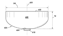
図6A、図6B、及び図6Cは、少なくとも幾つかの実施態様に従った3つの物体(objects)の側面図を示している。具体的には、図6Cは、切削ツールオブジェクト600を示しており、図6Bは、鋳型ツールオブジェクト602を示しており、図6Aは、ステムツールオブジェクト604を示している。オブジェクト600、602、及び604は、物理的なオブジェクトではない。むしろ、オブジェクトは、それらの三次元文字を含む、オブジェクトを画定する(任意の適切なファイルフォーマットにある)1以上の電子ファイル内のデータである。切削ツールオブジェクト600は、切削ツールオブジェクト600を鋳型ツールオブジェクト602から区別するのを助けるタブ606を除いて、円形断面(図のページの平面に対して垂直な平面において切削された断面)を有する。切削ツールオブジェクトは、円形断面に対して垂直であり且つ円形断面内で中心化される、中心軸608と、幾つかの実施形態では3インチである直径D3とを画定する。以下に更に議論するように、切削ツールオブジェクト600の円形断面は、解剖学的構造を取り囲む所定の外部形状であってよいが、他の形状が可能である。その上、切削ツールオブジェクト600は、(平坦な表面610から円錐区画614の頂部612まで測定された)厚さT3を画定する。例示的な切削ツールオブジェクト600は、切削ツールオブジェクト600の外面を取り囲む環状チャネル616も画定する。環状チャネル616の目的は、後の議論においてより明確になる。
6A, 6B, and 6C show side views of three objects according to at least some embodiments. Specifically, FIG. 6C shows the
図6Bは、例示的な鋳型ツールオブジェクト602を更に示している。鋳型ツールオブジェクト602は、円形断面(ページの平面に対して垂直な平面において切削された断面)を有する。また、鋳型ツールオブジェクト602は、鋳型ツールオブジェクト602を切削ツールオブジェクト600から区別するのを助けるのみならず、後述の鋳造において最終ネガ鋳型を整列させるのも助ける、円形ディスク又はノブ618を画定する。鋳型ツールオブジェクト602は、円形断面に対して垂直であり且つ円形断面内で中心化される中心軸620と、直径D2よりも大きい直径D4とを画定する。切削ツールオブジェクト602の直径D3が3インチであるならば、直径D4は、3インチに最終ネガ鋳型の壁厚の2倍を加えたものである。直径D3が変更されるならば、直径D4も変更される。以下に更に議論するように、鋳型ツールオブジェクト602の円形断面は、同様に、解剖学的構造を取り囲む所定の外部形状を画定する。その上、鋳型ツールオブジェクト602は、(平坦な表面622から円錐区画626の頂部624まで測定された)厚さT4を画定する。
FIG. 6B further shows an exemplary
図6Aは、更に、例示的なステムツールオブジェクト604を更に示している。以下の議論に基づいてより明確になるように、ステムツールオブジェクト604は、ポリマスリーブへの主孔を画定するのを助ける。例示的なステムツールオブジェクト604は、中心軸636を有する反転された切頭体の形態のタブ628を画定する。タブ628は、移行部分630に連結される。移行部分630の精密な形態は、複製されるべき解剖学的構造に依存する。解剖学的構造が口であるならば、移行部分は、ほぼ口の幅である長い寸法L(例えば、2インチ)を画定する。複製されるべき解剖学的構造が外部女性生殖器であるならば、ステムツールオブジェクト604は、第1の翼632又は第2の翼634を省略してよい(各翼は、移行部分630を通じる破線によって画定される)。最後に、複製されるべき解剖学的構造が肛門であるならば、両方の翼632及び634が省略されてよい。幾つかの場合には、翼は使用前に電子的に除去されてよく、他の場合において、ツールは、各々の可能な解剖学的構造について1つずつ、3つのステムツールオブジェクトを含んでよい。
FIG. 6A further shows an exemplary
図7A及び図7Bは、それぞれ、少なくとも幾つかの実施態様に従った、鋳型ツールオブジェクト及びステムツールオブジェクトの俯瞰図を示している。具体的には、図7Aの眺望は、鋳型ツールオブジェクト602の上面622を示しており、よって、鋳型ツールオブジェクト602が円形断面を有することを示している。また、図7Aに見えるのは、鋳型ツールオブジェクト602の中心軸620であるが、中心軸620は、図7Aの眺望においてページに対して垂直であり、よって、中心軸620は、ドットとして示されている。例示的な実施形態において、鋳型ツールオブジェクト602は、上面622上に環状トラフ638も画定し、環状トラフ638は、上面622内に中心化され、中心軸620を外接して取り囲む。環状トラフ638は、直径D4よりも小さい直径D5を画定する。例示的な実施形態において、任意の場所での直径D4と直径D5との間の距離は、最終ネガ鋳型の壁厚を最終的に画定し、且つ制御する。切削ツールオブジェクト600の上面610の眺望は、簡潔性のために省略されており、よって、鋳型ツールオブジェクト602の上面622の眺望と酷似しているが、環状トラフ638を有さない。
7A and 7B show bird's-eye views of the template tool object and the stem tool object, respectively, according to at least some embodiments. Specifically, the view of FIG. 7A shows the
図7Bは、例示的なステムツールオブジェクト604の俯瞰図を示している。具体的には、図7Bの眺望は、中心軸636と共にタブ628を示しているが、中心軸636は、図7Bの眺望においてページに対して垂直であり、よって、中心軸636は、ドットとして示されている。例示的な移行部分630は、長さL、並びに幅Lの半分未満の、幾つかの場合には幅Lの4分の1未満の幅Wを含む、長円形断面を画定する。ステムツールオブジェクト604は、よって、口である解剖学的構造のためにあるが、湾曲した破線に沿って翼632及び/又は634の一方又は両方を除去することによって、ステムツールオブジェクト604は、他の解剖学的構造のために構成されてよい。
FIG. 7B shows a bird's-eye view of an exemplary
ここで、より正確には、ポジモデルを作成するために、所定の外部形状のみならず、幾つかの場合には所定の深さを有するよう、初期モデル308を切削することは、概念的には、先ず、押出後の初期モデル308を切削ツールオブジェクト600と交差又は合体させ、次に、切削ツールオブジェクト600と交差しない初期モデル308の部分を除去することとして記載されることができる。図5及び図6を同時に参照すると、例示的な実施形態において、解剖学的構造の中心又は中心軸は、初期モデル308内の解剖学的構造の特徴(構成)(features)に基づいて識別される。図4の眺望において、特徴を識別することは、外部女性生殖器の陰唇302及び陰唇304を識別すること、陰唇の交差部(intersection)を識別すること(例示的な交差部500は破線500として示されている)、会陰300又は陰核包皮306のうちの少なくとも1つを識別することを含んでよい。識別された特徴の一部又は全部から、長手方向中心軸418が識別されてよく、中心は、(例えば、破線500によって示される陰唇の交差部にあるような)初期モデル308の外面及び長手方向中心軸418の交差部である。複製されるべき解剖学的構造が口であるならば、特徴は、上唇、下唇、(「キューピッド弓(cupids bow)」をもたらす)媚薬峰(philtra ridge)、及びオトガイ唇溝(mentolabial sulcus)を含んでよい。そのような特徴を識別することは、例えば、イメージ内の特徴(例えば、顔特徴)を見出すように設計されたソフトウェアによって又は人間の観察者によって、プログラム的に実行されてよい。
Here, more accurately, cutting the
ひとたび中心及び/又は長手方向中心軸418が見出されると、例示的な方法は、押出後、切削ツールオブジェクト600を初期モデル308と合体させることを含んでよい。より正確には、例示的な実施形態において、合体させることは、切削ツールオブジェクト600の中心軸608を解剖学的構造の中心から所定の距離内に配置することを含む。幾つかの場合において、中心軸608は、長手方向中心軸418に平行に、長手方向中心軸418の所定の距離内に配置される。更に他の場合には、中心軸608は、長手方向中心軸418と同軸に配置される。次に、切削ツールオブジェクト600は、初期モデル308と交差させられる。例えば、中心軸608が長手方向中心軸418と同軸である状況において、切削ツールオブジェクト600は、2つが3D空間で交差し、円錐区画614が解剖学的構造の外面の外側又は「上方」に存在するように、初期モデル308内に押し「込まれる」(push “into”)。2つのステップとして記述されているが、配置すること及び交差させることは同時に行われてよてい。
Once the central and / or longitudinal
図8は、少なくとも幾つかの実施態様に従った、初期モデルと部分的に交差させられた切削ツールオブジェクトの斜視図を示している。具体的には、図8の例において、切削ツールオブジェクト600の中心軸608は、(図8では見えない)解剖学的構造の中心を通過する長手方向中心軸418と同軸である。図示のように、切削ツールオブジェクト600の容積の一部は、初期モデル308によって画定される容積の一部と重なり合うか或いは交差する。
FIG. 8 shows a perspective view of a cutting tool object partially intersected with the initial model, according to at least some embodiments. Specifically, in the example of FIG. 8, the
図9は、少なくとも幾つかの実施態様に従った、図8の線9−9に沿って撮られた断面図を示している。具体的には、図9において見えているのは、外部女性生殖器の形態の例示的な解剖学的構造の側面図を含む、初期モデル308である。図9において同様に見えているのは、破線で示されているが、切削ツールオブジェクト600である。よって、切削ツールオブジェクト600は、解剖学的構造が所定の外部形状内でほぼ中心化されるように、初期モデル308と交差させられる。その上、初期モデル308と切削ツールオブジェクト600との交差は、解剖学的構造の最遠位部分900が切削ツールオブジェクト600の外面902からの所定のオフセットO内に存在する(例えば、所定のオフセットが1センチメートル以下である)ときに、停止してよい。
FIG. 9 shows a cross-sectional view taken along line 9-9 of FIG. 8 according to at least some embodiments. Specifically, what is visible in FIG. 9 is an
初期モデル308と切削ツールオブジェクト600との関係がひとたび決定されると、モデルとオブジェクトとの例示的な合体は、切削ツールオブジェクト500の外側に存在する初期モデル308の部分を除去することに進む。図9において、除去される部分は、単線網状陰影によって示されている。然る後、初期モデル308と交差しない切削ツールオブジェクト600の部分は除去される。図9において、除去される部分は、二重線網状陰影によって示されている。よって、除去するステップは、ポジモデルを作り出す。少なくとも幾つかの例示的なシステムにおいて、初期モデル308と切削ツールオブジェクト608との交差は、ZBRUSH(登録商標)ブランド彫刻ソフトウェアプログラムにおいて実行される。非交差部分を除去する特定の場合において、その操作は、ブール除去(Boolean remove)と呼ばれるが、他の彫刻ソフトウェアプログラムは異なる用語を使うことがある。
Once the relationship between the
図10は、少なくとも幾つかの実施態様に従った、例示的なポジモデルの斜視図を示している。具体的には、上記で議論したように、切削ツールオブジェクト608で初期モデル308を切削することによって、残存するものは、所定の外部形状によって取り囲まれた解剖学的構造を示すポジモデル1000である。ポジモデル1000は、ポリマスリーブ402(図4)の外面上に複製された男性マスターベーションデバイス120(同様に図4)の一部の形態を表す。ポジモデル1000は切削ツールオブジェクト600から作製されるので、ポジモデル1000は、(幾つかの場合には長手方向中心軸418と同軸である)中心軸608に沿って続行するか(carries)或いは中心軸608を引き継ぐ(inherits)。更に、ポジモデル1000は切削ツールオブジェクト600から作製されたので、ポジモデル1000は、環状チャネル616に沿って続行するか或いは継承する。幾つかの例示的な実施形態において、本方法は、直ちに、レプリカの解剖学的構造を有するポリマスリーブ402を鋳造するために使用される(以下に更に議論する)ネガ鋳型を作製することに進んでよい。しかしながら、他の例示的な実施形態において、ポジモデル1000は、最終製品をより実物そっくりにするために並びに/或いは特定の付加的特徴を実現するために操作されてよい。
FIG. 10 shows a perspective view of an exemplary positive model according to at least some embodiments. Specifically, as discussed above, by cutting the
図10を更に参照すると、ポジモデル1000は、初期モデルを切削ツールオブジェクトと合体させ、次に、初期モデル308と交差しない切削ツールオブジェクトの部分を除去することによって、作製された。よって、ポジモデル1000の外面の一部は、初期モデルから持ち越されたテクスチャ特徴(texture features)を有し、外面の一部は、テクスチャを有さないで滑らかである。初期モデル308からのテクスチャ特徴を有する部分と滑らかな表面との間の境界は、線1002及び1004によって図10に示されている。例えば、線1002の左側にあるポジモデルの外面のその部分は、テクスチャ特徴を有さないことがある一方で、(陰唇304により近い)ポジモデル1000の外面のその部分は、初期モデルから持ち越された表面テクスチャを有する可能性が高い。少なくとも幾つかの実施態様によれば、ポジモデル1000の外面は、ポジモデルの鋭い移行部(例えば、線1002)で滑らかにされる。より具体的には、例示的な場合において、所定の幅(例えば、1センチメートル)を有し且つ鋭い移行部に沿って中心化されるゾーンは、ゾーンに亘る表面テクスチャを平均化することによって滑らかにされてよい。
Further referring to FIG. 10, the
更に、被験者100(図1)の皮膚テクスチャの微細な詳細は、ビデオ及び/又は静止画像では見えないことがある。そのような皮膚テクスチャが見えるとしても、初期モデルを作製するプロセスにおいて、皮膚テクスチャの詳細の一部又は全部が失われることがある。よって、幾つかの例示的実施形態において、解剖学的構造の特定の特徴は、表面テクスチャを含むか或いは強化するように修正されてよい。例えば、陰核包皮306、陰唇302、及び陰唇304は、皮膚テクスチャにより密接に適合するように表面テクスチャを含むか或いは強化するように修正されてよい。関連して、解剖学的構造のビデオ及び/又は静止画像を取り込む前に除去された毛の存在を模倣するテクスチャのような特徴を追加されてよい。被験者100が解剖学的構造を十分に準備しなかったならば、その交差部をより良く画定するために陰唇を「開く」ことのような物理的な修正が行われてよい。ポジモデル1000は、例えば、ポジモデル1000の所定の外部形状に沿って被験者100の特異な識別番号を含むように修正されてもよい。被験者100が職業的な芸能人である場合、ポジモデルは、被験者のステージ名、署名、商標、又は他の識別表示のような、ブランド情報を含むように修正されてもよい。ポジモデル1000が上記で議論されたように修正されるか否かに拘わらず、例示的な方法における次のステップは、ポジモデル1000から解剖学的構造のネガモデルを作製することである。
In addition, the fine details of the skin texture of subject 100 (FIG. 1) may not be visible in video and / or still images. Even if such skin textures are visible, some or all of the skin texture details may be lost in the process of creating the initial model. Thus, in some exemplary embodiments, certain features of the anatomical structure may be modified to include or enhance surface texture. For example, the
ネガモデルを作製することは、概念的には、ポジモデル1000を鋳型ツールオブジェクト602と交差し或いは合体させ、次に、ポジモデルと交差する鋳型ツールオブジェクト602の部分を除去することとして記載されることができる。図6及び図10を同時に参照すると、例示的な実施形態において、ネガモデルを作製することは、鋳型ツールオブジェクト602をポジモデル1000と合体させることを含む。例示的な実施形態において、合体させることは、鋳型ツールオブジェクト602の中心軸620をポジモデル1000の中心の所定の距離内に配置することによってよい。鋳型ツールオブジェクト602内のポジモデル1000の中心化は、鋳型ツールオブジェクト602の平坦表面622上の環状トラフ638(図7A)に対するポジモデル1000の関係を見ることによって確認及び矯正されてよい。幾つかの場合において、中心軸620は、中心軸608に平行に、中心軸608の所定の距離内に配置される。更に他の場合には、中心軸620は、中心軸608と同軸に配置され、その場合、ポジモデル1000は、自動的に中心化。次に、鋳型ツールオブジェクト602は、ポジモデル1000と交差させられる。例えば、中心軸620がポジモデル1000の中心軸608と同軸である場合、鋳型ツールオブジェクト602は、2つが3D空間内で交差し、円錐区画626がポジモデル1000内の解剖学的構造の外面の外側又は「上方」に存在するように、ポジモデル1000内に押し「込まれる」。2つのステップとして記述されているが、配置すること及び交差させることは同時に行われてよい。
Creating a negative model can be conceptually described as crossing or coalescing the
図11は、少なくとも幾つかの実施態様に従った、ポジモデル1000と交差させられた鋳型ツールオブジェクト602の側断面図を示している。具体的には、図11の例において、鋳型ツールオブジェクト602の中心軸620は、ポジモデル1000の中心軸608と同軸である。中心軸620及び中心軸608を有することは厳密には要求されないが、それらを同軸にすることは、合体のプロセスを速めるのみならず、操作を自動化することも可能にすることに留意のこと。例示的な実施形態において、鋳型ツールオブジェクト602は、鋳型ツールオブジェクトの平坦な表面622が環状チャネル616と接触するまで共有軸に沿って並進させることによって、ポジモデル1000と交差させられる。よって、切削ツールオブジェクトの環状チャネル616は、ポジモデル1000によって引き継がれ、中心軸608/620に沿う深さ整列のためのガイドとなる。鋳型ツールオブジェクト602及びポジモデル1000がひとたび適切に整列させられると、例示的な方法は、ポジモデル1000と交差する鋳型ツールオブジェクト602の部分を除去し、次に、ポジモデル1000を除去することを含む。残存する例示的な部分は、網状陰影によって図11に示されている。残存するのは、ネガモデルである。
FIG. 11 shows a side sectional view of the
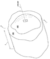
図12は、少なくとも幾つかの実施態様に従ったネガモデルの斜視図を示している。具体的には、上述のように、ポジモデル1000と交差する鋳型ツールオブジェクト602の部分を除去することによって、残存するものは、所定の外部形状によって取り囲まれた解剖学的構造のネガバージョンを示す、ネガモデル1200である。ネガモデル1200は、ポリマスリーブ402(図4)の外面上に複製された男性マスターベーションデバイス120(同様に図4)の一部の形態のネガを表す。ネガモデル1200は、鋳型ツールオブジェクト600から作製されたので、ネガモデル1200は、鋳型ツールオブジェクトから中心軸620に沿って続行するか、或いは中心軸620を引き継ぐ。ネガモデル1200は、例示的な場合には直径D4と直径D5との間の距離である(図7A)、壁厚T5を画定する。解剖学的構造のレプリカがデバイスを通じる主通路に至る孔を有することを意図しない状況において、例示的な方法は、ネガモデルを印刷してネガ鋳型を作製することに直接的に進んでよい。しかしながら、最終製品が男性マスターベーションデバイスである実施形態において、ネガモデル1200は、鋳造プロセス中に主孔412(図4)及び主通路の作製をサポートするように更に修正される。
FIG. 12 shows a perspective view of a negative model according to at least some embodiments. Specifically, as described above, by removing the portion of the
主孔及び主通路の作製をサポートするためにネガモデルを修正することは、ステムツールオブジェクト604を解剖学的構造のネガモデルの外表面上に配置することを含む(ブロック210、図2)。図6及び図12を同時に参照すると、例示的な実施形態において、最終ネガモデルを作製することは、ステムツールオブジェクト604をネガモデル1200と合体させることを含む。例示的な実施形態において、合体させることは、ステムツールオブジェクト604の中心軸636をネガモデル1200の中心の所定の距離内に配置することによってよい。幾つかの場合において、中心軸636は、中心軸620に平行に、中心軸620の所定の距離内に配置される。更に他の場合には、中心軸636は、中心軸620と同軸に配置され、その場合、ステムツールオブジェクト604は、ネガモデル1200内で自動的に中心化される。次に、ステムツールオブジェクト604は、ネガモデル1200に対して当接させられる。例えば、中心軸636がネガモデル1200の中心軸620と同軸である状況において、ステムツールオブジェクト604は、2つが3D空間内で少なくとも当接し、場合によっては交差するように、ネガモデル1200内に押し「込まれる」。2つのステップとして記載されているが、配置すること及び当接させることは同時に行われてよい。
Modifying the negative model to support the fabrication of the main hole and main passage involves placing the
図13は、少なくとも幾つかの実施態様による、ネガモデル1200と交差させられたステムツールオブジェクト604の斜視図を示している。具体的には、図13の例において、ステムツールオブジェクト604の中心軸620は、ネガモデル1200の中心軸620と同軸である。中心軸636及び中心軸620を有することは厳密には要求されないが、それらを同軸にすることは、合体のプロセスを速めるのみならず、操作を自動化するのを可能にすることに留意のこと。例示的な実施形態において、ステムツールオブジェクト604は、ステムツールオブジェクト604の底がネガモデルに当接するまで共有軸に沿って並進することによって、ネガモデル1200と交差させられる。解剖学的構造が外部女性生殖器である例において、ステムツールオブジェクト604は、陰唇の交差部に整列させられた長さLを有する。ステムツールオブジェクト604及びネガモデル1200がひとたび適切に整列及び当接させられると、例示的な方法は、ステムツールオブジェクト604及びネガモデル1200を合体することが最終ネガモデル1300を作製することを含む。
FIG. 13 shows a perspective view of the
依然として図13を参照すると、最終ネガモデル1300は、ステムツールオブジェクト604とネガモデル1200とを合体させることによって作製された。しかしながら、ステムツールオブジェクト604とネガモデル1200とを合体させることは、ネガモデル1200からの表面テクスチャとは異なるステムツールオブジェクト604からの表面テクスチャを有する境界を作り出すことがある。例示的な境界が線1302によって示されている。例えば、線1302より下の最終ネガモデル1300のその部分は、ポジモデルから(ネガ表現において)持ち越されたテクスチャ特徴を有することがある一方で、線1302より上のその部分は、ステムツールオブジェクト604の表面テクスチャを有する。少なくとも幾つかの実施態様によれば、最終ネガモデル1300の外面は、最終ネガモデル1300の鋭い移行部(例えば、線1302)で滑らかにされる。より具体的には、例示的な場合には、所定の幅を有し且つ鋭い移行部に沿って中心化されるゾーンは、ゾーンに亘る表面テクスチャを平均化することによって滑らかにされてよい。
Still referring to FIG. 13, the final
図12及び図13の例示的な実施形態は、外部女性生殖器である解剖学的構造に関するものであり、よって、ステムツールオブジェクト604は、単一の翼のみを含む(或いは特定のステムツールオブジェクトが使用される)。しかしながら、解剖学的構造が口であるならば、ステムツールオブジェクト604は、両方の翼を有する。解剖学的構造が肛門であるならば、両方の翼は、ステムツールオブジェクト604から省略される(そして、特定のステムツールオブジェクトが使用される)。
The exemplary embodiments of FIGS. 12 and 13 relate to an anatomical structure that is an external female reproductive organ, so that the
例示的な方法における次のステップは、最終ネガモデル1300を印刷して、鋳造プロセスにおいて使用されるネガ鋳型を作製することである。少なくとも幾つかの例示的な実施態様において、最終ネガモデル1300は、.STLフォーマットにある電子ファイルのような、電子ファイルに含められるデータである。データファイルは、溶着モデリング(FDM)、ステレオリソグラフィ(SLA)、デジタル光処理(DLP)、選択的レーザ焼結(SLS)、選択的レーザ溶融(SLM)、積層オブジェクト製造(LOM)、デジタルビーム溶融(EBM)のような、任意の適切な3Dプリンタ又は3Dプリンタ技術に提供されてよい。例えば、3Dプリンタは、Formlabs, Inc.(http://3dsystems.com)から入手可能なFormlabs 3Dプリンタであってよい。更に他の例示的な実施形態において、最終ネガモデル1300は、3D Systems Inc.(https://3dsystems.com)から入手可能な3D Systemsプリンタ(例えば、3D Systemsモデル図4)上で印刷されてよい。すなわち、3Dプリンタ112(図1)を介して、最終ネガモデル1300は、本明細書ではネガ鋳型と呼ばれる、物理的なものになる。よって、図13は、最終ネガモデル1300を示すのみならず、ネガモデルから印刷されるネガ鋳型の例も示す。
The next step in the exemplary method is to print the final
図1に戻る。よって、3Dプリンタ112は、鋳造プロセスに使用されるべきネガ鋳型116を印刷する。例示的なシステムにおいて、3Dプリンタ112は、レーザ光の焦点によって硬化される液体樹脂を使用するが、任意の適切な3D印刷技術が使用されてよい。3Dプリンタ112がひとたび印刷を完了すると、ネガ鋳型116がプリンタから除去され、作製されたあらゆる支持構造が除去される。残留樹脂を除去するために、ネガ鋳型116は、アルコール洗浄にさらされてよい。鋳造プロセスと関連付けられるパラメータ(例えば、液体ポリマの温度)に依存して、ネガ鋳型116は、例えば、炉内でネガ鋳型116を焼成することによって、硬化される必要があることがある。鋳造プロセス及び/又は樹脂の特性に依存して、硬化ステップは省略されてよい。本明細書は、次に、例示的な鋳造プロセスに向かう。
Return to FIG. Thus, the
図14は、少なくとも幾つかの実施態様に従った、鋳造システム114の斜視図を示している。具体的には、図14は、第1の鋳型部材1404と、第2の鋳型部材1406とを含む、例示的な外側鋳型アセンブリ118を示している。各鋳型部材1404及び1406は内面を画定するが、図14の眺望では、鋳型部材1406の内面1408のみが見える。鋳型部材1406の内面1408は、ポリマスリーブ402(図4)の外面の一部の、特に、外側カバー404(図4)内に存在するポリマスリーブ402の一部のネガイメージの半分を形成する。同様に、鋳型部材1404の内面は、ポリマスリーブ402のネガイメージの他の半分を形成する。
FIG. 14 shows a perspective view of the
鋳造システム114は、外側鋳型アセンブリ118によって画定される内面に対して動作的な関係に配置されたネガ鋳型116を更に含む。上記で詳細に議論したように、ネガ鋳型116は、ポリマスリーブ402(図4)の挿入端406(図4)の外側部分のネガイメージを構造的に画定する。別の言い方をすると、ネガ鋳型116は、解剖学的構造のネガイメージを画定し、ポリマスリーブ402の挿入端406を鋳造するために使用される。幾つかの例示的なシステムにおいて、第1の鋳型部材1404及び第2の鋳型部材1406は、アルミニウムのような、金属材料から研削されてよい。更に、例示的な実施形態において、ネガ鋳型116は、要求に応じて、例えば、上記で議論した3D印刷技術によって作製される。ネガ鋳型116は、ロッド部材1414に連結する。ロッド部材1414の外面は、ポリマスリーブ402を通じる主通路の内面のネガイメージを画定する。
The
鋳造又は成形プロセスは、外側鋳型アセンブリ118に対する動作的な関係にネガ鋳型116を配置し、ネガ鋳型をステムツールオブジェクトと合体させることによって作製されたネガ鋳型116の(図14では見えない)タブ628にロッド部材1414を連結することを含んでよい。外側鋳型アセンブリ118は、様々な構成要素の周囲で閉じられ、何らかの方法で所定の場所に保持される。液体形態のポリマ材料は、注入孔1418を通じた注入のように、内面1408によって画定される容積内に注入ポートを通じて注入される。液体形態のポリマ材料は、ネガ鋳型116及び内面1408によって画定される容積を満たし、空気を移し(displacing)、次に、ポリマ材料が硬化されるのを可能にする。ひとたび硬化されると、外側鋳型アセンブリ118は、再び開かれ、ロッド部材1414は、主通路から引き出され、ポリマスリーブ402は、ネガ鋳型116から除去されてよい。注入孔の内側で硬化されたポリマ材料及び外側鋳型アセンブリの界面によって形成されたあらゆる鋳型シーム(継ぎ目)又はマーク(印)を除去するために、ポリマスリーブ402のトリミングが実行されてよい。幾つかの場合において、作製されたポリマスリーブ402は、(例えば、滑石粉の塗布によって)表面張力を低下させるために化合物で処理されてよい。然る後、ポリマスリーブ402は、外側カバー404内に配置され、被験者100に発送されてよい。
The casting or forming process places the
この点について議論した様々な実施形態は、被験者100が配偶者のために男性マスターベーションデバイス120の作製を依頼すると仮定している。従って、男性マスターベーションデバイス120において具現される解剖学的構造のレプリカは、ビデオ及び/又は静止画像から作製され一回限りの装置である可能性が高い。しかしながら、被験者100は、解剖学的構造のレプリカを公衆に販売する目的でデータをアップロードする職業的なモデルであってよい。そのような職業的な被験者100は、レプリカ作製プロセスをより良く制御するインセンティブを有することがある。例えば、被験者100は、上記で議論したステップのうちの特定のものを迂回して、適切なポイントクラウドフォーマットにおいて直接的に男性マスターベーションデバイスの作製のための情報を提供することがある。同様に、職業的な被験者1000は、全ての所望の表面テクスチャ、署名、商標、及び同等物を有する、初期モデルを直接的に提供することがある。そのような場合、例示的なプロセスは、ポジモデル1000の作製及び後続のステップに直接的に進んでよい。よって、被験者100の素養並びにネガモデル及び鋳造のオンデマンド作製の目標に依存して、上記で議論したステップの特定のものが省略されてよい。
Various embodiments discussed in this regard assume that subject 100 requests the production of a
この点について議論した様々な実施形態は、解剖学的構造のレプリカが主通路を有し、よって、男性マスターベーションデバイスであると仮定した。しかしながら、身体的に興奮した状態又は弛緩した状態のいずれかにおける、外部男性生殖器(例えば、陰茎や睾丸)のレプリカを作製することも可能である。そのような状況では、主通路は、関連する考慮事項(例えば、ステムツールの使用)と共に省略される。その上、主通路のない外部男性生殖器を鋳造するときには、幾つかの場合において、ポリマ材料又はエラストマー材料が(例えば、シリコンゲルを作り出す2成分混合物から)室温で鋳造されてよい。室温鋳造の故に、単回使用鋳型アセンブリは、温度弾性である必要はない。これらの考慮事項を全てひとまとめにして考えると、写真測量ソフトウェアによって作製される初期モデルは、3Dプリンタに直接的に渡されてよい。ソフトウェア彫刻プログラムが使用される限りにおいて、そのようなものは、クリーンアップ、識別表示の追加であり、専門家の場合には、署名、商標、及び同等物である。(直接的にはポジモデルである)初期モデルは、3Dプリンタに直接的に渡されてよく、3Dプリンタは、幾つかの場合には、初期モデルからネガ鋳型を自動的に作製し且つ印刷することができる「シェルツール(shell tool)」を有する。そのようなシェルツールは、独立型(スタンドアローン)3D構造でなく、主通路を含む、解剖学的構造のレプリカには適用可能でない。 Various embodiments discussed in this regard have assumed that replicas of the anatomical structure have a main passage and are therefore male masturbation devices. However, it is also possible to make replicas of the external male reproductive organs (eg, penis and testicles), either in a physically excited or relaxed state. In such situations, the main corridor is omitted with relevant considerations (eg, the use of stem tools). Moreover, when casting an external male genitalia without a main passage, in some cases the polymer or elastomeric material may be cast at room temperature (eg, from a binary mixture that produces a silicon gel). Due to room temperature casting, the single use mold assembly need not be thermoelastic. Considering all these considerations together, the initial model created by the photogrammetric software may be passed directly to the 3D printer. To the extent that software engraving programs are used, such are the addition of cleanup, identification, and in the case of professionals, signatures, trademarks, and equivalents. The initial model (directly a positive model) may be passed directly to the 3D printer, which in some cases automatically creates and prints a negative mold from the initial model. Has a "shell tool" that can be used. Such shell tools are not stand-alone 3D structures and are not applicable to replicas of anatomical structures, including the main corridor.
例示的なレプリカシステム102は、2以上(2つ又はそれよりも多く)のコンピュータシステムを含む。図15は、少なくとも幾つかの実施態様に従ったコンピュータシステムを示している。コンピュータシステム1500は、顧客インタフェースコンピュータシステム108、及び/又は鋳型作製コンピュータシステム110の一例である。例示的なコンピュータシステム1500は、メモリ1504に連結されたプロセッサ1502と、記憶システム又は長期記憶デバイス1506とを含む。プロセッサ1502は、任意の現在入手可能な若しくは後に開発されるプロセッサ、又は一群のプロセッサであってよい。メモリ1504は、プロセッサ1502のための作業メモリを形成するランダムアクセス記憶装置(RAM)であってよい。幾つかの場合において、データ及びプログラムは、コンピュータシステム1500の動作の一部として、記憶デバイス1506からメモリ1504にコピーされてよい。
An
長期記憶デバイス1506は、非一時的コンピュータ可読媒体とも呼ばれる不揮発性長期記憶装置を実装するデバイス又は複数のデバイスである。幾つかの場合において、長期記憶デバイスは、ハードドライブ又はソリッドステートドライブであるが、他の例は、光ディスク1508、「フロッピー(登録商標)」ディスク1510、及びフラッシュメモリデバイス1512を含む。よって、論議したプログラム的な側面を実装するために使用される様々なプログラムは、長期記憶装置1506に格納され、プロセッサ1502によって実行されることがある。関連して、様々な実施形態の様々なオブジェクト及びモデルの作製及び相互作用は、プロセッサ1502によって実施され、テレメトリチャネル1514を介して(例示的な光ディスク1508、フロッピーディスク1510、フラッシュメモリデバイス1512、又は磁気テープを含む)記憶装置1506に通信されてよい。換言すれば、記憶装置1506は、プロセッサによって実行されるときに、上記で議論したプログラム的なステップのいずれかを実行する命令を記憶してよい。
The long-
上記の議論は、本発明の原理及び様々な実施形態を例示することが意図されている。ひとたび上記開示が完全に理解されるならば、数多くの変形及び修正が当業者に明らかになるであろう。以下の特許請求の範囲は、そのような変形及び修正の全てを包含するように解釈されるべきことが意図されている。 The above discussion is intended to illustrate the principles and various embodiments of the present invention. Once the above disclosure is fully understood, numerous modifications and modifications will be apparent to those skilled in the art. The following claims are intended to be construed to include all such modifications and modifications.
Claims (31)
第1のコンピュータシステムによって、被験者の解剖学的構造の複数の画像を受け取るステップであって、前記複数の画像の各画像は、前記解剖学的構造に対する異なる視認角から得られる、ステップと、
前記第1のコンピュータシステムによって、前記解剖学的構造の外面の初期モデルを含むオブジェクトファイルを作成するステップと、
前記第1のコンピュータシステムによって、前記初期モデルを、前記解剖学的構造を取り囲む所定の外部形状に切削するステップであって、切削することは、前記所定の外部形状内に前記解剖学的構造のポジモデルを作製する、切削するステップと、
前記第1のコンピュータシステムによって、前記ポジモデルから前記解剖学的構造のネガモデルを作製するステップと、
前記第1のコンピュータシステムによって、前記解剖学的構造のオリフィスに対する関係において前記ネガモデルの外面にステムツールオブジェクトを配置し、それによって、最終ネガモデルを作製する、ステップと、
三次元プリンタを介して、前記最終ネガモデルを印刷して、ネガ鋳型を作製するステップと、
該ネガ鋳型を使用して前記解剖学的構造のレプリカを鋳造するステップとを含む、
方法。 A method of making a replica of an anatomical structure
A step of receiving a plurality of images of a subject's anatomy by a first computer system, wherein each image of the plurality of images is obtained from different viewing angles to the anatomy.
A step of creating an object file containing an initial model of the outer surface of the anatomical structure by the first computer system.
The step of cutting the initial model into a predetermined external shape surrounding the anatomical structure by the first computer system, and cutting is the cutting of the anatomical structure within the predetermined external shape. Creating a positive model, cutting steps,
A step of producing a negative model of the anatomical structure from the positive model by the first computer system.
The first computer system places a stem tool object on the outer surface of the negative model in relation to the orifice of the anatomical structure, thereby creating the final negative model.
The step of printing the final negative model through a three-dimensional printer to prepare a negative mold, and
Including the step of casting a replica of the anatomical structure using the negative mold.
Method.
前記初期モデル内の前記解剖学的構造の特徴に基づいて前記解剖学的構造の中心を識別するステップと、
切削ツールオブジェクトを前記初期モデルと合体させるステップとを更に含み、
該合体させるステップは、
前記解剖学的構造の前記中心の所定の距離内に前記切削ツールオブジェクトの中心軸を配置するステップであって、前記切削ツールオブジェクトは、前記所定の外部形状と、所定の深さとを画定する、ステップと、
前記切削ツールオブジェクトを前記初期モデルと交差させるステップと、
前記切削ツールオブジェクトの外側に存在する前記解剖学的構造の部分を除去し、
次に、前記初期モデルが交差しない前記切削ツールオブジェクトの部分を除去し、前記ポジモデルを作製するステップとによる、
請求項1に記載の方法。 The step of cutting the initial model is
The step of identifying the center of the anatomy based on the characteristics of the anatomy in the initial model,
Further including the step of merging the cutting tool object with the initial model.
The step of coalescing is
A step of arranging the central axis of the cutting tool object within a predetermined distance of the center of the anatomical structure, wherein the cutting tool object defines the predetermined external shape and the predetermined depth. Steps and
The step of crossing the cutting tool object with the initial model,
Remove any portion of the anatomical structure that is outside the cutting tool object.
Next, according to the step of removing the portion of the cutting tool object that the initial model does not intersect and creating the positive model.
The method according to claim 1.
前記初期モデル内で外部女性生殖器の陰唇を識別するステップと、
該陰唇との交差部を識別するステップと、
前記外部女性生殖器の会陰又は前記外部女性生殖器の陰核包皮のうちの少なくとも1つを識別するステップとを更に含む、
請求項2に記載の方法。 The step of identifying the anatomical features
The step of identifying the labia of the external female genitalia within the initial model,
The step of identifying the intersection with the labia,
Further comprising the step of identifying at least one of the external female genital perineum or the external female genital clitoral hood.
The method according to claim 2.
鋳型ツールオブジェクトの中心軸を前記ポジモデルの中心の所定の距離内に配置し、
前記鋳型ツールオブジェクトを前記ポジモデルと交差させ、
前記ポジモデルと交差する前記鋳型ツールオブジェクトの部分を除去し、それによって、前記ネガモデルを作製することによって、
前記鋳型ツールオブジェクトを前記ポジモデルと合体させるステップを含む、
請求項1に記載の方法。 The step of preparing the negative mold is
The central axis of the mold tool object is placed within a predetermined distance from the center of the positive model.
Cross the mold tool object with the positive model and
By removing the portion of the mold tool object that intersects the positive model and thereby creating the negative model.
Including the step of merging the template tool object with the positive model.
The method according to claim 1.
前記ステムツールオブジェクトのチャネル軸を前記ネガモデルの中心の所定の距離内に配置するステップと、
前記ステムツールオブジェクトの入口表面を前記ネガモデルと当接させるステップと、
次に、前記ステムツールオブジェクトを前記ネガモデル内に合体させるステップとを更に含む、
請求項1に記載の方法。 The step of placing the stem tool object is
A step of arranging the channel axis of the stem tool object within a predetermined distance in the center of the negative model,
The step of bringing the entrance surface of the stem tool object into contact with the negative model,
Next, it further includes a step of incorporating the stem tool object into the negative model.
The method according to claim 1.
前記第1のコンピュータシステムによって、複数のフレームを含むビデオを受け取るステップと、
前記第1のコンピュータシステムによって、前記ビデオから前記複数の画像を抽出するステップであって、前記複数の画像の各画像は、前記ビデオのフレームに対応する、ステップとを更に含む、
請求項1に記載の方法。 The step of receiving the plurality of images is
The step of receiving a video containing a plurality of frames by the first computer system,
A step of extracting the plurality of images from the video by the first computer system, wherein each image of the plurality of images further includes a step corresponding to a frame of the video.
The method according to claim 1.
第2のコンピュータシステムによって、前記被験者が成年であることを検証するステップと、
前記第2のコンピュータシステムによって、特異な識別番号を前記被験者に割り当てるステップとを更に含み、
前記複数の画像を受け取るステップは、前記特異な識別子の下で、前記第1のコンピュータシステムが、前記特異な識別子以外の前記被験者についての更なる情報を含まないことを受け入れるステップを更に含む、
請求項1に記載の方法。 Before receiving the multiple images
A step of verifying that the subject is an adult by a second computer system,
Further including a step of assigning a unique identification number to the subject by the second computer system.
The step of receiving the plurality of images further comprises accepting that, under the unique identifier, the first computer system does not contain further information about the subject other than the unique identifier.
The method according to claim 1.
プロセッサと、
該プロセッサに連結されるメモリとを含み、
該メモリは、プログラムを格納し、該プログラムは、前記プロセッサによって実行されるときに、前記プロセッサに、
前記解剖学的構造の複数の画像を受け取らせ、
前記解剖学的構造の外面の初期モデルを含むオブジェクトファイルを作成させ、
前記初期モデルを、前記解剖学的構造を取り囲む所定の外部形状に切削して、該所定の外部形状内に前記解剖学的構造のポジモデルを作製させ、
該ポジモデルから前記解剖学的構造のネガモデルを作製させ、
前記解剖学的構造のオリフィスに対する関係において前記ネガモデルの外面にステムツールオブジェクトを配置させることによって、最終ネガモデルを作製させ、
該最終ネガモデルを印刷させて、ネガ鋳型を作製させ、
前記複数の画像の各画像は、前記解剖学的構造に対する異なる視認角からのものである、
システム。 A system for creating negative models of anatomical structures
With the processor
Includes memory attached to the processor
The memory stores a program, and when the program is executed by the processor, the processor receives the program.
Receive multiple images of the anatomical structure
Create an object file containing an initial model of the outer surface of the anatomical structure.
The initial model is cut into a predetermined external shape surrounding the anatomical structure to produce a positive model of the anatomical structure within the predetermined external shape.
A negative model of the anatomical structure is prepared from the positive model.
The final negative model is made by placing the stem tool object on the outer surface of the negative model in relation to the orifice of the anatomical structure.
The final negative model was printed to produce a negative mold.
Each image of the plurality of images is from different viewing angles with respect to the anatomical structure.
system.
前記解剖学的構造の中心を識別させ、
切削ツールオブジェクトを前記初期モデルと合体させ、
該合体は、
前記切削ツールオブジェクトの中心軸を前記解剖学的構造の前記中心の所定の距離内に配置させ、
前記切削ツールオブジェクトを前記初期モデルと交差させ、且つ
前記切削ツールオブジェクトの外側に存在する前記解剖学的構造の部分を除去することによって、前記ポジモデルを作製することにより、
前記切削ツールオブジェクトは、前記所定の外部形状と、所定の深さとを画定する、
請求項18に記載のシステム。 When the processor cuts the initial model, the program sends the processor to the processor.
Identify the center of the anatomical structure
Combine the cutting tool object with the initial model and
The union is
The central axis of the cutting tool object is placed within a predetermined distance of the center of the anatomical structure.
By creating the positive model by crossing the cutting tool object with the initial model and removing a portion of the anatomical structure that is outside the cutting tool object.
The cutting tool object defines the predetermined external shape and the predetermined depth.
The system according to claim 18.
前記初期モデル内の前記解剖学的構造の特徴を識別させ、
該特徴に基づいて前記中心を識別させる、
請求項19に記載のシステム。 When the processor identifies the center of the anatomy, the program tells the processor.
Identifying the anatomical features within the initial model
The center is identified based on the feature.
The system according to claim 19.
外部女性生殖器の陰唇を識別させ、
該陰唇の交差部を識別させ、
前記外部女性生殖器の会陰又は前記外部女性生殖器の尿道口のうちの少なくとも1つを識別させる、
請求項21に記載のシステム。 When the processor identifies the feature of the anatomy, the program tells the processor.
Identify the labia of the external female genitals,
Identify the intersection of the labia
Identify at least one of the perineum of the external female genitalia or the urethral meatus of the external female genitalia.
The system according to claim 21.
前記プログラムは、前記プロセッサに、
鋳型ツールオブジェクトの中心軸を前記ポジモデルの中心の所定の距離内に配置させ、
前記鋳型ツールオブジェクトを前記ポジモデルと交差させ、且つ
前記ポジモデルと交差する前記鋳型ツールオブジェクトの部分を除去することによって、前記ネガモデルを作製させることによって、
前記鋳型ツールオブジェクトを前記ポジモデルと合体させる、
請求項18に記載のシステム。 When the processor creates the negative model
The program is delivered to the processor.
The central axis of the mold tool object is placed within a predetermined distance from the center of the positive model.
By crossing the mold tool object with the positive model and removing a portion of the mold tool object that intersects the positive model, the negative model is produced.
Combine the mold tool object with the positive model,
The system according to claim 18.
前記ステムツールオブジェクトのチャネル軸を前記ネガモデルの中心の所定の距離内に配置させ、
前記ステムツールオブジェクトの入口表面を前記ネガモデルと当接させ、
次に、前記ステムツールオブジェクトを前記ネガモデル内に合体させる、
請求項18に記載のシステム。 When the processor places the stem tool object, the program puts the stem tool object on the processor.
The channel axis of the stem tool object is placed within a predetermined distance in the center of the negative model.
The entrance surface of the stem tool object is brought into contact with the negative model.
Next, the stem tool object is merged into the negative model.
The system according to claim 18.
複数のフレームを含むビデオを受け取らせ、
該ビデオから前記複数の画像を抽出させ、
前記複数の画像の各画像は、前記ビデオのフレームに対応する、
請求項18に記載のシステム。 When the processor receives the plurality of images, the program sends the processor to the processor.
Receive a video containing multiple frames
The plurality of images are extracted from the video, and the images are extracted.
Each image of the plurality of images corresponds to a frame of the video.
The system according to claim 18.
The system of claim 18, wherein the anatomical structure is at least one selected from the group, including the mouth, genitals, anus.
Applications Claiming Priority (2)
| Application Number | Priority Date | Filing Date | Title |
|---|---|---|---|
| US16/287241 | 2019-02-27 | ||
| US16/287,241 US11234893B2 (en) | 2019-02-27 | 2019-02-27 | Method and system of creating a replica of an anatomical structure |
Publications (2)
| Publication Number | Publication Date |
|---|---|
| JP2020142511A JP2020142511A (en) | 2020-09-10 |
| JP6936885B2 true JP6936885B2 (en) | 2021-09-22 |
Family
ID=69810568
Family Applications (1)
| Application Number | Title | Priority Date | Filing Date |
|---|---|---|---|
| JP2020030086A Active JP6936885B2 (en) | 2019-02-27 | 2020-02-26 | Methods and systems for replicating anatomical structures |
Country Status (7)
| Country | Link |
|---|---|
| US (1) | US11234893B2 (en) |
| EP (1) | EP3703014A1 (en) |
| JP (1) | JP6936885B2 (en) |
| CN (1) | CN111619119A (en) |
| AU (1) | AU2020200627B2 (en) |
| CA (1) | CA3071910C (en) |
| RU (1) | RU2747549C1 (en) |
Families Citing this family (2)
| Publication number | Priority date | Publication date | Assignee | Title |
|---|---|---|---|---|
| CN113408053B (en) * | 2021-06-18 | 2023-12-26 | 成都普什汽车模具有限公司 | Intelligent design method for automobile die |
| WO2023055389A1 (en) * | 2021-10-01 | 2023-04-06 | Shubin Sr Steven A | Method and system of creating a replica of an anatomical structure |
Family Cites Families (57)
| Publication number | Priority date | Publication date | Assignee | Title |
|---|---|---|---|---|
| US5466235A (en) | 1995-03-27 | 1995-11-14 | Shubin, Sr.; Steven A. | Female functional mannequin |
| US5807360A (en) | 1996-09-27 | 1998-09-15 | Shubin; Steven A. | Device for discreet sperm collection |
| US5782818A (en) | 1997-05-20 | 1998-07-21 | Shubin; Steven A. | Device for discreet sperm collection |
| US5806523A (en) | 1997-05-30 | 1998-09-15 | Shubin, Sr.; Steven A. | Prophylactic and prosthetic device |
| US6549819B1 (en) * | 2000-06-13 | 2003-04-15 | Larry Dale Danduran | Method of producing a three-dimensional image |
| JP3984585B2 (en) | 2003-11-10 | 2007-10-03 | 株式会社エムアイシー | Manufacturing method of mask |
| JP2006343434A (en) * | 2005-06-07 | 2006-12-21 | Toin Gakuen | Method for manufacturing entity model of human body diseased part |
| JP5613235B2 (en) | 2009-07-20 | 2014-10-22 | コーニンクレッカ フィリップス エヌ ヴェ | Tissue modeling for defining tumor areas of interest |
| WO2011031971A2 (en) | 2009-09-11 | 2011-03-17 | University Of Delaware | Process and system for manufacturing a customized orthosis |
| BR112012008840A2 (en) | 2009-10-16 | 2020-09-24 | 3Shape A/S | individually tailored soft components |
| US9959453B2 (en) | 2010-03-28 | 2018-05-01 | AR (ES) Technologies Ltd. | Methods and systems for three-dimensional rendering of a virtual augmented replica of a product image merged with a model image of a human-body feature |
| FR2964305B1 (en) * | 2010-09-06 | 2019-06-28 | L'oreal | METHOD FOR MANUFACTURING CUSTOM COSMETIC ARTICLES, IN PARTICULAR FALSE NAILS AND ARTICLES THUS PRODUCED |
| US20120088023A1 (en) | 2010-10-08 | 2012-04-12 | Bmfd Holdings, Llc | Method for molding chocolate from three dimensional images |
| US9949866B2 (en) | 2012-03-18 | 2018-04-24 | Steven A. Shubin, Sr. | Biological fluid collection system |
| WO2014045119A2 (en) | 2012-09-18 | 2014-03-27 | Curexo Technology Corporation | System and method for registration in orthopaedic applications |
| US20140088750A1 (en) | 2012-09-21 | 2014-03-27 | Kloneworld Pte. Ltd. | Systems, methods and processes for mass and efficient production, distribution and/or customization of one or more articles |
| WO2014100824A1 (en) | 2012-12-22 | 2014-06-26 | Cropper Medical, Inc. | Use of additive manufacturing processes in the manufacture of custom orthoses |
| US9469075B2 (en) | 2012-12-22 | 2016-10-18 | Joseph T. Zachariasen | Use of additive manufacturing processes in the manufacture of custom wearable and/or implantable medical devices |
| US9039600B2 (en) | 2013-03-12 | 2015-05-26 | Steven A. Shubin, Sr. | Systems and methods related to collection of biological fluids |
| US9202388B2 (en) | 2013-03-15 | 2015-12-01 | General Electric Company | Methods and systems for improving patient engagement via medical avatars |
| USD732662S1 (en) | 2013-03-20 | 2015-06-23 | Steven A. Shubin, Sr. | Biological fluid collection device |
| CA152715S (en) | 2013-03-20 | 2014-06-11 | Steven A Sr Shubin | Biological fluid collection device |
| USD726308S1 (en) | 2013-06-06 | 2015-04-07 | Steven A. Shubin, Sr. | Biological fluid collection device |
| USD724204S1 (en) | 2013-06-06 | 2015-03-10 | Steven A. Shubin, Sr. | Biological fluid collection device |
| USD706274S1 (en) | 2013-07-01 | 2014-06-03 | Steven A. Shubin, Sr. | Tablet computer holder |
| US20150025666A1 (en) | 2013-07-16 | 2015-01-22 | Children's National Medical Center | Three dimensional printed replicas of patient's anatomy for medical applications |
| CN108537628B (en) * | 2013-08-22 | 2022-02-01 | 贝斯普客公司 | Method and system for creating customized products |
| USD704201S1 (en) | 2013-09-17 | 2014-05-06 | Steven A. Shubin, Sr. | Leg mounted portable computer holder |
| USD703678S1 (en) | 2013-09-17 | 2014-04-29 | Steven A. Shubin, Sr. | Leg mounted portable computer |
| US9420260B2 (en) | 2013-12-12 | 2016-08-16 | Scott L McGregor | Methods and apparatus for 3D imaging and custom manufacturing |
| GB2526878A (en) | 2014-06-06 | 2015-12-09 | Sakproject Internat S A | Apparatus and method for creating protective equipment |
| US9738036B2 (en) | 2014-12-01 | 2017-08-22 | Cranial Technologies, Inc. | Method of manufacture of a surgical model for an anatomical feature |
| WO2016090093A1 (en) | 2014-12-04 | 2016-06-09 | Shin James | System and method for producing clinical models and prostheses |
| US9987801B2 (en) | 2014-12-31 | 2018-06-05 | Cranial Technologies, Inc. | Method of manufacturing a medical device for external application to the head of a patient |
| US20160217518A1 (en) | 2015-01-27 | 2016-07-28 | Joseph M. Shapiro | Custom Sexual Stimulation Device Production System And Method |
| WO2016167996A1 (en) | 2015-04-14 | 2016-10-20 | Baylor College Of Medicine | Vaginal stents, vaginal dilators, and methods of fabricating the same |
| DE102015210984A1 (en) | 2015-06-16 | 2016-12-22 | Siemens Corporation | Method and arithmetic unit for generating a production model |
| US10751943B2 (en) | 2015-08-24 | 2020-08-25 | Siemens Healthcare Gmbh | Personalized creation from medical imaging |
| US20170057175A1 (en) | 2015-09-02 | 2017-03-02 | Mayo Foundation For Medical Education And Research | System and method for five-dimensional additive manufacturing |
| US9824491B2 (en) * | 2015-09-09 | 2017-11-21 | Siemens Healthcare Gmbh | Data driven framework for optimizing artificial organ printing and scaffold selection for regenerative medicine |
| ES2615034B1 (en) | 2015-11-05 | 2018-08-16 | Dario GARCÍA CALDERÓN | Manufacturing procedure of anatomical models and models obtained |
| US20170142276A1 (en) | 2015-11-18 | 2017-05-18 | John Lacagnina | Mobile networked system for capturing and printing three dimensional images |
| EP3416550B1 (en) | 2016-02-17 | 2020-09-23 | Koninklijke Philips N.V. | Physical 3d anatomical structure model fabrication |
| US9460557B1 (en) * | 2016-03-07 | 2016-10-04 | Bao Tran | Systems and methods for footwear fitting |
| US10603247B2 (en) | 2016-05-02 | 2020-03-31 | Denslojac, Llc | Custom-made artificial nipple |
| US20180015379A1 (en) | 2016-07-14 | 2018-01-18 | Nevin Pratt | Method of creating a doll modeled after a baby |
| US10507614B2 (en) | 2016-07-22 | 2019-12-17 | Thika Holdings Llc | Method for creating personal replica device |
| US10359756B2 (en) | 2016-08-23 | 2019-07-23 | Echostar Technologies Llc | Dynamic 3D object recognition and printing |
| US10310778B2 (en) | 2016-09-14 | 2019-06-04 | Agfa Healthcare N.V. | System and methods for printing medical images from an internet browser |
| GB201617507D0 (en) | 2016-10-14 | 2016-11-30 | Axial3D Limited | Axial3D UK |
| WO2018089413A1 (en) | 2016-11-08 | 2018-05-17 | President And Fellows Of Harvard College | Methodology and apparatus for simulation of medical devices |
| US10284731B2 (en) | 2016-11-29 | 2019-05-07 | Echostar Technologies L.L.C. | Apparatus, systems and methods for generating 3D model data from a media content event |
| CN107139484A (en) * | 2017-05-08 | 2017-09-08 | 宁夏上河科技有限公司 | A kind of 3D printing method of medical model |
| TR201707065A2 (en) | 2017-05-12 | 2017-09-21 | Univ Istanbul Teknik | Implant Production Method That Can Be Shaped According To Personal Anatomical Structure With Three Dimensional (3D) Manufacturing Techniques |
| JP7092781B2 (en) | 2017-05-30 | 2022-06-28 | ディグニティ・ヘルス | Systems and methods for building synthetic anatomical models with given anatomical, biomechanical, and physiological properties |
| CN114886651A (en) | 2017-09-18 | 2022-08-12 | 德瑞克·席安 | Method of assembling a vaginal treatment device |
| CN109464755A (en) * | 2018-11-13 | 2019-03-15 | 哈尔滨医科大学 | The preparation method of the accurate mammary gland of novel 3D, the conformal device of the wall of the chest |
-
2019
- 2019-02-27 US US16/287,241 patent/US11234893B2/en active Active
-
2020
- 2020-01-29 AU AU2020200627A patent/AU2020200627B2/en active Active
- 2020-02-11 CA CA3071910A patent/CA3071910C/en active Active
- 2020-02-21 EP EP20158891.0A patent/EP3703014A1/en active Pending
- 2020-02-21 RU RU2020107878A patent/RU2747549C1/en active
- 2020-02-25 CN CN202010116254.5A patent/CN111619119A/en active Pending
- 2020-02-26 JP JP2020030086A patent/JP6936885B2/en active Active
Also Published As
| Publication number | Publication date |
|---|---|
| AU2020200627B2 (en) | 2021-03-11 |
| CN111619119A (en) | 2020-09-04 |
| AU2020200627A1 (en) | 2020-09-10 |
| CA3071910A1 (en) | 2020-08-27 |
| RU2747549C1 (en) | 2021-05-06 |
| JP2020142511A (en) | 2020-09-10 |
| US20200268596A1 (en) | 2020-08-27 |
| US11234893B2 (en) | 2022-02-01 |
| EP3703014A1 (en) | 2020-09-02 |
| CA3071910C (en) | 2022-05-10 |
Similar Documents
| Publication | Publication Date | Title |
|---|---|---|
| US20220203604A1 (en) | Method for creating personal replica device | |
| JP6936885B2 (en) | Methods and systems for replicating anatomical structures | |
| US20160148427A1 (en) | Techniques for processing reconstructed three-dimensional image data | |
| CN109219835A (en) | The generation of the customization wearable article of 3 D-printing | |
| US20100026775A1 (en) | Simultaneous Negative Cast and Shell Fabrication for Custom Hearing Aids | |
| US20160067926A1 (en) | Customized Figure Creation System | |
| JP2019522509A5 (en) | ||
| CN104616351A (en) | Fetus and infant model 3D (three dimensional) printing method | |
| Jablonski et al. | Accuracy of capturing oncology facial defects with multimodal image fusion versus laser scanning | |
| Fulton | " Phantasmatics": Sovereignity and the Image of Death in Derrida's First" Death Penalty" Seminar | |
| US20220020292A1 (en) | Method and system of creating a replica of an anatomical structure | |
| KR20230022154A (en) | Global configuration interface for basic self-image | |
| Chiu et al. | Digital fabrication of orbital prosthesis mold using 3D photography and computer-aided design | |
| AU2021466981A1 (en) | Method and system of creating a replica of an anatomical structure | |
| KR102170445B1 (en) | Modeling method of automatic character facial expression using deep learning technology | |
| KR102108422B1 (en) | System and Method for Optimizing Facial Expression of Virtual Characters through AI-based Facial Expression Classification and Retargeting, and Computer Readable Storage Medium | |
| Valding et al. | Should you buy a three-dimensional printer? A study of an orbital fracture | |
| CN109741442A (en) | A method of threedimensional model is quickly generated according to plane picture | |
| KR20210074962A (en) | Method for making video message easly and device using thereof | |
| KR20180026029A (en) | Method for simulation of plastic surgery | |
| JP2001312743A (en) | Automatic human body copy model preparing device | |
| Thomson et al. | Building Vocal Fold Solid Models from CAD models created from MRI/CT scans and Histological data | |
| Jiao et al. | Development of natural models of human lungs by means of rapid prototyping | |
| JP2021059049A (en) | Method and apparatus for manufacturing three-dimensional object | |
| CN117689770A (en) | Expression generating method and device, electronic equipment and storage medium |
Legal Events
| Date | Code | Title | Description |
|---|---|---|---|
| A621 | Written request for application examination |
Free format text: JAPANESE INTERMEDIATE CODE: A621 Effective date: 20200226 |
|
| A977 | Report on retrieval |
Free format text: JAPANESE INTERMEDIATE CODE: A971007 Effective date: 20210107 |
|
| A131 | Notification of reasons for refusal |
Free format text: JAPANESE INTERMEDIATE CODE: A131 Effective date: 20210126 |
|
| A521 | Request for written amendment filed |
Free format text: JAPANESE INTERMEDIATE CODE: A523 Effective date: 20210415 |
|
| TRDD | Decision of grant or rejection written | ||
| A01 | Written decision to grant a patent or to grant a registration (utility model) |
Free format text: JAPANESE INTERMEDIATE CODE: A01 Effective date: 20210803 |
|
| A61 | First payment of annual fees (during grant procedure) |
Free format text: JAPANESE INTERMEDIATE CODE: A61 Effective date: 20210827 |
|
| R150 | Certificate of patent or registration of utility model |
Ref document number: 6936885 Country of ref document: JP Free format text: JAPANESE INTERMEDIATE CODE: R150 |