JP6936070B2 - Peripheral monitoring device - Google Patents
Peripheral monitoring device Download PDFInfo
- Publication number
- JP6936070B2 JP6936070B2 JP2017149307A JP2017149307A JP6936070B2 JP 6936070 B2 JP6936070 B2 JP 6936070B2 JP 2017149307 A JP2017149307 A JP 2017149307A JP 2017149307 A JP2017149307 A JP 2017149307A JP 6936070 B2 JP6936070 B2 JP 6936070B2
- Authority
- JP
- Japan
- Prior art keywords
- region
- state
- threshold
- monitoring device
- vehicle
- Prior art date
- Legal status (The legal status is an assumption and is not a legal conclusion. Google has not performed a legal analysis and makes no representation as to the accuracy of the status listed.)
- Active
Links
Images
Classifications
-
- H—ELECTRICITY
- H04—ELECTRIC COMMUNICATION TECHNIQUE
- H04N—PICTORIAL COMMUNICATION, e.g. TELEVISION
- H04N7/00—Television systems
- H04N7/18—Closed-circuit television [CCTV] systems, i.e. systems in which the video signal is not broadcast
- H04N7/183—Closed-circuit television [CCTV] systems, i.e. systems in which the video signal is not broadcast for receiving images from a single remote source
-
- G—PHYSICS
- G06—COMPUTING OR CALCULATING; COUNTING
- G06V—IMAGE OR VIDEO RECOGNITION OR UNDERSTANDING
- G06V10/00—Arrangements for image or video recognition or understanding
- G06V10/40—Extraction of image or video features
- G06V10/44—Local feature extraction by analysis of parts of the pattern, e.g. by detecting edges, contours, loops, corners, strokes or intersections; Connectivity analysis, e.g. of connected components
- G06V10/443—Local feature extraction by analysis of parts of the pattern, e.g. by detecting edges, contours, loops, corners, strokes or intersections; Connectivity analysis, e.g. of connected components by matching or filtering
-
- B—PERFORMING OPERATIONS; TRANSPORTING
- B60—VEHICLES IN GENERAL
- B60W—CONJOINT CONTROL OF VEHICLE SUB-UNITS OF DIFFERENT TYPE OR DIFFERENT FUNCTION; CONTROL SYSTEMS SPECIALLY ADAPTED FOR HYBRID VEHICLES; ROAD VEHICLE DRIVE CONTROL SYSTEMS FOR PURPOSES NOT RELATED TO THE CONTROL OF A PARTICULAR SUB-UNIT
- B60W30/00—Purposes of road vehicle drive control systems not related to the control of a particular sub-unit, e.g. of systems using conjoint control of vehicle sub-units
-
- G—PHYSICS
- G05—CONTROLLING; REGULATING
- G05D—SYSTEMS FOR CONTROLLING OR REGULATING NON-ELECTRIC VARIABLES
- G05D1/00—Control of position, course, altitude or attitude of land, water, air or space vehicles, e.g. using automatic pilots
- G05D1/0055—Control of position, course, altitude or attitude of land, water, air or space vehicles, e.g. using automatic pilots with safety arrangements
-
- G—PHYSICS
- G05—CONTROLLING; REGULATING
- G05D—SYSTEMS FOR CONTROLLING OR REGULATING NON-ELECTRIC VARIABLES
- G05D1/00—Control of position, course, altitude or attitude of land, water, air or space vehicles, e.g. using automatic pilots
- G05D1/02—Control of position or course in two dimensions
- G05D1/021—Control of position or course in two dimensions specially adapted to land vehicles
- G05D1/0231—Control of position or course in two dimensions specially adapted to land vehicles using optical position detecting means
- G05D1/0246—Control of position or course in two dimensions specially adapted to land vehicles using optical position detecting means using a video camera in combination with image processing means
-
- G—PHYSICS
- G06—COMPUTING OR CALCULATING; COUNTING
- G06T—IMAGE DATA PROCESSING OR GENERATION, IN GENERAL
- G06T5/00—Image enhancement or restoration
- G06T5/73—Deblurring; Sharpening
-
- G—PHYSICS
- G06—COMPUTING OR CALCULATING; COUNTING
- G06V—IMAGE OR VIDEO RECOGNITION OR UNDERSTANDING
- G06V20/00—Scenes; Scene-specific elements
- G06V20/50—Context or environment of the image
- G06V20/56—Context or environment of the image exterior to a vehicle by using sensors mounted on the vehicle
Landscapes
- Engineering & Computer Science (AREA)
- Physics & Mathematics (AREA)
- General Physics & Mathematics (AREA)
- Multimedia (AREA)
- Automation & Control Theory (AREA)
- Computer Vision & Pattern Recognition (AREA)
- Theoretical Computer Science (AREA)
- Aviation & Aerospace Engineering (AREA)
- Radar, Positioning & Navigation (AREA)
- Remote Sensing (AREA)
- Electromagnetism (AREA)
- Transportation (AREA)
- Mechanical Engineering (AREA)
- Signal Processing (AREA)
- Traffic Control Systems (AREA)
- Studio Devices (AREA)
- Closed-Circuit Television Systems (AREA)
- Business, Economics & Management (AREA)
- Health & Medical Sciences (AREA)
- Artificial Intelligence (AREA)
- Evolutionary Computation (AREA)
- Game Theory and Decision Science (AREA)
- Medical Informatics (AREA)
Description
本発明は、保護窓を通して自車両の周辺領域を撮影するカメラが撮影したカメラ画像に基づいて自車両の運転を支援するための支援制御を実施する周辺監視装置に関する。 The present invention relates to a peripheral monitoring device that implements support control for assisting the driving of the own vehicle based on a camera image taken by a camera that photographs the peripheral area of the own vehicle through a protective window.
従来から、カメラが撮影したカメラ画像に基づいて、レーンマーク、他車両、歩行者、道路標識及び駐車枠等を検知し、車両の運転を支援するための支援制御を実施する装置が知られている。一方、カメラのレンズには、水滴、白濁、水滴痕及び泥等の汚れが付着すると、上記支援制御を適切に実施できない虞がある。そこで、従来の装置の一つは、カメラ画像の画素のエッジ強度を利用してこれらの汚れを検出し、汚れを検出した場合には支援制御を中止するようになっている(特許文献1を参照。)。 Conventionally, there has been known a device that detects a lane mark, another vehicle, a pedestrian, a road sign, a parking frame, etc. based on a camera image taken by a camera and implements support control for assisting the driving of the vehicle. There is. On the other hand, if dirt such as water droplets, cloudiness, water droplet marks, and mud adheres to the camera lens, the support control may not be properly performed. Therefore, one of the conventional devices detects these stains by utilizing the edge strength of the pixels of the camera image, and when the stains are detected, the support control is stopped (Patent Document 1). reference.).
一般に、カメラ画像の中央部近傍ではエッジ強度が正確に算出されやすいが、カメラ画像の周辺領域ではエッジ強度が本来の値よりも小さく算出されやすい。この傾向は、カメラレンズの画角が大きくなるほど顕著である。しかしながら、従来装置は、このようなカメラ画像の特性を考慮することなく汚れの検出を行っている。このため、従来装置は、汚れが付着していることを正確に判定できない可能性があるとともに、汚れが除去されたことを正確に判定できない可能性がある。 In general, the edge strength is likely to be calculated accurately in the vicinity of the central portion of the camera image, but the edge strength is likely to be calculated smaller than the original value in the peripheral region of the camera image. This tendency becomes more remarkable as the angle of view of the camera lens increases. However, the conventional apparatus detects stains without considering such characteristics of the camera image. Therefore, the conventional device may not be able to accurately determine that the dirt is attached, and may not be able to accurately determine that the dirt has been removed.
本発明は前述した課題に対処するためになされたものである。即ち、本発明の目的の一つは、汚れが付着しているか否かの判定及び汚れが除去されているか否かを正確に判定できる可能性を向上させた周辺監視装置を提供することにある。 The present invention has been made to address the above-mentioned problems. That is, one of the objects of the present invention is to provide a peripheral monitoring device having improved possibility of determining whether or not dirt is attached and whether or not dirt is removed accurately. ..
本発明の周辺監視装置(以下、「本発明装置」とも呼称する。)は、
自車両の外部に露出した保護窓(22)を通して当該自車両の周辺領域を撮影するカメラ(21)により撮影された画像であるカメラ画像に基づいて前記自車両の運転を支援するための支援制御を実施する制御部(10)と、
前記カメラ画像に含まれる画素のエッジ強度(ES)に基づいて前記保護窓の状態が前記保護窓の全面に汚れが付着している状態である全面汚れ状態であるか否かを判定し(ステップ740)、前記保護窓の状態が前記全面汚れ状態であると判定されている場合に前記エッジ強度に基づいて前記全面汚れ状態が解除されたか否かを判定する(ステップ940及びステップ975)判定部(10)と、
を備える。
The peripheral monitoring device of the present invention (hereinafter, also referred to as “the device of the present invention”) is
Support control for supporting the driving of the own vehicle based on the camera image which is an image taken by the camera (21) which captures the peripheral area of the own vehicle through the protective window (22) exposed to the outside of the own vehicle. The control unit (10) that implements
Based on the edge strength (ES) of the pixels included in the camera image, it is determined whether or not the state of the protective window is a state in which dirt is attached to the entire surface of the protective window (step). 740) When it is determined that the state of the protective window is the state of being completely soiled, it is determined based on the edge strength whether or not the state of being completely soiled is released (
To be equipped.
更に、前記制御部は、前記保護窓の状態が前記全面汚れ状態であると判定されている場合(ステップ630「No」)、前記支援制御を実施しないように構成される。
Further, the control unit is configured not to perform the support control when it is determined that the state of the protective window is the completely dirty state (
更に、前記判定部は、
前記カメラ画像の中央部を含む第1領域(中央領域CA)に属する画素のそれぞれの前記エッジ強度に基づいて算出される第1領域指標値(中央エッジ領域数CEN)が所定の汚れ閾値(閾値領域数CEN1th)よりも小さい場合(ステップ740「Yes」)、前記保護窓の状態が前記全面汚れ状態であると判定し(ステップ745)、且つ、
前記第1領域指標値が第1解除閾値以上(閾値領域数CEN1th)であるとの第1条件が成立した場合(ステップ940「No」)、前記全面汚れ状態が解除されたと判定し(ステップ945)、
前記第1条件が成立しない場合であっても、前記カメラ画像の前記第1領域以外の部分を含む第2領域(外側領域OA)に属する画素のそれぞれの前記エッジ強度に基づいて算出される第2領域指標値(外側エッジ領域数OEN)が第2解除閾値(閾値領域数OEN1th)以上であるとの第2条件が成立した場合(ステップ975「No」)、前記全面汚れ状態が解除されたと判定する(ステップ945)、
ように構成されている。
Further, the determination unit
The first region index value (number of central edge regions CEN) calculated based on the edge strength of each pixel belonging to the first region (central region CA) including the central portion of the camera image is a predetermined stain threshold value (threshold value). When it is smaller than the number of regions (CEN1th) (
When the first condition that the first area index value is equal to or greater than the first release threshold value (threshold value area number CEN1th) is satisfied (
Even when the first condition is not satisfied, the first is calculated based on the edge strength of each pixel belonging to the second region (outer region OA) including the portion other than the first region of the camera image. When the second condition that the two-region index value (the number of outer edge regions OEN) is equal to or higher than the second release threshold (the number of threshold regions OEN1th) is satisfied (
It is configured as follows.
カメラ画像の中央部を含む第1領域は、第1領域以外の部分を含む第2領域よりもエッジ強度が正確に算出されやすい。「エッジ強度が正確に算出されやすい第1領域に属する画素のそれぞれのエッジ強度に基づいて算出される第1領域指標値」を用いて全面汚れ状態であるか否かが判定される。即ち、「エッジ強度が正確に算出されにくい第2領域に属する画素のそれぞれのエッジ強度に基づいて算出される第2領域指標値」は全面汚れ状態であるか否かの判定に用いられない。これによって、全面汚れ状態であるか否かが正確に判定できる可能性を向上させることができる。 The edge strength of the first region including the central portion of the camera image can be calculated more accurately than the second region including the portion other than the first region. It is determined whether or not the entire surface is in a dirty state by using the "first region index value calculated based on the edge strength of each pixel belonging to the first region where the edge strength can be easily calculated". That is, the "second region index value calculated based on the edge strength of each pixel belonging to the second region where the edge strength is difficult to calculate accurately" is not used for determining whether or not the entire surface is in a dirty state. This makes it possible to improve the possibility that it can be accurately determined whether or not the entire surface is in a dirty state.
更に、第1条件が成立しない場合であっても第2条件が成立するとき、全面汚れ状態が解除されたと判定される。第2条件は、「エッジ強度が正確に算出されにくい第2領域に属する画素のそれぞれのエッジ強度に基づいて算出される第2領域指標値」が第2解除閾値以上であるときに成立する条件である。このため、カメラ21が、全面汚れが除去された場合に第1領域にエッジが検出され得ない風景を撮影しているときであっても、全面汚れが除去されたことを正確に判定することができる。
Further, even if the first condition is not satisfied, when the second condition is satisfied, it is determined that the entire surface is released from the dirty state. The second condition is a condition that is satisfied when the "second region index value calculated based on the edge strength of each pixel belonging to the second region where the edge strength is difficult to calculate accurately" is equal to or greater than the second release threshold value. Is. Therefore, even when the
本発明の一態様において、
前記判定部は、
前記第1領域に属し且つ前記エッジ強度が第1閾値強度(ES1th)以上である画素、の数と相関を有する値(CEN)を前記第1領域指標値として算出し(ステップ935)、
前記第2領域に属し且つ前記エッジ強度が第2閾値強度(ES1th)以上である画素、の数と相関を有する値(OEN)を前記第2領域指標値として算出する(ステップ970)、
ように構成されている。
In one aspect of the invention
The determination unit
A value (CEN) that correlates with the number of pixels that belong to the first region and whose edge strength is equal to or higher than the first threshold strength (ES1th) is calculated as the first region index value (step 935).
A value (OEN) that correlates with the number of pixels that belong to the second region and whose edge strength is equal to or higher than the second threshold strength (ES1th) is calculated as the second region index value (step 970).
It is configured as follows.
「第1領域に属し且つエッジ強度が第1閾値強度以上である画素」の数と相関を有する値が第1領域指標値として算出され、「第2領域に属し且つエッジ強度が第2閾値強度以上である画素」の数と相関を有する値が第2領域指標値として算出される。これによって、保護窓の状態が全面汚れ状態であるとより正確に判定でき、且つ、全面汚れ状態が解除されたことをより正確に判定できる。 A value having a correlation with the number of "pixels belonging to the first region and having an edge strength equal to or higher than the first threshold strength" is calculated as the first region index value, and "belonging to the second region and the edge strength is the second threshold strength". A value that correlates with the number of "pixels" is calculated as the second region index value. As a result, it is possible to more accurately determine that the state of the protective window is in a completely dirty state, and it is possible to more accurately determine that the entire surface is in a dirty state.
本発明の一態様において、
前記判定部は、
前記第1領域を複数の個別領域(AR)に分割し、前記第1領域の前記複数の個別領域のそれぞれに属し且つ前記エッジ強度が前記第1閾値強度以上である画素、の数(エッジ画素数EN)が第1閾値画素数(EN1th)以上の前記個別領域の数である第1エッジ領域数(CEN)を前記第1領域指標値として算出し(ステップ735)、前記第1エッジ領域数が前記汚れ閾値としての第1閾値領域数(CEN1th)よりも小さい場合(ステップ740「Yes」)、前記保護窓の状態が前記全面汚れ状態であると判定する(ステップ745)ように構成されている。
In one aspect of the invention
The determination unit
The number of pixels that divide the first region into a plurality of individual regions (AR), belong to each of the plurality of individual regions of the first region, and have an edge strength equal to or higher than the first threshold strength (edge pixels). The number of first edge regions (CEN), which is the number of individual regions whose number EN) is equal to or greater than the number of first threshold pixels (EN1th), is calculated as the first region index value (step 735), and the number of first edge regions is calculated. Is smaller than the number of first threshold areas (CEN1th) as the dirt threshold value (
「第1領域の複数の個別領域のそれぞれに属し且つエッジ強度が第1閾値強度以上である画素」の数が第1閾値画素数以上である個別領域の数である第1エッジ領域数が第1領域指標値として用いられる。これによって、保護窓の状態が全面汚れ状態であるとより正確に判定でき、且つ、全面汚れ状態が解除されたことをより正確に判定できる。 The number of first edge regions, which is the number of individual regions in which the number of "pixels belonging to each of the plurality of individual regions of the first region and the edge strength is equal to or greater than the first threshold strength" is equal to or greater than the number of first threshold pixels, is the first. It is used as a one-region index value. As a result, it is possible to more accurately determine that the state of the protective window is in a completely dirty state, and it is possible to more accurately determine that the entire surface is in a dirty state.
本発明の一態様において、
前記判定部は、
前記第2領域を複数の個別領域(AR)に分割し、前記第2領域の前記複数の個別領域のそれぞれに属し且つ前記エッジ強度が前記第2閾値強度以上である画素、の数(エッジ画素数EN)が第2閾値画素数(EN1th)以上の前記個別領域の数である第2エッジ領域数(OEN)を前記第2領域指標値として算出し(ステップ970)、前記第2エッジ領域数が前記第2解除閾値としての第2閾値領域数(OEN1th)以上である場合(ステップ975「No」)、前記第2条件が成立したと判定するように構成されている。
In one aspect of the invention
The determination unit
The number of pixels that divide the second region into a plurality of individual regions (AR), belong to each of the plurality of individual regions of the second region, and have an edge strength equal to or higher than the second threshold strength (edge pixels). The number of second edge regions (OEN), which is the number of individual regions whose number EN) is equal to or greater than the number of second threshold pixels (EN1th), is calculated as the second region index value (step 970), and the number of second edge regions is calculated. Is equal to or greater than the number of second threshold value regions (OEN1th) as the second release threshold value (
「第2領域の複数の個別領域のそれぞれに属し且つエッジ強度が第2閾値強度以上である画素」の数が第2閾値画素数以上である個別領域の数である第2エッジ領域数が第2領域指標値として用いられる。これによって、全面汚れ状態が解除されたことをより正確に判定できる。 The number of second edge regions is the number of individual regions in which the number of "pixels belonging to each of the plurality of individual regions of the second region and the edge strength is equal to or greater than the second threshold strength" is equal to or greater than the number of second threshold pixels. It is used as a two-region index value. As a result, it can be determined more accurately that the entire surface dirt state has been released.
本発明の一態様において、
前記判定部は、
前記第1領域及び前記第2領域のそれぞれを複数の個別領域(AR)に分割し、前記画素のうち所定時間における画素値の変化量が変化量判定値以下である画素の数(UCPN)が閾値画素数(UCPN1th)以上となる前記個別領域である無変化領域(UCA)が前記カメラ画像に含まれている場合(ステップ850「Yes」)、前記保護窓の状態が前記保護窓の前記無変化領域に対応する部分に汚れが付着している状態である部分汚れ状態であると判定する(ステップ855)ように構成され、
前記制御部は、
前記保護窓の状態が前記部分汚れ状態であると判定されている場合(ステップ630「No」)、前記支援制御を実施しないように構成されている。
In one aspect of the invention
The determination unit
Each of the first region and the second region is divided into a plurality of individual regions (AR), and the number of pixels (UCPN) in which the amount of change in the pixel value in a predetermined time is equal to or less than the change amount determination value among the pixels. When the camera image includes an unchanged region (UCA) which is an individual region equal to or greater than the threshold number of pixels (UCPN1th) (step 850 “Yes”), the state of the protective window is the absence of the protective window. It is configured to determine that it is in a partially soiled state (step 855), which is a state in which dirt is attached to the portion corresponding to the change region.
The control unit
When it is determined that the state of the protective window is the partially soiled state (step 630 “No”), the support control is not executed.
「カメラ画像の画素値が所定時間が所定時間が経過する間に実質的に変化しない画素の数が閾値画素数以上となる個別領域である無変化領域」に対応する部分の汚れ(部分汚れ)が検出される。このような部分汚れが保護窓に付着した状態で撮影された不正確である可能性があるカメラ画像に基づく支援制御の実施を禁止することができる。 Dirt (partial stain) of the portion corresponding to "a non-changeable region in which the number of pixels in which the pixel value of the camera image does not substantially change during a predetermined time elapses is equal to or greater than the threshold number of pixels". Is detected. It is possible to prohibit the implementation of assistive control based on a camera image that may be inaccurate, taken with such partial stains adhering to the protective window.
本発明の一態様において、
前記判定部は、
前記保護窓の状態が前記部分汚れ状態であると判定されている場合(ステップ950「Yes」)、前記無変化領域に属し且つ前記エッジ強度が第3閾値強度以上である画素、の数(EN)が第3閾値画素数(EN1th)以上となったとき(ステップ960「Yes」)、前記無変化領域に対する前記部分汚れ状態が解除されたと判定する(ステップ965)ように構成されている。
In one aspect of the invention
The determination unit
When it is determined that the state of the protective window is the partially soiled state (step 950 “Yes”), the number of pixels belonging to the unchanged region and whose edge strength is equal to or higher than the third threshold strength (EN). ) Is equal to or greater than the number of third threshold pixels (EN1th) (step 960 “Yes”), it is determined that the partially soiled state with respect to the unchanged region has been released (step 965).
これによって、部分汚れが除去されたか否かの判定には、無変化領域以外の領域が考慮されないので、部分汚れが除去されたことを正確に判定できる。 As a result, it can be accurately determined that the partial stain has been removed because the region other than the unchanged region is not considered in the determination of whether or not the partial stain has been removed.
本発明の一態様において、
前記判定部は、前記自車両の始動時に前記保護窓の状態が前記全面汚れ状態であると判定するように構成されている。
In one aspect of the invention
The determination unit is configured to determine that the state of the protective window is the completely dirty state when the own vehicle is started.
自車両が停車されてから自車両が始動するまでの間に保護窓に雪、霜及び雨滴等が付着することによって、保護窓に全面汚れが付着している可能性があるので、自車両の始動時には全面汚れ状態であると判定される。これによって、自車両の始動時に全面汚れが付着した保護窓を通して撮影された不正確である可能性があるカメラ画像に基づく支援制御の実施を禁止することができる。 Since snow, frost, raindrops, etc. may adhere to the protective window between the time when the own vehicle is stopped and the time when the own vehicle is started, there is a possibility that the entire protective window is dirty. At the time of starting, it is determined that the entire surface is dirty. As a result, it is possible to prohibit the implementation of assist control based on a camera image that may be inaccurate, which is taken through a protective window on which the entire surface is dirty when the own vehicle is started.
なお、上記説明においては、発明の理解を助けるために、後述する実施形態に対応する発明の構成に対し、その実施形態で用いた名称及び/又は符号を括弧書きで添えている。しかしながら、発明の各構成要素は、前記名称及び/又は符号によって規定される実施形態に限定されるものではない。本発明の他の目的、他の特徴及び付随する利点は、以下の図面を参照しつつ記述される本発明の実施形態についての説明から容易に理解されるであろう。 In the above description, in order to help the understanding of the invention, the name and / or the code used in the embodiment is added in parentheses to the structure of the invention corresponding to the embodiment described later. However, each component of the invention is not limited to the embodiments defined by the names and / or symbols. Other objects, other features and accompanying advantages of the invention will be readily understood from the description of embodiments of the invention described with reference to the drawings below.
以下、本発明の実施形態に係る周辺監視装置(以下、「本監視装置」と称呼する場合がある。)について図面を用いて説明する。本監視装置が搭載された車両を他車両と区別する必要がある場合、「自車両SV」と呼称する。 Hereinafter, the peripheral monitoring device according to the embodiment of the present invention (hereinafter, may be referred to as “the present monitoring device”) will be described with reference to the drawings. When it is necessary to distinguish a vehicle equipped with this monitoring device from other vehicles, it is referred to as "own vehicle SV".
本監視装置は、図1に示したカメラシステム20に備わるカメラ21が保護窓22を通して撮影したカメラ画像に基づいて自車両SVに自車両SVの運転を支援するための支援制御を実施する。更に、本監視装置は、保護窓22に汚れが付着しているか否かを判定し、汚れが付着している場合、当該保護窓22を有するカメラ21が撮影したカメラ画像に基づく支援制御の実施を禁止する。
This monitoring device implements support control for supporting the operation of the own vehicle SV to the own vehicle SV based on the camera image taken by the
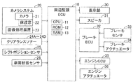
図1に示すように、本監視装置は周辺監視ECU10を備える。周辺監視ECU10は、CPU11、ROM12及びRAM13等を含むマイクロコンピュータを備える。なお、本明細書において、ECUは、「Electric Control Unit」の略であり、マイクロコンピュータを主要部として備える。マイクロコンピュータは、CPUとROM及びRAM等の記憶装置とを含む。CPUはROMに格納されたインストラクション(プログラム、ルーチン)を実行することによって、各種機能を実現する。
As shown in FIG. 1, this monitoring device includes a
本監視装置は、更に、カメラシステム20、クリアランスソナー24A乃至24D、シフトポジションセンサ25、車両状態センサ26、表示部30、スピーカ31、ブレーキECU32、ブレーキセンサ33、ブレーキアクチュエータ34、エンジンECU35及びエンジンアクチュエータ36を備える。周辺監視ECU10は、カメラシステム20、クリアランスソナー24A乃至24D、シフトポジションセンサ25、車両状態センサ26、表示部30、スピーカ31、ブレーキECU32及びエンジンECU35に接続されている。クリアランスソナー24A乃至24Dを総称する場合、単に「クリアランスソナー24」と称呼する。
This monitoring device further includes a
カメラシステム20は、カメラ21及び画像処理装置23を有する。図2に示すように、カメラ21は、自車両SVの後端部の車幅方向の中央に設けられている。図1に戻り、カメラ21は車外に設けられているので、レンズを水滴、泥、埃及び塵等から保護するための透光性の板部材である保護窓22を有している。カメラ21は、自車両SVの後方の領域の風景を、保護窓22を通して撮影する。なお、カメラ21の画角は広角(例えば、略180deg程度)である。カメラ21は、所定時間が経過する毎に風景を撮影し、撮影した画像(カメラ画像又はカメラ画像データ)を画像処理装置23に送信する。
The
画像処理装置23は、カメラ21が撮影したカメラ画像から予め設定された種類(歩行者、他車両及び二輪車等)の物標を抽出する。より詳細には、画像処理装置23は、各種類の物標の画像特徴量を照合パターンとして予め記憶している。画像処理装置23は、カメラ画像を所定の大きさの局所領域に区分し、当該局処領域の画像特徴量を算出する。そして、画像処理装置23は、算出した画像特徴量と照合パターンとして記憶している画像特徴量とを比較して、カメラ画像から物標を抽出する。画像処理装置23は、カメラ画像と、抽出した物標の種類を示す種類情報と、当該物標のカメラ画像における位置を示す位置情報と、を含むカメラ画像情報を所定時間が経過する毎に周辺監視ECU10に送信する。
The image processing device 23 extracts a preset type of target (pedestrian, other vehicle, motorcycle, etc.) from the camera image taken by the
クリアランスソナー24は、超音波を利用して自車両SVの後方側に存在する立体物(物標)の位置及び自車両SVに対する相対速度を検出する。より詳細には、クリアランスソナー24は、超音波を放射(送信)し、超音波の放射範囲内に存在する物標によって反射された超音波(反射波)を受信する。そして、クリアランスソナー24は、超音波の送信から受信までの時間に基づいて自車両SVから物標までの距離を算出するとともに、反射された超音波の方向に基づいて物標の自車両SVに対する方位を算出する。自車両SVから物標までの距離及び物標の自車両SVに対する方位によって、物標の自車両SVに対する位置が特定される。更に、クリアランスソナー24は、反射波の周波数変化(ドップラ効果)に基づいて、物標の自車両SVに対する相対速度を算出する。クリアランスソナー24は、物標の位置及び物標の相対速度を含む物標情報を周辺監視ECU10に送信する。
The clearance sonar 24 uses ultrasonic waves to detect the position of a three-dimensional object (target) existing on the rear side of the own vehicle SV and the relative speed with respect to the own vehicle SV. More specifically, the clearance sonar 24 emits (transmits) ultrasonic waves and receives ultrasonic waves (reflected waves) reflected by a target existing within the radiation range of the ultrasonic waves. Then, the clearance sonar 24 calculates the distance from the own vehicle SV to the target based on the time from the transmission to the reception of the ultrasonic wave, and also with respect to the own vehicle SV of the target based on the direction of the reflected ultrasonic wave. Calculate the orientation. The position of the target with respect to the own vehicle SV is specified by the distance from the own vehicle SV to the target and the orientation of the target with respect to the own vehicle SV. Further, the clearance sonar 24 calculates the relative speed of the target with respect to the own vehicle SV based on the frequency change (Doppler effect) of the reflected wave. The clearance sonar 24 transmits the target information including the position of the target and the relative speed of the target to the
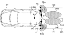
クリアランスソナー24A乃至24Dは、図2に示すように、自車両SVの後端部に、車幅方向に間隔をあけて取り付けられている。クリアランスソナー24Aは自車両SVの後端部の右端に取り付けられ、自車両SVの後方の右コーナーの領域DRAに存在する物標を検出する。クリアランスソナー24Bは、自車両SVの後端部の右側に取り付けられ、自車両SVの右後方の領域DRBに存在する物標を検出する。クリアランスソナー24Cは、自車両SVの後端部の左側に取り付けられ、自車両SVの左後方の領域DRCに存在する物標を検出する。クリアランスソナー24Dは自車両SVの後端部の左端に取り付けられ、自車両SVの後方の左コーナーの領域DRDに存在する物標を検出する。
As shown in FIG. 2, the
図1に戻り、シフトポジションセンサ25は、ドライバーが操作したシフトレバーのポジション(以下、「シフトポジション」と称呼する。)を検出し、検出したシフトポジションを表す信号を発生する。シフトポジションは、駐車レンジ「P」,前進レンジ「D」,後退レンジ「R」及びニュートラルレンジ「N」等がある。周辺監視ECU10は、所定時間が経過する毎にシフトポジションセンサ25からシフトポジションを取得(検出)するようになっている。
Returning to FIG. 1, the
車両状態センサ26は、自車両SVの速度(即ち、車速)Vsを検出する車速センサ、自車両SVの水平方向の前後方向及び左右(横)方向の加速度Asを検出する加速度センサ、自車両SVのヨーレートYrを検出するヨーレートセンサ、及び、操舵輪の舵角θを検出する舵角センサ等を含む。周辺監視ECU10は、所定時間が経過する毎に車両状態センサ26から車両状態情報(車速Vs、加速度As、ヨーレートYr及び舵角θ)を取得(検出)するようになっている。
The
周辺監視ECU10は、シフトポジションセンサ25から取得したシフトポジションが「R」である場合(即ち、自車両SVが後退する場合)、カメラ画像情報及び物標情報をフュージョンし、自車両SVの後方に存在する物標の位置を特定する。そして、周辺監視ECU10は、自車両SVの後方に物標が存在し且つ当該物標と衝突する可能性がある場合、表示部30及びスピーカ31を利用して当該物標の存在をドライバーに警告する。更に、周辺監視ECU10は、自車両の後方に存在する物標と衝突する可能性が警告時よりも高くなったとき、ブレーキECU32及びエンジンECU35を制御して、当該物標と衝突する前に自車両SVの車速Vsを減速させ、自車両SVを停止させる。
When the shift position acquired from the
表示部30は、自車両SV内の各種ECU及びナビゲーション装置からの表示情報を受信し、その表示情報を自車両SVのフロントガラスの一部の領域(表示領域)に表示するヘッドアップディスプレイ(以下、「HUD」と呼称する。)である。表示部30には、「自車両SVの後方に存在し且つ自車両SVと衝突する可能性がある物標(障害物)」に対してドライバーの注意を喚起するための注意喚起画面が表示される。表示部30は、周辺監視ECU10から注意喚起画面の表示指示である表示指示信号を受信した場合、注意喚起画面を表示する。なお、表示部30は、液晶ディスプレイであってもよい。
The
スピーカ31は、周辺監視ECU10から警報音の出力指示である出力指示信号を受信した場合、受信した出力指示信号に応答して障害物に対する「ドライバーの注意を喚起する警報音」を出力する。
When the
ブレーキECU32は、「車両状態センサ26の車速Vsを検出するための図示しない車速センサ」及びブレーキセンサ33と接続され、これらのセンサの検出信号を受け取るようになっている。ブレーキセンサ33は、自車両SVに搭載された制動装置(不図示)を制御する際に使用されるパラメータを検出するセンサであり、ブレーキペダルの操作量(踏込量)を検出するセンサ等を含む。
The
更に、ブレーキECU32は、ブレーキアクチュエータ34と接続されている。ブレーキアクチュエータ34は油圧制御アクチュエータである。ブレーキアクチュエータ34は、ブレーキペダルの踏力に応じて作動油を加圧するマスシリンダと、各車輪に設けられた周知のホイールシリンダを含む摩擦ブレーキ装置と、の間の油圧回路(何れも、図示略)に配設される。ブレーキアクチュエータ34は、ホイールシリンダに供給する油圧を調整する。ブレーキECU32は、ブレーキアクチュエータ34を駆動させることにより各車輪に制動力(自車両SVの加速度(負の加速度、即ち、減速度))を調整するようになっている。
Further, the
ブレーキECU32は、周辺監視ECU10から制動指示信号を受信したとき、自車両SVの実際の加速度Asが制動指示信号に含まれる目標減速度TGに一致するように車速Vsを制動により低下させるように、ブレーキアクチュエータ34を制御する。なお、周辺監視ECU10は、自車両SVの加速度Asを車両状態センサ26の加速度センサから取得するようになっている。
When the
エンジンECU35は、エンジンアクチュエータ36に接続されている。エンジンアクチュエータ36は自車両SVの駆動源である図示しない内燃機関の運転状態を変更するためのアクチュエータであり、少なくとも、スロットル弁の開度を変更するスロットル弁アクチュエータを含む。エンジンECU35は、エンジンアクチュエータ36を駆動することによって、内燃機関が発生するトルクを変更することができ、それにより、自車両SVの駆動力を制御することができる。なお、周辺監視ECU10からブレーキECU32に制動指示信号が送信されるとき、周辺監視ECU10からエンジンECU35にトルク低下指示信号が送信される。エンジンECU35は、トルク低下指示信号を受信すると、エンジンアクチュエータ36を駆動して(実際には、スロットル弁アクチュエータを駆動してスロットル弁開度を最小開度に変更して)、内燃機関のトルクを最小トルクに変更する。
The
(作動の概要)
次に、本監視装置の作動の概要について説明する。前述したように、本監視装置は、カメラ21によって撮影されたカメラ画像及びクリアランスソナー24の検出結果に基づいて、自車両SVの後方側に存在する物標を認識し、認識した物標の中から自車両SVと衝突する可能性がある障害物を抽出する。更に、本監視装置は、抽出された障害物が自車両SVと衝突するまでに(又は自車両SVに最接近するまでに)かかる時間を示す衝突所要時間TTC(Time To Collision)を算出する。なお、障害物の抽出処理及び衝突所要時間TTCの算出処理の詳細は後述する。
(Outline of operation)
Next, the outline of the operation of this monitoring device will be described. As described above, the monitoring device recognizes the target existing on the rear side of the own vehicle SV based on the camera image taken by the
衝突所要時間TTCが警告制御用の閾値時間T1th以下である場合、本監視装置は、前述した表示指示信号を表示部30に送信し、前述した出力指示信号をスピーカ31に送信することによって、障害物が存在する旨をドライバーに警告する警告制御(ドライバーの運転を支援する支援制御の一つ)を実施する。
When the collision required time TTC is equal to or less than the threshold time T1th for warning control, the monitoring device transmits the above-mentioned display instruction signal to the
衝突所要時間TTCが衝突回避制御用の閾値時間T2th以下である場合、本監視装置は、障害物に衝突する前に自車両SVを停止させる目標減速度TGを算出する。なお、閾値時間T2thは、前述した閾値時間T1thよりも小さい値に設定されている。そして、本監視装置は、目標減速度TGを含む前述した制動指示信号をブレーキECU32に送信し、前述したトルク低下指示信号をエンジンECU35に送信することによって、制動制御(ドライバーの運転を支援する支援制御の他の一つ)を実施する。
When the collision required time TTC is equal to or less than the threshold time T2th for collision avoidance control, the monitoring device calculates a target deceleration TG for stopping the own vehicle SV before colliding with an obstacle. The threshold time T2th is set to a value smaller than the above-mentioned threshold time T1th. Then, this monitoring device transmits the above-mentioned braking instruction signal including the target deceleration TG to the
ところで、本監視装置は、前述したようにカメラ画像及びクリアランスソナー24の検出結果に基づいて物標を検出するが、カメラ21の保護窓22に汚れが付着していた場合、正確に物標を検出することができない可能性が高い。
By the way, as described above, this monitoring device detects the target based on the camera image and the detection result of the clearance sonar 24, but if the protective window 22 of the
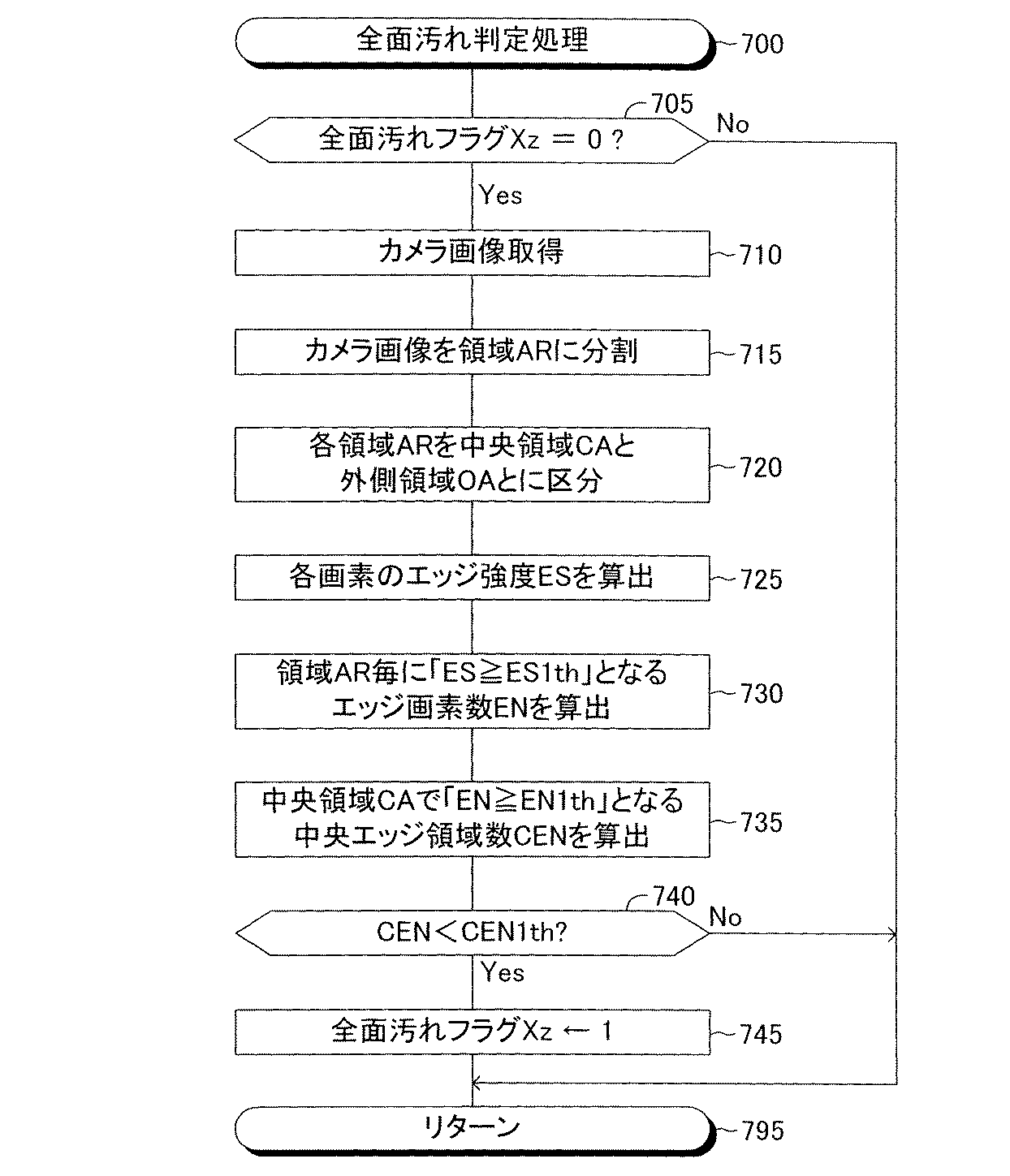
保護窓22に付着する汚れとしては、雪、水滴及び融雪剤等のように保護窓22の全面に付着する全面汚れと、泥等のように保護窓22の一部に付着する部分汚れと、が考えられる。本監視装置は、保護窓22の状態が全面汚れ状態であるか否かを判定する全面汚れ判定処理を実行し、保護窓22の状態が部分汚れ状態であるか否かを判定する部分汚れ判定処理を実行する。 The stains adhering to the protective window 22 include full-scale stains adhering to the entire surface of the protective window 22 such as snow, water droplets, and snow-melting agent, and partial stains adhering to a part of the protective window 22 such as mud. Can be considered. This monitoring device executes a full-face dirt determination process for determining whether or not the state of the protective window 22 is a full-face dirt state, and determines whether or not the state of the protective window 22 is a partial dirt state. Execute the process.
保護窓22の状態が全面汚れ状態及び部分汚れ状態の少なくとも一方であると判定された場合、本監視装置は、カメラ画像に基づく制御(即ち、前述した警告制御及び制動制御)の実施を禁止する。更に、本監視装置は、保護窓22の状態が全面汚れ状態であると判定された場合に全面汚れが除去されて全面汚れ状態が解除されたか否かを判定し、保護窓22の状態が部分汚れ状態であると判定された場合に部分汚れが除去されて部分汚れ状態が解除されたか否かを判定する汚れ解除判定処理を実行する。汚れ解除判定処理によって保護窓22の状態が汚れなし状態となったと判定された場合(即ち、何れの汚れ状態も解除されている場合)、本監視装置は、前述したカメラ画像に基づく制御の実施を許可する。 When it is determined that the state of the protective window 22 is at least one of a completely dirty state and a partially dirty state, the monitoring device prohibits the execution of control based on the camera image (that is, the warning control and braking control described above). .. Further, this monitoring device determines whether or not the entire surface of the protective window 22 is removed and the entire surface of the protective window 22 is released when the state of the protective window 22 is determined to be the state of the entire surface of the protective window 22. When it is determined that the state is dirty, the stain release determination process for determining whether or not the partial stain is removed and the partial stain state is released is executed. When it is determined by the stain release determination process that the state of the protective window 22 is in a clean state (that is, when any of the stain states is released), the monitoring device performs control based on the above-mentioned camera image. Allow.
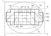
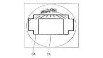
まず、全面汚れ判定処理について説明する。本監視装置は、図3に示すように、楕円形のカメラ画像CIを、カメラ画像CIの中心点Pcを含む判定用領域CIcと、それ以外の領域と、に区分する。更に、本監視装置は、その判定用領域CIcを、「中心点Pcを含む長方形の中央領域CA」と、「中央領域CAよりも外側の外側領域OA」と、に区分する。中央領域CAは「第1領域」と称呼される場合があり、外側領域OAは「第2領域」と称呼される場合がある。判定用領域CIcは、複数の個別領域ARに区分されている。複数の個別領域ARのそれぞれは長方形である。図3に示した例において、中央領域CAは20個の個別領域ARを含み、外側領域OAは21個の個別領域ARを含んでいる。 First, the entire surface stain determination process will be described. As shown in FIG. 3, the monitoring device divides the elliptical camera image CI into a determination region CIc including the center point Pc of the camera image CI and a region other than that. Further, the monitoring device divides the determination area CIc into "a rectangular central area CA including the center point Pc" and "an outer area OA outside the central area CA". The central region CA may be referred to as the "first region" and the outer region OA may be referred to as the "second region". The determination area CIc is divided into a plurality of individual areas AR. Each of the plurality of individual areas AR is rectangular. In the example shown in FIG. 3, the central region CA contains 20 individual region ARs and the outer region OA contains 21 individual region ARs.
ところで、一般に、カメラ画像は、カメラ画像の中心において最も鮮明であり、当該中心から離れるにつれて不鮮明になる。換言すると、カメラ画像のボケは、カメラ画像の中心において最も小さく、当該中心から離れるにつれて大きくなる。従って、一般に、カメラ画像の中心近傍におけるエッジ強度は、カメラ画像の周辺近傍におけるエッジ強度よりも大きくなる。即ち、外側領域OAは中央領域CAよりもカメラ画像CIの中心から離れているから、外側領域OAではエッジ強度が相対的に小さくなり、中央領域CAではエッジ強度が相対的に大きくなる。 By the way, in general, the camera image is the clearest at the center of the camera image, and becomes less clear as the distance from the center is increased. In other words, the blur of the camera image is the smallest at the center of the camera image and increases as the distance from the center increases. Therefore, in general, the edge strength near the center of the camera image is larger than the edge strength near the periphery of the camera image. That is, since the outer region OA is farther from the center of the camera image CI than the central region CA, the edge strength is relatively small in the outer region OA and relatively large in the central region CA.
そこで、本監視装置は、このようなカメラ画像の特性を利用して全面汚れ判定処理を行う。先ず、本監視装置は、式1に従って個別領域ARのそれぞれに属する各画素の水平方向エッジ強度ESxを算出し、且つ、式2に従って個別領域ARのそれぞれに属する各画素の鉛直方向エッジ強度ESyを算出する。次いで、本監視装置は、個別領域ARのそれぞれに属する各画素のエッジ強度ESを算出する。
Therefore, this monitoring device performs the entire surface stain determination process by utilizing such characteristics of the camera image. First, the monitoring device calculates the horizontal edge strength ESx of each pixel belonging to each of the individual region AR according to
なお、個別領域ARのそれぞれの左下の画素がx−y座標の原点Oとして規定される。更に、個別領域ARのそれぞれの左右方向がx軸に設定され、個別領域ARのそれぞれの上下方向がy軸に設定される。式1及び式2の「I(x、y)」は座標(x、y)の画素の画素値(R,G,B)を表す。よって、水平方向エッジ強度ESxは、赤、緑及び青の成分値(XR,XG,XB)を有するベクトルであり、その大きさは(XR2+XG2+XB2)1/2である。同様に、鉛直方向エッジ強度ESyは、赤、緑及び青の成分値(YR,YG,YB)を有するベクトルであり、その大きさは(YR2+YG2+YB2)1/2である。
The lower left pixel of each individual region AR is defined as the origin O of the xy coordinates. Further, each horizontal direction of the individual area AR is set to the x-axis, and each vertical direction of the individual area AR is set to the y-axis. “I (x, y)” in
次に、本監視装置は、各個別領域ARにおいて、エッジ強度ESが閾値強度(第1閾値強度)ES1th以上である画素の数(以下、「エッジ画素数」と称呼する。)ENを算出する。そして、本監視装置は、エッジ画素数ENが閾値画素数(第1閾値画素数)EN1th以上である個別領域ARを特定する。エッジ画素数ENが閾値画素数EN1th以上である個別領域ARは、以下、「強エッジ領域」とも称呼される。強エッジ領域は、エッジが明確に検出できている領域である。 Next, the monitoring device calculates the number of pixels (hereinafter, referred to as “edge pixel number”) EN in which the edge strength ES is the threshold strength (first threshold strength) ES 1th or higher in each individual region AR. .. Then, this monitoring device identifies the individual region AR in which the edge pixel number EN is the threshold pixel number (first threshold pixel number) EN 1th or more. The individual region AR in which the number of edge pixels EN is equal to or greater than the threshold number of pixels EN 1th is also hereinafter referred to as a “strong edge region”. The strong edge region is a region where the edge can be clearly detected.
次に、本監視装置は、中央領域CAに含まれる個別領域ARのうち強エッジ領域である領域の数CENを特定する。数CENは、以下、「中央エッジ領域数」、「第1エッジ領域数」又は「第1領域指標値」と称呼される場合がある。 Next, the monitoring device identifies the number CEN of the regions that are the strong edge regions in the individual region AR included in the central region CA. The number CEN may be hereinafter referred to as "the number of central edge regions", "the number of first edge regions", or "the index value of the first region".
更に、本監視装置は、中央エッジ領域数CENが閾値領域数CEN1thよりも小さい否かを判定する。例えば、閾値領域数CEN1thは「1」に設定されている。 Further, this monitoring device determines whether or not the central edge region number CEN is smaller than the threshold region number CEN 1th. For example, the threshold area number CEN1th is set to "1".
中央エッジ領域数CENが閾値領域数CEN1th以上である場合、本監視装置は、保護窓22の状態を全面汚れ状態と判定しない。図3に示した例において、保護窓22に汚れが付着していないとすると、道路の白線のエッジが「中央領域CAに属する個別領域AR1乃至AR7」にて抽出される。よって、本監視装置は、中央領域CAに属する個別領域AR1乃至AR7のそれぞれを強エッジ領域として特定する。この場合、中央エッジ領域数CENは「7」であり、中央エッジ領域数CENが閾値領域数CEN1th以上ある。従って、本監視装置は、保護窓22の状態を全面汚れ状態と判定しない。 When the number of central edge regions CEN is equal to or greater than the number of threshold regions CEN 1th, the monitoring device does not determine the state of the protective window 22 as a completely dirty state. In the example shown in FIG. 3, assuming that the protective window 22 is not dirty, the edge of the white line of the road is extracted in the "individual regions AR1 to AR7 belonging to the central region CA". Therefore, this monitoring device identifies each of the individual regions AR1 to AR7 belonging to the central region CA as a strong edge region. In this case, the number of central edge regions CEN is "7", and the number of central edge regions CEN is equal to or greater than the threshold region number CEN 1th. Therefore, this monitoring device does not determine the state of the protective window 22 as a completely dirty state.
一方、中央エッジ領域数CENが閾値領域数CEN1thよりも小さい場合、本監視装置は、保護窓22の状態が「保護窓22全面に汚れが付着している状態(即ち、全面汚れ状態)」であると判定する。保護窓22の全面に汚れが付着している場合のカメラ画像においては、中央領域CA及び外側領域OAでエッジが抽出されない可能性が高い。雪が保護窓22全面に付着している場合のカメラ画像の一例を図4に示す。図4に示すカメラ画像においては、中央エッジ領域数CENが「0」であり、中央エッジ領域数CENが閾値領域数CEN1thよりも小さいので、本監視装置は、保護窓22の状態を全面汚れ状態と判定する。 On the other hand, when the number of central edge regions CEN is smaller than the number of threshold regions CEN1th, the monitoring device is in a state where the protective window 22 is "dirty on the entire surface of the protective window 22 (that is, the entire surface is dirty)". Judge that there is. In the camera image when the entire surface of the protective window 22 is dirty, there is a high possibility that edges are not extracted in the central region CA and the outer region OA. FIG. 4 shows an example of a camera image when snow adheres to the entire surface of the protective window 22. In the camera image shown in FIG. 4, the number of central edge regions CEN is "0", and the number of central edge regions CEN is smaller than the number of threshold regions CEN 1th. Is determined.
前述したように、外側領域OAにおいては中央領域CAに比較してエッジ強度ESが小さく算出される傾向にある。従って、保護窓22の状態が全面汚れ状態でない場合であっても外側領域OAに属する個別領域ARのうち強エッジ領域であると特定される可能性が低くなる。このため、本監視装置は、外側領域OAにおける強エッジ領域の数を用いずに中央領域CAにおける強エッジ領域の数を用いて保護窓22の状態が全面汚れであるか否かを判定している。これによって、全面汚れであるか否かを正確に判定することができる可能性を向上させることができる。 As described above, in the outer region OA, the edge strength ES tends to be calculated smaller than that in the central region CA. Therefore, even if the state of the protective window 22 is not the state of being completely soiled, it is less likely that the individual area AR belonging to the outer area OA is identified as a strong edge area. Therefore, this monitoring device determines whether or not the state of the protective window 22 is totally dirty by using the number of strong edge regions in the central region CA without using the number of strong edge regions in the outer region OA. There is. This makes it possible to improve the possibility of accurately determining whether or not the entire surface is dirty.
本監視装置は、保護窓22の状態が全面汚れ状態であると判定した場合、以下の条件(1)及び(2)の何れかが成立するとき、全面汚れが除去された(即ち、全面汚れ状態が解除された)と判定する。条件(1)は第1条件とも称呼され、条件(2)は第2条件と称呼される場合がある。
条件(1)中央エッジ領域数CENが閾値領域数CEN1th以上である。
条件(2)外側領域OAにおける強エッジ領域の数(以下、「外側エッジ領域数」と称呼し、「第2エッジ領域数」又は「第2領域指標値」と称呼する場合もある。)OENが「第2解除閾値である閾値領域数OEN1th」以上である。
When the monitoring device determines that the protective window 22 is in a completely dirty state, the entire surface is removed (that is, the entire surface is dirty) when any of the following conditions (1) and (2) is satisfied. It is determined that the state has been released). The condition (1) may also be referred to as the first condition, and the condition (2) may be referred to as the second condition.
Condition (1) The number of central edge regions CEN is equal to or greater than the number of threshold regions CEN1th.
Condition (2) Number of strong edge regions in outer region OA (hereinafter, referred to as "number of outer edge regions", and may be referred to as "number of second edge regions" or "second region index value") OEN Is "the number of threshold areas OEN1th which is the second release threshold" or more.
外側領域OAにおける強エッジ領域は、エッジ強度ESが第2閾値強度以上であるエッジ画素数が第2閾値画素数以上である個別領域ARである。なお、本例においては、第2閾値強度は第1閾値強度ES1thと等しい値に設定されているが、第2閾値強度は第1閾値強度ES1thと異なる値に設定されてもよい。更に、第2閾値画素数は第1閾値画素数EN1thと等しい値に設定されているが、第2閾値画素数は第1閾値画素数EN1thと異なる値に設定されてもよい。 The strong edge region in the outer region OA is an individual region AR in which the edge strength ES is equal to or greater than the second threshold intensity and the number of edge pixels is equal to or greater than the number of second threshold pixels. In this example, the second threshold intensity is set to a value equal to the first threshold intensity ES1th, but the second threshold intensity may be set to a value different from the first threshold intensity ES1th. Further, although the number of second threshold pixels is set to a value equal to the number of first threshold pixels EN1th, the number of second threshold pixels may be set to a value different from the number of first threshold pixels EN1th.
更に、本例において、閾値領域数OEN1thは、閾値領域数CEN1thと同じく「1」に設定されているが、これらは互いに相違していてもよい。 Further, in this example, the threshold region number OEN1th is set to "1" like the threshold region number CEN1th, but these may be different from each other.
前述したように、外側領域OAにおいては中央領域CAに比較してエッジ強度ESが小さく算出される傾向にある。このため、このような外側領域OAにおいて外側エッジ領域数OENが閾値領域数OEN1th以上である場合(即ち、条件(2)が成立した場合)、保護窓22全面に付着した汚れが除去されていると考えることができる。通常、外側エッジ領域数OENが閾値領域数OEN1th以上である場合、中央エッジ領域数CENも閾値領域数CEN1th以上となる(即ち、条件(1)も成立する)と考えられる。 As described above, in the outer region OA, the edge strength ES tends to be calculated smaller than that in the central region CA. Therefore, in such an outer region OA, when the number of outer edge regions OEN is equal to or greater than the threshold region number OEN 1th (that is, when the condition (2) is satisfied), the dirt adhering to the entire surface of the protective window 22 is removed. Can be considered. Normally, when the number of outer edge regions OEN is equal to or greater than the number of threshold regions OEN 1th, it is considered that the number of central edge regions CEN also becomes equal to or greater than the number of threshold regions CEN 1th (that is, the condition (1) is also satisfied).
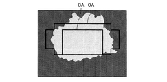
しかしながら、図5に示すように、カメラ21が撮影した風景によっては中央領域CAにエッジが抽出されず、外側領域OAにエッジが抽出され得る場合がある。図5に示したカメラ画像では、中央領域CAではエッジが抽出されないので、中央エッジ領域数CENは閾値領域数CEN1thよりも小さく、条件(1)は成立しない。しかし、外側領域OAの中央領域CAの上方の領域では7本の白線のエッジが検出されているので、外側エッジ領域数OENが閾値領域数OEN1th以上となる。よって、図5に示したカメラ画像では、条件(1)は成立しないものの、条件(2)は成立するため、本監視装置は、保護窓22の状態を汚れなし状態と判定することができる。即ち、条件(2)のみが成立する場合であっても、本監視装置は、全面汚れ状態を解除する。
However, as shown in FIG. 5, depending on the landscape photographed by the
次に、部分汚れ判定処理について説明する。本監視装置は、所定時間が経過する毎に画素値が実質的に変化しない領域を特定する処理を行う。更に、本監視装置は、所定の処理回数に渡って画素値が実質的に変化しない個別領域ARを無変化領域UCAとして特定する。そして、本監視装置は、無変化領域UCAが存在する場合、当該領域UCAを部分汚れ領域として特定し、保護窓22の状態を部分汚れ状態と判定する。 Next, the partial stain determination process will be described. This monitoring device performs a process of identifying a region in which the pixel value does not substantially change each time a predetermined time elapses. Further, the monitoring device specifies the individual region AR in which the pixel value does not substantially change over a predetermined number of processing times as the unchanged region UCA. Then, when the unchanged region UCA exists, the monitoring device identifies the region UCA as a partially soiled region and determines that the state of the protective window 22 is a partially soiled state.
本監視装置は、保護窓22の状態が部分汚れ状態であると判定した場合、部分汚れ領域(即ち、無変化領域UCA)のそれぞれが「汚れ解消強エッジ領域」へと変化したか否かを判定する。汚れ解消強エッジ領域は、「部分汚れ領域のそれぞれに属する画素であってそのエッジ強度ESが閾値強度(第3閾値強度)以上である画素」の数が第3閾値画素数以上である個別領域ARである。そして、本監視装置は、部分汚れエッジ領域と判定された個別領域ARの総てが汚れ解消強エッジ領域へと変化した場合、保護窓22の状態が部分汚れのない状態になった(即ち、部分汚れ状態が解消された)と判定する。なお、本例において、第3閾値強度は第1閾値強度ES1thと等しい値に設定されているが、第3閾値強度は第1閾値強度ES1thと異なる値に設定されてもよい。更に、本例において、第3閾値画素数は第1閾値画素数EN1thと等しい値に設定されているが、第3閾値画素数は第1閾値画素数EN1thと異なる値に設定されてもよい。 When the monitoring device determines that the state of the protective window 22 is a partially soiled state, it determines whether or not each of the partially soiled areas (that is, the unchanged area UCA) has changed to the "dirt-removing strong edge area". judge. The stain-removing strong edge region is an individual region in which the number of "pixels belonging to each of the partial stain regions and whose edge strength ES is equal to or greater than the threshold intensity (third threshold intensity)" is equal to or greater than the number of third threshold pixels. It is AR. Then, in this monitoring device, when all of the individual area AR determined to be the partially soiled edge area is changed to the dirt-removing strong edge area, the state of the protective window 22 becomes a state without partial dirt (that is,). It is determined that the partially soiled state has been resolved). In this example, the third threshold intensity is set to a value equal to the first threshold intensity ES1th, but the third threshold intensity may be set to a value different from the first threshold intensity ES1th. Further, in this example, the number of third threshold pixels is set to a value equal to the number of first threshold pixels EN1th, but the number of third threshold pixels may be set to a value different from the number of first threshold pixels EN1th.
以上の例から理解されるように、本監視装置は、全面汚れ判定処理において、強エッジ領域が現れ難い外側領域OAの強エッジ領域の数ではなく、強エッジ領域が現れ易い中央領域CAの強エッジ領域の数(中央エッジ領域数)CENが閾値領域数CEN1thよりも小さい場合、保護窓22の状態を全面汚れ状態と判定する。このように、本監視装置は、中央領域CAの強エッジ領域の数CENに基づいて全面汚れ状態であるか否かを判定するので、全面汚れ状態であるか否かを正確に判定することができる。 As can be understood from the above example, in this monitoring device, the strength of the central region CA where the strong edge region is likely to appear is not the number of the strong edge regions of the outer region OA where the strong edge region is unlikely to appear in the entire surface dirt determination process. When the number of edge regions (the number of central edge regions) CEN is smaller than the threshold region number CEN1th, the state of the protective window 22 is determined to be a completely dirty state. In this way, since the monitoring device determines whether or not the entire surface is dirty based on the number CEN of the strong edge region of the central region CA, it is possible to accurately determine whether or not the entire surface is dirty. can.
更に、本監視装置は、保護窓22の状態が全面汚れ状態である場合、前述した条件(1)及び条件(2)の何れかが成立したとき、全面汚れが除去されたと判定する。即ち、本監視装置は、エッジ強度ESが中央領域CAよりも小さい値に算出される傾向にある外側領域OAにおいて外側エッジ領域数OENが閾値領域数OEN1th以上である場合、中央エッジ領域数CENが閾値領域数CEN1thよりも小さくても、全面汚れが除去されたと判定できる。これによって、本監視装置は、全面汚れが除去されたか否かを正確に判定することができる。更に、前述したように、中央領域CAにエッジが検出されないカメラ画像であっても、条件(2)が成立した場合には、本監視装置は、全面汚れが除去されたと判定できる。 Further, the monitoring device determines that the entire surface of the protective window 22 has been removed when any of the above-mentioned conditions (1) and (2) is satisfied when the state of the protective window 22 is a completely dirty state. That is, in this monitoring device, when the number of outer edge regions OEN is equal to or greater than the threshold region number OEN 1th in the outer region OA where the edge strength ES tends to be calculated to be smaller than the central region CA, the central edge region number CEN is Even if it is smaller than the threshold area number CEN1th, it can be determined that the entire surface has been cleaned. As a result, the monitoring device can accurately determine whether or not the entire surface has been cleaned. Further, as described above, even if the camera image has no edge detected in the central region CA, if the condition (2) is satisfied, the monitoring device can determine that the entire surface has been cleaned.
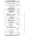
(具体的作動)
周辺監視ECU10のCPU11は、図6にフローチャートで示したルーチンを所定時間が経過する毎に実行する。図6に示すルーチンは、自車両SVが後退するときに自車両SVの後方側の障害物に対して、支援制御の一つである衝突前制御(後退時衝突前制御)を実施するためのルーチンである。
(Specific operation)
The
従って、所定のタイミングになると、CPU11は図6のステップ600から処理を開始してステップ605に進み、シフトポジションセンサ25からシフトポジションを取得する。次に、CPU11は、ステップ610に進み、ステップ605にて取得したシフトポジションが後退レンジ(「R」)であるか否かを判定する。シフトポジションが「R」でない場合、即ち、シフトポジションが前進レンジ(「D」)及びニュートラルレンジ(「N」)等である場合、CPU11は、ステップ610にて「No」と判定し、ステップ695に進んで本ルーチンを一旦終了する。この結果、衝突前制御は実施されない。
Therefore, at a predetermined timing, the
一方、シフトポジションが「R」である場合、CPU11は、ステップ610にて「Yes」と判定してステップ615に進み、車両状態センサ26から車両状態情報を取得し、ステップ620に進む。
On the other hand, when the shift position is "R", the
ステップ620にて、CPU11は、ステップ615にて取得した車両状態情報に基づいて、「自車両SVがこれから走行すると予測される進路である走行予測進路RCR(図2を参照。)」を推定し、ステップ625に進む。
In
ステップ620の処理について図2を用いて詳細に説明する。
CPU11は、ステップ615にて取得した車両状態情報に含まれる「自車両SVの車速Vs及びヨーレートYr」に基づいて、自車両SVの旋回半径を算出する。そして、CPU11は、算出した旋回半径に基づいて、自車両SVの左右の後輪の車軸上の中心点PO(図2を参照。)が向かっている走行進路を走行予測進路RCRとして推定する。ヨーレートYrが発生している場合、CPU11は、円弧状の進路を走行予測進路RCRとして推定する。一方、ヨーレートYrが「0」の場合、CPU11は、自車両SVに作用する加速度の方向に沿った直線進路を走行予測進路RCRとして推定する。
The process of
The
図6に戻り、ステップ625にて、CPU11は、クリアランスソナー24から物標情報を取得し、ステップ630に進み、全面汚れフラグXzの値及び部分汚れフラグXbの値の何れもが「0」であるか否かを判定する。全面汚れフラグXzの値は、後述する処理によって保護窓22の状態が全面汚れ状態であると判定されたとき「1」に設定される。更に、全面汚れフラグXzの値が「1」である場合、後述する処理によって保護窓22の全面汚れ状態が解除されたと判定されたとき、全面汚れフラグXzの値は「0」に設定される。部分汚れフラグXbの値は、後述する処理によって保護窓22の状態が部分汚れ状態であると判定されたとき「1」に設定される。更に、部分汚れフラグXbの値が「1」である場合、後述する処理によって保護窓22の部分汚れ状態が解除されたと判定されたとき、部分汚れフラグXbの値は「0」に設定される。従って、CPU11はステップ630にて、RAM13に「保護窓22の状態が汚れなし状態であることを示す汚れなし情報」が記憶されているか否かを実質的に判定している。
Returning to FIG. 6, in
全面汚れフラグXzの値及び部分汚れフラグXbの値の少なくとも一方が「1」である場合(即ち、RAM13に「保護窓22の状態が全面汚れ状態であることを示す全面汚れ情報」及び「保護窓22の状態が部分汚れ状態であることを示す部分汚れ情報」の少なくとも一方が記憶されている場合)、CPU11は、ステップ630にて「No」と判定し、ステップ695に進み、本ルーチンを一旦終了する。保護窓22の状態が全面汚れ状態及び部分汚れ状態の少なくとも一方である場合、保護窓22を通して撮影されたカメラ画像には汚れが映り込み、物標を正確に抽出できない可能性が高い。このため、衝突前制御が誤って実施される可能性があるので、CPU11は、衝突前制御の実施を禁止する。
When at least one of the value of the full-face dirt flag Xz and the value of the partial dirt flag Xb is "1" (that is, "full-face dirt information indicating that the state of the protective window 22 is the full-face dirt state" and "protection" in the
一方、全面汚れフラグXzの値及び部分汚れフラグXbの値の何れもが「0」である場合(即ち、RAM13に汚れなし情報が記憶されている場合)、CPU11は、ステップ630にて「Yes」と判定してステップ635に進み、カメラシステム20からカメラ画像情報を取得する。次に、CPU11はステップ640に進み、ステップ625にて取得した物標情報及びステップ635にて取得したカメラ画像情報をフュージョンして自車両SVに対する物標の位置を特定する。
On the other hand, when both the value of the entire surface stain flag Xz and the value of the partial stain flag Xb are "0" (that is, when the stain-free information is stored in the RAM 13), the
その後、CPU11はステップ645に進み、ステップ620にて推定した自車両SVの走行予測進路RCRと「ステップ640にて特定した物標の位置」と当該物標の相対速度とに基づいて、ステップ640にて位置を特定した物標の中から自車両SVと衝突する可能性があると推定される物標(自車両SVに衝突はしないものの自車両SVに極めて接近すると推定される特徴点を含む。)を障害物として抽出する。
After that, the
ステップ645の処理について図2を用いて詳細に説明する。
CPU11は、自車両SVの車体の左端部から一定距離αLだけ更に左側に位置する点PLが通過する左側走行予測進路LECと、自車両SVの車体の右端部から一定距離αRだけ更に右側に位置する点PRが通過する右側走行予測進路RECと、を「有限の長さの走行予測進路RCR」に基づいて推定する。左側走行予測進路LECは、走行予測進路RCRを自車両SVの左右方向の左側に「距離αLに車幅の半分を加えた値」だけ平行移動した進路である。右側走行予測進路RECは、走行予測進路RCRを自車両SVの左右方向の右側に「距離αRに車幅の半分を加えた値」だけ平行移動した進路である。距離αL及び距離αRは何れも「0」以上の値であり、互いに相違していても同じであってもよい。更に、CPU11は、左側走行予測進路LECと右側走行予測進路RECとの間の領域を走行予測進路領域ECAとして特定する。
The process of
The
そして、CPU11は、過去の物標の位置に基づいて物標の移動軌跡を算出(推定)し、算出した物標の移動軌跡に基づいて、物標の自車両SVに対する移動方向を算出する。次いで、CPU11は、走行予測進路領域ECAと、自車両SVと物標との相対関係(相対位置及び相対速度)と、物標の自車両SVに対する移動方向と、に基づいて、走行予測進路領域ECA内に既に存在し且つ自車両SVの先端領域TAと交差すると予測される物標と、走行予測進路領域ECAに将来的に進入し且つ自車両の先端領域TAと交差すると予測される物標と、を自車両SVに衝突する可能性のある障害物として抽出する。ここで、自車両SVの先端領域TAは、点PLと点PRとを結んだ線分により表される領域である。
Then, the
なお、CPU11は、左側走行予測進路LECを点PLが通過する進路として推定し、且つ、右側走行予測進路RECを点PRが通過する進路として推定している。このため、値αL及び値αRが正の値であれば、CPU11は、自車両SVの左側面近傍又は右側面近傍を通り抜ける可能性がある物標も、「走行予測進路領域ECA内に既に存在し、且つ、自車両SVの先端領域TAと交差すると予測される」又は「走行予測進路領域ECAに将来的に進入し且つ自車両SVの先端領域TAと交差すると予測される」と判断する。従って、CPU11は、自車両SVの左側方又は右側方を通り抜ける可能性のある物標も障害物として抽出する。
The
図6に戻り、CPU11は、ステップ645の実行後ステップ650に進み、ステップ645にて障害物が抽出されたか否かを判定する。ステップ645にて障害物が抽出されていない場合、CPU11は、ステップ650にて「No」と判定し、ステップ695に進み、本ルーチンを一旦終了する。この結果、衝突前制御は実施されない。一方、ステップ645にて障害物が抽出されている場合、CPU11は、ステップ650にて「Yes」と判定し、ステップ655に進む。
Returning to FIG. 6, the
ステップ655にて、CPU11は、障害物が自車両SVの領域TA(図2を参照。)と交差するまでにかかる時間を示す衝突所要時間TTCを算出し、ステップ660に進む。
In
ステップ655の処理について詳細に説明する。
CPU11は、自車両SVと障害物との間の距離(相対距離)を障害物の自車両SVに対する相対速度で除することによって、障害物の衝突所要時間TTCを算出する。
The process of
The
衝突所要時間TTCは、以下の時間T1及び時間T2の何れかである。
・障害物が自車両SVと衝突すると予測される時点までの時間T1(現時点から衝突予測時点までの時間)
・自車両SVの側方を通り抜ける可能性のある障害物が自車両SVに最接近する時点までの時間T2(現時点から最接近予測時点までの時間)
The collision time required TTC is any of the following time T1 and time T2.
-Time until the time when the obstacle is predicted to collide with the own vehicle SV T1 (time from the current time to the time when the collision is predicted)
-Time until the time when an obstacle that may pass by the side of the own vehicle SV comes closest to the own vehicle SV T2 (time from the present time to the time when the closest approach is predicted)
この衝突所要時間TTCは、障害物と自車両SVとが現時点における相対速度及び相対移動方向を維持しながら移動すると仮定した場合における障害物が「自車両SVの先端領域TA」に到達するまでの時間である。 This collision time TTC is until the obstacle reaches the "tip region TA of the own vehicle SV" when it is assumed that the obstacle and the own vehicle SV move while maintaining the current relative speed and relative movement direction. It's time.
衝突所要時間TTCは、衝突前制御又はドライバーによる衝突回避操作が実施可能な時間を表す。更に、衝突所要時間TTCは、障害物と自車両SVとが衝突する可能性(衝突可能性)を示す指標値である。衝突所要時間TTCが小さいほど衝突可能性が高いことを示し、衝突所要時間TTCが大きいほど衝突可能性が低いことを示す。 Collision time required TTC represents the time during which pre-collision control or collision avoidance operation by the driver can be performed. Further, the collision time required TTC is an index value indicating the possibility of collision between the obstacle and the own vehicle SV (collision possibility). The smaller the collision time TTC, the higher the collision possibility, and the larger the collision time TTC, the lower the collision possibility.
ステップ660にて、CPU11は、ステップ655にて算出された衝突所要時間TTCが閾値時間T(n)th以下であるか否かを判定する。衝突所要時間TTCが閾値時間T(n)thよりも大きな場合、CPU11は、ステップ660にて「No」と判定し、ステップ695に進み、本ルーチンを一旦終了する。これに対し、衝突所要時間TTCが閾値時間T(n)th以下である場合、CPU11は、ステップ660にて「Yes」と判定してステップ665に進み、衝突前制御を実施する。その後、CPU11は、ステップ695に進み、本ルーチンを一旦終了する。
In
なお、本例においては、上記の閾値時間T(n)thとして、警告制御用の閾値時間T1thと制動制御用の閾値時間T2thとが設定されている。閾値時間T1thは閾値時間T2thよりも大きい。衝突所要時間TTCが閾値時間T1th以下である場合、CPU11は、表示部30に表示指示信号を送信して注意喚起画面を表示部30に表示させ、スピーカ31に出力指示信号を送信してスピーカ31から警報音を出力させる。衝突所要時間TTCが閾値時間T2th以下である場合、CPU11は、閾値時間T2th以下となる衝突所要時間TTCの中で最小の衝突所要時間TTCの障害物を特定する。更に、CPU11は、その特定した障害物に衝突する前に自車両SVを停止させるために必要な減速度(即ち、目標減速度TG)を、当該障害物の相対速度及び位置に基づいて算出する。そして、CPU11は、目標減速度TGを含む制動指示信号をブレーキECU32に送信するとともにトルク低下指示信号をエンジンECU35に送信する。この結果、自車両SVは目標減速度TGと略等しい減速度にて減速させられる。
In this example, the threshold time T1th for warning control and the threshold time T2th for braking control are set as the above threshold time T (n) th. The threshold time T1th is larger than the threshold time T2th. When the collision required time TTC is equal to or less than the threshold time T1th, the
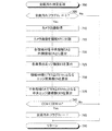
加えて、CPU11は、図7にフローチャートで示したルーチンを所定時間が経過する毎に実行している。図7に示したルーチンは、保護窓22の状態が全面汚れ状態であるか否かを判定するためのルーチンである。
In addition, the
従って、所定のタイミングになると、CPU11は図7のステップ700から処理を開始してステップ705に進み、全面汚れフラグXzの値が「0」であるか否か(即ち、RAM13に全面汚れ情報が記憶されていないか否か)を判定する。全面汚れフラグXzの値が「1」である場合(即ち、保護窓22の状態が全面汚れ状態であると既に判定されている場合)、CPU11は、ステップ705にて「No」と判定し、ステップ795に進んで本ルーチンを一旦終了する。
Therefore, at a predetermined timing, the
一方、全面汚れフラグXzの値が「0」である場合(即ち、RAM13に全面汚れ情報が記憶されていない場合)、CPU11はステップ705にて「Yes」と判定し、以下に述べるステップ710乃至ステップ735の処理を順に行い、ステップ740に進む。
On the other hand, when the value of the entire surface contamination flag Xz is "0" (that is, when the entire surface contamination information is not stored in the RAM 13), the
ステップ710:CPU11は、カメラシステム20からカメラ画像情報を取得する。
ステップ715:CPU11は、カメラ画像情報に含まれるカメラ画像を複数の個別領域AR(図3を参照。)に分割する。
ステップ720:CPU11は、複数の個別領域ARを、中央領域CA(図3を参照。)と外側領域OA(図3を参照。)とに区分する。
Step 710: The
Step 715: The
Step 720: The
ステップ725:CPU11は、前述した式1乃至式3に従って、中央領域CAに属する複数の個別領域ARに属する各画素のエッジ強度ESを算出する。
ステップ730:CPU11は、中央領域CAに属する複数の個別領域ARのそれぞれにおいて、エッジ強度ESが閾値強度ES1th以上であるエッジ画素数ENを算出する。
ステップ735:CPU11は、エッジ画素数ENが閾値画素数EN1th以上である個別領域ARの数(即ち、中央エッジ領域数CEN)を算出する。
Step 725: The
Step 730: The
Step 735: The
ステップ740にて、CPU11は、ステップ735にて算出した中央エッジ領域数CENが閾値領域数(第1閾値領域数)CEN1thよりも小さいか否かを判定する。中央エッジ領域数CENが閾値領域数CEN1th以上である場合、保護窓22の状態が全面汚れ状態ではないと判断することができる。そこで、中央エッジ領域数CENが閾値領域数CEN1th以上である場合、CPU11はステップ740にて「No」と判定してステップ795に直接進み、本ルーチンを一旦終了する。この結果、RAM13に全面汚れ情報は記憶されない。
In
一方、中央エッジ領域数CENが閾値領域数CEN1thよりも小さい場合、保護窓22の状態が全面汚れ状態であると判断できる。従って、中央エッジ領域数CENが閾値領域数CEN1thよりも小さい場合、CPU11はステップ740にて「Yes」と判定してステップ745に進み、全面汚れフラグXzの値を「1」に設定する。即ち、CPU11は、RAM13に全面汚れ情報を記憶する。その後、CPU11はステップ795に進み、本ルーチンを一旦終了する。
On the other hand, when the number of central edge regions CEN is smaller than the number of threshold regions CEN 1th, it can be determined that the state of the protective window 22 is a completely dirty state. Therefore, when the number of central edge regions CEN is smaller than the number of threshold regions CEN1th, the
以上の例から理解されるように、CPU11は、中央エッジ領域数CENが閾値領域数CEN1thよりも小さい場合、保護窓22に全面汚れが付着していると判断し、全面汚れフラグXzの値を「1」に設定する。これによって、CPU11は、エッジ強度ESが本来の値で算出される傾向にある中央領域CAにおけるエッジ領域数CENに基づいて保護窓22に全面汚れが付着しているか否かを判定することができ、全面汚れが付着しているか否かを正確に判定することができる。
As can be understood from the above example, when the central edge area number CEN is smaller than the threshold area number CEN1th, the
加えて、CPU11は、図8にフローチャートで示したルーチンを所定時間が経過する毎に実行している。図8に示したルーチンは、保護窓22の状態が部分汚れ状態であるか否かを判定するためのルーチンである。
In addition, the
従って、所定のタイミングになると、CPU11は図8のステップ800から処理を開始してステップ805に進み、車両状態センサ26から車両状態情報を取得する。
Therefore, at a predetermined timing, the
次に、CPU11はステップ810に進み、ステップ805にて取得した車両状態情報に含まれる車速Vsの絶対値が「0m/s」よりも大きいか否か(即ち、自車両SVが走行中であるか否か)を判定する。
Next, the
車速Vsの絶対値が「0m/s」である場合、CPU11は、ステップ810にて「No」と判定してステップ895に直接進み、本ルーチンを一旦終了する。車速Vsの絶対値が「0m/s」である場合(即ち、自車両SVが停止している場合)、保護窓22に部分汚れが付着している否かによらずに今回取得したカメラ画像Fnと前回取得したカメラ画像Fn−1とで画素値が変化しない可能性が高い。そのため、CPU11は、ステップ815の処理以降の処理に進まず、本ルーチンを一旦終了する。
When the absolute value of the vehicle speed Vs is "0 m / s", the
一方、車速Vsの絶対値が「0m/s」よりも大きい場合、CPU11は、ステップ810にて「Yes」と判定して以下に述べるステップ815乃至ステップ830の処理を順に行い、その後、ステップ835に進む。
On the other hand, when the absolute value of the vehicle speed Vs is larger than "0 m / s", the
ステップ815:CPU11は、カメラシステム20からカメラ画像情報を、今回カメラ画像Fnとして取得する。なお、このステップ815が所定時間前に実行された際に取得されたカメラ画像は、前回カメラ画像Fn−1と称呼される。
Step 815: The
ステップ820:CPU11は、今回カメラ画像Fnと前回カメラ画像Fn−1との差分画像Sn(Sn=Fn−Fn−1)を生成する。
Step 820: The
より詳細には、CPU11は、今回カメラ画像Fnの各画素の画素値から前回カメラ画像Fnの各画素の画素値をそれぞれ減算することにより各画素の減算値を求め、その減算値の絶対値を差分画像Snの各画素の画素値として取得する。
More specifically, the
ステップ825:CPU11は、差分画像SnをRAM13内の特定部分(以下、「積算メモリ」と称呼する。)に記憶されている積算差分画像に積算し、その結果を新たな積算差分画像として積算メモリに記憶する。この結果、積算メモリが初期化されてから現時点までのカメラ画像の各画素の画素値の変化の大きさの合計値(以下、「積算値」と称呼する。)VIが算出される。
Step 825: The
ステップ830:CPU11は、積算回数カウンタACの値に「1」を加算した値を新たな積算回数カウンタACの値に設定する。積算回数カウンタACは、差分画像Snが積算された回数を示すカウンタである。
Step 830: The
次に、CPUはステップ835に進み、積算回数カウンタACの値が閾値カウンタ値AC1th以上であるか否かを判定する。本例において、閾値カウンタ値AC1thは「10」に設定されているが、他の値であってもよい。積算回数カウンタACの値が閾値カウンタ値AC1thよりも小さい場合、CPU11は、ステップ835にて「No」と判定し、ステップ895に直接進んで本ルーチンを一旦終了する。一方、積算回数カウンタACの値が閾値カウンタ値AC1th以上である場合、CPU11は、ステップ835にて「Yes」と判定し、ステップ840に進む。
Next, the CPU proceeds to step 835 and determines whether or not the value of the integration number counter AC is equal to or greater than the threshold counter value AC1th. In this example, the threshold counter value AC1th is set to "10", but it may be another value. When the value of the integration number counter AC is smaller than the threshold counter value AC1th, the
ステップ840にて、CPU11は、差分画像Snを複数の個別領域ARに分割し、各個別領域ARにおいて、積算値IVが閾値積算値(変化量判定値)IV1th以下となる画素の数(以下、「無変化画素数」と称呼する。)UCPNを算出する。
In
次に、CPU11はステップ845に進み、無変化画素数UCPNが閾値画素数UCPN1th以上である個別領域AR(以下、「無変化領域UCA」と称呼する。)を特定する。この無変化領域UCAは、換言すれば、積算値IVが閾値積算値IV1th以下となる画素(以下、「無変化画素」)の個別領域ARにおける密度が閾値密度以上である個別領域ARであると表現できる。
Next, the
次に、CPU11はステップ850に進み、ステップ845にて無変化領域UCAが特定されたか否かを判定する。ステップ845にて無変化領域UCAが特定されている場合、保護窓22に部分汚れが付着していると判断することができる。
Next, the
そこで、CPU11は、無変化領域UCAが特定されている場合、ステップ850にて「Yes」と判定し、以下に述べるステップ855乃至ステップ865の処理を順に行い、ステップ895に進んで本ルーチンを一旦終了する。
Therefore, when the unchanged region UCA is specified, the
ステップ855:CPU11は、部分汚れフラグXbの値を「1」に設定する。即ち、CPU11は、部分汚れ情報をRAM13に記憶する。このとき、CPU11は、ステップ845にて特定した無変化領域UCAがどの個別領域であるかを識別するための情報もRAM13に記憶する。
Step 855: The
更に、CPU11は、ステップ855の処理を実行する時点において部分汚れフラグXbの値が既に「1」に設定されている場合、部分汚れフラグXbの値を再度「1」に設定するとともに、直前のステップ845にて特定された無変化領域UCAの識別情報をRAM13に記憶する。
Further, when the value of the partial dirt flag Xb is already set to "1" at the time of executing the process of
ステップ860:CPU11は、積算メモリに記憶されている差分画像Snを消去して積算メモリを初期化する。
ステップ865:CPU11は、積算回数カウンタACの値を「0」に設定することにより積算回数カウンタACを初期化する。
Step 860: The
Step 865: The
これに対し、CPU11がステップ850の処理を実行する時点において無変化領域UCAが特定されていない場合、CPU11はそのステップ850にて「No」と判定し、ステップ860以降の処理に進む。
On the other hand, if the unchanged region UCA is not specified at the time when the
以上の例から理解されるように、CPU11は、カメラ画像の画素値が所定時間が経過する間に実質的に変化しない画素を所定数以上含む個別領域AR(即ち、無変化画素数UCPNが閾値画素数UCPN1th以上である個別領域ARである無変化領域UCA)が一つでも検出された場合、保護窓22の状態が部分汚れ状態であると判定する。これによって、保護窓22の一部分にのみ付着する汚れ(例えば、泥)を部分汚れとして検出することができる。
As can be understood from the above example, the
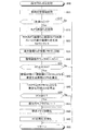
更に、CPU11は、図9にフローチャートで示したルーチンを所定時間が経過する毎に実行している。図9に示したルーチンは、保護窓22に付着した全面汚れ及び部分汚れが除去されたか否かを判定するためのルーチンである。
Further, the
従って、所定のタイミングになると、CPU11は図9のステップ900から処理を開始し、以下に述べるステップ905乃至ステップ925の処理を順に行い、ステップ930に進む。
Therefore, at a predetermined timing, the
ステップ905:CPU11は、カメラシステム20からカメラ画像情報を取得する。
ステップ910:CPU11は、図7のステップ715と同じくカメラ画像を複数の個別領域ARに分割する。
ステップ915:CPU11は、図7のステップ720と同じく複数の個別領域ARを中央領域CAと外側領域OAとに区分する。
ステップ920:CPU11は、前述した式1乃至式3に従って、複数の個別領域ARに属する各画素のエッジ強度ESを算出する。
ステップ925:CPU11は、複数の個別領域ARのそれぞれにおいて、エッジ強度ESが閾値強度ES1th以上であるエッジ画素数ENを算出する。
Step 905: The
Step 910: The
Step 915: The
Step 920: The
Step 925: The
次に、CPU11はステップ930に進み、全面汚れフラグXzの値が「1」であるか否かを判定する。即ち、CPU11は、RAM13に全面汚れ情報が記憶されているか否かを判定する。全面汚れフラグXzの値が「1」である場合、CPU11は、ステップ930にて「Yes」と判定し、ステップ935に進む。
Next, the
ステップ935にて、CPU11は、図7のステップ735と同じく、中央領域CAに属する複数の個別領域ARのうち、エッジ画素数ENが閾値画素数EN1th以上である個別領域ARの数(即ち、中央エッジ領域数CEN)を算出する。次に、CPU11はステップ940に進み、中央エッジ領域数CENが閾値領域数CEN1thよりも小さいか否かを判定する。
In
中央エッジ領域数CENが閾値領域数CEN1th以上である場合、保護窓22に付着した全面汚れが除去されたと判断することができる。そこで、この場合、CPU11はステップ940にて「No」と判定してステップ945に進み、全面汚れフラグXzの値を「0」に設定する。即ち、CPU11は、RAM13から全面汚れ情報を消去する。その後、CPU11はステップ950に進む。
When the number of central edge regions CEN is equal to or greater than the number of threshold regions CEN 1th, it can be determined that the entire surface dirt adhering to the protective window 22 has been removed. Therefore, in this case, the
ステップ950にて、CPU11は、部分汚れフラグXbの値が「1」であるか否かを判定する。即ち、CPU11は、RAM13に部分汚れ情報が記憶されているか否かを判定する。部分汚れフラグXbの値が「1」である場合、CPU11は、ステップ950にて「Yes」と判定してステップ960に進む。
In
ステップ960にて、CPU11は、ステップ845の処理によって無変化領域UCAであると特定された総ての個別領域ARのそれぞれのエッジ画素数ENが閾値画素数EN1th以上であるか否かを判定する。即ち、CPU11は、総ての無変化領域UCAが強エッジ領域(エッジが明確に検出される領域)であるか否かを判定する。
In
ステップ960の判定条件が成立する場合、保護窓22に付着した部分汚れの総てが除去されたと判断することができる。そこで、この場合、CPU11はステップ960にて「Yes」と判定してステップ965に進み、部分汚れフラグXbの値を「0」に設定する。即ち、CPU11は、RAM13から部分汚れ情報を消去する。その後、CPU11は、ステップ995に進み、本ルーチンを一旦終了する。
When the determination condition of
一方、CPU11がステップ930に進んだとき、全面汚れフラグXzの値が「1」でない場合(即ち、RAM13に全面汚れ情報が記憶されていない場合)、CPU11は、そのステップ930にて「No」と判定し、ステップ950に直接進む。
On the other hand, when the
更に、CPU11がステップ940に進んだとき、中央エッジ領域数CENが閾値領域数CEN1thよりも小さい場合、CPU11は、そのステップ940にて「Yes」と判定し、ステップ970に進む。ステップ970にて、CPU11は、外側領域OAに属する個別領域ARであって且つエッジ画素数ENが閾値画素数EN1th以上である個別領域ARの数である外側エッジ領域数OENを算出し、ステップ975に進む。
Further, when the
ステップ975にて、CPU11は、外側エッジ領域数OENが閾値領域数(第2閾値領域数)OEN1thよりも小さいか否かを判定する。本例において、閾値領域数OEN1thは「1」に設定されている。外側エッジ領域数OENが閾値領域数OEN1th以上である場合(即ち、明瞭にエッジを検出し難い外側エッジ領域において、エッジが明瞭に検出できている個別領域ARが存在する場合)、保護窓22に付着した全面汚れが除去されたと判断することができる。そこで、外側エッジ領域数OENが閾値領域数OEN1th以上である場合、CPU11はステップ975にて「No」と判定してステップ945に進み、全面汚れフラグXzの値を「0」に設定する。これに対し、外側エッジ領域数OENが閾値領域数OEN1thよりも小さい場合、CPU11は、ステップ975にて「Yes」と判定してステップ950に直接進む。
In
更に、CPU11がステップ950に進んだとき、部分汚れフラグXbの値が「0」である場合(即ち、RAM13に部分汚れ情報が記憶されていない場合)、CPU11は、そのステップ950にて「No」と判定し、ステップ995に直接進んで本ルーチンを一旦終了する。
Further, when the
更に、CPU11がステップ960に進んだとき、ステップ845の処理によって無変化領域UCAであると特定された個別領域ARのうちの少なくとも一つが「エッジ画素数ENが閾値画素数EN1th未満である」場合、保護窓22に付着した部分汚れが未だ除去されていないと判断できる。従って、この場合、CPU11はステップ960にて「No」と判定してステップ995に直接進み、本ルーチンを一旦終了する。
Further, when the
以上の例から理解されるように、CPU11は、全面汚れが付着していると判定されている場合、中央エッジ領域数CENが閾値領域数CEN1th以上であるとの条件(1)及び外側エッジ領域数OENが閾値領域数OEN1th以上であるとの条件(2)の少なくとも一方が成立したとき、全面汚れが除去されたと判定する。特に、条件(2)は、エッジ強度ESが小さく算出される傾向にある外側領域OAにおいて、エッジが明確に検出できている強エッジ領域の数(即ち、外側エッジ領域数OEN)が閾値領域数OEN1th以上であるとき成立する条件である。従って、カメラ21が、全面汚れが除去された場合には、中央領域CAにエッジが検出され得ない風景を撮影しているときであっても、CPU11は全面汚れが除去されたことを正確に判定することができる。
As can be understood from the above example, when it is determined that the entire surface is dirty, the
更に、CPU11は、部分汚れが付着していると判定されている場合、部分汚れ領域(無変化領域UCA)であると特定された総ての個別領域ARの各エッジ画素数ENが閾値画素数EN1th以上であるとき、部分汚れが除去されたと判定する。このように、部分汚れが除去されたか否かの判断には、無変化領域UCA以外の領域が考慮されないので、CPU11は部分汚れが除去されたことを正確に判定できる。
Further, when it is determined that the
更に、CPU11は、全面汚れが付着していると判定された場合と部分汚れが付着していると判定された場合とで、これらの汚れが除去されたと判定するための条件(除去判定条件)を異ならせている。従って、CPU11は、各汚れに対応した除去判定条件を設定することができ、これらの汚れが除去されたことを正確に判定することができる。
Further, the
本発明は上述した実施形態に限定されることはなく、本発明の種々の変形例を採用することができる。例えば、本監視装置は、自車両SVの図示しないイグニッション・キー・スイッチをオフ位置からオン位置へと変更する操作がなされたタイミング(以下、「初期状態」と称呼し、「始動時」と称呼する場合もある。)にて、全面汚れフラグXzの値を「1」に設定してもよい。これは、イグニッション・キー・スイッチをオン位置からオフ位置へと変更する操作がなされて自車両SVが停車されてから、自車両SVが初期状態となるまでの期間に、保護窓22に雪、霜及び雨滴等が付着することによって、保護窓22全面に汚れが付着している可能性があるからである。これによれば、本監視装置は、初期状態後において全面汚れ状態が解除されたと判定するまで(即ち、全面汚れフラグXzの値を「0」に設定するまで)、「不正確である可能性があるカメラ画像」に基づく後退時衝突前制御の実施を禁止することができる。 The present invention is not limited to the above-described embodiment, and various modifications of the present invention can be adopted. For example, in this monitoring device, the timing at which the ignition key switch (not shown) of the own vehicle SV is changed from the off position to the on position (hereinafter referred to as "initial state" and referred to as "starting time"). In some cases, the value of the entire surface dirt flag Xz may be set to "1". This is because the protective window 22 is covered with snow during the period from when the ignition key switch is changed from the on position to the off position and the own vehicle SV is stopped until the own vehicle SV is in the initial state. This is because there is a possibility that dirt is attached to the entire surface of the protective window 22 due to the adhesion of frost, raindrops, and the like. According to this, the monitoring device may be "inaccurate" until it is determined that the entire surface contamination state has been released after the initial state (that is, until the value of the entire surface contamination flag Xz is set to "0"). It is possible to prohibit the implementation of pre-collision control when reversing based on "a camera image".
更に、例えば、本監視装置は、車外の気温(外気温)を計測する図示しない気温センサを備えてもよい。この場合、本監視装置は、初期状態で気温センサから外気温を取得し、外気温が閾値気温以下である場合、全面汚れフラグXzの値を「1」に設定してもよい。これによって、初期状態において保護窓22に雪及び霜が付着している可能性がより高い場合に、「不正確である可能性があるカメラ画像」に基づく後退時衝突前制御の実施を禁止することができる。 Further, for example, the monitoring device may include a temperature sensor (not shown) that measures the air temperature outside the vehicle (outside air temperature). In this case, the monitoring device may acquire the outside air temperature from the temperature sensor in the initial state, and when the outside air temperature is equal to or less than the threshold temperature, the value of the entire surface dirt flag Xz may be set to "1". This prohibits the implementation of pre-collision control during retreat based on "camera images that may be inaccurate" when there is a higher possibility that snow and frost have adhered to the protective window 22 in the initial state. be able to.
更に、ステップ940にて使用される閾値領域数CEN1thと、ステップ975にて使用される閾値領域数OEN1thと、は互いに異なる値に設定されていてもよい。中央領域CAは外側領域OAよりもエッジ強度ESが正確に算出されやすいため、閾値領域数CEN1thは閾値領域数OEN1thよりも小さい値に設定されてもよい。これによって、より正確に全面汚れが除去されたことを判定することができる。更に、外側領域OAは中央領域CAよりもエッジ強度ESが小さく算出されやすいため、閾値領域数OEN1thは閾値領域数CEN1thよりも小さな値に設定されてもよい。これによって、より早い段階で全面汚れが除去されたことを判定することができる。
Further, the threshold region number CEN1th used in
更に、全面汚れ状態であるか否かの判定で用いられる閾値領域数CEN1th(ステップ740にて用いられる閾値領域数CEN1th)と全面汚れ状態が解除されたか否かの判定に用いられる閾値領域数CEN1th(ステップ940にて用いられる閾値領域数CEN1th)とは互いに異なる値に設定されていてもよい。この場合、全面汚れ状態が解除されたか否かの判定に用いられる閾値領域数CEN1thは、全面汚れ状態であるか否かの判定で用いられる閾値領域数CEN1thよりも大きいことが望ましい。 Further, the number of threshold regions CEN1th used in determining whether or not the entire surface is dirty (the number of threshold regions CEN1th used in step 740) and the number of threshold regions used in determining whether or not the entire surface is dirty CEN1th. (The threshold area number CEN1th used in step 940) may be set to a value different from each other. In this case, it is desirable that the threshold area number CEN1th used for determining whether or not the entire surface is dirty is larger than the threshold area number CEN1th used for determining whether or not the entire surface is dirty.
更に、図7に示すステップ730及びステップ735の処理の代わりに、本監視装置は、各個別領域ARにおけるエッジ強度ESの平均値AVEを算出し、中央領域CAに含まれる個別領域ARであって且つ算出した平均値AVEが閾値平均値AVE1th以上である個別領域ARの数を中央エッジ領域数CENとして算出してもよい。図9に示すステップ935にて、本監視装置は、中央領域CAに含まれる個別領域ARであって且つ算出した平均値AVEが閾値平均値AVE1th以上である個別領域ARの数を中央エッジ領域数CENとして算出してもよい。更に、図9に示すステップ955にて、本監視装置は、無変化領域UCAに含まれる個別領域ARであって且つ算出した平均値AVEが閾値平均値AVE1th以上である個別領域ARの数を部分汚れエッジ領域数DENとして算出してもよい。更に、図9に示すステップ970にて、本監視装置は、外側領域OAに含まれる個別領域ARであって且つ算出した平均値AVEが閾値平均値AVE1th以上である個別領域ARの数を外側エッジ領域数OENとして算出してもよい。
Further, instead of the processing of
更に、前述した実施例では、自車両SVの前端部に取り付けられ且つ自車両SVの前方側の風景を撮影する図示しない前方カメラの図示しない保護窓に全面汚れ及び部分汚れの少なくとも一方が付着した場合、支援制御の一つである前進時衝突前制御の実施を禁止してもよい。この場合、自車両SVの前端部の車幅方向の中心にはミリ波レーダが取り付けられる。ミリ波レーダは、ミリ波帯の電波(以下、「ミリ波」と称呼する。)を放射し、その反射波を受信し、物標の自車両SVに対する位置を検出するとともに物標の自車両SVに対する相対速度を検出する。なお、前方カメラが撮影した画像に基づいて物標の位置が特定可能であれば、ミリ波レーダは備えなくてもよい。本監視装置は、ミリ波レーダの検出結果及び前方カメラによって撮影されたカメラ画像(以下、「前方カメラ画像」と称呼する。)に基づいて自車両SVの前方側に存在する物標の位置を特定する。前進時衝突前制御を実施するための処理は、図6にフローチャートで示したルーチンと、自車両SVの前方に存在する障害物に対して実施される点のみで相違する。 Further, in the above-described embodiment, at least one of the entire surface stain and the partial stain adheres to the protective window (not shown) of the front camera (not shown) which is attached to the front end portion of the own vehicle SV and captures the landscape on the front side of the own vehicle SV. In this case, the implementation of pre-collision control during forward movement, which is one of the support controls, may be prohibited. In this case, a millimeter-wave radar is attached to the center of the front end of the own vehicle SV in the vehicle width direction. The millimeter-wave radar emits radio waves in the millimeter-wave band (hereinafter referred to as "millimeter wave"), receives the reflected wave, detects the position of the target with respect to the own vehicle SV, and detects the position of the target with respect to the own vehicle SV. Detects the relative velocity with respect to SV. If the position of the target can be specified based on the image taken by the front camera, the millimeter wave radar may not be provided. This monitoring device determines the position of the target existing on the front side of the own vehicle SV based on the detection result of the millimeter wave radar and the camera image taken by the front camera (hereinafter referred to as "front camera image"). Identify. The process for performing the pre-collision control during forward movement differs only from the routine shown in the flowchart in FIG. 6 in that it is performed on an obstacle existing in front of the own vehicle SV.
前方カメラの保護窓に対する全面汚れ判定処理は図7に示すルーチンと同じであり、当該保護窓に対する部分汚れ判定処理は図8に示すルーチンと同じであり、当該保護窓に対する汚れ解除判定処理は、図9に示すルーチンと同じである。 The entire surface stain determination process for the protective window of the front camera is the same as the routine shown in FIG. 7, the partial stain determination process for the protective window is the same as the routine shown in FIG. 8, and the stain release determination process for the protective window is It is the same as the routine shown in FIG.
カメラ21が撮影したカメラ画像に基づいて物標の自車両SVに対する位置を特定可能であれば、本監視装置はクリアランスソナー24を備えなくてもよい。
If the position of the target with respect to the own vehicle SV can be specified based on the camera image taken by the
更に、クリアランスソナー24は、無線媒体を放射して、反射された無線媒体を受信することによって物標を検出するセンサであればよい。このため、クリアランスソナー24の代わりに、ミリ波レーダ及び赤外線レーダ等が用いられてもよい。 Further, the clearance sonar 24 may be a sensor that detects a target by radiating the radio medium and receiving the reflected radio medium. Therefore, instead of the clearance sonar 24, a millimeter wave radar, an infrared radar, or the like may be used.
表示部30はHUDに特に限定されない。即ち、表示部30は、MID(Multi Information Display)、及び、ナビゲーション装置のタッチパネル等であってもよい。MIDは、スピードメータ、タコメータ、フューエルゲージ、ウォーターテンペラチャーゲージ、オド/トリップメータ、及び、ウォーニングランプ等のメータ類を集合させてダッシュボードに配置した表示パネルである。
The
10…周辺監視ECU、11…CPU、12…ROM、13…RAM、20…カメラシステム、21…カメラ、22…保護窓、23…画像処理装置、24A乃至24D…クリアランスソナー、25…シフトポジションセンサ、26…車両状態センサ、30…表示部、31…スピーカ、32…ブレーキECU、33…ブレーキセンサ、34…ブレーキアクチュエータ、35…エンジンECU、36…エンジンアクチュエータ。 10 ... Peripheral monitoring ECU, 11 ... CPU, 12 ... ROM, 13 ... RAM, 20 ... Camera system, 21 ... Camera, 22 ... Protective window, 23 ... Image processing device, 24A to 24D ... Clearance sonar, 25 ... Shift position sensor , 26 ... Vehicle status sensor, 30 ... Display, 31 ... Speaker, 32 ... Brake ECU, 33 ... Brake sensor, 34 ... Brake actuator, 35 ... Engine ECU, 36 ... Engine actuator.
Claims (7)
前記カメラ画像に含まれる画素のエッジ強度に基づいて前記保護窓の状態が前記保護窓の全面に汚れが付着している状態である全面汚れ状態であるか否かを判定し、前記保護窓の状態が前記全面汚れ状態であると判定されている場合に前記エッジ強度に基づいて前記全面汚れ状態が解除されたか否かを判定する判定部と、
を備えた周辺監視装置において、
前記制御部は、
前記保護窓の状態が前記全面汚れ状態であると判定されている場合、前記支援制御を実施しないように構成され、
前記判定部は、
前記カメラ画像の中央部を含む第1領域に属する画素のそれぞれの前記エッジ強度に基づいて算出される第1領域指標値が所定の汚れ閾値よりも小さい場合、前記保護窓の状態が前記全面汚れ状態であると判定し、且つ、
前記第1領域指標値が第1解除閾値以上であるとの第1条件が成立した場合、前記全面汚れ状態が解除されたと判定し、
前記第1条件が成立しない場合であっても、前記カメラ画像の前記第1領域以外の部分を含む第2領域に属する画素のそれぞれの前記エッジ強度に基づいて算出される第2領域指標値が第2解除閾値以上であるとの第2条件が成立した場合、前記全面汚れ状態が解除されたと判定する、
ように構成された、
周辺監視装置。 A control unit that implements support control to support the driving of the own vehicle based on a camera image which is an image taken by a camera that photographs the peripheral area of the own vehicle through a protective window exposed to the outside of the own vehicle. ,
Based on the edge strength of the pixels included in the camera image, it is determined whether or not the state of the protective window is a state in which dirt is attached to the entire surface of the protective window. A determination unit that determines whether or not the entire surface dirt state has been released based on the edge strength when the state is determined to be the entire surface dirt state.
In the peripheral monitoring device equipped with
The control unit
When it is determined that the state of the protective window is the state of being completely soiled, the support control is configured not to be executed.
The determination unit
When the first region index value calculated based on the edge strength of each of the pixels belonging to the first region including the central portion of the camera image is smaller than the predetermined stain threshold value, the state of the protective window is the entire surface stain. It is judged that it is in a state, and
When the first condition that the first region index value is equal to or higher than the first release threshold value is satisfied, it is determined that the entire surface dirt state has been released.
Even when the first condition is not satisfied, the second region index value calculated based on the edge strength of each pixel belonging to the second region including the portion other than the first region of the camera image is still present. When the second condition of being equal to or higher than the second release threshold value is satisfied, it is determined that the entire surface dirt state has been released.
Constructed as
Peripheral monitoring device.
前記判定部は、
前記第1領域に属し且つ前記エッジ強度が第1閾値強度以上である画素、の数と相関を有する値を前記第1領域指標値として算出し、
前記第2領域に属し且つ前記エッジ強度が第2閾値強度以上である画素、の数と相関を有する値を前記第2領域指標値として算出する、
ように構成された、
周辺監視装置。 In the peripheral monitoring device according to claim 1,
The determination unit
A value that correlates with the number of pixels that belong to the first region and whose edge strength is equal to or higher than the first threshold strength is calculated as the first region index value.
A value that correlates with the number of pixels that belong to the second region and whose edge strength is equal to or higher than the second threshold strength is calculated as the second region index value.
Constructed as
Peripheral monitoring device.
前記判定部は、
前記第1領域を複数の個別領域に分割し、前記第1領域の前記複数の個別領域のそれぞれに属し且つ前記エッジ強度が前記第1閾値強度以上である画素、の数が第1閾値画素数以上の前記個別領域の数である第1エッジ領域数を前記第1領域指標値として算出し、前記第1エッジ領域数が前記汚れ閾値としての第1閾値領域数よりも小さい場合、前記保護窓の状態が前記全面汚れ状態であると判定するように構成された、
周辺監視装置。 In the peripheral monitoring device according to claim 2,
The determination unit
The number of pixels that divide the first region into a plurality of individual regions, belong to each of the plurality of individual regions of the first region, and have an edge strength equal to or higher than the first threshold strength is the number of first threshold pixels. The number of first edge regions, which is the number of the individual regions, is calculated as the first region index value, and when the number of the first edge regions is smaller than the number of the first threshold regions as the stain threshold, the protective window Is configured to determine that the state of is the above-mentioned totally dirty state.
Peripheral monitoring device.
前記判定部は、
前記第2領域を複数の個別領域に分割し、前記第2領域の前記複数の個別領域のそれぞれに属し且つ前記エッジ強度が前記第2閾値強度以上である画素、の数が第2閾値画素数以上の前記個別領域の数である第2エッジ領域数を前記第2領域指標値として算出し、前記第2エッジ領域数が前記第2解除閾値としての第2閾値領域数以上である場合、前記第2条件が成立したと判定するように構成された、
周辺監視装置。 In the peripheral monitoring device according to claim 2,
The determination unit
The number of pixels that divide the second region into a plurality of individual regions, belong to each of the plurality of individual regions of the second region, and have an edge strength equal to or higher than the second threshold strength is the number of second threshold pixels. When the number of the second edge regions, which is the number of the individual regions, is calculated as the second region index value, and the number of the second edge regions is equal to or greater than the number of the second threshold regions as the second release threshold, the said. It is configured to determine that the second condition is met,
Peripheral monitoring device.
前記判定部は、
前記第1領域及び前記第2領域のそれぞれを複数の個別領域に分割し、前記画素のうち所定時間における画素値の変化量が変化量判定値以下である画素の数が閾値画素数以上となる前記個別領域である無変化領域が前記カメラ画像に含まれている場合、前記保護窓の状態が前記保護窓の前記無変化領域に対応する部分に汚れが付着している状態である部分汚れ状態であると判定するように構成され、
前記制御部は、
前記保護窓の状態が前記部分汚れ状態であると判定されている場合、前記支援制御を実施しないように構成された、
周辺監視装置。 The peripheral monitoring device according to claim 1.
The determination unit
Each of the first region and the second region is divided into a plurality of individual regions, and the number of pixels in which the amount of change in the pixel value in a predetermined time is equal to or less than the change amount determination value is equal to or greater than the number of threshold pixels. When the changeless region, which is an individual region, is included in the camera image, the state of the protective window is a partially soiled state in which dirt is attached to the portion of the protective window corresponding to the unchanged region. It is configured to determine that
The control unit
When the state of the protective window is determined to be the partially soiled state, the support control is not performed.
Peripheral monitoring device.
前記判定部は、
前記保護窓の状態が前記部分汚れ状態であると判定されている場合、前記無変化領域に属し且つ前記エッジ強度が第3閾値強度以上である画素、の数が第3閾値画素数以上となったとき、前記無変化領域に対する前記部分汚れ状態が解除されたと判定するように構成された、
周辺監視装置。 In the peripheral monitoring device according to claim 5,
The determination unit
When it is determined that the state of the protective window is the partially soiled state, the number of pixels belonging to the unchanged region and whose edge strength is equal to or greater than the third threshold intensity is equal to or greater than the number of third threshold pixels. At that time, it is configured to determine that the partial dirt state with respect to the unchanged region has been released.
Peripheral monitoring device.
前記判定部は、前記自車両の始動時に前記保護窓の状態が前記全面汚れ状態であると判定するように構成された、
周辺監視装置。 In the peripheral monitoring device according to claim 1,
The determination unit is configured to determine that the state of the protective window is the completely dirty state when the own vehicle is started.
Peripheral monitoring device.
Priority Applications (4)
| Application Number | Priority Date | Filing Date | Title |
|---|---|---|---|
| JP2017149307A JP6936070B2 (en) | 2017-08-01 | 2017-08-01 | Peripheral monitoring device |
| CN201810845388.3A CN109327677B (en) | 2017-08-01 | 2018-07-27 | Surrounding monitoring device |
| US16/049,909 US11194324B2 (en) | 2017-08-01 | 2018-07-31 | Monitor device |
| DE102018118463.8A DE102018118463A1 (en) | 2017-08-01 | 2018-07-31 | MONITORING DEVICE |
Applications Claiming Priority (1)
| Application Number | Priority Date | Filing Date | Title |
|---|---|---|---|
| JP2017149307A JP6936070B2 (en) | 2017-08-01 | 2017-08-01 | Peripheral monitoring device |
Publications (2)
| Publication Number | Publication Date |
|---|---|
| JP2019029901A JP2019029901A (en) | 2019-02-21 |
| JP6936070B2 true JP6936070B2 (en) | 2021-09-15 |
Family
ID=65019956
Family Applications (1)
| Application Number | Title | Priority Date | Filing Date |
|---|---|---|---|
| JP2017149307A Active JP6936070B2 (en) | 2017-08-01 | 2017-08-01 | Peripheral monitoring device |
Country Status (4)
| Country | Link |
|---|---|
| US (1) | US11194324B2 (en) |
| JP (1) | JP6936070B2 (en) |
| CN (1) | CN109327677B (en) |
| DE (1) | DE102018118463A1 (en) |
Families Citing this family (17)
| Publication number | Priority date | Publication date | Assignee | Title |
|---|---|---|---|---|
| JP6772113B2 (en) * | 2017-08-02 | 2020-10-21 | クラリオン株式会社 | Adhesion detection device and vehicle system equipped with it |
| JP7230507B2 (en) * | 2018-12-28 | 2023-03-01 | 株式会社デンソーテン | Deposit detection device |
| US11089205B2 (en) * | 2019-08-16 | 2021-08-10 | Toyota Motor Engineering & Manufacturing North America, Inc. | Window position monitoring system |
| JP7172932B2 (en) * | 2019-09-20 | 2022-11-16 | 株式会社デンソーテン | Attached matter detection device and attached matter detection method |
| JP7172931B2 (en) * | 2019-09-20 | 2022-11-16 | 株式会社デンソーテン | Attached matter detection device and attached matter detection method |
| JP7188336B2 (en) * | 2019-09-20 | 2022-12-13 | 株式会社デンソーテン | Attached matter detection device and attached matter detection method |
| CN114502984B (en) * | 2019-10-04 | 2025-06-06 | 株式会社电装 | Distance measuring device and method for detecting dirt on window of distance measuring device |
| JP7283461B2 (en) * | 2020-11-19 | 2023-05-30 | トヨタ自動車株式会社 | vehicle controller |
| JP7447783B2 (en) * | 2020-12-24 | 2024-03-12 | トヨタ自動車株式会社 | Vehicle control system and vehicle running control device |
| JP7410848B2 (en) * | 2020-12-28 | 2024-01-10 | 本田技研工業株式会社 | Vehicle recognition system and recognition method |
| US12319246B2 (en) * | 2021-08-25 | 2025-06-03 | Ford Global Technologies, Llc | Systems and methods for vehicle camera obstruction detection |
| JP7693523B2 (en) * | 2021-11-25 | 2025-06-17 | 株式会社小野測器 | Measurement System |
| JP7582253B2 (en) | 2022-05-20 | 2024-11-13 | トヨタ自動車株式会社 | Electronic inner mirror device, notification control method and notification control program thereof |
| US20250360938A1 (en) * | 2022-06-13 | 2025-11-27 | Honda Motor Co., Ltd. | Information processing device, information processing method, and program |
| EP4650229A1 (en) * | 2023-01-11 | 2025-11-19 | Astemo, Ltd. | Image processing device and image processing method |
| US12596077B2 (en) * | 2023-09-29 | 2026-04-07 | Apple Inc. | Passive camera lens smudge detection |
| WO2025158603A1 (en) * | 2024-01-25 | 2025-07-31 | Astemo株式会社 | Image processing device |
Family Cites Families (13)
| Publication number | Priority date | Publication date | Assignee | Title |
|---|---|---|---|---|
| JP2010041120A (en) * | 2008-07-31 | 2010-02-18 | Olympus Corp | Imaging apparatus and lens cover applied to same |
| CN201427565Y (en) * | 2009-07-14 | 2010-03-24 | 虞积勇 | Vehicle windshield wiper |
| JP2012191465A (en) * | 2011-03-11 | 2012-10-04 | Sony Corp | Image processing apparatus, image processing method, and program |
| US9319637B2 (en) * | 2012-03-27 | 2016-04-19 | Magna Electronics Inc. | Vehicle vision system with lens pollution detection |
| JP6055224B2 (en) * | 2012-07-27 | 2016-12-27 | クラリオン株式会社 | Lens cleaning device |
| US9445057B2 (en) * | 2013-02-20 | 2016-09-13 | Magna Electronics Inc. | Vehicle vision system with dirt detection |
| JP6245875B2 (en) * | 2013-07-26 | 2017-12-13 | クラリオン株式会社 | Lens dirt detection device and lens dirt detection method |
| JP6174975B2 (en) * | 2013-11-14 | 2017-08-02 | クラリオン株式会社 | Ambient environment recognition device |
| JP6048384B2 (en) * | 2013-12-11 | 2016-12-21 | トヨタ自動車株式会社 | Image determination device |
| CN203739844U (en) * | 2014-01-22 | 2014-07-30 | 成都华川电装有限责任公司 | Spraying device of washer for rear window |
| CN106415598B (en) * | 2014-05-27 | 2020-08-28 | 罗伯特·博世有限公司 | Lens contamination detection, identification and mitigation for vehicle-mounted camera systems |
| KR102351508B1 (en) * | 2015-04-28 | 2022-01-14 | 삼성디스플레이 주식회사 | Liquid crystal display |
| KR101714185B1 (en) * | 2015-08-05 | 2017-03-22 | 엘지전자 주식회사 | Driver Assistance Apparatus and Vehicle Having The Same |
-
2017
- 2017-08-01 JP JP2017149307A patent/JP6936070B2/en active Active
-
2018
- 2018-07-27 CN CN201810845388.3A patent/CN109327677B/en active Active
- 2018-07-31 DE DE102018118463.8A patent/DE102018118463A1/en active Pending
- 2018-07-31 US US16/049,909 patent/US11194324B2/en active Active
Also Published As
| Publication number | Publication date |
|---|---|
| US11194324B2 (en) | 2021-12-07 |
| CN109327677A (en) | 2019-02-12 |
| JP2019029901A (en) | 2019-02-21 |
| CN109327677B (en) | 2021-07-09 |
| DE102018118463A1 (en) | 2019-02-07 |
| US20190041849A1 (en) | 2019-02-07 |
Similar Documents
| Publication | Publication Date | Title |
|---|---|---|
| JP6936070B2 (en) | Peripheral monitoring device | |
| JP6597590B2 (en) | Driving assistance device | |
| CN105416283B (en) | Parking aids | |
| CN103241240B (en) | For the device for protecting outside rear-view mirror to be collided with flanking obstacle in the car | |
| CN104136282B (en) | Driving control device and driving control method | |
| EP2189811A1 (en) | Determination and signalling to a driver of a motor vehicle of a potential collision of the motor vehicle with an obstacle | |
| JP6849575B2 (en) | Braking support device and braking support control method in a vehicle | |
| JPWO2017068701A1 (en) | Parking space detection method and apparatus | |
| JP2001199260A (en) | Inter-vehicle distance control device, vehicle running status display device, vehicle speed control release device, and vehicle sudden braking warning device | |
| CN103359112A (en) | Driving support apparatus for vehicle | |
| CN106573589A (en) | Predicted-collision-time calculation device, and predicted-collision-time calculation method | |
| JP7200572B2 (en) | Deposit detection device | |
| JP6970547B2 (en) | Vehicle control device and vehicle control method | |
| WO2018190037A1 (en) | Obstacle detection and notification device, method and program | |
| JP6462492B2 (en) | Vehicle driving support device and driving support method | |
| JP2019002689A (en) | Target detection device | |
| CN104136281A (en) | Travel control device and travel control method | |
| US12344238B2 (en) | Driving assistance method and driving assistance device | |
| JP7380449B2 (en) | Judgment device and program | |
| US20220266830A1 (en) | Driving assist method and driving assist device | |
| JP7786931B2 (en) | Vehicle control device | |
| JP4661602B2 (en) | Rear vehicle analysis device and collision prediction device | |
| JP2024024349A (en) | Vehicle control device | |
| JP7279390B2 (en) | electronic controller | |
| JP2023073089A (en) | Parking support device |
Legal Events
| Date | Code | Title | Description |
|---|---|---|---|
| A621 | Written request for application examination |
Free format text: JAPANESE INTERMEDIATE CODE: A621 Effective date: 20200521 |
|
| A977 | Report on retrieval |
Free format text: JAPANESE INTERMEDIATE CODE: A971007 Effective date: 20210318 |
|
| A131 | Notification of reasons for refusal |
Free format text: JAPANESE INTERMEDIATE CODE: A131 Effective date: 20210413 |
|
| A521 | Request for written amendment filed |
Free format text: JAPANESE INTERMEDIATE CODE: A523 Effective date: 20210527 |
|
| TRDD | Decision of grant or rejection written | ||
| A01 | Written decision to grant a patent or to grant a registration (utility model) |
Free format text: JAPANESE INTERMEDIATE CODE: A01 Effective date: 20210803 |
|
| A61 | First payment of annual fees (during grant procedure) |
Free format text: JAPANESE INTERMEDIATE CODE: A61 Effective date: 20210826 |
|
| R151 | Written notification of patent or utility model registration |
Ref document number: 6936070 Country of ref document: JP Free format text: JAPANESE INTERMEDIATE CODE: R151 |
|
| R250 | Receipt of annual fees |
Free format text: JAPANESE INTERMEDIATE CODE: R250 |
|
| S111 | Request for change of ownership or part of ownership |
Free format text: JAPANESE INTERMEDIATE CODE: R313117 |
|
| S533 | Written request for registration of change of name |
Free format text: JAPANESE INTERMEDIATE CODE: R313533 |
|
| R350 | Written notification of registration of transfer |
Free format text: JAPANESE INTERMEDIATE CODE: R350 |
|
| R250 | Receipt of annual fees |
Free format text: JAPANESE INTERMEDIATE CODE: R250 |