JP6934350B2 - gas turbine - Google Patents
gas turbine Download PDFInfo
- Publication number
- JP6934350B2 JP6934350B2 JP2017150636A JP2017150636A JP6934350B2 JP 6934350 B2 JP6934350 B2 JP 6934350B2 JP 2017150636 A JP2017150636 A JP 2017150636A JP 2017150636 A JP2017150636 A JP 2017150636A JP 6934350 B2 JP6934350 B2 JP 6934350B2
- Authority
- JP
- Japan
- Prior art keywords
- side wall
- stationary blade
- wall portion
- stage stationary
- pressure surface
- Prior art date
- Legal status (The legal status is an assumption and is not a legal conclusion. Google has not performed a legal analysis and makes no representation as to the accuracy of the status listed.)
- Active
Links
Images


Classifications
-
- F—MECHANICAL ENGINEERING; LIGHTING; HEATING; WEAPONS; BLASTING
- F01—MACHINES OR ENGINES IN GENERAL; ENGINE PLANTS IN GENERAL; STEAM ENGINES
- F01D—NON-POSITIVE DISPLACEMENT MACHINES OR ENGINES, e.g. STEAM TURBINES
- F01D5/00—Blades; Blade-carrying members; Heating, heat-insulating, cooling or antivibration means on the blades or the members
- F01D5/12—Blades
- F01D5/14—Form or construction
- F01D5/141—Shape, i.e. outer, aerodynamic form
-
- F—MECHANICAL ENGINEERING; LIGHTING; HEATING; WEAPONS; BLASTING
- F01—MACHINES OR ENGINES IN GENERAL; ENGINE PLANTS IN GENERAL; STEAM ENGINES
- F01D—NON-POSITIVE DISPLACEMENT MACHINES OR ENGINES, e.g. STEAM TURBINES
- F01D9/00—Stators
- F01D9/02—Nozzles; Nozzle boxes; Stator blades; Guide conduits, e.g. individual nozzles
- F01D9/04—Nozzles; Nozzle boxes; Stator blades; Guide conduits, e.g. individual nozzles forming ring or sector
- F01D9/041—Nozzles; Nozzle boxes; Stator blades; Guide conduits, e.g. individual nozzles forming ring or sector using blades
-
- F—MECHANICAL ENGINEERING; LIGHTING; HEATING; WEAPONS; BLASTING
- F23—COMBUSTION APPARATUS; COMBUSTION PROCESSES
- F23R—GENERATING COMBUSTION PRODUCTS OF HIGH PRESSURE OR HIGH VELOCITY, e.g. GAS-TURBINE COMBUSTION CHAMBERS
- F23R3/00—Continuous combustion chambers using liquid or gaseous fuel
- F23R3/42—Continuous combustion chambers using liquid or gaseous fuel characterised by the arrangement or form of the flame tubes or combustion chambers
- F23R3/46—Combustion chambers comprising an annular arrangement of several essentially tubular flame tubes within a common annular casing or within individual casings
-
- F—MECHANICAL ENGINEERING; LIGHTING; HEATING; WEAPONS; BLASTING
- F01—MACHINES OR ENGINES IN GENERAL; ENGINE PLANTS IN GENERAL; STEAM ENGINES
- F01D—NON-POSITIVE DISPLACEMENT MACHINES OR ENGINES, e.g. STEAM TURBINES
- F01D9/00—Stators
- F01D9/02—Nozzles; Nozzle boxes; Stator blades; Guide conduits, e.g. individual nozzles
- F01D9/023—Transition ducts between combustor cans and first stage of the turbine in gas-turbine engines; their cooling or sealings
-
- F—MECHANICAL ENGINEERING; LIGHTING; HEATING; WEAPONS; BLASTING
- F02—COMBUSTION ENGINES; HOT-GAS OR COMBUSTION-PRODUCT ENGINE PLANTS
- F02C—GAS-TURBINE PLANTS; AIR INTAKES FOR JET-PROPULSION PLANTS; CONTROLLING FUEL SUPPLY IN AIR-BREATHING JET-PROPULSION PLANTS
- F02C3/00—Gas-turbine plants characterised by the use of combustion products as the working fluid
- F02C3/14—Gas-turbine plants characterised by the use of combustion products as the working fluid characterised by the arrangement of the combustion chamber in the plant
-
- F—MECHANICAL ENGINEERING; LIGHTING; HEATING; WEAPONS; BLASTING
- F05—INDEXING SCHEMES RELATING TO ENGINES OR PUMPS IN VARIOUS SUBCLASSES OF CLASSES F01-F04
- F05D—INDEXING SCHEME FOR ASPECTS RELATING TO NON-POSITIVE-DISPLACEMENT MACHINES OR ENGINES, GAS-TURBINES OR JET-PROPULSION PLANTS
- F05D2220/00—Application
- F05D2220/30—Application in turbines
- F05D2220/32—Application in turbines in gas turbines
- F05D2220/321—Application in turbines in gas turbines for a special turbine stage
- F05D2220/3212—Application in turbines in gas turbines for a special turbine stage the first stage of a turbine
-
- F—MECHANICAL ENGINEERING; LIGHTING; HEATING; WEAPONS; BLASTING
- F23—COMBUSTION APPARATUS; COMBUSTION PROCESSES
- F23R—GENERATING COMBUSTION PRODUCTS OF HIGH PRESSURE OR HIGH VELOCITY, e.g. GAS-TURBINE COMBUSTION CHAMBERS
- F23R3/00—Continuous combustion chambers using liquid or gaseous fuel
- F23R3/42—Continuous combustion chambers using liquid or gaseous fuel characterised by the arrangement or form of the flame tubes or combustion chambers
Description
本開示は、ガスタービンに関する。 The present disclosure relates to gas turbines.
ガスタービンの効率を向上させるために、タービンの最上流側に設けられる1段静翼の形状や配置に関し様々な工夫がなされている。 In order to improve the efficiency of the gas turbine, various measures have been taken regarding the shape and arrangement of the one-stage stationary blade provided on the most upstream side of the turbine.
例えば、特許文献1には、タービンの1段静翼が、燃焼器の尾筒の側壁の下流側において、該尾筒の下流側端に接近して配置されたガスタービンが開示されている。このように1段静翼が尾筒の下流側端に接近して配置されることにより、燃焼器の尾筒とタービンの1段静翼との間への燃焼ガスの流入が抑制されて、該燃焼ガスの流入による損失の発生が抑制されるようになっている。また、上述のように、1段静翼が燃焼器尾筒の側壁の下流側に配置されることにより、1段静翼の前縁に高温の燃焼ガスが直接衝突するのが抑制され、1段静翼の前縁を冷却するための冷却空気が低減されるようになっている。
For example,
また、特許文献1には、燃焼器尾筒の側壁の下流側端部において、側壁の内表面が、該側壁と隣接する1段静翼の外表面と滑らかに繋がる形状に形成されたガスタービンが開示されている。このように、尾筒の側壁の内表面と、1段静翼の外表面とが滑らかに繋がる形状とすることにより、燃焼ガス流路を流れる燃焼ガスの流れが乱れにくくなり、損失の発生が抑制されるようになっている。
Further,
また、特許文献2には、燃焼器の内圧変動を抑制するとともにガスタービンの空力効率を向上するために、1段静翼の周方向ピッチPに対する、隣接する燃焼器間の中心と1段静翼の前縁との間の周方向距離Sの比(S/P)や、1段静翼の周方向ピッチPに対する、1段静翼の前縁と燃焼器尾筒後端との軸方向距離Lの比(L/P)が所定範囲内に設定されたガスタービンが開示されている。
Further, in
ところで、本発明者らの鋭意検討の結果、例えば特許文献1に記載のように、タービン1段静翼の前方部を燃焼器の出口に近づけて、1段静翼と燃焼器の側壁との間の軸方向隙間を小さくすると、該1段静翼の圧力面側(腹側)と負圧面側(背側)との圧力差に起因して、軸方向隙間を介した高温の燃焼ガスの流れが生じる場合があることがわかった。
上述の軸方向隙間を介した高温ガスの流れが生じると、該高温ガスの流れにより1段静翼が加熱されるため、1段静翼を冷却するための冷却媒体の供給量を増加させる必要が生じ、これによりガスタービン全体として効率が低下する場合がある。
しかしながら、特許文献1及び2には、1段静翼と燃焼器の側壁との間の軸方向隙間を小さくしたときに生じる該軸方向隙間を介した高温の燃焼ガス流れに対する対策について、何ら記載されていない。
By the way, as a result of diligent studies by the present inventors, for example, as described in
When a flow of high-temperature gas occurs through the above-mentioned axial gap, the flow of the high-temperature gas heats the one-stage stationary blade, so that it becomes necessary to increase the supply amount of the cooling medium for cooling the one-stage stationary blade. This may reduce the efficiency of the gas turbine as a whole.
However,
上述の事情に鑑みて、本発明の少なくとも一実施形態は、1段静翼の効率的な冷却が可能なガスタービンを提供することを目的とする。 In view of the above circumstances, at least one embodiment of the present invention aims to provide a gas turbine capable of efficiently cooling a one-stage stationary blade.
(1)本発明の少なくとも一実施形態に係るガスタービンは、
周方向に複数配列され、圧力面および負圧面を含む翼面をそれぞれ有する1段静翼と、
一の前記1段静翼の前記負圧面側に設けられ、径方向に沿って延在する第1側壁部を含む第1燃焼器出口を有する第1燃焼器と、
前記周方向にて前記第1燃焼器の隣において前記一の前記1段静翼の前記圧力面側に設けられ、前記径方向に沿って延在する第2側壁部を含む第2燃焼器出口を有する第2燃焼器と、
を備えるガスタービンであって、
下記条件(a)又は(b)の何れかを満たし、
上流側から下流側に向かって前記軸方向をx軸と定義し、前記第1側壁部の外側から内側に向かって前記周方向をy軸と定義したとき、前記第1側壁部の下流端部における内側壁面の傾きdy/dxが最大となる位置を通る前記内側壁面の下流側に延ばした第1基準接線に対して、前記一の前記1段静翼の前方部の前記負圧面と前記第1基準接線との交点を通る前記負圧面の第1接線がなす第1角度が45度以下であり、
前記一の前記1段静翼は、前記第1側壁部の前記内側壁面からの前記負圧面の前記周方向への突出量をΔyとし、前記1段静翼の前記周方向における配列ピッチをPとしたとき、0.05≦Δy/P≦0.25を満たす。
(a)前記一の前記1段静翼の前方部と前記第1側壁部との間の軸方向の最小隙間、および、前記一の前記1段静翼の前記前方部と前記第2側壁部との間の前記軸方向の最小隙間が、前記軸方向における前記一の1段静翼の長さLaの10%以下である。
(b)前記一の前記1段静翼の前方部の最上流点が、前記第1側壁部又は前記第2側壁部の少なくとも一方の最下流端よりも、前記軸方向において上流側に位置する。
(1) The gas turbine according to at least one embodiment of the present invention is
A one-stage stationary blade that is arranged in the circumferential direction and has a blade surface including a pressure surface and a negative pressure surface, respectively.
A first combustor provided on the negative pressure surface side of the one-stage stationary blade and having a first combustor outlet including a first side wall portion extending along the radial direction.
It has a second combustor outlet provided on the pressure surface side of the one-stage stationary blade next to the first combustor in the circumferential direction and including a second side wall portion extending along the radial direction. With the second combustor
It is a gas turbine equipped with
Satisfy either the following conditions (a) or (b),
When the axial direction is defined as the x-axis from the upstream side to the downstream side and the circumferential direction is defined as the y-axis from the outside to the inside of the first side wall portion, the downstream end portion of the first side wall portion is defined. With respect to the first reference tangent line extending to the downstream side of the inner wall surface passing through the position where the inclination dy / dx of the inner wall surface in The first angle formed by the first tangent of the negative pressure surface passing through the intersection with the tangent is 45 degrees or less.
In the one-stage stationary blade, when the amount of protrusion of the negative pressure surface from the inner wall surface of the first side wall portion in the circumferential direction is Δy and the arrangement pitch of the first-stage stationary blade in the circumferential direction is P. Satisfy 0.05 ≦ Δy / P ≦ 0.25.
(A) The minimum axial clearance between the front portion of the one-stage stationary blade and the first side wall portion, and between the front portion of the one-stage stationary blade and the second side wall portion. The minimum clearance in the axial direction is 10% or less of the length La of the one-stage stationary blade in the axial direction.
(B) The most upstream point of the front portion of the one-stage stationary blade is located on the upstream side in the axial direction with respect to at least one most downstream end of the first side wall portion or the second side wall portion.
上記(1)の構成では、ガスタービンは、上記(a)又は(b)を満たすので、1段静翼の前方部と燃焼器出口の第1側壁部又は第2側壁部との間の最小距離が十分に小さい。このため、1段静翼の前方部と第1側壁部又は第2側壁部との間を流通する高温の燃焼ガス流れが低減されるため、1段静翼を冷却するために必要な冷却媒体の流量を低減することができる。また、上記(1)の構成では、第1側壁部の内側壁面における上述の第1基準接線に対して、1段静翼の前方部の負圧面における上述の第1接線がなす第1角度が45度以下であるので、燃焼器出口の第1側壁部と1段静翼の負圧面とが滑らかに接続されている。よって、燃焼器出口からの高温の燃焼ガスの流れの乱れを低減することができる。 In the configuration of the above (1), since the gas turbine satisfies the above (a) or (b), the minimum distance between the front portion of the one-stage stationary blade and the first side wall portion or the second side wall portion of the combustor outlet is set. Small enough. Therefore, the flow rate of the high-temperature combustion gas flowing between the front portion of the one-stage stationary blade and the first side wall portion or the second side wall portion is reduced, so that the flow rate of the cooling medium required for cooling the one-stage stationary blade is reduced. can do. Further, in the configuration of the above (1), the first angle formed by the above-mentioned first tangent on the negative pressure surface of the front portion of the one-stage stationary blade is 45 degrees with respect to the above-mentioned first reference tangent on the inner wall surface of the first side wall. Since it is as follows, the first side wall portion of the combustor outlet and the negative pressure surface of the one-stage stationary blade are smoothly connected. Therefore, it is possible to reduce the turbulence of the flow of the high-temperature combustion gas from the outlet of the combustor.
ここで、本発明者らは、第1側壁部の内側壁面からの1段静翼の負圧面の周方向への突出量Δyと、1段静翼の周方向における配列ピッチPとの比(Δy/P)に応じて、1段静翼の圧力面側と負圧面側との圧力差が変化し、Δy/Pを適切な値とすることにより該圧力差を低減できることを見出した。
この点、上記(1)の構成では、さらに、第1側壁部の内側壁面からの1段静翼の負圧面の周方向への突出量Δyと、1段静翼の周方向における配列ピッチPとが0.05≦Δy/P≦0.25を満たすので、1段静翼の圧力面側と負圧面側との圧力差が比較的小さい。このため、1段静翼の圧力面側と負圧面側の圧力差に起因した、1段静翼の前方部と、第1燃焼器出口及び第2燃焼器出口との間の隙間を介した高温ガスの流れの発生が抑制されるので、1段静翼を冷却するために必要な冷却媒体の流量を低減することができる。
Here, the present inventors have calculated the ratio (Δy / P) of the amount of protrusion Δy of the negative pressure surface of the one-stage stationary blade in the circumferential direction from the inner wall surface of the first side wall portion to the arrangement pitch P in the circumferential direction of the one-stage stationary blade. It was found that the pressure difference between the pressure surface side and the negative pressure surface side of the one-stage stationary blade changes accordingly, and the pressure difference can be reduced by setting Δy / P to an appropriate value.
In this regard, in the configuration of (1) above, the amount Δy of the negative pressure surface of the one-stage stationary blade in the circumferential direction from the inner wall surface of the first side wall portion and the arrangement pitch P in the circumferential direction of the one-stage stationary blade are 0. Since 05 ≦ Δy / P ≦ 0.25 is satisfied, the pressure difference between the pressure surface side and the negative pressure surface side of the one-stage stationary blade is relatively small. Therefore, the flow of high-temperature gas through the gap between the front portion of the one-stage combustor blade and the outlets of the first combustor and the second combustor due to the pressure difference between the pressure surface side and the negative pressure surface side of the one-stage stationary blade. Is suppressed, so that the flow rate of the cooling medium required to cool the one-stage stationary blade can be reduced.
以上より、上記(1)の構成によれば、燃焼器出口からの高温の燃焼ガスの流れの乱れを低減しながら、1段静翼を効率的に冷却することができる。これにより、ガスタービンの効率低下を抑制することができる。 From the above, according to the configuration of (1) above, the one-stage stationary blade can be efficiently cooled while reducing the turbulence of the flow of high-temperature combustion gas from the combustor outlet. As a result, it is possible to suppress a decrease in efficiency of the gas turbine.
(2)幾つかの実施形態では、上記(1)の構成において、
前記第2側壁部の外側から内側に向かって前記周方向をy’軸と定義したとき、前記第2側壁部の下流端部における内側壁面の傾きdy’/dxが最大となる位置を通る前記内側壁面の下流側に延ばした第2基準接線に対して、前記一の前記1段静翼の前記前方部の前記圧力面と前記第2基準接線との交点を通る前記圧力面の第2接線がなす第2角度が45度以下である。
(2) In some embodiments, in the configuration of (1) above,
When the circumferential direction is defined as the y'axis from the outside to the inside of the second side wall portion, the passage passes through a position where the inclination dy'/ dx of the inner wall surface at the downstream end portion of the second side wall portion is maximized. The second tangent of the pressure surface passing through the intersection of the pressure surface of the front portion of the one-stage stationary blade and the second reference tangent of the one-stage stationary blade forms with respect to the second reference tangent extending to the downstream side of the inner wall surface. The second angle is 45 degrees or less.
上記(2)の構成によれば、第2側壁部の内側壁面における上述の第2基準接線に対して、1段静翼の前方部の圧力面における上述の第2接線がなす第2角度が45度以下であるので、燃焼器出口の第2側壁部と1段静翼の圧力面とが滑らかに接続されている。よって、燃焼器出口からの高温の燃焼ガスの流れの乱れをより効果的に低減することができる。 According to the configuration of (2) above, the second angle formed by the above-mentioned second tangent on the pressure surface at the front portion of the one-stage stationary blade is 45 degrees with respect to the above-mentioned second reference tangent on the inner wall surface of the second side wall. Since it is as follows, the second side wall portion of the combustor outlet and the pressure surface of the one-stage stationary blade are smoothly connected. Therefore, the turbulence of the flow of the high-temperature combustion gas from the outlet of the combustor can be reduced more effectively.
(3)幾つかの実施形態では、上記(2)の構成において、
前記第1角度が20度以上45度以下であり、
前記第2角度が0度以上25度以下である。
(3) In some embodiments, in the configuration of (2) above,
The first angle is 20 degrees or more and 45 degrees or less.
The second angle is 0 degrees or more and 25 degrees or less.
上記(3)の構成によれば、負圧面側における第1角度を上記範囲内に設定することで、燃焼ガス流れの1段静翼の負圧面への衝突によって負圧面側で静圧が上昇する。一方、圧力面側における第2角度を上記範囲内に設定することで、第2角度が25度よりも大きい場合に比べて、圧力面が燃焼ガス流れの下流側に後退することになり、上述した隙間近傍における圧力面側の圧力を減少させることができる。よって、1段静翼の前方部と、第1燃焼器出口及び第2燃焼器出口との間の隙間を介した高温ガスの流れの発生を抑制可能である。 According to the configuration of (3) above, by setting the first angle on the negative pressure surface side within the above range, the static pressure rises on the negative pressure surface side due to the collision of the combustion gas flow with the negative pressure surface of the one-stage stationary blade. On the other hand, by setting the second angle on the pressure surface side within the above range, the pressure surface recedes to the downstream side of the combustion gas flow as compared with the case where the second angle is larger than 25 degrees. It is possible to reduce the pressure on the pressure surface side in the vicinity of the gap. Therefore, it is possible to suppress the generation of high-temperature gas flow through the gap between the front portion of the one-stage stationary blade and the outlets of the first combustor and the outlet of the second combustor.
(4)幾つかの実施形態では、上記(2)又は(3)の構成において、前記第1角度は、前記第2角度以上である。 (4) In some embodiments, in the configuration of (2) or (3) above, the first angle is equal to or greater than the second angle.
上記(4)の構成によれば、第1角度を第2角度以上にすることで、圧力面側における圧力を減少させながら、負圧面側において圧力を増大させることができ、1段静翼の前方部と、第1燃焼器出口及び第2燃焼器出口との間の隙間を介した高温ガスの流れの発生を効果的に抑制可能である。 According to the configuration of (4) above, by setting the first angle to the second angle or more, it is possible to increase the pressure on the negative pressure surface side while reducing the pressure on the pressure surface side, and the front portion of the one-stage stationary blade. And, it is possible to effectively suppress the generation of the flow of high temperature gas through the gap between the outlet of the first combustor and the outlet of the second combustor.
(5)幾つかの実施形態では、上記(1)乃至(4)の何れかの構成において、
前記第1側壁部の下流側端面、及び、前記第2側壁部の下流側端面は、それぞれ、前記軸方向の直交面に沿った平坦面を含み、
前記前方部は、前記第1側壁部の前記下流側端面及び前記第2側壁部の前記下流側端面に対向する前端面を含み、
前記前端面の少なくとも一部は、前記軸方向の前記直交面に沿って設けられる平坦面である。
(5) In some embodiments, in any of the configurations (1) to (4) above,
The downstream end surface of the first side wall portion and the downstream end surface of the second side wall portion each include a flat surface along the orthogonal plane in the axial direction.
The front portion includes the downstream end surface of the first side wall portion and the front end surface of the second side wall portion facing the downstream end surface.
At least a part of the front end surface is a flat surface provided along the orthogonal surface in the axial direction.
上記(5)の構成によれば、第1側壁部及び第2側壁部の下流側端面、及び、該下流側端面に対向する1段静翼の前方部の前端面の少なくとも一部がそれぞれ、軸方向の直交面に沿った平坦面により形成される。よって、第1側壁部及び第2側壁部の下流側端面、又は、1段静翼の前方部の前端面が湾曲面により形成される場合に比べて、1段静翼の前方部と、第1燃焼器出口及び第2燃焼器出口との間の軸方向における隙間の管理が容易となる。よって、1段静翼を冷却するために必要な冷却媒体の流量を削減しやすくなる。 According to the configuration of (5) above, at least a part of the downstream end faces of the first side wall portion and the second side wall portion and the front end face of the front portion of the one-stage stationary blade facing the downstream end face are in the axial direction, respectively. It is formed by flat surfaces along the orthogonal planes of. Therefore, compared to the case where the downstream end faces of the first side wall portion and the second side wall portion or the front end face of the front portion of the one-stage stationary blade is formed by a curved surface, the front portion of the one-stage stationary blade and the outlet of the first combustor And the management of the axial gap between the second combustor outlet and the second combustor outlet becomes easy. Therefore, it becomes easy to reduce the flow rate of the cooling medium required for cooling the one-stage stationary blade.
(6)幾つかの実施形態では、上記(1)乃至(5)の何れかの構成において、
前記一の前記1段静翼は、前記前方部の下流側に位置するとともに、前記負圧面のうち後縁側領域である凸状湾曲面、および、前記圧力面のうち後縁側領域である凹状湾曲面を有する後方部を含み、
前記負圧面の前記凸状湾曲面の前縁側端は、前記負圧面のうち前記第1側壁部の前記内側壁面から前記周方向に最も突出した部分よりも、前記周方向において、前記第2側壁部に近い。
(6) In some embodiments, in any of the configurations (1) to (5) above,
The one-stage stationary blade is located on the downstream side of the front portion, and has a convex curved surface which is a trailing edge side region of the negative pressure surface and a concave curved surface which is a trailing edge side region of the pressure surface. Including the rear part with
The front edge side end of the convex curved surface of the negative pressure surface is the second side wall in the circumferential direction from the portion of the negative pressure surface that most protrudes from the inner wall surface of the first side wall portion in the circumferential direction. Close to the club.
上記(6)の構成によれば、第1燃焼器出口からの燃焼ガス流れが1段静翼の負圧面に衝突しやすくなるため、負圧面側で静圧が上昇しやすくなる。これにより、負圧面側と圧力面側の圧力差を低減して、1段静翼の前方部と、第1燃焼器出口及び第2燃焼器出口との間の隙間を介した高温ガスの流れの発生を効果的に抑制することができる。 According to the configuration (6) above, the combustion gas flow from the outlet of the first combustor tends to collide with the negative pressure surface of the one-stage stationary blade, so that the static pressure tends to increase on the negative pressure surface side. As a result, the pressure difference between the negative pressure surface side and the pressure surface side is reduced, and the flow of high-temperature gas is generated through the gap between the front portion of the one-stage stationary blade and the outlets of the first combustor and the second combustor. Can be effectively suppressed.
(7)幾つかの実施形態では、上記(1)乃至(6)の何れかの構成において、
前記一の前記1段静翼は、前記前方部の下流側に位置するとともに、前記負圧面のうち後縁側領域である凸状湾曲面、および、前記圧力面のうち後縁側領域である凹状湾曲面を有する後方部を含み、
前記前方部は、
前記負圧面の前縁側領域を形成するように、前記凸状湾曲面の前縁側端から前記第1側壁部に向かって直線状に延びる第1表面と、
前記圧力面の前縁側領域を形成するように、前記凹状湾曲面の前縁側端から前記第2側壁部に向かって直線状に延びる第2表面と、
を含む。
(7) In some embodiments, in any of the configurations (1) to (6) above,
The one-stage stationary blade is located on the downstream side of the front portion, and has a convex curved surface which is a trailing edge side region of the negative pressure surface and a concave curved surface which is a trailing edge side region of the pressure surface. Including the rear part with
The front part
A first surface extending linearly from the front edge side end of the convex curved surface toward the first side wall portion so as to form a front edge side region of the negative pressure surface.
A second surface extending linearly from the front edge side end of the concave curved surface toward the second side wall portion so as to form a front edge side region of the pressure surface.
including.
上記(7)の構成によれば、負圧面の前縁側領域は、直線状に延びる第1表面により形成されるとともに、圧力面の前縁側領域は、直線状に延びる第2表面により形成されるので、1段静翼の作製が比較的容易である。 According to the configuration of (7) above, the front edge side region of the negative pressure surface is formed by the first surface extending linearly, and the front edge side region of the pressure surface is formed by the second surface extending linearly. Therefore, it is relatively easy to manufacture a one-stage stationary blade.
(8)幾つかの実施形態では、上記(7)の構成において、
前記第1側壁部の下流側端面、及び、前記第2側壁部の下流側端面は、それぞれ、前記軸方向の直交面に沿った平坦面を含み、
前記前方部は、
前記第1表面の前縁側端に接続される第1接続点を有し、前記第1側壁部の前記下流側端面に対向するように前記軸方向の前記直交面に沿って延在する第1平坦面と、
前記第2表面の前縁側端に接続される第2接続点を有し、前記第2側壁部の前記下流側端面に対向するように前記軸方向の前記直交面に沿って延在する第2平坦面と、
を含む。
(8) In some embodiments, in the configuration of (7) above,
The downstream end surface of the first side wall portion and the downstream end surface of the second side wall portion each include a flat surface along the orthogonal plane in the axial direction.
The front part
A first that has a first connection point connected to the front edge side end of the first surface and extends along the orthogonal plane in the axial direction so as to face the downstream end surface of the first side wall portion. Flat surface and
A second having a second connection point connected to the front edge side end of the second surface and extending along the orthogonal plane in the axial direction so as to face the downstream end surface of the second side wall portion. Flat surface and
including.
上記(8)の構成によれば、第1側壁部及び第2側壁部の下流側端面が平坦面によって形成されるとともに、前方部の第1平坦面及び第2平坦面が、それぞれ、平坦面を含む第1側壁部の下流側端面及び第2側壁部の下流側端面に対向する。よって、第1側壁部及び第2側壁部の下流側端面、又は、1段静翼の前方部の前端面が湾曲面により形成される場合に比べて、1段静翼の前方部と、第1燃焼器出口及び第2燃焼器出口との間の軸方向における隙間の管理が容易となる。よって、1段静翼を冷却するために必要な冷却媒体の流量を削減しやすくなる。 According to the configuration of (8) above, the downstream end faces of the first side wall portion and the second side wall portion are formed by flat surfaces, and the first flat surface and the second flat surface of the front portion are flat surfaces, respectively. Facing the downstream end face of the first side wall portion and the downstream end face of the second side wall portion including. Therefore, compared to the case where the downstream end faces of the first side wall portion and the second side wall portion or the front end face of the front portion of the one-stage stationary blade is formed by a curved surface, the front portion of the one-stage stationary blade and the outlet of the first combustor And the management of the axial gap between the second combustor outlet and the second combustor outlet becomes easy. Therefore, it becomes easy to reduce the flow rate of the cooling medium required for cooling the one-stage stationary blade.
(9)幾つかの実施形態では、上記(8)の構成において、
前記第1接続点と前記第2接続点との間の前記周方向における距離は、前記第1側壁部の前記内側壁面と前記第2側壁部の前記内側壁面との間の前記周方向における距離よりも小さい。
(9) In some embodiments, in the configuration of (8) above,
The distance between the first connection point and the second connection point in the circumferential direction is the distance in the circumferential direction between the inner wall surface of the first side wall portion and the inner wall surface of the second side wall portion. Smaller than
上記(9)の構成によれば、第1接続点と第2接続点との間の周方向における距離は、第1側壁部の内側壁面と第2側壁部の内側壁面との間の周方向における距離よりも小さいので、第1接続点と第2接続点との間の上記距離が第1側壁部の内側壁面と第2側壁部の内側壁面との間の上記距離よりも大きい場合に比べて、燃焼器出口からの燃焼ガスの流れが乱れにくい。よって、タービンにおける流体損失の発生を抑制しやすい。 According to the configuration of (9) above, the distance in the circumferential direction between the first connection point and the second connection point is the circumferential direction between the inner wall surface of the first side wall portion and the inner wall surface of the second side wall portion. Since it is smaller than the distance in, the distance between the first connection point and the second connection point is larger than the distance between the inner wall surface of the first side wall portion and the inner wall surface of the second side wall portion. Therefore, the flow of combustion gas from the combustor outlet is not easily disturbed. Therefore, it is easy to suppress the occurrence of fluid loss in the turbine.
(10)幾つかの実施形態では、上記(8)又は(9)の構成において、前記第1平坦面の前記第1接続点は、前記周方向において、前記第1側壁部の前記内側壁面よりも前記第2側壁部側に位置する。 (10) In some embodiments, in the configuration of (8) or (9), the first connection point of the first flat surface is from the inner wall surface of the first side wall portion in the circumferential direction. Is also located on the side of the second side wall.
上記(10)の構成によれば、第1平坦面の第1接続点が、周方向において、第1側壁部の内側壁面よりも第2側壁部側に位置するので、負圧面側において、第1燃焼器出口Aからの燃焼ガスの流れが乱れにくい。よって、タービンにおける流体損失の発生を抑制しやすい。 According to the configuration of (10) above, since the first connection point of the first flat surface is located on the second side wall portion side of the inner wall surface portion of the first side wall portion in the circumferential direction, the first side wall portion is located on the negative pressure surface side. 1 The flow of combustion gas from the combustor outlet A is less likely to be disturbed. Therefore, it is easy to suppress the occurrence of fluid loss in the turbine.
(11)幾つかの実施形態では、上記(8)乃至(10)の何れかの構成において、
前記第2平坦面の前記第2接続点は、前記周方向において、前記第2側壁部の前記内側壁面よりも前記第1側壁部側に位置する。
(11) In some embodiments, in any of the configurations (8) to (10) above,
The second connection point of the second flat surface is located closer to the first side wall portion than the inner wall surface of the second side wall portion in the circumferential direction.
上記(11)の構成によれば、第2平坦面の第2接続点は、周方向において、第2側壁部の内側壁面よりも第1側壁部側に位置するので、圧力面側において、第2燃焼器出口からの燃焼ガスの流れが乱れにくい。よって、タービンにおける流体損失の発生を抑制しやすい。 According to the configuration of (11) above, the second connection point of the second flat surface is located on the side of the first side wall portion with respect to the inner wall surface portion of the second side wall portion in the circumferential direction. 2 The flow of combustion gas from the combustor outlet is not easily disturbed. Therefore, it is easy to suppress the occurrence of fluid loss in the turbine.
(12)幾つかの実施形態では、上記(1)乃至(11)の何れかの構成において、
前記一の前記1段静翼は、前記前方部の前記第1接線が軸方向に対してなす角度が、15度以上45度以下である。
(12) In some embodiments, in any of the configurations (1) to (11) above,
The one-stage stationary blade has an angle formed by the first tangent line of the front portion with respect to the axial direction of 15 degrees or more and 45 degrees or less.
上記(12)の構成によれば、負圧面における第1接線が軸方向に対してなす角度を上記範囲内に設定することで、燃焼ガス流れの1段静翼の負圧面への衝突によって負圧面側で静圧が上昇しやすくなる。よって、1段静翼の前方部と、第1燃焼器出口及び第2燃焼器出口との間の隙間を介した高温ガスの流れの発生を効果的に抑制することができる。 According to the configuration of (12) above, by setting the angle formed by the first tangent on the negative pressure surface with respect to the axial direction within the above range, the combustion gas flow collides with the negative pressure surface of the one-stage stationary blade to the negative pressure surface side. The static pressure tends to rise. Therefore, it is possible to effectively suppress the generation of high-temperature gas flow through the gap between the front portion of the one-stage stationary blade and the outlets of the first combustor and the outlet of the second combustor.
(13)幾つかの実施形態では、上記(1)乃至(12)の何れかの構成において、
前記一の前記1段静翼は、前記前方部の前記第2接線が軸方向に対してなす角度が、0度以上30度以下である。
(13) In some embodiments, in any of the configurations (1) to (12) above,
The one-stage stationary blade has an angle formed by the second tangent line of the front portion with respect to the axial direction of 0 degrees or more and 30 degrees or less.
上記(13)の構成によれば、圧力面における第2接線が軸方向に対してなす角度を上記範囲内に設定することで、該角度が30度よりも大きい場合に比べて、圧力面が燃焼ガス流れの下流側に後退することになり、1段静翼の前方部と、第1燃焼器出口及び第2燃焼器出口との間の隙間近傍における圧力面側の圧力を減少させやすくなる。よって、1段静翼の前方部と、上述の隙間を介した高温ガスの流れの発生を効果的に抑制することができる。 According to the configuration of (13) above, by setting the angle formed by the second tangent on the pressure surface with respect to the axial direction within the above range, the pressure surface becomes larger than the case where the angle is larger than 30 degrees. Since it recedes to the downstream side of the combustion gas flow, it becomes easy to reduce the pressure on the pressure surface side in the vicinity of the gap between the front portion of the one-stage stationary blade and the outlets of the first combustor and the outlet of the second combustor. Therefore, it is possible to effectively suppress the generation of high-temperature gas flow through the front portion of the one-stage stationary blade and the above-mentioned gap.
(14)幾つかの実施形態では、上記(1)乃至(13)の何れかの構成において、
前記前方部と前記第1側壁部との間の前記軸方向における最小隙間g1と、前記前方部と前記第2側壁部との間の前記軸方向における最小隙間g2とが、0.9≦g1/g2≦1.1を満たす。
(14) In some embodiments, in any of the configurations (1) to (13) above,
The minimum clearance g 1 in the axial direction between the front portion and the first side wall portion and the minimum clearance g 2 in the axial direction between the front portion and the second side wall portion are 0.9. ≤g 1 / g 2 ≤1.1 is satisfied.
上記(14)の構成によれば、すなわち、1段静翼の負圧面側の最小隙間g1の大きさと、圧力面側の最小隙間g2の大きさとが同等であるので、第1側壁部及び第2側壁部の下流側端面と、1段静翼の前方部との隙間を介した負圧面側及び圧力面側へのそれぞれの冷却媒体の分配量の差を小さくすることができる。これにより、ガスタービン全体として、冷却媒体の流量を削減することができる。 According to the configuration of (14) above, that is, the size of the minimum gap g 1 on the negative pressure surface side of the one-stage stationary blade and the size of the minimum gap g 2 on the pressure surface side are the same, so that the first side wall portion and the first side wall portion and the first. It is possible to reduce the difference in the amount of each cooling medium distributed to the negative pressure surface side and the pressure surface side through the gap between the downstream end surface of the two side wall portions and the front portion of the one-stage stationary blade. As a result, the flow rate of the cooling medium can be reduced for the entire gas turbine.
(15)幾つかの実施形態では、上記(1)乃至(14)の何れかの構成において、
前記一の前記1段静翼は、0.1≦Δy/P≦0.2を満たす。
(15) In some embodiments, in any of the configurations (1) to (14) above,
The one-stage stationary blade satisfies 0.1 ≦ Δy / P ≦ 0.2.
上記(15)の構成によれば、第1側壁部の内側壁面からの1段静翼の負圧面の周方向への突出量Δyと、1段静翼の周方向における配列ピッチPとが0.1≦Δy/P≦0.2を満たすので、1段静翼の圧力面側と負圧面側との圧力差をより低減することができる。このため、1段静翼の圧力面側と負圧面側の圧力差に起因した、1段静翼の前方部と、第1燃焼器出口及び第2燃焼器出口との間の隙間を介した高温ガスの流れの発生が抑制されるので、1段静翼を冷却するために必要な冷却媒体の流量をより効果的に低減することができる。 According to the configuration of (15) above, the amount of protrusion Δy of the negative pressure surface of the one-stage stationary blade in the circumferential direction from the inner wall surface of the first side wall portion and the arrangement pitch P in the circumferential direction of the one-stage stationary blade are 0.1 ≦ Δy. Since / P ≦ 0.2 is satisfied, the pressure difference between the pressure surface side and the negative pressure surface side of the one-stage stationary blade can be further reduced. Therefore, the flow of high-temperature gas through the gap between the front portion of the one-stage combustor blade and the outlets of the first combustor and the second combustor due to the pressure difference between the pressure surface side and the negative pressure surface side of the one-stage stationary blade. Is suppressed, so that the flow rate of the cooling medium required for cooling the one-stage stationary blade can be reduced more effectively.
(16)本発明の少なくとも一実施形態に係るガスタービンは、
周方向に複数配列され、圧力面および負圧面を含む翼面をそれぞれ有する1段静翼と、
一の前記1段静翼の前記負圧面側に設けられ、径方向に沿って延在する第1側壁部を含む第1燃焼器出口を有する第1燃焼器と、
前記周方向にて前記第1燃焼器の隣において前記一の前記1段静翼の前記圧力面側に設けられ、前記径方向に沿って延在する第2側壁部を含む第2燃焼器出口を有する第2燃焼器と、
を備えるガスタービンであって、
下記条件(a)又は(b)の何れかを満たし、
上流側から下流側に向かって前記軸方向をx軸と定義し、前記第1側壁部の外側から内側に向かって前記周方向をy軸と定義し、前記第1側壁部の下流端の前記周方向における厚さをW1とし、前記第1側壁部の下流端部における内側壁面の傾きdy/dxが最大となる第1基準位置を通る前記内側壁面の下流側に延ばした第1基準接線を前記y軸の負の方向に0.5×W1ずらした第1外側境界線と、前記第1基準位置を通り、且つ、前記第1基準接線に対して45度の角度をなす第1内側境界線と、の間の領域を第1領域とし、前記軸方向における前記一の1段静翼の長さをLaとしたとき、前記一の前記1段静翼の前方部の前記負圧面のうち前記第1領域に含まれる部位の上流端の位置と、該位置から0.2Laの長さだけ下流側の位置までの間の軸方向範囲内において、前記前方部の前記負圧面は前記第1領域内に含まれており、
前記一の前記1段静翼は、前記第1側壁部の前記内側壁面からの前記負圧面の前記周方向への突出量をΔyとし、前記1段静翼の前記周方向における配列ピッチをPとしたとき、0.05≦Δy/P≦0.25を満たす。
(a)前記一の前記1段静翼の前方部と前記第1側壁部との間の前記軸方向の最小隙間、および、前記一の前記1段静翼の前記前方部と前記第2側壁部との間の前記軸方向の最小隙間が、前記軸方向における前記一の1段静翼の長さLaの10%以下である。
(b)前記一の前記1段静翼の前方部の最上流点が、前記第1側壁部又は前記第2側壁部の少なくとも一方の最下流端よりも、前記軸方向において上流側に位置する。
(16) The gas turbine according to at least one embodiment of the present invention is
A one-stage stationary blade that is arranged in the circumferential direction and has a blade surface including a pressure surface and a negative pressure surface, respectively.
A first combustor provided on the negative pressure surface side of the one-stage stationary blade and having a first combustor outlet including a first side wall portion extending along the radial direction.
It has a second combustor outlet provided on the pressure surface side of the one-stage stationary blade next to the first combustor in the circumferential direction and including a second side wall portion extending along the radial direction. With the second combustor
It is a gas turbine equipped with
Satisfy either the following conditions (a) or (b),
The axial direction is defined as the x-axis from the upstream side to the downstream side, the circumferential direction is defined as the y-axis from the outside to the inside of the first side wall portion, and the downstream end of the first side wall portion is described. The thickness in the circumferential direction is W 1, and the first reference tangent line extending to the downstream side of the inner wall surface passing through the first reference position where the inclination dy / dx of the inner wall surface at the downstream end of the first side wall portion is maximum. The first outer boundary line shifted by 0.5 × W 1 in the negative direction of the y-axis, the first that passes through the first reference position and forms an angle of 45 degrees with respect to the first reference tangent line. When the region between the inner boundary line and the inner boundary line is defined as the first region and the length of the one-stage stationary blade in the axial direction is La, the first of the negative pressure surfaces in the front portion of the one-stage stationary blade. Within the axial range between the position of the upstream end of the portion included in one region and the position on the downstream side by a length of 0.2 La from that position, the negative pressure surface of the front portion is within the first region. Included in
In the one-stage stationary blade, when the amount of protrusion of the negative pressure surface from the inner wall surface of the first side wall portion in the circumferential direction is Δy and the arrangement pitch of the first-stage stationary blade in the circumferential direction is P. Satisfy 0.05 ≦ Δy / P ≦ 0.25.
(A) The minimum axial clearance between the front portion of the one-stage stationary blade and the first side wall portion, and between the front portion of the one-stage stationary blade and the second side wall portion. The minimum clearance in the axial direction is 10% or less of the length La of the one-stage stationary blade in the axial direction.
(B) The most upstream point of the front portion of the one-stage stationary blade is located on the upstream side in the axial direction with respect to at least one most downstream end of the first side wall portion or the second side wall portion.
なお、上記(16)の構成を有するガスタービンは、上記(2)乃至(15)の何れかに記載の特徴を有していてもよい。 The gas turbine having the configuration (16) may have the characteristics described in any of the above (2) to (15).
上記(16)の構成では、ガスタービンは、上記(a)又は(b)を満たすので、1段静翼の前方部と燃焼器出口の第1側壁部又は第2側壁部との間の最小距離が十分に小さい。このため、1段静翼の前方部と第1側壁部又は第2側壁部との間を流通する高温の燃焼ガス流れが低減されるため、1段静翼を冷却するために必要な冷却媒体の流量を低減することができる。また、上記(16)の構成では、一の1段静翼の前方部の負圧面のうち上述の第1領域に含まれる部位の上流端の位置と、該位置から0.2La(ただし、Laは、軸方向における一の1段静翼の長さである。)の長さだけ下流側の位置までの間の軸方向範囲内において、1段静翼の前方部の負圧面は上述の第1領域内に含まれているので、燃焼器出口の第1側壁部と1段静翼の負圧面とが滑らかに接続されている。よって、燃焼器出口からの高温の燃焼ガスの流れの乱れを低減することができる。 In the configuration of (16) above, the gas turbine satisfies the above (a) or (b), so that the minimum distance between the front portion of the one-stage stationary blade and the first side wall portion or the second side wall portion of the combustor outlet is set. Small enough. Therefore, the flow rate of the high-temperature combustion gas flowing between the front portion of the one-stage stationary blade and the first side wall portion or the second side wall portion is reduced, so that the flow rate of the cooling medium required for cooling the one-stage stationary blade is reduced. can do. Further, in the configuration of the above (16), the position of the upstream end of the portion included in the above-mentioned first region in the negative pressure surface of the front portion of the one-stage stationary blade and 0.2 La (however, La is La) from the position. The negative pressure surface of the front part of the one-stage stationary blade is included in the above-mentioned first region within the axial range up to the position on the downstream side by the length of one one-stage stationary blade in the axial direction. Therefore, the first side wall portion of the combustor outlet and the negative pressure surface of the one-stage stationary blade are smoothly connected. Therefore, it is possible to reduce the turbulence of the flow of the high-temperature combustion gas from the outlet of the combustor.
また、上記(16)の構成では、さらに、第1側壁部の内側壁面からの1段静翼の負圧面の周方向への突出量Δyと、1段静翼の周方向における配列ピッチPとが0.05≦Δy/P≦0.25を満たすので、1段静翼の圧力面側と負圧面側との圧力差が比較的小さい。このため、1段静翼の圧力面側と負圧面側の圧力差に起因した、1段静翼の前方部と、第1燃焼器出口及び第2燃焼器出口との間の隙間を介した高温ガスの流れの発生が抑制されるので、1段静翼を冷却するために必要な冷却媒体の流量を低減することができる。 Further, in the configuration of (16) above, the amount Δy of the negative pressure surface of the one-stage stationary blade in the circumferential direction from the inner wall surface of the first side wall portion and the arrangement pitch P in the circumferential direction of the one-stage stationary blade are 0.05. Since ≦ Δy / P ≦ 0.25 is satisfied, the pressure difference between the pressure surface side and the negative pressure surface side of the one-stage stationary blade is relatively small. Therefore, the flow of high-temperature gas through the gap between the front portion of the one-stage combustor blade and the outlets of the first combustor and the second combustor due to the pressure difference between the pressure surface side and the negative pressure surface side of the one-stage stationary blade. Is suppressed, so that the flow rate of the cooling medium required to cool the one-stage stationary blade can be reduced.
以上より、上記(16)の構成によれば、燃焼器出口からの高温の燃焼ガスの流れの乱れを低減しながら、1段静翼を効率的に冷却することができる。これにより、ガスタービンの効率低下を抑制することができる。 From the above, according to the configuration (16) above, the one-stage stationary blade can be efficiently cooled while reducing the turbulence of the flow of the high-temperature combustion gas from the combustor outlet. As a result, it is possible to suppress a decrease in efficiency of the gas turbine.
(17)幾つかの実施形態では、上記(16)の構成において、
前記第2側壁部の外側から内側に向かって前記周方向をy’軸と定義し、前記第2側壁部の下流端の前記周方向における厚さをW2とし、前記第2側壁部の下流端部における内側壁面の傾きdy’/dxが最大となる第2基準位置を通る前記内側壁面の下流側に延ばした第2基準接線を前記y’軸の負の方向に0.5×W2ずらした第2外側境界線と、前記第2基準位置を通り、且つ、前記第2基準接線に対して45度の角度をなす第2内側境界線と、の間の領域を第2領域としたとき、前記前方部の前記圧力面のうち前記第2領域に含まれる部位の上流端の位置と、該位置から0.2Laの長さだけ下流側の位置までの間の軸方向範囲内において、前記前方部の前記圧力面は前記第2領域内に含まれている。
(17) In some embodiments, in the configuration of (16) above,
The circumferential direction is defined as the y'axis from the outside to the inside of the second side wall portion, the thickness of the downstream end of the second side wall portion in the circumferential direction is W 2, and the downstream side of the second side wall portion. The second reference tangent extending to the downstream side of the inner wall surface passing through the second reference position where the inclination dy'/ dx of the inner wall surface at the end is maximized is 0.5 × W 2 in the negative direction of the y'axis. The region between the shifted second outer boundary line and the second inner boundary line that passes through the second reference position and forms an angle of 45 degrees with respect to the second reference tangent line is defined as the second region. When, within the axial range between the position of the upstream end of the pressure surface of the front portion included in the second region and the position on the downstream side by a length of 0.2 La from that position. The pressure surface at the front portion is included in the second region.
上記(17)の構成では、一の1段静翼の前方部の圧力面のうち上述の第2領域に含まれる部位の上流端の位置と、該位置から0.2La(ただし、Laは、軸方向における一の1段静翼の長さである。)の長さだけ下流側の位置までの間の軸方向範囲内において、1段静翼の前方部の圧力面は上述の第2領域内に含まれているので、燃焼器出口の第2側壁部と1段静翼の圧力面とが滑らかに接続されている。よって、燃焼器出口からの高温の燃焼ガスの流れの乱れを低減することができる。 In the configuration of the above (17), the position of the upstream end of the pressure surface of the front portion of the one-stage stationary blade included in the above-mentioned second region and 0.2 La from the position (however, La is the axial direction). The pressure plane at the front portion of the one-stage stationary blade is included in the above-mentioned second region within the axial range up to the position on the downstream side by the length of the one-stage stationary blade. Therefore, the second side wall portion of the combustor outlet and the pressure surface of the one-stage stationary blade are smoothly connected. Therefore, it is possible to reduce the turbulence of the flow of the high-temperature combustion gas from the outlet of the combustor.
本発明の少なくとも一実施形態によれば、1段静翼の効率的な冷却が可能なガスタービンが提供される。 According to at least one embodiment of the present invention, there is provided a gas turbine capable of efficiently cooling a one-stage stationary blade.
以下、添付図面を参照して本発明の幾つかの実施形態について説明する。ただし、実施形態として記載されている又は図面に示されている構成部品の寸法、材質、形状、その相対的配置等は、本発明の範囲をこれに限定する趣旨ではなく、単なる説明例にすぎない。 Hereinafter, some embodiments of the present invention will be described with reference to the accompanying drawings. However, the dimensions, materials, shapes, relative arrangements, etc. of the components described as embodiments or shown in the drawings are not intended to limit the scope of the present invention to this, but are merely explanatory examples. No.
図1は、一実施形態に係るガスタービンの概略構成図である。
図1に示すように、ガスタービン1は、圧縮空気を生成するための圧縮機2と、圧縮空気及び燃料を用いて燃焼ガスを発生させるための燃焼器4と、燃焼ガスによって回転駆動されるように構成されたタービン6と、を備える。発電用のガスタービン1の場合、タービン6には不図示の発電機が連結される。
FIG. 1 is a schematic configuration diagram of a gas turbine according to an embodiment.
As shown in FIG. 1, the
圧縮機2は、圧縮機車室10側に固定された複数の静翼16と、静翼16に対して交互に配列されるようにロータ8に植設された複数の動翼18と、を含む。
圧縮機2には、空気取入口12から取り込まれた空気が送られるようになっており、この空気は、複数の静翼16及び複数の動翼18を通過して圧縮されることで高温高圧の圧縮空気となる。
The
Air taken in from the
燃焼器4には、燃料と、圧縮機2で生成された圧縮空気とが供給されるようになっており、該燃焼器4において燃料が燃焼され、タービン6の作動流体である燃焼ガスが生成される。図1に示すように、ガスタービン1は、ケーシング20内にロータ8を中心として周方向に沿って複数配置された燃焼器4を有する。
Fuel and compressed air generated by the
タービン6は、タービン車室22によって形成される燃焼ガス流路28を有し、該燃焼ガス流路28に設けられる複数の静翼24及び動翼26を含む。
静翼24はタービン車室22側に固定されており、ロータ8の周方向に沿って配列される複数の静翼24が静翼列を構成している。また、動翼26はロータ8に植設されており、ロータ8の周方向に沿って配列される複数の動翼26が動翼列を構成している。静翼列と動翼列とは、ロータ8の軸方向において交互に配列されている。なお、複数の静翼24のうち、最も上流側に設けられる静翼24(すなわち燃焼器4に近い位置に設けられる静翼24)が1段静翼23である。
タービン6では、燃焼ガス流路28に流れ込んだ燃焼器4からの燃焼ガスが複数の静翼24及び複数の動翼26を通過することでロータ8が回転駆動され、これにより、ロータ8に連結された発電機が駆動されて電力が生成されるようになっている。タービン6を駆動した後の燃焼ガスは、排気室30を介して外部へ排出される。
The
The
In the
図2は、一実施形態に係るガスタービン1の燃焼器4及びタービン6の入口部分を示す概略図である。
FIG. 2 is a schematic view showing an inlet portion of the
図2に示すように、ロータ8を中心として環状に複数配置される燃焼器4(図1参照)の各々は、ケーシング20により画定される燃焼器車室32に設けられた燃焼器ライナ36と、燃焼器ライナ36内にそれぞれ配置された第1燃焼バーナ38及び第1燃焼バーナ38を囲うように配置された複数の第2燃焼バーナ40と、を含む。なお、燃焼器4は、燃焼ガスをバイパスさせるためのバイパス管(不図示)等の他の構成要素を備えていてもよい。
As shown in FIG. 2, each of a plurality of combustors 4 (see FIG. 1) arranged in an annular shape around the
燃焼器ライナ36は、第1燃焼バーナ38及び複数の第2燃焼バーナ40の周囲に配置される内筒48と、内筒48の先端部に連結された尾筒50、を有している。なお、内筒48と尾筒50とが一体的な燃焼筒を構成していてもよい。
第1燃焼バーナ38及び第2燃焼バーナ40は、それぞれ、燃料を噴射するための燃料ノズル(不図示)と、該燃料ノズルを囲むように配置されたバーナ筒(不図示)と、を含む。各々の燃料ノズルには、燃料ポート42,44をそれぞれ介して燃料が供給されるようになっている。また、圧縮機2(図1参照)で生成された圧縮空気が、車室入口41を介して燃焼器車室32内に供給され、該圧縮空気が燃焼器車室32から各々のバーナ筒に流入するようになっている。そして、各バーナ筒では、燃料ノズルから噴射される燃料と圧縮空気とが混合され、この混合気が燃焼器ライナ36に流れ込み、着火されて燃焼することにより、燃焼ガスが発生するようになっている。
The
The
なお、第1燃焼バーナ38は拡散燃焼火炎を発生させるためのバーナであってもよく、第2燃焼バーナ40は予混合気を燃焼させ予混合燃焼火炎を発生させるためのバーナであってもよい。
すなわち、第2燃焼バーナ40において、燃料ポート44からの燃料と圧縮空気とが予混合されて、該予混合気がスワラ(不図示)によって主として旋回流を形成し、燃焼器ライナ36に流れ込む。また、圧縮空気と、燃料ポート42を介して第1燃焼バーナ38から噴射された燃料とが燃焼器ライナ36内で混合され、図示しない種火により着火されて燃焼し、燃焼ガスが発生する。このとき、燃焼ガスの一部が火炎を伴って周囲に拡散することで、各第2燃焼バーナ40から燃焼器ライナ36内に流れ込んだ予混合気に着火されて燃焼する。すなわち、第1燃焼バーナ38から噴射された拡散燃焼用燃料による拡散燃焼火炎によって、第2燃焼バーナ40からの予混合気(予混合燃料)の安定燃焼を行うための保炎を行うことができる。その際、燃焼領域は例えば内筒48に形成され、尾筒50には形成されなくてもよい。
The
That is, in the
上述のようにして燃焼器4において燃料の燃焼により発生した燃焼ガスは、尾筒50の下流端部に位置する燃焼器4の出口52を介して、タービン6の1段静翼23に流入する。
As described above, the combustion gas generated by the combustion of fuel in the
図3及び図4は、それぞれ、一実施形態に係るガスタービン1の燃焼器4の出口52及びタービン6の入口部の構成を示す図であり、周方向に沿った断面図である。
3 and 4 are views showing the configurations of the
図1、図3及び図4に示すように、ガスタービン1は、周方向に配置される複数の燃焼器4を備える。複数の燃焼器4の各々の出口52は、径方向(図3及び図4の紙面直交方向)に沿って延在する側壁部54を有している。
以下、周方向に隣り合う燃焼器4のうち一方を第1燃焼器4A、他方を第2燃焼器4Bとして説明する。第1燃焼器4Aの第1燃焼器出口52Aは径方向に沿って延在する第1側壁部54Aを有し、第2燃焼器4Bの第2燃焼器出口52Bは径方向に沿って延在する第2側壁部54Bを有する。
As shown in FIGS. 1, 3 and 4, the
Hereinafter, one of the
図3及び図4に示すように、タービン6の複数の1段静翼23(23A,23B)は、第1側壁部54A及び第2側壁部54Bの下流側の軸方向位置において、周方向に配列されている。複数の1段静翼23は、軸方向に沿って第1燃焼器4Aの第1側壁部54A及び第2燃焼器4Bの第2側壁部54Bの下流側に設けられる1段静翼23A(一の1段静翼)を含む。
図3及び図4に示す例示的な実施形態では、周方向において互いに対向する一対の第1側壁部54Aと第2側壁部54Bの各々の下流側に1段静翼23Aが設けられており、これらの1段静翼23Aが周方向に複数配列されている。
As shown in FIGS. 3 and 4, the plurality of one-stage stationary blades 23 (23A, 23B) of the
In the exemplary embodiment shown in FIGS. 3 and 4, a one-stage
図4に示す例示的な実施形態では、タービン6の複数の1段静翼23は、上述の1段静翼23A(一の1段静翼)以外の1段静翼23Bをさらに含む。1段静翼23Bは、周方向に隣り合う一対の1段静翼23A,23Aの間の周方向位置に設けられ、周方向において、1段静翼23Aと1段静翼23Bとが交互に配置されている。
In the exemplary embodiment shown in FIG. 4, the plurality of one-stage
1段静翼23A,23Bの各々は、後縁65と、径方向に沿ってそれぞれ延在する圧力面62(腹面)及び負圧面60(背面)を含む翼面と、を有する。圧力面62の少なくとも一部は、凹状の湾曲面により形成されているとともに、負圧面60の少なくとも一部は、凸状の湾曲面により形成されている。なお、これらの湾曲面によって、圧力面62、負圧面60及び後縁65を含む翼型が少なくとも部分的に形成されていてもよい。
なお、図4に示すように、1段静翼23Bの圧力面62及び負圧面60は、前縁63と後縁65との間において径方向に沿って延在していてもよく、これらの圧力面62及び負圧面60によって翼型が形成されていてもよい。
Each of the one-stage
As shown in FIG. 4, the
図3及び図4に示すように、第1燃焼器4Aは、周方向において1段静翼23Aの負圧面60側に設けられているとともに、第2燃焼器4Bは、周方向において1段静翼23Aの圧力面62側に設けられている。また、第1側壁部54Aは、周方向において1段静翼23Aの負圧面60側に設けられているとともに、第1側壁部54Aに対向する第2側壁部54Bは、周方向において1段静翼23Aの圧力面62側に設けられている。
As shown in FIGS. 3 and 4, the
図5〜図9は、それぞれ、図3又は図4に示すガスタービン1の部分的な拡大図であり、一実施形態に係るガスタービン1における一対の第1側壁部54A及び第2側壁部54Bと1段静翼23Aの周方向に沿った断面図である。
5 and 9 are partially enlarged views of the
図3〜図9に示すように、1段静翼23Aは、後縁65を含む後方部66と、後方部66よりも上流側に位置する前方部64と、を含む。
As shown in FIGS. 3 to 9, the one-stage
図5〜図9に示すように、第1側壁部54A及び第2側壁部54Bは、それぞれ、軸方向及び径方向を含む平面に沿って延在する内側壁面58A,58Bと、軸方向の直交面に沿った平坦面を含む下流側端面55A,55Bと、を有する。内側壁面58A,58Bは、それぞれ、第1燃焼器4A及び第2燃焼器4Bで生成された燃焼ガスが流通する燃焼ガス通路を形成する。
As shown in FIGS. 5 to 9, the first
図5及び図8に示す実施形態では、第1側壁部54A及び第2側壁部54Bの下流側端面55A,55Bは、それぞれ、軸方向の直交面に沿った平坦面により形成される。
In the embodiment shown in FIGS. 5 and 8, the downstream end faces 55A and 55B of the first
図6に示す実施形態では、第1側壁部54A及び第2側壁部54Bの下流側端面55A,55Bは、それぞれ、軸方向の直交面に沿った平坦面により形成される平坦部55Aa,55Baと、該平坦部55Aa,55Baと内側壁面58A,58Bとを滑らかに接続する湾曲面により形成される角部55Ab,55Bbと、を含む。
In the embodiment shown in FIG. 6, the downstream end faces 55A and 55B of the first
図7に示す実施形態では、第1側壁部54A及び第2側壁部54Bの下流側端面55A,55Bは、それぞれ、軸方向の直交面に沿った平坦面により形成される。また、第1側壁部54A及び第2側壁部54Bの内側壁面58A,58Bは、それぞれ、軸方向及び径方向を含む平面に沿って延在する平坦部58Aa,58Baと、第1側壁部54A及び第2側壁部54Bの下流端部56A,56Bにおいて、下流側に近づくに従い中心線Qから遠ざかるように設けられた傾斜面によって形成される傾斜部58Ab,58Bbと、を含む。
なお、中心線Qは、周方向に沿った断面において、第1側壁部54Aと第2側壁部54Bとの間において軸方向に沿って延びる直線である。
In the embodiment shown in FIG. 7, the downstream end faces 55A and 55B of the first
The center line Q is a straight line extending along the axial direction between the first
図9に示す実施形態では、1段静翼23Aの前方部64は、軸方向に突出した形状の凸部80を有する。また、第1側壁部54A及び第2側壁部54Bの下流端部56A,56Bは、下流側端面55A,55Bよりも上流側に位置する段差面86A,86Bと、段差面86A,86Bよりも下流側の部分である凸端部84A,84Bの側面と、によって凸部受入れ空間82が形成されている。そして、1段静翼23Aの凸部80は、第1側壁部54A及び第2側壁部54Bによって形成される凸部受入れ空間82に嵌合されている。
なお、特に図示しないが、他の実施形態では、1段静翼23Aの凸部80が嵌合する凸部受入れ空間は、第1側壁部54A又は第2側壁部54Bの何れか一方により形成されていてもよい。
また、他の実施形態では、1段静翼23Aは、軸方向において凹んだ形状の凹部を有するとともに、第1側壁部54A及び第2側壁部54Bの少なくとも一方に、該凹部に嵌合可能な凸部が設けられ、該凸部が凹部に嵌合するようになっていてもよい。
In the embodiment shown in FIG. 9, the
Although not particularly shown, in another embodiment, the convex portion receiving space into which the
Further, in another embodiment, the one-stage
図5〜図9に示す実施形態に係るガスタービン1は、以下に述べるI〜IIIの特徴を有している。
The
(I.側壁部と1段静翼との軸方向隙間等)
まず、ガスタービン1は、下記(a)又は(b)を満たす構成を有する。
(a)1段静翼23Aの前方部64と第1側壁部54Aとの間の軸方向の最小隙間g1、および、1段静翼23Aの前方部64と第2側壁部54Bとの間の前記軸方向の最小隙間g2が、軸方向における1段静翼23Aの長さLaの10%以下である。
(b)1段静翼23Aの前方部64の最上流点94(図8参照)が、第1側壁部54A又は第2側壁部54Bの少なくとも一方の最下流端よりも、軸方向において上流側に位置する。
(I. Axial clearance between the side wall and the one-stage stationary blade, etc.)
First, the
(A) minimum clearance g 1 axial between 1 stage
(B) The most upstream point 94 (see FIG. 8) of the
図5〜図8に示すガスタービン1は上記(a)を満たし、図9に示すガスタービン1は上記(b)を満たす。
The
ガスタービン1が上述の(a)又は(b)を満たすとき、1段静翼23Aの前方部64と、第1側壁部54A及び第2側壁部54Bとの間の最小隙間g1,g2が十分に小さい(上記(a)の場合)、又は、1段静翼23Aの前方部64と、第1側壁部54A及び第2側壁部54Bとの間に隙間が形成されていない(上記(b)の場合)。
このため、1段静翼23Aの前方部64と第1側壁部54A又は第2側壁部54Bとの間を流通する高温の燃焼ガス流れが低減されるため、1段静翼23Aを冷却するために必要な冷却媒体の流量を低減することができる。
When the gas turbine 1 satisfies the above (a) or (b), the minimum gaps g 1 and g 2 between the
Therefore, the high-temperature combustion gas flow flowing between the
なお、1段静翼23Aを冷却するための冷却媒体(例えば空気)は、1段静翼23Aの内部に形成されるキャビティ92や、第1側壁部54A及び第2側壁部54Bとの間において軸方向に延びる隙間90等を介して、1段静翼23Aの内壁面又は外壁面に供給されるようになっていてもよい。
The cooling medium (for example, air) for cooling the one-stage
(II.側壁部内側壁面と1段静翼翼面とのつながり)
次に、ガスタービン1では、以下に説明するように、第1側壁部54Aの内側壁面58Aと1段静翼23Aの負圧面60とが滑らかに接続されている。また、第2側壁部54Bの内側壁面58Bと1段静翼23Aの圧力面62とが滑らかに接続されていてもよい。
(II. Connection between the inner wall surface of the side wall and the one-stage stationary blade surface)
Next, in the
ここで、ガスタービン1の上流側から下流側に向かって前記軸方向をx軸と定義し、前記第1側壁部の外側から内側に向かって前記周方向をy軸と定義し、前記第2側壁部の外側から内側に向かって前記周方向をy’軸と定義する(図5〜図8参照)。
Here, the axial direction is defined as the x-axis from the upstream side to the downstream side of the
幾つかの実施形態では、例えば図5〜図8に示すように、周方向に沿った断面において、第1側壁部54Aの下流端部56Aにおける内側壁面58Aの傾きdy/dxが最大となる位置を通る内側壁面58Aの下流側に延ばした第1基準接線S1に対して、1段静翼23Aの前方部64の負圧面60と第1基準接線S1との交点P1を通る負圧面60の第1接線S3がなす第1角度A1が45度以下である。
なお、内側壁面58Aの傾きdy/dxが最大となる位置は、図5、図6及び図8に示す実施形態では軸方向に沿った平坦状の内側壁面58Aであり、図7に示す実施形態では、内側壁面58Aのうち、下流側に近づくに従い中心線Qから遠ざかるように設けられた傾斜面によって形成される傾斜部58Abである。
In some embodiments, for example, as shown in FIGS. 5 to 8, the position where the inclination dy / dx of the
The position where the inclination dy / dx of the
あるいは、幾つかの実施形態では、例えば図5〜図8に示すように、第1側壁部54Aの内側壁面58Aの下流側への延長線S1’に対して、第1側壁部54Aの内側壁面58Aの下流端の周方向位置における前方部64の負圧面60の第1接線S3’がなす第1角度A1’が45度以下である。
Alternatively, in some embodiments, for example, as shown in FIGS. 5 to 8, the inner wall surface of the first
あるいは、幾つかの実施形態では、例えば図9に示すように、周方向に沿った断面において、軸方向における一の1段静翼23Aの長さをLaとしたとき、一の前記1段静翼23Aの前方部64の負圧面60のうち第1領域R1に含まれる部位の上流端P7の位置と、該位置P7から0.2Laの長さだけ下流側の位置までの間の軸方向範囲(図8における直線U1と直線U2の間の範囲)内において、前方部64の負圧面60は第1領域内R1に含まれている。
ここで、第1領域R1は、図示する第1外側境界線S5と第1内側境界線S7との間の領域である。第1外側境界線S5は、第1側壁部54Aの下流端の周方向における厚さをW1としたとき、第1側壁部54Aの下流端部56Aにおける内側壁面58Aの傾きdy/dxが最大となる第1基準位置P3を通る内側壁面58Aの下流側に延ばした第1基準接線S1をy軸の負の方向に0.5×W1ずらした直線である。また、第1内側境界線S7は、第1基準位置P3を通り、且つ、第1基準接線S1に対して45度の角度をなす直線である。
なお、第1内側境界線S7は、第1基準位置P3を通り、且つ、第1基準接線S1に対して40度、又は35度の角度をなす直線であってもよい。
Alternatively, in some embodiments, for example, as shown in FIG. 9, when the length of the one-stage
Here, the first region R1 is a region between the first outer boundary line S5 and the first inner boundary line S7 (shown). The first outer boundary S5, when the thickness in the circumferential direction of the downstream end of the
The first inner boundary line S7 may be a straight line passing through the first reference position P3 and forming an angle of 40 degrees or 35 degrees with respect to the first reference tangent line S1.
このように、第1側壁部54Aの内側壁面58Aと1段静翼23Aの負圧面60とが滑らかに接続されていることにより、第1燃焼器出口52Aからの高温の燃焼ガスの流れの乱れを低減することができる。
In this way, the
幾つかの実施形態では、例えば図5〜図8に示すように、周方向に沿った断面において、第2側壁部54Bの下流端部56Bにおける内側壁面58Bの傾きdy’/dxが最大となる位置を通る内側壁面58Bの下流側に延ばした第2基準接線S2に対して、1段静翼23Aの前方部64の圧力面62と第2基準接線S2との交点P2を通る圧力面62の第2接線S4がなす第2角度A2が45度以下である。
なお、内側壁面58Bの傾きdy’/dxが最大となる位置は、図5、図6及び図8に示す実施形態では軸方向に沿った平坦状の内側壁面58Bであり、図7に示す実施形態では、内側壁面58Bのうち、下流側に近づくに従い中心線Qから遠ざかるように設けられた傾斜面によって形成される傾斜部58Bbである。
In some embodiments, for example, as shown in FIGS. 5 to 8, the inclination dy'/ dx of the
The position where the inclination dy'/ dx of the
あるいは、幾つかの実施形態では、例えば図5〜図8に示すように、第2側壁部54Bの内側壁面58Bの下流側への延長線S2’に対して、第2側壁部54Bの内側壁面58Bの下流端の周方向位置における前方部64の圧力面62の第2接線S4’がなす第2角度A2’が45度以下である。
Alternatively, in some embodiments, for example, as shown in FIGS. 5 to 8, the inner wall surface of the second
あるいは、幾つかの実施形態では、例えば図9に示すように、周方向に沿った断面において、軸方向における一の1段静翼23Aの長さをLaとしたとき、一の前記1段静翼23Aの前方部64の負圧面60のうち第1領域R1に含まれる部位の上流端P7の位置と、該位置P7から0.2Laの長さだけ下流側の位置P8までの間の軸方向範囲(図9における直線U3と直線U4の間の範囲)内において、前方部64の圧力面62は第2領域内R2に含まれている。
ここで、第2領域R2は、図示する第2外側境界線S6と第2内側境界線S8との間の領域である。第2外側境界線S6は、第2側壁部54Bの下流端の周方向における厚さをW2としたとき、第2側壁部54Bの下流端部56Bにおける内側壁面58Bの傾きdy’/dxが最大となる第2基準位置P4を通る内側壁面58Bの下流側に延ばした第2基準接線S2をy’軸の負の方向に0.5×W2ずらした直線である。第2内側境界線S8は、第2基準位置P4を通り、且つ、第2基準接線S2に対して45度の角度をなす直線である。
なお、第2内側境界線S8は、第2基準位置P4を通り、且つ、第2基準接線S2に対して35度、又は25度の角度をなす直線であってもよい。
Alternatively, in some embodiments, for example, as shown in FIG. 9, when the length of the one-stage
Here, the second region R2 is a region between the second outer boundary line S6 and the second inner boundary line S8 (shown). The second outer boundary line S6 has an inclination dy'/ dx of the
The second inner boundary line S8 may be a straight line passing through the second reference position P4 and forming an angle of 35 degrees or 25 degrees with respect to the second reference tangent line S2.
このように、第2側壁部54Bの内側壁面58Bと1段静翼23Aの圧力面62とが滑らかに接続されていることにより、第2燃焼器出口52Bからの高温の燃焼ガスの流れの乱れを低減することができる。
In this way, the
(III.1段静翼負圧面の周方向突出量)
そして、ガスタービン1において、1段静翼23Aは、周方向に沿った断面において、
第1側壁部54Aの下流端における内側壁面58Aからの負圧面60の周方向への突出量をΔyとし、1段静翼23(23A,23B)の周方向における配列ピッチをP(図3及び図4参照)としたとき、0.05≦Δy/P≦0.25を満たす。上記1段静翼23Aの突出量Δyと配列ピッチPとの比Δy/Pは、0.1≦Δy/P≦0.2であってもよい。
(III. Amount of protrusion in the circumferential direction of the negative pressure surface of the 1st stage stationary blade)
Then, in the
The amount of protrusion of the
ここで、1段静翼23(23A,23B)の周方向における配列ピッチPは、1段静翼23A(一の1段静翼)、及び、1段静翼23A以外の1段静翼23Bを含む複数の1段静翼23の配列ピッチPである。
例えば、図3に示す例示的な実施形態では、複数の1段静翼23は、1段静翼23Aのみを含み、周方向に隣接する1段静翼23,23はいずれも1段静翼23Aである。この場合、1段静翼23の周方向における配列ピッチPは、周方向に隣接する1段静翼23A,23Aのピッチ(例えば、隣接する1段静翼23A,23Aの後縁65,65の間の距離)である。
また、例えば、図4に示す例示的な実施形態では、複数の1段静翼23は、周方向において1段静翼23Aと1段静翼23Bとが交互に配列されており、周方向に隣接する1段静翼23,23は、1段静翼23Aと1段静翼23Bである。この場合、1段静翼23の周方向における配列ピッチPは、周方向に隣接する1段静翼23Aと1段静翼23Bのピッチ(例えば、1段静翼23Aの後縁65と、該1段静翼23Aに隣接する1段静翼23Bの後縁65との間の距離)である。
Here, the arrangement pitch P of the one-stage stationary blades 23 (23A, 23B) in the circumferential direction is the arrangement pitch of the one-stage
For example, in the exemplary embodiment shown in FIG. 3, the plurality of one-stage
Further, for example, in the exemplary embodiment shown in FIG. 4, in the plurality of one-stage
本発明者らは、第1側壁部54Aの内側壁面58Aからの1段静翼23Aの負圧面60の周方向への突出量Δyと、1段静翼23Aの周方向における配列ピッチPとの比(Δy/P)に応じて、1段静翼23Aの圧力面62側と負圧面60側との圧力差が変化し、Δy/Pを適切な値とすることにより該圧力差を低減できることを見出した。
The present inventors have a ratio (Δy /) of the amount of protrusion Δy of the
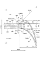
ここで、図10は、1段静翼23Aの負圧面60の上述の突出量Δyと配列ピッチPとの比(Δy/P)と、1段静翼の圧力面側と負圧面側との圧力差と、の相関関係の一例を示すグラフである。図10のグラフにおいて、縦軸は、1段静翼23Aの圧力面62側と負圧面60側との圧力差(圧力面62側の圧力−負圧面60側の圧力)を示し、横軸は、上述の突出量Δyと配列ピッチPとの比(Δy/P)を示す。
図10のグラフに示されるように、Δy/Pが増加するに従い、1段静翼23Aの圧力面62側と負圧面60側との圧力差(圧力面62側の圧力−負圧面60側の圧力)は小さくなる傾向がある。
例えば、1段静翼23Aの負圧面60の上述の突出量Δyがゼロである場合(すなわちΔy/P=0の場合)、1段静翼23Aの圧力面62側と負圧面60側との圧力差が比較的大きい。この場合、該圧力差に起因して、1段静翼23Aの前方部64と、第1燃焼器出口52A及び第2燃焼器出口52Bとの間の軸方向隙間を介して高温ガスの流れが発生する。
一方、Δy/Pが所定値Cであるとき(図10のグラフに示す例ではΔy/Pが0.13程度のとき)、1段静翼23Aの圧力面62側と負圧面60側との圧力差はゼロとなる。よって、Δy/Pが該所定値C近傍の値であるとき、上述の圧力差は比較的小さいため、第1燃焼器出口52A及び第2燃焼器出口52Bとの間の軸方向隙間を介した高温ガスの流れが低減される。
Here, FIG. 10 shows the ratio (Δy / P) of the above-mentioned protrusion amount Δy and the arrangement pitch P of the
As shown in the graph of FIG. 10, as Δy / P increases, the pressure difference between the
For example, when the above-mentioned protrusion amount Δy of the
On the other hand, when Δy / P is a predetermined value C (when Δy / P is about 0.13 in the example shown in the graph of FIG. 10), the pressure difference between the
この点、上述のように、第1側壁部54Aの内側壁面58Aからの1段静翼23Aの負圧面60の周方向への突出量Δyと、1段静翼23Aの周方向における配列ピッチPとが0.05≦Δy/P≦0.25を満たすので、1段静翼23Aの圧力面62側と負圧面60側との圧力差が比較的小さい。このため、1段静翼23Aの圧力面62側と負圧面60側の圧力差に起因した、1段静翼23Aの前方部64と、第1燃焼器出口52A及び第2燃焼器出口52Bとの間の軸方向隙間を介した高温ガスの流れの発生が抑制されるので、1段静翼23Aを冷却するために必要な冷却媒体の流量を低減することができる。
また、上述の突出量Δyと配列ピッチPとの比が0.1≦Δy/P≦0.2を満たせば、1段静翼23Aの圧力面62側と負圧面60側との圧力差が比較的小さい。このため、1段静翼23Aの圧力面62側と負圧面60側の圧力差に起因した、1段静翼23Aの前方部64と、第1燃焼器出口52A及び第2燃焼器出口52Bとの間の軸方向隙間を介した高温ガスの流れの発生をより一層抑制することができる。よって、1段静翼23Aを冷却するために必要な冷却媒体の流量を効果的に低減することができる。
In this regard, as described above, the amount Δy of the
Further, if the ratio of the above-mentioned protrusion amount Δy and the arrangement pitch P satisfies 0.1 ≦ Δy / P ≦ 0.2, the pressure difference between the
以上のように、ガスタービン1は、上述のI〜IIIの特徴を有するので、第1燃焼器出口52A及び第2燃焼器出口52Bからの高温の燃焼ガスの流れの乱れを低減しながら、1段静翼23Aを効率的に冷却することができる。これにより、ガスタービン1の効率低下を抑制することができる。
As described above, since the
ガスタービン1は、以下に述べる特徴をさらに有していてもよい。
The
いくつかの実施形態では、負圧面60側における上述の第1角度A1(図5〜図8参照)が20度以上45度以下であり、圧力面62側における上述の第2角度A2(図5〜図8参照)が0度以上25度以下であってもよい。
In some embodiments, the above-mentioned first angle A1 (see FIGS. 5 to 8) on the
この場合、負圧面60側における第1角度A1を20度以上45度以下に設定することで、燃焼ガス流れの1段静翼23Aの負圧面60への衝突によって負圧面60側で静圧が上昇する。一方、圧力面62側における第2角度A2を0度以上25度以下に設定することで、第2角度A2が25度よりも大きい場合に比べて、圧力面62が燃焼ガス流れの下流側に後退することになり、上述した隙間近傍における圧力面62側の圧力を減少させることができる。よって、1段静翼23Aの前方部64と、第1燃焼器出口52A及び第2燃焼器出口52Bとの間の隙間を介した高温ガスの流れの発生を抑制可能である。
In this case, by setting the first angle A1 on the
幾つかの実施形態では、負圧面60側における上述の第1角度A1は、圧力面62側における上述の第2角度A2以上の大きさである。
In some embodiments, the first angle A1 on the
このように、負圧面60側の第1角度A1を圧力面62側の第2角度A2以上にすることで、圧力面62側における圧力を減少させながら、負圧面60側において圧力を増大させることができる。よって、1段静翼23Aの前方部64と、第1燃焼器出口52A及び第2燃焼器出口52Bとの間の隙間を介した高温ガスの流れの発生を効果的に抑制可能である。
In this way, by setting the first angle A1 on the
また、幾つかの実施形態では、周方向に沿った断面において、1段静翼23Aの前方部64の第1接線S3が軸方向の直線S9に対してなす角度A3(図5〜図8参照)が、15度以上45度以下である。
Further, in some embodiments, the angle A3 (see FIGS. 5 to 8) formed by the first tangent line S3 of the
このように、負圧面60における第1接線S3が軸方向に対してなす角度A3を15度以上45度以下に設定することで、燃焼ガス流れの1段静翼23Aの負圧面60への衝突によって負圧面60側で静圧が上昇しやすくなる。よって、1段静翼23Aの前方部64と、第1燃焼器出口52A及び第2燃焼器出口52Bとの間の隙間を介した高温ガスの流れの発生を効果的に抑制することができる。
In this way, by setting the angle A3 formed by the first tangent line S3 on the
また、幾つかの実施形態では、周方向に沿った断面において、1段静翼23Aの前方部64の第2接線S4が軸方向の直線S10に対してなす角度A4(図5〜図8参照)が、0度以上30度以下である。
Further, in some embodiments, the angle A4 (see FIGS. 5 to 8) formed by the second tangent line S4 of the
このように、圧力面62における第2接線S4が軸方向に対してなす角度A4を0度以上30度以下に設定することで、角度A4が30度よりも大きい場合に比べて、圧力面62が燃焼ガス流れの下流側に後退することになり、1段静翼23Aの前方部64と、第1燃焼器出口52A及び第2燃焼器出口52Bとの間の隙間近傍における圧力面62側の圧力を減少させやすくなる。よって、1段静翼23Aの前方部64と、上述の隙間を介した高温ガスの流れの発生を効果的に抑制することができる。
In this way, by setting the angle A4 formed by the second tangent line S4 on the
幾つかの実施形態では、例えば図5〜図9に示すように、第1側壁部54Aの下流側端面55A、及び、第2側壁部54Bの下流側端面55Bは、上述したように、軸方向の直交面に沿った平坦面を含む。また、1段静翼23Aの前方部64は、第1側壁部54Aの下流側端面55A及び第2側壁部54Bの下流側端面55Bに対向する前端面68を含む。そして、前端面68の少なくとも一部は、軸方向の直交面に沿って設けられる平坦面である。
In some embodiments, for example, as shown in FIGS. 5-9, the
なお、図5〜図8に示す実施形態では、1段静翼23Aの前端面68は、軸方向の直交面に沿った平坦面により形成されている。また、図9に示す実施形態では、1段静翼23Aの前端面68は、軸方向の直交面に沿った平坦面により形成される第1平坦面68a及び第2平坦面68bを含み、第1平坦面68aは第1側壁部54Aの下流側端面55Aに対向するように設けられ、第2平坦面68bは、第2側壁部54Bの下流側端面55Bに対向するように設けられている。
In the embodiment shown in FIGS. 5 to 8, the
この場合、第1側壁部54A及び第2側壁部54Bの下流側端面55A,55B、又は、1段静翼23Aの前方部64の前端面68が湾曲面により形成される場合に比べて、1段静翼23Aの前方部64と、第1燃焼器出口52A及び第2燃焼器出口52Bとの間の軸方向における隙間の管理が容易となる。よって、1段静翼23Aを冷却するために必要な冷却媒体の流量を削減しやすくなる。
In this case, as compared with the case where the
幾つかの実施形態では、例えば図5〜図9に示すように、1段静翼23Aの前方部64の下流側に位置する後方部66は、負圧面60のうち後縁側領域である凸状湾曲面70、および、圧力面62のうち後縁側領域である凹状湾曲面72を有する。
In some embodiments, for example, as shown in FIGS. 5 to 9, the
いくつかの実施形態では、例えば図5〜図9に示すように、負圧面60の凸状湾曲面70の前縁側端70aは、負圧面60のうち第1側壁部54Aの内側壁面58Aから周方向に最も突出した部分(突出量がΔyである位置の部分)よりも、周方向において、第2側壁部54Bに近い。
In some embodiments, for example, as shown in FIGS. 5 to 9, the front
この場合、第1燃焼器出口52Aからの燃焼ガス流れが1段静翼23Aの負圧面60に衝突しやすくなるため、負圧面60側で静圧が上昇やすくなる。これにより、負圧面60側と圧力面62側の圧力差を低減して、1段静翼23Aの前方部64と、第1燃焼器出口52A及び第2燃焼器出口52Bとの間の隙間を介した高温ガスの流れの発生を効果的に抑制することができる。
In this case, the combustion gas flow from the
また、幾つかの実施形態では、例えば図5〜図7及び図9に示すように、1段静翼23Aの前方部64は、負圧面60の前縁側領域を形成する直線状の第1表面74と、圧力面62の前縁側領域を形成する直線状の第2表面76と、を含む。第1表面74は、負圧面60の前縁側領域を形成するように、凸状湾曲面70の前縁側端70aから第1側壁部54Aに向かって直線状に延びている。また、第2表面76は、圧力面62の前縁側領域を形成するように、凹状湾曲面72の前縁側端72aから第2側壁部54Bに向かって直線状に延びている。
Further, in some embodiments, for example, as shown in FIGS. 5 to 7 and 9, the
この場合、負圧面60の前縁側領域は、直線状に延びる第1表面74により形成されるとともに、圧力面62の前縁側領域は、直線状に延びる第2表面76により形成されるので、1段静翼23Aの作製が比較的容易である。
In this case, the front edge side region of the
なお、図8に示す例示的な実施形態では、1段静翼23Aの前方部64は、負圧面60の前縁側領域を形成する第1表面174と、圧力面62の前縁側領域を形成する第2表面176と、を含む。第1表面174は、凸状に湾曲した形状を有しており、負圧面60の前縁側領域を形成するように、凸状湾曲面70と滑らかに繋がるように延びている。また、第2表面176は、凹状に湾曲した形状を有しており、圧力面62の前縁側領域を形成するように、凹状湾曲面72と滑らかに繋がるように延びている。
In the exemplary embodiment shown in FIG. 8, the
幾つかの実施形態では、例えば図5〜図9に示すように、第1側壁部54Aの下流側端面55A、及び、第2側壁部54Bの下流側端面55Bは、それぞれ、前記軸方向の直交面に沿った平坦面を含む。そして、1段静翼23Aの前方部64は、第1側壁部54Aの下流側端面55Aに対向するように軸方向の直交面に沿って延在する第1平坦面68aと、第2側壁部54Bの下流側端面55Bに対向するように軸方向の直交面に沿って延在する第2平坦面68bと、を含む。図5〜図7及び図9に示す実施形態では、第1平坦面68aは、直線状の第1表面74の前縁側端に接続される第1接続点P5を有し、第2平坦面68bは、直線状の第2表面76の前縁側端に接続される第2接続点P6を有する。また、図8に示す実施形態では、第1平坦面68aは、第1表面174の前縁側端に接続される第3接続点P9を有し、第2平坦面68bは、第2表面176の前縁側端に接続される第4接続点P10を有する。
なお、図5〜図8に示す実施形態において、第1平坦面68a及び第2平坦面68bは、いずれも、第1側壁部54A及び第2側壁部54Bの下流側端面55A,55Bに対向する前端面68である。
In some embodiments, for example, as shown in FIGS. 5 to 9, the
In the embodiments shown in FIGS. 5 to 8, the first
このように、1段静翼23Aの前方部64の第1平坦面68a及び第2平坦面68bが、それぞれ、平坦面を含む第1側壁部54A及び第2側壁部54Bの下流側端面55A,55Bに対向するので、第1側壁部54A及び第2側壁部54Bの下流側端面55A,55B、又は、1段静翼23Aの前方部64の前端面68が湾曲面により形成される場合に比べて、1段静翼23Aの前方部64と、第1燃焼器出口52A及び第2燃焼器出口52Bとの間の軸方向における隙間の管理が容易となる。よって、1段静翼23Aを冷却するために必要な冷却媒体の流量を削減しやすくなる。
As described above, the first
幾つかの実施形態では、例えば図5〜図7及び図9に示すように、第1平坦面68aの第1接続点P5と、第2平坦面68bの第2接続点P6との間の周方向における距離D1は、第1側壁部54Aの内側壁面58Aと第2側壁部54Bの内側壁面58Bとの間の周方向における距離D2よりも小さい。
また、幾つかの実施形態では、例えば図8に示すように、第3接続点P9と第4接続点P10との間の周方向における距離D1’は、第1側壁部54Aの内側壁面58Aと第2側壁部54Bの内側壁面58Bとの間の周方向における距離D2よりも小さい。
In some embodiments, for example, as shown in FIGS. 5-7 and 9, the circumference between the first connection point P5 of the first
Further, in some embodiments, for example, as shown in FIG. 8, the distance D1'in the circumferential direction between the third connection point P9 and the fourth connection point P10 is the
この場合、第1接続点P5と第2接続点P6との間の距離D1又は第3接続点P9と第4接続点P10との間の距離D1’が第1側壁部54Aの内側壁面58Aと第2側壁部54Bの内側壁面58Bとの間の距離D2よりも大きい場合に比べて、第1燃焼器出口52A及び第2燃焼器出口52Bからの燃焼ガスの流れが乱れにくい。よって、タービン6における流体損失の発生を抑制しやすい。
In this case, the distance D1 between the first connection point P5 and the second connection point P6 or the distance D1'between the third connection point P9 and the fourth connection point P10 is the
いくつかの実施形態では、第1平坦面68aの第1接続点P5は、周方向において第1側壁部54Aの内側壁面58Aよりも第2側壁部54B側に位置する。
この場合、負圧面60側において、第1燃焼器出口52Aからの燃焼ガスの流れが乱れにくいため、タービン6における流体損失の発生を抑制しやすい。
In some embodiments, the first connection point P5 of the first
In this case, since the flow of combustion gas from the
いくつかの実施形態では、第2平坦面68bの第2接続点P6は、周方向において第2側壁部54Bの内側壁面58Bよりも第1側壁部54A側に位置する。
この場合、圧力面62側において、第2燃焼器出口52Bからの燃焼ガスの流れが乱れにくいため、タービン6における流体損失の発生を抑制しやすい。
In some embodiments, the second connection point P6 of the second
In this case, since the flow of combustion gas from the
幾つかの実施形態では、1段静翼23Aの前方部64と第1側壁部54Aとの間の軸方向における最小隙間g1と、1段静翼23Aの前方部64と第2側壁部54Bとの間の軸方向における最小隙間g2とが、0.9≦g1/g2≦1.1を満たす。
In some embodiments, one-
この場合、1段静翼23Aの負圧面60側の最小隙間g1の大きさと、圧力面62側の最小隙間g2の大きさとが同等であるので、第1側壁部54A及び第2側壁部54Bの下流側端面55A,55Bと、1段静翼23Aの前方部64との隙間を介した負圧面60側及び圧力面62側へのそれぞれの冷却媒体の分配量の差を小さくすることができる。これにより、ガスタービン1全体として、冷却媒体の流量を削減することができる。
In this case, since the size of the minimum gap g 1 on the
以上、本発明の実施形態について説明したが、本発明は上述した実施形態に限定されることはなく、上述した実施形態に変形を加えた形態や、これらの形態を適宜組み合わせた形態も含む。 Although the embodiments of the present invention have been described above, the present invention is not limited to the above-described embodiments, and includes a modified form of the above-described embodiments and a combination of these embodiments as appropriate.
本明細書において、「ある方向に」、「ある方向に沿って」、「平行」、「直交」、「中心」、「同心」或いは「同軸」等の相対的或いは絶対的な配置を表す表現は、厳密にそのような配置を表すのみならず、公差、若しくは、同じ機能が得られる程度の角度や距離をもって相対的に変位している状態も表すものとする。
例えば、「同一」、「等しい」及び「均質」等の物事が等しい状態であることを表す表現は、厳密に等しい状態を表すのみならず、公差、若しくは、同じ機能が得られる程度の差が存在している状態も表すものとする。
また、本明細書において、四角形状や円筒形状等の形状を表す表現は、幾何学的に厳密な意味での四角形状や円筒形状等の形状を表すのみならず、同じ効果が得られる範囲で、凹凸部や面取り部等を含む形状も表すものとする。
また、本明細書において、一の構成要素を「備える」、「含む」、又は、「有する」という表現は、他の構成要素の存在を除外する排他的な表現ではない。
In the present specification, expressions representing relative or absolute arrangements such as "in a certain direction", "along a certain direction", "parallel", "orthogonal", "center", "concentric" or "coaxial". Strictly represents not only such an arrangement, but also a tolerance or a state of relative displacement at an angle or distance to the extent that the same function can be obtained.
For example, expressions such as "same", "equal", and "homogeneous" that indicate that things are in the same state not only represent exactly the same state, but also have tolerances or differences to the extent that the same function can be obtained. It shall also represent the existing state.
Further, in the present specification, the expression representing a shape such as a quadrangular shape or a cylindrical shape not only represents a shape such as a quadrangular shape or a cylindrical shape in a geometrically strict sense, but also within a range in which the same effect can be obtained. , The shape including the uneven portion, the chamfered portion, etc. shall also be represented.
Further, in the present specification, the expression "comprising", "including", or "having" one component is not an exclusive expression excluding the existence of another component.
1 ガスタービン
2 圧縮機
4 燃焼器
4A 第1燃焼器
4B 第2燃焼器
6 タービン
8 ロータ
10 圧縮機車室
12 空気取入口
16 静翼
18 動翼
20 ケーシング
22 タービン車室
23 1段静翼
23A 1段静翼
23B 1段静翼
24 静翼
26 動翼
28 燃焼ガス流路
30 排気室
32 燃焼器車室
36 燃焼器ライナ
38 第1燃焼バーナ
40 第2燃焼バーナ
41 車室入口
42 燃料ポート
44 燃料ポート
48 内筒
50 尾筒
52 出口
52A 第1燃焼器出口
52B 第2燃焼器出口
54 側壁部
54A 第1側壁部
54B 第2側壁部
55A 下流側端面
55Aa 平坦部
55Ab 角部
55B 下流側端面
55Ba 平坦部
55Bb 角部
56A 下流端部
56B 下流端部
58A 内側壁面
58Aa 平坦部
58Ab 傾斜部
58B 内側壁面
58Ba 平坦部
58Bb 傾斜部
60 負圧面
62 圧力面
63 前縁
64 前方部
65 後縁
66 後方部
68 前端面
68a 第1平坦面
68b 第2平坦面
70 凸状湾曲面
70a 前縁側端
72 凹状湾曲面
72a 前縁側端
74 第1表面
76 第2表面
80 凸部
82 凸部受入れ空間
84A 凸端部
84B 凸端部
86A 段差面
86B 段差面
90 隙間
92 キャビティ
94 最上流点
174 第1表面
176 第2表面
A1 第1角度
A1’ 第1角度
A2 第2角度
A2’ 第2角度
A3 角度
A4 角度
D1 距離
D2 距離
L 軸方向距離
P 配列ピッチ
P1 交点
P2 交点
P3 第1基準位置
P4 第2基準位置
P5 第1接続点
P6 第2接続点
P7 上流端
P8 上流端
P9 第3接続点
P10 第4接続点
Q 中心線
R1 第1領域
R2 第2領域
S 周方向距離
S1 第1基準接線
S1’ 延長線
S2 第2基準接線
S2’ 延長線
S3 第1接線
S3’ 第1接線
S4 第2接線
S4’ 第2接線
S5 第1外側境界線
S6 第2外側境界線
S7 第1内側境界線
S8 第2内側境界線
g1 最小隙間
g2 最小隙間
Δy 突出量
1 Gas turbine 2 Compressor 4 Combustor 4A 1st combustor 4B 2nd combustor 6 Turbine 8 Rotor 10 Compressor cabin 12 Air intake 16 Static blade 18 Moving blade 20 Casing 22 Turbine cabin 23 1-stage stationary blade 23A 1-stage stationary blade 23B 1-stage stationary wing 24 Static wing 26 Driving wing 28 Combustor gas flow path 30 Exhaust chamber 32 Combustor vehicle compartment 36 Combustor liner 38 1st combustion burner 40 2nd combustion burner 41 Vehicle compartment entrance 42 Fuel port 44 Fuel port 48 Inner cylinder 50 tails Cylinder 52 Outlet 52A First combustor outlet 52B Second combustor outlet 54 Side wall 54A First side wall 54B Second side wall 55A Downstream end face 55Aa Flat portion 55Ab Corner 55B Downstream end face 55Ba Flat 55Bb Corner 56A Downstream End 56B Downstream end 58A Inner wall surface 58Aa Flat part 58Ab Inclined part 58B Inner wall surface 58Ba Flat part 58Bb Inclined part 60 Negative pressure surface 62 Pressure surface 63 Front edge 64 Front part 65 Rear edge 66 Rear part 68 Front end surface 68a First flat surface 68b Second flat surface 70 Convex curved surface 70a Front edge side end 72 Concave curved surface 72a Front edge side end 74 First surface 76 Second surface 80 Convex 82 Convex receiving space 84A Convex 84B Convex 86A Step surface 86B Step surface 90 Gap 92 Cavity 94 Most upstream point 174 First surface 176 Second surface A1 First angle A1'First angle A2 Second angle A2' Second angle A3 Angle A4 Angle D1 Distance D2 Distance L Axial distance P Arrangement Pitch P1 Intersection point P2 Intersection point P3 1st reference position P4 2nd reference position P5 1st connection point P6 2nd connection point P7 Upstream end P8 Upstream end P9 3rd connection point P10 4th connection point Q Center line R1 1st region R2 2 region S Circumferential distance S1 1st reference tangent line S1'extension line S2 2nd reference tangent line S2'extension line S3 1st tangent line S3' 1st tangent line S4 2nd tangent line S4' 2nd tangent line S5 1st outer boundary line S6 2 Outer boundary line S7 1st inner boundary line S8 2nd inner boundary line g1 Minimum gap g2 Minimum gap Δy Overhang amount
Claims (15)
一の前記1段静翼の前記負圧面側に設けられ、径方向に沿って延在する第1側壁部を含む第1燃焼器出口を有する第1燃焼器と、
前記周方向にて前記第1燃焼器の隣において前記一の前記1段静翼の前記圧力面側に設けられ、前記径方向に沿って延在する第2側壁部を含む第2燃焼器出口を有する第2燃焼器と、
を備えるガスタービンであって、
下記条件(a)又は(b)の何れかを満たし、
上流側から下流側に向かって軸方向をx軸と定義し、前記第1側壁部の外側から内側に向かって前記周方向をy軸と定義したとき、前記第1側壁部の下流端部における内側壁面の傾きdy/dxが最大となる位置を通る前記内側壁面の下流側に延ばした第1基準接線に対して、前記一の前記1段静翼の前方部の前記負圧面と前記第1基準接線との交点を通る前記負圧面の第1接線がなす第1角度が45度以下であり、
前記一の前記1段静翼は、前記第1側壁部の前記内側壁面からの前記負圧面の前記周方向への突出量をΔyとし、前記1段静翼の前記周方向における配列ピッチをPとしたとき、0.05≦Δy/P≦0.25を満たす
ガスタービン。
(a)前記一の前記1段静翼の前記前方部と前記第1側壁部との間の前記軸方向の最小隙間、および、前記一の前記1段静翼の前記前方部と前記第2側壁部との間の前記軸方向の最小隙間が、前記軸方向における前記一の1段静翼の長さLaの10%以下である。
(b)前記一の前記1段静翼の前記前方部の最上流点が、前記第1側壁部又は前記第2側壁部の少なくとも一方の最下流端よりも、前記軸方向において上流側に位置する。 A one-stage stationary blade that is arranged in the circumferential direction and has a blade surface including a pressure surface and a negative pressure surface, respectively.
A first combustor provided on the negative pressure surface side of the one-stage stationary blade and having a first combustor outlet including a first side wall portion extending along the radial direction.
It has a second combustor outlet provided on the pressure surface side of the one-stage stationary blade next to the first combustor in the circumferential direction and including a second side wall portion extending along the radial direction. With the second combustor
It is a gas turbine equipped with
Satisfy either the following conditions (a) or (b),
When the axial direction is defined as the x-axis from the upstream side to the downstream side and the circumferential direction is defined as the y-axis from the outside to the inside of the first side wall portion, the downstream end portion of the first side wall portion. The negative pressure surface and the first reference tangent line at the front portion of the one-stage stationary blade with respect to the first reference tangent line extending to the downstream side of the inner wall surface passing through the position where the inclination dy / dx of the inner wall surface is maximized. The first angle formed by the first tangent of the negative pressure surface passing through the intersection with is 45 degrees or less.
In the one-stage stationary blade, when the amount of protrusion of the negative pressure surface from the inner wall surface of the first side wall portion in the circumferential direction is Δy and the arrangement pitch of the first-stage stationary blade in the circumferential direction is P. A gas turbine that satisfies 0.05 ≦ Δy / P ≦ 0.25.
(A) The minimum axial clearance between the front portion of the one-stage stationary blade and the first side wall portion, and the front portion and the second side wall portion of the one-stage stationary blade. The minimum clearance between them in the axial direction is 10% or less of the length La of the one-stage stationary blade in the axial direction.
(B) The most upstream point of the front portion of the one-stage stationary blade is located on the upstream side in the axial direction with respect to at least one most downstream end of the first side wall portion or the second side wall portion.
ことを特徴とする請求項1に記載のガスタービン。 When the circumferential direction is defined as the y'axis from the outside to the inside of the second side wall portion, the passage passes through a position where the inclination dy'/ dx of the inner wall surface at the downstream end portion of the second side wall portion is maximized. The second tangent of the pressure surface passing through the intersection of the pressure surface of the front portion of the one-stage stationary blade and the second reference tangent of the one-stage stationary blade forms with respect to the second reference tangent extending to the downstream side of the inner wall surface. The gas turbine according to claim 1, wherein the second angle is 45 degrees or less.
前記第2角度が0度以上25度以下である
請求項2に記載のガスタービン。 The first angle is 20 degrees or more and 45 degrees or less.
The gas turbine according to claim 2, wherein the second angle is 0 degrees or more and 25 degrees or less.
前記前方部は、前記第1側壁部の前記下流側端面及び前記第2側壁部の前記下流側端面に対向する前端面を含み、
前記前端面の少なくとも一部は、前記軸方向の前記直交面に沿って設けられる平坦面である
ことを特徴とする請求項1乃至4の何れか一項に記載のガスタービン。 The downstream end surface of the first side wall portion and the downstream end surface of the second side wall portion each include a flat surface along the orthogonal plane in the axial direction.
The front portion includes the downstream end surface of the first side wall portion and the front end surface of the second side wall portion facing the downstream end surface.
The gas turbine according to any one of claims 1 to 4, wherein at least a part of the front end surface is a flat surface provided along the orthogonal surface in the axial direction.
前記負圧面の前記凸状湾曲面の前縁側端は、前記負圧面のうち前記第1側壁部の前記内側壁面から前記周方向に最も突出した部分よりも、前記周方向において、前記第2側壁部に近い
ことを特徴とする請求項1乃至5の何れか一項に記載のガスタービン。 The one-stage stationary blade is located on the downstream side of the front portion, and has a convex curved surface which is a trailing edge side region of the negative pressure surface and a concave curved surface which is a trailing edge side region of the pressure surface. Including the rear part with
The front edge side end of the convex curved surface of the negative pressure surface is the second side wall in the circumferential direction from the portion of the negative pressure surface that most protrudes from the inner wall surface of the first side wall portion in the circumferential direction. The gas turbine according to any one of claims 1 to 5, wherein the gas turbine is close to a part.
前記前方部は、
前記負圧面の前縁側領域を形成するように、前記凸状湾曲面の前縁側端から前記第1側壁部に向かって直線状に延びる第1表面と、
前記圧力面の前縁側領域を形成するように、前記凹状湾曲面の前縁側端から前記第2側壁部に向かって直線状に延びる第2表面と、
を含む
請求項1乃至6の何れか一項に記載のガスタービン。 The one-stage stationary blade is located on the downstream side of the front portion, and has a convex curved surface which is a trailing edge side region of the negative pressure surface and a concave curved surface which is a trailing edge side region of the pressure surface. Including the rear part with
The front part
A first surface extending linearly from the front edge side end of the convex curved surface toward the first side wall portion so as to form a front edge side region of the negative pressure surface.
A second surface extending linearly from the front edge side end of the concave curved surface toward the second side wall portion so as to form a front edge side region of the pressure surface.
The gas turbine according to any one of claims 1 to 6, wherein the gas turbine according to any one of claims 1 to 6.
前記前方部は、
前記第1表面の前縁側端に接続される第1接続点を有し、前記第1側壁部の前記下流側端面に対向するように前記軸方向の前記直交面に沿って延在する第1平坦面と、
前記第2表面の前縁側端に接続される第2接続点を有し、前記第2側壁部の前記下流側端面に対向するように前記軸方向の前記直交面に沿って延在する第2平坦面と、
を含む請求項7に記載のガスタービン。 The downstream end surface of the first side wall portion and the downstream end surface of the second side wall portion each include a flat surface along the orthogonal plane in the axial direction.
The front part
A first that has a first connection point connected to the front edge side end of the first surface and extends along the orthogonal plane in the axial direction so as to face the downstream end surface of the first side wall portion. Flat surface and
A second having a second connection point connected to the front edge side end of the second surface and extending along the orthogonal plane in the axial direction so as to face the downstream end surface of the second side wall portion. Flat surface and
The gas turbine according to claim 7.
請求項8に記載のガスタービン。 The distance between the first connection point and the second connection point in the circumferential direction is the distance in the circumferential direction between the inner wall surface of the first side wall portion and the inner wall surface of the second side wall portion. The gas turbine according to claim 8, which is smaller than the above.
ことを特徴とする請求項8又は9に記載のガスタービン。 8. Gas turbine.
ことを特徴とする請求項8乃至10の何れか一項に記載のガスタービン。 7. The gas turbine according to the first paragraph.
ことを特徴とする請求項1乃至14の何れか一項に記載のガスタービン。 The gas turbine according to any one of claims 1 to 14, wherein the one-stage stationary blade satisfies 0.1 ≦ Δy / P ≦ 0.2.
Priority Applications (3)
| Application Number | Priority Date | Filing Date | Title |
|---|---|---|---|
| JP2017150636A JP6934350B2 (en) | 2017-08-03 | 2017-08-03 | gas turbine |
| US16/624,668 US11280203B2 (en) | 2017-08-03 | 2018-06-19 | Gas turbine including first-stage stator vanes |
| PCT/JP2018/023186 WO2019026444A1 (en) | 2017-08-03 | 2018-06-19 | Gas turbine |
Applications Claiming Priority (1)
| Application Number | Priority Date | Filing Date | Title |
|---|---|---|---|
| JP2017150636A JP6934350B2 (en) | 2017-08-03 | 2017-08-03 | gas turbine |
Publications (3)
| Publication Number | Publication Date |
|---|---|
| JP2019027751A JP2019027751A (en) | 2019-02-21 |
| JP2019027751A5 JP2019027751A5 (en) | 2020-06-25 |
| JP6934350B2 true JP6934350B2 (en) | 2021-09-15 |
Family
ID=65233744
Family Applications (1)
| Application Number | Title | Priority Date | Filing Date |
|---|---|---|---|
| JP2017150636A Active JP6934350B2 (en) | 2017-08-03 | 2017-08-03 | gas turbine |
Country Status (3)
| Country | Link |
|---|---|
| US (1) | US11280203B2 (en) |
| JP (1) | JP6934350B2 (en) |
| WO (1) | WO2019026444A1 (en) |
Families Citing this family (1)
| Publication number | Priority date | Publication date | Assignee | Title |
|---|---|---|---|---|
| JP7154984B2 (en) * | 2018-12-11 | 2022-10-18 | 三菱重工業株式会社 | Turbine stator blades and gas turbines |
Family Cites Families (11)
| Publication number | Priority date | Publication date | Assignee | Title |
|---|---|---|---|---|
| BE529252A (en) * | 1953-06-01 | |||
| JP2001289003A (en) * | 2000-04-04 | 2001-10-19 | Mitsubishi Heavy Ind Ltd | Structure for cooling gas turbine |
| US6840048B2 (en) * | 2002-09-26 | 2005-01-11 | General Electric Company | Dynamically uncoupled can combustor |
| GB0323909D0 (en) * | 2003-10-11 | 2003-11-12 | Rolls Royce Plc | Turbine blades |
| JP2009197650A (en) * | 2008-02-20 | 2009-09-03 | Mitsubishi Heavy Ind Ltd | Gas turbine |
| JP5180807B2 (en) * | 2008-12-24 | 2013-04-10 | 三菱重工業株式会社 | 1st-stage stationary blade cooling structure and gas turbine |
| JP5479058B2 (en) * | 2009-12-07 | 2014-04-23 | 三菱重工業株式会社 | Communication structure between combustor and turbine section, and gas turbine |
| JP5848074B2 (en) * | 2011-09-16 | 2016-01-27 | 三菱日立パワーシステムズ株式会社 | Gas turbine, tail cylinder and combustor |
| DE112015003797B4 (en) * | 2014-08-19 | 2022-08-18 | Mitsubishi Heavy Industries, Ltd. | GAS TURBINE |
| EP3124749B1 (en) * | 2015-07-28 | 2018-12-19 | Ansaldo Energia Switzerland AG | First stage turbine vane arrangement |
| JP6871377B2 (en) * | 2017-06-29 | 2021-05-12 | 三菱パワー株式会社 | Gas turbine 1-stage stationary blade, gas turbine, gas turbine stationary blade unit and combustor assembly |
-
2017
- 2017-08-03 JP JP2017150636A patent/JP6934350B2/en active Active
-
2018
- 2018-06-19 US US16/624,668 patent/US11280203B2/en active Active
- 2018-06-19 WO PCT/JP2018/023186 patent/WO2019026444A1/en active Application Filing
Also Published As
| Publication number | Publication date |
|---|---|
| US20200109638A1 (en) | 2020-04-09 |
| JP2019027751A (en) | 2019-02-21 |
| US11280203B2 (en) | 2022-03-22 |
| WO2019026444A1 (en) | 2019-02-07 |
Similar Documents
| Publication | Publication Date | Title |
|---|---|---|
| JP4476176B2 (en) | Gas turbine premixed combustion burner | |
| JP6262986B2 (en) | Combustion turbine engine fuel injection assembly | |
| US11156361B2 (en) | Multi-point injection mini mixing fuel nozzle assembly | |
| CN105371300B (en) | Downstream nozzle and late lean injector for a combustor of a gas turbine engine | |
| US9243506B2 (en) | Methods and systems for cooling a transition nozzle | |
| JP2006300448A (en) | Combustor for gas turbine | |
| US10845055B2 (en) | Fuel nozzle assembly, and combustor and gas turbine including the same | |
| WO2012157498A1 (en) | Gas turbine engine | |
| JP7112342B2 (en) | gas turbine combustor and gas turbine | |
| KR101781722B1 (en) | Combustion burner, combustor and gas burner | |
| EP3220049B1 (en) | Gas turbine combustor having liner cooling guide vanes | |
| US11125090B2 (en) | First-stage stationary vane of gas turbine and gas turbine | |
| JP6239938B2 (en) | Gas turbine combustor | |
| JP6934350B2 (en) | gas turbine | |
| CN113167474B (en) | Combustor of gas turbine and gas turbine provided with same | |
| JP6871377B2 (en) | Gas turbine 1-stage stationary blade, gas turbine, gas turbine stationary blade unit and combustor assembly | |
| US11209163B2 (en) | Gas turbine combustor, manufacturing method for gas turbine and gas turbine combustor | |
| KR101891449B1 (en) | Gas turbine | |
| JP7154984B2 (en) | Turbine stator blades and gas turbines | |
| US20230094199A1 (en) | Annular combustor dilution with swirl vanes for lower emissions | |
| JP2018115594A (en) | Stepwise fuel and air injection on combustion system of gas turbine | |
| WO2019097947A1 (en) | Combustion cylinder for gas turbine, combustor, and gas turbine | |
| JP2014231977A (en) | Gas turbine engine |
Legal Events
| Date | Code | Title | Description |
|---|---|---|---|
| A521 | Written amendment |
Free format text: JAPANESE INTERMEDIATE CODE: A523 Effective date: 20200501 |
|
| A621 | Written request for application examination |
Free format text: JAPANESE INTERMEDIATE CODE: A621 Effective date: 20200501 |
|
| A131 | Notification of reasons for refusal |
Free format text: JAPANESE INTERMEDIATE CODE: A131 Effective date: 20210209 |
|
| A521 | Written amendment |
Free format text: JAPANESE INTERMEDIATE CODE: A523 Effective date: 20210318 |
|
| TRDD | Decision of grant or rejection written | ||
| A01 | Written decision to grant a patent or to grant a registration (utility model) |
Free format text: JAPANESE INTERMEDIATE CODE: A01 Effective date: 20210803 |
|
| A61 | First payment of annual fees (during grant procedure) |
Free format text: JAPANESE INTERMEDIATE CODE: A61 Effective date: 20210823 |
|
| R150 | Certificate of patent or registration of utility model |
Ref document number: 6934350 Country of ref document: JP Free format text: JAPANESE INTERMEDIATE CODE: R150 |