JP6934026B2 - Systems and methods for detecting lines in a vision system - Google Patents
Systems and methods for detecting lines in a vision system Download PDFInfo
- Publication number
- JP6934026B2 JP6934026B2 JP2019000018A JP2019000018A JP6934026B2 JP 6934026 B2 JP6934026 B2 JP 6934026B2 JP 2019000018 A JP2019000018 A JP 2019000018A JP 2019000018 A JP2019000018 A JP 2019000018A JP 6934026 B2 JP6934026 B2 JP 6934026B2
- Authority
- JP
- Japan
- Prior art keywords
- image
- projection
- line
- gradient
- component images
- Prior art date
- Legal status (The legal status is an assumption and is not a legal conclusion. Google has not performed a legal analysis and makes no representation as to the accuracy of the status listed.)
- Active
Links
Images


Classifications
-
- G—PHYSICS
- G06—COMPUTING OR CALCULATING; COUNTING
- G06T—IMAGE DATA PROCESSING OR GENERATION, IN GENERAL
- G06T5/00—Image enhancement or restoration
- G06T5/20—Image enhancement or restoration using local operators
-
- G—PHYSICS
- G06—COMPUTING OR CALCULATING; COUNTING
- G06T—IMAGE DATA PROCESSING OR GENERATION, IN GENERAL
- G06T7/00—Image analysis
- G06T7/10—Segmentation; Edge detection
- G06T7/13—Edge detection
-
- G—PHYSICS
- G06—COMPUTING OR CALCULATING; COUNTING
- G06T—IMAGE DATA PROCESSING OR GENERATION, IN GENERAL
- G06T7/00—Image analysis
- G06T7/10—Segmentation; Edge detection
- G06T7/136—Segmentation; Edge detection involving thresholding
-
- G—PHYSICS
- G06—COMPUTING OR CALCULATING; COUNTING
- G06T—IMAGE DATA PROCESSING OR GENERATION, IN GENERAL
- G06T7/00—Image analysis
- G06T7/10—Segmentation; Edge detection
- G06T7/143—Segmentation; Edge detection involving probabilistic approaches, e.g. Markov random field [MRF] modelling
-
- G—PHYSICS
- G06—COMPUTING OR CALCULATING; COUNTING
- G06T—IMAGE DATA PROCESSING OR GENERATION, IN GENERAL
- G06T7/00—Image analysis
- G06T7/10—Segmentation; Edge detection
- G06T7/162—Segmentation; Edge detection involving graph-based methods
-
- G—PHYSICS
- G06—COMPUTING OR CALCULATING; COUNTING
- G06T—IMAGE DATA PROCESSING OR GENERATION, IN GENERAL
- G06T7/00—Image analysis
- G06T7/10—Segmentation; Edge detection
- G06T7/181—Segmentation; Edge detection involving edge growing; involving edge linking
-
- G—PHYSICS
- G06—COMPUTING OR CALCULATING; COUNTING
- G06T—IMAGE DATA PROCESSING OR GENERATION, IN GENERAL
- G06T2207/00—Indexing scheme for image analysis or image enhancement
- G06T2207/20—Special algorithmic details
- G06T2207/20076—Probabilistic image processing
Landscapes
- Engineering & Computer Science (AREA)
- Physics & Mathematics (AREA)
- General Physics & Mathematics (AREA)
- Theoretical Computer Science (AREA)
- Computer Vision & Pattern Recognition (AREA)
- Probability & Statistics with Applications (AREA)
- Software Systems (AREA)
- Image Analysis (AREA)
- Image Processing (AREA)
- Length Measuring Devices By Optical Means (AREA)
- Studio Devices (AREA)
Description
関連出願
本出願は2015年2月11日に出願された同時係属米国特許仮出願第62/249918号「ビジョンシステムでラインを検出するためのシステム及び方法」の利益を主張するものであり、その教示内容は参照により本明細書に組み込まれる。
Related Applications This application claims the benefits of Simultaneously Pending U.S. Patent Application No. 62/249918, "Systems and Methods for Detecting Lines in Vision Systems," filed February 11, 2015. The teachings are incorporated herein by reference.
記述分野
本発明はマシンビジョンシステム、より具体的には取得した画像内のライン特徴を検出するビジョンシステムツールに関する。
Description Field The present invention relates to a machine vision system, more specifically a vision system tool for detecting line features in an acquired image.
マシンビジョンシステム(本明細書中では単に「ビジョンシステム」とも呼ぶ)は、製造、物流及び産業における多様なタスクに使用されている。そのようなタスクは表面および部品の検査、組立工程における対象物のアライメント、パターン及びIDコードの読取り、及び視覚データが取得されてその後のプロセスに使用するために解釈されるその他の操作を含んでいてもよい。ビジョンシステムは典型的には1台以上のカメラを用いて興味のある物体又は対象を含むシーンの画像を取得する。物体/対象は静止し、または相対運動をしてよい。運動はロボットで部品を操作する場合のように、ビジョンシステムによって得られる情報で制御することもできる。 Machine vision systems (also referred to herein simply as "vision systems") are used for a variety of tasks in manufacturing, logistics and industry. Such tasks include inspection of surfaces and parts, alignment of objects in the assembly process, reading of patterns and ID codes, and other operations in which visual data is acquired and interpreted for use in subsequent processes. You may. Vision systems typically use one or more cameras to capture an image of a scene containing an object or object of interest. The object / object may be stationary or relative in motion. Motion can also be controlled by the information obtained by the vision system, as in the case of manipulating parts with a robot.
ビジョンシステムの共通のタスクは、画像内のライン特徴を検出して特徴付けることである。そのようなライン特徴を特定して解析するために多様なツールが用いられる。典型的には、これらのツールは画像の部分で生じる明確なコントラスト差に依拠している。このコントラスト差、例えばキャリパツールを用いて解析して、コントラスト差のある画像内の個々のポイントがライン状の特徴に集合できるか決定する。できると決定した場合は、画像内でラインが特定される。特に、エッジポイントを検出するツールと、ラインをポイントにフィッティングするツールは互いに独立に動作する。これにより処理オーバーヘッドが増えて信頼性が低下する。画像が複数のラインを含む場合、そのようなツールはそれらを正確に特定する能力が制限されよう。更に、画像内のシングルラインを検出するために設計されたツールは、画像内で類似の向きと極性をもつ複数のラインが密集している場合は使用するのに問題があろう。 A common task of vision systems is to detect and characterize line features in images. Various tools are used to identify and analyze such line features. Typically, these tools rely on the clear contrast differences that occur in the parts of the image. This contrast difference, for example a caliper tool, is analyzed to determine if individual points in the contrasted image can be aggregated into line-like features. If it is determined that it can be done, the line is identified in the image. In particular, the tool for detecting edge points and the tool for fitting lines to points operate independently of each other. This increases the processing overhead and reduces reliability. If the image contains multiple lines, such tools will have limited ability to pinpoint them. In addition, tools designed to detect single lines in an image may be problematic to use if the image is densely populated with multiple lines of similar orientation and polarity.
本発明は先行技術の短所を、複数のラインを効率的且つ正確に特定して特徴付けることを可能にする、画像内のライン特徴を検出するためのシステム及び方法を提供することによって克服する。最初に、プロセスは各画像箇所における勾配場のx成分とy成分を計算し、勾配場を複数のサブ区域に投影し、各サブ区域内で複数の勾配極値を検出して、関連する位置と勾配を有する複数のエッジポイントを生み出す。次に、プロセスは2つのエッジポイントを反復的に選択し、それらのエッジポイントにモデルラインをフィッティングし、それらのエッジポイントの勾配がモデルラインと一致したら、位置と勾配がモデルラインと一致しているインライアポイントの完全なセットを計算する。最大のインライアカウントを有する候補ラインがライン結果として保存され、残りのセットのアウトライアポイントが導出される。次いでプロセスはこのセット及び後続のアウトライアセットにラインフィッティング操作を反復的に適用して複数のライン結果を検出する。ラインフィッティングプロセスは網羅的であるか、またはランダムサンプルコンセンサス(RANSAC)に基づいてもよい。 The present invention overcomes the disadvantages of the prior art by providing a system and method for detecting line features in an image that allows multiple lines to be efficiently and accurately identified and characterized. First, the process calculates the x and y components of the gradient field at each image location, projects the gradient field onto multiple sub-areas, detects multiple gradient extrema within each sub-area, and locates the relevant positions. And produce multiple edge points with a gradient. The process then iteratively selects two edge points, fits the model lines to those edge points, and if the slopes of those edge points match the model line, then the position and slope match the model line. Calculate the complete set of inlier points you have. The candidate line with the largest in-line account is saved as the line result and the remaining set of outlier points are derived. The process then iteratively applies line fitting operations to this set and subsequent outline assets to detect multiple line results. The line fitting process may be exhaustive or may be based on a random sample consensus (RANSAC).
例示的な実施形態によれば、取得した画像内のライン特徴を検出するためのシステムが提供される。ビジョンシステムプロセッサは、ライン特徴を包含するシーンの画像データを受け取る。エッジポイント抽出装置は、画像データから強度勾配画像を生成し、強度勾配画像に基づいてエッジポイントを検出する。次いでラインファインダはエッジポイントにおける強度勾配に基づいてエッジポイントを1以上のラインにフィッティングする。例示的に、ラインファインダはRANSACに基づくプロセスを操作してインライアエッジポイントを新しいラインにフィッティングし、これは事前に定義されたラインを基準にしてアウトライアエッジポイントから反復的にラインを定義することを含む。エッジポイント抽出装置は、強度勾配画像のライン特徴を含む区域勾配場の投影を実行する。例示的に、勾配場の投影は、1以上の特徴若しくはライン特徴の予想される向きに応答して設定された方向に沿って向けられており、勾配場の投影はガウスカーネルに基づいて粒度を定義できる。例示的に、画像データは複数のカメラから取得されて共通座標空間に変換された複数の画像からのデータを含んでいてもよい。画像データは平滑化(重み付け)カーネルを用いて平滑化されることもでき、平滑化カーネルは1Dガウスカーネル又は他の重み付け関数を含んでいてもよい。エッジポイントは絶対コントラストと、画像データの平均強度に基づいて正規化したコントラストとによって定義された閾値が選択され得る。例示的に、ラインファインダは、不正確な向きを補正するために平行線又は交差線の部分を表すエッジポイントを交換するように、及び/又はエッジポイントにおける勾配値に基づいてライン内の混合極性を含むライン特徴の極性変化を有するラインを特定するように構成及び配置されている。また、例示的に、エッジポイント抽出装置は勾配投影サブ区域の各々で複数の勾配最大値を検出するように配置されている。これらの勾配最大値はそれぞれ複数のエッジポイントの一部として特定ができ、位置ベクトルと勾配ベクトルによって記述され得る。加えてラインファインダは、メトリックを計算することによって複数の抽出されたエッジポイントの少なくとも1つのエッジポイントと、検出された複数のラインの少なくとも1つの候補ラインとの間の整合性を決定するように配置され得る。このメトリックは少なくとも1つのエッジポイントの候補ラインからの距離、及びエッジポイントの勾配方向と候補ラインの通常の方向との間の角度差に基づいていてもよい。 According to an exemplary embodiment, a system for detecting line features in an acquired image is provided. The vision system processor receives image data of the scene including the line features. The edge point extraction device generates an intensity gradient image from the image data and detects the edge point based on the intensity gradient image. The line finder then fits the edge points to one or more lines based on the intensity gradient at the edge points. Illustratively, the linefinder operates a RANSAC-based process to fit an inlier edge point to a new line, which iteratively defines a line from the outlier edge point relative to a predefined line. Including that. The edge point extractor performs a projection of the area gradient field containing the line features of the intensity gradient image. Illustratively, the gradient field projection is oriented along a set direction in response to the expected orientation of one or more features or line features, and the gradient field projection is grained based on the Gauss kernel. Can be defined. Illustratively, the image data may include data from a plurality of images acquired from the plurality of cameras and converted into a common coordinate space. Image data can also be smoothed using a smoothing (weighting) kernel, which may include a 1D Gaussian kernel or other weighting function. For the edge point, a threshold value defined by the absolute contrast and the contrast normalized based on the average intensity of the image data can be selected. Illustratively, the linefinder will swap edge points representing parts of parallel or intersecting lines to correct inaccurate orientation, and / or mix polarities within the line based on the gradient value at the edge points. It is configured and arranged to identify a line having a polarity change in line characteristics including. Also, exemplary, the edge point extractor is arranged to detect a plurality of maximum gradient values in each of the gradient projection sub-areas. Each of these gradient maximums can be identified as part of a plurality of edge points and can be described by a position vector and a gradient vector. In addition, the line finder may calculate the metric to determine the consistency between at least one edge point of multiple extracted edge points and at least one candidate line of multiple detected lines. Can be placed. This metric may be based on the distance of at least one edge point from the candidate line and the angular difference between the slope direction of the edge point and the normal direction of the candidate line.
以下に本発明を図面を参照して説明する。 The present invention will be described below with reference to the drawings.
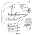
例示的な実施形態に従って使用できる模範的なビジョンシステム構成100が、図1に示されている。システム100は少なくとも1台のビジョンシステムカメラ110を含み、1台以上の追加の随意のカメラ112(仮想線で示す)。例示的なカメラ110、112は、画像センサ(又はイメージャ)Sと、画像フレームを取得してビジョンシステムプロセス(プロセッサ)130に伝送する関連エレクトロニクスを含み、ビジョンシステムプロセス(プロセッサ)130はスタンドアローンプロセッサ及び/又はコンピューティングデバイス140として例示され得る。カメラ110(及び112)は検査中の物体150を包含するシーンに焦点を当てた適当なレンズ/光学系116を含んでいてもよい。カメラ110(及び112)は、画像取得プロセスに従って作動する内部及び/又は外部照明器(図示せず)を含んでいてもよい。コンピューティングデバイス140は、例示的な実施形態に従って画像データを保存及び操作できる任意の容認可能なプロセッサベースのシステムであってよい。例えばコンピューティングデバイス140は、PC(図示の例)、サーバー、ラップトップ、タブレット、スマートフォン又は他の類似のデバイスを含んでいてもよい。コンピューティングデバイス140は、適当な端末装置、例えばカメラと相互接続するバスベースの画像キャプチャカードを含んでいてもよい。代替的な実施形態において、ビジョンプロセッサは部分的又は完全にカメラ本体それ自体の中に含まれることができ、画像データを共有及び処理する他のPC、サーバー及び/又はカメラベースのプロセッサとネットワーキングできる。コンピューティングデバイス140は随意に適当なディスプレイ142を含み、これはビジョンシステムプロセス(プロセッサ)130内に設けられたビジョンシステムツール及びプロセッサ132に従って作動できる適当なグラフィカルユーザインタフェース(GUI)をサポートすることができる。種々の実施形態でディスプレイは省くことができ及び/又はセットアップとサービス機能のためにのみ提供できることに留意されたい。ビジョンシステムツールは、物体の検査において使用することが認められる任意の容認可能なソフトウェア及び/又はハードウェアパッケージ、例えば米国マサチューセッツ州ネイティック市のコグネックス株式会社から市販されているものの一部であってよい。コンピューティングデバイスは、例えばキーボード144及びマウス146、並びにディスプレイ142内部のタッチスクリーンを含め関連するユーザインタフェース(UI)コンポーネントも含んでいてもよい。
An exemplary
カメラ110(及び112)は、シーン内部に位置する物体150の一部又は全部を撮像する。各カメラは光学軸OAを定義し、それを中心に光学系116、焦点距離などに基づいて視野が確定される。物体150はそれぞれ異なる方向に配置された複数のエッジ152、154を含む。例えば物体のエッジはスマートフォン本体内に組み付けられたカバーガラスのエッジを含んでよい。例示的に、カメラは物体全体又は特定の箇所(例えばガラスが本体と交わるコーナ)を撮像できる。(共通)座標空間は、物体、1台のカメラ又は他の基準点(例えば物体150を載せている可動ステージ)を基準に確定できる。図示されているように、座標空間は軸158によって表される。これらの軸は例示的に直交するx軸、y軸及びz軸、並びにx−y面上のz軸を中心とする回転Θzを定義する。
The camera 110 (and 112) captures part or all of the
例示的な実施形態に従い、ビジョンシステムプロセス130は集合的にビジョンシステムツール/プロセス132のセットを含む1以上のアプリケーション/プロセス(コンピューティングデバイス140上で実行)と相互作用する。これらのツールは、画像データを解像するために使用される多様な慣用的及び特殊なアプリケーション−例えば取得した画像データを所定の(例えば共通)座標系に変換するために使用できる多様な較正ツール及びアフィン変換ツールを含んでいてもよい。画像グレースケール強度データを所定の閾値に基づいて二値画像に転換するツールも含めることができる。同様に、隣接した画像ピクセル(及びサブピクセル)の間の強度の勾配(コントラスト)を解析するツールを設けることができる。
According to an exemplary embodiment, the
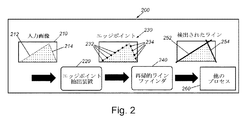
ビジョンシステムプロセス(プロセッサ)130は、例示的な実施形態に従い取得した画像内で複数のラインの位置を特定するライン検出プロセス、ツール又はモジュール13を含む。ここで図2を参照する例示的な実施形態に従うライン検出手順200の概観を図示する。手順200は2つの主要部分からなる。入力画像210がプロセッサに提供される。図示されているように、画像は1対の交差するエッジ212及び214を含む。これらは上述した物体150のコーナ区域を表すことができる。エッジポイント抽出装置220は、入力画像210を処理して、それぞれエッジ212及び214に沿って存在するエッジポイント232及び234を含む候補エッジポイントのセット230を得る。エッジポイント232、234、及びそれらに関連するデータ(例えば以下に説明する強度勾配情報)が再帰的ラインファインダ240に提供され、これは選択されたエッジポイントで一連の反復プロセスを実行する。反復プロセスの目標は、他の検出されたエッジポイントを候補ライン特徴にフィッティングすることを試みることである。ライン検出プロセス240の結果、図示されているようにライン252及び254が検出される。これらの結果は情報を使用する他の下流のプロセス260−例えばアライメントプロセス、ロボット操作、検査、ID読取り、部品/表面検査などに提供され得る。
The vision system process (processor) 130 includes a line detection process, tool or module 13 that locates a plurality of lines in an image acquired according to an exemplary embodiment. Here is an overview of the
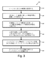
一実施形態に従う、エッジポイントを抽出するための手順を説明した図3を参照する。検出されるべきエッジ特徴を有する物体又は表面を含んでいるシーンの1以上の画像が取得される(ステップ310)。画像は単一のカメラ又は複数のカメラによって抽出できる。いずれの場合も、ステップ320で画像ピクセルは、(随意に)適当な較正パラメータによって新しい座標空間及び/又は共通座標空間に変換され得る。このステップは以下に説明するように画像の平滑化も含んでいてもよい。複数のカメラがシーンの不連続区域を撮像する−例えばより大きい物体のコーナ区域に焦点を当てる−実施形態において、共通座標空間はカメラ視野の間の空の区域を占めることができる。以下に説明するように、そのような視野の間に延びるライン(例えば2つの検出されたコーナ区域を接続する物体エッジ)は、例示的な実施形態のシステム及び方法によって例示的な実施形態のシステム及び方法によって外挿できる。ステップ330で、ラインを検出するために必要とされるエッジポイントは、適当な座標空間においてエッジポイント抽出装置によって勾配場の投影を用いて画像から抽出される。勾配値は最初に各ピクセルについて計算されて、x勾配成分とy勾配成分に対して画像を生成する。画像は更に勾配場を多数のキャリパ状区域に投影することによって処理される。強度値を投影する慣用的キャリパツールとは異なり、実施形態に従い勾配場を投影することによって、勾配の向きを保存でき、以下に説明するようにこれが後続のライン検出プロセスを容易にする。
See FIG. 3, which describes a procedure for extracting edge points according to one embodiment. One or more images of the scene containing an object or surface with edge features to be detected are acquired (step 310). Images can be extracted by a single camera or multiple cameras. In either case, in
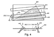
ステップ340で、図4の線図も参照して、候補エッジ特徴を含んでいる画像の部分(キャリパ状区域)400は(複数の投影410、420、430によって表された)勾配場の投影を受け、サーチ方向(矢印SD)で(近似的に)予想されるエッジの向きにわたってサーチされ、投影は直交投影方向(矢印PD)で区域400にわたって繰り返される。各投影(例えば投影420)に対してエッジは投影と関連した勾配場440における極大値として現れる。概して、エッジと関連した投影の内部の一連のエッジポイントは、エッジの延在方向に対して直角に強度勾配(ベクトル552、554)を示す。以下に説明するように、ユーザは予想されるラインの向きに基づいて投影方向を定義できる。代替として、これは既定のメカニズム又は他のメカニズム−例えば画像内の特徴の解析によって提供されてよい。
In
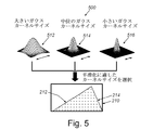
上述した勾配投影ステップには2つの粒度パラメータが包含されている。勾配場計算の前に、ユーザは異方性ガウスカーネルを用いて画像を平滑化することを選択できる。第1の粒度はこのガウス平滑化カーネルのサイズを決定する。図5の線図500に示されているように、近似的なサイズのガウスカーネル(例えば大きい512、中位514、小さい516)を適用して画像210を平滑化する。それゆえ第1の粒度パラメータは、場計算の前に等方性ガウス平滑化カーネルのサイズを決定する。
The gradient projection step described above includes two particle size parameters. Prior to the gradient field calculation, the user can choose to smooth the image using an anisotropic Gaussian kernel. The first particle size determines the size of this Gaussian smoothing kernel. As shown in diagram 500 of FIG. 5, an approximate size Gaussian kernel (eg, large 512, medium 514, small 516) is applied to smooth the
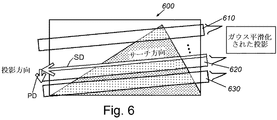
これにより勾配場計算の後で、慣用的なキャリパツールにおける統一的な重み付けではなく、ガウス重み付けされた投影がプロセスによって実行される。従って第2の粒度パラメータは、場の投影中に使用される1次元(1D)ガウスカーネルのサイズを決定し、図6に示されているように区域600はガウス平滑化カーネル610、620、630を受ける。典型的な操作の間、ユーザは(GUIを用いて)画像に重ね合わされたすべての抽出されたエッジを検証し、次いで検出されるべきラインに沿って抽出されたエッジの数が十分と思われるまで粒度とコントラスト閾値を調整する一方で、画像内のバックグラウンドノイズに起因するエッジの過度な数を回避する。換言すれば、このステップにより信号雑音比を画像特徴に対して最適化することが可能になる。この調整は、種々の実施形態でシステムにより既定値を用いて自動的に実行することもできる。ガウス重み付け関数は、(例えば)一様な重み付けを含む、投影を重み付けするための多様な方策の1つであることに留意されたい。
This causes the process to perform a Gauss-weighted projection after the gradient field calculation, rather than a uniform weighting in the conventional caliper tool. The second particle size parameter therefore determines the size of the one-dimensional (1D) Gauss kernel used during field projection, and
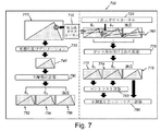
勾配場の抽出及び投影の全体の流れが、図7の線図700に図示されている。2つの粒度パラメータ、等方性ガウスカーネル710及び1Dガウスカーネル720が、全体図700の各半分に示されている。図示されているように、各々の取得された画像210は平滑化及びデシメーション730を受ける。次いで結果として生じる画像740は、上述したように勾配場の計算750を経て、2つの勾配画像752及び754を生成する。これらの勾配画像はgx及びgyとも表現され、それぞれ共通座標空間における2本の直交軸を表す。2つの勾配画像に加えて、強度画像756は典型的には平滑化、デシメーション及びに投影プロセス760(1Dガウスカーネル720に基づいてガウス重み付けされた投影770を用いる)を受けることに留意されたい。なぜなら、処理された強度情報は、以下に説明する実施形態に従って正規化したコントラストを計算するためにも使用されるからである。その結果は、勾配画像772(gx)、774(gy)及び強度画像776の投影プロフィルである。
The overall flow of gradient field extraction and projection is illustrated in diagram 700 of FIG. Two particle size parameters, the isotropic
手順300(図3)のステップ350も参照して、次にx勾配画像とy勾配画像の1D投影プロフィルを結合することによって適格化されたエッジポイントが抽出される。このことは生のコントラスト計算780と、強度画像に基づいて正規化したコントラスト計算790を用いて達成される。より具体的には、それぞれ閾値を超える生の投影された勾配の大きさと正規化した投影された勾配の大きさのいずれも有する局所的なピークは、次の例示的な式に従い後続のライン検出のための候補エッジポイントと見なされる。
(gx 2+gy 2)1/2>TABS
(gx 2+gy 2)1/2/I>TNORM
ここで、gx及びgyはそれぞれピクセル箇所におけるx勾配投影とy勾配投影の値、Iは強度、TABは生の投影された勾配の大きさに対する絶対コントラスト閾値、及びTNORMは強度正規化した投影された勾配の大きさに対する正規化したコントラスト閾値である。
Also with reference to step 350 in step 300 (FIG. 3), qualified edge points are extracted by combining the 1D projection profiles of the x-gradient image and the y-gradient image. This is achieved using a
(G x 2 + gy 2 ) 1/2 > T ABS
(G x 2 + gy 2 ) 1/2 / I> T NORM
Here, g x and g y values of each x-gradient projection and y gradient projection in the pixel portion, I is intensity, T AB is the absolute contrast threshold for the size of the projected gradient of the raw, and T NORM intensity normalized It is a normalized contrast threshold for the magnitude of the projected projected gradient.
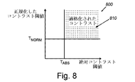
特に、ポイントはその絶対コントラストと正規化したコントラストがいずれもそれぞれの閾値を超える場合のみ候補エッジポイントと見なされる。このことは正規化したコントラスト閾値TNORMに対するコントラスト閾値TABSの模範的なグラフ800において、右上の象限810によって示されている。二重の閾値(絶対及び正規化)を用いることは、典型的に絶対コントラスト閾値を使用する既存の方策とは全体として異なる。二重コントラスト閾値の利点は、例を挙げるとある画像がいずれも興味のあるエッジを含む暗い強度区域と明るい強度区域の両方を含む場合に明確である。画像の暗い区域でエッジを検出するためには、低いコントラスト閾値を設定することが望ましい。しかしながらそのような低いコントラストを設定すると、その結果として画像の明るい部分で誤ったエッジを検出する可能性がある。反対に、画像の明るい区域で誤ったエッジを検出するのを避けるためには、高いコントラスト閾値を設定することが望ましい。しかしながら高いコントラストを設定すると、システムは画像の暗い区域でエッジを適切に検出できないかもしれない。伝統的な絶対コントラスト閾値に加えて、第2の正規化したコントラスト閾値を用いることによって、システムは暗い区域と明るい区域の両方で適切にエッジを検出することができ、画像の明るい区域で誤ったエッジを検出するのを避けることができる。それゆえ該当するエッジの検出を可能にする一方で誤ったエッジを回避することにより、避けながら、二重コントラスト閾値の使用は全体プロセスの後続のライン検出段階の速度と堅牢性を最大化するのに役立つ。
In particular, a point is considered a candidate edge point only if its absolute contrast and normalized contrast both exceed their respective thresholds. This is indicated by the upper right quadrant 810 in the
更に手順ステップ350(図3)を参照すると、すべてのエッジポイントが抽出されたら、後続のラインファインダが作動するために都合の良いデータ構造で再現され保存される。例えば次のタプルに留意されたい。
p=(x,y,gx,gy,gm,go,I,gm/I,m,n)
ここで、(x,y)はエッジポイントの箇所、(gx,gy)はそれぞれx勾配投影及びy勾配投影の値、(gm,go)は(gx,gy)から計算された勾配の大きさと向き、Iはエッジポイント箇所における強度、gm/Iは勾配の大きさgmを強度Iで除算することによって得られる強度正規化したコントラスト、mは画像インデックス、及びnは投影区域インデックスである。標準キャリパツールにおけるようなエッジポイントの箇所は、精度を向上させるために補間できる。
Further referring to step 350 (FIG. 3), once all the edge points have been extracted, they are reproduced and stored in a convenient data structure for the subsequent line finder to operate. Note, for example, the following tuple.
p = (x, y, gx, gy, gm, go, I, gm / I, m, n)
Here, (x, y) is part of the edge points, (g x, g y) is the value of each x-gradient projection and y gradient projection, calculated from (g m, g o) is (g x, g y) Gradient magnitude and orientation, I is the intensity at the edge point, g m / I is the intensity normalized contrast obtained by dividing the gradient magnitude g m by the intensity I, m is the image index, and n Is the projected area index. Edge points, such as those in standard caliper tools, can be interpolated to improve accuracy.
エッジポイント抽出プロセスは一般的に場の投影を、予想されるライン角度と実質的に一致する単一方向で行うように作動することに留意されたい。それゆえツールはこの角度にあるエッジに対して最も敏感であり、その感度は他の角度にあるエッジに対して徐々に減少し、減少率は場の投影の長さを間接的に決定する粒度の設定に依存する。結果として角度範囲はユーザによって指定されることを条件に、プロセスは角度が予想されるライン角度「に近い」ラインを検出することに制限される。プロセスは直交していないラインを検出するように適合されているが、種々の実施形態において直交方向を含む複数の方向(全方向ライン検出)で投影を実行することによって360度全体の任意の角度のラインを検出できるように一般化されることが想定されている。 It should be noted that the edge point extraction process generally operates to project the field in a single direction that substantially matches the expected line angle. Therefore, the tool is most sensitive to edges at this angle, its sensitivity gradually decreases with respect to edges at other angles, and the rate of decrease indirectly determines the length of the field projection. Depends on the setting of. As a result, the process is limited to detecting lines that are "close" to the expected line angle, provided that the angle range is specified by the user. The process is adapted to detect non-orthogonal lines, but in various embodiments any angle across 360 degrees by performing projection in multiple directions, including orthogonal directions (omnidirectional line detection). It is supposed to be generalized so that the line of can be detected.
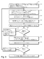
手順300(図3)のステップ360を参照すると、例示的な実施形態に従い閾値を超えるエッジポイント候補がラインファインダに提供される。例を挙げると、ラインファインダは再帰的に作動し、(例えば)ランダムサンプルコンセンサス(RANSAC)ベースの技術を採用する。図9におけるライン検出手順900も参照する。ステップ910において、ユーザは1つの画像内で予想されるラインの最大数を、予想される角度、角度誤差、距離誤差及び(例示的に)最小カバレージスコア(以下に一般に定義)と共に(例えば)GUIによって指定する。これらのパラメータは、次のプロセスを操作するためにラインファインダによって使用される。画像の各サブ区域に対するラインはRANSACラインファインダを再帰的に実行して、ある段階からのエッジポイントアウトライアが次の段階に対する入力ポイントとなることによって検出される。こうしてステップ920において、手順900は、エッジ検出プロセスにおいて極値として特定されたエッジポイントのグループ部分である1対のエッジポイントを選択する。手順900は、モデルラインと(選択された誤差範囲内で)一致している勾配値のマッチングに基づいて、モデルラインを選択されたエッジポイントにフィッティングすることを試みる。ステップ924ではステップ922からの1以上のライン候補が戻される。各ライン検出段階は候補ライン、そのインライア及びアウトライアを戻す。戻されたラインは、ライン候補と一致する位置と勾配を有するインライアエッジポイントが計算される(ステップ926)。ステップ928では、最大のインライアカウントを有する候補ラインが特定される。上述したライン検出段階(ステップ920−928)は、RANSAC反復の許容された最大数に達すると終了する(決定ステップ930)。各ライン検出段階内部の反復の最大数は、内部計算されたアウトライアの最悪比率とユーザによって指定された保証レベルを用いて自動的に計算される。各ライン検出段階は、ユーザ指定のフィッティング誤差、幾何学的制限及び極性を条件に、キャンプチャーされたエッジポイントの最大数を有するラインをそのすべての反復から戻す。各エッジポイントは1本のラインのインライアリストのみに割り当てることができ、各ラインは各投影区域からたかだか1つのエッジポイントのみ含むことが許される。エッジポイントの勾配の向きはその位置と共に、候補ラインのインライアリストに含まれるべきか決定するために使用される。具体的には、エッジポイントは候補ラインの角度と一致する勾配の向きを有するべきである。
With reference to step 360 of step 300 (FIG. 3), edge point candidates that exceed the threshold are provided to the line finder according to an exemplary embodiment. For example, the linefinder operates recursively and employs (eg) random sample consensus (RANSAC) based technology. The
決定ステップ930では、より多くの反復が許可されて、最良インライア候補からのアウトライア(ステップ940)を、RANSACプロセス(ステップ920)がライン候補の検出に使用するために戻すことを決定する。
In
各RANSAC反復において、異なる投影区域に属する2つのエッジポイントがランダムに選択され、それらの2つのポイントにラインがフィッティングされる。結果として生じる候補ラインは更に、その角度がポイント対の両エッジの勾配角度と一致するか、及びラインの角度がユーザによって指定された不確かさの範囲と一致するかについてのみ検討される。概して、エッジポイント勾配方向は通常直角であるが、ユーザ設定の角度誤差だけ異なることが許容される。候補ラインがこれらの初期テストに合格したら、次いでインライアエッジポイントの数が評価され、さもなければ新しいRANSAC反復が開始される。エッジポイントは、ユーザによって指定された勾配角度と距離誤差に基づいて、その勾配の方向と位置がラインと一致する場合のみ候補ラインのインライアと見なされる。 At each RANSAC iteration, two edge points belonging to different projection areas are randomly selected and a line is fitted to those two points. The resulting candidate line is further examined only to see if its angle matches the slope angle of both edges of the point pair and if the angle of the line matches the range of uncertainty specified by the user. In general, the edge point gradient direction is usually a right angle, but it is permissible to differ by a user-configured angular error. Once the candidate line has passed these initial tests, the number of aligner edge points is then evaluated and otherwise a new RANSAC iteration is initiated. An edge point is considered an aligner of a candidate line only if its slope direction and position match the line, based on the slope angle and distance error specified by the user.
RANSAC反復が最大数に達したら(決定ステップ930)、検出された最良のライン候補のインライアは、(例えば)最小二乗回帰又は他の受け入れ可能な近似法を用いて改善されたラインのフィッティングが行われ、インライアエッジポイントのセットが再評価され、これらのステップを最大N回(例えば3回以上)、インライアの数がそれ以上増加又は減少しなくなるまで繰り返す(ステップ960)。これはステップ970で検出されたラインとして出力されるラインである。
Once the maximum number of RANSAC iterations has been reached (determination step 930), the best line candidate aligners detected will be line-fitted with improved lines using (eg) least squares regression or other acceptable approximation methods. The set of approximation edge points is re-evaluated and these steps are repeated up to N times (eg, 3 or more times) until the number of inliers no longer increases or decreases (step 960). This is the line output as the line detected in
決定ステップ980は、((例えば)更にサブ区域又は他の基準をサーチすることによって)より多くのラインが検出されるべきか決定し、そうであればプロセスはステップ920にループバックして新しいセットのエッジポイントで作動する(ステップ982)。ポイントが使い尽くされるか、又は最大数反復カウントに達したら、手順900はステップ990で(複数の画像内で)検出されたラインのセットを戻す。
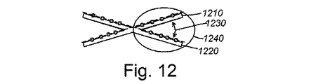
マルチラインファインダは、2本のラインが検査区域内で互いに交差する場合に、既存の結果の最終調整を実行するように適合されている。図10及び図11に一般的に示されているように、密集した平行線1010及び1020に対しては、RANSAC手順の統計的正確に起因して時々誤ったライン結果(即ち図10)が得られることがある。しかしながらそのようなエラーが発生したら、インライアポイントグループの交換(図11のグループ1110における矢印1120)は時々カバレージスコアが増加してフィッティング残余が減少した正しいラインの位置を特定することができる。ポイント交換は、図示されているように画像が密集した平行線を含んでいる場合は極めて効果的である。反対に、画像が図12及び図13に図示されているように実際に互いに交差するライン1210及び1220を包含する場合、カバレージスコアはポイント交換の後で減らされ(図12のグループ1240における矢印1230)、交換の前に得られた最初の結果は、交差線を首尾よく検出するプロセスにより保存される。
The multi-line finder is adapted to perform the final adjustment of existing results when two lines intersect each other within the inspection area. As is commonly shown in FIGS. 10 and 11, for dense
RANSAC手順は、ラインファインダがポイントをラインにフィッティングできる多様な技術の1つであることに留意されたい。代替的な実施形態において、候補ポイントはそれらの間の変位セットに従って選択でき、或いは画像は(例えば)網羅的サーチ技術を用いて処理できる。従って、本明細書中で用いられているようにRANSAC技術への参照は、広く多様な類似のポイントフィッティング技術を含むものと解するべきである。 Note that the RANSAC procedure is one of a variety of techniques that allows the line finder to fit points to the line. In an alternative embodiment, candidate points can be selected according to the set of displacements between them, or images can be processed using (eg) exhaustive search techniques. Therefore, references to RANSAC techniques, as used herein, should be understood to include a wide variety of similar point fitting techniques.
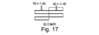
このシステム及び方法の追加の機能を設けることができる。これらは混合極性に対するサポート、投影区域幅の自動計算、多視点ライン検出のサポート、及び歪みのない入力画像により光学歪みを除去できるようにすることを含む。これらの機能について以下に説明する。 Additional functionality of this system and method can be provided. These include support for mixed polarities, automatic calculation of projected area widths, support for multi-view line detection, and the ability to remove optical distortion with distortion-free input images. These functions will be described below.
更に図14−図16の例を参照すると、例示的な実施形態のライン検出システム及び方法は、一般に検出されたエッジ間のコントラストに対して(それぞれ)標準的な明から暗、暗から明及び択一極性設定をサポートする。加えてこのシステム及び方法は明から暗と暗から明の両特徴が同一のラインに現れる混合極性設定(図17)もサポートできる。全4種類の設定のライン検出結果が次の図に示されている。例示的な実施形態において、システム及び方法は、反対極性のエッジポイントを包含する1本のラインの検出を可能にする混合極性設定を含んでいてもよい。これは、1本のラインのすべてのエッジポイントがいずれかの極性であるが1つの極性に限られている慣用的な「択一」極性設定とは異なる。混合極性設定は、幾つかある応用の中でも(例えば)較正プレートの明暗格子縞に用いられると有利であり得る。 Further referring to the examples of FIGS. 14-16, the line detection systems and methods of the exemplary embodiments are generally (respectively) standard light to dark, dark to light and for contrast between detected edges. Supports alternative polarity settings. In addition, the system and method can also support a mixed polarity setting (FIG. 17) in which both light-to-dark and dark-to-light features appear on the same line. The line detection results for all four settings are shown in the following figure. In an exemplary embodiment, the system and method may include a mixed polarity setting that allows the detection of a single line containing edge points of opposite polarity. This differs from the conventional "alternative" polarity setting, where all edge points in a line are of either polarity but are limited to one polarity. The mixed polarity setting may be advantageous when used for light-dark grid fringes of (eg) calibration plates, among other applications.
ユーザは、ライン検出の改善されたシフト不変を選択できる。そのような場合に、エッジポイント抽出装置は結果の安定性を改善するために実質的にオーバーラップした投影区域を使用する。これらの区域がオーバーラップしていないと、対象としているピクセルは画像がシフトしたとき投影区域の外に出る可能性があり、その結果としてライン検出結果におけるシフト不変が乏しいものとなる。オーバーラップした投影区域は、対象としているピクセルが投影区域によって連続的にカバーされることを保証する。オーバーラップした投影区域が使用された場合、増分計算を可能な低レベル最適化と共に実行できる。 The user can choose an improved shift immutability for line detection. In such cases, the edge point extractor uses substantially overlapping projection areas to improve the stability of the results. If these areas do not overlap, the pixels of interest may move out of the projected area when the image shifts, resulting in poor shift invariance in the line detection results. The overlapping projected areas ensure that the pixels of interest are continuously covered by the projected areas. If overlapping projected areas are used, incremental calculations can be performed with possible low-level optimizations.
ユーザは、取得した画像及び/又は撮像された表面の特定部分をライン特徴の解析から除外するマスクを設けることができる。これは表面が興味のない既知のライン特徴(例えば他のメカニズムによって解析されるバーコード、テキスト、及びラインを検出しようとするタスクと密接な関係がないその他の構造)を含む場合に望ましいことがある。従ってエッジポイント抽出装置は、画像内の「無関係」区域はマスクアウトでき「関係」区域はマスクインされる画像マスキングをサポートできる。そのようなマスキングが起きたら、例示的に検出されたラインのカバレージスコアはマスク内に入るエッジポイントの数に従って再重み付される。 The user can provide a mask that excludes the acquired image and / or a specific portion of the captured surface from the analysis of line features. This is desirable if the surface contains known line features that are of no interest (eg, barcodes, texts analyzed by other mechanisms, and other structures that are not closely related to the task of trying to detect the line). be. Therefore, the edge point extractor can support image masking in which "irrelevant" areas in the image can be masked out and "relationship" areas are masked in. When such masking occurs, the coverage score of the exemplary detected lines is reweighted according to the number of edge points that fall within the mask.
図18の模範的な画像区域1800を参照すると、画像マスクが存在する場合のカバレージスコアと、そのようなカバレージスコアに及ぼす画像マスキングの効果を示す。エッジポイント抽出装置は、画像内の「無関係」区域をマスクアウトできる画像マスキングをサポートする。図示されているように、検出されたライン1810は(「関係」マスク区域1820に基づき)関係エッジポイントによって特徴付けられる。そのような関係エッジポイントは、ライン1810に対する関係エッジポイントインライア1830と、ライン1810に対する無関係エッジポイントアウトライア1840からなる。ライン1810上の無関係エッジポイント1850は、この例で示されているようにマスクの関係区域1820の間にあり、たとえインライアとしてライン上にあってもカバレージスコア計算に含まれていない。ライン1810に沿ったエッジポイントに対する潜在的箇所1860も、図示のように決定されている。これらの潜在的箇所は、検出されたポイントの間隔に基づいて予測できる間隔で既知のポイントの間に位置決めされている。例示的に、検出されたラインのカバレージスコアは、マスク内に入るエッジポイントの数に従って再重み付される。これによりカバレージスコアは、次の通り修正される。
カバレージスコア = ラインに対する関係エッジポイントインライアの数/(ラインに対する関係エッジポイントインライアの数+ラインに対する関係エッジポイントアウトライア+関係エッジポイントの潜在的箇所の数)。
Reference to the
Coverage score = number of relational edgepoint inliers for the line / (number of relational edgepoint inliers for the line + relational edgepoint outliers for the line + number of potential points of relational edgepoint).
本明細書に記載したシステム及び方法に従うライン検出プロセスを実行した後で、検出されたラインはユーザが((例えば)GUIによって)指定する分類基準に基づいて種々の方法で分類できる。ユーザは、内部分類手段、例えばインライアカバレージスコア、強度又はコントラストから選択できる。ユーザは内部分類手段、例えば符号付き距離又は相対角度からも選択できる。外部分類手段を用いる場合、ユーザは検出されたラインの外部分類手段を計算するための参照ラインセグメントを指定できる。 After performing the line detection process according to the systems and methods described herein, the detected lines can be classified in various ways based on the classification criteria specified by the user (eg by GUI). The user can choose from internal classification means, such as inlay coverage score, intensity or contrast. The user can also choose from internal classification means, such as signed distances or relative angles. When using the external classification means, the user can specify a reference line segment for calculating the external classification means of the detected line.
一般的に上述したように、このシステム及び方法は多視野角(MFOV)オーバーロードを含むことができ、異なる視野からの画像のベクトルをプロセスに入れることができる。画像はすべて較正に基づいて共通クライアント座標空間にあるべきである。上記のように、この機能性は、複数のカメラを使って単一の部品の部分領域をキャプチャーする応用シナリオにおいて極めて有益であり得る。エッジポイントは勾配情報を保持するので、視野におけるギャップの間に投影されるライン特徴は、(両FOVにおける勾配が各FOVで与えられたラインの向き及びアライメントに匹敵するとき)依然として解像され得る。 Generally, as mentioned above, this system and method can include multi-viewing angle (MFOV) overloading and can incorporate vectors of images from different fields of view into the process. All images should be in common client coordinate space based on calibration. As mentioned above, this functionality can be extremely useful in application scenarios where multiple cameras are used to capture a subregion of a single component. Since the edge points retain the gradient information, the line features projected between the gaps in the field of view can still be resolved (when the gradient in both FOVs is comparable to the orientation and alignment of the lines given in each FOV). ..
特に、システム及び方法は、非直線ひずみを取り除いてひずみが重大でないことを保証するために、歪みの除去を要求しない(即ち画像が歪んでいないことを要求しない)(歪みのない画像を可能にする)。画像が歪んでいなければ、システム及び方法は依然として候補エッジポイントを検出し、非線形変換を通してポイント位置と勾配ベクトルをマッピングできる。 In particular, systems and methods do not require distortion removal (ie, do not require the image to be undistorted) (enable distortion-free images) to remove non-linear distortion and ensure that the distortion is not significant. do). If the image is not distorted, the system and method can still detect candidate edge points and map point positions and gradient vectors through non-linear transformations.
システム、及び方法及び種々の代替実施形態/改良に従って提供されるラインファインダは、多様な条件の下で多数のライン特徴を決定するための効果的且つ堅牢なツールであることは明らかであろう。概して、ライン特徴を検出するために使用する場合にシステム及び方法は画像内に検出されるべきラインの最大数に特別制限はない。記憶装置と計算時間のみが検出できるラインの数に実用的な制限を課すであろう。 It will be clear that the line finder provided according to the system and method and various alternative embodiments / improvements is an effective and robust tool for determining a large number of line features under a variety of conditions. In general, systems and methods when used to detect line features have no particular limitation on the maximum number of lines that should be detected in an image. It will impose a practical limit on the number of lines that only storage and compute time can detect.
以上、本発明の例示的な実施形態を詳細に説明した。本発明の精神と範囲を逸脱することなく種々の改変及び追加を行うことができる。上述した種々の実施形態の各々の特徴は、関連する新しい実施形態において多数の特徴の組み合わせを提供するのに適する限り、別の記載された実施形態の特徴と組み合わされてよい。更に、上に本発明の装置と方法の多数の別個の実施形態を記したが、ここに記載されたものは本発明の原理の応用を例示したものに過ぎない。例えば本明細書中で使用される「プロセス」及び/又は「プロセッサ」という言葉は広く電子ハードウェア及び/又はソフトウェアをベースとする多様な機能及びコンポーネント(代替として機能的「モジュール」又は「エレメント」と呼ぶことがある)を含むものと解釈されるべきである。更に、図示されたプロセス又はプロセッサは他のプロセス及び/又はプロセッサと組み合わせ、又は種々のサブプロセス又はサブプロセッサに分割されてよい。そのようなサブプロセス及び/又はサブプロセッサは、本明細書に記載された実施形態に従って多様に組み合わせることができる。同様に、本明細書中の何らかの機能、プロセス及び/又はプロセッサは、プログラム命令の非一時的コンピュータ可読媒体からなる電子ハードウェア、ソフトウェア、或いはハードウェアとソフトウェアの組合せを用いて実施できることが明確に想定されている。更に、本明細書で使用される様々な方向及び/又は向きを表わす用語、例えば、「垂直」、「水平」、「上」、「下」、「底部」、「頂部」、「側部」、「前部」、「後部」、「左」、「右」およびこれに類するものは、相対的な表現法として用いられているに過ぎず、重力の作用方向など固定した座標系を基準とした絶対的な向きを表わすものではない。従ってこの記述は例示としてのみ受け取られるべきであり、本発明の範囲を別途制限することを意味するものではない。加えて、与えられた測定、値又は特徴に関して「実質的に」又は「近似的に」という言葉が用いられている場合、それは所期の結果を達成するための通常の操作範囲内にある量を指しているが、システムに許容された誤差の範囲内の固有の不正確さや誤りに起因するある程度のばらつきを含む(例えば1−5パーセント)。従ってこの説明は例示の方法によるものであり、本発明の範囲を別途制限することを意味するものではない。 The exemplary embodiments of the present invention have been described in detail above. Various modifications and additions can be made without departing from the spirit and scope of the present invention. Each feature of the various embodiments described above may be combined with the features of another described embodiment as long as it is suitable to provide a combination of multiple features in the relevant new embodiment. Further, although a number of distinct embodiments of the devices and methods of the present invention have been described above, those described herein merely illustrate the application of the principles of the present invention. For example, the terms "process" and / or "processor" as used herein are broadly based on electronic hardware and / or software and various functions and components (alternatively functional "modules" or "elements". Should be construed as including). Further, the illustrated process or processor may be combined with other processes and / or processors or subdivided into various subprocesses or subprocessors. Such subprocesses and / or subprocessors can be combined in various ways according to the embodiments described herein. Similarly, it is clearly stated that any function, process and / or processor herein can be performed using electronic hardware, software, or a combination of hardware and software consisting of non-temporary computer-readable media of program instructions. It is supposed. In addition, terms used herein to describe various directions and / or orientations, such as "vertical," "horizontal," "top," "bottom," "bottom," "top," and "side." , "Front", "rear", "left", "right" and the like are only used as relative expressions and are based on a fixed coordinate system such as the direction of action of gravity. It does not represent the absolute orientation. Therefore, this description should be taken as an example only and does not imply limiting the scope of the invention separately. In addition, when the term "substantially" or "approximately" is used with respect to a given measurement, value or feature, it is an quantity that is within the normal operating range to achieve the desired result. However, it includes some variation due to inherent inaccuracies and errors within the margin of error allowed by the system (eg 1-5 percent). Therefore, this description is by way of example and does not imply limiting the scope of the invention separately.
特許請求の範囲 Claims
Claims (18)
当該システムは、取得したシーンの画像を受け取るビジョンシステムプロセッサと、ラインファインダと、を備え、
上記ビジョンシステムプロセッサは、
(a)前記取得した画像を勾配場計算プロセスに供して2つの勾配コンポーネント画像及び1つの強度画像を生成し、
(b)重み付けされた投影を前記2つの勾配コンポーネント画像及び1つの強度画像に適用して、前記2つの勾配コンポーネント画像及び1つの強度画像の1次元(1D)投影プロファイルを得て、
(c)前記2つの勾配コンポーネント画像の1D投影プロファイルを結合することにより候補エッジポイントを抽出するものであり、
上記ラインファインダは前記抽出されたエッジポイントと一致する複数のラインを生成するものである、
上記システム。 It is a system for detecting line features in the acquired image.
The system is equipped with a vision system processor that receives images of acquired scenes and a line finder.
The above vision system processor
(A) The acquired image is subjected to a gradient field calculation process to generate two gradient component images and one intensity image.
(B) applying the weighted projected on the two gradient component image and one intensity image, a one-dimensional of the two gradients component image and one intensity image (1D) to give a projection profile,
(C) Candidate edge points are extracted by combining the 1D projection profiles of the two gradient component images.
The line finder generates a plurality of lines that match the extracted edge points.
The above system.
取得したシーンの画像を受け取り、
前記取得した画像を勾配場計算プロセスに供して2つの勾配コンポーネント画像及び1つの強度画像を生成し、
重み付けされた投影を前記2つの勾配コンポーネント画像及び1つの強度画像に適用して、前記2つの勾配コンポーネント画像及び1つの強度画像の1次元(1D)投影プロファイルを得て、
前記2つの勾配コンポーネント画像の1D投影プロファイルを結合することにより候補エッジポイントを抽出し、かつ
前記抽出されたエッジポイントと一致する複数のラインを生成する、
上記方法。 It is a method for detecting line features in the acquired image.
Receive the image of the acquired scene and
The acquired image is subjected to a gradient field calculation process to generate two gradient component images and one intensity image.
The weighted projection is applied to the two gradient component images and one intensity image to obtain a one-dimensional (1D) projection profile of the two gradient component images and one intensity image.
Candidate edge points are extracted by combining the 1D projection profiles of the two gradient component images, and multiple lines that match the extracted edge points are generated.
The above method.
Priority Applications (2)
| Application Number | Priority Date | Filing Date | Title |
|---|---|---|---|
| JP2021135086A JP7297018B2 (en) | 2015-11-02 | 2021-08-20 | System and method for line detection with a vision system |
| JP2023097204A JP2023120281A (en) | 2015-11-02 | 2023-06-13 | System and method for line detection with a vision system |
Applications Claiming Priority (5)
| Application Number | Priority Date | Filing Date | Title |
|---|---|---|---|
| US201562249918P | 2015-11-02 | 2015-11-02 | |
| US62/249,918 | 2015-11-02 | ||
| US15/338,445 US10152780B2 (en) | 2015-11-02 | 2016-10-31 | System and method for finding lines in an image with a vision system |
| US15/338,445 | 2016-10-31 | ||
| JP2016214703A JP6463593B2 (en) | 2015-11-02 | 2016-11-01 | System and method for detecting lines in a vision system |
Related Parent Applications (1)
| Application Number | Title | Priority Date | Filing Date |
|---|---|---|---|
| JP2016214703A Division JP6463593B2 (en) | 2015-11-02 | 2016-11-01 | System and method for detecting lines in a vision system |
Related Child Applications (1)
| Application Number | Title | Priority Date | Filing Date |
|---|---|---|---|
| JP2021135086A Division JP7297018B2 (en) | 2015-11-02 | 2021-08-20 | System and method for line detection with a vision system |
Publications (3)
| Publication Number | Publication Date |
|---|---|
| JP2019079553A JP2019079553A (en) | 2019-05-23 |
| JP2019079553A5 JP2019079553A5 (en) | 2019-12-12 |
| JP6934026B2 true JP6934026B2 (en) | 2021-09-08 |
Family
ID=58546193
Family Applications (2)
| Application Number | Title | Priority Date | Filing Date |
|---|---|---|---|
| JP2019000018A Active JP6934026B2 (en) | 2015-11-02 | 2019-01-03 | Systems and methods for detecting lines in a vision system |
| JP2021135086A Active JP7297018B2 (en) | 2015-11-02 | 2021-08-20 | System and method for line detection with a vision system |
Family Applications After (1)
| Application Number | Title | Priority Date | Filing Date |
|---|---|---|---|
| JP2021135086A Active JP7297018B2 (en) | 2015-11-02 | 2021-08-20 | System and method for line detection with a vision system |
Country Status (4)
| Country | Link |
|---|---|
| US (3) | US10152780B2 (en) |
| JP (2) | JP6934026B2 (en) |
| CN (2) | CN112927249B (en) |
| DE (1) | DE102016120775B4 (en) |
Cited By (1)
| Publication number | Priority date | Publication date | Assignee | Title |
|---|---|---|---|---|
| JP2023120281A (en) * | 2015-11-02 | 2023-08-29 | コグネックス・コーポレイション | System and method for line detection with a vision system |
Families Citing this family (22)
| Publication number | Priority date | Publication date | Assignee | Title |
|---|---|---|---|---|
| DE102016120775B4 (en) | 2015-11-02 | 2025-02-20 | Cognex Corporation | System and method for detecting lines in an image with a vision system |
| US10937168B2 (en) | 2015-11-02 | 2021-03-02 | Cognex Corporation | System and method for finding and classifying lines in an image with a vision system |
| US9934578B2 (en) * | 2016-08-15 | 2018-04-03 | Macau University Of Science And Technology | Method for edge detection |
| KR102699826B1 (en) * | 2016-11-16 | 2024-08-29 | 삼성전자주식회사 | Method and device to perform to train and recognize material |
| US10977797B2 (en) * | 2016-12-14 | 2021-04-13 | Eyes Ltd. | System and methods for fully automated data analysis, reporting and quantification for medical and general diagnosis, and for edge detection in digitized images |
| US11158060B2 (en) | 2017-02-01 | 2021-10-26 | Conflu3Nce Ltd | System and method for creating an image and/or automatically interpreting images |
| US11176675B2 (en) * | 2017-02-01 | 2021-11-16 | Conflu3Nce Ltd | System and method for creating an image and/or automatically interpreting images |
| US10471955B2 (en) * | 2017-07-18 | 2019-11-12 | lvl5, Inc. | Stop sign and traffic light alert |
| CN110399892B (en) * | 2018-04-24 | 2022-12-02 | 北京京东尚科信息技术有限公司 | Environmental Feature Extraction Method and Device |
| JP2019220163A (en) * | 2018-06-06 | 2019-12-26 | コグネックス・コーポレイション | System and method for finding line with vision system |
| JP6740288B2 (en) * | 2018-07-13 | 2020-08-12 | ファナック株式会社 | Object inspection apparatus, object inspection system, and method for adjusting inspection position |
| CN111141208B (en) * | 2019-01-09 | 2021-08-27 | 银河水滴科技(北京)有限公司 | Parallel line detection method and device |
| CN109993747A (en) * | 2019-03-22 | 2019-07-09 | 上海理工大学 | A Fast Image Matching Method Based on Fusing Point and Line Features |
| KR102205325B1 (en) * | 2019-06-14 | 2021-01-21 | 경북대학교 산학협력단 | Line dectection method |
| JP7384916B2 (en) * | 2019-09-25 | 2023-11-21 | 株式会社Fuji | Information processing equipment and mounting equipment |
| US11410334B2 (en) * | 2020-02-03 | 2022-08-09 | Magna Electronics Inc. | Vehicular vision system with camera calibration using calibration target |
| CN111724366B (en) * | 2020-06-16 | 2023-08-25 | 武汉工程大学 | A laser cavity identification method and device |
| CN113096073B (en) * | 2021-03-19 | 2022-10-18 | 浙江华睿科技股份有限公司 | Method and device for detecting surface flatness of chemical fiber spindle |
| CN113111674A (en) * | 2021-04-12 | 2021-07-13 | 广东奥普特科技股份有限公司 | Aztec code positioning and decoding method, system, equipment and storage medium |
| KR102785795B1 (en) * | 2021-09-13 | 2025-03-26 | 삼성전자주식회사 | Method for adjusting contrast and apparatus using the same |
| US20250139785A1 (en) | 2022-01-27 | 2025-05-01 | Cognex Vision Inspection System (Shanghai) Co.,Ltd. | Easy line finder based on dynamic time warping method |
| CN119535475B (en) * | 2024-11-21 | 2025-11-25 | 东南大学 | A visual inertial odometry method and system based on radar-assisted visual line features |
Family Cites Families (120)
| Publication number | Priority date | Publication date | Assignee | Title |
|---|---|---|---|---|
| JPS61120002A (en) | 1984-11-16 | 1986-06-07 | Toyota Central Res & Dev Lab Inc | Method and device for detecting corner point of image |
| US4910786A (en) | 1985-09-30 | 1990-03-20 | Eichel Paul H | Method of detecting intensity edge paths |
| US6405072B1 (en) * | 1991-01-28 | 2002-06-11 | Sherwood Services Ag | Apparatus and method for determining a location of an anatomical target with reference to a medical apparatus |
| US6728404B1 (en) | 1991-09-12 | 2004-04-27 | Fuji Photo Film Co., Ltd. | Method for recognizing object images and learning method for neural networks |
| US6005984A (en) | 1991-12-11 | 1999-12-21 | Fujitsu Limited | Process and apparatus for extracting and recognizing figure elements using division into receptive fields, polar transformation, application of one-dimensional filter, and correlation between plurality of images |
| US6418424B1 (en) | 1991-12-23 | 2002-07-09 | Steven M. Hoffberg | Ergonomic man-machine interface incorporating adaptive pattern recognition based control system |
| US5809322A (en) | 1993-12-12 | 1998-09-15 | Associative Computing Ltd. | Apparatus and method for signal processing |
| JP3394104B2 (en) | 1993-12-24 | 2003-04-07 | 株式会社小松製作所 | Location recognition method |
| US5559695A (en) | 1994-12-27 | 1996-09-24 | Hughes Aircraft Company | Apparatus and method for self-calibrating visual time-to-contact sensor |
| JP3620884B2 (en) | 1995-03-01 | 2005-02-16 | 富士機械製造株式会社 | Image processing device |
| JP3366497B2 (en) | 1995-07-12 | 2003-01-14 | 松下電器産業株式会社 | Component detection method |
| EP0865637A4 (en) | 1995-12-04 | 1999-08-18 | Sarnoff David Res Center | Wide field of view/narrow field of view recognition system and method |
| US6256109B1 (en) * | 1996-05-29 | 2001-07-03 | Richard Rosenbaum | Image enlargement system |
| US6137893A (en) | 1996-10-07 | 2000-10-24 | Cognex Corporation | Machine vision calibration targets and methods of determining their location and orientation in an image |
| JP3189870B2 (en) * | 1996-12-24 | 2001-07-16 | シャープ株式会社 | Image processing device |
| US5974169A (en) | 1997-03-20 | 1999-10-26 | Cognex Corporation | Machine vision methods for determining characteristics of an object using boundary points and bounding regions |
| JP3548748B2 (en) * | 1998-04-07 | 2004-07-28 | オムロン株式会社 | Image processing apparatus and method, medium storing image processing program, and inspection apparatus |
| JPH11351827A (en) * | 1998-06-10 | 1999-12-24 | Fuji Mach Mfg Co Ltd | Image processor |
| US6621924B1 (en) * | 1999-02-26 | 2003-09-16 | Sony Corporation | Contour extraction apparatus, a method thereof, and a program recording medium |
| US7817844B2 (en) * | 1999-08-26 | 2010-10-19 | Nanogeometry Research Inc. | Pattern inspection apparatus and method |
| US6868175B1 (en) * | 1999-08-26 | 2005-03-15 | Nanogeometry Research | Pattern inspection apparatus, pattern inspection method, and recording medium |
| US7796801B2 (en) * | 1999-08-26 | 2010-09-14 | Nanogeometry Research Inc. | Pattern inspection apparatus and method |
| US7415156B2 (en) | 2000-01-28 | 2008-08-19 | Carnegie Mellon University | Parametric shape grammar interpreter |
| US6778699B1 (en) * | 2000-03-27 | 2004-08-17 | Eastman Kodak Company | Method of determining vanishing point location from an image |
| WO2001078005A2 (en) | 2000-04-11 | 2001-10-18 | Cornell Research Foundation, Inc. | System and method for three-dimensional image rendering and analysis |
| JP3776340B2 (en) | 2000-09-27 | 2006-05-17 | エムヴイテック・ソフトウェア・ゲーエムベーハー | Object recognition system and method |
| US7006694B1 (en) | 2000-10-05 | 2006-02-28 | Coreco Imaging, Inc. | System and method for pattern identification |
| DE10157958B4 (en) | 2000-11-29 | 2012-11-15 | Omron Corp. | Image processing method and apparatus |
| US6829384B2 (en) | 2001-02-28 | 2004-12-07 | Carnegie Mellon University | Object finder for photographic images |
| JP4707249B2 (en) * | 2001-03-28 | 2011-06-22 | Juki株式会社 | Component position detection method and apparatus |
| JP4199939B2 (en) * | 2001-04-27 | 2008-12-24 | 株式会社日立製作所 | Semiconductor inspection system |
| US6778688B2 (en) * | 2001-05-04 | 2004-08-17 | International Business Machines Corporation | Remote authentication of fingerprints over an insecure network |
| US7217266B2 (en) * | 2001-05-30 | 2007-05-15 | Anderson R Rox | Apparatus and method for laser treatment with spectroscopic feedback |
| US7190832B2 (en) | 2001-07-17 | 2007-03-13 | Amnis Corporation | Computational methods for the segmentation of images of objects from background in a flow imaging instrument |
| JP3822468B2 (en) * | 2001-07-18 | 2006-09-20 | 株式会社東芝 | Image processing apparatus and method |
| US6845171B2 (en) * | 2001-11-19 | 2005-01-18 | Microsoft Corporation | Automatic sketch generation |
| JP3780922B2 (en) * | 2001-11-30 | 2006-05-31 | 日産自動車株式会社 | Road white line recognition device |
| JP3863014B2 (en) * | 2001-12-14 | 2006-12-27 | 株式会社東芝 | Object detection apparatus and method |
| US7636455B2 (en) * | 2002-06-04 | 2009-12-22 | Raytheon Company | Digital image edge detection and road network tracking method and system |
| US7116823B2 (en) * | 2002-07-10 | 2006-10-03 | Northrop Grumman Corporation | System and method for analyzing a contour of an image by applying a Sobel operator thereto |
| US7110602B2 (en) * | 2002-08-21 | 2006-09-19 | Raytheon Company | System and method for detection of image edges using a polar algorithm process |
| US7133572B2 (en) * | 2002-10-02 | 2006-11-07 | Siemens Corporate Research, Inc. | Fast two dimensional object localization based on oriented edges |
| JP4206723B2 (en) * | 2002-10-11 | 2009-01-14 | オムロン株式会社 | Image processing method and image processing apparatus |
| US7400770B2 (en) * | 2002-11-06 | 2008-07-15 | Hrl Laboratories | Method and apparatus for automatically extracting geospatial features from multispectral imagery suitable for fast and robust extraction of landmarks |
| US7927278B2 (en) * | 2002-12-13 | 2011-04-19 | California Institute Of Technology | Split-screen display system and standardized methods for ultrasound image acquisition and multi-frame data processing |
| US7236632B2 (en) * | 2003-04-11 | 2007-06-26 | Ricoh Company, Ltd. | Automated techniques for comparing contents of images |
| US7983446B2 (en) * | 2003-07-18 | 2011-07-19 | Lockheed Martin Corporation | Method and apparatus for automatic object identification |
| US7500511B2 (en) | 2003-09-24 | 2009-03-10 | Magneco/Metrel, Inc. | Molding composition and method of use |
| US7324661B2 (en) | 2004-04-30 | 2008-01-29 | Colgate-Palmolive Company | Computer-implemented system and method for automated and highly accurate plaque analysis, reporting, and visualization |
| JP4327654B2 (en) | 2004-05-10 | 2009-09-09 | シャープマニファクチャリングシステム株式会社 | Image processing method, image processing apparatus, image processing program, and recording medium on which image processing program is recorded |
| EP1766552A2 (en) | 2004-06-23 | 2007-03-28 | Strider Labs, Inc. | System and method for 3d object recognition using range and intensity |
| JP4328692B2 (en) | 2004-08-11 | 2009-09-09 | 国立大学法人東京工業大学 | Object detection device |
| JP2006260527A (en) | 2005-02-16 | 2006-09-28 | Toshiba Corp | Image matching method and image interpolation method using the same |
| WO2006114003A1 (en) | 2005-04-27 | 2006-11-02 | The Governors Of The University Of Alberta | A method and system for automatic detection and segmentation of tumors and associated edema (swelling) in magnetic resonance (mri) images |
| US7412089B2 (en) | 2005-05-23 | 2008-08-12 | Nextcode Corporation | Efficient finder patterns and methods for application to 2D machine vision problems |
| US7689016B2 (en) | 2005-05-27 | 2010-03-30 | Stoecker & Associates, A Subsidiary Of The Dermatology Center, Llc | Automatic detection of critical dermoscopy features for malignant melanoma diagnosis |
| EP1897033A4 (en) | 2005-06-16 | 2015-06-24 | Strider Labs Inc | System and method for recognition in 2d images using 3d class models |
| JP2007018269A (en) | 2005-07-07 | 2007-01-25 | Nippon Telegr & Teleph Corp <Ntt> | Motion probability calculation method in video, motion probability map calculation method in video, change detection method, and program |
| US20070165966A1 (en) | 2005-07-15 | 2007-07-19 | Yissum Research Development Co. | Closed form method and system for matting a foreground object in an image having a background |
| JP4634250B2 (en) * | 2005-08-08 | 2011-02-16 | Juki株式会社 | Image recognition method and apparatus for rectangular parts |
| US7400414B2 (en) * | 2005-10-31 | 2008-07-15 | Mitutoyo Corporation | Hand-size structured-light three-dimensional metrology imaging system and method |
| JP4248558B2 (en) * | 2006-03-24 | 2009-04-02 | トヨタ自動車株式会社 | Road marking line detection device |
| US7831098B2 (en) | 2006-11-07 | 2010-11-09 | Recognition Robotics | System and method for visual searching of objects using lines |
| DE102006062061B4 (en) | 2006-12-29 | 2010-06-10 | Fraunhofer-Gesellschaft zur Förderung der angewandten Forschung e.V. | Apparatus, method and computer program for determining a position based on a camera image from a camera |
| CN101231755B (en) * | 2007-01-25 | 2013-03-06 | 上海遥薇(集团)有限公司 | Moving target tracking and quantity statistics method |
| JP4306744B2 (en) | 2007-03-01 | 2009-08-05 | ソニー株式会社 | Biometric authentication device |
| WO2008123584A1 (en) | 2007-04-04 | 2008-10-16 | Sony Corporation | Biometric authentication device |
| US8063889B2 (en) | 2007-04-25 | 2011-11-22 | Honeywell International Inc. | Biometric data collection system |
| US8675951B2 (en) | 2007-05-11 | 2014-03-18 | Three Pixels Wide Pty Ltd. | Method and system for generating a 3D model |
| CN101358936B (en) * | 2007-08-02 | 2011-03-16 | 同方威视技术股份有限公司 | Method and system for discriminating material by double-perspective multi energy transmission image |
| US8237935B2 (en) | 2007-10-23 | 2012-08-07 | Gii Acquisition, Llc | Method and system for automatically inspecting parts and for automatically generating calibration data for use in inspecting parts |
| JP4627782B2 (en) * | 2008-03-05 | 2011-02-09 | 株式会社日立ハイテクノロジーズ | Edge detection method and charged particle beam apparatus |
| JP2009252959A (en) * | 2008-04-04 | 2009-10-29 | Toshiba Corp | Pattern inspection apparatus, pattern inspection method, and method of manufacturing semiconductor device |
| US8385644B2 (en) * | 2008-07-08 | 2013-02-26 | Zeitera, Llc | Digital video fingerprinting based on resultant weighted gradient orientation computation |
| US8363973B2 (en) | 2008-10-01 | 2013-01-29 | Fuji Xerox Co., Ltd. | Descriptor for image corresponding point matching |
| JP2010092199A (en) | 2008-10-07 | 2010-04-22 | Sony Corp | Information processor and processing method, program, and recording medium |
| EP2374107B1 (en) | 2008-12-11 | 2020-07-08 | Imax Corporation | Devices and methods for processing images using scale space |
| JP5429869B2 (en) * | 2008-12-22 | 2014-02-26 | 株式会社 Ngr | Pattern inspection apparatus and method |
| US8442304B2 (en) | 2008-12-29 | 2013-05-14 | Cognex Corporation | System and method for three-dimensional alignment of objects using machine vision |
| US8774498B2 (en) | 2009-01-28 | 2014-07-08 | Xerox Corporation | Modeling images as sets of weighted features |
| JP5035284B2 (en) * | 2009-03-25 | 2012-09-26 | 株式会社日本自動車部品総合研究所 | Vehicle periphery display device |
| US9400769B2 (en) * | 2009-08-06 | 2016-07-26 | Hewlett-Packard Development Company, L.P. | Document layout system |
| US8121618B2 (en) | 2009-10-28 | 2012-02-21 | Digimarc Corporation | Intuitive computing methods and systems |
| WO2011069021A2 (en) | 2009-12-02 | 2011-06-09 | Qualcomm Incorporated | Improving performance of image recognition algorithms by pruning features, image scaling, and spatially constrained feature matching |
| WO2011114736A1 (en) * | 2010-03-19 | 2011-09-22 | パナソニック株式会社 | Feature-amount calculation apparatus, feature-amount calculation method, and program |
| US8805083B1 (en) * | 2010-03-21 | 2014-08-12 | Jeffrey M. Sieracki | System and method for discriminating constituents of image by complex spectral signature extraction |
| US8565536B2 (en) * | 2010-04-01 | 2013-10-22 | Microsoft Corporation | Material recognition from an image |
| WO2011155161A1 (en) | 2010-06-11 | 2011-12-15 | パナソニック株式会社 | Image processing apparatus and image processing method |
| JP2012027617A (en) | 2010-07-21 | 2012-02-09 | Canon Inc | Pattern identification device, pattern identification method and program |
| JP5597056B2 (en) * | 2010-08-02 | 2014-10-01 | 株式会社キーエンス | Image measuring apparatus, image measuring method, and program for image measuring apparatus |
| US8977005B2 (en) | 2010-09-17 | 2015-03-10 | Nec Corporation | Carried item region extraction device, carried item region extraction method, and computer readable medium |
| US9179035B2 (en) | 2011-07-19 | 2015-11-03 | Samsung Electronics Co., Ltd. | Method of editing static digital combined images comprising images of multiple objects |
| RU2458396C1 (en) | 2011-07-19 | 2012-08-10 | Корпорация "САМСУНГ ЭЛЕКТРОНИКС Ко., Лтд." | Method of editing static digital composite images, including images of several objects |
| JP5783567B2 (en) | 2011-10-12 | 2015-09-24 | 国立大学法人鳥取大学 | Straight line detection device, straight line detection method, straight line detection program, and imaging system |
| JP5743849B2 (en) | 2011-10-27 | 2015-07-01 | 株式会社日立製作所 | Video analysis apparatus and system |
| US9218536B2 (en) * | 2011-12-23 | 2015-12-22 | Cognex Corporation | Methods and apparatus for one-dimensional signal extraction |
| JP2013196308A (en) | 2012-03-19 | 2013-09-30 | Ricoh Co Ltd | Image processor, image processing method, program and recording medium |
| US8971637B1 (en) * | 2012-07-16 | 2015-03-03 | Matrox Electronic Systems Ltd. | Method and system for identifying an edge in an image |
| US9946947B2 (en) * | 2012-10-31 | 2018-04-17 | Cognex Corporation | System and method for finding saddle point-like structures in an image and determining information from the same |
| JP2014092922A (en) | 2012-11-02 | 2014-05-19 | Tottori Univ | Detector, detection method, and detection program |
| JP2014149788A (en) | 2013-02-04 | 2014-08-21 | Nippon Telegr & Teleph Corp <Ntt> | Object area boundary estimation device, object area boundary estimation method, and object area boundary estimation program |
| US10262462B2 (en) | 2014-04-18 | 2019-04-16 | Magic Leap, Inc. | Systems and methods for augmented and virtual reality |
| CN103390280B (en) * | 2013-07-26 | 2016-02-24 | 无锡信捷电气股份有限公司 | Based on the Fast Threshold dividing method of Gray Level-Gradient two-dimensional symmetric Tsallis cross entropy |
| US9269012B2 (en) | 2013-08-22 | 2016-02-23 | Amazon Technologies, Inc. | Multi-tracker object tracking |
| CN103440654B (en) * | 2013-08-27 | 2016-08-10 | 南京大学 | A kind of LCD foreign body defect detection method |
| JP6209069B2 (en) | 2013-11-26 | 2017-10-04 | 日本電信電話株式会社 | Boundary detection apparatus, boundary detection method, and computer program |
| CN103793880B (en) * | 2014-03-04 | 2016-09-21 | 山东科技大学 | A kind of structure adaptive and structure-preserved image local warping method |
| CN103793918A (en) * | 2014-03-07 | 2014-05-14 | 深圳市辰卓科技有限公司 | Image definition detecting method and device |
| US20150324688A1 (en) | 2014-05-12 | 2015-11-12 | Qualcomm Incorporated | Customized classifier over common features |
| CA2944829C (en) | 2014-05-23 | 2022-10-25 | Ting Chen | Systems and methods for detection of biological structures and/or patterns in images |
| CN104008553B (en) * | 2014-06-17 | 2017-03-22 | 武汉武大卓越科技有限责任公司 | Crack detection method with image gradient information and watershed method conflated |
| CN104268857B (en) * | 2014-09-16 | 2017-07-18 | 湖南大学 | A kind of fast sub-picture element rim detection and localization method based on machine vision |
| CN106157283A (en) | 2015-04-01 | 2016-11-23 | 株式会社理光 | The detection method of lane segmentation thing and device |
| DE102016009030B4 (en) | 2015-07-31 | 2019-05-09 | Fanuc Corporation | Machine learning device, robot system and machine learning system for learning a workpiece receiving operation |
| CN105260699B (en) | 2015-09-10 | 2018-06-26 | 百度在线网络技术(北京)有限公司 | A kind of processing method and processing device of lane line data |
| DE102016120775B4 (en) | 2015-11-02 | 2025-02-20 | Cognex Corporation | System and method for detecting lines in an image with a vision system |
| JP6463593B2 (en) | 2015-11-02 | 2019-02-06 | コグネックス・コーポレイション | System and method for detecting lines in a vision system |
| US10235623B2 (en) | 2016-02-12 | 2019-03-19 | Adobe Inc. | Accurate tag relevance prediction for image search |
| US10248124B2 (en) | 2016-07-21 | 2019-04-02 | Mobileye Vision Technologies, Inc. | Localizing vehicle navigation using lane measurements |
| US10878574B2 (en) | 2018-02-21 | 2020-12-29 | Topcon Corporation | 3D quantitative analysis of retinal layers with deep learning |
-
2016
- 2016-10-31 DE DE102016120775.6A patent/DE102016120775B4/en active Active
- 2016-10-31 US US15/338,445 patent/US10152780B2/en active Active
- 2016-11-02 CN CN202110169339.4A patent/CN112927249B/en active Active
- 2016-11-02 CN CN201610945410.2A patent/CN107424160B/en active Active
-
2018
- 2018-12-10 US US16/215,485 patent/US10902568B2/en active Active
-
2019
- 2019-01-03 JP JP2019000018A patent/JP6934026B2/en active Active
-
2020
- 2020-12-18 US US17/127,868 patent/US11854173B2/en active Active
-
2021
- 2021-08-20 JP JP2021135086A patent/JP7297018B2/en active Active
Cited By (1)
| Publication number | Priority date | Publication date | Assignee | Title |
|---|---|---|---|---|
| JP2023120281A (en) * | 2015-11-02 | 2023-08-29 | コグネックス・コーポレイション | System and method for line detection with a vision system |
Also Published As
| Publication number | Publication date |
|---|---|
| DE102016120775A1 (en) | 2017-05-04 |
| US20190378254A1 (en) | 2019-12-12 |
| CN112927249B (en) | 2025-03-11 |
| US11854173B2 (en) | 2023-12-26 |
| CN107424160A (en) | 2017-12-01 |
| DE102016120775B4 (en) | 2025-02-20 |
| CN112927249A (en) | 2021-06-08 |
| CN107424160B (en) | 2021-01-19 |
| JP2019079553A (en) | 2019-05-23 |
| US10902568B2 (en) | 2021-01-26 |
| US20210183032A1 (en) | 2021-06-17 |
| US20170236258A1 (en) | 2017-08-17 |
| JP7297018B2 (en) | 2023-06-23 |
| JP2021184307A (en) | 2021-12-02 |
| US10152780B2 (en) | 2018-12-11 |
Similar Documents
| Publication | Publication Date | Title |
|---|---|---|
| JP6934026B2 (en) | Systems and methods for detecting lines in a vision system | |
| KR102649038B1 (en) | System and method for finding lines in an image with a vision system | |
| US11699283B2 (en) | System and method for finding and classifying lines in an image with a vision system | |
| JP6899189B2 (en) | Systems and methods for efficiently scoring probes in images with a vision system | |
| JP7393106B2 (en) | System and method for detecting lines in a vision system | |
| US9319666B1 (en) | Detecting control points for camera calibration | |
| CN116958058B (en) | Lens dirt detection methods, devices and image inspection equipment | |
| CN107368829A (en) | The method and apparatus for determining the rectangular target areas in input picture | |
| Zhang et al. | A new algorithm for accurate and automatic chessboard corner detection | |
| US20240078801A1 (en) | System and method for finding and classifying lines in an image with a vision system | |
| CN110188758A (en) | Area-of-interest acquisition methods, device, equipment and storage medium in sugarcane image | |
| US20250139785A1 (en) | Easy line finder based on dynamic time warping method | |
| Rao et al. | Inferring plane orientation from a single motion blurred image | |
| CN120472348B (en) | Inspection Result Data Processing System and Method for UAV Inspection | |
| RU2351091C2 (en) | Method of automatic detection and correction of radial distortion on digital images | |
| CN121921382A (en) | Camera scanning error measurement method, image correction method and device |
Legal Events
| Date | Code | Title | Description |
|---|---|---|---|
| A521 | Request for written amendment filed |
Free format text: JAPANESE INTERMEDIATE CODE: A523 Effective date: 20191031 |
|
| A621 | Written request for application examination |
Free format text: JAPANESE INTERMEDIATE CODE: A621 Effective date: 20191031 |
|
| A977 | Report on retrieval |
Free format text: JAPANESE INTERMEDIATE CODE: A971007 Effective date: 20201126 |
|
| A131 | Notification of reasons for refusal |
Free format text: JAPANESE INTERMEDIATE CODE: A131 Effective date: 20201208 |
|
| A601 | Written request for extension of time |
Free format text: JAPANESE INTERMEDIATE CODE: A601 Effective date: 20210308 |
|
| A521 | Request for written amendment filed |
Free format text: JAPANESE INTERMEDIATE CODE: A523 Effective date: 20210608 |
|
| TRDD | Decision of grant or rejection written | ||
| A01 | Written decision to grant a patent or to grant a registration (utility model) |
Free format text: JAPANESE INTERMEDIATE CODE: A01 Effective date: 20210623 |
|
| A601 | Written request for extension of time |
Free format text: JAPANESE INTERMEDIATE CODE: A601 Effective date: 20210726 |
|
| A61 | First payment of annual fees (during grant procedure) |
Free format text: JAPANESE INTERMEDIATE CODE: A61 Effective date: 20210820 |
|
| R150 | Certificate of patent or registration of utility model |
Ref document number: 6934026 Country of ref document: JP Free format text: JAPANESE INTERMEDIATE CODE: R150 |
|
| R250 | Receipt of annual fees |
Free format text: JAPANESE INTERMEDIATE CODE: R250 |
|
| R250 | Receipt of annual fees |
Free format text: JAPANESE INTERMEDIATE CODE: R250 |