JP6933771B2 - Electrode group, battery and battery pack - Google Patents
Electrode group, battery and battery pack Download PDFInfo
- Publication number
- JP6933771B2 JP6933771B2 JP2020508896A JP2020508896A JP6933771B2 JP 6933771 B2 JP6933771 B2 JP 6933771B2 JP 2020508896 A JP2020508896 A JP 2020508896A JP 2020508896 A JP2020508896 A JP 2020508896A JP 6933771 B2 JP6933771 B2 JP 6933771B2
- Authority
- JP
- Japan
- Prior art keywords
- active material
- negative electrode
- containing layer
- positive electrode
- battery
- Prior art date
- Legal status (The legal status is an assumption and is not a legal conclusion. Google has not performed a legal analysis and makes no representation as to the accuracy of the status listed.)
- Active
Links
Images


Classifications
-
- H—ELECTRICITY
- H01—ELECTRIC ELEMENTS
- H01M—PROCESSES OR MEANS, e.g. BATTERIES, FOR THE DIRECT CONVERSION OF CHEMICAL ENERGY INTO ELECTRICAL ENERGY
- H01M4/00—Electrodes
- H01M4/02—Electrodes composed of, or comprising, active material
- H01M4/13—Electrodes for accumulators with non-aqueous electrolyte, e.g. for lithium-accumulators; Processes of manufacture thereof
- H01M4/131—Electrodes based on mixed oxides or hydroxides, or on mixtures of oxides or hydroxides, e.g. LiCoOx
-
- H—ELECTRICITY
- H01—ELECTRIC ELEMENTS
- H01M—PROCESSES OR MEANS, e.g. BATTERIES, FOR THE DIRECT CONVERSION OF CHEMICAL ENERGY INTO ELECTRICAL ENERGY
- H01M4/00—Electrodes
- H01M4/02—Electrodes composed of, or comprising, active material
- H01M4/36—Selection of substances as active materials, active masses, active liquids
- H01M4/48—Selection of substances as active materials, active masses, active liquids of inorganic oxides or hydroxides
- H01M4/485—Selection of substances as active materials, active masses, active liquids of inorganic oxides or hydroxides of mixed oxides or hydroxides for inserting or intercalating light metals, e.g. LiTi2O4 or LiTi2OxFy
-
- H—ELECTRICITY
- H01—ELECTRIC ELEMENTS
- H01M—PROCESSES OR MEANS, e.g. BATTERIES, FOR THE DIRECT CONVERSION OF CHEMICAL ENERGY INTO ELECTRICAL ENERGY
- H01M10/00—Secondary cells; Manufacture thereof
- H01M10/05—Accumulators with non-aqueous electrolyte
- H01M10/052—Li-accumulators
- H01M10/0525—Rocking-chair batteries, i.e. batteries with lithium insertion or intercalation in both electrodes; Lithium-ion batteries
-
- H—ELECTRICITY
- H01—ELECTRIC ELEMENTS
- H01M—PROCESSES OR MEANS, e.g. BATTERIES, FOR THE DIRECT CONVERSION OF CHEMICAL ENERGY INTO ELECTRICAL ENERGY
- H01M10/00—Secondary cells; Manufacture thereof
- H01M10/05—Accumulators with non-aqueous electrolyte
- H01M10/058—Construction or manufacture
- H01M10/0587—Construction or manufacture of accumulators having only wound construction elements, i.e. wound positive electrodes, wound negative electrodes and wound separators
-
- H—ELECTRICITY
- H01—ELECTRIC ELEMENTS
- H01M—PROCESSES OR MEANS, e.g. BATTERIES, FOR THE DIRECT CONVERSION OF CHEMICAL ENERGY INTO ELECTRICAL ENERGY
- H01M4/00—Electrodes
- H01M4/02—Electrodes composed of, or comprising, active material
- H01M4/36—Selection of substances as active materials, active masses, active liquids
- H01M4/362—Composites
- H01M4/366—Composites as layered products
-
- H—ELECTRICITY
- H01—ELECTRIC ELEMENTS
- H01M—PROCESSES OR MEANS, e.g. BATTERIES, FOR THE DIRECT CONVERSION OF CHEMICAL ENERGY INTO ELECTRICAL ENERGY
- H01M4/00—Electrodes
- H01M4/02—Electrodes composed of, or comprising, active material
- H01M4/36—Selection of substances as active materials, active masses, active liquids
- H01M4/48—Selection of substances as active materials, active masses, active liquids of inorganic oxides or hydroxides
- H01M4/483—Selection of substances as active materials, active masses, active liquids of inorganic oxides or hydroxides for non-aqueous cells
-
- H—ELECTRICITY
- H01—ELECTRIC ELEMENTS
- H01M—PROCESSES OR MEANS, e.g. BATTERIES, FOR THE DIRECT CONVERSION OF CHEMICAL ENERGY INTO ELECTRICAL ENERGY
- H01M4/00—Electrodes
- H01M4/02—Electrodes composed of, or comprising, active material
- H01M4/36—Selection of substances as active materials, active masses, active liquids
- H01M4/48—Selection of substances as active materials, active masses, active liquids of inorganic oxides or hydroxides
- H01M4/50—Selection of substances as active materials, active masses, active liquids of inorganic oxides or hydroxides of manganese
- H01M4/505—Selection of substances as active materials, active masses, active liquids of inorganic oxides or hydroxides of manganese of mixed oxides or hydroxides containing manganese for inserting or intercalating light metals, e.g. LiMn2O4 or LiMn2OxFy
-
- H—ELECTRICITY
- H01—ELECTRIC ELEMENTS
- H01M—PROCESSES OR MEANS, e.g. BATTERIES, FOR THE DIRECT CONVERSION OF CHEMICAL ENERGY INTO ELECTRICAL ENERGY
- H01M4/00—Electrodes
- H01M4/02—Electrodes composed of, or comprising, active material
- H01M4/36—Selection of substances as active materials, active masses, active liquids
- H01M4/48—Selection of substances as active materials, active masses, active liquids of inorganic oxides or hydroxides
- H01M4/52—Selection of substances as active materials, active masses, active liquids of inorganic oxides or hydroxides of nickel, cobalt or iron
- H01M4/525—Selection of substances as active materials, active masses, active liquids of inorganic oxides or hydroxides of nickel, cobalt or iron of mixed oxides or hydroxides containing iron, cobalt or nickel for inserting or intercalating light metals, e.g. LiNiO2, LiCoO2 or LiCoOxFy
-
- H—ELECTRICITY
- H01—ELECTRIC ELEMENTS
- H01M—PROCESSES OR MEANS, e.g. BATTERIES, FOR THE DIRECT CONVERSION OF CHEMICAL ENERGY INTO ELECTRICAL ENERGY
- H01M4/00—Electrodes
- H01M4/02—Electrodes composed of, or comprising, active material
- H01M2004/026—Electrodes composed of, or comprising, active material characterised by the polarity
- H01M2004/027—Negative electrodes
-
- H—ELECTRICITY
- H01—ELECTRIC ELEMENTS
- H01M—PROCESSES OR MEANS, e.g. BATTERIES, FOR THE DIRECT CONVERSION OF CHEMICAL ENERGY INTO ELECTRICAL ENERGY
- H01M4/00—Electrodes
- H01M4/02—Electrodes composed of, or comprising, active material
- H01M2004/026—Electrodes composed of, or comprising, active material characterised by the polarity
- H01M2004/028—Positive electrodes
-
- Y—GENERAL TAGGING OF NEW TECHNOLOGICAL DEVELOPMENTS; GENERAL TAGGING OF CROSS-SECTIONAL TECHNOLOGIES SPANNING OVER SEVERAL SECTIONS OF THE IPC; TECHNICAL SUBJECTS COVERED BY FORMER USPC CROSS-REFERENCE ART COLLECTIONS [XRACs] AND DIGESTS
- Y02—TECHNOLOGIES OR APPLICATIONS FOR MITIGATION OR ADAPTATION AGAINST CLIMATE CHANGE
- Y02E—REDUCTION OF GREENHOUSE GAS [GHG] EMISSIONS, RELATED TO ENERGY GENERATION, TRANSMISSION OR DISTRIBUTION
- Y02E60/00—Enabling technologies; Technologies with a potential or indirect contribution to GHG emissions mitigation
- Y02E60/10—Energy storage using batteries
-
- Y—GENERAL TAGGING OF NEW TECHNOLOGICAL DEVELOPMENTS; GENERAL TAGGING OF CROSS-SECTIONAL TECHNOLOGIES SPANNING OVER SEVERAL SECTIONS OF THE IPC; TECHNICAL SUBJECTS COVERED BY FORMER USPC CROSS-REFERENCE ART COLLECTIONS [XRACs] AND DIGESTS
- Y02—TECHNOLOGIES OR APPLICATIONS FOR MITIGATION OR ADAPTATION AGAINST CLIMATE CHANGE
- Y02P—CLIMATE CHANGE MITIGATION TECHNOLOGIES IN THE PRODUCTION OR PROCESSING OF GOODS
- Y02P70/00—Climate change mitigation technologies in the production process for final industrial or consumer products
- Y02P70/50—Manufacturing or production processes characterised by the final manufactured product
Landscapes
- Chemical & Material Sciences (AREA)
- Chemical Kinetics & Catalysis (AREA)
- Electrochemistry (AREA)
- General Chemical & Material Sciences (AREA)
- Engineering & Computer Science (AREA)
- Inorganic Chemistry (AREA)
- Materials Engineering (AREA)
- Manufacturing & Machinery (AREA)
- Composite Materials (AREA)
- Battery Electrode And Active Subsutance (AREA)
- Secondary Cells (AREA)
Description
本発明の実施形態は、電極群、電池及び電池パックに関する。 Embodiments of the present invention relate to electrode groups, batteries and battery packs.
非水電解質電池は、エネルギー密度の向上、及び長寿命化が求められている。エネルギー密度を向上させる方策としては、例えば、電極における電極活物質の充填密度を上げること、単位面積当りの電極の塗布量を増加することが考えられる。 Non-aqueous electrolyte batteries are required to have improved energy density and longer life. As a measure for improving the energy density, for example, it is conceivable to increase the packing density of the electrode active material in the electrode and increase the coating amount of the electrode per unit area.
一方、長寿命化の方策としては、例えば、活物質の表面に無機物などを被覆することや、活物質表面に被膜を形成するような物質を非水電解質に含ませることが挙げられる。 On the other hand, as a measure for extending the service life, for example, the surface of the active material may be coated with an inorganic substance or the like, or a substance that forms a film on the surface of the active material may be contained in the non-aqueous electrolyte.
優れたサイクル寿命及び低温環境下での優れた急速充電性能を示すことができる電池を実現できる電極群、この電極群を具備した電池、及びこの電池を具備した電池パックを提供することを目的とする。 An object of the present invention is to provide an electrode group capable of realizing a battery capable of exhibiting excellent cycle life and excellent quick charging performance in a low temperature environment, a battery provided with this electrode group, and a battery pack provided with this battery. do.
実施形態によると、電極群が提供される。この電極群は、正極活物質含有層を含む正極と、負極活物質含有層を含む負極とを具備する。負極活物質含有層は、単斜晶型ニオブチタン複合酸化物及び直方晶型チタン含有複合酸化物からなる群より選択される少なくとも1種のチタン含有複合酸化物を含む。負極活物質含有層の少なくとも一部が、正極活物質含有層の少なくとも一部に向き合っている。この電極群は、式:6500≦A/B≦18500を満たす。ここで、Aは、負極活物質含有層のうち正極活物質含有層に向き合った部分の面積[cm2]である。Bは、電極群の厚さ[cm]である。According to the embodiment, a group of electrodes is provided. This electrode group includes a positive electrode including a positive electrode active material-containing layer and a negative electrode including a negative electrode active material-containing layer. The negative electrode active material-containing layer contains at least one titanium-containing composite oxide selected from the group consisting of monoclinic niobium-titanium composite oxides and orthorhombic titanium-containing composite oxides. At least a part of the negative electrode active material-containing layer faces at least a part of the positive electrode active material-containing layer. This electrode group satisfies the formula: 6500 ≦ A / B ≦ 18500. Here, A is the area [cm 2 ] of the portion of the negative electrode active material-containing layer facing the positive electrode active material-containing layer. B is the thickness [cm] of the electrode group.
実施形態によると、電池が提供される。この電池は、実施形態に係る電極群と、電解質とを具備する。 According to embodiments, batteries are provided. This battery includes an electrode group according to an embodiment and an electrolyte.
実施形態によると、電池パックが提供される。この電池パックは、実施形態に係る電池を具備する。 According to embodiments, battery packs are provided. This battery pack comprises the battery according to the embodiment.
以下に、実施の形態について図面を参照しながら説明する。なお、実施の形態を通して共通の構成には同一の符号を付すものとし、重複する説明は省略する。また、各図は実施の形態の説明とその理解を促すための模式図であり、その形状や寸法、比などは実際の装置と異なる個所があるが、これらは以下の説明と公知の技術とを参酌して、適宜設計変更することができる。 Hereinafter, embodiments will be described with reference to the drawings. In addition, the same reference numerals are given to common configurations throughout the embodiment, and duplicate description will be omitted. In addition, each figure is a schematic view for explaining the embodiment and promoting its understanding, and the shape, dimensions, ratio, etc. of the figure are different from those of the actual device. The design can be changed as appropriate by taking into consideration.
(第1の実施形態)
第1の実施形態によると、電極群が提供される。この電極群は、正極活物質含有層を含む正極と、負極活物質含有層を含む負極とを具備する。負極活物質含有層は、単斜晶型ニオブチタン複合酸化物及び直方晶型チタン含有複合酸化物からなる群より選択される少なくとも1種のチタン含有複合酸化物を含む。負極活物質含有層の少なくとも一部が、正極活物質含有層の少なくとも一部に向き合っている。この電極群は、式:6500≦A/B≦18500を満たす。ここで、Aは、負極活物質含有層のうち正極活物質含有層に向き合った部分の面積[cm2]である。Bは、電極群の厚さ[cm]である。(First Embodiment)
According to the first embodiment, a group of electrodes is provided. This electrode group includes a positive electrode including a positive electrode active material-containing layer and a negative electrode including a negative electrode active material-containing layer. The negative electrode active material-containing layer contains at least one titanium-containing composite oxide selected from the group consisting of monoclinic niobium-titanium composite oxides and orthorhombic titanium-containing composite oxides. At least a part of the negative electrode active material-containing layer faces at least a part of the positive electrode active material-containing layer. This electrode group satisfies the formula: 6500 ≦ A / B ≦ 18500. Here, A is the area [cm 2 ] of the portion of the negative electrode active material-containing layer facing the positive electrode active material-containing layer. B is the thickness [cm] of the electrode group.
単斜晶型(monoclinic)ニオブチタン含有酸化物は、スピネル型チタン酸リチウムよりも高い理論容量を示すことができる。また、直方晶型(Orthorhombic)チタン含有複合酸化物は、スピネル型チタン酸リチウムよりも低いリチウム吸蔵放出電位を示すことができる。しかしながら、鋭意研究の結果、チタン酸化物を含んだ電極を具備する電池の中で、単斜晶型ニオブチタン含有酸化物又は直方晶型チタン含有複合酸化物を含んだ電極を具備する電池は、何の対策を講じない場合、サイクル寿命の点で、スピネル型チタン酸リチウムを含んだ電極を具備する電池に劣ることが分かった。 The monoclinic niobium-titanium-containing oxide can exhibit a higher theoretical capacity than the spinel-type lithium titanate. In addition, the orthorhombic titanium-containing composite oxide can exhibit a lower lithium occlusion / release potential than the spinel-type lithium titanate. However, as a result of diligent research, among the batteries having electrodes containing titanium oxide, what is the battery having an electrode containing a monoclinic niobium titanium-containing oxide or a rectangular titanium-containing composite oxide? In terms of cycle life, it was found to be inferior to batteries equipped with electrodes containing spinel-type lithium titanate without taking the above measures.
本発明者らは、単斜晶型ニオブチタン含有酸化物又は直方晶型チタン含有複合酸化物を含んだ電極を具備する電池の寿命を延ばすために鋭意研究を重ねている中で、以下の知見を得た。 The present inventors have made the following findings while conducting intensive studies to extend the life of a battery provided with an electrode containing a monoclinic niobium-titanium-containing oxide or an orthorhombic titanium-containing composite oxide. Obtained.
電池の寿命は、電池内の熱の影響を受ける。電池内の熱は、電極内での発熱と、電池外部への放熱との熱収支に依存する。電池の寿命を高めるためには、これらの発熱と放熱との熱収支において、放熱の方を大きくし、電極群に含まれる材料の熱劣化を防ぐことが有効である。そのためには、電池内での発熱を抑えることも重要である。 Battery life is affected by the heat inside the battery. The heat inside the battery depends on the heat balance between the heat generated inside the electrodes and the heat radiated to the outside of the battery. In order to extend the life of the battery, it is effective to increase the heat dissipation in the heat balance between the heat generation and the heat dissipation to prevent the heat deterioration of the material contained in the electrode group. For that purpose, it is also important to suppress heat generation in the battery.
電池内での発熱は、主に、充電及び放電の際の、電極群からのジュール発熱である。このジュール発熱の量は、電極群における負極活物質含有層と正極活物質含有層とが向き合った部分の見かけの面積(面積A)に依存する。具体的には、この面積Aが大きいほど、電極群の抵抗が小さくなる。電極群の抵抗が小さいほど、電極群で生じるジュール熱の量は小さくなる。 The heat generated in the battery is mainly Joule heat generated from the electrode group during charging and discharging. The amount of Joule heat generation depends on the apparent area (area A) of the portion of the electrode group in which the negative electrode active material-containing layer and the positive electrode active material-containing layer face each other. Specifically, the larger the area A, the smaller the resistance of the electrode group. The smaller the resistance of the electrode group, the smaller the amount of Joule heat generated in the electrode group.
また、例えば、電極群における面積Aが大きいほど、電極群からの熱をより放散しやすくなる。一方、電極群の高さ、幅及び奥行きに対応する3つの寸法のうち最も小さな寸法(厚さB)が小さいほど、電極群からの熱をより放散しやすくなる。 Further, for example, the larger the area A in the electrode group, the easier it is to dissipate heat from the electrode group. On the other hand, the smaller the smallest dimension (thickness B) among the three dimensions corresponding to the height, width and depth of the electrode group, the easier it is to dissipate heat from the electrode group.
以上を鑑みると、比A/Bが大きい方が、発熱と放熱との熱収支において放熱の方をより大きくすることできるため、より有利であると考えられる。 In view of the above, it is considered that a larger ratio A / B is more advantageous because the heat dissipation can be made larger in the heat balance between heat generation and heat dissipation.
しかしながら、電池の厚さBの減少は、電池容量の減少に繋がる。また、同じ内容積の電池を作製する際、負極活物質含有層と正極活物質含有層とが向き合った部分の面積(面積A)を増やすためには、負極活物質含有層及び正極活物質含有層の体積を減らす必要がある。更に、この場合には、必要な集電体及びセパレータの量が増加する。そのため、この場合には、電池の単位体積当たりの容量が減少する。例えばこれらの場合のように電池容量が減少すると、電池の抵抗が大きくなる場合がある。特に、大電流が印加された際、この抵抗上昇は顕著となる。抵抗値が上昇すると、ジュール発熱量も上昇する
また、鋭意研究の結果、単斜晶型ニオブチタン含有酸化物又は直方晶型チタン含有複合酸化物を含んだ負極を具備する電池において、充電の際に電池内部の温度を上げると、急速充電性能を高めることができることを発見した。However, a decrease in the battery thickness B leads to a decrease in the battery capacity. Further, when manufacturing a battery having the same internal volume, in order to increase the area (area A) of the portion where the negative electrode active material-containing layer and the positive electrode active material-containing layer face each other, the negative electrode active material-containing layer and the positive electrode active material-containing layer are contained. It is necessary to reduce the volume of the layer. Further, in this case, the amount of current collector and separator required increases. Therefore, in this case, the capacity per unit volume of the battery is reduced. For example, when the battery capacity decreases as in these cases, the resistance of the battery may increase. In particular, when a large current is applied, this resistance increase becomes remarkable. As the resistance value increases, the Joule calorific value also increases. As a result of diligent research, a battery having a negative electrode containing a monoclinic niobium-titanium-containing oxide or a rectangular titanium-containing composite oxide is charged during charging. It was discovered that raising the temperature inside the battery can improve the quick charging performance.
これらの知見に基づいて更に研究した結果、第1の実施形態に係る電極群を実現した。 As a result of further research based on these findings, the electrode group according to the first embodiment was realized.
第1の実施形態に係る電極群が具備する負極は、単斜晶型ニオブチタン複合酸化物及び直方晶型チタン含有複合酸化物からなる群より選択される少なくとも1種のチタン含有複合酸化物を含む負極活物質含有層を含む。また、この電極群は、式:6500≦A/B≦18500を満たす。ここで、Aは、負極活物質含有層のうち正極活物質含有層に向き合った部分の面積[cm2]である。Bは、電極群の厚さ[cm]である。The negative electrode included in the electrode group according to the first embodiment contains at least one titanium-containing composite oxide selected from the group consisting of a monoclinic niobium-titanium composite oxide and a rectangular titanium-containing composite oxide. Contains a negative electrode active material-containing layer. Further, this electrode group satisfies the formula: 6500 ≦ A / B ≦ 18500. Here, A is the area [cm 2 ] of the portion of the negative electrode active material-containing layer facing the positive electrode active material-containing layer. B is the thickness [cm] of the electrode group.
第1の実施形態に係る電極群は、比A/Bが6500以上であることにより、電極群からの発熱を十分に抑えることができると共に、電極群からの放熱を十分に行うことができる。加えて、第1の実施形態に係る電極群は、比A/Bが18500以下であることにより、十分な容量を示すことができ、それにより、大きな電圧が印加された際にも抵抗値の上昇を十分に抑えることができる。更に、第1の実施形態に係る電極群は、上記少なくとも1種のチタン含有複合酸化物を含む負極活物質含有層を含み且つ比A/Bが18500以下であることにより、低温環境下での充電の際に、電池の急速充電性能を高めるのに十分な熱を生じさせることができる。これらの結果、第1の実施形態に係る電極群は、優れたサイクル寿命及び低温環境下での優れた急速充電性能を示すことができる電池を実現できる。 Since the electrode group according to the first embodiment has a ratio A / B of 6500 or more, heat generation from the electrode group can be sufficiently suppressed, and heat dissipation from the electrode group can be sufficiently performed. In addition, the electrode group according to the first embodiment can exhibit a sufficient capacity by having a ratio A / B of 18500 or less, whereby the resistance value becomes high even when a large voltage is applied. The rise can be sufficiently suppressed. Further, the electrode group according to the first embodiment contains a negative electrode active material-containing layer containing at least one titanium-containing composite oxide and has a ratio A / B of 18500 or less, so that the electrode group can be used in a low temperature environment. During charging, sufficient heat can be generated to enhance the fast charging performance of the battery. As a result, the electrode group according to the first embodiment can realize a battery capable of exhibiting excellent cycle life and excellent quick charging performance in a low temperature environment.
比A/Bが6500未満である電極群の1つの例としては、例えば、厚さBに対して面積Aが小さ過ぎる電極群が挙げられる。このような電極群は、抵抗値が高いだけでなく、十分な放熱をすることができない。比A/Bが6500未満である電極群の他の例としては、例えば、面積Aに対して厚さBが大き過ぎる電極群が挙げられる。このような電極群は、電極群で生じた熱を十分に放散できない。 One example of an electrode group having a ratio A / B of less than 6500 is, for example, an electrode group in which the area A is too small with respect to the thickness B. Such an electrode group not only has a high resistance value, but also cannot sufficiently dissipate heat. Another example of the electrode group having a ratio A / B of less than 6500 is, for example, an electrode group in which the thickness B is too large with respect to the area A. Such an electrode group cannot sufficiently dissipate the heat generated by the electrode group.
比A/Bが18500を越える電極群の1つの例としては、例えば、面積Aに対して厚さBが小さ過ぎる電極群が挙げられる。このような電極群は、容量が低過ぎ、それにより高い抵抗値を示す。従って、このような電極群は、発熱を十分に抑えることができない。比A/Bが18500を越える電極群の他の例としては、例えば、面積Aが大きすぎる電極群が挙げられる。このような電極群は、充電の際に発生し得る熱量が低過ぎ、低温環境下での充電の際に電池の急速充電性能を高めることができない。 One example of an electrode group having a ratio A / B exceeding 18500 is, for example, an electrode group in which the thickness B is too small with respect to the area A. Such a group of electrodes is too low in capacitance and thus exhibits a high resistance value. Therefore, such an electrode group cannot sufficiently suppress heat generation. Another example of an electrode group having a ratio A / B of more than 18500 is, for example, an electrode group having an area A too large. In such an electrode group, the amount of heat that can be generated during charging is too low, and the quick charging performance of the battery cannot be improved during charging in a low temperature environment.
比A/Bは、8000≦A/B≦13000の範囲内にあることが好ましく、9000≦A/B≦11000の範囲内にあることがより好ましい。 The ratio A / B is preferably in the range of 8000 ≦ A / B ≦ 13000, and more preferably in the range of 9000 ≦ A / B ≦ 11000.
負極活物質含有層が単斜晶型ニオブチタン複合酸化物及び直方晶型チタン含有複合酸化物の何れも含んでいない電極群では、電極群の発熱を利用した低温環境下での急速充電性能の向上が望めない。例えば、負極活物質含有層がスピネル型チタン酸リチウムを含んでおり且つ比A/Bが18500以下である電極群は、比A/Bが18500を超える点以外はこの電極群と同様の構成を有する電極群のそれと同程度の、低温環境下での急速充電性能を示す。 In the electrode group in which the negative electrode active material-containing layer does not contain either a monoclinic niobium-titanium composite oxide or a rectangular titanium-containing composite oxide, the rapid charging performance in a low temperature environment is improved by utilizing the heat generated by the electrode group. I can't hope for it. For example, the electrode group in which the negative electrode active material-containing layer contains spinel-type lithium titanate and the ratio A / B is 18500 or less has the same configuration as this electrode group except that the ratio A / B exceeds 18500. It shows the same level of quick charging performance in a low temperature environment as that of the electrode group it has.
次に、第1の実施形態に係る電極群をより詳細に説明する。
第1の実施形態に係る電極群は、正極と、負極とを具備する。正極は、正極活物質含有層を含む。負極は、負極活物質含有層を含む。Next, the electrode group according to the first embodiment will be described in more detail.
The electrode group according to the first embodiment includes a positive electrode and a negative electrode. The positive electrode includes a positive electrode active material-containing layer. The negative electrode includes a negative electrode active material-containing layer.
正極は、例えば、正極集電体を含むことができる。正極集電体は、例えば、2つの表面を有する帯状である。正極活物質含有層は、正極集電体の両方の表面上に形成されていてもよいし、又は片方の表面上に形成されていてもよい。正極集電体は、片方の表面上のみに正極活物質含有層を担持している部分と、両方の表面に正極活物質含有層を担持している部分とを含むこともできる。正極集電体は、何れの表面にも正極活物質含有層を担持していない部分を含むこともできる。この部分は、例えば、正極集電タブとして用いることができる。或いは、正極は、正極集電体とは別体の正極集電タブを含むこともできる。 The positive electrode can include, for example, a positive electrode current collector. The positive electrode current collector is, for example, a strip having two surfaces. The positive electrode active material-containing layer may be formed on both surfaces of the positive electrode current collector, or may be formed on one surface. The positive electrode current collector may also include a portion in which the positive electrode active material-containing layer is supported on only one surface and a portion in which the positive electrode active material-containing layer is supported on both surfaces. The positive electrode current collector may include a portion that does not support a positive electrode active material-containing layer on any surface. This portion can be used, for example, as a positive electrode current collector tab. Alternatively, the positive electrode may include a positive electrode current collector tab that is separate from the positive electrode current collector.
正極活物質含有層は、例えば、正極活物質を含むことができる。正極活物質含有層は、導電剤及び結着剤を更に含むこともできる。 The positive electrode active material-containing layer can contain, for example, a positive electrode active material. The positive electrode active material-containing layer may further contain a conductive agent and a binder.
負極は、例えば、負極集電体を含むことができる。負極集電体は、例えば、2つの表面を有する帯状である。負極活物質含有層は、負極集電体の両方の表面上に形成されていてもよいし、又は片方の表面上に形成されていてもよい。負極集電体は、片方の表面上のみに負極活物質含有層を担持している部分と、両方の表面に負極活物質含有層を担持している部分とを含むこともできる。負極集電体は、何れの表面にも負極活物質含有層を担持していない部分を含むこともできる。この部分は、例えば、負極集電タブとして用いることができる。或いは、負極は、負極集電体とは別体の負極集電タブを含むこともできる。 The negative electrode can include, for example, a negative electrode current collector. The negative electrode current collector is, for example, a strip having two surfaces. The negative electrode active material-containing layer may be formed on both surfaces of the negative electrode current collector, or may be formed on one surface. The negative electrode current collector may also include a portion in which the negative electrode active material-containing layer is supported on only one surface and a portion in which the negative electrode active material-containing layer is supported on both surfaces. The negative electrode current collector may include a portion that does not support a negative electrode active material-containing layer on any surface. This portion can be used, for example, as a negative electrode current collector tab. Alternatively, the negative electrode may include a negative electrode current collector tab that is separate from the negative electrode current collector.
負極活物質含有層は、少なくとも1種のチタン含有酸化物を含む。少なくとも1種のチタン含有酸化物は、単斜晶型ニオブチタン複合酸化物及び直方晶型チタン含有複合酸化物からなる群より選択される。少なくとも1種のチタン含有酸化物は、負極活物質として、負極活物質含有層に含まれ得る。負極活物質含有層は、導電剤及び結着剤を更に含んでいてもよい。 The negative electrode active material-containing layer contains at least one titanium-containing oxide. At least one type of titanium-containing oxide is selected from the group consisting of monoclinic niobium-titanium composite oxides and orthorhombic titanium-containing composite oxides. At least one titanium-containing oxide can be contained in the negative electrode active material-containing layer as the negative electrode active material. The negative electrode active material-containing layer may further contain a conductive agent and a binder.
第1の実施形態に係る電極群は、セパレータを更に具備していてもよい。セパレータは、例えば、正極活物質含有層と負極活物質含有層との間に配置される。言い換えると、負極活物質含有層は、セパレータを介して、正極活物質含有層に向き合うことができる。 The electrode group according to the first embodiment may further include a separator. The separator is arranged, for example, between the positive electrode active material-containing layer and the negative electrode active material-containing layer. In other words, the negative electrode active material-containing layer can face the positive electrode active material-containing layer via the separator.
第1の実施形態に係る電極群の構造は、特に限定されない。
例えば、第1の実施形態に係る電極群は、スタック型の構造を有することができる。スタック型の構造を有する電極群では、複数の正極と複数の負極とが積層されており、各正極の正極活物質含有層と各負極の負極活物質含有層と向き合っている。正極活物質含有層と負極活物質含有層との間には、セパレータが配置されていてもよい。スタック型の構造を有する電極群において、面積A[cm2]は、各負極の負極活物質含有層のうち正極活物質含有層に向き合った部分の面積の合計である。また、スタック型の構造を有する電極群の厚さB[cm]は、正極と負極とが積層された方向における電極群の寸法である。The structure of the electrode group according to the first embodiment is not particularly limited.
For example, the electrode group according to the first embodiment can have a stack type structure. In the electrode group having a stack type structure, a plurality of positive electrodes and a plurality of negative electrodes are laminated, and the positive electrode active material-containing layer of each positive electrode and the negative electrode active material-containing layer of each negative electrode face each other. A separator may be arranged between the positive electrode active material-containing layer and the negative electrode active material-containing layer. In the electrode group having a stack type structure, the area A [cm 2 ] is the total area of the portions of the negative electrode active material-containing layer of each negative electrode facing the positive electrode active material-containing layer. The thickness B [cm] of the electrode group having a stack type structure is the dimension of the electrode group in the direction in which the positive electrode and the negative electrode are laminated.
或いは、第1の実施形態に係る電極群は、例えば、捲回型の構造を有することができる。捲回型の構造を有する電極群は、正極と負極との積層体が捲回された捲回体である。捲回型の構造を有する電極群では、負極活物質含有層の少なくとも一部と正極活物質含有層の少なくとも一部とが向き合っている。正極活物質含有層と負極活物質含有層との間には、セパレータが配置されていてもよい。捲回型の構造を有する電極群において、面積A[cm2]は、捲回されている状態の電極群において、負極活物質含有層のうち正極活物質含有層に向き合った部分の面積の合計である。Alternatively, the electrode group according to the first embodiment can have, for example, a winding type structure. The electrode group having a winding type structure is a wound body in which a laminated body of a positive electrode and a negative electrode is wound. In the electrode group having a wound structure, at least a part of the negative electrode active material-containing layer and at least a part of the positive electrode active material-containing layer face each other. A separator may be arranged between the positive electrode active material-containing layer and the negative electrode active material-containing layer. In the electrode group having a wound structure, the area A [cm 2 ] is the total area of the portions of the negative electrode active material-containing layer facing the positive electrode active material-containing layer in the wound electrode group. Is.
捲回型の構造を有する電極群は、扁平形状の捲回型電極群でもよいし、又は円筒形状の電極群でもよい。扁平形状の捲回型電極群の厚さB[cm]は、電極群の互いに直行する三方向(x方向、y方向及びz方向)における寸法のうち最も小さい寸法である。円筒形状の電極群の厚さB[cm]は、円筒の直径の長さである。 The electrode group having a wound structure may be a flat wound electrode group or a cylindrical electrode group. The thickness B [cm] of the flat-shaped wound electrode group is the smallest dimension among the dimensions of the electrode group in the three directions (x direction, y direction, and z direction) orthogonal to each other. The thickness B [cm] of the cylindrical electrode group is the length of the diameter of the cylinder.
電極群における面積Aは、例えば、負極活物質含有層の面積、正極活物質含有層の面積、及び負極活物質含有層と正極活物質含有層との重なり方を調整することで調整できる。負極活物質含有層の面積は、例えば、負極活物質を含んだスラリーの塗布幅及び塗布長を変更することで調整できる。正極活物質含有層の面積は、例えば、正極活物質を含んだスラリーの塗布幅及び塗布長を変更することで調整できる。また、例えば、スラリーの塗布幅又は塗布長を小さくすることで、電極の抵抗値を上げることができる及び/又は電極の容量を下げることができる。反対に、スラリーの塗布幅又は塗布長を大きくすることで、電極の抵抗値を下げることができる及び/又は電極の容量を上げることができる。 The area A in the electrode group can be adjusted by, for example, adjusting the area of the negative electrode active material-containing layer, the area of the positive electrode active material-containing layer, and the way in which the negative electrode active material-containing layer and the positive electrode active material-containing layer overlap. The area of the negative electrode active material-containing layer can be adjusted, for example, by changing the coating width and coating length of the slurry containing the negative electrode active material. The area of the positive electrode active material-containing layer can be adjusted, for example, by changing the coating width and coating length of the slurry containing the positive electrode active material. Further, for example, by reducing the coating width or coating length of the slurry, the resistance value of the electrode can be increased and / or the capacity of the electrode can be decreased. On the contrary, by increasing the coating width or coating length of the slurry, the resistance value of the electrode can be lowered and / or the capacity of the electrode can be increased.
電極群の厚さBは、例えば、負極活物質含有層の厚さ、負極集電体の厚さ、正極活物質含有層の厚さ、正極集電体の厚さ及び/又はセパレータの厚さを調整することによって調整できる。また、例えば、各電極の活物質含有層の厚さを大きくすることで、各電極の抵抗値を上げることができ、且つ電極の容量を上げることができる。しかしながら、電極の容量が高くなれば、電極群の容量が高くなり、電池全体としては低い抵抗値を示すことができる。逆に、例えば、各電極の活物質含有層の厚さを小さくすることで、各電極の抵抗値を下げることができ、且つ各電極の容量を下げることができる。また、例えば、セパレータの厚さを大きくすることで、電極群の抵抗を上げることができ、且つ電極群の容量を下げることができる。逆に、セパレータの厚さを小さくすることで、電極群の抵抗を下げることができ、且つ電極群の容量を上げることができる。 The thickness B of the electrode group is, for example, the thickness of the negative electrode active material-containing layer, the thickness of the negative electrode current collector, the thickness of the positive electrode active material-containing layer, the thickness of the positive electrode current collector, and / or the thickness of the separator. Can be adjusted by adjusting. Further, for example, by increasing the thickness of the active material-containing layer of each electrode, the resistance value of each electrode can be increased and the capacity of the electrode can be increased. However, as the capacity of the electrodes increases, the capacity of the electrode group increases, and the battery as a whole can exhibit a low resistance value. On the contrary, for example, by reducing the thickness of the active material-containing layer of each electrode, the resistance value of each electrode can be lowered, and the capacitance of each electrode can be lowered. Further, for example, by increasing the thickness of the separator, the resistance of the electrode group can be increased and the capacity of the electrode group can be decreased. On the contrary, by reducing the thickness of the separator, the resistance of the electrode group can be reduced and the capacity of the electrode group can be increased.
また、スタック型構造の電極群では、例えば、正極及び負極の積層数を変更することにより、厚さBを変更することができる。また、捲回型の構造を有する電極群では、例えば、捲回数を変更することにより、厚さBを変更することができる。また、扁平形状の捲回型電極群では、プレス条件等を変更して扁平率を変更することにより、厚さBを変更することができる。 Further, in the electrode group having a stack type structure, the thickness B can be changed by changing the number of layers of the positive electrode and the negative electrode, for example. Further, in the electrode group having a winding type structure, the thickness B can be changed by changing the number of windings, for example. Further, in the flat-shaped wound electrode group, the thickness B can be changed by changing the pressing conditions and the like to change the flatness.
次に、第1の実施形態に係る電極群の各構成部材をより詳細に説明する。 Next, each component of the electrode group according to the first embodiment will be described in more detail.
(1)正極
正極集電体は、アルミニウム箔、又は、Mg、Ti、Zn、Mn、Fe、Cu、及びSiから選択される一以上の元素を含むアルミニウム合金箔であることが好ましい。正極集電体の厚さは、8μm以上20μm以下であることが好ましく、10μm以上17μm以下であることがより好ましく、12μm以上15μm以下であることが特に好ましい。(1) Positive electrode The positive electrode current collector is preferably an aluminum foil or an aluminum alloy foil containing one or more elements selected from Mg, Ti, Zn, Mn, Fe, Cu, and Si. The thickness of the positive electrode current collector is preferably 8 μm or more and 20 μm or less, more preferably 10 μm or more and 17 μm or less, and particularly preferably 12 μm or more and 15 μm or less.
正極活物質としては、例えば、層状構造を有し且つLiuMeO2(Me=Ni、Co及びMnから選択される少なくとも1種)の一般式で表される複合酸化物が挙げられる。この複合酸化物は、上記Me以外の金属元素を含んだ複合酸化物も包含する。この複合酸化物の具体例としては、例えばリチウムニッケル複合酸化物(例えば、LiuNiO2)、リチウムコバルト複合酸化物(例えば、LiuCoO2)、リチウムニッケルコバルト複合酸化物(例えば、LiuNi1-sCosO2)、リチウムマンガンコバルト複合酸化物(例えば、LiuMnsCo1-sO2)、リチウムニッケルコバルトマンガン複合酸化物(例えば、LiuNi1-s-tCosMntO2)、リチウムニッケルコバルトアルミニウム複合酸化物(例えば、LiuNi1-s-tCosAltO2)。を挙げることができる。正極活物質の他の例としえては、スピネル型構造を有するリチウムマンガン複合酸化物(例えば、LiuMn2O4及びLiuMn2-sAlsO4)及びオリビン構造を有するリチウムリン酸化物(例えば、LiuFePO4、LiuMnPO4、LiuMn1-sFesPO4、LiuCoPO4)を挙げることができる。上記において、0<u≦1であり、0≦s≦1であり、0≦t≦1であることが好ましい。これらの化合物は、Liを吸蔵及び放出することができる。活物質として、上記化合物のうちの1種を単独で用いてもよいし、又は複数の化合物の混合物を用いることもできる。Examples of the positive electrode active material include a composite oxide having a layered structure and represented by the general formula of Li u MeO 2 (at least one selected from Me = Ni, Co and Mn). This composite oxide also includes a composite oxide containing a metal element other than Me. Specific examples of this composite oxide include, for example, a lithium nickel composite oxide (for example, Li u NiO 2 ), a lithium cobalt composite oxide (for example, Li u CoO 2 ), and a lithium nickel cobalt composite oxide (for example, Li u). Ni 1-s Co s O 2 ), lithium manganese cobalt composite oxide (eg Li u Mn s Co 1-s O 2 ), lithium nickel cobalt manganese composite oxide (eg Li u Ni 1-st Co s Mn) t O 2), lithium-nickel-cobalt-aluminum composite oxide (e.g., Li u Ni 1-st Co s Al t O 2). Can be mentioned. Is E as another example of the positive electrode active material, lithium manganese composite oxide having a spinel structure (e.g., Li u Mn 2 O 4 and Li u Mn 2-s Al s O 4) lithium phosphorus oxide having and olivine structure (For example, Li u FePO 4 , Li u MnPO 4 , Li u Mn 1-s Fe s PO 4 , Li u CoPO 4 ) can be mentioned. In the above, it is preferable that 0 <u ≦ 1, 0 ≦ s ≦ 1, and 0 ≦ t ≦ 1. These compounds can occlude and release Li. As the active material, one of the above compounds may be used alone, or a mixture of a plurality of compounds may be used.
高い入出力特性及び優れた寿命特性を得やすいため、中でもスピネル型構造を有するリチウムマンガン複合酸化物(LiuMn2O4やLiuMn2-sAlsO4)、リチウムコバルト複合酸化物(LiuCoO2)、リチウムニッケルコバルト複合酸化物(LiuNi1-sCosO2)、リチウムマンガンコバルト複合酸化物(LiuMnsCo1-sO2)、リチウムニッケルコバルトマンガン複合酸化物(例えばLiuNi1-s-tCosMntO2)、又はオリビン構造を有するリチウムリン酸化物(例えば、LiuFePO4、LiuMnPO4、LiuMn1-sFesPO4、LiuCoPO4)を含むことが好ましい。上記において、0<u≦1であり、0≦s≦1であり、0≦t≦1であることが好ましい。 Lithium manganese composite oxides (Li u Mn 2 O 4 and Li u Mn 2-s Al s O 4 ) and lithium cobalt composite oxides, which have a spinel-type structure, are easy to obtain high input / output characteristics and excellent life characteristics. (Li u CoO 2 ), Lithium Nickol Cobalt Composite Oxide (Li u Ni 1-s Co s O 2 ), Lithium Manganese Cobalt Composite Oxide (Li u Mn s Co 1-s O 2 ), Lithium Nickol Cobalt Manganese Composite oxides (e.g., Li u Ni 1-st Co s Mn t O 2), or lithium phosphates having an olivine structure (e.g., Li u FePO 4, Li u MnPO 4, Li u Mn 1-s Fe s
正極活物質は、リチウムニッケルコバルトマンガン複合酸化物を含むことが特に好ましい。正極活物質は、リチウムニッケルコバルトマンガン複合酸化物を、70質量%以上の割合で含むことが好ましく、90質量%以上の割合で含むことがより好ましい。 It is particularly preferable that the positive electrode active material contains a lithium nickel cobalt manganese composite oxide. The positive electrode active material preferably contains a lithium nickel cobalt manganese composite oxide in a proportion of 70% by mass or more, and more preferably in a proportion of 90% by mass or more.
正極が含むことができる導電剤は、集電性能を高め、また、活物質と集電体との接触抵抗を抑える作用を有することができる。導電剤の例には、カーボンブラック(例えば、アセチレンブラック)、黒鉛、カーボンナノファイバー、及びカーボンナノチューブのような炭素質物が含まれる。炭素質物としては、これらのうちの1種を単独で用いてもよいし、或いは複数の炭素質物を用いてもよい。 The conductive agent that can be contained in the positive electrode can have an effect of enhancing the current collecting performance and suppressing the contact resistance between the active material and the current collector. Examples of conductive agents include carbonaceous materials such as carbon black (eg, acetylene black), graphite, carbon nanofibers, and carbon nanotubes. As the carbonaceous material, one of these may be used alone, or a plurality of carbonaceous materials may be used.
結着剤は、活物質、導電剤及び集電体を結着させる作用を有することができる。結着剤の例には、ポリテトラフルオロエチレン(PTFE)、ポリフッ化ビニリデン(PVdF)、及びフッ素系ゴム、スチレンブタジエンゴム、アクリル樹脂またはその共重合体、ポリアクリル酸、ポリアクリロニトリルなどが挙げられる。 The binder can have the effect of binding the active material, the conductive agent and the current collector. Examples of the binder include polytetrafluoroethylene (PTFE), polyvinylidene fluoride (PVdF), and fluororubber, styrene-butadiene rubber, acrylic resin or a copolymer thereof, polyacrylic acid, polyacrylonitrile, and the like. ..
正極活物質含有層中の正極活物質、導電剤及び結着剤は、それぞれ80質量%以上95質量%以下、3質量%以上18質量%以下、及び2質量%以上17質量%以下の割合で配合することが好ましい。導電剤は、3質量%以上の量にすることにより上述した効果を発揮することができる。導電剤は、18質量%以下の量にすることにより高温保存下での導電剤表面での電解質の分解を低減することができる。結着剤は、2質量%以上の量にすることにより十分な電極強度が得られる。結着剤は、17質量%以下の量にすることにより、正極中の絶縁材料である結着剤の配合量を減少させ、内部抵抗を減少できる。 The positive electrode active material, the conductive agent and the binder in the positive electrode active material-containing layer are 80% by mass or more and 95% by mass or less, 3% by mass or more and 18% by mass or less, and 2% by mass or more and 17% by mass or less, respectively. It is preferable to mix. The above-mentioned effect can be exhibited by adjusting the amount of the conductive agent to 3% by mass or more. By setting the amount of the conductive agent to 18% by mass or less, decomposition of the electrolyte on the surface of the conductive agent under high temperature storage can be reduced. Sufficient electrode strength can be obtained by adjusting the amount of the binder to 2% by mass or more. By setting the amount of the binder to 17% by mass or less, the blending amount of the binder, which is an insulating material in the positive electrode, can be reduced, and the internal resistance can be reduced.
正極活物質含有層の厚さは、25μm以上60μm以下であることが好ましく、30μm以上50μm以下であることがより好ましい。また、正極活物質含有層は、1m2の面積当りの重さが40g以上150g以下であることが好ましく、50g以上100g以下であることがより好ましい。なお、これらの厚さ及び重さは、正極集電体上の一方の表面に形成された正極活物質含有層についてのパラメータである。The thickness of the positive electrode active material-containing layer is preferably 25 μm or more and 60 μm or less, and more preferably 30 μm or more and 50 μm or less. Further, the positive electrode active material-containing layer preferably has a weight per 1 m 2 of 40 g or more and 150 g or less, and more preferably 50 g or more and 100 g or less. The thickness and weight of these are parameters for the positive electrode active material-containing layer formed on one surface of the positive electrode current collector.
(2)負極
負極集電体は、アルミニウム箔、又はMg、Ti、Zn、Mn、Fe、Cu及びSiのような元素を含むアルミニウム合金箔から形成されることが好ましい。負極集電体の厚さは、8μm以上20μm以下であることが好ましく、10μm以上17μm以下であることがより好ましく、12μm以上15μmであることが特に好ましい。(2) Negative electrode The negative electrode current collector is preferably formed of an aluminum foil or an aluminum alloy foil containing elements such as Mg, Ti, Zn, Mn, Fe, Cu and Si. The thickness of the negative electrode current collector is preferably 8 μm or more and 20 μm or less, more preferably 10 μm or more and 17 μm or less, and particularly preferably 12 μm or more and 15 μm.
単斜晶型ニオブチタン複合酸化物は、いわゆる、単斜晶型の結晶構造を有するニオブチタン複合酸化物である。単斜晶型ニオブチタン複合酸化物としては、例えば、LixTi1-yM1yNb2-zM2zO7+δの一般式で表される組成を有する複合酸化物を挙げることができる。ここで、M1は、Zr、Si、及びSnからなる群より選択される少なくとも1つである。M2は、V、Ta、及びBiからなる群より選択される少なくとも1つである。各添字は、0≦x≦5、0≦y<1、0≦z<2、及び−0.3≦δ≦0.3のそれぞれの範囲内にある。単斜晶型ニオブチタン複合酸化物の具体例としては、LixNb2TiO7(0≦x≦5)の一般式で表される組成を有する複合酸化物が挙げられる。The monoclinic niobium-titanium composite oxide is a so-called monoclinic niobium-titanium composite oxide having a monoclinic crystal structure. Examples of the monoclinic niobium-titanium composite oxide include a composite oxide having a composition represented by the general formula of Li x Ti 1-y M1 y Nb 2-z M2 z O 7 + δ. Here, M1 is at least one selected from the group consisting of Zr, Si, and Sn. M2 is at least one selected from the group consisting of V, Ta, and Bi. Each subscript is in the range of 0 ≦ x ≦ 5, 0 ≦ y <1, 0 ≦ z <2, and −0.3 ≦ δ ≦ 0.3. Specific examples of the monoclinic niobium-titanium composite oxide include a composite oxide having a composition represented by the general formula of Li x Nb 2 TiO 7 (0 ≦ x ≦ 5).
単斜晶型ニオブチタン複合酸化物の他の例としては、LixTi1-yM3y+zNb2-zO7-δの一般式で表される組成を有する複合酸化物を挙げることができる。ここで、M3は、Mg、Fe、Ni、Co、W、Ta及びMoより選択される少なくとも1つである。また、各添字は、0≦x≦5、0≦y<1、0≦z<2及び−0.3≦δ≦0.3のそれぞれの範囲内にある。Another example of the monoclinic niobium-titanium composite oxide is a composite oxide having a composition represented by the general formula of Li x Ti 1-y M3 y + z Nb 2-z O 7-δ. can. Here, M3 is at least one selected from Mg, Fe, Ni, Co, W, Ta and Mo. Further, each subscript is within the respective ranges of 0 ≦ x ≦ 5, 0 ≦ y <1, 0 ≦ z <2, and −0.3 ≦ δ ≦ 0.3.
直方晶型チタン含有複合酸化物の例としては、Li2+aM(I)2-bTi6-cM(II)dO14+σで表される化合物が挙げられる。ここで、M(I)は、Sr、Ba、Ca、Mg、Na、Cs、Rb及びKからなる群より選択される少なくとも1つである。M(II)は、Zr、Sn、V、Nb、Ta、Mo、W、Y、Fe、Co、Cr、Mn、Ni及びAlからなる群より選択される少なくとも1つである。組成式中のそれぞれの添字は、0≦a≦6、0≦b<2、0≦c<6、0≦d<6、−0.5≦σ≦0.5である。直方晶型チタン含有複合酸化物の具体例として、Li2+aNa2Ti6O14(0≦a≦6)が挙げられる。Examples of the orthorhombic titanium-containing composite oxide include compounds represented by Li 2 + a M (I) 2-b Ti 6-c M (II) d O 14 + σ . Here, M (I) is at least one selected from the group consisting of Sr, Ba, Ca, Mg, Na, Cs, Rb and K. M (II) is at least one selected from the group consisting of Zr, Sn, V, Nb, Ta, Mo, W, Y, Fe, Co, Cr, Mn, Ni and Al. Each subscript in the composition formula is 0 ≦ a ≦ 6, 0 ≦ b <2, 0 ≦ c <6, 0 ≦ d <6, −0.5 ≦ σ ≦ 0.5. Specific examples of the orthorhombic titanium-containing composite oxide include Li 2 + a Na 2 Ti 6 O 14 (0 ≦ a ≦ 6).
負極が含むことができる導電剤は、集電性能を高め、また、活物質と集電体との接触抵抗を抑える作用を有することができる。導電剤の例には、カーボンブラック(例えば、アセチレンブラック)、黒鉛、カーボンナノファイバー、及びカーボンナノチューブのような炭素質物が含まれる。炭素質物としては、これらのうちの1種を単独で用いてもよいし、或いは複数の炭素質物を用いてもよい。 The conductive agent that can be contained in the negative electrode can have an effect of enhancing the current collecting performance and suppressing the contact resistance between the active material and the current collector. Examples of conductive agents include carbonaceous materials such as carbon black (eg, acetylene black), graphite, carbon nanofibers, and carbon nanotubes. As the carbonaceous material, one of these may be used alone, or a plurality of carbonaceous materials may be used.
結着剤は、活物質、導電剤及び集電体を結着させる作用を有することができる。結着剤の例には、ポリテトラフルオロエチレン(PTFE)、ポリフッ化ビニリデン(PVdF)、及びフッ素系ゴム、スチレンブタジエンゴム、アクリル樹脂またはその共重合体、ポリアクリル酸、ポリアクリロニトリルなどが挙げられる。 The binder can have the effect of binding the active material, the conductive agent and the current collector. Examples of the binder include polytetrafluoroethylene (PTFE), polyvinylidene fluoride (PVdF), and fluororubber, styrene-butadiene rubber, acrylic resin or a copolymer thereof, polyacrylic acid, polyacrylonitrile, and the like. ..
負極活物質含有層における負極活物質、導電剤及び結着剤の配合比は、負極活物質は70質量%以上96質量%以下、負極導電剤は2質量%以上28質量%以下、結着剤は2質量%以上28質量%以下の範囲であることが好ましい。導電剤が2質量%未満であると、負極活物質層の集電性能が低下し、大電流特性が低下する恐れがある。また、結着剤が2質量%未満であると、負極活物質層と負極集電体の結着性が低下し、サイクル特性が低下する恐れがある。一方、高容量化の観点から、導電剤及び結着剤は各々28質量%以下であることが好ましい。 The blending ratio of the negative electrode active material, the conductive agent and the binder in the negative electrode active material-containing layer is 70% by mass or more and 96% by mass or less for the negative electrode active material, 2% by mass or more and 28% by mass or less for the negative electrode conductive agent, and the binder. Is preferably in the range of 2% by mass or more and 28% by mass or less. If the conductive agent is less than 2% by mass, the current collecting performance of the negative electrode active material layer may be deteriorated, and the large current characteristics may be deteriorated. Further, if the amount of the binder is less than 2% by mass, the binding property between the negative electrode active material layer and the negative electrode current collector may be lowered, and the cycle characteristics may be lowered. On the other hand, from the viewpoint of increasing the capacity, the conductive agent and the binder are preferably 28% by mass or less, respectively.
負極活物質含有層の厚さは、20μm以上70μm以下であることが好ましく、25μm以上65以下であることがより好ましく、30μm以上45μmであることが特に好ましい。また、負極活物質含有層は、1m2の面積当りの重さが35g以上150g以下であることが好ましく、50g以上100g以下であることがより好ましい。なお、これらの厚さ及び重さは、負極集電体上の一方の表面に形成された負極活物質含有層についてのパラメータである。The thickness of the negative electrode active material-containing layer is preferably 20 μm or more and 70 μm or less, more preferably 25 μm or more and 65 or less, and particularly preferably 30 μm or more and 45 μm. Further, the negative electrode active material-containing layer preferably has a weight per 1 m 2 of 35 g or more and 150 g or less, and more preferably 50 g or more and 100 g or less. The thickness and weight of these are parameters for the negative electrode active material-containing layer formed on one surface of the negative electrode current collector.
(3)セパレータ
セパレータとしては、例えば、ポリエチレン、ポリプロピレン、ポリエチレンテレフタレート、セルロース及びポリフッ化ビニリデン(PVdF)のような材料から形成された多孔質フィルム、合成樹脂製不織布等を用いることができる。さらに多孔質フィルムに無機化合物を塗布したセパレータも使用できる。(3) Separator As the separator, for example, a porous film formed of a material such as polyethylene, polypropylene, polyethylene terephthalate, cellulose and polyvinylidene fluoride (PVdF), a non-woven fabric made of synthetic resin, or the like can be used. Further, a separator obtained by coating a porous film with an inorganic compound can also be used.
セパレータの厚さは、8μm以上25μm以下であることが好ましく、10μm以上15μm以下であることがより好ましい。 The thickness of the separator is preferably 8 μm or more and 25 μm or less, and more preferably 10 μm or more and 15 μm or less.
次に、図面を参照しながら、第1の実施形態に係る電極群の例を具体的に説明する。 Next, an example of the electrode group according to the first embodiment will be specifically described with reference to the drawings.
図1は、実施形態に係る第1の例の電極群の概略斜視図である。図2は、図1に示す電極群の一部展開斜視図である。図3は、図1及び図2に示す電極群の展開断面図である。なお、図3は、図1及び図2に示す電極群を図2の状態から更に展開して得られた積層体を、図2に一部を示す線分IIIに沿った断面で観察した概略断面図である。 FIG. 1 is a schematic perspective view of an electrode group of the first example according to the embodiment. FIG. 2 is a partially developed perspective view of the electrode group shown in FIG. FIG. 3 is a developed cross-sectional view of the electrode group shown in FIGS. 1 and 2. It should be noted that FIG. 3 is an outline of observing a laminated body obtained by further developing the electrode group shown in FIGS. 1 and 2 from the state of FIG. 2 in a cross section along a line segment III shown in FIG. It is a cross-sectional view.
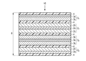
図1〜図3に示す電極群1は、扁平形状の捲回型の構造を有している。電極群1は、捲回軸wを軸として捲回されている。電極群1には、その捲回状態を保持するために、絶縁テープ11が巻かれている。電極群1は厚さB[cm]を有する。厚さB[cm]は、電極群1の互いに直行する三方向における寸法のうち最も小さい寸法である。
The
電極群1は、図2及び図3に示す負極2及び正極3を具備する。
負極2は、図2及び図3に示すように、負極集電体2aと、負極集電体2aの両面上に形成された負極活物質含有層2b1及び2b2とを具備する。図2に示すように、負極集電体2aは、負極活物質含有層2b1及び2b2を担持していない部分2cを含む。この部分2cは、負極集電タブとして働く。The
As shown in FIGS. 2 and 3, the
正極3は、図2及び3に示すように、正極集電体3aと、正極集電体3aの両面上に担持された正極活物質含有層3b1及び3b2とを具備する。図2に示すように、正極集電体3aは、正極活物質含有層3b1及び3b2を担持していない部分3cを含む。この部分3cは、正極集電タブとして働く。As shown in FIGS. 2 and 3, the
電極群1は、図2及び図3に示す2枚のセパレータ4を更に具備する。一枚のセパレータ4、負極2、もう一枚のセパレータ4及び正極3が、図2及び3に示すように、この順で積層されている。また、図2に示すように、負極集電タブ2cは、正極3と向き合わないように配置されており、正極集電タブ3cは、負極2と向き合わないように配置されている。また、図1及び図2に示すように、電極群1の捲回軸wに平行な方向における一方の端部に負極集電タブ2cが配置されており、他方の端部に正極集電タブ3cが配置されている。
The
図3に示すように、負極2は、方向T−T’において、正極3よりも大きな寸法を有する。そのため、負極活物質含有層2b1の一部のみが、正極活物質含有層3b2に向き合っている。図1〜図3に示す電極群1では、負極活物質含有層2b1のうち正極活物質含有層3b2に向き合った部分は、図2に示す幅C[cm]及び図3に示す長さL[cm]にわたって拡がっている。また、捲回された状態の電極群1では、負極活物質含有層2b2のうち正極活物質含有層3b1に向き合った部分も、図2に示す幅C[cm]にわたって拡がっている。ただし、図3に示すように、電極群1の最も外側に位置する部分(図3においてsで示す部分)では、負極集電体2aの一方の表面は、負極活物質含有層2b2を担持していない。そのため、負極活物質含有層2b2のうち正極活物質含有層3b1に向き合った部分は、図3に示す方向T−T’において、長さ(L−s)[cm]にわたって拡がっている。すなわち、図1〜図4に示す電極群1では、負極活物質含有層2b1及び2b2のうち正極活物質含有層3b1及び3b2に向き合った部分の面積A[cm2]は以下の式で得ることができる。As shown in FIG. 3, the
A[cm2]=(L[cm]×C[cm])+{(L−s)[cm]×C[cm]}
なお、例えば図3に示す視点V1から観察した場合に図4に模式的に示すように負極活物質含有層2b(実線)と正極活物質含有層3b(点線)との形状が異なっている場合、一方の負極活物質含有層2bのうち正極活物質含有層3bと向き合った部分は、斜線部分12となる。A [cm 2 ] = (L [cm] x C [cm]) + {(L-s) [cm] x C [cm]}
For example, when observed from the viewpoint V1 shown in FIG. 3, the shapes of the negative electrode active material-containing
次に、第1の実施形態に係る他の例の電極群を図5〜図7を参照しながら説明する。 Next, the electrode group of another example according to the first embodiment will be described with reference to FIGS. 5 to 7.
図5は、実施形態に係る第2の例の電極群の概略斜視図である。図6は、図5に示す電極群の線分VI−VIに沿った概略断面図である。図7は、図5及び図6に示す電極群における負極活物質含有層と正極活物質含有層とが向き合った部分を概略的に示す図である。 FIG. 5 is a schematic perspective view of the electrode group of the second example according to the embodiment. FIG. 6 is a schematic cross-sectional view taken along the line segment VI-VI of the electrode group shown in FIG. FIG. 7 is a diagram schematically showing a portion of the electrode group shown in FIGS. 5 and 6 in which the negative electrode active material-containing layer and the positive electrode active material-containing layer face each other.
図5〜図7に示す電極群1は、図6に示すように、スタック型の構造を有する。電極群1は、複数(例えば2枚)の負極21及び22と、複数(例えば2枚)の正極31及び32と、複数(例えば5枚)のセパレータ4とを具備する。As shown in FIG. 6, the
1つの負極21は、負極集電体2aと、負極集電体2aの両面上に形成された負極活物質含有層2bとを含む。もう1つの負極21は、負極集電体2aと、負極集電体2aの片面上に形成された負極活物質含有層2bとを含む。負極21及び22のそれぞれの負極集電体2aは、表面に負極活物質含有層2bを担持していない部分2cを含む。この部分2cは、負極集電体2aのうち表面に負極活物質含有層2bを担持している部分の幅よりも小さい幅を有する。子の部分2cは負極集電タブとして働く。One
1つの正極31は、正極集電体3aと、正極集電体3aの片面上に形成された正極活物質含有層3bとを含む。もう1つの正極31は、正極集電体3aと、正極集電体3aの両面上に形成された正極活物質含有層3bとを含む。正極31及び32のそれぞれの正極集電体3aは、表面に正極活物質含有層3bを担持していない部分3cを含む。この部分3cは、正極集電体3aのうち表面に正極活物質含有層3bを担持している部分の幅よりも小さな幅を有する。この部分3cは正極集電タブとして働く。One of the
図6に示すように、この例の電極群1では、下から、セパレータ4、負極22、セパレータ4、正極32、セパレータ4、負極21、セパレータ4、正極31及びセパレータ4の順で積層されている。負極21の一方の負極活物質含有層2bの一部は、セパレータ4を介して、正極31の正極活物質含有層3bと向き合っている。負極21の他方の負極活物質含有層2bの一部は、セパレータ4を介して、正極32の一方の正極活物質含有層3bと向き合っている。負極22の負極活物質含有層2bの一部は、セパレータ4を介して、正極32の他方の正極活物質含有層3bと向き合っている。As shown in FIG. 6, in the
また、負極集電タブ2cは、重なり合って接続されている。同様に、正極集電タブ3cは、重なり合って接続されている。図5に示すように、負極集電タブ2cの先端と正極集電タブ3cの先端とは、互いに反対の向きを向いている。
Further, the negative electrode
図7は、図5及び6に示す電極群1を図6の視点V2から観察した際の、負極21(点線)の負極活物質含有層2bと正極31(実線)の正極活物質含有層3bとが向き合っている部分12(斜線)を概略的に示している。FIG. 7 shows the
図5〜図7に示す電極群1において負極活物質含有層2bのうち正極活物質含有層3bに向き合った部分の面積A[cm2]は、負極21の負極活物質含有層2bのうち正極31の正極活物質含有層3bと向き合った部分の面積と、負極21の負極活物質含有層2bのうち正極32の正極活物質含有層3bと向き合った部分の面積と、負極22の負極活物質含有層2bのうち正極32の正極活物質含有層3bと向き合った部分の面積との和である。また、図5〜図7に示す電極群1は、厚さB[cm]を有する。Figures 5 In 7 the
[各種測定方法]
[前処理]
まず、測定対象の電極群を準備する。測定対象の電極群が電池に組み込まれている場合は、以下の手順で、測定対象の電極群を取り出す。まず、測定対象の電極群を含んだ電池を準備する。この電池を、25℃恒温槽内で、0.2C相当の電流値[A]にて、電池電圧が1.5Vに達するまで定電流放電する。その後、この電池を、1.5Vにて1時間にわたって定電圧放電する。定電圧放電後、電池をアルゴングローブボックスに入れ、電池を解体する。グローブボックス内で外装材から電極群を取り出す。この際、正極活物質含有層及び負極活物質含有層が損傷しないように、電極端子及び/又は電極リード留意する。取り出した電極群を、エチルメチルカーボネートに10分間浸漬させる。次いで、電極群をエチルメチルカーボネートから取り出し、乾燥させる。かくして、測定対象の電極群を得ることができる。[Various measurement methods]
[Preprocessing]
First, a group of electrodes to be measured is prepared. When the electrode group to be measured is incorporated in the battery, the electrode group to be measured is taken out by the following procedure. First, a battery including the electrode group to be measured is prepared. This battery is discharged at a constant current value [A] corresponding to 0.2 C in a constant temperature bath at 25 ° C. until the battery voltage reaches 1.5 V. Then, the battery is discharged at a constant voltage of 1.5 V for 1 hour. After constant voltage discharge, put the battery in the argon glove box and disassemble the battery. Take out the electrode group from the exterior material in the glove box. At this time, care should be taken for the electrode terminals and / or the electrode leads so that the positive electrode active material-containing layer and the negative electrode active material-containing layer are not damaged. The removed electrode group is immersed in ethyl methyl carbonate for 10 minutes. The electrodes are then removed from the ethyl methyl carbonate and dried. Thus, the electrode group to be measured can be obtained.
[面積Aの測定]
捲回型の電極群の場合、正極活物質含有層及び負極活物質含有層を損傷しないように留意しながら、電極群の捲回を解く。展開した電極群(積層体)において、負極活物質含有層と正極活物質含有層とが重なり合った部分の面積を測定する。積層体から、正極、負極及び/又はセパレータを剥がす際にも、正極活物質含有層及び負極活物質含有層を損傷しないように留意する。また、負極活物質含有層のうち、捲回された状態において正極活物質含有層と向き合った部分の面積も測定する。[Measurement of area A]
In the case of the winding type electrode group, the winding of the electrode group is unwound while being careful not to damage the positive electrode active material-containing layer and the negative electrode active material-containing layer. In the developed electrode group (laminated body), the area of the portion where the negative electrode active material-containing layer and the positive electrode active material-containing layer overlap is measured. Care should be taken not to damage the positive electrode active material-containing layer and the negative electrode active material-containing layer when the positive electrode, the negative electrode and / or the separator are peeled off from the laminate. In addition, the area of the portion of the negative electrode active material-containing layer facing the positive electrode active material-containing layer in the wound state is also measured.
スタック型構造の電極群の場合は、先のように取り出した電極群において、負極活物質含有層と正極活物質含有層とが重なり合った部分の面積を測定する。積層体から、正極、負極及び/又はセパレータを剥がす際には、正極活物質含有層及び負極活物質含有層を損傷しないように留意する。 In the case of the electrode group having a stack type structure, the area of the portion where the negative electrode active material-containing layer and the positive electrode active material-containing layer overlap in the electrode group taken out as described above is measured. When peeling the positive electrode, the negative electrode and / or the separator from the laminate, care should be taken not to damage the positive electrode active material-containing layer and the negative electrode active material-containing layer.
負極活物質含有層と正極活物質含有層とが重なり合った部分の長さは、定規、巻尺など、長さに応じて測定手段を使い分けて測定する。 The length of the portion where the negative electrode active material-containing layer and the positive electrode active material-containing layer overlap is measured by using a measuring means such as a ruler or a tape measure according to the length.
なお、面積Aは、負極活物質含有層のうち正極活物質含有層に向き合った部分のマクロ的な面積であり、例えば負極活物質含有層の細孔の面積を含まない。 The area A is a macroscopic area of the portion of the negative electrode active material-containing layer facing the positive electrode active material-containing layer, and does not include, for example, the area of the pores of the negative electrode active material-containing layer.
[厚さBの測定]
電極群の厚さBは、電極群の表面のうち最大面積を有する面に1cm2あたり15g以上20g以下の荷重をかけて測定した厚さとする。厚さの測定の際には、このような荷重をかけることができる機能と、このように荷重をかけた状態での長さを測定できる機能とを備えた測定装置を用いる。[Measurement of thickness B]
The thickness B of the electrode group is a thickness measured by applying a load of 15 g or more and 20 g or less per 1 cm 2 to the surface having the maximum area of the surface of the electrode group. When measuring the thickness, a measuring device having a function of applying such a load and a function of measuring the length under such a load is used.
[断面SEM観察]
測定対象の電極群についてイオンミリング装置を用いて、断面ミリングを行う。得られた断面を、エネルギー分散型X線分析装置を備えた走査型電子顕微鏡(SEM−EDX)で観察する。この観察により、負極活物質含有層及び負極活物質含有層のそれぞれに含まれている成分の組成(周期表におけるB〜Uの各元素)を知ることができる。[Cross-section SEM observation]
Cross-section milling is performed on the electrode group to be measured using an ion milling device. The obtained cross section is observed with a scanning electron microscope (SEM-EDX) equipped with an energy dispersive X-ray analyzer. From this observation, the composition of the components contained in each of the negative electrode active material-containing layer and the negative electrode active material-containing layer (each element of B to U in the periodic table) can be known.
[活物質の同定]
活物質に含まれている化合物の組成及び結晶構造は、上記SEM−EDXによる元素分析の結果と、以下に説明する誘導結合プラズマ(Inductively Coupled Plasma:ICP)発光分析の結果と、以下に説明する粉末X線回折(X-ray Diffraction:XRD)分析の結果とを組み合わせることにより、同定することができる。[Identification of active material]
The composition and crystal structure of the compound contained in the active material will be described below with the results of the elemental analysis by the above SEM-EDX and the results of the inductively coupled plasma (ICP) emission analysis described below. It can be identified by combining it with the results of powder X-ray Diffraction (XRD) analysis.
[SEM−EDXによる元素分析]
上記SEM−EDXによる元素分析によると、活物質に含まれている元素のうち、周期表におけるB〜Uまでの元素の組成を知ることができる。[Elemental analysis by SEM-EDX]
According to the elemental analysis by SEM-EDX, it is possible to know the composition of the elements from B to U in the periodic table among the elements contained in the active material.
[ICPによる元素分析]
電極群から、測定対象の活物質を含んでいる電極を取り出す。次いで、取り出した電極の一部を適切な溶媒中に入れて超音波を照射する。例えば、ガラスビーカー中に入れたエチルメチルカーボネートに電極を入れ、超音波洗浄機中で振動させることで、集電体から活物質を含む活物質含有層を剥離することができる。次に、減圧乾燥を行い、剥離した活物質含有層を乾燥する。得られた活物質含有層を乳鉢などで粉砕することで、測定対象たる活物質、導電剤、結着剤などを含む粉末が得られる。この粉末を、酸で溶解することで、活物質を含む液体サンプルを作成できる。酸としては、塩酸、硝酸、硫酸、フッ化水素などを使用できる。この液体サンプルをICP発光分光分析に供することで、活物質における金属元素(Liを含む)の濃度を知ることができる。
[活物質粒子に含まれる化合物の組成の同定]
SEM−EDXによる元素分析結果及びICP発光分光分析結果に基づいて、活物質に含まれていた化合物の組成を同定することができる。活物質が複数種類ある場合は、各活物質に固有の元素の含有比率からその質量比を推定する。固有の元素と活物質質量の比率とはEDXにより求めた構成元素の組成から判断することができる。[Elemental analysis by ICP]
From the electrode group, take out the electrode containing the active material to be measured. Then, a part of the removed electrode is put in a suitable solvent and irradiated with ultrasonic waves. For example, by placing an electrode in ethyl methyl carbonate placed in a glass beaker and vibrating it in an ultrasonic cleaner, the active material-containing layer containing the active material can be peeled off from the current collector. Next, vacuum drying is performed to dry the peeled active material-containing layer. By pulverizing the obtained active material-containing layer with a mortar or pestle, a powder containing the active material to be measured, a conductive agent, a binder and the like can be obtained. By dissolving this powder with an acid, a liquid sample containing an active material can be prepared. As the acid, hydrochloric acid, nitric acid, sulfuric acid, hydrogen fluoride and the like can be used. By subjecting this liquid sample to ICP emission spectroscopic analysis, the concentration of metal elements (including Li) in the active material can be known.
[Identification of the composition of compounds contained in active material particles]
The composition of the compound contained in the active material can be identified based on the elemental analysis result by SEM-EDX and the ICP emission spectroscopic analysis result. When there are multiple types of active materials, the mass ratio is estimated from the content ratio of the elements unique to each active material. The ratio of the specific element to the mass of the active material can be determined from the composition of the constituent elements obtained by EDX.
[結晶構造の同定]
活物質に含まれている化合物の結晶構造は、X線回折(XRD)測定により特定することができる。[Identification of crystal structure]
The crystal structure of the compound contained in the active material can be identified by X-ray diffraction (XRD) measurement.
測定は、CuKα線を線源として、2θ=10〜90°の測定範囲で行う。この測定により、活物質粒子に含まれる化合物のX線回折パターンを得ることができる。 The measurement is performed in a measurement range of 2θ = 10 to 90 ° using CuKα ray as a radiation source. By this measurement, an X-ray diffraction pattern of the compound contained in the active material particles can be obtained.
粉末X線回折測定の装置としては、Rigaku社製SmartLabを用いる。測定条件は以下の通りとする:Cuターゲット;45kV 200mA;ソーラスリット:入射及び受光共に5°;ステップ幅:0.02deg;スキャン速度:20deg/分;半導体検出器:D/teX Ultra 250;試料板ホルダ:平板ガラス試料板ホルダ(厚さ0.5mm);測定範囲:10°≦2θ≦90°の範囲。その他の装置を使用する場合は、粉末X線回折用標準Si粉末を用いた測定を行って、上記装置によって得られる結果と同等のピーク強度、半値幅及び回折角の測定結果が得られる条件を見つけ、その条件で試料の測定を行う。 As a device for powder X-ray diffraction measurement, a Smart Lab manufactured by Rigaku Co., Ltd. is used. The measurement conditions are as follows: Cu target; 45 kV 200 mA; solar slit: 5 ° for both incident and received light; step width: 0.02 deg; scan speed: 20 deg / min; semiconductor detector: D / teX Ultra 250; sample Plate holder: Flat glass sample plate holder (thickness 0.5 mm); Measurement range: 10 ° ≤ 2θ ≤ 90 °. When using other devices, perform measurements using standard Si powder for powder X-ray diffraction, and set the conditions under which measurement results of peak intensity, full width at half maximum, and diffraction angle equivalent to those obtained by the above device can be obtained. Find it and measure the sample under those conditions.
電極についてのXRD測定は、測定対象の電極を、広角X線回折装置のホルダの面積と同程度切り出し、直接ガラスホルダーに貼り付けて測定することによって行うことができる。この際、集電体についてのXRDを測定しておき、どの位置に集電体由来のピークが現れるかを把握しておく。また、導電剤や結着剤といった合剤のピークの有無もあらかじめ把握しておく。集電体のピークと活物質のピークとが重なる場合、集電体から活物質含有層を剥離して測定することが望ましい。これは、ピーク強度を定量的に測定する際、重なったピークを分離するためである。もちろん、これらを事前に把握できているのであれば、この操作を省略することができる。活物質含有層を物理的に剥離しても良いが、溶媒中で超音波をかけると剥離しやすい。このようにして回収した活物質含有層を測定することで、活物質の広角X線回折測定を行うことができる。 The XRD measurement of the electrode can be performed by cutting out the electrode to be measured to the same extent as the area of the holder of the wide-angle X-ray diffractometer and directly attaching it to the glass holder for measurement. At this time, the XRD of the current collector is measured, and the position where the peak derived from the current collector appears is grasped. In addition, the presence or absence of peaks of the mixture such as the conductive agent and the binder should be grasped in advance. When the peak of the current collector and the peak of the active material overlap, it is desirable to separate the active material-containing layer from the current collector for measurement. This is to separate overlapping peaks when quantitatively measuring the peak intensity. Of course, this operation can be omitted if these are known in advance. The active material-containing layer may be physically peeled off, but it is easily peeled off when ultrasonic waves are applied in a solvent. By measuring the active material-containing layer recovered in this way, wide-angle X-ray diffraction measurement of the active material can be performed.
以上の手順により、活物質に含まれる化合物のXRDパターンを得ることができる。得られたXRDパターンから、活物質に含まれる化合物の結晶構造を同定することができる。 By the above procedure, the XRD pattern of the compound contained in the active material can be obtained. From the obtained XRD pattern, the crystal structure of the compound contained in the active material can be identified.
第1の実施形態によると、電極群が提供される。この電極群は、正極活物質含有層を含む正極と、負極活物質含有層を含む負極とを具備する。負極活物質含有層は、単斜晶型ニオブチタン複合酸化物及び直方晶型チタン含有複合酸化物からなる群より選択される少なくとも1種のチタン含有複合酸化物を含む。負極活物質含有層の少なくとも一部が、正極活物質含有層の少なくとも一部に向き合っている。この電極群は、式:6500≦A/B≦18500を満たす。この電極群は、電極群からの発熱を十分に抑えることができると共に、電極群からの放熱を十分に行うことができる。また、この電極群は、大きな電圧が印加された際にも抵抗値の上昇を十分に抑えることができる。そして、この電極群は、低温環境下での充電の際に、電池の急速充電性能を高めるのに十分な熱を生じさせることができる。これらの結果、第1の実施形態に係る電極群は、優れたサイクル寿命及び低温環境下での優れた急速充電性能を示すことができる電池を実現できる。 According to the first embodiment, a group of electrodes is provided. This electrode group includes a positive electrode including a positive electrode active material-containing layer and a negative electrode including a negative electrode active material-containing layer. The negative electrode active material-containing layer contains at least one titanium-containing composite oxide selected from the group consisting of monoclinic niobium-titanium composite oxides and rectangular titanium-containing composite oxides. At least a part of the negative electrode active material-containing layer faces at least a part of the positive electrode active material-containing layer. This electrode group satisfies the formula: 6500 ≦ A / B ≦ 18500. This electrode group can sufficiently suppress heat generation from the electrode group and can sufficiently dissipate heat from the electrode group. In addition, this electrode group can sufficiently suppress an increase in resistance value even when a large voltage is applied. Then, this electrode group can generate enough heat to enhance the quick charging performance of the battery when charging in a low temperature environment. As a result, the electrode group according to the first embodiment can realize a battery capable of exhibiting excellent cycle life and excellent quick charging performance in a low temperature environment.
(第2の実施形態)
第2の実施形態によると、電池が提供される。この電池は、実施形態に係る電極群と、電解質とを具備する。(Second Embodiment)
According to the second embodiment, batteries are provided. This battery includes an electrode group according to an embodiment and an electrolyte.
第2の実施形態に係る電池は、第1の実施形態に係る電極群を具備するので、優れたサイクル寿命及び低温環境下での優れた急速充電性能を示すことができる。 Since the battery according to the second embodiment includes the electrode group according to the first embodiment, it can exhibit excellent cycle life and excellent quick charging performance in a low temperature environment.
第2の実施形態に係る電池は、充電及び放電を繰り返し行うことができる。そのため、第2の実施形態に係る電池は、二次電池ということもできる。 The battery according to the second embodiment can be repeatedly charged and discharged. Therefore, the battery according to the second embodiment can be said to be a secondary battery.
第2の実施形態に係る電池は、例えば非水電解質電池である。非水電解質電池は非水電解質を含み、非水電解質は電解質を含む。或いは、第2の実施形態に係る電池は、水系溶媒と、水系溶媒に溶解した電解質とを含んだ電解液を含んだ電池であってもよい。 The battery according to the second embodiment is, for example, a non-aqueous electrolyte battery. A non-aqueous electrolyte battery contains a non-aqueous electrolyte, and a non-aqueous electrolyte contains an electrolyte. Alternatively, the battery according to the second embodiment may be a battery containing an electrolytic solution containing an aqueous solvent and an electrolyte dissolved in the aqueous solvent.
次に、第2の実施形態に係る電池をより詳細に説明する。 Next, the battery according to the second embodiment will be described in more detail.
第2の実施形態に係る電池の一例である非水電解質電池において、非水電解質は、例えば電極群に含浸された状態で保持され得る。或いは、第2の実施形態に係る他の例の電池では、電解質を含んだ電解液が、例えば電極群に含浸された状態で保持され得る。 In the non-aqueous electrolyte battery, which is an example of the battery according to the second embodiment, the non-aqueous electrolyte can be held, for example, in a state of being impregnated in the electrode group. Alternatively, in the battery of another example according to the second embodiment, the electrolytic solution containing an electrolyte can be held, for example, in a state of being impregnated in the electrode group.
第2の実施形態に係る電池は、負極端子及び正極端子を更に含むことができる。負極端子は、その一部が負極の一部に電気的に接続されることによって、負極と外部端子との間で電子が移動するための導体として働くことができる。負極端子は、例えば、負極集電体、特に負極集電タブに接続することができる。同様に、正極端子は、その一部が正極の一部に電気的に接続されることによって、正極と外部回路との間で電子が移動するための導体として働くことができる。正極端子は、例えば、正極集電体、特に正極集電タブに接続することができる。 The battery according to the second embodiment can further include a negative electrode terminal and a positive electrode terminal. A part of the negative electrode terminal is electrically connected to a part of the negative electrode, so that the negative electrode terminal can function as a conductor for electrons to move between the negative electrode and the external terminal. The negative electrode terminal can be connected to, for example, a negative electrode current collector, particularly a negative electrode current collector tab. Similarly, the positive electrode terminal can act as a conductor for electrons to move between the positive electrode and the external circuit by electrically connecting a part of the positive electrode terminal to a part of the positive electrode. The positive electrode terminal can be connected to, for example, a positive electrode current collector, particularly a positive electrode current collector tab.
第2の実施形態に係る電池は、外装部材を更に具備することができる。外装部材は、電極群及び電解質を収容することができる。非水電解質電池の場合、非水電解質は、外装部材内で、電極群に含浸され得る。正極端子及び負極端子のそれぞれの一部は、外装部材から延出させることができる。 The battery according to the second embodiment may further include an exterior member. The exterior member can accommodate a group of electrodes and an electrolyte. In the case of a non-aqueous electrolyte battery, the non-aqueous electrolyte can be impregnated in the electrode group in the exterior member. A part of each of the positive electrode terminal and the negative electrode terminal can be extended from the exterior member.
第2の実施形態に係る電池の定格容量は、25Ah以上150Ah以下であることが好ましく、30Ah以上100Ah以下であることがより好ましい。電池の定格容量は、以下の手順で測定する。まず、測定対象の電池を、25℃環境下において、5Aの定電流にて3.2Vまで充電する。次いで、電池を、3.2Vの低電圧で、1時間にわたって放電する。その後、電池を、30分間開回路状態で放置する。次いで、電池を、5Aの定電流で、1.5Vまで放電する。この放電で得られた容量を、定格容量[Ah]とする。 The rated capacity of the battery according to the second embodiment is preferably 25 Ah or more and 150 Ah or less, and more preferably 30 Ah or more and 100 Ah or less. The rated capacity of the battery is measured by the following procedure. First, the battery to be measured is charged to 3.2 V with a constant current of 5 A in an environment of 25 ° C. The battery is then discharged at a low voltage of 3.2 V for 1 hour. Then, the battery is left in the open circuit state for 30 minutes. The battery is then discharged to 1.5 V at a constant current of 5 A. The capacity obtained by this discharge is defined as the rated capacity [Ah].
次に、第2の実施形態に係る電池の一例である非水電解質電池が含むことができる各部材をより詳細に説明する。 Next, each member that can be included in the non-aqueous electrolyte battery, which is an example of the battery according to the second embodiment, will be described in more detail.
(電極群)
第2の実施形態に係る電池が具備する電極群は、第1の実施形態に係る電極群である。(Electrode group)
The electrode group included in the battery according to the second embodiment is the electrode group according to the first embodiment.
(非水電解質)
非水電解質としては、例えば、液状非水電解質又はゲル状非水電解質を用いることができる。(Non-aqueous electrolyte)
As the non-aqueous electrolyte, for example, a liquid non-aqueous electrolyte or a gel-like non-aqueous electrolyte can be used.
液状非水電解質は、電解質を有機溶媒に溶解することにより調製することができる。電解質の濃度は、0.5〜2.5mol/lの範囲であることが好ましい。ゲル状非水電解質は、液状電解質と高分子材料とを複合化することにより調製される。 The liquid non-aqueous electrolyte can be prepared by dissolving the electrolyte in an organic solvent. The concentration of the electrolyte is preferably in the range of 0.5 to 2.5 mol / l. The gel-like non-aqueous electrolyte is prepared by combining a liquid electrolyte and a polymer material.
電解質の例には、過塩素酸リチウム(LiClO4)、六フッ化リン酸リチウム(LiPF6)、四フッ化ホウ酸リチウム(LiBF4)、六フッ化ヒ酸リチウム(LiAsF6)、トリフルオロメタンスルホン酸リチウム(LiCF3SO3)、及び、ビストリフルオロメチルスルホニルイミドリチウム[LiN(CF3SO2)2]のようなリチウム塩が含まれる。電解質としては、これらの電解質のうちの1種を単独で用いてもよいし、又は2種類以上の電解質を組合せて用いることもできる。電解質は、LiPF6を含むことが好ましい。Examples of electrolytes include lithium perchlorate (LiClO 4 ), lithium hexafluorophosphate (LiPF 6 ), lithium tetrafluoroborate (LiBF 4 ), lithium hexafluorophosphate (LiAsF 6 ), and trifluoromethane. Includes lithium sulfonate (LiCF 3 SO 3 ) and lithium salts such as bistrifluoromethylsulfonylimide lithium [LiN (CF 3 SO 2 ) 2]. As the electrolyte, one of these electrolytes may be used alone, or two or more kinds of electrolytes may be used in combination. The electrolyte preferably contains LiPF 6.
有機溶媒の例には、プロピレンカーボネート(PC)、エチレンカーボネート(EC)、ビニレンカーボネートのような環状カーボネート;ジエチルカーボネート(DEC)、ジメチルカーボネート(DMC)、メチルエチルカーボネート(MEC)のような鎖状カーボネート;テトラヒドロフラン(THF)、2−メチルテトラヒドロフラン(2MeTHF)、ジオキソラン(DOX)のような環状エーテル;ジメトキシエタン(DME)、ジエトキシエタン(DEE)のような鎖状エーテル;アセトニトリル(AN)、及び、スルホラン(SL)が含まれる。有機溶媒としては、これらの溶媒のうちの1種を単独で用いてもよいし、又は2種類以上の溶媒を組合せて用いることもできる。 Examples of organic solvents include cyclic carbonates such as propylene carbonate (PC), ethylene carbonate (EC), vinylene carbonate; chains such as diethyl carbonate (DEC), dimethyl carbonate (DMC), methyl ethyl carbonate (MEC). Carbonates; cyclic ethers such as tetrahydrofuran (THF), 2-methyltetrahydrofuran (2MeTHF), dioxolane (DOX); chain ethers such as dimethoxyethane (DME), diethoxyethane (DEE); acetonitrile (AN), and , Hydrofuran (SL) is included. As the organic solvent, one of these solvents may be used alone, or two or more kinds of solvents may be used in combination.
より好ましい有機溶媒の例には、プロピレンカーボネート(PC)、エチレンカーボネート(EC)、ジエチルカーボネート(DEC)、ジメチルカーボネート(DMC)、及びメチルエチルカーボネート(MEC)よりなる群から選択される2種以上を混合した混合溶媒が含まれる。このような混合溶媒を用いることによって、充放電サイクル特性の優れた非水電解質電池を得ることができる。また、電解液には添加剤を加えることもできる。 Examples of more preferable organic solvents are two or more selected from the group consisting of propylene carbonate (PC), ethylene carbonate (EC), diethyl carbonate (DEC), dimethyl carbonate (DMC), and methyl ethyl carbonate (MEC). A mixed solvent in which the above is mixed is included. By using such a mixed solvent, a non-aqueous electrolyte battery having excellent charge / discharge cycle characteristics can be obtained. In addition, an additive can be added to the electrolytic solution.
(外装部材)
外装部材としては、例えば、ラミネートフィルム製の袋状容器又は金属製容器を用いることができる。(Exterior member)
As the exterior member, for example, a bag-shaped container made of a laminated film or a metal container can be used.
形状としては、特に限定されないが、扁平型、角型、円筒型、コイン型、ボタン型、シート型、積層型等が挙げられる。なお、無論、携帯用電子機器等に積載される小型電池の他、二輪乃至四輪の自動車等に積載される大型電池でも良い。 The shape is not particularly limited, and examples thereof include a flat type, a square type, a cylindrical type, a coin type, a button type, a sheet type, and a laminated type. Of course, in addition to a small battery loaded on a portable electronic device or the like, a large battery loaded on a two-wheeled or four-wheeled automobile or the like may be used.
ラミネートフィルムとしては、例えば、樹脂フィルム間に金属層を挟み込んだ多層フィルムを用いることができる。或いは、金属層と、金属層を被覆する樹脂層とからなる多層フィルムを用いることもできる。 As the laminated film, for example, a multilayer film in which a metal layer is sandwiched between resin films can be used. Alternatively, a multilayer film composed of a metal layer and a resin layer covering the metal layer can also be used.
金属層は、軽量化のためにアルミニウム箔もしくはアルミニウム合金箔が好ましい。樹脂フィルムには、例えばポリプロピレン(PP)、ポリエチレン(PE)、ナイロン、及びポリエチレンテレフタレート(PET)のような高分子材料を用いることができる。ラミネートフィルムは、熱融着によりシールを行って外装部材の形状に成形することができる。ラミネートフィルムは、肉厚が0.2mm以下であることが好ましい。 The metal layer is preferably an aluminum foil or an aluminum alloy foil for weight reduction. As the resin film, polymer materials such as polypropylene (PP), polyethylene (PE), nylon, and polyethylene terephthalate (PET) can be used. The laminated film can be sealed into the shape of an exterior member by heat fusion. The laminated film preferably has a wall thickness of 0.2 mm or less.
金属製容器は、アルミニウム又はアルミニウム合金から形成されることができる。アルミニウム合金は、マグネシウム、亜鉛及びケイ素のような元素を含むことが好ましい。一方、鉄、銅、ニッケル、クロム等の遷移金属の含有量は100ppm以下にすることが好ましい。これにより、高温環境下での長期信頼性、放熱性を飛躍的に向上させることが可能となる。金属製容器は、肉厚が0.5mm以下であることが好ましく、肉厚が0.2mm以下であることがより好ましい。 The metal container can be made of aluminum or an aluminum alloy. The aluminum alloy preferably contains elements such as magnesium, zinc and silicon. On the other hand, the content of transition metals such as iron, copper, nickel and chromium is preferably 100 ppm or less. This makes it possible to dramatically improve long-term reliability and heat dissipation in a high temperature environment. The metal container preferably has a wall thickness of 0.5 mm or less, and more preferably 0.2 mm or less.
(正極端子)
正極端子は、例えばリチウムの酸化還元電位に対する電位が3.0V以上4.5V以下の範囲において電気的に安定であり、且つ導電性を有する材料から形成される。アルミニウム、又はMg、Ti、Zn、Mn、Fe、Cu及びSiのような元素を含むアルミニウム合金から形成されることが好ましい。正極端子は、正極集電体との接触抵抗を低減するために、正極集電体と同様の材料から形成されることが好ましい。(Positive terminal)
The positive electrode terminal is formed of, for example, a material that is electrically stable and has conductivity in a range where the potential of lithium with respect to the redox potential is 3.0 V or more and 4.5 V or less. It is preferably formed from aluminum or an aluminum alloy containing elements such as Mg, Ti, Zn, Mn, Fe, Cu and Si. The positive electrode terminal is preferably formed of the same material as the positive electrode current collector in order to reduce the contact resistance with the positive electrode current collector.
(負極端子)
負極端子は、リチウムの酸化還元電位に対する電位が0.8V以上3.0V以下の範囲において電気的に安定であり、かつ導電性を有する材料から形成される。アルミニウム、又は、Mg、Ti、Zn、Mn、Fe、Cu、Siのような元素を含むアルミニウム合金から形成されることが好ましい。負極端子は、負極集電体との接触抵抗を低減するために、負極集電体と同様の材料から形成されることが好ましい。(Negative electrode terminal)
The negative electrode terminal is formed of a material that is electrically stable and has conductivity in a range in which the potential of lithium with respect to the redox potential is 0.8 V or more and 3.0 V or less. It is preferably formed from aluminum or an aluminum alloy containing elements such as Mg, Ti, Zn, Mn, Fe, Cu and Si. The negative electrode terminal is preferably formed of the same material as the negative electrode current collector in order to reduce the contact resistance with the negative electrode current collector.
次に、第2の実施形態に係る幾つかの例の非水電解質電池を、図面を参照しながら具体的に説明する。 Next, some examples of non-aqueous electrolyte batteries according to the second embodiment will be specifically described with reference to the drawings.
図8は、第2の実施形態に係る一例の扁平型非水電解質電池の概略断面図である。図9は、図8のA部の拡大断面図である。 FIG. 8 is a schematic cross-sectional view of an example flat non-aqueous electrolyte battery according to the second embodiment. FIG. 9 is an enlarged cross-sectional view of part A in FIG.
図8及び図9に示す非水電解質電池10は、図8に示す扁平状の捲回型電極群1を具備している。扁平状の捲回電極群1は、ラミネートフィルムからなる袋状外装部材5内に収納されている。ラミネートフィルムは、金属層と、これを挟む2枚の樹脂フィルムとを含んでいる。
The
扁平状の捲回電極群1は、図9に示すように、外側から負極2、セパレータ4、正極3、セパレータ4の順で積層した積層物を渦巻状に捲回し、プレス成型することにより形成されている。負極2のうち最も外側に位置する部分は、図9に示すように負極集電体2aの内面側の片面上に負極活物質含有層2bを形成している。負極2のその他の部分では、負極集電体2aの両面上に負極活物質含有層2bが形成されている。正極3については、正極集電体3aの両面に正極活物質含有層3bが形成されている。
As shown in FIG. 9, the flat
捲回型の電極群1の外周端近傍において、負極端子7が、負極2の最外層の部分の負極集電体2aに接続されており、正極端子6が、内側に位置する正極3の正極集電体3aに接続されている。これらの負極端子7および正極端子6は、袋状外装部材5の開口部から外部に延出されている。
The
図8及び図9に示す非水電解質電池10は、図示しない非水電解質を更に具備する。非水電解質は、電極群1に含浸された状態で、外装部材5内に収容されている。
The
非水電解質は、例えば、袋状外装部材5の開口部から注入することができる。非水電解質注入後、袋状外装部材5の開口部を負極端子7及び正極端子6を挟んでヒートシールすることにより、捲回型電極群1及び非水電解質を完全密封することができる。
The non-aqueous electrolyte can be injected, for example, through the opening of the bag-shaped
図8に示す電極群1は、第1の実施形態に係る電極群の一例である。
The
第2の実施形態に係る非水電解質電池は、前述した図8及び図9に示す構成を有するものに限らず、例えば図10及び図11に示す構成を有することができる。 The non-aqueous electrolyte battery according to the second embodiment is not limited to the one having the configurations shown in FIGS. 8 and 9 described above, and may have, for example, the configurations shown in FIGS. 10 and 11.
図10は、第2の実施形態に係る他の一例の非水電解質電池の概略部分切欠き斜視図である。図11は、図10のB部の拡大断面図である。 FIG. 10 is a schematic partially cutaway perspective view of another example non-aqueous electrolyte battery according to the second embodiment. FIG. 11 is an enlarged cross-sectional view of a portion B of FIG.
図10及び図11に示す非水電解質電池10は、スタック型電極群1を具備する。スタック型電極群1は、ラミネートフィルムからなる外装部材5内に収納されている。ラミネートフィルムは、金属層と、これを間に挟んだ2枚の樹脂フィルムとを含んでいる。
The
スタック型電極群1は、図11に示すように、正極3と負極2とをその間にセパレータ4を介在させながら交互に積層した構造を有する。正極3は複数枚存在し、それぞれが集電体3aと、集電体3aの両面に担持された正極活物質含有層3bとを備える。負極2は複数枚存在し、それぞれが負極集電体2aと、負極集電体2aの両面に担持された負極活物質含有層2bとを備える。各負極2の負極集電体2aは、一辺が正極3から突出している。負極集電体2aのうち正極3から突出した部分2cは、帯状の負極端子7に電気的に接続されている。帯状の負極端子7の先端は、外装部材5から外部に引き出されている。また、図示しないが、正極3の正極集電体3aは、負極集電体2aの突出辺2cと反対側に位置する辺が負極2から突出している。正極集電体3aのうち負極2から突出した部分は、帯状の正極端子6に電気的に接続されている。帯状の正極端子6の先端は、負極端子8とは反対側に位置し、外装部材2の辺から外部に引き出されている。
As shown in FIG. 11, the stack
図10及び11に示す電極群1は、第1の実施形態に係る電極群の一例である。
The
第2の実施形態に係る電池は、第1の実施形態に係る電極群を含むので、優れたサイクル寿命及び低温環境下での優れた急速充電性能を示すことができる。 Since the battery according to the second embodiment includes the electrode group according to the first embodiment, it can exhibit excellent cycle life and excellent quick charging performance in a low temperature environment.
(第3の実施形態)
第3の実施形態によると、電池パックが提供される。この電池パックは、第2の実施形態に係る電池を具備する。(Third Embodiment)
According to a third embodiment, a battery pack is provided. This battery pack comprises the battery according to the second embodiment.
第3の実施形態に係る電池パックは、複数の電池を備えることもできる。複数の電池は、電気的に直列に接続することもできるし、又は電気的に並列に接続することもできる。或いは、複数の電池を、直列及び並列の組み合わせで接続することもできる。 The battery pack according to the third embodiment may include a plurality of batteries. Multiple batteries can be electrically connected in series or electrically in parallel. Alternatively, a plurality of batteries can be connected in series and in parallel.
例えば、第3の実施形態に係る電池パックは、第2の実施形態に係る電池を5つ具備することもできる。これらの電池は、直列に接続されることができる。また、直列に接続された電池は、組電池を構成することができる。すなわち、第3の実施形態に係る電池パックは、組電池を具備することもできる。 For example, the battery pack according to the third embodiment may include five batteries according to the second embodiment. These batteries can be connected in series. Further, the batteries connected in series can form an assembled battery. That is, the battery pack according to the third embodiment may also include an assembled battery.
第3の実施形態に係る電池パックは、複数の組電池を具備することができる。複数の組電池は、直列、並列、又は直列及び並列の組み合わせで接続することができる。 The battery pack according to the third embodiment may include a plurality of assembled batteries. A plurality of assembled batteries can be connected in series, in parallel, or in a combination of series and parallel.
第3の実施形態に係る電池パックを図12及び図13を参照して詳細に説明する。単電池には、図8及び図9に示す扁平型電池を使用することができる。 The battery pack according to the third embodiment will be described in detail with reference to FIGS. 12 and 13. As the cell, the flat battery shown in FIGS. 8 and 9 can be used.
前述した図8及び図9に示す扁平型非水電解質電池から構成される複数の単電池21は、外部に延出した負極端子7及び正極端子6が同じ向きに揃えられるように積層され、粘着テープ22で締結することにより組電池23を構成している。これらの単電池21は、図13に示すように互いに電気的に直列に接続されている。
The plurality of
プリント配線基板24は、負極端子7及び正極端子6が延出する単電池21側面と対向して配置されている。プリント配線基板24には、図13に示すようにサーミスタ25、保護回路26及び外部機器への通電用端子27が搭載されている。なお、組電池23と対向するプリント配線基板24の面には組電池23の配線と不要な接続を回避するために絶縁板(図示せず)が取り付けられている。
The printed
正極側リード28は、組電池23の最下層に位置する正極端子6に接続され、その先端はプリント配線基板24の正極側コネクタ29に挿入されて電気的に接続されている。負極側リード30は、組電池23の最上層に位置する負極端子7に接続され、その先端はプリント配線基板24の負極側コネクタ31に挿入されて電気的に接続されている。これらのコネクタ29及び31は、プリント配線基板24に形成された配線32及び33を通して保護回路26に接続されている。
The positive
サーミスタ25は、単電池21の温度を検出し、その検出信号は保護回路26に送信される。保護回路26は、所定の条件で保護回路26と外部機器への通電用端子27との間のプラス側配線34a及びマイナス側配線34bを遮断できる。所定の条件とは、例えばサーミスタ25の検出温度が所定温度以上になったときである。また、所定の条件とは単電池21の過充電、過放電、過電流等を検出したときである。この過充電等の検出は、個々の単電池21若しくは組電池23全体について行われる。個々の単電池21を検出する場合、電池電圧を検出してもよいし、正極電位もしくは負極電位を検出してもよい。後者の場合、個々の単電池21中に参照極として用いるリチウム電極が挿入される。図12及び図13の場合、単電池21それぞれに電圧検出のための配線35を接続し、これら配線35を通して検出信号が保護回路26に送信される。
The
正極端子6及び負極端子7が突出する側面を除く組電池23の三側面には、ゴムもしくは樹脂からなる保護シート36がそれぞれ配置されている。
組電池23は、各保護シート36およびプリント配線基板24と共に収納容器37内に収納される。すなわち、収納容器37の長辺方向の両方の内側面と短辺方向の内側面それぞれに保護シート36が配置され、短辺方向の反対側の内側面にプリント配線基板24が配置される。組電池23は、保護シート36およびプリント配線基板24で囲まれた空間内に位置する。蓋38は、収納容器37の上面に取り付けられている。
The assembled
なお、組電池23の固定には粘着テープ22に代えて、熱収縮テープを用いてもよい。この場合、組電池の両側面に保護シートを配置し、熱収縮テープを周回させた後、熱収縮テープを熱収縮させて組電池を結束させる。
A heat-shrinkable tape may be used instead of the
図12及び図13では単電池21を直列接続した形態を示したが、電池容量を増大させるためには並列に接続してもよい。組み上がった電池パックを直列及び/又は並列に接続することもできる。
Although FIGS. 12 and 13 show a form in which the
また、第3の実施形態に係る電池パックは、様々な形態の第1の実施形態に係る電池を具備することができる。 In addition, the battery pack according to the third embodiment can include the batteries according to the first embodiment in various forms.
第3の実施形態に係る電池パックの態様は、用途により適宜変更される。第3の実施形態に係る電池パックは、大電流を取り出したときにサイクル特性が優れていることが要求される用途に好適に用いられる。具体的には、デジタルカメラの電源として、又は、例えば列車、二輪乃至四輪のハイブリッド電気自動車、二輪乃至四輪の電気自動車、及び、アシスト自転車等の車両の車載用電池として用いられる。特に、車載用電池として好適に用いられる。 The mode of the battery pack according to the third embodiment is appropriately changed depending on the intended use. The battery pack according to the third embodiment is suitably used for applications in which excellent cycle characteristics are required when a large current is taken out. Specifically, it is used as a power source for a digital camera, or as an in-vehicle battery for a vehicle such as a train, a two-wheeled to four-wheeled hybrid electric vehicle, a two-wheeled to four-wheeled electric vehicle, and an assisted bicycle. In particular, it is suitably used as an in-vehicle battery.
第3の実施形態に係る電池パックは、第2の実施形態に係る電池を含むので、優れたサイクル寿命及び低温環境下での優れた急速充電性能を示すことができる。 Since the battery pack according to the third embodiment includes the battery according to the second embodiment, it can exhibit excellent cycle life and excellent quick charging performance in a low temperature environment.
[実施例]
以下に実施例を説明するが、本発明の主旨を超えない限り、本発明は以下に掲載される実施例に限定されるものでない。[Example]
Examples will be described below, but the present invention is not limited to the examples described below as long as the gist of the present invention is not exceeded.
(実施例1)
実施例1では、以下の手順で電極群を作製した。(Example 1)
In Example 1, an electrode group was prepared by the following procedure.
[負極の作製]
負極活物質として、式TiNb2O7で表される組成を有する単斜晶型ニオブチタン複合酸化物の粒子を準備した。この粒子は、平均粒径が15μmであり、表面に炭素が付着された二次粒子形状であった。また、導電剤としてのアセチレンブラックと、結着剤としてのポリフッ化ビニリデン(PVdF)とを準備した。これらを、負極活物質:導電剤:結着剤の質量比が80:10:10となるようにN−メチルピロリドン中で混合し、スラリーを得た。このスラリーを厚さが12μmであるアルミニウム箔の集電体の両面上に塗布し、塗膜を乾燥させた。かくして、集電体と、集電体の両面上に形成された負極活物質含有層とを含んだ複合体を得た。次いで、得られた複合体を、厚さが119.6μmになるようにロールプレスに供した。次いで、この複合体を更に真空乾燥に供した。次いで、複合体を、負極活物質含有層の塗工幅が190mmとなるように裁断した。かくして、負極を得た。[Preparation of negative electrode]
As the negative electrode active material, particles of a monoclinic niobium-titanium composite oxide having a composition represented by the formula TiNb 2 O 7 were prepared. The particles had an average particle size of 15 μm and had a secondary particle shape with carbon adhered to the surface. Further, acetylene black as a conductive agent and polyvinylidene fluoride (PVdF) as a binder were prepared. These were mixed in N-methylpyrrolidone so that the mass ratio of the negative electrode active material: the conductive agent: the binder was 80:10:10 to obtain a slurry. This slurry was applied on both sides of an aluminum foil current collector having a thickness of 12 μm, and the coating film was dried. Thus, a composite containing the current collector and the negative electrode active material-containing layer formed on both sides of the current collector was obtained. The resulting complex was then subjected to a roll press to a thickness of 119.6 μm. The complex was then further vacuum dried. Next, the composite was cut so that the coating width of the negative electrode active material-containing layer was 190 mm. Thus, a negative electrode was obtained.
[正極の作製]
正極活物質として、式LiNi0.5Co0.2Mn0.3O2で表されるリチウムニッケルコバルトマンガン複合酸化物の粒子を準備した。また、導電剤としてのアセチレンブラックと、結着剤としてポリフッ化ビニリデン(PVdF)とを用意した。これらを、正極活物質:導電剤:結着剤の質量比が90:5:5となるように混合して混合物を得た。次に、得られた混合物をn−メチルピロリドン(NMP)溶媒中に分散して、正極スラリーを調製した。このスラリーを、厚さが15μmであるアルミニウム箔の集電体の両面上に塗布し、塗膜を乾燥させた。かくして、集電体と、集電体の両面上に形成された正極活物質含有層とを含んだ複合体を得た。次いで、得られた複合体を、厚さが117.9μmとなるようにロールプレスに供した。次いで、複合体を、正極活物質含有層の塗工幅が189mmとなるように裁断した。かくして、正極を得た。[Preparation of positive electrode]
As the positive electrode active material, particles of a lithium nickel cobalt manganese composite oxide represented by the formula LiNi 0.5 Co 0.2 Mn 0.3 O 2 were prepared. Further, acetylene black as a conductive agent and polyvinylidene fluoride (PVdF) as a binder were prepared. These were mixed so that the mass ratio of the positive electrode active material: the conductive agent: the binder was 90: 5: 5 to obtain a mixture. Next, the obtained mixture was dispersed in an n-methylpyrrolidone (NMP) solvent to prepare a positive electrode slurry. This slurry was applied on both sides of an aluminum foil current collector having a thickness of 15 μm, and the coating film was dried. Thus, a composite containing the current collector and the positive electrode active material-containing layers formed on both sides of the current collector was obtained. The resulting complex was then subjected to a roll press to a thickness of 117.9 μm. Next, the composite was cut so that the coating width of the positive electrode active material-containing layer was 189 mm. Thus, a positive electrode was obtained.
[電池の組み立て]
厚さが10μmであるセルロース繊維不織布の2枚のセパレータを用意した。次いで、負極、セパレータ、正極及びセパレータの順で積層し、積層体を得た。次いで、この積層体を、負極の一部が最も外側に位置するように渦巻き状に捲回し、捲回体を得た。次いで、この捲回体をプレスした。かくして、電極群を製造した。捲回数及びプレス圧は、得られた電極群の厚さBが1.67cmとなるように調整した。この電極群を、ラミネートフィルム製の容器に挿入した。[Battery assembly]
Two separators of a cellulose fiber non-woven fabric having a thickness of 10 μm were prepared. Next, the negative electrode, the separator, the positive electrode, and the separator were laminated in this order to obtain a laminated body. Next, this laminated body was spirally wound so that a part of the negative electrode was located on the outermost side to obtain a wound body. The wound body was then pressed. Thus, a group of electrodes was manufactured. The number of turns and the press pressure were adjusted so that the thickness B of the obtained electrode group was 1.67 cm. This group of electrodes was inserted into a container made of a laminated film.
一方で、以下の手順で非水電解質を調製した。まず、プロピレンカーボネート(PC)とジエチルカーボネート(DEC)を体積比PC:DECが1:2となるように混合して、混合溶媒を得た。この混合溶媒に、六フッ化リン酸リチウムLiPF6を1Mの濃度で溶解させ、液状非水電解質を得た。On the other hand, a non-aqueous electrolyte was prepared by the following procedure. First, propylene carbonate (PC) and diethyl carbonate (DEC) were mixed so that the volume ratio of PC: DEC was 1: 2 to obtain a mixed solvent. Lithium hexafluorophosphate LiPF 6 was dissolved in this mixed solvent at a concentration of 1 M to obtain a liquid non-aqueous electrolyte.
調製した液状非水電解質を、容器内に注入した。かくして、電極群が非水電解質を保持した。次いで、容器を封止することにより、厚さが17mmであり、幅が88mmであり、高さが240mmである非水電解質電池を得た。 The prepared liquid non-aqueous electrolyte was injected into the container. Thus, the electrode group retained the non-aqueous electrolyte. The container was then sealed to give a non-aqueous electrolyte battery having a thickness of 17 mm, a width of 88 mm and a height of 240 mm.
(実施例2)
実施例2では、以下の点以外は実施例1と同様にして、非水電解質電池を作製した。
負極作製の際、複合体の厚さが91.3μmとなるように、ロールプレスを行った。また、正極作製の際、複合体の厚さが96.4μmとなるように、ロールプレスを行った。プレスを実施した。そして、電極群の作製の際、捲回数及びプレス圧を、得られた電極群の厚さBが1.67cmとなるように調整した。具体的には、実施例2では、実施例1よりも捲回数を増やした。(Example 2)
In Example 2, a non-aqueous electrolyte battery was produced in the same manner as in Example 1 except for the following points.
When producing the negative electrode, a roll press was performed so that the thickness of the composite was 91.3 μm. Further, when producing the positive electrode, a roll press was performed so that the thickness of the composite was 96.4 μm. The press was carried out. Then, when producing the electrode group, the number of turns and the press pressure were adjusted so that the thickness B of the obtained electrode group was 1.67 cm. Specifically, in Example 2, the number of turns was increased as compared with Example 1.
実施例2の電池は、厚さが17mmであり、幅が88mmであり、高さが240mmである非水電解質電池であった。 The battery of Example 2 was a non-aqueous electrolyte battery having a thickness of 17 mm, a width of 88 mm, and a height of 240 mm.
(実施例3)
実施例3では、以下の点以外は実施例1と同様にして、非水電解質電池を作製した。
負極作製の際、複合体の厚さが91.3μmとなるように、ロールプレスを行った。また、複合体を、負極活物質含有層の塗工幅が93mmとなるように裁断し、負極を得た。更に、正極作製の際、複合体の厚さが96.4μmとなるように、ロールプレスを行った。また、複合体を、正極活物質含有層の塗工幅が92mmとなるように裁断し、正極を得た。そして、電極群作製の際、捲回数及びプレス圧を、得られた電極群の厚さBが2.0cmとなるように調整した。得られた電極群を、アルミニウム製の容器に収容した。(Example 3)
In Example 3, a non-aqueous electrolyte battery was produced in the same manner as in Example 1 except for the following points.
When producing the negative electrode, a roll press was performed so that the thickness of the composite was 91.3 μm. Further, the composite was cut so that the coating width of the negative electrode active material-containing layer was 93 mm to obtain a negative electrode. Further, when producing the positive electrode, a roll press was performed so that the thickness of the composite was 96.4 μm. Further, the composite was cut so that the coating width of the positive electrode active material-containing layer was 92 mm to obtain a positive electrode. Then, at the time of producing the electrode group, the number of turns and the press pressure were adjusted so that the thickness B of the obtained electrode group was 2.0 cm. The obtained electrode group was housed in an aluminum container.
実施例3の電池は、厚さが21mmであり、幅が115mmであり、高さが105mmである角形の非水電解質電池であった。 The battery of Example 3 was a square non-aqueous electrolyte battery having a thickness of 21 mm, a width of 115 mm, and a height of 105 mm.
(実施例4)
実施例4では、以下の点以外は実施例3と同様にして、非水電解質電池を作製した。
電極群作製の際、セパレータとして、厚さが20μmであるセルロース繊維不織布の2枚のセパレータを用意した。また、捲回数及びプレス圧を、得られた電極群の厚さBが2.0cmとなるように調整した。(Example 4)
In Example 4, a non-aqueous electrolyte battery was produced in the same manner as in Example 3 except for the following points.
When producing the electrode group, two separators made of cellulose fiber non-woven fabric having a thickness of 20 μm were prepared as separators. Further, the number of turns and the press pressure were adjusted so that the thickness B of the obtained electrode group was 2.0 cm.
実施例4の電池は、厚さが21mmであり、幅が115mmであり、高さが105mmである角形の非水電解質電池であった。 The battery of Example 4 was a square non-aqueous electrolyte battery having a thickness of 21 mm, a width of 115 mm, and a height of 105 mm.
(実施例5)
実施例5では、以下の点以外は実施例1と同様にして、非水電解質電池を作製した。
負極作製の際、複合体の厚さが111.5μmとなるように、ロールプレスを行った。また、正極作製の際、複合体の厚さが126.3μmとなるように、ロールプレスを行った。プレスを実施した。そして、電極群の作製の際、捲回数及びプレス圧を、得られた電極群の厚さBが3.47cmとなるように調整した。(Example 5)
In Example 5, a non-aqueous electrolyte battery was produced in the same manner as in Example 1 except for the following points.
When producing the negative electrode, a roll press was performed so that the thickness of the composite was 111.5 μm. Further, when producing the positive electrode, a roll press was performed so that the thickness of the composite was 126.3 μm. The press was carried out. Then, at the time of producing the electrode group, the number of turns and the press pressure were adjusted so that the thickness B of the obtained electrode group was 3.47 cm.
実施例5の電池は、厚さが35mmであり、幅が88mmであり、高さが240mmである非水電解質電池であった。 The battery of Example 5 was a non-aqueous electrolyte battery having a thickness of 35 mm, a width of 88 mm, and a height of 240 mm.
(実施例6)
実施例6では、以下の点以外は実施例1と同様にして、非水電解質電池を作製した。
負極作製の際、複合体の厚さが91.3μmとなるように、ロールプレスを行った。また、複合体を、負極活物質含有層の塗工幅が190mmとなるように裁断し、負極を得た。更に、正極作製の際、複合体の厚さが96.4μmとなるように、ロールプレスを行った。また、複合体を、正極活物質含有層の塗工幅が189mmとなるように裁断し、正極を得た。そして、電極群作製の際、捲回数及びプレス圧を、得られた電極群の厚さBが4.27cmとなるように調整した。(Example 6)
In Example 6, a non-aqueous electrolyte battery was produced in the same manner as in Example 1 except for the following points.
When producing the negative electrode, a roll press was performed so that the thickness of the composite was 91.3 μm. Further, the composite was cut so that the coating width of the negative electrode active material-containing layer was 190 mm to obtain a negative electrode. Further, when producing the positive electrode, a roll press was performed so that the thickness of the composite was 96.4 μm. Further, the composite was cut so that the coating width of the positive electrode active material-containing layer was 189 mm to obtain a positive electrode. Then, at the time of producing the electrode group, the number of turns and the press pressure were adjusted so that the thickness B of the obtained electrode group was 4.27 cm.
実施例6の電池は、厚さが43mmであり、幅が88mmであり、高さが240mmである非水電解質電池であった。 The battery of Example 6 was a non-aqueous electrolyte battery having a thickness of 43 mm, a width of 88 mm, and a height of 240 mm.
(比較例1)
比較例1では、以下の点以外は実施例1と同様にして、非水電解質電池を作製した。
負極作製の際、複合体の厚さが64.5μmとなるように、ロールプレスを行った。また、複合体を、負極活物質含有層の塗工幅が190mmとなるように裁断し、負極を得た。更に、正極作製の際、複合体の厚さが69.0μmとなるように、ロールプレスを行った。また、複合体を、正極活物質含有層の塗工幅が189mmとなるように裁断し、正極を得た。そして、電極群作製の際、捲回数及びプレス圧を、得られた電極群の厚さBが1.67cmとなるように調整した。(Comparative Example 1)
In Comparative Example 1, a non-aqueous electrolyte battery was produced in the same manner as in Example 1 except for the following points.
When producing the negative electrode, a roll press was performed so that the thickness of the composite was 64.5 μm. Further, the composite was cut so that the coating width of the negative electrode active material-containing layer was 190 mm to obtain a negative electrode. Further, when producing the positive electrode, a roll press was performed so that the thickness of the composite was 69.0 μm. Further, the composite was cut so that the coating width of the positive electrode active material-containing layer was 189 mm to obtain a positive electrode. Then, at the time of producing the electrode group, the number of turns and the press pressure were adjusted so that the thickness B of the obtained electrode group was 1.67 cm.
比較例1の電池は、厚さが17mmであり、幅が88mmであり、高さが240mmである非水電解質電池であった。 The battery of Comparative Example 1 was a non-aqueous electrolyte battery having a thickness of 17 mm, a width of 88 mm, and a height of 240 mm.
(比較例2)
比較例2では、以下の点以外は実施例1と同様の手順で、非水電解質電池を作製した。
負極作製の際、複合体の厚さが121.6μmとなるように、ロールプレスを行った。また、複合体を、負極活物質含有層の塗工幅が93mmとなるように裁断し、負極を得た。更に、正極作製の際、複合体の厚さが131.9μmとなるように、ロールプレスを行った。また、複合体を、正極活物質含有層の塗工幅が92mmとなるように裁断し、正極を得た。そして、電極群作製の際、捲回数及びプレス圧を、得られた電極群の厚さBが2.0cmとなるように調整した。得られた電極群を、アルミニウム製の容器に収容した。(Comparative Example 2)
In Comparative Example 2, a non-aqueous electrolyte battery was produced in the same procedure as in Example 1 except for the following points.
When producing the negative electrode, a roll press was performed so that the thickness of the composite was 121.6 μm. Further, the composite was cut so that the coating width of the negative electrode active material-containing layer was 93 mm to obtain a negative electrode. Further, when producing the positive electrode, a roll press was performed so that the thickness of the composite was 131.9 μm. Further, the composite was cut so that the coating width of the positive electrode active material-containing layer was 92 mm to obtain a positive electrode. Then, at the time of producing the electrode group, the number of turns and the press pressure were adjusted so that the thickness B of the obtained electrode group was 2.0 cm. The obtained electrode group was housed in an aluminum container.
比較例2の電池は、厚さが21mmであり、幅が115mmであり、高さが105mmである角形の非水電解質電池であった。 The battery of Comparative Example 2 was a square non-aqueous electrolyte battery having a thickness of 21 mm, a width of 115 mm, and a height of 105 mm.
(比較例3)
比較例1では、以下の手順で電極群を作製した。
[負極の作製]
負極活物質として、式Li4Ti5O12で表される組成を有する粒子を準備した。この粒子は、平均粒径が2μmである一次粒子形状であった。また、導電剤としてのアセチレンブラックと、結着剤としてのポリフッ化ビニリデン(PVdF)とを準備した。これらを、負極活物質:導電剤:結着剤の質量比が80:10:10となるようにN−メチルピロリドン中で混合し、スラリーを得た。このスラリーを厚さが15μmであるアルミニウム箔の集電体の両面上に塗布し、塗膜を乾燥させた。かくして、集電体と、集電体の両面上に形成された負極活物質含有層とを含んだ複合体を得た。次いで、得られた複合体を、厚さが130.4μmになるようにロールプレスに供した。次いで、この複合体を更に真空乾燥に供した。次いで、複合体を、負極活物質含有層の塗工幅が185mmとなるように裁断した。かくして、負極を得た。
(Comparative Example 3)
In Comparative Example 1, an electrode group was prepared by the following procedure.
[Preparation of negative electrode]
As an anode active material was prepared particle child that having a composition represented by the formula Li 4 Ti 5 O 12. The particles had a primary particle shape with an average particle size of 2 μm. Further, acetylene black as a conductive agent and polyvinylidene fluoride (PVdF) as a binder were prepared. These were mixed in N-methylpyrrolidone so that the mass ratio of the negative electrode active material: the conductive agent: the binder was 80:10:10 to obtain a slurry. This slurry was applied on both sides of an aluminum foil current collector having a thickness of 15 μm, and the coating film was dried. Thus, a composite containing the current collector and the negative electrode active material-containing layer formed on both sides of the current collector was obtained. The resulting complex was then subjected to a roll press to a thickness of 130.4 μm. The complex was then further vacuum dried. Next, the composite was cut so that the coating width of the negative electrode active material-containing layer was 185 mm. Thus, a negative electrode was obtained.
[正極の作製]
以下の点以外は実施例1と同様の手順で、正極を作製した。
複合体の厚さが96.0μmとなるように、ロールプレスを行った。また、複合体を、正極活物質含有層の塗工幅が184mmとなるように裁断し、正極を得た。[Preparation of positive electrode]
A positive electrode was prepared in the same procedure as in Example 1 except for the following points.
Roll pressing was performed so that the thickness of the composite was 96.0 μm. Further, the composite was cut so that the coating width of the positive electrode active material-containing layer was 184 mm to obtain a positive electrode.
[電池の組み立て]
以下の点以外は実施例1と同様の手順で、電池を作製した。
まず、以上に説明した手順で作製した負極及び正極を用いた。また、捲回数及びプレス圧を、得られた電極群の厚さBが1.67cmとなるように調整した。[Battery assembly]
A battery was produced in the same procedure as in Example 1 except for the following points.
First, the negative electrode and the positive electrode produced by the procedure described above were used. Further, the number of turns and the press pressure were adjusted so that the thickness B of the obtained electrode group was 1.67 cm.
比較例3の電池は、厚さが17mmであり、幅が88mmであり、高さが240mmである非水電解質電池であった。 The battery of Comparative Example 3 was a non-aqueous electrolyte battery having a thickness of 17 mm, a width of 88 mm, and a height of 240 mm.
(比較例4)
比較例4では、以下の点以外は比較例3と同様にして、非水電解質電池を作製した。
負極作製の際、複合体の厚さが68.4μmとなるように、ロールプレスを行った。また、複合体を、負極活物質含有層の塗工幅が185mmとなるように裁断し、負極を得た。更に、正極作製の際、複合体の厚さが51.7μmとなるように、ロールプレスを行った。また、複合体を、正極活物質含有層の塗工幅が184mmとなるように裁断し、正極を得た。そして、電極群作製の際、捲回数及びプレス圧を、得られた電極群の厚さBが1.67cmとなるように調整した。(Comparative Example 4)
In Comparative Example 4, a non-aqueous electrolyte battery was produced in the same manner as in Comparative Example 3 except for the following points.
When producing the negative electrode, a roll press was performed so that the thickness of the composite was 68.4 μm. Further, the composite was cut so that the coating width of the negative electrode active material-containing layer was 185 mm to obtain a negative electrode. Further, when producing the positive electrode, a roll press was performed so that the thickness of the composite was 51.7 μm. Further, the composite was cut so that the coating width of the positive electrode active material-containing layer was 184 mm to obtain a positive electrode. Then, at the time of producing the electrode group, the number of turns and the press pressure were adjusted so that the thickness B of the obtained electrode group was 1.67 cm.
比較例4の電池は、厚さが17mmであり、幅が88mmであり、高さが240mmである非水電解質電池であった。 The battery of Comparative Example 4 was a non-aqueous electrolyte battery having a thickness of 17 mm, a width of 88 mm, and a height of 240 mm.
(比較例5)
比較例5では、以下の点以外は比較例3と同様にして、非水電解質電池を作製した。
負極作製の際、複合体の厚さが155.6μmとなるように、ロールプレスを行った。また、複合体を、負極活物質含有層の塗工幅が93mmとなるように裁断し、負極を得た。更に、正極作製の際、複合体の厚さが112.9μmとなるように、ロールプレスを行った。また、複合体を、正極活物質含有層の塗工幅が92mmとなるように裁断し、正極を得た。そして、電極群作製の際、捲回数及びプレス圧を、得られた電極群の厚さBが2.0cmとなるように調整した。得られた電極群を、アルミニウム製の容器に収容した。(Comparative Example 5)
In Comparative Example 5, a non-aqueous electrolyte battery was produced in the same manner as in Comparative Example 3 except for the following points.
When producing the negative electrode, a roll press was performed so that the thickness of the composite was 155.6 μm. Further, the composite was cut so that the coating width of the negative electrode active material-containing layer was 93 mm to obtain a negative electrode. Further, when producing the positive electrode, a roll press was performed so that the thickness of the composite was 112.9 μm. Further, the composite was cut so that the coating width of the positive electrode active material-containing layer was 92 mm to obtain a positive electrode. Then, at the time of producing the electrode group, the number of turns and the press pressure were adjusted so that the thickness B of the obtained electrode group was 2.0 cm. The obtained electrode group was housed in an aluminum container.
比較例5の電池は、厚さが21mmであり、幅が115mmであり、高さが105mmである非水電解質電池であった。 The battery of Comparative Example 5 was a non-aqueous electrolyte battery having a thickness of 21 mm, a width of 115 mm, and a height of 105 mm.
実施例1〜6、及び比較例1〜5の各々の電池についての、電極群における負極活物質含有層のうち正極活物質含有層と向き合った部分の面積(対向面積)A[cm2]及び電極群の厚さB[cm]を以下の表1に示す。また、各電池の定格容量を、以下の表1に示す。対向面積、電極群の厚さ及び定格容量は、先に説明した手順で測定した。For each of the batteries of Examples 1 to 6 and Comparative Examples 1 to 5, the area (opposing area) A [cm 2 ] of the portion of the negative electrode active material-containing layer facing the positive electrode active material-containing layer in the electrode group and The thickness B [cm] of the electrode group is shown in Table 1 below. The rated capacity of each battery is shown in Table 1 below. The facing area, the thickness of the electrode group, and the rated capacity were measured by the procedure described above.

<低温での急速充電性能試験>
各電池の低温での急速充電性能を、以下の手順で評価した。<Quick charging performance test at low temperature>
The quick charging performance of each battery at low temperature was evaluated by the following procedure.
まず、電池を、25℃環境下において、5Aの定電流で、1.5Vの電圧に達するまで放電した。その後、電池を、充電状態(State−of−Charge:SOC)が定格容量の30%(SOC30%)に達するまで、0.2Cの定電流で充電した。この状態の電池を、以下の手順で、0℃での急速充電試験及び25℃での急速充電試験に供した。
First, the battery was discharged in a 25 ° C. environment at a constant current of 5 A until a voltage of 1.5 V was reached. Then, the battery was charged with a constant current of 0.2 C until the charged state (State-of-Charge: SOC) reached 30% of the rated capacity (
<0℃での急速充電試験>
電池の表面温度が0℃±3℃になるように環境温度を調整した。その後、この環境温度を3時間保持した。次いで、電池を開回路状態とした。次いで、電池を、10Cの定電流で、10秒間充電した。<Quick charging test at 0 ° C>
The environmental temperature was adjusted so that the surface temperature of the battery was 0 ° C. ± 3 ° C. Then, this environmental temperature was maintained for 3 hours. Next, the battery was put into an open circuit state. The battery was then charged at a constant current of 10C for 10 seconds.
この際の抵抗値を以下のようにして算出した。まず、電流印加前の電圧をV0とした。一方、10秒放電時の電圧をV10とした。電圧V0及び電圧V10のそれぞれの値、並びに10Cレートに相当する電流値I10Cの値を、下記式(A)のV0、V10及びI10Cのそれぞれに代入して、10秒抵抗R10secを算出した。The resistance value at this time was calculated as follows. First, the voltage before applying the current was set to V 0 . On the other hand, the voltage at the time of discharging for 10 seconds was set to V 10 . Substituting the respective values of voltage V 0 and voltage V 10 and the value of current value I 10 C corresponding to the 10 C rate into each of V 0 , V 10 and I 10 C of the following formula (A), a 10-
R10sec =|V10−V0|/I10C (A)
このようにして算出した10秒抵抗値R10secを、0℃での10C充電抵抗値R0とした。R 10sec = | V 10 −V 0 | / I 10C (A)
The 10-second resistance value R 10sec calculated in this way was defined as the 10C charging resistance value R 0 at 0 ° C.
<25℃での急速充電試験>
電池の表面温度が25℃±3℃になるように環境温度を調整した。その後、この環境温度を3時間保持した。次いで、電池を開回路状態とした。次いで、電池を、10Cの定電流で、10秒間充電した。この際の抵抗値(25℃での10C充電抵抗値R25)を、先と同様の手順で算出した。<Quick charging test at 25 ° C>
The environmental temperature was adjusted so that the surface temperature of the battery was 25 ° C. ± 3 ° C. Then, this environmental temperature was maintained for 3 hours. Next, the battery was put into an open circuit state. The battery was then charged at a constant current of 10C for 10 seconds. The resistance value at this time (10C charging resistance value R 25 at 25 ° C.) was calculated by the same procedure as above.
各電池の比R0/R25(すなわち、0℃での10C充電抵抗値R0の25℃での10C充電抵抗値R25に対する比)を、低温での急速充電性能の指標とした。比R0/R25が低い電池ほど、低温で急速充電を行った際の抵抗値が低く、低温での急速充電性能が優れていることを意味する。Each cell ratio R 0 / R 25 (i.e., the ratio of 10C charge resistance R 25 at 25 ° C. of 10C charging resistor value R 0 at 0 ° C.) was used as an index for quick charging performance at low temperatures. A battery having a lower ratio R 0 / R 25 has a lower resistance value when rapidly charged at a low temperature, which means that the quick charging performance at a low temperature is excellent.
<充放電サイクル試験>
各電池のサイクル寿命を、以下の手順で評価した。<Charge / discharge cycle test>
The cycle life of each battery was evaluated by the following procedure.
まず、電池を、55℃の温度環境下においた。この温度環境下で、電池を、1000回の充放電サイクルに供した。1つのサイクルでは、まず、電池を、1Cの定電流で電池電圧が3.0Vに到達するまで充電した。次いで、電池を、3.0Vの定電圧で充電し続け、電流値が0.05Cに収束したところで充電をカットした。次いで、電池を、1Cの定電流で放電し、電池電圧が1.5Vに到達したときに放電をカットした。また、充放電サイクルの前後に、電池の放電容量を測定した。1000回の充放電サイクルに供した後の放電容量を、初回の充放電サイクルに供する前の放電容量で除して、1000サイクル後の放電容量維持率[%]とした。 First, the battery was placed in a temperature environment of 55 ° C. In this temperature environment, the batteries were subjected to 1000 charge / discharge cycles. In one cycle, the battery was first charged with a constant current of 1C until the battery voltage reached 3.0V. Next, the battery was continuously charged at a constant voltage of 3.0 V, and the charge was cut off when the current value converged to 0.05 C. Next, the battery was discharged with a constant current of 1C, and the discharge was cut when the battery voltage reached 1.5V. In addition, the discharge capacity of the battery was measured before and after the charge / discharge cycle. The discharge capacity after being subjected to 1000 charge / discharge cycles was divided by the discharge capacity before being subjected to the first charge / discharge cycle to obtain the discharge capacity retention rate [%] after 1000 cycles.
上記評価の結果を、以下の表2及び表3に示す。 The results of the above evaluation are shown in Tables 2 and 3 below.
なお、表2では、実施例1、2、5及び6、並びに比較例1の電池の結果を、比較例1の結果を基準(1.000)とした相対値で示している。また、表3では、実施例3及び4、並びに比較例2の電池の結果を、比較例2の結果を基準(1.000)とした相対値で示している。また、表4では、比較例3〜5の電池の結果を、比較例4を基準(1.000)とした相対値で示している。 In Table 2, the results of the batteries of Examples 1, 2, 5 and 6 and Comparative Example 1 are shown as relative values based on the result of Comparative Example 1 (1.000). Further, in Table 3, the results of the batteries of Examples 3 and 4 and Comparative Example 2 are shown as relative values based on the result of Comparative Example 2 (1.000). Further, in Table 4, the results of the batteries of Comparative Examples 3 to 5 are shown as relative values with Comparative Example 4 as a reference (1.000).
表1及び表2から明らかなように、比A/Bが6500≦A/B≦18500の範囲にある実施例1、2、5及び6の各電池は、比A/Bがこの範囲外にある比較例1の電池よりも、優れたサイクル寿命及び低温環境下での優れた急速充電性能を示すことができたことが分かる。また、表1及び表3から明らかなように、比A/Bが6500≦A/B≦18500の範囲にある実施例3及び4の各電池は、比A/Bがこの範囲外にある比較例2の電池よりも、優れたサイクル寿命及び低温環境下での優れた急速充電性能を示すことができたことが分かる。 As is clear from Tables 1 and 2, the batteries of Examples 1, 2, 5 and 6 having a ratio A / B in the range of 6500 ≦ A / B ≦ 18500 have a ratio A / B outside this range. It can be seen that it was possible to exhibit superior cycle life and excellent quick charging performance in a low temperature environment as compared with the battery of a certain Comparative Example 1. Further, as is clear from Tables 1 and 3, the batteries of Examples 3 and 4 in which the ratio A / B is in the range of 6500 ≦ A / B ≦ 18500 are compared in which the ratio A / B is outside this range. It can be seen that it was possible to exhibit superior cycle life and excellent quick charging performance in a low temperature environment as compared with the battery of Example 2.
一方、表1及び表4から明らかなように、負極活物質含有層がスピネル型チタン酸リチウムを含んでいる負極を具備した電池に関しては、比A/Bが6500≦A/B≦18500の範囲にある比較例3の電池も、比A/Bがこの範囲外にある比較例4及び5の電池も、同程度のサイクル寿命及び同程度の低温環境下での急速充電性能を示した。この結果から、負極活物質含有層が単斜晶型ニオブチタン複合酸化物及び直方晶型チタン含有複合酸化物の何れも含んでいない電極群では、比A/Bを6500≦A/B≦18500としても、実現できる電池性能を向上させることができないことが分かる。 On the other hand, as is clear from Tables 1 and 4, for a battery having a negative electrode in which the negative electrode active material-containing layer contains spinel-type lithium titanate, the ratio A / B is in the range of 6500 ≦ A / B ≦ 18500. Both the battery of Comparative Example 3 and the batteries of Comparative Examples 4 and 5 having a ratio A / B outside this range showed the same cycle life and the same quick charging performance in a low temperature environment. From this result, in the electrode group in which the negative electrode active material-containing layer does not contain either the monoclinic niobium titanium composite oxide or the rectangular titanium-containing composite oxide, the ratio A / B is set to 6500 ≦ A / B ≦ 18500. However, it can be seen that the battery performance that can be realized cannot be improved.
これらの少なくとも1つの実施形態又は実施例の電極群は、正極活物質含有層を含む正極と、負極活物質含有層を含む負極とを具備する。負極活物質含有層は、単斜晶型ニオブチタン複合酸化物及び直方晶型チタン含有複合酸化物からなる群より選択される少なくとも1種のチタン含有複合酸化物を含む。負極活物質含有層の少なくとも一部が、正極活物質含有層の少なくとも一部に向き合っている。この電極群は、式:6500≦A/B≦18500を満たす。この電極群は、電極群からの発熱を十分に抑えることができると共に、電極群からの放熱を十分に行うことができる。また、この電極群は、大きな電圧が印加された際にも抵抗値の上昇を十分に抑えることができる。そして、この電極群は、低温環境下での充電の際に電池の急速充電性能を高めるのには十分な熱を生じさせることができる。これらの結果、この電極群は、優れたサイクル寿命及び低温環境下での優れた急速充電性能を示すことができる電池を実現できる。 The electrode group of at least one of these embodiments or examples includes a positive electrode including a positive electrode active material-containing layer and a negative electrode including a negative electrode active material-containing layer. The negative electrode active material-containing layer contains at least one titanium-containing composite oxide selected from the group consisting of monoclinic niobium-titanium composite oxides and rectangular titanium-containing composite oxides. At least a part of the negative electrode active material-containing layer faces at least a part of the positive electrode active material-containing layer. This electrode group satisfies the formula: 6500 ≦ A / B ≦ 18500. This electrode group can sufficiently suppress heat generation from the electrode group and can sufficiently dissipate heat from the electrode group. In addition, this electrode group can sufficiently suppress an increase in resistance value even when a large voltage is applied. Then, this electrode group can generate enough heat to enhance the quick charging performance of the battery when charging in a low temperature environment. As a result, this electrode group can realize a battery capable of exhibiting excellent cycle life and excellent quick charging performance in a low temperature environment.
本発明のいくつかの実施形態を説明したが、これらの実施形態は、例として提示したものであり、発明の範囲を限定することは意図していない。これら新規な実施形態は、その他の様々な形態で実施されることが可能であり、発明の要旨を逸脱しない範囲で、種々の省略、置き換え、変更を行うことができる。これら実施形態やその変形は、発明の範囲や要旨に含まれるとともに、特許請求の範囲に記載された発明とその均等の範囲に含まれる。 Although some embodiments of the present invention have been described, these embodiments are presented as examples and are not intended to limit the scope of the invention. These novel embodiments can be implemented in various other embodiments, and various omissions, replacements, and changes can be made without departing from the gist of the invention. These embodiments and modifications thereof are included in the scope and gist of the invention, and are also included in the scope of the invention described in the claims and the equivalent scope thereof.
Claims (6)
単斜晶型ニオブチタン複合酸化物及び直方晶型チタン含有複合酸化物からなる群より選択される少なくとも1種のチタン含有複合酸化物を含む負極活物質含有層を含む負極と
を具備し、
前記負極活物質含有層の少なくとも一部が、前記正極活物質含有層の少なくとも一部に向き合っており、
以下の式を満たす電極群:
6500≦A/B≦18500:
ここで、Aは、前記負極活物質含有層のうち前記正極活物質含有層に向き合った部分の面積[cm2]であり、Bは、前記電極群の厚さ[cm]である。Positive electrode A positive electrode containing an active material-containing layer and a positive electrode
It comprises a negative electrode containing a negative electrode active material-containing layer containing at least one titanium-containing composite oxide selected from the group consisting of a monoclinic niobium-titanium composite oxide and a rectangular titanium-containing composite oxide.
At least a part of the negative electrode active material-containing layer faces at least a part of the positive electrode active material-containing layer.
Electrode group satisfying the following equation:
6500 ≤ A / B ≤ 18500:
Here, A is the area [cm 2 ] of the portion of the negative electrode active material-containing layer facing the positive electrode active material-containing layer, and B is the thickness [cm] of the electrode group.
電解質と
を具備する電池。The electrode group according to any one of claims 1 to 3 and the electrode group.
A battery comprising an electrolyte.
Applications Claiming Priority (1)
| Application Number | Priority Date | Filing Date | Title |
|---|---|---|---|
| PCT/JP2018/013924 WO2019187131A1 (en) | 2018-03-30 | 2018-03-30 | Electrode group, battery, and battery pack |
Publications (2)
| Publication Number | Publication Date |
|---|---|
| JPWO2019187131A1 JPWO2019187131A1 (en) | 2021-01-07 |
| JP6933771B2 true JP6933771B2 (en) | 2021-09-08 |
Family
ID=68058056
Family Applications (1)
| Application Number | Title | Priority Date | Filing Date |
|---|---|---|---|
| JP2020508896A Active JP6933771B2 (en) | 2018-03-30 | 2018-03-30 | Electrode group, battery and battery pack |
Country Status (5)
| Country | Link |
|---|---|
| US (1) | US11831005B2 (en) |
| EP (1) | EP3780165A4 (en) |
| JP (1) | JP6933771B2 (en) |
| CN (1) | CN111837261B (en) |
| WO (1) | WO2019187131A1 (en) |
Families Citing this family (3)
| Publication number | Priority date | Publication date | Assignee | Title |
|---|---|---|---|---|
| EP3828961B1 (en) * | 2018-07-23 | 2023-09-13 | Panasonic Intellectual Property Management Co., Ltd. | Lithium primary cell and smart meter |
| CN112531217A (en) | 2019-09-18 | 2021-03-19 | 财团法人工业技术研究院 | Quick-charging lithium ion battery |
| CN114639872B (en) * | 2022-02-21 | 2024-04-05 | 深圳新宙邦科技股份有限公司 | Lithium ion battery |
Family Cites Families (24)
| Publication number | Priority date | Publication date | Assignee | Title |
|---|---|---|---|---|
| JP5550988B2 (en) * | 2009-05-25 | 2014-07-16 | 住友化学株式会社 | Sodium secondary battery manufacturing method and sodium secondary battery |
| JP2010272492A (en) * | 2009-05-25 | 2010-12-02 | Sumitomo Chemical Co Ltd | Method of manufacturing sodium secondary battery, and sodium secondary battery |
| JP6162431B2 (en) | 2013-02-28 | 2017-07-12 | 株式会社東芝 | battery |
| JP6193184B2 (en) | 2013-07-08 | 2017-09-06 | 株式会社東芝 | Negative electrode active material for nonaqueous electrolyte secondary battery, method for producing negative electrode active material for nonaqueous electrolyte secondary battery, nonaqueous electrolyte secondary battery, battery pack and vehicle |
| JP6250432B2 (en) | 2014-02-24 | 2017-12-20 | チタン工業株式会社 | Active material for titanium-niobium composite oxide electrode and lithium secondary battery using the same |
| AU2015313241B2 (en) | 2014-09-10 | 2018-07-12 | Kabushiki Kaisha Toshiba | Wound electrode group, electrode group, and non-aqueous electrolyte battery |
| JP6363439B2 (en) | 2014-09-10 | 2018-07-25 | 株式会社東芝 | Electrode group and non-aqueous electrolyte battery |
| EP2999032B1 (en) | 2014-09-18 | 2017-08-09 | Kabushiki Kaisha Toshiba | Active material, nonaqueous electrolyte battery, and battery pack |
| JP6396270B2 (en) * | 2014-09-18 | 2018-09-26 | 株式会社東芝 | Negative electrode active material for non-aqueous electrolyte secondary battery, negative electrode, non-aqueous electrolyte secondary battery, battery pack and vehicle |
| EP3273517B1 (en) * | 2015-02-16 | 2023-01-18 | Kabushiki Kaisha Toshiba | Nonaqueous electrolyte battery and battery pack |
| JP2016177974A (en) * | 2015-03-19 | 2016-10-06 | 株式会社東芝 | Electrode, nonaqueous electrolyte battery and battery pack |
| CN106299329B (en) | 2015-05-19 | 2019-04-23 | 中信国安盟固利动力科技有限公司 | A kind of lithium-ion-power cell of high capacity titanium system's negative electrode material and its composition |
| WO2017138309A1 (en) | 2016-02-08 | 2017-08-17 | ソニー株式会社 | Secondary battery positive electrode active material, secondary battery positive electrode, secondary battery, battery pack, electric vehicle, electric power storage system, electric tool, and electronic apparatus |
| KR101950086B1 (en) * | 2016-03-15 | 2019-02-19 | 가부시끼가이샤 도시바 | Non-aqueous electrolyte battery, battery pack and vehicle |
| JP6633434B2 (en) * | 2016-03-16 | 2020-01-22 | 株式会社東芝 | Negative electrode active material for lithium ion secondary battery, negative electrode for lithium ion secondary battery, lithium ion secondary battery, battery pack and vehicle |
| JP6710554B2 (en) * | 2016-03-17 | 2020-06-17 | 株式会社東芝 | Non-aqueous electrolyte battery, battery pack and vehicle |
| JP6699908B2 (en) * | 2016-07-29 | 2020-05-27 | 株式会社東芝 | Non-aqueous electrolyte battery and battery pack |
| CN109196694B (en) * | 2016-07-29 | 2021-05-04 | 株式会社东芝 | Nonaqueous electrolyte battery and battery pack |
| JP6833648B2 (en) * | 2017-09-20 | 2021-02-24 | 株式会社東芝 | Rechargeable batteries, battery packs and vehicles |
| JP6903602B2 (en) * | 2018-03-22 | 2021-07-14 | 株式会社東芝 | Electrodes, rechargeable batteries, battery packs, and vehicles |
| JP2021048009A (en) * | 2019-09-17 | 2021-03-25 | 株式会社東芝 | Electrode, secondary battery, battery pack, and vehicle |
| CN114204132B (en) * | 2020-09-18 | 2024-09-17 | 株式会社东芝 | Electrode group, secondary battery, battery pack and vehicle |
| JP7542469B2 (en) * | 2021-03-19 | 2024-08-30 | 株式会社東芝 | Secondary battery, battery pack, and vehicle |
| JP7480101B2 (en) * | 2021-09-15 | 2024-05-09 | 株式会社東芝 | Lithium-ion secondary batteries, battery packs, vehicle and stationary power sources |
-
2018
- 2018-03-30 WO PCT/JP2018/013924 patent/WO2019187131A1/en active Application Filing
- 2018-03-30 JP JP2020508896A patent/JP6933771B2/en active Active
- 2018-03-30 CN CN201880090969.9A patent/CN111837261B/en active Active
- 2018-03-30 EP EP18912720.2A patent/EP3780165A4/en active Pending
-
2020
- 2020-09-08 US US17/014,130 patent/US11831005B2/en active Active
Also Published As
| Publication number | Publication date |
|---|---|
| WO2019187131A1 (en) | 2019-10-03 |
| CN111837261A (en) | 2020-10-27 |
| US11831005B2 (en) | 2023-11-28 |
| US20200403219A1 (en) | 2020-12-24 |
| CN111837261B (en) | 2023-08-01 |
| EP3780165A4 (en) | 2021-10-20 |
| BR112020018102A2 (en) | 2020-12-22 |
| JPWO2019187131A1 (en) | 2021-01-07 |
| EP3780165A1 (en) | 2021-02-17 |
Similar Documents
| Publication | Publication Date | Title |
|---|---|---|
| JP6130053B1 (en) | Battery pack and battery pack | |
| JP6100385B2 (en) | Non-aqueous electrolyte battery positive electrode, non-aqueous electrolyte battery, battery pack and vehicle | |
| JP5694221B2 (en) | Nonaqueous electrolyte battery and battery pack | |
| JP5734813B2 (en) | Battery electrode, non-aqueous electrolyte battery, and battery pack | |
| JP6668478B2 (en) | Non-aqueous electrolyte battery and battery pack | |
| JP6965435B2 (en) | Electrodes, batteries and battery packs | |
| JP6571284B2 (en) | Electrode, non-aqueous electrolyte battery and battery pack | |
| JPWO2020110260A1 (en) | Electrodes, batteries, and battery packs | |
| US11831005B2 (en) | Electrode group, battery, and battery pack | |
| JP5535160B2 (en) | Nonaqueous electrolyte battery and battery pack | |
| KR20170107895A (en) | Nonaqueous electrolyte battery, battery pack and vehicle | |
| JP6668509B2 (en) | Non-aqueous electrolyte battery and battery pack | |
| JP6081604B2 (en) | Non-aqueous electrolyte battery, battery pack and automobile | |
| JP6054540B2 (en) | Positive electrode active material, non-aqueous electrolyte battery, and battery pack | |
| JP6113852B2 (en) | Non-aqueous electrolyte battery, battery pack and car | |
| WO2020208718A1 (en) | Electrode, electrode group, battery and battery pack | |
| JP7467162B2 (en) | Nonaqueous electrolyte battery and battery pack | |
| JPWO2019187132A1 (en) | Electrode composites, batteries and battery packs | |
| JP7024083B2 (en) | Positive electrode, non-aqueous electrolyte battery, and battery pack | |
| JP5851547B2 (en) | Nonaqueous electrolyte battery and battery pack |
Legal Events
| Date | Code | Title | Description |
|---|---|---|---|
| A621 | Written request for application examination |
Free format text: JAPANESE INTERMEDIATE CODE: A621 Effective date: 20200721 |
|
| A131 | Notification of reasons for refusal |
Free format text: JAPANESE INTERMEDIATE CODE: A131 Effective date: 20210615 |
|
| A521 | Request for written amendment filed |
Free format text: JAPANESE INTERMEDIATE CODE: A523 Effective date: 20210625 |
|
| TRDD | Decision of grant or rejection written | ||
| A01 | Written decision to grant a patent or to grant a registration (utility model) |
Free format text: JAPANESE INTERMEDIATE CODE: A01 Effective date: 20210720 |
|
| A61 | First payment of annual fees (during grant procedure) |
Free format text: JAPANESE INTERMEDIATE CODE: A61 Effective date: 20210819 |
|
| R151 | Written notification of patent or utility model registration |
Ref document number: 6933771 Country of ref document: JP Free format text: JAPANESE INTERMEDIATE CODE: R151 |