JP6933552B2 - Furniture with elevating top plate - Google Patents

Furniture with elevating top plate Download PDF

Info

Publication number
JP6933552B2
JP6933552B2 JP2017206459A JP2017206459A JP6933552B2 JP 6933552 B2 JP6933552 B2 JP 6933552B2 JP 2017206459 A JP2017206459 A JP 2017206459A JP 2017206459 A JP2017206459 A JP 2017206459A JP 6933552 B2 JP6933552 B2 JP 6933552B2
Authority
JP
Japan
Prior art keywords
elevating
top plate
counter
fixed
vertical beam
Prior art date
Legal status (The legal status is an assumption and is not a legal conclusion. Google has not performed a legal analysis and makes no representation as to the accuracy of the status listed.)
Active
Application number
JP2017206459A
Other languages
Japanese (ja)
Other versions
JP2019076484A (en
Inventor
正夫 水口
正夫 水口
絢子 武田
絢子 武田
真行 黒江
真行 黒江
Current Assignee (The listed assignees may be inaccurate. Google has not performed a legal analysis and makes no representation or warranty as to the accuracy of the list.)
Okamura Corp
Original Assignee
Okamura Corp
Priority date (The priority date is an assumption and is not a legal conclusion. Google has not performed a legal analysis and makes no representation as to the accuracy of the date listed.)
Filing date
Publication date
Application filed by Okamura Corp filed Critical Okamura Corp
Priority to JP2017206459A priority Critical patent/JP6933552B2/en
Publication of JP2019076484A publication Critical patent/JP2019076484A/en
Application granted granted Critical
Publication of JP6933552B2 publication Critical patent/JP6933552B2/en
Active legal-status Critical Current
Anticipated expiration legal-status Critical

Links

Images

Landscapes

  • Tables And Desks Characterized By Structural Shape (AREA)

Description

本発明は、例えばオフィスや金融機関等の受付や窓口等に設置されている対面式カウンター等を含む昇降天板付き什器に関する。 The present invention relates to fixtures with an elevating top plate, including, for example, a face-to-face counter installed at a reception desk or window of an office or financial institution.

従来、対面式カウンターとして、例えば特許文献1に記載されたものが提案されている。この対面カウンターでは、左右の側板間に、係員用のテーブル板と顧客用テーブル板が対向して配設されている。対面式カウンターは、顧客の混み具合等、窓口の業務形態に応じて係員用テーブル板と顧客用テーブル板とを個別に昇降できるようになっている。
両サイドの側板は中空形状とされ、約片側半分の内側に係員用のテーブル板の脚部を昇降できるようにしている。顧客側の約半分の内側にも顧客用のテーブル板の脚部を昇降できるようにしている。係員用テーブル板の下部には、両方のテーブル板を昇降できるスイッチ部が設けられている。
Conventionally, as a face-to-face counter, for example, the one described in Patent Document 1 has been proposed. In this face-to-face counter, a table plate for staff and a table plate for customers are arranged between the left and right side plates so as to face each other. The face-to-face counter can raise and lower the staff table board and the customer table board individually according to the business form of the counter, such as how crowded the customers are.
The side plates on both sides are hollow so that the legs of the table plate for staff can be raised and lowered inside about half of one side. The legs of the customer's table board can be raised and lowered inside about half of the customer's side. At the bottom of the staff table plate, a switch unit that can raise and lower both table plates is provided.

特開2006−158731号公報Japanese Unexamined Patent Publication No. 2006-158731

しかしながら、上述した対面式カウンターでは、互いに昇降可能な係員用テーブル板と顧客用テーブル板が隣接して対向配置されているため、いずれかのテーブルが昇降する際に他方のテーブルとの間の隙間が変化して紙やその他の薄物等を挟む恐れがあった。また、係員用テーブル板と顧客用テーブル板の間で、何れかのテーブル板に幕板を垂下させた場合でも、昇降する高い方のテーブル板の幕板と低い方のテーブル板との間で隙間が変化して紙等の薄物を挟む恐れがあった。 However, in the above-mentioned face-to-face counter, since the staff table plate and the customer table plate that can be raised and lowered are arranged adjacent to each other, a gap between the other table when one of the tables is raised and lowered is provided. There was a risk of pinching paper or other thin objects. In addition, even if the curtain plate is hung on one of the table plates for staff and the table plate for customers, there is a gap between the curtain plate of the higher table plate that moves up and down and the lower table plate. There was a risk that it would change and pinch a thin object such as paper.

本発明は、このような課題に鑑みてなされたものであり、少なくともいずれかが昇降可能な第一什器と第二什器の間で隙間を一定に維持できて紙等の異物を挟む恐れを低減できるようにした昇降天板付き什器を提供することを目的とする。 The present invention has been made in view of such a problem, and it is possible to maintain a constant gap between the first fixture and the second fixture in which at least one of them can move up and down, and reduce the risk of pinching foreign matter such as paper. It is an object of the present invention to provide furniture with an elevating top plate that can be used.

本発明による昇降天板付き什器は、床面から垂直に起立した縦ビームを備えた第一什器と、昇降天板と、第一什器に隣接して配置されていて、縦ビームに対して所定距離を開けて垂直に起立し、昇降天板を昇降可能に支持する昇降支持部材と、を備えた第二什器と、昇降支持部材または昇降天板に直接または間接的に固定されていて前記昇降天板と一体に昇降可能であるとともに、縦ビームまたは該縦ビームに固定された別部材に、縦ビームと昇降天板との隙間を一定に維持しながら上下に摺動されガイドされて昇降可能なガイド部材と、を備えたことを特徴とする。
本発明によれば、第一什器に対して第二什器の昇降天板を昇降させる際、第一什器と第二什器の間に隙間があっても、ガイド部材が第一什器の縦ビームまたは縦ビームに固定された別部材にガイドされつつ隙間を昇降天板と一体に昇降するため、第一什器と第二什器の隙間が一定に保持され、紙等の異物を誤って挟むことを防止できる。
The fixture with an elevating top plate according to the present invention is arranged adjacent to the first fixture, the elevating top plate, and the first fixture having a vertical beam that stands vertically from the floor surface, and is predetermined with respect to the vertical beam. distance erected vertically opened, vertically movable with the lifting support member for supporting a second furniture provided with the elevating be directly or indirectly fixed to the vertical movement support member or lift the top plate to lift the top plate It can be raised and lowered integrally with the top plate, and can be moved up and down by being guided by a vertical beam or another member fixed to the vertical beam while maintaining a constant gap between the vertical beam and the raising and lowering top plate. It is characterized by being provided with a guide member.
According to the present invention, when raising and lowering the elevating top plate of the second fixture with respect to the first fixture, even if there is a gap between the first fixture and the second fixture, the guide member is a vertical beam of the first fixture or Since the gap is moved up and down integrally with the elevating top plate while being guided by another member fixed to the vertical beam, the gap between the first fixture and the second fixture is kept constant, preventing foreign matter such as paper from being accidentally pinched. can.

また、昇降天板には第一什器に対向して幕板が設けられ、ガイド部材は幕板の幅方向両端部に設けられていることが好ましい。
第二什器の昇降天板と幕板はガイド部材によって第一什器の縦ビームにガイドされて昇降するため、第二什器の昇降天板及び幕板の左右方向全域で第一什器との隙間を一定に維持できる。
Further, it is preferable that the elevating top plate is provided with a curtain plate facing the first fixture, and the guide members are provided at both ends in the width direction of the curtain plate.
Since the elevating top plate and the curtain plate of the second fixture are guided by the vertical beam of the first fixture by the guide member to move up and down, there is a gap between the elevating top plate of the second fixture and the curtain plate in the entire left-right direction. Can be kept constant.

また、ガイド部材は縦ビームまたは別部材を挟むように配設されていることが好ましい。
ガイド部材が縦ビームまたは別部材を挟んで配設されていることで、第二什器を昇降させる際に縦ビームと昇降支持部材、昇降天板との隙間の距離を一定に維持できる。
また、縦ビームは、第二什器に隣接して設けられた第一リブと、第一リブに対向して設けられた第二リブと、第一リブ及び第二リブを連結するウェブとを有しており、ガイド部材は第一リブにガイドされて昇降するようにしてもよい。
第二什器のガイド部材は、第一什器の第一リブにガイドされて昇降天板の昇降に沿って昇降するため、第一什器と第二什器の隙間を一定に維持できて、紙等の異物を挟むことを防止できる。
Further, it is preferable that the guide member is arranged so as to sandwich the vertical beam or another member.
Since the guide member is arranged so as to sandwich the vertical beam or another member, the distance between the vertical beam and the elevating support member and the elevating top plate can be kept constant when the second fixture is moved up and down.
Further, the vertical beam has a first rib provided adjacent to the second fixture, a second rib provided opposite to the first rib, and a web connecting the first rib and the second rib. The guide member may be guided by the first rib to move up and down.
Since the guide member of the second fixture is guided by the first rib of the first fixture and moves up and down along the elevating and lowering of the elevating top plate, the gap between the first fixture and the second fixture can be kept constant, and paper or the like can be used. It is possible to prevent foreign matter from being caught.

本発明による昇降天板付き什器によれば、第一什器と第二什器の間の隙間を、第二什器の昇降天板と一体にガイド部材が昇降作動するため一定に維持できて、隙間に紙等の異物を挟むことを防止できる。 According to the fixture with the elevating top plate according to the present invention, the gap between the first fixture and the second fixture can be maintained constant because the guide member moves up and down integrally with the elevating top plate of the second fixture, and the gap can be maintained. It is possible to prevent foreign matter such as paper from being pinched.

本発明の第一実施形態による昇降天板付き対面カウンターを示す要部斜視図である。It is a main part perspective view which shows the face-to-face counter with the elevating top plate by 1st Embodiment of this invention. 対面カウンターの固定カウンターに昇降カウンターを組み立てる工程の側面図である。It is a side view of the process of assembling the elevating counter to the fixed counter of the face-to-face counter. 対面カウンターにおける昇降カウンターの分解斜視図である。It is an exploded perspective view of the elevating counter in a face-to-face counter. 固定カウンターに昇降支持部材を取り付けた状態の斜視図である。It is a perspective view of the state where the elevating support member is attached to the fixed counter. 昇降支持部材に取り付ける縦ビームの要部分解図である。It is the main part exploded view of the vertical beam attached to the elevating support member. 昇降支持部材の下部ブラケット及び固定筒部と縦ビームの取り付け構成を示す要部説明図である。It is explanatory drawing of the main part which shows the attachment structure of the lower bracket of the elevating support member, the fixed cylinder part and the vertical beam. 下部ブラケットの拡大図であり、(a)は後面側を固定枠部の下部横ビームに固定された図、(b)は前面側を第二横ビームに固定された図である。It is an enlarged view of the lower bracket, (a) is a view in which the rear surface side is fixed to the lower lateral beam of the fixed frame portion, and (b) is a view in which the front surface side is fixed to the second lateral beam. 昇降カウンターを後面側から見た斜視図である。It is a perspective view which looked at the elevating counter from the rear side. 図8におけるガイド部材の拡大図である。It is an enlarged view of the guide member in FIG. (a)はガイド部材を後側幕板に固定した構造を示す斜視図、(b)は同図(a)のA−A線水平断面図である。(A) is a perspective view showing a structure in which the guide member is fixed to the rear curtain plate, and (b) is a horizontal cross-sectional view taken along the line AA of FIG. 対面カウンターの昇降天板が降下位置にある状態の側断面図である。It is a side sectional view of the state where the elevating top plate of the face-to-face counter is in the descending position. 昇降天板が上昇位置にある状態の側断面図である。It is a side sectional view in a state where the elevating top plate is in an ascending position. 第二実施形態による対面カウンターを示す要部模式図であり、(a)は要部縦断面図、(b)は要部水平断面図である。2 is a schematic view of a main part showing a face-to-face counter according to the second embodiment, where FIG. 3A is a vertical cross-sectional view of the main part and FIG. 変形例による昇降カウンターの模式図である。It is a schematic diagram of an elevating counter according to a modification.

以下、本発明の実施形態による昇降天板付き対面カウンターを、添付図面を参照して説明する。
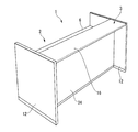
図1及び図2は本発明の第一実施形態による昇降天板付き対面カウンター1である。この対面カウンター1は、例えば金融機関や市役所等の公共施設、病院やオフィス等で顧客と係員とが対面して面談する場合に用いられる。この対面カウンター1は、係員が対面する固定カウンター2と顧客が対面する昇降カウンター3とが向い合せで対向して配設されている。
この対面カウンター1は係員が固定カウンター2に着座して対面し、顧客は着座する場合と立つ場合のいずれかの姿勢で係員に対面できる。例えば窓口が顧客で混雑している場合には、昇降カウンター3を固定カウンター2より高い位置に保持して顧客が立って対応する。窓口の顧客が少ない場合には、昇降カウンター3を固定カウンター2と同じ高さ位置に調整して顧客も着座して対応する。一般に昇降カウンター3の高さ調整は営業時間外に行われる。
Hereinafter, a face-to-face counter with an elevating top plate according to an embodiment of the present invention will be described with reference to the accompanying drawings.
1 and 2 are a face-to-face counter 1 with an elevating top plate according to the first embodiment of the present invention. The face-to-face counter 1 is used, for example, when a customer and a staff member have a face-to-face interview at a public facility such as a financial institution or a city hall, a hospital or an office. The face-to-face counter 1 is arranged such that a fixed counter 2 facing a staff member and an elevating counter 3 facing a customer face each other facing each other.
In this face-to-face counter 1, the staff member sits on the fixed counter 2 and faces the staff member, and the customer can face the staff member in either the sitting posture or the standing posture. For example, when the counter is crowded with customers, the elevating counter 3 is held at a position higher than the fixed counter 2 so that the customer can stand up and respond. When the number of customers at the counter is small, the elevating counter 3 is adjusted to the same height position as the fixed counter 2, and the customers also sit down to respond. Generally, the height of the elevating counter 3 is adjusted outside business hours.

次に対面カウンター1の具体的構成について説明する。
本明細書の対面カウンター1では、固定カウンター側、即ち図2の側面図における左側を後方、後側とし、昇降カウンター側、即ち、図2で右側を前方、前側とする。そして、これに直交する水平方向を左右方向とする。図2〜図4において、固定カウンター2は例えば断面コの字状の縦ビーム5が床面から起立して設置されている。縦ビーム5は幅方向両側に一対設けられており、その上部には高さが一定の固定テーブルとして固定天板6が連結されている。一対の縦ビーム5の上下端部には上部横ビーム7a及び下部横ビーム7bがそれぞれ連結されている。一対の縦ビーム5と上部横ビーム7a及び下部横ビーム7bとで略四角形枠状の補強枠体8が形成されている。
Next, a specific configuration of the face-to-face counter 1 will be described.
In the face-to-face counter 1 of the present specification, the fixed counter side, that is, the left side in the side view of FIG. 2 is the rear side and the rear side, and the elevating counter side, that is, the right side in FIG. 2 is the front side and the front side. Then, the horizontal direction orthogonal to this is defined as the left-right direction. In FIGS. 2 to 4, the fixed counter 2 is installed, for example, with a vertical beam 5 having a U-shaped cross section standing upright from the floor surface. A pair of vertical beams 5 are provided on both sides in the width direction, and a fixed top plate 6 is connected to the upper portion of the vertical beams 5 as a fixed table having a constant height. An upper horizontal beam 7a and a lower horizontal beam 7b are connected to the upper and lower ends of the pair of vertical beams 5, respectively. A substantially quadrangular frame-shaped reinforcing frame 8 is formed by the pair of vertical beams 5, the upper horizontal beam 7a, and the lower horizontal beam 7b.

縦ビーム5は、例えば図10に示すように、断面略コの字状の部材が例えば二重に重ねて形成されており、内側の縦ビーム5Aと外側の縦ビーム5Bを有している。内側の縦ビーム5Aは、昇降カウンター3側に位置する第一リブ5aと、これに対向する第二リブ5bと、第一リブ5a及び第二リブ5bを連結するウェブ5cとを有している。外側の縦ビーム5Bも同様な構成を有している。なお、縦ビーム5はいずれか一方の縦ビーム5Aまたは5Bだけで形成されていてもよい。
縦ビーム5及び上部横ビーム7aの上部に固定天板6の前端部6aが固定されている。固定天板6の下部には、補強枠体8の後ろ側に固定幕板9が垂下して固定され、その下部には横ブラケット10が両端の縦ビーム5に連結されている。横ブラケット10は、上部横ビーム7a及び下部横ビーム7b間に配設され、昇降カウンター3を昇降させるための電気配線のコントローラが収納されている。
As shown in FIG. 10, for example, the vertical beam 5 is formed by, for example, doubly overlapping members having a substantially U-shaped cross section, and has an inner vertical beam 5A and an outer vertical beam 5B. The inner vertical beam 5A has a first rib 5a located on the elevating counter 3 side, a second rib 5b facing the first rib 5a, and a web 5c connecting the first rib 5a and the second rib 5b. .. The outer vertical beam 5B has a similar configuration. The vertical beam 5 may be formed of only one of the vertical beams 5A or 5B.
The front end portion 6a of the fixed top plate 6 is fixed to the upper part of the vertical beam 5 and the upper horizontal beam 7a. A fixed curtain plate 9 hangs down and is fixed to the lower part of the fixed top plate 6 on the rear side of the reinforcing frame body 8, and horizontal brackets 10 are connected to the vertical beams 5 at both ends below the fixed curtain plate 9. The horizontal bracket 10 is arranged between the upper horizontal beam 7a and the lower horizontal beam 7b, and houses an electric wiring controller for raising and lowering the elevating counter 3.

固定カウンター2の左右側部にはパネル状の側板12がそれぞれ配設され、各側板12の内面に形成されたレール溝12a(図8参照)に固定天板6の左右端部が嵌合されてねじ等で連結されている。縦ビーム5は側板12に連結されていない。なお、固定天板6に代えて、または固定天板6と共に縦ビーム5が側板12の内面に連結されていてもよい。側板12は固定カウンター2の両側部を囲うと共に固定天板6の上方に延びており、しかも昇降カウンター3の両側部を囲うように延びている。
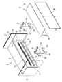
図3、図4、図11、図12等に示すように、固定カウンター2の前側に隣接して配設された昇降カウンター3には、両側の縦ビーム5に対向する位置に昇降支持部材14がそれぞれ設置されている。各昇降支持部材14の上端部には前方に向けて延びる天板ブラケット15がそれぞれ連結されている。天板ブラケット15の上部には昇降天板16が固定されている。昇降天板16はその後端部16a近傍の下面に昇降支持部材14が固定され、前端部が前方に向けて延びている。
Panel-shaped side plates 12 are arranged on the left and right sides of the fixed counter 2, and the left and right ends of the fixed top plate 6 are fitted into rail grooves 12a (see FIG. 8) formed on the inner surface of each side plate 12. It is connected with a screw or the like. The vertical beam 5 is not connected to the side plate 12. In addition, instead of the fixed top plate 6, the vertical beam 5 may be connected to the inner surface of the side plate 12 together with the fixed top plate 6. The side plates 12 surround both sides of the fixed counter 2 and extend above the fixed top plate 6, and extend so as to surround both sides of the elevating counter 3.
As shown in FIGS. 3, 4, 11, 12, and the like, the elevating counter 3 arranged adjacent to the front side of the fixed counter 2 has an elevating support member 14 at a position facing the vertical beams 5 on both sides. Are installed respectively. A top plate bracket 15 extending forward is connected to the upper end of each elevating support member 14. An elevating top plate 16 is fixed to the upper part of the top plate bracket 15. The elevating support member 14 is fixed to the lower surface of the elevating top plate 16 near the rear end portion 16a, and the front end portion extends forward.

図2において、昇降支持部材14は昇降天板16を昇降可能に支持しており、その降下位置(本昇降カウンター3の使用設定範囲において昇降天板16を最も降下させた位置)で昇降天板16は固定天板6と同じ高さ位置に保持され(図11参照)、上昇位置(本昇降カウンター3の使用設定範囲において昇降天板16を最も上昇させた位置)で固定天板6よりも高い位置に保持されている(図12参照)。
図2、図5等に示す昇降支持部材14は、床面に着座する固定部材としての下部ブラケット18と、下部ブラケット18の上面18aにボルト等で固定される中空の固定筒部19と、固定筒部19内に進退可能に挿入されている昇降軸部20とで構成されている。昇降軸部20は例えば2段の昇降部材を有しており(図12参照)、略筒状で固定筒部19内に進退可能な第一昇降軸部20aと第一昇降軸部20a内に進退可能な第二昇降軸部20bとで構成されている。伸縮機構を固定筒部19と第一昇降軸部20aと第二昇降軸部20bで構成することで、伸長時に互いに重なる部分が長く確保できて剛性が高い。即ち、図11に示す昇降天板16が固定天板6と同一高さに降下した第一位置と図12に示す上昇した第二位置との間で、固定筒部19と第一昇降軸部20aと第二昇降軸部20bは互いに一部重複した長さに保持される。なお、昇降軸部20は1つの昇降部材で構成してもよいし、或いは上下3段以上の複数組の昇降部材で構成して伸縮可能としてもよい。
In FIG. 2, the elevating support member 14 supports the elevating top plate 16 so as to be able to elevate, and the elevating top plate 16 is lowered at the lowering position (the position where the elevating top plate 16 is most lowered in the usage setting range of the main elevating counter 3). 16 is held at the same height position as the fixed top plate 6 (see FIG. 11), and is higher than the fixed top plate 6 at the ascending position (the position where the elevating top plate 16 is most raised in the usage setting range of the main elevating counter 3). It is held in a high position (see FIG. 12).
The elevating support member 14 shown in FIGS. 2 and 5 is fixed to a lower bracket 18 as a fixing member seated on the floor surface and a hollow fixing cylinder portion 19 fixed to the upper surface 18a of the lower bracket 18 with bolts or the like. It is composed of an elevating shaft portion 20 that is inserted into the cylinder portion 19 so as to be able to advance and retreat. The elevating shaft portion 20 has, for example, a two-stage elevating member (see FIG. 12), and is contained in a first elevating shaft portion 20a and a first elevating shaft portion 20a which are substantially tubular and can move forward and backward in the fixed tubular portion 19. It is composed of a second elevating shaft portion 20b that can move forward and backward. By configuring the expansion / contraction mechanism with the fixed cylinder portion 19, the first elevating shaft portion 20a, and the second elevating shaft portion 20b, it is possible to secure a long portion that overlaps with each other at the time of extension, and the rigidity is high. That is, the fixed cylinder portion 19 and the first elevating shaft portion are between the first position where the elevating top plate 16 shown in FIG. 11 is lowered to the same height as the fixed top plate 6 and the raised second position shown in FIG. The 20a and the second elevating shaft portion 20b are held at lengths that partially overlap each other. The elevating shaft portion 20 may be composed of one elevating member, or may be composed of a plurality of sets of elevating members having three or more upper and lower stages so that the elevating shaft portion 20 can be expanded and contracted.

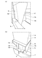
下部ブラケット18は図5〜図7に示されており、略四角形板状の上面18aに対して背面18bと両側面18cとが平板状で床面に垂下している。しかも、両側面18cは上面18aから床面に向けて後端側に傾斜する略直角三角形板状に形成されている。下部ブラケット18の前面は上面18aの幅方向中央から板状の中央支持部18dが床面に垂下しており、その両側と側面18cとの間は凹部をなす空間とされている。
図6及び図7(a)において、下部ブラケット18の背面18bを補強枠体8に固定するに際し、中央支持部18dの左側では例えば2本のボルトbを縦ビーム5の上下に締め込み固定する。中央支持部18dの右側では背面18bをボルトbにより下部横ビーム7bに締め込み固定する。そのため、縦ビーム5の幅が小さくても補強枠体8の両側の下部角部において、縦ビーム5と下部横ビーム7bにボルトbで下部ブラケット18を強固に固定できる。
The lower bracket 18 is shown in FIGS. 5 to 7, and the back surface 18b and both side surfaces 18c are flat and hang down on the floor surface with respect to the substantially quadrangular plate-shaped upper surface 18a. Moreover, both side surfaces 18c are formed in the shape of a substantially right triangle plate that inclines toward the rear end side from the upper surface 18a toward the floor surface. On the front surface of the lower bracket 18, a plate-shaped central support portion 18d hangs down from the center of the upper surface 18a in the width direction to the floor surface, and a space forming a recess is formed between both sides thereof and the side surface 18c.
In FIGS. 6 and 7A, when the back surface 18b of the lower bracket 18 is fixed to the reinforcing frame 8, for example, two bolts b are tightened up and down on the vertical beam 5 on the left side of the central support portion 18d. .. On the right side of the central support portion 18d, the back surface 18b is tightened and fixed to the lower lateral beam 7b by bolts b. Therefore, even if the width of the vertical beam 5 is small, the lower bracket 18 can be firmly fixed to the vertical beam 5 and the lower horizontal beam 7b with bolts b at the lower corners on both sides of the reinforcing frame 8.

また、背面18bの厚みを他より大きい厚みaに形成して縦ビーム5と固定筒部19との隙間を所定の距離aに設定し、縦ビーム5と昇降支持部材14との間に後述する後側幕板25を垂下させるための隙間Kが形成されている。
図7(b)において、両側の下部ブラケット18における中央支持部18dの下端面には、第二横ビーム17がボルトbで固定されている。そのため、両側の下部ブラケット18を挟んでその後側の下部横ビーム7bと前側の第二横ビーム17とが対向して平行に連結されている。
Further, the thickness of the back surface 18b is formed to be larger than the others, the gap between the vertical beam 5 and the fixed cylinder portion 19 is set to a predetermined distance a, and the space between the vertical beam 5 and the elevating support member 14 will be described later. A gap K for hanging the rear curtain plate 25 is formed.
In FIG. 7B, the second lateral beam 17 is fixed to the lower end surface of the central support portion 18d of the lower brackets 18 on both sides with bolts b. Therefore, the lower lateral beam 7b on the rear side and the second lateral beam 17 on the front side are opposed to each other and connected in parallel with the lower brackets 18 on both sides interposed therebetween.

図5及び図6において、下部ブラケット18の上面18aにボルト等で固定された固定筒部19は角筒状であり、内部に昇降軸部20が進退可能である。しかも、固定筒部19の内部には昇降軸部20を昇降させるための駆動モータと配線等が収納されている。
固定筒部19は縦ビーム5に第一取付ブラケット22及び第二取付ブラケット23によって固定されている。第一取付ブラケット22は断面略コの字状に形成されていて、上下端部がボルトb等で縦ビーム5に固定されている。第一取付ブラケット22はスペーサとして縦ビーム5と固定筒部19の間に所定の距離aを開けられるように所定の厚みで屈曲して形成されている。
In FIGS. 5 and 6, the fixed cylinder portion 19 fixed to the upper surface 18a of the lower bracket 18 with bolts or the like has a square tubular shape, and the elevating shaft portion 20 can move forward and backward inside. Moreover, a drive motor, wiring, and the like for raising and lowering the elevating shaft portion 20 are housed inside the fixed cylinder portion 19.
The fixed cylinder portion 19 is fixed to the vertical beam 5 by the first mounting bracket 22 and the second mounting bracket 23. The first mounting bracket 22 is formed in a substantially U-shaped cross section, and the upper and lower end portions are fixed to the vertical beam 5 with bolts b or the like. The first mounting bracket 22 is formed as a spacer by being bent to a predetermined thickness so that a predetermined distance a can be opened between the vertical beam 5 and the fixed cylinder portion 19.

第一取付ブラケット22に当接する固定筒部19を介して、断面略コの字状の第二取付ブラケット23が縦ビーム5に取り付けられる。第二取付ブラケット23の一方の端部に設けたフックが縦ビーム5に形成されたスリット溝(図示せず)に係合し、他方の端部はボルトbを第一取付ブラケット22に捩じ込んで固定される。これにより、昇降支持部材14は縦ビーム5に対して所定距離aを開けて垂直に起立して固定され、しかも下部ブラケット18と固定筒部19の第二取付ブラケット23との上下二段で縦ビーム5に平行になるよう固定されている。
昇降支持部材14に対して昇降天板16が片持ち支持状態であっても、昇降天板16で受ける荷重は両側の昇降支持部材14及び縦ビーム5を介して側板12で受けることができる。昇降天板16は特に固定天板6より上昇した位置で、顧客が寄りかかる等で荷重を受けると強い倒れ込み荷重を受けるが、上述した取付構造で高強度に支持される。
The second mounting bracket 23 having a substantially U-shaped cross section is mounted on the vertical beam 5 via the fixed cylinder portion 19 that abuts on the first mounting bracket 22. A hook provided at one end of the second mounting bracket 23 engages a slit groove (not shown) formed in the vertical beam 5, and the other end twists the bolt b into the first mounting bracket 22. It is crowded and fixed. As a result, the elevating support member 14 is vertically erected and fixed with a predetermined distance a from the vertical beam 5, and is vertically formed in two upper and lower stages of the lower bracket 18 and the second mounting bracket 23 of the fixed cylinder portion 19. It is fixed so as to be parallel to the beam 5.
Even if the elevating top plate 16 is cantilevered with respect to the elevating support member 14, the load received by the elevating top plate 16 can be received by the side plate 12 via the elevating support members 14 and the vertical beam 5 on both sides. The elevating top plate 16 receives a strong collapse load when it receives a load such as when a customer leans against it, especially at a position raised above the fixed top plate 6, but it is supported with high strength by the above-mentioned mounting structure.

図11及び図12等において、固定カウンター2の固定天板6と昇降カウンター3の昇降支持部材14との間に距離aの隙間Kを形成するが、昇降天板16の後端部16aの下面には後側幕板25が固定されて垂下され、昇降天板16の後端部16aと後側幕板25とは面一に形成されている。そのため、固定天板6と昇降天板16及び後側幕板25との間には例えば5mm以下のわずかな隙間しかなく、紙等の書類や薄物の異物が入りにくい。
特に、固定天板6の厚み方向の前端部6aにモヘア等の繊維材の束を固定して昇降天板16または後側幕板25に当接させれば、紙等の薄物が隙間に進入することをより確実に阻止できる。
In FIGS. 11 and 12, a gap K having a distance a is formed between the fixed top plate 6 of the fixed counter 2 and the elevating support member 14 of the elevating counter 3, but the lower surface of the rear end portion 16a of the elevating top plate 16. The rear curtain plate 25 is fixed and hung down, and the rear end portion 16a of the elevating top plate 16 and the rear curtain plate 25 are formed flush with each other. Therefore, there is only a slight gap of, for example, 5 mm or less between the fixed top plate 6, the elevating top plate 16 and the rear curtain plate 25, and it is difficult for documents such as paper and thin foreign matter to enter.
In particular, if a bundle of fiber materials such as mohair is fixed to the front end portion 6a in the thickness direction of the fixed top plate 6 and brought into contact with the elevating top plate 16 or the rear curtain plate 25, a thin object such as paper enters the gap. You can more reliably prevent it from doing so.

昇降支持部材14を挟んで後側幕板25の前側には前側幕板26が昇降天板16の下面に固定されて垂下している。前側幕板26と後側幕板25は昇降天板16の幅方向略全長に延びており、その上下方向の長さは、図2及び図11に示す昇降天板16の降下位置で、第一取付ブラケット22及び第二取付ブラケット23に当接しない程度の長さに設定されている。前側幕板26及び後側幕板25の下端部は連結部材27によって互いに連結されている。
そのため、前側幕板26及び後側幕板25と昇降天板16と連結部材27とで側面視略四角形枠状に連結されており、前側幕板26及び後側幕板25を高強度に保持できる。昇降天板16が昇降した際に後側幕板25が揺動して固定天板6に接触することを確実に阻止できる。連結部材27は前側幕板26及び後側幕板25の下端部において、幅方向両端部と中間部に設けられているが、少なくとも1カ所に設けていれば前側幕板26及び後側幕板25の固定強度を確保できる。
A front curtain plate 26 is fixed to the lower surface of the elevating top plate 16 and hangs down on the front side of the rear curtain plate 25 with the elevating support member 14 interposed therebetween. The front curtain plate 26 and the rear curtain plate 25 extend substantially the entire length in the width direction of the elevating top plate 16, and the length in the vertical direction is the lowering position of the elevating top plate 16 shown in FIGS. 2 and 11. The length is set so as not to come into contact with the first mounting bracket 22 and the second mounting bracket 23. The lower ends of the front curtain plate 26 and the rear curtain plate 25 are connected to each other by a connecting member 27.
Therefore, the front curtain plate 26, the rear curtain plate 25, the elevating top plate 16 and the connecting member 27 are connected in a substantially quadrangular frame shape in the side view, and the front curtain plate 26 and the rear curtain plate 25 are held with high strength. can. When the elevating top plate 16 moves up and down, the rear curtain plate 25 can be reliably prevented from swinging and coming into contact with the fixed top plate 6. The connecting member 27 is provided at both ends in the width direction and the intermediate portion at the lower ends of the front curtain plate 26 and the rear curtain plate 25, but if it is provided at at least one place, the front curtain plate 26 and the rear curtain plate 26 and the rear curtain plate 25 are provided. A fixed strength of 25 can be secured.

なお、前側幕板26及び後側幕板25の下端部に連結部材27は必ずしも設けなくてもよい。この場合でも、前側幕板26及び後側幕板25の上端部を昇降天板16の下面にボルト等で連結しているので昇降時の揺動を抑制できる。
また、昇降支持部材14を前側幕板26及び後側幕板25で挟んでいることで、固定筒部19及び昇降軸部20の接続部等に顧客の足や膝等が接触することから保護できる。
The connecting member 27 does not necessarily have to be provided at the lower ends of the front curtain plate 26 and the rear curtain plate 25. Even in this case, since the upper ends of the front curtain plate 26 and the rear curtain plate 25 are connected to the lower surface of the elevating top plate 16 with bolts or the like, swinging during elevating can be suppressed.
Further, by sandwiching the elevating support member 14 between the front curtain plate 26 and the rear curtain plate 25, the customer's feet, knees, etc. are protected from contact with the connection portions of the fixed cylinder portion 19 and the elevating shaft portion 20. can.

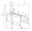
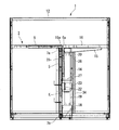
次に図8〜図10において、固定カウンター2に隣接する昇降カウンター3の後部が開示されている。図において、昇降カウンター3の後側幕板25における下端部の幅方向両側にはガイド部材30がそれぞれ固定されている。ガイド部材30は例えば略階段状に形成されており、その下片部30aが後側幕板25の下面に当接してボルトbで固定され、基板部30bが後側幕板25の後面に当接していると共にその上側リブ30cが外側に折れ曲がっている。
基板部30bは幅方向外側に延びていて、その一端部は縦ビーム5の第一リブ5aをガイド面として挟んで後ろ側に折れ曲がる段付き部30dを形成している。この段付き部30dには縦ビーム5の第一リブ5aに当接するガイドピン32がガイド部として固着されている(図10(b)参照)。
Next, in FIGS. 8 to 10, the rear part of the elevating counter 3 adjacent to the fixed counter 2 is disclosed. In the figure, guide members 30 are fixed to both sides of the lower end portion of the rear curtain plate 25 of the elevating counter 3 in the width direction. The guide member 30 is formed in a substantially stepped shape, for example, its lower piece portion 30a abuts on the lower surface of the rear curtain plate 25 and is fixed by bolts b, and the substrate portion 30b abuts on the rear surface of the rear curtain plate 25. While in contact with each other, the upper rib 30c is bent outward.
The substrate portion 30b extends outward in the width direction, and one end thereof forms a stepped portion 30d that bends rearward with the first rib 5a of the vertical beam 5 as a guide surface. A guide pin 32 that abuts on the first rib 5a of the vertical beam 5 is fixed to the stepped portion 30d as a guide portion (see FIG. 10B).

そのため、昇降カウンター3の昇降天板16が昇降すると、後側幕板25も一体に昇降するため、その両端部に固定したガイド部材30のガイドピン32が縦ビーム5の第一リブ5aに当接しながら摺動する。しかも、固定カウンター2の前面側の固定天板6及び縦ビーム5と昇降カウンター3の後面側の後側幕板25との間の隙間内にガイド部材30が配設され、ガイド部材30はその上側リブ30cが隙間を埋めて昇降天板16と一体に昇降可能となる。
固定カウンター2と昇降カウンター3の後側幕板25との隙間はガイド部材30によって連携されて一定間隔に保持されている。なお、ガイド部材30は金属製であり、ガイドピン32は縦ビーム5の第一リブ5aを擦過しないように例えばナイロン等の樹脂製とされている。
Therefore, when the elevating top plate 16 of the elevating counter 3 moves up and down, the rear curtain plate 25 also moves up and down integrally, so that the guide pins 32 of the guide members 30 fixed to both ends of the elevating counter 3 hit the first rib 5a of the vertical beam 5. It slides while touching. Moreover, the guide member 30 is arranged in the gap between the fixed top plate 6 and the vertical beam 5 on the front side of the fixed counter 2 and the rear curtain plate 25 on the rear surface side of the elevating counter 3, and the guide member 30 is the guide member 30. The upper rib 30c fills the gap and can be raised and lowered integrally with the raising and lowering top plate 16.
The gap between the fixed counter 2 and the rear curtain plate 25 of the elevating counter 3 is linked by the guide member 30 and held at regular intervals. The guide member 30 is made of metal, and the guide pin 32 is made of a resin such as nylon so as not to scratch the first rib 5a of the vertical beam 5.

本実施形態による対面カウンター1では、固定カウンター2の縦ビーム5と昇降カウンター3の昇降支持部材14との隙間K内に後側幕板25が配設されている。更に、縦ビーム5と後側幕板25との隙間にガイド部材30の上側リブ30cが配設されて埋めている。そのため、固定天板6と昇降天板16及び後側幕板25との隙間内に紙等の書類が挟まったり落下したりすることを阻止できる。 In the face-to-face counter 1 according to the present embodiment, the rear curtain plate 25 is arranged in the gap K between the vertical beam 5 of the fixed counter 2 and the elevating support member 14 of the elevating counter 3. Further, the upper rib 30c of the guide member 30 is arranged and filled in the gap between the vertical beam 5 and the rear curtain plate 25. Therefore, it is possible to prevent documents such as paper from being caught or dropped in the gap between the fixed top plate 6, the elevating top plate 16 and the rear curtain plate 25.

図1乃至図3、図11等において、昇降カウンター3における昇降天板16の下空間には昇降支持部材14に近接する位置に板状のフロントパネル34が設置されている。図12に示すように、フロントパネル34はその後面側に下部係止片34aと上部係止片34bが設けられている。下部係止片34aは下部ブラケット18の中央支持部18dに形成したスリット18eに係合させられ、上部係止片34bは第二取付ブラケット23に形成したスリット23aに係合させられている。そのため、フロントパネル34は着脱が容易である。 In FIGS. 1 to 3, 11 and the like, a plate-shaped front panel 34 is installed in the space under the elevating top plate 16 in the elevating counter 3 at a position close to the elevating support member 14. As shown in FIG. 12, the front panel 34 is provided with a lower locking piece 34a and an upper locking piece 34b on the rear surface side. The lower locking piece 34a is engaged with the slit 18e formed in the central support portion 18d of the lower bracket 18, and the upper locking piece 34b is engaged with the slit 23a formed in the second mounting bracket 23. Therefore, the front panel 34 can be easily attached and detached.

そのため、フロントパネル34は、例えばその下端部が床面上または床面から若干浮いて保持され、その上端部は降下位置にある昇降天板16の天板ブラケット15より若干下側に位置している。フロントパネル34によって昇降天板16の下部空間の奥側に位置する両側の昇降支持部材14と前側幕板26の下側の空間と前側幕板26の大部分とが覆われているため、顧客側から昇降支持部材14や前側幕板26やその下側の空間等がほとんど目視できず、意匠性が向上する。
また、昇降天板16が上昇した場合には、前側幕板26も昇降天板16と一体に上昇するため、前側幕板26と昇降支持部材14の下部がフロントパネル34に覆われる。
Therefore, for example, the lower end portion of the front panel 34 is held on the floor surface or slightly above the floor surface, and the upper end portion thereof is located slightly below the top plate bracket 15 of the elevating top plate 16 in the descending position. There is. Since the front panel 34 covers the space under the elevating support members 14 on both sides located on the back side of the lower space of the elevating top plate 16 and the front curtain plate 26 and most of the front curtain plate 26, the customer. The elevating support member 14, the front curtain plate 26, the space below the elevating support member 14, and the space below the elevating support member 14 can hardly be seen from the side, and the design is improved.
Further, when the elevating top plate 16 is raised, the front curtain plate 26 is also raised integrally with the elevating top plate 16, so that the lower part of the front curtain plate 26 and the elevating support member 14 is covered with the front panel 34.

本実施形態による対面カウンター1は上述した構成を有しており、一例として次のように組み立てることができる。
対面カウンター1の組立に際して、予め固定カウンター2の両側部に側板12を配設し、レール溝12aに固定天板6を固定させる。昇降カウンター3は一対の昇降支持部材14の上部に昇降天板16を固定して一体化する。昇降支持部材14の前後には後側幕板25と前側幕板26が設置されている。そして、図2に示すように、後付けで昇降カウンター3を両側板12の間に挿入して固定カウンター2に連結できる。
その際、図3、図5に示すように、固定カウンター2における補強枠体8の縦ビーム5に昇降カウンター3の昇降支持部材14を対向させ、昇降支持部材14の下部ブラケット18を縦ビーム5及び下部横ビーム7bにボルトbで連結すると共に、縦ビーム5に固定した第一取付ブラケット22に固定筒部19を当接させて第二取付ブラケット23を縦ビーム5及び第一取付ブラケット22に係止、固定させる。
The face-to-face counter 1 according to the present embodiment has the above-described configuration, and can be assembled as an example as follows.
When assembling the facing counter 1, side plates 12 are arranged on both sides of the fixed counter 2 in advance, and the fixed top plate 6 is fixed to the rail groove 12a. The elevating counter 3 is integrated by fixing the elevating top plate 16 on the upper part of the pair of elevating support members 14. A rear curtain plate 25 and a front curtain plate 26 are installed in front of and behind the elevating support member 14. Then, as shown in FIG. 2, the elevating counter 3 can be retrofitted between the side plates 12 and connected to the fixed counter 2.
At that time, as shown in FIGS. 3 and 5, the elevating support member 14 of the elevating counter 3 is opposed to the vertical beam 5 of the reinforcing frame 8 in the fixed counter 2, and the lower bracket 18 of the elevating support member 14 is moved to the vertical beam 5. The second mounting bracket 23 is attached to the vertical beam 5 and the first mounting bracket 22 by connecting the lower horizontal beam 7b to the lower horizontal beam 7b with a bolt b and bringing the fixing cylinder portion 19 into contact with the first mounting bracket 22 fixed to the vertical beam 5. Lock and fix.

後側幕板25の下端部における左右両端部にガイド部材30をボルトbで固定する。両側のガイド部材30における基板部30bの段付き部30dで縦ビーム5の第一リブ5aを覆い、ガイドピン32を第一リブ5aに当接させて昇降可能に係止させる。第一リブ5aは後側幕板25と段付き部30dのガイドピン32との間に保持される。次に、昇降天板16の下部空間の奥側にフロントパネル34を取り付け、下部係止片34aと上部係止片34bを下部ブラケット18と第二取付ブラケット23にそれぞれ係止させることで、前面側をフロントパネル34で覆うことができる。
得られた対面カウンター1では、側板12の間に設けた昇降カウンター3の昇降天板16が昇降支持部材14の伸縮作動によって縦ビーム5との隙間を一定に維持しながら昇降できる。しかも、側板12によって昇降カウンター3の倒れや揺れを規制できる。
或いは、昇降カウンター3を組み立てた後に固定カウンター2に連結させてもよい。
The guide members 30 are fixed to the left and right ends of the lower end of the rear curtain plate 25 with bolts b. The stepped portion 30d of the substrate portion 30b of the guide members 30 on both sides covers the first rib 5a of the vertical beam 5, and the guide pin 32 is brought into contact with the first rib 5a to be locked so as to be able to move up and down. The first rib 5a is held between the rear curtain plate 25 and the guide pin 32 of the stepped portion 30d. Next, the front panel 34 is attached to the back side of the lower space of the elevating top plate 16, and the lower locking piece 34a and the upper locking piece 34b are locked to the lower bracket 18 and the second mounting bracket 23, respectively. The side can be covered with the front panel 34.
In the obtained face-to-face counter 1, the elevating top plate 16 of the elevating counter 3 provided between the side plates 12 can be moved up and down while maintaining a constant gap with the vertical beam 5 by the expansion and contraction operation of the elevating support member 14. Moreover, the side plate 12 can regulate the tilting and shaking of the elevating counter 3.
Alternatively, the elevating counter 3 may be assembled and then connected to the fixed counter 2.

上述したように、本実施形態による対面カウンター1は次の作用効果を奏する。
(1)昇降位置に関わらず、昇降天板16及び後側幕板25と固定天板6との間の隙間を小さく維持できる。更に、後側幕板25の両側端部に固定されたガイド部材30のガイドピン32が縦ビーム5の第一リブ5aをガイドとして上下方向に摺動可能であるため、昇降天板16の昇降位置に関わらず固定天板6との隙間を小さく一定に維持でき、この小さな隙間内に紙等の書類等を挟むことを防止できる。
しかも、固定天板6の前端部6aに繊維束を取り付けて隙間を埋めることで書類等の薄物等が隙間内に入り込むことをより確実に阻止できる。
(2)昇降カウンター3は昇降天板16の後端部を昇降支持部材14で支持するため、昇降カウンター3側の昇降天板16の下側の空間が広くなり、昇降カウンター3側に対面する顧客の足元が広く圧迫することを防止できる。
As described above, the face-to-face counter 1 according to the present embodiment has the following effects.
(1) Regardless of the elevating position, the gap between the elevating top plate 16 and the rear curtain plate 25 and the fixed top plate 6 can be kept small. Further, since the guide pins 32 of the guide member 30 fixed to both end portions of the rear curtain plate 25 can slide in the vertical direction using the first rib 5a of the vertical beam 5 as a guide, the elevating top plate 16 can be raised and lowered. The gap between the fixed top plate 6 and the fixed top plate 6 can be kept small and constant regardless of the position, and it is possible to prevent documents such as paper from being caught in the small gap.
Moreover, by attaching a fiber bundle to the front end portion 6a of the fixed top plate 6 to fill the gap, it is possible to more reliably prevent thin objects such as documents from entering the gap.
(2) Since the elevating counter 3 supports the rear end portion of the elevating top plate 16 with the elevating support member 14, the space under the elevating top plate 16 on the elevating counter 3 side becomes wider and faces the elevating counter 3 side. It is possible to prevent the customer's feet from being widely pressed.

(3)しかも、昇降天板16を後端部で片持ち式に支持する昇降支持部材14はその下部側の2カ所で縦ビーム5に固定され、固定天板6を介して両側の側板12で支持できる。そのため、昇降天板16に前倒れ方向の荷重がかかっても側板12で強固に支えることができて、昇降カウンター3の安定した支持ができる。また、昇降カウンター3は両側の側板12で倒れや揺れを規制できる。
(4)昇降カウンター3の昇降天板16を支持する昇降支持部材14は、下端部に設けた下部ブラケット18の上に固定筒部19とその内部を進退可能な昇降軸部20として第一昇降軸部20a及び第二昇降軸部20bを設けたため、第一昇降軸部20a及び第二昇降軸部20bのストロークが短くて固定筒部19内に納まる重複長さを確保できて、昇降支持部材14の剛性が高く昇降天板16の支持強度が高い。
(3) Moreover, the elevating support member 14 that cantileverly supports the elevating top plate 16 at the rear end is fixed to the vertical beam 5 at two places on the lower side thereof, and the side plates 12 on both sides via the fixed top plate 6. Can be supported by. Therefore, even if a load in the forward tilting direction is applied to the elevating top plate 16, the side plate 12 can firmly support the elevating counter 3, and the elevating counter 3 can be stably supported. Further, the elevating counter 3 can be regulated from falling or shaking by the side plates 12 on both sides.
(4) The elevating support member 14 that supports the elevating top plate 16 of the elevating counter 3 is first ascended and lowered as a fixed cylinder portion 19 and an elevating shaft portion 20 capable of advancing and retreating inside the fixed cylinder portion 19 on the lower bracket 18 provided at the lower end portion. Since the shaft portion 20a and the second elevating shaft portion 20b are provided, the strokes of the first elevating shaft portion 20a and the second elevating shaft portion 20b are short, and an overlapping length that can be accommodated in the fixed cylinder portion 19 can be secured. The rigidity of the 14 is high, and the supporting strength of the elevating top plate 16 is high.

(5)昇降カウンター3の昇降支持部材14はその前後を前側幕板26と後側幕板25で囲う構成であるため、対面した顧客の足が昇降支持部材14に接触したりすることから保護できる。しかも、前側幕板26と後側幕板25は昇降天板16と連結部材27で上下端部を連結することで保持強度が高く、昇降天板16の昇降時に後側幕板25が固定天板6との間で揺動したりしない。
また、後側幕板25は縦ビーム5と昇降支持部材14の間の隙間K内に位置するため、隙間Kを更に小さい隙間に規制できて紙等の異物を挟んだりしにくい。
(5) Since the elevating support member 14 of the elevating counter 3 is configured to surround the front and rear of the elevating support member 14 with the front curtain plate 26 and the rear curtain plate 25, it is protected from the feet of the facing customers coming into contact with the elevating support member 14. can. Moreover, the front curtain plate 26 and the rear curtain plate 25 have high holding strength by connecting the upper and lower end portions with the elevating top plate 16 and the connecting member 27, and the rear curtain plate 25 is fixed when the elevating top plate 16 is raised and lowered. It does not swing with the plate 6.
Further, since the rear curtain plate 25 is located in the gap K between the vertical beam 5 and the elevating support member 14, the gap K can be restricted to a smaller gap, and it is difficult for foreign matter such as paper to be caught.

(6)更に、前側幕板26を設けたため、顧客側から昇降支持部材14や空間等が露出することを防止できて安全性と意匠性が高い。
また、昇降カウンター3の昇降天板16の下部空間を覆うフロントパネル34を昇降支持部材14に係止させたため、昇降支持部材14や下部空間の前側幕板26等を覆って美観と意匠性を向上できる。しかもフロントパネル34は昇降支持部材14と縦ビーム5と固定天板6を介して側板12に支持されるため、支持強度が高い。
(6) Further, since the front curtain plate 26 is provided, it is possible to prevent the elevating support member 14 and the space from being exposed from the customer side, and the safety and design are high.
Further, since the front panel 34 covering the lower space of the elevating top plate 16 of the elevating counter 3 is locked to the elevating support member 14, the elevating support member 14 and the front curtain plate 26 of the lower space are covered to improve the appearance and design. Can be improved. Moreover, since the front panel 34 is supported by the side plate 12 via the elevating support member 14, the vertical beam 5, and the fixed top plate 6, the support strength is high.

なお、本発明は上述の実施形態による対面カウンター1に限定されることはなく、本発明の要旨を変更しない範囲で適宜の変更や置換等が可能であり、これらはいずれも本発明に含まれる。以下に、本発明の他の実施形態や変形例等について説明するが、上述した実施形態と同一または同様な部品や部材等には同一の符号を用いて説明を行う。 The present invention is not limited to the face-to-face counter 1 according to the above-described embodiment, and appropriate changes and substitutions can be made without changing the gist of the present invention, all of which are included in the present invention. .. Hereinafter, other embodiments and modifications of the present invention will be described, and the same or similar parts and members as those in the above-described embodiments will be described using the same reference numerals.

上述した実施形態では、対面カウンター1は後方に設けた固定カウンター2の前側に昇降カウンター3を対面して設置したが、本発明による第一の什器は固定カウンター2に限定されない。例えば第一の什器として固定カウンター2に代えて棚や壁等を設けてもよく、棚や壁等に対面して昇降天板16を有する昇降カウンター3を第二什器として設けて昇降天板16を昇降可能に保持してもよい。 In the above-described embodiment, the facing counter 1 is installed with the elevating counter 3 facing the front side of the fixed counter 2 provided at the rear, but the first fixture according to the present invention is not limited to the fixed counter 2. For example, a shelf, a wall, or the like may be provided as the first fixture instead of the fixed counter 2, and an elevating counter 3 having an elevating top plate 16 facing the shelf, the wall, or the like may be provided as the second fixture, and the elevating top plate 16 may be provided. May be held so that it can be raised and lowered.

また、対面カウンター1の第二実施形態として、固定カウンター2に代えて昇降カウンター3をもう1つの昇降カウンター3に対面して逆向きに設けてもよい。第二実施形態による対面カウンター1Aを図13(a)、(b)に示す模式図に基づいて説明する。
本実施形態による対面カウンター1Aは、上述した第一実施形態における固定カウンター2に代えて昇降カウンター3と同様な構成を備えた第二昇降カウンター3Aが設置されている。図13に示す例では、第二昇降カウンター3Aは、昇降支持部材14Aとして下部ブラケット18の上部に固定筒部19Aと第一及び第二昇降軸部20a、20bからなる昇降軸部20Aとを備えている。昇降軸部20Aの上端に天板ブラケット15Aが設置され、その上に昇降天板16Aが固定されている。
Further, as a second embodiment of the face-to-face counter 1, the elevating counter 3 may be provided in the opposite direction facing the other elevating counter 3 instead of the fixed counter 2. The face-to-face counter 1A according to the second embodiment will be described with reference to the schematic views shown in FIGS. 13 (a) and 13 (b).
In the face-to-face counter 1A according to the present embodiment, a second elevating counter 3A having the same configuration as the elevating counter 3 is installed in place of the fixed counter 2 in the first embodiment described above. In the example shown in FIG. 13, the second elevating counter 3A includes a fixed cylinder portion 19A and an elevating shaft portion 20A including the first and second elevating shaft portions 20a and 20b above the lower bracket 18 as the elevating support member 14A. ing. A top plate bracket 15A is installed at the upper end of the elevating shaft portion 20A, and the elevating top plate 16A is fixed on the top plate bracket 15A.

昇降カウンター3及び第二昇降カウンター3Aにおける各昇降天板16,16Aの対向する各後端部16a、16aの下面には後側幕板25、25Aがそれぞれ垂下されている。昇降カウンター3及び第二昇降カウンター3Aの昇降天板16,16Aの間、後側幕板25,25Aの間には、紙等の書類等の進入を阻止する小さい一定距離の隙間が設定されている。その側部には一対の後側幕板25、25Aを囲うように水平断面視略コの字状のガイド部材37が配設されている。ガイド部材37は両側の側壁ガイド37a、37bの内面がそれぞれ後側幕板25,25Aに対向し、外面に昇降支持部材14、14Aの固定筒部19、19Aが連結されている。 Rear curtain plates 25 and 25A are hung on the lower surfaces of the opposite rear end portions 16a and 16a of the elevating top plates 16 and 16A in the elevating counter 3 and the second elevating counter 3A, respectively. A small constant distance gap is set between the elevating counter 3 and the elevating top plate 16 and 16A of the second elevating counter 3A and between the rear curtain plates 25 and 25A to prevent the entry of documents such as paper. There is. A guide member 37 having a substantially U-shaped horizontal cross section is arranged on the side portion so as to surround the pair of rear curtain plates 25, 25A. The inner surfaces of the side wall guides 37a and 37b on both sides of the guide member 37 face the rear curtain plates 25 and 25A, respectively, and the fixed cylinder portions 19 and 19A of the elevating support members 14 and 14A are connected to the outer surface.

このような構成において、第二昇降カウンター3Aが固定保持された状態で、一方の昇降天板16が昇降すると後側幕板25はガイド部材37の側壁ガイド37aに沿って昇降するため、他方の後側幕板25A及び昇降天板16Aとの隙間は一定に保持される。また、一方の昇降カウンター3が固定保持された状態で、他方の昇降天板16Aが昇降すると後側幕板25Aはガイド部材37の側壁ガイド37bに沿って昇降するため、同様に一方の後側幕板25及び昇降天板16との隙間は一定に保持される。 In such a configuration, when one of the elevating top plates 16 moves up and down while the second elevating counter 3A is fixedly held, the rear curtain plate 25 moves up and down along the side wall guide 37a of the guide member 37, so that the other side curtain plate 25 moves up and down. The gap between the rear curtain plate 25A and the elevating top plate 16A is kept constant. Further, when one of the elevating counters 3 is fixedly held and the other elevating top plate 16A moves up and down, the rear curtain plate 25A moves up and down along the side wall guide 37b of the guide member 37. The gap between the curtain plate 25 and the elevating top plate 16 is kept constant.

なお、本実施形態では、後側幕板25,25Aは側壁ガイド37a、37bの内面に沿って面接触して昇降するが、第一実施形態のように後側幕板25,25Aまたは側壁ガイド37a、37bにガイドピン32を設けてもよい。
従って、対面カウンター1Aにおける昇降カウンター3及び第二昇降カウンター3Aのいずれか一方が昇降した場合でも、隙間が小さい一定の距離に維持されるため、紙等の書類が隙間内に進入するおそれを低減できる。
In the present embodiment, the rear curtain plates 25, 25A move up and down in surface contact along the inner surfaces of the side wall guides 37a, 37b, but the rear curtain plates 25, 25A or the side wall guides move up and down as in the first embodiment. Guide pins 32 may be provided at 37a and 37b.
Therefore, even if either the elevating counter 3 or the second elevating counter 3A in the face-to-face counter 1A moves up and down, the gap is maintained at a small and constant distance, which reduces the risk of documents such as paper entering the gap. can.

次に図14は上述した各実施形態の第一変形例を示すものであり、対面カウンター1の昇降カウンター3のみが開示されている。上述した実施形態における昇降支持部材14では、床面に固定部材として下部ブラケット18が設置され、その上面18aに固定筒部19と進退可能な昇降軸部20が配設されているが、本変形例では上下逆に構成した。即ち、天板ブラケット15の下部に固定部材として上部ブラケット40が連結され、その下部に固定筒部19が下向きに固定され、固定筒部19内に進退可能な昇降軸部20が設置されている。昇降軸部20の第二昇降軸部20bの下端部が床面に着座している。
この場合、昇降支持部材14を縦ビーム5に連結する第一取付ブラケット22及び第二取付ブラケット23は下部の第二昇降軸部20bに設けられている。
Next, FIG. 14 shows a first modification of each of the above-described embodiments, and only the elevating counter 3 of the face-to-face counter 1 is disclosed. In the elevating support member 14 in the above-described embodiment, the lower bracket 18 is installed as a fixing member on the floor surface, and the fixing cylinder portion 19 and the elevating shaft portion 20 capable of advancing and retreating are arranged on the upper surface 18a thereof. In the example, it was configured upside down. That is, the upper bracket 40 is connected to the lower part of the top plate bracket 15 as a fixing member, the fixed cylinder portion 19 is fixed downward, and the elevating shaft portion 20 capable of advancing and retreating is installed in the fixed cylinder portion 19. .. The lower end of the second elevating shaft portion 20b of the elevating shaft portion 20 is seated on the floor surface.
In this case, the first mounting bracket 22 and the second mounting bracket 23 for connecting the elevating support member 14 to the vertical beam 5 are provided on the lower second elevating shaft portion 20b.

そのため、昇降天板16の降下位置では、昇降軸部20が第一取付ブラケット22及び第二取付ブラケット23の取付部を除いて固定筒部19に収納された状態に保持され、昇降天板16は固定天板6と同一高さ位置に保持されている。そして、昇降時には昇降軸部20の第一昇降軸部20a及び第二昇降軸部20bが固定筒部19から突出して、上部ブラケット40を介して昇降天板16を上昇させることができる。
この第一変形例は第二実施形態の二つの昇降カウンター3、第二昇降カウンター3Aにも適用できる。
Therefore, at the lowering position of the elevating top plate 16, the elevating shaft portion 20 is held in a state of being housed in the fixed cylinder portion 19 except for the mounting portions of the first mounting bracket 22 and the second mounting bracket 23, and the elevating top plate 16 Is held at the same height as the fixed top plate 6. Then, at the time of ascending / descending, the first elevating shaft portion 20a and the second elevating shaft portion 20b of the elevating shaft portion 20 project from the fixed cylinder portion 19, and the elevating top plate 16 can be raised via the upper bracket 40.
This first modification can also be applied to the two elevating counters 3 and the second elevating counter 3A of the second embodiment.

なお、上述した実施形態において、昇降カウンター3の後側幕板25に設けたガイド部材30は、固定カウンター2の断面略コの字型の縦ビーム5に形成したガイド面としての第一リブ5aにガイドピン32が当接し、第一リブ5aにガイドされながら昇降天板16と一体に昇降するように構成した。しかしながら、縦ビーム5は必ずしも断面略コの字型に形成されていなくてもよい。
例えば、縦ビーム5は断面略L字型や断面略平板状等の適宜の形状を採用でき、その際、第一リブ5aを有していなくてもよい。縦ビーム5にガイドされてガイドピン32が上下動できればよい。また、例えば、縦ビーム5にガイド面として別部材を固定し、別部材をガイド面としてこれに沿ってガイドピン32が上下に摺動するようにしてもよい。その際、別部材のガイド面はガイドピン32と後側幕板25との間に配設されていることが好ましい。
In the above-described embodiment, the guide member 30 provided on the rear curtain plate 25 of the elevating counter 3 is the first rib 5a as a guide surface formed on the vertical beam 5 having a substantially U-shaped cross section of the fixed counter 2. The guide pin 32 abuts on the top plate 16 and is guided by the first rib 5a to move up and down integrally with the elevating top plate 16. However, the vertical beam 5 does not necessarily have to be formed in a substantially U-shaped cross section.
For example, the vertical beam 5 can adopt an appropriate shape such as a substantially L-shaped cross section or a substantially flat cross section, and at that time, the first rib 5a may not be provided. It suffices if the guide pin 32 can move up and down guided by the vertical beam 5. Further, for example, another member may be fixed to the vertical beam 5 as a guide surface, and the guide pin 32 may slide up and down along the other member as a guide surface. At that time, it is preferable that the guide surface of the separate member is arranged between the guide pin 32 and the rear curtain plate 25.

また、ガイド部材30を固定する部材として後側幕板25,25Aを設けずに昇降天板16または昇降支持部材14、14Aに直接、または他の仲介部材を介して間接的にガイド部材30を取り付けてもよい。
なお、本発明において、上述した実施形態における固定天板6、昇降天板16Aは第一天板に含まれ、固定カウンター2や棚、壁等は第一什器に含まれる。昇降カウンター3は第二什器に含まれる。第一什器は必ずしも固定天板6を設けていなくてもよく、少なくとも縦ビーム5を有していればよい。棚、壁等も縦ビームを有しているものとする。
Further, the guide member 30 is directly attached to the elevating top plate 16 or the elevating support members 14 and 14A or indirectly via another intermediary member without providing the rear curtain plates 25 and 25A as members for fixing the guide member 30. It may be attached.
In the present invention, the fixed top plate 6 and the elevating top plate 16A in the above-described embodiment are included in the first top plate, and the fixed counter 2, shelves, walls and the like are included in the first fixture. The elevating counter 3 is included in the second fixture. The first fixture does not necessarily have to be provided with the fixed top plate 6, and may have at least a vertical beam 5. It is assumed that shelves, walls, etc. also have a vertical beam.

1、1A 対面カウンター
2 固定カウンター
3 昇降カウンター
5 縦ビーム
5a 第一リブ
6 固定天板
7 横ビーム
8 補強枠体
12 側板
14 昇降支持部材
15 天板ブラケット
16 昇降天板
18 下部ブラケット
19 固定筒部
20 昇降軸部
22 第一取付ブラケット
23 第二取付ブラケット
25 後側幕板
26 前側幕板
27 連結部材
30、37 ガイド部材
32 ガイドピン
34 フロントパネル
1, 1A Face-to-face counter 2 Fixed counter 3 Lifting counter 5 Vertical beam 5a First rib 6 Fixed top plate 7 Horizontal beam 8 Reinforcing frame 12 Side plate 14 Lifting support member 15 Top plate bracket 16 Lifting top plate 18 Lower bracket 19 Fixed cylinder 20 Lifting shaft 22 First mounting bracket 23 Second mounting bracket 25 Rear curtain plate 26 Front curtain plate 27 Connecting members 30, 37 Guide members 32 Guide pins 34 Front panel

Claims (4)

床面から垂直に起立した縦ビームを備えた第一什器と、
昇降天板と、前記第一什器に隣接して配置されていて、前記縦ビームに対して所定距離を開けて垂直に起立し、前記昇降天板を昇降可能に支持する昇降支持部材と、を備えた第二什器と、
前記昇降支持部材または昇降天板に直接または間接的に固定されていて前記昇降天板と一体に昇降可能であるとともに、前記縦ビームまたは該縦ビームに固定された別部材に、前記縦ビームと前記昇降天板との隙間を一定に維持しながら上下に摺動されガイドされて昇降可能なガイド部材と、
を備えたことを特徴とする昇降天板付き什器。
The first fixture with a vertical beam that stands vertically from the floor,
An elevating top plate and an elevating support member which is arranged adjacent to the first fixture and stands vertically with a predetermined distance from the vertical beam to support the elevating top plate so as to be able to elevate. With the second furniture provided
It is directly or indirectly fixed to the elevating support member or the elevating top plate and can be moved up and down integrally with the elevating top plate, and the vertical beam or another member fixed to the vertical beam is attached to the vertical beam. A guide member that can be moved up and down by being slid up and down while maintaining a constant gap with the elevating top plate.
A fixture with an elevating top plate, which is characterized by being equipped with.
前記昇降天板には前記第一什器に対向して幕板が設けられ、前記ガイド部材は前記幕板の幅方向両端部に設けられている請求項1に記載された昇降天板付き什器。 The fixture with an elevating top plate according to claim 1, wherein a curtain plate is provided on the elevating top plate so as to face the first fixture, and the guide members are provided at both ends in the width direction of the curtain plate. 前記ガイド部材は前記縦ビームまたは前記別部材を挟むように配設されている請求項1または2に記載された昇降天板付き什器。 The fixture with an elevating top plate according to claim 1 or 2, wherein the guide member is arranged so as to sandwich the vertical beam or the separate member. 前記縦ビームは、前記第二什器に隣接して設けられた第一リブと、前記第一リブに対向して設けられた第二リブと、前記第一リブ及び第二リブを連結するウェブとを有しており、前記ガイド部材は前記第一リブにガイドされて昇降するようにした請求項1から3のいずれか1項に記載された昇降天板付き什器。 The vertical beam includes a first rib provided adjacent to the second fixture, a second rib provided opposite to the first rib, and a web connecting the first rib and the second rib. The fixture with a lifting top plate according to any one of claims 1 to 3, wherein the guide member is guided by the first rib to move up and down.
JP2017206459A 2017-10-25 2017-10-25 Furniture with elevating top plate Active JP6933552B2 (en)

Priority Applications (1)

Application Number Priority Date Filing Date Title
JP2017206459A JP6933552B2 (en) 2017-10-25 2017-10-25 Furniture with elevating top plate

Applications Claiming Priority (1)

Application Number Priority Date Filing Date Title
JP2017206459A JP6933552B2 (en) 2017-10-25 2017-10-25 Furniture with elevating top plate

Publications (2)

Publication Number Publication Date
JP2019076484A JP2019076484A (en) 2019-05-23
JP6933552B2 true JP6933552B2 (en) 2021-09-08

Family

ID=66626720

Family Applications (1)

Application Number Title Priority Date Filing Date
JP2017206459A Active JP6933552B2 (en) 2017-10-25 2017-10-25 Furniture with elevating top plate

Country Status (1)

Country Link
JP (1) JP6933552B2 (en)

Also Published As

Publication number Publication date
JP2019076484A (en) 2019-05-23

Similar Documents

Publication Publication Date Title
US8065966B1 (en) Odd link work surface lift
EP2898796B1 (en) A folding sofa bed
KR102600240B1 (en) Horizontal Frame Reinforcement And Prefabricated Shelf Using The Same
JP6675857B2 (en) Furniture with top plate
JP6933552B2 (en) Furniture with elevating top plate
JP6933555B2 (en) Furniture with elevating top plate
JP6933554B2 (en) Furniture with elevating top plate
JP6933553B2 (en) Furniture with elevating top plate
JP6998727B2 (en) Furniture with elevating top plate
US20080163422A1 (en) Structure for a Piece of Furniture Such as a Retractable Bed, with Retractable Legs
EP3175126B1 (en) Modular wall system with slidable furniture
US20130113259A1 (en) Adjustment mechanism
US3805307A (en) Folding bed
JPWO2011115263A1 (en) Medicine cart
JP6832680B2 (en) Furniture with top plate
KR20170002937U (en) Rail assembly for receipt furniture
KR102876373B1 (en) The hanger for bag
KR101732443B1 (en) Roller Shelf of Show Case Refrigerator and the Mounting Device Thereof
EP4052610B1 (en) System for mechanically adjusting the position of a tabletop
CN213720986U (en) Steel frame bed
KR102468965B1 (en) Fall-preventing shelf for storage structures
US12480298B2 (en) Sanitary furniture to be hung on the wall
JP6678559B2 (en) Table equipment
JP2012135429A (en) Tip-over prevention furniture, and tip-over prevention device
JP2016016240A (en) furniture

Legal Events

Date Code Title Description
A621 Written request for application examination

Free format text: JAPANESE INTERMEDIATE CODE: A621

Effective date: 20200415

A977 Report on retrieval

Free format text: JAPANESE INTERMEDIATE CODE: A971007

Effective date: 20210108

A131 Notification of reasons for refusal

Free format text: JAPANESE INTERMEDIATE CODE: A131

Effective date: 20210216

A521 Request for written amendment filed

Free format text: JAPANESE INTERMEDIATE CODE: A523

Effective date: 20210412

TRDD Decision of grant or rejection written
A01 Written decision to grant a patent or to grant a registration (utility model)

Free format text: JAPANESE INTERMEDIATE CODE: A01

Effective date: 20210810

A61 First payment of annual fees (during grant procedure)

Free format text: JAPANESE INTERMEDIATE CODE: A61

Effective date: 20210819

R150 Certificate of patent or registration of utility model

Ref document number: 6933552

Country of ref document: JP

Free format text: JAPANESE INTERMEDIATE CODE: R150

R250 Receipt of annual fees

Free format text: JAPANESE INTERMEDIATE CODE: R250

R250 Receipt of annual fees

Free format text: JAPANESE INTERMEDIATE CODE: R250