JP6933169B2 - Pachinko machine - Google Patents
Pachinko machine Download PDFInfo
- Publication number
- JP6933169B2 JP6933169B2 JP2018056256A JP2018056256A JP6933169B2 JP 6933169 B2 JP6933169 B2 JP 6933169B2 JP 2018056256 A JP2018056256 A JP 2018056256A JP 2018056256 A JP2018056256 A JP 2018056256A JP 6933169 B2 JP6933169 B2 JP 6933169B2
- Authority
- JP
- Japan
- Prior art keywords
- state
- displacement
- view
- transmission
- unit
- Prior art date
- Legal status (The legal status is an assumption and is not a legal conclusion. Google has not performed a legal analysis and makes no representation as to the accuracy of the status listed.)
- Active
Links
Images


Landscapes
- Pinball Game Machines (AREA)
Description
本発明は、パチンコ機などの遊技機に関するものである。 The present invention relates to a gaming machine such as a pachinko machine.
被収容物を収容する収容体を備えた遊技機が知られている(特許文献1)。 Gaming machine having a that yield capacity body to accommodate the contained object is known (Patent Document 1).
しかしながら、上述した従来の遊技機では、被収容物に配設された操作手段の操作について改良の余地があった。 However, in the conventional gaming machine described above, there is room for improvement in the operation of the operating means arranged on the object to be contained.
本発明は、上記例示した問題点を解決するためになされたものであり、操作手段を好適に操作できる遊技機を提供することを目的とする。 The present invention has been made to solve the above-exemplified problems, and an object of the present invention is to provide a gaming machine capable of suitably operating the operating means.
この目的を達成するために請求項1記載の遊技機は、被収容物を収容し所定の枠部材に対して相対変位可能に構成される収容体を備えたものであり、前記被収容物に配設され操作可能に構成される操作手段と、その操作手段の操作に関する情報を遊技機前面側へ向けて報知可能とされ遊技機前面側に配設される報知手段と、第1の電気的接続線により前記被収容物に接続され前記報知手段を制御する制御手段と、第2の電気的接続線により前記被収容物に接続される電源手段と、前記操作手段の配設位置に対応して形成される形成部と、を備え、前記被収容物には、前記第1の電気的接続線と、前記第2の電気的接続線と、1又は複数の他の電気的接続線とが接続され、前記電気的接続線の内の少なくとも前記第1の電気的接続線および前記第2の電気的接続線が前記被収容物に接続され、少なくとも1の前記他の電気的接続線が非接続とされた状態において、前記操作手段の操作に関する情報が報知可能に構成され、前記第1の電気的接続線および前記第2の電気的接続線は、遊技機背面側から前記被収容物に接続され、前記操作手段は、前記操作手段の操作方向と反対側における前記形成部の端部よりも前記操作手段の操作方向側に操作可能に構成され、前記収容体は、前記遊技機の前面視において前記所定の枠部材に前記操作手段が重ならない位置まで前記所定の枠部材に対して相対変位可能とされる。
Gaming machine of
請求項1記載の遊技機によれば、操作手段を好適に操作できる。
According to the gaming machine according to
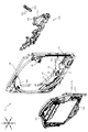
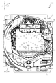
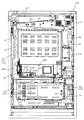
以下、本発明の実施形態について、添付図面を参照して説明する。まず、図1から図97を参照し、第1実施形態として、本発明をパチンコ遊技機(以下、単に「パチンコ機」という)10に適用した場合の一実施形態について説明する。図1は、第1実施形態におけるパチンコ機10の正面図であり、図2はパチンコ機10の遊技盤13の正面図であり、図3はパチンコ機10の背面図である。
Hereinafter, embodiments of the present invention will be described with reference to the accompanying drawings. First, with reference to FIGS. 1 to 97, as a first embodiment, an embodiment when the present invention is applied to a pachinko gaming machine (hereinafter, simply referred to as “pachinko machine”) 10 will be described. FIG. 1 is a front view of the
なお、以下の説明では、図1に示す状態のパチンコ機10に対して、紙面手前側を前方(正面)側として、紙面奥側を後方(背面)側として説明する。また、図1に示す状態のパチンコ機10に対して、上側を上方(上)側として、下側を下方(下)側として、右側を右方(右)側として、左側を左方(左)側としてそれぞれ説明する。さらに、図中(例えば、図2参照)の矢印U−D,L−R,F−Bは、パチンコ機10の上下方向,左右方向,前後方向をそれぞれ示している。
In the following description, the
図1に示すように、パチンコ機10は、略矩形状に組み合わせた木枠により外殻が形成される外枠11と、その外枠11と略同一の外形形状に形成され外枠11に対して開閉可能に支持された内枠12とを備えている。外枠11には、内枠12を支持するために正面視(図1参照)左側の上下2カ所に金属製のヒンジ18が取り付けられ、そのヒンジ18が設けられた側を開閉の軸として内枠12が正面手前側へ開閉可能に支持されている。
As shown in FIG. 1, the
内枠12には、多数の釘や入賞口63,64等を有する遊技盤13(図2参照)が裏面側から着脱可能に装着される。この遊技盤13の正面を球(遊技球)が流下することにより弾球遊技が行われる。なお、内枠12には、球を遊技盤13の正面領域に発射する球発射ユニット112a(図4参照)やその球発射ユニット112aから発射された球を遊技盤13の正面領域まで誘導する発射レール(図示せず)等が取り付けられている。
A game board 13 (see FIG. 2) having a large number of nails, winning
内枠12の正面側には、その正面上側を覆う正面枠14と、その下側を覆う下皿ユニット15とが設けられている。正面枠14及び下皿ユニット15を支持するために正面視(図1参照)左側の上下2カ所に金属製のヒンジ19が取り付けられ、そのヒンジ19が設けられた側を開閉の軸として正面枠14及び下皿ユニット15が正面手前側へ開閉可能に支持されている。なお、内枠12の施錠と正面枠14の施錠とは、シリンダ錠20の鍵穴21に専用の鍵を差し込んで所定の操作を行うことでそれぞれ解除される。
On the front side of the
正面枠14は、装飾用の樹脂部品や電気部品等を組み付けたものであり、その略中央部には略楕円形状に開口形成された窓部14cが設けられている。正面枠14の裏面側には2枚の板ガラスを有するガラスユニット16が配設され、そのガラスユニット16を介して遊技盤13の正面がパチンコ機10の正面側に視認可能となっている。
The
正面枠14には、球を貯留する上皿17が正面側へ張り出して上面を開放した略箱状に形成されており、この上皿17に賞球や貸出球などが排出される。上皿17の底面は正面視(図1参照)右側に下降傾斜して形成され、その傾斜により上皿17に投入された球が球発射ユニット112a(図4参照)へと案内される。また、上皿17の上面には、枠ボタン22が設けられている。この枠ボタン22は、例えば、第3図柄表示装置81(図2参照)で表示される演出のステージを変更したり、スーパーリーチの演出内容を変更したりする場合などに、遊技者により操作される。
In the
正面枠14には、その周囲(例えばコーナー部分)に各種ランプ等の発光手段が設けられている。これら発光手段は、大当たり時や所定のリーチ時等における遊技状態の変化に応じて、点灯又は点滅することにより発光態様が変更制御され、遊技中の演出効果を高める役割を果たす。窓部14cの周縁には、LED等の発光手段を内蔵した電飾部29〜33が設けられている。パチンコ機10においては、これら電飾部29〜33が大当たりランプ等の演出ランプとして機能し、大当たり時やリーチ演出時等には内蔵するLEDの点灯や点滅によって各電飾部29〜33が点灯または点滅して、大当たり中である旨、或いは大当たり一歩手前のリーチ中である旨が報知される。また、正面枠14の正面視(図1参照)左上部には、LED等の発光手段が内蔵され賞球の払い出し中とエラー発生時とを表示可能な表示ランプ34が設けられている。
The
また、右側の電飾部32下側には、正面枠14の裏面側を視認できるように裏面側より透明樹脂を取り付けて小窓35が形成され、遊技盤13正面の貼着スペースK1(図2参照)に貼付される証紙等がパチンコ機10の正面から視認可能とされている。また、パチンコ機10においては、より煌びやかさを醸し出すために、電飾部29〜33の周りの領域にクロムメッキを施したABS樹脂製のメッキ部材36が取り付けられている。
Further, on the lower side of the illuminated
窓部14cの下方には、貸球操作部40が配設されている。貸球操作部40には、度数表示部41と、球貸しボタン42と、返却ボタン43とが設けられている。パチンコ機10の側方に配置されるカードユニット(球貸しユニット)(図示せず)に紙幣やカード等を投入した状態で貸球操作部40が操作されると、その操作に応じて球の貸出が行われる。具体的には、度数表示部41はカード等の残額情報が表示される領域であり、内蔵されたLEDが点灯して残額情報として残額が数字で表示される。球貸しボタン42は、カード等(記録媒体)に記録された情報に基づいて貸出球を得るために操作されるものであり、カード等に残額が存在する限りにおいて貸出球が上皿17に供給される。返却ボタン43は、カードユニットに挿入されたカード等の返却を求める際に操作される。なお、カードユニットを介さずに球貸し装置等から上皿17に球が直接貸し出されるパチンコ機、いわゆる現金機では貸球操作部40が不要となるが、この場合には、貸球操作部40の設置部分に飾りシール等を付加して部品構成は共通のものとしても良い。カードユニットを用いたパチンコ機と現金機との共通化を図ることができる。
A ball
上皿17の下側に位置する下皿ユニット15には、その左側部に上皿17に貯留しきれなかった球を貯留するための下皿50が上面を開放した略箱状に形成されている。下皿50の右側には、球を遊技盤13の正面へ打ち込むために遊技者によって操作される操作ハンドル51が配設される。
In the
操作ハンドル51の内部には、球発射ユニット112aの駆動を許可するためのタッチセンサ51aと、押下操作している期間中には球の発射を停止する発射停止スイッチ51bと、操作ハンドル51の回動操作量(回動位置)を電気抵抗の変化により検出する可変抵抗器(図示せず)などが内蔵されている。操作ハンドル51が遊技者によって右回りに回動操作されると、タッチセンサ51aがオンされると共に可変抵抗器の抵抗値が回動操作量に対応して変化し、その可変抵抗器の抵抗値に対応した強さ(発射強度)で球が発射され、これにより遊技者の操作に対応した飛び量で遊技盤13の正面へ球が打ち込まれる。また、操作ハンドル51が遊技者により操作されていない状態においては、タッチセンサ51aおよび発射停止スイッチ51bがオフとなっている。
Inside the
下皿50の正面下方部には、下皿50に貯留された球を下方へ排出する際に操作するための球抜きレバー52が設けられている。この球抜きレバー52は、常時、右方向に付勢されており、その付勢に抗して左方向へスライドさせることにより、下皿50の底面に形成された底面口が開口して、その底面口から球が自然落下して排出される。この球抜きレバー52の操作は、通常、下皿50の下方に下皿50から排出された球を受け取る箱(一般に「千両箱」と称される)を置いた状態で行われる。下皿50の右方には、上述したように操作ハンドル51が配設され、下皿50の左方には灰皿53が取り付けられている。
A
図2に示すように、遊技盤13は、正面視略正方形状に切削加工したベース板60に、球案内用の多数の釘(図示せず)や風車(図示せず)の他、レール61,62、一般入賞口63、第1入賞口64、第2入賞口640、可変入賞装置65、スルーゲート67、可変表示装置ユニット80等を組み付けて構成され、その周縁部が内枠12(図1参照)の裏面側(又は表面側)に取り付けられる。
As shown in FIG. 2, the
ベース板60は、木製の板部材から形成される。一般入賞口63、第1入賞口64、第2入賞口640、可変表示装置ユニット80は、ルータ加工によってベース板60に形成された貫通穴(例えば、図5参照)に配設され、遊技盤13の正面側からタッピングネジ等により固定されている。なお、ベース板60を光透過性の樹脂材料から構成しても良い。この場合、その正面側からベース板60の背面側に配設された各種構造体を遊技者に視認させることが可能となる。
The
遊技盤13の正面中央部分は、正面枠14の窓部14c(図1参照)を通じて内枠12の正面側から視認することができる。以下に、主に図2を参照して、遊技盤13の構成について説明する。
The front central portion of the
遊技盤13の正面には、帯状の金属板を略円弧状に屈曲加工して形成した外レール62が植立され、その外レール62の内側位置には外レール62と同様に帯状の金属板で形成した円弧状の内レール61が植立される。この内レール61と外レール62とにより遊技盤13の正面外周が囲まれ、遊技盤13とガラスユニット16(図1参照)とにより前後が囲まれることにより、遊技盤13の正面には、球の挙動により遊技が行われる遊技領域が形成される。遊技領域は、遊技盤13の正面であって2本のレール61,62とレール間を繋ぐ樹脂製の外縁部材73とにより区画して形成される領域(入賞口等が配設され、発射された球が流下する領域)である。
An
2本のレール61,62は、球発射ユニット112a(図4参照)から発射された球を遊技盤13上部へ案内するために設けられたものである。内レール61の先端部分(図2の左上部)には戻り球防止部材68が取り付けられ、一旦、遊技盤13の上部へ案内された球が再度球案内通路内に戻ってしまうといった事態が防止される。外レール62の先端部(図2の右上部)には、球の最大飛翔部分に対応する位置に返しゴム69が取り付けられ、所定以上の勢いで発射された球は、返しゴム69に当たって、勢いが減衰されつつ中央部側へ跳ね返される。
The two
遊技領域の正面視左側下部(図2の左側下部)には、発光手段である複数のLED及び7セグメント表示器を備える第1図柄表示装置37A,37Bが配設されている。第1図柄表示装置37A,37Bは、主制御装置110(図4参照)で行われる各制御に応じた表示がなされるものであり、主にパチンコ機10の遊技状態の表示が行われる。本実施形態では、第1図柄表示装置37A,37Bは、球が、第1入賞口64へ入賞したか、第2入賞口640へ入賞したかに応じて使い分けられるように構成されている。具体的には、球が、第1入賞口64へ入賞した場合には、第1図柄表示装置37Aが作動し、一方で、球が、第2入賞口640へ入賞した場合には、第1図柄表示装置37Bが作動するように構成されている。
In the lower left side of the front view (lower left side of FIG. 2) of the game area, first
また、第1図柄表示装置37A,37Bは、LEDにより、パチンコ機10が確変中か時短中か通常中であるかを点灯状態により示したり、変動中であるか否かを点灯状態により示したり、停止図柄が確変大当たりに対応した図柄か普通大当たりに対応した図柄か外れ図柄であるかを点灯状態により示したり、保留球数を点灯状態により示すと共に、7セグメント表示装置により、大当たり中のラウンド数やエラー表示を行う。なお、複数のLEDは、それぞれのLEDの発光色(例えば、赤、緑、青)が異なるよう構成され、その発光色の組み合わせにより、少ないLEDでパチンコ機10の各種遊技状態を示唆することができる。
Further, the first
尚、本パチンコ機10では、第1入賞口64及び第2入賞口640へ入賞があったことを契機として抽選が行われる。パチンコ機10は、その抽選において、大当たりか否かの当否判定(大当たり抽選)を行うと共に、大当たりと判定した場合はその大当たり種別の判定も行う。ここで判定される大当たり種別としては、15R確変大当たり、4R確変大当たり、15R通常大当たりが用意されている。第1図柄表示装置37A,37Bには、変動終了後の停止図柄として抽選の結果が大当たりであるか否かが示されるだけでなく、大当たりである場合はその大当たり種別に応じた図柄が示される。
In the
ここで、「15R確変大当たり」とは、最大ラウンド数が15ラウンドの大当たりの後に高確率状態へ移行する確変大当たりのことであり、「4R確変大当たり」とは、最大ラウンド数が4ラウンドの大当たりの後に高確率状態へ移行する確変大当たりのことである。また、「15R通常大当たり」は、最大ラウンド数が15ラウンドの大当たりの後に、低確率状態へ移行すると共に、所定の変動回数の間(例えば、100変動回数)は時短状態となる大当たりのことである。 Here, the "15R probability variation jackpot" is a probability variation jackpot in which the maximum number of rounds shifts to a high probability state after the jackpot of 15 rounds, and the "4R probability variation jackpot" is a jackpot with a maximum number of rounds of 4 rounds. It is a probabilistic jackpot that shifts to a high probability state after. Further, "15R normal jackpot" is a jackpot in which the maximum number of rounds is 15 rounds, and then the probability shifts to a low probability state, and the time is shortened during a predetermined number of fluctuations (for example, 100 fluctuations). be.
また、「高確率状態」とは、大当たり終了後に付加価値としてその後の大当たり確率がアップした状態、いわゆる確率変動中(確変中)の時をいい、換言すれば、特別遊技状態へ移行し易い遊技の状態のことである。本実施形態における高確率状態(確変中)は、後述する第2図柄の当たり確率がアップして第2入賞口640へ球が入賞し易い遊技の状態を含む。「低確率状態」とは、確変中でない時をいい、大当たり確率が通常の状態、即ち、確変の時より大当たり確率が低い状態をいう。また、「低確率状態」のうちの時短状態(時短中)とは、大当たり確率が通常の状態であると共に、大当たり確率がそのままで第2図柄の当たり確率のみがアップして第2入賞口640へ球が入賞し易い遊技の状態のことをいう。一方、パチンコ機10が通常中とは、確変中でも時短中でもない遊技の状態(大当たり確率も第2図柄の当たり確率もアップしていない状態)である。
In addition, the "high probability state" refers to a state in which the probability of a jackpot is increased as an added value after the end of the jackpot, that is, during a so-called probability fluctuation (probability change), in other words, a game in which it is easy to shift to a special gaming state. It is the state of. The high-probability state (during probabilistic change) in the present embodiment includes a game state in which the winning probability of the second symbol, which will be described later, is increased and the ball is likely to win the second winning opening 640. The "low probability state" refers to a state in which the probability change is not in progress, and a state in which the jackpot probability is normal, that is, a state in which the jackpot probability is lower than that in the probability change state. In addition, in the "low probability state", the time saving state (time saving medium) is a state in which the jackpot probability is a normal state, and the jackpot probability remains the same and only the hit probability of the second symbol is increased to increase the second winning opening 640. It refers to the state of the game in which the ball is easy to win. On the other hand, when the
確変中や時短中は、第2図柄の当たり確率がアップするだけではなく、第2入賞口640に付随する電動役物640aが開放される時間も変更され、通常中と比して長い時間が設定される。電動役物640aが開放された状態(開放状態)にある場合は、その電動役物640aが閉鎖された状態(閉鎖状態)にある場合と比して、第2入賞口640へ球が入賞しやすい状態となる。よって、確変中や時短中は、第2入賞口640へ球が入賞し易い状態となり、大当たり抽選が行われる回数を増やすことができる。
During the probability change and the time reduction, not only the probability of hitting the second symbol increases, but also the time when the
電動役物640aの開放状態と閉鎖状態との状態変化は、下端部に回転軸を備え、遊技領域側へ傾倒または起立する態様で回転変位する開閉板の開閉動作により生じる。電動役物640aが開放状態の時は、開閉板の上面を伝って球が第2入賞口640に案内され易く構成され、電動役物640aが閉鎖状態の時は、開閉板が遊技領域と第2入賞口640との間を塞ぐことで球が第2入賞口640に入球し難くなるように構成している。
The state change between the open state and the closed state of the
なお、確変中や時短中において、第2入賞口640に付随する電動役物640aの開放時間を変更するのではなく、または、その開放時間を変更することに加えて、1回の当たりで電動役物640aが開放する回数を通常中よりも増やす変更を行うものとしてもよい。また、確変中や時短中において、第2図柄の当たり確率は変更せず、第2入賞口640に付随する電動役物640aが開放される時間および1回の当たりで電動役物640aが開放する回数の少なくとも一方を変更するものとしてもよい。また、確変中や時短中において、第2入賞口640に付随する電動役物640aが開放される時間や、1回の当たりで電動役物640aを開放する回数は変更せず、第2図柄の当たり確率だけを、通常中と比してアップするよう変更するものであってもよい。
In addition, during the probability change or the time reduction, the opening time of the
遊技領域には、球が入賞することにより5個から15個の球が賞球として払い出される複数の一般入賞口63が配設されている。また、遊技領域の中央部分を通して視認可能な位置(ベース板60の窓部の後方)に、可変表示装置ユニット80が配設されている。可変表示装置ユニット80には、第1入賞口64及び第2入賞口640への入賞(始動入賞)をトリガとして、第1図柄表示装置37A,37Bにおける変動表示と同期させながら、第3図柄の変動表示を行う液晶ディスプレイ(以下単に「表示装置」と略す)で構成された第3図柄表示装置81と、スルーゲート67の球の通過をトリガとして第2図柄を変動表示するLEDで構成される第2図柄表示装置(図示せず)とが設けられている。また、ベース板60には、第3図柄表示装置81を正面視で囲むようにして、センターフレーム86が配設されている。
In the game area, a plurality of general winning
第3図柄表示装置81は9インチサイズから19インチサイズ程度の大型の液晶ディスプレイで構成されるものであり、表示制御装置114(図4参照)によって表示内容が制御されることにより、例えば上、中及び下の3つの図柄列が表示される。各図柄列は複数の図柄(第3図柄)によって構成され、これらの第3図柄が図柄列毎に横スクロールして第3図柄表示装置81の表示画面上にて第3図柄が可変表示されるようになっている。本実施形態の第3図柄表示装置81は、主制御装置110(図4参照)の制御に伴った遊技状態の表示が第1図柄表示装置37A,37Bで行われるのに対して、その第1図柄表示装置37A,37Bの表示に応じた装飾的な表示を行うものである。なお、表示装置に代えて、例えばリール等を用いて第3図柄表示装置81を構成するようにしても良い。
The third
第2図柄表示装置は、球がスルーゲート67を通過する毎に表示図柄(第2図柄(図示せず))としての「○」の図柄と「×」の図柄とを所定時間交互に点灯させる変動表示を行うものである。パチンコ機10では、球がスルーゲート67を通過したことが検出されると、当たり抽選が行われる。その当たり抽選の結果、当たりであれば、第2図柄表示装置において、第2図柄の変動表示後に「○」の図柄が停止表示される。また、当たり抽選の結果、外れであれば、第2図柄表示装置において、第3図柄の変動表示後に「×」の図柄が停止表示される。
The second symbol display device alternately lights the “○” symbol and the “×” symbol as the display symbol (second symbol (not shown)) each time the sphere passes through the through
パチンコ機10は、第2図柄表示装置における変動表示が所定図柄(本実施形態においては「○」の図柄)で停止した場合に、第2入賞口640に付随された電動役物640aが所定時間だけ作動状態となる(開放される)よう構成されている。
In the
第2図柄の変動表示にかかる時間は、遊技状態が通常中の場合よりも、確変中または時短中の方が短くなるように設定される。これにより、確変中および時短中は、第2図柄の変動表示が短い時間で行われるので、当たり抽選を通常中よりも多く行うことができる。よって、当たり抽選において当たりとなる機会が増えるので、第2入賞口640の電動役物640aが開放状態となる機会を遊技者に多く与えることができる。よって、確変中および時短中は、第2入賞口640へ球が入賞しやすい状態とすることができる。
The time required for the variation display of the second symbol is set to be shorter during the probability change or the time reduction than when the game state is normal. As a result, during the probability change and the time reduction, the variation display of the second symbol is performed in a short time, so that the winning lottery can be performed more than during the normal time. Therefore, since the chances of winning in the winning lottery increase, it is possible to give the player many opportunities to open the
なお、確変中または時短中において、当たり確率を高める、1回の当たりに対する電動役物640aの開放時間や開放回数を増やすなど、その他の方法によっても、確変中または時短中に第2入賞口640へ球が入賞しやすい状態としている場合は、第2図柄の変動表示にかかる時間を遊技状態にかかわらず一定としてもよい。一方、第2図柄の変動表示にかかる時間を、確変中または時短中において通常中よりも短く設定する場合は、当たり確率を遊技状態にかかわらず一定にしてもよいし、また、1回の当たりに対する電動役物640aの開放時間や開放回数を遊技状態にかかわらず一定にしてもよい。
In addition, during the probability change or the time reduction, the second winning opening 640 may be performed during the probability change or the time reduction by other methods such as increasing the opening time and the number of times of opening the
スルーゲート67は、可変表示装置ユニット80の右側の領域において遊技盤13に組み付けられ、遊技盤13に発射された球の一部が通過可能に構成されている。スルーゲート67を球が通過すると、第2図柄の当たり抽選が行われる。当たり抽選の後、第2図柄表示装置にて変動表示を行い、当たり抽選の結果が当たりであれば、変動表示の停止図柄として「○」の図柄を表示し、当たり抽選の結果が外れであれば、変動表示の停止図柄として「×」の図柄を表示する。
The through
球のスルーゲート67の通過回数は、合計で最大4回まで保留され、その保留球数が上述した第1図柄表示装置37A,37Bにより表示されると共に第2図柄保留ランプ(図示せず)においても点灯表示される。第2図柄保留ランプは、最大保留数分の4つ設けられ、第3図柄表示装置81の下方に左右対称に配設されている。
The number of times the ball has passed through the through
なお、第2図柄の変動表示は、本実施形態のように、第2図柄表示装置において複数のランプの点灯と非点灯を切り換えることにより行うものの他、第1図柄表示装置37A,37B及び第3図柄表示装置81の一部を使用して行うようにしても良い。同様に、第2図柄保留ランプの点灯を第3図柄表示装置81の一部で行うようにしても良い。
The variation display of the second symbol is performed by switching the lighting and non-lighting of a plurality of lamps in the second symbol display device as in the present embodiment, as well as the first
また、スルーゲート67の球の通過に対する最大保留球数は4回に限定されるものでなく、3回以下、又は、5回以上の回数(例えば、8回)に設定しても良い。また、スルーゲート67の組み付け数は1つに限定されるものではなく、例えば2つであっても良い。
Further, the maximum number of reserved balls for the passage of the balls of the through
また、スルーゲート67の組み付け位置は可変表示装置ユニット80の右側に限定されるものではなく、例えば、可変表示装置ユニット80の左右や、下方でも良い。また、第1図柄表示装置37A,37Bにより保留球数が示されるので、第2図柄保留ランプにより点灯表示を行わないものとしてもよい。
Further, the assembly position of the through
可変表示装置ユニット80の下方には、球が入賞し得る第1入賞口64が配設されている。この第1入賞口64へ球が入賞すると遊技盤13の裏面側に設けられる第1入賞口スイッチ(図示せず)がオンとなり、その第1入賞口スイッチのオンに起因して主制御装置110(図4参照)で大当たりの抽選がなされ、その抽選結果に応じた表示が第1図柄表示装置37Aで示される。
Below the variable
一方、スルーゲート67の正面視右下側には、球が入賞し得る第2入賞口640が配設されている。この第2入賞口640へ球が入賞すると遊技盤13の裏面側に設けられる第2入賞口スイッチ(図示せず)がオンとなり、その第2入賞口スイッチのオンに起因して主制御装置110(図4参照)で大当たりの抽選がなされ、その抽選結果に応じた表示が第1図柄表示装置37Bで示される。なお、第2入賞口640の配置は、これに限られるものではない。例えば、第1入賞口64の正面視下方でも良いし、遊技領域の左右中央よりも左側でも良い。
On the other hand, on the lower right side of the through
また、第1入賞口64および第2入賞口640は、それぞれ、球が入賞すると5個の球が賞球として払い出される入賞口の1つにもなっている。なお、本実施形態においては、第1入賞口64へ球が入賞した場合に払い出される賞球数と第2入賞口640へ球が入賞した場合に払い出される賞球数とを同じに構成したが、第1入賞口64へ球が入賞した場合に払い出される賞球数と第2入賞口640へ球が入賞した場合に払い出される賞球数とを異なる数、例えば、第1入賞口64へ球が入賞した場合に払い出される賞球数を3個とし、第2入賞口640へ球が入賞した場合に払い出される賞球数を5個として構成してもよい。
In addition, the first winning
第2入賞口640には電動役物640aが付随されている。この電動役物640aは開閉可能に構成されており、通常は電動役物640aが閉鎖状態(縮小状態)となって、球が第2入賞口640へ入賞しにくい状態となっている。一方、スルーゲート67への球の通過を契機として行われる第2図柄の変動表示の結果、「○」の図柄が第2図柄表示装置に表示された場合、電動役物640aが開放状態(拡大状態)となり、球が第2入賞口640へ入賞しやすい状態となる。
An
上述した通り、確変中および時短中は、通常中と比して第2図柄の当たり確率が高く、また、第2図柄の変動表示にかかる時間も短いので、第2図柄の変動表示において「○」の図柄が表示され易くなって、電動役物640aが開放状態(拡大状態)となる回数が増える。更に、確変中および時短中は、電動役物640aが開放される時間も、通常中より長くなる。よって、確変中および時短中は、通常時と比して、第2入賞口640へ球が入賞しやすい状態を作ることができる。
As described above, during the probabilistic change and the time reduction, the probability of hitting the second symbol is higher than during the normal time, and the time required for the variation display of the second symbol is short. The symbol "" is easily displayed, and the number of times that the
ここで、第1入賞口64に球が入賞した場合と第2入賞口640へ球が入賞した場合とで、大当たりとなる確率は、低確率状態であっても高確率状態でも同一である。しかしながら、大当たりとなった場合に選定される大当たりの種別として15R確変大当たりとなる確率は、第2入賞口640へ球が入賞した場合のほうが第1入賞口64へ球が入賞した場合よりも高く設定されている。一方、第1入賞口64は、第2入賞口640にあるような電動役物640aは有しておらず、球が常時入賞可能な状態となっている。
Here, the probability of winning a jackpot is the same in both the low probability state and the high probability state when the ball wins in the first winning
よって、通常中においては、第2入賞口640に付随する電動役物640aが閉鎖状態にある場合が多く、第2入賞口640に入賞しづらいので、電動役物640aのない第1入賞口64へ向けて、可変表示装置ユニット80の左方を球が通過するように球を発射し(所謂「左打ち」)、第1入賞口64への入賞によって大当たり抽選の機会を多く得て、大当たりとなることを狙った方が、遊技者にとって有利となる。
Therefore, in normal times, the
一方、確変中や時短中は、スルーゲート67に球を通過させることで、第2入賞口640に付随する電動役物640aが開放状態となりやすく、第2入賞口640に入賞しやすい状態であるので、第2入賞口640へ向けて、可変表示装置80の右方を球が通過するように球を発射し(所謂「右打ち」)、スルーゲート67を通過させて電動役物640aを開放状態にすると共に、第2入賞口640への入賞によって15R確変大当たりとなることを狙った方が、遊技者にとって有利となる。
On the other hand, during the probability change or the time reduction, by passing the ball through the through
なお、本実施形態におけるパチンコ機10とは異なり、遊技盤13の構成が左右対称とされる場合には、「右打ち」で第1入賞口64を狙うことも、「左打ち」で第2入賞口640を狙うこともできる。そのため、本実施形態のパチンコ機10は、パチンコ機10の遊技状態(確変中であるか、時短中であるか、通常中であるか)に応じて、遊技者に対し、球の発射の仕方を「左打ち」と「右打ち」とに変えさせることを不要にできる。よって、球の打ち方を変化させる煩わしさを解消することができる。
Unlike the
一方で、本実施形態におけるパチンコ機10では、「右打ち」では第1入賞口64を狙うことはできないように構成され、「左打ち」で発射された球はスルーゲート67を通過しないように構成されている。そのため、本実施形態のパチンコ機10は、パチンコ機10の遊技状態(確変中であるか、時短中であるか、通常中であるか)に応じて、遊技者に対し、球の発射の仕方を「左打ち」と「右打ち」とに変えることを要求することができる。よって、球の打ち方を変化させる遊技性を付加することで遊技が緩慢となることを防止することができる。
On the other hand, the
第1入賞口64の右方には可変入賞装置65(図2参照)が配設されており、その略中央部分に特定入賞口65aが設けられている。パチンコ機10においては、第1入賞口64又は第2入賞口640への入賞に起因して行われた大当たり抽選が大当たりとなると、所定時間(変動時間)が経過した後に、大当たりの停止図柄となるよう第1図柄表示装置37A又は第1図柄表示装置37Bを点灯させると共に、その大当たりに対応した停止図柄を第3図柄表示装置81に表示させて、大当たりの発生が示される。その後、球が入賞し易い特別遊技状態(大当たり)に遊技状態が遷移する。この特別遊技状態として、通常時には閉鎖されている特定入賞口65aが、所定時間(例えば、30秒経過するまで、或いは、球が10個入賞するまで)開放される。
A variable winning device 65 (see FIG. 2) is arranged on the right side of the first winning
この特定入賞口65aは、所定時間が経過すると閉鎖され、その閉鎖後、再度、その特定入賞口65aが所定時間開放される。この特定入賞口65aの開閉動作は、最高で例えば15回(15ラウンド)繰り返し可能にされている。この開閉動作が行われている状態が、遊技者にとって有利な特別遊技状態の一形態であり、遊技者には、遊技上の価値(遊技価値)の付与として通常時より多量の賞球の払い出しが行われる。
The
なお、上記した形態に特別遊技状態は限定されるものではない。特定入賞口65aとは別に開閉される大開放口を遊技領域に設け、第1図柄表示装置37A,37Bにおいて大当たりに対応したLEDが点灯した場合に、特定入賞口65aが所定時間開放され、その特定入賞口65aの開放中に、球が特定入賞口65a内へ入賞することを契機として特定入賞口65aとは別に設けられた大開放口が所定時間、所定回数開放される遊技状態を特別遊技状態として形成するようにしても良い。また、特定入賞口65aは1つに限るものではなく、1つ若しくは2以上の複数(例えば3つ)を配置しても良く、また配置位置も第1入賞口64の右方に限らず、例えば、第1入賞口64の下方右側や、第1入賞口64の下方左側や、可変表示装置ユニット80の左方または右方や、上方でも良い。
The special gaming state is not limited to the above-described form. A large opening that opens and closes separately from the specific winning
遊技盤13の下側における右隅部には、証紙や識別ラベル等を貼着するための貼着スペースK1が設けられ、貼着スペースK1に貼られた証紙等は、正面枠14の小窓35(図1参照)を通じて視認することができる。
In the right corner on the lower side of the
遊技盤13には、アウト口71が設けられている。遊技領域を流下する球であって、いずれの入賞口63,64,65a,640にも入賞しなかった球は、アウト口71を通って図示しない球排出路へと案内される。アウト口71は、第2入賞口640の左右に一対で配設される。
The
遊技盤13には、球の落下方向を適宜分散、調整等するために多数の釘が植設されているとともに、風車等の各種部材(役物)とが配設されている。
A large number of nails are planted on the
図3に示すように、パチンコ機10の背面側には、制御基板ユニット90,91と、裏パックユニット94とが主に備えられている。制御基板ユニット90は、主基板(主制御装置110)と音声ランプ制御基板(音声ランプ制御装置113)と表示制御基板(表示制御装置114)とが搭載されてユニット化されている。制御基板ユニット91は、払出制御基板(払出制御装置111)と発射制御基板(発射制御装置112)と電源基板(電源装置115)とカードユニット接続基板116とが搭載されてユニット化されている。
As shown in FIG. 3, the
裏パックユニット94は、保護カバー部を形成する裏パック92と払出ユニット93とがユニット化されている。また、各制御基板には、各制御を司る1チップマイコンとしてのMPU、各種機器との連絡をとるポート、各種抽選の際に用いられる乱数発生器、時間計数や同期を図る場合などに使用されるクロックパルス発生回路等が、必要に応じて搭載されている。
In the
なお、主制御装置110、音声ランプ制御装置113及び表示制御装置114、払出制御装置111及び発射制御装置112、電源装置115、カードユニット接続基板116は、それぞれ基板ボックス100〜104に収納されている。基板ボックス100〜104は、ボックスベースと該ボックスベースの開口部を覆うボックスカバーとを備えており、そのボックスベースとボックスカバーとが互いに連結されて、各制御装置や各基板が収納される。
The
また、基板ボックス100(主制御装置110)及び基板ボックス102(払出制御装置111及び発射制御装置112)は、ボックスベースとボックスカバーとを封印ユニット(図示せず)によって開封不能に連結(かしめ構造による連結)している。また、ボックスベースとボックスカバーとの連結部には、ボックスベースとボックスカバーとに亘って封印シール(図示せず)が貼着されている。この封印シールは、脆性な素材で構成されており、基板ボックス100,102を開封するために封印シールを剥がそうとしたり、基板ボックス100,102を無理に開封しようとすると、ボックスベース側とボックスカバー側とに切断される。よって、封印ユニット又は封印シールを確認することで、基板ボックス100,102が開封されたかどうかを知ることができる。
Further, in the board box 100 (main control device 110) and the board box 102 (
払出ユニット93は、裏パックユニット94の最上部に位置して上方に開口したタンク130と、タンク130の下方に連結され下流側に向けて緩やかに傾斜するタンクレール131と、タンクレール131の下流側に縦向きに連結されるケースレール132と、ケースレール132の最下流部に設けられ、払出モータ216(図4参照)の所定の電気的構成により球の払出を行う払出装置133とを備えている。タンク130には、遊技ホールの島設備から供給される球が逐次補給され、払出装置133により必要個数の球の払い出しが適宜行われる。タンクレール131には、当該タンクレール131に振動を付加するためのバイブレータ134が取り付けられている。
The
また、払出制御装置111には状態復帰スイッチ120が設けられ、発射制御装置112には可変抵抗器の操作つまみ121が設けられ、電源装置115にはRAM消去スイッチ122が設けられている。状態復帰スイッチ120は、例えば、払出モータ216(図4参照)部の球詰まり等、払出エラーの発生時に球詰まりを解消(正常状態への復帰)するために操作される。操作つまみ121は、発射ソレノイドの発射力を調整するために操作される。RAM消去スイッチ122は、パチンコ機10を初期状態に戻したい場合に電源投入時に操作される。
Further, the
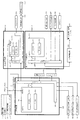
次に、図4を参照して、本パチンコ機10の電気的構成について説明する。図4は、パチンコ機10の電気的構成を示すブロック図である。
Next, the electrical configuration of the
主制御装置110には、演算装置である1チップマイコンとしてのMPU201が搭載されている。MPU201には、該MPU201により実行される各種の制御プログラムや固定値データを記憶したROM202と、そのROM202内に記憶される制御プログラムの実行に際して各種のデータ等を一時的に記憶するためのメモリであるRAM203と、そのほか、割込回路やタイマ回路、データ送受信回路などの各種回路が内蔵されている。主制御装置110では、MPU201によって、大当たり抽選や第1図柄表示装置37A,37B及び第3図柄表示装置81における表示の設定、第2図柄表示装置における表示結果の抽選といったパチンコ機10の主要な処理を実行する。
The
なお、払出制御装置111や音声ランプ制御装置113などのサブ制御装置に対して動作を指示するために、主制御装置110から該サブ制御装置へ各種のコマンドがデータ送受信回路によって送信されるが、かかるコマンドは、主制御装置110からサブ制御装置へ一方向にのみ送信される。
In order to instruct the operation of the sub control device such as the
RAM203は、各種エリア、カウンタ、フラグのほか、MPU201の内部レジスタの内容やMPU201により実行される制御プログラムの戻り先番地などが記憶されるスタックエリアと、各種のフラグおよびカウンタ、I/O等の値が記憶される作業エリア(作業領域)とを有している。なお、RAM203は、パチンコ機10の電源の遮断後においても電源装置115からバックアップ電圧が供給されてデータを保持(バックアップ)できる構成となっており、RAM203に記憶されるデータは、すべてバックアップされる。
The
停電などの発生により電源が遮断されると、その電源遮断時(停電発生時を含む。以下同様)のスタックポインタや、各レジスタの値がRAM203に記憶される。一方、電源投入時(停電解消による電源投入を含む。以下同様)には、RAM203に記憶される情報に基づいて、パチンコ機10の状態が電源遮断前の状態に復帰される。RAM203への書き込みはメイン処理(図示せず)によって電源遮断時に実行され、RAM203に書き込まれた各値の復帰は電源投入時の立ち上げ処理(図示せず)において実行される。なお、MPU201のNMI端子(ノンマスカブル割込端子)には、停電等の発生による電源遮断時に、停電監視回路252からの停電信号SG1が入力されるように構成されており、その停電信号SG1がMPU201へ入力されると、停電時処理としてのNMI割込処理(図示せず)が即座に実行される。
When the power supply is cut off due to the occurrence of a power failure or the like, the stack pointer at the time of the power failure (including the time when a power failure occurs; the same applies hereinafter) and the value of each register are stored in the
主制御装置110のMPU201には、アドレスバス及びデータバスで構成されるバスライン204を介して入出力ポート205が接続されている。入出力ポート205には、払出制御装置111、音声ランプ制御装置113、第1図柄表示装置37A,37B、第2図柄表示装置、第2図柄保留ランプ、特定入賞口65aの開閉板を前後方向に開閉駆動するための大開放口ソレノイドや電動役物640aを駆動するためのソレノイドなどからなるソレノイド209が接続され、MPU201は、入出力ポート205を介してこれらに対し各種コマンドや制御信号を送信する。
An input /
また、入出力ポート205には、図示しないスイッチ群およびスライド位置検出センサSや回転位置検出センサRを含むセンサ群などからなる各種スイッチ208、電源装置115に設けられた後述のRAM消去スイッチ回路253が接続され、MPU201は各種スイッチ208から出力される信号や、RAM消去スイッチ回路253より出力されるRAM消去信号SG2に基づいて各種処理を実行する。
Further, the input /
払出制御装置111は、払出モータ216を駆動させて賞球や貸出球の払出制御を行うものである。演算装置であるMPU211は、そのMPU211により実行される制御プログラムや固定値データ等を記憶したROM212と、ワークメモリ等として使用されるRAM213とを有している。
The
払出制御装置111のRAM213は、主制御装置110のRAM203と同様に、MPU211の内部レジスタの内容やMPU211により実行される制御プログラムの戻り先番地などが記憶されるスタックエリアと、各種のフラグおよびカウンタ、I/O等の値が記憶される作業エリア(作業領域)とを有している。RAM213は、パチンコ機10の電源の遮断後においても電源装置115からバックアップ電圧が供給されてデータを保持(バックアップ)できる構成となっており、RAM213に記憶されるデータは、すべてバックアップされる。なお、主制御装置110のMPU201と同様、MPU211のNMI端子にも、停電等の発生による電源遮断時に停電監視回路252から停電信号SG1が入力されるように構成されており、その停電信号SG1がMPU211へ入力されると、停電時処理としてのNMI割込処理(図示せず)が即座に実行される。
The RAM 213 of the
払出制御装置111のMPU211には、アドレスバス及びデータバスで構成されるバスライン214を介して入出力ポート215が接続されている。入出力ポート215には、主制御装置110や払出モータ216、発射制御装置112などがそれぞれ接続されている。また、図示はしないが、払出制御装置111には、払い出された賞球を検出するための賞球検出スイッチが接続されている。なお、該賞球検出スイッチは、払出制御装置111に接続されるが、主制御装置110には接続されていない。
An input /
発射制御装置112は、主制御装置110により球の発射の指示がなされた場合に、操作ハンドル51の回動操作量に応じた球の打ち出し強さとなるよう球発射ユニット112aを制御するものである。球発射ユニット112aは、図示しない発射ソレノイドおよび電磁石を備えており、その発射ソレノイドおよび電磁石は、所定条件が整っている場合に駆動が許可される。具体的には、遊技者が操作ハンドル51に触れていることをタッチセンサ51aにより検出し、球の発射を停止させるための発射停止スイッチ51bがオフ(操作されていないこと)を条件に、操作ハンドル51の回動操作量(回動位置)に対応して発射ソレノイドが励磁され、操作ハンドル51の操作量に応じた強さで球が発射される。
The
音声ランプ制御装置113は、音声出力装置(図示しないスピーカなど)226における音声の出力、ランプ表示装置(電飾部29〜33、表示ランプ34など)227における点灯および消灯の出力、変動演出(変動表示)や予告演出といった表示制御装置114で行われる第3図柄表示装置81の表示態様の設定などを制御するものである。演算装置であるMPU221は、そのMPU221により実行される制御プログラムや固定値データ等を記憶したROM222と、ワークメモリ等として使用されるRAM223とを有している。
The voice
音声ランプ制御装置113のMPU221には、アドレスバス及びデータバスで構成されるバスライン224を介して入出力ポート225が接続されている。入出力ポート225には、主制御装置110、表示制御装置114、音声出力装置226、ランプ表示装置227、その他装置228、枠ボタン22などがそれぞれ接続されている。その他装置228には駆動モータMT1,MT2,MT3,MT4,MT5等が含まれる。
An input /
音声ランプ制御装置113は、主制御装置110から受信した各種のコマンド(変動パターンコマンド、停止種別コマンド等)に基づいて、第3図柄表示装置81の表示態様を決定し、決定した表示態様をコマンド(表示用変動パターンコマンド、表示用停止種別コマンド等)によって表示制御装置114へ通知する。また、音声ランプ制御装置113は、枠ボタン22からの入力を監視し、遊技者によって枠ボタン22が操作された場合は、第3図柄表示装置81で表示されるステージを変更したり、スーパーリーチ時の演出内容を変更したりするように、表示制御装置114へ指示する。ステージが変更される場合は、変更後のステージに応じた背面画像を第3図柄表示装置81に表示させるべく、変更後のステージに関する情報を含めた背面画像変更コマンドを表示制御装置114へ送信する。ここで、背面画像とは、第3図柄表示装置81に表示させる主要な画像である第3図柄の背面側に表示される画像のことである。表示制御装置114は、この音声ランプ制御装置113から送信されるコマンドに従って、第3図柄表示装置81に各種の画像を表示する。
The voice
また、音声ランプ制御装置113は、表示制御装置114から第3図柄表示装置81の表示内容を表すコマンド(表示コマンド)を受信する。音声ランプ制御装置113では、表示制御装置114から受信した表示コマンドに基づき、第3図柄表示装置81の表示内容に合わせて、その表示内容に対応する音声を音声出力装置226から出力し、また、その表示内容に対応させてランプ表示装置227の点灯および消灯を制御する。
Further, the voice
表示制御装置114は、音声ランプ制御装置113及び第3図柄表示装置81が接続され、音声ランプ制御装置113より受信したコマンドに基づいて、第3図柄表示装置81における第3図柄の変動演出などの表示を制御するものである。また、表示制御装置114は、第3図柄表示装置81の表示内容を通知する表示コマンドを適宜音声ランプ制御装置113へ送信する。音声ランプ制御装置113は、この表示コマンドによって示される表示内容にあわせて音声出力装置226から音声を出力することで、第3図柄表示装置81の表示と音声出力装置226からの音声出力とをあわせることができる。
In the
電源装置115は、パチンコ機10の各部に電源を供給するための電源部251と、停電等による電源遮断を監視する停電監視回路252と、RAM消去スイッチ122(図3参照)が設けられたRAM消去スイッチ回路253とを有している。電源部251は、図示しない電源経路を通じて、各制御装置110〜114等に対して各々に必要な動作電圧を供給する装置である。その概要としては、電源部251は、外部より供給される交流24ボルトの電圧を取り込み、各種スイッチ208などの各種スイッチや、ソレノイド209などのソレノイド、モータ等を駆動するための12ボルトの電圧、ロジック用の5ボルトの電圧、RAMバックアップ用のバックアップ電圧などを生成し、これら12ボルトの電圧、5ボルトの電圧及びバックアップ電圧を各制御装置110〜114等に対して必要な電圧を供給する。
The
停電監視回路252は、停電等の発生による電源遮断時に、主制御装置110のMPU201及び払出制御装置111のMPU211の各NMI端子へ停電信号SG1を出力するための回路である。停電監視回路252は、電源部251から出力される最大電圧である直流安定24ボルトの電圧を監視し、この電圧が22ボルト未満になった場合に停電(電源断、電源遮断)の発生と判断して、停電信号SG1を主制御装置110及び払出制御装置111へ出力する。停電信号SG1の出力によって、主制御装置110及び払出制御装置111は、停電の発生を認識し、NMI割込処理を実行する。なお、電源部251は、直流安定24ボルトの電圧が22ボルト未満になった後においても、NMI割込処理の実行に充分な時間の間、制御系の駆動電圧である5ボルトの電圧の出力を正常値に維持するように構成されている。よって、主制御装置110及び払出制御装置111は、NMI割込処理(図示せず)を正常に実行し完了することができる。
The power
RAM消去スイッチ回路253は、RAM消去スイッチ122(図3参照)が押下された場合に、主制御装置110へ、バックアップデータをクリアさせるためのRAM消去信号SG2を出力するための回路である。主制御装置110は、パチンコ機10の電源投入時に、RAM消去信号SG2を入力した場合に、バックアップデータをクリアすると共に、払出制御装置111においてバックアップデータをクリアさせるための払出初期化コマンドを払出制御装置111に対して送信する。
The RAM erase
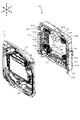
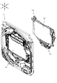
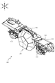
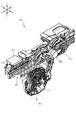
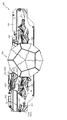
次いで、遊技盤13及び動作ユニット500の構造について説明する。図5は、遊技盤13及び動作ユニット500の分解正面斜視図であり、図6は、遊技盤13及び動作ユニット500の分解背面斜視図である。なお、図5及び図6では、背面ケース510の開口511aに配設される液晶表示装置(可変表示装置ユニット80)の図示が省略され、開口511aを通して奥側を視認可能に図示される。また、図5及び図6の説明においては、図2を適宜参照する。
Next, the structures of the
動作ユニット500は、底壁部511と、その底壁部511の外縁から立設される外壁部512とから正面側が開放された箱状に形成される背面ケース510を備える。背面ケース510は、底壁部511の中央に矩形状の開口511aが開口形成されることで、正面視矩形の枠状に形成される。開口511aは、第3図柄表示装置81の表示領域の外形(外縁)に対応した(即ち、第3図柄表示装置81の表示領域を正面視で区切ることが可能な)大きさに形成される。
The
背面ケース510は、外壁部512の正面側端部に遊技盤13の背面に沿う(例えば、平行に配置される)平面板として延設され、組立状態(図2参照)において遊技盤13を面支持する支持板部513を備える。
The
支持板部513は、遊技盤13のベース板60に形成される嵌合凹部(図示せず)と嵌合可能な形状で正面側へ向けて突設される位置決め凸部513aと、ベース板60に締結される締結ネジを挿通可能に穿設される複数の挿通孔513bとを備える。
The
ベース板60の嵌合凹部に位置決め凸部513aを嵌合させることによりベース板60に対して背面ケース510を位置決めし、締結ネジを挿通孔513bに挿通し、ベース板60に螺入することにより、遊技盤13と動作ユニット500とを一体的に固定することができるので、遊技盤13及び動作ユニット500の全体としての剛性の向上を図ることができる。
The
なお、位置決め凸部513aの形状は何ら限定されるものではなく、種々の態様が例示される。例えば、ベース板60の嵌合凹部の内形(本実施形態では、円形または長円形)よりも若干小さな外形の凸部でも良いし、組み付け時の作業性を考慮して、嵌合隙間が大きくなるような形状(更に小さな外形)の突部でも良い。また、嵌合凹部の内形が矩形状に形成される場合には、それに対応して位置決め凸部513aの形状も矩形状とされることは当然想定される。
The shape of the positioning
遊技盤13は、上述のように、正面視略正方形状に切削加工したベース板60に、球案内用の多数の釘(図示せず)や風車(図示せず)の他、レール61,62、一般入賞口63、第1入賞口64、第2入賞口640、スルーゲート67、可変入賞装置65、ベース板60に開口される窓部60a(図90参照)に正面側から嵌合可能な形状で構成されるセンターフレーム86、遊技領域から排出された球が流下可能に構成される球流下ユニット150、第3図柄表示装置81の正面側へ向けて粒状部材320(図54参照)を発射可能に構成される発射演出ユニット300等を組み付けて構成され、その周縁部が内枠12(図1参照)の表面と対向配置され固定される態様で内枠12に取り付けられる。
As described above, the
ベース板60は、光透過性の樹脂材料から板状に形成されており、正面側からベース板60の背面側に配設された各種構造体を遊技者に視認させ易いように構成される。これにより、ベース板60の形状や配置に関わらず、その背面側に配設される構造体を視認させ、各種演出に利用することができる。
The
例えば、ベース板60の背面側に球流下ユニット150を配設する場合であっても、ベース板60が透けて奥側が見えるので、球流下ユニット150を流下している球を視認させることができる。本実施形態では、球流下ユニット150が、視認される球により奏する効果を考慮して設計されているが、詳細は後述する。
For example, even when the ball flow-down
なお、遊技者に対して見せたくない箇所がある場合には、光透過性の低い(又は光不透過の)シール部材を貼り付ける等して対処すれば良い。 If there is a part that the player does not want to see, a seal member having low light transmission (or light transmission) may be attached.
センターフレーム86は、ルータ加工によってベース板60に形成された貫通穴に配設され、遊技盤13の正面側からタッピングネジ等によりベース板60に固定される。
The
発射演出ユニット300は、粒状部材320(図54参照)を受け入れ、粒状部材320が飛散可能な範囲を区画する区画部材310がセンターフレーム86の内側に配置されることで、粒状部材320をセンターフレーム86の内側へ向けて発射可能とされる。そのため、センターフレーム86の内側窓部を通して第3図柄表示装置81の表示を視認する遊技者に対して、第3図柄表示装置81の正面側で飛散する粒状部材320を効果的に視認させることができる。なお、発射演出ユニット300の詳細については後述する。
The firing
動作ユニット500は、遊技盤13の背面側に配置され、各種発光手段や、各種動作ユニットが内部に配設されている。即ち、動作ユニット500は、背面ケース510と、その背面ケース510の内側上部に配設される拡大縮小ユニット600と、背面ケース510の内側左右部に左右対称で配設される変位回転ユニット800とを備える。
The
具体的には、拡大縮小ユニット600は、開口511aの上方位置において、変位回転ユニット800は、開口511aの左右位置において、それぞれ背面ケース510の底壁部511に配設される。まず、この動作ユニット500の動作制御の概要について説明する。
Specifically, the enlargement /
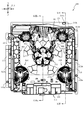
図7から図11は、動作ユニット500の動作制御の一例を時系列で示す動作ユニット500の正面図である。なお、図7では、演出待機状態の拡大縮小ユニット600及び変位回転ユニット800が図示され、図8では、張出状態の拡大縮小ユニット600と、演出待機状態の変位回転ユニット800とが図示され、図9では、拡大状態の拡大縮小ユニット600と、演出待機状態の変位回転ユニット800とが図示される。
7 to 11 are front views of the
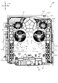
また、図10では、演出待機状態の拡大縮小ユニット600と、演出上端状態の変位回転ユニット800とが図示され、図11では、左側の変位回転ユニット800は演出上端状態とされ、右側の変位回転ユニット800は演出下端状態とされる。
Further, in FIG. 10, the enlargement /
図7から図11に図示されるように、拡大縮小ユニット600の変位軌跡と変位回転ユニット800の変位軌跡とは正面視で部分的に重なる。そのため、例えば、変位回転ユニット800が演出上端状態(図10参照)の時に、拡大縮小ユニット600が演出待機状態から状態変化すると、衝突する可能性がある。
As shown in FIGS. 7 to 11, the displacement locus of the enlargement /
これに対して、本実施形態では、拡大縮小ユニット600の演出待機状態からの状態変化を、変位回転ユニット800が演出待機状態であることを条件として実行可能に制御したり、変位回転ユニット800の演出待機状態からの状態変化を、拡大縮小ユニット600が演出待機状態であることを条件として実行可能に制御したりすることで、拡大縮小ユニット600と変位回転ユニット800とが正面視で重なることを避けることができる。従って、拡大縮小ユニット600及び変位回転ユニット800の配置自由度を向上することができる(前後位置が重なることを許容できる)。
On the other hand, in the present embodiment, the state change of the enlargement /
図7から図9に示すように、拡大縮小ユニット600は、演出部材700が一箇所に集合配置された状態で下降変位可能に構成され、下降変位後に第3図柄表示装置81の表示領域の前方に配置された状態で演出部材700の構成部材が互いに離散して、正面視で視認される面積が大きくなるよう動作制御される(図9参照)。
As shown in FIGS. 7 to 9, the enlargement /
その後、拡大縮小ユニット600は、演出部材700が再び集合し(図8参照)、一箇所に集合配置された状態で上昇変位し、図7に示す演出待機状態に復帰するよう制御される。
After that, the enlargement /
図10及び図11に示す状態変化は、拡大縮小ユニット600が演出待機状態の時に実行される。図7、図10及び図11に示すように、変位回転ユニット800は、横スライド部材840が演出待機状態から、上下方向成分のみでは無く、左右方向成分を有する方向で変位可能に構成される。
The state change shown in FIGS. 10 and 11 is executed when the enlargement /
本実施形態では、後述の機構により設定される経路曲線S1に沿って横スライド部材840が変位する。経路曲線S1は、各中心点C1を中心とする円弧形状からなる共通円弧部S1aと、その共通円弧部S1aの下端から左右外側下方へ延びる進退経路部S1bとを備える。
In the present embodiment, the
図10では、左右一対の横スライド部材840が共通円弧部S1aの上端位置に配置されており、図11では、左側の横スライド部材840は共通円弧部S1aの上端位置に配置される一方、右側の横スライド部材840は共通円弧部S1aの下端位置よりも上側の位置に配置される。
In FIG. 10, a pair of left and right
そのため、図11に示す状態から、左側の横スライド部材840を下側へ変位させ、右側の横スライド部材840を上側へ変位させるよう制御すると、あたかも横スライド部材840が第3図柄表示装置81の中心寄りに配置される中心点C1を中心に回転変位しているかのように遊技者に視認させることができる。
Therefore, when the left
即ち、横スライド部材840を第3図柄表示装置81の表示領域と同等の大きさの回転演出体の一部として視認させることができ、横スライド部材840を利用した演出の演出自由度を向上することができる。
That is, the
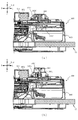
図12(a)及び図12(b)は、図7のXIIa−XIIa線における遊技盤13及び動作ユニット500の断面図であり、図13(a)及び図13(b)は、図9のXIIIa−XIIIa線における遊技盤13及び動作ユニット500の断面図であり、図14は、図9のXIV−XIV線における遊技盤13及び動作ユニット500の断面図である。
12 (a) and 12 (b) are cross-sectional views of the
なお、図7及び図9では遊技盤13は図示されていないが、図12から図14では、遊技盤13が動作ユニット500の正面側に組み付いた状態(図2参照)が図示される。
Although the
また、図12(a)及び図13(a)では、粒状部材320が下方に滞留した状態の一例が図示され、図12(b)及び図13(b)では、粒状部材320が発射され飛散した状態の一例が図示される。
Further, FIGS. 12 (a) and 13 (a) show an example of a state in which the
拡大縮小ユニット600の演出部材700は、図12(a)及び図12(b)に示す演出待機状態では集合配置の中央部分が発射演出ユニット300の区画部材310よりも上側に配置され、区画部材310を通して第3図柄表示装置81の表示領域の大部分を視認可能に構成される。
In the effect standby state shown in FIGS. 12 (a) and 12 (b), the central portion of the collective arrangement of the
一方、図13(a)及び図13(b)に示す拡大状態では発射演出ユニット300の区画部材310の背後に演出部材700が近接配置され、演出部材700に目隠しされることで(図9参照)、第3図柄表示装置81の表示領域の大部分が視認不能に遮蔽される。
On the other hand, in the enlarged state shown in FIGS. 13 (a) and 13 (b), the
拡大縮小ユニット600の変位軌跡と、区画部材310とは干渉しないので、拡大縮小ユニット600の配置に関わらず、区画部材310に粒状部材320を発射する動作演出を実行するように発射演出ユニット300を制御することが可能である。
Since the displacement locus of the enlargement /
図12(a)に示すように、粒状部材320は第3図柄表示装置81の表示領域の下縁よりも下側に配置されており、前方へ向かうほど上昇傾斜する経路で発射されることで、区画部材310の前壁部に打ち付けられ、区画部材310により形成される範囲で跳ね返りながら上昇する。
As shown in FIG. 12A, the
これにより、遊技者に対して、粒状部材320が、あたかも自分の側へ向かって来るかのように見せることができるので、粒状部材320を利用した演出に対する注目力を向上することができる。
As a result, the
また、このように構成することにより、粒状部材320を飛散させる範囲を遊技者側へ寄せることができると共に、第1入賞口64(図2参照)等、遊技領域に配設される構成部材の配置自由度が低くなることを避けることができる。
Further, by configuring in this way, the range in which the
換言すれば、本実施形態の区画部材310へ向けて発射される粒状部材320の待機位置として、区画部材310の真下の位置や、前寄りの位置を採用することもできる。しかし、この場合、第1入賞口64の背面側のスペースに発射演出ユニット300が配設されるので、第1入賞口64に入球した球を流す案内経路の配設スペースを確保することが難しくなり、第1入賞口64の位置を移動させて対処することが必要となる虞がある。
In other words, as a standby position of the
これに対し、本実施形態では、区画部材310は最前面位置に配置し、粒状部材320の待機位置を斜め後方に配置することで、第1入賞口64の背面側のスペースを確保できるので、球の案内経路を問題なく配設することができ、第1入賞口64を自由に配置できないという事態が生じることを未然に防ぐことができる。
On the other hand, in the present embodiment, by arranging the
図12(a)に示す状態で、粒状部材320を発射する制御を行うと、図12(b)に示すように、区画部材310の内部で飛散する粒状部材320と第3図柄表示装置81の表示領域における表示とを合わせて遊技者に見せることができる。これにより、平面的な表示と、三次元的に変位する粒状部材320の動きとを組み合わせて遊技者に視認させることができる。
When the control for firing the
図13(a)に示す状態で、粒状部材320を発射する制御を行うと、図13(b)に示すように、区画部材310の内部における粒状部材320の飛散と、拡大縮小ユニット600の状態変化とを合わせて遊技者に見せることができる。この場合、例えば、粒状部材320の飛散のタイミングと、拡大縮小ユニット600の演出部材700が離散する態様で変位するタイミングとを合わせることで、状態変化する拡大縮小ユニット600の正面側で粒状部材320が飛び散る様子を視認させることができ、拡大縮小ユニット600の状態変化の迫力を強化することができる。
When the control for firing the
ここで、拡大縮小ユニット600の状態変化と合わせて演出する方法として、第3図柄表示装置81の表示を拡大縮小ユニット600の状態変化と合わせて切り替える方法も考えられる。
Here, as a method of producing the effect together with the state change of the enlargement /
しかし、本実施形態のように、第3図柄表示装置81が拡大縮小ユニット600の背面側に配置され、拡大縮小ユニット600により第3図柄表示装置81の表示領域の大部分が遮蔽される状況では、第3図柄表示装置81の表示を切り替えたとしても、その表示を見せ難く、効果的に演出することは困難であると考えられる。
However, as in the present embodiment, in a situation where the third
これに対し、本実施形態では、拡大縮小ユニット600の状態変化と合わせて動作演出する粒状部材320が飛散する範囲を形成する区画部材310の位置を、拡大縮小ユニット600の正面側に設けているので、拡大縮小ユニット600が第3図柄表示装置81の表示領域の大部分を遮蔽する状況においても、粒状部材320を遊技者に見せ難いということは無い。
On the other hand, in the present embodiment, the position of the
更に、粒状部材320を小形の部材で構成することにより、粒状部材320を大形の部材で構成する場合に比較して、拡大縮小ユニット600が、かえって見え難くなることを防止することができる。
Further, by forming the
従って、拡大縮小ユニット600により第3図柄表示装置81の表示領域の大部分が遮蔽されている状態においても、拡大縮小ユニット600の演出効果を向上させることができる。
Therefore, even when most of the display area of the third
また、粒状部材320の飛散を、拡大縮小ユニット600と組み合わせて視認させる演出は、そのまま粒状部材320の飛散を変位回転ユニット800と組み合わせて視認させる演出に利用できる。
Further, the effect of visually recognizing the scattering of the
即ち、変位回転ユニット800は、拡大縮小ユニット600と同様に、横スライド部材840が第3図柄表示装置81の表示領域から退避して配置される状態(演出待機状態、図7参照)と、横スライド部材840が第3図柄表示装置81の表示領域の正面側に配置される状態(演出下端状態、演出上端状態、図10及び図11参照)とで状態変化できるので、その状態に対応して、飛散する粒状部材320と第3図柄表示装置81の表示とを組み合わせて視認させる演出と、飛散する粒状部材320と変位回転ユニット800の横スライド部材840とを組み合わせて視認させる演出とを実行することができる。
That is, the
この場合、拡大縮小ユニット600では、演出部材700を離散させる態様の変位に合わせて粒状部材320を飛散させることで効果的に演出することができると説明したが、変位回転ユニット800では、回転可能に配設される羽状部材854の回転に合わせて粒状部材320を飛散させることで、羽状部材854の回転により空気の流れが生じている(空気の流れが生じるほどに羽状部材854が高速回転している)かのように視認させることができ、変位回転ユニット800の演出効果を向上することができる。
In this case, it has been explained that the enlargement /
このように、本実施形態によれば、粒状部材320の飛散を、第3図柄表示装置81の表示領域と組み合わせて視認させる演出と、拡大縮小ユニット600又は変位回転ユニット800と組み合わせて視認させる演出とに兼用することができる。
As described above, according to the present embodiment, the effect of visually recognizing the scattering of the
図14に示すように、発射演出ユニット300の一部であって変位回転ユニット800の横スライド部材840の真上に配置される第1光照射装置330の後端ラインBL1は、図14に示す断面上における変位回転ユニット800の前端ラインFL1よりも背面側に配置される。そのため、変位回転ユニット800の横スライド部材840の変位軌跡によっては(例えば、図14に示す状態から横スライド部材840が真上への変位を継続すると)、第1光照射装置330と変位回転ユニット800とが衝突する可能性がある。
As shown in FIG. 14, the rear end line BL1 of the first
これに対し、本実施形態では、進退経路部S1bを発射演出ユニット300と変位回転ユニット800との衝突を回避可能な経路として設定している。即ち、発射演出ユニット300の射出装置400と第1光照射装置330との間に斜め方向で設けられる隙間を通る経路として進退経路部S1bを設定することで、後端ラインBL1及び前端ラインFL1の設定自由度を向上することができると共に、後端ラインBL1を設定する第1光照射装置330を超えて上昇変位可能に構成されており、変位回転ユニット800の変位幅を大きく確保することができる。
On the other hand, in the present embodiment, the advance / retreat path portion S1b is set as a path that can avoid the collision between the
図13に示すように、演出部材700の変位時、演出部材700と区画部材310とは前後方向で近接配置される。遊技可能状態においては、演出部材700と区画部材310との間で間隔を確保できる程度に配置しているが、搬送時においてまで演出部材700と区画部材310との間に間隔を確保することまで考慮しているものでは無い。そのため、搬送時においては、演出部材700を変位範囲の上側終端位置に維持し、区画部材310と演出部材700とが近接配置されないように規制することが望ましい。
As shown in FIG. 13, when the
図6に戻って説明する。動作ユニット500は、背面ケース510に締結固定される変位規制装置180を備える。変位規制装置180は、背面ケース510の背面からの手動操作で状態変化可能に構成されており、規制状態において、拡大縮小ユニット600が演出待機状態から下降変位することを規制する。
It will be described back to FIG. The
変位規制装置180を採用することにより、本実施形態のように、ベース板60の中央の開口が閉塞される場合であっても、パチンコ機10の出荷や搬送を容易とすることができる。
By adopting the
詳述すると、従来、可動役物が変位する範囲に緩衝材(わた等のクッション部材)を詰めるなどして可動役物の変位を抑制し、遊技ホールに到着した後で緩衝材を抜き取るという手段により、出荷時や搬送時に可動役物が変位することを防止する場合があった。しかし、ベース板60の中央の開口部が本実施形態のように閉塞されていると(図12(a)参照)、緩衝材を抜き取るための貫通箇所が無いため、遊技盤13と背面ケース510とを分解しないと緩衝材を抜き取ることができず、遊技ホールの負担が多大となる可能性がある。
More specifically, conventionally, a means of suppressing the displacement of the movable accessory by filling the displacement range of the movable accessory with a cushioning material (cushion member such as cotton) and removing the cushioning material after arriving at the game hall. As a result, it may be possible to prevent the movable accessory from being displaced at the time of shipment or transportation. However, if the central opening of the
この対策として、本実施形態では変位形成装置180を採用している。これにより、遊技盤13及び背面ケース510の固定を解除することなく、拡大縮小ユニット600の昇降変位を規制する規制状態と、その規制が解除される規制解除状態とで変位規制装置180の状態を切り替えることができる。以下、まず変位形成装置180の構成の詳細を説明し、その後で状態変化の詳細について説明する。
As a countermeasure, the
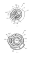
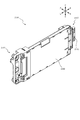
図15(a)は、変位規制装置180の背面斜視図であり、図15(b)は、変位規制装置180の正面斜視図であり、図15(c)は、変位規制装置180の正面斜視図である。
15 (a) is a rear perspective view of the
なお、図15(a)及び図15(b)では、規制解除状態の変位規制装置180が図示され、図15(c)では、規制状態の変位規制装置180が図示される。図15(a)から図15(c)で示すように、変位規制装置180は、当接部材181から円筒部183dが出没することにより、規制状態と規制解除状態とが切り替えられる。変位規制装置180の規制状態において、円筒部183dは、背面ケース510の内側まで張り出し、拡大縮小ユニット600の被規制孔657と係合可能に構成されるが、詳細は後述する。
In addition, FIG. 15A and FIG. 15B show the
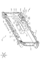
図16は、変位規制装置180の分解背面斜視図であり、図17は、変位規制装置180の分解正面斜視図であり、図18(a)は、当接部材181の背面図であり、図18(b)は、案内部材182の正面図であり、図18(c)は、操作部材183の正面図である。
16 is an exploded rear perspective view of the
図16から図18に示すように、変位規制装置180は、背面ケース510(図6参照)に当接配置される当接部材181と、その当接部材181の背面側に配置され当接部材181に締結固定されると共に操作部材183を前後方向に案内する案内部材182と、その案内部材182に変位を案内される操作部材183と、その操作部材183と当接部材181との間に配設され操作部材181に背面側へ向く付勢力を付与可能に構成されるコイルスプリング184とを主に備える。
As shown in FIGS. 16 to 18, the
操作部材183が背面視で左右に長尺の略楕円形状から形成されることに伴い、操作部材183を収容する当接部材181や案内部材182も背面視で左右に長尺の略楕円形状から形成されるので、変位規制装置180の外観形状は、背面視で左右に長尺の略楕円形状となる。
As the operating
当接部材181は、背面ケース510との接触面積を大きくすることで保持力を高めるよう主に板状で設計されており、その板端から背面側へ向けて案内部材182を保持するための壁部が延設されており、左右端部において穿設され背面ケース510から突出する締結部が挿通される挿通孔181aと、コイルスプリング184を隙間に配置可能な形状の二重筒状で背面側へ突設される筒状保持部181bと、操作部材183との関係で周知のラッチ機構を構成し操作部材183と係合可能に構成される被係合部181cとを備える。
The
案内部材182は、当接部材181の外周に沿う楕円の環状で前後方向に延設される本体部182aと、挿通孔181aに挿通される締結部に螺入される締結ネジが挿通されるネジ挿通部182bと、当接部材181に挿通される締結ネジが螺入される締結部182cと、本体部182aの背面側端部において径方向内側に張り出す抜け止め部182dと、本体部182aの上下内側部において前後方向に亘って径方向内側に突設される突条182eとを備える。
The
本構成から、当接部材181と案内部材182とを締結固定することで、当接部材181と案内部材182との間に操作部材183を配置し、脱落不能に保持することができるが、本実施形態では、その締結方向の設定により、当接部材181と案内部材182とを分解可能な状況を限定している。
From this configuration, by fastening and fixing the
換言すれば、本実施形態では、当接部材181と案内部材182とを締結固定するための締結ネジを、当接部材182の正面側(背面ケース510により覆われる側)から挿通させる構成としているので、背面ケース510に変位規制装置180が組み付けられている状態では、締結ネジに触れることができない。従って、変位規制装置180を背面ケース510から取り外した状態でのみ当接部材181と案内部材182とを分解することができる。
In other words, in the present embodiment, the fastening screw for fastening and fixing the
なお、変位規制装置180を背面ケース510に締結固定するための締結ネジは、案内部材182の背面側からネジ挿通部182bに挿通されているので、背面ケース510の背面側が露出する状態(図19参照)において容易に触れることができ、変位規制装置180を背面ケース510から取り外すことを容易とすることができる。
Since the fastening screw for fastening and fixing the
操作部材183は、案内部材182の抜け止め部182dよりも若干小さな楕円形で背面視外形が形成され正面側が開放されるカップ状に形成される本体部183aと、その本体部183aの前縁部から径方向外方へ張り出すフランジ部183bと、そのフランジ部183bに凹設される溝部183cと、本体部183aの底部中央から正面側へ円筒状に突設される円筒部183dと、その円筒部183dを中心としてコイルスプリング184の外径よりも大径の円弧形状で正面側に突設される円弧形状突条部183eと、当接部材181の被係合部181cに係合可能な位置に突設され、被係合部181cとの関係で周知のラッチ機構を構成可能とされる係合部183fとを備える。
The
操作部材183の板背面には、楕円形状のシールが貼り付けられている。このシールは、短手方向の端部の一方に凹形状が形成されており(図15(a)参照)、この凹形状を上向きに配置することで、組み付け時における上下姿勢間違いを容易に防止することができる。
An elliptical seal is attached to the back surface of the plate of the operating
本体部183aを楕円形とすることにより、操作部材183が回転変位することを容易に防止することができる。即ち、操作部材183が回転変位しそうになっても、案内部材182の本体部182aと当接することで回転が規制される。
By making the
フランジ部183bは、案内部材182の抜け止め部182dよりも背面視で大きく形成されており、これにより操作部材183が案内部材182から抜け落ちることを防止することができる。即ち、操作部材183は、フランジ部183bが当接部材181と案内部材182との間に保持された状態において前後方向に変位可能とされる。
The
溝部183cは、案内部材182の突条182eと対応する位置に形成されており、操作部材183の前後変位を滑らかに行わせる役割がある。なお、本実施形態では、突条182eが上側に2箇所、下側に1箇所で形成されていることに伴い、溝部183cも上側に2箇所、下側に1箇所で形成される。これにより、操作部材183の上下を間違えて行う誤組立を防止することができる。
The
円筒部183dは、コイルスプリング184の巻き中心に挿通される部分であって、当接部材181の筒状保持部181bの中央開口に挿通可能に構成される。円筒部183dが当接部材181の中央開口から張り出した状態では、後述するように、円筒部183dは拡大縮小ユニット600の被規制孔657と係合し、演出部材700の昇降変位を規制する。
The
即ち、本実施形態では、円筒部183dを、拡大縮小ユニット600の演出部材700の昇降変位を規制する部分と、コイルスプリング184を支持する部分とで兼用することができる。
That is, in the present embodiment, the
円弧形状突条部183eは、コイルスプリング184の外径側と対向配置可能に配設され、当接部材181の筒状保持部181bの大径側筒状部と前後方向で対向配置される。操作部材183が押し込み操作される際には、他の部分に先行して円弧形状突条部183eと筒状保持部181bとが当接するので、負荷発生面積を増やすことができ、局所的に大負荷が生じることを防止することができる。
The arc-shaped
円弧形状突条部183eは、円状では無く、円が途切れた円弧状に形成され、その途切れた位置において係合部183fが配設される。これにより、係合部183fと、円筒部183d及びコイルスプリング184とが離れすぎることを回避することができる。
The arc-shaped
操作部材183の状態変化について説明する。操作部材183には、コイルスプリング184により背面側へ付勢されているところ、この付勢力に抗して操作部材183を正面側へ押し込むと、係合部183fと被係合部181cとで構成されるラッチ機構が作用し、ラッチ機構が作用する最小ストローク以上で押し込む度に、上述した規制状態と、規制解除状態とで交互に切り替えられる。
The state change of the operating
このように、ラッチ機構により状態変化可能に構成されているので、操作部材183が意図的に操作された場合に限らず、パチンコ機10に大きな外力が与えられることで操作部材183が上述の最小ストローク分だけ変位してしまうと、意図せず変位規制装置180が状態変化する虞がある。
As described above, since the state can be changed by the latch mechanism, the operating
例えば、変位規制装置180の規制状態において、出荷時の衝撃や、搬送時の振動で、意図せずに変位規制装置180に状態変化が生じると、拡大縮小ユニット600が演出待機状態(演出部材700が上側変位終端に配置される状態)から変位する可能性がある。演出待機状態から変位した演出部材700が区画部材310に近接配置された状態(図13参照)で、出荷時の衝撃や搬送時の振動を受けると、演出部材700が発射演出ユニット300の区画部材310に衝突する虞があり、演出部材700や区画部材310が破損する虞がある。
For example, in the regulated state of the
これに対し、本実施形態では、操作部材183に対して付勢力が加えられる位置(中央位置)から離れた位置(右側に偏心した位置)に係合部183fが配置されていると共に、操作部材183の溝部183cと案内部材182の突条182eとの隙間寸法が大きく設定され、操作部材183の姿勢維持能力を敢えて下げて構成される。
On the other hand, in the present embodiment, the engaging
これにより、案内部材182に対する操作部材183の姿勢を予め傾斜させておくことができることから、操作部材183の変位抵抗を増加させておくことができる。従って、意図しない外力により操作部材183が前後方向に変位する変位量を抑制することができる。
As a result, the posture of the operating
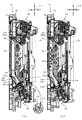
変位規制装置180の動作ユニット500との関係について説明する。図19は、正面枠14を開放した状態におけるパチンコ機10の正面斜視図であり、図20は、遊技盤13及び動作ユニット500の背面図であり、図21(a)及び図21(b)は、図20のXXIa−XXIa線における遊技盤13及び動作ユニット500の断面図である。
The relationship between the
なお、図21(a)では、変位規制装置180の規制状態が図示され、図21(b)では、変位規制装置180の規制解除状態が図示される。
Note that FIG. 21 (a) shows the regulated state of the
図19に示すように、変位規制装置180は、内枠12の開閉基端側(左側)に配置されており、裏パック92を内枠12に対して開放することにより作業者が手を延ばせば触れられるよう構成される。この位置は、内枠12を開放して作業を行う作業者が進入する側(開閉先端側、右側)の反対側であるので、内枠12の開放時に、作業者が意図せず変位規制装置180に触れることを回避することができる。
As shown in FIG. 19, the
図21(a)及び図21(b)に示すように、上述のラッチ機構を構成する係合部183f及び被係合部181cは、変位規制装置180の右側部に形成されている。操作部材183は緩い支持とされているので、操作部材183を押しこむ負荷の全てが操作部材183の前後移動に使用されるものでは無く、操作部材183の姿勢変化にも使用される。
As shown in FIGS. 21 (a) and 21 (b), the engaging
例えば、操作部材183の右側を押し込んだ場合に、右側部は十分に前後移動するとしても、操作部材183が姿勢変化して、左側部が十分に押し込まれないという事態が十分生じ得る。
For example, when the right side of the operating
そのため、変位規制装置180を押し込んで状態の切り替えを行う目的からすれば、作業者は、ラッチ機構の形成部をピンポイントで押し込む方が、変位規制装置180に必要な変位を生じさせ易く、変位規制装置180の状態切り替えに成功し易いといえる。
Therefore, for the purpose of pushing the
本実施形態では、上述のように、ラッチ機構を構成する係合部183f及び被係合部181cは、変位規制装置180の右側部に形成されており、作業者は右側から進入して変位規制装置180を操作するので、作業者は最小限の動作で変位規制装置180に到達することができる。従って、作業者は、ラッチ機構の形成部をピンポイントで押し込む操作を容易に実行することができる。
In the present embodiment, as described above, the engaging
また、操作部材183を押し込む際の姿勢変化は、押し込まれる側へ押圧面(円筒部183dの基端側に形成される面)を向ける態様で生じる。従って、押し込み量が大きくなるにしたがって、作業者の押し込み負荷が操作部材183に伝達され易く構成することができる。
Further, the posture change when the operating
図21(a)に示す規制状態では、操作部材183の円筒部183dが、伝達ギア650の被規制孔657に挿通され、伝達ギア650の変位を規制している。これにより、拡大縮小ユニット600の状態が変化することを防止することができる。
In the regulated state shown in FIG. 21A, the
伝達ギア650の変位方向(前後方向軸を中心とした回転方向)と、操作部材183の変位方向(前後方向)とは直交しているので、伝達ギア650から操作部材183が変位方向の負荷を受けることを防止することができる。これにより、ラッチ機構の形成部を強固な構成とせずとも、伝達ギア650の変位を有効に規制することができる。
Since the displacement direction of the transmission gear 650 (rotational direction centered on the front-rear axis) and the displacement direction of the operating member 183 (front-rear direction) are orthogonal to each other, the operating
このように、変位規制装置180を規制状態とすることで、拡大縮小ユニット600の状態を維持することができることから、変位規制装置180の用途は、搬送時に限られるものでは無い。例えば、遊技機店に設置後、メンテナンス時において、変位規制装置180を規制状態として拡大縮小ユニット600の状態を維持することで、後述する変位回転ユニット800のメンテナンスを安全簡易に行うことができる。
As described above, by setting the
即ち、本実施形態のように、拡大縮小ユニット600の変位軌跡と、変位回転ユニット800の変位軌跡とが部分的に重なる場合において、変位回転ユニット800のメンテナンス作業中に拡大縮小ユニット600の駆動モータMT2を誤動作させてしまったとしても、変位規制装置180により拡大縮小ユニット600の状態(配置)を維持することができるので、拡大縮小ユニット600と変位回転ユニット800とが衝突することを防止することができる。
That is, when the displacement locus of the enlargement /
パチンコ機10に電源が投入される前において、変位規制装置180が規制状態である場合には、変位規制装置180の操作部材183を押し込み操作することで、変位規制装置180が規制解除状態に切り替えられる(図21(b)参照)。これにより、伝達ギア650は変位可能となり、拡大縮小ユニット600に状態変化を伴う演出動作を実行させることができる。
If the
ここで、電源投入前に、正面枠14及び内枠12を外枠11に対してわずかに開放し、開放先端側(右側)から覗き込むことで、変位規制装置180が規制解除状態となっているかを確認可能に構成されることについて説明する。
Here, before the power is turned on, the
図21(a)に示すように、変位規制装置180の規制状態では、操作部材183が背面ケース510の底壁部511の形状部よりも前側に配置されているので、右側から覗き込む方向視において、操作部材183が底壁部511の形状部に隠される。
As shown in FIG. 21 (a), in the regulated state of the
一方、図21(b)に示すように、変位規制装置180の規制解除状態では、操作部材183が背面ケース510の底壁部511の形状部よりも背面側に張り出して配置されているので、右側から覗き込む方向視において、操作部材183が底壁部511からはみ出す位置に視認される。
On the other hand, as shown in FIG. 21B, in the deregulated state of the
従って、作業者は、電源投入前の確認作業として、正面枠14及び内枠12を外枠11に対して全開にしなくても、正面枠14及び内枠12を外枠11に対してわずかに開放し、右側から覗き込む方向視において、操作部材183が底壁部511からはみ出していることを視認することで、変位規制装置180が規制解除状態となっていることを確認することができる。
Therefore, as a confirmation work before turning on the power, the operator does not have to fully open the
なお、本実施形態では、背面ケース510が無色透明の樹脂材料から形成され、操作部材183が赤色透明の樹脂材料から形成されているので、操作部材183の視認性を向上することができる。
In the present embodiment, since the
ここで、変位規制装置180の規制状態において拡大縮小ユニット600の伝達ギア650の被規制孔657に円筒部183dが挿通されたまま(図21(a)参照)、電源投入された場合について説明する。本実施形態では、変位規制装置180が規制状態のままパチンコ機10の電源が投入された場合、電源導入時動作において拡大縮小ユニット600が状態変化していないことが検出センサSC7(図52参照)の出力から判定され、この判定に伴う位置検出エラー表示が第3図柄表示装置81により表示される。
Here, a case where the power is turned on with the
この位置検出エラー表示を遊技機店の店員に見せることで、変位規制装置180の状態を変化させていないかもしれないことに気付かせることができる。なお、このエラー表示は、拡大縮小ユニット600の状態変化の有無の検出により表示されるものであり、変位規制装置180の状態を検出したものでは無い。
By showing this position detection error display to the clerk of the gaming machine store, it is possible to notice that the state of the
即ち、本実施形態では、追加のエラー表示のためのプログラムや、表示素材を用意することなく、拡大縮小ユニット600に通常備えられる位置検出エラー表示を利用して変位規制装置180の状態に関する警報を出力することができる。これにより、設計コストの低減を図ることができる。
That is, in the present embodiment, an alarm regarding the state of the
なお、本実施形態では、変位規制装置180の規制状態において拡大縮小ユニット600の伝達ギア650の被規制孔657に円筒部183dが挿通されたまま(図21(a)参照)、電源を投入した場合に、電源投入中は操作部材183の押し込み操作を不能に構成され、一端電源をオフすることを要求されるが、必ずしもこれに限られるものではない。例えば、電源投入中においても操作部材183の操作が可能に構成されても良い。
In the present embodiment, the power is turned on while the
また、操作部材183の押し込み操作を不能にする構成は任意に設定可能である。例えば、伝達ギア650と操作部材183との間で生じる摩擦により押し込み操作を不能とする構成でも良いし、操作部材183の円筒部183dの基端側に大径部を設け、伝達ギア650の変位中においては、伝達ギア650の板背面と、円筒部183dの大径部とが前後で係合し、操作部材183の変位を制限するように構成しても良い。
Further, the configuration for disabling the pushing operation of the operating
異なるシチュエーションとして、遊技機店でのメンテナンス中に変位規制装置180の操作部材183を押し込み操作する場合の一例について説明する。本実施形態では、操作部材183の押し込み操作は、拡大縮小ユニット600の被規制孔657が円筒部183dと前後で合致する場合においてのみ可能であるものではない。
As a different situation, an example will be described in which the operating
例えば、メンテナンスの際に、拡大縮小ユニット600を張出状態(図8参照)としながら操作部材183を押し込み操作した場合でも、変位規制装置180は規制状態に状態変化する。この場合、拡大縮小ユニット600の伝達ギア650の変位軌跡上に円筒部183dが配置されることになるので、メンテナンス終了後に駆動力が生じ伝達ギア650が変位する場合に、その変位が円筒部183dに制限される。
For example, even when the
本実施形態では、伝達ギア650の変位が制限されていることを判定可能に構成されており、この判定に基づきエラー表示(異常の報知)を行うことで、変位規制装置180が規制状態のままであることを遊技機店の店員に報知することができるが、詳細は後述する。
In the present embodiment, it is possible to determine that the displacement of the
これにより、変位規制装置180の状態を検出する装置を別途設けなくても、拡大縮小ユニット600の状態を検出する装置を流用して変位規制装置180の状態を判定することができる。
Thereby, even if a device for detecting the state of the
なお、変位規制装置180の操作は、遊技盤13及び動作ユニット500を内枠12に組み付ける前でも、組み付けた後でも実行可能である。内枠12に組み付けた後においては、内枠12を開放するだけでなく、裏パック92を内枠12に対して開放する作業を要するので、可能であれば内枠12に組み付ける前に変位規制装置180の操作を行っておくことが好ましい。
The operation of the
図5及び図6に戻って説明する。本実施形態では、第3図柄表示装置81の他に、遊技を盛り上げる演出装置として、上述の発射演出ユニット300、拡大縮小ユニット600及び変位回転ユニット800が配設される。これら演出装置について、発射演出ユニット300から順に説明する。
A description will be given by returning to FIGS. 5 and 6. In the present embodiment, in addition to the third
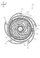
図22は、遊技盤13及び発射演出ユニット300の分解正面斜視図であり、図23は、遊技盤13及び発射演出ユニット300の分解背面斜視図である。図22及び図23に示すように、発射演出ユニット300は組立状態において、区画部材310が導光板161に対向配置される。即ち、遊技者に対して、導光板161と区画部材310とを重ねて視認させる演出を実行することができる。
FIG. 22 is an exploded front perspective view of the
区画部材310は、無色で光透過性の樹脂材料から形成されているので内部で飛散する粒状部材320を遊技者に視認させることができ、センターフレーム86で囲まれる範囲を視認する遊技者に対して、導光板161と飛散する粒状部材320とを重ねて視認させる演出を実行することができる。
Since the
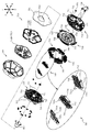
図24は、発射演出ユニット300の分解正面斜視図であり、図25は、発射演出ユニット300の分解背面斜視図である。図24及び図25では、区画部材310が分解して図示される。
FIG. 24 is an exploded front perspective view of the firing
図24及び図25に示すように、発射演出ユニット300は、センターフレーム86(図22及び図23参照)の内方に配置され下側が開放された箱形状を形成する区画部材310と、その区画部材310の内部を変位可能に配置される複数の粒状部材320と、その粒状部材320が区画部材310から脱落しないよう下側の開放部分を塞ぐ態様で配設される射出装置400と、区画部材310の右側に配設される第1光照射装置330と、区画部材310の左側に配設される第2光照射装置340と、を備える。
As shown in FIGS. 24 and 25, the firing
区画部材310は、光透過性の樹脂材料から形成され、最前面に配置される板状部である前面板部311と、その前面板部311の下方に一体的に形成される湾曲板部312と、前面板部311の背面側に前面板部311と平行な関係の底板部が対向配置され、その底板部の左右および上部から空隙を塞ぐように前面側へ延設される閉塞壁を有する背面区画部313と、その背面区画部313の下方に一体的に形成され、前面板部311と背面区画部313との間に構成される内部空間IE1(図12(a)参照)に連通する経路を湾曲板部312との間で構成可能とされる背面区画下部314と、その背面区画下部314に貫通形成される異形貫通部315と、を備える。
The
区画部材310の大きさは何ら限定されるものでは無いが、本実施形態では、センターフレーム86の内側において導光板161を囲む窓部の大きさと、区画部材310の正面視の大きさとが同程度となるように形成される。即ち、導光板161と前面板部311とが略同一形状となるように形成される。
The size of the
これにより、導光板161の縁部を隠すための構成部材を、区画部材310の縁部を隠す用途で兼用することができる。区画部材310の縁部を隠すための専用の構成部材を不要とし、部材個数の削減を図りながら、区画部材310の縁部が第3図柄表示装置81による表示に重なって視認されることにより表示が分断される事態の発生を避けることができるので、第3図柄表示装置81による表示の視認性を維持することができる。
As a result, the constituent member for hiding the edge portion of the
内部空間IE1は、粒状部材320が飛散可能な範囲としての役割を持つが、この空間が広すぎると、粒状部材320が散らばりすぎて、迫力のある演出のために粒状部材320の個数を非常に多くする必要が生じる。そのため、ある程度狭い空間として形成するほうが、少数の粒状部材320を密度高く視認させることで迫力のある演出を実行できる。
The internal space IE1 has a role as a range in which the
一方で、空間を狭くし過ぎると、粒状部材320の詰まりを生じる虞がある。これに対し、本実施形態では、内部空間IE1の前後幅は、湾曲板部312の左右中央部312bと背面区画下部314との間の前後幅と同程度で確保される。そのため、前後幅が短縮される場合に比較して、内部空間IE1における粒状部材320の詰まりや、射出時の急激な減速を回避することができる。
On the other hand, if the space is made too narrow, the
更に、湾曲板部312の左右部312aが左右中央部312bよりも背面区画下部314に近接配置されることから、左右中央部312b付近における粒状部材320の移動経路に比較して、左右部312b付近における粒状部材320の移動経路を狭くすることができる。
Further, since the left and
即ち、射出装置400により粒状部材320が内部空間IE1へ射出される場合に、粒状部材320の移動経路が左右中央部312b付近に集中するようにすることができ、粒状部材320が内部空間IE1の中央部付近に到達し易くすることができる。これにより、粒状部材320を遊技者に視認させ易くすることができる。
That is, when the
加えて、粒状部材320が内部空間IE1の中央部付近に到達した後は、粒状部材320は前面板部311と衝突し、内部空間IE1を飛散する。これにより、遊技者に対して、あたかも内部空間IE1の中央部付近から粒状部材320が爆発して四方八方に飛散しているかのように視認させることができるので、粒状部材320の動作演出の迫力を向上することができる。
In addition, after the
湾曲板部312は、内部空間IE1に射出された粒状部材320が落下する際に、その粒状部材320を受け止める部分とし機能する。この観点で、湾曲板部312は、本実施形態では、背面側へ向かうほど下降傾斜し、左右中央へ向かうほど下降傾斜するように設計される。
The
これにより、粒状部材320が内部空間IE1のどこに配置されたかに関わらず、自重で下降変位する粒状部材320を左右中央側へ寄せつつ、背面側下方へ向けて変位させることができる。
As a result, regardless of where the
更に、湾曲板部312の左右部312aにおける下降傾斜の度合いは、背面側へ向けた下降傾斜に比較して、左右中央側へ向けた下降傾斜の方が急激となるように構成されている。これにより、粒状部材320の下降変位の傾向として、背面側へ向かう変位に優先して左右中央側へ向かう変位を生じさせることができる。そのため、後述する射出装置400の構成から粒状部材320が密集し易い左右端位置において粒状部材320が一斉に背面側へ変位しようとして、粒状部材320が下降変位の途中で滞留する(詰まる)という事態の発生を回避することができる。
Further, the degree of downward inclination of the
加えて、湾曲板部312の左右中央部312bにおける背面側へ向けた下降傾斜の度合いは、湾曲板部312の左右部312aにおける左右中央側へ向けた下降傾斜の度合いに比較して急激となるように構成されている。これにより、粒状部材320が流下途中で密集することを避け易くすることができる。
In addition, the degree of downward inclination of the
これに対し、背面区画下部314は、湾曲板部312の背面側に対向配置される板部が、湾曲板部312の左右中央部312bと側面視(図12(a)参照)で同程度(若干、正面側へ向かう程に左右中央部312bとの間隔が広くなる態様、即ち、水平方向に対する角度が大)の傾斜角度の平板状に形成される。
On the other hand, in the rear compartment
本実施形態では、背面区画下部314の上下方向に対する傾斜角度は、粒状部材320を射出する衝突部材420の変位方向の上下方向に対する傾斜角度と同等(若干、大きい角度)とされる。
In the present embodiment, the inclination angle of the
そのため、左右に変化し得る粒状部材320の射出方向に寄らず、背面区画下部314に対する粒状部材320の入射角が同じになるので、背面区画下部314から粒状部材320に与えられる抵抗をほぼ均一とすることができる。
Therefore, the incident angle of the
異形貫通部315は、蓋部材480を挿入可能な形状で形成されており、左右両端において上下に延びる短尺部と、その短尺部の上端同士を結ぶ態様で左右に湾曲して延びる長尺部とを備える。貫通方向は、背面区画下部314の板面に対し背面側から正面側へ向かうにつれて斜め上向きに傾斜して形成される(図12(a)参照)。これにより、異形貫通部315を構成する背面区画下部314の鋭角部分(図12(a)において、異形貫通部315の下側部分)は、粒状部材320の射出方向と対向配置されない。
The deformed penetrating
これにより、粒状部材320の射出時に、粒状部材320が鋭角部分に衝突する可能性を低くすることができるので、粒状部材320や背面区画下部314に局所的な負荷が生じることを回避でき、粒状部材320や背面区画下部314に割れや欠けが生じることを防ぐことができる。
As a result, it is possible to reduce the possibility that the
粒状部材320は、図24及び図25に拡大して図示されるように、比較的柔軟(少なくとも区画部材310を形成する樹脂材料よりも柔軟)な樹脂材料から略サッカーボール形状(12の正五角形と20の正六角形からなる32面体であり、準正多面体)に形成され、互いに平行な複数の直線に沿って非貫通で凹設される非貫通凹部321を備える。
The
この非貫通凹部321により、粒状部材320の軽量化を図ることができると共に、粒状部材320の重心を形状的な中心位置から偏らせることができる。即ち、非貫通凹部321が形成される直線方向において、非貫通凹部321が形成されていない側には肉部が残るので、非貫通凹部321が形成されていない側に重心を偏らせることができる。
The
これにより、粒状部材320の待機姿勢を調整することができる。即ち、粒状部材320の待機姿勢を、非貫通凹部321が上方を向く姿勢に調整することができる(図24参照)。
Thereby, the standby posture of the
この場合、射出装置400からの負荷を、非貫通凹部321が形成されていない側の面(図25参照)で受けることができるので、粒状部材320の破損や欠けを回避し易くすることができる。更に、射出装置400から負荷を受けて射出される際の射出方向側に非貫通凹部321を向けることになるので、非貫通凹部321が形成される側の面を前面板部311に衝突させることができる。これにより、前面板部311との衝突時の負荷を粒状部材320の変形により吸収し易くすることができ、前面板部311を傷付ける可能性を低くすることができる。
In this case, since the load from the
第1光照射部330は、背面区画部313の背面側に締結固定される固定板部331と、その固定板部331の右側に締結固定される電飾基板332と、その電飾基板332の右側に配設され固定板部331に締結固定され固定板部331との間に電飾基板332を収容可能に形成される蓋部333と、を備える。
The first
電飾基板332は、左右両面にLED等の光照射部332aが配設され、光照射部332aから左右方向へ光軸を有する光が照射される。固定板部331及び蓋部333は、光透過性の低い樹脂材料から形成され、光照射部332aに対応する位置に貫通孔331a,333aが穿設される。これにより、粒状に分割された光として視認させることができる。
The
電飾基板332から照射される光の内、右側へ照射される光は、スルーゲート67等(図2参照)が配設される遊技領域の右側経路(右打ち流路)を照らすことが一つの目的となる。左側へ照射される光については後述する。
Of the light emitted from the
固定板部331及び蓋部333は、光透過性の低い(又は光不透過の)樹脂材料から形成され、光照射部332aに対応する位置に貫通孔331a,333aが穿設される。これにより、光照射部332aから照射される光を、粒状に分割された光として視認させることができると共に、光照射部332aから離れた範囲において電飾基板332が固定板部331及び蓋部333により遮蔽され、視認されることを避けることができる。
The fixing
第2光照射部340は、背面区画部313の背面側に締結固定される固定板部341と、その固定板部341の左側に締結固定される電飾基板342と、その電飾基板342の左側に配設され固定板部341に締結固定され固定板部341との間に電飾基板342を収容可能に形成される蓋部343と、を備える。
The second
固定板部341は光透過性の低い(又は光不透過の)樹脂材料から形成される一方で、蓋部343は、無色で光透過性の樹脂材料から形成される。そのため、左方向から視認すると電飾基板342が見えてしまう構成であるが、本実施形態では、センターフレーム86(図2参照)の左側部が左方へ長く張り出して構成される。これにより、遊技者の視界を予め狭めることができ、正面視で電飾基板342の左側面が視認されることを避けることができる。
The fixing
これにより、電飾基板342が視認されることは避けながら、透明な蓋部343を通して光を照射することができる。
As a result, light can be emitted through the
電飾基板342は、左右両面にLED等の光照射部342aが配設される。左側面に配設される光照射部342aからは、前方向へ向く光軸を有する光が照射される。この光は、遊技領域の左側経路を照らさないようにしつつ、センターフレーム86の左側部を照らすことが一つの目的となる。
The
ここで、右側の電飾基板332の光照射部342aから照射される光を遊技領域に積極的に向ける構成と違う構成を採用しているのは、本パチンコ機10の遊技性(通常時は左打ちで遊技を行い、確変中、時短中および大当たり遊技中は右打ちで遊技を行うこと)を考慮したものである。これについて以下で説明する。
Here, it is the playability of the pachinko machine 10 (normally, that is different from the configuration in which the light emitted from the
本パチンコ機10の遊技領域は、遊技領域の左側部における球の流下経路の自由度は高いので、通常時の遊技中には、好みの経路で球が流下するように球の発射強度を調整するという操作が遊技者により行われる。そのため、遊技領域の左側部における発光強度を高くし過ぎると、球の視認性が悪くなり、球の発射強度調整に支障をきたし、遊技者の不満の原因となる虞がある。
Since the gaming area of the
一方で、遊技領域の右側部へ球を発射する際、基本的には、遊技者は球を最大の発射強度で打ち出す。発射された球は、返しゴム69で勢いが抑えられ、その下流側での球の流下経路の選択自由度は著しく低くなり、専ら同様の経路を通るようになる。
On the other hand, when launching a ball to the right side of the game area, the player basically launches the ball with the maximum firing intensity. The momentum of the launched ball is suppressed by the
詳述すると、本実施形態では、第2入賞口640よりも下流側において球が1個通る幅で単一の案内経路DL1(図2参照)が形成されており、第2入賞口640に入球しなかった球は全て案内経路DL1を通り、その下流側に配置される可変入賞装置65や一般入賞口63へ向かうことになる。
More specifically, in the present embodiment, a single guide path DL1 (see FIG. 2) is formed with a width through which one ball passes on the downstream side of the second winning opening 640, and enters the second winning opening 640. All the balls that did not ball pass through the guide path DL1 and head toward the variable winning
このように、球の発射強度を調整する必要性が乏しいことから、遊技領域の右側部(特に、案内経路DL1が形成される箇所)において球の視認性が悪くなったとしても遊技に支障をきたす可能性が低いので、この範囲においては発光強度の高い演出を実行可能となる。 In this way, since it is not necessary to adjust the firing intensity of the ball, even if the visibility of the ball deteriorates in the right side portion of the game area (particularly, the place where the guide path DL1 is formed), the game is hindered. Since it is unlikely to occur, it is possible to perform an effect with high emission intensity in this range.
このような事情から、本実施形態では、右側に配置される電飾基板332では、遊技領域に光を向けるように光照射部332aを配設する一方で、左側に配置される電飾基板342では、遊技領域に光を向けないように光照射部342aを配設するようにしている。これにより、遊技者の不満の発生を抑えながら、効果的な発光演出を実行することができる。
Under these circumstances, in the present embodiment, in the
右側面に配設される光照射部342aからは、右方へ向く光軸を有する光が照射される。固定板部341には、光照射部342aに対応する位置に貫通孔341aが穿設される。これにより、光照射部342aから照射される光を、粒状に分割された光として視認させることができると共に、光照射部342aから離れた範囲において電飾基板342が固定板部341により遮蔽され、視認されることを避けることができる。なお、右側面に配設される光照射部342aにより照らされる対象については後述する。
Light having an optical axis pointing to the right is emitted from the
図26(a)は、図25の矢印R方向視における第1光照射装置330の側面図であり、図26(b)は、図25の矢印L方向視における第2光照射装置340の側面図である。図26(a)及び図26(b)では、区画部材310の外形が想像線で図示される。
26 (a) is a side view of the first
図26(a)に示すように、第1光照射装置330の左面側に配設される光照射部332aは、区画部材310を光軸が通過するLEDと、区画部材310の背面側を光軸が通過するLEDとを備える。
As shown in FIG. 26A, the
これにより、区画部材310の内部で粒状部材320に光を照射する演出だけでなく、区画部材310の背面側に配置される他の可動手段(拡大縮小ユニット600や変位回転ユニット800)に光を照射する演出を実行することができる。
As a result, not only the effect of irradiating the
図26(b)に示すように、第2光照射装置340の右面側に配設される光照射部342aは、区画部材310を光軸が通過するLEDは無く、区画部材310の背面側を光軸が通過するLEDのみにより構成される。
As shown in FIG. 26B, the
これにより、区画部材310の内部への発光強度を抑制しながら、区画部材310の背面側に配置される他の可動手段(拡大縮小ユニット600や変位回転ユニット800)へ向けた光の照射強度を向上させることができる。
As a result, while suppressing the intensity of light emission to the inside of the
第2照射装置340において、区画部材310の内部への発光強度を抑制することにより、通常状態での遊技の快適性を向上することができる。即ち、通常状態での遊技において、遊技者の視線は固定されるものではないが、主に遊技領域の左側や、第3図柄表示装置81の表示または第1入賞口64付近に向けられるので、遊技領域の中央から左側の範囲を見ていることが多い。
In the
この場合において、第2照射装置340から区画部材310の内部へ光が照射されると、遊技領域と同程度に前寄りの位置で光ることから、遊技領域の左側を視認する遊技者にとっては逆光となり、遊技者にとって遊技領域の視認性が悪くなる虞がある。
In this case, when the inside of the
これに対し、本実施形態では、第2照射装置340の光照射部342aの配置を背面側に寄せ、遊技領域と光照射部342aとを離しているので、光照射部342aから照射される光が遊技領域の視認性に与える影響の度合いを弱めることができる。
On the other hand, in the present embodiment, since the arrangement of the
このように、本実施形態によれば、第2照射装置340の光照射部342aから照射された光が遊技領域を光らせる度合いを下げながら、正面視におけるセンターフレーム86の内側を高強度に光らせる発光演出を実行することができる。従って、遊技領域の視認性を下げることなく、拡大縮小ユニット600や変位回転ユニット800(図5参照)を光らせる演出を実行することができる。
As described above, according to the present embodiment, the light emitted from the
図27は、図2のXXVII−XXVII線における遊技盤13及び発射ユニット300の断面図である。即ち、図27では、遊技盤13及び発射ユニット300が図示され、動作ユニット500の図示は省略されている。また、第1光照射装置330や第2光照射装置340から照射される光の方向が模式的に矢印で図示される。
FIG. 27 is a cross-sectional view of the
図27に示すように、第2光照射装置340は、導光板161へ光を照射する後述する縦置き基板ユニット167を避けて、縦置き基板ユニット167の左側かつ背面側に配置されている。これにより、導光板161に光照射部342aからの光が入射することを避けて発光演出を行うことができるので、光照射部342aから照射される光で行う光演出と、導光板161を光らせる演出とを切り分けることができる。
As shown in FIG. 27, the second
本実施形態のように導光板161を採用する場合、光の照射経路によっては、意図せず導光板161が発光してしまい、演出効果を下げる虞がある。特に、導光板161周辺(例えば、センターフレーム86の前側)に照射された光は導光板161を光らせやすいことから、発光強度を抑える必要性が生じる虞があり、演出自由度を下げる原因になっていた。
When the
これに対し、本実施形態によれば、光照射部342aからの光が導光板161を避けて進行するよう構成されるので、光照射部342aからの光の照射強度の設定自由度を向上することができる。これにより、導光板161周辺の発光演出の自由度を向上することができる。
On the other hand, according to the present embodiment, since the light from the
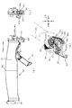
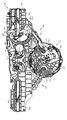
図24及び図25に戻って説明する。射出装置400は、区画部材310の下側に配設され、区画部材310の内部空間IE1(図12(a)参照)から下方へ流下した粒状部材320が乗る装置である。
The explanation will be returned to FIGS. 24 and 25. The
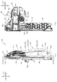
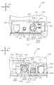
図28、図29及び図30は、射出装置400の正面分解斜視図であり、図31、図32及び図33は、射出装置400の背面分解斜視図である。なお、図28及び図31には、射出装置400の構成が概要として図示され、図29及び図32には、正面側寄りに配置される射出装置400の一部の構成の詳細が図示され、図30及び図33には、背面側寄りに配置される射出装置400の一部の構成の詳細が図示される。また、図28から図33の説明においては、図24及び図25を適宜参照する。
28, 29 and 30 are front exploded perspective views of the
図28から図33に示すように、射出装置400は、固定される部材として、区画部材310(図24参照)に締結固定される固定部材350と、その固定部材350の背面側において締結固定され固定部材350との間に他の可動部材を収容可能な空間を形成可能に構成される空間形成部材360と、その空間形成部材360の背面側において締結固定され後述する電気配線や伝達アーム部材470の前後方向の変位を制限する制限部材370と、固定部材350と空間形成部材360との間に配設され中央部に鍵穴形状の開口402が穿設される中間部材401と、を備える。
As shown in FIGS. 28 to 33, the
区画部材310への固定部材350の締結固定に利用される締結ネジは、区画部材310に正面側から挿通される。そのため、区画部材310から固定部材350を取り外す場合には、この締結ネジをドライバーで緩めて取り外す必要があるが、遊技盤13と発射ユニット300とが組み付いた状態(図12(a)参照)では、固定部材350の正面側にベース板60が配置されており、締結ネジにドライバーを差しこむことができないように構成される。
The fastening screw used for fastening and fixing the fixing
そのため、区画部材310から固定部材350を取り外す前準備として、発射ユニット300を遊技盤13から取り外す作業を行わせることができる。これにより、発射ユニット300が遊技盤13に組み付いた状態で、誤って固定部材350を区画部材310から取り外してしまい粒状部材320が固定部材310から排出される事態が発生することを未然に防ぐことができる。
Therefore, as a preparation for removing the fixing
射出装置400は、中間部材401と固定部材350との間に変位可能に配置される部材として、中間部材401の前面側に固定される複数の金属棒MB1が挿通され直動変位可能に構成される直動部材410と、その直動部材410の上側に配置され、直動部材410の変位方向に沿って変位可能に支持されると共に上部にアーチ形状の衝突面を有する衝突部材420と、直動部材410の下側に配置され、直動部材410の変位方向で当接可能な状態と当接不能な状態とで状態変化可能に構成される当接部材430と、を備える。
The
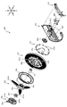
射出装置400は、中間部材401と空間形成部材360との間に変位可能に配置される部材として、直動部材410及び当接部材430に負荷を伝達可能に形成され空間形成部材360に回転可能に軸支されると共に外周面にギア歯が形成される前側伝達部材440と、固定部材350に締結固定される駆動モータMT1の駆動軸に固定され前側伝達部材440のギア歯に歯合する駆動ギア450と、その駆動ギア450に対して前側伝達部材440のフランジ部444の反対側に配設され、回転伝達部材440に締結固定される後側伝達部材460と、を備える。
The
射出装置400は、空間形成部材360の背面側で変位可能に配置される部材として、前側伝達部材440の回転軸と平行な回転軸で回転変位可能に軸支され、後側伝達部材460からの作用で変位可能に構成される伝達アーム部材470と、左右方向を向く直線を回転軸として回転変位可能に軸支され、伝達アーム部材470から受ける負荷により変位する蓋部材480と、を備える。
The
上述の構成を備える射出装置400の、設計思想について説明する。射出装置400では、固定の中間部材401と空間形成部材360とによって、空間形成部材360から突設される軸部362の突設方向に沿って、構成部材の配置範囲が3つに区切られる。このように区切られた配置範囲の内、駆動モータMT1の駆動力で回転する駆動ギア450が配置される中間の範囲に駆動モータMT1の駆動力が生じ、その駆動力が前側の範囲および後側の範囲にそれぞれ伝達されることで、前側の範囲および後側の範囲で各構成部材の変位が生じる。
The design concept of the
このような設計思想から、中間部材401及び空間形成部材360には、それぞれ駆動力伝達用の開口部が穿設される。即ち、中間部401は、鍵穴形状で穿設される開口402を備え、空間形成部材360は、レモン形状(略楕円形状)で穿設される開口361を備える。
Based on such a design concept, openings for transmitting driving force are bored in the
駆動力の伝達は、中間部401の前側の範囲、空間形成部材360の後側の範囲でそれぞれ完結するので、以下、前側の範囲、後側の範囲の順で構成の詳細を説明し、その後、中間の範囲の構成の詳細を説明し、動作態様について説明する。
Since the transmission of the driving force is completed in the front side range of the
まず、前側の範囲に着目して説明する。図29及び図32図示されるように、中間部材401は、上述の開口402と、上端部から正面側へ円柱状に突設される複数の円柱状突部403と、その円柱状突部403に上端部が支持される複数のコイルスプリングSP1と、複数の金属棒MB1を固定可能に左右対称位置で配置される複数の棒固定部404と、下端部付近において正面側へ円柱状に突設される支持柱部405と、を備えており、コイルスプリングSP1の下端部が直動部材410の下端部に形成される複数の爪部411のそれぞれ引っかけられている。
First, the front range will be focused on. As shown in FIGS. 29 and 32, the
コイルスプリングSP1の自然長は、直動部材410が上端位置に配置された状態において、円柱状突部403と爪部411との間の距離よりも短くなるように形成される。従って、直動部材410は、コイルスプリングSP1により常時付勢されることになり、中間の範囲からの駆動力伝達前において、直動部材410は付勢力により上端位置に配置される。コイルスプリングSP1は、直動部材410の斜め下側に配置されているが、これには、粒状部材320の溜まり易い側にコイルスプリングSP1の付勢力を集中させる狙いもある。
The natural length of the coil spring SP1 is formed so as to be shorter than the distance between the
直動部材410は、上述の爪部411と、金属棒MB1を挿通可能に形成される複数の挿通部412と、左右中央における上端部から台形形状に突設される台形突設部413と、背面側において上下幅方向略中央位置で左右方向に延びる直線状の突条部414と、その突条部414の下側において突条部414よりも短い突条として形成される下側突条部415と、左右中央における下端部から正面側へ向けて突設される変位規制部416と、を備える。
The
台形突設部413は、直動部材410が上端位置に配置された状態で衝突部材420と当接可能に形成される。換言すると、直動部材410は、台形突設部413のみが衝突部材420と当接可能とされ、台形突設部413を除く部分は、衝突部材420とは非当接となるように形成される。
The
突条部414及び下側突条部415は、負荷伝達の際に他の構成部材から負荷を受ける部分であるが、詳細は後述する。
The
変位規制部416は、固定部材350の緩衝部材352と変位方向で当接する部分であり、この当接により直動部材410の変位が規制される(上昇側変位終端が設定される)。
The
衝突部材420は、アーチ形状の衝突面を形成する湾曲板部421と、その湾曲板部421の背面側端部から直動部材410の変位する平面に対して平行に延設される平板状の板部422と、その板部422の延設方向に沿って延びる長孔形状で穿設される複数の案内孔423と、板部422の左右中央部下端において台形突設部413の変位方向で対向配置される位置に固定され、台形突設部413と当接可能に配置される緩衝部材424と、を備える。
The
案内孔423には、円柱状突部403が挿通される。即ち、円柱状突部403は、コイルスプリングSP1の上端部を支持する部分と、衝突部材420の変位を案内する部分とに兼用される。
A
緩衝部材424は、耐久性が高く、柔軟性の高い樹脂材料から外形正方形の小片として形成される。特に限定されるものでは無いが、例えば、ナイロン樹脂や、ウレタン樹脂等を利用することができる。この場合、緩衝部材424と直動部材410の台形突設部413とが当接した場合の負荷や衝撃を樹脂材料の特性により和らげることができ、台形突設部413の破損や欠けの発生を抑制することができる。
The cushioning
当接部材430は、略三角形の長尺板状に形成され、その長尺板の一端において支持柱部405を挿通可能な円形開口として穿設される支持孔431と、長尺板の他端において背面側へ断面円形で突設される突設部432と、支持孔431と突設部432との間の位置において断面鉤状で正面側へ突設される鉤状突部433と、を備える。
The abutting
支持孔431は、支持柱部405が挿通される開口部であり、これにより、当接部材430は支持柱部405に回転変位可能に軸支される。
The
突設部432及び鉤状突部433は、負荷伝達の際に他の構成部材から負荷を受ける部分であるが、詳細は後述する。
The projecting
固定部材350は、上述の駆動モータMT1が配設固定されるモータ固定部351と、変位規制部416と当接可能に配置される緩衝部材352と、円形状突部403の先端を受け入れ可能な凹部として形成され、その内側の貫通孔に正面側から挿通された締結ネジを円形状突部403に形成される雌ネジに螺入し締結固定可能に構成される複数の締結用凹部353と、正面側および左右の三方向からすぼまる態様の傾斜面から構成され粒状部材320(図24参照)の変位を案内する案内部354と、を備える。
The fixing
緩衝部材352は、耐久性が高く、柔軟性の高い樹脂材料から外形正方形の小片として形成される。特に限定されるものでは無いが、例えば、ナイロン樹脂や、ウレタン樹脂等を利用することができる。この場合、緩衝部材352と直動部材410の変位規制部416とが当接した場合の負荷や衝撃を樹脂材料の特性により和らげることができ、変位規制部416の破損や欠けの発生を抑制することができる。
The cushioning
このように、本実施形態では、直動部材410が付勢方向の変位終端で当接する複数箇所に緩衝部材352,424が配設されている。これにより、後述するように、直動部材410がコイルスプリングSP1の付勢力により高速で上昇変位し、急停止するような変位態様であっても、急停止の際に直動部材410が受ける負荷を緩衝部材352,424の変形で吸収することができると共に、その負荷を複数箇所に分散させることができる。
As described above, in the present embodiment, the
締結用凹部353を介して、円柱状突部403と固定部材350とが連結され、この連結を解除するには、連結用凹部353に挿通される締結ネジを回して取り外す必要がある。一方で、この締結ネジは固定部材350の正面側から挿通されているので、遊技盤13と発射演出ユニット300とが組み付けられている状態(図12参照)では、締結ネジにドライバーを差すことができないように構成される。
The
これにより、遊技盤13と発射演出ユニット300とが組み付けられている状態で、誤って締結ネジが緩められ、固定部材350と中間部材401との締結が緩む事態が発生することを未然に防ぐことができる。
As a result, it is possible to prevent a situation in which the fastening screw is accidentally loosened and the fixing
次に、後側の範囲に着目して説明する。図30及び図33に図示されるように、空間形成部材360は、上述の開口361と、背面板部の略中央位置から正面側へ向けて円柱状に突設される軸部362と、背面板部の上端位置左右端部において正面側へ延設される板状部の上面に傾斜面として形成される左右一対の案内傾斜面363と、それら案内傾斜面363の左右内側の下方に配設され背面板部から正面側に突設される左右一対の突設支持部364と、左右両端部において円筒状に形成され同一線上に配置され蓋部材480を軸支可能な大きさで形成される複数の支持柱部365と、左側の支持柱部364に巻きつけられ蓋部材480を退避させる側へ付勢力を発生させるトーションスプリングSP2と、開口361の左上部において背面側に円柱状に突設される円柱状突部366と、を備える。
Next, the description will be given focusing on the rear range. As shown in FIGS. 30 and 33, the
軸部362は、後述するように前側伝達部材440及び後側伝達部材460を回転可能に軸支する部分である。これに合わせて、軸部362を中心とした円弧形状の内面を有する壁部が、空間形成部材360の背面板部から正面側へ延設されている。この壁部によって、内部の前側伝達部材440及び後側伝達部材460をカバーすることができる。
The
案内傾斜面363は、左右内側面の傾斜が案内部354(図32参照)の左右内ぐぁ面と面一となるように構成され、流下する粒状部材320を衝突部材420側(左右中央側)へ向けて案内可能に形成される。
The guide inclined
突設支持部364は、突設先端が中間部材401の背面と当接し、上面が中間部材401と面一となるように形成される。この面一の上面で、衝突部材420が下端位置に配置された状態において湾曲板部421の左右端を下支えする。
The
支持柱部365は、左右で形状が異なる。即ち、右側では、左右外側へ向けて突設される小径筒状に形成され、左側では、左カバー部材489の筒状部を受け入れ可能な内径を備える筒状に形成される。
The shape of the
円柱状突部366は、伝達アーム470に挿通されることで伝達アーム470を回転可能に軸支する部分である。円柱状突部366の先端に形成される雌ネジに頭部大径のネジが固定されることで、伝達アーム470が脱落不能に支持される。
The
伝達アーム部材470は、外観略への字状に形成される長尺部材であって、円柱状突部366の外径よりも若干大きな直径で穿設され円柱状突部366が挿通される支持孔471と、長尺方向の一端から正面側へ向けて支持孔471の軸方向と平行に突設される円柱状突部472と、長尺方向の他端から支持孔471の軸と直交する平面に沿って円柱状に突設される伝達突部473と、を備える。
The
円柱状突部472は、空間形成部材360の開口361を通り正面側へ張り出し、後側伝達部材460と係合可能に形成される。本実施形態では、後側伝達部材460の姿勢変化に伴い、円柱状突部472の配置が変化して、伝達アーム部材470の姿勢が変化するように構成されるが、詳細は後述する。
The
円柱状突部472の背面側には、制限部材370が配設される。即ち、制限部材370は、空間形成部材360の背面側に締結固定される板状部材であって、円柱状突部472の移動経路を背面側から覆う覆設板部371と、電気配線を押さえる又は束ねる目的で爪状に形成される複数の押さえ爪部372と、を備える。
A limiting
覆設板部371は、伝達アーム部材470の背面側に近接配置され、円柱状突部472の背面側(伝達アーム部材470の回転軸方向背面側)への変位を規制する。これにより、円柱状突部472が後側伝達部材460から離れることを防止することができるので、円柱状突部472と後側伝達部材460との係合が解除されることを防止することができる。
The
押さえ爪部372は、駆動モータMT1や検出センサSC4に接続される電気配線を空間形成部材360の背面側板との間で仮留めする部分である。これにより、電気配線の配置揺れ(例えば、振動等で電気配線の配置が変化すること)が生じることを防ぐことができ、他の構成部材の進入経路を確保できるので、上述のように、射出装置400に近接する位置を含む経路で変位回転ユニット800の横スライド部材840及び羽状部材854(図10及び図12参照)を変位させるよう構成することができる。
The
伝達突部473は、蓋部材480に挿通され、蓋部材480へ駆動力を伝達するための部分である。
The
蓋部材480は、区画部材310の異形貫通部315(図12(a)参照)を通して、区画部材310の内外へ進退変位可能に構成される部材であって、湾曲板状に形成される進退部481と、その進退部481の左右両端部から同方向に延設される複数の延設板部485と、その延設板部485の延設端部において支持柱部365と同軸に受け入れられる複数の受入部486と、左側の延設板部485において湾曲した長孔形状で穿設され伝達アーム部材470の伝達突部473が挿通される伝達孔487と、右側の受入部486を囲む筒状部を有する円板状に形成され、受入部486を囲んだ状態で、支持柱部365の先端に形成される雌ネジに締結される締結ネジを挿通可能な挿通孔を有し、その締結ネジにより抜け止めされる右カバー部材488と、左側の受入部486に挿通される筒状部と、伝達孔487に連続的に連なる長孔形状部とを有する左カバー部材489と、を備える。
The
左カバー部材489には、軸方向に沿ってドリル孔のように穿設されるのではなく、機能的に形成される当接面489a〜489cが形成されるが、詳細は後述する。
The
蓋部材480の進退部481の断面形状は、受入部486に想定される回転軸を中心とした円弧状とされることにより、外径側からの負荷(粒状部材320から与えられる負荷)が回転軸へ向かうように構成されるが、単純にパイプを分割した形状では無く、左右位置に対応して円弧の半径や、形成長さを変化させている。この設計意図について説明する。
The cross-sectional shape of the advancing / retreating
第1に、進退部481は、左右中央位置において進入側に出張る張出部482を備える。張出部482は、左右外側へ向かうほど張出幅が短くなるように形成されており、進入側の端面は、左右外側へ向けて傾斜形成される。これにより、張出部482と他の構成部材(本実施形態では、粒状部材320(図24参照)が想定される)とが当接した場合に、その構成部材に対して左右外側へ向く負荷を与えることができ、構成部材を左右外側へ追いやることができる。
First, the advancing / retreating
第2に、進退部481は、上述のように、区画部材310の異形貫通部315(図25参照)を通して、区画部材310に進入可能に構成されるところ、張出部482が先行して区画部材310に進入することから、張出部482が形成される左右中央位置において進退部481の円弧半径を短くしている。
Secondly, as described above, the advancing / retreating
これにより、異形貫通部315に進入し始める箇所(張出部482の左右中央)に生じ得る位置ずれを小さく抑えることができるので、進退部481が異形貫通部315に進入不能となる不具合の発生を抑えることができる。
As a result, the positional deviation that may occur at the position where the deformed penetrating
第3に、張出部482の左右中央位置とは反対に、進退部481の左右外側付近において円弧半径を長くしている。これは、粒状部材320との接触を避けることが主な目的である。即ち、本実施形態では、衝突部材420の上面に配置される粒状部材320(図12(a)参照)は、湾曲板部421の形状により左右外側に寄って滞留する。
Thirdly, the arc radius is lengthened in the vicinity of the left and right outer sides of the advancing / retreating
この滞留の仕方は、完全に左右均一となるわけでは無く、左右不均一となる可能性がある。例えば、右側に極端に多くの粒状部材320が滞留する可能性もあり、十分なスペースが確保されていない場合には、偏って滞留した粒状部材320と進退部481とが衝突する可能性がある。
This way of staying is not completely uniform on the left and right, and may be non-uniform on the left and right. For example, an extremely large number of
これに対し、本実施形態では、粒状部材320が多く滞留し易い左右外側部付近において、進退部481の円弧半径を長くしている。これにより、予め進退部481と湾曲板部421との間隔を十分長く確保することができるので、粒状部材320の滞留の仕方が不均一となった場合でも、粒状部材320と進退部481とが衝突することを避けることができる。
On the other hand, in the present embodiment, the arc radius of the advancing / retreating
他の設計思想について説明する。延設板部485は蓋部材480の回転軸に直交する平面上に形成されるところ、進入側の端面が退避側へ向けて凹設形成される。これにより、延設板部485が、滞留している粒状部材320に衝突することを避けることができる。
Other design concepts will be explained. The
加えて、粒状部材320が流下しきる前に蓋部材480を進入側の変位終端に配置した場合であっても、粒状部材320を、延設板部485の凹設形成部と区画部材310の湾曲板部312(図25参照)との間の隙間を通過可能な程度の大きさで構成することにより、粒状部材320を衝突部材420の上部に集めることができる。
In addition, even when the
受入部486は、左右で形状が異なる。即ち、左側の左受入部486aは、円形筒状に形成され、右側の右受入部486bは半円筒状(ハーフパイプ形状)に形成されるが、これは、組み付けを考慮した設計である。
The receiving
図28及び図31に戻って説明する。蓋部材480を支持する支持柱部365は、特に右側において左右方向外側へ延びているので、蓋部材480の受入部486が両方とも円形筒状で形成される場合には、蓋部材480を支持柱部365に組み付けるために進退部481を分割する必要がある。
A description will be given by returning to FIGS. 28 and 31. Since the
上述のように、本実施形態において蓋部材480は異形貫通部315(図25参照)を通り進退変位する。異形貫通部315は、区画部材310に蓋部材480を進退変位可能に構成される一方で、粒状部材320の区画部材310からの排出を防止可能に構成される必要がある。即ち、異形貫通部315を無制限に大きくすることはできず、異形貫通部315の設計自由度は限定的となる。
As described above, in the present embodiment, the
ここで、蓋部材480が異形貫通部315を通過できない程度に形状が崩れてしまうと進退変位が不能となることから、形状に精度が求められる。一方、蓋部材480の進退部481を複数部材の結合により構成する場合には、組み付け誤差等の要因により形状が崩れる可能性がある。
Here, if the shape of the
これに対し、本実施形態では、受入部486の形状を左右で異ならせ、進退部481の分割が不要となるように構成している。組み付け過程としては、まず支持柱部365の軸方向外側(左側)に左受入部486aを配置し、左受入部486aに左カバー部材489の筒状部を挿通させつつ支持柱部365に挿通することで、左受入部486aを支持柱部365と同軸に配置することができる。
On the other hand, in the present embodiment, the shape of the receiving
この時、右受入部486bは半筒の開放側に支持柱部365が対向配置されることになる。左カバー部材489に複数形成されるネジ挿通孔を通して締結ネジを挿通し、蓋部材480の左側の延設板部485に螺入することで、左カバー部材489を延設板部485に締結固定することができる。
At this time, in the
この後、軸方向外側から右カバー部材488を取り付け、右側の支持柱部365の先端に形成される雌ネジに螺入される締結ネジのネジ頭で脱落不能に支持すれば蓋部材480を空間形成部材360に対して回転可能に支持することができる。
After that, if the
図34から図36を参照して、伝達アーム部材470の伝達突部473と左カバー部材489との設計思想について説明する。図34から図36では、伝達アーム部材470及び蓋部材480の変位が時系列で図示される。
The design concept of the
図34(a)は、図28の矢印XXXIVa方向視における伝達アーム部材470及び蓋部材480の平面図であり、図34(b)は、図34(a)の矢印XXXIVb方向視における伝達アーム部材470及び蓋部材480の側面図であり、図34(c)は、図34(b)のXXXIVc−XXXIVc線における伝達アーム部材470及び蓋部材480の部分断面図である。
34 (a) is a plan view of the
図35(a)は、図28の矢印XXXIVa方向視における伝達アーム部材470及び蓋部材480の平面図であり、図35(b)は、図35(a)の矢印XXXVb方向視における伝達アーム部材470及び蓋部材480の側面図であり、図35(c)は、図35(b)のXXXVc−XXXVc線における伝達アーム部材470及び蓋部材480の部分断面図である。
35 (a) is a plan view of the
図36(a)は、図28の矢印XXXIVa方向視における伝達アーム部材470及び蓋部材480の平面図であり、図36(b)は、図36(a)の矢印XXXVIb方向視における伝達アーム部材470及び蓋部材480の側面図であり、図36(c)は、図36(b)のXXXVIc−XXXVIc線における伝達アーム部材470及び蓋部材480の部分断面図である。
36 (a) is a plan view of the
図35及び図36では、図34に示す状態から伝達アーム部材470の伝達突部473が上昇変位し、蓋部材480の進退部481が進入側に変位する過程が図示される。詳細には、図36では、蓋部材480が、変位範囲の内の進入側端部に配置された状態が図示され、図34では、蓋部材480が、変位範囲の内の退避側端部に配置された状態が図示され、図35では、蓋部材480が、変位範囲の中間位置に配置された状態が図示される。
In FIGS. 35 and 36, a process is shown in which the
図34から図36に示すように、本実施形態では、伝達アーム部材470の回転軸と、蓋部材480の回転軸とが平行ではない。詳述すると、伝達アーム部材470の回転軸と直交する平面(図34(a)に図示される平面)と、蓋部材480の回転軸と直交する平面(図34(b)に図示される平面)とが直交する。
As shown in FIGS. 34 to 36, in the present embodiment, the rotation axis of the
そのため、対策なしでは、左カバー部材489と当接する伝達突部473の姿勢が変化することに伴い、その当接面積が変化することが通常である。例えば、左カバー部材489の開口の内側面が蓋部材480の軸方向と平行に延びる面で形成される場合、図34(a)に示すように伝達突部473の長尺方向が左右方向に対して傾斜している状態では、伝達突部473の上側面が左カバー部材489の右寄り(伝達アーム部材470の支持孔471寄り)位置で当接すると考えられる。
Therefore, without countermeasures, the contact area usually changes as the posture of the
一方、図36(a)に示すように伝達突部473の長尺方向が左右方向に沿う状態では、伝達突部473の上側面が、左カバー部材489の幅方向に亘って当接すると考えられる。
On the other hand, as shown in FIG. 36A, when the longitudinal direction of the
これに対し、本実施形態では、図34(c)、図35(c)及び図36(c)に示すように、伝達突部473の姿勢変化に対応して、伝達突部473の上側面と左カバー部材489の開口上側面とが左右幅方向に亘って当接可能となる形状で左カバー部材489が設計される。
On the other hand, in the present embodiment, as shown in FIGS. 34 (c), 35 (c) and 36 (c), the upper side surface of the
即ち、左カバー部材489は、蓋部材480が退避側の変位終端位置に配置される状態で伝達突部473と当接する第1当接面489aと、その第1当接面489aに比較して左右方向に対する傾斜が小さく形成される第2当接面489bと、その第2当接面489bに比較して左右方向に対する傾斜が小さく形成され蓋部材480が進入側の変位終端位置に配置される状態で伝達突部473と当接する第3当接面489cと、を備える。
That is, the
このように、本実施形態では、左カバー部材489の開口上側面の形状における左右方向に対する傾斜が、第1当接面489aを最大として、蓋部材480の回転軸に近づくにつれて徐々に減少するように設計される。
As described above, in the present embodiment, the inclination of the
詳述すれば、伝達アーム部材470の回転に伴い伝達突部473と左カバー部材489の開口上側面との当接位置が蓋部材480の軸径方向に変化することから、伝達突部473と左カバー部材489の開口上側面との当接位置における傾斜を、その当接状態の伝達突部473の上面に沿う傾斜角度で設計するようにしている。
More specifically, as the
これにより、伝達アーム部材470と左カバー部材489との当接状態において、伝達アーム部材470の姿勢に依存せず、常に伝達突部473と左カバー部材489との当接面積を確保することができるので、伝達突部473に左カバー部材489から局所的な負荷(過負荷)が与えられることを防止することができる。
As a result, in the contact state between the
更に、本実施形態では、蓋部材480を重力に対抗して変位させ始めるタイミングという、大きな負荷が生じるタイミングにおいて、伝達突部473の傾斜角度が左右方向(左カバー部材489の幅方向)に対して最大とされているので、伝達突部473と左カバー部材489との当接面積(当接長さ)を最大とすることができる。
Further, in the present embodiment, the inclination angle of the
これにより、伝達突部473にかけられる負荷を受け持つ面積を大きくすることができ、単位面積あたりにかけられる負荷を小さくすることができるので、伝達突部473の耐久性を向上することができる。
As a result, the area responsible for the load applied to the
一方、本実施形態によれば、蓋部材480が進入側の変位終端に配置された状態において、伝達突部473の傾斜角度が左右方向(左カバー部材489の幅方向)に沿うので、伝達突部473と左カバー部材489との当接面積(当接長さ)が小さくなることに加え、トーションスプリングSP2の付勢力は最大となっており、伝達突部473に過負荷が生じる可能性がある。
On the other hand, according to the present embodiment, when the
この対策として、本実施形態では、蓋部材480が進入側の変位終端位置に配置された状態において、蓋部材480の自重の内、伝達突部473に負荷される割合が小さくなるように構成している。
As a countermeasure for this, in the present embodiment, when the
即ち、図36(b)に示すように、蓋部材480が進入側の変位終端位置に配置された状態において、蓋部材の480の自重の大半を占める進退部481は、蓋部材480の回転軸O1に対して前後方向における伝達突部473の反対側(正面側)に配置される。そのため、蓋部材480の自重の大半は、蓋部材480を進入側へ変位させる方向に生じることになり、伝達突部473に与えられる負荷を低減することができる。
That is, as shown in FIG. 36B, when the
この場合において、蓋部材480にかけられるトーションスプリングSP2の付勢力は最大となっているが、蓋部材480の自重の大半がトーションスプリングSP2の付勢力に対抗して生じているので、付勢力の少なくとも一部を蓋部材480の自重によって相殺することができる。
In this case, the urging force of the torsion spring SP2 applied to the
これにより、蓋部材480が進入側の変位終端位置に配置された状態においてトーションスプリングSP2の付勢力の大半が伝達突部473に伝達される場合に比較して、伝達突部473に与えられる負荷を低減することができる。
As a result, the load applied to the
また、上述のように、本実施形態では伝達突部473と左カバー部材489との当接位置は、蓋部材480の回転軸O1の軸径方向に変化する。詳述すると、蓋部材480を退避側の位置から、進入側の位置へ変位させる過程における伝達突部473と左カバー部材489との当接位置と蓋部材480の回転軸との距離は、蓋部材480が退避側の変位終端位置に配置される場合に最長となるように構成される。
Further, as described above, in the present embodiment, the contact position between the
加えて、第1当接面489aは、蓋部材480の回転軸O1と直交する平面において伝達突部473との当接位置における法線が、蓋部材480の回転軸O1を中心とする円弧に沿う(傾斜角度が小さくなる)ように第1当接面489aの傾斜が設計されるので、伝達突部473から蓋部材480へ伝達される負荷を、蓋部材480の回転軸O1を中心とする円弧に沿って生じさせることができる。
In addition, the
これにより、伝達突部473から蓋部材480へ負荷が伝達され始める際に、蓋部材480に生じるモーメントの腕長さが長くなることで、蓋部材480を回転させるのに必要となる負荷を低減することができる。
As a result, when the load starts to be transmitted from the
伝達突部473自体の形状の工夫としては、図34(c)に示すように、伝達突部473は、長手方向に沿って形成される溝部473aを備える。即ち、伝達突部473には、長手方向に沿う溝部473aが、正面側から背面側へ向けて幅方向中心を超える位置まで形成される。
As an ingenuity in the shape of the
これにより、伝達突部473は、左カバー部材489との当接方向で圧縮変形可能とされるので、当接時の負荷を変形により逃がすことができると共に、変形により当接面積を増加させ易くすることができる。
As a result, the
図34(b)、図35(b)及び図36(b)に示すように、蓋部材480の進退部481と対向配置される湾曲板部312は、左右に亘り同一平面に沿う形状で形成される。そのため、進退部481及び張出部482の形状から、蓋部材480と湾曲板部312との間隔が左右方向中央側に行くほど短くなる。
As shown in FIGS. 34 (b), 35 (b) and 36 (b), the
なお、蓋部材480の張出部482の左右中央位置における半径は、回転軸O1から湾曲板部312までの距離(長さ)未満となるように設計される。これにより、進入幅が最大となる張出部482が湾曲板部312と衝突することを回避することができるので、蓋部材480に若干(部材ごとの設計誤差により生じる程度)の過回転が生じた場合に、蓋部材480と湾曲板部312とが衝突し破損することを避けることができる。
The radius of the overhanging
図28及び図31に戻り、中間の範囲に着目して説明する。駆動ギア450は前側伝達部材440と歯合され、その前側伝達部材440には後側伝達部材460が締結固定されるので、結果として、駆動ギア450の回転に伴い、前側伝達部材440及び後側伝達部材460が一体で空間形成部材360の軸部362を中心として回転する。なお、以下において、正面視(前側伝達部材440側視)で反時計回り方向の回転を正回転として、説明する。
Returning to FIGS. 28 and 31, the description will be given focusing on the intermediate range. The
前側伝達部材440及び後側伝達部材460は、互いに対向配置される側には互いの相対位置確保および剛性確保のための構成が形成されており、反対側の面に駆動力伝達に利用される形状部が形成されている。この駆動力伝達に利用される形状部の詳細について以下で説明する。
The
図37(a)は、図28の矢印XXXVIIa方向視における前側伝達部材440の平面図であり、図37(b)は、図28の矢印XXXVIIb方向視における後側伝達部材460の平面図である。なお、矢印XXXVIIa方向および矢印XXXVIIb方向は、前側伝達部材440及び後側伝達部材460の回転軸と平行な方向として設定される。
37 (a) is a plan view of the
図37(a)に示すように、前側伝達部材440は、略円板形状の本体板部441と、その本体板部441の縁部よりも中央側において軸方向に張り出し、その内側に溝が凹設される溝形成部442と、本体板部441の中心部において軸部362を挿通可能な大きさに穿設される円形開口である支持孔443と、本体板部441に形成されるギア歯に覆設されるフランジ部444と、そのフランジ部444から径方向外方へ延設され検出センサSC4(図32参照)の検出溝に進入可能に形成される被検出部445と、溝形成部442に形成される溝よりも支持孔443側において支持孔443に対して偏心した位置から回転軸と平行に突設される伝達突部446と、を備える。
As shown in FIG. 37 (a), the
溝形成部442は、当接部材430(図28参照)の突設部432が進入可能となるように突設部432の直径よりも若干長い溝幅で形成される溝が凹設され、その溝は、第1の円弧形状に沿って形成される第1溝部442aと、その第1溝部442aに当接部材430の突設部432が配置された状態で前側伝達部材440が正回転することで突設部432が案内される第2溝部442bと、その第2溝部442bに対して第1溝部442aの反対側に形成され、第1溝部442aの基準となる円弧よりも大径の円弧形状に沿って形成される第3溝部442cと、その第3溝部442cと第1溝部442aとを連結する第4溝部442dと、を備える。
In the
第2溝部442b及び第4溝部442dは、第1溝部442aと第3溝部442cとの間を連結するという共通の役割を有する一方で、その形成角度範囲は共通では無い。即ち、第2溝部442bに比較して、第4溝部442dの方が小さな形成角度範囲とされており、前側伝達部材440の回転角度に対する溝と支持孔443との間の距離の変化が急激となるように設計される。
While the
伝達突部446は、単純な円筒形状とされているのではなく、中央部と外径側の一点とを結ぶ直線状に突設方向に沿って形成される溝部446aを備える。これにより、径方向から入力される負荷に対する伝達突部446の変形の度合いを、負荷の入力角度に対応して変化させることができる。即ち、溝部446aの基準となる直線と直交する方向から負荷が入力される場合に変形度合いが最大となるように伝達突部446を形成することができる。
The
図37(b)に示すように、後側伝達部材460は、前側伝達部材440のフランジ部444と同程度の直径で略円板形状に形成される本体板部461と、その本体板部461の軸方向に張り出し、その内側に溝が凹設される溝形成部462と、本体板部461の中心部において軸部362の土台側外径よりも十分大きな内径で穿設され軸部362との接触を避けるように形成される非接触開放部463と、を備える。
As shown in FIG. 37 (b), the
本体板部461は、凹設される溝部が溝形成部462に形成されておらず、溝としては機能していない範囲において径方向に拡大形成される錘部461aを備える。錘部461aは、回転変位する後側伝達部材460の重心の回転軸からのずれ量を修正する目的で形成される調整部である。
The main
本実施形態では、一体で回転変位する後側伝達部材460及び前側伝達部材440を一体物としてみた場合の重心を計算し、その重心を回転軸状に修正する目的で、錘部461aの配置および重量を計算し、後側伝達部材460に一体的に形成している。これにより、前側伝達部材440及び後側伝達部材460の重心を回転軸に一致させるよう図ることができるので、前側伝達部材440及び後側伝達部材460の回転軸に対する姿勢変化を抑制することができる。
In the present embodiment, the center of gravity of the
溝形成部462は、伝達アーム部材470(図28参照)の円柱状突部472が進入可能となるように円柱状突部472の直径よりも若干長い溝幅で形成される溝が凹設され、その溝は、第1の円弧形状に沿って形成される第1溝部462aと、その第1溝部462aに伝達アーム部材470の円柱状突部472が配置された状態で後側伝達部材460が正回転(背面視時計回り方向回転)することで円柱状突部472が案内される第2溝部462bと、その第2溝部462bに対して第1溝部462aの反対側に形成され、第1溝部462aの基準となる円弧よりも大径の円弧形状に沿って形成される第3溝部462cと、その第3溝部462cと第1溝部462aとを連結する第4溝部462dと、を備える。
The
第2溝部462b及び第4溝部462dは、第1溝部462aと第3溝部462cとの間を連結するという共通の役割を有する一方で、その形成角度範囲は共通では無い。即ち、第2溝部462bに比較して、第4溝部462dの方が著しく大きな形成角度範囲(約180度)とされており、後側伝達部材460の回転角度に対する溝と非接触開放部463との間の距離の変化が緩慢となるように設計される。
While the
以下、射出装置400により可能とされる変位態様の一例について説明する。まず、射出装置400の変位態様の概要について説明する。
Hereinafter, an example of the displacement mode enabled by the
図38、図39、図40及び図41は、図28の矢印XXXVIIa方向視における射出装置400の平面図である。なお、図38、図39、図40及び図41では、固定部材350の図示が省略され、射出装置400の内部構造を視認可能とされる。また、理解を容易とするために、コイルスプリングSP1については、長さの変化が把握可能な程度の模式図として想像線で図示される。
38, 39, 40 and 41 are plan views of the
図38から図41では、射出装置400の変位が時系列に沿って図示される。即ち、図38には、粒状部材320が衝突部材420へ向けて流下し停止した直後の状態が図示され、図39には、射出装置400の演出待機状態が図示され、図40には、射出装置400の発射タイミング待ちの状態である発射待機状態が図示され、図41には、射出装置400が発射演出を実行した直後の状態である発射状態が図示される。なお、図41では、粒状部材320が依然として衝突部材420に乗っている状態が図示されるが、粒状部材320は、この直後、湾曲板部421の法線方向に飛散する。
In FIGS. 38 to 41, the displacement of the
図38に示す状態では、衝突部材420は直動部材410に下支えされ、蓋部材480は退避側の変位終端位置に配置されている。なお、図38に示す状態から、蓋部材480が進入側変位終端まで変位した状態を射出装置400の演出待機状態(図39参照)として説明する。
In the state shown in FIG. 38, the
図39に示す演出待機状態では、蓋部材480が進入側の変位終端位置に配置されているので、蓋部材480により、遊技者の粒状部材320への視線を部分的に遮ることができる。これにより、粒状部材320に対する遊技者の注目力を下げることができるので、その後の粒状部材320や、その下側に配置される衝突部材420の変位から遊技者の目を離させることができる。
In the effect standby state shown in FIG. 39, since the
図40に示す発射待機状態では、衝突部材420は、円柱状突部403が案内孔423の上側内面と当接する態様で吊り下げられ、蓋部材480は退避側の変位終端位置に配置されている。加えて、後述するように、直動部材410は当接部材430に変位を規制され、コイルスプリングSP1の付勢力が蓄積されている。
In the launch standby state shown in FIG. 40, the
図41に示す発射状態では、蓋部材480の配置は退避側の変位終端位置に維持されており、衝突部材420は、直動部材410に跳ね飛ばされ上昇し、円柱状突部403が案内孔423の下側内面と当接する位置で止まる。その後、自重または粒状部材320の重みで衝突部材420は下降変位し、図38に示す配置まで戻る。
In the firing state shown in FIG. 41, the arrangement of the
衝突部材420に跳ね飛ばされ飛散した粒状部材320の流下は、区画部材310の湾曲板部312(図25参照)の形状により、左右中央側に寄せられた後で、衝突部材420側へ案内される(図38に模式的に示す矢印参照)。
The flow of the
本実施形態では、粒状部材320が衝突部材420側へ案内される際に、衝突部材420が比較的上方に配置されることから、固定部材350の案内部354(図32参照)と衝突部材420の湾曲板部421の上面とで構成される受け皿形状の深さが浅く設定されている。
In the present embodiment, when the
そのため、形状的に、複数の粒状部材320を偏って受けきることができない可能性がある。本実施形態では、偏って受けきることができない数の粒状部材320を区画部材310に収容するようにしている。
Therefore, in terms of shape, it may not be possible to receive the plurality of
これにより、例えば、粒状部材320が衝突部材420の右側に多数偏って戻り始めた場合であっても、その後から粒状部材320が戻る際には、先に戻った粒状部材320によって衝突部材420の右側部に左側へ向かう程下降傾斜する坂が構成されることになるので、後から戻った粒状部材320は、この坂に沿って左側へ流れることになる。即ち、粒状部材320の上に乗って流れる態様で左側へ流れることになる。
As a result, for example, even if a large number of
これにより、衝突部材420の湾曲板部421の上面に溜まる粒状部材320の左右の偏りを少なくすることができるので、毎回の発射演出における粒状部材320の配置の偏り(飛散態様の違い)を少なくすることができる。
As a result, the left-right bias of the
また、粒状部材320が衝突部材420側へ案内される際に、衝突部材420は、変位区間の途中位置に配置されており、下側の直動部材410とは台形突設部413との一点で当接しているだけである。そのため、衝突部材420は、円柱状突部403と案内孔423との間に生じる隙間分だけ姿勢変化することが許容される。即ち、一方の円柱状突部403の軸と平行な軸を中心として回転する態様で姿勢変化することが許容される。
Further, when the
上述の説明のように、例えば、粒状部材320が衝突部材420の右側に多数偏って戻り始めた場合、衝突部材420は右側部が左側部に比較して下降する態様で姿勢変化することになるが、この場合、湾曲板部421の最上部が、相対的に右側に変位することになる。
As described above, for example, when a large number of
そのため、案内部354(図32参照)の左右中央位置付近を流下して衝突部材420側に戻る粒状部材320を、左側に案内し易くなる。例えば、衝突部材420が姿勢変化する前であれば、案内部354の左右中央位置と湾曲板部421の最上部の位置とは正面視で一致しており、案内部354の調度左右中央位置を流下する粒状部材320が左右いずれに流下するかは粒状部材320と湾曲板部421との当たり所の違いにより、ほぼ均一に左右に振り分けられることになると考えられる。
Therefore, it becomes easy to guide the
一方、衝突部材420が姿勢変化していると、案内部354の左右中央位置に対して湾曲板部421の最上部の位置が右側にずれており、案内部354の調度左右中央位置を流下する粒状部材320は湾曲板部421の傾斜に沿って左側に案内されると考えられる。これにより、滞留している粒状部材320が少ない側に、後から戻った粒状部材320を流下させ易くなるので、粒状部材320を略左右均等に振分易くすることができる。
On the other hand, when the attitude of the
なお、衝突部材420の姿勢変化は、常時同様に許容されるものでは無い。例えば、射出装置400の発射待機状態(図40参照)では、一対の案内孔423の双方の上端位置に円柱状突部403がそれぞれ配置され、衝突部材420が左右対称の2点で吊り下げられることになるので、射出装置400の演出待機状態に比較して衝突部材420の姿勢変化が抑制される。
It should be noted that the attitude change of the
また、例えば、射出装置400の発射状態(図41参照)では、一対の案内孔423の双方の下端位置に円柱状突部403がそれぞれ配置され、衝突部材420が左右対称の2点で上方への変位を規制されることから、射出装置400の演出待機状態に比較して衝突部材420の姿勢変化が抑制される。
Further, for example, in the firing state of the injection device 400 (see FIG. 41),
加えて、衝突部材420が直動部材410から負荷を受ける際、その負荷は、一対の案内孔423の長尺方向と平行な方向に伸縮する一対のコイルスプリングSP1により生じる付勢力であるため、衝突部材420の姿勢は安定し易い。
In addition, when the
従って、発射待機状態から発射状態へ至るまでの間における衝突部材420の姿勢変化の抑制を図ることができる。これにより、粒状部材320の滞留状態(粒の個数の左右の偏り)が同等の場合において、衝突部材420から負荷を受けて飛散する粒状部材320の飛び散り方を安定させることができる。
Therefore, it is possible to suppress the posture change of the
上述のように、射出装置400が発射演出を実行することにより、粒状部材320が飛散した後、区画部材310(図25参照)の内部形状に沿って流下し、衝突部材420の湾曲板部421の上面に戻り、再び演出待機状態に戻る。即ち、本実施形態では、射出装置400は、図38から図41の状態変化を繰り返し実行可能に構成される。この状態変化を実行可能とするための射出装置400の構造間の関係について、以下で詳細に説明する。
As described above, when the
図42(a)から図42(f)及び図43(a)から図43(e)は、図28の矢印XXXVIIa方向視における直動部材410、衝突部材420、当接部材430及び前側伝達部材440の平面図である。
42 (a) to 42 (f) and 43 (a) to 43 (e) show the
なお、図42(a)から図42(f)及び図43(a)から図43(e)では、直動部材410、衝突部材420及び当接部材430の外形が想像線で図示され、外形を除き互いの負荷伝達に関わる部分として、直動部材410の突条部414及び下側突条部415と、衝突部材420の緩衝部材424と、当接部材430の突設部432及び鉤状突部433と、の外形が実線で図示され、その内部が透明に図示され、その背面側に配置される前側伝達部材440が隠されることなく図示される。
In addition, in FIGS. 42 (a) to 42 (f) and 43 (a) to 43 (e), the outer shapes of the
また、衝突部材420の変位可能区間の理解を容易とするために、円柱状突部403の外形が実線で図示され、その内部が透明に図示され、その背面側に配置される前側伝達部材440が隠されることなく図示される。
Further, in order to facilitate understanding of the displaceable section of the
また、駆動制御との関連の理解を容易とするために、検出センサSC4の配置が想像線で図示される。 Further, in order to facilitate understanding of the relationship with the drive control, the arrangement of the detection sensor SC4 is illustrated by an imaginary line.
図42及び図43では、前側伝達部材440が正回転することに伴う直動部材410、衝突部材420及び当接部材430(以下、図42及び図43の説明において、「各構成部材」とも称す)の配置の変化が時系列で図示される。以下、順に説明する。
In FIGS. 42 and 43, the
図42(a)では、射出装置400の演出待機状態における各構成部材の配置が図示される。図42(a)に示すように、射出装置400の演出待機状態では、検出センサSC4の検出溝に前側伝達部材440の被検出部445が進入し始める。
In FIG. 42A, the arrangement of each component member in the effect standby state of the
そのため、本実施形態では、音声ランプ制御装置113のMPU221(図4参照)は、駆動モータMT1が正回転で駆動制御されている状態において、検出センサSC4の検出溝に前側伝達部材440の被検出部445が配置されていない状態から、被検出部445が進入される状態への切り替わりを検出することで、射出装置400が演出待機状態であると判定できる。
Therefore, in the present embodiment, the MPU 221 (see FIG. 4) of the voice
図42(b)では、前側伝達部材440の伝達突部446が直動部材410の突条部414に当接し直動部材410を押し下げ開始する状態における各構成部材の配置が図示される。図42(b)に示す状態から、前側伝達部材440がコイルスプリングSP1(図38参照)の付勢力に対抗して直動部材410を押し下げ開始する。
FIG. 42B shows the arrangement of each component member in a state where the
従って、図42(a)から図42(b)までの間は、直動部材410と前側伝達部材440とが当接していないので、部材間の直接的な負荷伝達は遮断される。そのため、例えば、粒状部材320(図38参照)が流下し、衝突部材420に衝突することで衝突部材420が微振動したとしても、その振動や負荷が前側伝達部材440に直接的に伝達することは遮断可能に構成される。
Therefore, between FIGS. 42 (a) and 42 (b), since the
図42(c)では、衝突部材420が変位範囲の下側終端位置に配置され、直動部材410と衝突部材420との当接が解除され始める状態における各構成部材の配置が図示される。
FIG. 42 (c) illustrates the arrangement of each component in a state where the
図42(b)に示す状態から図42(c)に示す状態までにおいて、直動部材410と衝突部材420とが一体的に下降変位する。この状態では、衝突部材420と直動部材410とが当接し、直動部材410と前側伝達部材440とが当接しているので、粒状部材320が衝突部材420に衝突して生じる振動や負荷が、間接的に前側伝達部材440に伝達し得る。
From the state shown in FIG. 42 (b) to the state shown in FIG. 42 (c), the
一方で、粒状部材320が衝突部材420に衝突することで生じる負荷は、直動部材410を押し下げる方向の負荷であり、これは直動部材410を、伝達部材440との当接箇所である伝達突部446から離す方向である。そのため、前側伝達部材440に伝達される負荷や振動が、伝達部材440の正回転変位に与える影響を低減することができる。
On the other hand, the load generated when the
なお、正回転変位に与える影響としては、何ら限定されるものでは無い。例えば、回転変位として駆動制御される速度と実際の速度とを異ならせるような影響や、回転変位を妨げ、駆動モータMT1(図38参照)を発熱させるような影響が例示される。 The effect on the forward rotation displacement is not limited at all. For example, an effect that causes the speed that is driven and controlled as a rotational displacement to differ from the actual speed, and an effect that hinders the rotational displacement and causes the drive motor MT1 (see FIG. 38) to generate heat are exemplified.
図42(d)では、当接部材430の突設部432が前側伝達部材440の第1溝部442aの終端位置に配置され、当接部材430が傾倒し始める状態における各構成部材の配置が図示される。
In FIG. 42D, the
当接部材430は、他の付勢手段から付勢力を与えられているわけでは無く、溝形成部442の形状に従い姿勢変化する部材である。図42(d)以降は、前側伝達部材440が変位させる部材の個数が、直動部材410及び当接部材430の2個に増えるが、当接部材430の変位方向は自重で変位する方向と同様なので、実質的には、前側伝達部材440が受ける負荷の状態は、直動部材410のみを変位させていた図42(d)以前の状態に対して変化は少ない。
The
図42(e)では、直動部材410が変位範囲の下側終端位置に配置された状態における各構成部材の配置が図示される。図42(e)に示すように、直動部材410が下側終端位置に配置された状態では、依然として、直動部材410と当接部材430とは離れて配置される。
In FIG. 42 (e), the arrangement of each constituent member in a state where the
図42(e)に示す状態以降は、前側伝達部材440の伝達突部446は上側へ向けた変位を開始する。そのため、直動部材410に与えられるコイルスプリングSP1(図38参照)の付勢力が伝達突部446を押進する方向に生じることになるので、前側伝達部材440の回転と、当接部材430の姿勢変化とに必要となる負荷を、コイルスプリングSP1の付勢力で補助することができる。これにより、駆動モータMT1(図38参照)の負担を軽くすることができる。
After the state shown in FIG. 42 (e), the
図42(f)では、当接部材430の突設部432が前側伝達部材440の第2溝部442bの終端位置に配置され、当接部材430が傾倒し終える状態における各構成部材の配置が図示される。
In FIG. 42 (f), the
図42(f)に示すように、直動部材410と当接部材430とは依然として離れて配置されているが、図42(f)に示す状態以降は、当接部材430の突設部432が第3溝部442cに配置される状態において、当接部材430の姿勢は維持される(姿勢変化が防止される)。
As shown in FIG. 42 (f), the
従って、この後の直動部材410と当接部材430との当接に関して、直動部材410及び当接部材430が向かい合う方向への速度を有して当接する場合に比較して、当接の態様を柔らかくすることができる。
Therefore, with respect to the subsequent contact between the
図43(a)では、理解を容易にするために、図42(f)と同じ状態の図が図示される。図43(b)では、前側伝達部材440の伝達突部446が上側へ向けて変位することに伴い直動部材410が上昇変位し、直動部材410の下側突条部415と当接部材430の鉤状突部433とが当接開始した状態における各構成部材の配置が図示される。
In FIG. 43 (a), a diagram in the same state as in FIG. 42 (f) is shown for ease of understanding. In FIG. 43 (b), as the
なお、図43(a)に示す状態から図43(d)に示す状態の直前までが、発射待機状態(例えば、図40参照)に対応する。 The state shown in FIG. 43 (a) to immediately before the state shown in FIG. 43 (d) corresponds to the launch standby state (see, for example, FIG. 40).
下側突条部415及び鉤状突部433には、互いに対向する側の先端部に、互いに対向する側へ向けて張り出す張出部を備える。これにより、下側突条部415と鉤状突部433との当接位置において滑りが生じることを抑制することができ、安定して下側突条部415と鉤状突部433とを当接させることができる。
The
図43(b)に示す状態では、前側伝達部材440の被検出部445の終端位置が検出センサSC4の検出溝に配置される。そのため、図43(b)に示す状態から前側伝達部材440が正回転すると、被検出部445は検出センサSC4の検出溝から退避することになり、この状態の切り替わりがMPU221(図4参照)に出力される。
In the state shown in FIG. 43B, the terminal position of the detected
即ち、本実施形態では、音声ランプ制御装置113のMPU221(図4参照)は、駆動モータMT1が正回転で駆動制御されている状態において、検出センサSC4の検出溝に前側伝達部材440の被検出部445が配置されている状態から、被検出部445が検出センサSC4の検出溝から退避する状態への切り替わりを検出することで、射出装置400が発射待機状態へ移行したと判定するように制御される。
That is, in the present embodiment, the MPU 221 (see FIG. 4) of the voice
図43(b)に示す状態以降は、直動部材410の変位が当接部材430により規制される。直動部材410にはコイルスプリングSP1(図38参照)による付勢力が生じており、当接部材430を起立させる方向の負荷を当接部材430に与えるが、当接部材430の変位は、突設部432の変位が溝形成部442に妨げられることにより規制される。
After the state shown in FIG. 43B, the displacement of the
突設部432と溝形成部442との当接は、円形に湾曲する面(突設部432の外側面)と円弧状面(第3溝部442cの内側面)との当接になるので、その際に生じる負荷は、円の中心へ向く。
The contact between the projecting
即ち、図43(b)に示す状態において、突設部432から溝形成部442に与えられる負荷は、前側伝達部材440の回転軸へ向けて生じるので、突設部432から与えられる負荷が前側伝達部材440の回転に影響を与えることを防止することができると共に、前側伝達部材440の駆動状態に関わらず、突設部432の変位を規制することができる。
That is, in the state shown in FIG. 43B, the load applied from the
そのため、図43(b)に示す発射待機状態において、駆動モータMT1(図38参照)の通電を解除した後も、図43(b)に示す状態を維持可能に構成される。これにより、例えば、発射待機状態において常に駆動モータMT1を通電させておく必要がある構成に比較して、駆動モータMT1の発熱を抑えることができるので、駆動モータMT1の駆動制御の設定自由度を向上させることができる。 Therefore, in the launch standby state shown in FIG. 43 (b), the state shown in FIG. 43 (b) can be maintained even after the energization of the drive motor MT1 (see FIG. 38) is de-energized. As a result, for example, the heat generation of the drive motor MT1 can be suppressed as compared with the configuration in which the drive motor MT1 must always be energized in the launch standby state, so that the degree of freedom in setting the drive control of the drive motor MT1 can be increased. Can be improved.
これは、例えば、第3図柄表示装置81における表示演出と連動して射出装置400を駆動制御させる場合に、発射待機状態となってから発射状態となるまでの表示演出の長さの設定に対する制限が駆動モータMT1の発熱の観点からは生じないという点で、有利である。
This is, for example, a limitation on the setting of the length of the display effect from the launch standby state to the launch state when the
図43(c)では、当接部材430の突設部432が前側伝達部材440の第3溝部442cの終端位置に配置され、当接部材430が起立し始める状態における各構成部材の配置が図示される。
In FIG. 43 (c), the
図43(c)の状態以降は、突設部432と当接する溝形成部442の位置が第3溝部442cから変わるので、突設部432から溝形成部442へ与えられる負荷の方向が前側伝達部材440の回転軸からずれることになる。
After the state shown in FIG. 43 (c), the position of the
従って、駆動モータMT1(図38参照)の通電を解除して発射待機状態で維持するためには、図43(b)で示す状態から図43(c)で示す状態となる前に駆動モータMT1の通電を解除する必要がある。 Therefore, in order to de-energize the drive motor MT1 (see FIG. 38) and maintain the launch standby state, the drive motor MT1 is changed from the state shown in FIG. 43 (b) to the state shown in FIG. 43 (c). It is necessary to de-energize.
図43(d)では、直動部材410の下側突条部415の変位軌跡から当接部材430の鉤状突部433が退避することで、直動部材410の上昇変位の規制が解除され、コイルスプリングSP1(図38参照)に蓄積された付勢力により直動部材410が上昇変位し、衝突部材420が上側へ跳ね飛ばされた状態における各構成部材の配置が図示される。図43(d)に示す状態が、発射状態(図41参照)に対応する。
In FIG. 43 (d), the
当接部材430の起立方向の変位は、基本的には前側伝達部材440の溝形成部442の形状に沿って生じることから、その駆動力は駆動モータMT1(図38参照)から発生している。一方で、直動部材410の変位が前側伝達部材440の伝達突部446に規制されている状態には無いことから、直動部材410を介して当接部材430に伝達されているコイルスプリングSP1(図38参照)の付勢力も、当接部材430の起立方向の変位を補助するように働く。
Since the displacement of the
本実施形態では、駆動モータMT1の駆動力により生じる当接部材430の変位方向と、直動部材410を介して与えられるコイルスプリングSP1の付勢力により生じる当接部材430の変位方向とが、共に起立する方向で同じに構成されるので、当接部材430に対して与えられる駆動力と付勢力とを互いに補助し合う態様で発生させることができる。
In the present embodiment, both the displacement direction of the
図43(e)では、当接部材430の突設部432が前側伝達部材440の第4溝部442dの終端位置に配置され、当接部材430が起立し終える状態における各構成部材の配置が図示される。
In FIG. 43 (e), the
図43(e)に示す状態以降では、当接部材430の突設部432と当接する溝形成部442の位置は、第1溝部442aになる。これにより、突設部432から溝形成部442へ与えられる負荷が前側伝達部材440の回転軸へ向かうことになるので、突設部432から溝形成部442へ与えられる負荷が前側伝達部材440の回転に与える影響を低減することができる。
After the state shown in FIG. 43 (e), the position of the
例えば、本実施形態では、図43(d)に示す状態の直前まで、コイルスプリングSP1(図38参照)に蓄積される付勢力が当接部材430に負荷されていたことから、図43(d)以降の変位において当接部材430を起立させる方向に生じる負荷も、大きくなることが予想される。そのため、対策なしでは、当接部材430が起立する変位により、前側伝達部材440の回転が阻害される虞がある。
For example, in the present embodiment, since the urging force accumulated in the coil spring SP1 (see FIG. 38) was applied to the
これに対し、本実施形態では、当接部材430が起立し終えるや否や、当接部材430の突設部432を第1溝部442aに配置し、突設部432を介して当接部材430から前側伝達部材440へ与えられる負荷が前側伝達部材440の回転軸へ向くように構成している。これにより、当接部材430が起立する変位により前側伝達部材440の回転が阻害されることを回避し易くすることができる。
On the other hand, in the present embodiment, as soon as the
図43(e)に示す状態から、前側伝達部材440を正回転させる方向に駆動モータMT1(図38参照)を駆動させ、被検出部445が検出センサSC4の検出溝に進入したことを検出したら、駆動モータMT1を停止させるよう制御することで、射出装置400を演出待機状態に戻すことができ、図42及び図43に示す状態変化が、一連の発射演出として制御可能となるようにMPU221(図4参照)の制御プログラムが設計されている。
When the drive motor MT1 (see FIG. 38) is driven in the direction of rotating the
図42及び図43を参照した上述の説明では、射出装置400の制御の一例として、射出装置400の演出待機状態から前側伝達部材440を正回転方向に1回転させる発射実行制御を説明した。発射実行制御では、発射状態において、コイルスプリングSP1の付勢力で上昇する直動部材410により衝突部材420が跳ね飛ばされ、粒状部材320が飛散する演出が実行される。
In the above description with reference to FIGS. 42 and 43, as an example of the control of the
この演出は、遊技者の視界に粒状部材320を飛散させることから、派手で、遊技者の注目力を向上させることができるので、例えば、大当たりか否か遊技者に分からせない状態で数分続くロングリーチの終盤付近のタイミングで、もしも大当たりであれば、発射状態に移行し粒状部材320を飛散させて演出することで、遊技者の興趣を向上させることができる。
In this production, the
一方で、もしも大当たりではなければ(はずれであれば)、粒状部材320を飛散させる演出を実行すると、遊技者に対して大当たりであると勘違いさせる虞があり、好ましくない。
On the other hand, if it is not a big hit (if it is off), executing the effect of scattering the
また、発射状態に移行しない場合(はずれの場合)に、射出装置400の駆動モータMT1(図38参照)を全く駆動させないと、駆動モータMT1の駆動音から、実行中のロングリーチの結果、大当たりとなるのか、はずれとなるのかを遊技者が把握できてしまうことになり、遊技者の興趣を下げる虞がある。
Further, if the drive motor MT1 (see FIG. 38) of the
これに対し、本実施形態では、はずれの場合に、射出装置400を発射待機状態とした後で、前側伝達部材440を逆回転させる方向に駆動モータMT1を駆動制御することにより、射出装置400の発射状態を経由せずに射出装置400の演出待機状態に復帰可能に構成される。
On the other hand, in the present embodiment, in the case of disconnection, after the
つまり、例えば図43(c)に示す状態から、前側伝達部材440を逆回転(時計回り)させる方向に駆動モータMT1を駆動制御することにより、上述の時系列の逆方向で各構成部材を変位させることができる。
That is, for example, by driving and controlling the drive motor MT1 in the direction of rotating (clockwise) the
この場合において、当接部材430が起立する方向へ変位開始する(図42(e)参照)よりも前に、直動部材410を押し下げて、直動部材410と当接部材430との当接を解除していることにより(図42(f)参照)、直動部材410と当接部材430との間で当接を解除する際に擦れが生じることを回避することができる。
In this case, before the
また、図42(e)以降は、直動部材410を介して前側伝達突部440の伝達突部446に与えられるコイルスプリングSP1(図38参照)の付勢力が前側伝達突部440の回転を補助する向きで働くので、駆動モータMT1(図38参照)に要求される駆動力の大きさを低減することができる。
Further, after FIG. 42 (e), the urging force of the coil spring SP1 (see FIG. 38) applied to the
この場合における直動部材410の上昇変位は、コイルスプリングSP1(図38参照)の弾性復帰に基づく瞬間的なものでは無く、伝達突部446の変位に伴う緩やかな変位として構成される。
The upward displacement of the
これにより、直動部材410が衝突部材420を跳ね飛ばすことを回避することができるので、粒状部材320が飛散する演出を実行しないで、射出装置400を演出待機状態(図42(a)参照)に復帰させることができる。
As a result, it is possible to prevent the
なお、前側伝達部材440の逆回転の後、図42(a)に示す状態とするためには、検出センサSC4の検出溝から被検出部445が退避したことを検出した後で、検出センサSC4の検出溝に被検出溝445が再び進入したと検出されるまで前側伝達部材440を正回転させるよう駆動モータMT1(図38参照)を駆動制御すれば良い。
In order to obtain the state shown in FIG. 42A after the reverse rotation of the
これにより、粒状部材320を飛散させる演出制御と、粒状部材320を飛散させない演出制御の双方を、駆動モータMT1の駆動に伴う予備動作を同じとして実行することができる。従って、大当たりかはずれかを遊技者が分かり易いように演出することができると共に、駆動音の違いにより遊技者が当否結果を予測可能となることを回避することができる。
As a result, both the effect control for scattering the
特に、本実施形態によれば、発射待機状態(図43(c)参照)において、駆動モータMT1(図38参照)の通電を解除して、駆動モータMT1の駆動音を一端消失させることができる。これにより、駆動モータMT1の駆動を継続した状態から駆動方向を切り替える制御を行う場合に比較して、駆動方向が同じなのか、逆方向となったのかを駆動音から把握し難くすることができる。 In particular, according to the present embodiment, in the launch standby state (see FIG. 43 (c)), the drive motor MT1 (see FIG. 38) can be de-energized to temporarily eliminate the drive sound of the drive motor MT1. .. As a result, it is possible to make it difficult to grasp from the drive sound whether the drive direction is the same or the opposite direction as compared with the case where the drive direction is switched from the state where the drive motor MT1 is continuously driven. ..
そのため、演出における当否報知タイミングに先行して駆動モータMT1を駆動制御し、駆動音が生じたとしても、その駆動方向を判定し難いことから、遊技者に当否結果を把握される事態を回避することができる。 Therefore, the drive motor MT1 is driven and controlled prior to the hit / miss notification timing in the production, and even if a drive sound is generated, it is difficult to determine the drive direction. be able to.
これにより、遊技者に駆動音で当否結果を把握される危険を冒すことなく、当否報知タイミングに先行して駆動モータMT1の駆動制御を開始することができるので、発射待機状態における駆動モータMT1の停止タイミングに幅を持たせることができる。換言すれば、発射状態の直前の状態で駆動モータMT1を停止させることを不要とすることができ、発射状態の十分前の状態で駆動モータMT1を停止してもその後の演出に支障をきたさないので、制御に反して駆動モータMT1が過回転し意図せず発射状態となる事態を回避することができる。 As a result, the drive control of the drive motor MT1 can be started prior to the hit / miss notification timing without risking the player to grasp the hit / fail result by the drive sound, so that the drive motor MT1 in the launch standby state can be started. The stop timing can be varied. In other words, it is not necessary to stop the drive motor MT1 in the state immediately before the launch state, and even if the drive motor MT1 is stopped in the state sufficiently before the launch state, the subsequent production is not hindered. Therefore, it is possible to avoid a situation in which the drive motor MT1 over-rotates against control and unintentionally enters a firing state.
図44(a)から図44(f)は、図28の矢印XXXVIIb方向視における後側伝達部材460、伝達アーム部材470及び蓋部材480の平面図である。
44 (a) to 44 (f) are plan views of the
図44では、後側伝達部材460が正回転(時計回り)することに伴う伝達アーム部材470及び蓋部材480(以下、図44の説明において、「各構成部材」とも称す)の配置の変化が時系列で図示される。以下、順に説明する。
In FIG. 44, the arrangement of the
図44(a)では、射出装置400の演出待機状態(図42(a)参照)における各構成部材の配置が図示される。図44(a)に示すように、射出装置400の演出待機状態では、伝達アーム部材470の円柱状突部472が後側伝達部材460の第3溝部462cの終端位置に配置され、蓋部材480が進入側の変位終端位置に配置される。
In FIG. 44 (a), the arrangement of each component member in the effect standby state (see FIG. 42 (a)) of the
蓋部材480は、トーションスプリングSP2(図33参照)から退避側へ向かう付勢力を受けるため、蓋部材480を介して伝達アーム部材470の伝達突部473を押し下げる方向の負荷が生じ、この負荷が後側伝達部材460に伝達されることで、対策なしでは、後側伝達部材460の回転に影響を与える虞がある。
Since the
これに対し、本実施形態では、図44(a)以降の状態において、伝達アーム部材470の円柱状突部472が、溝形成部462の第3溝部462cと当接し、その当接点を介して後側伝達部材460に負荷が与えられるところ、円形状の湾曲面と円弧形状面との当接なので、当接により生じる負荷は円の中心へ向かう。
On the other hand, in the present embodiment, in the state after FIG. 44A, the
従って、円柱状突部472を介して溝形成部462に与えられる負荷は、後側伝達部材460の回転軸へ向かうので、円柱状突部472を介して溝形成部462に与えられる負荷が後側伝達部材460の回転に与える影響を少なくすることができる。
Therefore, the load applied to the
図44(b)では、伝達アーム部材470の円柱状突部472が後側伝達部材460の第3溝部462cの終端位置に配置され、蓋部材480が進入側の変位終端位置に依然として配置される状態における各構成部材の配置が図示される。
In FIG. 44 (b), the
図44(c)では、伝達アーム部材470の円柱状突部472が後側伝達部材460の第4溝部462dの中間位置に配置され、蓋部材480が変位範囲の略中間位置に配置される状態における各構成部材の配置が図示される。
In FIG. 44 (c), the
伝達アーム部材470の姿勢変化は、基本的には後側伝達部材460の溝形成部462の形状に沿って生じることから、その姿勢変化のための駆動力は後側伝達部材460を回転駆動する駆動モータMT1(図38参照)から発生している。
Since the posture change of the
一方で、トーションスプリングSP2(図33参照)の付勢力が、蓋部材480を介して伝達アーム部材470の伝達突部473を押し下げる方向に働き、同時に、この付勢力は円柱状突部472を上側へ変位させる方向に働くことから、トーションスプリングSP2の付勢力も、伝達アーム部材470の姿勢変化を補助するように働く。
On the other hand, the urging force of the torsion spring SP2 (see FIG. 33) acts in the direction of pushing down the
本実施形態では、駆動モータMT1の駆動力により生じる伝達アーム部材470の姿勢変化方向と、蓋部材480を介して与えられるトーションスプリングSP2の付勢力により生じる伝達アーム部材470の姿勢変化方向とが、共に時計回り方向で同じに構成されるので、伝達アーム部材470に対して与えられる駆動力と付勢力とを互いに補助し合う態様で発生させることができる。
In the present embodiment, the posture change direction of the
図44(d)では、伝達アーム部材470の円柱状突部472が後側伝達部材460の第4溝部462dの終端位置に配置され、蓋部材480が退避側の変位終端位置に配置される状態における各構成部材の配置が図示される。
In FIG. 44 (d), the
図44(d)に示す状態において、蓋部材480はトーションスプリングSP2(図33参照)の付勢力により退避側の変位終端に維持される。また、伝達アーム部材470の伝達突部473と左カバー部材489とは非当接で配置される。
In the state shown in FIG. 44 (d), the
これにより、蓋部材480を進入側へ変位させる必要が無い場合にまで伝達突部473に負荷が与えられることを回避することができ、伝達アーム部材470への疲労の蓄積度合いを和らげることができる。
As a result, it is possible to avoid applying a load to the
図44(e)では、伝達アーム部材470の円柱状突部472が後側伝達部材460の第1溝部462aの途中位置に配置され、蓋部材480が依然として退避側の変位終端に配置される状態における各構成部材の配置が図示される。
In FIG. 44 (e), the
図44(e)に示す状態以降、発射待機状態(図43(b)参照)が構成される。発射待機状態から発射状態に亘り、蓋部材480は退避側の変位終端に配置され、射出される粒状部材320(図41参照)との衝突を回避可能に構成される。
After the state shown in FIG. 44 (e), a launch standby state (see FIG. 43 (b)) is configured. From the launch standby state to the launch state, the
図44(f)では、伝達アーム部材470の円柱状突部472が後側伝達部材460の第1溝部462aの終端位置に配置され、蓋部材480が依然として退避側の変位終端位置に配置される状態における各構成部材の配置が図示される。
In FIG. 44 (f), the
図44(e)に示す状態から図44(f)に示す状態までに、射出装置400は発射状態(図41参照)を経由する。そして、図44(f)に示す状態から正回転を継続することで、蓋部材480が進入側の変位終端位置に配置され、演出待機状態へ復帰する(図44(a)参照)。
From the state shown in FIG. 44 (e) to the state shown in FIG. 44 (f), the
ここで、図44(f)に示す状態は、発射演出実行後の状態であるので、直動部材410又は当接部材430からの前側伝達部材440への負荷伝達は無い(例えば、図43(e)参照)。従って、駆動モータMT1(図38参照)の駆動力の内、前側伝達部材440側へ振り分ける分量を非常に少なくすることができる。
Here, since the state shown in FIG. 44F is the state after the firing effect is executed, there is no load transmission from the
これにより、蓋部材480の変位の方向が、トーションスプリングSP2(図33参照)の付勢力に対抗する方向であるために大きな駆動力が必要となる場合であっても、駆動モータMT1の駆動力の大半を、後側伝達部材460に当接する他の構成部材を回転させるための駆動力として利用することができるので、十分な駆動力を確保することができる。
As a result, even when a large driving force is required because the displacement direction of the
図45は、図28の矢印XXXVIIa方向視における射出装置400の平面図である。なお、図45では、固定部材350の図示が省略され、射出装置400の内部構造を視認可能とされる。
FIG. 45 is a plan view of the
図45では、直動部材410、衝突部材420及び当接部材430が、図42及び図43での説明と同様の態様で図示される。また、衝突部材420の変位可能区間の理解を容易とするために、円柱状突部403の外形が実線で図示され、その内部が透明に図示され、その背面側に配置される前側伝達部材440が隠されることなく図示される。
In FIG. 45, the
図45では、直動部材410が上昇側の変位終端位置に配置された状態(例えば、演出待機状態、図42(a)参照)で、前側伝達部材440が逆回転方向に駆動され、前側伝達部材440の伝達突部446が直動部材410の下側突条部415に下側から当接し、それ以上の回転変位を規制される状態が図示される。
In FIG. 45, in a state where the
このように、本実施形態では、前側伝達部材440に許容される変位態様に限界が設定される。即ち、正回転方向の駆動では、図42及び図43に示すように、前側伝達部材440の変位が規制されることなく継続的に駆動可能であるのに対して、逆回転方向の駆動では、変位角度が許容角度を超えると、直動部材410に伝達突部446が変位を規制され、それ以上の継続駆動が規制される。
As described above, in the present embodiment, the limit is set in the displacement mode allowed for the
変位が規制された状態で駆動モータMT1の駆動を継続する場合、駆動モータMT1が発熱し、損傷する虞があるので、本実施形態では、前側伝達部材440を逆回転させる方向の駆動制御に制限を設けることで、駆動モータMT1の損傷を回避しているが、詳細は後述する。
If the drive motor MT1 is continuously driven in a state where the displacement is regulated, the drive motor MT1 may generate heat and be damaged. Therefore, in the present embodiment, the drive control in the direction in which the
図46は、前側伝達部材440及び後側伝達部材460の回転に伴う、検出センサSC4の出力状態、直動部材410の配置、衝突部材420の配置、当接部材430の突設部432の配置および伝達アーム部材470の円柱状突部472の配置の計時変化を示した図である。
FIG. 46 shows the output state of the detection sensor SC4, the arrangement of the
なお、図46では、各構成の配置変化の変化幅同士での相対関係が記載されているわけではなく、配置変化が生じるタイミングの相対関係の目安が示される。また、直動部材410の配置変化は、コイルスプリングSP1に蓄積される付勢力の変化に対応する。
It should be noted that FIG. 46 does not show the relative relationship between the change widths of the arrangement changes of each configuration, but shows a guideline of the relative relationship of the timing at which the arrangement changes occur. Further, the change in the arrangement of the
また、図46では、演出待機状態(図42(a)及び図44(a))からの正回転の回転角度の目安が横軸に図示される。即ち、0度は図42(a)に対応し、66度は図42(b)に対応し、125度は図42(c)に対応し、162度は図42(d)に対応し、202度は図42(e)に対応し、219度は図42(f)及び図43(a)に対応し、228度は図43(b)に対応し、266度は図43(c)に対応し、287度は図43(d)に対応し、295度は図43(e)に対応する。 Further, in FIG. 46, a guideline for the rotation angle of the forward rotation from the effect standby state (FIGS. 42 (a) and 44 (a)) is shown on the horizontal axis. That is, 0 degrees corresponds to FIG. 42 (a), 66 degrees corresponds to FIG. 42 (b), 125 degrees corresponds to FIG. 42 (c), 162 degrees corresponds to FIG. 42 (d), and so on. 202 degrees corresponds to FIG. 42 (e), 219 degrees corresponds to FIGS. 42 (f) and 43 (a), 228 degrees corresponds to FIG. 43 (b), and 266 degrees corresponds to FIG. 43 (c). 287 degrees corresponds to FIG. 43 (d), and 295 degrees corresponds to FIG. 43 (e).
また、図46では、0度は図44(a)に対応し、21度は図44(b)に対応し、96度は図44(c)に対応し、173度は図44(d)に対応し、304度は図44(e)に対応し、360度は図44(f)に対応する。 Further, in FIG. 46, 0 degrees corresponds to FIG. 44 (a), 21 degrees corresponds to FIG. 44 (b), 96 degrees corresponds to FIG. 44 (c), and 173 degrees corresponds to FIG. 44 (d). 304 degrees corresponds to FIG. 44 (e) and 360 degrees corresponds to FIG. 44 (f).
図46では、演出待機状態を基準(角度が0度)として、前側伝達部材440及び後側伝達部材460の正回転の回転角度が横軸に記載され、その角度に対応する上述の各構成部材における状態変化について記載される。なお、正回転での駆動制御による各構成の配置変化は、図46の右方向へ向けた変化に対応し、逆回転での駆動制御による各構成の配置変化は、図46の左方向へ向けた変化に対応する。
In FIG. 46, the rotation angles of the forward rotation of the
図46に示すように、発射状態(角度が287度)になる前に、前側伝達部材440及び後側伝達部材460を逆回転させることにより、衝突部材420を上昇変位させる場合の変位速度は、発射状態に到達して衝突部材420が上昇変位する場合の変位速度に比較して遅くなる。即ち、本実施形態では、衝突部材420の上昇変位の速度を複数通りで構成することができる。
As shown in FIG. 46, the displacement speed when the
なお、発射状態を超えた後は、既に衝突部材420が上昇してしまっているので、前側伝達部材440及び後側伝達部材460の逆回転は途中で規制される(図45参照)。一方、前側伝達部材440及び後側伝達部材460の配置が発射状態(角度が287度)から演出待機状態(角度が360度)の間にあるかは、検出センサSC4の出力状態のみからは判定できない。
Since the
例えば、前側伝達部材440及び後側伝達部材460の配置が発射状態(角度が287度)から演出待機状態(角度が360度)の間である場合に、パチンコ機10の電源が再投入されたとしても、MPU221(図4参照)は、前側伝達部材440及び後側伝達部材460の逆回転が規制される配置か、否かを判定することができない。
For example, when the arrangement of the
これに対し、本実施形態では、電源再投入時に、前側伝達部材440及び後側伝達部材460の配置が発射状態(角度が287度)から演出待機状態(角度が360度)の間である疑いがある場合、即ち、検出センサSC4に被検出部445が配置されていない場合(検出センサSC4の出力OFFの場合)には、前側伝達部材440及び後側伝達部材460を正回転させる方向に駆動モータMT1が回転するよう制御される。
On the other hand, in the present embodiment, it is suspected that the arrangement of the
この回転により射出装置400を、一端、演出待機状態に復帰し、その後で各演出の実行制御を行うよう構成される。これにより、電源再投入時等、制御が途切れる事態の後において、意図せず前側伝達部材440及び後側伝達部材460の回転が規制され、駆動モータMT1が発熱する事態が生じることを防止することができる。
By this rotation, the
本実施形態では、発射状態(角度が287度)から伝達アーム部材470の円柱状突部472の配置が変化し始める状態(角度が304度)までに、粒状部材320(図38参照)の配置が安定するような回転速度で、前側伝達部材440及び後側伝達部材460が回転駆動される。
In the present embodiment, the arrangement of the granular member 320 (see FIG. 38) is performed from the firing state (angle is 287 degrees) to the state where the arrangement of the
例えば、発射から2秒で配置が安定するのであれば、毎秒8度(45秒/回転)で前側伝達部材440及び後側伝達部材460が回転するように駆動制御することで、流下途中の粒状部材320が蓋部材480(図38参照)に噛み込まれる事態が発生することを回避できる。
For example, if the arrangement is stable in 2 seconds from the launch, the drive control is performed so that the
なお、前側伝達部材440及び後側伝達部材460の回転速度は、これに限られるものでは無く、任意に設定可能である。例えば、4倍速で回転させても良い。この場合、粒状部材320が流下開始する程度のタイミングで蓋部材480を進入側に変位開始させることができる。この場合、粒状部材320が蓋部材480の進行方向に配置される前に蓋部材480を変位完了することができる。
The rotation speeds of the
この状態で、演出待機状態で駆動を停止することで、蓋部材480の上方に粒状部材320を堆積させることができるので、蓋部材480の形状に沿って粒状部材320を左右中央側へ集めることができる。その後、前側伝達部材440及び後側伝達部材460を正回転方向に駆動制御することで、蓋部材480が退避側へ変位することに伴って粒状部材320が蓋部材480から落下し衝突部材420の上に乗る。
In this state, by stopping the drive in the effect standby state, the
このように、前側伝達部材440及び後側伝達部材460の回転速度を異なるように制御することで、粒状部材320が衝突部材420に到達するまでの態様を複数種類構成することができる。
In this way, by controlling the rotational speeds of the
これにより、発射実行制御ごとに、各粒状部材320(各球状部材)の衝突部材420に対する相対位置を変化させることができる。そのため、例えば、形状や色の異なる複数の球状部材で粒状部材320を構成することで、発射される粒状部材320の見え方(各粒状部材320の配置や変位方向)を異ならせることができるので、演出効果を向上させることができる。
As a result, the relative position of each granular member 320 (each spherical member) with respect to the
図5及び図6に戻って説明する。本実施形態では、第3図柄表示装置81の他に、遊技を盛り上げる演出装置として、上述の発射演出ユニット300、拡大縮小ユニット600及び変位回転ユニット800が配設される。次いで、拡大縮小ユニット600について説明する。
A description will be given by returning to FIGS. 5 and 6. In the present embodiment, in addition to the third
図47及び図48は、拡大縮小ユニット600の正面斜視図であり、図49及び図50は、拡大縮小ユニット600の背面斜視図である。図47及び図49では、拡大縮小ユニット600の演出待機状態が図示され、図48及び図50では、拡大縮小ユニット600の張出状態が図示される。
47 and 48 are front perspective views of the enlargement /
図47から図50に示すように、拡大縮小ユニット600は、左右方向中央位置を昇降変位可能であり発光演出可能に構成される演出部材700と、その左右に離れて固定配置される半球状照明装置613とを備える。
As shown in FIGS. 47 to 50, the enlargement /
演出部材700及び半球状照明装置613により発光演出を行うことで、第3図柄表示装置81(図7参照)の手前側から遊技者に対して光を出射し、煌びやかに視認させる演出を実行することができる。
By performing a light emitting effect by the
図51は、拡大縮小ユニット600の正面分解斜視図であり、図52は、拡大縮小ユニット600の背面分解斜視図である。図51及び図52では、演出部材700は組立状態で図示される。なお、図47及び図49に示すように、組立状態において、演出部材700と連結される下アーム部材630の先端部は後板部611の正面側に配置されるが、図51及び図52では、便宜的に後板部611の背面側に配置する。
FIG. 51 is a front exploded perspective view of the enlargement /
図51及び図52に示すように、拡大縮小ユニット600は、背面ケース510(図5参照)の底壁部511に締結固定される左右長尺形状の本体部材601と、その本体部材601の正面側に配置され意匠面を有する正面カバー部材610と、本体部材601の円柱軸部603に回転可能に軸支され歯合関係で連動する一対の上アーム部材620と、その上アーム部材620と中間部で連結されており上アーム部材620の回転に伴い姿勢変化する一対の下アーム部材630と、本体部材601の背面側に締結固定される駆動モータMT2と、その駆動モータMT2の駆動ギアと歯合され、左側の上アーム部材620に駆動モータMT2の駆動力を伝達可能に係合し、本体部材601に回転可能に軸支される伝達ギア650と、本体部材601に環状部が組み付けられ、上アーム部材620に上昇方向の付勢力を負荷するトーションスプリングSP3と、下アーム部材630の先端部に連結される演出部材700と、を備える。
As shown in FIGS. 51 and 52, the enlargement /
本体部材601は、左右長尺の板状に形成され、左右一直線上に配置される左右一対の長孔である案内孔602と、左右対称位置から前後両方向へ円柱状に突設される一対の円柱軸部603と、その円柱軸部603を中心軸とした円弧状に穿設される一対の円弧状孔604と、左側部から背面側へ円柱状に突設される円柱軸部605と、その円柱軸部605を中心軸とした円弧状に穿設される円弧状孔606と、円柱軸部605を中心とした円状において検出溝を円柱軸部605側に向けた姿勢で背面側に締結固定される検出センサ607と、を備える。
The
案内孔602は、下アーム部材630の円柱状突部632の外径よりも若干長い上下幅で形成される。案内孔602は、下アーム部材630の円柱状突部632が挿通されることにより、下アーム部材630の変位を案内する長孔として機能する。
The
円柱軸部603は、正面側に突設される部分が、上アーム部材620の支持孔621に挿通され、上アーム部材620を回転可能に支持する。円柱軸部603の先端に形成される雌ネジに頭部大径のネジが螺入されることにより、上アーム部材620が、脱落不能に支持される。
A portion of the
円柱軸部603は、背面側に突設される部分が、トーションスプリングSP3の巻き状本体部に挿通され、これにより、トーションスプリングSP3の配置が安定する。
The portion of the
トーションスプリングSP3の一方の腕部は、本体部材601の背面側からく字状に張り出す張出部601aに上側から押さえられ、他方の腕部は、上アーム部材620の被付勢部625に係合される。これにより、トーションスプリングSP3の弾性回復力が被付勢部625を押し下げる方向に機能するので、上アーム部材620は、連結部623が上昇変位する方向に付勢される。
One arm of the torsion spring SP3 is pressed from above by an overhanging
円弧状孔604は、上アーム部材620の被付勢部625を本体部材601の背面側へ通すための貫通孔である。これにより、上アーム部材620の被付勢部625とトーションスプリングSP3とを係合可能に構成することができる。
The
円柱軸部605は、伝達ギア650の支持孔653に挿通され、伝達ギア650を回転可能に支持する。円柱軸部605の先端に形成される雌ネジに頭部大径のネジが螺入されることにより、伝達ギア650が脱落不能に支持される。
The
円弧状孔606は、伝達ギア650の円柱状突部654を本体部材601の正面側へ通すための貫通孔である。これにより、上アーム部材620の伝達孔624と伝達ギア650とを係合可能に構成することができる。伝達ギア650の円柱状突部654の先端に形成される雌ネジに頭部大径のネジが螺入されることにより、伝達ギア650に上アーム部材620が脱落不能に支持される。
The
検出センサ607は、伝達ギア650の被検出板部655が進入可能な検出溝を備え、伝達ギア650が拡大縮小ユニット600を演出待機状態とする位置に配置されているか、それ以外の位置に配置されているかを判定可能に構成される。
The
正面カバー部材610は、光透過性の低い樹脂材料から形成され、本体部材601に締結固定される薄肉の部材であって、左右中央部に形成される後板部611と、その後板部611の左右上端部との連結位置から左右外側に形成され、後板部611よりも正面側に張り出して形成される前板部612と、その前板部612の正面側に締結固定され発光可能に構成される半球状照明装置613と、を備える。
The
後板部611は、本体部材601の円柱軸部603の正面側に配設され、円柱軸部603が視認されないように視界を遮蔽する。後板部611の背面側には、上アーム部材620のギア部622の移動軌跡を避けて、そのギア部622の前後幅よりも若干長い寸法で背面側へ張り出し、本体部材601と面で当接する張出当接部611aを備える。
The
これにより、後板部611の本体部材601に対する締結状態の安定を図ることができると共に、後板部611と本体部材601とにより区分けされる空間において上アーム部材620を変位させるよう構成することができる。換言すれば、上アーム部材620の姿勢変化(例えば、回転軸に対して撓むような姿勢変化)を、軸方向両側で抑制することができるので、上アーム部材620の状態を安定させることができる。
As a result, the fastening state of the
前板部612は、上アーム部材620や下アーム部材630の正面側に配置され、これら部材の構造的な部分を遊技者に視認させないように構成される板状部であって、本体部材601の正面板部に対して平行な平面として左右一対で形成される摺動面612aと、左側上端部から背面へ向けて張り出す板部において、背面側へ開放される凹部として形成される配線通し凹部612bと、を備える。
The
摺動面612aは、下アーム部材630に正面側から組み付けられ締結固定され、その形状および材料から低摩擦に形成される押圧部材PC1が摺動可能な平面として構成される。即ち、下アーム部材630の長尺方向の途中に固定される押圧部材PC1が、下アーム部材630の変位に伴い変位する軌跡に沿って形成される平面状板面である。
The sliding
押圧部材PC1の摺動面612aに対向する側の形状は、摺動面612a側に突き出た略半円形状とされ、押圧部材PC1と摺動面612aとが接触した場合の状態は、点接触となるように構成される。これにより、押圧部材PC1と摺動面612aとの間で生じる抵抗を低減することができ、下アーム部材630を滑らかに変位させ易くすることができる。
The shape of the pressing member PC1 facing the sliding
摺動面612aと押圧部材PC1とは常時接触しているものでは無く、隙間が設けられている。一方で、下アーム部材630が正面側に変位する量が許容量を超える前に、摺動面612aと押圧部材PC1が当接し下アーム部材630の正面側への変位を制限するように構成される。
The sliding
本実施形態では、下アーム部材630の正面側への変位量の許容量は、区画部材310(図13(a)参照)の背面側板部と演出部材700との寸法関係により設定される。即ち、下アーム部材630の配置から想定される配置の演出部材700が、区画部材310と当接しない程度の寸法で、下アーム部材630の正面側への変位量の許容量が設定される。
In the present embodiment, the allowable amount of displacement of the
即ち、本実施形態によれば、摺動面612aが押圧部材PC1と当接し、下アーム部材630の正面側への変位を制限することにより、拡大縮小ユニット600の演出部材700が区画部材310と当接することを防止することができる。
That is, according to the present embodiment, the sliding
なお、右側に配置される摺動部612aは押圧部材PC1の軌跡に沿った円弧形状で形成されるが、左側に配置される摺動部612aは、押圧部材PC1の軌跡としての円弧形状を含む大きな平面として形成されているが、左右の摺動部612aの機能は共通である。即ち、少なくとも押圧部材PC1の軌跡としての円弧形状が平面状に形成されていれば良く、それ以外の部分における形状は任意に設定可能である。例えば、本実施形態の右側部分のように、摺動部612aが押圧部材PC1の軌跡としての円弧形状に限定して形成され、それ以外の部分において背面側に張り出す(正面側の意匠部分が背面側寄りに配置される影響で背面側に張り出す)ように構成しても良いし、本実施形態の左側部分のように、摺動部612aの周囲も同様の平面形状で構成しても良い。
The sliding
なお、下アーム部材630の前方への変位が押圧部材PC1と摺動部612aとの当接により制限されることに加え、上アーム部材620は、トーションスプリングSP3と、円柱状突部654に締結固定される締結ネジとにより前方への変位が規制される。即ち、下アーム部材630の前方への変位の制限に加えて、上アーム部材620の変位の制限も行っていることにより、局所的に大きな負荷が生じることを避けることができる。
The forward displacement of the
配線通し凹部612bは、下アーム部材630の基端側貫通孔635aを通される電気配線の通り道として機能する凹部である。即ち、背面ケース510と拡大縮小ユニット600との間に到達した電気配線は、配線通し凹部612bを通り、下アーム部材630の基端側貫通孔635a通ったのち、下アーム部材630の先端側へ案内され、演出部材700に通される。
The wiring through
このように、拡大縮小ユニット600の内部への電気配線の挿通経路を上側からとすることで、演出部材700と連結される長尺の下アーム部材630が、変位に伴い左右方向に大きく変位する(本実施形態では、背面ケース510の左右幅の約半分の距離を変位する)場合であっても、電気配線が弛んで下方に垂れる事態の発生を防止し易くすることができる。
In this way, by setting the insertion path of the electric wiring into the inside of the enlargement /
半球状照明装置613は、半球状のレンズ部材を備え、その背面側に配設されるLED等の発光手段から照射される光を半球状のレンズ部材を通して正面側へ照射させるための装置である。本実施形態では、発光手段から照射される光の光軸が、左右方向中央側下方へ傾斜するよう構成されている。
The
これにより、半球状照明装置613から照射される光の光軸が前後方向を向く場合に比較して、半球状照明装置613から照射される光に対する遊技者の注目力を向上させ易くすることができる。例えば、第3図柄表示装置81の中央を視認している遊技者の視界に光を入れ易くしたり、張出状態または拡大状態の演出部材700に光を照射することで光に気付かせ易くしたりすることができる。
This makes it easier for the player to improve the player's attention to the light emitted from the
上アーム部材620は、長尺板状に形成され、円柱軸部603の外径よりも若干大径の円形孔として形成されることで円柱軸部603を挿通可能に構成される支持孔621と、その支持孔621を中心とした円弧上に形成され、一対の上アーム部材620で互いに歯合可能に構成されるギア部622と、長尺方向端部に円形に穿設され下アーム部材630の円柱状突部631を挿通可能に構成される連結部623と、左側の上アーム部材620にのみ形成され、伝達ギア650の円柱状突部654の外径よりも若干長い幅の長孔として形成される伝達孔624と、上アーム部材620の背面側から突設され先端部が鉤状に形成される被付勢部625と、を備える。
The
伝達孔624は、支持孔621の中心を通る直線に沿って形成される伝達部624aと、伝達ギア650の回転軸を中心とする円弧に沿って伝達部624aの一端から連続的に延ばされる余裕部624bと、を備える。
The
伝達部624aは、伝達ギア650を介して伝達される駆動力を受ける部分として機能し、余裕部624bは、駆動力伝達を遮断するための部分として機能するが、詳細は後述する。
The
被付勢部625は、トーションスプリングSP3の腕部の一端が係合される部分であり、この被付勢部625を介して上アーム部材620の左右外側を上昇変位させる方向の付勢力を上アーム部材620は受ける。
The urging
また、被付勢部625の先端鉤状部とトーションスプリングSP3の係合により、上アーム部材620の前方への変位を規制することができる(図49参照)。
Further, the displacement of the
下アーム部材630は、左側のアームが電気配線を通す経路を有することを除き、長尺板部材から略左右対称に構成され、長尺方向中間位置から背面側に円柱状に突設される円柱状突部631と、その円柱状突部631に対して左右外側位置から背面側に円柱状に突設される円柱状突部632と、円柱状突部631に対して左右内側位置において前後方向に円形に穿設される支持孔633と、その支持孔633を中心とする一対の円弧に沿って貫通形成される複数の円弧状孔634と、を備える。
The
円柱状突部631は、上アーム部材620の連結部623に挿通され、円柱状突部631の先端に形成される雌ネジに背面側から頭部大径のネジが螺入されることで、下アーム部材630が上アーム部材620に対して脱落不能に支持される。
The
円柱状突部632は、抵抗低減用として円筒形状に形成されるカラー部材C1を介して本体部材601の案内孔602に挿通され、円柱状突部632の先端に形成される雌ネジに背面側から頭部大径のネジが螺入されることで、下アーム部材630が本体部材601に対して脱落不能に支持される。
The
支持孔633及び円弧状孔634は、演出部材700との連結に利用される。後述する配置用部635との関係により、円弧状孔634が形成される箇所の肉厚が、上側部に比較して下側部の方が分厚く構成されている。これにより、演出部材700が下端位置に配置されて場合に、分厚い箇所で演出部材700を左右から抱え込むように支持することができるので、演出部材700が前傾姿勢に姿勢変化することを効果的に規制することができる。
The
また、左側の下アーム部材630は、アーム本体の長尺方向に亘り電気配線を通すための空間を形成するために背面側へ開放形成される配置用部635と、その配置用部635の背面側に配設され配置用部635の蓋として機能する薄肉蓋部636と、を備える。
Further, the
配置用部635は、円柱状突部632側端部で前後方向に穿設される基端側貫通孔635aを備える。
The
基端側貫通孔635aは、配置用部635に配置される電気配線を前後方向に通すための貫通孔である。即ち、配置用部635に配置される電気配線は、基端側貫通孔635aを正面側から通り配置用部635に案内され、配置用部635から下アーム部材630の先端側へ抜ける。
The base end side through
下アーム部材630は、下アーム部材630の長尺方向に沿う境界を有し、演出待機状態において、その境界よりも下側に配設される下側肉部637が、背面側に奥まって形成される。換言すれば、接線を境界として上側が、薄肉の板部として形成される。
The
この下側肉部637は、右側の下アーム部材630においては、短手方向に延設される複数のリブにより補強される。また、下側肉部637は、左側の下アーム部材630においては、配置用部635の上側壁部を構成し、内部に電気配線を案内可能に構成され、その案内経路に蓋として配設される薄肉蓋部636が締結固定されることで補強される。
The
電気配線は、下アーム部材630の内部(配置用部635と薄肉蓋部636との間)を通り演出部材700側へ案内されるので、下アーム部材630の前後に配置される部材(例えば、上アーム部材620)と電気配線とが当接することを防止することができる。これにより、これらの部材に電気配線が絡まったり、擦れたりして電気配線が損傷することを避けることができる。
Since the electrical wiring passes through the inside of the lower arm member 630 (between the
下アーム部材630は、正面側から組み付けられる上述の押圧部材PC1の他に、同一部材から構成され背面側から組み付けられる押圧部材PC1を備える。この押圧部材PC1を介して、下アーム部材630は、本体部材601の本体板状部と前後で当接可能に構成される。なお、本体部材601と押圧部材PC1とは、常時接触しているものでは無く若干の隙間を有しており、下アーム部材630が背面側へ変位した場合に当接し、その変位を制限するように機能することは、前側の押圧部材PC1の場合と同様である。
The
即ち、下アーム部材630は、前後両側に押圧部材PC1が組み付けられ、その押圧部材PC1を介して本体部材601又は正面カバー部材610と当接可能に構成されるので、前後方向に変位した場合の変位の制限を容易とし、変位制限時に昇降変位に対して生じる抵抗を低減し易くすることができる。
That is, since the
背面側から組み付けられる押圧部材PC1の背面側への張り出し先端は、上アーム部材620の背面側端部よりも背面側寄りに配置される。これにより、押圧部材PC1の先端が本体部材601に当接する程度に背面側へ変位した場合においても、上アーム部材620が本体部材601と当接することを回避することができる。従って、本実施形態によれば、上アーム部材620が、前後に配置される本体部材601又は正面カバー部材610と当接することを防止することができる。
The overhanging tip of the pressing member PC1 assembled from the back side to the back side is arranged closer to the back side than the back side end portion of the
この構成は、下アーム部材630が意図せず前後方向に変位し易い場合に特に有効である。例えば、本実施形態では、下アーム部材630の先端部が演出部材700の後端面付近に配置されており、演出部材700の重心と、演出部材700と下アーム部材630との連結位置とが前後方向に位置ずれしているので、下アーム部材630に前後方向変位が生じやすい構成と言える。他にも、下アーム部材630の変位態様や、演出部材700自体の駆動変位により、下アーム部材630の前後方向変位が生じやすい構成とされている。
This configuration is particularly effective when the
伝達ギア650は、略半円形状の板状に形成される半円本体部651と、その半円本体部651の径方向外側にギア状に刻設されるギア部652と、半円本体部651の半円形状の中心軸上に円柱軸部605を挿通可能な円形孔として貫通形成される支持孔653と、半円本体部651の外径端部から正面側へ円柱形状で突設される円柱状突部654と、半円本体部651の周方向端部に検出センサ607の検出溝に進入可能な薄さの板状に形成される被検出板部655と、その被検出板部655と支持孔653との間に亘り増厚形成される増厚部656と、その増厚部656の支持孔653側の位置において前後方向に貫通形成される被規制孔657と、を備える。
The
ギア部652は、駆動モータMT2の駆動ギアと歯合した状態で配設され、駆動モータMT2の駆動力が直接的に伝達される。
The
円柱状突部654は、本体部材601の円弧状孔606を通り、上アーム部材620の伝達孔624の内側に配置される。これにより、伝達ギア650の回転に伴い、円柱状突部654を介して、駆動力が上アーム部材620に伝達可能とされる。円柱状突部654は、伝達孔624の幅よりも外径が若干短いカラー部材に挿通され、円柱状突部654の突設先端に形成される雌ネジ部に頭部大径の締結ネジが螺入されることにより、カラー部材および上アーム部材620が脱落不能に支持され、上アーム部材620の前方への変位が規制される。
The
増厚部656及び被規制孔657は、上述の変位規制装置180(図6参照)と係合可能に構成される部分である。被規制孔657が支持孔653側(支持孔653寄りの位置)に配設されることで、変位規制装置180の規制状態(図21(a)参照)において伝達ギア650から変位規制装置180に伝達される負荷(モーメント)が低減されるよう構成される。
The thickened
また、伝達ギア650の厚みの設計思想として、変位規制装置180との係合により生じる負荷に耐えられることが必要な箇所として増厚部656を設定している。即ち、変位規制装置180との係合が生じ得ない箇所は薄肉で形成することで、伝達ギア650に要する材料費用の低減を図ることができる。
Further, as a design concept of the thickness of the
図53は、演出部材700の正面分解斜視図であり、図54は、演出部材700の背面分解斜視図である。なお、図53及び図54の説明では、図51及び図52を適宜参照する。
FIG. 53 is a front exploded perspective view of the
図53及び図54に示すように、演出部材700は、下アーム部材630の先端部に連結される板状本体710と、その板状本体710の正面側に締結固定される機能板部720と、その機能板部720と板状本体710との間に配設され機能板部720に対して回転変位可能に支持される回転板730と、その回転板730と機能板部720との間に配設され回転板730の回転に連動してマジックハンドと同様の変位を可能に構成される伸縮変位部材740と、機能板部720の正面側に締結固定され駆動ギアMG3が機能板部720の背面側に配置される駆動モータMT3と、機能板部720の正面側に締結固定され発光演出を実行する発光演出装置750と、複数の伸縮変位部材740の先端部にそれぞれ締結固定され演出待機状態において発光演出装置750の正面側における光の通過を遮蔽するように組み合わせられる複数の遮蔽意匠部材760と、を備える。
As shown in FIGS. 53 and 54, the
板状本体710は、左右対称な位置から背面側に下アーム部材630の支持孔633の内径よりも若干短い外径の円柱形状で突設される一対の円柱突部711と、その円柱突部711を中心とした円弧上位置から背面側に下アーム部材630の円弧上孔634の幅よりも若干短い外径の円柱形状で突設される複数の補助突部712と、一対の円柱突部711の間の位置において前後方向に穿設される通し孔713と、その通し孔713の下側に配設され正面側のみが開放される配線案内部材714と、板背面に配設される押圧部材PC1と、を備える。
The plate-shaped
通し孔713は、下アーム部材630を通り、配置用部635と薄肉蓋部636との間を下アーム部材630の先端側へ案内された電気配線DK1を正面側へ通すための貫通孔である。下アーム部材630の先端から通し孔713までの区間は、電気配線DK1は配線案内部材714により案内される。これにより、下アーム部材630から通し孔713までの限られた区間においても、電気配線DK1が他の部材と当接したり、遊技者から視認されたりする可能性を無くすことができる。
The through
配線案内部材714は、電気配線DK1を案内する機能の他に、上面が背面側へ向かうほど下降傾斜する傾斜面で形成されていることから、正面カバー部材610の後板部611の下端部との当接を和らげる機能を併せ持つ。
In addition to the function of guiding the electric wiring DK1, the
即ち、配線案内部材714の上側面は、演出部材700が上昇変位する際に、正面カバー部材610の後板部611と対向配置されており、演出部材700が背面側に位置ずれしている場合であっても、配線案内部材714が後板部611に当接することで、配線案内部材714の上面の傾斜に沿って上昇変位途中で演出部材700を正面側へ戻すことができる。
That is, the upper side surface of the
押圧部材PC1も配線案内部材714と同様に、正面カバー部材610の後板部611と摺動可能に配設される。即ち、本実施形態では、演出部材700の上昇変位の過程において、上端部に配置される押圧部材PC1及び下部に配置される配線案内部材714を正面カバー部材610の後板部611と当接可能に構成することで、演出部材700の姿勢維持のための負荷の発生位置を分けることができる。
Like the
図55は、機能板部720の正面図である。なお、図55の説明では、図53及び図54を適宜参照する。
FIG. 55 is a front view of the
機能板部720は、樹脂材料から略板状に形成され、中心部において背面側へ筒状に突設され筒内部が貫通形成される筒状部721と、その筒状部721の中心軸と同軸の円弧形状に沿って穿設される円弧形状孔722と、その円弧形状孔722の一端に検出センサSC7を配置可能に形成されるセンサ配置部723と、駆動モータMT3の駆動軸を挿通可能な開口部を有し駆動モータMT3を締結固定可能に形成されるモータ固定部724と、筒状部721の中心軸を通る直線に沿う径方向長孔725aと、その径方向長孔725aに対して直角に交差する一対の交差長孔725bとから構成される複数(本実施形態では、5組)の案内孔725と、径方向長孔725aの延長線上において径方向外方へ延設される複数(本実施形態では、5箇所)の延設板部726と、その延設板部726の延設基端に配置される平面部の背面側端部から延設板部726の幅方向両端において突設される一対(本実施形態では、延設板部726それぞれに一対)の補助突部727と、径外方向端部付近から背面側へ柱状に突設される一対の柱状突設部728と、を備える。
The
筒状部721は、背面側端部が板状本体710と当接するように配置され、内部の貫通孔が板状本体710の通し孔713と連通している状態で板状本体710と締結固定される。この際、締結ネジは板状本体710の背面側から板状本体710に挿通され、ネジ部が、筒状部721の背面側端部に形成される雌ネジに螺入される。
The
これにより、機能板部720は板状本体710に締結固定され、その中央部に貫通孔が形成されることになり、本実施形態では、この貫通孔を通して電気配線DK1が正面側へ案内される。
As a result, the
正面側に案内された電気配線DK1(図76参照)は、センサ配置部723に締結固定される検出センサSC7や、モータ固定部724に締結固定される駆動モータMT3に接続される。これにより、検出センサSC7及び駆動モータMT3を通電状態にすることができる。
The electrical wiring DK1 (see FIG. 76) guided to the front side is connected to the detection sensor SC7 which is fastened and fixed to the
円弧形状孔722は、回転板730の被検出部731aを正面側に張り出し可能とするための貫通孔であり、この被検出部731aが検出センサSC7の検出溝に進入することで回転板730の姿勢を判定可能としている。
The arc-shaped
案内孔725は、伸縮変位部材740の被案内突部741b,741c,742aを配置可能な幅で形成される貫通孔群であり、筒状部721の中心軸から径方向に延びる直線に沿って形成される長孔状の径方向長孔725aと、その径方向長孔725aの外径側端部の両側において径方向長孔725aの基準となった直線と直交する直線に沿って長孔状に形成される一対の交差長孔725bと、を備える。
The
径方向長孔725a及び交差長孔725bは、伸縮変位部材740の変位を制限するように機能し、延設板部726及び補助突部727は、伸縮変位部材740の集合配置状態における姿勢を修正するように機能するが、詳細は後述する。
The radial
柱状突設部728は、背面側先端が板状本体710と当接可能に構成されている。当接状態において、柱状突設部728の先端側に形成される雌ネジに、板状本体710に背面側から挿通される締結ネジが螺入されることで、機能板部720は板状本体710に締結固定される。
The
組立状態では、柱状突設部728は、回転板730の円弧形状孔732に挿通され、回転板730の回転角度を制限する。即ち、柱状突設部728は、機能板部720を板状本体710に締結固定する部分と、回転板730の回転角度を制限する部分とで兼用される。
In the assembled state, the
図56は、回転板730の正面図であり、図57は、回転板730の側面図である。図56及び図57の説明では、図53及び図54を適宜参照する。
FIG. 56 is a front view of the
回転板730は、樹脂材料から略円板形状に形成され、中心部において正面側へ筒状に突設され筒内部が貫通形成される筒状部731と、その筒状部731の中心軸と同軸の円弧形状に沿って穿設される複数の円弧形状孔732と、筒状部731よりも外径側であり円弧形状孔732よりも内径側である位置に長尺の貫通孔として形成される複数(本実施形態では5箇所)の案内孔733と、その案内孔733と対応する位置において径外方向へ爪状に延設される延設爪部734と、を備える。
The
筒状部731は、内径が機能板部720の筒状部721の外径よりも若干長く設計され、正面側先端から正面側へ延設され機能板部720の円弧形状孔722を通して検出センサSC7の被検出溝に進入可能に形成される被検出部731aと、駆動モータMT3の駆動ギアMG3と歯合可能なギア状に外周側に形成されるギア部731bと、を備える。
The
円弧形状孔732は、機能板部720の柱状突設部728が配置される開口部であり、回転板730の回転角度を約120度弱で確保可能な長さで形成される。
The arc-shaped
案内孔733は、それぞれ同形状で形成されており、筒状部731の中心軸を中心とする円弧形状で形成される小径円弧部733aと、その小径円弧部733aよりも筒状部731の中心軸からの長さが長い大径円弧部733bと、その大径円弧部733b及び小径円弧部733aを連結する連結部733cと、を備える。
The guide holes 733 are each formed to have the same shape, and the small-
連結部733cの態様は何ら限定されるものでは無いが、本実施形態では、単位角度あたりにおける筒状部731の中心軸からの長さの変化が、位置に対応して変化するように形成される。特に、本実施形態では、小径円弧部733aや大径円弧部733b付近における単位角度あたりの筒状部731の中心軸からの長さの変化が比較的小さく設計される。
The mode of the connecting
これにより、伸縮変位部材740への負荷伝達の際に生じる抵抗を低減することができると共に、伸縮変位部材740の変位速度を不均一とすることにより演出効果を向上することができる。
As a result, the resistance generated when the load is transmitted to the
延設爪部734は、正面視時計回りの向きへ張り出す爪状に形成され、正面側に配置される伸縮変位部材740と係合可能に構成され、厚み方向背面側に寄って形成される背面側爪部734aと、その背面側爪部734aよりも正面側に形成される正面側爪部734bと、を備える。本実施形態では、延設爪部734の厚み寸法の略中間位置で、背面側爪部734aと正面側爪部734bとが区分けされる。
The
延設爪部734は、伸縮変位部材740の第1被案内突部743b及び第2被案内突部744bと係合する部分として機能する。伸縮変位部材740からの突設先端位置が前後で異なる第2被案内突部744bと第1被案内突部743bとに、それぞれ正面側爪部734bと背面側爪部734aとが対応し、順に径方向内側へ案内するが、詳細は後述する。
The
本実施形態では、延設爪部734は、上側に配置される延設爪部734に比較して、下側に配置される延設爪部734の方が、延設長さが長くなるように形成される。本実施形態では、周方向および径方向の両方向で延設長さが長くされる。これにより、重力の影響を緩和することができる。
In the present embodiment, the
即ち、伸縮変位部材740が同一形状で構成されるとしても、変位可能な方向と重力方向との関係が異なるので、重力の作用により生じる変位は伸縮変位部材740ごとに異なる。例えば、下側に配設される伸縮変位部材740は、自重により垂れ下がり、回転板730の回転軸から離れる方向へ変位するので、対策なしでは、延設爪部734の径方向外側に伸縮変位部材740の第1被案内突部743bが配置されてしまい、延設爪部734による径方向内側への案内が失敗する可能性がある。
That is, even if the
これに対し、本実施形態では、下側に配置される延設爪部734の延設長さを、伸縮変位部材740の垂れ下がりを考慮して、十分に長く設計しているので、延設爪部734による径方向内側への案内を安定して実行することができる。
On the other hand, in the present embodiment, the extended length of the
一方で、上側に配置される伸縮変位部材740が自重の影響で変位したとしても、その変位は回転板730の回転軸に近寄る方向の変位なので、延設爪部734の径方向内側への案内が失敗する可能性は低い。そのため、上側に配置される延設爪部734については、必要以上に長く延設することはせず、短く形成することで、材料コストの低減と、回転板730の小型化と、を図ることができる。
On the other hand, even if the
図58及び図59を参照して、伸縮変位部材740及び遮蔽意匠部材760について説明する。なお、図58及び図59の説明では、図53及び図54を適宜参照する。
The
図58(a)は、伸縮変位部材740及び遮蔽意匠部材760の正面斜視図であり、図58(b)は、伸縮変位部材740及び遮蔽意匠部材760の背面斜視図であり、図59(a)は、伸縮変位部材740及び遮蔽意匠部材760の正面斜視図であり、図59(b)は、伸縮変位部材740及び遮蔽意匠部材760の背面斜視図である。
FIG. 58 (a) is a front perspective view of the
図58(a)及び図58(b)では、5組の伸縮変位部材740及び遮蔽意匠部材760の内、最上部に配置される一組が、集合配置される場合の状態で図示され、図59(a)及び図59(b)では、同じ一組が、離散される場合の状態で図示される。
In FIGS. 58 (a) and 58 (b), of the five sets of
伸縮変位部材740は、前後2層に配置される複数の長尺部材により構成されるリンク機構を構成する部材であるので、以下の説明において、伸縮変位部材740の内、前側に配置される複数の長尺部材が変位可能な平面を前層平面、後側に配置される複数の長尺部材が変位可能な平面を後層平面とも称する。
Since the
伸縮変位部材740は、前後2層に配置され下端部で相対回転可能に軸支される一対の基端側部材741と、その基端側部材741の上端部において相対回転可能に軸支される一対の第1長尺部材742と、その第1長尺部材742の上端部において相対回転可能に軸支される一対の第2長尺部材743と、その第2長尺部材742の上端部を案内可能に直線状に延設される案内長孔744aを有する先端調整部材744と、を備える。
The
前後一対で構成される基端側部材741、第1長尺部材742及び第2長尺部材743は、長尺方向の長さ及び支持位置が、一対で互いに同一で設計される。
The base
基端側部材741は、後層平面側の部材の下端部から背面側へ円柱状に突設される被伝達突部741aと、その円柱突部741aが突設される裏面から正面側へ円柱状に突設され前層平面側の部材に挿通される被案内突部741bと、後層平面側の部材の上端部から正面側へ円柱状に突設され第1長尺部材742の下端部に穿設される貫通孔に挿通される被案内突部741cと、を備える。
The base
被伝達突部741aは、回転板730の案内孔733(図56参照)に配置され回転板730の回転に伴い径方向に変位するよう構成される。
The transmitted
被案内突部741b及び被案内突部741cは、機能板部725の案内孔725に配置され、その長尺方向に案内される。なお、被案内突部741bは径方向長孔725aに配置され、被案内突部741cは交差長孔725bに配置される(図55参照)。
The guided
第1長尺部材742は、長尺方向の略中間位置において前後方向軸で相対回転可能に軸支され、後層平面側の部材の下端部から正面側へ円柱状に突設され前層平面側の基端側部材741の上端部に挿通される被案内突部742aを備える。
The first
被案内突部742aは、機能板部725の交差長孔725bに配置され、その長尺方向に案内される(図55参照)。
The guided
第2長尺部材743は、長尺方向の略中間位置において前後方向軸で相対回転可能に軸支され、前層平面側の部材の上端部からは正面側へ円柱状に突設され、後層平面側の部材の上端部からは部材幅程度の径で前層平面側の部材の前端面と面一まで突設され、その突設先端から正面側へ円柱状に突設される一対の支持突部743aと、後層平面側の部材の略中間位置から背面側へ円柱状に突設される第1被案内突部743bと、を備える。
The second
第1被案内突部743bは、回転板730の延設爪部734の背面側爪部734aに案内され、この案内により径方向内側へ向けた負荷を受ける(図56参照)。
The first guided
先端調整部材744は、正面側に遮蔽意匠部材760が締結固定される部材であって、第2長尺部材743の支持突部743aを挿通可能な幅で直線方向に沿って延設される長孔形状で穿設される一対の案内長孔744aと、長尺方向の中央位置から背面側へ円柱状に突設される第2被案内突部744bと、を備える。
The
第2被案内突部744bは、突設先端が第1被案内突部743bの突設先端よりも前側に配置され、回転板730の延設爪部734の正面側爪部734bに案内され、この案内により径方向内側へ向けた負荷を受ける(図57参照)。
The protruding tip of the second guided
第2被案内突部744bは、突設先端の形状が円形では無く、被伝達突部741a側に回転中心を備える回転板730が背面視反時計回り方向に回転変位することに伴い近接する傾斜面734c(図57参照)に対向配置する側の面(図59(b)の左側の面)が、面取りされる態様の傾斜面を備える。
The shape of the tip of the second guided
この傾斜面により、伸縮変位部材740の配置が前後方向に多少ずれている場合であっても、回転板730の延設爪部734との当接時の抵抗が過大となることを回避することができる。
Due to this inclined surface, even if the arrangement of the
図58(b)及び図59(b)に示すように、伸縮変位部材740が集合配置される場合および離散される場合では、伸縮変位部材740の第2長尺部材743の先端に配置される支持突部743aが、先端調整部材744の案内長孔744aの外側両端部または内側両端部に配置される。これにより、一対の支持突部743aに対する先端調整部材744の配置(長尺方向の配置)を安定させることができる。
As shown in FIGS. 58 (b) and 59 (b), when the
遮蔽意匠部材760は、先端調整部材744の正面側に締結固定され、その締結部を端として正面側へ延設され、その延設先端から正面側へ向かう程に伸縮変位部材740を覆う側へ向けて傾斜して延設され、その延設先端から伸縮変位部材740が変位する平面(前層平面または後層平面)と平行に延設される形状部を有する正面視略三角形状の部材である。
The shielding
遮蔽意匠部材760は、表裏に有色(本実施形態では赤色)の反射シートが貼り付けられることで背面側の装飾部材752を視認不能に遮蔽するよう構成され、右側端部において、部材背面に沿って板表面が形成される態様で右側へ板状に延設される延設板部761を備える。
The shielding
延設板部761は、遮蔽意匠部材760の本体部と同様に表裏に有色(本実施形態では赤色)の反射シートが貼り付けられ、正面視右隣(時計回り方向隣)に配置される遮蔽意匠部材760の左側端部の背面側と対向配置され、その遮蔽意匠部材760が背面側へ位置ずれする場合に当接し、その位置ずれを抑制可能に構成される。
Similar to the main body of the shielding
延設板部761の配置は、必ずしもこれに限定されるものではない。例えば、板正面が、遮蔽意匠部材760の本体部の背面よりも背面側にずれて配置されても良い。この場合、複数の遮蔽意匠部材760が集合配置位置に変位する際に、遮蔽意匠部材760の本体部と延設板部761とが遮蔽意匠部材760又は伸縮変位部材740の変位方向(変位平面)に沿って当接(衝突)することを避けることができる。
The arrangement of the
この作用は、延設板部761の配置を遮蔽意匠部材760の本体部から離すほど顕著になるが、少なくとも、遮蔽意匠部材760の前後方向の位置ずれとして遮蔽意匠部材760に許容される寸法分は離して延設板部761を配置することにより、延設板部761と遮蔽意匠部材760の本体部とが遮蔽意匠部材760又は伸縮変位部材740の変位方向(変位平面)に沿って当接(衝突)することを避けることができる。
This action becomes more remarkable as the arrangement of the
また、延設板部761の前面の形状は、傾斜面として形成しても良いし、法線を前後方向に向ける平面として形成しても良い。本実施形態では、遮蔽意匠部材760から離れるほど背面側へ寄る態様の傾斜面として構成される。
Further, the shape of the front surface of the extending
これにより、例えば、最上部の遮蔽意匠部材760に対して、最上部の遮蔽意匠部材760の正面視右隣りの遮蔽意匠部材760が背面側に若干位置ずれした状態で、遮蔽意匠部材760が集合配置(図63参照)位置へ変位する場合であっても、最上部の遮蔽意匠部材760の延設板部761の前面傾斜に沿って、正面視右隣りの遮蔽意匠部材760の前後方向の位置ずれを修正することができる。これにより、隣り合う遮蔽意匠部材760の相対的な前後方向位置を合わせ易くすることができる。
As a result, for example, the shielding
また、図58(b)に示すように、遮蔽意匠部材760を支持する伸縮変位部材740の第2長尺部材743は、遮蔽意匠部材760の右側部を支持する部材が後層平面に配置され、遮蔽意匠部材760の左側部を支持する部材が前層平面に配置され、これら一対の第2長尺部材743の中間部が前後に重ねられる態様で交差することで、左側部が右側部に比較して前側へ配置される姿勢に遮蔽意匠部材760を傾かせ易いよう構成される。
Further, as shown in FIG. 58B, in the second
遮蔽意匠部材760を支持する伸縮変位部材740の構成は5組とも共通とされるので、各遮蔽意匠部材760は共通で、左側部が右側部(延設板部761が形成される側)に比較して前側へ配置される姿勢に傾き易いよう構成される。
Since the configuration of the
この遮蔽意匠部材760の姿勢の傾斜により、延設板部761を、その延設板部761側に対向配置される遮蔽意匠部材760の背面側から離して位置させることができる。この状態で遮蔽意匠部材760が集合配置の位置へ変位することにより、遮蔽意匠部材760の本体部と、延設板部761とが、遮蔽意匠部材760又は伸縮変位部材740の変位方向(変位平面)に沿って当接(衝突)することを避けることができる。
Due to the inclination of the posture of the shielding
5組の遮蔽意匠部材760が集合配置した状態(図53参照)では、遮蔽意匠部材760が円状に配置され、全ての遮蔽意匠部材760が、左隣(正面視反時計回り方向隣)の遮蔽意匠部材760の延設板部761に背面側への位置ずれを抑制される。
In the state where the five sets of the shielding
この構成によれば、遮蔽意匠部材760は、延設板部761が右隣(正面視時計回り方向隣)の遮蔽意匠部材760に当接することで正面側への位置ずれを抑制される。そのため、5組の遮蔽意匠部材760が互いに前後方向で対向配置されることで、5組の遮蔽意匠部材760それぞれについて、前後方向の位置ずれを抑制することができる。
According to this configuration, the shielding
図60及び図61を参照して、回転板730と伸縮変位部材740との連動について説明する。図60及び図61は、機能板部720の正面図である。図60及び図61では、回転板730の案内孔733が想像線で図示され、伸縮変位部材740の被伝達突部741a、被案内突部741b,741c,742aの外形の配置の一例が図示される。
The interlocking of the
図60では、伸縮変位部材740が集合配置される状態(図58参照)が図示され、図61では、回転板730が正面視反時計回りに約120度回転し、伸縮変位部材740が離散される状態(図59参照)が図示される。
FIG. 60 shows a state in which the
本実施形態では、被案内突部741b,741c,742aが案内孔725に沿って案内されると共に、回転板730の回転に伴い案内孔733に配置される被伝達突部741aの配置が回転板730の回転軸側へ近接する方向に変位することで、伸縮変位部材740の状態が変化する。
In the present embodiment, the guided
この状態変化において、被案内突部741c,742aが依然として機能板部720の外径側に維持されるので、被案内突部741c,742aの位置を基準として遮蔽意匠部材760が外径側へ張り出すように変位可能に構成されるが、詳細は後述する。
In this state change, the guided
図53及び図54に戻って説明する。発光演出装置750は、中央部に開口を有する電飾基板751と、その電飾基板751の正面側に配設され光透過性の樹脂材料から形成される装飾部材752と、を備える。電飾基板751の中央部には開口が形成され、装飾部材752は正面側に張り出すドーム状に形成されているので、駆動モータMT3の配設領域を確保することができる。
It will be described back to FIG. 53 and FIG. 54. The light emitting
電飾基板751は、中央部に開口751aが形成される。開口751aの内側には、駆動モータMT3と、下アーム部材630を通り案内された電気配線とが配置される。開口751aが大きくなるほど、駆動モータMT3や電気配線を楽に配置可能となるが、発光手段としてのLEDの配置領域が制限されることになるので、発光演出の観点からは、開口751aは小さい方が望ましい。
An
開口751aには、LEDを配設することができないので、その正面側が暗く視認され易い。これに対し、本実施形態では、装飾部材752の構成を2分割することにより対処している。
Since the LED cannot be arranged in the
即ち、装飾部材752は、無色で光透過性の樹脂材料から形成される光透過部材752aと、その光透過部材752aに正面側から組み付けられ視認面が鏡面状の(例えば、銀メッキ塗装が施される)鏡面部材752bと、を備える。
That is, the
光透過部材752aの中央部に開口が形成されており、鏡面部材752bは中央部が閉塞されていることにより、正面視において駆動モータMT3が配置される位置に鏡面部材752bを配置することができる。これにより、背面側からのLEDからの光照射が無くても、他の方向からの光照射(例えば、半球状照明装置613からの光照射)による反射光を遊技者に視認させることができるので、開口751aの正面側部分が暗く視認されることを防ぐことができる。
Since an opening is formed in the central portion of the
拡大縮小ユニット600の演出部材700の上下変位について説明する。図62から図64は、演出部材700の下降変位を時系列で示す拡大縮小ユニット600の正面図である。なお、図62から図64では、理解を容易とするために、正面カバー部材610の図示が省略される。
The vertical displacement of the
図62では、拡大縮小ユニット600の演出待機状態が図示され、図63では、演出待機状態から演出部材700が下降した下降途中状態が図示され、図64では、拡大縮小ユニット600の張出状態が図示される。
FIG. 62 shows the effect standby state of the enlargement /
なお、図63に示す下降途中状態は、下アーム部材630の回転角度が演出待機状態から張出状態までの下アーム部材630の回転角度の半分となる状態として図示される。本実施形態では、上アーム部材620の回転角度も同様に半分となっている。
The
図62に示すように、拡大縮小ユニット600の演出待機状態では、円柱状突部654が、上アーム部材620の伝達部624aと余裕部624bとの境界位置に配置される。即ち、円柱状突部654が即座に伝達部624aに進入し、演出部材700の下降変位を開始可能な位置に配置される状態が、拡大縮小ユニット600の演出待機状態とされる。
As shown in FIG. 62, in the effect standby state of the enlargement /
この演出待機状態は、例えば、パチンコ機10に配設される第3図柄表示装置81(図7参照)も含めた演出用部材により、拡大縮小ユニット600の演出部材700が下降変位することを示唆する演出の実行に合わせて切り替えられる状態であり、その示唆演出が実行される前においては、円柱状突部654は余裕部624b側に配置される。
This effect standby state suggests that the
余裕部624bは、上述のように、伝達ギア650の回転軸を中心とする円弧に沿って伝達部624aの一端から連続的に延ばされる形状部であり、図62に示す状態において、円弧状孔606と前後方向で重なる位置に配置される。
As described above, the
そのため、上アーム部材620の伝達孔624を介して円柱状突部654に与えられる負荷は、伝達ギア650の回転軸へ向かうことになり、伝達ギア650を回転させる負荷としては機能しない。従って、駆動モータMT2(図51参照)の通電の有無に関わらず、上アーム部材620の変位を規制することができ、これにより、上アーム部材620に連結される下アーム部材630に連結される演出部材700の変位を規制することができる。
Therefore, the load applied to the
なお、上述の、演出部材700が下降変位することを示唆する演出が、最終的に演出部材700が下降変位しない演出態様であったとしても、本実施形態では、拡大縮小ユニット600を演出待機状態へ状態変化させるよう制御される。
Even if the above-mentioned effect suggesting that the
この場合、演出部材700が下降変位しないことが遊技者に報知された直後に、円柱状突部654を余裕部624b側へ戻すために、伝達ギア650が正面視反時計回りに回転する方向で駆動モータMT2(図51参照)が駆動される。
In this case, immediately after the player is notified that the
これにより、演出部材700が下降変位することを示唆する演出が実行された場合に、駆動モータMT2の駆動音の違いにより、その後の演出部材700に関する演出が予測されることを回避することができる。
As a result, when an effect suggesting that the
余裕部624bには、演出部材700を上昇させる方向に駆動モータMT2を回転駆動させる際の、駆動停止位置に要求される精度を低くする機能もある。即ち、演出部材700を上昇させる駆動態様の際、図62に示す状態で演出部材700は既に上端側の変位終端位置に配置されており、この後の円柱状突部654の変位は、余裕部624bに沿って摺動するだけの変位となる。
The
そして、円柱状突部654が余裕部624bのどの位置に配置されていても、上アーム部材620の変位を規制するという機能に差が生じることは無い。そのため、円柱状突部654の停止位置の設定精度が低くなることが許容されるので、検出センサ607(図52参照)に被検出板部655が進入したら即座に伝達ギア650を停止可能な回転速度に限定されず、演出部材700を上昇変位させる際の駆動モータMT2(図51参照)の回転速度を大きく設定することができる。これにより、演出部材700の上昇速度を大きく設定することができる。
Further, no matter where the
加えて、上昇速度が過大であっても、上アーム部材620が円柱状突部654と当接した場合に、円柱状突部654へ与えられる負荷は、伝達ギア650の径方向へ向かうことになるので、円柱状突部654を回転方向へ変位させるようには機能しない。従って、上昇速度が過大であっても、上アーム部材620の変位を、円柱状突部654と当接する位置で規制することができる。
In addition, even if the ascending speed is excessive, when the
更に、上昇速度が過大であっても、下アーム部材630は上アーム部材620に上昇変位を規制されることになるが、詳細は後述する。
Further, even if the ascending speed is excessive, the ascending displacement of the
図62から図64に示すように、一対の下アーム部材630の端部間の左右距離(本体部材601の案内孔602に配置される端部間の左右距離)の変化は、演出待機状態から下降途中状態までに比較して、下降途中状態から張出状態までの方が大きく設定される。 As shown in FIGS. 62 to 64, the change in the left-right distance between the ends of the pair of lower arm members 630 (the left-right distance between the ends arranged in the guide holes 602 of the main body member 601) is changed from the effect standby state. Compared to the state in the middle of descent, the state from the state in the middle of descent to the overhanging state is set to be larger.
このように、演出部材700の下降変位に伴う一対の下アーム部材630の端部間の変位速度を増速させることで、演出部材700を支えている下アーム部材630が幅方向に激しく変位しているように視認させることができ、遊技者に対して、あたかも、演出部材700の変位速度が激しく増速しているかのように視認させることができ、演出部材700の昇降変位の演出効果を向上させることができる。
In this way, by increasing the displacement speed between the ends of the pair of
図65から図67は、演出部材700の下降変位を時系列で示す拡大縮小ユニット600の背面図である。なお、図65では、理解を容易とするために、本体部材601及び正面カバー部材610の図示が省略された図として図65(b)が併記される。
65 to 67 are rear views of the enlargement /
図65(a)及び図65(b)では、拡大縮小ユニット600の演出待機状態が図示され、図66では、演出待機状態から演出部材700が下降した下降途中状態が図示され、図67では、拡大縮小ユニット600の張出状態が図示される。
In FIGS. 65A and 65B, the effect standby state of the enlargement /
図65(a)に示すように、拡大縮小ユニット600の演出待機状態において、伝達ギア650の被検出板部655は検出センサ607の検出溝から退避している。即ち、本実施形態では、演出部材700が下降変位することを示唆する演出の実行前は、被検出板部655が検出センサ607の検出溝に配置されている状態において駆動モータMT2が停止されているところ、上述の示唆演出の実行に伴い駆動モータMT2が駆動制御され、被検出板部655が検出センサ607の検出溝から退避したと判定される位置で駆動モータMT2を一端停止させることで、拡大縮小ユニット600を演出待機状態に状態変化させるよう制御されている。
As shown in FIG. 65A, the detected
逆に、演出部材700を上昇変位させる側へ伝達ギア650を回転駆動させる場合には、被検出板部655が検出センサ607の検出溝に進入したと判定された場合に、駆動モータMT2の通電を解除するよう制御することで、演出待機状態における円柱状突部654の位置から余裕部624bに若干でも進入した位置で伝達ギア650を停止させることができ、上述のように、上アーム部材620、下アーム部材630及び演出部材700の変位を規制することができる。
On the contrary, when the
本実施形態では、被検出板部655が検出センサ607の検出溝に進入したと判定されたら駆動モータMT2の駆動を即座に停止させるのではなく、駆動速度を保つか減速するかに関わらず、円柱状突部654の位置が余裕部624bの端部に配置されるのに十分な時間の時間遅れの後で駆動モータMT2の駆動を停止するよう制御している。
In the present embodiment, when it is determined that the detected
これにより、伝達ギア650の停止位置を円柱状突部654の位置が余裕部624bの端部に配置される位置とすることができる。この位置において、変位規制装置180の円筒部183が、伝達ギア650の被規制孔657に挿通可能とされる(図21(a)参照)。なお、伝達ギア650の停止位置が若干ずれた場合でも、円筒部183の先端にテーパ面が形成されているので(図15(c)参照)、円筒部183を被規制孔657に容易に挿通することができる。
As a result, the stop position of the
なお、円筒部183が挿通可能な時の被規制孔657の位置は、図65(a)に示す状態から背面視で時計回りに若干回転移動した位置であり、図65(a)に示す被規制孔657と部分的に重なる位置に設定される。
The position of the
そのため、例えば、図66又は図67に示す状態において変位規制装置180の操作部材183を押し込み操作して変位規制装置180を規制状態(図15(c)参照)とした後で、伝達ギア650を駆動制御して演出部材700を上昇変位させる方向に伝達ギア650を回転制御したとしても、円筒部183に伝達ギア650の変位が妨害され、図65(a)に示す状態まで至らない。
Therefore, for example, in the state shown in FIG. 66 or FIG. 67, the operating
駆動モータMT2の駆動を継続しているにも関わらず被検出板部655が検出センサ607の検出溝に進入しないことで、MPU221(図4参照)は、伝達ギア650の変位不良を判定することができる。
The MPU 221 (see FIG. 4) determines the displacement defect of the
この判定を基に、第3図柄表示装置81(図4参照)に拡大縮小ユニット600の変位不良のエラー表示を行う等の方法で、異常を報知することができ、この報知により、遊技機店の店員に、変位規制装置180が規制状態のままであるかもしれないことを把握させることができる。
Based on this determination, an abnormality can be notified by a method such as displaying an error display of a displacement defect of the enlargement /
これにより、拡大縮小ユニット600の変位に関するエラー表示等の報知を流用して、変位規制装置180の状態に関する情報を遊技機店の店員に伝えることができる。そのため、変位規制装置180の状態を検出する装置を別途設けることを不要とすることができる。
Thereby, the notification such as the error display regarding the displacement of the enlargement /
ここで、伝達ギア650の停止位置は、伝達孔624の余裕部624bの長さ分の余裕があるので、伝達ギア650の回転速度を大きく設定することが可能に構成されているところ、演出部材700を上昇変位させる際の伝達ギア650の回転速度が過大であると、上アーム部材620に吊り下げられている下アーム部材630の上昇速度が過大となり、下アーム部材630が上アーム部材620に衝突する可能性がある。
Here, since the stop position of the
これに対し、本実施形態では、演出部材700を演出待機状態へ向けて変位させる方向が重力方向と逆方向(上方向)で設定されているので、下アーム部材630に常に下向きの加速度を付加することができ、下アーム部材630が上アーム部材620に衝突した場合の当接位置における上下方向負荷を低減することができる。
On the other hand, in the present embodiment, since the direction in which the
加えて、図65(b)に示すように、下アーム部材630の下側肉部637の上側面形状が、上アーム部材620の下側面形状に沿って形成されているので、下アーム部材630が上アーム部材620に衝突した場合の当接面積を増大させることができる。これにより、上アーム部材620及び下アーム部材630に局所的に大きな負荷が生じることを回避することができ、上アーム部材620又は下アーム部材630の破損や折れの発生を防止することができる。
In addition, as shown in FIG. 65B, since the upper side surface shape of the
このように、下アーム部材630は上アーム部材620の下面に十分に広い当接面積で当接可能に構成されているので、演出部材700を上昇変位させる際の伝達ギア650の回転速度が過大であり、上アーム部材620に吊り下げられている下アーム部材630の上昇速度が過大となっても、上述のように円柱状突部654により変位を規制される上アーム部材620によって、下アーム部材630の上昇変位を規制することができる。これにより、演出部材700が、演出待機状態における配置を超えて上側へ変位することを防止することができる。
As described above, since the
図66及び図67で示される状態は、駆動モータMT2の駆動力によりトーションスプリングSP3の付勢力に対抗して、上アーム部材620、下アーム部材630及び演出部材700を演出待機状態から下降変位させた状態に対応する。
In the state shown in FIGS. 66 and 67, the
図66に示す状態では、演出部材700の補助突部712が下アーム部材630の円弧状孔634の中間位置に配置され、図67に示す状態では、図65に示す状態と同様に、演出部材700の補助突部712が下アーム部材630の円弧状孔634の端部に配置される。
In the state shown in FIG. 66, the
これにより、下アーム部材630が演出部材700を保持する程度(姿勢を安定させる程度)を変化させることができる。即ち、下降途中状態に比較して、演出待機状態や張出状態の方が、下アーム部材630が演出部材700を保持する程度を高くすることができる。
Thereby, the degree to which the
換言すれば、演出部材700が円柱突部711を中心として回転する方向に姿勢変化することを防止し易くすることができる。例えば、補助突部712が円弧形状孔732の中間位置に配置され回転方向の変位を規制されていない場合(図66参照)、右側の円柱状突部711を中心として演出部材700が回転方向に姿勢変化する可能性がある。
In other words, it is possible to easily prevent the
本実施形態では、演出部材700は左側の円柱状突部711も含めた2点で左右一対の下アーム部材630に支持されているが、右側の円柱状突部711を中心として回転する方向に演出部材700が姿勢変化する場合の左側の円柱状突部711の変位方向は、下アーム部材630の短手方向、即ち下アーム部材630を変位させる方向を向く。そのため、演出部材700の姿勢変化が下アーム部材630に規制されずに、目に見えて生じる可能性があり、遊技者に対して違和感を与える可能性がある。
In the present embodiment, the
これに対し、本実施形態では、張出状態において、右側の円柱状突部711を中心として回転する方向に演出部材700が姿勢変化する場合の左側の円柱状突部711の変位方向は、下アーム部材630の長手方向に沿うように下アーム部材630が配置される。これにより、演出部材700の姿勢変化を下アーム部材630により有効に制限することができ、演出部材700が判別可能な程度に姿勢変化することを防止することができる。
On the other hand, in the present embodiment, the displacement direction of the left
加えて、張出状態において、右側に配置される一対の補助突部712が円弧形状孔732の終端位置に配置されているので、補助突部712と円弧形状孔732との当接により、右側の円柱状突部711を中心として演出部材700が背面視時計回り方向に姿勢変化することを防止することができる。なお、背面視反時計回り方向に姿勢変化することは、上述のように、左側の円柱状突部711の変位方向が左側の下アーム部材630の長手方向に沿うことにより制限される。
In addition, since the pair of
同様に、張出状態において、左側に配置される一対の補助突部712が円弧形状孔732の終端位置に配置されているので、補助突部712と円弧形状孔732との当接により、左側の円柱状突部711を中心として演出部材700が背面視反時計回り方向に姿勢変化することを防止することができる。なお、背面視時計回り方向に姿勢変化することは、上述のように、右側の円柱状突部711の変位方向が右側の下アーム部材630の長手方向に沿うことにより制限される。
Similarly, in the overhanging state, the pair of
更に、補助突部712は、演出部材700の回転方向(前後方向にのびる軸を中心とする回転方向)の姿勢変化のみでなく、傾倒方向(左右方向にのびる軸を中心とする回転方向)の姿勢変化や、横振り方向(上下方向にのびる軸を中心とする回転方向)の姿勢変化も抑制するよう機能する。
Further, the
例えば、下アーム部材630と演出部材700とが、左右一対の円柱突部711のみで連結されるのではなく、円柱突部711の上側に配置される補助突部712や、円柱突部711の左右外側下方に配置される補助突部712によっても連結されることにより、下アーム部材630と演出部材700とを上下3位置で連結することができるので、演出部材700の傾倒方向の姿勢変化を抑制することができる。
For example, the
加えて、円柱突部711の上側に配置される補助突部712は、下アーム部材630の長尺本体部の途中(円弧状孔634の根元側)に配置されるので、演出部材700の傾倒方向の姿勢変化により生じる負荷を下アーム部材630の長尺本体部で耐えることができる。
In addition, the
更に、下アーム部材630の長尺本体部には上述のように押圧部材PC1が配設され(図64及び図67参照)、その押圧部材PC1を介して本体部材601又は正面カバー部材610により下アーム部材630の前後方向変位が規制される。
Further, a pressing member PC1 is disposed on the long main body portion of the
このように、演出部材700の姿勢変化による負荷が下アーム部材630の長尺本体部に与えられ、下アーム部材630が長尺方向に沿った撓み方向に負荷を受ける場合、下アーム部材630の変位を規制する構成を利用して、演出部材700の姿勢変化を強固に防止することができる。
In this way, when the load due to the posture change of the
また、上述のように円柱突部711の左右外側(下方)に配置される補助突部712により、下アーム部材630と演出部材700との連結位置を増加させることができ、演出部材700が下アーム部材630に対して横振り方向に姿勢変化することを抑制することができる。
Further, as described above, the
本実施形態では、下アーム部材630と演出部材700との連結位置が、演出部材700の板状本体710の上下中心を通る水平面上に配置される。なお、本実施形態では、同一の水平面上に演出部材700の重心が配置される。
In the present embodiment, the connection position between the
これにより、下アーム部材630との連結部分を中心に演出部材700が前倒れする態様で姿勢変化した場合における前後方向への変位量を最小限に抑えることができると共に、下アーム部材630との連結部分を中心に演出部材700が後倒れする態様で姿勢変化した場合における前後方向への変位量を最小限に抑えることができる。
As a result, it is possible to minimize the amount of displacement in the front-rear direction when the
即ち、演出部材700に複数種類の姿勢変化が生じる可能性がある場合であっても、それら複数の姿勢変化のいずれの姿勢変化が生じた場合であっても演出部材700の前後方向変位を抑制できるので、いずれの姿勢変化にも対応することができる。
That is, even if there is a possibility that a plurality of types of posture changes occur in the
これにより、演出部材700と区画部材310(図13(a)参照)との前後間隔を狭めて配置する場合であっても、演出部材700が区画部材310に擦れたり、衝突したりすることを回避することができるので、演出部材700の破損や意匠部分の劣化、区画部材310の損傷や擦れ傷による視認性の低下(透過性の低下)等が生じ難くすることができる。
As a result, even when the
演出部材700が下側終端位置に配置された状態において、伝達ギア650は、回転方向で本体部材601の形状部と当接し、それ以上の回転を規制される。従って、駆動モータMT2の駆動を継続しても、伝達ギア650に駆動力を蓄積するだけで上アーム部材620、下アーム部材630及び演出部材700が過度に変位することを防止することができる。
In the state where the
本実施形態では、図67に示す張出状態において、トーションスプリングSP3の付勢力を若干超える程度の駆動力を継続的に与え続け、演出部材700が上昇側に跳ね返り変位することを防止するように制御している。
In the present embodiment, in the overhanging state shown in FIG. 67, a driving force slightly exceeding the urging force of the torsion spring SP3 is continuously applied to prevent the
これにより、トーションスプリングSP3の付勢力を大きめ(例えば、演出部材700を持ち上げ可能な程度の大きさ)に設定しながら、演出部材700を下側終端位置で安定して停止させることができる。
As a result, the
一方で、演出部材700を上側へ変位開始させる場合には、トーションスプリングSP3の付勢力を利用することができるので、駆動モータMT2に過大な負荷が生じることを回避することができる。
On the other hand, when the
例えば、上側へ変位開始させる場合には、演出部材700を下側終端位置に安定配置させるための駆動力を解除した後で、トーションスプリングSP3の付勢力により演出部材700が上昇変位し始めるのを待ってから駆動モータMT2の駆動力を発生させることにより(駆動モータMT2の駆動開始までの待ち時間を設けることにより)、変位開始した後の演出部材700に対して駆動力を与えることができる。
For example, when starting the displacement to the upper side, after releasing the driving force for stably arranging the
これにより、停止状態の演出部材700を上昇変位させる場合に比較して、駆動モータMT2にかけられる負担を低減することができる。
As a result, the load applied to the drive motor MT2 can be reduced as compared with the case where the
図65から図67では、下アーム部材630に通される電気配線DK1の配置の変化が想像線で図示され、その電気配線DK1を案内するための配線案内部材714の内側面形状が隠れ線で図示される。
In FIGS. 65 to 67, the change in the arrangement of the electric wiring DK1 passed through the
図65(b)に示すように、電気配線DK1は、下アーム部材630の薄肉蓋部636の正面側を通り、円弧状孔634の内径側を抜けて配線案内部材714の内側へ案内され、通し孔713を通り正面側へ通される。
As shown in FIG. 65 (b), the electric wiring DK1 passes through the front side of the thin-
図65から図67に示すように、下アーム部材630の演出部材700に対する相対変位により生じ得る電気配線DK1の張りを、配線案内部材714の内部に予め配置する電気配線DK1の余分長さにより相殺するようにしている。これにより、電気配線DK1の変位を、配線案内部材714付近で完結させることができるので、通し孔713の正面側や、下アーム部材630の内部における電気配線DK1の変位を抑制することができる。
As shown in FIGS. 65 to 67, the tension of the electric wiring DK1 that may be caused by the relative displacement of the
配線案内部材714の内側面の形状は、電気配線DK1側に中心を持つ円弧形状から形成される。これにより、電気配線DK1が配線案内部材714から受ける負荷を低減することができる。
The shape of the inner surface of the
加えて、下アーム部材630の円弧状孔634が形成される形状部が、電気配線DK1の変位を案内するように機能する。例えば、拡大縮小ユニット600の張出状態(図67参照)から演出部材700を上昇変位させる場合、電気配線DK1に対して、下アーム部材630の円弧状孔634が形成される形状部が電気配線DK1を配線案内部材714側へ押し込み可能な配置で構成される。
In addition, the shaped portion of the
これにより、電気配線DK1を安定的に配線案内部材714から出し入れすることができ、拡大縮小ユニット600の状態変化を安定して生じさせることができる。
As a result, the electrical wiring DK1 can be stably moved in and out of the
図65から図67に示すように、薄肉蓋部636の正面側に配置され薄肉蓋部636に大部分が隠されている円弧状孔634に配置される補助突部712は、張出状態でのみ背面視で視認可能な位置に配置される(図67参照)。
As shown in FIGS. 65 to 67, the
補助突部712は、円弧状孔634に案内される部分であると同時に、下アーム部材630と演出部材700との連結に利用される締結部である。従って、下アーム部材630と演出部材700とを組み立てる(又は、分解する)には、補助突部712に締結ネジを螺入する(又は、取り外す)必要がある。
The
そのため、本実施形態では、下アーム部材630と演出部材700とを組み立てる状態(又は、分解する状態)を、拡大縮小ユニット600の張出状態に限定することができる。これにより、組立効率や、メンテナンス効率を向上することができる。また、演出部材700が中途半端な位置に配置される状態で組立やメンテナンスを行う結果、演出部材700や他の構成部材に損傷を与える事態が発生することを防止することができる。
Therefore, in the present embodiment, the state in which the
次いで、演出部材700の伸縮変位部材740の状態変化に伴う変位(拡大縮小変位)について説明する。本実施形態では、演出部材700の拡大縮小変位の度合いを、演出部材700の配置によって変化可能に制御している。
Next, the displacement (enlargement / reduction displacement) of the expansion /
図68は、拡大縮小ユニット600の正面図であり、図69は、拡大縮小ユニット600の背面図である。図68及び図69では、理解を容易とするために、正面カバー部材610の図示が省略される。
FIG. 68 is a front view of the enlargement /
図68及び図69では、拡大縮小ユニット600の下降途中状態が図示される。図68及び図69に示すように、拡大縮小ユニット600の下降途中状態では、伸縮変位部材740が最大径で離散するまでは演出部材700が拡大変位するようには制御されず、途中位置までの拡大変位を許容するように制御している。
In FIGS. 68 and 69, the descending state of the enlargement /
換言すれば、駆動モータMT3(図53参照)の駆動時間を短くすることで回転板730の回転角度を制限している。そのため、演出部材700の正面視での大きさが過大となることを回避できるので、区画部材310(図22参照)との当接を回避するという観点で演出部材700に許容される姿勢変化量を大きくすることができる。
In other words, the rotation angle of the
演出部材700の拡大変位の途中位置において、装飾部材752は部分的に遮蔽意匠部材760に覆われる(外径側部分が覆われる)。正面視における装飾部材752の配置として、光透過部材752aは、演出部材700に覆われない位置(隙間位置)に配置され、鏡面部材752bは、演出部材700に覆われる位置も含め、光透過部材752aが視認される位置以外の位置に配置される。
At a position in the middle of the expansion and displacement of the
これにより、電飾基板751(図53参照)に配置されるLED等から光透過部材752aを通り照射される光の視認性を向上することができると共に、光透過部材752aを透過して遮蔽意匠部材760の背面側で反射した光を鏡面部材752bで反射させることで、鏡面部材752bの演出効果を向上することができる。
As a result, the visibility of the light emitted from the LED or the like arranged on the illuminated substrate 751 (see FIG. 53) through the
例えば、鏡面部材752bの演出態様として、電飾基板751(図53参照)のLEDから光を照射しない場合には、鏡面部材752bに遮蔽意匠部材760の地の色(本実施形態では、赤色)を反射して遊技者に視認させることができる。
For example, as an effect mode of the
一方、電飾基板751のLEDから光を照射する場合には、鏡面部材752bから反射して視認される色を、遮蔽意匠部材760の地の色と、LEDから照射した光の色とが混ざった色とすることができる。従って、鏡面部材752bの見え方を、鏡面部材752以外の部分(例えば、光透過部材752a)を通る光により変化させることができる。
On the other hand, when irradiating light from the LED of the
なお、制御態様としては、何ら限定されるものでは無い。例えば、図68に示す状態で遮蔽意匠部材760を停止させた後、集合配置状態に戻すように制御しても良いし、図68に示す状態から駆動モータMT3(図53参照)の駆動方向を正逆に小刻みに切り替えることで、遮蔽意匠部材760を径方向に振動させるように制御しても良い。
The control mode is not limited in any way. For example, the shielding
遮蔽意匠部材760を振動させるように制御する場合、更に遮蔽意匠部材760の変位を複雑にすることができる。本実施形態では、途中位置までの拡大変位の状態において、図69に示すように、伸縮変位部材740の第2長尺部材743の先端に配置される支持突部743aの位置が、先端調整部材744の案内長孔744aの中間位置とされる。これにより、先端調整部材744が案内長孔744aの長尺方向に変位可能となるので、遮蔽意匠部材760を、径方向だけでなく、周方向にも変位させることができる。
When the shielding
このような変位を達成可能としながら、遮蔽意匠部材760が集合配置される場合や、径方向に最大まで拡大変位する場合には、第2長尺部材743の先端に配置される支持突部743aの位置が、先端調整部材744の案内長孔744aの両端位置に配置されることで、遮蔽意匠部材760の周方向の配置を戻すことができる(図58(b)及び図59(b)参照)。
While such displacement can be achieved, when the shielding
また、演出部材700の拡大変位として許容される途中位置は、図69に示される位置に限るものではなく、任意に設定可能である。例えば、集合配置状態から、わずかにずれた位置でも良いし、最大に拡大変位する位置の若干手前の位置でも良い。
Further, the intermediate position allowed as the enlarged displacement of the
ここで、集合配置状態からわずかにずれた位置(例えば、正面視で延設板部761が対向配置される遮蔽意匠部材760と重なって視認される位置)に拡大変位した状態では、延設板部761が遮蔽意匠部材760間の隙間を埋める役割を果たすので、遊技者に対して、集合配置状態を維持しているように視認させることができる。
Here, in a state of being expanded and displaced to a position slightly deviated from the collective arrangement state (for example, a position where the
本実施形態では、遮蔽意匠部材760の本体部と同様に、延設板部761に赤色の反射シートが貼り付けられるので、遮蔽意匠部材760の間の隙間に延設板部761の赤色が視認された場合であっても、その赤色が延設板部761の色なのか、遮蔽意匠部材760の色なのかを判別し難く構成することができる。
In the present embodiment, since the red reflective sheet is attached to the extending
なお、本実施形態とは異なり、延設板部761を他の色(例えば、金色)で塗装する等の手段により、演出部材700が集合配置状態からわずかにずれた位置に拡大変位した状態において遮蔽意匠部材760の間の隙間に視認される延設板部761を目立たせるようにしても良い。
In addition, unlike the present embodiment, in a state where the
本実施形態では、光透過部材752aが無色で光透過性の樹脂材料から形成される場合を説明したが、必ずしもこれに限られるものではない。例えば、赤色の樹脂材料から形成しても良い。
In the present embodiment, the case where the
この場合、集合配置状態から、遮蔽意匠部材760が延設板部761との重なり代を超えて変位した場合であっても、遮蔽意匠部材760間の隙間に視認される光透過部材752aが遮蔽意匠部材760と同様に赤色で視認されるので、遊技者に対して、遮蔽意匠部材760同士が少なくとも部分的に連なっているように視認させることができる。
In this case, even if the shielding
一方で、電飾基板751(図53参照)のLEDから光を照射する場合には、遮蔽意匠部材760間の隙間に視認される光透過部材752aを発光させて目立たせることができ、発光演出の演出効果を向上させることができる。
On the other hand, when irradiating light from the LED of the illuminated substrate 751 (see FIG. 53), the
図70は、拡大縮小ユニット600の正面図であり、図71は、拡大縮小ユニット600の背面図である。図70及び図71では、理解を容易とするために、正面カバー部材610の図示が省略される。
FIG. 70 is a front view of the enlargement /
図70及び図71では、拡大縮小ユニット600の張出状態かつ演出部材700の拡大状態が図示される。図70及び図71に示すように、拡大縮小ユニット600の張出状態では、伸縮変位部材740が最大径で離散するまで演出部材700が拡大変位可能に制御される。
In FIGS. 70 and 71, the overhanging state of the enlargement /
そのため、演出部材700の正面視での大きさが最大となり、区画部材310(図22参照)との当接を回避するという観点で演出部材700に許容される姿勢変化量は最小となる。なお、演出部材700の姿勢変化を抑制する工夫は、上述の通りである。
Therefore, the size of the
演出部材700の拡大状態では、遮蔽意匠部材760は正面視で装飾部材752から退避して配置される。そのため、電飾基板751(図53参照)のLEDから光を照射した場合に鏡面部材752bに写る態様を、演出部材700が拡大変位の途中位置に配置される場合と変更することができる。
In the enlarged state of the
即ち、遮蔽意匠部材760の地の色の反射を抑え、鏡面部材752bの地の色(本実施形態では、銀色)が遊技者に視認され易いようにすることができる。そのため、伸縮変位部材740が変位して遮蔽意匠部材760が拡大変位する場合に、電飾基板751(図53参照)のLEDから同色の光を照射し続ける制御態様においても、装飾部材752を視認する遊技者に視認させる光の色味を時系列で変化させることができる。
That is, it is possible to suppress the reflection of the ground color of the shielding
詳述すれば、例えば、電飾基板751から白色光を照射する場合において、拡大開始付近では、遮蔽意匠部材760の地の色(赤色)が視認される一方で、拡大変位に伴い遮蔽意匠部材760の字の色が弱まり(範囲が狭まり)、拡大変位の終端位置では鏡面部材752bの地の色(銀色)が視認され易くなる。これにより、発光色を変化させることなく、遊技者が視認する光の色味を変化させることができる。
More specifically, for example, when irradiating white light from the illuminated
なお、本実施形態では、図68及び図69に示す拡大変位と、図70及び図71に示す拡大変位とが連続的に生じる制御態様では無く、あくまで演出部材700の上下位置を固定した状態で、演出部材700の拡大変位を実行するように制御される。
It should be noted that the present embodiment is not a control mode in which the enlarged displacement shown in FIGS. 68 and 69 and the enlarged displacement shown in FIGS. 70 and 71 occur continuously, but in a state where the vertical position of the
即ち、演出部材700の上下変位は演出部材700が集合配置された状態でのみ実行可能に制御される。これにより、遮蔽意匠部材760が半球状正面装置613(図47参照)等の他の構成部材と衝突することを防止することができる。
That is, the vertical displacement of the
なお、他の構成部材との衝突の回避を考慮したり、他の構成部材との衝突により変位に問題が生じないように構成したりした上で、演出部材700の上下変位の途中で拡大変位可能に制御しても良い。
In addition, after considering avoidance of collision with other constituent members and configuring so that the displacement does not cause a problem due to collision with other constituent members, the
図72から図75を参照して、遮蔽意匠部材760の径方向縮小変位について説明する。図72(a)、図72(b)、図73、図74(a)及び図75(a)は、演出部材700の縮小変位を時系列で示す演出部材700の背面図である。図74(b)は、図74(a)の矢印LXXIVb方向視における演出部材700の上面図であり、図75(b)は、図75(a)の矢印LXXVb方向視における演出部材700の上面図である。
The radial reduction displacement of the shielding
図72(a)、図72(b)、図73、図74(a)及び図75(a)では、理解を容易とするために、板状本体710の図示が省略され、図72を基準として、回転板730が背面視反時計回りに回転する様子が図示される。図74(b)及び図75(b)では、更に、回転板730bの図示が省略される。
In FIGS. 72 (a), 72 (b), 73, 74 (a) and 75 (a), the plate-shaped
図72(a)では、演出部材700の遮蔽意匠部材760が最大径で離散した状態(図70及び図71参照)が図示され、図72(b)では、演出部材700の遮蔽意匠部材760が途中位置まで拡大変位した状態(図68及び図69参照)が図示される。
In FIG. 72 (a), a state in which the shielding
図72(a)に示す状態では、伸縮変位部材740の被伝達突部741aが回転板730の小径円弧部733aと連結部733cとの境界位置に配置され、図72(b)に示す状態では、伸縮変位部材740の被伝達突部741aが回転板730の連結部733cの途中位置に配置される。
In the state shown in FIG. 72 (a), the transmitted
図73では、下側に配置される伸縮変位部材740の第1被案内突部743bが回転板730の背面側爪部734aと当接開始した状態が図示され、図74では、下側に配置される伸縮変位部材740の第1被案内突部743bが回転板730の背面側爪部734aに案内され、集合配置状態の直前位置に到達した状態が図示される。
FIG. 73 shows a state in which the first guided
上側に配置される部材と下側に配置される部材とで重力の影響が異なることにより、伸縮変位部材740及び遮蔽意匠部材760の変位態様が上側に配置される部材と下側に配置される部材とで異なる。
Since the influence of gravity is different between the member arranged on the upper side and the member arranged on the lower side, the displacement modes of the
図73に示すように、上側に配置される伸縮変位部材740及び遮蔽意匠部材760は自重で回転板730側に近接配置される状態において、下側に配置される伸縮変位部材740は自重が回転板730から離れる方向に作用するので、案内孔733と被伝達突部741aとの隙間に許容される程度、回転板730から離れる方向へ垂れ下がる。
As shown in FIG. 73, the
この垂れ下がり分が、回転板730の延設爪部734からの負荷により持ち上げられ、下側の伸縮変位部材740及び遮蔽意匠部材760は集合配置状態の位置に到達することになる。従って、遮蔽意匠部材760が集合配置状態に到達するタイミングは5個で同時では無く、少なくとも、上側3個の方が、下側2個に比較して、早い。
This hanging portion is lifted by the load from the extending
これにより、演出部材700の集合配置状態への変位を安定して行わせることができる。即ち、下側の伸縮変位部材740及び遮蔽意匠部材760が先に配置される場合、上側の伸縮変位部材740及び遮蔽意匠部材760が勢いよく集合配置状態へ到達することで下側の伸縮変位部材740及び遮蔽意匠部材760に衝突すると、下側の伸縮変位部材740及び遮蔽意匠部材760に疲労が蓄積し、早期の破損の原因になる虞がある。
As a result, the displacement of the
これに対し、本実施形態のように上側の伸縮変位部材740及び遮蔽意匠部材760が先に配置され、その後から下側の伸縮変位部材740及び遮蔽意匠部材760を集合配置状態に配置する場合には、自重が下側の伸縮変位部材740及び遮蔽意匠部材760の変位に対抗する向きで生じるので、上側の伸縮変位部材740及び遮蔽意匠部材760に衝突する勢いを抑えることができる。これにより、伸縮変位部材740及び遮蔽意匠部材760の衝突による疲労の蓄積を抑えることができる。
On the other hand, when the upper
図74では、伸縮変位部材740の被伝達突部741aが回転板730の大径円弧部733bと連結部733cとの境界位置に配置される。この直後、伸縮変位部材740は背面側爪部734aに押され切り、集合配置状態とされる。一方で、先端調整部材744の第2被案内突部744bは、正面側爪部734bとは離れて配置される。
In FIG. 74, the transmitted
図75では、演出部材700の集合配置状態が図示される。即ち、回転板730の円弧形状孔732の端部に機能板部720の柱状突設部728が配置される終端位置まで、回転板730が背面視反時計回りに回転した状態が図示される。
In FIG. 75, the collective arrangement state of the
図76は、図75のLXXVI−LXXVI線における演出部材700の断面図である。図76に示すように、演出部材700の集合配置状態では、伸縮変位部材740の第1被案内突部743bに背面側爪部734aの中心軸側の面が当接し、伸縮変位部材740の径方向外側への変位が規制される。
FIG. 76 is a cross-sectional view of the
加えて、伸縮変位部材740の第2被案内突部744bに正面側爪部734bの中心軸側の面が当接し、伸縮変位部材740の径方向外側への変位が規制される。この時、第2被案内突部744bと第1被案内突部743bとが、突設方向の前後幅をもって径方向で当接することで、第2長尺部材743及び先端調整部材744の配置および姿勢を安定させることができる。
In addition, the surface of the front
更に、先端調整部材744の前面は、延設板部726の背面に摺動可能に構成される。この摺動の過程において、伸縮変位部材740の第2被案内突部744bの突設先端は回転板730の傾斜面734cと前後方向で当接するところ、傾斜面734cが回転方向に傾斜している(集合配置状態に近づくほど、正面側へ張り出す態様で傾斜している)ので、傾斜面734cにより、第2被案内突部744bに対して正面側への負荷を与えることができる。
Further, the front surface of the
これにより、先端調整部材744を機能板部720の延設板部726と回転板730の傾斜面734cとで挟む構成において、回転板730が回転し演出部材700が集合配置状態に近づくにつれて、先端調整部材744を延設板部726に徐々に密着させる態様で、先端調整部材744を正面側へ向けて変位させることができる。
As a result, in a configuration in which the
従って、回転板730の回転により生じる抵抗が過度に増大することを防止しながら、先端調整部材744に対して前後方向で挟む負荷を漸増させる態様で与え、先端調整部材744の前後方向位置および姿勢の安定化を図ることができるので、遮蔽意匠部材760の前後方向位置および姿勢の安定化を図ることができると共に、集合配置状態において遮蔽意匠部材760を隙間なく密着配置させることができる。
Therefore, while preventing the resistance generated by the rotation of the
図74(b)及び図75(b)を参照して、第2被案内突部744bに与えられる負荷により、遮蔽意匠部材760の姿勢傾斜を修正可能とされることについて説明する。遮蔽意匠部材760の構成はいずれも共通とされており、遮蔽意匠部材760を変位させる伸縮変位部材740の構成も共通とされている。
With reference to FIGS. 74 (b) and 75 (b), it will be described that the posture inclination of the shielding
遮蔽意匠部材760は、上述のように、幅方向で延設板部761(図59(a)参照)が形成される側(最上部に配置される遮蔽意匠部材760の場合は右側、図74(b)参照)が反対側に比較して後側へ配置されるように姿勢傾斜し易く構成される。
As described above, the shielding
これは、第2長尺部材743の形成態様に起因するものであり、この姿勢傾斜は、遮蔽意匠部材760が締結固定される先端調整部材744にも同様に生じる。この先端調整部材744の姿勢の傾斜により、第2被案内突部744bの先端位置は、第1被案内突部743bの先端位置(突設方向が前後方向に沿うもの)に比較して、背面視時計回り方向側(最上部に配置される遮蔽意匠部材760の場合は左側、図74(b)参照)に位置ずれし易い。
This is due to the formation mode of the second
一方で、回転板730は、延設爪部734が第2被案内突部744bの背面視時計回り方向側に対向配置され、第2被案内突部744bに対して背面視反時計回り方向の負荷を付与可能に回転変位する。
On the other hand, in the
即ち、例えば、正面側爪部734bの内径側面や、傾斜面734cの正面側面(図56及び図57参照)が第2被案内突部744bと当接することにより、第2被案内突部744bの先端位置を背面視反時計回り方向側に戻すことができるので、先端調整部材744及び遮蔽意匠部材760の姿勢の傾斜度合いを緩めることができる(傾斜を解消することができる)。これにより、演出部材700の集合配置の位置における遮蔽意匠部材760の姿勢傾斜を解消し易くすることができる。
That is, for example, the inner diameter side surface of the front
この第2被案内突部744bに対する負荷は、図74に示す状態から図75に示す状態までで生じるように構成される。そのため、図72から図75に時系列で示す演出部材700の状態変化の過程において、変位許容範囲の小径側終端(縮小側終端)に遮蔽意匠部材760が配置されるまでは(図74参照)、先端調整部材744及び遮蔽意匠部材760の姿勢傾斜が維持され、その後で先端調整部材744及び遮蔽意匠部材760の姿勢傾斜を解消(修正)するような姿勢変化を生じさせることができる。
The load on the second guided
即ち、遮蔽意匠部材760同士が互いに接近する間は先端調整部材744及び遮蔽意匠部材760の姿勢傾斜を維持することで、遮蔽意匠部材760の本体部と延設板部761とが当接(衝突)することを回避し易くすることができる一方で、遮蔽意匠部材760同士の接近が完了した後は先端調整部材744及び遮蔽意匠部材760の姿勢傾斜を解消(修正)することで、遮蔽意匠部材760の最前面に配置される板部を面一に配置することができ、集合配置状態における遮蔽意匠部材760の一体感を演出し易くすることができる。
That is, by maintaining the posture inclination of the
なお、図74(b)に示す状態は、遮蔽意匠部材760の姿勢ずれが最大に生じた状態として図示されている。また、図74(b)の姿勢ずれの逆側の姿勢ずれは、第2長尺部材743の前後配置構成から、生じ難いように構成される。これにより、延設板部761が、対向配置される遮蔽意匠部材760の本体部と衝突することを回避し易くすることができる。
The state shown in FIG. 74B is shown as a state in which the posture deviation of the shielding
また、延設板部726の反対側に配置される補助突部727(図54参照)が、先端調整部材744の拡大縮小変位における縮小側壁部に当接可能に構成される。補助突部727が延設板部726の左右側に一対で形成されることから、変位範囲の縮小側端部に到達した先端調整部材744の左右端部に当接することで先端調整部材744の姿勢ずれを修正することができる。
Further, the auxiliary protrusion 727 (see FIG. 54) arranged on the opposite side of the extending
これにより、他の遮蔽意匠部材760との係合により姿勢を修正するだけでなく、先端調整部材744の単品で、変位範囲の縮小側端部に到達した際の姿勢の安定化を図ることができる。
As a result, not only the posture is corrected by engaging with other shielding
図5及び図6に戻って説明する。本実施形態では、第3図柄表示装置81の他に、遊技を盛り上げる演出装置として、上述の発射演出ユニット300、拡大縮小ユニット600及び変位回転ユニット800が配設される。次いで、変位回転ユニット800について説明する。
A description will be given by returning to FIGS. 5 and 6. In the present embodiment, in addition to the third
変位回転ユニット800は一対のユニットが左右対称に配置され、互いに左右対称の形状から構成されるので、以下では、左側の変位回転ユニット800の構成について説明し、右側の変位回転ユニット800の説明は省略する。なお、以下の説明では、図5を適宜参照する。
Since a pair of units of the
図77は、変位回転ユニット800の正面斜視図であり、図78は、変位回転ユニット800の背面斜視図である。図77及び図78では、変位回転ユニット800の演出待機状態が図示される。
FIG. 77 is a front perspective view of the
図79は、変位回転ユニット800の正面分解斜視図であり、図80は、変位回転ユニット800の背面分解斜視図である。なお、図79及び図80では、横スライド部材840は組立状態のまま図示される。
FIG. 79 is a front exploded perspective view of the
図79及び図80に示すように、変位回転ユニット800は、背面ケース510の底壁部511に締結固定されるベース板部810と、そのベース板部810にネジ等の部材で固定される金属棒MB2と、その金属棒MB2が挿通され上下方向にスライド変位可能に構成される縦スライド部材820と、その縦スライド部材820の背面側に締結固定され、ベース板部810に締結固定される駆動モータMT4の駆動力が伝達可能に構成される伝達部材830と、縦スライド部材820にネジ等の部材で固定される金属棒MB3と、その金属棒MB3が挿通され左右方向にスライド変位可能に構成される横スライド部材840と、縦スライド部材820の上下方向変位に伴い、駆動モータMT4の駆動力を、縦スライド部材820を介して横スライド部材840に伝達可能に構成される伝達手段860と、縦スライド部材820の金属棒MB2側上端位置において縦スライド部材820に回転変位可能に締結固定される配線アーム部材870と、その配線アーム部材870及び電気配線を案内する配線案内部材880と、を備える。
As shown in FIGS. 79 and 80, the
ベース板部810は、金属棒MB2が配設される一対の両端固定部811と、正面側に配設される伝達部材830を案内可能に形成されるスライド案内部812と、背面側に長尺溝状に形成され伝達手段860の円柱状突部862bを案内可能に形成される伝達案内部813と、背面側に締結固定される駆動モータMT4と、伝達案内部813に案内されるラック部材862の脱落を防止するために背面側に配設される脱落防止板814と、を備える。
The
縦スライド部材820は、平面板部821と、その平面板部821の縁部から背面側へ延設される壁部822と、その壁部822により囲まれる領域の略中央位置から背面側へ円柱状に突設される円柱状突部823と、電気配線のコネクタ部を挿通可能な程度の大きさで壁部の形成が省略される省略部824a,824bと、平面板部821の左端部において金属棒MB2を挿通可能な筒状に形成(又は、筒状部材が配設)される上下一対の金属棒挿通部825と、平面板部821の上下中央部において金属棒MB3を挿通可能な通常に形成(又は、筒状部材が配設)される左右一対の金属棒挿通部826と、その金属棒挿通部826の端部付近で平面板部821に締結固定され金属棒MB3の脱落を防止可能に構成される脱落防止部材827と、平面板部821の背面側に柱状に突設形成され2段ピニオン861を軸支可能に形成される軸支部828と、上端部から水平方向左右外側(図79左方)へ向けて円筒状に突設される支持突部829と、を備える。
The
壁部822は、配線アーム部材870と横スライド部材840との間に配置される電気配線が変位可能な領域を内側に構成し、電気配線の耐久性を確保するための部分である。壁部822の途絶える部分として形成される省略部824a,824bは、開口形成される第1省略部824aと、背面側に開放される凹部として形成される第2省略部824bとから構成される。
The
金属棒挿通部825は、その上側部において背面側に板状に延設され、ベース部材810の正面側に検出溝を向ける姿勢でベース部材810に締結固定される上側検出センサSC8及び下側検出センサSC9の検出溝に配置可能に構成される被検出板部825aを備える。
The metal
伝達部材830は、上下方向に長尺の板状に形成される本体部831と、その本体部831の上側部において、縦スライド部材820の円柱状突部823の先端部に形成される雌ネジに螺入可能な締結ネジを挿通可能に開口形成される挿通孔832と、その挿通孔832が穿設される板部であって、縦スライド部材820の壁部822により構成される領域に背面側から蓋をする蓋形状部833と、本体部831の左側面に上下方向に直線的にギア歯が形成される直線状ギア部834と、を備える。
The
円柱状突部823は、上述の挿通孔832に挿通される締結ネジが螺入される部分としての役割と、後述するように、電気配線の巻き中心としての役割を併せ持つ。
The
直線状ギア部834は、駆動モータMT4の駆動ギアMG4と歯合される。即ち、駆動モータMT4が回転駆動制御されることに伴って、伝達部材830は上下方向に昇降変位する。これにより、縦スライド部材820が昇降変位する。
The
図81は、横スライド部材840の分解正面斜視図であり、図82は、横スライド部材840の分解背面斜視図である。図81及び図82に示すように、横スライド部材840は、略円形板状に形成され金属棒MB3が挿通され左右方向に変位を制限される本体板部材841と、その本体板部841の背面側上部に締結固定され電気配線の案内経路を構成する配線案内部材844と、本体板部材841の正面側に配設され正面視円形の板状に形成される円形部材847と、その円形部材847と本体板部材841との間に配設される電飾基板850と、円形部材847の正面側に締結固定される円環状の装飾部材853と、円筒状のカラー部材C8を介して円形部材847に回転可能に軸支される羽状部材854と、その羽状部材854の中心開口径をカラー部材C8の開口径に合わせるために羽状部材854の開口に正面側から嵌め込まれる仲介部材857と、その仲介部材857の中心開口に挿通可能な外径の柱状部材が背面側に突設される中央意匠部材858と、を備える。
FIG. 81 is an exploded front perspective view of the
本体板部材841は、駆動モータMT5が背面側に締結固定され、その駆動ギアMG5が正面側に配置され、金属棒MB3が配置される棒配置部842と、その棒配置部842の下側において左右方向に沿ってギア歯が刻設されるラックギア部843と、を備える。
In the main
配線案内部材844は、電気配線の左右方向変位を案内するための部材であって、電気配線を迂回させる形状から形成される。これにより、電気配線が他の構成部材と擦れることを回避することができるが、詳細は後述する。
The
円形部材847は、光透過性の樹脂材料から形成され、互いに歯合可能に形成される羽状部材854と駆動ギアMG5とが、前後異なる方向から組み付けられる態様で構成される。
The
円形部材847は、羽状部材854を受け入れ可能な大きさのカップ状に背面側へ向けて凹設形成される受入部848と、その受入部848の中心部から正面側へ円筒状に突設される円筒状突部849と、を備える。
The
受入部848は、駆動モータMT5の駆動軸を中心とした円柱と重なる形状が切り取られる態様で貫通形成される貫通孔部848aを備え、この貫通孔部848aを通して羽状部材854のギア部855が背面視で視認可能な位置まで露出する。
The receiving
このように、ギア部855の露出する部分が、駆動ギアMG5と歯合可能とされ、駆動モータMT5の回転に伴い、駆動力伝達がされ、羽状部材854が回転制御される。この羽状部材854の回転駆動は、変位回転ユニット800の状態によらず可能とされる。即ち、演出待機状態においても可能となるように、経路形成部材882の壁部882aの形状が設計される。
In this way, the exposed portion of the
円筒状突部849は、先端部に線状の切り欠き849aが形成される。これは、中央意匠部材858の径方向突設部858bが配置されることで、中央意匠部材858の姿勢維持を容易とするための形状部であるが、詳細は後述する。
A
図83は、図7のLXXXIII−LXXXIII線における変位回転ユニット800の部分断面図である。図83の説明では、図81及び図82を適宜参照する。
FIG. 83 is a partial cross-sectional view of the
電飾基板850は、円形部材847の受入部848の外径よりも若干大きな内径で穿設される円形開口と、その上方に延長される長尺開口により形成される異形開口851と、その異形開口851付近において正面側に配設される複数のLED等から構成される正面側発光手段852aと、電飾基板850の外径端部において背面側に配設される複数のLED等から構成される背面側発光手段852bと、を備える。
The illuminated
異形開口851は、開口内側に円形部材847の受入部848を配置可能とされ、組立状態において、羽状部材854のギア部855は異形開口851の背面側に配置される。
In the
異形開口851の上方に延びる長孔形状部は、駆動ギアMG5の回転軸との当接を避ける目的で形成されている。これにより、駆動ギアMG5を電飾基板850に寄せることができ、羽状部材854のギア部855と駆動ギアMG5とを歯合させ易くすることができる。
The elongated hole-shaped portion extending above the
正面側発光手段852aは、光軸が前後方向を向くLED等から構成される。これにより、羽状部材854の回転軸付近において矢印D8aに沿って光を正面側へ照射することができる。
The front side
背面側発光手段852bは、光軸が径方向外側を向くLED等から構成される。これにより、矢印D8bに沿って円形部材847の外径側へ向けて光を照射することができる。この光を、円形部材847の板背面に形成される凹凸形状により正面側へ反射(屈折)させることにより、羽状部材854の回転軸から遠い位置において光を正面側へ進行させることができる。なお、本実施形態では、円形部材847の板背面には、羽状部材854の回転軸と同心円の円弧に沿って形成される複数の長尺凹凸形状が密に形成されているので、遊技者に対して、正面視で円弧状(又は円状)の光を視認させることができる。
The rear side
即ち、本実施形態によれば、電飾基板850の正面側に、羽状部材854の回転軸から遠い位置において光軸が前後方向を向くLED等を配置することをせずとも、遊技者から光が視認される位置を径外方向に寄せることができる。換言すれば、羽状部材854の最外径よりも小径の電飾基板850を利用しながら、電飾基板850が形成される面の外側、即ち、羽状部材854の最外径よりも外側において光を視認させることができる(図14参照)。
That is, according to the present embodiment, the player does not need to arrange an LED or the like whose optical axis faces the front-rear direction at a position far from the rotation axis of the
これにより、電飾基板850を大型化しなくても、羽状部材854の径方向外側に光を視認させる演出を実行することができる。本実施形態では、後述のように、羽状部材854が高速回転する際、羽状部材854の背面側が影になり、この範囲における発光演出を効果的に行うことが困難となる虞があった。これを解消するためには、羽状部材854の回転軌跡の径方向外側から光を照射することが効果的と考えられるが、そのためには、LED等の配置面積を増大させる必要がある。換言すれば、電飾基板の面積を増大させる必要が生じるので、基板の製造コストが増大する。
As a result, it is possible to perform an effect of visually recognizing the light on the radial outside of the
これに対し、本実施形態では、電飾基板850の大きさを羽状部材854の回転軌跡よりも小さく維持したまま、光の視認位置のみを羽状部材854の回転軌跡よりも径外方向に変位させることができる。これにより、製造コストを増大させずに、発光演出の演出効果を向上させることができる。
On the other hand, in the present embodiment, while maintaining the size of the illuminated
図81及び図82に戻って説明する。装飾部材853は、光不透過性の樹脂材料から形成され、円形部材847の正面側に同軸で締結固定される部材である。そのため、円形部材847を通る光は、装飾部材853により区切られるので、装飾部材853を境界として、その内側と外側とで光の見え方を変える演出を効果的に行うことができる。
A description will be given by returning to FIGS. 81 and 82. The
例えば、正面側発光手段852aからは青色の光を照射する一方、後側発光手段852bからは赤色の光を照射することで、青色に発光して見える領域と、赤色に発光して見える領域とを装飾部材853で明確に区切ることができる。
For example, by irradiating blue light from the front side light emitting means 852a and irradiating red light from the rear side light emitting means 852b, there are a region that appears to emit blue light and a region that appears to emit red light. Can be clearly separated by the
羽状部材854は、光透過性の樹脂材料から形成され、中央部において前後方向に穿設される円形開口854aと、その円形開口854aを中心として周方向等間隔で径外方向に延設される複数の羽根部854bと、背面側において円形開口854aと同軸のギア形状に形成されるギア部855と、隣り合う羽根部854bの中間位置において背面側に凹設される複数の凹設部856と、を備える。
The
円形開口854aは、その内径がカラー部材C8の外径よりも若干長い直径で形成される。
The
羽状部材854は、駆動モータMT5により回転駆動される駆動ギアMG5を介して回転可能に構成されるところ、羽状部材854の姿勢を検出する検出センサは配設されておらず、駆動モータMT5の駆動時間の長短によって羽状部材854の姿勢を管理している。この構成において、羽状部材854は回転軸と重心位置とが一致するように構成されており、駆動モータMT5への通電解除後の空回りを最小限とするようにしていることで、駆動モータMT5の駆動時間により想定される羽状部材854の姿勢と、羽状部材854の実際の姿勢とのずれが小さくなるように図ることができる。なお、駆動モータMT5をステッピングモータで構成することで、羽状部材854の姿勢を検出可能に構成しても良い。
The
仲介部材857は、円形開口854aの正面側開口部に嵌合可能に形成され、開口部857aの内径は円形部材847の円筒状突部849の外径よりも若干長く形成される。これにより、仲介部材857が円筒状突部849を中心に回転可能とすることができる。
The mediating
中央意匠部材858は、中央部から背面側に円柱状に突設される中央突部858aと、その中央突部858aの径外方向に突設される径方向突設部858bと、円形本体部から上方に突設される意匠突条部858cと、を備える。
The
中央突部858aは、径方向突設部858bを切り欠き849aに進入させる姿勢で円筒状突部849に挿通される部分であり、先端部に形成される雌ネジに円形部材847の背面側から挿通される締結ネジが螺入されることで、中央意匠部材858が円形部材847に締結固定される。
The
意匠突条部858cは、意匠部分としての機能の他に、羽状部材854と当接し、羽状部材854の回転態様を調整するよう機能させることができる。即ち、意匠突条部858cの背面と羽状部材854の前面とが擦れる程度に近接配置される場合に、この擦れ時の抵抗増加を利用して、羽状部材854の停止姿勢の安定化を図ることができる。
In addition to the function as the design portion, the
これにより、羽状部材854の駆動制御態様として、長時間に亘り回転を継続する駆動態様と、一回転程度の回転を断続的に生じさせる駆動態様(回転し始めの不規則な動作を演出する駆動態様)とがある場合に、後者の駆動態様における羽状部材854の断続的な停止姿勢の安定化を図ることができる。
As a result, as the drive control mode of the
図79及び図80に戻って説明する。伝達手段860は、縦スライド部材820に回転可能に軸支される2段ピニオン861と、その2段ピニオン861の小径ピニオン861aと歯合し左右方向にスライド変位可能に縦スライド部材820に支持されるラック部材862と、そのラック部材862の縦スライド部材820からの脱落を防ぐ脱落防止部材863と、を備える。
It will be described back to FIG. 79 and FIG. 80. The transmission means 860 is supported by the
2段ピニオン861は、ラック部材862のギア歯と歯合する小径ピニオン861aと、その小径ピニオン861aよりもピッチ円半径が長いピニオンとして形成され、横スライド部材840のラックギア部843のギア歯と歯合する大径ピニオン861bと、を備え、小径ピニオン861aと大径ピニオン861bとが一体形成される。
The two-
ラック部材862は、左右長尺に形成され、2段ピニオン861の小径ピニオン861aと歯合可能なラックギアとして形成されるギア部862aと、そのギア部862aの形成位置に対して長尺方向反対側端部から正面側に円柱状に突設される円柱状突部862bと、を備える。
The
本実施形態では、ラック部材862のギア部862aのギア歯と、横スライド部材840のラックギア部843のギア歯とが、同一形状のギア歯で構成されており、小径ピニオン861aのピッチ円半径と、大径ピニオン861bのピッチ円半径との比が9:16で設計される。従って、ラック部材862の左右方向の変位量と、横スライド部材840の左右方向の変位量との比は、9:16で維持される。
In the present embodiment, the gear teeth of the
円柱状突部862bは、ベース部材810の伝達案内部813の内側に配置可能な外径で形成される。また、ラック部材862の、円柱状突部862bが形成される側の板厚は、円柱状突部862bが伝達案内部813に配置された状態において、ラック部材862の背面側端部が脱落防止板814と当接するまで背面側に寄ったとしても、円柱状突部862bが伝達案内部813から脱落しないような板厚とされる。
The
これにより、脱落防止板814が組立状態にある場合において、ラック部材862が伝達案内部813から脱落することを防止することができる。
As a result, it is possible to prevent the
本実施形態では、ギア部862aのギア歯と、横スライド部材840のラックギア部843のギア歯とが同一形状のギア歯として形成されるので、ラック部材862の変位量に、小径ピニオン861aと大径ピニオン861bとのギア比を掛け合わせて算出される変位量で横スライド部材840が左右方向に変位する。
In the present embodiment, the gear teeth of the
そのため、ラック部材862の変位量に比較して、横スライド部材840の変位量を増大させることができる。これにより、伝達案内部813の左右幅を小さく抑えながら、横スライド部材840の左右方向変位幅を大きく確保することができるが、詳細は後述する。
Therefore, the displacement amount of the
図84は、配線アーム部材870の斜視図であり、図85は、配線案内部材880の経路形成部材882の斜視図である。なお、図84及び図85の説明では、図79及び図80を適宜参照する。
FIG. 84 is a perspective view of the
図84に示すように、配線アーム部材870は、樹脂材料から形成される長尺部材であり、長尺湾曲形状で形成され一側が開放される長尺本体部871と、その長尺本体部871の長尺方向における一方の端部に円形で穿設される支持孔872と、その支持孔872と近接配置されると共に同方向に穿設され電気配線が配置可能とされる配線配置孔873と、長尺本体部871の開放側端部において一方の壁部から他方の壁部へ向けて延設される複数の爪部874と、その爪部874を形成するための樹脂型を抜き取り可能とするための貫通孔875と、長尺本体部871の長尺方向における他方の端部付近から支持孔872の軸方向と平行に断面円形で突設される円形突設部876と、を備える。
As shown in FIG. 84, the
長尺本体部871は、配線配置孔873を通り開放側部に案内された電気配線が配置される部分であり、その中間部に幅長さが短くなる絞り部871aを備える。電気配線は、長尺本体部871の長尺方向に沿って配置され、長尺方向における他方の端部(支持孔872が形成される側の反対側の端部)から外部へ案内される。
The long
絞り部871aは、長尺本体部871の開放側部に配置される電気配線を断線が生じない程度に緩く挟み込み、電気配線の配置が過度にずれないようにする部分として機能する。絞り部871aにより、長尺本体部871の開放側部に配置される電気配線が絞り部871aを超えて位置ずれすることを防止することができる。
The
支持孔872は、縦スライド部材820(図79参照)の支持突部829が挿通可能な大きさで形成され、これにより、配線アーム部材870は縦スライド部820に回転可能に軸支される。
The
配線配置孔873は、配線アーム部材870に配置される電気配線が縦スライド部材820へ渡る際に通る貫通孔である。本実施形態では、配線配置孔873が支持孔872に近接配置されているので、配線アーム部材870が回転した場合の配線配置孔873の位置ずれ量を低減することができる。これにより、配線アーム部材870の回転に伴い電気配線にかけられる負荷を低減することができる。
The
爪部874は、長尺本体部871の開放部側に収容される態様で配置される電気配線が長尺本体部871から脱落することを防止する。また、爪部874の形成に必要とされる樹脂型の抜き取りのための空間は、最小限の面積の貫通孔875により確保されるので、電気配線が長尺本体部871の開放部側の反対側(本実施形態において貫通孔875が形成される側)から外方へ抜け出ることを防止することができる。
The
円形突設部876は、配線案内部880(図79参照)の案内凹部886に配置可能な外径および突設長さで形成される。本実施形態では、配線案内部880の案内凹部886は、配線アーム部材870の変位を適切に生じさせるという観点から設計される。
The
図79に示すように、配線案内部材880は、配線アーム部材870の案内凹部886からの脱落を防止するための防止板881と、その防止板881が締結固定されることで内部経路を構成する部材であって、ベース部材810に締結固定される経路形成部材882と、を備える。
As shown in FIG. 79, the
図85に示すように、経路形成部材882は、一側が開放される箱状に形成され、その開放部分に防止板881が締結固定されることで、上下方向に離れた位置において背面側へ開放される上開放部883及び下開放部884を通る経路を構成する。
As shown in FIG. 85, the
即ち、経路形成部材882は、縁部において一側に張り出す壁部882aを備え、その壁部882aが欠けることで経路の上側開放部を構成する上開放部883と、経路形成部材882の下端部において電気配線のコネクタを挿通可能な大きさで壁部882aに穿設される下開放部884と、左右方向視で防止板881と重ならない範囲で壁部882aから上開放部883へ向けて延設される延設部885と、左右方向視で延設部885と重ならない範囲で長尺溝状に凹設される案内凹部886と、その案内凹部886の下縁部よりも下側において防止板881側に円柱状に突設され、先端に形成される雌ネジに防止板881に挿通された締結ネジが螺入される円柱突設部887と、を備える。
That is, the
経路形成部材882の背面側には、縦スライド部材820が上下方向変位可能な空間が形成され、その変位に伴い左右方向に変位する横スライド部材840は、壁部882aが最も正面側に寄って配置される位置(変位下端付近の位置)において壁部882aの背面側に進入する(図86(a)参照)。
A space is formed on the back surface side of the
即ち、横スライド部材840は、変位下端付近の位置において、電気配線が案内される経路を構成する配線案内部材880の背面側に配置される。これにより、正面視における電気配線と横スライド部材840の配置の重なりを許容しながら、電気配線が横スライド部材840と当接したり、擦れたりすることを防止することができる。
That is, the
組立状態では、上開放部883を通して配線アーム部材870が配線案内部材880の経路に案内され、配線アーム部材870の変位の内、配線案内部材880の経路の幅方向の変位は、延設部885及び防止板881に規制される。更に、配線案内部材880の経路の幅方向長さは、配線アーム部材870の長尺本体部871と円形突設部876との幅方向長さの合計よりも短く設計される。これにより、組立状態において、配線アーム部材870の円形突設部876が案内凹部886から脱落することを規制することができる。
In the assembled state, the
下開放部884は、円柱突設部887の周囲に巻かれるように配設される電気配線を背面側へ通す配線通し孔として機能する。
The
案内凹部886は、下端から鉛直上方へ延びる前側鉛直凹部886aと、上端から鉛直下方へ延びる後側鉛直凹部886bと、その後側鉛直凹部886bの下端と前側鉛直凹部886aの上端とをつなぐ連結凹部886cとを備える。
The
円柱突設部887は、電気配線の変位を制限する制限部としての役割と、防止板881を経路形成部材882に固定するための締結部としての役割と、を備える。
The
図86から図89を参照して、変位回転ユニット800の変位態様について説明する。図86から図89では、変位回転ユニット800が演出待機状態から演出上端状態まで状態変化するする様子が時系列で図示される。
The displacement mode of the
図86(a)は、図77の矢印L方向視における変位回転ユニット800の側面図であり、図86(b)は、図86(a)のLXXXVIb−LXXXVIb線における変位回転ユニット800の断面図であり、図87(a)は、図77の矢印L方向視における変位回転ユニット800の側面図であり、図87(b)は、図87(a)のLXXXVIIb−LXXXVIIb線における変位回転ユニット800の断面図であり、図88(a)は、図77の矢印L方向視における変位回転ユニット800の側面図であり、図88(b)は、図88(a)のLXXXVIIIb−LXXXVIIIb線における変位回転ユニット800の断面図であり、図89(a)は、図77の矢印L方向視における変位回転ユニット800の側面図であり、図89(b)は、図89(a)のLXXXIXb−LXXXIXb線における変位回転ユニット800の断面図である。
FIG. 86 (a) is a side view of the
図86では、変位回転ユニット800の演出待機状態が図示され、図87では、縦スライド部材820の被検出板部825a(図80参照)が上側検出センサSC8に配置され横スライド部材840が変位経路の右端に配置される途中右端状態が図示され、図88では、縦スライド部材820が途中右端状態と演出上端状態との中間位置に配置され、横スライド部材840が途中右端状態と演出上端状態との間における変位経路の左端に配置される途中左端状態が図示され、図89では、変位回転ユニット800の演出上端状態が図示される。
In FIG. 86, the effect standby state of the
図86(a)、図87(a)、図88(a)及び図89(a)では、理解を容易とするために、配線案内部材880は、壁部882a、案内凹部886及び円柱突設部887の外形が想像線で図示され、その他の形状部の図示が省略されることで配線アーム部材870や横スライド部材840を視認可能としている。また、ベース板810の上端部付近の形状部を一部破断することで、昇降変位中に縦スライド部材820が隠れることを防止している。
In FIGS. 86 (a), 87 (a), 88 (a) and 89 (a), in order to facilitate understanding, the
図86(b)、図87(b)、図88(b)及び図89(b)では、ベース部材810の伝達案内部813の形状線が想像線で図示され、横スライド部材840については、左右方向変位幅のみを図示する目的で本体板部材841の外形に沿う円形状の想像線で図示される。
In FIGS. 86 (b), 87 (b), 88 (b) and 89 (b), the shape line of the
また、図86から図89では、駆動モータMT5に接続される電気配線DK2の、変位回転ユニット800の状態変化に伴う変位の様子が想像線で図示される。電気配線DK2は、配線案内部材880の下開放部884(図85参照)から配線案内部材880の内部に案内され、配線アーム部材870の内部を通った後、縦スライド部材820の壁部822に囲まれる空間を通り横スライド部材840へ案内されるが、変位の詳細は後述する。
Further, in FIGS. 86 to 89, the state of displacement of the electric wiring DK2 connected to the drive motor MT5 due to the state change of the
変位回転ユニット800は、縦スライド部材820が上下方向に往復変位可能に構成される。まず、縦スライド部材820及び横スライド部材840の上昇変位について説明する。
The
本実施形態では、演出待機状態において、縦スライド部材820が上下方向の下端位置に配置される(図86参照)。演出待機状態において、縦スライド部材820の被検出板部825aが下側検出センサSC9の検出溝に配置されるので、下側検出センサSC9の出力により変位回転ユニット800が演出待機状態とされていることを、MPU221(図4参照)は判定することができる。
In the present embodiment, the
また、演出待機状態において、横スライド部材840が変位経路の左端(左右外側端部)に配置される一方で、配線アーム部材870の下端側が正面側に配置される。即ち、配線アーム部材870を横スライド部材840の変位軌跡から退避させるように前側に配置することで、配線アーム部材870の左右位置に、横スライド部材840の左右方向変位が制限されることを回避することができる。従って、左右外側一杯まで、横スライド部材840を変位させることができる。
Further, in the effect standby state, the
演出待機状態から、縦スライド部材820を上昇変位させる方向に駆動モータMT4を駆動制御し、被検出板部825aが上側検出センサSC8に配置された状態が、途中右端状態に対応する(図87参照)。従って、上側検出センサSC8の出力により変位回転ユニット800が途中右端状態とされていることを、MPU221(図4参照)は判定することができる。
The state in which the drive motor MT4 is driven and controlled in the direction in which the
途中右端状態では、演出待機状態から横スライド部材840が上昇方向および右方向へ変位している一方で、配線アーム部材870は上昇方向の変位が生じているのみで、姿勢は維持されている。
In the right end state on the way, the
即ち、途中右端状態では、配線アーム部材870の円形突設部876(図84参照)が、依然として案内凹部886の前側鉛直凹部886aに配置されているので、配線アーム部材870の支持点としての支持突部829と、配線アーム部材870の円形突設部876(図84参照)との前後方向距離が、演出待機状態から維持される。
That is, in the right end state on the way, the circular protrusion 876 (see FIG. 84) of the
このように、本実施形態では、演出待機状態から途中右端状態までの縦スライド部材820の上昇変位に伴う、横スライド部材840の右方への変位が、配線アーム部材870の姿勢変化無く実行される。これにより、横スライド部材840と配線アーム部材870を共に変位させる場合に生じがちな、変位タイミングのずれによる部材同士の衝突を避けることができる。
As described above, in the present embodiment, the displacement of the
図86(b)及び図87(b)に示すように、縦スライド部材820の上昇変位に伴い、横スライド部材840は左右方向へ変位する。この変位では、伝達案内部813の形状に沿って変位方向が切り替えられるが、伝達案内部813の左右幅を超えて左右方向へ変位する。
As shown in FIGS. 86 (b) and 87 (b), the
これは、横スライド部材840の変位が、2段ピニオン861を介して伝達されるためである。即ち、伝達案内部813を案内されるのは、伝達手段860のラック部材862であり、2段ピニオン861には、ラック部材862のギア部862aと、横スライド部材840のラックギア部843とが歯合される。そのため、2段ピニオン861のピッチ円半径の比が、ラック部材862の変位幅と、横スライド部材864の変位幅との比に対応する。
This is because the displacement of the
本実施形態では、2段ピニオン861(図80参照)の小径ピニオン861aのピッチ円半径と大径ピニオン861bのピッチ円半径との比が9:16とされるので、伝達案内部813の左右位置の変化量に、定数(即ち、16/9=約1.78)を掛け合わせた左右幅で横スライド部材864が左右方向に変位する。
In the present embodiment, the ratio of the pitch circular radius of the small-
図88(b)に示すように、途中左端状態では、横スライド部材840は演出待機状態ほどには左右外方へ変位しない。換言すれば、横スライド部材840が配線アーム部材870と前後方向視で重なる位置までは変位しない。
As shown in FIG. 88 (b), the
このような配置において、図88(a)に示すように、配線アーム部材870の姿勢変化が生じる。即ち、途中右端状態から途中左端状態に至る過程において、配線アーム部材870の円形突設部876(図84参照)が、案内凹部886の前側鉛直凹部よりも背面側に形成される連結凹部886cに配置され、配線アーム部材870の支持点としての支持突部829と、配線アーム部材870の円形突設部876(図84参照)との前後方向距離が、演出待機状態に比較して縮められる。
In such an arrangement, as shown in FIG. 88A, the posture of the
従って、本実施形態では、横スライド部材840が前後方向視で配線アーム部材870と重ならない状態となってから、配線アーム部材870の姿勢変化が生じるように構成される。また、下降変位時には、逆(配線アーム部材870の姿勢変化が生じないようになってから、横スライド部材840が前後方向視で配線アーム部材870と重なる位置に配置される)が成立する。
Therefore, in the present embodiment, the posture of the
これにより、横スライド部材840の変位タイミングと配線アーム部材870の変位タイミングとにずれが生じても、横スライド部材840と配線アーム部材870とが衝突する事態となることを避けることができる。
As a result, even if the displacement timing of the
配線アーム部材870は、変位回転ユニット800の左端部(左右方向外側端部)に配置され、変位は、昇降変位と、前後方向の姿勢変化のみとされる。即ち、変位回転ユニット800の状態に関わらず、配線アーム部材870を遊技者に注目されにくい左右外側端部に配置し続けることができるので、配線アーム部材870及びその配線アーム部材870に案内される電気配線DK2が遊技者の視界に入り込むことを回避することができる。
The
図89(a)及び図89(b)に示すように、変位回転ユニット800の演出上端状態に到達するまでの期間においては、配線アーム部材870の円形突設部876(図84参照)が、案内凹部886の連結凹部886cよりも背面側に形成される後側鉛直凹部886bに配置され、配線アーム部材870の支持点としての支持突部829と、配線アーム部材870の円形突設部876(図84参照)との前後方向距離が、最小の状態で維持される。
As shown in FIGS. 89 (a) and 89 (b), in the period until the
このように、本実施形態では、縦スライド部材820の昇降変位に伴い姿勢変化可能に構成される配線アーム部材870を利用して、電気配線DK2を、上下位置に対応して異なる前後位置に配置可能に構成することで、構成部材の配置スペースを確保することができるという有利な効果を奏する。
As described above, in the present embodiment, the electrical wiring DK2 is arranged at different front-rear positions corresponding to the vertical positions by using the
例えば、電気配線DK2を、後寄りの位置に配置する場合、横スライド部材840の左右方向変位が制限される。詳述すれば、電気配線DK2との接触を避けるために、演出待機状態における横スライド部材840の配置が右寄り(左右内側寄り)に設定される。本実施形態では、横スライド部材840の右寄り(左右内側寄り)の位置には、射出装置400(図6参照)が配置されているので、接触を避けるために変位回転ユニット800を小形化させるなどの対処が必要となる虞がある。即ち、変位回転ユニット800の設計自由度が低下する。
For example, when the electrical wiring DK2 is arranged at a rearward position, the lateral displacement of the
また、例えば、電気配線DK2を、前寄りの位置に配置する場合、横スライド部材840の左右方向変位は十分確保することができる一方で、変位回転ユニット800の正面側に配置される遊技盤13の裏側の構成部材の配置自由度が低下する。
Further, for example, when the electric wiring DK2 is arranged at a position closer to the front, the
本実施形態では、変位回転ユニット800が左右対称で配置されているので、特に遊技盤13の右側領域に配設される第2入賞口640の電動役物640a(図2参照)を駆動するためのソレノイド等の構成の設計自由度が低くなり易い。
In the present embodiment, since the
これに対し、本実施形態では、配線アーム部材870により電気配線DK2の配置を前後方向で変位可能に構成することで、横スライド部材840の左右方向変位が制限されることを回避しながら、遊技盤13の裏側の構成部材の配置自由度が低下することを回避できる。
On the other hand, in the present embodiment, the
即ち、横スライド部材840を左右外側に退避させたい下端位置においては、配線アーム部材870の下端部を前側へ配置することで電気配線DK2を横スライド部材840の前側に配置し、横スライド部材840の変位が電気配線DK2により制限されることを回避している。
That is, at the lower end position where the
加えて、横スライド部材840は左右内側へ変位し、第2入賞口640(図2参照)を配置したい上側位置においては、配線アーム部材870の下端部を後側へ配置することで、電気配線DK2を後ろ寄りに配置し、前側のスペースを空けている。これにより、第2入賞口640の電動役物640a(図2参照)を駆動するためのソレノイド等の構成として遊技盤13に配設される部材の配置自由度を向上させることができる。
In addition, the
図86から図89に示す状態変化における、電気配線DK2の状態変化について説明する。なお、ここでいう電気配線DK2の状態変化とは、柱を中心に電気配線DK2が巻かれている状態における、電気配線DK2の巻き状態の変化のことを意味する。 The state change of the electric wiring DK2 in the state change shown in FIGS. 86 to 89 will be described. The state change of the electric wiring DK2 referred to here means a change of the winding state of the electric wiring DK2 in the state where the electric wiring DK2 is wound around the pillar.
電気配線DK2において、下側巻き部DK2bの上側部(配線アーム部材870に近い側)は、専ら上下に延び、湾曲することを好まれない。特に、下降変位時には、電気配線DK2を円柱突設部887の前側に滑り込ませる(図86(a)参照)ことが必要となるので、下側巻き部DK2bの巻き変位する部分に比較して剛性が高い方が好ましい。 In the electric wiring DK2, the upper portion (the side close to the wiring arm member 870) of the lower winding portion DK2b is not preferred to extend and bend exclusively up and down. In particular, at the time of downward displacement, it is necessary to slide the electric wiring DK2 to the front side of the cylindrical projecting portion 887 (see FIG. 86 (a)), so that the rigidity is higher than that of the winding displacement portion of the lower winding portion DK2b. Is preferable.
そこで、本実施形態では、下側巻き部DK2bの上側部に樹脂製のケーブルチューブを巻き付け、巻き変位する部分に比較して剛性が高いような挙動を示すようにしている。 Therefore, in the present embodiment, the resin cable tube is wound around the upper portion of the lower winding portion DK2b so as to exhibit a behavior in which the rigidity is higher than that of the winding displacement portion.
図89(a)に示す状態では、そのケーブルチューブが壁部882aと電気配線DK2との間に配置されることで、電気配線DK2と壁部882aとの間で擦れが生じることを回避している。
In the state shown in FIG. 89A, the cable tube is arranged between the
また、配線アーム部材870の下端開放向きが鉛直下方へ向くように構成しているので、下降変位開始時の電気配線DK2の変位方向を、鉛直下方へ向けることができる。これにより、電気配線DK2に不要な湾曲変形が生じることを回避することができる。
Further, since the
図86から図89に示すように、電気配線DK2は、上側巻き部DK2aが配線アーム部材870と横スライド部材840との間において円柱状突部823の周りに巻かれるように配置され、下側巻き部DK2bが配線アーム部材870の下方において円柱突設部887の周りに巻かれるように配置される。
As shown in FIGS. 86 to 89, the electrical wiring DK2 is arranged such that the upper winding portion DK2a is wound around the
電気配線DK2の内、円柱状突部823に巻かれるように配置される上側巻き部DK2aは、円柱状突部823の中心軸と直交する平面に沿って径方向に拡大縮小する態様で変位可能に構成される。
Of the electrical wiring DK2, the upper winding portion DK2a arranged so as to be wound around the
電気配線DK2の内、円柱突設部887に巻かれるように配置される下側巻き部DK2bは、円柱突設部887の中心軸と直交する平面に沿って径方向に拡大縮小する態様で変位可能に構成される。
Of the electrical wiring DK2, the lower winding portion DK2b arranged so as to be wound around the
即ち、配線アーム部材870と横スライド部材840との間における電気配線DK2の変位が生じる平面と、配線アーム部材870の下方における電気配線DK2の変位が生じる平面とは、異なるよう構成される。なお、本実施形態では、各平面が直交し、配線アーム部材870と横スライド部材840との間における電気配線DK2の変位が生じる平面が第1省略部824a、第2省略部824b及び配線配置孔873を通るように構成される。
That is, the plane in which the electric wiring DK2 is displaced between the
電気配線DK2は、配線アーム部材870の長尺本体部871の内側に配置される部分が、上述のように絞り部871aに挟まれることで変位を抑制される。そのため、配線アーム部材870に対する電気配線DK2の相対変位は抑制される。
Displacement of the electric wiring DK2 is suppressed by having a portion of the
ここから、本実施形態では、変位回転ユニット800の状態変化に伴い電気配線DK2に必要となる変位が、上側巻き部DK2aと下側巻き部DK2bとのそれぞれで独立して完結するように構成されるので、以下では、別々に説明する。
From here, in the present embodiment, the displacement required for the electric wiring DK2 due to the state change of the
まず、上側巻き部DK2aの変位について説明する。上側巻き部DK2aは、配線アーム部材870の配線配置孔873を右側へ通過した箇所から、円柱状突部823を中心に正面視反時計回りに巻きつけられる部分を含み、配線案内部材844の左側先端部に案内される箇所までの部分を意味する。
First, the displacement of the upper winding portion DK2a will be described. The upper winding portion DK2a includes a portion that is wound counterclockwise from the front view centering on the
上側巻き部DK2aは、壁部822に囲まれる空間を限界として円柱状突部823中心の径方向に変位可能に構成されるところ、径方向に最も広がる演出待機状態(図86(b)参照)において、無負荷で配置される電気配線DK2の配置に沿う位置(又は、若干の隙間が空く位置)に壁部822が形成される。これにより、演出待機状態において壁部822から電気配線DK2に与えられる負荷を低減することができる。
The upper winding portion DK2a is configured to be displaceable in the radial direction at the center of the
演出待機状態から、横スライド部材840が右側へ変位すると、配線案内部材844に案内される側が右側へ変位することで上側巻き部DK2aが引かれ、円柱状突部823を中心とする径方向内側に上側巻き部DK2aが変位することにより生じる余剰長さによって、横スライド部材840の変位長さが補完される。これにより、電気配線DK2に引張力が与えられることを回避することができる。
When the
一方、横スライド部材840が左側へ変位すると、配線案内部材844に案内される側が左側へ変位することで上側巻き部DK2aが押され、円柱状突部823を中心とする径方向外側へ上側巻き部DK2aが変位する。この際、配線案内部材844の左端部から、左方へ向かうほど下降傾斜する案内片844aが突設されていることにより、上側巻き部DK2aが外方(縦スライド部材820と配線案内部材844との間を上方)へはみ出すことを防止することができ、上側巻き部DK2aを壁部822の形状に沿って適切に押し込むことができる。
On the other hand, when the
次に、下側巻き部DK2bの変位について説明する。下側巻き部DK2bは、配線アーム部材870から下方へ垂れる箇所から、円柱突設部887を中心に左面視(左右外側からの方向視)で時計回りに巻きつけられる(円柱突設部887の前側を通り前転方向に巻きつけられる)部分を含み、下開放部884(図85参照)に配置される箇所までの部分を意味する。
Next, the displacement of the lower winding portion DK2b will be described. The lower winding portion DK2b is wound clockwise from the portion hanging downward from the
下側巻き部DK2bは、壁部882aに囲まれる空間を限界として円柱突設部887中心の径方向に変位可能に構成されるところ、径方向に最も広がる演出待機状態(図86(a)参照)において、無負荷で配置される電気配線DK2の配置に沿う位置(又は、若干の隙間が空く位置)に壁部882aが形成される。これにより、演出待機状態において壁部882aから電気配線DK2に与えられる負荷を低減することができる。
The lower winding portion DK2b is configured to be displaceable in the radial direction at the center of the cylindrical projecting
演出待機状態から、縦スライド部材820が上昇変位することに伴い配線アーム部材870が上昇変位すると、配線アーム部材870に案内される側が上方へ変位することで下側巻き部DK2bが上方へ引かれ、円柱突設部887を中心とする径方向内側に下側巻き部DK2bが変位することにより生じる余剰長さによって、配線アーム部材870の変位長さが補完される。これにより、電気配線DK2に引張力が与えられることを回避することができる。
When the
一方、配線アーム部材870が下方へ変位すると、配線アーム部材870に配置される側が下方へ変位することで下側巻き部DK2bが押され、円柱突設部887を中心とする径方向外側へ下側巻き部DK2bが変位する。この際、配線アーム部材870の下端部が、下方へ向かうほど正面側へ向かう傾斜方向に開口していることにより、下側巻き部DK2bが円柱突設部887と壁部882aとの間(円柱突設部887の上方)に入り込むことを防止することができ、下側巻き部DK2bを壁部882aの形状に沿って適切に押し込むことができる。
On the other hand, when the
なお、本実施形態では、下側巻き部DK2bが配置される空間を、横スライド部材840の変位範囲下端位置よりも下側に配置している。これにより、下側巻き部DK2bが径方向に変位する空間の大きさが横スライド部材840の配置により制限されることを回避することができるので、下側巻き部DK2bを背面ケース510(図5参照)の前後幅を一杯まで利用して変位させることができる。
In the present embodiment, the space in which the lower winding portion DK2b is arranged is arranged below the lower end position of the displacement range of the
従って、配線アーム部材870の下方において下側巻き部DK2bを収容可能なスペースを大きく確保することができるので、下側巻き部DK2bの長さを十分長くすることができると共に、配線アーム部材870に許容される上下変位量を長くすることができる。
Therefore, since a large space capable of accommodating the lower winding portion DK2b can be secured below the
図90は、遊技盤13の分解正面斜視図であり、図91は、遊技盤13の分解背面斜視図である。図90及び図91に示すように、遊技盤13は、ベース板60に開口形成される窓部60aの正面側に配設されるセンターフレーム86と、樹脂部材から正面側が開放される複数の流路形状で形成されベース板60の背面側下部に配設される球流下ユニット150と、を備える。
90 is an exploded front perspective view of the
球流下ユニット150は、ベース板60に締結固定される固定板部151の上端部付近において第2入賞口640に入球した遊技球の流路下端LB1を流下した球を受け入れ可能に形成される第1受入流路152と、正面側が開放される長尺の箱状部材であって受入流路151の下流側に連結される態様で固定板部151に背面側から締結固定される第2受入流路部材153と、その第2受入流路部材153の左右壁内側部から球の流下方向と直交する方向に亘って内方へ突設される複数の突条部154と、を備える。
The ball flow-down
複数の突条部154は、左右の壁部ごとに球の直径程度の間隔を空けて、左右互い違いに配置される。これにより、第2受入流路部材153を流下する球の流下を減速させることができる。
The plurality of
第1受入流路152及び第2受入流路部材153の機能について説明する。第1受入流路152及び第2受入流路部材153には、第2入賞口640に入球した遊技球を図示しない球排出路へ案内する機能の他に、第2入賞口640に入球後の遊技球を、遊技者に視認可能とすることで演出効果を向上する機能がある。なお、以下の説明では、図2を適宜参照する。
The functions of the first
第2入賞口640は、図90に示す下縁付近に球通過検出用の検出センサが配設される。これにより、賞球の払い出しや第3図柄表示装置81における保留表示を即座に実行することができ、快適な遊技を遊技者に提供することができる。第2入賞口640への入球を見ていなくても、第1受入流路152を流下する球を視認することで第2入賞口640への入球に遊技者が気づくことができるので、例えば、遊技機店側の不具合で払い出しが行われていない事態に気付き易くすることができる。
In the second winning opening 640, a detection sensor for detecting ball passage is arranged near the lower edge shown in FIG. 90. As a result, the prize balls can be paid out and the hold display on the third
なお、以下で説明するように、中間流路LM1を流下する球を視認させることで第2入賞口640に球が入球したことは明らかなので、検出センサの位置を中間流路LM1の下流等に配設するようにして、賞球の払い出しのタイミングや保留表示のタイミングを遅らせるようにしても良い。 As will be described below, since it is clear that the ball has entered the second winning opening 640 by visually recognizing the ball flowing down the intermediate flow path LM1, the position of the detection sensor is set to the downstream of the intermediate flow path LM1 or the like. The timing of paying out the prize balls and the timing of holding display may be delayed.
第2入賞口640に入球した遊技球は、第2入賞口640から逸れた球が流下する案内経路DL1の、左右方向内側に正面視で視認可能に配設される中間流路LM1(図27参照)を流下する。 The game ball that has entered the second winning opening 640 is an intermediate flow path LM1 (FIG. 27) flow down.
中間流路LM1は、案内流路DL1と同様に、球を左右にジグザグに変位させつつ鉛直下方へ向けて案内可能に形成される。即ち、中間流路LM1を流下する球と、案内流路DL1を流下する球とは、流下態様が同じに見えることから、右打ち遊技の際に第3図柄表示装置81の右側の経路における球を視認しても、球が中間流路LM1を流下しているのか、案内流路DL1を流下しているのか、判別し難くすることができる。
Similar to the guide flow path DL1, the intermediate flow path LM1 is formed so that the sphere can be guided vertically downward while being displaced in a zigzag manner to the left and right. That is, since the ball flowing down the intermediate flow path LM1 and the ball flowing down the guide flow path DL1 look the same in the flow mode, the ball in the path on the right side of the third
ここで、右打ち遊技の際に球がどの流路を流下しているのかの情報は、遊技者の利益に直結する情報であり、ベース板60に植設される釘(図示せず)の状態に対応して、パチンコ機10の個体差が生じる部分である。
Here, the information on which flow path the ball is flowing down during the right-handed game is information that is directly linked to the interests of the player, and is the information of the nail (not shown) planted on the
本実施形態では、ベース板60の肉部がスルーゲート付近67に残されており、この位置にスルーゲート67を通過する前の球が衝突したり、第2入賞口640に入球する前の球が衝突したりする釘が植設されていることから、右打ち遊技の際に球が中間流路LM1を流下し易いか、案内流路DL1を流下し易いかは、パチンコ機10ごとに異なる。
In the present embodiment, the meat portion of the
右打ち遊技を行う確変中か時短中において、第2入賞口640に入球しなかった球は、案内経路DL1を流下し、その下流側に配置される一般入賞口63に入球しない限り、アウト口71を通り遊技領域から排出され遊技者の利益にはならない(無駄球となる)。
A ball that does not enter the second winning opening 640 during the probability change or the time saving during the right-handed game will flow down the guide path DL1 and will not enter the general winning
ここから、第2入賞口640に入球するか否かと、球が案内経路DL1を流下するか否かとは、一義的に対応する。そして、第2入賞口640のみに注目する場合に比較して、案内経路DL1に注目する場合の方が、注目位置の自由度が高くなることは案内経路DL1が上下方向に延びていることから明確である。 From here, whether or not the ball enters the second winning opening 640 and whether or not the ball flows down the guide path DL1 correspond uniquely. The degree of freedom of the attention position is higher when paying attention to the guide path DL1 than when paying attention only to the second winning opening 640 because the guide path DL1 extends in the vertical direction. It's clear.
そのため、遊技者によっては、案内経路DL1を球が流下する頻度を確認して、第2入賞口640への球の入球頻度や、右打ち遊技における無駄球の発生頻度等を算定し、これを加味して、遊技を継続するか否かを考えるものと予想される。 Therefore, depending on the player, the frequency of the ball flowing down the guide path DL1 is confirmed, the frequency of the ball entering the second winning opening 640, the frequency of occurrence of wasted balls in the right-handed game, and the like are calculated. It is expected to consider whether or not to continue the game in consideration of.
これに対し、本実施形態によれば、案内経路DL1を流下する球と、第2入賞口640に入球し中間流路LM1を流下する球との見分けを付け難くすることができる。これにより、あたかも第2入賞口640への入球頻度が高いように思わせることができ、遊技継続を促すことができる。 On the other hand, according to the present embodiment, it is possible to make it difficult to distinguish between a ball that flows down the guide path DL1 and a ball that enters the second winning opening 640 and flows down the intermediate flow path LM1. As a result, it is possible to make it appear as if the frequency of entering the second winning opening 640 is high, and it is possible to promote the continuation of the game.
一方で、中間流路LM1を流下している球は、既に第2入賞口640に入球し、遊技領域から排出されている球なので、そのまま鉛直下方に流下し、正面視で特定入賞口65aと重なる位置まで流下すると、実際に特定入賞口65aに入球し得る球と区別し難く、遊技に支障をきたす虞がある。
On the other hand, the ball flowing down the intermediate flow path LM1 has already entered the second winning opening 640 and is discharged from the game area, so it flows down vertically as it is and the specific winning
そのため、本実施形態では、特定入賞口65aよりも上方において、第1受入流路152により左右内側へ球を流下させることで、球が正面視で特定入賞口65aと重なる位置まで到達することを防止している(図2参照)。これにより、実際に特定入賞口65aに入球し得る球と、既に第2入賞口640に入球しており、特定入賞口65aに入球し得ない球とを区別し易くすることができる。
Therefore, in the present embodiment, the ball reaches the position where it overlaps with the specific winning
第1受入流路152は、正面視における第3図柄表示装置81(図7参照)の表示領域の右側から、正面視における第3図柄表示装置81の表示領域の下縁付近を通り、表示領域の左右中央位置側へ球を流下させる。即ち、第1受入流路152に案内される球は、第3図柄表示装置81の表示に注目している遊技者の視界に進入するので、第3図柄表示装置81の表示に注目しており、右打ち経路に注目していない遊技者に対して、第2入賞口640への入球の有無を認識させることができる。
The first
これにより、第3図柄表示装置81に注目したまま視界を動かさずとも、第2入賞口640への入球の有無を遊技者に認識させることができる。そのため、第2入賞口640を見るための第3図柄表示装置81から目を逸らした時に重要な表示が実行され、遊技者がその表示を見逃すという事態の発生を避けることができ、快適な遊技を提供することができる。
As a result, the player can be made to recognize whether or not the ball has entered the second winning opening 640 without moving the field of view while paying attention to the third
第2受入流路部材153を流下する球は、正面視で第1入賞口64の右側において左斜め下方へ向けて流下する。この球は、突条部154により減速されるので、流下する球の滞在時間を延ばすことができる。これにより、正面視において、遊技領域に視認される遊技球の個数を増大させ易くすることができる。
The ball flowing down the second receiving
また、球の流下経路の左右幅を長く確保することにより、第3図柄表示装置81の表示領域へ向けられる視線と、第2受入流路部材153の流下経路とが交差し易くなる。これにより、第2受入流路部材153の内側を流下する球が遊技者の視界に入り易くすることができる。
Further, by ensuring a long left-right width of the flow path of the sphere, the line of sight directed to the display area of the third
図92及び図93は、センターフレーム86、導光板演出手段160及び装飾手段170の分解正面斜視図であり、図94及び図95は、センターフレーム86、導光板演出手段160及び装飾手段170の分解背面斜視図である。
92 and 93 are exploded front perspective views of the
図92から図95に示すように、導光板演出手段160は、導光板161と、センターフレーム86に背面側から締結固定され、導光板161の正面側および上面側と当接可能に構成される不透過性の樹脂材料から形成され、導光板161を位置合わせする上側支持部材162と、光透過性の樹脂材料から形成され導光板161の下側部を背面側から押さえる態様でセンターフレーム86に締結固定可能に構成される下側支持部材163と、その下側支持部材163に締結固定され光透過性の樹脂材料から形成され球流路を構成する球流路構成部材164と、光透過性の樹脂材料から形成され導光板161の左右両側部を背面側から押さえる態様でセンターフレーム86に締結固定可能に構成される複数の左右側支持部材165と、左右長尺形状に形成され、上側支持部材162の上側を通りセンターフレーム86の前側まで張り出した状態でセンターフレーム86に締結固定される横置き基板ユニット166と、上下長尺形状に形成され、センターフレーム86の正面側からセンターフレーム86の左側内壁に沿って配置され締結固定される縦置き基板ユニット167と、を備える。
As shown in FIGS. 92 to 95, the light guide plate effect means 160 is fastened and fixed to the
装飾手段170は、光透過性の樹脂材料から形成されセンターフレーム86の上部付近左右中央位置に配置される第1装飾部材171と、光透過性の樹脂材料から形成され第1装飾部材171の左側においてセンターフレーム86の左側枠部の正面側に配置される第2装飾部材174と、光透過性の樹脂材料から形成され第1装飾部材171の右側においてセンターフレーム86の右側枠部の正面側に配置される第3装飾部材177と、を備える。
The
第1装飾部材171は、その中央部に締結固定可能に構成される横長矩形の中央装飾部材172と、パチンコ機10を代表するタイトル等の余白部分として別部材から構成される余白部材173と、を備える。
The first
第1装飾部材171は、図E4に示すように、背面側に横長溝状の横長溝部171aが凹設される。横長溝部171aは、導光板演出手段160の横置き基板ユニット166の電飾基板を配置可能な溝幅で形成される。
As shown in FIG. E4, the first
第1装飾部材171は、センターフレーム86の上部において前後方向に穿設される開口部86aの下側に若干重なる位置で配設される。本実施形態では、開口部86aを通して、演出待機状態における演出部材700を視認可能に構成される(図2参照)。
The first
このように、本実施形態では、センターフレーム86の内方において、第3図柄表示装置81の前側位置は導光板161で閉塞されている一方で、演出待機状態における演出部材700の前側位置は開口部86aにより開放されている。そのため、演出待機状態における演出部材700による発光演出を、導光板161に遮蔽されることなく遊技者に視認させることができる。
As described above, in the present embodiment, the front position of the third
図96を参照して、横長溝部171aと横置き基板ユニット166との関係について説明する。図96は、図2のXCVI−XCVI線における遊技盤13及び動作ユニット500の断面図である。なお、図96では、横長溝部171a付近が別途拡大図として図示される。また、図96の説明では、図92から図95を適宜参照する。
The relationship between the horizontally
本実施形態では、横置き基板ユニット166の電飾基板の先端側において表裏にLED等の発光手段166aが配設され、上下方向に矢印D1a,D1bに沿って光が照射されることで、第1装飾部材171の背面側において横長溝部171aの上下側に横長の楔状に形成される反射形状部171bに到達した光を際立って視認させることができる。
In the present embodiment, light emitting means 166a such as LEDs are arranged on the front and back sides of the illuminated substrate of the
これにより、発光手段の配置を横置き基板ユニット166に集中させた状態においても、反射形状部171bの形成範囲または形成形状によって、遊技者に視認される発光演出の態様(発光範囲または発光形状)を異ならせて視認させることができる。
As a result, even when the arrangement of the light emitting means is concentrated on the
なお、本実施形態では、横置き基板ユニット166の上面には、LED等の発光手段166aが横1列に並べられ、下面には、LED等の発光手段166aが上面においてLEDが並べられる列に上下で対応する列と、その列と平行な列であって背面側に形成される列との横2列に並べられる。これら発光手段166aとしてのLEDが並べられる列の内、上面の列と、下面の前列とが横長溝部171aの内側に配置され、下面の後列が横長溝部171aの外側に配置される。
In the present embodiment, the light emitting means 166a such as LEDs are arranged in a horizontal row on the upper surface of the
このように構成することで、上面の列と、下面の前列とに配置されるLEDで反射形状部171bに光を照射することができ、下面の後列に配置されるLEDで別の発光対象に光を照射することができる。
With this configuration, the LEDs arranged in the upper row and the front row of the lower surface can irradiate the
本実施形態では、下面の後列に配置されるLED等の発光手段166bは、導光板161の上方に配置されており、照射されるLED光は導光板161のエッジから入射される。即ち、横置き基板ユニット166の下面の後列に配置されるLED等の発光手段166bは導光板161を光らせるために利用される。
In the present embodiment, the light emitting means 166b such as an LED arranged in the rear row of the lower surface is arranged above the
なお、横置き基板ユニット166の下面に配置されるLEDは、前後2列の間に上側支持部材162が配置される。これにより、前後2列のLEDから照射される光を上側支持部材162により分けることができる。
In the LED arranged on the lower surface of the
横置き基板ユニット166は、導光板161の上縁の真上、即ち、正面視における第3図柄表示装置81の表示領域の上縁付近に配置される。換言すれば、正面視における表示領域と遊技領域との境界位置に配置される。これにより、表示領域側へ照射する光と、表示領域側へは照射せずに遊技領域側へ照射する光とを明確に分けることができる。
The
中央装飾部材172は、反射形状部171bと同様の前後位置に配置される一方で、前後面が平坦面で形成される。これにより、横置き基板ユニット166から光が照射された場合であっても、強度に光が反射することを回避することができ、視認性を維持することができる。
The central
本実施形態では、中央装飾部材172の前面に星形状などの模様が描かれており、この星形状の個数によりパチンコ機10の性能の種類(例えば、スペックの種類。所謂、別スペック)を表示できるように構成している。この中央装飾部材172を第1装飾部材171とは別部材として構成することで、性能の種類を異ならせたパチンコ機10を製造する場合において、中央装飾部材172のみを取り替えることでパチンコ機10を構成することができる。
In the present embodiment, a pattern such as a star shape is drawn on the front surface of the central
余白部材173は、第1装飾部材171とは別部材として構成されており、板前後面の形状として、反射形状部171bに形成される形状とは異なる形状(本実施形態では、縞状の溝)が形成されることで、反射する光の見え方が反射形状部171bと異なるように構成される。
The
図97は、図2の範囲XCVIIにおける第1装飾部材171の部分正面拡大図である。本実施形態では、矢印D1a,D1bに沿って横置き基板ユニット166の上下方向へ光が照射された場合に、反射形状部171bに到達した光は、反射や屈折により正面側へ進行し、煌びやかに視認される一方で、余白部材173に到達した光は、反射が主では無く、大部分が透過してそのまま進行するように構成されるので、若干暗く視認される。
FIG. 97 is a partially front enlarged view of the first
これにより、横置き基板ユニット166から照射された光を上下方向に進行させるという構成を採用しながら、余白部材173の形状を影として視認させることができるので、正面視において任意形状で発光しているように視認させることができる。換言すれば、あたかも、背面側にLEDを配置して発光演出を行っているように視認させることができる。
As a result, the shape of the
第2装飾部材174は、透過性の低い薄板部材(シート状部材)に任意の態様で着色がされた遮蔽部材175を備え、その遮蔽部材175が第2装飾部材174の背面側に固定される。これにより、第2装飾部材174の背面側を視認し難く構成することができる。
The second
これにより、ベース板60の正面側に形成される遊技領域(特に左側部)と、正面視における導光板161の形成領域(第3図柄表示装置81の表示領域と前後で重なる領域を含む)とを明確に分けることができる。従って、導光板161の演出に伴う光や、第3図柄表示装置81から照射される光により遊技領域を流下する球の視認性が低下することを防止することができる。
As a result, the game area (particularly the left side portion) formed on the front side of the
第3装飾部材177は、正面側に六角形の装飾模様が立体的に複数形成され、その背面側に、前後に位置ずれして配設される複数の六角形形状部が組み合わせられる態様で立体的に形成される複数の立体装飾部材178を備える。
The third
立体装飾部材178は、第3装飾部材177と同様に、光透過性の樹脂材料から形成され、センターフレーム86における導光板161配置部分と案内経路DL1との間に配置される空間に配設される。
Like the third
これにより、導光板161配置部分と案内経路DL1との間において平面的に視認される光演出では無く、立体的に視認させる光演出を実行することができる。即ち、正面視において、奥行きのある発光演出を実行することができる。
As a result, it is possible to execute a light effect that is visually recognized three-dimensionally, instead of a light effect that is visually recognized in a plane between the
例えば、立体装飾部材178へ背面側から光が照射される場合、その光が正面視における立体装飾部材178のどの位置に照射されるかにより、立体装飾部材178の前後方向位置のいずれの位置が明るくなるかが変化する。そのため、遊技者目線で、手前側を光らせて見せたり、奥側を光らせて見せたりする光演出を実行することができる。
For example, when the three-dimensional
本実施形態では、立体装飾部材178に背面側から光を照射する手段として、第3図柄表示装置81や、変位回転ユニット800の正面側発光手段852a等(図81参照)が想定されることから、光の出射位置は変化可能とされる。そのため、固定配置されるLED等の発光手段から立体装飾部材178へ向けて光を照射する場合に比較して、光演出の種類を容易に増やすことができる。
In the present embodiment, as a means for irradiating the three-dimensional
また、例えば、立体装飾部材178へ左右方向または上下方向から光が照射される場合、その光が正面視における立体装飾部材178のどの位置に照射されるかにより、立体装飾部材178の前後方向位置のいずれの位置が明るくなるかが変化する。そのため、遊技者目線で、手前側を光らせて見せたり、奥側を光らせて見せたりする光演出を実行することができる。
Further, for example, when the three-dimensional
本実施形態では、立体装飾部材178に左右方向から光を照射する手段として、発射演出ユニット300の第1光照射装置330が想定される(図27参照)。第1光照射装置330は、その配置から、第3図柄表示装置81の表示領域から照射される光の内、立体装飾部材178へ向かう光の少なくとも一部を遮蔽するように機能する。
In the present embodiment, the first
これにより、立体装飾部材178を介して視認される光の態様が、第3図柄表示装置81の表示演出態様に依存する程度を抑えることができる。例えば、第3図柄表示装置81から照射される光の色が青である場合に、第1光照射装置330から出射される光の色が赤であっても、立体装飾部材178を介して遊技者が視認する光の色が紫(青色の光と赤色の光とが混じった色)となることを回避し易くすることができる。即ち、立体装飾部材178を介して視認される光を、第3図柄表示装置81の表示とは独立して視認させ易くすることができる。
As a result, it is possible to suppress the degree to which the mode of light visually recognized through the three-dimensional
図98を参照して、第2実施形態について説明する。第1実施形態では、球流下ユニット150を流下する球が正面視で視認可能に構成され、全球が同一経路で流下するように構成される場合を説明したが、第2実施形態の球流下ユニット2150では、流下する球が複数の経路の内のいずれかを流下するように構成される。なお、上述した各実施形態と同一の部分には同一の符号を付して、その説明は省略する。
A second embodiment will be described with reference to FIG. 98. In the first embodiment, the case where the sphere flowing down the ball flow-down
図98は、第2実施形態における遊技盤2013の正面図である。図98では、発射直後の粒状部材320の見え方の一例が図示される。図98に示すように、球流下ユニット2150は、第1実施形態で説明した球流下ユニット150との相違点として、第1受入流路152の下端から左方へ向けて下降傾斜して形成される流路であって、球が流下可能な大きさで形成される第3受入流路2155を備える。
FIG. 98 is a front view of the
第3受入流路2155は、上流側に形成され第1受入流路152よりも傾斜角度が緩く設定され、下端(左端)が第1入賞口64の正面視左側に設定される傾斜部2155aと、その傾斜部2155aの下端(左側)から正面視鉛直下方へ延設される排出部2155bと、を備える。
The third
傾斜部2155aを流下する球の流下速度は、その傾斜角度の浅さから、第1受入流路152における球の流下速度よりも遅くなる。傾斜部2155aを流下する球は遊技者が視認可能となるように構成されており、傾斜部2155aの配置は正面視において導光板161の下縁付近とされる。そのため、傾斜部2155aを流下する球を長時間に亘り遊技者の視界に入れることができる。
The flow speed of the sphere flowing down the
これにより、傾斜部2155aを流下する球が、導光板161を通して第3図柄表示装置81(図12(a)参照)を視認しながら遊技を行う遊技者の視界に入るように構成することができる。換言すれば、傾斜部2155aを流下する球に対する注目力を、違和感なく向上させることができる。
As a result, the sphere flowing down the
傾斜部2155aへの球の案内について説明する。本実施形態では、第2入賞口640に入球した球は第1受入流路152の下端までは同様に流下し、第1受入流路152の下端において第2受入流路部材153に沿って流下する第1方向D21で流下するか、第3受入流路2155に沿って流下する第2方向D22で流下するかが切替手段によって切り替えられる。
The guidance of the ball to the
本実施形態では、第2受入流路部材153に形成される突条部154(図90参照)により第2受入流路部材153を流れる球の流下抵抗を増大させている。そのため、第2受入流路部材153を球が流下する最中に次の球が第1受入流路152の下端に到達した場合、その球は第3受入流路2155に案内されることになる。
In the present embodiment, the ridge portion 154 (see FIG. 90) formed in the second receiving
このような状況は、例えば、第2入賞口640に複数の球が連なって入球する等、短期間に複数の球が連続して入球した場合に生じやすい。そのため、第3受入流路2155を球が流下する状況を視認することで、遊技者は、第2入賞口640に複数の球が連なって入球したことを把握することができる。
Such a situation is likely to occur when a plurality of balls are continuously entered in a short period of time, for example, a plurality of balls are continuously entered into the second winning opening 640. Therefore, by visually recognizing the situation in which the balls flow down the third
なお、切替手段の態様は、何ら限定されるものでは無い。例えば、第1方向D21への球の流下を許容する状態と、規制する状態とを、ソレノイド等の駆動手段を利用して切り替え可能に構成される開閉板を球流下ユニット2150に配設しても良いし、第1方向D21と第2方向D22との分岐点において磁力を発生可能に配設される電磁石を配設し、その発生する磁力を引っ張り力または斥力として利用することで球の流下経路を切り替えるようにしても良い。
The mode of the switching means is not limited at all. For example, the
これらの方法によれば、球の流下経路を第1方向D21又は第2方向D22に切り替えるだけでなく、球を停留させたり、球を逆戻りさせたりすることができる。遊技領域を流下する球と異なり、第2入賞口640に入球した球の流下経路を変化させても、その後の遊技結果に影響を及ぼすものではないので、上述のように磁力を用いた球の流下経路を切替を実行することが可能となる。 According to these methods, not only the flow path of the ball can be switched to the first direction D21 or the second direction D22, but also the ball can be stopped or the ball can be turned back. Unlike a ball that flows down in the game area, changing the flow path of the ball that has entered the second winning opening 640 does not affect the subsequent game result, so a ball that uses magnetic force as described above. It is possible to switch the flow path of.
上述のように、電気を利用した装置で球の流下経路を切り替える場合、球が第1方向D21に流下するか、第2方向D22に流下するかをMPU221(図4参照)で制御することができる。そのため、第2入賞口640への入球による抽選の結果と、その球が第1方向D21で流下するか第2方向D22で流下するかの切替とを関連付けることができる。 As described above, when the flow path of the sphere is switched by the device using electricity, it is possible to control whether the sphere flows down in the first direction D21 or the second direction D22 by MPU221 (see FIG. 4). can. Therefore, it is possible to associate the result of the lottery by entering the second winning opening 640 with the switching of whether the ball flows down in the first direction D21 or the second direction D22.
例えば、第2入賞口640への入球による抽選が大当たりの場合の60%で、球が第3受入流路2155を流下するように切替手段を制御するようにすれば、第3受入流路2155を球が流下しているのを視認した遊技者の大当たりに対する期待感を向上させることができる。
For example, if the switching means is controlled so that the ball flows down the third
この場合、第3受入流路2155への案内路となる第1受入流路152の下端位置に遊技者の視線を最も集め易くなり、結果的に、球流下ユニット2150を流下する排出球(遊技領域から既に排出された球)への注目力を向上させることができる。
In this case, it is easiest to gather the player's line of sight at the lower end position of the first
上述のように、第3受入流路2155を球が流下することは、第2入賞口640への入球頻度が高い場合や、第2入賞口640への入球による抽選の大当たりの期待値が高い場合を示唆している。
As described above, the fact that the ball flows down the third
そこで、本実施形態では、排出部2155bの途中に球の通過を検出可能な検出センサSC21を配設し、球の通過が判定された場合に、粒状部材320を発射するように制御している。
Therefore, in the present embodiment, a detection sensor SC21 capable of detecting the passage of a sphere is arranged in the middle of the
なお、上述のように、粒状部材320の発射のためには、予め射出装置400を演出待機状態(図38参照)から、発射待機状態(図40)に状態変化させる必要があるので、ある程度の時間がかかる。一方で、第2入賞口640に球が入球したタイミングで粒状部材320の発射を実行するか否かが決まり、そこから球が排出部2155bへ到達するまでにもある程度の時間がかかるので、この流下時間を利用して射出装置400を状態変化させるように制御している。
As described above, in order to launch the
これにより、球の通過が検出センサSC21に判定されると同時に、粒状部材320を発射するように制御することができる。このように制御することにより、第2入賞口640に入球してから球が第3受入流路2155を流下するのに要すると予想される一定の時間遅れの後に粒状部材320を発射するように制御する場合に比較して、球の流下と粒状部材320の発射タイミングとを合わせ易くすることができる。
As a result, the passage of the sphere is determined by the detection sensor SC21, and at the same time, the
例えば、球に付着した油が第1受入流路152に付着することにより球の流下速度の低下が生じている場合があり、この場合に一定の時間遅れ分だけ待って粒状部材320を発射するように制御すると、球が第3受入流路2155に到達する前に粒状部材320の発射が実行されてしまい、演出効果が低下する可能性がある。
For example, the oil adhering to the sphere may adhere to the first
これに対し、球の通過が検出センサSC21に判定されると同時に、粒状部材320を発射するように制御することで、球が第3受入流路2155に到達するのを見届けさせるまで遊技者の注目力を第3受入流路2155に集中させた後で、粒状部材320の発射により導光板161の面積程度に広がる迫力のある演出を実行するという、一連の演出の演出効果を向上することができる。
On the other hand, at the same time that the detection sensor SC21 determines the passage of the ball, by controlling the
なお、球が流下する第3受入流路2155の配置と、導光板161を通して視認される第3図柄表示装置81(図12(a)参照)の表示領域の配置とは、正面視で部分的に重なるので、遊技者に視線の変化を要求することなく、上述の一連の演出を視認させることができる。
The arrangement of the third
なお、検出センサSC21を球が通過した場合に粒状部材320を発射しない制御も組み合わせるようにしても良い。例えば、粒状部材320の発射が実行されない場合に大当たりとなると、上述の確変大当たりの可能性が高くなるように制御しても良い。
It should be noted that a control that does not fire the
この場合、第3受入流路2155に球が案内された後の演出の種類を増やすことができるので、第3受入流路2155に球が案内された段階で第3受入流路2155に対する遊技者の注目力が低下することを避けることができる。
In this case, since it is possible to increase the types of effects after the ball is guided to the third
加えて、粒状部材320の発射が実行されなかった場合に、その後の第3図柄表示装置81での表示演出に対する注目力を向上させることができる。
In addition, when the
なお、検出センサSC21の機能と同様の機能を有する検出センサを、他の箇所に配置するようにしても良い。例えば、特定入賞口65aに入球した球が通過可能な箇所に配置しても良い。この場合、特定入賞口65aに入球した球の通過タイミングで、粒状部材320を発射する演出を実行することができる。この場合に、検出センサSC21を、遊技球が通過することで遊技者に付与する利益がより有利なものとなる特定領域に配設するようにしても良い。
A detection sensor having the same function as that of the detection sensor SC21 may be arranged at another location. For example, the ball may be placed in a place where the ball that has entered the specific winning
図99及び図100を参照して、第3実施形態について説明する。第1実施形態では、拡大縮小ユニット600の演出部材700が、左右対称で離散するように径方向に拡大縮小変位するように構成される場合を説明したが、第3実施形態の演出部材3700では、径方向の拡大縮小変位において、左右対称では無い区間を形成可能に構成される。なお、上述した各実施形態と同一の部分には同一の符号を付して、その説明は省略する。
A third embodiment will be described with reference to FIGS. 99 and 100. In the first embodiment, the case where the
図99は、第3実施形態における拡大縮小ユニット3600の正面図である。なお、拡大縮小ユニット3600の第1実施形態との相違点は、演出部材3700にのみあり、本体部材601、正面カバー部材610、上アーム部材620、下アーム部材630及び伝達ギア650の構成は共通であるので、説明は省略する。
FIG. 99 is a front view of the enlargement /
図99では、演出部材3700の遮蔽意匠部材760が径方向の拡大縮小変位の途中位置(中間位置)に配置された状態が図示される。図99に示すように、本実施形態では、5枚の遮蔽意匠部材760を採用していることは第1実施形態と同様であるが、遮蔽意匠部材760の内、下側2枚および左上1枚が同様の長さで径方向拡大変位している一方で、上側1枚および右上1枚は依然として集合配置状態とされている(径方向拡大変位していない)。この変位を実現するための構成について説明する。
FIG. 99 shows a state in which the shielding
図100は、回転板3730の正面図である。回転板3730は、第1実施形態で説明した回転板730に対して、一部の案内孔733が別案内孔3733に変化していることを除き、共通の構成を備える。
FIG. 100 is a front view of the
図100に示すように、回転板730は、正面視で上側および右上側の案内孔733の代わりとして、別案内孔3733を備える。別案内孔3733は、上述の小径円弧部733aと、大径円弧部733bと、それら小径円弧部733a及び大径円弧部733bを連結する調整連結部3733cと、を備える。
As shown in FIG. 100, the
調整連結部3733cは、大径円弧部733bとの連結部から中間位置付近まで同一円弧形状に沿って延び、大径円弧部733bの反対側において(右回り方向に隣設される案内孔733又は別案内孔3733に近接する位置において)小径円弧部733a側へ向けて急激に近づくよう形成される。
The
即ち、伸縮変位部材740を集合配置状態(図63参照)から変位させる変位態様において、連結部733cに案内される伸縮変位部材740は早い段階から径方向に拡大変位する一方で、調整連結部3733cに案内される伸縮変位部材740は、大径円弧部733bと同一円弧形状に案内されている間は径方向の拡大変位が生じない。そのため、図99に示すように、遮蔽意匠部材760の配置にずれを生じさせることができる。遮蔽意匠部材760の配置ずれにより生じる作用について説明する。
That is, in the displacement mode in which the
図99に示すように、遮蔽意匠部材760の配置を左右非対称とすることで、演出部材3700の重心位置を左右方向中心や、上下方向中心からずらすことができる。特に、図99に示す状態では、右上位置に配置される遮蔽意匠部材760が集合配置状態に依然として留まっていることから、その分だけ、演出部材3700の重心G31が左下位置にずれる。
As shown in FIG. 99, by making the arrangement of the shielding
この結果、演出部材3700には、重心G31のずれを修正する方向の負荷、即ち、正面視反時計回り方向の負荷が自重により生じる。この負荷により、演出部材3700に、前後方向軸中心の回転方向の姿勢変化を生じさせることができるので、遮蔽意匠部材760を、演出部材3700の回転軸を中心とした径方向と、回転方向とを組み合わせた方向に変位させることができる。
As a result, the
これにより、遮蔽意匠部材760を変位させるための部材である機能板部720(図55参照)、回転板3730及び伸縮変位部材740(図59参照)の形状のみからは予定されていない方向(即ち、回転方向)に遮蔽意匠部材760を変位させることができる。
As a result, the direction (that is, unplanned) is not planned only from the shapes of the functional plate portion 720 (see FIG. 55), the
本実施形態では、連結部733cと調整連結部3733cとが異なるだけで、それ以外の部分については、案内孔733と別案内孔3733との形状は同じであり、小径円弧部733a及び大径円弧部733bの配置は案内孔733と別案内孔3733とで同じである。
In the present embodiment, only the connecting
そのため、図99に示す状態で重心G31の位置がずれた後、遮蔽意匠部材760が集合配置状態とされるか、径方向の拡大変位終端位置に配置されることで、遮蔽意匠部材760は左右対称に配置されることになるので、再び重心G31は演出部材3700の左右中心位置および上下中心位置に戻る。これにより、重心G31の位置がずれたまま維持され不具合の発生を防止することができる。
Therefore, after the position of the center of gravity G31 is displaced in the state shown in FIG. 99, the shielding
この重心G31の戻りを利用した演出例について説明する。第1実施形態では、演出部材700の上下変位と径方向変位とが同時に行われることは無く、個別に実行される場合を説明したが、この目的は他の構成との衝突を避けることである。
An example of production using the return of the center of gravity G31 will be described. In the first embodiment, the case where the vertical displacement and the radial displacement of the
本実施形態では、他の構成との衝突を避ける工夫を採用した上で、演出部材3700の上下変位と径方向変位とを同時に実行可能に制御される。即ち、図99に示す状態から、演出部材3700を下降変位させながら、遮蔽意匠部材760を径方向に拡大変位させることが可能に構成される。
In the present embodiment, after adopting a device for avoiding collision with other configurations, the vertical displacement and the radial displacement of the
この場合、演出部材3700の下降変位と、遮蔽意匠部材760の径方向の拡大変位とに加えて、演出部材3700の重心G31の戻りが生じることになるので、演出部材3700に、図99に示す状態から想定される回転方向(正面視反時計回り)とは逆回転の姿勢変化を生じさせることができる。
In this case, in addition to the downward displacement of the
このように、演出部材3700の径方向の拡大変位に対して、正逆方向の回転変位を加えることができるので、遮蔽意匠部材760を径方向に拡大縮小変位させることに特化した簡易な構成を採用しながら、結果として回転方向の変位も加わった複雑な動きとすることができる。これにより、演出部材3700による演出効果を向上することができる。
In this way, it is possible to apply rotational displacement in the forward and reverse directions to the radial expansion and displacement of the
図101を参照して、第4実施形態について説明する。第1実施形態では、演出待機状態から駆動モータM1が正回転方向に駆動されることで、直動部材410と伝達アーム部材470とが同時に変位する場合を説明したが、第4実施形態では、後側伝達部材460の溝形成部462の形状が変化され、直動部材410の変位に先立って伝達アーム部材470の変位、即ち蓋部材480の変位が完了する。なお、上述した各実施形態と同一の部分には同一の符号を付して、その説明は省略する。
A fourth embodiment will be described with reference to FIG. 101. In the first embodiment, the case where the
図101は、第4実施形態における前側伝達部材440及び後側伝達部材460の回転に伴う、検出センサSC4の出力状態、直動部材410の配置、衝突部材420の配置、当接部材430の突設部432の配置および伝達アーム部材470の円柱状突部472の配置の計時変化を示した図である。
FIG. 101 shows the output state of the detection sensor SC4, the arrangement of the
なお、図101では、各構成の配置変化の変化幅同士での相対関係が記載されているわけではなく、配置変化が生じるタイミングの相対関係の目安が示される。また、直動部材410の配置変化は、コイルスプリングSP1に蓄積される付勢力の変化に対応する。
Note that FIG. 101 does not show the relative relationship between the change widths of the arrangement changes of each configuration, but shows a guideline of the relative relationship of the timing at which the arrangement change occurs. Further, the change in the arrangement of the
図101に示すように、第4実施形態では、直動部材410及び衝突部材420の変位に先立って伝達アーム部材470の変位が完了する。そのため、蓋部材480が退避側の変位終端位置に配置された状態で直動部材410及び衝突部材420の下降変位が開始されるので、遊技者は、蓋部材480に視線を遮られることなく、衝突部材420の下降変位に伴う粒状部材の変位を視認することができる(図12(a)、図38参照)。
As shown in FIG. 101, in the fourth embodiment, the displacement of the
この状況において、図101に示す角度66度から角度125度の間において直動部材410を往復動作させることで、粒状部材320を振動(微小変位)させて遊技者に視認させることができる。
In this situation, by reciprocating the
本実施形態では、コイルスプリングSP1の付勢力が強力なので、駆動モータM1の駆動を解消すると、コイルスプリングSP1の付勢力で直動部材410及び衝突部材420が上昇変位する。
In the present embodiment, since the urging force of the coil spring SP1 is strong, when the drive of the drive motor M1 is canceled, the
そのため、駆動モータMT1に断続的に通電することで、直動部材410を往復動作させることができる。これにより、駆動モータMT1の駆動方向を切り替えることを不要とすることができるので、制御を容易とすることができる。
Therefore, by intermittently energizing the drive motor MT1, the
また、このように粒状部材320を振動(微小変位)させて遊技者に視認させる態様において、蓋部材480が共に変位する場合に比較して、トーションスプリングSP2が受ける負荷(疲労)を低減することができる。
Further, in the embodiment in which the
なお、粒状部材320を振動(微小変位)させるために衝突部材420を変位させる態様はこれに限るものではない。例えば、他の振動装置から衝突部材420へ振動を伝達して、衝突部材420を振動させるようにしても良い。この場合、他の振動装置は衝突部材420の変位方向下側に配置されることが好ましい。これにより、コイルスプリングSP1の付勢力による衝突部材420の変位時に他の振動装置が負荷を受けることを回避することができる。
The mode in which the
図102を参照して、第5実施形態について説明する。第1実施形態では、演出待機状態から駆動モータM1が正回転方向に駆動されることで、直動部材410と伝達アーム部材470とが同時に変位する場合を説明したが、第5実施形態では、後側伝達部材460の溝形成部462の形状が変化され、直動部材410の変位が完了した後で伝達アーム部材470の変位、即ち蓋部材480の変位が開始する。なお、上述した各実施形態と同一の部分には同一の符号を付して、その説明は省略する。
A fifth embodiment will be described with reference to FIG. 102. In the first embodiment, the case where the
図102は、第5実施形態における前側伝達部材440及び後側伝達部材460の回転に伴う、検出センサSC4の出力状態、直動部材410の配置、衝突部材420の配置、当接部材430の突設部432の配置および伝達アーム部材470の円柱状突部472の配置の計時変化を示した図である。
FIG. 102 shows the output state of the detection sensor SC4, the arrangement of the
なお、図102では、各構成の配置変化の変化幅同士での相対関係が記載されているわけではなく、配置変化が生じるタイミングの相対関係の目安が示される。また、直動部材410の配置変化は、コイルスプリングSP1に蓄積される付勢力の変化に対応する。
Note that FIG. 102 does not show the relative relationship between the change widths of the arrangement changes of each configuration, but shows a guideline of the relative relationship of the timing at which the arrangement change occurs. Further, the change in the arrangement of the
図102に示すように、第5実施形態では、直動部材410及び衝突部材420の変位が完了した後で伝達アーム部材470の変位が開始する。更に、粒状部材320の発射後、粒状部材320が衝突部材420に到達する前に蓋部材480の変位が完了するように構成される(角度290度付近を参照)。
As shown in FIG. 102, in the fifth embodiment, the displacement of the
そのため、粒状部材320の少なくとも一部を蓋部材480の上側に乗せ、滞留させることができる。粒状部材320が蓋部材480に衝突することで蓋部材480の回転を阻害する可能性も考えられるが、本実施形態では蓋部材480の進退部481が回転軸を中心とする円弧形状から形成されるので、粒状部材320から受ける負荷を回転軸側へ向けることができる。これにより、蓋部材480の回転を阻害し難くすることができる。
Therefore, at least a part of the
蓋部材480の上に粒状部材320が乗ったまま、駆動モータMT1の正回転方向の駆動を継続すると、伝達アーム部材470が退避側(図102小径側)へ変位することにより粒状部材320は衝突部材420の上に落ちる。
When the drive motor MT1 is continuously driven in the forward rotation direction while the
一方、このタイミングでは衝突部材420と直動部材410との接触は解けているので、粒状部材320から衝突部材420に伝達される負荷が直動部材410まで伝達されることを回避することができる。
On the other hand, since the contact between the
また、発射待機状態から駆動モータMT1は逆回転方向に回転駆動させる場合に、高速とすると直動部材410及び衝突部材420の上昇速度を向上させることができ粒状部材320を発射することができる。
Further, when the drive motor MT1 is rotationally driven in the reverse rotation direction from the launch standby state, the ascending speed of the
この場合において、発射時に、蓋部材480は進入側の変位終端位置に配置されているので、張出部482が配置される左右中央部において粒状部材320の発射が阻害され、左右方向への発射た主になるように視認させることができる。
In this case, since the
即ち、駆動モータMT1を正回転させる場合の発射態様と、逆回転させる場合の発射態様とで、粒状部材320が打ち出される方向を変化させることができる。これにより、粒状部材320の発射方向にバリエーションを持たせることができ、演出効果を向上することができる。
That is, the direction in which the
図103を参照して、第6実施形態について説明する。第1実施形態では、第1光照射装置330や第2光照射装置340が平板状の基板を備え、前後方向や左右方向に光を照射する場合を説明したが、第6実施形態では、第1光照射装置6330や第2光照射装置6340が折れ曲がり配置される電飾基板を備える。なお、上述した各実施形態と同一の部分には同一の符号を付して、その説明は省略する。
A sixth embodiment will be described with reference to FIG. 103. In the first embodiment, the case where the first
図103は、図2のXXVII−XXVII線に対応する線における第6実施形態における遊技盤13及び発射ユニット6300の断面図である。即ち、図103では、遊技盤13及び発射ユニット6300が図示され、動作ユニット500の図示は省略されている。また、第1光照射装置6330や第2光照射装置6340から照射される光の方向が模式的に矢印で図示される。
FIG. 103 is a cross-sectional view of the
図103に示すように、第1光照射装置6330は、電飾基板332に加えて、その電飾基板332の正面側端部に正面側端部が近接し、背面側端部が電飾基板332から離れる姿勢で傾斜配置される第2電飾基板6334を備える。
As shown in FIG. 103, in the first
第2電飾基板6334は、少なくとも正面側面から光を照射可能に配設されるLED等の発光手段を備えている。この発光手段により、区画部材310へ光を向け易くなり、区画部材310の内部空間IE1を飛散する粒状部材320を光らせる演出の演出効果を向上させることができる。
The
第2光照射装置6340は、電飾基板342に加えて、その電飾基板342の背面側端部に背面側端部が近接し、正面側端部が電飾基板342から離れる姿勢で傾斜配置される第2電飾基板6344を備える。
In addition to the illuminated
第2電飾基板6344は、少なくとも背面側面から光を照射可能に配設されるLED等の発光手段を備えている。この発光手段により、発射ユニット6300の背面側に配置される拡大縮小ユニット600の演出部材700や変位回転ユニット800等に光を向け易くなり、発光演出の演出効果を向上させることができる。
The
なお、電飾基板の配置はこれに限るものでは無い。例えば、第2電飾基板6334,6344のみ採用し、電飾基板332,342を省略しても良いし、その他の組み合わせを採用しても良い。また、第2電飾基板6334,6344において発光手段を配置しなかった側に発光手段を配置するようにしても良いし、両面から光を照射可能に構成しても良い。
The arrangement of the illumination board is not limited to this. For example, only the second
また、光照射の方向を斜めにするという目的からすれば、電飾基板を増やすという方法をとらずに、発光手段の姿勢を変化可能な装置を構成するようにしてもいい。また、電飾基板332,342と第2電飾基板6334,6344の交差位置に発光手段を配置し、光照射可能に構成しても良い。
Further, for the purpose of tilting the direction of light irradiation, a device capable of changing the posture of the light emitting means may be configured without taking the method of increasing the number of illuminated substrates. Further, the light emitting means may be arranged at the intersection of the illumination substrate 332,342 and the
図104から図120を参照して、本発明の第7実施形態における基板ボックスA100について説明する。まず、図104から図107を参照して、基板ボックスA100の概略構成について説明する。なお、上述した各実施形態と同一の部分には同一の符号を付してその説明を省略する。 The substrate box A100 according to the seventh embodiment of the present invention will be described with reference to FIGS. 104 to 120. First, a schematic configuration of the substrate box A100 will be described with reference to FIGS. 104 to 107. The same parts as those of the above-described embodiments are designated by the same reference numerals, and the description thereof will be omitted.
図104は、第7実施形態におけるパチンコ機A10の背面図であり、図105は、第7実施形態における基板ボックスA100の正面斜視図であり、図106は、基板ボックスA100の背面斜視図であり、図107(a)は、基板ボックスA100の正面図であり、図107(b)は、基板ボックスA100の側面図である。 FIG. 104 is a rear view of the pachinko machine A10 according to the seventh embodiment, FIG. 105 is a front perspective view of the substrate box A100 according to the seventh embodiment, and FIG. 106 is a rear perspective view of the substrate box A100. 107 (a) is a front view of the substrate box A100, and FIG. 107 (b) is a side view of the substrate box A100.
なお、図105から図107における矢印F,B、矢印L,R及び矢印U,Dは、基板ボックスA100の前後方向、左右方向および上下方向をそれぞれ示している。なお、以下の各図においても同様であるので、その説明は省略する。 The arrows F, B, L, R, and U, D in FIGS. 105 to 107 indicate the front-rear direction, the left-right direction, and the up-down direction of the substrate box A100, respectively. Since the same applies to the following figures, the description thereof will be omitted.
また、第7実施形態におけるパチンコ機A10は、第1実施形態におけるパチンコ機10に対し、基板ボックスA100を除き、その他の構成は同一とされる。よって、その他の説明は省略する。
Further, the pachinko machine A10 in the seventh embodiment has the same configuration as the
図104から図107に示すように、基板ボックスA100は、ボックスカバーA200と、そのボックスカバーA200により開口が覆われるボックスベースA300と、それらボックスカバーA200及びボックスベースA300を開封不能に連結(かしめ構造による連結)する封印ユニットA400と、その封印ユニットA400により連結されたボックスカバーA200及びボックスベースA300の封印ユニットA400とは反対側の端部に配設されるサブカバーA500とを備え、主制御装置A110(図112参照)が収納される。 As shown in FIGS. 104 to 107, the substrate box A100 connects the box cover A200, the box base A300 whose opening is covered by the box cover A200, and the box cover A200 and the box base A300 so as not to be opened (caulking structure). The main control device includes a sealing unit A400 to be connected by the sealing unit A400, a box cover A200 connected by the sealing unit A400, and a sub cover A500 arranged at an end opposite to the sealing unit A400 of the box base A300. A110 (see FIG. 112) is stored.
封印ユニットA400には、回転軸A410が形成される。回転軸A410は、基板ボックスA100を内枠12の背面側に回転可能に軸支するための軸であり(図120参照)、基板ボックスA100(ボックスカバーA200)の短手方向(矢印U,D方向)に平行、且つ、基板ボックスA100(ボックスカバーA200)の長手方向(矢印L,R方向)に直交する軸として形成される。 A rotation shaft A410 is formed on the sealing unit A400. The rotating shaft A410 is a shaft for rotatably supporting the board box A100 on the back side of the inner frame 12 (see FIG. 120), and is in the lateral direction (arrows U, D) of the board box A100 (box cover A200). It is formed as an axis parallel to the direction) and orthogonal to the longitudinal direction (arrows L and R directions) of the substrate box A100 (box cover A200).
また、回転軸A410は、正面視(矢印B方向視)において、基板ボックスA100(ボックスカバーA200)の長手方向一側(後述する被覆部A270を挟んで第1接続壁部A220と反対側、矢印R方向側)に配設される。なお、回転軸A410を基板ボックスA100(ボックスカバーA200)の長手方向一側と反対側となる長手方向他側(矢印L方向側)に配設しても良い。 Further, the rotating shaft A410 is located on one side in the longitudinal direction of the substrate box A100 (box cover A200) in the front view (viewed in the direction of arrow B) (the side opposite to the first connecting wall portion A220 with the covering portion A270 to be described later). It is arranged on the R direction side). The rotating shaft A410 may be arranged on the other side (arrow L direction side) of the substrate box A100 (box cover A200), which is opposite to one side in the longitudinal direction.
主制御装置A110には、スイッチ装置A120とキー装置A130とが配設(搭載)される。なお、主制御装置A110は、第1実施形態における主制御装置110に対し、スイッチ装置A120及びキー装置A130が更に配設(搭載)されて構成される。即ち、主制御装置A110と第1実施形態における主制御装置110とは、スイッチ装置A120及びキー装置A130の有無を除き、その他の構成は同一とされる。よって、その他の説明は省略する。
A switch device A120 and a key device A130 are arranged (mounted) on the main control device A110. The main control device A110 is configured by further disposing (mounting) the switch device A120 and the key device A130 with respect to the
スイッチ装置A120は、操作部A122が初期位置から押し込まれることにより動作(オン)されると共に押し込みが解除されることによりオフされる(操作部A122が初期位置へ復帰される)モーメンタリ式の押ボタンスイッチとして構成され、主制御装置A110への入力に利用される。なお、スイッチ装置A120及びキー装置A130は、主制御装置A110(主制御装置110)における各種スイッチ208(図4参照)の一部に相当する。 The switch device A120 is operated (on) when the operation unit A122 is pushed from the initial position, and is turned off when the push is released (the operation unit A122 is returned to the initial position). It is configured as a switch and is used for input to the main control device A110. The switch device A120 and the key device A130 correspond to a part of various switches 208 (see FIG. 4) in the main control device A110 (main control device 110).
スイッチ装置A120は、操作部A122が動作位置(オンされる位置)まで押し込まれる際に、所定のクリック感(押し込み力の変化)が発生するように構成され、かかるクリック感に基づいて、主制御装置A110への入力の完了を操作者が検知可能とされる。よって、操作部A122を視認できない状況で操作する必要がある場合に有効となる。 The switch device A120 is configured to generate a predetermined click feeling (change in pushing force) when the operation unit A122 is pushed to the operating position (turned on position), and the main control is based on the click feeling. The operator can detect the completion of the input to the device A110. Therefore, it is effective when it is necessary to operate the operation unit A122 in a situation where it cannot be visually recognized.
キー装置A130は、初期位置(以下「オフ位置」と称す)において鍵A140が挿抜可能とされ、オフ位置において差し込まれた鍵A140が回転(本実施形態では右回転)され所定位置(以下「オン位置」と称す)に配置されることにより動作(オン)されると共に鍵A140が回転(本実施形態では左回転)されオフ位置に配置されることによりオフされる鍵操作式のセレクタスイッチ(モード切替スイッチ)として構成される。 In the key device A130, the key A140 can be inserted and removed at the initial position (hereinafter referred to as "off position"), and the key A140 inserted at the off position is rotated (rotated clockwise in the present embodiment) to a predetermined position (hereinafter "on"). A key-operated selector switch (mode) that is operated (on) by being placed in a position (referred to as "position") and is turned off by rotating the key A140 (rotating counterclockwise in this embodiment) and being placed in an off position. It is configured as a changeover switch).
なお、本実施形態では、オフ位置とオン位置との位相差は略90度に設定される。また、キー装置A130は、オフ位置においては、鍵A140の挿抜が可能とされる一方、オン位置においては、鍵A140の抜き取りが不能とされる。 In the present embodiment, the phase difference between the off position and the on position is set to about 90 degrees. Further, in the key device A130, the key A140 can be inserted and removed in the off position, while the key A140 cannot be removed in the on position.
また、キー装置A130のオン・オフの状態に応じて、スイッチ装置A120の機能を切り替えられる。例えば、本実施形態では、キー装置A130がオフされている状態では、スイッチ装置A120は、主制御装置A110を初期化(RAM消去を実行)するリセットスイッチ(RAMクリアスイッチ)として機能し、キー装置A130がオンされている状態では、スイッチ装置A120は、後述するように、抽選における当たり確率の値を変更(以下「設定変更」と称す)するための設定変更スイッチとして機能する形態が例示される。 Further, the function of the switch device A120 can be switched according to the on / off state of the key device A130. For example, in the present embodiment, when the key device A130 is turned off, the switch device A120 functions as a reset switch (RAM clear switch) that initializes the main control device A110 (executes RAM erasure), and is a key device. In the state where the A130 is turned on, as will be described later, a mode in which the switch device A120 functions as a setting change switch for changing the value of the winning probability in the lottery (hereinafter referred to as “setting change”) is exemplified. ..
ここで、上述のように、基板ボックスA100(ボックスカバーA200及びボックスベースA300)は開封不能に連結されるため、主制御装置A110(例えば、スイッチ装置A120やキー装置A130)の操作を行うためには、基板ボックスA100を開封する必要があり、手間がかかる。 Here, as described above, since the board boxes A100 (box cover A200 and box base A300) are connected so as not to be opened, in order to operate the main control device A110 (for example, the switch device A120 and the key device A130). Needs to open the board box A100, which is troublesome.
これに対し、本実施形態における基板ボックスA100によれば、ボックスカバーA200に開口A250,A260が形成され、それら開口A250,A260を介して、スイッチ装置A120やキー装置A130を操作可能とされる。即ち、基板ボックスA100の開封を不要として、手間を抑制できる。詳細については後述する。 On the other hand, according to the substrate box A100 in the present embodiment, openings A250 and A260 are formed in the box cover A200, and the switch device A120 and the key device A130 can be operated through the openings A250 and A260. That is, it is possible to save time and effort by eliminating the need to open the substrate box A100. Details will be described later.
スイッチ装置A120及びキー装置A130の背面側(操作部A122の押し込み方向側、鍵A140の差し込み方向側、矢印B方向側)には、脚A121,A131(電気的接続端子、図114参照))が突出され、それら脚A121,A131が、主制御装置A110(プリント基板A119)に開口する孔に正面側から挿通されて背面側に突出した部分がはんだ付けされることで、スイッチ装置A120及びキー装置A130は、主制御装置A110(プリント基板A119)の正面側に配設される。 Legs A121 and A131 (electrical connection terminals, see FIG. 114) are located on the back side of the switch device A120 and the key device A130 (the pushing direction side of the operation unit A122, the insertion direction side of the key A140, and the arrow B direction side). The legs A121 and A131 are projected, and the legs A121 and A131 are inserted into the holes opened in the main control device A110 (printed circuit board A119) from the front side, and the protruding portion is soldered to the switch device A120 and the key device. The A130 is arranged on the front side of the main control device A110 (printed circuit board A119).
この場合、スイッチ装置A120及びキー装置A130に外力(例えば、操作部A122や鍵A140を押し込み方向(差し込み方向)と直交する方向へ変位させる力、矢印U,D及び矢印L,Rを含む平面に平行な方向の力)が作用され、主制御装置A110(プリント基板A119)に対して傾倒されると、スイッチ装置A120及びキー装置A130の一側(傾倒によりプリント基板A119から持ち上げられる側)の脚A121,A131に引張力が作用される一方、他側(傾倒によりプリント基板A119に押さえ付けられる側)の脚A121,A131に圧縮力が作用される。そのため、脚A121,A131の破断や屈曲、孔からの脚A121,A131の抜け、はんだの剥がれが発生し、断線や接触不良を招く虞がある。これに対し、基板ボックスA100には、かかる問題点を解決する手段が採用される。詳細については後述する。 In this case, on a plane including an external force (for example, a force that displaces the operation unit A122 or the key A140 in a direction orthogonal to the pushing direction (insertion direction), arrows U, D, and arrows L, R) on the switch device A120 and the key device A130. When a force in the parallel direction) is applied and tilted with respect to the main control device A110 (printed circuit board A119), the leg on one side of the switch device A120 and the key device A130 (the side lifted from the printed circuit board A119 by tilting). While a tensile force is applied to A121 and A131, a compressive force is applied to the legs A121 and A131 on the other side (the side pressed against the printed circuit board A119 by tilting). Therefore, the legs A121 and A131 may be broken or bent, the legs A121 and A131 may come off from the holes, and the solder may be peeled off, resulting in disconnection or poor contact. On the other hand, the substrate box A100 employs a means for solving such a problem. Details will be described later.
主制御装置100は、複数(本実施形態では4個)の7セグメント表示器(図示せず)を備え、かかる7セグメント表示器がプリント基板A119に搭載される。なお、ボックスカバーA200が光透過性の樹脂材料から構成されるため、作業者は、7セグメント表示器の表示を、ボックスカバーA200を介して、視認できる。
The
ここで、スイッチ装置A120及びキー装置A130を用いた設定変更の方法について説明する。 Here, a method of changing the setting using the switch device A120 and the key device A130 will be described.
まず、パチンコ機A10の電源がオフされた状態において、キー装置A130に差し込まれている鍵A140をオン位置に配置した上で、スイッチ装置A120の操作部A122を動作位置まで押し込みつつ、パチンコ機A10の電源をオンする。これにより、設定変更モードとして起動され、スイッチ装置A120の操作部A122が押し込み操作される毎に、設定が変更される。 First, in a state where the power of the pachinko machine A10 is turned off, the key A140 inserted in the key device A130 is placed in the on position, and then the operation unit A122 of the switch device A120 is pushed to the operating position while the pachinko machine A10. Turn on the power of. As a result, the setting change mode is activated, and the setting is changed each time the operation unit A122 of the switch device A120 is pushed in.
本実施形態では、設定値として、第1から第6の6値が規定されており、これらの値が循環される(例えば、操作部A122の押し込み操作により、設定値が第1の値から第6の値へ順に進み、第6の値に設定された状態から操作部A122が押し込み操作されると、設定値が第1の値に進む)。 In the present embodiment, the first to sixth six values are defined as the set values, and these values are circulated (for example, the set values are changed from the first value to the first value by the pushing operation of the operation unit A122). When the operation unit A122 is pushed in from the state set to the sixth value, the set value advances to the first value).
設定値は、液晶ディスプレイ(表示装置)である第3図柄表示装置81に表示され、スイッチ装置A120の操作部A122が押し込み操作されると(設定値が変更されると)、第3図柄表示装置81に表示される設定値も変更される。本実施形態では、設定値が7セグメント表示器にも表示される。
The set value is displayed on the third
なお、第3図柄表示装置81に表示される設定変更に関する情報は、設定値に限られず、他の情報を含むものであっても良い。他の情報としては、現在のモード(設定変更モード、設定確認モード)、前回の設定値などが例示される。このように、第3図柄表示装置81を利用することで、例えば、7セグメント表示器を利用する場合と比較して、表示できる情報量を確保(多く)できる。その結果、操作状態を把握し易くなり、操作性の向上と操作間違いの抑制とを図ることができる。また、遊技に関する情報を表示する装置(第3図柄表示装置81)を兼用することで、その分、製品コストを低減できる。
The information regarding the setting change displayed on the third
また、設定値の表示は、第3図柄表示装置81又は7セグメント表示器の一方のみに表示され、他方には表示されない形態でも良い。或いは、第3図柄表示装置81及び7セグメント表示器の両者ともに表示されない形態であっても良い。
Further, the display of the set value may be displayed only on one of the third
所望の設定値を変更した後は、キー装置A130に差し込まれている鍵A140をオフ位置に配置する。これにより、設定変更モードが終了される(設定値が確定される)。この場合、キー装置A130のオフエッジが検出され、その検出を契機に復電処理が実行され、設定(変更)した設定値での通常モードが起動される。 After changing the desired set value, the key A140 inserted in the key device A130 is placed in the off position. As a result, the setting change mode is terminated (the setting value is confirmed). In this case, the off-edge of the key device A130 is detected, the power recovery process is executed with the detection, and the normal mode with the set value set (changed) is activated.
なお、所望の設定値を変更した後、キー装置A130に差し込まれている鍵A140をオフ位置に配置せず(即ち、オン位置に配置された状態のままで)、パチンコ機A10の電源をオフし、キー装置A130の鍵A140がオフ位置に配置された状態で、パチンコ機A10の電源をオンすることによっても、設定(変更)した設定値での通常モードが起動される。 After changing the desired set value, the power of the pachinko machine A10 is turned off without arranging the key A140 inserted in the key device A130 in the off position (that is, in the state of being arranged in the on position). Then, when the power of the pachinko machine A10 is turned on while the key A140 of the key device A130 is arranged in the off position, the normal mode with the set value set (changed) is also activated.
また、設定変更モードでは、RAM消去が実行される。かかるRAM消去は、キー装置A130に差し込まれている鍵A140がオフ位置に配置されることで確定される。なお、RAM消去を実行するタイミングとしては、パチンコ機A10の電源がオンされたタイミング、そのタイミングから所定時間が経過したタイミング、鍵A140がオフ位置に配置されたタイミングなどが例示される。即ち、RAM消去を実行するタイミングは適宜設定できる。 Further, in the setting change mode, RAM erasing is executed. Such RAM erasure is confirmed by arranging the key A140 inserted in the key device A130 in the off position. Examples of the timing for executing the RAM erasure include the timing when the power of the pachinko machine A10 is turned on, the timing when a predetermined time elapses from that timing, and the timing when the key A140 is arranged at the off position. That is, the timing for executing the RAM erase can be set as appropriate.
また、設定変更モード中(即ち、スイッチ装置A120の操作部A122の押し込み操作により設定値の変更が可能となった状態において、キー装置A130に差し込まれている鍵A140をオフ位置に配置せず(即ち、オン位置に配置された状態のままで)、パチンコ機A10の電源をオフした場合、キー装置A130から鍵A140が抜き取られた状態で、又は、キー装置A130に差し込まれている鍵A140がオフ位置に配置された状態で、パチンコ機A10の電源がオンされると、通常モードでの起動が行われず、エラー状態とされ、第3図柄表示装置81にエラー表示が表示される。なお、第3図柄表示装置81と同時に、又は、これに代えて、7セグメント表示器にエラー表示を表示しても良い。
Further, in the setting change mode (that is, in a state where the set value can be changed by pushing the operation unit A122 of the switch device A120), the key A140 inserted in the key device A130 is not placed in the off position (that is, the key A140 inserted in the key device A130 is not placed in the off position. That is, when the power of the pachinko machine A10 is turned off (while it is placed in the on position), the key A140 is removed from the key device A130 or the key A140 inserted into the key device A130 is inserted. If the power of the pachinko machine A10 is turned on while it is placed in the off position, it will not be started in the normal mode and will be in an error state, and an error display will be displayed on the third
次いで、設定変更モードで設定された設定値の確認は、まず、パチンコ機A10の電源をオフし、キー装置A130に差し込まれている鍵A140をオン位置に配置した上で、パチンコ機A10の電源をオンする。これにより、設定値を確認するための設定確認モードが起動され、その時点で設定されている設定値が第3図柄表示装置81及び7セグメント表示器に表示される。
Next, to confirm the set value set in the setting change mode, first, the power of the pachinko machine A10 is turned off, the key A140 inserted in the key device A130 is placed in the on position, and then the power of the pachinko machine A10 is confirmed. Turn on. As a result, the setting confirmation mode for confirming the set value is activated, and the set value set at that time is displayed on the third
なお、設定確認モードでの設定値の表示は、第3図柄表示装置81又は7セグメント表示器の一方のみに表示され、他方には表示されない形態でも良い。或いは、第3図柄表示装置81及び7セグメント表示器の両者ともに表示されない形態であっても良い。
The display of the set value in the setting confirmation mode may be displayed only on one of the third
この設定確認モードにおいて、キー装置A130に差し込まれている鍵A140をオフ位置に配置する。これにより、設定確認モードが終了される。また、キー装置A130のオフエッジが検出され、その検出を契機に復電処理が実行され、その時点で設定されている設定値での通常モードが起動される。 In this setting confirmation mode, the key A140 inserted in the key device A130 is placed in the off position. As a result, the setting confirmation mode is terminated. Further, the off-edge of the key device A130 is detected, the power recovery process is executed with the detection, and the normal mode with the set value set at that time is activated.
なお、設定確認モードにおいて、パチンコ機A10の電源をオフし、キー装置A130に差し込まれている鍵A140をオフ位置に配置した状態で、パチンコ機A10の電源をオンすることによっても、その時点で設定されている設定値での通常モードが起動される。 In the setting confirmation mode, the power of the pachinko machine A10 can be turned off, and the power of the pachinko machine A10 can be turned on with the key A140 inserted in the key device A130 placed in the off position. The normal mode with the set value is activated.
本実施形態では、設定変更モードでの設定値の変更が完了(確定)すると、7セグメント表示器が所定の態様で発行される。所定の態様としては、例えば、所定の表示(例えば、「7」)が一定の時間間隔で点滅される態様が例示される。 In the present embodiment, when the change of the set value in the setting change mode is completed (confirmed), the 7-segment display is issued in a predetermined mode. As a predetermined embodiment, for example, an embodiment in which a predetermined display (for example, “7”) blinks at regular time intervals is exemplified.
また、7セグメント表示器は、4個が並設されることで、4桁の表示が可能とされ、前半の2桁(2個)によりモードが表示され(例えば、設定変更モードでは「01」が、設定確認モードでは「02」が、それぞれ表示され)、後半の2桁(2個)により設定値が表示される(例えば、第1の値は「01」が、第2の値は「02」が、・・、第6の値は「06」が、それぞれ表示され)。 In addition, four 7-segment displays are arranged side by side to enable 4-digit display, and the mode is displayed by the first two digits (2) (for example, "01" in the setting change mode. However, in the setting confirmation mode, "02" is displayed respectively), and the set value is displayed by the latter two digits (two) (for example, the first value is "01" and the second value is "". "02" is displayed, and "06" is displayed as the sixth value).
次いで、図108から図114を参照して、基板ボックスA100を構成する各部品(ボックスカバーA200、ボックスベースA300及び主制御装置A110)について順に説明する。まず、図108から図110を参照して、ボックスカバーA200について説明する。 Next, with reference to FIGS. 108 to 114, each component (box cover A200, box base A300, and main control device A110) constituting the board box A100 will be described in order. First, the box cover A200 will be described with reference to FIGS. 108 to 110.
図108は、ボックスカバーA200の正面斜視図であり、図109は、ボックスカバーA200の背面斜視図であり、図110(a)は、図108の矢印CXa方向視におけるボックスカバーA200の部分拡大正面図であり、図110(b)は、図109の矢印CXb方向視におけるボックスカバーA200の部分拡大背面図である。 FIG. 108 is a front perspective view of the box cover A200, FIG. 109 is a rear perspective view of the box cover A200, and FIG. 110 (a) is a partially enlarged front view of the box cover A200 in the direction of arrow CXa of FIG. FIG. 110 (b) is a partially enlarged rear view of the box cover A200 in the direction of the arrow CXb of FIG. 109.
図108から図110に示すように、ボックスカバーA200は、正面視略横長矩形の板状に形成される正面壁部A201と、その正面壁部A201の4辺から背面側(矢印B方向)へ向けて立設され板状に形成される壁部(上壁部A202、下壁部A203、それら上壁部A202及び下壁部A203を連結する左壁部A204及び右壁部A205)とを主に備え、これら各壁部A201〜A205により背面側が開放された箱状に形成される。なお、ボックスカバーA200は、光透過性の樹脂材料を素材とし、樹脂成形型を用いて成形される。 As shown in FIGS. 108 to 110, the box cover A200 has a front wall portion A201 formed in a substantially horizontally long rectangular plate shape in front view, and from four sides of the front wall portion A201 to the back side (direction of arrow B). Mainly the wall portions (upper wall portion A202, lower wall portion A203, left wall portion A204 and right wall portion A205 connecting the upper wall portion A202 and the lower wall portion A203) that are erected toward the surface and formed in a plate shape. In preparation for the above, each of the wall portions A201 to A205 is formed in a box shape with the back surface open. The box cover A200 is made of a light-transmitting resin material and is molded using a resin molding mold.
上壁部A202、下壁部A203、左壁部A204及び右壁部A205の立設先端面(矢印B方向側の面)には、2段の段差が形成される。段差は、基板ボックスA100(ボックスカバーA200)の内部空間側に第1の面(第1の段)が形成され、その第1の面の外方側(内部空間と反対側)に第2の面(第1の段)が形成される。第1の面は、第2の面よりも低く(正面壁部A201からの立設高さが小さく)され、主制御装置A110(プリント基板A119)を載置する面(以下「座面A206」と称す)として形成される。 Two steps are formed on the upright tip surface (the surface on the arrow B direction side) of the upper wall portion A202, the lower wall portion A203, the left wall portion A204, and the right wall portion A205. As for the step, the first surface (first step) is formed on the internal space side of the substrate box A100 (box cover A200), and the second surface is formed on the outer side (opposite side of the internal space) of the first surface. A surface (first step) is formed. The first surface is lower than the second surface (the height of standing from the front wall portion A201 is small), and the surface on which the main control device A110 (printed circuit board A119) is placed (hereinafter, "seat surface A206"). Is formed as).
座面A206は、各壁部A201〜A205の面(第1の面)が連続した正面視略矩形枠状に形成され、正面壁部A201と平行な面として形成される。座面A206の4箇所の角部分(各壁部A201〜A205の面(第1の面)どうしが連結される部分)には、内周にめねじが螺刻された締結孔A206aが凹設される。 The seat surface A206 is formed so that the surfaces (first surface) of the wall portions A201 to A205 are continuous in a substantially rectangular frame shape in front view, and are formed as surfaces parallel to the front wall portion A201. Fastening holes A206a with female threads screwed on the inner circumference are recessed in the four corners of the seat surface A206 (the portions where the surfaces (first surfaces) of the wall portions A201 to A205 are connected to each other). Will be done.
よって、主制御装置A110(プリント基板A119)は、その正面のうちの外縁側を座面A206に当接させ、主制御装置A110(プリント基板A119)の挿通孔A112に挿通されたねじASC(図117(b)及び図118(b)参照)が締結孔A206aに螺合されることで、正面壁部A201と平行な姿勢でボックスカバーA200(座面A206)に締結固定され、基板ボックスA100に収納される。 Therefore, in the main control device A110 (printed circuit board A119), the outer edge side of the front surface thereof is brought into contact with the seat surface A206, and the screw ASC (FIG. 117 (b) and (see FIG. 118 (b)) are screwed into the fastening hole A206a to be fastened and fixed to the box cover A200 (seat surface A206) in a posture parallel to the front wall portion A201, and to the substrate box A100. It is stored.
上壁部A202及び下壁部A203には、複数の係合片A207が所定間隔を隔てて並設される。係合片A207は、上壁部A202及び下壁部A203から背面側(矢印B方向)へ立設される基部と、その基部の立設先端から一方向(矢印R方向)へ延設される延設部とから略L字状に屈曲した形状に形成され、後述するように、ボックスベースA300の被係合部A307に係合される。 A plurality of engaging pieces A207 are arranged side by side on the upper wall portion A202 and the lower wall portion A203 at predetermined intervals. The engaging piece A207 extends in one direction (arrow R direction) from the base portion erected from the upper wall portion A202 and the lower wall portion A203 toward the back surface side (arrow B direction) and the erection tip of the base portion. It is formed in a shape bent in a substantially L shape from the extending portion, and is engaged with the engaged portion A307 of the box base A300 as described later.
正面壁部A201には、その一部に背面側(矢印B方向)へ向けて凹設される部分が形成される。かかる凹設部分は、正面壁部A201よりも背面側(主制御装置110側)へ後退して位置する板状の操作用壁部A210と、その操作用壁部A210の各辺を正面壁部A201に接続する板状の壁部(第1接続壁部A220、第2接続壁部A230及び第3接続壁部A240)とによって正面壁部A201に形成される。
The front wall portion A201 is formed with a portion recessed in a portion thereof toward the back surface side (direction of arrow B). Such a recessed portion includes a plate-shaped operation wall portion A210 located retracted to the back side (
即ち、基板ボックスA100の正面側の外面(矢印F方向側の面)は、正面壁部A201により形成される第1領域と、その第1領域よりも主制御装置A110に近い側に位置し操作用壁部A210により形成される第2領域とから形成される。 That is, the outer surface on the front side of the substrate box A100 (the surface on the side in the direction of arrow F) is located on the first region formed by the front wall portion A201 and the side closer to the main control device A110 than the first region for operation. It is formed from a second region formed by the wall portion A210.
操作用壁部A210は、スイッチ装置A120やキー装置A130の操作面を形成する部位であり、正面視略横長矩形(矢印U,D方向における長さ寸法に対して矢印L,R方向における長さ寸法が長くされる長方形状)に形成され、正面壁部A201と略平行な姿勢で配設される。 The operation wall portion A210 is a portion that forms an operation surface of the switch device A120 and the key device A130, and is a substantially horizontally long rectangle in front view (the length in the arrow L and R directions with respect to the length dimension in the arrow U and D directions). It is formed in a rectangular shape whose dimensions are lengthened), and is arranged in a posture substantially parallel to the front wall portion A201.
なお、操作用壁部A210は、正面視(矢印B方向視)において、ボックスカバーA200の長手方向中央よりも一側(封印ユニットA400の回転軸A410側)に配設される。 The operating wall portion A210 is arranged on one side (the rotation axis A410 side of the sealing unit A400) from the center in the longitudinal direction of the box cover A200 in the front view (arrow B direction view).
第1接続壁部A220は、操作用壁部A210の長手方向一側(矢印L方向側)における一辺を正面壁部A201に接続する壁部であり、正面壁部A201から操作用壁部A210へ向かうに従って主制御装置A110へ近接する方向に傾斜(下降傾斜)して形成される。よって、第1接続壁部A220の正面側(矢印F方向側)に、操作用壁部A210の正面側(矢印F方向側)の空間に連なる空間を形成でき、それら第1接続壁部A220及び操作用壁部A210の正面側の空間を合せた空間として、全体としての空間(キー装置A130の操作の際に使用できる空間)を拡大できる。 The first connection wall portion A220 is a wall portion that connects one side of the operation wall portion A210 on one side in the longitudinal direction (arrow L direction side) to the front wall portion A201, and from the front wall portion A201 to the operation wall portion A210. It is formed so as to be inclined (downwardly inclined) in a direction closer to the main control device A110 as it is directed. Therefore, on the front side (arrow F direction side) of the first connection wall portion A220, a space connected to the space on the front side (arrow F direction side) of the operation wall portion A210 can be formed, and the first connection wall portion A220 and the first connection wall portion A220 and the space can be formed. The space as a whole (the space that can be used when operating the key device A130) can be expanded as a space that combines the space on the front side of the operation wall portion A210.
なお、本実施形態では、正面壁部A201及び操作用壁部A210に対する第1接続壁部A220の傾斜角度が略45度に設定される。これにより、操作用壁部A210の正面側(矢印F方向側)における空間の拡大と、基板ボックスA100の内部における空間の確保との両立を図ることができる。 In the present embodiment, the inclination angle of the first connection wall portion A220 with respect to the front wall portion A201 and the operation wall portion A210 is set to approximately 45 degrees. As a result, it is possible to achieve both the expansion of the space on the front side (arrow F direction side) of the operation wall portion A210 and the securing of the space inside the substrate box A100.
第2接続壁部A230は、操作用壁部A210の短手方向一側(矢印U方向側)における一辺を、第3接続壁部A240は、操作用壁部A210の長手方向他側(矢印R方向側)における一辺を、それぞれ正面壁部A201に接続する壁部であり、正面壁部A201及び操作用壁部A210に略直交する姿勢で配設される。 The second connection wall portion A230 is on one side of the operation wall portion A210 in the lateral direction (arrow U direction side), and the third connection wall portion A240 is on the other side in the longitudinal direction of the operation wall portion A210 (arrow R). One side on the direction side) is a wall portion connected to the front wall portion A201, respectively, and is arranged in a posture substantially orthogonal to the front wall portion A201 and the operation wall portion A210.
操作用壁部A210には、操作部A122を基板ボックスA100の外部へ突出させるための開口A250と、鍵A140のキー装置A130への挿抜を可能とするための開口A260と、主制御装置A110(プリント基板A119)に搭載されるコネクタ(図示せず)への接続を可能とするための開口AOP1〜AOP8とがそれぞれ形成される。 The operation wall portion A210 has an opening A250 for projecting the operation portion A122 to the outside of the board box A100, an opening A260 for allowing the key A140 to be inserted and removed from the key device A130, and a main control device A110 ( Openings AOP1 to AOP8 are formed to enable connection to a connector (not shown) mounted on the printed circuit board A119).
開口A250は、その正面視形状が、操作部A122の外形に対応する形状(本実施形態では正面視略正方形)に形成され、操作用壁部A210の長手方向(矢印L,R方向)における略中央に配置される。開口A250の周囲には、操作用壁部A210の正面(外面、矢印F方向側の面)からガイド壁A251が立設される。 The front view shape of the opening A250 is formed in a shape corresponding to the outer shape of the operation portion A122 (a substantially square front view in the present embodiment), and is substantially square in the longitudinal direction (arrows L and R directions) of the operation wall portion A210. Located in the center. A guide wall A251 is erected around the opening A250 from the front surface (outer surface, surface on the side of the arrow F direction) of the operation wall portion A210.
ガイド壁A251は、操作部A122の押し込み方向(矢印B方向)への変位をガイドすると共に押し込み方向と直交する方向(矢印U,D及び矢印L,Rを含む平面に平行な方向)への変位(倒れ)を規制するための部位であり、開口A250を取り囲む正面視略正方形の額縁状に形成され、その内周面が開口A250の内周面に滑らかに連なって形成される。 The guide wall A251 guides the displacement of the operation unit A122 in the pushing direction (arrow B direction) and is displaced in a direction orthogonal to the pushing direction (direction parallel to the plane including arrows U, D and arrows L, R). It is a part for controlling (falling down), and is formed in the shape of a frame having a substantially square front view surrounding the opening A250, and the inner peripheral surface thereof is smoothly connected to the inner peripheral surface of the opening A250.
ガイド壁A251の操作用壁部A210からの立設高さは、本実施形態では、動作位置(オンされる位置)まで押し込まれた操作部A122の先端よりも操作用壁部A210からの立設先端が低い位置となる(操作部A122の先端がガイド壁A251の立設先端よりも外方(矢印F方向側)へ突出される)寸法に設定される。これにより、操作部A122の押し込み操作がガイド壁A251によって阻害されることを回避でき、操作部A122の操作性の向上を図ることができる。 In this embodiment, the height of the guide wall A251 standing from the operating wall portion A210 is higher than the tip of the operating portion A122 pushed to the operating position (turned on position) from the operating wall portion A210. The dimension is set so that the tip is at a low position (the tip of the operating portion A122 projects outward (toward the arrow F direction) from the standing tip of the guide wall A251). As a result, it is possible to prevent the pushing operation of the operation unit A122 from being hindered by the guide wall A251, and it is possible to improve the operability of the operation unit A122.
但し、ガイド壁A251の操作用壁部A210からの立設高さを、動作位置(オンされる位置)まで押し込まれた操作部A122の先端よりも操作用壁部A210からの立設先端が高い位置となる(操作部A122の先端がガイド壁A251の立設先端よりも内方(矢印B方向側)へ没入される)寸法に設定しても良い。これにより、作業者の不用意な操作や他の部材との当接(干渉)によって操作部A122が意図せずに動作位置へ押し込まれる(オンされる)ことを抑制できる。 However, the vertical height of the guide wall A251 from the operating wall A210 is higher than the tip of the operating wall A122 pushed to the operating position (turned on position). It may be set to a position (the tip of the operation unit A122 is immersed inward (toward the arrow B direction) from the vertical tip of the guide wall A251). As a result, it is possible to prevent the operation unit A122 from being unintentionally pushed (turned on) to the operating position due to careless operation by the operator or contact (interference) with other members.
また、ガイド壁A251の操作用壁部A210からの立設高さを、動作位置(オンされる位置)まで押し込まれた操作部A122の先端が、操作用壁部A210からの立設先端と略同一の高さ位置となる寸法に設定しても良い。操作部A122を押し込む際に、手指がガイド壁A251の立設先端に当接されるので、かかる当接を基準として、操作部A122を動作位置まで押し込んだことを作業者に認識させることができる。操作部A122を視認できない状況で操作する必要がある場合に有効となる。 Further, the tip of the operation unit A122 in which the height of the guide wall A251 from the operation wall portion A210 is pushed to the operating position (turned on position) is abbreviated as the erection tip from the operation wall portion A210. It may be set to the same height position. When the operation unit A122 is pushed in, the fingers are brought into contact with the vertical tip of the guide wall A251, so that the operator can recognize that the operation unit A122 has been pushed to the operating position based on the contact. .. This is effective when it is necessary to operate the operation unit A122 in a situation where it cannot be visually recognized.
操作用壁部A210には、その正面(外面、矢印F方向側の面)から被覆部A270が突設される。被覆部A270は、キー装置A130(図112(a)参照)の先端側(矢印F方向側)の一部に被さる部位であり、操作用壁部A210から立設され円筒状に形成される周壁部A271と、その周壁部A271の突設先端を塞ぐ(端面を形成する)板状の端面壁部A272とを主に備え、その内部の空間にキー装置A130の先端側の一部が収納される。 A covering portion A270 is projected from the front surface (outer surface, surface on the side of the arrow F direction) of the operating wall portion A210. The covering portion A270 is a portion that covers a part of the tip end side (arrow F direction side) of the key device A130 (see FIG. 112A), and is a peripheral wall that is erected from the operating wall portion A210 and is formed in a cylindrical shape. A portion A271 and a plate-shaped end face wall portion A272 that closes (forms an end face) the protruding tip of the peripheral wall portion A271 are mainly provided, and a part of the tip side of the key device A130 is housed in the space inside the portion A271. NS.
周壁部A271は、断面略円形の筒状に形成される基部A271aと、その基部A271aの対向する2箇所(位相を略180度異ならせた位置)から径方向外方へ突出される一対の突部A271bとを備える。周壁部A271(基部A271a及び突部A271b)は、軸方向(矢印F,B方向)に沿って全体が略同一の断面形状に形成される。よって、操作用壁部A210には、周壁部A271(基部A271a及び突部A271b)の断面形状(即ち、円形のうちの対向する2箇所を径方向外方へ突出させた形状)と略同形状の開口が形成される(図110(b)参照)。 The peripheral wall portion A271 is a pair of protrusions protruding outward in the radial direction from a base portion A271a formed in a cylindrical shape having a substantially circular cross section and two opposing positions (positions in which the phases are substantially 180 degrees out of phase) of the base portion A271a. It includes a part A271b. The peripheral wall portion A271 (base portion A271a and protrusion A271b) is formed to have substantially the same cross-sectional shape as a whole along the axial direction (arrows F and B directions). Therefore, the operation wall portion A210 has substantially the same cross-sectional shape as the peripheral wall portion A271 (base portion A271a and protrusion A271b) (that is, a shape in which two opposing portions of the circle are projected outward in the radial direction). An opening is formed (see FIG. 110 (b)).
開口A260は、被覆部A270の突設先端面、即ち、端面壁部A272に形成される。これにより、端面壁部A272は、周壁部A271の突設先端の内周面から径方向内方へ延設される板状に形成される。即ち、端面壁部A272は、基端が周壁部A271の内周面に固定され、一端(開口A260側)が自由な状態の板状(片持ち梁)として形成される。 The opening A260 is formed in the projecting tip surface of the covering portion A270, that is, the end face wall portion A272. As a result, the end face wall portion A272 is formed in a plate shape extending inward in the radial direction from the inner peripheral surface of the protruding tip of the peripheral wall portion A271. That is, the end face wall portion A272 is formed as a plate-like (cantilever) in which the base end is fixed to the inner peripheral surface of the peripheral wall portion A271 and one end (opening A260 side) is free.
ここで、開口A260は、鍵A140がオフ位置とオン位置との間で変位(回転)される際のその鍵A140の変位軌跡に対応する領域(変位を許容するために必要な領域)のみに形成される。詳細には、開口A260は、鍵A140の回転中心よりも一側の部分の変位を許容するための中心角略90度の第1の扇形状の開口と、鍵A140の回転中心よりも他側(一側と反対側)の部分の変位を許容するための中心角略90度の第2の扇形状の開口とが、位相を略180度異ならせて結合された形状に形成される。 Here, the opening A260 is limited to the region corresponding to the displacement locus of the key A140 when the key A140 is displaced (rotated) between the off position and the on position (the region required to allow the displacement). It is formed. Specifically, the opening A260 has a first fan-shaped opening with a central angle of approximately 90 degrees to allow displacement of a portion of the key A140 on one side of the center of rotation and the other side of the center of rotation of the key A140. A second fan-shaped opening with a central angle of approximately 90 degrees for allowing displacement of the portion (on one side and the opposite side) is formed in a combined shape with a phase difference of approximately 180 degrees.
これにより、端面壁部A272には、周壁部A271の突設先端の内周面から径方向内方へ延設され正面視(矢印B方向視)略円環形状に形成される円環部A272aと、その円環部A272aの内縁から径方向内方へ延設され正面視(矢印B方向視)略三角形状に形成される角形部A272bとが形成される。角形部A272bは、正面視(矢印B方向視)において、径方向内方へ向けて先細となる姿勢で配設され、位相を略180度異ならせた2箇所に形成される。 As a result, the end face wall portion A272 extends inward in the radial direction from the inner peripheral surface of the protruding tip of the peripheral wall portion A271 and is formed in a substantially annular shape in the front view (arrow B direction view). And a square portion A272b extending inward in the radial direction from the inner edge of the annular portion A272a and formed in a substantially triangular shape in the front view (arrow B direction view). The square portions A272b are arranged in a posture of tapering inward in the radial direction in the front view (viewing in the direction of arrow B), and are formed at two positions having a phase difference of approximately 180 degrees.
なお、鍵A140は、回転中心よりも一側の部分の回転半径と、回転中心よりも他側の部分の回転半径とが異なる寸法とされる。よって、開口A260は、第1の扇形状の開口と第2の扇形状の開口とが異なる大きさ(半径)の開口とされる。 The key A140 has dimensions such that the radius of gyration of a portion on one side of the center of rotation and the radius of gyration of a portion on the other side of the center of rotation are different. Therefore, the opening A260 is an opening having a size (radius) different from that of the first fan-shaped opening and the second fan-shaped opening.
操作用壁部A210の正面(外面、矢印F方向側の面)には、第1突条A211及び第2突条A212が突設される。これら第1突条A211及び第2突条A212は、略矩形の断面形状を維持しつつすじ状に延設される突条であり、一端が被覆部A270の外周面(外面)に連結される。 The first ridge A211 and the second ridge A212 are projected from the front surface (outer surface, surface on the side of the arrow F direction) of the operation wall portion A210. The first ridge A211 and the second ridge A212 are ridges extending in a streak shape while maintaining a substantially rectangular cross-sectional shape, and one end thereof is connected to the outer peripheral surface (outer surface) of the covering portion A270. ..
詳細には、第1突条A211の一端は、オフ位置にある鍵A140の縁部と対向する位置(位相)において、周壁部A271の突部A271bの外周面(外面)に連結され、第2突条A212の一端は、オン位置にある鍵A140の縁部と対向する位置(位相)において、周壁部A271の基部A271aの外周面(外面)に連結される。即ち、第1突条A211の一端と第2突条A212の一端とは、位相を略180度異ならせた位置において、それぞれ被覆部A270の外周面(外面)に連結される。 Specifically, one end of the first protrusion A211 is connected to the outer peripheral surface (outer surface) of the protrusion A271b of the peripheral wall portion A271 at a position (phase) facing the edge of the key A140 in the off position, and the second One end of the ridge A212 is connected to the outer peripheral surface (outer surface) of the base portion A271a of the peripheral wall portion A271 at a position (phase) facing the edge portion of the key A140 in the on position. That is, one end of the first ridge A211 and one end of the second ridge A212 are connected to the outer peripheral surface (outer surface) of the covering portion A270 at positions that are substantially 180 degrees out of phase with each other.
また、操作用壁部A210の正面(外面、矢印F方向側の面)には、第1突条A211及び第2突条A212の他端に隣接する位置(他端の延長線上)に表示部がそれぞれ形成される。表示部は、鍵A140の操作位置(回転位置)の情報を示す部位であり、「OFF」及び「ON」が表示される。即ち、縁部を第1突条A211の一端へ向けた姿勢の鍵A140はオフ位置に配置され(図115(a)参照)、縁部を第2突条A212の一端へ向けた姿勢の鍵A140はオン位置に配置される(図115(b)参照)。 Further, on the front surface (outer surface, surface on the arrow F direction side) of the operation wall portion A210, a display unit is located at a position adjacent to the other ends of the first ridge A211 and the second ridge A212 (on the extension line of the other end). Are formed respectively. The display unit is a portion that shows information on the operation position (rotation position) of the key A140, and "OFF" and "ON" are displayed. That is, the key A140 in a posture in which the edge is directed toward one end of the first ridge A211 is placed in the off position (see FIG. 115 (a)), and the key in a posture in which the edge is directed toward one end of the second ridge A212. The A140 is placed in the on position (see FIG. 115 (b)).
開口AOP1は、操作用壁部A210に形成され、開口AOP2〜AOP8は、正面壁部A201の縁部に沿って直列(一列)に形成(並設)される。 The opening AOP1 is formed in the operation wall portion A210, and the openings AOP2 to AOP8 are formed (parallel arrangement) in series (in a row) along the edge portion of the front wall portion A201.
操作用壁部A210の背面(内面、矢印B方向側の面)には、立設壁A280,A290が立設される。立設壁A280は、第1立設壁A281、第2立設壁A282、第3立設壁A283及び第4立設壁A284を備え、これら各立設壁A281,A282,A283,A284により開口A250が取り囲まれる(図110(b)参照)。よって、基板ボックスA100に主制御装置A110が収納された状態では、スイッチ装置A120が立設壁A280により取り囲まれる。 Standing walls A280 and A290 are erected on the back surface (inner surface, surface on the side of the arrow B) of the operation wall portion A210. The erection wall A280 includes a first erection wall A281, a second erection wall A282, a third erection wall A283, and a fourth erection wall A284, and is opened by each of these erection walls A281, A282, A283, and A284. A250 is surrounded (see FIG. 110 (b)). Therefore, when the main control device A110 is housed in the board box A100, the switch device A120 is surrounded by the erection wall A280.
第1立設壁A281は、開口A250と第2接続壁部A230との間に配置され、第2接続壁部A230及び下壁部A203のそれぞれと略平行な板状に形成される。第2立設壁A282及び第3立設壁A283は、開口A250を挟んで対向配置され、第1立設壁A281と略直交する板状に形成される。第4立設壁A284は、開口A250と下壁部A203との間に配置され、第1立設壁A281と略平行な板状に形成される。 The first erection wall A281 is arranged between the opening A250 and the second connection wall portion A230, and is formed in a plate shape substantially parallel to each of the second connection wall portion A230 and the lower wall portion A203. The second erection wall A282 and the third erection wall A283 are arranged to face each other with the opening A250 interposed therebetween, and are formed in a plate shape substantially orthogonal to the first erection wall A281. The fourth erection wall A284 is arranged between the opening A250 and the lower wall portion A203, and is formed in a plate shape substantially parallel to the first erection wall A281.
第2立設壁A282及び第3立設壁A283は、一側が第1立設壁A281に、他側が下壁部A203に、それぞれ連結される。即ち、第1立設壁A281は、第2立設壁A282及び第3立設壁A283を介して、下壁部A203に連結される。また、第4立設壁A284は、一側が第2立設壁A282に、他側が第3立設壁A283に、それぞれ連結される。 The second erection wall A282 and the third erection wall A283 are connected to the first erection wall A281 on one side and to the lower wall portion A203 on the other side. That is, the first erection wall A281 is connected to the lower wall portion A203 via the second erection wall A282 and the third erection wall A283. Further, the fourth erection wall A284 is connected to the second erection wall A282 on one side and to the third erection wall A283 on the other side.
また、立設壁A290は、第1立設壁A291、第2立設壁A292及び第3立設壁A293を備え、これら各立設壁A291,A292,A293により開口A260が取り囲まれる(図110(b)参照)。よって、基板ボックスA100に主制御装置A110が収納された状態では、キー装置A130が立設壁A290により取り囲まれる。 Further, the erection wall A290 includes a first erection wall A291, a second erection wall A292, and a third erection wall A293, and the opening A260 is surrounded by each of these erection walls A291, A292, and A293 (FIG. 110). See (b)). Therefore, when the main control device A110 is housed in the board box A100, the key device A130 is surrounded by the erection wall A290.
第1立設壁A291は、開口A260と第2接続壁部A230との間に配置され、第2接続壁部A230及び下壁部A203のそれぞれと略平行な板状に形成される。第2立設壁A292及び第3立設壁A293は、開口A260を挟んで対向配置され、第1立設壁A291と略直交する板状に形成される。 The first erection wall A291 is arranged between the opening A260 and the second connection wall portion A230, and is formed in a plate shape substantially parallel to each of the second connection wall portion A230 and the lower wall portion A203. The second erection wall A292 and the third erection wall A293 are arranged to face each other with the opening A260 in between, and are formed in a plate shape substantially orthogonal to the first erection wall A291.
第2立設壁A292及び第3立設壁A293は、一側が第1立設壁A291に、他側が下壁部A203に、それぞれ連結される。即ち、第1立設壁A291は、第2立設壁A292及び第3立設壁A293を介して、下壁部A203に連結される。また、第4立設壁A284は、一側が第2立設壁A292に、他側が第3立設壁A293に、それぞれ連結される。 The second erection wall A292 and the third erection wall A293 are connected to the first erection wall A291 on one side and to the lower wall portion A203 on the other side. That is, the first erection wall A291 is connected to the lower wall portion A203 via the second erection wall A292 and the third erection wall A293. Further, the fourth erection wall A284 is connected to the second erection wall A292 on one side and to the third erection wall A293 on the other side.
立設壁A290は、正面視(矢印B方向視)において、被覆部A270の周囲を取り囲む大きさ(被覆部A270よりも外方となる位置)に形成される。詳細には、正面視(矢印B方向視)において、被覆部A270の周壁部A271における基部A271aの外面(円弧)が、第2立設壁A292及び第3立設壁A293の内面(直線)にそれぞれ内接され、被覆部A270の周壁部A271における突部A271bの外面(円弧)が、第1立設壁A291及び下壁部A203の内面(直線)にそれぞれ内接される。 The erection wall A290 is formed in a size surrounding the periphery of the covering portion A270 (a position outside the covering portion A270) in the front view (viewed in the direction of arrow B). Specifically, in the front view (arrow B direction view), the outer surface (arc) of the base portion A271a in the peripheral wall portion A271 of the covering portion A270 becomes the inner surface (straight line) of the second erection wall A292 and the third erection wall A293. Each is inscribed, and the outer surface (arc) of the protrusion A271b in the peripheral wall portion A271 of the covering portion A270 is inscribed on the inner surface (straight line) of the first standing wall A291 and the lower wall portion A203, respectively.
立設壁A280,A290における第1立設壁A281,A291、第2立設壁A282,A292及び第3立設壁A283,A293は、操作用壁部A210の背面(内面、矢印B方向側の面)からの立設高さがそれぞれ同じ寸法とされると共に、それら各立設壁A281,A291,A282,A292,A283,A293の立設先端面(矢印B方向側の面)が座面A206と同じ高さ位置に配置される。 The first standing walls A281 and A291, the second standing walls A282 and A292, and the third standing walls A283 and A293 in the standing walls A280 and A290 are the back surfaces (inner surface, on the arrow B direction side) of the operating wall portion A210. The height of the erection from the surface) is the same, and the erection tip surface (the surface on the arrow B direction side) of each of the erection walls A281, A291, A282, A292, A283, and A293 is the seat surface A206. It is placed at the same height as.
よって、立設壁A280,A290は、第2立設壁A282,A292及び第3立設壁A283,A293の立設先端面が座面A206に連なり、座面A206と各立設壁A281,A293,A282,A292,A283,A293の立設先端面とが同一の平面状に位置する(同一平面を形成する)。これにより、主制御装置A110(プリント基板A119)がボックスカバーA200(座面A206)に締結固定されると、第1立設壁A281,A291、第2立設壁A282,A292及び第3立設壁A283,A293の立設先端面(矢印B方向側の面)が主制御装置A110(プリント基板A119)の正面(矢印F方向側の面)に当接される。 Therefore, in the erection walls A280 and A290, the erection tip surfaces of the second erection walls A282 and A292 and the third erection walls A283 and A293 are connected to the seat surface A206, and the seat surface A206 and the respective erection walls A281 and A293 are connected. , A282, A292, A283, A293 are located on the same plane as the standing tip surface (forms the same plane). As a result, when the main control device A110 (printed circuit board A119) is fastened and fixed to the box cover A200 (seat surface A206), the first standing walls A281, A291, the second standing walls A282, A292 and the third standing wall A281 are erected. The standing tip surface (the surface on the arrow B direction side) of the walls A283 and A293 is in contact with the front surface (the surface on the arrow F direction side) of the main control device A110 (printed circuit board A119).
ここで、立設壁A280では、第2立設壁A282及び第3立設壁A283の長さ寸法(矢印U,D方向寸法)が、第1立設壁A281の長さ寸法(矢印L,R方向寸法)よりも大きな値とされる。そのため、後述するように、傾倒されたスイッチ装置A120の外面が立設壁A280(第2立設壁A282及び第3立設壁A283)の内面に当接された際に、第2立設壁A282及び第3立設壁A283が変形して、スイッチ装置A120の傾倒を抑制できない虞がある。 Here, in the erection wall A280, the length dimension of the second erection wall A282 and the third erection wall A283 (dimensions in the directions of arrows U and D) is the length dimension of the first erection wall A281 (arrow L, The value is larger than the R direction dimension). Therefore, as will be described later, when the outer surface of the tilted switch device A120 comes into contact with the inner surface of the erection wall A280 (the second erection wall A282 and the third erection wall A283), the second erection wall There is a possibility that the A282 and the third erection wall A283 are deformed and the tilting of the switch device A120 cannot be suppressed.
これに対し、本実施形態では、第2立設壁A282及び第3立設壁A283の対向間が第4立設壁A284により連結されるので、第2立設壁A282及び第3立設壁A283の変形を抑制できる。その結果、スイッチ装置A120の傾倒を抑制できる。 On the other hand, in the present embodiment, since the facing space between the second erection wall A282 and the third erection wall A283 is connected by the fourth erection wall A284, the second erection wall A282 and the third erection wall A282 and the third erection wall are connected. Deformation of A283 can be suppressed. As a result, the tilt of the switch device A120 can be suppressed.
一方で、第4立設壁A284が下壁部A203と近接した位置に配置されることで、かかる第4立設壁A284近傍の材料ボリュームが大きくなる。これは、板厚寸法の大きな部位が部分的に形成されることに相当し、他の部位との収縮率の差に伴い、部分的に板厚寸法が大きい部位およびその近傍での成形不良を生じさせる。 On the other hand, by arranging the fourth erection wall A284 at a position close to the lower wall portion A203, the material volume in the vicinity of the fourth erection wall A284 becomes large. This corresponds to the partial formation of a portion having a large plate thickness dimension, and due to the difference in shrinkage rate from other portions, molding defects in the portion having a partially large plate thickness dimension and its vicinity are caused. Give rise.
これに対し、第4立設壁A284の立設高さは、第1立設壁A281、第2立設壁A282及び第3立設壁A283の立設高さよりも小さく(低く)される。これにより、第2立設壁A282及び第3立設壁A283の変形を抑制する機能は確保しつつ、第4立設壁A284近傍の材料ボリュームを小さくして、収縮率の差に伴う成形不良を抑制できる。 On the other hand, the standing height of the fourth standing wall A284 is smaller (lower) than the standing height of the first standing wall A281, the second standing wall A282, and the third standing wall A283. As a result, while ensuring the function of suppressing the deformation of the second erection wall A282 and the third erection wall A283, the material volume in the vicinity of the fourth erection wall A284 is reduced, and molding defects due to the difference in shrinkage rate are obtained. Can be suppressed.
また、下壁部A203よりも開口A250に近接する位置に第4立設壁A284が設けられていることで、後述するように、スイッチ装置A120の矢印D方向側への傾倒に対し、かかるスイッチ装置A120の外面を第4立設壁A284の内面に当接させ、その傾倒を適切な範囲で(即ち、下壁部A203に当接させる場合よりも小さい角度の傾倒に)抑制させることができる。 Further, since the fourth standing wall A284 is provided at a position closer to the opening A250 than the lower wall portion A203, as will be described later, the switch device A120 is tilted toward the arrow D direction. The outer surface of the device A120 can be brought into contact with the inner surface of the fourth erection wall A284, and its inclination can be suppressed within an appropriate range (that is, the inclination is smaller than when it is brought into contact with the lower wall portion A203). ..
立設壁A280,A290における第1立設壁A281,A291、第2立設壁A282,A292及び第3立設壁A283,A293の立設先端側の内面には、立設先端側(矢印B方向)へ向かうに従って外面側へ近接する傾斜面であるテーパ面A280a,A290aがそれぞれ形成される。これにより、各立設壁A281,A291,A282,A292,A283,A293の立設先端における厚み寸法(板厚寸法)が立設先端側へ向かうに従って漸次小さくされ、その分、各立設壁A281,A291,A282,A292,A283,A293の立設先端面(矢印B方向側の面)の面積が小さくされる。 On the inner surface of the first standing walls A281 and A291, the second standing walls A282 and A292, and the third standing walls A283 and A293 on the standing tip side of the standing walls A280 and A290, the standing tip side (arrow B). Tapered surfaces A280a and A290a, which are inclined surfaces that approach the outer surface side toward the outer surface side, are formed, respectively. As a result, the thickness dimension (plate thickness dimension) at the erection tip of each erection wall A281, A291, A282, A292, A283, A293 is gradually reduced toward the erection tip side, and each erection wall A281 is correspondingly reduced. , A291, A282, A292, A283, A293, the area of the vertical tip surface (the surface on the arrow B direction side) is reduced.
なお、テーパ面A280a,A290aを省略しても良い。また、テーパ面A280a,A290aを、立設壁A280,A290における第1立設壁A281,A291、第2立設壁A282,A292及び第3立設壁A283,A293の立設先端側の外面に設けても良い。 The tapered surfaces A280a and A290a may be omitted. Further, the tapered surfaces A280a and A290a are provided on the outer surfaces of the first standing walls A281 and A291, the second standing walls A282 and A292, and the third standing walls A283 and A293 on the standing walls A280 and A290. It may be provided.
正面壁部A201の背面(内面、矢印B方向側の面)には、立設壁A208が立設される。また、操作用壁部A210の背面(内面、矢印B方向側の面)には、上述した立設壁A280,A290の他に、立設壁A209が立設される。 An erection wall A208 is erected on the back surface (inner surface, the surface on the side of the arrow B) of the front wall portion A201. Further, in addition to the above-mentioned erection walls A280 and A290, an erection wall A209 is erected on the back surface (inner surface, the surface on the arrow B direction side) of the operation wall portion A210.
立設壁A208は、4辺の板状体を連結し正面壁部A201と反対側が開放される箱状に形成され、主制御装置A110(プリント基板A119)に搭載される演算装置(MPU201、図4参照)に対応する位置に形成される。また、立設壁A209は、開口AOP1に対応する内形を有し、操作用壁部A210と反対側が開放される箱状に形成され、主制御装置A110(プリント基板A119)に搭載されるコネクタに対応する位置に形成される。よって、基板ボックスA100に主制御装置A110が収納された状態では、演算装置(MPU201)が立設壁A208により、コネクタが立設壁A209により、それぞれ取り囲まれる。 The erection wall A208 is formed in a box shape in which plate-like bodies on four sides are connected and the side opposite to the front wall portion A201 is opened, and is mounted on the main control device A110 (printed circuit board A119). 4) is formed at the position corresponding to). Further, the erection wall A209 has an inner shape corresponding to the opening AOP1, is formed in a box shape in which the side opposite to the operation wall portion A210 is opened, and is a connector mounted on the main control device A110 (printed circuit board A119). It is formed at the position corresponding to. Therefore, in the state where the main control device A110 is housed in the board box A100, the arithmetic unit (MPU201) is surrounded by the erection wall A208, and the connector is surrounded by the erection wall A209.
ここで、複数の対象物をそれぞれ取り囲む複数の立設壁A208,A209,A280,A290は、1又は複数の立設壁の立設先端面の高さ位置が、残りの立設壁の立設先端面の高さ位置と異なる高さ位置に設定される。本実施形態では、立設壁A209の立設先端面の高さ位置が、立設壁A208,A280,A290の立設先端面の高さ位置よりも後退される(即ち、プリント基板A119から離間する側に位置する)。これにより、立設壁A208,A209,A280,A290の寸法公差、プリント基板A119のボックスカバーA200への取付公差、或いは、プリント基板A119の寸法公差(例えば、平面度のばらつき)が存在する場合でも、立設壁A209に比較して、立設壁A208,A280,A290の立設先端面をプリント基板A119に密着させやすくできる。即ち、重要度の高い対象物を取り囲む立設壁のプリント基板A119への密着を確保できる。 Here, in the plurality of erection walls A208, A209, A280, and A290 that surround the plurality of objects, the height position of the erection tip surface of one or more erection walls is the erection of the remaining erection walls. It is set to a height position different from the height position of the tip surface. In the present embodiment, the height position of the erection tip surface of the erection wall A209 is set back from the height position of the erection tip surface of the erection walls A208, A280, A290 (that is, separated from the printed circuit board A119). Located on the side to do). As a result, even if there is a dimensional tolerance of the standing walls A208, A209, A280, A290, a mounting tolerance of the printed circuit board A119 on the box cover A200, or a dimensional tolerance of the printed circuit board A119 (for example, variation in flatness). As compared with the standing wall A209, the standing tip surfaces of the standing walls A208, A280, and A290 can be easily brought into close contact with the printed circuit board A119. That is, it is possible to secure the adhesion of the vertical wall surrounding the object of high importance to the printed circuit board A119.
次いで、図111を参照して、ボックスベースA300について説明する。図111(a)は、ボックスベースA300の正面斜視図であり、図111(b)は、ボックスベースA300の背面斜視図である。 Next, the box base A300 will be described with reference to FIG. 111. FIG. 111A is a front perspective view of the box base A300, and FIG. 111B is a rear perspective view of the box base A300.
図111に示すように、ボックスベースA300は、正面視略横長矩形の板状に形成される背面壁部A301と、その背面壁部A301の4辺から正面側(矢印F方向)へ向けて立設され板状に形成される壁部(上壁部A302、下壁部A303、それら上壁部A302及び下壁部A303を連結する左壁部A304及び右壁部A305)とを主に備え、これら各壁部A301〜A305により正面側が開放された箱状に形成される。なお、ボックスベースA300は、樹脂材料を素材とし、樹脂成形型を用いて成形される。 As shown in FIG. 111, the box base A300 stands from the back wall portion A301 formed in a substantially horizontally long rectangular plate shape in front view and the four sides of the back wall portion A301 toward the front side (arrow F direction). Mainly provided with wall portions (upper wall portion A302, lower wall portion A303, left wall portion A304 and right wall portion A305 connecting the upper wall portion A302 and the lower wall portion A303) provided and formed in a plate shape. Each of these wall portions A301 to A305 forms a box shape with the front side open. The box base A300 is made of a resin material and is molded using a resin molding mold.
上壁部A302及び下壁部A303には、複数の被係合部A307が所定間隔を隔てて並設される。被係合部A307は、ボックスカバーA200の係合片A207が係合される部位であり、下方側(矢印D方向側)へ張り出して形成される。 A plurality of engaged portions A307 are arranged side by side on the upper wall portion A302 and the lower wall portion A303 at predetermined intervals. The engaged portion A307 is a portion where the engaging piece A207 of the box cover A200 is engaged, and is formed so as to project downward (toward the arrow D direction).
ボックスベースA300とボックスカバーA200との連結は、まず、係合片A207における延設部の延設方向と反対側(矢印L方向側)にその延設部の延設長さの分だけ位相をずらした位置で対面させ、ボックスカバーA200をボックスベースA300へ向けて押し込む。これにより、隣り合う被係合部A307どうしの間の空間に係合片A207が入り込むので、次いで、ボックスベースA300に対してボックスカバーA200を、係合片A207における延設部の延設方向(矢印R方向)へ向けてスライド変位させる。これにより、係合片A207が被係合部A307の背面側(矢印B方向側)へ入り込み、両者が係合(矢印F方向へのボックスカバーA200の変位が規制)される。 In the connection between the box base A300 and the box cover A200, first, the phase of the engaging piece A207 is set on the opposite side (arrow L direction side) of the extension portion by the extension length of the extension portion. Face each other at a shifted position, and push the box cover A200 toward the box base A300. As a result, the engaging piece A207 enters the space between the adjacent engaged portions A307. Next, the box cover A200 is attached to the box base A300 in the extending direction of the extending portion in the engaging piece A207. Slide and displace in the direction of arrow R). As a result, the engaging piece A207 enters the back surface side (arrow B direction side) of the engaged portion A307, and both are engaged (displacement of the box cover A200 in the arrow F direction is restricted).
次いで、図112から図114を参照して、主制御装置A110について説明する。図112(a)は、主制御装置A110の正面斜視図であり、図112(b)は、主制御装置A110の背面斜視図であり、図113は、図112(a)の部分CXIIIにおける主制御装置A110の部分拡大正面斜視図である。 Next, the main control device A110 will be described with reference to FIGS. 112 to 114. 112 (a) is a front perspective view of the main control device A110, FIG. 112 (b) is a rear perspective view of the main control device A110, and FIG. 113 is a main view in the partial CXIII of FIG. 112 (a). It is a partially enlarged front perspective view of the control device A110.
図114(a)は、図112(a)の矢印CXIVa方向視における主制御装置A110の正面図であり、図114(b)は、図114(a)の矢印CXIVb方向視における主制御装置A110の側面図であり、図114(c)は、図114(a)の矢印CXIVc方向視における主制御装置A110の側面図である。 114 (a) is a front view of the main control device A110 in the direction of arrow CXIVa of FIG. 112 (a), and FIG. 114 (b) is a main control device A110 in the direction of arrow CXIVb of FIG. 114 (a). 114 (c) is a side view of the main control device A110 in the direction of the arrow CXIVc of FIG. 114 (a).
なお、図112から図114では、図面を簡素化して、理解を容易とするために、プリント基板A119に搭載される各種電子部品のうちの主要なもののみを図示し、その他の図示を省略する。 In addition, in FIGS. 112 to 114, in order to simplify the drawings and facilitate understanding, only the main ones among the various electronic components mounted on the printed circuit board A119 are illustrated, and the other illustrations are omitted. ..
図112から図114に示すように、主制御装置A110は、プリント基板A119と、そのプリント基板A119に搭載されるスイッチ装置A120及びキー装置A130とを備える。プリント基板A119は、絶縁性の樹脂材料からなる板に各種電子部品(IC、抵抗器、コンデンサやトランジスタ)を搭載し、それら電子部品の間を接続する回路(パターン)が銅箔などの導電体で形成して構成され、4箇所の角部分に挿通孔A112が穿設される。 As shown in FIGS. 112 to 114, the main control device A110 includes a printed circuit board A119, and a switch device A120 and a key device A130 mounted on the printed circuit board A119. In the printed circuit board A119, various electronic components (ICs, resistors, capacitors and transistors) are mounted on a plate made of an insulating resin material, and the circuit (pattern) connecting these electronic components is a conductor such as copper foil. The insertion holes A112 are formed at four corners.
プリント基板A119は、正面(スイッチ装置A120及びキー装置A130が搭載される側の面、矢印F方向側の面)をボックスカバーA200(正面壁部A201)の背面に対面させた姿勢で基板ボックスA100に収納される。 The printed circuit board A119 has a substrate box A100 in a posture in which the front surface (the surface on which the switch device A120 and the key device A130 are mounted, the surface on the side in the direction of arrow F) faces the back surface of the box cover A200 (front wall portion A201). It is stored in.
この場合、プリント基板A119の正面のうちの少なくともボックスカバーA200における立設壁A280,A290の立設先端面および下壁部A203の座面A206が当接される領域AS1,AS2には(図114(a)参照)、電子部品が搭載または回路が形成されず、かかる領域AS1,AS2が平坦な面として形成される。なお、図114(a)では、座面A206が当接される領域のうちの立設壁A280,A290に連なる部分のみが図示される。 In this case, at least in the front surface of the printed circuit board A119, the regions AS1 and AS2 where the standing tip surfaces of the standing walls A280 and A290 and the seating surface A206 of the lower wall portion A203 in the box cover A200 are in contact with each other (FIG. 114). (See (a)), electronic components are not mounted or circuits are not formed, and such regions AS1 and AS2 are formed as flat surfaces. In FIG. 114 (a), only the portion of the region where the seat surface A206 is in contact with the standing walls A280 and A290 is shown.
スイッチ装置A120は、操作部A122を変位(押し込み操作)可能に保持する本体A123と、その本体A123の内部に配設され操作部A122に初期位置へ復帰するための付勢力を付与するコイルスプリング(付勢手段、図示せず)と、本体A123の内部に配設され操作部A122の変位に伴い接触が切り替えられる接点(図示せず)と、その接点に電気的に接続される脚A121とを備える。 The switch device A120 includes a main body A123 that holds the operation unit A122 so that it can be displaced (pushed in), and a coil spring that is arranged inside the main body A123 and applies an urging force to the operation unit A122 to return to the initial position. The urging means (not shown), the contact (not shown) that is arranged inside the main body A123 and whose contact is switched according to the displacement of the operation unit A122, and the leg A121 that is electrically connected to the contact. Be prepared.
本体A123は、略立方体形状に形成されプリント基板A119の正面に搭載される基部A123aと、その基部A123aの正面(矢印F方向側の面)から突出される円柱状の突部A123bとを備え、突部A123bの外径寸法は、開口A250(ガイド壁A251の内縁)の最大の寸法(対角線の長さ)よりも大きくされる。基板ボックスA100に主制御装置A110が収納された状態では、突部A123bの正面と操作用壁部A210の背面(矢印B方向側の面)とが対面される。 The main body A123 includes a base portion A123a formed in a substantially cubic shape and mounted on the front surface of the printed circuit board A119, and a columnar protrusion A123b projecting from the front surface (the surface on the arrow F direction side) of the base portion A123a. The outer diameter dimension of the protrusion A123b is made larger than the maximum dimension (diagonal length) of the opening A250 (inner edge of the guide wall A251). When the main control device A110 is housed in the board box A100, the front surface of the protrusion A123b and the back surface of the operation wall portion A210 (the surface on the arrow B direction side) face each other.
なお、本実施形態では、基部A123aの底面から突出される部分(基部A123aの底面の一部であって脚A121が突出される部位)がプリント基板A119の正面に当接される。但し、基部A123aの底面(基部A123aの底面の一部であって脚A121が突出される部位)とプリント基板A119の正面との間に隙間が形成されても良い。即ち、脚A121によりプリント基板A119の正面から基部A123aが嵩上げされて配設されていても良い。 In the present embodiment, a portion protruding from the bottom surface of the base portion A123a (a portion of the bottom surface of the base portion A123a and a portion where the legs A121 project out) is brought into contact with the front surface of the printed circuit board A119. However, a gap may be formed between the bottom surface of the base portion A123a (a portion of the bottom surface of the base portion A123a where the legs A121 project) and the front surface of the printed circuit board A119. That is, the base portion A123a may be raised and arranged from the front surface of the printed circuit board A119 by the legs A121.
また、本実施形態では、突部A123bの正面と操作用壁部A210の背面(矢印B方向側の面)との間に所定の隙間が形成される。但し、突部A123bの正面と操作用壁部A210の背面(矢印B方向側の面)とが当接するように構成しても良い。 Further, in the present embodiment, a predetermined gap is formed between the front surface of the protrusion A123b and the back surface (the surface on the arrow B direction side) of the operation wall portion A210. However, the front surface of the protrusion A123b and the back surface of the operation wall portion A210 (the surface on the side of the arrow B) may be in contact with each other.
脚A121は、本体A123における基部A123aの背面(矢印B方向側の面、プリント基板A119との対向面)から突出され、上述したように、プリント基板A119に開口する孔に正面側から挿通されて背面側に突出した部分がはんだ付けされる。これにより、スイッチ装置A120がプリント基板A119の正面側に配設(搭載)される。 The legs A121 are projected from the back surface (the surface in the direction of arrow B, the surface facing the printed circuit board A119) of the base A123a in the main body A123, and are inserted into the holes opened in the printed circuit board A119 from the front side as described above. The part protruding to the back side is soldered. As a result, the switch device A120 is arranged (mounted) on the front side of the printed circuit board A119.
キー装置A130は、適合する鍵A140が内筒A132aに差し込まれた場合に外筒A132bに対する内筒A132aの回転を許容する錠前として形成されるシリンダ部A132と、そのシリンダ部A132を内部に配設して保持する本体A133と、その本体A133の外周面(外面)を支持する支持体A134と、シリンダ部A132の状態(外筒A132bに対する内筒A132aの回転位置)に応じて接触が切り替えられる接点(図示せず)と、その接点に電気的に接続される脚A131とを備える。 The key device A130 internally arranges a cylinder portion A132 formed as a lock that allows the inner cylinder A132a to rotate with respect to the outer cylinder A132b when a matching key A140 is inserted into the inner cylinder A132a, and the cylinder portion A132 thereof. A contact that can be contacted according to the state of the main body A133, the support A134 that supports the outer peripheral surface (outer surface) of the main body A133, and the state of the cylinder portion A132 (the rotational position of the inner cylinder A132a with respect to the outer cylinder A132b). (Not shown) and a leg A131 electrically connected to the contact point.
本体A133は、略円筒状に形成されその内周側(内部)にシリンダ部A132を保持する基部A133aと、その基部A133aの外周面(外面)における2箇所(位相を略180度異ならせた位置)から径方向外方へ突出される一対の突部A133bと、基部A133aの先端側(矢印F方向側)の端面を形成する端部A133cとを備える。 The main body A133 has a base portion A133a which is formed in a substantially cylindrical shape and holds a cylinder portion A132 on the inner peripheral side (inside) thereof, and two locations (positions where the phases are substantially different from each other by 180 degrees) on the outer peripheral surface (outer surface) of the base portion A133a. ), A pair of protrusions A133b protruding outward in the radial direction, and an end portion A133c forming an end surface on the tip end side (arrow F direction side) of the base portion A133a.
なお、本実施形態では、本体A133の底面から突出される部分(本体A133の底面の一部であって脚A131が突出される部位)がプリント基板A119の正面に当接される。但し、本体A133の底面(本体A133の底面の一部であって脚A131が突出される部位)とプリント基板A119の正面との間に隙間が形成されても良い。即ち、脚A131によりプリント基板A119の正面から本体A133が嵩上げされて配設されていても良い。 In the present embodiment, a portion protruding from the bottom surface of the main body A133 (a part of the bottom surface of the main body A133 and a portion protruding from the leg A131) is brought into contact with the front surface of the printed circuit board A119. However, a gap may be formed between the bottom surface of the main body A133 (a portion of the bottom surface of the main body A133 where the legs A131 project) and the front surface of the printed circuit board A119. That is, the main body A133 may be raised and arranged from the front surface of the printed circuit board A119 by the legs A131.
突部A133bの矢印F方向側の端面は、端部A133cにより形成される端面(矢印F方向側の面)から一段低い位置(矢印B方向側)に形成される。端部A133cには、基部A133aと略同芯となる位置に正面視円形の開口が形成され、かかる開口を介して、シリンダ部A132(内筒A132a)への鍵A140の挿抜が可能とされる。 The end surface of the protrusion A133b on the arrow F direction side is formed at a position one step lower (arrow B direction side) than the end surface (the surface on the arrow F direction side) formed by the end portion A133c. A circular opening in front view is formed in the end portion A133c at a position substantially concentric with the base portion A133a, and the key A140 can be inserted and removed from the cylinder portion A132 (inner cylinder A132a) through such an opening. ..
基板ボックスA100に主制御装置A110が収納された状態では、本体A133の先端側(矢印F方向側)の一部が被覆部A270の内部空間に収納される。 When the main control device A110 is housed in the board box A100, a part of the tip side (arrow F direction side) of the main body A133 is housed in the internal space of the covering portion A270.
詳細には、本体A133の基部A133aの外径が、被覆部A270の周壁部A271における基部A271aの内径と同等または若干小さい値に設定されると共に、本体A133の突部A133bの突出形状が、被覆部A270における周壁部A271の突部A271bの凹設形状と同等または若干小さい大きさに形成され、これにより、本体A133の基部A133aが周壁部A271の基部A271aの内周側(内側)に、本体A133の突部A133bが周壁部A271の突部A271bの内周側(内側)に、それぞれ収納される。 Specifically, the outer diameter of the base portion A133a of the main body A133 is set to a value equal to or slightly smaller than the inner diameter of the base portion A271a in the peripheral wall portion A271 of the covering portion A270, and the protruding shape of the protruding portion A133b of the main body A133 is covered. The size of the concave portion A271b of the peripheral wall portion A271 of the peripheral wall portion A270 is formed to be the same as or slightly smaller than that of the concave portion A271b. The protrusion A133b of A133 is housed on the inner peripheral side (inside) of the protrusion A271b of the peripheral wall portion A271, respectively.
また、この場合、本体A133の端部A133cの正面(端面、矢印F方向側の面)と被覆部A270における端面壁部A272の背面(矢印B方向側の面)との間に所定の隙間が形成される。なお、端部A133cの正面と端面壁部A272の背面とが当接するように構成しても良い。 Further, in this case, a predetermined gap is formed between the front surface (end surface, the surface on the arrow F direction side) of the end portion A133c of the main body A133 and the back surface (the surface on the arrow B direction side) of the end surface wall portion A272 in the covering portion A270. It is formed. The front surface of the end portion A133c and the back surface of the end face wall portion A272 may be configured to come into contact with each other.
脚A131は、本体A133における基部A133aの背面(矢印B方向側の面、プリント基板A119との対向面)から突出され、上述したように、プリント基板A119に開口する孔に正面側から挿通されて背面側に突出した部分がはんだ付けされる。これにより、キー装置A130がプリント基板A119の正面側に配設(搭載)される。 The leg A131 protrudes from the back surface (the surface on the arrow B direction side, the surface facing the printed circuit board A119) of the base portion A133a in the main body A133, and is inserted into the hole opened in the printed circuit board A119 from the front side as described above. The part protruding to the back side is soldered. As a result, the key device A130 is arranged (mounted) on the front side of the printed circuit board A119.
支持体A134は、略中央に開口が形成されその開口に本体A133(基部A133a及び突部A133b)が挿通されるベース部A134aと、そのベース部A134aの対向する2辺からプリント基板A119へ向けて延設される一対の延設部A134bと、ベース部A134aの残りの2辺からプリント基板A119へ向けて延設される一対の補強部A134cとを備え、金属製の板状体を折り曲げて一体に形成される。 The support A134 has an opening formed substantially in the center, and the base portion A134a through which the main body A133 (base portion A133a and protrusion A133b) is inserted, and the two opposite sides of the base portion A134a toward the printed circuit board A119. A pair of extending portions A134b to be extended and a pair of reinforcing portions A134c extending from the remaining two sides of the base portion A134a toward the printed circuit board A119 are provided, and a metal plate-like body is bent and integrated. Is formed in.
延設部A134bのベース部A134aからの延設長さは、補強部A134cのベース部A134aからの延設長さよりも大きくされ、延設部A134bの延設先端面(矢印B方向側の面)がプリント基板A119の正面(矢印F方向側の面)に当接される。また、延設部A134bの延設先端面には、脚A134b1が突設される。支持体A134は、脚A134b1がプリント基板A119に開口する孔に正面側から挿通されて背面側に突出した部分がはんだ付けされることで、プリント基板A119の正面側に配設され自立される。その結果、本体A133を支持体A134により支持して、かかる本体A133がプリント基板A119に対して傾倒することを支持体A134により抑制することができる。 The extension length of the extension portion A134b from the base portion A134a is made larger than the extension length of the reinforcement portion A134c from the base portion A134a, and the extension tip surface of the extension portion A134b (the surface on the side in the direction of arrow B). Is in contact with the front surface (the surface on the side of the arrow F direction) of the printed circuit board A119. Further, the leg A134b1 is projected from the extension tip surface of the extension portion A134b. The support A134 is arranged on the front side of the printed circuit board A119 and becomes self-supporting by inserting the leg A134b1 into the hole opened in the printed circuit board A119 from the front side and soldering the portion protruding to the back side. As a result, the main body A133 can be supported by the support A134, and the support A134 can prevent the main body A133 from tilting with respect to the printed circuit board A119.
なお、延設部A134bの延設先端面(矢印B方向側の面)とプリント基板A119の正面(矢印F方向側の面)との間に隙間を設けても良い。即ち、脚A131によりプリント基板A119の正面から支持体A134が嵩上げされて配設されていても良い。この場合には、隙間の分、キー装置A130の放熱性を高めることができる。 A gap may be provided between the extension tip surface (the surface on the arrow B direction side) of the extension portion A134b and the front surface (the surface on the arrow F direction side) of the printed circuit board A119. That is, the support A134 may be raised and arranged from the front surface of the printed circuit board A119 by the legs A131. In this case, the heat dissipation of the key device A130 can be improved by the amount of the gap.
一方、延設部A134bのベース部A134aからの延設長さと、補強部A134cからの延設長さとを同じ寸法としても良い。即ち、補強部A134cの延設先端面(矢印B方向側の面)もプリント基板A119の正面(矢印F方向側の面)に当接されるように構成しても良い。この場合には、本体A133を、延設部A134b及び補強部A134cの両者により支持して、かかる本体A133がプリント基板A119に対して傾倒することをより強固に抑制できる。また、針金等の異物がキー装置A130の脚A131側へ侵入されることを抑制できる。 On the other hand, the extension length of the extension portion A134b from the base portion A134a and the extension length from the reinforcement portion A134c may have the same dimensions. That is, the extended tip surface (the surface on the arrow B direction side) of the reinforcing portion A134c may also be configured to be in contact with the front surface (the surface on the arrow F direction side) of the printed circuit board A119. In this case, the main body A133 can be supported by both the extending portion A134b and the reinforcing portion A134c, and the main body A133 can be more strongly suppressed from tilting with respect to the printed circuit board A119. Further, it is possible to prevent foreign matter such as a wire from entering the leg A131 side of the key device A130.
また、脚A134b1のはんだ付けを省略し、脚A134b1を略くの字状や略S字状に屈曲させた断面形状に形成し、弾性変形させた状態でプリント基板A119の孔に脚A134b1を挿通する構成としても良い。即ち、脚A134b1の弾性回復力を利用して、脚A134b1をプリント基板A119の孔の内周面(内面)に弾性的に係合させても良い。はんだ付けを省略できる分、製造コストを低減できる。或いは、かかる脚A134b1の孔への弾性的な係合に加え、はんだ付けも行う構成であっても良い。脚A134b1が孔から抜ける出ることをより強固に抑制できる。よって、本体A133の傾倒を支持する支持体A134の機能をより高めることができる。 Further, the soldering of the leg A134b1 is omitted, the leg A134b1 is formed into an abbreviated shape or a substantially S-shaped bent cross-sectional shape, and the leg A134b1 is inserted into the hole of the printed circuit board A119 in a state of being elastically deformed. It may be configured to be used. That is, the leg A134b1 may be elastically engaged with the inner peripheral surface (inner surface) of the hole of the printed circuit board A119 by utilizing the elastic recovery force of the leg A134b1. Since soldering can be omitted, the manufacturing cost can be reduced. Alternatively, in addition to the elastic engagement of the leg A134b1 with the hole, soldering may be performed. It is possible to more firmly prevent the leg A134b1 from coming out of the hole. Therefore, the function of the support A134 that supports the tilt of the main body A133 can be further enhanced.
脚A134b1は、支持体A134を構成する板状体の厚み寸法よりも幅寸法(矢印L,B方向寸法、図114(b)左右方向寸法)が大きな値に設定され(即ち、脚A134b1の断面形状の長方形状とし)、かかる脚A134b1が挿通されるプリント基板A119の孔が長方形状に形成される。これにより、脚A134b1の剛性を高めて、本体A133の傾倒を支持体A134により支持する際に、脚A134b1の基部(延設部A134bとの連結部分)が変形や破断することを抑制できる。 The width dimension (arrow L, B direction dimension, FIG. 114 (b) left-right direction dimension) of the leg A134b1 is set to a larger value than the thickness dimension of the plate-shaped body constituting the support A134 (that is, the cross section of the leg A134b1). The hole of the printed substrate A119 through which the leg A134b1 is inserted is formed in a rectangular shape. As a result, the rigidity of the leg A134b1 can be increased, and when the tilt of the main body A133 is supported by the support A134, the base portion of the leg A134b1 (the connecting portion with the extending portion A134b) can be prevented from being deformed or broken.
但し、脚A134b1の幅寸法を、厚み寸法と略同一の寸法としても良い。即ち、脚A134b1の断面形状を正方形状としても良い。 However, the width dimension of the leg A134b1 may be substantially the same as the thickness dimension. That is, the cross-sectional shape of the leg A134b1 may be square.
また、支持体A134の対向する2辺に補強部A134cが形成されることで、ベース部A134aの撓みやねじれを規制することができる。これにより、支持体A134全体としての剛性を高めて、本体A133を支持する機能を高められるので、本体A133のプリント基板A119に対する傾倒をより強固に規制(抑制)することができる。 Further, by forming the reinforcing portion A134c on the two opposite sides of the support A134, it is possible to regulate the bending and twisting of the base portion A134a. As a result, the rigidity of the support A134 as a whole can be increased and the function of supporting the main body A133 can be enhanced, so that the inclination of the main body A133 with respect to the printed circuit board A119 can be more strongly regulated (suppressed).
次いで、図115から図119を参照して、基板ボックスA100の詳細構成について説明する。 Next, the detailed configuration of the substrate box A100 will be described with reference to FIGS. 115 to 119.
図115(a)は、鍵A140がオフ位置に操作された状態における基板ボックスA100の部分拡大正面図であり、図115(b)は、鍵A140がオン位置に操作された状態における基板ボックスA100の部分拡大正面図であり、図116(a)は、図115(a)の矢印CXVIa方向視における基板ボックスA100の部分拡大側面図であり、図116(b)は、図115(b)の矢印CXVIb方向視における基板ボックスA100の部分拡大側面図である。 FIG. 115 (a) is a partially enlarged front view of the board box A100 when the key A140 is operated in the off position, and FIG. 115 (b) is a partially enlarged front view of the board box A100 when the key A140 is operated in the on position. 116 (a) is a partially enlarged side view of the substrate box A100 in the direction of the arrow CXVIa of FIG. 115 (a), and FIG. 116 (b) is a partially enlarged side view of FIG. 115 (b). It is a partially enlarged side view of the substrate box A100 in the direction view of arrow CXVIb.
図117(a)は、図115(a)の切断線CXVIIa−CXVIIaにおける基板ボックスA100の部分拡大断面図であり、図117(b)は、図115(a)の切断線CXVIIb−CXVIIbにおける基板ボックスA100の部分拡大断面図であり、図118(a)は、図115(a)の切断線CXVIIIa−CXVIIIaにおける基板ボックスA100の部分拡大断面図であり、図118(b)は、図115(a)の切断線CXVIIIb−CXVIIIbにおける基板ボックスA100の部分拡大断面図である。 117 (a) is a partially enlarged cross-sectional view of the substrate box A100 in the cutting line CXVIIa-CXVIIa of FIG. 115 (a), and FIG. 117 (b) is a substrate in the cutting line CXVIIb-CXVIIb of FIG. 115 (a). FIG. 118 (a) is a partially enlarged cross-sectional view of the box A100, FIG. 118 (a) is a partially enlarged cross-sectional view of the substrate box A100 in the cutting line CXVIIIa-CXVIIIa of FIG. 115 (a), and FIG. 118 (b) is a partially enlarged cross-sectional view of FIG. 115 (b). It is a partially enlarged sectional view of the substrate box A100 in the cutting line CXVIIIb-CXVIIIb of a).
図119(a)は、図116(a)の切断線CXIXa−CXIXaにおける基板ボックスA100の部分拡大断面図であり、図119(b)は、図116(a)の切断線CXIXb−CXIXbにおける基板ボックスA100の部分拡大断面図である。 119 (a) is a partially enlarged cross-sectional view of the substrate box A100 in the cutting line CXIXa-CXIXa of FIG. 116 (a), and FIG. 119 (b) is a substrate in the cutting line CXIXb-CXIXb of FIG. 116 (a). It is a partially enlarged sectional view of the box A100.
なお、図117から図119では、図面を簡素化して、理解を容易とするために、内部構造を図示せず、断面に単一のハッチングを付して、スイッチ装置A120及びキー装置A130を模式的に図示する。 In addition, in FIGS. 117 to 119, in order to simplify the drawing and facilitate understanding, the internal structure is not shown, and a single hatch is attached to the cross section to model the switch device A120 and the key device A130. Illustrated.
図115から図118に示すように、基板ボックスA100は、ボックスカバーA200の操作用壁部A210の正面(矢印F方向側の面)から被覆部A270が突設され、その被覆部A270の突設先端面(矢印F方向側の面)を形成する端面壁部A272に開口A260が形成される。これにより、針金等の異物の先端を開口A260へ到達させ難くできる。 As shown in FIGS. 115 to 118, in the substrate box A100, the covering portion A270 is projected from the front surface (the surface on the side in the direction of arrow F) of the operating wall portion A210 of the box cover A200, and the covering portion A270 is projected. An opening A260 is formed in the end face wall portion A272 forming the tip surface (the surface on the side in the direction of arrow F). This makes it difficult for the tip of a foreign substance such as a wire to reach the opening A260.
例えば、不正を行う者から開口A260が遮蔽物などにより視認できず、針金等の異物の先端を開口A260へ直接挿入することが困難な場合、針金等の異物の先端をボックスカバーA200(操作用壁部A210)の正面(外面、矢印F方向側の面)で摺動させて開口A260へ到達させる方法が行われる。 For example, when the opening A260 cannot be visually recognized by a cheating person due to a shield or the like and it is difficult to insert the tip of a foreign object such as a wire directly into the opening A260, the tip of the foreign substance such as a wire is inserted into the box cover A200 (for operation). A method is performed in which the wall portion A210) is slid on the front surface (outer surface, the surface on the side of the arrow F direction) to reach the opening A260.
これに対し、被覆部A270が操作用壁部A210の正面(外面)から突設されていることで、針金等の異物の先端を操作用壁部A210の正面(外面)で摺動させた場合、その針金等の異物の先端を被覆部A270の外面(周壁部A271の外周面)に突き当たらせて、それ以上の進行(摺動)を止めることができる。即ち、被覆部A270(周壁部A271)の外面を、針金等の異物の摺動を規制する壁として機能させることができる。その結果、開口A260から針金等の異物が挿入されることを抑制できる。 On the other hand, when the covering portion A270 is projected from the front surface (outer surface) of the operation wall portion A210 and the tip of a foreign substance such as a wire is slid on the front surface (outer surface) of the operation wall portion A210. , The tip of a foreign substance such as a wire can be brought into contact with the outer surface of the covering portion A270 (the outer peripheral surface of the peripheral wall portion A271) to stop further progress (sliding). That is, the outer surface of the covering portion A270 (peripheral wall portion A271) can function as a wall that regulates the sliding of foreign matter such as a wire. As a result, it is possible to prevent foreign matter such as a wire from being inserted through the opening A260.
被覆部A270は、内部空間を有し、その内部空間に主制御装置A110のキー装置A130の先端側(一端側、矢印F方向側)の一部が収納される。即ち、キー装置A130の先端側の一部に被覆部A270が被さる。 The covering portion A270 has an internal space, and a part of the tip end side (one end side, arrow F direction side) of the key device A130 of the main control device A110 is housed in the internal space. That is, the covering portion A270 covers a part of the tip side of the key device A130.
これにより、被覆部A270の内面とキー装置A130の外面との間の隙間を屈曲させることができる。即ち、開口A260から基板ボックスA100内へ針金等の異物が挿入された場合に、その針金等の異物が通過する経路(端面壁部A272と端部A133cとの間の隙間、及び、周壁部A271と基部A133a及び突部A133bとの間の隙間により形成される経路)を屈曲させ、針金等の異物の先端が突き当たる壁(端面壁部A272と端部A133cとの間の隙間を通過する針金等の異物の先端が突き当たる壁、即ち、周壁部A271の内面)を経路中に形成することができる。よって、挿入された針金等の異物により主制御装置A110に不正が加えられることを抑制できる(図117(a)及び図117(b)参照)。 As a result, the gap between the inner surface of the covering portion A270 and the outer surface of the key device A130 can be bent. That is, when a foreign substance such as a wire is inserted into the substrate box A100 from the opening A260, the path through which the foreign substance such as the wire passes (the gap between the end face wall portion A272 and the end portion A133c, and the peripheral wall portion A271). The path formed by the gap between the base portion A133a and the protrusion portion A133b) is bent, and the wall (the wire passing through the gap between the end face wall portion A272 and the end portion A133c) to which the tip of a foreign substance such as a wire abuts is bent. A wall to which the tip of the foreign matter abuts, that is, an inner surface of the peripheral wall portion A271) can be formed in the path. Therefore, it is possible to prevent the main control device A110 from being illegally applied by foreign matter such as the inserted wire (see FIGS. 117 (a) and 117 (b)).
キー装置A130は、略円柱形状の本体A133が、略直方体形状の外形を有する支持体A134に挿通されて形成される。この場合、支持体A134の幅寸法(図117(a)及び図117(b)の左右方向寸法)が被覆部A270(周壁部A271)の内径寸法(図117(a)及び図117(b)の左右方向寸法)よりも大きな値に設定される。 The key device A130 is formed by inserting a substantially cylindrical main body A133 through a support A134 having a substantially rectangular parallelepiped outer shape. In this case, the width dimension of the support A134 (the left-right dimension of FIGS. 117 (a) and 117 (b)) is the inner diameter dimension of the covering portion A270 (peripheral wall portion A271) (FIGS. 117 (a) and 117 (b)). It is set to a value larger than (horizontal dimension of).
これにより、支持体A134の上面(矢印F方向側の面)を操作用壁部A210の内面(矢印B方向側の面)に対面させることができる。よって、被覆部A270の内面とキー装置A130の外面との間の隙間を屈曲させることができる。 As a result, the upper surface of the support A134 (the surface on the arrow F direction side) can be made to face the inner surface of the operation wall portion A210 (the surface on the arrow B direction side). Therefore, the gap between the inner surface of the covering portion A270 and the outer surface of the key device A130 can be bent.
即ち、開口A260から基板ボックスA100内へ針金等の異物が挿入された場合に、その針金等の異物が通過する経路(周壁部A271と基部A133a及び突部A133bとの間の隙間により形成される経路)を屈曲させ、針金等の異物の先端が突き当たる壁(周壁部A271と基部A133a及び突部A133bとの間の隙間を通過する針金等の異物の先端が突き当たる壁、即ち、支持体A134の上面。また、支持体A134の上面に突き当たって進行方向が変更された針金等の異物に対しては、各立設壁A291,A292,A293及び下壁部A203の内面)を経路中に形成することができる。よって、挿入された針金等の異物により主制御装置A110に不正が加えられることを抑制できる(図117(a)及び図117(b)参照)。 That is, when a foreign substance such as a wire is inserted into the substrate box A100 from the opening A260, it is formed by a gap between the peripheral wall portion A271 and the base portion A133a and the protrusion portion A133b. The wall (path) is bent and the tip of the foreign matter such as a wire abuts the wall (the wall where the tip of the foreign matter such as the wire passes through the gap between the peripheral wall portion A271 and the base A133a and the protrusion A133b, that is, the support A134. The upper surface. Further, for foreign matter such as a wire whose traveling direction is changed by hitting the upper surface of the support A134, each vertical wall A291, A292, A293 and the inner surface of the lower wall portion A203) are formed in the path. be able to. Therefore, it is possible to prevent the main control device A110 from being illegally applied by foreign matter such as the inserted wire (see FIGS. 117 (a) and 117 (b)).
被覆部A270の周壁部A271には、突部A271bが形成され、本体A133には、突部A133bが形成され、本体A133の基部A133aが周壁部A271の基部A271aの内周側(内側)に、本体A133の突部A133bが周壁部A271の突部A271bの内周側(内側)に、それぞれ収納される。 A protrusion A271b is formed on the peripheral wall portion A271 of the covering portion A270, a protrusion A133b is formed on the main body A133, and the base portion A133a of the main body A133 is formed on the inner peripheral side (inside) of the base portion A271a of the peripheral wall portion A271. The protrusion A133b of the main body A133 is housed on the inner peripheral side (inside) of the protrusion A271b of the peripheral wall portion A271, respectively.
これにより、突部A133bの周方向の外面(矢印L,R方向側の面)と突部A271bの周方向の内面(矢印L,R方向側の面)とを対面させることができる。よって、被覆部A270の内面とキー装置A130の外面との間の隙間を屈曲させることができる。 As a result, the outer surface of the protrusion A133b in the circumferential direction (the surface on the side of the arrows L and R) and the inner surface of the protrusion A271b in the circumferential direction (the surface on the side of the arrows L and R) can face each other. Therefore, the gap between the inner surface of the covering portion A270 and the outer surface of the key device A130 can be bent.
即ち、開口A260から基板ボックスA100内へ針金等の異物が挿入された場合に、その針金等の異物が通過する経路(周壁部A271と基部A133a及び突部A133bとの間の隙間により周方向に沿って形成される経路)を屈曲させ、針金等の異物の先端が突き当たる壁(周壁部A271と基部A133a及び突部A133bとの間の隙間を周方向に沿って通過する針金等の異物の先端が突き当たる壁、即ち、突部A133bの周方向の外面、及び、突部A271bの周方向の内面)を経路中に形成することができる。よって、挿入された針金等の異物により主制御装置A110に不正が加えられることを抑制できる(図118(a)参照)。 That is, when a foreign substance such as a wire is inserted into the substrate box A100 from the opening A260, the path through which the foreign substance such as the wire passes (in the circumferential direction due to the gap between the peripheral wall portion A271 and the base portion A133a and the protrusion portion A133b). The tip of the foreign matter such as a wire that passes along the gap between the peripheral wall portion A271 and the base A133a and the protrusion A133b with which the tip of the foreign matter such as a wire abuts by bending the path formed along the route). The wall on which the protrusion A133b abuts, that is, the outer surface in the circumferential direction of the protrusion A133b and the inner surface in the circumferential direction of the protrusion A271b) can be formed in the path. Therefore, it is possible to prevent the main control device A110 from being illegally applied by a foreign substance such as an inserted wire (see FIG. 118 (a)).
スイッチ装置A120は、突部A123bの外径寸法が、開口A250(ガイド壁A251の内縁)の最大の寸法(対角線の長さ)よりも大きくな値に設定される。これにより、突部A123bの上面(矢印F方向側の面)を操作用壁部A210の内面(矢印B方向側の面)に対面させることができる。よって、ガイド壁A251及び操作用壁部A210の内面とスイッチ装置A120の外面との間の隙間を屈曲させることができる。 In the switch device A120, the outer diameter dimension of the protrusion A123b is set to a value larger than the maximum dimension (diagonal length) of the opening A250 (inner edge of the guide wall A251). As a result, the upper surface of the protrusion A123b (the surface on the arrow F direction side) can be made to face the inner surface of the operation wall portion A210 (the surface on the arrow B direction side). Therefore, the gap between the inner surface of the guide wall A251 and the operation wall portion A210 and the outer surface of the switch device A120 can be bent.
即ち、開口A250から基板ボックスA100内へ針金等の異物が挿入された場合に、その針金等の異物が通過する経路(ガイド壁A251及び操作用壁部A210と操作部A122及び突部A123bとの間の隙間により形成される経路)を屈曲させ、針金等の異物の先端が突き当たる壁(ガイド壁A251と操作部A122との間の隙間を通過する針金等の異物の先端が突き当たる壁、即ち、突部A123bの上面。また、突部A123bの上面に突き当たって進行方向が変更された針金等の異物に対しては、各立設壁A281,A282,A283及び下壁部A203の内面)を経路中に形成することができる。よって、挿入された針金等の異物により主制御装置A110に不正が加えられることを抑制できる(図118(a)及び図118(b)参照)。 That is, when a foreign substance such as a wire is inserted into the substrate box A100 from the opening A250, the path through which the foreign substance such as the wire passes (the guide wall A251, the operating wall portion A210, the operating portion A122, and the protruding portion A123b). The wall (path formed by the gap between them) is bent and the tip of the foreign matter such as a wire abuts (the wall where the tip of the foreign matter such as a wire passing through the gap between the guide wall A251 and the operation unit A122 abuts, that is, The upper surface of the protrusion A123b. For foreign matter such as a wire that hits the upper surface of the protrusion A123b and whose traveling direction is changed, the route is (the inner surface of each of the standing walls A281, A282, A283 and the lower wall A203). Can be formed inside. Therefore, it is possible to prevent the main control device A110 from being illegally applied by a foreign substance such as an inserted wire (see FIGS. 118 (a) and 118 (b)).
上述したように、被覆部A270は、内部空間を有し、その内部空間に主制御装置A110のキー装置A130の先端側(一端側、矢印F方向側)の一部が収納される。即ち、キー装置A130の先端側の一部に被覆部A270が被さる。 As described above, the covering portion A270 has an internal space, and a part of the tip side (one end side, arrow F direction side) of the key device A130 of the main control device A110 is housed in the internal space. That is, the covering portion A270 covers a part of the tip side of the key device A130.
これにより、被覆部A270の内面とキー装置A130の外面とを鍵A140の差し込み方向と直交する方向(矢印U,D及び矢印L,Rを含む平面に平行な方向)で対面させることができる。よって、例えば、キー装置A130に差し込まれた鍵A140に対する作業者の不用意な操作や乱暴な操作、外枠11に対する内枠12の開放動作時における鍵A140への他の部材の衝突などにより、鍵A140にその差し込み方向と直交する方向の外力が作用された場合に、被覆部170の内面にキー装置A130の外面を当接させて、キー装置A130の傾倒を抑制(規制)できる。
As a result, the inner surface of the covering portion A270 and the outer surface of the key device A130 can be made to face each other in a direction orthogonal to the insertion direction of the key A140 (a direction parallel to the plane including the arrows U and D and the arrows L and R). Therefore, for example, due to an operator's careless operation or rough operation on the key A140 inserted into the key device A130, or a collision of another member with the key A140 when the
よって、上述したように、脚A131の破断や屈曲、プリント基板A119の孔からの脚A131の抜け、はんだの剥がれが発生することを抑制できる。その結果、キー装置A130が主制御装置A110(プリント基板A119)から脱落することや、キー装置A130(脚A131)の断線や接触不良が発生することを抑制できる。 Therefore, as described above, it is possible to suppress breakage or bending of the leg A131, removal of the leg A131 from the hole of the printed circuit board A119, and peeling of the solder. As a result, it is possible to prevent the key device A130 from falling off from the main control device A110 (printed circuit board A119), and to prevent the key device A130 (leg A131) from being disconnected or having poor contact.
被覆部A270には、その突設先端(矢印F方向側)に端面壁部A272が形成され、この端面壁部A272がキー装置A130の端部A133cに対面される。これにより、開口A260の面積(正面視(矢印B方向視)における開口A260の面積に加え、針金等の異物が通過する経路の断面積)を小さくできる。よって、針金等の異物が基板ボックスA100内へ挿入されて、主制御装置A110に不正が加えられることを抑制できる。 An end face wall portion A272 is formed on the covering portion A270 at the protruding tip (side in the direction of arrow F), and the end face wall portion A272 faces the end portion A133c of the key device A130. As a result, the area of the opening A260 (in addition to the area of the opening A260 in the front view (arrow B direction view), the cross-sectional area of the path through which foreign matter such as a wire passes) can be reduced. Therefore, it is possible to prevent foreign matter such as a wire from being inserted into the substrate box A100 and being illegally applied to the main control device A110.
特に、被覆部A270の端面壁部A272は、円環部A272aの内縁の2箇所から角形部A272bが径方向内方へ延設される。即ち、被覆部A270の突設先端面(矢印F方向側の面)は、鍵A140の変位を許容する領域(鍵A140の変位軌跡に対応する領域)のみが開口し、被覆部A270の突設先端面(矢印F方向側の面)のうちの他の領域が全て端面壁部A272とされる。よって、開口A260の面積を最小として、針金等の異物を開口A260へ挿入し難くできる。また、端面壁部A272の内面とキー装置A130(端部A133c)の外面との対向面積を最大とできるので、開口A260から針金等の異物が挿入されたとしても、その針金等の異物を通過し難くできる。 In particular, in the end face wall portion A272 of the covering portion A270, the square portion A272b extends inward in the radial direction from two locations on the inner edge of the annular portion A272a. That is, only the region that allows the displacement of the key A140 (the region corresponding to the displacement locus of the key A140) is opened in the protruding tip surface (the surface on the arrow F direction side) of the covering portion A270, and the protruding portion A270 is projected. All other regions of the tip surface (the surface on the side in the direction of arrow F) are referred to as end face wall portions A272. Therefore, it is possible to minimize the area of the opening A260 and make it difficult to insert a foreign substance such as a wire into the opening A260. Further, since the facing area between the inner surface of the end face wall portion A272 and the outer surface of the key device A130 (end portion A133c) can be maximized, even if a foreign matter such as a wire is inserted from the opening A260, the foreign matter such as the wire passes through. It can be difficult to do.
このように、開口A260を異形(一対の扇形状を対向させて組み合わせた形状)とするために、端面壁部A272が、円環部A272aの内縁から一対の角形部A272bが張り出す比較的複雑な形状に形成される。この場合、端面壁部A272(円環部A272a及び角形部A272b)は、厚み寸法が一定の板状(基端が周壁部A271に固定され一端(延設先端)が自由な状態の片持ち梁状)に形成されるので、形状を簡素化して、その成形性を確保できる。その結果、歩留まりを向上させ、製品コストを低減できる。 In this way, in order to make the opening A260 irregular (a shape in which a pair of fan shapes are combined so as to face each other), the end face wall portion A272 is relatively complicated so that the pair of square portions A272b project from the inner edge of the annular portion A272a. Formed into a unique shape. In this case, the end face wall portion A272 (annular portion A272a and square portion A272b) is a cantilever beam having a constant thickness dimension (the base end is fixed to the peripheral wall portion A271 and one end (extended tip) is free. Since it is formed in a shape), the shape can be simplified and its moldability can be ensured. As a result, the yield can be improved and the product cost can be reduced.
ここで、被覆部A270に周壁部A271のみが形成され、端面壁部A272が形成されていない構成(即ち、周壁部A271の突設先端側(矢印F方向側)の内縁が開口A260とされる構成)であっても、鍵A140にその差し込み方向と直交する方向の外力が作用された場合に、周壁部A271の内面にキー装置A130の外面を当接させて、キー装置A130の傾倒を抑制(規制)できる。 Here, only the peripheral wall portion A271 is formed in the covering portion A270, and the end face wall portion A272 is not formed (that is, the inner edge of the peripheral wall portion A271 on the protruding tip side (arrow F direction side) is the opening A260. Even in the case of the configuration), when an external force in a direction orthogonal to the insertion direction is applied to the key A140, the outer surface of the key device A130 is brought into contact with the inner surface of the peripheral wall portion A271 to suppress the tilt of the key device A130. (Regulation) Can be done.
これに対し、本実施形態では、被覆部A270の突設先端側(矢印F方向側)に端面壁部A272が形成され、その端面壁部A272の内縁(開口A260を形成する部分)に鍵A140を当接させることができる。即ち、上述した外力の作用によりキー装置A130が傾倒する際の支点(脚A131)からより遠い位置(鍵A140)を端面壁部A272に当接させることができる。その結果、キー装置A130の傾倒を抑制(規制)できると共に、ボックスカバーA200(被覆部A270)の破損を抑制できる。 On the other hand, in the present embodiment, the end face wall portion A272 is formed on the protruding tip side (arrow F direction side) of the covering portion A270, and the key A140 is formed on the inner edge (the portion forming the opening A260) of the end face wall portion A272. Can be brought into contact with each other. That is, a position (key A140) farther from the fulcrum (leg A131) when the key device A130 is tilted by the action of the above-mentioned external force can be brought into contact with the end face wall portion A272. As a result, tilting of the key device A130 can be suppressed (regulated), and damage to the box cover A200 (covered portion A270) can be suppressed.
また、本体A133の突部A133bと周壁部A271の突部A271bとが周方向に部分的に形成され、本体A133の突部A133bが周壁部A271の突部A271bの内周側(内側)に収納されるので、上述したように、突部A133bの周方向の外面(矢印L,R方向側の面)と突部A271bの周方向の内面(矢印L,R方向側の面)とを対面させることができる(図118(a)参照)。 Further, the protrusion A133b of the main body A133 and the protrusion A271b of the peripheral wall portion A271 are partially formed in the circumferential direction, and the protrusion A133b of the main body A133 is housed on the inner peripheral side (inside) of the protrusion A271b of the peripheral wall portion A271. Therefore, as described above, the outer surface of the protrusion A133b in the circumferential direction (the surface on the side of the arrows L and R) and the inner surface of the protrusion A271b in the circumferential direction (the surface on the side of the arrows L and R) face each other. Can be done (see FIG. 118 (a)).
よって、例えば、キー装置A130に差し込まれた鍵A140に対する作業者の不用意な操作や乱暴な操作、外枠11に対する内枠12の開放動作時における鍵A140への他の部材の衝突などにより、鍵A140に回転方向の外力が作用された場合に、突部A133bの周方向の外面(矢印L,R方向側の面)を突部A271bの周方向の内面(矢印L,R方向側の面)に当接させて、キー装置A130の回転(周方向の変位)を規制できる。
Therefore, for example, due to an operator's careless or violent operation on the key A140 inserted into the key device A130, or a collision of another member with the key A140 when the
よって、上述したように、脚A131の破断や屈曲、プリント基板A119の孔からの脚A131の抜け、はんだの剥がれが発生することを抑制できる。その結果、キー装置A130が主制御装置A110(プリント基板A119)から脱落することや、キー装置A130(脚A131)の断線や接触不良が発生することを抑制できる。 Therefore, as described above, it is possible to suppress breakage or bending of the leg A131, removal of the leg A131 from the hole of the printed circuit board A119, and peeling of the solder. As a result, it is possible to prevent the key device A130 from falling off from the main control device A110 (printed circuit board A119), and to prevent the key device A130 (leg A131) from being disconnected or having poor contact.
ここで、例えば、スイッチ装置A120の操作部A122又はキー装置A130に差し込まれた鍵A140に対する作業者の不用意な操作や乱暴な操作、外枠11に対する内枠12の開放動作時における操作部A122又は鍵A140への他の部材の衝突などにより、操作部A122又は鍵A140に押し込み方向または差し込み方向と直交する方向(矢印U,D及び矢印L,Rを含む平面に平行な方向)の外力が作用された場合、スイッチ装置A120、キー装置A130或いは鍵A140が傾倒し、それらの当接により、ボックスカバーA200(特に、操作用壁部A210や被覆部A270)が変形して破損する虞がある。
Here, for example, the operation unit A122 when the operator carelessly or violently operates the operation unit A122 of the switch device A120 or the key A140 inserted into the key device A130, or opens the
これに対し、操作用壁部A210の背面(内面、矢印B方向側の面)には、立設壁A280,A290が立設され、これら立設壁A280,A290は、その立設先端面(矢印B方向側の面)がプリント基板A119の正面(矢印F方向側の面)に当接される(図117(a)及び図117(b)参照)。 On the other hand, erection walls A280 and A290 are erected on the back surface (inner surface, the surface on the arrow B direction side) of the operation wall portion A210, and these erection walls A280 and A290 are the erection tip surfaces (inner surface, the surface on the side in the direction of arrow B). The surface on the side of the arrow B is in contact with the front surface of the printed circuit board A119 (the surface on the side of the arrow F) (see FIGS. 117 (a) and 117 (b)).
これにより、立設壁A280,A290が立設される(リブとして機能する)ことによる操作用壁部A210の剛性の向上に加え、操作用壁部A210や被覆部A270を支える支持部(変形抑制手段)として立設壁A280,A290を機能させることができる。その結果、ボックスカバーA200(特に、操作用壁部A210や被覆部A270)の変形を抑制して、その破損を抑制できる。 As a result, in addition to improving the rigidity of the operating wall portion A210 by erection of the standing walls A280 and A290 (functioning as ribs), the support portion (deformation suppression) that supports the operating wall portion A210 and the covering portion A270 is suppressed. As a means), the standing walls A280 and A290 can function. As a result, the deformation of the box cover A200 (particularly, the operating wall portion A210 and the covering portion A270) can be suppressed, and the damage thereof can be suppressed.
また、外力の作用によりスイッチ装置A120又はキー装置A130が傾倒された場合には、それらスイッチ装置A120又はキー装置A130の外面を立設壁A280,A290の内面に当接させて、スイッチ装置A120又はキー装置A130の傾倒を抑制(規制)することができる。即ち、スイッチ装置A120又はキー装置A130に当接してその傾倒を抑制する部分を、操作用壁部A210又は被覆部A270だけでなく、立設壁A280,A290にも分担させ、その分、荷重を分散させることができる。この点からもボックスカバーA200の破損を抑制できる。 When the switch device A120 or the key device A130 is tilted by the action of an external force, the outer surface of the switch device A120 or the key device A130 is brought into contact with the inner surfaces of the erection walls A280 and A290 to bring the switch device A120 or the key device A130 into contact with each other. The tilt of the key device A130 can be suppressed (regulated). That is, the portion that comes into contact with the switch device A120 or the key device A130 and suppresses its tilt is shared not only with the operating wall portion A210 or the covering portion A270 but also with the standing walls A280 and A290, and the load is applied accordingly. Can be dispersed. From this point as well, damage to the box cover A200 can be suppressed.
更に、立設壁A280,A290の立設先端面がプリント基板A119の正面に当接されていることで、開口A250,A260から挿入された針金等の異物がプリント基板A119まで達したとしても、かかる針金等の異物の先端が突き当たる壁(それ以上の進行を規制する壁)として立設壁A280,A290を機能させることができる。これにより、主制御装置A110(プリント基板A119)に不正が加えられることを抑制できる。 Further, since the erection tip surfaces of the erection walls A280 and A290 are in contact with the front surface of the printed circuit board A119, even if foreign matter such as a wire inserted from the openings A250 and A260 reaches the printed circuit board A119. The erection walls A280 and A290 can function as a wall (a wall that regulates further progress) to which the tip of a foreign substance such as a wire abuts. As a result, it is possible to prevent the main control device A110 (printed circuit board A119) from being fraudulently applied.
立設壁A280,A290は、下壁部A203と共に、スイッチ装置A120及びキー装置A130の周囲を取り囲む形態に形成される(図118(b)参照)。即ち、立設壁A280,A290の立設先端面(矢印B方向側の面)及び下壁部A203の座面A206とプリント基板A119の正面(矢印F方向側の面)とが当接する領域AS1,AS2は、略矩形枠状であって、無端の連続した形状(閉じた形状)として形成される(図114(a)参照)。 The erection walls A280 and A290 are formed together with the lower wall portion A203 so as to surround the switch device A120 and the key device A130 (see FIG. 118 (b)). That is, the region AS1 in which the erection tip surfaces (the surface on the arrow B direction side) of the erection walls A280 and A290 and the seat surface A206 of the lower wall portion A203 and the front surface (the surface on the arrow F direction side) of the printed circuit board A119 come into contact with each other. , AS2 has a substantially rectangular frame shape and is formed as an endless continuous shape (closed shape) (see FIG. 114 (a)).
よって、針金等の異物が基板ボックスA100の内部へ侵入するための経路を立設壁A280,A290により遮断(分断)することができる。即ち、開口A250,A260から挿入された針金等の異物がプリント基板A119まで達したとしても、立設壁A280,A290及び下壁部A203により囲まれた空間よりも外への進行を規制することができる。これにより、主制御装置A110(プリント基板A119)に不正が加えられることを抑制できる。 Therefore, the path for foreign matter such as a wire to enter the inside of the substrate box A100 can be blocked (divided) by the erection walls A280 and A290. That is, even if a foreign substance such as a wire inserted through the openings A250 and A260 reaches the printed circuit board A119, the movement to the outside of the space surrounded by the standing walls A280 and A290 and the lower wall portion A203 is restricted. Can be done. As a result, it is possible to prevent the main control device A110 (printed circuit board A119) from being fraudulently applied.
また、立設壁A280,A290が、下壁部A203と共に、スイッチ装置A120及びキー装置A130の周囲を取り囲む形態で形成されることで、立設壁A280,A290が立設される(リブとして機能する)ことによる操作用壁部A210の剛性をより向上させることができるだけでなく、操作部A122又は鍵A140に作用される外力の方向によらず(即ち、矢印U,D及び矢印L,Rを含む平面内のいずれの方向の外力が作用した場合であっても)、操作用壁部A210や被覆部A270を支える支持部(変形抑制手段)としての機能を確実に発揮させることができる。その結果、ボックスカバーA200(特に、操作用壁部A210や被覆部A270)の変形を抑制して、その破損を抑制できる。 Further, the erection walls A280 and A290 are formed together with the lower wall portion A203 so as to surround the periphery of the switch device A120 and the key device A130, so that the erection walls A280 and A290 are erected (function as ribs). Not only can the rigidity of the operating wall portion A210 be further improved, but also the arrows U, D and arrows L, R can be changed regardless of the direction of the external force acting on the operating portion A122 or the key A140. Regardless of which direction of external force acts in the including plane), the function as a support portion (deformation suppressing means) for supporting the operating wall portion A210 and the covering portion A270 can be reliably exerted. As a result, the deformation of the box cover A200 (particularly, the operating wall portion A210 and the covering portion A270) can be suppressed, and the damage thereof can be suppressed.
なお、第1立設壁A291は、オフ位置にある鍵A140に対しては直交し、オン位置にある鍵A140に対しては平行となる姿勢で配設され、第2立設壁A292及び第3立設壁A293は、オン位置にある鍵A140に対しては直交し、オフ位置にある鍵A140に対しては平行となる姿勢で配設される。よって、操作用壁部A210や被覆部A270を支える支持部(変形抑制手段)としての機能を立設壁A290に能率的に発揮させることができる。 The first standing wall A291 is arranged so as to be orthogonal to the key A140 in the off position and parallel to the key A140 in the on position, and the second standing wall A292 and the second standing wall A291. The three erection walls A293 are arranged in such a posture that they are orthogonal to the key A140 in the on position and parallel to the key A140 in the off position. Therefore, the function as a support portion (deformation suppressing means) for supporting the operation wall portion A210 and the covering portion A270 can be efficiently exerted on the erection wall A290.
即ち、矢印U,D及び矢印L,Rを含む平面に平行な方向への外力のうち、矢印U,D方向または矢印L,R方向の外力が鍵A140に作用される場合に、立設壁A290の受ける荷重(立設壁A290が支持部として発揮すべき耐荷重)が最大となる一方、矢印U,D方向または矢印L,R方向と所定の角度だけ傾斜する方向の外力が作用される場合には、その外力の作用方向の傾斜により、鍵A140が回転される可能性が高く、その回転で外力が逃げる分、立設壁A290の受ける荷重(立設壁A290が支持部として発揮すべき耐荷重)は低くなる。その結果、立設壁A290の姿勢を上述の配置とすることで、操作用壁部A210や被覆部A270を支える支持部(変形抑制手段)としての機能を立設壁A290に能率的に発揮させることができる。 That is, when the external force in the direction parallel to the plane including the arrows U, D and the arrows L, R is applied to the key A140, the external force in the direction of the arrows U, D or the arrow L, R is applied to the erection wall. While the load received by A290 (the load capacity that the erection wall A290 should exert as a support part) is maximized, an external force is applied in the direction of arrow U, D or the direction of arrow L, R and the direction of inclination by a predetermined angle. In that case, there is a high possibility that the key A140 will be rotated due to the inclination of the external force in the acting direction, and the load received by the erection wall A290 (the erection wall A290 exerts as a support portion) by the amount that the external force escapes due to the rotation. Should load capacity) is low. As a result, by arranging the posture of the erection wall A290 as described above, the erection wall A290 can efficiently exert its function as a support portion (deformation suppressing means) for supporting the operation wall portion A210 and the covering portion A270. be able to.
立設壁A280,A290(第2立設壁A282,A292及び第3立設壁A283,A293)は、下壁部A203に連結されるので、ボックスカバーA200の剛性を利用して、立設壁A280,A290の剛性を高めることができると共に、立設壁A280,A290を介した操作用壁部A210及び下壁部A203の内面どうしの連結により、ボックスカバーA200全体の剛性を高めることができる。よって、操作用壁部A210や被覆部A270を支える支持部(変形抑制手段)としての立設壁A280,A290の機能を高めることができる。その結果、ボックスカバーA200の破損を抑制できる。 Since the erection walls A280 and A290 (the second erection wall A282, A292 and the third erection wall A283, A293) are connected to the lower wall portion A203, the rigidity of the box cover A200 is used to utilize the erection wall. The rigidity of the A280 and A290 can be increased, and the rigidity of the entire box cover A200 can be increased by connecting the inner surfaces of the operation wall portion A210 and the lower wall portion A203 via the standing walls A280 and A290. Therefore, the functions of the standing walls A280 and A290 as support portions (deformation suppressing means) for supporting the operation wall portion A210 and the covering portion A270 can be enhanced. As a result, damage to the box cover A200 can be suppressed.
プリント基板A119は、電子部品をはんだにより接続する面が、ボックスベースA300に対面する側(スイッチ装置A120やキー装置A130が搭載される面と反対側)の面とされ、また、立設壁A280,A290の立設先端面および下壁部A203の座面A206が当接される領域AS1,AS2には(図114(a)参照)、電子部品が搭載または回路が形成されず、かかる領域AS1,AS2が平坦な面として形成される。 In the printed circuit board A119, the surface to which the electronic components are connected by solder is the surface facing the box base A300 (the side opposite to the surface on which the switch device A120 and the key device A130 are mounted), and the standing wall A280. , Areas AS1 and AS2 (see FIG. 114 (a)) where the vertical tip surface of A290 and the seating surface A206 of the lower wall portion A203 are in contact with each other (see FIG. 114 (a)), where electronic components are not mounted or a circuit is not formed, and such area AS1 , AS2 is formed as a flat surface.
よって、立設壁A280,A290の立設先端面(矢印B方向側の面)をプリント基板A119の正面(矢印F方向側の面)に密着させやすくして、それら立設壁A280,A290とプリント基板A119との間に隙間が形成されることを抑制できる。よって、立設壁A280,A290を、開口A250,A260から挿入された針金等の異物の先端が突き当たる壁として確実に機能させることができる。 Therefore, the erection tip surfaces (the surface on the arrow B direction side) of the erection walls A280 and A290 can be easily brought into close contact with the front surface (the surface on the arrow F direction side) of the printed circuit board A119, and the erection walls A280 and A290 are combined with the erection walls A280 and A290. It is possible to suppress the formation of a gap between the printed circuit board A119 and the printed circuit board A119. Therefore, the standing walls A280 and A290 can be reliably functioned as a wall against which the tip of a foreign substance such as a wire inserted through the openings A250 and A260 abuts.
立設壁A280,A290における第1立設壁A281,A291、第2立設壁A282,A292及び第3立設壁A283,A293は、テーパ面A280a,A290aが形成されることで、立設先端面(矢印B方向側の面)の面積が小さくされる(図117及び図118参照)。これにより、プリント基板A119へ当接させた立設先端面における面圧を高めて、プリント基板A119と立設壁A280,A290との間から針金等の異物が挿入されることを抑制できる。 The first erection walls A281, A291, the second erection walls A282, A292 and the third erection walls A283, A293 in the erection walls A280 and A290 have tapered surfaces A280a and A290a, so that the erection tips are formed. The area of the surface (the surface on the side in the direction of arrow B) is reduced (see FIGS. 117 and 118). As a result, it is possible to increase the surface pressure on the standing tip surface in contact with the printed circuit board A119 and prevent foreign matter such as a wire from being inserted between the printed circuit board A119 and the standing walls A280 and A290.
この場合、テーパ面A280a,A290aは、立設壁A280,A290の立設先端側の内面(スイッチ装置A120やキー装置A130に対面する側の面)に形成されるので、成形性の向上を図りつつ、基板ボックスA100の内部へ針金等の異物が挿入されることを抑制できる。 In this case, the tapered surfaces A280a and A290a are formed on the inner surface (the surface facing the switch device A120 and the key device A130) on the erection tip side of the erection walls A280 and A290, so that the moldability is improved. At the same time, it is possible to prevent foreign matter such as a wire from being inserted into the substrate box A100.
即ち、立設先端側(矢印B方向)へ向かうに従って外面側へ漸次近接する傾斜面(テーパ面A280a,A290a)により立設先端面の面積を小さくすることで、立設壁A280,A290の形状変化を緩やかとして、成形型内での樹脂の流動性を確保できる。よって、成形性を向上できる。 That is, the shapes of the erection walls A280 and A290 are formed by reducing the area of the erection tip surface by the inclined surfaces (tapered surfaces A280a and A290a) that gradually approach the outer surface side toward the erection tip side (arrow B direction). The change is gradual, and the fluidity of the resin in the mold can be ensured. Therefore, the moldability can be improved.
更に、立設壁A280,A290の立設先端面がプリント基板A119の正面に当接されると、テーパ面A280a,A290aとプリント基板A119の正面とにより断面略V字状の溝を形成できる(図117(a)及び図117(b)参照)。よって、開口A250,A260から挿入された針金等の異物の先端を、上述した溝に沿って移動(誘導)することができる。即ち、立設壁A280,A290の立設先端面とプリント基板A119の正面との間を通過(間に侵入)させ難くできる。よって、基板ボックスA100の内部へ針金等の異物が挿入されることを抑制できる。 Further, when the erection tip surfaces of the erection walls A280 and A290 are in contact with the front surface of the printed circuit board A119, a groove having a substantially V-shaped cross section can be formed by the tapered surfaces A280a and A290a and the front surface of the printed circuit board A119. See FIGS. 117 (a) and 117 (b)). Therefore, the tip of a foreign substance such as a wire inserted through the openings A250 and A260 can be moved (guided) along the above-mentioned groove. That is, it is possible to make it difficult for the erection walls A280 and A290 to pass between the erection tip surfaces of the erection walls A280 and A290 and the front surface of the printed circuit board A119. Therefore, it is possible to prevent foreign matter such as a wire from being inserted into the substrate box A100.
操作用壁部A210の正面(外面、矢印F方向側の面)には、第1突条A211及び第2突条A212が突設される。これら第1突条A211及び第2突条A212の一端が被覆部A270(周壁部A271の基部A271a又は突部A271b)の外周面(外面)に連結される(図115(a)及び図115(b)参照)。 The first ridge A211 and the second ridge A212 are projected from the front surface (outer surface, surface on the side of the arrow F direction) of the operation wall portion A210. One end of the first ridge A211 and the second ridge A212 is connected to the outer peripheral surface (outer surface) of the covering portion A270 (base A271a or protrusion A271b of the peripheral wall portion A271) (FIGS. 115 (a) and 115 (FIG. 115). b) See).
これにより、第1突条A211及び第2突条A212を剛性を高めるためのリブとして機能させて、被覆部A270を第1突条A211及び第2突条A212により支えることができる。その結果、スイッチ装置A120やキー装置A130の外面が被覆部A270の内面に当接された際に、各突条A211,222の剛性を利用して、スイッチ装置A120やキー装置A130の傾倒をより確実に抑制できると共に、被覆部A270の破損を抑制できる。 As a result, the first ridge A211 and the second ridge A212 can function as ribs for increasing the rigidity, and the covering portion A270 can be supported by the first ridge A211 and the second ridge A212. As a result, when the outer surface of the switch device A120 or the key device A130 is in contact with the inner surface of the covering portion A270, the rigidity of each of the protrusions A211,222 is utilized to further tilt the switch device A120 or the key device A130. It can be reliably suppressed and damage to the covering portion A270 can be suppressed.
また、操作用壁部A210の正面(外面、矢印F方向側の面)には、第1突条A211及び第2突条A212の他端に隣接する位置(他端の延長線上)に表示部(「ON」及び「OFF」)がそれぞれ形成される。これにより、表示部が表示する所定の情報に対応する位置を指し示すための指示線としての機能を第1突条A211及び第2突条A212に兼用させることができる。よって、その分、製品コストを低減できる。 Further, on the front surface (outer surface, surface on the arrow F direction side) of the operation wall portion A210, a display unit is located at a position adjacent to the other ends of the first ridge A211 and the second ridge A212 (on the extension line of the other end). ("ON" and "OFF") are formed, respectively. As a result, the first ridge A211 and the second ridge A212 can be combined with the function as an instruction line for indicating the position corresponding to the predetermined information displayed by the display unit. Therefore, the product cost can be reduced accordingly.
この場合、第1突条A211の一端が被覆部A270(周壁部A271の突部A271b)の外周面(外面)に連結される位置は、オフ位置にある鍵A140の端面(指で把持する面の外縁に沿う細幅の面)と同じ位相位置(鍵A140の端面と対向する位置)とされ(図115(a)参照)、第2突条A212の一端が被覆部A270(周壁部A271の基部A271a)の外周面(外面)に連結される位置は、オン位置にある鍵A140の端面と同じ位相位置とされる(図115(b)参照)。 In this case, the position where one end of the first protrusion A211 is connected to the outer peripheral surface (outer surface) of the covering portion A270 (the protrusion A271b of the peripheral wall portion A271) is the end surface (the surface gripped by the finger) of the key A140 in the off position. It is set to the same phase position (position facing the end surface of the key A140) as the narrow surface along the outer edge of the key (see FIG. 115 (a)), and one end of the second ridge A212 is the covering portion A270 (peripheral wall portion A271). The position connected to the outer peripheral surface (outer surface) of the base portion A271a) is set to the same phase position as the end surface of the key A140 in the on position (see FIG. 115 (b)).
これにより、オフ位置にある鍵A140に外力が作用して、その鍵A140が矢印U方向側の端面(指で把持する面の外縁に沿う細幅の面)を被覆部A270(端面壁部A272)へ当接させる方向(矢印U方向)へ傾倒される際には、その鍵A140から入力される荷重の延長線上に第1突条A211が位置し(図115(a)参照)、オン位置にある鍵A140に外力が作用して、その鍵A140が矢印L方向側の端面を被覆部A270(端面壁部A272)へ当接させる方向(矢印L方向)へ傾倒される際には、その鍵A140から入力される荷重の延長線上に第2突条A212が位置する(図115(b)参照)。 As a result, an external force acts on the key A140 in the off position, and the key A140 covers the end surface (a narrow surface along the outer edge of the surface gripped by the finger) on the arrow U direction side as the covering portion A270 (end surface wall portion A272). ), The first ridge A211 is located on the extension line of the load input from the key A140 (see FIG. 115A) and is in the on position. When an external force acts on the key A140 in the key A140 and the key A140 is tilted in the direction (arrow L direction) in which the end face on the arrow L direction side is brought into contact with the covering portion A270 (end face wall portion A272), the key A140 is tilted. The second ridge A212 is located on the extension of the load input from the key A140 (see FIG. 115 (b)).
その結果、外力の作用によりキー装置A130が傾倒される際に鍵A140の端面(指で把持する面の外縁に沿う細幅の面)から荷重が入力される部分(鍵A140の端面が当接される部分)を第1突条A211及び第2突条A212により効率的に補強することができる。その結果、被覆部A270の破損を抑制できる。 As a result, when the key device A130 is tilted by the action of an external force, a load is input from the end surface of the key A140 (a narrow surface along the outer edge of the surface gripped by a finger) (the end surface of the key A140 comes into contact with the end surface). The portion to be formed) can be efficiently reinforced by the first ridge A211 and the second ridge A212. As a result, damage to the covering portion A270 can be suppressed.
なお、オフ位置にある鍵A140に上述した場合と逆方向への外力(鍵A140を矢印D方向へ変位させる力)が作用することは、第2接続壁部A230により抑制でき(図115(a)参照)、オン位置にある鍵A140に上述した場合と逆方向への外力(鍵A140を矢印R方向へ変位させる力)が作用することは、第1接続壁部A220により抑制でき(図115(b)参照)。 The second connection wall portion A230 can suppress the action of an external force (a force that displaces the key A140 in the direction of arrow D) on the key A140 in the off position in the direction opposite to that described above (FIG. 115 (a)). ), The action of an external force (force that displaces the key A140 in the direction of arrow R) in the opposite direction to the above-mentioned case can be suppressed by the first connection wall portion A220 (FIG. 115). See (b)).
即ち、後述するように、操作用壁部A210が正面視横長の長方形に形成され、かかる操作用壁部A210(第2領域)における短手方向(矢印U,D方向)の他側(矢印D方向側)が開放(接続壁が非形成)とされる。また、キー装置A130が操作用壁部A210(第2領域)の長手方向(矢印L,R方向)中央よりも一側(第1接続壁部A220側)に位置され、キー装置A130から第3接続壁部A240までの距離が大きくされる。 That is, as will be described later, the operation wall portion A210 is formed in a horizontally long rectangular shape in front view, and the other side (arrow D) of the operation wall portion A210 (second region) in the lateral direction (arrows U and D directions). The direction side) is open (the connection wall is not formed). Further, the key device A130 is located on one side (first connection wall portion A220 side) from the center in the longitudinal direction (arrows L and R directions) of the operation wall portion A210 (second region), and is located on the third side from the key device A130. The distance to the connection wall portion A240 is increased.
そのため、開放側の空間、及び、第3接続壁部A240側の空間があることで、それらの空間側にある作業者の手や他の構成が鍵A140に衝突して、鍵A140を矢印D方向または矢印L方向へ変位させる外力が作用されやすい。よって、かかる外力に対してのキー装置A130の傾倒を抑制する側(受け止める側)に第1突条A211及び第2突条A212を形成することで、材料コストの低減と、剛性の確保とを効率的に行うことができる。 Therefore, since there is a space on the open side and a space on the third connection wall portion A240 side, the operator's hand or other configuration on the space side collides with the key A140, and the key A140 is pointed at the arrow D. An external force that displaces in the direction or the L direction of the arrow is likely to be applied. Therefore, by forming the first ridge A211 and the second ridge A212 on the side that suppresses the tilt of the key device A130 with respect to such an external force (the side that receives it), it is possible to reduce the material cost and secure the rigidity. It can be done efficiently.
端面壁部A272の角形部A272bは、上述したように、位相を略180度異ならせた2箇所に配設され、正面視(矢印B方向視)略三角形状に形成される。この場合、角形部A272bの三角形状における2辺(外縁、開口A260を形成する縁部)の長さ寸法が異なる値に設定される(即ち、正面視形状が不等辺三角形として形成される)。 As described above, the square portion A272b of the end face wall portion A272 is arranged at two locations having a phase difference of substantially 180 degrees, and is formed in a substantially triangular shape in front view (arrow B direction view). In this case, the length dimensions of the two sides (outer edge, edge portion forming the opening A260) in the triangular shape of the square portion A272b are set to different values (that is, the front view shape is formed as an unequal side triangle).
詳細には、オフ位置にある鍵A140に対し、第1接続壁部A220に近い側にある角形部A272bは、鍵A140の把持面(指で把持する面)に対面する側の辺(外縁)の長さ寸法が長く(大きく)され、オフ位置にある鍵A140に対し、第1接続壁部A220から遠い側(鍵A140を挟んで反対側)にある角形部A272bは、鍵A140の把持面に対面する側の辺(外縁)の長さ寸法が短く(小さく)される(図115(a)参照)。 Specifically, the square portion A272b on the side closer to the first connection wall portion A220 with respect to the key A140 in the off position is the side (outer edge) on the side facing the gripping surface (the surface gripped by the finger) of the key A140. The square portion A272b on the side farther from the first connection wall portion A220 (opposite side across the key A140) is the gripping surface of the key A140 with respect to the key A140 in the off position. The length dimension of the side (outer edge) facing the surface is shortened (smaller) (see FIG. 115 (a)).
よって、言い換えると、第1接続壁部A220に近い側にある角形部A272bは、オン位置にある鍵A140の把持面(指で把持する面)に対面する側の辺(外縁)の長さ寸法が短く(小さく)され、第1接続壁部A220から遠い側にある角形部A272bは、オン位置にある鍵A140の把持面に対面する側の辺(外縁)の長さ寸法が長く(大きく)される(図115(b)参照)。 Therefore, in other words, the square portion A272b on the side closer to the first connection wall portion A220 is the length dimension of the side (outer edge) facing the gripping surface (the surface gripped by the finger) of the key A140 in the on position. Is shortened (smaller), and the square portion A272b on the side farther from the first connection wall portion A220 has a longer (larger) side (outer edge) on the side facing the gripping surface of the key A140 in the on position. (See FIG. 115 (b)).
上述したように、開放側の空間、及び、第3接続壁部A240側の空間があることで、それらの空間側にある作業者の手や他の構成が鍵A140に衝突して、鍵A140を矢印D方向または矢印L方向へ変位させる外力が作用されやすいところ、本実施形態における角形部A272bによれば、かかる矢印D方向または矢印F方向の外力が作用された鍵A140を受け止める側の辺(外縁)の長さ寸法が長くされるので、角形部A272bの剛性を効率的に高め、鍵A140(キー装置A130)の傾倒を確実に抑制できる。また、面圧を抑制して、角形部A272bの破損を抑制できる。 As described above, since there is a space on the open side and a space on the third connection wall portion A240 side, the operator's hand or other configuration on the space side collides with the key A140, and the key A140. Where an external force that displaces in the arrow D direction or the arrow L direction is likely to be applied, according to the square portion A272b in the present embodiment, the side on the side that receives the key A140 on which the external force in the arrow D direction or the arrow F direction is applied. Since the length dimension of the (outer edge) is lengthened, the rigidity of the square portion A272b can be efficiently increased, and the tilting of the key A140 (key device A130) can be reliably suppressed. Further, the surface pressure can be suppressed, and the damage of the square portion A272b can be suppressed.
基板ボックスA100の正面側の外面(矢印F方向側の面)は、正面壁部A201により形成される第1領域と、その第1領域よりも主制御装置A110に近い側に位置し操作用壁部A210により形成される第2領域とから形成され、第2領域に開口A250,A260が形成される。 The outer surface on the front side of the board box A100 (the surface on the side in the direction of arrow F) is located on the first region formed by the front wall portion A201 and the side closer to the main control device A110 than the first region, and is an operation wall. It is formed from a second region formed by the portion A210, and openings A250 and A260 are formed in the second region.
これにより、基板ボックスA100(ボックスカバーA200)の外面(正面壁部A201により形成される第1領域)から奥まった位置に開口A250,A260を配置すると共に、第1領域と第2領域とを接続する段差(第1接続壁部A220、第2接続壁部A230及び第3接続壁部A240)を開口A250,A260の周りに配置することができる。これにより、正面壁部A201(第1領域)に開口A250,A260が形成される場合と比較して、不正を行う者に対して、開口A250,A260までの距離を遠くすることができると共に、開口A250,A260を視認し難くして、針金等の異物の先端を開口A260へ直接挿入することを困難とできる。 As a result, the openings A250 and A260 are arranged at positions recessed from the outer surface (first region formed by the front wall portion A201) of the substrate box A100 (box cover A200), and the first region and the second region are connected. Steps (first connection wall portion A220, second connection wall portion A230, and third connection wall portion A240) can be arranged around the openings A250 and A260. As a result, the distance to the openings A250 and A260 can be increased from the person who commits the fraud as compared with the case where the openings A250 and A260 are formed in the front wall portion A201 (first region). The openings A250 and A260 can be made difficult to see, and it can be difficult to insert the tip of a foreign substance such as a wire directly into the opening A260.
ここで、基板ボックスA100は、主制御装置A110からの放熱を考慮すると、主制御装置A110との間の距離(例えば、プリント基板A119の正面とボックスカバーA200の内面との間の距離(内部空間))を確保する必要がある。一方で、スイッチ装置A120やキー装置A130から開口A250,A260が離れすぎると、操作性が悪化する。 Here, the board box A100 is a distance from the main control device A110 (for example, a distance between the front surface of the printed circuit board A119 and the inner surface of the box cover A200 (internal space) in consideration of heat dissipation from the main control device A110. )) It is necessary to secure. On the other hand, if the openings A250 and A260 are too far from the switch device A120 and the key device A130, the operability deteriorates.
この場合、操作用壁部A210(第2領域)に開口A250,A260が形成されることで、スイッチ装置A120やキー装置A130の操作性を確保しやすくできると共に、上述したように、開口A250,A260から基板ボックスA100の内部へ針金等の異物が挿入されることを抑制できる。しかしながら、スイッチ装置A120やキー装置A130を操作する際に第1領域と第2領域とを接続する段差(第1接続壁部A220、第2接続壁部A230及び第3接続壁部A240)に作業者(操作者)の手が干渉して操作の邪魔になる。そのため、スイッチ装置A120やキー装置A130を操作する際の操作性が悪化する。 In this case, by forming the openings A250 and A260 in the operation wall portion A210 (second region), it is possible to easily secure the operability of the switch device A120 and the key device A130, and as described above, the openings A250, It is possible to prevent foreign matter such as a wire from being inserted from A260 into the substrate box A100. However, when operating the switch device A120 or the key device A130, work is performed on the steps (first connection wall portion A220, second connection wall portion A230, and third connection wall portion A240) connecting the first region and the second region. The hand of the person (operator) interferes and interferes with the operation. Therefore, the operability when operating the switch device A120 and the key device A130 deteriorates.
これに対し、本実施形態では、第1接続壁部A220が、正面壁部A201から操作用壁部A210へ向かうに従って主制御装置A110へ近接する方向に傾斜(下降傾斜)して形成されるので、かかる傾斜の分(第1接続壁部A220の正面側の空間の分)、操作用壁部A210の正面側(矢印F方向側)の空間を拡大できる。その結果、スイッチ装置A120やキー装置A130を操作する際の操作性を向上できる。 On the other hand, in the present embodiment, the first connection wall portion A220 is formed so as to be inclined (downwardly inclined) in a direction closer to the main control device A110 as the front wall portion A201 is directed toward the operation wall portion A210. The space on the front side (arrow F direction side) of the operation wall portion A210 can be expanded by the amount of such inclination (the space on the front side of the first connection wall portion A220). As a result, the operability when operating the switch device A120 and the key device A130 can be improved.
操作用壁部A210(第2領域)は、正面視(矢印B方向視)において、一方向(矢印L,R方向)に沿う長さ寸法が、一方向に直交する他方向(矢印U,D方向)に沿う長さ寸法よりも大きい正面視略矩形(横長の長方形)の領域として形成される(図115(a)及び図115(b)参照)。 In the front view (arrow B direction view), the operation wall portion A210 (second region) has a length dimension along one direction (arrow L, R direction) orthogonal to one direction (arrows U, D). It is formed as a region of a substantially rectangular shape (horizontally long rectangle) larger than the length dimension along the direction) (see FIGS. 115 (a) and 115 (b)).
キー装置A130は、オフ位置にある鍵A140の姿勢が、上述した他方向(矢印U,D方向)に沿う姿勢となるように配置される(図115(a)参照)。即ち、オフ位置にある鍵A140は、指で把持する面が操作用壁部A210(第2領域)の長手方向(矢印L,R方向)に臨み、正面視(矢印B方向視)における鍵A140の長手方向が操作用壁部A210(第2領域)の短手方向(矢印U,D方向)に沿う姿勢とされる。 The key device A130 is arranged so that the posture of the key A140 in the off position is along the other directions (arrows U and D directions) described above (see FIG. 115A). That is, in the key A140 in the off position, the surface to be gripped by the finger faces the longitudinal direction (arrow L, R direction) of the operation wall portion A210 (second region), and the key A140 in the front view (arrow B direction view). The longitudinal direction of is taken along the lateral direction (arrows U and D directions) of the operating wall portion A210 (second region).
これにより、オフ位置にある鍵A140の指で把持する面が望む側(図115(a)の右側および左側)に空間を確保することができる。よって、鍵A140をキー装置A130に差し込む又はキー装置A130から引き抜く際に、鍵A140を把持する手指(例えば、親指と人差し指)が第1領域と第2領域とを接続する段差(第1接続壁部A220、第2接続壁部A230及び第3接続壁部A240)に干渉することを抑制できる。その結果、キー装置A130を操作する際の操作性を向上できる。 As a result, it is possible to secure a space on the side (right side and left side of FIG. 115A) where the surface to be gripped by the finger of the key A140 in the off position is desired. Therefore, when the key A140 is inserted into or pulled out from the key device A130, a step (first connection wall) in which a finger (for example, a thumb and an index finger) holding the key A140 connects the first region and the second region. Interference with the portion A220, the second connection wall portion A230, and the third connection wall portion A240) can be suppressed. As a result, operability when operating the key device A130 can be improved.
この場合、キー装置A130は、操作用壁部A210(第2領域)の長手方向(矢印L,R方向)中央よりも一側(第1接続壁部A220側)に位置されるところ、上述した通り、第1接続壁部A220が下降傾斜して形成されるので、鍵A140を手指で把持して操作(オフ位置からオン位置へ回転、又は、その逆へ回転)させる際に、鍵A140を把持する手指とは異なる手指が第1領域と第2領域とを接続する段差(第1接続壁部A220、第2接続壁部A230及び第3接続壁部A240)に干渉することを抑制できる。その結果、キー装置A130を操作する際の操作性を向上できる。 In this case, the key device A130 is located on one side (first connection wall portion A220 side) of the operation wall portion A210 (second region) in the longitudinal direction (arrows L and R directions), as described above. As the first connection wall portion A220 is formed so as to be inclined downward, the key A140 is operated by grasping the key A140 with fingers (rotating from the off position to the on position or vice versa). It is possible to prevent a finger different from the gripping finger from interfering with a step (first connection wall portion A220, second connection wall portion A230, and third connection wall portion A240) connecting the first region and the second region. As a result, operability when operating the key device A130 can be improved.
例えば、オフ位置にある鍵A140を人差し指と親指で把持する際には、小指や薬指を、第1接続壁部A220の下降傾斜により確保された空間を利用して配置でき、オフ位置からオン位置へ鍵A140を操作(回転)させる際には、小指や薬指を、第1接続壁部A220の下降傾斜により確保された空間を利用して変位(移動)させることができる。 For example, when grasping the key A140 in the off position with the index finger and the thumb, the little finger and the ring finger can be arranged by utilizing the space secured by the downward inclination of the first connection wall portion A220, and the key A140 can be arranged from the off position to the on position. When operating (rotating) the key A140, the little finger or ring finger can be displaced (moved) using the space secured by the downward inclination of the first connecting wall portion A220.
また、オン位置にある鍵A140を人差し指と親指で把持する際には、小指や薬指を、操作用壁部A210(第2領域)を正面視横長の長方形に形成すると共にキー装置A130を操作用壁部A210(第2領域)の長手方向中央よりも一側に位置させることにより操作用壁部A210の正面側に確保された長手方向他側(矢印R方向側)の空間を利用して配置でき、オフ位置からオン位置へ鍵A140を操作(回転)させる際には、小指や薬指を、上述した長手方向他側(矢印R方向側)の空間を利用して変位(移動)させることができる。 Further, when the key A140 in the on position is gripped by the index finger and the thumb, the little finger and the medicine finger are formed, and the operation wall portion A210 (second area) is formed into a horizontally long rectangular shape in the front view, and the key device A130 is used for operation. Arranged using the space on the other side (arrow R direction side) secured on the front side of the operation wall portion A210 by locating the wall portion A210 (second region) on one side of the center in the longitudinal direction. When operating (rotating) the key A140 from the off position to the on position, the little finger and index finger can be displaced (moved) using the space on the other side (arrow R direction side) in the longitudinal direction described above. can.
なお、スイッチ装置A120は、初期位置にある操作部A122の突設先端面(矢印F方向側の面)の位置(操作用壁部A210からの立設高さ)が、被覆部A270の突設先端面(端面壁部A272の正面、矢印F方向側の面)の位置(操作用壁部A210からの立設高さ)よりも低い位置(小さい寸法)に設定される。よって、鍵A140を操作する際の操作部A122と手指との干渉を抑制できる。 In the switch device A120, the position (standing height from the operating wall portion A210) of the protruding tip surface (the surface on the arrow F direction side) of the operating portion A122 at the initial position is the protruding portion of the covering portion A270. It is set to a position (smaller dimension) lower than the position of the tip surface (front surface of the end surface wall portion A272, the surface on the side in the direction of arrow F) (standing height from the operation wall portion A210). Therefore, it is possible to suppress the interference between the operation unit A122 and the fingers when operating the key A140.
操作用壁部A210(第2領域)には、長手方向の一側(矢印L方向側)及び他側(矢印R方向側9の両側に接続面(第1接続壁部A220及び第3接続壁部A240)が形成され、短手方向の一側(矢印U方向側)には接続面(第2接続壁部A230)が形成される一方、短手方向の他側(矢印D方向側)には接続面が非形成とされる。 The operation wall portion A210 (second region) has connection surfaces (first connection wall portion A220 and third connection wall) on both sides of one side (arrow L direction side) and the other side (arrow R direction side 9) in the longitudinal direction. Part A240) is formed, and a connection surface (second connection wall part A230) is formed on one side in the lateral direction (arrow U direction side), while the other side in the lateral direction (arrow D direction side) is formed. The connection surface is non-formed.
これにより、操作用壁部A210(第2領域)における短手方向の他側(矢印D方向側)を開放させることができる。即ち、かかる開放により、操作用壁部A210(第2領域)の正面側の空間と外部の空間と連通させることができる。よって、鍵A140を手指で把持して操作(キー装置A130への差し込み、キー装置A130からの引き抜き、オフ位置からオン位置への回転、又は、その逆の回転)を行う際に、鍵A140を把持した手指(例えば、親指と人差し指)とは異なる手指(小指や薬指)を配置すると共に変位(移動)させるための空間として、上述した開放に連通された空間(外部の空間)を利用することができる。その結果、キー装置A130を操作する際の操作性を向上できる。 As a result, the other side (arrow D direction side) in the lateral direction of the operating wall portion A210 (second region) can be opened. That is, by such opening, the space on the front side of the operation wall portion A210 (second region) can be communicated with the external space. Therefore, when the key A140 is gripped by the fingers and operated (insertion into the key device A130, withdrawal from the key device A130, rotation from the off position to the on position, or vice versa), the key A140 is pressed. Use the space (external space) communicated with the above-mentioned opening as a space for arranging and displacing (moving) the fingers (pinkie finger and ring finger) different from the grasped fingers (for example, thumb and index finger). Can be done. As a result, operability when operating the key device A130 can be improved.
ここで、上述したように、基板ボックスA100は、主制御装置A110からの放熱を考慮すると、主制御装置A110との間の距離(例えば、プリント基板A119の正面とボックスカバーA200の内面との間の距離(内部空間))を確保する必要がある。 Here, as described above, the board box A100 is located at a distance from the main control device A110 (for example, between the front surface of the printed circuit board A119 and the inner surface of the box cover A200) in consideration of heat dissipation from the main control device A110. Distance (internal space)) must be secured.
この場合、正面壁部A201(第1領域)と操作用壁部A210(第2領域)とを接続する段差(第1接続壁部A220、第2接続壁部A230及び第3接続壁部A240)は、第1接続壁部A220が第1領域から第2領域へ向けて下降傾斜される一方、第2接続壁部A230及び第3接続壁部A240は、正面壁部A201(第1領域)及び操作用壁部A210(第2領域)に対して略直交する形態に形成される。 In this case, a step connecting the front wall portion A201 (first region) and the operation wall portion A210 (second region) (first connection wall portion A220, second connection wall portion A230, and third connection wall portion A240). The first connection wall portion A220 is tilted downward from the first region to the second region, while the second connection wall portion A230 and the third connection wall portion A240 are the front wall portion A201 (first region) and It is formed in a form substantially orthogonal to the operation wall portion A210 (second region).
即ち、第1接続壁部A220を下降傾斜させることにより、手指との干渉を抑制して、キー装置A130の操作性の向上を図りつつ、第2接続壁部A230及び第3接続壁部A240を非傾斜とすることで(下降傾斜させるものを第1接続壁部A220のみとすることで)、主制御装置A110からの放熱に対応するための基板ボックスA100の内部空間の体積を確保できる。 That is, by tilting the first connection wall portion A220 downward, interference with the fingers is suppressed and the operability of the key device A130 is improved, while the second connection wall portion A230 and the third connection wall portion A240 are moved. By making it non-tilted (only the first connecting wall portion A220 is tilted downward), it is possible to secure the volume of the internal space of the substrate box A100 for heat dissipation from the main control device A110.
このように、第1接続壁部A220のみを下降傾斜させ、他(第2接続壁部A230及び第3接続壁部A240)を非傾斜としても、手指との干渉を抑制することができたのは、操作用壁部A210(第2領域)を正面視横長の長方形状とし、且つ、その操作用壁部A210(第2領域)の長手方向中央よりも一側(第1接続壁部A220側)にキー装置A130を近接させて配置する構成の採用による。 In this way, even if only the first connection wall portion A220 is tilted downward and the others (second connection wall portion A230 and third connection wall portion A240) are non-tilted, interference with the fingers can be suppressed. Makes the operation wall portion A210 (second region) a horizontally long rectangular shape in front view, and one side (first connection wall portion A220 side) of the operation wall portion A210 (second region) from the center in the longitudinal direction. ) By adopting a configuration in which the key device A130 is arranged close to each other.
なお、操作用壁部A210(第2領域)の長手方向他側(第1接続壁部A220と反対側)に第3接続壁部A240が形成されることで、かかる第3接続壁部A240によりスイッチ装置A120やキー装置A130(鍵A140)を保護することができる。例えば、製造時に基板ボックスA100をハンドリングするロボットアームがスイッチ装置A120やキー装置A130に衝突することを抑制できる。 The third connection wall portion A240 is formed on the other side (opposite side of the first connection wall portion A220) in the longitudinal direction of the operation wall portion A210 (second region), whereby the third connection wall portion A240 causes the third connection wall portion A240. The switch device A120 and the key device A130 (key A140) can be protected. For example, it is possible to prevent the robot arm that handles the substrate box A100 from colliding with the switch device A120 or the key device A130 during manufacturing.
図120は、パチンコ機A10の正面斜視図であり、外枠11に対して内枠12を開放した状態が図示される。なお、図120では、図面を簡素化して、理解を容易とするために、構成の一部(例えば、主制御装置A110に接続される各種の電気的接続線)の図示が省略されると共に、主要な構成のみに符号が図示される。
FIG. 120 is a front perspective view of the pachinko machine A10, showing a state in which the
図120に示すように、パチンコ機A10は、上述したように、内枠12を外枠11に支持するためのヒンジ18(回転軸)が正面視左側の上下2カ所に取り付けられ、そのヒンジ18が設けられた側を開閉の軸として内枠12が正面手前側へ開閉可能に外枠11に支持される。
As shown in FIG. 120, in the pachinko machine A10, as described above, hinges 18 (rotating shafts) for supporting the
ここで、ヒンジ18を開閉の軸として内枠12が正面手前側に開放された状態において、その解放角度を十分に大きくすることができる場合(例えば、図120に示すように、略90度程度の開放角度を確保できる場合)には、作業者は、基板ボックスA100の正面に対面する位置に立つことで、上述した要領(図115から図119で説明した要領)でスイッチ装置A120やキー装置A130を操作でき、その操作性を確保できる。
Here, in a state where the
一方、その解放角度を十分に大きくすることができない場合(例えば、開放角度が略45度程度しか確保できず、その開放により内枠12の背面側に形成された空間へ外枠11と内枠12との間から手を差し入れて、キー装置A130を操作する必要がある場合)であっても、スイッチ装置A120やキー装置A130の操作性が確保される。
On the other hand, when the release angle cannot be sufficiently increased (for example, the opening angle can be secured only about 45 degrees, and the
即ち、基板ボックスA100は、操作用壁部A210(第2領域)の長手方向(例えば、図115(a)における矢印R,L方向)をヒンジ18(回転軸)の軸方向と略直交する方向へ向けると共に短手方向(図115(a)における矢印U,D方向)をヒンジ18(回転軸)の軸方向と略平行となる方向へ向け、長手方向一側(図115(a)の矢印L方向側)をヒンジ18側に位置させる姿勢で配設される。よって、キー装置A130よりもヒンジ18に近い側に第1接続壁部A220が、キー装置A130よりもヒンジ18から遠い側にスイッチ装置A120が、それぞれ配置される。
That is, the substrate box A100 has a direction in which the longitudinal direction of the operating wall portion A210 (second region) (for example, the arrow R and L directions in FIG. 115 (a)) is substantially orthogonal to the axial direction of the hinge 18 (rotation axis). Along with facing, the lateral direction (arrows U and D in FIG. 115 (a)) is directed in a direction substantially parallel to the axial direction of the hinge 18 (rotation axis), and one side in the longitudinal direction (arrow in FIG. 115 (a)). It is arranged in a posture in which the L direction side) is positioned on the
これにより、操作用壁部A210(第2領域)と同じ高さ位置において、外枠11と内枠12との間から内枠12の背面(基板ボックスA100の正面)へ手を差し入れると、親指および親指の付け根付近の手のひらを、キー装置A130と第3接続壁部A240との間の空間(即ち、操作用壁部A210(第2領域)を正面視横長の長方形に形成すると共にキー装置A130を操作用壁部A210(第2領域)の長手方向中央よりも一側に位置させることにより操作用壁部A210の正面側に確保された長手方向他側(矢印R方向側)の空間)を利用して配置できる。
As a result, when a hand is inserted from between the
このように配置した状態であれば、スイッチ装置A120に対しては、親指または人差し指で操作部A122を操作する(押し込む)ことができ、キー装置A130に対しては、鍵A140を回転させる際に、鍵A140を把持する親指および人差し指を変位(移動)させる空間として、第1接続壁部A220を下降傾斜させて確保された空間を利用できる。その結果、スイッチ装置A120やキー装置A130の操作性を確保できる。 In this arrangement, the operation unit A122 can be operated (pushed) with the thumb or index finger with respect to the switch device A120, and the key A140 can be operated with respect to the key device A130 when rotating the key A140. As a space for displacing (moving) the thumb and index finger holding the key A140, the space secured by tilting the first connecting wall portion A220 downward can be used. As a result, the operability of the switch device A120 and the key device A130 can be ensured.
なお、基板ボックスA100を、図120に示す状態から回転軸A410を回転中心として回転させた状態で、上述した設定変更(スイッチ装置A120及びキー装置A130の操作)を行っても良い。スイッチ装置A120及びキー装置A130をより前面側(外枠11の正面側)に位置させることができるので、これらスイッチ装置A120及びキー装置A130の操作性を向上できる。 The above-mentioned setting change (operation of the switch device A120 and the key device A130) may be performed while the board box A100 is rotated around the rotation axis A410 from the state shown in FIG. 120. Since the switch device A120 and the key device A130 can be positioned on the front side (front side of the outer frame 11), the operability of the switch device A120 and the key device A130 can be improved.
ヒンジ18を開閉の軸として内枠12が正面手前側に開放された状態において、更に、基板ボックスA100を、回転軸A410を開閉の軸として正面手前側(図120紙面手前側)に開放させても良い。これにより、作業者が、外枠11と干渉しない位置において、基板ボックスA100の正面に対面する位置に立つことができ、上述した要領(図115から図119で説明した要領)でスイッチ装置A120やキー装置A130を操作でき、その操作性を確保できる。
In a state where the
この場合、主制御装置A110(入出力ポート205)には、開口AOP1〜AOP8を介して、各種装置(電源装置115、払出制御装置111、音声ランプ制御装置113、各種スイッチ208、ソレノイド209、第1図柄表示装置37、第2図柄表示装置83、第2図柄保留ランプ84、図4参照)に一端が接続される電気的接続線の他端(コネクタ)がそれぞれ接続される。
In this case, the main control device A110 (input / output port 205) has various devices (
ここで、これら電気的接続線の主制御装置A110への接続状態に関わらず、スイッチ装置A120及びキー装置A130の操作を許容すれば、スイッチ装置A120及びキー装置A130が不正に操作されやすくなる虞がある一方、複数の電気的接続線の接続状態に関わらずスイッチ装置A120及びキー装置A130の操作を一律に禁止すれば、スイッチ装置A120及びキー装置A130の操作に伴う作業(設定変更)の作業性の悪化を招く虞がある。 Here, if the operation of the switch device A120 and the key device A130 is allowed regardless of the connection state of these electrical connection lines to the main control device A110, there is a possibility that the switch device A120 and the key device A130 are likely to be operated illegally. On the other hand, if the operation of the switch device A120 and the key device A130 is uniformly prohibited regardless of the connection state of a plurality of electrical connection lines, the work (setting change) associated with the operation of the switch device A120 and the key device A130 is performed. There is a risk of sexual deterioration.
これに対し、本実施形態では、電気的接続線の主制御装置A110との接続状態に応じてスイッチ装置A120及びキー装置A130の操作可否が変更される。これにより、不正の抑制と作業性の向上とを図ることができる。 On the other hand, in the present embodiment, the operability of the switch device A120 and the key device A130 is changed according to the connection state of the electrical connection line with the main control device A110. As a result, fraud can be suppressed and workability can be improved.
具体的には、本実施形態では、複数の電気的接続線の内の少なくとも電源装置115及び音声ランプ制御装置113に一端が接続される電気的接続線の他端(コネクタ)が主制御装置A110(入出力ポート205)に接続されていれば、他の電気的接続線の接続状態に関わらず(即ち、接続されていても、解除されていても、接続と解除とが混在していても)、スイッチ装置A120及びキー装置A130の操作が許容される。これにより、不正の抑制と作業性の向上とを図ることができる。
Specifically, in the present embodiment, at least the other end (connector) of the electrical connection line to which at least one end is connected to the
即ち、所定の電気的接続線(電源装置115及び音声ランプ制御装置113を主制御装置A110に接続する電気的接続線)が主制御装置A110に接続されていなければ、スイッチ装置A120及びキー装置A130の操作が禁止されるので、これらスイッチ装置A120及びキー装置A130の操作が不正に操作されることを抑制できる。
That is, if the predetermined electrical connection line (the electrical connection line that connects the
一方で、所定の電気的接続線(電源装置115及び音声ランプ制御装置113を主制御装置A110に接続する電気的接続線)の主制御装置A110への接続が確保され、不正が抑制できる場合には、その他の電気的接続線(払出制御装置111、各種スイッチ208、ソレノイド209、第1図柄表示装置37、第2図柄表示装置83、及び、第2図柄保留ランプ84を主制御装置A110に接続する電気的接続線)が主制御装置A110から解除されて(抜かれて)いても、スイッチ装置A120及びキー装置A130の操作(設定変更)を許容することで、作業性の向上(汎用性の確保)を図ることができる。
On the other hand, when the connection of the predetermined electrical connection line (electrical connection line connecting the
即ち、主制御装置A110を、回転軸A410を開閉の軸として正面手前側(図120紙面手前側)に開放させる場合には、主制御装置A110を回転させるために(電気的接続線に主制御装置A110の回転が制限されないように)、電気的接続線を解除する(抜き取る)必要がある。 That is, when the main control device A110 is opened to the front side (the front side of the paper in FIG. 120) with the rotation shaft A410 as the axis for opening and closing, in order to rotate the main control device A110 (main control to the electrical connection line). It is necessary to disconnect (pull out) the electrical connection line so that the rotation of the device A110 is not restricted).
そのため、全ての電気的接続線が主制御装置A110に接続されていなければ、スイッチ装置A120及びキー装置A130の操作(設定の変更)が許容されない構成では、主制御装置A110を所定位置(スイッチ装置A120及びキー装置A130の操作が行い易い位置)まで回転させて後に、主制御装置A110から解除した(抜いた)電気的接続線を、主制御装置A110に接続し直す必要がある。 Therefore, in a configuration in which the operation (change of setting) of the switch device A120 and the key device A130 is not allowed unless all the electrical connection lines are connected to the main control device A110, the main control device A110 is placed in a predetermined position (switch device). It is necessary to rotate the A120 and the key device A130 to a position where they can be easily operated), and then reconnect the electrical connection line released (pulled out) from the main control device A110 to the main control device A110.
特に、主制御装置A110が変位(回転)により内枠12の背面から離間されており、電気的接続線の長さが不足する場合には、延長線を介在させて、解除した(抜いた)電気的接続線を、主制御装置A110に接続し直す必要があり、手間が嵩む。
In particular, when the main control device A110 is separated from the back surface of the
これに対し、本実施形態では、所定の電気的接続線(電源装置115及び音声ランプ制御装置113を主制御装置A110に接続する電気的接続線)が主制御装置A110に接続されていれば、スイッチ装置A120及びキー装置A130の操作(設定の変更)が許容されるので、他の電気的接続線(払出制御装置111、各種スイッチ208、ソレノイド209、第1図柄表示装置37、第2図柄表示装置83、及び、第2図柄保留ランプ84を主制御装置A110に接続する電気的接続線)を、延長線を介在させて、接続し直す(再接続する)ことを不要とできる。
On the other hand, in the present embodiment, if a predetermined electrical connection line (electrical connection line connecting the
その結果、スイッチ装置A120及びキー装置A130の操作がし易い位置へ主制御装置A110を配置可能としつつ、手間を抑制して、スイッチ装置A120及びキー装置A130の操作(設定変更)に伴う作業性を向上できる。 As a result, the main control device A110 can be arranged at a position where the switch device A120 and the key device A130 can be easily operated, and the labor is suppressed, and the workability associated with the operation (setting change) of the switch device A120 and the key device A130 is reduced. Can be improved.
次いで、図121を参照して、第8実施形態における基板ボックスA2100について説明する。第7実施形態では、端面壁部A272の背面全体が平坦面として形成される場合を説明したが、第8実施形態における端面壁部A2272には、その背面から突条A2273が突設される。なお、上述した各実施形態と同一の部分には同一の符号を付してその説明を省略する。 Next, the substrate box A2100 according to the eighth embodiment will be described with reference to FIG. 121. In the seventh embodiment, the case where the entire back surface of the end face wall portion A272 is formed as a flat surface has been described, but the ridge A2273 is projected from the back surface of the end face wall portion A2272 in the eighth embodiment. The same parts as those of the above-described embodiments are designated by the same reference numerals, and the description thereof will be omitted.
図121(a)は、第8実施形態における基板ボックスA2100の部分拡大背面図であり、図121(b)は、図121(a)の切断線CXXIb−CXXIbにおける基板ボックスA2100の部分拡大断面図である。 121 (a) is a partially enlarged rear view of the substrate box A2100 according to the eighth embodiment, and FIG. 121 (b) is a partially enlarged cross-sectional view of the substrate box A2100 in the cutting line CXXXIb-CXXXIb of FIG. 121 (a). Is.
なお、図121(a)は、図110(b)に対応する。また、図121(b)では、図面を簡素化して、理解を容易とするために、断面視される部位のみが図示される。 Note that FIG. 121 (a) corresponds to FIG. 110 (b). Further, in FIG. 121 (b), only the portion to be cross-sectionally viewed is shown in order to simplify the drawing and facilitate understanding.
図121に示すように、第8実施形態の被覆部A2270における端面壁部A2272には、その背面(内面、矢印B方向側の面)から突条A2273が突設される。突条A2273は、略半円の断面形状を維持しつつすじ状に延設される部位(突条)であり、端面壁部A2272の外縁(周壁部A271から径方向内側へ張り出す張り出し方向先端側の縁部)に沿って所定の範囲に形成される。 As shown in FIG. 121, a ridge A2273 is projected from the back surface (inner surface, surface on the arrow B direction side) of the end face wall portion A2272 of the covering portion A2270 of the eighth embodiment. The ridge A2273 is a portion (ridge) extending in a streak shape while maintaining a substantially semicircular cross-sectional shape, and is an outer edge of the end face wall portion A2272 (the tip in the overhang direction protruding radially inward from the peripheral wall portion A271). It is formed in a predetermined range along the side edge).
詳細には、突条A2273が形成される範囲は、キー装置A130の本体A133における端部A133c(図113参照)に対面(対向)する位置であって、角形部A272bの外縁に沿う範囲(位置AP2を含む位置AP1と位置AP3との間の範囲、及び、位置AP5を含む位置AP4と位置AP6との間の範囲)と、角形部A272bを挟んで一方側(周壁部A271から径方向内方への張り出し寸法が大きい側)の円環部A272aの内縁に沿う範囲(位置AP3と位置AP4との間の範囲)とに設定され、この範囲(位置AP1と位置AP6との間の範囲)で連続して形成される。 Specifically, the range in which the ridge A2273 is formed is a position facing (opposing) the end portion A133c (see FIG. 113) of the main body A133 of the key device A130, and a range (position) along the outer edge of the square portion A272b. The range between the position AP1 and the position AP3 including the AP2 and the range between the position AP4 and the position AP6 including the position AP5) and one side (diameterally inward from the peripheral wall portion A271) with the square portion A272b in between. It is set to the range along the inner edge of the ring portion A272a (the range between the position AP3 and the position AP4) on the side where the overhanging dimension is large), and in this range (the range between the position AP1 and the position AP6). It is formed continuously.
突条A2273の端面壁部A2272(円環部A272a及び角形部A272b)の背面からの突設寸法は、位置AP3と位置AP4との間の範囲で一定の値に設定され、位置AP3から位置AP2へ向かうに従って漸次大きな値に変化されると共に、位置AP2から位置AP1へ向かうに従って漸次小さな値に変化され、位置AP2では位置AP3と同じ値に設定される。同様に、かかる突設寸法は、位置AP4から位置AP5へ向かうに従って漸次大きな値に変化されると共に、位置AP5から位置AP6へ向かうに従って漸次小さな値に変化され、位置AP6では位置AP4と同じ値に設定される。また、位置AP2と位置AP5とは同じ値(突設寸法)に設定される。 The protrusion dimension from the back surface of the end face wall portion A2272 (annular portion A272a and square portion A272b) of the ridge A2273 is set to a constant value in the range between the position AP3 and the position AP4, and the position AP3 to the position AP2 The value is gradually changed to a larger value toward the position AP2, and is gradually changed to a smaller value from the position AP2 toward the position AP1, and is set to the same value as the position AP3 at the position AP2. Similarly, the protrusion dimension is gradually changed to a larger value from the position AP4 to the position AP5, and is gradually changed to a smaller value from the position AP5 to the position AP6, and is the same value as the position AP4 at the position AP6. Set. Further, the position AP2 and the position AP5 are set to the same value (protruding dimension).
このように、端面壁部A2272に突条A2273が突設されることで、端面壁部A2272の剛性を高めることができる。よって、キー装置A130に差し込まれた鍵A140にその差し込み方向と直交する方向(矢印U,D及び矢印L,Rを含む平面に平行な方向)の力が作用され、キー装置A130の傾倒に伴い、鍵A140が端面壁部A2272の内縁に当接される際に、端面壁部A2272が破損することを抑制できる。 By projecting the ridge A2273 from the end face wall portion A2272 in this way, the rigidity of the end face wall portion A2272 can be increased. Therefore, a force is applied to the key A140 inserted into the key device A130 in a direction orthogonal to the insertion direction (direction parallel to the plane including the arrows U, D and arrows L, R), and the key device A130 is tilted. , It is possible to prevent the end face wall portion A2272 from being damaged when the key A140 is brought into contact with the inner edge of the end face wall portion A2272.
突条A2273は、キー装置A130の本体A133における端部A133c(図113参照)に対面(対向)する位置に形成されるので、端面壁部A2272の背面とキー装置A130(本体A133の端部A133c)の正面との間の隙間を小さくして、かかる隙間から針金等の異物が基板ボックスA2100の内部へ挿入されることを抑制できる。 Since the ridge A2273 is formed at a position facing (opposing) the end portion A133c (see FIG. 113) of the main body A133 of the key device A130, the back surface of the end face wall portion A2272 and the key device A130 (the end portion A133c of the main body A133) are formed. ), It is possible to reduce the gap between the front surface and the front surface of the substrate box A2100 to prevent foreign matter such as a wire from being inserted into the substrate box A2100.
ここで、本実施形態では、突条A2273は、位置AP3と位置AP4との間の範囲における突設寸法が、端面壁部A2272の背面とキー装置A130の本体A133における端部A133cの正面との間の対向間隔と略同等の値に設定される。よって、突条A2273の突設先端(矢印B方向側)が、キー装置A130の本体A133における端部A133c(図113参照)の正面に当接される。 Here, in the present embodiment, the protrusion A2273 has a protrusion dimension in the range between the position AP3 and the position AP4, which is the back surface of the end face wall portion A2272 and the front surface of the end portion A133c in the main body A133 of the key device A130. It is set to a value that is approximately the same as the facing interval between them. Therefore, the protruding tip of the ridge A2273 (on the side in the direction of arrow B) is brought into contact with the front of the end A133c (see FIG. 113) of the main body A133 of the key device A130.
これにより、端面壁部A2272の背面とキー装置A130(本体A133の端部A133c)の正面との間の隙間を無くして、かかる隙間から針金等の異物が基板ボックスA2100の内部へ挿入されることを抑制できる。 As a result, the gap between the back surface of the end face wall portion A2272 and the front surface of the key device A130 (the end portion A133c of the main body A133) is eliminated, and foreign matter such as a wire is inserted into the substrate box A2100 through such a gap. Can be suppressed.
特に、位置AP2,AP5では、突条A2273の突設寸法が大きな値に設定されるので、外縁側が自由な状態の板状(片持ち梁)として形成される角形部A272bの弾性変形を利用して、位置AP1から位置AP3の範囲、及び、位置AP4から位置AP6の範囲における突条A2273をキー装置A130(本体A133の端部A133c)の正面に強固に密着させることができる。これにより、端面壁部A2272の背面とキー装置A130(本体A133の端部A133c)の正面との間の隙間から針金等の異物が基板ボックスA2100の内部へ挿入されることをより確実に抑制できる。 In particular, at positions AP2 and AP5, since the protrusion dimension of the protrusion A2273 is set to a large value, the elastic deformation of the square portion A272b formed as a plate shape (cantilever) with the outer edge side free is used. Then, the ridge A2273 in the range from the position AP1 to the position AP3 and the range from the position AP4 to the position AP6 can be firmly brought into close contact with the front surface of the key device A130 (the end portion A133c of the main body A133). As a result, it is possible to more reliably prevent foreign matter such as a wire from being inserted into the substrate box A2100 from the gap between the back surface of the end face wall portion A2272 and the front surface of the key device A130 (the end portion A133c of the main body A133). ..
また、このように、突条A2273の突設先端(矢印B方向側)が、キー装置A130の本体A133における端部A133c(図113参照)の正面に当接されていることで、キー装置A130に鍵A140を差し込む際に、誤って端面壁部A2272が鍵A140によって差し込み方向へ押されても、その差し込み方向へ端面壁部A2272が変形することを抑制できる。よって、端面壁部A2272の基端側(周壁部A271に連結される側)が破損することを抑制できる。 Further, in this way, the protruding tip of the ridge A2273 (on the side in the direction of arrow B) is in contact with the front of the end A133c (see FIG. 113) of the main body A133 of the key device A130, so that the key device A130 Even if the end face wall portion A2272 is accidentally pushed in the insertion direction by the key A140 when the key A140 is inserted into the key A140, it is possible to prevent the end face wall portion A2272 from being deformed in the insertion direction. Therefore, it is possible to prevent the base end side (the side connected to the peripheral wall portion A271) of the end face wall portion A2272 from being damaged.
次いで、図122を参照して、第9実施形態における基板ボックスA3100について説明する。第7実施形態では、基板ボックスA100(ボックスカバーA200)の長手方向(矢印L,R方向)中央よりも回転軸A410に近い側(矢印R方向側)にスイッチ装置A120及びキー装置A130が配設される場合を説明したが、第9実施形態におけるスイッチ装置A120及びキー装置A130は、基板ボックスA3100(ボックスカバーA3200)の長手方向中央よりも回転軸A410から遠い側に配設される。なお、上述した各実施形態と同一の部分には同一の符号を付してその説明を省略する。 Next, the substrate box A3100 according to the ninth embodiment will be described with reference to FIG. 122. In the seventh embodiment, the switch device A120 and the key device A130 are arranged on the side closer to the rotation axis A410 (arrow R direction side) than the center in the longitudinal direction (arrow L, R direction) of the substrate box A100 (box cover A200). However, the switch device A120 and the key device A130 in the ninth embodiment are arranged on the side of the substrate box A3100 (box cover A3200) farther from the rotation axis A410 than the center in the longitudinal direction. The same parts as those of the above-described embodiments are designated by the same reference numerals, and the description thereof will be omitted.
図122(a)は、第9実施形態における基板ボックスA3100の正面図であり、図122(b)は、パチンコ機A3010の正面模式図である。なお、図122(b)では、基板ボックスA3100を可動範囲(回転可能範囲)のうちの最大可動位置(第2の位置)まで変位(回転)させた状態が図示される。また、図122(b)では、図面を簡素化して、理解を容易とするために、主要な構成のみが模式的に図示される。 FIG. 122A is a front view of the substrate box A3100 according to the ninth embodiment, and FIG. 122B is a schematic front view of the pachinko machine A3010. Note that FIG. 122B shows a state in which the substrate box A3100 is displaced (rotated) to the maximum movable position (second position) in the movable range (rotatable range). Also, in FIG. 122 (b), only the main configurations are schematically shown in order to simplify the drawings and facilitate understanding.
ここで、第9実施形態における基板ボックスA3100は、第7実施形態における基板ボックスA100に対し、操作用壁部A210の形成位置、及び、その操作用壁部A210における開口A260(被覆部A270、キー装置A130)及び開口A250(ガイド壁A251、スイッチ装置A120)の配置が異なる一方、その他の構成は同一であるので、その説明は省略する。 Here, the substrate box A3100 in the ninth embodiment has a forming position of the operation wall portion A210 and an opening A260 (cover portion A270, key) in the operation wall portion A210 with respect to the substrate box A100 in the seventh embodiment. Since the arrangement of the device A130) and the opening A250 (guide wall A251, switch device A120) is different, the other configurations are the same, and the description thereof will be omitted.
図122に示すように、第9実施形態における基板ボックスA3100は、操作用壁部A210がボックスカバーA3200の長手方向中央よりも回転軸A410から遠い側(矢印L方向側)に形成され、その操作用壁部A210の3辺が、第1接続壁部A220、第2接続壁部A230及び第3接続壁部A240により正面壁部A201に接続される。 As shown in FIG. 122, in the substrate box A3100 according to the ninth embodiment, the operation wall portion A210 is formed on the side (arrow L direction side) farther from the rotation axis A410 than the center in the longitudinal direction of the box cover A3200, and the operation thereof is performed. The three sides of the wall portion A210 are connected to the front wall portion A201 by the first connection wall portion A220, the second connection wall portion A230, and the third connection wall portion A240.
操作用壁部A210には、開口AOP1、開口A260(被覆部A270)及び開口A250(ガイド壁A251)が形成され、それら開口A250,A260を介して、スイッチ装置A120及びキー装置A130が操作可能とされる。 An opening AOP1, an opening A260 (covered portion A270) and an opening A250 (guide wall A251) are formed in the operating wall portion A210, and the switch device A120 and the key device A130 can be operated through the openings A250 and A260. Will be done.
この場合、本実施形態では、スイッチ装置A120が、キー装置A130よりも、回転軸A410から遠い側(第1接続壁部A220に近い側、矢印L方向側)に配置される。即ち、第7実施形態における配置と逆の配置とされる。 In this case, in the present embodiment, the switch device A120 is arranged on the side farther from the rotation axis A410 (the side closer to the first connection wall portion A220, the side in the arrow L direction) than the key device A130. That is, the arrangement is the reverse of the arrangement in the seventh embodiment.
ここで、基板ボックスA3100は、回転軸A410を回転中心として回転される際の可動範囲(回転可能範囲)が、内枠12の背面側に配置される第1の位置(遊技時に配設される位置、図120参照)から、内枠12の背面から離間する方向へ変位(回転)され、ボックスカバーA3200(操作用壁部A210)の正面がパチンコ機A3010の正面側を向く第2の位置(即ち、第3図柄表示装置81の表示面と同じ側を向く位置、図122(b)参照)までの略180°の範囲に設定される。
Here, the substrate box A3100 has a movable range (rotatable range) when it is rotated about the rotation axis A410 as a rotation center, and is arranged at a first position (arranged during a game) on the back side of the
これにより、第3図柄表示装置81に表示される情報(例えば、設定変更に関する情報、設定値)を視認しながらスイッチ装置A120及びキー装置A130を操作できる位置に基板ボックスA3100を配置する(変位させる)ことができる。その結果、表示(情報)を確認しながら操作できるので、表示(情報)に基づいて、スイッチ装置A120及びキー装置A130の操作状態を把握しやすくできる。その結果、操作性を向上できると共に、操作間違いを抑制できる。 As a result, the board box A3100 is arranged (displaced) at a position where the switch device A120 and the key device A130 can be operated while visually recognizing the information displayed on the third symbol display device 81 (for example, information on setting change, set value). )be able to. As a result, since the operation can be performed while checking the display (information), it is possible to easily grasp the operation state of the switch device A120 and the key device A130 based on the display (information). As a result, operability can be improved and operation mistakes can be suppressed.
一方、スイッチ装置A120及びキー装置A130の操作を行わない状態では、パチンコ機A3010(内枠12)の背面側(即ち、外部から視認され難い位置、図120参照)に配置できるので、不正が施される(スイッチ装置A120及びキー装置A130が不正に操作される)ことを抑制できる。 On the other hand, when the switch device A120 and the key device A130 are not operated, they can be placed on the back side of the pachinko machine A3010 (inner frame 12) (that is, a position that is difficult to see from the outside, see FIG. 120), so that fraud is performed. (The switch device A120 and the key device A130 are illegally operated) can be suppressed.
特に、本実施形態では、基板ボックスA3100のスイッチ装置A120及びキー装置A130が配設される面(操作用壁部A210の正面)と、第3図柄表示装置81の表示面とが同じ方向(矢印B方向)を望む姿勢(本実施形態では、両面が略平行となる姿勢)となる位置に基板ボックスA3100を変位(回転)させることができる。なお、操作用壁部A210の正面と、第3図柄表示装置81の表示面とがなす角度は、略0°から略45°の範囲に設定されることが好ましい。
In particular, in the present embodiment, the surface on which the switch device A120 and the key device A130 of the board box A3100 are arranged (front of the operation wall portion A210) and the display surface of the third
即ち、基板ボックスA3100のスイッチ装置A120及びキー装置A130が配設される面(操作用壁部A210の正面)と、第3図柄表示装置81の表示面とを同時に視認可能となる位置に、基板ボックスA3100を変位(回転)させることができる。その結果、第3図柄表示装置81を視認しつつ、スイッチ装置A120やキー装置A130を操作するために、手をパチンコ機A3010の背面側に回り込ませるといった無理な姿勢を取る必要を無くすことができる。
That is, the substrate is located at a position where the surface on which the switch device A120 and the key device A130 of the substrate box A3100 are arranged (the front surface of the operation wall portion A210) and the display surface of the third
その結果、第3図柄表示装置81に表示される情報(例えば、設定変更に関する情報)を確認しながらスイッチ装置A120及びキー装置A130を操作する作業をより行い易くでき、操作性の向上と操作間違いの抑制とをより確実に達成できる。 As a result, the work of operating the switch device A120 and the key device A130 while checking the information displayed on the third symbol display device 81 (for example, the information related to the setting change) can be made easier, and the operability is improved and the operation error is made. Can be achieved more reliably.
また、上述したように、操作用壁部A210がボックスカバーA3200の長手方向中央よりも回転軸A410から遠い側(矢印L方向側)に形成され、その操作用壁部A210にスイッチ装置A120及びキー装置A130が配設される。 Further, as described above, the operation wall portion A210 is formed on the side (arrow L direction side) farther from the rotation axis A410 than the center in the longitudinal direction of the box cover A3200, and the switch device A120 and the key are formed on the operation wall portion A210. The device A130 is arranged.
これにより、基板ボックスA3100のスイッチ装置A120及びキー装置A130が配設される面(操作用壁部A210の正面)と、第3図柄表示装置81の表示面とを同時に視認可能となる位置に基板ボックスA3100を変位(回転)させた状態において(図122(b)参照)、スイッチ装置A120及びキー装置A130をパチンコ機A10(内枠12)の外縁からより遠い位置(図122(b)右側)に配置できる。よって、スイッチ装置A120(操作部A122)及びキー装置A130(鍵A140)を操作する手指がパチンコ機A10(内枠12)の外縁と干渉することを抑制できる。その結果、操作性を向上できる。
As a result, the substrate is positioned so that the surface on which the switch device A120 and the key device A130 of the substrate box A3100 are arranged (the front surface of the operation wall portion A210) and the display surface of the third
ここで、設定変更モードでは、スイッチ装置A120(操作部A122)の押し込み動作を繰り返し行う必要があり、キー装置A130よりもスイッチ装置A120の操作頻度が高くされる。 Here, in the setting change mode, it is necessary to repeatedly push the switch device A120 (operation unit A122), and the operation frequency of the switch device A120 is higher than that of the key device A130.
これに対し、本実施形態では、キー装置A130と比較して操作頻度が高いスイッチ装置A120が、キー装置A130よりも回転軸A410から遠い側(即ち、第1接続壁部A220に近い側)に配設される。これにより、操作頻度の高いスイッチ装置A120をパチンコ機A10(内枠12)の外縁からより遠い位置(図122(b)右側)に配置できる。よって、スイッチ装置A120(操作部A122)を操作する手指がパチンコ機A10(内枠12)の外縁と干渉することをより確実に抑制できる。その結果、操作性を向上できる。 On the other hand, in the present embodiment, the switch device A120, which is operated more frequently than the key device A130, is located on the side farther from the rotation axis A410 (that is, on the side closer to the first connection wall portion A220) than the key device A130. Arranged. As a result, the frequently operated switch device A120 can be arranged at a position farther from the outer edge of the pachinko machine A10 (inner frame 12) (on the right side in FIG. 122B). Therefore, it is possible to more reliably prevent the fingers operating the switch device A120 (operation unit A122) from interfering with the outer edge of the pachinko machine A10 (inner frame 12). As a result, operability can be improved.
更に、スイッチ装置A120が第1接続壁部A220に隣接して配設されるので、第1接続壁部A220の傾斜により形成される空間も、スイッチ装置A120(操作部A122)を操作する際の空間(手指とボックスカバーA3200との干渉を避けるための空間)として利用できる。その結果、この点からも操作性を向上できる。 Further, since the switch device A120 is arranged adjacent to the first connection wall portion A220, the space formed by the inclination of the first connection wall portion A220 is also used when operating the switch device A120 (operation unit A122). It can be used as a space (a space for avoiding interference between the fingers and the box cover A3200). As a result, operability can be improved from this point as well.
ここで、第9実施形態におけるパチンコ機A3010は、基板ボックスA3100が上述した第2の位置(操作用壁部A210の正面がパチンコ機A3010の正面側を向く位置、図122(b)参照)まで変位(回転)されると、基板ボックスA3100に係合して、かかる基板ボックスA3100の第1の位置へ向かう方向への変位(回転)を規制(即ち、基板ボックスA3100を第2の位置に固定)する規制手段を備える。これにより、スイッチ装置A120及びキー装置A130を操作する際に、基板ボックスA3100を手で保持する必要がないので、操作性を向上できる。 Here, the pachinko machine A3010 according to the ninth embodiment is up to the second position described above by the substrate box A3100 (a position where the front surface of the operating wall portion A210 faces the front side of the pachinko machine A3010, see FIG. 122 (b)). When displaced (rotated), it engages with the substrate box A3100 to regulate the displacement (rotation) of the substrate box A3100 in the direction toward the first position (that is, fix the substrate box A3100 to the second position). ) Provide regulatory measures. As a result, when operating the switch device A120 and the key device A130, it is not necessary to hold the board box A3100 by hand, so that the operability can be improved.
なお、規制手段としては、磁石の磁力(吸着力)を利用して、基板ボックスA3100を第2の位置に固定(保持)するもの(吸着力を越える力が作用されることで、第1の位置へ向かう方向への変位(回転)が許容されるもの)、弾性変形された付勢手段(例えば、コイルばね)の弾性回復力により突出位置に配置される突出部材を備え、突出位置に配置された突出部材が、第2の位置に配置された基板ボックスA3100に係合し、基板ボックスA3100の第1の位置へ向かう方向への変位(回転)を規制するもの(突出位置から付勢手段の付勢力に抗して突出部材を没入させると、基板ボックスA3100の第1の位置へ向かう方向への変位(回転)が許容されるもの)などが例示される。 As the regulating means, the substrate box A3100 is fixed (held) at the second position by using the magnetic force (adhesive force) of the magnet (a force exceeding the attractive force is applied to the first one. It is provided with a protruding member that is placed in the protruding position by the elastic recovery force of the elastically deformed urging means (for example, coil spring), which allows displacement (rotation) in the direction toward the position), and is placed in the protruding position. The protruding member engages with the substrate box A3100 arranged at the second position and regulates the displacement (rotation) of the substrate box A3100 in the direction toward the first position (the urging means from the protruding position). When the projecting member is immersed against the urging force of the substrate box A3100, displacement (rotation) in the direction toward the first position of the substrate box A3100 is allowed) and the like are exemplified.
次いで、図123を参照して、第10実施形態における基板ボックスA4100について説明する。第7実施形態では、基板ボックスA100の回転軸A410がパチンコ機A10の上下方向(矢印U,D方向)に沿う姿勢で配置される場合を説明したが、第10実施形態における回転軸A4410は、パチンコ機A4010の幅方向(左右方向、矢印L,R方向)に沿う姿勢で配置される。なお、上述した各実施形態と同一の部分には同一の符号を付してその説明を省略する。 Next, the substrate box A4100 according to the tenth embodiment will be described with reference to FIG. 123. In the seventh embodiment, the case where the rotating shaft A410 of the substrate box A100 is arranged in a posture along the vertical direction (arrows U and D directions) of the pachinko machine A10 has been described, but the rotating shaft A4410 in the tenth embodiment has been described. The pachinko machine A4010 is arranged in a posture along the width direction (horizontal direction, arrow L, R direction). The same parts as those of the above-described embodiments are designated by the same reference numerals, and the description thereof will be omitted.
図123(a)は、第10実施形態における基板ボックスA4100の正面図であり、図123(b)は、パチンコ機A4010の正面模式図である。なお、図123(b)では、基板ボックスA4100を可動範囲(回転可能範囲)のうちの最大可動位置(第2の位置)まで変位(回転)させた状態が図示され、第1の位置に変位(回転)された基板ボックスA4100が破線で図示される。また、図123(b)では、図面を簡素化して、理解を容易とするために、主要な構成のみが模式的に図示される。 FIG. 123 (a) is a front view of the substrate box A4100 according to the tenth embodiment, and FIG. 123 (b) is a front schematic view of the pachinko machine A4010. Note that FIG. 123 (b) shows a state in which the substrate box A4100 is displaced (rotated) to the maximum movable position (second position) in the movable range (rotatable range), and is displaced to the first position. The (rotated) substrate box A4100 is shown by a broken line. Further, in FIG. 123 (b), only the main configuration is schematically illustrated in order to simplify the drawing and facilitate understanding.
ここで、第10実施形態における基板ボックスA4100は、第7実施形態における基板ボックスA100に対し、回転軸A4410の配置(配設位置および向き)と配設数とが異なる一方、その他の構成は同一であるので、その説明は省略する。 Here, the substrate box A4100 in the tenth embodiment is different from the substrate box A100 in the seventh embodiment in the arrangement (arrangement position and orientation) of the rotation shaft A4410 and the number of arrangements, but the other configurations are the same. Therefore, the description thereof will be omitted.
図123に示すように、第10実施形態における基板ボックスA4100は、封印ユニットA400及びサブカバーA500のそれぞれから互いに離間する方向へ突設される一対の回転軸A4410を備える。一対の回転軸A4410は、基板ボックスA4100の短手方向(矢印U,D方向)一側(操作用壁部A210と反対側、矢印U方向側)に位置し、基板ボックスA4100の長手方向(矢印L,R方向)両端からその基板ボックスA4100の長手方向に沿って外方へ突出する姿勢で形成される。また、一対の回転軸A4410は同軸上に配置される。 As shown in FIG. 123, the substrate box A4100 in the tenth embodiment includes a pair of rotating shafts A4410 projecting from each of the sealing unit A400 and the sub-cover A500 in a direction away from each other. The pair of rotation axes A4410 are located on one side of the substrate box A4100 in the lateral direction (arrows U and D directions) (opposite to the operating wall portion A210 and in the arrow U direction), and are located in the longitudinal direction of the substrate box A4100 (arrows). It is formed in a posture of projecting outward from both ends along the longitudinal direction of the substrate box A4100 (L, R directions). Further, the pair of rotation axes A4410 are arranged coaxially.
ここで、基板ボックスA4100は、回転軸A4410を回転中心として回転される際の可動範囲(回転可能範囲)が、内枠12の背面側に配置される第1の位置(遊技時に配設される位置、図123(b)に破線で示す位置)から、内枠12の背面から離間する方向(矢印B方向)へ変位(回転)され、ボックスカバー4200(操作用壁部A210)の正面が鉛直方向上方(矢印U方向)を向く第2の位置(即ち、基板ボックスA4100が内枠12の背面側へ最も張り出す位置、図123(b)参照)までの略90°の範囲に設定される。
Here, the substrate box A4100 has a movable range (rotatable range) when it is rotated around the rotation axis A4410 at a first position (arranged during a game) arranged on the back side of the
これにより、第2の位置においては、操作用壁部A210を上方へ向けると共に、その解放側(第2接続壁部A230と反対側)を作業者が居る側へ向けることができ、スイッチ装置A120及びキー装置A130の操作性を向上できる。 As a result, at the second position, the operation wall portion A210 can be directed upward, and the release side thereof (the side opposite to the second connection wall portion A230) can be directed to the side where the operator is present, and the switch device A120 can be directed. And the operability of the key device A130 can be improved.
一方、第1の位置においては、操作用壁部A210の正面を、内枠12に配設される別部品の背面に対面させることができる。よって、スイッチ装置A120及びキー装置A130に別部品を対面させ、これらスイッチ装置A120及びキー装置A130を操作し難い位置に配置できる。その結果、不正が施される(スイッチ装置A120及びキー装置A130が不正に操作される)ことを抑制できる。
On the other hand, in the first position, the front surface of the operating wall portion A210 can face the back surface of another component arranged on the
また、本実施形態では、キー装置A130に鍵A140が差し込まれた状態では、基板ボックスA4100が第1の位置へ向けて変位(回転)されても、内枠12の別部材に鍵A140が当接されることで、基板ボックスA4100を第1の位置に配置不能に形成される。これにより、鍵A140の抜き忘れを抑制できる。よって、抜き忘れた鍵A140が不正に取得されることを抑制できる。
Further, in the present embodiment, in the state where the key A140 is inserted into the key device A130, even if the board box A4100 is displaced (rotated) toward the first position, the key A140 is applied to another member of the
特に、本実施形態では、基板ボックスA4100は、第2の位置が第1の位置よりも重力方向(鉛直方向)下方に位置されるため、上述のように、キー装置A130に鍵A140が差し込まれた状態で、基板ボックスA4100が第1の位置へ向けて変位(回転)された場合には、その後、基板ボックスA4100をその自重により第2の位置へ変位(回転)させることができる。よって、作業者に、基板ボックスA4100が第1の位置へ配置不能な状態にあることを認識させやすくできる。 In particular, in the present embodiment, since the second position of the substrate box A4100 is located below the first position in the direction of gravity (vertical direction), the key A140 is inserted into the key device A130 as described above. When the substrate box A4100 is displaced (rotated) toward the first position in this state, the substrate box A4100 can be subsequently displaced (rotated) to the second position by its own weight. Therefore, it is possible to make it easier for the operator to recognize that the substrate box A4100 cannot be placed in the first position.
なお、別部材は、基板ボックスA4100が第1の位置に変位(回転)された状態において、その別部材の一部が、ボックスカバー4200の正面壁部A201よりも操作用壁部A210の正面側へ入り込む形状とされることが好ましい。これにより、操作用壁部A210の正面側に形成される空間を小さくして、スイッチ装置A120及びキー装置A130が不正に操作されることを抑制できる。 As for the separate member, when the substrate box A4100 is displaced (rotated) to the first position, a part of the separate member is on the front side of the operating wall portion A210 rather than the front wall portion A201 of the box cover 4200. It is preferable that the shape is such that it penetrates into. As a result, the space formed on the front side of the operation wall portion A210 can be reduced to prevent the switch device A120 and the key device A130 from being illegally operated.
以上、上記実施形態に基づき本発明を説明したが、本発明は上記形態に何ら限定されるものではなく、本発明の趣旨を逸脱しない範囲内で種々の変形改良が可能であることは容易に推察できるものである。 Although the present invention has been described above based on the above-described embodiment, the present invention is not limited to the above-described embodiment, and it is easy to make various modifications and improvements within a range that does not deviate from the gist of the present invention. It can be inferred.
上記各実施形態において、一の実施形態における構成の一部または全部を、他の実施形態における構成の一部または全部の構成と組み合わせて或いは置き換えて、別の実施形態としても良い。 In each of the above embodiments, a part or all of the configurations in one embodiment may be combined with or replaced with a part or all of the configurations in another embodiment to form another embodiment.
上記第1実施形態では、突条部154により球流下ユニット150を流下する球を減速される場合を説明したが、必ずしもこれに限るものではない。例えば、内面に粘着性の部材を配設するなどして、球の流下抵抗を増大させても良いし、流路内に空気を送り込む等しても良いし、磁力で球の流下速度を調整しても良い。
In the first embodiment, the case where the ball flowing down the ball flow-down
上記第1実施形態では、変位規制装置180が背面ケース510に配設される場合を説明したが、必ずしもこれに限るものではない。例えば、変位規制装置180が可動役物側に配設されても良い。演出部材700の背面側に変位規制装置180を配設し、押し込み操作により背面側への張出幅を変化可能に構成しても良い。
In the first embodiment, the case where the
この場合、張出幅が長い状態で、変位規制装置180の操作部材183の本体部183aを背面ケース510に挿通させることができるように構成することで、演出部材700の変位を規制することができる。一方で、操作部材183を操作し張出幅を短くした状態で背面ケース510への挿通が解除されるように構成することで演出部材700が変位可能となるが、この時、演出部材700の変位に伴い変位規制装置180も変位する。そのため、変位規制装置180に意匠形状を付加したり、LED等の発光装置を配置したりすることで、変位規制装置180を遊技者に視認させて演出することができる。
In this case, the displacement of the
上記第1実施形態では、変位規制装置180の状態変化が手動操作により生じる場合を説明したが、必ずしもこれに限るものではない。例えば、変位規制装置180が駆動装置を備え、操作部材183の配置が電動で切り替えられるものでも良い。この場合、電源オンからの初期動作に先立って変位規制装置180が規制解除状態となるように制御することで、変位規制装置180が規制状態のままで拡大縮小ユニット600が変位開始することを回避することができる。これにより、操作部材183に過負荷がかけられることを防止することができる。
In the first embodiment, the case where the state change of the
また、操作部材183の円筒部183dの周囲にクッション性の高い緩衝材を配設しても良い。また、変位規制装置180を駆動するまではしなくても、操作部材183の配置を検出可能な検出センサを配設し、この検出センサにより変位規制装置180が規制状態であると判定される場合には、拡大縮小ユニット600の駆動を開始しないように制御しても良い。
Further, a cushioning material having a high cushioning property may be arranged around the
上記第1実施形態では、変位規制装置180が背面ケース510の背面側に配置される場合を説明したが、必ずしもこれに限るものではない。例えば、背面ケース510の上下側の少なくとも一方に配置しても良いし、背面ケース510の左右側の少なくとも一方に配置しても良いし、これらの組み合わせでも良い。
In the first embodiment, the case where the
例えば、演出部材700の配置を維持するためには、下アーム部材630の配置変化を防止すれば足りるので、演出待機状態における下アーム部材630の上面部に凹部を設け、背面ケース510の上側から操作部材183の円筒部183dを張り出した場合に円筒部183dが下アーム部材630に設けられる凹部と係合するように構成することで、下アーム部材630の左右方向への配置変化を防止することができる。
For example, in order to maintain the arrangement of the
上記第1実施形態では、遊技領域の上側に配置される拡大縮小ユニット600の変位を規制する装置の一例として変位規制装置180を配設する場合を説明したが、必ずしもこれに限られるものではない。例えば、射出装置400の粒状部材320(内部空間IE1を自由に変位可能な部材)の変位を規制(制限)するための装置を配設することにより、出荷時に粒状部材320が内部空間IE1を変位することで区画部材310の壁面と擦れ、粒状部材320が割れたり、区画部材310に傷が付いたりすることを防止するように図っても良い。
In the first embodiment, the case where the
例えば、蓋部材480が進入側の変位終端位置に配置されている状態(演出待機状態)で出荷することで、粒状部材320が蓋部材480を超えて内部空間IE1を変位することを防止することができるので、出荷時に粒状部材320が接触できる区画部材310の範囲を制限することができると共に、粒状部材320の変位量を抑制できることから粒状部材320同士の衝突による割れが生じる事態を避けることができる。
For example, by shipping the
また、他例として、導光板演出手段160の下側支持部材163に配設され、区画部材310の内部空間IE1に張り出し可能に構成され、張り出した状態で内部空間IE1に配置される粒状部材320の変位を制限可能に構成される張出部材を設けても良い。
Further, as another example, the
この張出部材を、下側支持部材163の前側(遊技盤13の前側)から押し込み操作可能に構成し、押し込み操作の度に張出状態と、非張出状態とが切り替わるよう構成することで、遊技機店にパチンコ機10を設置した後は、正面枠14を開放することで前側から張出部材を操作することができるので、張出部材の操作性を向上することができる。
This overhanging member is configured to be able to be pushed in from the front side of the lower support member 163 (front side of the gaming board 13), and is configured to switch between the overhanging state and the non-overhanging state each time the pushing operation is performed. After installing the
なお、張出部材の状態変化の態様は何ら限定されるものでは無い。例えば、変位規制装置180と同様にラッチ機構により状態変化させても良いし、爪と爪との係合や係合解除により状態変化させても良い。
The mode of changing the state of the overhanging member is not limited at all. For example, the state may be changed by a latch mechanism as in the
また、他例として、区画部材310の内部気圧を上昇した状態で出荷することで、粒状部材320の配置を維持するようにしても良い。この場合、遊技機店にパチンコ機10を設置し、稼働させる前に区画部材310内の気圧を下げることで、粒状部材320の配置を自由にすることができる。
Further, as another example, the arrangement of the
また、他例として、粒状部材320の材料となる樹脂に強磁性体の金属粉を混ぜて形成し、出荷時には区画部材310の下端付近に磁石を配置するようにしても良い。これにより、出荷時には、磁石の磁力で粒状部材320の配置を維持することができる。一方で、稼働時には、この磁石を取り去ることで、粒状部材320の配置を自由にすることができる。
Further, as another example, a resin used as a material for the
なお、磁石は、稼働時に取り去る必要があるものに限るものではない。例えば、他の可動役物の一部に磁石が配設されても良く、一例として、蓋部材480に磁石が配設されるようにしても良い。
The magnet is not limited to the one that needs to be removed during operation. For example, a magnet may be arranged as a part of another movable accessory, and as an example, a magnet may be arranged on the
なお、粒状部材320に強磁性体の金属粉を混ぜる態様では、例えば、発射演出実行後に、区画部材310付近に磁力を生じさせるように動作する(例えば、磁石を区画部材310に近接させるように動作する)演出用役物を配設することにより、粒状部材320を空中で停止させる(浮いているように視認させる)演出態様を発射演出に含めることができる。
In the embodiment in which the
上記第1実施形態では、拡大縮小ユニット600の変位を規制する変位規制装置180が背面ケース510に固定される場合を説明したが、必ずしもこれに限るものでは無い。例えば、拡大縮小ユニット600の伝達ギア650が所定の終端位置に配置された状態における被規制孔657の中心軸と同一直線上で穿設される挿通孔が背面ケース510に形成され、出荷時には、その挿通孔を通して金属棒または樹脂棒を被規制孔657に挿通し、テープ等で固定しておき、遊技機店に到着後は、遊技機店の店員が金属棒または樹脂棒を抜き去ることで拡大縮小ユニット600が変位可能となるように構成しても良い。
In the first embodiment, the case where the
一方で、この方法だと、固定のためのテープでパチンコ機10が汚れる可能性が合ったり、パチンコ機10の他店への配送のために金属棒または樹脂棒を捨てるわけにはいかず、保管する必要が生じたりする。
On the other hand, with this method, there is a possibility that the
また、金属棒または樹脂棒の保管を各遊技機店に任せる場合、紛失の可能性が高まり、金属棒または樹脂棒が無い状態で他店へ配送した場合には、パチンコ機10の品質を確保できない可能性がある。この観点を改善したものが、背面ケース510に締結固定される変位規制装置180であると認識することもできる。
In addition, if the storage of the metal rod or resin rod is left to each game machine store, the possibility of loss increases, and if the metal rod or resin rod is delivered to another store without the metal rod or resin rod, the quality of the
上記第1実施形態では、内部空間IE1の前後幅と、湾曲板部312の左右中央部312bと背面区画下部314との前後幅とが同程度となる場合を説明したが、必ずしもこれに限るものではない。例えば、左右中央部312bと背面区画下部314との前後幅も、左右部312aと背面区画下部314との前後幅と同程度に狭く構成しても良い。この場合、粒状部材320の移動抵抗を、左右位置に関わらず内部空間IE1の下側において大きくすることができるので、射出される粒状部材320の勢いを落とすことができるので、前面板部311と粒状部材320とが衝突により破損したり、傷ついたりする確率を低減することができる。
In the first embodiment, the case where the front-rear width of the internal space IE1 and the front-rear width of the left-right
また、例えば、左右部312aと背面区画下部314との前後幅が、内部空間IE1の前後幅と同程度に広げられても良い。この場合、射出される粒状部材320の勢いを落とすことなく内部空間IE1に粒状部材320を進入させることができる。
Further, for example, the front-rear width of the left-
また、内部空間IE1の前後幅も一定である必要はない。例えば、射出された粒状部材320の移動方向(上側)に向かう程、先細りする形状としても良い。この場合、粒状部材320の勢いを徐々に落とすことができるので、区画部材310に局所的に過大な負荷が生じることを避け易くすることができる。更に、先細りの向きを正面側へ寄せることで、飛散する粒状部材320を正面側へ寄せやすくすることができる。
Further, the front-rear width of the internal space IE1 does not have to be constant. For example, the shape may be tapered toward the moving direction (upper side) of the injected
また、例えば、前面板部311の一部であって、射出された粒状部材320がまとまって到達すると予測される箇所に、背面側へ向けて隆起する態様で張り出す瘤状部を設けても良い。この瘤状部は、前面板部311の背面に別部材が配設固定されるようにしても良いし、前面板部311の一部を背面側へ張り出させるように成形可能なように金型に凸部を設けるように構成しても良い。
Further, for example, a bump-shaped portion that protrudes toward the back side may be provided at a portion of the
上記第1実施形態では、粒状部材320がサッカーボール形状で構成される場合を説明したが、必ずしもこれに限るものではない。例えば、球状でも良いし、ラグビーボール形状でも良いし、星形状(立体的に突部が形成される形状)でも良い。ある程度の大きさの部材で構成することで、部材間に隙間を生じさせることができるので、発射演出を実行した場合に粒状部材320を激しく散らばらせることができる。
In the first embodiment, the case where the
上記第1実施形態では、射出装置400が導光板161の背面側下方に配置され、斜め前上方向に粒状部材320を発射するように構成したが、必ずしもこれに限るものではない。例えば、射出装置400の配置は導光板161の左右位置でも良いし、上側の位置でも良い。この場合であっても、斜め前側へ粒状部材320を発射する演出を実行することができる。なお、上側の位置に射出装置400を配置する場合には、粒状部材320を演出待機位置まで持ち上げる装置を追加することが好ましい。
In the first embodiment, the
上記第1実施形態では、粒状部材320が単色(本実施形態では、赤色)の樹脂部材から形成される場合を説明したが、必ずしもこれに限るものではない。例えば、2色成形や、異なる色の2部材を合体して一つの粒状部材320を構成するようにしても良い。この場合に、重心位置を考慮して色分けすることで、堆積時の見え方を工夫することができる。例えば、重心位置を考慮して、粒状部材320の安定姿勢における水平位置で色を変化させることで、粒状部材320の堆積時に色の層を視認させることができる。
In the first embodiment, the case where the
また、粒状部材320の個数は限定されるものでは無く、1個でも良い。例えば、粒状部材320として衝突部材420と同程度の大きさの部材を採用し、衝突部材420の湾曲板部421と同程度の凹側の湾曲形状を外面に構成しても良い。これにより、湾曲形状がうまくはまった状態で発射演出が実行される場合と、湾曲形状がはまっていない状態で発射演出が実行される場合とで、粒状部材320の飛び方および見え方を変化させることができる。
Further, the number of
上記第1実施形態では、粒状部材320が内部空間IE1に飛散可能に配置され、重力で衝突部材420の上に集まってくる場合を説明したが、必ずしもこれに限るものではない。例えば、粒状部材320を初期位置側(演出待機状態の位置側)へ向けて付勢する付勢手段を備え、その付勢手段の付勢力により粒状部材320を初期位置側へ戻すように構成しても良い。この場合、粒状部材320の初期位置側が下側に限定されることを避けることができる。
In the first embodiment, the case where the
付勢手段としては、例えば、スプリングや、伸縮可能なゴム状部材や、端部が固定配置される網状部材や、粒状部材320の経路を部分的に覆う弾性シート等が例示される。
Examples of the urging means include a spring, a stretchable rubber-like member, a net-like member having fixed ends, an elastic sheet that partially covers the path of the
付勢手段と粒状部材320との関係は、何ら限定されるものではない。例えば、粒状部材320と付勢手段とが接着されている態様でも良いし、接着はされていないものの離れているわけではなく、付勢手段の一部が粒状部材320の内部に配置され一体的に変位可能な態様でも良いし、付勢手段は内部空間IE1に支持される一方で粒状部材320とは離れて配置可能な態様でも良い。
The relationship between the urging means and the
また、付勢手段は、粒状部材320と接触可能な物体に限られるものでは無い。例えば、上記第1実施形態において重力が粒状部材320に作用したのと同様に、内部空間IE1の気圧を調整する気圧調整手段を採用しても良い。この場合、内部空間IE1の気圧を上昇させたり、下降させたりすることで、粒状部材320の配置に影響を与えることができる。
Further, the urging means is not limited to an object that can come into contact with the
例えば、内部空間IE1に上側からガスを注入する態様で内部空間IE1の気圧を上昇させる場合、粒状部材320を内部空間IE1の下側に維持し易くすることができ、逆に内部空間IE1の上側からガスを抜き取る態様で内部空間IE1の気圧を下降させる場合、粒状部材320を内部空間IE1の上側へ向けて変位(浮く変位)させることができる。また、ガスの注入の方向や、ガスを抜き取る方向は、上側に限るものでは無く、上下左右前後の任意の側に設定可能である。
For example, when the pressure of the internal space IE1 is increased by injecting gas into the internal space IE1 from above, the
なお、気圧変化を生じさせる場合には、異形貫通部315を閉塞することが好ましい。異形貫通部315を閉塞させる機能を、蓋部材480に付与することは容易に可能である。例えば、蓋部材480に柔軟で薄く変形性に富む変形可能部材(例えば、スポンジ状部材や、低摩擦のゴム状部材)を貼り付け、異形貫通部315に蓋部材480が進入する場合に、蓋部材480と異形貫通部315との間の隙間を変形可能部材で埋めるようにしても良い。これにより、蓋部材480の異形貫通部315に対する変位に合わせて、異形貫通部315を閉塞したり、開放したりすることができる。
When the atmospheric pressure is changed, it is preferable to close the deformed penetrating
上記第1実施形態では、直動部材410の突条部414が直線に沿うように形成される場合を説明したが、必ずしもこれに限るものではない。例えば、右側先端部の伝達突部446に対向する側の面が、前側伝達部材440の伝達突部446の変位軌跡に沿う湾曲状面として形成されても良い。この場合、伝達突部446が下端位置に配置される場合に限らず、湾曲状面と当接している間に亘って直動部材410を変位下端位置に維持することができるので、コイルスプリングSP1の付勢力を最大で維持したまま、発射状態に移行することができる。
In the first embodiment, the case where the
上記第1実施形態では、衝突部材420の左右中央部が上に突の湾曲形状から構成される場合を説明したが、必ずしもこれに限るものではない。例えば、中央部が尖り左右方向に下る坂状でも良いし、寄棟状でも良い。この場合、湾曲形状に比較して、中央部の尖りを粒状部材320が左右方向に通過し難いようにすることができる。そのため、粒状部材320の左右配置の偏りを大きくすることができる。
In the first embodiment, the case where the left and right central portions of the
また、例えば、変位方向に直交する平面形状でも良いし、左右中央部が下に凹む湾曲形状から構成しても良い。この場合、第1実施形態と異なり、区画部材310の内壁に衝突するまでは粒状部材320を塊で変位させ、衝突により離散させるという変位態様を構成することができる。
Further, for example, it may have a planar shape orthogonal to the displacement direction, or may have a curved shape in which the left and right central portions are recessed downward. In this case, unlike the first embodiment, it is possible to configure a displacement mode in which the
なお、衝突部材420の形状を変化させる場合には、それに合わせて蓋部材480の形状も変化させることが好ましい。例えば、衝突部材420の上面を左右中央部が下に凹む湾曲形状から構成する場合には、蓋部材480の進退部481は左右中央部が上に凸の湾曲形状から構成することが好ましく、これにより粒状部材320と蓋部材480とが衝突することを回避し易くすることができる。
When changing the shape of the
上記第1実施形態では、衝突部材420の湾曲板部421が側方視で平坦形状に構成される場合を説明したが、必ずしもこれに限るものではない。例えば、下半分が張り出して側方視で屈曲した形状に構成されても良い。この場合、粒状部材320の密集位置を上半分側に寄せることができる。
In the first embodiment, the case where the
上記第1実施形態では、区画部材310の正面視における大きさが、導光板161の大きさと同程度で構成される場合を説明したが、必ずしもこれに限るものではない。例えば、区画部材310の正面視における大きさが、第3図柄表示装置81の表示領域の内、遊技者が表示を視認可能とされる視認領域の大きさ程度または大きさ以上で設計されるようにしても良い。これにより、区画部材310の縁部が第3図柄表示装置81による表示に重なって視認される事態の発生を避けることができるので、第3図柄表示装置81の表示の視認性を向上することができる。
In the first embodiment, the case where the size of the
上記第1実施形態では、粒状部材320に対して負荷を与える部材として単一の衝突部材420を採用したが、必ずしもこれに限るものではない。例えば、粒状部材320に負荷を付与可能に配置される複数個の衝突部材420を採用し、別々の駆動装置で協調動作または個別動作させても良い。
In the first embodiment, a
上記第1実施形態では、直動部材410が衝突部材420と当接し、前側伝達部材440は衝突部材420と当接しない場合を説明したが、必ずしもこれに限るものではない。例えば、板部422から背面側へ突設される柱部が中間部材401を貫通し、前側伝達部材440と当接可能に構成しても良い。この場合において、柱部との前側伝達部材440の当接部が角度配置に応じて径方向長さが切り替わる態様で凹凸形成されることにより、前側伝達部材440の回転に伴い、柱部の配置を変化させることができる。これを利用して、衝突部材420を上下に微小変位させ、粒状部材320を振動(微小変位)させるようにしても良い。
In the first embodiment, the case where the
上記第1実施形態では、蓋部材480が回転変位で区画部材310に進入する場合を説明したが、蓋部材480の変位態様は何ら限定されるものでは無く、必ずしもこれに限るものではない。例えば、直線方向に沿ったスライド変位により進入しても良い。この場合、異形貫通部315の形状を簡易に形成することができる。
In the first embodiment, the case where the
上記第1実施形態では、蓋部材480の左右に配置される延設板部485が背面側へ向けて凹む形状で形成される場合を説明したが、必ずしもこれに限るものではない。例えば、凹部を形成しないでも良い。この場合、左右から衝突部材420への粒状部材320の流入を防止し易くすることができる。
In the first embodiment, the case where the
上記第1実施形態では、射出装置400の演出待機状態において、蓋部材480の下方に粒状部材320が離れて収まる場合を説明したが、必ずしもこれに限るものではない。例えば、蓋部材480の下面(内径側面)から内径側へ向けて突設される突出部が形成され、この突出部が粒状部材320と当接可能に構成しても良い。この場合、粒状部材320が局所的に堆積する場合に、突出部により粒状部材320を押進することにより、蓋部材480の進入側への変位に伴って粒状部材320の堆積を崩すことができる。これにより、粒状部材320の配置の均一化を図ることができる。
In the first embodiment, the case where the
蓋部材480の突出部の形状は何ら限定されるものではない。例えば、複数の突起が散在するように構成しても良い。この場合、粒状部材320の堆積が生じる位置に関わらず、堆積する粒状部材320に突起を接触させることができ、粒状部材320の堆積を崩すことができる。
The shape of the protruding portion of the
また、張出部482の進入側先端部の左右中央部を起点として、進退部481の退避側先端部へ向かうにつれて左右両外側へ傾斜して配置される一対の突条として構成しても良い。この場合、蓋部材480の進入側の変位に伴い、粒状部材320を左右外側へ向けて押し進める方向の負荷を粒状部材320にかけることができる。
Further, it may be configured as a pair of ridges that are arranged so as to be inclined to the left and right outwards as the advance /
また、突条の向きはこれに限られるものではない。例えば、逆の傾斜でも良いし、突条が一対の傾斜方向では無く、単一の傾斜方向に沿って形成されるものでも良いし、異なる傾斜度合いの突条を組み合わせたものでも良いし、傾斜の無い突条(回転軸に対して直交する平面上を延びる突条や、回転軸と平行な(または重なる)平面上を延びる突条)でも良い。また、突条の本数はこれに限られるものではなく、任意に設定可能とされる。 Moreover, the direction of the ridge is not limited to this. For example, the inclination may be opposite, the ridges may be formed along a single inclination direction instead of a pair of inclination directions, or a combination of ridges having different degrees of inclination may be used, or an inclination may be obtained. A ridge without a ridge (a ridge extending on a plane orthogonal to the rotation axis or a ridge extending on a plane parallel to (or overlapping with) the rotation axis) may be used. In addition, the number of ridges is not limited to this, and can be set arbitrarily.
なお、突出部の突設長さは何ら限定されるものでは無い。例えば、突出先端が蓋部材480の回転軸と同軸同径の円に到達するまで突出されるものでも良いし、蓋部材480の進退部481からの突出長さが一定となるように構成しても良い。後者の場合、突出部の突出先端を結んだ面が、進退部481の下面(内径側面)に沿う形状となるので、蓋部材480の形状から奏する効果として上述した効果と同様の効果を、突出部により奏することができる。
The projecting length of the protruding portion is not limited at all. For example, the protruding tip may be projected until it reaches a circle having the same diameter as the rotation axis of the
蓋部材480に突出部が形成される場合の突出部の作用タイミングは、粒状部材320が停止し、蓋部材480が進入側へ変位する時に限られるものでは無い。例えば、粒状部材320が蓋部材480の下方に収まっている状態において、演出待機状態を基準として前側伝達部材440が正回転方向で66度回転した状態付近で、駆動モータMT1を小刻みに正逆方向回転させる(例えば、56度から76度の間で往復動作させる)ことで、直動部材410及び衝突部材420を小刻みに上下変位させることができ、衝突部材420の上に乗っている粒状部材320を上下変位させることができる。
The action timing of the protruding portion when the protruding portion is formed on the
粒状部材320は衝突部材420に固着しているものではないので、衝突部材420の上下変位により跳ね上げられ、蓋部材480の突出部と衝突させることができる。この衝突により、粒状部材320の配置替えを実行することができ、粒状部材320の堆積の崩れを図ることができる。
Since the
また、衝突部材420が粒状部材320を跳ね上げる際(上昇変位する際)には、蓋部材480は進入側へ変位することになるので、突出部を介する粒状部材320への負荷をかけやすくすることができる。
Further, when the
なお、駆動モータMT1の小刻みな正逆方向回転の実行は、駆動力を正逆で反転させるように制御するものでも良いし、正方向の回転を短い時間間隔を空けて生じさせるものでも良い。この場合、コイルスプリングSP1の付勢力により、直動部材410を介して前側伝達部材440の伝達突部446が逆回転方向に変位することで、駆動モータMT1の逆回転を生じさせることができる。
The execution of the small forward / reverse rotation of the drive motor MT1 may be controlled so that the driving force is reversed in the forward / reverse direction, or the forward rotation may be generated at short time intervals. In this case, the urging force of the coil spring SP1 causes the
上記第1実施形態では、蓋部材480の進退部481と対向配置される湾曲板部312が左右に亘り同一平面に沿う形状で形成されることで、蓋部材480の形状に対応して蓋部材480と湾曲板部312との間隔が変化する場合を説明したが、必ずしもこれに限るものではない。例えば、蓋部材480と対向配置される湾曲板部312が平面では無く凹凸(波形状)を有する形状から構成され、蓋部材480の形状と湾曲板部312の形状との相対関係に寄り蓋部材480と湾曲板部312との間隔が変化するように構成しても良い。また、蓋部材480の進退部481の進入側端部が回転軸O1の軸線と平行に形成されるように構成しても良い。
In the first embodiment, the
上記第1実施形態では、左カバー部材489の当接面489a〜489cの傾斜角度を変化させることで伝達アーム部材470と左カバー部材489との当接面積を確保する場合を説明したが、必ずしもこれに限るものではない。例えば、伝達アーム部材470の伝達突部473に姿勢変化可能なローラー部材を配設し、そのローラー部材の姿勢変化により左カバー部材489の内面との当接面積を確保するようにしても良い。この場合、左カバー部材489の内壁を簡易な貫通孔として形成することができる。
In the first embodiment, the case where the contact area between the
上記第1実施形態では、前側伝達部材440及び後側伝達部材460を介して駆動モータMT1の駆動力を伝達し、複数の部材(直動部材410、衝突部材420、当接部材430、伝達アーム部材470及び蓋部材480)を変位させる状況において、全ての部材が同時に変位することは無いように変位タイミングが工夫されている場合を説明したが、必ずしもこれに限るものではない。例えば、駆動モータMT1の駆動力により、複数の部材の内、全ての部材を変位させるタイミングがあっても良い。この場合には、採用する駆動モータMT1を若干大型化すれば良い。
In the first embodiment, the driving force of the drive motor MT1 is transmitted via the
上記第1実施形態では、前側伝達部材440が直動部材410と当接することで駆動力を伝達する場合を説明したが、必ずしもこれに限るものではない。例えば、前側伝達部材440の伝達突部446の少なくとも一部を磁性材料で構成し、直動部材410の突条部414を磁性材料で構成することで、間に斥力が生じる場合には、前側伝達部材440と直動部材410とが非当接の状態で直動部材410に負荷を伝達することができる。
In the first embodiment, the case where the
例えば、伝達突部446の内、直動部材410の突条部414と対向配置される円周方向半部には、突条部414との間に引力が生じる磁極の磁性材料が配設される一方、反対側の円周半部には、突条部414との間に斥力が生じる磁極の磁性材料が配設されるように構成することで、斥力が、直動部材410を下端位置に維持しようとする側に生じるように構成できるので、直動部材410と当接部材430との当接開始時の負荷を低減させることができる。
For example, among the
上記第1実施形態では、前側伝達部材440の前面に形成される溝形成部442と、後側伝達部材460の後面に形成される溝形成部462との2位置で駆動力伝達を行う場合を説明したが、必ずしもこれに限るものではない。例えば、前側伝達部材440又は後側伝達部材460の少なくとも一方の円周面に溝部を形成し、この溝部を介して駆動力伝達を行うことで、駆動力の伝達対象を増やしても良い。
In the first embodiment, the driving force is transmitted at two positions, the
上記第1実施形態では、検出センサSC4による検出により前側伝達部材440を逆回転させるべきタイミングか否かが不明となる可能性がある場合を説明したが、必ずしもこれに限るものではない。例えば、検出センサSC4に加えて、直動部材410又は衝突部材420の配置を検出する検出センサを配設し、その検出センサと検出センサSC4との検出結果により、前側伝達部材440の逆回転の可否を判定しても良い。これにより、正回転方向の駆動で発射状態を経由したか否かを判定することができるので、発射状態に至っていなければ逆回転が可能であり、発射状態を超えていれば逆回転は不可能であると判定することができる。
In the first embodiment, the case where it may be unclear whether or not the timing at which the
上記第1実施形態では、前側伝達部材440及び後側伝達部材460が回転変位する場合を説明したが、必ずしもこれに限るものではない。例えば、前側伝達部材440及び後側伝達部材460の少なくとも一方が、回転以外の変位(例えば、直動スライド)で変位するものでも良い。
In the first embodiment, the case where the
上記第1実施形態では、演出部材700の延設爪部734の形状を上下で異ならせることにより、伸縮変位部材740及び遮蔽意匠部材760の集合配置状態へ向けての変位に関する不具合を防止するよう構成される場合を説明したが、必ずしもこれに限るものではない。
In the first embodiment, by making the shape of the
例えば、延設爪部734の形状を異ならせることにより、径方向の拡大変位の開始タイミングが、下側の伸縮変位部材740及び遮蔽意匠部材760に比較して、上側の伸縮変位部材740及び遮蔽意匠部材760の方が早くなるように構成しても良い。これにより、下側の伸縮変位部材740及び遮蔽意匠部材760が自重により変位開始が早まることとの均衡を図り、遊技者に対しては、伸縮変位部材740及び遮蔽意匠部材760が全方向で同時に変位開始しているように見せることができる。
For example, by making the shape of the
上記第1実施形態では、伸縮変位部材740に回転板730を当接させることで、回転板730の回転軸を中心とする円の径方向へ負荷を生じさせる場合を説明したが、必ずしもこれに限るものではない。例えば、伸縮変位部材740に付勢力を与えるバネ部材を配設し、付勢力を伸縮変位部材740に与えても良いし、磁石を配置して、伸縮変位部材740に磁力を与えるようにしても良い。
In the first embodiment, the case where the
上記第1実施形態では、回転板730が、伸縮変位部材740に負荷を伝達する手段と、伸縮変位部材740を変位させる手段として兼用される場合を説明したが、必ずしもこれに限るものではない。例えば、伸縮変位部材740に負荷を与える手段と、伸縮変位部材740を変位させる手段とを別で設けるようにしても良い。
In the first embodiment, the case where the
上記第1実施形態では、伸縮変位部材740が集合配置状態へ向けて変位する場合に、第1被案内突部743bが先に負荷を受け、第1被案内突部743bよりも径方向外側に配置される第2被案内突部744bが後から負荷を受ける場合を説明したが、必ずしもこれに限るものではない。例えば、順番が逆となるように回転板730の延設爪部734の形状を構成しても良いし、第1被案内突部743b及び第2被案内突部744bへの負荷伝達が同時に生じるように構成しても良い。
In the first embodiment, when the
上記第1実施形態では、伸縮変位部材740が第1被案内突部743b及び第2被案内突部744bという2本の突部を備える場合を説明したが、必ずしもこれに限るものではない。例えば、1本の突部が、回転板730の回転軸に対して斜めに突設されるように構成しても良い。この場合、伸縮変位部材740の配置変化の機能に加えて、遮蔽意匠部材760の姿勢調整のための負荷を生じさせる機能を1本の突部に生じさせることができる。
In the first embodiment, the case where the
上記第1実施形態では、円周外方に配設される延設爪部734が、伸縮変位部材740の集合配置状態へ向けた変位を補助するように構成される場合を説明したが、必ずしもこれに限るものではない。例えば、回転板730の円周外方に張出部が形成され、その張出部で第1被案内突部743bを径方向外側へ押し出し可能に構成することで、伸縮変位部材740の離散状態側へ向けた変位を補助することができる。
In the first embodiment, the case where the
上記第1実施形態では、下アーム部材630が、演出部材700を変位下端位置において姿勢変化を抑制し、上下中間位置において許容される演出部材700の姿勢変化の度合いを緩めにする場合を説明したが、必ずしもこれに限るものではない。例えば、変位下端位置へ向かう程、演出部材700の姿勢変化の許容度合いを大きくするように構成しても良い。
In the first embodiment, the case where the
また、姿勢変化の度合いは、演出部材700に対する作用力の発生位置の増減により構成したが、これに限られるものではない。例えば、作用力の発生面積の増減により構成しても良い。
Further, the degree of posture change is configured by increasing or decreasing the position where the acting force is generated on the
即ち、円弧状孔634と補助突部712との接触面積を変化可能に構成しても良い。例えば、下アーム部材630の先端部の厚みを部分ごとに変化させることで、円弧状孔634の厚さ(孔深さ)を変化させることができるので、円弧状孔634と補助突部712との接触面積を変化させることができる。
That is, the contact area between the
演出部材700の姿勢変化の度合いは、下アーム部材630と演出部材700との連結位置のみで特定されるものでは無い。例えば、下アーム部材630の押圧部材PC1と対向配置される本体部材601の板前面や、正面カバー610の摺動部612aに凹凸を設けて、押圧部材PC1との間隔を変化させるようにしても良い。この場合、下アーム部材630の変位の過程において本体部材601の板前面や、正面カバー610の摺動部612aと押圧部材PC1との間隔が広い部分においては演出部材700の姿勢変化を許容し易くなり、間隔が狭い部分においては、姿勢変化を抑制し易くなる。また、演出部材700が下降終端に近づくにつれて間隔が徐々に狭くなるように構成しても良い。
The degree of change in posture of the
上記第1実施形態では、下アーム部材630と演出部材700との連結位置における構成は変化しないように構成する場合を説明したが、必ずしもこれに限るものではない。例えば、下アーム部材630と演出部材700との連結位置において、下アーム部材630と演出部材700との相対変位の変位抵抗を増減可能な抵抗増減装置を配設するようにしても良い。抵抗増減装置としては、摩擦抵抗を増減可能なブレーキ装置でも良いし、磁力で変位抵抗を増減させる装置でも良いし、下アーム部材630の変位を機械的に規制可能な位置に張り出す装置でも良い。磁力による装置の場合は、下アーム部材630の先端側部として近接配置される部分(例えば、円弧状孔634が形成される補助腕部)に磁性体を配設することで、容易に構成することができる。
In the first embodiment, the case where the configuration at the connection position between the
上記第1実施形態では、演出部材700が、配置位置が下側へ向かう程、拡大方向の変位として大変位が許容され、演出部材700の上下位置が固定されてから演出部材700の拡大方向の変位が生じる場合を説明したが、必ずしもこれに限るものではない。例えば、演出部材700の上下方向の変位途中で拡大方向の変位が生じるように制御しても良い。この場合、演出部材700が下降変位する最中に演出部材700を縮小する(径方向内側へ変位する)方向に伸縮変位部材740及び遮蔽意匠部材760を変位させることで、下アーム部材630が左右に長尺な姿勢から上下に長尺な姿勢に変化することによる影響を相殺することができ、演出部材700の前傾方向の姿勢変化を抑制することができる。
In the first embodiment, as the arrangement position of the
上記第1実施形態では、演出部材700が上下に変位する場合を説明したが、必ずしもこれに限るものではない。例えば、前後に変位するようにしても良い。この場合において、センターフレーム86の中央部に開口を設け、演出部材700が集合配置状態のままセンターフレーム86の正面側まで張り出し、センターフレーム86の正面側で離散状態へ状態変化することで、開口よりも大きな状態に変化するように構成しても良い。
In the first embodiment, the case where the
なお、この場合は、ガラスユニット16と演出部材700との衝突を避けるために、ガラスユニット16のセンターフレーム86正面側部分に開口を空けることが好ましい。即ち、遊技領域の前面を覆うガラスユニット16とは別で、ガラスユニット16の前側を覆う2層目のガラスユニットを設けることが好ましい。また、この2層目のガラスユニットは、ガラスユニット16の下端と同様の前後位置から、上側へ向かう程に正面側へ向かう傾斜姿勢とされることが、上皿17の大きさを維持する観点からは好ましい。
In this case, in order to avoid a collision between the
上記第1実施形態では、第2長尺部材743の位置関係によって遮蔽意匠部材760や先端調整部材744の姿勢が傾斜し易い場合を説明したが、必ずしもこれに限るものではない。例えば、第2長尺部材743と先端調整部材744との間に付勢力を発生されるバネなどの付勢手段を配設し、その付勢力により先端調整部材744及び遮蔽意匠部材760の姿勢を変化させるように構成しても良い。この場合、先端調整部材744及び遮蔽意匠部材760の姿勢傾斜を意図的に形成することができるので、先端調整部材744及び遮蔽意匠部材760の姿勢傾斜による効果を奏し易くすることができる。
In the first embodiment, the case where the postures of the shielding
上記第1実施形態では、配線DK2にケーブルチューブを巻き付ける場合について説明したが、必ずしもこれに限るものではない。例えば、電気配線DK1にケーブルチューブを巻き付けるようにしても良い。特に、基端側貫通孔635aの上側に配置される部分にケーブルチューブを巻き付けることで、本体部材601や正面カバー部材610と電気配線DK1とが擦れることを防止することができる。
In the first embodiment described above, the case where the cable tube is wound around the wiring DK2 has been described, but the present invention is not necessarily limited to this. For example, the cable tube may be wound around the electrical wiring DK1. In particular, by winding the cable tube around the portion arranged on the upper side of the base end side through
上記第1実施形態では、変位回転ユニット800において、配線アーム部材870が案内凹部886の形状に沿って変位する場合を説明したが、必ずしもこれに限るものではない。例えば、配線アーム部材870の配置を変化させるためのソレノイド等の駆動装置を設けても良い。縦スライド部材820の位置の検出を基に駆動装置の動作制御を実行することで、配線アーム部材870の配置を適切に変更することができる。
In the first embodiment, the case where the
上記第1実施形態では、電気配線DK2が配線アーム部材870の絞り部871aで挟まれることで仮留めされる場合を説明したが、必ずしもこれに限るものではない。例えば、結束バンド等の固定具で電気配線DK2を配線アーム部材870に固定しても良いし、電気配線DK2の変位方向を制限するようにしても良い。
In the first embodiment, the case where the electric wiring DK2 is temporarily fastened by being sandwiched between the
また、電気配線DK2の留め位置は任意に設定可能である。例えば、配線アーム部材870と縦スライド部材820との連結位置を通して配設される電気配線DK2において、連結位置よりも配線アーム部材870側に留め位置(例えば、絞り部871a)を設けても良いし、連結位置よりも縦スライド部材820側に留め位置を設けても良い。
Further, the fastening position of the electric wiring DK2 can be arbitrarily set. For example, in the electric wiring DK2 arranged through the connecting position of the
また、電気配線DK2を留める手段は、電気配線DK2への利用に限定されるものではない。例えば、拡大縮小ユニット600の電気配線DK1を留めるために利用しても良い。即ち、電気配線DK1が配設される配置用部635の一部の幅が狭められることで、電気配線DK1を挟み込んで変位を制限するように構成しても良いし、配置用部635の内側や、電気配線DK1の配線経路としての配置用部635よりも上流側または下流側の位置で結束バンド等の固定具で電気配線DK1を仮留めするように構成しても良い。
Further, the means for fastening the electric wiring DK2 is not limited to the use for the electric wiring DK2. For example, it may be used to fasten the electrical wiring DK1 of the enlargement /
この場合において、電気配線DK1が仮留めされる対象は、配置用部635を備える下アーム部材630でも良いし、下アーム部材630の先端側(一端側)に配設される演出部材700でも良いし、下アーム部材630の基端側(他端側)に配設される本体部材601や正面カバー部材610でも良いし、本体部材601が締結固定される背面ケース510でも良い。
In this case, the target to which the electric wiring DK1 is temporarily fastened may be the
上記第1実施形態では、変位回転ユニット800において、横スライド部材840が上下左右平面上を変位することに対応付けて、配線アーム部材870が上下左右平面から近接離反する方向(前後方向)に変位する場合を説明したが、必ずしもこれに限るものではない。例えば、横スライド部材840の変位方向を前後左右平面上とする場合には、配線アーム部材870を上下方向に変位させることは当然可能であるし、近接離反する方向として、前後左右平面に対して傾斜して変位する方向としても良い。
In the first embodiment, in the
上記第1実施形態では、変位回転ユニット800において、小径ピニオン861aと大径ピニオン861bとの関係を説明したが、必ずしもこれに限るものではない。例えば、大小関係が逆転しても良いし、小径ピニオン861aと大径ピニオン861bとが同径で構成されても良い。
In the first embodiment, the relationship between the small-
上記第1実施形態では、変位回転ユニット800において、電気配線DK2を、上側巻き部DK2aや、下側巻き部DK2bにおいて渦巻き状に変位させる場合を説明したが、必ずしもこれに限るものではない。例えば、縦スライド部材820の上下変位に伴い姿勢変化可能な複数のアーム部材が、上側巻き部DK2aや下側巻き部DK2bの配置に合わせて配設され、それら複数のアーム部材に電気配線を通しておくことで、アーム部材の姿勢変化により電気配線の配置を変化可能に構成しても良い。
In the first embodiment, the case where the electric wiring DK2 is displaced in a spiral shape in the upper winding portion DK2a and the lower winding portion DK2b in the
上記第1実施形態では、変位回転ユニット800において、縦スライド部材820と配線アーム部材870とが一体的に変位する場合を説明したが、必ずしもこれに限るものではない。例えば、縦スライド部材820と配線アーム部材870とが離れて配置されても良い。
In the first embodiment, the case where the
この場合、配線アーム部材870を変位させるソレノイド等の駆動装置を配設することで、縦スライド部材820の停止中においても配線アーム部材870を変位させることができる。そのため、例えば、羽状部材854の回転変位中に配線アーム部材870を更に縦スライド部材820から離すことにより、縦スライド部材820の停止中においても、必要な場合には配線アーム部材870を変位させるように駆動制御することができる。
In this case, by disposing a drive device such as a solenoid that displaces the
上記第1実施形態では、拡大縮小ユニット600の演出部材700の張出状態や拡大状態への状態変化が、変位回転ユニット800の演出待機状態において生じる場合を説明したが、必ずしもこれに限るものではない。例えば、演出部材700に対して前後方向の位置が同じとなる変位回転ユニット800の羽状部材854が、離散状態の演出部材700の遮蔽意匠部材760間の隙間に配置される場合において演出部材700を拡大状態へ状態変化可能に構成しても良い。
In the first embodiment, the case where the overhanging state of the
この場合、演出部材700と変位回転ユニット800との衝突を避けることができると共に、変位回転ユニット800の配置から演出部材700の状態変化を予想されることを避けることができる。なお、この場合、変位回転ユニット800の羽状部材854の上下配置を検出するための検出センサを追加することが好ましい。
In this case, it is possible to avoid a collision between the
上記第1実施形態では、中間流路LM1の形状が案内経路DL1と同様の形状から構成される場合を説明したが、必ずしもこれに限るものではない。例えば、案内経路DL1に比較して長い左右幅で屈曲する流路として形成されても良いし、前後方向に屈曲しても良いし、屈曲せずに鉛直に延びる流路として形成されても良い。 In the first embodiment, the case where the shape of the intermediate flow path LM1 is composed of the same shape as the guide path DL1 has been described, but the present invention is not necessarily limited to this. For example, it may be formed as a flow path that bends with a longer left-right width than the guide path DL1, may be bent in the front-rear direction, or may be formed as a flow path that extends vertically without bending. ..
上記第1実施形態では、中間流路LM1を、第2入賞口640に入球した球を流下させる経路として構成する場合を説明したが、必ずしもこれに限るものではない。例えば、中間流路LM1を、一般入賞口63に入球した球の経路として利用しても良いし、特定入賞口65aに入球した球の経路として利用しても良いし、兼用しても良い。また、中間流路LM1はアウト口71を通過した球の経路として構成しても良い。
In the first embodiment, the case where the intermediate flow path LM1 is configured as a path for the ball that has entered the second winning opening 640 to flow down has been described, but the present invention is not necessarily limited to this. For example, the intermediate flow path LM1 may be used as a route for a ball that has entered the general winning
また、各入賞口63,64,640,65の配置は遊技領域内の任意位置に設定されることから、中間流路LM1の配置も任意に設定することができる。例えば、中間流路LM1を遊技領域の左側に配置するようにしても良い。
Further, since the arrangement of the winning
また、中間流路LM1は遊技領域の背面側に配置される場合に限られるものでは無い。例えば、遊技領域の左右に並んで配置されても良いし、遊技領域の前側(ガラスユニット16の内部等)に配置されても良い。この場合においても、中間流路LM1は、遊技領域を流下する球の正面視における経路に沿って流下する区間を備えることが好ましい。
Further, the intermediate flow path LM1 is not limited to the case where it is arranged on the back side of the game area. For example, they may be arranged side by side on the left and right sides of the game area, or may be arranged on the front side of the game area (inside the
また、中間流路LM1を流下する球を遊技者の視界に入れるという目的から、中間流路LM1は遊技領域の左右中心側へ寄るように形成されれば足りる。そのため、正面視でセンターフレーム86の内方にまでは到達しないような経路でも良い。
Further, for the purpose of putting the ball flowing down the intermediate flow path LM1 into the player's field of view, it is sufficient that the intermediate flow path LM1 is formed so as to be closer to the left and right center side of the game area. Therefore, a route that does not reach the inside of the
上記第1実施形態では、横置き基板ユニット166の電飾基板が、厚み方向が上下方向と一致する姿勢で配置される場合を説明したが、必ずしもこれに限るものではない。例えば、半球状照明装置613のように、電飾基板が鉛直方向に対して傾斜するように配置されても良い。
In the first embodiment, the case where the illuminated substrate of the
また、電飾基板の全範囲を第1装飾部材171で隠されるものに限るものではない。例えば、電飾基板の一部は遮蔽されず、LED等の発光手段から照射される光を直接的に視認可能に構成しても良い。
Further, the entire range of the illuminated substrate is not limited to the one hidden by the first
上記第3実施形態では、案内孔733の形状を異ならせることにより、伸縮変位部材740の変位開始タイミングが変化する場合を説明したが、必ずしもこれに限るものではない。例えば、案内孔733の形状を階段状に形成することで、伸縮変位部材740が変位する区間と停止する区間とが交互に生じるように構成しても良い。
In the third embodiment, the case where the displacement start timing of the
また、階段状に形成される案内孔733を一部の案内孔733に留めることで、異なる変位軌跡や、異なる変位タイミングで遮蔽意匠部材760を近接または当接させるように変位させることができる。
Further, by fastening the guide holes 733 formed in a stepped shape to a part of the guide holes 733, the shielding
上記第6実施形態では、発射演出ユニット6300の左右に配置される第1光照射装置6330や第2光照射装置6340が複数枚の電飾基板を備える場合を説明したが、必ずしもこれに限るものではない。例えば、導光板演出手段160の横置き基板ユニット166や縦置き基板ユニット167に、複数の電飾基板による構成を採用しても良い。また、装飾手段170の横長溝部171aに対応する部分(左右長尺部分)を光透過が良好となるように構成し、横長溝部171aを複数の電飾基板の交差位置として採用し、交差部にLED等の発光手段を配置することで、横長溝部171aを通して光を視認させることができるように構成しても良い。
In the sixth embodiment, the case where the first
また、光の照射方向を増やすという観点からすれば、硬質の電飾基板を複数枚利用する場合に限られるものではない。例えば、フレキシブル基板(フレキシブルプリント基板)にLED等の発光手段を配設するようにしても良い。この場合、フレキシブル基板を巻いたり、部分で固定したりすることで、フレキシブル基板の面を様々な方向に向けることができる。これにより、フレキシブル基板の面に配設されるLED等の発光手段の光軸を様々な方向に向けることができ、光の照射方向を増やすことができる。また、この場合、単一基板で構成することができる。 Further, from the viewpoint of increasing the light irradiation direction, the present invention is not limited to the case where a plurality of hard illuminated substrates are used. For example, a light emitting means such as an LED may be arranged on a flexible substrate (flexible printed circuit board). In this case, the surface of the flexible substrate can be oriented in various directions by winding the flexible substrate or fixing it at a portion. As a result, the optical axis of the light emitting means such as an LED arranged on the surface of the flexible substrate can be directed in various directions, and the light irradiation direction can be increased. Further, in this case, it can be configured by a single substrate.
上記各実施形態において、その構成の数が単数または複数かに関わらず、その構成を省略(複数の場合は構成数を削減)しても良い。同様に、構成の数を増加させても良い。 In each of the above embodiments, the configuration may be omitted (in the case of a plurality of configurations, the number of configurations may be reduced) regardless of whether the number of configurations is singular or plural. Similarly, the number of configurations may be increased.
例えば、上記各実施形態では、キー装置A130の2箇所に突部A133bが形成される場合を説明したが、かかる突部A133bの数(形成数)を1に削減しても良い。同様に、上記各実施形態では、主制御装置A110に1のキー装置A130が配設される場合を説明したが、かかるキー装置A130の数(配設数)を2以上に増加させても良い。 For example, in each of the above embodiments, the case where the protrusions A133b are formed at two positions of the key device A130 has been described, but the number of such protrusions A133b (the number of formations) may be reduced to one. Similarly, in each of the above embodiments, the case where the key device A130 of 1 is arranged in the main control device A110 has been described, but the number of such key devices A130 (the number of arrangements) may be increased to 2 or more. ..
また、上記各実施形態において、各構成の他の構成に対する配設位置、各構成の他の構成に対する配設方向(向き、姿勢、位相)、或いは、各構成の他の構成を基準とする配置の順序をそれぞれ変更しても良い。配置の順序は、全ての構成に対して変更しても良く、一部の構成のみ入れ替えても良い。即ち、各構成の配設位置、配設方向、配置の順序は任意である。 Further, in each of the above embodiments, the arrangement position with respect to the other configuration of each configuration, the arrangement direction (direction, posture, phase) with respect to the other configuration of each configuration, or the arrangement based on the other configuration of each configuration is used as a reference. The order of each may be changed. The order of arrangement may be changed for all configurations, or only some configurations may be replaced. That is, the arrangement position, arrangement direction, and arrangement order of each configuration are arbitrary.
例えば、上記各実施形態では、開口A260(キー装置A130)が操作用壁部A210(第2領域)の長手方向(矢印L,R方向)中央よりも一側(第1接続壁部A220側)に配置される場合を説明したが、開口A260(キー装置A130)を操作用壁部A210(第2領域)の長手方向中央に配置しても良く、操作用壁部A210(第2領域)の長手方向他側(第3接続壁部A240側)に配置しても良い。 For example, in each of the above embodiments, the opening A260 (key device A130) is on one side of the center of the operation wall portion A210 (second region) in the longitudinal direction (arrows L and R directions) (first connection wall portion A220 side). However, the opening A260 (key device A130) may be arranged in the center of the operation wall portion A210 (second region) in the longitudinal direction of the operation wall portion A210 (second region). It may be arranged on the other side in the longitudinal direction (the third connection wall portion A240 side).
また、例えば、上記各実施形態では、キー装置A130(被覆部A270)が、一対の突部A133b(突部A271b)を結ぶ方向が操作用壁部A210(第2領域)の長手方向(矢印L,R方向)に対して直交される配設方向(姿勢、位相)で配設される場合を説明したが、一対の突部A133b(突部A271b)を結ぶ方向が、操作用壁部A210(第2領域)の長手方向(矢印L,R方向)と平行となる配設方向(姿勢、位相)や、操作用壁部A210(第2領域)の長手方向(矢印L,R方向)と所定の角度(0°よりも大きく90°よりも小さい角度)を有する配設方向(姿勢、位相)でキー装置A130(被覆部A270)が配設されても良い。 Further, for example, in each of the above embodiments, the direction in which the key device A130 (covering portion A270) connects the pair of protruding portions A133b (protruding portions A271b) is the longitudinal direction (arrow L) of the operating wall portion A210 (second region). , R direction) has been described, but the direction in which the pair of protrusions A133b (protrusions A271b) are connected is the operation wall portion A210 (original wall portion A210). Predetermined as the arrangement direction (posture, phase) parallel to the longitudinal direction (arrow L, R direction) of the second region) and the longitudinal direction (arrow L, R direction) of the operation wall portion A210 (second region). The key device A130 (covered portion A270) may be arranged in an arrangement direction (attitude, phase) having an angle (an angle greater than 0 ° and less than 90 °).
また、例えば、上記各実施形態では、第1接続壁部A220に近い側から順に、開口A260(被覆部A270)、開口A250(ガイド壁A251)、開口AOP1が配置される場合を説明したが、例えば、上記各実施形態の配置の順序とは逆(即ち、第1接続壁部A220に近い側から順に、開口AOP1、開口A250(ガイド壁A251)、開口A260(被覆部A270)を配置する順序)としても良く、一部のみの配置の順序を入れ替えても良い(例えば、開口AOP1が、開口A250(ガイド壁A251)と開口A260(被覆部A270)との間に位置する配置の順序が例示される)。 Further, for example, in each of the above embodiments, the case where the opening A260 (covering portion A270), the opening A250 (guide wall A251), and the opening AOP1 are arranged in order from the side closer to the first connecting wall portion A220 has been described. For example, the order of arranging the openings AOP1, the opening A250 (guide wall A251), and the opening A260 (covering portion A270) in the reverse order of the arrangement of each of the above embodiments (that is, in order from the side closer to the first connecting wall portion A220). ), And the order of arrangement of only a part may be changed (for example, the order of arrangement in which the opening AOP1 is located between the opening A250 (guide wall A251) and the opening A260 (covering portion A270) is exemplified. Will be).
上記各実施形態では、被覆部A270が操作用壁部A210の正面(矢印F方向側の面)に突設される場合を説明したが、必ずしもこれに限られるものではない。例えば、操作用壁部A210を端面壁部A272,A2272と同じ高さ位置に形成し(即ち、端面壁部A272,A2272を操作用壁部A210が兼用する)、周壁部A271に相当する構成を操作用壁部A210の背面側(矢印B方向側)に設けても良い。 In each of the above embodiments, the case where the covering portion A270 is projected from the front surface (the surface on the side of the arrow F direction) of the operating wall portion A210 has been described, but the present invention is not necessarily limited to this. For example, the operation wall portion A210 is formed at the same height position as the end face wall portions A272 and A2272 (that is, the end face wall portions A272 and A2272 are also used by the operation wall portion A210), and a configuration corresponding to the peripheral wall portion A271 is formed. It may be provided on the back side (arrow B direction side) of the operation wall portion A210.
上記各実施形態では、開口A250が操作用壁部A210に、開口A260が被覆部A270(端面壁部A272)に、それぞれ形成される場合を説明したが、必ずしもこれに限られるものではなく、他の部位に形成されていても良い。即ち、基板ボックスA100,A2100,A3100,A4100の外面のうちの一段低くされた部位に形成される必要はない。他の部位としては、例えば、基板ボックスA100,A2100,A3100,A4100の外面を形成する部位、即ち、ボックスカバーA200,A3200の正面壁部A201、上壁部A202、下壁部A203、左壁部A204又は右壁部A205や、ボックスベースA300の背面壁部A301、上壁部A302、下壁部A303、左壁部A304又は右壁部A305などが例示される。また、同様に、他の部位としては、例えば、第1接続壁部A220、第2接続壁部A230又は第3接続壁部A240が例示される。 In each of the above embodiments, the case where the opening A250 is formed in the operation wall portion A210 and the opening A260 is formed in the covering portion A270 (end face wall portion A272) has been described, but the present invention is not necessarily limited to this, and the like. It may be formed at the site of. That is, it is not necessary to form the substrate box A100, A2100, A3100, A4100 on the lower portion of the outer surface. As other parts, for example, a part forming the outer surface of the substrate boxes A100, A2100, A3100, A4100, that is, the front wall part A201, the upper wall part A202, the lower wall part A203, and the left wall part of the box covers A200 and A3200. Examples thereof include A204 or the right wall portion A205, the back wall portion A301 of the box base A300, the upper wall portion A302, the lower wall portion A303, the left wall portion A304, the right wall portion A305, and the like. Similarly, as other portions, for example, a first connection wall portion A220, a second connection wall portion A230, or a third connection wall portion A240 is exemplified.
上記各実施形態では、被覆部A270が操作用壁部A210の正面(矢印F方向側の面)に突設される場合を説明したが、必ずしもこれに限られるものではない。例えば、操作用壁部A210を端面壁部A272,A2272と同じ高さ位置に形成し(即ち、端面壁部A272,A2272を操作用壁部A210が兼用する)、周壁部A271に相当する構成を操作用壁部A210の背面側(矢印B方向側)に設けても良い。 In each of the above embodiments, the case where the covering portion A270 is projected from the front surface (the surface on the side of the arrow F direction) of the operating wall portion A210 has been described, but the present invention is not necessarily limited to this. For example, the operation wall portion A210 is formed at the same height position as the end face wall portions A272 and A2272 (that is, the end face wall portions A272 and A2272 are also used by the operation wall portion A210), and a configuration corresponding to the peripheral wall portion A271 is formed. It may be provided on the back side (arrow B direction side) of the operation wall portion A210.
この場合、スイッチ装置A120は、操作用壁部A210の正面(矢印F方向側の面)から突出される位置まで操作部A122の長さ寸法を延長すれば良い。なお、操作部A122の長さ寸法の延長に伴い、ガイド壁A251を操作用壁部A210の背面(矢印B方向側の面)にも設けることが好ましい。 In this case, the switch device A120 may extend the length dimension of the operating portion A122 to a position where it protrudes from the front surface (the surface on the side of the arrow F direction) of the operating wall portion A210. It is preferable that the guide wall A251 is also provided on the back surface (the surface on the arrow B direction side) of the operation wall portion A210 as the length dimension of the operation portion A122 is extended.
上記各実施形態では、ボックスカバーA200,A3200の外面(正面)に凹部が形成され、その凹部の凹設底面を形成する部位が操作用壁部A210とされる場合(即ち、正面壁部A201よりも一段低い位置(主制御装置A110側)に操作用壁部A210が位置される場合)を説明したが、必ずしもこれに限られるものではなく、ボックスカバーA200,A3200の外面(例えば、正面)に突部を形成し、その突部の突設先端面を形成する部位を操作用壁部A210としても良い(即ち、正面壁部A201よりも一段高い位置(主制御装置A110と反対側)に操作用壁部A210を位置させる)。 In each of the above embodiments, a recess is formed on the outer surface (front surface) of the box covers A200 and A3200, and the portion forming the recessed bottom surface of the recess is the operation wall portion A210 (that is, from the front wall portion A201). Although the case where the operation wall portion A210 is located at a lower position (on the side of the main controller A110) is not necessarily limited to this, the outer surface (for example, the front surface) of the box covers A200 and A3200 is not necessarily limited to this. The portion that forms the protrusion and the protruding tip surface of the protrusion may be the operation wall portion A210 (that is, the portion is operated at a position one step higher than the front wall portion A201 (opposite to the main control device A110). (Position the wall portion A210).
上記各実施形態では、基板ボックスA100,A2100,A3100,A4100に主制御装置100が収納される場合を説明したが、必ずしもこれに限られるものではなく、少なくとも基板ボックスA100,A2100,A3100,A4100の開口を介して操作子を操作するものであれば、その収納物は任意である。例えば、電気的な構成を有さないものであっても良い。このような収納物としては、例えば、球の流路から球を排出する排出口を開閉する開閉蓋に連結される連結部を有し、その連結部が操作子として操作されることで開閉蓋を開閉させる部材(構造体、装置)が例示される。
In each of the above embodiments, the case where the
上記各実施形態では、操作手段(スイッチ装置A120、キー装置A130)として、押ボタンスイッチ、鍵操作式のセレクタスイッチを採用する場合を説明したが、必ずしもこれに限られるものではなく、他のタイプの操作手段を採用しても良い。他のタイプの操作手段としては、例えば、タクタイルスイッチ、ロッカースイッチ、ディップスイッチ、サムロータリースイッチ、トグルスイッチ等が例示される。 In each of the above embodiments, a case where a push button switch and a key operation type selector switch are adopted as the operation means (switch device A120, key device A130) has been described, but the present invention is not necessarily limited to this, and other types. The operating means of may be adopted. Examples of other types of operating means include tactile switches, rocker switches, DIP switches, thumb rotary switches, toggle switches and the like.
上記各実施形態では、操作子(操作部A122、鍵A140)の操作態様が、押し込み及び回転である場合を説明したが、必ずしもこれに限られるものではなく、ボックスカバーA200,A3200に形成された開口(上記各実施形態では開口A250,A260)を介して操作可能に配設されていれば、どのような操作態様であっても良い。他の操作態様としては、引き抜き、スライド、シーソー変位(例えば、ロッカースイッチの操作ボタンのように、両端が交互に押されることで操作ボタンがシーソーのように変位する態様)、傾倒(例えば、トグルスイッチの操作レバーのように、基端側を支点として操作レバーが一方へ倒れるように変位する態様)等が例示される。 In each of the above embodiments, the case where the operation mode of the operation elements (operation unit A122, key A140) is pushing and rotation has been described, but the present invention is not necessarily limited to this, and is formed on the box covers A200 and A3200. Any operation mode may be used as long as it is arranged so as to be operable through the openings (openings A250 and A260 in each of the above embodiments). Other operating modes include pulling out, sliding, seesaw displacement (eg, a mode in which the operating buttons are displaced like a seesaw by alternately pressing both ends, such as a rocker switch operation button), tilting (eg, toggle). An embodiment in which the operating lever is displaced so as to tilt to one side with the base end side as a fulcrum, such as an operating lever of a switch) is exemplified.
この場合、操作子のスライド方向、シーソー変位する操作子の両端を結ぶ方向、傾倒する操作子の倒れる方向が、操作用壁部A210(第2領域)の長手方向(矢印L,R方向)に平行となる姿勢で、操作手段を配設することが好ましい。操作用壁部A210(第2領域)の長手方向に沿って形成される空間を有効に活用して、操作手段の操作性を向上できるからである。 In this case, the sliding direction of the operator, the direction connecting both ends of the operator that is displaced by the seesaw, and the tilting direction of the tilting operator are the longitudinal directions (arrows L and R directions) of the operating wall portion A210 (second region). It is preferable to dispose the operating means in a parallel posture. This is because the space formed along the longitudinal direction of the operating wall portion A210 (second region) can be effectively utilized to improve the operability of the operating means.
なお、上述した操作態様のいずれの形態においても、開口A250,A260の正面視形状を、操作子の変位軌跡に対応する領域(変位を許容するために必要な領域)のみに形成される形状としても良い。 In any of the above-described operation modes, the front view shape of the openings A250 and A260 is formed only in the region corresponding to the displacement locus of the operator (the region required to allow the displacement). Is also good.
上記各実施形態では、鍵A140の指で把持する面および端面と端面壁部A272,A2272(円環部A272a及び角形部A272bの外縁)との間に所定の隙間が形成される場合を説明したが、必ずしもこれに限られるものではなく、鍵A140又はキー装置A130に外力が作用されていない状態で、鍵A140の指で把持する面または端面の少なくとも一方と端面壁部A272,A2272(円環部A272a又は角形部A272bの外縁)とが当接される構成であっても良い。即ち、オフ位置またはオン位置にある鍵A140の指で把持する面または端面の少なくとも一方が端面壁部A272,A2272(円環部A272a又は角形部A272bの外縁)に当接され、鍵A140が操作(回転)される際には、鍵A140の端面が端面壁部A272,A2272(円環部A272aの外縁)に対して摺動される構成でも良い。 In each of the above embodiments, a case where a predetermined gap is formed between the surface and end surface of the key A140 to be gripped by a finger and the end surface wall portions A272 and A2272 (the outer edges of the annular portion A272a and the square portion A272b) has been described. However, the present invention is not limited to this, and in a state where no external force is applied to the key A140 or the key device A130, at least one of the surface or the end surface to be gripped by the finger of the key A140 and the end surface wall portion A272, A2272 (annulus). The structure may be such that the portion A272a or the outer edge of the square portion A272b) is in contact with the portion A272a. That is, at least one of the face or end face of the key A140 in the off position or the on position to be gripped by the finger is in contact with the end face wall portion A272, A2272 (the outer edge of the ring portion A272a or the square portion A272b), and the key A140 is operated. When (rotated), the end face of the key A140 may be slid with respect to the end face wall portions A272 and A2272 (the outer edge of the ring portion A272a).
なお、鍵A140の指で把持する面および端面と端面壁部A272,A2272(円環部A272a及び角形部A272bの外縁)との間の隙間、キー装置A130の外面と被覆部A270の内面との間の隙間、キー装置A130の外面と立設壁A290及び下壁部A203の内面との間の隙間は、プリント基板A119に対するキー装置A130の傾倒が規定角度(キー装置A130の傾倒を許容できる角度、即ち、脚A131の抜けや損傷、はんだの剥がれが生じ難い角度)に達する前に、上記隙間の少なくとも一の隙間が無くなる(鍵A140又はキー装置A130が当接される)値に設定される。規定角度は、10度以下が好ましく、7度以下がより好ましく、5度以下が更に好ましい。本実施形態では、7度に設定される。 The surface and end surface of the key A140 to be gripped by the fingers and the gap between the end surface wall portions A272 and A2272 (the outer edges of the annular portion A272a and the square portion A272b), the outer surface of the key device A130 and the inner surface of the covering portion A270. The gap between the outer surface of the key device A130 and the inner surface of the upright wall A290 and the lower wall portion A203 is such that the tilt of the key device A130 with respect to the printed circuit board A119 is a specified angle (an angle that allows the tilt of the key device A130 to be tolerated). That is, it is set to a value at which at least one of the above gaps is eliminated (the key A140 or the key device A130 is abutted) before reaching an angle (an angle at which the leg A131 is unlikely to come off or be damaged or the solder is peeled off). .. The specified angle is preferably 10 degrees or less, more preferably 7 degrees or less, and even more preferably 5 degrees or less. In this embodiment, it is set to 7 degrees.
上記各実施形態では、被覆部A270の突部A271b及びキー装置A130の突部A133bを、それぞれ周方向の2箇所に形成する場合を説明したが、必ずしもこれに限られるものではなく、突部A271b,A133bの形成は、1箇所のみでも良く、3箇所以上でも良い。また、2箇所以上に形成する場合、それらの周方向位置(位相)は任意である。即ち、上記各実施形態のように周方向等間隔に形成しても良く、或いは、周方向不等間隔に形成しても良い。 In each of the above embodiments, the case where the protrusion A271b of the covering portion A270 and the protrusion A133b of the key device A130 are formed at two locations in the circumferential direction has been described, but the present invention is not necessarily limited to this, and the protrusion A271b is not necessarily limited to this. , A133b may be formed at only one place or at three or more places. When formed at two or more locations, their circumferential positions (phases) are arbitrary. That is, they may be formed at equal intervals in the circumferential direction as in each of the above embodiments, or may be formed at irregular intervals in the circumferential direction.
上記各実施形態では、被覆部A270の突部A271b及びキー装置A130の突部A133bを、それぞれ周方向に断続的に形成する場合を説明したが、必ずしもこれに限られるものではなく、突部A271b,A133bを周方向に連続して形成しても良い。 In each of the above embodiments, the case where the protrusion A271b of the covering portion A270 and the protrusion A133b of the key device A130 are formed intermittently in the circumferential direction has been described, but the present invention is not necessarily limited to this, and the protrusion A271b is not necessarily limited to this. , A133b may be continuously formed in the circumferential direction.
上記各実施形態では、被覆部A270の突部A271b及びキー装置A130の突部A133bが径方向外方へ突設され、突部A271bにより形成された空間へ装置A130の突部A133bが配置される場合を説明したが、必ずしもこれに限られるものではなく、被覆部A270の周壁部A271の内面から径方向内方へ突部を突設し、キー装置A130の基部A133aの外面に径方向内方へ凹む凹部を凹設し、被覆部A270の突部がキー装置A130の凹部の内部空間に配置される構成でも良い。この場合には、被覆部A270をキー装置A130に被せる(突部を凹部へ挿入する)ことができるように、基部A133aの端面(矢印F方向側の面)まで凹部を連続させれば(突部を凹部へ挿入するための開口を端面に形成すれば)良い。 In each of the above embodiments, the protrusion A271b of the covering portion A270 and the protrusion A133b of the key device A130 are projected outward in the radial direction, and the protrusion A133b of the device A130 is arranged in the space formed by the protrusion A271b. Although the case has been described, the case is not necessarily limited to this, and a protrusion is projected inward in the radial direction from the inner surface of the peripheral wall portion A271 of the covering portion A270, and the protrusion is radially inward on the outer surface of the base A133a of the key device A130. A recessed portion may be provided so that the protrusion of the covering portion A270 is arranged in the internal space of the recessed portion of the key device A130. In this case, if the recess is made continuous up to the end surface (the surface on the arrow F direction side) of the base A133a so that the covering portion A270 can be put on the key device A130 (the protrusion is inserted into the recess) (protrusion). An opening for inserting the portion into the recess may be formed on the end face).
上記各実施形態では、被覆部A270に第1突条A211及び第2突条A212を連結する場合を説明したが、必ずしもこれに限られるものではなく、これに加えて、ガイド壁A251に突条を連結しても良い。 In each of the above embodiments, the case where the first ridge A211 and the second ridge A212 are connected to the covering portion A270 has been described, but the present invention is not necessarily limited to this, and in addition to this, the ridge A251 is connected to the guide wall A251. May be concatenated.
上記各実施形態では、被覆部A270に2本の突条(第1突条A211及び第2突条A212)を連結する場合を説明したが、必ずしもこれに限られるものではなく、かかる形成本数は、1本であっても良く、3本以上であっても良い。複数本を形成する場合、それらの一端と被覆部A270との連結位置は任意である。但し、第1突条A211及び第2突条A212とそれぞれ位相を略180度異ならせた位置に他の突条を連結することが好ましい。オフ位置・オン位置にある鍵A140から被覆部A270へ入力される荷重を効率的に受け止めることができるからである。 In each of the above embodiments, the case where two ridges (first ridge A211 and second ridge A212) are connected to the covering portion A270 has been described, but the present invention is not necessarily limited to this, and the number of such ridges is not necessarily limited to this. It may be one, or three or more. When forming a plurality of lines, the connection position between one end of the line and the covering portion A270 is arbitrary. However, it is preferable to connect the other ridges at positions that are substantially 180 degrees out of phase with the first ridge A211 and the second ridge A212. This is because the load input from the key A140 in the off position / on position to the covering portion A270 can be efficiently received.
なお、第1突条A211及び第2突条A212、他の突条の断面形状、その断面形状の高さ寸法(操作用壁部A210の正面(矢印F方向側の面)からの立設寸法)や幅寸法(断面消え状の高さ方向に直交する方向の寸法)は、任意であり、適宜設定可能である。端面形状としては、矩形形状、半円形状、三角形状、これらを組み合わせた形状等が例示される。断面形状の高さ寸法と幅寸法との関係は任意であり、どちらが大きい値であっても良い。 In addition, the cross-sectional shape of the first ridge A211 and the second ridge A212, the cross-sectional shape of the other ridges, and the height dimension of the cross-sectional shape (the erecting dimension from the front surface (the surface on the arrow F direction side) of the operating wall portion A210). ) And the width dimension (the dimension in the direction orthogonal to the height direction of the cross-sectional disappearance) are arbitrary and can be set as appropriate. Examples of the end face shape include a rectangular shape, a semicircular shape, a triangular shape, and a shape in which these are combined. The relationship between the height dimension and the width dimension of the cross-sectional shape is arbitrary, and whichever is larger may be used.
上記各実施形態では、第1突条A211及び第2突条A212の高さ寸法(操作用壁部A210の正面(矢印F方向側の面)からの立設寸法)がその延設方向に沿って一定とされる場合を説明したが、必ずしもこれに限られるものではなく、延設方向に沿って変化させても良い。 In each of the above embodiments, the height dimension of the first ridge A211 and the second ridge A212 (the vertical dimension from the front surface (the surface on the arrow F direction side) of the operating wall portion A210) is along the extending direction. However, the case is not necessarily limited to this, and may be changed along the extension direction.
なお、被覆部A270に連結される一端から離間されるに従って高さ寸法が漸次低くなるように構成しても良い。この場合には、材料コストを低減しつつ、被覆部A270の剛性を効率的に高めることができる。 It should be noted that the height dimension may be gradually lowered as it is separated from one end connected to the covering portion A270. In this case, the rigidity of the covering portion A270 can be efficiently increased while reducing the material cost.
上記各実施形態では、鍵A140の回転角度(オン位置とオフ位置との位相差)が90°に設定される場合を説明したが、必ずしもこれに限られるものではなく、他の回転角度(位相差)に設定しても良い。即ち、鍵A140の回転角度は、90°よりも小さい角度に設定されても良く、90°よりも大きい角度に設定されても良い。 In each of the above embodiments, the case where the rotation angle (phase difference between the on position and the off position) of the key A140 is set to 90 ° has been described, but the present invention is not necessarily limited to this, and other rotation angles (positions) are not necessarily limited to this. Phase difference) may be set. That is, the rotation angle of the key A140 may be set to an angle smaller than 90 °, or may be set to an angle larger than 90 °.
この場合、開口A260の形状(端面壁部A272の縁部の形状)は、鍵A140がオフ位置とオン位置との間で変位(回転)される際のその鍵A140の変位軌跡に対応する領域(変位を許容するために必要な領域)のみに形成されることが好ましい。即ち、鍵A140の回転角度がθとされる場合、開口A260は、鍵A140の回転中心よりも一側の部分の変位を許容するための中心角略θの第1の扇形状の開口と、鍵A140の回転中心よりも他側(一側と反対側)の部分の変位を許容するための中心角略θの第2の扇形状の開口とが、位相を略180度異ならせて結合された形状に形成される。 In this case, the shape of the opening A260 (the shape of the edge of the end face wall portion A272) is a region corresponding to the displacement locus of the key A140 when the key A140 is displaced (rotated) between the off position and the on position. It is preferably formed only in (the region required to allow displacement). That is, when the rotation angle of the key A140 is θ, the opening A260 has a first fan-shaped opening having a central angle of approximately θ for allowing the displacement of a portion on one side of the rotation center of the key A140. A second fan-shaped opening with a central angle of approximately θ for allowing displacement of a portion of the key A140 on the other side (opposite to one side) of the center of rotation is coupled with a phase difference of approximately 180 degrees. It is formed in a shape.
上記各実施形態では、鍵A140が、回転中心よりも一側の部分の回転半径(回転中心から端面(指で把持する面の外縁に沿う細幅の面)までの距離)と、回転中心よりも他側の部分の回転半径とが異なる寸法とされる場合を説明したが、必ずしもこれに限られるものではなく、一側および他側において、その回転半径(回転中心から端面(指で把持する面の外縁に沿う細幅の面)までの距離)が略同一とされるものであっても良い。即ち、開口A260の第1の扇形状の開口と第2の扇形状の開口とが略同一の大きさ(半径)の開口とされるものであっても良い。 In each of the above embodiments, the key A140 has a radius of gyration (distance from the center of rotation to the end face (a narrow surface along the outer edge of the surface gripped by a finger)) and a center of rotation of the key A140. Explained the case where the radius of gyration of the other side is different from the radius of gyration, but the present invention is not limited to this, and the radius of gyration (from the center of rotation to the end face (grasped with a finger)) on one side and the other side. The distance) to the narrow surface along the outer edge of the surface) may be substantially the same. That is, the first fan-shaped opening and the second fan-shaped opening of the opening A260 may be openings having substantially the same size (radius).
上記各実施形態では、操作用壁部A210の正面視形状が略横長矩形(長方形状)に形成される場合を説明したが、必ずしもこれに限られるものでは、他の正面視形状であっても良い。他の正面視形状としては、例えば、略正方形、略円形、略楕円形、略三角形、五角字以上の略多角形、これらを組み合わせた形状が例示される。 In each of the above embodiments, the case where the front view shape of the operation wall portion A210 is formed into a substantially horizontally long rectangle (rectangular shape) has been described, but the case is not necessarily limited to this, and other front view shapes may be used. good. Examples of other front view shapes include a substantially square, a substantially circular shape, a substantially elliptical shape, a substantially triangular shape, a substantially polygonal shape having a pentagon or more, and a shape combining these.
上記各実施形態では、操作用壁部A210の長手方向が、基板ボックスA100,A2100,A3100,A4100(ボックスカバーA200,A3200)の長手方向と略平行とされる場合を説明したが、必ずしもこれに限られるものではなく、非平行であっても良い。或いは、略直交するもの(即ち、操作用壁部A210の長手方向を矢印U,D方向に沿わせる形態)であっても良い。 In each of the above embodiments, the case where the longitudinal direction of the operating wall portion A210 is substantially parallel to the longitudinal direction of the substrate boxes A100, A2100, A3100, A4100 (box covers A200, A3200) has been described, but this is not necessarily the case. It is not limited and may be non-parallel. Alternatively, it may be substantially orthogonal (that is, a form in which the longitudinal direction of the operating wall portion A210 is along the arrows U and D directions).
上記各実施の形態では、操作用壁部A210の外縁の一部(上記各実施形態では3辺)が接続壁部(第1接続壁部A220、第2接続壁部A230及び第3接続壁部A240)により取り囲まれ、外縁の残りの部分(上記各実施形態では1辺)が取り囲まれない(開放された)形態とされる場合を説明したが、必ずしもこれに限られるものではない。操作用壁部A210の外縁の全域が接続壁部により取り囲まれていても良い。 In each of the above embodiments, a part of the outer edge of the operation wall portion A210 (three sides in each of the above embodiments) is a connection wall portion (first connection wall portion A220, second connection wall portion A230, and third connection wall portion). A240) has been described, and the remaining portion of the outer edge (one side in each of the above embodiments) is not surrounded (opened), but the present invention is not limited to this. The entire outer edge of the operating wall portion A210 may be surrounded by the connecting wall portion.
即ち、ボックスカバーA200,A3200の正面視において、上記各実施形態では、ボックスカバーA200,A3200の外縁の一部に操作用壁部A210の外縁の一部が一致される位置に操作用壁部A210が配置(形成)されたが、ボックスカバーA200,A3200の外縁に操作用壁部A210の外縁が一致されない位置に操作用壁部A210を配置(形成)しても良い。 That is, in the front view of the box covers A200 and A3200, in each of the above embodiments, the operation wall portion A210 is located at a position where a part of the outer edge of the operation wall portion A210 coincides with a part of the outer edge of the box covers A200 and A3200. However, the operation wall portion A210 may be arranged (formed) at a position where the outer edge of the operation wall portion A210 does not match the outer edge of the box covers A200 and A3200.
上記各実施形態では、開口AOP1、開口A250(ガイド壁A251)及び開口A260(被覆部A270)が略直列(略一列)に配置される場合を説明したが、必ずしもこれに限られるものではなく、他の配置としても良い。他の配置としては、千鳥状の配置、規則性を有さない位置へ分散された配置、格子状の配置(複数の互いに直交する直線の交差点への配置)などが例示される。また、略直列(略一列)に配置する場合、その直列方向が、操作用壁部A210(ボックスカバーA200,A3200)の長手方向と非平行となる配置であっても良く、略直交される配置であっても良い。 In each of the above embodiments, the case where the opening AOP1, the opening A250 (guide wall A251) and the opening A260 (covering portion A270) are arranged in substantially series (substantially in a row) has been described, but the present invention is not limited to this. Other arrangements may be used. Examples of other arrangements include staggered arrangements, arrangements dispersed in non-regular positions, and arrangements in a grid pattern (arrangements at intersections of a plurality of straight lines orthogonal to each other). Further, when arranged in substantially series (substantially in a row), the series direction may be arranged not parallel to the longitudinal direction of the operation wall portions A210 (box covers A200, A3200), and the arrangement is substantially orthogonal to each other. It may be.
上記各実施形態では、端面壁部A272,A2272の正面(矢印F方向側の面)が平坦面として形成される場合を説明したが、必ずしもこれに限られるものではなく、端面壁部A272,A2272の正面(矢印F方向側の面)から1又は複数の突起や突条(リブ)を立設しても良い。 In each of the above embodiments, the case where the front surface (the surface on the side of the arrow F direction) of the end face wall portions A272 and A2272 is formed as a flat surface has been described, but the present invention is not necessarily limited to this, and the end face wall portions A272 and A2272 are not necessarily limited to this. One or more protrusions or ridges (ribs) may be erected from the front surface (the surface on the side of the arrow F).
この場合、突条(リブ)(例えば、略半円または略矩形の断面形状を維持しつつすじ状に延設して形成される部位)は、正面視(矢印B方向視)において、端面壁部A272,A2272の中央(周壁部A271の軸心)から径方向外方へ向けて放射直線状に延設される形態が好ましい。また、このような突条(リブ)が周方向に所定間隔を隔てつつ複数配設されることが好ましい。これにより、鍵A140を抜き取る際に、鍵A140が端面壁部A272,A2272の縁部に係合し、鍵A140の抜き取り方向(矢印F方向)へ端面壁部A272,A2272が持ち上げられても、突条(リブ)の剛性を利用して、端面壁部A272,A2272の破損を抑制できるからである。 In this case, the ridges (ribs) (for example, the portions formed by extending in a streak shape while maintaining the cross-sectional shape of a substantially semicircle or a substantially rectangular shape) are the end face walls in the front view (arrow B direction view). It is preferable that the portions A272 and A2272 extend radially outward from the center (the axis of the peripheral wall portion A271) in a radial direction. Further, it is preferable that a plurality of such ridges (ribs) are arranged at predetermined intervals in the circumferential direction. As a result, when the key A140 is pulled out, even if the key A140 engages with the edge of the end face wall portions A272 and A2272 and the end face wall portions A272 and A2272 are lifted in the pulling direction (arrow F direction) of the key A140, This is because damage to the end face wall portions A272 and A2272 can be suppressed by utilizing the rigidity of the ridges (ribs).
或いは、突条(リブ)は、周方向に連続する正面視円環状に形成されるものでも良い。かかる突条(リブ)は、径を異ならせて(即ち、径方向に所定間隔を隔てつつ)複数が配設されても良い。なお、周方向に断続的(非連続)でも良い。 Alternatively, the ridges (ribs) may be formed in an annular shape in the front view that is continuous in the circumferential direction. A plurality of such ridges (ribs) may be arranged at different diameters (that is, at predetermined intervals in the radial direction). In addition, it may be intermittent (discontinuous) in the circumferential direction.
上記各実施形態では、立設壁A209の立設先端面の高さ位置が、立設壁A208,A280,A290の立設先端面の高さ位置よりも後退される(即ち、プリント基板A119から離間する側に位置される)場合を説明したが、必ずしもこれに限られるものではなく、別の立設壁A208,A280,A290が後退されていても良い。 In each of the above embodiments, the height position of the erection tip surface of the erection wall A209 is set back from the height position of the erection tip surface of the erection walls A208, A280, A290 (that is, from the printed circuit board A119). Although the case (positioned on the separated side) has been described, the case is not necessarily limited to this, and other standing walls A208, A280, and A290 may be retracted.
また、各立設壁A208,A209,A280,A290の基準面からの後退量が他の立設壁A208,A209,A280,A290の基準面からの後退量とそれぞれ異なるものであっても良い。更に、1の立設壁A208,A209,A280,A290において、その後退量が変化するものであっても良い。 Further, the amount of retreat of each of the standing walls A208, A209, A280, and A290 from the reference plane may be different from the amount of retreat of the other standing walls A208, A209, A280, and A290 from the reference plane. Further, the amount of retreat of the standing walls A208, A209, A280, and A290 of 1 may be changed.
この場合、締結孔A206aから遠い立設壁ほど立設先端面の基準面からの後退量を小さくすることが好ましい。プリント基板A119は、締結孔A206aから遠い領域ほど、近い領域と比較して、ねじASCによる規制が弱くなる分、立設壁が当接された際に、その当接された立設壁から離間する方向へ変形(変位)しやすくなり、プリント基板A119の正面との密着度が弱まるところ、締結孔A206aから遠い立設壁ほど立設先端面の基準面からの後退量を小さくすることで、立設壁の立設先端面とプリント基板A119の正面との密着を、全ての立設壁においてそれぞれ確保しやすくできるからである。 In this case, it is preferable that the amount of retreat of the erection tip surface from the reference surface is smaller as the erection wall is farther from the fastening hole A206a. The area farther from the fastening hole A206a of the printed circuit board A119 is separated from the abutted erection wall when the erection wall is abutted by the amount that the regulation by the screw ASC is weaker than the area closer to the fastening hole A206a. The degree of adhesion to the front surface of the printed circuit board A119 is weakened due to the tendency of deformation (displacement) in the direction of the erection. This is because it is possible to easily secure the close contact between the erection tip surface of the erection wall and the front surface of the printed circuit board A119 on all the erection walls.
例えば、本実施形態では、締結孔A206aに最も近い立設壁A209の立設先端面を基準面と仮定した場合、立設壁A280、立設壁A290、立設壁A208の順に締結孔A206a(立設壁A209)からの距離が遠くなるため、この順に、締結孔A206aからの離間距離に応じて、上述した基準面からの後退量を小さくする(即ち、立設壁A208の立設先端面の基準面からの後退量を最小とする)ことが好ましい。 For example, in the present embodiment, assuming that the erection tip surface of the erection wall A209 closest to the fastening hole A206a is the reference plane, the fastening hole A206a (in this order), the erection wall A280, the erection wall A290, and the erection wall A208 ( Since the distance from the erection wall A209) becomes longer, the amount of retreat from the above-mentioned reference plane is reduced in this order according to the distance from the fastening hole A206a (that is, the erection tip surface of the erection wall A208). The amount of retreat from the reference plane is minimized).
また、各立設壁A208,A209,A280,A290においても、締結孔A206aからの離間距離が遠くなるに従って、上述した基準面からの後退量が小さくなるように変化させても良い。即ち、1の立設壁A208,A209,A280,A290における立設先端面が、例えば、ボックスカバーA200,A3200の正面壁部A201に対して、それぞれ傾斜した面とされる構成としても良い。 Further, the standing walls A208, A209, A280, and A290 may also be changed so that the amount of retreat from the reference plane described above decreases as the distance from the fastening hole A206a increases. That is, the erection tip surfaces of the erection walls A208, A209, A280, and A290 of 1 may be configured to be inclined with respect to the front wall portions A201 of the box covers A200 and A3200, respectively.
上記各実施形態では、設定変更モードでは、第3図柄表示装置81又は7セグメント表示器の少なくとも一方に設定値が表示される場合を説明したが、必ずしもこれに限られるものではなく、これに代えて、或いは、これに加えて、他の表示装置に表示しても良い。他の表示装置としては、例えば、第1図柄表示装置37、第2図柄表示装置83、第2図柄保留ランプ84などが例示される。
In each of the above embodiments, the case where the set value is displayed on at least one of the third
また、第3図柄表示装置81及び7セグメント表示器のいずれにも設定値が表示されない構成でも良い。
Further, the set value may not be displayed on any of the third
この場合は、設定変更モードの起動時は、その起動前における設定値に関わらず、所定の初期値(例えば、第1の値)に設定値を更新し、スイッチ装置A120の操作部A122を押し込む回数に基づいて、設定値を作業者が認識する構成としても良い。不正な手段(例えば、ホールに設置した隠しカメラにより第3図柄表示装置81の表示を撮影する手段)により、設定値を不正に取得されることを抑制できる。また、遊技中に設定変更を行う場合に、遊技者に設定値が認識されることを抑制できる。なお、この場合、設定確認モードは、省略しても良い。
In this case, when the setting change mode is activated, the set value is updated to a predetermined initial value (for example, the first value) regardless of the set value before the activation, and the operation unit A122 of the switch device A120 is pushed. The configuration may be such that the operator recognizes the set value based on the number of times. It is possible to prevent the set value from being illegally acquired by an illegal means (for example, a means for capturing the display of the third
上記各実施形態では説明を省略したが、外枠11に対する内枠12の相対位置(ヒンジ18を回転中心とする回転位置)を検出する第1の検出センサを設け、外枠11に対して内枠12が所定角度以上だけ開放(回転)されていることが第1の検出センサにより検出されている場合には、上述した設定変更が許容され、外枠11に対する内枠12の所定角度以上の開放(回転)が第1の検出センサにより検出されていない場合には、設定変更が禁止される(例えば、スイッチ装置A120やキー装置A130からの入力を無効とする)ように構成しても良い。不正に設定変更がなされることを抑制できるからである。
Although the description is omitted in each of the above embodiments, a first detection sensor for detecting the relative position of the
また、内枠12に対する基板ボックスA100,A2100,A3100,A4100の相対位置(回転軸A410を回転中心とする回転位置)を検出する第2の検出センサを設け、内枠12に対して基板ボックスA100,A2100,A3100,A4100が所定角度以上だけ開放(回転)されていることが第2の検出センサにより検出されている場合には、上述した設定変更が禁止され(例えば、スイッチ装置A120やキー装置A130からの入力が無効とされ)、内枠12に対する基板ボックスA100,A2100,A3100,A4100の所定角度以上の開放(回転)が第2の検出センサにより検出されていない場合には、設定変更が許容されるように構成しても良い。不正に設定変更がなされることを抑制できるからである。
Further, a second detection sensor for detecting the relative position of the board boxes A100, A2100, A3100, and A4100 with respect to the inner frame 12 (rotation position centered on the rotation axis A410) is provided, and the board box A100 is provided with respect to the
なお、第1の検出センサ及び第2の検出センサの両方を設けても良く、一方のみを設けても良い(他方を省略しても良い)。両方を設ける場合には、第1の検出センサにより外枠11に対する内枠12の所定角度以上の開放(回転)が検出され、且つ、内枠12に対する基板ボックスA100,A2100,A3100,A4100の所定角度以上の開放(回転)が第2の検出センサにより検出されていない場合に、上述した設定変更が許容されるようにしても良い。なお、第1の検出センサ及び第2の検出センサとしては、例えば、回転角度を検出するロータリセンサや、開閉に伴い機械的検出部が変位されるリミットスイッチが例示される。
Both the first detection sensor and the second detection sensor may be provided, or only one of them may be provided (the other may be omitted). When both are provided, the opening (rotation) of the
上記各実施形態では、所定の電気的接続線(電源装置115及び音声ランプ制御装置113を主制御装置A110に接続する電気的接続線)が主制御装置A110に接続されていれば、スイッチ装置A120及びキー装置A130の操作(設定変更)が許容される(即ち、所定の電気的接続線が主制御装置A110に接続されていなければ、設定変更が禁止される)場合を説明したが、必ずしもこれに限られるものではなく、所定の電気的接続線は任意に設定(選択)できる。
In each of the above embodiments, if a predetermined electrical connection line (an electrical connection line connecting the
例えば、所定の電気的接続線を、電源装置115を主制御装置A110に接続する電気的接続線のみとしても良い。即ち、少なくとも電源装置115が主制御装置A110に電気的接続線により接続されていれば、他の電気的接続線の接続の状態に関わらず(即ち、接続されていても、解除されていても、接続と解除とが混在していても)、スイッチ装置A120及びキー装置A130の操作(設定変更)が許容されるように構成しても良い。この場合、設定変更に伴う設定値は、第3図柄表示装置81では確認できないが、主制御装置A110の7セグメント表示器により確認できる。
For example, the predetermined electrical connection line may be only the electrical connection line that connects the
上記各実施形態では、所定の電気的接続線(電源装置115及び音声ランプ制御装置113を主制御装置A110に接続する電気的接続線)が主制御装置A110に接続されていれば、スイッチ装置A120及びキー装置A130の操作(設定変更)が許容される場合(即ち、所定の電気的接続線が主制御装置A110に接続されていなければ、設定変更が禁止される)を説明したが、必ずしもこれに限られるものではなく、所定の電気的接続線が主制御装置A110から解除されていなければ、他の電気的接続線の接続状態に関わらず(即ち、接続されていても、解除されていても、接続と解除とが混在していても)、スイッチ装置A120及びキー装置A130の操作(設定変更)が許容されない(即ち、所定の電気的接続線が主制御装置A110に接続されている場合には、設定変更が禁止される)ように構成しても良い。この場合も、所定の電気的接続線は任意に設定(選択)できる。
In each of the above embodiments, if a predetermined electrical connection line (an electrical connection line connecting the
例えば、所定の電気的接続線としては、払出制御装置111が例示される。これによれば、払出制御装置111の電源がオフされるため、かかる払出制御装置111が不正に動作され、遊技球の払出が行われることを抑制できる。
For example, as a predetermined electrical connection line, a
上記第8実施形態では、端面壁部A2272の背面(矢印B方向側の面)から突設される部位の形態として、突条A2273がすじ状に延設される場合を説明したが、必ずしもこれに限られるものではない。例えば、複数の突部が、位置AP2からAP5を含む位置AP1から位置AP6までの間において、所定間隔を隔てつつ並設される構成でも良い。或いは、突条A2273が、位置AP2からAP5を含む位置AP1から位置AP6までの間において、断続的に形成される構成でも良い。 In the eighth embodiment, the case where the ridge A2273 is extended in a streak shape has been described as a form of the portion protruding from the back surface (the surface on the arrow B direction side) of the end face wall portion A2272, but this is not necessarily the case. It is not limited to. For example, a plurality of protrusions may be arranged side by side at a predetermined interval between the position AP1 and the position AP6 including the positions AP2 to AP5. Alternatively, the ridge A2273 may be formed intermittently between the position AP1 and the position AP6 including the positions AP2 to AP5.
なお、突条A2273又は複数の突部が形成される範囲は、位置AP2からAP5を含む位置AP1から位置AP6までの範囲に限れるものではなく、かかる範囲を縮小しても拡大しても良い。かかる範囲を円環部A272a及び角形部A272bの外縁の全域としても良い。 The range in which the ridge A2273 or a plurality of ridges are formed is not limited to the range from the position AP1 to the position AP6 including the positions AP2 to AP5, and the range may be reduced or expanded. .. Such a range may be the entire outer edge of the annular portion A272a and the square portion A272b.
上記第9実施形態では、基板ボックスA3100が回転軸A410を回転中心として回転されることで、第2の位置(操作用壁部A210の正面がパチンコ機A3010の正面側を向く位置、図122(b)参照)に配置される場合を説明したが、必ずしもこれに限られるものではなく、他の変位形態を採用することは当然可能である。 In the ninth embodiment, the substrate box A3100 is rotated about the rotation axis A410 to be rotated to a second position (a position where the front surface of the operation wall portion A210 faces the front side of the pachinko machine A3010). Although the case where it is arranged in b)) has been described, it is not necessarily limited to this, and it is naturally possible to adopt another displacement form.
他の変位形態としては、例えば、基板ボックスを内枠12に対してその幅方向(矢印L,R方向)にスライド変位可能に配設し、ヒンジ18と反対側(矢印L方向)へスライド変位されることで、基板ボックスが第2の位置に配置される形態、回転軸A410をパチンコ機A10(内枠12)の前後方向(矢印F,B方向)に沿う軸として形成し、その回転軸A410を回転中心として変位(回転)されることで、基板ボックスが第2の位置に配置される形態などが例示される。
As another displacement form, for example, the substrate box is arranged so as to be slidable in the width direction (arrows L and R directions) with respect to the
上記第10実施形態では、回転軸A4410が、封印ユニットA400及びサブカバーA500のそれぞれに形成される場合を説明したが、必ずしもこれに限られるものではなく、少なくとも一方または両方の回転軸A4410を、ボックスカバーA200,A3200又はボックスベースA300に形成しても良い。この場合、ボックスカバーA200,A3200とボックスベースA300とのそれぞれに回転軸A4410の分割体を形成し、ボックスカバーA200,A3200をボックスベースA300に連結した状態で、それぞれの分割体から1の回転軸A4410が形成されるようにしても良い。 In the tenth embodiment, the case where the rotating shaft A4410 is formed on each of the sealing unit A400 and the sub-cover A500 has been described, but the present invention is not limited to this, and at least one or both of the rotating shafts A4410 may be formed. It may be formed on the box cover A200, A3200 or the box base A300. In this case, a split body of the rotation shaft A4410 is formed in each of the box covers A200 and A3200 and the box base A300, and one rotation shaft is formed from each of the split bodies in a state where the box covers A200 and A3200 are connected to the box base A300. A4410 may be formed.
なお、上記第7実施形態から第9実施形態でも同様であり、封印ユニットA400に回転軸A410が形成される場合を説明したが、回転軸A410をボックスカバーA200,A3200又はボックスベースA300に形成しても良い。また、上述した場合と同様に、ボックスカバーA200,A3200をボックスベースA300に連結した状態で、それぞれに形成される分割体から1の回転軸A410が形成されるようにしても良い。 The same applies to the seventh to ninth embodiments, and the case where the rotating shaft A410 is formed on the sealing unit A400 has been described. However, the rotating shaft A410 is formed on the box covers A200, A3200 or the box base A300. You may. Further, as in the case described above, one rotation axis A410 may be formed from the divided bodies formed in the box covers A200 and A3200 connected to the box base A300.
本発明を上記各実施形態とは異なるタイプのパチンコ機等に実施してもよい。例えば、一度大当たりすると、それを含めて複数回(例えば2回、3回)大当たり状態が発生するまで、大当たり期待値が高められるようなパチンコ機(通称、2回権利物、3回権利物と称される)として実施してもよい。また、大当たり図柄が表示された後に、所定の領域に球を入賞させることを必要条件として遊技者に所定の遊技価値を付与する特別遊技を発生させるパチンコ機として実施してもよい。また、Vゾーン等の特別領域を有する入賞装置を有し、その特別領域に球を入賞させることを必要条件として特別遊技状態となるパチンコ機に実施してもよい。更に、パチンコ機以外にも、アレパチ、雀球、スロットマシン、いわゆるパチンコ機とスロットマシンとが融合した遊技機などの各種遊技機として実施するようにしても良い。 The present invention may be implemented in a pachinko machine or the like of a type different from each of the above embodiments. For example, once a jackpot is hit, a pachinko machine (commonly known as a two-time right item, a three-time right item) that raises the expected value of the jackpot until multiple times (for example, two or three times) a big hit state occurs. It may be carried out as). Further, after the jackpot symbol is displayed, it may be implemented as a pachinko machine that generates a special game that gives a player a predetermined game value on the condition that a ball is won in a predetermined area. Further, it may be carried out on a pachinko machine that has a winning device having a special area such as a V zone and is in a special gaming state on the condition that a ball is won in the special area. Further, in addition to the pachinko machine, it may be implemented as various game machines such as a pachinko machine, a sparrow ball, a slot machine, a so-called pachinko machine and a slot machine.
なお、スロットマシンは、例えばコインを投入して図柄有効ラインを決定させた状態で操作レバーを操作することにより図柄が変動され、ストップボタンを操作することにより図柄が停止されて確定される周知のものである。従って、スロットマシンの基本概念としては、「複数の識別情報からなる識別情報列を変動表示した後に識別情報を確定表示する表示装置を備え、始動用操作手段(例えば操作レバー)の操作に起因して識別情報の変動表示が開始され、停止用操作手段(例えばストップボタン)の操作に起因して、或いは、所定時間経過することにより、識別情報の変動表示が停止して確定表示され、その停止時の識別情報の組合せが特定のものであることを必要条件として、遊技者に所定の遊技価値を付与する特別遊技を発生させるスロットマシン」となり、この場合、遊技媒体はコイン、メダル等が代表例として挙げられる。 In the slot machine, for example, the symbol is changed by operating the operation lever in a state where a coin is inserted to determine the symbol effective line, and the symbol is stopped and confirmed by operating the stop button. It is a thing. Therefore, the basic concept of the slot machine is "provided with a display device for variably displaying an identification information string composed of a plurality of identification information and then confirming and displaying the identification information, which is caused by the operation of a starting operation means (for example, an operation lever). The variable display of the identification information is started, and the variable display of the identification information is stopped and confirmed and displayed due to the operation of the stop operation means (for example, the stop button) or after a predetermined time has elapsed, and the stop is stopped. It becomes a "slot machine that generates a special game that gives a player a predetermined game value on the condition that the combination of time identification information is specific". In this case, the game medium is represented by coins, medals, etc. Take as an example.
また、パチンコ機とスロットマシンとが融合した遊技機の具体例としては、複数の図柄からなる図柄列を変動表示した後に図柄を確定表示する表示装置を備えており、球打出用のハンドルを備えていないものが挙げられる。この場合、所定の操作(ボタン操作)に基づく所定量の球の投入の後、例えば操作レバーの操作に起因して図柄の変動が開始され、例えばストップボタンの操作に起因して、或いは、所定時間経過することにより、図柄の変動が停止され、その停止時の確定図柄がいわゆる大当たり図柄であることを必要条件として遊技者に所定の遊技価値を付与する特別遊技が発生させられ、遊技者には、下部の受皿に多量の球が払い出されるものである。かかる遊技機をスロットマシンに代えて使用すれば、遊技ホールでは球のみを遊技価値として取り扱うことができるため、パチンコ機とスロットマシンとが混在している現在の遊技ホールにおいてみられる、遊技価値たるメダルと球との別個の取扱による設備上の負担や遊技機設置個所の制約といった問題を解消し得る。 Further, as a specific example of a gaming machine in which a pachinko machine and a slot machine are fused, a display device for variably displaying a symbol sequence composed of a plurality of symbols and then confirming the symbol is provided, and a handle for launching a ball is provided. Some are not. In this case, after a predetermined amount of balls are thrown in based on a predetermined operation (button operation), the symbol variation is started, for example, due to the operation of the operation lever, and for example, due to the operation of the stop button or a predetermined amount. As time elapses, the fluctuation of the symbol is stopped, and a special game is generated that gives the player a predetermined game value on the condition that the confirmed symbol at the time of the stop is a so-called jackpot symbol, and the player is given a predetermined game value. Is for paying out a large amount of balls to the lower saucer. If such a game machine is used instead of a slot machine, only the ball can be treated as a game value in the game hall, which is a game value seen in the current game hall where pachinko machines and slot machines are mixed. Problems such as the burden on equipment due to the separate handling of medals and balls and restrictions on the locations where game machines are installed can be solved.
以下に、本発明の遊技機に加えて上述した実施形態に含まれる各種発明の概念を示す。 The concepts of various inventions included in the above-described embodiments in addition to the gaming machine of the present invention are shown below.
<ランダム性を取り入れた演出>
作用手段と、その作用手段から作用を受けて変位可能に構成される変位手段とを備え、その変位手段の変位態様が複数態様となるよう構成される補助手段を備えることを特徴とする遊技機A1。
<Direction incorporating randomness>
A gaming machine characterized by comprising an operating means and a displacement means configured to be displaceable by receiving an action from the acting means, and including an auxiliary means configured so that the displacement modes of the displacement means are in a plurality of modes. A1.
パチンコ機等の遊技機において、液晶表示領域の正面側に変位可能に配置され、モータ等の駆動装置の駆動に伴い変位する変位手段を備える遊技機がある(例えば、特開2016−153095号公報を参照)。しかし、上述した従来の遊技機では、変位手段の動作パターンが乏しく、液晶表示領域の正面側における演出が単調になり、遊技者の注目力が徐々に低くなってしまうという問題点があった。 In a gaming machine such as a pachinko machine, there is a gaming machine that is displaceably arranged on the front side of a liquid crystal display area and includes a displacement means that is displaced when a driving device such as a motor is driven (for example, Japanese Patent Application Laid-Open No. 2016-153095). See). However, the above-mentioned conventional gaming machine has a problem that the operation pattern of the displacement means is poor, the effect on the front side of the liquid crystal display area becomes monotonous, and the player's attention is gradually lowered.
これに対し、遊技機A1によれば、補助手段が変位手段の変位態様を複数態様にするという補助手段の働きにより、変位手段の変位を複雑にすることができる。これにより、遊技者を飽きさせることを防止でき、遊技者の注目力を高い状態で保つことができる。 On the other hand, according to the gaming machine A1, the displacement of the displacement means can be complicated by the action of the auxiliary means in which the auxiliary means makes the displacement modes of the displacement means into a plurality of modes. As a result, it is possible to prevent the player from getting bored, and it is possible to keep the player's attention in a high state.
なお、補助手段の具体例は何ら限定されるものではない。例えば、変位手段が変位可能な空間を構成する箱状の空間構成手段でも良いし、作用手段とは別の駆動装置により変位し変位手段を押進することで変位手段の変位態様を変える押進手段でも良い。また、押進手段の駆動装置を、作用手段を駆動する駆動装置と兼用しても良い。 The specific examples of the auxiliary means are not limited at all. For example, a box-shaped space-constructing means that constitutes a space in which the displacement means can be displaced may be used, or a pushing device that is displaced by a driving device different from the acting means and pushes the displacement means to change the displacement mode of the displacement means. It may be a means. Further, the driving device of the pushing means may also be used as the driving device for driving the acting means.
遊技機A1において、前記作用手段は、第1作用部で前記変位手段へ作用可能な第1状態と、第2作用部で前記変位手段へ作用可能な第2状態とを構成可能とされることを特徴とする遊技機A2。 In the gaming machine A1, the operating means can be configured into a first state in which the first acting unit can act on the displacement means and a second state in which the second acting unit can act on the displacement means. A2 game machine characterized by.
遊技機A2によれば、遊技機A1の奏する効果に加え、作用手段が変位手段に作用する際の部分を異ならせることができるので、作用手段の作用時の動きが同じであっても、変位手段の変位態様を異ならせることができる。 According to the gaming machine A2, in addition to the effect of the gaming machine A1, the part when the acting means acts on the displacement means can be different, so that even if the movements of the acting means at the time of action are the same, the displacement The displacement mode of the means can be different.
遊技機A1又はA2において、前記作用手段は、前記変位手段に対して当接して負荷を与える当接手段を備え、その当接手段を介して複数種類の態様で負荷発生可能に構成されることを特徴とする遊技機A3。 In the gaming machines A1 or A2, the operating means includes a contacting means that abuts against the displacement means to apply a load, and is configured to be capable of generating a load in a plurality of types via the abutting means. A3 gaming machine characterized by.
遊技機A3によれば、遊技機A1又はA2の奏する効果に加え、当接手段を介して生じる負荷の態様が複数種類あることにより、変位手段の変位態様を複数種類とすることができる。 According to the gaming machine A3, in addition to the effects of the gaming machines A1 or A2, there are a plurality of types of loads generated via the abutting means, so that the displacement means can have a plurality of types of displacement modes.
遊技機A3において、前記当接手段は、変位可能に構成され、前記変位手段に当接可能に構成される第1当接部と、前記変位手段に当接可能に構成され前記第1当接部とは異なる第2当接部とを備え、前記当接手段の変位方向と前記第1当接部(又は第1当接部の接線)との間の所定方向視での角度は、前記当接手段の変位方向と前記第2当接部(又は第2当接部の接線)との間の前記所定方向視での角度と異なるよう構成されることを特徴とする遊技機A4。 In the game machine A3, the contacting means is configured to be displaceable and is configured to be able to contact the displacement means, and the first contacting portion is configured to be able to contact the displacement means. A second contact portion different from the portion is provided, and the angle between the displacement direction of the contact means and the first contact portion (or the tangent line of the first contact portion) in a predetermined direction is determined by the above. The gaming machine A4 is characterized in that it is configured to be different from the angle in the predetermined directional view between the displacement direction of the abutting means and the second abutting portion (or the tangent line of the second abutting portion).
遊技機A4によれば、遊技機A3の奏する効果に加え、当接手段の変位方向を変えることなく、変位手段に与えられる負荷の方向を異ならせることができるので、変位手段の変位を複数種類の方向で生じさせることができる。 According to the gaming machine A4, in addition to the effect of the gaming machine A3, the direction of the load applied to the displacement means can be changed without changing the displacement direction of the contacting means, so that there are a plurality of types of displacements of the displacement means. Can occur in the direction of.
遊技機A4において、前記当接手段は、前記第1当接部および第2当接部に引いた接線であって互いに平行な接線が、前記当接手段の前記変位方向に対して直交するよう構成されることを特徴とする遊技機A5。 In the gaming machine A4, the contact means is a tangent line drawn to the first contact portion and the second contact portion, and the tangent lines parallel to each other are orthogonal to the displacement direction of the contact means. A gaming machine A5 characterized by being configured.
遊技機A5によれば、遊技機A4の奏する効果に加え、当接手段の変位方向に沿う平面に対して平行な方向で変位手段に負荷を与えることができるので、エネルギー損失少なく変位手段を変位させることができる。これにより、変位手段の変位量を大きく確保することができる。 According to the game machine A5, in addition to the effect of the game machine A4, the displacement means can be loaded in a direction parallel to the plane along the displacement direction of the contact means, so that the displacement means is displaced with less energy loss. Can be made to. As a result, a large amount of displacement of the displacement means can be secured.
遊技機A1からA5のいずれかにおいて、前記作用手段を変位させるための負荷を発生可能に構成される負荷発生手段を備え、その負荷発生手段は、前記変位手段の配置がより密な位置で負荷を発生させるよう構成されることを特徴とする遊技機A6。 In any of the gaming machines A1 to A5, a load generating means configured to be able to generate a load for displacement of the acting means is provided, and the load generating means loads at a position where the displacement means are arranged more densely. The gaming machine A6, which is configured to generate the above.
遊技機A6によれば、遊技機A1からA5のいずれかの奏する効果に加え、変位手段に負荷を効率よく伝達することができる。 According to the gaming machine A6, in addition to the effect of any of the gaming machines A1 to A5, the load can be efficiently transmitted to the displacement means.
遊技機A1からA6のいずれかにおいて、前記作用手段は、姿勢変化を許容する支持態様で支持され、前記姿勢変化は、前記変位手段の前記作用手段に対する配置の均衡を維持し易い側に生じることを特徴とする遊技機A7。 In any of the gaming machines A1 to A6, the acting means is supported in a support mode that allows a posture change, and the posture change occurs on the side where it is easy to maintain a balance of arrangement of the displacement means with respect to the acting means. A7 game machine characterized by.
遊技機A7によれば、遊技機A1からA6のいずれかの奏する効果に加え、作用手段の姿勢変化によって、変位手段の配置の均衡を維持することができるので、作用手段の局所に過負荷が生じることを回避することができる。 According to the gaming machine A7, in addition to the effect of any of the gaming machines A1 to A6, the balance of the arrangement of the displacement means can be maintained by the posture change of the acting means, so that the overload is locally applied to the acting means. It can be avoided to occur.
なお、作用手段の姿勢変化が生じる原因は何ら限定されるものでは無い。例えば、変位手段からの負荷の均衡により生じても良いし、作用手段を姿勢変化させる駆動装置を設けるようにしても良い。変位手段からの負荷の均衡により作用手段の姿勢変化を生じさせる場合は、変位手段との対向部から作用手段の支持位置までの長さを複数種類設けることで、作用手段の姿勢変化のし易さを複数種類で生じさせることができる。 The cause of the change in posture of the means of action is not limited in any way. For example, it may be generated by the balance of the load from the displacement means, or a drive device for changing the posture of the acting means may be provided. When the posture of the acting means is changed by balancing the load from the displacement means, it is easy to change the posture of the acting means by providing a plurality of lengths from the portion facing the displacement means to the support position of the acting means. It is possible to generate multiple types of displacement.
遊技機A1からA7のいずれかにおいて、前記補助手段は、前記変位手段の変位を案内可能に構成される案内手段を備え、その案内手段は、前記変位手段の一の方向への変位を案内可能な第1案内部と、前記変位手段の他の方向への変位を案内可能な第2案内部とを備え、前記第1案内部と前記第2案内部とは、前記変位手段と対向する面の形成態様が異なることを特徴とする遊技機A8。 In any of the gaming machines A1 to A7, the auxiliary means includes a guide means configured to be able to guide the displacement of the displacement means, and the guide means can guide the displacement of the displacement means in one direction. The first guide portion and the second guide portion capable of guiding the displacement of the displacement means in another direction are provided, and the first guide portion and the second guide portion are surfaces facing the displacement means. The gaming machine A8, which is characterized in that the formation mode of the above is different.
遊技機A8によれば、遊技機A1からA7のいずれかの奏する効果に加え、変位手段の変位方向に対応して、変位手段の変位態様を異ならせることができる。 According to the gaming machine A8, in addition to the effect of any of the gaming machines A1 to A7, the displacement mode of the displacement means can be changed according to the displacement direction of the displacement means.
遊技機A1からA8のいずれかにおいて、前記作用手段は、変位可能に構成され、その配置によって前記変位手段の均衡の保ち易さが変化するよう構成され、前記変位手段の均衡を保ち易い位置で前記変位手段に作用可能に構成されることを特徴とする遊技機A9。 In any of the gaming machines A1 to A8, the operating means is configured to be displaceable, and the arrangement of the acting means is configured to change the ease of maintaining the balance of the displacement means, at a position where the balance of the displacement means can be easily maintained. A gaming machine A9 characterized in that it can act on the displacement means.
遊技機A9によれば、遊技機A1からA8のいずれかの奏する効果に加え、作用手段に対する変位手段の均衡を保ち易くすることができる。 According to the gaming machine A9, in addition to the effect of any of the gaming machines A1 to A8, it is possible to easily maintain the balance of the displacement means with respect to the acting means.
遊技機A1からA9のいずれかにおいて、前記変位手段は、一または複数の部材を備え、それらは互いに結合しないよう構成されることを特徴とする遊技機A10。 The gaming machine A10, wherein in any of the gaming machines A1 to A9, the displacement means includes one or more members, which are configured not to be coupled to each other.
遊技機A10によれば、遊技機A1からA9のいずれかの奏する効果に加え、変位手段が複数の部材で構成される場合に、複数の部材が結合し固まりになることを防止することができるので、複数の部材が飛散する構成を容易に実現することができる。 According to the gaming machine A10, in addition to the effect of any of the gaming machines A1 to A9, when the displacement means is composed of a plurality of members, it is possible to prevent the plurality of members from being combined and formed into a mass. Therefore, it is possible to easily realize a configuration in which a plurality of members are scattered.
遊技機A10において、前記一または複数の部材は、部材中心と異なる位置に重心が配置されることを特徴とする遊技機A11。 In the gaming machine A10, the gaming machine A11 is characterized in that the center of gravity of the one or more members is arranged at a position different from the center of the members.
遊技機A11によれば、遊技機A10の奏する効果に加え、作用手段に変位手段が配置される場合の、変位手段の姿勢を安定させることができる。 According to the gaming machine A11, in addition to the effect of the gaming machine A10, the posture of the displacement means can be stabilized when the displacement means is arranged in the acting means.
なお、重心の形成方法は何ら限定されるものでは無い。例えば、部材の密度を部分的に変化させる方法でも良いし、部分的に部材に孔を空ける方法でも良い。 The method of forming the center of gravity is not limited at all. For example, a method of partially changing the density of the member or a method of partially making a hole in the member may be used.
<変位手段の変位する範囲に進退変位する進退手段による変化>
所定の範囲に配置可能に構成される配置手段と、前記範囲に対する進退方向へ変位可能に構成される進退手段とを備え、その進退手段は、前記範囲の所定部に進入することで、前記範囲の幅を変化可能に構成され、その幅の変化態様が複数種類となるように構成されることを特徴とする遊技機B1。
<Changes due to advancing / retreating means that advance / retreat to the displacement range of the displacement means>
An arrangement means configured to be displaceable in a predetermined range and an advancing / retreating means configured to be displaceable in the advancing / retreating direction with respect to the range are provided, and the advancing / retreating means enters the predetermined portion of the range to reach the range. The gaming machine B1 is configured so that the width of the machine can be changed, and the width can be changed in a plurality of types.
パチンコ機等の遊技機において、左右に変位する第1可動部材と、その第1可動部材の変位に伴って第1可動部材の間に生じた範囲に進入する第2可動部材とを備える遊技機がある(例えば、特開2015−231434号公報を参照)。しかし、上述した従来の遊技機では、範囲に第2可動部材が進入する際の変位態様が一通りしかなく、第2可動部材の変位態様に改良の余地があるという問題点があった。 In a gaming machine such as a pachinko machine, a gaming machine including a first movable member that is displaced to the left and right and a second movable member that enters a range generated between the first movable members due to the displacement of the first movable member. (See, for example, Japanese Patent Application Laid-Open No. 2015-231434). However, the above-mentioned conventional gaming machine has a problem that there is only one displacement mode when the second movable member enters the range, and there is room for improvement in the displacement mode of the second movable member.
これに対し、遊技機B1によれば、進退手段が、範囲に進入する場合の範囲の幅の変化態様が複数種類で構成されるので、配置手段の変位態様を複数種類で構成でき、配置手段の変位態様を改良することができる。 On the other hand, according to the gaming machine B1, since the moving / retreating means is configured with a plurality of types of changing modes of the width of the range when entering the range, the displacement modes of the arranging means can be configured with a plurality of types. The displacement mode of can be improved.
なお、配置手段の態様は何ら限定されるものではない。例えば、樹脂材料から形成される粒状の演出部材でも良いし、粉状部材でも良いし、液体でも良いし、遊技球でも良い。 The mode of the arrangement means is not limited at all. For example, it may be a granular effect member formed from a resin material, a powdery member, a liquid, or a game ball.
また、進退手段の変位による範囲の幅の変化態様を複数種類で構成する方法は何ら限定されるものではない。例えば、進退手段の進入側部が傾斜面で形成され、範囲に入り込む幅が異なる部分を備えることで範囲の幅が変化するようにしても良いし、進退手段の変位幅を変化させることで範囲の幅を変化可能にしても良い。 Further, the method of configuring the changing mode of the width of the range due to the displacement of the advancing / retreating means with a plurality of types is not limited at all. For example, the approach side portion of the advancing / retreating means may be formed by an inclined surface, and the width of the range may be changed by providing a portion having a different width of entering the range, or the displacement width of the advancing / retreating means may be changed to change the range. The width of may be variable.
遊技機B1において、前記範囲は、前記配置手段の出入りを防止可能に構成される箱状手段の内部に形成され、変化可能に構成され、前記進退手段は、前記範囲の非変化状態において進入する態様で変位可能に構成され、前記箱状手段は、前記進退手段を挿通可能であって、前記配置手段を挿通不能に形成される開放部を備えることを特徴とする遊技機B2。 In the gaming machine B1, the range is formed inside a box-shaped means configured to prevent the arrangement means from entering and exiting, and is configured to be changeable, and the advancing / retreating means enters in the unchanged state of the range. The gaming machine B2 is configured to be displaceable in an embodiment, and the box-shaped means includes an opening portion capable of inserting the advancing / retreating means and immovably forming the arranging means.
遊技機B2によれば、遊技機B1の奏する効果に加え、開放部を通して、範囲に進退手段を進入可能とされる一方、範囲からの配置手段の脱落を防止することができる。 According to the gaming machine B2, in addition to the effect of the gaming machine B1, the advancing / retreating means can enter the range through the open portion, while the displacement means can be prevented from falling out of the range.
なお、開放部の配置は何ら限定されるものでは無い。例えば、配置手段が到達し難い箇所に配置しても良い。この場合は、配置手段が誤って範囲の外方へ脱落する可能性を更に低くすることができる。また、開放部を配置手段からの負荷が生じにくい箇所(例えば重力方向の逆側としての上側)に配置しても良い。この場合は、配置手段からの負荷が変位中の進退手段に与えられ、進退手段の変位が妨害されたり、進退手段または配置手段に欠損が生じたりすることを回避することができる。 The arrangement of the open portion is not limited at all. For example, it may be arranged in a place where the arrangement means is difficult to reach. In this case, the possibility that the placement means accidentally falls out of the range can be further reduced. Further, the open portion may be arranged at a place where a load from the arrangement means is unlikely to occur (for example, the upper side as the opposite side in the direction of gravity). In this case, it is possible to prevent the load from the arranging means from being applied to the advancing / retreating means during displacement, obstructing the displacement of the advancing / retreating means, or causing a defect in the advancing / retreating means or the arranging means.
遊技機B1又はB2において、前記進退手段は、前記配置手段と当接する向きに対応して、前記配置手段を案内する方向が異なるように構成されることを特徴とする遊技機B3。 The gaming machine B1 or B2 is characterized in that the advancing / retreating means is configured so that the direction in which the placement means is guided differs depending on the direction in which the placement means is in contact with the placement means.
遊技機B3によれば、遊技機B1又はB2の奏する効果に加え、同じ進退手段によって配置手段が異なる方向に案内されているように遊技者に見せることができる。これにより、演出の種類を増やすことができるので、配置手段および進退手段を利用した演出の演出効果を向上することができる。 According to the gaming machine B3, in addition to the effect of the gaming machine B1 or B2, it is possible to make the player appear as if the arranging means is guided in different directions by the same advancing / retreating means. As a result, the types of effects can be increased, so that the effect of the effects using the arrangement means and the advancing / retreating means can be improved.
遊技機B1からB3のいずれかにおいて、前記進退手段は、前記範囲に進入した状態において、前記範囲の対向面との間の隙間が前記配置手段の幅長さに比較して短くなるよう構成されることを特徴とする遊技機B4。 In any of the gaming machines B1 to B3, the advancing / retreating means is configured such that the gap between the advancing / retreating means and the facing surface of the range becomes shorter than the width and length of the arranging means when entering the range. A gaming machine B4 characterized by the fact that.
遊技機B4によれば、遊技機B1からB3のいずれかの奏する効果に加え、配置手段が進退手段から遠い側に配置される場合であっても、進入した状態において、進退手段を配置手段に作用させることができる。 According to the gaming machine B4, in addition to the effect of any of the gaming machines B1 to B3, even when the arranging means is arranged on the side far from the advancing / retreating means, the advancing / retreating means is used as the arranging means in the entered state. Can act.
なお、進退手段と範囲の対向面との間に隙間が無いように構成しても良い。また、一部には隙間があって、他の部分で隙間が無いように構成しても良い。 It should be noted that the structure may be configured so that there is no gap between the advancing / retreating means and the facing surface of the range. Further, it may be configured so that there is a gap in a part and there is no gap in the other part.
遊技機B1からB4のいずれかにおいて、前記進退手段は、所定の軸を中心とした回転変位により前記範囲へ進入するよう構成され、進入側の先端において、前記軸から最も遠い代表先端部が前記範囲との間の隙間が最短となるように構成されることを特徴とする遊技機B5。 In any of the gaming machines B1 to B4, the advancing / retreating means is configured to enter the range by rotational displacement about a predetermined axis, and at the tip on the approach side, the representative tip portion farthest from the axis is said. The gaming machine B5 characterized in that the gap between the range and the range is minimized.
遊技機B5によれば、遊技機B1からB4のいずれかの奏する効果に加え、軸からの位置ずれが最も大きくなり易い代表先端部が最初に範囲に進入するようにすることで、軸からの位置ずれに早期に対応することができ、その後に続く進入動作の抵抗を低減することができる。 According to the gaming machine B5, in addition to the effect of any of the gaming machines B1 to B4, the representative tip portion, which is most likely to be displaced from the axis, first enters the range, so that the position from the axis is increased. It is possible to respond to the misalignment at an early stage, and it is possible to reduce the resistance of the subsequent approaching motion.
遊技機B5において、前記代表先端部は、所定の張出部を備え、その張出部に対し前記軸方向に沿って遠ざかるほど、前記範囲から退く側に傾斜するよう形成されることを特徴とする遊技機B6。 The pachinko / pachislot machine B5 is characterized in that the representative tip portion is provided with a predetermined overhanging portion, and is formed so as to incline toward a side that recedes from the range as the distance from the overhanging portion is along the axial direction. Pachinko machine B6.
遊技機B6によれば、遊技機B5の奏する効果に加え、進退手段の進入過程において、配置手段を所定の張出部から遠ざけるように変位させることができる。 According to the gaming machine B6, in addition to the effect of the gaming machine B5, the arranging means can be displaced so as to move away from a predetermined overhanging portion in the approaching process of the advancing / retreating means.
遊技機B6において、前記進退手段は、前記軸方向に前記張出部から離れた位置において、前記範囲側が開放される形状から構成されることを特徴とする遊技機B7。 In the gaming machine B6, the advancing / retreating means is configured to have a shape in which the range side is opened at a position away from the overhanging portion in the axial direction.
遊技機B7によれば、遊技機B6の奏する効果に加え、進退手段の形状が、張出部から離れた位置において範囲側が開放される形状とされるので、張出部に押しのけられた配置手段の配置箇所を確保することができる。 According to the gaming machine B7, in addition to the effect of the gaming machine B6, the shape of the advancing / retreating means is such that the range side is opened at a position away from the overhanging portion. It is possible to secure a place for arranging.
なお、範囲側が開放される形状としては、種々の態様が例示される。例えば、進退手段の進入前において範囲側が開放される形状でも良いし、進退手段が進入した状態において範囲側が開放される形状でも良い。 Various aspects are exemplified as the shape in which the range side is opened. For example, the shape may be such that the range side is opened before the advancing / retreating means is entered, or the shape may be such that the range side is opened when the advancing / retreating means is entered.
遊技機B5からB7のいずれかにおいて、駆動力を発生可能な駆動手段と、その駆動手段の駆動力を前記進退手段に伝達可能に構成される伝達手段とを備え、前記伝達手段と前記進退手段とは、当接することで駆動力の伝達がされ、前記伝達手段と前記進退手段との当接面の接触面積が変化可能に構成され、その接触面積は、前記進退手段の前記範囲への進入初期に最大となり、その後減少するように構成されることを特徴とする遊技機B8。 In any of the gaming machines B5 to B7, a driving means capable of generating a driving force and a transmitting means configured to be able to transmit the driving force of the driving means to the advancing / retreating means are provided, and the transmitting means and the advancing / retreating means are provided. The driving force is transmitted by abutting, and the contact area of the contact surface between the transmitting means and the advancing / retreating means can be changed, and the contact area is such that the advancing / retreating means enters the range. The gaming machine B8 is characterized in that it is configured to be maximum at the initial stage and then decrease.
遊技機B8によれば、遊技機B5からB7のいずれかの奏する効果に加え、進退手段が配置手段と当接開始することで大きな負荷が生じやすい進入初期に接触面積が最大となるように構成することで、接触面の単位面積あたりにかかる負荷を低減することができる。これにより、進退手段および伝達手段の耐久性を向上することができる。 According to the gaming machine B8, in addition to the effect of any of the gaming machines B5 to B7, the contact area is maximized at the initial stage of approach where a large load is likely to occur when the advancing / retreating means starts to come into contact with the arranging means. By doing so, the load applied per unit area of the contact surface can be reduced. Thereby, the durability of the advancing / retreating means and the transmitting means can be improved.
なお、進退手段の態様は、何ら限定されるものではない。例えば、遊技領域外において変位する手段でも良いし、遊技領域内に変位する手段でも良い。 The mode of the advancing / retreating means is not limited at all. For example, it may be a means of displacing outside the game area or a means of displacing inside the game area.
<伝達カムで2部材を同期動作させる>
駆動手段と、変位可能に構成され1又は複数の部材から構成される変位手段と、その変位手段へ前記駆動手段の駆動力を伝達可能に構成される伝達手段とを備え、前記伝達手段は、第1の態様で前記変位手段の第1対象部に前記駆動手段の駆動力を伝達可能に構成される第1伝達部と、前記第1の態様とは異なる第2の態様で前記変位手段の第2対象部に前記駆動手段の駆動力を伝達可能に構成される第2伝達部とを備えることを特徴とする遊技機C1。
<Synchronous operation of two members with a transmission cam>
The transmission means includes a drive means, a displacement means configured to be displaceable and composed of one or a plurality of members, and a transmission means configured to be capable of transmitting the driving force of the drive means to the displacement means. A first transmission unit configured to be able to transmit the driving force of the driving means to the first target portion of the displacement means in the first aspect, and the displacement means in a second aspect different from the first aspect. The gaming machine C1 is provided with a second transmission unit configured to be capable of transmitting the driving force of the driving means to the second target unit.
パチンコ機等の遊技機において、変位手段の変位に利用する駆動装置であって、変位手段を昇降変位させるための第1駆動装置と、変位手段を回転変位させるための第2駆動装置とを備える遊技機がある(例えば、特開2016−202210号公報を参照)。しかし、上述した従来の遊技機では、変位手段の動作演出を実行させるために、第1駆動装置と第2駆動装置とを同期させて複数の変位手段を変位させたとしても、駆動タイミングがずれる可能性を排除できず、変位手段の変位が不安定になり易いという問題点があった。 In a gaming machine such as a pachinko machine, it is a drive device used for the displacement of the displacement means, and includes a first drive device for moving the displacement means up and down and a second drive device for rotationally displacement the displacement means. There are gaming machines (see, for example, Japanese Patent Application Laid-Open No. 2016-202210). However, in the above-mentioned conventional gaming machine, even if a plurality of displacement means are displaced in synchronization with the first drive device and the second drive device in order to execute the operation effect of the displacement means, the drive timings are shifted. There is a problem that the possibility cannot be ruled out and the displacement of the displacement means tends to be unstable.
これに対し、遊技機C1によれば、伝達手段に第1伝達部および第2伝達部が配設されており、それぞれ変位手段の第1対象部または第2対象部に駆動力を伝達するよう構成されているので、第1対象部および第2対象部への駆動力の伝達の同期を自動的にとることができ、変位手段の変位を安定させることができる。 On the other hand, according to the gaming machine C1, the transmission means is provided with the first transmission unit and the second transmission unit, and the driving force is transmitted to the first target portion or the second target portion of the displacement means, respectively. Since it is configured, the transmission of the driving force to the first target portion and the second target portion can be automatically synchronized, and the displacement of the displacement means can be stabilized.
なお、駆動力が伝達される時期は何ら限定されるものでは無い。例えば、第1対象部および第2対象部に同時に駆動力が伝達される態様でも良いし、駆動力が伝達される時期を分けても良いし、その組み合わせ(部分的に同時に伝達)でも良い。 The time when the driving force is transmitted is not limited at all. For example, the driving force may be transmitted to the first target portion and the second target portion at the same time, the timing at which the driving force is transmitted may be divided, or a combination thereof (partially transmitted at the same time) may be used.
また、第1対象部および第2対象部に同時に駆動力を伝達する場合には、駆動力の少なくとも一部の発生方向が重力方向に沿うように配置することが好ましい。これにより、駆動力伝達に自重を利用することができる。 Further, when the driving force is simultaneously transmitted to the first target portion and the second target portion, it is preferable to arrange the driving force so that at least a part of the driving force is generated in the direction of gravity. As a result, the weight of the vehicle can be used for transmitting the driving force.
遊技機C1において、前記第1対象部への駆動力伝達と、前記第2対象部への駆動力伝達とは、時期を分けて生じるよう構成されることを特徴とする遊技機C2。 In the gaming machine C1, the gaming machine C2 is characterized in that the driving force transmission to the first target portion and the driving force transmission to the second target portion are configured to occur at different times.
遊技機C2によれば、遊技機C1の奏する効果に加え、駆動抵抗の最大値を低く抑えることで、駆動手段に要求される駆動力を抑えることができる。 According to the gaming machine C2, in addition to the effect of the gaming machine C1, the driving force required for the driving means can be suppressed by suppressing the maximum value of the driving resistance to a low value.
なお、ここで駆動力伝達とは、駆動力により伝達手段が変位する進行方向の負荷のことを意味するとしても良いし、進行方向を考慮せずに、駆動力により生じる変位で生じる負荷伝達としても良い。 Here, the driving force transmission may mean a load in the traveling direction in which the transmitting means is displaced by the driving force, or as a load transmission generated by the displacement caused by the driving force without considering the traveling direction. Is also good.
遊技機C1又はC2において、前記変位手段は、前記第1対象部を有する第1部材と、前記第2対象部を有する第2部材とを備え、前記第1部材の変位軌跡と前記第2部材の変位軌跡とは、部分的に交わるよう構成され、前記第1部材は、所定配置において前記第2部材に当接可能に構成され、その当接した状態において、前記第1部材を介して前記第2部材へ駆動力を伝達可能に構成されることを特徴とする遊技機C3。 In the gaming machine C1 or C2, the displacement means includes a first member having the first target portion and a second member having the second target portion, and the displacement locus of the first member and the second member. The first member is configured to be able to come into contact with the second member in a predetermined arrangement, and in the state of being in contact with the first member, the first member is interposed via the first member. A gaming machine C3 characterized in that a driving force can be transmitted to a second member.
遊技機C3によれば、遊技機C1又はC2の奏する効果に加え、変位手段へ駆動力が伝達される状態を、複数種類構成することができる。換言すれば、第2部材に伝達手段から直接的に駆動力が伝達される場合と、第1部材を介して間接的に駆動力が伝達される場合とを構成することができる。 According to the gaming machine C3, in addition to the effects produced by the gaming machines C1 or C2, a plurality of types of states in which the driving force is transmitted to the displacement means can be configured. In other words, a case where the driving force is directly transmitted to the second member from the transmission means and a case where the driving force is indirectly transmitted through the first member can be configured.
遊技機C3において、前記第1部材が前記所定配置へ向けて変位する状態において、前記第2部材は前記第1部材と当接しない位置に退避可能に構成されることを特徴とする遊技機C4。 The gaming machine C3 is characterized in that, in a state where the first member is displaced toward the predetermined arrangement, the second member can be retracted to a position where it does not come into contact with the first member. ..
遊技機C4によれば、遊技機C3の奏する効果に加え、変位中の第1部材が第2部材と当接することを回避することができる。これにより、第2部材と第1部材との当接は、第1部材が所定配置に到着し停止した状態で生じるので、第2部材への駆動力伝達の態様の切り替わりを滑らかに生じさせることを容易にすることができる。 According to the gaming machine C4, in addition to the effect of the gaming machine C3, it is possible to prevent the first member being displaced from coming into contact with the second member. As a result, the contact between the second member and the first member occurs in a state where the first member arrives at a predetermined arrangement and is stopped, so that the mode of transmitting the driving force to the second member can be smoothly switched. Can be facilitated.
遊技機C3又はC4において、前記第1部材の状態は、前記伝達手段の配置と対応づけられることを特徴とする遊技機C5。 In the gaming machine C3 or C4, the gaming machine C5 is characterized in that the state of the first member is associated with the arrangement of the transmitting means.
遊技機C5によれば、遊技機C3又はC4の奏する効果に加え、駆動力の伝達態様の切り替えを伝達手段の配置変化で行うことができるので、第1部材および第2部材の変位を安定させることができ、各部材の意図しない衝突または接触を避けることができる。 According to the gaming machine C5, in addition to the effect of the gaming machine C3 or C4, the transmission mode of the driving force can be switched by changing the arrangement of the transmitting means, so that the displacements of the first member and the second member are stabilized. It is possible to avoid unintended collisions or contacts of each member.
遊技機C3からC5のいずれかにおいて、前記第2部材を所定方向に付勢可能に構成される付勢手段を備え、前記第2部材への駆動力伝達は、前記付勢力に対抗する方向で行われ、前記第1部材は、前記所定配置において、前記第2部材に対して前記所定方向側に配置されることを特徴とする遊技機C6。 In any of the gaming machines C3 to C5, an urging means configured to urge the second member in a predetermined direction is provided, and the driving force is transmitted to the second member in a direction that opposes the urging force. A gaming machine C6, wherein the first member is arranged on the predetermined direction side with respect to the second member in the predetermined arrangement.
遊技機C6によれば、遊技機C3からC5のいずれかの奏する効果に加え、第2部材を第1部材に対して所定方向反対側に配置した状態で、第1部材を所定配置とすることができる。これにより、伝達手段の変位に伴い第2部材を付勢力に対抗して変位させるタイミングと、第2部材を付勢力に抗して留めるタイミングとを形成することができる。 According to the gaming machine C6, in addition to the effect of any of the gaming machines C3 to C5, the first member is arranged in a predetermined direction with the second member arranged on the opposite side of the first member in a predetermined direction. Can be done. As a result, it is possible to form a timing in which the second member is displaced against the urging force and a timing in which the second member is fastened against the urging force due to the displacement of the transmission means.
遊技機C6において、前記伝達手段の前記第1伝達部が前記所定方向側へ変位する間に、前記第1部材が前記所定配置へ向けて変位するよう構成されることを特徴とする遊技機C7。 In the gaming machine C6, the gaming machine C7 is configured such that the first member is displaced toward the predetermined arrangement while the first transmitting portion of the transmitting means is displaced toward the predetermined direction side. ..
遊技機C7によれば、遊技機C6の奏する効果に加え、第1部材の変位に必要な負荷の一部を、付勢手段の付勢力により発生させることができる。即ち、付勢力を補助的に利用することができる。 According to the gaming machine C7, in addition to the effect of the gaming machine C6, a part of the load required for the displacement of the first member can be generated by the urging force of the urging means. That is, the urging force can be used as an auxiliary.
遊技機C3からC7のいずれかにおいて、前記第2伝達部は、前記第2部材と非当接となる非当接状態を形成可能とされ、前記非当接状態において、前記第2部材の変位を前記第2伝達部が妨害しないように前記第2部材が構成されることを特徴とする遊技機C8。 In any of the gaming machines C3 to C7, the second transmission unit can form a non-contact state that is non-contact with the second member, and in the non-contact state, the displacement of the second member. The gaming machine C8 is characterized in that the second member is configured so as not to interfere with the second transmission unit.
遊技機C8によれば、遊技機C3からC7のいずれかの奏する効果に加え、第2部材の変位状態として、第2伝達部に押される変位状態と、第2伝達部とは離れた変位状態とを構成することができる。 According to the gaming machine C8, in addition to the effect of any of the gaming machines C3 to C7, the displacement state of the second member includes a displacement state pushed by the second transmission unit and a displacement state separated from the second transmission unit. And can be configured.
遊技機C3からC8のいずれかにおいて、前記所定配置とされた前記第1部材と前記伝達手段との当接点から、前記所定方向と平行に延びる直線は、前記伝達手段の変位を所定の態様に規制する規制部を通ることを特徴とする遊技機C9。 In any of the gaming machines C3 to C8, a straight line extending parallel to the predetermined direction from the contact point between the first member and the transmission means arranged in the predetermined arrangement causes the displacement of the transmission means to be in a predetermined mode. A gaming machine C9 characterized by passing through a regulatory section that regulates.
遊技機C9によれば、遊技機C3からC8のいずれかの奏する効果に加え、第1部材を介して伝達手段へ伝達される付勢力を規制部で遮断することで、駆動手段まで到達することを防止することができる(度合いを下げることができる)。 According to the gaming machine C9, in addition to the effect of any of the gaming machines C3 to C8, the urging force transmitted to the transmitting means via the first member is blocked by the regulating unit to reach the driving means. Can be prevented (the degree can be reduced).
なお、規制部の態様は、何ら限定されるものでは無い。例えば、変位を規制することで変位態様をスライド変位に限定する案内部でも良いし、回転変位に限定する軸支部でも良い。 The mode of the regulatory department is not limited in any way. For example, a guide portion that limits the displacement mode to the slide displacement by regulating the displacement may be used, or a shaft support portion that limits the displacement to the rotational displacement may be used.
遊技機C1からC9のいずれかにおいて、前記変位手段の第1対象部は、前記駆動手段の駆動力を受けて変位したり停止したりする第1状態と、前記第2対象部から負荷を受けて変位したり停止したりする第2状態とで状態変化可能に構成されることを特徴とする遊技機C10。 In any of the gaming machines C1 to C9, the first target portion of the displacement means receives a first state of being displaced or stopped by receiving a driving force of the drive means and a load from the second target portion. The gaming machine C10 is characterized in that it can change its state in a second state in which it is displaced or stopped.
遊技機C10によれば、遊技機C1からC9のいずれかの奏する効果に加え、第1対象部の変位態様を複雑化することができる。 According to the gaming machine C10, in addition to the effect of any of the gaming machines C1 to C9, the displacement mode of the first target portion can be complicated.
<負荷の発生を離れている時に限定することで、負荷伝達を遮断する>
駆動手段と、変位可能に構成される変位手段と、その変位手段へ前記駆動手段の駆動力を伝達可能に構成される伝達手段とを備える遊技機であって、前記変位手段に当接する当接状態と、前記変位手段に非当接な非当接状態とで状態変化可能に構成される第1手段を備え、その第1手段に外部から与えられる負荷を伝達する対象が切替可能に構成されることを特徴とする遊技機D1。
<Load transmission is cut off by limiting the generation of load when it is far away>
A gaming machine including a driving means, a displacement means configured to be displaceable, and a transmitting means configured to be able to transmit the driving force of the driving means to the displacement means, and abutting the displacement means in contact with the displacement means. A first means that can change the state between a state and a non-contact state that is not in contact with the displacement means is provided, and an object that transmits a load given from the outside to the first means is switchably configured. The gaming machine D1 characterized by the fact that.
パチンコ機等の遊技機において、駆動手段の駆動力により変位する一の可動体から構成される変位手段が、変位終端位置(上端位置)で他の可動体と当接し負荷を受け得る遊技機がある(例えば、特開2016−028623号公報を参照)。しかし、上述した従来の遊技機では、他の可動体からの負荷が、変位手段を介して駆動手段に伝達される虞があり、制御による駆動手段の状態(例えば、モータの回転角度)と、実際の駆動手段の状態とに差異が生じる可能性があるため、駆動状態を安定させる観点から改善の余地があった。 In a gaming machine such as a pachinko machine, a gaming machine in which a displacement means composed of one movable body displaced by the driving force of the driving means can come into contact with another movable body at the displacement end position (upper end position) and receive a load. (See, for example, Japanese Patent Application Laid-Open No. 2016-028623). However, in the above-mentioned conventional gaming machine, a load from another movable body may be transmitted to the driving means via the displacement means, and the state of the driving means by control (for example, the rotation angle of the motor) and Since there is a possibility that the state of the driving means may differ from the actual state, there is room for improvement from the viewpoint of stabilizing the driving state.
また、駆動手段に与えられる負荷により、駆動手段の動作抵抗が不安定に増減し、駆動手段の劣化を早める可能性も考えられる。 Further, it is conceivable that the operating resistance of the driving means may be unstablely increased or decreased depending on the load applied to the driving means, and the deterioration of the driving means may be accelerated.
これに対し、遊技機D1によれば、当接状態における負荷伝達を抑制可能に構成されることから、駆動手段の駆動状態を安定させることができる。また、駆動手段の動作抵抗の不安定な増減を抑制することで、駆動手段の耐久性を向上することができる。 On the other hand, according to the gaming machine D1, the load transmission in the contact state can be suppressed, so that the drive state of the drive means can be stabilized. Further, the durability of the driving means can be improved by suppressing the unstable increase / decrease in the operating resistance of the driving means.
なお、当接状態における負荷伝達の抑制の方法は、何ら限定されるものでは無い。例えば、当接部分において負荷を吸収可能な部材を介在させても良いし、負荷を生じさせる原因となる第1手段の変位(例えば、第1手段が外力を受けること)が、第1手段の非当接状態においてのみ生じるよう構成しても良い。 The method of suppressing load transmission in the contact state is not limited at all. For example, a member capable of absorbing a load may be interposed at the contact portion, and the displacement of the first means (for example, the first means receiving an external force) that causes the load may be caused by the first means. It may be configured to occur only in the non-contact state.
遊技機D1において、前記変位手段が前記第1手段から受ける負荷と、前記変位手段が前記伝達手段を介して受ける駆動力とが、同じ側を向くことを特徴とする遊技機D2。 The gaming machine D2 is characterized in that the load received by the displacement means from the first means and the driving force received by the displacement means via the transmission means face the same side.
遊技機D2によれば、第1手段からの負荷と、駆動力とが反対側を向く場合に比較して、変位手段が受ける負荷を低減することができる。 According to the gaming machine D2, the load received by the displacement means can be reduced as compared with the case where the load from the first means and the driving force face opposite sides.
遊技機D1又はD2において、前記第1手段に衝突可能に配置される配置手段を備え、その配置手段の衝突は、前記伝達手段と、前記変位手段とが非当接の状態で生じるよう構成されることを特徴とする遊技機D3。 The gaming machine D1 or D2 is provided with an arrangement means that is arranged so as to collide with the first means, and the collision of the arrangement means is configured so that the transmission means and the displacement means are not in contact with each other. The gaming machine D3 characterized by the fact that.
遊技機D3によれば、遊技機D1又はD2の奏する効果に加え、配置手段の衝突が、伝達手段および変位手段の非当接の状態で生じるので、伝達手段および変位手段の間で負荷伝達を遮断することができる。 According to the gaming machine D3, in addition to the effect of the gaming machine D1 or D2, the collision of the arranging means occurs in the non-contact state of the transmitting means and the displacement means, so that the load is transmitted between the transmitting means and the displacement means. It can be blocked.
なお、配置手段の衝突は、第1手段の当接状態で生じても良いし、非当接状態で生じても良い。配置手段の衝突が非当接状態において生じる場合は、第1手段と変位手段との間の負荷伝達を遮断することができるので、伝達手段の配置(伝達手段と変位手段との当接の有無)に関わらず、駆動手段への負荷伝達を抑制することができる。 The collision of the arranging means may occur in the contact state of the first means or in the non-contact state. When the collision of the arrangement means occurs in the non-contact state, the load transmission between the first means and the displacement means can be blocked, so that the arrangement of the transmission means (presence or absence of contact between the transmission means and the displacement means) ), The load transmission to the drive means can be suppressed.
遊技機D1からD3のいずれかにおいて、前記伝達手段は、前記変位手段に当接可能に構成される当接部を備え、その当接部は、当接により生じる負荷の方向に撓める(変形できる)程度に柔軟に構成されることを特徴とする遊技機D4。 In any of the gaming machines D1 to D3, the transmission means includes a contact portion configured to be able to contact the displacement means, and the contact portion bends in the direction of the load generated by the contact (the contact portion). The gaming machine D4 is characterized in that it is flexibly configured to the extent that it can be deformed.
遊技機D4によれば、遊技機D1からD3のいずれかの奏する効果に加え、当接部の撓み(変形)により負荷を吸収することで、変位手段と伝達手段との間の負荷伝達を抑制することができる。 According to the gaming machine D4, in addition to the effect of any of the gaming machines D1 to D3, the load is absorbed by the bending (deformation) of the contact portion, thereby suppressing the load transmission between the displacement means and the transmitting means. can do.
遊技機D1からD4のいずれかにおいて、前記第1手段および前記変位手段は、当接可能に構成される第2当接部を備え、前記第1手段または前記変位手段の少なくとも一方の前記第2当接部は、衝撃吸収可能な材料から形成されることを特徴とする遊技機D5。 In any of the gaming machines D1 to D4, the first means and the displacement means include a second contact portion configured to be abuttable, and the second means of at least one of the first means or the displacement means. The gaming machine D5, wherein the contact portion is formed of a shock-absorbable material.
遊技機D5によれば、遊技機D1からD4のいずれかの奏する効果に加え、第2当接部により衝撃を吸収できるので、駆動手段への負荷伝達を抑制することができる。 According to the gaming machine D5, in addition to the effect of any of the gaming machines D1 to D4, the impact can be absorbed by the second contact portion, so that the load transmission to the driving means can be suppressed.
遊技機D1からD5のいずれかにおいて、前記変位手段を付勢する付勢手段を備え、前記変位手段の待機位置は、前記付勢手段の付勢方向変位範囲端部に設定されることを特徴とする遊技機D6。 One of the gaming machines D1 to D5 is provided with an urging means for urging the displacement means, and the standby position of the displacement means is set at the end of the displacement range in the urging direction of the urging means. The gaming machine D6.
遊技機D6によれば、遊技機D1からD5のいずれかの奏する効果に加え、変位手段の待機位置(伝達手段からの負荷発生を待機する位置)がずれることを回避することができるので、第1手段と変位手段とが離れる位置まで伝達手段を高速動作する制御の、伝達手段の停止位置(高速回転開始位置)を適切な位置に配置し易い。これにより、駆動手段の制御を容易かつ適切に行うことができる。 According to the game machine D6, in addition to the effect of any one of the game machines D1 to D5, it is possible to prevent the standby position of the displacement means (the position of waiting for the load generation from the transmission means) from shifting. It is easy to arrange the stop position (high-speed rotation start position) of the transmission means at an appropriate position for controlling the transmission means to operate at high speed to a position where the means and the displacement means are separated from each other. Thereby, the driving means can be easily and appropriately controlled.
また、第1手段および変位手段の配置の自由度を低くすることで、不用意に第1手段と変位手段とが当接することを回避することができる。 Further, by lowering the degree of freedom in arranging the first means and the displacement means, it is possible to prevent the first means and the displacement means from inadvertently coming into contact with each other.
遊技機D3からD6のいずれかにおいて、前記第1手段は、前記配置手段の衝突に伴う姿勢変化を許容されることを特徴とする遊技機D7。 A gaming machine D7, wherein in any of the gaming machines D3 to D6, the first means is allowed to change its posture due to a collision of the arranging means.
遊技機D7によれば、遊技機D3からD6のいずれかの奏する効果に加え、第1手段の姿勢変化に配置手段からの負荷を利用することができるので、駆動手段への負荷伝達を抑制することができる。 According to the gaming machine D7, in addition to the effect of any of the gaming machines D3 to D6, the load from the arranging means can be used to change the posture of the first means, so that the load transmission to the driving means is suppressed. be able to.
遊技機D6又はD7において、前記第1手段と前記変位手段とが当接し、前記伝達手段と前記変位手段とが非当接とされることで前記第1手段が前記付勢手段の付勢力を受ける付勢状態と、前記伝達手段が前記変位手段と当接し、前記付勢手段の付勢力の方向の反対側へ前記変位手段を変位させており、前記付勢手段の付勢力の前記第1手段への伝達が無効とされる無効当接状態と、前記第1手段と前記変位手段とが離れている非当接状態とで状態変化可能に構成されることを特徴とする遊技機D8。 In the gaming machine D6 or D7, the first means and the displacement means are in contact with each other, and the transmission means and the displacement means are not in contact with each other, so that the first means exerts the urging force of the urging means. The urging state to be received and the transmission means are in contact with the displacement means, and the displacement means is displaced to the opposite side in the direction of the urging force of the urging means. The gaming machine D8 is characterized in that the state can be changed between an invalid contact state in which transmission to the means is invalid and a non-contact state in which the first means and the displacement means are separated from each other.
遊技機D8によれば、遊技機D6又はD7の奏する効果に加え、第1手段の状態(例えば、配置手段の衝突に対する姿勢変化のし易さの度合い)を複数種類構成することができる。 According to the gaming machine D8, in addition to the effects produced by the gaming machine D6 or D7, a plurality of types of states of the first means (for example, the degree of easiness of changing the posture with respect to a collision of the arranging means) can be configured.
<正逆回転の一方の回転を条件付きで規制する>
所定位置を含む経路で変位可能に構成される変位手段を備え、その変位手段は、前記所定位置から変位態様の変わる基準点となる基準位置へ変位可能に構成され、その基準位置から、複数種類の態様で前記所定位置へ変位可能に構成されていることを特徴とする遊技機E1。
<Conditionally regulate one of the forward and reverse rotations>
A displacement means configured to be displaceable by a path including a predetermined position is provided, and the displacement means is configured to be displaceable from the predetermined position to a reference position serving as a reference point at which the displacement mode changes, and there are a plurality of types from the reference position. The gaming machine E1 is configured to be displaceable to the predetermined position in the above-described embodiment.
パチンコ機等の遊技機において、同一の可動役物を複数の演出で異なる動作をするよう制御する遊技機がある(例えば、特開2016−73517号公報を参照)。しかし、上述した従来の遊技機では、異なる動作は、駆動装置の駆動方向の切り替わりの有無と対応しているので、駆動装置の駆動音から演出の種類が判別できてしまい、これから実行される演出について遊技者が予測できてしまうので、遊技者の興趣の向上という観点から改善の余地があるという問題点があった。 In gaming machines such as pachinko machines, there are gaming machines that control the same movable accessory to perform different operations in a plurality of effects (see, for example, Japanese Patent Application Laid-Open No. 2016-73517). However, in the above-mentioned conventional gaming machine, different operations correspond to the presence or absence of switching of the drive direction of the drive device, so that the type of effect can be determined from the drive sound of the drive device, and the effect to be executed from now on. Since the player can predict about the above, there is a problem that there is room for improvement from the viewpoint of improving the interest of the player.
これに対し、遊技機E1によれば、判別関与手段により、これから実行される演出を遊技者が判別し難くすることができる。これにより、遊技者の興趣の向上を図ることができる。 On the other hand, according to the gaming machine E1, it is possible for the player to make it difficult for the player to discriminate the effect to be executed from now on by the discriminating involvement means. As a result, it is possible to improve the interest of the player.
なお、変位手段の変位態様は何ら限定されるものでは無い。例えば、当確演出と、外れ演出とで変位手段の変位を伴う異なる演出としても良い。この場合、変位手段の所定位置への変位態様が一通りであると、所定位置からの変位が生じる(例えば、駆動音が生じる)ことにより当確か否かが分かってしまう。一方、変位態様を複数通りとすることで、変位が生じた(例えば、駆動音が生じた)としても、当確か否かを分かり難くすることができる。 The displacement mode of the displacement means is not limited at all. For example, the correct effect and the displacement effect may be different effects with displacement of the displacement means. In this case, if the displacement means of the displacement means is displaced to a predetermined position in one way, the displacement from the predetermined position occurs (for example, a driving sound is generated), and it is possible to know whether or not the displacement means is correct. On the other hand, by setting a plurality of displacement modes, it is possible to make it difficult to understand whether or not the displacement is correct even if the displacement occurs (for example, a driving sound is generated).
また、変位の態様としては、何ら限定されるものではない。例えば、経路でも良いし、変位速度でも良いし、変位の速度パターンでも良い。 Moreover, the mode of displacement is not limited in any way. For example, it may be a path, a displacement speed, or a displacement speed pattern.
遊技機E1において、前記変位手段を変位させるための駆動力を発生させる駆動手段と、前記変位手段の変位を規制する規制手段とを備え、その規制手段は、前記駆動手段が駆動力を生じていない状態において、前記変位手段の変位を規制可能に構成されることを特徴とする遊技機E2。 The game machine E1 includes a driving means for generating a driving force for displacement of the displacement means and a regulating means for regulating the displacement of the displacement means, and the driving means generates the driving force in the regulating means. The gaming machine E2 is characterized in that the displacement of the displacement means can be regulated in the absence state.
遊技機E2によれば、遊技機E1の奏する効果に加え、変位手段の規制時に駆動手段の駆動音を消すことができるので、その後で再駆動した場合に、その駆動方向が正方向なのか、逆方向なのかを判別し難くすることができる。 According to the gaming machine E2, in addition to the effect of the gaming machine E1, the driving sound of the driving means can be muted when the displacement means is regulated. It is possible to make it difficult to determine whether the direction is the opposite.
また、変位手段の変位を規制した状態で長時間演出(ロングリーチ等)を実行する場合に駆動手段で駆動力を発生し続ける場合と異なり、駆動手段が発熱することを抑制することができる。 Further, unlike the case where the driving force continues to generate the driving force when the effect for a long time (long reach or the like) is executed in the state where the displacement of the displacement means is regulated, it is possible to suppress the driving means from generating heat.
遊技機E1又はE2において、前記規制手段は、前記駆動手段の駆動力により変位手段に作用可能な位置へ変位することを特徴とする遊技機E3。 In the gaming machine E1 or E2, the regulating means is displaced to a position where it can act on the displacement means by the driving force of the driving means.
遊技機E3によれば、遊技機E1又はE2の奏する効果に加え、規制手段を駆動するための駆動手段を別で設ける場合に比較して、駆動手段の配設個数を減らすことができる。 According to the gaming machine E3, in addition to the effect of the gaming machine E1 or E2, the number of arranged driving means can be reduced as compared with the case where the driving means for driving the regulating means is separately provided.
遊技機E1からE3のいずれかにおいて、前記複数種類の態様の内、どの態様で変位しているかを判別し難くする区間を有するように構成される判別関与手段を備えることを特徴とする遊技機E4。 A gaming machine characterized in that any one of the gaming machines E1 to E3 is provided with a discrimination-involvement means configured to have a section in which it is difficult to determine which aspect of the plurality of modes is displaced. E4.
遊技機E4によれば、遊技機E1からE3のいずれかの奏する効果に加え、判別関与手段により、所定区間で変位手段の変位態様の判別がし難いように構成することができるので、所定地点においてのみ変位態様の判別がし難い場合に比較して、変位態様の判別をし難いままでの変位手段の変位継続を行い易くすることができる。 According to the gaming machine E4, in addition to the effect of any of the gaming machines E1 to E3, the discriminant-involved means can be configured so that it is difficult to discriminate the displacement mode of the displacement means in the predetermined section. It is possible to facilitate the continuation of displacement of the displacement means up to now, which is difficult to determine the displacement mode, as compared with the case where the displacement mode is difficult to determine.
遊技機E4において、前記区間において、前記変位手段の配置を維持可能に構成されることを特徴とする遊技機E5。 The gaming machine E5 is characterized in that the arrangement of the displacement means can be maintained in the section of the gaming machine E4.
遊技機E5によれば、遊技機E4の奏する効果に加え、変位手段を維持したままで、駆動手段の駆動方向切替を行うことが可能となる。これにより、駆動音から変位手段の変位態様の種類が発覚することを防止することができる。そのため、例えば、当否の報知前に駆動手段を駆動開始させるといった駆動制御が可能となる。 According to the gaming machine E5, in addition to the effect of the gaming machine E4, it is possible to switch the driving direction of the driving means while maintaining the displacement means. As a result, it is possible to prevent the type of displacement mode of the displacement means from being discovered from the driving sound. Therefore, for example, it is possible to perform drive control such as starting the drive means before notifying the result.
遊技機E1からE5のいずれかにおいて、前記変位手段の位置を検出可能な検出手段を備え、その検出手段は、前記複数種類の変位態様での変位の内、実行可能な変位の切替を判定する判定手段と兼用されることを特徴とする遊技機E6。 In any of the gaming machines E1 to E5, a detecting means capable of detecting the position of the displacement means is provided, and the detecting means determines a feasible displacement switching among the displacements in the plurality of types of displacement modes. A gaming machine E6 that is also used as a determination means.
遊技機E6によれば、遊技機E1からE5のいずれかの奏する効果に加え、変位手段の位置検出用のセンサと、変位態様切替判定用のセンサとを兼用することができるので、検出センサの配設個数を低減することができる。 According to the gaming machine E6, in addition to the effect of any of the gaming machines E1 to E5, the sensor for detecting the position of the displacement means and the sensor for determining the displacement mode switching can be used together, so that the detection sensor can be used. The number of arrangements can be reduced.
<複数部材の一体感>
第1部材と第2部材とが変位可能に構成される遊技機であって、前記第1部材と前記第2部材とが近接する態様が、前記第1部材と前記第2部材とで異なるように構成されることを特徴とする遊技機F1。
<A sense of unity of multiple members>
In a gaming machine in which the first member and the second member are displaceable, the mode in which the first member and the second member are close to each other is different between the first member and the second member. The gaming machine F1 characterized by being configured in.
パチンコ機等の遊技機において、変位可能に構成される第1部材および第2部材が、近接した状態を維持したまま昇降変位するよう制御する遊技機がある(例えば、特開2015−231434号公報を参照)。しかし、上述した従来の遊技機では、第1部材および第2部材の変位は同一直線上で生じているので、近接する速度によっては、第1部材および第2部材が当接後に逆戻りする虞があり、見栄えが悪くなる可能性がある。即ち、変位速度に関わらず、演出態様を維持する観点で改善の余地があるという問題点があった。 In a gaming machine such as a pachinko machine, there is a gaming machine that controls the first member and the second member, which are configured to be displaceable, to move up and down while maintaining a close state (for example, Japanese Patent Application Laid-Open No. 2015-231434). See). However, in the conventional gaming machine described above, since the displacements of the first member and the second member occur on the same straight line, there is a possibility that the first member and the second member will revert after contacting each other depending on the speeds close to each other. Yes, it can look bad. That is, there is a problem that there is room for improvement from the viewpoint of maintaining the effect mode regardless of the displacement speed.
これに対し、遊技機F1によれば、第1部材と第2部材との近接する態様を異ならせるようにしている。例えば、第1部材と第2部材との変位態様を同一直線上での近接とせず、別直線上での近接後に方向を変えて互いに近づくようにすることで、第1部材および第2部材の逆戻りを回避し、演出態様を維持し易くすることができる。 On the other hand, according to the gaming machine F1, the mode in which the first member and the second member are close to each other is different. For example, the displacement modes of the first member and the second member are not set to be close to each other on the same straight line, but the first member and the second member are brought closer to each other by changing the direction after approaching on another straight line. It is possible to avoid reversion and make it easier to maintain the effect mode.
遊技機F1において、前記第1部材および前記第2部材の変位は、互いに近接するための第1区間と、互いに当接するための準備区間としての第2区間とに少なくとも分かれ、前記第1部材および前記第2部材は、前記第1区間と前記第2区間とにおける姿勢が異なるように構成されることを特徴とする遊技機F2。 In the gaming machine F1, the displacement of the first member and the second member is divided into at least a first section for approaching each other and a second section as a preparation section for contacting each other, and the first member and the second member The gaming machine F2 is characterized in that the second member is configured so that the postures of the first section and the second section are different.
遊技機F2によれば、遊技機F1の奏する効果に加え、第1部材および第2部材の姿勢を、変位の目的に合わせて変化させることができる。 According to the gaming machine F2, in addition to the effect of the gaming machine F1, the postures of the first member and the second member can be changed according to the purpose of displacement.
遊技機F1又はF2において、前記第1部材および前記第2部材の近接配置を維持する側へ向く負荷を発生可能な負荷発生手段を備えることを特徴とする遊技機F3。 The gaming machine F1 or F2 is provided with a load generating means capable of generating a load toward the side that maintains the proximity arrangement of the first member and the second member.
遊技機F3によれば、遊技機F1又はF2の奏する効果に加え、負荷発生手段により前記第1部材および第2部材の配置を維持することができる。 According to the gaming machine F3, in addition to the effect of the gaming machine F1 or F2, the arrangement of the first member and the second member can be maintained by the load generating means.
なお、負荷発生手段により生じる負荷は一定の方向の負荷や、一定の大きさの負荷に限定されるものでは無い。例えば、状況(例えば、遊技状態)によって受けやすい負荷(例えば、外力を生じる演出態様)が変化する場合には、それに合わせて負荷発生手段により生じる負荷の方向や大きさを変化させても良い。 The load generated by the load generating means is not limited to a load in a certain direction or a load having a certain size. For example, when a load that is easily received (for example, an effect mode that generates an external force) changes depending on a situation (for example, a gaming state), the direction and magnitude of the load generated by the load generating means may be changed accordingly.
また、負荷発生手段による負荷は常時生じている必要はない。例えば、上述の状況の変化に合わせて、負荷の発生と、負荷の解消とを切り替えるようにしても良い。なお、負荷発生手段は外部的なものでも良い。 Further, it is not necessary that the load generated by the load generating means is always generated. For example, the generation of the load and the elimination of the load may be switched according to the above-mentioned change in the situation. The load generating means may be an external one.
遊技機F3において、前記第1部材または前記第2部材の少なくとも一方を変位させるよう構成され、その変位により所定状態を構成可能に構成される変位発生手段を備え、前記負荷発生手段は、前記変位発生手段と一体的に構成されることを特徴とする遊技機F4。 The gaming machine F3 includes a displacement generating means configured to displace at least one of the first member or the second member, and a predetermined state can be configured by the displacement, and the load generating means is the displacement. A gaming machine F4 characterized in that it is integrally configured with a generating means.
遊技機F4によれば、遊技機F3の奏する効果に加え、負荷発生手段による負荷の発生タイミングと、第1部材および第2部材の配置との関係を適切に維持することができ、ずれたタイミングで負荷が生じることを防止することができる。 According to the gaming machine F4, in addition to the effect of the gaming machine F3, the relationship between the load generation timing by the load generating means and the arrangement of the first member and the second member can be appropriately maintained, and the timing is deviated. It is possible to prevent a load from being generated.
また、負荷発生手段の作用と、変位発生手段の作用とを互いに補完し合うことができる。例えば、負荷発生手段の負荷を利用して、変位発生手段で生じさせる第1部材または第2部材の変位を補助することができる。 Further, the action of the load generating means and the action of the displacement generating means can complement each other. For example, the load of the load generating means can be used to assist the displacement of the first member or the second member caused by the displacement generating means.
遊技機F4において、前記所定状態は、前記第1部材の少なくとも一部が前記第2部材と当接する当接状態であることを特徴とする遊技機F5。 In the gaming machine F4, the predetermined state is a contact state in which at least a part of the first member comes into contact with the second member.
遊技機F5によれば、遊技機F4の奏する効果に加え、第1部材と第2部材との隙間を埋める態様の演出を実行し易くすることができる。 According to the gaming machine F5, in addition to the effect of the gaming machine F4, it is possible to easily execute an effect of filling a gap between the first member and the second member.
遊技機F4又はF5において、前記負荷発生手段は、前記所定状態において負荷を生じるよう構成されることを特徴とする遊技機F6。 In the gaming machine F4 or F5, the load generating means is configured to generate a load in the predetermined state.
遊技機F6によれば、遊技機F4又はF5の奏する効果に加え、所定状態を除く状態においてまで負荷発生手段の負荷が第1部材および第2部材に影響することを避けることができる。 According to the gaming machine F6, in addition to the effect of the gaming machine F4 or F5, it is possible to prevent the load of the load generating means from affecting the first member and the second member even in a state other than a predetermined state.
遊技機F3からF6のいずれかにおいて、前記負荷発生手段は、前記第1部材または前記第2部材に対して、複数箇所で負荷を生じるよう構成されることを特徴とする遊技機F7。 A gaming machine F7, wherein in any of the gaming machines F3 to F6, the load generating means is configured to generate a load on the first member or the second member at a plurality of places.
遊技機F7によれば、遊技機F3からF6のいずれかにおいて、負荷発生手段が第1部材または第2部材に対して複数箇所で負荷を生じるので、一方向の変位に対する状態の維持に留まらず、第1部材または第2部材の姿勢変化に対する状態の維持も図ることができる。これにより、第1部材および第2部材が立体的に構成されている場合であっても、配置のずれが目立つことを避けることができる。 According to the gaming machine F7, in any of the gaming machines F3 to F6, the load generating means generates a load on the first member or the second member at a plurality of places, so that the state is not limited to the maintenance of the state with respect to the displacement in one direction. , It is also possible to maintain the state of the first member or the second member against a change in posture. As a result, even when the first member and the second member are three-dimensionally configured, it is possible to avoid conspicuous misalignment.
遊技機F7において、前記第1部材または前記第2部材は、前記負荷発生手段から負荷を受ける複数の被負荷部を備え、前記複数の被負荷部は、第1被負荷部と、その第1被負荷部よりも前記負荷発生手段に対する変位量が大きい第2被負荷部とを備え、前記負荷発生手段は、前記第2被負荷部よりも先に前記第1被負荷部に負荷を与えるよう構成されることを特徴とする遊技機F8。 In the gaming machine F7, the first member or the second member includes a plurality of loaded portions that receive a load from the load generating means, and the plurality of loaded portions include a first loaded portion and a first load portion thereof. A second loaded portion having a larger displacement amount with respect to the load generating means than the loaded portion is provided, and the load generating means applies a load to the first loaded portion before the second loaded portion. A gaming machine F8 characterized by being configured.
遊技機F8によれば、遊技機F7の奏する効果に加え、負荷発生手段からの負荷を段階的に第1部材または第2部材に与えることができる。また、第1被負荷部と、第2被負荷部とに与えられる負荷の役割を分けることができる。例えば、第1被負荷部を所定位置への配置の役割で、第2被負荷部を姿勢調整の役割で利用することができる。 According to the gaming machine F8, in addition to the effect of the gaming machine F7, the load from the load generating means can be gradually applied to the first member or the second member. Further, the roles of the loads given to the first loaded portion and the second loaded portion can be separated. For example, the first loaded portion can be used in the role of arranging the first loaded portion at a predetermined position, and the second loaded portion can be used in the role of adjusting the posture.
遊技機F3からF8のいずれかにおいて、前記負荷発生手段は、重力に対向する側へ向く負荷を前記第1部材または第2部材に与える部分が、他の部分に比較して、前記第1部材または前記第2部材に対向する対向面の迎え長さが長く形成されることを特徴とする遊技機F9。 In any of the gaming machines F3 to F8, in the load generating means, the portion that applies a load toward the side facing gravity to the first member or the second member is the first member as compared with the other parts. Alternatively, the gaming machine F9 is characterized in that the pick-up length of the facing surface facing the second member is formed to be long.
遊技機F9によれば、遊技機F3からF8のいずれかの奏する効果に加え、第1部材または第2部材の自重による垂れ下がりに対応し易くすることができる。一方、他の部分については、第1部材または第2部材に対向する対向面を短く形成できるので、負荷発生手段の設計自由度を向上したり、対向面を隠しやすくしたりすることができる。 According to the gaming machine F9, in addition to the effect of any of the gaming machines F3 to F8, it is possible to easily cope with the hanging of the first member or the second member due to its own weight. On the other hand, with respect to the other portion, since the facing surface facing the first member or the second member can be formed short, the degree of freedom in designing the load generating means can be improved, and the facing surface can be easily hidden.
遊技機F3からF9のいずれかにおいて、前記第1部材および前記第2部材の組み付けは、前記第1部材および前記第2部材が離れた状態において可能に構成されることを特徴とする遊技機F10。 In any of the gaming machines F3 to F9, the gaming machine F10 is characterized in that the first member and the second member can be assembled in a state where the first member and the second member are separated from each other. ..
遊技機F10によれば、遊技機F3からF9のいずれかの奏する効果に加え、組み付け作業で生じる負荷により第1部材または第2部材に割れや欠けが生じることを回避し易くすることができる。即ち、当接状態で組み付け作業をする場合に比較して、第1部材と第2部材との間で負荷伝達が生じることを避け易いので、第1部材および第2部材を欠損無く組み付けることができる。 According to the gaming machine F10, in addition to the effect of any of the gaming machines F3 to F9, it is possible to easily avoid cracking or chipping of the first member or the second member due to the load generated in the assembling work. That is, it is easier to avoid load transmission between the first member and the second member as compared with the case of assembling in the contact state, so that the first member and the second member can be assembled without any loss. can.
これにより、第1部材および第2部材に設計通りの当接面を設けることができるので、隙間が生じている場合など、負荷発生手段による負荷により、かえって配置ずれが生じ易くなるという事態を防止することができる。 As a result, the first member and the second member can be provided with the contact surface as designed, so that it is possible to prevent a situation in which a misalignment is likely to occur due to a load by the load generating means such as when a gap is generated. can do.
<変位手段のぐらつき状態を複数種類構成>
変位手段と、その変位手段を変位させる作用手段を備え、その作用手段は、前記変位手段の所定方向への姿勢変化を抑制するよう構成されることを特徴とする遊技機G0。
<Multiple types of wobbling states of displacement means>
The gaming machine G0 includes a displacement means and an action means for displacing the displacement means, and the action means is configured to suppress a change in posture of the displacement means in a predetermined direction.
パチンコ機等の遊技機において、配置変化と回転とで構成される変位を可能に構成される変位手段を備える遊技機がある(例えば、特開2016−116782号公報を参照)。しかし、上述した従来の遊技機では、アーム先端に配設される変位手段を支持する部分は、大径に形成されているものの、変位を確保するために隙間を設ける必要性から変位手段の姿勢変化に対する対策が十分でなく、変位手段の姿勢変化を抑制するという観点から改善の余地があるという問題点があった。 In a gaming machine such as a pachinko machine, there is a gaming machine provided with a displacement means configured to enable a displacement composed of a change in arrangement and rotation (see, for example, Japanese Patent Application Laid-Open No. 2016-116782). However, in the above-mentioned conventional gaming machine, although the portion supporting the displacement means disposed at the tip of the arm is formed to have a large diameter, the posture of the displacement means is due to the need to provide a gap to secure the displacement. There was a problem that the countermeasures against the change were not sufficient and there was room for improvement from the viewpoint of suppressing the change in the posture of the displacement means.
これに対し、遊技機G0によれば、作用手段の構成により、変位手段の姿勢変化を抑制することができる。これにより、変位手段の変位が許容されるスペースが狭い場合であっても、そのスペースを形成する壁部材と変位手段との衝突が生じることを回避し易くすることができる。 On the other hand, according to the gaming machine G0, the posture change of the displacement means can be suppressed by the configuration of the action means. As a result, even when the space where the displacement of the displacement means is allowed is narrow, it is possible to easily avoid a collision between the wall member forming the space and the displacement means.
なお、変位手段の姿勢変化の方向は、何ら限定されるものでは無い。例えば、横方向(水平方向等)に沿う直線を軸とした傾倒でも良いし、縦方向(鉛直方向等)に沿う直線を軸とした横振りでも良い。 The direction of the posture change of the displacement means is not limited at all. For example, tilting may be performed with a straight line along the horizontal direction (horizontal direction, etc.) as the axis, or horizontal swing may be performed with the straight line along the vertical direction (vertical direction, etc.) as the axis.
遊技機G0において、前記作用手段は、前記変位手段の配置位置に対応して、前記変位手段の姿勢変化を抑制する作用力を増減可能に構成されることを特徴とする遊技機G1。 In the gaming machine G0, the gaming machine G1 is characterized in that the acting means is configured to be able to increase or decrease the acting force for suppressing a posture change of the displacement means according to the arrangement position of the displacement means.
遊技機G1によれば、遊技機G0の奏する効果に加え、変位手段の配置に対応して、変位手段の姿勢変化の抑制の度合いを変化させることができる。これにより、変位手段の演出の自由度を高く維持しながら、変位手段の配置スペースを狭くすることができる。 According to the gaming machine G1, in addition to the effect of the gaming machine G0, the degree of suppression of the posture change of the displacement means can be changed according to the arrangement of the displacement means. As a result, the space for arranging the displacement means can be narrowed while maintaining a high degree of freedom in the effect of the displacement means.
例えば、変位手段が往復変位する場合には、変位方向の切換が行われる変位終端において変位手段の姿勢が崩れやすい傾向があるところ、変位終端に変位手段が配置された際に作用力発生位置を増やすことで、変位手段の姿勢の崩れを抑制することができる。 For example, when the displacement means reciprocates, the posture of the displacement means tends to collapse at the displacement end where the displacement direction is switched. By increasing the number, it is possible to suppress the collapse of the posture of the displacement means.
また、例えば、変位手段に搭載されている駆動力で、変位手段自体が拡大縮小変位したり、回転変位したりする場合も、変位手段の姿勢が崩れやすい傾向があるので、その駆動力発生位置において作用力発生位置を増やすことで、変位手段の姿勢の崩れを抑制することができる。 Further, for example, when the displacement means itself is expanded / contracted or rotationally displaced by the driving force mounted on the displacement means, the posture of the displacement means tends to collapse, so that the driving force generation position By increasing the position where the acting force is generated, it is possible to suppress the collapse of the posture of the displacement means.
遊技機G0又はG1において、前記作用手段は、前記変位手段の重心を通る水平面上に配置される複数の主支持手段で前記変位手段を支持するよう構成されることを特徴とする遊技機G2。 In the gaming machine G0 or G1, the gaming machine G2 is characterized in that the operating means is configured to support the displacement means by a plurality of main supporting means arranged on a horizontal plane passing through the center of gravity of the displacement means.
遊技機G2によれば、遊技機G0又はG1の奏する効果に加え、作用手段が変位手段の重心位置の水平面上の複数の主支持手段で変位手段を支持するので、変位手段の傾倒を防止し易くすることができる。 According to the gaming machine G2, in addition to the effect of the gaming machine G0 or G1, the displacement means is supported by a plurality of main supporting means on the horizontal plane at the position of the center of gravity of the displacement means, so that the displacement means is prevented from tilting. It can be made easier.
遊技機G2において、前記作用手段は、前記主支持手段の配置される水平面とは異なる位置で前記変位手段を支持する補助支持手段を備えることを特徴とする遊技機G3。 In the gaming machine G2, the gaming machine G3 is characterized in that the operating means includes an auxiliary supporting means for supporting the displacement means at a position different from the horizontal plane on which the main supporting means is arranged.
遊技機G3によれば、遊技機G2の奏する効果に加え、主支持手段および補助支持手段で、一直線上に配置されてはいない3点以上の支持点で変位手段を支持するので、変位手段の姿勢変化を全方位で抑制することができる。 According to the gaming machine G3, in addition to the effect of the gaming machine G2, the displacement means is supported by three or more support points that are not arranged in a straight line by the main support means and the auxiliary support means. Posture changes can be suppressed in all directions.
遊技機G3において、前記補助支持手段は、前記作用手段に対する前記変位手段の変位を案内する案内手段としても機能することを特徴とする遊技機G4。 In the gaming machine G3, the auxiliary supporting means also functions as a guiding means for guiding the displacement of the displacement means with respect to the acting means.
遊技機G4によれば、遊技機G3の奏する効果に加え、補助支持手段を、支持力発生位置としてだけでは無く、変位を案内する位置としての機能を付加することができる。 According to the gaming machine G4, in addition to the effect of the gaming machine G3, the auxiliary supporting means can be added not only as a supporting force generating position but also as a position for guiding the displacement.
遊技機G1において、前記変位手段は、所定方向視の面積が増減する態様で変位可能とされ、前記作用手段は、前記変位手段の変位終端位置で、作用力発生位置が最大となるよう構成されることを特徴とする遊技機G5。 In the gaming machine G1, the displacement means can be displaced in such a manner that the area in a predetermined direction is increased or decreased, and the action means is configured so that the acting force generation position is maximized at the displacement end position of the displacement means. The gaming machine G5 characterized by the fact that.
遊技機G5によれば、遊技機G1の奏する効果に加え、変位手段の面積増大演出が最も効果的となる変位終端位置において、複数点で変位手段に対して作用力を発生させることができるので、変位手段の姿勢変化を効果的に抑制することができる。 According to the gaming machine G5, in addition to the effect of the gaming machine G1, it is possible to generate an acting force on the displacement means at a plurality of points at the displacement end position where the effect of increasing the area of the displacement means is most effective. , The change in posture of the displacement means can be effectively suppressed.
更に、変位手段の変位中における作用力発生位置を相対的に減らすことにより、変位手段の変位抵抗を減らし変位を滑らかにすることができる。即ち、変位手段の変位中は、その変位に伴う慣性により姿勢維持し易い状況にあるので、作用力発生位置をむやみに増加させると作用力が過剰となり、変位手段の変位抵抗が只々上昇し、駆動装置が大型化するという問題点が想定される。 Further, by relatively reducing the position where the acting force is generated during the displacement of the displacement means, the displacement resistance of the displacement means can be reduced and the displacement can be smoothed. That is, during the displacement of the displacement means, it is easy to maintain the posture due to the inertia accompanying the displacement. Therefore, if the position where the acting force is generated is increased unnecessarily, the acting force becomes excessive and the displacement resistance of the displacement means rises. , The problem that the drive device becomes large is assumed.
これに対し、変位終端位置以外の位置では作用力発生位置を減らすように構成することで、変位手段の変位抵抗が過剰となることを避け、駆動装置の大型化を避けることができる。 On the other hand, by configuring the position other than the displacement end position to reduce the position where the acting force is generated, it is possible to prevent the displacement resistance of the displacement means from becoming excessive and to avoid increasing the size of the drive device.
<プロペラユニットの配線案内>
変位手段と、その変位手段に接続される電気配線と、その電気配線の所定部を変位可能に構成される電気配線変位手段とを備え、その電気配線変位手段は、前記変位手段が前記所定部に近づく側へ変位する場合に、前記変位手段を避ける側に前記所定部を変位可能に構成されることを特徴とする遊技機H1。
<Wiring guidance for propeller unit>
The displacement means, the electric wiring connected to the displacement means, and the electric wiring displacement means configured to displace a predetermined portion of the electric wiring are provided, and the displacement means is the predetermined portion of the electric wiring displacement means. The gaming machine H1 is characterized in that the predetermined portion is displaceable on the side avoiding the displacement means when the displacement is made toward the side approaching.
パチンコ機等の遊技機において、変位手段に接続される電気配線を、変位手段に連動する長尺部材に添わせ、電気配線の配置を限定する遊技機がある(例えば、特開2012−157474号公報を参照)。しかし、上述した従来の遊技機では、変位手段と電気配線との接触を避ける目的から、変位手段が電気配線を超えて変位し続けるよう構成することが困難であり、変位手段の変位終端よりも外方に電気配線を配置するためのスペースが必要となるので、変位手段の配置自由度が低くなるという問題点があった。 In gaming machines such as pachinko machines, there are gaming machines in which the electrical wiring connected to the displacement means is attached to a long member linked to the displacement means to limit the arrangement of the electrical wiring (for example, Japanese Patent Application Laid-Open No. 2012-157474). See publication). However, in the conventional gaming machine described above, for the purpose of avoiding contact between the displacement means and the electric wiring, it is difficult to configure the displacement means so as to continue to displace beyond the electric wiring, and it is more difficult than the displacement end of the displacement means. Since a space for arranging the electric wiring is required on the outside, there is a problem that the degree of freedom in arranging the displacement means is lowered.
これに対し、遊技機H1によれば、電気配線変位手段により、電気配線の所定部を、変位手段を避ける側に変位可能に構成されているので、変位手段と電気配線との接触を積極的に避けることができるので、変位手段が電気配線を超えて変位するように構成することができる。従って、変位手段の配置自由度を高くすることができる。 On the other hand, according to the game machine H1, since the predetermined portion of the electric wiring can be displaced to the side avoiding the displacement means by the electric wiring displacement means, the contact between the displacement means and the electric wiring is positive. Since it can be avoided, the displacement means can be configured to be displaced beyond the electrical wiring. Therefore, the degree of freedom in arranging the displacement means can be increased.
なお、変位手段が所定部に近づく場合は、何ら限定されるものでない。例えば、所定部が止まっていたら変位手段と所定部とが接触する危険がある場合でも良いし、所定部と変位手段との間の距離が基準の長さよりも近づく場合としても良い。 When the displacement means approaches a predetermined portion, there is no limitation. For example, if the predetermined portion is stopped, there is a risk that the displacement means and the predetermined portion come into contact with each other, or the distance between the predetermined portion and the displacement means may be closer than the reference length.
遊技機H1において、前記変位手段は、少なくとも第1方向と第2方向とで変位可能に構成され、前記所定部は、前記第1方向および前記第2方向と直交する第3方向に変位可能に構成されることを特徴とする遊技機H2。 In the gaming machine H1, the displacement means is configured to be displaceable in at least the first direction and the second direction, and the predetermined portion is displaceable in the first direction and the third direction orthogonal to the second direction. A gaming machine H2 characterized by being configured.
遊技機H2によれば、遊技機H1の奏する効果に加え、第1方向および第2方向により形成される所定平面における変位手段の変位量が電気配線に制限されることを避けることができる。 According to the gaming machine H2, in addition to the effect of the gaming machine H1, it is possible to avoid that the displacement amount of the displacement means in the predetermined plane formed by the first direction and the second direction is limited to the electric wiring.
遊技機H2において、前記第1方向および前記第2方向は、所定の方向視と直交する平面と平行な方向とされることを特徴とする遊技機H3。 The gaming machine H2 is characterized in that the first direction and the second direction are parallel to a plane orthogonal to a predetermined direction view.
遊技機H3によれば、遊技機H2の奏する効果に加え、所定部の変位する変位方向を所定の方向視に沿う方向とすることができるので、電気配線が変位することで所定の方向視における見え方に生じる影響を小さくすることができる。 According to the gaming machine H3, in addition to the effect of the gaming machine H2, the displacement direction of the predetermined portion can be set to be along the predetermined directional view. The effect on the appearance can be reduced.
遊技機H1からH3のいずれかにおいて、前記所定部に対して前記変位手段の反対側に配置される前記電気配線の第2所定部を停留させる停留手段を備え、前記電気配線変位手段は、前記第2所定部が前記停留手段に対して変位し易くなるように構成されることを特徴とする遊技機H4。 In any of the gaming machines H1 to H3, a stopping means for stopping a second predetermined portion of the electrical wiring arranged on the opposite side of the displacement means with respect to the predetermined portion is provided, and the electrical wiring displacement means is the said. The gaming machine H4 is characterized in that the second predetermined portion is configured so as to be easily displaced with respect to the stopping means.
遊技機H4によれば、遊技機H1からH3のいずれかの奏する効果に加え、停留手段に配置される電気配線の第2所定部の耐久性を向上することができる。 According to the gaming machine H4, in addition to the effect of any of the gaming machines H1 to H3, the durability of the second predetermined portion of the electric wiring arranged in the stopping means can be improved.
なお、第2所定部が停留手段に対して変位し易くなる構成は、何ら限定されるものではない。例えば、停留手段において第2所定部が渦巻き状に配設される場合において、その渦巻きの外周部の接線方向に沿って第2所定部を押し込む態様でも良いし、第2所定部が可動部材に案内される場合において、その可動部材を変位させるよう第2所定部または可動部材を押し込む態様でも良い。 The configuration in which the second predetermined portion is easily displaced with respect to the stopping means is not limited at all. For example, when the second predetermined portion is arranged in a spiral shape in the stopping means, the second predetermined portion may be pushed along the tangential direction of the outer peripheral portion of the spiral, or the second predetermined portion may be a movable member. In the case of being guided, the second predetermined portion or the movable member may be pushed in so as to displace the movable member.
遊技機H4において、前記停留手段は、前記変位手段の前記第1方向の変位終端よりも外方に配置されることを特徴とする遊技機H5。 In the gaming machine H4, the stopping means is arranged outside the displacement end of the displacement means in the first direction.
遊技機H5によれば、遊技機H4の奏する効果に加え、停留手段が変位手段の第1方向の変位終端よりも外方に配置されるので、停留手段を変位手段が変位する平面側に張り出して構成することができる。これにより、停留手段の電気配線の収容量を増やすことができるので、停留手段との離間分を第2所定部で補う変位手段の変位量をより大きくすることができる。 According to the gaming machine H5, in addition to the effect of the gaming machine H4, since the stopping means is arranged outside the displacement end in the first direction of the displacement means, the stopping means is projected to the plane side where the displacement means is displaced. Can be configured. As a result, the capacity of the electrical wiring of the stopping means can be increased, so that the displacement amount of the displacement means that compensates for the distance from the stopping means by the second predetermined portion can be further increased.
遊技機H1からH5のいずれかにおいて、前記電気配線変位手段は、変位手段と一体に構成され、前記変位手段の配置に対応して、前記電気配線変位手段の配置を変化させる対応変化手段を備えることを特徴とする遊技機H6。 In any of the gaming machines H1 to H5, the electric wiring displacement means is integrally configured with the displacement means, and includes corresponding changing means for changing the arrangement of the electric wiring displacement means in accordance with the arrangement of the displacement means. The gaming machine H6 characterized by this.
遊技機H6によれば、遊技機H1からH5のいずれかの奏する効果に加え、対応変化手段により、電気配線と変位手段との相対配置を適切に管理することができる。 According to the gaming machine H6, in addition to the effect of any of the gaming machines H1 to H5, the relative arrangement of the electrical wiring and the displacement means can be appropriately managed by the corresponding changing means.
<電チュー通した球の流路>
遊技領域と、その遊技領域から排出された遊技球を流下させる流下手段とを備え、その流下手段は、前記遊技領域から排出された遊技球を視認可能に構成される区間を備えることを特徴とする遊技機I0。
<Flower path of sphere through electric chew>
A game area and a flow-down means for causing the game ball discharged from the game area to flow down are provided, and the flow-down means includes a section configured so that the game ball discharged from the game area can be visually recognized. Game machine I0 to play.
パチンコ機等の遊技機において、遊技領域を構成するベース板がベニヤ板で構成される遊技機がある(例えば、特開2017−80178号公報を参照)。しかし、上述した従来の遊技機では、遊技領域から排出された遊技球がベース板の背面側へ流れると、ベース板で隠れてしまい、遊技者は遊技球を視認することができない。そのため、遊技者は遊技球を見失う事態が生じ易く、排出タイミングに注目していないと、遊技領域から突然、遊技球が無くなったかのような印象を受ける可能性がある。 In gaming machines such as pachinko machines, there are gaming machines in which the base plate constituting the gaming area is composed of plywood (see, for example, Japanese Patent Application Laid-Open No. 2017-80178). However, in the conventional gaming machine described above, when the gaming ball discharged from the gaming area flows to the back side of the base plate, it is hidden by the base plate, and the player cannot visually recognize the gaming ball. Therefore, the player tends to lose sight of the game ball, and if he / she does not pay attention to the discharge timing, he / she may suddenly get the impression that the game ball has disappeared from the game area.
また、排出タイミングに注目していたとしても、昨今のパチンコ機では、入賞口とアウト口とが近接配置されている場合が多く、実際はアウト口に入球したのにも関わらず、入賞口に入球したものと見間違える可能性がある。この場合には、賞球の払い出しが無いことに対して不信感を覚える可能性がある。即ち、従来の遊技機では、遊技領域からの遊技球の排出に改良の余地があるという問題点があった。 In addition, even if attention is paid to the discharge timing, in recent pachinko machines, the winning opening and the out opening are often arranged close to each other, and even though the ball actually entered the out opening, the winning opening is used. It may be mistaken for a ball that has entered the ball. In this case, there is a possibility of distrust that the prize balls are not paid out. That is, the conventional gaming machine has a problem that there is room for improvement in discharging the gaming ball from the gaming area.
これに対し、遊技機I0によれば、流下手段が、遊技領域から排出された遊技球を視認可能な区間を備えて構成されるので、遊技者は、その区間を流下する遊技球を目視することで、遊技球が遊技領域からどのように配置されたのかを確認することができる。これにより、遊技領域からの遊技球の排出を改良することができる。 On the other hand, according to the gaming machine I0, since the flow-down means is configured to include a section in which the game ball discharged from the game area can be visually recognized, the player visually observes the game ball flowing down in the section. This makes it possible to confirm how the game balls are arranged from the game area. Thereby, the discharge of the game ball from the game area can be improved.
なお、遊技領域からの遊技球の排出は、遊技領域から遊技球が排出される態様の全般を意味する。例えば、賞球口を通り排出される場合でも良いし、賞球の無いアウト口を通り排出される場合でも良い。 The discharge of the game ball from the game area means the whole mode in which the game ball is discharged from the game area. For example, it may be discharged through the prize ball opening, or may be discharged through the out port without the prize ball.
遊技機I0において、前記遊技領域を流下した遊技球が通過可能に配置され、遊技球が通過することに基づいて遊技者に所定の利益を付与可能に構成される利益付与手段を備え、前記流下手段は、前記利益付与手段よりも上側において前記利益付与手段へ近づく側へ遊技球を案内可能に構成される第1構成部と、その第1構成部よりも下流側に配設され、前記利益付与手段よりも上側において前記利益付与手段から離れる側へ遊技球を案内可能に構成される第2構成部とを備えることを特徴とする遊技機I1。 In the game machine I0, a game ball that has flowed down the game area is arranged so as to be able to pass through, and a profit-giving means configured to be able to give a predetermined profit to the player based on the passage of the game ball is provided. The means are arranged above the profit-giving means and on the downstream side of the first component, which is configured to be able to guide the game ball toward the side approaching the profit-giving means, and the profit. The game machine I1 is provided with a second component that is configured to be able to guide the game ball to a side away from the profit-giving means on the upper side of the giving means.
遊技機I1によれば、遊技機I0の奏する効果に加え、流下手段を流下する遊技球を視認することで遊技球が遊技領域からどのように排出したかを遊技者が把握可能にすると共に、その遊技球が下側の利益付与手段に近づくことを回避することができる。これにより、既に遊技領域から排出された遊技球と、依然として遊技領域を流下している遊技球とを利益付与手段の付近において明確に見分けることができるので、遊技者が遊技を快適に行うことができるように図ることができる。 According to the gaming machine I1, in addition to the effect of the gaming machine I0, the player can grasp how the gaming ball is discharged from the gaming area by visually recognizing the gaming ball flowing down the flow-down means. It is possible to prevent the game ball from approaching the lower profit-giving means. As a result, the game ball that has already been discharged from the game area and the game ball that is still flowing down the game area can be clearly distinguished in the vicinity of the profit-giving means, so that the player can comfortably play the game. You can try to do it.
なお、所定の利益としては、何ら限定されるものではない。例えば、賞球の払い出しでも良いし、第1図柄や第2図柄等の図柄の抽選でも良いし、その他の利益でも良い。 The predetermined profit is not limited in any way. For example, the prize ball may be paid out, a lottery of symbols such as the first symbol and the second symbol may be used, or other profits may be used.
遊技機I0又はI1において、前記遊技領域の内方に形成される注目手段と、その注目手段の周りに枠状に配設される枠手段とを備え、前記流下手段は、正面視において前記枠手段の内方側へ遊技球を流下させるように構成されることを特徴とする遊技機I2。 In the gaming machine I0 or I1, the attention means formed inside the gaming area and the frame means arranged in a frame shape around the attention means are provided, and the flow-down means has the frame in front view. A gaming machine I2 characterized in that the gaming ball is configured to flow down to the inward side of the means.
遊技機I2によれば、遊技機I0又はI1の奏する効果に加え、流下手段によって、注目手段に注目している遊技者の視界に遊技領域から排出された遊技球を進入させることができる。これにより、遊技者が注目手段に注目している状況においても、遊技球が遊技領域から排出されたことを把握させることができる。 According to the gaming machine I2, in addition to the effect of the gaming machine I0 or I1, the flow-down means allows the gaming ball discharged from the gaming area to enter the field of view of the player paying attention to the means of interest. As a result, even in a situation where the player is paying attention to the means of interest, it is possible to grasp that the game ball has been discharged from the game area.
なお、注目手段としては何ら限定されるものでは無く、種々の態様が例示される。例えば、導光板(イルミネーションプレート)でも良いし、図柄が変動表示される液晶表示手段でも良いし、モータなどの駆動手段で変位可能に構成される可動役物でも良いし、LED等の発光手段でも良い。 The means of interest is not limited in any way, and various aspects are exemplified. For example, it may be a light guide plate (illumination plate), a liquid crystal display means in which a pattern is variablely displayed, a movable accessory configured to be displaceable by a driving means such as a motor, or a light emitting means such as an LED. good.
遊技機I2において、前記流下手段は、前記注目手段の内方側において遊技球を減速させる減速手段を備えることを特徴とする遊技機I3。 In the game machine I2, the flow-down means is provided with a deceleration means for decelerating the game ball on the inner side of the attention means.
遊技機I3によれば、遊技機I2の奏する効果に加え、注目手段に注目している遊技者の視界に遊技球が滞在する期間を長くすることができる。 According to the gaming machine I3, in addition to the effect of the gaming machine I2, the period during which the gaming ball stays in the field of view of the player paying attention to the means of interest can be extended.
<盤面意匠部分、導光板周りの工夫>
発光手段を備える所定基板と、所定方向視において前記所定基板の少なくとも一部の手前側に配置される被配置手段と、を備え、前記所定基板は、前記所定方向視で視認される面積が、前記発光手段から照射される光が視認される面積に比較して小さくなるように配置されることを特徴とすることを特徴とする遊技機J0。
<Ingenuity around the board design and light guide plate>
A predetermined substrate provided with light emitting means and a means to be arranged provided on the front side of at least a part of the predetermined substrate in a predetermined direction view, and the predetermined substrate has an area visually recognized in the predetermined direction view. The gaming machine J0 is characterized in that the light emitted from the light emitting means is arranged so as to be smaller than the visible area.
パチンコ機等の遊技機において、遊技領域が前面に構成されるベース板の背面側にLED等の発光手段を有する電飾基板が配置され、その電飾基板の板面とベース板の板面とがほぼ平行に配置される遊技機がある(例えば、特開2006−333887号公報を参照)。しかし、上述した従来の遊技機では、正面視において視認される電飾基板の面積が大きいので、電飾基板の正面側に配置される装飾部材にLED光を照射する場合に、その視界に電飾基板が入り込み、装飾部材と電飾基板とが前後で重なっているように視認される可能性がある。 In a gaming machine such as a pachinko machine, an illuminated board having a light emitting means such as an LED is arranged on the back side of a base plate having a game area on the front surface, and the plate surface of the illuminated substrate and the plate surface of the base plate There are gaming machines in which the LEDs are arranged substantially in parallel (see, for example, Japanese Patent Application Laid-Open No. 2006-333887). However, in the above-mentioned conventional gaming machine, since the area of the illuminated substrate that can be visually recognized in the front view is large, when the decorative member arranged on the front side of the illuminated substrate is irradiated with the LED light, the visibility is illuminated. There is a possibility that the decorative substrate may enter and the decorative member and the illuminated substrate may be visually recognized as overlapping in the front-rear direction.
電飾基板の表面には、回路や抵抗等の機能上必要となる構成が配置されているのみであり、通常、意匠性の高いものでは無い。そのため、装飾部材と電飾基板とが前後で重なって視認される場合には、見栄えが悪く、遊技者の興趣を低下させる可能性があった。即ち、従来の遊技機では、所定基板の演出効果に改善の余地があった。 On the surface of the illuminated circuit board, only the configurations necessary for functions such as circuits and resistors are arranged, and usually, the design is not high. Therefore, when the decorative member and the illuminated substrate overlap each other in the front-rear direction and are visually recognized, the appearance is poor and the player's interest may be reduced. That is, in the conventional gaming machine, there is room for improvement in the effect of the predetermined substrate.
これに対し、遊技機J0によれば、所定方向視で視認される所定基板の面積が、照射される光の面積に比較して小さくなるように所定基板を配置しているので、少なくとも、所定基板と重なることなく光のみを視認可能な領域を構成することができる。これにより、所定基板の演出効果を向上させることができる。 On the other hand, according to the gaming machine J0, since the predetermined substrate is arranged so that the area of the predetermined substrate visually recognized in the predetermined direction is smaller than the area of the irradiated light, at least the predetermined substrate is predetermined. It is possible to form an area in which only light can be visually recognized without overlapping with the substrate. Thereby, the effect of the predetermined substrate can be improved.
なお、所定基板の配置は、何ら限定されるものでは無い。例えば、部分的に隠されることで、視認される面積が小さくされても良いし、全体が遮蔽されることで視認される面積が無いような態様でも良い。 The arrangement of the predetermined substrate is not limited in any way. For example, the visible area may be reduced by partially hiding it, or the visible area may not be visible by being totally shielded.
なお、所定基板に配置される発光手段から照射される光の光軸は、任意に設定可能である。例えば、所定基板の厚さ方向に光軸が向けられるものでも良いし、所定基板の厚さ方向に対して直角な方向に光軸が向けられるものでも良いし、その間の角度で光軸が向けられるものでも良い。 The optical axis of the light emitted from the light emitting means arranged on the predetermined substrate can be arbitrarily set. For example, the optical axis may be oriented in the thickness direction of the predetermined substrate, the optical axis may be directed in the direction perpendicular to the thickness direction of the predetermined substrate, or the optical axis may be directed at an angle between them. It may be something that can be done.
なお配置手段の光透過性は、何ら限定されるものではない。例えば、光透過が良好に構成しても良いし、低透過性に構成しても良いし、光透過性の程度を部分ごとに変化させても良い。 The light transmission of the arrangement means is not limited in any way. For example, the light transmission may be configured to be good, the light transmission may be configured to be low, or the degree of light transmission may be changed for each portion.
遊技機J0において、前記被配置手段は、前記所定基板の両面側に配置され前記発光手段から照射される光の進行方向を変化させる複数の方向変化手段を備え、前記複数の方向変化手段の間に、その方向変化手段に比較して光透過率が低い低透過手段が配設され、所定方向視において、前記所定基板は、少なくとも一部が前記低透過手段の内側に配置されることを特徴とする遊技機J1。 In the gaming machine J0, the placed means is provided on both sides of the predetermined substrate and includes a plurality of direction changing means for changing the traveling direction of the light emitted from the light emitting means, and is provided between the plurality of direction changing means. In addition, a low-transmittance means having a low light transmittance as compared with the direction-changing means is arranged, and in a predetermined directional view, at least a part of the predetermined substrate is arranged inside the low-transmitt means. The gaming machine J1.
遊技機J1によれば、遊技機J0の奏する効果に加え、所定基板を低透過手段により隠すことができる。これにより、所定基板が視認される範囲を狭めることができる。 According to the gaming machine J1, in addition to the effect of the gaming machine J0, the predetermined substrate can be hidden by the low transmission means. As a result, the visible range of the predetermined substrate can be narrowed.
なお、方向変化手段としては、何ら限定されるものではなく、種々の態様が例示される。例えば、導光板やイルミネーションプレートでも良いし、駆動装置で変位可能に構成される可動役物でも良いし、遊技球が流下する遊技領域や流路でも良いし、固定配置されるケース部材や装飾部材でも良い。 The direction changing means is not limited in any way, and various aspects are exemplified. For example, it may be a light guide plate or an illumination plate, a movable accessory configured to be displaceable by a driving device, a game area or a flow path through which a game ball flows down, or a case member or a decorative member that is fixedly arranged. But it's okay.
遊技機J1において、前記低透過手段は、所定の模様や図形の形状を構成する形状部の少なくとも一部であることを特徴とする遊技機J2。 In the gaming machine J1, the low transmission means is at least a part of a shape portion forming a shape of a predetermined pattern or figure.
遊技機J2によれば、遊技機J1の奏する効果に加え、低透過手段を所定の模様や図形の形状に紛れさせることができるので、遊技者に違和感を与えることを回避することができる。 According to the gaming machine J2, in addition to the effect of the gaming machine J1, the low-transparency means can be mixed with the shape of a predetermined pattern or figure, so that it is possible to avoid giving a sense of discomfort to the player.
なお、所定の模様や図形の形状としては、何ら限定されるものでは無い。例えば、窓枠等の枠形状の骨部でも良いし、タイヤ等の回転体の軸と回転外周部とをつなぐ骨部でも良いし、任意の文字列と模様とで構成され一連の意味内容を表現する意匠(例えば、タイトルロゴ)の一部でも良い。 The shape of a predetermined pattern or figure is not limited at all. For example, it may be a frame-shaped bone such as a window frame, or it may be a bone that connects the axis of a rotating body such as a tire and the outer peripheral portion of rotation. It may be a part of the design to be expressed (for example, the title logo).
遊技機J0からJ2のいずれかにおいて、前記所定基板は、前記所定方向に板の端面を向けて配置されることを特徴とする遊技機J3。 A gaming machine J3, wherein in any of the gaming machines J0 to J2, the predetermined substrate is arranged with the end surface of the plate facing in the predetermined direction.
遊技機J3によれば、所定基板の所定方向視における面積を最小化することができる。 According to the gaming machine J3, the area of the predetermined substrate in a predetermined direction can be minimized.
遊技機J3において、所定方向視で視認可能な表示演出を実行する表示手段と、その表示手段の前方に配置される遊技領域とを備え、前記所定基板は、前記表示手段の表示領域と、前記遊技領域との所定方向視における境界に配置されることを特徴とする遊技機J4。 The gaming machine J3 includes a display means for executing a display effect that can be visually recognized in a predetermined direction, and a gaming area arranged in front of the display means. The predetermined board includes the display area of the display means and the display area. A gaming machine J4 characterized in that it is arranged at a boundary in a predetermined directional view with a gaming area.
遊技機J4によれば、所定基板が境界に配置されることで、遊技領域の背面から光を正面側へ照射し、全体的に光演出を実行する場合と異なり、所定基板から表示領域側のみに光を照射する演出や、遊技領域側のみに光を照射する演出を実行することができる。 According to the gaming machine J4, by arranging the predetermined substrate at the boundary, light is emitted from the back surface of the gaming area to the front side, and unlike the case where the light effect is performed as a whole, only the display area side from the predetermined substrate is used. It is possible to perform an effect of irradiating light on the pachinko machine or an effect of irradiating light only on the game area side.
遊技機J4において、前記所定基板は、前記遊技領域を前面側に構成する遊技盤に固定配置されることを特徴とする遊技機J5。 In the game machine J4, the predetermined board is fixedly arranged on a game board constituting the game area on the front side.
遊技機J5によれば、所定基板が遊技盤に固定配置されるので、例えば、可動役物等が配設される背面ケースの内側面に固定配置される場合に比較して、発光手段の配置の自由度を向上することができる。 According to the gaming machine J5, since the predetermined board is fixedly arranged on the gaming board, for example, the light emitting means is arranged as compared with the case where the predetermined substrate is fixedly arranged on the inner surface of the back case where the movable accessory or the like is arranged. The degree of freedom can be improved.
また、発光手段に電気を供給する電気配線を、遊技盤の背面を伝って背面ケースの外方に案内することができるので、遊技盤の窓部から背面ケース側を視認される場合であっても、特別広い視野で見まわさないと遊技盤の背面まで見ることは不可能なので、遊技者に電気配線が見られることを防止し易くすることができる。 In addition, since the electrical wiring that supplies electricity to the light emitting means can be guided to the outside of the back case along the back of the game board, the back case side can be visually recognized from the window of the game board. However, since it is impossible to see the back of the game board without looking around in a particularly wide field of view, it is possible to easily prevent the player from seeing the electrical wiring.
更に、背面ケースの中央部に液晶表示装置が配設される場合、所定基板の配置スペースは液晶表示装置の外側に限定されることになるが、遊技盤の背面に所定基板を配置する方法であれば、液晶表示装置の大きさに制限されずに、任意位置で所定基板を配置することができる。従って、所定基板の配置自由度を向上することができる。 Further, when the liquid crystal display device is arranged in the center of the back case, the space for arranging the predetermined board is limited to the outside of the liquid crystal display device. If there is, a predetermined substrate can be arranged at an arbitrary position without being limited by the size of the liquid crystal display device. Therefore, the degree of freedom in arranging the predetermined substrate can be improved.
<出荷時の役物位置ずれを防止するロック部材>
変位手段と、その変位手段の変位を制限可能に構成される制限手段とを備え、その制限手段は、前記変位手段に作用可能な第1状態と、前記変位手段に作用不能な第2状態とで状態変化可能に構成され、前記第1状態において、変位手段の所定方向の移動を抑制するよう構成されることを特徴とする遊技機K1。
<Lock member to prevent misalignment of accessories at the time of shipment>
A displacement means and a limiting means configured to be able to limit the displacement of the displacement means are provided, and the limiting means includes a first state that can act on the displacement means and a second state that cannot act on the displacement means. The gaming machine K1 is configured to be state-changeable, and is configured to suppress the movement of the displacement means in a predetermined direction in the first state.
パチンコ機等の遊技機において、待機位置から液晶表示領域の前方に下降変位する可動役物(変位手段)を備える遊技機がある(例えば、特開2015−231434号公報を参照)。しかし、上述した従来の遊技機では、変位手段の配置固定および解除の観点で改良の余地があるという問題点があった。 In gaming machines such as pachinko machines, there is a gaming machine provided with a movable accessory (displacement means) that is downwardly displaced from the standby position to the front of the liquid crystal display area (see, for example, Japanese Patent Application Laid-Open No. 2015-231434). However, the above-mentioned conventional gaming machine has a problem that there is room for improvement from the viewpoint of fixing and releasing the arrangement of the displacement means.
即ち、遊技機は設置された後において正常に動作可能となるように構成されている一方で、出荷時等の遊技機に大きな振動や外力が加わり得る状況に対してまで可動役物の固定が機能するようには構成されていない。 That is, while the gaming machine is configured to be able to operate normally after it is installed, the movable accessory can be fixed even in situations where a large vibration or external force can be applied to the gaming machine at the time of shipment. Not configured to work.
そのため、出荷時に可動役物を固定するための対処として、可動役物が変位する範囲に緩衝材を詰めるなどして可動役物の変位を抑制し、遊技ホールに到着した後で緩衝材を抜き取るという手段をとっていたが、遊技盤の中央の開口部が閉塞された構成の場合、緩衝材を容易に抜き取ることができず、遊技ホールの負担が多大となる可能性がある。 Therefore, as a measure to fix the movable accessory at the time of shipment, the cushioning material is suppressed in the range where the movable accessory is displaced to suppress the displacement of the movable accessory, and the cushioning material is removed after arriving at the game hall. However, in the case of a configuration in which the central opening of the game board is closed, the cushioning material cannot be easily removed, which may increase the burden on the game hall.
これに対し、遊技機K1によれば、制限手段を状態変化させることで、変位手段の変位に対する制限を解除することができるので、変位手段の配置固定および解除を良好とすることができる。 On the other hand, according to the gaming machine K1, the restriction on the displacement of the displacement means can be released by changing the state of the limiting means, so that the arrangement and release of the displacement means can be improved.
一方、緩衝材を抜き取る場合と異なり、制限手段を抜き取ってはいないので、遊技中に生じ得る外力によって容易に状態変化が生じるようでは遊技を継続し難い。これに対し、制限手段が第1状態において、意図しない状態変化を抑制するよう構成されることにより、遊技中の不具合の発生を抑制することができる。 On the other hand, unlike the case where the cushioning material is pulled out, since the limiting means is not pulled out, it is difficult to continue the game if the state is easily changed by an external force that may occur during the game. On the other hand, by configuring the limiting means to suppress an unintended state change in the first state, it is possible to suppress the occurrence of a defect during the game.
遊技機K1において、前記制限手段は、非通電時において、前記第1状態と前記第2状態とで状態変化可能に構成されることを特徴とする遊技機K2。 The gaming machine K1 is characterized in that the limiting means is configured to be capable of changing a state between the first state and the second state when the power is off.
遊技機K2によれば、遊技機K1の奏する効果に加え、制限手段の状態変化を遊技機の非通電時に生じさせることができるので、制限手段の誤動作の発生を抑制することができる。これにより、停電状態や、停電状態からの復旧作業において、作業者の作業が困難となることを防止することができる。 According to the gaming machine K2, in addition to the effect of the gaming machine K1, the state change of the limiting means can be caused when the gaming machine is not energized, so that the occurrence of malfunction of the limiting means can be suppressed. As a result, it is possible to prevent the worker from becoming difficult in the power failure state and the recovery work from the power failure state.
遊技機K1又はK2において、前記制限手段の操作部を所定方向に付勢する付勢手段を備え、前記制限手段は、前記操作部が基準位置から前記所定方向の反対側へ所定量変位することに伴い状態変化するよう構成され、前記操作部は、前記付勢手段の付勢力により前記基準位置から前記所定方向へ離れるように変位可能とされ、前記第2状態において前記基準位置から前記所定方向へ離れた離間位置に配置されることを特徴とする遊技機K3。 The gaming machine K1 or K2 includes an urging means for urging the operating portion of the limiting means in a predetermined direction, and the limiting means is such that the operating portion is displaced by a predetermined amount from a reference position to the opposite side of the predetermined direction. The operation unit is configured to change state in accordance with the above, and the operating unit can be displaced from the reference position in the predetermined direction by the urging force of the urging means, and in the second state, the operation unit is displaced from the reference position in the predetermined direction. A gaming machine K3 characterized in that it is arranged at a separated position away from the ground.
遊技機K3によれば、遊技機K1又はK2の奏する効果に加え、第2状態において操作部が基準位置から離れた離間位置に配置されるので、扉の開閉等、設置後の遊技機に与えられ得る外力によって、制限手段の状態変化に要する所定量の変位が生じることを回避することができ、制限手段が第2状態から状態変化することを防止し易くすることができる。 According to the gaming machine K3, in addition to the effect of the gaming machine K1 or K2, since the operation unit is arranged at a separated position away from the reference position in the second state, it is given to the gaming machine after installation such as opening and closing the door. It is possible to prevent the limiting means from being displaced by a predetermined amount required for the state change of the limiting means due to the external force that can be applied, and it is possible to easily prevent the limiting means from changing the state from the second state.
遊技機K1からK3のいずれかにおいて、前記制限手段の操作部は、変位手段が変位可能な領域を構成する領域構成手段の外方に配置されることを特徴とする遊技機K4。 In any of the gaming machines K1 to K3, the operating portion of the limiting means is arranged outside the area forming means constituting the displaceable area.
遊技機K4によれば、遊技機K1からK3のいずれかの奏する効果に加え、操作部が領域構成手段の外方に配置されるので、操作手段の操作に伴い変位手段が変位したとしても、変位手段が作業者に接触することを避けることができる。 According to the gaming machine K4, in addition to the effect of any of the gaming machines K1 to K3, the operating unit is arranged outside the area forming means, so that even if the displacement means is displaced due to the operation of the operating means. It is possible to prevent the displacement means from coming into contact with the operator.
遊技機K1からK4のいずれかにおいて、前記制限手段の操作部を所定方向に付勢する付勢手段を備え、前記制限手段は、前記操作部が基準位置から前記所定方向の反対側へ所定量変位することに伴い状態変化するよう構成され、前記制限手段は、前記操作部の前記所定方向の変位を案内する案内手段を備え、その案内手段は、前記所定方向と交差する方向への前記操作部の変位許容幅(姿勢変化幅)を確保するよう構成されることを特徴とする遊技機K5。 In any of the gaming machines K1 to K4, an urging means for urging the operating portion of the limiting means in a predetermined direction is provided, and the limiting means has a predetermined amount of the operating portion from a reference position to the opposite side of the predetermined direction. The limiting means is configured to change state with displacement, the limiting means includes a guiding means for guiding the displacement of the operating unit in the predetermined direction, and the guiding means is the operation in a direction intersecting the predetermined direction. A gaming machine K5 characterized in that it is configured to secure a displacement allowable width (posture change width) of a portion.
遊技機K5によれば、遊技機K1からK4のいずれかの奏する効果に加え、操作手段の変位が、所定方向と交差する方向へも可能となるように構成されることから、操作部に方向不明の負荷が与えられた場合に、容易に所定方向に変位することを防止することができ、操作部が所定量変位することを防止し易くすることができる。これにより、扉の開閉などで生じる意図しない外力により、制限手段が状態変化することを回避することができる。 According to the gaming machine K5, in addition to the effect of any of the gaming machines K1 to K4, the displacement of the operating means is configured to be possible in the direction intersecting the predetermined direction. When an unknown load is applied, it is possible to easily prevent the operation unit from being displaced in a predetermined direction, and it is possible to easily prevent the operation unit from being displaced by a predetermined amount. As a result, it is possible to prevent the limiting means from changing its state due to an unintended external force generated by opening and closing the door.
遊技機K5において、前記操作部は、前記案内手段と係合可能に構成される係合部を備え、前記付勢手段は、前記操作部の中心に配置され、前記係合部は、前記操作部の中心から離れた位置に配置されることを特徴とする遊技機K6。 In the gaming machine K5, the operating portion includes an engaging portion configured to be engageable with the guiding means, the urging means is arranged at the center of the operating portion, and the engaging portion is the operation. The gaming machine K6 is characterized in that it is arranged at a position away from the center of the unit.
遊技機K6によれば、遊技機K5の奏する効果に加え、制限手段の第1状態において、制限手段に方向不明の外力が与えられたとしても、操作部は、係合部を支点とした変位(姿勢変化)をするに留まり、状態変化に要する所定量の変位を生じることを防止することができる。従って、扉の開閉等の外力や、出荷時の振動等により、制限手段が第1状態から第2状態へ状態変化することを防止することができる。 According to the gaming machine K6, in addition to the effect of the gaming machine K5, in the first state of the limiting means, even if an external force of unknown direction is applied to the limiting means, the operating portion is displaced with the engaging portion as a fulcrum. It is possible to prevent a predetermined amount of displacement required for the state change from occurring by merely performing (posture change). Therefore, it is possible to prevent the limiting means from changing from the first state to the second state due to an external force such as opening / closing the door, vibration at the time of shipment, or the like.
遊技機K6において、前記制限手段は、左右位置側の支持軸で回動可能に構成される前記領域構成手段の背面側に配設され、前記係合部は、前記支持軸の反対側に配置されることを特徴とする遊技機K7。 In the gaming machine K6, the limiting means is arranged on the back side of the area forming means configured to be rotatable by the support shafts on the left and right position sides, and the engaging portion is arranged on the opposite side of the support shafts. A gaming machine K7 characterized by being played.
遊技機K7によれば、遊技機K6の奏する効果に加え、制限手段の係合部を押し込むことで容易に制限手段の状態を変化させることができることから、遊技ホールの店員が、前扉を開放して制御手段を操作する場合の操作を容易にすることができる。即ち、前扉を開放した場合に、開放幅が大きくなる側(支持軸の反対側)に係合部が配置されるので、制限手段の操作位置を、より手前側にすることができる。 According to the gaming machine K7, in addition to the effect of the gaming machine K6, the state of the limiting means can be easily changed by pushing the engaging portion of the limiting means, so that the clerk of the gaming hall opens the front door. Therefore, the operation when operating the control means can be facilitated. That is, when the front door is opened, the engaging portion is arranged on the side where the opening width becomes large (opposite the support shaft), so that the operating position of the limiting means can be set to the front side.
遊技機K7において、前記制限手段は、前記領域構成手段の支持軸側に配設されることを特徴とする遊技機K8。 In the gaming machine K7, the limiting means is arranged on the support shaft side of the area forming means.
遊技機K8によれば、遊技機K7の奏する効果に加え、制限手段が支持軸側に配設されるので、前扉を開放して作業する作業者が、誤って制限手段に触れることを防止することができる。 According to the gaming machine K8, in addition to the effect of the gaming machine K7, the limiting means are arranged on the support shaft side to prevent an operator who works with the front door open from accidentally touching the limiting means. can do.
加えて、支持軸の反対側に配設される場合に比較して、前扉の開閉時に制限手段に与えられる負荷を小さくすることができるので、前扉の開閉に伴う衝撃で制限手段が状態変化することを防止することができる。 In addition, since the load applied to the limiting means when opening and closing the front door can be reduced as compared with the case where the limiting means is arranged on the opposite side of the support shaft, the limiting means is in a state due to the impact caused by opening and closing the front door. It can be prevented from changing.
遊技機K1からK8のいずれかにおいて、前記第1状態において、前記変位手段は前記制限手段の変位を案内するよう構成されることを特徴とする遊技機K9。 A gaming machine K9 in any of the gaming machines K1 to K8, wherein in the first state, the displacement means is configured to guide the displacement of the limiting means.
遊技機K9によれば、遊技機K1からK8のいずれかの奏する効果に加え、制限手段単体の変位の案内精度を落とした状態で、制限手段が変位手段に作用する場合の変位の案内精度は向上することができる。 According to the gaming machine K9, in addition to the effect of any of the gaming machines K1 to K8, the displacement guiding accuracy when the limiting means acts on the displacement means with the displacement guiding accuracy of the limiting means alone lowered. Can be improved.
遊技機K1からK9のいずれかにおいて、前記第1状態で通電した場合に、その通電状態の継続を防止するよう報知する防止報知手段を備えることを特徴とする遊技機K10。 The gaming machine K10 is characterized in that, when any of the gaming machines K1 to K9 is energized in the first state, the gaming machine K10 is provided with a prevention notification means for notifying the continuation of the energized state.
遊技機K10によれば、遊技機K1からK9のいずれかの奏する効果に加え、防止報知手段により、制限手段の状態を第1状態から切り替えるよう報知することができる。 According to the gaming machine K10, in addition to the effect of any of the gaming machines K1 to K9, the prevention notification means can notify the state of the limiting means to be switched from the first state.
なお、報知の態様は何ら限定されるものでは無い。例えば、エラー表示を液晶表示装置に表示することで報知しても良いし、スピーカーから報知音を出力することで報知しても良いし、所定の照明手段を光らせる(又は消灯状態で維持する)ことで報知しても良い。 The mode of notification is not limited in any way. For example, an error display may be displayed on a liquid crystal display device for notification, a notification sound may be output from a speaker for notification, or a predetermined lighting means may be illuminated (or maintained in an extinguished state). You may notify by.
<基板ボックスA100,A2100,A3100,A4100を一例とする発明の概念について>
対象物を収容する収容体を備えた遊技機において、前記対象物に配設され操作可能に形成される操作手段を備え、前記収容体には、前記操作手段に対応する位置に開口が形成されることを特徴とする遊技機L0。
<Concept of the invention using the substrate boxes A100, A2100, A3100, and A4100 as examples>
A gaming machine provided with an accommodating body for accommodating an object includes an operating means arranged on the object and operably formed, and the accommodating body is formed with an opening at a position corresponding to the operating means. The gaming machine L0 characterized by the fact that.
制御基板(対象物)を収容する基板ボックス(収容体)を備えた遊技機が知られている(特開2015−205029)。基板ボックスは、封印されており、制御基板に不正が加えられることが抑制されている。 A gaming machine including a substrate box (accommodating body) for accommodating a control substrate (object) is known (Japanese Patent Laid-Open No. 2015-205029). The board box is sealed to prevent tampering with the control board.
しかしながら、上述した従来の遊技機では、制御基板に操作手段が設けられている場合に、その操作手段を操作するためには、基板ボックスを開封する必要がある。そのため、手間がかかるという問題点があった。 However, in the above-mentioned conventional gaming machine, when the control board is provided with the operating means, it is necessary to open the board box in order to operate the operating means. Therefore, there is a problem that it takes time and effort.
遊技機L0によれば、対象物に配設され操作可能に形成される操作手段を備え、収容体には、操作手段に対応する位置に開口が形成されるので、開口を介して操作手段を操作することができる。即ち、操作手段を操作する際に収容体を開封することを不要とできる。よって、手間を抑制できる。 According to the gaming machine L0, an operating means arranged on an object and formed to be operable is provided, and an opening is formed in the housing body at a position corresponding to the operating means. Can be operated. That is, it is not necessary to open the housing when operating the operating means. Therefore, the labor can be suppressed.
<基板ボックスA100、A2100(被覆部A270,A2270)を一例とする発明の概念について>
遊技機L0において、前記操作手段は、前記収容体の開口に対面する第1面を備え、前記収容体は、前記操作手段の第1面に対向する対向部を備えることを特徴とする遊技機M1。
<Concept of the invention using the substrate boxes A100 and A2100 (covered parts A270 and A2270) as an example>
In the gaming machine L0, the operating means includes a first surface facing the opening of the accommodating body, and the accommodating body includes an opposing portion facing the first surface of the operating body. M1.
遊技機M1によれば、遊技機L0の奏する効果に加え、操作手段は、収容体の開口に対面する第1面を備え、収容体は、操作手段の第1面に対向する対向部を備えるので、開口の面積を対向部により小さくできる分、開口から収容体の内部へ針金等の異物が挿入されることを抑制できる。 According to the gaming machine M1, in addition to the effect of the gaming machine L0, the operating means includes a first surface facing the opening of the accommodating body, and the accommodating body includes an opposing portion facing the first surface of the operating body. Therefore, since the area of the opening can be made smaller by the facing portion, it is possible to prevent foreign matter such as a wire from being inserted from the opening into the inside of the housing.
遊技機M1において、前記操作手段は、操作子が差し込まれて変位されることで操作され、前記対向部は、前記操作手段の第1面のうちの前記操作子の変位軌跡を除く範囲の少なくとも一部に対向して配設されることを特徴とする遊技機M2。 In the gaming machine M1, the operating means is operated by inserting and displaces the operator, and the facing portion is at least in a range excluding the displacement locus of the operator on the first surface of the operating means. A gaming machine M2 characterized in that it is disposed so as to face a part thereof.
遊技機M2によれば、遊技機M1の奏する効果に加え、対向部は、操作子の第1面のうちの操作子の変位軌跡を除く範囲の少なくとも一部に対向して配設されるので、操作子の操作手段への差し込み及びその差し込んだ操作子の変位が阻害されることを抑制しつつ、開口の面積を対向部により小さくできる分、開口から収容体の内部へ針金等の異物が挿入されることを抑制できる。 According to the gaming machine M2, in addition to the effect of the gaming machine M1, the facing portion is arranged so as to face at least a part of the first surface of the operator except for the displacement locus of the operator. , While suppressing the insertion of the operator into the operating means and the displacement of the inserted operator being hindered, the area of the opening can be made smaller by the facing portion, so that foreign matter such as a wire can flow from the opening to the inside of the housing. It can be suppressed from being inserted.
遊技機M1又はM2において、前記対向部は、基端が固定され一端が自由な状態の板状に形成されることを特徴とする遊技機M3。 In the gaming machine M1 or M2, the facing portion is formed in a plate shape in which a base end is fixed and one end is free.
遊技機M3によれば、遊技機M1又はM2の奏する効果に加え、対向部は、基端が固定され一端が自由な状態の板状に形成されるので、形状を簡素化して、成形性を確保できる。その結果、歩留まりを向上させ、製品コストを低減できる。 According to the gaming machine M3, in addition to the effect of the gaming machine M1 or M2, the facing portion is formed in a plate shape in which the base end is fixed and one end is free, so that the shape is simplified and the moldability is improved. Can be secured. As a result, the yield can be improved and the product cost can be reduced.
遊技機M3において、前記対向部には、突部が突設されることを特徴とする遊技機M4。 In the gaming machine M3, the gaming machine M4 is characterized in that a protruding portion is provided so as to project from the facing portion.
遊技機M4によれば、遊技機M3の奏する効果に加え、対向部には、突部が突設されるので、対向部の剛性を高め、その破損を抑制できる。 According to the gaming machine M4, in addition to the effect of the gaming machine M3, a protrusion is provided on the facing portion, so that the rigidity of the facing portion can be increased and the damage thereof can be suppressed.
なお、突部は、すじ状に延設される突条として形成されていても良い。 The protrusion may be formed as a protrusion extending in a streak shape.
遊技機M4において、前記突部は、前記対向部における前記操作手段の第1面に対向する側の面から突設されることを特徴とする遊技機M5。 In the gaming machine M4, the protruding portion is projected from a surface of the facing portion facing the first surface of the operating means.
遊技機M5によれば、遊技機M4の奏する効果に加え、突部は、対向部における操作手段の第1面に対向する側の面から突設されるので、対向部と操作手段の第1面との間の隙間を小さくして、かかる隙間から収容体の内部へ針金等の異物が挿入されることを抑制できる。 According to the gaming machine M5, in addition to the effect of the gaming machine M4, the protruding portion is projected from the surface of the facing portion facing the first surface of the operating means, so that the facing portion and the operating means first. The gap between the surface and the surface can be reduced to prevent foreign matter such as a wire from being inserted into the housing through such a gap.
遊技機M5において、前記突部は、前記操作手段の第1面に当接されることを特徴とする遊技機M6。 In the gaming machine M5, the protruding portion is brought into contact with the first surface of the operating means.
遊技機M6によれば、遊技機M5の奏する効果に加え、突部は、操作手段の第1面に当接されるので、かかる当接箇所では、対向部と操作手段の第1面との間の隙間を無くして、収容体の内部へ針金等の異物が挿入されることを抑制できる。 According to the gaming machine M6, in addition to the effect of the gaming machine M5, the protrusion is brought into contact with the first surface of the operating means. By eliminating the gap between them, it is possible to prevent foreign matter such as a wire from being inserted into the housing.
また、突部が操作手段の第1面に当接されていることで、操作手段へ操作子を差し込む際に、対向部が操作子により差し込み方向へ押されても、その差し込み方向へ対向部が変形することを抑制できる。よって、対向部の基端側が破損することを抑制できる。 Further, since the protrusion is in contact with the first surface of the operating means, when the operator is inserted into the operating means, even if the opposed portion is pushed in the insertion direction by the operator, the opposed portion in the insertion direction. Can be suppressed from being deformed. Therefore, it is possible to prevent the base end side of the facing portion from being damaged.
なお、対向部は、基端が固定され一端が自由な状態の板状に形成されるので、対向部の弾性変形を利用して、突部を当接させた状態の形成と、その維持(即ち、密着度を高めて、針金等の異物が挿入されることを抑制)とを達成できる。 Since the facing portion is formed in a plate shape in which the base end is fixed and one end is free, the elastic deformation of the facing portion is used to form and maintain the state in which the protrusions are in contact with each other. That is, the degree of adhesion is increased to prevent foreign matter such as a wire from being inserted).
遊技機M3からM5のいずれかにおいて、前記突部は、すじ状に延設される突条として形成されることを特徴とする遊技機M7。 A gaming machine M7, wherein in any of the gaming machines M3 to M5, the protrusion is formed as a protrusion extending in a streak shape.
遊技機M7によれば、遊技機M3からM5のいずれかの奏する効果に加え、突部は、すじ状に延設される突条として形成されるので、対向部の剛性をより高めることができると共に、収容体の内部へ針金等の異物が挿入されることを抑制しやすくできる。 According to the gaming machine M7, in addition to the effect of any of the gaming machines M3 to M5, the protrusion is formed as a protrusion extending in a streak shape, so that the rigidity of the facing portion can be further increased. At the same time, it is possible to easily prevent foreign matter such as a wire from being inserted into the housing.
遊技機M1からM7のいずれかにおいて、前記操作手段は、操作子が差し込まれて変位されることで操作され、前記対向部は、前記操作手段に差し込まれた前記操作子に縁部が当接可能に形成されることを特徴とする遊技機M8。 In any of the gaming machines M1 to M7, the operating means is operated by inserting and displaces the operator, and the facing portion is in contact with the operator inserted into the operating means. A gaming machine M8 characterized in that it can be formed as possible.
ここで、操作手段に差し込まれた操作子が傾倒されると(例えば、作業者が操作子を不用意に横方向へ操作したり、収容体が配設された部材を不用意に開閉させて、他の部材に衝突された操作子が横方向へ押圧されると)、操作手段も傾倒され、操作手段の根本(対象物との連結部分)への負荷が大きくなる。また、操作手段に差し込まれた操作子の変位(例えば、回転)が過大となると、その変位の方向へ操作手段も変位され、操作手段の根本(対象物との連結部分)への負荷が大きくなる。これらの場合、操作手段が対象物から脱落する(例えば、操作手段と対象物とを連結する連結部が折れる)虞がある。 Here, when the operator inserted into the operating means is tilted (for example, the operator carelessly operates the operator laterally or carelessly opens and closes the member on which the housing is arranged. When the operator collided with another member is pressed laterally), the operating means is also tilted, and the load on the root of the operating means (the portion connected to the object) becomes large. Further, if the displacement (for example, rotation) of the operator inserted into the operating means becomes excessive, the operating means is also displaced in the direction of the displacement, and the load on the root of the operating means (the portion connected to the object) is large. Become. In these cases, the operating means may fall off from the object (for example, the connecting portion connecting the operating means and the object may break).
これに対し、遊技機M8によれば、遊技機M1からM7のいずれかの奏する効果に加え、対向部は、操作手段に差し込まれた操作子に縁部が当接可能に形成されるので、操作子(即ち、操作手段が傾倒する際の支点からより遠い位置)を対向部の縁部に当接させて、操作子の傾倒や過大な変位を抑制できる。その結果、操作手段の傾倒や過大な変位を抑制して、操作手段が対象物から脱落することを抑制できる。 On the other hand, according to the gaming machine M8, in addition to the effect of any of the gaming machines M1 to M7, the facing portion is formed so that the edge portion can come into contact with the operator inserted into the operating means. The operator (that is, a position farther from the fulcrum when the operating means is tilted) can be brought into contact with the edge of the facing portion to suppress tilting or excessive displacement of the operator. As a result, it is possible to suppress tilting and excessive displacement of the operating means and prevent the operating means from falling off from the object.
遊技機M1からM8のいずれかにおいて、前記収容体は、前記操作手段の一端側に被さる被覆部を備えることを特徴とする遊技機M9。 In any of the gaming machines M1 to M8, the housing is provided with a covering portion that covers one end side of the operating means. The gaming machine M9.
遊技機M9によれば、遊技機M1からM8のいずれかの奏する効果に加え、収容体は、前記操作手段の一端側に被さる被覆部を備えるので、操作手段と被覆部との間の隙間を屈曲させることができる。即ち、開口から挿入された針金等の異物の先端が突き当たる壁を形成できる。よって、収容体の内部へ針金等の異物が挿入されることを抑制できる。 According to the gaming machine M9, in addition to the effect of any of the gaming machines M1 to M8, the housing body includes a covering portion that covers one end side of the operating means, so that a gap between the operating means and the covering portion is provided. Can be bent. That is, it is possible to form a wall against which the tip of a foreign substance such as a wire inserted through the opening abuts. Therefore, it is possible to prevent foreign matter such as a wire from being inserted into the housing.
ここで、操作手段が、操作子が差し込まれて変位されることで操作されるものである場合、操作手段に差し込まれた操作子が傾倒されると(例えば、作業者が操作子を不用意に横方向へ操作したり、収容体が配設された部材を不用意に開閉させて、他の部材に衝突された操作子が横方向へ押圧されると)、操作手段も傾倒され、操作手段の根本(対象物との連結部分)への負荷が大きくなる。この場合、操作手段が対象物から脱落する(例えば、操作手段と対象物とを連結する連結部が折れる)虞がある。 Here, when the operating means is operated by inserting and displacementing the operator, when the operator inserted into the operating means is tilted (for example, the operator carelessly prepares the operator). When the operator is operated laterally or the member on which the housing is arranged is inadvertently opened and closed and the operator collided with another member is pressed laterally), the operating means is also tilted and operated. The load on the root of the means (the part connected to the object) increases. In this case, the operating means may fall off from the object (for example, the connecting portion connecting the operating means and the object may break).
これに対し、遊技機M9によれば、操作手段の一端側に被覆部が被さっているので、操作手段を被覆部の内面に当接させて、操作手段の傾倒を抑制できる。その結果、操作手段が対象物から脱落することを抑制できる。 On the other hand, according to the gaming machine M9, since the covering portion covers one end side of the operating means, the operating means can be brought into contact with the inner surface of the covering portion to suppress the tilting of the operating means. As a result, it is possible to prevent the operating means from falling off from the object.
遊技機M9において、前記操作手段の前記一端側とは反対の基端側における外形が、前記被覆部の内形よりも大きくされることを特徴とする遊技機M10。 The gaming machine M9 is characterized in that the outer shape of the operating means on the base end side opposite to the one end side is larger than the inner shape of the covering portion.
遊技機M10によれば、遊技機M9の奏する効果に加え、操作手段の一端側とは反対の基端側における外形が、被覆部の内形よりも大きくされるので、操作手段の基端側と被覆部との間の隙間を屈曲させることができる。即ち、開口から挿入された針金等の異物の先端が突き当たる壁を形成できる。よって、収容体の内部へ針金等の異物が挿入されることを抑制できる。 According to the gaming machine M10, in addition to the effect of the gaming machine M9, the outer shape on the base end side opposite to one end side of the operating means is made larger than the inner shape of the covering portion, so that the base end side of the operating means The gap between the and the covering can be bent. That is, it is possible to form a wall against which the tip of a foreign substance such as a wire inserted through the opening abuts. Therefore, it is possible to prevent foreign matter such as a wire from being inserted into the housing.
遊技機M9又はM10において、前記被覆部または前記操作手段の一方は、膨出して形成される膨出部を備え、前記被覆部または前記操作手段の他方は、前記膨出部を受け入れる受入部を備えることを特徴とする遊技機M11。 In the gaming machine M9 or M10, one of the covering portion or the operating means includes a bulging portion formed by bulging, and the covering portion or the other of the operating means has a receiving portion for receiving the bulging portion. A gaming machine M11 characterized by being provided.
遊技機M11によれば、遊技機M9又はM10のいずれかの奏する効果に加え、被覆部または操作手段の一方は、膨出して形成される膨出部を備え、被覆部または操作手段の他方は、膨出部を受け入れる受入部を備えるので、膨出部と受入部との間の隙間を屈曲させることができる。即ち、開口から挿入された針金等の異物の先端が突き当たる壁を形成できる。よって、収容体の内部へ針金等の異物が挿入されることを抑制できる。 According to the gaming machine M11, in addition to the effects of either the gaming machine M9 or M10, one of the coverings or operating means comprises a bulging formed bulge, and the other of the coverings or operating means. Since the receiving portion for receiving the bulging portion is provided, the gap between the bulging portion and the receiving portion can be bent. That is, it is possible to form a wall against which the tip of a foreign substance such as a wire inserted through the opening abuts. Therefore, it is possible to prevent foreign matter such as a wire from being inserted into the housing.
遊技機M11において、前記膨出部および受入部が周方向に部分的に形成されることを特徴とする遊技機M12。 In the gaming machine M11, the gaming machine M12 is characterized in that the bulging portion and the receiving portion are partially formed in the circumferential direction.
遊技機M12によれば、遊技機M11の奏する効果に加え、膨出部および受入部が周方向に部分的に形成されるので、膨出部と受入部とを当接させて、操作手段の過大な変位(特に、周方向への変位(回転))を抑制できる。その結果、操作手段が対象物から脱落することを抑制できる。 According to the gaming machine M12, in addition to the effect of the gaming machine M11, the bulging portion and the receiving portion are partially formed in the circumferential direction. Excessive displacement (particularly, displacement (rotation) in the circumferential direction) can be suppressed. As a result, it is possible to prevent the operating means from falling off from the object.
遊技機M1からM12のいずれかにおいて、前記収容体は、その内面から立設され立設先端が前記対象物に当接する立設壁を備えることを特徴とする遊技機M13。 In any of the gaming machines M1 to M12, the housing is provided with an erection wall that is erected from the inner surface thereof and whose erection tip abuts on the object.
遊技機M13によれば、遊技機M1からM12の奏する効果に加え、収容体は、その内面から立設され立設先端が対象物に当接する立設壁を備えるので、かかる立設壁を、開口から挿入された針金等の異物の先端が突き当たる壁として機能させることができる。よって、収容体の内部へ針金等の異物が挿入されることを抑制できる。 According to the gaming machine M13, in addition to the effects of the gaming machines M1 to M12, the accommodating body includes a standing wall that is erected from the inner surface thereof and the tip of the erection abuts on the object. It can function as a wall against which the tip of a foreign substance such as a wire inserted through the opening abuts. Therefore, it is possible to prevent foreign matter such as a wire from being inserted into the housing.
遊技機M13において、前記立設壁は、前記操作手段を取り囲む形態に形成されることを特徴とする遊技機M14。 In the gaming machine M13, the erection wall is formed in a form surrounding the operating means. The gaming machine M14.
遊技機M14によれば、遊技機M13の奏する効果に加え、立設壁は、操作手段を取り囲む形態に形成されるので、収容体の内部へ侵入するための経路を遮断することができる。即ち、開口から針金等の異物が挿入されても、それ以上の挿入を規制できる。よって、収容体の内部へ針金等の異物が挿入されることを抑制できる。 According to the gaming machine M14, in addition to the effect of the gaming machine M13, the erection wall is formed in a form surrounding the operating means, so that the path for entering the inside of the housing can be blocked. That is, even if a foreign substance such as a wire is inserted through the opening, further insertion can be restricted. Therefore, it is possible to prevent foreign matter such as a wire from being inserted into the housing.
遊技機M13又はM14において、前記対象物は電子部品が搭載される制御基板として形成され、前記制御基板の回路に前記電子部品をハンダにより接続する面が、前記操作手段が配設される側とは反対側の面に設定されることを特徴とする遊技機M15。 In the gaming machine M13 or M14, the object is formed as a control board on which electronic components are mounted, and a surface for connecting the electronic components to the circuit of the control board by solder is a side on which the operating means is arranged. Is a gaming machine M15 characterized in that it is set on the opposite surface.
遊技機M15によれば、遊技機M13又はM14の奏する効果に加え、対象物は電子部品が搭載される制御基板として形成され、制御基板の回路に電子部品をハンダにより接続する面が、操作手段が配設される側とは反対側の面に設定されるので、立設壁の立設先端を対象物(制御基板)に密着させやすくして、対象物(制御基板)と立設壁との間に隙間が形成されることを抑制できる。よって、立設壁を、開口から挿入された針金等の異物の先端が突き当たる壁として確実に機能させ、収容体の内部へ針金等の異物が挿入されることを抑制できる。 According to the gaming machine M15, in addition to the effects of the gaming machine M13 or M14, the object is formed as a control board on which the electronic components are mounted, and the surface for connecting the electronic components to the circuit of the control board by soldering is the operating means. Since it is set on the surface opposite to the side on which It is possible to suppress the formation of a gap between the two. Therefore, the erecting wall can be reliably functioned as a wall against which the tip of a foreign substance such as a wire inserted through the opening abuts, and foreign matter such as a wire can be suppressed from being inserted into the housing.
遊技機M13からM15のいずれかにおいて、前記立設壁は、板状に形成され、立設先端の厚み寸法が小さくされることを特徴とする遊技機M16。 In any of the gaming machines M13 to M15, the erection wall is formed in a plate shape, and the thickness dimension of the erection tip is reduced.
遊技機M16によれば、遊技機M13からM15のいずれかの奏する効果に加え、立設壁は、板状に形成され、立設先端の厚み寸法が小さくされるので、対象物へ当接させた立設先端における面圧を高めて、対象物と立設先端との間から針金等の異物が挿入されることを抑制できる。その結果、収容体の内部へ針金等の異物が挿入されることを抑制できる。 According to the gaming machine M16, in addition to the effect of any of the gaming machines M13 to M15, the erection wall is formed in a plate shape and the thickness dimension of the erection tip is reduced, so that the erection wall is brought into contact with the object. It is possible to increase the surface pressure at the vertical tip to prevent foreign matter such as a wire from being inserted between the object and the vertical tip. As a result, it is possible to prevent foreign matter such as a wire from being inserted into the housing.
遊技機M16において、前記立設壁の立設先端は、前記操作手段側の面にテーパ面が形成されることで、立設先端の厚み寸法が小さくされることを特徴とする遊技機M17。 In the gaming machine M16, the erection tip of the erection wall is characterized in that the thickness dimension of the erection tip is reduced by forming a tapered surface on the surface on the operating means side.
遊技機M17によれば、遊技機M16の奏する効果に加え、立設壁の立設先端は、操作手段側の面にテーパ面が形成されることで、立設先端の厚み寸法が小さくされるので、成形性の向上を図りつつ、収容体の内部へ針金等の異物が挿入されることを抑制できる。即ち、テーパ面とすることで、形状変化を緩やかとして、成形型内での樹脂の流動性を確保できる。一方で、立設壁の立設先端が対象物に当接されると、テーパ面と対象物とにより溝を形成できる。よって、開口から挿入された針金等の異物の先端を、上述した溝に沿って移動(誘導)することができる。即ち、立設壁と対象物との間を通過させ難くできる。その結果、収容体の内部へ針金等の異物が挿入されることを抑制できる。 According to the gaming machine M17, in addition to the effect of the gaming machine M16, the thickness dimension of the standing tip of the standing wall is reduced by forming a tapered surface on the surface on the operating means side. Therefore, it is possible to prevent foreign matter such as a wire from being inserted into the housing while improving the moldability. That is, by using a tapered surface, the shape change can be made gentle and the fluidity of the resin in the molding mold can be ensured. On the other hand, when the erection tip of the erection wall comes into contact with the object, a groove can be formed by the tapered surface and the object. Therefore, the tip of a foreign substance such as a wire inserted through the opening can be moved (guided) along the above-mentioned groove. That is, it is possible to make it difficult to pass between the erection wall and the object. As a result, it is possible to prevent foreign matter such as a wire from being inserted into the housing.
遊技機M9からM12のいずれかにおいて、前記収容体は、第1領域と、その第1領域よりも前記対象物に近い側に位置する第2領域とから一側の外面が形成され、前記第2領域から前記被覆部が突設されることを特徴とする遊技機M18。 In any of the gaming machines M9 to M12, the accommodating body is formed with an outer surface on one side from a first region and a second region located closer to the object than the first region. The gaming machine M18, wherein the covering portion is projected from two regions.
遊技機M18によれば、遊技機M9からM12のいずれかの奏する効果に加え、収容体は、第1領域と、その第1領域よりも対象物に近い側に位置する第2領域とから一側の外面が形成され、第2領域から被覆部が突設されるので、被覆部の突設高さを高くできる。よって、操作手段に被覆部が被さる領域(針金等の異物の挿入を抑制する領域、及び、操作手段に当接してその操作手段の傾倒や変位を抑制する領域)をより大きくできる。その結果、収容体の内部へ針金等の異物が挿入されることの抑制と、操作手段が対象物から脱落することの抑制とを図ることができる。 According to the gaming machine M18, in addition to the effect of any of the gaming machines M9 to M12, the housing is one from the first region and the second region located closer to the object than the first region. Since the outer surface on the side is formed and the covering portion is projected from the second region, the protruding height of the covering portion can be increased. Therefore, the region covered by the covering portion on the operating means (the region that suppresses the insertion of foreign matter such as a wire and the region that abuts on the operating means and suppresses the tilting or displacement of the operating means) can be made larger. As a result, it is possible to suppress the insertion of foreign matter such as a wire into the inside of the housing and the prevention of the operating means from falling off from the object.
遊技機M9からM12のいずれかにおいて、前記被覆部は、前記収容体の外面から突設され、その被覆部の突設先端側に前記開口が形成されることを特徴とする遊技機M19。 In any of the gaming machines M9 to M12, the covering portion is projected from the outer surface of the housing body, and the opening is formed on the protruding tip side of the covering portion.
遊技機M19によれば、遊技機M9からM12の奏する効果に加え、被覆部は、収容体の外面から突設され、その被覆部の突設先端側に開口が形成されるので、針金等の異物の先端を開口へ到達させ難くできる。 According to the gaming machine M19, in addition to the effects of the gaming machines M9 to M12, the covering portion is projected from the outer surface of the housing body, and an opening is formed on the protruding tip side of the covering portion. It is possible to make it difficult for the tip of a foreign object to reach the opening.
例えば、遮蔽物などにより開口を視認できず、針金等の異物の先端を開口へ直接挿入することが困難な場合、針金等の異物の先端を収容体の外面で摺動させて開口へ到達させる方法が行われる。これに対し、遊技機M19によれば、針金等の異物の先端を収容体の外面で摺動させた場合に、その針金等の異物の先端を被覆部の外面に突き当たらせて、それ以上の進行を止めることができる。即ち、被覆部の外面を、針金等の異物の摺動を規制する壁として機能させることができる。その結果、収容体の内部へ針金等の異物が挿入されることを抑制できる。 For example, when the opening cannot be visually recognized due to a shield or the like and it is difficult to insert the tip of a foreign substance such as a wire directly into the opening, the tip of the foreign substance such as a wire is slid on the outer surface of the housing to reach the opening. The method is done. On the other hand, according to the gaming machine M19, when the tip of a foreign substance such as a wire is slid on the outer surface of the accommodating body, the tip of the foreign substance such as the wire is brought into contact with the outer surface of the covering portion, and further. Can stop the progress of. That is, the outer surface of the covering portion can function as a wall that regulates the sliding of foreign matter such as a wire. As a result, it is possible to prevent foreign matter such as a wire from being inserted into the housing.
<基板ボックスA100(立設壁A280,A290)を一例とする発明の概念について>
遊技機L0において、前記操作手段は、操作子が差し込まれて変位されることで操作され、前記収容体は、前記操作手段または前記操作子の外面に当接可能に形成されることを特徴とする遊技機N1。
<Concept of the invention using the substrate box A100 (standing walls A280, A290) as an example>
The gaming machine L0 is characterized in that the operating means is operated by inserting and displaces an operator, and the housing is formed so as to be in contact with the operating means or the outer surface of the operator. Game machine N1 to play.
ここで、操作手段に差し込まれた操作子が傾倒されると(例えば、作業者が操作子を不用意に横方向へ操作したり、収容体が配設された部材を不用意に開閉させて、他の部材に衝突された操作子が横方向へ押圧されると)、操作手段も変位(対象物に対して傾倒)される。この場合、変位(傾倒)された操作手段が破損する(例えば、操作手段と対象物とを連結する連結部が抜けたり折れる)虞がある。 Here, when the operator inserted into the operating means is tilted (for example, the operator carelessly operates the operator laterally or carelessly opens and closes the member on which the housing is arranged. , When the operator collided with another member is pressed laterally), the operating means is also displaced (tilted with respect to the object). In this case, the displaced (tilted) operating means may be damaged (for example, the connecting portion connecting the operating means and the object may come off or break).
これに対し、遊技機N1によれば、遊技機L0の奏する効果に加え、収容体は、操作手段または操作子の外面に当接可能に形成されるので、操作手段または操作子を収容体で受け止めて、操作手段の変位を抑制できる。その結果、操作手段の破損を抑制できる。 On the other hand, according to the gaming machine N1, in addition to the effect of the gaming machine L0, the accommodating body is formed so as to be in contact with the outer surface of the operating means or the operator. It can be received and the displacement of the operating means can be suppressed. As a result, damage to the operating means can be suppressed.
遊技機N1において、前記収容体は、その内面から立設され立設先端が前記対象物に当接する立設壁を備えることを特徴とする遊技機N2。 In the gaming machine N1, the housing is provided with an erection wall that is erected from the inner surface thereof and whose erection tip abuts on the object.
ここで、変位(傾倒)された操作手段を収容体が受け止める構成であると、収容体が変形し破損する虞がある。 Here, if the housing body receives the displaced (tilted) operating means, the housing body may be deformed and damaged.
これに対し、遊技機N2によれば、遊技機N1の奏する効果に加え、収容体は、その内面から立設され立設先端が対象物に当接する立設壁を備えるので、かかる立設壁が支えとなり、収容体の変形を抑制できる。その結果、収容体の破損を抑制できる。 On the other hand, according to the gaming machine N2, in addition to the effect of the gaming machine N1, the accommodating body is provided with a standing wall that is erected from the inner surface thereof and the tip of the erection abuts on the object. Can serve as a support and suppress deformation of the housing. As a result, damage to the housing can be suppressed.
同時に、立設壁の支えにより収容体の変形が抑制されることで、操作手段の傾倒をより確実に抑制できる。その結果、操作手段の破損も抑制しやすくできる。 At the same time, the support of the erecting wall suppresses the deformation of the housing, so that the tilting of the operating means can be suppressed more reliably. As a result, damage to the operating means can be easily suppressed.
遊技機N2において、前記立設壁は、前記操作手段を取り囲む形態に形成されることを特徴とする遊技機N3。 The gaming machine N2 is characterized in that the upright wall is formed in a form surrounding the operating means.
遊技機N3によれば、遊技機N2の奏する効果に加え、立設壁は、操作手段を取り囲む形態に形成されるので、操作手段のいずれの方向への傾倒に対しても、立設壁を支えとして、収容体の変形を抑制できる。よって、収容体の破損を抑制できる。 According to the gaming machine N3, in addition to the effect of the gaming machine N2, the erection wall is formed in a form surrounding the operating means, so that the erection wall can be tilted in any direction of the operating means. As a support, deformation of the housing can be suppressed. Therefore, damage to the housing can be suppressed.
また、立設壁により収容体の内部へ侵入するための経路を遮断することができる。即ち、開口から針金等の異物が挿入されても、それ以上の挿入を規制できる。よって、収容体の内部へ針金等の異物が挿入されることを抑制できる。 In addition, the erecting wall can block the route for entering the inside of the housing. That is, even if a foreign substance such as a wire is inserted through the opening, further insertion can be restricted. Therefore, it is possible to prevent foreign matter such as a wire from being inserted into the housing.
遊技機N3において、前記立設壁は、その立設壁が立設される前記収容体の内面とは異なる他の内面に連結されることを特徴とする遊技機N4。 In the gaming machine N3, the erection wall is connected to another inner surface different from the inner surface of the accommodating body on which the erection wall is erected.
遊技機N4によれば、遊技機N3の奏する効果に加え、立設壁は、その立設壁が立設される収容体の内面とは異なる他の内面に連結されるので、収容体の剛性を利用して、立設壁の剛性を高めることができると共に、内面どうしの連結により、収容体全体の剛性を高めることができる。よって、操作手段が傾倒した際の収容体の変形を抑制する立設壁の支持部(変形抑制手段)としての機能を高めることができる。その結果、収容体の破損を抑制できる。 According to the gaming machine N4, in addition to the effect of the gaming machine N3, the erecting wall is connected to another inner surface different from the inner surface of the accommodating body on which the erecting wall is erected, so that the rigidity of the accommodating body is increased. It is possible to increase the rigidity of the erection wall by utilizing the above, and it is possible to increase the rigidity of the entire housing by connecting the inner surfaces to each other. Therefore, it is possible to enhance the function as a support portion (deformation suppressing means) of the standing wall that suppresses the deformation of the housing body when the operating means is tilted. As a result, damage to the housing can be suppressed.
遊技機N1からN4のいずれかにおいて、前記収容体は、前記操作手段の一端側に被さる被覆部を備えることを特徴とする遊技機N5。 A gaming machine N5, wherein in any of the gaming machines N1 to N4, the accommodating body includes a covering portion that covers one end side of the operating means.
遊技機N5によれば、遊技機N1からN4のいずれかの奏する効果に加え、収容体は、前記操作手段の一端側に被さる被覆部を備えるので、操作手段を被覆部の内面に当接させて、操作手段の傾倒を抑制できる。その結果、操作手段が対象物から脱落することを抑制できる。 According to the gaming machine N5, in addition to the effect of any of the gaming machines N1 to N4, the housing body includes a covering portion that covers one end side of the operating means, so that the operating means is brought into contact with the inner surface of the covering portion. Therefore, the tilt of the operating means can be suppressed. As a result, it is possible to prevent the operating means from falling off from the object.
また、遊技機N5によれば、操作手段の一端側に被覆部が被さっているので、操作手段と被覆部との間の隙間を屈曲させることができる。即ち、開口から挿入された針金等の異物の先端が突き当たる壁を形成できる。よって、収容体の内部へ針金等の異物が挿入されることを抑制できる。 Further, according to the gaming machine N5, since the covering portion covers one end side of the operating means, the gap between the operating means and the covering portion can be bent. That is, it is possible to form a wall against which the tip of a foreign substance such as a wire inserted through the opening abuts. Therefore, it is possible to prevent foreign matter such as a wire from being inserted into the housing.
遊技機N5において、前記被覆部は、前記収容体の外面から突設され、前記収容体は、その外面から突設されすじ状に延設される突条を備え、前記突条の一端が前記被覆部に連結されることを特徴とする遊技機N6。 In the gaming machine N5, the covering portion is projected from the outer surface of the accommodating body, and the accommodating body includes a ridge projecting from the outer surface and extending in a streak shape, and one end of the ridge is said. A gaming machine N6 characterized in that it is connected to a covering portion.
遊技機N6によれば、遊技機N5の奏する効果に加え、被覆部は、収容体の外面から突設され、収容体は、その外面から突設されすじ状に延設される突条を備え、突条の一端が被覆部に連結されるので、突条をリブとして機能させて、被覆部を突条により支えることができる。よって、操作手段を被覆部の内面に当接させて、操作手段の傾倒を抑制できると共に、その際の被覆部の破損を抑制できる。その結果、操作手段が対象物から脱落することを抑制できる。 According to the gaming machine N6, in addition to the effect of the gaming machine N5, the covering portion is projected from the outer surface of the housing body, and the housing body is provided with a ridge projecting from the outer surface thereof and extending in a streak shape. Since one end of the ridge is connected to the covering portion, the ridge can function as a rib and the covering portion can be supported by the ridge. Therefore, the operating means can be brought into contact with the inner surface of the covering portion to suppress the tilting of the operating means and the damage of the covering portion at that time can be suppressed. As a result, it is possible to prevent the operating means from falling off from the object.
また、被覆部が収容体の外面から突設されることで、その分、被覆部の突設高さを高くできる。よって、操作手段に被覆部が被さる領域(針金等の異物の挿入を抑制する領域、及び、操作手段に当接してその操作手段の傾倒や変位を抑制する領域)をより大きくできる。その結果、収容体の内部へ針金等の異物が挿入されることの抑制と、操作手段が対象物から脱落することの抑制とを図ることができる。 Further, since the covering portion is projected from the outer surface of the housing, the protruding height of the covering portion can be increased accordingly. Therefore, the region covered by the covering portion on the operating means (the region that suppresses the insertion of foreign matter such as a wire and the region that abuts on the operating means and suppresses the tilting or displacement of the operating means) can be made larger. As a result, it is possible to suppress the insertion of foreign matter such as a wire into the inside of the housing and the prevention of the operating means from falling off from the object.
遊技機N6において、前記収容体は、その外面に形成され所定の情報を表示する表示部を備え、その表示部が前記突条の他端側に隣接されることを特徴とする遊技機N7。 In the gaming machine N6, the housing is provided with a display unit formed on the outer surface thereof and displaying predetermined information, and the display unit is adjacent to the other end side of the ridge.
遊技機N7によれば、遊技機N6の奏する効果に加え、収容体は、その外面に形成され所定の情報を表示する表示部を備え、その表示部が突条の他端側に隣接されるので、表示部が表示する所定の情報に対応する位置を指し示すための指示線としての機能を突条に兼用させることができる。よって、その分、製品コストを低減できる。 According to the gaming machine N7, in addition to the effect of the gaming machine N6, the accommodating body includes a display unit formed on the outer surface thereof and displaying predetermined information, and the display unit is adjacent to the other end side of the ridge. Therefore, the ridge can also function as an instruction line for pointing to the position corresponding to the predetermined information displayed by the display unit. Therefore, the product cost can be reduced accordingly.
遊技機N6又はN7において、前記操作手段は、前記収容体の開口に対面する第1面を備え、前記第1面に操作子が差し込まれて変位されることで操作手段が操作され、前記収容体は、前記操作手段の第1面に対向する対向部を備え、前記対向部は、前記操作手段に差し込まれた前記操作子に縁部が当接可能に形成されることを特徴とする遊技機N8。 In the gaming machine N6 or N7, the operating means includes a first surface facing the opening of the accommodating body, and the operating means is operated by inserting an operator into the first surface and displacement, and the accommodating means. The body is provided with an facing portion facing the first surface of the operating means, and the facing portion is formed so that an edge portion can come into contact with the operator inserted into the operating means. Machine N8.
遊技機N8によれば、遊技機N6又はN7の奏する効果に加え、操作手段は、収容体の開口に対面する第1面を備え、収容体は、操作手段の第1面に対向する対向部を備えるので、開口の面積を対向部により小さくできる分、開口から収容体の内部へ針金等の異物が挿入されることを抑制できる。 According to the gaming machine N8, in addition to the effect of the gaming machine N6 or N7, the operating means includes a first surface facing the opening of the accommodating body, and the accommodating body is an opposing portion facing the first surface of the operating body. Therefore, since the area of the opening can be made smaller by the facing portion, it is possible to prevent foreign matter such as a wire from being inserted from the opening into the inside of the housing.
また、対向部は、操作手段に差し込まれた操作子に縁部が当接可能に形成されるので、操作子(即ち、操作手段が傾倒する際の支点からより遠い位置)を対向部の縁部に当接させて、操作子の傾倒や過大な変位を抑制できる。その結果、操作手段の傾倒や過大な変位を抑制して、操作手段が対象物から脱落することを抑制できる。 Further, since the facing portion is formed so that the edge portion can come into contact with the operator inserted into the operating means, the operating element (that is, a position farther from the fulcrum when the operating means is tilted) is placed on the edge of the facing portion. It is possible to prevent the operator from tilting or excessive displacement by bringing it into contact with the portion. As a result, it is possible to suppress tilting and excessive displacement of the operating means and prevent the operating means from falling off from the object.
遊技機N8において、前記対向部は、前記操作手段の第1面のうちの前記操作子の変位軌跡を除く範囲の少なくとも一部に対向して配設されることを特徴とする遊技機N9。 In the gaming machine N8, the facing portion is arranged so as to face at least a part of a range excluding the displacement locus of the operator on the first surface of the operating means.
遊技機N9によれば、遊技機N8の奏する効果に加え、対向部は、操作子の第1面のうちの操作子の変位軌跡を除く範囲の少なくとも一部に配設されるので、操作子の操作手段への差し込み及びその差し込んだ操作子の変位が阻害されることを抑制しつつ、開口の面積を対向部により小さくできる分、開口から収容体の内部へ針金等の異物が挿入されることを抑制できる。 According to the gaming machine N9, in addition to the effect of the gaming machine N8, the facing portion is arranged in at least a part of the first surface of the operator except for the displacement locus of the operator. Foreign matter such as a wire is inserted from the opening into the inside of the housing by the amount that the area of the opening can be made smaller by the facing portion while suppressing the insertion into the operating means and the displacement of the inserted operator. Can be suppressed.
また、変位された操作子に当接する対向部の面積を大きくして、操作子の過大な変位(特に、周方向への変位(回転))を抑制しやすくできる。その結果、操作手段の過大な変位を抑制して、操作手段が対象物から脱落することを抑制できる。 Further, it is possible to increase the area of the facing portion that comes into contact with the displaced operator so that excessive displacement of the operator (particularly, displacement (rotation) in the circumferential direction) can be easily suppressed. As a result, it is possible to suppress an excessive displacement of the operating means and prevent the operating means from falling off from the object.
遊技機N9において、前記操作手段は、前記操作子を第1位置に変位可能に形成され、前記突条の一端が前記被覆部に連結される位置が、前記第1位置に変位された前記操作子と対向部とが当接する位置とされることを特徴とする遊技機N10。 In the gaming machine N9, the operating means is formed so that the operator can be displaced to the first position, and the position where one end of the ridge is connected to the covering portion is displaced to the first position. The gaming machine N10 is characterized in that the child and the facing portion are in contact with each other.
遊技機N9又はN10において、前記操作手段は、前記操作子を前記第1位置と異なる第2位置に変位可能に形成され、前記突条の一端が前記被覆部に連結される位置が、前記第2位置に変位された前記操作子と対向部とが当接する位置とされることを特徴とする遊技機N11。 In the gaming machine N9 or N10, the operating means is formed so that the operator can be displaced to a second position different from the first position, and a position where one end of the ridge is connected to the covering portion is the first position. The gaming machine N11 is characterized in that the operator displaced at two positions and the facing portion are in contact with each other.
遊技機N10又はN11によれば、遊技機N9又はN10の奏する効果に加え、操作手段は、操作子を第1位置および第2位置に変位可能に形成され、突条の一端が被覆部に連結される位置が、第1位置または第2位置に変位された前記操作子と対向部とが当接する位置とされるので、第1位置または第2位置へ変位させた操作子が対向部に当接した際に対向部や被覆部が破損することを突条を利用して効果的に抑制できる。 According to the game machine N10 or N11, in addition to the effect of the game machine N9 or N10, the operating means is formed so that the operator can be displaced to the first position and the second position, and one end of the ridge is connected to the covering portion. Since the position to be moved is the position where the operator displaced to the first position or the second position and the facing portion come into contact with each other, the operator displaced to the first position or the second position hits the facing portion. It is possible to effectively prevent the facing portion and the covering portion from being damaged when they come into contact with each other by using a ridge.
<基板ボックスA100,A2100,A3100,A4100(操作用壁部A210)を一例とする発明の概念について>
遊技機L0において、前記収容体は、第1領域と、その第1領域よりも前記対象物に近い側に位置する第2領域とから一側の外面が形成され、前記第2領域に前記開口が形成されることを特徴とする遊技機O1。
<Concept of the invention using the substrate boxes A100, A2100, A3100, and A4100 (operating wall portion A210) as an example>
In the gaming machine L0, the accommodating body has an outer surface formed on one side from a first region and a second region located closer to the object than the first region, and the opening is formed in the second region. The gaming machine O1 characterized in that
ここで、開口を介して操作手段を操作できることで、操作手段を操作する際に収容体を開封することを不要とできる。よって、手間を抑制できる。しかしながら、開口から針金等の異物を挿入する不正の行われる虞がある。 Here, since the operating means can be operated through the opening, it is not necessary to open the housing when operating the operating means. Therefore, the labor can be suppressed. However, there is a risk of fraudulent insertion of foreign matter such as wire through the opening.
これに対し、遊技機O1によれば、収容体は、第1領域と、その第1領域よりも対象物に近い側に位置する第2領域とから一側の外面が形成され、第2領域に開口が形成されるので、収容体の外面から奥まった位置に開口を配置すると共に、第1領域と第2領域とを接続する段差(接続面)を開口の周りに配置することができる。これにより、開口までの距離を遠くすると共に開口の位置を視認させ難くできる。その結果、開口から収容体の内部へ針金等の異物が挿入されることを抑制できる。即ち、不正が行われることを抑制できる。 On the other hand, according to the gaming machine O1, the housing has an outer surface formed on one side from the first region and the second region located closer to the object than the first region, and the second region is formed. Since the opening is formed in, the opening can be arranged at a position recessed from the outer surface of the housing, and a step (connecting surface) connecting the first region and the second region can be arranged around the opening. This makes it possible to increase the distance to the opening and make it difficult to visually recognize the position of the opening. As a result, it is possible to prevent foreign matter such as a wire from being inserted into the housing through the opening. That is, it is possible to suppress fraud.
遊技機O1において、前記第1領域と前記第2領域とを接続する接続面のうちの少なくとも一部が前記第1領域から前記第2領域へ向けて下降傾斜されることを特徴とする遊技機O2。 The gaming machine O1 is characterized in that at least a part of the connecting surface connecting the first region and the second region is inclined downward from the first region to the second region. O2.
ここで、収容体(基板ボックス)は、対象物(制御基板)からの放熱を考慮すると、対象物(制御基板)と内面との距離(内部空間)を確保する必要がある。一方で、操作手段から開口が離れすぎると、操作性が悪化する。そこで、第2領域に開口が形成されることで、操作手段の操作性を確保しやすくできると共に、上述したように、開口から収容体の内部へ針金等の異物が挿入されることを抑制できる。しかしながら、操作手段を操作する際に第1領域と第2領域との間の段差(接続面)に作業者(操作者)の手が干渉して操作の邪魔になる。そのため、操作手段を操作する際の操作性が悪化する虞がある。 Here, the housing (board box) needs to secure a distance (internal space) between the object (control board) and the inner surface in consideration of heat dissipation from the object (control board). On the other hand, if the opening is too far from the operating means, the operability deteriorates. Therefore, by forming the opening in the second region, it is possible to easily secure the operability of the operating means, and as described above, it is possible to suppress the insertion of foreign matter such as a wire from the opening into the inside of the housing. .. However, when operating the operating means, the hands of the operator (operator) interfere with the step (connecting surface) between the first region and the second region, which interferes with the operation. Therefore, there is a risk that the operability when operating the operating means may deteriorate.
これに対し、遊技機O2によれば、第1領域と前記第2領域とを接続する接続面のうちの少なくとも一部が第1領域から第2領域へ向けて下降傾斜されるので、遊技機O1の奏する効果に加え、下降傾斜の分、第2領域に連なる空間を拡大して、操作手段を操作する際の操作性を向上できる。 On the other hand, according to the gaming machine O2, at least a part of the connecting surface connecting the first region and the second region is inclined downward from the first region to the second region, so that the gaming machine In addition to the effect of O1, the space connected to the second region can be expanded by the amount of the downward inclination, and the operability when operating the operating means can be improved.
遊技機O2において、前記第2領域は、一方向に沿う長さ寸法が一方向に直交する他方向に沿う長さ寸法よりも大きい正面視略矩形の領域として形成され、前記操作手段は、操作子が差し込まれて変位されることで操作され、前記操作手段に差し込む又は前記操作手段から引く抜く際の前記操作子の姿勢が前記他方向に沿う姿勢とされることを特徴とする遊技機O3。 In the game machine O2, the second region is formed as a region having a substantially rectangular front view in which the length dimension along one direction is larger than the length dimension along the other direction orthogonal to one direction, and the operating means is operated. The gaming machine O3 is operated by inserting and displaces the child, and the posture of the operator when it is inserted into or pulled out from the operating means is set to a posture along the other direction. ..
遊技機O3によれば、遊技機O2の奏する効果に加え、第2領域は、一方向に沿う長さ寸法が一方向に直交する他方向に沿う長さ寸法よりも大きい正面視略矩形の領域として形成され、操作手段は、操作子が差し込まれて変位されることで操作され、操作手段に差し込む又は操作手段から引く抜く際の操作子の姿勢が他方向に沿う姿勢とされるので、操作子を把持する面を第2領域の長手方向へ向けて、かかる把持する面が対向する側に空間を確保できる。よって、操作子を操作手段に差し込む又は操作手段から引き抜く際に、操作子を把持した手指が収容体と干渉することを抑制できる。その結果、操作手段を操作する際の操作性を向上できる。 According to the game machine O3, in addition to the effect of the game machine O2, the second region is a region having a substantially rectangular front view in which the length dimension along one direction is larger than the length dimension along the other direction orthogonal to one direction. The operating means is operated by inserting and displacement of the operator, and the posture of the operator when it is inserted into or pulled out from the operating means is set to be a posture along the other direction. A space can be secured on the side where the gripping surfaces face each other with the surface for gripping the child directed in the longitudinal direction of the second region. Therefore, when the operator is inserted into or pulled out from the operating means, it is possible to prevent the fingers holding the operator from interfering with the housing. As a result, operability when operating the operating means can be improved.
遊技機O3において、前記開口は、前記第2領域における長手方向中央よりも一側に配設され、前記第2領域における長手方向一側に位置する前記接続面が前記第1領域から前記第2領域へ向けて下降傾斜されることを特徴とする遊技機O4。 In the gaming machine O3, the opening is arranged on one side of the center in the longitudinal direction in the second region, and the connecting surface located on one side in the longitudinal direction in the second region is from the first region to the second. A gaming machine O4 characterized in that it is tilted downward toward an area.
遊技機O4によれば、遊技機O3の奏する効果に加え、開口は、第2領域における長手方向中央よりも一側に配設され、第2領域における長手方向一側に位置する接続面が第1領域から第2領域へ向けて下降傾斜されるので、操作子を把持して変位させる際に、把持した手指とは異なる手指が収容体に干渉することを抑制できる。例えば、操作子を人差し指と親指で把持し、操作子を変位(例えば、回転)させる際に、接続面の下降傾斜により形成された空間、及び、第2領域における長手方向他側の空間を、小指側を移動させるための空間として確保でき、小指側と収容体との干渉を抑制できる。その結果、操作手段を操作する際の操作性を向上できる。 According to the gaming machine O4, in addition to the effect of the gaming machine O3, the opening is arranged on one side of the center in the longitudinal direction in the second region, and the connecting surface located on one side in the longitudinal direction in the second region is the second. Since it is tilted downward from the first region to the second region, it is possible to prevent a finger different from the gripped finger from interfering with the housing when the operator is gripped and displaced. For example, when the operator is grasped by the index finger and the thumb and the operator is displaced (for example, rotated), the space formed by the downward inclination of the connecting surface and the space on the other side in the longitudinal direction in the second region are displayed. It can be secured as a space for moving the little finger side, and interference between the little finger side and the housing can be suppressed. As a result, operability when operating the operating means can be improved.
遊技機O4において、前記第2領域における長手方向他側に前記接続面が形成されることを特徴とする遊技機O5。 In the gaming machine O4, the gaming machine O5 is characterized in that the connecting surface is formed on the other side in the longitudinal direction in the second region.
遊技機O5によれば、遊技機O4の奏する効果に加え、第2領域のける長手方向他側に前記接続面が形成されるので、かかる長手方向他側における接続面(第1領域)により操作手段を保護することができる。例えば、製造時における他の部材との干渉を抑制して、操作手段の破損を抑制できる。また、開口の位置を視認させ難くして、開口から収容体の内部へ針金等の異物が挿入されることを抑制できる。 According to the gaming machine O5, in addition to the effect of the gaming machine O4, the connecting surface is formed on the other side in the longitudinal direction of the second region, so that the connecting surface (first region) on the other side in the longitudinal direction is used for operation. The means can be protected. For example, it is possible to suppress interference with other members during manufacturing and prevent damage to the operating means. Further, it is possible to make it difficult to visually recognize the position of the opening and prevent foreign matter such as a wire from being inserted from the opening into the inside of the housing.
また、第2領域のける長手方向他側に前記接続面が形成されることで、その分、第1領域の面積を拡大できる、即ち、対象物(制御基板)からの放熱に対応するための収容体の内部空間の体積を大きくできる。 Further, by forming the connection surface on the other side in the longitudinal direction of the second region, the area of the first region can be expanded by that amount, that is, in order to cope with heat dissipation from the object (control substrate). The volume of the internal space of the housing can be increased.
遊技機O3からO5のいずれかにおいて、前記第2領域における短手方向一側には前記接続面が形成され、前記第2領域における短手方向他側には前記接続面が非形成とされることを特徴とする遊技機O6。 In any of the gaming machines O3 to O5, the connecting surface is formed on one side in the lateral direction in the second region, and the connecting surface is not formed on the other side in the lateral direction in the second region. The gaming machine O6 characterized by this.
遊技機O6によれば、遊技機O3からO5のいずれかにおいて、第2領域における短手方向一側には接続面が形成され、第2領域における短手方向他側には接続面が非形成とされるので、第2領域における短手方向他側を開放させることができる。よって、操作子を手指で把持して操作(操作手段への差し込み、操作手段からの引き抜き、又は、操作子の変位(例えば、回転))する際に、把持した手指(例えば、親指と人差し指)とは異なる手指を配置する又は変位させるための空間として、上述した開放された空間を利用することができる。その結果、操作手段を操作する際の操作性を向上できる。 According to the gaming machine O6, in any of the gaming machines O3 to O5, a connecting surface is formed on one side in the lateral direction in the second region, and a connecting surface is not formed on the other side in the lateral direction in the second region. Therefore, the other side in the lateral direction in the second region can be opened. Therefore, when the operator is gripped and operated (insertion into the operating means, withdrawal from the operating means, or displacement (for example, rotation) of the operator), the gripped fingers (for example, thumb and index finger) are used. The above-mentioned open space can be used as a space for arranging or displacing the fingers different from the above. As a result, operability when operating the operating means can be improved.
遊技機O3からO6のいずれかにおいて、前記第2領域における長手方向一側に位置する前記接続面が前記第1領域から前記第2領域へ向けて下降傾斜され、他の接続面は前記第1領域および前記第2領域に対して略直交されることを特徴とする遊技機O7。 In any of the gaming machines O3 to O6, the connecting surface located on one side in the longitudinal direction in the second region is inclined downward from the first region to the second region, and the other connecting surfaces are the first. The gaming machine O7, which is substantially orthogonal to the region and the second region.
遊技機O7によれば、遊技機O3からO6のいずれかの奏する効果に加え、第2領域における長手方向一側に位置する接続面が第1領域から第2領域へ向けて下降傾斜され、他の接続面は第1領域および第2領域に対して略直交されるので、接続面を下降傾斜させることによる効果を確保しつつ、対象物(制御基板)からの放熱に対応するための収容体の内部空間の体積を確保できる。即ち、接続面を下降傾斜させることによる収容体の内部空間の体積の減少を最小限とできる。 According to the gaming machine O7, in addition to the effect of any of the gaming machines O3 to O6, the connecting surface located on one side in the longitudinal direction in the second region is inclined downward from the first region to the second region, and the like. Since the connection surface of the above is substantially orthogonal to the first region and the second region, the housing body for dealing with heat dissipation from the object (control board) while ensuring the effect of inclining the connection surface downward. The volume of the internal space can be secured. That is, it is possible to minimize the decrease in the volume of the internal space of the accommodating body by inclining the connecting surface downward.
遊技機O4又はO5において、前記収容体が配設されるベース体と、そのベース体を回転可能に軸支する回転軸とを備え、前記第2領域における長手方向が前記回転軸の軸方向と略直交されると共に短手方向が前記回転軸の軸方向と略平行とされ、前記第2領域における長手方向一側が長手方向他側よりも前記回転軸から遠い側に配置されることを特徴とする遊技機O8。 In the game machine O4 or O5, a base body on which the housing body is arranged and a rotation axis that rotatably supports the base body are provided, and the longitudinal direction in the second region is the axial direction of the rotation axis. It is characterized in that it is substantially orthogonal and its lateral direction is substantially parallel to the axial direction of the rotation axis, and one side in the longitudinal direction in the second region is arranged on a side farther from the rotation axis than the other side in the longitudinal direction. Game machine O8 to play.
遊技機O8によれば、遊技機O4又はO5の奏する効果に加え、収容体が配設されるベース体と、そのベース体を回転可能に軸支する回転軸とを備え、第2領域における長手方向が回転軸の軸方向と略直交されると共に短手方向が回転軸の軸方向と略平行とされ、第2領域における長手方向一側が長手方向他側よりも回転軸から遠い側に配置されるので、回転軸を軸としてベース体を回転させて形成された空間において操作手段の操作を行う場合に、接続面の下降傾斜により形成された空間を有効に活用できる。即ち、作業者(操作者)の手を操作手段にアクセスさせるための空間を、接続面の下降傾斜により形成された空間の分、確保できる。その結果、操作手段を操作する際の操作性を向上できる。 According to the game machine O8, in addition to the effect of the game machine O4 or O5, a base body on which the accommodating body is arranged and a rotation shaft that rotatably supports the base body are provided, and the length in the second region is long. The direction is substantially orthogonal to the axial direction of the rotation axis, the lateral direction is substantially parallel to the axial direction of the rotation axis, and one side in the longitudinal direction in the second region is arranged on the side farther from the rotation axis than the other side in the longitudinal direction. Therefore, when operating the operating means in the space formed by rotating the base body around the rotation axis, the space formed by the downward inclination of the connecting surface can be effectively utilized. That is, it is possible to secure a space for allowing the operator (operator)'s hand to access the operating means by the amount of the space formed by the downward inclination of the connecting surface. As a result, operability when operating the operating means can be improved.
<基板ボックスA100,A2100,A3100,A4100を一例とする発明の概念について>
対象物を収容する収容体を備えた遊技機において、遊技領域に配設される表示装置と、前記対象物に配設され操作可能に形成される操作手段とを備え、前記操作手段の操作に関する情報が前記表示装置に表示可能とされることを特徴とする遊技機P1。
<Concept of the invention using the substrate boxes A100, A2100, A3100, and A4100 as examples>
A gaming machine provided with an accommodating body for accommodating an object, comprising a display device arranged in a gaming area and an operating means arranged on the object and operably formed, relating to the operation of the operating means. A gaming machine P1 characterized in that information can be displayed on the display device.
制御基板(対象物)を収容する基板ボックス(収容体)を備えた遊技機が知られている(特開2015−205029)。しかしながら、上述した従来の遊技機では、制御基板(対象物)に操作手段を配設した場合、その操作手段の操作状態を把握し難いという問題点があった。 A gaming machine provided with a substrate box (accommodating body) for accommodating a control substrate (object) is known (Japanese Patent Laid-Open No. 2015-205029). However, in the above-mentioned conventional gaming machine, when the operating means is arranged on the control board (object), there is a problem that it is difficult to grasp the operating state of the operating means.
遊技機P1によれば、遊技領域に配設される表示装置と、対象物に配設され操作可能に形成される操作手段を備え、操作手段の操作に関する情報が表示装置に表示可能とされるので、表示装置の表示に基づいて操作手段の操作状態を把握しやすくできる。また、表示手段が遊技領域に配設されることで、かかる表示手段を遊技に関する情報を表示する装置として兼用することができ、その分、製品コストを低減できる。 According to the gaming machine P1, a display device arranged in the game area and an operating means arranged in the object and formed to be operable are provided, and information on the operation of the operating means can be displayed on the display device. Therefore, it is possible to easily grasp the operating state of the operating means based on the display of the display device. Further, by disposing the display means in the game area, the display means can also be used as a device for displaying information related to the game, and the product cost can be reduced accordingly.
遊技機P1において、前記収容体は、変位可能に形成されることを特徴とする遊技機P2。 In the gaming machine P1, the housing is formed so as to be displaceable.
遊技機P2によれば、遊技機P1の奏する効果に加え、収容体は、変位可能に形成されるので、表示装置を視認しながら操作手段が操作できる位置に収容体を配置する(変位させる)ことができる。その結果、表示(情報)を確認しながら操作できるので、操作性を向上できると共に、操作間違いを抑制できる。一方、操作手段の操作を行わない状態では、所定の位置(例えば、外部から視認され難い位置)に配置できるので、不正が施されることを抑制できる。 According to the gaming machine P2, in addition to the effect of the gaming machine P1, the accommodating body is formed so as to be displaceable, so that the accommodating body is arranged (displaced) at a position where the operating means can be operated while visually recognizing the display device. be able to. As a result, the operation can be performed while checking the display (information), so that the operability can be improved and the operation error can be suppressed. On the other hand, when the operating means is not operated, it can be arranged at a predetermined position (for example, a position that is difficult to be visually recognized from the outside), so that fraud can be suppressed.
遊技機P2において、前記収容体の前記操作手段が配設される面と前記表示装置の表示面とを同時に視認可能となる位置に前記収容体が変位可能とされることを特徴とする遊技機P3。 The gaming machine P2 is characterized in that the accommodating body can be displaced to a position where the surface on which the operating means of the accommodating body is arranged and the display surface of the display device can be visually recognized at the same time. P3.
遊技機P3によれば、遊技機P2の奏する効果に加え、収容体の操作手段が配設される面と表示装置の表示面とを同時に視認可能となる位置に収容体が変位可能とされるので、表示装置の表示を確認しながら操作手段を操作する作業を行いやすくできる。その結果、操作性の向上と操作間違いの抑制とをより確実に達成できる。 According to the gaming machine P3, in addition to the effect of the gaming machine P2, the housing can be displaced to a position where the surface on which the operating means of the housing is arranged and the display surface of the display device can be visually recognized at the same time. Therefore, it is possible to easily perform the work of operating the operating means while checking the display on the display device. As a result, improvement of operability and suppression of operation mistakes can be achieved more reliably.
遊技機P3において、前記収容体は回転可能に軸支され、前記操作手段は前記収容体の中央よりも前記軸支される位置から遠い側に配設されることを特徴とする遊技機P4。 In the gaming machine P3, the housing is rotatably pivotally supported, and the operating means is arranged on a side farther from the center of the housing from the pivotally supported position.
遊技機P4によれば、遊技機P3の奏する効果に加え、収容体は回転可能に軸支され、操作手段は収容体の中央よりも軸支される位置から遠い側に配設されるので、収容体の操作手段が配設される面と表示装置の表示面とを同時に視認可能となる位置に収容体を変位(回転)させた状態において、操作手段を遊技機本体の外縁からより遠い位置に配置できる。よって、操作手段を操作する手指が遊技機本体の外縁と干渉することを抑制できる。その結果、操作性を向上できる。 According to the game machine P4, in addition to the effect of the game machine P3, the accommodating body is rotatably pivotally supported, and the operating means is arranged on the side farther from the axially supported position than the center of the accommodating body. In a state where the housing is displaced (rotated) to a position where the surface on which the operating means of the housing is arranged and the display surface of the display device can be visually recognized at the same time, the operating means is located farther from the outer edge of the game machine main body. Can be placed in. Therefore, it is possible to prevent the fingers operating the operating means from interfering with the outer edge of the gaming machine main body. As a result, operability can be improved.
遊技機P4において、前記操作手段は複数からなり、第1の操作手段と比較して操作頻度の高い第2の操作手段が、前記第1の操作手段よりも前記軸支される位置から遠い側に配設されることを特徴とする遊技機P5。 In the gaming machine P4, the operating means is composed of a plurality of the operating means, and the second operating means, which is operated more frequently than the first operating means, is farther from the axially supported position than the first operating means. The gaming machine P5, which is characterized in that it is arranged in.
遊技機P5によれば、遊技機P4の奏する効果に加え、操作手段は複数からなり、第1の操作手段と比較して操作頻度の高い第2の操作手段が、第1の操作手段よりも軸支される位置から遠い側に配設されるので、操作頻度の高い操作手段(第1の操作手段)を遊技機本体の外縁からより遠い位置に配置できる。よって、操作頻度の高い操作手段(第1の操作手段)を操作する際に、手指が遊技機本体の外縁と干渉することを抑制できる。その結果、操作性を向上できる。 According to the gaming machine P5, in addition to the effect of the gaming machine P4, the operating means are composed of a plurality of operating means, and the second operating means, which is operated more frequently than the first operating means, is more frequently operated than the first operating means. Since it is arranged on the side far from the position where it is supported by the shaft, the operating means (first operating means) having a high operation frequency can be arranged at a position farther from the outer edge of the gaming machine main body. Therefore, it is possible to prevent the fingers from interfering with the outer edge of the gaming machine main body when operating the operating means (first operating means) that is frequently operated. As a result, operability can be improved.
<基板ボックスA100,A2100,A3100,A4100を一例とする発明の概念について>
対象物を収容する収容体を備えた遊技機において、前記対象物に配設され操作可能に形成される操作手段を備え、前記対象物には1又は複数の電気的接続線が接続され、前記電気的接続線の前記対象物との接続状態に応じて前記操作手段の操作可否が変更されることを特徴とする遊技機Q1。
<Concept of the invention using the substrate boxes A100, A2100, A3100, and A4100 as examples>
In a gaming machine provided with an accommodating body for accommodating an object, the gaming machine includes an operating means arranged on the object and operably formed, and one or a plurality of electrical connection lines are connected to the object. A gaming machine Q1 characterized in that the operability of the operating means is changed according to the connection state of the electrical connection line with the object.
制御基板(対象物)を収容する基板ボックス(収容体)を備えた遊技機が知られている(特開2015−205029)。しかしながら、上述した従来の遊技機では、制御基板(対象物)に操作手段を配設した場合、その操作手段の操作可否について改良の余地があった。即ち、1又は複数の電気的接続線の対象物への接続状態に関わらず操作を許容すれば、操作手段が不正に操作されやすくなる虞がある一方、1又は複数の電気的接続線の接続状態に関わらず操作を禁止すれば、操作手段の操作に伴う作業の作業性の悪化を招く虞がある。 A gaming machine provided with a substrate box (accommodating body) for accommodating a control substrate (object) is known (Japanese Patent Laid-Open No. 2015-205029). However, in the above-mentioned conventional gaming machine, when the operating means is arranged on the control board (object), there is room for improvement in whether or not the operating means can be operated. That is, if the operation is allowed regardless of the connection state of one or more electrical connection lines to the object, the operating means may be easily operated illegally, while the connection of one or more electrical connection lines. If the operation is prohibited regardless of the state, the workability of the work due to the operation of the operating means may be deteriorated.
遊技機Q1によれば、対象物に配設され操作可能に形成される操作手段を備え、対象物には1又は複数の電気的接続線が接続され、電気的接続線の対象物との接続状態に応じて操作手段の操作可否が変更されるので、不正の抑制と作業性の向上とを図ることができる。 According to the gaming machine Q1, the gaming machine Q1 is provided with an operating means arranged on the object and formed to be operable, and one or a plurality of electrical connection lines are connected to the object, and the electrical connection line is connected to the object. Since the operability of the operating means is changed according to the state, it is possible to suppress fraud and improve workability.
遊技機Q1において、前記収容体は、変位可能に形成されることを特徴とする遊技機Q2。 In the gaming machine Q1, the housing is formed so as to be displaceable.
遊技機Q2によれば、遊技機Q1の奏する効果に加え、収容体は、変位可能に形成されるので、操作手段を操作しやすい位置に収容体を配置する(変位させる)ことができる。その結果、操作性を向上できる。一方、操作手段の操作を行わない状態では、所定の位置(例えば、外部から視認され難い位置)に配置できるので、不正が施されることを抑制できる。この場合、収容体を変位させる際には、少なくとも1の電気的接続線が対象物から解除される(抜かれる)ため、電気的接続線の接続状態に応じて操作手段の操作可否が変更される構成が、不正の抑制と作業性の向上とを図る上で特に有効となる。 According to the gaming machine Q2, in addition to the effect of the gaming machine Q1, the accommodating body is formed so as to be displaceable, so that the accommodating body can be arranged (displaced) at a position where the operating means can be easily operated. As a result, operability can be improved. On the other hand, when the operating means is not operated, it can be arranged at a predetermined position (for example, a position that is difficult to be visually recognized from the outside), so that fraud can be suppressed. In this case, when the housing is displaced, at least one electrical connection line is released (pulled out) from the object, so that the operationability of the operating means is changed according to the connection state of the electrical connection line. This configuration is particularly effective in suppressing fraud and improving workability.
遊技機Q1又はQ2において、前記電気的接続線の内の少なくとも所定の電気的接続線が前記対象物に接続されている状態では、前記操作手段の操作が許容されることを特徴とする遊技機Q3。 The gaming machine Q1 or Q2 is characterized in that the operation of the operating means is permitted in a state where at least a predetermined electrical connecting line among the electrical connecting lines is connected to the object. Q3.
遊技機Q3によれば、遊技機Q1又はQ2の奏する効果に加え、電気的接続線の内の少なくとも所定の電気的接続線が接続されている状態では、操作手段の操作が許容されるので、不正の抑制と作業性の向上とを図ることができる。即ち、所定の電気的接続線が対象物に接続されていなければ、操作手段の操作が禁止されるので、不正を抑制できる。一方で、所定の電気的接続線の対象物への接続が確保され、不正が抑制できる場合には、その他の電気的接続線が対象物から解除されて(抜かれて)いても、操作手段の操作を許容することで、作業性の向上(汎用性の確保)を図ることができる。 According to the gaming machine Q3, in addition to the effect of the gaming machine Q1 or Q2, the operation of the operating means is permitted in a state where at least a predetermined electrical connection line among the electrical connection lines is connected. It is possible to suppress fraud and improve workability. That is, if a predetermined electrical connection line is not connected to the object, the operation of the operating means is prohibited, so that fraud can be suppressed. On the other hand, if the connection of the predetermined electrical connection line to the object is secured and fraud can be suppressed, even if the other electrical connection lines are disconnected (pulled out) from the object, the operating means By allowing the operation, it is possible to improve workability (ensure versatility).
特に、収容体が変位可能に形成される構成においては、収容体を変位させる(即ち、操作しやすい配置する)ために対象物から解除した(抜いた)他の電気的接続線を、収容体を変位させた後に、操作手段の操作を許容させるために、例えば、延長線を対象物と他の電気的接続線との間に介在させて、解除した(抜いた)他の電気的接続線を対象物に再接続するという手間を回避できる。 In particular, in a configuration in which the accommodating body is formed to be displaceable, another electrical connection line released (pulled out) from the object in order to displace the accommodating body (that is, arrange it in an easy-to-operate manner) is attached to the accommodating body. After the displacement, for example, an extension wire is interposed between the object and the other electrical connection wire to allow the operation of the operating means, and the other electrical connection wire released (pulled out) is released. You can avoid the trouble of reconnecting to the object.
遊技機Q1又はQ2において、前記電気的接続線の内の少なくとも1の電気的接続線が前記対象物から解除されている状態では、前記操作手段の操作が禁止されることを特徴とする遊技機Q4。 In the gaming machine Q1 or Q2, when at least one of the electrical connecting lines is released from the object, the operation of the operating means is prohibited. Q4.
遊技機Q4によれば、遊技機Q1又はQ2の奏する効果に加え、電気的接続線の内の少なくとも1の電気的接続線が対象物から解除されている状態では(即ち、全ての電気的接続線が対象物に接続されていなければ)、操作手段の操作が禁止されるので、不正に操作手段が操作されることを抑制できる。 According to the gaming machine Q4, in addition to the effect of the gaming machine Q1 or Q2, in a state where at least one of the electrical connection lines is disconnected from the object (that is, all electrical connections). Since the operation of the operating means is prohibited (unless the wire is connected to the object), it is possible to prevent the operating means from being operated illegally.
なお、収容体が変位可能に形成される構成においては、収容体を変位させる(即ち、操作しやすい配置する)ために対象物から解除した(抜いた)他の電気的接続線を、収容体を変位させた後に、例えば、延長線を対象物と他の電気的接続線との間に介在させて、解除した(抜いた)他の電気的接続線を対象物に再接続すれば、操作手段の操作を許容させることができるので、操作手段の操作による作業を可能とで
<基板ボックスA3100,A4100を一例とする発明の概念について>
対象物を収容する収容体を備えた遊技機において、前記対象物に配設され操作可能に形成される操作手段とを備え、前記収容体は、変位可能に形成され、遊技時に配設される位置よりも前記操作手段が操作しやすい位置に変位可能とされることを特徴とする遊技機R1。
In the configuration in which the accommodating body is formed so as to be displaceable, another electrical connection line released (pulled out) from the object in order to displace the accommodating body (that is, arrange it in an easy-to-operate manner) is connected to the accommodating body. After displacement, for example, by inserting an extension wire between the object and another electrical connection line, and reconnecting the released (pulled out) other electrical connection line to the object, the operation is performed. Since the operation of the means can be allowed, the work by the operation of the operating means is possible. <About the concept of the invention using the board boxes A3100 and A4100 as an example>
In a gaming machine provided with an accommodating body for accommodating an object, the accommodating machine is provided with an operating means arranged on the object and operably formed, and the accommodating body is formed displaceably and is arranged at the time of a game. The gaming machine R1 is characterized in that it can be displaced to a position where the operating means can be easily operated rather than a position.
制御基板(対象物)を収容する基板ボックス(収容体)を備えた遊技機が知られている(特開2015−205029)。しかしながら、上述した従来の遊技機では、制御基板(対象物)に操作手段を配設した場合、その操作手段の操作性が不十分であるという問題点があった。 A gaming machine provided with a substrate box (accommodating body) for accommodating a control substrate (object) is known (Japanese Patent Laid-Open No. 2015-205029). However, in the above-mentioned conventional gaming machine, when the operating means is arranged on the control board (object), there is a problem that the operability of the operating means is insufficient.
遊技機R1によれば、対象物に配設され操作可能に形成される操作手段とを備え、収容体は、変位可能に形成され、遊技時に配設される位置よりも操作手段が操作しやすい位置に変位可能とされるので、操作手段の操作性を向上できる。 According to the gaming machine R1, the operating body is provided with an operating means arranged on the object and formed so as to be operable, and the housing body is formed so as to be displaceable, and the operating means is easier to operate than the position arranged at the time of the game. Since it can be displaced to a position, the operability of the operating means can be improved.
遊技機R1において、前記収容体は、回転可能に軸支され、その軸支された部分を回転中心とする回転により変位されることを特徴とする遊技機R2。 In the gaming machine R1, the housing is rotatably supported by an axis, and the housing is displaced by rotation about the axis-supported portion as a rotation center.
遊技機R2によれば、遊技機R1の奏する効果に加え、収容体は、回転可能に軸支され、その軸支された部分を回転中心とする回転により変位されるので、収容体を変位させる構造を簡素化できる。その結果、製品コストを低減できる。 According to the game machine R2, in addition to the effect of the game machine R1, the accommodating body is rotatably pivotally supported and displaced by rotation about the pivotally supported portion, so that the accommodating body is displaced. The structure can be simplified. As a result, the product cost can be reduced.
遊技機R1又はR2において、前記収容体は、前記遊技時に配設される位置では、前記操作手段に別部材が対面されることを特徴とする遊技機R3。 A gaming machine R3, wherein in the gaming machine R1 or R2, another member faces the operating means at a position where the accommodating body is arranged at the time of the game.
遊技機R3によれば、遊技機R1又はR2の奏する効果に加え、収容体は、遊技時に配設される位置では、操作手段に別部材が対面されるので、操作手段が不正に操作されることを抑制できる。 According to the gaming machine R3, in addition to the effect of the gaming machine R1 or R2, at the position where the housing is arranged during the game, another member is faced with the operating means, so that the operating means is illegally operated. Can be suppressed.
遊技機R3において、前記操作手段は、操作子が差し込まれて変位されることで操作され、前記操作子が差し込まれた状態では、前記操作子が前記別部材に当接されることで、前記収容体が前記遊技時に配設される位置まで変位不能とされることを特徴とする遊技機R4。 In the gaming machine R3, the operating means is operated by inserting and displaceting the operator, and in the state where the operator is inserted, the operator is brought into contact with the other member, whereby the operator is said to be in contact with the other member. The gaming machine R4, characterized in that the accommodating body cannot be displaced to a position where it is arranged during the game.
遊技機R4によれば、遊技機R3の奏する効果に加え、操作手段は、操作子が差し込まれて変位されることで操作され、操作子が差し込まれた状態では、操作子が別部材に当接されることで、収容体が遊技時に配設される位置まで変位不能とされるので、操作子の抜き取り忘れを抑制できる。よって、操作子が不正に使用されることを抑制できる。 According to the gaming machine R4, in addition to the effect of the gaming machine R3, the operating means is operated by inserting and displace the operator, and when the operator is inserted, the operator hits another member. By being in contact with the container, it is impossible to displace the housing to the position where it is arranged during the game, so that it is possible to prevent the operator from forgetting to remove it. Therefore, it is possible to prevent the operator from being used illegally.
遊技機A1からA11、B1からB8、C1からC10、D1からD8、E1からE6、F1からF10、G0からG5、H1からH6、I0からI3、J0からJ5、K1からK10、L0、M1からM19、N1からN11、O1からO8、P1からP5、Q1からQ4及びR1からR4のいずれかにおいて、前記遊技機はスロットマシンであることを特徴とする遊技機X1。中でも、スロットマシンの基本構成としては、「複数の識別情報からなる識別情報列を動的表示した後に識別情報を確定表示する可変表示手段を備え、始動用操作手段(例えば操作レバー)の操作に起因して識別情報の動的表示が開始され、停止用操作手段(ストップボタン)の操作に起因して、或いは、所定時間経過することにより、識別情報の動的表示が停止され、その停止時の確定識別情報が特定識別情報であることを必要条件として、遊技者に有利な特別遊技状態を発生させる特別遊技状態発生手段とを備えた遊技機」となる。この場合、遊技媒体はコイン、メダル等が代表例として挙げられる。 From game machines A1 to A11, B1 to B8, C1 to C10, D1 to D8, E1 to E6, F1 to F10, G0 to G5, H1 to H6, I0 to I3, J0 to J5, K1 to K10, L0, M1 In any of M19, N1 to N11, O1 to O8, P1 to P5, Q1 to Q4, and R1 to R4, the gaming machine X1 is characterized in that the gaming machine is a slot machine. Among them, as a basic configuration of a slot machine, "a variable display means for dynamically displaying an identification information string composed of a plurality of identification information and then confirming the identification information is provided for operating a starting operation means (for example, an operation lever). Due to this, the dynamic display of the identification information is started, and the dynamic display of the identification information is stopped due to the operation of the stop operation means (stop button) or after a predetermined time has elapsed, and at the time of the stop. A gaming machine provided with a special gaming state generating means for generating a special gaming state advantageous to the player, provided that the definite identification information of the above is the specific identification information. In this case, coins, medals, and the like are typical examples of the game medium.
遊技機A1からA11、B1からB8、C1からC10、D1からD8、E1からE6、F1からF10、G0からG5、H1からH6、I0からI3、J0からJ5、K1からK10、L0、M1からM19、N1からN11、O1からO8、P1からP5、Q1からQ4及びR1からR4のいずれかにおいて、前記遊技機はパチンコ遊技機であることを特徴とする遊技機X2。中でも、パチンコ遊技機の基本構成としては操作ハンドルを備え、その操作ハンドルの操作に応じて球を所定の遊技領域へ発射し、球が遊技領域内の所定の位置に配設された作動口に入賞(又は作動口を通過)することを必要条件として、表示手段において動的表示されている識別情報が所定時間後に確定停止されるものが挙げられる。また、特別遊技状態の発生時には、遊技領域内の所定の位置に配設された可変入賞装置(特定入賞口)が所定の態様で開放されて球を入賞可能とし、その入賞個数に応じた有価価値(景品球のみならず、磁気カードへ書き込まれるデータ等も含む)が付与されるものが挙げられる。 From game machines A1 to A11, B1 to B8, C1 to C10, D1 to D8, E1 to E6, F1 to F10, G0 to G5, H1 to H6, I0 to I3, J0 to J5, K1 to K10, L0, M1 A gaming machine X2 characterized in that the gaming machine is a pachinko gaming machine in any of M19, N1 to N11, O1 to O8, P1 to P5, Q1 to Q4, and R1 to R4. Among them, the basic configuration of the pachinko gaming machine is provided with an operation handle, and the ball is launched into a predetermined game area in response to the operation of the operation handle, and the ball is placed in a predetermined position in the game area. As a prerequisite for winning a prize (or passing through the operating port), the identification information dynamically displayed by the display means is fixedly stopped after a predetermined time. In addition, when a special gaming state occurs, a variable winning device (specific winning opening) arranged at a predetermined position in the gaming area is opened in a predetermined manner to enable a ball to be won, and is valuable according to the number of winnings. Some are given value (including not only prize balls but also data written on a magnetic card).
遊技機A1からA11、B1からB8、C1からC10、D1からD8、E1からE6、F1からF10、G0からG5、H1からH6、I0からI3、J0からJ5、K1からK10、L0、M1からM19、N1からN11、O1からO8、P1からP5、Q1からQ4及びR1からR4のいずれかにおいて、前記遊技機はパチンコ遊技機とスロットマシンとを融合させたものであることを特徴とする遊技機X3。中でも、融合させた遊技機の基本構成としては、「複数の識別情報からなる識別情報列を動的表示した後に識別情報を確定表示する可変表示手段を備え、始動用操作手段(例えば操作レバー)の操作に起因して識別情報の変動が開始され、停止用操作手段(例えばストップボタン)の操作に起因して、或いは、所定時間経過することにより、識別情報の動的表示が停止され、その停止時の確定識別情報が特定識別情報であることを必要条件として、遊技者に有利な特別遊技状態を発生させる特別遊技状態発生手段とを備え、遊技媒体として球を使用すると共に、前記識別情報の動的表示の開始に際しては所定数の球を必要とし、特別遊技状態の発生に際しては多くの球が払い出されるように構成されている遊技機」となる。
<その他>
制御基板(対象物)を収容する基板ボックス(収容体)を備えた遊技機が知られている(特開2015−205029号公報)。しかしながら、上述した従来の遊技機では、手間がかかるという問題点があった。本技術的思想は、上記例示した問題点を解決するためになされたものであり、手間を抑制できる遊技機を提供することを目的とする。
<手段>
この目的を達成するために技術的思想1の遊技機は、対象物を収容する収容体を備えたものであり、前記対象物に配設され操作可能に形成される操作手段を備え、前記収容体には、前記操作手段に対応する位置に開口が形成される。
技術的思想2の遊技機は、技術的思想1記載の遊技機において、前記操作手段は、前記収容体の開口に対面する第1面を備え、前記収容体は、前記操作手段の第1面に対向する対向部を備える。
技術的思想3の遊技機は、技術的思想2記載の遊技機において、前記操作手段は、操作子が差し込まれて変位されることで操作され、前記対向部は、前記操作手段の第1面のうちの前記操作子の変位軌跡を除く範囲の少なくとも一部に対向して配設される。
<効果>
技術的思想1記載の遊技機によれば、手間を抑制できる。
技術的思想2記載の遊技機によれば、異物が挿入されることを抑制できる。
技術的思想3記載の遊技機によれば、異物が挿入されることを抑制できる。
<符号>
10 パチンコ機(遊技機)
13 遊技盤(領域構成手段の一部)
18 ヒンジ(支持軸の一部)
19 ヒンジ(支持軸の一部)
65a 特定入賞口(利益付与手段の一部)
81 第3図柄表示装置(注目手段の一部、表示手段)
86 センターフレーム(枠手段)
150 球流下ユニット(流下手段の一部)
152 第1受入流路(第1構成部、第2構成部)
153 第2受入流路部材(第2構成部)
154 突条部(減速手段の一部)
161 導光板(注目手段の一部)
166 横置き基板ユニット(所定基板)
170 装飾手段(被配置手段)
171a 横長溝部(低透過手段)
171b 反射形状部(方向変化手段)
180 変位規制装置(制限手段)
181 当接部材(案内手段の一部)
181b 筒状保持部(案内手段の一部)
183 操作部材(操作部)
183f 係合部
184 コイルスプリング(付勢手段)
221 MPU(防止報知手段)
310 区画部材(補助手段の一部、案内手段、箱状手段)
312 湾曲板部(第1案内部)
314 背面区画下部(第2案内部)
315 異形貫通部(開放部)
320 粒状部材(変位手段の一部、配置手段の一部)
362 軸部(規制部)
410 直動部材(変位手段の一部、第2部材)
413 台形突設部(第2当接部)
414 突条部(第2対象部)
420 衝突部材(作用手段の一部、当接手段、第1手段)
424 緩衝部材(第2当接部)
430 当接部材(変位手段の一部、第1部材、規制手段)
432 突設部(第1対象部)
440 前側伝達部材(伝達手段の一部)
442 溝形成部(第2伝達部、判別関与手段)
446 伝達突部(第1伝達部、当接部)
470 伝達アーム部材(伝達手段)
480 蓋部材(作用手段の一部、当接手段、進退手段)
482 張出部(代表先端部)
489a 第1当接面(当接面)
489b 第2当接面(当接面)
489c 第3当接面(当接面)
510 背面ケース(領域構成手段の一部)
630 下アーム部材(作用手段の一部)
633 支持孔(主支持手段)
634 円弧状孔(補助支持手段、案内手段)
700 演出部材(変位手段)
730 回転板(負荷発生手段、変位発生手段)
740 伸縮変位部材(第1部材の一部、第2部材の一部)
743b 第1被案内突部(第1被負荷部)
744b 第2被案内突部(第2被負荷部)
760 遮蔽意匠部材(第1部材の一部、第2部材の一部)
820 縦スライド部材(変位手段の一部)
840 横スライド部材(変位手段の一部)
870 長尺アーム部材(電気配線変位手段)
882a 壁部(停留手段の一部)
886 案内凹部(対応変化手段)
887 円柱突設部(停留手段の一部)
DK2 電気配線
DK2b 下側巻き部(第2所定部)
LM1 中間流路(流下手段の一部、第1構成部)
MT1 駆動モータ(駆動手段)
IE1 内部空間(範囲)
SC4 検出センサ(検出手段)
SP1 コイルスプリング(負荷発生手段の一部、付勢手段)
A10,A3010,A4010 パチンコ機(遊技機)
11 外枠
12 内枠(ベース体)
18 ヒンジ(回転軸)
A100,A2100,A3100,A4100 基板ボックス(収容体)
A110 主制御装置(対象物)
A119 プリント基板(対象物、制御基板)
A120 スイッチ装置(操作手段)
A122 操作部(操作子)
A123b 突部(第1面)
A130 キー装置(操作手段)
A133b 突部(受入部)
A133c 端部(第1面)
A140 鍵(操作子)
A200,A3200 ボックスカバー(収容体)
A203 下壁部(立設壁)
A210 操作用壁部(対向部)
A211 第1突条(突条)
A212 第2突条(突条)
A220 第1接続壁部(接続面)
A230 第2接続壁部(接続面、他の接続面)
A240 第3接続壁部(接続面、他の接続面)
A250 開口
A260 開口
A270,A2270 被覆部
A271 周壁部(被覆部)
A271a 基部(被覆部)
A271b 突部(膨出部)
A272,A2272 端面壁部(被覆部、対向部)
A272a 円環部(対向部)
A272b 角形部(対向部)
A2273 突条(突部)
A280,A290 立設壁
A280a,A290a テーパ面
A281,A291 第1立設壁(立設壁)
A282,A292 第2立設壁(立設壁)
A283,A293 第3立設壁(立設壁)
A284 第4立設壁(立設壁)
A300 ボックスベース(収容体)
A410,A4410 回転軸
From game machines A1 to A11, B1 to B8, C1 to C10, D1 to D8, E1 to E6, F1 to F10, G0 to G5, H1 to H6, I0 to I3, J0 to J5, K1 to K10, L0, M1 In any of M19, N1 to N11, O1 to O8, P1 to P5, Q1 to Q4, and R1 to R4, the gaming machine is a fusion of a pachinko gaming machine and a slot machine. Machine X3. Among them, as a basic configuration of the fused gaming machine, "a variable display means for dynamically displaying an identification information string composed of a plurality of identification information and then confirming and displaying the identification information is provided, and a starting operation means (for example, an operation lever). The variation of the identification information is started due to the operation of, and the dynamic display of the identification information is stopped due to the operation of the stop operation means (for example, the stop button) or after a predetermined time elapses. A special gaming state generating means for generating a special gaming state advantageous to the player is provided on the condition that the definite identification information at the time of stopping is the specific identification information, the ball is used as the game medium, and the identification information is described. A game machine that requires a predetermined number of balls to start the dynamic display of, and is configured to pay out a large number of balls when a special gaming state occurs. "
<Others>
A gaming machine including a substrate box (accommodating body) for accommodating a control substrate (object) is known (Japanese Unexamined Patent Publication No. 2015-205029). However, the above-mentioned conventional gaming machine has a problem that it takes time and effort. The technical idea has been made to solve the above-exemplified problems, and an object of the present invention is to provide a gaming machine capable of reducing labor.
<Means>
In order to achieve this object, the gaming machine of the
The gaming machine according to the technical idea 2 is the gaming machine according to the
The gaming machine of the
<Effect>
According to the gaming machine described in
According to the gaming machine described in Technical Idea 2, it is possible to prevent foreign matter from being inserted.
According to the gaming machine described in
<Code>
10 Pachinko machines (game machines)
13 Game board (part of area construction means)
18 hinges (part of support shaft)
19 hinges (part of support shaft)
65a Specified winning opening (part of profit-giving means)
81 Third symbol display device (part of the means of interest, display means)
86 Center frame (frame means)
150 ball flow unit (part of flow means)
152 1st receiving flow path (1st component, 2nd component)
153 Second receiving flow path member (second component)
154 ridges (part of deceleration means)
161 light guide plate (part of the means of interest)
166 Horizontal board unit (predetermined board)
170 Decorative means (placed means)
171a Horizontal groove (low transmission means)
171b Reflective shape part (direction changing means)
180 Displacement regulation device (restriction means)
181 contact member (part of guide means)
181b Cylindrical holding part (part of guiding means)
183 Operation member (operation unit)
183f engaging part
184 coil spring (biasing means)
221 MPU (prevention notification means)
310 compartment members (part of auxiliary means, guide means, box-shaped means)
312 Curved plate part (1st guide part)
314 Lower part of back compartment (2nd guide)
315 Deformed penetration (open part)
320 Granular member (part of displacement means, part of placement means)
362 shaft part (regulation part)
410 Linear moving member (part of displacement means, second member)
413 Trapezoidal protrusion (second contact part)
414 ridge part (second target part)
420 Collision member (part of action means, contact means, first means)
424 buffer member (second contact part)
430 contact member (part of displacement means, first member, regulatory means)
432 protruding part (first target part)
440 Front transmission member (part of transmission means)
442 groove forming part (second transmission part, discrimination involvement means)
446 Transmission protrusion (first transmission part, contact part)
470 transmission arm member (transmission means)
480 lid member (part of action means, contact means, advancing / retreating means)
482 overhang (representative tip)
489a First contact surface (contact surface)
489b Second contact surface (contact surface)
489c Third contact surface (contact surface)
510 rear case (part of area construction means)
630 Lower arm member (part of the means of action)
633 Support hole (main support means)
634 Arc-shaped hole (auxiliary support means, guide means)
700 directing member (displacement means)
730 rotating plate (load generating means, displacement generating means)
740 Telescopic displacement member (part of the first member, part of the second member)
743b 1st guided protrusion (1st loaded portion)
744b Second guided protrusion (second loaded portion)
760 shielding design member (part of the first member, part of the second member)
820 Vertical slide member (part of displacement means)
840 horizontal slide member (part of displacement means)
870 long arm member (electrical wiring displacement means)
882a wall (part of stopping means)
886 Guide recess (corresponding change means)
887 Cylindrical protrusion (part of stopping means)
DK2 electrical wiring
DK2b lower winding part (second predetermined part)
LM1 intermediate flow path (part of flow-down means, first component)
MT1 drive motor (drive means)
IE1 internal space (range)
SC4 detection sensor (detection means)
SP1 coil spring (part of load generating means, urging means)
A10, A3010, A4010 Pachinko machines (game machines)
11 outer frame
12 Inner frame (base body)
18 hinges (rotating shaft)
A100, A2100, A3100, A4100 board box (accommodation)
A110 main controller (object)
A119 Printed circuit board (object, control board)
A120 switch device (operating means)
A122 operation unit (operator)
A123b protrusion (first surface)
A130 key device (operating means)
A133b protrusion (reception part)
A133c end (first surface)
A140 key (operator)
A200, A3200 box cover (containment body)
A203 Lower wall (standing wall)
A210 Operation wall (opposing part)
A211 1st ridge (ridge)
A212 2nd ridge (ridge)
A220 1st connection wall (connection surface)
A230 2nd connection wall (connection surface, other connection surface)
A240 3rd connection wall (connection surface, other connection surface)
A250 opening
A260 opening
A270, A2270 Cover
A271 Peripheral wall part (covering part)
A271a base (cover)
A271b protrusion (bulging part)
A272, A2272 End face wall part (covering part, facing part)
A272a Annulus (opposite part)
A272b square part (opposing part)
A2273 ridge (protrusion)
A280, A290 standing wall
A280a, A290a tapered surface
A281, A291 1st standing wall (standing wall)
A282, A292 2nd standing wall (standing wall)
A283, A293 3rd standing wall (standing wall)
A284 4th standing wall (standing wall)
A300 box base (containment body)
A410, A4410 rotating shaft
10 パチンコ機(遊技機)
81 第3図柄表示装置(報知手段)
113 音声ランプ基板(制御手段)
115 電源装置(電源手段)
12 内枠(所定の枠部材)
226 音声出力装置(報知手段)
A100,A2100,A3100 基板ボックス(収容体)
A110 主制御装置(被収容物)
A120 スイッチ装置(操作手段)
A251 ガイド壁(形成部)
10 Pachinko machine (game machine )
8 1 Third symbol display device ( notification means)
113 Audio lamp board (control means)
115 Power supply unit (power supply means)
12 Inner frame ( predetermined frame member)
226 Audio output device (notification means)
A 100, A2100, A310 0 substrate box (container)
A110 Main controller ( contained object )
A 120 switch device (operating means)
A251 guide wall (forming part)
Claims (1)
前記被収容物に配設され操作可能に構成される操作手段と、
その操作手段の操作に関する情報を遊技機前面側へ向けて報知可能とされ遊技機前面側に配設される報知手段と、
第1の電気的接続線により前記被収容物に接続され前記報知手段を制御する制御手段と、
第2の電気的接続線により前記被収容物に接続される電源手段と、
前記操作手段の配設位置に対応して形成される形成部と、を備え、
前記被収容物には、前記第1の電気的接続線と、前記第2の電気的接続線と、1又は複数の他の電気的接続線とが接続され、
前記電気的接続線の内の少なくとも前記第1の電気的接続線および前記第2の電気的接続線が前記被収容物に接続され、少なくとも1の前記他の電気的接続線が非接続とされた状態において、前記操作手段の操作に関する情報が報知可能に構成され、
前記第1の電気的接続線および前記第2の電気的接続線は、遊技機背面側から前記被収容物に接続され、
前記操作手段は、前記操作手段の操作方向と反対側における前記形成部の端部よりも前記操作手段の操作方向側に操作可能に構成され、
前記収容体は、前記遊技機の前面視において前記所定の枠部材に前記操作手段が重ならない位置まで前記所定の枠部材に対して相対変位可能とされることを特徴とする遊技機。 In a gaming machine equipped with an accommodating body that accommodates an object to be accommodated and is configured to be relatively displaceable with respect to a predetermined frame member.
An operating means disposed on the object to be contained and configured to be operable,
Information regarding the operation of the operating means can be notified toward the front side of the gaming machine, and the notification means arranged on the front side of the gaming machine.
A control means connected to the object to be contained by the first electrical connection line and controlling the notification means, and a control means.
A power supply means connected to the object to be contained by a second electrical connection line, and
A forming portion formed corresponding to the arrangement position of the operating means is provided.
The first electrical connection line, the second electrical connection line, and one or more other electrical connection lines are connected to the contained object.
At least the first electrical connection line and the second electrical connection line of the electrical connection lines are connected to the contained object, and at least one other electrical connection line is disconnected. In this state, information about the operation of the operating means can be notified.
The first electrical connection line and the second electrical connection line are connected to the object to be contained from the back side of the gaming machine.
The operating means is configured to be operable on the operating direction side of the operating means with respect to the end portion of the forming portion on the side opposite to the operating direction of the operating means.
The housing is characterized in that it can be relatively displaced with respect to the predetermined frame member to a position where the operating means does not overlap with the predetermined frame member in the front view of the gaming machine.
Priority Applications (3)
| Application Number | Priority Date | Filing Date | Title |
|---|---|---|---|
| JP2018056256A JP6933169B2 (en) | 2018-03-23 | 2018-03-23 | Pachinko machine |
| JP2021134319A JP2021178246A (en) | 2018-03-23 | 2021-08-19 | Game machine |
| JP2023075554A JP2023086995A (en) | 2018-03-23 | 2023-05-01 | game machine |
Applications Claiming Priority (1)
| Application Number | Priority Date | Filing Date | Title |
|---|---|---|---|
| JP2018056256A JP6933169B2 (en) | 2018-03-23 | 2018-03-23 | Pachinko machine |
Related Child Applications (1)
| Application Number | Title | Priority Date | Filing Date |
|---|---|---|---|
| JP2021134319A Division JP2021178246A (en) | 2018-03-23 | 2021-08-19 | Game machine |
Publications (3)
| Publication Number | Publication Date |
|---|---|
| JP2019166074A JP2019166074A (en) | 2019-10-03 |
| JP2019166074A5 JP2019166074A5 (en) | 2021-05-06 |
| JP6933169B2 true JP6933169B2 (en) | 2021-09-08 |
Family
ID=68105919
Family Applications (3)
| Application Number | Title | Priority Date | Filing Date |
|---|---|---|---|
| JP2018056256A Active JP6933169B2 (en) | 2018-03-23 | 2018-03-23 | Pachinko machine |
| JP2021134319A Pending JP2021178246A (en) | 2018-03-23 | 2021-08-19 | Game machine |
| JP2023075554A Pending JP2023086995A (en) | 2018-03-23 | 2023-05-01 | game machine |
Family Applications After (2)
| Application Number | Title | Priority Date | Filing Date |
|---|---|---|---|
| JP2021134319A Pending JP2021178246A (en) | 2018-03-23 | 2021-08-19 | Game machine |
| JP2023075554A Pending JP2023086995A (en) | 2018-03-23 | 2023-05-01 | game machine |
Country Status (1)
| Country | Link |
|---|---|
| JP (3) | JP6933169B2 (en) |
Families Citing this family (12)
| Publication number | Priority date | Publication date | Assignee | Title |
|---|---|---|---|---|
| JP7235153B2 (en) * | 2017-12-29 | 2023-03-08 | 株式会社三洋物産 | game machine |
| JP7235154B2 (en) * | 2018-02-15 | 2023-03-08 | 株式会社三洋物産 | game machine |
| JP7231076B2 (en) * | 2018-03-08 | 2023-03-01 | 株式会社三洋物産 | game machine |
| JP2020130466A (en) * | 2019-02-15 | 2020-08-31 | 株式会社三洋物産 | Game machine |
| JP7234740B2 (en) * | 2019-03-28 | 2023-03-08 | 株式会社三洋物産 | game machine |
| JP7234741B2 (en) * | 2019-03-28 | 2023-03-08 | 株式会社三洋物産 | game machine |
| JP7234760B2 (en) * | 2019-04-11 | 2023-03-08 | 株式会社三洋物産 | game machine |
| JP7234761B2 (en) * | 2019-04-11 | 2023-03-08 | 株式会社三洋物産 | game machine |
| JP2023063369A (en) * | 2022-01-07 | 2023-05-09 | 株式会社三洋物産 | game machine |
| JP2023053387A (en) * | 2022-02-04 | 2023-04-12 | 株式会社三洋物産 | game machine |
| JP2023060269A (en) * | 2022-04-01 | 2023-04-27 | 株式会社三洋物産 | game machine |
| JP2023060270A (en) * | 2022-04-01 | 2023-04-27 | 株式会社三洋物産 | game machine |
Family Cites Families (7)
| Publication number | Priority date | Publication date | Assignee | Title |
|---|---|---|---|---|
| JP5196117B2 (en) * | 2007-08-13 | 2013-05-15 | 株式会社三洋物産 | Game machine |
| JP2009056187A (en) * | 2007-09-03 | 2009-03-19 | Sanyo Product Co Ltd | Game machine |
| JP4870181B2 (en) * | 2009-03-02 | 2012-02-08 | 株式会社藤商事 | Game machine |
| JP5950187B2 (en) * | 2012-03-19 | 2016-07-13 | 株式会社三洋物産 | Game machine |
| JP6228892B2 (en) * | 2014-05-28 | 2017-11-08 | 株式会社ニューギン | Game machine |
| JP6748627B2 (en) * | 2017-11-30 | 2020-09-02 | 株式会社ソフイア | Amusement machine |
| JP6787308B2 (en) * | 2017-12-29 | 2020-11-18 | 株式会社三洋物産 | Game machine |
-
2018
- 2018-03-23 JP JP2018056256A patent/JP6933169B2/en active Active
-
2021
- 2021-08-19 JP JP2021134319A patent/JP2021178246A/en active Pending
-
2023
- 2023-05-01 JP JP2023075554A patent/JP2023086995A/en active Pending
Also Published As
| Publication number | Publication date |
|---|---|
| JP2023086995A (en) | 2023-06-22 |
| JP2019166074A (en) | 2019-10-03 |
| JP2021178246A (en) | 2021-11-18 |
Similar Documents
| Publication | Publication Date | Title |
|---|---|---|
| JP6787308B2 (en) | Game machine | |
| JP6933169B2 (en) | Pachinko machine | |
| JP6933171B2 (en) | Pachinko machine | |
| JP2021041247A (en) | Game machine | |
| JP2021107017A (en) | Game machine | |
| JP2021045637A (en) | Game machine | |
| JP2022040367A (en) | Game machine | |
| JP2022040366A (en) | Game machine | |
| JP2021166923A (en) | Game machine | |
| JP2021079149A (en) | Game machine | |
| JP2021045634A (en) | Game machine | |
| JP2021166918A (en) | Game machine | |
| JP2021166920A (en) | Game machine | |
| JP2021166921A (en) | Game machine | |
| JP2021181013A (en) | Game machine | |
| JP6933172B2 (en) | Pachinko machine | |
| JP2021079152A (en) | Game machine | |
| JP2021079154A (en) | Game machine | |
| JP2021041288A (en) | Game machine | |
| JP2021045635A (en) | Game machine | |
| JP2021045636A (en) | Game machine | |
| JP7052466B2 (en) | Pachinko machine | |
| JP6933170B2 (en) | Pachinko machine | |
| JP6935778B2 (en) | Pachinko machine | |
| JP6922808B2 (en) | Pachinko machine |
Legal Events
| Date | Code | Title | Description |
|---|---|---|---|
| A521 | Written amendment |
Free format text: JAPANESE INTERMEDIATE CODE: A523 Effective date: 20210323 |
|
| A621 | Written request for application examination |
Free format text: JAPANESE INTERMEDIATE CODE: A621 Effective date: 20210323 |
|
| A871 | Explanation of circumstances concerning accelerated examination |
Free format text: JAPANESE INTERMEDIATE CODE: A871 Effective date: 20210323 |
|
| TRDD | Decision of grant or rejection written | ||
| A977 | Report on retrieval |
Free format text: JAPANESE INTERMEDIATE CODE: A971007 Effective date: 20210714 |
|
| A01 | Written decision to grant a patent or to grant a registration (utility model) |
Free format text: JAPANESE INTERMEDIATE CODE: A01 Effective date: 20210720 |
|
| A61 | First payment of annual fees (during grant procedure) |
Free format text: JAPANESE INTERMEDIATE CODE: A61 Effective date: 20210802 |
|
| R150 | Certificate of patent or registration of utility model |
Ref document number: 6933169 Country of ref document: JP Free format text: JAPANESE INTERMEDIATE CODE: R150 |