JP6932016B2 - Multi-cylinder engine valve gear - Google Patents
Multi-cylinder engine valve gear Download PDFInfo
- Publication number
- JP6932016B2 JP6932016B2 JP2017059570A JP2017059570A JP6932016B2 JP 6932016 B2 JP6932016 B2 JP 6932016B2 JP 2017059570 A JP2017059570 A JP 2017059570A JP 2017059570 A JP2017059570 A JP 2017059570A JP 6932016 B2 JP6932016 B2 JP 6932016B2
- Authority
- JP
- Japan
- Prior art keywords
- camshaft
- cylinder
- pair
- intake
- rocker arm
- Prior art date
- Legal status (The legal status is an assumption and is not a legal conclusion. Google has not performed a legal analysis and makes no representation as to the accuracy of the status listed.)
- Active
Links
Images


Classifications
-
- F—MECHANICAL ENGINEERING; LIGHTING; HEATING; WEAPONS; BLASTING
- F02—COMBUSTION ENGINES; HOT-GAS OR COMBUSTION-PRODUCT ENGINE PLANTS
- F02F—CYLINDERS, PISTONS OR CASINGS, FOR COMBUSTION ENGINES; ARRANGEMENTS OF SEALINGS IN COMBUSTION ENGINES
- F02F1/00—Cylinders; Cylinder heads
- F02F1/24—Cylinder heads
- F02F1/42—Shape or arrangement of intake or exhaust channels in cylinder heads
- F02F1/4214—Shape or arrangement of intake or exhaust channels in cylinder heads specially adapted for four or more valves per cylinder
-
- F—MECHANICAL ENGINEERING; LIGHTING; HEATING; WEAPONS; BLASTING
- F01—MACHINES OR ENGINES IN GENERAL; ENGINE PLANTS IN GENERAL; STEAM ENGINES
- F01L—CYCLICALLY OPERATING VALVES FOR MACHINES OR ENGINES
- F01L1/00—Valve-gear or valve arrangements, e.g. lift-valve gear
- F01L1/02—Valve drive
- F01L1/04—Valve drive by means of cams, camshafts, cam discs, eccentrics or the like
-
- F—MECHANICAL ENGINEERING; LIGHTING; HEATING; WEAPONS; BLASTING
- F01—MACHINES OR ENGINES IN GENERAL; ENGINE PLANTS IN GENERAL; STEAM ENGINES
- F01L—CYCLICALLY OPERATING VALVES FOR MACHINES OR ENGINES
- F01L1/00—Valve-gear or valve arrangements, e.g. lift-valve gear
- F01L1/02—Valve drive
- F01L1/026—Gear drive
-
- F—MECHANICAL ENGINEERING; LIGHTING; HEATING; WEAPONS; BLASTING
- F01—MACHINES OR ENGINES IN GENERAL; ENGINE PLANTS IN GENERAL; STEAM ENGINES
- F01L—CYCLICALLY OPERATING VALVES FOR MACHINES OR ENGINES
- F01L1/00—Valve-gear or valve arrangements, e.g. lift-valve gear
- F01L1/02—Valve drive
- F01L1/04—Valve drive by means of cams, camshafts, cam discs, eccentrics or the like
- F01L1/047—Camshafts
- F01L1/053—Camshafts overhead type
-
- F—MECHANICAL ENGINEERING; LIGHTING; HEATING; WEAPONS; BLASTING
- F01—MACHINES OR ENGINES IN GENERAL; ENGINE PLANTS IN GENERAL; STEAM ENGINES
- F01L—CYCLICALLY OPERATING VALVES FOR MACHINES OR ENGINES
- F01L1/00—Valve-gear or valve arrangements, e.g. lift-valve gear
- F01L1/12—Transmitting gear between valve drive and valve
- F01L1/18—Rocking arms or levers
- F01L1/181—Centre pivot rocking arms
- F01L1/182—Centre pivot rocking arms the rocking arm being pivoted about an individual fulcrum, i.e. not about a common shaft
-
- F—MECHANICAL ENGINEERING; LIGHTING; HEATING; WEAPONS; BLASTING
- F01—MACHINES OR ENGINES IN GENERAL; ENGINE PLANTS IN GENERAL; STEAM ENGINES
- F01L—CYCLICALLY OPERATING VALVES FOR MACHINES OR ENGINES
- F01L1/00—Valve-gear or valve arrangements, e.g. lift-valve gear
- F01L1/12—Transmitting gear between valve drive and valve
- F01L1/18—Rocking arms or levers
- F01L1/185—Overhead end-pivot rocking arms
-
- F—MECHANICAL ENGINEERING; LIGHTING; HEATING; WEAPONS; BLASTING
- F01—MACHINES OR ENGINES IN GENERAL; ENGINE PLANTS IN GENERAL; STEAM ENGINES
- F01L—CYCLICALLY OPERATING VALVES FOR MACHINES OR ENGINES
- F01L1/00—Valve-gear or valve arrangements, e.g. lift-valve gear
- F01L1/26—Valve-gear or valve arrangements, e.g. lift-valve gear characterised by the provision of two or more valves operated simultaneously by same transmitting-gear; peculiar to machines or engines with more than two lift-valves per cylinder
- F01L1/267—Valve-gear or valve arrangements, e.g. lift-valve gear characterised by the provision of two or more valves operated simultaneously by same transmitting-gear; peculiar to machines or engines with more than two lift-valves per cylinder with means for varying the timing or the lift of the valves
-
- F—MECHANICAL ENGINEERING; LIGHTING; HEATING; WEAPONS; BLASTING
- F01—MACHINES OR ENGINES IN GENERAL; ENGINE PLANTS IN GENERAL; STEAM ENGINES
- F01L—CYCLICALLY OPERATING VALVES FOR MACHINES OR ENGINES
- F01L13/00—Modifications of valve-gear to facilitate reversing, braking, starting, changing compression ratio, or other specific operations
- F01L13/0015—Modifications of valve-gear to facilitate reversing, braking, starting, changing compression ratio, or other specific operations for optimising engine performances by modifying valve lift according to various working parameters, e.g. rotational speed, load, torque
- F01L13/0021—Modifications of valve-gear to facilitate reversing, braking, starting, changing compression ratio, or other specific operations for optimising engine performances by modifying valve lift according to various working parameters, e.g. rotational speed, load, torque by modification of rocker arm ratio
-
- F—MECHANICAL ENGINEERING; LIGHTING; HEATING; WEAPONS; BLASTING
- F01—MACHINES OR ENGINES IN GENERAL; ENGINE PLANTS IN GENERAL; STEAM ENGINES
- F01L—CYCLICALLY OPERATING VALVES FOR MACHINES OR ENGINES
- F01L13/00—Modifications of valve-gear to facilitate reversing, braking, starting, changing compression ratio, or other specific operations
- F01L13/0015—Modifications of valve-gear to facilitate reversing, braking, starting, changing compression ratio, or other specific operations for optimising engine performances by modifying valve lift according to various working parameters, e.g. rotational speed, load, torque
- F01L13/0036—Modifications of valve-gear to facilitate reversing, braking, starting, changing compression ratio, or other specific operations for optimising engine performances by modifying valve lift according to various working parameters, e.g. rotational speed, load, torque the valves being driven by two or more cams with different shape, size or timing or a single cam profiled in axial and radial direction
-
- F—MECHANICAL ENGINEERING; LIGHTING; HEATING; WEAPONS; BLASTING
- F01—MACHINES OR ENGINES IN GENERAL; ENGINE PLANTS IN GENERAL; STEAM ENGINES
- F01L—CYCLICALLY OPERATING VALVES FOR MACHINES OR ENGINES
- F01L1/00—Valve-gear or valve arrangements, e.g. lift-valve gear
- F01L1/20—Adjusting or compensating clearance
- F01L1/22—Adjusting or compensating clearance automatically, e.g. mechanically
- F01L1/24—Adjusting or compensating clearance automatically, e.g. mechanically by fluid means, e.g. hydraulically
- F01L1/2405—Adjusting or compensating clearance automatically, e.g. mechanically by fluid means, e.g. hydraulically by means of a hydraulic adjusting device located between the cylinder head and rocker arm
-
- F—MECHANICAL ENGINEERING; LIGHTING; HEATING; WEAPONS; BLASTING
- F01—MACHINES OR ENGINES IN GENERAL; ENGINE PLANTS IN GENERAL; STEAM ENGINES
- F01L—CYCLICALLY OPERATING VALVES FOR MACHINES OR ENGINES
- F01L1/00—Valve-gear or valve arrangements, e.g. lift-valve gear
- F01L1/02—Valve drive
- F01L1/04—Valve drive by means of cams, camshafts, cam discs, eccentrics or the like
- F01L1/047—Camshafts
- F01L2001/0476—Camshaft bearings
-
- F—MECHANICAL ENGINEERING; LIGHTING; HEATING; WEAPONS; BLASTING
- F01—MACHINES OR ENGINES IN GENERAL; ENGINE PLANTS IN GENERAL; STEAM ENGINES
- F01L—CYCLICALLY OPERATING VALVES FOR MACHINES OR ENGINES
- F01L1/00—Valve-gear or valve arrangements, e.g. lift-valve gear
- F01L1/02—Valve drive
- F01L1/04—Valve drive by means of cams, camshafts, cam discs, eccentrics or the like
- F01L1/047—Camshafts
- F01L1/053—Camshafts overhead type
- F01L2001/0537—Double overhead camshafts [DOHC]
-
- F—MECHANICAL ENGINEERING; LIGHTING; HEATING; WEAPONS; BLASTING
- F01—MACHINES OR ENGINES IN GENERAL; ENGINE PLANTS IN GENERAL; STEAM ENGINES
- F01L—CYCLICALLY OPERATING VALVES FOR MACHINES OR ENGINES
- F01L1/00—Valve-gear or valve arrangements, e.g. lift-valve gear
- F01L1/02—Valve drive
- F01L1/04—Valve drive by means of cams, camshafts, cam discs, eccentrics or the like
- F01L1/047—Camshafts
- F01L2001/054—Camshafts in cylinder block
-
- F—MECHANICAL ENGINEERING; LIGHTING; HEATING; WEAPONS; BLASTING
- F01—MACHINES OR ENGINES IN GENERAL; ENGINE PLANTS IN GENERAL; STEAM ENGINES
- F01L—CYCLICALLY OPERATING VALVES FOR MACHINES OR ENGINES
- F01L2305/00—Valve arrangements comprising rollers
-
- F—MECHANICAL ENGINEERING; LIGHTING; HEATING; WEAPONS; BLASTING
- F01—MACHINES OR ENGINES IN GENERAL; ENGINE PLANTS IN GENERAL; STEAM ENGINES
- F01L—CYCLICALLY OPERATING VALVES FOR MACHINES OR ENGINES
- F01L2810/00—Arrangements solving specific problems in relation with valve gears
- F01L2810/04—Reducing noise
Landscapes
- Engineering & Computer Science (AREA)
- Mechanical Engineering (AREA)
- General Engineering & Computer Science (AREA)
- Chemical & Material Sciences (AREA)
- Combustion & Propulsion (AREA)
- Valve-Gear Or Valve Arrangements (AREA)
Description
本発明は、各シリンダに設けた一対のバルブを、カムホルダに支持されたカムシャフトに相対移動不能に設けたカムにより作動する一対のロッカアームで開閉駆動する多気筒エンジンの動弁装置に関する。 The present invention relates to a valve operating device for a multi-cylinder engine in which a pair of valves provided in each cylinder is opened and closed by a pair of rocker arms operated by a cam provided on a camshaft supported by a cam holder so as to be relatively immovable.
エンジンの吸気バルブや排気バルブを開閉駆動するエンジンの動弁装置は、クランクシャフトの回転に同期して回転するカムシャフトと、カムシャフトに相対移動不能に設けたカムに当接して揺動運動するロッカアームとを備え、揺動運動するロッカアームで吸気バルブや排気バルブを押圧して開閉駆動するようになっている。 The valve gear of the engine that opens and closes the intake valve and exhaust valve of the engine abuts against the camshaft that rotates in synchronization with the rotation of the crankshaft and the cam that is provided so that it cannot move relative to the camshaft and swings. It is equipped with a rocker arm, and the rocker arm that swings presses the intake valve and exhaust valve to open and close the valve.
ところで、カムシャフトからロッカアームへの駆動力の伝達は、カムシャフトに相対移動不能に設けたカムとロッカアームに設けたローラとの当接により行われるが、寸法誤差や組付誤差によりロッカアームの長手方向がカムシャフトの軸線に対して正しく直交していないと、カムがローラを押し下げたときの反力荷重でロッカアームからカムシャフトに不均衡なスラスト荷重が作用してしまい、カムシャフトが軸線方向に移動してカムホルダに衝突することで打音が発生したり、接触部の摩耗により信頼性が低下したりする問題があった。 By the way, the driving force is transmitted from the camshaft to the rocker arm by the contact between the cam provided on the camshaft so as to be relatively immovable and the roller provided on the rocker arm. Is not correctly orthogonal to the axis of the camshaft, the reaction load when the cam pushes down the roller causes an unbalanced thrust load from the rocker arm to the camshaft, causing the camshaft to move in the axial direction. Then, there is a problem that a hitting sound is generated by colliding with the cam holder, and reliability is lowered due to wear of the contact portion.
本発明は前述の事情に鑑みてなされたもので、多気筒エンジンの動弁装置においてロッカアームからカムシャフトに作用するスラスト荷重をコントロール可能にすることを目的とする。 The present invention has been made in view of the above circumstances, and an object of the present invention is to make it possible to control the thrust load acting on the camshaft from the rocker arm in the valve gear of a multi-cylinder engine.
上記目的を達成するために、請求項1に記載された発明によれば、各シリンダに設けた一対のバルブを、カムホルダに支持されたカムシャフトに相対移動不能に設けたカムにより作動する一対のロッカアームで開閉駆動する多気筒エンジンの動弁装置であって、シリンダ軸線方向に見たときに、少なくとも一つの前記シリンダの前記一対のロッカアームは、その長手方向の中心線がカムシャフト軸線に直交する方向に対して相互に逆方向に傾斜することを特徴とする多気筒エンジンの動弁装置が提案される。
In order to achieve the above object, according to the invention described in
また請求項2に記載された発明によれば、各シリンダに設けた一対のバルブを、カムホルダに支持されたカムシャフトに相対移動不能に設けたカムにより作動する一対のロッカアームで開閉駆動する多気筒エンジンの動弁装置であって、シリンダ軸線方向に見たときに、少なくとも一つの前記シリンダの前記一対のロッカアームは、その長手方向の中心線がカムシャフト軸線に直交する方向に対して相互に同方向に傾斜することを特徴とする多気筒エンジンの動弁装置が提案される。
Further, according to the invention described in
また請求項3に記載された発明によれば、各シリンダに設けた一対のバルブを、カムホルダに支持されたカムシャフトに相対移動不能に設けたカムにより作動する一対のロッカアームで開閉駆動する多気筒エンジンの動弁装置であって、シリンダ軸線方向に見たときに、前記一対のロッカアームは、その長手方向の中心線がカムシャフト軸線に直交する方向に対して相互に同方向に傾斜し、爆発順序が連続する二つの前記シリンダの前記ロッカアームの傾斜方向は相互に逆方向であることを特徴とする多気筒エンジンの動弁装置が提案される。 According to the third aspect of the invention, a pair of valves provided in each cylinder is opened and closed by a pair of rocker arms operated by a cam provided on a camshaft supported by a cam holder so as to be relatively immovable. When viewed in the direction of the cylinder axis, which is the valve gear of the engine, the pair of rocker arms are inclined in the same direction with respect to the direction in which the center line in the longitudinal direction is orthogonal to the camshaft axis, and the pair of rocker arms explodes. A valve gear for a multi-cylinder engine is proposed, characterized in that the tilting directions of the rocker arms of the two cylinders having a continuous order are opposite to each other.
また請求項4に記載された発明によれば、各シリンダに設けた一対のバルブを、カムホルダに支持されたカムシャフトに相対移動不能に設けたカムにより作動する一対のロッカアームで開閉駆動する多気筒エンジンの動弁装置であって、シリンダ軸線方向に見たときに、前記一対のロッカアームは、その長手方向の中心線がカムシャフト軸線に直交する方向に対して相互に同方向に傾斜し、爆発順序が連続する二つの前記シリンダの前記ロッカアームの傾斜方向は相互に同方向であることを特徴とする多気筒エンジンの動弁装置が提案される。
Further, according to the invention described in
また請求項5に記載された発明によれば、各シリンダに設けた一対のバルブを、カムホルダに支持されたカムシャフトに相対移動不能に設けたカムにより作動する一対のロッカアームで開閉駆動する多気筒エンジンの動弁装置であって、シリンダ軸線方向に見たときに、前記一対のロッカアームは、その長手方向の中心線がカムシャフト軸線に直交する方向に対して相互に同方向に傾斜し、吸気側の前記カムシャフトにより駆動される前記ロッカアームの傾斜方向と、排気側の前記カムシャフトにより駆動される前記ロッカアームの傾斜方向とは相互に同方向であり、前記吸気側のカムシャフトに設けた吸気側のヘリカルギヤと、前記排気側のカムシャフトに設けた排気側のヘリカルギヤとが相互に歯合し、前記吸気側のヘリカルギヤにより発生するスラスト荷重は、吸気側の前記ロッカアームにより発生するスラスト荷重に対して逆方向であり、前記排気側のヘリカルギヤにより発生するスラスト荷重は、排気側の前記ロッカアームにより発生するスラスト荷重に対して逆方向であることを特徴とする多気筒エンジンの動弁装置が提案される。 Further, according to the invention described in claim 5, a pair of valves provided in each cylinder is opened and closed by a pair of rocker arms operated by a cam provided on a camshaft supported by a cam holder so as to be relatively immovable. The valve gear of the engine, when viewed in the direction of the cylinder axis, the pair of rocker arms are inclined in the same direction with respect to the direction in which the center line in the longitudinal direction is orthogonal to the camshaft axis, and intake air is taken. The tilting direction of the rocker arm driven by the camshaft on the side and the tilting direction of the rocker arm driven by the camshaft on the exhaust side are in the same direction as each other, and the intake air provided on the camshaft on the intake side is provided. The helical gear on the side and the helical gear on the exhaust side provided on the camshaft on the exhaust side mesh with each other, and the thrust load generated by the helical gear on the intake side is relative to the thrust load generated by the rocker arm on the intake side. A valve gear for a multi-cylinder engine has been proposed, which is characterized in that the thrust load generated by the helical gear on the exhaust side is in the opposite direction to the thrust load generated by the rocker arm on the exhaust side. NS.
また請求項6に記載された発明によれば、各シリンダに設けた一対のバルブを、カムホルダに支持されたカムシャフトに相対移動不能に設けたカムにより作動する一対のロッカアームで開閉駆動する多気筒エンジンの動弁装置であって、シリンダ軸線方向に見たときに、前記一対のロッカアームは、その長手方向の中心線がカムシャフト軸線に直交する方向に対して相互に同方向に傾斜し、吸気側の前記カムシャフトにより駆動される前記ロッカアームの傾斜方向と、排気側の前記カムシャフトにより駆動される前記ロッカアームの傾斜方向とは相互に同方向であり、前記吸気側のカムシャフトに設けた吸気側のヘリカルギヤと、前記排気側のカムシャフトに設けた排気側のヘリカルギヤとが相互に歯合し、前記吸気側のヘリカルギヤにより発生する
スラスト荷重は、吸気側の前記ロッカアームにより発生するスラスト荷重に対して同方向であり、前記排気側のヘリカルギヤにより発生するスラスト荷重は、排気側の前記ロッカアームにより発生するスラスト荷重に対して同方向であることを特徴とする多気筒エンジンの動弁装置が提案される。
According to the invention described in claim 6, a pair of valves provided in each cylinder is opened and closed by a pair of rocker arms operated by a cam provided on a camshaft supported by a cam holder so as to be relatively immovable. The valve gear of the engine, when viewed in the direction of the cylinder axis, the pair of rocker arms are inclined in the same direction with respect to the direction in which the center line in the longitudinal direction is orthogonal to the camshaft axis, and intake air is taken. The tilting direction of the rocker arm driven by the camshaft on the side and the tilting direction of the rocker arm driven by the camshaft on the exhaust side are in the same direction as each other, and the intake air provided on the camshaft on the intake side is provided. The helical gear on the side and the helical gear on the exhaust side provided on the camshaft on the exhaust side mesh with each other, and the thrust load generated by the helical gear on the intake side is relative to the thrust load generated by the rocker arm on the intake side. A valve gear for a multi-cylinder engine has been proposed, characterized in that the thrust load generated by the helical gear on the exhaust side is in the same direction as the thrust load generated by the rocker arm on the exhaust side. NS.
また請求項7に記載された発明によれば、請求項1〜請求項6の何れか1項の構成に加えて、前記ロッカアームの支点の位置をカムシャフト軸線方向にずらすことで、前記ロッカアームの長手方向の中心線をカムシャフト軸線に直交する方向に対して傾斜させたことを特徴とする多気筒エンジンの動弁装置が提案される。
Further, according to the invention described in claim 7, in addition to the configuration of any one of
また請求項8に記載された発明によれば、請求項1〜請求項6の何れか1項の構成に加えて、前記ロッカアームは前記カムに当接するローラを備え、前記ローラの軸線を前記カムシャフト軸線に対して傾斜させることで、前記ローラを前記カムに当接させる際に、前記ロッカアームの長手方向の中心線をカムシャフト軸線に直交する方向に対して傾斜させたことを特徴とする多気筒エンジンの動弁装置が提案される。
Further, according to the invention described in
なお、実施の形態の吸気バルブ13Iおよび排気バルブ13Eは本発明のバルブに対応し、実施の形態の吸気ロッカアーム16Iおよび排気ロッカアーム16Eは本発明のロッカアームに対応し、実施の形態の吸気カムシャフト20Iおよび排気カムシャフト20Eは本発明のカムシャフトに対応し、実施の形態の吸気カム21Iおよび排気カム21Eは本発明のカムに対応し、実施の形態の吸気ヘリカルギヤ22Iおよび排気ヘリカルギヤ22Eは本発明のヘリカルギヤに対応する。
The
請求項1〜請求項6の構成によれば、多気筒エンジンの動弁装置は、各シリンダに設けた一対のバルブを、カムホルダに支持されたカムシャフトに相対移動不能に設けたカムにより作動する一対のロッカアームで開閉駆動する。
According to the configurations of
特に請求項1の構成によれば、シリンダ軸線方向に見たときに、少なくとも一つのシリンダの一対のロッカアームは、その長手方向の中心線がカムシャフト軸線に直交する方向に対して相互に逆方向に傾斜するので、一対のロッカアームからカムシャフトに作用するスラスト荷重を各シリンダ毎に相殺することで、スラスト荷重を低減してカムシャフトの軸方向の移動を阻止することができる。
In particular, according to the configuration of
特に請求項2の構成によれば、シリンダ軸線方向に見たときに、少なくとも一つのシリンダの一対のロッカアームは、その長手方向の中心線がカムシャフト軸線に直交する方向に対して相互に同方向に傾斜するので、一対のロッカアームからカムシャフトに作用するスラスト荷重の方向を各シリンダ毎に一定にすることで、カムシャフトをカムホルダに押し付けて軸方向の移動を阻止することができる。
In particular, according to the configuration of
特に請求項3の構成によれば、シリンダ軸線方向に見たときに、一対のロッカアームは、その長手方向の中心線がカムシャフト軸線に直交する方向に対して相互に同方向に傾斜し、爆発順序が連続する二つのシリンダのロッカアームの傾斜方向は相互に逆方向であるので、前記二つのシリンダのロッカアームからカムシャフトに作用するスラスト荷重を相殺することで、スラスト荷重を低減してカムシャフトの軸方向の移動を阻止することができる。
In particular, according to the configuration of
特に請求項4の構成によれば、シリンダ軸線方向に見たときに、一対のロッカアームは、その長手方向の中心線がカムシャフト軸線に直交する方向に対して相互に同方向に傾斜し、爆発順序が連続する二つのシリンダのロッカアームの傾斜方向は相互に同方向であるので、前記二つのシリンダのロッカアームからカムシャフトに作用するスラスト荷重の方向を一定にすることで、カムシャフトをカムホルダに押し付けて軸方向の移動を阻止することができる。
In particular, according to the configuration of
特に請求項5の構成によれば、シリンダ軸線方向に見たときに、一対のロッカアームは、その長手方向の中心線がカムシャフト軸線に直交する方向に対して相互に同方向に傾斜し、吸気側のカムシャフトにより駆動されるロッカアームの傾斜方向と、排気側のカムシャフトにより駆動されるロッカアームの傾斜方向とは相互に同方向であり、吸気側のカムシャフトに設けた吸気側のヘリカルギヤと、排気側のカムシャフトに設けた排気側のヘリカルギヤとが相互に歯合し、吸気側のヘリカルギヤにより発生するスラスト荷重は、吸気側のロッカアームにより発生するスラスト荷重に対して逆方向であり、排気側のヘリカルギヤにより発生するスラスト荷重は、排気側のロッカアームにより発生するスラスト荷重に対して逆方向であるので、吸気側のカムシャフトおよび排気側のカムシャフトに作用するスラスト荷重を、それぞれ吸気側のヘリカルギヤおよび排気側のヘリカルギヤにより発生するスラスト荷重で相殺し、スラスト荷重を低減して吸気側のカムシャフトおよび排気側のカムシャフトの軸方向の移動を阻止することができる。 In particular, according to the configuration of claim 5, when viewed in the direction of the cylinder axis, the pair of rocker arms are inclined in the same direction with respect to the direction in which the center line in the longitudinal direction is orthogonal to the camshaft axis, and the intake air is taken. The tilting direction of the rocker arm driven by the camshaft on the side and the tilting direction of the rocker arm driven by the camshaft on the exhaust side are in the same direction as each other. The exhaust side helical gears provided on the exhaust side camshaft mesh with each other, and the thrust load generated by the intake side helical gear is in the opposite direction to the thrust load generated by the intake side rocker arm, and is on the exhaust side. Since the thrust load generated by the helical gear of the above is in the opposite direction to the thrust load generated by the rocker arm on the exhaust side, the thrust load acting on the intake side camshaft and the exhaust side camshaft is set to the intake side helical gear, respectively. And, it can be offset by the thrust load generated by the helical gear on the exhaust side, and the thrust load can be reduced to prevent the axial movement of the camshaft on the intake side and the camshaft on the exhaust side.
特に請求項6の構成によれば、シリンダ軸線方向に見たときに、一対のロッカアームは、その長手方向の中心線がカムシャフト軸線に直交する方向に対して相互に同方向に傾斜し、吸気側のカムシャフトにより駆動されるロッカアームの傾斜方向と、排気側のカムシャフトにより駆動されるロッカアームの傾斜方向とは相互に同方向であり、吸気側のカムシャフトに設けた吸気側のヘリカルギヤと、排気側のカムシャフトに設けた排気側のヘリカルギヤとが相互に歯合し、吸気側のヘリカルギヤにより発生するスラスト荷重は、吸気側のロッカアームにより発生するスラスト荷重に対して同方向であり、排気側のヘリカルギヤにより発生するスラスト荷重は、排気側のロッカアームにより発生するスラスト荷重に対して同方向であるので、吸気側のカムシャフトおよび排気側のカムシャフトに作用するスラスト荷重を、それぞれ吸気側のヘリカルギヤおよび排気側のヘリカルギヤにより発生するスラスト荷重で付勢し、吸気側のカムシャフトおよび排気側のカムシャフトをカムホルダに押し付けて軸方向の移動を阻止することができる。 In particular, according to the configuration of claim 6, when viewed in the direction of the cylinder axis, the pair of rocker arms are inclined in the same direction with respect to the direction in which the center line in the longitudinal direction is orthogonal to the camshaft axis, and the intake air is taken. The tilting direction of the rocker arm driven by the camshaft on the side and the tilting direction of the rocker arm driven by the camshaft on the exhaust side are in the same direction as each other. The exhaust side helical gears provided on the exhaust side camshaft mesh with each other, and the thrust load generated by the intake side helical gear is in the same direction as the thrust load generated by the intake side rocker arm, and is on the exhaust side. Since the thrust load generated by the helical gear of the above is in the same direction as the thrust load generated by the rocker arm on the exhaust side, the thrust load acting on the camshaft on the intake side and the camshaft on the exhaust side is applied to the helical gear on the intake side, respectively. The thrust load generated by the helical gear on the exhaust side can be urged to push the camshaft on the intake side and the camshaft on the exhaust side against the cam holder to prevent axial movement.
また請求項7の構成によれば、ロッカアームの支点の位置をカムシャフト軸線方向にずらすことで、ロッカアームの長手方向の中心線をカムシャフト軸線に直交する方向に対して傾斜させたので、既存のロッカアームを設計変更することなくロッカアームを傾斜させることができる。 Further, according to the configuration of claim 7, by shifting the position of the fulcrum of the rocker arm in the direction of the camshaft axis, the center line in the longitudinal direction of the rocker arm is inclined with respect to the direction orthogonal to the camshaft axis. The rocker arm can be tilted without changing the design of the rocker arm.
また請求項8の構成によれば、ロッカアームはカムに当接するローラを備え、ローラの軸線をカムシャフト軸線に対して傾斜させることで、ローラをカムに当接させる際に、ロッカアームの長手方向の中心線をカムシャフト軸線に直交する方向に対して傾斜させたので、既存のシリンダヘッドを設計変更することなくロッカアームを傾斜させることができる。
Further, according to the configuration of
以下、図1〜図4に基づいて本発明の第1の実施の形態を説明する。第1の実施の形態は、本願の請求項1の発明に対応する。
Hereinafter, the first embodiment of the present invention will be described with reference to FIGS. 1 to 4. The first embodiment corresponds to the invention of
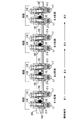
図1〜図3に示すように、直列4気筒エンジンのシリンダヘッド11には、各シリンダ12毎に一対の吸気ポート11a,11aが形成されており、一対の吸気ポート11a,11aが一対の吸気バルブ13I,13Iで開閉される。吸気バルブ13Iは、吸気ポート11aを開閉する傘部13aと、シリンダヘッド11に設けたバルブガイド14に摺動自在に案内される軸部13bとを備えており、バルブスプリング15により閉弁方向に付勢される。
As shown in FIGS. 1 to 3, a pair of
吸気バルブ13Iを開閉駆動する吸気ロッカアーム16Iはスイングアーム式のもので、その一端の支点がシリンダヘッド11の上面に設けた油圧ラッシュアジャスタ17に揺動自在に枢支され、その他端の作用点が吸気バルブ13Iの軸部13bの先端部に当接し、その長手方向中間部にローラ18が設けられる。シリンダヘッド11の上部に一体に形成されたカムホルダ11bと、このカムホルダ11bに締結されたカムキャップ19との間に、吸気カムシャフト20Iが回転自在に支持される。吸気カムシャフト20Iには吸気カム21Iが相対移動不能に設けられており、吸気カム21Iは吸気ロッカアーム16Iのローラ18に当接する。
The
図2から明らかなように、シリンダ軸線L1方向に見たとき、カムシャフト軸線L2に直交する方向に対して、各シリンダ12の一対の吸気ロッカアーム16I,16Iの長手方向の中心線は相互に逆方向に角度θで傾斜する。従って、シリンダ軸線L1方向に見たとき、各シリンダ12の一対の吸気ロッカアーム16I,16Iは「ハ」字状に配置される。以下、 一対の吸気ロッカアーム16I,16Iの「ハ」字状の配置を傾斜対称配置と呼ぶ。一対の吸気ロッカアーム16I,16Iの傾斜対称配置は、一対の油圧ラッシュアジャスタ17,17の間隔を広げることで実現される。
As is clear from FIG. 2, when viewed in the direction of the cylinder axis L1 , the center lines of the pair of
以上の構成により、吸気カムシャフト20Iはクランクシャフトが2回転する間に1回転し、吸気カムシャフト20Iが1回転する間に吸気カム21I,21Iのカム山がローラ18,18を1回押圧すると、吸気ロッカアーム16I,16Iが油圧ラッシュアジャスタ17,17を支点として一方向に揺動することで、一対の吸気バルブ13I,13Iがバルブスプリング15,15を圧縮しながら開弁する。吸気カム21I,21Iのカム山がローラ18,18を通過すると、圧縮されたバルブスプリング15,15の弾発力で一対の吸気バルブ13I,13Iが閉弁する。なお、本実施の形態において、4個のシリンダ12…の爆発順序、つまり吸気ロッカアーム16I,16Iの作動順序は、♯1シリンダ→♯3シリンダ→♯4シリンダ→♯2シリンダの順序である。
With the above configuration, the intake camshaft 20I makes one rotation while the crankshaft makes two rotations, and when the cam ridges of the
次に、上記構成を備えた本発明の第1の実施の形態の作用を説明する。 Next, the operation of the first embodiment of the present invention having the above configuration will be described.
吸気カムシャフト20Iの回転により、各シリンダ12の一対の吸気カム21I,21Iが一対の吸気ロッカアーム16I,16Iのローラ18,18をバルブスプリング15,15の弾発力に抗して押圧すると、一対の吸気カム21I,21Iはローラ18,18からの反力荷重を受けることになる。このとき、図3に示すように、各シリンダ12の一対の吸気ロッカアーム16I,16Iは「ハ」字状の傾斜対称配置に配置されるため、一方の吸気ロッカアーム16Iのローラ18から吸気カムシャフト20Iに伝達される荷重f1と、他方の吸気ロッカアーム16Iのローラ18から吸気カムシャフト20Iに伝達される荷重f2とは、同じ大きさで相互に逆方向となり、二つの反力荷重f1,f2が相殺される。このようにして、各シリンダ12毎に二つの反力荷重f1,f2が相殺されることで、吸気ロッカアーム16I…の傾斜角度のばらつきにより吸気カムシャフト20Iにスラスト荷重が作用することが防止され、吸気カムシャフト20Iの軸方向位置が安定する。その結果、吸気カムシャフト20Iがカムホルダ11bに衝突して打音が発生することが防止される。
When the pair of
上述した一対の吸気ロッカアーム16I,16Iの傾斜対称配置は4個のシリンダ12…の全てに適用する必要はなく、4個のシリンダ12…のうちの特定のシリンダ12…だけに適用することができる。
The tilt-symmetrical arrangement of the pair of
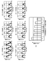
図4(A)〜図4(F)のグラフにおいて、横軸がクランクシャフトの回転角で、縦軸が吸気カムシャフト20Iのスラスト荷重であり、スラスト荷重の四つのピークは左側から順番に♯1シリンダによるスラスト荷重、♯3シリンダによるスラスト荷重、♯4シリンダによるスラスト荷重および♯2シリンダによるスラスト荷重である。 In the graphs of FIGS. 4A to 4F, the horizontal axis is the rotation angle of the crankshaft, the vertical axis is the thrust load of the intake camshaft 20I, and the four peaks of the thrust load are # in order from the left side. It is a thrust load by 1 cylinder, a thrust load by # 3 cylinder, a thrust load by # 4 cylinder, and a thrust load by # 2 cylinder.
図4(A)は、一対の吸気ロッカアーム16I,16Iの傾斜対称配置を全く適用しない場合であり、各シリンダ12による吸気カムシャフト20Iのスラスト荷重は全て大きくなっている。図4(F)は、一対の吸気ロッカアーム16I,16Iの傾斜対称配置を全てのシリンダ12…に適用した場合であり、各シリンダ12による吸気カムシャフト20Iのスラスト荷重は全て小さくなっている。
FIG. 4A shows a case where the tilt-symmetrical arrangement of the pair of
図4(B)は、4個のシリンダ12…のうちの1個のシリンダ12(♯2シリンダ)に一対の吸気ロッカアーム16I,16Iの傾斜対称配置を適用したもので、♯1シリンダにより発生するスラスト荷重が低減していることが分かる。図4(C)は、4個のシリンダ12…のうちの爆発順序が連続する2個のシリンダ12,12(つまり吸気ロッカアーム16I,16Iの作動順序が連続する♯4シリンダおよび♯2シリンダ)に一対の吸気ロッカアーム16I,16Iの傾斜対称配置を適用したもので、♯1シリンダおよび♯2シリンダにより発生するスラスト荷重が低減していることが分かる。
FIG. 4B shows an inclined symmetrical arrangement of a pair of
図4(D)は、4個のシリンダ12…のうちの爆発順序が連続しない2個のシリンダ12,12(つまり吸気ロッカアーム16I,16Iの作動順序が連続しない♯2シリンダおよび♯3シリンダ)に一対の吸気ロッカアーム16I,16Iの傾斜対称配置を適用したもので、♯1シリンダおよび♯4シリンダにより発生するスラスト荷重が低減していることが分かる。図4(E)は、4個のシリンダ12…のうちの3個のシリンダ12…(♯2シリンダ、♯3シリンダおよび♯4シリンダ)に一対の吸気ロッカアーム16I,16Iの傾斜対称配置を適用したもので、♯1シリンダ、♯2シリンダおよび♯4シリンダにより発生するスラスト荷重が低減していることが分かる。
FIG. 4D shows the four
図4(G)のグラフは、傾斜対称配置の吸気ロッカアーム16I,16Iを適用したシリンダ12…の数と、吸気カムシャフト20Iに作用するスラスト荷重のピーク値との関係を示すものである。スラスト荷重のピーク値は、吸気ロッカアーム16I,16Iの傾斜対称配置を適用していないシリンダ12…において発生することは明らかであるが、そのスラスト荷重のピーク値は、吸気ロッカアーム16I,16Iの傾斜対称配置を適用したシリンダ12…の数が増加するほど減少する。
The graph of FIG. 4 (G) shows the relationship between the number of
その理由は、シリンダ12…の爆発順序が、傾斜対称配置を適用したシリンダ12→傾斜対称配置を適用しないシリンダ12の順序であると、前者の傾斜対称配置を適用したシリンダ12によるスラスト荷重の減少効果が、後者の傾斜対称配置を適用しないシリンダ12に及ぶことで、そのシリンダ12のスラスト荷重のピーク値が減少するためである。
The reason is that if the explosion order of the
以上、エンジンの吸気側の動弁装置について説明したが、第1の実施の形態の技術思想は、エンジンの排気側の動弁装置、つまり排気カムシャフトで排気ロッカアームを介して
排気バルブを駆動する動弁装置に対しても、そのまま適用することができる。
The valve gear on the intake side of the engine has been described above, but the technical idea of the first embodiment is to drive the valve gear on the exhaust side of the engine, that is, the exhaust camshaft via the exhaust rocker arm. It can be applied to the valve gear as it is.
また第1の実施の形態では、全てのシリンダ12…に吸気ロッカアーム16I,16Iの傾斜対称配置を適用しているが、特定のシリンダ12だけに吸気ロッカアーム16I,16Iの傾斜対称配置を適用しても良い。
Further, in the first embodiment, the tilt-symmetrical arrangement of the
以下、図5に基づいて本発明の第2の実施の形態を説明する。第2の実施の形態は、本願の請求項2の発明に対応する。
Hereinafter, a second embodiment of the present invention will be described with reference to FIG. The second embodiment corresponds to the invention of
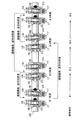
第2の実施の形態は、全てのシリンダ12…の一対の吸気ロッカアーム16I,16Iの長手方向の中心線が、シリンダ軸線L1方向に見たとき、カムシャフト軸線L2に直交する方向に対して、相互に同方向に同角度で傾斜する。すなわち、リンダ軸線L1方向に見たとき、各シリンダ12の一対の吸気ロッカアーム16I,16Iは傾斜平行状態に配置される。一対の吸気ロッカアーム16I,16Iの傾斜平行配置は、一対の油圧ラッシュアジャスタ17,17の位置をカムシャフト軸線L2方向の同方向に移動させることで実現される。
In the second embodiment, when the center line of the pair of
この構成により、吸気カムシャフト20Iの回転により、各シリンダ12の一対の吸気カム21I,21Iが一対の吸気ロッカアーム16I,16Iのローラ18,18をバルブスプリング15,15の弾発力に抗して押圧し、一対の吸気カム21I,21Iがローラ18,18からの反力荷重を受けるとき、各シリンダ12の一対の吸気ロッカアーム16I,16Iは傾斜平行配置されているため、一方の吸気ロッカアーム16Iのローラ18から吸気カムシャフト20Iに伝達される荷重f1と、他方の吸気ロッカアーム16Iのローラ18から吸気カムシャフト20Iに伝達される荷重f2とが同方向に作用する。しかも各シリンダ12の吸気ロッカアーム16I,16Iから吸気カムシャフト20Iに作用するスラスト荷重の方向が同方向であるため、吸気カムシャフト20Iがシリンダヘッド11のカムホルダ11bに対して常に一定の方向に押し付けられることで、吸気カムシャフト20Iの位置を安定させて打音の発生を防止することができる。
With this configuration, due to the rotation of the intake camshaft 20I, the pair of
以上、エンジンの吸気側の動弁装置について説明したが、第2の実施の形態の技術思想は、エンジンの排気側の動弁装置、つまり排気カムシャフトで排気ロッカアームを介して排気バルブを駆動する動弁装置に対しても、そのまま適用することができる。 The valve gear on the intake side of the engine has been described above, but the technical idea of the second embodiment is to drive the valve gear on the exhaust side of the engine, that is, the exhaust camshaft via the exhaust rocker arm. It can be applied to the valve gear as it is.
また第2の実施の形態では、全てのシリンダ12…に吸気ロッカアーム16I,16Iの傾斜平行配置を適用しているが、特定のシリンダ12だけに吸気ロッカアーム16I,16Iの傾斜平行配置を適用しても良い。
Further, in the second embodiment, the inclined parallel arrangement of the
次に、図6に基づいて本発明の第3の実施の形態を説明する。第3の実施の形態は、本願の請求項3あるいは請求項4の発明に対応する。
Next, a third embodiment of the present invention will be described with reference to FIG. The third embodiment corresponds to the invention of
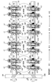
第1の実施の形態では、各シリンダ12の一対の吸気ロッカアーム16I,16Iの長手方向の中心線が「ハ」字状に配置されているが、第3の実施の形態では、各シリンダ12の一対の吸気ロッカアーム16I,16Iの長手方向の中心線が、カムシャフト軸線L2に直交する方向に対して同方向に平行に同角度ずつ傾斜している。この一対の吸気ロッカアーム16I,16Iの傾斜平行配置の傾斜方向はシリンダ12…毎に異なっており、図6において、♯1シリンダは時計方向、♯2シリンダは反時計方向、♯3シリンダは反時計方向、♯4シリンダは時計方向に設定される。
In the first embodiment, the longitudinal center lines of the pair of
4個のシリンダ12…の爆発順序は、♯1シリンダ→♯3シリンダ→♯4シリンダ→♯
2シリンダであるため、♯1シリンダおよび♯3シリンダは連続して爆発するが、♯1および♯3シリンダの一対の吸気ロッカアーム16I,16Iの長手方向の中心線の傾斜方向は相互に逆方向であるため、♯1および♯3シリンダの吸気ロッカアーム16I…により発生する吸気カムシャフト20Iのスラスト荷重が相互に打ち消し合い、吸気カムシャフト20Iの軸方向位置が安定する。
The order of explosion of the four
Since there are two cylinders, the # 1 cylinder and the # 3 cylinder explode continuously, but the inclination directions of the longitudinal center lines of the pair of
同様に、♯3シリンダおよび♯4シリンダは連続して爆発するが、♯3および♯4シリンダの一対の吸気ロッカアーム16I,16Iの長手方向の中心線の傾斜方向は相互に逆方向であるため、♯3および♯4シリンダの吸気ロッカアーム16I…により発生する吸気カムシャフト20Iのスラスト荷重が相互に打ち消し合い、吸気カムシャフト20Iの軸方向位置が安定する。
Similarly, the # 3 cylinder and the # 4 cylinder explode continuously, but the inclination directions of the longitudinal center lines of the pair of
以上のように、多気筒エンジンの各シリンダ12の一対の吸気ロッカアーム16I,16Iを傾斜平行配置とし、連続して爆発する二つのシリンダ12,12の各一対の吸気ロッカアーム16I,16Iの長手方向の中心線の傾斜方向を逆方向とすれば、スラスト荷重を相殺して吸気カムシャフト20Iの移動を抑制することができ、また連続して爆発する二つのシリンダ12,12の各一対の吸気ロッカアーム16I,16Iの長手方向の中心線の傾斜方向を同方向とすれば、スラスト荷重を加算して吸気カムシャフト20Iをシリンダヘッド11のカムホルダ11bに押し付けて打音の発生を防止することができる。
As described above, the pair of
以上、エンジンの吸気側の動弁装置について説明したが、第3の実施の形態の技術思想は、エンジンの排気側の動弁装置、つまり排気カムシャフトで排気ロッカアームを介して排気バルブを駆動する動弁装置に対しても、そのまま適用することができる。 The valve gear on the intake side of the engine has been described above, but the technical idea of the third embodiment is to drive the valve gear on the exhaust side of the engine, that is, the exhaust camshaft via the exhaust rocker arm. It can be applied to the valve gear as it is.
次に、図7に基づいて本発明の第4の実施の形態を説明する。第4の実施の形態は、本願の請求項5の発明に対応する。 Next, a fourth embodiment of the present invention will be described with reference to FIG. 7. The fourth embodiment corresponds to the invention of claim 5 of the present application.
第4の実施の形態は、吸気側の動弁装置に加えて、排気バルブ13E,13E、排気カムシャフト20E、排気カム21E,21Eおよび排気ロッカアーム16E,16Eを含む排気側の動弁装置を備え、吸気側の動弁装置および排気側の動弁装置の協働によって作用効果を発揮するものである。
In the fourth embodiment, in addition to the intake side valve gear, the exhaust side valve gear including the
各シリンダ12の一対の吸気ロッカアーム16I,16Iは傾斜平行配置されており、かつ全てのシリンダ12…の吸気ロッカアーム16I…の長手方向の中心線の傾斜方向は同一であるため、吸気ロッカアーム16I…からの反力荷重で吸気カムシャフト20Iは矢印A方向に付勢される。また各シリンダ12の一対の排気ロッカアーム16E,16Eは傾斜平行配置されており、かつ全てのシリンダ12…の排気ロッカアーム16E…の長手方向の中心線の傾斜方向は同一であるため、排気ロッカアーム16E…からの反力荷重で排気カムシャフト20Eは矢印A´方向に付勢される。すなわち、吸気カムシャフト20Iの付勢方向Aと、排気カムシャフト20Eの付勢方向A´とは、相互に逆方向である。
Since the pair of
吸気カムシャフト20Iの軸端に固設された吸気ヘリカルギヤ22Iと、排気カムシャフト20Eの軸端に固設された排気ヘリカルギヤ22Eとが相互に歯合しており、吸気カム21Iおよび排気カム21Eは同速度で矢印C,C′で示すように相互に逆方向に回転する。このとき、吸気ヘリカルギヤ22Iおよび排気ヘリカルギヤ22Eは傾斜する歯筋で歯合するため、吸気カムシャフト20Iには矢印B方向の歯合反力が作用し、排気カム21Eには矢印B´方向の歯合反力が作用する。
The intake helical gear 22I fixed to the shaft end of the intake camshaft 20I and the exhaust
吸気ロッカアーム16I…から吸気カムシャフト20Iに作用するスラスト荷重Aと、
吸気ヘリカルギヤ22Iから吸気カムシャフト20Iに作用するスラスト荷重Bとは相互に逆方向であるため、それらが相殺することで吸気カムシャフト20Iに作用するトータルのスラスト荷重が低減する。また排気ロッカアーム16E…から排気カムシャフト20Eに作用するスラスト荷重A´と、排気ヘリカルギヤ22Eから排気カムシャフト20Eに作用するスラスト荷重B´とは相互に逆方向であるため、それらが相殺することで排気カムシャフト20Eに作用するトータルのスラスト荷重が低減する。
The thrust load A acting on the intake camshaft 20I from the
Since the thrust load B acting on the intake camshaft 20I from the intake helical gear 22I is opposite to each other, the total thrust load acting on the intake camshaft 20I is reduced by canceling them. Further, since the thrust load A'acting on the
このようにして吸気カムシャフト20Iおよび排気カムシャフト20Eに作用するスラスト荷重が低減することで、吸気カムシャフト20Iおよび排気カムシャフト20Eの軸方向位置が安定し、吸気カムシャフト20Iおよび排気カムシャフト20Eの移動による打音の発生が防止される。
By reducing the thrust load acting on the intake camshaft 20I and the
次に、図8に基づいて本発明の第5の実施の形態を説明する。第5の実施の形態は、本願の請求項6の発明に対応する。 Next, a fifth embodiment of the present invention will be described with reference to FIG. A fifth embodiment corresponds to the invention of claim 6 of the present application.
第5の実施の形態は、第4の実施の形態の変形であって、吸気ヘリカルギヤ22Iおよび排気ヘリカルギヤ22Eの歯筋の傾斜方向が逆方向になっており、そのために吸気ヘリカルギヤ22Iが受ける歯合反力よりなるスラスト荷重Bの方向が、吸気カムシャフト20Iが吸気ロッカアーム16I…から受けるスラスト荷重Aの方向に一致し、かつ排気ヘリカルギヤ22Eが受ける歯合反力よりなるスラスト荷重B´の方向が、排気カムシャフト20Eが排気ロッカアーム16E…から受けるスラスト荷重A´の方向に一致する。
The fifth embodiment is a modification of the fourth embodiment, in which the inclination directions of the tooth muscles of the intake helical gear 22I and the exhaust
その結果、吸気カムシャフト20Iは両スラスト荷重A,Bの合力でシリンダヘッド11のカムホルダ11bに押し付けられて軸方向の位置が安定し、かつ排気カムシャフト20Eは両スラスト荷重A´,B´の合力でシリンダヘッド11のカムホルダ11bに押し付けられて軸方向の位置が安定する。
As a result, the intake camshaft 20I is pressed against the
次に、図9に基づいて本発明の第6の実施の形態を説明する。 Next, a sixth embodiment of the present invention will be described with reference to FIG.
上述した第1〜第5の実施の形態では、油圧ラッシュアジャスタ17の位置を移動させることで吸気ロッカアーム16I(あるいは排気ロッカアーム16E)を傾斜させているが、第6の実施の形態は他の手法で吸気ロッカアーム16I(あるいは排気ロッカアーム16E)を傾斜させるものである。
In the first to fifth embodiments described above, the
吸気ロッカアーム16Iを例にとって説明すると、図9(A)に示すように、カムシャフト軸線L2に対してローラ18の軸線L3が予め角度αだけ傾斜している。図9(B)に示すように、この吸気ロッカアーム16Iのローラ18に吸気カム21Iが当接すると、ローラ18が吸気カム21Iから受ける荷重で、吸気ロッカアーム16Iの長手方向の中心線は遊びの範囲内でカムシャフト軸線L2に直交する方向に対して角度θで傾斜するため、第1〜第5の実施の形態と同様に、吸気ロッカアーム16Iから吸気カムシャフト20Iに積極的にスラスト荷重を作用させることができる。
Taking the
以上、本発明の実施の形態を説明したが、本発明はその要旨を逸脱しない範囲で種々の設計変更を行うことが可能である。 Although the embodiments of the present invention have been described above, the present invention can make various design changes without departing from the gist thereof.
例えば、本発明の多気筒エンジンは実施の形態の直列4気筒エンジンに限定されず、4気筒以外の直列多気筒エンジンや、各バンクが多気筒であるV型多気筒エンジン等に対しても適用することができる。 For example, the multi-cylinder engine of the present invention is not limited to the in-line 4-cylinder engine of the embodiment, but is also applied to an in-line multi-cylinder engine other than 4-cylinder, a V-type multi-cylinder engine in which each bank is multi-cylinder, and the like. can do.
また本発明のロッカアームは、実施の形態の一端に油圧ラッシュアジャスタに当接する支点を備え、他端にバルブに当接する作用点を備え、中間部にカムに当接する力点を備えるスイングアーム式のものに限定されず、中間部に支点を備え、両端に力点および作用点を備えるシーソ式のものであっても良い。 Further, the rocker arm of the present invention is a swing arm type having a fulcrum that contacts the hydraulic rush adjuster at one end of the embodiment, an action point that contacts the valve at the other end, and a force point that contacts the cam at the middle portion. The type is not limited to the above, and may be a seesaw type having a fulcrum in the middle portion and a force point and an action point at both ends.
また一対の吸気ロッカアーム16I,16Iの傾斜対称配置を実現するために、一対の吸気バルブ13I,13I間の距離を、一対の油圧ラッシュアジャスタ17,17間の距離よりも大きくしても良い。一対の排気ロッカアーム16E,16Eの傾斜対称配置についても同様である。
Further, in order to realize the tilt-symmetrical arrangement of the pair of
また一対の吸気ロッカアーム16I,16Iあるいは一対の排気ロッカアーム16E,16Eの傾斜対称配置において、2本のロッカアームの傾斜角度θは一致している必要はなく、また傾斜平行配置においても、2本のロッカアームの傾斜角度θは一致している必要はない。
Further, in the tilt-symmetrical arrangement of the pair of
また本発明のロッカアームは、実施の形態のローラ18を備えるものに限定されず、ローラ18の代わりにスリッパを備えるものであっても良い。
Further, the rocker arm of the present invention is not limited to the one provided with the
また実施の形態ではロッカアームの支点として油圧ラッシュアジャスタ17,17を用いているが、それに限定されるものではない。
Further, in the embodiment, the
11b カムホルダ
12 シリンダ
13I 吸気バルブ(バルブ)
13E 排気バルブ(バルブ)
16I 吸気ロッカアーム(ロッカアーム)
16E 排気ロッカアーム(ロッカアーム)
18 ローラ
20I 吸気カムシャフト(カムシャフト)
20E 排気カムシャフト(カムシャフト)
21I 吸気カム(カム)
21E 排気カム(カム)
22I 吸気ヘリカルギヤ(ヘリカルギヤ)
22E 排気ヘリカルギヤ(ヘリカルギヤ)
L1 シリンダ軸線
L2 カムシャフト軸線
L3 ローラの軸線
13E Exhaust valve (valve)
16I Intake rocker arm (rocker arm)
16E Exhaust Rocker Arm (Rocker Arm)
18 Roller 20I Intake camshaft (camshaft)
20E exhaust camshaft (camshaft)
21I Intake cam (cam)
21E Exhaust cam (cam)
22I Intake helical gear (helical gear)
22E Exhaust Helical Gear (Helical Gear)
L1 Cylinder axis L2 Camshaft axis L3 Roller axis
Claims (8)
シリンダ軸線(L1)方向に見たときに、少なくとも一つの前記シリンダ(12)の前記一対のロッカアーム(16I)は、その長手方向の中心線がカムシャフト軸線(L2)に直交する方向に対して相互に逆方向に傾斜することを特徴とする多気筒エンジンの動弁装置。 A pair of valves (13I) provided in each cylinder (12) is operated by a pair of rocker arms (16I) operated by a cam (21I) provided on a camshaft ( 20I) supported by a cam holder (11b) so as not to move relative to each other. It is a valve gear of a multi-cylinder engine that opens and closes.
When viewed in the direction of the cylinder axis (L1), the pair of rocker arms (16I) of at least one of the cylinders (12) have a center line in the longitudinal direction with respect to a direction orthogonal to the camshaft axis (L2). A valve gear for a multi-cylinder engine characterized by tilting in opposite directions.
シリンダ軸線(L1)方向に見たときに、少なくとも一つの前記シリンダ(12)の前記一対のロッカアーム(16I)は、その長手方向の中心線がカムシャフト軸線(L2)に直交する方向に対して相互に同方向に傾斜することを特徴とする多気筒エンジンの動弁装置。 A pair of valves (13I) provided in each cylinder (12) is operated by a pair of rocker arms (16I) operated by a cam (21I) provided on a camshaft ( 20I) supported by a cam holder (11b) so as not to move relative to each other. It is a valve gear of a multi-cylinder engine that opens and closes.
When viewed in the direction of the cylinder axis (L1), the pair of rocker arms (16I) of at least one of the cylinders (12) have a center line in the longitudinal direction with respect to a direction orthogonal to the camshaft axis (L2). A valve gear for a multi-cylinder engine characterized by tilting in the same direction.
シリンダ軸線(L1)方向に見たときに、前記一対のロッカアーム(16I)は、その長手方向の中心線がカムシャフト軸線(L2)に直交する方向に対して相互に同方向に傾斜し、爆発順序が連続する二つの前記シリンダ(12)の前記ロッカアーム(16I)の傾斜方向は相互に逆方向であることを特徴とする多気筒エンジンの動弁装置。 A pair of valves (13I) provided in each cylinder (12) is operated by a pair of rocker arms (16I) operated by a cam (21I) provided on a camshaft ( 20I) supported by a cam holder (11b) so as not to move relative to each other. It is a valve gear of a multi-cylinder engine that opens and closes.
When viewed in the cylinder axis (L1) direction, the pair of rocker arms (16I) are inclined in the same direction with respect to the direction in which the center line in the longitudinal direction is orthogonal to the camshaft axis (L2) and explode. A valve operating device for a multi-cylinder engine, characterized in that the tilting directions of the rocker arm (16I) of the two cylinders (12) having a continuous order are opposite to each other.
シリンダ軸線(L1)方向に見たときに、前記一対のロッカアーム(16I)は、その長手方向の中心線がカムシャフト軸線(L2)に直交する方向に対して相互に同方向に傾斜し、爆発順序が連続する二つの前記シリンダ(12)の前記ロッカアーム(16I)の傾斜方向は相互に同方向であることを特徴とする多気筒エンジンの動弁装置。 A pair of valves (13I) provided in each cylinder (12) is operated by a pair of rocker arms (16I) operated by a cam (21I) provided on a camshaft ( 20I) supported by a cam holder (11b) so as not to move relative to each other. It is a valve gear of a multi-cylinder engine that opens and closes.
When viewed in the cylinder axis (L1) direction, the pair of rocker arms (16I) are inclined in the same direction with respect to the direction in which the center line in the longitudinal direction is orthogonal to the camshaft axis (L2) and explode. A valve operating device for a multi-cylinder engine, characterized in that the rocker arms (16I) of the two cylinders (12) having a continuous order are inclined in the same direction with each other.
シリンダ軸線(L1)方向に見たときに、前記一対のロッカアーム(16I,16E)は、その長手方向の中心線がカムシャフト軸線(L2)に直交する方向に対して相互に同方向に傾斜し、吸気側の前記カムシャフト(20I)により駆動される前記ロッカアーム(16I)の傾斜方向と、排気側の前記カムシャフト(20E)により駆動される前記ロッカアーム(16E)の傾斜方向とは相互に同方向であり、前記吸気側のカムシャフト(20I)に設けた吸気側のヘリカルギヤ(22I)と、前記排気側のカムシャフト(20E)に設けた排気側のヘリカルギヤ(22E)とが相互に歯合し、前記吸気側のヘリカルギヤ(22I)により発生するスラスト荷重は、吸気側の前記ロッカアーム(16I)により発生するスラスト荷重に対して逆方向であり、前記排気側のヘリカルギヤ(22E)により発生するスラスト荷重は、排気側の前記ロッカアーム(16E)により発生するスラスト荷重に対して逆方向であることを特徴とする多気筒エンジンの動弁装置。 A pair of valves (13I, 13E) provided to each cylinder (12), cam holder cam supported on (11b) shaft (2 0 I, 2 0 E ) a cam which is provided in a relatively immovable (21I, 21E) It is a valve gear of a multi-cylinder engine that is opened and closed by a pair of rocker arms (16I, 16E) operated by
When viewed in the cylinder axis (L1) direction, the pair of rocker arms (16I, 16E) are inclined in the same direction with respect to the direction in which the center line in the longitudinal direction is orthogonal to the camshaft axis (L2). , the inclination direction of the rocker arm driven by the intake side of the camshaft (2 0 I) (16I) , the inclination direction of the rocker arm driven by said camshaft at the exhaust side (2 0 E) (16E) is the same direction to each other, the intake side camshaft (2 0 I) to provided the intake helical gear and (22I), said to provided the exhaust side exhaust side camshaft (2 0 E) helical ( The thrust load generated by the helical gear (22I) on the intake side is opposite to the thrust load generated by the rocker arm (16I) on the intake side and is in the opposite direction to the thrust load generated by the rocker arm (16I) on the intake side. A valve gear of a multi-cylinder engine, characterized in that the thrust load generated by the helical gear (22E) is in the opposite direction to the thrust load generated by the rocker arm (16E) on the exhaust side.
シリンダ軸線(L1)方向に見たときに、前記一対のロッカアーム(16I,16E)は、その長手方向の中心線がカムシャフト軸線(L2)に直交する方向に対して相互に同方向に傾斜し、吸気側の前記カムシャフト(20I)により駆動される前記ロッカアーム(16I)の傾斜方向と、排気側の前記カムシャフト(20E)により駆動される前記ロッカアーム(16E)の傾斜方向とは相互に同方向であり、前記吸気側のカムシャフト(20I)に設けた吸気側のヘリカルギヤ(22I)と、前記排気側のカムシャフト(20E)に設けた排気側のヘリカルギヤ(22E)とが相互に歯合し、前記吸気側のヘリカルギヤ(22I)により発生するスラスト荷重は、吸気側の前記ロッカアーム(16I)により発生するスラスト荷重に対して同方向であり、前記排気側のヘリカルギヤ(22E)により発生するスラスト荷重は、排気側の前記ロッカアーム(16E)により発生するスラスト荷重に対して同方向であることを特徴とする多気筒エンジンの動弁装置。 A pair of valves (13I, 13E) provided to each cylinder (12), cam holder cam supported on (11b) shaft (2 0 I, 2 0 E ) a cam which is provided in a relatively immovable (21I, 21E) It is a valve gear of a multi-cylinder engine that is opened and closed by a pair of rocker arms (16I, 16E) operated by
When viewed in the cylinder axis (L1) direction, the pair of rocker arms (16I, 16E) are inclined in the same direction with respect to the direction in which the center line in the longitudinal direction is orthogonal to the camshaft axis (L2). , the inclination direction of the rocker arm driven by the intake side of the camshaft (2 0 I) (16I) , the inclination direction of the rocker arm driven by said camshaft at the exhaust side (2 0 E) (16E) is the same direction to each other, the intake side camshaft (2 0 I) to provided the intake helical gear and (22I), said to provided the exhaust side exhaust side camshaft (2 0 E) helical ( The thrust load generated by the helical gear (22I) on the intake side is in the same direction as the thrust load generated by the rocker arm (16I) on the intake side, and is in the same direction as the thrust load generated by the rocker arm (16I) on the intake side. A valve gear of a multi-cylinder engine, characterized in that the thrust load generated by the helical gear (22E) is in the same direction as the thrust load generated by the rocker arm (16E) on the exhaust side.
The rocker arm (16I, 16E) includes a roller (18) that abuts on the cam (21I, 21E), and the axis (L3) of the roller (18) is inclined with respect to the camshaft axis (L2). When the roller (18) is brought into contact with the cam (21I, 21E), the center line in the longitudinal direction of the rocker arm (16I, 16E) is inclined with respect to the direction orthogonal to the camshaft axis (L2). The valve operating device for a multi-cylinder engine according to any one of claims 1 to 6, wherein the valve gear is characterized by the above.
Priority Applications (3)
| Application Number | Priority Date | Filing Date | Title |
|---|---|---|---|
| JP2017059570A JP6932016B2 (en) | 2017-03-24 | 2017-03-24 | Multi-cylinder engine valve gear |
| US15/896,246 US10626822B2 (en) | 2017-03-24 | 2018-02-14 | Valve operating system for multicylinder engine |
| CN201810233800.6A CN108625918B (en) | 2017-03-24 | 2018-03-21 | Valve gear of multi-cylinder engine |
Applications Claiming Priority (1)
| Application Number | Priority Date | Filing Date | Title |
|---|---|---|---|
| JP2017059570A JP6932016B2 (en) | 2017-03-24 | 2017-03-24 | Multi-cylinder engine valve gear |
Publications (2)
| Publication Number | Publication Date |
|---|---|
| JP2018162697A JP2018162697A (en) | 2018-10-18 |
| JP6932016B2 true JP6932016B2 (en) | 2021-09-08 |
Family
ID=63582246
Family Applications (1)
| Application Number | Title | Priority Date | Filing Date |
|---|---|---|---|
| JP2017059570A Active JP6932016B2 (en) | 2017-03-24 | 2017-03-24 | Multi-cylinder engine valve gear |
Country Status (3)
| Country | Link |
|---|---|
| US (1) | US10626822B2 (en) |
| JP (1) | JP6932016B2 (en) |
| CN (1) | CN108625918B (en) |
Family Cites Families (11)
| Publication number | Priority date | Publication date | Assignee | Title |
|---|---|---|---|---|
| JPS4933218U (en) | 1972-06-30 | 1974-03-23 | ||
| GB2125479A (en) | 1982-08-18 | 1984-03-07 | Ford Motor Co | I.c.engine valve rocker assembly |
| JPH076369B2 (en) | 1986-07-09 | 1995-01-30 | 本田技研工業株式会社 | SOHC type multi-cylinder internal combustion engine |
| JPS63167016A (en) | 1986-12-27 | 1988-07-11 | Honda Motor Co Ltd | Valve train for multi-cylinder internal combustion engine |
| JP3373947B2 (en) | 1994-09-02 | 2003-02-04 | 本田技研工業株式会社 | Valve train for multi-cylinder internal combustion engine |
| US5596958A (en) | 1995-08-11 | 1997-01-28 | Miller; James | Rocker arm bridge for internal combustion engines |
| CN2471932Y (en) | 2001-03-28 | 2002-01-16 | 重庆宗申摩托车科技集团有限公司 | Eccentric axial style gate gap regulator for motorcycle engine |
| JP3938339B2 (en) | 2001-07-26 | 2007-06-27 | 本田技研工業株式会社 | Valve control device for internal combustion engine |
| CN202348361U (en) | 2011-09-19 | 2012-07-25 | 隆鑫通用动力股份有限公司 | Air valve driving component of petrol engine and petrol engine comprising same |
| CN103195602B (en) | 2013-04-18 | 2015-06-10 | 安徽江淮汽车股份有限公司 | Cylinder head and overhead camshaft engine |
| JP6520909B2 (en) * | 2016-12-26 | 2019-05-29 | トヨタ自動車株式会社 | Variable valve mechanism of engine |
-
2017
- 2017-03-24 JP JP2017059570A patent/JP6932016B2/en active Active
-
2018
- 2018-02-14 US US15/896,246 patent/US10626822B2/en active Active
- 2018-03-21 CN CN201810233800.6A patent/CN108625918B/en active Active
Also Published As
| Publication number | Publication date |
|---|---|
| CN108625918A (en) | 2018-10-09 |
| US20180274478A1 (en) | 2018-09-27 |
| US10626822B2 (en) | 2020-04-21 |
| JP2018162697A (en) | 2018-10-18 |
| CN108625918B (en) | 2020-10-30 |
Similar Documents
| Publication | Publication Date | Title |
|---|---|---|
| JP4741541B2 (en) | Engine valve gear | |
| JP2008180214A (en) | Camshaft torque reduction mechanism for internal combustion engine | |
| JP4381188B2 (en) | Variable valve operating device for internal combustion engine | |
| US6378474B1 (en) | Variable value timing mechanism with crank drive | |
| JP4960753B2 (en) | Engine valve gear | |
| JP2008248872A (en) | Engine valve gear | |
| JP2007510090A (en) | Valve gear | |
| JP2007126966A (en) | Variable valve mechanism | |
| JP2005282573A (en) | Adjustable lifting device | |
| JP6932016B2 (en) | Multi-cylinder engine valve gear | |
| KR101317140B1 (en) | Continuous variable valve lift apparatus | |
| JP4697011B2 (en) | Variable valve mechanism | |
| JP4070124B2 (en) | Decompression device for internal combustion engine | |
| JP4920476B2 (en) | Engine valve gear | |
| JP4200975B2 (en) | Variable valve operating device for internal combustion engine | |
| CA2535323A1 (en) | Variable valve gear | |
| JP4157649B2 (en) | Variable valve operating device for internal combustion engine | |
| JP2010229879A (en) | Roller type rocker arm structure | |
| KR101305688B1 (en) | Continuous variable valve lift(CVVL) apparatus | |
| JP2007071108A (en) | Variable stroke characteristics engine | |
| JP2015183530A (en) | Engine valve gear | |
| JP2008157080A (en) | Engine valve mechanism | |
| WO2021131190A1 (en) | Adjustable valve mechanism | |
| JP2004278313A (en) | Engine valve drive | |
| JP2006029262A (en) | Internal combustion engine equipped with variable valve characteristic device |
Legal Events
| Date | Code | Title | Description |
|---|---|---|---|
| A621 | Written request for application examination |
Free format text: JAPANESE INTERMEDIATE CODE: A621 Effective date: 20191209 |
|
| A977 | Report on retrieval |
Free format text: JAPANESE INTERMEDIATE CODE: A971007 Effective date: 20201027 |
|
| A131 | Notification of reasons for refusal |
Free format text: JAPANESE INTERMEDIATE CODE: A131 Effective date: 20201118 |
|
| A521 | Request for written amendment filed |
Free format text: JAPANESE INTERMEDIATE CODE: A523 Effective date: 20210115 |
|
| A131 | Notification of reasons for refusal |
Free format text: JAPANESE INTERMEDIATE CODE: A131 Effective date: 20210224 |
|
| A521 | Request for written amendment filed |
Free format text: JAPANESE INTERMEDIATE CODE: A523 Effective date: 20210421 |
|
| TRDD | Decision of grant or rejection written | ||
| A01 | Written decision to grant a patent or to grant a registration (utility model) |
Free format text: JAPANESE INTERMEDIATE CODE: A01 Effective date: 20210804 |
|
| A61 | First payment of annual fees (during grant procedure) |
Free format text: JAPANESE INTERMEDIATE CODE: A61 Effective date: 20210817 |
|
| R150 | Certificate of patent or registration of utility model |
Ref document number: 6932016 Country of ref document: JP Free format text: JAPANESE INTERMEDIATE CODE: R150 |