JP6930968B2 - Eyelid support and related methods - Google Patents
Eyelid support and related methods Download PDFInfo
- Publication number
- JP6930968B2 JP6930968B2 JP2018517673A JP2018517673A JP6930968B2 JP 6930968 B2 JP6930968 B2 JP 6930968B2 JP 2018517673 A JP2018517673 A JP 2018517673A JP 2018517673 A JP2018517673 A JP 2018517673A JP 6930968 B2 JP6930968 B2 JP 6930968B2
- Authority
- JP
- Japan
- Prior art keywords
- mounting plate
- assembly
- elongated shaft
- eyelid
- support member
- Prior art date
- Legal status (The legal status is an assumption and is not a legal conclusion. Google has not performed a legal analysis and makes no representation as to the accuracy of the status listed.)
- Active
Links
Images


Classifications
-
- A—HUMAN NECESSITIES
- A61—MEDICAL OR VETERINARY SCIENCE; HYGIENE
- A61F—FILTERS IMPLANTABLE INTO BLOOD VESSELS; PROSTHESES; DEVICES PROVIDING PATENCY TO, OR PREVENTING COLLAPSING OF, TUBULAR STRUCTURES OF THE BODY, e.g. STENTS; ORTHOPAEDIC, NURSING OR CONTRACEPTIVE DEVICES; FOMENTATION; TREATMENT OR PROTECTION OF EYES OR EARS; BANDAGES, DRESSINGS OR ABSORBENT PADS; FIRST-AID KITS
- A61F2/00—Filters implantable into blood vessels; Prostheses, i.e. artificial substitutes or replacements for parts of the body; Appliances for connecting them with the body; Devices providing patency to, or preventing collapsing of, tubular structures of the body, e.g. stents
- A61F2/02—Prostheses implantable into the body
- A61F2/14—Eye parts, e.g. lenses, corneal implants; Implanting instruments specially adapted therefor; Artificial eyes
-
- A—HUMAN NECESSITIES
- A61—MEDICAL OR VETERINARY SCIENCE; HYGIENE
- A61F—FILTERS IMPLANTABLE INTO BLOOD VESSELS; PROSTHESES; DEVICES PROVIDING PATENCY TO, OR PREVENTING COLLAPSING OF, TUBULAR STRUCTURES OF THE BODY, e.g. STENTS; ORTHOPAEDIC, NURSING OR CONTRACEPTIVE DEVICES; FOMENTATION; TREATMENT OR PROTECTION OF EYES OR EARS; BANDAGES, DRESSINGS OR ABSORBENT PADS; FIRST-AID KITS
- A61F9/00—Methods or devices for treatment of the eyes; Devices for putting-in contact lenses; Devices to correct squinting; Apparatus to guide the blind; Protective devices for the eyes, carried on the body or in the hand
- A61F9/007—Methods or devices for eye surgery
- A61F9/00718—Restoration of lid function
-
- A—HUMAN NECESSITIES
- A61—MEDICAL OR VETERINARY SCIENCE; HYGIENE
- A61F—FILTERS IMPLANTABLE INTO BLOOD VESSELS; PROSTHESES; DEVICES PROVIDING PATENCY TO, OR PREVENTING COLLAPSING OF, TUBULAR STRUCTURES OF THE BODY, e.g. STENTS; ORTHOPAEDIC, NURSING OR CONTRACEPTIVE DEVICES; FOMENTATION; TREATMENT OR PROTECTION OF EYES OR EARS; BANDAGES, DRESSINGS OR ABSORBENT PADS; FIRST-AID KITS
- A61F2/00—Filters implantable into blood vessels; Prostheses, i.e. artificial substitutes or replacements for parts of the body; Appliances for connecting them with the body; Devices providing patency to, or preventing collapsing of, tubular structures of the body, e.g. stents
- A61F2/0059—Cosmetic or alloplastic implants
-
- A—HUMAN NECESSITIES
- A61—MEDICAL OR VETERINARY SCIENCE; HYGIENE
- A61F—FILTERS IMPLANTABLE INTO BLOOD VESSELS; PROSTHESES; DEVICES PROVIDING PATENCY TO, OR PREVENTING COLLAPSING OF, TUBULAR STRUCTURES OF THE BODY, e.g. STENTS; ORTHOPAEDIC, NURSING OR CONTRACEPTIVE DEVICES; FOMENTATION; TREATMENT OR PROTECTION OF EYES OR EARS; BANDAGES, DRESSINGS OR ABSORBENT PADS; FIRST-AID KITS
- A61F2250/00—Special features of prostheses classified in groups A61F2/00 - A61F2/26 or A61F2/82 or A61F9/00 or A61F11/00 or subgroups thereof
- A61F2250/0004—Special features of prostheses classified in groups A61F2/00 - A61F2/26 or A61F2/82 or A61F9/00 or A61F11/00 or subgroups thereof adjustable
- A61F2250/0007—Special features of prostheses classified in groups A61F2/00 - A61F2/26 or A61F2/82 or A61F9/00 or A61F11/00 or subgroups thereof adjustable for adjusting length
Description
関連案件
本出願は、参照によりその全体が本明細書に組み込まれる、「EYELID SUPPORTERS AND RELATED METHODS」と題された、2015年6月18日出願の米国特許仮出願第62/181,383号に対する優先権を主張するものである。
Related Matters This application relates to US Patent Provisional Application No. 62 / 181,383, filed June 18, 2015, entitled "EYELID SUPPORTERS AND RELATED METHODS," which is incorporated herein by reference in its entirety. It claims priority.
本開示は、全般的に、下眼瞼を支持するための医療器具などの、医療器具の分野に関する。 The present disclosure generally relates to the field of medical devices, such as medical devices for supporting the lower eyelid.
世界中で数万人の人々が、下眼瞼麻痺を発症している。同様の病状はまた、イヌなどの他の哺乳類も発症する。下眼瞼の麻痺は、外反、眼瞼弛緩、流涙、兎眼、及び/又は角膜損傷を引き起こす恐れがある。下眼瞼麻痺に対する是正措置としては、再建手術、及び/又は、下眼瞼を安定化して支持するための下眼瞼スペーサの埋め込みが挙げられる。 Tens of thousands of people worldwide develop lower eyelid paralysis. Similar medical conditions also occur in other mammals, such as dogs. Paralysis of the lower eyelid can cause valgus, eyelid relaxation, lacrimation, lagophthalmos, and / or corneal damage. Corrective measures for lower eyelid paralysis include reconstructive surgery and / or implantation of a lower eyelid spacer to stabilize and support the lower eyelid.
しかしながら、下眼瞼麻痺を処置するための既存の器具及び方法は、1つ以上の欠点を抱えるものであり、1つ以上の態様において最適には機能しない場合がある。本明細書で開示される特定の実施形態は、これらの問題点のうちの1つ以上に対処し得るものである。 However, existing instruments and methods for treating lower eyelid paralysis have one or more drawbacks and may not function optimally in one or more embodiments. Certain embodiments disclosed herein can address one or more of these issues.
本明細書における書面による開示は、非限定的かつ非網羅的な、例示的実施形態を説明するものである。以下の図に示される、そのような例示的実施形態のうちの特定のものについて、参照するものとする。 Written disclosure herein describes an exemplary embodiment that is non-limiting and non-exhaustive. Reference shall be made to certain of such exemplary embodiments shown in the figures below.
本明細書の図において全般的に説明され、図示されるような実施形態の構成要素は、多種多様な異なる構成で、配置及び設計することができる。それゆえ、それらの図に表されるような、以下の様々な実施形態のより詳細な説明は、本開示の範囲を限定することを意図するものではなく、単に様々な実施形態を代表するものに過ぎない。それらの実施形態の様々な態様が、図面に提示されているが、それらの図面は、具体的な指示がない限り、必ずしも縮尺通りに描かれたものではない。 The components of embodiments as generally described and illustrated in the figures herein can be arranged and designed in a wide variety of different configurations. Therefore, the more detailed description of the various embodiments below, as shown in those figures, is not intended to limit the scope of the present disclosure, but merely represents the various embodiments. It's just that. Various aspects of those embodiments are presented in the drawings, but the drawings are not necessarily drawn to scale unless specifically instructed to do so.
「接続される」及び「結合される」という表現は、それらの通常の意味で使用され、2つ以上の実体間での任意の好適な結合、あるいは、機械的、摩擦的、圧迫的、流体的、及び熱的な相互作用を含めた、他の形態の相互作用を指す程度に広義である。2つの構成要素は、それらが互いに直接接触していないとしても、互いに結合されている場合がある。例えば、第1の構成要素は、第3の構成要素を介して、第2の構成要素に結合される場合がある。「取り付けられる」又は「直接取り付けられる」という表現は、互いに直接接触している、2つ以上の実体間での相互作用、及び/又は、任意の好適な様々な締結具(例えば、ネジ、圧迫ネジ、圧迫バー、クランプ、圧着ビーズ、又は接着剤)によってのみ互いに隔てられている、2つ以上の実体間での相互作用を指す。患者という用語は、ヒト患者及び他の非ヒト哺乳類患者の双方を包含する程度に広義である。 The expressions "connected" and "bonded" are used in their usual sense, any suitable bond between two or more entities, or mechanical, frictional, oppressive, fluid. It is broad enough to refer to other forms of interaction, including targeted and thermal interactions. The two components may be connected to each other, even if they are not in direct contact with each other. For example, the first component may be coupled to the second component via the third component. The expressions "attached" or "directly attached" are interactions between two or more entities that are in direct contact with each other and / or any suitable various fasteners (eg, screws, compressions). Refers to the interaction between two or more entities that are separated from each other only by screws, compression bars, clamps, crimp beads, or adhesives). The term patient is broad enough to include both human patients and other non-human mammalian patients.
多くのヒト及び他の哺乳類は、下眼瞼麻痺、若しくは下眼瞼を苛む他の病状に苦しんでいる。そのような病状は、特に、下眼瞼の外反を引き起こし、下眼瞼の弛緩を増大させ、かつ/又は眼瞼の完全な閉鎖を妨げる恐れがある。下眼瞼の問題はまた、刺激、不快感、感染、及び/又は角膜損傷を促進する恐れもある。そのような問題はまた、目領域の美的外観にも悪影響を及ぼす恐れがある。 Many humans and other mammals suffer from lower eyelid paralysis, or other medical conditions that afflict the lower eyelids. Such conditions can, in particular, cause valgus of the lower eyelid, increase relaxation of the lower eyelid, and / or prevent complete closure of the eyelid. Lower eyelid problems can also promote irritation, discomfort, infection, and / or corneal damage. Such problems can also adversely affect the aesthetic appearance of the eye area.
眼瞼支持アセンブリを使用することにより、下眼瞼を持ち上げること、又は他の方式で支持することができる。例えば、本明細書で開示される一部の実施形態では、眼瞼支持アセンブリは、取り付けプレート、細長形シャフト、及び眼瞼支持部材を含む。取り付けプレートは、顔面骨(例えば、頬骨、上顎骨、又は、下顎よりも上方の他の顔面骨)に取り付けられることにより、又は他の方式で結合されることにより、その眼瞼支持アセンブリの1つ以上の他の要素を取り付けることが可能な、足場としての機能を果たし得る。例えば、細長形シャフトは、取り付けプレートに取り付けられた第1の端部、及び眼瞼支持部材に取り付けられた第2の端部を含み得る。換言すれば、この細長形シャフトは、取り付けプレートと眼瞼支持部材との間に延びて、それらを結合することができる。一部の実施形態では、眼瞼支持部材は、患者の下眼瞼の下瞼板に取り付けられる(例えば、縫合される)。例えば、眼瞼支持部材は、下瞼板の全長に沿って、下瞼板の下に配置することができ、下瞼板に取り付けることができ、下瞼板と接触させることができる。眼瞼支持アセンブリが、顔面骨(取り付けプレートを介して)及び下瞼板(眼瞼支持部材を介して)の双方に取り付けられることにより、眼瞼支持部材は、患者の眼瞼を持ち上げる、若しくは他の方式で変位させる、上向き及び/又は内向きの力を及ぼすことができる。そのような変位により、下眼瞼の位置を改善することができる。 By using the eyelid support assembly, the lower eyelid can be lifted or otherwise supported. For example, in some embodiments disclosed herein, the eyelid support assembly includes a mounting plate, an elongated shaft, and an eyelid support member. The attachment plate is one of its eyelid support assemblies by being attached to the facial bones (eg, the cheekbones, maxilla, or other facial bones above the mandible) or otherwise joined. It can function as a scaffold to which the above other elements can be attached. For example, the elongated shaft may include a first end attached to a mounting plate and a second end attached to an eyelid support member. In other words, this elongated shaft can extend between the mounting plate and the eyelid support member to connect them. In some embodiments, the eyelid support member is attached (eg, sutured) to the lower tarsal plate of the patient's lower eyelid. For example, the eyelid support member can be arranged under the lower tarsal plate along the entire length of the lower eyelid plate, can be attached to the lower eyelid plate, and can be brought into contact with the lower eyelid plate. By attaching the eyelid support assembly to both the facial bone (via the attachment plate) and the lower tarsal plate (via the eyelid support member), the eyelid support member lifts the patient's eyelid, or otherwise. It can exert upward and / or inward forces that displace. Such displacement can improve the position of the lower eyelid.
一部の実施形態では、眼瞼支持アセンブリは、一体的に形成されているが、他の実施形態では、眼瞼支持アセンブリは、その眼瞼支持アセンブリの構成部品を互いに結合することによって組み立てられる。 In some embodiments, the eyelid support assembly is integrally formed, but in other embodiments, the eyelid support assembly is assembled by joining the components of the eyelid support assembly to each other.
一部の実施形態では、外科用キットなどのキットを、下眼瞼を支持するために供給することができる。このキットは、取り付けプレート、眼瞼支持部材、細長形シャフト、顔面骨に取り付けプレートを結合するための締結具(例えば、ネジ)、取り付けプレートに細長形シャフトを結合するための締結具(例えば、ネジ又は圧着ビーズ)、滅菌剤、位置合わせ治具、ネジ回し、圧着工具、接着剤、接着剤ディスペンサ、箱などのうちの1つ以上を含み得る。一部の実施形態では、接着剤は、シアノアクリレート接着剤又は熱可塑性樹脂(例えば、HDPE)である。一部の実施形態では、接着剤ディスペンサは、シアノアクリレート接着剤ディスペンサ、又は熱可塑性樹脂(例えば、HDPE)を昇温で送達するためのディスペンサである。 In some embodiments, a kit, such as a surgical kit, can be supplied to support the lower eyelid. This kit includes mounting plates, eyelid support members, elongated shafts, fasteners for connecting mounting plates to facial bones (eg screws), fasteners for connecting elongated shafts to mounting plates (eg screws). Or crimp beads), sterilizers, alignment jigs, screwdrivers, crimping tools, adhesives, adhesive dispensers, boxes and the like. In some embodiments, the adhesive is a cyanoacrylate adhesive or a thermoplastic resin (eg HDPE). In some embodiments, the adhesive dispenser is a cyanoacrylate adhesive dispenser, or dispenser for delivering a thermoplastic resin (eg, HDPE) at elevated temperature.
一部の実施形態では、眼瞼支持アセンブリは、患者内に埋め込むことができる。眼瞼支持アセンブリを埋め込むことは、眼瞼支持部材が、下瞼板を持ち上げるべく位置決めされるように、その眼瞼支持部材を患者の顔面骨に結合することを伴い得る。例えば、眼瞼支持アセンブリを埋め込むことは、顔面骨に取り付けプレートを結合するステップと、その取り付けプレートのチャネルに、細長形シャフトを通して挿入するステップと、取り付けプレートに対して細長形シャフトを固定するステップと、下瞼板(例えば、下瞼板の下側部分)に眼瞼支持部材を取り付ける(例えば、縫合する)ステップなどのうちの、1つ以上を伴い得る。 In some embodiments, the eyelid support assembly can be implanted within the patient. Embedding the eyelid support assembly can involve connecting the eyelid support member to the patient's facial bone so that the eyelid support member is positioned to lift the lower tarsal plate. For example, implanting an eyelid support assembly involves joining the mounting plate to the facial bone, inserting it through the channel of the mounting plate through an elongated shaft, and fixing the stripped shaft to the mounting plate. , One or more of the steps of attaching (eg, suturing) the eyelid support member to the lower tarsal plate (eg, the lower portion of the lower tarsal plate).
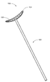
図1A、図1Bは、眼瞼支持アセンブリ100(すなわち、下眼瞼などの眼瞼を持ち上げるためのアセンブリ)の代替的な図を提示するものである。より詳細には、図1Aは、眼瞼支持アセンブリ100の正面図を提示している。図1Bは、眼瞼支持アセンブリ100の側面図を提示している。眼瞼支持アセンブリ100は、取り付けプレート110、細長形シャフト120、及び眼瞼支持部材130を含む。
1A and 1B present an alternative view of the eyelid support assembly 100 (ie, an assembly for lifting the eyelid, such as the lower eyelid). More specifically, FIG. 1A presents a front view of the
図1A及び図1Bに示される実施形態では、取り付けプレート110は、頬骨などの顔面骨に結合するように構成されている。例えば、取り付けプレート110は、1つ以上の締結具112(例えば、骨ネジ)を介して、頬骨に取り付けることができる。取り付けプレート110は、眼瞼支持アセンブリ100の1つ以上の他の要素を取り付けることが可能な、足場としての機能を果たし得る。
In the embodiments shown in FIGS. 1A and 1B, the
細長形シャフト120は、取り付けプレート110と眼瞼支持部材130との間に延びて、それらを結合するように構成されている。例えば、図1A及び図1Bでは、細長形シャフト120は、取り付けプレート110及び眼瞼支持部材130の双方に取り付けられることにより、眼瞼支持部材130に取り付けプレート110を結合している。細長形シャフト120は、図1Bに示される経路などの(図9も参照)蛇行性経路を、細長形シャフト120が辿ることを可能にする、可撓性材料から形成することができる。図1A及び図1Bに示される実施形態では、細長形シャフト120、取り付けプレート110、及び/又は眼瞼支持部材130は、一体的に形成されている。他の実施形態では、これらの構成要素のうちの1つ以上は、別個に製造され、その後に、締結具(例えば、接着剤、溶接、圧迫バー、圧着ビーズ、ネジなど)を介して、残余の構成要素に取り付けられる。例えば、一部の実施形態では、細長形シャフト及び眼瞼支持部材が、一体的に形成され、締結具を介して、取り付けプレートに取り付けられる。
The
眼瞼支持アセンブリ100の細長形シャフト120の長さは、患者の解剖学的構造に合致するように選択することができる。例えば、一部の患者では、頬骨から、下瞼板の底縁部が位置するべき場所までの距離が、比較的長い場合がある。他の患者では、頬骨から下瞼板の適切な場所までの距離は、比較的短い。したがって、一部の実施形態では、施術者は、異なる長さの様々な眼瞼支持アセンブリから、適切な長さの細長形シャフト120を有する眼瞼支持アセンブリ100を選択することにより、取り付けプレート110が患者の顔面骨に固定される場合に、適切な量で眼瞼を持ち上げることができる。
The length of the
眼瞼支持部材130は、眼瞼組織に接触し、それにより麻痺眼瞼を持ち上げるように、構成することができる。例えば、一部の実施形態では、眼瞼支持部材130は、患者の下瞼板の下側部分に接触及び/又は結合して(例えば、下側部分を巻き込む、又は貫通する縫合糸を介して)、それにより下瞼板(及び、患者の下眼瞼)を持ち上げる。眼瞼支持部材130は、水平方向に延びて、下眼瞼の幅(すなわち、下瞼板の全長)に近似するように構成することができる。一部の実施形態では、眼瞼支持部材130は、湾曲状(例えば、下眼瞼/下瞼板の輪郭に従うバナナ形状)である。他の実施形態では、眼瞼支持部材には、異なる形状を採用することができる。
The
眼瞼支持アセンブリ100の構成要素は、任意の好適な材料から作製することができる。例えば、一部の実施形態では、取り付けプレート110、細長形シャフト120、及び眼瞼支持部材130のうちの1つ以上は、超高分子量ポリエチレンなどの、生体適合性ポリマーを含むものであり、又は本質的にそのような生体適合性ポリマーからなる。より詳細には、一部の実施形態では、取り付けプレートは、超高分子量ポリエチレンを含むものであり、又は本質的に超高分子量ポリエチレンからなる。一部の実施形態では、取り付けプレートなどの1つ以上の構成要素は、チタンを含むものであり、又は本質的にチタンからなる。一部の実施形態では、取り付けプレート、細長形シャフト120、及び眼瞼支持部材130のうちの1つ以上は、2種以上の異なる生体適合性ポリマーから形成される。例えば、種々の生体適合性ポリマーを成形型に注入することによって、1つの構成要素を作製することができる。
The components of the
眼瞼支持アセンブリ100を使用して、麻痺下眼瞼などの眼瞼を支持することができる。例えば、是正措置が施されない場合、麻痺眼瞼は、垂れさがる傾向があることにより、比較的低い位置に眼瞼が配置される恐れがある。眼瞼支持部材130が、下瞼板などの眼瞼組織に対して作用することにより、その眼瞼を所望の位置に持ち上げることができる。換言すれば、眼瞼支持部材130は、眼瞼を、眼瞼支持アセンブリ100が存在しない場合よりも高く配置させる、力を及ぼすことができる。この方式で下眼瞼を持ち上げることにより、(1)眼瞼の完全な(又は、より完全な)閉鎖を容易にし、(2)目領域の美的外観を改善し、かつ/又は(3)外反、眼瞼弛緩、流涙、兎眼、並びに/あるいは角膜損傷のリスク及び/又は発生を低減することができる。
The
図2A〜図2Dは、特定の態様において上述の眼瞼支持アセンブリ100に類似する、眼瞼支持アセンブリ200の実施形態を示すものである。したがって、同様の特徴には、同様の参照番号が、先頭の桁を「2」に増分して割り当てられている。例えば、図2A〜図2Dに示される実施形態は、一部の態様では図1A及び図1Bの眼瞼支持部材130に類似し得る、眼瞼支持部材230を含む。それゆえ、同様に特定される特徴に関して上述された、関連性のある開示は、以降では繰り返されない場合がある。更には、図1A並びに図1Bに示される、眼瞼支持アセンブリ及び関連構成要素の特定の特徴は、図面中の参照番号によって示されない場合、若しくは特定されない場合があり、又は、以下に記載される説明では具体的に論じられない場合もある。しかしながら、そのような特徴は、他の実施形態で示される特徴、及び/又は、そのような実施形態に関して説明される特徴と、明白に同じもの、あるいは実質的に同じものとすることができる。したがって、そのような特徴の関連説明は、図2A〜図2Dに示される眼瞼支持アセンブリ200及び関連構成要素の特徴に、等しく適用される。図1A並びに図1Bに示される眼瞼支持アセンブリ100及び関連構成要素に関して説明された特徴の、任意の好適な組み合わせ、並びにそれらの変形例は、図2A〜図2Dの眼瞼支持アセンブリ200及び関連構成要素の場合にも採用することができ、逆もまた同様である。この開示のパターンは、後続の図に示され、かつ以降で説明される、更なる実施形態にも等しく適用されるものであり、先頭の桁を更に増分することができる。
2A-2D show embodiments of the eyelid support assembly 200, which is similar to the
図2A〜図2Dは、長さ調節可能な眼瞼支持アセンブリ200(すなわち、施術者によって調節することが可能な長さを有する、眼瞼支持アセンブリ200)を示すものである。より詳細には、図2Aは、患者の顔面骨50に取り付けられた取り付けプレート210を有する、眼瞼支持アセンブリ200の正面図を提示している。図2Bは、細長形シャフト220の一部分の切除を示す、同じ眼瞼支持アセンブリ200の正面図を提示している。図2Cは、図2Aの線2C−2Cを通る、眼瞼支持アセンブリ200の断面図を提示している。図2Dは、眼瞼支持アセンブリ200の一部分の斜視図を提示している。眼瞼支持アセンブリ200は、患者の顔面の外面と関連して示されている(すなわち、患者の肉体に対して外向きに示されている)が、本開示の恩恵を受けることにより、当業者には、眼瞼支持アセンブリ200が、一般に患者の皮膚よりも下に埋め込まれることが認識されるであろう。
2A-2D show a length-adjustable eyelid-supporting assembly 200 (ie, an eyelid-supporting assembly 200 having a length that can be adjusted by the practitioner). More specifically, FIG. 2A presents a front view of the eyelid support assembly 200 with a mounting
これらの図に示されるように、眼瞼支持アセンブリ200は、取り付けプレート210、細長形シャフト220、及び眼瞼支持部材230を含む。図示の実施形態では、細長形シャフト220及び眼瞼支持部材230は、単一の分離不可能なユニットを構成している。
As shown in these figures, the eyelid support assembly 200 includes a mounting
図2A〜図2Dに示される実施形態では、取り付けプレート210は、顔面骨50に結合するように構成されている。例えば、一部の実施形態では、取り付けプレート210は、1つ以上の締結具212を介して、患者の頬骨に取り付けられるか、又は他の方式で結合される。換言すれば、骨ネジなどの締結具212は、取り付けプレート210を貫通して延び、顔面骨50内にめり込むことにより、患者の骨構造に対して取り付けプレート210を固定することができる。一部の実施形態では、取り付けプレート210は、患者の顔面骨50の表面に合致するように輪郭形成される。他の実施形態又は更なる実施形態では、顔面骨50が、取り付けプレート210のプロファイルを受け入れるように削られる。図2Aに示されるものなどの一部の実施形態では、取り付けプレート210は、取り付けプレート210が眼窩の中心の真下に配置されるように、顔面骨50に取り付けられる。他の実施形態又は更なる実施形態では、取り付けプレートは、患者の眼窩の中心の側方の位置に配置されており、その取り付けプレートから患者の矢状面に向けて内側に延びる、細長形シャフトを有することにより、眼瞼支持部材は、患者の下眼瞼を支持するように、眼窩の中心の真下に配置される。
In the embodiments shown in FIGS. 2A-2D, the
一部の実施形態では、取り付けプレート210(例えば、主として超高分子量ポリエチレンから作製された、取り付けプレート)は、顔面骨に接触するように構成された、シート240又は層を含む。換言すれば、シート240は、顔面骨50と取り付けプレート210の残余部分との間に配置することができる。一部の実施形態では、シート240は、その取り付けプレートの残余部分に(例えば、接着剤を介して)取り付けられる。他の実施形態又は更なる実施形態では、シート240は、1つ以上の締結具212を介して、取り付けプレート210の残余部分に対して保持される。一部の実施形態では、シート240は、メッシュ層、又はスパッタコーティングによって形成された層である。他の実施形態又は更なる実施形態では、シート240は、チタンを含むものであり、かつ/又は本質的にチタンからなる。例えば、一部の実施形態では、凹凸のある(粗い)チタン層(例えば、チタン製メッシュシート又はチタン適用コーティング)が、顔面骨50に接触することにより、骨成長及び/又はシート240への固着を容易にすることができる。他の実施形態(例えば、チタン製取り付けプレートが、テクスチャ加工された下側表面を含む実施形態)では、シート240に類似するシートが欠如している場合がある。
In some embodiments, the mounting plate 210 (eg, a mounting plate made primarily of ultra-high molecular weight polyethylene) comprises a
図示の実施形態では、取り付けプレート210は、チャネル214を備えている。チャネル214は、取り付けプレート210の長手方向軸線に対して垂直に延びることができる。チャネル214はまた、細長形シャフト220の底部部分を受け入れるようなサイズ及び形状にすることもできる。換言すれば、チャネル214は、細長形シャフト220の底部部分が、チャネル214を通過することを可能にするように、構成することができる。図示の実施形態では、チャネル214及び細長形シャフト220は双方とも、実質的に楕円の形状の断面を含む。このチャネル214及び細長形シャフト220の楕円形の断面形状は、細長形シャフト220がチャネル214内部で回転することを防止するものである。本開示の恩恵を受けることにより、当業者には、種々の形状及びサイズのチャネル並びに細長形シャフト(例えば、円形若しくは矩形の断面を有するチャネル及びシャフト)もまた、使用に好適であり、かつ本開示の範囲内にあることが認識されるであろう。
In the illustrated embodiment, the mounting
眼瞼支持アセンブリ200を埋め込む際、施術者は最初に、患者の顔面骨50に取り付けプレート210を取り付けること、又は他の方式で結合することによって、取り付けプレート210を固定することができる。例えば、一部の状況では、施術者は、取り付けプレート210を、患者の頬骨に取り付けることができる。次いで、施術者は、細長形シャフト220の底部部分を、取り付けプレート210のチャネル214に挿通することができる。細長形シャフト220の第1の(すなわち、底部の)端部が、チャネル214を通って進行する(例えば、スライドする)と、取り付けプレート210と細長形シャフト220の第2の端部との距離が減少する。それゆえ、細長形シャフト220がチャネル214を通って進行する程度を変化させることによって、施術者は、取り付けプレート210と細長形シャフト220の第2の端部との距離を調節することができる。そのような調節は、眼瞼支持アセンブリ200を患者内に埋め込む間に達成することができる。この方式で、施術者は、細長形シャフト220に結合されている眼瞼支持部材230の、取り付けプレート210に対する位置を調節することができる。換言すれば、調節可能な眼瞼支持アセンブリ200は、眼瞼支持部材230が、患者の顔面の特定の構造を考慮する方式で、眼瞼を支持するために適切に位置決めされることを、確実にするように調節することができる。
When implanting the eyelid support assembly 200, the practitioner can first secure the
例えば、眼瞼支持部材230に結合されている第2の端部を有する細長形シャフト220は、眼瞼支持部材230が、患者の下瞼板に隣接して(例えば、真下に)配置されるまで、取り付けプレート210のチャネル214に通して挿入することができる。一部の実施形態では、次いで、施術者は、眼瞼支持部材230を下瞼板に縫合すること、又は他の方式で結合することができる。次いで、施術者は、取り付けプレート210に対して細長形シャフト220を移動させることによって、眼瞼支持部材230の位置を(例えば、眼瞼を持ち上げるように)調節することができる。細長形シャフト220の第2の端部が、取り付けプレート210から適切な距離に配置されるように、細長形シャフト220が、取り付けプレート210内部で位置決めされた後、細長形シャフト220を、取り付けプレート210に対して固定することができる。例えば、接着剤5(例えば、シアノアクリレート接着剤)を、取り付けプレート210のポート216を通じて送達することにより(図2Dを参照)、取り付けプレートに対して細長形シャフト220を固定することができる。
For example, an
取り付けプレート210に対して細長形シャフト220を固定するための、接着剤5の送達は、細長形シャフト220の1つ以上の溝によって容易にすることができる。例えば、一部の実施形態では、細長形シャフト220は、細長形シャフト220の長手方向軸線に対して垂直に延びる、1つ以上の溝222を備え得る。ポート216を通じて接着剤5を送達すると、接着剤5は、溝220に回り込んで流れることができる。溝220に回り込んで流れることによって、接着剤5は、細長形シャフト220の周囲(例えば、外周)にわたって広がり、取り付けプレート210に細長形シャフト220を恒久的に固着させることができる。
Delivery of the adhesive 5 for fixing the
細長形シャフト220が、取り付けプレート210に対して適切に位置決めされ、取り付けプレート210に固定された後、取り付けプレート210全体を通過している細長形シャフト220の任意の部分(例えば、細長形シャフト220の第1の端部)を切除して、廃棄することができる(図2Bを参照)。
Any part of the elongated shaft 220 (eg, the elongated shaft 220) that passes through the entire mounting
細長形シャフト220が、取り付けプレート210内部で位置決めされ、取り付けプレート210に固着される(又は、他の方式で確実に結合される)と、細長形シャフト220は、患者の矢状面から実質的に等距離の経路(その経路に沿った全ての地点で等距離な経路)に沿って、延びることができる。換言すれば、細長形シャフト220は、患者の矢状面に対して、実質的に平行に延びることができる。
When the
図3A〜図3Cは、別の実施形態による、眼瞼支持アセンブリ300又はその構成要素を示すものである。より詳細には、図3Aは、眼瞼支持アセンブリ300の断面図を提示している。図3Bは、図3Aに示される取り付けプレート310の第1部分311の底面図を提示している。また図3Cは、同じ取り付けプレート310の第2部分319の上面図を提示している。図示の実施形態では、第1部分311は、図3Aに示されるように取り付けプレート310を見た場合、第2部分319の概して上方に配置されている。換言すれば、取り付けプレート310が顔面骨50に結合される場合、取り付けプレート310の第2部分319は、取り付けプレート310の第1部分311よりも、顔面骨50に近接して配置することができる。換言すれば、取り付けプレート310が顔面骨50に結合される場合、取り付けプレート310の第1部分311と顔面骨50との距離は、取り付けプレート310の第2部分319と顔面骨50との距離よりも大きいものであり得る。
3A-3C show the
眼瞼支持アセンブリ300は、取り付けプレート310、細長形シャフト320、及び眼瞼支持部材330(図示せず)を含む。上述のように、眼瞼支持アセンブリ300の取り付けプレート310は、2つの別個の構成要素である、第1部分311及び第2部分319を含む。一部の実施形態では、第1部分311及び第2部分319のうちの1つ以上は、チタンを含むものであり、又は本質的にチタンからなる。
The
図示の実施形態では、取り付けプレート310の第2部分319は、開口360を含み、この開口360は、取り付けプレート310の第2部分319内部に配置されている、細長形シャフト320の長さの一部分に隣接して、その部分に沿って延びている。
In the illustrated embodiment, the
取り付けプレート310の第1部分311は、その第1部分311の残部から延びる、圧迫バー350を含み得る(図3A及び図3Bを参照)。圧迫バー350は、チタンを含み得るものであり、又は本質的にチタンからなるものとすることができる。更には、一部の実施形態では、圧迫バー350は、複数の溝を含む。圧迫バー350は、取り付けプレート310の第2部分319の開口360を通って延びることにより、細長形シャフト320と係合するような、サイズ及び形状にすることができる。
The
例えば、締結具312が、顔面骨50内に進行する際、それらの締結具は、取り付けプレート310の第1部分311を、患者の顔面骨50に向けて引き寄せることができる。取り付けプレート310の第1部分311を、患者の顔面骨50に向けて引き寄せることによって、圧迫バー350は、細長形シャフト320と係合し、かつ/又は圧迫するように、開口360を通って延びることができる。圧迫バー350による、細長形シャフト320との係合及び/又は圧迫により、チャネル314内部での細長形シャフト320の移動を制限することができる。換言すれば、顔面骨内への締結具312の進行が、圧迫バー350と細長形シャフト320との摩擦係合を促進することにより、チャネル314を通る細長形シャフト320の移動を防止することができる。
For example, as the
図示の実施形態は、単一の圧迫バー350のみを含むものであるが、他の実施形態は、下側プレートの1つ以上の開口を通って延び、細長形シャフトと係合するように構成された、複数の圧迫バー350を含み得る。
The illustrated embodiment comprises only a
図4A及び図4Bは、別の眼瞼支持アセンブリの、細長形シャフト420及び取り付けプレート410の断面図を提示するものである。より詳細には、図4Aは、取り付けプレート410内への細長形シャフト420の挿入を示す。図4Bは、細長形シャフト420が適切に挿入され、取り付けプレート410に対して細長形シャフト420を確実に固定するために、接着剤が追加された後の、同じ眼瞼支持アセンブリ構成要素を示す。
4A and 4B present a cross-sectional view of an
図4A及び図4Bでは、細長形シャフト420は、その細長形シャフト420の長手方向軸線から離れる方向に延びる、複数の突出部424を備えている。これらの突出部424は、細長形シャフト420の周りに延びる溝を形成する。取り付けプレート410もまた、その取り付けプレート410のチャネル414内に延びる、複数の突出部418を含む。
In FIGS. 4A and 4B, the
図4Aに示されるように、取り付けプレート410内に、細長形シャフト420を挿入することができる。取り付けプレート410の突出部418は、細長形シャフト420が取り付けプレート410内部で進行する際に、偏向することにより、チャネル414内部で細長形シャフト420が進行することを許容し得る。換言すれば、細長形シャフト420が、取り付けプレート410内に挿入されると、細長形シャフト420の突出部424は、取り付けプレート410の突出部418に接触して、それら突出部418を偏向させることができる。取り付けプレート410の突出部418は、細長形シャフト420が進入することを可能にするように、一方向に偏向するが、しかしながら、反対方向での偏向を防ぐように、構成することができる。換言すれば、突出部418は、取り付けプレート410内に細長形シャフト420を挿入することを可能にし得るものであるが、取り付けプレート410から細長形シャフト420を引き抜くことは可能にし得ない。突出部418は、取り付けプレート410の残部の材料とは異なる材料で作製することができる。例えば、突出部418は、取り付けプレート410の残部が作製される材料よりも可撓性の材料で作製することができ、又は、そのような材料を含み得る。
As shown in FIG. 4A, the
細長形シャフト420の第2の端部(すなわち、取り付けプレート410内に挿入されていない、細長形シャフト420の端部)が、取り付けプレート410から適切な距離に配置されるように、細長形シャフト420が挿入された後、取り付けプレート410の突出部418は、細長形シャフト420の突出部424と噛み合うことにより、取り付けプレート410から細長形シャフト420が引き抜かれることを防止する(又は、他の方式で妨げる)ことができる。
The slender shaft so that the second end of the slender shaft 420 (ie, the end of the
細長形シャフト420を、取り付けプレート410に確実に固定することにより、細長形シャフト420の更なる挿入及び引き抜きの双方を防止することができる。例えば、図4Bに示されるように、取り付けプレート410のポート416を通じて、接着剤5を送達することができる。この接着剤は、細長形シャフト420の周りに流れて、細長形シャフト420と取り付けプレート410との間の空隙を充填することにより、取り付けプレート410に細長形シャフト420を確実に固着させることができる。
By securely fixing the
図4A及び図4Bの突出部418は、取り付けプレートへの細長形シャフト420の挿入のみを許容する(かつ、引き抜きを許容しない)ものとして説明されているが、他の実施形態では、これらの突出部は、取り付けプレート410からの細長形シャフト420の引き抜きを妨げるものではない。換言すれば、一部の実施形態では、突出部418は、細長形シャフト420が双方向で移動することを可能にする。
The
図5A及び図5Bは、別の実施形態による、眼瞼支持アセンブリ500を示すものである。より詳細には、図5Aは、眼瞼支持アセンブリ500の正面図を提示しており、その一方で、図5Bは、図5Aの線5B−5Bを通る、眼瞼支持アセンブリ500の断面図を提示している。図5A及び図5Bを参照すると、眼瞼支持アセンブリ500は、取り付けプレート510、細長形シャフト520、及び眼瞼支持部材530を備え得る。
5A and 5B show the
図示の実施形態では、取り付けプレート510は、患者の顔面骨50に結合するように構成されている。例えば、取り付けプレート510は、骨ネジなどの1つ以上の締結具512を介して、患者の頬骨、上顎骨、又は他の顔面骨に取り付けることができる。取り付けプレート510はまた、チャネル514も備え得る。チャネル514は、眼瞼支持アセンブリ500の細長形シャフト520を受け入れるような、サイズ及び形状にすることができる。取り付けプレート510はまた、取り付けプレート510への細長形シャフト520の結合を容易にするための、穴517も備え得る。穴517は、セルフタッピング骨ネジなどの締結具513を受け入れるような、サイズ及び形状にすることができる。
In the illustrated embodiment, the mounting
図示の実施形態で示されるように、細長形シャフト520は、複数の穴526を含む。複数の穴526は、細長形シャフト520の長手方向軸線に沿って、一直線に並べることができる。細長形シャフト520は、細長形シャフト520が、下眼瞼の支持を容易にするように適切に位置決めされるまで、取り付けプレート510のチャネル514内に挿入することができる。例えば、細長形シャフト520は、細長形シャフト520の第2の端部(すなわち、チャネル514内に挿入されていない、細長形シャフト520の端部)に配置されている眼瞼支持部材530が、患者の下眼瞼を適切に持ち上げるべく位置決めされるように、挿入することができる。
As shown in the illustrated embodiment, the
細長形シャフト520が、取り付けプレートに対して適切に位置決めされた後、取り付けプレート510の穴517を、細長形シャフト520の複数の穴526のうちの1つと位置合わせすることができる。これらの穴が適切に位置合わせされると、骨ネジなどの締結具513を、細長形シャフト520の穴517と複数の穴526のうちの1つとの双方に通して挿入することにより、取り付けプレート510と眼瞼支持部材530との距離を固定することができる。換言すれば、挿入された締結具513は、細長形シャフト520に取り付けプレート510を確実に取り付けることにより、取り付けプレート510から、細長形シャフト520の第2の端部に結合されている眼瞼支持部材530までの距離を規定することができる。
After the
図6は、別の実施形態による、眼瞼支持アセンブリ600の断面図を提示するものである。眼瞼支持アセンブリ600は、取り付けプレート610、細長形シャフト620、及び眼瞼支持部材(図示せず)を含む。図示の実施形態では、取り付けプレート610は、矩形の形状の断面を有する、チャネル614を備えている。
FIG. 6 presents a cross-sectional view of the
図6に示される実施形態は、図5A及び図5Bに示された実施形態に類似しているが、ただし、細長形シャフト620は、複数の穴を含まない。細長形シャフト620は、その細長形シャフト620が適切な程度に挿入されるまで、取り付けプレートのチャネル614内に挿入することができる。次いで、圧迫ネジなどの締結具613を使用して、細長形シャフト620をチャネル614に対して押圧することにより、取り付けプレート610に対して細長形シャフト620を固定することができる。
The embodiment shown in FIG. 6 is similar to the embodiment shown in FIGS. 5A and 5B, except that the
図7A〜図7Eは、別の実施形態による、眼瞼支持アセンブリ700の様々な状態を示すものである。図7A〜図7Eに示されるように、眼瞼支持アセンブリ700は、圧着ビーズ701、702を介して、取り付けプレート710に細長形シャフト720を固定するように構成されている。圧着ビーズ701、702は、細長形シャフト720の周りを締め付けるように圧迫することが可能な、円形、楕円形、矩形、若しくは何らかの他の形状の、帯又は輪とすることができる。例えば、図7Aに示されるように、第1の圧着ビーズ701を、最初に、細長形シャフト720の第1の(すなわち、底部の)端部の周りに滑り込ませることができる。次いで、図7Bに示されるように、細長形シャフトの第2の(すなわち、頂部の)端部に取り付けられている眼瞼支持部材730が、患者の下瞼板に隣接して(例えば、真下に)配置されるまで、細長形シャフト720の底端部を、患者の顔面(例えば、頬)骨に取り付けられた取り付けプレート710のチャネルに通して挿入することができる。一部の状況では、次いで、眼瞼支持部材730を、下瞼板に取り付ける(例えば、縫合する)ことができる。眼瞼支持部材730が、取り付けプレート710から適切な距離に配置されるように、細長形シャフト720が、取り付けプレート710内部で位置決めされた後、第1の圧着ビーズ701を、取り付けプレート710の直上の位置で圧迫することができる。次いで、図7C及び図7Dに示されるように、第2の圧着ビーズ702を、細長形シャフト720の底端部の上に配置して、その第2の圧着ビーズ702が、取り付けプレート710の直下に配置されるまで、上向きに押し込むことができる。次いで、第2の圧着ビーズ702を圧迫することにより、取り付けプレート710に細長形シャフト720を固定することができる。取り付けプレート710に細長形シャフト720が固定された後、図7Eに示されるように、細長形シャフト720の尾部を切除して、廃棄することができる。一部の実施形態では、圧着ビーズ701、702は、1つ以上の他の締結具と関連して使用することができる。例えば、取り付けプレート710に対する細長形シャフト720の位置を係止するために、止めネジもまた使用することができる。
7A-7E show different states of the
図8A及び図8Bは、別の実施形態による、眼瞼支持アセンブリ用の取り付けプレート810の代替的な図を提示するものである。より詳細には、図8Aは、取り付けプレート810の側面図を提示しており、その一方で、図8Bは、取り付けプレート810の上面図を提示している。取り付けプレート810は、頬骨などの顔面骨に結合するように構成されている。例えば、取り付けプレート810は、取り付けプレート810内の開口803に通して挿入される、1つ以上の締結具を介して、頬骨に取り付けることができる。取り付けプレート810は、眼瞼支持アセンブリの1つ以上の他の要素を取り付けることが可能な、足場としての機能を果たし得る。
8A and 8B provide an alternative view of the mounting
図8A及び図8Bに示される実施形態では、取り付けプレート810は、中央領域804及び一対の側方領域806を含み、中央領域804は、側方領域806よりも厚い。一部の実施形態では、中央領域804は、比較的なだらかな尾根部を形成するように、側方領域806から徐々に隆起している。中央領域804は、細長形シャフトを収容するように設計された、チャネル814を含み得る。比較的薄い側方領域806と、より厚い中央領域804とを有するように設計された、取り付けプレート810は、細長形シャフトを収容するための十分な構造を可能にしつつも、不要な埋め込み材料の量を最小限に抑えることができる。取り付けプレート810は、任意の好適な材料(例えば、チタン)から作製することができる。
In the embodiments shown in FIGS. 8A and 8B, the mounting
図9は、患者の下眼瞼を持ち上げるように位置決めされている、眼瞼支持アセンブリ900の部分切り欠き側面図を提示するものである。眼瞼支持アセンブリ900は、取り付けプレート910、細長形シャフト920、及び眼瞼支持部材930を含む。
FIG. 9 presents a partially cutaway side view of the
図9に示されるように、取り付けプレート910は、1つ以上の締結具912を介して、患者の顔面骨50(例えば、頬骨)に取り付けられている。細長形シャフト920は、取り付けプレート910から、概して上向きの方向に延びている。例えば、一部の実施形態では、細長形シャフト920は、取り付けプレート910から、眼窩隔膜55又は近傍の解剖学的構造に沿って、上向きに延びることができる。
As shown in FIG. 9, the
眼瞼支持部材930は、細長形シャフト920の第2の(すなわち、頂部の)端部に取り付けること、又は他の方式で結合することができる。例えば、支持部材930及び細長形シャフト920は、一体的に形成することができる。患者の下瞼板70を眼瞼支持部材930が持ち上げるように、眼瞼支持部材930を位置決めするために、施術者によって、細長形シャフト920を調節することができる。例えば、眼瞼支持部材930は、下瞼板70に縫合すること、又は他の方式で取り付けることができる。したがって、細長形シャフト920が、眼瞼支持部材930を持ち上げる結果となる方式で変位されると、眼瞼支持部材930は、患者の下瞼板70を持ち上げることにより、下眼瞼を支持することができる。そのような支持により、下眼瞼を持ち上げることができ、かつ/又は、その眼瞼を患者の目に向けて引き寄せることもできる。換言すれば、この眼瞼支持アセンブリ900によって供給される力により、患者の眼瞼を、上向き及び内向きの双方に(すなわち、患者の目に向けて)押圧することができる。
The
図10は、別の実施形態による、眼瞼支持アセンブリの一部分の斜視図を提示するものである。より詳細には、図10は、眼瞼支持部材1030に取り付けられている、細長形シャフト1020を示している。
FIG. 10 presents a perspective view of a portion of the eyelid support assembly according to another embodiment. More specifically, FIG. 10 shows an
図示の実施形態では、眼瞼支持部材1030は、メッシュ外装1032を含む。メッシュ外装1032は、眼瞼支持部材1030の形状を実質的に画定し得る。例えば、図示の実施形態では、眼瞼支持部材1030のメッシュ外装は、湾曲した形状である。メッシュ外装1032は、超高分子量ポリエチレン又は任意の他の好適な材料から形成することができる。
In the illustrated embodiment, the
眼瞼支持部材1030はまた、コア内部領域1034も含み得る。コア内部領域1034は、Alloderm(登録商標)若しくは他の同様の材料などの、皮膚由来の生体適合性無細胞材料を含み得るものであり、かつ/又は、そのような材料で充填することができる。換言すれば、コア内部領域1034は、コラーゲンに富むマトリックスを含み得るものであり、かつ/又は、コラーゲンに富むマトリックスで充填することができる。そのような材料は、患者の生存細胞が増殖することが可能な、足場としての役割を果たし得る。そのような材料を使用することにより、その眼瞼支持アセンブリの生体適合性を向上させることができる。更には、又はあるいは、そのような材料を使用することにより、その埋め込まれた眼瞼支持部材1030上での、細胞の増殖を促進することができる。そのような増殖の改善により、眼瞼支持部材1030と下眼瞼に隣接する組織との、固着の改善を促進することができる。
The
図11は、別の実施形態による、眼瞼支持アセンブリの取り付けプレート1110の正面図を提示するものである。図12は、図11の線12−12を通る、取り付けプレート1110の断面図を提示するものである。取り付けプレート1110は、患者の骨に取り付けプレート1110を締結する際に使用することが可能な、複数の開口1103を含む。一部の実施形態では、取り付けプレート1110は、1つ、2つ、3つ、4つ、5つ、6つ、又はそれよりも多くの開口1103を含む。取り付けプレート1110などの、複数の開口を含む一部の取り付けプレートは、いずれの場所に締結具(1つ以上)を配置するべきかを、施術者が複数の選択肢の中から選択することを可能にし得る。例えば、取り付けプレート1110は、2つのネジを介して、患者の頬骨に固定することができ、それらのネジの一方は、取り付けプレート1110の中心から第1の側の、3つの開口1103のうちのいずれかに配置される。第2のネジは、取り付けプレート1110の中心から第2の(すなわち、反対の)側の、3つの開口1103のうちのいずれかに配置することができる。施術者は、患者の骨密度に基づいて、いずれの場所に各締結具を配置するべきかを選択することができる。例えば、施術者は、十分な密度の骨に隣接して位置決めされている穴に通して、ネジを配置するように選択することができる。取り付けプレート1110の上面は、取り付けプレート1110の中心から側方に向けて先細になるため、取り付けプレート1110の側縁部に隣接して配置されたネジは、取り付けプレート1110の中心に隣接して配置されているネジよりも、更に患者の骨の中に延びることができる。一部の状況では、複数の開口1103を有する取り付けプレート1110と関連して、3つ以上の締結具を使用することができる。
FIG. 11 presents a front view of the mounting
図13は、別の実施形態による、取り付けプレート1210の正面図を提示するものである。取り付けプレート1210は、締結具(1つ以上)1212の調節可能な配置を可能にする、少なくとも1つの横方向チャネル1209を含む。例えば、取り付けプレート1210は、2つの横方向チャネル1209を含む。第1の締結具1212(例えば、ネジ)を、一方の横方向チャネル1209の長さに沿った、任意の位置に配置することができる。第2の締結具1212(例えば、ネジ)を、他方の横方向チャネル1209の長さに沿った、任意の位置に配置することができる。施術者は、患者の骨密度に基づいて、締結具1212の配置を決定することができる。換言すれば、施術者は、患者の骨の密度が十分である、横方向チャネル1209に沿った位置に、締結具1212を配置することができる。一部の実施形態では、取り付けプレート1210の上面は、取り付けプレート1210の中心から側方に向けて先細にすることができる。それゆえ、取り付けプレート1210の側縁部に隣接して配置された締結具1212は、取り付けプレート1210の中心に隣接して配置されている締結具1212よりも、更に患者の骨の中に延びることができる。一部の実施形態及び/又は一部の状況では、横方向チャネル1209を有する取り付けプレート1210と関連して、3つ以上の締結具1212を使用することができる。
FIG. 13 presents a front view of the mounting
実施例
以下の実施例は、開示される方法及び構成を例示するものである。本開示の観点から、当業者には、開示される方法並びに構成の本実施例及び他の実施例の変形例が、過度の実験を実施せずとも可能となることが認識されるであろう。
Examples The following examples exemplify the disclosed methods and configurations. From the point of view of the present disclosure, those skilled in the art will recognize that the methods and configurations of this embodiment and other variants of the disclosed embodiments will be possible without undue experimentation. ..
実施例1−眼瞼アセンブリの構成要素及び接続の安定性分析(加速寿命試験)
眼瞼支持アセンブリの構成要素の安定性を、それらの構成要素間の接続の安定性と併せて試験するために、3×1×25mmの細長形シャフトを、4×4×3mmの取り付けプレートに、その取り付けプレートの1×3mmのポートを通じて送達されるシアノアクリレート接着剤を使用して取り付けた。シアノアクリレート接着剤が乾燥した後、取り付けプレートを動かないように固定した。次いで、その固定された取り付けプレートの反対側に配置されている、細長形シャフトの端部を、30サイクル/分の速度で、静止位置から双方向に4mmの距離で、横方向に偏向させた。取り付けプレート、細長形シャフト、及び、取り付けプレートと細長形シャフトとの接続を、8時間(14,400サイクル)、16時間(28,800サイクル、24時間(43,200サイクル)、及び48時間(86,400サイクル)で試験した。取り付けプレート及び細長形シャフトの双方とも、顕著な損傷を受けることなく、試験期間全体を耐え抜いた。細長形シャフトと取り付けプレートとの間の、シアノアクリレート固着部も同様に、試験期間全体を耐え抜いた。接着接合部には、観察可能な損傷は存在しなかった。
Example 1-Stability analysis of components and connections of eyelid assembly (accelerated life test)
To test the stability of the components of the eyelid support assembly, along with the stability of the connections between those components, a 3 x 1 x 25 mm elongated shaft was placed on a 4 x 4 x 3 mm mounting plate. It was mounted using a cyanoacrylate adhesive delivered through a 1 x 3 mm port on the mounting plate. After the cyanoacrylate adhesive had dried, the mounting plate was fixed in place. The end of the elongated shaft, located on the opposite side of the fixed mounting plate, was then laterally deflected at a speed of 30 cycles / minute at a distance of 4 mm bidirectionally from the rest position. .. Mounting plates, elongated shafts, and connections between mounting plates and elongated shafts are 8 hours (14,400 cycles), 16 hours (28,800 cycles, 24 hours (43,200 cycles), and 48 hours (48 hours). Tested in 86,400 cycles). Both the mounting plate and the elongated shaft survived the entire test period without significant damage. The cyanoacrylate anchorage between the elongated shaft and the mounting plate was also Similarly, it survived the entire test period. There was no observable damage to the adhesive joint.
本明細書で開示されるいずれの方法も、説明されている方法を実行するための、1つ以上のステップ又は行為を含む。それらの方法のステップ及び/又は行為は、互いに入れ替えることができる。換言すれば、実施形態の適切な動作に関して、特定のステップ又は行為の順序が必要とされない限り、それら特定のステップ及び/又は行為の順序並びに/あるいは使用を変更することができる。更には、本明細書で説明されている方法のサブルーチン又は一部分のみを、本開示の範囲内の別個の方法とすることもできる。換言すれば、一部の方法は、より詳細な方法で説明されているステップの一部分のみを含み得る。 Each method disclosed herein includes one or more steps or actions to carry out the methods described. The steps and / or actions of those methods can be interchanged with each other. In other words, with respect to the proper operation of the embodiment, the order and / or use of those specific steps and / or actions may be modified unless a particular order of steps or actions is required. Furthermore, only subroutines or parts of the methods described herein may be separate methods within the scope of this disclosure. In other words, some methods may include only some of the steps described in the more detailed methods.
本明細書の全体にわたる、「ある実施形態」又は「その実施形態」への言及は、その実施形態に関連して説明されている特定の特徴、構造、又は特性が、少なくとも1つの実施形態に含まれていることを意味する。それゆえ、引用される表現又はその変形は、本明細書の全体にわたって記載されている場合、必ずしも全てが、同じ実施形態に言及するものとは限らない。 References to "an embodiment" or "the embodiment" throughout this specification include specific features, structures, or properties described in connection with that embodiment in at least one embodiment. Means that it is included. Therefore, not all cited expressions or variations thereof, when described throughout this specification, refer to the same embodiment.
同様に、本開示の恩恵を受けることにより、当業者には、上記の実施形態の説明において、開示の効率化の目的上、様々な特徴が単一の実施形態、図、又はそれらの説明に集約されている場合がある点を理解されたい。しかしながら、本開示の方法は、いずれの請求項も、その請求項で明示的に記載された特徴よりも多くの特徴を必要とするという意図を反映するものとして、解釈されるべきではない。むしろ、以下の請求項が反映するように、発明の態様は、上記で開示された任意の単一の実施形態の全ての特徴よりも、少ない特徴の組み合わせにある。それゆえ、この「発明を実施するための形態」に続く請求項は、この「発明を実施するための形態」に明示的に組み込まれるものであり、各請求項は、それ自体が別個の実施形態として独立している。本開示は、独立請求項とそれらの従属請求項の、あらゆる並べ替えを含む。 Similarly, by benefiting from this disclosure, one of ordinary skill in the art will appreciate that in the description of the embodiments described above, various features will be incorporated into a single embodiment, figure, or description thereof for the purpose of streamlining the disclosure. Please understand that it may be aggregated. However, the methods of the present disclosure should not be construed as reflecting the intent that any claim requires more features than those explicitly stated in that claim. Rather, as the following claims reflect, aspects of the invention are in a combination of fewer features than all features of any single embodiment disclosed above. Therefore, the claims following this "form for carrying out the invention" are explicitly incorporated into this "form for carrying out the invention", and each claim is itself a separate practice. It is independent as a form. The present disclosure includes any sort of independent claims and their dependent claims.
ある特徴又は要素に関する、請求項における「第1の」という用語の記載は、必ずしも、第2の若しくは追加的な、そのような特徴又は要素の存在を示唆するものではない。本開示の根本的な原理から逸脱することなく、上述の実施形態の詳細に変更を加えることができる点が、当業者には明らかとなるであろう。 The description of the term "first" in the claims with respect to a feature or element does not necessarily imply the existence of a second or additional such feature or element. It will be apparent to those skilled in the art that modifications can be made to the details of the embodiments described above without departing from the underlying principles of the present disclosure.
Claims (44)
顔面骨に結合するように構成された、取り付けプレートと、
眼瞼支持部材と、
前記取り付けプレートと前記眼瞼支持部材との間に延びて、前記眼瞼支持部材に前記取り付けプレートを結合するように構成された、細長形シャフトと、を備えており、
前記眼瞼支持部材は、湾曲状であり、患者の下瞼板の輪郭に従うように、構成されている、アセンブリ。 An assembly for lifting the lower eyelid
With a mounting plate configured to connect to the facial bones,
Eyelid support member and
It comprises an elongated shaft that extends between the mounting plate and the eyelid support member and is configured to connect the mounting plate to the eyelid support member .
An assembly in which the eyelid support member is curved and is configured to follow the contours of the patient's lower tarsal plate.
前記細長形シャフトが、前記患者内に前記アセンブリが埋め込まれる場合、前記患者の矢状面から実質的に等距離の経路に沿って延びる、請求項1に記載のアセンブリ。 Both the eyelid support member and the mounting plate are coupled to the elongated shaft.
It said elongated shaft, when the assembly is embedded in said patient, extending substantially along equidistant path from sagittal plane of the patient, the assembly according to claim 1.
請求項1に記載のアセンブリと、
前記顔面骨に前記取り付けプレートを結合するための、締結具と、を備えて、キット。 A kit to support the lower eyelids
The assembly according to claim 1 and
For coupling said mounting plate prior Symbol facial bones, provided with a fastener, the kit.
Applications Claiming Priority (3)
| Application Number | Priority Date | Filing Date | Title |
|---|---|---|---|
| US201562181383P | 2015-06-18 | 2015-06-18 | |
| US62/181,383 | 2015-06-18 | ||
| PCT/US2016/037852 WO2016205499A1 (en) | 2015-06-18 | 2016-06-16 | Eyelid supporters and related methods |
Publications (2)
| Publication Number | Publication Date |
|---|---|
| JP2018518346A JP2018518346A (en) | 2018-07-12 |
| JP6930968B2 true JP6930968B2 (en) | 2021-09-01 |
Family
ID=57546144
Family Applications (1)
| Application Number | Title | Priority Date | Filing Date |
|---|---|---|---|
| JP2018517673A Active JP6930968B2 (en) | 2015-06-18 | 2016-06-16 | Eyelid support and related methods |
Country Status (5)
| Country | Link |
|---|---|
| US (1) | US11266493B2 (en) |
| EP (1) | EP3310308B1 (en) |
| JP (1) | JP6930968B2 (en) |
| CA (1) | CA3026068A1 (en) |
| WO (1) | WO2016205499A1 (en) |
Families Citing this family (2)
| Publication number | Priority date | Publication date | Assignee | Title |
|---|---|---|---|---|
| CN112587299B (en) * | 2020-12-17 | 2022-11-18 | 广西中医药大学第一附属医院 | Combined device for cataract operation |
| CN113425424B (en) * | 2021-08-05 | 2022-06-03 | 樊涛 | A design measuring tool for double-edged eyelid operation |
Family Cites Families (19)
| Publication number | Priority date | Publication date | Assignee | Title |
|---|---|---|---|---|
| DE431950C (en) | 1925-11-06 | 1926-07-27 | Inst Kuenstliche Augen | Device for lifting paralyzed eyelids |
| US3710788A (en) | 1971-07-23 | 1973-01-16 | W Reeves | Eyelid support for invalids |
| US5522889A (en) * | 1995-01-13 | 1996-06-04 | University Of Kentucky Research Foundation | Apparatus and method for restoring eyelid function |
| US5843147A (en) | 1996-04-30 | 1998-12-01 | Medtronic, Inc. | Implantable eyelid electrode and method of implanting same |
| DE60137419D1 (en) | 2000-05-19 | 2009-03-05 | Coapt Systems Inc | COMPARATIVE DEVICE FOR TISSUE |
| EP1317216A4 (en) | 2000-09-15 | 2006-06-07 | Macropore Inc | Cranial flap fixation device |
| AR033840A1 (en) | 2000-10-04 | 2004-01-07 | Synthes Ag | AN ORTHOPEDIC DEVICE TO MODIFY THE DISTANCE BETWEEN THE MAXILAR AND THE CIGOMA OF A PATIENT |
| JP2005040250A (en) | 2003-07-25 | 2005-02-17 | Mizuho Co Ltd | Orthopaedic implant |
| US7686836B2 (en) * | 2004-05-13 | 2010-03-30 | Kls-Martin, L.P. | Bone distractor and method |
| US20070037120A1 (en) | 2005-07-29 | 2007-02-15 | Kurt Ritter | Facial support device |
| US8480757B2 (en) * | 2005-08-26 | 2013-07-09 | Zimmer, Inc. | Implants and methods for repair, replacement and treatment of disease |
| US7819899B2 (en) | 2006-01-03 | 2010-10-26 | Zimmer Spine, Inc. | Instrument for pedicle screw adhesive materials |
| US20080200993A1 (en) | 2007-02-15 | 2008-08-21 | Jenifer Lee Henderson | Temporal Brow Lifting and Fixation Device |
| US8449581B2 (en) | 2007-05-07 | 2013-05-28 | Stryker Trauma Gmbh | Sliding plate with reinforced slot |
| US20080288081A1 (en) | 2007-05-16 | 2008-11-20 | Joel Scrafton | Implant articular surface wear reduction system |
| US8403968B2 (en) | 2007-12-26 | 2013-03-26 | Illuminoss Medical, Inc. | Apparatus and methods for repairing craniomaxillofacial bones using customized bone plates |
| WO2009091802A2 (en) | 2008-01-14 | 2009-07-23 | Zimmer, Inc. | A knee system and method of making same |
| US8097041B2 (en) | 2008-01-31 | 2012-01-17 | Epitera Solutions, Inc. | Infra-orbital implant |
| US10052186B2 (en) * | 2013-10-10 | 2018-08-21 | Osteosymbionics Llc | Prosthetic implants |
-
2016
- 2016-06-16 EP EP16812428.7A patent/EP3310308B1/en active Active
- 2016-06-16 US US15/737,056 patent/US11266493B2/en active Active
- 2016-06-16 WO PCT/US2016/037852 patent/WO2016205499A1/en unknown
- 2016-06-16 JP JP2018517673A patent/JP6930968B2/en active Active
- 2016-06-16 CA CA3026068A patent/CA3026068A1/en active Pending
Also Published As
| Publication number | Publication date |
|---|---|
| US11266493B2 (en) | 2022-03-08 |
| JP2018518346A (en) | 2018-07-12 |
| WO2016205499A1 (en) | 2016-12-22 |
| EP3310308B1 (en) | 2020-09-02 |
| EP3310308A1 (en) | 2018-04-25 |
| EP3310308A4 (en) | 2019-04-10 |
| CA3026068A1 (en) | 2016-12-22 |
| US20180168799A1 (en) | 2018-06-21 |
Similar Documents
| Publication | Publication Date | Title |
|---|---|---|
| JP6532113B2 (en) | Clip and Applicator for Tissue Closure | |
| EP2897684B1 (en) | Implantable body with a lead and with engagement wings | |
| US20210244944A1 (en) | Implantable stimulating assembly | |
| US9895252B2 (en) | Septal implant | |
| JP2014516286A (en) | Fasteners, installation systems, and methods for ocular tissue closure and ocular artificial tissue fixation and other uses | |
| US6726719B2 (en) | Attachment mechanism for middle ear prosthesis | |
| EP3062743B1 (en) | Stimulating assembly fixation features | |
| KR101443820B1 (en) | Nose implant | |
| KR20160098105A (en) | Membrane for implant operation | |
| US7326171B2 (en) | Adjustable bone bracket | |
| KR101137943B1 (en) | Palate-supporting device for orthodontics | |
| JP6930968B2 (en) | Eyelid support and related methods | |
| US9011384B2 (en) | Outer ear bone anchor | |
| JP2019524220A (en) | Glaucoma treatment apparatus and method | |
| US8641760B2 (en) | Ossicular prosthesis with stabilizer and method of use with intact stapes | |
| US11399879B2 (en) | Devices and methods for positioning of an implant | |
| EP3932440A1 (en) | Medical device | |
| KR20150133671A (en) | Membrane for implant operation | |
| US20150272728A1 (en) | Ossicular prosthesis having a longitudinally perforated bight | |
| KR20120052234A (en) | Coupling apparatus | |
| CN209916243U (en) | Extension plate for correction nail | |
| TW202034859A (en) | Anchorage screw extension plate | |
| WO2010118514A1 (en) | Adjustable extra-ocular muscle implant | |
| KR20070017315A (en) | Resorbable surgical fixation device |
Legal Events
| Date | Code | Title | Description |
|---|---|---|---|
| RD01 | Notification of change of attorney |
Free format text: JAPANESE INTERMEDIATE CODE: A7426 Effective date: 20190306 |
|
| A521 | Request for written amendment filed |
Free format text: JAPANESE INTERMEDIATE CODE: A821 Effective date: 20190306 |
|
| A621 | Written request for application examination |
Free format text: JAPANESE INTERMEDIATE CODE: A621 Effective date: 20190610 |
|
| A977 | Report on retrieval |
Free format text: JAPANESE INTERMEDIATE CODE: A971007 Effective date: 20200826 |
|
| A131 | Notification of reasons for refusal |
Free format text: JAPANESE INTERMEDIATE CODE: A131 Effective date: 20200901 |
|
| A601 | Written request for extension of time |
Free format text: JAPANESE INTERMEDIATE CODE: A601 Effective date: 20201125 |
|
| A521 | Request for written amendment filed |
Free format text: JAPANESE INTERMEDIATE CODE: A523 Effective date: 20210301 |
|
| TRDD | Decision of grant or rejection written | ||
| A01 | Written decision to grant a patent or to grant a registration (utility model) |
Free format text: JAPANESE INTERMEDIATE CODE: A01 Effective date: 20210720 |
|
| A61 | First payment of annual fees (during grant procedure) |
Free format text: JAPANESE INTERMEDIATE CODE: A61 Effective date: 20210812 |
|
| R150 | Certificate of patent or registration of utility model |
Ref document number: 6930968 Country of ref document: JP Free format text: JAPANESE INTERMEDIATE CODE: R150 |