JP6930560B2 - Hub unit bearing manufacturing method, rocking caulking device, and vehicle manufacturing method - Google Patents
Hub unit bearing manufacturing method, rocking caulking device, and vehicle manufacturing method Download PDFInfo
- Publication number
- JP6930560B2 JP6930560B2 JP2019150197A JP2019150197A JP6930560B2 JP 6930560 B2 JP6930560 B2 JP 6930560B2 JP 2019150197 A JP2019150197 A JP 2019150197A JP 2019150197 A JP2019150197 A JP 2019150197A JP 6930560 B2 JP6930560 B2 JP 6930560B2
- Authority
- JP
- Japan
- Prior art keywords
- hub
- ring
- inner ring
- reference axis
- holder
- Prior art date
- Legal status (The legal status is an assumption and is not a legal conclusion. Google has not performed a legal analysis and makes no representation as to the accuracy of the status listed.)
- Active
Links
Images


Classifications
-
- B—PERFORMING OPERATIONS; TRANSPORTING
- B21—MECHANICAL METAL-WORKING WITHOUT ESSENTIALLY REMOVING MATERIAL; PUNCHING METAL
- B21D—WORKING OR PROCESSING OF SHEET METAL OR METAL TUBES, RODS OR PROFILES WITHOUT ESSENTIALLY REMOVING MATERIAL; PUNCHING METAL
- B21D39/00—Application of procedures in order to connect objects or parts, e.g. coating with sheet metal otherwise than by plating; Tube expanders
- B21D39/04—Application of procedures in order to connect objects or parts, e.g. coating with sheet metal otherwise than by plating; Tube expanders of tubes with tubes; of tubes with rods
- B21D39/046—Connecting tubes to tube-like fittings
-
- B—PERFORMING OPERATIONS; TRANSPORTING
- B21—MECHANICAL METAL-WORKING WITHOUT ESSENTIALLY REMOVING MATERIAL; PUNCHING METAL
- B21D—WORKING OR PROCESSING OF SHEET METAL OR METAL TUBES, RODS OR PROFILES WITHOUT ESSENTIALLY REMOVING MATERIAL; PUNCHING METAL
- B21D39/00—Application of procedures in order to connect objects or parts, e.g. coating with sheet metal otherwise than by plating; Tube expanders
- B21D39/04—Application of procedures in order to connect objects or parts, e.g. coating with sheet metal otherwise than by plating; Tube expanders of tubes with tubes; of tubes with rods
- B21D39/048—Application of procedures in order to connect objects or parts, e.g. coating with sheet metal otherwise than by plating; Tube expanders of tubes with tubes; of tubes with rods using presses for radially crimping tubular elements
-
- B—PERFORMING OPERATIONS; TRANSPORTING
- B21—MECHANICAL METAL-WORKING WITHOUT ESSENTIALLY REMOVING MATERIAL; PUNCHING METAL
- B21J—FORGING; HAMMERING; PRESSING METAL; RIVETING; FORGE FURNACES
- B21J9/00—Forging presses
- B21J9/02—Special design or construction
- B21J9/025—Special design or construction with rolling or wobbling dies
-
- B—PERFORMING OPERATIONS; TRANSPORTING
- B21—MECHANICAL METAL-WORKING WITHOUT ESSENTIALLY REMOVING MATERIAL; PUNCHING METAL
- B21D—WORKING OR PROCESSING OF SHEET METAL OR METAL TUBES, RODS OR PROFILES WITHOUT ESSENTIALLY REMOVING MATERIAL; PUNCHING METAL
- B21D53/00—Making other particular articles
- B21D53/10—Making other particular articles parts of bearings; sleeves; valve seats or the like
-
- B—PERFORMING OPERATIONS; TRANSPORTING
- B21—MECHANICAL METAL-WORKING WITHOUT ESSENTIALLY REMOVING MATERIAL; PUNCHING METAL
- B21D—WORKING OR PROCESSING OF SHEET METAL OR METAL TUBES, RODS OR PROFILES WITHOUT ESSENTIALLY REMOVING MATERIAL; PUNCHING METAL
- B21D53/00—Making other particular articles
- B21D53/88—Making other particular articles other parts for vehicles, e.g. cowlings, mudguards
-
- B—PERFORMING OPERATIONS; TRANSPORTING
- B21—MECHANICAL METAL-WORKING WITHOUT ESSENTIALLY REMOVING MATERIAL; PUNCHING METAL
- B21K—MAKING FORGED OR PRESSED METAL PRODUCTS, e.g. HORSE-SHOES, RIVETS, BOLTS OR WHEELS
- B21K25/00—Uniting components to form integral members, e.g. turbine wheels and shafts, caulks with inserts, with or without shaping of the components
-
- B—PERFORMING OPERATIONS; TRANSPORTING
- B23—MACHINE TOOLS; METAL-WORKING NOT OTHERWISE PROVIDED FOR
- B23P—METAL-WORKING NOT OTHERWISE PROVIDED FOR; COMBINED OPERATIONS; UNIVERSAL MACHINE TOOLS
- B23P11/00—Connecting or disconnecting metal parts or objects by metal-working techniques not otherwise provided for
- B23P11/005—Connecting or disconnecting metal parts or objects by metal-working techniques not otherwise provided for by expanding or crimping
-
- B—PERFORMING OPERATIONS; TRANSPORTING
- B60—VEHICLES IN GENERAL
- B60B—VEHICLE WHEELS; CASTORS; AXLES FOR WHEELS OR CASTORS; INCREASING WHEEL ADHESION
- B60B27/00—Hubs
- B60B27/0078—Hubs characterised by the fixation of bearings
- B60B27/0084—Hubs characterised by the fixation of bearings caulking to fix inner race
-
- B—PERFORMING OPERATIONS; TRANSPORTING
- B60—VEHICLES IN GENERAL
- B60B—VEHICLE WHEELS; CASTORS; AXLES FOR WHEELS OR CASTORS; INCREASING WHEEL ADHESION
- B60B35/00—Axle units; Parts thereof ; Arrangements for lubrication of axles
- B60B35/02—Dead axles, i.e. not transmitting torque
-
- F—MECHANICAL ENGINEERING; LIGHTING; HEATING; WEAPONS; BLASTING
- F16—ENGINEERING ELEMENTS AND UNITS; GENERAL MEASURES FOR PRODUCING AND MAINTAINING EFFECTIVE FUNCTIONING OF MACHINES OR INSTALLATIONS; THERMAL INSULATION IN GENERAL
- F16C—SHAFTS; FLEXIBLE SHAFTS; ELEMENTS OR CRANKSHAFT MECHANISMS; ROTARY BODIES OTHER THAN GEARING ELEMENTS; BEARINGS
- F16C19/00—Bearings with rolling contact, for exclusively rotary movement
- F16C19/02—Bearings with rolling contact, for exclusively rotary movement with bearing balls essentially of the same size in one or more circular rows
- F16C19/14—Bearings with rolling contact, for exclusively rotary movement with bearing balls essentially of the same size in one or more circular rows for both radial and axial load
- F16C19/18—Bearings with rolling contact, for exclusively rotary movement with bearing balls essentially of the same size in one or more circular rows for both radial and axial load with two or more rows of balls
- F16C19/181—Bearings with rolling contact, for exclusively rotary movement with bearing balls essentially of the same size in one or more circular rows for both radial and axial load with two or more rows of balls with angular contact
- F16C19/183—Bearings with rolling contact, for exclusively rotary movement with bearing balls essentially of the same size in one or more circular rows for both radial and axial load with two or more rows of balls with angular contact with two rows at opposite angles
- F16C19/184—Bearings with rolling contact, for exclusively rotary movement with bearing balls essentially of the same size in one or more circular rows for both radial and axial load with two or more rows of balls with angular contact with two rows at opposite angles in O-arrangement
- F16C19/186—Bearings with rolling contact, for exclusively rotary movement with bearing balls essentially of the same size in one or more circular rows for both radial and axial load with two or more rows of balls with angular contact with two rows at opposite angles in O-arrangement with three raceways provided integrally on parts other than race rings, e.g. third generation hubs
-
- F—MECHANICAL ENGINEERING; LIGHTING; HEATING; WEAPONS; BLASTING
- F16—ENGINEERING ELEMENTS AND UNITS; GENERAL MEASURES FOR PRODUCING AND MAINTAINING EFFECTIVE FUNCTIONING OF MACHINES OR INSTALLATIONS; THERMAL INSULATION IN GENERAL
- F16C—SHAFTS; FLEXIBLE SHAFTS; ELEMENTS OR CRANKSHAFT MECHANISMS; ROTARY BODIES OTHER THAN GEARING ELEMENTS; BEARINGS
- F16C19/00—Bearings with rolling contact, for exclusively rotary movement
- F16C19/22—Bearings with rolling contact, for exclusively rotary movement with bearing rollers essentially of the same size in one or more circular rows, e.g. needle bearings
- F16C19/34—Bearings with rolling contact, for exclusively rotary movement with bearing rollers essentially of the same size in one or more circular rows, e.g. needle bearings for both radial and axial load
- F16C19/38—Bearings with rolling contact, for exclusively rotary movement with bearing rollers essentially of the same size in one or more circular rows, e.g. needle bearings for both radial and axial load with two or more rows of rollers
- F16C19/383—Bearings with rolling contact, for exclusively rotary movement with bearing rollers essentially of the same size in one or more circular rows, e.g. needle bearings for both radial and axial load with two or more rows of rollers with tapered rollers, i.e. rollers having essentially the shape of a truncated cone
- F16C19/385—Bearings with rolling contact, for exclusively rotary movement with bearing rollers essentially of the same size in one or more circular rows, e.g. needle bearings for both radial and axial load with two or more rows of rollers with tapered rollers, i.e. rollers having essentially the shape of a truncated cone with two rows, i.e. double-row tapered roller bearings
- F16C19/386—Bearings with rolling contact, for exclusively rotary movement with bearing rollers essentially of the same size in one or more circular rows, e.g. needle bearings for both radial and axial load with two or more rows of rollers with tapered rollers, i.e. rollers having essentially the shape of a truncated cone with two rows, i.e. double-row tapered roller bearings in O-arrangement
-
- F—MECHANICAL ENGINEERING; LIGHTING; HEATING; WEAPONS; BLASTING
- F16—ENGINEERING ELEMENTS AND UNITS; GENERAL MEASURES FOR PRODUCING AND MAINTAINING EFFECTIVE FUNCTIONING OF MACHINES OR INSTALLATIONS; THERMAL INSULATION IN GENERAL
- F16C—SHAFTS; FLEXIBLE SHAFTS; ELEMENTS OR CRANKSHAFT MECHANISMS; ROTARY BODIES OTHER THAN GEARING ELEMENTS; BEARINGS
- F16C35/00—Rigid support of bearing units; Housings, e.g. caps, covers
- F16C35/04—Rigid support of bearing units; Housings, e.g. caps, covers in the case of ball or roller bearings
- F16C35/06—Mounting or dismounting of ball or roller bearings; Fixing them onto shaft or in housing
- F16C35/063—Fixing them on the shaft
-
- F—MECHANICAL ENGINEERING; LIGHTING; HEATING; WEAPONS; BLASTING
- F16—ENGINEERING ELEMENTS AND UNITS; GENERAL MEASURES FOR PRODUCING AND MAINTAINING EFFECTIVE FUNCTIONING OF MACHINES OR INSTALLATIONS; THERMAL INSULATION IN GENERAL
- F16C—SHAFTS; FLEXIBLE SHAFTS; ELEMENTS OR CRANKSHAFT MECHANISMS; ROTARY BODIES OTHER THAN GEARING ELEMENTS; BEARINGS
- F16C43/00—Assembling bearings
- F16C43/04—Assembling rolling-contact bearings
-
- B—PERFORMING OPERATIONS; TRANSPORTING
- B21—MECHANICAL METAL-WORKING WITHOUT ESSENTIALLY REMOVING MATERIAL; PUNCHING METAL
- B21J—FORGING; HAMMERING; PRESSING METAL; RIVETING; FORGE FURNACES
- B21J9/00—Forging presses
- B21J9/02—Special design or construction
- B21J9/06—Swaging presses; Upsetting presses
-
- B—PERFORMING OPERATIONS; TRANSPORTING
- B21—MECHANICAL METAL-WORKING WITHOUT ESSENTIALLY REMOVING MATERIAL; PUNCHING METAL
- B21K—MAKING FORGED OR PRESSED METAL PRODUCTS, e.g. HORSE-SHOES, RIVETS, BOLTS OR WHEELS
- B21K1/00—Making machine elements
- B21K1/28—Making machine elements wheels; discs
- B21K1/40—Making machine elements wheels; discs hubs
-
- B—PERFORMING OPERATIONS; TRANSPORTING
- B23—MACHINE TOOLS; METAL-WORKING NOT OTHERWISE PROVIDED FOR
- B23P—METAL-WORKING NOT OTHERWISE PROVIDED FOR; COMBINED OPERATIONS; UNIVERSAL MACHINE TOOLS
- B23P2700/00—Indexing scheme relating to the articles being treated, e.g. manufactured, repaired, assembled, connected or other operations covered in the subgroups
- B23P2700/14—Suspension elements of automobile vehicles
-
- B—PERFORMING OPERATIONS; TRANSPORTING
- B60—VEHICLES IN GENERAL
- B60B—VEHICLE WHEELS; CASTORS; AXLES FOR WHEELS OR CASTORS; INCREASING WHEEL ADHESION
- B60B2380/00—Bearings
- B60B2380/80—Shafts specially adapted to receive bearings
- B60B2380/82—Caulked to fix race
-
- F—MECHANICAL ENGINEERING; LIGHTING; HEATING; WEAPONS; BLASTING
- F16—ENGINEERING ELEMENTS AND UNITS; GENERAL MEASURES FOR PRODUCING AND MAINTAINING EFFECTIVE FUNCTIONING OF MACHINES OR INSTALLATIONS; THERMAL INSULATION IN GENERAL
- F16C—SHAFTS; FLEXIBLE SHAFTS; ELEMENTS OR CRANKSHAFT MECHANISMS; ROTARY BODIES OTHER THAN GEARING ELEMENTS; BEARINGS
- F16C2220/00—Shaping
- F16C2220/40—Shaping by deformation without removing material
Description
本発明は、自動車などの車両の車輪を懸架装置に対して回転可能に支持するためのハブユニット軸受の製造方法、該製造方法を実施するために用いる揺動かしめ装置、及び車両の製造方法に関する。 The present invention relates to a method for manufacturing a hub unit bearing for rotatably supporting a wheel of a vehicle such as an automobile with respect to a suspension device, a rocking caulking device used for carrying out the manufacturing method, and a method for manufacturing a vehicle. ..
自動車の車輪及び制動用回転体は、ハブユニット軸受により、懸架装置に対して回転自在に支持される。図8は、従来から知られているハブユニット軸受の1例を示している。ハブユニット軸受100は、外輪101の内径側にハブ102を、複数個の転動体103a、103bを介して、回転可能に支持してなる。
The wheels of the automobile and the rotating body for braking are rotatably supported by the hub unit bearings with respect to the suspension device. FIG. 8 shows an example of a conventionally known hub unit bearing. The hub unit bearing 100 rotatably supports the
なお、ハブユニット軸受100に関して、軸方向外側は、ハブユニット軸受100を自動車に組み付けた状態で車体の幅方向外側となる、図8の左側であり、軸方向内側は、ハブユニット軸受1を自動車に組み付けた状態で車体の幅方向中央側となる、図8の右側である。 Regarding the hub unit bearing 100, the outer side in the axial direction is the left side in the width direction of the vehicle body when the hub unit bearing 100 is assembled to the automobile, and the inner side in the axial direction is the outer side in the width direction of the vehicle body. It is the right side of FIG. 8 which is the center side in the width direction of the vehicle body in the state of being assembled to.
外輪101は、内周面に複列の外輪軌道104a、104bを有し、かつ、軸方向中間部に、外輪101を懸架装置のナックルに支持固定するための静止フランジ105を有する。ハブ102は、外周面に複列の内輪軌道106a、106bを有し、かつ、軸方向外側部に、車輪及び制動用回転体をハブ102に支持固定するための回転フランジ107及び筒状のパイロット部108を有する。ハブ102の軸方向外側部において、回転フランジ107は、径方向外方に突出しており、パイロット部108は、回転フランジ107の径方向内側に隣接する部分から軸方向外側に延びている。転動体103a、103bは、複列の外輪軌道104a、104bと複列の内輪軌道106a、106bとの間に、列ごとに複数個ずつ配置されている。このような構成により、ハブ102が、外輪101の内径側に回転自在に支持されている。
The
図示の例では、ハブ102は、ハブ輪109と、内輪110とを組み合わせてなる。ハブ輪109は、軸方向中間部外周面に複列の内輪軌道106a、106bのうちの軸方向外側の内輪軌道106aを有し、かつ、軸方向外側部に回転フランジ107及びパイロット部108を有する。また、ハブ輪109は、軸方向内側部に、軸方向外側に隣接する部分よりも外径が小さい嵌合軸部111を有する。内輪110は、外周面に、軸方向内側の内輪軌道106bを有する。このような内輪110は、軸方向外側端面を、嵌合軸部111の外周面の軸方向外側端部に存在する段差面112に突き当てた状態で、嵌合軸部111に圧入により外嵌されている。この状態で、嵌合軸部111の軸方向内側端部から軸方向内側に伸長した円筒部を、径方向外方に塑性変形させることにより形成されたかしめ部113により、内輪110の軸方向内側端面が抑え付けられている。そして、このようにかしめ部113により内輪110の軸方向内側端面を抑え付けることで、転動体103a、103bに適正な予圧が付与されている。
In the illustrated example, the
上述のようなかしめ部113を形成するための装置として、図9に示すような揺動かしめ装置114が知られている(例えば、特開2012−45612号公報(特許文献1)、特許第5261023号公報(特許文献2)参照)。揺動かしめ装置114は、押型115と、ホルダ116とを備える。ホルダ116は、押型115からハブ輪109に加えられる荷重を支承する受具として機能するもので、上側面に備えられたフランジ受面117と、フランジ受面117に開口する挿入孔118を有する。
As an apparatus for forming the
かしめ部113を形成する際には、ハブ輪109のパイロット部108を、ホルダ116の挿入孔118に径方向のがたつきなく挿入するとともに、ハブ輪109の回転フランジ107の軸方向外側面を、ホルダ116のフランジ受面117に接触させる。これにより、ハブ輪109を、該ハブ輪109の径方向の移動を阻止した状態で、ホルダ116によって支持する。
When forming the
そして、この状態で、ハブ輪109の中心軸に対して傾斜した自転軸を有する押型115を、ハブ輪109の軸方向内側端部(円筒部)に押し付けつつ、押型115をハブ輪109の中心軸を中心に回転させることにより、ハブ輪109の軸方向内側端部をかしめ部113に加工する。すなわち、押型115からハブ輪109の軸方向内側端部の円周方向一部に、上下方向に関して下方に向き、かつ、径方向に関して外方に向いた加工力を加える。また、この加工力を加える位置を、ハブ輪109の中心軸を中心とする押型115の回転に伴って、ハブ輪109の軸方向内側端部の円周方向に関して連続的に変化させる。これにより、ハブ輪109の軸方向内側端部を径方向外方に塑性変形させることで、かしめ部113を形成する。
Then, in this state, the
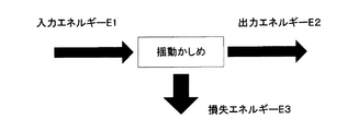
ところで、上述のようにかしめ部113を形成する場合、揺動かしめ装置114は、押型115をハブ輪109の軸方向内側端部に押し付けるためのエネルギーと、押型115をハブ輪109の中心軸(基準軸)を中心に回転させるためのエネルギーとを発生する。ただし、これらのエネルギー(図10の入力エネルギーE1)は、そのすべてが、かしめ部113を形成するためのエネルギー(図10の出力エネルギーE2)として消費されるわけではない。すなわち、入力エネルギーE1の一部は、例えば、揺動かしめ装置114を構成する部材やハブユニット軸受100を構成する部材のうちハブ輪109の軸方向内側端部以外の部分を変形させたり、振動させたりするエネルギー(図10の損失エネルギーE3)として消費される。このため、かしめ部113の加工効率を高くする、すなわち、入力エネルギーE1に対する出力エネルギーE2の割合(E2/E1)を大きくするためには、損失エネルギーE3を小さくすることが望まれる。
By the way, when the
これに対して、上述した従来方法では、ハブ輪109のパイロット部108を、ホルダ116の挿入孔118に径方向のがたつきなく挿入することにより、ハブ輪109の径方向の移動を阻止した状態でかしめ部113の加工を行う。このため、該加工中に、揺動かしめ装置114に振動が生じやすく、その分、損失エネルギーE3が大きくなりやすいという、改善すべき問題がある。
On the other hand, in the above-mentioned conventional method, the
本発明は、上述のような事情に鑑み、かしめ部の加工効率を高くすることができるハブユニット軸受の製造方法、揺動かしめ装置、及び車両の製造方法を実現することを目的とする。 In view of the above circumstances, it is an object of the present invention to realize a method for manufacturing a hub unit bearing, a swing crimping device, and a method for manufacturing a vehicle, which can increase the processing efficiency of the crimped portion.
本発明の製造対象となるハブユニット軸受は、内周面に複列の外輪軌道を有する外輪と、外周面に複列の内輪軌道を有するハブと、前記複列の外輪軌道と前記複列の内輪軌道との間に、列ごとに複数個ずつ配置された転動体とを備える。
前記ハブは、内輪と、ハブ輪とを有する。
前記内輪は、外周面に、前記複列の内輪軌道のうちの軸方向内側の内輪軌道を有する。
前記ハブ輪は、軸方向外側部から径方向外方に突出した回転フランジと、該回転フランジの径方向内側に隣接する部分から軸方向外側に延びる筒状のパイロット部と、前記回転フランジよりも軸方向内側に位置する部分の外周面に直接又は他の部材を介して形成された、前記複列の内輪軌道のうちの軸方向外側の内輪軌道と、該軸方向外側の内輪軌道よりも軸方向内側に位置し、前記内輪を外嵌した嵌合軸部と、該嵌合軸部よりも軸方向内側に位置する筒状の軸方向内側端部を径方向外方に塑性変形させることで形成され、前記内輪の軸方向内側端面を抑え付けるかしめ部とを有する。
The hub unit bearing to be manufactured according to the present invention includes an outer ring having a double row of outer ring races on the inner peripheral surface, a hub having a double row of inner ring races on the outer peripheral surface, the double row outer ring raceway, and the double row. A plurality of rolling elements arranged in each row are provided between the inner ring orbits.
The hub has an inner ring and a hub ring.
The inner ring has an inner ring orbit on the outer peripheral surface in the axial direction of the double-row inner ring orbits.
The hub ring has a rotary flange protruding radially outward from the axial outer portion, a tubular pilot portion extending axially outward from a portion adjacent to the radial inner side of the rotary flange, and a rotary flange. The inner ring orbit on the outer side of the double row of the inner ring orbits formed in the outer peripheral surface of the portion located on the inner side in the axial direction directly or via other members, and the inner ring orbit on the outer side in the axial direction. By plastically deforming the fitting shaft portion located on the inner side in the direction and fitted with the inner ring and the cylindrical inner end portion in the axial direction located on the inner side in the axial direction with respect to the fitting shaft portion in the radial direction. It is formed and has a caulking portion that holds down the axially inner end surface of the inner ring.
本発明のハブユニット軸受の製造方法は、前記ハブ輪を、該ハブ輪の中心軸を基準軸と同軸乃至平行に配置し、かつ、該ハブ輪の径方向の移動を可能にホルダで支持した状態で、前記基準軸に対して傾斜した自転軸を有する押型を前記ハブ輪の軸方向内側端部に押し付けつつ、該押型を、前記自転軸を中心に回転させながら前記基準軸を中心に回転させることにより、前記ハブ輪の軸方向内側端部を前記かしめ部に加工するかしめ工程を備える。 In the method for manufacturing a hub unit bearing of the present invention, the hub wheel is supported by a holder so that the central axis of the hub wheel is arranged coaxially or parallel to the reference axis and the hub wheel can be moved in the radial direction. In this state, while pressing a die having a rotation axis inclined with respect to the reference axis against the axially inner end of the hub wheel, the push die is rotated about the reference axis while rotating about the rotation axis. A caulking step is provided in which the axially inner end portion of the hub ring is processed into the caulking portion.
本発明のハブユニット軸受の製造方法の第1の態様では、ホルダのフランジ受面に開口し、かつ、前記基準軸と同軸に配置された、前記パイロット部の外径よりも大きい内径を有する挿入孔に、前記パイロット部を挿入するとともに、前記フランジ受面に前記回転フランジの軸方向外側面を接触させることにより、前記ハブ輪を、該ハブ輪の中心軸を前記基準軸と同軸乃至平行に配置し、かつ、該ハブ輪の径方向の移動を可能に支持する。 In the first aspect of the method for manufacturing a hub unit bearing of the present invention, an insertion having an inner diameter larger than the outer diameter of the pilot portion, which is opened in the flange receiving surface of the holder and is arranged coaxially with the reference shaft. By inserting the pilot portion into the hole and bringing the axially outer surface of the rotating flange into contact with the flange receiving surface, the hub ring is made coaxial or parallel with the reference axis by the central axis of the hub ring. It is arranged and supports the radial movement of the hub wheel.
前記製造方法の第1の態様では、例えば、前記挿入孔の内径と前記パイロット部の外径との差である直径差を、前記かしめ工程において前記押型を前記基準軸を中心に回転させるのに要する総エネルギーと、前記押型を前記ハブ輪の軸方向内側端部に押し付けるのに要する総エネルギーとの和であるエネルギー和に基づいて決定する。 In the first aspect of the manufacturing method, for example, the diameter difference, which is the difference between the inner diameter of the insertion hole and the outer diameter of the pilot portion, is used to rotate the stamping die around the reference axis in the caulking step. It is determined based on the sum of energy, which is the sum of the total energy required and the total energy required to press the stamp against the axially inner end of the hub wheel.
この場合に、例えば、前記エネルギー和が所定値以下となる範囲で、前記直径差を決定する。
又は、例えば、前記エネルギー和がほぼ一定となる範囲で、前記直径差を決定する。
又は、例えば、前記直径差の変化量に対する前記エネルギー和の変化量が所定値以下となる範囲で、前記直径差を決定する。
In this case, for example, the diameter difference is determined within a range in which the sum of energies is equal to or less than a predetermined value.
Alternatively, for example, the diameter difference is determined within a range in which the sum of energies is substantially constant.
Alternatively, for example, the diameter difference is determined within a range in which the amount of change in the sum of energies with respect to the amount of change in the diameter difference is equal to or less than a predetermined value.
前記製造方法の第1の態様では、例えば、前記押型を前記基準軸を中心に回転させるためのトルクを、前記基準軸を中心とする前記押型の回転角度で積分することにより、前記かしめ工程において前記押型を前記基準軸を中心に回転させるのに要する総エネルギーを求める。 In the first aspect of the manufacturing method, for example, in the caulking step, the torque for rotating the stamping mold around the reference shaft is integrated at the rotation angle of the stamping mold centered on the reference shaft. The total energy required to rotate the stamp around the reference axis is obtained.
前記製造方法の第1の態様では、例えば、前記押型と前記ハブ輪の軸方向内側端部とを前記基準軸の方向に押し付け合うための荷重を、前記ホルダと前記押型との前記基準軸の方向に関する相対移動量で積分することにより、前記かしめ工程において前記押型を前記ハブ輪の軸方向内側端部に押し付けるのに要する総エネルギーを求める。 In the first aspect of the manufacturing method, for example, a load for pressing the stamp and the axially inner end of the hub ring in the direction of the reference shaft is applied to the reference shaft of the holder and the stamp. By integrating with the relative movement amount with respect to the direction, the total energy required to press the stamp against the axially inner end of the hub wheel in the caulking step is obtained.
前記製造方法の第1の態様では、例えば、前記ハブ輪の中心軸を前記基準軸と同軸に配置した状態で、前記かしめ工程を開始する。 In the first aspect of the manufacturing method, for example, the caulking step is started in a state where the central axis of the hub ring is arranged coaxially with the reference axis.
この場合に、例えば、前記挿入孔に挿入した前記パイロット部を、前記基準軸と同軸に配置された筒状の芯合わせ治具に内嵌することで、前記ハブ輪の中心軸を前記基準軸と同軸に配置した状態とし、その後、前記ハブ輪の中心軸を前記基準軸と同軸に配置した状態を維持しつつ、前記芯合わせ治具を前記パイロット部から軸方向に退避させた状態で、前記かしめ工程を開始する。 In this case, for example, by fitting the pilot portion inserted into the insertion hole into a tubular centering jig coaxially arranged with the reference shaft, the central axis of the hub wheel can be fitted to the reference shaft. After that, while maintaining the state in which the central axis of the hub wheel is arranged coaxially with the reference axis, the centering jig is retracted from the pilot portion in the axial direction. The caulking step is started.
本発明のハブユニット軸受の製造方法の第2の態様では、前記基準軸に直交する方向の移動を可能とされたホルダのフランジ受面に開口する挿入孔に前記パイロット部を挿入するとともに、前記フランジ受面に前記回転フランジの軸方向外側面を接触させることにより、前記ハブ輪を、該ハブ輪の中心軸を前記基準軸と同軸乃至平行に配置し、かつ、該ハブ輪の径方向の移動を可能に支持する。 In the second aspect of the method for manufacturing a hub unit bearing of the present invention, the pilot portion is inserted into an insertion hole opened in the flange receiving surface of a holder capable of moving in a direction orthogonal to the reference axis, and the pilot portion is inserted. By bringing the axially outer surface of the rotating flange into contact with the flange receiving surface, the hub ring is arranged so that the central axis of the hub ring is coaxial or parallel to the reference axis, and the hub ring is in the radial direction. Supports movement possible.
前記製造方法の第2の態様では、例えば、前記ハブ輪の中心軸を前記基準軸と同軸に配置した状態で、前記かしめ工程を開始する。 In the second aspect of the manufacturing method, for example, the caulking step is started in a state where the central axis of the hub ring is arranged coaxially with the reference axis.
本発明の揺動かしめ装置の第1の態様は、基準軸と、ホルダと、押型と、芯合わせ治具とを備える。
前記ホルダは、前記基準軸の方向に関する一方側の側面に備えられた、前記回転フランジの軸方向外側面を接触させるためのフランジ受面、及び、該フランジ受面に開口し、かつ、前記基準軸と同軸に配置された、前記パイロット部の外径よりも大きい内径を有する挿入孔を有する。
前記押型は、前記基準軸の方向に関して前記ホルダの一方側に配置され、前記基準軸に対して傾斜した自転軸を有し、かつ、前記基準軸を中心とする回転、及び、前記基準軸の方向に関する前記ホルダとの相対移動が可能である。
前記芯合わせ治具は、前記挿入孔の内側で前記基準軸と同軸に配置された筒状の治具であり、前記挿入孔に挿入された前記パイロット部を内嵌することにより、前記ハブ輪の中心軸を前記基準軸と同軸に配置する状態と、該パイロット部から軸方向に退避することにより、前記ハブ輪の径方向の移動を可能とする状態とを、切り換え可能である。
The first aspect of the swing crimping device of the present invention includes a reference shaft, a holder, a stamp, and a centering jig.
The holder is provided on one side surface with respect to the direction of the reference shaft, and is open to the flange receiving surface for contacting the axially outer surface of the rotating flange and the flange receiving surface, and the reference. It has an insertion hole arranged coaxially with the shaft and having an inner diameter larger than the outer diameter of the pilot portion.
The stamp is arranged on one side of the holder with respect to the direction of the reference axis, has a rotation axis inclined with respect to the reference axis, rotates around the reference axis, and has a rotation of the reference axis. It is possible to move relative to the holder in terms of direction.
The centering jig is a tubular jig arranged coaxially with the reference shaft inside the insertion hole, and the hub ring is formed by internally fitting the pilot portion inserted into the insertion hole. It is possible to switch between a state in which the central axis of the hub wheel is arranged coaxially with the reference axis and a state in which the hub wheel can be moved in the radial direction by retracting from the pilot portion in the axial direction.
本発明の揺動かしめ装置の第2の態様は、基準軸と、ホルダと、押型と、芯合わせ治具とを備える。
前記ホルダは、前記基準軸の方向に関する一方側の側面に備えられた、前記回転フランジの軸方向外側面を接触させるためのフランジ受面、及び、該フランジ受面に開口した、前記パイロット部を挿入するための挿入孔を有し、かつ、前記基準軸に直交する方向の移動を可能に支持されている。
前記押型は、前記基準軸の方向に関して前記ホルダの一方側に配置され、前記基準軸に対して傾斜した自転軸を有し、かつ、前記基準軸を中心とする回転、及び、前記基準軸の方向に関する前記ホルダとの相対移動が可能である。
A second aspect of the swing crimping device of the present invention includes a reference shaft, a holder, a stamp, and a centering jig.
The holder has a flange receiving surface provided on one side surface in the direction of the reference axis for contacting the axially outer surface of the rotating flange, and the pilot portion opened in the flange receiving surface. It has an insertion hole for insertion and is supported so that it can move in a direction orthogonal to the reference axis.
The stamp is arranged on one side of the holder with respect to the direction of the reference axis, has a rotation axis inclined with respect to the reference axis, rotates around the reference axis, and has a rotation of the reference axis. It is possible to move relative to the holder in terms of direction.
前記揺動かしめ装置の第2の態様では、例えば、前記基準軸に直交する方向の移動を阻止された支持台と、可動台と、該可動台を前記支持台に対して、前記基準軸に直交する1の方向であるX方向の移動を可能に支持するX方向リニアガイドと、前記ホルダを前記可動台に対して、前記基準軸と前記X方向とのそれぞれに直交するY方向の移動を可能に支持するY方向リニアガイドと、をさらに備える。 In the second aspect of the rocking caulking device, for example, a support base that is prevented from moving in a direction orthogonal to the reference axis, a movable base, and the movable base with respect to the support base, on the reference axis. An X-direction linear guide that enables movement in the X-direction, which is one orthogonal direction, and a Y-direction movement in which the holder is orthogonal to the reference axis and the X-direction with respect to the movable table. It further includes a Y-direction linear guide that supports it as much as possible.
前記揺動かしめ装置の第2の態様では、例えば、前記挿入孔の中心軸と前記基準軸とが不一致となるように前記ホルダが移動した場合に、前記挿入孔の中心軸と前記基準軸とが一致する方向に前記ホルダを付勢するばねをさらに備える。 In the second aspect of the swing crimping device, for example, when the holder moves so that the central axis of the insertion hole and the reference axis do not match, the central axis of the insertion hole and the reference axis A spring is further provided to urge the holder in the direction in which the holders coincide with each other.
本発明の製造対象となる車両は、ハブユニット軸受を備える。
本発明の車両の製造方法は、本発明のハブユニット軸受の製造方法により、前記ハブユニット軸受を製造する。
The vehicle to be manufactured according to the present invention includes a hub unit bearing.
The vehicle manufacturing method of the present invention manufactures the hub unit bearing by the hub unit bearing manufacturing method of the present invention.
本発明によれば、かしめ部の加工効率を高くすることができる。 According to the present invention, the processing efficiency of the crimped portion can be increased.
[実施の形態の第1例]
本発明の実施の形態の第1例について、図1〜図5を用いて説明する。
[First Example of Embodiment]
A first example of the embodiment of the present invention will be described with reference to FIGS. 1 to 5.
(本例の概要)
本例では、図1に示すようなハブユニット軸受1を構成するハブ輪22のかしめ部26を形成するために、図2及び図3に示すような揺動かしめ装置28を用いる。また、かしめ部26の加工効率を高めるために、図3に示すように、揺動かしめ装置28を構成するホルダ29の挿入孔33の内径Dを、ハブ輪22のパイロット部13の外径dよりも大きくする(D>d)ことにより、ホルダ29の挿入孔33の内周面と、ハブ輪22のパイロット部13の外周面との間に、径方向の隙間37を設けることで、かしめ部26を形成するための加工中に、ホルダ29に対してハブ輪22が径方向に移動できるようにする。ただし、かしめ部26を形成するための加工開始時は、ハブ輪22の中心軸を、挿入孔33の中心軸である基準軸Cと同軸に配置しておく。
(Outline of this example)
In this example, in order to form the crimped
以下、本例の製造対象となるハブユニット軸受1の構成と、かしめ部26を形成するための揺動かしめ装置28の構成と、ハブユニット軸受1の製造方法とを説明した後、かしめ部26の加工効率を十分に高くすることができる直径差δ(=挿入孔33の内径Dとパイロット部13の外径dとの差D−d)の設定方法について説明する。
Hereinafter, after explaining the configuration of the hub unit bearing 1 to be manufactured in this example, the configuration of the
(ハブユニット軸受1の構成)
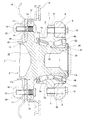
図1は、本例の製造対象となるハブユニット軸受1を示している。ハブユニット軸受1は、従動輪用であり、外輪2と、ハブ3と、複数個の転動体4a、4bとを備える。
(Structure of hub unit bearing 1)
FIG. 1 shows a hub unit bearing 1 to be manufactured in this example. The hub unit bearing 1 is for a driven wheel, and includes an
なお、ハブユニット軸受1に関して、軸方向外側は、車両への組み付け状態で車両の幅方向外側となる、図1の左側であり、軸方向内側は、車両への組み付け状態で車両の幅方向中央側となる、図1の右側である。 Regarding the hub unit bearing 1, the outside in the axial direction is the left side in the width direction of the vehicle when assembled to the vehicle, and the inside in the axial direction is the center in the width direction of the vehicle when assembled to the vehicle. It is the right side of FIG. 1 on the side.
外輪2は、中炭素鋼などの硬質金属製で、複列の外輪軌道5a、5bと、静止フランジ6とを備える。複列の外輪軌道5a、5bは、外輪2の軸方向中間部内周面に形成されており、軸方向に関して互いに離れる方向に向かうほど直径が大きくなる方向に傾斜した部分円すい状の凹面である。静止フランジ6は、外輪2の軸方向中間部から径方向外方に突出しており、円周方向複数箇所にねじ孔である支持孔7を有する。
The
外輪2は、車両の懸架装置を構成するナックル8の通孔9を挿通したボルト10を、静止フランジ6の支持孔7に軸方向内側から螺合して締め付けることで、ナックル8に支持固定されている。
The
ハブ3は、外輪2の径方向内側に、外輪2と同軸に配置されており、複列の内輪軌道11a、11bと、回転フランジ12と、パイロット部13とを備える。複列の内輪軌道11a、11bは、ハブ3の外周面のうち、複列の外輪軌道5a、5bに対向する部分に形成されており、軸方向に関して互いに離れる方向に向かうほど直径が大きくなる方向に傾斜した部分円すい状の凸面である。回転フランジ12は、外輪2よりも軸方向外側に位置するハブ3の軸方向外側部から径方向外方に突出しており、円周方向複数箇所に取付孔14を有する。パイロット部13は、外輪2よりも軸方向外側に位置するハブ3の軸方向外側部のうち、回転フランジ12の径方向内側に隣接する部分から軸方向外側に延びる円筒状の部位である。また、パイロット部13の外周面は、軸方向内側部を構成する円筒面状の大径部44と、軸方向外側部を構成する、大径部44よりも外径が小さい円筒面状の小径部45とを備えた、段付円筒面である。
The
また、図示の例では、ディスクやドラムなどの制動用回転体15を回転フランジ12に結合固定するために、制動用回転体15をパイロット部13の軸方向内側部(大径部44)に外嵌した状態で、スタッド16の基端寄り部分に備えられたセレーション部を、取付孔14に圧入するとともに、スタッド16の中間部を、制動用回転体15の通孔17に圧入している。さらに、車輪を構成するホイール18を回転フランジ12に固定するために、ホイール18をパイロット部13の軸方向外側部(小径部45)に外嵌した状態で、スタッド16の先端部に備えられた雄ねじ部を、ホイール18の通孔19に挿通した状態で、該雄ねじ部にナット20を螺合して締め付けている。
Further, in the illustrated example, in order to connect and fix the
転動体4a、4bは、それぞれが軸受鋼などの硬質金属製あるいはセラミックス製で、複列の外輪軌道5a、5bと複列の内輪軌道11a、11bとの間に、列ごとに複数個ずつ配置されている。また、転動体4a、4bは、列ごとに、保持器21a、21bにより転動自在に保持されている。なお、本例では、転動体4a、4bのそれぞれは、円すいころである。
The rolling
本例では、ハブ3は、中炭素鋼などの硬質金属製のハブ輪22と、軸受鋼などの硬質金属製の内輪23とを組み合わせてなる。
In this example, the
ハブ輪22は、軸方向中間部外周面に複列の内輪軌道11a、11bのうちの軸方向外側の内輪軌道11aを有し、かつ、軸方向外側部に回転フランジ12及びパイロット部13を有する。また、ハブ輪22は、軸方向外側の内輪軌道11aよりも軸方向内側に位置する軸方向内側部に、軸方向外側に隣接する部分よりも外径が小さい嵌合軸部24を有する。内輪23は、外周面に、複列の内輪軌道11a、11bのうちの軸方向内側の内輪軌道11bを有する。このような内輪23は、軸方向外側端面を、嵌合軸部24の外周面の軸方向外側端部に存在する段差面25に突き当てた状態で、嵌合軸部24に圧入により外嵌される。この状態で、嵌合軸部24の軸方向内側端部から軸方向に伸長する円筒部27を、径方向外方に塑性変形させることにより形成されたかしめ部26により、内輪23の軸方向内側端面が抑え付けられている。そして、このようにかしめ部26により内輪23の軸方向内側端面を抑え付けることで、転動体4a、4bに適正な予圧が付与されている。
The
(揺動かしめ装置28の構成)
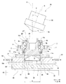
次に、かしめ部26を形成するための揺動かしめ装置28について、図2及び図3を参照しつつ説明する。揺動かしめ装置28は、上下方向の基準軸Cと、ホルダ29と、押型31と、芯合わせ治具30とを備える。
(Structure of rocking caulking device 28)
Next, the
ホルダ29は、かしめ部26を形成する際に押型31からハブ輪22に加えられる荷重を支承する受具として機能する部材である。ホルダ29は、上側面に備えられたフランジ受面32と、フランジ受面32に開口する挿入孔33とを有する。フランジ受面32は、基準軸Cに直交する平坦面である。挿入孔33は、基準軸Cと同軸に配置された円筒状の内周面を有する、有底の孔である。挿入孔33の内径Dは、ハブ輪22のパイロット部13の外径dよりも大きい(D>d)。ここで、外径dは、パイロット部13の大径部44の外径である。また、挿入孔33の軸方向深さは、ハブ輪22のパイロット部13の軸方向寸法よりも大きい。このような構成を有するホルダ29は、基準軸Cに直交する方向の移動、及び、基準軸Cに沿う上下方向の移動を阻止された状態で、図示しない支持台に支持されている。ただし、本発明を実施する場合、ホルダ29は、基準軸Cに沿う上下方向の移動を可能に支持し、かつ、上方への移動によって、かしめ部26を形成するための荷重を発生させることもできる。
The
押型31は、かしめ部26を形成するための工具であり、ホルダ29の上方に配置されている。押型31は、基準軸Cに対して角度θだけ傾斜した自転軸αを有し、かつ、下端部に自転軸αと同軸の円環状の凹面である加工面部36を有する。押型31は、基準軸Cに沿った上下方向の移動及び基準軸Cを中心とする回転を可能とされており、かつ、自転軸βを中心とする自転を自在とされている。なお、本発明を実施する場合、上述のようにホルダ29の上方への移動によって、かしめ部26を形成するための荷重を発生させる場合には、押型31を、基準軸Cに沿う上下方向の移動を阻止した状態で支持することもできる。
The
芯合わせ治具30は、かしめ部26の形成を開始する前に、ハブ輪22の中心軸を基準軸Cと同軸に配置するための治具である。芯合わせ治具30は、円筒状に構成されており、ホルダ29の挿入孔33の内側で、基準軸Cと同軸に配置され、かつ、基準軸Cに沿う上下方向の移動を可能とされている。このために、図示の例では、芯合わせ治具30は、挿入孔33の内側に、径方向(水平方向)のがたつきなく、かつ、軸方向(上下方向)の移動を可能に内嵌されている。また、芯合わせ治具30の下端部は、ホルダ29の中心部を上下方向に貫通し、かつ、ホルダ29に対する上下方向の移動を可能とされたアクチュエータロッド34の上端部に、連結部材35を介して連結されている。なお、図示の例では、芯合わせ治具30とアクチュエータロッド34と連結部材35とは、一体に造られているが、別体に造ることもできる。
The centering
また、芯合わせ治具30は、ハブ輪22のパイロット部13の大径部44を、径方向のがたつきなく内嵌することが可能な内径を有する。ただし、芯合わせ治具30は、ハブ輪22のパイロット部13の小径部45を径方向のがたつきなく内嵌することが可能な内径を有する構成とすることもできる。また、芯合わせ治具30を、挿入孔33の内側の下端位置まで移動させた状態で、芯合わせ治具30の上端面とフランジ受面32との間の軸方向距離は、ハブ輪22のパイロット部13の軸方向寸法よりも大きい。
Further, the centering
(ハブユニット軸受1の製造方法)
次に、ハブユニット軸受1を製造する際に、揺動かしめ装置28を用いてかしめ部26を形成する方法について説明する。
(Manufacturing method of hub unit bearing 1)
Next, a method of forming the
かしめ部26の形成作業は、かしめ部26が形成される前のハブユニット軸受1を組み立てた状態で行う。このため、予め、かしめ部26が形成される前のハブユニット軸受1を組み立てておく。
The work of forming the
かしめ部26が形成される前のハブユニット軸受1は、適宜の手順で組み立てることができるが、例えば、次のような手順で組み立てることができる。まず、かしめ部26が形成される前のハブ輪22(軸方向内側端部に円筒部27を有するハブ輪22)のうち、軸方向外側の内輪軌道11aの周囲に、軸方向外側列の転動体4aを、軸方向外側の保持器21aにより保持した状態で配置し、さらに、該ハブ輪22の軸方向中間部の周囲に、外輪2を配置する。次に、内輪23のうち、軸方向内側の内輪軌道11bの周囲に、軸方向内側列の転動体4bを、軸方向内側の保持器21bにより保持した状態で配置する。そして、内輪23を、かしめ部26が形成される前のハブ輪22の嵌合軸部24に外嵌し、内輪23の軸方向外側端面を段差面25に当接させる。
The hub unit bearing 1 before the
揺動かしめ装置28を用いてかしめ部26を形成する際には、まず、かしめ部26が形成される前のハブユニット軸受1を、ホルダ29にセットする。
When forming the
具体的には、図2に示すように、押型31を上方に退避させ、かつ、芯合わせ治具30を、ホルダ29の挿入孔33の内側の上部に配置する。そして、この状態で、図2に示すように、ハブ輪22のパイロット部13を、ホルダ29の挿入孔33の内側に挿入する。これとともに、パイロット部13の大径部44を、芯合わせ治具30の内側に、径方向のがたつきなく内嵌する。これにより、ハブ輪22の中心軸を基準軸Cと同軸に配置する。さらに、ハブ輪22の回転フランジ12の軸方向外側面を、ホルダ29のフランジ受面32に接触させる。
Specifically, as shown in FIG. 2, the stamping die 31 is retracted upward, and the centering
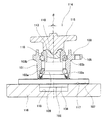
続いて、図2→図3に示すように、ハブ輪22の中心軸を基準軸Cと同軸に配置した状態を維持しつつ、芯合わせ治具30をパイロット部13の周囲から下方に退避させる。これにより、挿入孔33の内周面とパイロット部13の大径部44の外周面との間に、全周にわたり径方向の隙間37を存在させた状態とする。
Subsequently, as shown in FIGS. 2 to 3, the centering
つまり、本例では、次述するかしめ部26を形成するための加工開始時に、ハブ輪22が基準軸Cと同軸に配置された状態にしておく。これとともに、次述するかしめ部26を形成するための加工中に、隙間37の存在に基づいて、ホルダ29に対してハブ輪22が径方向に移動できるようにしておく。
That is, in this example, the
次に、この状態で、かしめ工程を開始する。すなわち、図2→図3に示すように、押型31を下方に移動させることで、押型31の加工面部36をハブ輪22の円筒部27に押し付けつつ、押型31を基準軸Cを中心に回転させることにより、円筒部27をかしめ部26に加工する。すなわち、押型31の加工面部36から円筒部27の円周方向一部に、上下方向に関して下方に向き、かつ、径方向に関して外方に向いた加工力を加える。また、この加工力を加える位置を、基準軸Cを中心とする押型31の回転に伴って、円筒部27の円周方向に関して連続的に変化させる。これにより、円筒部27を径方向外方に塑性変形させることで、かしめ部26を形成する。
Next, in this state, the caulking process is started. That is, as shown in FIGS. 2 to 3, by moving the
以上のような本例のハブユニット軸受1の製造方法では、かしめ部26を形成するための加工中に、隙間37の存在に基づいて、ホルダ29に対してハブ輪22が径方向に移動ができる。このため、このようなハブ輪22の移動によって、揺動かしめ装置28を構成するホルダ29や、ホルダ29を支持する図示しない支持台などに生じる、変形や振動を低減することができる。すなわち、本例によれば、かしめ部26の形成以外に消費されるエネルギー(図10の損失エネルギーE3)を小さくすることができ、その分、かしめ部26の加工効率(図10の入力エネルギーE1に対する出力エネルギーE2の割合(E2/E1))を高くすることができる。
In the manufacturing method of the hub unit bearing 1 of this example as described above, the
また、本例では、かしめ部26を形成するための加工開始時に、ハブ輪22が基準軸Cと同軸に配置されている。換言すれば、かしめ部26を形成するための加工開始時における、ハブ輪22の径方向位置のばらつきが十分に抑えられている。このため、かしめ部26の形成による品質特性(例えば、かしめ部26から内輪23に加わる軸力、かしめ部26の形成に伴う内輪23の膨張量に関する特性など)のばらつきを十分に抑えることができる。
Further, in this example, the
(直径差δの設定方法)
次に、かしめ部26の加工効率を高くすることができる直径差δ(=D−d)(隙間37の大きさ)の設定方法について説明する。
(How to set the diameter difference δ)
Next, a method of setting the diameter difference δ (= Dd) (the size of the gap 37) that can increase the processing efficiency of the crimped
まず、製造対象となるハブユニット軸受1との関係で、直径差δ(=D−d)が異なる複数のホルダ29を用意する。そして、用意したホルダ29ごとに、該ホルダ29を含む揺動かしめ装置28を用いて、ハブ輪22の円筒部27をかしめ部26に加工する(かしめ工程を行う)。そして、該かしめ工程において、具体的には、かしめ部26を形成するための加工開始時から加工終了時までの間に、押型31を基準軸Cを中心に回転させるのに要した総エネルギーEtと、押型31をハブ輪22の軸方向内側端部(円筒部27)に押し付けるのに要した総エネルギーEzとを求め、さらに、これらの和であるエネルギー和E(=Et+Ez)を求める。
First, a plurality of
本例では、かしめ工程において押型31を基準軸Cを中心に回転させるのに要した総エネルギーEtを求めるために、かしめ工程中の、押型31の総回転角度である「押型総回転角度」、及び、押型31を基準軸Cを中心に回転させるためのトルクである「押型回転トルク」を測定する。図4(A)は、このように測定した「押型総回転角度」と「押型回転トルク」との関係(曲線f1)を表す線図(仮想例)である。そして、本例では、該線図において、曲線f1と横軸(「押型回転トルク」=0を表す直線)との間に挟まれた領域の面積を、総エネルギーEtとして求める。すなわち、「押型回転トルク」を「押型総回転角度」で積分する(数値計算を行う)ことにより、前記面積(総エネルギーEt)を求める。なお、「押型総回転角度」は、例えば、ロータリーエンコーダなどを用いて測定することができる。また、「押型回転トルク」は、例えば、押型31を基準軸Cを中心に回転させるための電動モータの電流値などに基づいて測定することができる。
In this example, in order to obtain the total energy Et required to rotate the
また、本例では、かしめ工程において押型31をハブ輪22の軸方向内側端部に押し付けるのに要した総エネルギーEzを求めるために、かしめ工程中の、ホルダ29と押型31との基準軸Cの方向に関する相対移動量である「押型軸方向移動量」及び、押型31とハブ輪22の軸方向内側端部とを基準軸Cの方向に押し付け合うための荷重である「押型軸方向荷重」を測定する。図4(B)は、このように測定した「押型軸方向移動量」と「押型軸方向荷重」との関係(曲線f2)を表す線図(仮想例)である。そして、本例では、該線図において、曲線f2と横軸(「押型軸方向荷重」=0を表す直線)との間に挟まれた領域の面積を、総エネルギーEzとして求める。すなわち、「押型軸方向荷重」を「押型軸方向移動量」で積分する(数値計算を行う)ことにより、前記面積(総エネルギーEz)を求める。なお、「押型軸方向移動量」は、例えば、リニアスケールなどを用いて測定することができる。また、「押型軸方向荷重」は、例えば、押型31を軸方向に移動させるための油圧機構内の油圧などに基づいて測定することができる。
Further, in this example, in order to obtain the total energy Ez required to press the
次に、上述のように直径差δ(=D−d)が異なるホルダ29ごとに求めたエネルギー和E(=Et+Ez)を利用して、図5に例示するような、直径差δ(=D−d)とエネルギー和E(=Et+Ez)との関係(曲線f3)を求める。
Next, using the energy sum E (= Et + Ez) obtained for each
該関係において、直径差δ(=D−d)を0から徐々に大きくしていくと、エネルギー和E(=Et+Ez)は、初めのうちは徐々に小さくなるが、途中からほぼ一定になる。エネルギー和Eがほぼ一定になる範囲では、直径差δ(=D−d)の値にかかわらず、かしめ加工中のハブ輪22の径方向の移動量がほぼ一定になると考えられる。なお、直径差δ(=D−d)を大きくしても、かしめ部26の形成による品質特性(例えば、かしめ部26から内輪23に加わる軸力、かしめ部26の形成に伴う内輪23の膨張量に関する特性など)が悪くなることはない。
In this relationship, when the diameter difference δ (= D−d) is gradually increased from 0, the energy sum E (= Et + Ez) gradually decreases at the beginning, but becomes almost constant from the middle. In the range where the energy sum E is almost constant, it is considered that the amount of movement of the
ところで、かしめ部26を形成するためのエネルギー(図10の出力エネルギーE2)は、ほぼ一定である。このため、上述のように直径差δ(=D−d)の増大に伴ってエネルギー和E(=Et+Ez)(図10の入力エネルギーE1)が小さくなるということは、かしめ部26の形成以外に消費されるエネルギー(図10の損失エネルギーE3)が小さくなるということ、すなわち、かしめ部26の加工効率が高くなることを意味する。
By the way, the energy for forming the crimped portion 26 (output energy E2 in FIG. 10) is substantially constant. Therefore, as described above, the energy sum E (= Et + Ez) (input energy E1 in FIG. 10) decreases as the diameter difference δ (= Dd) increases, in addition to the formation of the
したがって、かしめ部26の加工効率を高くするためには、図5の関係を利用して、エネルギー和E(=Et+Ez)が所望とする所定値以下となる範囲で、直径差δ(=D−d)を設定(決定)すれば良い。この場合に、好ましくは、エネルギー和E(=Et+Ez)がほぼ一定になる範囲で、直径差δ(=D−d)を設定するのが良い。
Therefore, in order to increase the processing efficiency of the crimped
なお、エネルギー和E(=Et+Ez)がほぼ一定になる範囲における、直径差δ(=D−d)の下限値δmの選択の仕方は、任意である。例えば、図5の関係を表す曲線f3に対して、次の定数A、Sをもつ(1)式で表される曲線をフィッティングさせた場合の定数Sを、下限値δmとすることができる。
E=A×exp(−δ/S) −−−−−(1)
ここで、(1)式中、Eは、エネルギー和E(=Et+Ez)を表す変数であり、δは、直径差δ(=D−d)を表す変数であり、Aは、直径差δ(=D−d)が0のときのエネルギー和E(=Et+Ez)の値であり、Sは、時定数と同じ考え方の定数である。
The method of selecting the lower limit value δm of the diameter difference δ (= Dd) in the range where the energy sum E (= Et + Ez) is almost constant is arbitrary. For example, the lower limit value δm can be set as the constant S when the curve represented by the equation (1) having the following constants A and S is fitted to the curve f3 representing the relationship shown in FIG.
E = A × exp (−δ / S) −−−−− (1)
Here, in Eq. (1), E is a variable representing the energy sum E (= Et + Ez), δ is a variable representing the diameter difference δ (= D−d), and A is the diameter difference δ ( = D−d) is the value of the energy sum E (= Et + Ez) when 0, and S is a constant of the same concept as the time constant.
あるいは、図5の関係を表す曲線f3に対して、上記(1)式で表される曲線をフィッティングさせた場合のパラメータSよりも大きい値(例えば、図5の曲線f3がほぼ一定に見える直径差δ(=D−d)の範囲の下限値)を、下限値δmとして選択することもできる。 Alternatively, a value larger than the parameter S when the curve represented by the above equation (1) is fitted to the curve f3 representing the relationship of FIG. 5 (for example, the diameter at which the curve f3 of FIG. 5 looks almost constant). The lower limit value in the range of the difference δ (= Dd)) can also be selected as the lower limit value δm.
なお、本発明者の経験から、前述した従来方法でかしめ部を形成するための加工を行う際には、ホルダの支持台の水平方向の振動幅が0.5mm程度になることが確認されている。したがって、このような事情を考慮すると、下限値δmは、0.5mm以上の値とすることが望ましい。 From the experience of the present inventor, it has been confirmed that the horizontal vibration width of the support base of the holder is about 0.5 mm when the processing for forming the crimped portion is performed by the above-mentioned conventional method. There is. Therefore, in consideration of such circumstances, it is desirable that the lower limit value δm is a value of 0.5 mm or more.
あるいは、図5の関係を表す曲線f3に関して、直径差δ(=D−d)の変化量(増大量)に対するエネルギー和E(=Et+Ez)の変化量(減少量)が所定値以下となる範囲で、直径差δ(=D−d)を決定することもできる。 Alternatively, with respect to the curve f3 representing the relationship shown in FIG. 5, the range in which the amount of change (decrease) in the sum of energies E (= Et + Ez) with respect to the amount of change (increase) in the diameter difference δ (= Dd) is equal to or less than a predetermined value. Therefore, the diameter difference δ (= D−d) can also be determined.
ただし、直径差δ(=D−d)を過度に大きくすると、すなわち、ホルダ29の挿入孔33の内径を過度に大きくすると、かしめ部26を形成するための加工時に回転フランジ12が軸方向内側に向けて倒れるように変形しやすくなる可能性がある。このため、このような不都合が生じることを防止するために、直径差δ(=D−d)は、下限値δmの2〜10倍以下とすることが望ましい。
However, if the diameter difference δ (= Dd) is made excessively large, that is, if the inner diameter of the
なお、図2及び図3に示した例では、回転フランジ12の取付孔14にスタッド16(図1参照)を取り付ける前の状態でかしめ部26を形成するための加工を行っている。ただし、本発明を実施する場合には、回転フランジ12の取付孔14にスタッド16を取り付けた状態でかしめ部26を形成するための加工を行うこともできる。この場合には、ホルダの形状を、該加工中にスタッド16がぶつからない形状(例えば、スタッド16のうち回転フランジ12の軸方向外側面から軸方向外側に突出した部分を緩く挿入できるスタッド用挿入孔を有する形状)とする。
In the examples shown in FIGS. 2 and 3, the
[実施の形態の第2例]
本発明の実施の形態の第2例について、図6及び図7を用いて説明する。
[Second Example of Embodiment]
A second example of the embodiment of the present invention will be described with reference to FIGS. 6 and 7.
本例では、揺動かしめ装置28aを構成するホルダ29a及びその周辺部の構造が、実施の形態の第1例の場合と異なる。すなわち、本例では、ホルダ29aの挿入孔33aは、ハブ輪22のパイロット部13を径方向のがたつきなく挿入(内嵌)可能である。
In this example, the structures of the
また、ホルダ29aは、基準軸Cに直交する方向の移動を可能に支持されている。このために、本例の揺動かしめ装置28aは、支持台40と、可動台38と、X方向リニアガイド39と、Y方向リニアガイド41とを備える。なお、本例においては、基準軸Cは、移動前の中立位置にあるホルダ29aに形成された挿入孔33aの中心軸である。
Further, the
支持台40は、ホルダ29aの下方に配置されており、基準軸Cに直交する方向の移動を阻止されている。可動台38は、上下方向に関して、ホルダ29aと支持台40との間に配置されている。また、可動台38は、支持台40の上側面に、X方向リニアガイド39を介して支持されている。X方向リニアガイド39は、支持台40に対する可動台38の、基準軸Cに直交する1方向であるX方向の移動を可能とするガイド装置である。また、ホルダ29aは、可動台38の上面に、Y方向リニアガイド41を介して支持されている。Y方向リニアガイド41は、可動台38に対するホルダ29aの、基準軸Cに直交し、かつ、X方向にも直交する方向である、Y方向の移動を可能とするガイド装置である。したがって、ホルダ29aは、X方向リニアガイド39及びY方向リニアガイド41により、支持台40に対し、基準軸Cに直交する全方向の移動が許容されるようになっている。
The
また、可動台38がX方向の中立位置に配置され、かつ、ホルダ29aがY方向の中立位置に配置された状態で、ホルダ29aの挿入孔33aの中心軸は、基準軸Cと一致するようになっている。
Further, with the
また、可動台38と図示しない固定の部分との間には、可動台38がX方向の中立位置からX方向に移動した場合に、可動台38をX方向の中立位置に戻す方向の弾力を付与するX方向ばね42が組み付けられている。また、ホルダ29aと図示しない固定の部分との間には、ホルダ29aがY方向の中立位置からY方向に移動した場合に、ホルダ29aをY方向の中立位置に戻す方向の弾力を付与するY方向ばね43が組み付けられている。したがって、可動台38にX方向の外力が作用しておらず、かつ、ホルダ29aにY方向の外力が作用していない状態(例えば、後述するかしめ部26(図1参照)を形成するための加工開始以前の状態)で、可動台38はX方向の中立位置に配置され、かつ、ホルダ29aはY方向の中立位置に配置されるようになっている。その結果、ホルダ29aの挿入孔33aの中心軸は、基準軸Cと一致するようになっている。つまり、X方向ばね42及びY方向ばね43は、挿入孔33aの中心軸と基準軸Cとが不一致になるようにホルダ29aが移動した場合に、挿入孔33aの中心軸と基準軸Cとが一致する方向にホルダ29aを付勢する機能を有する。
Further, between the movable table 38 and the fixed portion (not shown), when the movable table 38 moves from the neutral position in the X direction to the neutral position in the X direction, the elasticity in the direction of returning the movable table 38 to the neutral position in the X direction is provided. The
また、本例では、後述するように揺動かしめ装置28aを用いてかしめ部26を形成する際に、押型31からハブ輪22に作用する径方向外方に向いた加工力よりも、X方向ばね42及びY方向ばね43の弾力を十分に小さくしている(例えば、該加工力の1/10以下としている)。
Further, in this example, when the
揺動かしめ装置28aを用いてかしめ部26を形成する際には、まず、図6に示すように、ハブ輪22のパイロット部13を、ホルダ29aの挿入孔33aに径方向のがたつきなく挿入することにより、ハブ輪22の中心軸を基準軸Cと同軸に配置する。これとともに、ハブ輪22の回転フランジ12の軸方向外側面を、ホルダ29aのフランジ受面32に接触させる。そして、この状態で、実施の形態の第1例と同様に、押型31を用いて円筒部27をかしめ部26に加工する。
When forming the
以上のような本例のハブユニット軸受1の製造方法では、かしめ部26を形成するための加工中に、X方向リニアガイド39及びY方向リニアガイド41の存在に基づいて、基準軸Cに対してハブ輪22が径方向に移動できる。そして、このように、かしめ部26を形成するための加工中、基準軸Cに対してハブ輪22が径方向に移動することにより、揺動かしめ装置28aを構成するホルダ29aやホルダ29aを支持する支持台40などの、変形や振動を低減することができる。また、本例では、基準軸Cに対してハブ輪22が径方向に移動することに伴って、X方向ばね42及びY方向ばね43の弾性変形量が変化するが、X方向ばね42及びY方向ばね43の弾力は十分に小さいため、X方向ばね42及びY方向ばね43の弾性変形量を変化させるためのエネルギーを十分に抑えられる。したがって、本例では、かしめ部26の形成以外に消費されるエネルギー(図10の損失エネルギーE3)を小さくすることができ、その分、かしめ部26の加工効率(図10の入力エネルギーE1に対する出力エネルギーE2の割合(E2/E1))を高くすることができる。
In the manufacturing method of the hub unit bearing 1 of this example as described above, with respect to the reference axis C based on the presence of the X-direction
また、本例では、かしめ部26を形成するための加工開始時に、ハブ輪22が基準軸Cと同軸に配置されている。換言すれば、かしめ部26を形成するための加工開始時における、ハブ輪22の径方向位置のばらつきが十分に抑えられている。このため、かしめ部26の形成による品質特性(例えば、かしめ部26から内輪23に加わる軸力、かしめ部26の形成に伴う内輪23の膨張量に関する特性など)のばらつきを十分に抑えることができる。
その他の構成及び作用効果は、実施の形態の第1例と同様である。
Further, in this example, the
Other configurations and effects are the same as in the first example of the embodiment.
なお、本発明は、従動輪用のハブユニット軸受に限らず、駆動輪用のハブユニット軸受を製造対象とすることもできる。
また、本発明は、転動体として円すいころを使用したハブユニット軸受に限らず、転動体として玉を使用したハブユニット軸受を製造対象とすることもできる。
また、本発明は、軸方向外側の内輪軌道を、ハブ輪の軸方向中間部外周面に直接形成しているハブユニット軸受に限らず、軸方向外側の内輪軌道を、ハブ輪の軸方向中間部に外嵌した別部材である第2の内輪の外周面に形成しているハブユニット軸受を製造対象とすることもできる。
The present invention is not limited to hub unit bearings for driven wheels, but hub unit bearings for drive wheels can also be manufactured.
Further, the present invention is not limited to a hub unit bearing that uses tapered rollers as a rolling element, and a hub unit bearing that uses a ball as a rolling element can also be manufactured.
Further, the present invention is not limited to the hub unit bearing in which the inner ring raceway on the outer side in the axial direction is directly formed on the outer peripheral surface of the intermediate portion in the axial direction of the hub ring. It is also possible to manufacture a hub unit bearing formed on the outer peripheral surface of the second inner ring, which is a separate member externally fitted to the portion.
1 ハブユニット軸受
2 外輪
3 ハブ
4a、4b 転動体
5a、5b 外輪軌道
6 静止フランジ
7 支持孔
8 ナックル
9 通孔
10 ボルト
11a、11b 内輪軌道
12 回転フランジ
13 パイロット部
14 取付孔
15 制動用回転体
16 スタッド
17 通孔
18 ホイール
19 通孔
20 ナット
21a、21b 保持器
22 ハブ輪
23 内輪
24 嵌合軸部
25 段差面
26 かしめ部
27 円筒部
28、28a 揺動かしめ装置
29、29a ホルダ
30 芯合わせ治具
31 押型
32 フランジ受面
33、33a 挿入孔
34 アクチュエータロッド
35 連結部材
36 加工面部
37 隙間
38 可動台
39 X方向リニアガイド
40 支持台
41 Y方向リニアガイド
42 X方向ばね
43 Y方向ばね
44 大径部
45 小径部
100 ハブユニット軸受
101 外輪
102 ハブ
103a、103b 転動体
104a、104b 外輪軌道
105 静止フランジ
106a、106b 内輪軌道
107 回転フランジ
108 パイロット部
109 ハブ輪
110 内輪
111 嵌合軸部
112 段差面
113 かしめ部
114 揺動かしめ装置
115 押型
116 ホルダ
117 フランジ受面
118 挿入孔
1
Claims (20)
外周面に複列の内輪軌道を有するハブと、
前記複列の外輪軌道と前記複列の内輪軌道との間に、列ごとに複数個ずつ配置された転動体と、を備え、
前記ハブは、内輪と、ハブ輪とを有し、
前記内輪は、外周面に、前記複列の内輪軌道のうちの軸方向内側の内輪軌道を有し、
前記ハブ輪は、軸方向外側部から径方向外方に突出した回転フランジと、該回転フランジの径方向内側に隣接する部分から軸方向外側に延びる筒状のパイロット部と、前記回転フランジよりも軸方向内側に位置する部分の外周面に直接又は他の部材を介して形成された、前記複列の内輪軌道のうちの軸方向外側の内輪軌道と、該軸方向外側の内輪軌道よりも軸方向内側に位置し、前記内輪を外嵌した嵌合軸部と、該嵌合軸部よりも軸方向内側に位置する筒状の軸方向内側端部を径方向外方に塑性変形させることで形成され、前記内輪の軸方向内側端面を抑え付けるかしめ部とを有する、
ハブユニット軸受の製造方法であって、
前記ハブ輪を、該ハブ輪の中心軸を基準軸と同軸乃至平行に配置し、かつ、該ハブ輪の径方向の移動を可能にホルダで支持した状態で、前記基準軸に対して傾斜した自転軸を有する押型を前記ハブ輪の軸方向内側端部に押し付けつつ、該押型を、前記自転軸を中心に回転させながら前記基準軸を中心に回転させることにより、前記ハブ輪の軸方向内側端部を前記かしめ部に加工するかしめ工程を備え、
ホルダのフランジ受面に開口し、かつ、前記基準軸と同軸に配置された、前記パイロット部の外径よりも大きい内径を有する挿入孔に、前記パイロット部を挿入するとともに、前記挿入孔に挿入した前記パイロット部を、前記基準軸と同軸に配置された筒状の芯合わせ治具に内嵌することで、前記ハブ輪の中心軸を前記基準軸と同軸に配置した状態とし、その後、前記ハブ輪の中心軸を前記基準軸と同軸に配置した状態を維持しつつ、前記芯合わせ治具を前記パイロット部から軸方向に退避させた状態で、前記かしめ工程を開始する、
ハブユニット軸受の製造方法。 An outer ring having a double row of outer ring tracks on the inner peripheral surface,
A hub with multiple rows of inner ring tracks on the outer peripheral surface,
A plurality of rolling elements arranged in each row between the outer ring track of the double row and the inner ring track of the double row are provided.
The hub has an inner ring and a hub ring.
The inner ring has an inner ring orbit on the outer peripheral surface in the axial direction of the double-row inner ring orbits.
The hub ring has a rotary flange protruding radially outward from the axial outer portion, a tubular pilot portion extending axially outward from a portion adjacent to the radial inner side of the rotary flange, and a rotary flange. The inner ring orbit on the outer side of the double row of the inner ring orbits formed in the outer peripheral surface of the portion located on the inner side in the axial direction directly or via other members, and the inner ring orbit on the outer side in the axial direction. By plastically deforming the fitting shaft portion located on the inner side in the direction and fitted with the inner ring and the cylindrical inner end portion in the axial direction located on the inner side in the axial direction with respect to the fitting shaft portion in the radial direction. It has a caulked portion that is formed and holds down the axially inner end face of the inner ring.
It is a manufacturing method of hub unit bearings.
The hub wheel is tilted with respect to the reference axis in a state where the central axis of the hub wheel is arranged coaxially or parallel to the reference axis and the hub wheel is supported by a holder so as to be movable in the radial direction. While pressing the stamp having the rotation shaft against the axially inner end of the hub wheel, the stamp is rotated around the reference axis while rotating around the rotation shaft, thereby causing the hub wheel to rotate inside in the axial direction. It is provided with a caulking process in which the end portion is processed into the caulking portion.
The pilot portion is inserted into an insertion hole having an inner diameter larger than the outer diameter of the pilot portion, which is opened in the flange receiving surface of the holder and is arranged coaxially with the reference shaft, and is inserted into the insertion hole. By fitting the pilot portion into a tubular centering jig coaxially arranged with the reference shaft, the central axis of the hub wheel is arranged coaxially with the reference shaft, and then the above. The caulking process is started with the centering jig retracted from the pilot portion in the axial direction while maintaining the state in which the central axis of the hub wheel is arranged coaxially with the reference axis.
How to manufacture hub unit bearings.
請求項1に記載のハブユニット軸受の製造方法。 By bringing the axially outer surface of the rotating flange into contact with the flange receiving surface, the hub ring is arranged so that the central axis of the hub ring is coaxial or parallel to the reference axis, and the hub ring is radially oriented. Supports the movement of
The method for manufacturing a hub unit bearing according to claim 1.
請求項2に記載のハブユニット軸受の製造方法。 The diameter difference, which is the difference between the inner diameter of the insertion hole and the outer diameter of the pilot portion, is the total energy required to rotate the stamp around the reference axis in the caulking step, and the stamp is the hub ring. Determined based on the sum of energy, which is the sum of the total energy required to press against the inner end in the axial direction.
The method for manufacturing a hub unit bearing according to claim 2.
請求項3に記載のハブユニット軸受の製造方法。 The diameter difference is determined within a range in which the sum of energies is equal to or less than a predetermined value.
The method for manufacturing a hub unit bearing according to claim 3.
請求項3に記載のハブユニット軸受の製造方法。 The diameter difference is determined within a range in which the sum of energies is substantially constant.
The method for manufacturing a hub unit bearing according to claim 3.
請求項3に記載のハブユニット軸受の製造方法。 The diameter difference is determined within a range in which the change amount of the energy sum with respect to the change amount of the diameter difference is equal to or less than a predetermined value.
The method for manufacturing a hub unit bearing according to claim 3.
請求項3〜6のうちのいずれかに記載のハブユニット軸受の製造方法。 By integrating the torque for rotating the stamping mold around the reference shaft at the rotation angle of the stamping mold centered on the reference shaft, the stamping mold is rotated about the reference shaft in the caulking step. Find the total energy required for
The method for manufacturing a hub unit bearing according to any one of claims 3 to 6.
請求項3〜7のうちのいずれかに記載のハブユニット軸受の製造方法。 The load for pressing the stamp and the axially inner end of the hub wheel in the direction of the reference axis is integrated by the amount of relative movement of the holder and the stamp with respect to the direction of the reference shaft. The total energy required to press the stamp against the axially inner end of the hub wheel in the caulking process is determined.
The method for manufacturing a hub unit bearing according to any one of claims 3 to 7.
外周面に複列の内輪軌道を有するハブと、
前記複列の外輪軌道と前記複列の内輪軌道との間に、列ごとに複数個ずつ配置された転動体と、を備え、
前記ハブは、内輪と、ハブ輪とを有し、
前記内輪は、外周面に、前記複列の内輪軌道のうちの軸方向内側の内輪軌道を有し、
前記ハブ輪は、軸方向外側部から径方向外方に突出した回転フランジと、該回転フランジの径方向内側に隣接する部分から軸方向外側に延びる筒状のパイロット部と、前記回転フランジよりも軸方向内側に位置する部分の外周面に直接又は他の部材を介して形成された、前記複列の内輪軌道のうちの軸方向外側の内輪軌道と、該軸方向外側の内輪軌道よりも軸方向内側に位置し、前記内輪を外嵌した嵌合軸部と、該嵌合軸部よりも軸方向内側に位置する筒状の軸方向内側端部を径方向外方に塑性変形させることで形成され、前記内輪の軸方向内側端面を抑え付けるかしめ部とを有する、
ハブユニット軸受の製造方法であって、
前記ハブ輪を、該ハブ輪の中心軸を基準軸と同軸乃至平行に配置し、かつ、該ハブ輪の径方向の移動を可能にホルダで支持した状態で、前記基準軸に対して傾斜した自転軸を有する押型を前記ハブ輪の軸方向内側端部に押し付けつつ、該押型を、前記自転軸を中心に回転させながら前記基準軸を中心に回転させることにより、前記ハブ輪の軸方向内側端部を前記かしめ部に加工するかしめ工程を備え、
ホルダのフランジ受面に開口し、かつ、前記基準軸と同軸に配置された、前記パイロット部の外径よりも大きい内径を有する挿入孔に、前記パイロット部を挿入するとともに、前記フランジ受面に前記回転フランジの軸方向外側面を接触させることにより、前記ハブ輪を、該ハブ輪の中心軸を前記基準軸と同軸乃至平行に配置し、かつ、該ハブ輪の径方向の移動を可能に支持し、
前記挿入孔の内径と前記パイロット部の外径との差である直径差を、前記かしめ工程において前記押型を前記基準軸を中心に回転させるのに要する総エネルギーと、前記押型を前記ハブ輪の軸方向内側端部に押し付けるのに要する総エネルギーとの和であるエネルギー和に基づいて決定する、
ハブユニット軸受の製造方法。 An outer ring having a double row of outer ring tracks on the inner peripheral surface,
A hub with multiple rows of inner ring tracks on the outer peripheral surface,
A plurality of rolling elements arranged in each row between the outer ring track of the double row and the inner ring track of the double row are provided.
The hub has an inner ring and a hub ring.
The inner ring has an inner ring orbit on the outer peripheral surface in the axial direction of the double-row inner ring orbits.
The hub ring has a rotary flange protruding radially outward from the axial outer portion, a tubular pilot portion extending axially outward from a portion adjacent to the radial inner side of the rotary flange, and a rotary flange. The inner ring orbit on the outer side of the double row of the inner ring orbits formed in the outer peripheral surface of the portion located on the inner side in the axial direction directly or via other members, and the inner ring orbit on the outer side in the axial direction. By plastically deforming the fitting shaft portion located on the inner side in the direction and fitted with the inner ring and the cylindrical inner end portion in the axial direction located on the inner side in the axial direction with respect to the fitting shaft portion in the radial direction. It has a caulked portion that is formed and holds down the axially inner end face of the inner ring.
It is a manufacturing method of hub unit bearings.
The hub wheel is tilted with respect to the reference axis in a state where the central axis of the hub wheel is arranged coaxially or parallel to the reference axis and the hub wheel is supported by a holder so as to be movable in the radial direction. While pressing the stamp having the rotation shaft against the axially inner end of the hub wheel, the stamp is rotated around the reference axis while rotating around the rotation shaft, thereby causing the hub wheel to rotate inside in the axial direction. It is provided with a caulking process in which the end portion is processed into the caulking portion.
The pilot portion is inserted into an insertion hole having an inner diameter larger than the outer diameter of the pilot portion, which is opened in the flange receiving surface of the holder and is arranged coaxially with the reference shaft, and is inserted into the flange receiving surface. By bringing the axially outer surface of the rotating flange into contact, the hub ring is arranged so that the central axis of the hub ring is coaxial or parallel to the reference axis, and the hub ring can be moved in the radial direction. Support,
The diameter difference, which is the difference between the inner diameter of the insertion hole and the outer diameter of the pilot portion, is the total energy required to rotate the stamp around the reference axis in the caulking step, and the stamp is the hub ring. Determined based on the sum of energy, which is the sum of the total energy required to press against the inner end in the axial direction.
How to manufacture hub unit bearings.
前記ハブユニット軸受は、外輪と、ハブと、前記外輪と前記ハブとの間に配置された転動体と、を備え、
前記ハブは、第1ハブ素子と、第2ハブ素子と、前記第1ハブ素子と前記第2ハブ素子とを互いに結合するためのかしめ部と、を備え、
前記第2ハブ素子は、前記転動体用の軌道が設けられた軸部と、前記軸部の軸端部に設けられたパイロット部と、を有し、
前記製造方法は、
前記第2ハブ素子の前記パイロット部の外径よりも大きい内径を有する挿入孔を有するホルダを用意する工程と、
前記第2ハブ素子の前記パイロット部を前記ホルダの前記挿入孔に挿入しつつ、前記第1ハブ素子が組み合わされた前記第2ハブ素子を前記ホルダ上に保持する工程と、
前記保持された前記第2ハブ素子の前記パイロット部に芯合わせ治具を嵌め合わせ、前記第2ハブ素子の中心軸を基準軸に位置合わせする工程と、
前記位置合わせされた前記第2ハブ素子から前記芯合わせ治具を外す工程と、
前記芯合わせ治具が外された前記第2ハブ素子が前記ホルダに対して径方向に移動可能な状態で、押型を用いて前記かしめ部を形成する工程と、
を備える、
ハブユニット軸受の製造方法。 It is a manufacturing method of hub unit bearings.
The hub unit bearing includes an outer ring, a hub, and a rolling element arranged between the outer ring and the hub.
The hub includes a first hub element, a second hub element, and a caulking portion for coupling the first hub element and the second hub element to each other.
The second hub element has a shaft portion provided with a track for the rolling element and a pilot portion provided at the shaft end portion of the shaft portion.
The manufacturing method is
A step of preparing a holder having an insertion hole having an inner diameter larger than the outer diameter of the pilot portion of the second hub element, and a step of preparing the holder.
A step of holding the second hub element in which the first hub element is combined on the holder while inserting the pilot portion of the second hub element into the insertion hole of the holder.
A step of fitting a centering jig to the pilot portion of the held second hub element and aligning the central axis of the second hub element with a reference axis .
The step of removing the alignment jig from the aligned second hub element, and
A step of forming the crimped portion by using a stamp in a state where the second hub element from which the alignment jig has been removed can be moved in the radial direction with respect to the holder.
To prepare
How to manufacture hub unit bearings.
外周面に複列の内輪軌道を有するハブと、
前記複列の外輪軌道と前記複列の内輪軌道との間に、列ごとに複数個ずつ配置された転動体と、を備え、
前記ハブは、内輪と、ハブ輪とを有し、
前記内輪は、外周面に、前記複列の内輪軌道のうちの軸方向内側の内輪軌道を有し、
前記ハブ輪は、軸方向外側部から径方向外方に突出した回転フランジと、該回転フランジの径方向内側に隣接する部分から軸方向外側に延びる筒状のパイロット部と、前記回転フランジよりも軸方向内側に位置する部分の外周面に直接又は他の部材を介して形成された、前記複列の内輪軌道のうちの軸方向外側の内輪軌道と、該軸方向外側の内輪軌道よりも軸方向内側に位置し、前記内輪を外嵌した嵌合軸部と、該嵌合軸部よりも軸方向内側に位置する筒状の軸方向内側端部を径方向外方に塑性変形させることで形成され、前記内輪の軸方向内側端面を抑え付けるかしめ部とを有する、
ハブユニット軸受の製造方法であって、
前記ハブ輪を、該ハブ輪の中心軸を基準軸と同軸乃至平行に配置し、かつ、該ハブ輪の径方向の移動を可能にホルダで支持した状態で、前記基準軸に対して傾斜した自転軸を有する押型を前記ハブ輪の軸方向内側端部に押し付けつつ、該押型を、前記自転軸を中心に回転させながら前記基準軸を中心に回転させることにより、前記ハブ輪の軸方向内側端部を前記かしめ部に加工するかしめ工程を備え、
前記基準軸に直交する方向の移動を可能とされたホルダのフランジ受面に開口する挿入孔に前記パイロット部を挿入するとともに、前記フランジ受面に前記回転フランジの軸方向外側面を接触させることにより、前記ハブ輪を、該ハブ輪の中心軸を前記基準軸と同軸乃至平行に配置し、かつ、該ハブ輪の径方向の移動を可能に支持する、
ハブユニット軸受の製造方法。 An outer ring having a double row of outer ring tracks on the inner peripheral surface,
A hub with multiple rows of inner ring tracks on the outer peripheral surface,
A plurality of rolling elements arranged in each row between the outer ring track of the double row and the inner ring track of the double row are provided.
The hub has an inner ring and a hub ring.
The inner ring has an inner ring orbit on the outer peripheral surface in the axial direction of the double-row inner ring orbits.
The hub ring has a rotary flange protruding radially outward from the axial outer portion, a tubular pilot portion extending axially outward from a portion adjacent to the radial inner side of the rotary flange, and a rotary flange. The inner ring orbit on the outer side of the double row of the inner ring orbits formed in the outer peripheral surface of the portion located on the inner side in the axial direction directly or via other members, and the inner ring orbit on the outer side in the axial direction. By plastically deforming the fitting shaft portion located on the inner side in the direction and fitted with the inner ring and the cylindrical inner end portion in the axial direction located on the inner side in the axial direction with respect to the fitting shaft portion in the radial direction. It has a caulked portion that is formed and holds down the axially inner end face of the inner ring.
It is a manufacturing method of hub unit bearings.
The hub wheel is tilted with respect to the reference axis in a state where the central axis of the hub wheel is arranged coaxially or parallel to the reference axis and the hub wheel is supported by a holder so as to be movable in the radial direction. While pressing the stamp having the rotation shaft against the axially inner end of the hub wheel, the stamp is rotated around the reference axis while rotating around the rotation shaft, thereby causing the hub wheel to rotate inside in the axial direction. It is provided with a caulking process in which the end portion is processed into the caulking portion.
The pilot portion is inserted into an insertion hole opened in the flange receiving surface of the holder capable of moving in a direction orthogonal to the reference axis, and the axial outer surface of the rotating flange is brought into contact with the flange receiving surface. Therefore, the hub ring is arranged so that the central axis of the hub ring is coaxial or parallel to the reference axis and supports the movement of the hub ring in the radial direction.
How to manufacture hub unit bearings.
請求項11に記載のハブユニット軸受の製造方法。 The caulking step is started in a state where the central axis of the hub wheel is arranged coaxially with the reference axis.
The method for manufacturing a hub unit bearing according to claim 11.
前記ハブユニット軸受は、外輪と、ハブと、前記外輪と前記ハブとの間に配置された転動体と、を備え、
前記ハブは、第1ハブ素子と、第2ハブ素子と、前記第1ハブ素子と前記第2ハブ素子とを互いに結合するためのかしめ部と、を備え、
前記製造方法は、
基準軸に直交する方向に移動可能なホルダを用意する工程と、
前記第1ハブ素子が組み合わされた前記第2ハブ素子を前記ホルダ上に保持する工程と、
前記第2ハブ素子を保持した前記ホルダが前記基準軸に直交する方向に移動可能な状態で、押型を用いて前記かしめ部を形成する工程と、
を備える、
ハブユニット軸受の製造方法。 It is a manufacturing method of hub unit bearings.
The hub unit bearing includes an outer ring, a hub, and a rolling element arranged between the outer ring and the hub.
The hub includes a first hub element, a second hub element, and a caulking portion for coupling the first hub element and the second hub element to each other.
The manufacturing method is
The process of preparing a holder that can move in the direction orthogonal to the reference axis, and
A step of holding the second hub element in which the first hub element is combined on the holder, and
A step of forming the crimped portion by using a stamp in a state where the holder holding the second hub element can move in a direction orthogonal to the reference axis.
To prepare
How to manufacture hub unit bearings.
外周面に複列の内輪軌道を有するハブと、
前記複列の外輪軌道と前記複列の内輪軌道との間に、列ごとに複数個ずつ配置された転動体と、を備え、
前記ハブは、内輪と、ハブ輪とを有し、
前記内輪は、外周面に、前記複列の内輪軌道のうちの軸方向内側の内輪軌道を有し、
前記ハブ輪は、軸方向外側部から径方向外方に突出した回転フランジと、該回転フランジの径方向内側に隣接する部分から軸方向外側に延びる筒状のパイロット部と、前記回転フランジよりも軸方向内側に位置する部分の外周面に直接又は他の部材を介して形成された、前記複列の内輪軌道のうちの軸方向外側の内輪軌道と、該軸方向外側の内輪軌道よりも軸方向内側に位置し、前記内輪を外嵌した嵌合軸部と、該嵌合軸部よりも軸方向内側に位置する筒状の軸方向内側端部を径方向外方に塑性変形させることで形成され、前記内輪の軸方向内側端面を抑え付けるかしめ部とを有する、
ハブユニット軸受を製造するために用いられる揺動かしめ装置であって、
基準軸と、
該基準軸の方向に関する一方側の側面に備えられた、前記回転フランジの軸方向外側面を接触させるためのフランジ受面、及び、該フランジ受面に開口し、かつ、前記基準軸と同軸に配置された、前記パイロット部の外径よりも大きい内径を有する挿入孔を有するホルダと、
前記基準軸の方向に関して前記ホルダの一方側に配置され、前記基準軸に対して傾斜した自転軸を有し、かつ、前記基準軸を中心とする回転、及び、前記基準軸の方向に関する前記ホルダとの相対移動が可能な押型と、
前記挿入孔の内側で前記基準軸と同軸に配置された筒状の芯合わせ治具と、を備え、
前記芯合わせ治具は、前記挿入孔に挿入された前記パイロット部を内嵌することにより、前記ハブ輪の中心軸を前記基準軸と同軸に配置する状態と、該パイロット部から軸方向に退避することにより、前記ハブ輪の径方向の移動を可能とする状態とを、切り換え可能である、
揺動かしめ装置。 An outer ring having a double row of outer ring tracks on the inner peripheral surface,
A hub with multiple rows of inner ring tracks on the outer peripheral surface,
A plurality of rolling elements arranged in each row between the outer ring track of the double row and the inner ring track of the double row are provided.
The hub has an inner ring and a hub ring.
The inner ring has an inner ring orbit on the outer peripheral surface in the axial direction of the double-row inner ring orbits.
The hub ring has a rotary flange protruding radially outward from the axial outer portion, a tubular pilot portion extending axially outward from a portion adjacent to the radial inner side of the rotary flange, and a rotary flange. The inner ring orbit on the outer side of the double row of the inner ring orbits formed in the outer peripheral surface of the portion located on the inner side in the axial direction directly or via other members, and the inner ring orbit on the outer side in the axial direction. By plastically deforming the fitting shaft portion located on the inner side in the direction and fitted with the inner ring and the cylindrical inner end portion in the axial direction located on the inner side in the axial direction with respect to the fitting shaft portion in the radial direction. It has a caulked portion that is formed and holds down the axially inner end face of the inner ring.
A rocking caulking device used to manufacture hub unit bearings.
Reference axis and
A flange receiving surface provided on one side surface in the direction of the reference axis for contacting the axially outer surface of the rotating flange, and an opening in the flange receiving surface and coaxially with the reference axis. A holder having an insertion hole having an inner diameter larger than the outer diameter of the pilot portion, which is arranged,
The holder which is arranged on one side of the holder with respect to the direction of the reference axis, has a rotation axis inclined with respect to the reference axis, rotates around the reference axis, and has the direction of the reference axis. With a stamp that can move relative to
A tubular centering jig arranged coaxially with the reference shaft inside the insertion hole is provided.
The centering jig has a state in which the central axis of the hub ring is arranged coaxially with the reference axis by internally fitting the pilot portion inserted into the insertion hole, and retracts from the pilot portion in the axial direction. By doing so, it is possible to switch between a state in which the hub wheel can be moved in the radial direction.
Swing caulking device.
外周面に複列の内輪軌道を有するハブと、
前記複列の外輪軌道と前記複列の内輪軌道との間に、列ごとに複数個ずつ配置された転動体と、を備え、
前記ハブは、内輪と、ハブ輪とを有し、
前記内輪は、外周面に、前記複列の内輪軌道のうちの軸方向内側の内輪軌道を有し、
前記ハブ輪は、軸方向外側部から径方向外方に突出した回転フランジと、該回転フランジの径方向内側に隣接する部分から軸方向外側に延びる筒状のパイロット部と、前記回転フランジよりも軸方向内側に位置する部分の外周面に直接又は他の部材を介して形成された、前記複列の内輪軌道のうちの軸方向外側の内輪軌道と、該軸方向外側の内輪軌道よりも軸方向内側に位置し、前記内輪を外嵌した嵌合軸部と、該嵌合軸部よりも軸方向内側に位置する筒状の軸方向内側端部を径方向外方に塑性変形させることで形成され、前記内輪の軸方向内側端面を抑え付けるかしめ部とを有する、
ハブユニット軸受を製造するために用いられる揺動かしめ装置であって、
基準軸と、
該基準軸の方向に関する一方側の側面に備えられた、前記回転フランジの軸方向外側面を接触させるためのフランジ受面、及び、該フランジ受面に開口した、前記パイロット部を挿入するための挿入孔を有し、かつ、前記基準軸に直交する方向の移動を可能に支持されたホルダと、
前記基準軸の方向に関して前記ホルダの一方側に配置され、前記基準軸に対して傾斜した自転軸を有し、かつ、前記基準軸を中心とする回転、及び、前記基準軸の方向に関する前記ホルダとの相対移動が可能な押型と、を備える、
揺動かしめ装置。 An outer ring having a double row of outer ring tracks on the inner peripheral surface,
A hub with multiple rows of inner ring tracks on the outer peripheral surface,
A plurality of rolling elements arranged in each row between the outer ring track of the double row and the inner ring track of the double row are provided.
The hub has an inner ring and a hub ring.
The inner ring has an inner ring orbit on the outer peripheral surface in the axial direction of the double-row inner ring orbits.
The hub ring has a rotary flange protruding radially outward from the axial outer portion, a tubular pilot portion extending axially outward from a portion adjacent to the radial inner side of the rotary flange, and a rotary flange. The inner ring orbit on the outer side of the double row of the inner ring orbits formed in the outer peripheral surface of the portion located on the inner side in the axial direction directly or via other members, and the inner ring orbit on the outer side in the axial direction. By plastically deforming the fitting shaft portion located on the inner side in the direction and fitted with the inner ring and the cylindrical inner end portion in the axial direction located on the inner side in the axial direction with respect to the fitting shaft portion in the radial direction. It has a caulked portion that is formed and holds down the axially inner end face of the inner ring.
A rocking caulking device used to manufacture hub unit bearings.
Reference axis and
A flange receiving surface provided on one side surface in the direction of the reference axis for contacting the axially outer surface of the rotating flange, and an opening for inserting the pilot portion opened in the flange receiving surface. A holder having an insertion hole and supported so as to be able to move in a direction orthogonal to the reference axis.
The holder which is arranged on one side of the holder with respect to the direction of the reference axis, has a rotation axis inclined with respect to the reference axis, rotates around the reference axis, and has the direction of the reference axis. Equipped with a stamp that can move relative to
Swing caulking device.
請求項15に記載の揺動かしめ装置。 A support base that is blocked from moving in a direction orthogonal to the reference axis, a movable base, and the movable base can be moved in the X direction, which is one direction orthogonal to the reference axis, with respect to the support base. The X-direction linear guide that supports the holder and the Y-direction linear guide that supports the holder so as to be able to move in the Y direction orthogonal to each of the reference axis and the X direction with respect to the movable table are further provided.
The rocking caulking device according to claim 15.
請求項15又は16に記載の揺動かしめ装置。 When the holder moves so that the central axis of the insertion hole and the reference axis do not match, a spring that urges the holder in a direction in which the central axis of the insertion hole and the reference axis coincide with each other is further added. Prepare, prepare
The rocking caulking device according to claim 15 or 16.
前記ハブユニット軸受は、外輪と、ハブと、前記外輪と前記ハブとの間に配置された転動体と、を備え、
前記ハブは、第1ハブ素子と、第2ハブ素子と、前記第1ハブ素子と前記第2ハブ素子とを互いに結合するためのかしめ部と、を備え、
前記第2ハブ素子は、前記転動体用の軌道が設けられた軸部と、前記軸部の軸端部に設けられたパイロット部と、を有し、
前記揺動かしめ装置は、
基準軸と、
押型と、
芯合わせ治具と、
前記押型を用いて前記かしめ部を形成するかしめ加工時に、前記第1ハブ素子が組み合わされた前記第2ハブ素子を保持するホルダと、
を備え、
前記ホルダは、前記第2ハブ素子の前記パイロット部の外径よりも大きい内径を有する挿入孔を有し、
前記ホルダの前記挿入孔に挿入された前記第2ハブ素子の前記パイロット部に前記芯合わせ治具が嵌め合わされ、前記第2ハブ素子の中心軸が前記基準軸に位置合わせされる第1状態と、前記第2ハブ素子から前記芯合わせ治具が外れ、前記ホルダに対して前記第2ハブ素子が径方向に移動可能である第2状態とを、切り換え可能である、
揺動かしめ装置。 A rocking caulking device used to manufacture hub unit bearings.
The hub unit bearing includes an outer ring, a hub, and a rolling element arranged between the outer ring and the hub.
The hub includes a first hub element, a second hub element, and a caulking portion for coupling the first hub element and the second hub element to each other.
The second hub element has a shaft portion provided with a track for the rolling element and a pilot portion provided at the shaft end portion of the shaft portion.
The rocking caulking device is
Reference axis and
Stamping and
With a centering jig,
A holder that holds the second hub element in which the first hub element is combined during caulking to form the caulking portion using the stamping die.
With
The holder has an insertion hole having an inner diameter larger than the outer diameter of the pilot portion of the second hub element.
A first state in which the centering jig is fitted into the pilot portion of the second hub element inserted into the insertion hole of the holder, and the central axis of the second hub element is aligned with the reference axis. The alignment jig is removed from the second hub element, and the second hub element can be switched to a second state in which the second hub element can move in the radial direction with respect to the holder.
Swing caulking device.
前記ハブユニット軸受は、外輪と、ハブと、前記外輪と前記ハブとの間に配置された転動体と、を備え、
前記ハブは、第1ハブ素子と、第2ハブ素子と、前記第1ハブ素子と前記第2ハブ素子とを互いに結合するためのかしめ部と、を備え、
前記揺動かしめ装置は、
基準軸と、
押型と、
前記第1ハブ素子が組み合わされた前記第2ハブ素子を保持するホルダであり、前記押型を用いて前記かしめ部を形成するかしめ加工時に、前記第2ハブ素子を保持した状態で前記基準軸に直交する方向に移動可能である前記ホルダと、
を備える、
揺動かしめ装置。 A swing crimping device used to manufacture a hub unit bearing, wherein the hub unit bearing comprises an outer ring, a hub, and a rolling element disposed between the outer ring and the hub.
The hub includes a first hub element, a second hub element, and a caulking portion for coupling the first hub element and the second hub element to each other.
The rocking caulking device is
Reference axis and
Stamping and
A holder that holds the second hub element in which the first hub element is combined, and is used on the reference shaft while holding the second hub element during caulking to form the caulking portion using the stamping die. With the holder that can move in the orthogonal direction,
To prepare
Swing caulking device.
請求項1〜13のうちのいずれかに記載のハブユニット軸受の製造方法により、前記ハブユニット軸受を製造する、
車両の製造方法。 A method of manufacturing a vehicle equipped with hub unit bearings.
The hub unit bearing is manufactured by the method for manufacturing a hub unit bearing according to any one of claims 1 to 13.
How to manufacture a vehicle.
Priority Applications (7)
| Application Number | Priority Date | Filing Date | Title |
|---|---|---|---|
| JP2019150197A JP6930560B2 (en) | 2019-08-20 | 2019-08-20 | Hub unit bearing manufacturing method, rocking caulking device, and vehicle manufacturing method |
| CN202080053278.9A CN114173954A (en) | 2019-08-20 | 2020-08-19 | Method for manufacturing hub unit bearing, swing pressing device and method for manufacturing vehicle |
| US17/622,498 US11796006B2 (en) | 2019-08-20 | 2020-08-19 | Method for manufacturing hub unit bearing, swaging device, and method for manufacturing vehicle |
| KR1020227000992A KR20220046547A (en) | 2019-08-20 | 2020-08-19 | Manufacturing method of hub unit bearing, rocking crimping device, and manufacturing method of vehicle |
| EP20855423.8A EP3922373B1 (en) | 2019-08-20 | 2020-08-19 | Method for manufacturing hub unit bearing, swinging crimping device, and method for manufacturing vehicle |
| PCT/JP2020/031244 WO2021033710A1 (en) | 2019-08-20 | 2020-08-19 | Method for manufacturing hub unit bearing, swinging crimping device, and method for manufacturing vehicle |
| JP2021127028A JP2022000588A (en) | 2019-08-20 | 2021-08-03 | Method for manufacturing hub unit bearing, swing caulking device and method for manufacturing vehicle |
Applications Claiming Priority (1)
| Application Number | Priority Date | Filing Date | Title |
|---|---|---|---|
| JP2019150197A JP6930560B2 (en) | 2019-08-20 | 2019-08-20 | Hub unit bearing manufacturing method, rocking caulking device, and vehicle manufacturing method |
Related Child Applications (1)
| Application Number | Title | Priority Date | Filing Date |
|---|---|---|---|
| JP2021127028A Division JP2022000588A (en) | 2019-08-20 | 2021-08-03 | Method for manufacturing hub unit bearing, swing caulking device and method for manufacturing vehicle |
Publications (3)
| Publication Number | Publication Date |
|---|---|
| JP2021032269A JP2021032269A (en) | 2021-03-01 |
| JP2021032269A5 JP2021032269A5 (en) | 2021-04-08 |
| JP6930560B2 true JP6930560B2 (en) | 2021-09-01 |
Family
ID=74660899
Family Applications (2)
| Application Number | Title | Priority Date | Filing Date |
|---|---|---|---|
| JP2019150197A Active JP6930560B2 (en) | 2019-08-20 | 2019-08-20 | Hub unit bearing manufacturing method, rocking caulking device, and vehicle manufacturing method |
| JP2021127028A Pending JP2022000588A (en) | 2019-08-20 | 2021-08-03 | Method for manufacturing hub unit bearing, swing caulking device and method for manufacturing vehicle |
Family Applications After (1)
| Application Number | Title | Priority Date | Filing Date |
|---|---|---|---|
| JP2021127028A Pending JP2022000588A (en) | 2019-08-20 | 2021-08-03 | Method for manufacturing hub unit bearing, swing caulking device and method for manufacturing vehicle |
Country Status (6)
| Country | Link |
|---|---|
| US (1) | US11796006B2 (en) |
| EP (1) | EP3922373B1 (en) |
| JP (2) | JP6930560B2 (en) |
| KR (1) | KR20220046547A (en) |
| CN (1) | CN114173954A (en) |
| WO (1) | WO2021033710A1 (en) |
Families Citing this family (1)
| Publication number | Priority date | Publication date | Assignee | Title |
|---|---|---|---|---|
| KR20230048737A (en) | 2021-10-05 | 2023-04-12 | 주식회사 현대케피코 | Full Circumference Fixed type Ball Bearing Unit and Caulking type Bearing Assembling Method thereof |
Family Cites Families (9)
| Publication number | Priority date | Publication date | Assignee | Title |
|---|---|---|---|---|
| JP2000211302A (en) * | 1999-01-26 | 2000-08-02 | Nsk Ltd | Rolling bearing unit for wheel support |
| JP2003148499A (en) * | 2000-12-05 | 2003-05-21 | Koyo Seiko Co Ltd | Bearing device for vehicle |
| JP2003113848A (en) * | 2001-10-09 | 2003-04-18 | Koyo Seiko Co Ltd | Bearing device manufacturing method, and bearing device |
| JP2004162913A (en) * | 2002-10-21 | 2004-06-10 | Nsk Ltd | Method for manufacturing rolling bearing unit for supporting wheel, and manufacturing apparatus |
| JP2005257034A (en) * | 2004-03-15 | 2005-09-22 | Nsk Ltd | Method of manufacturing hub unit for supporting wheel |
| JP2006116550A (en) * | 2004-10-19 | 2006-05-11 | Nsk Ltd | Pressing die |
| JP5261023B2 (en) | 2008-05-13 | 2013-08-14 | Ntn株式会社 | Processing method for wheel bearing device |
| US8096045B2 (en) | 2008-12-17 | 2012-01-17 | Il Jin Global Co., Ltd. | Device and method for manufacturing wheel bearing assembly |
| JP2012045612A (en) | 2010-08-30 | 2012-03-08 | Jtekt Corp | Method of manufacturing vehicular hub unit |
-
2019
- 2019-08-20 JP JP2019150197A patent/JP6930560B2/en active Active
-
2020
- 2020-08-19 WO PCT/JP2020/031244 patent/WO2021033710A1/en unknown
- 2020-08-19 CN CN202080053278.9A patent/CN114173954A/en active Pending
- 2020-08-19 EP EP20855423.8A patent/EP3922373B1/en active Active
- 2020-08-19 KR KR1020227000992A patent/KR20220046547A/en unknown
- 2020-08-19 US US17/622,498 patent/US11796006B2/en active Active
-
2021
- 2021-08-03 JP JP2021127028A patent/JP2022000588A/en active Pending
Also Published As
| Publication number | Publication date |
|---|---|
| EP3922373B1 (en) | 2023-06-14 |
| JP2021032269A (en) | 2021-03-01 |
| CN114173954A (en) | 2022-03-11 |
| WO2021033710A1 (en) | 2021-02-25 |
| EP3922373A4 (en) | 2022-05-18 |
| KR20220046547A (en) | 2022-04-14 |
| JP2022000588A (en) | 2022-01-04 |
| US20220243772A1 (en) | 2022-08-04 |
| EP3922373A1 (en) | 2021-12-15 |
| US11796006B2 (en) | 2023-10-24 |
Similar Documents
| Publication | Publication Date | Title |
|---|---|---|
| US5597965A (en) | Method and apparatus for measuring the preload gap of a double row rolling bearing | |
| JP4263993B2 (en) | Method for manufacturing cross roller bearing with lid | |
| JP7255541B2 (en) | Oscillation machining device, oscillation machining method, hub unit bearing manufacturing method, and automobile manufacturing method | |
| JP6897893B2 (en) | Manufacturing method of caulking assembly, manufacturing method of hub unit bearing and manufacturing method of vehicle | |
| JP6930560B2 (en) | Hub unit bearing manufacturing method, rocking caulking device, and vehicle manufacturing method | |
| JP6555426B2 (en) | Hub unit bearing and manufacturing method thereof, and automobile and manufacturing method thereof | |
| WO2019107021A1 (en) | Method for centering swinging caulking device, method for manufacturing swinging caulking device, method for manufacturing hub unit bearing, method for manufacturing vehicle, device for centering swinging caulking device, and swinging caulking system | |
| JP2004162913A (en) | Method for manufacturing rolling bearing unit for supporting wheel, and manufacturing apparatus | |
| JP7201025B2 (en) | Hub unit bearings and vehicles | |
| WO2020209321A1 (en) | Method for manufacturing swaging assembly, method for manufacturing hub unit bearing, swaging assembly, and method for manufacturing vehicle | |
| JP4715172B2 (en) | Bearing device assembling apparatus and assembling method thereof | |
| JP2005195084A (en) | Method for caulking to bearing device | |
| JP2019206978A (en) | Hub unit bearing and assembly method thereof | |
| JP6940011B2 (en) | Manufacturing method of caulking assembly, manufacturing method of hub unit bearing, caulking device, caulking assembly, and manufacturing method of vehicle | |
| EP4000758A1 (en) | Swaging device and swaging method for bearing unit, hub unit bearing manufacturing method and manufacturing device, and vehicle manufacturing method | |
| JP7290086B2 (en) | HUB UNIT BEARING AND MANUFACTURING METHOD THEREOF | |
| JP5233367B2 (en) | Processing method of rolling bearing device for wheel | |
| JP2005163978A (en) | Bearing device | |
| KR20210149693A (en) | A method for manufacturing a caulking assembly, a method for manufacturing a hub unit bearing, and a method for manufacturing a vehicle | |
| JP2020002998A (en) | Hub unit bearing and its assembling method |
Legal Events
| Date | Code | Title | Description |
|---|---|---|---|
| RD03 | Notification of appointment of power of attorney |
Free format text: JAPANESE INTERMEDIATE CODE: A7423 Effective date: 20201110 |
|
| A521 | Request for written amendment filed |
Free format text: JAPANESE INTERMEDIATE CODE: A523 Effective date: 20210202 |
|
| A621 | Written request for application examination |
Free format text: JAPANESE INTERMEDIATE CODE: A621 Effective date: 20210202 |
|
| A871 | Explanation of circumstances concerning accelerated examination |
Free format text: JAPANESE INTERMEDIATE CODE: A871 Effective date: 20210202 |
|
| A975 | Report on accelerated examination |
Free format text: JAPANESE INTERMEDIATE CODE: A971005 Effective date: 20210218 |
|
| A131 | Notification of reasons for refusal |
Free format text: JAPANESE INTERMEDIATE CODE: A131 Effective date: 20210406 |
|
| A521 | Request for written amendment filed |
Free format text: JAPANESE INTERMEDIATE CODE: A523 Effective date: 20210604 |
|
| TRDD | Decision of grant or rejection written | ||
| A01 | Written decision to grant a patent or to grant a registration (utility model) |
Free format text: JAPANESE INTERMEDIATE CODE: A01 Effective date: 20210713 |
|
| A61 | First payment of annual fees (during grant procedure) |
Free format text: JAPANESE INTERMEDIATE CODE: A61 Effective date: 20210726 |
|
| R150 | Certificate of patent or registration of utility model |
Ref document number: 6930560 Country of ref document: JP Free format text: JAPANESE INTERMEDIATE CODE: R150 |