JP6928811B2 - Paper leaf sorting device - Google Patents
Paper leaf sorting device Download PDFInfo
- Publication number
- JP6928811B2 JP6928811B2 JP2017180017A JP2017180017A JP6928811B2 JP 6928811 B2 JP6928811 B2 JP 6928811B2 JP 2017180017 A JP2017180017 A JP 2017180017A JP 2017180017 A JP2017180017 A JP 2017180017A JP 6928811 B2 JP6928811 B2 JP 6928811B2
- Authority
- JP
- Japan
- Prior art keywords
- stacker
- operator
- unit
- display unit
- paper
- Prior art date
- Legal status (The legal status is an assumption and is not a legal conclusion. Google has not performed a legal analysis and makes no representation as to the accuracy of the status listed.)
- Active
Links
Images

Classifications
-
- G—PHYSICS
- G07—CHECKING-DEVICES
- G07D—HANDLING OF COINS OR VALUABLE PAPERS, e.g. TESTING, SORTING BY DENOMINATIONS, COUNTING, DISPENSING, CHANGING OR DEPOSITING
- G07D3/00—Sorting a mixed bulk of coins into denominations
-
- G—PHYSICS
- G07—CHECKING-DEVICES
- G07D—HANDLING OF COINS OR VALUABLE PAPERS, e.g. TESTING, SORTING BY DENOMINATIONS, COUNTING, DISPENSING, CHANGING OR DEPOSITING
- G07D9/00—Counting coins; Handling of coins not provided for in the other groups of this subclass
Landscapes
- Physics & Mathematics (AREA)
- General Physics & Mathematics (AREA)
- Pile Receivers (AREA)
Description
本発明は、紙葉類仕分け装置に関する。 The present invention relates to a paper leaf sorting device.
従来、金融機関の現金精査に用いられる装置としては、銀行の本店や支店のバックヤード、あるいは現金センタに設置されている紙幣仕分け装置が良く知られている。精査の際には、枚数の確認と真偽判定、正券紙幣と損券紙幣とを仕分けする正損分離処理や帯封処理等を行っている。ここで、正券紙幣とは、精査処理後、再度市場に流通させても問題のない綺麗な紙幣を示し、損券紙幣とは、汚れや破れ、落書きなどがある損傷紙幣のことを示している。 Conventionally, as a device used for cash scrutiny of a financial institution, a banknote sorting device installed in the backyard of a bank's head office or branch office or a cash center is well known. At the time of scrutiny, the number of sheets is confirmed and the authenticity is judged, and the positive / loss separation processing and the banding processing for sorting the genuine bills and the non-loss bills are performed. Here, the regular banknote indicates a beautiful banknote that can be re-distributed to the market after scrutiny, and the non-defective banknote indicates a damaged banknote that is dirty, torn, or has graffiti. There is.
紙幣仕分け装置は、例えば、特許文献1では、予め設定された複数の分類パターンの中からオペレータがどのパターンを使用するか選択する。あらかじめ設定されているパターンには、同じ区分を複数のスタッカに割り付けることが出来る。例えば、スタッカが8つある場合、スタッカ1−4は第1金種、スタッカ5−6は第2金種、スタッカ7−8は第3金種に割り当てられる。特定のスタッカが所定枚数集積されると、そのスタッカへの集積は終了し、同じ区分に割り当てられた別のスタッカに集積する。例えば、スタッカ1が所定枚数集積した場合、スタッカ2への集積に自動的に切り替える。スタッカ2への集積を実施している間に、オペレータはスタッカ1に集積された紙幣を抜き取る。その後、スタッカ2が所定枚数集積されると、再びスタッカ1への集積に切り替える。同じ区分に割り当てたスタッカの集積順番は、あらかじめ装置で決まっており、スタッカが水平方向に複数個配置されている場合は、左から、もしくは右側から順番に集積する。スタッカが垂直方向に複数個配置されている場合は、上からもしくは下側から順番に集積する。
For example, in Patent Document 1, the banknote sorting device selects which pattern the operator uses from a plurality of preset classification patterns. The same division can be assigned to a plurality of stackers for a preset pattern. For example, when there are eight stackers, stackers 1-4 are assigned to the first denomination, stackers 5-6 are assigned to the second denomination, and stackers 7-8 are assigned to the third denomination. When a predetermined number of specific stackers are accumulated, the accumulation in the stacker is completed and the accumulation is completed in another stacker assigned to the same category. For example, when a predetermined number of stackers 1 are accumulated, the stacking is automatically switched to the
一人あるいは複数人数で1台の装置を操作する場合、スタッカがフル集積した後に抜き取るタイミングが全体のスループットに大きく左右する。例えば、8ポケットが水平方向に並んでいる場合で、スタッカの紙幣抜き取り作業を二人で実施し、一人目が左側4個のスタッカ、二人目が右側4個のスタッカを担当する場合、左側4個の方が多く集積されると、二人目の作業が発生せず、無駄が生じる。また、左側4個のスタッカが所定枚数集積して格納先が無くなり搬送が止まった場合、作業効率が落ちる。このため、より作業効率が高い紙葉類の仕分け技術が求められていた。 When one or more people operate one device, the timing of pulling out after the stackers are fully integrated greatly affects the overall throughput. For example, when 8 pockets are lined up horizontally and two people perform the bill extraction work of the stacker, the first person is in charge of the left side 4 stackers and the second person is in charge of the right side 4 stackers, the left side 4 If more individuals are accumulated, the work of the second person will not occur and waste will occur. Further, when a predetermined number of stackers on the left side are accumulated and the storage destination is lost and the transportation is stopped, the work efficiency is lowered. For this reason, there has been a demand for a paper sorting technique with higher work efficiency.
本発明は、従来に比べて紙葉類を仕分けする作業効率の高い紙葉類仕分け装置を提供することを目的とする。 An object of the present invention is to provide a paper leaf sorting apparatus having higher work efficiency for sorting paper leaves as compared with the conventional case.
本発明にかかる紙葉類仕分け装置は、紙葉類を集積する複数のスタッカと、同じ振分け区分として設定された紙葉類の前記複数のスタッカへの集積順序の設定を受け付ける操作部と、前記操作部により設定された集積順序で前記紙葉類を前記スタッカに搬送して集積する制御部と、を備えることを特徴とする紙葉類仕分け装置として構成される。 The paper leaf sorting apparatus according to the present invention includes a plurality of stackers for accumulating paper sheets, an operation unit for accepting the setting of the stacking order of the paper sheets set as the same sorting category in the plurality of stackers, and the above. The paper leaf sorting device is configured to include a control unit for transporting and accumulating the paper sheets to the stacker in an accumulation order set by the operation unit.
本発明によれば、従来に比べて紙葉類を仕分けする作業効率を高めることができる。 According to the present invention, it is possible to improve the work efficiency of sorting paper leaves as compared with the conventional case.
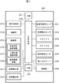
以下、図1に示す紙幣仕分け装置の制御ブロック図と、図2に示す紙幣仕分け装置の概略構成図を用いて、本実施例の詳細について説明する。紙幣仕分け装置は、回収された紙幣Sの計数、真偽判定、正損分離処理といった精査業務を行う装置である。なお、以下では、紙葉類の一例として紙幣を取り扱う場合について説明しているが、証券をはじめとする様々な紙葉類に適用することができる。 Hereinafter, the details of this embodiment will be described with reference to the control block diagram of the banknote sorting device shown in FIG. 1 and the schematic configuration diagram of the banknote sorting device shown in FIG. The banknote sorting device is a device that performs scrutiny work such as counting of collected banknotes S, authenticity determination, and positive / loss separation processing. In the following, the case of handling banknotes as an example of paper leaves will be described, but it can be applied to various paper leaves including securities.
図1に示すように、紙幣仕分け装置200は、装置内の各部を制御する主制御部250、主制御部250の動作プログラム等を記録したROM251、主制御部250が各部を制御する制御データを読み書き可能に記録するRAM252、操作者による入力操作を受け付けたり、操作後のデータを表示する場合に使用する表示操作部253、ホストコンピュータ等と接続する際、情報の送受信を行う通信部254、及び各種情報を格納する格納部255を備えている。格納部255には、紙幣の真偽判定に使用する真偽判定基準情報256、正券損券といった紙幣の区分振分けの判定の基準となる正損分離基準情報257、後述するスキャナA204、スキャナB206にて取得した画像に関する情報である紙幣画像情報258が保存される。
As shown in FIG. 1, the
また、上記の他に、確認時固有特徴量認識手段に対応する記番号読取センサ201、枚数検出センサ203、紙幣の表裏全体の画像を取得するスキャナA204、及び搬送されてくる紙幣の損券レベルを読み取る損券検知センサ205、紙幣の全体の透過画像を取得するスキャナB206、紙幣を1枚ずつ繰出す紙幣繰出部281、1枚ずつ繰出された紙幣を、紙幣識別部を通過してスタッカまで搬送する紙幣搬送部282、紙幣識別部により精査した紙幣を振り分ける振り分けゲート230を備えている。又投影部300を備えている場合もある。投影部300については、図8を用いて後述する。
In addition to the above, the serial
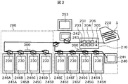
次に、紙幣仕分け装置200の機構を示す構造図である図2について説明する。以下に示す設定や表示(例えば、図3〜5、8の設定や表示)、処理の実行(例えば、図6、7のフローチャートの実行)は、主制御部250からの指示に従って実行される。紙幣仕分け装置200の内部には、紙幣識別部210、ホッパ220、振り分けゲート230、リジェクトスタッカA240、リジェクトスタッカB242、第1〜第8スタッカ245A〜245Hを備えている。
Next, FIG. 2 which is a structural diagram showing the mechanism of the
また、各スタッカに隣接して、リジェクトスタッカA用表示部241、リジェクトスタッカB用表示部243、第1〜第8スタッカ用表示部246A〜246Hを備えている。又投影部300を備えている場合もある。紙幣識別部210は、記番号読取センサ201、枚数検出センサ203、スキャナA204、損券検知センサ205、スキャナB206を搭載し、ホッパ220から繰り出された紙幣Sに対して計数、真偽判定、正損分離処理といった精査を行う。ホッパ220は、紙幣Sの投入部であり、投入された紙幣Sを1枚ずつ繰り出す。振り分けゲート230は、紙幣識別部210により精査した紙幣Sを振り分ける。リジェクトスタッカ240、スタッカ245A〜245Fは紙幣の収納手段であって、紙幣を取出すことを可能とした開口部を装置前面(ホッパ220を設けた側面)に備えている。
Further, adjacent to each stacker, a reject stacker
紙幣の区分振分けをどのスタッカに割り当てるかは、表示操作部253を介して各種設定できる。以下、紙幣抜き取り作業を2人で実施する場合を想定する。振分け対象となる紙幣は、金種が1種類で、正損仕分けを実施するものとする。作業を開始する前に、表示操作部253は、オペレータから、何人で紙幣抜き取り作業を実施するのかの指定を受け付ける。例えば、表示操作部253が、オペレータの人数として2人が指定されると、主制御部250は、RAM252に、第1スタッカ245Aと第2スタッカ245Bは金種Aの正券、第3スタッカ245Cと第4スタッカ245Dは金種Aの損券、第5スタッカ245Eと第6スタッカ245Fは金種Aの正券、第7スタッカ245Gと第8スタッカ245Hは金種Aの損券であることを記憶し、各スタッカに集積される紙幣が自動で割り当てられる。
It is possible to set various stackers to which the classification and distribution of banknotes are assigned via the
そして、主制御部250は、第1スタッカ245Aから第4スタッカ245Dまでは一人目が作業する範囲、第5スタッカ245Eから第8スタッカ245Hまでが二人目が作業する範囲であることがわかるよう、スタッカ用表示部246A〜246Hや表示操作部253に、作業を担当するオペレータの作業範囲を識別するための範囲識別情報を表示する。範囲識別情報としては、例えば、赤、青、黄色等の色彩情報、数字や文字、記号等の識別符号をはじめ、作業を担当するオペレータが視認可能な様々な識別情報を用いることができる。又投影部300により投影画像として表示される場合もある。
Then, in the
リジェクトスタッカA240は搬送異常、リジェクトスタッカA242は偽造券の紙幣に割り当てたとして説明する。また、リジェクトスタッカA用表示部241、リジェクトスタッカB用表示部243、第1〜第8スタッカ用表示部246A〜246Hには、各スタッカに格納されている紙幣の枚数が表示される。また、表示操作部253には、リジェクトスタッカA240、リジェクトスタッカB242、第1〜第8スタッカ245A〜245Hに集積された紙幣の枚数が表示される。又投影部300により投影画像として紙幣枚数を表示する場合もある。紙幣を投入する前は、各表示部は“0”が表示されている。
It will be explained that the reject stacker A240 is assigned to the transfer abnormality and the reject stacker A242 is assigned to the bill of the counterfeit ticket. Further, the number of banknotes stored in each stacker is displayed on the reject stacker
オペレータが紙幣Sをホッパ220に装填すると、紙幣Sは1枚ずつ分離され、ホッパ220から識別部210に搬送される。識別部210は、枚数検出センサ203によって紙幣枚数を検出するとともに、スキャナA204、スキャナB206により紙幣Sの表裏の反射画像、透過画像をスキャンして、それらから得られる紙幣Sの真偽データを真偽判定基準情報256と比較する。当該紙幣Sが正券ならば、振り分けゲート230の駆動により第1スタッカ245Aに振り分け集積する。この時、第1スタッカ用表示部246Aには、第1スタッカ245Aに集積されている紙幣の枚数が表示される。又投影部300により投影画像として第1スタッカ又は第1スタッカ近傍に紙幣の枚数を表示する場合もある。
When the operator loads the bill S into the
各スタッカの集積枚数の上限は設定により定められており、この例では各スタッカ上限を100枚とする。正券に割り当てられている第1スタッカ245Aの集積枚数が上限の100枚に達したとき、次に正券と判定された紙幣は、第5スタッカ245Eへ集積される。第2スタッカ245Bではなく、第5スタッカ245Eへ集積されることで、一人目のオペレータの抜き取り作業が連続で実施されるのを防ぐことが出来る。以下、紙幣仕分け装置200は、交互に一人目用のスタッカ、二人目用のスタッカに格納していく。
The upper limit of the number of stacked sheets of each stacker is set by the setting, and in this example, the upper limit of each stacker is 100 sheets. When the accumulated number of the
損券の場合でも同様に、紙幣仕分け装置200は、交互に一人目用のスタッカ、二人目用のスタッカに交互に集積していく。これに合せ投影部300により操作案内を投影画像として表示することもある。これにより、一人目と二人目の作業量が均等になり、オペレータの作業負担を分散することが出来、どちらか一人の能力の限界を超えた作業量が割り当てられ、もう一人の能力を充分生かすことが出来ないという事態を防ぐことが出来、各自の能力を最大限発揮することが出来る。
Similarly, in the case of a loss ticket, the
次に、オペレータの経験値を考慮した振分けについて説明する。表示操作部253は、何人で紙幣抜き取り作業を実施するのか人数の指定を受け付けるが、その際に人数に加えて、オペレータの経験値の設定を受け付ける。例えば、二人のオペレータが作業する場合、表示操作部253は、オペレータのそれぞれについて、一人目の経験値として第1の設定値である「高」の設定を受け付け、二人目の経験値として第2の設定値である「低」の設定を受け付け、上記人数や経験値、スタッカの担当範囲を設定結果として表示する。
Next, the distribution considering the experience value of the operator will be described. The
ここでも、区分振分け対象となる紙幣は、金種が1種類で、正損仕分けを実施するものとする。第1スタッカ245Aと第2スタッカ245Bと第3スタッカ245Cは金種Aの正券、第4スタッカ245Dと第5スタッカ245Eは金種Aの損券、第6スタッカ245Fは金種Aの正券、第7スタッカ245Gと第8スタッカ245Hは金種Aの損券が自動で割り当てられる。そして、第1スタッカから第5スタッカまでは一人目が作業する範囲、第6スタッカから第8スタッカまでが二人目が作業する範囲であることが分かるよう、スタッカ用表示部246A〜246Hや表示操作部253に表示される。又、投影部300により投影画像として作業する範囲を表示する場合もある。
Here, too, the banknotes to be sorted and sorted have one type of denomination, and positive and loss sorting is performed. The
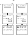
図3は、表示操作部253の例を示す図である。図3では、表示操作部253に、複数のオペレータにより仕分け作業を行う場合に表示される画面を示している。図3の左側の列は、二人のオペレータの熟練度が同じである場合、図3の右側の列は、二人のオペレータの熟練度が異なる場合の画面遷移をあらわしている。
FIG. 3 is a diagram showing an example of the
図3の左側の画面遷移では、紙幣仕分け装置200は、表示操作部253にオペレータの人数を確認するための人数確認画面を表示する(a)。この例では、オペレータが二人であるとして人数が入力されている。オペレータの人数が入力されると、紙幣仕分け装置200は、表示操作部253に、それぞれのオペレータの熟練度の入力を受け付けるための熟練度入力画面を表示する(b)。この例では、オペレータの熟練度が、いずれも「高」であるとして熟練度が入力されている。オペレータの熟練度が入力されると、紙幣仕分け装置200は、表示操作部253に、それぞれのオペレータが担当するスタッカの担当範囲を示す担当範囲表示画面を表示する(c)。この例では、オペレータAの担当範囲としてスタッカ1〜4を表示し、オペレータBの担当範囲としてスタッカ5〜8を表示していることがわかる。このように、オペレータの熟練度が同じである場合、紙幣仕分け装置200は、同じ数のスタッカを、それぞれのオペレータの担当範囲として画面に表示する。
In the screen transition on the left side of FIG. 3, the
一方、図3の右側の画面遷移では、左側の画面遷移の場合と同様に、紙幣仕分け装置200は、表示操作部253に人数確認画面を表示し(a)、オペレータの人数が入力されると、表示操作部253に、熟練度入力画面を表示する(b)。このとき、一人目のオペレータの熟練度は「高」、二人目のオペレータの熟練度は「低」であるとして熟練度が入力されると、紙幣仕分け装置200は、表示操作部253に、担当範囲表示画面を表示する(c)。この場合は、オペレータAの担当範囲としてスタッカ1〜5を表示し、オペレータBの担当範囲としてスタッカ6〜8を表示していることがわかる。このように、オペレータの熟練度が異なる場合、紙幣仕分け装置200は、熟練度が高いオペレータと熟練度が低いオペレータとの間で担当するスタッカの数に差をつけて、熟練度が高いオペレータには多く、熟練度が低いオペレータには少ない範囲をそれぞれのオペレータの担当範囲として画面に表示する。
On the other hand, in the screen transition on the right side of FIG. 3, as in the case of the screen transition on the left side, the
例えば、オペレータによって紙幣Sがホッパ220に装填され、各スタッカ上限が100枚であるとする。紙幣仕分け装置200は、正券に割り当てられている第1スタッカ245Aの集積枚数が上限の100枚に達したか否かを判定する。紙幣仕分け装置200は、第1スタッカ245Aの集積枚数が上限の100枚に達したと判定した場合、次に正券と判定した紙幣を、オペレータ二人目が担当する第6スタッカ245Fへ集積する。さらに、紙幣仕分け装置200は、正券に割り当てられている第6スタッカ245Fの集積枚数が上限の100枚に達したか否かを判定し、第6スタッカ245Fの集積枚数が上限の100枚に達したと判定した場合、次に正券と判定した紙幣を、オペレータ一人目が担当するスタッカのうちの次のスタッカである第2スタッカ245Bへ集積される。
For example, it is assumed that the banknote S is loaded into the
さらに、紙幣仕分け装置200は、正券に割り当てられている第2スタッカ245Bの集積枚数が上限の100枚に達したか否かを判定し、第2スタッカ245Bの集積枚数が上限の100枚に達したと判定した場合、次に正券と判定した紙幣を、オペレータ一人目が担当するスタッカのうちのさらに次のスタッカである第3スタッカ245Cへ集積する。このように、経験値が高いオペレータの負担を大きくすることで、作業効率を改善する。なお、スタッカの割り当て、担当範囲、集積順番は、全て表示操作部253を介して設定することも可能とする。
Further, the
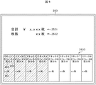
図4は、表示操作部253に表示されるスタッカ設定表示画面の例を示す図である。図4に示すように、スタッカ設定表示画面には、その上段に、計数した(あるいは計数中)の紙幣の合計金額2531およびその枚数2532が表示される。また、スタッカ設定表示画面の下段には、紙幣仕分け装置200が有するそれぞれのスタッカに収納されている紙幣の枚数を表示する枚数表示欄401と、紙幣の区分振分けにより振り分けられる紙幣の振分け区分を表示する区分表示欄402と、そのスタッカを担当するオペレータを表示するオペレータ表示欄403とを含むスタッカ表示部2533が表示される。図4では、一人目のオペレータがスタッカ1〜4を担当し、二人目のオペレータがスタッカ5〜8を担当するように設定され、その設定結果が表示されていることを示している。上記各表示欄に表示されている値は、例えば、当該スタッカ設定表示画面や後述する担当範囲設定画面(図5)からの数値の入力や数値を選択するタッチ操作により設定することができる。
FIG. 4 is a diagram showing an example of a stacker setting display screen displayed on the
次に、動的にスタッカの担当範囲を変更する方法について説明する。区分振分け対象となる紙幣は、金種が8種類で、スタッカごとに1金種を割り当て、第1スタッカ245Aから第4スタッカ245Dまでは一人目のオペレータが作業する範囲、第5スタッカ245Eから第8スタッカ245Hまでが二人目のオペレータが作業する範囲で運用を開始したと想定する。このとき、二人の経験値に差がある、もしくは、スタッカに搬送されてくる子への頻度が金種毎に異なる場合を考える。この場合、一人目のオペレータが担当するスタッカの集積枚数が上限の100枚に達する頻度が高く、紙幣を抜き取るまでの時間が長くなってしまう場合、紙幣が抜き取られるまでは搬送が停止するので、作業効率が低下する。
Next, a method of dynamically changing the range of responsibility of the stacker will be described. There are eight types of banknotes to be sorted and sorted, one denomination is assigned to each stacker, the range from the
例えば、第1スタッカ245Aから第4スタッカ245Dに収納される紙幣の搬送頻度が高く、上限枚数である100枚に早く到達した場合、一人目のオペレータはこれらのスタッカから紙幣を抜き取らなければならない。しかし、収納される紙幣の搬送頻度が低い第5スタッカ245Eから第8スタッカ245Hの各スタッカ二人目のオペレータと同じ割合で担当するスタッカの数が割り当てられているため、一人目のオペレータが紙幣の抜き取りを完了するまでの時間だけ搬送が停止してボトルネックとなってしまう。
For example, if the banknotes stored in the
このような場合、主制御部250は、それまでに処理された振分け区分ごとの紙幣の枚数や、紙幣の枚数が各スタッカの上限に達してから紙幣が抜き取られるまでの抜き取り時間に応じて、オペレータの紙幣抜き取り作業を担当するスタッカの担当範囲を変更する。例えば、図4では、一人目が担当する範囲を第1スタッカ245Aから第4スタッカ245Dとし、二人目が担当する範囲を第5スタッカ245Eから第8スタッカ245Hとして、両者の担当範囲を同じ数、同じ割合で設定したが、図5に示すように、一人目の担当するスタッカの範囲を第1スタッカ245Aから第3スタッカ245Cまで変更し、二人目の担当するスタッカの範囲を第4スタッカ245Dから第8スタッカ245Hまでに変更することで、作業効率を改善する。主制御部250は、上記紙幣の量や上記抜き取り時間を参照し、各オペレータが担当するスタッカを変更し、その結果をスタッカ用表示部246A〜246Hや表示操作部253に表示する。また、投影部300により投影画像として表示してもよい。
In such a case, the
図5は、スタッカの担当範囲、区分振分けおよび集積順の設定や変更を行うための担当範囲設定画面の例を示す図である。図5に示すように、担当範囲設定画面には、スタッカごとに、担当するオペレータを示すオペレータ表示欄501と、区分振分けによりそのスタッカに振り分けられる紙幣の振分け区分(例えば、正券、損券)を示す区分表示欄502と、そのスタッカに紙幣を集積する順序を示す集積順表示欄503とが表示されている。
FIG. 5 is a diagram showing an example of a charge range setting screen for setting or changing the charge range, division distribution, and accumulation order of the stacker. As shown in FIG. 5, on the charge range setting screen, an
また、図5では、一人目のオペレータはスタッカ1〜5を担当し、二人目のオペレータはスタッカ6〜8を担当するように設定され、その設定結果が表示されていることがわかる。また、紙幣の集積順序は、ある金種の正券(区分A)は、一人目のオペレータが担当するスタッカのうちスタッカ1〜4および二人目のオペレータが担当するスタッカのうちスタッカ6に、スタッカ1→スタッカ6→スタッカ3→スタッカ4の順で集積されることがわかる。すなわち、区分振分けにより同じ振分け区分に振り分けられる紙幣が、一人目のオペレータ(例えば、経験値が高いオペレータ)が担当するスタッカに続き、二人目のオペレータオペレータ(例えば、経験値が低いオペレータ)が担当するスタッカに集積されるというように、オペレータを跨いで集積順序の優先順位が交互に設定され、その設定結果が表示されている。
Further, in FIG. 5, it can be seen that the first operator is in charge of stackers 1 to 5 and the second operator is in charge of stackers 6 to 8, and the setting result is displayed. In addition, the order of collecting banknotes is as follows: for a certain denomination of regular tickets (Category A), stackers 1 to 4 among the stackers in charge of the first operator and stackers 6 among the stackers in charge of the second operator. It can be seen that 1 → stacker 6 →
このように、表示操作部253が、紙幣を仕分けるオペレータの人数と上記振分け区分と紙幣の集積順序の設定を受け付け、主制御部250が、受け付けられたオペレータの人数に応じて、上記振分け区分ごとに設定された集積順序で紙幣を集積する。したがって、上記のようなボトルネックの発生を減らすことができる。
In this way, the
実施例1では、複数のオペレータが紙幣の仕分けを担当する前提で説明した。しかし、実際には、オペレータが1人で作業することも通常の作業では十分考えられる。そこで、実施例2では、オペレータが1人で作業することを考慮して、紙幣の搬送速度を動的に変化させる方法について説明する。 In the first embodiment, it has been described on the premise that a plurality of operators are in charge of sorting banknotes. However, in reality, it is fully conceivable that the operator works alone in normal work. Therefore, in the second embodiment, a method of dynamically changing the transport speed of banknotes will be described in consideration of the fact that the operator works alone.
実施例2では、紙幣仕分け装置200が、紙幣の金種分けをする際、スタッカが満杯になってから、オペレータが紙幣を取出すまでの時間を毎回測定し、今回の取出し時間と直近の1回前の取出し時間と比較して、オペレータの操作性を考慮して装置の処理速度を常に最適化するものである。
In the second embodiment, when the
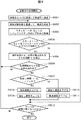
実施例2の中で、装置の処理速度を最適化する説明を図6のフローチャートを用いて説明する。図6の例では、区分振分け対象となる紙幣は金種が8種類で、スタッカごとに1金種が割り当てられているものとする。 In the second embodiment, the explanation for optimizing the processing speed of the apparatus will be described with reference to the flowchart of FIG. In the example of FIG. 6, it is assumed that the banknotes to be sorted and sorted have eight types of denominations and one denomination is assigned to each stacker.
まず、オペレータにより紙幣がホッパ220に装填されると、紙幣仕分け装置200は、仕分け処理を開始する(S601)。紙幣仕分け装置200の紙幣搬送部282は、ホッパ220に装填された紙幣の搬送を開始し、紙幣識別部210を通過する。紙幣識別部210は、搬送された紙幣を識別し、その識別結果を基に、搬送された紙幣を何処に集積させるかを判断し、集積を行う(S602、S603)。
First, when the banknotes are loaded into the
ここで、紙幣仕分け装置200は、スタッカもしくはリジェクトスタッカのいずれかが満杯(設定枚数に達しているか)であるか否かを判定する(S604)。紙幣仕分け装置200は、いずれも満杯でないと判定した場合は(S604;No)、ホッパの紙幣が無くなったか否かを判定する(S612)。紙幣仕分け装置200は、ホッパの紙幣が無くなっていないと判定した場合は(S612;No)、再びS602の処理に戻る。
Here, the
一方、紙幣仕分け装置200は、スタッカ、もしくはリジェクトスタッカのいずれかが満杯になったと判定した場合(S604;Yes)、満杯を検知してから抜き取られるまでの時間をRAM252に都度記憶しておく(S605)。これは、図示していないが、各スタッカ、リジェクトスタッカは残留センサを具備しており、媒体が無くなれば残留センサで検知できる。したがって、紙幣仕分け装置200は、スタッカの満杯を検知してから、取り出されたと検知される時間の計測は容易である。
On the other hand, when it is determined that either the stacker or the reject stacker is full (S604; Yes), the
次に、紙幣仕分け装置200は、金種分け処理して最初の満杯か否かを判定し(S606)、初めてスタッカ、もしくはリジェクトスタッカが満杯であると判定した場合(S606;Yes)、再びS602の処理に戻る。一方、紙幣仕分け装置200は、金種分け処理開始から2回目以降の満杯であると判定した場合(S606;No)、取出し時間tが、前回の取出し時間sと比較して長いか、短いかを判定する(S607)。紙幣仕分け装置200は、今回の取出し時間の方が前回の取出し時間よりも短いと判定した場合は(S607;Yes)、オペレータの能力にまだ余裕があると判断して、搬送速度と繰出し速度を上げて、紙幣の集積速度を上げる(S608、S609)。
Next, the
一方、紙幣仕分け装置200は、今回の取出し時間が前回の取出し時間よりも長いと判定した場合は(S607;No)、オペレータの作業効率が落ちてきていることを示している。よって、満杯で集積された紙幣が放置されるため、紙幣の搬送が止まってしまい、結果としてスループットが下がってしまう。紙幣仕分け装置200は、その状態が続くことを避けるため、繰出し速度を下げ、搬送速度を下げる(S610、S611)。この処理を、ホッパの紙幣が無くなるまで行う。
On the other hand, when the
ここで、投影部300が投影画像310にてスタッカ内の紙幣の集積情報を表示すると、オペレータの視線移動がスタッカ近辺に集中できるため、さらなる作業効率の向上が期待できる。
Here, when the
実施例2では、スタッカの満杯検知毎に前回の満杯検知時の取出し時間と比較して、搬送速度や繰出し速度を変更する処理としたが、本方式の場合、満杯の紙幣を抜取る度に大きく集積速度の変動が生じる可能性がある。これを緩和する案として、第3の実施例について考える。 In the second embodiment, the transport speed and the feeding speed are changed every time the stacker is detected to be full, as compared with the take-out time at the time of the previous full detection. However, in the case of this method, every time a full bill is taken out. There is a possibility that the accumulation rate will fluctuate greatly. As a plan to alleviate this, consider a third embodiment.
実施例3では、紙幣仕分け装置200が紙幣の金種分けをする際、スタッカが満杯になってから、オペレータが紙幣を取出すまでの時間を毎回測定し、今回の取出し時間と過去の所定回数分(例えば、5回分)の取出し時間の平均値と比較して、装置の処理速度を常に最適化するものである。
In the third embodiment, when the
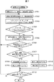
実施例3の中で、装置の処理速度を最適化する説明を図7のフローチャートを用いて説明する。図7の例では、S701からS705の各処理は、図6に示した実施例2のS601からS605の各処理と同様であるため説明を省略し、S706以降の各処理について説明する。 In the third embodiment, the explanation for optimizing the processing speed of the apparatus will be described with reference to the flowchart of FIG. In the example of FIG. 7, since each process of S701 to S705 is the same as each process of S601 to S605 of the second embodiment shown in FIG. 6, description thereof will be omitted, and each process after S706 will be described.
紙幣仕分け装置200は、S705で紙幣が取り出されるまでの時間を計測すると、金種分け処理して6回目以降の満杯か否かを判定する(S706)。紙幣仕分け装置200は、5回目以内のスタッカ、もしくはリジェクトスタッカが満杯の処理であると判定した場合(S706;No)、再びS702の処理に戻る。一方、紙幣仕分け装置200は、金種分け処理開始から6回目以降の満杯であると判定した場合(S706;Yes)、取出し時間tが、直前5回分の取出し時間の平均値s_avgと比較して長いか、短いかを判定する(S707)。
When the
紙幣仕分け装置200は、今回の取出し時間の方が直前5回分の取出し時間よりも短いと判定した場合は(S706;Yes)、オペレータの能力にまだ余裕があると判断して、搬送速度と繰出し速度を上げて、紙幣の集積速度を上げる(S708、S709)。一方、紙幣仕分け装置200は、今回の取出し時間が直前5回分の取出し時間よりも長いと判定した場合は(S706;No)、実施例2同様に繰出し速度を下げ、搬送速度を下げる(S710、S711)。この処理を、ホッパの紙幣が無くなるまで行う。このように、主制御部250は、紙幣の枚数が各スタッカの上限に達してからオペレータにより紙幣が抜き取られるまでの抜き取り時間の長さに応じて、紙幣の繰出し速度または/および搬送速度を変化させる。したがって、大きく集積速度の変動が生じることが少ないため、オペレータはより快適に装置の操作ができる。
If the
ここで、応用例として、紙幣仕分け装置200は、過去に実施したオペレータ毎の最適な搬送速度を記憶しておき、作業開始前にオペレータの名前を入力すると、初めから最適な速度で振分を開始してもよい。例えば、紙幣仕分け装置200は、オペレータの名前やID等の識別情報と、その識別情報に対応付けてRAM252に蓄積されている過去の所定回数分(例えば、5回分)の取り出し時間を参照し、入力されたオペレータの識別情報に対応する上記取り出し時間の中で最も小さい値のときの搬送速度となるように、紙幣搬送部282の動作を制御する。
Here, as an application example, the
また、紙幣仕分け装置200は、オペレータ同士の取り出し時間を比較し、例えば、過去の取り出し時間の中で常に抜取り時間が短いオペレータを特定し、そのオペレータを識別するためのIDをRAM252に記憶しておき、優秀オペレータとしてそのIDを表示操作部253に出力し、表彰できる仕組みを備えてもよい。また、紙幣仕分け装置200は、抜取り時間が前回よりも短くなったと判定した場合は、図示しないスピーカ等の音声出力装置から楽曲を出力して、オペレータが気持ち良く操作ができるようにしてもよい。
Further, the
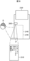
図8は、投影部300の例を示す図である。図8に示すように、紙幣仕分け装置200は、各スタッカの上部に設けられた振り分けゲート230と、紙幣仕分け装置200に取り付けられた各スタッカ用表示部246A〜Hを有した各スタッカ245A〜Hの設置面またはその近傍に設けられた投影表示部Pと、各スタッカ245A〜Hのそれぞれに対応付けて、その上部に設置された投影部300とを有している。投影表示部Pは、例えば、投影可能な平板状の部材により構成され、各スタッカ245A〜Hの底面と同じレベルに設けられている。投影部300は、例えば、小型のプロジェクタから構成される。図8に示す例では、投影部300は、RAM252から、図4に示したスタッカ設定表示画面や図5に示した担当範囲設定画面に表示される項目を読み出し、これらの項目を含む投影画像310を投影表示部Pに投影している。投影画像310には、例えば、図4に示したスタッカ設定表示画面や図5に示した担当範囲設定画面に表示される項目が表示される。
FIG. 8 is a diagram showing an example of the
このように、紙幣仕分け装置200は、各スタッカ245A〜Hの上方から下方に向けて上記項目を投影し、上記項目を投影表示部Pに投影する。各スタッカ245A〜Hに設けられた各スタッカ用表示部246A〜Hを目視することで、オペレータOはスタッカ設定や自身の担当範囲を確認することができるが、この場合にはスタッカ設定や自身の担当範囲が装置内部に表示されるため、取り出し時の視線を変えなければこれらの情報を確認することができなかったが、図8に示したような投影部300および投影表示部Pを設けることにより、オペレータOは取り出し時の視線を変えることなくスタッカ設定や自身の担当範囲を確認することができる。例えば、オペレータOは各スタッカに収納された紙幣の枚数を確認後、その姿勢、視線のまま直ちに満杯となったスタッカから紙幣を取り出すことができるため、より一層効率よく仕分け作業を継続することができる。
In this way, the
以上より、動的にスタッカの担当範囲を変える判断要素として、過去一定時間内に担当スタッカに振り分けられた紙幣の量、集積枚数が上限に達しているスタッカの数、上限に達していないがあと少しで上限に達しそうなスタッカの数等から、どちらのオペレータ側の抜き取り作業が遅延して作業効率のネックになるかを判断できる。また、動的に紙幣の搬送速度、繰出し速度を変化させる要素として、紙幣がスタッカ上限に達してから抜き取られるまでに要した時間からオペレータの作業効率を判断できる。 Based on the above, as judgment factors for dynamically changing the range of responsibility of stackers, the amount of banknotes distributed to the stackers in charge within a certain period of time in the past, the number of stackers whose accumulated number has reached the upper limit, and the number of stackers that have not reached the upper limit are later. From the number of stackers that are likely to reach the upper limit in a short time, it is possible to determine which operator's extraction work is delayed and becomes a bottleneck in work efficiency. Further, as an element for dynamically changing the transport speed and the feeding speed of the bill, the operator's work efficiency can be determined from the time required from when the bill reaches the upper limit of the stacker to when the bill is pulled out.
なお、ここでは動的にスタッカの担当範囲を変更する方法について説明したが、同じ振分け区分が各作業者に割り当てられている場合、動的に集積順番を変更することで作業効率を上げることも可能である。このような構成としたことにより、搬送が止まっている時間が低減することにより、処理能力が上がる。また、複数のオペレータ間での作業量が能力に応じて最適化されるので、マイペースで作業できるようになり、作業者の精神的負担が低減する。 In addition, although the method of dynamically changing the range of responsibility of the stacker was explained here, if the same distribution division is assigned to each worker, the work efficiency can be improved by dynamically changing the accumulation order. It is possible. With such a configuration, the processing capacity is increased by reducing the time during which the transportation is stopped. In addition, since the amount of work between a plurality of operators is optimized according to the ability, it becomes possible to work at one's own pace, and the mental burden on the operator is reduced.
S…紙幣,200…紙幣仕分け装置,201…記番号読取センサ,203…枚数検出センサ,204…スキャナA,205…損券検知センサ,206…スキャナB,210…識別部,220…ホッパ,230…振り分けゲート,240…リジェクトスタッカA,241…リジェクトスタッカA用表示部,242…リジェクトスタッカB,243…リジェクトスタッカB用表示部,245A…第1スタッカ,245B…第2スタッカ,245C…第3スタッカ,245D…第4スタッカ,245E…第5スタッカ,245F…第6スタッカ,245G…第7スタッカ,245H…第8スタッカ,246A…第1スタッカ用表示部,246B…第2スタッカ用表示部,246C…第3スタッカ用表示部,246D…第4スタッカ用表示部,246E…第5スタッカ用表示部,246F…第6スタッカ用表示部,246G…第7スタッカ用表示部,246H…第8スタッカ用表示部,250…主制御部,251…ROM,252…RAM,253…表示操作部,254…通信部,255…格納部,256…真偽判定基準情報,257…正損分離基準情報,258…紙幣画像情報,281…紙幣繰出部,282…紙幣搬送部,300…投影部,310…投影画像 S ... Banknote, 200 ... Banknote sorting device, 201 ... Serial number reading sensor, 203 ... Number of sheets detection sensor, 204 ... Scanner A, 205 ... Loss ticket detection sensor, 206 ... Scanner B, 210 ... Identification unit, 220 ... Hopper, 230 ... Sorting gate, 240 ... Reject stacker A, 241 ... Reject stacker A display unit, 242 ... Reject stacker B, 243 ... Reject stacker B display unit, 245A ... 1st stacker, 245B ... 2nd stacker, 245C ... 3rd Stacker, 245D ... 4th stacker, 245E ... 5th stacker, 245F ... 6th stacker, 245G ... 7th stacker, 245H ... 8th stacker, 246A ... 1st stacker display unit, 246B ... 2nd stacker display unit, 246C ... Display unit for 3rd stacker, 246D ... Display unit for 4th stacker, 246E ... Display unit for 5th stacker, 246F ... Display unit for 6th stacker, 246G ... Display unit for 7th stacker, 246H ... 8th stacker Display unit, 250 ... Main control unit, 251 ... ROM, 252 ... RAM, 253 ... Display operation unit, 254 ... Communication unit, 255 ... Storage unit, 256 ... Authenticity judgment standard information, 257 ... Positive / loss separation standard information, 258 ... Banknote image information, 281 ... Banknote feeding section, 282 ... Banknote transport section, 300 ... Projection section, 310 ... Projection image
Claims (8)
同じ振分け区分として設定された紙葉類の前記複数のスタッカへの集積順序の設定を受け付ける操作部であって、設定された前記集積順序を、前記操作部に設けられた表示部に表示し、スタッカの担当範囲と前記振分け区分と前記集積順序の設定や変更を行うための担当範囲設定画面において前記担当範囲と前記振分け区分と前記集積順序の設定を受け付け、受け付けた設定結果を前記表示部に表示する前記操作部と、
前記操作部により設定された集積順序で前記紙葉類を前記スタッカに搬送して集積する制御部と、を備え、
前記制御部は、前記振分け区分ごとに設定された前記集積順序で前記紙葉類を集積する、
ことを特徴とする紙葉類仕分け装置。 Multiple stackers that collect paper leaves and
It is an operation unit that accepts the setting of the accumulation order of paper sheets set as the same distribution division on the plurality of stackers, and displays the set accumulation order on the display unit provided in the operation unit. On the charge range setting screen for setting or changing the charge range of the stacker, the distribution division, and the accumulation order, the setting of the charge range, the distribution division, and the accumulation order is accepted, and the accepted setting result is displayed on the display unit. The operation unit to be displayed and
A control unit for transporting and accumulating the paper sheets to the stacker in the accumulation order set by the operation unit is provided.
The control unit collects the paper sheets in the collection order set for each distribution category.
A paper leaf sorting device characterized by this.
同じ振分け区分として設定された紙葉類の前記複数のスタッカへの集積順序の設定を受け付ける操作部と、
前記操作部により設定された集積順序で前記紙葉類を前記スタッカに搬送して集積する制御部と、
前記スタッカまたは前記スタッカの近傍に設けられた投影表示部に、設定された前記集積順序を投影する投影部と、を備え、
前記投影部は、前記紙葉類を仕分けるオペレータに対するスタッカの割り振りと前記振分け区分と前記集積順序とを、前記投影表示部に表示し、
前記制御部は、前記振分け区分ごとに設定された前記集積順序で前記紙葉類を集積する、
ことを特徴とする請求項1に記載の紙葉類仕分け装置。 Multiple stackers that collect paper leaves and
An operation unit that accepts the setting of the stacking order of paper sheets set as the same distribution classification in the plurality of stackers, and
A control unit that transports the paper sheets to the stacker and accumulates them in the accumulation order set by the operation unit.
A projection unit for projecting the set integration order is provided on the stacker or a projection display unit provided in the vicinity of the stacker.
The projection unit displays the allocation of stackers to the operator who sorts the paper sheets, the distribution classification, and the accumulation order on the projection display unit.
The control unit collects the paper sheets in the collection order set for each distribution category.
The paper leaf sorting apparatus according to claim 1.
前記制御部は、設定された前記オペレータの人数に応じて、当該オペレータが担当する前記スタッカを設定し、設定した結果を前記表示部に表示する、
ことを特徴とする請求項1に記載の紙葉類仕分け装置。 The operation unit accepts the setting of the number of operators on the number confirmation screen for confirming the number of operators who sort the paper sheets.
The control unit sets the stacker in charge of the operator according to the set number of operators, and displays the set result on the display unit.
The paper leaf sorting apparatus according to claim 1.
前記投影部は、前記投影表示部に、前記設定した結果を投影する、
ことを特徴とする請求項3に記載の紙葉類仕分け装置。 As a display unit different from the display unit, a projection unit that projects the set integration order onto the stacker or a projection display unit provided in the vicinity of the stacker is provided.
The projection unit projects the set result onto the projection display unit.
The paper leaf sorting apparatus according to claim 3.
前記制御部は、各オペレータが担当する前記スタッカを設定し、設定した結果を前記表示部に表示する、
ことを特徴とする請求項1に記載の紙葉類仕分け装置。 The operation unit accepts the setting of the number of operators on the number confirmation screen for confirming the number of operators who sort the paper sheets, and the operator's experience on the skill input screen for accepting the input of the operator's skill level. Accepts value settings,
The control unit sets the stacker in charge of each operator, and displays the set result on the display unit.
The paper leaf sorting apparatus according to claim 1.
前記投影部は、前記投影表示部に、前記設定した結果を投影する、
ことを特徴とする請求項5に記載の紙葉類仕分け装置。 As a display unit different from the display unit, a projection unit that projects the set integration order onto the stacker or a projection display unit provided in the vicinity of the stacker is provided.
The projection unit projects the set result onto the projection display unit.
The paper leaf sorting apparatus according to claim 5.
ことを特徴とする請求項1に記載の紙葉類仕分け装置。 In the control unit, the paper sheets are extracted by an operator who sorts the paper sheets after the number of the paper sheets and the number of the paper sheets for each of the processed distribution categories reaches the upper limit of each stacker. The stacker in charge of the operator is changed according to the extraction time up to.
The paper leaf sorting apparatus according to claim 1.
ことを特徴とする請求項1に記載の紙葉類仕分け装置。 The control unit feeds out the paper sheets according to the extraction time from when the number of the sheets reaches the upper limit of each stacker until the sheets are extracted by the operator who sorts the sheets. Or / and change the transport speed,
The paper leaf sorting apparatus according to claim 1.
Priority Applications (2)
| Application Number | Priority Date | Filing Date | Title |
|---|---|---|---|
| JP2017180017A JP6928811B2 (en) | 2017-09-20 | 2017-09-20 | Paper leaf sorting device |
| PCT/JP2018/018749 WO2019058635A1 (en) | 2017-09-20 | 2018-05-15 | Paper sheet classification device |
Applications Claiming Priority (1)
| Application Number | Priority Date | Filing Date | Title |
|---|---|---|---|
| JP2017180017A JP6928811B2 (en) | 2017-09-20 | 2017-09-20 | Paper leaf sorting device |
Publications (2)
| Publication Number | Publication Date |
|---|---|
| JP2019057018A JP2019057018A (en) | 2019-04-11 |
| JP6928811B2 true JP6928811B2 (en) | 2021-09-01 |
Family
ID=65810715
Family Applications (1)
| Application Number | Title | Priority Date | Filing Date |
|---|---|---|---|
| JP2017180017A Active JP6928811B2 (en) | 2017-09-20 | 2017-09-20 | Paper leaf sorting device |
Country Status (2)
| Country | Link |
|---|---|
| JP (1) | JP6928811B2 (en) |
| WO (1) | WO2019058635A1 (en) |
Family Cites Families (6)
| Publication number | Priority date | Publication date | Assignee | Title |
|---|---|---|---|---|
| JPH0816940B2 (en) * | 1989-09-25 | 1996-02-21 | ローレルバンクマシン株式会社 | Banknote sorting machine |
| JP4772331B2 (en) * | 2005-01-20 | 2011-09-14 | 株式会社東芝 | Paper sheet processing equipment |
| WO2009040944A1 (en) * | 2007-09-28 | 2009-04-02 | Glory Ltd. | Paper sheet handling machine and paper sheet handling system |
| JP5927811B2 (en) * | 2011-08-30 | 2016-06-01 | 沖電気工業株式会社 | Paper sheet processing equipment |
| JP6362479B2 (en) * | 2014-08-27 | 2018-07-25 | グローリー株式会社 | Paper sheet processing equipment |
| JP2017091136A (en) * | 2015-11-09 | 2017-05-25 | グローリー株式会社 | Money management apparatus and money management method |
-
2017
- 2017-09-20 JP JP2017180017A patent/JP6928811B2/en active Active
-
2018
- 2018-05-15 WO PCT/JP2018/018749 patent/WO2019058635A1/en not_active Ceased
Also Published As
| Publication number | Publication date |
|---|---|
| WO2019058635A1 (en) | 2019-03-28 |
| JP2019057018A (en) | 2019-04-11 |
Similar Documents
| Publication | Publication Date | Title |
|---|---|---|
| KR102202966B1 (en) | A bill-recycling ATM for teller with a bill stacking box and the banknote transfer method applied thereto | |
| JP5216308B2 (en) | Paper sheet handling equipment | |
| JP5927811B2 (en) | Paper sheet processing equipment | |
| JP5914687B2 (en) | Paper sheet processing apparatus, paper sheet sorting apparatus, and paper sheet sorting system | |
| CN101952858B (en) | Method and system for sorting banknotes, providing change funds and equalizing revenue | |
| KR101885423B1 (en) | Bill processing device | |
| CN104658102B (en) | Banknote processing device | |
| JP5012199B2 (en) | Cash processing equipment | |
| WO2017014209A1 (en) | Paper currency processing device and paper currency processing method | |
| JP2013164679A (en) | Bill processor | |
| JP3793940B2 (en) | Cash processing apparatus and deposit processing method thereof | |
| JP6928811B2 (en) | Paper leaf sorting device | |
| CN112309029B (en) | Paper sorting device and paper management method | |
| CN104919496B (en) | Paper processing apparatus and paper sheet processing method | |
| JP5087889B2 (en) | Cash processing equipment | |
| JP2005099887A (en) | Cash processor and program therefor | |
| JPWO2018003145A1 (en) | Banknote handling equipment | |
| JP6411946B2 (en) | Money handling machine | |
| CN105844784B (en) | Paper money processing device | |
| JP6928536B2 (en) | Banknote processing system | |
| JP2007087314A (en) | Cash processor | |
| JP5271807B2 (en) | Bill processing apparatus and transaction processing apparatus | |
| JP2018200729A (en) | Money handling machine | |
| JP6537173B2 (en) | Banknote processing device | |
| CN103955991A (en) | Paper money processing device |
Legal Events
| Date | Code | Title | Description |
|---|---|---|---|
| A621 | Written request for application examination |
Free format text: JAPANESE INTERMEDIATE CODE: A621 Effective date: 20200213 |
|
| A131 | Notification of reasons for refusal |
Free format text: JAPANESE INTERMEDIATE CODE: A131 Effective date: 20200929 |
|
| A521 | Written amendment |
Free format text: JAPANESE INTERMEDIATE CODE: A523 Effective date: 20201102 |
|
| A131 | Notification of reasons for refusal |
Free format text: JAPANESE INTERMEDIATE CODE: A131 Effective date: 20201215 |
|
| A521 | Written amendment |
Free format text: JAPANESE INTERMEDIATE CODE: A523 Effective date: 20210203 |
|
| A131 | Notification of reasons for refusal |
Free format text: JAPANESE INTERMEDIATE CODE: A131 Effective date: 20210316 |
|
| A521 | Written amendment |
Free format text: JAPANESE INTERMEDIATE CODE: A523 Effective date: 20210514 |
|
| TRDD | Decision of grant or rejection written | ||
| A01 | Written decision to grant a patent or to grant a registration (utility model) |
Free format text: JAPANESE INTERMEDIATE CODE: A01 Effective date: 20210622 |
|
| A61 | First payment of annual fees (during grant procedure) |
Free format text: JAPANESE INTERMEDIATE CODE: A61 Effective date: 20210714 |
|
| R150 | Certificate of patent or registration of utility model |
Ref document number: 6928811 Country of ref document: JP Free format text: JAPANESE INTERMEDIATE CODE: R150 |