JP6928574B2 - Protectors, connecting modules, and end connecting members for connecting modules - Google Patents
Protectors, connecting modules, and end connecting members for connecting modules Download PDFInfo
- Publication number
- JP6928574B2 JP6928574B2 JP2018061470A JP2018061470A JP6928574B2 JP 6928574 B2 JP6928574 B2 JP 6928574B2 JP 2018061470 A JP2018061470 A JP 2018061470A JP 2018061470 A JP2018061470 A JP 2018061470A JP 6928574 B2 JP6928574 B2 JP 6928574B2
- Authority
- JP
- Japan
- Prior art keywords
- electric wire
- lead
- opening
- state
- holding
- Prior art date
- Legal status (The legal status is an assumption and is not a legal conclusion. Google has not performed a legal analysis and makes no representation as to the accuracy of the status listed.)
- Active
Links
Images


Classifications
-
- H—ELECTRICITY
- H01—ELECTRIC ELEMENTS
- H01M—PROCESSES OR MEANS, e.g. BATTERIES, FOR THE DIRECT CONVERSION OF CHEMICAL ENERGY INTO ELECTRICAL ENERGY
- H01M10/00—Secondary cells; Manufacture thereof
- H01M10/42—Methods or arrangements for servicing or maintenance of secondary cells or secondary half-cells
- H01M10/48—Accumulators combined with arrangements for measuring, testing or indicating the condition of cells, e.g. the level or density of the electrolyte
- H01M10/482—Accumulators combined with arrangements for measuring, testing or indicating the condition of cells, e.g. the level or density of the electrolyte for several batteries or cells simultaneously or sequentially
-
- H—ELECTRICITY
- H01—ELECTRIC ELEMENTS
- H01R—ELECTRICALLY-CONDUCTIVE CONNECTIONS; STRUCTURAL ASSOCIATIONS OF A PLURALITY OF MUTUALLY-INSULATED ELECTRICAL CONNECTING ELEMENTS; COUPLING DEVICES; CURRENT COLLECTORS
- H01R13/00—Details of coupling devices of the kinds covered by groups H01R12/70 or H01R24/00 - H01R33/00
- H01R13/58—Means for relieving strain on wire connection, e.g. cord grip, for avoiding loosening of connections between wires and terminals within a coupling device terminating a cable
- H01R13/5804—Means for relieving strain on wire connection, e.g. cord grip, for avoiding loosening of connections between wires and terminals within a coupling device terminating a cable comprising a separate cable clamping part
-
- H—ELECTRICITY
- H01—ELECTRIC ELEMENTS
- H01M—PROCESSES OR MEANS, e.g. BATTERIES, FOR THE DIRECT CONVERSION OF CHEMICAL ENERGY INTO ELECTRICAL ENERGY
- H01M50/00—Constructional details or processes of manufacture of the non-active parts of electrochemical cells other than fuel cells, e.g. hybrid cells
- H01M50/50—Current conducting connections for cells or batteries
- H01M50/502—Interconnectors for connecting terminals of adjacent batteries; Interconnectors for connecting cells outside a battery casing
- H01M50/507—Interconnectors for connecting terminals of adjacent batteries; Interconnectors for connecting cells outside a battery casing comprising an arrangement of two or more busbars within a container structure, e.g. busbar modules
-
- H—ELECTRICITY
- H01—ELECTRIC ELEMENTS
- H01R—ELECTRICALLY-CONDUCTIVE CONNECTIONS; STRUCTURAL ASSOCIATIONS OF A PLURALITY OF MUTUALLY-INSULATED ELECTRICAL CONNECTING ELEMENTS; COUPLING DEVICES; CURRENT COLLECTORS
- H01R11/00—Individual connecting elements providing two or more spaced connecting locations for conductive members which are, or may be, thereby interconnected, e.g. end pieces for wires or cables supported by the wire or cable and having means for facilitating electrical connection to some other wire, terminal, or conductive member, blocks of binding posts
- H01R11/11—End pieces or tapping pieces for wires, supported by the wire and for facilitating electrical connection to some other wire, terminal or conductive member
- H01R11/28—End pieces consisting of a ferrule or sleeve
- H01R11/281—End pieces consisting of a ferrule or sleeve for connections to batteries
-
- H—ELECTRICITY
- H01—ELECTRIC ELEMENTS
- H01R—ELECTRICALLY-CONDUCTIVE CONNECTIONS; STRUCTURAL ASSOCIATIONS OF A PLURALITY OF MUTUALLY-INSULATED ELECTRICAL CONNECTING ELEMENTS; COUPLING DEVICES; CURRENT COLLECTORS
- H01R13/00—Details of coupling devices of the kinds covered by groups H01R12/70 or H01R24/00 - H01R33/00
- H01R13/46—Bases; Cases
- H01R13/50—Bases; Cases formed as an integral body
- H01R13/501—Bases; Cases formed as an integral body comprising an integral hinge or a frangible part
-
- H—ELECTRICITY
- H01—ELECTRIC ELEMENTS
- H01M—PROCESSES OR MEANS, e.g. BATTERIES, FOR THE DIRECT CONVERSION OF CHEMICAL ENERGY INTO ELECTRICAL ENERGY
- H01M2220/00—Batteries for particular applications
- H01M2220/20—Batteries in motive systems, e.g. vehicle, ship, plane
-
- H—ELECTRICITY
- H01—ELECTRIC ELEMENTS
- H01M—PROCESSES OR MEANS, e.g. BATTERIES, FOR THE DIRECT CONVERSION OF CHEMICAL ENERGY INTO ELECTRICAL ENERGY
- H01M50/00—Constructional details or processes of manufacture of the non-active parts of electrochemical cells other than fuel cells, e.g. hybrid cells
- H01M50/20—Mountings; Secondary casings or frames; Racks, modules or packs; Suspension devices; Shock absorbers; Transport or carrying devices; Holders
- H01M50/204—Racks, modules or packs for multiple batteries or multiple cells
- H01M50/207—Racks, modules or packs for multiple batteries or multiple cells characterised by their shape
- H01M50/209—Racks, modules or packs for multiple batteries or multiple cells characterised by their shape adapted for prismatic or rectangular cells
-
- H—ELECTRICITY
- H01—ELECTRIC ELEMENTS
- H01M—PROCESSES OR MEANS, e.g. BATTERIES, FOR THE DIRECT CONVERSION OF CHEMICAL ENERGY INTO ELECTRICAL ENERGY
- H01M50/00—Constructional details or processes of manufacture of the non-active parts of electrochemical cells other than fuel cells, e.g. hybrid cells
- H01M50/50—Current conducting connections for cells or batteries
- H01M50/502—Interconnectors for connecting terminals of adjacent batteries; Interconnectors for connecting cells outside a battery casing
- H01M50/503—Interconnectors for connecting terminals of adjacent batteries; Interconnectors for connecting cells outside a battery casing characterised by the shape of the interconnectors
-
- H—ELECTRICITY
- H01—ELECTRIC ELEMENTS
- H01M—PROCESSES OR MEANS, e.g. BATTERIES, FOR THE DIRECT CONVERSION OF CHEMICAL ENERGY INTO ELECTRICAL ENERGY
- H01M50/00—Constructional details or processes of manufacture of the non-active parts of electrochemical cells other than fuel cells, e.g. hybrid cells
- H01M50/50—Current conducting connections for cells or batteries
- H01M50/502—Interconnectors for connecting terminals of adjacent batteries; Interconnectors for connecting cells outside a battery casing
- H01M50/514—Methods for interconnecting adjacent batteries or cells
- H01M50/517—Methods for interconnecting adjacent batteries or cells by fixing means, e.g. screws, rivets or bolts
-
- H—ELECTRICITY
- H01—ELECTRIC ELEMENTS
- H01M—PROCESSES OR MEANS, e.g. BATTERIES, FOR THE DIRECT CONVERSION OF CHEMICAL ENERGY INTO ELECTRICAL ENERGY
- H01M50/00—Constructional details or processes of manufacture of the non-active parts of electrochemical cells other than fuel cells, e.g. hybrid cells
- H01M50/50—Current conducting connections for cells or batteries
- H01M50/502—Interconnectors for connecting terminals of adjacent batteries; Interconnectors for connecting cells outside a battery casing
- H01M50/521—Interconnectors for connecting terminals of adjacent batteries; Interconnectors for connecting cells outside a battery casing characterised by the material
- H01M50/522—Inorganic material
-
- H—ELECTRICITY
- H01—ELECTRIC ELEMENTS
- H01M—PROCESSES OR MEANS, e.g. BATTERIES, FOR THE DIRECT CONVERSION OF CHEMICAL ENERGY INTO ELECTRICAL ENERGY
- H01M50/00—Constructional details or processes of manufacture of the non-active parts of electrochemical cells other than fuel cells, e.g. hybrid cells
- H01M50/50—Current conducting connections for cells or batteries
- H01M50/543—Terminals
- H01M50/547—Terminals characterised by the disposition of the terminals on the cells
- H01M50/55—Terminals characterised by the disposition of the terminals on the cells on the same side of the cell
-
- H—ELECTRICITY
- H01—ELECTRIC ELEMENTS
- H01M—PROCESSES OR MEANS, e.g. BATTERIES, FOR THE DIRECT CONVERSION OF CHEMICAL ENERGY INTO ELECTRICAL ENERGY
- H01M50/00—Constructional details or processes of manufacture of the non-active parts of electrochemical cells other than fuel cells, e.g. hybrid cells
- H01M50/50—Current conducting connections for cells or batteries
- H01M50/543—Terminals
- H01M50/552—Terminals characterised by their shape
- H01M50/553—Terminals adapted for prismatic, pouch or rectangular cells
-
- H—ELECTRICITY
- H01—ELECTRIC ELEMENTS
- H01M—PROCESSES OR MEANS, e.g. BATTERIES, FOR THE DIRECT CONVERSION OF CHEMICAL ENERGY INTO ELECTRICAL ENERGY
- H01M50/00—Constructional details or processes of manufacture of the non-active parts of electrochemical cells other than fuel cells, e.g. hybrid cells
- H01M50/50—Current conducting connections for cells or batteries
- H01M50/543—Terminals
- H01M50/564—Terminals characterised by their manufacturing process
- H01M50/567—Terminals characterised by their manufacturing process by fixing means, e.g. screws, rivets or bolts
Description
本明細書に開示される技術は、電線導出開口から突出した電線取付部を有するプロテクタ、接続モジュール、および、接続モジュールの端部連結部材に関する。 The techniques disclosed herein relate to protectors, connecting modules, and end connecting members of connecting modules that have wire mounting portions that project from the wire lead-out opening.
従来、複数の電線導出開口を有するプロテクタや、接続モジュールが知られている。例えば特許文献1のように、複数の電池を並べてなる電池集合体に重ねて取り付けられて電池の電極端子をバスバによって接続するバスバモジュールが知られている。このバスバモジュールは、複数のバスバと、それぞれのバスバに接続される複数の電線と、これら複数のバスバおよび電線が収容される収容部材とを備えている。収容部材は、バスバおよび電線を収容する一対の収容部と、一対の収容部を連結する連結部とを有している。 Conventionally, protectors having a plurality of wire lead-out openings and connection modules have been known. For example, as in Patent Document 1, there is known a bus bar module that is mounted on a battery assembly in which a plurality of batteries are arranged side by side and connects the electrode terminals of the batteries with a bus bar. This bus bar module includes a plurality of bus bars, a plurality of electric wires connected to the respective bus bars, and a housing member for accommodating the plurality of bus bars and the electric wires. The accommodating member has a pair of accommodating portions for accommodating the bus bar and the electric wire, and a connecting portion for connecting the pair of accommodating portions.
収容部材には、複数の電線を外部へ引き出す複数の電線引き出し部が設けられ、各電線引き出し部は、複数の電線を固定する平板状の電線固定部を備えている。各電線固定部は、収容部材から外側に突出して設けられている。 The accommodating member is provided with a plurality of electric wire drawing portions for drawing out a plurality of electric wires to the outside, and each electric wire drawing portion includes a flat plate-shaped electric wire fixing portion for fixing the plurality of electric wires. Each electric wire fixing portion is provided so as to project outward from the accommodating member.
ところで、このようなバスバモジュールにおいて、上述したように電線固定部を突出させて設けた場合、電線が引き出されていない側の端部において、突出した電線固定部が邪魔になるという問題がある。また、このように電線が固定されていない状態の電線固定部は、車両の振動に伴って振動し易いという問題がある。 By the way, in such a bus module, when the electric wire fixing portion is provided so as to protrude as described above, there is a problem that the protruding electric wire fixing portion becomes an obstacle at the end portion on the side where the electric wire is not drawn out. Further, the electric wire fixing portion in the state where the electric wire is not fixed in this way has a problem that it easily vibrates with the vibration of the vehicle.
本明細書に開示される技術は上記のような事情に基づいて完成されたものであって、電線取付部に電線が取り付けられない場合でも、電線取付部が邪魔になったり、振動の影響を受けたりし難いプロテクタ、接続モジュール、および、接続モジュールの端部連結部材を提供することを目的とする。 The technique disclosed in the present specification has been completed based on the above circumstances, and even if the electric wire cannot be attached to the electric wire attachment portion, the electric wire attachment portion may be an obstacle or may be affected by vibration. It is an object of the present invention to provide a protector, a connection module, and an end connecting member of the connection module which are difficult to receive.
本明細書に開示される技術は、電線が導出可能な複数の導出開口を有するプロテクタであって、前記導出開口の開口縁部に、可撓性を有するヒンジ部を介して前記電線を取り付け可能な電線取付部が突出して設けられており、前記電線取付部は、前記ヒンジ部により前記導出開口側に屈曲された状態でその屈曲状態が保持手段により保持可能とされている。 The technique disclosed herein is a protector having a plurality of lead-out openings from which the wire can be led out, and the wire can be attached to the opening edge of the lead-out opening via a flexible hinge portion. The electric wire attachment portion is provided so as to project, and the bent state of the electric wire attachment portion can be held by the holding means in a state of being bent toward the lead-out opening side by the hinge portion.
また本明細書に開示される他の技術は、複数の蓄電素子が並べられてなる蓄電素子群に取り付けられる接続モジュールであって、隣り合う前記蓄電素子を電気的に接続する複数のバスバーと、前記複数のバスバーに接続された複数の電線と、前記複数の電線を収容する電線収容部を有する保持部材と、を備え、前記電線収容部は前記電線が導出可能な導出開口を有し、当該導出開口の開口縁部に、可撓性を有するヒンジ部を介して前記複数の電線を取り付け可能な電線取付部が突出して設けられており、前記電線取付部は、前記ヒンジ部により前記電線収容部側に屈曲された状態でその屈曲状態が保持手段により保持可能とされている。 Another technique disclosed in the present specification is a connection module attached to a group of power storage elements in which a plurality of power storage elements are arranged, and a plurality of bus bars for electrically connecting the adjacent power storage elements. The electric wire accommodating portion includes a plurality of electric wires connected to the plurality of bus bars and a holding member having an electric wire accommodating portion for accommodating the plurality of electric wires, and the electric wire accommodating portion has a lead-out opening from which the electric wire can be led out. An electric wire attachment portion to which the plurality of electric wires can be attached protrudes from the opening edge of the lead-out opening via a flexible hinge portion, and the electric wire attachment portion accommodates the electric wire by the hinge portion. The bent state can be held by the holding means in the state of being bent toward the portion side.
このようなプロテクタおよび接続モジュールによれば、複数の電線が導出されている導出開口側の電線取付部には、導出された複数の電線が取り付けられる。複数の電線が取り付けられた電線取付部は、電線の接続先の設置位置により、ヒンジ部を回動軸として任意の角度に屈曲させてもよいし、屈曲させなくてもよい。 According to such a protector and a connection module, a plurality of led-out electric wires are attached to the electric wire attachment portion on the lead-out opening side from which the plurality of electric wires are led out. The electric wire attachment portion to which a plurality of electric wires are attached may or may not be bent at an arbitrary angle with the hinge portion as the rotation axis, depending on the installation position of the connection destination of the electric wires.
一方、電線が導出されていない導出開口側の電線取付部は、ヒンジ部により導出開口側(電線収容部側)に屈曲させ、その屈曲状態を保持手段により保持させる。従って、電線が取り付けられていない電線取付部が外部に突出して邪魔になることが回避される。また、このように屈曲状態で保持された電線取付部は、車両の振動の影響を受け難い。 On the other hand, the wire attachment portion on the lead-out opening side where the wire is not led out is bent to the lead-out opening side (wire accommodating portion side) by the hinge portion, and the bent state is held by the holding means. Therefore, it is possible to prevent the electric wire attachment portion to which the electric wire is not attached from protruding to the outside and becoming an obstacle. Further, the electric wire mounting portion held in the bent state in this way is not easily affected by the vibration of the vehicle.
上記プロテクタおよび接続モジュールは、以下の構成を備えていてもよい。 The protector and the connection module may have the following configurations.
電線取付部は屈曲状態で導出開口を塞ぐように配されるようになっていてもよい。電線が導出されない導出開口にも電線取付部を有するプロテクタおよび接続モジュールにおいては、電線が導出されない導出開口が開放されたままの状態とされるという問題がある。このような問題に対し、上記構成によれば、開放状態の導出開口は屈曲された電線取付部により塞がれた状態とされるから、導出開口から誤って指が入ったり、異物が進入することを抑制することができる。 The electric wire mounting portion may be arranged so as to close the lead-out opening in a bent state. In the protector and the connection module having the wire attachment portion even in the lead-out opening from which the electric wire is not led out, there is a problem that the lead-out opening from which the electric wire is not led out is left open. In response to such a problem, according to the above configuration, the lead-out opening in the open state is closed by the bent electric wire mounting portion, so that a finger or a foreign substance may accidentally enter through the lead-out opening. Can be suppressed.
また接続モジュールにおいて、電線取付部は、当該電線取付部に直交する方向かつヒンジ部の延び方向に延びる立壁を外面側に有しており、電線取付部がヒンジ部により電線収容部側に折り返された状態で立壁が導出開口を塞ぐように配されるようになっていてもよい。 Further, in the connection module, the electric wire mounting portion has a vertical wall extending in the direction orthogonal to the electric wire mounting portion and in the extending direction of the hinge portion on the outer surface side, and the electric wire mounting portion is folded back toward the electric wire accommodating portion by the hinge portion. In this state, the vertical wall may be arranged so as to close the lead-out opening.
電線収容部に電線の延び方向において少なくとも導出開口に隣接する部分が開放された開口部が設けられており、保持部材に開口部を塞ぐ塞ぎ部が第2ヒンジ部を介して一体的に設けられている構成としてもよい。 The electric wire accommodating portion is provided with an opening in which at least a portion adjacent to the lead-out opening is opened in the extending direction of the electric wire, and a closing portion for closing the opening is integrally provided in the holding member via the second hinge portion. It may be configured as such.
このような構成によれば、電線収容部の開口部は、第2ヒンジ部を回動軸として塞ぎ部を回動させることにより塞ぐことができる。 According to such a configuration, the opening of the electric wire accommodating portion can be closed by rotating the closing portion with the second hinge portion as the rotation axis.
電線取付部は、当該電線取付部に直交する方向かつヒンジ部の延び方向に延びる立壁を外面側に有しており、ヒンジ部により電線収容部側に折り返された状態の電線取付部は、開口部を塞いだ状態の塞ぎ部が立壁に干渉することにより、折り返し状態に保持可能とされていてもよい。 The electric wire mounting portion has a vertical wall extending in the direction orthogonal to the electric wire mounting portion and in the extending direction of the hinge portion on the outer surface side, and the electric wire mounting portion in a state of being folded back toward the electric wire accommodating portion by the hinge portion is opened. The closed portion in the closed portion may interfere with the standing wall so that the closed portion can be held in the folded state.
このような構成によれば、電線取付部は、立壁および塞ぎ部からなる保持手段により折り返し状態が保持可能とされ、新たな保持手段を設ける必要がない。 According to such a configuration, the electric wire mounting portion can be held in the folded state by the holding means including the standing wall and the closing portion, and it is not necessary to provide a new holding means.
また、開口部が塞ぎ部により塞がれた状態において、塞ぎ部の外面に電線を収容可能な第2電線収容部が設けられていてもよい。このような構成によれば、接続モジュールに、例えば電源用電線等、別の電線を配索することができる。 Further, in a state where the opening is closed by the closing portion, a second electric wire accommodating portion capable of accommodating the electric wire may be provided on the outer surface of the closing portion. According to such a configuration, another electric wire such as a power supply electric wire can be arranged in the connection module.
保持部材は、複数のバスバーを蓄電素子の並び方向に沿って保持する一対のバスバー保持部材と、一対のバスバー保持部材の端部同士を連結する一対の端部連結部材とを有しており、電線収容部の少なくとも一部は端部連結部材に設けられており、電線取付部は端部連結部材にヒンジ部を介して設けられている構成としてもよい。 The holding member includes a pair of bus bar holding members that hold a plurality of bus bars along the arrangement direction of the power storage elements, and a pair of end connecting members that connect the ends of the pair of bus bar holding members. At least a part of the electric wire accommodating portion may be provided on the end connecting member, and the electric wire attaching portion may be provided on the end connecting member via a hinge portion.
接続モジュールにおいて、一対のバスバー保持部材を当該バスバー保持部材とは別部材とされた一対の端部連結部材により連結する場合、一対の端部連結部材は、製造コスト削減のため、同型として共通化したいという要望がある。 In the connection module, when the pair of bus bar holding members are connected by a pair of end connecting members which are separate members from the bus bar holding member, the pair of end connecting members are shared as the same type in order to reduce the manufacturing cost. There is a desire to do so.
上記構成によれば、接続モジュールを一対の端部連結部材を用いて構成する場合、電線が導出される側と、電線が導出されない側の端部連結部材を共通化することができる。すなわち、電線が導出されない側の端部連結部材に、電線が導出される側において必要な電線取付部が設けられていても、電線取付部は電線収容部側に屈曲され、その屈曲状態が保持手段により保持されるようになっているから、電線取付部が邪魔になることがなく、また、車両の振動に伴って振動し難い。従って、共通の端部連結部材を使用することが可能であり、製造コストを抑えることができる。 According to the above configuration, when the connection module is configured by using a pair of end connecting members, the end connecting member on the side where the electric wire is led out and the end connecting member on the side where the electric wire is not drawn out can be shared. That is, even if the end connecting member on the side from which the electric wire is not drawn out is provided with the electric wire mounting portion required on the side where the electric wire is led out, the electric wire mounting portion is bent toward the electric wire accommodating portion and the bent state is maintained. Since it is held by means, the electric wire mounting portion does not get in the way, and it is difficult to vibrate with the vibration of the vehicle. Therefore, it is possible to use a common end connecting member, and the manufacturing cost can be suppressed.
また、本明細書に開示される他の技術は、複数の蓄電素子が並べられてなる蓄電素子群の隣り合う前記蓄電素子を電気的に接続する複数のバスバーと、前記複数のバスバーに接続された複数の電線と、前記複数のバスバーを保持する一対のバスバー保持部材および前記複数の電線を収容する電線収容部を有する保持部材と、を備える接続モジュールの、前記一対のバスバー保持部材の端部同士を連結する一対の端部連結部材であって、前記電線収容部の少なくとも一部を構成する導出部を備え、前記導出部は前記電線が導出可能な導出開口を有し、当該導出開口の開口縁部に、可撓性を有するヒンジ部を介して前記複数の電線を取り付け可能な電線取付部が突出して設けられており、前記電線取付部が前記ヒンジ部により前記導出部側に屈曲された状態でその屈曲状態を保持可能な保持手段を備えている。 Further, another technique disclosed in the present specification is connected to a plurality of bus bars for electrically connecting the power storage elements adjacent to each other in a group of power storage elements in which a plurality of power storage elements are arranged, and the plurality of bus bars. The end of the pair of bus bar holding members of a connection module comprising the plurality of electric wires, a pair of bus bar holding members for holding the plurality of electric wires, and a holding member having an electric wire accommodating portion for accommodating the plurality of electric wires. A pair of end connecting members that connect to each other, including a lead-out portion that constitutes at least a part of the electric wire accommodating portion, and the lead-out portion has a lead-out opening from which the electric wire can be led out. An electric wire attachment portion to which the plurality of electric wires can be attached protrudes from the opening edge portion via a flexible hinge portion, and the electric wire attachment portion is bent toward the lead-out portion side by the hinge portion. It is provided with a holding means capable of holding the bent state in the bent state.
本明細書に開示される技術によれば、電線取付部に電線が取り付けられない場合でも、電線取付部が邪魔になったり、振動の影響を受けたりし難い、プロテクタ、接続モジュール、および、接続モジュールの端部連結部材が得られる。 According to the techniques disclosed herein, protectors, connection modules, and connections are less likely to get in the way or be affected by vibrations, even if the wires cannot be attached to the wires. An end connecting member of the module is obtained.
<実施形態1>
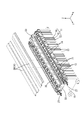
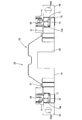
実施形態1を、図1ないし図14を参照しつつ説明する。図2に示すように、本実施形態に係る接続モジュール20は、複数の蓄電素子10を並べてなる蓄電素子群11に取り付けられて蓄電モジュールMを構成する。蓄電モジュールMは、電気自動車又はハイブリッド自動車等の車両(図示せず)に搭載されて、車両を駆動するための動力源として使用される。
<Embodiment 1>
The first embodiment will be described with reference to FIGS. 1 to 14. As shown in FIG. 2, the
以下の説明においては、図1における左上を左方とし、右下を右方およびX方向とする。また、図1における左下を前方およびY方向とし、右上を後方とする。また、図1における上方を上方およびZ方向とし、下方を下方とする。以下の説明において、複数の同一部材については、一の部材に符号を付し、他の部材については符号を省略することがある。 In the following description, the upper left in FIG. 1 is to the left, and the lower right is to the right and the X direction. Further, the lower left in FIG. 1 is the front and the Y direction, and the upper right is the rear. Further, the upper side in FIG. 1 is the upper side and the Z direction, and the lower side is the lower side. In the following description, for a plurality of the same members, one member may be designated by a reference numeral, and the other members may be omitted from the reference numerals.
(蓄電素子10)
本実施形態に係る蓄電素子10は二次電池である。蓄電素子10は略直方体形状をなしており、その内部には蓄電要素が収容されている。また、図2に示すように、その上面に左右方向(X方向)に並んで上方に突出する一対の円柱状の電極端子12が設けられている。電極端子12の一方は正極端子であり、他方は負極端子である。蓄電素子10は、隣り合う電極端子12が異なる極性となるように配置されている。
(Storage element 10)
The
隣り合う蓄電素子10の間にはセパレータ13が設けられており、セパレータ13には隣り合う蓄電素子10の電極端子12間を絶縁する絶縁リブ14が上方に突出して設けられている。複数の蓄電素子10は前後方向(Y方向)に並べられるとともに、その両端部に配された一対のエンドプレート15で挟持された状態で例えば結束バンド(図示せず)等により束ねられて、蓄電素子群11を構成している。
A separator 13 is provided between the adjacent
なお、エンドプレート15の上端には、後述する接続モジュール20と固定するための蓄電素子側固定部16が上方に突出して設けられている。蓄電素子側固定部16はその中央にボルト挿通孔16Aを有しており、板面を前後方向に向けた状態で、蓄電素子群11の上端の4つの角部付近に配されている。
At the upper end of the
(接続モジュール20)
接続モジュール20は、蓄電素子10の並び方向(前後方向、Y方向)に沿った細長い形状をなしており、蓄電素子群11の上面に取り付けられる。
(Connection module 20)
The
接続モジュール20は、図3に示すように、隣り合う蓄電素子10を電気的に接続する複数のバスバー21と、バスバー21にそれぞれ電気的に接続される複数の電圧検知線27(電線の一例)と、複数のバスバー21および電圧検知線27を保持する保持部材30(プロテクタの一例)と、を備える。保持部材30は、複数のバスバー21を蓄電素子10の並び方向(Y方向)に沿って保持する一対のバスバー保持部材31と、複数の電圧検知線27を収容する一対の電線収容部40と、一対のバスバー保持部材31の両端部同士を連結する一対の端部連結部材50と、複数のバスバー21をそれらの並び方向に沿って上方から一括に覆う一対のカバー28(図1参照)と、を備える。なお、電圧検知線27は一部だけを図示し、全体は省略する。
As shown in FIG. 3, the
(バスバー21)
バスバー21は、金属板材を所定形状にプレス加工してなる。金属板材としては、銅、銅合金、鉄、鉄合金、アルミニウム、アルミニウム合金等、必要に応じて任意の金属を適宜に選択できる。バスバー21は、隣り合う電極端子12間の寸法に応じた長さの本体部22を有している。バスバー21の本体部22には、電極端子12が挿通される一対の端子挿通孔23が貫通形成されている。
(Busbar 21)
The
バスバー21は、図3に示すように、長手方向に延びる一対の側縁部の一方側において、当該側縁部の中央部から外側に向けて延びて電圧検知線27と接続される接続部24を有している。また接続部24をはさんだ両隣に、同じく外側に向けて延びて後述するバスバー連結シート32に係合する一対の第1係合部25が設けられている。さらに他方側の側縁部の中央部には、外側に向けて延びて後述するバスバー保持レール37に係合する第2係合部26が設けられている。
As shown in FIG. 3, the
バスバー21は、端子挿通孔23内に電極端子12が貫通された状態で図示しないボルトが螺合されることにより、電極端子12と電気的に接続される。
The
(バスバー保持部材31)
バスバー保持部材31は、複数のバスバー21を一列に並んだ状態に連結する一対のバスバー連結シート32と、バスバー連結シート32により連結された状態の複数のバスバー21を蓄電素子10の並び方向に沿うように一直線状に保持するバスバー保持レール37とからなる。バスバー連結シート32は可撓性を有しており、バスバー保持レール37は剛性を有している。
(Busbar holding member 31)
The bus
バスバー連結シート32は、例えばポリエチレンテレフタレート(PET)、ポリスチレン(PS)、ポリカーボネイト(PC)、ポリアミド(PA)等の絶縁材料からなり、全体として細長い帯状とされている。バスバー連結シート32は、前後方向(Y方向)の寸法がバスバー21とほぼ同等の長さ寸法とされた略E字形状の複数の板状部33間がU字形状の繋ぎ部34で連結された形態をなしており、繋ぎ部34が撓むことにより公差吸収可能とされている。
The bus
各板状部33には、上述したバスバー21の第1係合部25と係合するための第1被係合部35が設けられている。すなわち複数のバスバー21は、第1係合部25が第1被係合部35と係合することにより、バスバー連結シート32によって一列に並べられた状態で連結されるとともに、保持されるようになっている。
Each plate-shaped
また、バスバー連結シート32の延び方向(前後方向、Y方向)における両端部には、後述する端部連結部材50の嵌合リブ67を嵌め入れるシート側切欠部36が形成されている。
Further, seat-
一方、バスバー保持レール37は、バスバー連結シート32と同様の絶縁材料からなり、上述したバスバー21の第2係合部26と係合可能な長尺なレール状の部材である。バスバー21の第2係合部26は、バスバー保持レール37に沿って移動可能な状態で係合する。
On the other hand, the bus
バスバー保持レール37の延び方向(前後方向、Y方向)における両端部付近には、後述する端部連結部材50の抜止リブ56が嵌め入れられるレール側切欠部38が設けられている。
Rail-
複数の各バスバー21は、一方側の側縁部において第1係合部25がバスバー連結シート32の第1被係合部35と係合することにより、概ね等間隔で並んだ状態で連結され、他方側の側縁部において第2係合部26がバスバー保持レール37に係合することにより、一直線状に並んだ状態に保持されるようになっている。
The plurality of
(電線収容部40)
保持部材30は、バスバー21と接続された複数の電圧検知線27が収容される電線収容部40を備える。本実施形態の電線収容部40は、図3に示すように、電圧検知線27をバスバー保持部材31の延び方向(前後方向、Y方向)沿って取り囲むように覆う保護チューブ41と、後述する端部連結部材50に設けられるとともに保護チューブ41の両端部に配される導出部60とから構成されている。
(Electric wire accommodating part 40)
The holding
保護チューブ41は、例えばポリ塩化ビニル(PVC)、オレフィン系エラストマー(TPO)、スチレン系エラストマー(SVC)、酢酸ビニル(EVA)等の軟質樹脂やゴム等からなる、断面略矩形の細長い管状の部材である。保護チューブ41のうち下方に配された底壁には、その延び方向に沿って切り込みが形成されている。また、上方に配された天井壁42の外面には、その延び方向に沿って切欠部43が設けられている。この切欠部43を屈曲させることにより、保護チューブ41は切り込みを開くことが可能とされている。
The
一方、保護チューブ41の端部に連なる導出部60は、上述したように後述する端部連結部材50に形成されており、比較的柔軟な保護チューブ41から導出された複数の電圧検知線27を保持部材30の外側に案内する部分である。導出部60については、後程さらに詳細に説明する。
On the other hand, the lead-out
(端部連結部材50)
端部連結部材50は、上述した一対のバスバー保持部材31(一対のバスバー連結シート32および一対のバスバー保持レール37)の端部同士を連結する部材である。端部連結部材50は、全体として、門型をなす架橋部52の両側が左右方向に張り出した細長い形態をなしている。また端部連結部材50は、架橋部52を中心として左右対象に形成されている。以下、図3の左側に配された端部連結部材50を基準とし、図3の左下を前方として説明する。
(End connecting member 50)
The
例えば図11および図12に示すように、架橋部52の左右両側には、内側から順に、各一対の第1ロック部53、レール保持溝54、第2ロック部58、導出部60が設けられている。第1ロック部53および第2ロック部58は、後述する第1ロック片82および第2ロック片84を受け入れ可能な上下方向に延びる孔部53A,58Aを有するとともに、各ロック片82,84に設けられた係止爪82A.84Aを係止可能な被係止部53B,58Bを備えている(図9参照)。
For example, as shown in FIGS. 11 and 12, each pair of a
レール保持溝54は、バスバー保持レール37の端部を嵌め入れる溝状とされており、その前端(保持部材30の前端)は前壁55により塞がれている。また、レール保持溝54の後端付近には、一対の溝壁から内側に向けて突出する抜止リブ56が設けられており(図14参照)、バスバー保持レール37のレール側切欠部38内に嵌め入れられるようになっている。
The
また、一対の溝壁の前後方向(Y方向)における中心付近には、内側かつ下方に向けて斜めに伸びるレール係止片57が、溝壁の一部を切り起こすことにより形成されている(図9参照)。
Further, near the center of the pair of groove walls in the front-rear direction (Y direction), a
第2ロック部58のうち左右方向の外側に配された側壁61には、側方(X方向)かつ上下方向(Z方向)に延びる一対の離隔壁62が設けられている。また、離隔壁62よりも外側であって、側壁61から側方に所定距離介した位置には、前後方向(X方向)かつ上下方向(Z方向)に延びる第1案内壁63が設けられている。側壁61と、離隔壁62と、第1案内壁63とは、下端縁が底壁64により連なっている。
A pair of
そして離隔壁62のうち左右方向(X方向)における外側の端縁部と、底壁64と、第1案内壁63とによって囲まれた正面視略U字形状の領域が、保護チューブ41から導出された複数の電圧検知線27を保持部材30の外側(図11の前方)に案内する、上述した導出部60(電線収容部40の一部)とされている。導出部60の前端(電線収容部40の端部)は、電圧検知線27が導出可能な導出開口66である。また導出部60は、図11に示すように、上方が開放されている(以下、開放された部分を電線収容部40の開口部65とする)。
Then, a substantially U-shaped front view region surrounded by the outer edge portion of the
導出開口66の開口縁部には、底壁64から可撓性を有する第1ヒンジ部70を介して前方に向けて(電圧検知線27の延び方向(Y方向)に沿って)突出して複数の電圧検知線27を取り付け可能な電線取付部71が設けられている。
A plurality of opening edges of the lead-out
電線取付部71は、導出開口66から引き出された電圧検知線27を載置する平板状の載置部72を有しており、当該載置部72には、その先端寄りの位置において左右方向(第1ヒンジ部70の延び方向)に配されて電圧検知線27を電線取付部71に対して結束するための結束部73が設けられている。
The electric
より詳細には、載置部72は基部側(第1ヒンジ部70側)の第1領域72Aと先端側の第2領域72Bに分割されており、これらの領域72A,72Bの互いに対向する側縁部には、各領域72A,72Bに直交する方向、かつ、図11の下方に延びる一対の第1立壁74Aおよび第2立壁74Bが形成されている。すなわち、第1立壁74Aおよび第2立壁74Bは、載置部72のうち電圧検知線27が載置される面の反対の面(導出部60の外面に連なる面)から立ち上がるように形成されている。
More specifically, the mounting
対向配置された第1立壁74Aおよび第2立壁74Bの間は、連結部75により連結されている。連結部75は、各立壁74A,74Bの載置部72からの立ち上がり高さの中央付近において載置部72と平行に配されており、その左右方向の寸法は載置部72の左右方向の寸法よりやや小さく設定されている。すなわち、連結部75は平面視および側面視の双方が略H字形状となるように第1立壁74Aおよび第2立壁74Bを連結している(図12参照)。
The
このように電線取付部71の一部が凹んだ結束部73とされることにより、結束部材88を、電線取付部71及び電圧検知線27の外周に巻回するとともに位置決めすることが容易になっている。
By forming the binding
第1立壁74Aおよび第2立壁74Bの載置部72からの立ち上がり高さは同等とされるとともに、電線取付部71が第1ヒンジ部70により折り返された状態(図13)において、第1立壁74Aおよび第2立壁74Bは離隔壁62の高さよりやや低くなるように設定されている(図9および図10参照)。なお、第1立壁74Aおよび第2立壁74Bの互いに対向する面の反対側の面には、載置部72と直交する方向に延びる補強リブ76が設けられている。
The rising heights of the first standing
また、導出部60の底壁64には、電線取付部71が第1ヒンジ部70により折り返された状態において上述した連結部75に対応する位置に、連結部75の下方の凹状とされた部分に嵌る一対の嵌合リブ67が設けられている(図10および図11参照)。
Further, on the
また、第1案内壁63の前端縁には、側方(左右方向の外側)に張り出して上述した蓄電素子10の蓄電素子側固定部16に重ねられる板状のモジュール側固定部68が設けられており、その中心にボルトを挿通するためのボルト挿通孔68Aが設けられている。これらの固定部16,68が互いに重ね合わされ、ボルト締結されることにより、接続モジュール20が蓄電素子群11に対して固定される。
Further, a plate-shaped module-
さらに、第1案内壁63の後方側の領域には側方(左右方向の外側)に向けて延びる延出部79が設けられており、その外側の上端縁に、前後方向に延びる第2ヒンジ部80を介して塞ぎ部81が設けられている。塞ぎ部81は、第2ヒンジ部80によって折り返された状態において、上述した導出部60、第2ロック部58、レール保持溝54、第1ロック部53を一括に覆う形状に形成されている。
Further, an extending
なお、この塞ぎ部81に対し、上述した架橋部52から延出部79までの部分を本体部51とよぶこととする。本体部51と塞ぎ部81とは、第2ヒンジ部80を介して連結されている。
The portion from the bridged
図9および図11に示すように、塞ぎ部81には、本体部51の第1ロック部53、レール保持溝54、第2ロック部58に対応する位置に、それぞれ、第1ロック片82、当接リブ83、第2ロック片84が設けられている。また塞ぎ部81には、導出部60のうち一対の離隔壁62の先端付近に位置するように、第2案内壁85が設けられている。塞ぎ部81が閉じられた状態において、第2案内壁85は第1案内壁63と平行に配され、第1案内壁63との間で保護チューブ41から導出された電圧検知線27を電線取付部71側に確実に案内する。
As shown in FIGS. 9 and 11, in the closing
なお、第2案内壁85のうち上述した嵌合リブ67に対応する領域には、嵌合リブ67を逃がす逃がし部86が切り欠かれて形成されている。
In the region of the
また、塞ぎ部81のうち、当該塞ぎ部81が閉じられた状態において、第2案内壁85より外側に配される領域であって、導出部60に対応する領域は、規制部87とされている。規制部87は、導出部60に電圧検知線27が配索された場合には、電圧検知線27が上方に抜けるのを規制する。また、導出部60に上述した第1立壁74Aおよび第2立壁74Bが配置された場合(電線取付部71が折り返された場合)には、これらの立壁74A,74Bに当接また近接して立壁74A,74Bの上方への移動を規制する。すなわち、電線取付部71の折り返し状態を保持する機能を有する(保持手段の一例)。
Further, among the closing
さらに、塞ぎ部81のうち、当該塞ぎ部81が閉じられた状態において上面となる面には、例えば電力線等の電線を配索するための配索溝89(第2電線収容部の一例)が形成されている。
Further, on the surface of the closing
本実施形態の接続モジュール20は上記構成であって、次に、組み立て方法について説明する。なお、組み立て方法は以下の方法および手順に限定されるものではない。
The
まず、予め電圧検知線27と接続したバスバー21の第1係合部25をバスバー連結シート32の第1被係合部35に係合させるとともに、第2係合部26をバスバー保持レール37に係合させることにより、バスバー21をバスバー保持部材31に保持した状態とする。また、各バスバー21に接続された複数の電圧検知線27をバスバー21の並び方向(前後方向)に配索し、保護チューブ41の切り込みから内部に収容する。複数の電圧検知線27は、前方(Y方向)に向けて配索する。
First, the first engaging
次に、保護チューブ41をバスバー連結シート32の板状部33上に載置し、保護チューブ41およびバスバー連結シート32を結束部材45により一体とする。保護チューブ41はバスバー連結シート32よりも短い寸法とされており、両者が一体とされた状態において、バスバー連結シート32のシート側切欠部36は保護チューブ41の端部から前後方向に突出した位置に配されている。
Next, the
次に、一対のバスバー保持部材31の両端部を一対の端部連結部材50により連結する。具体的には、バスバー保持部材31のうち、バスバー保持レール37の端部を端部連結部材50のレール保持溝54に嵌め入れるとともに、バスバー連結シート32の端部を端部連結部材50の導出部60の底壁64に載置する。バスバー保持レール37は、レール側切欠部38内に抜止リブ56が嵌め入れられることにより前後方向の抜け止めが図られるとともに、レール係止片57により上方への抜け止めが図られる。また、バスバー連結シート32は、シート側切欠部36内に端部連結部材50の嵌合リブ67が嵌め入れられることにより、前後方向の抜け止めが図られる。
Next, both ends of the pair of bus
この状態において、保護チューブ41の両端部は、導出部60の底壁64の端部付近に載置されており、保護チューブ41から導出された電圧検知線27は、導出部60内に配索されるとともに導出開口66から前方に導出されている。
In this state, both ends of the
次に、組み立てられた保持部材30のうち、電圧検知線27が導出されている端部側(前端側)において塞ぎ部81を第2ヒンジ部80により折り返し、塞ぎ部81を閉じた状態とする。すると、塞ぎ部81の第1ロック片82および第2ロック片84が本体部51の第1ロック部53および第2ロック部58の孔部53A,58A内に嵌め入れられるとともに、各ロック片82,84の先端に設けられた係止爪82A,84Aが、各ロック部53,58に設けられた被係止部53B,58Bに係止する。これにより、塞ぎ部81は本体部51に対して固定される(図9参照)。
Next, of the assembled holding
この状態において、塞ぎ部81の当接リブ83は、バスバー保持レール37の上面に当接している。また、塞ぎ部81の第2案内壁85は、本体部51のうち、導出部60に配索された複数の電圧検知線27を第1案内壁63との間にはさむように、第1案内壁63と対向して配されている。これにより、導出部60内の電圧検知線27は確実に導出開口66側に案内される。
In this state, the
次に、導出開口66から導出された複数の電圧検知線27を、電線取付部71に取り付ける。具体的には、電線取付部71を導出部60からまっすぐに伸ばし(第1ヒンジ部70を伸ばした状態とし)、載置部72上に複数の電圧検知線27を載置する。そして、結束部73において結束部材88を巻回することにより、複数の電圧検知線27を電線取付部71に対して固定する。なお、結束部材45,88は、合成樹脂、金属等、必要に応じて任意の材料から構成されており、細長い帯状に形成されている。
Next, a plurality of
以上により、電圧検知線27が導出される側の端部(前方側の端部)の組み立てが完成する。なお、この組立状態において、第1ヒンジ部70は任意の角度に屈曲可能である。
As described above, the assembly of the end portion (front end portion) on the side from which the
一方、電圧検知線27が導出されない側の端部(後方側の端部)においては、上記と同様に、一対のバスバー保持部材31の端部を端部連結部材50により連結した後、単独の状態の電線取付部71を第1ヒンジ部70により折り返し、導出部60に重ね合わせる。この状態においては、第1立壁74Aおよび第2立壁74Bが導出部60内において垂直に立ち上がった状態とされている。
On the other hand, at the end on the side where the
次に、上記と同様に、塞ぎ部81を第2ヒンジ部80により折り返し、閉じた状態とする。塞ぎ部81は、第1ロック片82および第2ロック片84が、本体部51の第1ロック部53および第2ロック部58とロックすることにより、本体部51に対して固定される。
Next, in the same manner as described above, the closing
この状態において、塞ぎ部81の規制部87は、第1立壁74Aおよび第2立壁74Bの先端との間に僅かな隙間を介した状態で上方に配置されている(図9および図10参照)。すなわち、第1立壁74Aおよび第2立壁74Bが上方へ移動しようとすると、規制部87に当接して互いに干渉し合うため、上方への移動が規制されている。換言すると、第1立壁74Aおよび第2立壁74Bを備える電線取付部71は、折り返し状態が塞ぎ部81(規制部87)により保持されている。
In this state, the regulating
またこの状態において、第1立壁74Aおよび第2立壁74Bは、導出開口66を塞いでいる。これにより、導出開口66内に誤って指が入ったり、異物が進入することが抑制される。
Further, in this state, the first standing
次に、本実施形態の接続モジュール20の作用効果について説明する。
Next, the operation and effect of the
本実施形態の接続モジュール20は、隣り合う蓄電素子10を電気的に接続する複数のバスバー21と、複数のバスバー21に接続された複数の電圧検知線27と、複数の電圧検知線27を収容する電線収容部40を有する保持部材30と、を備え、電線収容部40は電圧検知線27が導出可能な導出開口66を有し、当該導出開口66の開口縁部に、可撓性を有する第1ヒンジ部70を介して複数の電圧検知線27を取り付け可能な電線取付部71が突出して設けられており、電線取付部71は、第1ヒンジ部70により電線収容部40側(導出開口66側)に屈曲された状態でその屈曲状態が電線取付部71の立壁74A,74Bおよび塞ぎ部81の規制部87(保持手段の一例)により保持可能とされている。
The
このような接続モジュール20によれば、複数の電圧検知線27が導出されている導出開口66側の電線取付部71には、導出された複数の電圧検知線27が取り付けられる。複数の電圧検知線27が取り付けられた電線取付部71は、電圧検知線27の接続先(ECU等)の設置位置に応じて、第1ヒンジ部70を回動軸として任意の角度に屈曲させてもよいし、屈曲させなくてもよい。
According to such a
一方、電圧検知線27が導出されていない導出開口66側の電線取付部71は、第1ヒンジ部70により電線収容部40側に折り返し、その折り返し状態を保持手段により保持させることができる。従って、電圧検知線27が取り付けられていない電線取付部71が外部に突出して邪魔になることが回避される。また、このように折り返し状態で保持された電線取付部71は、車両の振動の影響を受け難い。なお、折り返し状態とは、屈曲状態の一形態である。
On the other hand, the electric
また本実施形態の接続モジュール20においては、電線取付部71は屈曲状態(折り返し状態)で導出開口66を塞ぐように配される。具体的には、電線取付部71は、当該電線取付部71に直交する方向かつ第1ヒンジ部70の延び方向に延びる第1立壁74Aおよび第2立壁74Bを外面側(電圧検知線27が取り付けられる面の反対側の面)に有しており、電線取付部71が第1ヒンジ部70により電線収容部40側に折り返された状態で、第1立壁74Aおよび第2立壁74Bが導出開口66を塞ぐように配される。
Further, in the
電線が導出されない導出開口にも電線取付部を有する接続モジュールにおいては、電線が導出されない導出開口が開放されたままの状態とされるという問題がある。このような問題に対し、本実施形態によれば、開放状態の導出開口66は屈曲された電線取付部71(立壁74)により塞がれた状態とされるから、導出開口66から誤って指が入ったり、異物が進入することを抑制することができる。
In a connection module having a wire mounting portion even in a lead-out opening from which the electric wire is not led out, there is a problem that the lead-out opening from which the electric wire is not led out is left open. In response to such a problem, according to the present embodiment, the lead-out
本実施形態において、電線収容部40の導出部60(導出開口66に隣接する部分)には電圧検知線27の延び方向に開放された開口部65が設けられており、端部連結部材50(保持部材30)に開口部65を塞ぐ塞ぎ部81が第2ヒンジ部80を介して一体的に設けられている。
In the present embodiment, the lead-out portion 60 (the portion adjacent to the lead-out opening 66) of the electric
このような構成によれば、端部連結部材50に設けられた電線収容部40(導出部60)の開口部65は、第2ヒンジ部80を回動軸として塞ぎ部81を回動させることにより塞ぐことができる。
According to such a configuration, the
また、本実施形態の電線取付部71は、当該電線取付部71に直交する方向かつ第1ヒンジ部70の延び方向に延びる第1立壁74Aおよび第2立壁74Bを外面側(電圧検知線27が取り付けられる面の反対側の面)に有しており、第1ヒンジ部70により電線収容部40側に折り返された状態の電線取付部71は、開口部65を塞いだ状態の塞ぎ部81が第1立壁74Aおよび第2立壁74Bに干渉することにより、折り返し状態に保持されるようになっている。
Further, the electric
このような構成により、電線取付部71は、第1立壁74Aおよび第2立壁74Bと塞ぎ部81とからなる保持手段によって折り返し状態が保持されるから、新たな保持手段を設ける必要がない。
With such a configuration, the electric
また、開口部65が塞ぎ部81により塞がれた状態において、塞ぎ部81の外面に電線を収容可能な第2電線収容部40が設けられているから、接続モジュール20に、例えば電源用電線等、別の電線を配索することができる。
Further, since the second electric
また、本実施形態の保持部材30は、複数のバスバー21を蓄電素子10の並び方向に沿って保持する一対のバスバー保持部材31と、一対のバスバー保持部材31の端部同士を連結する一対の端部連結部材50とを有しており、電線収容部40の一部(導出部60)は端部連結部材50に設けられており、電線取付部71は端部連結部材50に第1ヒンジ部70を介して設けられている。
Further, the holding
このような構成によれば、本実施形態のように接続モジュール20を一対の端部連結部材50を用いて構成した場合に、電圧検知線27が導出される側と、電圧検知線27が導出されない側の端部連結部材50を共通化することができる。すなわち、電圧検知線27が導出されない側の端部連結部材50に、電圧検知線27が導出される側において必要な電線取付部71が設けられていても、電線取付部71は電線収容部40側に屈曲され、その屈曲状態が保持手段により保持されるようになっているから、電線取付部71が邪魔になることがなく、また、車両の振動に伴って振動し難い。従って、共通の端部連結部材50を使用することが可能であり、製造コストを抑えることができる。
According to such a configuration, when the
<実施形態2>
次に、実施形態2を図15ないし図22によって説明する。なお、以下においては、端部連結部材120について実施形態1と異なる構成についてのみ説明するものとし、実施形態1と同様の構成には実施形態1の各構成に付した符号の数字に70を加えた数字の符号を用いるものとする。端部連結部材120以外の部材については、実施形態1と同じ符号を用いる。また、図17の左下を前方として説明する。
<Embodiment 2>
Next, the second embodiment will be described with reference to FIGS. 15 to 22. In the following, only the configuration of the
本実施形態の接続モジュール90は、端部連結部材120の電線取付部141の形態と、当該電線取付部141の保持構造が上記実施形態1と相違している。
The
本実施形態の端部連結部材120は、図17に示すように、導出部130の導出開口136の開口縁部には、底壁134から可撓性を有する第1ヒンジ部140を介して前方に向けて(電圧検知線27の延び方向(Y方向)に沿って)突出して、複数の電圧検知線27を取り付け可能な電線取付部141が設けられている。
As shown in FIG. 17, the
本実施形態の電線取付部141の一対の側縁部の先端寄りの位置には、電圧検知線27を電線取付部141に対して結束するための結束部材158を嵌め入れるべく凹状に切り欠かれた一対の切欠凹部145が形成されている。
At a position near the tip of the pair of side edge portions of the electric
またこれら一対の切欠凹部145のうち、左右方向における外側に配された切欠凹部145Aは、電線取付部141の内側(中心)に向けて電圧検知線27の載置面側が凹状に窪むように延びており、導出部130の底壁134に設けられた篏合リブ137を嵌め入れる篏合凹部143が形成されている。他方側の切欠凹部145Bは、この切欠凹部145B内に篏合リブ137を受け入れ可能である(図18参照)。
Further, of these pair of notch recesses 145, the notch recesses 145A arranged on the outside in the left-right direction extend toward the inside (center) of the electric
さらに、一対の切欠凹部145より基端側(第1ヒンジ部140側)には、外面(電圧検知線27が配される面の反対側の面)から凹状に窪む部分が設けられており、後述する一対の係止部139,161に係止される被係止部147,148とされている(図19参照)。以下、左右方向における外側に配された被係止部を第1被係止部147、内側に配された被係止部を第2被係止部148とする。
Further, on the base end side (
導出部130には、電線取付部141が第1ヒンジ部140により折り返された際に、上述した第1被係止部147に上方から係止して電線取付部141を折り返し状態に保持するする第1係止部139(保持手段の一例)が、第1案内壁133から突出して設けられている(図17および図18参照)。
When the electric
また、塞ぎ部151に設けられた第2案内壁155の前端縁には、塞ぎ部151が第2ヒンジ部150により折り返されて開口部135を塞いだ状態において、導出部130の内側に張り出して上述した第2被係止部148に上方から係止して電線取付部141を折り返し状態に保持する第2係止部161(保持手段の一例)が、第2案内壁155から突出して設けられている(図17および図18参照)。
Further, at the front end edge of the
このような本実施形態の接続モジュール90によっても、複数の電圧検知線27が導出されている導出開口136側の電線取付部141には、導出された複数の電圧検知線27が取り付けられる一方、電圧検知線27が導出されない導出開口136側の電線取付部141は、第1ヒンジ部140により電線収容部110(導出部130)側に折り返し、その折り返し状態を保持手段(係止部139,161および被係止部147,148の係止構造)により保持させることができる。従って、電圧検知線27が取り付けられていない電線取付部141が外部に突出して邪魔になることが回避される。また、このように折り返し状態で保持された電線取付部141は、車両の振動の影響を受け難い。
Even with the
<他の実施形態>
本明細書に開示される技術は上記記述及び図面によって説明した実施形態に限定されるものではなく、例えば次のような実施形態も技術的範囲に含まれる。
<Other embodiments>
The techniques disclosed herein are not limited to the embodiments described above and in the drawings, and for example, the following embodiments are also included in the technical scope.
(1)上記実施形態においては、電線収容部40,110を保護チューブ41と端部連結部材50,120の導出部60,130とで構成したが、保護チューブは省略し、導出部だけで電線収容部を構成してもよい。
(1) In the above embodiment, the electric wire
(2)上記実施形態1では、電線取付部71を第1ヒンジ部70により折り返し、立壁74により導出開口66を塞ぐ構成を示したが、例えば、第1ヒンジ部をL字形状に屈曲させて載置部で導出開口を塞ぐ構成としてもよい。
(2) In the first embodiment, the electric
(3)上記実施形態においては、1つの接続モジュール20,90に4つの電線取付部71,141が設けられる構成としたが、これに限らず、1つの接続モジュールに電線取付部がいくつ形成されていてもよい。また、電線取付部は必要に応じて任意の位置に形成することができる。
(3) In the above embodiment, one
(4)上記実施形態においては、複数の電線は蓄電素子10の電圧を検知する電圧検知線27とされた例を示したが、これに限らず、複数の電線は、蓄電素子の温度を検知するものとしてもよい。また、複数の電線は、蓄電素子に接続されていなくてもよく、例えば、蓄電モジュールとは異なる機器に接続された複数の電線が、接続モジュールに配索されているものであってもよい。
(4) In the above embodiment, an example is shown in which the plurality of electric wires are
(5)上記実施形態では、保持部材30を、一対のバスバー保持部材31と、これら一対のバスバー保持部材31の端部同士を連結する端部連結部材50,120とを組み付けることにより構成したが、保持部材は一体型としてもよい。
(5) In the above embodiment, the holding
(6)上記実施形態では、保持部材30(端部連結部材50,120)に設けた塞ぎ部81,151により、電線取付部71,141を屈曲状態に保持する保持手段を構成したが、保持手段は上記実施形態に限るものではなく、他の構成とすることができる。
(6) In the above embodiment, the holding means for holding the electric
10:蓄電素子
11:蓄電素子群
20,90:接続モジュール
21:バスバー
27:電圧検知線(電線)
30:保持部材(プロテクタ)
31:バスバー保持部材
32:バスバー連結シート
37:バスバー保持レール
40,110:電線収容部
41:保護チューブ
50,120:端部連結部材
51:本体部
60,130:導出部
65,135:開口部
66,136:導出開口
70,140:第1ヒンジ部(ヒンジ部)
71,141:電線取付部
74A:第1立壁(保持手段)
74B:第2立壁(保持手段)
80,150:第2ヒンジ部
81,151:塞ぎ部(保持手段)
87:規制部(保持手段)
89:配索溝(第2電線収容部)
139:第1係止部(保持手段)
147:第1被係止部(保持手段)
148:第2被係止部(保持手段)
161:第2係止部(保持手段)
10: Power storage element 11: Power
30: Holding member (protector)
31: Bus bar holding member 32: Bus bar connecting sheet 37: Bus
71, 141:
74B: Second standing wall (holding means)
80, 150:
87: Regulatory Department (holding means)
89: Chordee groove (second wire accommodating part)
139: First locking portion (holding means)
147: First locked portion (holding means)
148: Second locked portion (holding means)
161: Second locking portion (holding means)
Claims (8)
前記電線取付部は、前記ヒンジ部により前記導出開口側に屈曲された状態でその屈曲状態が保持手段により保持可能とされるとともに、前記屈曲状態で前記導出開口を塞ぐように配されるプロテクタ。 A protector having a plurality of lead-out openings from which an electric wire can be led out, and an electric wire attachment portion to which the electric wire can be attached is provided so as to project from an opening edge portion of the lead-out opening via a flexible hinge portion. Ori,
The electric wire mounting portion, the hinge portion the bent state in a state of being bent in the derived opening side is capable of holding by the holding means by Rutotomoni, protector disposed so as to block the outlet opening in the bent state.
隣り合う前記蓄電素子を電気的に接続する複数のバスバーと、
前記複数のバスバーに接続された複数の電線と、
前記複数の電線を収容する電線収容部を有する保持部材と、を備え、
前記電線収容部は前記電線が導出可能な導出開口を有し、当該導出開口の開口縁部に、可撓性を有するヒンジ部を介して前記複数の電線を取り付け可能な電線取付部が突出して設けられており、
前記電線取付部は、前記ヒンジ部により前記電線収容部側に屈曲された状態でその屈曲状態が保持手段により保持可能とされるとともに、前記屈曲状態で前記導出開口を塞ぐように配される接続モジュール。 It is a connection module that can be attached to a group of power storage elements in which a plurality of power storage elements are arranged side by side.
A plurality of bus bars that electrically connect the adjacent power storage elements,
With a plurality of electric wires connected to the plurality of bus bars,
A holding member having an electric wire accommodating portion for accommodating the plurality of electric wires, and
The electric wire accommodating portion has a lead-out opening from which the electric wire can be led out, and an electric wire attachment portion to which the plurality of electric wires can be attached protrudes from the opening edge of the lead-out opening via a flexible hinge portion. It is provided,
The electric wire mounting portion is connected to the bent state by the hinge portion in a state of being bent in the wire receiving portion side Rutotomoni is capable of holding by the holding means, it is arranged so as to close the outlet opening in the bent state module.
前記電線取付部が前記ヒンジ部により前記電線収容部側に折り返された状態で前記立壁が前記導出開口を塞ぐように配される請求項2に記載の接続モジュール。 The electric wire mounting portion has a vertical wall extending in a direction orthogonal to the electric wire mounting portion and in an extending direction of the hinge portion on the outer surface side.
The connection module according to claim 2 , wherein the vertical wall is arranged so as to close the lead-out opening in a state where the electric wire mounting portion is folded back toward the electric wire accommodating portion by the hinge portion.
前記保持部材に前記開口部を塞ぐ塞ぎ部が第2ヒンジ部を介して一体的に設けられている請求項2または請求項3に記載の接続モジュール。 The electric wire accommodating portion is provided with an opening in which at least a portion adjacent to the lead-out opening is opened in the extending direction of the electric wire.
The connection module according to claim 2 or 3 , wherein a closing portion for closing the opening is integrally provided in the holding member via a second hinge portion.
前記ヒンジ部により前記電線収容部側に折り返された状態の前記電線取付部は、前記開口部を塞いだ状態の前記塞ぎ部が前記立壁に干渉することにより、折り返し状態に保持可能とされている請求項4に記載の接続モジュール。 The electric wire mounting portion has a vertical wall extending in a direction orthogonal to the electric wire mounting portion and in an extending direction of the hinge portion on the outer surface side.
The electric wire mounting portion in a state of being folded back toward the electric wire accommodating portion by the hinge portion can be held in the folded state by the closing portion in a state of closing the opening interfering with the standing wall. The connection module according to claim 4.
前記電線収容部の少なくとも一部は前記端部連結部材に設けられており、
前記電線取付部は前記端部連結部材に前記ヒンジ部を介して設けられている請求項2ないし請求項6のいずれか一項に記載の接続モジュール。 The holding member includes a pair of bus bar holding members that hold the plurality of bus bars along the arrangement direction of the power storage elements, and a pair of end connecting members that connect the ends of the pair of bus bar holding members. And
At least a part of the electric wire accommodating portion is provided on the end connecting member.
The connection module according to any one of claims 2 to 6 , wherein the electric wire mounting portion is provided on the end connecting member via the hinge portion.
前記複数のバスバーに接続された複数の電線と、
前記複数のバスバーを保持する一対のバスバー保持部材および前記複数の電線を収容する電線収容部を有する保持部材と、を備える接続モジュールの、前記一対のバスバー保持部材の端部同士を連結する一対の端部連結部材であって、
前記電線収容部の少なくとも一部を構成する導出部を備え、
前記導出部は前記電線が導出可能な導出開口を有し、当該導出開口の開口縁部に、可撓性を有するヒンジ部を介して前記複数の電線を取り付け可能な電線取付部が突出して設けられており、
前記電線取付部が前記ヒンジ部により前記導出部側に屈曲された状態でその屈曲状態を保持可能な保持手段を備えている、接続モジュールの端部連結部材。 A plurality of bus bars that electrically connect the adjacent power storage elements of a group of power storage elements in which a plurality of power storage elements are arranged, and
With a plurality of electric wires connected to the plurality of bus bars,
A pair of connecting modules of a connection module including a pair of bus bar holding members for holding the plurality of bus bars and a holding member having an electric wire accommodating portion for accommodating the plurality of electric wires, and connecting the ends of the pair of bus bar holding members. It is an end connecting member
It is provided with a lead-out portion that forms at least a part of the electric wire accommodating portion.
The lead-out portion has a lead-out opening from which the electric wire can be led out, and an electric wire attachment portion to which the plurality of electric wires can be attached protrudes from the opening edge portion of the lead-out opening via a flexible hinge portion. Has been
An end connecting member of a connection module, comprising a holding means capable of holding the bent state in a state where the electric wire mounting portion is bent toward the lead-out portion by the hinge portion.
Priority Applications (3)
| Application Number | Priority Date | Filing Date | Title |
|---|---|---|---|
| JP2018061470A JP6928574B2 (en) | 2018-03-28 | 2018-03-28 | Protectors, connecting modules, and end connecting members for connecting modules |
| CN201910193674.0A CN110323397B (en) | 2018-03-28 | 2019-03-14 | Protector, connection module, and end connection member of connection module |
| US16/360,473 US11404749B2 (en) | 2018-03-28 | 2019-03-21 | Protector, connection module, and end linking member for connection module |
Applications Claiming Priority (1)
| Application Number | Priority Date | Filing Date | Title |
|---|---|---|---|
| JP2018061470A JP6928574B2 (en) | 2018-03-28 | 2018-03-28 | Protectors, connecting modules, and end connecting members for connecting modules |
Publications (2)
| Publication Number | Publication Date |
|---|---|
| JP2019176599A JP2019176599A (en) | 2019-10-10 |
| JP6928574B2 true JP6928574B2 (en) | 2021-09-01 |
Family
ID=68055550
Family Applications (1)
| Application Number | Title | Priority Date | Filing Date |
|---|---|---|---|
| JP2018061470A Active JP6928574B2 (en) | 2018-03-28 | 2018-03-28 | Protectors, connecting modules, and end connecting members for connecting modules |
Country Status (3)
| Country | Link |
|---|---|
| US (1) | US11404749B2 (en) |
| JP (1) | JP6928574B2 (en) |
| CN (1) | CN110323397B (en) |
Families Citing this family (3)
| Publication number | Priority date | Publication date | Assignee | Title |
|---|---|---|---|---|
| US11916242B2 (en) * | 2019-10-11 | 2024-02-27 | Briggs & Stratton, Llc | Commercial flexible battery pack with secondary output control |
| JP7157039B2 (en) * | 2019-11-29 | 2022-10-19 | 矢崎総業株式会社 | busbar module |
| CN113540663B (en) * | 2020-03-31 | 2022-11-11 | 比亚迪股份有限公司 | Battery module and vehicle |
Family Cites Families (12)
| Publication number | Priority date | Publication date | Assignee | Title |
|---|---|---|---|---|
| JP5345913B2 (en) * | 2009-09-14 | 2013-11-20 | 矢崎総業株式会社 | Power supply cover structure |
| JP2011233333A (en) * | 2010-04-27 | 2011-11-17 | Yazaki Corp | Wire-cabling member and battery connecting body |
| JP5741230B2 (en) * | 2011-06-09 | 2015-07-01 | 株式会社オートネットワーク技術研究所 | Battery wiring module |
| US8859909B2 (en) * | 2012-03-02 | 2014-10-14 | Amphenol Thermometrics, Inc. | Flexible cable for low profile electrical device |
| KR101440890B1 (en) * | 2013-01-29 | 2014-09-18 | 삼성에스디아이 주식회사 | Battery Pack |
| JP6162470B2 (en) | 2013-04-26 | 2017-07-12 | 矢崎総業株式会社 | Bus bar module |
| JP6118178B2 (en) * | 2013-05-30 | 2017-04-19 | 矢崎総業株式会社 | Bus bar module and power supply |
| JP6202338B2 (en) * | 2014-04-25 | 2017-09-27 | 株式会社オートネットワーク技術研究所 | Wiring module, wiring module intermediate, and wiring module manufacturing method |
| JP6274051B2 (en) * | 2014-09-01 | 2018-02-07 | 株式会社オートネットワーク技術研究所 | Wiring module and wiring module manufacturing method |
| JP6602793B2 (en) * | 2015-01-30 | 2019-11-06 | 三洋電機株式会社 | Battery pack |
| KR102320437B1 (en) * | 2015-03-03 | 2021-11-01 | 삼성에스디아이 주식회사 | Flexible rechargeable battery |
| JP6622163B2 (en) * | 2016-09-13 | 2019-12-18 | 矢崎総業株式会社 | Battery module voltage detector and battery pack |
-
2018
- 2018-03-28 JP JP2018061470A patent/JP6928574B2/en active Active
-
2019
- 2019-03-14 CN CN201910193674.0A patent/CN110323397B/en active Active
- 2019-03-21 US US16/360,473 patent/US11404749B2/en active Active
Also Published As
| Publication number | Publication date |
|---|---|
| JP2019176599A (en) | 2019-10-10 |
| CN110323397B (en) | 2022-04-05 |
| CN110323397A (en) | 2019-10-11 |
| US20190305283A1 (en) | 2019-10-03 |
| US11404749B2 (en) | 2022-08-02 |
Similar Documents
| Publication | Publication Date | Title |
|---|---|---|
| US9287672B2 (en) | Battery wiring module including a wire routing space disposed on a lid covering a bus bar | |
| JP6928574B2 (en) | Protectors, connecting modules, and end connecting members for connecting modules | |
| US9564661B2 (en) | Battery module and wiring module | |
| JP5772524B2 (en) | Battery wiring module | |
| JP5454626B2 (en) | Wiring module | |
| JP6176126B2 (en) | Wiring module and power storage module | |
| US20130068522A1 (en) | Wiring harness and method of assembling the same | |
| US10249865B2 (en) | Bus bar module | |
| JP5561117B2 (en) | Assembled battery | |
| JP2014093218A (en) | Bus bar module and power supply | |
| CN109075279B (en) | Electricity storage device | |
| JP5382149B2 (en) | Wiring module | |
| JP2018156907A (en) | Battery wiring module | |
| US20180212224A1 (en) | Wiring module | |
| WO2017126328A1 (en) | Wiring module and power storage module | |
| WO2015163113A1 (en) | Wiring module | |
| JP6593166B2 (en) | Wiring module | |
| JP2006185668A (en) | Battery pack | |
| CN109148803B (en) | Conductor module attaching structure | |
| US11038245B2 (en) | Battery wiring module | |
| WO2020137613A1 (en) | In-vehicle mounting structure for power storage device | |
| WO2021131861A1 (en) | Battery wiring module | |
| US10923702B2 (en) | Connection module | |
| WO2021079937A1 (en) | Electrical storage device | |
| JP6820896B2 (en) | Battery unit |
Legal Events
| Date | Code | Title | Description |
|---|---|---|---|
| A621 | Written request for application examination |
Free format text: JAPANESE INTERMEDIATE CODE: A621 Effective date: 20200323 |
|
| A977 | Report on retrieval |
Free format text: JAPANESE INTERMEDIATE CODE: A971007 Effective date: 20210203 |
|
| A131 | Notification of reasons for refusal |
Free format text: JAPANESE INTERMEDIATE CODE: A131 Effective date: 20210304 |
|
| A521 | Request for written amendment filed |
Free format text: JAPANESE INTERMEDIATE CODE: A523 Effective date: 20210430 |
|
| TRDD | Decision of grant or rejection written | ||
| A01 | Written decision to grant a patent or to grant a registration (utility model) |
Free format text: JAPANESE INTERMEDIATE CODE: A01 Effective date: 20210803 |
|
| A61 | First payment of annual fees (during grant procedure) |
Free format text: JAPANESE INTERMEDIATE CODE: A61 Effective date: 20210806 |
|
| R150 | Certificate of patent or registration of utility model |
Ref document number: 6928574 Country of ref document: JP Free format text: JAPANESE INTERMEDIATE CODE: R150 |