JP6927328B2 - Hybrid vehicle control method and control device - Google Patents
Hybrid vehicle control method and control device Download PDFInfo
- Publication number
- JP6927328B2 JP6927328B2 JP2019558865A JP2019558865A JP6927328B2 JP 6927328 B2 JP6927328 B2 JP 6927328B2 JP 2019558865 A JP2019558865 A JP 2019558865A JP 2019558865 A JP2019558865 A JP 2019558865A JP 6927328 B2 JP6927328 B2 JP 6927328B2
- Authority
- JP
- Japan
- Prior art keywords
- power
- battery
- upper limit
- mode
- engine
- Prior art date
- Legal status (The legal status is an assumption and is not a legal conclusion. Google has not performed a legal analysis and makes no representation as to the accuracy of the status listed.)
- Active
Links
Images


Classifications
-
- B—PERFORMING OPERATIONS; TRANSPORTING
- B60—VEHICLES IN GENERAL
- B60W—CONJOINT CONTROL OF VEHICLE SUB-UNITS OF DIFFERENT TYPE OR DIFFERENT FUNCTION; CONTROL SYSTEMS SPECIALLY ADAPTED FOR HYBRID VEHICLES; ROAD VEHICLE DRIVE CONTROL SYSTEMS FOR PURPOSES NOT RELATED TO THE CONTROL OF A PARTICULAR SUB-UNIT
- B60W20/00—Control systems specially adapted for hybrid vehicles
- B60W20/10—Controlling the power contribution of each of the prime movers to meet required power demand
- B60W20/13—Controlling the power contribution of each of the prime movers to meet required power demand in order to stay within battery power input or output limits; in order to prevent overcharging or battery depletion
-
- B—PERFORMING OPERATIONS; TRANSPORTING
- B60—VEHICLES IN GENERAL
- B60K—ARRANGEMENT OR MOUNTING OF PROPULSION UNITS OR OF TRANSMISSIONS IN VEHICLES; ARRANGEMENT OR MOUNTING OF PLURAL DIVERSE PRIME-MOVERS IN VEHICLES; AUXILIARY DRIVES FOR VEHICLES; INSTRUMENTATION OR DASHBOARDS FOR VEHICLES; ARRANGEMENTS IN CONNECTION WITH COOLING, AIR INTAKE, GAS EXHAUST OR FUEL SUPPLY OF PROPULSION UNITS IN VEHICLES
- B60K6/00—Arrangement or mounting of plural diverse prime-movers for mutual or common propulsion, e.g. hybrid propulsion systems comprising electric motors and internal combustion engines ; Control systems therefor, i.e. systems controlling two or more prime movers, or controlling one of these prime movers and any of the transmission, drive or drive units Informative references: mechanical gearings with secondary electric drive F16H3/72; arrangements for handling mechanical energy structurally associated with the dynamo-electric machine H02K7/00; machines comprising structurally interrelated motor and generator parts H02K51/00; dynamo-electric machines not otherwise provided for in H02K see H02K99/00
- B60K6/20—Arrangement or mounting of plural diverse prime-movers for mutual or common propulsion, e.g. hybrid propulsion systems comprising electric motors and internal combustion engines ; Control systems therefor, i.e. systems controlling two or more prime movers, or controlling one of these prime movers and any of the transmission, drive or drive units Informative references: mechanical gearings with secondary electric drive F16H3/72; arrangements for handling mechanical energy structurally associated with the dynamo-electric machine H02K7/00; machines comprising structurally interrelated motor and generator parts H02K51/00; dynamo-electric machines not otherwise provided for in H02K see H02K99/00 the prime-movers consisting of electric motors and internal combustion engines, e.g. HEVs
- B60K6/42—Arrangement or mounting of plural diverse prime-movers for mutual or common propulsion, e.g. hybrid propulsion systems comprising electric motors and internal combustion engines ; Control systems therefor, i.e. systems controlling two or more prime movers, or controlling one of these prime movers and any of the transmission, drive or drive units Informative references: mechanical gearings with secondary electric drive F16H3/72; arrangements for handling mechanical energy structurally associated with the dynamo-electric machine H02K7/00; machines comprising structurally interrelated motor and generator parts H02K51/00; dynamo-electric machines not otherwise provided for in H02K see H02K99/00 the prime-movers consisting of electric motors and internal combustion engines, e.g. HEVs characterised by the architecture of the hybrid electric vehicle
- B60K6/46—Series type
-
- B—PERFORMING OPERATIONS; TRANSPORTING
- B60—VEHICLES IN GENERAL
- B60K—ARRANGEMENT OR MOUNTING OF PROPULSION UNITS OR OF TRANSMISSIONS IN VEHICLES; ARRANGEMENT OR MOUNTING OF PLURAL DIVERSE PRIME-MOVERS IN VEHICLES; AUXILIARY DRIVES FOR VEHICLES; INSTRUMENTATION OR DASHBOARDS FOR VEHICLES; ARRANGEMENTS IN CONNECTION WITH COOLING, AIR INTAKE, GAS EXHAUST OR FUEL SUPPLY OF PROPULSION UNITS IN VEHICLES
- B60K6/00—Arrangement or mounting of plural diverse prime-movers for mutual or common propulsion, e.g. hybrid propulsion systems comprising electric motors and internal combustion engines ; Control systems therefor, i.e. systems controlling two or more prime movers, or controlling one of these prime movers and any of the transmission, drive or drive units Informative references: mechanical gearings with secondary electric drive F16H3/72; arrangements for handling mechanical energy structurally associated with the dynamo-electric machine H02K7/00; machines comprising structurally interrelated motor and generator parts H02K51/00; dynamo-electric machines not otherwise provided for in H02K see H02K99/00
- B60K6/20—Arrangement or mounting of plural diverse prime-movers for mutual or common propulsion, e.g. hybrid propulsion systems comprising electric motors and internal combustion engines ; Control systems therefor, i.e. systems controlling two or more prime movers, or controlling one of these prime movers and any of the transmission, drive or drive units Informative references: mechanical gearings with secondary electric drive F16H3/72; arrangements for handling mechanical energy structurally associated with the dynamo-electric machine H02K7/00; machines comprising structurally interrelated motor and generator parts H02K51/00; dynamo-electric machines not otherwise provided for in H02K see H02K99/00 the prime-movers consisting of electric motors and internal combustion engines, e.g. HEVs
- B60K6/22—Arrangement or mounting of plural diverse prime-movers for mutual or common propulsion, e.g. hybrid propulsion systems comprising electric motors and internal combustion engines ; Control systems therefor, i.e. systems controlling two or more prime movers, or controlling one of these prime movers and any of the transmission, drive or drive units Informative references: mechanical gearings with secondary electric drive F16H3/72; arrangements for handling mechanical energy structurally associated with the dynamo-electric machine H02K7/00; machines comprising structurally interrelated motor and generator parts H02K51/00; dynamo-electric machines not otherwise provided for in H02K see H02K99/00 the prime-movers consisting of electric motors and internal combustion engines, e.g. HEVs characterised by apparatus, components or means specially adapted for HEVs
- B60K6/28—Arrangement or mounting of plural diverse prime-movers for mutual or common propulsion, e.g. hybrid propulsion systems comprising electric motors and internal combustion engines ; Control systems therefor, i.e. systems controlling two or more prime movers, or controlling one of these prime movers and any of the transmission, drive or drive units Informative references: mechanical gearings with secondary electric drive F16H3/72; arrangements for handling mechanical energy structurally associated with the dynamo-electric machine H02K7/00; machines comprising structurally interrelated motor and generator parts H02K51/00; dynamo-electric machines not otherwise provided for in H02K see H02K99/00 the prime-movers consisting of electric motors and internal combustion engines, e.g. HEVs characterised by apparatus, components or means specially adapted for HEVs characterised by the electric energy storing means, e.g. batteries or capacitors
-
- B—PERFORMING OPERATIONS; TRANSPORTING
- B60—VEHICLES IN GENERAL
- B60L—PROPULSION OF ELECTRICALLY-PROPELLED VEHICLES; SUPPLYING ELECTRIC POWER FOR AUXILIARY EQUIPMENT OF ELECTRICALLY-PROPELLED VEHICLES; ELECTRODYNAMIC BRAKE SYSTEMS FOR VEHICLES IN GENERAL; MAGNETIC SUSPENSION OR LEVITATION FOR VEHICLES; MONITORING OPERATING VARIABLES OF ELECTRICALLY-PROPELLED VEHICLES; ELECTRIC SAFETY DEVICES FOR ELECTRICALLY-PROPELLED VEHICLES
- B60L50/00—Electric propulsion with power supplied within the vehicle
- B60L50/50—Electric propulsion with power supplied within the vehicle using propulsion power supplied by batteries or fuel cells
- B60L50/60—Electric propulsion with power supplied within the vehicle using propulsion power supplied by batteries or fuel cells using power supplied by batteries
- B60L50/61—Electric propulsion with power supplied within the vehicle using propulsion power supplied by batteries or fuel cells using power supplied by batteries by batteries charged by engine-driven generators, e.g. series hybrid electric vehicles
-
- B—PERFORMING OPERATIONS; TRANSPORTING
- B60—VEHICLES IN GENERAL
- B60L—PROPULSION OF ELECTRICALLY-PROPELLED VEHICLES; SUPPLYING ELECTRIC POWER FOR AUXILIARY EQUIPMENT OF ELECTRICALLY-PROPELLED VEHICLES; ELECTRODYNAMIC BRAKE SYSTEMS FOR VEHICLES IN GENERAL; MAGNETIC SUSPENSION OR LEVITATION FOR VEHICLES; MONITORING OPERATING VARIABLES OF ELECTRICALLY-PROPELLED VEHICLES; ELECTRIC SAFETY DEVICES FOR ELECTRICALLY-PROPELLED VEHICLES
- B60L58/00—Methods or circuit arrangements for monitoring or controlling batteries or fuel cells, specially adapted for electric vehicles
- B60L58/10—Methods or circuit arrangements for monitoring or controlling batteries or fuel cells, specially adapted for electric vehicles for monitoring or controlling batteries
- B60L58/12—Methods or circuit arrangements for monitoring or controlling batteries or fuel cells, specially adapted for electric vehicles for monitoring or controlling batteries responding to state of charge [SoC]
- B60L58/13—Maintaining the SoC within a determined range
-
- B—PERFORMING OPERATIONS; TRANSPORTING
- B60—VEHICLES IN GENERAL
- B60L—PROPULSION OF ELECTRICALLY-PROPELLED VEHICLES; SUPPLYING ELECTRIC POWER FOR AUXILIARY EQUIPMENT OF ELECTRICALLY-PROPELLED VEHICLES; ELECTRODYNAMIC BRAKE SYSTEMS FOR VEHICLES IN GENERAL; MAGNETIC SUSPENSION OR LEVITATION FOR VEHICLES; MONITORING OPERATING VARIABLES OF ELECTRICALLY-PROPELLED VEHICLES; ELECTRIC SAFETY DEVICES FOR ELECTRICALLY-PROPELLED VEHICLES
- B60L58/00—Methods or circuit arrangements for monitoring or controlling batteries or fuel cells, specially adapted for electric vehicles
- B60L58/10—Methods or circuit arrangements for monitoring or controlling batteries or fuel cells, specially adapted for electric vehicles for monitoring or controlling batteries
- B60L58/12—Methods or circuit arrangements for monitoring or controlling batteries or fuel cells, specially adapted for electric vehicles for monitoring or controlling batteries responding to state of charge [SoC]
- B60L58/15—Preventing overcharging
-
- B—PERFORMING OPERATIONS; TRANSPORTING
- B60—VEHICLES IN GENERAL
- B60L—PROPULSION OF ELECTRICALLY-PROPELLED VEHICLES; SUPPLYING ELECTRIC POWER FOR AUXILIARY EQUIPMENT OF ELECTRICALLY-PROPELLED VEHICLES; ELECTRODYNAMIC BRAKE SYSTEMS FOR VEHICLES IN GENERAL; MAGNETIC SUSPENSION OR LEVITATION FOR VEHICLES; MONITORING OPERATING VARIABLES OF ELECTRICALLY-PROPELLED VEHICLES; ELECTRIC SAFETY DEVICES FOR ELECTRICALLY-PROPELLED VEHICLES
- B60L7/00—Electrodynamic brake systems for vehicles in general
- B60L7/10—Dynamic electric regenerative braking
- B60L7/14—Dynamic electric regenerative braking for vehicles propelled by ac motors
-
- B—PERFORMING OPERATIONS; TRANSPORTING
- B60—VEHICLES IN GENERAL
- B60W—CONJOINT CONTROL OF VEHICLE SUB-UNITS OF DIFFERENT TYPE OR DIFFERENT FUNCTION; CONTROL SYSTEMS SPECIALLY ADAPTED FOR HYBRID VEHICLES; ROAD VEHICLE DRIVE CONTROL SYSTEMS FOR PURPOSES NOT RELATED TO THE CONTROL OF A PARTICULAR SUB-UNIT
- B60W10/00—Conjoint control of vehicle sub-units of different type or different function
- B60W10/04—Conjoint control of vehicle sub-units of different type or different function including control of propulsion units
- B60W10/06—Conjoint control of vehicle sub-units of different type or different function including control of propulsion units including control of combustion engines
-
- B—PERFORMING OPERATIONS; TRANSPORTING
- B60—VEHICLES IN GENERAL
- B60W—CONJOINT CONTROL OF VEHICLE SUB-UNITS OF DIFFERENT TYPE OR DIFFERENT FUNCTION; CONTROL SYSTEMS SPECIALLY ADAPTED FOR HYBRID VEHICLES; ROAD VEHICLE DRIVE CONTROL SYSTEMS FOR PURPOSES NOT RELATED TO THE CONTROL OF A PARTICULAR SUB-UNIT
- B60W10/00—Conjoint control of vehicle sub-units of different type or different function
- B60W10/04—Conjoint control of vehicle sub-units of different type or different function including control of propulsion units
- B60W10/08—Conjoint control of vehicle sub-units of different type or different function including control of propulsion units including control of electric propulsion units, e.g. motors or generators
-
- B—PERFORMING OPERATIONS; TRANSPORTING
- B60—VEHICLES IN GENERAL
- B60W—CONJOINT CONTROL OF VEHICLE SUB-UNITS OF DIFFERENT TYPE OR DIFFERENT FUNCTION; CONTROL SYSTEMS SPECIALLY ADAPTED FOR HYBRID VEHICLES; ROAD VEHICLE DRIVE CONTROL SYSTEMS FOR PURPOSES NOT RELATED TO THE CONTROL OF A PARTICULAR SUB-UNIT
- B60W10/00—Conjoint control of vehicle sub-units of different type or different function
- B60W10/24—Conjoint control of vehicle sub-units of different type or different function including control of energy storage means
- B60W10/26—Conjoint control of vehicle sub-units of different type or different function including control of energy storage means for electrical energy, e.g. batteries or capacitors
-
- B—PERFORMING OPERATIONS; TRANSPORTING
- B60—VEHICLES IN GENERAL
- B60W—CONJOINT CONTROL OF VEHICLE SUB-UNITS OF DIFFERENT TYPE OR DIFFERENT FUNCTION; CONTROL SYSTEMS SPECIALLY ADAPTED FOR HYBRID VEHICLES; ROAD VEHICLE DRIVE CONTROL SYSTEMS FOR PURPOSES NOT RELATED TO THE CONTROL OF A PARTICULAR SUB-UNIT
- B60W20/00—Control systems specially adapted for hybrid vehicles
- B60W20/10—Controlling the power contribution of each of the prime movers to meet required power demand
- B60W20/13—Controlling the power contribution of each of the prime movers to meet required power demand in order to stay within battery power input or output limits; in order to prevent overcharging or battery depletion
- B60W20/14—Controlling the power contribution of each of the prime movers to meet required power demand in order to stay within battery power input or output limits; in order to prevent overcharging or battery depletion in conjunction with braking regeneration
-
- B—PERFORMING OPERATIONS; TRANSPORTING
- B60—VEHICLES IN GENERAL
- B60W—CONJOINT CONTROL OF VEHICLE SUB-UNITS OF DIFFERENT TYPE OR DIFFERENT FUNCTION; CONTROL SYSTEMS SPECIALLY ADAPTED FOR HYBRID VEHICLES; ROAD VEHICLE DRIVE CONTROL SYSTEMS FOR PURPOSES NOT RELATED TO THE CONTROL OF A PARTICULAR SUB-UNIT
- B60W30/00—Purposes of road vehicle drive control systems not related to the control of a particular sub-unit, e.g. of systems using conjoint control of vehicle sub-units, or advanced driver assistance systems for ensuring comfort, stability and safety or drive control systems for propelling or retarding the vehicle
- B60W30/18—Propelling the vehicle
- B60W30/182—Selecting between different operative modes, e.g. comfort and performance modes
-
- B—PERFORMING OPERATIONS; TRANSPORTING
- B60—VEHICLES IN GENERAL
- B60W—CONJOINT CONTROL OF VEHICLE SUB-UNITS OF DIFFERENT TYPE OR DIFFERENT FUNCTION; CONTROL SYSTEMS SPECIALLY ADAPTED FOR HYBRID VEHICLES; ROAD VEHICLE DRIVE CONTROL SYSTEMS FOR PURPOSES NOT RELATED TO THE CONTROL OF A PARTICULAR SUB-UNIT
- B60W30/00—Purposes of road vehicle drive control systems not related to the control of a particular sub-unit, e.g. of systems using conjoint control of vehicle sub-units, or advanced driver assistance systems for ensuring comfort, stability and safety or drive control systems for propelling or retarding the vehicle
- B60W30/18—Propelling the vehicle
- B60W30/184—Preventing damage resulting from overload or excessive wear of the driveline
-
- B—PERFORMING OPERATIONS; TRANSPORTING
- B60—VEHICLES IN GENERAL
- B60W—CONJOINT CONTROL OF VEHICLE SUB-UNITS OF DIFFERENT TYPE OR DIFFERENT FUNCTION; CONTROL SYSTEMS SPECIALLY ADAPTED FOR HYBRID VEHICLES; ROAD VEHICLE DRIVE CONTROL SYSTEMS FOR PURPOSES NOT RELATED TO THE CONTROL OF A PARTICULAR SUB-UNIT
- B60W50/00—Details of control systems for road vehicle drive control not related to the control of a particular sub-unit, e.g. process diagnostic or vehicle driver interfaces
- B60W50/08—Interaction between the driver and the control system
- B60W50/082—Selecting or switching between different modes of propelling
-
- H—ELECTRICITY
- H02—GENERATION; CONVERSION OR DISTRIBUTION OF ELECTRIC POWER
- H02J—CIRCUIT ARRANGEMENTS OR SYSTEMS FOR SUPPLYING OR DISTRIBUTING ELECTRIC POWER; SYSTEMS FOR STORING ELECTRIC ENERGY
- H02J7/00—Circuit arrangements for charging or depolarising batteries or for supplying loads from batteries
- H02J7/0029—Circuit arrangements for charging or depolarising batteries or for supplying loads from batteries with safety or protection devices or circuits
- H02J7/00302—Overcharge protection
-
- H—ELECTRICITY
- H02—GENERATION; CONVERSION OR DISTRIBUTION OF ELECTRIC POWER
- H02J—CIRCUIT ARRANGEMENTS OR SYSTEMS FOR SUPPLYING OR DISTRIBUTING ELECTRIC POWER; SYSTEMS FOR STORING ELECTRIC ENERGY
- H02J7/00—Circuit arrangements for charging or depolarising batteries or for supplying loads from batteries
- H02J7/14—Circuit arrangements for charging or depolarising batteries or for supplying loads from batteries for charging batteries from dynamo-electric generators driven at varying speed, e.g. on vehicle
- H02J7/1446—Circuit arrangements for charging or depolarising batteries or for supplying loads from batteries for charging batteries from dynamo-electric generators driven at varying speed, e.g. on vehicle in response to parameters of a vehicle
-
- B—PERFORMING OPERATIONS; TRANSPORTING
- B60—VEHICLES IN GENERAL
- B60L—PROPULSION OF ELECTRICALLY-PROPELLED VEHICLES; SUPPLYING ELECTRIC POWER FOR AUXILIARY EQUIPMENT OF ELECTRICALLY-PROPELLED VEHICLES; ELECTRODYNAMIC BRAKE SYSTEMS FOR VEHICLES IN GENERAL; MAGNETIC SUSPENSION OR LEVITATION FOR VEHICLES; MONITORING OPERATING VARIABLES OF ELECTRICALLY-PROPELLED VEHICLES; ELECTRIC SAFETY DEVICES FOR ELECTRICALLY-PROPELLED VEHICLES
- B60L2240/00—Control parameters of input or output; Target parameters
- B60L2240/40—Drive Train control parameters
- B60L2240/42—Drive Train control parameters related to electric machines
- B60L2240/423—Torque
-
- B—PERFORMING OPERATIONS; TRANSPORTING
- B60—VEHICLES IN GENERAL
- B60L—PROPULSION OF ELECTRICALLY-PROPELLED VEHICLES; SUPPLYING ELECTRIC POWER FOR AUXILIARY EQUIPMENT OF ELECTRICALLY-PROPELLED VEHICLES; ELECTRODYNAMIC BRAKE SYSTEMS FOR VEHICLES IN GENERAL; MAGNETIC SUSPENSION OR LEVITATION FOR VEHICLES; MONITORING OPERATING VARIABLES OF ELECTRICALLY-PROPELLED VEHICLES; ELECTRIC SAFETY DEVICES FOR ELECTRICALLY-PROPELLED VEHICLES
- B60L2240/00—Control parameters of input or output; Target parameters
- B60L2240/40—Drive Train control parameters
- B60L2240/54—Drive Train control parameters related to batteries
- B60L2240/545—Temperature
-
- B—PERFORMING OPERATIONS; TRANSPORTING
- B60—VEHICLES IN GENERAL
- B60L—PROPULSION OF ELECTRICALLY-PROPELLED VEHICLES; SUPPLYING ELECTRIC POWER FOR AUXILIARY EQUIPMENT OF ELECTRICALLY-PROPELLED VEHICLES; ELECTRODYNAMIC BRAKE SYSTEMS FOR VEHICLES IN GENERAL; MAGNETIC SUSPENSION OR LEVITATION FOR VEHICLES; MONITORING OPERATING VARIABLES OF ELECTRICALLY-PROPELLED VEHICLES; ELECTRIC SAFETY DEVICES FOR ELECTRICALLY-PROPELLED VEHICLES
- B60L2260/00—Operating Modes
- B60L2260/20—Drive modes; Transition between modes
-
- B—PERFORMING OPERATIONS; TRANSPORTING
- B60—VEHICLES IN GENERAL
- B60W—CONJOINT CONTROL OF VEHICLE SUB-UNITS OF DIFFERENT TYPE OR DIFFERENT FUNCTION; CONTROL SYSTEMS SPECIALLY ADAPTED FOR HYBRID VEHICLES; ROAD VEHICLE DRIVE CONTROL SYSTEMS FOR PURPOSES NOT RELATED TO THE CONTROL OF A PARTICULAR SUB-UNIT
- B60W2510/00—Input parameters relating to a particular sub-units
- B60W2510/24—Energy storage means
- B60W2510/242—Energy storage means for electrical energy
- B60W2510/244—Charge state
-
- B—PERFORMING OPERATIONS; TRANSPORTING
- B60—VEHICLES IN GENERAL
- B60W—CONJOINT CONTROL OF VEHICLE SUB-UNITS OF DIFFERENT TYPE OR DIFFERENT FUNCTION; CONTROL SYSTEMS SPECIALLY ADAPTED FOR HYBRID VEHICLES; ROAD VEHICLE DRIVE CONTROL SYSTEMS FOR PURPOSES NOT RELATED TO THE CONTROL OF A PARTICULAR SUB-UNIT
- B60W2510/00—Input parameters relating to a particular sub-units
- B60W2510/24—Energy storage means
- B60W2510/242—Energy storage means for electrical energy
- B60W2510/246—Temperature
-
- B—PERFORMING OPERATIONS; TRANSPORTING
- B60—VEHICLES IN GENERAL
- B60W—CONJOINT CONTROL OF VEHICLE SUB-UNITS OF DIFFERENT TYPE OR DIFFERENT FUNCTION; CONTROL SYSTEMS SPECIALLY ADAPTED FOR HYBRID VEHICLES; ROAD VEHICLE DRIVE CONTROL SYSTEMS FOR PURPOSES NOT RELATED TO THE CONTROL OF A PARTICULAR SUB-UNIT
- B60W2540/00—Input parameters relating to occupants
- B60W2540/215—Selection or confirmation of options
-
- B—PERFORMING OPERATIONS; TRANSPORTING
- B60—VEHICLES IN GENERAL
- B60W—CONJOINT CONTROL OF VEHICLE SUB-UNITS OF DIFFERENT TYPE OR DIFFERENT FUNCTION; CONTROL SYSTEMS SPECIALLY ADAPTED FOR HYBRID VEHICLES; ROAD VEHICLE DRIVE CONTROL SYSTEMS FOR PURPOSES NOT RELATED TO THE CONTROL OF A PARTICULAR SUB-UNIT
- B60W2710/00—Output or target parameters relating to a particular sub-units
- B60W2710/08—Electric propulsion units
- B60W2710/086—Power
-
- B—PERFORMING OPERATIONS; TRANSPORTING
- B60—VEHICLES IN GENERAL
- B60W—CONJOINT CONTROL OF VEHICLE SUB-UNITS OF DIFFERENT TYPE OR DIFFERENT FUNCTION; CONTROL SYSTEMS SPECIALLY ADAPTED FOR HYBRID VEHICLES; ROAD VEHICLE DRIVE CONTROL SYSTEMS FOR PURPOSES NOT RELATED TO THE CONTROL OF A PARTICULAR SUB-UNIT
- B60W2710/00—Output or target parameters relating to a particular sub-units
- B60W2710/24—Energy storage means
- B60W2710/242—Energy storage means for electrical energy
- B60W2710/248—Current for loading or unloading
-
- B—PERFORMING OPERATIONS; TRANSPORTING
- B60—VEHICLES IN GENERAL
- B60Y—INDEXING SCHEME RELATING TO ASPECTS CROSS-CUTTING VEHICLE TECHNOLOGY
- B60Y2200/00—Type of vehicle
- B60Y2200/90—Vehicles comprising electric prime movers
- B60Y2200/92—Hybrid vehicles
-
- B—PERFORMING OPERATIONS; TRANSPORTING
- B60—VEHICLES IN GENERAL
- B60Y—INDEXING SCHEME RELATING TO ASPECTS CROSS-CUTTING VEHICLE TECHNOLOGY
- B60Y2300/00—Purposes or special features of road vehicle drive control systems
- B60Y2300/18—Propelling the vehicle
- B60Y2300/182—Selecting between different operative modes, e.g. comfort and performance modes
-
- H—ELECTRICITY
- H02—GENERATION; CONVERSION OR DISTRIBUTION OF ELECTRIC POWER
- H02J—CIRCUIT ARRANGEMENTS OR SYSTEMS FOR SUPPLYING OR DISTRIBUTING ELECTRIC POWER; SYSTEMS FOR STORING ELECTRIC ENERGY
- H02J2310/00—The network for supplying or distributing electric power characterised by its spatial reach or by the load
- H02J2310/40—The network being an on-board power network, i.e. within a vehicle
- H02J2310/48—The network being an on-board power network, i.e. within a vehicle for electric vehicles [EV] or hybrid vehicles [HEV]
-
- Y—GENERAL TAGGING OF NEW TECHNOLOGICAL DEVELOPMENTS; GENERAL TAGGING OF CROSS-SECTIONAL TECHNOLOGIES SPANNING OVER SEVERAL SECTIONS OF THE IPC; TECHNICAL SUBJECTS COVERED BY FORMER USPC CROSS-REFERENCE ART COLLECTIONS [XRACs] AND DIGESTS
- Y02—TECHNOLOGIES OR APPLICATIONS FOR MITIGATION OR ADAPTATION AGAINST CLIMATE CHANGE
- Y02T—CLIMATE CHANGE MITIGATION TECHNOLOGIES RELATED TO TRANSPORTATION
- Y02T10/00—Road transport of goods or passengers
- Y02T10/60—Other road transportation technologies with climate change mitigation effect
- Y02T10/62—Hybrid vehicles
-
- Y—GENERAL TAGGING OF NEW TECHNOLOGICAL DEVELOPMENTS; GENERAL TAGGING OF CROSS-SECTIONAL TECHNOLOGIES SPANNING OVER SEVERAL SECTIONS OF THE IPC; TECHNICAL SUBJECTS COVERED BY FORMER USPC CROSS-REFERENCE ART COLLECTIONS [XRACs] AND DIGESTS
- Y02—TECHNOLOGIES OR APPLICATIONS FOR MITIGATION OR ADAPTATION AGAINST CLIMATE CHANGE
- Y02T—CLIMATE CHANGE MITIGATION TECHNOLOGIES RELATED TO TRANSPORTATION
- Y02T10/00—Road transport of goods or passengers
- Y02T10/60—Other road transportation technologies with climate change mitigation effect
- Y02T10/64—Electric machine technologies in electromobility
-
- Y—GENERAL TAGGING OF NEW TECHNOLOGICAL DEVELOPMENTS; GENERAL TAGGING OF CROSS-SECTIONAL TECHNOLOGIES SPANNING OVER SEVERAL SECTIONS OF THE IPC; TECHNICAL SUBJECTS COVERED BY FORMER USPC CROSS-REFERENCE ART COLLECTIONS [XRACs] AND DIGESTS
- Y02—TECHNOLOGIES OR APPLICATIONS FOR MITIGATION OR ADAPTATION AGAINST CLIMATE CHANGE
- Y02T—CLIMATE CHANGE MITIGATION TECHNOLOGIES RELATED TO TRANSPORTATION
- Y02T10/00—Road transport of goods or passengers
- Y02T10/60—Other road transportation technologies with climate change mitigation effect
- Y02T10/70—Energy storage systems for electromobility, e.g. batteries
-
- Y—GENERAL TAGGING OF NEW TECHNOLOGICAL DEVELOPMENTS; GENERAL TAGGING OF CROSS-SECTIONAL TECHNOLOGIES SPANNING OVER SEVERAL SECTIONS OF THE IPC; TECHNICAL SUBJECTS COVERED BY FORMER USPC CROSS-REFERENCE ART COLLECTIONS [XRACs] AND DIGESTS
- Y02—TECHNOLOGIES OR APPLICATIONS FOR MITIGATION OR ADAPTATION AGAINST CLIMATE CHANGE
- Y02T—CLIMATE CHANGE MITIGATION TECHNOLOGIES RELATED TO TRANSPORTATION
- Y02T10/00—Road transport of goods or passengers
- Y02T10/80—Technologies aiming to reduce greenhouse gasses emissions common to all road transportation technologies
- Y02T10/92—Energy efficient charging or discharging systems for batteries, ultracapacitors, supercapacitors or double-layer capacitors specially adapted for vehicles
Description
本発明は、ハイブリッド車両の制御方法、及び、制御装置に関する。 The present invention relates to a hybrid vehicle control method and a control device.
従来、搭載した内燃機関により駆動される発電機と、発電機によって充電されるバッテリと、バッテリの放電電力により駆動力を発生させるモータとを備えるシリーズハイブリッド電気自動車が知られている。JP2009−240116Aに開示されたシリーズハイブリッド電気自動車は、発電機の発電量やバッテリの充放電量等に関する複数のモードを有し、それぞれのモードに応じてバッテリの目標充放電電流値を制御する電圧制御手段を備えている。 Conventionally, a series hybrid electric vehicle including a generator driven by an on-board internal combustion engine, a battery charged by the generator, and a motor that generates a driving force by the discharge power of the battery is known. The series hybrid electric vehicle disclosed in JP2009-240116A has a plurality of modes relating to the amount of power generated by the generator and the amount of charge / discharge of the battery, and the voltage for controlling the target charge / discharge current value of the battery according to each mode. It is equipped with a control means.
上記の電圧制御手段は、バッテリ保護の観点から、走行時の充電を抑制する充電抑制モードを備えており、当該モード時における目標充放電電流値(充放電状態)を、通常モード時よりも放電方向に制御するとともに、走行時の発電を抑制する発電カットモード時よりも充電方向に制御している。 From the viewpoint of battery protection, the above voltage control means has a charge suppression mode that suppresses charging during running, and the target charge / discharge current value (charge / discharge state) in the mode is discharged more than in the normal mode. In addition to controlling the direction, it is controlled in the charging direction more than in the power generation cut mode, which suppresses power generation during running.
ここで、例えば、ドライバがモータ駆動によって静かに走行したい要求がある場合は、事前にバッテリの充電量を高い状態にしておくのが望ましい。しかしながら、上記のシリーズハイブリッド電気自動車は、走行中にバッテリの充電量をドライバの要求に応じて積極的に高い状態に制御するモードを備えてはいない。 Here, for example, when the driver wants to drive quietly by driving the motor, it is desirable to set the charge amount of the battery to a high state in advance. However, the above-mentioned series hybrid electric vehicle does not have a mode for actively controlling the charge amount of the battery to a high state according to the driver's request while driving.
一方で、ドライバの要求に応じてバッテリの充電量を高い状態に制御するためには、当該要求に応じて発電機を積極的に駆動させる必要がある。 On the other hand, in order to control the charge amount of the battery to a high state in response to the driver's request, it is necessary to positively drive the generator in response to the request.
しかしながら、バッテリ保護の観点からは、過充電の防止等を考慮して所定量以上の充電がなされるのを回避する必要があるため、ドライバの充電要求があっても充電することができない場面が発生し得る。 However, from the viewpoint of battery protection, it is necessary to avoid charging more than a predetermined amount in consideration of prevention of overcharging, etc. Therefore, there are cases where charging cannot be performed even if the driver requests charging. Can occur.
本発明は、バッテリの充放電を適切に制御することにより、ドライバの充電要求に応じてバッテリの充電量を高めつつも、バッテリに所定量以上の充電がなされるのを回避する技術を提供することを目的とする。 The present invention provides a technique for appropriately controlling the charge and discharge of a battery to increase the charge amount of the battery in response to a charge request of a driver while avoiding charging of the battery more than a predetermined amount. The purpose is.
本発明の一態様におけるハイブリッド車両の制御方法は、エンジンと、当該エンジンによる発電電力を充電するバッテリと、駆動源としてのモータとを備え、走行モード選択スイッチにより選択可能な複数の走行モードを有するハイブリッド車両の制御方法である。このハイブリッド車両の制御方法は、走行モードとして、走行状態に応じてエンジンによる発電を行う通常モードと、走行状態によらずエンジンによる発電を行うチャージモードと、を含み、チャージモード時における発電電力に基づく充電電力の上限値を、通常モード時における発電電力に基づく充電電力の上限値よりも小さくする。 The method for controlling a hybrid vehicle according to one aspect of the present invention includes an engine, a battery for charging the power generated by the engine, and a motor as a drive source, and has a plurality of driving modes that can be selected by a driving mode selection switch. This is a control method for hybrid vehicles. The control method of this hybrid vehicle includes, as a running mode, a normal mode in which the engine generates power according to the running state and a charge mode in which the engine generates power regardless of the running state. The upper limit of the charging power based on is made smaller than the upper limit of the charging power based on the generated power in the normal mode.
本発明の実施形態については、添付された図面とともに以下に詳細に説明する。 Embodiments of the present invention will be described in detail below with the accompanying drawings.
−実施形態−
以下では、本発明のハイブリッド車両の制御装置をシリーズハイブリッド電気自動車に適用した実施形態について説明する。− Embodiment −
Hereinafter, embodiments in which the hybrid vehicle control device of the present invention is applied to a series hybrid electric vehicle will be described.
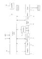
図1は、一実施形態におけるハイブリッド車両の制御装置を適用したシリーズハイブリッド車両のシステム構成を示すブロック図である。図1では、発電用のモータ(以下、発電機2という)と、駆動用のモータ(以下駆動モータ6という)とを搭載したシリーズハイブリッド車両が示されている。 FIG. 1 is a block diagram showing a system configuration of a series hybrid vehicle to which a hybrid vehicle control device according to an embodiment is applied. FIG. 1 shows a series hybrid vehicle equipped with a motor for power generation (hereinafter referred to as a generator 2) and a motor for driving (hereinafter referred to as a drive motor 6).
本実施形態のシリーズハイブリッド車両(以下単に「車両」という)は、エンジン1と、発電機2と、発電機インバータ3と、バッテリ4と、駆動インバータ5と、駆動モータ6と、減速機7と、車両コントローラ10と、モードSW15と、を備える。
The series hybrid vehicle of the present embodiment (hereinafter, simply referred to as "vehicle") includes an engine 1, a
エンジン(内燃機関)1は、不図示のギヤを介して発電機2と接続されており、発電機2が発電するための動力を発電機2へ伝達する。なお、本実施形態のハイブリッド車両の制御装置が適用される車両はシリーズ方式である為、エンジン1は、主として発電機2を回転駆動させるための駆動源として用いられる。
The engine (internal combustion engine) 1 is connected to the
発電機2は、エンジン1からの動力によって回転することにより発電する。すなわち、エンジン1の駆動力は発電機2に伝達され、発電機2はエンジン1の駆動力によって発電する。また、発電機2は、エンジン1の始動時には、発電機2の動力を用いてエンジン1をクランキングさせることや、エンジン1を発電機2の動力を用いて力行回転させることにより電力を消費するモータリングも行う。
The
発電機インバータ3は、発電機2、バッテリ4、および駆動インバータ5に接続されており、発電機2が発電する交流の電力を直流の電力に変換して、バッテリ4に供給する。すなわち、発電機2の発電電力は、バッテリ4に充電される。また、発電機インバータ3は、バッテリ4から供給される直流の電力を交流の電力に変換して、発電機2に供給する。
The generator inverter 3 is connected to the
バッテリ4は、発電機2が発電した電力および駆動モータ6の回生電力を充電する一方で、発電機2および駆動モータ6を駆動させるための駆動電力を放電する。本実施形態のバッテリ4は、リチウムイオンバッテリによって構成される。
The battery 4 charges the electric power generated by the
駆動インバータ5は、バッテリ4または発電機インバータ3から供給される直流の電力を交流の電力に変換して、駆動モータ6に供給する。また、駆動インバータ5は、駆動モータ6で回生発電された交流の電力を直流の電力に変換して、バッテリ4に供給する。 The drive inverter 5 converts the DC power supplied from the battery 4 or the generator inverter 3 into AC power and supplies it to the drive motor 6. Further, the drive inverter 5 converts the alternating current power regenerated by the drive motor 6 into direct current power and supplies it to the battery 4.
駆動モータ6は、駆動インバータ5から供給される交流電流により駆動力を発生し、減速機7を通して駆動輪に駆動力を伝達する。また、車両の減速時やコーストと走行中等に駆動輪に連れ回されて回転するときに、回生駆動力を発生させることで、車両の運動エネルギーを電気エネルギーとして回収する。回収した電気エネルギーは、回生電力としてバッテリ4に充電される。
The drive motor 6 generates a driving force by an alternating current supplied from the drive inverter 5, and transmits the driving force to the drive wheels through the
車両コントローラ10は、例えば、中央演算装置(CPU)、読み出し専用メモリ(ROM)、ランダムアクセスメモリ(RAM)、および、入出力インタフェース(I/Oインタフェース)から構成される。車両コントローラ10は、アクセル開度、車速、および路面勾配などの車両状態などの情報に応じて、駆動モータ6へのモータトルク指令値を演算する。
The
また、車両コントローラ10は、後述するモードSW15により選択されたモード、および、バッテリ4のSOC情報、バッテリ4の入力可能電力、出力可能電力、駆動モータ6の回生電力などの情報に基づいてバッテリ4の目標充電電力を演算して、演算した目標充電電力を達成するために発電機2の発電電力を制御する。
Further, the
より詳細には、車両コントローラ10は、発電機2からの電力に基づくバッテリ4の充電電力を調整するために、エンジン1、発電機2、発電機インバータ3、およびバッテリ4を制御する。例えば、車両コントローラ10は、発電機2の目標発電量を達成するようにエンジン1を制御し、スロットルアクチュエータによる吸入空気量と、インジェクタによる燃料噴射量と、点火プラグによる点火時期とをエンジン1の回転数や温度などの状態信号に応じて調整する。バッテリ4の充電電力を調整する具体的な方法については後述する。
More specifically, the
また、車両コントローラ10は、バッテリ4へ充放電される電流や電圧に基づいて充電状態(SOC:State Of Charge)を計測する。また、バッテリ4の温度、内部抵抗、およびSOCに応じて、バッテリ4の入力可能電力と出力可能電力を演算して、算出した値をバッテリ4の充放電可能電力に関する基本情報として取得する。
Further, the
また、車両コントローラ10は、駆動モータ6が所望の駆動トルクを達成するように、駆動モータ6の回転数や電圧などの状態に応じて、駆動インバータ5をスイッチング制御する。
Further, the
なお、上述した車両コントローラ10の各機能は、本実施形態のようにその全てを車両コントローラ10が単独で実行するように構成される必要はない。例えばエンジン1を制御するエンジンコントローラを別個に設ける等、複数のコントローラが協調して各機能を実行するように構成してもよい。
It should be noted that each function of the
モードスイッチ(モードSW)15は、複数の走行モードをドライバ或いは乗員が択一的に選択できるように設けられたモード選択(切替)用のスイッチである。モードSW15により選択可能な走行モードには、通常モードと、マナーモードと、チャージモードとが少なくとも含まれる。以下、各モードについてバッテリ4の充放電に関する相違点を中心に説明する。 The mode switch (mode SW) 15 is a mode selection (switching) switch provided so that a driver or an occupant can selectively select a plurality of traveling modes. The traveling mode that can be selected by the mode SW15 includes at least a normal mode, a manner mode, and a charge mode. Hereinafter, the differences in charging / discharging of the battery 4 will be mainly described for each mode.
通常モードは、通常走行時のモードであって、バッテリ4の充放電を走行状態に応じて制御するモードである。ここでの走行状態とは、例えばバッテリ4のSOC等である。通常モードでは、例えばSOCが予め定めた所定値以下になると、車両コントローラ10は、エンジン1により発電機2を駆動させて、バッテリ4の充電を行う。また、通常モードでは、一般的なエンジン駆動車におけるエンジンブレーキに相当する回生制動力が生成される。なお、本実施形態の通常モードは、車両システム起動後の初期状態において設定されている。
The normal mode is a mode during normal running, and is a mode in which the charging / discharging of the battery 4 is controlled according to the running state. The running state here is, for example, the SOC of the battery 4. In the normal mode, for example, when the SOC becomes equal to or lower than a predetermined value, the
マナーモードは、通常モードよりも騒音を低減した走行を可能とするモードである。マナーモードでは、発電機2が発電する電力に基づくバッテリ4の充電は行われない。従って、マナーモードが選択された車両は、発電を目的とするエンジン1の駆動は行わず、バッテリ4の放電電力のみを電力源とする駆動モータ6によって静かに走行する。つまり、ドライバは、マナーモードを選択することによって車両を意図的に静かに走行させることができる。
The manner mode is a mode that enables driving with less noise than the normal mode. In the manner mode, the battery 4 is not charged based on the electric power generated by the
チャージモードは、バッテリ4の充電を通常モード時よりも積極的に行うモードである。チャージモードが選択されると、バッテリ4のSOCが予め設定した基準値に到達するようエンジン1による発電が優先的に行われる。すなわち、走行状態に応じて発電が行われる通常モードに対して、チャージモードは、ドライバ或いは乗員によるモード操作に応じてエンジン1による発電が行われるモードといえる。例えば、通常モード時ではバッテリ4のSOCが所定値以下(例えば50%以下)にならないとエンジン1による発電が実行されないが、チャージモードが選択されると、仮にバッテリ4のSOCが60%であっても強制的にエンジン1による発電が行われて、バッテリ4の充電が開始される。つまり、ドライバは、チャージモードを選択することによってエンジン1による発電を実行させることにより、バッテリ4のSOCを意図的に高めることができる。これにより、例えば、マナーモードを選択する前にチャージモードを選択することで、その後に選択されるマナーモードの開始時点におけるSOCを高めることができるので、マナーモードでの走行距離を向上させることができる。 The charge mode is a mode in which the battery 4 is charged more positively than in the normal mode. When the charge mode is selected, power generation by the engine 1 is preferentially performed so that the SOC of the battery 4 reaches a preset reference value. That is, in contrast to the normal mode in which power generation is performed according to the traveling state, the charge mode can be said to be a mode in which power generation is performed by the engine 1 in response to a mode operation by the driver or the occupant. For example, in the normal mode, the power generation by the engine 1 is not executed unless the SOC of the battery 4 becomes a predetermined value or less (for example, 50% or less), but if the charge mode is selected, the SOC of the battery 4 is tentatively 60%. However, power is forcibly generated by the engine 1 and charging of the battery 4 is started. That is, the driver can intentionally increase the SOC of the battery 4 by executing the power generation by the engine 1 by selecting the charge mode. As a result, for example, by selecting the charge mode before selecting the manner mode, the SOC at the start of the manner mode selected after that can be increased, so that the mileage in the manner mode can be improved. can.
なお、本実施形態においては、駆動モータ6の回生電力に基づいてのバッテリ4の充電は上記のいずれの走行モードであっても相違なく実行される。 In the present embodiment, the charging of the battery 4 based on the regenerative power of the drive motor 6 is executed without any difference in any of the above traveling modes.
ところで、バッテリ4を保護する観点からは、バッテリ4が過充電となることを回避すべきであり、バッテリ4の充電電力(可能充電量)に上限値を設定することが好ましい。このような上限値として、本実施形態では、バッテリ4の内部でリチウムイオンが析出することを回避するための閾値である「Li析出保護閾値」が設定される。 By the way, from the viewpoint of protecting the battery 4, it should be avoided that the battery 4 is overcharged, and it is preferable to set an upper limit value for the charging power (possible charge amount) of the battery 4. As such an upper limit value, in the present embodiment, a “Li precipitation protection threshold value”, which is a threshold value for avoiding the precipitation of lithium ions inside the battery 4, is set.
バッテリ4(リチウムイオンバッテリ)は、急速或いは過度に充電されることに起因して、その内部にリチウムイオン(金属リチウム)が析出する虞がある。析出したリチウムイオンは、バッテリ4の内部回路を短絡させる等してバッテリ4を劣化させる。本実施形態で設定されるLi析出保護閾値は、所定時間におけるバッテリ4の平均充電電流と比較される値である。Li析出保護閾値は、バッテリ4の所定時間における平均充電電流をこれ以下に抑えることにより、バッテリ4の内部でリチウムイオンが析出することを防止できるように設定される閾値である。ここでの所定時間として、本実施形態では100秒が設定され、100秒間におけるバッテリ4の平均充電電流がLi析出保護閾値を超えると、バッテリ4の充電を一定時間停止させることにより、バッテリ4の内部でリチウムイオンが析出することを回避する。このようにしてバッテリ4の充電が停止される区間を、以下では「充電禁止区間」と称する。 The battery 4 (lithium ion battery) may be charged rapidly or excessively, so that lithium ions (metallic lithium) may be deposited inside the battery 4. The deposited lithium ions deteriorate the battery 4 by short-circuiting the internal circuit of the battery 4. The Li precipitation protection threshold set in this embodiment is a value to be compared with the average charging current of the battery 4 in a predetermined time. The Li precipitation protection threshold value is a threshold value set so that lithium ions can be prevented from being deposited inside the battery 4 by suppressing the average charging current of the battery 4 in a predetermined time to this level or less. As the predetermined time here, 100 seconds is set in the present embodiment, and when the average charging current of the battery 4 in 100 seconds exceeds the Li precipitation protection threshold, the charging of the battery 4 is stopped for a certain period of time, so that the battery 4 is charged. Avoid precipitation of lithium ions inside. The section in which charging of the battery 4 is stopped in this way is hereinafter referred to as a "charging prohibited section".
なお、ここで示した所定時間は例示であって、これに限られない。所定時間は、バッテリ4の充電電力および充電速度の可否をLi析出保護閾値との対比において判断可能な値が適宜設定される。例えば、所定時間として10秒及び100秒の2通りが設定され、少なくとも一方の所定時間におけるバッテリ4の平均充電電流がLi析出保護閾値を超えると、バッテリ4の充電を一定時間停止させるように構成してもよい。 The predetermined time shown here is an example, and is not limited to this. For the predetermined time, values that can determine whether or not the charging power and charging speed of the battery 4 can be determined in comparison with the Li precipitation protection threshold value are appropriately set. For example, two types of predetermined times, 10 seconds and 100 seconds, are set, and when the average charging current of the battery 4 in at least one predetermined time exceeds the Li precipitation protection threshold value, the charging of the battery 4 is stopped for a certain period of time. You may.
ここで、ドライバがチャージモードを選択した場合は、上述したようにバッテリ4の充電が積極的に行われるので、バッテリ4の充電電力がLi析出保護閾値を超える可能性が高まる。そうすると、ドライバはバッテリ4の充電電力を高めたくてチャージモードを選択したにも関わらず、所定時間におけるバッテリ4の平均充電電流がLi析出保護閾値を超えることで充電禁止区間に突入し、チャージモードであっても充電が実行されない状態が生じ得る。その結果、マナーモードを選択する等してチャージモードが解除された時に、事前にチャージモードを選択していたにも関わらず却ってバッテリ4の充電電力が少なくなってしまう事態が起こり得る。 Here, when the driver selects the charge mode, the battery 4 is actively charged as described above, so that the possibility that the charging power of the battery 4 exceeds the Li precipitation protection threshold value increases. Then, even though the driver selected the charge mode in order to increase the charging power of the battery 4, the average charging current of the battery 4 in a predetermined time exceeds the Li precipitation protection threshold value, and the driver enters the charge prohibition section and enters the charge mode. Even so, a state in which charging is not executed may occur. As a result, when the charge mode is canceled by selecting the manner mode or the like, the charging power of the battery 4 may be reduced even though the charge mode has been selected in advance.
そこで、本実施形態に係る車両コントローラ10は、チャージモード時に充電禁止区間に突入することを回避するための発電制限処理を実行する。
Therefore, the
図2は、本実施形態の発電制限処理を示すフローチャートである。車両コントローラ10は、以下に説明する発電制限処理を所定の間隔で繰り返し実行するようにプログラムされている。
FIG. 2 is a flowchart showing the power generation limiting process of the present embodiment. The
ステップS10では、車両コントローラ10(以下単に「コントローラ10」と呼ぶ)が、車両の走行モードとしてチャージモードが選択されているか否かを判定する。チャージモードが選択されていると判定された場合は、ステップS20の処理が実行される。
In step S10, the vehicle controller 10 (hereinafter simply referred to as “
チャージモードが選択されていないと判定された場合は、現状のモード(通常モード又はマナーモード)に適用された発電制御が維持される。例えばマナーモードが選択されている場合には、コントローラ10は、エンジン1による発電を禁止する。
If it is determined that the charge mode is not selected, the power generation control applied to the current mode (normal mode or manner mode) is maintained. For example, when the manner mode is selected, the
ステップS20では、コントローラ10は、チャージモード時の充電電力の上限値(第1上限値)を設定する。上述したように、チャージモードはドライバがエンジン1を意図的に駆動させることにより発電するモードなので、所定時間における平均充電電流が増加傾向となり、通常モード時よりも充電禁止区間に入りやすい。従って、本ステップでは、チャージモード時における充電電力の上限値を通常モード時よりも小さく設定する。これにより、チャージモードにおいては、バッテリ4の充電電力が第1上限値を超えないようにエンジン1による発電電力が制限されるので、所定時間における平均充電電流が増加傾向になることを抑制し、充電禁止区間に入りにくくすることができる。なお、本実施形態においては、駆動モータ6の回生電力に基づく充電電力は、第1上限値、及び後述する第2上限値によっては制限されないものとする。
In step S20, the
なお、本実施形態の第1上限値は数十kWに設定されるが、その値は、通常モード時における充電電力の上限値(通常時上限値)の約半分である。また、第1上限値は、バッテリ4の内部抵抗値等に関する特性を考慮して、バッテリ4の温度、SOC、及び、車速の少なくとも一つに応じて調整されてもよい。本実施形態では、バッテリ4の温度、SOC、及び、車速が大きくなると、第1上限値はより大きい値に設定される。 The first upper limit value of the present embodiment is set to several tens of kW, but the value is about half of the upper limit value of the charging power (normal time upper limit value) in the normal mode. Further, the first upper limit value may be adjusted according to at least one of the temperature, SOC, and vehicle speed of the battery 4 in consideration of the characteristics related to the internal resistance value and the like of the battery 4. In the present embodiment, as the temperature, SOC, and vehicle speed of the battery 4 increase, the first upper limit value is set to a larger value.
ステップS30では、コントローラ10は、所定時間におけるバッテリ4の平均充電電流が予め定めた「発電制限閾値」を超えたか否かを判定する。「発電制限閾値」は、チャージモード時において、バッテリ4の所定時間あたりの平均充電電力が上述のLi析出保護閾値を超えることを防止するために設定される閾値である。従って、発電制限閾値は、Li析出保護閾値よりも小さな値が設定される。また、ここでの所定時間は、Li析出保護閾値との比較の際に用いた上述の所定時間と同じ時間が適用される。
In step S30, the
また、本実施形態のLi析出保護閾値および発電制限閾値も、バッテリ4の内部抵抗値等に関する特性を考慮して、バッテリ4の温度およびSOCの少なくとも一方の値に応じて調整される。例えば、本実施形態では、バッテリ4の温度やSOCが低くなるほど、Li析出保護閾値および発電制限閾値はより低い値に設定される。なお、温度等に応じてLi析出保護閾値および発電制限閾値が調整される際の下げ幅は双方とも同じである必要はない。本実施形態では、発電制限閾値の下げ幅がLi析出保護閾値の下げ幅よりも大きくなるように調整される。すなわち、Li析出保護閾値と発電制限閾値との差分は、バッテリ4の温度又はSOCが小さくなるほど、より大きくなるように調整される。 Further, the Li precipitation protection threshold value and the power generation limit threshold value of the present embodiment are also adjusted according to at least one of the temperature and SOC of the battery 4 in consideration of the characteristics related to the internal resistance value of the battery 4 and the like. For example, in the present embodiment, the lower the temperature and SOC of the battery 4, the lower the Li precipitation protection threshold value and the power generation limit threshold value are set. It should be noted that the amount of reduction when the Li precipitation protection threshold value and the power generation limit threshold value are adjusted according to the temperature or the like does not have to be the same for both. In the present embodiment, the amount of decrease in the power generation limit threshold is adjusted to be larger than the amount of decrease in the Li precipitation protection threshold. That is, the difference between the Li precipitation protection threshold value and the power generation limit threshold value is adjusted so as to become larger as the temperature or SOC of the battery 4 becomes smaller.
ステップ30において、所定時間におけるバッテリ4の平均充電電流が発電制限閾値を超えたと判定されると、バッテリ4の充電電力をより制限するために続くステップS40の処理が実行される。平均充電電流が発電制限閾値を超えていないと判定された場合は、発電制限閾値を超えたと判定されるまでステップS30の処理が繰り返し実行される。 In step 30, when it is determined that the average charging current of the battery 4 in a predetermined time exceeds the power generation limit threshold value, the subsequent process of step S40 is executed in order to further limit the charging power of the battery 4. If it is determined that the average charging current does not exceed the power generation limit threshold, the process of step S30 is repeatedly executed until it is determined that the power generation limit threshold has been exceeded.
ステップS40では、コントローラ10は、バッテリ4が充電禁止区間に入ることを防止するために、チャージモード時の充電電力の上限値としての第2上限値を設定する。第2上限値は、第1上限値よりも更に低い値が設定される。ここで、図3から5を参照して、第2上限値によってエンジン1による発電が制限される「発電制限」の概念について説明する。
In step S40, the
図3は、回生電力が発生していない運転状態(力行運転状態)における発電制限の概念を説明する図である。図示するとおり、第2上限値は、第1上限値よりも低い値に設定されており(本実施形態では数kW)、ステップS40において第2上限値が設定された以降のコントローラ10は、バッテリ4の充電電力が両矢印aの範囲に収まるようにエンジン1の発電量を制御する。例えば、充電電力が第2上限値に達する値であれば、エンジン1の発電電力は、第2上限値に相当する量の充電電力と、駆動モータ6の駆動や補機類を動作させるための消費電力とを足し合わせた電力(両矢印a+b)となる。
FIG. 3 is a diagram for explaining the concept of power generation limitation in an operating state (power running state) in which regenerative power is not generated. As shown in the figure, the second upper limit value is set to a value lower than the first upper limit value (several kW in this embodiment), and the
図4は、回生電力が発生している運転状態における発電制限の概念を説明する図である。図示するとおり、回生電力(両矢印d)も充電されるので、第2上限値が設定された以降のコントローラ10は、回生電力と発電電力を足し合わせた電力(両矢印c+d)が、第2上限値を超えないように、エンジン1の発電量を制御する。例えば、充電電力が第2上限値に達する値であれば、エンジン1の発電量は、第2上限値から回生電力を差し引いた電力(両矢印c)となる。なお、第1上限値を用いての制限も図中の第2上限値を第1上限値に置き換えることで同様に説明可能である。
FIG. 4 is a diagram for explaining the concept of power generation limitation in an operating state in which regenerative power is generated. As shown in the figure, the regenerative power (double-headed arrow d) is also charged, so that the power (double-headed arrow c + d) obtained by adding the regenerative power and the generated power is the power of the
図5は、第2上限値を超える量の回生電力が発生している運転状態における発電制限の概念を説明する図である。駆動モータ6の回生電力に基づく充電電力は第1上限値或いは第2上限値によっては制限されないので、図示するとおり、回生電力に基づく充電電力が第2上限値を超える場合がある。ここで、図4を用いて上述したとおり、回生電力と発電電力の総和が第2上限値を超えないように発電電力を制御すると、回生電力が第2上限値を超えるとエンジン1を停止させ、回生電力が第2上限値を下回るとエンジン1を駆動させる必要がある。そうすると、回生電力が第2上限値近傍を上下するような場合には、エンジン1の駆動と停止が頻繁に繰り返されることになるため、ドライバに違和感を生じさせる虞がある。また、チャージモードは、ドライバが意図的にエンジン1を駆動させることにより積極的に充電を行うモードなので、チャージモードを選択したにも関わらずエンジン1が駆動しない状態はドライバの期待に反した状態を提供する事になり得る。 FIG. 5 is a diagram for explaining the concept of power generation limitation in an operating state in which an amount of regenerative power exceeding the second upper limit value is generated. Since the charging power based on the regenerative power of the drive motor 6 is not limited by the first upper limit value or the second upper limit value, the charging power based on the regenerative power may exceed the second upper limit value as shown in the figure. Here, as described above with reference to FIG. 4, if the generated power is controlled so that the sum of the regenerated power and the generated power does not exceed the second upper limit value, the engine 1 is stopped when the regenerated power exceeds the second upper limit value. , It is necessary to drive the engine 1 when the regenerative power falls below the second upper limit value. Then, when the regenerative power fluctuates near the second upper limit value, the driving and stopping of the engine 1 are frequently repeated, which may cause a sense of discomfort to the driver. Further, since the charge mode is a mode in which the driver intentionally drives the engine 1 to actively charge the engine 1, the state in which the engine 1 is not driven even though the charge mode is selected is contrary to the driver's expectation. Can be provided.
従って、本実施形態では、第2上限値が設定された以降のコントローラ10は、図示するように第2上限値を超える量の回生電力が発生している場合でも、エンジン1の発電量をエンジン1の発電量に基づく充電電力が第2上限値を超えない範囲で制御する。ただし、この状態におけるエンジン1の発電電力に基づく充電電力の上限は、第2上限値に相当する電力であっても良いし、回生電力等に応じてより小さい値に設定してもよい。これにより、回生電力が第2上限値を超えた場合でも、チャージモードにおいては、エンジン1による発電が継続されるので、回生電力が第2上限値近傍を上下するような場合でも、エンジン1の駆動と停止が頻繁に繰り返されることを回避して、ドライバに違和感を生じさせる虞を解消することができる。ただし、バッテリ4の保護を優先して、第2上限値を超える量の回生電力が発生している場合は、エンジン1の発電量に基づく充電電力をゼロに設定してもよい。すなわち、コントローラ10は、第2上限値を超える量の回生電力が発生している場合には、エンジン1による発電を停止することもできる。なお、第1上限値を用いての制限も図中の第2上限値を第1上限値に置き換えることで同様に説明可能である。ただし、第1上限値を用いての制限中に回生電力が第1上限値を超えた場合には、エンジン1の発電量に基づく充電電力の最大値は、第2上限値相当量であることが好ましい。
Therefore, in the present embodiment, the
以上のとおり、ステップS40において、ステップS20で設定された第1上限値よりも更に低い値の第2上限値が設定されることにより、チャージモードにおける充電量を第1上限値までの範囲内において早期に増加させつつ、第2上限値が設定されて以降は、平均充電電力がLi析出保護閾値に達する虞をさらに抑制して、チャージモード時にバッテリ4の状態が充電禁止区間に突入することを回避することができる。本ステップにおいて第2上限値が設定されると、続くステップS50の処理が実行される。 As described above, in step S40, the second upper limit value, which is a value lower than the first upper limit value set in step S20, is set, so that the charge amount in the charge mode is within the range up to the first upper limit value. While increasing at an early stage, after the second upper limit value is set, the possibility that the average charging power reaches the Li precipitation protection threshold is further suppressed, and the state of the battery 4 enters the charge prohibition section in the charge mode. It can be avoided. When the second upper limit value is set in this step, the processing of the following step S50 is executed.
ステップS50では、コントローラ10は、所定時間におけるバッテリ4の平均充電電流が「発電制限解除閾値」を下回ったか否かを判定する。「発電制限解除閾値」は、第2上限値による発電制限を解除するか否かを判断するために設定される閾値である。換言すると、発電制限解除閾値は、チャージモード時の発電制御における発電制限閾値に対する制限解除ヒステリシスである。バッテリ4の平均充電電流が発電制限解除閾値を下回ったと判定されると、続くステップS60の処理が実行される。平均充電電流が発電制限解除閾値を下回っていないと判定されると、平均充電電流が発電制限解除閾値を下回ったと判定されるまで、ステップS50の処理が繰り返し実行される。
In step S50, the
ステップS60では、コントローラ10は、第2上限値を解除することによりステップ40以降の発電制限を止めて、本フローに係る発電制限処理を終了する。以上が、本実施形態のコントローラ10が実行するチャージモード時における発電制限処理の内容である。続いて、上述の発電制限処理が実行された場合の実際例について、タイムチャートを参照しながら説明する。
In step S60, the
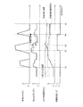
図6は、チャージモード時における発電制限処理の挙動を示すタイムチャートである。 FIG. 6 is a time chart showing the behavior of the power generation limiting process in the charge mode.
図6は、上から、車速[km/h]、エンジン1による発電電力[kW]、所定時間(ここでは100sec)におけるバッテリ4の平均充電電流[A]、および、発電制限フラグ(0又は1)を示している。横軸は時間[sec]である。 From the top, FIG. 6 shows the vehicle speed [km / h], the power generated by the engine 1 [kW], the average charging current [A] of the battery 4 in a predetermined time (100 sec in this case), and the power generation limit flag (0 or 1). ) Is shown. The horizontal axis is time [sec].
また、エンジン1による発電電力[kW]、および、バッテリ4の平均充電電流[A]において示されている実線は、チャージモードが選択されたことによって第1上限値が設定されている状態における各値の挙動を示し、点線部分は、発電制限により第2上限値が設定されている状態における各値の挙動を示している。また、バッテリ4の平均充電電流[A]は、点線で示されたLi析出保護閾値と、一点鎖線で示された発電制限閾値及び発電制限解除閾値と共に示されている。 Further, the solid lines shown in the power generated by the engine 1 [kW] and the average charging current [A] of the battery 4 are the states in which the first upper limit value is set by selecting the charge mode. The behavior of the values is shown, and the dotted line portion shows the behavior of each value in the state where the second upper limit value is set due to the power generation limitation. Further, the average charging current [A] of the battery 4 is shown together with the Li precipitation protection threshold value shown by the dotted line, and the power generation limit threshold value and the power generation limit release threshold value shown by the alternate long and short dash line.
ドライバの操作により選択されたチャージモード時は、所定のSOCに到達するまで強制的にエンジン1による発電が行われるので、図示のとおり、平均充電電流[A]と充電電力[kW]とは常に正の値を示している。ただし、図示しないが、チャージモード時であっても、特に安全面からの要求により例外的にエンジン1による発電が停止される場合もある。例えば、ブレーキペダルアシスト用の負圧生成が必要になった場合は、エンジンの吸気通路に負圧を生成するために、チャージモード時であってもバッテリ電力により発電機2を駆動してエンジン1を作動させるモータリング制御が実行されることもある。
In the charge mode selected by the driver's operation, the engine 1 forcibly generates power until a predetermined SOC is reached. Therefore, as shown in the figure, the average charging current [A] and the charging power [kW] are always the same. It shows a positive value. However, although not shown, even in the charge mode, the power generation by the engine 1 may be exceptionally stopped due to a special safety requirement. For example, when it becomes necessary to generate negative pressure for brake pedal assist, the
時刻t1では、車速の立ち上りに応じて発電電力が急峻に増加するとともに、それ以降の平均充電電流が増加傾向を示していることが分かる。時刻t1以降、平均充電電流は、その増加傾きが第1上限値を超えないように制限されながらも、時刻t2にかけて徐々に増加する。このように、本実施形態の発電制御によれば、第1上限値を設定することで平均充電電流の増加傾きを通常モード時に比べて相対的に小さくすることにより、エンジン1の発電電力によりSOCを増加させながらも、充電禁止区間に突入する虞を抑制することができる。 It can be seen that at time t1, the generated power sharply increases as the vehicle speed rises, and the average charging current thereafter shows an increasing tendency. After the time t1, the average charging current gradually increases toward the time t2, although the increase slope is limited so as not to exceed the first upper limit value. As described above, according to the power generation control of the present embodiment, by setting the first upper limit value, the increase slope of the average charging current is made relatively small as compared with the normal mode, so that the SOC is generated by the power generated by the engine 1. It is possible to suppress the possibility of entering the charge-prohibited section while increasing the number of charges.
時刻t2では、コントローラ10は、平均充電電流が発電制限閾値を超えたことに起因して、充電電力の上限値としての第2上限値を設定する発電制限を実行する(発電制限フラグ=1)。これにより、発電電力がさらに制限されて、平均充電電流の増加傾きが更に抑制されるので(点線参照)、平均充電電流の増加傾向が時刻t2を境に緩やかになる。なお、発電制限によって制限される発電量(発電制限量)は、バッテリ4の温度や車速に応じて適宜調整される。例えば、バッテリ4の温度や、車速が大きくなると、発電制限量はより大きくなるように調整されてもよい。
At time t2, the
一方、仮に第2上限値を設けずに、第1上限値のみによる発電制御が実行された場合は、平均充電電流が時刻t2以降も増加し続けてしまうので(実線参照)、時刻t3においてLi析出保護閾値を超えてしまう。その結果、充電禁止区間に突入し、チャージモードにも関わらず、充電が一定期間禁止されてしまう。 On the other hand, if the power generation control is executed only by the first upper limit value without setting the second upper limit value, the average charging current will continue to increase after the time t2 (see the solid line), so Li at the time t3. The precipitation protection threshold is exceeded. As a result, the charging prohibited section is entered, and charging is prohibited for a certain period of time in spite of the charging mode.
本実施形態では、第2上限値により平均充電電流の増加傾きがより小さく制限されることにより平均充電電流がLi析出保護閾値を超えることを防止できるので、チャージモードにも関わらず、充電が一定期間禁止されてしまう事態を回避することができる。そして、第2上限値による制限のもとで、時刻t4にかけて平均充電電流が徐々に低下していく。 In the present embodiment, since the increase slope of the average charging current is limited to a smaller value by the second upper limit value, it is possible to prevent the average charging current from exceeding the Li precipitation protection threshold value, so that the charging is constant regardless of the charge mode. It is possible to avoid the situation where the period is prohibited. Then, under the limitation of the second upper limit value, the average charging current gradually decreases toward time t4.
時刻t4では、コントローラ10は、平均充電電流が発電制限解除閾値を下回ったことに起因して、発電制限を解除して、充電電力の上限値を第2上限値から第1上限値に変更する(発電制限フラグ=0)。その結果、エンジン1による発電電力が増加するとともに、平均充電電流が再び増加傾向を示しているのが分かる。時刻t4以降は、第1上限値による制御のもと、バッテリ4のSOCが時刻t5にかけて徐々に増加していく。これにより、チャージモードオフ後にマナーモードを選択した場合でも、チャージモード中に充電されたバッテリ4の放電電力によって駆動モータ6を駆動させることができる。
At time t4, the
一方で、第2上限値が設けられていなかった場合は、時刻t3において充電禁止区間に突入しているので、バッテリ4への充電がなされないにも関わらず、駆動モータ6の駆動によって電力は消費され続ける。その結果、第2上限値が設定されない従来の発電制御では、チャージモードオフ後(例えば時刻t5)におけるバッテリ4のSOCが、第2上限値が設定される本実施形態の発電制御よりも却って小さくなってしまう。 On the other hand, if the second upper limit value is not set, the charge prohibition section is entered at time t3, so that the power is generated by the drive of the drive motor 6 even though the battery 4 is not charged. Continues to be consumed. As a result, in the conventional power generation control in which the second upper limit value is not set, the SOC of the battery 4 after the charge mode is turned off (for example, at time t5) is rather smaller than the power generation control in the present embodiment in which the second upper limit value is set. turn into.
以上、一実施形態のハイブリッド車両の制御装置は、エンジン1と、当該エンジン1による発電電力を充電するバッテリ4と、駆動源としてのモータ6と、モード操作により選択可能な複数の走行モードを制御するコントローラ10とを備えるハイブリッド車両の制御装置である。このハイブリッド車両の制御装置は、走行モードとして、走行状態に応じてバッテリの充放電を行う通常モードと、モード操作に応じてエンジンによる発電を行うチャージモードと、を含み、コントローラ10は、チャージモード時における発電電力に基づく充電電力の上限値(第1上限値)を、通常モード時における発電電力に基づく充電電力の上限値(通常時上限値)よりも小さくする。これにより、チャージモードにおいては、バッテリ4の充電電力が第1上限値を超えないようにエンジン1による発電電力が制限される。その結果、所定時間における平均充電電流が増加傾向になることを抑制し、ドライバの要求に応じてバッテリ4のSOCを高めつつも、所定量以上の充電を回避して、バッテリ4の状態が充電禁止区間に入る虞を低減することができる。
As described above, the control device for the hybrid vehicle of one embodiment controls the engine 1, the battery 4 for charging the power generated by the engine 1, the motor 6 as a drive source, and a plurality of driving modes that can be selected by mode operation. It is a control device of a hybrid vehicle including the
また、一実施形態のハイブリッド車両の制御装置によれば、コントローラ10は、チャージモード時における所定時間での充電電力が予め定めた所定値(発電制限閾値)を超えた場合には、チャージモード時の上限値を更に小さくする(第2上限値を設定する)。これにより、チャージモードにおける充電量を第1上限値までの範囲内において早期に増加させつつ、第2上限値が設定されて以降は、平均充電電力がLi析出保護閾値に達する虞をさらに抑制して、チャージモード時にバッテリ4の状態が充電禁止区間に突入することを回避することができる。
Further, according to the control device of the hybrid vehicle of one embodiment, when the charging power in the predetermined time in the charge mode exceeds a predetermined value (power generation limit threshold value) in the charge mode, the
また、一実施形態のハイブリッド車両の制御装置によれば、バッテリ4がモータ6で発生する回生電力を充電する場合は、コントローラ10は、チャージモード時における発電電力に基づく充電電力の上限値を、回生電力の量に応じて小さくする。これにより、回生電力を考慮しながら、エンジン1による発電電力を制御することができ、バッテリ4の充電電力を設定した上限値の範囲で適切に制御することができる。
Further, according to the control device of the hybrid vehicle of one embodiment, when the battery 4 charges the regenerative power generated by the motor 6, the
また、一実施形態のハイブリッド車両の制御装置によれば、コントローラ10は、バッテリ4の温度に応じて上限値(第1上限値、第2上限値)を調整する。これにより、バッテリ4の温度変化によって内部抵抗等の特性が変わっても、バッテリ4の状態が充電禁止区間に突入することを抑制する発電制御を安定的に実行することができる。
Further, according to the control device of the hybrid vehicle of one embodiment, the
以上、本発明の実施形態について説明したが、上記実施形態は本発明の適用例の一部を示したに過ぎず、本発明の技術的範囲を上記実施形態の具体的構成に限定する趣旨ではない。例えば、発電制御における指標或いは制御対象となる各値は上述したものに限られない。 Although the embodiments of the present invention have been described above, the above embodiments are only a part of the application examples of the present invention, and the technical scope of the present invention is limited to the specific configurations of the above embodiments. No. For example, the index in power generation control or each value to be controlled is not limited to the above.
例えば、エンジン1による発電電力[kW]は、エンジン1による発電電流[A]に置き換えてもよいし、平均充電電流[A]は平均充電電力[kW]に置き換えてもよい。また、所定時間あたりの平均充電電流は、所定時間における充電電流の積算値(総和)であってもよい。すなわち、上述した発電制御は、上記の実施形態で用いた電流値等の各指標のみでなく、その指標と比例関係にある他の指標を用いて行うこともできる。 For example, the generated power [kW] by the engine 1 may be replaced with the generated current [A] by the engine 1, and the average charging current [A] may be replaced with the average charging power [kW]. Further, the average charging current per predetermined time may be an integrated value (total) of the charging currents in the predetermined time. That is, the power generation control described above can be performed not only by using each index such as the current value used in the above embodiment, but also by using another index having a proportional relationship with the index.
Claims (6)
前記走行モードは、
走行状態に応じて前記エンジンによる発電を行う通常モードと、
走行状態によらず前記エンジンによる発電を行うチャージモードと、を含み、
前記チャージモード時における充電電流が予め定めた所定値を超えた場合には、
前記チャージモード時における前記発電電力に基づく充電電力の上限値を、前記通常モード時における前記発電電力に基づく充電電力の上限値よりも小さい値に設定する、
ハイブリッド車両の制御方法。 In a control method of a hybrid vehicle including an engine, a battery for charging the electric power generated by the engine, and a motor as a drive source, and having a plurality of driving modes that can be selected by a driving mode selection switch.
The driving mode is
A normal mode in which power is generated by the engine according to the driving condition, and
Including a charge mode in which the engine generates electricity regardless of the running condition.
When the charging current in the charge mode exceeds a predetermined value,
The upper limit value of the charging power based on the generated power in the charge mode is set to a value smaller than the upper limit value of the charging power based on the generated power in the normal mode.
How to control a hybrid vehicle.
前記バッテリが前記モータで発生する回生電力を充電する場合は、
前記チャージモード時における前記発電電力に基づく充電電力の上限値を、前記回生電力の量に応じて小さくする、
ハイブリッド車両の制御方法。 In the hybrid vehicle control method according to claim 1,
When the battery charges the regenerative power generated by the motor,
The upper limit of the charge power based on the generated power in the charge mode is reduced according to the amount of the regenerative power.
How to control a hybrid vehicle.
前記バッテリの温度に応じて前記上限値を調整する、
ハイブリッド車両の制御方法。 In the method for controlling a hybrid vehicle according to claim 1 or 2.
The upper limit is adjusted according to the temperature of the battery.
How to control a hybrid vehicle.
前記走行モードは、
走行状態に応じて前記エンジンによる発電を行う通常モードと、
走行状態によらず前記エンジンによる発電を行うチャージモードと、を含み、
前記チャージモード時における充電電流が予め定めた所定値を超えた場合には、
前記コントローラは、前記チャージモード時における前記発電電力に基づく充電電力の上限値を、前記通常モード時における前記発電電力に基づく充電電力の上限値よりも小さい値に設定する、
ハイブリッド車両の制御装置。 In a hybrid vehicle control device including an engine, a battery for charging the power generated by the engine, a motor as a drive source, and a controller for controlling a plurality of driving modes that can be selected by a driving mode selection switch.
The driving mode is
A normal mode in which power is generated by the engine according to the driving condition, and
Including a charge mode in which the engine generates electricity regardless of the running condition.
When the charging current in the charge mode exceeds a predetermined value,
The controller sets the upper limit value of the charging power based on the generated power in the charge mode to a value smaller than the upper limit value of the charging power based on the generated power in the normal mode.
Hybrid vehicle control device.
前記バッテリが前記モータで発生する回生電力を充電する場合は、
前記コントローラは、前記チャージモード時における前記発電電力に基づく充電電力の上限値を、前記回生電力の量に応じて小さくする、
ハイブリッド車両の制御装置。 In the hybrid vehicle control device according to claim 4.
When the battery charges the regenerative power generated by the motor,
The controller reduces the upper limit of the charge power based on the generated power in the charge mode according to the amount of the regenerative power.
Hybrid vehicle control device.
前記コントローラは、前記バッテリの温度に応じて前記上限値を調整する、
ハイブリッド車両の制御装置。 In the hybrid vehicle control device according to claim 4 or 5.
The controller adjusts the upper limit value according to the temperature of the battery.
Hybrid vehicle control device.
Applications Claiming Priority (1)
| Application Number | Priority Date | Filing Date | Title |
|---|---|---|---|
| PCT/JP2017/045210 WO2019116576A1 (en) | 2017-12-15 | 2017-12-15 | Method and device for controlling hybrid vehicle |
Publications (2)
| Publication Number | Publication Date |
|---|---|
| JPWO2019116576A1 JPWO2019116576A1 (en) | 2021-01-07 |
| JP6927328B2 true JP6927328B2 (en) | 2021-09-01 |
Family
ID=66820187
Family Applications (1)
| Application Number | Title | Priority Date | Filing Date |
|---|---|---|---|
| JP2019558865A Active JP6927328B2 (en) | 2017-12-15 | 2017-12-15 | Hybrid vehicle control method and control device |
Country Status (9)
| Country | Link |
|---|---|
| US (1) | US11518363B2 (en) |
| EP (1) | EP3725614A4 (en) |
| JP (1) | JP6927328B2 (en) |
| KR (1) | KR102352463B1 (en) |
| CN (1) | CN111479733B (en) |
| BR (1) | BR112020011919A2 (en) |
| MX (1) | MX2020006152A (en) |
| RU (1) | RU2746116C1 (en) |
| WO (1) | WO2019116576A1 (en) |
Families Citing this family (5)
| Publication number | Priority date | Publication date | Assignee | Title |
|---|---|---|---|---|
| EP3725619B1 (en) * | 2017-12-15 | 2021-08-18 | Nissan Motor Co., Ltd. | Control method for hybrid vehicle and control apparatus for hybrid vehicle |
| CN113613945A (en) * | 2019-03-20 | 2021-11-05 | 沃尔沃卡车集团 | Method for controlling an energy storage system of a vehicle |
| US11932235B2 (en) * | 2020-08-19 | 2024-03-19 | Nissan Motor Co., Ltd. | Method and device for controlling hybrid vehicle |
| US11376943B1 (en) | 2021-08-13 | 2022-07-05 | Oshkosh Defense, Llc | Electrified military vehicle |
| US11498409B1 (en) | 2021-08-13 | 2022-11-15 | Oshkosh Defense, Llc | Electrified military vehicle |
Family Cites Families (11)
| Publication number | Priority date | Publication date | Assignee | Title |
|---|---|---|---|---|
| JP3211595B2 (en) * | 1994-12-12 | 2001-09-25 | トヨタ自動車株式会社 | Hybrid electric vehicle |
| JP3926514B2 (en) | 1999-08-17 | 2007-06-06 | 本田技研工業株式会社 | Control device for hybrid vehicle |
| JP3838233B2 (en) * | 2003-08-28 | 2006-10-25 | トヨタ自動車株式会社 | Storage device control device |
| US7746026B2 (en) * | 2006-12-22 | 2010-06-29 | Chrysler Group Llc | Controlling state of charge of a vehicle battery |
| JP5024626B2 (en) | 2008-03-28 | 2012-09-12 | スズキ株式会社 | Control device for vehicle generator |
| JP5146502B2 (en) * | 2009-11-12 | 2013-02-20 | トヨタ自動車株式会社 | Secondary battery charge / discharge controller |
| US8798833B2 (en) * | 2009-11-17 | 2014-08-05 | Toyota Jidosha Kabushiki Kaisha | Vehicle and method for controlling vehicle |
| JP2014118079A (en) * | 2012-12-18 | 2014-06-30 | Mitsubishi Motors Corp | Charge control unit for hybrid vehicle |
| JP6354141B2 (en) | 2013-12-04 | 2018-07-11 | トヨタ自動車株式会社 | Charge control device |
| JP6164245B2 (en) * | 2015-04-24 | 2017-07-19 | トヨタ自動車株式会社 | Vehicle control apparatus and vehicle control method |
| US11697355B2 (en) * | 2018-08-22 | 2023-07-11 | Ford Global Technologies, Llc | Electrified vehicle electrical distribution system component protection systems and methods |
-
2017
- 2017-12-15 JP JP2019558865A patent/JP6927328B2/en active Active
- 2017-12-15 CN CN201780097646.8A patent/CN111479733B/en active Active
- 2017-12-15 EP EP17934706.7A patent/EP3725614A4/en active Pending
- 2017-12-15 KR KR1020207018229A patent/KR102352463B1/en active IP Right Grant
- 2017-12-15 RU RU2020119770A patent/RU2746116C1/en active
- 2017-12-15 MX MX2020006152A patent/MX2020006152A/en unknown
- 2017-12-15 US US16/771,972 patent/US11518363B2/en active Active
- 2017-12-15 BR BR112020011919-9A patent/BR112020011919A2/en active Search and Examination
- 2017-12-15 WO PCT/JP2017/045210 patent/WO2019116576A1/en unknown
Also Published As
| Publication number | Publication date |
|---|---|
| US11518363B2 (en) | 2022-12-06 |
| US20210213934A1 (en) | 2021-07-15 |
| BR112020011919A2 (en) | 2020-11-24 |
| WO2019116576A1 (en) | 2019-06-20 |
| MX2020006152A (en) | 2020-08-13 |
| EP3725614A4 (en) | 2021-01-06 |
| CN111479733B (en) | 2023-10-20 |
| RU2746116C1 (en) | 2021-04-07 |
| KR20200088885A (en) | 2020-07-23 |
| CN111479733A (en) | 2020-07-31 |
| JPWO2019116576A1 (en) | 2021-01-07 |
| EP3725614A1 (en) | 2020-10-21 |
| KR102352463B1 (en) | 2022-01-18 |
Similar Documents
| Publication | Publication Date | Title |
|---|---|---|
| JP6919720B2 (en) | Hybrid vehicle control method and control device | |
| JP6927328B2 (en) | Hybrid vehicle control method and control device | |
| US20130030634A1 (en) | Control device for hybrid vehicle, and hybrid vehicle incorporating control device | |
| CN107826099B (en) | Operation control system for hybrid vehicle | |
| KR20140135246A (en) | Electric power generation control system for hybrid automobile | |
| JP7021570B2 (en) | Vehicle power control device | |
| KR20130017723A (en) | System of control engine start for hybrid vehicle and method thereof | |
| JP6606453B2 (en) | Hybrid vehicle control system and motor control unit | |
| JP6630210B2 (en) | Hybrid vehicle control device and hybrid vehicle | |
| JP7254267B2 (en) | Hybrid vehicle control device | |
| JP2022034587A (en) | Control device for vehicle | |
| WO2013132531A1 (en) | Engine control device and engine control method | |
| JP7204508B2 (en) | vehicle | |
| WO2023037420A1 (en) | Method for controlling vehicle, and vehicle | |
| JP7336300B2 (en) | vehicle controller | |
| JP7124352B2 (en) | vehicle power controller | |
| JP7222737B2 (en) | vehicle | |
| JP7235173B2 (en) | Hybrid vehicle control device | |
| JP2024020029A (en) | Hybrid vehicle control device | |
| JP2011225077A (en) | Hybrid automobile | |
| JP2021126964A (en) | Control device for vehicle | |
| JP2020125036A (en) | Power supply system |
Legal Events
| Date | Code | Title | Description |
|---|---|---|---|
| A529 | Written submission of copy of amendment under article 34 pct |
Free format text: JAPANESE INTERMEDIATE CODE: A5211 Effective date: 20200612 |
|
| A621 | Written request for application examination |
Free format text: JAPANESE INTERMEDIATE CODE: A621 Effective date: 20200612 |
|
| A131 | Notification of reasons for refusal |
Free format text: JAPANESE INTERMEDIATE CODE: A131 Effective date: 20210420 |
|
| A521 | Request for written amendment filed |
Free format text: JAPANESE INTERMEDIATE CODE: A523 Effective date: 20210519 |
|
| TRDD | Decision of grant or rejection written | ||
| A01 | Written decision to grant a patent or to grant a registration (utility model) |
Free format text: JAPANESE INTERMEDIATE CODE: A01 Effective date: 20210706 |
|
| A61 | First payment of annual fees (during grant procedure) |
Free format text: JAPANESE INTERMEDIATE CODE: A61 Effective date: 20210719 |
|
| R151 | Written notification of patent or utility model registration |
Ref document number: 6927328 Country of ref document: JP Free format text: JAPANESE INTERMEDIATE CODE: R151 |