JP6926479B2 - Image reader - Google Patents
Image reader Download PDFInfo
- Publication number
- JP6926479B2 JP6926479B2 JP2017000919A JP2017000919A JP6926479B2 JP 6926479 B2 JP6926479 B2 JP 6926479B2 JP 2017000919 A JP2017000919 A JP 2017000919A JP 2017000919 A JP2017000919 A JP 2017000919A JP 6926479 B2 JP6926479 B2 JP 6926479B2
- Authority
- JP
- Japan
- Prior art keywords
- medium
- feeding
- speed
- roller
- control
- Prior art date
- Legal status (The legal status is an assumption and is not a legal conclusion. Google has not performed a legal analysis and makes no representation as to the accuracy of the status listed.)
- Active
Links
Images


Classifications
-
- H—ELECTRICITY
- H04—ELECTRIC COMMUNICATION TECHNIQUE
- H04N—PICTORIAL COMMUNICATION, e.g. TELEVISION
- H04N1/00—Scanning, transmission or reproduction of documents or the like, e.g. facsimile transmission; Details thereof
- H04N1/04—Scanning arrangements, i.e. arrangements for the displacement of active reading or reproducing elements relative to the original or reproducing medium, or vice versa
- H04N1/047—Detection, control or error compensation of scanning velocity or position
-
- H—ELECTRICITY
- H04—ELECTRIC COMMUNICATION TECHNIQUE
- H04N—PICTORIAL COMMUNICATION, e.g. TELEVISION
- H04N1/00—Scanning, transmission or reproduction of documents or the like, e.g. facsimile transmission; Details thereof
- H04N1/00567—Handling of original or reproduction media, e.g. cutting, separating, stacking
- H04N1/0057—Conveying sheets before or after scanning
- H04N1/00588—Conveying sheets before or after scanning to the scanning position
-
- H—ELECTRICITY
- H04—ELECTRIC COMMUNICATION TECHNIQUE
- H04N—PICTORIAL COMMUNICATION, e.g. TELEVISION
- H04N1/00—Scanning, transmission or reproduction of documents or the like, e.g. facsimile transmission; Details thereof
- H04N1/00567—Handling of original or reproduction media, e.g. cutting, separating, stacking
- H04N1/0057—Conveying sheets before or after scanning
- H04N1/00599—Using specific components
- H04N1/00602—Feed rollers
-
- H—ELECTRICITY
- H04—ELECTRIC COMMUNICATION TECHNIQUE
- H04N—PICTORIAL COMMUNICATION, e.g. TELEVISION
- H04N1/00—Scanning, transmission or reproduction of documents or the like, e.g. facsimile transmission; Details thereof
- H04N1/04—Scanning arrangements, i.e. arrangements for the displacement of active reading or reproducing elements relative to the original or reproducing medium, or vice versa
- H04N1/12—Scanning arrangements, i.e. arrangements for the displacement of active reading or reproducing elements relative to the original or reproducing medium, or vice versa using the sheet-feed movement or the medium-advance or the drum-rotation movement as the slow scanning component, e.g. arrangements for the main-scanning
- H04N1/121—Feeding arrangements
Description
本発明は、画像を読み取る画像読取装置に関する。 The present invention relates to an image reader that reads an image.
以下、画像読取装置の一例であるスキャナーを例に説明する。スキャナーには、媒体の一例である原稿を自動送りする給送装置(ADF(Auto Document Feeder)とも呼ばれる)が設けられ、複数枚の原稿の自動送りと読み込みとを行える様に構成される場合がある(例えば、特許文献1参照)。 Hereinafter, a scanner, which is an example of an image reading device, will be described as an example. The scanner may be provided with a feeding device (also called an ADF (Auto Patent Feeder)) that automatically feeds a document, which is an example of a medium, and may be configured to automatically feed and read a plurality of documents. (See, for example, Patent Document 1).
ところで、複数枚の原稿を連続して搬送する際、先行する原稿と、後続の原稿との間隔は極力狭くするほうがスループットの観点では有利である。従って少なくとも画像読取センサーに至る前の原稿搬送領域において原稿の搬送速度を高めることが考えられるが、例えば先行する原稿と後続の原稿との間隔を調整しようとして搬送ローラーの停止制御を行おうとしても、原稿の長さが短い場合には搬送ローラーの停止制御が間に合わない虞があり、原稿間隔が意図せず短くなったり或いは最悪の場合重なり合ったりしてしまう虞もある。 By the way, when a plurality of original documents are continuously conveyed, it is advantageous from the viewpoint of throughput that the distance between the preceding original document and the succeeding original document is made as narrow as possible. Therefore, it is conceivable to increase the document transport speed at least in the document transport area before reaching the image reading sensor. For example, even if the transport roller is stopped and controlled in order to adjust the distance between the preceding document and the succeeding document. If the length of the originals is short, the stop control of the transport rollers may not be in time, and the intervals between the originals may be unintentionally shortened or, in the worst case, overlapped.
そこで本発明はこの様な問題に鑑み成されたものであり、その目的は、スループットの向上を図りながらも、先行する原稿と後続の原稿との間隔を適切に調整することのできる画像読取装置を提供することにある。 Therefore, the present invention has been made in view of such a problem, and an object of the present invention is an image reader capable of appropriately adjusting the distance between a preceding document and a succeeding document while improving throughput. Is to provide.
上記課題を解決する為の、本発明の第1の態様に係る画像読取装置は、媒体を載置する媒体載置部と、前記媒体載置部から媒体を送り出す給送手段と、前記給送手段と対向配置された、媒体を分離する分離手段と、前記給送手段及び前記分離手段の下流側に設けられた、媒体を搬送する搬送手段と、前記搬送手段の下流側に設けられた、媒体を読み取る読み取り手段と、前記給送手段及び前記搬送手段を制御する制御手段と、を備え、前記制御手段は、複数の媒体を連続して給送する際、先行する第1の媒体の給送方向長さに応じ、後続の第2の媒体を前記給送手段により給送する際の給送制御を変更することを特徴とする。 An image reading device according to a first aspect of the present invention for solving the above problems includes a medium mounting portion on which a medium is placed, a feeding means for feeding the medium from the medium mounting portion, and the feeding. A separating means for separating the medium, which is arranged opposite to the means, a transporting means for transporting the medium provided on the downstream side of the feeding means and the separating means, and a transporting means provided on the downstream side of the transporting means. A reading means for reading a medium and a control means for controlling the feeding means and the transporting means are provided, and the control means supplies a first medium that precedes when a plurality of media are continuously fed. It is characterized in that the feeding control when feeding the subsequent second medium by the feeding means is changed according to the length in the feeding direction.
本態様によれば、前記給送手段及び前記搬送手段を制御する制御手段は、複数の媒体を連続して給送する際、先行する第1の媒体の給送方向長さに応じ、後続の第2の媒体を前記給送手段により給送する際の給送制御を変更するので、原稿の長さの変化に伴う原稿間隔の調整の失敗を抑制でき、スループットの向上を図りながらも、原稿間隔を適切に調整することができる。 According to this aspect, when the feeding means and the controlling means for controlling the transporting means continuously feed a plurality of media, the subsequent feeding means and the control means controlling the transporting means follow according to the feeding direction length of the preceding first medium. Since the feeding control when the second medium is fed by the feeding means is changed, it is possible to suppress the failure of the document spacing adjustment due to the change in the document length, and while improving the throughput, the document. The interval can be adjusted appropriately.
本発明の第2の態様は、第1の態様において、媒体の先端が前記分離手段を通過する迄の前記給送手段による媒体の給送速度を速度Va、媒体の先端が前記分離手段を通過した後の前記給送手段による媒体の給送速度を速度Vbとして、前記制御手段は、前記第1の媒体の給送方向長さが予め定めた長さLより長い場合、前記速度Vbを前記速度Vaより高速である速度Vb1に設定する第1給送制御と、前記第1の媒体の給送方向長さが前記長さL以下である場合、前記速度Vbを前記速度Vb1より低速である速度Vb2に設定する第2給送制御と、を実行可能であることを特徴とする。 In the second aspect of the present invention, in the first aspect, the feeding speed of the medium by the feeding means until the tip of the medium passes through the separating means is set to a speed Va, and the tip of the medium passes through the separating means. When the feeding speed of the medium by the feeding means is set to the speed Vb, and the feeding direction length of the first medium is longer than a predetermined length L, the control means sets the speed Vb to the speed Vb. When the first feeding control set to the speed Vb1 which is higher than the speed Va and the feeding direction length of the first medium is the length L or less, the speed Vb is lower than the speed Vb1. It is characterized in that the second feed control set to the speed Vb2 can be executed.
本態様によれば、前記制御手段は、前記第1の媒体の給送方向長さが予め定めた長さLより長い場合、前記速度Vbを前記速度Vaより高速である速度Vb1に設定する第1給送制御と、前記第1の媒体の給送方向長さが前記長さL以下である場合、前記速度Vbを前記速度Vb1より低速である速度Vb2に設定する第2給送制御と、を実行可能であるので、前記第1の媒体の給送方向長さが前記長さL以下である場合に前記第2給送制御を選択することで、原稿間隔を適切に制御できる。 According to this aspect, when the feeding direction length of the first medium is longer than a predetermined length L, the control means sets the speed Vb to a speed Vb1 which is faster than the speed Va. 1 feed control and a second feed control in which the speed Vb is set to a speed Vb2 which is lower than the speed Vb1 when the feed direction length of the first medium is the length L or less. Therefore, when the feeding direction length of the first medium is the length L or less, the document spacing can be appropriately controlled by selecting the second feeding control.
本発明の第3の態様は、第2の態様において、媒体搬送経路において前記給送手段と前記搬送手段との間に設けられた、媒体を検出する第1検出手段と、媒体搬送経路において前記搬送手段の下流側に設けられた、媒体を検出する第2検出手段と、を備え、前記制御手段は、前記第1の媒体の先端を前記第2検出手段により検出した時点から、前記第1の媒体の後端を前記第1検出手段により検出する迄の前記第1の媒体の搬送量と、前記第1検出手段と前記第2検出手段との間の経路長をもとにして、前記第1の媒体の給送方向長さを算出することを特徴とする。 A third aspect of the present invention is, in the second aspect, the first detecting means for detecting the medium provided between the feeding means and the transporting means in the medium transporting path, and the said in the medium transporting path. The control means includes a second detection means for detecting the medium provided on the downstream side of the transport means, and the control means starts from the time when the tip of the first medium is detected by the second detection means. Based on the amount of the first medium conveyed until the rear end of the medium is detected by the first detecting means and the path length between the first detecting means and the second detecting means. It is characterized in that the length in the feeding direction of the first medium is calculated.
本態様によれば、前記制御手段は、前記第1の媒体の先端を前記第2検出手段により検出した時点から、前記第1の媒体の後端を前記第1検出手段により検出する迄の前記第1の媒体の搬送量と、前記第1検出手段と前記第2検出手段との間の経路長をもとにして、前記第1の媒体の給送方向長さを算出するので、先行する原稿と後続の原稿との間隔をより正確に制御できる。 According to this aspect, the control means is described from the time when the tip of the first medium is detected by the second detection means to the time when the rear end of the first medium is detected by the first detection means. Since the feed direction length of the first medium is calculated based on the transport amount of the first medium and the path length between the first detection means and the second detection means, it precedes. The distance between the original document and the subsequent original document can be controlled more accurately.
本発明の第4の態様は、第2のまたは第3の態様において、前記長さLは、国際規格ISO/IEC7810「ID−1」で規定されるカードの短辺サイズに応じて設定されている。
本態様によれば、国際規格ISO/IEC7810「ID−1」で規定されるカードを、短辺サイズが搬送方向に沿うようにして搬送する際に、上述した第1から第3の態様のいずれかの作用効果が得られる。
In a fourth aspect of the present invention, in the second or third aspect, the length L is set according to the short side size of the card defined by the international standard ISO / IEC7810 "ID-1". There is.
According to this aspect, when the card defined by the international standard ISO / IEC7810 "ID-1" is transported so that the short side size is along the transport direction, any of the first to third aspects described above is used. The effect is obtained.
本発明の第5の態様に係る画像読取装置は、媒体を載置する媒体載置部と、前記媒体載置部から媒体を送り出す給送手段と、前記給送手段と対向配置された、媒体を分離する分離手段と、前記給送手段及び前記分離手段の下流側に設けられた、媒体を搬送する搬送手段と、前記搬送手段の下流側に設けられた、媒体を読み取る読み取り手段と、前記給送手段及び前記搬送手段を制御する制御手段と、を備え、前記制御手段は、複数の媒体を連続して給送する際、先行する第1の媒体の属性に応じ、後続の第2の媒体を前記給送手段により給送する際の給送制御を変更することを特徴とする。 The image reading device according to the fifth aspect of the present invention includes a medium mounting portion on which the medium is placed, a feeding means for feeding the medium from the medium mounting portion, and a medium arranged to face the feeding means. A separating means for separating the medium, a transporting means for transporting the medium provided on the downstream side of the feeding means and the separating means, a reading means for reading the medium provided on the downstream side of the transporting means, and the above. A feeding means and a control means for controlling the transporting means are provided, and the control means, when continuously feeding a plurality of media, according to the attribute of the preceding first medium, and the subsequent second medium. It is characterized in that the feeding control when the medium is fed by the feeding means is changed.
本態様によれば、前記給送手段及び前記搬送手段を制御する制御手段は、複数の媒体を連続して給送する際、先行する第1の媒体の属性に応じ、後続の第2の媒体を前記給送手段により給送する際の給送制御を変更するので、原稿の属性の変化に伴う原稿間隔の調整の失敗を抑制でき、スループットの向上を図りながらも、原稿間隔を適切に調整することができる。 According to this aspect, when the feeding means and the controlling means for controlling the transporting means continuously feed a plurality of media, the subsequent second medium depends on the attributes of the preceding first medium. Since the feeding control at the time of feeding by the feeding means is changed, it is possible to suppress the failure of the document spacing adjustment due to the change in the document attributes, and to appropriately adjust the document spacing while improving the throughput. can do.
本発明の第6の態様は、第5の態様において、媒体の先端が前記分離手段を通過する迄の前記給送手段による媒体の給送速度を速度Va、媒体の先端が前記分離手段を通過した後の前記給送手段による媒体の給送速度を速度Vbとして、前記制御手段は、前記第1の媒体の厚みが予め定めた厚みtより厚い場合、前記速度Vbを前記速度Vaより高速である速度Vb1に設定する第1給送制御と、前記第1の媒体の厚みが前記厚みt以下である場合、前記速度Vbを前記速度Vb1より低速である速度Vb2に設定する第2給送制御と、を実行可能であることを特徴とする。 In a sixth aspect of the present invention, in the fifth aspect, the feeding speed of the medium by the feeding means until the tip of the medium passes through the separating means is set to a speed Va, and the tip of the medium passes through the separating means. When the thickness of the first medium is thicker than the predetermined thickness t, the control means sets the speed Vb to be higher than the speed Va. A first feed control set to a certain speed Vb1 and a second feed control to set the speed Vb to a speed Vb2 lower than the speed Vb1 when the thickness of the first medium is t or less. And are characterized by being feasible.
本態様によれば、前記制御手段は、前記第1の媒体の厚みが予め定めた厚みtより厚い場合、前記速度Vbを前記速度Vaより高速である速度Vb1に設定する第1給送制御と、前記第1の媒体の給送方向長さが前記厚みt以下である場合、前記速度Vbを前記速度Vb1より低速である速度Vb2に設定する第2給送制御と、を実行可能であるので、前記第1の媒体の厚みが前記厚みt以下である場合に前記第2給送制御を選択することで、原稿間隔を適切に制御できる。 According to this aspect, when the thickness of the first medium is thicker than the predetermined thickness t, the control means sets the speed Vb to the speed Vb1 which is faster than the speed Va. When the feeding direction length of the first medium is the thickness t or less, the second feeding control for setting the speed Vb to the speed Vb2 which is lower than the speed Vb1 can be executed. When the thickness of the first medium is equal to or less than the thickness t, the document spacing can be appropriately controlled by selecting the second feeding control.
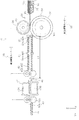
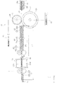
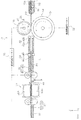
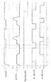
図1は本発明に係るスキャナーの外観斜視図であり、図2は本発明に係るスキャナーの媒体給送経路を示す側面図であり、図3ないし図10は給送経路を模式的に示した図であって、第1給送制御における給送状態の推移を段階的に示す図であり、図11は第1給送制御のタイミングチャートである。 FIG. 1 is an external perspective view of the scanner according to the present invention, FIG. 2 is a side view showing a medium feeding route of the scanner according to the present invention, and FIGS. 3 to 10 schematically show the feeding route. FIG. 11 is a diagram showing a stepwise transition of a feeding state in the first feeding control, and FIG. 11 is a timing chart of the first feeding control.
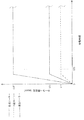
図12ないし図17は給送経路を模式的に示した図であって、第2給送制御における給送状態の推移を段階的に示す図であり、図18は第2給送制御のタイミングチャートであり、図19は低解像度スキャンモードにおける各ローラーの速度制御を示すグラフであり、図20は高解像度スキャンモードにおける各ローラーの速度制御を示すグラフであり、図21は本発明に係る媒体の給送時における媒体の分離に係るフローチャートであり、図22は高解像度スキャンモードにおける各ローラーの速度制御の変更例を示すグラフ。 12 to 17 are diagrams schematically showing the feeding route, and are diagrams showing the transition of the feeding state in the second feeding control stepwise, and FIG. 18 is the timing of the second feeding control. 19 is a chart, FIG. 19 is a graph showing speed control of each roller in a low resolution scan mode, FIG. 20 is a graph showing speed control of each roller in a high resolution scan mode, and FIG. 21 is a medium according to the present invention. It is a flowchart related to the separation of the medium at the time of feeding, and FIG. 22 is a graph showing an example of changing the speed control of each roller in the high resolution scan mode.
■■■実施例■■■■
<<<画像読取装置について>>>
図1及び図2を参照するに、「画像読取装置」としてのスキャナー10は、下部ユニット12と、上部ユニット14と、カバー部16と、排出トレイ18とを備えている。本実施例において、図示しないが上部ユニット14は下部ユニット12に対して用紙搬送方向下流側を回動支点として回動可能に下部ユニット12に取り付けられている。
■■■ Example ■■■■
<<< About image reader >>>
Referring to FIGS. 1 and 2, the
また、下部ユニット12の背面側の上部には、カバー部16が下部ユニット12に対して回動可能に取り付けられている。カバー部16は、上部ユニット14の上部及び給送口20(不図示)を覆う非給送状態と、図2に示すように装置背面側に回動し、給送口20を開放する給送可能状態とを取り得る。そして、カバー部16は、図1に示すように給送可能状態となると、カバー部16の裏面は、媒体Pを載置する媒体載置部16aとして機能する。
Further, a
また、下部ユニット12の装置前面側には媒体Pを排出する排出口24が設けられている。また、下部ユニット12は、排出口24から装置前面側に向けて引き出し可能な排出トレイ18を備えている。排出トレイ18は、下部ユニット12の底部に収納された状態(不図示)と、装置前面側に引き出された状態(図1参照)とを取り得る。また、本実施形態において排出トレイ18は複数のトレイ部材を連結して構成されており、排出される媒体Pの長さに応じて、排出口24からの引き出し長さを調整可能である。
Further, a
<スキャナーにおける用紙搬送経路について>
次に、図2及び図3を参照して、スキャナー10における媒体搬送経路26について説明する。また、図2では下部ユニット12及び上部ユニット14は、その筐体の外郭のみを仮想線で示している。尚、図2において符号Pが付された太い実線は、スキャナー10内において媒体搬送経路26に沿って搬送される媒体の案内経路を示している。
<About the paper transport route in the scanner>
Next, the
本実施例において、給送口20にセットされる媒体Pは、下部ユニット12に対して装置背面側に回動した姿勢を取るカバー部16の裏面、すなわち媒体載置部16aにより支持されて載置される。給送口20には、複数枚の媒体Pをセットすることができる。また、媒体載置部16aには、載置部検出手段28が設けられている。載置部検出手段28は、一例としてレバー等を有する接触式センサーあるいは光学式センサーとして構成され、媒体載置部16aに媒体Pがセットされると検出信号を後述する制御部30に送信する。そして、媒体載置部16aには複数枚の媒体Pをセットすることができる。
In this embodiment, the medium P set in the feeding
媒体載置部16aに載置された媒体Pは、最も下に載置された媒体Pが、給送駆動モーター32(図3参照)により回転駆動される「給送手段」としての給送ローラー34により給送方向下流側に給送される。給送ローラー34の外周面は、高摩擦材料(例えば、ゴムなどのエラストマ等)により構成されている。
The medium P mounted on the
尚、図2において符号Gは、媒体載置部16aに載置(セット)された媒体Pの束を示している。媒体束Gは、給送開始前ではその先端が不図示のストッパーにより給送待機位置(図2の位置)に保持され、給送ローラー34と後述する分離ローラー36との間への入り込みが規制されている。
In FIG. 2, reference numeral G indicates a bundle of media P mounted (set) on the
また、給送ローラー34と対向する位置には分離ローラー36が設けられている。分離ローラー36は、不図示の付勢手段によって給送ローラー34に対して付勢された状態に設けられている。また、分離ローラー36は、搬送駆動モーター38(図3参照)により給送ローラー34の回転方向(図3において反時計回り方向すなわち媒体を下流側に送る方向)と同じ方向(図3において反時計回り方向)に回転駆動される。本実施例において分離ローラー36の外周面は、給送ローラー34と同様に高摩擦材料(例えば、ゴムなどのエラストマ等)により構成されている。
Further, a
さらに、本実施例において分離ローラー36には、トルクリミッタ40が設けられている。分離ローラー36は、トルクリミッタ40を介して、搬送駆動モーター38の駆動トルクを受ける様に構成されている。
Further, in this embodiment, the
ここで、給送ローラー34から受ける回転トルクがトルクリミッタ40のリミットトルクを超えると、分離ローラー36はトルクリミッタ40により搬送駆動モーター38の駆動系から切り離され、給送ローラー34に従動して回転する(図3において時計回り方向)。
Here, when the rotational torque received from the
そして媒体Pの給送が開始され、給送ローラー34と分離ローラー36との間に複数枚の媒体Pが入り込むと、分離ローラー36は給送ローラー34から回転トルクを受けなくなり、給送ローラー34に従動した回転が止まる。そして、分離ローラー36は、トルクリミッタ40を介して搬送駆動モーター38の駆動力を受けて給送ローラー34と同じ方向に回転(図3における反時計回り方向)を始める。これにより給送されるべき最下位の媒体Pを除く上位の媒体P(重送を防止すべき媒体P)は、下流側へ進む為の搬送力を受けられず、分離ローラー36の回転により搬送方向上流側に戻される。これにより、媒体Pの重送が防止される。尚、給送されるべき最下位の媒体Pは、給送ローラー34と直接接触している為、給送ローラー34から受ける搬送力によって下流側に進む。
Then, when the feeding of the medium P is started and a plurality of media P are inserted between the feeding
続いて、媒体搬送経路26において給送ローラー34及び分離ローラー36の下流側には、媒体Pの給送を検出する第1検出手段42が設けられている。第1検出手段42は、一例として光学式センサーとして構成されている。第1検出手段42は、発光部42aと、受光部42bとを備えている。そして、発光部42aと受光部42bとは、媒体搬送経路26を挟んで対向する位置に配置され、媒体搬送経路26において媒体Pが搬送された際、媒体Pが発光部42aからの光を遮ることにより、媒体Pを検出するように構成されている。また、第1検出手段42は、媒体Pを検出すると、制御部30に検出信号を送信する。
Subsequently, in the
また、媒体搬送経路において第1検出手段42の搬送方向下流側には、媒体Pの重送を検出する重送検出センサー44が配置されている。本実施例において重送検出センサー44は、スピーカー部44aと、マイク部44bとを備える超音波センサーとして構成されている。また、重送検出センサー44は、スピーカー部44aから媒体搬送経路26を通る媒体Pに向けて超音波を発振し、媒体Pからの反射音をマイク部44bで検出するように構成されている。本実施例において重送検出センサー44は、反射音の周波数により媒体Pの重送を検知するだけでなく、厚紙等の紙種も検出可能に構成されている。
Further, in the medium transport path, a double
また、媒体搬送経路26において重送検出センサー44の搬送方向下流側には、「搬送手段」としての搬送ローラー対46が設けられている。搬送ローラー対46は搬送駆動ローラー46aと、搬送駆動ローラー46aに対して従動回転する搬送従動ローラー46bを備えている。本実施例において、搬送駆動ローラー46aは、搬送駆動モーター38により回転駆動させられる。
Further, in the
また、媒体搬送経路26において搬送ローラー対46の搬送方向下流側には、第2検出手段48が設けられている。第2検出手段48は、一例としてレバーを有する接触式センサーとして構成されている。ここで、媒体搬送経路26に沿って媒体Pが搬送されると、第2検出手段48のレバーが媒体Pの先端に押されて搬送方向下流側に回動する(図4参照)。これにより第2検出手段48は、媒体Pを検出する。そして、第2検出手段48は、媒体Pを検出すると、制御部30に検出信号を送信する。
Further, in the
第2検出手段48の下流側には、「読み取り手段」としての画像読取部50が設けられている。ここで、画像読取部50は、媒体搬送経路26に沿って搬送される媒体Pの上面と対向するように上部ユニット14に設けられた上部読み取りユニット50Aと、媒体搬送経路26に沿って搬送される媒体Pの下面と対向するように下部ユニット12に設けられた下部読み取りユニット50Bとを備えている。本実施例において、上部読み取りユニット50A及び下部読み取りユニット50Bは読み取りユニットとして構成され、一例として密着型イメージセンサーモジュール(CISM)として構成されている。
An
媒体Pは、画像読取部50において媒体Pの表面及び裏面の少なくとも一方の面の画像を読み取られた後、画像読取部50の搬送方向下流側に位置する排出ローラー対52にニップされて排出口24から排出される。
After the
また、本実施例において排出ローラー対52は排出駆動ローラー52aと、排出駆動ローラー52aに対して従動回転する排出従動ローラー52bを備えている。本実施例において、排出駆動ローラー52aは、搬送駆動モーター38により回転駆動させられる。尚、搬送駆動ローラー46aと排出駆動ローラー52aとは、共通の駆動源である搬送駆動モーター38により回転駆動させられる構成としたが、別々の駆動源により別個に回転駆動させられる構成としてもよい。
Further, in the present embodiment, the
また、下部ユニット12内には制御部30(図2参照)が設けられている。本実施例において制御部30は、複数の電子部品を備える電気回路として構成されている。制御部30は、載置部検出手段28、第1検出手段42、重送検出センサー44及び第2検出手段48の検出信号を受けて、上部読み取りユニット50A、下部読み取りユニット50B及び給送ローラー34、搬送駆動ローラー46a及び排出駆動ローラー52aを回転駆動させる給送駆動モーター32、搬送駆動モーター38を制御している。
Further, a control unit 30 (see FIG. 2) is provided in the
また、一例として制御部30は、スキャナー10における媒体Pの搬送及び画像読取動作を制御するように構成されている。また、制御部30は外部(PCなど)からの指示でスキャナー10における媒体読取動作の実行に必要な動作を制御してもよい。
Further, as an example, the
また、本実施例では、媒体載置部16aと、給送ローラー34と、分離ローラー36と、制御部30とは媒体搬送装置54を構成している。
Further, in this embodiment, the
<<<給送制御について>>>
次いで、図3ないし図18を参照して、スキャナー10における媒体Pの給送制御について説明する。本実施例において、スキャナー10の制御部30(図2参照)は、先行する媒体の給送方向長さが予め定めた長さより長い場合、後続の媒体の給送に対して第1給送制御を選択し、先行する媒体の給送方向長さが予め定めた長さ以下である場合、後続の媒体の給送に対して第2給送制御を選択する。
より詳しくは後述するが、第1給送制御は、先行する媒体の後端と後続の媒体の先端との間隔を詰める為に給送速度を一時的に増速させる処理を行う制御であり、第2給送制御は、上記増速処理を行わないか、或いは増速しても第1給送制御での増速より速度を抑えて増速する処理を行う制御である。
以下、図3ないし図11を参照して第1給送制御について、図12ないし図18を参照して第2給送制御について順次説明する。
<<< About feed control >>>
Next, the feeding control of the medium P in the
As will be described in more detail later, the first feeding control is a control for temporarily increasing the feeding speed in order to close the gap between the rear end of the preceding medium and the front end of the succeeding medium. The second feed control is a control in which the speed-up process is not performed, or even if the speed is increased, the speed is suppressed and the speed is increased as compared with the speed increase in the first feed control.
Hereinafter, the first feed control will be sequentially described with reference to FIGS. 3 to 11, and the second feed control will be sequentially described with reference to FIGS. 12 to 18.
<<<第1給送制御について>>>
以下、図11のタイミングチャートを主に参照しながら、第1給送制御について説明する。制御部30は、給送ローラー34及び搬送ローラー対46の回転駆動を開始させる(図11の第1タイミングt1参照、以下第10タイミングt10まで図11を参照)。そして、図3に示すように媒体載置部16aから「第1の媒体」としての先行の媒体P1の給送が開始される。そして、媒体P1は、給送ローラー34と分離ローラー36とによりニップされ、給送速度Vaで下流側に給送される。
<<< About the first feed control >>>
Hereinafter, the first feeding control will be described with reference mainly to the timing chart of FIG. The
そして、媒体P1は、媒体搬送経路26において分離ローラー36を超えて下流側に進むと、第1検出手段42により検出される(第2タイミングt2参照)。第1検出手段42は制御部30に媒体P1の検出信号を送信する。さらに媒体P1が給送方向下流側に送られると、媒体P1の先端が第2検出手段48のレバーを押圧して給送方向下流側に回動させる。これにより、第2検出手段48が媒体P1を検出する(第3タイミングt3参照)。第2検出手段48は制御部30に媒体P1の検出信号を送信する。
Then, when the medium P1 goes downstream beyond the
第2検出手段48が媒体P1を検出したということは、媒体P1が搬送ローラー対46にニップされたことを意味する(図4参照)。従って第2検出手段48の検出信号を受けた制御部30は、給送ローラー34の回転を停止させる(第3タイミングt3参照)。そして、画像読取部50は、媒体P1の画像読取を開始する。この際、給送ローラー34は停止するので、媒体P1は、図5に示すように搬送ローラー対46により画像読取部50に搬送される。そして給送ローラー34は停止するので、媒体P1の送り速度は、搬送ローラー対46による搬送速度Vc1となる。本実施例では、搬送速度Vc1は給送速度Vaより速い速度に設定されている。
The fact that the second detecting
次いで、図6に示すように媒体P1の後端が第1検出手段42を通過すると、第1検出手段42における検出状態が、一例としてON状態からOFF状態に切り換わる(第4タイミングt4参照)。制御部30は、媒体搬送経路26において媒体P1の後端が第1検出手段42を通過したと判断し、搬送ローラー対46による媒体搬送速度を搬送速度Vc1から搬送速度Vc2に減速させる。
Next, when the rear end of the medium P1 passes through the first detection means 42 as shown in FIG. 6, the detection state in the first detection means 42 is switched from the ON state to the OFF state as an example (see the fourth timing t4). .. The
ここで、制御部30は、媒体P1の給送方向長さL2(図6参照)を算出する。具体的には、媒体P1の給送方向長さL2は、第2検出手段48が媒体P1の先端を検出した時から第1検出手段42が媒体P1の後端が通過したことを検出した時までの時間、すなわち第3タイミングt3から第4タイミングt4までの経過時間t4−t3に搬送ローラー対46の搬送速度Vc1を掛けて求められた数値に媒体搬送経路26における第1検出手段42から第2検出手段48までの経路長L1を足した値となる。すなわち、媒体P1の給送方向長さL2は、L2=(t4−t3)×Vc1+L1で表される。
Here, the
そして、制御部30は、算出した媒体P1の給送方向長さL2が、予め設定した長さLより長いかを判断する。そして、媒体P1の給送方向長さL2が長さLより長い場合には、制御部30は、次に給送される媒体P2に対して先端が分離ローラー36を通過してから第2検出手段48が検出を行うまでの間の少なくとも所定期間の給送速度を速度Vaから速度Vaよりも速い速度Vb1に変更して給送する第1給送制御を行う。ここで、予め設定した長さLとは、国際規格ISO/IEC7810「ID−1」で規定されるカードの短辺サイズに応じて設定された長さである。尚、以下の説明では、後続する媒体P2以降の媒体Pにおいても給送方向長さL2が長さLより長いものとして説明する。
Then, the
より詳しくは、図7に示すように再度、給送ローラー34を回転駆動させて、媒体載置部16aから「第2の媒体」としての後続の媒体P2の給送を開始する(第5タイミングt5参照)。ここで、後続の媒体P2の給送開始タイミング、すなわち第5タイミングt5は、第1検出手段42がOFF状態となってから所定の第1の待ち時間が経過した後に媒体P2の給送を開始するタイミングとして設定されている。尚、制御部30は、後続の媒体P2の先端が分離ローラー36を通過し、更に第1検出手段42を通過して所定の時間が経過する迄(第8タイミングt8)は、給送ローラー34により給送速度Vaで給送を行う。
More specifically, as shown in FIG. 7, the feeding
即ち、後続の媒体P2の先端が第1検出手段42を通過すると、検出信号が制御部30に送信される(第6タイミングt6参照)。その後、先行する媒体P1の後端が第2検出手段48を通過する(第7タイミングt7参照)。 That is, when the tip of the subsequent medium P2 passes through the first detection means 42, the detection signal is transmitted to the control unit 30 (see the sixth timing t6). After that, the rear end of the preceding medium P1 passes through the second detection means 48 (see the seventh timing t7).
そして、図8に示すように先行する媒体P1の後端が第2検出手段48により検出されてから所定時間経過した後、制御部30は給送ローラー34による後続の媒体P2の給送速度を速度Vaから速度Vb1に増速させるとともに、搬送ローラー対46による媒体Pの搬送速度を速度Vc2から速度Vc1に増速させる(第8タイミングt8参照)。これにより先行する媒体P1の後端と後続の媒体P2の先端との間隔が縮められる。ここで第8タイミングt8は第7タイミングt7から所定の第2の待ち時間が経過した後のタイミングとして設定されている。
Then, as shown in FIG. 8, after a predetermined time has elapsed from the detection of the rear end of the preceding medium P1 by the second detection means 48, the
そして、図9に示すように第2検出手段48が媒体P2の先端を検出すると、制御部30は給送ローラー34の回転を停止させる(第9タイミングt9参照)。そして、画像読取部50は、媒体P2の画像読取を開始する。この際、給送ローラー34は停止するので、媒体P2は図10に示すように搬送ローラー対46により搬送速度Vc1で画像読取部50に搬送される。そして、第1検出手段42が媒体P2の後端を検出すると、制御部30は媒体P2の給送方向長さL2を算出し、予め設定した長さLより長いか判断する(第10タイミングt10参照)。
Then, when the second detecting
この様にして以降同様に、制御部30は媒体の給送方向長さL2が予め設定した長さLより長い場合には、さらに後続する媒体の給送においてその先端が分離ローラー36を通過してから所定の時間が経過するまでは給送速度Vaで給送し、先行する媒体の後端が第2検出手段48を通過した後、給送速度Vaから給送速度Vb1に増速する制御を行う。そして、載置部検出手段28が媒体Pを検出しなくなるまで、上記給送を繰り返す。尚、図11において第10タイミングt10以降は、媒体載置部16aに載置された媒体Pが全て送り出されるまで第4タイミングt4から第10タイミングt10までの動作を繰り返す。
In this way, similarly, when the feed direction length L2 of the medium is longer than the preset length L, the tip of the
以上説明した第1給送制御により、所定のタイミングで後続する媒体の給送速度が速度Vaから速度Vb1に増速されるので、媒体搬送経路26において先行する媒体の後端と後続する媒体の先端との間隔が狭められ、スループットの向上が図られる。
By the first feeding control described above, the feeding speed of the succeeding medium is increased from the speed Va to the speed Vb1 at a predetermined timing, so that the rear end of the preceding medium and the succeeding medium in the
<<<第2給送制御について>>>
次いで、図3及び図12ないし図18を参照して第2給送制御について説明する。図3に示すように制御部30は、給送ローラー34及び搬送ローラー対46の回転駆動を開始させ、媒体載置部16aから「第1の媒体」としての先行の媒体P1の給送を開始させる(図18における第11タイミングt11参照、以下第19タイミングt19まで図18を参照)。
<<< About the second feed control >>>
Next, the second feeding control will be described with reference to FIGS. 3 and 12 to 18. As shown in FIG. 3, the
そして、媒体P1は、給送ローラー34と分離ローラー36とによりニップされ、給送速度Vaで下流側に給送される。そして、第1検出手段42が媒体P1を検出する(第12タイミングt12参照)。次いで、図12に示すように第2検出手段48が媒体P1の先端を検出する(第13タイミングt13参照)。そして、制御部30は、第2検出手段48の検出信号を受信すると、給送ローラー34の回転を停止させる。尚、媒体P1は給送開始から第13タイミングt13までの間、給送速度Vaで送られている。
Then, the medium P1 is nipated by the feeding
そして、画像読取部50は、媒体P1の画像読取を開始する。この際、給送ローラー34は停止するので、媒体P1は、搬送ローラー対46にニップされて搬送速度Vc1で画像読取部50に送られる。そして、図13に示すように媒体P1の後端が第1検出手段42を通過する(第14タイミングt14参照)。
Then, the
そして、制御部30は、算出した媒体P1の給送方向長さL3(図13参照)が、予め設定した長さLより長いかを判断する。そして、媒体P1の給送方向長さL3が長さL以下である場合には、制御部30は、次に給送される媒体P2に対して給送速度を速度Vaに維持して(図11に示した第1給送制御の様に速度Vb1への増速を行わないで)給送する第2給送制御を行う。
Then, the
尚、次に給送される媒体P2の先端が分離ローラー36を通過してから第2検出手段48が検出を行うまでの間の少なくとも所定期間の給送速度をVb2として、本実施例では、速度Vb2は速度Vaと同じ速度に設定されている。但し速度Vb2は、少なくとも図11に示した第1給送制御の速度Vb1より低速であることを前提とし、給送制御に支障が出ない範囲で、速度Vaよりも高速に設定しても良い。
In this embodiment, the feeding speed for at least a predetermined period from the time when the tip of the medium P2 to be fed next passes through the
そして、制御部30は、図14に示すように媒体P1の後端が第1検出手段42を通過すると、搬送ローラー対46の搬送速度を速度Vc1から速度Vc2に減速させるとともに給送ローラー34を再駆動させて後続する媒体P2の給送を開始させる(第14タイミングt14参照)。ここで、媒体P2は給送ローラー34により分離ローラー36を通過した後も給送速度Vaで給送される。そして、図15に示すように、第1検出手段42が媒体P2の先端を検出する(第15タイミングt15参照)。
Then, as shown in FIG. 14, when the rear end of the medium P1 passes through the first detection means 42, the
尚、第1検出手段42が媒体P2の先端を検出した時点では、媒体P1は第2検出手段48に検出された状態にある。しかしながら、媒体P2の給送速度Vaよりも媒体P1の搬送速度Vc2の方が速いので、媒体P2が媒体P1に追いつくことがなく、媒体間の間隔が適切に維持される。
When the first detecting
そして、図16に示すように、媒体P1は搬送ローラー対46により搬送速度Vc2で下流側に送られて、その後端が第2検出手段48により検出される(第16タイミングt16参照)。そして、制御部30は、第2検出手段48の検出信号に応じて搬送ローラー対46の搬送速度Vc2を速度Vc1に増速させる(第17タイミングt17参照)。その後、媒体P2の先端が第2検出手段48の位置まで達すると、媒体P2の先端が第2検出手段48により媒体P2が検出され、制御部30は、給送ローラー34の回転を停止させる(第18タイミングt18参照)。そして、媒体P2は、搬送ローラー対46により搬送速度Vc1で画像読取部50に向けて搬送され、読み取りが行われる。
Then, as shown in FIG. 16, the medium P1 is fed downstream by the
次いで、図17に示すように、媒体P2の後端が第1検出手段42を通過すると、第1検出手段42が媒体P2の後端を検出する(第19タイミングt19参照)。そして、制御部30は媒体P2の給送方向長さL3を算出し、予め設定された長さL以下かを判断する。媒体P2の給送方向長さL3が長さL以下である場合、制御部30は後続する媒体P3の給送制御を第2給送制御により行うことを決定する。また、図17に示すように制御部30は給送ローラー34を再駆動させて後続する媒体P3の給送を開始させるとともに、搬送ローラー対46の搬送速度を速度Vc1から速度Vc2に減速させる(第19タイミングt19参照)。
Then, as shown in FIG. 17, when the rear end of the medium P2 passes through the first detection means 42, the first detection means 42 detects the rear end of the medium P2 (see the 19th timing t19). Then, the
ここで、後続する媒体P3の給送では、制御部30により第2給送制御が選択されているので、媒体P3が分離ローラー36を通過した後も給送速度Va(=Vb2)で給送を行う。そして、載置部検出手段28が媒体Pを検出しなくなるまで、上記給送を繰り返す。尚、図18において第19タイミングt19以降は、媒体載置部16aに載置された媒体が全て送り出されるまで第14タイミングt14から第19タイミングt19までの動作を繰り返す。
Here, in the subsequent feeding of the medium P3, since the second feeding control is selected by the
第2給送制御についてまとめると、先行する媒体P1の給送方向長さL3が予め設定された長さL以下である場合、後続する媒体P2の給送において分離ローラー36を通過した後も、図11に示した第1給送制御での給送速度Vb1より低速である給送速度Vb2で給送する速度制御モードである。
To summarize the second feed control, when the feed
尚、本実施例において、予め設定する長さLは、国際規格ISO/IEC7810「ID−1」で規定されるカードの短辺サイズに応じた長さとしたが、これに限られない。即ち、予め設定する長さLを、例えば給送ローラー34と分離ローラー36とのニップ点から搬送ローラー対46のニップ点までの経路長L4(図4参照)より長く、給送ローラー34と分離ローラー36とのニップ点から第2検出手段48までの経路長L5(図4参照)以下の長さとすることができる。
In this embodiment, the preset length L is a length corresponding to the short side size of the card defined by the international standard ISO / IEC7810 "ID-1", but is not limited to this. That is, the preset length L is longer than, for example, the path length L4 (see FIG. 4) from the nip point of the feeding
即ち、先行する媒体P1の給送方向長さが図4の経路長L5以下である場合、第2検出手段48が先行する媒体P1の先端を検出したときには、先行する媒体P1の後端は給送ローラー34と分離ローラー36とのニップ点を通過してしまっている。このように、先行する媒体P1の後端が給送ローラー34と分離ローラー36とのニップ点を通過すると、後続する媒体P2の先端が給送ローラー34と分離ローラー36とのニップ点に位置するか或いは前記ニップ点より下流側に進んでしまっていることになり、即ち後続する媒体P2の給送が意図せず開始されてしまう。その後、第2検出手段48が先行する媒体P1の先端を検出した際、制御部30は給送制御を停止するが、後続する媒体P2は、制御部30により給送制御が停止される前、給送速度Vb2で給送されているので、先行する媒体P1と後続する媒体P2との間隔が意図せず短くなってしまい、読み取り不良を招く虞がある(詳しくは後述)。
That is, when the feeding direction length of the preceding medium P1 is equal to or less than the path length L5 in FIG. 4, when the second detecting
<<第1給送制御と第2給送制御の使い分けによる作用効果>>
以上説明したように、制御部30は、先行する媒体の給送方向長さが予め定めた長さより長い場合、後続の媒体の給送に対して第1給送制御を選択し、先行する媒体の給送方向長さが予め定めた長さ以下である場合、後続の媒体の給送に対して第2給送制御を選択する。第2給送制御は、上述したように先行する媒体の後端と後続の媒体の先端との間隔を詰める為に給送速度を一時的に増速させる処理を行わない制御である。これにより得られる作用効果は、以下の通りである。
<< Action and effect by properly using the first feed control and the second feed control >>
As described above, when the feeding direction length of the preceding medium is longer than a predetermined length, the
即ち、媒体の給送動作(給送ローラー34の駆動)は、基本的に媒体の先端が第2検出手段48により検出されたことをもって停止させるが、制御部30が給送ローラー34の駆動を停止してから、実際に給送ローラー34の回転が完全に止まる迄には、ある程度の時間が掛かる(制動距離)。
ここで、長さが比較的長い媒体の場合には、後端が分離ローラー36より上流側にあるので、給送ローラー34の回転が止まるまでに時間が掛かっても、後続の媒体が給送されることはない。しかしながら長さが短い媒体の場合には、その先端が第2検出手段48により検出された時点で後端が分離ローラー36より下流側に進んでしまっている。従ってこの状態で給送ローラー34が完全に止まるまでに時間が掛かってしまうと、後続の媒体が意図せず送り出されてしまい、場合により分離ローラー36より下流側に進んでしまって、その結果先行する媒体の後端と後続の媒体の先端との間隔が意図せず短くなってしまい、読み取り不良を招く虞がある。
That is, the feeding operation of the medium (driving the feeding roller 34) is basically stopped when the tip of the medium is detected by the second detecting
Here, in the case of a medium having a relatively long length, since the rear end is on the upstream side of the
この様な問題は、図11(第1給送制御)の給送速度Vb1の様に、給送速度を一時的に増速させた場合に特に発生し易い。給送ローラー34を高速で回転させると、それだけ給送ローラー34が完全に停止するまで時間が掛かる為である。
そこで本実施形態では、上述のように先行する媒体の長さを判定して所定長さ以下である場合には、後続の媒体に対して給送速度を一時的に増速させる処理を行わないことで(第2給送制御)、媒体の後端と後続の媒体の先端との間隔が意図せず短くなり、読み取り不良を招く問題を回避することができる。
Such a problem is particularly likely to occur when the feeding speed is temporarily increased as in the feeding speed Vb1 of FIG. 11 (first feeding control). This is because when the feeding
Therefore, in the present embodiment, as described above, when the length of the preceding medium is determined and is less than or equal to the predetermined length, the process of temporarily increasing the feeding speed with respect to the succeeding medium is not performed. As a result (second feeding control), the distance between the rear end of the medium and the leading end of the subsequent medium is unintentionally shortened, and the problem of causing reading failure can be avoided.
尚、複数枚の媒体の給送を行う場合は、図11及び図18に示す様に媒体長さに拘わらず最初の一枚目については給送速度を一時的に増速させる処理は行わない。一枚目については、媒体の給送方向長さを検知できない為である。 When feeding a plurality of sheets, as shown in FIGS. 11 and 18, the process of temporarily increasing the feeding speed is not performed for the first sheet regardless of the length of the medium. .. This is because the length of the medium in the feeding direction cannot be detected for the first sheet.
<<<給送制御の変更例>>>
本実施例では、制御部30は、搬送される媒体Pの給送方向長さL2を予め設定された長さLと比較して、長さL2が長さLより長い場合、第1給送制御を行い、長さL2が長さL以下である場合、第2給送制御を行うように制御したが、この制御に代えて、媒体Pの属性、例えば、媒体Pの厚みに応じて第1給送制御と第2給送制御とを切換える制御としてもよい。具体的には、制御部30は、搬送されてきた媒体Pの厚みが予め設定された厚みtより厚い場合、第1給送制御を行い、搬送されてきた媒体Pの厚みが予め設定された厚みt以下である場合、第2給送制御を行うように制御する。
つまり、媒体の厚みが薄く剛性が低い場合、給送速度を増速させると、媒体搬送経路の微少な突起や凹みに媒体が引っ掛かった際のダメージが大きくなり、その後の搬送においてジャムを招く虞がある。しかし、上記のように媒体の厚みに応じて給送制御を切り換えることで、上記の問題の回避が期待できる。
<<< Example of change in feed control >>>
In the present embodiment, the
That is, when the thickness of the medium is thin and the rigidity is low, if the feeding speed is increased, the damage when the medium is caught in the minute protrusions or dents of the medium transport path becomes large, and there is a risk of causing jam in the subsequent transport. There is. However, by switching the feeding control according to the thickness of the medium as described above, the above problem can be expected to be avoided.
<<<解像度に応じた給送制御について>>>
次いで、図19ないし図22を参照して、媒体Pを読み取る解像度の違いに応じた給送制御について説明する。本実施例のスキャナー10の画像読取部50は、媒体Pを少なくとも2種類の解像度で読み取りが可能に構成されている。具体的には、低解像度スキャンモードと高解像度スキャンモードとを備えている。一例として低解像度スキャンモードは300dpiで媒体Pを読み取り、高解像度スキャンモードは600dpiで媒体Pを読み取るように設定されている。
<<< Feeding control according to resolution >>>
Next, with reference to FIGS. 19 to 22, feeding control according to the difference in the resolution at which the medium P is read will be described. The
<<<低解像度スキャンモードについて>>>
まず、図19を参照して低解像度スキャンモードについて説明する。制御部30は、まず、給送ローラー34、分離ローラー36及び搬送ローラー対46の回転駆動を開始する。そして、給送ローラー34のローラー周速度をVf1とし、分離ローラー36のローラー周速度をVr1とし、搬送ローラー対46(搬送駆動ローラー46a)のローラー周速度をVpf1とする。ここでこれらのローラー周速度は、Vpf1>Vf1>Vr1の関係に設定されている。
<<< About low resolution scan mode >>>
First, the low resolution scan mode will be described with reference to FIG. First, the
給送ローラー34のローラー周速度Vf1が搬送駆動ローラー46aのローラー周速度Vpf1よりも大きいと、媒体搬送経路26内において媒体Pが詰まり、傷が生じることがあるので、給送ローラー34のローラー周速度Vf1が搬送駆動ローラー46aのローラー周速度Vpf1よりも低速に設定されている。
If the roller peripheral speed Vf1 of the
尚、本実施例において、媒体載置部16aから給送される媒体Pは、各ローラーが回転駆動を開始してから時間t20経過後に分離ローラー36に達するように設定されている。そして、本実施例では、分離ローラー36は時間t20経過前にローラー周速度Vr1に達しており、媒体Pへの分離性能を十分に発揮することができ、重送を抑制できる。
In this embodiment, the medium P fed from the
そして、一例として図4に示すように給送ローラー34により下流側に送られた媒体P(図4において媒体P1)の先端が、第2検出手段48に検出されると、制御部30は給送ローラー34の回転を停止する。ここで、第2検出手段48が媒体Pを検出した状態では、媒体Pが搬送ローラー対46にニップされているので、制御部30は搬送ローラー対46により媒体Pを画像読取部50に送り、媒体Pの画像読取を開始させる。尚、この際、搬送駆動ローラー46aのローラー周速度はVpf1である。
Then, as an example, when the tip of the medium P (medium P1 in FIG. 4) sent downstream by the feeding
ここで、低解像度スキャンモードは後述する高解像度スキャンモードより画質を落とす変わりに媒体Pの搬送速度及び読み取り速度を速めてスループットを向上させている。 Here, the low-resolution scan mode improves the throughput by increasing the transport speed and the reading speed of the medium P instead of lowering the image quality as compared with the high-resolution scan mode described later.
<<<高解像度スキャンモードについて>>>
次いで、図20を参照して高解像度スキャンモードについて説明する。制御部30は、まず、給送ローラー34、分離ローラー36及び搬送ローラー対46の回転駆動を開始する。そして、各ローラーは、一例として低解像度モードと略同じ速度まで加速される。つまり、給送ローラー34はローラー周速度Vf1まで加速され、分離ローラー36はローラー周速度Vr1まで加速され、搬送ローラー対46(搬送駆動ローラー46a)はローラー周速度Vpf1まで加速される。
<<< About high resolution scan mode >>>
Next, the high resolution scan mode will be described with reference to FIG. First, the
そして、媒体載置部16aから送られた媒体Pは、各ローラーが回転駆動を開始してから時間t21経過後に分離ローラー36に達する。ここで、分離ローラー36は時間t21経過前にローラー周速度Vr1に達しており、媒体Pへの分離性能を十分に発揮することができ、重送を抑制できる。
Then, the medium P sent from the
そして、制御部30は、媒体Pの給送開始後、媒体搬送経路26における位置W1(図3参照)に媒体Pの先端が達する様に、時間t22において給送ローラー34、分離ローラー36及び搬送ローラー対46の回転駆動を停止させる。ここで、図3の位置W1に媒体Pの先端を位置決めする為の給送ローラー34の回転量は、予め求めることができる。本実施例では、媒体Pの先端が第1検出手段42に検出される位置よりも手前で媒体Pの先端が停止できる位置を位置W1として設定している。
Then, after the start of feeding the medium P, the
そして、制御部30は、後述するが第1検出手段42が媒体Pを検出しない場合、各ローラーを時間t23において再駆動させる。そして、制御部30は、給送ローラー34をローラー周速度Vf2まで加速させ、分離ローラー36をローラー周速度Vr2まで加速させ、搬送ローラー対46(搬送駆動ローラー46a)をローラー周速度Vpf2まで加速させる。
Then, as will be described later, when the first detecting
そして、一例として図4に示すように給送ローラー34により下流側に送られた媒体P(図4において媒体P1)の先端が、第2検出手段48に検出されると、制御部30は給送ローラー34の回転を停止する。ここで、第2検出手段48が媒体Pを検出した状態では、媒体Pが搬送ローラー対46にニップされているので、制御部30は搬送ローラー対46により媒体P1を画像読取部50に送り、媒体Pの画像読取を開始させる。尚、この際、搬送駆動ローラー46aのローラー周速度はVpf2である。
Then, as an example, when the tip of the medium P (medium P1 in FIG. 4) sent downstream by the feeding
ここで、各ローラーの周速度は、Vpf1>Vf1>Vpf2>Vf2>Vr1>Vr2の関係を有している。つまり、時間t23において再駆動された各ローラーの周速度は、時間t22より前の各ローラーの周速度(低解像度スキャンモードにおける各ローラーの周速度に相当)よりも低速に設定されている。したがって、画像読取部50において媒体Pを低解像度スキャンモードの送り速度よりも低速で送ることができ、高解像度で画像を読み取ることができる。
Here, the peripheral speed of each roller has a relationship of Vpf1> Vf1> Vpf2> Vf2> Vr1> Vr2. That is, the peripheral speed of each roller redriven at time t23 is set to be lower than the peripheral speed of each roller before time t22 (corresponding to the peripheral speed of each roller in the low resolution scan mode). Therefore, the
また、給送ローラー34の周速度が低い状態で媒体Pが給送ローラー34と接すると搬送力が低いので媒体Pのノンフィードが発生する場合がある。しかしながら、本実施例における高解像度スキャンモードでは、最初に給送ローラー34を高速回転させて媒体Pの搬送に必要な搬送力を与えてから媒体Pが給送ローラー34に接するので、媒体Pのノンフィードを抑制することができる。また、分離ローラー36は時間t23経過前にローラー周速度Vr1に達しており、媒体Pへの分離性能を十分に発揮することができ、重送を抑制できる。
Further, if the medium P comes into contact with the feeding
次いで図21を参照して、解像度に応じた給送制御の流れについて説明する。ステップS1として制御部30が、画像読取ジョブの開始信号を受信する。そして、制御部30は、ステップS2として画像読取モードが高解像度スキャンモードであるか否かを判断する。制御部30は画像読取モードが高解像度スキャンモードである場合にはステップS3に移行し、画像読取モードが高解像度スキャンモードでない場合、つまり低解像度スキャンモードである場合にはステップS12に移行する。
Next, with reference to FIG. 21, the flow of feeding control according to the resolution will be described. As step S1, the
ステップS3において制御部30は給送ローラー34、分離ローラー36及び搬送ローラー対46(搬送駆動ローラー46a)を第1の速度(Vf1、Vr1、Vpf1)で回転駆動させて媒体Pの給送を開始させる。次いで、制御部30は、媒体Pの先端を図3の位置W1で停止させる為に給送ローラー34を予め定めた距離分回転させる処理と(ステップS6)、その回転の途中で第1検出手段42が媒体Pの先端を検出するか否かの監視を行う(ステップS4)。
In step S3, the
ここで、給送ローラー34が媒体Pの先端を図3の位置W1で停止させる為に予め求めた距離分回転する前に、第1検出手段42が媒体Pを検出する場合、即ち媒体Pの先端が目論見よりも多く下流側に進んでしまっている場合は、媒体Pが適切にセットされていなかった虞がある。また、媒体Pの先端が搬送ローラー対46に送り速度が速いまま、接触する場合があり、紙詰まりや媒体Pに傷を生じさせる場合がある。従って、第1検出手段42が媒体Pを検出した場合、ステップS5として制御部30は給送ローラー34、分離ローラー36及び搬送ローラー対46(搬送駆動ローラー46a)の回転を停止させてエラー信号を発する。その結果、紙詰まりや媒体Pに傷を生じさせることを低減できる。そして、制御部30はエラー信号を発した後、画像読取ジョブを終了させる。
Here, when the first detecting
給送ローラー34が予め求めた距離分回転した場合(ステップS6においてYes)、ステップS7に移行する。ステップS7において制御部30は、給送ローラー34、分離ローラー36及び搬送ローラー対46(搬送駆動ローラー46a)の回転を停止させる。そして、ステップS8として制御部30は給送ローラー34、分離ローラー36及び搬送ローラー対46(搬送駆動ローラー46a)を第2の速度(Vf2、Vr2、Vpf2)で回転駆動させる。
When the feeding
そして、ステップS9として制御部30は第2検出手段48が媒体Pの先端を検出したか否かを判断する。第2検出手段48が媒体Pの先端を検出していない場合、ステップS9を継続する。第2検出手段48が媒体Pの先端を検出した場合、ステップS10として制御部30は給送ローラー34の回転を停止させる。そして、ステップS11として制御部30は媒体搬送ローラー対46により媒体Pを画像読取部50に搬送させ、高解像度スキャンモードで媒体Pの画像読取を開始させる。そして、媒体Pの画像読取が終了すると、制御部30は搬送ローラー対46を停止させて画像読取ジョブを終了させる。
Then, in step S9, the
また、ステップS2において画像読取モードが高解像度スキャンモードでない場合、ステップS12に移行する。そして、ステップS12として制御部30は給送ローラー34、分離ローラー36及び搬送ローラー対46(搬送駆動ローラー46a)を第1の速度(Vf1、Vr1、Vpf1)で回転駆動させて、媒体の給送を開始させる。
If the image reading mode is not the high resolution scan mode in step S2, the process proceeds to step S12. Then, in step S12, the
そして、ステップS13として制御部30は第2検出手段48が媒体Pの先端を検出したか否かを判断する。第2検出手段48が媒体Pの先端を検出していない場合、ステップS13を継続する。第2検出手段48が媒体Pの先端を検出した場合、ステップS14として制御部30は給送ローラー34の回転を停止させる。そして、ステップS15として制御部30は媒体搬送ローラー対46により媒体Pを画像読取部50に搬送させ、低解像度スキャンモードで媒体Pの画像読取を開始させる。そして、媒体Pの画像読取が終了すると、制御部30は搬送ローラー対46を停止させて画像読取ジョブを終了させる。
Then, in step S13, the
<<<解像度に応じた給送制御の変更例>>>
(1)本実施例において、図20に示すように時間t23において給送ローラー34、分離ローラー36及び搬送ローラー対46(搬送駆動ローラー46a)の第2の速度での駆動を同じタイミングで行う様に制御したが、この制御に代えて、図22に示すように、給送ローラー34の再駆動のタイミングを時間t23より後の時間t24にずらして再駆動させてもよい。これにより制御のバラツキ等により、給送ローラー34の周速度が搬送ローラー対46(搬送駆動ローラー46a)の周速度よりも速くなることを抑制できる。
(2)また、媒体Pの給送を開始する前に分離ローラー36を一定距離分回転させてもよい。このように制御することで、分離ローラー36の動力伝達機構(不図示)におけるバックラッシを除去し、分離ローラー36が分離性能を発揮するまでの時間を早めることができる。これにより媒体Pの重送を抑制できる。
(3)また、媒体Pの給送を開始する前に給送ローラー34を一定距離分回転させて給送ローラー34と当接する分離ローラー36を共回りさせてもよい。これにより、分離ローラー36の動力伝達機構(不図示)におけるバックラッシが除去され、分離ローラー36が分離性能を発揮するまでの時間を早めることができる。これにより媒体Pの重送を抑制できる。
(4)実施例において、図20に示すように時間t22において給送ローラー34、分離ローラー36及び搬送ローラー対46(搬送駆動ローラー46a)を一端停止させて、時間t23において再駆動するように制御したが、この制御に代えて、時間t23から時間t24の間において給送ローラー34、分離ローラー36及び搬送ローラー対46(搬送駆動ローラー46a)の速度を第1の速度(Vf1、Vr1、Vpf1)から第2の速度(Vf2、Vr2、Vpf2)に切換えるように制御してもよい。
<<< Example of changing the feed control according to the resolution >>>
(1) In the present embodiment, as shown in FIG. 20, the feeding
(2) Further, the
(3) Further, before starting the feeding of the medium P, the feeding
(4) In the embodiment, as shown in FIG. 20, the
上記説明をまとめると、スキャナー10は、媒体Pを載置する媒体載置部16aと、媒体載置部16aから媒体Pを送り出す給送ローラー34と、給送ローラー34と対向配置された、媒体Pを分離する分離ローラー36と、給送ローラー34及び分離ローラー36の下流側に設けられた、媒体Pを搬送する搬送ローラー対46と、搬送ローラー対46の下流側に設けられた、媒体Pを読み取る画像読取部50と、給送ローラー34及び搬送ローラー対46を制御する制御部30と、を備え、制御部30は、複数の媒体Pを連続して給送する際、先行する第1の媒体P1の給送方向長さL2に応じ、後続の第2の媒体P2を給送ローラー34により給送する際の給送制御を変更する。
To summarize the above description, the
上記構成によれば、給送ローラー34及び搬送ローラー対46を制御する制御部30は、複数の媒体Pを連続して給送する際、先行する第1の媒体P1の給送方向長さL2に応じ、後続の第2の媒体P2を給送ローラー34により給送する際の給送制御を変更するので、原稿の長さの変化に伴う原稿間隔の調整の失敗を抑制でき、スループットの向上を図りながらも、原稿間隔を適切に調整することができる。
According to the above configuration, when the
媒体Pの先端が分離ローラー36を通過する迄の給送ローラー34による媒体Pの給送速度を速度Va、媒体Pの先端が分離ローラー36を通過した後の給送ローラー34による媒体Pの給送速度を速度Vbとして、制御部30は、第1の媒体P1の給送方向長さL2が予め定めた長さLより長い場合、速度Vbを速度Vaより高速である速度Vb1に設定する第1給送制御と、第1の媒体P1の給送方向長さL2が長さL以下である場合、速度Vbを速度Vb1より低速である速度Vb2に設定する第2給送制御と、を実行可能である。
The feeding speed of the medium P by the feeding
上記構成によれば、制御部30は、第1の媒体P1の給送方向長さL2が予め定めた長さLより長いである場合、速度Vbを速度Vaより高速である速度Vb1に設定する第1給送制御と、第1の媒体P1の給送方向長さL2が長さL以下である場合、速度Vbを速度Vb1より低速である速度Vb2に設定する第2給送制御と、を実行可能であるので、第1の媒体P1の給送方向長さL2が長さL以下である場合に第2給送制御を選択することで、原稿間隔を適切に制御できる。
According to the above configuration, when the feeding direction length L2 of the first medium P1 is longer than the predetermined length L, the
媒体搬送経路26において給送ローラー34と搬送ローラー対46との間に設けられた、媒体Pを検出する第1検出手段42と、媒体搬送経路26において搬送ローラー対46の下流側に設けられた、媒体Pを検出する第2検出手段48と、を備え、制御部30は、第1の媒体P1の先端を第2検出手段48により検出した時点から、第1の媒体P1の後端を第1検出手段42により検出する迄の第1の媒体P1の搬送量と、第1検出手段42と第2検出手段48との間の経路長L1をもとにして、第1の媒体P1の給送方向長さL2を算出する。
The first detecting
上記構成によれば、制御部30は、第1の媒体P1の先端を第2検出手段48により検出した時点から、第1の媒体P1の後端を第1検出手段42により検出する迄の第1の媒体P1の搬送量と、第1検出手段42と第2検出手段48との間の経路長L1をもとにして、第1の媒体P1の給送方向長さL2を算出するので、先行する原稿と後続の原稿との間隔をより正確に制御できる。
According to the above configuration, the
長さLは、国際規格ISO/IEC7810「ID−1」で規定されるカードの短辺サイズに応じて設定されている。 The length L is set according to the short side size of the card defined by the international standard ISO / IEC7810 "ID-1".
スキャナー10は、媒体Pを載置する媒体載置部16aと、媒体載置部16aから媒体Pを送り出す給送ローラー34と、給送ローラー34と対向配置された、媒体Pを分離する分離ローラー36と、給送ローラー34及び分離ローラー36の下流側に設けられた、媒体Pを搬送する搬送ローラー対46と、搬送ローラー対46の下流側に設けられた、媒体Pを読み取る画像読取部50と、給送ローラー34及び搬送ローラー対46を制御する制御部30と、を備え、制御部30は、複数の媒体Pを連続して給送する際、先行する第1の媒体P1の属性に応じ、後続の第2の媒体P2を給送ローラー34により給送する際の給送制御を変更する。
The
上記構成によれば、給送ローラー34及び搬送ローラー対46を制御する制御部30は、複数の媒体Pを連続して給送する際、先行する第1の媒体P1の属性に応じ、後続の第2の媒体P2を給送ローラー34により給送する際の給送制御を変更するので、原稿の属性の変化に伴う原稿間隔の調整の失敗を抑制でき、スループットの向上を図りながらも、原稿間隔を適切に調整することができる。
According to the above configuration, when the
媒体Pの先端が分離ローラー36を通過する迄の給送ローラー34による媒体Pの給送速度を速度Va、媒体Pの先端が分離ローラー36を通過した後の給送ローラー34による媒体Pの給送速度を速度Vbとして、制御部30は、第1の媒体P1の厚みが予め定めた厚みtより厚いである場合、速度Vbを速度Vaより高速である速度Vb1に設定する第1給送制御と、第1の媒体P1の厚みが厚みt以下である場合、速度Vbを速度Vb1より低速である速度Vb2に設定する第2給送制御と、を実行可能である。
The feeding speed of the medium P by the feeding
上記構成によれば、制御部30は、第1の媒体P1の厚みが予め定めた厚みtより厚い場合、速度Vbを速度Vaより高速である速度Vb1に設定する第1給送制御と、第1の媒体P1の厚みが厚みt以下である場合、速度Vbを速度Vb1より低速である速度Vb2に設定する第2給送制御と、を実行可能であるので、第1の媒体P1の厚みが厚みt以下である場合に第2給送制御を選択することで、原稿間隔を適切に制御できる。
According to the above configuration, when the thickness of the first medium P1 is thicker than the predetermined thickness t, the
尚、本発明は上記実施例に限定されることなく、特許請求の範囲に記載した発明の範囲内で、種々の変形が可能であり、それらも本発明の範囲内に含まれるものであることは言うまでもない。 The present invention is not limited to the above examples, and various modifications can be made within the scope of the invention described in the claims, and these are also included in the scope of the present invention. Needless to say.
10…スキャナー、12…下部ユニット、14…上部ユニット、16…カバー部、16a…媒体載置部、18…排出トレイ、20…給送口、24…排出口、26…媒体搬送経路、28…載置部検出手段、30…制御部、32…給送駆動モーター、34…給送ローラー、36…分離ローラー、38…搬送駆動モーター、40…トルクリミッタ、42…第1検出手段、42a…発光部、42b…受光部、44…重送検出センサー、44a…スピーカー部、44b…マイク部、46…搬送ローラー対、46a…搬送駆動ローラー、46b…搬送従動ローラー、48…第2検出手段、50…画像読取部、50A…上部読み取りユニット、50B…下部読み取りユニット、52…排出ローラー対、52a…排出駆動ローラー、52b…排出従動ローラー、54…媒体搬送装置、G…媒体束、L1…経路長、L2、L3…媒体P2の給送方向長さ、L4、L5…経路長、P、P1、P2、P3…媒体、S1、S2、S3、S4、S5、S6、S7、S8、S9、S10、S11、S12、S13、S14、S15…ステップ、Va…給送速度、Vb…速度、Vb1…給送速度、Vb2…給送速度、Vc1…搬送速度、Vc2…搬送速度、Vf1、Vf2、Vpf1、Vpf2、Vr1、Vr2…ローラー周速度、t…厚み、t1…第1タイミング、t2…第2タイミング、t3…第3タイミング、t4…第4タイミング、t5…第5タイミング、t6…第6タイミング、t7…第7タイミング、t8…第8タイミング、t9…第9タイミング、t10…第10タイミング、t11…第11タイミング、t12…第12タイミング、t13…第13タイミング、t14…第14タイミング、t15…第15タイミング、t16…第16タイミング、t17…第17タイミング、t18…第18タイミング、t19…第19タイミング、t20、t21、t22、t23、t24…時間、W1…媒体Pの先端停止位置 10 ... Scanner, 12 ... Lower unit, 14 ... Upper unit, 16 ... Cover part, 16a ... Medium mounting part, 18 ... Discharge tray, 20 ... Feed port, 24 ... Discharge port, 26 ... Media transfer path, 28 ... Mounting unit detection means, 30 ... Control unit, 32 ... Feed drive motor, 34 ... Feed roller, 36 ... Separation roller, 38 ... Transport drive motor, 40 ... Torque limiter, 42 ... First detection means, 42a ... Light emission Unit, 42b ... light receiving unit, 44 ... double feed detection sensor, 44a ... speaker unit, 44b ... microphone unit, 46 ... transfer roller pair, 46a ... transfer drive roller, 46b ... transfer driven roller, 48 ... second detection means, 50 ... image reading unit, 50A ... upper reading unit, 50B ... lower reading unit, 52 ... discharge roller pair, 52a ... discharge drive roller, 52b ... discharge driven roller, 54 ... medium transfer device, G ... medium bundle, L1 ... path length , L2, L3 ... Medium P2 feeding direction length, L4, L5 ... Path length, P, P1, P2, P3 ... Medium, S1, S2, S3, S4, S5, S6, S7, S8, S9, S10 , S11, S12, S13, S14, S15 ... Step, Va ... Feeding speed, Vb ... Speed, Vb1 ... Feeding speed, Vb2 ... Feeding speed, Vc1 ... Transport speed, Vc2 ... Transport speed, Vf1, Vf2, Vpf1 , Vpf2, Vr1, Vr2 ... Roller peripheral speed, t ... Thickness, t1 ... 1st timing, t2 ... 2nd timing, t3 ... 3rd timing, t4 ... 4th timing, t5 ... 5th timing, t6 ... 6th timing , T7 ... 7th timing, t8 ... 8th timing, t9 ... 9th timing, t10 ... 10th timing, t11 ... 11th timing, t12 ... 12th timing, t13 ... 13th timing, t14 ... 14th timing, t15 ... 15th timing, t16 ... 16th timing, t17 ... 17th timing, t18 ... 18th timing, t19 ... 19th timing, t20, t21, t22, t23, t24 ... time, W1 ... Tip stop position of medium P
Claims (4)
前記媒体載置部から媒体を送り出す給送手段と、
前記給送手段と対向配置された、媒体を分離する分離手段と、
前記給送手段及び前記分離手段の下流側に設けられた、媒体を搬送する搬送手段と、
前記搬送手段の下流側に設けられた、媒体を読み取る読み取り手段と、
前記給送手段及び前記搬送手段を制御する制御手段と、を備え、
前記制御手段は、複数の媒体を連続して給送する際、先行する第1の媒体の給送方向長さに応じ、後続の第2の媒体を前記給送手段により給送する際の給送制御を変更し、
媒体の先端が前記分離手段を通過する迄の前記給送手段による媒体の給送速度を速度Va、媒体の先端が前記分離手段を通過した後の前記給送手段による媒体の給送速度を速度Vbとして、
前記第1の媒体の給送方向長さが予め定めた長さLより長い場合、前記速度Vbを前記速度Vaより高速である速度Vb1に設定する第1給送制御と、
前記第1の媒体の給送方向長さが前記長さL以下である場合、前記速度Vbを前記速度Va以上の高速である速度Vb2、かつ、前記速度Vbを前記速度Vb1より低速である速度Vb2に設定する第2給送制御と、を実行可能である、
ことを特徴とする画像読取装置。 The medium mounting part on which the medium is placed and the
A feeding means for feeding the medium from the medium mounting portion, and
A separating means for separating the medium, which is arranged so as to face the feeding means,
A transporting means for transporting a medium provided on the downstream side of the feeding means and the separating means, and a transporting means for transporting the medium.
A reading means for reading the medium provided on the downstream side of the transport means,
The feeding means and the control means for controlling the transporting means are provided.
When the plurality of media are continuously fed, the control means supplies the following second medium by the feeding means according to the length of the preceding first medium in the feeding direction. Change the feed control,
The speed of feeding the medium by the feeding means until the tip of the medium passes through the separating means Va, and the speed of feeding the medium by the feeding means after the tip of the medium passes through the separating means. As Vb
When the feeding direction length of the first medium is longer than the predetermined length L, the first feeding control for setting the speed Vb to the speed Vb1 which is faster than the speed Va, and
When the feeding direction length of the first medium is the length L or less, the speed Vb is a high speed Vb2 equal to or higher than the speed Va, and the speed Vb is a speed lower than the speed Vb1. The second feed control set in Vb2 can be executed.
An image reader characterized by this.
媒体搬送経路において前記搬送手段の下流側に設けられた、媒体を検出する第2検出手段と、を備え、
前記制御手段は、前記第1の媒体の先端を前記第2検出手段により検出した時点から、前記第1の媒体の後端を前記第1検出手段により検出する迄の前記第1の媒体の搬送量と、前記第1検出手段と前記第2検出手段との間の経路長をもとにして、前記第1の媒体の給送方向長さを算出する、
ことを特徴とする画像読取装置。 In the image reading apparatus according to claim 1, a first detecting means for detecting a medium, which is provided between the feeding means and the transporting means in the medium transport path,
A second detection means for detecting the medium, which is provided on the downstream side of the transfer means in the medium transfer path, is provided.
The control means conveys the first medium from the time when the tip of the first medium is detected by the second detection means until the rear end of the first medium is detected by the first detection means. The feed direction length of the first medium is calculated based on the amount and the path length between the first detection means and the second detection means.
An image reader characterized by this.
ことを特徴とする画像読取装置。 In the image reader according to claim 1 or 2, the length L is set according to the short side size of the card defined by the international standard ISO / IEC7810 "ID-1".
An image reader characterized by this.
前記媒体載置部から媒体を送り出す給送手段と、
前記給送手段と対向配置された、媒体を分離する分離手段と、
前記給送手段及び前記分離手段の下流側に設けられた、媒体を搬送する搬送手段と、
前記搬送手段の下流側に設けられた、媒体を読み取る読み取り手段と、
前記給送手段及び前記搬送手段を制御する制御手段と、を備え、
前記制御手段は、複数の媒体を連続して給送する際、先行する第1の媒体の属性に応じ、後続の第2の媒体を前記給送手段により給送する際の給送制御を変更し、
媒体の先端が前記分離手段を通過する迄の前記給送手段による媒体の給送速度を速度Va、媒体の先端が前記分離手段を通過した後の前記給送手段による媒体の給送速度を速度Vbとして、
前記制御手段は、
前記第1の媒体の厚みが予め定めた厚みtより厚い場合、前記速度Vbを前記速度Vaより高速である速度Vb1に設定する第1給送制御と、
前記第1の媒体の厚みが前記厚みt以下である場合、前記速度Vbを前記速度Va以上の高速である速度Vb2、かつ、前記速度Vbを前記速度Vb1より低速である速度Vb2に設定する第2給送制御と、を実行可能である、
ことを特徴とする画像読取装置。 The medium mounting part on which the medium is placed and the
A feeding means for feeding the medium from the medium mounting portion, and
A separating means for separating the medium, which is arranged so as to face the feeding means,
A transporting means for transporting a medium provided on the downstream side of the feeding means and the separating means, and a transporting means for transporting the medium.
A reading means for reading the medium provided on the downstream side of the transport means,
The feeding means and the control means for controlling the transporting means are provided.
When a plurality of media are continuously fed, the control means changes the feeding control when the succeeding second medium is fed by the feeding means according to the attribute of the preceding first medium. death,
The speed of feeding the medium by the feeding means until the tip of the medium passes through the separating means Va, and the speed of feeding the medium by the feeding means after the tip of the medium passes through the separating means. As Vb
The control means
When the thickness of the first medium is thicker than the predetermined thickness t, the first feeding control for setting the speed Vb to the speed Vb1 which is faster than the speed Va, and
When the thickness of the first medium is t or less, the speed Vb is set to a speed Vb2 which is higher than the speed Va, and the speed Vb is set to a speed Vb2 which is lower than the speed Vb1. 2 Feeding control and can be executed,
An image reader characterized by this.
Priority Applications (2)
| Application Number | Priority Date | Filing Date | Title |
|---|---|---|---|
| JP2017000919A JP6926479B2 (en) | 2017-01-06 | 2017-01-06 | Image reader |
| US15/830,251 US10574851B2 (en) | 2017-01-06 | 2017-12-04 | Image scanning apparatus |
Applications Claiming Priority (1)
| Application Number | Priority Date | Filing Date | Title |
|---|---|---|---|
| JP2017000919A JP6926479B2 (en) | 2017-01-06 | 2017-01-06 | Image reader |
Publications (3)
| Publication Number | Publication Date |
|---|---|
| JP2018108889A JP2018108889A (en) | 2018-07-12 |
| JP2018108889A5 JP2018108889A5 (en) | 2019-11-21 |
| JP6926479B2 true JP6926479B2 (en) | 2021-08-25 |
Family
ID=62783546
Family Applications (1)
| Application Number | Title | Priority Date | Filing Date |
|---|---|---|---|
| JP2017000919A Active JP6926479B2 (en) | 2017-01-06 | 2017-01-06 | Image reader |
Country Status (2)
| Country | Link |
|---|---|
| US (1) | US10574851B2 (en) |
| JP (1) | JP6926479B2 (en) |
Families Citing this family (10)
| Publication number | Priority date | Publication date | Assignee | Title |
|---|---|---|---|---|
| JP6922233B2 (en) * | 2017-01-31 | 2021-08-18 | セイコーエプソン株式会社 | Image reader |
| JP6971828B2 (en) * | 2017-12-19 | 2021-11-24 | キヤノン株式会社 | Recording device and recording method |
| JP7027994B2 (en) | 2018-03-20 | 2022-03-02 | セイコーエプソン株式会社 | Image reader |
| US10868940B2 (en) * | 2018-09-04 | 2020-12-15 | Toshiba Tec Kabushiki Kaisha | Duplex scanning content alignment |
| JP7354692B2 (en) * | 2019-08-29 | 2023-10-03 | セイコーエプソン株式会社 | Reading device and reading control method |
| JP2021076658A (en) * | 2019-11-06 | 2021-05-20 | ブラザー工業株式会社 | Image forming apparatus |
| JP7358947B2 (en) | 2019-11-27 | 2023-10-11 | セイコーエプソン株式会社 | Media feeding device, image reading device, media feeding method in media feeding device |
| JP2022092222A (en) | 2020-12-10 | 2022-06-22 | 京セラドキュメントソリューションズ株式会社 | Sheet carrier, image reader and method of carrying sheet |
| JP2023043291A (en) * | 2021-09-16 | 2023-03-29 | コニカミノルタ株式会社 | Image forming system and control method of the same |
| JP2023077255A (en) * | 2021-11-24 | 2023-06-05 | キヤノン株式会社 | Image reading device and image forming system |
Family Cites Families (6)
| Publication number | Priority date | Publication date | Assignee | Title |
|---|---|---|---|---|
| US20060164695A1 (en) * | 2005-01-21 | 2006-07-27 | Kabushiki Kaisha Toshiba | Automatic document feeder, apparatus for scanning image, apparatus for processing image, method and program for feeding sheet |
| JP5273217B2 (en) | 2011-06-30 | 2013-08-28 | ブラザー工業株式会社 | Image reading device |
| JP5556777B2 (en) * | 2011-09-22 | 2014-07-23 | コニカミノルタ株式会社 | Sheet-through type document reader |
| US20130201646A1 (en) * | 2012-02-03 | 2013-08-08 | Petra Braun | Card adaptor apparatus |
| JP5847040B2 (en) | 2012-08-31 | 2016-01-20 | 株式会社Pfu | Paper transport device |
| US9141876B1 (en) * | 2013-02-22 | 2015-09-22 | Cummins-Allison Corp. | Apparatus and system for processing currency bills and financial documents and method for using the same |
-
2017
- 2017-01-06 JP JP2017000919A patent/JP6926479B2/en active Active
- 2017-12-04 US US15/830,251 patent/US10574851B2/en active Active
Also Published As
| Publication number | Publication date |
|---|---|
| US20180198943A1 (en) | 2018-07-12 |
| US10574851B2 (en) | 2020-02-25 |
| JP2018108889A (en) | 2018-07-12 |
Similar Documents
| Publication | Publication Date | Title |
|---|---|---|
| JP6926479B2 (en) | Image reader | |
| JP7140244B2 (en) | Image reader | |
| JP5758674B2 (en) | Image reading apparatus, control method thereof, and program | |
| JP4321534B2 (en) | Document feeder | |
| JP2007096803A (en) | Automatic document feeder | |
| US20130135699A1 (en) | Sheet feeding device | |
| US11203498B2 (en) | Medium feeding apparatus and image reading apparatus | |
| US10752027B2 (en) | Medium transporting device and recording apparatus | |
| JP4391153B2 (en) | Document reader | |
| JP5994510B2 (en) | Document reading apparatus and image forming apparatus | |
| US11381695B2 (en) | Image reading apparatus | |
| JP2006248640A (en) | Image forming device and sheet conveying method | |
| JP2021052352A (en) | Image reading apparatus | |
| JP7247029B2 (en) | Paper transport device | |
| JP6848192B2 (en) | Media feeder, image reader, recording device | |
| JP6532230B2 (en) | Sheet conveying device | |
| JP2022162748A (en) | Image reading device and image forming apparatus | |
| JP2003212394A (en) | Sheet carrier device and picture image reading device | |
| JP2012250807A (en) | Document carrying device, and image reader | |
| JP2017071480A (en) | Recording device | |
| JP2004051275A (en) | Document conveying apparatus and image forming device | |
| JP2011093665A (en) | Medium carrying device | |
| JP2006180256A (en) | Image reading apparatus | |
| JP2005015085A (en) | Image forming device | |
| JP2006173740A (en) | Image reading apparatus |
Legal Events
| Date | Code | Title | Description |
|---|---|---|---|
| RD05 | Notification of revocation of power of attorney |
Free format text: JAPANESE INTERMEDIATE CODE: A7425 Effective date: 20180910 |
|
| RD03 | Notification of appointment of power of attorney |
Free format text: JAPANESE INTERMEDIATE CODE: A7423 Effective date: 20190402 |
|
| A521 | Request for written amendment filed |
Free format text: JAPANESE INTERMEDIATE CODE: A523 Effective date: 20191009 |
|
| A621 | Written request for application examination |
Free format text: JAPANESE INTERMEDIATE CODE: A621 Effective date: 20191009 |
|
| RD07 | Notification of extinguishment of power of attorney |
Free format text: JAPANESE INTERMEDIATE CODE: A7427 Effective date: 20200803 |
|
| A977 | Report on retrieval |
Free format text: JAPANESE INTERMEDIATE CODE: A971007 Effective date: 20200824 |
|
| A131 | Notification of reasons for refusal |
Free format text: JAPANESE INTERMEDIATE CODE: A131 Effective date: 20200929 |
|
| A521 | Request for written amendment filed |
Free format text: JAPANESE INTERMEDIATE CODE: A523 Effective date: 20201125 |
|
| A131 | Notification of reasons for refusal |
Free format text: JAPANESE INTERMEDIATE CODE: A131 Effective date: 20210406 |
|
| A521 | Request for written amendment filed |
Free format text: JAPANESE INTERMEDIATE CODE: A523 Effective date: 20210601 |
|
| TRDD | Decision of grant or rejection written | ||
| A01 | Written decision to grant a patent or to grant a registration (utility model) |
Free format text: JAPANESE INTERMEDIATE CODE: A01 Effective date: 20210706 |
|
| A61 | First payment of annual fees (during grant procedure) |
Free format text: JAPANESE INTERMEDIATE CODE: A61 Effective date: 20210719 |
|
| R150 | Certificate of patent or registration of utility model |
Ref document number: 6926479 Country of ref document: JP Free format text: JAPANESE INTERMEDIATE CODE: R150 |