JP6926094B2 - Metal bond and vitreous bond Polished article manufacturing method, and polished article precursor - Google Patents
Metal bond and vitreous bond Polished article manufacturing method, and polished article precursor Download PDFInfo
- Publication number
- JP6926094B2 JP6926094B2 JP2018537671A JP2018537671A JP6926094B2 JP 6926094 B2 JP6926094 B2 JP 6926094B2 JP 2018537671 A JP2018537671 A JP 2018537671A JP 2018537671 A JP2018537671 A JP 2018537671A JP 6926094 B2 JP6926094 B2 JP 6926094B2
- Authority
- JP
- Japan
- Prior art keywords
- particles
- metal
- powder particles
- bond
- polished article
- Prior art date
- Legal status (The legal status is an assumption and is not a legal conclusion. Google has not performed a legal analysis and makes no representation as to the accuracy of the status listed.)
- Active
Links
Images


Classifications
-
- B—PERFORMING OPERATIONS; TRANSPORTING
- B24—GRINDING; POLISHING
- B24D—TOOLS FOR GRINDING, BUFFING OR SHARPENING
- B24D3/00—Physical features of abrasive bodies, or sheets, e.g. abrasive surfaces of special nature; Abrasive bodies or sheets characterised by their constituents
- B24D3/02—Physical features of abrasive bodies, or sheets, e.g. abrasive surfaces of special nature; Abrasive bodies or sheets characterised by their constituents the constituent being used as bonding agent
- B24D3/04—Physical features of abrasive bodies, or sheets, e.g. abrasive surfaces of special nature; Abrasive bodies or sheets characterised by their constituents the constituent being used as bonding agent and being essentially inorganic
- B24D3/06—Physical features of abrasive bodies, or sheets, e.g. abrasive surfaces of special nature; Abrasive bodies or sheets characterised by their constituents the constituent being used as bonding agent and being essentially inorganic metallic or mixture of metals with ceramic materials, e.g. hard metals, "cermets", cements
-
- B—PERFORMING OPERATIONS; TRANSPORTING
- B22—CASTING; POWDER METALLURGY
- B22F—WORKING METALLIC POWDER; MANUFACTURE OF ARTICLES FROM METALLIC POWDER; MAKING METALLIC POWDER; APPARATUS OR DEVICES SPECIALLY ADAPTED FOR METALLIC POWDER
- B22F10/00—Additive manufacturing of workpieces or articles from metallic powder
- B22F10/10—Formation of a green body
- B22F10/16—Formation of a green body by embedding the binder within the powder bed
-
- B—PERFORMING OPERATIONS; TRANSPORTING
- B24—GRINDING; POLISHING
- B24D—TOOLS FOR GRINDING, BUFFING OR SHARPENING
- B24D18/00—Manufacture of grinding tools or other grinding devices, e.g. wheels, not otherwise provided for
-
- B—PERFORMING OPERATIONS; TRANSPORTING
- B24—GRINDING; POLISHING
- B24D—TOOLS FOR GRINDING, BUFFING OR SHARPENING
- B24D18/00—Manufacture of grinding tools or other grinding devices, e.g. wheels, not otherwise provided for
- B24D18/009—Tools not otherwise provided for
-
- B—PERFORMING OPERATIONS; TRANSPORTING
- B24—GRINDING; POLISHING
- B24D—TOOLS FOR GRINDING, BUFFING OR SHARPENING
- B24D3/00—Physical features of abrasive bodies, or sheets, e.g. abrasive surfaces of special nature; Abrasive bodies or sheets characterised by their constituents
- B24D3/02—Physical features of abrasive bodies, or sheets, e.g. abrasive surfaces of special nature; Abrasive bodies or sheets characterised by their constituents the constituent being used as bonding agent
- B24D3/04—Physical features of abrasive bodies, or sheets, e.g. abrasive surfaces of special nature; Abrasive bodies or sheets characterised by their constituents the constituent being used as bonding agent and being essentially inorganic
- B24D3/14—Physical features of abrasive bodies, or sheets, e.g. abrasive surfaces of special nature; Abrasive bodies or sheets characterised by their constituents the constituent being used as bonding agent and being essentially inorganic ceramic, i.e. vitrified bondings
-
- B—PERFORMING OPERATIONS; TRANSPORTING
- B24—GRINDING; POLISHING
- B24D—TOOLS FOR GRINDING, BUFFING OR SHARPENING
- B24D5/00—Bonded abrasive wheels, or wheels with inserted abrasive blocks, designed for acting only by their periphery; Bushings or mountings therefor
- B24D5/10—Bonded abrasive wheels, or wheels with inserted abrasive blocks, designed for acting only by their periphery; Bushings or mountings therefor with cooling provisions, e.g. with radial slots
-
- B—PERFORMING OPERATIONS; TRANSPORTING
- B24—GRINDING; POLISHING
- B24D—TOOLS FOR GRINDING, BUFFING OR SHARPENING
- B24D7/00—Bonded abrasive wheels, or wheels with inserted abrasive blocks, designed for acting otherwise than only by their periphery, e.g. by the front face; Bushings or mountings therefor
- B24D7/10—Bonded abrasive wheels, or wheels with inserted abrasive blocks, designed for acting otherwise than only by their periphery, e.g. by the front face; Bushings or mountings therefor with cooling provisions
-
- B—PERFORMING OPERATIONS; TRANSPORTING
- B29—WORKING OF PLASTICS; WORKING OF SUBSTANCES IN A PLASTIC STATE IN GENERAL
- B29C—SHAPING OR JOINING OF PLASTICS; SHAPING OF MATERIAL IN A PLASTIC STATE, NOT OTHERWISE PROVIDED FOR; AFTER-TREATMENT OF THE SHAPED PRODUCTS, e.g. REPAIRING
- B29C64/00—Additive manufacturing, i.e. manufacturing of three-dimensional [3D] objects by additive deposition, additive agglomeration or additive layering, e.g. by 3D printing, stereolithography or selective laser sintering
- B29C64/10—Processes of additive manufacturing
- B29C64/141—Processes of additive manufacturing using only solid materials
- B29C64/153—Processes of additive manufacturing using only solid materials using layers of powder being selectively joined, e.g. by selective laser sintering or melting
-
- B—PERFORMING OPERATIONS; TRANSPORTING
- B33—ADDITIVE MANUFACTURING TECHNOLOGY
- B33Y—ADDITIVE MANUFACTURING, i.e. MANUFACTURING OF THREE-DIMENSIONAL [3-D] OBJECTS BY ADDITIVE DEPOSITION, ADDITIVE AGGLOMERATION OR ADDITIVE LAYERING, e.g. BY 3-D PRINTING, STEREOLITHOGRAPHY OR SELECTIVE LASER SINTERING
- B33Y10/00—Processes of additive manufacturing
-
- B—PERFORMING OPERATIONS; TRANSPORTING
- B33—ADDITIVE MANUFACTURING TECHNOLOGY
- B33Y—ADDITIVE MANUFACTURING, i.e. MANUFACTURING OF THREE-DIMENSIONAL [3-D] OBJECTS BY ADDITIVE DEPOSITION, ADDITIVE AGGLOMERATION OR ADDITIVE LAYERING, e.g. BY 3-D PRINTING, STEREOLITHOGRAPHY OR SELECTIVE LASER SINTERING
- B33Y70/00—Materials specially adapted for additive manufacturing
- B33Y70/10—Composites of different types of material, e.g. mixtures of ceramics and polymers or mixtures of metals and biomaterials
-
- B—PERFORMING OPERATIONS; TRANSPORTING
- B33—ADDITIVE MANUFACTURING TECHNOLOGY
- B33Y—ADDITIVE MANUFACTURING, i.e. MANUFACTURING OF THREE-DIMENSIONAL [3-D] OBJECTS BY ADDITIVE DEPOSITION, ADDITIVE AGGLOMERATION OR ADDITIVE LAYERING, e.g. BY 3-D PRINTING, STEREOLITHOGRAPHY OR SELECTIVE LASER SINTERING
- B33Y80/00—Products made by additive manufacturing
-
- B—PERFORMING OPERATIONS; TRANSPORTING
- B22—CASTING; POWDER METALLURGY
- B22F—WORKING METALLIC POWDER; MANUFACTURE OF ARTICLES FROM METALLIC POWDER; MAKING METALLIC POWDER; APPARATUS OR DEVICES SPECIALLY ADAPTED FOR METALLIC POWDER
- B22F12/00—Apparatus or devices specially adapted for additive manufacturing; Auxiliary means for additive manufacturing; Combinations of additive manufacturing apparatus or devices with other processing apparatus or devices
- B22F12/40—Radiation means
- B22F12/41—Radiation means characterised by the type, e.g. laser or electron beam
- B22F12/42—Light-emitting diodes [LED]
-
- B—PERFORMING OPERATIONS; TRANSPORTING
- B22—CASTING; POWDER METALLURGY
- B22F—WORKING METALLIC POWDER; MANUFACTURE OF ARTICLES FROM METALLIC POWDER; MAKING METALLIC POWDER; APPARATUS OR DEVICES SPECIALLY ADAPTED FOR METALLIC POWDER
- B22F2998/00—Supplementary information concerning processes or compositions relating to powder metallurgy
- B22F2998/10—Processes characterised by the sequence of their steps
-
- Y—GENERAL TAGGING OF NEW TECHNOLOGICAL DEVELOPMENTS; GENERAL TAGGING OF CROSS-SECTIONAL TECHNOLOGIES SPANNING OVER SEVERAL SECTIONS OF THE IPC; TECHNICAL SUBJECTS COVERED BY FORMER USPC CROSS-REFERENCE ART COLLECTIONS [XRACs] AND DIGESTS
- Y02—TECHNOLOGIES OR APPLICATIONS FOR MITIGATION OR ADAPTATION AGAINST CLIMATE CHANGE
- Y02P—CLIMATE CHANGE MITIGATION TECHNOLOGIES IN THE PRODUCTION OR PROCESSING OF GOODS
- Y02P10/00—Technologies related to metal processing
- Y02P10/25—Process efficiency
Description
本開示は、概して、メタルボンドマトリックス又はガラス質ボンドマトリックス内に研磨粒子を有する研磨物品の製造方法に関する。 The present disclosure generally relates to a method for producing a polished article having abrasive particles in a metal bond matrix or a vitreous bond matrix.
従来、ビトリファイドボンド研磨物品(例えば、研磨ホイール、研磨セグメント、及び砥石)は、研磨粒子(例えば、ダイヤモンド、立方窒化ホウ素、アルミナ、若しくはSiC)、ガラス質ボンド前駆体(例えば、ガラスフリット、セラミック前駆体)、任意選択的な細孔誘導剤(例えば、グラスバブルズ、ナフタレン、破砕されたヤシ若しくはクルミ殻、又はアクリルガラス若しくはPMMA)、並びに液状ビヒクル中の一時的有機バインダー(例えば、フェノール樹脂、ポリビニルアルコール、尿素ホルムアルデヒド樹脂、若しくはデキストリンの水溶液)のブレンドを圧縮することによって製造されている。研磨粒子、ガラス質ボンド前駆体、及び通常は細孔誘導剤を、典型的には、合わせてドライブレンドする。次に、一時的有機バインダー溶液を加え、砥粒混合物を浸潤させる。その後、ブレンドされた混合物を、離型剤で処理された焼入鋼成形型内に配置する。充填された成形型を、次いで、プレス機内で圧縮して、成形されたグリーン体を形成する。グリーン体を成形型から取り出し、その後、一時的有機バインダーがバーンアウトして、ガラス質ボンド前駆体がガラス質ボンドマトリックス(当該技術分野において「ガラス質ボンド」及び「ガラス質バインダー」とも呼ばれる)に変換されるまで加熱する。 Traditionally, vitrified bond polished articles (eg, polishing wheels, polishing segments, and grindstones) have been polished particles (eg, diamond, cubic boron nitride, alumina, or SiC), vitreous bond precursors (eg, glass frit, ceramic precursors). Body), optional pore inducers (eg, glass bubbles, naphthalene, crushed palm or walnut shells, or acrylic glass or PMMA), and temporary organic binders in liquid vehicles (eg, phenolic resins, etc.). It is produced by compressing a blend of polyvinyl alcohol, urea formaldehyde resin, or an aqueous solution of dextrin). Abrasive particles, vitreous bond precursors, and usually pore inducers are typically dry blended together. Next, a temporary organic binder solution is added to infiltrate the abrasive grain mixture. The blended mixture is then placed in a hardened steel mold treated with a mold release agent. The filled mold is then compressed in a press to form a molded green body. The green form is removed from the mold, after which the temporary organic binder burns out and the vitreous bond precursor becomes a vitreous bond matrix (also referred to as "glassy bond" and "glassy binder" in the art). Heat until converted.
従来、メタルボンド研磨物品は、ダイヤモンド、立方窒化ホウ素(cBN)、又は他の研磨砥粒などの研磨グリットと、非融解性金属粉末(例えば、タングステン、ステンレス鋼、その他)、融解性金属粉末(例えば、青銅若しくは銅)、又はこれらの組み合わせとを混合することによって製造されている。細孔誘発物質、一時的バインダー、及び他の添加剤を添加してもよい。この混合物を、次いで、離型剤が塗布された成形型に導入する。充填された成形型を、次いで、プレス機内で圧縮して、成形されたグリーン体を形成する。次いで、グリーン体を成形型から取り出し、その後に、金属組成物の一部分を溶融させるために炉内で高温で加熱するか、又は溶融した金属を注入する。加熱は、典型的には、不活性ガス若しくは還元ガス(例えば、窒素、アルゴン、水素)の好適な制御された雰囲気内で、又は減圧下で、行われる。 Traditionally, metal-bonded abrasive articles have been polished grit such as diamond, cubic boron nitride (cBN), or other abrasive grains, as well as non-meltable metal powders (eg, tungsten, stainless steel, etc.), meltable metal powders (eg, tungsten, stainless steel, etc.). For example, it is manufactured by mixing bronze or copper) or a combination thereof. Pore inducers, temporary binders, and other additives may be added. The mixture is then introduced into a mold coated with a mold release agent. The filled mold is then compressed in a press to form a molded green body. The green body is then removed from the mold and then heated at a high temperature in a furnace to melt a portion of the metal composition or injected with the molten metal. Heating is typically carried out in a suitable controlled atmosphere of an inert or reducing gas (eg, nitrogen, argon, hydrogen) or under reduced pressure.
これらの製造アプローチには多数の欠点が存在する:各研磨物品の形状は特殊な成形型を必要とする;成形型は典型的には高額で、製造までのリードタイムが長い;何らかの設計変更は新たな成形型の製造を必要とする;成形できる形状に制限があり、アンダーカット又は冷却チャネルなどの内部構造がある複雑な形状は、概ね不可能である;成形型は摩滅し、1つの成形型で製造できる単位数は限られる;成形型に研磨混合物が充填されている場合、構成成分の分離が起こり、不均質な研磨成分及び濃度のばらつきを招く可能性があり、これは容易に視認できると共に性能のばらつきの原因となり得る。更に、プロセスは、多くの場合手作業であり、労働集約的である。 There are a number of drawbacks to these manufacturing approaches: the shape of each article requires a special mold; the mold is typically expensive and has a long lead time to manufacture; any design changes Requires the production of new molds; complex shapes with limited shapes that can be molded and internal structures such as undercuts or cooling channels are largely impossible; molds wear out and one molding The number of units that can be produced in the mold is limited; if the mold is filled with a polishing mixture, component separation can occur, leading to inhomogeneous polishing components and variations in concentration, which are easily visible. It can be done and can cause variations in performance. In addition, the process is often manual and labor intensive.
選択的レーザー焼結では、不活性雰囲気エンクロージャ内で、金属粉末と研磨砥粒とを含む粉末の層を、均一な層に展延する。所定のエリアで、レーザービームによって粉末を加熱して、金属粉末をその焼結温度まで加熱する。従来のレーザー焼結の欠点は、高出力のレーザーを必要とする(例えば30〜150ワットの範囲)こと、及び印刷プロセス全体にわたって不活性雰囲気を維持する必要があることである。 In selective laser sintering, a layer of powder containing metal powder and abrasive grains is spread over a uniform layer within an inert atmosphere enclosure. In a predetermined area, the powder is heated by a laser beam to heat the metal powder to its sintering temperature. The disadvantages of conventional laser sintering are that it requires a high power laser (eg in the range of 30-150 watts) and that it needs to maintain an inert atmosphere throughout the printing process.
第1の態様では、本開示は、ガラス質ボンド研磨物品の製造方法を提供し、この製造方法は、逐次的な工程を含む。工程a)は、逐次的に、i)固まっていない粉末粒子の層を限定された領域内に堆積させる工程、及びii)伝導又は照射によって熱を選択的に適用して、固まっていない粉末粒子の層のエリアを加熱処理する工程、を含むサブプロセス工程を含む。固まっていない粉末粒子は、ガラス質ボンド前駆体粒子、研磨粒子、及び有機化合物粒子を含む。固まっていない粉末粒子の層は、実質的に均一な厚さを有する。工程b)は、工程a)を複数回独立して実施して、結合された粉末粒子及び残りの固まっていない粉末粒子を含む研磨物品プリフォームを生成する工程を含む。それぞれの工程a)では、固まっていない粉末粒子が独立して選択される。工程c)は、残りの固まっていない粉末粒子の実質的に全てを研磨物品プリフォームから分離する工程を含み、工程d)は、研磨物品プリフォームを加熱して、ガラス質ボンド材料内に保持された研磨粒子を含むガラス質ボンド研磨物品を提供する工程を含む。 In a first aspect, the present disclosure provides a method of making a vitreous bond polished article, which manufacturing method comprises sequential steps. Step a) is a step of sequentially depositing a layer of non-solidified powder particles in a limited area, and ii) selectively applying heat by conduction or irradiation to solidify the powder particles. Includes a subprocess step, including a step of heat treating the area of the layer. Non-solidified powder particles include vitreous bond precursor particles, abrasive particles, and organic compound particles. The layer of unsolidified powder particles has a substantially uniform thickness. The step b) includes a step of independently performing the step a) a plurality of times to produce a polished article preform containing the bonded powder particles and the remaining non-solidified powder particles. In each step a), unsolidified powder particles are independently selected. Step c) comprises separating substantially all of the remaining unsolidified powder particles from the polished article preform, step d) heating the polished article preform and retaining it in the vitreous bond material. Including a step of providing a vitreous bond polished article containing the polished particles.
第2の態様では、本開示は、ガラス質ボンド前駆体材料及び有機化合物によって互いに結合された研磨粒子を含むガラス質ボンド研磨物品前駆体を提供し、当該ガラス質ボンド研磨物品前駆体は、ガラス質ボンド研磨物品前駆体を少なくとも部分的に通って延びる少なくとも1つの蛇行状冷却チャネル;又はガラス質ボンド研磨物品前駆体を少なくとも部分的に通って延びる少なくとも1つの弓状冷却チャネルのうちの少なくとも1つを更に含む。 In a second aspect, the present disclosure provides a vitreous bond abrasive article precursor comprising a vitreous bond precursor material and abrasive particles bonded to each other by an organic compound, the vitreous bond abrasive article precursor being glass. At least one serpentine cooling channel extending at least partially through the quality bond abrasive article precursor; or at least one of at least one arched cooling channel extending at least partially through the vitreous bond abrasive article precursor. Including one more.
第3の態様では、本開示は、メタルボンド研磨物品の製造方法を提供し、この製造方法は、逐次的な工程を含む。工程a)は、逐次的に、i)固まっていない粉末粒子の層を限定された領域内に堆積させる工程、及びii)伝導又は照射によって熱を選択的に適用して、固まっていない粉末粒子の層のエリアを加熱処理する工程、を含むサブプロセス工程を含む。固まっていない粉末粒子は、高融点金属粒子、研磨粒子、及び有機化合物粒子を含む。固まっていない粉末粒子の層は、実質的に均一な厚さを有する。工程b)は、工程a)を複数回独立して実施して、結合された粉末粒子及び残りの固まっていない粉末粒子を含む研磨物品プリフォームを生成する工程を含む。それぞれの工程a)では、固まっていない粉末粒子が独立して選択される。工程c)は、残りの固まっていない粉末粒子の実質的に全てを研磨物品プリフォームから分離する工程を含む。工程d)は、研磨物品プリフォームに溶融した低融点金属を注入する工程を含み、高融点金属粒子の少なくとも一部が、溶融した低融点金属と接触したときに完全には溶融しない。工程e)は、溶融した低融点金属を固化して、メタルボンド研磨物品を提供する工程を含む。 In a third aspect, the present disclosure provides a method of making a metal-bonded polished article, which manufacturing method comprises sequential steps. Step a) is a step of sequentially depositing a layer of non-solidified powder particles in a limited area, and ii) selectively applying heat by conduction or irradiation to solidify the powder particles. Includes a subprocess step, including a step of heat treating the area of the layer. Non-solidified powder particles include refractory metal particles, abrasive particles, and organic compound particles. The layer of unsolidified powder particles has a substantially uniform thickness. The step b) includes a step of independently performing the step a) a plurality of times to produce a polished article preform containing the bonded powder particles and the remaining non-solidified powder particles. In each step a), unsolidified powder particles are independently selected. Step c) includes separating substantially all of the remaining unsolidified powder particles from the polished article preform. Step d) includes injecting the molten low melting point metal into the preform of the polished article, and at least a part of the refractory metal particles does not completely melt when they come into contact with the molten low melting point metal. Step e) includes a step of solidifying the molten low melting point metal to provide a metal bond polished article.
第4の態様では、本開示は、メタルボンド研磨物品の製造方法を提供し、この製造方法は、逐次的な工程を含む。工程a)は、逐次的に、i)固まっていない粉末粒子の層を限定された領域内に堆積させる工程、及びii)伝導又は照射によって熱を選択的に適用して、固まっていない粉末粒子の層のエリアを加熱処理する工程、を含むサブプロセス工程を含む。固まっていない粉末粒子は、金属粒子、研磨粒子、及び有機化合物粒子を含む。固まっていない粉末粒子の層は、実質的に均一な厚さを有する。工程は、b)工程a)を複数回独立して実施して、結合された粉末粒子及び残りの固まっていない粉末粒子を含む研磨物品プリフォームを生成する工程を含み、研磨物品プリフォームは、所定の形状を有する。それぞれの工程a)では、固まっていない粉末粒子が独立して選択される。工程c)は、残りの固まっていない粉末粒子の実質的に全てを研磨物品プリフォームから分離する工程を含む。工程d)は、研磨物品プリフォームを加熱して、メタルボンド研磨物品を提供する工程を含む。 In a fourth aspect, the present disclosure provides a method of making a metal-bonded polished article, which manufacturing method comprises sequential steps. Step a) is a step of sequentially depositing a layer of non-solidified powder particles in a limited area, and ii) selectively applying heat by conduction or irradiation to solidify the powder particles. Includes a subprocess step, including a step of heat treating the area of the layer. Non-solidified powder particles include metal particles, abrasive particles, and organic compound particles. The layer of unsolidified powder particles has a substantially uniform thickness. The steps include the step of performing b) step a) independently a plurality of times to produce a polished article preform containing the bonded powder particles and the remaining non-solidified powder particles. It has a predetermined shape. In each step a), unsolidified powder particles are independently selected. Step c) includes separating substantially all of the remaining unsolidified powder particles from the polished article preform. Step d) includes a step of heating the polished article preform to provide a metal bond polished article.
第5の態様では、本開示は、有機化合物材料によって互いに結合された金属粒子と研磨粒子とを含むメタルボンド研磨物品前駆体を提供し、当該メタルボンド研磨物品前駆体は、メタルボンド研磨物品前駆体を少なくとも部分的に通って延びる少なくとも1つの蛇行状冷却チャネル;及びメタルボンド研磨物品前駆体を少なくとも部分的に通って延びる少なくとも1つの弓状冷却チャネルのうちの少なくとも1つを更に含む。 In a fifth aspect, the present disclosure provides a metal bond polished article precursor comprising metal particles and abrasive particles bonded to each other by an organic compound material, wherein the metal bond polished article precursor is a metal bond polished article precursor. It further comprises at least one serpentine cooling channel extending at least partially through the body; and at least one of at least one arched cooling channel extending at least partially through the metal bond abrasive article precursor.
本開示の特徴及び利点は、詳細な説明並びに添付の特許請求の範囲を考慮することにより更に理解されるであろう。 The features and advantages of the present disclosure will be further understood by considering the detailed description and the appended claims.
明細書及び図面中の参照文字が繰り返して使用されている場合、本開示の同じ又は類似の特徴又は要素を表すことを意図している。多くの他の変更形態及び実施形態を当業者であれば考案することができ、それらは本開示の原理の趣旨及び範囲に入ることは理解されるべきである。図面は、縮尺どおりに描かれていない場合がある。 When the reference characters in the specification and drawings are used repeatedly, they are intended to represent the same or similar features or elements of the present disclosure. It should be understood that many other modifications and embodiments can be devised by those skilled in the art and that they fall within the spirit and scope of the principles of the present disclosure. Drawings may not be drawn to scale.
本開示によるガラス質ボンド研磨物品及びメタルボンド研磨物品の製造方法は、共通の積層サブプロセスを含む。サブプロセス工程は、少なくとも3つの工程を逐次的に、好ましくは連続的に(ただし、必須ではない)実施する工程を含む。有利には、方法は、熱源として高電力設備を要さず、かつ不活性雰囲気を必要とせずに、伝導又は照射によって熱を選択的に適用することを含む。 The method for producing a vitreous bond polished article and a metal bond polished article according to the present disclosure includes a common laminating subprocess. Subprocess steps include steps in which at least three steps are carried out sequentially, preferably sequentially (but not essential). Advantageously, the method comprises selectively applying heat by conduction or irradiation without the need for high power equipment as a heat source and without the need for an inert atmosphere.
図1Aは、ガラス質ボンド研磨物品又はメタルボンド研磨物品の製造に使用される例示的な粉末床プロセス100を概略的に図示している。
FIG. 1A schematically illustrates an exemplary
第1の工程では、固まっていない粉末粒子110の層138を、可動ピストン122aを有する粉末槽120aから、可動ピストン122bを有する粉末槽120bの限定された領域140に堆積させる。層138は、実質的に均一な厚さとするべきである。例えば、層の厚さは、50ミクロン未満、好ましくは30ミクロン未満、より好ましくは10ミクロン未満で変化しうる。層は、熱が適用された場所にある、固まっていない粉末の全てを、その熱が結合できる限り、最大約1ミリメートルの任意の厚さを有してもよい。好ましくは、層の厚さは、約10ミクロン〜約500ミクロン、10ミクロン〜約250ミクロン、より好ましくは、約50ミクロン〜約250ミクロン、及びより好ましくは、約100ミクロン〜約200ミクロンである。
In the first step, the
研磨粒子は、研磨剤産業において用いられる任意の研磨粒子を含み得る。好ましくは、研磨粒子は、少なくとも4、好ましくは、少なくとも5、より好ましくは、少なくとも6、より好ましくは、少なくとも7、より好ましくは、少なくとも8、より好ましくは、少なくとも8.5、及びより好ましくは、少なくとも9のモース硬度を有する。実施形態のいくつかでは、研磨粒子は超研磨粒子を含む。本明細書で使用するとき、用語「超研磨」は、炭化ケイ素の硬度以上の硬度を有する任意の研磨粒子(例えば、炭化ケイ素、炭化ホウ素、立方窒化ホウ素、及びダイヤモンド)を指す。 Abrasive particles may include any abrasive particles used in the abrasive industry. Preferably, the abrasive particles are at least 4, preferably at least 5, more preferably at least 6, more preferably at least 7, more preferably at least 8, more preferably at least 8.5, and more preferably. Has a Mohs hardness of at least 9. In some of the embodiments, the abrasive particles include super-abrasive particles. As used herein, the term "superpolishing" refers to any abrasive particle (eg, silicon carbide, boron carbide, cubic boron nitride, and diamond) that has a hardness greater than or equal to that of silicon carbide.
好適な研磨材料の具体例としては、酸化アルミニウム(例えば、αアルミナ)材料(例えば、溶融、熱処理、セラミック、及び/若しくは焼結酸化アルミニウム材料)、炭化ケイ素、二ホウ化チタン、窒化チタン、炭化ホウ素、炭化タングステン、炭化チタン、窒化アルミニウム、ダイヤモンド、立方窒化ホウ素(CBN)、ガーネット、溶融アルミナ−ジルコニア、ゾル−ゲル由来研磨粒子、金属酸化物、例えば、酸化セリウム、酸化ジルコニウム、酸化チタン、並びにこれらの組み合わせが挙げられる。実施形態のいくつかでは、研磨粒子は金属酸化物セラミック粒子を含む。米国特許第4,314,827号(Leitheiser et al.)、同第4,623,364号(Cottringer et al.)、同第4,744,802号(Schwabel)、同第4,770,671号(Monroe et al.)、及び同第4,881,951号(Monroe et al.)に、ゾル−ゲル由来研磨粒子の例を見出すことができる。ガラス質ボンドマトリックス中により微細な研磨粒子を含む凝集研磨粒子(例えば、米国特許第6,551,366号(D’Souza et al.))に記載されているとおりの)も同様に用いられ得る。 Specific examples of suitable polishing materials include aluminum oxide (eg, α-alumina) materials (eg, molten, heat-treated, ceramic, and / or sintered aluminum oxide materials), silicon carbide, titanium diboride, titanium nitride, carbonized. Boron, tungsten carbide, titanium carbide, aluminum nitride, diamond, cubic boron nitride (CBN), garnet, molten alumina-zirconia, sol-gel-derived abrasive particles, metal oxides such as cerium oxide, zirconium oxide, titanium oxide, and These combinations can be mentioned. In some of the embodiments, the abrasive particles include metal oxide ceramic particles. U.S. Pat. Nos. 4,314,827 (Leithieser et al.), 4,623,364 (Cottinger et al.), 4,744,802 (Schwabel), 4,770,671 Examples of sol-gel-derived abrasive particles can be found in No. (Monroe et al.) And No. 4,881,951 (Monroe et al.). Aggregate abrasive particles containing finer abrasive particles in the vitreous bond matrix (eg, as described in US Pat. No. 6,551,366 (D'Souza et al.)) Can also be used. ..
上記のように、固まっていない粉末粒子は有機化合物粒子を含み、熱を選択的に適用すると、研磨粒子(並びに、固まっていない粉末粒子中に存在する他の種類の粒子)を一緒に保持できることが発見された。多くの実施形態において、有機化合物粒子は、50℃〜250℃(両端の値を含む)、例えば、100℃〜180℃(両端の値を含む)の融点を有する。別の言い方をすれば、実施形態のいくつかにおいて、有機化合物粒子は、少なくとも50℃、又は少なくとも60℃、又は少なくとも70℃、又は少なくとも80℃、又は少なくとも90℃、又は少なくとも100℃、又は少なくとも110℃、又は少なくとも120℃、又は少なくとも130℃の融点、及び最大250℃、又は最大240℃、又は最大230℃、又は最大220℃、又は最大210℃、又は最大200℃、又は最大190℃、又は最大180℃、又は最大170℃、又は最大160℃の融点を有する。 As mentioned above, the non-solidified powder particles contain organic compound particles, and when heat is selectively applied, the abrasive particles (as well as other types of particles present in the non-solidified powder particles) can be retained together. Was discovered. In many embodiments, the organic compound particles have a melting point of 50 ° C. to 250 ° C. (including values at both ends), for example, 100 ° C. to 180 ° C. (including values at both ends). In other words, in some of the embodiments, the organic compound particles are at least 50 ° C., or at least 60 ° C., or at least 70 ° C., or at least 80 ° C., or at least 90 ° C., or at least 100 ° C., or at least. Melting point of 110 ° C, or at least 120 ° C, or at least 130 ° C, and maximum 250 ° C, or maximum 240 ° C, or maximum 230 ° C, or maximum 220 ° C, or maximum 210 ° C, or maximum 200 ° C, or maximum 190 ° C, Alternatively, it has a melting point of up to 180 ° C, or up to 170 ° C, or up to 160 ° C.
有機化合物粒子は特に限定されず、ワックス、糖、デキストリン、250℃以下の融点を有する熱可塑性材料、アクリレート、メタクリレート、及びこれらの組み合わせから任意に選択される。 The organic compound particles are not particularly limited, and are arbitrarily selected from waxes, sugars, dextrins, thermoplastic materials having a melting point of 250 ° C. or lower, acrylates, methacrylates, and combinations thereof.
好適なワックスとしては、例えば、限定するものではないが、植物、動物、石油、及び/又は鉱物由来の材料が挙げられる。代表的なワックスとしては、カルナウバワックス、キャンデリラワックス、酸化フィッシャートロプシュワックス、微結晶性ワックス、ラノリン、ヤマモモワックス、パーム核ワックス、羊脂ワックス、ポリエチレンワックス、ポリエチレンコポリマーワックス、石油由来ワックス、モンタンワックス誘導体、ポリプロピレンワックス、酸化ポリエチレンワックス、及びこれらの組み合わせが挙げられる。 Suitable waxes include, for example, but not limited to, materials derived from plants, animals, petroleum, and / or minerals. Typical waxes include carnauba wax, candelilla wax, oxidized Fishertropsh wax, microcrystalline wax, lanolin, yamamomo wax, palm kernel wax, sheep fat wax, polyethylene wax, polyethylene copolymer wax, petroleum-derived wax, and montan. Wax derivatives, polypropylene waxes, polyethylene oxide waxes, and combinations thereof can be mentioned.
好適な糖としては、例えば、限定するものではないが、ラクトース、トレハロース、グルコース、スクロース、レボロース、デキストロース、及びこれらの組み合わせが挙げられる。 Suitable sugars include, but are not limited to, lactose, trehalose, glucose, sucrose, levorose, dextrose, and combinations thereof.
好適なデキストリンとしては、例えば、限定するものではないが、γ−シクロデキストリン、α−シクロデキストリン、β−シクロデキストリン、グルコシル−α−シクロデキストリン、マルトシル−α−シクロデキストリン、グルコシル−β−シクロデキストリン、マルトシル−β−シクロデキストリン、2−ヒドロキシ−β−シクロデキストリン、2−ヒドロキシプロピル−β−シクロデキストリン、2−ヒドロキシプロピル−γ−シクロデキストリン、ヒドロキシエチル−β−シクロデキストリン、メチル−β−シクロデキストリン、スルホブチルエーテル−α−シクロデキストリン、スルホブチルエーテル−β−シクロデキストリン、スルホブチルエーテル−γ−シクロデキストリン、及びこれらの組み合わせが挙げられる。 Suitable dextrins include, for example, but not limited to, γ-cyclodextrin, α-cyclodextrin, β-cyclodextrin, glucosyl-α-cyclodextrin, maltosyl-α-cyclodextrin, glucosyl-β-cyclodextrin. , Martosyl-β-cyclodextrin, 2-hydroxy-β-cyclodextrin, 2-hydroxypropyl-β-cyclodextrin, 2-hydroxypropyl-γ-cyclodextrin, hydroxyethyl-β-cyclodextrin, methyl-β-cyclo Dextrin, sulfobutyl ether-α-cyclodextrin, sulfobutyl ether-β-cyclodextrin, sulfobutyl ether-γ-cyclodextrin, and combinations thereof can be mentioned.
好適な熱可塑性材料としては、例えば、限定するものではないが、ポリエチレンテレフタレート(PET)、ポリ乳酸(PLA)、ポリ塩化ビニル(PVC)、ポリメチルメタクリレート(PMMA)、ポリプロピレン(PP)、ビスフェノールAポリカーボネート(BPA−PC)、ポリスルホン(PSF)、ポリエーテルイミド(PEI)、及びこれらの組み合わせ等の、250℃以下の融点を有する熱可塑性材料が挙げられる。 Suitable thermoplastic materials include, for example, but not limited to, polyethylene terephthalate (PET), polylactic acid (PLA), polyvinyl chloride (PVC), polymethylmethacrylate (PMMA), polypropylene (PP), bisphenol A. Examples thereof include thermoplastic materials having a melting point of 250 ° C. or lower, such as polypropylene (BPA-PC), polysulfone (PSF), polyetherimide (PEI), and combinations thereof.
好適なアクリレート及びメタクリレートとしては、例えば、限定するものではないが、ウレタンアクリレート、エポキシアクリレート、ポリエステルアクリレート、アクリル化(メタ)アクリル、ポリエーテルアクリレート、アクリル化ポリオレフィン、及びこれらの組み合わせ、又はこれらのメタクリレート類似体が挙げられる。 Suitable acrylates and methacrylates include, but are not limited to, urethane acrylates, epoxy acrylates, polyester acrylates, acrylicized (meth) acrylics, polyether acrylates, acrylicized polyolefins, and combinations thereof, or methacrylates thereof. Acrylate can be mentioned.
有機化合物粒子は、典型的には、固まっていない粉末粒子の2.5重量%〜30重量%(両端の値を含む)、例えば、5重量%〜20重量%(両端の値を含む)の量で存在する。別の言い方をすれば、実施形態のいくつかにおいて、有機化合物粒子は、固まっていない粉末粒子の少なくとも2.5重量%、又は少なくとも3重量%、又は少なくとも4重量%、又は少なくとも5重量%、又は少なくとも7重量%、又は少なくとも8重量、又は少なくとも10重量%、又は少なくとも12重量%;かつ固まっていない粉末粒子の最大30重量%、又は最大28重量%、又は最大25重量%、又は最大23重量%、又は最大20重量%、又は最大18重量%の量で存在する。典型的には、有機化合物粒子の平均粒径は、約1マイクロメートル〜約100マイクロメートル、好ましくは約5マイクロメートル〜約50マイクロメートル、最も好ましくは約10マイクロメートル〜約30マイクロメートルの範囲である。 The organic compound particles are typically 2.5% to 30% by weight (including the values at both ends), for example 5% to 20% by weight (including the values at both ends) of the unsolidified powder particles. Exists in quantity. In other words, in some of the embodiments, the organic compound particles are at least 2.5% by weight, or at least 3% by weight, or at least 4% by weight, or at least 5% by weight, of the unsolidified powder particles. Or at least 7% by weight, or at least 8% by weight, or at least 10% by weight, or at least 12% by weight; and up to 30% by weight, or up to 28% by weight, or up to 25% by weight, or up to 23% of unsolidified powder particles. It is present in an amount of% by weight, or up to 20% by weight, or up to 18% by weight. Typically, the average particle size of the organic compound particles ranges from about 1 micrometer to about 100 micrometers, preferably from about 5 micrometers to about 50 micrometers, most preferably from about 10 micrometers to about 30 micrometers. Is.
ガラス質ボンド研磨物品を形成する際に、固まっていない粉末粒子は、ガラス質ボンド前駆体粒子、研磨粒子、及び有機化合物粒子を含む。メタルボンド研磨物品を形成する際に、固まっていない粉末粒子は、金属粒子、研磨粒子、及び有機化合物粒子を含む。メタルボンド研磨物品を形成する実施形態のいくつかでは、金属粒子は、高融点金属粒子を含む。 In forming the vitreous bond polished article, the unsolidified powder particles include vitreous bond precursor particles, abrasive particles, and organic compound particles. When forming a metal bond polished article, the powder particles that are not solidified include metal particles, abrasive particles, and organic compound particles. In some embodiments of forming a metal bond polished article, the metal particles include refractory metal particles.
ガラス質ボンド前駆体粒子は、ガラス質材料に熱的に転換され得る任意の材料の粒子を含み得る。例としては、ガラスフリット粒子、セラミック粒子、セラミック前駆体粒子、及びこれらの組み合わせが挙げられる。 The vitreous bond precursor particles can include particles of any material that can be thermally converted to a vitreous material. Examples include glass frit particles, ceramic particles, ceramic precursor particles, and combinations thereof.
本開示に係る研磨砥粒を互いに固結するガラス質ボンドは、研磨剤の技術分野において既知の任意の好適な組成のものであることができる。ガラス質ボンド相はまた、当技術分野において、「セラミックボンド」、「ガラス質相」、「ガラス質マトリックス」、又は「ガラスボンド」として様々に知られており、(例えば、組成に依存して)、高温に加熱されると反応して一体的なガラス質ボンド相を形成する、1又は複数の酸化物(例えば、金属酸化物及び/又はボリア)、及び/又はフリット(即ち、小粒子)としての少なくとも1つのケイ酸塩から生成されてもよい。例としては、ガラス粒子(例えば、再生ガラスフリット、水ガラスフリット)、シリカフリット(例えば、ゾル−ゲルシリカフリット)、アルミナ三水和物粒子、アルミナ粒子、ジルコニア粒子、及びこれらの組み合わせが挙げられる。好適なフリット、これらの原料、及び組成物は当該技術分野において既知である。 The vitreous bond for solidifying the abrasive grains according to the present disclosure can be of any suitable composition known in the technical field of abrasives. The vitreous bond phase is also variously known in the art as a "ceramic bond", a "glass phase", a "glass matrix", or a "glass bond" (eg, depending on the composition). ), One or more oxides (eg, metal oxides and / or boria), and / or frit (ie, small particles) that react when heated to high temperatures to form an integral vitreous bond phase. It may be produced from at least one silicate as. Examples include glass particles (eg recycled glass frit, water glass frit), silica frit (eg sol-gel silica frit), alumina trihydrate particles, alumina particles, zirconia particles, and combinations thereof. .. Suitable frit, raw materials and compositions thereof are known in the art.
研磨物品は通例、研磨砥粒、ガラス質ボンド前駆体、任意選択の細孔形成剤、及び一時的バインダーで構成された未焼成構造体を形成することによって調製される。未焼成構造体はその後焼成される。ガラス質ボンド相は通常、本開示の研磨物品を生成するためのプロセスの焼成工程において生成される。典型的な焼成温度は、540℃〜1700℃(1000°F〜3100°F)の範囲である。焼成工程のために選択される温度及びガラス質ボンド相の組成は、ガラス質ボンド研磨物品中に含有される研磨粒子の物理的特性及び/又は組成に悪影響を与えないように選定されなければならないことを理解されたい。 Polished articles are typically prepared by forming an unfired structure composed of abrasive grains, a vitreous bond precursor, an optional pore-forming agent, and a temporary binder. The unfired structure is then fired. The vitreous bond phase is typically produced in the firing process of the process for producing the abrasive articles of the present disclosure. Typical firing temperatures range from 540 ° C to 1700 ° C (1000 ° F to 3100 ° F). The temperature and composition of the vitreous bond phase selected for the firing process must be selected so as not to adversely affect the physical properties and / or composition of the abrasive particles contained in the vitreous bond polished article. Please understand that.
有用なガラスフリット粒子は、ガラス質ボンド研磨物品における使用のために知られている任意のガラスフリット材料を含み得る。例としては、シリカガラスフリット、ケイ酸塩ガラスフリット、ホウケイ酸塩ガラスフリット、及びこれらの組み合わせからなる群から選択されるガラスフリットが挙げられる。一実施形態では、代表的なガラス質固結材料は、約70〜90%のSiO2+B2O3、1〜20%のアルカリ酸化物、1〜20%のアルカリ土類酸化物、及び1〜20%の遷移金属酸化物を含有する。別の実施形態では、ガラス質固結材料は、約82重量%のSiO2+B2O3、5%のアルカリ金属酸化物、5%の遷移系列金属酸化物、4%のAl2O3、及び4%のアルカリ土類酸化物の組成を有する。別の実施形態では、ガラス質固結材料として、約20%のB2O3、60%のシリカ、2%のソーダ、及び4%のマグネシアを有するフリットを使用することができる。当業者であれば、上記の特定の成分及びそれらの成分の量が、該組成物で形成される最終研磨物品に特定の性質を与えることを一部目的として選択されることができる点が理解されよう。 Useful glass frit particles can include any glass frit material known for use in vitreous bond polished articles. Examples include silica glass frit, silicate glass frit, borosilicate glass frit, and glass frit selected from the group consisting of combinations thereof. In one embodiment, typical vitreous solidifying materials are about 70-90% SiO 2 + B 2 O 3 , 1-20% alkaline oxides, 1-20% alkaline earth oxides, and 1 Contains ~ 20% transition metal oxide. In another embodiment, the vitreous solidifying material is about 82% by weight SiO 2 + B 2 O 3 , 5% alkali metal oxide, 5% transition series metal oxide, 4% Al 2 O 3 , And has a composition of 4% alkaline earth oxides. In another embodiment, the vitreous consolidated materials, it is possible to use a frit having approximately 20% of B 2 O 3, 60% of the silica, 2% soda, and 4% magnesia. Those skilled in the art will appreciate that the particular components described above and the amounts of those components can be selected, in part, for the purpose of imparting specific properties to the final polished article formed of the composition. Will be done.
ガラスフリットのサイズは様々であり得る。例えば、それは研磨粒子と同じサイズであっても異なってもよい。典型的には、ガラスフリットの平均粒径は、約0.01マイクロメートル〜約100マイクロメートル、好ましくは、約0.05マイクロメートル〜約50マイクロメートル、及び最も好ましくは、約0.1マイクロメートル〜約25マイクロメートルの範囲である。少なくとも約4のモース硬度を有する研磨粒子の平均粒径に対する、ガラスフリットの平均粒径は、様々であり得る。通例、ガラスフリットの平均粒径は、研磨剤の平均粒径の約1〜約200パーセント、好ましくは、約10〜約100パーセント、及び最も好ましくは、約15〜約50パーセントである。 The size of the glass frit can vary. For example, it may be the same size as or different from the abrasive particles. Typically, the average particle size of the glass frit is from about 0.01 micrometer to about 100 micrometers, preferably from about 0.05 micrometer to about 50 micrometers, and most preferably from about 0.1 micron. It ranges from meters to about 25 micrometers. The average particle size of the glass frit can vary relative to the average particle size of the abrasive particles having a Mohs hardness of at least about 4. Generally, the average particle size of the glass frit is about 1 to about 200 percent, preferably about 10 to about 100 percent, and most preferably about 15 to about 50 percent of the average particle size of the abrasive.
典型的には、固まっていない粉末粒子中における、ガラス質ボンド前駆体粒子の、研磨粒子に対する重量比は、約10:90〜約90:10の範囲である。ガラス質ボンド前駆体粒子の形状もまた、様々であり得る。典型的に、それらは形状が不規則である(例えば、破砕され、任意選択的に選別される)。ただし、これは必要条件ではない。例えば、それらは、球状、立方体状、又は何らかの他の所定の形状であってもよい。 Typically, the weight ratio of vitreous bond precursor particles to abrasive particles in the unsolidified powder particles ranges from about 10:90 to about 90:10. The shape of the vitreous bond precursor particles can also vary. Typically, they are irregular in shape (eg, crushed and optionally sorted). However, this is not a requirement. For example, they may be spherical, cubic, or some other predetermined shape.
好ましくは、ガラス質ボンド前駆体粒子の熱膨張係数は研磨粒子のものと同じであるか、又は実質的に同じである。 Preferably, the coefficient of thermal expansion of the vitreous bond precursor particles is the same as or substantially the same as that of the abrasive particles.
1つの好ましいガラス質ボンドは、SiO2 63.28、TiO2 0.32、Al2O3 10.99、B2O3 5.11、Fe2O3 0.13、K2O 3.81、Na2O 4.20、Li2O 4.98、CaO 3.88、MgO 3.04及びBaO 0.26の酸化物ベースのモルパーセント(%)組成を有する。これらの成分の焼結は、典型的には、温度を室温から所望の焼結温度(例えば、1149℃(2100°F))まで長時間(例えば、約25〜26時間)かけて上昇させ、最高温度で保持し(例えば、数時間)、その後、焼結された物品を長時間(例えば、約25〜30時間)かけて室温まで冷却することによって達成される。 One preferred vitreous bond is SiO 2 63.28, TiO 2 0.32, Al 2 O 3 10.99, B 2 O 3 5.11, Fe 2 O 3 0.13, K 2 O 3.81. , Na 2 O 4.20, Li 2 O 4.98, CaO 3.88, MgO 3.04 and BaO 0.26 have an oxide-based mol% (%) composition. Sintering of these components typically raises the temperature from room temperature to the desired sintering temperature (eg, 1149 ° C. (2100 ° F.)) over a long period of time (eg, about 25-26 hours). This is achieved by holding at maximum temperature (eg, several hours) and then cooling the sintered article to room temperature over a long period of time (eg, about 25-30 hours).
研磨物品の製造を補助し、及び/又はこのような物品の性能を工場させるために、様々な結合接着物品の製造において様々な添加物を使用することは当該技術分野において既知である。本開示の実施において同様に使用され得るこのような従来の添加物としては、限定するものではないが、潤滑剤、充填剤、細孔誘導剤、及び加工助剤が挙げられる。潤滑剤の例としては、黒鉛、硫黄、ポリテトラフルオロエチレン及び二硫化モリブデンが挙げられる。細孔誘導剤の例としては、グラスバブルズ及び有機粒子が挙げられる。例えば、添加物の意図された目的のために、当技術分野において知られているとおりの添加物の濃度が採用されてもよい。好ましくは、添加物は、本開示の実施において採用された研磨粒子に対してほとんど又は全く悪影響を及ぼさない。 It is known in the art to use various additives in the production of various bonded adhesive articles to assist in the production of polished articles and / or to factory the performance of such articles. Such conventional additives that may also be used in the practice of the present disclosure include, but are not limited to, lubricants, fillers, pore inducers, and processing aids. Examples of lubricants include graphite, sulfur, polytetrafluoroethylene and molybdenum disulfide. Examples of pore inducers include glass bubbles and organic particles. For example, the concentration of the additive as known in the art may be employed for the intended purpose of the additive. Preferably, the additive has little or no adverse effect on the abrasive particles employed in the practice of the present disclosure.
ガラス質ボンド前駆体粒子はセラミック粒子を含んでもよい。このような場合には、セラミック粒子の焼結及び/又は溶融がガラス質マトリックスを形成する。任意の焼結可能及び/又は溶融可能セラミック材料が用いられ得る。好ましいセラミック材料としては、アルミナ、ジルコニア、及びこれらの組み合わせが挙げられる。無機ガラス質ボンド前駆体は、任意にαアルミナの前駆体を含む。実施形態のいくつかでは、研磨粒子とガラス質ボンド材料とは、同じ化学組成を有する。 The vitreous bond precursor particles may include ceramic particles. In such cases, sintering and / or melting of the ceramic particles forms a vitreous matrix. Any sinterable and / or meltable ceramic material can be used. Preferred ceramic materials include alumina, zirconia, and combinations thereof. The inorganic vitreous bond precursor optionally contains a precursor of α-alumina. In some of the embodiments, the abrasive particles and the vitreous bond material have the same chemical composition.
所望の場合には、αアルミナセラミック粒子は、マグネシウム、ニッケル、亜鉛、イットリア、希土類酸化物、ジルコニア、ハフニウム、クロム、又は同様のものなどの金属の酸化物で修飾されてもよい。アルミナ及びジルコニア研磨粒子は、例えば、米国特許第4,314,827号(Leitheiser et al.)、同第4,518,397号(Leitheiser et al.)、同第4,574,003号(Gerk)、同第4,623,364号(Cottringer et al.)、同第4,744,802号(Schwabel)、及び同第5,551,963号(Larmie)において開示されているとおりの、ゾル−ゲルプロセスによって製造されてもよい。 If desired, the α-alumina ceramic particles may be modified with metal oxides such as magnesium, nickel, zinc, yttria, rare earth oxides, zirconia, hafnium, chromium, or the like. Alumina and zirconia abrasive particles are, for example, US Pat. Nos. 4,314,827 (Processier et al.), 4,518,397 (Processier et al.), And 4,574,003 (Gerk). ), No. 4,623,364 (Patenter et al.), No. 4,744,802 (Schwabel), and No. 5,551,963 (Larmie). -May be manufactured by gel process.
ガラス質ボンド前駆体粒子は、ガラス質ボンド前駆体粒子と研磨粒子との複合体積の10〜40体積パーセント、好ましくは、研磨組成物の15〜35体積パーセントの量で存在してもよい。 The vitreous bond precursor particles may be present in an amount of 10 to 40% by volume, preferably 15 to 35% by volume of the composite volume of the vitreous bond precursor particles and the abrasive particles.
メタルボンド前駆体粒子の場合、任意の高融点金属粒子は、例えば、元素周期表の第2族から第15族の、任意の金属を含んでもよい。これらの金属の合金、及び、任意選択的に周期表の第1族及び第15族の1つ以上の元素(例えば、金属、及び/又は、炭素、ケイ素、ホウ素などの非金属)を含む合金を使用してもよい。好適な金属粒子の例としては、マグネシウム、アルミニウム、鉄、チタン、ニオブ、タングステン、クロム、タンタル、コバルト、ニッケル、バナジウム、ジルコニウム、モリブデン、パラジウム、プラチナ、銅、銀、金、カドミウム、スズ、インジウム、タンタル、亜鉛、前述のいずれかの合金、及びこれらの組み合わせを含む粉末が挙げられる。 In the case of metal bond precursor particles, any refractory metal particles may include, for example, any metal of Group 2 to Group 15 of the Periodic Table of the Elements. Alloys of these metals and, optionally, alloys containing one or more of the Group 1 and Group 15 elements of the Periodic Table (eg, metals and / or non-metals such as carbon, silicon, boron). May be used. Examples of suitable metal particles are magnesium, aluminum, iron, titanium, niobium, tungsten, chromium, tantalum, cobalt, nickel, vanadium, zirconium, molybdenum, palladium, platinum, copper, silver, gold, cadmium, tin and indium. , Tantalum, zinc, alloys of any of the above, and powders containing combinations thereof.
高融点金属粒子は、好ましくは少なくとも約1100℃、より好ましくは少なくとも1200℃の融点を有するが、より低い融点の金属も使用してもよい。例としては、ステンレス鋼(約1360〜1450℃)、ニッケル(1452℃)、鋼(1371℃)、タングステン(3400℃)、クロム(1615℃)、インコネル(Ni+Cr+Fe、1390〜1425℃)、鉄(1530℃)、マンガン(1245〜1260℃)、コバルト(1132℃)、モリブデン(2625℃)、モネル(Ni+Cu、1300〜1350℃)、ニオブ(2470℃)、チタン(1670℃)、バナジウム(1900℃)、アンチモン(1167℃)、ニクロム(Ni+Cr、1400℃)、前述の金属の合金(任意選択的に、炭素、ケイ素、及びホウ素のうちの1つ以上も含む)、及びこれらの組み合わせが挙げられる。異なる2つ以上の高融点金属粒子の組み合わせを使用してもよい。 The refractory metal particles preferably have a melting point of at least about 1100 ° C., more preferably at least 1200 ° C., but metals having a lower melting point may also be used. Examples include stainless steel (about 1360 to 1450 ° C), nickel (1452 ° C), steel (1371 ° C), tungsten (3400 ° C), chromium (1615 ° C), Inconel (Ni + Cr + Fe, 1390 to 1425 ° C), iron ( 1530 ° C.), Manganese (1245-1260 ° C.), Cobalt (1132 ° C.), Molybdenum (2625 ° C.), Monel (Ni + Cu, 1300 to 1350 ° C.), Niobium (2470 ° C.), Titanium (1670 ° C.), Vanadium (1900 ° C.) ), Antimon (1167 ° C.), Nichrome (Ni + Cr, 1400 ° C.), alloys of the aforementioned metals (optionally including one or more of carbon, silicon, and boron), and combinations thereof. .. Combinations of two or more different refractory metal particles may be used.
固まっていない粉末粒子は、任意選択的に、低融点金属粒子(例えば、ろう材粒子)を更に含んでいてもよい。低融点金属粒子は、高融点金属粒子の最低融点よりも少なくとも50℃低い(好ましくは少なくとも75℃低い、少なくとも100℃又は少なくとも150℃低い)最高融点を有することが好ましい。本明細書で使用するとき、用語「融点」は、ある材料の融解温度範囲内の全ての温度を含む。好適な低融点金属粒子の例としては、アルミニウム(660℃)、インジウム(157℃)、黄銅(905〜1083℃)、青銅(798〜1083℃)、銀(961℃)、銅(1083℃)、金(1064℃)、鉛(327℃)、マグネシウム(671℃)、ニッケル(1452℃、高融点金属と共に使用される場合)、亜鉛(419℃)、スズ(232℃)、活性金属ろう材(例えば、InCuAg、TiCuAg、CuAg)、前述の金属の合金、及びこれらの組み合わせなどの金属の粒子が挙げられる。 The unsolidified powder particles may optionally further contain low melting point metal particles (eg, brazing particles). The low melting point metal particles preferably have a maximum melting point that is at least 50 ° C. lower (preferably at least 75 ° C. lower, at least 100 ° C. or at least 150 ° C. lower) than the minimum melting point of the high melting point metal particles. As used herein, the term "melting point" includes all temperatures within the melting temperature range of a material. Examples of suitable low melting point metal particles are aluminum (660 ° C.), indium (157 ° C.), brass (905-1083 ° C.), bronze (798-1083 ° C.), silver (961 ° C.), copper (1083 ° C.). , Gold (1064 ° C), Lead (327 ° C), Magnesium (671 ° C), Nickel (1452 ° C, when used with refractory metals), Zinc (419 ° C), Tin (232 ° C), Active metal brazing material (For example, InCuAg, TiCuAg, CuAg), metal alloys described above, and metal particles such as combinations thereof.
一般的に、研磨粒子に対する高融点金属粒子及び/又は任意選択的な低融点金属粒子の重量比は、約10:90〜約90:10の範囲に及ぶが、このことは必須ではない。 Generally, the weight ratio of the refractory metal particles to the abrasive particles and / or the optional low melting point metal particles ranges from about 10:90 to about 90:10, but this is not essential.
固まっていない粉末粒子は、任意選択的に、例えば、細孔誘発物質、充填剤、及び/又は融剤粒子などの他の成分を更に含んでもよい。細孔誘導剤の例としては、グラスバブルズ及び有機粒子が挙げられる。いくつかの実施形態では、低融点金属粒子は、例えば米国特許第6,858,050号明細書(Palmgren)に記載されるように、融剤の役割も果たしうる。 The non-solidified powder particles may optionally further contain other components such as, for example, pore inducers, fillers, and / or flux particles. Examples of pore inducers include glass bubbles and organic particles. In some embodiments, the low melting point metal particles can also serve as a flux, as described, for example, in US Pat. No. 6,858,050 (Pamgren).
固まっていない粉末粒子は、任意選択的に、それらの流動性及び層の展開の均一性を向上するために改質されていてもよい。粉末の改良方法としては、凝集、噴霧乾燥、ガス噴霧又は水噴霧、フレーム形成、粒状化、ミリング加工、及び篩分けが挙げられる。追加的に、例えば、ヒュームドシリカ、ナノシリカ、ステアリン酸塩類、及びデンプンなどの流動剤が任意選択的に添加されてもよい。 The unsolidified powder particles may optionally be modified to improve their fluidity and the uniformity of layer development. Methods for improving the powder include agglomeration, spray drying, gas or water spraying, frame formation, granulation, milling, and sieving. In addition, fluids such as, for example, fumed silica, nanosilica, stearate, and starch may be optionally added.
微細な細粒度を達成するために、固まっていない粉末粒子は、好ましくは、400ミクロン以下、好ましくは、250ミクロン以下、より好ましくは、200ミクロン以下、より好ましくは、150ミクロン以下、100ミクロン以下、又は更に80ミクロン以下の最大サイズを有するように(例えば、篩い分けによって)サイズが設定される。ただし、より大きなサイズもまた用いられ得る。実施形態のいくつかでは、固まっていない粉末粒子は、1ミクロン以下(例えば、「サブミクロン」);例えば、500ナノメートル(nm)以下、又は更には150nm以下の平均粒径を有する。固まっていない粉末粒子の様々な構成成分は、最大粒径、D90、D50、及び/又はD10粒径分布パラメータが同じでも異なっていてもよい。 In order to achieve a fine particle size, the unsolidified powder particles are preferably 400 microns or less, preferably 250 microns or less, more preferably 200 microns or less, more preferably 150 microns or less, 100 microns or less. , Or even more, the size is set to have a maximum size of 80 microns or less (eg, by sieving). However, larger sizes can also be used. In some embodiments, the unsolidified powder particles have an average particle size of 1 micron or less (eg, "submicron"); for example, 500 nanometers (nm) or less, or even 150 nm or less. The various constituents of the unsolidified powder particles may have the same or different maximum particle size, D 90 , D 50 , and / or D 10 particle size distribution parameters.
更に図1Aを参照すると、熱170は、伝導又は照射によって選択的に適用されて、層138の(例えば、所定の)エリア180を加熱処理する。熱の供給源150は特に限定されず、例えば単一供給源又は多点供給源が挙げられるがこれらに限定されない。好適な単一点供給源としては、例えば加熱チップ156及びレーザー158が挙げられる。加熱チップとしては、典型的には、加熱された金属チップ又は加熱されたセラミックチップ、例えば一般的なはんだづけツールに見られる金属チップが挙げられる。当業者は、適切な低出力レーザー、例えば、Coherent Inc.(Santa Clara,CA)のCUBE 405−100Cダイオードレーザーシステムを選択することができる。有用な多点供給源としては、直接感熱印刷又は熱転写印刷で一般的に使用されるようなサーマルプリントヘッド、及び2つ以上のレーザーが挙げられる。例えば、好適なサーマルプリントヘッドの1つは、京セラ株式会社(京都、日本)から入手可能なモデルKEE−57−24GAG4−STAである。したがって、図1Bを参照すると、図1Aのプロセスの第3工程が、サーマルプリントヘッド152熱源と共に表示されている。フィルム154は、層138の上に配置され、サーマルプリントヘッド152熱源と層138のエリア180との間に障壁を提供している。好適なフィルムとしては、例えば、限定するものではないが、ポリエチレンテレフタレート(PET)、ポリエチレンナフタレート(PEN)、ポリイミド、ポリテトラフルオロエチレン(PTFE)、パーフルオロアルコキシ(PFA)、及び高温で安定であることが知られる他のフィルムが挙げられる。
Further referring to FIG. 1A,
図1Cを参照すると、図1Aのプロセスの第3工程が、単一チップ156熱源と共に表示されている。フィルム154が層138の上に配置され、単一チップ156熱源と層138のエリア180との間に障壁を提供する。次に図1Dを参照すると、図1Aのプロセスの第3工程が、レーザー158熱源と共に表示されている。図1Dは、層138のエリア180に向けられているレーザービーム170を更に含む。この図示された例示的な実施形態では、フィルムは設けられていない。
With reference to FIG. 1C, the third step of the process of FIG. 1A is shown with a
熱は、層138の選択エリア180内の有機化合物粒子を軟化及び/又は溶融し、固まっていない粉末粒子を所定のパターン(及び複数回繰り返したときの最終的な3D形状)に従って互いに結合する。熱が単一の加熱チップを用いて適用される実施形態のいくつかでは、チップは、固まっていない粉末粒子の層の(例えば、所定の)エリアに任意で圧力を更に適用する。圧力適用の利点は、特に、固まっていない粉末粒子が多量の有機化合物粒子を含む場合に、圧力が粉末粒子を高密度化するのに有効となり得ることである。
The heat softens and / or melts the organic compound particles in the selected
再度図1Aを参照すると、有機化合物材料は、固まっていない粉末粒子の少なくとも1つの所定の領域(又はエリア)において、固まっていない粉末粒子を結合して、例えば、有機化合物粒子の少なくとも一部を軟化及び/又は融解することによって、結合された粉末粒子の層を形成する。 Referring again to FIG. 1A, the organic compound material binds the non-solidified powder particles in at least one predetermined region (or area) of the non-solidified powder particles, eg, at least a portion of the non-solidified powder particles. By softening and / or melting, it forms a layer of bonded powder particles.
その後、上記の工程は、3次元(3D)研磨物品プリフォームにおいて、繰返しにより得られる所定のデザインに従って、熱の適用が実施される領域を層毎に変更しながら、繰り返される(工程185)。各繰り返しにおいて、固まっていない粉末粒子は独立して選択されてもよく、すなわち、固まっていない粉末粒子の一部又は全部は、隣接する堆積層と同じであっても異なっていてもよい。 The above steps are then repeated in a three-dimensional (3D) polished article preform, changing the area where heat is applied layer by layer according to a predetermined design obtained by repetition (step 185). At each iteration, the non-solidified powder particles may be selected independently, i.e., some or all of the non-solidified powder particles may be the same as or different from the adjacent sedimentary layer.
研磨物品プリフォームは、結合された粉末粒子及び残りの固まっていない粉末粒子を含む。研磨物品プリフォームを形成するために十分な繰返しを実施した後、同プリフォームを、残りの固まっていない粉末粒子の実質的に全て(例えば、少なくとも85パーセント、少なくとも90パーセント、好ましくは少なくとも95パーセント、より好ましくは少なくとも99パーセント)から分離することが好ましいが、このことは必須ではない。実施形態のいくつかにおいて、有機化合物材料の少なくとも一部は、結合された粉末粒子の分離の後、かつ金属の注入の前又は注入と同時に、バーンオフ(例えば、揮発及び/又は分解)される。 Polished article preforms include bonded powder particles and the remaining non-solidified powder particles. After performing sufficient iterations to form the polished article preform, the preform is applied to substantially all of the remaining unsolidified powder particles (eg, at least 85 percent, at least 90 percent, preferably at least 95 percent). , More preferably at least 99 percent), but this is not essential. In some of the embodiments, at least a portion of the organic compound material is burned off (eg, volatilized and / or decomposed) after the separation of the bound powder particles and before or at the same time as the injection of the metal.
所望に応じて、異なる粉末を各々に収容する複数の粒子貯蔵槽を使用してもよい。同様に、複数の異なる有機化合物粒子を使用してもよい。この結果、異なる粉末/バインダーが、研磨物品の異なる個別の領域に配置される。例えば、比較的廉価であるが性能の低い研磨粒子及び又はガラス質ボンド前駆体粒子は、高い性能特性を有することが特に重要とされない(例えば、研磨面から離れた内部における)ビトリファイドボンド研磨物品の領域に割り当てられてもよい。同じアプローチを、メタルボンド研磨物品に適用することができる。 If desired, multiple particle storage tanks may be used, each containing a different powder. Similarly, a plurality of different organic compound particles may be used. As a result, different powders / binders are placed in different separate areas of the polished article. For example, relatively inexpensive but poorly performing abrasive particles and / or vitreous bond precursor particles are not particularly important to have high performance properties (eg, inside away from the polished surface) of a vitrified bond polished article. It may be allocated to an area. The same approach can be applied to metal bond polished articles.
別の態様において、本開示は、ガラス質ボンド研磨物品前駆体を提供する。ガラス質ボンド研磨物品前駆体は、ガラス質ボンド前駆体材料及び有機化合物によって互いに結合された研磨粒子を含み、当該ガラス質ボンド研磨物品前駆体は、ガラス質ボンド研磨物品前駆体を少なくとも部分的に通って延びる少なくとも1つの蛇行状冷却チャネル;又はガラス質ボンド研磨物品前駆体を少なくとも部分的に通って延びる少なくとも1つの弓状冷却チャネルのうちの少なくとも1つを更に含む。研磨粒子は、多くの場合、炭化ケイ素、炭化ホウ素、窒化ケイ素、又は金属酸化物セラミック粒子のうちの少なくとも1つを含む。 In another aspect, the present disclosure provides a vitreous bond polished article precursor. The vitreous bond abrasive article precursor contains abrasive particles bonded to each other by the vitreous bond precursor material and the organic compound, and the vitreous bond abrasive article precursor contains at least a partial vitreous bond abrasive article precursor. It further comprises at least one serpentine cooling channel extending through; or at least one arched cooling channel extending at least partially through the vitreous bond abrasive article precursor. Abrasive particles often include at least one of silicon carbide, boron carbide, silicon nitride, or metal oxide ceramic particles.
概して、本開示のやり方で製造されたガラス質ボンド研磨物品は、その体積全体にわたって相当な多孔性を有する。したがって、研磨物品プリフォームは、次に、追加のガラス質ボンド前駆体材料の溶液若しくは分散液、又は結晶粒成長変性剤を注入されてもよい。 In general, vitreous bond-polished articles manufactured by the methods of the present disclosure have considerable porosity throughout their volume. Therefore, the polished article preform may then be injected with a solution or dispersion of additional vitreous bond precursor material, or a grain growth modifier.
固まっていない粉末粒子が高融点金属粒子及び低融点金属粒子を含む実施形態では、研磨物品プリフォームを十分に加熱して、低融点金属粒子を軟化/融解させ、固まっていない粉末粒子の少なくとも一部分に結合させた後、冷却してメタルボンド研磨物品を得る。固まっていない粉末粒子が、高融点金属粒子を含むが、低融点金属粒子を含まない実施形態では、研磨物品プリフォームを十分に加熱して、高融点金属粒子を少なくとも焼結させ、固まっていない粉末粒子の少なくとも一部分に結合させた後、冷却してメタルボンド研磨物品を得る。冷却は、例えば、低温急冷又は室温までの空気冷却など、当該技術で知られている任意の手段によって実現されうる。 In the embodiment in which the non-solidified powder particles include high melting point metal particles and low melting point metal particles, the polished article preform is sufficiently heated to soften / melt the low melting point metal particles, and at least a part of the non-solidified powder particles. After being bonded to, it is cooled to obtain a metal-bonded polished article. In the embodiment in which the non-solidified powder particles contain the refractory metal particles but do not contain the low melting point metal particles, the polished article preform is sufficiently heated to at least sinter the refractory metal particles and not solidify. After binding to at least a portion of the powder particles, it is cooled to give a metal-bonded polished article. Cooling can be achieved by any means known in the art, such as low temperature quenching or air cooling to room temperature.
本開示により製造される、メタルボンド研磨物品及び/又は研磨物品プリフォームは、体積全体で相当な多孔率を有する多孔性の金属含有マトリックス(例えば、焼結されうる、金属粒子及び研磨粒子を含みうる)を含みうるが、このことは必須ではない。例えば、多孔性の金属含有マトリックスは、1〜60体積パーセント、好ましくは5〜50体積パーセント、より好ましくは15〜50体積パーセント、より好ましくは40〜50体積パーセントの空隙率を有してもよいが、このことは必須ではない。これに応じ、次いで、研磨物品プリフォームに、他の任意の金属成分の(1つ以上の)融点よりも低い温度の溶融した金属を注入した後、冷却してもよい。融解され、研磨物品プリフォームに注入にされ得る好適な金属の例としては、アルミニウム、インジウム、黄銅、青銅、銀、銅、金、鉛、コバルト、マグネシウム、ニッケル、亜鉛、スズ、鉄、クロム、ケイ素合金、前述の金属の合金、及びこれらの組み合わせが挙げられる。 The metal-bonded polished article and / or polished article preform produced according to the present disclosure contains a porous metal-containing matrix having a considerable porosity over the entire volume (eg, metal particles and abrasive particles that can be sintered. This can be included, but this is not essential. For example, the porous metal-containing matrix may have a porosity of 1-60% by volume, preferably 5-50% by volume, more preferably 15-50% by volume, more preferably 40-50% by volume. However, this is not essential. Accordingly, the polished article preform may then be injected with molten metal at a temperature below the melting point (one or more) of any other metal component and then cooled. Examples of suitable metals that can be melted and injected into polished article preforms are aluminum, indium, brass, bronze, silver, copper, gold, lead, cobalt, magnesium, nickel, zinc, tin, iron, chromium, Examples include silicon alloys, alloys of the above-mentioned metals, and combinations thereof.
焼結及びその後の融解金属の注入に関する更なる詳細は、例えば、米国特許第2,367,404号明細書(Kott)及び米国特許出願公開第2002/095875号明細書(D’Evelyn et al.)に見ることができる。 Further details regarding sintering and subsequent injection of molten metal can be found, for example, in US Pat. No. 2,367,404 (Kott) and US Patent Application Publication No. 2002/095875 (D'Evelyn et al.). ) Can be seen.
有利なことに、本開示による方法は、他の方法により簡単に又は容易に製造できない各種のメタルボンド研磨物品の製造に適している。例えば、結合されていない固まっていない粉末の除去のための研磨剤プリフォームの外部への開口部が存在している限り、内部空隙を含むことが可能である。したがって、本開示の方法を用いて、蛇行状及び又は弓状経路を有する冷却チャネルを容易に製作することができる。冷却チャネルは、メタルボンド研磨物品の外部に対して開いている。いくつかの実施形態では、それらは単一の開口部を有するが、より典型的には、それらは2つ以上の開口部を有する。冷却媒体(例えば、空気、水、エマルション、又は油)は、冷却チャネル(単数又は複数)を通って循環し、研磨プロセスの間に発生した熱を除去する。 Advantageously, the method according to the present disclosure is suitable for the production of various metal bond polished articles which cannot be easily or easily produced by other methods. For example, it is possible to include internal voids as long as there is an outward opening in the abrasive preform for the removal of unbonded, unsolidified powder. Therefore, using the methods of the present disclosure, cooling channels with meandering and / or arched paths can be easily made. The cooling channel is open to the outside of the metal bond polished article. In some embodiments, they have a single opening, but more typically they have more than one opening. The cooling medium (eg, air, water, emulsion, or oil) circulates through the cooling channels (s) to remove the heat generated during the polishing process.
したがって、別の態様では、本開示は、有機化合物材料によって互いに結合された金属粒子と研磨粒子とを含むメタルボンド研磨物品前駆体を提供し、当該メタルボンド研磨物品前駆体は、メタルボンド研磨物品前駆体を少なくとも部分的に通って延びる少なくとも1つの蛇行状冷却チャネル;メタルボンド研磨物品前駆体を少なくとも部分的に通って延びる少なくとも1つの弓状冷却チャネル、のうちの少なくとも1つを更に含む。 Thus, in another aspect, the present disclosure provides a metal bond polished article precursor comprising metal particles and abrasive particles bonded to each other by an organic compound material, wherein the metal bond polished article precursor is a metal bond polished article. It further comprises at least one of at least one serpentine cooling channel extending at least partially through the precursor; and at least one arched cooling channel extending at least partially through the metal bond polished article precursor.
次いで、研磨物品プリフォーム190を加熱して(図1Aの工程195)、存在し得る有機化合物材料を除去し、メタルボンド又はガラス質ボンド前駆体粒子と共に研磨粒子を焼結し(例えば、有機化合物材料をバーンオフすることによって)、それによって、それぞれメタルボンド又はガラス質ボンド研磨物品を提供する。
The
実施形態のいくつかでは、ガラス質ボンド又はメタルボンド研磨物品は、単体構造化された研磨ディスク、研磨研削ビット、研磨セグメント、研磨リム、成形研磨粒子(例えば、三角形研磨粒子)及び研磨ホイール、並びに多数のこれまで未知のガラス質ボンド又はメタルボンド研磨物品からなる群から選択される。いくつかの好ましい実施形態では、メタルボンド研磨物品は、歯科用回転ツール(例えば、歯科用ドリルビット、歯科用バー、又は歯科用艶出しツール)の少なくとも一部分を構成する。 In some of the embodiments, the vitreous bond or metal bond polished article is a single-structured polishing disc, polishing grinding bit, polishing segment, polishing rim, molded polishing particles (eg, triangular polishing particles) and polishing wheel, and It is selected from the group consisting of a large number of previously unknown vitreous bond or metal bond polished articles. In some preferred embodiments, the metal bond abrasive article constitutes at least a portion of a dental rotating tool (eg, a dental drill bit, a dental bar, or a dental glazing tool).
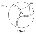
次に図2を参照すると、例示的なガラス質ボンド又はメタルボンド研磨ホイール200は、弓状及び蛇行状冷却チャネル220をそれぞれ有する。
Next, referring to FIG. 2, the exemplary glassy bond or metal
図3は、蛇行状の冷却チャネル320を有する別の例示的なガラス質ボンド又はメタルボンド研磨ホイール300を示す。
FIG. 3 shows another exemplary glassy bond or metal
図4は、例示的なガラス質ボンド又はメタルボンド研磨セグメント400を示す。一般的な使用においては、複数のガラス質ボンド又はメタルボンド研磨セグメント400を、金属ディスクの周縁に沿って一様に間隔を設けて取り付け、研磨ホイールを形成する。
FIG. 4 shows an exemplary glassy bond or metal bond
図5は、ガラス質ボンド又はメタルボンド研磨ディスク500が2つの領域510、520を有することを示す。各領域は、ガラス質ボンド又はメタルボンドマトリックス材料550、560中にそれぞれ保持された研磨粒子530、540を有する。
FIG. 5 shows that the vitreous bond or metal
図6A〜図6B及び図7A〜図7Bは、セラミック平面状基材620、720と一体的に形成された、精密に賦形されたセラミック研磨要素610、710を有する様々な単体構造化された研磨ディスクをそれぞれ示す。
6A-6B and 7A-7B are various single-structured structures with precisely shaped
図8は、回転研磨工具800(例えば、Dremel工具などの、手持ち式モータ駆動シャフトのための刃)を示す。 FIG. 8 shows a rotary polishing tool 800 (for example, a blade for a handheld motor drive shaft such as a Dremel tool).
例示的な歯科用バー900を図9に示す。次に図9を参照すると、歯科用バー900は、軸920に固定されたヘッド930を含む。歯科用バー900は、多孔性のメタルボンド又はガラス質ボンド910に固定された研磨粒子905を含む。
An exemplary
図2及び図3に示される上記の研磨ホイールは、対応するグリーン体(即ち、同じ大まかな形状特徴を有するが、一時的バインダーによって保持されたガラス質ボンド又はメタルボンド前駆体粒子を含む)を焼成することによって、調製することができる。 The above-mentioned polishing wheel shown in FIGS. 2 and 3 has a corresponding green body (ie, including vitreous bond or metal bond precursor particles having the same rough shape characteristics but held by a temporary binder). It can be prepared by firing.
本開示の選択された実施形態 Selected Embodiments of the present disclosure
実施形態1は、ガラス質ボンド研磨物品の製造方法であって、
a)逐次的に、
i)固まっていない粉末粒子の層を限定された領域内に堆積させる工程であって、固まっていない粉末粒子が、ガラス質ボンド前駆体粒子、研磨粒子、及び有機化合物粒子を含み、固まっていない粉末粒子の層が、実質的に均一な厚さを有する、堆積させる工程、及び
ii)伝導又は照射によって熱を選択的に適用して、固まっていない粉末粒子の層のエリアを加熱処理する工程、
を含むサブプロセス工程と、
b)工程a)を複数回独立して実施して、結合された粉末粒子と残りの固まっていない粉末粒子とを含む研磨物品プリフォームを生成する工程であって、各工程a)において、固まっていない粉末粒子が独立して選択される、工程と、
c)残りの固まっていない粉末粒子の実質的に全てを研磨物品プリフォームから分離する工程と、
d)研磨物品プリフォームを加熱して、ガラス質ボンド材料中に保持された研磨粒子を含むガラス質ボンド研磨物品を提供する工程と、
の逐次的工程を含む、製造方法である。
The first embodiment is a method for manufacturing a vitreous bond polished article.
a) Sequentially
i) A step of depositing a layer of non-solidified powder particles in a limited area, in which the non-solidified powder particles contain vitreous bond precursor particles, abrasive particles, and organic compound particles and are not solidified. A step of depositing a layer of powder particles having a substantially uniform thickness, and a step of selectively applying heat by conduction or irradiation to heat-treat an area of a layer of unsolidified powder particles. ,
Subprocess process including
b) A step of independently performing the step a) a plurality of times to generate a polished article preform containing the bonded powder particles and the remaining non-solidified powder particles, which are solidified in each step a). The process and the process, in which the powder particles that are not are selected independently,
c) A step of separating substantially all of the remaining unsolidified powder particles from the polished article preform,
d) Polished article A step of heating a preform to provide a vitreous bond polished article containing abrasive particles retained in a vitreous bond material.
It is a manufacturing method including the sequential process of.
実施形態2は、研磨粒子が、ダイヤモンド粒子又は立方窒化ホウ素粒子のうちの少なくとも1つを含む、実施形態1に記載の方法である。 The second embodiment is the method according to the first embodiment, wherein the abrasive particles include at least one of diamond particles or cubic boron nitride particles.
実施形態3は、研磨粒子が、金属酸化物セラミック粒子を含む、実施形態1に記載の方法である。 The third embodiment is the method according to the first embodiment, wherein the polishing particles include metal oxide ceramic particles.
実施形態4は、研磨粒子及びガラス質ボンド材料が、同じ化学組成を有する、実施形態1〜3のいずれか1つに記載の方法である。 The fourth embodiment is the method according to any one of the first to third embodiments, wherein the abrasive particles and the vitreous bond material have the same chemical composition.
実施形態5は、ガラス質ボンド研磨物品が、少なくとも1つの冷却チャネルを含む、実施形態1〜4のいずれか1つに記載の方法である。 The fifth embodiment is the method according to any one of embodiments 1 to 4, wherein the vitreous bond polished article comprises at least one cooling channel.
実施形態6は、ガラス質ボンド研磨物品が、単体構造化された研磨ディスク、研磨研削ビット、研磨セグメント、研磨リム、及び研磨ホイールからなる群から選択される、実施形態1〜5のいずれか1つに記載の方法である。 In the sixth embodiment, the vitreous bond polished article is selected from the group consisting of a single-structured polishing disc, a polishing grinding bit, a polishing segment, a polishing rim, and a polishing wheel, any one of the first to fifth embodiments. It is the method described in one.
実施形態7は、有機化合物粒子が、50℃〜250℃(両端の値を含む)の融点を有する、実施形態1〜6のいずれか1つに記載の方法である。 Embodiment 7 is the method according to any one of embodiments 1 to 6, wherein the organic compound particles have a melting point of 50 ° C. to 250 ° C. (including values at both ends).
実施形態8は、有機化合物粒子が、100℃〜180℃(両端の値を含む)の融点を有する、実施形態1〜7のいずれか1つに記載の方法である。 The eighth embodiment is the method according to any one of the first to seventh embodiments, wherein the organic compound particles have a melting point of 100 ° C. to 180 ° C. (including values at both ends).
実施形態9は、有機化合物粒子が、ワックス、糖、デキストリン、250℃以下の融点を有する熱可塑性材料、アクリレート、メタクリレート、及びこれらの組み合わせから選択される、実施形態1〜8のいずれか1つに記載の方法である。 In the ninth embodiment, the organic compound particles are selected from wax, sugar, dextrin, a thermoplastic material having a melting point of 250 ° C. or lower, acrylate, methacrylate, and a combination thereof. It is the method described in.
実施形態10は、有機化合物粒子が、ワックス、アクリレート、メタクリレート、ポリエチレンテレフタレート(PET)、ポリ乳酸(PLA)、及びこれらの組み合わせから選択される、実施形態7〜9のいずれか1つに記載の方法である。 Embodiment 10 according to any one of embodiments 7-9, wherein the organic compound particles are selected from wax, acrylate, methacrylate, polyethylene terephthalate (PET), polylactic acid (PLA), and combinations thereof. The method.
実施形態11は、有機化合物粒子が、固まっていない粉末粒子の2.5重量%〜30重量%の量で存在する、実施形態1〜10のいずれか1つに記載の方法である。 The eleventh embodiment is the method according to any one of the first to tenth embodiments, wherein the organic compound particles are present in an amount of 2.5% by weight to 30% by weight of the unsolidified powder particles.
実施形態12は、有機化合物粒子が、固まっていない粉末粒子の5重量%〜20重量%の量で存在する、実施形態1〜11のいずれか1つに記載の方法である。 Embodiment 12 is the method according to any one of embodiments 1 to 11, wherein the organic compound particles are present in an amount of 5% to 20% by weight of the unsolidified powder particles.
実施形態13は、無機ガラス質ボンド前駆体が、αアルミナの前駆体を含む、実施形態11又は12に記載の方法である。 13th embodiment is the method according to embodiment 11 or 12, wherein the inorganic vitreous bond precursor comprises a precursor of α-alumina.
実施形態14は、固まっていない粉末粒子がサブミクロンのセラミック粒子を含む、実施形態8〜13のいずれか1つに記載の方法である。 Embodiment 14 is the method according to any one of embodiments 8 to 13, wherein the unsolidified powder particles contain submicron ceramic particles.
実施形態15は、固まっていない粉末粒子が、流動剤粒子を更に含む、実施形態1〜14のいずれか1つに記載の方法である。 The fifteenth embodiment is the method according to any one of embodiments 1 to 14, wherein the non-solidified powder particles further include fluidizer particles.
実施形態16は、工程d)が、有機化合物材料をバーンアウトすることを更に含む、実施形態1〜15のいずれか1つに記載の方法である。 Embodiment 16 is the method according to any one of embodiments 1-15, wherein step d) further comprises burning out the organic compound material.
実施形態17は、工程ii)において、熱が単一の加熱チップ又はサーマルプリントヘッドを用いて適用される、実施形態1〜16のいずれか1つに記載の方法である。 Embodiment 17 is the method according to any one of embodiments 1-16, wherein heat is applied using a single heating chip or thermal printhead in step ii).
実施形態18は、工程ii)において、単一の加熱チップが、固まっていない粉末粒子の層のエリアに圧力を更に適用する、実施形態17に記載の方法である。 Embodiment 18 is the method of embodiment 17, wherein in step ii), a single heating chip further applies pressure to the area of the layer of unsolidified powder particles.
実施形態19は、工程ii)において、熱が少なくとも1つのレーザーを用いて適用される、実施形態1〜16のいずれか1つに記載の方法である。 19th embodiment is the method according to any one of embodiments 1-16, wherein heat is applied using at least one laser in step ii).
実施形態20は、ガラス質ボンド前駆体材料及び有機化合物によって互いに結合された研磨粒子を含むガラス質ボンド研磨物品前駆体であって、当該ガラス質ボンド研磨物品前駆体は、ガラス質ボンド研磨物品前駆体を少なくとも部分的に通って延びる少なくとも1つの蛇行状冷却チャネル;又はガラス質ボンド研磨物品前駆体を少なくとも部分的に通って延びる少なくとも1つの弓状冷却チャネルのうちの少なくとも1つを更に含む。 Embodiment 20 is a glassy bond polished article precursor containing polishing particles bonded to each other by a glassy bond precursor material and an organic compound, and the glassy bond polished article precursor is a glassy bond polished article precursor. It further comprises at least one serpentine cooling channel extending at least partially through the body; or at least one arched cooling channel extending at least partially through the vitreous bond abrasive article precursor.
実施形態21は、研磨粒子が、炭化ケイ素、炭化ホウ素、窒化ケイ素、又は金属酸化物セラミック粒子のうちの少なくとも1つを含む、実施形態20に記載のガラス質ボンド研磨前駆体である。 21st embodiment is the vitreous bond polishing precursor according to 20th embodiment, wherein the polishing particles contain at least one of silicon carbide, boron carbide, silicon nitride, or metal oxide ceramic particles.
実施形態22は、メタルボンド研磨物品の製造方法であって、
a)逐次的に、
i)固まっていない粉末粒子の層を限定された領域内に堆積させる工程であって、固まっていない粉末粒子が、高融点金属粒子、研磨粒子、及び有機化合物粒子を含み、固まっていない粉末粒子の層が、実質的に均一な厚さを有する、堆積させる工程
ii)伝導又は照射によって熱を選択的に適用して、固まっていない粉末粒子の層のエリアを加熱処理する工程、
を含むサブプロセス工程と、
b)工程a)を複数回独立して実施して、結合された粉末粒子と残りの固まっていない粉末粒子とを含む研磨物品プリフォームを生成する工程であって、各工程a)において、固まっていない粉末粒子が独立して選択される、工程と、
c)残りの固まっていない粉末粒子の実質的に全てを研磨物品プリフォームから分離する工程と、
d)研磨物品プリフォームに溶融した低融点金属を注入する工程であって、高融点金属粒子の少なくとも一部が、溶融した低融点金属と接触したときに完全には溶融しない、注入する工程と、
e)溶融した低融点金属を固化して、メタルボンド研磨物品を提供する工程と、
の逐次的工程を含む、製造方法。
The 22nd embodiment is a method for manufacturing a metal bond polished article.
a) Sequentially
i) A step of depositing a layer of non-solidified powder particles in a limited area, wherein the non-solidified powder particles contain refractory metal particles, abrasive particles, and organic compound particles, and are not solidified powder particles. Layers have a substantially uniform thickness, the step of depositing ii) the step of selectively applying heat by conduction or irradiation to heat-treat an area of a layer of unsolidified powder particles,
Subprocess process including
b) A step of independently performing the step a) a plurality of times to generate a polished article preform containing the bonded powder particles and the remaining non-solidified powder particles, which are solidified in each step a). The process and the process, in which the powder particles that are not are selected independently,
c) A step of separating substantially all of the remaining unsolidified powder particles from the polished article preform,
d) A step of injecting a molten low melting point metal into a preform of a polished article, in which at least a part of the refractory metal particles does not completely melt when in contact with the molten low melting point metal. ,
e) A process of solidifying a molten low melting point metal to provide a metal-bonded polished article,
A manufacturing method that includes a sequential process of.
実施形態23は、固まっていない粉末粒子が、融剤粒子を更に含む、実施形態22に記載の方法である。 23rd embodiment is the method according to 22nd embodiment, wherein the non-solidified powder particles further include flux particles.
実施形態24は、研磨粒子が、ダイヤモンド粒子又は立方窒化ホウ素粒子のうちの少なくとも1つを含む、実施形態22又は23に記載の方法である。 The 24th embodiment is the method according to the 22nd or 23rd embodiment, wherein the polishing particles include at least one of diamond particles or cubic boron nitride particles.
実施形態25は、研磨粒子が、金属酸化物セラミック粒子を含む、実施形態22又は23に記載の方法である。 The 25th embodiment is the method according to the 22nd or 23rd embodiment, wherein the polishing particles include metal oxide ceramic particles.
実施形態26は、メタルボンド研磨物品が、少なくとも1つの冷却チャネルを含む、実施形態22〜25のいずれか1つに記載の方法である。 Embodiment 26 is the method according to any one of embodiments 22-25, wherein the metal bond polished article comprises at least one cooling channel.
実施形態27は、メタルボンド研磨物品が、研磨パッド、研磨研削ビット、研磨セグメント、及び研磨ホイールからなる群から選択される、実施形態22〜26のいずれか1つに記載の方法である。 The 27th embodiment is the method according to any one of the 22nd to 26th embodiments, wherein the metal bond polishing article is selected from the group consisting of a polishing pad, a polishing grinding bit, a polishing segment, and a polishing wheel.
実施形態28は、メタルボンド研磨物品が、歯科用回転ツールの少なくとも一部分を構成する、請求項22〜26のいずれか1つに記載の方法である。 28 is the method of any one of claims 22-26, wherein the metal bond polished article constitutes at least a portion of the dental rotating tool.
実施形態29は、有機化合物粒子が、50℃〜250℃(両端の値を含む)の融点を有する、実施形態22〜28のいずれか1つに記載の方法である。 The 29th embodiment is the method according to any one of 22nd to 28th embodiments, wherein the organic compound particles have a melting point of 50 ° C. to 250 ° C. (including values at both ends).
実施形態30は、有機化合物粒子が、100℃〜180℃(両端の値を含む)の融点を有する、実施形態22〜29のいずれか1つに記載の方法である。 30 is the method according to any one of embodiments 22-29, wherein the organic compound particles have a melting point of 100 ° C. to 180 ° C. (including values at both ends).
実施形態31は、有機化合物粒子が、ワックス、糖、デキストリン、250℃以下の融点を有する熱可塑性材料、アクリレート、メタクリレート、及びこれらの組み合わせから選択される、実施形態22〜30のいずれか1つに記載の方法である。 In embodiment 31, the organic compound particles are selected from wax, sugar, dextrin, a thermoplastic material having a melting point of 250 ° C. or lower, acrylate, methacrylate, and a combination thereof, any one of embodiments 22 to 30. It is the method described in.
実施形態32は、有機化合物粒子が、ワックス、アクリレート、メタクリレート、ポリエチレンテレフタレート(PET)、ポリ乳酸(PLA)、及びこれらの組み合わせから選択される、実施形態29〜31のいずれか1つに記載の方法である。 32. The 32nd embodiment is described in any one of embodiments 29-31, wherein the organic compound particles are selected from wax, acrylate, methacrylate, polyethylene terephthalate (PET), polylactic acid (PLA), and combinations thereof. The method.
実施形態33は、有機化合物粒子が、固まっていない粉末粒子の1.5重量%〜25重量%の量で存在する、実施形態22〜32のいずれか1つに記載の方法である。 The 33rd embodiment is the method according to any one of 22 to 32, wherein the organic compound particles are present in an amount of 1.5% by weight to 25% by weight of the unsolidified powder particles.
実施形態34は、有機化合物粒子が、固まっていない粉末粒子の3重量%〜20重量%の量で存在する、実施形態22〜33のいずれか1つに記載の方法である。 Embodiment 34 is the method according to any one of embodiments 22-33, wherein the organic compound particles are present in an amount of 3% to 20% by weight of the unsolidified powder particles.
実施形態35は、高融点金属粒子が、溶融した低融点金属の温度よりも少なくとも50℃高い融点を有する、実施形態22〜34のいずれか1つに記載の方法である。 35 is the method according to any one of embodiments 22-34, wherein the refractory metal particles have a melting point that is at least 50 ° C. higher than the temperature of the molten low melting point metal.
実施形態36は、工程c)と工程d)との間に、有機化合物材料の少なくとも一部分をバーンオフすることを更に含む、実施形態22〜35のいずれか1つに記載の方法である。 Embodiment 36 is the method according to any one of embodiments 22-35, further comprising burning off at least a portion of the organic compound material between steps c) and d).
実施形態37は、工程ii)において、熱が単一の加熱チップ又はサーマルプリントヘッドを用いて適用される、実施形態22〜36のいずれか1つに記載の方法である。 Embodiment 37 is the method of any one of embodiments 22-36, wherein heat is applied using a single heating chip or thermal printhead in step ii).
実施形態38は、工程ii)において、単一の加熱チップが、固まっていない粉末粒子の層のエリアに圧力を更に適用する、実施形態37に記載の方法である。 Embodiment 38 is the method of embodiment 37, wherein in step ii), a single heating chip further applies pressure to the area of the layer of unsolidified powder particles.
実施形態39は、工程ii)において、熱が少なくとも1つのレーザーを用いて適用される、実施形態22〜36のいずれか1つに記載の方法である。 Embodiment 39 is the method of any one of embodiments 22-36, wherein heat is applied using at least one laser in step ii).
実施形態40は、メタルボンド研磨物品の製造方法であって、
a)逐次的に、
i)固まっていない粉末粒子の層を限定された領域内に堆積させる工程であって、固まっていない粉末粒子が、金属粒子、研磨粒子、及び有機化合物粒子を含み、固まっていない粉末粒子の層が、実質的に均一な厚さを有する、堆積させる工程、
ii)伝導又は照射によって熱を選択的に適用して、固まっていない粉末粒子の層のエリアを加熱処理する工程、
を含むサブプロセス工程と、
b)工程a)を複数回独立して実施して、結合された粉末粒子と残りの固まっていない粉末粒子とを含む研磨物品プリフォームを生成する工程であって、研磨物品プリフォームは所定の形状を有し、各工程a)において、固まっていない粉末粒子が独立して選択される、工程と、
c)残りの固まっていない粉末粒子の実質的に全てを研磨物品プリフォームから分離する工程と、
d)研磨物品プリフォームを加熱して、メタルボンド研磨物品を提供する工程と、
の逐次的工程を含む、製造方法である。
The 40th embodiment is a method for manufacturing a metal bond polished article.
a) Sequentially
i) A step of depositing a layer of non-solidified powder particles in a limited area, wherein the non-solidified powder particles contain metal particles, abrasive particles, and organic compound particles, and the layer of non-solidified powder particles. However, the process of depositing, which has a substantially uniform thickness,
ii) A step of heat-treating an area of a layer of unsolidified powder particles by selectively applying heat by conduction or irradiation.
Subprocess process including
b) Step a) is carried out a plurality of times independently to generate a polished article preform containing the bonded powder particles and the remaining non-solidified powder particles, and the polished article preform is a predetermined step. In each step a), the powder particles having a shape and not solidified are independently selected.
c) A step of separating substantially all of the remaining unsolidified powder particles from the polished article preform,
d) Polished article The process of heating the preform to provide a metal bond polished article, and
It is a manufacturing method including the sequential process of.
実施形態41は、固まっていない粉末粒子が、融剤粒子を更に含む、実施形態40に記載の方法である。 The 41st embodiment is the method according to the 40th embodiment, wherein the non-solidified powder particles further include flux particles.
実施形態42は、研磨粒子が、ダイヤモンド粒子又は立方窒化ホウ素粒子のうちの少なくとも1つを含む、実施形態40又は41に記載の方法である。 Embodiment 42 is the method according to embodiment 40 or 41, wherein the abrasive particles include at least one of diamond particles or cubic boron nitride particles.
実施形態43は、研磨粒子が、金属酸化物セラミック粒子を含む、実施形態40又は41に記載の方法である。 The 43rd embodiment is the method according to the 40th or 41st embodiment, wherein the polishing particles include metal oxide ceramic particles.
実施形態44は、金属粒子が、高融点金属粒子と低融点金属粒子との組み合わせを含み、高融点金属粒子は、溶融した低温金属の温度よりも少なくとも50℃高い融点を有する、実施形態40〜43のいずれか1つに記載の方法である。 In the 44th embodiment, the metal particles include a combination of the high melting point metal particles and the low melting point metal particles, and the high melting point metal particles have a melting point at least 50 ° C. higher than the temperature of the molten low temperature metal. It is the method according to any one of 43.
実施形態45は、メタルボンド研磨物品が、少なくとも1つの冷却チャネルを含む、実施形態40〜44のいずれか1つに記載の方法である。 Embodiment 45 is the method of any one of embodiments 40-44, wherein the metal bond polished article comprises at least one cooling channel.
実施形態46は、メタルボンド研磨物品が、研磨パッド、研磨研削ビット、研磨セグメント、及び研磨ホイールからなる群から選択される、実施形態40〜45のいずれか1つに記載の方法である。 The 46th embodiment is the method according to any one of the 40th to 45th embodiments, wherein the metal bond polishing article is selected from the group consisting of a polishing pad, a polishing grinding bit, a polishing segment, and a polishing wheel.
実施形態47は、メタルボンド研磨物品が、歯科用回転ツールの少なくとも一部分を含む、請求項40〜45のいずれか1つに記載の方法である。 Embodiment 47 is the method of any one of claims 40-45, wherein the metal bond polished article comprises at least a portion of a dental rotating tool.
実施形態48は、有機化合物粒子が、50℃〜250℃(両端の値を含む)の融点を有する、実施形態40〜47のいずれか1つに記載の方法である。 Embodiment 48 is the method according to any one of embodiments 40-47, wherein the organic compound particles have a melting point of 50 ° C. to 250 ° C. (including values at both ends).
実施形態49は、有機化合物粒子が、100℃〜180℃(両端の値を含む)の融点を有する、実施形態40〜48のいずれか1つに記載の方法である。 Embodiment 49 is the method according to any one of embodiments 40-48, wherein the organic compound particles have a melting point of 100 ° C. to 180 ° C. (including values at both ends).
実施形態50は、有機化合物粒子が、ワックス、糖、デキストリン、250℃以下の融点を有する熱可塑性材料、アクリレート、メタクリレート、及びこれらの組み合わせから選択される、実施形態40〜49のいずれか1つに記載の方法である。 In embodiment 50, the organic compound particles are selected from wax, sugar, dextrin, a thermoplastic material having a melting point of 250 ° C. or lower, acrylate, methacrylate, and a combination thereof, any one of embodiments 40 to 49. It is the method described in.
実施形態51は、有機化合物粒子が、ワックス、アクリレート、メタクリレート、ポリエチレンテレフタレート(PET)、ポリ乳酸(PLA)、及びこれらの組み合わせから選択される、実施形態48〜50のいずれか1つに記載の方法である。 51. The 51st embodiment is described in any one of embodiments 48-50, wherein the organic compound particles are selected from wax, acrylate, methacrylate, polyethylene terephthalate (PET), polylactic acid (PLA), and combinations thereof. The method.
実施形態52は、有機化合物粒子が、固まっていない粉末粒子の1.5重量%〜25重量%の量で存在する、実施形態40〜51のいずれか1つに記載の方法である。 52 is the method according to any one of embodiments 40-51, wherein the organic compound particles are present in an amount of 1.5% to 25% by weight of the unsolidified powder particles.
実施形態53は、有機化合物粒子が、固まっていない粉末粒子の3重量%〜20重量%の量で存在する、実施形態40〜52のいずれか1つに記載の方法である。 Embodiment 53 is the method according to any one of embodiments 40-52, wherein the organic compound particles are present in an amount of 3% to 20% by weight of the unsolidified powder particles.
実施形態54は、工程ii)において、熱が単一の加熱チップ又はサーマルプリントヘッドを用いて適用される、実施形態40〜53のいずれか1つに記載の方法である。 Embodiment 54 is the method of any one of embodiments 40-53, wherein heat is applied using a single heating chip or thermal printhead in step ii).
実施形態55は、工程ii)において、単一の加熱チップが、固まっていない粉末粒子の層のエリアに圧力を更に適用する、実施形態54に記載の方法である。 Embodiment 55 is the method of embodiment 54, wherein in step ii), a single heating chip further applies pressure to the area of the layer of unsolidified powder particles.
実施形態56は、工程ii)において、熱が少なくとも1つのレーザーを用いて適用される、実施形態40〜53のいずれか1つに記載の方法である。 Embodiment 56 is the method of any one of embodiments 40-53, wherein heat is applied using at least one laser in step ii).
実施形態57は、有機化合物材料によって互いに結合された金属粒子と研磨粒子とを含むメタルボンド研磨物品前駆体であって、メタルボンド研磨物品前駆体は、メタルボンド研磨物品前駆体を少なくとも部分的に通って延びる少なくとも1つの蛇行状冷却チャネル;及びメタルボンド研磨物品前駆体を少なくとも部分的に通って延びる少なくとも1つの弓状冷却チャネルのうちの少なくとも1つを更に含む。 Embodiment 57 is a metal bond polished article precursor containing metal particles and abrasive particles bonded to each other by an organic compound material, wherein the metal bond polished article precursor is at least partially a metal bond polished article precursor. It further comprises at least one serpentine cooling channel extending through; and at least one of at least one arched cooling channel extending at least partially through the metal-bonded abrasive article precursor.
特に記載のない限り、実施例及び本明細書のその他の箇所における全ての部、百分率、比などは、重量によるものである。

Unless otherwise stated, all parts, percentages, ratios, etc. in the Examples and elsewhere herein are by weight.
実施例1
混合物重量を基準として、77.3重量%のPDR1、13.6重量%のPDR2、及び9.1重量%のPDR3を混合することによって、印刷材料P1を調製した。粉末混合物を、ガラスジャーに入れ、ローリングバンクミキサ上で約50rpmで15分間回転させた。直線状の金属ブレードを用いて、印刷材料を1枚の紙の上に展延し、1枚の紙をシムとして使用し、得られた第1の粉末層の厚さは約100ミクロンであった。これを、厚さ2mil(50.8マイクロメートル)のPETフィルムで被覆した。はんだごてを約425°F(約218℃)まで加熱し、その高温チップを、所定の約1センチメートル(cm)×1cmのエリア上にゆっくりと動かした。わずかな圧力しか適用されず、PETフィルムはほとんど変形しなかった。その後、PETフィルムを除去し、加熱チップがPETフィルムに接触したエリアにおいて、印刷材料P1が淡灰色から暗灰色に変わったことが観察された。第2層の紙をシムとして使用して、第2の厚さ0.1ミリメートル(mm)の印刷材料の層を、印刷材料の第1層の上に展延した。再びPETフィルムで被覆し、再びはんだごてのチップで同じ1cmx1cmのエリアを加熱した。その後、第3層について、この手順を繰り返した。PETフィルムを除去した後、固まっていない粉末から固形物を抽出した。3つの層は共に溶融してグリーン体を形成したことが観察された。次に、このグリーン体を炉内に入れ、400℃で2時間バーンアウトした後、700℃で4時間焼結して、約1cm×1cmで厚さ0.3mmの寸法の正方形の研磨剤を得た。
Example 1
The printing material P1 was prepared by mixing 77.3% by weight of PDR1, 13.6% by weight of PDR2, and 9.1% by weight of PDR3 based on the weight of the mixture. The powder mixture was placed in a glass jar and spun on a rolling bank mixer at about 50 rpm for 15 minutes. Using a linear metal blade, the printing material was spread on a sheet of paper and the sheet of paper was used as a shim, the thickness of the first powder layer obtained was about 100 microns. rice field. This was coated with a 2 mil (50.8 micrometer) thick PET film. The soldering iron was heated to about 425 ° F (about 218 ° C) and the hot tip was slowly moved over a predetermined area of about 1 cm (cm) x 1 cm. Only a small amount of pressure was applied and the PET film was hardly deformed. After that, the PET film was removed, and it was observed that the printing material P1 changed from light gray to dark gray in the area where the heating chip came into contact with the PET film. Using the second layer of paper as a shim, a second layer of 0.1 mm (mm) thick printing material was spread over the first layer of printing material. It was coated with PET film again, and the same 1 cm × 1 cm area was heated again with a soldering iron tip. Then, this procedure was repeated for the third layer. After removing the PET film, solids were extracted from the unsolidified powder. It was observed that the three layers melted together to form a green body. Next, this green body was placed in a furnace, burned out at 400 ° C. for 2 hours, sintered at 700 ° C. for 4 hours, and a square abrasive having a size of about 1 cm × 1 cm and a thickness of 0.3 mm was applied. Obtained.
実施例2
実験装置及び製剤
Example 2
Experimental equipment and formulation
Coherent(Santa Clara,California)から入手可能なCO2レーザー、モデルE−400、及びGSI Group,Inc(Billerica,MA)から入手可能な3軸モジュラースキャナ、モデルHPLK 1330−17,CO2 30MMからなるレーザーマーキング装置を組み立てた。装置は、Nutfield Technology(Hudson,NH)のWaveRunner Advanced Laser Scanning Software,Version 3.3.5 build−0200を実行するコンピュータによって制御した。 Laser marking consisting of CO2 lasers available from Coherent (Santa Clara, California), model E-400, and 3-axis modular scanners available from GSI Group, Inc (Billerica, MA), models HPLK 1330-17, CO2 30MM. Assembled the device. The device was controlled by a computer running WaveRunner Advanced Laser Scanning Software, Version 3.3.5 build-0200 from Nutfield Technology (Hudson, NH).
WaveRunnerスキャンソフトウェアプログラムでは、一辺1.5cmの正方形がスキャンフィールドのほぼ中心に描かれた。このプログラム内で「ハッチ」機能を使用可にし、正方形をクロスハッチするために使用した。第1のハッチパターンは0度の角度であり、第2のハッチパターンは90度の角度であった。いずれのハッチパターンでも、線は0.5mmの間隔に設定した。ハッチパターンのみがマークされ、形状の輪郭はマークされなかった。 In the WaveRunner scan software program, a square with a side of 1.5 cm was drawn approximately in the center of the scan field. We enabled the "hatch" feature within this program and used it to cross-hatch squares. The first hatch pattern had an angle of 0 degrees and the second hatch pattern had an angle of 90 degrees. In each hatch pattern, the lines were set at intervals of 0.5 mm. Only the hatch pattern was marked, not the contour of the shape.
レーザースキャン条件は、速度2000mm/秒、出力:8%、周波数20kHzに設定した。8%の出力設定は、27.8Wのレーザービーム出力に等しい。 The laser scanning conditions were set at a speed of 2000 mm / sec, an output of 8%, and a frequency of 20 kHz. An 8% power setting is equal to a 27.8 W laser beam power.
実験手順 Experimental procedure
2枚の紙をレーザーマーキング装置のレーザースキャンエリアに置いた。紙の上に、直線状の金属ブレードを用いて印刷材料P1を展延し、互いに重なり合って層状になった2枚の紙をシムとして使用した。得られた第1の粉末層の厚さは約200ミクロンであった。第1の粉末層を、上記条件を用いてレーザースキャナでマーキングした。レーザーが層をマーキングしたエリアにおいて、印刷材料P1が淡灰色から暗灰色に変わったことが観察された。その後、それぞれ厚さ200ミクロンの第2及び第3層の印刷材料P1を置いて、同様にマーキングした。最後に、先の3つの層の上に第4層を置き、この最終層にレーザーを2回通過させてマーキングした。 Two sheets of paper were placed in the laser scan area of the laser marking device. The printing material P1 was spread on the paper using a linear metal blade, and two sheets of paper that overlapped each other and were layered were used as shims. The thickness of the obtained first powder layer was about 200 microns. The first powder layer was marked with a laser scanner using the above conditions. It was observed that the printing material P1 changed from light gray to dark gray in the area where the laser marked the layer. Then, the printing materials P1 of the second and third layers having a thickness of 200 microns were placed and marked in the same manner. Finally, a fourth layer was placed on top of the previous three layers, and this final layer was marked by passing the laser twice.
固まっていない粉末から固形物を抽出した。4つの層が共に溶融し、分離することなく安全に取り扱うことができるグリーン体を形成したことが観察された。次に、このグリーン体を炉内に入れ、400℃で2時間バーンアウトした後、700℃で4時間焼結して、約1.5cm×1.5cmで厚さ0.8mmの寸法の正方形の研磨剤を得た。 Solids were extracted from the unsolidified powder. It was observed that the four layers melted together to form a green body that could be safely handled without separation. Next, this green body was placed in a furnace, burned out at 400 ° C. for 2 hours, sintered at 700 ° C. for 4 hours, and a square measuring about 1.5 cm × 1.5 cm and having a thickness of 0.8 mm. Abrasive was obtained.
実施例3
実験装置及び製剤
Example 3
Experimental equipment and formulation
粉末を用いた3D印刷用の装置を、図1の概略図のように構築した。それぞれxy平面に約3インチ×2インチ(7.62cmx5.08cm)及びz方向に2インチ(5.08cm)の寸法の隣接する2つのチャンバを、厚さ2インチ(5.08cm)のアルミニウムブロック状にフライス加工した。アルミニウム製の密着する正方形のピストン2つをチャンバに挿入し、USAutomation(Mission Viejo,California)より入手可能なステッピングモーターリニアアクチュエータ、VersaDrive 17、モデルUSV17−110−AB−0506(リードスクリュー長さ6インチ(15.24))に接続した。一方のチャンバ及びピストンを粉末供給に指定し、他方をビルドチャンバに指定した。リニアアクチュエータは、ピストンがz方向に上下動できるようにする。チャンバの上方の約1mmの面内には、モータで駆動される回転アルミローラーを取付けた。このローラを、USAutomation(Mission Viejo,California)より入手可能なステッピングモーターリニアアクチュエータ、VersaDrive 17、モデルUSV17−110−AB−2512(リードスクリュー長さ12インチ(30.48cm))を用いて、x方向に作動した。この作動されたローラにより、粉末が粉末供給チャンバからビルドチャンバに移動できる。 A device for 3D printing using powder was constructed as shown in the schematic view of FIG. Two adjacent chambers measuring approximately 3 inches x 2 inches (7.62 cm x 5.08 cm) in the xy plane and 2 inches (5.08 cm) in the z direction, each with a 2 inch (5.08 cm) thick aluminum block. It was milled into a shape. Two close-fitting square aluminum pistons are inserted into the chamber and a stepper motor linear actuator, VersaDrive 17, model USV17-110-AB-0506 (lead screw length 6 inches) available from USAtomy (Mission Viejo, California). (15.24)) was connected. One chamber and piston were designated as powder feed and the other as build chamber. The linear actuator allows the piston to move up and down in the z direction. A rotating aluminum roller driven by a motor was mounted in a plane of about 1 mm above the chamber. This roller is driven in the x direction using a stepping motor linear actuator, VersaDrive 17, model USV17-110-AB-2512 (lead screw length 12 inches (30.48 cm)) available from USAtomy (Mission Viejo, California). It worked. This actuated roller allows the powder to move from the powder supply chamber to the build chamber.
モータを、AllMotion(Union City,California)より入手可能なモーションコントローラボード、モデルEZ4AXISに接続した。モーションコントローラは、次のシーケンスを実行するようにプログラムした:最初に、ビルドピストンを0.10mm下降させる。次いで、粉末供給ピストンを0.16mm上昇させる。次いで、ローラモータをオンにしてローラを作動させて、粉末を粉末供給チャンバからビルドチャンバへと移動させる。ローラモータを停止する。その後、ローラを原点に戻す。この手順は、ビルドエリアに、均一な、厚さ0.1mmの粉末の層を生じる。2つのチャンバアセンブリの上に、電動のxy位置決めステージを取り付け、TEM−Laser(Wuhan,Hubei,China)より入手可能な500mW、405nmダイオードレーザー、モデルM−33A405−500−Gを取り付けた。このxy台は、レーザー彫刻用のGrblコントローラボードを含み、機械の動作を制御するためのオープンソースソフトウェアであるGrbl0.9によって制御することができた。図案を、オープンソースグラフィクスソフトウェアであるInkscape 0.48(レーザー彫刻機プラグイン使用)にロードした。このソフトウェアは、図面からxyモーションコントロール及びレーザー出力コードを生成し、それをGrbl 0.9ソフトウェアに転送した。 The motor was connected to model EZ4AXIS, a motion controller board available from AllMotion (Union City, California). The motion controller was programmed to perform the following sequence: First, the build piston is lowered by 0.10 mm. The powder supply piston is then raised by 0.16 mm. The roller motor is then turned on to actuate the rollers to move the powder from the powder supply chamber to the build chamber. Stop the roller motor. After that, the roller is returned to the origin. This procedure produces a uniform, 0.1 mm thick layer of powder in the build area. An electric xy positioning stage was mounted on top of the two chamber assemblies, and a 500 mW, 405 nm diode laser, model M-33A405-500-G available from TEM-Laser (Wuhan, Hubei, China) was mounted. The xy platform included a Grbl controller board for laser engraving and could be controlled by Grbl 0.9, open source software for controlling the operation of the machine. The design was loaded into the open source graphics software Inkscape 0.48 (using a laser engraving machine plug-in). The software generated an xy motion control and laser output code from the drawing and transferred it to the Grbl 0.9 software.
混合物重量を基準として、77.3重量%のPDR1、13.6重量%のPDR2、及び9.1重量%のPDR4を混合することによって、印刷材料P2を調製した。粉末混合物を、ガラスジャーに入れ、ローリングバンクミキサ上で約50rpmで15分間回転させた。粉末供給ピストンを底まで下降させ、チャンバ内に印刷材料P2を充填した。ビルドピストンを、最上部まで上昇させた。その後、粉末展延手順を10回実行して、ビルドエリア内に均一な粉末ベースを形成した。 The printing material P2 was prepared by mixing 77.3% by weight of PDR1, 13.6% by weight of PDR2, and 9.1% by weight of PDR4 based on the weight of the mixture. The powder mixture was placed in a glass jar and spun on a rolling bank mixer at about 50 rpm for 15 minutes. The powder supply piston was lowered to the bottom and the chamber was filled with the printing material P2. The build piston was raised to the top. The powder spreading procedure was then performed 10 times to form a uniform powder base within the build area.
Inkscapeソフトウェアで、Arialフォント、フォントサイズ14ptを選択し、「Test」という語を書いた。その後、レーザー彫刻機プラグインを選択した。レーザーを100%出力に設定し、10mm/秒の移動速度を選択し、Grblコードを生成し、Grbl 0.9ソフトウェアに転送した。次いで、印刷材料P2の厚さ0.1mmの第1層を展延した。次に、Grblコードを実行した。レーザーがオンになって、「Test」の語の形に移動し、粉末は「Test」の語の形で淡灰色から暗灰色に変わったことが観測された。 In Inkscape software, I chose Arial font, font size 14pt and wrote the word "Test". After that, I chose the laser engraving machine plug-in. The laser was set to 100% power, a moving speed of 10 mm / sec was selected, a Grbl code was generated and transferred to Grbl 0.9 software. Next, a first layer having a thickness of 0.1 mm of the printing material P2 was spread. Next, the Grbl code was executed. It was observed that the laser was turned on and moved to the form of the word "Test", and the powder changed from light gray to dark gray in the form of the word "Test".
同じく厚さ0.1mmの印刷材料P2の第2層を展延し、第2回目のGrblコードが実行された。このシーケンスを、合計20層が展延されてレーザーに露光されるまで繰り返した。 The second layer of the printing material P2, also 0.1 mm thick, was spread and the second Grbl code was executed. This sequence was repeated until a total of 20 layers were spread and exposed to the laser.
次に、ヘラを用いて対象物を周囲の粉末から除去した。固まっていない粉末を除去し、「Test」の語の形の、厚さ2.05mmの物体を回収した。 The object was then removed from the surrounding powder using a spatula. The uncured powder was removed and a 2.05 mm thick object in the form of the word "Test" was recovered.
20層が共に溶融し、分離することなく安全に取り扱うことができるグリーン体を形成したことが観察された。このグリーン体を炉内に入れ、400℃で2時間バーンアウトした後、700℃で4時間焼結して、「Test」の語の形の研磨物品を得た。この物品でアルミニウムのブロックを摩擦し、研磨パターンを観察した。 It was observed that the 20 layers melted together to form a green body that could be safely handled without separation. The green body was placed in a furnace, burned out at 400 ° C. for 2 hours, and then sintered at 700 ° C. for 4 hours to obtain a polished article in the form of the word "Test". A block of aluminum was rubbed with this article and a polishing pattern was observed.
Claims (15)
a)逐次的に、
i)固まっていない粉末粒子の層を限定された領域内に堆積させる工程であって、前記固まっていない粉末粒子が、ガラス質ボンド前駆体粒子、研磨粒子、及び有機化合物粒子の混合物であり、前記固まっていない粉末粒子の層が、実質的に均一な厚さを有する、堆積させる工程、及び
ii)伝導又は照射によって熱を選択的に適用して、前記固まっていない粉末粒子の層のエリアを加熱処理する工程、
を含むサブプロセス工程と、
b)工程a)を複数回独立して実施して、結合された粉末粒子と残りの固まっていない粉末粒子とを含む研磨物品プリフォームを生成する工程であって、各工程a)において、前記固まっていない粉末粒子が独立して選択される、工程と、
c)前記残りの固まっていない粉末粒子の実質的に全てを前記研磨物品プリフォームから分離する工程と、
d)前記研磨物品プリフォームを加熱して、ガラス質ボンド材料中に保持された前記研磨粒子を含む前記ガラス質ボンド研磨物品を提供する工程と、
の逐次的工程を含む、製造方法。 A method for manufacturing glassy bond polished products.
a) Sequentially
i) A step of depositing a layer of non-solidified powder particles in a limited area, wherein the non-solidified powder particles are a mixture of vitreous bond precursor particles, abrasive particles, and organic compound particles. The area of the layer of the non-solidified powder particles, wherein the layer of the non-solidified powder particles has a substantially uniform thickness, the step of depositing, and ii) selectively applying heat by conduction or irradiation. Heat treatment process,
Subprocess process including
b) Step a) is carried out a plurality of times independently to generate a polished article preform containing the bonded powder particles and the remaining non-solidified powder particles, and in each step a), the above. In the process, the powder particles that are not solidified are selected independently.
c) A step of separating substantially all of the remaining unsolidified powder particles from the polished article preform, and
d) A step of heating the polished article preform to provide the glassy bond polished article containing the abrasive particles held in the vitreous bond material.
A manufacturing method that includes a sequential process of.
a)逐次的に、
i)固まっていない粉末粒子の層を限定された領域内に堆積させる工程であって、前記固まっていない粉末粒子が、高融点金属粒子、研磨粒子、及び有機化合物粒子を含み、前記固まっていない粉末粒子の層が、実質的に均一な厚さを有する、堆積させる工程
ii)伝導又は照射によって熱を選択的に適用して、前記固まっていない粉末粒子の層のエリアを加熱処理する工程、
を含むサブプロセス工程と、
b)工程a)を複数回独立して実施して、結合された粉末粒子及び残りの固まっていない粉末粒子を含む研磨物品プリフォームを生成する工程であって、各工程a)において、前記固まっていない粉末粒子が独立して選択される、工程と、
c)前記残りの固まっていない粉末粒子の実質的に全てを前記研磨物品プリフォームから分離する工程と、
d)前記研磨物品プリフォームに溶融した低融点金属を注入する工程であって、前記高融点金属粒子の少なくとも一部が、前記溶融した低融点金属と接触したときに完全には溶融しない、注入する工程と、
e)前記溶融した低融点金属を固化して、メタルボンド研磨物品を提供する工程と、
の逐次的工程を含む、製造方法。 A method for manufacturing metal bond polished products.
a) Sequentially
i) A step of depositing a layer of non-solidified powder particles in a limited area, wherein the non-solidified powder particles contain refractory metal particles, abrasive particles, and organic compound particles and are not solidified. A step of depositing a layer of powder particles having a substantially uniform thickness ii) A step of heat-treating an area of the layer of non-solidified powder particles by selectively applying heat by conduction or irradiation.
Subprocess process including
b) Step a) is carried out a plurality of times independently to generate a polished article preform containing the bonded powder particles and the remaining non-solidified powder particles, and in each step a), the solidification is performed. The process and the process, in which the powder particles that are not are selected independently,
c) A step of separating substantially all of the remaining unsolidified powder particles from the polished article preform, and
d) In the step of injecting the molten low melting point metal into the polished article preform, the injection in which at least a part of the refractory metal particles does not completely melt when they come into contact with the molten low melting point metal. And the process to do
e) A step of solidifying the molten low melting point metal to provide a metal bond polished article, and
A manufacturing method that includes a sequential process of.
a)逐次的に、
i)固まっていない粉末粒子の層を限定された領域内に堆積させる工程であって、前記固まっていない粉末粒子が、金属粒子、研磨粒子、及び有機化合物粒子を含み、前記固まっていない粉末粒子の層が、実質的に均一な厚さを有する、堆積させる工程、
ii)伝導又は照射によって熱を選択的に適用して、前記固まっていない粉末粒子の層のエリアを加熱処理する工程、
を含むサブプロセス工程と、
b)工程a)を複数回独立して実施して、前記結合された粉末粒子及び残りの固まっていない粉末粒子とを含む研磨物品プリフォームを生成する工程であって、前記研磨物品プリフォームは所定の形状を有し、各工程a)において、前記固まっていない粉末粒子が独立して選択される、工程と、
c)前記残りの固まっていない粉末粒子の実質的に全てを前記研磨物品プリフォームから分離する工程と、
d)前記研磨物品プリフォームを加熱して、メタルボンド研磨物品を提供する工程と、
の逐次的工程を含む、製造方法。 A method for manufacturing metal bond polished products.
a) Sequentially
i) A step of depositing a layer of non-solidified powder particles in a limited area, wherein the non-solidified powder particles contain metal particles, abrasive particles, and organic compound particles, and the non-solidified powder particles. Layers have a substantially uniform thickness, the step of depositing,
ii) A step of heat-treating an area of the layer of unsolidified powder particles by selectively applying heat by conduction or irradiation.
Subprocess process including
b) Step a) is carried out a plurality of times independently to generate a polished article preform containing the bonded powder particles and the remaining unsolidified powder particles, wherein the polished article preform is a step. In each step a), the unsolidified powder particles having a predetermined shape are independently selected.
c) A step of separating substantially all of the remaining unsolidified powder particles from the polished article preform, and
d) A step of heating the polished article preform to provide a metal bond polished article, and
A manufacturing method that includes a sequential process of.
前記メタルボンド研磨物品前駆体を少なくとも部分的に通って延びる少なくとも1つの蛇行状冷却チャネル;
前記メタルボンド研磨物品前駆体を少なくとも部分的に通って延びる少なくとも1つの弓状冷却チャネル、
のうちの少なくとも1つを更に含む、メタルボンド研磨物品前駆体。 A metal-bonded abrasive article precursor containing metal particles and abrasive particles bonded to each other by an organic compound material.
At least one meandering cooling channel extending at least partially through the metal-bonded abrasive article precursor;
At least one arched cooling channel extending at least partially through the metal bond polished article precursor,
A metal bond polished article precursor further comprising at least one of.
Applications Claiming Priority (5)
| Application Number | Priority Date | Filing Date | Title |
|---|---|---|---|
| US201662281349P | 2016-01-21 | 2016-01-21 | |
| US62/281,349 | 2016-01-21 | ||
| US201662315044P | 2016-03-30 | 2016-03-30 | |
| US62/315,044 | 2016-03-30 | ||
| PCT/US2017/013867 WO2017127392A1 (en) | 2016-01-21 | 2017-01-18 | Methods of making metal bond and vitreous bond abrasive articles, and abrasive article precursors |
Publications (3)
| Publication Number | Publication Date |
|---|---|
| JP2019508264A JP2019508264A (en) | 2019-03-28 |
| JP2019508264A5 JP2019508264A5 (en) | 2020-02-27 |
| JP6926094B2 true JP6926094B2 (en) | 2021-08-25 |
Family
ID=57915145
Family Applications (1)
| Application Number | Title | Priority Date | Filing Date |
|---|---|---|---|
| JP2018537671A Active JP6926094B2 (en) | 2016-01-21 | 2017-01-18 | Metal bond and vitreous bond Polished article manufacturing method, and polished article precursor |
Country Status (7)
| Country | Link |
|---|---|
| US (2) | US11072053B2 (en) |
| EP (2) | EP4011923A1 (en) |
| JP (1) | JP6926094B2 (en) |
| KR (1) | KR102629658B1 (en) |
| CN (1) | CN108472787B (en) |
| BR (1) | BR112018015021A2 (en) |
| WO (1) | WO2017127392A1 (en) |
Families Citing this family (28)
| Publication number | Priority date | Publication date | Assignee | Title |
|---|---|---|---|---|
| KR102187425B1 (en) | 2011-12-30 | 2020-12-09 | 생-고뱅 세라믹스 앤드 플라스틱스, 인코포레이티드 | Shaped abrasive particle and method of forming same |
| BR112014017050B1 (en) | 2012-01-10 | 2021-05-11 | Saint-Gobain Ceramics & Plastics, Inc. | molded abrasive particle |
| US9440332B2 (en) | 2012-10-15 | 2016-09-13 | Saint-Gobain Abrasives, Inc. | Abrasive particles having particular shapes and methods of forming such particles |
| WO2014161001A1 (en) | 2013-03-29 | 2014-10-02 | Saint-Gobain Abrasives, Inc. | Abrasive particles having particular shapes and methods of forming such particles |
| KR101870617B1 (en) | 2013-12-31 | 2018-06-26 | 생-고뱅 어브레이시브즈, 인코포레이티드 | Abrasive article including shaped abrasive particles |
| US9771507B2 (en) | 2014-01-31 | 2017-09-26 | Saint-Gobain Ceramics & Plastics, Inc. | Shaped abrasive particle including dopant material and method of forming same |
| CN106457522B (en) | 2014-04-14 | 2020-03-24 | 圣戈本陶瓷及塑料股份有限公司 | Abrasive article including shaped abrasive particles |
| US9914864B2 (en) | 2014-12-23 | 2018-03-13 | Saint-Gobain Ceramics & Plastics, Inc. | Shaped abrasive particles and method of forming same |
| EP3277459B1 (en) | 2015-03-31 | 2023-08-16 | Saint-Gobain Abrasives, Inc. | Fixed abrasive articles and methods of forming same |
| TWI634200B (en) | 2015-03-31 | 2018-09-01 | 聖高拜磨料有限公司 | Fixed abrasive articles and methods of forming same |
| WO2016201104A1 (en) | 2015-06-11 | 2016-12-15 | Saint-Gobain Ceramics & Plastics, Inc. | Abrasive article including shaped abrasive particles |
| US11230053B2 (en) | 2016-01-21 | 2022-01-25 | 3M Innovative Properties Company | Additive processing of fluoropolymers |
| JP7010566B2 (en) * | 2016-03-30 | 2022-01-26 | スリーエム イノベイティブ プロパティズ カンパニー | Metal bond and vitreous bond Polished article manufacturing method, and polished article precursor |
| KR102243356B1 (en) | 2016-05-10 | 2021-04-23 | 생-고뱅 세라믹스 앤드 플라스틱스, 인코포레이티드 | Abrasive particles and their formation method |
| WO2017197002A1 (en) | 2016-05-10 | 2017-11-16 | Saint-Gobain Ceramics & Plastics, Inc. | Abrasive particles and methods of forming same |
| EP4349896A2 (en) | 2016-09-29 | 2024-04-10 | Saint-Gobain Abrasives, Inc. | Fixed abrasive articles and methods of forming same |
| CN109890568B (en) | 2016-10-25 | 2022-07-29 | 3M创新有限公司 | Bonded abrasive article including oriented abrasive particles and method of making the same |
| US10563105B2 (en) | 2017-01-31 | 2020-02-18 | Saint-Gobain Ceramics & Plastics, Inc. | Abrasive article including shaped abrasive particles |
| KR102464517B1 (en) | 2017-02-28 | 2022-11-10 | 쓰리엠 이노베이티브 프로퍼티즈 캄파니 | Metal Bonded Abrasive Articles and Methods of Making Metal Bonded Abrasive Articles |
| US10865148B2 (en) | 2017-06-21 | 2020-12-15 | Saint-Gobain Ceramics & Plastics, Inc. | Particulate materials and methods of forming same |
| CN108655970B (en) * | 2018-05-31 | 2020-04-28 | 东北大学 | Preparation and finishing method of structured diamond cylindrical grinding wheel formed by laser near-net |
| CN109534845A (en) * | 2018-12-26 | 2019-03-29 | 华侨大学 | A kind of porous ceramics grinding wheel and preparation method thereof |
| KR20220062639A (en) * | 2019-10-16 | 2022-05-17 | 생-고뱅 어브레이시브즈, 인코포레이티드 | Abrasive Articles and Methods of Forming |
| EP4081369A4 (en) | 2019-12-27 | 2024-04-10 | Saint Gobain Ceramics | Abrasive articles and methods of forming same |
| EP4200452A1 (en) | 2020-08-18 | 2023-06-28 | Enviro Metals, LLC | Metal refinement |
| DE102021104481A1 (en) | 2021-02-25 | 2022-08-25 | Gühring KG | Method of manufacturing a grinding wheel |
| JP2024509813A (en) * | 2021-03-05 | 2024-03-05 | サンーゴバン アブレイシブズ,インコーポレイティド | Abrasive article and method for forming the same |
| KR102545934B1 (en) * | 2021-09-02 | 2023-06-22 | 경상국립대학교산학협력단 | Manufacturing method for Inconel 718 alloy multilayer shaped structure with excellent low-temperature tensile properties and Inconel 718 alloy multilayer shaped structure thereof |
Family Cites Families (45)
| Publication number | Priority date | Publication date | Assignee | Title |
|---|---|---|---|---|
| US2367404A (en) | 1943-07-09 | 1945-01-16 | Fish Schurman Corp | Abrasive composition of matter and method of forming same |
| US3850590A (en) | 1970-09-28 | 1974-11-26 | Impregnated Diamond Prod Ltd | An abrasive tool comprising a continuous porous matrix of sintered metal infiltrated by a continuous synthetic resin |
| US4518397A (en) | 1979-06-29 | 1985-05-21 | Minnesota Mining And Manufacturing Company | Articles containing non-fused aluminum oxide-based abrasive mineral |
| US4314827A (en) | 1979-06-29 | 1982-02-09 | Minnesota Mining And Manufacturing Company | Non-fused aluminum oxide-based abrasive mineral |
| US4623364A (en) | 1984-03-23 | 1986-11-18 | Norton Company | Abrasive material and method for preparing the same |
| US4574003A (en) | 1984-05-03 | 1986-03-04 | Minnesota Mining And Manufacturing Co. | Process for improved densification of sol-gel produced alumina-based ceramics |
| CA1254238A (en) | 1985-04-30 | 1989-05-16 | Alvin P. Gerk | Process for durable sol-gel produced alumina-based ceramics, abrasive grain and abrasive products |
| US4770671A (en) | 1985-12-30 | 1988-09-13 | Minnesota Mining And Manufacturing Company | Abrasive grits formed of ceramic containing oxides of aluminum and yttrium, method of making and using the same and products made therewith |
| US4881951A (en) | 1987-05-27 | 1989-11-21 | Minnesota Mining And Manufacturing Co. | Abrasive grits formed of ceramic containing oxides of aluminum and rare earth metal, method of making and products made therewith |
| US4918874A (en) | 1988-08-05 | 1990-04-24 | The Dow Chemical Company | Method of preparing abrasive articles |
| US5178644A (en) * | 1992-01-23 | 1993-01-12 | Cincinnati Milacron Inc. | Method for making vitreous bonded abrasive article and article made by the method |
| ATE151063T1 (en) | 1992-09-25 | 1997-04-15 | Minnesota Mining & Mfg | ALUMINUM OXIDE AND ZIRCONIUM OXIDE CONTAINING ABRASIVE GRAIN |
| WO1995024992A1 (en) | 1994-03-16 | 1995-09-21 | Minnesota Mining And Manufacturing Company | Abrasive articles and method of making abrasive articles |
| US5745834A (en) | 1995-09-19 | 1998-04-28 | Rockwell International Corporation | Free form fabrication of metallic components |
| US5749041A (en) | 1995-10-13 | 1998-05-05 | Dtm Corporation | Method of forming three-dimensional articles using thermosetting materials |
| US5738817A (en) | 1996-02-08 | 1998-04-14 | Rutgers, The State University | Solid freeform fabrication methods |
| JP3136276B2 (en) * | 1996-11-29 | 2001-02-19 | ノリタケダイヤ株式会社 | Composite cutting blade |
| JP3683663B2 (en) | 1996-12-03 | 2005-08-17 | サンコー瓦斯精機株式会社 | Pipe fixing tool for joint connection |
| US6086648A (en) | 1998-04-07 | 2000-07-11 | Norton Company | Bonded abrasive articles filled with oil/wax mixture |
| US6551366B1 (en) | 2000-11-10 | 2003-04-22 | 3M Innovative Properties Company | Spray drying methods of making agglomerate abrasive grains and abrasive articles |
| US20020095875A1 (en) | 2000-12-04 | 2002-07-25 | D'evelyn Mark Philip | Abrasive diamond composite and method of making thereof |
| US6575353B2 (en) | 2001-02-20 | 2003-06-10 | 3M Innovative Properties Company | Reducing metals as a brazing flux |
| US6585930B2 (en) * | 2001-04-25 | 2003-07-01 | Extrude Hone Corporation | Method for article fabrication using carbohydrate binder |
| US7377840B2 (en) | 2004-07-21 | 2008-05-27 | Neopad Technologies Corporation | Methods for producing in-situ grooves in chemical mechanical planarization (CMP) pads, and novel CMP pad designs |
| US7875091B2 (en) | 2005-02-22 | 2011-01-25 | Saint-Gobain Abrasives, Inc. | Rapid tooling system and methods for manufacturing abrasive articles |
| US7524345B2 (en) * | 2005-02-22 | 2009-04-28 | Saint-Gobain Abrasives, Inc. | Rapid tooling system and methods for manufacturing abrasive articles |
| US7867302B2 (en) | 2005-02-22 | 2011-01-11 | Saint-Gobain Abrasives, Inc. | Rapid tooling system and methods for manufacturing abrasive articles |
| US20070031791A1 (en) | 2005-08-03 | 2007-02-08 | 3M Innovative Properties Company | Scanning models for digital orthodontics |
| JP2008018479A (en) | 2006-07-11 | 2008-01-31 | Nic:Kk | Cutting whetstone |
| US20090022826A1 (en) | 2007-07-20 | 2009-01-22 | Shrier David L | Multi-step method of pain and/or inflammation treatment |
| GB0917936D0 (en) | 2009-10-13 | 2009-11-25 | 3D Printer Aps | Three-dimensional printer |
| JP5456535B2 (en) | 2010-03-29 | 2014-04-02 | 株式会社フジミインコーポレーテッド | Resin bond grinding wheel |
| CN202088120U (en) | 2011-03-16 | 2011-12-28 | 青岛理工大学 | Manufacturing device for grinding wheels with arbitrary section profiles |
| DE102011078722A1 (en) | 2011-07-06 | 2013-01-10 | Evonik Degussa Gmbh | Powder containing polymer-coated inorganic particles |
| RU2600464C2 (en) | 2011-09-07 | 2016-10-20 | 3М Инновейтив Пропертиз Компани | Bonded abrasive article |
| US9393674B2 (en) | 2013-04-04 | 2016-07-19 | Smith International, Inc. | Cemented carbide composite for a downhole tool |
| CN103273432B (en) | 2013-04-27 | 2015-07-15 | 衢州飞瑞特种陶瓷有限公司 | Formulation of zirconium oxide and aluminum oxide ceramic mirror polishing pellet tablet fixation grinding material |
| CN103264361A (en) | 2013-05-17 | 2013-08-28 | 华侨大学 | Manufacturing method for abrasive grain tool |
| PT107096B (en) | 2013-08-02 | 2016-06-06 | Inst Politécnico De Leiria | STEREO SYSTEM MULTIMATERIAL LITHOGRAPHY AND RESPECT PROCESS |
| DE102013217422A1 (en) | 2013-09-02 | 2015-03-05 | Carl Zeiss Industrielle Messtechnik Gmbh | Coordinate measuring machine and method for measuring and at least partially producing a workpiece |
| RU2643004C2 (en) * | 2013-09-30 | 2018-01-29 | Сен-Гобен Серэмикс Энд Пластикс, Инк. | Formed abrasive particles and methods of their production |
| CN104440597B (en) | 2014-10-31 | 2017-02-01 | 河南新源超硬材料有限公司 | Diamond grinding wheel made of resin and ceramic composite materials and manufacturing method thereof |
| US20180104793A1 (en) | 2015-06-25 | 2018-04-19 | 3M Innovative Properties Company | Vitreous bond abrasive articles and methods of making the same |
| EP3313617B1 (en) | 2015-06-25 | 2023-06-14 | 3M Innovative Properties Company | Methods of making metal bond abrasive articles and metal bond abrasive articles |
| CN105081992B (en) * | 2015-07-13 | 2018-01-26 | 郑州磨料磨具磨削研究所有限公司 | A kind of ceramic resin combined binder and skive and its preparation technology |
-
2017
- 2017-01-18 WO PCT/US2017/013867 patent/WO2017127392A1/en active Application Filing
- 2017-01-18 EP EP22154812.6A patent/EP4011923A1/en active Pending
- 2017-01-18 BR BR112018015021A patent/BR112018015021A2/en not_active Application Discontinuation
- 2017-01-18 CN CN201780007652.XA patent/CN108472787B/en active Active
- 2017-01-18 JP JP2018537671A patent/JP6926094B2/en active Active
- 2017-01-18 KR KR1020187023371A patent/KR102629658B1/en active IP Right Grant
- 2017-01-18 EP EP17702243.1A patent/EP3405309B1/en active Active
- 2017-01-18 US US16/070,316 patent/US11072053B2/en active Active
-
2021
- 2021-06-23 US US17/304,604 patent/US20210362297A1/en active Pending
Also Published As
| Publication number | Publication date |
|---|---|
| EP3405309A1 (en) | 2018-11-28 |
| CN108472787A (en) | 2018-08-31 |
| EP3405309B1 (en) | 2022-04-27 |
| CN108472787B (en) | 2021-07-16 |
| US20190022826A1 (en) | 2019-01-24 |
| KR102629658B1 (en) | 2024-01-29 |
| KR20180104654A (en) | 2018-09-21 |
| EP4011923A1 (en) | 2022-06-15 |
| BR112018015021A2 (en) | 2019-02-12 |
| US20210362297A1 (en) | 2021-11-25 |
| WO2017127392A1 (en) | 2017-07-27 |
| JP2019508264A (en) | 2019-03-28 |
| US11072053B2 (en) | 2021-07-27 |
Similar Documents
| Publication | Publication Date | Title |
|---|---|---|
| JP6926094B2 (en) | Metal bond and vitreous bond Polished article manufacturing method, and polished article precursor | |
| JP7030803B2 (en) | Bonded polished article containing oriented abrasive particles and its manufacturing method | |
| JP7010566B2 (en) | Metal bond and vitreous bond Polished article manufacturing method, and polished article precursor | |
| US11597058B2 (en) | Methods of making metal bond abrasive articles and metal bond abrasive articles | |
| KR102464517B1 (en) | Metal Bonded Abrasive Articles and Methods of Making Metal Bonded Abrasive Articles | |
| JP2018522746A (en) | Glassy bonded abrasive article and manufacturing method thereof | |
| US20230219195A1 (en) | Polymer bond abrasive articles and methods of making them | |
| WO2021001730A1 (en) | Methods of making metal bond abrasive articles and metal bond abrasive articles |
Legal Events
| Date | Code | Title | Description |
|---|---|---|---|
| RD03 | Notification of appointment of power of attorney |
Free format text: JAPANESE INTERMEDIATE CODE: A7423 Effective date: 20191114 |
|
| RD04 | Notification of resignation of power of attorney |
Free format text: JAPANESE INTERMEDIATE CODE: A7424 Effective date: 20191118 |
|
| A521 | Request for written amendment filed |
Free format text: JAPANESE INTERMEDIATE CODE: A523 Effective date: 20200115 |
|
| A621 | Written request for application examination |
Free format text: JAPANESE INTERMEDIATE CODE: A621 Effective date: 20200115 |
|
| A977 | Report on retrieval |
Free format text: JAPANESE INTERMEDIATE CODE: A971007 Effective date: 20210226 |
|
| A131 | Notification of reasons for refusal |
Free format text: JAPANESE INTERMEDIATE CODE: A131 Effective date: 20210309 |
|
| A521 | Request for written amendment filed |
Free format text: JAPANESE INTERMEDIATE CODE: A523 Effective date: 20210322 |
|
| TRDD | Decision of grant or rejection written | ||
| A01 | Written decision to grant a patent or to grant a registration (utility model) |
Free format text: JAPANESE INTERMEDIATE CODE: A01 Effective date: 20210706 |
|
| A61 | First payment of annual fees (during grant procedure) |
Free format text: JAPANESE INTERMEDIATE CODE: A61 Effective date: 20210804 |
|
| R150 | Certificate of patent or registration of utility model |
Ref document number: 6926094 Country of ref document: JP Free format text: JAPANESE INTERMEDIATE CODE: R150 |