JP6925973B2 - Double-sided tape - Google Patents
Double-sided tape Download PDFInfo
- Publication number
- JP6925973B2 JP6925973B2 JP2017544721A JP2017544721A JP6925973B2 JP 6925973 B2 JP6925973 B2 JP 6925973B2 JP 2017544721 A JP2017544721 A JP 2017544721A JP 2017544721 A JP2017544721 A JP 2017544721A JP 6925973 B2 JP6925973 B2 JP 6925973B2
- Authority
- JP
- Japan
- Prior art keywords
- double
- sided tape
- sensitive adhesive
- pressure
- micrometers
- Prior art date
- Legal status (The legal status is an assumption and is not a legal conclusion. Google has not performed a legal analysis and makes no representation as to the accuracy of the status listed.)
- Active
Links
Images


Classifications
-
- C—CHEMISTRY; METALLURGY
- C09—DYES; PAINTS; POLISHES; NATURAL RESINS; ADHESIVES; COMPOSITIONS NOT OTHERWISE PROVIDED FOR; APPLICATIONS OF MATERIALS NOT OTHERWISE PROVIDED FOR
- C09J—ADHESIVES; NON-MECHANICAL ASPECTS OF ADHESIVE PROCESSES IN GENERAL; ADHESIVE PROCESSES NOT PROVIDED FOR ELSEWHERE; USE OF MATERIALS AS ADHESIVES
- C09J7/00—Adhesives in the form of films or foils
- C09J7/20—Adhesives in the form of films or foils characterised by their carriers
- C09J7/29—Laminated material
-
- C—CHEMISTRY; METALLURGY
- C09—DYES; PAINTS; POLISHES; NATURAL RESINS; ADHESIVES; COMPOSITIONS NOT OTHERWISE PROVIDED FOR; APPLICATIONS OF MATERIALS NOT OTHERWISE PROVIDED FOR
- C09J—ADHESIVES; NON-MECHANICAL ASPECTS OF ADHESIVE PROCESSES IN GENERAL; ADHESIVE PROCESSES NOT PROVIDED FOR ELSEWHERE; USE OF MATERIALS AS ADHESIVES
- C09J133/00—Adhesives based on homopolymers or copolymers of compounds having one or more unsaturated aliphatic radicals, each having only one carbon-to-carbon double bond, and at least one being terminated by only one carboxyl radical, or of salts, anhydrides, esters, amides, imides, or nitriles thereof; Adhesives based on derivatives of such polymers
- C09J133/04—Homopolymers or copolymers of esters
- C09J133/06—Homopolymers or copolymers of esters of esters containing only carbon, hydrogen and oxygen, the oxygen atom being present only as part of the carboxyl radical
-
- C—CHEMISTRY; METALLURGY
- C09—DYES; PAINTS; POLISHES; NATURAL RESINS; ADHESIVES; COMPOSITIONS NOT OTHERWISE PROVIDED FOR; APPLICATIONS OF MATERIALS NOT OTHERWISE PROVIDED FOR
- C09J—ADHESIVES; NON-MECHANICAL ASPECTS OF ADHESIVE PROCESSES IN GENERAL; ADHESIVE PROCESSES NOT PROVIDED FOR ELSEWHERE; USE OF MATERIALS AS ADHESIVES
- C09J7/00—Adhesives in the form of films or foils
- C09J7/30—Adhesives in the form of films or foils characterised by the adhesive composition
- C09J7/38—Pressure-sensitive adhesives [PSA]
-
- C—CHEMISTRY; METALLURGY
- C09—DYES; PAINTS; POLISHES; NATURAL RESINS; ADHESIVES; COMPOSITIONS NOT OTHERWISE PROVIDED FOR; APPLICATIONS OF MATERIALS NOT OTHERWISE PROVIDED FOR
- C09J—ADHESIVES; NON-MECHANICAL ASPECTS OF ADHESIVE PROCESSES IN GENERAL; ADHESIVE PROCESSES NOT PROVIDED FOR ELSEWHERE; USE OF MATERIALS AS ADHESIVES
- C09J2203/00—Applications of adhesives in processes or use of adhesives in the form of films or foils
- C09J2203/318—Applications of adhesives in processes or use of adhesives in the form of films or foils for the production of liquid crystal displays
-
- C—CHEMISTRY; METALLURGY
- C09—DYES; PAINTS; POLISHES; NATURAL RESINS; ADHESIVES; COMPOSITIONS NOT OTHERWISE PROVIDED FOR; APPLICATIONS OF MATERIALS NOT OTHERWISE PROVIDED FOR
- C09J—ADHESIVES; NON-MECHANICAL ASPECTS OF ADHESIVE PROCESSES IN GENERAL; ADHESIVE PROCESSES NOT PROVIDED FOR ELSEWHERE; USE OF MATERIALS AS ADHESIVES
- C09J2301/00—Additional features of adhesives in the form of films or foils
- C09J2301/10—Additional features of adhesives in the form of films or foils characterized by the structural features of the adhesive tape or sheet
- C09J2301/12—Additional features of adhesives in the form of films or foils characterized by the structural features of the adhesive tape or sheet by the arrangement of layers
- C09J2301/124—Additional features of adhesives in the form of films or foils characterized by the structural features of the adhesive tape or sheet by the arrangement of layers the adhesive layer being present on both sides of the carrier, e.g. double-sided adhesive tape
-
- C—CHEMISTRY; METALLURGY
- C09—DYES; PAINTS; POLISHES; NATURAL RESINS; ADHESIVES; COMPOSITIONS NOT OTHERWISE PROVIDED FOR; APPLICATIONS OF MATERIALS NOT OTHERWISE PROVIDED FOR
- C09J—ADHESIVES; NON-MECHANICAL ASPECTS OF ADHESIVE PROCESSES IN GENERAL; ADHESIVE PROCESSES NOT PROVIDED FOR ELSEWHERE; USE OF MATERIALS AS ADHESIVES
- C09J2301/00—Additional features of adhesives in the form of films or foils
- C09J2301/10—Additional features of adhesives in the form of films or foils characterized by the structural features of the adhesive tape or sheet
- C09J2301/16—Additional features of adhesives in the form of films or foils characterized by the structural features of the adhesive tape or sheet by the structure of the carrier layer
- C09J2301/162—Additional features of adhesives in the form of films or foils characterized by the structural features of the adhesive tape or sheet by the structure of the carrier layer the carrier being a laminate constituted by plastic layers only
-
- C—CHEMISTRY; METALLURGY
- C09—DYES; PAINTS; POLISHES; NATURAL RESINS; ADHESIVES; COMPOSITIONS NOT OTHERWISE PROVIDED FOR; APPLICATIONS OF MATERIALS NOT OTHERWISE PROVIDED FOR
- C09J—ADHESIVES; NON-MECHANICAL ASPECTS OF ADHESIVE PROCESSES IN GENERAL; ADHESIVE PROCESSES NOT PROVIDED FOR ELSEWHERE; USE OF MATERIALS AS ADHESIVES
- C09J2301/00—Additional features of adhesives in the form of films or foils
- C09J2301/30—Additional features of adhesives in the form of films or foils characterized by the chemical, physicochemical or physical properties of the adhesive or the carrier
- C09J2301/302—Additional features of adhesives in the form of films or foils characterized by the chemical, physicochemical or physical properties of the adhesive or the carrier the adhesive being pressure-sensitive, i.e. tacky at temperatures inferior to 30°C
-
- C—CHEMISTRY; METALLURGY
- C09—DYES; PAINTS; POLISHES; NATURAL RESINS; ADHESIVES; COMPOSITIONS NOT OTHERWISE PROVIDED FOR; APPLICATIONS OF MATERIALS NOT OTHERWISE PROVIDED FOR
- C09J—ADHESIVES; NON-MECHANICAL ASPECTS OF ADHESIVE PROCESSES IN GENERAL; ADHESIVE PROCESSES NOT PROVIDED FOR ELSEWHERE; USE OF MATERIALS AS ADHESIVES
- C09J2407/00—Presence of natural rubber
- C09J2407/006—Presence of natural rubber in the substrate
-
- C—CHEMISTRY; METALLURGY
- C09—DYES; PAINTS; POLISHES; NATURAL RESINS; ADHESIVES; COMPOSITIONS NOT OTHERWISE PROVIDED FOR; APPLICATIONS OF MATERIALS NOT OTHERWISE PROVIDED FOR
- C09J—ADHESIVES; NON-MECHANICAL ASPECTS OF ADHESIVE PROCESSES IN GENERAL; ADHESIVE PROCESSES NOT PROVIDED FOR ELSEWHERE; USE OF MATERIALS AS ADHESIVES
- C09J2409/00—Presence of diene rubber
- C09J2409/006—Presence of diene rubber in the substrate
-
- C—CHEMISTRY; METALLURGY
- C09—DYES; PAINTS; POLISHES; NATURAL RESINS; ADHESIVES; COMPOSITIONS NOT OTHERWISE PROVIDED FOR; APPLICATIONS OF MATERIALS NOT OTHERWISE PROVIDED FOR
- C09J—ADHESIVES; NON-MECHANICAL ASPECTS OF ADHESIVE PROCESSES IN GENERAL; ADHESIVE PROCESSES NOT PROVIDED FOR ELSEWHERE; USE OF MATERIALS AS ADHESIVES
- C09J2421/00—Presence of unspecified rubber
- C09J2421/006—Presence of unspecified rubber in the substrate
-
- C—CHEMISTRY; METALLURGY
- C09—DYES; PAINTS; POLISHES; NATURAL RESINS; ADHESIVES; COMPOSITIONS NOT OTHERWISE PROVIDED FOR; APPLICATIONS OF MATERIALS NOT OTHERWISE PROVIDED FOR
- C09J—ADHESIVES; NON-MECHANICAL ASPECTS OF ADHESIVE PROCESSES IN GENERAL; ADHESIVE PROCESSES NOT PROVIDED FOR ELSEWHERE; USE OF MATERIALS AS ADHESIVES
- C09J2423/00—Presence of polyolefin
- C09J2423/006—Presence of polyolefin in the substrate
-
- C—CHEMISTRY; METALLURGY
- C09—DYES; PAINTS; POLISHES; NATURAL RESINS; ADHESIVES; COMPOSITIONS NOT OTHERWISE PROVIDED FOR; APPLICATIONS OF MATERIALS NOT OTHERWISE PROVIDED FOR
- C09J—ADHESIVES; NON-MECHANICAL ASPECTS OF ADHESIVE PROCESSES IN GENERAL; ADHESIVE PROCESSES NOT PROVIDED FOR ELSEWHERE; USE OF MATERIALS AS ADHESIVES
- C09J2425/00—Presence of styrenic polymer
- C09J2425/006—Presence of styrenic polymer in the substrate
-
- C—CHEMISTRY; METALLURGY
- C09—DYES; PAINTS; POLISHES; NATURAL RESINS; ADHESIVES; COMPOSITIONS NOT OTHERWISE PROVIDED FOR; APPLICATIONS OF MATERIALS NOT OTHERWISE PROVIDED FOR
- C09J—ADHESIVES; NON-MECHANICAL ASPECTS OF ADHESIVE PROCESSES IN GENERAL; ADHESIVE PROCESSES NOT PROVIDED FOR ELSEWHERE; USE OF MATERIALS AS ADHESIVES
- C09J2433/00—Presence of (meth)acrylic polymer
-
- C—CHEMISTRY; METALLURGY
- C09—DYES; PAINTS; POLISHES; NATURAL RESINS; ADHESIVES; COMPOSITIONS NOT OTHERWISE PROVIDED FOR; APPLICATIONS OF MATERIALS NOT OTHERWISE PROVIDED FOR
- C09J—ADHESIVES; NON-MECHANICAL ASPECTS OF ADHESIVE PROCESSES IN GENERAL; ADHESIVE PROCESSES NOT PROVIDED FOR ELSEWHERE; USE OF MATERIALS AS ADHESIVES
- C09J2475/00—Presence of polyurethane
- C09J2475/006—Presence of polyurethane in the substrate
-
- Y—GENERAL TAGGING OF NEW TECHNOLOGICAL DEVELOPMENTS; GENERAL TAGGING OF CROSS-SECTIONAL TECHNOLOGIES SPANNING OVER SEVERAL SECTIONS OF THE IPC; TECHNICAL SUBJECTS COVERED BY FORMER USPC CROSS-REFERENCE ART COLLECTIONS [XRACs] AND DIGESTS
- Y10—TECHNICAL SUBJECTS COVERED BY FORMER USPC
- Y10T—TECHNICAL SUBJECTS COVERED BY FORMER US CLASSIFICATION
- Y10T428/00—Stock material or miscellaneous articles
- Y10T428/24—Structurally defined web or sheet [e.g., overall dimension, etc.]
- Y10T428/24942—Structurally defined web or sheet [e.g., overall dimension, etc.] including components having same physical characteristic in differing degree
- Y10T428/2495—Thickness [relative or absolute]
- Y10T428/24967—Absolute thicknesses specified
-
- Y—GENERAL TAGGING OF NEW TECHNOLOGICAL DEVELOPMENTS; GENERAL TAGGING OF CROSS-SECTIONAL TECHNOLOGIES SPANNING OVER SEVERAL SECTIONS OF THE IPC; TECHNICAL SUBJECTS COVERED BY FORMER USPC CROSS-REFERENCE ART COLLECTIONS [XRACs] AND DIGESTS
- Y10—TECHNICAL SUBJECTS COVERED BY FORMER USPC
- Y10T—TECHNICAL SUBJECTS COVERED BY FORMER US CLASSIFICATION
- Y10T428/00—Stock material or miscellaneous articles
- Y10T428/28—Web or sheet containing structurally defined element or component and having an adhesive outermost layer
- Y10T428/2843—Web or sheet containing structurally defined element or component and having an adhesive outermost layer including a primer layer
-
- Y—GENERAL TAGGING OF NEW TECHNOLOGICAL DEVELOPMENTS; GENERAL TAGGING OF CROSS-SECTIONAL TECHNOLOGIES SPANNING OVER SEVERAL SECTIONS OF THE IPC; TECHNICAL SUBJECTS COVERED BY FORMER USPC CROSS-REFERENCE ART COLLECTIONS [XRACs] AND DIGESTS
- Y10—TECHNICAL SUBJECTS COVERED BY FORMER USPC
- Y10T—TECHNICAL SUBJECTS COVERED BY FORMER US CLASSIFICATION
- Y10T428/00—Stock material or miscellaneous articles
- Y10T428/28—Web or sheet containing structurally defined element or component and having an adhesive outermost layer
- Y10T428/2848—Three or more layers
Description
本開示は、両面テープに関する。より詳細には、本開示は、例えば電子ディスプレイ用のレンズ接着用途において使用できる、両面感圧性接着テープに関する。 The present disclosure relates to double-sided tape. More specifically, the present disclosure relates to double-sided pressure-sensitive adhesive tapes that can be used, for example, in lens bonding applications for electronic displays.
現在のデジタル時代において、電子デバイスは家や職場で生活の不可欠な部分になったため、電子ディスプレイは広く普及している。こうしたディスプレイは、テレビ、コンピュータモニタ、携帯電話端末(例えば、「スマートフォン」)、ラップトップコンピュータ、タブレットコンピュータ、更には腕時計を含む、私たちが毎日使用する多種多様な製品において顕在している。携帯型の電子デバイスは、一般にこうしたディスプレイを使用しており、民生用電子機器市場において急速に成長している分野である。多くのディスプレイはまた、スタイラスペン及び/又は1本若しくは複数の指でスクリーンをタッチすることで、ユーザーがジェスチャーによってデバイスに入力することができる、フィーチャータッチスクリーンである。 In today's digital age, electronic displays have become widespread as electronic devices have become an integral part of life at home and at work. These displays are manifested in the wide variety of products we use every day, including televisions, computer monitors, mobile phone terminals (eg, "smartphones"), laptop computers, tablet computers, and even watches. Portable electronic devices generally use such displays and are a rapidly growing area of the consumer electronics market. Many displays are also feature touch screens that allow the user to gesture into the device by touching the screen with a stylus pen and / or one or more fingers.
こうしたデバイスは壊れやすく、また頻繁に操作及びタッチされるため、製造業者は通常、電子ディスプレイの上に、「レンズ」と呼ばれるウィンドウ付き保護カバーを接着する。このレンズは一般に、ガラス又は結晶性材料などの薄い透明の硬質材料で構成されていて、引っかき抵抗性を備えている。レンズはまた、指先に存在する油をはじくために、露出した主表面に1種以上の特別なコーティングも含み得る。用途に応じて、レンズは平らであっても、又は湾曲していてもよい。 Due to the fragility and frequent operation and touch of these devices, manufacturers typically glue a protective cover with a window called a "lens" over the electronic display. The lens is generally made of a thin, transparent, hard material such as glass or crystalline material and is scratch resistant. The lens may also include one or more special coatings on the exposed main surface to repel the oil present on the fingertips. Depending on the application, the lens may be flat or curved.
通常、製造業者は、ディスプレイ周囲のベゼルに沿って配置されたフレームに、レンズ周端部を取り付けることによって、レンズをディスプレイに接着する。有利には、フレームに接着することにより、レンズの大部分又は全体をディスプレイ上に直接載せることができるようになり、デバイスの厚みを減らし、画像の歪みを防ぐのに役立ちうる。 Manufacturers typically adhere the lens to the display by attaching the peripheral end of the lens to a frame located along the bezel around the display. Advantageously, by adhering to the frame, most or all of the lens can be placed directly on the display, which can help reduce the thickness of the device and prevent image distortion.
効率的に、更には頑丈にレンズをフレームに結合することは、簡単な問題ではない。現在の業界の解決策としては、ポリエチレンテレフタレート(PET)ベースのテープ、アクリル、又はポリオレフィンベースのフォームテープ、液体接着剤、及び物理的固定具の使用が挙げられるが、どれも理想的な技術ではなかった。 Connecting the lens to the frame efficiently and robustly is not a trivial matter. Current industry solutions include the use of polyethylene terephthalate (PET) -based tapes, acrylic or polyolefin-based foam tapes, liquid adhesives, and physical fixtures, all of which are not ideal techniques. There wasn't.
携帯型電子デバイスは本質的に、過酷な操作環境にさらされる。特にモバイル端末及びタブレットコンピュータは、時として衝突又は落下し、広範な温度及び湿度にさらされる。こうした極端な状況下で試験した場合、既存の解決策には、十分な改善の余地が残っている。特に、多くの従来の接着方法では、フレームからレンズが外れることなく携帯型電子デバイスがかなり大きい落下衝撃に耐えることを可能にする、高い耐衝撃性及び押抜力は得られない。 Portable electronic devices are inherently exposed to harsh operating environments. Mobile terminals and tablet computers in particular are sometimes subject to collisions or drops and are exposed to a wide range of temperatures and humidity. When tested under these extreme conditions, existing solutions still have ample room for improvement. In particular, many conventional bonding methods do not provide the high impact resistance and punching force that allows a portable electronic device to withstand a fairly large drop impact without the lens coming off the frame.
この問題は、テープ支持体の組成を変更することによって対処されるかもしれないが、これらの材料の個別の断片を、例えば打ち抜き加工又は類似のプロセスを使用して、材料の連続ウェブからきれいに切断することができないため、耐衝撃性を向上させる組成は実施することが技術的に困難であることが見出されている。 This problem may be addressed by changing the composition of the tape support, but individual pieces of these materials are cut cleanly from the continuous web of material, for example using punching or similar processes. It has been found that it is technically difficult to implement compositions that improve impact resistance.
1組のプラスチックスキン層の間に配置されたコア層で構成されるキャリアフィルムを使用する両面接着テープが、本明細書に記載されている。キャリアフィルムは、次に、その対向する主表面の両方で、感圧性接着層に積層される。得られる多層構造は、接着された組立品が繰返し衝撃又はショック試験にさらされた場合でさえ高度な接着力をもたらし、更に、テープは連続製造プロセスで容易に打ち抜き加工できるようになる。 Double-sided adhesive tapes that use a carrier film composed of core layers arranged between a set of plastic skin layers are described herein. The carrier film is then laminated on the pressure sensitive adhesive layer on both of its opposing main surfaces. The resulting multilayer structure provides a high degree of adhesion even when the bonded assembly is exposed to repeated impact or shock tests, and the tape can be easily punched in a continuous manufacturing process.
第1の態様において、両面テープが提供される。両面テープは、以下の順序で、第1の感圧性接着層と、第1のプラスチックスキン層と、弾性基層と、第2のプラスチックスキン層と、第2の感圧性接着層とを含み、第1の感圧性接着層及び第2の感圧性接着層は、両面テープの両側の最外層である。 In the first aspect, double-sided tape is provided. The double-sided tape includes a first pressure-sensitive adhesive layer, a first plastic skin layer, an elastic base layer, a second plastic skin layer, and a second pressure-sensitive adhesive layer in the following order. The pressure-sensitive adhesive layer 1 and the pressure-sensitive adhesive layer 2 are the outermost layers on both sides of the double-sided tape.
第2の態様において、前述の両面テープを使用するデバイス組立品であって、レンズと、レンズに貼り合わされた両面テープとを備える、デバイス組立品が提供される。 In a second aspect, there is provided a device assembly that uses the above-mentioned double-sided tape and includes a lens and a double-sided tape attached to the lens.
第3の態様において、前述の両面テープを製造する方法であって、第1及び第2のプラスチックスキン樹脂及び弾性ベース樹脂をインフレーションフィルムダイから同時に押出して、押出チューブを形成することと、押出チューブをスリットして、第1のプラスチックスキン層、弾性基層、及び第2のプラスチックフィルム層を含むキャリアフィルムを提供することと、第1及び第2の感圧性接着層をキャリアフィルムの対向する主表面に積層して、両面テープを提供することと、を含む、方法が提供される。 In the third aspect, in the method for producing the double-sided tape described above, the first and second plastic skin resins and the elastic base resin are simultaneously extruded from the inflation film die to form an extruded tube, and the extruded tube. To provide a carrier film containing a first plastic skin layer, an elastic base layer, and a second plastic film layer, and to allow the first and second pressure sensitive adhesive layers to face each other on the main surface of the carrier film. Methods are provided, including the provision of double-sided tape by laminating in.
第4の態様において、前述の両面テープを製造する方法であって、第1及び第2のプラスチックスキン樹脂及び弾性ベース樹脂をダイから共押出して、第1のプラスチックスキン層、弾性基層、及び第2のプラスチックスキン層を含むキャリアフィルムを形成することと、第1及び第2の感圧性接着層をキャリアフィルムの対向する主表面に積層して、両面テープを提供することと、を含む、方法が提供される。 In a fourth aspect, in the method for producing the above-mentioned double-sided tape, the first and second plastic skin resins and the elastic base resin are coextruded from the die, and the first plastic skin layer, the elastic base layer, and the elastic base resin are coextruded. A method comprising forming a carrier film comprising two plastic skin layers and laminating the first and second pressure sensitive adhesive layers on opposite main surfaces of the carrier film to provide a double-sided tape. Is provided.
以下の本開示の様々な実施形態に関する詳細な説明を添付の図面と併せて考慮することで、本開示をより完全に理解できる。 A more complete understanding of the present disclosure can be made by considering the following detailed description of the various embodiments of the present disclosure in conjunction with the accompanying drawings.
一定の縮尺に従わずに描かれている場合もある上記で特定された図面は、本開示の様々な実施形態を説明しているが、発明を実施するための形態において記述されているとおり、別の実施形態もまた意図される。全ての場合において、本開示は、明示的な限定ではなく例示的な実施形態を説明する目的で、本開示の発明を記述する。多数の別の変更形態及び実施形態を当業者は考案することができ、それらは本開示の精神及び範囲内に入ることが理解されるべきである。 The drawings identified above, which may be drawn without following a certain scale, describe various embodiments of the present disclosure, but as described in embodiments for carrying out the invention. Another embodiment is also intended. In all cases, the present disclosure describes the invention of the present disclosure for the purpose of illustrating exemplary embodiments rather than explicit limitations. It should be understood that one of ordinary skill in the art can devise a number of other modifications and embodiments, which fall within the spirit and scope of the present disclosure.
本明細書において使用される場合、端点による数値範囲の列挙は、その範囲内に含まれる全ての数を含む(例えば、1〜5は、1、1.5、2、2.75、3、3.8、4及び5などを含む)。 As used herein, the enumeration of numerical ranges by endpoints includes all numbers contained within that range (eg, 1-5 are 1, 1.5, 2, 2.75, 3, Includes 3.8, 4 and 5 etc.).
特に指示がない限り、本明細書及び実施形態において使用されている量又は成分、特性の測定値などを表す全ての数は、全ての場合において「約」という用語により修飾されていると理解されるべきである。したがって、そうでない旨が示されない限り、前述の明細書及び添付の実施形態の列挙において記載されている数値パラメータは、本開示の教示を利用して当業者が得ようとする所望の特性に応じて変わりうる。少なくとも、各数値パラメータは、報告される有効桁数を考慮し、通常の端数処理技術を適用することによって少なくとも解釈されるべきであるが、このことは、請求項がカバーする範囲について均等論の適用を制限しようとするものではない。 Unless otherwise indicated, all numbers representing quantities or components, measurements of properties, etc. used herein and in embodiments are understood to be modified by the term "about" in all cases. Should be. Thus, unless indicated otherwise, the numerical parameters described in the above specification and the enumeration of the accompanying embodiments will depend on the desired properties that one of ordinary skill in the art would obtain using the teachings of the present disclosure. Can change. At a minimum, each numerical parameter should be at least interpreted by applying conventional rounding techniques, taking into account the number of significant digits reported, but this is the doctrine of equivalents to the extent covered by the claims. It does not attempt to limit the application.
以下の定義されている用語に関して、これらの定義は、以下の用語集において使用されている用語の変形への具体的な参照に基づいて特許請求の範囲又は明細書中の他の箇所に異なる定義が示されていない限り、特許請求の範囲を含む明細書全体に適用されるものとする。 With respect to the following defined terms, these definitions differ from the claims or elsewhere in the specification based on specific references to variants of the terms used in the following glossary. Unless indicated, it shall apply to the entire specification including the claims.
用語集
「1つの(a)」、「1つの(an)」、及び「その(the)」という用語は、「少なくとも1つの」と交換可能に使用されて、説明されている要素の1つ以上を意味する。
Glossary The terms "one (a)", "one (an)", and "the" are used interchangeably with "at least one" and are one of the elements described. It means the above.
「層」という用語は、基板上の又は基板の表面を覆う任意の材料又は材料の組み合わせを指す。 The term "layer" refers to any material or combination of materials on or covering the surface of a substrate.
様々な層の位置を説明するための、「の頂部に」、「上に」、「を覆う」、「の最上部に」、「の表面を覆う」、「の下にある」などの配置を表す用語は、水平に配置された上向きの基板に対する層の相対位置を指す。基板、層、又は基板及び層を含む物品は、製造中又は製造後に何らかの特定の空間的配置を有さなければならないというわけではない。 Arrangements such as "at the top", "above", "cover", "at the top", "cover the surface", "under", etc. to describe the location of the various layers The term refers to the relative position of the layer with respect to the horizontally arranged upward substrate. Substrates, layers, or articles containing substrates and layers do not have to have any particular spatial arrangement during or after manufacture.
別の層と基板、又は2つの別の層に対する位置を記述するための「によって隔てられた」という用語は、記述されている層が、別の層及び/又は基板の間にあるが、必ずしもそれらと隣接してはいないことを意味する。 The term "separated by" to describe the position of another layer and substrate, or two separate layers, is that the described layer is between another layer and / or substrate, but not necessarily. It means that they are not adjacent to them.
「(コ)ポリマー」又は「(コ)ポリマーの」という用語は、ホモポリマー及びコポリマー、並びに混和性ブレンドで(例えば共押出によって)、又は反応(例えばエステル交換反応を含む)によって形成されうるホモポリマー又はコポリマーを含む。「コポリマー」という用語は、ランダム、ブロック、グラフト、及び星型コポリマーを含む。 The terms "(co) polymer" or "(co) polymer" can be formed in homopolymers and copolymers, as well as in miscible blends (eg, by coextrusion) or by reactions (including, for example, transesterification reactions). Includes polymers or copolymers. The term "copolymer" includes random, block, graft, and star copolymers.
説明及び例として、両面感圧性接着テープの様々な実施形態が本明細書において提示されている。図1は、一般的な民生品である携帯電話における両面テープの使用を示す。この図に示すように、携帯電話は、ここで数字50で示されている例示的な接着されたレンズ組立品を例示する。
As description and examples, various embodiments of double-sided pressure-sensitive adhesive tape are presented herein. FIG. 1 shows the use of double-sided tape in a mobile phone, which is a general consumer product. As shown in this figure, the mobile phone illustrates the exemplary glued lens assembly represented by
接着されたレンズ組立品50は、以下の順序で、レンズ102と、両面テープ100と、基板104とを含む。レンズ102は、ガラス、水晶又は硬質プラスチックなどの材料の薄い透明の層であり、下にある基板104にテープ100で貼り合わされる。場合により、示されているように、テープ100は隣接する層の外周部(又は「フレーム」)だけに延在しており、それにより基板104によって発生した光が、透明であっても又は透明でなくてもよいテープ100に妨害されずに、レンズ102を通過することができる。
The bonded
レンズ102及び基板104は包括的に表されるが、いずれか又は両方が、それ自体多層であっても又は他の点でかなりの複雑さを有してもよい。
Although the lens 102 and the
図2は、独立して、接着されたレンズ組立品50の両面テープ100を示す。両面テープ100は、キャリアフィルム150の第1の主表面110上に配置された第1の感圧性接着層120と、キャリアフィルム150の第2の主表面112(第1の主表面110の反対側)上に配置された第2の感圧性接着層122とを含む。キャリアフィルム150は多層であり、弾性基層140の第1の主表面141上に配置された第1のプラスチックスキン層130と、弾性基層140の第2の主表面142(第1の主表面141の反対側)上に配置された第2のプラスチックスキン層132とを含む。
FIG. 2 shows the double-
両面テープ100はしたがって、以下の順序で、第1の感圧性接着層120と、第1のプラスチックスキン層130と、弾性基層140と、第2のプラスチックスキン層132と、第2の感圧性接着層122とを含む。
Therefore, the double-
本開示の感圧性接着層120、122は特に限定されず、任意の既知の感圧性接着剤で構成されてよい。感圧性接着剤は、特異な部類の接着剤及び特異な部類の熱可塑性物質であり、乾燥(無溶剤型)形態では、室温でアグレッシブ(aggressively)で持続的に粘着性である。感圧性接着剤は、指又は手で押すだけで、接触さえすれば、様々な異種表面にしっかりと接着する。感圧性接着剤は、紙、セロハン、ガラス、木材、及び金属などの材料に対して強力な接着保持力を発揮するために、水、溶媒、又は熱による活性化を必要としない。感圧性接着剤は、本質的に十分に粘着性で弾性があり、その結果、その高強度の粘着性にもかかわらず、指で取り扱うことができ、平滑な表面から残留物を残さずに除去することができる。感圧性接着剤は、これらの材料の弾性率が室温で106ダイン/cm2未満であると主張する、「Dahlquist基準」を使用して量的に記述することができる(例えば、Pocius,A.V.,Adhesion&Adhesives:An Introduction,Hanser Publishers,New York,N.Y.,First Edition,1997を参照されたい)。
The pressure-sensitive
本開示の感圧性接着層120、122に有用な例示的な感圧性接着剤としては、アクリル系感圧性接着剤、ゴム系感圧性接着剤、ゴム−樹脂系感圧性接着剤、ビニルアルキルエーテル系感圧性接着剤、シリコーン系感圧性接着剤、ポリエステル系感圧性接着剤、ポリアミド系感圧性接着剤、ウレタン系感圧性接着剤、フッ素化感圧性接着剤、エポキシ系感圧性接着剤、ブロックコポリマーベースの感圧性接着剤及び他の既知の感圧性接着剤が挙げられるが、これらに限定されない。好ましい実施形態において、アクリル系感圧性接着剤が使用される。異なる感圧性接着剤はそれぞれ、単独で又は組み合わせて使用することができる。使用される特定の感圧性接着剤は決定的なものではなく、例として、エマルジョン型感圧性接着剤、溶剤型感圧性接着剤、光重合型感圧性接着剤及びホットメルト型感圧性接着剤(すなわち、ホットメルト押出された感圧性接着剤)を挙げることができる。
Examples of the exemplary pressure-sensitive adhesives useful for the pressure-sensitive
アクリル系感圧性接着剤は、ベースポリマー(又はベース樹脂)としてアクリル系ポリマーを含有する感圧性接着剤を含む。そのように限定はされないが、アクリル系ポリマーは、必須のモノマー構成成分(主モノマー構成成分)として1種以上のアルキル(メタ)アクリレート、及び必要な場合はアルキル(メタ)アクリレートと共重合可能な1種以上のモノマーを、重合(又は共重合)に供することによって調製することができる。例示的な共重合可能なモノマーとしては、極性基含有モノマー及び多官能性モノマーが挙げられる。重合は、紫外線重合、溶液重合、又は乳化重合などの、当技術分野において既知の任意の技術に従って、限定されずに行うことができる。 The acrylic pressure-sensitive adhesive includes a pressure-sensitive adhesive containing an acrylic polymer as a base polymer (or base resin). Although not so limited, the acrylic polymer can be copolymerized with one or more alkyl (meth) acrylates as essential monomer constituents (main monomer constituents) and, if necessary, alkyl (meth) acrylates. It can be prepared by subjecting one or more kinds of monomers to polymerization (or copolymerization). Exemplary copolymerizable monomers include polar group-containing monomers and polyfunctional monomers. The polymerization can be carried out without limitation according to any technique known in the art, such as UV polymerization, solution polymerization, or emulsion polymerization.
本発明においてアクリル系ポリマーの主モノマー構成成分として使用するためのアルキル(メタ)アクリレートは、直鎖又は分枝鎖アルキル基をそれぞれ有するアルキル(メタ)アクリレートであり、例として、アルキル部分が1〜20個の炭素原子を有するアルキル(メタ)アクリレート、例えばメチル(メタ)アクリレート、エチル(メタ)アクリレート、プロピル(メタ)アクリレート、イソプロピル(メタ)アクリレート、ブチル(メタ)アクリレート、イソブチル(メタ)アクリレート、s−ブチル(メタ)アクリレート、t−ブチル(メタ)アクリレート、ペンチル(メタ)アクリレート、イソペンチル(メタ)アクリレート、ヘキシル(メタ)アクリレート、ヘプチル(メタ)アクリレート、オクチル(メタ)アクリレート、2−エチルヘキシル(メタ)アクリレート、イソオクチル(メタ)アクリレート、ノニル(メタ)アクリレート、イソノニル(メタ)アクリレート、デシル(メタ)アクリレート、イソデシル(メタ)アクリレート、ウンデシル(メタ)アクリレート、ドデシル(メタ)アクリレート、トリデシル(メタ)アクリレート、テトラデシル(メタ)アクリレート、ペンタデシル(メタ)アクリレート、ヘキサデシル(メタ)アクリレート、ヘプタデシル(メタ)アクリレート、オクタデシル(メタ)アクリレート、ノナデシル(メタ)アクリレート、及びエイコシル(メタ)アクリレートが挙げられる。これらのなかでも、アルキル部分が2〜14個の炭素原子を有するアルキル(メタ)アクリレートが好ましく、アルキル部分が2〜10個の炭素原子を有するアルキル(メタ)アクリレートがより好ましい。 The alkyl (meth) acrylate for use as the main monomer constituent of the acrylic polymer in the present invention is an alkyl (meth) acrylate having a linear or branched alkyl group, respectively, and, for example, the alkyl moiety is 1 to 1 to. Alkyl (meth) acrylates having 20 carbon atoms, such as methyl (meth) acrylate, ethyl (meth) acrylate, propyl (meth) acrylate, isopropyl (meth) acrylate, butyl (meth) acrylate, isobutyl (meth) acrylate, s-butyl (meth) acrylate, t-butyl (meth) acrylate, pentyl (meth) acrylate, isopentyl (meth) acrylate, hexyl (meth) acrylate, heptyl (meth) acrylate, octyl (meth) acrylate, 2-ethylhexyl ( Meta) acrylate, isooctyl (meth) acrylate, nonyl (meth) acrylate, isononyl (meth) acrylate, decyl (meth) acrylate, isodecyl (meth) acrylate, undecyl (meth) acrylate, dodecyl (meth) acrylate, tridecyl (meth) Examples thereof include acrylate, tetradecyl (meth) acrylate, pentadecyl (meth) acrylate, hexadecyl (meth) acrylate, heptadecyl (meth) acrylate, octadecyl (meth) acrylate, nonadecil (meth) acrylate, and ecocil (meth) acrylate. Among these, an alkyl (meth) acrylate having an alkyl moiety having 2 to 14 carbon atoms is preferable, and an alkyl (meth) acrylate having an alkyl moiety having 2 to 10 carbon atoms is more preferable.
アクリル系ポリマーの主要なモノマー構成成分として、アルキル(メタ)アクリレートの量は、アクリル系ポリマーを構成するためのモノマー構成成分の総量を基準として、いくつかの実施形態において60重量%以上、及び別の実施形態において80重量%以上である。アクリル系ポリマーは、モノマー構成成分として、極性基含有モノマー及び多官能性モノマーなどの1種以上の共重合可能なモノマーを更に含有してもよい。モノマー構成成分として共重合可能なモノマーが存在することにより、いくつかの実施形態において、被着体への接着強度が向上した、かつ/又はより高い粘着力を有する感圧性接着剤が提供される。異なる共重合可能なモノマーはそれぞれ、単独で又は他と組み合わせて使用することができる。 As the main monomer component of the acrylic polymer, the amount of alkyl (meth) acrylate is 60% by weight or more in some embodiments based on the total amount of the monomer components for forming the acrylic polymer, and another. In the embodiment of the above, it is 80% by weight or more. The acrylic polymer may further contain one or more copolymerizable monomers such as a polar group-containing monomer and a polyfunctional monomer as a monomer constituent component. The presence of a copolymerizable monomer as a monomer component provides, in some embodiments, a pressure sensitive adhesive having improved adhesive strength to an adherend and / or higher adhesive strength. .. The different copolymerizable monomers can be used alone or in combination with others.
例示的な極性基含有モノマーとして、カルボキシ含有モノマー、例えば(メタ)アクリル酸、イタコン酸、マレイン酸、フマル酸、クロトン酸、及びイソクロトン酸、加えて無水マレイン酸などのそれらの無水物など;ヒドロキシエチル(メタ)アクリレート、ヒドロキシプロピル(メタ)アクリレート、及びヒドロキシブチル(メタ)アクリレートなどのヒドロキシアルキル(メタ)アクリレートを含むヒドロキシル含有モノマー;アクリルアミド、メタクリルアミド、N,N−ジメチル(メタ)アクリルアミド、N−メチロール(メタ)アクリルアミド、N−メトキシメチル(メタ)−アクリルアミド、及びN−ブトキシメチル(メタ)アクリルアミドなどのアミド含有モノマー;アミノエチル(メタ)アクリレート、ジメチルアミノエチル(メタ)アクリレート、及びt−ブチルアミノエチル(メタ)アクリレートなどのアミノ含有モノマー;グリシジル(メタ)アクリレート及びメチルグリシジル(メタ)アクリレートなどのグリシジル含有モノマー;アクリロニトリル及びメタクリロニトリルなどのシアノ含有モノマー;N−ビニル−2−ピロリドン、(メタ)アクリロイルモルホリン、N−ビニルピリジン、N−ビニルピペリドン、N−ビニルピリミジン、N−ビニルピペラジン、N−ビニルピロール、N−ビニルイミダゾール、N−ビニルオキサゾール、及びN−ビニルカプロラクタムなどの複素環含有ビニルモノマー;メトキシエチル(メタ)アクリレート及びエトキシエチル(メタ)アクリレートなどのアルコキシアルキル(メタ)アクリレートモノマー;ビニルスルホン酸ナトリウムなどのスルホ含有モノマー;2−ヒドロキシエチルアクリロイルホスフェートなどのホスフェート含有モノマー;シクロヘキシルマレイミド及びイソプロピルマレイミドなどのイミド含有モノマー;並びに2−メタクリロイルオキシエチルイソシアネートなどのイソシアネート含有モノマーが挙げられる。これらの極性基含有モノマーのうち、アクリル酸及び他のカルボキシル含有モノマー、並びにそれらの無水物が好ましい。存在する極性基含有モノマーの量は、典型的には、アクリル系ポリマー中のモノマー構成成分の総量を基準として、30重量%以下(例えば、0.1〜30重量%)、好ましくは0.1〜15重量%である。30重量%を超える量で使用される場合、極性基含有モノマーのために、アクリル系感圧性接着剤が過度に高い粘着力を有し、それにより不十分な粘着性を示す可能性がある。逆に、極性基含有モノマーは、過度に少ない量(例えば、アクリル系ポリマー中のモノマー構成成分の総量を基準として1重量%未満)で使用される場合、十分な粘着力及び/又は十分に高いせん断力を有するアクリル系感圧性接着剤を満足に提供できない可能性がある。 Exemplary polar group-containing monomers include carboxy-containing monomers such as (meth) acrylic acid, itaconic acid, maleic acid, fumaric acid, crotonic acid, and isocrotonic acid, plus their anhydrides such as maleic anhydride; hydroxy. Hydroxyl-containing monomers containing hydroxyalkyl (meth) acrylates such as ethyl (meth) acrylates, hydroxypropyl (meth) acrylates, and hydroxybutyl (meth) acrylates; acrylamide, methacrylicamide, N, N-dimethyl (meth) acrylamide, N. Amido-containing monomers such as −methylol (meth) acrylamide, N-methoxymethyl (meth) -acrylamide, and N-butoxymethyl (meth) acrylamide; aminoethyl (meth) acrylate, dimethylaminoethyl (meth) acrylate, and t- Amino-containing monomers such as butylaminoethyl (meth) acrylates; glycidyl-containing monomers such as glycidyl (meth) acrylates and methylglycidyl (meth) acrylates; cyano-containing monomers such as acrylonitrile and methacrylonitrile; N-vinyl-2-pyrrolidone, (Meta) Contains heterocycles such as acryloylmorpholine, N-vinylpyridine, N-vinylpiperidone, N-vinylpyrimidine, N-vinylpiperazin, N-vinylpyrrole, N-vinylimidazole, N-vinyloxazole, and N-vinylcaprolactam. Vinyl monomer; alkoxyalkyl (meth) acrylate monomer such as methoxyethyl (meth) acrylate and ethoxyethyl (meth) acrylate; sulfo-containing monomer such as sodium vinyl sulfonate; phosphate-containing monomer such as 2-hydroxyethylacryloyl phosphate; cyclohexyl maleimide And imide-containing monomers such as isopropylmaleimide; and isocyanate-containing monomers such as 2-methacryloyloxyethyl isocyanate. Of these polar group-containing monomers, acrylic acid and other carboxyl-containing monomers, and their anhydrides are preferable. The amount of polar group-containing monomer present is typically 30% by weight or less (eg, 0.1 to 30% by weight), preferably 0.1, based on the total amount of monomer constituents in the acrylic polymer. ~ 15% by weight. When used in amounts greater than 30% by weight, due to the polar group-containing monomers, acrylic pressure sensitive adhesives may have excessively high adhesive strength, thereby exhibiting inadequate adhesiveness. Conversely, polar group-containing monomers are sufficiently adhesive and / or sufficiently high when used in excessively small amounts (eg, less than 1% by weight based on the total amount of monomer constituents in the acrylic polymer). It may not be possible to satisfactorily provide an acrylic pressure-sensitive adhesive having a shearing force.
多官能性モノマーの例として、ヘキサンジオールジ(メタ)アクリレート、ブタンジオールジ(メタ)アクリレート、(ポリ)エチレングリコールジ(メタ)アクリレート、(ポリ)プロピレングリコールジ(メタ)アクリレート、ネオペンチルグリコールジ(メタ)アクリレート、ペンタエリスリトールジ(メタ)アクリレート、ペンタエリスリトールトリ(メタ)アクリレート、ジペンタエリスリトールヘキサ(メタ)アクリレート、トリメチロールプロパン(trimethyloipropane)トリ(メタ)アクリレート、テトラメチロールメタントリ(メタ)アクリレート、アリル(メタ)アクリレート、ビニル(メタ)アクリレート、ジビニルベンゼン、エポキシアクリレート、ポリエステルアクリレート、及びウレタンアクリレートが挙げられる。存在する多官能性モノマーの量は、典型的には、アクリル系ポリマー中のモノマー構成成分の総量を基準として、2重量%以下(例えば、0.01〜2重量%)、好ましくは0.02〜1重量%である。アクリル系ポリマー中のモノマー構成成分の総量の2重量%を超える量で使用される場合、多官能性モノマーのために、アクリル系感圧性接着剤が過度に高い粘着力を有し、不十分な粘着性をもたらす可能性がある。多官能性モノマーは、過度に少ない量(例えば、アクリル系ポリマーを構成するためのモノマー構成成分の総量の0.01重量%未満)で使用される場合、十分な粘着力を有するアクリル系感圧性接着剤を提供しない可能性がある。 Examples of polyfunctional monomers include hexanediol di (meth) acrylate, butanediol di (meth) acrylate, (poly) ethylene glycol di (meth) acrylate, (poly) propylene glycol di (meth) acrylate, and neopentyl glycol di. (Meta) acrylate, pentaerythritol di (meth) acrylate, pentaerythritol tri (meth) acrylate, dipentaerythritol hexa (meth) acrylate, trimethyloipropane tri (meth) acrylate, tetramethylol methanetri (meth) acrylate , Allyl (meth) acrylate, vinyl (meth) acrylate, divinylbenzene, epoxy acrylate, polyester acrylate, and urethane acrylate. The amount of polyfunctional monomer present is typically 2% by weight or less (eg, 0.01-2% by weight), preferably 0.02, based on the total amount of monomer constituents in the acrylic polymer. ~ 1% by weight. When used in an amount greater than 2% by weight of the total amount of the monomer constituents in the acrylic polymer, the acrylic pressure sensitive adhesive has excessively high adhesive strength due to the polyfunctional monomer, which is insufficient. May result in stickiness. Polyfunctional monomers are acrylic pressure sensitive with sufficient adhesive strength when used in excessively small amounts (eg, less than 0.01% by weight of the total amount of monomer constituents to make up the acrylic polymer). May not provide adhesive.
極性基含有モノマー及び多官能性モノマーに加えて、本発明において使用できる例示的な共重合可能なモノマーとして更に、酢酸ビニル及びプロピオン酸ビニルなどのビニルエステル;スチレン及びビニルトルエンなどの芳香族ビニル化合物;エチレン、ブタジエン、イソプレン、及びイソブチレンなどのオレフィン又はジエン;ビニルアルキルエーテルなどのビニルエーテル;並びに塩化ビニルが挙げられる。例示的な共重合可能なモノマーとしては更に、シクロペンチル(メタ)アクリレート、シクロヘキシル(メタ)アクリレート、及びイソボルニル(メタ)アクリレートなどの、脂環式炭化水素基をそれぞれ有する(メタ)アクリレートが挙げられる。 In addition to polar group-containing monomers and polyfunctional monomers, as exemplary copolymerizable monomers that can be used in the present invention, vinyl esters such as vinyl acetate and vinyl propionate; aromatic vinyl compounds such as styrene and vinyl toluene Examples include olefins or dienes such as ethylene, butadiene, isoprene, and isobutylene; vinyl ethers such as vinyl alkyl ethers; and vinyl chloride. Exemplary copolymerizable monomers further include (meth) acrylates each having an alicyclic hydrocarbon group, such as cyclopentyl (meth) acrylate, cyclohexyl (meth) acrylate, and isobornyl (meth) acrylate.
感圧性接着層120、122は、1種以上の好適な添加剤を含んでもよい。本発明において使用できる例示的な添加剤としては、シラン、粘着付与剤(例えば、ロジンエステル、テルペン、フェノール、及び脂肪族の、芳香族の、又は脂肪族と芳香族の混合物の合成炭化水素樹脂)、架橋剤(例えば、ポリイソシアネート化合物、シリコーン化合物、エポキシ化合物、及びアルキル−エーテル化メラミン化合物)、界面活性剤、可塑剤(物理的発泡剤以外)、核剤(例えば、タルク、シリカ、又はTiO2)、充填剤(例えば、ガラス又はポリマーの低密度マイクロスフェア)、繊維、老化防止剤、酸化防止剤、紫外線吸収剤、静電気防止剤、潤滑剤、顔料、染料、補強剤、疎水性又は親水性シリカ、炭酸カルシウム、強靱化剤、難燃剤、微粉砕ポリマー粒子(例えば、ポリエステル、ナイロン、又はポリプロピレン)、安定剤(例えば、紫外線安定剤)、着色剤(例えば、染料及びカーボンブラックなどの顔料)、及びそれらの組み合わせが挙げられる。
The pressure-sensitive
低密度マイクロスフェアを含むことにより、効率的に感圧性接着剤中に空隙を作り出す。有利には、このことが、耐ショック性/耐衝撃性が強化された両面テープ100をもたらした発泡構造をもたらす。例示的な実施形態において、第1及び第2の感圧性接着層120、122の一方又は両方は、関連する感圧性接着層120、122の全組成物に対して、少なくとも0.1重量%、少なくとも0.3重量%、少なくとも0.5重量%、少なくとも0.7重量%、又は少なくとも1重量%の量で存在する、低密度マイクロスフェアを含む。例示的な実施形態において、第1及び第2の感圧性接着層120、122の一方又は両方は、関連する感圧性接着層120、122の全組成物に対して、最大で5パーセント、少なくとも4パーセント、少なくとも3パーセント、又は少なくとも2パーセントの量で存在する、低密度マイクロスフェアを含有する。
The inclusion of low density microspheres efficiently creates voids in the pressure sensitive adhesive. Advantageously, this results in a foamed structure that results in a double-
好ましい実施形態において、感圧性接着剤は、高ガラス転移温度オリゴマー(「HTGO」)を含有するアクリル系感圧性接着剤である。有利には、HTGOの添加により、低表面エネルギー表面への接着及び高温での耐クリープ性を強化する微小領域相モルフォロジーをもたらすことができる。HTGOに関連する更なる選択肢及び利点は、例えば、米国特許出願公開第2015/0044457号(Chen et al.)に記載されている。 In a preferred embodiment, the pressure sensitive adhesive is an acrylic pressure sensitive adhesive containing a high glass transition temperature oligomer (“HTGO”). Advantageously, the addition of HTGO can result in microregional phase morphology that enhances adhesion to low surface energy surfaces and creep resistance at high temperatures. Further options and benefits related to HTGO are described, for example, in US Patent Application Publication No. 2015/0044457 (Chen et al.).
感圧性接着剤は場合により、接着剤のせん断強さを高めるための架橋剤、又は架橋剤の組み合わせを含む。有用な架橋剤としては、米国特許第5,602,221号(Bennett et al.)に記載されているものなどの置換トリアジンが挙げられる。 The pressure sensitive adhesive optionally comprises a cross-linking agent or a combination of cross-linking agents to increase the shear strength of the adhesive. Useful cross-linking agents include substituted triazines such as those described in US Pat. No. 5,602,221 (Bennet et al.).
感圧性接着層120、122において使用される組成物は、既知の技術に基づいて、ベースポリマー、任意の添加剤、及び任意の他の構成成分を混合することによって調製することができる。
The compositions used in the pressure sensitive
そのように限定はされないが、感圧性接着層120、122は、例えば、感圧性接着剤組成物を、剥離ライナー又は基材などの好適な担持体(キャリア)に適用して、層を形成することによって形成されてもよい。必要に応じて、加熱及び/又は乾燥などの追加のプロセスを実施してもよい。
Although not so limited, the pressure sensitive
場合により、感圧性接着層120、122の一方又は両方は、2つ以上の副次的感圧性接着層で構成されている。感圧性接着層の全体の厚さ(キャリアフィルム150の片側又は両側の表面又はその上に配置された副次的層(sublayer)の全体の厚さ)は、少なくとも5マイクロメートル、少なくとも10マイクロメートル、少なくとも20マイクロメートル、又は少なくとも25マイクロメートルとすることができる。いくつかの実施形態において、感圧性接着層の全体の厚さは、最大で200マイクロメートル、最大で170マイクロメートル、最大で150マイクロメートル、又は最大で100マイクロメートルである。
In some cases, one or both of the pressure sensitive
感圧性接着層120、122の一方又は両方が多層の副次的層を含む場合、個々の副次的層の厚さは、少なくとも5マイクロメートル、少なくとも10マイクロメートル、少なくとも15マイクロメートル、又は少なくとも20マイクロメートルとすることができる。いくつかの実施形態において、個々の層構成要素の厚さは、最大で100マイクロメートル、最大で85マイクロメートル、最大で75マイクロメートル、又は最大で65マイクロメートルである。
If one or both of the pressure sensitive
プラスチックスキン層130、132に好適な材料としては、例えば、高密度ポリエチレン(HDPE)、低密度ポリエチレン(LDPE)、線形低密度ポリエチレン(LLDPE)、超線形低密度ポリエチレンU−LLDPE)及びポリプロピレン(PP)などのポリオレフィン;ポリ塩化ビニル(PVC)及びポリ酢酸ビニル(PVA)などのポリビニルポリマー;エチレン−メタクリル酸コポリマー(EEMA)及びエチレン−酢酸ビニルコポリマー(EVA)などのポリオレフィンベースのコポリマー;アクリルブロックコポリマー及びスチレン−イソプレン−酢酸ビニルコポリマーなどのブロックコポリマー;ポリアミド変性ポリエーテル、並びに熱可塑性エラストマー(TPE)が挙げられる。 Suitable materials for the plastic skin layers 130, 132 include, for example, high density polyethylene (HDPE), low density polyethylene (LDPE), linear low density polyethylene (LLDPE), linear low density polyethylene U-LLDPE) and polypropylene (PP). ) And other polyolefins; polyvinyl polymers such as polyvinyl chloride (PVC) and polyvinyl acetate (PVA); polyolefin-based copolymers such as ethylene-methacrylic acid copolymer (EEMA) and ethylene-vinyl acetate copolymer (EVA); acrylic block copolymers. And block copolymers such as styrene-isoprene-vinyl acetate copolymer; polyamide modified polyether, and thermoplastic elastomer (TPE).
上記の材料は、前述のポリマーのうちの1つ又はそれらの2つ以上の組み合わせによって構成されていてもよい。例えば、プラスチックスキン層130、132の一方又は両方は、2つ以上のポリマーフィルムを積層し、一体化することによって得られる複合フィルムであってもよい。あるいは、プラスチックスキン層130、132の一方又は両方は、前述のポリマーの2種以上のブレンド又はコポリマーであってもよい。 The above-mentioned material may be composed of one of the above-mentioned polymers or a combination of two or more thereof. For example, one or both of the plastic skin layers 130 and 132 may be a composite film obtained by laminating and integrating two or more polymer films. Alternatively, one or both of the plastic skin layers 130, 132 may be a blend or copolymer of two or more of the polymers described above.
第1及び第2のプラスチックスキン層130、132に好ましい材料は、半結晶性であり、少なくとも70℃、少なくとも75℃、少なくとも80℃、又は少なくとも85℃の融解温度を有する熱可塑性樹脂である。好ましい半結晶性熱可塑性樹脂は、最大で130℃、最大で125℃、最大で120℃、又は最大で112℃の融解温度を有する。 Preferred materials for the first and second plastic skin layers 130, 132 are thermoplastic resins that are semi-crystalline and have a melting temperature of at least 70 ° C, at least 75 ° C, at least 80 ° C, or at least 85 ° C. Preferred semi-crystalline thermoplastic resins have a melting temperature of up to 130 ° C., up to 125 ° C., up to 120 ° C., or up to 112 ° C.
いくつかの実施形態において、第1及び第2のプラスチックスキン層130、132の一方又は両方は、少なくとも10マイクロメートル、少なくとも15マイクロメートル、又は少なくとも20マイクロメートルの平均厚さを有する。いくつかの実施形態において、第1及び第2のプラスチックスキン層130、132の一方又は両方は、最大で50マイクロメートル、少なくとも40マイクロメートル、又は少なくとも30マイクロメートルの平均厚さを有する。 In some embodiments, one or both of the first and second plastic skin layers 130, 132 have an average thickness of at least 10 micrometers, at least 15 micrometers, or at least 20 micrometers. In some embodiments, one or both of the first and second plastic skin layers 130, 132 have an average thickness of up to 50 micrometers, at least 40 micrometers, or at least 30 micrometers.
両面テープ100の中心に位置する弾性基層140は、好ましくは高度に耐衝撃性である。典型的には、弾性基層140は、第1又は第2のプラスチックスキン層130、132のいずれよりもかなり軟らかい。
The
弾性基層140に好適な材料としては、例えば、天然ゴム、熱可塑性ゴム、熱可塑性ポリオレフィン、エチレンプロピレンジエンモノマー、ポリイソブチレン、熱可塑性ポリウレタン、及び熱可塑性ゴムと接着形成性樹脂とのゴム−樹脂タイプのブレンドが挙げられる。いくつかの実施形態において、ゴム構成成分は、未加硫であり、フィルムにゴム弾性及び粘着力を付与する。熱可塑性ゴムの例として、オレフィンブロックコポリマー、スチレン−ブタジエンブロックコポリマー及びスチレン−イソプレンブロックコポリマーが挙げられる。接着形成性樹脂の例として、ロジン誘導体、テルペン樹脂、テルペン−フェノール樹脂、及び合成石油樹脂などの、エステル又は遊離酸として存在する天然及び合成樹脂が挙げられる。所望であれば、樹脂は、水素化、不均化、又は二量体化されていてもよい。
Suitable materials for the
いくつかの実施形態において、弾性基層140は、少なくとも20マイクロメートル、少なくとも30マイクロメートル、少なくとも40マイクロメートル、又は少なくとも50マイクロメートルの平均厚さを有する。いくつかの実施形態において、弾性基層140は、最大で130マイクロメートル、少なくとも120マイクロメートル、少なくとも110マイクロメートル、又は少なくとも100マイクロメートルの平均厚さを有する。
In some embodiments, the
第1及び第2のプラスチック層130、132並びに弾性基層140の相対的な厚さは、両面テープ100の全体の耐衝撃性/耐ショック性並びに打ち抜き加工作業における両面テープ100の加工性に、大きな影響を及ぼしうる。好ましい実施形態において、第1及び第2のプラスチックスキン層130、132のそれぞれは、弾性基層140の平均厚さの少なくとも10パーセント、少なくとも15パーセント、少なくとも20パーセント、又は少なくとも25パーセントの平均厚さを有する。好ましい実施形態において、第1及び第2のプラスチックスキン層130、132のそれぞれは、弾性基層140の平均厚さの最大で50パーセント、最大で45パーセント、最大で40パーセント、又は最大で35パーセントの平均厚さを有する。
The relative thicknesses of the first and second
第1又は第2のプラスチックスキン層130、132及び弾性基層140の少なくとも一部は、テープ100の機能面又は装飾面を強化するために、当業者に既知の1種以上の添加剤を更に含んでもよい。そのような添加剤としては、例えば、充填剤、酸化防止剤、紫外線安定剤、加工助剤、及び着色剤が挙げられうる。
At least a portion of the first or second plastic skin layers 130, 132 and
テープ100が電子ディスプレイ又はタッチスクリーン用途に使用される場合、有利には、カーボンブラック(CB)充填剤を第1及び第2のプラスチックスキン層130、132の一方又は両方に組み込んで、ディスプレイ又はタッチスクリーンの周辺端部に沿ってテープ100から光が漏れることを効率的に防止することができる。
When the
有利には、テープ100は、非常に薄く平らな形状で高い接着性能を提供することができる。例示的な実施形態において、テープ100は、少なくとも50マイクロメートル、少なくとも75マイクロメートル、少なくとも100マイクロメートル、少なくとも125マイクロメートル、又は少なくとも150マイクロメートルの全厚を有する。同じ又は代替の実施形態において、テープ100は、最大で400マイクロメートル、最大で375マイクロメートル、最大で350マイクロメートル、最大で325マイクロメートル、又は最大で300マイクロメートルの全厚を有する。
Advantageously, the
テープ100の耐ショック/衝撃性能は、引張落下試験を使用して特徴づけることができ、その詳細は、図6及び図7に示す試験構成を用いて実施例の項(下記)に記載している。好ましい実施形態において、両面テープ100は、40センチメートル引張落下試験による少なくとも15回の落下、少なくとも18回の落下、又は少なくとも20回の落下に耐える。
The shock / impact performance of the
テープ100の接着強度は、同様に実施例の項に記載されている押抜き試験により特徴づけることができる。両面テープ200の好ましい実施形態は、押抜き試験により少なくとも80ニュートン、少なくとも85ニュートン、又は少なくとも90ニュートンの押抜力を生じる。
The adhesive strength of the
好ましい実施形態において、両面テープ100はリワーク可能であり、テープ100が、接着した後であってもレンズ又は基板からきれいに除去できることを意味する。有利には、キャリアフィルム150が弾性基層140を含むことにより、テープ100は、ある特定の状況下で接着されている表面からきれいに剥がすことができる。例えば、これは、接着表面に軽く熱を加え、テープ100を横方向に(表面に対して平行に)引っ張って、接着剤を層間剥離することによって、達成されうる。
In a preferred embodiment, the double-
テープ100の接着性能は、それを構成する層の間の接着性によって制限されうる。層間接着は、テープ100の1つ以上の境界面を化学的に修飾することによって改善することができる。例えば、キャリアフィルム250の外向きの表面は、感圧性接着層220、222への接着を促進するよう機能化された表面であってもよい。任意に、表面機能化は、プラズマ処理、空気コロナ処理、窒素コロナ処理、プラズマ処理、電子線照射、又は紫外線照射を使用して達成することができる。
The adhesive performance of the
化学修飾の代替方法を、図3に示す変更された両面テープ200に示す。両面テープ100と同様に、テープ200は、1組の感圧性接着層220、222の間に配置されたキャリアフィルム250を含む多層構造を有し、キャリアフィルム250は、弾性基層240と、弾性基層240の対向する主表面上に配置された1組のプラスチックスキン層230、232とを含む。テープ100とは異なり、テープ200は、キャリアフィルム250と、第1及び第2の感圧性接着層220、222のそれぞれとの境界面に配置された第1及び第2のプライマーコーティング260、262を含む。
An alternative method of chemical modification is shown in the modified double-
プライマーコーティング260、262は、組成物を、プラスチックスキン層230、232及び感圧性接着層220、222の両方と化学的に適合性にすることによって、層間接着を強化する。そのような適合性は、例えば、境界面での層間のポリマー相互浸透及び鎖の絡み合いが存在することによって表すことができる。あるいは、プライマーコーティング260、262は、層間接着を促進するために、プラスチックスキン層230、232及び/又は感圧性接着層220、222上の化学部分と共有結合することができる化学部分を含みうる。
更なる選択肢として、好適なプライマー組成物は、カナダ特許第2,002,449号(Strobel et al.)に記載されているように、ゲル化ネットワーク中又はその表面に位置する有効量の両官能性シランと組み合わせて使用される、無機酸化物粒子の連続的なゲル化ネットワークから得られうる。 As a further option, suitable primer compositions are an effective amount of bifunctional located in or on the surface of the gelation network, as described in Canadian Patent No. 2,002,449 (Strobe et al.). It can be obtained from a continuous gelling network of inorganic oxide particles used in combination with sex silanes.
図4は、別の実施形態である両面テープ300を示す。テープ300は、テープ300が、使用前の取り扱い及び保管を容易にするために、第2の感圧性接着層322の露出主表面に剥離可能なように接着された剥離ライナー370を更に含むことを除いて、テープ100のものと本質的に同一の、キャリア層350及び感圧性接着層320、322を含む層状構造を有する。場合により、第2の剥離ライナーを第1の感圧性接着層320上に配置することができる。更なる選択肢として、テープ300が連続プロセスで製造され、ロールに巻かれる場合、剥離ライナー370は有利には、第1及び第2の感圧性接着層320、322の両方を保護することができる。
FIG. 4 shows another embodiment of the double-
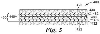
図5は、先行する実施形態と同様に、キャリアフィルム450の対向する側に対称に配置された1組の感圧性接着層320、322を含む、更に別の実施形態である両面テープ400を示す。キャリアフィルム450は、弾性基層440の対向する側に対称に配置された1組のプラスチックスキン層430、432を含むが、弾性基層440は、下記に記述されているように、他と異なる層状構造を有する。
FIG. 5 shows yet another embodiment, the double-
再び図5を参照して、弾性基層440は、発泡していない第1及び第2の弾性フィルム482、482に埋め込まれるフォームコア480を含む。ここで、第1及び第2の弾性フィルム482、482は同じエラストマーを含むが、該フィルムは代替として異なるエラストマーを含んでもよい。場合により、弾性フィルム482は、フォームコア480と本質的に同じエラストマー樹脂構成成分を有し、唯一異なるのは、フォームコア480中に発泡剤(発泡剤又は多量の発泡性マイクロスフェアなど)が存在することである。例示的な実施形態において、フォームコア480は、発泡性マイクロスフェアをエラストマー樹脂中にブレンドすることによって得られる独立気泡フォームである。
With reference to FIG. 5 again, the
いくつかの実施形態において、発泡剤は、フォームコア480の全重量に対して少なくとも0.2重量%の量で存在する。いくつかの実施形態において、発泡剤は、フォームコア480の全重量に対して最大で5パーセントの量で存在する。
In some embodiments, the foaming agent is present in an amount of at least 0.2% by weight based on the total weight of the
有利には、フォームコア480が存在することにより、両面テープ400の全体の耐ショック性又は耐衝撃性を強化することができる。好ましくは、フォームコア480は、弾性基層440の平均厚さの少なくとも1パーセント、少なくとも5パーセント、少なくとも10パーセント、又は少なくとも20パーセントを占める。好ましくは、フォームコア480は、弾性基層440の平均厚さの最大で100パーセント、最大で75パーセント、最大で50パーセント、最大で30パーセント、又は最大で20パーセントを占める。
Advantageously, the presence of the
両面テープ200、300、400の更なる態様は、両面テープ100に関してすでに記述されたものに本質的に類似しており、繰り返さないこととする。
Further aspects of the double-
本明細書に開示の両面感圧性接着テープは、当業者に既知の様々な製造方法を使用して製造することができる。テープ100に関して、例えば、それを構成する各層は、連続押出プロセスによって形成され、一緒に積層されてもよい。プラスチックスキン及び弾性ベース構成成分の性質に応じて、2つ以上の層を同じダイから共押出してもよい。本明細書に記載されているように、両面テープのキャリアフィルムが対称的な層構成を有する場合、その製造はインフレーションフィルム押出を使用して容易にすることができ、これにより、層の幅及び厚さのより優れた制御を行うことができる。
The double-sided pressure-sensitive adhesive tape disclosed herein can be manufactured using a variety of manufacturing methods known to those of skill in the art. With respect to the
例示的なインフレーションフィルムプロセスにおいて、プラスチックスキンポリマー及び弾性ベースポリマーは、インフレーションフィルムダイに配置された同心環状オリフィスから同時に押出される。ローラーがチューブを上に引き取りながら、押出されたポリマーのチューブを圧縮空気によって膨らませ、このようにしてフィルムの横方向及び縦方向の延伸をもたらす。次に、押出された多層チューブを連続的にスリットし、開いてフラットシートを形成し、ニップロールを通過させて、第1のプラスチックスキン層と、弾性基層と、第2のプラスチックフィルム層とを含むキャリアフィルムを生成させる。次に、別々に押出されてもよい第1及び第2の感圧性接着層を、キャリアフィルムの対向する主表面に積層して、両面感圧性接着テープを提供することができる。 In an exemplary inflation film process, the plastic skin polymer and elastic base polymer are simultaneously extruded from a concentric annular orifice placed on the inflation film die. As the rollers pull the tube up, the extruded polymer tube is inflated with compressed air, thus resulting in lateral and longitudinal stretching of the film. The extruded multilayer tube is then continuously slit and opened to form a flat sheet and passed through a nip roll to include a first plastic skin layer, an elastic base layer and a second plastic film layer. Generate a carrier film. Next, the first and second pressure-sensitive adhesive layers, which may be extruded separately, can be laminated on the opposite main surfaces of the carrier film to provide a double-sided pressure-sensitive adhesive tape.
有利には、感圧性接着剤と隣接するプラスチックスキン層との間の接着性は、層を互いに積層する前に、少なくとも1つの接着層を表面機能化することによって実質的に強化することができる。前に述べたように、そのような表面修飾は、コロナ放電処理、プラズマ放電処理、火炎処理、電子線照射、紫外線照射、及び好適なプライマーによるコーティングによって達成されうる。 Advantageously, the adhesion between the pressure sensitive adhesive and the adjacent plastic skin layer can be substantially enhanced by surface functionalizing at least one adhesive layer before laminating the layers together. .. As mentioned earlier, such surface modifications can be achieved by corona discharge treatment, plasma discharge treatment, flame treatment, electron beam irradiation, UV irradiation, and coating with suitable primers.
米国特許第5,888,594号(David et al.)に記載されている有利な表面処理の1つにおいて、第1及び第2のプラスチックスキン層の一方又は両方が、シングルパスプロセスでヘキサメチルジシロキサン蒸気と酸素ガスを混合することによってエッチングされる。 In one of the advantageous surface treatments described in US Pat. No. 5,888,594 (David et al.), One or both of the first and second plastic skin layers are hexamethylated in a single pass process. Etched by mixing disiloxane vapor and oxygen gas.
限定する意図はないが、両面テープの特定の実施形態及びそれらの組み合わせを以下のとおり列挙する。 Although not intended to be limiting, specific embodiments of double-sided tape and combinations thereof are listed below.
1. 以下の順序で、第1の感圧性接着層と、第1のプラスチックスキン層と、弾性基層と、第2のプラスチックスキン層と、第2の感圧性接着層と、を含む両面テープであって、第1の感圧性接着層及び第2の感圧性接着層は、両面テープの両側の最外層である、両面テープ。 1. 1. A double-sided tape comprising a first pressure-sensitive adhesive layer, a first plastic skin layer, an elastic base layer, a second plastic skin layer, and a second pressure-sensitive adhesive layer in the following order. The first pressure-sensitive adhesive layer and the second pressure-sensitive adhesive layer are double-sided tapes, which are the outermost layers on both sides of the double-sided tape.
2. 弾性基層は、スチレンブロックコポリマー、オレフィンブロックコポリマー、熱可塑性ポリオレフィン、天然ゴム、スチレンブタジエンゴム、エチレンプロピレンジエンモノマー、ポリイソブチレン、熱可塑性ポリウレタン、及びそれらのブレンド又はコポリマーから選択されるエラストマーを含む、実施形態1に記載の両面テープ。 2. The elastic base layer comprises a styrene block copolymer, an olefin block copolymer, a thermoplastic polyolefin, a natural rubber, a styrene butadiene rubber, an ethylene propylene diene monomer, polyisobutylene, a thermoplastic polyurethane, and an elastomer selected from a blend or copolymer thereof. The double-sided tape according to Form 1.
3. 弾性基層はフォームを含む、実施形態1又は2に記載の両面テープ。 3. 3. The double-sided tape according to embodiment 1 or 2, wherein the elastic base layer contains foam.
4. 弾性基層は、以下の順序で、第1の弾性フィルムと、フォームコアと、第2の弾性フィルムと、を含む、実施形態3に記載の両面テープ。 4. The double-sided tape according to the third embodiment, wherein the elastic base layer includes a first elastic film, a foam core, and a second elastic film in the following order.
5. フォームコアは、エラストマー及びエラストマー中に分散した発泡剤を含む、実施形態4に記載の両面テープ。 5. The double-sided tape according to the fourth embodiment, wherein the foam core contains an elastomer and a foaming agent dispersed in the elastomer.
6. 発泡剤は、フォームコアの全重量に対して0.2重量%〜5重量%の範囲の量で存在する、実施形態5に記載の両面テープ。 6. The double-sided tape according to the fifth embodiment, wherein the foaming agent is present in an amount in the range of 0.2% by weight to 5% by weight based on the total weight of the foam core.
7. 第1及び第2の弾性フィルムの両方がエラストマーを含む、実施形態4〜6のいずれか1つに記載の両面テープ。 7. The double-sided tape according to any one of embodiments 4 to 6, wherein both the first and second elastic films contain an elastomer.
8. フォームコアは、弾性基層の平均厚さのの1パーセント〜99パーセントを占める、実施形態4〜7のいずれか1つに記載の両面テープ。 8. The double-sided tape according to any one of embodiments 4 to 7, wherein the foam core accounts for 1% to 99% of the average thickness of the elastic base layer.
9. フォームコアは、弾性基層の平均厚さの1パーセント〜50パーセントを占める、実施形態8に記載の両面テープ。 9. The double-sided tape according to embodiment 8, wherein the foam core occupies 1% to 50% of the average thickness of the elastic base layer.
10. フォームコアは、弾性基層の平均厚さの1パーセント〜20パーセントを占める、実施形態9に記載の両面テープ。 10. The double-sided tape according to embodiment 9, wherein the foam core occupies 1% to 20% of the average thickness of the elastic base layer.
11. 弾性基層は、20マイクロメートル〜130マイクロメートルの範囲の平均厚さを有する、実施形態1〜10のいずれか1つに記載の両面テープ。 11. The double-sided tape according to any one of embodiments 1 to 10, wherein the elastic base layer has an average thickness in the range of 20 micrometers to 130 micrometers.
12. 弾性基層は、30マイクロメートル〜120マイクロメートルの範囲の平均厚さを有する、実施形態11に記載の両面テープ。 12. The double-sided tape according to embodiment 11, wherein the elastic base layer has an average thickness in the range of 30 micrometers to 120 micrometers.
13. 弾性基層は、50マイクロメートル〜100マイクロメートルの範囲の平均厚さを有する、実施形態12に記載の両面テープ。 13. The double-sided tape according to embodiment 12, wherein the elastic base layer has an average thickness in the range of 50 micrometers to 100 micrometers.
14. 第1及び第2のプラスチックスキン層のそれぞれは、70℃〜130℃の範囲の融解温度を有する半結晶性熱可塑性樹脂を含む、実施形態1〜13のいずれか1つに記載の両面テープ。 14. The double-sided tape according to any one of embodiments 1 to 13, wherein each of the first and second plastic skin layers comprises a semi-crystalline thermoplastic resin having a melting temperature in the range of 70 ° C to 130 ° C.
15. 第1及び第2のプラスチックスキン層のそれぞれは、80℃〜120℃の範囲の融解温度を有する熱可塑性樹脂を含む、実施形態14に記載の両面テープ。 15. The double-sided tape according to embodiment 14, wherein each of the first and second plastic skin layers contains a thermoplastic resin having a melting temperature in the range of 80 ° C. to 120 ° C.
16. 第1及び第2のプラスチックスキン層のそれぞれは、85℃〜112℃の範囲の融解温度を有する熱可塑性樹脂を含む、実施形態15に記載の両面テープ。 16. The double-sided tape according to embodiment 15, wherein each of the first and second plastic skin layers contains a thermoplastic resin having a melting temperature in the range of 85 ° C to 112 ° C.
17. 第1及び第2のプラスチックスキン層のぞれぞれは、高密度ポリエチレン、低密度ポリエチレン、エチレンビニルアセテート、ポリウレタン、スチレンブロックコポリマー、ポリアミド変性ポリエーテル、及びそれらのブレンド又はコポリマーから選択されるポリマーを含む、実施形態1〜16のいずれか1つに記載の両面テープ。 17. Each of the first and second plastic skin layers is a polymer selected from high density polyethylene, low density polyethylene, ethylene vinyl acetate, polyurethane, styrene block copolymers, polyamide modified polyethers, and blends or copolymers thereof. The double-sided tape according to any one of Embodiments 1 to 16, which comprises.
18. 第1及び第2のプラスチックスキン層のそれぞれは、10マイクロメートル〜50マイクロメートルの範囲の平均厚さを有する、実施形態1〜17のいずれか1つに記載の両面テープ。 18. The double-sided tape according to any one of embodiments 1 to 17, wherein each of the first and second plastic skin layers has an average thickness in the range of 10 micrometers to 50 micrometers.
19. 第1及び第2のプラスチックスキン層のそれぞれは、15マイクロメートル〜40マイクロメートルの範囲の平均厚さを有する、実施形態18に記載の両面テープ。 19. The double-sided tape according to embodiment 18, wherein each of the first and second plastic skin layers has an average thickness in the range of 15 micrometers to 40 micrometers.
20. 第1及び第2のプラスチックスキン層のそれぞれは、20マイクロメートル〜30マイクロメートルの範囲の平均厚さを有する、実施形態19に記載の両面テープ。 20. The double-sided tape according to embodiment 19, wherein each of the first and second plastic skin layers has an average thickness in the range of 20 micrometers to 30 micrometers.
21. 第1及び第2のプラスチックスキン層のそれぞれは、弾性基層の平均厚さの10パーセント〜50パーセントの範囲の平均厚さを有する、実施形態1〜20のいずれか1つに記載の両面テープ。 21. The double-sided tape according to any one of embodiments 1 to 20, wherein each of the first and second plastic skin layers has an average thickness in the range of 10 percent to 50 percent of the average thickness of the elastic base layer.
22. 第1及び第2のプラスチックスキン層のそれぞれは、弾性基層の平均厚さの20パーセント〜40パーセントの範囲の平均厚さを有する、実施形態21に記載の両面テープ。 22. The double-sided tape according to embodiment 21, wherein each of the first and second plastic skin layers has an average thickness in the range of 20 percent to 40 percent of the average thickness of the elastic base layer.
23. 第1及び第2のプラスチックスキン層のそれぞれは、弾性基層の平均厚さの25パーセント〜35パーセントの範囲の平均厚さを有する、実施形態22に記載の両面テープ。 23. 22. The double-sided tape according to embodiment 22, wherein each of the first and second plastic skin layers has an average thickness in the range of 25 percent to 35 percent of the average thickness of the elastic base layer.
24. 第1及び第2の感圧性接着層のそれぞれは、アクリル系感圧性接着剤を含む、実施形態1〜23のいずれか1つに記載の両面テープ。 24. The double-sided tape according to any one of embodiments 1 to 23, wherein each of the first and second pressure-sensitive adhesive layers contains an acrylic pressure-sensitive adhesive.
25. 各アクリル系感圧性接着剤は、高ガラス転移温度オリゴマーを含む、実施形態1〜24のいずれか1つに記載の両面テープ。 25. The double-sided tape according to any one of Embodiments 1 to 24, wherein each acrylic pressure-sensitive adhesive contains a high glass transition temperature oligomer.
26. 各アクリル系感圧性接着剤は、微小領域相モルフォロジーを有する、実施形態25に記載の両面テープ。 26. The double-sided tape according to embodiment 25, wherein each acrylic pressure-sensitive adhesive has a microregional phase morphology.
27. 第1及び第2の感圧性接着層の一方又は両方は、低密度マイクロスフェアを含む、実施形態1〜26のいずれか1つに記載の両面テープ。 27. The double-sided tape according to any one of embodiments 1 to 26, wherein one or both of the first and second pressure-sensitive adhesive layers comprises low-density microspheres.
28. 低密度マイクロスフェアは、感圧性接着層の全組成物に対して0.1重量%〜5重量%の範囲の量で存在する、実施形態27に記載の両面テープ。 28. The double-sided tape according to embodiment 27, wherein the low density microspheres are present in an amount in the range of 0.1% to 5% by weight with respect to the total composition of the pressure sensitive adhesive layer.
29. 低密度マイクロスフェアは、感圧性接着層の全組成物に対して0.5重量%〜3重量%の範囲の量で存在する、実施形態28に記載の両面テープ。 29. The double-sided tape according to embodiment 28, wherein the low density microspheres are present in an amount in the range of 0.5% to 3% by weight based on the total composition of the pressure sensitive adhesive layer.
30. 低密度マイクロスフェアは、感圧性接着層の全組成物に対して1重量%〜2重量%の範囲の量で存在する、実施形態29に記載の両面テープ。 30. The double-sided tape according to embodiment 29, wherein the low density microspheres are present in an amount in the range of 1% to 2% by weight with respect to the total composition of the pressure sensitive adhesive layer.
31. 第1及び第2の感圧性接着層のうちの少なくとも1つに接着された剥離ライナーを更に含む、実施形態1〜30のいずれか1つに記載の両面テープ。 31. The double-sided tape according to any one of embodiments 1 to 30, further comprising a release liner adhered to at least one of the first and second pressure-sensitive adhesive layers.
32. 第1の感圧性接着層と第1のプラスチックスキン層との間に位置する第1のプライマーを更に含む、実施形態1〜31のいずれか1つに記載の両面テープ。 32. The double-sided tape according to any one of embodiments 1 to 31, further comprising a first primer located between the first pressure sensitive adhesive layer and the first plastic skin layer.
33. 第2の感圧性接着層と第2のプラスチックスキン層との間に位置する第2のプライマーコーティングを更に含む、実施形態32に記載の両面テープ。 33. The double-sided tape according to embodiment 32, further comprising a second primer coating located between the second pressure sensitive adhesive layer and the second plastic skin layer.
34. 第1及び第2のプラスチックスキン層のそれぞれは、プラズマ処理によって表面機能化されており、それぞれの感圧性接着層に直接接触している、実施形態1〜31のいずれか1つに記載の両面テープ。 34. The double-sided surface according to any one of embodiments 1 to 31, wherein each of the first and second plastic skin layers is surface-functionalized by plasma treatment and is in direct contact with the respective pressure-sensitive adhesive layer. tape.
35. 第1及び第2のプラスチックスキン層のそれぞれは、コロナ処理によって表面機能化されており、それぞれの感圧性接着層に直接接触している、実施形態1〜31のいずれか1つに記載の両面テープ。 35. The double-sided surface according to any one of embodiments 1 to 31, wherein each of the first and second plastic skin layers is surface-functionalized by corona treatment and is in direct contact with the respective pressure-sensitive adhesive layer. tape.
36. 第1及び第2のプラスチックスキン層並びに弾性基層の1つ以上は、充填剤、酸化防止剤、紫外線安定剤、加工助剤、及び着色剤から選択される添加剤を含む、実施形態1〜35のいずれか1つに記載の両面テープ。 36. One or more of the first and second plastic skin layers and elastic base layers comprises additives selected from fillers, antioxidants, UV stabilizers, processing aids, and colorants, embodiments 1-35. Double-sided tape according to any one of.
37. 添加剤は、カーボンブラック充填剤を含む、実施形態36に記載の両面テープ。 37. The double-sided tape according to embodiment 36, wherein the additive contains a carbon black filler.
38. 両面テープは、50マイクロメートル〜400マイクロメートルの範囲の全厚を有する、実施形態1〜37のいずれか1つに記載の両面テープ。 38. The double-sided tape according to any one of embodiments 1 to 37, wherein the double-sided tape has a total thickness in the range of 50 micrometers to 400 micrometers.
39. 両面テープは、100マイクロメートル〜350マイクロメートルの範囲の全厚を有する、実施形態38に記載の両面テープ。 39. The double-sided tape according to embodiment 38, wherein the double-sided tape has a total thickness in the range of 100 micrometers to 350 micrometers.
40. 両面テープは、150マイクロメートル〜300マイクロメートルの範囲の全厚を有する、実施形態39に記載の両面テープ。 40. The double-sided tape according to embodiment 39, wherein the double-sided tape has a total thickness in the range of 150 micrometers to 300 micrometers.
41. 両面テープは、40センチメートル引張落下試験による少なくとも15回の落下に耐える、実施形態1〜40のいずれか1つに記載の両面テープ。 41. The double-sided tape according to any one of embodiments 1 to 40, wherein the double-sided tape can withstand at least 15 drops in a 40-centimeter tensile drop test.
42. 両面テープは、40センチメートル引張落下試験による少なくとも18回の落下に耐える、実施形態41に記載の両面テープ。 42. The double-sided tape according to embodiment 41, wherein the double-sided tape can withstand at least 18 drops in a 40-centimeter tensile drop test.
43. 両面テープは、40センチメートル引張落下試験による少なくとも20回の落下に耐える、実施形態42に記載の両面テープ。 43. The double-sided tape according to embodiment 42, wherein the double-sided tape can withstand at least 20 drops in a 40-centimeter tensile drop test.
44. 両面テープは、押抜き試験により少なくとも80ニュートンの押抜力を生じる、実施形態1〜43のいずれか1つに記載の両面テープ。 44. The double-sided tape according to any one of embodiments 1 to 43, wherein the double-sided tape produces a punching force of at least 80 Newtons by a punching test.
45. 両面テープは、押抜き試験により少なくとも85ニュートンの押抜力を生じる、実施形態44に記載の両面テープ。 45. The double-sided tape according to embodiment 44, wherein the double-sided tape produces a punching force of at least 85 Newtons by a punching test.
46. 両面テープは、押抜き試験により少なくとも90ニュートンの押抜力を生じる、実施形態45に記載の両面テープ。 46. The double-sided tape according to embodiment 45, wherein the double-sided tape produces a punching force of at least 90 Newtons by a punching test.
47. 透明レンズと、透明レンズに貼り合わされた両面テープとを備える、実施形態1〜46のいずれか1つに記載の両面テープを使用したデバイス組立品。 47. A device assembly using the double-sided tape according to any one of embodiments 1 to 46, comprising a transparent lens and a double-sided tape attached to the transparent lens.
48. 基板を更に含み、両面テープは透明レンズと基板を互いに貼り合わせる、実施形態47に記載のデバイス組立品。 48. The device assembly according to embodiment 47, further comprising a substrate, wherein the double-sided tape attaches the transparent lens and the substrate to each other.
49. 実施形態1〜46のいずれか1つに記載の両面テープを製造する方法であって、第1及び第2のプラスチックスキン樹脂及び弾性ベース樹脂をインフレーションフィルムダイから同時に押出して、押出チューブを形成することと、押出チューブをスリットして、第1のプラスチックスキン層、弾性基層、及び第2のプラスチックフィルム層を含むキャリアフィルムを提供することと、第1及び第2の感圧性接着層をキャリアフィルムの対向する主表面に積層して、両面テープを提供することと、を含む、方法。 49. The method for producing a double-sided tape according to any one of embodiments 1 to 46, wherein the first and second plastic skin resins and elastic base resins are simultaneously extruded from an inflation film die to form an extruded tube. That, the extrusion tube is slit to provide a carrier film containing a first plastic skin layer, an elastic base layer, and a second plastic film layer, and the first and second pressure-sensitive adhesive layers are used as a carrier film. A method of providing a double-sided tape, which is laminated on the opposite main surface of the.
50. 実施形態1〜46のいずれか1つに記載の両面テープを製造する方法であって、第1及び第2のプラスチックスキン樹脂及び弾性ベース樹脂をダイから共押出して、第1のプラスチックスキン層、弾性基層、及び第2のプラスチックスキン層を含むキャリアフィルムを形成することと、第1及び第2の感圧性接着層をキャリアフィルムの対向する主表面に積層して、両面テープを提供することと、を含む、方法。 50. The method for producing a double-sided tape according to any one of embodiments 1 to 46, wherein the first and second plastic skin resins and elastic base resins are coextruded from a die to obtain a first plastic skin layer. To form a carrier film containing an elastic base layer and a second plastic skin layer, and to laminate the first and second pressure-sensitive adhesive layers on the opposite main surfaces of the carrier film to provide a double-sided tape. , Including, methods.
51. 第1及び第2の感圧性接着層を積層する前に、コロナ処理によって、キャリアフィルムの対向する主表面の一方又は両方を表面機能化することを更に含む、実施形態49又は50に記載の方法。
51. The method according to
52. 第1及び第2の感圧性接着層を積層する前に、プラズマ処理によって、キャリアフィルムの対向する主表面の一方又は両方を表面機能化することを更に含む、実施形態49又は50に記載の方法。
52. The method according to
53. プラズマ処理は、シングルパスプロセスでヘキサメチルジシロキサン蒸気と酸素ガスを混合することによって、第1及び第2のプラスチックスキン層の一方又は両方をエッチングすることを含む、実施形態52に記載の方法。 53. 25. The method of embodiment 52, wherein the plasma treatment comprises etching one or both of the first and second plastic skin layers by mixing hexamethyldisiloxane vapor and oxygen gas in a single pass process.
54. 第1及び第2の感圧性接着層を積層する前に、プライマーコーティングプロセスによって、キャリアフィルムの対向する主表面の一方又は両方を表面機能化することを更に含む、請求項49又は50に記載の方法。 54. 49 or 50. Method.
以下の実施例は、本開示の範囲内の例示的な実施形態を説明することを目的とする。本開示の広い範囲を記載する数値範囲及びパラメータは近似値であるが、具体例に記載されている数値は、可能な限り正確に報告されている。しかしながら、いずれの数値も、それらの各試験測定値に見られる標準偏差から必然的に生じる若干の誤差を本質的に含む。少なくとも、各数値パラメータは、報告される有効桁数を考慮し、端数処理技術を適用することによって少なくとも解釈されるべきであるが、このことは、請求項がカバーする範囲について均等論の適用を制限しようとするものではない。 The following examples are intended to illustrate exemplary embodiments within the scope of the present disclosure. Although the numerical ranges and parameters that describe the broad range of the present disclosure are approximate values, the numerical values described in the specific examples are reported as accurately as possible. However, each number essentially contains some error that inevitably arises from the standard deviation found in each of those test measurements. At a minimum, each numerical parameter should be at least interpreted by applying rounding techniques, taking into account the number of significant digits reported, but this applies the doctrine of equivalents to the extent covered by the claims. I'm not trying to limit it.
引張落下試験−室温状態調節(conditioning)
図6を参照して、「M」=2インチ(5.1cm)×「L」=4インチ(10.2cm)×0.236インチ(0.60cm)の寸法を有するポリ(メタクリル酸メチル(「PMMA」)パネル192(Aeromat Plastics(Burnsville,MN)から商品名「TEST PANEL−CLEAR ACRYLITE ARII」で入手可能)を、2−プロパノールで3回洗浄した。洗浄した表面の表面エネルギーを、携帯型ゴニオメーター(FIBRO System AB(Sweden)から商品名「POCKET GONIOMETER PG−X」で入手可能)を使用して測定したところ、約39〜40ダイン/cmであることが分かった。
Tensile drop test-room temperature conditioning
With reference to FIG. 6, poly (methyl methacrylate (methyl methacrylate) having dimensions of “M” = 2 inches (5.1 cm) × “L” = 4 inches (10.2 cm) × 0.236 inches (0.60 cm). "PMMA") panel 192 (available from Aeromat Plastics (Burnsville, MN) under the trade name "TEST PANEL-CLEAR ACRYLITE ARII") was washed 3 times with 2-propanol. The surface energy of the washed surface was portable. When measured using a goniometer (available from FIBRO System AB (Sweden) under the trade name "POCKET GONIOMETER PG-X"), it was found to be about 39-40 dyne / cm.
幅「T」=2mm及び長さ2インチ(5.1cm)の、両面感圧性接着テープ100(又は比較例テープ材料)の2つのストリップを、図6に示すようにテープストリップがくぼみの端壁から「S」=0.5インチ(約1.3cm)となるように、特別注文のアルミニウム試験固定具196の下面のくぼみの幅の端から端まで長く貼りつけた。試験固定具196は、幅「M」=2インチ(5.1cm)×長さ「N」=4.5インチ(13.97cm×高さ「P」=0.5インチ(約1.3cm)であり、質量は143gであった。
Two strips of double-sided pressure-sensitive adhesive tape 100 (or comparative tape material) with a width of "T" = 2 mm and a length of 2 inches (5.1 cm), as shown in FIG. From end to end, the width of the recess on the underside of the custom-made
PMMAパネル192を試験固定具196のくぼみの中央に置き、各テープストリップ100と接触させて接着物品を得た。次に接着物品を、くぼみが上向きになるような位置にし、PMMAパネルの露出した表面に4kg(8.8lb.)の重りを15秒間置き、その後、重りを外し、接着物品を24時間、23℃及び50%RHで静置した。
The
次に、落下試験機(Shinyei Corporation(America,New York,NY)から商品名「DT−202」で入手可能)、及び図6に示すようにPMMA基板が下向きになる接着物品の水平な配置(すなわち、大きな矢印が下方向を示す)を使用して、接着物品を引張モードで落下耐性に関して評価した。接着物品を、40cm又は70cmのいずれかの高さから1.2cmの厚さの鋼板の上に落下させた。それぞれの高さで2つのサンプルを試験し、破壊までの落下回数を各サンプルについて記録した。加えて、破壊状態を記録した:飛び出したもの(pop-off)は「PO」(すなわち、両面感圧性接着テープがPMMAパネルから剥離した)、粘着、コア剥離、又は2−接着破壊(2-bond failure)は「2B」。観察された場合は破壊状態の組み合わせを書き留めた。 Next, a drop tester (available from Shinyei Corporation (America, New York, NY) under the trade name "DT-202") and a horizontal arrangement of the adhesive article with the PMMA substrate facing down (as shown in FIG. 6). That is, the large arrow points downward) was used to evaluate the adherent article in terms of drop resistance in tensile mode. The adhesive article was dropped onto a steel plate 1.2 cm thick from a height of either 40 cm or 70 cm. Two samples were tested at each height and the number of drops to failure was recorded for each sample. In addition, the failure state was recorded: the pop-off was "PO" (ie, the double-sided pressure sensitive adhesive tape peeled off the PMMA panel), adhesive, core peeling, or 2-adhesive failure (2- bond failure) is "2B". If observed, write down the combination of destructive states.
押抜き試験
2インチ(5.1cm)×4インチ(10.2cm)×0.236インチ(0.60cm)の寸法を有するポリ(メタクリル酸メチル(「PMMA」)パネル(Aeromat Plastics(Burnsville,MN)から商品名「TEST PANEL−CLEAR ACRYLITE ARII」で入手可能)の主表面、及び寸法が2インチ(5.1cm)×5インチ(12.7cm)で、パネル中央に15mmの穴を有する予め穴を開けたPMMAパネルを、2−プロパノールで3回洗浄した。幅2mm及び長さ2インチ(5.1cm)の両面感圧性接着テープ100(又は比較例テープ材料)の2つのストリップを、予め穴を開けたPMMAパネルの幅の端から端まで、パネルの端から2インチ(5.1cm)のところに貼りつけた。TEST PANEL−CLEAR ACRYLITE ARIIを中央に置き、4kgのおもりを使用して30秒間、接着テープストリップ上に押しつけた。試験の前に、サンプルを72時間、室温で静置した。パネルを押し抜くために、12mmプローブアタッチメント及び毎分2インチ(5.1cm)の押し抜き速度を有するInstron装置を使用し、押し抜きプロセス中の押す力を測定した。パネルが離れたら試験を終了し、ピーク荷重をニュートン(「N」)で記録した。加えて、破壊状態を記録した:飛び出したものは「PO」(すなわち、両面感圧性接着テープがPMMAパネルから剥離した)、コア剥離、又は2−接着破壊は「2B」。観察された場合は破壊状態の組み合わせを書き留めた。
Punch test Poly (methyl methacrylate (“PMMA”) panel (Aeromat Plastics (Burnsville, MN)) with dimensions of 2 inches (5.1 cm) x 4 inches (10.2 cm) x 0.236 inches (0.60 cm) ) To the main surface of the trade name "TEST PANEL-CLEAR ACRYLITE ARII"), and a pre-hole with dimensions of 2 inches (5.1 cm) x 5 inches (12.7 cm) and a 15 mm hole in the center of the panel. The opened PMMA panel was washed 3 times with 2-propanol. Two strips of double-sided pressure-sensitive adhesive tape 100 (or comparative tape material) 2 mm wide and 2 inches (5.1 cm) long were pre-drilled. The opened PMMA panel was pasted from end to end, 2 inches (5.1 cm) from the end of the panel. TEST PANEL-CLEAR ACRYLITE ARII was placed in the center and 30 with a 4 kg weight. Pressed onto an adhesive tape strip for seconds. Prior to testing, the sample was allowed to stand at room temperature for 72 hours. 12 mm probe attachment and 2 inch (5.1 cm) punch rate per minute to punch the panel. The pushing force during the punching process was measured using an Instron device with. The test was terminated when the panel was separated and the peak load was recorded in Newton (“N”). Those that popped out were "PO" (ie, double-sided pressure-sensitive adhesive tape peeled off the PMMA panel), core peeling, or 2-adhesive failure was "2B". If observed, note the combination of broken states.
耐反発性試験
陽極酸化処理したアルミニウムストリップ(180mm×20mm×0.5mm)を、シート素材(Lawrence&Fredrick(Stremwood,IL)から商品名「5005 ALLOY H34 TEMPER MILL FINISH UND/UNSEALED ANODIZED ALUMINUM」で入手可能)から切断した。長さ7.9インチ(200mm)、幅1.19インチ(30mm)、及び厚さ0093インチ(約2mm)のポリカーボネート基板を、Bayer MaterialScience AG(Germany)から商品名「MAKROLON 2405」で入手した。
Repulsion resistance test Anodized aluminum strip (180 mm x 20 mm x 0.5 mm) can be obtained from the sheet material (Lawrence & Fredrick (Streamwood, IL) under the trade name "5005 ALLOY H34 TEMPER MILL FINISH UND / UNSEALED ANODIZED ALU". Disconnected from. Polycarbonate substrates 7.9 inches (200 mm) long, 1.19 inches (30 mm) wide, and 093 inches (about 2 mm) thick were obtained from Bayer MaterialScience AG (Germany) under the trade name "MAKROLLON 2405".
両面テープサンプル(幅>30mm及び長さ200mm、片側が剥離ライナーで保護されている)を、ゴムローラーを使用して、陽極酸化処理されたアルミニウム上に積層した。アルミニウムストリップの4辺全ての周囲の余分なテープを、慎重に切り取った。剥離ライナーを剥がし、次に軽く指で押して、試験片の辺の一端を基板の端と合わせながら中央に置き、試験片の接着側を基板上に押しつけた。アルミニウムストリップ側を上にした積層試験片を圧延機に置き、毎分12インチ(約30cm)で15ポンド(約6.8kg)の重量で各方向に1回圧延した。試験片を恒温恒湿室(23±2C及び50±1%相対湿度)で24±2時間保管した。
Double-sided tape samples (width> 30 mm and
積層試験片の端を下向きにわずかに曲げ(基板側を下にして)、積層試験片を長さ190mmの曲げジグに載せた。試験サンプルを載せた曲げジグを、70℃のオーブン中に24±1時間入れた。次に、サンプルを載せた曲げジグをオーブンから取り出し、30分間冷ました。次に鋼製定規を使用して、テープサンプルの最端部における、基板からの試験片の「浮き」を測定した。基板の最も高い表面から接着表面の底面までの距離を測定し、1mm単位まで値を記録した。

多層キャリアフィルムの調製
3層スパイラルマンドレル(2インチ(約5.0cm)マンドレル)インフレーションフィルムダイにおいて、多層キャリアフィルムを製造した。ダイへの気流を手動で調節して、約3.5:1のブローアップ比を達成した。続いて、膨らんだフィルムをダイの約4フィート(約1.2m)上で折りたたみ、巻き取った。プラスチックスキン層上には2つの3/4インチ(約1.9cm)BRABENDER SINGLE SCREW押出機(C.W.Brabender Intruments(South Hackensack,NJ)から入手可能)によって、コア上には1つの3/4インチ(約1.9cm)KILLION SINGLE SCREW押出機(Davis−Standard(Pawcatuck,CT)から入手可能)によって、供給材料を供給した。
Preparation of Multilayer Carrier Film A multilayer carrier film was produced on a 3-layer spiral mandrel (2-inch (about 5.0 cm) mandrel) inflation film die. The airflow to the die was manually adjusted to achieve a blow-up ratio of approximately 3.5: 1. The swollen film was then folded and rolled up about 4 feet above the die. Two 3/4 inch (about 1.9 cm) BRABENDER SINGLE SCREW extruders (available from CW Brabender Instruments (South Hackensack, NJ)) on the plastic skin layer and one 3/4 inch on the core. The feedstock was supplied by a 4-inch KILLION SINGLE SCREW extruder (available from Davis-Standard (Pawcatuck, CT)).
プロセス温度は以下のとおりであった:
外側及び内側のスキン層の押出機温度:
ゾーン1、330°F(166℃);ゾーン2、360°F(182℃);ゾーン3、360°F(182℃)。
コア層の押出機温度:
ゾーン1、350°F(177℃);ゾーン2、375°F(191℃);ゾーン3、390°F(199℃).
アダプター温度:390°F(199℃)。
ダイ温度:380°F(193℃)。
The process temperature was as follows:
Extruder temperature for outer and inner skin layers:
Zone 1, 330 ° F (166 ° C); Zone 2, 360 ° F (182 ° C); Zone 3, 360 ° F (182 ° C).
Core layer extruder temperature:
Adapter temperature: 390 ° F (199 ° C).
Die temperature: 380 ° F (193 ° C).
得られる押出された多層キャリアフィルムの組成を表2にまとめる。
多層キャリアフィルムは、PSA材料による処理の前に、プラズマエッチング又は空気コロナ処理で任意に表面処理した。プラズマエッチング処理(「プラズマエッチ」)は、電極幅を42.5インチ(108cm)に大きくし、排気の全てを2つのターボ分子ポンプ(Leybold Model MAGW−2200及びShimadzu Model 3203−LMC)の組み合わせによって行ったことを除いて、係属中の特許出願国際公開第2015/013387号(2015年1月29日公開)及び米国登録特許第5,888,594号(David,et al.)に記載のプラズマ処理装置を使用して行った。 The multilayer carrier film was optionally surface-treated by plasma etching or air corona treatment prior to treatment with the PSA material. Plasma etching (“plasma etching”) increases the electrode width to 42.5 inches (108 cm) and exhausts all by a combination of two turbo molecular pumps (Leybold Model MAGW-2200 and Shimadzu Model 3203-LMC). Plasma described in pending patent application International Publication No. 2015/0133387 (published January 29, 2015) and US Registered Patent No. 5,888,594 (David, et al.), Except for what has been done. This was done using a processing device.
あるいは、多層キャリアフィルムは、PSA材料による処理の前に、0.5J/cm2のレベルで空気コロナ処理で表面処理した。
アクリル系PSA調製
Acrylic PSA preparation
アクリル系PSAグループA
アクリル系PSA−グループAは、2EHA、AA、IBOA、NVCモノマー及びHTGOオリゴマーを、表4にまとめた相対量で含んでいた(「wt%」は、アクリレート構成成分100重量パーセントに対するアクリレート構成成分の重量パーセントを指し、「php」は、アクリレート構成成分100重量パーセントに対する重量百分率を指す)。構成成分を二段階プロセスでランダムに共重合させた:モノマー(及びHTGO)及び開始剤の一部を前添加し(「前添加」)、透明なガラス製バイアル中でマグネチックスターラーバーを使用して混合した。次に、ガラス製バイアルに窒素を5分間パージして溶存酸素を除去し、次に、被覆できる粘度になるまで(すなわち、部分的に重合したシロップ)、紫外光(365nm、約5mW/cm2)の前に置いた。この段階の典型的な目標値は、室温で約3000cPの粘度であった。次に、粘着付与剤、更なる開始剤、及び架橋剤を、表4にまとめた相対量で、「増粘した」サンプルに添加した(「後添加」)。次に、固体成分が完全に溶解するまでバイアルを暗所で回転させた。接着剤配合物を、剥離ライナー又は2mil(51マイクロメートル)プライマー処理PETフィルム上に被覆し、次に、1.5ミリワット毎平方センチメートル(mW/cm2)の強度で、700ミリジュール毎平方センチメートル(mJ/cm2)のUV照射を使用して更に硬化させた。
Acrylic PSA Group A
Acrylic PSA-Group A contained 2EHA, AA, IBOA, NVC monomers and HTGO oligomers in the relative amounts summarized in Table 4 (“wt%” is the acrylate component relative to 100 weight percent of the acrylate component. By weight percent, "php" refers to the weight percentage of 100 weight percent of the acrylate component). The components were randomly copolymerized in a two-step process: the monomer (and HTGO) and some of the initiators were pre-added (“pre-added”) and a magnetic stirrer bar was used in a clear glass vial. And mixed. The glass vial was then purged with nitrogen for 5 minutes to remove dissolved oxygen, then UV light (365 nm, about 5 mW / cm 2) until viscous to coat (ie, partially polymerized syrup). ) Was placed in front of it. A typical target value for this step was a viscosity of about 3000 cP at room temperature. The tackifier, additional initiator, and crosslinker were then added to the "thickened" sample in relative amounts summarized in Table 4 ("post-addition"). The vial was then rotated in the dark until the solid component was completely dissolved. The adhesive formulation is coated on a release liner or 2 mil (51 micrometer) primer-treated PET film and then 700 milliwatts per square centimeter (mJ) with a strength of 1.5 milliwatts per square centimeter (mW / cm 2). It was further cured using UV irradiation at / cm 2).
アクリル系PSAグループB
アクリル系PSA−グループB接着剤は、IOA及びAAモノマーを含んでいた。グループBのPSAを製造するための方法は、グループAのPSAに関して記載されたものに従った。グループBの接着剤の組成を表5にまとめた。
Acrylic PSA Group B
The acrylic PSA-Group B adhesive contained IOA and AA monomers. The method for producing Group B PSA followed that described for Group A PSA. The composition of the Group B adhesives is summarized in Table 5.
両面テープ
実施例EX−1〜EX−23は、表6にまとめた組み合わせに従って、手で又はラミネーターによって、多層キャリアフィルムの両側にPSAを積層することによって製造した。試験のためのサンプル調製の前に、積層したシートを終夜室温に置いた。
比較例CE−A及びCE−Bは、表6にまとめた組み合わせに従って、手で又はラミネーターによって、PETキャリアフィルムの両側にPSAを積層することによって製造した。試験のためのサンプル調製の前に、積層したシートを終夜室温に置いた。比較例CE−C〜CE−Fは、市販の両面テープであった。 Comparative Examples CE-A and CE-B were produced by laminating PSA on both sides of the PET carrier film, either by hand or by laminator, according to the combinations summarized in Table 6. Prior to sample preparation for testing, the laminated sheets were placed at room temperature overnight. Comparative Examples CE-C to CE-F were commercially available double-sided tapes.
明細書においてある特定の例示的な実施形態を詳細に記述してきたが、当業者は、前述のことを理解すると、これらの実施形態の修正、変形及び等価物を容易に想起しうることが理解されるであろう。したがって、本開示は、本明細書で上記された例示的な実施形態に過度に限定されるものではないことが理解されるべきである。更に、本明細書において参照されている全ての出版物、公開された特許出願及び交付された特許は、それぞれの個々の出版物又は特許が参照により援用されると明確にかつ個別に示されているのと同程度に、それらの全体が参照により本明細書に援用される。様々な例示的な実施形態を記述してきた。これら及び他の実施形態は、開示されている実施形態の以下の列挙の範囲内である。 Although certain exemplary embodiments have been described in detail herein, one of ordinary skill in the art will appreciate that, understanding the above, modifications, modifications and equivalents of these embodiments can be easily recalled. Will be done. Therefore, it should be understood that the present disclosure is not overly limited to the exemplary embodiments set forth herein. In addition, all publications, published patent applications and issued patents referenced herein are clearly and individually indicated that their respective individual publications or patents are incorporated by reference. To the same extent they are incorporated herein by reference in their entirety. Various exemplary embodiments have been described. These and other embodiments are within the scope of the following enumeration of the disclosed embodiments.
Claims (10)
第1の感圧性接着層と、
10〜100重量%のエチレンビニルアセテートを含み、10マイクロメートル〜50マイクロメートルの範囲の平均厚さを有する第1のプラスチックスキン層と、
弾性基層と、
10〜100重量%のエチレンビニルアセテートを含む第2のプラスチックスキン層と、
第2の感圧性接着層と、を含む両面テープであって、
前記第1の感圧性接着層及び前記第2の感圧性接着層は、前記両面テープの両側の最外層であり、
前記第1の感圧接着層と前記第2の感圧接着層は、室温で10N/cm 2 未満の弾性率を有する、両面テープ。 In the following order
With the first pressure-sensitive adhesive layer,
A first plastic skin layer containing 10 to 100% by weight ethylene vinyl acetate and having an average thickness in the range of 10 micrometers to 50 micrometers.
Elastic base layer and
A second plastic skin layer containing 10-100% by weight ethylene vinyl acetate,
A double-sided tape containing a second pressure-sensitive adhesive layer.
The first pressure-sensitive adhesive layer and the second pressure-sensitive adhesive layer are outermost layers on both sides of the double-sided tape.
The first pressure-sensitive adhesive layer and the second pressure-sensitive adhesive layer are double-sided tapes having an elastic modulus of less than 10 N / cm 2 at room temperature.
第1の弾性フィルムと、
フォームコアと、
第2の弾性フィルムと、を含む、請求項1又は2に記載の両面テープ。 The elastic base layer is formed in the following order.
The first elastic film and
Form core and
The double-sided tape according to claim 1 or 2, comprising a second elastic film.
Applications Claiming Priority (3)
| Application Number | Priority Date | Filing Date | Title |
|---|---|---|---|
| US201562121967P | 2015-02-27 | 2015-02-27 | |
| US62/121,967 | 2015-02-27 | ||
| PCT/US2016/018204 WO2016137793A1 (en) | 2015-02-27 | 2016-02-17 | Double coated tape |
Publications (3)
| Publication Number | Publication Date |
|---|---|
| JP2018511669A JP2018511669A (en) | 2018-04-26 |
| JP2018511669A5 JP2018511669A5 (en) | 2019-03-28 |
| JP6925973B2 true JP6925973B2 (en) | 2021-08-25 |
Family
ID=55521811
Family Applications (1)
| Application Number | Title | Priority Date | Filing Date |
|---|---|---|---|
| JP2017544721A Active JP6925973B2 (en) | 2015-02-27 | 2016-02-17 | Double-sided tape |
Country Status (7)
| Country | Link |
|---|---|
| US (1) | US20180010018A1 (en) |
| EP (2) | EP3789466B1 (en) |
| JP (1) | JP6925973B2 (en) |
| KR (1) | KR20170125344A (en) |
| CN (1) | CN107429136B (en) |
| TW (1) | TW201700668A (en) |
| WO (1) | WO2016137793A1 (en) |
Families Citing this family (16)
| Publication number | Priority date | Publication date | Assignee | Title |
|---|---|---|---|---|
| US11498320B2 (en) | 2016-07-29 | 2022-11-15 | 3M Innovative Properties Company | Multilayer films and adhesive tapes |
| EP3551449B1 (en) | 2016-12-09 | 2021-05-26 | 3M Innovative Properties Company | Article comprising multilayer film |
| WO2018106558A1 (en) | 2016-12-09 | 2018-06-14 | 3M Innovative Properties Company | Polymeric multilayer film |
| JP7129411B2 (en) | 2016-12-09 | 2022-09-01 | スリーエム イノベイティブ プロパティズ カンパニー | polymer multilayer film |
| EP3551440B1 (en) | 2016-12-09 | 2023-08-23 | 3M Innovative Properties Company | Polymeric multilayer film |
| JP7036715B2 (en) * | 2017-03-29 | 2022-03-15 | 積水化学工業株式会社 | Double-sided adhesive tape |
| US20190031923A1 (en) * | 2017-07-26 | 2019-01-31 | 3M Innovative Properties Company | Backing for adhesive tape with thermal resistance |
| KR102060309B1 (en) * | 2017-09-06 | 2019-12-30 | 쓰리엠 이노베이티브 프로퍼티즈 캄파니 | Double-coated tape, method for producing the same and electrical device including the same |
| JP7323360B2 (en) * | 2018-07-04 | 2023-08-08 | 積水化学工業株式会社 | double sided adhesive tape |
| WO2020059791A1 (en) * | 2018-09-21 | 2020-03-26 | 積水化学工業株式会社 | Double-sided adhesive tape |
| US10889423B2 (en) | 2019-01-22 | 2021-01-12 | W/S Packaging Group, Inc. | Bonding label |
| JP7430513B2 (en) | 2019-10-30 | 2024-02-13 | 日東電工株式会社 | double sided adhesive tape |
| CN111145635A (en) * | 2019-12-26 | 2020-05-12 | 深圳深汕特别合作区昌茂粘胶新材料有限公司 | PE/EVA foam adhesive tape and preparation method thereof |
| CN112852339B (en) * | 2021-02-08 | 2022-08-23 | 佛山市南海区新永泰胶粘制品有限公司 | High-temperature-resistant release paper and preparation method and application thereof |
| JP7355096B2 (en) * | 2021-10-05 | 2023-10-03 | Dic株式会社 | Adhesive tape and its manufacturing method, articles using the adhesive tape and its dismantling method |
| CN117417700A (en) * | 2022-07-11 | 2024-01-19 | 德莎欧洲股份公司 | Heat-activated internal stripping adhesive tape and preparation and application thereof |
Family Cites Families (14)
| Publication number | Priority date | Publication date | Assignee | Title |
|---|---|---|---|---|
| CA2002449C (en) | 1988-12-05 | 2001-05-08 | Mark A. Strobel | Pressure-sensitive article with priming layer |
| US5354597A (en) * | 1990-03-30 | 1994-10-11 | Minnesota Mining And Manufacturing Company | Elastomeric tapes with microtextured skin layers |
| US5496615A (en) * | 1991-03-01 | 1996-03-05 | W. R. Grace & Co.-Conn. | Waterproofing membrane |
| US5602221A (en) | 1993-11-10 | 1997-02-11 | Minnesota Mining And Manufacturing Company | Pressure sensitive adhesives with good low energy surface adhesion |
| US5476712A (en) * | 1994-05-31 | 1995-12-19 | Avery Dennison Corporation | Flexographic plate mounting tape |
| US5888594A (en) | 1996-11-05 | 1999-03-30 | Minnesota Mining And Manufacturing Company | Process for depositing a carbon-rich coating on a moving substrate |
| DE19716996C1 (en) * | 1997-04-23 | 1998-06-04 | Beiersdorf Ag | Production of 2-sided pressure-sensitive adhesive tape |
| DE102006043259A1 (en) * | 2006-09-11 | 2008-06-19 | Tesa Ag | Process for producing a double-sided pressure-sensitive adhesive tape and its use |
| DE102008031356A1 (en) * | 2008-07-04 | 2010-01-07 | Tesa Se | Double-sided foam adhesive tapes for bonding electronic components |
| JP5881391B2 (en) * | 2011-01-25 | 2016-03-09 | 日立マクセル株式会社 | Double-sided adhesive tape for waterproofing |
| US9290682B2 (en) | 2011-11-18 | 2016-03-22 | 3M Innovative Properties Company | Pressure-sensitive adhesive composition |
| JP2013249367A (en) * | 2012-05-31 | 2013-12-12 | Hitachi Kasei Polymer Co Ltd | Double-sided pressure-sensitive adhesive tape |
| JP2014051566A (en) * | 2012-09-06 | 2014-03-20 | Nitto Denko Corp | Double-sided adhesive sheet |
| SG10201704677QA (en) | 2013-07-26 | 2017-07-28 | 3M Innovative Properties Co | Method of making a nanostructure and nanostructured articles |
-
2016
- 2016-02-17 KR KR1020177025757A patent/KR20170125344A/en unknown
- 2016-02-17 JP JP2017544721A patent/JP6925973B2/en active Active
- 2016-02-17 CN CN201680012163.9A patent/CN107429136B/en active Active
- 2016-02-17 EP EP20197262.7A patent/EP3789466B1/en active Active
- 2016-02-17 WO PCT/US2016/018204 patent/WO2016137793A1/en active Application Filing
- 2016-02-17 EP EP16709191.7A patent/EP3265527B1/en active Active
- 2016-02-17 US US15/547,088 patent/US20180010018A1/en active Pending
- 2016-02-26 TW TW105105993A patent/TW201700668A/en unknown
Also Published As
| Publication number | Publication date |
|---|---|
| KR20170125344A (en) | 2017-11-14 |
| JP2018511669A (en) | 2018-04-26 |
| EP3265527A1 (en) | 2018-01-10 |
| TW201700668A (en) | 2017-01-01 |
| EP3789466A1 (en) | 2021-03-10 |
| WO2016137793A1 (en) | 2016-09-01 |
| US20180010018A1 (en) | 2018-01-11 |
| CN107429136B (en) | 2020-07-17 |
| EP3265527B1 (en) | 2020-10-28 |
| EP3789466B1 (en) | 2022-04-13 |
| CN107429136A (en) | 2017-12-01 |
Similar Documents
| Publication | Publication Date | Title |
|---|---|---|
| JP6925973B2 (en) | Double-sided tape | |
| JP6140491B2 (en) | Double-sided adhesive sheet and portable electronic device | |
| US8043682B2 (en) | Release liner and pressure-sensitive adhesive sheet using the same | |
| JP6653290B2 (en) | Double-sided adhesive sheet and portable electronic equipment | |
| WO2009144891A1 (en) | Acrylic pressure-sensitive adhesive tape or sheet | |
| KR20170088833A (en) | Adhesive sheet for portable electronic devices | |
| JP2009132038A (en) | Viscoelastic member having polymer layer with elastomer distributed unevenly | |
| EP2653516B1 (en) | Pressure-sensitive adhesive sheet and pressure-sensitive adhesive composition | |
| US11168236B2 (en) | Acrylic pressure-sensitive adhesive composition and pressure-sensitive adhesive sheet | |
| JP2012077177A (en) | Molding decoration adhesive sheet | |
| WO2009144889A1 (en) | Acrylic pressure-sensitive adhesive tape or sheet | |
| KR20190003644A (en) | Adhesive sheet with release liner | |
| EP2581424A1 (en) | Adhesive sheet | |
| JP2014101457A (en) | Pressure sensitive adhesive sheet and laminate using the same | |
| CN109852271B (en) | Adhesive sheet | |
| US11898070B2 (en) | Adhesive tape and electronic device | |
| JP6317938B2 (en) | Adhesive sheet | |
| EP3492543A1 (en) | Pressure-sensitive adhesive sheet | |
| EP3467067A1 (en) | Pressure-sensitive adhesive sheet | |
| JP2013100438A (en) | Surface protective sheet |
Legal Events
| Date | Code | Title | Description |
|---|---|---|---|
| A521 | Request for written amendment filed |
Free format text: JAPANESE INTERMEDIATE CODE: A523 Effective date: 20190215 |
|
| A621 | Written request for application examination |
Free format text: JAPANESE INTERMEDIATE CODE: A621 Effective date: 20190215 |
|
| A977 | Report on retrieval |
Free format text: JAPANESE INTERMEDIATE CODE: A971007 Effective date: 20191219 |
|
| A131 | Notification of reasons for refusal |
Free format text: JAPANESE INTERMEDIATE CODE: A131 Effective date: 20200107 |
|
| A601 | Written request for extension of time |
Free format text: JAPANESE INTERMEDIATE CODE: A601 Effective date: 20200406 |
|
| A601 | Written request for extension of time |
Free format text: JAPANESE INTERMEDIATE CODE: A601 Effective date: 20200605 |
|
| A521 | Request for written amendment filed |
Free format text: JAPANESE INTERMEDIATE CODE: A523 Effective date: 20200707 |
|
| A131 | Notification of reasons for refusal |
Free format text: JAPANESE INTERMEDIATE CODE: A131 Effective date: 20210105 |
|
| A601 | Written request for extension of time |
Free format text: JAPANESE INTERMEDIATE CODE: A601 Effective date: 20210401 |
|
| A521 | Request for written amendment filed |
Free format text: JAPANESE INTERMEDIATE CODE: A523 Effective date: 20210603 |
|
| TRDD | Decision of grant or rejection written | ||
| A01 | Written decision to grant a patent or to grant a registration (utility model) |
Free format text: JAPANESE INTERMEDIATE CODE: A01 Effective date: 20210706 |
|
| A61 | First payment of annual fees (during grant procedure) |
Free format text: JAPANESE INTERMEDIATE CODE: A61 Effective date: 20210804 |
|
| R150 | Certificate of patent or registration of utility model |
Ref document number: 6925973 Country of ref document: JP Free format text: JAPANESE INTERMEDIATE CODE: R150 |