JP6925552B1 - Shift lever device - Google Patents
Shift lever device Download PDFInfo
- Publication number
- JP6925552B1 JP6925552B1 JP2021059660A JP2021059660A JP6925552B1 JP 6925552 B1 JP6925552 B1 JP 6925552B1 JP 2021059660 A JP2021059660 A JP 2021059660A JP 2021059660 A JP2021059660 A JP 2021059660A JP 6925552 B1 JP6925552 B1 JP 6925552B1
- Authority
- JP
- Japan
- Prior art keywords
- shift lever
- sound deadening
- parking switch
- locked
- lever device
- Prior art date
- Legal status (The legal status is an assumption and is not a legal conclusion. Google has not performed a legal analysis and makes no representation as to the accuracy of the status listed.)
- Active
Links
Images

Landscapes
- Arrangement Or Mounting Of Control Devices For Change-Speed Gearing (AREA)
Abstract
【課題】柔軟にパーキングスイッチを固定可能なシフトレバー装置を提供する。【解決手段】シフトレバー装置は、レバーと、レバーを回動自在に支持するボディーと消音部材とパーキングスイッチとを備え、レバーは、長溝から突出するポジションピンを備え、ボディーの側壁面にはパーキングレンジに対応したPレンジ凹部を有する窓を備える。消音部材が窓の周縁部に係止固定され、パーキングスイッチは消音部材とボディーの側壁面とに峡持固定される。【選択図】図2PROBLEM TO BE SOLVED: To provide a shift lever device capable of flexibly fixing a parking switch. A shift lever device includes a lever, a body that rotatably supports the lever, a sound deadening member, and a parking switch. The lever is provided with a position pin protruding from a long groove, and is parked on a side wall surface of the body. It is provided with a window having a P-range recess corresponding to the range. The muffling member is locked and fixed to the peripheral edge of the window, and the parking switch is fixed to the muffling member and the side wall surface of the body. [Selection diagram] Fig. 2
Description
本発明は、シフトレバー装置に関するものである。 The present invention relates to a shift lever device.
自動車の自動変速機を操作するためのシフトレバー装置には、少なくとも「Pポジション」、「Rポジション」、「Nポジション」、「Dポジション」が設けられており、運転者はシフトレバーを操作してレンジの切替を行う。このシフトレバーを回動自在に支持する本体部には、各レンジに対応したポジション溝が設けられている。シフトレバーは各ポジションを維持するために、バネにより付勢されたポジションピンが、対応するポジション溝に嵌まり込むことで係合する。運転者がレンジの切替を行う際には、シフトレバーのノブ部に設けられたボタンを押操作し、ポジションピンをポジション溝から解放させた状態で、シフトレバーを所望にポジションへ移動させる。 The shift lever device for operating the automatic transmission of an automobile is provided with at least "P position", "R position", "N position", and "D position", and the driver operates the shift lever. To switch the range. The main body that rotatably supports the shift lever is provided with position grooves corresponding to each range. In order to maintain each position, the shift lever is engaged by the position pins urged by the springs being fitted into the corresponding position grooves. When the driver switches the range, he presses a button provided on the knob portion of the shift lever to move the shift lever to a desired position with the position pin released from the position groove.
シフトレバーがパーキングポジションに位置することを検知するために、シフトレバー装置にはパーキングスイッチが設けられている。パーキングポジションにおいて、ポジションピンがパーキングスイッチに当接することで、パーキングスイッチがシフトレバーがパーキングポジションに位置することが検知される。 The shift lever device is provided with a parking switch to detect that the shift lever is in the parking position. In the parking position, when the position pin comes into contact with the parking switch, the parking switch detects that the shift lever is located in the parking position.
パーキングスイッチは、シフトレバーがパーキングポジションに位置することを検知するものであるため、シフトレバー装置の本体に設けられたPレンジに対応するポジション溝の脇に係止爪やねじにより不動に固定される。
パーキングスイッチは、通常、市販のマイクロスイッチが使用される。パーキングスイッチに使用されるマイクロスイッチは汎用に使用されるものであり、その形状に合わせてシフトレバー装置の本体に係止爪やねじ孔を配置する必要がある。このことは、本体設計上の自由度を制限することに繋がり得る。また、別途パーキングスイッチを固定するための固定治具を準備することは、追加部品の追加や、製造上の追加工程を要することになる。
Since the parking switch detects that the shift lever is in the parking position, it is immovably fixed to the side of the position groove corresponding to the P range provided in the main body of the shift lever device by a locking claw or a screw. NS.
As the parking switch, a commercially available micro switch is usually used. The micro switch used for the parking switch is used for general purposes, and it is necessary to arrange a locking claw or a screw hole in the main body of the shift lever device according to its shape. This can lead to limiting the degree of freedom in designing the main body. Further, preparing a fixing jig for fixing the parking switch separately requires addition of additional parts and additional manufacturing steps.
本発明は、柔軟にパーキングスイッチを固定可能なシフトレバー装置を提供することを課題とする。 An object of the present invention is to provide a shift lever device capable of flexibly fixing a parking switch.
本発明にかかるシフトレバー装置は、
レバー(2)と、前記レバー(2)を回転軸(3)の周りに回動自在に支持するボディー(4)と消音部材(11)とパーキングスイッチ(14)とを備え、
前記レバー(2)は、長溝(6)及び前記長溝(6)から突出するポジションピン(7)を備え、
前記ボディー(4)の側壁面にはパーキングレンジに対応したPレンジ凹部(10)を有する窓(8)を備え、
前記ポジションピン(7)は前記窓(8)から突出し、
前記消音部材(11)が窓(8)の周縁部に係止固定され、
前記消音部材(11)と前記ボディー(4)の側壁面とに前記パーキングスイッチ(14)が峡持固定されることを特徴とする。
The shift lever device according to the present invention is
A lever (2), a body (4) that rotatably supports the lever (2) around a rotation shaft (3), a muffling member (11), and a parking switch (14) are provided.
The lever (2) includes a long groove (6) and a position pin (7) protruding from the long groove (6).
A window (8) having a P-range recess (10) corresponding to a parking range is provided on the side wall surface of the body (4).
The position pin (7) protrudes from the window (8).
The sound deadening member (11) is locked and fixed to the peripheral edge of the window (8).
The parking switch (14) is fixed to the side wall surface of the sound deadening member (11) and the body (4).
このような構成のシフトレバー装置とすることにより、パーキングレンジを選択したことを検知するパーキングスイッチを柔軟に固定可能となり、ボディーの設計上の制約を緩和することができる。 By adopting the shift lever device having such a configuration, the parking switch that detects that the parking range has been selected can be flexibly fixed, and the restrictions on the design of the body can be relaxed.
また本発明にかかるシフトレバー装置は、
前記消音部材(11)は第1の被係止部(12)が設けられ、前記ボディー(4)は前記第1の被係止部(12)に対応する第1の係止部材(13)が設けられ、
さらに、前記消音部材(11)は前記第1の被係止部(12)に対向する側に第2の係止部材(21)が設けられ、前記ボディー(4)は前記第2の係止部材(21)に対応する第2の被係止部(22)が設けられ、
前記第1の被係止部(12)は前記第1の係止部材(13)に係止され、
前記第2の被係止部(22)は前記第2の係止部材(21)に係止される
ことを特徴とする。
Further, the shift lever device according to the present invention is
The sound deadening member (11) is provided with a first locked portion (12), and the body (4) is a first locking member (13) corresponding to the first locked portion (12). Is provided,
Further, the sound deadening member (11) is provided with a second locking member (21) on the side facing the first locked portion (12), and the body (4) is locked by the second locking member (4). A second locked portion (22) corresponding to the member (21) is provided.
The first locked portion (12) is locked to the first locking member (13).
The second locked portion (22) is locked to the second locking member (21).
また本発明にかかるシフトレバー装置は、
前記ボディー(4)の側壁にはリブ(15)が設けられ、
前記パーキングスイッチ(14)の少なくとも1つの側面が前記リブ(15)と接することを特徴とする。
Further, the shift lever device according to the present invention is
A rib (15) is provided on the side wall of the body (4).
At least one side surface of the parking switch (14) is in contact with the rib (15).
このような構成のシフトレバー装置とすることにより、パーキングスイッチを2方向から押圧し固定することができ、一層強固にパーキングスイッチを固定することができる。
また、さらにポジションピンの当接に対する耐性も強化することができる。
With the shift lever device having such a configuration, the parking switch can be pressed and fixed from two directions, and the parking switch can be fixed more firmly.
In addition, the resistance to contact of the position pin can be further enhanced.
本発明は、柔軟にパーキングスイッチを固定可能なシフトレバー装置を提供することができる。 The present invention can provide a shift lever device capable of flexibly fixing a parking switch.
以下、図面を参照して本発明の実施形態について説明する。但し、以下の実施形態は、いずれも本発明の要旨の認定において限定的な解釈を与えるものではない。また、同一又は同種の部材については同じ参照符号を付して、説明を省略することがある。 Hereinafter, embodiments of the present invention will be described with reference to the drawings. However, none of the following embodiments give a limiting interpretation in finding the gist of the present invention. Further, the same or the same type of members may be designated by the same reference numerals and the description thereof may be omitted.
(実施形態1)
図1(A)は、シフトレバー装置1の主要構成を示す側面図であり、図1(B)は点線で囲んだ領域Aの部分拡大図である。
シフトレバー装置1は、レバー2と、レバー2を回転軸3の周りに回動可能に支持するボディー(支持台)4とを備える。レバー2の先端部にはノブ5が備えられている。
(Embodiment 1)
FIG. 1A is a side view showing a main configuration of the
The
レバー2の所定箇所に長溝6が設けられている。長溝6から突出するように設けられたポジションピン(ディテントピン)7は、長溝6に沿って高さ方向の上下に滑動自在である。
また、ポジションピン7は、レバー2内に配された不図示のバネにより回転軸3からノブ5に向かう方向(図中Y方向)に付勢されている。
A long groove 6 is provided at a predetermined position of the
Further, the
ボディー4の側面には窓8が開口されている。窓8の上部には複数の運転レンジ(運転条件)に対応したポジション溝として機能する凹部が設けられている。ポジションピン7は、選択されたレンジに対応する凹部に係合し、バネの付勢力により保持される。ノブ5の設けられた不図示のボタンが押されると、ポジションピン7は、回転軸3に向かう方向(図中Y方向と反対方向)に押し下げられ、凹部から抜け出し回転軸3の周りに回動可能となる。
A
ポジションピン7が押し下げられた状態でレバー2を、図1(B)中の白矢印方向に回動させると、図1(B)中点線矢印で示すように、ポジションピン7は、障壁9を超え、パーキングレンジに対応するP(パーキング)レンジ凹部10(パーキング溝)に達する。この位置でノブ5のボタンが解放されると、バネの付勢力によりポジションピン7はPレンジ凹部10に係合される。
When the
ポジションピン7が窓8の凹部と接触した際の異音を防止するため、窓8の凹部の周縁に沿って樹脂製の消音部材11がボディー4の外壁面に設けられている。ポジションピン7は、窓8及びその外側に設けられた消音部材11から突出するように設けられている。
運転レンジの変更にともないポジションピン7が窓8の凹部間を移動し、凹部に係合すると、ポジションピン7は消音部材11に接触することになる。
消音部材11の緩衝効果により、ポジションピン7がボディー4の窓8の凹部と衝突することにより生じる異音を軽減する。
A resin
When the
Due to the cushioning effect of the
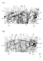
図2(A)、(B)は、消音部材11とパーキングスイッチ14との位置関係を示す側面図である。図2(B)は、視認性のため、消音部材11を透明化している。
消音部材11には第1の係止孔12(第1の被係止部)が設けられ、ボディー4には第1の係止孔12に対応する係止爪13(第1の係止部材)が設けられている。
また、消音部材11には、第1の係止孔12が設けられている側と対向する側に係止片21(第2の係止部材)が設けられており、ボディー4には係止片21に対応する第2の係止孔22(第2の被係止部)が設けられている。
消音部材11の第1の係止孔12及び係止片21は、それぞれボディー4の係止爪13及び第2の係止孔22と係止され、消音部材11はボディー4の側壁に固定される。
2A and 2B are side views showing the positional relationship between the muffling
The
Further, the
The
消音部材11をボディー4に組み付ける際は、まず、消音部材11の係止片21がボディー4の第2の係止孔22に挿入され、その後、ボディー4の係止爪13を消音部材11の第1の係止孔12に係合する。そのため、ボディー4の係止爪13は消音部材11を第2の係止孔22側に(図中Y方向に)押圧する。
When assembling the
ボディー4の側壁には、Pレンジ凹部10に隣接した位置に、パーキングスイッチ14が設置されている。パーキングスイッチ14は、ボディー4の側壁と消音部材11とにより峡持される。緩衝材であり弾性を有する消音部材11の側壁面が、パーキングスイッチ14をボディー4の側壁に押圧し、摩擦力によりパーキングスイッチ14を固定する。
従って、ボディー4の側壁には、パーキングスイッチ13を固定するための係止爪、ねじ孔を必要としない。
A
Therefore, the side wall of the body 4 does not require a locking claw or a screw hole for fixing the
パーキングスイッチ14は、接点部等のスイッチング回路を収容するケース部141を備え、ケース部141の側壁面は、消音部材11により押圧される。
ケース部141の消音部材11に対向するする壁面はボディー4の側壁に接触している。
The
The wall surface of the
ケース部141から、例えばヒンジレバー等からなる接触部142(アクチュエータ部)が突出し、少なくとも接触部142の一部がPレンジ凹部10に位置している。
接触部142の少なくともその一部が、ポジションピン7との当接可能なように消音部材11外に突出している。
Pレンジ凹部10に位置するポジションピン7が、図2(B)中矢印に示すように、バネの付勢力によりノブ5側に移動すると、接触部142の先端部を押圧し、パーキングスイッチ14がポジションピン7の存在を検知する。
A contact portion 142 (actuator portion) including, for example, a hinge lever projects from the
At least a part of the
When the
また、ボディー4の側壁にはリブ15が設けられている。リブ15はボディー4の剛性を強化する効果がある。
図2(B)に示すように、ケース部141の側壁面(消音部材11に接触する面に垂直な面)の一部は、リブ15に接触する。
消音部材11の第1の係止孔12と係合するボディー4の係止爪13とリブ15との間にパーキングスイッチ14が配置されている。従って、ボディー4の係止爪13は消音部材11をリブ15に向かって押圧することにより、パーキングスイッチ14を固定する効果が強められる。
また、リブ15はケース部141の角と同じ角度、90度で折り曲がったコーナー部Cを有してもよい。ケース部141の角をコーナー部Cで囲むことにより、一層パーキングスイッチ14を固定保持することができる。
Further, a
As shown in FIG. 2B, a part of the side wall surface (the surface perpendicular to the surface in contact with the sound deadening member 11) of the
A
Further, the
このように、パーキングスイッチ14は消音部材11とボディー4の側壁とによって挟み込まれるように保持されるとともに、消音部材11を介して、ボディー4の係止爪13とリブ15によっても挟み込まれるように保持される。
消音部材11に対して、異なる2種の係止方法によって固定するため、消音部材11を介して2方向からパーキングスイッチ14を押圧固定することが可能となる。
In this way, the
Since the
また、接触部142が突出するケース部141の側壁面は、リブ15に接触するケース部141の側壁面と対向する。そのため、ポジションピン7が接触部142を繰り返し押圧しても、パーキングスイッチ14が移動することはない。
Further, the side wall surface of the
なお、消音部材11がパーキングスイッチ14と接する面に、断面が鋸波状に加工し、さらに消音部材11のPレンジ凹部10側への摩擦力を高めてもよい。ケース部141の壁面が交差する辺と鋸波状加工部とを平行に設けることで、さらに摩擦力を向上させることが可能となる。
The surface of the
このようにシフトレバー装置1は、ポジションピン7の異音防止という別途の目的に使用される消音部材11によりパーキングスイッチ14を固定する。そのため、ケース部141を係止する係止爪や固定ネジは不要となり、シフトレバー装置1に使用する部品数の低減に寄与する。
In this way, the
本発明にかかるシフトレバー装置によれば、市販のパーキングスイッチの組み込みが容易となり。シフトレバー装置のボディー部の設計上の制約が緩和され、さらに部品点数を低減し、組み込み作業の効率も向上することができる。種々のAT車へ適用ができ、産業上の利用可能性は高い。 According to the shift lever device according to the present invention, it is easy to incorporate a commercially available parking switch. The design restrictions on the body of the shift lever device can be relaxed, the number of parts can be reduced, and the efficiency of assembly work can be improved. It can be applied to various AT vehicles and has high industrial applicability.
1 シフトレバー装置
2 レバー
3 回転軸
4 ボディー(支持台)
5 ノブ
6 長溝
7 ポジションピン(ディテントピン)
8 窓
9 障壁
10 P(パーキング)レンジ凹部(パーキング溝)
11 消音部材
12 第1の係止孔(第1の被係止部)
13 係止爪(第1の係止部材)
14 パーキングスイッチ
141 ケース部
142 接触部(アクチュエータ部)
15 リブ
21 係止片(第2の係止部材)
22 第2の係止孔(第2の被係止部)
C コーナー部
1
5 Knob 6
8
11
13 Locking claw (first locking member)
14
15
22 Second locking hole (second locked portion)
C corner
Claims (3)
前記レバー(2)は、長溝(6)及び前記長溝(6)から突出するポジションピン(7)を備え、
前記ボディー(4)の側壁面にはパーキングレンジに対応したPレンジ凹部(10)を有する窓(8)を備え、
前記ポジションピン(7)は前記窓(8)から突出し、
前記消音部材(11)が窓(8)の周縁部に係止固定され、
前記消音部材(11)と前記ボディー(4)の側壁面とに前記パーキングスイッチ(14)が峡持固定されることを特徴とするシフトレバー装置。 A lever (2), a body (4) that rotatably supports the lever (2) around a rotation shaft (3), a muffling member (11), and a parking switch (14) are provided.
The lever (2) includes a long groove (6) and a position pin (7) protruding from the long groove (6).
A window (8) having a P-range recess (10) corresponding to a parking range is provided on the side wall surface of the body (4).
The position pin (7) protrudes from the window (8).
The sound deadening member (11) is locked and fixed to the peripheral edge of the window (8).
A shift lever device characterized in that the parking switch (14) is held and fixed to the side wall surface of the sound deadening member (11) and the body (4).
さらに、前記消音部材(11)は前記第1の被係止部(12)に対向する側に第2の係止部材(21)が設けられ、前記ボディー(4)は前記第2の係止部材(21)に対応する第2の被係止部(22)が設けられ、
前記第1の被係止部(12)は前記第1の係止部材(13)に係止され、
前記第2の被係止部(22)は前記第2の係止部材(21)に係止される
ことを特徴とする請求項1記載のシフトレバー装置。 The sound deadening member (11) is provided with a first locked portion (12), and the body (4) is a first locking member (13) corresponding to the first locked portion (12). Is provided,
Further, the sound deadening member (11) is provided with a second locking member (21) on the side facing the first locked portion (12), and the body (4) is locked by the second locking member (4). A second locked portion (22) corresponding to the member (21) is provided.
The first locked portion (12) is locked to the first locking member (13).
The shift lever device according to claim 1, wherein the second locked portion (22) is locked to the second locking member (21).
前記パーキングスイッチ(14)の少なくとも1つの側面が前記リブ(15)と接することを特徴とする請求項1又は2記載のシフトレバー装置。 A rib (15) is provided on the side wall of the body (4).
The shift lever device according to claim 1 or 2, wherein at least one side surface of the parking switch (14) is in contact with the rib (15).
Priority Applications (1)
| Application Number | Priority Date | Filing Date | Title |
|---|---|---|---|
| JP2021059660A JP6925552B1 (en) | 2021-03-31 | 2021-03-31 | Shift lever device |
Applications Claiming Priority (1)
| Application Number | Priority Date | Filing Date | Title |
|---|---|---|---|
| JP2021059660A JP6925552B1 (en) | 2021-03-31 | 2021-03-31 | Shift lever device |
Publications (2)
| Publication Number | Publication Date |
|---|---|
| JP6925552B1 true JP6925552B1 (en) | 2021-08-25 |
| JP2022156124A JP2022156124A (en) | 2022-10-14 |
Family
ID=77364566
Family Applications (1)
| Application Number | Title | Priority Date | Filing Date |
|---|---|---|---|
| JP2021059660A Active JP6925552B1 (en) | 2021-03-31 | 2021-03-31 | Shift lever device |
Country Status (1)
| Country | Link |
|---|---|
| JP (1) | JP6925552B1 (en) |
Family Cites Families (2)
| Publication number | Priority date | Publication date | Assignee | Title |
|---|---|---|---|---|
| JP3273377B2 (en) * | 1992-11-04 | 2002-04-08 | スズキ株式会社 | Shift lever device |
| JPH08200484A (en) * | 1995-01-20 | 1996-08-06 | Suzuki Motor Corp | Shift lever device for AT vehicles |
-
2021
- 2021-03-31 JP JP2021059660A patent/JP6925552B1/en active Active
Also Published As
| Publication number | Publication date |
|---|---|
| JP2022156124A (en) | 2022-10-14 |
Similar Documents
| Publication | Publication Date | Title |
|---|---|---|
| US10832876B2 (en) | Push-button switch with the switching elment arranged on the keycap | |
| US10638622B2 (en) | Assembly structure for bracket | |
| JP2009531213A (en) | Multifunctional display / operation device installed in automobiles | |
| WO2009110085A1 (en) | Fan motor mounting structure | |
| JP4428120B2 (en) | Push-on switch | |
| JP5234284B2 (en) | Wiring device and its mounting frame | |
| JP2007193767A (en) | Operation lever device | |
| US6967298B2 (en) | Motor switch cell | |
| JP2022156124A (en) | shift lever device | |
| JP2008177094A (en) | Switch | |
| JP2025085543A (en) | Switch device | |
| JP2008184124A (en) | Check mechanism for shift lever device | |
| JP4720435B2 (en) | Key switch | |
| CN107615434A (en) | Switch | |
| JP2007005103A (en) | How to attach the key top to the press switch, and the press switch | |
| EP3680747A1 (en) | Operating device | |
| JP2008234934A (en) | Switch device | |
| JP5056451B2 (en) | Operating device and switch device provided with the same | |
| JP4279658B2 (en) | Locker switch misoperation prevention tool | |
| JP6903461B2 (en) | Key switch device and keyboard | |
| WO2017038411A1 (en) | Switch | |
| JP2024081298A (en) | Push button structure | |
| JP4654833B2 (en) | PRESSING MEMBER AND PRESSING OPERATION DEVICE HAVING THE SAME | |
| JP2006059619A (en) | Vehicle-mounted pushbutton switch | |
| JP4537768B2 (en) | Push button device |
Legal Events
| Date | Code | Title | Description |
|---|---|---|---|
| A621 | Written request for application examination |
Free format text: JAPANESE INTERMEDIATE CODE: A621 Effective date: 20210408 |
|
| A871 | Explanation of circumstances concerning accelerated examination |
Free format text: JAPANESE INTERMEDIATE CODE: A871 Effective date: 20210408 |
|
| A975 | Report on accelerated examination |
Free format text: JAPANESE INTERMEDIATE CODE: A971005 Effective date: 20210422 |
|
| TRDD | Decision of grant or rejection written | ||
| A01 | Written decision to grant a patent or to grant a registration (utility model) |
Free format text: JAPANESE INTERMEDIATE CODE: A01 Effective date: 20210713 |
|
| A61 | First payment of annual fees (during grant procedure) |
Free format text: JAPANESE INTERMEDIATE CODE: A61 Effective date: 20210803 |
|
| R150 | Certificate of patent or registration of utility model |
Ref document number: 6925552 Country of ref document: JP Free format text: JAPANESE INTERMEDIATE CODE: R150 |
|
| R250 | Receipt of annual fees |
Free format text: JAPANESE INTERMEDIATE CODE: R250 |
|
| R250 | Receipt of annual fees |
Free format text: JAPANESE INTERMEDIATE CODE: R250 |
|
| R250 | Receipt of annual fees |
Free format text: JAPANESE INTERMEDIATE CODE: R250 |