JP6924809B2 - Surgical incision and closure device - Google Patents
Surgical incision and closure device Download PDFInfo
- Publication number
- JP6924809B2 JP6924809B2 JP2019212229A JP2019212229A JP6924809B2 JP 6924809 B2 JP6924809 B2 JP 6924809B2 JP 2019212229 A JP2019212229 A JP 2019212229A JP 2019212229 A JP2019212229 A JP 2019212229A JP 6924809 B2 JP6924809 B2 JP 6924809B2
- Authority
- JP
- Japan
- Prior art keywords
- incision
- panel
- closing
- lateral
- panels
- Prior art date
- Legal status (The legal status is an assumption and is not a legal conclusion. Google has not performed a legal analysis and makes no representation as to the accuracy of the status listed.)
- Active
Links
Images


Classifications
-
- A—HUMAN NECESSITIES
- A61—MEDICAL OR VETERINARY SCIENCE; HYGIENE
- A61B—DIAGNOSIS; SURGERY; IDENTIFICATION
- A61B17/00—Surgical instruments, devices or methods, e.g. tourniquets
- A61B17/04—Surgical instruments, devices or methods, e.g. tourniquets for suturing wounds; Holders or packages for needles or suture materials
- A61B17/0466—Suture bridges
-
- A—HUMAN NECESSITIES
- A61—MEDICAL OR VETERINARY SCIENCE; HYGIENE
- A61B—DIAGNOSIS; SURGERY; IDENTIFICATION
- A61B17/00—Surgical instruments, devices or methods, e.g. tourniquets
- A61B17/08—Wound clamps or clips, i.e. not or only partly penetrating the tissue ; Devices for bringing together the edges of a wound
- A61B17/085—Wound clamps or clips, i.e. not or only partly penetrating the tissue ; Devices for bringing together the edges of a wound with adhesive layer
-
- A—HUMAN NECESSITIES
- A61—MEDICAL OR VETERINARY SCIENCE; HYGIENE
- A61B—DIAGNOSIS; SURGERY; IDENTIFICATION
- A61B17/00—Surgical instruments, devices or methods, e.g. tourniquets
- A61B17/04—Surgical instruments, devices or methods, e.g. tourniquets for suturing wounds; Holders or packages for needles or suture materials
- A61B17/0469—Suturing instruments for use in minimally invasive surgery, e.g. endoscopic surgery
-
- A—HUMAN NECESSITIES
- A61—MEDICAL OR VETERINARY SCIENCE; HYGIENE
- A61B—DIAGNOSIS; SURGERY; IDENTIFICATION
- A61B17/00—Surgical instruments, devices or methods, e.g. tourniquets
- A61B17/04—Surgical instruments, devices or methods, e.g. tourniquets for suturing wounds; Holders or packages for needles or suture materials
- A61B17/0482—Needle or suture guides
-
- A—HUMAN NECESSITIES
- A61—MEDICAL OR VETERINARY SCIENCE; HYGIENE
- A61B—DIAGNOSIS; SURGERY; IDENTIFICATION
- A61B17/00—Surgical instruments, devices or methods, e.g. tourniquets
- A61B17/08—Wound clamps or clips, i.e. not or only partly penetrating the tissue ; Devices for bringing together the edges of a wound
-
- A—HUMAN NECESSITIES
- A61—MEDICAL OR VETERINARY SCIENCE; HYGIENE
- A61B—DIAGNOSIS; SURGERY; IDENTIFICATION
- A61B17/00—Surgical instruments, devices or methods, e.g. tourniquets
- A61B2017/00831—Material properties
- A61B2017/00893—Material properties pharmaceutically effective
-
- A—HUMAN NECESSITIES
- A61—MEDICAL OR VETERINARY SCIENCE; HYGIENE
- A61B—DIAGNOSIS; SURGERY; IDENTIFICATION
- A61B17/00—Surgical instruments, devices or methods, e.g. tourniquets
- A61B17/04—Surgical instruments, devices or methods, e.g. tourniquets for suturing wounds; Holders or packages for needles or suture materials
- A61B2017/0496—Surgical instruments, devices or methods, e.g. tourniquets for suturing wounds; Holders or packages for needles or suture materials for tensioning sutures
-
- A—HUMAN NECESSITIES
- A61—MEDICAL OR VETERINARY SCIENCE; HYGIENE
- A61B—DIAGNOSIS; SURGERY; IDENTIFICATION
- A61B17/00—Surgical instruments, devices or methods, e.g. tourniquets
- A61B17/08—Wound clamps or clips, i.e. not or only partly penetrating the tissue ; Devices for bringing together the edges of a wound
- A61B2017/081—Tissue approximator
-
- A—HUMAN NECESSITIES
- A61—MEDICAL OR VETERINARY SCIENCE; HYGIENE
- A61B—DIAGNOSIS; SURGERY; IDENTIFICATION
- A61B17/00—Surgical instruments, devices or methods, e.g. tourniquets
- A61B17/08—Wound clamps or clips, i.e. not or only partly penetrating the tissue ; Devices for bringing together the edges of a wound
- A61B17/085—Wound clamps or clips, i.e. not or only partly penetrating the tissue ; Devices for bringing together the edges of a wound with adhesive layer
- A61B2017/086—Wound clamps or clips, i.e. not or only partly penetrating the tissue ; Devices for bringing together the edges of a wound with adhesive layer having flexible threads, filaments, laces or wires, e.g. parallel threads, extending laterally from a strip, e.g. for tying to opposing threads extending from a similar strip
Description
(関連出願への相互参照)
本PCT出願は、2013年10月11日に出願された米国仮出願番号第61/889,569号(代理人書類番号第35383−712.101号)、2013年7月24日に出願された第61/958,259号(代理人書類番号第35383−710.101号)、および2013年7月24日に出願された第61/958,254号(代理人書類番号第35383−711.101号)の利益を主張しており、これら米国仮出願の全体の開示は参考として本明細書中に援用される。
(Cross-reference to related applications)
This PCT application was filed on October 11, 2013, US Provisional Application No. 61 / 889,569 (Agent Document No. 35383-712.101), July 24, 2013. No. 61 / 958,259 (Agent Document No. 35383-710.101) and No. 61 / 958,254 filed on July 24, 2013 (Agent Document No. 35383-711.101). No.), and the entire disclosure of these US provisional applications is incorporated herein by reference.
本出願の内容は、2012年10月31日に出願された米国特許出願番号第13/665,160号(代理人書類番号第35383−709.501号)に関連しており、この米国特許出願は、2011年11月1日に出願された米国特許出願番号第13/286,757号(代理人書類番号第35383−709.201号)の一部継続出願であり、これら米国特許出願の全体の開示は参考として本明細書中に援用される。 The content of this application is related to U.S. Patent Application No. 13 / 665,160 (Agent Document No. 35383-709.501) filed on October 31, 2012, and this U.S. Patent Application. Is a partial continuation of U.S. Patent Application No. 13 / 286,757 (Agent Document No. 35383-709.201) filed on November 1, 2011, and all of these U.S. Patent Applications. Is incorporated herein by reference.
本出願の内容は、同時係属中の2014年2月 日に出願された米国特許出願番号第 / , 号(代理人書類番号第35383−712.201号)、および2014年2月 日に出願された米国特許出願番号第 / , 号(代理人書類番号第35383−709.502号)に関連しており、これら米国特許出願の全体の開示は参考として本明細書中に援用される。 The contents of this application are co-pending U.S. Patent Application No. /, filed February 2014 (Agent Document No. 35383-712.201), and filed February 2014. In connection with U.S. Patent Application Nos. /, (Agent Document No. 35383-709.502), the entire disclosure of these U.S. Patent Applications is incorporated herein by reference.
(発明の背景)
本発明は、概して、医療装置および方法に関する。より具体的には、本発明は、外科手術用切開を形成および閉鎖するための装置および方法に関する。
(Background of invention)
The present invention generally relates to medical devices and methods. More specifically, the present invention relates to devices and methods for forming and closing surgical incisions.
1.発明の分野
右および左パネルを伴う接着性ベースのパッチを含む、外科手術用閉鎖デバイスは、公知である。本発明の特に着目すべきこととして、そのようなデバイスは、同時係属中の同時所有のPCT出願第US2010/000430号に説明されており、その全開示は、参照することによって本明細書に組み込まれる。このPCT出願に説明されるように、接着性パッチは、外科手術用切開を形成することが所望される部位において、患者の皮膚を覆って留置される。パッチが留置された後、切開が、パッチの中央を通って延在する、軸方向線に沿って形成される。それが形成された後、切開は、所望の手技を行なうために開かれることができ、手技が完了した後、切開は、クリップ、ジッパ、または他の閉鎖部材によって、パネルの内側縁をともに牽引することによって閉鎖されてもよい。
1. 1. Fields of Invention Surgical closure devices, including adhesive-based patches with right and left panels, are known. Of particular note in the present invention, such devices are described in co-owned PCT application US2010 / 00430, which is co-pending, the entire disclosure of which is incorporated herein by reference. Is done. As described in this PCT application, the adhesive patch is placed over the patient's skin at the site where it is desired to form a surgical incision. After the patch is placed, an incision is formed along the axial line that extends through the center of the patch. After it is formed, the incision can be opened to perform the desired procedure, and after the procedure is completed, the incision pulls the inner edge of the panel together by a clip, zipper, or other closing member. It may be closed by doing so.
そのような外科手術用閉鎖デバイスの主目的は、治癒を改善し、切開から生じる瘢痕化を低減させることである。しかしながら、本目的は、現在利用可能なデバイスのある特性によって阻まれている。例えば、組織縁は、常時、均等な線に沿って接合されているわけではなく、これは、最終的瘢痕化を増加させ得る。多くのそのような閉鎖デバイスは、閉鎖力または組織縁上の距離を調節する能力を有しておらず、若干、組織を「すぼめさせる」(瘢痕化を低減させることが分かっている)能力を制限する。利用可能な切開および創傷閉鎖デバイスの他の欠点として、使用の困難性および後続外科手術プロトコルの間の組織操作への順応不能性、すなわち、組織を固着して閉鎖するには十分に剛性であるこれらのデバイスは、多くの場合、外科手術手技の間、組織移動に順応不能であることが挙げられる。 The main purpose of such surgical closure devices is to improve healing and reduce scarring resulting from incisions. However, this goal is hampered by certain characteristics of currently available devices. For example, tissue edges are not always joined along even lines, which can increase final scarring. Many such closure devices do not have the ability to regulate closure forces or distances on the tissue margin, and have the ability to slightly "shrink" tissue (known to reduce scarring). Restrict. Other drawbacks of the available incision and wound closure devices are the difficulty of use and the inflexibility to tissue manipulation during subsequent surgical protocols, ie, rigid enough to anchor and close the tissue. These devices are often cited as incapable of adapting to tissue movement during surgical procedures.
接着性外科手術用切開ドレープの真下で使用されるとき、自己接着性創傷閉鎖パッチに関して、特定の問題が生じる。そのようなドレープは、外科手術手技の間、組織表面の無菌状態を維持するのを支援するために使用され、ドレープは、前もって位置付けられた組織閉鎖パッチを覆って留置されてもよい。外科手術用切開ドレープは、組織に接着する接着性下側表面を有するため、ドレープは、下にある組織閉鎖パッチの上側表面に接着する。外科手術用切開ドレープの除去は、したがって、多くの場合、前もって留置された組織閉鎖パッチを除去するか、または少なくとも変位させる。組織閉鎖パッチの任意の有意な部分が、除去または変位される場合、パッチは、もはや外科手術創傷を閉鎖するために有用ではなくなるで。 When used directly under an adhesive surgical incision drape, certain problems arise with respect to self-adhesive wound closure patches. Such drapes are used to help maintain sterility on the tissue surface during surgical procedures, and the drapes may be placed over a pre-positioned tissue closure patch. The surgical incision drape has an adhesive lower surface that adheres to the tissue, so the drape adheres to the upper surface of the underlying tissue closure patch. Removal of surgical incision drapes therefore often removes, or at least displaces, pre-placed tissue closure patches. If any significant portion of the tissue closure patch is removed or displaced, the patch will no longer be useful for closing surgical wounds.
これらの理由から、改良された外科手術用切開閉鎖デバイスおよびその使用のための方法を提供することが望ましいであろう。特に、組織に接着し得、切開の形成を可能にし、後続外科手術手技の間、組織の変形に順応し、手技に続いて、隣接する組織縁の制御された閉鎖を提供することが可能である、切開閉鎖デバイスを提供することが望ましいであろう。特に、切開閉鎖デバイスが、組織縁上に、制御され、かつ均一な閉鎖力の分散を提供可能である一方、外科手術手技の間、組織の最小拘束または伸展を生じさせる場合、望ましいであろう。さらに、外科手術用切開ドレープの真下で使用されるとき、デバイスが、除去および転位に抵抗する、改良された外科手術用切開閉鎖デバイスおよびその使用の方法を提供することが望ましいであろう。これらの目的の少なくともいくつかは、以下に説明される本発明によって充足される。 For these reasons, it would be desirable to provide an improved surgical incision and closure chain device and a method for its use. In particular, it can adhere to tissue, allow the formation of incisions, adapt to tissue deformity during subsequent surgical procedures, and provide controlled closure of adjacent tissue edges following the procedure. It would be desirable to provide some open / close chain devices. In particular, it may be desirable if the incision chain device can provide a controlled and uniform distribution of closing force on the tissue margin, while causing minimal restraint or extension of the tissue during the surgical procedure. .. In addition, it would be desirable to provide an improved surgical incision opening and closing chain device and a method of its use in which the device resists removal and dislocation when used directly under a surgical incision drape. At least some of these objectives are fulfilled by the present invention as described below.
外科手術用閉鎖デバイスについては、米国特許第2,012,755号、第3,516,409号、第3,863,640号、第3,933,158号、第4,114,624号、第3,926,193号、第4,535,772号、第4,676,245号、第4,881,546号、第4,905,694号、第5,377,695号、および第7,455,681号、ならびに米国特許公開第2005/0020956号および第2008/0114396号に説明されている。さらなる外科手術閉鎖デバイスは、同時所有の米国特許第8,313,508号、第8,323,313号、および第8,439,945号、米国特許公報第2013/0066365号、ならびにPCT公開第WO2011/139912号、第WO2011/159623号、第WO2011/043786号、および第WO2013/067024号に説明されており、それらの全開示は、参照することによって本明細書に組み込まれる。Johnson & Johnsonの小会社であるEthiconからEthizipTM商標名で利用可能な市販の切開閉鎖デバイスである、一時的腹部用創傷閉鎖デバイスも挙げられる。 For surgical closure devices, US Pat. Nos. 2,012,755, 3,516,409, 3,863,640, 3,933,158, 4,114,624, Nos. 3,926,193, 4,535,772, 4,676,245, 4,881,546, 4,905,694, 5,377,695, and No. 7,455,681, as well as US Patent Publication Nos. 2005/0020956 and 2008/0114396. Additional surgical closure devices are co-owned US Pat. Nos. 8,313,508, 8,323,313, and 8,439,945, US Pat. Nos. 2013/0066365, and PCT Publication No. WO2011 / 139912, WO2011 / 159623, WO2011 / 043786, and WO2013 / 067024, the full disclosure of which is incorporated herein by reference. Also included is a temporary abdominal wound closure device, a commercially available incision and closure chain device available under the Ethicon TM brand name from Ethicon, a small company of Johnson & Johnson.
本発明は、例えば、以下を提供する:
(項目1)
切開閉鎖器具であって、
第1の弾性を有する、可撓性接着性最下層と、
前記可撓性接着性層に結合され、その少なくとも一部を被覆し、前記第1の弾性より小さい第2の弾性を有する、中間層と、
前記中間層に結合され、その少なくとも一部を被覆し、前記第2の弾性より小さい第3の弾性を有する、最上層と、
を備え、
前記可撓性接着性最下層と前記最上層との間の弾性勾配は、切開および周囲組織を被覆するとき、前記器具の側方に隣接する組織の移動が、前記被覆された切開および周囲組織を実質的に広げないように、十分な剛直性を前記切開閉鎖器具に提供する、切開閉鎖器具。
(項目2)
前記弾性勾配は、前記切開および周囲組織を被覆するとき、前記器具に隣接する組織の移動による膨れおよび接着性損失が、最小限にされるように、十分な弾性を前記切開閉鎖器具に提供する、項目1に記載の切開閉鎖器具。
(項目3)
前記切開閉鎖器具は、前記切開閉鎖器具によって被覆された前記切開および周囲組織の軸方向伸展に応答して、軸方向に可撓性である、項目1に記載の切開閉鎖器具。
(項目4)
前記可撓性接着性最下層の周縁に隣接する第1の組織領域の移動は、前記可撓性接着性最下層の周縁に隣接し、前記第1の組織領域に対向する第2の組織領域の同じ移動に実質的に変換される、項目3に記載の切開閉鎖器具。
(項目5)
前記可撓性接着性最下層は、親水性接着性材料を含む、項目1に記載の切開閉鎖器具。
(項目6)
前記親水性接着性材料は、親水コロイド、ヒドロゲル、アクリルポリマー、またはポリ(エチレングリコール)の1つ以上を含む、項目5に記載の切開閉鎖器具。
(項目7)
前記上層は、ゴム、ラテックス、ウレタン、ポリウレタン、シリコーン、熱可塑性エラストマー(TPE)、織布、または紡布の1つ以上を含む、項目1に記載の切開閉鎖器具。
(項目8)
前記可撓性接着性最下層は、第1および第2の接着性最下層を備える、項目1に記載の切開閉鎖器具。
(項目9)
前記中間層は、前記第1の接着性最下層に結合される第1の上層と、前記第2の接着性最下層に結合される第2の上層とを有する少なくとも1つの基部パネルを備える、項目8に記載の切開閉鎖器具。
(項目10)
前記最上層は、前記第1の接着性最下層および前記第1の上層を前記第2の接着性最下層および前記第2の上層に締結するために、複数の軸方向支持体構造と、前記軸方向支持体構造に結合される複数の側方閉鎖構成要素との配列を備える、項目9に記載の切開閉鎖器具。
(項目11)
前記複数の軸方向支持体構造および前記複数の閉鎖構成要素は、前記切開閉鎖デバイスによって被覆された前記切開および周囲組織の軸方向伸展に応答して、下側の前記接着性層および前記中間層の1つ以上が、少なくとも部分的に、前記閉鎖デバイスの軸方向に伸展することを可能にするために、相互に結合され、蛇行パターンを形成する、項目10に記載の切開閉鎖器具。
(項目12)
前記複数の軸方向支持体構造および前記複数の側方閉鎖構成要素は、相互に結合され、梯子パターンを形成する、項目10に記載の切開閉鎖器具。
(項目13)
前記複数の軸方向支持体構造および前記複数の側方閉鎖構成要素の1つまたはそれを上回るものは、可撓性の非伸張性材料から形成される、項目10に記載の切開閉鎖器具。
(項目14)
前記複数の側方閉鎖構成要素は、可撓性接着性最下層が、前記切開の両側の組織に接着された後、前記第1および第2の接着性最下層および前記第1および第2の上層の1つ以上の内側縁をともに牽引するように構成される、項目10に記載の切開閉鎖器具。
(項目15)
前記側方閉鎖構成要素の1つ以上は、左端部と、右端部と、前記左または右端部にしっかりと結合され、反対の端部に調節可能に取り付けられた繋ぎ材とを備える、項目10に記載の切開閉鎖器具。
(項目16)
前記複数の軸方向支持体構造および前記複数の側方閉鎖構成要素の1つ以上は、前記第1および第2の上層内に埋入または積層される、項目10に記載の切開閉鎖器具。
(項目17)
組織内の切開を閉鎖するためのシステムであって、
項目1に記載の切開閉鎖器具と、
前記切開閉鎖器具ならびに被覆された切開および周囲組織を覆うための可撓性カバーと、
を備える、システム。
(項目18)
前記可撓性カバーは、前記可撓性接着性最下層の側方および軸方向縁を覆って延在するように構成される、項目17に記載のシステム。
(項目19)
前記カバーは、前記カバーが、前記切開閉鎖器具によって被覆された前記切開および周囲組織の軸方向伸展に応答して、少なくとも部分的に、前記カバーの軸方向に伸展することを可能にする、1つ以上の穿孔を有する、項目17に記載のシステム。
(項目20)
前記1つ以上の穿孔は、前記カバーの中心軸方向線に沿って配置される、項目19に記載のシステム。
(項目21)
前記カバーは、前記カバーの接着性層の少なくとも一部に結合される1つ以上の補強部材を備える、項目17に記載のシステム。
(項目22)
前記補強部材は、ゴム、ラテックス、ウレタン、ポリウレタン、シリコーン、熱可塑性エラストマー(TPE)、織布、または紡布の1つ以上を含む、項目21に記載のシステム。
(項目23)
前記カバーは、親水性接着性層を備える、項目17に記載のシステム。
(項目24)
前記親水性接着性層は、親水コロイド、ヒドロゲル、アクリルポリマー、またはポリ(エチレングリコール)の1つ以上を含む、項目23に記載のシステム。
(項目25)
切開閉鎖器具であって、
第1の弾性を有する下部と、
前記第1の弾性未満の第2の弾性を有する上部と、
前記下側部分と前記上側部分との間の弾性勾配と、
を備え、
前記弾性勾配は、切開および周囲組織を被覆するとき、器具の側方に隣接する組織の移動が、前記被覆された切開および周囲組織を実質的に広げないように、十分な剛直性を前記切開閉鎖器具に提供する、切開閉鎖器具。
(項目26)
前記弾性勾配は、切開および周囲組織を被覆するとき、前記器具の側方に隣接する組織の移動による膨れおよび接着性損失が、最小限にされるように、十分な弾性を前記切開閉鎖器具に提供する、項目25に記載の切開閉鎖器具。
(項目27)
患者の皮膚内の切開を閉鎖するための方法であって、
前記切開閉鎖器具の下部を切開に隣接して接着するステップであって、前記下部は、第1の弾性を有し、第1の弾性よりも小さい第2の弾性を有する中間部に結合されるステップと、
前記切開閉鎖器具の上部の側方縁をともに牽引し、側方縁間の切開を圧迫するステップであって、前記上部は、中間部に結合され、第1および第2の弾性よりも小さい第3の弾性を有する、ステップと、
を備え、
前記上部と前記下部との間に弾性勾配が存在し、前記弾性勾配は、前記切開および周囲組織を被覆するとき、前記器具の側方に隣接する組織の移動が、被覆された切開および周囲組織を実質的に広げないように、十分な剛直性を前記切開閉鎖器具に提供する、方法。
(項目28)
固着層が、前記上部の第1および第2の側方縁を覆って延在するように、前記切開閉鎖器具を覆って前記固着層を留置するステップをさらに含む、項目25に記載の方法。
(項目29)
前記切開閉鎖器具は、前記切開閉鎖器具によって被覆された前記切開および周囲組織の軸方向伸展に応答して、軸方向に可撓性である、項目25に記載の方法。
(項目30)
前記下部の周縁に隣接する第1の組織領域の移動は、前記下部の周縁に隣接し、前記第1の組織領域に対向する第2の組織領域の同じ動きに実質的に変換される、項目29に記載の方法。
(項目31)
切開閉鎖器具であって、
左パネルおよび右パネルを含み、各パネルは、組織接着性下側表面、上側表面、第1の側方縁、第2の側方縁を含む、基部と、
それぞれ、前記左および右パネルに結合される、左および右力分配構造であって、それぞれ前記第1または第2の側方縁の一方に沿った前記パネルの軸方向拡張が、前記パネルを横断した側方拡張の1つ以上、または前記反対側方縁に沿った軸方向拡張を制限することを可能にするように適合される、力分配構造と、
前記パネルが組織に接着され、それらの間に切開が生成された後、前記左および右パネルに固着され、前記パネルをともに牽引し得る、複数の閉鎖構成要素と、
を備える、切開閉鎖器具。
(項目32)
各パネルの第1の側方縁は、各パネルの内側縁を備え、前記各パネルの内側縁は、相互に向かって面する、項目31に記載の切開閉鎖器具。
(項目33)
前記複数の閉鎖構成要素は、左および右基部パネルの内側縁をともに牽引し、前記切開閉鎖器具によって被覆された切開を圧迫するように構成される、項目32に記載の切開閉鎖器具。
(項目34)
各パネルの第2の側方縁は、各パネルの外側縁を備え、前記各パネルの外側縁は、相互から離れるように面する、項目31に記載の切開閉鎖器具。
(項目35)
前記基部の左および右パネルの1つまたはそれを上回るものは、弾性マトリックスら含む、項目31に記載の切開閉鎖器具。
(項目36)
前記弾性マトリックスは、エラストマー膜、織布、紡布、ゴム、ラテックス、ウレタン、ポリウレタン、シリコーン、熱可塑性エラストマー(TPE)を含む、項目35に記載の切開閉鎖器具。
(項目37)
前記弾性マトリックスは、弾性要素から織られる織布を備え、そして前記第1または第2の側方縁に沿って、かつそれを横断して側方に延在する非弾性要素を含む、項目35に記載の切開閉鎖器具。
(項目38)
各力分配構造は、前記パネルの前記第1の側方縁に隣接して軸方向に配置される背部と、側方に配置され、前記背部から前記パネルの前記第1の側方縁に向かって延在する、複数の軸方向に離間した側方支持体とを備える、項目35に記載の切開閉鎖器具。
(項目39)
前記背部および側方支持体は、可撓性の非伸張性材料から形成される、項目38に記載の切開閉鎖器具。
(項目40)
前記力分配構造は、各パネルの上側表面内に埋入または積層される、項目38に記載の切開閉鎖器具。
(項目41)
前記複数の閉鎖構成要素は、複数の右係合部材と、複数の左係合部材と、所定の距離だけ離間して、前記右および左係合部材を側方に保持するための複数の側方支柱とを備え、前記右係合部材は、前記右パネルの支持体に取り外し可能に係合するように適合され、前記左係合部材は、前記左パネルの支持体に取り外し可能に係合するように適合される、項目38に記載の切開閉鎖器具。
(項目42)
支持体の少なくともいくつかは、前記第1および第2の側方縁の1つ以上の近傍に滑り止め具を有し、前記係合部材は、前記滑り止め具を受容する、スロットを有する、項目41に記載の切開閉鎖器具。
(項目43)
前記側方支柱は、前記係合部材の少なくとも1つに調節可能に接続され、前記所定の距離の調節を可能にする、項目41に記載の切開閉鎖器具。
(項目44)
前記閉鎖構成要素は、前記側方支持体の少なくともいくつかに取り付けられる、複数の独立側方繋ぎ材を備え、前記側方繋ぎ材は、側方支持体間に固着されるように構成される、項目38に記載の切開閉鎖器具。
(項目45)
前記独立側方繋ぎ材はそれぞれ、パネルに固定された一端と、前記他方のパネルに調節可能に取り付けられた第2の端部とを有する、項目44に記載の切開閉鎖器具。
(項目46)
前記第2の端部は、ラチェット緊締機構を備える、項目45に記載の切開閉鎖器具。
(項目47)
前記基部および前記閉鎖構成要素のアセンブリのアセンブリが、患者の皮膚上の切開を覆って固着された後、該アセンブリを覆って留置されるように適合される、固着層をさらに備える、項目31に記載の切開閉鎖器具。
(項目48)
前記固着層は、内側自己接着性表面を有する、項目47に記載の切開閉鎖器具。
(項目49)
前記固着層は、左および右基部パネルの第1または第2の側方縁の1つ以上を覆って延在するように構成される、項目47に記載の切開閉鎖器具。
(項目50)
前記固着層は、1つ以上の穿孔を有し、前記固着層が、前記切開閉鎖器具が留置される前記切開および周囲組織の軸方向伸展に応答して、少なくとも部分的に、軸方向に伸展することを可能にする、項目47に記載の切開閉鎖器具。
(項目51)
前記複数の閉鎖構成要素は、左パネルに固着された左閉鎖構成要素端部および右パネルに固着された右閉鎖構成要素端部を備え、
前記複数の閉鎖構成要素は、前記左力分配構造の1つ以上が、少なくともいくつかの軸方向に隣接する左閉鎖構成要素端部間に配置され、前記右力分配構造の1つ以上が、少なくともいくつかの軸方向に隣接する右閉鎖構成要素端部間に配置された状態で、前記左および右パネルを横断して側方に位置付けられ、力分配構造および閉鎖構成要素の蛇行配列を形成する、項目31に記載の切開閉鎖器具。
(項目52)
左力分配構造は、1つおきの軸方向に隣接する対の左閉鎖構成要素端部を前記左パネル上でともに結合する、項目51に記載の切開閉鎖器具。
(項目53)
右力分配構造は、1つおきの軸方向に隣接する対の右閉鎖構成要素端部を前記左パネル上でともに結合する、項目51に記載の切開閉鎖器具。
(項目54)
組織接着性下側表面は、親水性接着性材料を備える、項目31に記載の切開閉鎖器具。
(項目55)
前記親水性接着性材料は、親水コロイド、ヒドロゲル、アクリルポリマー、またはポリ(エチレングリコール)の1つ以上を含む、項目54に記載の切開閉鎖器具。
(項目56)
前記複数の左および右力分配構造の前記少なくとも1つの力分配構造は、C形状である、項目31に記載の切開閉鎖器具。
(項目57)
C形状力分配構造は、前記左または右基部パネルの軸方向拡張を制限するための軸方向部分と、前記左または右基部パネルの側方拡張を制限するための側方部分とを備える、項目54に記載の切開閉鎖器具。
(項目58)
患者の皮膚内の切開を閉鎖するための方法であって、
それぞれ、右および左基部パネルを切開の右および左へ接着するステップと、
前記右および左基部パネルの内側縁をともに牽引し、その間の切開を圧迫するステップと、
前記右および左基部パネルの第1の側方縁に沿って、右および左基部パネルの軸方向拡張を可能にする一方、前記右および左基部パネルを横断する側方拡張または第1の側方縁の反対の左および右基部パネルの第2の側方縁に沿った軸方向拡張の1つまたはそれを上回るものを制限するステップと、
を含む、方法。
(項目59)
前記内側縁をともに牽引するステップは、前記右および左基部パネルに結合される複数の閉鎖構成要素を緊締するステップを含み、
前記右および左基部パネルの軸方向拡張を可能にするステップは、それぞれ、前記右および左基部パネルに結合される複数の左および右力分配構造を提供するステップを含み、
前記複数の閉鎖構成要素および前記複数の左および右基部パネルは、ともに結合され、蛇行配列を形成する、項目58に記載の方法。
(項目60)
前記固着層は、前記右および左基部パネルの第1および第2の側方縁にわたって延在するように、前記右および左基部パネルにわたって前記固着層を留置するステップをさらに含む、項目58に記載の方法。
(発明の要旨)
本発明は、創傷、特に、外科手術手技の間に行なわれる切開から生じる創傷を閉鎖するための改良された装置および方法を提供する。切開は、通常、腹部等を通して、患者の皮膚内に形成されるであろうが、ある場合には、また、内部器官上、口腔内、体腔内、または同等物にも形成され得る。
The present invention provides, for example:
(Item 1)
It is an incision opening / closing chain device
With the first elastic, flexible adhesive bottom layer,
An intermediate layer that is bonded to the flexible adhesive layer, covers at least a part thereof, and has a second elasticity smaller than the first elasticity.
The top layer, which is bonded to the intermediate layer, covers at least a part thereof, and has a third elasticity smaller than the second elasticity.
With
The elastic gradient between the flexible bottom layer and the top layer is that when the incision and surrounding tissue are covered, the movement of the tissue flanking the device is the covered incision and surrounding tissue. An incision chain device that provides the incision opening / closing chain device with sufficient rigidity so as not to substantially spread.
(Item 2)
The elastic gradient provides the incision opening / closing chain instrument with sufficient elasticity so that when covering the incision and surrounding tissue, swelling and adhesive loss due to movement of tissue adjacent to the instrument are minimized. , The incision opening / closing chain device according to item 1.
(Item 3)
The cut / close chain device according to item 1, wherein the cut / close chain device is axially flexible in response to the incision and axial extension of surrounding tissue coated by the cut / close chain device.
(Item 4)
The movement of the first tissue region adjacent to the periphery of the flexible bottom layer is a second tissue region adjacent to the periphery of the flexible bottom layer and facing the first tissue region. The incision opening / closing device according to
(Item 5)
The incision / opening / closing chain device according to item 1, wherein the flexible adhesive bottom layer contains a hydrophilic adhesive material.
(Item 6)
The incision / closing chain device according to item 5, wherein the hydrophilic adhesive material comprises one or more of hydrophilic colloids, hydrogels, acrylic polymers, or poly (ethylene glycol).
(Item 7)
The cut / close chain device according to item 1, wherein the upper layer comprises one or more of rubber, latex, urethane, polyurethane, silicone, thermoplastic elastomer (TPE), woven fabric, or spun fabric.
(Item 8)
The incision opening / closing chain device according to item 1, wherein the flexible adhesive bottom layer includes first and second adhesive bottom layers.
(Item 9)
The intermediate layer comprises at least one base panel having a first top layer coupled to the first adhesive bottom layer and a second top layer bonded to the second adhesive bottom layer. The incision opening / closing chain device according to item 8.
(Item 10)
The top layer comprises a plurality of axial support structures and the above, in order to fasten the first adhesive bottom layer and the first upper layer to the second adhesive bottom layer and the second upper layer. 9. The incision closure device according to item 9, comprising an array with a plurality of laterally closed components coupled to an axial support structure.
(Item 11)
The plurality of axial support structures and the plurality of closure components are the lower adhesive layer and the intermediate layer in response to the incision and the axial extension of the surrounding tissue coated by the incision chain device. 10. The incision chain device according to
(Item 12)
The incision opening / closing device according to
(Item 13)
10. The incision / closing chain device according to
(Item 14)
The plurality of laterally closed components include the first and second adhesive bottom layers and the first and second adhesive bottom layers after the flexible adhesive bottom layer has been adhered to the tissues on both sides of the incision. The incision opening / closing device according to
(Item 15)
(Item 16)
The incision opening / closing device according to
(Item 17)
A system for closing incisions in tissue
The incision opening / closing chain device described in item 1 and
With the incision closure device and a flexible cover to cover the covered incision and surrounding tissue,
The system.
(Item 18)
17. The system of
(Item 19)
The cover allows the cover to extend, at least in part, in the axial direction of the cover in response to the incision and the axial extension of the surrounding tissue coated by the incision chain device. 17. The system of
(Item 20)
19. The system of item 19, wherein the one or more perforations are arranged along a central axial direction line of the cover.
(Item 21)
17. The system of
(Item 22)
21. The system of item 21, wherein the reinforcing member comprises one or more of rubber, latex, urethane, polyurethane, silicone, thermoplastic elastomer (TPE), woven fabric, or spun fabric.
(Item 23)
The system of
(Item 24)
23. The system of item 23, wherein the hydrophilic adhesive layer comprises one or more of hydrophilic colloids, hydrogels, acrylic polymers, or poly (ethylene glycol).
(Item 25)
It is an incision opening / closing chain device
The lower part with the first elasticity and
With an upper part having a second elasticity less than the first elasticity,
The elastic gradient between the lower portion and the upper portion,
With
The elastic gradient provides sufficient rigidity to the incision and surrounding tissue so that movement of laterally adjacent tissue of the instrument does not substantially widen the incision and surrounding tissue when covering the incision and surrounding tissue. An incision opening / closing chain device provided for a closing device.
(Item 26)
The elastic gradient provides sufficient elasticity to the incision opening / closing chain instrument so that swelling and adhesive loss due to movement of laterally adjacent tissue of the instrument are minimized when covering the incision and surrounding tissue. The incision opening / closing chain device according to item 25 provided.
(Item 27)
A method for closing an incision in the patient's skin,
In the step of adhering the lower part of the incision opening / closing device adjacent to the incision, the lower part is bonded to an intermediate portion having a first elasticity and a second elasticity smaller than the first elasticity. Steps and
A step of pulling together the upper lateral edges of the incision closure device and compressing the incision between the lateral edges, the upper portion being coupled to the middle portion and having less elasticity than the first and second elasticity. With 3 elasticity,
With
There is an elastic gradient between the upper part and the lower part, and when the elastic gradient covers the incision and the surrounding tissue, the movement of the tissue adjacent to the side of the instrument is the covered incision and the surrounding tissue. A method of providing the incision chain device with sufficient rigidity so as not to substantially spread.
(Item 28)
25. The method of item 25, further comprising the step of covering the incision closure device and indwelling the anchoring layer such that the anchoring layer extends over the first and second lateral edges of the upper portion.
(Item 29)
25. The method of item 25, wherein the incision closure device is axially flexible in response to the incision and axial extension of surrounding tissue coated by the incision opening / closing chain device.
(Item 30)
The movement of the first tissue region adjacent to the lower periphery is substantially transformed into the same movement of the second tissue region adjacent to the lower periphery and facing the first tissue region. 29.
(Item 31)
It is an incision opening / closing chain device
Including a left panel and a right panel, each panel includes a base, including a tissue-adhesive lower surface, upper surface, first lateral edge, second lateral edge, and
Axial extensions of the left and right force distribution structures coupled to the left and right panels, respectively, along one of the first or second lateral edges, traverse the panel. With a force distribution structure adapted to allow for limiting axial extension along one or more of the lateral extensions made, or said opposite lateral edges.
With a plurality of closure components, the panel can be glued to the tissue and an incision is made between them, then anchored to the left and right panels and can pull the panel together.
Incision opening and closing chain device.
(Item 32)
31. The incision opening / closing device according to item 31, wherein the first lateral edge of each panel comprises an inner edge of each panel, and the inner edges of each panel face each other.
(Item 33)
32. The incision closure device of
(Item 34)
31. The incision opening / closing device according to item 31, wherein the second lateral edge of each panel comprises an outer edge of each panel, and the outer edges of each panel face away from each other.
(Item 35)
31. The incision closure device according to item 31, wherein one or more of the left and right panels of the base comprises an elastic matrix and the like.
(Item 36)
35. The cut / close chain device according to item 35, wherein the elastic matrix comprises an elastomer film, a woven fabric, a spun fabric, a rubber, a latex, a urethane, a polyurethane, a silicone, and a thermoplastic elastomer (TPE).
(Item 37)
Item 35, wherein the elastic matrix comprises a woven fabric woven from elastic elements and includes inelastic elements extending laterally along and across the first or second lateral edge. The incision opening / closing chain device described in.
(Item 38)
Each force distribution structure is arranged axially adjacent to the first lateral edge of the panel and laterally arranged from the back towards the first lateral edge of the panel. 35. The incision / opening / closing chain device according to item 35, comprising a plurality of axially spaced lateral supports that extend.
(Item 39)
38. The incision / closing chain device according to
(Item 40)
38. The incision / closing chain device according to
(Item 41)
The plurality of closing components are separated from the plurality of right engaging members and the plurality of left engaging members by a predetermined distance, and the plurality of sides for holding the right and left engaging members laterally. With a square strut, the right engaging member is adapted to removably engage the support on the right panel, and the left engaging member is removably engaged with the support on the left panel. 38. The incision / closing chain device adapted to.
(Item 42)
At least some of the supports have anti-slip devices in the vicinity of one or more of the first and second lateral edges, and the engaging member has a slot that receives the anti-slip device. The incision opening / closing chain device according to item 41.
(Item 43)
41. The incision opening / closing device according to item 41, wherein the lateral strut is operably connected to at least one of the engaging members to allow adjustment of the predetermined distance.
(Item 44)
The closure component comprises a plurality of independent lateral joints attached to at least some of the lateral supports, the lateral joints configured to be anchored between the lateral supports. 38. The incision opening / closing chain device according to
(Item 45)
44. The incision closure device of
(Item 46)
The incision opening / closing chain device according to item 45, wherein the second end portion includes a ratchet tightening mechanism.
(Item 47)
Item 31 further comprises a fixation layer, wherein the assembly of the assembly of the base and the closure component is adapted to cover and indwell the incision on the patient's skin and then indwell over the assembly. The described incision chain device.
(Item 48)
47. The incision / closing chain device according to item 47, wherein the fixation layer has an inner self-adhesive surface.
(Item 49)
47. The incision closure device of item 47, wherein the anchoring layer is configured to extend over one or more of the first or second lateral edges of the left and right base panels.
(Item 50)
The anchoring layer has one or more perforations, the anchoring layer extending at least partially axially in response to the incision in which the incision closure device is placed and the axial extension of the surrounding tissue. 47. The opening / closing chain device according to item 47.
(Item 51)
The plurality of closure components comprises a left closure component end fixed to the left panel and a right closure component end fixed to the right panel.
In the plurality of closure components, one or more of the left force distribution structures are arranged between the ends of at least several axially adjacent left closure components, and one or more of the right force distribution structures. Positioned laterally across the left and right panels, placed between the ends of at least several axially adjacent right closure components, forming a meandering arrangement of force distribution structures and closure components. The incision opening / closing chain device according to item 31.
(Item 52)
The incision opening / closing device according to item 51, wherein the left force distribution structure joins every other axially adjacent pair of left closing component ends together on the left panel.
(Item 53)
The incision opening / closing device according to item 51, wherein the right force distribution structure joins every other pair of right closing component ends adjacent in the axial direction together on the left panel.
(Item 54)
Tissue Adhesive The opening / closing chain device according to item 31, wherein the lower surface comprises a hydrophilic adhesive material.
(Item 55)
54. The incision / closing chain device according to
(Item 56)
The incision opening / closing chain device according to item 31, wherein the at least one force distribution structure of the plurality of left and right force distribution structures is C-shaped.
(Item 57)
The C-shape force distribution structure comprises an axial portion for limiting axial expansion of the left or right base panel and a lateral portion for limiting lateral expansion of the left or right base panel. 54. The incision opening / closing chain device.
(Item 58)
A method for closing an incision in the patient's skin,
The steps of gluing the right and left base panels to the right and left of the incision, respectively,
A step of pulling both the inner edges of the right and left base panels and compressing the incision between them.
Along the first lateral edge of the right and left base panels, it allows axial expansion of the right and left base panels, while lateral expansion or first lateral extension across the right and left base panels. With the step of limiting one or more of the axial extensions along the second lateral edge of the opposite left and right base panels.
Including methods.
(Item 59)
The step of pulling the inner edge together includes the step of tightening a plurality of closing components coupled to the right and left base panels.
The steps that allow axial expansion of the right and left base panels include providing multiple left and right force distribution structures coupled to the right and left base panels, respectively.
58. The method of item 58, wherein the plurality of closed components and the plurality of left and right base panels are combined together to form a meandering array.
(Item 60)
58. Item 58, further comprising indwelling the anchoring layer across the right and left base panels such that the anchoring layer extends over the first and second lateral edges of the right and left base panels. the method of.
(Summary of Invention)
The present invention provides improved devices and methods for closing wounds, in particular wounds resulting from incisions made during surgical procedures. The incision will usually be made in the patient's skin, such as through the abdomen, but in some cases it can also be made on internal organs, in the oral cavity, in the body cavities, or equivalent.
本発明のデバイスおよび方法は、切開が生成された後に行なわれる外科手術手技に対して、最小障害または干渉を呈する。特に、デバイスおよび方法は、切開された組織の対向縁が、閉鎖デバイスの存在から生じる最小拘束を伴って、開放、伸展、および自由に変形されることを可能にする。しかしながら、手技が完了すると、本発明のデバイスおよび方法は、瘢痕化を最小限にする様式において、閉鎖力の均一分散を提供し、組織縁をともに牽引する。特に、閉鎖デバイスは、組織縁を上向きに外転させ、「縮み」を生じさせ、瘢痕化を低減させ得るために、切開形成時に最初に存在したものより、若干、近接した間隔において、組織縁をともに牽引することができる。 The devices and methods of the present invention present minimal obstacles or interference to surgical procedures performed after the incision has been generated. In particular, the devices and methods allow the opposing edges of the incised tissue to open, extend, and freely deform with minimal constraints resulting from the presence of the closed device. However, upon completion of the procedure, the devices and methods of the invention provide uniform distribution of closure forces and pull together tissue edges in a manner that minimizes scarring. In particular, the closed device abducts the tissue edge upwards, causing "shrinkage" and reducing scarring, so that the tissue edge is slightly closer to the tissue edge than was originally present at the time of incision formation. Can be towed together.
本発明のデバイスおよび方法はまた、切開閉鎖器具が、閉鎖器具上から除去されなければならない、外科手術用切開ドレープの真下で使用されるとき、破砕を回避または低減させることが可能である。犠牲層が、閉鎖器具の上側表面の少なくとも一部を覆って提供され、犠牲カバーは、定位置に保持される一方、外科手術用切開ドレープは、切開閉鎖器具を覆って留置される。切開および外科手術手技が完了した後、外科手術用切開ドレープは、患者の皮膚から引き下げられる。組織閉鎖器具に接着し、それを取り除く代わりに、外科手術ドレープは、犠牲カバーに接着し、犠牲カバーのみ、ドレープとともに、患者から引き下げられ、切開閉鎖器具の残りを定位置に残す。 The devices and methods of the present invention are also capable of avoiding or reducing crushing when the incision closure instrument is used directly under a surgical incision drape, which must be removed from the closure instrument. A sacrificial layer is provided covering at least a portion of the upper surface of the closing instrument, the sacrificial cover is held in place, while the surgical incision drape is placed over the incision closure instrument. After the incision and surgical procedure is completed, the surgical incision drape is pulled down from the patient's skin. Instead of gluing to the tissue closure device and removing it, the surgical drape is glued to the sacrificial cover, only the sacrificial cover, with the drape, pulled down from the patient, leaving the rest of the incision closure device in place.
本発明の第1の側面では、切開閉鎖器具は、左パネルおよび右パネルを含む、基部を備える。各パネルは、組織接着性下側表面、上側表面、内側縁、および外側縁を有する。下側組織接着性表面は、典型的には、少なくとも部分的に、外科手術用包帯およびパッチにおいて使用されるもの等、一般的組織接着性用接着剤によって、コーティングされる。 In a first aspect of the invention, the incision chain device comprises a base including a left panel and a right panel. Each panel has a tissue-adhesive lower surface, upper surface, inner edge, and outer edge. The inferior tissue adhesive surface is typically coated, at least in part, with a common tissue adhesive, such as that used in surgical bandages and patches.
切開閉鎖器具はさらに、各パネルに結合された力分配構造を含み(すなわち、各パネルは、そこに結合された少なくとも1つの力分配構造を有する)、各力分配構造は、内側縁に沿ったパネルの軸方向拡張を可能にする一方、全長にわたる側方拡張および外側縁に沿った軸方向拡張を制限するように適合される。内側縁に沿ったパネルの軸方向拡張をもたらすことによって、組織縁は、外科手術手技の間、伸展されるとき、組織が変形することを可能にするように、最小限に制約される。逆に言えば、外側縁に沿った側方拡張および軸方向拡張の両方を制限することによって、パネルは、以下により詳細に説明されるように、外科手術手技が完了した後、パネルがともに牽引されると、制御され、かつ分散された閉鎖力を印加することが可能である。 The incision chain device also includes a force distribution structure coupled to each panel (ie, each panel has at least one force distribution structure coupled therein), with each force distribution structure along the medial edge. It is adapted to allow axial expansion of the panel while limiting lateral expansion over the entire length and axial expansion along the outer edge. By providing axial expansion of the panel along the medial edge, the tissue edge is minimized to allow the tissue to deform when stretched during the surgical procedure. Conversely, by limiting both lateral and axial dilation along the lateral edge, the panel is pulled together after the surgical procedure is completed, as described in more detail below. Once done, it is possible to apply a controlled and dispersed closing force.
切開閉鎖器具はさらに、切開部位の両側の組織に接着され、外科手術手技が完了後、力分配構造に取り付けられ、パネルの内側縁をともに牽引する、閉鎖構成要素またはアセンブリを含む。基部の各パネルは、典型的には、少なくとも部分的に、弾性マトリックスを含み、典型的には、等方性弾性を有する(すなわち、パネルは、全方向に均等に伸展する)が、随意に、異方性弾性を有する(マトリックスは、優先的に、ある方向に、またはその一部にわたって伸展する)。弾性マトリックスは、エラストマー膜またはシート(例えば、ポリウレタンシートまたは熱可塑性エラストマー(TPE))、織布(典型的には、少なくとも部分的に、エラストマーフィラメント、糸、または繊維から織られる)、紡布、または同等物を含んでもよい。ある実施形態では、エラストマーマトリックスは、力分配構造に対して、前述の拡張特性を提供するために、弾性要素(典型的には、糸、フィラメント、繊維、または同等物)および外側縁に沿って配置され、それを横断して側方に延在する、非弾性要素の両方から織られる織物から成ってもよい。すなわち、ある場合には、力分配構造は、織られるか、または別様に布地膜内に組み込まれる、非弾性要素を含む、またはそれから構成されてもよい。 The incision closure instrument further comprises a closure component or assembly that is glued to the tissues on both sides of the incision site, attached to the force distribution structure after the surgical procedure is completed, and pulls together the medial edge of the panel. Each panel at the base typically contains an elastic matrix, at least in part, and typically has isotropic elasticity (ie, the panels extend evenly in all directions), but optionally. , Has anisotropic elasticity (the matrix preferentially extends in one direction or over a portion thereof). Elastic matrices include elastomeric films or sheets (eg, polyurethane sheets or thermoplastic elastomers (TPE)), woven fabrics (typically at least partially woven from elastomer filaments, threads, or fibers), textiles, Alternatively, it may contain an equivalent. In certain embodiments, the elastomeric matrix is along the elastic elements (typically threads, filaments, fibers, or equivalents) and the outer edge to provide the aforementioned expansion properties for the force distribution structure. It may consist of a woven fabric woven from both inelastic elements that are arranged and extend laterally across it. That is, in some cases, the force distribution structure may include, or be composed of, inelastic elements that are woven or otherwise incorporated into the fabric film.
典型的には、力分配構造は、切開閉鎖器具の別個の構成要素を備え、例えば、パネルの外側縁に隣接して軸方向に配置される背部と、側方に配置され、背部からパネルの内側縁に向かって延在する、複数の軸方向に離間した側方支持体とを含む。そのような「櫛状」構造は、要素が、組織変形に伴って、ともに撓曲することができるが、それらの長さに沿って伸展せず、それらが、側方方向に、ならびにパネルの外側縁に沿って、寸法安定性を提供し得るように、典型的には、可撓性であるが、非伸張性材料から形成されるであろう。そのような材料の例として、ナイロン、ポリプロピレン、ポリエチレン、およびポリカーボネート、または他の熱可塑性ポリマーが挙げられる。着目すべきこととして、力分配構造は、外科手術手技の間、所望の拡張性および組織への適合能力を提供するために、パネルの内側縁の軸方向伸展を制限しない。そのような別個の力分配構造は、パネルの上側表面に取り付けられてもよく、もしくは代替として、パネル内に埋入または積層されてもよい。典型的には、力分配構造は、パネルと皮膚または他の組織の接着性に干渉しないように、パネルの下側表面内またはそれを越えては延在しない。 Typically, the force distribution structure comprises a separate component of the incision chain device, eg, a back that is arranged axially adjacent to the outer edge of the panel and a side that is located from the back to the panel. Includes a plurality of axially spaced lateral supports extending towards the medial edge. Such "comb" structures allow the elements to flex together with tissue deformation, but do not extend along their length, and they are laterally as well as of the panel. Along the outer edge, it will typically be formed from a flexible but non-stretchable material so that it can provide dimensional stability. Examples of such materials include nylon, polypropylene, polyethylene, and polycarbonate, or other thermoplastic polymers. Notably, the force distribution structure does not limit the axial extension of the medial edge of the panel to provide the desired expandability and ability to adapt to the tissue during the surgical procedure. Such a separate force distribution structure may be attached to the upper surface of the panel, or, as an alternative, may be embedded or laminated within the panel. Typically, the force distribution structure does not extend within or beyond the lower surface of the panel so as not to interfere with the adhesion of the panel to the skin or other tissues.
基部パネルおよび力分配構造のアセンブリは、典型的には、使用に先立って、パネルの接着性表面を被覆および保護する、除去可能な裏材上に担持されるであろう。裏材は、基部を外科手術介入の部位における皮膚または他の組織に適用するために、除去されてもよい。加えて、右および左パネルは、典型的には、組織に接着されるにつれて、パネルの内側縁を所定の距離または間隔に保持するために、除去可能なタブ、軸方向ストリップ、もしくは他の除去可能なカバーまたは構造によって、ともに保持される。例えば、除去可能なタブが、基部の各軸方向端に留置され、一時的に、2つの基部パネルをともに固着してもよい。代替として、除去可能なストリップまたはテープが、右と左パネル間の軸方向間隙を覆って留置され、基部が、組織表面に接着されるにつれて、パネルを相互に対して定位置に保持してもよい。そのようなタブまたはストリップは、典型的には、パネルに固着され、次いで、パネルが、組織上に適切に留置された後、単に、引っ張ることによって、除去され得るように、自己接着性であり得る。カバー、タブ、またはストリップは、次いで、除去され、パネルを定位置に残すが、それらの間における外科手術用切開の形成に先立っては、接続されていなくてもよい。 The assembly of the base panel and force distribution structure will typically be supported on a removable backing that covers and protects the adhesive surface of the panel prior to use. The lining may be removed to apply the base to the skin or other tissue at the site of the surgical intervention. In addition, the right and left panels typically have removable tabs, axial strips, or other removal to keep the inner edges of the panel at a given distance or spacing as they adhere to the tissue. Hold together by possible covers or structures. For example, removable tabs may be placed at each axial end of the base to temporarily secure the two base panels together. Alternatively, a removable strip or tape may be placed over the axial gap between the right and left panels to hold the panels in place with respect to each other as the base adheres to the tissue surface. good. Such tabs or strips are typically self-adhesive so that they can be attached to the panel and then removed by simply pulling after the panel has been properly placed on the tissue. obtain. Covers, tabs, or strips are then removed, leaving the panel in place, but may not be connected prior to the formation of a surgical incision between them.
閉鎖構成要素またはアセンブリの第1の例示的構造は、右係合部材と、左係合部材と、所定の距離だけ離して、係合部材を側方に保持する、複数の側方支柱とを備える。右係合部材は、その内側縁に沿って、右パネルの支持体に取り外し可能に係合するように適合され、左係合部材は、その内側縁に沿って、左パネルの支持体に取り外し可能に係合するように適合される。具体的実施形態では、力分配構成要素の支持体の少なくともいくつかは、その内側縁の近傍に滑り止め具を有し、係合部材は、滑り止め具を受容する、スロットを有する。外科手術介入が完了した後、閉鎖構成要素は、次いで、力分配構造を覆って留置されてもよく、片側の滑り止め具が、最初に、係合部材によって係合され、次いで、対向する係合部材が、反対側の滑り止め具上で引っ張られる。 A first exemplary structure of a closed component or assembly comprises a right engaging member, a left engaging member, and a plurality of lateral struts that hold the engaging member laterally at a predetermined distance. Be prepared. The right engaging member is adapted to removably engage the support on the right panel along its inner edge, and the left engaging member is detached along its inner edge to the support on the left panel. Fitted to engage as possible. In a specific embodiment, at least some of the supports of the force distribution component have a non-slip near its inner edge and the engaging member has a slot that receives the non-slip. After the surgical intervention is complete, the closure component may then be placed over the force distribution structure, with one side of the antislip being first engaged by the engaging member and then the opposing engagement. The mating member is pulled over the anti-slip on the opposite side.
代替として、閉鎖構成要素またはアセンブリは、側方支持体の少なくともいくつかに取り付けられる、複数の独立した側方繋ぎ材を備えてもよい。そのような側方繋ぎ材は、側方支持体間に固着されるように構成され、典型的には、一方のパネルに固定され、他方のパネルに調節可能に取り付け可能である。例示的実施形態の場合、調節可能に取り付け可能な端部は、各側方繋ぎ材が、独立して、右と左パネル間において、異なる間隔で調節されることを可能にする、ラチェット緊締機構または類似構造を備えてもよい。このように、右および左パネルは、ともに牽引されている隣接する組織縁に印加される力を制御および最適化するために、それらの内側縁に沿って、異なるように張力を与えられてもよい。 Alternatively, the closure component or assembly may include a plurality of independent lateral binders that are attached to at least some of the lateral supports. Such lateral binders are configured to be anchored between the lateral supports, typically secured to one panel and adjustable to the other panel. In the case of the exemplary embodiment, the adjustable attachable end allows each side tether to be independently adjusted at different intervals between the right and left panels, a ratchet tightening mechanism. Alternatively, it may have a similar structure. Thus, the right and left panels may be tensioned differently along their inner edges to control and optimize the forces applied to adjacent tissue edges that are both being towed. good.
随意に、本発明の閉鎖器具はさらに、アセンブリが、患者の皮膚上の切開を覆って固着され、外科手術手技が完了した後、基部および閉鎖構成要素のアセンブリを覆って留置されるように適合される、固着層を備えてもよい。固着層は、典型的には、基部および閉鎖構成要素のアセンブリを覆って留置され、それを定位置に固着させる支援をし、清潔性を維持することができる、自己接着性下側表面を有する。固着層は、随意に、観察、消毒剤の送達、および同等物のために、創傷へのアクセスをもたらす、開口部を有してもよい。 Optionally, the closure device of the invention is further adapted so that the assembly is secured over the incision on the patient's skin and is placed over the base and closure component assembly after the surgical procedure is completed. It may be provided with a fixed layer. The anchoring layer typically has a self-adhesive underside that is placed over the base and closure component assembly to help anchor it in place and maintain cleanliness. .. The anchoring layer may optionally have openings that provide access to the wound for observation, disinfectant delivery, and equivalents.
本発明のさらなる側面では、組織内に切開を形成するための方法は、前述のような切開閉鎖器具を提供するステップを含む。器具の右および左パネルは、患者の皮膚に接着され、パネルの内側縁は、事前に選択された距離、典型的には、0.5mm〜15mmだけ離間される。切開(典型的には、線形)は、パネルの内側縁間の組織または皮膚表面内に形成され、切開された組織の縁は、次いで、所望の外科手術手技を行なうために、分離される。パネルの内側縁は、組織縁の移動および変形に伴って、伸展し、それに沿って順応する一方、各パネルの外側縁および側方範囲は、寸法上、安定したままであることができる。手技が完了した後、閉鎖構成要素は、力分配構造に固着され、パネルの内側縁を逆にともに牽引する。随意に、閉鎖構成要素は、それらが切開が形成された直後であったより近接して組織縁を牽引する、寸法(または、調節可能パネル間間隔)を有する。そのように組織をともに牽引することは、縁を外転させ、組織を「すぼめさせ」、瘢痕化を低減させることができる。 In a further aspect of the invention, the method for forming an incision in the tissue comprises the step of providing an incision closure device as described above. The right and left panels of the instrument are glued to the patient's skin and the medial edges of the panels are separated by a preselected distance, typically 0.5 mm to 15 mm. An incision (typically linear) is formed within the tissue or skin surface between the medial edges of the panel, and the edges of the incised tissue are then separated to perform the desired surgical procedure. The inner edges of the panels extend and adapt along with the movement and deformation of the tissue edges, while the outer edges and lateral ranges of each panel can remain dimensionally stable. After the procedure is complete, the closure component is anchored to the force distribution structure and pulls the inner edges of the panel together in reverse. Optionally, the closure components have dimensions (or adjustable interpanel spacing) that pull the tissue edges closer than they were immediately after the incision was formed. Towing the tissue together in this way can abduct the edges, "shrink" the tissue and reduce scarring.
本発明の別のさらなる側面では、切開閉鎖器具が、提供される。切開閉鎖器具は、左および右基部パネルと、左および右基部パネルを相互に側方に結合するための複数の閉鎖構成要素と、それぞれ、左および右基部パネルに結合された複数の左および右軸方向支持体とを備えてもよい。各閉鎖構成要素は、それぞれ、左および右基部パネルに結合された左および右閉鎖構成要素端部を備える。複数の閉鎖構成要素は、(i)少なくともいくつかの軸方向に隣接する左閉鎖構成要素端部間に配置される左軸方向支持体の1つ以上と、(ii)少なくともいくつかの軸方向に隣接する右閉鎖構成要素端部間に配置される右軸方向支持体の1つ以上ともに、左および右パネルを横断して側方に位置付けられ、蛇行配列を形成してもよい。 In another further aspect of the invention, an incision closure device is provided. The incision closure device is a left and right base panel, a plurality of closing components for laterally connecting the left and right base panels, and a plurality of left and right coupled to the left and right base panels, respectively. An axial support may be provided. Each closure component comprises left and right closure component ends coupled to left and right base panels, respectively. The closure components are (i) one or more of the left axial supports located between the ends of the left closure components adjacent to at least some axial directions, and (ii) at least some axial directions. One or more of the right axial supports located between the ends of the right closed components adjacent to each other may be laterally positioned across the left and right panels to form a meandering arrangement.
蛇行配列を形成するために、左軸方向支持体は、1つおきの軸方向に隣接する対の左閉鎖構成要素端部を左パネル上でともに結合するか、そして/または右軸方向支持体は、1つおきの軸方向に隣接する対の右閉鎖構成要素端部を右パネル上でともに結合する。左および/または右パネルは、それらの間に配置される軸方向支持体を有していない、軸方向に隣接する個別の左および/または右閉鎖構成要素端部間に配置される1つ以上の穿孔を有してもよい。1つ以上の穿孔は、基部パネルの軸方向伸展に応じて、基部パネルセグメントへの基部パネルの分離を促進する、複数の穿孔を備えてもよい。 To form a meandering array, the left axial support joins the ends of every other axially adjacent pair of left closed components together on the left panel and / or the right axial support. Joins every other axially adjacent pair of right closed component ends together on the right panel. One or more left and / or right panels placed between the ends of separate left and / or right closed components that are axially adjacent and do not have axial supports placed between them. May have perforations. The one or more perforations may include a plurality of perforations that facilitate the separation of the base panel into the base panel segments in response to the axial extension of the base panel.
左または右基部パネルの1つ以上は、複数の別個の基部パネルセグメントを備えてもよい。少なくとも2つの左閉鎖構成要素端部または少なくとも2つの右閉鎖構成要素端部は、各基部パネルセグメントに結合されてもよい。左基部パネルは、複数の左基部パネルセグメントを備えてもよく、右基部パネルは、複数の右基部パネルセグメントを備えてもよい。左基部パネルセグメントおよび右基部パネルセグメントは、切開および周囲組織に適用されると、軸方向に相互からオフセットされてもよい。複数の閉鎖構成要素は、左および右基部パネルセグメントを相互に側方に結合し、蛇行配列を形成してもよい。 One or more of the left or right base panels may include a plurality of separate base panel segments. At least two left-closed component ends or at least two right-closed component ends may be coupled to each base panel segment. The left base panel may include a plurality of left base panel segments, and the right base panel may include a plurality of right base panel segments. The left base panel segment and the right base panel segment may be axially offset from each other when applied to the incision and surrounding tissue. The closure components may join the left and right base panel segments laterally to each other to form a meandering arrangement.
左または右基部パネルの1つ以上は、切開に隣接する組織に接着するための組織接着性下側表面を備えてもよい。左または右基部パネルの1つ以上は、組織接着性下側表面を備える、下側接着性層と、上側表面を備える上層とを備えてもよい。上層は、下側接着性層より剛性であってもよい。下側接着性層は、切開および周囲組織を被覆するとき、切開閉鎖デバイスの側方に隣接する組織の移動による膨れおよび接着性損失が、最小限にされるように、十分に弾性であってもよい。接着性下層は、親水性接着性材料を備えてもよい。親水性接着性材料は、親水コロイド、ヒドロゲル、アクリルポリマー、またはポリ(エチレングリコール)の1つ以上を含んでもよい。上層は、ゴム、ラテックス、ウレタン、ポリウレタン、シリコーン、熱可塑性エラストマー(TPE)、織布、または紡布の1つ以上を含んでもよい。左閉鎖構成要素端部、右閉鎖構成要素端部、左軸方向支持体、または右軸方向支持体の1つ以上は、左および右基部パネルの上側表面内に埋入されるか、またはそこに積層されてもよい。 One or more of the left or right base panels may be provided with a tissue adhesive lower surface for adhering to the tissue adjacent to the incision. One or more of the left or right base panels may include a lower adhesive layer with a tissue-adhesive lower surface and an upper layer with an upper surface. The upper layer may be more rigid than the lower adhesive layer. The lower adhesive layer is elastic enough to minimize swelling and adhesive loss due to the movement of laterally adjacent tissue of the incision opening and closing chain device when covering the incision and surrounding tissue. May be good. The adhesive underlayer may include a hydrophilic adhesive material. The hydrophilic adhesive material may include one or more of hydrophilic colloids, hydrogels, acrylic polymers, or poly (ethylene glycol). The upper layer may contain one or more of rubber, latex, urethane, polyurethane, silicone, thermoplastic elastomer (TPE), woven fabric, or spun fabric. One or more of the left closed component end, the right closed component end, the left axial support, or the right axial support is embedded or embedded in the upper surface of the left and right base panels. It may be laminated on.
左閉鎖構成要素端部、右閉鎖構成要素端部、左軸方向支持体、または右軸方向支持体の1つ以上は、可撓性の非伸張性材料から形成されてもよい。 One or more of the left closed component end, the right closed component end, the left axial support, or the right axial support may be formed from a flexible non-extensible material.
複数の閉鎖構成要素、左軸方向支持体、および右軸方向支持体はともに、切開および周囲組織を被覆するとき、切開閉鎖デバイスの側方に隣接する組織の移動が、被覆された切開および周囲組織を実質的に広げないように、十分に剛性であってもよい。故に、切開閉鎖デバイスの周縁の側方に隣接する第1の組織領域の移動は、周縁の側方に隣接し、第1の組織領域と対向する第2の組織領域の同一の移動に実質的に変換されてもよい。 When multiple closure components, the left axial support, and the right axial support both cover the incision and surrounding tissue, the movement of tissue flanking the incision chain device is covered by the incision and surrounding tissue. It may be sufficiently rigid so as not to substantially spread the tissue. Therefore, the movement of the first tissue region flanked by the incision chain device is substantially similar to the same movement of the second tissue region flanking the periphery and facing the first tissue region. May be converted to.
複数の閉鎖構成要素の1つ以上は、左または右閉鎖構成要素端部にしっかりと結合され、対向する閉鎖構成要素端部に調節可能に取り付けられる繋ぎ材を備えてもよい。対向する閉鎖構成要素端部は、ラチェット緊締機構を備えてもよい。 One or more of the plurality of closure components may be provided with a binder that is tightly coupled to the left or right closure component end and is adjustablely attached to the opposite closure component end. Opposing closure component ends may be provided with a ratchet tightening mechanism.
複数の閉鎖構成要素は、左および右基部パネルの内側縁をともに牽引し、切開閉鎖器具によって被覆された切開を圧迫するように構成されてもよい。 The closure components may be configured to pull together the medial edges of the left and right base panels and compress the incision covered by the incision closure device.
複数の左軸方向支持体または複数の右軸方向支持体の1つ以上は、C形状であってもよい。C形状の左および/または右軸方向支持体はそれぞれ、個別の基部パネルの軸方向拡張を制限するための軸方向部分と、個別の基部パネルの側方拡張を制限するための側方部分とを備えてもよい。 One or more of the plurality of left axial supports or the plurality of right axial supports may be C-shaped. The C-shaped left and / or right axial supports have an axial portion to limit the axial extension of the individual base panels and a lateral portion to limit the lateral expansion of the individual base panels, respectively. May be provided.
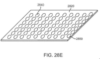
本発明の本側面はまた、組織内の切開を閉鎖するためのシステムを提供してもよい。本システムは、切開閉鎖デバイスと、切開閉鎖デバイスならびにそれによって被覆された切開および周囲組織を覆うための可撓性カバーとを備えてもよい。 This aspect of the invention may also provide a system for closing an incision in a tissue. The system may include an incision opening / closing chain device and a flexible cover for covering the incision opening / closing chain device and the incision and surrounding tissue coated thereby.
可撓性カバーは、左および右基部パネルの側方および軸方向縁を覆って延在するように構成されてもよい。カバーは、カバーが、切開閉鎖デバイスによって被覆された切開および周囲組織の軸方向伸展に応答して、少なくとも部分的に、軸方向に伸展することを可能にする、1つ以上の穿孔を有してもよい。1つ以上の穿孔は、カバーの中心軸方向線に沿って配置されてもよい。カバーは、カバーの接着性層の少なくとも一部に結合される1つ以上の補強部材を備えてもよい。補強部材は、ゴム、ラテックス、ウレタン、ポリウレタン、シリコーン、熱可塑性エラストマー(TPE)、織布、または紡布の1つ以上を含んでいてもよい。カバーは、親水コロイド、ヒドロゲル、アクリルポリマー、またはポリ(エチレングリコール)の1つ以上を含み得る親水性接着性層を備えてもよい。 The flexible cover may be configured to extend over the lateral and axial edges of the left and right base panels. The cover has one or more perforations that allow the cover to extend, at least in part, axially in response to the incision covered by the incision chain device and the axial extension of the surrounding tissue. You may. One or more perforations may be arranged along the central axial direction of the cover. The cover may include one or more reinforcing members that are attached to at least a portion of the adhesive layer of the cover. The reinforcing member may include one or more of rubber, latex, urethane, polyurethane, silicone, thermoplastic elastomer (TPE), woven fabric, or spun fabric. The cover may include a hydrophilic adhesive layer that may contain one or more of hydrophilic colloids, hydrogels, acrylic polymers, or poly (ethylene glycol).
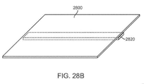
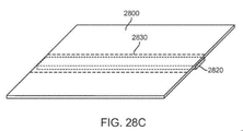
本発明の別のさらなる側面では、切開閉鎖器具が、提供される。切開閉鎖器具は、可撓性接着性最下層と、中間層と、最上層とを備える。可撓性接着性最下層は、第1の弾性を有してもよい。中間層は、可撓性接着性層に結合され、その少なくとも一部を被覆し、第1の弾性より小さい第2の弾性を有してもよい。最上層は、中間層に結合され、その少なくとも一部を被覆し、第2の弾性より小さい第3の弾性を有してもよい。可撓性接着性最下層と最上層との間の弾性勾配は、切開および周囲組織を被覆するとき、器具の側方に隣接する組織の移動が、被覆された切開および周囲組織を実質的に広げないように、十分な剛直性を切開閉鎖器具に提供してもよい。 In another further aspect of the invention, an incision closure device is provided. The incision opening / closing chain device includes a flexible adhesive bottom layer, an intermediate layer, and an top layer. The flexible bottom layer may have first elasticity. The intermediate layer may be bonded to a flexible adhesive layer, covering at least a portion thereof and having a second elasticity less than the first elasticity. The top layer may be bonded to an intermediate layer, covering at least a portion thereof and having a third elasticity less than the second elasticity. Flexible Adhesive The elastic gradient between the bottom and top layers, when covering the incision and surrounding tissue, allows the movement of tissue adjacent to the side of the instrument to substantially cover the covered incision and surrounding tissue. Sufficient rigidity may be provided to the incision chain device so that it does not spread.
弾性勾配は、切開および周囲組織を被覆するとき、器具に隣接する組織の移動による膨れおよび接着性損失が、最小限にされるように、十分な弾性を切開閉鎖器具に提供してもよい。 The elastic gradient may provide sufficient elasticity to the incision closure device so that swelling and loss of adhesion due to movement of tissue adjacent to the device are minimized when covering the incision and surrounding tissue.
切開閉鎖器具は、切開閉鎖器具によって被覆された切開および周囲組織の軸方向伸展に応答して、軸方向に可撓性であってもよい。可撓性接着性最下層の周縁に隣接する第1の組織領域の移動は、可撓性接着性最下層の周縁に隣接し、第1の組織領域に対向する第2の組織領域の同じ移動に実質的に変換されてもよい。 The incision closure device may be axially flexible in response to the incision covered by the incision opening / closing chain device and the axial extension of the surrounding tissue. The movement of the first tissue region adjacent to the periphery of the flexible bottom layer is the same movement of the second tissue region adjacent to the periphery of the flexible bottom layer and facing the first tissue region. May be substantially converted to.
可撓性接着性最下層は、親水性接着性材料を含んでもよい。親水性接着性材料は、親水コロイド、ヒドロゲル、アクリルポリマー、またはポリ(エチレングリコール)の1つ以上を含んでいてもよい。 The flexible bottom layer may contain a hydrophilic adhesive material. The hydrophilic adhesive material may contain one or more of hydrophilic colloids, hydrogels, acrylic polymers, or poly (ethylene glycol).
上層は、ゴム、ラテックス、ウレタン、ポリウレタン、シリコーン、熱可塑性エラストマー(TPE)、織布、または紡布の1つを含んでいてもよい。 The upper layer may contain one of rubber, latex, urethane, polyurethane, silicone, thermoplastic elastomer (TPE), woven fabric, or spun fabric.
可撓性接着性最下層は、第1および第2の接着性最下層を備えてもよい。中間層は、第1の接着性最下層に結合される第1の上層および第2の接着性最下層に結合される第2の上層を備えてもよい。最上層は、第1の接着性最下層および第1の上層を第2の接着性最下層および第2の上層に締結するために、複数の軸方向支持体構造と、軸方向支持体構造に結合される複数の側方閉鎖構成要素との配列を備えてもよい。複数の軸方向支持体構造および複数の閉鎖構成要素は、下側接着性層または中間層の1つ以上が、切開閉鎖デバイスによって被覆された切開および周囲組織の軸方向伸展に応答して、少なくとも部分的に、閉鎖デバイスの軸方向に伸展することを可能にするために、相互に結合され、蛇行パターンを形成してもよい。複数の軸方向支持体構造および複数の側方閉鎖構成要素は、相互に結合され、梯子パターンを形成してもよい。複数の軸方向支持体構造または複数の側方閉鎖構成要素の1つ以上は、可撓性の非伸張性材料から形成されてもよい。複数の側方閉鎖構成要素は、可撓性接着性最下層が、切開の両側の組織に接着された後、第1または第2の接着性最下層および第1または第2の上層の1つ以上の内側縁をともに牽引するように構成されてもよい。側方閉鎖構成要素の1つ以上は、左端部と、右端部と、左または右端部にしっかりと結合され、対向する端部に調節可能に取り付けられた繋ぎ材とを備えてもよい。複数の軸方向支持体構造または複数の側方閉鎖構成要素の1つ以上は、第1および第2の上層内に埋入されるか、またはそこに積層されてもよい。 The flexible bottom layer may include first and second adhesive bottom layers. The intermediate layer may include a first upper layer that is bonded to the first adhesive bottom layer and a second top layer that is bonded to the second adhesive bottom layer. The top layer has a plurality of axial support structures and axial support structures in order to fasten the first adhesive bottom layer and the first upper layer to the second adhesive bottom layer and the second upper layer. It may include an array with a plurality of laterally closed components to be combined. The plurality of axial support structures and the plurality of closure components are such that at least one or more of the lower adhesive layer or intermediate layer responds to an incision in which the incision opening / closing chain device is coated and the axial extension of the surrounding tissue. Partially, they may be coupled together to form a meandering pattern to allow axial extension of the closure device. The plurality of axial support structures and the plurality of laterally closed components may be interconnected to form a ladder pattern. One or more of the plurality of axial support structures or the plurality of laterally closed components may be formed from a flexible non-extensible material. The plurality of laterally closed components is one of a first or second adhesive bottom layer and a first or second upper layer after the flexible adhesive bottom layer has been adhered to the tissues on both sides of the incision. It may be configured to pull together the above inner edges. One or more of the side closure components may include a left end, a right end, and a tether that is tightly coupled to the left or right end and is adjustablely attached to the opposite end. One or more of the plurality of axial support structures or the plurality of laterally closed components may be embedded in or laminated in the first and second upper layers.
本発明のこの側面はまた、組織内の切開を閉鎖するためのシステムを提供してもよい。本システムは、切開閉鎖器具と、切開閉鎖器具ならびに被覆された切開および周囲組織を覆うための可撓性カバーとを備える。 This aspect of the invention may also provide a system for closing an incision in a tissue. The system comprises an incision closure device and a cut / close chain device as well as a flexible cover to cover the covered incision and surrounding tissue.
可撓性カバーは、可撓性接着性最下層の側方および軸方向縁を覆って延在するように構成されてもよい。カバーは、カバーが、切開閉鎖器具によって被覆された切開および周囲組織の軸方向伸展に応答して、少なくとも部分的に、カバーの軸方向に伸展することを可能にする、1つ以上の穿孔を有してもよい。1つ以上の穿孔は、カバーの中心軸方向線に沿って配置されてもよい。カバーは、カバーの接着性層の少なくとも一部に結合される1つ以上の補強部材を備えてもよい。補強部材は、ゴム、ラテックス、ウレタン、ポリウレタン、シリコーン、熱可塑性エラストマー(TPE)、織布、または紡布の1つ以上を含んでもよい。カバーは、親水性接着性層を備えてもよい。親水性接着性層は、親水コロイド、ヒドロゲル、アクリルポリマー、またはポリ(エチレングリコール)の1つ以上を含んでもよい。 The flexible cover may be configured to extend over the lateral and axial edges of the flexible adhesive bottom layer. The cover has one or more perforations that allow the cover to extend, at least in part, axially in response to the incision covered by the incision chain device and the axial extension of the surrounding tissue. You may have. One or more perforations may be arranged along the central axial direction of the cover. The cover may include one or more reinforcing members that are attached to at least a portion of the adhesive layer of the cover. The reinforcing member may include one or more of rubber, latex, urethane, polyurethane, silicone, thermoplastic elastomer (TPE), woven fabric, or spun fabric. The cover may include a hydrophilic adhesive layer. The hydrophilic adhesive layer may contain one or more of hydrophilic colloids, hydrogels, acrylic polymers, or poly (ethylene glycol).
本発明の別のさらなる側面では、切開閉鎖器具が提供される。切開閉鎖器具は、第1の弾性を有する下側部分と、第1の弾性より小さい第2の弾性を有する上側部分と、下側部分と上側部分との間の弾性勾配とを備えてもよい。弾性勾配は、切開および周囲組織を被覆するとき、器具の側方に隣接する組織の移動が、被覆された切開および周囲組織を実質的に広げないように、十分な剛直性を切開閉鎖器具に提供してもよい。弾性勾配は、切開および周囲組織を被覆するとき、器具の側方に隣接する組織の移動による膨れおよび接着性損失が、最小限にされるように、十分な弾性を切開閉鎖器具に提供してもよい。 In another further aspect of the invention, an incision closure device is provided. The incision chain device may include a lower portion having a first elasticity, an upper portion having a second elasticity smaller than the first elasticity, and an elastic gradient between the lower portion and the upper portion. .. The elastic gradient provides sufficient rigidity to the incision opening and closing chain device so that when the incision and surrounding tissue are covered, the movement of tissue flanking the device does not substantially widen the covered incision and surrounding tissue. May be provided. The elastic gradient provides the incision opening and closing chain instrument with sufficient elasticity to minimize swelling and adhesive loss due to movement of the tissue adjacent to the side of the instrument when covering the incision and surrounding tissue. May be good.
本発明の別のさらなる側面では、切開閉鎖器具が提供される。切開閉鎖器具は、左パネルおよび右パネルを含む基部と、左および右力分配構造と、複数の閉鎖構成要素とを備えてもよい。各パネルは、組織接着性下側表面と、上側表面と、第1の側方縁と、第2の側方縁とを有してもよい。左および右力分配構造は、それぞれ、左および右パネルに結合されてもよい。各力分配構造は、第1または第2の側方縁の一方に沿ったパネルの軸方向拡張が、パネルを横断する側方拡張および対向する側方縁に沿った軸方向拡張を制限することを可能にするように適合されてもよい。複数の閉鎖構成要素は、パネルがそれらの間に生成された組織および切開に接着された後、左および右パネルに固着され、パネルをともに牽引してもよい。 In another further aspect of the invention, an incision closure device is provided. The incision closure device may include a base including left and right panels, a left and right force distribution structure, and a plurality of closure components. Each panel may have a tissue-adhesive lower surface, an upper surface, a first lateral edge, and a second lateral edge. The left and right force distribution structures may be coupled to the left and right panels, respectively. In each force distribution structure, the axial extension of the panel along one of the first or second lateral edges limits the lateral extension across the panel and the axial extension along the opposite lateral edges. May be adapted to enable. Multiple closure components may be attached to the left and right panels and tow the panels together after the panels have been glued to the tissue and incisions created between them.
各パネルの第1の側方縁は、各パネルの内側縁を備えてもよい。各パネルの内側縁は、相互に向かって面してもよい。 The first lateral edge of each panel may comprise the inner edge of each panel. The inner edges of each panel may face each other.
各パネルの第2の側方縁は、各パネルの外側縁を備えてもよい。各パネルの外側縁は、相互から離れるように面してもよい。 The second lateral edge of each panel may comprise the outer edge of each panel. The outer edges of each panel may face apart from each other.
基部の左および右パネルの1つ以上は、弾性マトリックスを含んでもよい。弾性マトリックスは、エラストマー膜、織布、または紡布を含んでもよい。弾性マトリックスは、弾性要素から織成され、第1または第2の側方縁に沿って、それを横断して側方に延在する非弾性要素を有する、織物を備えてもよい。 One or more of the left and right panels of the base may include an elastic matrix. The elastic matrix may include an elastomeric membrane, a woven fabric, or a spun fabric. The elastic matrix may comprise a woven fabric that is woven from elastic elements and has inelastic elements that extend laterally across the first or second lateral edge.
各力分配構造は、パネルの第1の側方縁に隣接して軸方向に配置される背部と、側方に配置され、背部からパネルの第1の側方縁に向かって延在する、複数の軸方向に離間した側方支持体とを備えてもよい。背部および側方支持体は、可撓性の非伸張性材料から形成されてもよい。力分配構造は、各パネルの上側表面内に埋入されるか、またはそこに積層されてもよい。 Each force distribution structure is arranged axially adjacent to the first lateral edge of the panel and laterally located and extends from the back towards the first lateral edge of the panel. A plurality of axially spaced lateral supports may be provided. The back and lateral supports may be formed from a flexible, non-extensible material. The force distribution structure may be embedded in or laminated in the upper surface of each panel.
閉鎖構成要素は、右係合部材と、左係合部材と、所定の距離だけ側方に離して係合部材を保持する、複数の側方支柱とを備えてもよい。右係合部材は、右パネルの支持体に取り外し可能に適合されてもよく、左係合部材は、左パネルの支持体に取り外し可能に適合されてもよい。支持体の少なくともいくつかは、第1または第2の側方縁の1つ以上の近傍に滑り止め具を有してもよく、係合部材は、滑り止め具を受容する、スロットを有してもよい。側方支柱は、係合部材の少なくとも1つに調節可能に接続され、所定の距離の調節をもたらしてもよい。閉鎖構成要素は、側方支持体の少なくともいくつかに取り付けられた複数の独立側方繋ぎ材を備えてもよい。側方繋ぎ材は、側方支持体間に固着されるように構成されてもよい。独立側方繋ぎ材はそれぞれ、パネルに固定された一端と、他方のパネルに調節可能に取着された第2の端部とを有してもよい。第2の端部は、ラチェット緊締機構を備えてもよい。 The closing component may include a right engaging member, a left engaging member, and a plurality of side struts that hold the engaging member laterally apart by a predetermined distance. The right engaging member may be removably fitted to the support on the right panel and the left engaging member may be removably fitted to the support on the left panel. At least some of the supports may have a non-slip near one or more of the first or second lateral edges, and the engaging member has a slot that receives the non-slip. You may. The side struts may be tunably connected to at least one of the engaging members to provide a predetermined distance adjustment. The closing component may include a plurality of independent lateral binders attached to at least some of the lateral supports. The lateral binder may be configured to be anchored between the lateral supports. Each independent lateral binder may have one end fixed to the panel and a second end adjustablely attached to the other panel. The second end may be provided with a ratchet tightening mechanism.
切開閉鎖器具はさらに、基部および閉鎖構成要素のアセンブリが、患者の皮膚上の切開を覆って固着された後、このアセンブリを覆って留置されるように適合される、固着層を備えてもよい。固着層は、内側自己接着性表面を有してもよい。 The incision closure device may further comprise a fixation layer in which the assembly of the base and closing components is adapted to cover and indwell the incision on the patient's skin and then indwell over this assembly. .. The anchoring layer may have an inner self-adhesive surface.
(発明の詳細な説明)
本発明の装置および方法は、外科手術手技の間、患者の皮膚または他の組織に生成される、外科手術用切開の形成および閉鎖の両方の間に使用される。本明細書に後述されるように、切開の方向は、それらの用語が本明細書で使用されるように、「軸方向」および「側方」方向の両方を定義する。大部分の切開は、軸方向を画定する、略直線に沿って生成される。側方方向は、概して、典型的には、軸方向を横断するが、必ずしも、軸方向に直交または垂直ではない。大部分の切開は、概して、線状であるが、いくつかの場合には、切開は、湾曲しているか、または他の幾何学形状を有し得る。用語「軸方向」は、次いで、任意の特定の場所における切開の方向に適用され、同様に変動し得る、側方方向をもたらす。
(Detailed description of the invention)
The devices and methods of the invention are used during both the formation and closure of surgical incisions produced on the patient's skin or other tissue during the surgical procedure. As described herein, the direction of the incision defines both the "axial" and "lateral" directions, as those terms are used herein. Most incisions are made along a substantially straight line that defines the axial direction. The lateral direction generally traverses the axial direction, but is not necessarily orthogonal or perpendicular to the axial direction. Most incisions are generally linear, but in some cases the incisions may be curved or have other geometric shapes. The term "axial" is then applied to the direction of the incision at any particular location, resulting in a lateral direction that can vary as well.
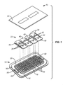
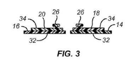
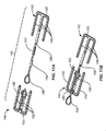
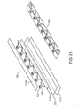
次に、図1−3を参照すると、切開閉鎖器具10は、右パネル14および左パネル16を含む、基部アセンブリ12を備える。右力分配構造18は、典型的には、力分配構造をパネルの上側表面に積層することによって、右パネル14に固着され、左力分配構造20は、同様に、左パネル16の上側表面に取り付けられる。切開閉鎖器具はさらに、以下により詳細に説明されるように、切開を閉鎖するために、右および左力分配構造18および20に除去可能に取り付け可能である閉鎖構成要素22を備え、器具は、患者に固着され、閉鎖構成要素を使用してパネルをともに牽引することによって切開が閉鎖された後、組み合わせられた基部アセンブリ12および閉鎖構成要素22を覆って留置され得る、随意の固着層24で完成される。
Next, referring to FIG. 1-3, the
閉鎖構成要素22は、力分配構造18および20の内側部分を内向きに相互に向かって牽引し、その間に形成された外科手術用切開を閉鎖するように意図および適合される。例証される実施形態では、複数の滑り止め具26が、力分配構造18および20の背部37によって軸方向に保持される、側方支持体36上に形成される。滑り止め具26は、閉鎖構成要素22の対向係合部材40の内側縁に沿って形成されるスロット38内に受容される。対向係合部材40は、係合部材が、固定された側方に離間した距離(他の実施形態では、離間距離は、調節可能であってもよい)に保持されるように、側方支柱42によって、ともに保持される。スロット38は、閉鎖構成要素22を力分配構造18および20を覆って固着させるために、スロットが、対応する滑り止め具に上向きに引っ張られることを可能にする、好ましくは、可撓性タブ状構造44上に形成される。
The
各パネル18および20の下側表面32は、典型的には、感圧式接着剤で被覆され、接着剤は、最初は、使用直前に引き剥がされ得る、保護層48で被覆される。加えて、引き離し用タブ50または他の類似構造が、層48が除去された後、但し、患者の皮膚または他の組織表面へのパネルの接着性に先立って、右および左パネル14および16を所定の離間距離にともに保持するために提供されてもよい。各パネル14および16の内側縁28間の距離は、組織縁が、閉鎖構成要素22によって閉鎖されると、典型的には、若干の外転を伴って、精密に接合されるように、元の標的間隔に可能な限り近接して維持されることが重要である。
The
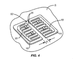
次に、図4から7を参照すると、本発明の原理による、切開を形成し、続いて、切開を閉鎖する両方のためのプロトコルが、説明される。最初に、右および左パネル14および16が、図4に示されるように、参照文字Sを伴う、患者の皮膚上に留置される。パネル14および16は、最初に、保護層18を引き剥がし、パネルを組織上に留置することによって適用され、その後、タブ50が、除去され、内側縁28間に画定された切開経路52を残す。内側縁28の間隔は、固定された所定の距離d1を提供するように選択される。
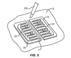
Next, with reference to FIGS. 4-7, a protocol for both forming an incision and subsequently closing the incision according to the principles of the present invention is described. First, right and left
右および左パネル14および16が、定位置にくると、切開Iが、図5に示されるように、外科用メスまたは他の外科手術切除デバイスCDを使用して、パネル間の空間内に形成されることができる。
When the right and left
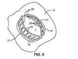
切開Iが生成された後、切開の内側縁を開放し、順に、図6に示されるように、右および左パネル14および16の内側縁28を変形させることによって、外科手術手技が、行なわれてもよい。支持体36の最内端は、接続されないため、図6において明白であるように、自由に分離し、右および左パネル14および16の弾性マトリックスが拡張することを可能にする。しかしながら、パネルの残りの寸法安定性は、切開を開放させる伸展によって印加される力の影響下において伸長しない、側方支持体36ならびに軸方向背部37によって保持される。
After the incision I is generated, the surgical procedure is performed by opening the medial edge of the incision and, in turn, deforming the
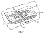
外科手術手技が完了した後、閉鎖構成要素22が、図7に例証されるように、力分配構造18および20を覆って固着される。特に、タブ状構造44内のスロット38は、パネルならびに組織切開の対向縁をともに牽引するために、対向滑り止め具26を覆って係合される。スロット38の深さを適切に離間させることによって、閉鎖構成要素22は、事前に選択された距離d2だけ、パネル14および16がともに接合されるように調整されることができる。典型的には、距離d2は、組織の内側縁が接合され、切開に沿った組織縁を、若干、外転させ(上向きにすぼめさせ)、治癒を改善し、瘢痕化を低減させ得るように、初期分離d1より小さい。
After the surgical procedure is completed, the
随意に、図8に示されるように、閉鎖構成要素22’は、係合部材40’を含んでもよく、各側方支柱42’の一端は、対向係合部材40’の内側縁間の距離が、それらの間の距離d2を増加または減少させるために、調節され得るように、調節可能留め金または他の機構54によって継合される。
Optionally, as shown in FIG. 8, the closing component 22'may include an engaging member 40', with one end of each side strut 42' being the distance between the inner edges of the opposing engaging member 40'. Are joined by an adjustable clasp or
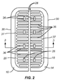
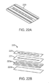
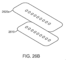
本発明の切開閉鎖器具の代替実施形態100は、図9および10に例証される。器具100は、右パネル104および左パネル106を有する、基部アセンブリ102を含む。位置決めまたは整合ストリップ108が、図10に最良に示されるように、各パネルの内側縁をともに固着するために提供され、パネルが組織表面上の定位置に置かれた後、ユーザが、ストリップをパネル104および106を引っ張ることを可能にする、端部タブ109を含む。
切開閉鎖器具100はさらに、部分的に、折り返され、パネル上の下層の接着性裏材を暴露させ、基部アセンブリ102の端部が、組織に接着されることを可能にする一方、基部アセンブリの残りは、依然として、裏材によって被覆され得る端部を有する、裏材110を含む。補強フレーム113を含む、固着層112は、概して、前述の実施形態と関連して説明されるように、基部アセンブリ102が切開を覆って閉鎖された後、右パネル104および左パネル106を覆って留置するために提供される。通常、保持トレイ114は、トレイ114が、従来の医療用パッケージングカバーによって被覆される、滅菌条件において、器具の構成要素をともに維持するために提供される。
The
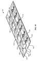
図9および10に例証されるように、右力分配構造116および左力分配構造118は、それぞれ、右パネル104および左パネル106の上側表面上に提供される。右力分配構造116は、右軸方向背部120および複数の側方支持体122を含む。典型的には、右軸方向背部120は、基部ストリップ121内に埋入される、またはそこに積層されるか、蛇行またはジグザグ数を備える。蛇行性軸方向背部120は、典型的には、可撓性の弾性プラスチック、典型的には、硬質プラスチックから形成され得る一方、基部ストリップ121は、ポリウレタンまたは類似プラスチック層を含み得る。ポリウレタン層の下側表面は、組織接着性のために、親水コロイド層によって被覆され得る。左力分配構造118の構造は、同一であって、左軸方向背部124、左側方支持体126、および左基部ストリップ127を含む。
As illustrated in FIGS. 9 and 10, the right
切開閉鎖器具100は、図9に示されるように、複数の側方繋ぎ材アセンブリ128を備える、閉鎖機構を含む。図10に最良に見られるように、各側方繋ぎ材アセンブリ128は、一端において、左側方支持体126に固着される、ロッドと、右側方支持体122に固着される、ラチェット機構132とを含む。各ロッド130は、通常、右パネル104と左パネル106との間の間隙129が、開放されたままであって、切開がそれらの間に生成され得るように、左パネル106関係の軸と整合されるであろう。切開が生成された後、各ロッド130は、右パネル104上の付随するラチェット132上で引っ張られる。各ロッド上の一連のラチェットリングは、付随するラチェット機構132内に引き込まれ、ロッドは、次いで、所望の閉鎖張力が、基部アセンブリ102に沿ったその点に印加されるまで、側方に引っ張られる。側方繋ぎ材アセンブリ128のそれぞれが、閉鎖される切開の長さに沿って、組織を横断して、個々に、調節され、所望の閉鎖張力を供給し得ることは、特に利点である。所望の閉鎖張力が、切開全体に沿って提供されると、固着層112は、基部アセンブリ102を覆って留置され、器具および組織を定位置に保持してもよい。
The incision opening /
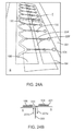
次に、図11Aおよび11Bを参照すると、本発明の側方繋ぎ材アセンブリ140のための代替設計が、例証される。これらの側方繋ぎ材アセンブリ140は、前述の切開閉鎖器具10または100のいずれかと併用されてもよい。各側方繋ぎ材アセンブリ140は、右力分配構造142および左力分配構造144を含む。右力分配構造は、右背部146および複数の側方支持体148を含む。3つが示されるが、4つ、5つ、6つ、またはそれ以上の側方支持体が、含まれ得ることを理解される。左力分配構造144は、同様に、左背部150および複数の左側方支持体152を含む。閉鎖を提供するために、右力分配構造142は、中心側方支持体148から延在する、ロッド154を含む。典型的には、ロッド154は、ライブ(live)または受動継手158によって、支持体に継合される。引っ張りループ156が、ロッド154の自由端に提供され、複数のラチェット歯162は、ロッド154の中央区画に沿って提供される。
Next, with reference to FIGS. 11A and 11B, an alternative design for the
左力分配構造144は、右力分配構造のロッド154上の歯162を受容するように適合される、ラチェット機構160を含む。このように、ロッド154は、ラチェット160内に降下され、歯162に係合し、ロッドが、右および左パネルに張力を印加するため、右および左力分配構造142および144をともに牽引するために前方に押動されることを可能にすることができる。
The left
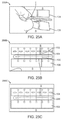
図12に例証されるように、本発明のさらなる側面が、例証される。切開閉鎖器具100が、図式的に例証されるが、右および左パネル104および106と、右および左力分配構造116および118とのみが、例証される。残りのシステム構成要素は、例証を容易にするために、示されない。
Further aspects of the invention are illustrated, as illustrated in FIG. The
右パネル104は、右犠牲カバー170によって被覆され、左パネル106は、左犠牲カバー172によって被覆される。右および左パネル104および106は、領域175を画定してもよく、ここで、右および左犠牲カバー170および172は、右および左パネル104および106と別個である。各カバー170および172は、切開閉鎖器具100の通常の取扱およびそれが切開される組織表面を覆って留置される間、カバーが定位置にとどまるように、関連付けられた基部パネルの各縁に沿って、脱着可能に固着される。これらの犠牲カバー170および172の使用および目的は、図13Aおよび13Eを参照して説明される。
The
図13Aは、切開生成に先立った、組織表面T上の定位置の右および左パネル104および106を例証する。右パネル104は、右犠牲カバー170によって被覆され、左パネル106は、左犠牲カバー172によって被覆される。多くの外科手術に一般的であるように、接着性外科手術用切開ドレープ180が、組織表面Tを覆って留置される。3M(St.Paul,Minnesota)から利用可能なIobanTM抗菌性切開ドレープ等、任意の従来のドレープが、使用されてもよい。
FIG. 13A illustrates the in-position right and left
切開ドレープ180が、切開閉鎖器具を覆って、定位置にくると、外科手術用切開Iが、所望の外科手術介入を行なうために生成されてもよい。図から分かるように、切開Iは、それぞれ、右と左パネル104および106間の外科手術ドレープ180を通して切り込む。外科手術手技が完了した後、外科手術ドレープ180は、組織表面Tから除去される。外科手術ドレープは、本発明の以前には、下側接着性表面を有するため、ドレープの除去は、右パネル104および左パネル106のいずれかまたは両方を変位させ得た。しかしながら、犠牲層170および172の存在は、そのような変位を防止する。外科手術ドレープ180の除去は、犠牲層170および172を除去するが、これらの層のそれぞれは、比較的に低分離力で破壊するように構成されるため、犠牲層の除去は、下層のパネル104または106を変位させない。したがって、パネル104および106は、図13Dに示されるように、定位置に残され、力分配構造116および118は、図13Eに示されるように、パネルをともに閉鎖し、切開を閉鎖するために、前述のように使用されることができる。
Once the
図29を参照すると、右および左犠牲カバー層170および172はそれぞれ、ウレタンの薄シート(例えば、0.001インチ厚)から構築されてもよい。ウレタンシートの中央は、ウレタンシートの最上部に組み立てられる力分配構造116、118ならびに任意のストラップ130および係止部132とともに、右および左パネル104および106の最上部に接着されてもよい。ウレタンシートは、次いで、その長さに沿って相互に積層される、ウレタンの自由端とともに、力分配構造116、118の周囲に巻着されてもよい(および、ストラップ130は、パネル106にわたって含有されるように、図29に示されるように、内向きに屈曲されてもよい)。したがって、ウレタンシートは、力分配構造116、118および閉鎖要素130、132にわたって巻着し、それらを外科手術ドレープ180から保護してもよい。ウレタンシートは、好ましくは、その長さに沿って配置され、各パネル104、106の内側および外側縁104e、106eと隣接して整合される、複数の穿孔を備えてもよい。穿孔は、ウレタンシートが、外科手術ドレープ、例えば、本明細書に説明される外科手術ドレープ180が除去されると、制御された様式において、外科手術ドレープ180とともに断裂することを可能にしてもよい。穿孔は、好ましくは、3mmの切目および1mm繋ぎ材から構築されてもよいが、正確な寸法は、所望の断裂力を制御するように変動されてもよい。穿孔は、単一長手方向線または複数の線に沿って形成されてもよい。複数の長手方向穿孔線は、外科手術ドレープが犠牲層170、172に接着するばらつきにもかかわらず、確実な分離を可能にし得る。穿孔は、パネル104、106の縁の近傍でより容易に剥離するように作製され、パネル104、106の縁104e、106eの近傍の分離の可能性を改善し、残される過剰ウレタンを最小限にするのに役立ち得る。犠牲層170、172の持ち上げを補助するために、タブ170t、172tが、犠牲層170、172を備えるウレタン巻着部の各端部に接着されてもよい。タブ170t、172tは、好ましくは、ウレタン巻着部の上側表面の内側に接着されてもよい。タブ170t、172tは、それ自体または各パネル104、106の端部からの任意の暴露接着剤へのウレタンの接着を防止するように成形されてもよい。各パネル104、106の端部における穿孔の事前破断は、タブ170t、172tの初期持ち上げおよびユーザによる断裂の開始を補助し得る。
With reference to FIG. 29, the right and left sacrificial cover layers 170 and 172 may each be constructed from a thin sheet of urethane (eg, 0.001 inch thick). The center of the urethane sheet may be glued to the top of the right and left
ここで図14A1−14A3を参照すると、切開閉鎖器具のさらなる実施形態が、例証される。基部アセンブリ1400a(図14A1)、1400b(図14A2)、および1400c(図14A3)はそれぞれ、右基部パネル1402と、左基部パネル1404とを備えてもよい。右基部パネル1402は、上層1406と、下層1408とを備えてもよい。同様に、左基部パネル1404は、上層1410と、下層1412とを備えてもよい。上層1406、1410は、典型的には、可撓性であるが、組織をしっかりと閉鎖し、切開および周囲組織の分裂を最小限にするために十分に剛性である。上層1406、1410は、ゴム、ラテックス、ポリウレタン、シリコーン、熱可塑性エラストマー、織布、紡布、または類似材料から作製される、プラスチック層を備えてもよい。接着性最下層1408、1412は、典型的には、可撓性であって、上層1406、1410より弾性であって、下にある皮膚および組織の任意の移動に追従し、接着を維持し、膨れを最小限にし、別様に炎症を低減させるであろう。接着性最下層1408、1412は、親水コロイド、ヒドロゲル、アクリルポリマー、ポリ(エチレングリコール)、および同等物等の親水性接着性材料を含んでいてもよい。
Here, with reference to FIGS. 14A1-14A3, a further embodiment of the incision chain device is illustrated. The
右および左基部パネル1402、1404は、基部アセンブリ1400の軸方向および側方伸展を促進および制限するための構造を備えてもよい。これらの構造はまた、切開に付与される閉鎖力を均一に分散させ得、その軸方向長に沿って、基部アセンブリ1400a、1400b、および1400c上に配置されてもよい。右基部パネル1402は、1つ以上の右力分配構造または軸方向支持体1414を備えてもよい。各右軸方向支持体1414は、軸方向支持体部分または背部1414aと、背部1414aの軸方向端部に結合される2つの側方支持体部分1414bとを備えてもよい。ともに、背部1414aおよび2つの側方支持体部分1414bは、いくつかの実施形態では、単一支持体1414の2つの側方支持体部分1414b間の軸方向伸展を制限しながら、隣接する支持体1414の2つの側方に隣接する側方支持体部分1414b間の右基部パネル1402の軸方向伸展を促進する程度まで軸方向に開放することができる、C−形状を形成する。多くの実施形態では、C形状軸方向支持体1414は、垂直撓曲を可能にするためだけに十分に可撓性であるが、軸方向および側方伸展を最小限にするように剛直である。図14A1に示されるように、右軸方向支持体1414は、内向きに面してもよい。図14A2および14A3に示されるように、右軸方向支持体1414は、外向きに面してもよく、これは、右および左基部パネル1402、1404間の切開Iへの組織閉鎖に対して任意の機械的荷重を分散させるのに役立ち得る。同様に、左基部パネル1404は、1つ以上の左力分配構造または軸方向支持体1416を備えてもよい。各左軸方向支持体1416は、軸方向支持体部分または背部1416aと、背部1416aの軸方向端部に結合される2つの側方支持体部分1416bとを備えてもよい。ともに、背部1416aおよび2つの側方支持体部分1416bは、いくつかの実施形態では、単一支持体1416の2つの側方支持体部分1416b間の軸方向伸展を制限しながら、隣接する支持体1416の2つの側方に隣接する側方支持体部分1416b間の左基部パネル1402の軸方向伸展を促進する程度まで軸方向に開放することができる、C−形状を形成する。多くの実施形態では、C形状軸方向支持体1416は、垂直撓曲を可能にするためだけに十分に可撓性であるが、軸方向および側方伸展を最小限にするために剛性である。図14A1に示されるように、左軸方向支持体1416は、内向きに面してもよい。図14A2および14A3に示されるように、左軸方向支持体1416は、外向きに面してもよく、これは、右および左基部パネル1402、1404間の切開Iへの組織閉鎖に対する任意の機械的荷重を分散させるのに役立ち得る。
Right and left
図14A3に示されるように、基部パネルアセンブリ1400cはさらに、スカート1424および1426を備えてもよい。スカート1424、1426は、以下に説明される薄基部アセンブリカバーに類似してもよい。例えば、各スカート1424、1426は、0.002インチ厚アクリル接着剤に結合される0.001インチ厚ウレタン膜を備えてもよい。接着剤は、スカート1424、1426の下表面全体に塗布されてもよく、もしくは基部パネル1402または1404を越えたスカート1424、1426の領域のみに塗布されてもよい。基部パネルアセンブリ1400cの構築の際、スカート1424、1426は、それぞれ、接着性層1408、1412の全部または一部にわたって、直接、適用されてもよい。スカート1424、1426は、それぞれ、薄膜上層1406、1410の代わりに、またはそれに加え、適用されてもよい。本明細書に説明されるような剥離ライナがさらに、スカート1424、1426の接着性下表面を裏打ちするために提供されてもよい。スカート1424、1426は、例えば、8mmだけ、または1〜20mmの範囲内において、それぞれ、基部パネル1402、1404の外側境界を越えて延在してもよいが、切開部位を可視化および/または清浄するための能力を改善するために、基部パネル1402、1404間の側方面積を横断しては広がらない。したがって、スカート1424、1426は、別個のカバーまたはカバーシートが基部パネルアセンブリ1400を覆うように整合および留置する必要なく、基部パネル1402、1404の接着性層1408、1412に付加的接着性支持体および/またはクリープ低減を提供するのに役立ち得る。製造後、スカート1424、1426は、典型的には、基部パネル1402、1404に対してすでに精密に整合されている。本明細書に説明されるような別個のカバーまたはカバーシートは、依然として、切開部位および基部パネルアセンブリ1400cの構成要素の改ざんを防止するために使用されてもよい。スカート1424、1426は、それぞれ、基部パネル1402、1404にわたってすでに側方に延在しているため、そのような別個のカバーまたはカバーシートは、基部パネルアセンブリ1400cに対する精密な留置を要求しなくてもよく、本明細書に説明される他のカバーまたはカバーシートと比較して、より狭くあり得る。
As shown in FIG. 14A3, the
1つ以上の穿孔1418が、右パネル1402上の軸方向に隣接する右軸方向支持体1414間に提供され、右基部パネル1402の軸方向および/または側方伸展を促進してもよい。穿孔1418は全て、上および下層1406、1408を貫通し、通気を下にある組織に提供してもよく、または上層1406上のみに存在してもよい。同様に、1つ以上の穿孔1420が、左パネル1404上の軸方向に隣接する左軸方向支持体1416間に提供され、基部パネル1402の軸方向および/または側方伸展を促進してもよい。穿孔1420は全て、上および下層1410、1412を貫通し、通気を下にある組織に提供してもよく、または上層1410上のみに存在してもよい。図14A1に示されるように、軸方向支持体1414または1418間に単一穿孔1418または1420のみが存在してもよい。図14A2および14A3に示されるように、軸方向支持体1414または1418間の側方線内に複数の穿孔1418または1420が存在してもよい。穿孔1418、1420はまた、関節運動および膨隆等の際、皮膚が切開Iから半径方向外向きに伸展するにつれて被られる応力を低減させ得る。
One or
複数の穿孔1418、1420が、例えば、図14Bに示される右および左線1424、1426に沿って、右および/または左軸方向支持体1414、1416の軸方向端部間に提供されてもよい。複数の軸方向に整合された穿孔は、少なくとも、それぞれ、基部パネル1402、1404の上および下層1410、1412が、以下にさらに説明されるように軸方向に伸展されると、別個のセグメントに分割し得るように、各線セグメント1424または1426上に提供されてもよい。いくつかの事例では、デバイス1400の装着持続時間の間、穿孔1418、1420は、右パネル1402の層1406および1408ならびに左パネル1404の層1410および1412が、図14A2および14A3に示される、穿孔線において完全に分割および分離することを可能にしてもよい。完全に分割および分離するための能力はさらに、皮膚が、以下に論じられる軸方向支持体1414および1416と閉鎖構成要素1422の結合によって可能にされる(および、制限される)伸長に伴って、必要に応じて、軸方向に伸展することを可能にする。本明細書に論じられるように、可撓性の伸展性のカバーが、切開Iが閉鎖された後、基部パネル1402、1404を覆って適用されてもよい。カバーはさらに、基部構造1400bの軸方向および側方移動を提供(および、制限)する役割を果たしてもよい。代替として、または組み合わせて、右または左基部パネル1402、1404の1つ以上は、力分配構造または軸方向支持体1414、1416間で側方に切断され、分離され、右および/または左基部パネル1402、1404の軸方向および/または側方伸展を促進してもよい。
右および左基部パネル1402、1404を側方にともに結合し、随意に、右および左基部パネル1402、1404を相互に対して緊締するために、基部アセンブリ1400はさらに、複数の側方閉鎖構成要素または繋ぎ材アセンブリ1422を備えてもよい。側方閉鎖構成要素または繋ぎ材アセンブリ1422は、前述の側方繋ぎ材アセンブリ128および140のものに類似する、ラチェット機構を備えてもよい。側方繋ぎ材アセンブリ1422は、典型的には、その軸方向端部において、側方に隣接する右および左軸方向支持体1414、1416をともに結合してもよい。図14A1−14A3に示されるように、それぞれ、右および左パネル1402、1404上への右および左軸方向支持体1414、1416の留置は、ずらして配置または軸方向にオフセットされてもよく、右および左軸方向支持体1414、1416は、側方に面し、相互と整合する(および、側方繋ぎ材アセンブリ1422によって相互に接続される)、側方端部部分1414b、1416bを伴う、C形状構造であってもよい。例えば、第1の右軸方向支持体1414の遠端側方部分1414bは、第1の左軸方向支持体1416の近端側方部分1416bと側方に整合されてもよく、第1の左軸方向支持体1416の遠端側方部分1416bは、第2の右軸方向支持体1414の近端側方部分1414bと側方に整合されてもよい等となる。したがって、側方繋ぎ材アセンブリ1422ならびに右および左軸方向支持体1414、1416は、相互に接続され、連続側方繋ぎ材アセンブリ1422ならびに右および左軸方向支持体1414、1416の線を形成してもよく、本線は、図14A1−14A3に示されるように、右および左基部パネル1402、1404の側方に及ぶ(すなわち、右および左基部パネル1402、1404間の距離を横断する)、蛇行配列を有してもよい。側方繋ぎ材アセンブリ1422ならびに右および左軸方向支持体1414、1416の蛇行配列は、切開上に基部アセンブリ1400によって提供される閉鎖力を均一に分散させること、基部アセンブリ1400の軸方向可撓性を提供(および、制限)すること、および切開を十分に閉鎖し、最小限にされる分裂および膨張を伴って治癒することを可能にする(すなわち、側方および軸方向安定性を提供する)ための剛性または剛直性を基部アセンブリ1400a、1400b、および1400cに提供することの1つ以上を行い得る。多くの実施形態では、側方支持体1414、1416は、側方支持体1414、1416で被覆されていない、基部パネル1402、1404の面積が伸展するように剛直である。これらの被覆されていない面積は、右基部パネル1402から左基部パネル1404へと相互からオフセットされるため、繋ぎ材アセンブリ1422は、切開Iが軸方向に伸展されるにつれて、その係留点から軸方向に枢動してもよい。繋ぎ材アセンブリ1422のそのような軸方向枢動は、左および右パネル1402、1404をともにより密接させ、切開Iの閉鎖を維持し得る。
To join the right and left
側方繋ぎ材アセンブリ1422ならびに右および左軸方向支持体1414、1416の材料は、例えば、可撓性の弾性プラスチック、典型的には、ナイロン、ポリプロピレン、ポリエチレン、ポリカーボネート、および他の熱可塑性ポリマー等の硬質プラスチックを含んでもよい。多くの場合、側方繋ぎ材アセンブリ1422ならびに右および左軸方向支持体1414、1416は、右および左基部パネル1402、1404のものほど弾性ではない材料を備えてもよい。したがって、本明細書に開示される切開閉鎖器具の多くの他の基部アセンブリと同様に、より大きい剛直性(および、より低い弾性)が、基部アセンブリ1400a、1400b、および1400cの最上部に向かって提供されてもよい。言い換えると、基部アセンブリ1400a、1400b、および1400cの最上部と底部との間に弾性勾配が存在してもよい。基部アセンブリ1400a、1400b、および1400cの最上部は、切開閉鎖器具が、切開および周囲組織に適用されると、器具の側方に隣接する組織の移動が、実質的に、被覆された切開および周囲組織を広げないように防止するように十分に剛性または堅固であってもよい。すなわち、適用される切開閉鎖器具の少なくとも一部(例えば、より堅固な層の下方の部分)の移動は、集合的であって、下にある切開を分裂させない。また、基部アセンブリ1400a、1400b、および1400cの底部は、適用される切開閉鎖器具に隣接する組織の移動による膨れおよび接着性損失が、最小限にされるように、十分に弾性であってもよい。側方繋ぎ材アセンブリ1422の主要機能は、各基部パネル1402、1404に張力を印加し、切開Iを閉鎖したまま保持することであり得るが、多くの実施形態では、側方繋ぎ材アセンブリ1422はまた、切開縁整合および並置を分裂させ得る離開力から、切開Iに及ぼす圧迫(または、それに沿った屈曲/クリープ)の影響を最小限にすることによって、切開Iを隔離するような柱強度を提供する役割を果たしてもよい。側方繋ぎ材1422の軸方向間隔、材料特性、および寸法は、十分な軸方向屈曲可撓性ならびに側方圧迫および屈曲支持のために最適化されてもよい。好ましい実施形態では、繋ぎ材1422間の間隔は、10mmであって、繋ぎ材1422の材料は、ナイロンであって、寸法は、0.030インチの円形断面である。
The materials of the
ここで図14Bを参照すると、基部アセンブリ1400bは、膝等の患者の皮膚または対象の関節における切開を覆って留置されてもよい。連接する関節、特に、膝に近接して留置される切開では、閉鎖デバイスまたは閉鎖器具完全性は、多くの場合、いくつかの要因によって困難となる。これらの要因として、長手方向伸長、円周方向膨隆、関節運動が生じるにつれた創傷の開放、膨れ等の皮膚損傷、接着性損失、および創傷浸出液の通過が挙げられる。膝、肘、足首、および肩等の関節は、時として、135°を上回る移動を網羅する関節運動をもたらし、前述の課題につながる可能性のある、移動を受け得る。
With reference to FIG. 14B here, the
屈曲位置では、膝の周囲の皮膚は、最大50%まで、軸方向(すなわち、切開に平行)および側方に(すなわち、切開を横断する、またはそれに対して垂直)、伸展することができる。本面積内の皮膚に接着される切開閉鎖器具は、好ましくは、切開を閉鎖するが、最小局所応力を伴って、伸展に対応するために十分な張力を提供可能であってもよい。局所応力を最小限にすることは、局所皮膚接着性損失、または接着性損失が生じない場合の皮膚への損傷を防止し得る。本明細書に開示される多くの切開閉鎖器具のための重要な特性は、引張要素取り付け点自体のものより大きい面積を横断して分散される器具の閉鎖要素の引張荷重の能力である。さらに、引張要素が取り付けられる、接着剤を含む構造は、多くの場合、器具が、皮膚がその周囲を移動する間、切開を定位置に保持するように、皮膚伸展の領域を横断して、構造の伸展性を分散させる能力を有し得る。本明細書に説明される実施形態は、ストラップを定位置に保持する「係止部」に結合される、非伸展張力要素(一般に、「ストラップ」と称される)の複合設計を含んでもよい。例えば、そのような要素は、前述の側方繋ぎ材アセンブリ128、140、および1422を含んでもよい。これらの要素は、張力荷重を分散させるのに役立つ弾性ポリマー材料とともに、皮膚接着剤にわたって搭載されてもよい。そのような弾性ポリマーは、多くの場合、座屈または恒久的に変形する前に、高伸長性を有し得、ポリウレタン等の熱可塑性エラストマーならびに種々のグレードのシリコーンを含んでもよい。そのような材料はまた、低プロフィールおよび十分な伸展性を維持するために必要な薄膜に容易に形成され得る。
In the flexed position, the skin around the knee can be extended axially (ie, parallel to the incision) and laterally (ie, across or perpendicular to the incision) up to 50%. An incision closure device that adheres to the skin within this area preferably closes the incision, but may be able to provide sufficient tension to accommodate extension with minimal local stress. Minimizing local stresses can prevent local skin adhesive loss, or damage to the skin in the absence of adhesive loss. An important property for many incision chain devices disclosed herein is the ability of the closing element of the device to be distributed across a larger area than that of the tension element attachment point itself. In addition, the adhesive-containing structure to which the tension element is attached often traverses the area of skin extension so that the device holds the incision in place while the skin moves around it. It may have the ability to disperse the extensibility of the structure. The embodiments described herein may include a composite design of non-extension tension elements (commonly referred to as "straps") that are coupled to "locking portions" that hold the straps in place. .. For example, such elements may include the aforementioned
器具内で使用される皮膚接着剤はまた、皮膚の伸長に耐え、皮膚が非伸展状態(例えば、完全に延在された膝位置)に戻るとき、後退/反跳可能である必要があり得る。親水コロイド接着剤は、そのような特性を提供し得、かつ好ましくは、この適用に好適であり得る。アクリル等の他の接着剤もまた、本特性を提供するために使用されてもよい。一般に、そのような接着剤は、拡張および反跳の際、その構造を保持するために、前述のもの等の弾性薄膜に取り付けられる必要があり得る。そのような支持体がない場合、接着剤は、反復伸長に伴って、断裂および分離し得る。 The skin adhesive used within the device may also need to withstand stretching of the skin and be receding / recoiling when the skin returns to a non-extended state (eg, a fully extended knee position). .. Hydrocolloid adhesives can provide such properties and are preferably suitable for this application. Other adhesives such as acrylic may also be used to provide this property. In general, such adhesives may need to be attached to elastic thin films such as those mentioned above to retain their structure during expansion and recoil. In the absence of such a support, the adhesive can rupture and separate with repeated elongation.
一連の短セグメントとして構築される切開閉鎖器具は、接着性の損失または皮膚損傷がない場合、より高い全体的伸長性に対応し得る。各個々のセグメントは、その下の皮膚の局所伸展を受け得る。2つの隣接するセグメント間の空間は、応力緩和空間として作用し、皮膚がその空間内で伸展することを可能にしてもよい。セグメント化は、(1)切開線に沿って個々のセグメントを敷設する、または(2)皮膚に適用されるにつれて、または皮膚への適用後、デバイスが短セグメントに分割することを可能にすることによって等、いくつかの方法で達成されてもよい。 An incision chain device constructed as a series of short segments can accommodate higher overall extensibility in the absence of loss of adhesion or skin damage. Each individual segment can undergo a local extension of the skin beneath it. The space between two adjacent segments may act as a stress relaxation space, allowing the skin to stretch within that space. Segmentation allows the device to divide into short segments as (1) laying individual segments along the incision line, or (2) as it is applied to the skin or after application to the skin. It may be achieved in several ways, such as by.
皮膚への適用後のセグメント化を達成する好ましい手段は、前述のように、穿孔(例えば、断裂を促進するための穿孔の側方線)をポリウレタン層(すなわち、基部パネル1402、1404の上層1406、1410)内に作成し、図14Bに示されるように、下にある接着剤を無傷のまま残すことを含む。穿孔は、膝が撓曲する(すなわち、関節運動する)につれて、伸展を受けると、穿孔線(例えば、線1424、1426)に沿って、少なくとも、基部パネルの上層(例えば、上層1406、1410)の断裂をもたらし得る。好ましい実施形態では、切開の各側の接着性パネルは、12mm幅であってもよく、所与のパネル内の穿孔は、約12〜20mm離間される。実験が行われ、3mm切目および1mm繋ぎ材距離の穿孔が、膝が撓曲するとき、0.001インチ厚ウレタン基部パネルにおいてセグメント化を達成する際に効果的であることが示された。膝が撓曲するにつれて、皮膚は、いくつかの場所では、軸方向(切開に沿って)および側方方向に、最大50%まで伸長し得る。ポリウレタンの分離は、したがって、伸展を受けるにつれて、デバイス内の応力を緩和することができる。
A preferred means of achieving segmentation after application to the skin is to make the perforations (eg, the side lines of the perforations to promote rupture) the polyurethane layer (ie, the
実施例として、外科手術で修復された膝は、数日間、閉鎖後、関節の約30%半径方向膨隆をもたらし得る、炎症を起こし得る。ポリウレタンのような弾性材料は、切開閉鎖器具(例えば、図14Bにおける結果として生じる切開Iに接着される基部アセンブリ1400bを含む)が、この円周方向膨隆に伴って拡張することを可能にし得る。器具の幅を最小限にすること(例えば、各基部パネルセグメント1402、1404に対して12mmまたはそれ未満)は、切開Iに対して垂直方向に器具が拡張を受ける量を最小限にし得、したがって、皮膚損傷の潜在性を最小限にしながら、接着性を保存し得る。図14Bは、線1424、1426に沿って切開に対して側方方向に延設され、より容易な軸方向伸展を可能にする、接着性セグメント内の穿孔を示す。穿孔または他の開窓もまた、関節運動および膨隆等の際、皮膚が切開から半径方向外向きに伸展するにつれて被られる応力を低減させるために、切開に平行な接着性セグメントの外側縁近傍に作製され得る。
As an example, a surgically repaired knee can become inflamed, which can result in approximately 30% radial bulge of the joint after closure for several days. An elastic material such as polyurethane may allow the incision closure device (eg, including the
ここで図15A−15Dを参照すると、切開は、多くの場合、膝または他の関節の撓曲のため、切開を開放する傾向にある力を被り得る。多くの実施形態では、切開閉鎖器具は、撓曲の間、緊密に閉鎖し、切開が閉鎖された状態に保つのを補助することによって、開放力に対抗する、係止機構を具備する。図15Aおよび15Bは、滑車効果を利用する、すなわち、皮膚が切開に沿って伸展すると、切開の両側の係止点間の距離を短縮させる機構を備える、切開閉鎖器具の基部アセンブリ1500を示す。好ましい実施形態では、基部パネル1510a、1510b対間の切開の両側の接着性パネル1510a、1510bは、12mm幅であって、所与のパネル1510内の線状穿孔1530は、約18mm離間される。典型的には、係止機構の部材は全て、伸展しない。アンカ1540、滑車1520、係止部1550、および可撓性係止要素1580(例えば、テザーまたはストラップ)によって形成される三角形は、図15Cに示されるように、切開に軸方向に沿った基部Bと、切開を側方に横断するその高さHとを有する。膝が撓曲するにつて、三角形基部長は、増加する。典型的には、三角形の部材は全て、伸展せず、これは、任意の2つの点間を接続する個々の要素の長さを保持するために、高さが減少しなければならないことを要求し、切開を横断する付加的閉鎖力をもたらす。図15Aおよび15Bはさらに、基部パネル1510a、1510bの下側表面が、親水コロイド接着剤1560を含んでもよく、パネル1510aまたは1510bの一方が、ストラップ1580を定位置に係止するための係止アーム1570を備えてもよいことを示す。三角形の基部は、図15Aでは、左基部パネル1510b上に示されるが、三角形の基部は、代わりに、右基部パネル1510a上にあってもよいことも企図される。
Referring here to FIGS. 15A-15D, the incision may be subject to forces that tend to open the incision, often due to flexure of the knee or other joint. In many embodiments, the incision closure device comprises a locking mechanism that counteracts the opening force by tightly closing during flexure and assisting in keeping the incision closed. 15A and 15B show the
三角形が、アンカ1540、滑車1520、係止部1550、および可撓性係止要素1580によって形成されるが、他の形状もまた、企図される。例えば、滑車1520は、2つのアンカ1540の周囲に巻着され、正方形または長方形形状を形成してもよく、または滑車1520は、3つまたはそれを上回るアンカ1540の周囲に巻着され、台形形状を形成してもよい。図15Dを参照すると、基部アセンブリ1500に類似する、切開閉鎖器具の基部アセンブリ1500aが、示される。基部パネル1500aでは、アンカ1540、2つの滑車1520、係止部1550、および可撓性係止要素1580は、長方形を形成し、下にある皮膚が伸展すると、切開Iに付加的閉鎖を提供する。図15Dに示される長方形構成では、切開Iの両側の2つの固定点間の間隔は、典型的には、同一である。一方、図15Aおよび15Cに示される三角形構成では、滑車1520側の固定点は、切開Iの他側よりさらに離間されてもよい。長方形は、左基部パネル1510b上で「開放」されるように示されるが、長方形は、代わりに、右基部パネル1510a上で「開放」されてもよいことも企図される。
Triangles are formed by
図14A1−14A3に示される切開閉鎖器具基部アセンブリ1400a、1400b、および1400cならびに本明細書に説明されるその他では、個々のストラップ1422は、切開Iの対向側の個々の係止部に係合するように使用されてもよい。図15A−15Dでは、各可撓性係止要素またはストラップ1580は、典型的には、切開Iの片側に係留され、他側の周囲に巻着され、次いで、アンカ1540の場所と切開Iの同一の側の係止部1550に係合する。図15Dによって示される実施形態では、可撓性係止要素またはストラップ1580は、同一の側の係止部1550に係合する前に、切開Iの他側の2つの固定スプール(ボビン/滑車1520)の周囲に巻着する。その周囲に可撓性ストラップ1580が巻着される、スプール1520は、好ましくは、閉鎖デバイス基部パネルアセンブリ1500が軸方向に伸長するとき、それらの間の距離が増加しないように、剛性部材と結合されてもよい。代替実施形態では、滑車またはスプール1520間の拡張を可能にすることが、望ましくあり得る。可撓性係止要素1580は、基部パネル1510aまたは1510b内の穿孔1530によって分離される、隣接するセグメント内に係止されたまま、一方の基部パネルセグメント内に係留されてもよいことに留意されたい。そのような係留および係止は、基部細片の3つのセグメント(2つが同一の側にあって、1つが他側にある)間の接続を作成し得る。切開閉鎖デバイスもしくは基部アセンブリ1500または1500aの長さを横断してともにまとめられると、取着機構は、切開Iを横断して連続「S」形状(すなわち、蛇行)接続を形成する。
Incision closure chain
スピンドル、スプール、または滑車1520の周囲に巻着する、引っ張られた可撓性コネクタ1580は、離開力が、切開を開放しようと試み、下にある皮膚が伸展を被るとき、切開Iの余剰圧迫を提供するように構成されてもよい。可撓性ストラップ1580は、ある場合には、潜在的に、スピンドル1520から滑脱し、2つの基部パネル1510aがさらに、下にある皮膚のいかなる伸展も伴わずに、ともに合わせられる外部力によって圧迫される場合、弛緩し得る。そのような滑脱が生じないように防止するために、可撓性巻着部材1580が、基部細片1510a上に係留された要素1590内に摺動可能に含まれるか、または係留されることができる。図15Eおよび15Fは、管1590を通して螺入され、順に、基部パネル1510aに取着または係留される、可撓性要素1580を示す。基部パネル1510a、1510bが、ともにより近接されるとき、可撓性ストラップ要素1580は、依然として、捕捉され、必要閉鎖機能を提供し続ける。他の実施形態では、図15Eおよび15Fに示されるスプール特徴1590は、それを通してトラップ1590が摺動する中心を通して孔を有してもよい。可撓性ストラップ1580およびそれを通して摺動する要素1590は、好ましくは、要素1580と1590との間の摩擦を最小限にするように設計されてもよい。
A pulled
実験が行われ、基部Bが、12mmであって、高さHが、切開が閉鎖された後、2つの基部パネル1510a、1510b上のストラップ接続点間の距離によって決定され(典型的には、約16mm)、ヒト膝上の器具1500の撓曲は、皮膚Sの伸長が最大であった面積内において、高さHの5%の減少のもたらしたことが示された。高さの減少は、三角形の基部、下にある皮膚の伸長のレベル、および切開の両側の2つの基部間の距離等、いくつかの要因に依存し得ることに留意されたい。アンカ1540と係止部1550との間を接続する「ストラップ」は、少なくとも部分的に、可撓性であって、滑車の周囲のループ化を可能にする必要があり得る。好ましい実施形態では、モノフィラメントプラスチック糸が、係止機構の中で係合する特徴と統合される。そのような特徴は、係止部内のラチェット状機構内に係合する、丸みを帯びた「歯」であり得る。そのようなプラスチックは、所望の可撓性、長手方向剛性、低細菌居住性質を達成し、押出成形および/または射出成形プロセスを可能にするために使用されることができる。編組縫合糸(好ましくは、細菌の居住を制限するためにコーティングされる)もまた、可撓性であるが、伸展不可能なコネクタを作成するために使用されることができる。シリコーンのような可撓性材料から作製される、丸みを帯びたワイヤまたは管類もまた、可撓性を達成するために使用されることができる。滑車のストラップは、成形プラスチックおよび編組縫合糸等の材料の複合材であり得る。他の実施形態では、滑車のストラップは、成形ストラップをネッキング加工することによって形成されることができる。成形ストラップをその座屈点を超えて引っ張ることは、ストラップの断面を恒久的に低減させ、伸長するとき、より可撓性にすることができる。熱が、ネッキングプロセスにおいて使用され、伸長および断面積の低減を促進することができる。図16A−16Bに示される代替機構は、いったん所望の閉鎖が達成されると、縫合糸およびより軟質のプラスチック等のストラップ材料を係止するために使用されることができる。図16Aは、摺動のためのスロット1610と、係留フレーム1620とを備える、係止機構を示す。図16Bは、係止歯1630を備える、係止機構を示す。図16Cは、摺動のためのスロット1640と、係留フレーム1650とを備える、係止機構を示す。図16Dは、円筒形管1660と、係止歯1670とを備える、係止機構を示す。
Experiments were performed, the base B was 12 mm and the height H was determined by the distance between the strap connection points on the two
膝が撓曲するとき、切開を横断する付加的閉鎖力は、図17に示されるように、ヒンジ機構1700を使用することによって達成されてもよい。図17に示されるように、切開の両側の4つの点(切開閉鎖器具の両側または基部パネル1710上の2つのアンカ点1720)が、交差点1740に提供されるヒンジを用いて、Xの形状において、非伸展アーム1730と接続されてもよい。膝が撓曲し、切開の同一の側の2つの点間の距離が増加するにつれて、切開の両側のセグメント間の距離は、減少し、付加的閉鎖力をもたらし得る。図17に示されるように、基部パネル1710はまた、複数の穿孔1750を具備し、基部パネル1710に対する軸方向伸展または軸方向伸展に応じた離散セグメントへのその分離を促進してもよい。
When the knee flexes, an additional closing force across the incision may be achieved by using the
図18に示されるように、多くの実施形態による、切開閉鎖器具1800のストラップおよび係止部は、膝の皮膚S上の切開Iの全長を横断して、S形状もしくは蛇行接続または配列を形成するように構成されることができる。切開閉鎖器具1800は、多くの点において、前述の切開閉鎖器具1400に類似し得る。デバイス1800のセグメント1810a、1810bは、切開Iの片側の各セグメント1810aと切開の反対側の2つの隣接するセグメント1810bを接続することによって、相互に接続される。これは、一対のストラップ1820を各セグメント1810a内に、一対の係止部1830を他側の対応するセグメント1810b上に搭載することによって達成されてもよい。各対の係止部1830およびストラップ1820は、相互に接続されてもよい。創傷または切開Iの閉鎖の間、基部パネルセグメント1810a(例えば、1810a1)のストラップ1820の一方(例えば、ストラップ1820a)は、切開Iの他側のセグメント1810b(例えば、セグメント1810b1)上の係止部1830(例えば、1830a)と接続されてもよく、第2のストラップ1820(例えば、ストラップ1820b)は、前の対のストラップ1820(例えば、ストラップ1820a)が接続されたセグメント1810b(例えば、1810b1)に隣接する切開Iの反対側のセグメント1810(例えば、セグメント1810b2)内の係止部1830(例えば、1830b)と接続されてもよい。前述の接続は、基部パネルセグメント1810、ストラップ1820、および係止部1830のS形状または蛇行配列の単一ループを形成する。穿孔線1850は、軸方向に隣接する基部パネルセグメント1810aおよび1810bを分離してもよい。片側(例えば、基部パネルセグメント1810aを伴う)の穿孔線1850は、他側(例えば、基部パネルセグメント1810bを伴う)の穿孔線1850と交互されてもよい。図15Aと同様に、好ましい実施形態では、切開の両側の接着性パネルは、12mm幅であってもよく、所与のパネル内の穿孔は、約18mm離間されてもよい。
As shown in FIG. 18, according to many embodiments, the straps and locks of the
本明細書に説明されるような切開閉鎖器具またはデバイスは、多くの方法で適用されてもよい。図19は、いくつかの実施形態による、例示的切開閉鎖器具190を示す。ここでは、対で配列される個々の基部対セグメント1910が、個々の担体/剥離ライナ上に提供されてもよい。各基部パネルセグメント1910対は、独立して、切開と整合され、相互に隣接する皮膚に接着され得る、ストラップ1920および係止部1930を備える。個々のセグメント1910は、剥離ライナおよび外側担体テープ1950とともに、相互に対してともに保持されてもよい。剥離ライナ1950は、接着剤を暴露させるために除去されてもよいが、デバイス1900全体またはデバイス1900のグループ化された部分が、外側担体テープと結合されてもよい。皮膚への適用に応じて、担体テープ1950は、除去され、相互に整合されるが、独立して移動することができる、接着性セグメント1910を残してもよい。
An incision chain device or device as described herein may be applied in many ways. FIG. 19 shows an exemplary incision / opening / closing chain device 190 according to some embodiments. Here, the individual base-to-
典型的には、ポリウレタンを含む、基部パネル上層の穿孔セグメントは、典型的には、親水コロイド接着剤を含む、接着性最下層の連続層とともに保持され、1つの連続的動きにおいて、皮膚上への配設を可能にしてもよい。それぞれ、図14A−14B、15A−15C、および18の切開閉鎖器具1400、1500、および1800は、そのような連続接着性最下層を具備してもよい。
The perforated segments of the base panel top layer, typically containing polyurethane, are retained with a continuous layer of adhesive bottom layer, typically containing a hydrophilic colloidal adhesive, onto the skin in one continuous movement. May be possible to dispose of. The incision and closing
本明細書に説明される切開閉鎖器具の基部アセンブリまたは基部パネルは、好ましくは、創傷または切開閉鎖の端部において、可撓性接着性膜材料で被覆されてもよい。本膜面積は、好ましくは、要素を皮膚上に重置するように、基部切開閉鎖パネル要素より大きくてもよい。膜は、基部の移動を防止するのに役立ち得、アンカおよび係止機構のいかなる偶発的移動も防止し得る。カバー膜は、ゴム、ラテックス、ポリウレタン、シリコーン、または熱可塑性エラストマー等のような伸展可能材料から作製されてもよい。好ましい実施形態では、薄カバー(例えば、0.001インチウレタンおよび0.002インチ厚アクリル接着剤の積層)は、基部パネル要素の複合材構造より柔軟性を有するであろう。その結果、カバーは、暴露された皮膚と基部セグメントとの間にある程度の歪み緩和をもたらし得る。カバーはまた、透明であって、切開の目視検査を可能にしてもよい。カバーは、切開を横断して完全に密閉してもよく(例えば、感染症に対する障壁として)、またはカバー内に、切開線と整合され、創傷からのいかなる浸出液の通過も可能にする、開口部が存在してもよい。カバーはまた、基部パネルに橋架し、基部細片間の皮膚縁に接着することによって、切開縁の並置を改善する役割を果たしてもよい。カバーはまた、基部パネル要素間の引っ張り強度を改善するが、切開長に沿って伸展性を可能にする、付加的補強要素とともに構築されてもよい。好ましい実施形態は、カバーに適用される一連のポリエチレン接着性テープ細片を備えてもよい。 The base assembly or base panel of the incision closure device described herein may preferably be coated with a flexible adhesive membrane material at the end of the wound or incision chain. The membrane area may preferably be larger than the base incision opening and closing chain panel element so that the element rests on the skin. The membrane can help prevent the movement of the base and can prevent any accidental movement of the anchor and locking mechanism. The cover membrane may be made of a stretchable material such as rubber, latex, polyurethane, silicone, or thermoplastic elastomer. In a preferred embodiment, the thin cover (eg, a laminate of 0.001 inch urethane and 0.002 inch thick acrylic adhesive) will be more flexible than the composite structure of the base panel elements. As a result, the cover can provide some degree of distortion relief between the exposed skin and the base segment. The cover may also be transparent, allowing visual inspection of the incision. The cover may be completely sealed across the incision (eg, as a barrier against infection), or within the cover, an opening that is aligned with the incision line and allows the passage of any exudate from the wound. May exist. The cover may also serve to improve the juxtaposition of the incision edges by bridging the base panel and adhering to the skin edges between the base pieces. The cover may also be constructed with additional reinforcing elements that improve tensile strength between the base panel elements but allow extensibility along the incision length. A preferred embodiment may include a series of polyethylene adhesive tape strips applied to the cover.
ユーザは、基部アセンブリおよびパネルが皮膚上に留置された後、カバーを適用してもよいが、また、カバー材料は、基部セグメントの外側周縁の周囲に延在する「スカート」として供給されてもよいことが企図される。したがって、基部に対するカバー材料の整合は、ユーザ留置に依存しなくてもよい。これらの同一のカバー材料は、患者の衣類への親水コロイド接着剤の暴露を限定し、親水コロイドまたは他の接着性下層の移動を制限し、基部セグメントにかかる張力のための歪み緩和を提供する等の効果を提供し得る。 The user may apply the cover after the base assembly and panel have been placed on the skin, but the cover material may also be supplied as a "skirt" that extends around the outer periphery of the base segment. Good things are planned. Therefore, the alignment of the cover material with respect to the base does not have to depend on user placement. These identical cover materials limit the exposure of the hydrophilic colloid adhesive to the patient's clothing, limit the movement of the hydrophilic colloid or other adhesive underlayer, and provide strain relief due to tension applied to the base segment. Etc. can be provided.
多くの実施形態では、親水コロイド接着剤は、切開閉鎖のために、皮膚を引っ張るために使用される。親水コロイドは、(1)表面上の積層を使用して、クリープを制限すること、または(2)皮膚および親水コロイド接着剤を横断して接着性カバーを適用し、クリープを防止し、皮膚に歪み緩和を提供し、皮膚損傷を防止することの1つ以上によって、クリープが防止されてもよい。 In many embodiments, the hydrophilic colloidal adhesive is used to pull the skin due to the incision chain. Hydrocolloids can be applied to the skin by (1) using a laminate on the surface to limit creep, or (2) applying an adhesive cover across the skin and hydrophilic colloid adhesives to prevent creep. Creep may be prevented by one or more of providing strain relief and preventing skin damage.
多くの実施形態では、基部アセンブリと併用されるようなカバーは、穿孔または開口部の1つ以上を含み、接着された基部アセンブリの除去を伴わずに、創傷浸出液(ならびに、任意の適用された絆創膏/吸収性材料)の除去を可能にしてもよい。 In many embodiments, the cover, such as that used in combination with the base assembly, comprises one or more perforations or openings, without removal of the glued base assembly, wound exudate (as well as any application). Adhesive plasters / absorbent materials) may be allowed to be removed.
多くの実施形態では、カバーは、可撓性ウレタンおよび補強された細片の複合材を備える。複合材構造は、切開を横断して強度を提供し、かつ切開長に沿って、伸展性を提供し得る。 In many embodiments, the cover comprises a composite of flexible urethane and reinforced strips. The composite structure can provide strength across the incision and can provide extensibility along the length of the incision.
多くの実施形態では、カバーは、基部アセンブリと組み合わせて、皮膚切開縁を整合するか、または軸方向および側方方向の両方において、皮膚縁の後続不整合を有意に防止する。 In many embodiments, the cover, in combination with the base assembly, aligns the skin incision edges or significantly prevents subsequent inconsistencies in the skin edges, both axially and laterally.
多くの実施形態では、カバーライナ構成が、カバーの一部が皮膚に最初に適用されることができ、次いで、他のライナの除去を補助するように提供され、したがって、最小皺発生を伴って、均一に配設されるように、薄材料を制御するのに役立ち得る。 In many embodiments, a cover liner configuration is provided so that part of the cover can be applied first to the skin and then assists in the removal of other liners, thus with minimal wrinkle formation. Can help control thin materials so that they are evenly distributed.
多くの実施形態では、第1のライナの除去は、留置の間の可視化を可能にし得、デバイスの残りが、ユーザに粘着しないように防止し得る。 In many embodiments, removal of the first liner can allow visualization during placement and prevent the rest of the device from sticking to the user.
図9および10に戻って参照すると、2つの接着性パネル104、106が、多くの好ましい実施形態では、外科手術切開の両側に適用される(切開が行なわれる前または後のいずれかにおいて)。閉鎖機構が、接着性パネル104、106の最上部に搭載されてもよく、好ましくは、構成要素120に取着され、閉鎖機構の取着点間に閉鎖力を分散させるのに役立ち得る。図9および10ならびに図20Aおよび20Bに示されるように、本閉鎖機構は、ストラップ130と、係止部132とを備えてもよい。ストラップ130は、係合歯を伴う、伸長構成要素を備えてもよい。係止部132は、ストラップ130の係合歯を捕捉するための特徴を備えてもよい。ストラップ130は、係止部132内に緊締され、接着性パネル104、106(したがって、切開縁)をともに引っ張り得る。ユーザは、必要に応じて、ストラップ130を脱係合し、係止部132内に再係合させ、皮膚閉鎖の量を適切に調節してもよい。ともに、図20Aに例証される切開閉鎖器具は、基部または基部アセンブリ102として説明され得る。
Returning to FIGS. 9 and 10, the two
各パネル104、106のために使用される皮膚接着剤は、好ましくは、親水コロイド接着剤を含んでもよい。代替として、または組み合わせて、皮膚接着剤は、当技術分野において公知の多くのアクリル製剤の1つを含んでもよい。親水コロイド接着剤は、非常に粘性であって、湿気および脱落皮膚細胞を吸着可能であるという利点を有し得る。したがって、親水コロイド接着剤は、長期装着用途(例えば、最大14日)のために、特に、好適であり得る。少なくともいくつかの事例では、親水コロイド構造は、軟質であってもよいが、しかしながら、親水コロイド接着性層をより堅固な基部パネル102、104または本明細書に開示される他の被覆構造で被覆すること等によって、何らかの様式において補強されない限り、張力下、クリープを発生する傾向にあり得る。
The skin adhesive used for each of the
故に、本発明のさらなる側面はまた、本明細書に説明される切開閉鎖器具の基部アセンブリ内の接着性層を補強および保護する種々の手段、ならびに、特に、軸方向に、皮膚縁をともに保持する付加的手段を提供する。少なくともいくつかの場合、親水コロイド接着剤のみでは、非常に低い引っ張り強度を有し、使用の間、断裂しないように、またはクリープを発生させないように、補強の手段を要求し得る。図21に例証されるように、基部パネル104、106内で使用される接着性層211は、最大0.010インチ厚の潜在的範囲を伴う、好ましくは、0.001インチ厚のウレタン等の伸展性プラスチックまたはポリマー212の薄層とともに積層されてもよく、これは、臨床使用の間、その構造を維持するのに役立ち得る。接着性層自体は、公称上、0.010インチ厚であってもよいが、0.005インチ〜0.020インチ厚の範囲であってもよい。荷重分散構成要素118に取着されたストラップ130または係止部132を備える、引張要素が、接着剤構造211の最上部に搭載され得るため、材料が経時的にクリープを発生させ得る、可能性が存在する。積層212ならびに接着性層211と荷重分散構成要素118との間の任意の他の接着性積層215a、215bは、接着性層のクリープを防止するための構造を提供するのに役立ち得る。
Therefore, a further aspect of the invention is also to hold together the various means of reinforcing and protecting the adhesive layer within the base assembly of the incision chain device described herein, and in particular, axially. Provide additional means of doing so. In at least some cases, hydrophilic colloidal adhesives alone have very low tensile strength and may require a means of reinforcement to prevent tearing or creeping during use. As illustrated in FIG. 21, the
接着性パネル211の移動をさらに防止するために、カバー220がまた、図22Aに示されるように、パネル104、106を覆って適用されてもよい。図22Bに示されるように、カバー220は、薄い接着剤がコーティングされた伸展性エラストマー221を備えてもよい。多くの実施形態では、カバー220はさらに、1つ以上の剥離ライナ223a、223b上に提供され得る、アクリル接着剤等の皮膚接着剤(好ましくは、0.002インチ厚)でコーティングされた薄ウレタン層(好ましくは、0.001インチ厚)を備える。カバーはさらに、補強特徴225を備えてもよい。
To further prevent the
図23Aおよび23Bに示されるように、カバー220は、基部パネル104、106を越えて延在し、それによって、皮膚Sとパネル104、106との間の距離d3に跨架し得るように構築されてもよい。典型的最小必要距離d3は、8mmであってもよいが、2〜15mmの範囲でもあり得る。基部パネル104、106の接着性層のクリープを防止するのに役立つことに加え、カバー220のウレタン皮膚接着剤はまた、周囲皮膚Sの移動から基部パネル104、106に印加される張力を歪み緩和するのに役立ち得る。これは、基部パネル104、106縁における皮膚損傷(例えば、侵食または膨れから)を防止する役割を果たし得る。しかしながら、親水コロイドの伸展性質は、皮膚Sとともに移動することが可能なそれ自体によって、膨れからの局所保護を提供し、したがって、皮膚Sに対する損傷に抵抗することに留意されたい。多くの実施形態では、接着性層の外側表面に搭載されるより剛直な構造を用いる場合でも、皮膚表面に至るまでの接着性層の公称0.010インチ厚以内の伸展性は、皮膚損傷に対する抵抗を提供し得る。
As shown in FIGS. 23A and 23B, the
基部パネル構造の安定化および歪み緩和に加え、カバー220は、他の目的も果たし得る。ストラップ130が係止部132に係合するであろう場所を被覆することによって、カバー220は、患者が、ストラップ130が脱係合され得る点まで、係止部132を用いて改ざんすることを防止し得る。図23A−23Cに示されるように、カバー220は、外部に適用されたガーゼが創傷浸出液を吸収し得るように、切開に重置する領域の長さに沿って、開口部224、224’を装備してもよい。他の実施形態では、カバー220は、創傷を感染源から保護するための開口部を有していなくてもよい。カバー220自体が、補強特徴225、225’を有し、ストラップ130間の領域内において、基部102に、切開開口に対する、特に付加的抵抗を提供してもよい。図23Cは、補強特徴225’が接着性テープの長方形細片であり得る、特定の実施形態を示す。テープ225’は、好ましくは、周囲の伸展性のウレタン層221より皮膚切開に垂直により剛直であってもよい。テープ225’は、接着剤がコーティングされた織布、ポリマー繊維、ポリエチレン、ポリプロピレン、ナイロン、PET、親水コロイド、または当技術分野において公知の他の材料の任意の組み合わせから構築されてもよい。補強特徴225’はまた、「本体」、すなわち、剛直性をカバー220に追加し、その留置を補助し得る。ウレタン層210は、そのような材料から構築され、双方向伸展を与え得る。
In addition to stabilizing the base panel structure and reducing strain, the
補強特徴225、225’の間隔は、カバー220の長手方向(切開線に平行な)伸展性(例えば、伸展性薄ウレタンによる)を確実にするために重要であり得る。これは、カバー220および下にある基部アセンブリ102が、身体の動きに伴って移動することを可能にすることによって、患者快適性および皮膚損傷への抵抗を改善する役割を果たし得る。本効果は、カバー220単独からであってもよく、または長手方向伸展性を可能にし得る、基部アセンブリ102に及ぼす特徴との複合効果としてであってもよい。補強材225、225’はまた、均一構造であるが、穿孔、細隙、または別様に、機械的に中断され、身体の動きに伴って、伸展および/または制御された断裂を可能にしてもよい。カバー220の薄ウレタン層(単数または複数)もまた、同一の結果まで機械的に中断されてもよい。少なくともいくつかの場合、カバー220の補強特徴225、225’は、カバー220の幅(切開に垂直)全体に延在しなくてもよい。この制限された被覆幅は、切開Iに垂直な基部アセンブリ102から身体の動きに対する歪み緩和を確実にするのに役立ち得る。好ましい実施形態では、補強部材225、225’によって補強されたカバー220の領域は、切開縁から各方向に10mm延在するが、これは、2〜50mmの範囲であってもよい。
The spacing between the stiffening features 225 and 225'can be important to ensure longitudinal extensibility (eg, due to extensibility thin urethane) of the
カバー220の別の特徴は、特に、基部アセンブリの引張要素130、132間の切開縁に制御を追加することが可能となることであり得る。図24Aに例証されるように、基部パネル104、106と組み合わせられた引張要素130、132は、切開縁205をともに近接させる役割を果たし得る。いったん皮膚Sが近接されると、皮膚縁が垂直に(皮膚表面に垂直)整合されることが重要であり得る。垂直不整合は、切開におけるより遅い治癒および可視的「段差」、すなわち、出っ張りにつながり得、これは、不良な瘢痕外観をもたらし得る。切開に沿って、カバー220の部分を基部パネル104、106の各縁に接着させることによって、各縁は、矢印201a、201bによって示されるように、張力下、垂直整合に保持され得る。切開Iを交差するカバー220の一部上の接着剤はまた、直接、切開縁において皮膚Sに接着し、接着される切開縁間の距離をさらに短縮し、垂直皮膚整合をさらに向上させ得る。好ましい実施形態では、切開Iを交差するカバー220の部分は、図23Cに示されるように、接着性テープの長方形細片225’である。各細片225’の幅および細片225’間の軸方向間隙は、切開縁制御、切開可視性、および創傷浸出液の逃散のために最適化されてもよい。好ましい実施形態は、細片12mm幅を備え、6mm離間され、ストラップが各細片間に位置してもよい。他の幅および間隔もまた、企図される。各ストラップ130を橋架しない/それにわたってテントを張るようにしないことによって、細片225は、より優れた接着性および縁制御のために、皮膚Sに対してより平坦に横たわり得る。
Another feature of the
いくつかの実施形態では、補強特徴225、225’は、切開部位における屈曲の量を制限するように構築されてもよい。これらの実施形態における補強特徴225、225’は、皮膚Sより剛直、好ましくは、基部パネル104、106の周囲要素より剛直であってもよい。このように、通常の患者の動きを通した皮膚Sの屈曲または圧迫は、切開部位の周囲において、隔離される、または伝搬が制限されるであろう。この動きの隔離または制限は、張力下における切開部位を強化するのに役立つであろうが、より優れた利点は、切開縁が、皮膚表面に対して垂直方向に有意または不均一に内転、外転、または偏移しないように防止することであり得る。前述の補強材料は、所望の剛直性をもたらすように厚さ調整されて使用されてもよい。好ましくは、基部アセンブリ102およびカバー220の複合材は、周囲皮膚から隔離された切開部位への剛直性および伸展性の平滑遷移をもたらすように構築されてもよい。
In some embodiments, the stiffening features 225 and 225'may be constructed to limit the amount of flexion at the incision site. Reinforcing
特定の使用方法では、皮膚縁を近接させるために、基部アセンブリ102を使用して、切開の初期閉鎖後、基部パネル104、106は、さらにともに押動され、閉鎖された切開Iを上向きに「丸め」、若干、縁を外転させ、および/または切開縁の周囲の皮膚Sを圧迫し、張力を緩和させてもよい。図25A−25Cは、インビボ組織モデルにおける本方法の実施形態を例証する。図25Aは、基部パネル104、106が、切開Iに隣接して皮膚Sに接着され、ともに押動され、閉鎖された切開Iを上向きに「丸める」、ステップ250Aを示す。基部パネル104、106は、次いで、さらにともに押動され、組織を本配向に保持してもよい。これらの方法は、基部パネル104、106を切開縁から5〜10mmだけ離して位置付けることによって、向上され得る。図25Bによって示されるステップ250Bでは、基部パネル104、106は、ストラップ130および係止部132を用いて、相互に対して定位置に係止されてもよい。図25Cによって示されるステップ250Cでは、カバー220は、次いで、基部パネル104、106および「丸められた」切開Iの相対的場所において係止部に適用されてもよい。切開Iはさらに、前述の補強要素225、225’を用いて補強され得る。
In certain uses, the
所与のカバー220は、多くの実施形態では、剥離ライナが装備され、患者への適用前およびその間、ユーザのカバー220の取扱を補助してもよい。図22Aおよび22Bに示されるように、カバー220は、3部構成において適用される、剥離ライナ223a、223bを有してもよい。ユーザは、最初に、長手方向中心ライナ223bを除去し、中心暴露接着剤を基部アセンブリ102および皮膚切開領域に適用してもよい。最初に本ライナ223bを除去することは、基部220の中心における透明プラスチックおよび/または開口部を通した可視化と組み合わせて、カバー220が、カバー220が適用されるにつれて、基部アセンブリ102と適切に整合され得るように、ユーザが、真下の基部アセンブリ102を確認することを可能にし得る。これはまた、カバー220が、最初に、基部アセンブリ102および/または皮膚Sに固着されるまで、ユーザに粘着しないカバー220の領域を提供するのに役立ち得る。次に、側方剥離ライナ223aが、切開Iに垂直方向に除去されてもよい。ライナ223aは、皮膚Sに適用されるにつれて、実質的に、皺が寄らないように、極薄ウレタンを保持および張力を与える。また、最初に、カバー220の中心を基部アセンブリ102および/または皮膚Sに粘着させることによって、カバー220は、十分な張力および制御が、患者への薄接着剤がコーティングされたカバー220の残りの円滑適用のために、側方剥離ライナ223aに適用され得るように、定位置に保持され得る。代替として、または組み合わせて、ライナは、第1のライナが、除去され、カバー220の全幅(切開Iに垂直)にわたって、細形細片を暴露させ、基部アセンブリ102および/または皮膚S上への初期留置を可能にした後、切開Iと平行方向に1つまたは2つの付加的ライナの除去が続くように構築されてもよい。第1のライナは、長さの中央において、いずれかの端部において、またはその間のある場所にあってもよい。端部上ではない場合、2つの付加的ライナが、要求され、それぞれ、デバイスの長さに沿って、第1のライナの場所から外向きの方向に除去されてもよい。第1のライナが、一端にある場合、第2の単一ライナは、第1のライナの場所からデバイスの端部に向かって除去されてもよい。
A given
別の剥離ライナ構成は、適用前に、カバー220の底部から完全に除去され得る、単一ライナを有することであり得る。本タイプのライナは、外側膜、すなわち、カバー220の外側表面に軽く接着され、薄ウレタンがその形状を保持することに役立ち、ユーザに、接着剤を有していない側および/または端部の場所を提供し、したがって、適用の際、ユーザの手に粘着しないであろう、キャスティングシートを要求してもよい。外側膜は、外側表面全体またはカバー220の周縁を取り囲む特定の幅のみにわたり得る。膜および/または剥離ライナはまた、カバー220内の薄ウレタンの面積を越えて延在する面積を有し得る。いったんカバー接着剤が、基部アセンブリ102または皮膚Sに取り付けられると、キャスティングシートは、カバー220の外側から容易に除去され得る。
Another release liner configuration may have a single liner that can be completely removed from the bottom of the
本明細書に説明されるように、可撓性創傷包帯および創傷または切開閉鎖デバイスもしくは器具は、典型的には、可撓性かつ伸展可能であって、身体の湾曲部分(例えば、腕、曲線から成るより長い切開等)または伸展を受ける面積(例えば、膝)の輪郭に追従する。そのようなデバイスのドレーピングを補助するために、裏当て材料が、使用され、適用の際、包帯形状の維持を補助してもよい。本明細書に説明されるそのような一時的裏当て材料は、いくつかの利点を有し得る。裏当て材料は、透明であって、創傷の可視化を可能にし得る。材料は、伸展可能ではなく、適用の間、包帯または閉鎖デバイスもしくは器具の伸長を防止してもよい。裏当ては、創傷部位における実際の包帯の接着性に影響を及ぼさないように、創傷包帯または閉鎖デバイスもしくは器具の適用後、容易に除去可能であってもよい。裏当て材料はまた、製造プロセスの間、包帯の取扱を補助してもよい。多くの実施形態では、裏当て材料は、包帯の接着剤側上の引き剥がし用剥離ライナとともに、包帯または閉鎖デバイスに結合し、裏当て材料の容易かつ確実な除去を可能にしてもよい。 As described herein, flexible wound dressings and wound or incision open / close chain devices or instruments are typically flexible and extendable, with curved parts of the body (eg, arms, curves). Follows the contour of the area (eg, knee) that is subject to longer incisions (eg, knees) consisting of. To assist in draping such devices, a backing material may be used to assist in maintaining the bandage shape upon application. Such temporary backing materials as described herein may have several advantages. The backing material is transparent and can allow visualization of the wound. The material is not stretchable and may prevent the bandage or closure device or instrument from stretching during application. The backing may be readily removable after application of the wound bandage or closure device or instrument so as not to affect the actual adhesion of the bandage at the wound site. The backing material may also assist in the handling of bandages during the manufacturing process. In many embodiments, the backing material, along with a peeling liner on the adhesive side of the bandage, may be attached to the bandage or closure device to allow easy and reliable removal of the backing material.
ここで図26Aを参照すると、創傷包帯カバー2600は、ゴム、ウレタン、シリコーン等のような可撓性材料から作製される、可撓性シート2610を備えてもよい。可撓性材料2610は、キャスティングシートまたは担体層2620の形態において、比較的より剛性の材料上に積層されてもよい。キャスティングシート2620は、可撓性材料2610が、それ自体に丸まらないように、かつ使用不能にならないように防止する。可撓性シート2610は、接着剤を片側(例えば、底部側)に、比較的に剛性(堅固な)担体層またはキャスティングシート2620を他側に有してもよい。接着剤側は、制御された様式で、逐次的に除去され、接着剤を暴露させ得る、2つのライナ2630、2640によって保護される。包帯2600を創傷または切開上に適用するために、接着剤の小細片が、剥離ライナの一方、通常、より小さい剥離ライナ2630を除去することによって暴露される。本剥離ライナ2630は、テープ2650を使用して、キャスティングシート2620に取着されてもよい。可撓性シート2610の暴露された部分は、次いで、創傷または切開の一端に接着されてもよい。可撓性カバー2600は、次いで、第2の剥離ライナ2640が、ゆっくりと除去され、逐次的に接着剤を暴露させるにつれて、創傷または切開の輪郭および身体上の湾曲に追従する。
Here, referring to FIG. 26A, the
典型的には、テープ2650を用いて、キャスティングシート2620に依然として取り付けられている、第1の剥離ライナ2630が、次いで、キャスティングシート2620を可撓性包帯2610から持ち上げるために使用されてもよい。
Typically, a
創傷包帯カバー2600および関連付けられたライナ2630、2640のための製造プロセスは、単一ダイを使用して、剥離ライナ2630、2640、可撓性包帯(接着剤を用いて)2610、およびキャスティングシート2620の積層の共通プロファイル(周縁)を切断することであり得る。ライナ2630、2640の除去および皮膚への包帯シート2610の適用に応じて、キャスティングシート2620は、包帯シート2610上に留まり得る。キャスティングシート2620の除去は、キャスティングシート2620の縁を包帯シート2610から離層および引き剥がすことによる開始を要求し得る。いったん開始されると、キャスティングシート2620の継続的引き剥がしおよび除去は、簡単となり得る。キャスティングシート2620の縁の開始および持ち上げは、常時、直感的でなくてもよく、持ち上げ点を識別し、引き剥がしを始めるのに役立つ、キャスティングシート2620に接続される遊離縁を要求してもよい。テープ2650は、キャスティングシート2620を剥離ライナ2630に橋架するために使用されてもよく、引き剥がしを開始するために使用され得る、容易に識別可能なタブを提供し得る。
The manufacturing process for the
キャスティングシート2620の代替構成が、図26B−26Eに示されるように、キャスティングシート2620の引き剥がしを開始するために使用されてもよい。
An alternative configuration of
図26Bに示されるように、キャスティングシートダイは、キャスティングシート2620aが、可撓性包帯シート2610を越えて軸方向に延在するように切断されてもよい(例えば、可撓性包帯シート2610のライナ2630、2640およびウレタン材料は、キャスティングシート2620aの表面に対して「キスカット」されてもよい)。
As shown in FIG. 26B, the casting sheet die may be cut such that the
図26Cに示されるように、キャスティングシート2620は、キャスティングシートを越えて延在するように、一方または両方の軸方向側のいずれかに適用されたテープ2650を有してもよい。テープ2650は、必ずしも、剥離ライナ2630に取着されなくてもよい。
As shown in FIG. 26C, the
図26Dに示されるように、キャスティングシートテープ2650は、キャスティングシート2620の軸方向縁またはその近傍に取り付けられ、また、キャスティングシート2620のプロファイルの内側に延在し、ユーザが把持するための自由非粘着性縁2652を伴ってもよい。
As shown in FIG. 26D, the
図26Eに示されるように、キャスティングシートダイが、キャスティングシート2620の一方の軸方向縁から別の軸方向縁までの部分的または全長距離において、切断(例えば、キャスティングシート2620が、可撓性包帯シート2610の中まで切断されないようにキスカット)されてもよい。切断されたキャスティングシート2620は、ユーザによって把持するための縁を作成するように、「つまみ」によって分離されてもよい。内部ダイカット縁はまた、図26Eに示されるように、内部縁の一方または両方に適用され、把持および引き剥がしのためのテープまたは類似タブ2654を有してもよい。
As shown in FIG. 26E, the casting sheet die cuts at a partial or overall distance from one axial edge of the
多くの実施形態では、キャスティングシート2620、2620aおよび/またはテープ2650、2652、2654は、異なる色であるか、または可撓性包帯シート2610および剥離ライナ2630、2640を区別するためのマーキングを有してもよい。
In many embodiments, the
種々の基部アセンブリ、基部パネル、力分配構造、軸方向支持体、側方支持体、閉鎖構成要素、繋ぎ材アセンブリ、ストラップ、係止部、接着性層、接着性層、カバー、カバー構造、ドレープ等の1つ以上を含む、本明細書に開示される切開閉鎖器具または切開閉鎖器具アセンブリの構成要素の1つ以上は、抗真菌性、抗菌性、抗微生物性、防腐性、または薬用材料の1つ以上を含むか、それでコーティングされるか、または別様に、それを組み込み得る。例えば、そのような材料は、親水コロイド接着性層の中に組み込まれる、皮膚と接着性層との間の別の層またはコーティング(接着性層の少なくとも一部を被覆する)として、基部アセンブリカバーまたは少なくともその接着性層の中に組み込まれる等であってもよい。1つ以上のウェル、溝、開口部、細孔、または類似構造が、デバイスまたは装置構成要素上に提供され、そのような組み込みを促進してもよい。多くの実施形態では、そのような材料は、活性材として、銀、ヨウ化物、亜鉛、塩素、銅、またはティーツリーオイル等の天然材料の1つまたはそれを上回るものを備えてもよい。そのような抗真菌性、抗菌性、抗微生物性、防腐性、または薬用材料の実施例として、限定ではないが、Smith&Nephew plc(イギリス)から市販の材料であるActicoatTM系類、Smith&Nephewplc(イギリス)から市販の材料であるActicoat(登録商標) Moisture Control系類、Coloplast A/S(デンマーク)から市販の材料であるContreet(登録商標)Foam系類、Urgo Limited(イギリス)(Laboratoires URGO(フランス)の子会社)から市販の材料であるUrgoCell(登録商標)Silver系類、Smith&Nephewplc(イギリス)から市販の材料であるContreet(登録商標)Hydrocolloid系類、ConvaTec Inc.(Skillman、NJ)から市販の材料であるAquacel(登録商標)Ag系類、Kinetic Concepts,Inc.(San Antonio、TX)から市販の材料であるSilvercel(登録商標)系類、Kinetic Concepts,Inc.(San Antonio、TX)から市販のActisorb(登録商標)Silver 220、Urgo Limited(イギリス)(Laboratoires URGO(フランス)の子会社)から市販の材料であるUrgotul(登録商標)SSD系類、Kinetic Concepts,Inc.(San Antonio、TX)から市販の材料であるInadine(登録商標)系類、Smith&Nephewplc(イギリス)から市販の材料であるIodoflex(登録商標)系類、Aspen Medical Europe Ltd.(イギリス)から市販の材料であるSorbsan SilverTM系類、Ferris Mfg.Corp.(Burr Ridge、IL)から市販の材料であるPolymem Silver(登録商標)系類、KineticConcepts,Inc.(SanAntonio、TX)から市販の材料であるPromogramTM系類、Kinetic Concepts,Inc.(San Antonio、TX)から市販の材料であるPromogram PrismaTM系類、およびMedline Industries,Inc.(Mundelein、IL)から市販の材料であるArglaes(登録商標)系類が挙げられる。同一人が所有する米国特許第8,313,508号、第8,323,313号、および第8,439,945号、米国特許公報第2013/0066365号、およびPCT出願第US2010/000430号、第US2011/139912号、第US2011/40213号、第US2011/34649号、および第US2013/067024号に説明される閉鎖デバイスの構成要素もまた、限定ではないが、前述の材料の1つ以上を含む、抗真菌性、抗菌性、抗微生物性、防腐性、または薬用材料の1つまたはそれを上回るものから成る、それでコーティングされる、または別様に、それを組み込んでもよい。
Various base assemblies, base panels, force distribution structures, axial supports, side supports, closure components, binder assemblies, straps, locking parts, adhesive layers, adhesive layers, covers, cover structures, drapes One or more of the components of an incision / opening / closing chain device or an incision / closing chain device assembly disclosed herein are of antifungal, antibacterial, antimicrobial, antiseptic, or medicinal materials. It may contain one or more, be coated with it, or otherwise incorporate it. For example, such a material is incorporated into the hydrophilic colloidal adhesive layer, as a separate layer or coating between the skin and the adhesive layer (covering at least part of the adhesive layer), the base assembly cover. Or at least it may be incorporated in the adhesive layer. One or more wells, grooves, openings, pores, or similar structures may be provided on the device or device component to facilitate such incorporation. In many embodiments, such materials may include, as the active material, one or more of the natural materials such as silver, iodide, zinc, chlorine, copper, or tea tree oil. Examples of such antifungal, antibacterial, antimicrobial, antiseptic, or medicinal materials are, but not limited to, Acticoat TM series, Smith & Nephewplc (UK), which are commercially available materials from Smith & Nephewplc (UK). Commercially available material from Acticoat® Moisture Control series, Coloplast A / S (Denmark) commercially available material from Control® Foam series, Urgo Limited (UK) (Laboratoires URGO (France)) UrgoCell® Silver series, which is a commercially available material from (subsidiary), Control Coloplast®, which is a commercially available material from Smith & Nephewplc (UK), ConvaTec Inc. (Skillman, NJ), a commercially available material, Aquacel® Ag series, Kinetic Concepts, Inc. (San Antonio, TX), a commercially available material from Silvercel® series, Kinetic Concepts, Inc. (San Antonio, TX) Commercially available
多くの実施形態では、局所医薬剤が、直接、本明細書に説明される創傷閉鎖器具の中に組み込まれる。創傷閉鎖デバイスは、多くの場合、医療保護を必要とする創傷または切開に近接近して適用されるため、閉鎖デバイスの中へのそのような医薬品の直接組み込みは、有益となり得る。感染症の危険のある創傷では、例えば、抗菌剤の組み込みは、有益であり得る。抗菌剤として、銀、ヨウ素、銅、および塩素、またはティーツリーオイル等の天然材料を含み得る、抗生剤医薬品ならびに防腐性金属イオンおよび関連付けられた化合物が挙げられ得る。真菌を被る創傷では、例えば、亜鉛等の医薬剤が、妥当であり得る。これらの薬剤のいずれかの組み合わせもまた、有益であり得、したがって、創傷閉鎖器具の中に組み込まれてもよい。 In many embodiments, the topical drug is incorporated directly into the wound closure device described herein. Since wound closure devices are often applied in close proximity to wounds or incisions that require medical protection, direct incorporation of such medications into the closure device can be beneficial. For wounds at risk of infection, for example, the incorporation of antibacterial agents can be beneficial. Antimicrobial agents may include antibiotic pharmaceuticals and preservative metal ions and associated compounds, which may include natural materials such as silver, iodine, copper, and chlorine, or tea tree oil. For wounds affected by fungi, pharmaceutical agents such as zinc, for example, may be appropriate. A combination of any of these agents can also be beneficial and may therefore be incorporated into a wound closure device.
局所医薬剤は、閉鎖デバイスに、治癒改善のために、創傷を十分に水和された状態に保ちながら、浸出液を創傷から吸い上げる能力を与えるように、閉鎖デバイスの中に組み込まれてもよい(例えば、望ましくない微生物を創傷から排除し、および/または皮膚浸溶を防止する)。 Topical medications may be incorporated into the closure device to give the closure device the ability to suck exudate from the wound while keeping the wound sufficiently hydrated for improved healing ( For example, eliminate unwanted microorganisms from the wound and / or prevent skin infiltration).
ここで図27Aを参照すると、創傷または切開閉鎖器具2700は、外科手術切開Iの両側に近接近して適応される、上側ポリマー層2720R、2720Lおよび下側接着性層2730R、2730Lを備える、2つの基部パネル2710R、2710Lを備える、基部を備える。ストラップ2740等のパネル2710R、2710Lの特徴は、切開Iの両側の皮膚が、治癒周期の間、ともに牽引され、定位置に保持されることを可能にし得る。接着剤は、好ましくは、親水コロイド製剤を備えてもよいが、アクリルまたは当技術分野において公知の他の接着剤を備えてもよい。上側ポリマー層2710R、2710L(例えば、1milポリウレタン)が、好ましくは、接着性層2720R、2720Lの最上部に適用され、接着性層2720R、2720Lを隔離する。医薬剤が、基部パネル2710R、2710Lの構造の中に組み込まれてもよい。最低でも、薬剤は、基部パネル2710R、2710Lから皮膚が接触する場所における望ましくない微生物の成長を阻止し得る。薬剤は、基部パネル2710R、2710Lから放出されてもよく、創傷内またはそれに近接近する領域に移動させてもよい。薬剤は、流体を吸収し、薬剤の放出を補助可能な接着性層2730R、2730L等の担体構造とともに含有されてもよい。そのような構造は、親水コロイド、ハイドロファイバ(カルボキシメチルセルロースナトリウムを含有するもの等)、ヒドロゲル、コラーゲン、アルギン酸、ポリウレタンまたはシリコーンの発泡体、または当技術分野において公知の他の関連材料を含んでもよい。担体は、代替として、または組み合わせて、軟膏、クリーム、ゲル、または粉末であり得る。医薬剤(銀イオン等)は、代替として、または組み合わせて、溶媒コーティングプロセスまたは蒸着を介して、金属またはポリマー(例えば、メッシュ形態における)に適用されてもよい。そのようなメッシュ状製品は、閉鎖デバイスの構造内に接合または埋入されてもよい。
Referring now to FIG. 27A, the wound or incision opening /
例示的実施形態では、硫酸銀等の銀化合物を含む医薬剤は、基部パネル2710R、2710Lの中に組み込まれてもよい。基部パネル2710R、2710Lが創傷浸出液および/または汗または外部流体と接触するにつれて、薬剤は、創傷に向かって搬送されてもよい。流体が、基部パネル2710R、2710Lの中に吸収されるにつれて、基部パネル2710R、2710Lは、銀イオンを放出可能であって、細菌の成長に干渉し得る。銀等の薬剤が、基部パネルの中に組み込まれ得る実施例は、図27における右基部パネル2710Rのサンプルセグメント2750の種々の実施形態を示す、図28A−28Bに示される。これらの実施例はまた、左基部パネル2710Lにも適用されてもよい。
In an exemplary embodiment, a pharmaceutical agent containing a silver compound such as silver sulphate may be incorporated into the
図27Bは、サンプルセグメント2750内の接着性層2730Rの中に直接混成された医薬剤2760Rを示す。接着剤は、典型的には、親水コロイドであって、流体中のその重量の有意な割合を吸収し、それによって、薬剤の放出を補助することが可能であり得る。
FIG. 27B shows the
図27Cは、医薬剤が、基部パネル2710Rの最上部に組み込まれる、担体構造2770Rの中に組み込まれ、好ましくは、切開I近傍の基部パネル2710Rの一部に集中する、基部パネル2710Rのサンプルセグメント2750の別の実施形態を示す。さらなる特徴が、浸出液または他の流体で飽和される場合、および/または医薬剤の濃度が、以下におよび効果的レベルを下回って降下する場合、担体構造2770Rを取り去る(および、必要に応じて交換する)ために組み込まれてもよい。
FIG. 27C shows a sample segment of the
図27Dは、医薬剤を含む担体構造2770Rが、基部パネル2710Rの内側縁上に組み込まれる、図27Cのものに類似する実施形態を示す。
FIG. 27D shows an embodiment similar to that of FIG. 27C, in which a
図27Eは、担体2770Rが、基部パネル2710Rの最上部および内側縁の両方に組み込まれ得る方法を例証する。これらの実施例では、基部パネル2710Rの一方または両方の内側縁上の担体構造2770Rは、創傷または切開Iにわたって圧迫され、創傷または切開Iにわたるその安定性を補助し得る。
FIG. 27E illustrates how
医薬剤およびその担体構造は、代替として、または組み合わせて、切開閉鎖器具のためのカバーの中に組み込まれてもよい。前述のように、カバーは、典型的には、切開閉鎖器具の基部パネルを覆って適用され、器具を皮膚に固着させ、皮膚を保護するのに役立つ。図28Aに示されるように、カバー2800は、医薬剤が混合された接着性層2810等、担体構造を伴って、または伴わずに、医薬剤2810をカバー2800の表面全体の中に組み込ませ得る。代替として、または組み合わせて、薬剤は、カバー2800の離散部分の中に、好ましくは、図28Bに示されるように、創傷部位にわたって直接横たわる担体構造2820内に組み込まれてもよい。
The pharmaceutical agent and its carrier structure may be incorporated as an alternative or in combination within the cover for the incision closure device. As mentioned above, the cover is typically applied over the base panel of the incision closure device, helping to secure the device to the skin and protect the skin. As shown in FIG. 28A, the
少なくともいくつかの事例では、担体構造2820は、経時的に飽和され、および/またはその医療強度を損失し得、医療構造2820の交換が、有益となる。図28Cに示されるように、医療構造2820は、除去可能な(例えば、カバー2800内の穿孔2830の断裂を通して)であって、随意に、図28Dに示される細形カバー細片2801に統合される別の医療構造2821と交換され得る。細形カバー細片2801では、カバー2801の接着性部分は、医療構造2821を越えて延在し、構造2821を皮膚に対して保持し得る。細形細片2801は、代替として、カバー2800が適用される前に、創傷部位に適用されてもよい。カバー2800は、細形細片2801を被覆するように設計されてもよく、または下層の細片の除去を可能にするための穿孔2830を有してもよい。
In at least some cases, the
基部パネル2710R、2710Lの一方または両方およびカバー2800のために、担体構造2770Rまたは2820(医薬剤を伴う、または伴わない)または医薬剤単独が、個別の構造の接着性層とともにパターン化され得る。パターン化構造は、接着性材料の反復形状(例えば、円形、卵形、多角形、スロット等)を担体構造の類似反復形状(または、基材の残り)に隣接して備えてもよい。これは、担体構造2770Rまたは2820内に医薬剤を統合しながら、基部パネル2710R、2710Lまたはカバー2800の接着性を確実にするのに役立つであろう。単純実施例は、担体構造2820が、反復形状2850を備える、図29Eに示される。医薬剤および担体構造2820はまた、切開Iを交差する、基部ストラップ2740にも適用され得る。
For one or both of the
本発明の好ましい実施形態が、本明細書に例証および説明されたが、そのような実施形態が一例として提供されるにすぎないことは、当業者に明白となるであろう。多数の変形例、変更、および代用が、ここで、本発明から逸脱することなく、当業者に想起されるであろう。本明細書に説明される本発明の実施形態の種々の代替が、本発明を実践する際に採用されてもよいことを理解されたい。以下の請求項は、発明の範囲を定義し、これらの請求項およびその均等物の範囲内の方法および構造は、それによって網羅されることが意図される。 Although preferred embodiments of the invention have been illustrated and described herein, it will be apparent to those skilled in the art that such embodiments are provided only as an example. Numerous variations, modifications, and substitutions will now be recalled to those skilled in the art without departing from the present invention. It should be understood that various alternatives to the embodiments of the invention described herein may be employed in practicing the invention. The following claims define the scope of the invention, by which methods and structures within the scope of these claims and their equivalents are intended to be covered.
Claims (10)
左パネルおよび右パネルを含み、各パネルは、組織接着性下側表面、上側表面、第1の側方縁、第2の側方縁を含む、基部と、
それぞれ、前記左および右パネルに結合される、左および右力分配構造であって、それぞれ前記第1または第2の側方縁の一方に沿った前記パネルの軸方向拡張が、前記パネルを横断した側方拡張の1つ以上、または反対側の側方縁に沿った軸方向拡張を制限することを可能にするように適合される、力分配構造と、
前記左および右パネルが組織に接着され、前記左および右パネルの間に切開が生成された後、前記左および右パネルに固着され、前記左および右パネルをともに牽引し得るように構成された、複数の閉鎖構成要素と、
を備え
前記複数の閉鎖構成要素は、前記左パネルに固着された左閉鎖構成要素端部および前記右パネルに固着された右閉鎖構成要素端部を備え、
各々の前記右閉鎖構成要素端部は、前記右パネルから取り外し可能かつ前記右パネルに再取り付け可能であり、
前記左および右力分配構造は、前記左および右パネルよりも低い弾性であり、
前記複数の閉鎖構成要素は、前記左力分配構造の1つ以上が、少なくともいくつかの軸方向に隣接する左閉鎖構成要素端部間に配置され、前記右力分配構造の1つ以上が、少なくともいくつかの軸方向に隣接する右閉鎖構成要素端部間に配置された状態で、前記左および右パネルを横断して側方に位置付けられ、力分配構造および閉鎖構成要素の蛇行配列を形成する、切開閉鎖器具。 It is an incision opening / closing chain device
Including a left panel and a right panel, each panel includes a base, including a tissue-adhesive lower surface, upper surface, first lateral edge, second lateral edge, and
Axial extensions of the left and right force distribution structures coupled to the left and right panels, respectively, along one of the first or second lateral edges, traverse the panel. With a force distribution structure that is adapted to allow restriction of one or more of the lateral extensions that have been made, or axial extensions along the opposite lateral edge.
The left and right panels were adhered to the tissue and an incision was made between the left and right panels, which were then anchored to the left and right panels and configured to be able to pull both the left and right panels. , With multiple closed components,
The plurality of closing components comprises a left closing component end fixed to the left panel and a right closing component end fixed to the right panel.
Each of the right closing component ends is removable from the right panel and reattachable to the right panel.
The left and right force distribution structures are less elastic than the left and right panels.
In the plurality of closure components, one or more of the left force distribution structures are arranged between the ends of at least several axially adjacent left closure components, and one or more of the right force distribution structures. Positioned laterally across the left and right panels, placed between the ends of at least several axially adjacent right closure components, forming a meandering arrangement of force distribution structures and closure components. Incision opening and closing chain device.
各前記左および右パネルの第2の側方縁は、各パネルの外側縁を備え、前記各前記左および右パネルの外側縁は、相互から離れるように面する、請求項1に記載の切開閉鎖器具。 The first lateral edge of each said left and right panel comprises the inner edge of each said left and right panel, and the inner edges of each said left and right panel face each other.
The incision according to claim 1, wherein the second lateral edge of each of the left and right panels comprises an outer edge of each panel, and the outer edges of each of the left and right panels face away from each other. Closing device.
Priority Applications (1)
| Application Number | Priority Date | Filing Date | Title |
|---|---|---|---|
| JP2021126500A JP7216160B2 (en) | 2013-07-24 | 2021-08-02 | Surgical incision and closure device |
Applications Claiming Priority (7)
| Application Number | Priority Date | Filing Date | Title |
|---|---|---|---|
| US201361958259P | 2013-07-24 | 2013-07-24 | |
| US201361958254P | 2013-07-24 | 2013-07-24 | |
| US61/958,259 | 2013-07-24 | ||
| US61/958,254 | 2013-07-24 | ||
| US201361889569P | 2013-10-11 | 2013-10-11 | |
| US61/889,569 | 2013-10-11 | ||
| JP2018088239A JP2018114382A (en) | 2013-07-24 | 2018-05-01 | Surgical incision and closure apparatus |
Related Parent Applications (1)
| Application Number | Title | Priority Date | Filing Date |
|---|---|---|---|
| JP2018088239A Division JP2018114382A (en) | 2013-07-24 | 2018-05-01 | Surgical incision and closure apparatus |
Related Child Applications (1)
| Application Number | Title | Priority Date | Filing Date |
|---|---|---|---|
| JP2021126500A Division JP7216160B2 (en) | 2013-07-24 | 2021-08-02 | Surgical incision and closure device |
Publications (2)
| Publication Number | Publication Date |
|---|---|
| JP2020036973A JP2020036973A (en) | 2020-03-12 |
| JP6924809B2 true JP6924809B2 (en) | 2021-08-25 |
Family
ID=52393732
Family Applications (4)
| Application Number | Title | Priority Date | Filing Date |
|---|---|---|---|
| JP2016529750A Active JP6419179B2 (en) | 2013-07-24 | 2014-02-14 | Surgical incision and closure device |
| JP2018088239A Withdrawn JP2018114382A (en) | 2013-07-24 | 2018-05-01 | Surgical incision and closure apparatus |
| JP2019212229A Active JP6924809B2 (en) | 2013-07-24 | 2019-11-25 | Surgical incision and closure device |
| JP2021126500A Active JP7216160B2 (en) | 2013-07-24 | 2021-08-02 | Surgical incision and closure device |
Family Applications Before (2)
| Application Number | Title | Priority Date | Filing Date |
|---|---|---|---|
| JP2016529750A Active JP6419179B2 (en) | 2013-07-24 | 2014-02-14 | Surgical incision and closure device |
| JP2018088239A Withdrawn JP2018114382A (en) | 2013-07-24 | 2018-05-01 | Surgical incision and closure apparatus |
Family Applications After (1)
| Application Number | Title | Priority Date | Filing Date |
|---|---|---|---|
| JP2021126500A Active JP7216160B2 (en) | 2013-07-24 | 2021-08-02 | Surgical incision and closure device |
Country Status (6)
| Country | Link |
|---|---|
| EP (1) | EP3024401A4 (en) |
| JP (4) | JP6419179B2 (en) |
| KR (4) | KR101826450B1 (en) |
| CN (2) | CN105578972B (en) |
| AU (2) | AU2014293653B2 (en) |
| WO (1) | WO2015012887A1 (en) |
Families Citing this family (21)
| Publication number | Priority date | Publication date | Assignee | Title |
|---|---|---|---|---|
| US10159825B2 (en) | 2009-09-17 | 2018-12-25 | Zipline Medical, Inc. | Rapid closing surgical closure device |
| JP6030551B2 (en) | 2010-06-14 | 2016-11-24 | ジップライン メディカル, インコーポレイテッド | Method and apparatus for inhibiting scar formation |
| US10123800B2 (en) | 2011-11-01 | 2018-11-13 | Zipline Medical, Inc. | Surgical incision and closure apparatus with integrated force distribution |
| US10123801B2 (en) | 2011-11-01 | 2018-11-13 | Zipline Medical, Inc. | Means to prevent wound dressings from adhering to closure device |
| US9561034B2 (en) | 2011-11-01 | 2017-02-07 | Zipline Medical, Inc. | Surgical incision and closure apparatus |
| JP2017502762A (en) | 2014-01-05 | 2017-01-26 | ジップライン メディカル, インコーポレイテッドZipline Medical, Inc. | Wound closure device with equipment |
| CN107495996B (en) * | 2016-06-14 | 2019-12-17 | 浙江海创医疗器械有限公司 | Wound closing device |
| WO2018081795A1 (en) | 2016-10-31 | 2018-05-03 | Zipline Medical, Inc. | Systems and methods for monitoring physical therapy of the knee and other joints |
| KR101993288B1 (en) * | 2017-05-11 | 2019-09-30 | 한문석 | Drain Tube Fixation and Surgical Skin Closure |
| CN109938791A (en) * | 2017-12-20 | 2019-06-28 | 朱瀚林 | A kind of noninvasive skin closure device of disposable high-intensity |
| CN109938792A (en) * | 2017-12-20 | 2019-06-28 | 朱瀚林 | A kind of noninvasive skin closure device of disposable high-intensity and method |
| CN108154781A (en) * | 2018-01-30 | 2018-06-12 | 高伟 | The purposes of elastic webbing/cloth and surgical operation model for training |
| JP6873938B2 (en) | 2018-02-22 | 2021-05-19 | 株式会社ニフコ | Closing device |
| GB2574074B (en) | 2018-07-27 | 2020-05-20 | Mclaren Applied Tech Ltd | Time synchronisation |
| EP3843645A4 (en) | 2018-08-31 | 2022-05-11 | Zipline Medical, Inc. | Closure apparatuses and methods for ulcers and irregular skin defects |
| EP3955828A4 (en) | 2019-04-19 | 2023-06-28 | Suturegard Medical, Inc. | Hemi-bridge and methods of manufacturing and using same |
| WO2020252430A1 (en) * | 2019-06-14 | 2020-12-17 | The Board Of Trustees Of The Leland Stanford Junior University | Devices and methods for closing abdominal fascia and other incisions |
| CN110368050B (en) * | 2019-08-10 | 2022-08-16 | 徐州创之社通用技术产业研究院有限公司 | A wound suturing device for joint position |
| GB2588236B (en) | 2019-10-18 | 2024-03-20 | Mclaren Applied Ltd | Gyroscope bias estimation |
| RU2727577C1 (en) * | 2019-10-28 | 2020-07-22 | Общество с Ограниченной Ответственностью "ФАРМА - БЬЮТИ" (ООО "ФАРМА - БЬЮТИ") | Skin wound closure device |
| CN117679101B (en) * | 2024-02-04 | 2024-04-05 | 苏州大学附属第二医院 | Pre-buried type traceless skin stitching instrument |
Family Cites Families (26)
| Publication number | Priority date | Publication date | Assignee | Title |
|---|---|---|---|---|
| US3516409A (en) * | 1968-02-28 | 1970-06-23 | Robert B Howell | Slide fastener employing skin closure appliances and techniques |
| US3971384A (en) * | 1971-03-12 | 1976-07-27 | Hasson Harrith M | Surgical closure |
| US3926193A (en) * | 1971-12-17 | 1975-12-16 | Harrith M Hasson | Surgical closure having ease of assembly |
| US3983878A (en) * | 1973-12-10 | 1976-10-05 | Claude Edward Kawchitch | Surgical appliance |
| DK5492A (en) * | 1992-01-17 | 1993-07-18 | Coloplast As | A dressing |
| US5419913A (en) * | 1992-03-05 | 1995-05-30 | Podell; Howard I. | Adhesive bandages, wound dressings, sutures, drapes, orthodontic rubber bands, toothbrushes, and the like |
| JPH10506817A (en) * | 1994-10-06 | 1998-07-07 | テラテクノロジーズ インコーポレイテッド | Closure of wounds with harness and cast elements without using thread |
| US5665108A (en) | 1996-09-16 | 1997-09-09 | Galindo; Eugene R. | Surgical dressing strap |
| US6936066B2 (en) * | 1999-11-19 | 2005-08-30 | Advanced Bio Prosthetic Surfaces, Ltd. | Complaint implantable medical devices and methods of making same |
| US6831205B2 (en) * | 1999-11-29 | 2004-12-14 | Clozex Medical, Llc | Bandage for wound or incision closure |
| US7361185B2 (en) * | 2001-05-09 | 2008-04-22 | Canica Design, Inc. | Clinical and surgical system and method for moving and stretching plastic tissue |
| EP1521551A1 (en) * | 2002-07-10 | 2005-04-13 | Canica Design Inc. | System and method for moving and stretching plastic tissue |
| CN1442119A (en) * | 2003-04-11 | 2003-09-17 | 俞智慧 | Plaster for closing skin wound |
| US7414168B2 (en) * | 2003-07-24 | 2008-08-19 | Clozex Medical Llc | Device for laceration or incision closure |
| US7232454B2 (en) * | 2003-09-29 | 2007-06-19 | Ethicon, Inc. | Surgical wound closure/transfer marking device |
| US20080114396A1 (en) * | 2006-11-15 | 2008-05-15 | Precision Closure Llc | Adjustable non-invasive wound closure system |
| EP3590480B1 (en) * | 2007-10-11 | 2023-05-03 | 3M Innovative Properties Company | Closed incision negative pressure wound therapy device |
| EP2211726B1 (en) | 2007-10-16 | 2012-12-12 | Close-it B.V. | Device for adhering to the skin of a patient |
| HRPK20070533B3 (en) * | 2007-11-21 | 2011-01-31 | Zelimir Obradovic | Instrument for intradermal suturing of surgical wounds |
| GB0905290D0 (en) * | 2009-03-27 | 2009-05-13 | First Water Ltd | Multilayer compositions and dressings |
| JP2013505057A (en) * | 2009-09-17 | 2013-02-14 | ジップライン メディカル, インコーポレイテッド | Rapid closure surgical closure device |
| US8439945B2 (en) * | 2010-05-03 | 2013-05-14 | Zipline Medical, Inc. | Methods for biopsying tissue |
| US8323313B1 (en) * | 2011-11-01 | 2012-12-04 | Zipline Medical, Inc. | Surgical incision and closure apparatus with integrated force distribution |
| US10123800B2 (en) * | 2011-11-01 | 2018-11-13 | Zipline Medical, Inc. | Surgical incision and closure apparatus with integrated force distribution |
| CN104825200B (en) * | 2012-10-31 | 2017-03-22 | 奇普林医药公司 | Surgical incision and closure apparatus |
| EP3574848A1 (en) * | 2012-10-31 | 2019-12-04 | Zipline Medical, Inc. | Surgical incision and closure apparatus |
-
2014
- 2014-02-14 KR KR1020167004568A patent/KR101826450B1/en active IP Right Review Request
- 2014-02-14 CN CN201480050158.8A patent/CN105578972B/en active Active
- 2014-02-14 KR KR1020217001721A patent/KR102354693B1/en active IP Right Grant
- 2014-02-14 EP EP14829202.2A patent/EP3024401A4/en not_active Withdrawn
- 2014-02-14 KR KR1020187022862A patent/KR102223703B1/en active IP Right Grant
- 2014-02-14 KR KR1020177025004A patent/KR102008155B1/en active IP Right Grant
- 2014-02-14 WO PCT/US2014/016587 patent/WO2015012887A1/en active Application Filing
- 2014-02-14 JP JP2016529750A patent/JP6419179B2/en active Active
- 2014-02-14 AU AU2014293653A patent/AU2014293653B2/en active Active
- 2014-02-14 CN CN201811248784.4A patent/CN109077767A/en active Pending
-
2018
- 2018-05-01 JP JP2018088239A patent/JP2018114382A/en not_active Withdrawn
-
2019
- 2019-07-01 AU AU2019204693A patent/AU2019204693A1/en not_active Abandoned
- 2019-11-25 JP JP2019212229A patent/JP6924809B2/en active Active
-
2021
- 2021-08-02 JP JP2021126500A patent/JP7216160B2/en active Active
Also Published As
| Publication number | Publication date |
|---|---|
| JP2020036973A (en) | 2020-03-12 |
| KR20160037186A (en) | 2016-04-05 |
| KR102223703B1 (en) | 2021-03-05 |
| JP2021184806A (en) | 2021-12-09 |
| CN105578972B (en) | 2018-11-20 |
| JP2018114382A (en) | 2018-07-26 |
| AU2019204693A1 (en) | 2019-07-18 |
| CN109077767A (en) | 2018-12-25 |
| CN105578972A (en) | 2016-05-11 |
| KR20210010950A (en) | 2021-01-28 |
| JP6419179B2 (en) | 2018-11-07 |
| JP2016527958A (en) | 2016-09-15 |
| KR20180091968A (en) | 2018-08-16 |
| KR20170104670A (en) | 2017-09-15 |
| KR102008155B1 (en) | 2019-08-07 |
| JP7216160B2 (en) | 2023-01-31 |
| EP3024401A1 (en) | 2016-06-01 |
| KR102354693B1 (en) | 2022-01-21 |
| AU2014293653B2 (en) | 2019-04-04 |
| KR101826450B1 (en) | 2018-02-06 |
| EP3024401A4 (en) | 2017-03-22 |
| AU2014293653A1 (en) | 2016-02-11 |
| WO2015012887A1 (en) | 2015-01-29 |
Similar Documents
| Publication | Publication Date | Title |
|---|---|---|
| JP6924809B2 (en) | Surgical incision and closure device | |
| JP6842496B2 (en) | Surgical incision and closure device | |
| US10456136B2 (en) | Surgical incision and closure apparatus | |
| US9642622B2 (en) | Surgical incision and closure apparatus | |
| US20240041458A1 (en) | Closure Apparatuses and Methods for Ulcers and Irregular Skin Defects |
Legal Events
| Date | Code | Title | Description |
|---|---|---|---|
| A621 | Written request for application examination |
Free format text: JAPANESE INTERMEDIATE CODE: A621 Effective date: 20191224 |
|
| RD03 | Notification of appointment of power of attorney |
Free format text: JAPANESE INTERMEDIATE CODE: A7423 Effective date: 20200806 |
|
| RD04 | Notification of resignation of power of attorney |
Free format text: JAPANESE INTERMEDIATE CODE: A7424 Effective date: 20201111 |
|
| A131 | Notification of reasons for refusal |
Free format text: JAPANESE INTERMEDIATE CODE: A131 Effective date: 20210119 |
|
| A521 | Request for written amendment filed |
Free format text: JAPANESE INTERMEDIATE CODE: A523 Effective date: 20210414 |
|
| A131 | Notification of reasons for refusal |
Free format text: JAPANESE INTERMEDIATE CODE: A131 Effective date: 20210528 |
|
| A521 | Request for written amendment filed |
Free format text: JAPANESE INTERMEDIATE CODE: A523 Effective date: 20210610 |
|
| TRDD | Decision of grant or rejection written | ||
| A01 | Written decision to grant a patent or to grant a registration (utility model) |
Free format text: JAPANESE INTERMEDIATE CODE: A01 Effective date: 20210702 |
|
| A61 | First payment of annual fees (during grant procedure) |
Free format text: JAPANESE INTERMEDIATE CODE: A61 Effective date: 20210802 |
|
| R150 | Certificate of patent or registration of utility model |
Ref document number: 6924809 Country of ref document: JP Free format text: JAPANESE INTERMEDIATE CODE: R150 |