JP6922597B2 - Printing device, printing control method of printing device, and program - Google Patents
Printing device, printing control method of printing device, and program Download PDFInfo
- Publication number
- JP6922597B2 JP6922597B2 JP2017182507A JP2017182507A JP6922597B2 JP 6922597 B2 JP6922597 B2 JP 6922597B2 JP 2017182507 A JP2017182507 A JP 2017182507A JP 2017182507 A JP2017182507 A JP 2017182507A JP 6922597 B2 JP6922597 B2 JP 6922597B2
- Authority
- JP
- Japan
- Prior art keywords
- printing
- time
- mode
- medium
- Prior art date
- Legal status (The legal status is an assumption and is not a legal conclusion. Google has not performed a legal analysis and makes no representation as to the accuracy of the status listed.)
- Active
Links
Images


Landscapes
- Printers Characterized By Their Purpose (AREA)
- Handling Of Sheets (AREA)
- Accessory Devices And Overall Control Thereof (AREA)
- Electronic Switches (AREA)
Description
本明細書は、印刷装置、印刷装置の印刷制御方法、及び、プログラムに関する。 The present specification relates to a printing apparatus, a printing control method of the printing apparatus, and a program.
連続で複数枚の被印刷媒体(ラベル)を印刷する印刷装置において、連続的に印刷された複数枚の被印刷媒体を一つなぎにまとめて排出せずに、印刷済の被印刷媒体が1枚取られるたびに、次の1枚の被印刷媒体を印刷する印刷装置(例えば、特許文献1参照)が知られている。 In a printing device that prints a plurality of sheets of printed media (labels) in succession, one printed medium is printed without ejecting the plurality of sheets of printed media continuously printed together. A printing apparatus (see, for example, Patent Document 1) that prints the next sheet to be printed medium each time it is taken is known.
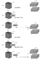
例えば、図1に示すように、このような印刷装置Pで連続的に複数枚の被印刷媒体の印刷を開始(S11)すると、印刷装置は1枚目のラベルL1の印刷終了時点で待機(S12)し、印刷された1枚目のラベルL1を作業者が取る(S13)と、印刷装置は2枚目のラベルL2の印刷を開始(S14)する。そして、作業者が1枚目のラベルL1を商品S等に貼っている作業中に、印刷装置が2枚目のラベルL2の印刷終了時点でまた待機(S15)する、ということが繰り返される。 For example, as shown in FIG. 1, when printing of a plurality of sheets to be printed is continuously started (S11) by such a printing device P, the printing device waits at the end of printing of the first label L1 (S11). S12), and when the operator takes the printed first label L1 (S13), the printing apparatus starts printing the second label L2 (S14). Then, while the worker is affixing the first label L1 to the product S or the like, the printing apparatus waits (S15) again at the end of printing the second label L2, which is repeated.
例えば、図2(a)に示すように、印刷装置が印刷する印刷時間よりも、作業者が印刷された被印刷媒体を商品等に貼っている作業時間の方が長い場合には、印刷装置が印刷を待機することとなる。これに対し、図2(b)に示すように、作業者の作業時間よりも印刷装置の印刷時間の方が長い場合には、作業者は印刷が終了するまで待機しなければならず、作業者の待機時間が長くなり、作業者(ユーザ)の作業の効率化が図れないという問題があった。 For example, as shown in FIG. 2A, when the working time of the worker sticking the printed medium to be printed on the product or the like is longer than the printing time of the printing device, the printing device. Will wait for printing. On the other hand, as shown in FIG. 2B, when the printing time of the printing device is longer than the working time of the worker, the worker has to wait until the printing is completed, and the work There is a problem that the waiting time of the worker becomes long and the work efficiency of the worker (user) cannot be improved.
以上のような実情を踏まえ、本発明の一側面に係る目的は、複数枚の被印刷媒体を連続で印刷する場合に、ユーザの待機時間に応じて印刷時間を調整することである。 Based on the above circumstances, an object of one aspect of the present invention is to adjust the printing time according to the waiting time of the user when printing a plurality of sheets to be printed in succession.
本発明の一態様に係る印刷装置は、被印刷媒体に連続して印刷を行う印刷部と、印刷速度が異なる複数の印刷モードに基づき、前記印刷部による印刷を制御する制御部と、を備え、前記制御部は、前記被印刷媒体への印刷が終了してから、前記印刷された被印刷媒体がユーザによりカットされるまでの時間を印刷の待機時間として計測し、計測された前記待機時間に応じて、前記複数の印刷モードのうち前記被印刷媒体への印刷時の印刷モードと印刷速度が異なる印刷モードに切り替える。 The printing apparatus according to one aspect of the present invention includes a printing unit that continuously prints on a printing medium, and a control unit that controls printing by the printing unit based on a plurality of printing modes having different printing speeds. The control unit measures the time from the end of printing on the printable medium until the printed printout medium is cut by the user as the print standby time, and the measured standby time is measured. The printing mode is switched to a printing mode in which the printing speed is different from that at the time of printing on the printing medium among the plurality of printing modes.
本発明の一態様に係る印刷装置の印刷制御方法は、印刷装置の印刷制御方法であって、前記印刷装置は、被印刷媒体に連続して印刷を行う印刷部を備え、印刷速度が異なる複数の印刷モードに基づき、前記印刷部による印刷を制御し、前記被印刷媒体への印刷が終了してから、前記印刷された被印刷媒体がユーザによりカットされるまでの時間を印刷の待機時間として計測し、計測された前記待機時間に応じて、前記複数の印刷モードのうち前記被印刷媒体への印刷時の印刷モードと印刷速度が異なる印刷モードに切り替える。 The printing control method of the printing apparatus according to one aspect of the present invention is the printing control method of the printing apparatus, wherein the printing apparatus includes a printing unit that continuously prints on a printing medium and has a plurality of different printing speeds. Based on the print mode of, the time from when the printing by the printing unit is controlled and the printing on the printing medium is completed until the printed printing medium is cut by the user is set as the waiting time for printing. It is measured, and the printing mode is switched to a printing mode in which the printing speed is different from the printing mode at the time of printing on the printing medium among the plurality of printing modes according to the measured waiting time.
本発明の一態様に係るプログラムは、印刷装置のコンピュータに実行させるプログラムであって、前記印刷装置は、被印刷媒体に連続して印刷を行う印刷部を備え、前記コンピュータに、印刷時間が異なる複数の印刷モードに基づき、前記印刷部による印刷を制御させ、前記被印刷媒体への印刷が終了してから、前記印刷された被印刷媒体がユーザによりカットされるまでの時間を印刷の待機時間として計測させ、計測された前記待機時間に応じて、前記複数の印刷モードのうち前記被印刷媒体への印刷時の印刷モードと印刷時間が異なる印刷モードに切り替えさせる。 The program according to one aspect of the present invention is a program to be executed by a computer of a printing apparatus, and the printing apparatus includes a printing unit that continuously prints on a printing medium, and the printing time differs depending on the computer. Based on a plurality of print modes, printing by the printing unit is controlled, and the time from the end of printing on the printed medium to the time when the printed printed medium is cut by the user is the waiting time for printing. was measured as in accordance with the measured the waiting time, the printing mode and the printing time when printing on the print medium among the plurality of print modes to switch to a different print modes.
上記の態様によれば、複数枚の被印刷媒体を連続で印刷する場合に、ユーザの待機時間に応じて印刷時間を調整することができる。 According to the above aspect, when printing a plurality of sheets to be printed continuously, the printing time can be adjusted according to the waiting time of the user.
[第1の実施形態]
図3は、第1の実施形態に係る印刷装置を含む印刷システムの構成を例示した図である。図4は、印刷装置1の開閉蓋3を開放した状態の斜視図である。図3に示す印刷システムは、印刷装置1と、印刷装置1へ印刷データを送信する電子機器100と、を含んでいる。印刷装置1と電子機器100は、無線通信または有線通信でデータをやり取りする。印刷装置1は、被印刷媒体に連続して印刷する印刷装置である。本実施形態においては、印刷された被印刷媒体を切断(カット)することで、1つのラベルが形成される。
[First Embodiment]
FIG. 3 is a diagram illustrating the configuration of a printing system including the printing apparatus according to the first embodiment. FIG. 4 is a perspective view showing a state in which the opening / closing lid 3 of the printing device 1 is opened. The printing system shown in FIG. 3 includes a printing device 1 and an
なお、本実施形態において、被印刷媒体M(印刷テープ)の搬送される方向を「搬送方向X」とし、この搬送方向Xに直交する被印刷媒体M(印刷テープ)の幅方向を「媒体幅方向Y」とする。これらX方向、及びY方向は、互いに直交する。
印刷装置1は、被印刷媒体に印刷を行うサーマルヘッド(印刷部)を備える印刷装置であり、例えば、長尺な帯状の被印刷媒体Mに、シングルパス方式で印刷を行うラベルプリンタである。図5は、印刷装置1に使用される被印刷媒体Mを媒体幅方向Yから見た断面図である。被印刷媒体Mは、例えば、基材Bと、基材Bに塗布された粘着材A(のり面)と、粘着材Aを介して基材Bに対し剥離可能に貼り付けられた剥離紙Fと、を有する長尺状のテープ部材である。なお、被印刷媒体Mは、剥離紙Fなしの長尺状のテープ部材であってもよい。
In the present embodiment, the transport direction of the print medium M (printing tape) is defined as the “convey direction X”, and the width direction of the print medium M (print tape) orthogonal to the transport direction X is the “medium width”. Direction Y ”. These X and Y directions are orthogonal to each other.
The printing device 1 is a printing device including a thermal head (printing unit) that prints on a printing medium, and is, for example, a label printer that prints on a long strip-shaped printing medium M by a single-pass method. FIG. 5 is a cross-sectional view of the printing medium M used in the printing apparatus 1 as viewed from the medium width direction Y. The printing medium M is, for example, a base material B, an adhesive material A (glue surface) applied to the base material B, and a release paper F releasably attached to the base material B via the adhesive material A. It is a long tape member having and. The printing medium M may be a long tape member without the release paper F.
図3、図4に示すように、印刷装置1は、装置筐体2と、この装置筐体2に開閉自在に取り付けられた開閉蓋3を備える。図2に示すように、装置筐体2は、内部にテープカセット30を収納するカセット収納部19を備えている。カセット収納部19の詳細については後述する。
装置筐体2の上面には、電源ボタン25の他、各種操作を行う操作ボタン26a,26b,26c(以下、「操作ボタン26」と呼ぶ)、被印刷媒体Mを後述のハーフカット装置16(図9参照)またはフルカット装置17(図9参照)で切断させるカットボタン27等が配置されている。
外部電源D(図9参照)が接続されている状態(即ちACアダプタ接続状態)で電源ボタン25が押下されると、電源回路40(図9参照)に信号が送られて印刷装置1の電源がONになる。そして、電源がONの状態で、再び電源ボタン25が押下されると、電源回路40に信号が送られて印刷装置1の電源がOFFになる。また、操作ボタン26が押下されると、制御回路5(図9参照)に信号が送られて、各ボタンに応じた処理が行われる。また、カットボタン27が押下されると、制御回路(図9参照)に信号が送られて、ハーフカット装置16またはフルカット装置17により被印刷媒体Mに対し、ハーフカットまたはフルカットによる切断(カット)が行われる。
また、図示しないが、装置筐体2には、電源コード接続端子、外部機器接続端子、記憶媒体挿入口等が設けられている。なお、印刷装置1が電池等の内部電源で動作するものである場合には、電源コード接続端子はなくてもよい。また、印刷装置1がパーソナルコンピュータや各種の端末装置等の外部機器との接続を行わずに使用できるものである場合や、外部機器と無線で接続可能に構成されている場合には、外部機器接続端子を備えていなくてもよい。
As shown in FIGS. 3 and 4, the printing apparatus 1 includes an apparatus housing 2 and an opening / closing lid 3 that is openably and closably attached to the apparatus housing 2. As shown in FIG. 2, the apparatus housing 2 includes a
On the upper surface of the device housing 2, in addition to the
When the
Further, although not shown, the device housing 2 is provided with a power cord connection terminal, an external device connection terminal, a storage medium insertion port, and the like. If the printing device 1 operates on an internal power source such as a battery, the power cord connection terminal may not be provided. Further, when the printing device 1 can be used without being connected to an external device such as a personal computer or various terminal devices, or when it is configured to be wirelessly connectable to the external device, the external device It does not have to have a connection terminal.
開閉蓋3は、カセット収納部19の上部を覆うように開閉可能に配置されている。
また、開閉蓋3には、この開閉蓋3が閉じた状態でもカセット収納部19にテープカセット30(図6参照)が収納されているか否かを目視で確認可能とするために、窓3aが形成されている。
また、装置筐体2の側面であって、被印刷媒体Mの搬送方向Xの下流側に位置する部分には、排出口2aが形成されている。印刷装置1内でサーマルヘッド10による印刷が行われた被印刷媒体Mは、排出口2aから装置外へ排出される。
The opening / closing lid 3 is arranged so as to be openable / closable so as to cover the upper part of the
Further, the opening / closing lid 3 has a
Further, a
図6は、印刷装置1に収納されるテープカセット30の斜視図である。図7は、印刷装置1のカセット収納部19の斜視図である。図8は、印刷装置1の本実施形態に係る要部断面図である。図6に示すテープカセット30は、図7に示すカセット収納部19に着脱して交換可能に収納される。図8には、テープカセット30がカセット収納部19に収納された状態が示されている。
FIG. 6 is a perspective view of the
テープカセット30は、図6に示すように、サーマルヘッド被挿入部36及び係合部37が形成された、被印刷媒体MとインクリボンRを収容するカセットケース31を有する。カセットケース31には、テープコア32とインクリボン供給コア34とインクリボン巻取りコア35が設けられている。被印刷媒体Mは、カセットケース31内部のテープコア32にロール状に巻かれている。また、熱転写用のインクリボンRは、その先端がインクリボン巻取りコア35に巻きつけられた状態で、カセットケース31内部のインクリボン供給コア34にロール状に巻かれている。
As shown in FIG. 6, the
装置筐体2のカセット収納部19には、図7に示すように、テープカセット30を所定の位置で支持するための複数のカセット受け部20が設けられている。
As shown in FIG. 7, the
カセット収納部19には、更に、複数の発熱素子を有し、被印刷媒体Mに印刷を行うサーマルヘッド10と、被印刷媒体Mを搬送する搬送機構であるプラテンローラ21と、テープコア係合軸22と、インクリボン巻取り駆動軸23が設けられている。更に、サーマルヘッド10には、サーミスタ13が埋め込まれている。サーミスタ13は、サーマルヘッド10の温度を測定するヘッド温度測定部である。
The
テープカセット30がカセット収納部19に収納された状態では、図8に示すように、カセットケース31に設けられた係合部37がカセット収納部19に設けられたカセット受け部20に支持されて、サーマルヘッド10がカセットケース31に形成されたサーマルヘッド被挿入部36に挿入される。また、テープコア係合軸22には、テープカセット30のテープコア32が係合し、更に、インクリボン巻取り駆動軸23には、インクリボン巻取りコア35が係合する。
In a state where the
印刷装置1に印刷開始の指示が入力されると、被印刷媒体Mは、プラテンローラ21の回転によりテープコア32から繰り出される。この際、インクリボン巻取り駆動軸23がプラテンローラ21に同調して回転することで、被印刷媒体MとともにインクリボンRがインクリボン供給コア34から繰り出される。これにより、被印刷媒体MとインクリボンRは重なった状態で搬送される。そして、サーマルヘッド10とプラテンローラ21の間を通過する際にインクリボンRがサーマルヘッド10によって加熱されることで、インクが被印刷媒体Mに転写され、印刷が行われる。
When an instruction to start printing is input to the printing apparatus 1, the printing medium M is fed out from the
サーマルヘッド10とプラテンローラ21の間を通過した使用済みのインクリボンRは、インクリボン巻取りコア35に巻き取られる。一方、サーマルヘッド10とプラテンローラ21の間を通過した印刷済みの被印刷媒体Mは、ハーフカット装置16またはフルカット装置17で切断され、1つのラベルとして排出口2aから排出される。
The used ink ribbon R that has passed between the
図9は、印刷装置1と電子機器100のハードウェア構成を示したブロック図である。印刷装置1は、上述のサーマルヘッド10、サーミスタ13、ハーフカット装置16、フルカット装置17、プラテンローラ21、操作ボタン26、カットボタン27に加えて、制御回路5、ROM(Read Only Memory)6、RAM(Random Access Memory)7、通信インターフェース(IF)8、ヘッド駆動回路9、搬送用モータ駆動回路11(搬送装置)、ステッピングモータ12、カッターモータ駆動回路14、カッターモータ15、及び、電源回路40を備える。なお、少なくとも制御回路5、ROM6、及びRAM7は、印刷装置1のコンピュータを構成する。
FIG. 9 is a block diagram showing a hardware configuration of the printing device 1 and the
制御回路5は、例えばCPU(Central Processing Unit)などのプロセッサ5aを含む。制御回路5は、ROM6に記憶されているプログラムをRAM7に展開し実行することで、印刷装置1の各部の動作を制御する。
The
制御回路5は、例えば、制御信号(ストローブ信号、ラッチ信号、クロック信号)と印刷データをヘッド駆動回路9へ供給し、ヘッド駆動回路9を介してサーマルヘッド10を制御する。また、制御回路5は、モータ駆動回路(搬送用モータ駆動回路11、カッターモータ駆動回路14)を介してモータ(ステッピングモータ12、カッターモータ15)を制御する。
The
制御回路5は、印刷速度が異なる複数の印刷モードに基づき、サーマルヘッド10による印刷を制御する。図10は、第1の実施形態の印刷モードを説明する図である。図10に示すように、印刷装置1は複数の印刷モードを有し、第1の実施形態においては、5つの印刷モードを有する。各印刷モードには、印刷解像度、印刷時間が設定されており、印刷解像度が高い印刷モードほど、印刷時間が長く設定されている。これに対し、印刷時間が早い印刷モードほど、印刷解像度が低く設定されている。すなわち、印刷装置1は、印刷時間と印刷解像度とがそれぞれ反比例する複数の印刷モードを有する。
印刷モードは、初期状態では標準モードに設定されている。制御回路5により印刷モードが高速に切り替えられた場合には、現在の印刷モード(最後に被印刷媒体Mに印刷した際の印刷モード)よりも1段階高速な印刷モードに設定される。例えば、現在の印刷モードが標準モードである場合には、印刷モードは高速モード(エコモード)に切り替えられる。これに対し、制御回路5により印刷モードが高精細に切り替えられた場合には、現在の印刷モードよりも1段階高精細な印刷モードに設定される。例えば、現在の印刷モードが標準モードである場合には、印刷モードは高精細(低速モード)に切り替えられる。
The
The print mode is set to the standard mode in the initial state. When the print mode is switched at high speed by the
制御回路5は、被印刷媒体Mへの印刷が終了してから、印刷された被印刷媒体Mが作業者(ユーザ)によりカットされるまでの時間を印刷の待機時間(以下、「印刷装置1の待機時間」と称する)として計測する。具体的には、搬送用モータ駆動回路11による被印刷媒体Mの搬送が停止した場合には、被印刷媒体Mへの印刷が終了したと見做して、印刷装置1の待機時間の計測を開始する。そして、被印刷媒体Mがハーフカット装置16またはフルカット装置17により切断された場合には、被印刷媒体Mが作業者によりカットされたと見做して、印刷装置1の待機時間の計測を停止する。すなわち、制御回路5は、搬送用モータ駆動回路11による被印刷媒体Mの搬送が停止してから、被印刷媒体Mがハーフカット装置16またはフルカット装置17により切断(カット)されるまでの時間を印刷装置1の待機時間として計測する。
The
そして、制御回路5は、計測された印刷装置1の待機時間に応じて、複数の印刷モードのうち現在の印刷モードと印刷速度が異なる印刷モードに切り替える。例えば、制御回路5は、計測された印刷装置1の待機時間が所定の時間未満である場合には、現在の印刷モードよりも印刷速度が速い印刷モードに切り替える。具体的には、制御回路5は、印刷装置1の待機時間が3秒(第1の時間)未満である場合が2回(第3の回数)以上となった場合には、複数の印刷モードのうち、現在の印刷モードよりも印刷速度が速い印刷モードに切り替える。
Then, the
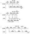
図11は、印刷装置1の印刷時間と、作業者の作業時間との関係を例示した図である。第1の実施形態において、印刷装置1の印刷時間とは、サーマルヘッド10により印刷が開始されてから、搬送用モータ駆動回路11による被印刷媒体Mの搬送が停止するまでの時間をいう。
作業者の作業時間とは、印刷された被印刷媒体Mを作業者が印刷装置1から取ってから、その被印刷媒体Mを商品等に貼った後カットボタン27を押下して被印刷媒体Mがハーフカット装置16またはフルカット装置17により切断されるまでの時間をいう。
作業者の作業時間よりも印刷装置1の印刷時間の方が長い場合には、作業者は印刷が終了するまで作業を待機することとなる。
また、図11(a)に示すように、印刷装置1の印刷時間と、作業者の作業時間とがほぼ同じ時間の場合には、作業者の作業スキルが向上することにより作業者の作業時間が早くなることを見越すと、作業者の作業時間よりも印刷装置1の印刷時間の方が長くなることも考えられる。この場合も、作業者は印刷が終了するまで作業を待機することとなる。
作業を待機していた作業者はすぐに作業に移行すると考えられるため、印刷装置1の待機時間が発生する前に、カットボタン27を押下して、被印刷媒体Mを印刷装置1から取ると推測される。この場合、印刷装置1は、作業者がすぐに作業に移行できるよう1段階印刷速度が速い高速の印刷モードに切り替える。図11(a)の例では、1枚目、2枚目の印刷時間を100%とした場合、印刷装置1は、印刷モードを高速の印刷モードに切り替えることで、3枚目の印刷時間を75%に短縮している。その結果、作業者の作業時間よりも印刷装置1の印刷時間を短くすることができる。
FIG. 11 is a diagram illustrating the relationship between the printing time of the printing apparatus 1 and the working time of the operator. In the first embodiment, the printing time of the printing apparatus 1 means the time from the start of printing by the
The working time of the worker means that the worker takes the printed medium M to be printed from the printing device 1, attaches the printed medium M to a product or the like, and then presses the
If the printing time of the printing device 1 is longer than the working time of the worker, the worker waits for the work until the printing is completed.
Further, as shown in FIG. 11A, when the printing time of the printing device 1 and the working time of the worker are substantially the same time, the working time of the worker is improved by improving the working time of the worker. It is conceivable that the printing time of the printing apparatus 1 will be longer than the working time of the operator in anticipation of the faster operation. In this case as well, the worker waits for the work until the printing is completed.
Since it is considered that the worker who has been waiting for the work immediately shifts to the work, if the
図11(b)に示すように、印刷装置1が、1段階印刷速度が速い高速の印刷モードに切り替えたにもかかわらず、作業者の作業時間よりも印刷装置の印刷時間の方が依然として長い場合がある。この場合、印刷装置1は、更に1段階印刷速度が速い高速の印刷モードに切り替える。図11(b)の例では、1枚目、2枚目の印刷時間を100%とした場合、印刷装置1は、印刷モードを高速の印刷モードに切り替えることで、3枚目の印刷時間を75%に短縮している。更に、印刷装置1は、印刷モードを高速の印刷モードに切り替えることで、4枚目の印刷時間を50%に短縮している。その結果、複数回印刷時間を短縮することで、作業者の作業時間よりも印刷装置1の印刷時間を短くすることができる。 As shown in FIG. 11B, even though the printing apparatus 1 has switched to the high-speed printing mode in which the one-step printing speed is high, the printing time of the printing apparatus is still longer than the working time of the operator. In some cases. In this case, the printing device 1 switches to a high-speed printing mode in which the printing speed is further increased by one step. In the example of FIG. 11B, when the printing time of the first and second sheets is 100%, the printing device 1 switches the printing mode to the high-speed printing mode to reduce the printing time of the third sheet. It has been shortened to 75%. Further, the printing apparatus 1 reduces the printing time of the fourth sheet to 50% by switching the printing mode to the high-speed printing mode. As a result, by shortening the printing time a plurality of times, the printing time of the printing device 1 can be shorter than the working time of the operator.
これにより、作業者の作業時間と印刷装置1の印刷時間がほぼ同じ時間の場合や、作業者の作業時間よりも印刷装置1の印刷時間の方が長い場合であっても、印刷装置1の印刷時間を作業者の作業時間よりも短くすることにより、作業者の待機時間を減少または、ほぼゼロにすることができる。その結果、作業者は印刷が終了するまで待機することなく作業者はすぐに作業に移行できることから、作業者の作業の効率化を図ることができる。 As a result, even when the working time of the worker and the printing time of the printing device 1 are substantially the same, or when the printing time of the printing device 1 is longer than the working time of the worker, the printing device 1 can be used. By making the printing time shorter than the working time of the worker, the waiting time of the worker can be reduced or almost zero. As a result, the worker can immediately shift to the work without waiting until the printing is completed, so that the work efficiency of the worker can be improved.
また、制御回路5は、印刷装置1の待機時間が3秒(第1の時間)より長い6秒(第2の時間)以上である場合が4回(第4の回数)以上となった場合には、解像度が高い印刷モードに切り替える。例えば、図11(c)に示すように、印刷装置1が印刷する印刷時間よりも、作業者の作業時間の方が長い場合には、印刷装置1が印刷を待機することとなる。
Further, the
この場合は、印刷装置1は、作業者が作業を終了するまで待機しなければならず、印刷装置1の待機時間を有効に活用できないため、印刷装置1は、印刷モードを1段階高精細な印刷モードに切り替える。
例えば、図11(c)の例では、2枚目の印刷時間後の印刷装置1の待機時間を100%とした場合、印刷装置1は、印刷モードを高精細の印刷モードに切り替えることで、3枚目の印刷時間後の印刷装置1の待機時間を50%に短縮している。これにより、印刷装置の印刷時間よりも作業者の作業時間の方が長い場合には、印刷装置1の待機時間を有効に利用して、解像度が高い印刷モードで印刷することにより、印刷機能を十分に発揮して印刷を行うことができる。
In this case, the printing device 1 has to wait until the worker finishes the work, and the waiting time of the printing device 1 cannot be effectively utilized. Therefore, the printing device 1 sets the printing mode to one step higher definition. Switch to print mode.
For example, in the example of FIG. 11C, when the standby time of the printing device 1 after the printing time of the second sheet is set to 100%, the printing device 1 switches the printing mode to the high-definition printing mode. The standby time of the printing apparatus 1 after the printing time of the third sheet is shortened to 50%. As a result, when the working time of the operator is longer than the printing time of the printing device, the waiting time of the printing device 1 can be effectively used to print in a print mode having a high resolution, thereby providing a printing function. It is possible to fully demonstrate and print.
ROM6は、被印刷媒体Mに印刷を行う印刷プログラム、印刷プログラムの実行に必要な各種データ(例えば、フォント等)を記憶する。ROM6は、制御回路5によって読取り可能なプログラムが記憶された記憶媒体としても機能する。ROM6は、電源OFF時にもデータを保持して記憶できるフラッシュメモリにより構成されている。ROM6は、電源OFF時には、最後に設定されていた印刷モードを一時的に記憶することもできる。RAM7は、印刷内容のパターンを示すデータ(以降、印刷データと記す)を記憶する印刷データ記憶部を含む。RAM7は、表示データを記憶する表示データ記憶部を含む。通信インターフェース8は、有線通信または無線通信により外部装置(例えば、電子機器100)や外部サーバの記憶装置との間でデータを授受する。また、RAM7には、後述の高速カウンタ及び高精細カウンタが格納されている。高速カウンタは、後述の印刷モード切替処理において、印刷装置1の待機時間が3秒未満である場合に加算されるカウンタである。高精細カウンタは、後述の印刷モード切替処理において、印刷装置1の待機時間が6秒以上である場合に加算されるカウンタである。
The ROM 6 stores a print program for printing on the print medium M and various data (for example, fonts and the like) necessary for executing the print program. The ROM 6 also functions as a storage medium in which a program readable by the
ヘッド駆動回路9は、制御回路5から供給された制御信号と印刷データに基づいてサーマルヘッド10を駆動する。サーマルヘッド10は、主走査方向に配列された複数の発熱素子10aを有する印刷ヘッドである。ヘッド駆動回路9が、制御回路5から供給されたストローブ信号により指定される通電期間中に、ヘッド駆動回路9から出力された印刷データに応じて複数の発熱素子10aの何れかへ電流を選択的に流すことで、複数の発熱素子10aの何れかが発熱してインクリボンRを加熱する。これにより、サーマルヘッド10は、熱転写により被印刷媒体Mに1ラインずつ印刷を行う。即ち、印刷装置1は、サーマルラインプリンタである。
The head drive circuit 9 drives the
搬送用モータ駆動回路11は、ステッピングモータ12を駆動する。ステッピングモータ12は、プラテンローラ21を回転させる。プラテンローラ21は、ステッピングモータ12の動力によって回転し、被印刷媒体Mの長手方向(副走査方向)に被印刷媒体Mを搬送する搬送機構である。
The transport
カッターモータ駆動回路14は、カットボタン27の押下を契機として、カッターモータ15を駆動する。ハーフカット装置16及びフルカット装置17は、カッターモータ15の動力によって動作し、被印刷媒体Mをハーフカットまたはフルカットにより切断する。フルカットとは、被印刷媒体Mの基材Bを剥離紙Fとともに幅方向に沿って切断する動作のことであり、ハーフカットは、基材Bのみを幅方向に沿って切断する動作のことである。電源回路40は、外部電源Dからの直流電圧(例えば、24V)から出力電圧を生成し、印刷装置1の各部に電力を供給する電源部である。
The cutter
電子機器100は、図3及び図9に示すように、表示装置101と入力装置102を備える、例えば、スマートフォン、タブレット端末などの携帯型のコンピュータである。表示装置101は、例えば、液晶ディスプレイであっても、有機エレクトロルミネッセンス(有機EL)ディスプレイであってもよい。入力装置102は、例えば、タッチパネルである。
As shown in FIGS. 3 and 9, the
電子機器100は、上記の構成に加えて、表示部駆動装置103、通信インターフェース(IF)104、ROM105、RAM106、制御回路107を備える。表示部駆動装置103は、例えば、液晶表示ドライバ回路、有機EL表示ドライバ回路である。制御回路107は、プロセッサ108を備える。プロセッサ108は、演算部であり、アプリケーションプログラムを実行することで、印刷装置1から送られてきたメッセージを表示装置101に表示したり、入力装置102に対する利用者のタッチ操作を受け付けたりする。
In addition to the above configuration, the
図12は、第1の実施形態の印刷モード切替処理のフローチャートである。
印刷モード切替処理では、被印刷媒体Mへの印刷が終了してから、印刷された被印刷媒体Mがハーフカット装置16またはフルカット装置17により切断されるまでの印刷装置1の待機時間に応じて、印刷モードを切り替える処理が行われる。
印刷モード切替処理を行うにあたり、工場出荷状態においては、制御回路5は、印刷モードを標準モードに設定する。ROM6に標準モード以外の印刷モードが設定されている場合には、制御回路5は、電源ON時に、ROM6に記憶されている印刷モードをRAM7に呼び出して設定する。なお、ROM6に標準モード以外の印刷モードが記憶されている場合とは、後述のステップS109またはステップS115により印刷モードが切り替えられた状態を示す。
FIG. 12 is a flowchart of the print mode switching process of the first embodiment.
In the print mode switching process, depending on the waiting time of the printing device 1 from the completion of printing on the printing medium M to the cutting of the printed printing medium M by the half-
In performing the print mode switching process, the
印刷装置1は、印刷開始の指示に基づき、図12に示す印刷モード切替処理を開始する。印刷モード切替処理では、制御回路5は、まず、サーマルヘッド10をONとし、ステッピングモータ12をONとする。これにより、プラテンローラ21が搬送方向に回転し、被印刷媒体Mの搬送が開始され、印刷データに基づいて被印刷媒体Mへの印刷が開始される(ステップS101)。
制御回路5は、被印刷媒体Mへの印刷が終了したか否かを判定する(ステップS102)。この処理では、搬送用モータ駆動回路11による被印刷媒体Mの搬送が停止することにより、被印刷媒体Mへの印刷が終了したか否かが判定される。なお、印刷が終了したか否かの判定は、搬送用モータ駆動回路11の搬送が停止したか否かに基づくものに限られず、例えば印刷データに基づく印刷が終了し、サーマルヘッド10がOFFにされたことに基づいて、印刷が終了したか判定することもできる。
The printing device 1 starts the printing mode switching process shown in FIG. 12 based on the instruction to start printing. In the print mode switching process, the
The
印刷が終了していない場合(ステップS102のNO)には、印刷が終了するまで印刷モード切替処理は待機状態となり、印刷が終了した場合(ステップS102のYES)には、制御回路5は、印刷装置1の待機時間のカウントを開始する(ステップS103)。
When printing is not completed (NO in step S102), the print mode switching process is in a standby state until printing is completed, and when printing is completed (YES in step S102), the
制御回路5は、作業者によりカットボタン27が押下され、被印刷媒体Mがハーフカットまたはフルカットにより切断されたか否かを判定する(ステップ104)。この処理では、制御回路5は、作業者の操作に基づき、印刷装置1のカットボタン27に対する操作を受け付けたか否かを判定する。カットボタン27に対する操作を判定することで、被印刷媒体Mがハーフカットまたはフルカットにより切断されたか否かが判定される。被印刷媒体Mが切断されていない場合(ステップS104のNO)には、被印刷媒体Mが切断されるまで印刷モード切替処理は待機状態となる。
The
被印刷媒体Mが切断された場合(ステップS104のYES)には、制御回路5は、被印刷媒体Mが作業者によりカットされたと見做して、カウントを開始した印刷装置1の待機時間が3秒(第1の時間)未満であるか否かを判定する(ステップS105)。この処理では、制御回路5は、印刷装置1が印刷を終了してから、印刷された被印刷媒体Mが作業者によりすぐにカットされたか否か、すなわち、被印刷媒体Mの印刷終了を作業者が待機していた状態であるか否かを判定する。本実施形態においては、印刷装置1の待機時間は3秒に設定されているが、作業者の作業速度に応じて、3秒の印刷装置1の待機時間を任意の時間に設定することができる。
印刷装置1の待機時間が3秒未満である場合(ステップS105のYES)には、制御回路5は、高精細カウンタを初期化する(ステップS106)。
When the print medium M is cut (YES in step S104), the
When the standby time of the printing device 1 is less than 3 seconds (YES in step S105), the
制御回路5は、高速カウンタに1加算し(ステップS107)、加算された結果、高速カウンタの値が2以上になったか否かが判定される(ステップS108)。この処理では、制御回路5は、印刷装置1の待機時間が3秒未満、すなわち、作業者が作業を待機していた状態が2回以上あったか否かを判定する。本実施形態においては、高速カウンタの値は2以上になったか判定しているがこの限りではなく、頻繁に印刷モードを変更したくない場合には、高速カウンタの値の判定を2以上の任意の値に設定することもできる。高速カウンタの値が2以上になっていない場合(ステップS108のNO)、すなわち、印刷装置1の待機時間が3秒未満となった回数が2回未満である場合には、処理はステップS117に進む。
The
高速カウンタの値が2以上になった場合(ステップS108のYES)、すなわち、印刷装置1の待機時間が3秒未満となった回数が2回以上となった場合には、制御回路5は印刷モードを現在の印刷モードよりも高速の印刷モードに切り替える(ステップS109)。例えば、現在の印刷モードが標準モードである場合には、制御回路5は、印刷モードを、1段階印刷速度が高速な印刷モードである、高速モード(エコモード)(図10参照)に切り替える。また、現在の印刷モードが高速モード(エコモード)(図10参照)である場合には、制御回路5は、印刷モードを、更に1段階印刷速度が高速な印刷モードである、超高速モード(超エコモード)(図10参照)に切り替える。制御回路5は、高速カウンタの値を初期化(ステップS110)し、ステップS117の処理へ進む。
When the value of the high-speed counter becomes 2 or more (YES in step S108), that is, when the number of times the standby time of the printing device 1 becomes less than 3 seconds becomes 2 or more, the
印刷装置1の待機時間が3秒以上である場合(ステップS105のNO)には、制御回路5は、カウントを開始した印刷装置1の待機時間が6秒(第2の時間)以上であるか否かを判定する(ステップS111)。この処理では、制御回路5は、印刷装置1が印刷を終了してから、印刷された被印刷媒体Mが作業者によりすぐにカットされなかったか否か、すなわち、作業者の作業が終了することを印刷装置1が待機していた状態であるか否かを判定する。本実施形態においては、印刷装置1の待機時間は6秒に設定されているが、作業者の作業速度に応じて、6秒の印刷装置1の待機時間を任意の時間に設定することができる。
印刷装置1の待機時間が6秒以上である場合(ステップS111のYES)には、制御回路5は、高速カウンタを初期化する(ステップS112)。
When the standby time of the printing device 1 is 3 seconds or more (NO in step S105), does the
When the standby time of the printing device 1 is 6 seconds or more (YES in step S111), the
制御回路5は、高精細カウンタに1加算し(ステップS113)、加算された結果、高精細カウンタの値が4以上になったか否かが判定される(ステップS114)。この処理では、制御回路5は、印刷装置1の待機時間が6秒以上、すなわち、印刷された被印刷媒体Mを作業者が6秒以上取らなかった回数が4回以上あったか否かを判定する。本実施形態においては、高精細カウンタの値は4以上になったか判定しているがこの限りではなく、頻繁に印刷モードを変更したくない場合には、高精細カウンタの値の判定を4以外の任意の値に設定することもできる。高精細カウンタの値が4以上になっていない場合(ステップS114のNO)、すなわち、印刷装置1の待機時間が6秒以上となった回数が4回未満である場合には、処理はステップS117に進む。
The
高精細カウンタの値が4以上になった場合(ステップS114のYES)、すなわち、印刷装置1の待機時間が6秒以上となった回数が4回以上となった場合には、制御回路5は印刷モードを現在の印刷モードよりも高精細な印刷モードに切り替える(ステップS115)。例えば、現在の印刷モードが標準モードである場合には、制御回路5は、現在の印刷モードを、1段階高精細な印刷モードである、高精細モード(低速モード)(図10参照)に切り替える。また、現在の印刷モードが高精細モード(低速モード)(図10参照)である場合には、制御回路5は、印刷モードを、更に1段階印刷速度が高精細な印刷モードである、超高精細モード(超低速モード)(図10参照)に切り替える。制御回路5は、高精細カウンタの値を初期化(ステップS116)し、ステップS117の処理へ進む。
When the value of the high-definition counter becomes 4 or more (YES in step S114), that is, when the number of times the standby time of the printing device 1 becomes 6 seconds or more becomes 4 times or more, the
印刷装置1の待機時間が6秒未満である場合(ステップS111のNO)には、制御回路5は、処理はステップS117へ進む。すなわち、印刷装置1の待機時間が3秒以上6秒未満である場合には、印刷装置1の待機時間は、作業者の作業時間及び印刷装置1の印刷時間を考慮した上で、作業者及び印刷装置1の双方にとって、早過ぎず遅過ぎないという最も好ましい時間に設定されている。したがって、制御回路5は、現在の印刷モードを変更せずにこのまま維持する。
When the standby time of the printing device 1 is less than 6 seconds (NO in step S111), the
ステップS117において、制御回路5は、連続印刷の対象の全ての被印刷媒体Mが印刷されたか否かを判定する。全ての被印刷媒体Mが印刷されていない場合(ステップS117のNO)には、処理はステップS101へ戻り、全ての被印刷媒体Mが印刷されるまで、ステップS101〜ステップS117の処理が繰り返し実行される。これに対し、全ての被印刷媒体Mが印刷された場合(ステップS117のYES)には、印刷モード切替処理は終了となる。
In step S117, the
印刷モード切替処理が終了し、利用者の操作に基づき電源ボタン25が押下され、電源がOFFにされる時、制御回路5は、現在の印刷モードをROM6に移して一時的に記憶する。ROM6はフラッシュメモリにより形成されているため、電源がOFFにされた場合であっても、現在設定されていた印刷モードは継続して保持される。そして、再び電源ONされた時には、制御回路5は、ROM6に記憶されている印刷モードをRAM7に呼び出して記憶することで、前回作業者が使用していた印刷モードを用いて、印刷モード切替処理を実行することができる。
When the print mode switching process is completed, the
第1の実施形態の印刷装置1では、制御回路5は、被印刷媒体Mへの印刷が終了してから、印刷された被印刷媒体が作業者によりカットされるまでの印刷装置1の待機時間に応じて、複数の印刷モードのうち印刷速度が速い印刷モードに切り替える。これにより、複数枚の被印刷媒体を連続で印刷する場合に、印刷速度が速い印刷モードに切り替えることで、作業者の待機時間を減少することができ、作業の効率化を図ることができる。
In the printing device 1 of the first embodiment, the
また、制御回路5は、印刷装置1の待機時間が第1の時間未満である場合が第3の回数以上となった場合には、複数の印刷モードのうち、印刷速度が速い印刷モードに切り替える。このため、印刷された被印刷媒体Mが作業者によりすぐにカットされたか、または、被印刷媒体Mの印刷終了を作業者が待機していた状態が複数回続いた場合には、すぐに印刷装置1の印刷速度を上げて、作業者の待機時間を減少し、作業の効率化を図ることができる。
Further, when the standby time of the printing device 1 is less than the first time and becomes the third number or more, the
また、第1の実施形態では、制御回路5は、被印刷媒体Mがハーフカット装置16またはフルカット装置17により切断された場合には、被印刷媒体が作業者によりカットされたと見做して、印刷装置1の待機時間を計測する。これにより、作業者が作業を開始するタイミングをハードウェアの変更なしに把握することができ、印刷装置1の待機時間を容易に把握することができる。また、第1の実施形態では、制御回路5は、搬送用モータ駆動回路11による被印刷媒体Mの搬送が停止した場合には、被印刷媒体Mへの印刷が終了したと見做して、印刷装置1の待機時間を計測する。これにより、印刷装置1が待機を開始するタイミングをハードウェアの変更なしに把握することができ、印刷装置1の待機時間を容易に把握することができる。
Further, in the first embodiment, when the print medium M is cut by the half-
第1の実施形態では、制御回路5は、印刷時間と印刷解像度とが反比例する複数の印刷モードに基づきサーマルヘッド10による印刷を制御する。すなわち、作業者の作業時間よりも印刷装置の印刷時間の方が長い場合には、制御回路5は、高速の印刷モードに切り替える。これに対し、印刷装置1が印刷する印刷時間よりも、作業者の作業時間の方が長い場合には、制御回路5は、高精細な印刷モードに切り替える。これにより、作業者の待機時間を減少して作業者の作業の効率化が図れるとともに、印刷装置1の待機時間を有効に利用して、解像度が高い印刷モードで印刷することにより、印刷機能を十分に発揮して印刷を行うことができる。
In the first embodiment, the
第1の実施形態では、制御回路5は、印刷装置1の待機時間が第2の時間以上である場合が第4の回数以上となった場合には、解像度が高い印刷モードに切り替える。このため、印刷された被印刷媒体Mが作業者によりカットされず、または、印刷後に印刷装置1が待機していた状態が複数回続いた場合には、印刷装置1の待機時間を有効に利用して、解像度が高い印刷モードで印刷することにより、印刷機能を十分に発揮して印刷を行うことができる。
In the first embodiment, the
なお、第1の実施形態では、高速カウンタが2以上になった場合に、印刷モードを高速に切り替えているが、印刷装置1の待機時間が3秒(第1の時間)未満となった場合には、すぐに印刷モードを高速に切り替えてもよい。同様に、第1の実施形態では、高精細カウンタが4以上になった場合に、印刷モードを高精細に切り替えているが、印刷装置1の待機時間が6秒(第2の時間)以上となった場合には、すぐに印刷モードを高精細に切り替えてもよい。これにより、作業者の作業速度に即座に対応して印刷速度を変えることができ、作業者の待機時間を減少し、作業の効率化を図ることができる。 In the first embodiment, the print mode is switched at high speed when the high-speed counter becomes 2 or more, but the standby time of the printing device 1 becomes less than 3 seconds (first time). The print mode may be switched at high speed immediately. Similarly, in the first embodiment, when the high-definition counter becomes 4 or more, the print mode is switched to high-definition, but the standby time of the printing device 1 is 6 seconds (second time) or more. If this happens, the print mode may be switched to high definition immediately. As a result, the printing speed can be changed immediately in response to the working speed of the worker, the waiting time of the worker can be reduced, and the work efficiency can be improved.
また、第1の実施形態では、制御回路5は、被印刷媒体Mがハーフカット装置16またはフルカット装置17により切断された場合には、被印刷媒体Mが作業者によりカットされたと見做して、印刷装置1の待機時間の計測を行っているが、この限りではない。例えば、被印刷媒体を排出する排出口2a(図3参照)付近に人感センサ(図示せず)を設け、被印刷媒体Mの印刷後に、人感センサが作業者の身体を検知した場合には、被印刷媒体Mが作業者によりカットされたと見做して印刷装置1の待機時間の計測を行うこともできる。
Further, in the first embodiment, when the print medium M is cut by the half-
また、第1の実施形態においては、制御回路5は、電源OFF時に、フラッシュメモリにより形成されたROM6に印刷モードの情報を一時的に記憶しているがこの限りではない。例えば、制御回路5は、制御回路5は、電源OFF時に、印刷モードの情報を電子機器100のROM105や、外部サーバ上の記憶装置に対し通信IF8を介して記憶することもできる。
Further, in the first embodiment, the
[第2の実施形態]
次に、第2の実施形態について説明する。第2の実施形態の印刷装置1と電子機器100のハードウェア構成については、第1の実施形態と同様であるため、説明を省略する。第1の実施形態においては、被印刷媒体Mへの印刷が終了してから、被印刷媒体への印刷が再度開始されるまでの印刷装置1の待機時間のみに応じて、印刷モードを切り替える処理が行われていた。この点第2の実施形態においては、印刷データに基づき構成される印刷画像を形成するドットが連続する割合が所定の閾値未満である場合には、印刷装置1の待機時間が第1の時間未満である場合が2回(第3の回数)以上となった場合であっても、印刷モードを被印刷媒体への印刷時の印刷モードよりも印刷速度が速い印刷モードに切り替えない点で相違する。
[Second Embodiment]
Next, the second embodiment will be described. Since the hardware configurations of the printing device 1 and the
第2の実施形態の制御回路5は、印刷画像を形成するドットが連続する割合を、印刷画像を構成する黒または白のドットが連続する割合から判断する。黒または白のドットが長く続く割合が所定の閾値未満である場合には、制御回路5は、印刷画像の内容が細かいと判断する。黒または白のドットが長く続く割合が所定の閾値以上である場合には、制御回路5は、印刷画像の内容が粗いと判断する。
The
第2の実施形態の制御回路5は、サーマルヘッド10へ供給される印刷データに基づき構成される印刷画像を形成するドットが連続する割合が所定の閾値以上であるか否かを判定する。そして、ドットが連続する割合が所定の閾値未満である場合には、印刷装置1の待機時間が第1の時間未満である場合が第3の回数以上となった場合であっても、制御回路5は、印刷モードを被印刷媒体への印刷時の印刷モードよりも印刷速度が速い印刷モードに切り替えない点で、第1の実施形態の印刷装置1と相違する。
The
図13は、サーマルヘッド10により印刷される印刷データに基づき構成される印刷画像を例示した図である。図13には、それぞれ印刷画像を構成するドットの粗さが異なる印刷画像の例を示す。
FIG. 13 is a diagram illustrating a printed image formed based on the print data printed by the
図13(a)に示すように、ドットが細かい印刷画像201aの場合には、解像度が低い印刷モードで印刷した場合には、印刷画像201aに含まれるバーコードや、QRコード(登録商標)、細かい文字が鮮明に印刷できない。したがって第2の実施形態では、図13(a)に示すように、黒または白のドットが長く続く割合が所定の閾値未満である場合には、制御回路5は、細かい内容の印刷画像201aと判断する。このような印刷画像201aを印刷する場合には、印刷装置1の待機時間が第1の時間未満である場合が第3の回数以上となった場合であっても、制御回路5は、印刷モードを被印刷媒体への印刷時の印刷モードよりも印刷速度が速い印刷モードに切り替えない。なお、閾値としては、例えば、印刷画面に対し、黒または白のドットが10個続く割合が30%以上であるか否かを採用することができる。
As shown in FIG. 13A, in the case of the printed
また、第2の実施形態の制御回路5は、印刷データに基づき構成される印刷画像を形成するドットが連続する割合が閾値以上である場合には、印刷装置1の待機時間が第2の時間以上である場合が第4の回数以上となった場合であっても、印刷モードを現在の印刷モードよりも解像度が高い印刷モードに切り替えない点で第1の実施形態と相違する。
Further, in the
図13(b)に示すように、ドットが粗い印刷画像201bの場合には、解像度が高い印刷モードで印刷した場合であっても、高速の印刷モードで印刷した場合であっても、印刷画像201bに含まれる文字等の印刷結果に大きな差異は見られない。したがって第2の実施形態では、図13(b)に示すように、黒または白のドットが長く続く割合が所定の閾値以上である場合には、制御回路5は、粗い内容の印刷画像201bと判断する。このような印刷画像201bを印刷する場合には、印刷装置1の待機時間が第2の時間以上である場合が第4の回数以上となった場合であっても、印刷モードを現在の印刷モードよりも解像度が高い印刷モードに切り替えない。
As shown in FIG. 13B, in the case of the
なお、第2の実施形態では、ドットが連続する割合が所定の閾値以上であるか否かに応じて、制御回路5は、印刷モードを印刷速度が速い印刷モードに切り替えないか否かの判断をしているがこれに限られるものではない。例えば、印刷画像にQRコード(登録商標)、バーコード、所定のポイント数以下の文字が含まれるか否かに応じて、印刷モードを印刷速度が速い印刷モードに切り替えないか否かの判断をすることもできる。
例えば、図13(b)の印刷画像201aのように、印刷画像にQRコード(登録商標)が含まれる場合や、図13(c)の印刷画像201cのように、印刷画像にバーコードが含まれる場合には、制御回路5は、細かい内容の印刷画像と判断する。したがって、このような印刷画像201aや印刷画像201cを印刷する場合には、印刷装置1の待機時間が第1の時間未満である場合が第3の回数以上となった場合であっても、制御回路5は、印刷モードを現在の印刷モードよりも印刷速度が速い印刷モードに切り替えないようにすることもできる。
In the second embodiment, the
For example, when the printed image contains a QR code (registered trademark) as in the printed
次に、図14を参照にして、第2の実施形態の印刷モード切替処理について説明する。図14は、第2の実施形態の印刷モード切替処理のフローチャートである。第2の実施形態の印刷モード切替処理は、基本的には図12の第1の実施形態の印刷モード切替処理のフローチャートと同じである。第2の実施形態のステップS201〜S208、S210〜S215、S217〜S219の処理は、第1の実施形態のステップS101〜S108、S109〜S114、S115〜S117の処理と同一であるため、説明を省略し相違点のみ説明する。 Next, the print mode switching process of the second embodiment will be described with reference to FIG. FIG. 14 is a flowchart of the print mode switching process of the second embodiment. The print mode switching process of the second embodiment is basically the same as the flowchart of the print mode switching process of the first embodiment of FIG. The processing of steps S201 to S208, S210 to S215, and S217 to S219 of the second embodiment is the same as the processing of steps S101 to S108, S109 to S114, and S115 to S117 of the first embodiment. Only the differences will be explained by omitting them.
ステップS208において、高速カウンタの値が2以上になった場合(ステップS208のYES)、すなわち、印刷装置1の待機時間が3秒未満となった回数が2回以上となった場合には、制御回路5は印刷データに基づき構成される印刷画像を形成するドットが連続する割合が所定の閾値以上であるか否かを判定する(ステップS209)。
In step S208, when the value of the high-speed counter becomes 2 or more (YES in step S208), that is, when the number of times the standby time of the printing device 1 becomes less than 3 seconds becomes 2 times or more, control is performed. The
ドットが連続する割合が所定の閾値未満である場合(ステップS209のNO)には、処理はステップ219へ進む。例えば、図13(a)に示すように、バーコード、QRコード(登録商標)、細かい文字等、ドットが連続する割合が所定の閾値未満である解像度の高い印刷画像201aを印刷する場合には、文字等が潰れてしまうため高い印刷解像度で印刷する必要がある。したがって、制御回路5は、印刷装置1の印刷時間よりも作業者の作業時間の方が長い場合、すなわち、作業者の待機時間が長い場合であっても、これ以上印刷速度を優先した印刷モードに変更せずに、現在の印刷モードをこのまま維持する。これに対し、ドットが連続する割合が所定の閾値以上である場合(ステップS209のYES)には、制御回路5は印刷モードを現在の印刷モードよりも高速の印刷モードに切り替える(ステップS210)。
このように、印刷データに基づき構成される印刷画像がバーコードや、QRコード(登録商標)、細かい文字等、ドットが連続する割合が所定の閾値以上である解像度の高い印刷画像である場合には、これ以上印刷速度を優先した印刷モードに変更しない。これにより、鮮明に印刷を行うことができる。
When the ratio of continuous dots is less than a predetermined threshold value (NO in step S209), the process proceeds to step 219. For example, as shown in FIG. 13A, when printing a high-resolution printed
In this way, when the print image composed based on the print data is a high-resolution print image such as a barcode, a QR code (registered trademark), fine characters, etc., in which the ratio of continuous dots is equal to or higher than a predetermined threshold value. Does not change to the print mode that prioritizes the print speed any more. As a result, printing can be performed clearly.
ステップS215の説明に移り、高精細カウンタの値が4以上になった場合(ステップS215のYES)、すなわち、印刷装置1の待機時間が6秒以上となった回数が4回以上となった場合には、制御回路5は印刷データに基づき構成される印刷画像を形成するドットが連続する割合が所定の閾値以上であるか否かを判定する(ステップS216)。
Moving on to the description of step S215, when the value of the high-definition counter becomes 4 or more (YES in step S215), that is, when the number of times the standby time of the printing device 1 becomes 6 seconds or more becomes 4 times or more. The
ドットが連続する割合が所定の閾値以上である場合(ステップS216のYES)には、処理はステップ219へ進む。例えば、図13(b)に示すように、大きな文字や数字等、ドットが連続する割合が所定の閾値以上である解像度の低い画像を印刷する場合には、解像度が高い高精細の印刷モードで印刷した場合であっても、印刷結果に大きな差異は見られない。したがって、制御回路5は、印刷装置1の待機時間が長い場合であっても、これ以上解像度を優先した高精細な印刷モードに変更せずに、現在の印刷モードをこのまま維持する。これに対し、ドットが連続する割合が所定の閾値未満である場合(ステップS216のNO)には、制御回路5は印刷モードを現在の印刷モードよりも高精細の印刷モードに切り替える(ステップS217)。このように、印刷データに基づき構成される印刷画像が大きな文字や数字等、ドットが連続する割合が所定の閾値以上である解像度の低い画像である場合には、これ以上解像度を優先した高精細な印刷モードに変更しない。これにより、いたずらに印刷速度を落とすことなく、必要時にはすぐに作業者が作業できる環境を維持することができる。
When the ratio of continuous dots is equal to or greater than a predetermined threshold value (YES in step S216), the process proceeds to step 219. For example, as shown in FIG. 13B, when printing a low-resolution image in which the ratio of consecutive dots is equal to or higher than a predetermined threshold value, such as large characters and numbers, the high-resolution high-definition print mode is used. Even when printed, there is no significant difference in the printed results. Therefore, even when the standby time of the printing device 1 is long, the
[第3の実施形態]
次に、第3の実施形態について説明する。第3の実施形態の印刷装置1と電子機器100のハードウェア構成については、第1の実施形態及び第2の実施形態と同様であるため、説明を省略する。第3の実施形態の制御回路5は、印刷開始前に、印刷データに基づき構成される印刷画像を形成するドットが連続する割合が閾値以上である場合には、予め印刷モードを高速の印刷モードに切り替える点で第2の実施形態と相違する。
[Third Embodiment]
Next, a third embodiment will be described. Since the hardware configurations of the printing device 1 and the
次に、図15、図16を参照にして、第3の実施形態の印刷モード切替処理及び印刷準備開始処理について説明する。図15は、第3の実施形態の印刷モード切替処理のフローチャートである。図16は、第3の実施形態の印刷準備開始処理のフローチャートである。第3の実施形態の印刷モード切替処理は、基本的には図14の第2の実施形態の印刷モード切替処理のフローチャートと同じである。第3の実施形態のステップS302〜S320の処理は、第2の実施形態のステップS201〜S219の処理と同一であるため、説明を省略し相違点のみ説明する。 Next, the print mode switching process and the print preparation start process of the third embodiment will be described with reference to FIGS. 15 and 16. FIG. 15 is a flowchart of the print mode switching process of the third embodiment. FIG. 16 is a flowchart of the print preparation start process of the third embodiment. The print mode switching process of the third embodiment is basically the same as the flowchart of the print mode switching process of the second embodiment of FIG. Since the processes of steps S302 to S320 of the third embodiment are the same as the processes of steps S201 to S219 of the second embodiment, the description thereof will be omitted and only the differences will be described.
ステップS301において、制御回路5は、図15の印刷準備開始処理を行う。図16のステップS401において、制御回路5は、印刷データに基づき構成される印刷画像を形成するドットが連続する割合が所定の閾値以上であるか否かを判定する。
In step S301, the
ドットが連続する割合が所定の閾値以上である場合(ステップS401のYES)には、制御回路5は、印刷モードを現在の印刷モードよりも高速の印刷モードに切り替える(ステップS402)。例えば、現在の印刷モードが標準モードである場合には、制御回路5は、印刷モードを、1段階印刷速度が高速な印刷モードである、高速モード(エコモード)(図10参照)に切り替える。この処理が終了すると、印刷準備開始処理は終了となり、図15のステップS302の処理に進む。
When the ratio of continuous dots is equal to or greater than a predetermined threshold value (YES in step S401), the
これに対し、ドットが連続する割合が所定の閾値未満である場合(ステップS401のNO)には、制御回路5は、印刷モードを現在の印刷モードよりも高精細の印刷モードに切り替える(ステップS403)。例えば、現在の印刷モードが標準モードである場合には、制御回路5は、現在の印刷モードを、1段階高精細な印刷モードである、高精細モード(低速モード)(図10参照)に切り替える。この処理が終了すると、印刷準備開始処理は終了となり、図15のステップS302の処理に進む。
On the other hand, when the ratio of continuous dots is less than a predetermined threshold value (NO in step S401), the
図13(b)に示すように、大きな文字や数字等、ドットが連続する割合が所定の閾値以上である解像度の低い画像を印刷する場合には、高速の印刷モードで印刷しても、解像度が高い高精細の印刷モードで印刷した場合であっても、印刷結果に大きな差異は見られない。したがって、第3の実施形態の制御回路5は、解像度の低い画像を印刷する場合には、印刷速度を上げて、作業者の待機時間を減少し、作業の効率化を図ることができる。
As shown in FIG. 13B, when printing a low-resolution image in which the ratio of consecutive dots is equal to or higher than a predetermined threshold, such as large letters and numbers, the resolution is high even if the image is printed in the high-speed print mode. Even when printing in the high-definition printing mode, there is no significant difference in the printing results. Therefore, when printing an image having a low resolution, the
図13(a)に示すように、バーコード、QRコード(登録商標)、細かい文字等、ドットが連続する割合が所定の閾値未満である解像度の高い画像を印刷する場合には、文字等が潰れてしまうため高い印刷解像度で印刷する必要がある。したがって、第3の実施形態の制御回路5は、高精細な印刷モードに切り替える。したがって、印刷画像がバーコードや、QRコード(登録商標)、細かい文字等、ドットが連続する割合が所定の閾値以上である解像度の高い画像である場合には、高精細な印刷を行うことにより、鮮明に印刷を行うことができる。
As shown in FIG. 13 (a), when printing a high-resolution image such as a bar code, a QR code (registered trademark), fine characters, etc., in which the ratio of continuous dots is less than a predetermined threshold, the characters, etc. are printed. It is necessary to print at a high print resolution because it will be crushed. Therefore, the
上述した実施形態は、発明の理解を容易にするために具体例を示したものであり、本発明はこれらの実施形態に限定されるものではない。印刷装置、印刷装置の印刷制御方法、及び、プログラムは、特許請求の範囲の記載を逸脱しない範囲において、さまざまな変形、変更が可能である。 The above-described embodiments show specific examples for facilitating the understanding of the invention, and the present invention is not limited to these embodiments. The printing apparatus, the printing control method of the printing apparatus, and the program can be variously modified and changed without departing from the description of the claims.
以下、本願の出願当初の特許請求の範囲に記載された発明を付記する。
[付記1]
被印刷媒体に連続して印刷を行う印刷部と、
印刷速度が異なる複数の印刷モードに基づき、前記印刷部による印刷を制御する制御部と、を備え、
前記制御部は、
前記被印刷媒体への印刷が終了してから、前記印刷された被印刷媒体がユーザによりカットされるまでの時間を印刷の待機時間として計測し、
計測された前記待機時間に応じて、前記複数の印刷モードのうち前記被印刷媒体への印刷時の印刷モードと印刷速度が異なる印刷モードに切り替える
ことを特徴とする印刷装置。
Hereinafter, the inventions described in the claims at the time of filing the application of the present application will be added.
[Appendix 1]
A printing unit that continuously prints on the print medium,
A control unit that controls printing by the printing unit based on a plurality of printing modes having different printing speeds is provided.
The control unit
The time from the end of printing on the printable medium until the printed printout medium is cut by the user is measured as the print standby time.
A printing apparatus characterized in that, according to the measured standby time, the printing mode is switched to a printing mode in which the printing speed is different from the printing mode at the time of printing on the printing medium among the plurality of printing modes.
[付記2]
付記1に記載の印刷装置において、
前記制御部は、
計測された前記待機時間が所定の時間未満である場合には、前記複数の印刷モードのうち前記被印刷媒体への印刷時の印刷モードよりも印刷速度が速い印刷モードに切り替える
ことを特徴とする印刷装置。
[Appendix 2]
In the printing apparatus described in Appendix 1,
The control unit
When the measured waiting time is less than a predetermined time, the printing mode is switched to a printing mode in which the printing speed is faster than the printing mode at the time of printing on the printing medium among the plurality of printing modes. Printing equipment.
[付記3]
付記1に記載の印刷装置において、
前記制御部は、
前記待機時間が第1の時間未満である場合が第3の回数以上となった場合には、複数の印刷モードのうち、前記被印刷媒体への印刷時の印刷モードよりも印刷速度が速い印刷モードに切り替える
ことを特徴とする印刷装置。
[Appendix 3]
In the printing apparatus described in Appendix 1,
The control unit
When the waiting time is less than the first time and becomes the third number or more, the printing speed is faster than the printing mode at the time of printing on the printing medium among the plurality of printing modes. A printing device characterized by switching to a mode.
[付記4]
付記1乃至3のいずれかに記載の印刷装置において、
前記被印刷媒体を切断するカット装置を更に備え、
前記制御部は、
前記被印刷媒体が前記カット装置により切断された場合には、前記切断された被印刷媒体がユーザによりカットされたと見做して、前記待機時間を計測する
ことを特徴とする印刷装置。
[Appendix 4]
In the printing apparatus according to any one of Supplementary note 1 to 3,
A cutting device for cutting the print medium is further provided.
The control unit
When the printed medium is cut by the cutting device, the printing device is characterized in that the cut waiting time is measured on the assumption that the cut medium to be printed is cut by the user.
[付記5]
付記1乃至4のいずれかに記載の印刷装置において、
前記被印刷媒体を搬送する搬送装置を更に備え、
前記制御部は、
前記搬送装置による前記被印刷媒体の搬送が停止した場合には、前記被印刷媒体への印刷が終了したと見做して、前記待機時間を計測する
ことを特徴とする印刷装置。
[Appendix 5]
In the printing apparatus according to any one of Appendix 1 to 4.
A transport device for transporting the printable medium is further provided.
The control unit
A printing apparatus characterized in that when the transfer of the print medium by the transfer device is stopped, it is considered that printing on the print medium has been completed, and the standby time is measured.
[付記6]
付記1乃至5のいずれかに記載の印刷装置において、
前記制御部は、
印刷時間と印刷解像度とが反比例する複数の印刷モードに基づき前記印刷部による印刷を制御する
ことを特徴とする印刷装置。
[Appendix 6]
In the printing apparatus according to any one of Appendix 1 to 5.
The control unit
A printing apparatus characterized in that printing by the printing unit is controlled based on a plurality of printing modes in which a printing time and a printing resolution are inversely proportional.
[付記7]
付記3に記載の印刷装置において、
前記印刷部は、印刷データに基づいて前記被印刷媒体に印刷を行い、
前記制御部は、
前記印刷データに基づき構成される印刷画像を形成するドットが連続する割合が所定の閾値未満である場合には、前記待機時間が第1の時間未満である場合が前記第3の回数以上となった場合であっても、前記印刷モードを前記被印刷媒体への印刷時の印刷モードよりも印刷速度が速い印刷モードに切り替えない
ことを特徴とする印刷装置。
[Appendix 7]
In the printing apparatus described in Appendix 3,
The printing unit prints on the printing medium based on the print data.
The control unit
When the ratio of continuous dots forming a print image formed based on the print data is less than a predetermined threshold value, the waiting time is less than the first time, which is the third or more times. Even in such a case, the printing apparatus is characterized in that the printing mode is not switched to a printing mode in which the printing speed is faster than the printing mode at the time of printing on the printing medium.
[付記8]
付記1乃至7のいずれかに記載の印刷装置において、
前記制御部は、
前記待機時間が第2の時間以上である場合が第4の回数以上となった場合には、複数の印刷モードのうち、前記被印刷媒体への印刷時の印刷モードよりも解像度が高い印刷モードに切り替える
ことを特徴とする印刷装置。
[Appendix 8]
In the printing apparatus according to any one of Appendix 1 to 7.
The control unit
When the waiting time is the second time or more and the fourth time or more, the print mode having a higher resolution than the print mode at the time of printing on the print medium among the plurality of print modes. A printing device characterized by switching to.
[付記9]
付記8に記載の印刷装置において、
前記印刷部は、印刷データに基づいて前記被印刷媒体に印刷を行い、
前記制御部は、
前記印刷データに基づき構成される印刷画像を形成するドットが連続する割合が所定の閾値以上である場合には、前記待機時間が第2の時間以上である場合が第4の回数以上となった場合であっても、前記印刷モードを前記被印刷媒体への印刷時の印刷モードよりも解像度が高い印刷モードに切り替えない
ことを特徴とする印刷装置。
[Appendix 9]
In the printing apparatus described in Appendix 8,
The printing unit prints on the printing medium based on the print data.
The control unit
When the ratio of continuous dots forming a print image formed based on the print data is equal to or greater than a predetermined threshold value, the waiting time is equal to or longer than the second time, which is the fourth number or longer. Even in this case, the printing apparatus is characterized in that the printing mode is not switched to a printing mode having a higher resolution than the printing mode at the time of printing on the printing medium.
[付記10]
印刷装置の印刷制御方法であって、
前記印刷装置は、被印刷媒体に連続して印刷を行う印刷部を備え、
印刷速度が異なる複数の印刷モードに基づき、前記印刷部による印刷を制御し、
前記被印刷媒体への印刷が終了してから、前記印刷された被印刷媒体がユーザによりカットされるまでの時間を印刷の待機時間として計測し、
計測された前記待機時間に応じて、前記複数の印刷モードのうち前記被印刷媒体への印刷時の印刷モードと印刷速度が異なる印刷モードに切り替える
ことを特徴とする印刷装置の印刷制御方法。
[Appendix 10]
It is a printing control method of the printing device.
The printing apparatus includes a printing unit that continuously prints on a printing medium.
Controlling printing by the printing unit based on a plurality of printing modes having different printing speeds,
The time from the end of printing on the printable medium until the printed printout medium is cut by the user is measured as the print standby time.
A printing control method for a printing apparatus, characterized in that, according to the measured standby time, the printing mode is switched to a printing mode in which the printing speed is different from the printing mode at the time of printing on the printing medium among the plurality of printing modes.
[付記11]
印刷装置のコンピュータに実行させるプログラムであって、
前記印刷装置は、被印刷媒体に連続して印刷を行う印刷部を備え、
前記コンピュータに、
印刷速度が異なる複数の印刷モードに基づき、前記印刷部による印刷を制御させ、
前記被印刷媒体への印刷が終了してから、前記印刷された被印刷媒体がユーザによりカットされるまでの時間を印刷の待機時間として計測させ、
計測された前記待機時間に応じて、前記複数の印刷モードのうち前記被印刷媒体への印刷時の印刷モードと印刷速度が異なる印刷モードに切り替えさせる
ことを特徴とするプログラム。
[Appendix 11]
A program that is executed by the computer of the printing device.
The printing apparatus includes a printing unit that continuously prints on a printing medium.
On the computer
Based on a plurality of printing modes having different printing speeds, printing by the printing unit is controlled.
The time from the end of printing on the printable medium until the printed printout medium is cut by the user is measured as the print standby time.
A program characterized in that, according to the measured standby time, the printing mode is switched to a printing mode in which the printing speed is different from the printing mode at the time of printing on the printing medium among the plurality of printing modes.
1・・・印刷装置、2・・・装置筐体、2a・・・排出口、3・・・開閉蓋、3a・・・窓、5・・・制御回路、5a・・・プロセッサ、6・・・ROM、7・・・RAM、8・・・通信インターフェース(IF)、9・・・ヘッド駆動回路、10・・・サーマルヘッド、10a・・・発熱素子、11・・・搬送用モータ駆動回路、12・・・ステッピングモータ、13・・・サーミスタ、14・・・カッターモータ駆動回路、15・・・カッターモータ、16・・・ハーフカット装置、17・・・フルカット装置、19・・・カセット収納部、20・・・カセット受け部、21・・・プラテンローラ、22・・・テープコア係合軸、23・・・インクリボン巻取り駆動軸、25・・・電源ボタン、26・・・操作ボタン、27・・・カットボタン、30・・・テープカセット、31・・・カセットケース、32・・・テープコア、34・・・インクリボン供給コア、35・・・インクリボン巻取りコア、36・・・サーマルヘッド被挿入部、37・・・係合部、40・・・電源回路、100・・・電子機器、101・・・表示装置、102・・・入力装置、103・・・表示部駆動装置、104・・・通信インターフェース(IF)、105・・・ROM、106・・・RAM、107・・・制御回路、108・・・プロセッサ、M・・・被印刷媒体、R・・・インクリボン 1 ... printing device, 2 ... device housing, 2a ... discharge port, 3 ... opening / closing lid, 3a ... window, 5 ... control circuit, 5a ... processor, 6 ... ROM, 7 ... RAM, 8 ... communication interface (IF), 9 ... head drive circuit, 10 ... thermal head, 10a ... heat generating element, 11 ... transport motor drive Circuit, 12 ... Stepping motor, 13 ... Thermista, 14 ... Cutter motor drive circuit, 15 ... Cutter motor, 16 ... Half cut device, 17 ... Full cut device, 19 ...・ Cassette storage part, 20 ・ ・ ・ cassette receiving part, 21 ・ ・ ・ platen roller, 22 ・ ・ ・ tape core engaging shaft, 23 ・ ・ ・ ink ribbon winding drive shaft, 25 ・ ・ ・ power button, 26 ・ ・-Operation button, 27 ... Cut button, 30 ... Tape cassette, 31 ... Cassette case, 32 ... Tape core, 34 ... Ink ribbon supply core, 35 ... Ink ribbon winding core, 36 ... Thermal head insertion part, 37 ... Engagement part, 40 ... Power supply circuit, 100 ... Electronic equipment, 101 ... Display device, 102 ... Input device, 103 ... Display drive device, 104 ... Communication interface (IF), 105 ... ROM, 106 ... RAM, 107 ... Control circuit, 108 ... Processor, M ... Printed medium, R. ··ink ribbon
Claims (14)
印刷時間が異なる複数の印刷モードに基づき、前記印刷部による印刷を制御する制御部と、を備え、
前記制御部は、
前記被印刷媒体への印刷が終了してから、前記印刷された被印刷媒体がユーザによりカットされるまでの時間を印刷の待機時間として計測し、
計測された前記待機時間に応じて、前記複数の印刷モードのうち前記被印刷媒体への印刷時の印刷モードと印刷時間が異なる印刷モードに切り替えることを特徴とする印刷装置。 A printing unit that continuously prints on the print medium,
A control unit that controls printing by the printing unit based on a plurality of printing modes having different printing times is provided.
The control unit
The time from the end of printing on the printable medium until the printed printout medium is cut by the user is measured as the print standby time.
A printing apparatus characterized by switching to a printing mode in which a printing mode at the time of printing on a printing medium and a printing time are different from the plurality of printing modes according to the measured standby time.
前記制御部は、
計測された前記待機時間が所定の時間未満である場合には、前記複数の印刷モードのうち前記被印刷媒体への印刷時の印刷モードよりも印刷時間が短い印刷モードに切り替えることを特徴とする印刷装置。 In the printing apparatus according to claim 1,
The control unit
When the measured waiting time is less than a predetermined time, the printing mode is switched to a printing mode in which the printing time is shorter than the printing mode at the time of printing on the printing medium among the plurality of printing modes. Printing equipment.
前記制御部は、
前記待機時間が第1の時間未満である場合が第1の回数以上となった場合には、複数の印刷モードのうち、前記被印刷媒体への印刷時の印刷モードよりも印刷時間が短い印刷モードに切り替えることを特徴とする印刷装置。 In the printing apparatus according to claim 1,
The control unit
When the waiting time is less than the first time and the first number of times or more, the printing time is shorter than the printing mode at the time of printing on the printing medium among the plurality of printing modes. A printing device characterized by switching to a mode.
前記制御部は、 The control unit
計測された前記待機時間が所定の時間以上である場合には、前記複数の印刷モードのうち前記被印刷媒体への印刷時の印刷モードよりも印刷時間が長い印刷モードに切り替えることを特徴とする印刷装置。 When the measured waiting time is equal to or longer than a predetermined time, the printing mode is switched to a printing mode in which the printing time is longer than the printing mode at the time of printing on the printing medium among the plurality of printing modes. Printing equipment.
前記制御部は、 The control unit
前記待機時間が第1の時間より長い第2の時間以上である場合が第2の回数以上となった場合には、複数の印刷モードのうち、前記被印刷媒体への印刷時の印刷モードよりも印刷時間が長い印刷モードに切り替えることを特徴とする印刷装置。 When the waiting time is longer than the first time and is longer than or equal to the second time, when the number of times is more than or equal to the second time, the printing mode at the time of printing on the printing medium is selected from among the plurality of printing modes. A printing device characterized by switching to a printing mode in which the printing time is long.
前記制御部は、 The control unit
次回の印刷時の待機時間が、今回の印刷時の待機時間よりも長くならないように、前記印刷モードを切り替えることを特徴とする印刷装置。 A printing apparatus characterized in that the printing mode is switched so that the waiting time at the time of the next printing does not become longer than the waiting time at the time of the current printing.
前記被印刷媒体を切断するカット装置を更に備え、
前記制御部は、
前記被印刷媒体が前記カット装置により切断された場合には、前記切断された被印刷媒体がユーザによりカットされたと見做して、前記待機時間を計測することを特徴とする印刷装置。 In the printing apparatus according to any one of claims 1 to 6.
A cutting device for cutting the print medium is further provided.
The control unit
When the printed medium is cut by the cutting device, the printing device is characterized in that the cut waiting time is measured on the assumption that the cut medium to be printed is cut by the user.
前記被印刷媒体を搬送する搬送装置を更に備え、
前記制御部は、
前記搬送装置による前記被印刷媒体の搬送が停止した場合には、前記被印刷媒体への印刷が終了したと見做して、前記待機時間を計測することを特徴とする印刷装置。 In the printing apparatus according to any one of claims 1 to 7.
A transport device for transporting the printable medium is further provided.
The control unit
A printing apparatus characterized in that when the transfer of the print medium by the transfer device is stopped, it is considered that printing on the print medium has been completed, and the standby time is measured.
前記制御部は、
印刷時間と印刷解像度とが反比例する複数の印刷モードに基づき前記印刷部による印刷を制御することを特徴とする印刷装置。 In the printing apparatus according to any one of claims 1 to 8.
The control unit
A printing apparatus characterized in that printing by the printing unit is controlled based on a plurality of printing modes in which a printing time and a printing resolution are inversely proportional.
前記印刷部は、印刷データに基づいて前記被印刷媒体に印刷を行い、
前記制御部は、
前記印刷データに基づき構成される印刷画像を形成するドットが連続する割合が所定の閾値未満である場合には、前記印刷モードを前記被印刷媒体への印刷時の印刷モードよりも印刷時間が短い印刷モードに切り替えないことを特徴とする印刷装置。 In the printing apparatus according to any one of claims 1 to 9.
The printing unit prints on the printing medium based on the print data.
The control unit
If the proportion of dots forming the printed image configured based on the print data are continued is less than the predetermined threshold value, a short printing time than the printing mode for printing of the printing mode to the printing medium A printing device characterized in that it does not switch to the print mode.
前記印刷部は、印刷データに基づいて前記被印刷媒体に印刷を行い、
前記制御部は、
前記印刷データに基づき構成される印刷画像を形成するドットが連続する割合が所定の閾値以上である場合には、前記印刷モードを前記被印刷媒体への印刷時の印刷モードよりも時間が長い印刷モードに切り替えないことを特徴とする印刷装置。 In the printing apparatus according to any one of claims 1 to 9.
The printing unit prints on the printing medium based on the print data.
The control unit
When the ratio of continuous dots forming a print image formed based on the print data is equal to or greater than a predetermined threshold value, the print mode is printed for a longer time than the print mode at the time of printing on the print medium. A printing device characterized by not switching to a mode.
前記印刷時間とは、前記印刷装置の印刷部により印刷が開始されてから、前記印刷装置の搬送部による前記被印刷媒体の搬送が停止するまでの時間であることを特徴とする印刷装置。 The printing apparatus is characterized in that the printing time is a time from when printing is started by the printing unit of the printing apparatus to when the conveying of the printing medium is stopped by the conveying portion of the printing apparatus.
前記印刷装置は、被印刷媒体に連続して印刷を行う印刷部を備え、
印刷時間が異なる複数の印刷モードに基づき、前記印刷部による印刷を制御し、
前記被印刷媒体への印刷が終了してから、前記印刷された被印刷媒体がユーザによりカットされるまでの時間を印刷の待機時間として計測し、
計測された前記待機時間に応じて、前記複数の印刷モードのうち前記被印刷媒体への印刷時の印刷モードと印刷時間が異なる印刷モードに切り替えることを特徴とする印刷装置の印刷制御方法。 It is a printing control method of the printing device.
The printing apparatus includes a printing unit that continuously prints on a printing medium.
Controlling printing by the printing unit based on a plurality of printing modes having different printing times,
The time from the end of printing on the printable medium until the printed printout medium is cut by the user is measured as the print standby time.
A printing control method for a printing apparatus, characterized in that, among the plurality of printing modes, the printing mode at the time of printing on the printing medium is switched to a printing mode in which the printing time is different from the measured standby time.
前記印刷装置は、被印刷媒体に連続して印刷を行う印刷部を備え、
前記コンピュータに、
印刷時間が異なる複数の印刷モードに基づき、前記印刷部による印刷を制御させ、
前記被印刷媒体への印刷が終了してから、前記印刷された被印刷媒体がユーザによりカットされるまでの時間を印刷の待機時間として計測させ、
計測された前記待機時間に応じて、前記複数の印刷モードのうち前記被印刷媒体への印刷時の印刷モードと印刷時間が異なる印刷モードに切り替えさせることを特徴とするプログラム。 A program that is executed by the computer of the printing device.
The printing apparatus includes a printing unit that continuously prints on a printing medium.
On the computer
Based on a plurality of printing modes having different printing times, printing by the printing unit is controlled.
The time from the end of printing on the printable medium until the printed printout medium is cut by the user is measured as the print standby time.
A program characterized in that, according to the measured standby time, the printing mode is switched to a printing mode in which the printing time at the time of printing on the printing medium is different from the printing mode among the plurality of printing modes.
Priority Applications (1)
| Application Number | Priority Date | Filing Date | Title |
|---|---|---|---|
| JP2017182507A JP6922597B2 (en) | 2017-09-22 | 2017-09-22 | Printing device, printing control method of printing device, and program |
Applications Claiming Priority (1)
| Application Number | Priority Date | Filing Date | Title |
|---|---|---|---|
| JP2017182507A JP6922597B2 (en) | 2017-09-22 | 2017-09-22 | Printing device, printing control method of printing device, and program |
Publications (3)
| Publication Number | Publication Date |
|---|---|
| JP2019055566A JP2019055566A (en) | 2019-04-11 |
| JP2019055566A5 JP2019055566A5 (en) | 2020-10-22 |
| JP6922597B2 true JP6922597B2 (en) | 2021-08-18 |
Family
ID=66106971
Family Applications (1)
| Application Number | Title | Priority Date | Filing Date |
|---|---|---|---|
| JP2017182507A Active JP6922597B2 (en) | 2017-09-22 | 2017-09-22 | Printing device, printing control method of printing device, and program |
Country Status (1)
| Country | Link |
|---|---|
| JP (1) | JP6922597B2 (en) |
Family Cites Families (5)
| Publication number | Priority date | Publication date | Assignee | Title |
|---|---|---|---|---|
| JP5513822B2 (en) * | 2009-09-18 | 2014-06-04 | ニスカ株式会社 | Thermal transfer printer |
| JP5577950B2 (en) * | 2010-08-25 | 2014-08-27 | セイコーエプソン株式会社 | Tape printer and control method of tape printer |
| JP5962378B2 (en) * | 2012-09-21 | 2016-08-03 | 株式会社寺岡精工 | Label printer |
| JP6403191B2 (en) * | 2014-08-29 | 2018-10-10 | サトーホールディングス株式会社 | Label printer |
| US9457925B1 (en) * | 2015-04-21 | 2016-10-04 | Toshiba Tec Kabushiki Kaisha | Printing apparatus for controlling label mount rewind time, control method for controlling label mount rewind time and non-temporary recording medium |
-
2017
- 2017-09-22 JP JP2017182507A patent/JP6922597B2/en active Active
Also Published As
| Publication number | Publication date |
|---|---|
| JP2019055566A (en) | 2019-04-11 |
Similar Documents
| Publication | Publication Date | Title |
|---|---|---|
| JP7070752B2 (en) | Printing system and printing support method | |
| JP2004025563A (en) | Tape printer and tape cassette | |
| US20160107453A1 (en) | Tape Printer and Recording Medium | |
| US8803933B2 (en) | Printing apparatus and printing method | |
| JP6760167B2 (en) | Printing equipment, printing system, printing control method, and program | |
| JP6922597B2 (en) | Printing device, printing control method of printing device, and program | |
| JP6669107B2 (en) | PRINTING APPARATUS, PRINTING APPARATUS CONTROL METHOD, AND PROGRAM | |
| US10406823B2 (en) | Printing device, method of controlling printing device, and computer-readable storage medium | |
| JP2018149689A (en) | Printer, printing system, printing control method, and program | |
| JP5479050B2 (en) | Printing apparatus and control method thereof | |
| JP6747208B2 (en) | Printing device, printing device control method, and program | |
| JP4702168B2 (en) | Printing device | |
| JP2021053974A (en) | Printer | |
| JP2020196140A (en) | Control method of printing device and printing device | |
| JP6819162B2 (en) | Printing device, control method of printing device, and program | |
| JP4266615B2 (en) | Printing condition setting method and printing apparatus | |
| JP2019064012A (en) | Printer and print program | |
| JP2018161839A (en) | Printer, printing system, printing control method, and program | |
| JP5743079B2 (en) | Printing device | |
| CN117656671A (en) | Printing apparatus, control method of printing apparatus, and recording medium | |
| JP2021066097A (en) | Printing apparatus | |
| JP2019072847A (en) | Printer and control method of printer | |
| JP2021098335A (en) | Printer, control method, and program | |
| JP2019155751A (en) | Printer, printing method, and program | |
| JP2020152073A (en) | Printer, printing control method, and program |
Legal Events
| Date | Code | Title | Description |
|---|---|---|---|
| RD03 | Notification of appointment of power of attorney |
Free format text: JAPANESE INTERMEDIATE CODE: A7423 Effective date: 20190415 |
|
| A521 | Written amendment |
Free format text: JAPANESE INTERMEDIATE CODE: A523 Effective date: 20200910 |
|
| A621 | Written request for application examination |
Free format text: JAPANESE INTERMEDIATE CODE: A621 Effective date: 20200910 |
|
| TRDD | Decision of grant or rejection written | ||
| A977 | Report on retrieval |
Free format text: JAPANESE INTERMEDIATE CODE: A971007 Effective date: 20210623 |
|
| A01 | Written decision to grant a patent or to grant a registration (utility model) |
Free format text: JAPANESE INTERMEDIATE CODE: A01 Effective date: 20210629 |
|
| A61 | First payment of annual fees (during grant procedure) |
Free format text: JAPANESE INTERMEDIATE CODE: A61 Effective date: 20210712 |
|
| R150 | Certificate of patent or registration of utility model |
Ref document number: 6922597 Country of ref document: JP Free format text: JAPANESE INTERMEDIATE CODE: R150 |