JP6922358B2 - Biological observation system and biological observation control program - Google Patents
Biological observation system and biological observation control program Download PDFInfo
- Publication number
- JP6922358B2 JP6922358B2 JP2017076174A JP2017076174A JP6922358B2 JP 6922358 B2 JP6922358 B2 JP 6922358B2 JP 2017076174 A JP2017076174 A JP 2017076174A JP 2017076174 A JP2017076174 A JP 2017076174A JP 6922358 B2 JP6922358 B2 JP 6922358B2
- Authority
- JP
- Japan
- Prior art keywords
- observation
- unit
- image
- focus
- oct
- Prior art date
- Legal status (The legal status is an assumption and is not a legal conclusion. Google has not performed a legal analysis and makes no representation as to the accuracy of the status listed.)
- Expired - Fee Related
Links
- 230000003287 optical effect Effects 0.000 claims description 219
- 230000004907 flux Effects 0.000 claims description 112
- 238000001514 detection method Methods 0.000 claims description 60
- 230000033001 locomotion Effects 0.000 claims description 52
- 238000003384 imaging method Methods 0.000 claims description 19
- 238000012014 optical coherence tomography Methods 0.000 description 188
- 238000000034 method Methods 0.000 description 67
- 230000008859 change Effects 0.000 description 23
- 230000008569 process Effects 0.000 description 21
- 238000005286 illumination Methods 0.000 description 16
- 238000005259 measurement Methods 0.000 description 9
- 230000009467 reduction Effects 0.000 description 7
- 239000000835 fiber Substances 0.000 description 5
- 230000006870 function Effects 0.000 description 5
- 210000001519 tissue Anatomy 0.000 description 5
- 230000004044 response Effects 0.000 description 4
- 201000009310 astigmatism Diseases 0.000 description 3
- 210000004204 blood vessel Anatomy 0.000 description 3
- 238000001356 surgical procedure Methods 0.000 description 3
- 238000011144 upstream manufacturing Methods 0.000 description 3
- 206010025421 Macule Diseases 0.000 description 2
- 230000005540 biological transmission Effects 0.000 description 2
- 238000001000 micrograph Methods 0.000 description 2
- 238000007781 pre-processing Methods 0.000 description 2
- 230000003595 spectral effect Effects 0.000 description 2
- 230000009471 action Effects 0.000 description 1
- 230000017531 blood circulation Effects 0.000 description 1
- 230000008878 coupling Effects 0.000 description 1
- 238000010168 coupling process Methods 0.000 description 1
- 238000005859 coupling reaction Methods 0.000 description 1
- 238000003745 diagnosis Methods 0.000 description 1
- 230000003760 hair shine Effects 0.000 description 1
- 210000004880 lymph fluid Anatomy 0.000 description 1
- 210000003733 optic disk Anatomy 0.000 description 1
- 239000013307 optical fiber Substances 0.000 description 1
- 238000012634 optical imaging Methods 0.000 description 1
- 210000001747 pupil Anatomy 0.000 description 1
- 230000001052 transient effect Effects 0.000 description 1
- 230000000007 visual effect Effects 0.000 description 1
Images


Classifications
-
- A—HUMAN NECESSITIES
- A61—MEDICAL OR VETERINARY SCIENCE; HYGIENE
- A61B—DIAGNOSIS; SURGERY; IDENTIFICATION
- A61B3/00—Apparatus for testing the eyes; Instruments for examining the eyes
- A61B3/0016—Operational features thereof
- A61B3/0041—Operational features thereof characterised by display arrangements
-
- A—HUMAN NECESSITIES
- A61—MEDICAL OR VETERINARY SCIENCE; HYGIENE
- A61B—DIAGNOSIS; SURGERY; IDENTIFICATION
- A61B3/00—Apparatus for testing the eyes; Instruments for examining the eyes
- A61B3/10—Objective types, i.e. instruments for examining the eyes independent of the patients' perceptions or reactions
- A61B3/14—Arrangements specially adapted for eye photography
-
- A—HUMAN NECESSITIES
- A61—MEDICAL OR VETERINARY SCIENCE; HYGIENE
- A61B—DIAGNOSIS; SURGERY; IDENTIFICATION
- A61B3/00—Apparatus for testing the eyes; Instruments for examining the eyes
- A61B3/0075—Apparatus for testing the eyes; Instruments for examining the eyes provided with adjusting devices, e.g. operated by control lever
-
- A—HUMAN NECESSITIES
- A61—MEDICAL OR VETERINARY SCIENCE; HYGIENE
- A61B—DIAGNOSIS; SURGERY; IDENTIFICATION
- A61B3/00—Apparatus for testing the eyes; Instruments for examining the eyes
- A61B3/10—Objective types, i.e. instruments for examining the eyes independent of the patients' perceptions or reactions
- A61B3/102—Objective types, i.e. instruments for examining the eyes independent of the patients' perceptions or reactions for optical coherence tomography [OCT]
-
- A—HUMAN NECESSITIES
- A61—MEDICAL OR VETERINARY SCIENCE; HYGIENE
- A61B—DIAGNOSIS; SURGERY; IDENTIFICATION
- A61B3/00—Apparatus for testing the eyes; Instruments for examining the eyes
- A61B3/10—Objective types, i.e. instruments for examining the eyes independent of the patients' perceptions or reactions
- A61B3/13—Ophthalmic microscopes
Landscapes
- Health & Medical Sciences (AREA)
- Life Sciences & Earth Sciences (AREA)
- Medical Informatics (AREA)
- Biophysics (AREA)
- Ophthalmology & Optometry (AREA)
- Engineering & Computer Science (AREA)
- Biomedical Technology (AREA)
- Heart & Thoracic Surgery (AREA)
- Physics & Mathematics (AREA)
- Molecular Biology (AREA)
- Surgery (AREA)
- Animal Behavior & Ethology (AREA)
- General Health & Medical Sciences (AREA)
- Public Health (AREA)
- Veterinary Medicine (AREA)
- Nuclear Medicine, Radiotherapy & Molecular Imaging (AREA)
- Radiology & Medical Imaging (AREA)
- Eye Examination Apparatus (AREA)
- Microscoopes, Condenser (AREA)
Description
本開示は、生体を観察するために用いられる生体観察システムおよび生体観察制御プログラムに関する。 The present disclosure relates to a biological observation system and a biological observation control program used for observing a living body.
手術、検査、または診断等が行われる際に、ユーザ(例えば術者等)に生体を観察させるための種々のシステムが知られている。例えば、特許文献1に記載の眼科用手術顕微鏡では、観察光学系は、ユーザの右眼用の観察光路と左眼用の観察光路を備える。ユーザは、観察対象である患者眼を、左右の接眼レンズを通じて双眼で観察することで、患者眼を立体視する。また、生体の断層画像を生成してユーザに観察させる技術(光コヒーレンストモグラフィ(OCT))等も知られている。OCTでは、生体上で測定光が走査され、走査された位置の断層画像が生成(撮影)される。また、例えば眼科分野では、眼底カメラ、走査型レーザ検眼鏡(SLO)等、様々な生体観察システムが使用されている。
Various systems are known for allowing a user (for example, an operator) to observe a living body when an operation, an examination, a diagnosis, or the like is performed. For example, in the ophthalmologic operating microscope described in
生体観察システムでは、より適切に生体をユーザに観察させるために、観察状態(例えば、システムの光学系、または撮影画像の表示方法等)が適宜調整される。例えば、手術顕微鏡では、ユーザが注目する位置が頻繁に変更される場合等に、注目位置に合わせて高速且つ細かくピントを合わせられることが望ましい。また、OCTでは、断層画像の撮影位置、および撮影画像の表示方法等が、ユーザの希望通りに高速且つ正確に変更されることが望ましい。しかし、従来の一般的な生体観察システムでは、ユーザは、観察状態を最適な状態に調整する場合、操作ボタン等を細かく操作する必要があり、手術および検査等の進行が妨げられる場合があった。 In the biological observation system, the observation state (for example, the optical system of the system, the display method of the photographed image, etc.) is appropriately adjusted in order to allow the user to observe the living body more appropriately. For example, in a surgical microscope, when the position of interest by the user is frequently changed, it is desirable to be able to focus at high speed and finely according to the position of interest. Further, in OCT, it is desirable that the imaging position of the tomographic image, the display method of the captured image, and the like are changed at high speed and accurately as desired by the user. However, in the conventional general biological observation system, when adjusting the observation state to the optimum state, the user needs to finely operate the operation buttons and the like, which may hinder the progress of surgery and examination. ..
本開示の典型的な目的は、観察状態を調整するための指示をユーザが容易に入力することが可能な生体観察システムおよび生体観察制御プログラムを提供することである。 A typical object of the present disclosure is to provide a biological observation system and a biological observation control program in which a user can easily input instructions for adjusting an observation state.
本開示における典型的な実施形態が提供する生体観察システムは、観察対象である生体をユーザに観察させる生体観察システムであって、前記生体からの光束を導光する光学系、および、前記光学系のフォーカスを調整する観察フォーカス調整駆動部を備えた観察光学部と、前記生体に応じた光学情報を受光する受光素子と、前記受光素子によって受光された光学情報に基づいて生成された、前記生体の観察画像を表示する表示部と、前記表示部によって表示された前記観察画像の表示領域において物体の位置または動作を検出する検出部と、前記生体観察システムの動作を制御する制御部と、を備え、前記表示部は、画像を表示するモニタと、前記モニタの表示面から発せられた光線を結像することで、空中に実像である空中画像を表示させる結像部と、を備えた空中ディスプレイであり、前記検出部は、前記空中画像が表示される空中の領域において物体の位置または動作を検出し、前記制御部は、前記観察画像の表示領域において前記検出部によって検出された物体の位置または動作に基づいて、前記受光素子によって撮影された前記観察画像上の一部に、ユーザが注目する領域であり且つ前記観察画像上で移動する領域である注目領域を設定し、前記受光素子からの信号のうち、設定した前記注目領域内における信号に基づいて、前記注目領域におけるフォーカス状態を取得し、前記注目領域におけるフォーカス状態の取得結果に基づいて前記観察フォーカス調整駆動部を駆動させることで、前記観察画像における前記注目領域のピントを調整する。
The biological observation system provided by the typical embodiment in the present disclosure is a biological observation system that allows a user to observe a living body to be observed, and is an optical system that guides a light beam from the living body and the optical system. An observation optical unit provided with an observation focus adjustment drive unit for adjusting the focus of the living body, a light receiving element for receiving optical information corresponding to the living body, and the living body generated based on the optical information received by the light receiving element. A display unit that displays the observation image of the above, a detection unit that detects the position or movement of an object in the display area of the observation image displayed by the display unit, and a control unit that controls the operation of the biological observation system. The display unit includes a monitor for displaying an image and an imaging unit for displaying an aerial image which is a real image in the air by forming an image of a light beam emitted from a display surface of the monitor. It is a display, the detection unit detects the position or operation of an object in an aerial area where the aerial image is displayed, and the control unit detects an object detected by the detection unit in the display area of the observation image. Based on the position or operation, a region of interest, which is a region of interest to the user and a region of movement on the observation image, is set in a part of the observation image captured by the light receiving element, and the light receiving element is used. Of the signals from, the focus state in the attention region is acquired based on the set signal in the attention region, and the observation focus adjustment drive unit is driven based on the acquisition result of the focus state in the attention region. Then, the focus of the area of interest in the observed image is adjusted .
本開示における典型的な実施形態が提供する生体観察制御プログラムは、生体観察システムを制御する制御装置において実行される生体観察制御プログラムであって、前記生体観察システムは、前記生体からの光束を導光する光学系、および、前記光学系のフォーカスを調整する観察フォーカス調整駆動部を備えた観察光学部と、前記生体に応じた光学情報を受光する受光素子と、前記受光素子によって受光された光学情報に基づいて生成された、前記生体の観察画像を表示する表示部と、前記表示部によって表示された前記観察画像の表示領域において物体の位置または動作を検出する検出部と、を備え、前記表示部は、画像を表示するモニタと、前記モニタの表示面から発せられた光線を結像することで、空中に実像である空中画像を表示させる結像部と、を備えた空中ディスプレイであり、前記検出部は、前記空中画像が表示される空中の領域において物体の位置または動作を検出し、前記生体観察制御プログラムが前記制御装置の制御部によって実行されることで、前記観察画像の表示領域において前記検出部によって検出された物体の位置または動作に基づいて、前記受光素子によって撮影された前記観察画像上の一部に、ユーザが注目する領域であり且つ前記観察画像上で移動する領域である注目領域を設定し、前記受光素子からの信号のうち、設定した前記注目領域内における信号に基づいて、前記注目領域におけるフォーカス状態を取得し、前記注目領域におけるフォーカス状態の取得結果に基づいて前記観察フォーカス調整駆動部を駆動させることで、前記観察画像における前記注目領域のピントを調整するステップ、を前記制御装置に実行させる。 The biological observation control program provided by the typical embodiment in the present disclosure is a biological observation control program executed in a control device for controlling the biological observation system, and the biological observation system guides a light beam from the living body. An observation optical unit including an optical system that shines and an observation focus adjustment drive unit that adjusts the focus of the optical system, a light receiving element that receives optical information according to the living body, and an optical light received by the light receiving element. provided is generated based on the information, a display unit for displaying an observation image of the living body, and a detector for detecting a position or operation of the object in the display area of the observation image displayed by the display unit, the The display unit is an aerial display including a monitor for displaying an image and an imaging unit for displaying an aerial image which is a real image in the air by forming an image of light rays emitted from the display surface of the monitor. The detection unit detects the position or movement of an object in the aerial region where the aerial image is displayed, and the biological observation control program is executed by the control unit of the control device to display the observation image. A region that the user pays attention to and moves on the observation image in a part of the observation image captured by the light receiving element based on the position or operation of the object detected by the detection unit in the region. Of the signals from the light receiving element, the focus state in the attention region is acquired based on the set signal in the attention region, and the focus state in the attention region is acquired based on the acquisition result. By driving the observation focus adjustment drive unit, the control device is made to execute the step of adjusting the focus of the area of interest in the observation image.
本開示に係る生体観察システムおよび生体観察制御プログラムによると、観察状態を調整するための指示をユーザが容易に入力することができる。 According to the biological observation system and the biological observation control program according to the present disclosure, the user can easily input instructions for adjusting the observation state.
<概要>
本開示で例示する生体観察システムは、観察光学部、受光素子、表示部、検出部、および制御部を備える。観察光学部は、生体からの光束を導光する光学系と、光学系を駆動させる駆動部を備える。受光素子は、生体に応じた光学情報を受光する。表示部は、受光素子によって受光された光学情報に基づいて生成された、生体の観察画像を表示する。検出部は、表示部によって表示された観察画像の表示領域において物体の位置を検出する。制御部は、観察画像の表示領域において検出された物体の位置または動きに応じて、観察光学部の駆動部を制御する。
<Overview>
The biological observation system illustrated in the present disclosure includes an observation optical unit, a light receiving element, a display unit, a detection unit, and a control unit. The observation optical unit includes an optical system that guides the light flux from the living body and a driving unit that drives the optical system. The light receiving element receives optical information according to the living body. The display unit displays an observation image of a living body generated based on the optical information received by the light receiving element. The detection unit detects the position of the object in the display area of the observation image displayed by the display unit. The control unit controls the driving unit of the observation optical unit according to the position or movement of the object detected in the display area of the observation image.
この場合、制御部は、観察画像の表示領域において検出された物体の位置情報または動作情報を用いて観察光学部の駆動部を制御することができる。従って、ユーザは、複数の操作ボタンを操作する場合、または操作ボタンの操作回数等を細かく調整する場合等とは異なり、観察画像の表示領域において指等の位置または動きを調整するだけで適切な指示を入力することができる。 In this case, the control unit can control the driving unit of the observation optical unit by using the position information or the operation information of the object detected in the display area of the observation image. Therefore, unlike the case of operating a plurality of operation buttons or finely adjusting the number of operations of the operation buttons, the user only needs to adjust the position or movement of the finger or the like in the display area of the observation image. You can enter instructions.
表示部は、モニタと結像部を備えた空中ディスプレイであってもよい。結像部は、モニタの表示面から発せられた光線を結像することで、空中に実像である空中画像を表示させる。検出部は、空中画像が表示される空中の領域において物体の位置または動作を検出してもよい。この場合、ユーザは、物体に触れることなく位置情報または動き情報を生体観察システムに入力することができる。従って、ユーザは、手等を清潔に保ちながら観察状態を適切な状態に調整することができる。 The display unit may be an aerial display including a monitor and an imaging unit. The imaging unit displays an aerial image, which is a real image, in the air by forming an image of light rays emitted from the display surface of the monitor. The detection unit may detect the position or movement of the object in the aerial area where the aerial image is displayed. In this case, the user can input the position information or the movement information into the biological observation system without touching the object. Therefore, the user can adjust the observation state to an appropriate state while keeping the hands and the like clean.
ただし、表示部は、表示面に画像を表示させる通常のモニタであってもよい。また、検出部は、モニタの表示面に触れた物体の位置または動きを検出するタッチパネルであってもよい。この場合でも、ユーザは、指等の位置または動きを調整するだけで適切な指示を入力することができる。 However, the display unit may be a normal monitor that displays an image on the display surface. Further, the detection unit may be a touch panel that detects the position or movement of an object that touches the display surface of the monitor. Even in this case, the user can input an appropriate instruction only by adjusting the position or movement of the finger or the like.
観察光学部は、顕微鏡光学系と顕微鏡フォーカス調整駆動部を備えた顕微鏡部を含んでいてもよい。顕微鏡光学系は、ユーザに生体を拡大観察させるための観察光束を導光する。顕微鏡フォーカス調整駆動部は、顕微鏡光学系における観察光束の光路上に設けられ、顕微鏡光学系のフォーカスを調整する。受光素子は、顕微鏡光学系によって導光された観察光束を受光して観察画像を撮影してもよい。制御部は、観察画像の表示領域において検出部によって検出された物体の位置または動作に基づいて、受光素子によって撮影された観察画像上に注目領域を設定してもよい。制御部は、顕微鏡光学系のフォーカス状態を取得し、顕微鏡光学系のフォーカス状態の取得結果に基づいて顕微鏡フォーカス調整駆動部を駆動させることで、観察画像における注目領域のピントを調整してもよい。この場合、ユーザが観察画像上の注目したい位置に指等を移動させるだけで、注目したい位置のピントが適切に調整される。 The observation optical unit may include a microscope unit including a microscope optical system and a microscope focus adjustment driving unit. The microscope optical system guides the observation light beam for allowing the user to magnify and observe the living body. The microscope focus adjustment drive unit is provided on the optical path of the observation luminous flux in the microscope optical system, and adjusts the focus of the microscope optical system. The light receiving element may receive an observation light beam guided by the microscope optical system and take an observation image. The control unit may set a region of interest on the observation image captured by the light receiving element based on the position or operation of the object detected by the detection unit in the display region of the observation image. The control unit may adjust the focus of the region of interest in the observed image by acquiring the focus state of the microscope optical system and driving the microscope focus adjustment drive unit based on the acquisition result of the focus state of the microscope optical system. .. In this case, the user simply moves his or her finger or the like to the position of interest on the observation image, and the focus of the position of interest is appropriately adjusted.
なお、検出部によって検出された物体の位置または動作に基づいて注目領域を設定するための具体的な方法は、適宜設定できる。例えば、検出された物体の位置が点で検出された場合、制御部は、検出された点の位置を含む領域(例えば、検出された点を中心とする領域等)を注目領域として設定してもよい。この場合、注目領域の大きさは、予め定められていてもよいし、ユーザからの指示に応じて設定されてもよい。また、検出された物体の位置または動作が線を形成する場合、制御部は、線を含む領域を注目領域として設定してもよい。また、検出された物体の位置または動作が面を形成する場合、制御部は、形成される面を注目領域として設定してもよい。 A specific method for setting the region of interest based on the position or movement of the object detected by the detection unit can be appropriately set. For example, when the position of the detected object is detected at a point, the control unit sets a region including the position of the detected point (for example, an region centered on the detected point) as a region of interest. May be good. In this case, the size of the region of interest may be predetermined or may be set according to an instruction from the user. Further, when the position or movement of the detected object forms a line, the control unit may set a region including the line as a region of interest. Further, when the detected position or movement of the object forms a surface, the control unit may set the formed surface as a region of interest.
また、制御部は、顕微鏡フォーカス状態の取得結果に基づいて調整される顕微鏡フォーカスのピント位置に対する、ユーザが所望するピント位置のオフセット量(ずれ量)の入力を受け付けてもよい。制御部は、顕微鏡フォーカス状態の取得結果に基づくピント位置から、入力されたオフセット量だけずれた位置に、顕微鏡フォーカスのピントを合わせてもよい。この場合、オートフォーカスによって合わせられる通常のピント位置に対して所望の量だけずれた位置に、ピントが合わせられる。よって、ユーザはより適切に生体を観察することができる。 Further, the control unit may accept input of an offset amount (shift amount) of the focus position desired by the user with respect to the focus position of the microscope focus adjusted based on the acquisition result of the microscope focus state. The control unit may focus the microscope focus on a position deviated by an input offset amount from the focus position based on the acquisition result of the microscope focus state. In this case, the focus is adjusted to a position deviated by a desired amount from the normal focus position adjusted by autofocus. Therefore, the user can observe the living body more appropriately.
観察光学部は、OCT光源、光分割器、走査駆動部、およびOCT受光素子を備えたOCT部を含んでいてもよい。OCT光源はOCT光を出射する。光分割器は、OCT光源から出射された光束を測定光束と参照光束に分割する。走査駆動部は、光分割器によって分割された測定光束を生体上で走査する。OCT受光素子は、参照光束と、生体で反射した測定光束の合成によって得られる干渉光を受光する。制御部は、観察画像の表示領域において検出部によって検出された物体の位置または動作に応じてOCT部の走査駆動部を制御してもよい。この場合、ユーザが観察画像上の注目したい位置に指等を移動させるだけで、注目したい位置のOCT信号(例えば、二次元断層画像、三次元断層画像、モーションコントラスト画像等を取得するためのOCT信号)が適切に取得される。 The observation optical unit may include an OCT unit including an OCT light source, an optical divider, a scanning drive unit, and an OCT light receiving element. The OCT light source emits OCT light. The optical divider divides the luminous flux emitted from the OCT light source into a measurement luminous flux and a reference luminous flux. The scanning drive unit scans the measured luminous flux divided by the optical divider on the living body. The OCT light receiving element receives the interference light obtained by combining the reference luminous flux and the measured luminous flux reflected by the living body. The control unit may control the scanning drive unit of the OCT unit according to the position or operation of the object detected by the detection unit in the display area of the observation image. In this case, the OCT for acquiring an OCT signal (for example, a two-dimensional tomographic image, a three-dimensional tomographic image, a motion contrast image, etc.) at a position to be focused on simply by moving a finger or the like to a position on the observed image that the user wants to pay attention to. Signal) is properly acquired.
なお、検出部によって検出された物体の位置または動作に基づいて測定光束の走査位置を制御するための具体的な方法は、適宜設定できる。例えば、検出された物体の位置が点で検出された場合、制御部は、検出された点の位置に基づいて(例えば、検出された点を横断する走査ライン上に)測定光束を走査させてもよい。また、検出された物体の位置または動作が線を形成する場合、制御部は、検出された線の位置に基づいて(例えば、検出された線に重なる走査ライン上、および、検出された線に交差する走査ライン上の少なくともいずれかに)測定光束を走査させてもよい。また、検出された物体の位置または動作が面を形成する場合、制御部は、形成された面の位置に基づいて(例えば、形成された面内で三次元断層画像またはモーションコントラスト画像が取得されるように)測定光束を走査させてもよい。 A specific method for controlling the scanning position of the measured luminous flux based on the position or operation of the object detected by the detection unit can be appropriately set. For example, when the position of a detected object is detected at a point, the control unit scans the measured luminous flux based on the position of the detected point (for example, on a scanning line that crosses the detected point). May be good. In addition, when the position or movement of the detected object forms a line, the control unit is based on the position of the detected line (for example, on a scanning line overlapping the detected line and on the detected line. The measured luminous flux may be scanned (at least on any of the intersecting scan lines). Further, when the position or motion of the detected object forms a surface, the control unit acquires a three-dimensional tomographic image or a motion contrast image in the formed surface based on the position of the formed surface (for example, in the formed surface). As such) the measured luminous flux may be scanned.
観察光学部は、顕微鏡部とOCT部を共に備えていてもよい。OCT部はOCT光調整駆動部を備えていてもよい。OCT光調整駆動部は、測定光束の光路上、および参照光束の光路上の少なくともいずれかに設けられ、測定光束と参照光束の光路長差、および、測定光束を導光する光学系のフォーカスの少なくともいずれかを調整する。制御部は、観察画像の表示領域において検出部によって検出された物体の位置または動作に応じてOCT部の走査駆動部を制御してもよい。また、制御部は、顕微鏡光学系のフォーカス状態の変化に応じてOCT光調整駆動部を駆動させてもよい。 The observation optical unit may include both a microscope unit and an OCT unit. The OCT unit may include an OCT optical adjustment drive unit. The OCT light adjustment drive unit is provided on at least one of the optical path of the measured luminous flux and the optical path of the reference luminous flux, and is used for the difference in optical path length between the measured luminous flux and the reference luminous flux and the focus of the optical system for guiding the measured luminous flux. Adjust at least one. The control unit may control the scanning drive unit of the OCT unit according to the position or operation of the object detected by the detection unit in the display area of the observation image. Further, the control unit may drive the OCT light adjustment drive unit in response to a change in the focus state of the microscope optical system.
この場合、ユーザが観察画像上の注目したい位置に指等を移動させるだけで、顕微鏡部によって観察される範囲のうち注目したい位置のピントが適切に調整されると共に、注目したい位置のOCT信号が適切に取得される。さらに、顕微鏡部によって観察される注目領域のピントが適切に調整されることに加え、OCT部の光路長差およびフォーカス(以下、「OCTフォーカス」という)の少なくともいずれかも適切に調整される。詳細には、光路長差を変更させながら断層画像が取得される位置を探索する自動光路長(OPL)調整のみを行う場合には、制御部は、光路長差を大幅に変動させながら広い範囲を探索する必要がある。同様に、OCTフォーカスを、顕微鏡部のフォーカス(以下、「顕微鏡フォーカス」という)と独立して調整する場合には、OCTフォーカスの調整に時間を要する場合がある。これに対し、制御部は、顕微鏡フォーカスの調整に連動させてOCT光を調整することもできる。従って、OCT光の調整が高速且つ適切に実行される。 In this case, simply by moving the finger or the like to the position of interest on the observation image, the focus of the position of interest in the range observed by the microscope unit is appropriately adjusted, and the OCT signal of the position of interest is generated. Obtained properly. Further, in addition to appropriately adjusting the focus of the region of interest observed by the microscope unit, at least one of the optical path length difference and the focus (hereinafter referred to as “OCT focus”) of the OCT unit is appropriately adjusted. In detail, when only the automatic optical path length (OPL) adjustment for searching the position where the tomographic image is acquired while changing the optical path length difference is performed, the control unit has a wide range while greatly changing the optical path length difference. Need to be searched. Similarly, when the OCT focus is adjusted independently of the focus of the microscope unit (hereinafter, referred to as “microscope focus”), it may take time to adjust the OCT focus. On the other hand, the control unit can also adjust the OCT light in conjunction with the adjustment of the microscope focus. Therefore, the OCT light adjustment is performed at high speed and appropriately.
光路長差を調整する場合、OCT光調整駆動部は、測定光束と参照光束の光路長差を調整する光路長差調整駆動部を備えていてもよい。OCTフォーカスを調整する場合、OCT光調整駆動部は、測定光束を導光する光学系のフォーカスを調整するOCTフォーカス調整駆動部を、測定光束の光路上に備えていてもよい。 When adjusting the optical path length difference, the OCT optical path length adjustment drive unit may include an optical path length difference adjustment drive unit that adjusts the optical path length difference between the measured luminous flux and the reference luminous flux. When adjusting the OCT focus, the OCT light adjustment drive unit may include an OCT focus adjustment drive unit that adjusts the focus of the optical system that guides the measured luminous flux on the optical path of the measured luminous flux.
注目領域における顕微鏡フォーカス状態の変化に応じた光路長差調整駆動部の具体的な駆動方法は、適宜選択できる。例えば、制御部は、顕微鏡フォーカス調整駆動部の駆動量に基づいて、観察する位置の変化量ΔZを算出し、算出したΔZから光路長差調整駆動部の駆動量を決定してもよい。また、顕微鏡フォーカス調整駆動部の駆動量に対応する顕微鏡フォーカスの移動量と、光路長差調整駆動部の駆動量に対応する光路長差の変動量との比率を用いても良い。この場合、制御部は、顕微鏡フォーカス調整駆動部の駆動量と、前述した比率に応じて、光路長差調整駆動部の駆動量を決定してもよい。また、制御部は、適切な顕微鏡フォーカスに対する現在の顕微鏡フォーカスのずれを検出し、検出した顕微鏡フォーカスのずれに基づいて光路長差調整駆動部の駆動量を決定してもよい。この場合でも、顕微鏡フォーカス状態の変化に応じた光路長差の調整が適切に実行される。なお、制御部は、顕微鏡フォーカス調整駆動部を駆動させた後に光路長差調整駆動部を駆動させてもよいし、顕微鏡フォーカス調整駆動部と光路長差調整駆動部を同時に連動させて駆動することも可能である。 The specific driving method of the optical path length difference adjusting driving unit according to the change in the microscope focus state in the region of interest can be appropriately selected. For example, the control unit may calculate the change amount ΔZ of the observation position based on the drive amount of the microscope focus adjustment drive unit, and determine the drive amount of the optical path length difference adjustment drive unit from the calculated ΔZ. Further, the ratio of the movement amount of the microscope focus corresponding to the drive amount of the microscope focus adjustment drive unit and the fluctuation amount of the optical path length difference corresponding to the drive amount of the optical path length difference adjustment drive unit may be used. In this case, the control unit may determine the drive amount of the optical path length difference adjustment drive unit according to the drive amount of the microscope focus adjustment drive unit and the ratio described above. Further, the control unit may detect a deviation of the current microscope focus with respect to an appropriate microscope focus, and may determine a driving amount of the optical path length difference adjusting driving unit based on the detected deviation of the microscope focus. Even in this case, the adjustment of the optical path length difference according to the change in the microscope focus state is appropriately executed. The control unit may drive the optical path length difference adjustment drive unit after driving the microscope focus adjustment drive unit, or may drive the microscope focus adjustment drive unit and the optical path length difference adjustment drive unit in conjunction with each other at the same time. Is also possible.
制御部は、OCT受光素子を介して取得されるOCT信号を解析し、注目領域における顕微鏡フォーカス状態の変化とOCT信号の解析結果に基づいて、光路長差調整駆動部を駆動させてもよい。この場合、実際に取得されているOCT信号の解析結果も考慮されたうえで光路長差調整駆動部が駆動される。従って、光路長差の調整がより適切に実行される。 The control unit may analyze the OCT signal acquired via the OCT light receiving element and drive the optical path length difference adjustment drive unit based on the change in the microscope focus state in the region of interest and the analysis result of the OCT signal. In this case, the optical path length difference adjusting drive unit is driven after considering the analysis result of the actually acquired OCT signal. Therefore, the adjustment of the optical path length difference is performed more appropriately.
なお、この場合の光路長差調整駆動部の具体的な制御方法は適宜選択できる。例えば、制御部は、顕微鏡フォーカス調整駆動部の駆動量に基づいて、光路長差調整駆動部を第1位置に駆動させた後、OCT信号の解析結果に基づいて(例えば、OCT信号のレベルが閾値以上となる位置に)光路長差調整駆動部を駆動させてもよい。また、制御部は、顕微鏡フォーカス調整駆動部の駆動量に基づいて光路長差調整駆動部を第1位置に向けて駆動させながら、OCT信号の解析結果を参照することで、駆動を停止させる位置を判断してもよい。また、OCT信号の解析結果を用いずに光路長差調整駆動部を駆動させることも可能である。 The specific control method of the optical path length difference adjustment drive unit in this case can be appropriately selected. For example, the control unit drives the optical path length difference adjustment drive unit to the first position based on the drive amount of the microscope focus adjustment drive unit, and then based on the analysis result of the OCT signal (for example, the level of the OCT signal is changed). The optical path length difference adjusting drive unit may be driven (at a position equal to or higher than the threshold value). Further, the control unit drives the optical path length difference adjustment drive unit toward the first position based on the drive amount of the microscope focus adjustment drive unit, and refers to the analysis result of the OCT signal to stop the drive. May be judged. It is also possible to drive the optical path length difference adjusting drive unit without using the analysis result of the OCT signal.
また、制御部は、注目領域における顕微鏡フォーカス状態の変化とOCT信号の解析結果に基づいて、OCTフォーカス調整駆動部を駆動させてもよい。この場合、実際に取得されているOCT信号の解析結果も考慮されたうえでOCTフォーカス調整駆動部が駆動される。従って、OCTフォーカスの調整がより適切に実行される。なお、OCTフォーカス調整駆動部の具体的な制御方法は、光路長差調整駆動部の具体的な制御方法と同様に適宜選択できる。 Further, the control unit may drive the OCT focus adjustment drive unit based on the change in the microscope focus state in the region of interest and the analysis result of the OCT signal. In this case, the OCT focus adjustment drive unit is driven after considering the analysis result of the actually acquired OCT signal. Therefore, the OCT focus adjustment is performed more appropriately. The specific control method of the OCT focus adjustment drive unit can be appropriately selected in the same manner as the specific control method of the optical path length difference adjustment drive unit.
なお、生体観察システムは、顕微鏡部とOCT部が一体となった1つのデバイスであってもよいし、顕微鏡部と、顕微鏡部とは別のデバイスであるOCT部とを備えたシステムであってもよい。また、OCT光の調整を制御する制御部は、OCT部に設けられた制御部であってもよいし、顕微鏡部に設けられた制御部であってもよい。顕微鏡部とOCT部の各々に接続されたパーソナルコンピュータ等の制御部が、OCT光の調整を制御してもよい。複数のデバイス(例えば、顕微鏡部とOCT装置)の各々に設けられた制御部が、協同してOCT光の調整を制御してもよい。 The biological observation system may be one device in which the microscope unit and the OCT unit are integrated, or is a system including the microscope unit and the OCT unit which is a device different from the microscope unit. May be good. Further, the control unit that controls the adjustment of the OCT light may be a control unit provided in the OCT unit or a control unit provided in the microscope unit. A control unit such as a personal computer connected to each of the microscope unit and the OCT unit may control the adjustment of the OCT light. A control unit provided in each of the plurality of devices (for example, a microscope unit and an OCT device) may cooperate to control the adjustment of the OCT light.
また、OCT光の走査位置を注目領域に設定せずに、走査位置と注目領域の各々が独立していてもよい。また、OCT光の調整を、注目領域における顕微鏡フォーカスの変化に連動させなくてもよい。 Further, the scanning position and the region of interest may be independent of each other without setting the scanning position of the OCT light in the region of interest. Further, the adjustment of the OCT light does not have to be linked to the change in the microscope focus in the region of interest.
制御部は、受光素子からの信号のうち、設定した注目領域内における信号に基づいて顕微鏡フォーカス状態を取得してもよい。この場合、観察画像を取得するための受光素子を利用して、注目領域のピントを合わせるための顕微鏡フォーカス状態を適切に取得することができる。従って、眼科用観察システムは、顕微鏡フォーカス状態を取得するための専用の構成が増加することを抑制しつつ、顕微鏡フォーカス状態を適切に取得することができる。 The control unit may acquire the microscope focus state based on the signal in the set area of interest among the signals from the light receiving element. In this case, the light receiving element for acquiring the observation image can be used to appropriately acquire the microscope focus state for focusing on the region of interest. Therefore, the ophthalmic observation system can appropriately acquire the microscope focus state while suppressing the increase in the dedicated configuration for acquiring the microscope focus state.
なお、受光素子からの信号に基づいて顕微鏡フォーカス状態を取得する方式には、種々の方式を適用できる。例えば、制御部は、コントラスト検出方式によって顕微鏡フォーカス状態を取得してもよい。この場合、制御部は、顕微鏡フォーカスを変更しながら、受光素子によって撮影された観察画像における注目領域内の画像を解析し、注目領域内の画像のコントラストが高くなる位置を顕微鏡フォーカスが合う位置とすることで、顕微鏡フォーカス状態を取得してもよい。 Various methods can be applied to the method of acquiring the microscope focus state based on the signal from the light receiving element. For example, the control unit may acquire the microscope focus state by the contrast detection method. In this case, the control unit analyzes the image in the region of interest in the observation image taken by the light receiving element while changing the focus of the microscope, and sets the position where the contrast of the image in the region of interest is high as the position where the microscope focus is achieved. By doing so, the microscope focused state may be acquired.
ただし、コントラスト検出方式以外の方式が用いられてもよい。例えば、制御部は、像面位相差検出方式によって顕微鏡フォーカス状態を取得してもよい。この場合、像の位相差(視差)を検出するために左右方向に非対称な形状に形成された位相差画素が、受光素子の画素の一部に組み込まれている。制御部は、左右いずれかの方向から入射する光が位相差画素によって選択的に受光されることで得られる信号に基づいて、位相差を算出する。制御部は、位相差が小さくなる位置を顕微鏡フォーカスが合う位置とすることで、フォーカス状態を取得してもよい。 However, a method other than the contrast detection method may be used. For example, the control unit may acquire the microscope focus state by the image plane phase difference detection method. In this case, a phase difference pixel formed in an asymmetrical shape in the left-right direction in order to detect the phase difference (parallax) of the image is incorporated in a part of the pixels of the light receiving element. The control unit calculates the phase difference based on the signal obtained by selectively receiving the light incident from either the left or right direction by the phase difference pixel. The control unit may acquire the focused state by setting the position where the phase difference becomes small to the position where the microscope is in focus.
また、受光素子とは別の位相差検出センサを用いる位相差検出方式を適用してもよい。この場合、手術顕微鏡は、例えば、観察光束から2つの像を作るセパレータレンズと、2つの像から位相差(視差)を検出するための位相差検出センサを備えていてもよい。制御部は、位相差検出センサによって得られる信号に基づいて位相差を算出し、位相差が小さくなる位置を顕微鏡フォーカスが合う位置とすることで、顕微鏡フォーカス状態を取得してもよい。 Further, a phase difference detection method using a phase difference detection sensor different from the light receiving element may be applied. In this case, the operating microscope may include, for example, a separator lens that creates two images from the observed luminous flux and a phase difference detection sensor for detecting the phase difference (parallax) from the two images. The control unit may acquire the microscope focus state by calculating the phase difference based on the signal obtained by the phase difference detection sensor and setting the position where the phase difference becomes small as the position where the microscope focus is achieved.
また、例えば、非点収差方式、ナイフエッジ方式、フーコー方式、臨界角方式等によって顕微鏡フォーカス状態が取得されてもよい。非点収差方式は、円筒レンズと対物レンズの焦点の位置のサによって生じる非点収差を利用して、フォーカス状態を検出する方式である。ナイフエッジ方式は、対物レンズと二分割フォトダイオードの間の対物レンズ焦点上に、光路の半面の光を遮る壁(ナイフエッジ)を設け、二分割フォトダイオードに入射する光の量によってフォーカス状態を検出する方式である。フーコー方式は、対物レンズによる集光点の位置と、プリズム表面位置の関係によって生じる光路の変化を、2つの二分割フォトダイオードによって検出することで、フォーカス状態を検出する方式である。臨界角方式は、臨界角プリズムを用いて、光の反射と透過の比率の変化を二分割フォトダイオードによって検出することで、フォーカス状態を検出する方式である。 Further, for example, the microscope focus state may be acquired by an astigmatism method, a knife edge method, a Foucault method, a critical angle method, or the like. The astigmatism method is a method of detecting a focus state by utilizing the astigmatism generated by the focus position of the cylindrical lens and the objective lens. In the knife edge method, a wall (knife edge) that blocks light on one side of the optical path is provided on the focal point of the objective lens between the objective lens and the two-division photodiode, and the focus state is determined by the amount of light incident on the two-division photodiode. This is a detection method. The Foucault method is a method of detecting a focus state by detecting a change in an optical path caused by a relationship between a position of a focusing point by an objective lens and a position of a prism surface by two two-divided photodiodes. The critical angle method is a method of detecting a focus state by detecting a change in the ratio of light reflection and transmission by a two-division photodiode using a critical angle prism.
また、複数の検出方式を組み合わせたハイブリッド方式が用いられてもよい。例えば、コントラスト検出方式と像面位相差検出方式を組み合わせたハイブリッド検出方式等を採用することも可能である。ハイブリッド検出方式を用いる場合、1つの検出方式でエラーが生じた場合でも、他の検出方式で適切にフォーカス状態が検出される。 Further, a hybrid method in which a plurality of detection methods are combined may be used. For example, it is also possible to adopt a hybrid detection method that combines a contrast detection method and an image plane phase difference detection method. When the hybrid detection method is used, even if an error occurs in one detection method, the focus state is appropriately detected by the other detection method.
制御部は、撮影された観察画像に対して画像処理を行うことで、観察画像に写り込んでいる被写体(例えば、生体、または、生体に対して固定された位置に配置される前置レンズの開口の位置等)の動きを検出してもよい。制御部は、検出した被写体の動きに応じて、観察画像における注目領域の位置を追従(トラッキング)させてもよい。この場合、被写体が動いても、注目領域の画像の品質が良好のまま維持される。 By performing image processing on the captured observation image, the control unit performs image processing on the subject (for example, a living body or a front lens arranged at a fixed position with respect to the living body) in the observed image. The movement of the opening position, etc.) may be detected. The control unit may track the position of the region of interest in the observation image according to the movement of the detected subject. In this case, even if the subject moves, the quality of the image in the region of interest remains good.
観察光学部は、可変絞りと絞り駆動部を備えていてもよい。可変絞りは、顕微鏡光学系における観察光束の光路上に設けられ、観察光束の光束径を調整する。絞り駆動部は可変絞りを駆動させる。制御部は、観察画像の表示領域において検出部によって検出された物体の位置または動作に応じて絞り駆動部を制御してもよい。可変絞りを小さくすると、解像力は低下するが、焦点深度が深くなるのでピントが合いやすくなる。逆に、可変絞りを大きくすると、観察されている範囲の明るさが明るくなり解像力が高くなり、焦点深度は浅くなる。ユーザは、観察画像の表示領域に指等を移動させるだけで、可変絞りによる調整を容易に実行することができる。 The observation optical unit may include a variable diaphragm and a diaphragm drive unit. The variable diaphragm is provided on the optical path of the observed luminous flux in the microscope optical system, and adjusts the luminous flux diameter of the observed luminous flux. The aperture drive unit drives a variable aperture. The control unit may control the aperture drive unit according to the position or operation of the object detected by the detection unit in the display area of the observation image. If the variable aperture is made smaller, the resolution will be lower, but the depth of focus will be deeper, making it easier to focus. On the contrary, when the variable aperture is increased, the brightness of the observed range becomes brighter, the resolution becomes higher, and the depth of focus becomes shallower. The user can easily perform the adjustment by the variable aperture simply by moving the finger or the like to the display area of the observation image.
生体観察システムは、OCT部を備えずに顕微鏡部のみを備えていてもよいし、顕微鏡部を備えずにOCT部を備えていてもよい。また、本開示で例示する技術の少なくとも一部を、顕微鏡部およびOCT部以外の構成および制御に適用することも可能である。例えば眼科分野では、眼底カメラまたは走査型レーザ検眼鏡(SLO)等の撮影位置またはフォーカス等の調整が、観察画像の表示領域において検出部によって検出された物体の位置または動作に応じて行われてもよい。 The biological observation system may include only a microscope unit without an OCT unit, or may include an OCT unit without a microscope unit. It is also possible to apply at least some of the techniques exemplified in the present disclosure to configurations and controls other than the microscope and OCT sections. For example, in the field of ophthalmology, adjustment of the imaging position or focus of a fundus camera or a scanning laser ophthalmoscope (SLO) is performed according to the position or operation of an object detected by a detection unit in the display area of an observation image. May be good.
また、観察画像の表示領域において検出部によって検出された物体の位置または動作に応じて、撮影された画像の表示状態(例えば画像の向き等)等を制御してもよい。つまり、制御部は、観察画像の表示領域において検出部によって検出された物体の位置または動作に応じて、前記生体観察システムによる生体の観察状態を制御してもよい。この場合でも、ユーザは、観察状態を調整するための指示を容易に入力することができる。 Further, the display state (for example, the orientation of the image) of the captured image may be controlled according to the position or operation of the object detected by the detection unit in the display area of the observation image. That is, the control unit may control the observation state of the living body by the biological observation system according to the position or operation of the object detected by the detection unit in the display area of the observation image. Even in this case, the user can easily input the instruction for adjusting the observation state.
医療の現場で表示部として空中ディスプレイを使用する場合、空中ディスプレイの利用方法には、前述した利用方法以外にも有効な利用方法が存在する。例えば、手術等を行う現場では、医師等は、患者に知られたくない情報を複数の医師の間や看護師と共有する必要があるが、従来は、隠語などを使用して伝えるしか術がなかった。従って、患者に知られたくない情報を複数の医師や看護師と共有する作業を行うことは煩雑であった。 When an aerial display is used as a display unit in a medical field, there are effective usage methods other than the above-mentioned usage methods for using the aerial display. For example, in the field of surgery, doctors need to share information that they do not want patients to know among multiple doctors or with nurses, but in the past, the only way to convey it was to use jargon. There wasn't. Therefore, it is complicated to share information that the patient does not want to know with a plurality of doctors and nurses.
そこで、生体観察システムは、モニタの表示面から発せられた光線を結像することで、空中に空中画像を表示させる結像部を備えた空中ディスプレイと、患者が配置される処置台に前記患者が配置されたか否かを検出する患者配置検出部とを備えていてもよい。制御部は、前記患者配置検出部によって前記患者が前記処置台に配置されたことが検出された場合に、特定の情報(例えば、患者に知られたくない情報)を前記空中ディスプレイに表示させてもよい。また、制御部は、前記患者配置検出部によって前記患者が前記処置台から離れたことが検出された場合に、前記空中ディスプレイにおける前記特定の情報の表示を停止させてもよい。この場合、患者が処置台に配置されて空中ディスプレイの表示内容の視認が困難な状態において、特定の情報が自動的に空中ディスプレイに表示される。よって、特定の情報を表示させながら作業を行うことが容易である。 Therefore, the biological observation system has an aerial display provided with an imaging unit that displays an aerial image in the air by forming an image of light rays emitted from the display surface of the monitor, and the patient on a treatment table on which the patient is placed. It may be provided with a patient placement detection unit that detects whether or not a device has been placed. When the patient placement detection unit detects that the patient has been placed on the treatment table, the control unit displays specific information (for example, information that the patient does not want to know) on the aerial display. May be good. In addition, the control unit may stop displaying the specific information on the aerial display when the patient placement detection unit detects that the patient has left the treatment table. In this case, specific information is automatically displayed on the aerial display when the patient is placed on the treatment table and it is difficult to visually recognize the contents displayed on the aerial display. Therefore, it is easy to perform the work while displaying specific information.
<実施形態>
以下、本開示における典型的な実施形態の1つについて、図面を参照して説明する。本実施形態では、眼科手術において患者眼の立体視等を行うための生体観察システム(以下、単に「観察システム」という)100を例示する。しかし、本実施形態で例示する技術の少なくとも一部は、眼科以外の用途に用いられる観察システムにも適用できる。また、本実施形態では、顕微鏡部1によって撮影した観察画像をディスプレイ67に立体表示させる観察システム100を例示する。しかし、他の方法で生体をユーザに観察させる観察システムにも、本実施形態で例示する技術の少なくとも一部を適用できる。
<Embodiment>
Hereinafter, one of the typical embodiments in the present disclosure will be described with reference to the drawings. In this embodiment, a biological observation system (hereinafter, simply referred to as “observation system”) 100 for performing stereoscopic vision of a patient's eye in ophthalmic surgery is illustrated. However, at least some of the techniques illustrated in this embodiment can also be applied to observation systems used in applications other than ophthalmology. Further, in the present embodiment, an
図1に示すように、本実施形態の観察システム100は、顕微鏡部1、OCT部40、および制御部60を備える。顕微鏡部1およびOCT部40の各々は、生体をユーザに観察させるための光学系および駆動部を備える観察光学部の1種である。なお、以下の説明では、手術顕微鏡1の観察光束RS,LSに沿う方向をZ方向、Z方向に交差する方向をXY方向とする。
As shown in FIG. 1, the
顕微鏡部1について説明する。図1に示すように、本実施形態の顕微鏡部1は、ベース部2、アーム部4、および観察装置10を備える。ベース部2は顕微鏡部1の土台となる部分である。本実施形態では、後述する制御部60がベース部2内に内蔵されている。アーム部4は、少なくとも1つの関節部を有し、観察装置10を可動可能に支持する。
The
観察装置10は、照明光学系20、ビームスプリッタ25、反射ミラー26、および観察光学系(顕微鏡光学系)30を備える。照明光学系10は、観察対象である生体(本実施形態では患者眼E)を照明する照明光を出射する。照明光学系10は、観察光学系30における右眼用の観察光束RSの光軸と同軸とされる照明光と、観察光学系30における左眼用の観察光束LSの光軸と同軸とされる照明光を出射することが可能である。ただし、照明光は、観察光束RS,LSの光軸とは異なる角度から観察対象に向けて照射される照明光であってもよい。なお、本実施形態における観察光束RS,LSとは、観察対象からの光束(例えば、観察対象によって反射された照明光の光束)のうち、ユーザUによって観察される光を生成するために観察光学系30によって導光される光束を言う。
The
ビームスプリッタ25は、照明光学系10が出射する照明光の光軸と、観察光学系30における観察光束RS,LSの光軸を同軸とする光軸結合素子の一例である。図1に例示するビームスプリッタ25は、照明光学系10から出射された照明光の少なくとも一部を反射させると共に、観察対象からの観察光束RS,LSの少なくとも一部を透過させることで、照明光の光軸と観察光束RS,LSの光軸を同軸とする。ビームスプリッタ25によって反射された照明光は、観察光束RS,LSの光路の一部と同じ光路を、観察光束RS,LSの進行方向とは逆の方向に進み、観察対象に照射される。
The
反射ミラー26は、OCT部40(詳細は後述する)が出射するOCT信号測定用の測定光束を、生体に向けて反射させる。図1に例示する反射ミラー26は、観察光束RS,LSおよび照明光と干渉しない位置(本実施形態では、2つの観察光束RS,LSの間)に設けられている。なお、図1では、反射ミラー26は、ビームスプリッタ25と観察フォーカス調整部32(後述する)の間に設けられているが、反射ミラー26の位置はOCT部40の位置等に応じて適宜変更できる。
The
観察光学系30は、観察対象をユーザに観察(本実施形態では立体視)させるために、観察対象からの観察光束を導光する。本実施形態の顕微鏡部1は、ユーザUの右眼で観察される観察画像と、ユーザUの左眼で観察される観察画像をディスプレイ(本実施形態では立体画像表示装置)67に表示させる(つまり、左右の顕微鏡画像をディスプレイ67に表示させる)ことで、観察対象をユーザUに立体視させる。従って、観察光学系30は、観察対象からの右眼用の観察光束RSを右眼用受光素子38Rに導光すると共に、左眼用の観察光束LSを左眼用受光素子38Lに導光する。制御部50は、2つの受光素子38R,38Lによる信号に基づいて、ディスプレイ67の画像表示を制御する。なお、観察対象を立体視させるためのディスプレイには、例えば、3Dディスプレイ、ステレオビューア、またはヘッドマウントディスプレイ等の各種デバイスを採用できる。また、右眼用の観察光束RSが導光される右眼用受光素子38Rと、左眼用の観察光束LSが導光される左眼用受光素子38Lが別々に設けられている必要は無い。例えば、1つの受光素子の撮影エリア内に、右眼用の観察光束RSが導光されるエリアと、左眼用の観察光束LSが導光されるエリアがそれぞれ設けられていてもよい。
The observation
ユーザは、広角観察ユニット27を使用した状態で生体を観察することもできる。広角観察ユニット27は、患者眼Eの眼底の観察画角を広げるために使用される。例えば、ユーザは、患者眼Eの眼底を観察する際に広角観察ユニット27を使用し、患者眼Eの前眼部を観察する際に広角観察ユニット27を取り外すことで、部位に応じた適切な観察を行うことができる。本実施形態における広角観察ユニット27は、観察光学系30側に配置される縮小レンズ28と、患者眼E側に配置される前置レンズ29を備える。
The user can also observe the living body while using the wide-
観察光学系30は、対物レンズ31、観察フォーカス調整部32、ズーム・絞り光学系35、および前述した受光素子38R,38Lを備える。観察フォーカス調整部32は、観察光束RS,LSの光路上に設けられており、観察光学系30のフォーカス(顕微鏡フォーカス)を調整することができる。ズーム・絞り光学系35は、受光素子38R,38Lによる生体の撮影倍率の変更、および、観察光束の光束径の調整を実行することができる。詳細には、本実施形態では、ズーム・絞り光学系35におけるレンズの少なくとも一部が観察光束RS,LSに沿う方向に移動されることで、撮影倍率が変更される。また、ズーム・絞り光学系35における左右の観察光束の各々の光路上には、可変絞り36が設けられている。可変絞り36の開口径が絞り駆動部(例えばモータ等)37によって調整されることで、観察光束の光束径が調整される。
The observation
一例として、本実施形態の観察フォーカス調整部32は、対物レンズ31と観察フォーカス調整駆動モータ34を備える。さらに、広角観察ユニット27が使用される場合には、広角観察ユニット27の縮小レンズ(正レンズ)28も、観察フォーカス調整部32の一部となる。観察フォーカス調整駆動モータ34は、対物レンズ31(広角観察ユニット37が使用される場合には、対物レンズ31と縮小レンズ28)を、観察光束RS,LSに沿う方向に移動させる。その結果、観察光学系30のフォーカス(以下、「観察フォーカス」という)が変更される。なお、本実施形態では、観察フォーカス調整駆動モータ34として、対物レンズ31を移動させるモータと、縮小レンズ28を移動させるモータが別々に設けられている。従って、対物レンズ31と、対物レンズ31の鏡筒外に設置される縮小レンズ28が、共に適切に移動される。しかし、対物レンズ31と縮小レンズ28が1つのモータで移動されてもよいことは言うまでもない。
As an example, the observation
なお、観察フォーカス調整部の構成を変更することも可能である。例えば、観察フォーカス調整部は、ズーム・絞り光学系35におけるレンズの少なくとも一部(例えば、図1の例では、光路の上流側から正レンズ、負レンズ、正レンズ、正レンズの順に並んでいるレンズのうち、最も上流側の正レンズ)を観察光束RS,LSに沿う方向に移動させることで、観察フォーカスを調整してもよい。また、観察フォーカス調整部は、対物レンズ31よりも光路の受光素子38R,38L側に負レンズを備え、観察フォーカス調整駆動モータ34によって負レンズを観察光束RS,LSに沿う方向に移動させることで、観察フォーカスを調整してもよい。
It is also possible to change the configuration of the observation focus adjustment unit. For example, the observation focus adjustment unit is arranged in the order of a positive lens, a negative lens, a positive lens, and a positive lens from the upstream side of the optical path in at least a part of the lenses in the zoom / aperture optical system 35 (for example, in the example of FIG. 1). The observation focus may be adjusted by moving the positive lens on the most upstream side of the lenses in the direction along the observation optical paths RS and LS. Further, the observation focus adjustment unit is provided with a negative lens on the
また、観察光学系30は、ユーザUに接眼レンズを覗かせて観察対象を立体視させるための構成をさらに備えていてもよい。この場合、観察光学系30は、右眼用の観察光束RSをユーザUの右眼用の接眼レンズに導光すると共に、左眼用の観察光束LSをユーザUの左眼用の接眼レンズに導光すればよい。
Further, the observation
OCT部40について説明する。OCT部40は、光コヒーレンストモグラフィー(OCT)の原理を用いてOCT信号(本実施形態では、OCT断層画像)を取得する。本実施形態では、OCT部40は、顕微鏡部1における観察装置10に組み込まれている。つまり、本実施形態では、顕微鏡部1とOCT部40が一体となっている。しかし、観察システム100では、顕微鏡部1とOCT部40が別のデバイスとなっていてもよい。
The
図2を参照して、OCT部40の光学系の構成について説明する。OCT部40は、OCT光源41、カップラー(光分割器)42、測定光学系43、参照光学系54、およびOCT受光素子(検出器)59を備える。OCT光源41は、OCT信号を取得するための光(OCT光)を出射する。カップラー42は、OCT光源41から出射された光束を、測定光束と参照光束に分割する。また、本実施形態のカップラー42は、生体によって反射された測定光束と、参照光学系54によって生成された参照光束とを合成し、OCT受光素子59に受光させる。
The configuration of the optical system of the
測定光学系43は、カップラー42によって分割された測定光束を生体(患者眼E)に導くと共に、生体によって反射された測定光束をカップラー42に戻す。本実施形態では、測定光学系43は、光路の上流側(OCT光源41側)から順に、コリメータレンズ44、NA調整部45、光スキャナ(走査駆動部)46、レンズ50、およびレンズ52を備える。コリメータレンズ44は、カップラー42によって分割されてファイバを通過した測定光束を平行光束とする。
The measuring
NA調整部45は、コリメータレンズ44から平行光束として入射する測定光束のビーム径を変更することで、生体に向けて集光される測定光束の開口数NAを調整する。一例として、本実施形態のNA調整部45には、公知の無限焦点ズームシステムが採用されている。制御部60は、NA調整部45に設けられたモータ(図示せず)の駆動を制御し、NA調整部45が備えるレンズを光軸方向に移動させることで、ビーム径を変更する。その結果、生体に向けて集光される測定光束の開口数NAが調整されて、OCT信号を取得する際の横分解能と焦点深度が調整される。
The
光スキャナ46は、駆動部によって駆動されることで、測定光束を二次元方向に走査させる。その結果、生体におけるOCT信号の取得位置が決定される。本実施形態の光スキャナ46は、患者眼Eの瞳孔と略共役な位置に設けられている。また、本実施形態では、互いに異なる方向に測定光束を偏向させることが可能な2つのガルバノミラーが光スキャナ46として用いられている。しかし、光を偏向させる別のデバイス(例えば、ポリゴンミラー、レゾナントスキャナ、音響光学素子等の少なくともいずれか)が光スキャナ46として用いられてもよい。
The
レンズ50およびレンズ52は、光スキャナ46よりも下流側(つまり、生体側)の測定光束の光路上に設けられており、測定光束を患者眼Eに向けて投影する投影光学系として機能する。本実施形態のレンズ50,52はケプラー式望遠鏡である。なお、OCT部40は、測定光束を導光する測定光学系43のフォーカス(以下、「OCTフォーカス」という)を調整するOCTフォーカス調整部49を備える。図2に例示するOCTフォーカス調整部49は、ケプラー式望遠鏡における前群のレンズ50と、OCTフォーカス調整駆動モータ51を備える。OCTフォーカス調整駆動モータ51は、レンズ50を測定光束に沿う方向に移動させることでOCTフォーカスを調整することができる。
The
参照光学系54は、参照光束を導光してカップラー42に戻す。本実施形態の参照光学系54は、コリメータレンズ55および参照ミラー57を備える。コリメータレンズ55は、カップラー42によって分割されてファイバを通過した参照光束を平行光束とする。参照ミラー57は、参照光束を反射させてカップラー42に戻す。なお、参照光学系54の構成は変更できる。例えば、参照光学系54は、カップラー42から導かれた参照光束を反射させずに、光ファイバ等の透過光学系によってカップラー42に戻してもよい。
The reference
OCT部40は、測定光束と参照光束の光路長差を調整する光路長差調整部56を備える。光路長差が調整されることで、OCT信号が取得される深さ方向(Z方向)の範囲(断層画像を取得する場合には、断層画像の深さ方向の視野)が変更される。光路長差調整部56は、測定光束の光路上、および参照光束の光路上の少なくともいずれかに設けられる。図2に例示する光路長差調整部56は、参照ミラー57と、光路長差調整駆動モータ58を備える。光路長差調整駆動モータ58は、参照ミラー57を参照光束に沿う方向に移動させることで、光路長差を調整する。ただし、光路長差調整部の構成も適宜変更できる。例えば、光路長差調整部は、測定光束の光路上に設けられたコリメータレンズ44と、カップラー42から測定光束を導くファイバの端部を光軸方向に移動させることで、光路長差を調整してもよい。また、光路長差調整部は、参照光束の光路上に設けられたコリメータレンズ55と、カップラー42から参照光束を導くファイバの端部を光軸方向に移動させることで、光路長差を調整してもよい。
The
OCT受光素子59は、測定光束と参照光束の干渉状態を検出する。フーリエドメインOCTの場合には、干渉光のスペクトル強度がOCT受光素子59によって検出され、スペクトル強度データに対するフーリエ変換によって、所定範囲における深さプロファイル(Aスキャン信号)が取得される。観察システム100には、種々のOCTを採用できる。例えば、Spectral−domain OCT(SD−OCT)、Swept−source OCT(SS−OCT)、Time−domain OCT(TD−OCT)等のいずれを観察システム100に採用してもよい。
The OCT
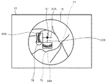
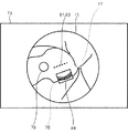
図1の説明に戻る。観察システム100は、空中ディスプレイ70および検出部75を備える。図3に示すように、空中ディスプレイ70はモニタ71および結像部72を備える。モニタ71は、発光性を有し、各種画像を表示する。結像部(本実施形態では空中結像パネル)72は、モニタ71の表示面から発せられた光線を結像することで、空中の表示領域73に、実像である空中画像を表示させる。結像部72には、例えば、再公表2009−131128、WO2014/024677等で開示されている光学結像装置等を用いてもよい。本実施形態では、結像部72は、モニタ71の上部から前方に延びる支持板74の先端部と、モニタ71の下部によって、モニタ71の表示面に対して斜めに配置されている。その結果、結像部72を対称面として、モニタ71の表示面の対称となる位置に表示領域73が形成される。検出部75は、空中の表示領域73における物体の位置または動作を検出する。一例として、本実施形態の検出部75は、発光部および受光部を備える。発光部は近赤外光を発光させる。受光部は、表示領域73に位置する物体(例えば、ユーザの手、指、またはユーザが持つ器具等)から反射された近赤外光を受光し、受光した光の位相の遅れを計測することで、物体の位置を検出する。物体の位置が連続して検出されることで、物体の動きが検出される。
Returning to the description of FIG. The
操作部69は、ユーザUが各種操作指示を観察システム100に入力するために、ユーザによって操作される。本実施形態では、操作部69として、ユーザUの足で操作されるフットスイッチが少なくとも設けられている。従って、ユーザUは、手術器具等を手で扱いながら、各種操作指示を操作部69から入力することができる。ただし、フットスイッチと共に、またはフットスイッチの代わりに、他のデバイス(例えば、各種ボタンおよびタッチパネル等)が操作部69として用いられてもよい。
The
制御部60は、観察システム100の各種制御(例えば、顕微鏡フォーカス調整部32による顕微鏡フォーカスの調整制御、OCT部40による測定光束の走査制御、およびOCT光の調整制御等)を司る。制御部60は、CPU61、RAM62、ROM63、および不揮発性メモリ(NVM)64を備える。CPU61は各種制御を行うコントローラである。RAM62は各種情報を一時的に記憶する。ROM63には、CPU61が実行するプログラム、および各種初期値等が記憶されている。NVM64は、電源の供給が遮断されても記憶内容を保持できる非一過性の記憶媒体である。後述する生体観察制御処理を実行するための生体観察制御プログラムは、NVM64に記憶されていてもよい。
The
なお、本実施形態では、一例として、顕微鏡部1に設けられた制御部60が、顕微鏡フォーカスの調整制御、OCT部40による測定光束の走査制御、およびOCT光の調整制御等を行う制御部として機能する。つまり、本実施形態では、顕微鏡部1が、観察システム100を制御する制御装置として機能する。しかし、観察システム100の制御を司る制御部(つまり、生体観察制御プログラムを実行する制御部)の構成は、適宜変更できる。例えば、顕微鏡部1に接続されたパーソナルコンピュータ(図示せず)の制御部が、観察システム100を制御してもよい。複数の装置の各々に設けられた制御部(例えば、顕微鏡部1の制御部60と、パーソナルコンピュータの制御部)が協同して、観察システム100を制御してもよい。
In the present embodiment, as an example, the
<観察光学系のフォーカス状態の取得>
本実施形態の制御部60は、顕微鏡部1における観察光学系30のフォーカス状態(以下、単に「顕微鏡フォーカス状態」という場合もある)を取得することができる。詳細は後述するが、本実施形態の制御部60は、空中ディスプレイ70によって表示された観察画像の表示領域において検出部75によって検出された物体の位置または動作に応じて、観察画像内に注目領域を設定する。また、制御部60は、顕微鏡フォーカス状態の取得結果に応じて、観察画像における注目領域のピントを自動的に調整することができる。ここで、顕微鏡フォーカス状態の取得方法の一例について説明する。本実施形態の制御部60は、受光素子38R,38Lからの信号に基づいて顕微鏡フォーカス状態を取得する。従って、本実施形態の観察システム100では、顕微鏡フォーカス状態を取得(検出)するための専用の構成を省略することができる。
<Acquisition of focus state of observation optical system>
The
一例として、本実施形態の制御部60は、コントラスト検出方式によって顕微鏡フォーカス状態を取得する。詳細には、制御部60は、顕微鏡フォーカス調整部32によって顕微鏡フォーカスを変更しながら、受光素子38R,38Lによって撮影された観察画像(本実施形態では顕微鏡画像)のうち、注目領域内の画像を解析する。制御部60は、注目領域内の画像のコントラストが最も高くなる位置を、顕微鏡フォーカスが合う位置とすることで、顕微鏡フォーカス状態を取得する。ただし、前述したように、顕微鏡フォーカス状態を取得する方式として、コントラスト検出方式以外の方式が用いられてもよい。
As an example, the
<生体観察制御処理>
以下、観察システム100の制御部60が実行する生体観察制御処理について説明する。制御部60のCPU61は、NVM64に記憶された生体観察制御プログラムに従って、図4に示す生体観察制御処理を実行する。
<Biological observation control processing>
Hereinafter, the biological observation control process executed by the
まず、CPU61は事前処理を開始する(S1)。前述したように、CPU61は、観察光学系30の受光素子38R,38Lによって患者眼Eを撮影する。事前処理では、CPU61は、受光素子38R,38Lからの信号に基づいて、ディスプレイ67への観察画像の表示を開始させる。この場合、CPU61は、予め設定された領域(例えば、画面中央の領域)における顕微鏡フォーカス状態を取得し、顕微鏡フォーカス状態が良好となるように顕微鏡フォーカスを調整してもよい。また、CPU61は、顕微鏡フォーカス状態を取得せずに、顕微鏡フォーカスを調整可能範囲の中点に置いて観察画像の撮影および表示を開始させてもよい。また、CPU51は、観察光学系30の光学パラメータに基づいて、OCT部40における光路長差を調整する。例えば、焦点距離を変更できる対物レンズ31が用いられており、焦点距離が170mmから200mmに変更された場合を例示する。この場合、対物レンズ31から患者眼Eまでの距離(ワーキングディスタンス)も30mm程度長くなる。従って、CPU51は、観察光学系30の光学パラメータ(焦点距離)に基づいて光路長差調整部56の駆動を制御し、光路長差を30mm程度変化させる。
First, the
次いで、CPU61は、受光素子38R,38Lによって撮影された最新の観察画像を取得し、空中ディスプレイ70に表示させる(S2)。CPU61は、空中の表示領域73内の物体(例えば、ユーザの指等)を、検出部73によって検出する(S3)。空中の表示領域73内において、関心領域を指定するための物体の位置または動作が検出されなければ(S6:NO)、処理はそのままS30へ移行する。関心領域を指定するための物体の位置または動作が検出されると(S6:YES)、CPU61は、検出された物体の位置または動作に応じて、顕微鏡フォーカスの調整制御、OCT部40による測定光束の走査制御、およびOCT光の調整制御を実行する(S9〜S24)。
Next, the
まず、CPU61は、表示領域73内で検出された物体の位置または動作に応じて、観察画像内に注目領域を設定する(S9)。次いで、CPU61は、顕微鏡フォーカス状態を取得する(S10)。前述したように、本実施形態のCPU61は、設定した注目領域内における受光素子38R,38Lからの信号に基づいて、注目領域における顕微鏡フォーカス状態を取得する。次いで、CPU61は、顕微鏡フォーカス状態の取得結果に基づいて顕微鏡フォーカス調整駆動部32の駆動を制御することで、観察画像における注目領域のピントを調整する(S11)。さらに、CPU61は、表示領域73内で検出された物体の位置または動作に応じて、OCT部40による測定光束の走査位置を設定する(S12)。
First, the
以上の処理について、図5〜図9を参照して具体的に説明する。なお、図5〜図9では、空中ディスプレイ70による空中の表示領域73において、眼底の観察画像15が表示されている状態が例示されている。図5〜図9に示す観察画像15では、視神経乳頭77、黄斑78、および眼底血管79等の組織が写っている。また、以下説明する関心領域81は、領域だけでなく、点および線も含む。
The above processing will be specifically described with reference to FIGS. 5 to 9. Note that FIGS. 5 to 9 illustrate a state in which the
まず、図5および図6を参照して、ユーザの関心領域81が点で指定された場合の処理の一例について説明する。図5および図6に示す例では、ユーザは、表示領域73に表示された観察画像15上の1点に指等を位置させることで、点の関心領域81を指定している。この場合、CPU61は、点の関心領域81を含む領域を注目領域82として設定する(S9)。図5に示す例では、検出された点の関心領域81を中心とする長方形の領域が、注目領域82として設定されている。なお、注目領域82の形状は長方形に限定されない。注目領域82の大きさは、予め定められていてもよいし、ユーザからの指示(例えば、操作部69による操作指示等)に応じて設定されてもよい。
First, with reference to FIGS. 5 and 6, an example of processing when the user's region of
また、図6に示すように、CPU61は、検出された点の関心領域81の位置に基づいて、OCT部40による測定光束の走査位置83A,83Bを設定する(S12)。図6に示す例では、点の関心領域81を横断し、且つ互いに直行する2つのライン状の走査位置83A,83Bが設定されている。なお、走査位置83の数が2つに限定されないことは言うまでもない。CPU61は、走査位置83Aに測定光束を走査させることで撮影された二次元断層画像84Aを、走査位置83Aと並べて表示させる。また、CPU61は、走査位置83Bに測定光束を走査させることで撮影された二次元断層画像84Bを、走査位置84Bと並べて表示させる。
Further, as shown in FIG. 6, the
また、ユーザは、表示領域73に対して指等によって特定の動作を行うことで、表示領域73における二次元断層画像84A,84Bの表示および非表示を切り替えることができる。本実施形態では、CPU61は、表示されている二次元断層画像84A,84B上で指等を横断させる(スワイプジェスチャーを行う)動作が検出されると、横断位置に表示させていた二次元断層画像84A,84Bを非表示とする。また、同様の動作が再度検出されると、CPU61は、二次元断層画像84A,84Bを表示領域73内に表示させる。従って、ユーザは、表示領域73に表示されている観察画像15上に対して特定の動作を行うことで、二次元断層画像84A,84Bの表示および非表示を容易に切り換えることができる。
In addition, the user can switch between displaying and hiding the two-dimensional
図7および図8を参照して、ユーザの関心領域81が線で指定された場合の処理の一例について説明する。図7および図8に示す例では、ユーザは、表示領域73に表示された観察画像15上で指等を線状に移動させる(スワイプジェスチャーを行う)ことで、線の関心領域81を指定している。この場合、CPU61は、線の関心領域81を含む領域を注目領域82として設定する(S9)。図7に示す例では、検出された直線状の関心領域81の長さと一辺の長さが同じであり、且つ、直線状の関心領域81を中心として対称な形状となる長方形の注目領域82が設定されている。なお、図5および図6に示した例と同様に、注目領域82の形状および大きさ等は適宜変更できる。
An example of processing when the user's region of
また、図8に示すように、CPU61は、検出された線の関心領域81の位置に基づいて、OCT部40による測定光束の走査位置83を設定する(S12)。図8に示す例では、線の関心領域81上に走査位置83が設定されている。ユーザは、複数の関心領域81および走査位置83を指定してもよい。また、図8に示す例では、関心領域81および走査位置83の長さは測定光束のスキャン範囲以下の長さに限定される。CPU61は、走査位置83に測定光束を走査させることで撮影された二次元断層画像84を、走査位置83と並べて表示させる。また、CPU61は、図5および図6で例示した方法と同様の方法で、二次元断層画像84の表示および非表示を切り替える。
Further, as shown in FIG. 8, the
図9を参照して、ユーザの関心領域81が面で指定された場合の処理の一例について説明する。面の関心領域81をユーザが指定する方法は、適宜選択できる。例えば、ユーザは、四角形の関心領域81を指定する場合、対角線の少なくとも一方に沿うように観察画像15上で指等を移動させてもよい。また、ユーザは、四角形の関心領域81を指定する場合、指定する関心領域81の4つの頂点のうちの少なくとも2つ(例えば、互いに対角に位置する2つの頂点)に指等を位置させてもよい。なお、点および線の関心領域81と面の関心領域81を区別するための特定の動作が設けられていてもよい。例えば、CPU61は、対角線の開始点または頂点をユーザに指定させる場合に、同一の点を複数回指定させる動作をユーザに要求してもよい。図9に示す例では、検出された面の関心領域81と同一の領域に注目領域82が設定される(S9)。ただし、関心領域81と注目領域82は同一の領域でなくてもよい。
With reference to FIG. 9, an example of processing when the user's region of
CPU61は、検出された面の関心領域81の位置に基づいて、OCT部40による測定光束の走査位置を設定する(S12)。図9に示す例では、面の関心領域81内で三次元断層画像85を取得するためのラスタースキャンの走査位置(図示せず)が設定されている。CPU61は、関心領域81内で測定光束のラスタースキャンを実行することで撮影された三次元断層画像85を、表示領域73内に表示させることができる。また、CPU61は、関心領域81内で撮影された複数の二次元断層画像84の少なくとも1つを、表示領域73内に表示させることもできる。
The
CPU61は、図5および図6で例示した方法と同様の方法で、二次元断層画像84の表示および非表示を切り替える。また、CPU61は、表示領域73に表示された三次元断層画像85上で検出された物体の位置または動作に応じて、三次元断層画像85の向きを変更することができる。例えば、三次元断層画像85上で左から右への物体の動作(左から右へのスワイプジェスチャー)が検出されると、CPU61は、表示させている三次元断層画像85を左から右へ(つまり、上方から見て反時計回りに)回転させる。従って、ユーザは、表示されている三次元断層画像85の向きを、容易に適切な向きに調整することができる。
The
図10を参照して、顕微鏡フォーカスを調整する処理(S11)について説明する。図10に示す例では、ユーザによって関心領域81Aが関心領域81Bに変更された場合、患者眼Eの動きが無くても、Z方向における顕微鏡フォーカスの適切な位置は、+Z方向にΔZだけ移動する。この場合、CPU61は、変更された関心領域81Bに基づいて設定される注目領域のフォーカスが合うように、顕微鏡フォーカス調整駆動モータ34を制御する。従って、ユーザが注目する位置のピントが適切に調整される。
The process of adjusting the microscope focus (S11) will be described with reference to FIG. In the example shown in FIG. 10, when the region of
また、CPU61は、S11の処理において、ユーザによって入力されたオフセット量に基づいてピントを調整することも可能である。本実施形態では、ユーザは、顕微鏡フォーカス状態の取得結果に基づいて合わせられる通常のピント位置(オフセット量が「0」の場合にオートフォーカスによって合わせられるピント位置)に対する、所望のピント位置の、光軸に沿う方向のオフセット量(ずれ量)を入力することができる。オフセット量の入力方法は適宜選択できる。例えば、「オフセット無し」「前ピン」「後ピン」の中の1つをユーザに選択させる方法でもよい。また、オフセットが無い場合を「0」として、プラスおよびマイナスのずれ量の数値をユーザに入力させる方法でもよい。CPU61は、オフセット量が入力されている場合、顕微鏡フォーカス状態の取得結果に基づく通常のピント位置(本実施形態では、注目領域82のコントラストが最も良くなるピント位置)から、入力されたオフセット量だけずれた位置にピントを合わせる。
Further, the
図4の説明に戻る。CPU61は、注目領域82における顕微鏡フォーカス状態の変化に応じてOCT光を調整するための処理を実行する(S13〜S17)。一例として、本実施形態のCPU61は、観察光学系30(顕微鏡フォーカス調整部32を含む)の光学パラメータと、顕微鏡フォーカス調整部32の駆動量に基づいて、観察する位置(顕微鏡フォーカスを合わせる位置)の深さ方向(Z方向)の移動量ΔZを算出する。CPU61は、移動量ΔZに基づいてOCT光を調整する。以下、詳細に説明する。
Returning to the description of FIG. The
まず、CPU61は、観察光学系30の光学パラメータを取得する(S13)。本実施形態では、顕微鏡フォーカス調整部32によって変化する観察光学系30の焦点距離が取得される。さらに、本実施形態では、広角観察ユニット27(図1参照)が使用されているか否かに応じて光学パラメータが変化する。従って、本実施形態のCPU61は、広角観察ユニット27の有無に応じた光学パラメータを取得する。具体的には、本実施形態では、観察光学系30の中間像(前置レンズ29の前側焦点位置)への観察物体の結像倍率β1、および縦倍率α1(広角観察ユニット27が使用されるか否か、および焦点距離に応じて変化する)が、観察光学系30の光学パラメータとして取得される。また、本実施形態では、OCT部40の観察物体のケプラー式望遠鏡における前群のレンズ50の焦点位置、すなわちファイバ端面の中間像への結像倍率β2および縦倍率α2も取得される。
First, the
次いで、CPU61は、観察する位置がZ方向において移動した量ΔZを、顕微鏡フォーカス状態の変化に基づいて算出する(S14)。例えば、図6に示す例では、観察する位置が81Aから81Bに移動したことに伴い、顕微鏡フォーカス調整部32によって顕微鏡フォーカスが調整される。従って、CPU61は、顕微鏡フォーカス調整部32の駆動量から、観察する位置の移動量ΔZを算出することができる。図1に示す例では、中間像位置における顕微鏡フォーカスの移動量(顕微鏡フォーカス調整部32における対物レンズ31および縮小レンズ28の繰出し量に一致する)をΔZ1とすると、ΔZ=α1×ΔZ1=β1 2×ΔZ1となる。
Next, the
次いで、CPU61は、顕微鏡フォーカスSfを合わせる基準とする観察目標位置と、OCT信号を取得する基準とするOCT目標位置の、光束に沿う深さ方向(Z方向)のずれ量を取得する(S15)。なお、OCT目標位置は、ゼロディレイ位置(OCT光の光路長差がゼロとなる位置)を合わせる基準とする目標位置、および、OCTフォーカスOfを合わせる基準とする目標位置の少なくともいずれかとされる。本実施形態の観察システム100では、ユーザは、操作部69等に指示を入力することで、深さ方向における観察目標位置とOCT目標位置を別々に指定することも可能である。なお、観察目標位置とOCT目標位置が深さ方向において一致している場合には、S15で取得されるずれ量はゼロとなる。
Next, the
次いで、CPU61は、観察する位置のZ方向の移動量ΔZに基づいてOCT部40の光路長差調整部56を駆動させることで、光路長差を調整する(S16)。本実施形態では、CPU61は、光路長差調整部56の光路長差調整駆動モータ58の駆動を制御し、ΔZ×ng(ngは、患者眼Eの群屈折率)だけ参照ミラー57を移動させることで、光路長差を調整する。例えば、図6に示す例では、顕微鏡フォーカスの変化に伴って光路長差が調整される結果、Z方向の地点Aが中心となっていたOCT信号取得範囲が、地点Bを中心とするOCT信号取得範囲に変更される。なお、観察目標位置と、ゼロディレイ位置を合わせる目標位置がずれている場合には、CPU61は、S15で取得したずれ量も考慮して光路長差調整部56を駆動させる。従って、観察目標位置と、ゼロディレイ位置を合わせる目標位置がずれている場合でも、光路長差が適切に調整される。
Next, the
次いで、CPU61は、観察する位置の移動量ΔZに基づいてOCTフォーカス調整部49を駆動させることで、OCTフォーカスを調整する(S17)。本実施形態では、図1に示すように、OCTの測定光束も、顕微鏡フォーカス調整部32を通過する。従って、顕微鏡フォーカス調整部32が駆動されると、OCTフォーカスも移動する。しかし、顕微鏡部1の観察光とOCT光の波長の違い等によって、顕微鏡フォーカス調整部32の駆動量に対する顕微鏡フォーカスの移動量とOCTフォーカスの移動量は一致しない場合がある。従って、本実施形態のCPU61は、顕微鏡フォーカス状態の変化に応じてOCTフォーカス調整部49も駆動させることで、OCTフォーカスをより正確に調整する。
Next, the
なお、OCTフォーカス調整部49の駆動量は、測定光学系43等の光学パラメータに基づいて算出することができる。一例として、中間像位置におけるOCTフォーカスの移動量をΔZ2、測定光学系43における結像倍率をβ2、縦倍率をα2、OCTフォーカス調整部32の駆動量(本実施形態ではレンズ52の移動量)をΔZ3すると、ΔZ2=α2×ΔZ3=β2 2×ΔZ3となる。ΔZ2は、S14で算出される観察位置の移動量ΔZに応じて定まるので、前述した式からOCTフォーカス調整部32の駆動量を算出することができる。また、観察目標位置と、OCTフォーカスOfを合わせる目標位置がずれている場合には、CPU61は、S15で取得したずれ量も考慮してOCTフォーカス調整部32を駆動させる。
The driving amount of the OCT
以上説明したS13〜S17の処理が行われることで、注目領域82における顕微鏡フォーカス状態の変化に応じたOCT光の調整が実行される。その結果、OCT部40の光路長差およびOCTフォーカスは高速且つ容易に調整される。ここで、顕微鏡フォーカス状態の変化に応じたOCT光の調整のみを実行してもよいが、本実施形態のCPU61は、OCT信号の解析結果に基づくOCT光の調整も実行する(S19〜S22)。その結果、OCT光の調整がより適切に行われる。以下詳細に説明する。
By performing the processes S13 to S17 described above, the OCT light is adjusted according to the change in the microscope focus state in the region of
まず、CPU61は、OCT受光素子59を介してOCT信号を仮取得し、解析する(S19)。次いで、CPU61は、解析したOCT信号のレベルが閾値よりも大きいか否かを判断する(S20)。OCT信号のレベルが閾値以下である場合には(S20:NO)CPU61は、光路長差調整部56を駆動させて光路長差の微調整を行うと共に(S21)、OCTフォーカス調整部49を駆動させてOCTフォーカスの微調整を行う(S22)。処理はS19へ戻り、OCT信号のレベルが閾値より大きくなるまでS19〜S22の処理が繰り返される。光路長差およびOCTフォーカスは、顕微鏡フォーカス状態の変化に応じて概ね適切に調整されるので、OCT信号の解析結果に基づく調整(S19〜S22)の範囲は狭くすることが可能である。よって、OCT光は、高速且つ適切に調整される。OCT信号のレベルが閾値よりも大きくなると(S20:YES)、CPU61は、OCT信号を正式に取得する(S24)。
First, the
なお、OCT信号を解析する方法も適宜選択できる。例えば、CPU61は、取得されたOCT画像の全体の信号を解析してもよい。また、CPU61は、取得されたOCT画像のうち、関心領域81を中心とする所定範囲の信号を解析してもよい。この場合、関心領域81の近傍におけるOCT画像の品質がさらに向上する。また、CPU61は、取得されたOCT画像のうち、関心領域81の近傍の解析結果を、関心領域81から離間した位置の解析結果よりも重視する重み付けを行ってもよい。
The method of analyzing the OCT signal can also be appropriately selected. For example, the
次いで、CPU61は、検出部75による検出結果に応じた絞り調整処理を行う(S30)。詳細には、CPU61は、可変絞り36を調整する指示が検出部75によって検出されると、指示に応じて絞り駆動部37を駆動し、可変絞り36の開口径を調整する。可変絞り36を調整する指示の入力方法は、適宜選択できる。例えば、表示領域73に表示されている観察画像15のうち、一度設定された関心領域81と同一の位置で物体が検出された場合に、可変絞り36の開口径が小さくされてもよい。例えば、被写体である生体等によっては、S11で実行される観察画像のオートフォーカスが適切に行われ難い場合もあり得る。オートフォーカスが適切に行われなかった場合、ユーザは、可変絞り36を小さくする指示を入力することで、焦点深度を深くしてピントを合致させやすくすることができる。逆に、ユーザは、可変絞り36を大きくする指示を入力することで、観察している範囲の明るさを明るくすることもできる。
Next, the
次いで、CPU61は、注目領域82のトラッキング処理を実行し(S31)、処理はS2へ戻る。注目領域82のトラッキング処理とは、検出した被写体の動きに応じて注目領域82の位置を追従(トラッキング)させる処理である。一例として、本実施形態のCPU61は、受光素子38R,38Lによって撮影された観察画像15に対して画像処理を行うことで、観察画像15に写っている被写体の動きを検出する。例えば、CPU61は、画像処理を行うことで、生体の特定部位(例えば、視神経乳頭77、黄斑78、および眼底血管79の少なくともいずれか)を検出し、特定部位の移動を検出することで被写体の動きを検出してもよい。また、光学観察ユニット27(図1参照)が使用されている場合には、CPU61は、広角観察ユニット27が備える前置レンズ29の位置(例えば、前置レンズ29の開口の位置)の移動を検出することで、被写体の動きを検出してもよい。CPU61は、検出した被写体の動きに応じて注目領域82の位置を追従させる。その結果、被写体が動いても、注目領域における観察画像15の品質が良好なまま維持される。なお、CPU61は、検出した被写体の動きに応じて、OCT測定光束の走査位置を追従させる処理も実行する。
Next, the
以上のように、本実施形態では、ユーザは、表示領域73に表示された観察画像15上の所望の位置に指等を直接移動させることで、観察状態を調整するための指示を容易且つ適切に入力することができる。CPU61は、検出された位置情報および動作情報の少なくともいずれかを用いて観察状態を調整するので、ユーザの希望に合致した調整をより正確に実行できる。
As described above, in the present embodiment, the user can easily and appropriately give an instruction for adjusting the observation state by directly moving the finger or the like to a desired position on the
なお、本実施形態の生体観察システム100は、空中ディスプレイ70の表示領域における特定の情報の表示制御を自動的に行う機能も有する。詳細には、生体観察システム100は、処置台(例えば手術台)に患者が配置されているか否かを検出する患者配置検出部(一例として、処置台に配置された感圧センサ等)を備える。CPU61は、患者が処置台に配置されたことが患者配置検出部によって検出された場合に、患者に知られたくない情報等である特定情報の、空中ディスプレイ70への表示を開始させる。また、CPU61は、患者が処置台から離れたことが検出された場合に、空中ディスプレイ70における特定情報の表示を停止させる。その結果、特定情報が自動的且つ適切に空中ディスプレイ70に表示される。
The
上記実施形態で開示された技術は一例に過ぎない。従って、上記実施形態で例示された技術を変更することも可能である。例えば、上記実施形態で例示した複数の技術の一部のみを実行することも可能である。上記実施形態では、空中ディスプレイ70に表示された観察画像15上における物体の検出結果に基づいて、顕微鏡部1の顕微鏡フォーカスの調整処理、および、OCT部40による測定光束の走査位置の設定処理が共に実行される。しかし、顕微鏡部1の顕微鏡フォーカスの調整処理、および、OCT部40による測定光束の走査位置の設定処理の一方のみが、検出部75による検出結果に基づいて実行されてもよい。観察システムは、顕微鏡部1およびOCT部40の一方のみを備えていてもよい。また、手術顕微鏡およびOCT装置以外のデバイスに、上記実施形態で例示された技術の少なくとも一部を適用してもよい。例えば、生体の撮影を行う各種デバイス(例えば、眼科分野であれば眼底カメラ、走査型レーザ検眼鏡、赤外カメラ)において、撮影範囲を決める光学系を駆動させる基準となる位置、または、撮影画像のフォーカスを合わせる基準となる位置が、観察画像上における物体の検出結果に基づいて設定されてもよい。また、OCT部40によって取得されるモーションコントラスト画像の撮影範囲が、観察画像上における物体の検出結果に基づいて設定されてもよい。モーションコントラスト画像とは、組織における動き(例えば、組織の血管を流れる血流、組織内のリンパ液の流れ等)を示す画像である。制御部61は、組織の同一位置から異なるタイミングで複数のOCT信号を取得し、取得した複数のOCT信号を処理することで、モーションコントラスト画像を取得することが可能である。
The techniques disclosed in the above embodiments are merely examples. Therefore, it is possible to modify the techniques exemplified in the above embodiments. For example, it is possible to implement only some of the plurality of techniques exemplified in the above embodiments. In the above embodiment, the microscope focus adjustment process of the
上記実施形態の受光素子38R,38Lは、顕微鏡部1の観察光学系30によって導光される観察光束を受光することで、観察画像15を撮影する。しかし、生体の観察画像を取得する方法を変更してもよい。例えば、OCT装置では、被検体の正面画像を撮影する正面画像撮影部が、OCT部とは別に設けられていてもよい。この場合、正面画像撮影部の撮影素子が観察画像を撮影する。また、OCT受光素子が取得するOCT信号から得られるEnface画像が観察画像として用いられてもよい。この場合、OCT受光素子が、観察画像を生成するための光学情報を受光する受光素子として機能する。
The
また、上記実施形態では、注目領域82における顕微鏡フォーカス状態の変化に応じて、OCT部40における光路長差の調整とOCTフォーカスの調整が共に実行される。しかし、光路長差の調整とOCTフォーカスの調整の一方のみが実行されてもよい。また、OCT光の調整を、顕微鏡フォーカス状態の変化に連動させなくてもよい。また、上記実施形態では、OCT信号の解析結果に応じて、OCT光路長差の微調整(S21)、およびOCTフォーカスの微調整(S22)が共に実行される。しかし、S21およびS22の処理の少なくともいずれかを省略することも可能である。
Further, in the above embodiment, the adjustment of the optical path length difference and the adjustment of the OCT focus in the
1 顕微鏡部
20 照明光学系
30 観察光学系
32 顕微鏡フォーカス調整部
34 顕微鏡フォーカス調整駆動モータ
36 可変絞り
37 絞り駆動部
38R,38L 受光素子
40 OCT部
41 OCT光源
42 カップラー
43 測定光学系
46 光スキャナ
49 OCTフォーカス調整部
51 OCTフォーカス調整駆動モータ
54 参照光学系
56 光路長差調整部
58 光路長差調整駆動モータ
59 OCT受光素子
60 制御部
61 CPU
70 空中ディスプレイ
71 モニタ
72 結像部
73 表示領域
75 検出部
100 生体観察システム
1
70
Claims (2)
前記生体からの光束を導光する光学系、および、前記光学系のフォーカスを調整する観察フォーカス調整駆動部を備えた観察光学部と、
前記生体に応じた光学情報を受光する受光素子と、
前記受光素子によって受光された光学情報に基づいて生成された、前記生体の観察画像を表示する表示部と、
前記表示部によって表示された前記観察画像の表示領域において物体の位置または動作を検出する検出部と、
前記生体観察システムの動作を制御する制御部と、
を備え、
前記表示部は、
画像を表示するモニタと、
前記モニタの表示面から発せられた光線を結像することで、空中に実像である空中画像を表示させる結像部と、
を備えた空中ディスプレイであり、
前記検出部は、
前記空中画像が表示される空中の領域において物体の位置または動作を検出し、
前記制御部は、
前記観察画像の表示領域において前記検出部によって検出された物体の位置または動作に基づいて、前記受光素子によって撮影された前記観察画像上の一部に、ユーザが注目する領域であり且つ前記観察画像上で移動する領域である注目領域を設定し、
前記受光素子からの信号のうち、設定した前記注目領域内における信号に基づいて、前記注目領域におけるフォーカス状態を取得し、
前記注目領域におけるフォーカス状態の取得結果に基づいて前記観察フォーカス調整駆動部を駆動させることで、前記観察画像における前記注目領域のピントを調整することを特徴とする生体観察システム。 A biological observation system that allows the user to observe the living body to be observed.
An optical system that guides the light flux from the living body, an observation optical unit that includes an observation focus adjustment drive unit that adjusts the focus of the optical system, and an observation optical unit.
A light receiving element that receives optical information according to the living body and
A display unit that displays an observation image of the living body, which is generated based on the optical information received by the light receiving element.
A detection unit that detects the position or movement of an object in the display area of the observation image displayed by the display unit, and
A control unit that controls the operation of the biological observation system,
With
The display unit
A monitor that displays images and
An imaging unit that displays a real aerial image in the air by forming an image of light rays emitted from the display surface of the monitor.
It is an aerial display equipped with
The detection unit
Detecting the position or movement of an object in the aerial area where the aerial image is displayed,
The control unit
A part of the observation image taken by the light receiving element based on the position or operation of the object detected by the detection unit in the display area of the observation image is a region in which the user pays attention to the observation image. Set the area of interest, which is the area to move on,
Among the signals from the light receiving element, the focus state in the attention region is acquired based on the set signal in the attention region.
A biological observation system characterized in that the focus of the attention region in the observation image is adjusted by driving the observation focus adjustment driving unit based on the acquisition result of the focus state in the attention region.
前記生体観察システムは、
前記生体からの光束を導光する光学系、および、前記光学系のフォーカスを調整する観察フォーカス調整駆動部を備えた観察光学部と、
前記生体に応じた光学情報を受光する受光素子と、
前記受光素子によって受光された光学情報に基づいて生成された、前記生体の観察画像を表示する表示部と、
前記表示部によって表示された前記観察画像の表示領域において物体の位置または動作を検出する検出部と、
を備え、
前記表示部は、
画像を表示するモニタと、
前記モニタの表示面から発せられた光線を結像することで、空中に実像である空中画像を表示させる結像部と、
を備えた空中ディスプレイであり、
前記検出部は、
前記空中画像が表示される空中の領域において物体の位置または動作を検出し、
前記生体観察制御プログラムが前記制御装置の制御部によって実行されることで、
前記観察画像の表示領域において前記検出部によって検出された物体の位置または動作に基づいて、前記受光素子によって撮影された前記観察画像上の一部に、ユーザが注目する領域であり且つ前記観察画像上で移動する領域である注目領域を設定し、
前記受光素子からの信号のうち、設定した前記注目領域内における信号に基づいて、前記注目領域におけるフォーカス状態を取得し、
前記注目領域におけるフォーカス状態の取得結果に基づいて前記観察フォーカス調整駆動部を駆動させることで、前記観察画像における前記注目領域のピントを調整するステップ、
を前記制御装置に実行させることを特徴とする生体観察制御プログラム。
A biological observation control program executed in a control device that controls a biological observation system.
The biological observation system
An optical system that guides the light flux from the living body, an observation optical unit that includes an observation focus adjustment drive unit that adjusts the focus of the optical system, and an observation optical unit.
A light receiving element that receives optical information according to the living body and
A display unit that displays an observation image of the living body, which is generated based on the optical information received by the light receiving element.
A detection unit that detects the position or movement of an object in the display area of the observation image displayed by the display unit, and
With
The display unit
A monitor that displays images and
An imaging unit that displays a real aerial image in the air by forming an image of light rays emitted from the display surface of the monitor.
It is an aerial display equipped with
The detection unit
Detecting the position or movement of an object in the aerial area where the aerial image is displayed,
When the biological observation control program is executed by the control unit of the control device,
A part of the observation image taken by the light receiving element based on the position or operation of the object detected by the detection unit in the display area of the observation image is a region in which the user pays attention to the observation image. Set the area of interest, which is the area to move on,
Among the signals from the light receiving element, the focus state in the attention region is acquired based on the set signal in the attention region.
A step of adjusting the focus of the attention region in the observation image by driving the observation focus adjustment driving unit based on the acquisition result of the focus state in the attention region.
A biological observation control program, characterized in that the control device executes the above.
Priority Applications (2)
| Application Number | Priority Date | Filing Date | Title |
|---|---|---|---|
| JP2017076174A JP6922358B2 (en) | 2017-04-06 | 2017-04-06 | Biological observation system and biological observation control program |
| US15/946,829 US10820793B2 (en) | 2017-04-06 | 2018-04-06 | Biological object observation system and non-transitory computer-readable medium |
Applications Claiming Priority (1)
| Application Number | Priority Date | Filing Date | Title |
|---|---|---|---|
| JP2017076174A JP6922358B2 (en) | 2017-04-06 | 2017-04-06 | Biological observation system and biological observation control program |
Publications (3)
| Publication Number | Publication Date |
|---|---|
| JP2018180119A JP2018180119A (en) | 2018-11-15 |
| JP2018180119A5 JP2018180119A5 (en) | 2020-04-23 |
| JP6922358B2 true JP6922358B2 (en) | 2021-08-18 |
Family
ID=63710506
Family Applications (1)
| Application Number | Title | Priority Date | Filing Date |
|---|---|---|---|
| JP2017076174A Expired - Fee Related JP6922358B2 (en) | 2017-04-06 | 2017-04-06 | Biological observation system and biological observation control program |
Country Status (2)
| Country | Link |
|---|---|
| US (1) | US10820793B2 (en) |
| JP (1) | JP6922358B2 (en) |
Families Citing this family (8)
| Publication number | Priority date | Publication date | Assignee | Title |
|---|---|---|---|---|
| WO2019181554A1 (en) * | 2018-03-22 | 2019-09-26 | ソニー株式会社 | Control device and method, and surgical microscope system |
| JP2021121821A (en) * | 2018-05-07 | 2021-08-26 | ソニーグループ株式会社 | Ophthalmic operating microscope system, control device and control method |
| US11096574B2 (en) * | 2018-05-24 | 2021-08-24 | Welch Allyn, Inc. | Retinal image capturing |
| CN110638527B (en) * | 2019-07-01 | 2021-06-01 | 中国科学院苏州生物医学工程技术研究所 | Operation microscopic imaging system based on optical coherence tomography augmented reality |
| JP7417981B2 (en) * | 2019-10-15 | 2024-01-19 | 株式会社トーメーコーポレーション | ophthalmology equipment |
| JP7435961B2 (en) * | 2020-03-27 | 2024-02-21 | 興和株式会社 | fundus imaging device |
| CN114584662B (en) * | 2020-11-30 | 2024-10-11 | 深圳市瑞图生物技术有限公司 | Image acquisition method, device, computer equipment and storage medium |
| JP2022157207A (en) * | 2021-03-31 | 2022-10-14 | 株式会社トプコン | Ophthalmic device and its control method |
Family Cites Families (8)
| Publication number | Priority date | Publication date | Assignee | Title |
|---|---|---|---|---|
| JP4933413B2 (en) * | 2007-12-11 | 2012-05-16 | 株式会社トーメーコーポレーション | Anterior segment optical coherence tomography apparatus and anterior segment optical coherence tomography method |
| JP5404078B2 (en) * | 2009-02-03 | 2014-01-29 | 株式会社トプコン | Optical image measuring device |
| JP2015163092A (en) | 2014-02-28 | 2015-09-10 | 株式会社ニデック | Ophthalmic laser surgery device, and eyeball fixing part moving unit and eyeball fixing unit used for the same |
| JP6507536B2 (en) * | 2014-09-12 | 2019-05-08 | 株式会社ニデック | Ophthalmic imaging apparatus and ophthalmologic imaging program |
| WO2016047173A1 (en) * | 2014-09-24 | 2016-03-31 | オリンパス株式会社 | Medical system |
| JP6436294B2 (en) * | 2014-09-30 | 2018-12-12 | 株式会社ニデック | Ophthalmic apparatus and ophthalmic apparatus control program |
| JP2016095634A (en) * | 2014-11-13 | 2016-05-26 | パナソニックヘルスケアホールディングス株式会社 | Midair touch panel and surgery simulator display system having the same |
| JP2016202453A (en) * | 2015-04-20 | 2016-12-08 | 株式会社トプコン | Microscope for ophthalmic surgery |
-
2017
- 2017-04-06 JP JP2017076174A patent/JP6922358B2/en not_active Expired - Fee Related
-
2018
- 2018-04-06 US US15/946,829 patent/US10820793B2/en not_active Expired - Fee Related
Also Published As
| Publication number | Publication date |
|---|---|
| JP2018180119A (en) | 2018-11-15 |
| US20180289254A1 (en) | 2018-10-11 |
| US10820793B2 (en) | 2020-11-03 |
Similar Documents
| Publication | Publication Date | Title |
|---|---|---|
| JP6922358B2 (en) | Biological observation system and biological observation control program | |
| JP6939815B2 (en) | Observation system and observation control program | |
| US10849499B2 (en) | Ophthalmologic apparatus and method of controlling the same | |
| US10456034B2 (en) | Ophthalmic microscope system | |
| US10383517B2 (en) | Ophthalmic operation microscope | |
| JP6812724B2 (en) | Ophthalmic Surgery System, Ophthalmic Surgery System Control Program, and Ophthalmic Surgical Microscope | |
| JP6734642B2 (en) | Ophthalmic equipment | |
| WO2016170816A1 (en) | Ophthalmic surgical microscope | |
| JP6499936B2 (en) | Ophthalmic microscope system | |
| JP5830264B2 (en) | Ophthalmic imaging equipment | |
| US10321819B2 (en) | Ophthalmic imaging apparatus | |
| JP6942536B2 (en) | Laser treatment device | |
| US20200288966A1 (en) | Ophthalmologic apparatus, and ophthalmologic information processing apparatus | |
| WO2016170815A1 (en) | Ophthalmic surgical microscope | |
| WO2019044180A1 (en) | Microscope and function expansion unit | |
| JP5991415B2 (en) | Ophthalmic imaging equipment | |
| JP2013116424A (en) | Ophthalmic photographing apparatus | |
| JP5888343B2 (en) | Ophthalmic imaging equipment | |
| JP2018114230A (en) | Ophthalmic equipment | |
| JP6754096B2 (en) | Ophthalmic observation system and ophthalmic observation control program | |
| US20240074649A1 (en) | Ophthalmic apparatus, method of controlling ophthalmic apparatus, and recording medium | |
| JP6877947B2 (en) | Ophthalmologic imaging equipment and its control method | |
| JP6880683B2 (en) | Ophthalmic equipment | |
| AU2015203775B2 (en) | Electronically controlled fixation light for ophthalmic imaging systems | |
| JP2019063268A (en) | Ophthalmologic imaging device |
Legal Events
| Date | Code | Title | Description |
|---|---|---|---|
| A521 | Request for written amendment filed |
Free format text: JAPANESE INTERMEDIATE CODE: A523 Effective date: 20200313 |
|
| A621 | Written request for application examination |
Free format text: JAPANESE INTERMEDIATE CODE: A621 Effective date: 20200313 |
|
| A131 | Notification of reasons for refusal |
Free format text: JAPANESE INTERMEDIATE CODE: A131 Effective date: 20210105 |
|
| A977 | Report on retrieval |
Free format text: JAPANESE INTERMEDIATE CODE: A971007 Effective date: 20201228 |
|
| A601 | Written request for extension of time |
Free format text: JAPANESE INTERMEDIATE CODE: A601 Effective date: 20210307 |
|
| A521 | Request for written amendment filed |
Free format text: JAPANESE INTERMEDIATE CODE: A523 Effective date: 20210506 |
|
| TRDD | Decision of grant or rejection written | ||
| A01 | Written decision to grant a patent or to grant a registration (utility model) |
Free format text: JAPANESE INTERMEDIATE CODE: A01 Effective date: 20210629 |
|
| A61 | First payment of annual fees (during grant procedure) |
Free format text: JAPANESE INTERMEDIATE CODE: A61 Effective date: 20210712 |
|
| R150 | Certificate of patent or registration of utility model |
Ref document number: 6922358 Country of ref document: JP Free format text: JAPANESE INTERMEDIATE CODE: R150 |
|
| LAPS | Cancellation because of no payment of annual fees |