JP6812724B2 - Ophthalmic Surgery System, Ophthalmic Surgery System Control Program, and Ophthalmic Surgical Microscope - Google Patents
Ophthalmic Surgery System, Ophthalmic Surgery System Control Program, and Ophthalmic Surgical Microscope Download PDFInfo
- Publication number
- JP6812724B2 JP6812724B2 JP2016194084A JP2016194084A JP6812724B2 JP 6812724 B2 JP6812724 B2 JP 6812724B2 JP 2016194084 A JP2016194084 A JP 2016194084A JP 2016194084 A JP2016194084 A JP 2016194084A JP 6812724 B2 JP6812724 B2 JP 6812724B2
- Authority
- JP
- Japan
- Prior art keywords
- ophthalmic
- eye
- optical device
- observation
- patient
- Prior art date
- Legal status (The legal status is an assumption and is not a legal conclusion. Google has not performed a legal analysis and makes no representation as to the accuracy of the status listed.)
- Expired - Fee Related
Links
- 238000001356 surgical procedure Methods 0.000 title claims description 53
- 230000003287 optical effect Effects 0.000 claims description 322
- 238000001000 micrograph Methods 0.000 claims description 51
- 230000007246 mechanism Effects 0.000 claims description 36
- 230000004907 flux Effects 0.000 claims description 35
- 238000012545 processing Methods 0.000 claims description 18
- 238000001514 detection method Methods 0.000 claims description 7
- 238000003384 imaging method Methods 0.000 claims description 5
- 238000011282 treatment Methods 0.000 description 65
- 238000005259 measurement Methods 0.000 description 35
- 238000000034 method Methods 0.000 description 28
- 230000008859 change Effects 0.000 description 21
- 238000005286 illumination Methods 0.000 description 18
- 210000000695 crystalline len Anatomy 0.000 description 17
- 230000008569 process Effects 0.000 description 12
- 238000012014 optical coherence tomography Methods 0.000 description 9
- 238000013459 approach Methods 0.000 description 6
- 230000001225 therapeutic effect Effects 0.000 description 6
- 238000013532 laser treatment Methods 0.000 description 5
- 230000004323 axial length Effects 0.000 description 4
- 210000004204 blood vessel Anatomy 0.000 description 4
- 206010025421 Macule Diseases 0.000 description 3
- 210000004087 cornea Anatomy 0.000 description 3
- 210000001747 pupil Anatomy 0.000 description 3
- 125000002066 L-histidyl group Chemical group [H]N1C([H])=NC(C([H])([H])[C@](C(=O)[*])([H])N([H])[H])=C1[H] 0.000 description 2
- 238000004891 communication Methods 0.000 description 2
- 208000002177 Cataract Diseases 0.000 description 1
- 230000008878 coupling Effects 0.000 description 1
- 238000010168 coupling process Methods 0.000 description 1
- 238000005859 coupling reaction Methods 0.000 description 1
- 230000003247 decreasing effect Effects 0.000 description 1
- 238000005516 engineering process Methods 0.000 description 1
- 210000000744 eyelid Anatomy 0.000 description 1
- 230000006870 function Effects 0.000 description 1
- 238000009434 installation Methods 0.000 description 1
- 238000011900 installation process Methods 0.000 description 1
- 210000003733 optic disk Anatomy 0.000 description 1
- 230000011514 reflex Effects 0.000 description 1
- 230000004044 response Effects 0.000 description 1
- 230000001052 transient effect Effects 0.000 description 1
- 230000001960 triggered effect Effects 0.000 description 1
Images


Landscapes
- Eye Examination Apparatus (AREA)
- Microscoopes, Condenser (AREA)
Description
本開示は、手術において生体(例えば患者眼)の観察等を行うために用いられる眼科手術システム、眼科手術システム制御プログラム、および眼科用手術顕微鏡に関する。 The present disclosure relates to an ophthalmic surgery system, an ophthalmic surgery system control program, and an ophthalmic operating microscope used for observing a living body (for example, a patient's eye) in surgery.
手術においてユーザ(例えば術者等)に生体を観察させるための種々のシステムが知られている。例えば、特許文献1には、光断層干渉計(Optical Coherence Tomography:OCT)を用いたOCT装置と、患者眼の内部を拡大表示する手術顕微鏡を、手術中に同時に使用する技術が開示されている。 Various systems are known for allowing a user (for example, an operator) to observe a living body in surgery. For example, Patent Document 1 discloses a technique of simultaneously using an OCT device using an optical coherence tomography (OCT) and a surgical microscope that magnifies and displays the inside of a patient's eye during surgery. ..
従来の技術における1つの側面について述べる。患者眼をユーザに観察させる手術顕微鏡に、患者眼の特性の測定または治療を行う眼科用光学機器を予め組み込むと、装置の大型化、コストの増大等の問題が生じる。一方で、手術顕微鏡と眼科用光学機器を別々に用いる場合、装置の種々の設定(例えば、装置の設置等)が面倒である。 One aspect of the prior art will be described. If an ophthalmic optical device for measuring or treating the characteristics of the patient's eye is incorporated in advance into a surgical microscope that allows the user to observe the patient's eye, problems such as an increase in size of the device and an increase in cost occur. On the other hand, when the operating microscope and the optical instrument for ophthalmology are used separately, various settings of the apparatus (for example, installation of the apparatus) are troublesome.
他の側面について述べる。手術顕微鏡を使用するユーザは、観察光学系を備えた筐体の位置を、観察光束に沿って移動させたい場合がある。この場合、ユーザは、筐体を移動させるだけでなく、観察光学系のピント位置を適切な位置に調整する必要があった。 Other aspects will be discussed. A user using an operating microscope may want to move the position of the housing with the observation optics along the observation luminous flux. In this case, the user has to not only move the housing but also adjust the focus position of the observation optical system to an appropriate position.
本開示の典型的な目的は、前述した複数の側面の少なくともいずれかを解決し、生体を容易にユーザに観察させることが可能な眼科手術システム、眼科手術システム制御プログラム、および眼科用手術顕微鏡を提供することである。 A typical object of the present disclosure is to provide an ophthalmic surgery system, an ophthalmic surgery system control program, and an ophthalmologic operating microscope that can solve at least one of the above-mentioned aspects and allow the user to easily observe the living body. Is to provide.
本開示における典型的な実施形態が提供する眼科手術システムは、患者眼からの観察光束を導光する観察光学系を有し、手術中に前記患者眼をユーザに観察させる手術顕微鏡と、光の出射および受光の少なくともいずれかを行うことで前記患者眼の特性の測定または治療を行う眼科用光学機器と、前記眼科用光学機器の少なくとも一部を、前記観察光学系と前記患者眼の間で前記患者眼の特性の測定または治療を行う作動位置と、前記作動位置から離間する退避位置との間で移動可能に支持する支持機構と、を備え、前記手術顕微鏡は、前記観察光学系によって導光された前記観察光束を受光することで、前記患者眼の顕微鏡画像を撮影する撮影素子をさらに備え、前記眼科手術システムは、少なくとも表示手段における前記顕微鏡画像の表示制御を行う制御部をさらに備え、前記手術顕微鏡は、前記眼科用光学機器から前記患者眼に向けて出射された光を、前記患者眼に対する前記眼科用光学機器のアライメント、および、前記眼科用光学機器のフォーカス状態の判断の少なくともいずれかに用いる指標として撮影する。
The ophthalmic surgery system provided by the typical embodiment in the present disclosure includes an observation optical system that guides an observation light beam from the patient's eye, and a surgical microscope that allows the user to observe the patient's eye during surgery, and an optical system. An ophthalmic optical device that measures or treats the characteristics of the patient's eye by performing at least one of emission and reception, and at least a part of the ophthalmic optical device are placed between the observation optical system and the patient's eye. The surgical microscope is guided by the observation optical system, comprising an operating position for measuring or treating the characteristics of the patient's eye and a support mechanism for movably supporting the retracted position away from the operating position. The ophthalmic surgery system further includes a photographing element that captures a microscopic image of the patient's eye by receiving the illuminated observation light beam, and further includes a control unit that controls the display of the microscopic image at least in the display means. The surgical microscope uses light emitted from the ophthalmic optical device toward the patient's eye to determine at least the alignment of the ophthalmic optical device with respect to the patient's eye and the focus state of the ophthalmic optical device. Take a picture as an index to be used for either .
本開示に係る眼科手術システム、眼科手術システム制御プログラム、および眼科用手術顕微鏡によると、生体を容易にユーザに観察させることができる。 According to the ophthalmic surgery system, the ophthalmologic surgery system control program, and the ophthalmic surgery microscope according to the present disclosure, the living body can be easily observed by the user.
<概要>
本開示で例示する眼科手術システムは、手術顕微鏡、眼科用光学機器、および支持機構を備える。手術顕微鏡は、患者眼からの観察光束を導光する観察光学系を有し、手術中に患者眼をユーザに観察させる。眼科用光学機器は、光の出射および受光の少なくともいずれかを行うことで、患者眼の特性の測定または治療を行う。支持機構は、眼科用光学機器の少なくとも一部を、手術顕微鏡の観察光学系と患者眼の間で患者眼の特性の測定または治療を行う作動位置と、作動位置から離間する退避位置との間で眼科用光学機器を移動可能に支持する。この場合、眼科用光学機器の少なくとも一部が支持機構によって移動されるだけで、眼科用光学機器を用いずに手術顕微鏡による観察を行う使用態様と、眼科用光学機器による測定または観察を行う使用態様とが切り替えられる。従って、手術顕微鏡と眼科用測定機器が、手術中に容易に使用される。
<Overview>
The ophthalmic surgery system exemplified in the present disclosure includes a surgical microscope, ophthalmic optical instruments, and a support mechanism. The operating microscope has an observation optical system that guides the observation light beam from the patient's eye, and allows the user to observe the patient's eye during the operation. Ophthalmic optics measure or treat the characteristics of a patient's eye by at least either emitting or receiving light. The support mechanism places at least a portion of the ophthalmic optical instrument between the operating position where the observation optics of the surgical microscope and the patient's eye measure or treat the characteristics of the patient's eye and the retracted position away from the operating position. Supports ophthalmic optical instruments in a movable manner. In this case, only a part of the ophthalmic optical instrument is moved by the support mechanism, and the usage mode of observing with a surgical microscope without using the ophthalmic optical instrument and the use of measuring or observing with the ophthalmic optical instrument. The mode can be switched. Therefore, operating microscopes and ophthalmic measuring instruments are readily used during surgery.
なお、眼科用光学機器には種々の機器を利用できる。例えば、波面センサ、患者眼の眼軸長を測定する眼軸長測定装置、患者眼の屈折力を測定する眼屈折力測定装置、患者眼の角膜形状を測定する角膜形状測定装置、患者眼の断層画像を取得するOCT装置、患者眼の眼底を撮影する眼底カメラ、患者眼の組織に治療光を出射するレーザ治療装置等の少なくともいずれかを、眼科用光学機器として使用してもよい。 Various devices can be used as the optical device for ophthalmology. For example, a wave surface sensor, an axial length measuring device for measuring the axial length of the patient's eye, an ophthalmoflex measuring device for measuring the refractive force of the patient's eye, a corneal shape measuring device for measuring the corneal shape of the patient's eye, and a patient's eye. At least one of an OCT device for acquiring a tomographic image, a fundus camera for photographing the fundus of the patient's eye, a laser treatment device for emitting therapeutic light to the tissue of the patient's eye, and the like may be used as an ophthalmic optical device.
手術顕微鏡は、焦点距離変更部と観察光学系移動部を備えていてもよい。焦点距離変更部は、観察光学系における観察光束の光路上に設けられており、観察光学系の焦点距離を変更する。観察光学系移動部は、観察光学系の位置を少なくとも観察光束に沿う方向に移動させる。この場合、手術顕微鏡は、観察光学系のフォーカスを適切な位置に合わせつつ、眼科用光学機器を作動位置に設置するか否かに応じて観察光学系と患者眼の距離を変更することができる。その結果、患者眼と装置の間のワーキングスペースが適切に確保される。 The operating microscope may include a focal length changing portion and an observation optical system moving portion. The focal length changing unit is provided on the optical path of the observed luminous flux in the observation optical system, and changes the focal length of the observation optical system. The observation optical system moving unit moves the position of the observation optical system at least in the direction along the observation luminous flux. In this case, the operating microscope can change the distance between the observation optical system and the patient's eye depending on whether or not the ophthalmic optical device is installed in the operating position while focusing the observation optical system at an appropriate position. .. As a result, a working space between the patient's eye and the device is adequately secured.
眼科手術システムは、少なくとも手術顕微鏡の動作を制御する顕微鏡制御部をさらに備えてもよい。手術顕微鏡は、焦点距離変更部を駆動させる焦点距離変更駆動部と、観察光学系移動部を駆動させる観察光学系移動駆動部を備えてもよい。顕微鏡制御部は、観察光学系を移動させる指示が入力された場合に、観察光学系移動駆動部を制御して観察光学系を移動させると共に、焦点距離変更駆動部を制御して観察光学系の焦点距離を観察光学系の移動距離と同じ距離だけ変更してもよい。この場合、観察光学系の位置が移動する前後で、観察光学系のピント位置が同じ位置に保たれる。従って、ユーザは、観察光学系のピント位置を変えることなく観察光学系の位置を容易に移動させることができる。 The ophthalmic surgery system may further include at least a microscope control unit that controls the operation of the operating microscope. The operating microscope may include a focal length changing driving unit that drives the focal length changing unit and an observation optical system moving driving unit that drives the observation optical system moving unit. When an instruction to move the observation optical system is input, the microscope control unit controls the observation optical system movement drive unit to move the observation optical system, and controls the focal length change drive unit to control the observation optical system. The focal length may be changed by the same distance as the moving distance of the observation optical system. In this case, the focus position of the observation optical system is kept at the same position before and after the position of the observation optical system is moved. Therefore, the user can easily move the position of the observation optical system without changing the focus position of the observation optical system.
顕微鏡制御部は、手術顕微鏡の使用態様を変更する指示が入力された場合に、観察光学系移動駆動部を制御して観察光学系を観察光束に沿う方向に所定距離移動させると共に、焦点距離変更駆動部を制御して観察光学系の焦点距離を観察光学系の移動距離と同じ距離だけ変更してもよい。この場合、ユーザは、手術顕微鏡の使用態様を変更する指示を入力するだけで、観察光学系のピント位置を変えることなく観察光学系の位置を所定距離移動させることができる。 When an instruction to change the usage mode of the surgical microscope is input, the microscope control unit controls the observation optical system movement drive unit to move the observation optical system by a predetermined distance in the direction along the observation light beam and change the focal distance. The drive unit may be controlled to change the focal distance of the observation optical system by the same distance as the movement distance of the observation optical system. In this case, the user can move the position of the observation optical system by a predetermined distance without changing the focus position of the observation optical system simply by inputting an instruction to change the usage mode of the surgical microscope.
なお、顕微鏡制御部は、観察光学系のピント位置を変えずに観察光学系を移動させる場合、観察光学系移動駆動部による観察光学系の移動と、焦点距離変更駆動部による焦点距離の変更を並行して行ってもよいし、いずれか一方を先に行ってもよい。また、使用態様の変更指示を契機として観察光学系を所定距離移動させる場合、所定距離はユーザによって指定された距離であってもよい。また、観察光学系のピント位置を変えずに観察光学系を移動させる動作は、眼科用光学機器を用いずに手術顕微鏡による観察を行う使用態様と、眼科用光学機器による測定または観察を行う使用態様とを切り替える場合に限定して実施されるものではない。例えば、手術の種類に応じて生体と観察光学系の間のワーキングスペースを変化させたい場合等にも、ピント位置を変えずに観察光学系を移動させる技術は有用である。 When moving the observation optical system without changing the focus position of the observation optical system, the microscope control unit moves the observation optical system by the observation optical system movement drive unit and changes the focal length by the focal length change drive unit. It may be performed in parallel, or one of them may be performed first. Further, when the observation optical system is moved by a predetermined distance triggered by an instruction to change the usage mode, the predetermined distance may be a distance specified by the user. In addition, the operation of moving the observation optical system without changing the focus position of the observation optical system is the usage mode of observing with a surgical microscope without using an ophthalmic optical instrument and the use of measuring or observing with an ophthalmic optical instrument. It is not limited to the case of switching between modes. For example, when it is desired to change the working space between the living body and the observation optical system according to the type of surgery, the technique of moving the observation optical system without changing the focus position is useful.
観察光束の少なくとも一部を透過させると共に、眼科用光学機器による測定または治療に用いられる光の少なくとも一部を反射させる光学素子が用いられてもよい。この場合、手術顕微鏡による患者眼の観察と、眼科用光学機器による測定または治療が、適切に並行して実行される。また、手術顕微鏡の観察光学系と患者眼の間のワーキングスペースを確保することがより容易になる。 An optical element that transmits at least a part of the observed luminous flux and reflects at least a part of the light used for measurement or treatment by an ophthalmic optical instrument may be used. In this case, observation of the patient's eye with a surgical microscope and measurement or treatment with an ophthalmic optical instrument are appropriately performed in parallel. In addition, it becomes easier to secure a working space between the observation optical system of the operating microscope and the patient's eye.
光学素子は、眼科用光学機器に設けられていてもよい。この場合、眼科用光学機器に対する光学素子の位置調整が容易になる。また、眼科用光学機器と光学素子が別体である場合に比べて、ユーザの作業量が減少する。 The optical element may be provided in an ophthalmic optical instrument. In this case, the position of the optical element with respect to the ophthalmic optical device can be easily adjusted. Further, the amount of work of the user is reduced as compared with the case where the optical device for ophthalmology and the optical element are separate bodies.
ただし、光学素子と眼科用光学機器を別体とすることも可能である。例えば、眼科用光学機器を支持する支持機構に光学素子が設けられていてもよい。この場合、眼科用光学機器が支持機構によって支持されることで、眼科用光学機器に対する光学素子の位置が適切な位置となるように、支持機構が設計されていてもよい。また、光学素子は、眼科用光学機器とは別で手術顕微鏡に着脱可能に装着されてもよい。 However, it is also possible to separate the optical element and the ophthalmic optical device. For example, an optical element may be provided in a support mechanism that supports an ophthalmic optical device. In this case, the support mechanism may be designed so that the position of the optical element with respect to the ophthalmic optical device becomes an appropriate position by supporting the ophthalmic optical device by the support mechanism. Further, the optical element may be detachably attached to the operating microscope separately from the ophthalmic optical instrument.
手術顕微鏡は、観察光学系によって導光された観察光束を受光することで患者眼の顕微鏡画像を撮影する撮影素子を備えていてもよい。眼科手術システムは、少なくとも表示手段における顕微鏡画像の表示制御を行う制御部を備えていてもよい。この場合、ユーザは、表示手段に表示された画像を見ることで、患者眼を容易に観察することができる。特に、眼科用光学機器を作動位置に設置するか否かに応じて観察光学系と患者眼の距離が変更される場合には、手術顕微鏡の接眼レンズの位置も変化する。その結果、ユーザは、接眼レンズの位置に応じて姿勢を変える必要がある。これに対し、顕微鏡画像を表示手段に表示させる場合には、ユーザは、姿勢を変えることなく顕微鏡画像を見ることができる。なお、手術顕微鏡は、表示手段の顕微鏡画像および接眼レンズの両方でユーザに患者眼を観察させてもよい。 The operating microscope may include an imaging element that captures a microscopic image of the patient's eye by receiving an observation luminous flux guided by an observation optical system. The ophthalmologic surgery system may include at least a control unit that controls the display of a microscope image in the display means. In this case, the user can easily observe the patient's eye by looking at the image displayed on the display means. In particular, when the distance between the observation optical system and the patient's eye is changed depending on whether or not the ophthalmic optical device is installed in the operating position, the position of the eyepiece of the operating microscope also changes. As a result, the user needs to change the posture according to the position of the eyepiece. On the other hand, when the microscope image is displayed on the display means, the user can see the microscope image without changing the posture. The operating microscope may allow the user to observe the patient's eye with both the microscope image of the display means and the eyepiece.
制御部は、手術顕微鏡、眼科用光学機器、および支持機構のいずれかに設けられていてもよいし、手術顕微鏡に接続されたパーソナルコンピュータの制御部であってもよい。また、複数の装置の各々に設けられた制御部が協同して顕微鏡画像の表示制御等を行ってもよい。また、前述した顕微鏡制御部は、顕微鏡画像の表示制御を行う制御部と同じであってもよいし、別であってもよい。 The control unit may be provided in any of the operating microscope, an ophthalmic optical instrument, and a support mechanism, or may be a control unit of a personal computer connected to the operating microscope. Further, the control units provided in each of the plurality of devices may cooperate to control the display of the microscope image. Further, the microscope control unit described above may be the same as or different from the control unit that controls the display of the microscope image.
手術顕微鏡は、眼科用光学機器から患者眼に向けて出射された光を、患者眼に対する眼科用光学機器のアライメント、および、眼科用光学機器のフォーカス状態の判断の少なくともいずれかに用いる指標として撮影してもよい。この場合、眼科用光学機器のアライメントおよびフォーカス調整の少なくともいずれかが、手術顕微鏡によって撮影された顕微鏡画像に基づいて実行される。従って、患者眼に対する手術顕微鏡のアライメントと共に、眼科用光学機器のアライメントおよびフォーカス調整の少なくともいずれかが、簡易な構成で適切に実行される。 The surgical microscope photographs the light emitted from the ophthalmic optical instrument toward the patient's eye as an index used for at least one of the alignment of the ophthalmic optical instrument with respect to the patient's eye and the determination of the focus state of the ophthalmic optical instrument. You may. In this case, at least one of the alignment and focus adjustment of the ophthalmic optics is performed based on the microscopic image taken by the operating microscope. Therefore, at least one of the alignment and focus adjustment of the ophthalmic optical instrument, along with the alignment of the operating microscope with respect to the patient's eye, is properly performed in a simple configuration.
支持機構は、眼科用光学機器の移動を駆動させる光学機器移動駆動部を備えていてもよい。制御部は、指標を含む顕微鏡画像を表示手段に表示させてもよい。制御部は、眼科用光学機器を移動させるためにユーザによって入力される信号に基づいて光学機器移動駆動部を制御することで、眼科用光学機器のアライメントおよびフォーカス調整の少なくともいずれかを行ってもよい。この場合、ユーザは、指標を含む顕微鏡画像を確認しながら移動指示を入力することで、眼科用光学機器のアライメントおよびフォーカス調整の少なくともいずれかを適切に行うことができる。 The support mechanism may include an optical device movement drive unit that drives the movement of the ophthalmic optical device. The control unit may display a microscope image including an index on the display means. The control unit may perform at least one of alignment and focus adjustment of the ophthalmic optical instrument by controlling the optical instrument movement drive unit based on a signal input by the user to move the ophthalmic optical instrument. Good. In this case, the user can appropriately perform at least one of the alignment and the focus adjustment of the ophthalmic optical instrument by inputting the movement instruction while checking the microscope image including the index.
なお、移動指示の入力を受け付けるための操作部には、種々の操作部を利用することができる。例えば、ユーザが足で操作するフットスイッチが操作部として用いられてもよい。この場合、ユーザは、例えば手で手術器具を扱いながら足で移動指示を入力することも可能である。また、タッチパネル、キーボード、各種ボタン等が操作部として用いられてもよい。また、支持機構は、光学機器移動駆動部を備えずに、ユーザの手動操作によって眼科用光学機器を移動させてもよい。 In addition, various operation units can be used as the operation unit for receiving the input of the movement instruction. For example, a foot switch operated by the user with his / her foot may be used as an operation unit. In this case, the user can also input a movement instruction with his / her foot while handling the surgical instrument by hand, for example. Further, a touch panel, a keyboard, various buttons and the like may be used as an operation unit. Further, the support mechanism may move the ophthalmologic optical device manually by the user without providing the optical device moving drive unit.
制御部は、顕微鏡画像に対して画像処理を行うことで、指標を検出してもよい。制御部は、指標の検出結果に基づいて光学機器移動駆動部を制御することで、眼科用光学機器のアライメントおよびフォーカス調整の少なくともいずれかを行ってもよい。この場合、顕微鏡画像に基づく眼科用光学機器のアライメントおよびフォーカス調整の少なくともいずれかが、自動的に実行される。よって、ユーザが各種操作を行う頻度が減少する。 The control unit may detect the index by performing image processing on the microscope image. The control unit may perform at least one of alignment and focus adjustment of the ophthalmic optical device by controlling the optical device moving drive unit based on the detection result of the index. In this case, at least one of the alignment and focus adjustment of the ophthalmic optical instrument based on the microscopic image is automatically performed. Therefore, the frequency with which the user performs various operations is reduced.
なお、眼科用光学機器から投影される指標のパターンには、種々のパターンを採用できる。例えば、指標の中心を認識することが可能なパターン(例えば、環状のパターン、十字状のパターン等)が、眼科用光学機器から投影されてもよい。この場合、指標の中心が認識されることで、アライメントがより正確に実行される。また、特定の大きさの指標パターン(例えば、特定の径を有する円形または環状のパターン)が、眼科用光学機器から患者眼に向けて投影されてもよい。この場合、指標パターンの大きさに基づいて、眼科用光学機器のフォーカス調整がより適切に実行される。また、有限遠の光と無限遠の光が眼科用光学機器から投影されてもよい。この場合、有限遠の光によって現れる指標の位置と、無限遠の光によって現れる指標の位置によって、眼科用光学機器のフォーカス調整が適切に実行される。 Various patterns can be adopted as the index pattern projected from the ophthalmic optical instrument. For example, a pattern capable of recognizing the center of the index (for example, an annular pattern, a cross-shaped pattern, etc.) may be projected from an ophthalmic optical instrument. In this case, the recognition of the center of the index allows the alignment to be performed more accurately. In addition, an index pattern of a specific size (for example, a circular or annular pattern having a specific diameter) may be projected from an ophthalmic optical instrument toward the patient's eye. In this case, the focus adjustment of the ophthalmic optical instrument is performed more appropriately based on the size of the index pattern. Further, finite distance light and infinity light may be projected from an ophthalmic optical instrument. In this case, the focus adjustment of the ophthalmic optical instrument is appropriately performed depending on the position of the index appearing by the light at finite distance and the position of the index appearing by the light at infinity.
制御部は、眼科用光学機器による測定または治療を行う位置を、顕微鏡画像に基づいて設定してもよい。この場合、顕微鏡画像によって正確に患者眼を観察できる状態で、手術顕微鏡とは別のデバイスである眼科用光学機器による測定または治療を行う位置が適切に設定される。 The control unit may set a position for measurement or treatment by an ophthalmic optical instrument based on a microscope image. In this case, the position for measurement or treatment with an ophthalmic optical instrument, which is a device different from the operating microscope, is appropriately set so that the patient's eye can be accurately observed by the microscope image.
なお、制御部は、顕微鏡画像を表示手段に表示させた状態で、測定または治療を行う位置を指定するためのユーザからの指示を入力し、入力された指示に基づいて位置を設定してもよい。また、制御部は、顕微鏡画像に対して画像処理を行うことで、測定または治療を行う位置を自動で設定してもよい。 In addition, even if the control unit inputs an instruction from the user for designating a position to perform measurement or treatment while displaying the microscope image on the display means, and sets the position based on the input instruction. Good. In addition, the control unit may automatically set a position for measurement or treatment by performing image processing on the microscope image.
また、制御部は、測定または治療を行う位置または範囲を設定すると共に、設定した位置または範囲と、眼科用光学機器から出射された光に基づいて、眼科用光学機器のアライメントを行ってもよい。この場合、測定または治療を行う位置または範囲に基づいて、眼科用光学機器のアライメントがより正確に行われる。 Further, the control unit may set a position or range for performing measurement or treatment, and may align the ophthalmic optical device based on the set position or range and the light emitted from the ophthalmic optical device. .. In this case, the ophthalmic optics are more accurately aligned based on the position or range of measurement or treatment.
制御部は、手術前に設定された、眼科用光学機器による測定または治療を行う部位を示す情報である手術前情報を取得してもよい。制御部は、手術前情報と顕微鏡画像を照合させることで、眼科用光学機器による測定または治療を行う位置を設定してもよい。この場合、顕微鏡画像に基づいて、測定または治療を行う位置を、手術前に設定された部位に適切に設定することができる。 The control unit may acquire preoperative information which is set before the operation and indicates a site to be measured or treated by an ophthalmic optical instrument. The control unit may set a position for measurement or treatment by an ophthalmic optical instrument by collating the preoperative information with the microscope image. In this case, based on the microscopic image, the position for measurement or treatment can be appropriately set at the site set before the surgery.
眼科用光学機器は、測定または治療を行うために出射する光を偏向させる偏向部を備えてもよい。制御部は、顕微鏡画像に対して画像処理を行うことで患者眼の動きを検出し、検出した動きに応じて偏向部の駆動を制御することで、測定または治療を行う位置を、設定した位置に追従(トラッキング)させてもよい。この場合、患者眼が動いた場合でも、顕微鏡画像に基づいて、正確な位置で測定または治療が実行される。 Ophthalmic optics may include deflectors that deflect light emitted for measurement or treatment. The control unit detects the movement of the patient's eye by performing image processing on the microscope image, and controls the drive of the deflection unit according to the detected movement to set the position for measurement or treatment. May be tracked. In this case, even if the patient's eye moves, the measurement or treatment is performed at an accurate position based on the microscopic image.
<実施形態>
以下、本開示における典型的な実施形態の1つについて、図面を参照して説明する。以下の実施形態では、眼科手術において使用される眼科手術システム100を例示する。しかし、本実施形態で例示する技術の少なくとも一部は、眼科以外の用途に用いられるシステムおよび装置にも適用できる。例えば、本実施形態の手術顕微鏡1に用いられている技術の一部を、眼科以外の用途に用いられる手術顕微鏡に適用してもよい。本実施形態で例示する眼科手術システム100は、手術顕微鏡1、眼科用光学機器50、および支持機構60を備える。
<Embodiment>
Hereinafter, one of the typical embodiments in the present disclosure will be described with reference to the drawings. The following embodiments illustrate the
手術顕微鏡1について説明する。図1に示すように、本実施形態の手術顕微鏡1は、ベース部2、アーム部4、観察光学系移動部6、観察装置10、および操作部48を備える。
The operating microscope 1 will be described. As shown in FIG. 1, the operating microscope 1 of the present embodiment includes a
ベース部2は、手術顕微鏡1の土台となる部分である。本実施形態では、後述する制御部40がベース部2内に内蔵されている。アーム部4は、少なくとも1つの関節部を有し、観察装置10を可動可能に支持する。本実施形態では、アーム部4の基部はベース部2に接続されており、アーム部4の先端部は観察光学系移動部6に接続されている。ユーザは、アーム部4の関節部を可動させることで、観察装置10の位置を手動で移動させることもできる。
The
観察光学系移動部6は、観察光学系30を備えた観察装置10の位置を移動させる。一例として、本実施形態の観察光学系移動部6は、XY移動部7およびZ移動部8を備える。XY移動部7は、アーム部4およびZ移動部8に接続されている。さらに、Z移動部8には観察装置10が接続されている。XY移動部7に設けられたXY移動モータ(図示せず)が制御部40によって駆動されると、Z移動部および観察装置10が、観察光束RS,LSに交差する方向(XY方向)に移動する。また、Z移動部8に設けられたZ移動モータ(観察光学系移動駆動部)9が制御部40によって駆動されると、観察装置10が観察光束RS,LSの光軸に沿う方向(Z方向)に移動する。なお、移動部6の構成を変更することも可能である。例えば、XY移動部に回転機構を利用してもよい。
The observation optical
観察装置10は、照明光学系20、ビームスプリッタ25、および観察光学系30を備える。照明光学系10は、観察対象である生体(本実施形態では患者眼E)を照明する照明光を出射する。一例として、本実施形態では、白内障手術が実行される際に、照明光学系10が備える照明光源の像を患者眼Eの眼底に結像させて、眼底の血管に由来する赤色で水晶体を明視野照明する技術(所謂レッドリフレックス)が採用されている。照明光学系10は、観察光学系30における右眼用の観察光束RSの光軸と同軸とされる照明光と、観察光学系30における左眼用の観察光束LSの光軸と同軸とされる照明光を出射することが可能である。ただし、照明光は、観察光束RS,LSの光軸とは異なる角度から観察対象に向けて照射される照明光であってもよい。なお、本実施形態における観察光束RS,LSとは、観察対象からの光束(例えば、観察対象によって反射された照明光の光束)のうち、ユーザUによって観察される光を生成するために観察光学系30によって導光される光束を言う。
The
ビームスプリッタ25は、照明光学系10が出射する照明光の光軸と、観察光学系30における観察光束RS,LSの光軸を同軸とする光軸結合素子の一例である。図1に例示するビームスプリッタ25は、照明光学系10から出射された照明光の少なくとも一部を反射させると共に、観察対象からの観察光束RS,LSの少なくとも一部を透過させることで、照明光の光軸と観察光束RS,LSの光軸を同軸とする。ビームスプリッタ25によって反射された照明光は、観察光束RS,LSの光路の一部と同じ光路を、観察光束RS,LSの進行方向とは逆の方向に進み、観察対象に照射される。なお、ビームスプリッタ25以外の光学素子(例えば、プリズムまたは部分反射ミラー等)によって、照明光を観察対象に向けて導光させてもよい。
The
観察光学系30は、観察対象をユーザに観察(本実施形態では立体視)させるために、観察対象からの観察光束を導光する。本実施形態の手術顕微鏡1は、ユーザUの右眼で観察される観察画像と、ユーザUの左眼で観察される観察画像をディスプレイ(本実施形態では立体画像表示装置)47に表示させることで、観察対象をユーザUに立体視させる。従って、観察光学系30は、観察対象からの右眼用の観察光束RSを右眼用撮影素子36Rに導光すると共に、左眼用の観察光束LSを左眼用撮影素子36Lに導光する。詳細は後述するが、制御部40は、2つの撮影素子36R,36Lによる撮影信号に基づいて、ディスプレイ47の画像表示を制御する。なお、観察対象を立体視させるためのディスプレイには、例えば、3Dディスプレイ、ステレオビューア、またはヘッドマウントディスプレイ等の各種デバイスを採用できる。また、右眼用の観察光束RSが導光される右眼用撮影素子36Rと、左眼用の観察光束LSが導光される左眼用撮影素子36Lが別々に設けられている必要は無い。例えば、1つの撮影素子の撮影エリア内に、右眼用の観察光束RSが導光されるエリアと、左眼用の観察光束LSが導光されるエリアがそれぞれ設けられていてもよい。
The observation
観察光学系30は、焦点距離変更部31、ズームレンズ群35、および前述した撮影素子36R,36Lを備える。焦点距離変更部31は、観察光束RS,LSの光路上に設けられており、観察光学系30の焦点距離を変更することができる。ズームレンズ群35は、撮影素子36R,36Lによる生体の撮影倍率を変更することができる。本実施形態では、ズームレンズ群35におけるレンズの少なくとも一部が観察光束RS,LSに沿う方向に移動されることで、撮影倍率が変更される。
The observation
一例として、本実施形態の焦点距離変更部31は、正レンズである対物レンズ32と、負レンズ33と、焦点距離変更モータ(焦点距離変更駆動部)34を備える。負レンズ33は、対物レンズ32よりも光路の下流側(つまり、撮影素子36R,36L側)に設けられている。焦点距離変更モータ34は、負レンズ33を観察光束RS,LSに沿う方向に移動させる。負レンズ33が観察光束RS,LSに沿う方向に移動されることで、観察光学系30の焦点距離が変更され、観察光学系30に対するピントの相対的な位置が移動する。
As an example, the focal
なお、焦点距離変更部の構成を変更することも可能である。例えば、焦点距離変更部がズームレンズ群35に設けられていてもよい。この場合、ズームレンズ群35におけるレンズの少なくとも一部が観察光束RS,LSに沿う方向に移動されることで、観察光学系30の焦点距離が変更される。また、焦点距離変更モータを用いずに、ユーザによる手動操作によって焦点距離変更部が駆動されてもよい。
It is also possible to change the configuration of the focal length changing unit. For example, the focal length changing unit may be provided in the
また、観察光学系30は、ユーザUに接眼レンズを覗かせて観察対象を立体視させるための構成を備えていてもよい。この場合、観察光学系30は、右眼用の観察光束RSをユーザUの右眼用の接眼レンズに導光すると共に、左眼用の観察光束LSをユーザUの左眼用の接眼レンズに導光すればよい。また、硝子体手術を行う場合等には、患者眼Eの眼底をより広い角度でユーザに観察させるための広角観察ユニットが、対物レンズ32と患者眼Eの間の光路上に付加的に設けられてもよい。
Further, the observation
眼科用光学機器50について説明する。眼科用光学機器50は、光の出射および受光の少なくともいずれかを行うことで、患者眼Eの特性の測定、および患者眼Eの治療の少なくともいずれかを行う。眼科用光学機器50には種々の機器を利用できる。例えば、波面センサ、患者眼の眼軸長を測定する眼軸長測定装置、患者眼の屈折力を測定する眼屈折力測定装置、患者眼の角膜形状を測定する角膜形状測定装置、患者眼の断層画像を取得するOCT装置、患者眼の眼底を撮影する眼底カメラ、患者眼の組織に治療光を出射するレーザ治療装置等の少なくともいずれかを、眼科用光学機器50として使用してもよい。
The ophthalmic
眼科用光学機器50は、光の出射および受光の少なくともいずれかを行うための光学系52を備える。例えば、角膜形状測定装置を眼科用光学機器50として用いる場合には、光学系52は、角膜形状を測定するための測定光を出射すると共に、角膜によって反射された測定光の反射光を受光素子に導光する。また、レーザ治療装置を眼科用光学機器50として用いる場合には、光学系52は、治療レーザ光と共に、治療レーザ光が照射される位置を示すエイミング光を出射してもよい。
The ophthalmic
また、図1に例示する眼科用光学機器50の光学系52は、偏向部53を備える。偏向部53は、患者眼Eの特性の測定または治療を行うために出射する光を偏向させることができる。例えば、レーザ治療装置を眼科用光学機器50として用いる場合には、偏向部53は、治療レーザ光およびエイミング光の少なくともいずれかを偏向させることで光の照射位置を変更するミラー(例えば、ガルバノミラー等)であってもよい。また、OCT装置を眼科用光学機器50として用いる場合には、偏向部53は、OCT測定光を偏向させるミラーであってもよい。ミラーの代わりに、音響光学素子(AOM)等を偏向部として用いてもよい。また、偏向部53を備えていない眼科用光学機器50を眼科手術システム100に用いることも当然可能である。
Further, the
また、図1に例示する眼科用光学機器50は、光学素子55を備える。光学素子55は、観察光束RS,LSの少なくとも一部を透過させると共に、眼科用光学機器50による測定または治療に用いられる光の少なくとも一部を反射させる。その結果、手術顕微鏡1による患者眼Eの観察と、眼科用光学機器50による測定または治療が、適切に並行して実行される。また、患者眼Eと装置の間のワーキングスペースを確保することが容易になる。
Further, the ophthalmic
一例として、眼科用光学機器50が、測定または治療に用いる光とは別でエイミング光を出射する場合、本実施形態の光学素子55は、エイミング光の波長は部分的に透過させる一方で、測定または治療に用いられる光はエイミング光の反射率よりも高い反射率(例えば95%以上)で反射させる。その結果、測定または治療が適切に行われる。
As an example, when the ophthalmic
また、本実施形態の光学素子55は、眼科用光学機器50に設けられている。従って、眼科用光学機器50に対する光学素子55の位置調整が容易または不要になり、ユーザの作業量も低下する。しかし、光学素子55と眼科用光学機器50を別体としてもよい。例えば、支持機構60に光学素子55が設けられていてもよい。また、光学素子55は、眼科用光学機器50とは別で手術顕微鏡1に着脱可能に装着されてもよい。
Further, the
支持機構60について説明する。支持機構60は、眼科用光学機器50の少なくとも一部を移動可能に支持する。例えば、光学系52を備えた筐体と、制御部を備えた筐体が分離されている眼科用光学機器50を用いる場合には、支持機構60は、光学系52を備えた筐体のみを移動可能に支持してもよい。
The
支持機構60は、少なくとも作動位置と退避位置の間で眼科用光学機器50を移動させることができる。本実施形態では、作動位置とは、眼科用光学機器50の少なくとも一部が観察光学系30と患者眼Eの間にある位置である。眼科用光学機器50は、作動位置にある状態で患者眼Eの特性の測定および治療の少なくともいずれかを実行する。退避位置とは、作動位置から離れた位置である。
The
さらに、本実施形態の支持機構60は、眼科用光学機器50の少なくとも一部を移動させることで、患者眼Eに対する眼科用光学機器50のアライメント(位置調整)およびフォーカス調整の少なくともいずれかを実行することができる。
Further, the
一例として、本実施形態の支持機構60は、ベース部51および光学機器移動部63を備える。ベース部61は、支持機構60の土台となり、光学機器移動部63を支持する。光学機器移動部63は、眼科用光学機器50の少なくとも一部を移動させる。詳細には、本実施形態における光学機器移動部63は、アライメント駆動部64およびスライドレール65を備える。アライメント駆動部64は、スライドレール65を支持すると共に、スライドレール65を三方向(互いに垂直に交差するX方向、Y方向、およびZ方向)に移動させることで、眼科用光学機器50のアライメントおよびフォーカス調整の少なくともいずれかを行う。スライドレール65は、眼科用光学機器50を水平方向に移動させることで、眼科用光学機器50を作動位置と退避位置の間で移動させる。ただし、光学機器移動部63は、複数の移動機構(本実施形態ではアライメント駆動部64およびスライドレール65)を備えていなくてもよい。つまり、光学機器移動部63は、1つの移動機構によって、作動位置と退避位置の間の移動と、アライメントの両方を実現させてもよい。
As an example, the
また、本実施形態の光学機器移動部63は、眼科用光学機器50の移動を駆動させる光学機器移動駆動部(本実施形態では移動モータ)66を備える。後述する制御部40は、光学機器移動駆動部66の駆動を制御することで、眼科用光学機器50を移動させる。ただし、光学機器移動部63は、ユーザの手動操作によって眼科用光学機器50を移動させてもよい。また、他の変更を支持機構60に加えることも可能である。例えば、眼科用光学機器50を吊り下げて移動可能に支持するアーム等を、支持機構として用いてもよい。また、本実施形態では、眼科用光学機器50と支持機構60は別のデバイスである。しかし、眼科用光学機器50と支持機構60が一体に形成されて1つのデバイスとなっていてもよい。
Further, the optical
操作部48は、ユーザUが各種操作指示を眼科手術システム100に入力するために、ユーザによって操作される。本実施形態では、操作部48として、ユーザUの足で操作されるフットスイッチが少なくとも設けられている。従って、ユーザUは、手術器具等を手で扱いながら、各種操作指示をフットスイッチから入力することができる。ただし、フットスイッチと共に、またはフットスイッチの代わりに、他のデバイス(例えば、各種ボタンおよびタッチパネル等)が操作部48として用いられてもよい。
The
制御部40は、眼科手術システム100の各種制御を司る。一例として、本実施形態の制御部40は、ディスプレイ47の表示制御、および手術顕微鏡1の動作の制御等を行う。つまり、本実施形態の制御部40は、手術顕微鏡1の動作を制御する顕微鏡制御部を兼ねる。制御部40は、CPU41、RAM42、ROM43、および不揮発性メモリ(NVM)44を備える。CPU41は各種制御を行うコントローラである。RAM42は各種情報を一時的に記憶する。ROM43には、CPU41が実行するプログラム、および各種初期値等が記憶されている。不揮発性メモリ44は、電源の供給が遮断されても記憶内容を保持できる非一過性の記憶媒体である。後述する各種処理を実行するための眼科手術システム制御プログラムは、不揮発性メモリ44に記憶されていてもよい。制御部40は、有線通信または無線通信によって、眼科用光学機器50および支持機構60に接続されている。
The
なお、本実施形態では、一例として、手術顕微鏡1に設けられた制御部40が、眼科手術システム100の制御を司る制御部として機能する場合を例示する。しかし、眼科手術システム100の制御を司る制御部(つまり、眼科手術システム制御プログラムを実行する制御部)の構成は、適宜変更できる。例えば、眼科用光学機器50に設けられた制御部が、眼科手術システム100の制御を司ってもよい。手術顕微鏡1および眼科用光学機器50に接続されたパーソナルコンピュータ(図示せず)の制御部が、眼科手術システム100を制御してもよい。また、複数の装置の各々に設けられた制御部(例えば、手術顕微鏡1の制御部40と、眼科用光学機器50の制御部)が協同して、眼科手術システム100を制御してもよい。
In this embodiment, as an example, a case where the
<眼科手術システム制御処理>
以下、眼科手術システム100の制御部(本実施形態では手術顕微鏡1の制御部40)が実行する眼科手術システム制御処理について説明する。制御部40のCPU41は、NVM44に記憶された眼科手術システム制御プログラムに従って、以下説明する各種処理を実行する。
<Ophthalmic surgery system control processing>
Hereinafter, the ophthalmic surgery system control process executed by the control unit of the ophthalmic surgery system 100 (in the present embodiment, the
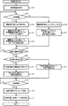
<作動位置設置処理>
まず、図2を参照して観察光学系移動処理について説明する。観察光学系移動処理では、手術顕微鏡1の観察光学系30を観察光束RS,LSに沿って移動させる処理と、観察光学系30の移動に対応させて観察光学系30の焦点距離を変更する処理が行われる。
<Operating position installation process>
First, the observation optical system movement process will be described with reference to FIG. In the observation optical system movement process, a process of moving the observation
本実施形態では、ユーザは、操作部48を操作することで、観察光学系30の移動方向の指示、または、手術顕微鏡1の使用態様を変更する指示を入力することができる。例えば、ユーザは、患者眼Eと手術顕微鏡30の間のワーキングスペースを変更したい場合等に、観察光学系30の移動方向の指示を入力することで、観察光学系30を所望の方向に所望の距離だけ移動させることができる。また、使用態様を変更する指示には、眼科用光学機器50が用いられていない使用態様から、眼科用光学機器50による測定または治療を行う使用態様に変更する指示と、測定または治療を行う使用態様を終了する指示がある。なお、使用態様の種類を変更してもよいことは言うまでもない。
In the present embodiment, the user can input an instruction of the moving direction of the observation
図2に示すように、観察光学系30の移動方向の指示が入力されると(S1:YES)、CPU41は、手術顕微鏡1の観察光学系30を、指示された方向へ、指示された距離だけ移動させる(S2)。本実施形態では、CPU41は、観察光学系移動部6におけるZ移動モータ9の駆動を制御することで、観察光学系30を自動的に移動させる。次いで、CPU41は、焦点距離変更モータ34の駆動を制御することで、観察光学系30の移動方向および移動距離に応じて観察光学系30の焦点距離を変更する(S3)。詳細には、CPU41は、観察光学系30の焦点距離を、観察光学系30の移動距離と同じ距離だけ変更する。なお、観察光学系30が患者眼Eから遠ざけられる場合には焦点距離は増加され、観察光学系30が患者眼Eに近づけられる場合には焦点距離は減少される。その結果、観察光学系30のピント位置が保持されたまま、観察光学系30が移動される。従って、観察光学系30の移動前にフォーカスが患者眼Eに合っていた場合には、観察光学系30の移動後もフォーカスは患者眼Eに合う。
As shown in FIG. 2, when the instruction of the moving direction of the observation
また、眼科用光学機器50による測定または治療を行う使用態様に変更する指示が入力されると(S1:NO、S4:YES)、CPU41は、Z移動モータ9の駆動を制御することで、観察光学系30を、患者眼Eから遠ざかる方向へ所定距離移動させる(S5)。所定距離は、予め固定された距離であってもよいし、ユーザによって予め指定された距離であってもよい。CPU41は、S3と同様に、観察光学系30の移動方向および移動距離に応じて、観察光学系30の焦点距離を、移動距離と同じ距離だけ変更する(S6)。従って、使用態様を変更する指示をユーザが入力するだけで、手術顕微鏡1が使用態様に適した状態となる。次いで、支持機構60によって、眼科用光学機器50の少なくとも一部の位置が、退避位置から作動位置に移動される(S7)。以上の手順によって、患者眼Eと装置の間のワーキングスペースが適切に確保された状態で、眼科用光学機器50が作動位置に移動される。本実施形態では、CPU41は、光学機器移動駆動部66の駆動を制御することで、眼科用光学機器50の少なくとも一部を自動的に作動位置に移動させる。
Further, when an instruction to change the usage mode for measurement or treatment by the ophthalmic
また、測定または治療を行う使用態様を終了する指示が入力されると(S4:NO)、支持機構60によって、眼科用光学機器50の少なくとも一部の位置が、作動位置から退避位置に移動される(S8)。次いで、CPU41は、Z移動モータ9の駆動を制御することで、観察光学系30を、患者眼Eに近づく方向へ所定距離移動させる(S9)。CPU41は、S3と同様に、観察光学系30の移動方向および移動距離に応じて、観察光学系30の焦点距離を、移動距離と同じ距離だけ変更する(S10)。
Further, when an instruction to end the usage mode for performing measurement or treatment is input (S4: NO), the
なお、観察光学系30を移動させる手順(S2,S5,S9)と、観察光学系30の焦点距離を変更する手順(S3,S6,S10)については、いずれの手順が先に行われてもよいし、2つの手順が並行して行われてもよい。 Regarding the procedure for moving the observation optical system 30 (S2, S5, S9) and the procedure for changing the focal length of the observation optical system 30 (S3, S6, S10), whichever procedure is performed first. Alternatively, the two steps may be performed in parallel.
<前眼部用処理>
図3および図4を参照して、眼科手術システム100を用いて患者眼Eの前眼部の観察等を行う場合の処理の一例について説明する。図3および図4に示す例では、眼科用光学機器50として、患者眼Eの前眼部における角膜の形状を測定する角膜形状測定装置(ケラト測定装置)が用いられる場合を例示する。しかし、他の機器が眼科用光学機器50として用いられる場合でも、図3および図4で例示する技術の少なくとも一部を適用できる。また、患者眼Eの眼底の測定または治療を行う場合に、図3および図4で例示する技術の少なくとも一部を適用してもよい。
<Treatment for the anterior segment>
An example of processing in the case of observing the anterior segment of the patient's eye E using the
図3に示すように、CPU41は、眼科用光学機器50のアライメントおよびフォーカスの自動調整を実行する指示が入力されたか否かを判断する(S11)。本実施形態では、ユーザは、眼科用光学機器50のアライメントおよびフォーカスの自動調整および手動調整のいずれかを、操作部48を操作することで選択できる。
As shown in FIG. 3, the
自動調整が選択されている場合には(S11:YES)、CPU41は、撮影素子36R,36Lによって撮影されている顕微鏡画像に対して画像処理を行うことで、アライメントおよびフォーカス調整を行うための指標を検出する(S12)。図4に示すように、本実施形態の眼科用光学機器50は、患者眼Eの角膜形状を測定するために、複数の点状の光77が環状に配置された環状パターンで測定光を照射する。手術顕微鏡1は、眼科用光学機器50から患者眼Eに向けて出射された光(本実施形態では、光77の環状パターン)を、患者眼Eに対する眼科用光学機器50のアライメント、および眼科用光学機器50のフォーカス状態の判断の少なくともいずれかに用いる指標として撮影する。CPU41は、撮影した顕微鏡画像15から、指標の位置を検出する。なお、図4に示す顕微鏡画像15には、測定光によって現れる指標と共に、患者眼Eの瞳孔71、虹彩73、および瞼75等が写り込んでいる。
When automatic adjustment is selected (S11: YES), the
次いで、CPU41は、指標の検出結果に基づいて光学機器移動駆動部66を制御することで、患者眼Eに対する眼科用光学機器50の自動アライメントを実行する(S13)。図4に示す例では、CPU41は、検出した指標の中心78(本実施形態では、複数の点状の光77によって形成された環状パターンの中心78)の位置を検出する。さらに、CPU41は、顕微鏡画像15に対して画像処理を行うことで、アライメントの基準とする基準位置72を検出する。本実施形態では、患者眼Eの瞳孔71が検出されることで、瞳孔71の中心が基準位置72として検出される。しかし、他の位置(例えば、角膜の中心等)が基準位置として検出されてもよい。CPU41は、指標の中心78が基準位置72に近づくように光学機器移動駆動部66の駆動を制御することで、患者眼Eに対する眼科用光学機器50の自動アライメントを実行する。
Next, the
なお、本実施形態では、眼科用光学機器50から環状パターンで出射された光が、アライメントの指標として用いられる。従って、指標の中心位置を認識することが容易である。しかし、眼科用光学機器50から出射される光のパターンを変更することも可能である。例えば、円形のパターン、十字状のパターン等が眼科用光学機器50から出射される場合でも、指標の中心位置を認識することが容易である。
In the present embodiment, the light emitted from the ophthalmic
次いで、CPU41は、指標の検出結果に基づいて光学機器移動駆動部66を制御することで、眼科用光学機器50のフォーカス調整を実行する(S14)。例えば、有限遠の光と無限遠の光を眼科用光学機器50が出射する場合には、CPU41は、有限光による指標の位置と、無限光による指標の位置に基づいてフォーカス状態を判断し、眼科用光学機器50のフォーカスを調整する。
Next, the
なお、フォーカス状態を判断する方法を変更することも可能である。例えば、CPU41は、顕微鏡画像15に対する画像処理によって、指標のサイズ(例えば、図4では環状のパターンの径等)を検出してもよい。この場合、CPU41は、検出される指標のサイズが所定のサイズに近づくように光学機器移動駆動部66の駆動を制御することで、眼科用光学機器50のフォーカスを調整してもよい。指標のパターンを変更することも可能である。また、CPU41は、顕微鏡画像15の指標のエッジが鮮明になるように光学機器移動駆動部66の駆動を制御することで、フォーカス調整を行ってもよい。
It is also possible to change the method of determining the focus state. For example, the
また、アライメントおよびフォーカスの手動調整が選択されている場合には(S11:NO)、CPU41は、眼科用光学機器50から投影された指標が含まれる顕微鏡画像15をディスプレイ47に表示させる(S16)。この状態で、ユーザは、ディスプレイ47に表示された顕微鏡画像15、および、顕微鏡画像15における指標を確認しながら、支持機構60を移動させる指示を操作部(本実施形態ではフットスイッチ)48に入力する。CPU41は、操作部48に入力された信号に基づいて、光学機器移動駆動部66の駆動を制御する(S17)。従って、ユーザは、指標を含む顕微鏡画像15を確認しながら操作部48を操作することで、アライメントおよびフォーカス調整の少なくともいずれかを適切に行うことができる。例えば、ユーザは、指標のパターンの中心が基準位置72に近づくように、測定または治療のための光の光軸に交差する方向に眼科用光学機器50を移動させることで、患者眼Eに対する眼科用光学機器50のアライメントを行ってもよい。
When the manual alignment and focus adjustment are selected (S11: NO), the
CPU41は、測定または治療を実行させる指示が操作部48に入力されたか否かを判断する(S18)。入力されていなければ(S18:NO)、処理はS11へ戻り、アライメントおよびフォーカス調整の少なくともいずれかが継続して実行される。従って、測定または治療の前に患者眼Eの動き等が生じても、患者眼Eに対する眼科用光学機器50の位置が適切な位置に保たれる。測定または治療を実行させる指示が入力されると(S18:YES)、CPU41は、測定または治療(図3および図4に示す例では、角膜形状の測定)を実行し(S19)、処理は終了する。
The
<眼底用処理>
図5および図6を参照して、眼科手術システム100を用いて患者眼Eの眼底の観察等を行う場合の処理の一例について説明する。図5および図6に示す例では、眼科用光学機器50として、患者眼Eの眼底に治療レーザ光を照射するレーザ治療装置が用いられる場合を例示する。しかし、他の機器(例えば、眼底の断層画像を撮影するOCT装置)が眼科用光学機器50として用いられる場合でも、図5および図6で例示する技術の少なくとも一部を適用できる。OCT装置を用いる場合、以下の説明における「治療」「治療位置」の用語は、「断層画像の取得」「断層画像を取得するために測定光を走査させる走査位置」にそれぞれ置き換えられる。
<Treatment for fundus>
With reference to FIGS. 5 and 6, an example of processing in the case of observing the fundus of the patient's eye E using the
図5に示すように、CPU41は、眼底上における治療範囲90(図6参照)を取得する(S20)。例えば、CPU41は、ユーザが操作部48を操作することで入力した指示に応じて、眼底上の治療範囲90を取得してもよい。また、治療を行う部位(範囲でもよい)を示す情報が手術前に設定されている場合には、手術前に設定された情報(以下、「手術前情報」という)から治療範囲90を取得してもよい。
As shown in FIG. 5, the
CPU41は、眼科用光学機器50のアライメントおよびフォーカスの自動調整を実行する指示が入力されたか否かを判断する(S21)。この処理は、前述したS11(図3参照)の処理と同様である。
The
自動調整が選択されている場合には(S21:YES)、CPU41は、撮影素子36R,36Lによって撮影されている顕微鏡画像に対して画像処理を行うことで、アライメントおよびフォーカス調整を行うための指標を検出する(S22)。図5に示すように、本実施形態の眼科用光学機器50は、治療レーザ光の照射位置を示すエイミング光85を出射する。図5に示す状態では、偏向部53(図1参照)によって治療レーザ光およびエイミング光85が偏向される範囲の中心に、エイミング光85が照射されている。CPU41は、撮影した顕微鏡画像15から、エイミング光85の照射位置を指標の位置として検出する。なお、図5に示す顕微鏡画像には、エイミング光85によって現れる指標と共に、患者眼Eの眼底の視神経乳頭81、黄斑82、および血管83が写り込んでいる。
When automatic adjustment is selected (S21: YES), the
次いで、CPU41は、指標の検出結果に基づいて光学機器移動駆動部66を制御することで、患者眼Eに対する眼科用光学機器50の自動アライメントを実行する(S23)。図5に示す例では、CPU41は、検出した指標(エイミング光85)が治療範囲90の中心91に近づくように光学機器移動駆動部66の駆動を制御することで、患者眼Eに対する眼科用光学機器50の自動アライメントを実行する。ただし、アライメントの具体的な方法を変更することも可能である。例えば、CPU41は、治療範囲90の中心91の代わりに、アライメントの基準となる基準位置を設定し、指標が基準位置に近づくように光学機器移動駆動部66の駆動を制御してもよい。
Next, the
次いで、CPU41は、指標の検出結果に基づいて光学機器移動駆動部66を制御することで、眼科用光学機器50のフォーカス調整を実行する(S24)。一例として、本実施形態の眼科用光学機器50では、治療レーザ光とエイミング光85のスポットサイズは、フォーカスが合った状態で最も小さくなる。従って、CPU41は、顕微鏡画像15に対する画像処理によってエイミング光85のスポットサイズを検出する。CPU41は、スポットサイズが最も小さくなるように光学機器移動駆動部66の駆動を制御することで、眼科用光学機器50のフォーカスを調整する。
Next, the
また、アライメントおよびフォーカスの手動調整が選択されている場合には(S21:NO)、CPU41は、眼科用光学機器50から投影された指標が含まれる顕微鏡画像15をディスプレイ47に表示させる(S26)。この状態で、ユーザは、ディスプレイ47に表示された顕微鏡画像15、および、顕微鏡画像15における指標の位置を確認しながら、眼科用光学機器50を移動させる指示を操作部(本実施形態ではフットスイッチ)48に入力する。CPU41は、操作部48に入力された信号に基づいて、光学機器移動駆動部66の駆動を制御する(S27)。例えば、ユーザは、指標が治療範囲90の中心91に近づくように操作部48を操作することで、眼科用光学機器50のアライメントを行ってもよい。また、ユーザは、エイミング光85のスポットサイズが最も小さくなるように操作部48を操作することで、フォーカス調整を行ってもよい。
When the manual alignment and focus adjustment are selected (S21: NO), the
治療位置93(図6参照)の設定を開始する指示が操作部48に入力されると(S28:YES)、CPU41は、治療位置93の設定に手術前情報を使用するか否かを判断する(S30)。本実施形態では、ユーザは、治療位置93の設定に手術前情報を使用するか否かを選択できる。
When an instruction to start setting the treatment position 93 (see FIG. 6) is input to the operation unit 48 (S28: YES), the
手術前情報を使用する旨が選択されている場合には(S30:YES)、CPU41は、手術前情報と顕微鏡画像15を照合させる(S31)。例えば、CPU41は、顕微鏡画像15に対して画像処理を行うことで、顕微鏡画像15に写り込んでいる患者眼Eの特徴部位(例えば、視神経乳頭81、黄斑82、および血管83の少なくともいずれか)を検出し、検出結果に基づいて、手術前情報と顕微鏡画像15を自動的に照合させてもよい。また、CPU41は、ユーザによる操作指示に応じて手術前情報と顕微鏡画像15を照合させてもよい。なお、手術前情報は、例えば、治療を行う部位を示す位置情報が眼底画像上に付加された情報であってもよいし、治療を行う部位と特定の部位の位置関係を示す情報であってもよい。次いで、CPU41は、手術前情報と顕微鏡画像15の照合結果に基づいて、眼科用光学機器50による治療を行う位置93を設定する(S32)。
When it is selected to use the preoperative information (S30: YES), the
また、手術前情報を使用しない旨が選択されている場合には(S30:NO)、CPU41は、手術前情報を使用せずに、顕微鏡画像15に基づいて治療位置93を設定する(S34)。S34の具体的な方法は適宜選択できる。例えば、CPU41は、ユーザが操作部48を操作することで指定した位置に、1つまたは複数の治療位置93を設定してもよい。また、CPU41は、S20で取得した治療範囲90の範囲内に、1つまたは複数の治療位置93を自動的に設定してもよい。なお、それぞれの治療位置93の間隔等の条件が、ユーザの指示等に応じて定められていてもよい。この場合、CPU41は、定められた条件に基づいて、治療範囲90内に治療位置93を設定してもよい。また、CPU41は、治療レーザ光の照射を禁止する禁止領域を治療範囲90内に設定し、治療範囲93の範囲内且つ禁止領域外に治療位置93を設定してもよい。この場合、CPU41は、ユーザの指示に応じて禁止領域を設定してもよい。また、CPU41は、顕微鏡画像15に対して画像処理を行い、患者眼Eの特徴部位(例えば、視神経乳頭81、黄斑82、および血管83の少なくともいずれか)を検出して、特徴部位(特徴部位の近傍も含めてもよい)を禁止領域として設定してもよい。
When it is selected not to use the preoperative information (S30: NO), the
次いで、CPU41は、治療の開始指示が入力されたか否かを判断する(S35)。治療の開始指示が入力されると(S35:YES)、CPU41は、治療位置93のトラッキングを開始し(S36)、治療位置93に治療レーザ光を照射する。例えば、CPU41は、顕微鏡画像15に対して画像処理を行うことで、患者眼Eの動きを検出する。CPU41は、検出した患者眼Eの動きに応じて偏向部53の駆動を制御することで、眼科用光学機器50によって治療レーザ光を照射する位置を、S32またはS34で設定した位置に追従させる。その結果、患者眼Eの動きに関わらず、治療位置93が、設定された位置に追従(トラッキング)される。
Next, the
上記実施形態で開示された技術は一例に過ぎない。従って、上記実施形態で例示された技術を変更することも可能である。例えば、上記実施形態では、顕微鏡画像15に基づくアライメントとフォーカス調整が共に実行される。しかし、アライメントおよびフォーカス調整の一方のみが顕微鏡画像15に基づいて実行されてもよい。また、CPU41は、顕微鏡画像15に基づくアライメントとフォーカス調整を実行せずに、測定または治療を行う位置の設定のみを顕微鏡画像15に基づいて実行してもよい。
The techniques disclosed in the above embodiments are merely examples. Therefore, it is possible to modify the techniques exemplified in the above embodiments. For example, in the above embodiment, alignment and focus adjustment based on the
1 手術顕微鏡
6 観察光学系移動部
9 Z移動モータ
10 観察装置
15 顕微鏡画像
30 観察光学系
31 焦点距離変更部
34 焦点距離変更モータ
36R,36L 撮影素子
40 制御部
47 ディスプレイ
48 操作部
50 眼科用光学機器
53 偏向部
55 光学素子
60 支持機構
63 光学機器移動部
66 光学機器移動駆動部
100 眼科手術システム
1
Claims (3)
患者眼からの観察光束を導光する観察光学系を有し、手術中に前記患者眼をユーザに観察させる手術顕微鏡と、
光の出射および受光の少なくともいずれかを行うことで前記患者眼の特性の測定または治療を行う眼科用光学機器と、
前記眼科用光学機器の少なくとも一部を、前記観察光学系と前記患者眼の間で前記患者眼の特性の測定または治療を行う作動位置と、前記作動位置から離間する退避位置との間で移動可能に支持する支持機構と、
を備え、
前記手術顕微鏡は、
前記観察光学系によって導光された前記観察光束を受光することで、前記患者眼の顕微鏡画像を撮影する撮影素子をさらに備え、
前記眼科手術システムは、
少なくとも表示手段における前記顕微鏡画像の表示制御を行う制御部をさらに備え、
前記手術顕微鏡は、
前記眼科用光学機器から前記患者眼に向けて出射された光を、前記患者眼に対する前記眼科用光学機器のアライメント、および、前記眼科用光学機器のフォーカス状態の判断の少なくともいずれかに用いる指標として撮影することを特徴とする眼科手術システム。 It ’s an eye surgery system.
An operating microscope that has an observation optical system that guides the observation light beam from the patient's eye and allows the user to observe the patient's eye during surgery.
An ophthalmic optical instrument that measures or treats the characteristics of the patient's eye by at least either emitting or receiving light.
At least a part of the ophthalmic optical device is moved between the observation optical system and the patient's eye at an operating position for measuring or treating the characteristics of the patient's eye and a retracting position away from the operating position. Support mechanism that supports possible and
Equipped with a,
The operating microscope
An imaging element for capturing a microscope image of the patient's eye by receiving the observation luminous flux guided by the observation optical system is further provided.
The ophthalmic surgery system
A control unit that controls the display of the microscope image at least in the display means is further provided.
The operating microscope
The light emitted from the ophthalmic optical device toward the patient's eye is used as an index used for at least one of the alignment of the ophthalmic optical device with respect to the patient's eye and the determination of the focus state of the ophthalmic optical device. An ophthalmic surgery system characterized by taking pictures .
前記支持機構は、 The support mechanism
前記支持機構による前記眼科用光学機器の移動を駆動させる光学機器移動駆動部を備え、 An optical device movement drive unit for driving the movement of the ophthalmic optical device by the support mechanism is provided.
前記制御部は、 The control unit
前記指標を含む前記顕微鏡画像を前記表示手段に表示させると共に、 While displaying the microscope image including the index on the display means,
前記眼科用光学機器を移動させるためにユーザによって入力される信号に基づいて前記光学機器移動駆動部を制御することで、前記眼科用光学機器のアライメントおよびフォーカス調整の少なくともいずれかを行うことを特徴とする眼科手術システム。 By controlling the optical device movement drive unit based on a signal input by the user to move the ophthalmic optical device, at least one of alignment and focus adjustment of the ophthalmic optical device is performed. Ophthalmic surgery system.
前記支持機構は、 The support mechanism
前記支持機構による前記眼科用光学機器の移動を駆動させる光学機器移動駆動部を備え、 An optical device movement drive unit for driving the movement of the ophthalmic optical device by the support mechanism is provided.
前記制御部は、 The control unit
前記顕微鏡画像に対して画像処理を行うことで前記指標を検出し、 The index is detected by performing image processing on the microscope image.
前記指標の検出結果に基づいて前記光学機器移動駆動部を制御することで、前記眼科用光学機器のアライメントおよびフォーカス調整の少なくともいずれかを行うことを特徴とする眼科手術システム。 An ophthalmic surgery system characterized in that at least one of alignment and focus adjustment of the ophthalmic optical device is performed by controlling the moving drive unit of the optical device based on the detection result of the index.
Priority Applications (1)
| Application Number | Priority Date | Filing Date | Title |
|---|---|---|---|
| JP2016194084A JP6812724B2 (en) | 2016-09-30 | 2016-09-30 | Ophthalmic Surgery System, Ophthalmic Surgery System Control Program, and Ophthalmic Surgical Microscope |
Applications Claiming Priority (1)
| Application Number | Priority Date | Filing Date | Title |
|---|---|---|---|
| JP2016194084A JP6812724B2 (en) | 2016-09-30 | 2016-09-30 | Ophthalmic Surgery System, Ophthalmic Surgery System Control Program, and Ophthalmic Surgical Microscope |
Publications (3)
| Publication Number | Publication Date |
|---|---|
| JP2018051210A JP2018051210A (en) | 2018-04-05 |
| JP2018051210A5 JP2018051210A5 (en) | 2019-09-26 |
| JP6812724B2 true JP6812724B2 (en) | 2021-01-13 |
Family
ID=61833263
Family Applications (1)
| Application Number | Title | Priority Date | Filing Date |
|---|---|---|---|
| JP2016194084A Expired - Fee Related JP6812724B2 (en) | 2016-09-30 | 2016-09-30 | Ophthalmic Surgery System, Ophthalmic Surgery System Control Program, and Ophthalmic Surgical Microscope |
Country Status (1)
| Country | Link |
|---|---|
| JP (1) | JP6812724B2 (en) |
Families Citing this family (7)
| Publication number | Priority date | Publication date | Assignee | Title |
|---|---|---|---|---|
| US11771596B2 (en) | 2010-05-10 | 2023-10-03 | Ramot At Tel-Aviv University Ltd. | System and method for treating an eye |
| KR102169674B1 (en) * | 2018-04-23 | 2020-10-23 | 인제대학교 산학협력단 | Mixed reality fundus camera |
| JP2021121821A (en) * | 2018-05-07 | 2021-08-26 | ソニーグループ株式会社 | Ophthalmology surgical microscope system, controller, and method for control |
| IL279749B2 (en) * | 2018-07-02 | 2024-04-01 | Belkin Vision Ltd | Direct selective laser trabeculoplasty |
| JP7263726B2 (en) * | 2018-09-28 | 2023-04-25 | 株式会社ニデック | Ophthalmic laser therapy device and ophthalmic laser control program |
| WO2020121456A1 (en) * | 2018-12-12 | 2020-06-18 | 株式会社ニコン | Microscope, adjustment device for microscope, microscope system, method for controlling microscope, and program |
| EP4238483A1 (en) * | 2020-10-27 | 2023-09-06 | Topcon Corporation | Ophthalmologic observation device |
Family Cites Families (5)
| Publication number | Priority date | Publication date | Assignee | Title |
|---|---|---|---|---|
| JP3872219B2 (en) * | 1998-11-02 | 2007-01-24 | 株式会社ニデック | Laser therapy device |
| JP3939328B2 (en) * | 2005-02-16 | 2007-07-04 | オリンパス株式会社 | Surgical microscope |
| US9844314B2 (en) * | 2014-07-28 | 2017-12-19 | Novartis Ag | Increased depth of field microscope and associated devices, systems, and methods |
| DE112015004692A5 (en) * | 2014-10-17 | 2017-07-13 | Carl Zeiss Meditec Ag | Systems and methods for short-pulse laser eye surgery |
| JP6456711B2 (en) * | 2015-02-16 | 2019-01-23 | 株式会社トプコン | Ophthalmic surgical microscope and ophthalmic surgical attachment |
-
2016
- 2016-09-30 JP JP2016194084A patent/JP6812724B2/en not_active Expired - Fee Related
Also Published As
| Publication number | Publication date |
|---|---|
| JP2018051210A (en) | 2018-04-05 |
Similar Documents
| Publication | Publication Date | Title |
|---|---|---|
| JP6812724B2 (en) | Ophthalmic Surgery System, Ophthalmic Surgery System Control Program, and Ophthalmic Surgical Microscope | |
| TWI672121B (en) | Movable wide-angle ophthalmic surgical system | |
| US8205988B2 (en) | Stereomicroscope | |
| JP4080379B2 (en) | Ophthalmic laser equipment | |
| US10820793B2 (en) | Biological object observation system and non-transitory computer-readable medium | |
| CN107529981B (en) | Tracking system for surgical optical coherence tomography | |
| US20220115122A1 (en) | Control device, ophthalmic microscope system, ophthalmic microscope, and image processing apparatus | |
| JPH09149914A (en) | Ophthalmologic operation device | |
| US11134842B2 (en) | Observation system and non-transitory computer-readable medium storing computer-readable instructions | |
| JP2016193033A (en) | Ophthalmologic apparatus and ophthalmologic apparatus control program | |
| US10456035B2 (en) | Ophthalmic surgical microscope | |
| JP2016193030A (en) | Ophthalmic laser surgery device and ophthalmic surgery control program | |
| JP2016193028A (en) | Ophthalmic laser surgery device | |
| JP3675852B2 (en) | Ophthalmic surgery equipment | |
| JP2016193029A (en) | Ophthalmologic apparatus and ophthalmologic apparatus control program | |
| JP6572596B2 (en) | Ophthalmic apparatus and ophthalmic apparatus control program | |
| WO2016159331A1 (en) | Ophthalmic laser surgery device, ophthalmic device, ophthalmic device control program, and ophthalmic surgery control program | |
| EP3345532B1 (en) | Observation system and observation control program | |
| JP6098094B2 (en) | Ophthalmic equipment | |
| JP3872228B2 (en) | Laser surgical device |
Legal Events
| Date | Code | Title | Description |
|---|---|---|---|
| A521 | Request for written amendment filed |
Free format text: JAPANESE INTERMEDIATE CODE: A523 Effective date: 20190810 |
|
| A621 | Written request for application examination |
Free format text: JAPANESE INTERMEDIATE CODE: A621 Effective date: 20190810 |
|
| A977 | Report on retrieval |
Free format text: JAPANESE INTERMEDIATE CODE: A971007 Effective date: 20200522 |
|
| A131 | Notification of reasons for refusal |
Free format text: JAPANESE INTERMEDIATE CODE: A131 Effective date: 20200728 |
|
| A521 | Request for written amendment filed |
Free format text: JAPANESE INTERMEDIATE CODE: A523 Effective date: 20200928 |
|
| TRDD | Decision of grant or rejection written | ||
| A01 | Written decision to grant a patent or to grant a registration (utility model) |
Free format text: JAPANESE INTERMEDIATE CODE: A01 Effective date: 20201117 |
|
| A61 | First payment of annual fees (during grant procedure) |
Free format text: JAPANESE INTERMEDIATE CODE: A61 Effective date: 20201130 |
|
| R150 | Certificate of patent or registration of utility model |
Ref document number: 6812724 Country of ref document: JP Free format text: JAPANESE INTERMEDIATE CODE: R150 |
|
| LAPS | Cancellation because of no payment of annual fees |