JP6917451B2 - Fluid centrifuge - Google Patents
Fluid centrifuge Download PDFInfo
- Publication number
- JP6917451B2 JP6917451B2 JP2019517960A JP2019517960A JP6917451B2 JP 6917451 B2 JP6917451 B2 JP 6917451B2 JP 2019517960 A JP2019517960 A JP 2019517960A JP 2019517960 A JP2019517960 A JP 2019517960A JP 6917451 B2 JP6917451 B2 JP 6917451B2
- Authority
- JP
- Japan
- Prior art keywords
- fluid
- modular cassette
- chamber
- wax
- separation
- Prior art date
- Legal status (The legal status is an assumption and is not a legal conclusion. Google has not performed a legal analysis and makes no representation as to the accuracy of the status listed.)
- Active
Links
- 0 CC1CC*CC1 Chemical compound CC1CC*CC1 0.000 description 2
Images


Classifications
-
- B—PERFORMING OPERATIONS; TRANSPORTING
- B01—PHYSICAL OR CHEMICAL PROCESSES OR APPARATUS IN GENERAL
- B01L—CHEMICAL OR PHYSICAL LABORATORY APPARATUS FOR GENERAL USE
- B01L3/00—Containers or dishes for laboratory use, e.g. laboratory glassware; Droppers
- B01L3/50—Containers for the purpose of retaining a material to be analysed, e.g. test tubes
- B01L3/502—Containers for the purpose of retaining a material to be analysed, e.g. test tubes with fluid transport, e.g. in multi-compartment structures
- B01L3/5027—Containers for the purpose of retaining a material to be analysed, e.g. test tubes with fluid transport, e.g. in multi-compartment structures by integrated microfluidic structures, i.e. dimensions of channels and chambers are such that surface tension forces are important, e.g. lab-on-a-chip
- B01L3/502738—Containers for the purpose of retaining a material to be analysed, e.g. test tubes with fluid transport, e.g. in multi-compartment structures by integrated microfluidic structures, i.e. dimensions of channels and chambers are such that surface tension forces are important, e.g. lab-on-a-chip characterised by integrated valves
-
- B—PERFORMING OPERATIONS; TRANSPORTING
- B01—PHYSICAL OR CHEMICAL PROCESSES OR APPARATUS IN GENERAL
- B01D—SEPARATION
- B01D17/00—Separation of liquids, not provided for elsewhere, e.g. by thermal diffusion
- B01D17/02—Separation of non-miscible liquids
- B01D17/0217—Separation of non-miscible liquids by centrifugal force
-
- A—HUMAN NECESSITIES
- A61—MEDICAL OR VETERINARY SCIENCE; HYGIENE
- A61M—DEVICES FOR INTRODUCING MEDIA INTO, OR ONTO, THE BODY; DEVICES FOR TRANSDUCING BODY MEDIA OR FOR TAKING MEDIA FROM THE BODY; DEVICES FOR PRODUCING OR ENDING SLEEP OR STUPOR
- A61M1/00—Suction or pumping devices for medical purposes; Devices for carrying-off, for treatment of, or for carrying-over, body-liquids; Drainage systems
- A61M1/02—Blood transfusion apparatus
- A61M1/0209—Multiple bag systems for separating or storing blood components
- A61M1/0231—Multiple bag systems for separating or storing blood components with gas separating means, e.g. air outlet through microporous membrane or gas bag
-
- A—HUMAN NECESSITIES
- A61—MEDICAL OR VETERINARY SCIENCE; HYGIENE
- A61M—DEVICES FOR INTRODUCING MEDIA INTO, OR ONTO, THE BODY; DEVICES FOR TRANSDUCING BODY MEDIA OR FOR TAKING MEDIA FROM THE BODY; DEVICES FOR PRODUCING OR ENDING SLEEP OR STUPOR
- A61M1/00—Suction or pumping devices for medical purposes; Devices for carrying-off, for treatment of, or for carrying-over, body-liquids; Drainage systems
- A61M1/02—Blood transfusion apparatus
- A61M1/029—Separating blood components present in distinct layers in a container, not otherwise provided for
-
- A—HUMAN NECESSITIES
- A61—MEDICAL OR VETERINARY SCIENCE; HYGIENE
- A61M—DEVICES FOR INTRODUCING MEDIA INTO, OR ONTO, THE BODY; DEVICES FOR TRANSDUCING BODY MEDIA OR FOR TAKING MEDIA FROM THE BODY; DEVICES FOR PRODUCING OR ENDING SLEEP OR STUPOR
- A61M1/00—Suction or pumping devices for medical purposes; Devices for carrying-off, for treatment of, or for carrying-over, body-liquids; Drainage systems
- A61M1/36—Other treatment of blood in a by-pass of the natural circulatory system, e.g. temperature adaptation, irradiation ; Extra-corporeal blood circuits
- A61M1/3621—Extra-corporeal blood circuits
- A61M1/3622—Extra-corporeal blood circuits with a cassette forming partially or totally the blood circuit
- A61M1/36224—Extra-corporeal blood circuits with a cassette forming partially or totally the blood circuit with sensing means or components thereof
-
- A—HUMAN NECESSITIES
- A61—MEDICAL OR VETERINARY SCIENCE; HYGIENE
- A61M—DEVICES FOR INTRODUCING MEDIA INTO, OR ONTO, THE BODY; DEVICES FOR TRANSDUCING BODY MEDIA OR FOR TAKING MEDIA FROM THE BODY; DEVICES FOR PRODUCING OR ENDING SLEEP OR STUPOR
- A61M1/00—Suction or pumping devices for medical purposes; Devices for carrying-off, for treatment of, or for carrying-over, body-liquids; Drainage systems
- A61M1/36—Other treatment of blood in a by-pass of the natural circulatory system, e.g. temperature adaptation, irradiation ; Extra-corporeal blood circuits
- A61M1/3621—Extra-corporeal blood circuits
- A61M1/3622—Extra-corporeal blood circuits with a cassette forming partially or totally the blood circuit
- A61M1/36226—Constructional details of cassettes, e.g. specific details on material or shape
- A61M1/362262—Details of incorporated reservoirs
-
- A—HUMAN NECESSITIES
- A61—MEDICAL OR VETERINARY SCIENCE; HYGIENE
- A61M—DEVICES FOR INTRODUCING MEDIA INTO, OR ONTO, THE BODY; DEVICES FOR TRANSDUCING BODY MEDIA OR FOR TAKING MEDIA FROM THE BODY; DEVICES FOR PRODUCING OR ENDING SLEEP OR STUPOR
- A61M1/00—Suction or pumping devices for medical purposes; Devices for carrying-off, for treatment of, or for carrying-over, body-liquids; Drainage systems
- A61M1/36—Other treatment of blood in a by-pass of the natural circulatory system, e.g. temperature adaptation, irradiation ; Extra-corporeal blood circuits
- A61M1/3621—Extra-corporeal blood circuits
- A61M1/3622—Extra-corporeal blood circuits with a cassette forming partially or totally the blood circuit
- A61M1/36226—Constructional details of cassettes, e.g. specific details on material or shape
- A61M1/362265—Details of valves
-
- A—HUMAN NECESSITIES
- A61—MEDICAL OR VETERINARY SCIENCE; HYGIENE
- A61M—DEVICES FOR INTRODUCING MEDIA INTO, OR ONTO, THE BODY; DEVICES FOR TRANSDUCING BODY MEDIA OR FOR TAKING MEDIA FROM THE BODY; DEVICES FOR PRODUCING OR ENDING SLEEP OR STUPOR
- A61M1/00—Suction or pumping devices for medical purposes; Devices for carrying-off, for treatment of, or for carrying-over, body-liquids; Drainage systems
- A61M1/36—Other treatment of blood in a by-pass of the natural circulatory system, e.g. temperature adaptation, irradiation ; Extra-corporeal blood circuits
- A61M1/3621—Extra-corporeal blood circuits
- A61M1/3622—Extra-corporeal blood circuits with a cassette forming partially or totally the blood circuit
- A61M1/36226—Constructional details of cassettes, e.g. specific details on material or shape
- A61M1/362266—Means for adding solutions or substances to the blood
-
- A—HUMAN NECESSITIES
- A61—MEDICAL OR VETERINARY SCIENCE; HYGIENE
- A61M—DEVICES FOR INTRODUCING MEDIA INTO, OR ONTO, THE BODY; DEVICES FOR TRANSDUCING BODY MEDIA OR FOR TAKING MEDIA FROM THE BODY; DEVICES FOR PRODUCING OR ENDING SLEEP OR STUPOR
- A61M1/00—Suction or pumping devices for medical purposes; Devices for carrying-off, for treatment of, or for carrying-over, body-liquids; Drainage systems
- A61M1/36—Other treatment of blood in a by-pass of the natural circulatory system, e.g. temperature adaptation, irradiation ; Extra-corporeal blood circuits
- A61M1/3693—Other treatment of blood in a by-pass of the natural circulatory system, e.g. temperature adaptation, irradiation ; Extra-corporeal blood circuits using separation based on different densities of components, e.g. centrifuging
-
- B—PERFORMING OPERATIONS; TRANSPORTING
- B04—CENTRIFUGAL APPARATUS OR MACHINES FOR CARRYING-OUT PHYSICAL OR CHEMICAL PROCESSES
- B04B—CENTRIFUGES
- B04B5/00—Other centrifuges
- B04B5/04—Radial chamber apparatus for separating predominantly liquid mixtures, e.g. butyrometers
- B04B5/0407—Radial chamber apparatus for separating predominantly liquid mixtures, e.g. butyrometers for liquids contained in receptacles
- B04B5/0428—Radial chamber apparatus for separating predominantly liquid mixtures, e.g. butyrometers for liquids contained in receptacles with flexible receptacles
-
- B—PERFORMING OPERATIONS; TRANSPORTING
- B04—CENTRIFUGAL APPARATUS OR MACHINES FOR CARRYING-OUT PHYSICAL OR CHEMICAL PROCESSES
- B04B—CENTRIFUGES
- B04B5/00—Other centrifuges
- B04B5/04—Radial chamber apparatus for separating predominantly liquid mixtures, e.g. butyrometers
- B04B5/0442—Radial chamber apparatus for separating predominantly liquid mixtures, e.g. butyrometers with means for adding or withdrawing liquid substances during the centrifugation, e.g. continuous centrifugation
-
- B—PERFORMING OPERATIONS; TRANSPORTING
- B04—CENTRIFUGAL APPARATUS OR MACHINES FOR CARRYING-OUT PHYSICAL OR CHEMICAL PROCESSES
- B04B—CENTRIFUGES
- B04B7/00—Elements of centrifuges
- B04B7/08—Rotary bowls
-
- F—MECHANICAL ENGINEERING; LIGHTING; HEATING; WEAPONS; BLASTING
- F16—ENGINEERING ELEMENTS AND UNITS; GENERAL MEASURES FOR PRODUCING AND MAINTAINING EFFECTIVE FUNCTIONING OF MACHINES OR INSTALLATIONS; THERMAL INSULATION IN GENERAL
- F16K—VALVES; TAPS; COCKS; ACTUATING-FLOATS; DEVICES FOR VENTING OR AERATING
- F16K99/00—Subject matter not provided for in other groups of this subclass
- F16K99/0001—Microvalves
- F16K99/0003—Constructional types of microvalves; Details of the cutting-off member
- F16K99/0032—Constructional types of microvalves; Details of the cutting-off member using phase transition or influencing viscosity
-
- F—MECHANICAL ENGINEERING; LIGHTING; HEATING; WEAPONS; BLASTING
- F16—ENGINEERING ELEMENTS AND UNITS; GENERAL MEASURES FOR PRODUCING AND MAINTAINING EFFECTIVE FUNCTIONING OF MACHINES OR INSTALLATIONS; THERMAL INSULATION IN GENERAL
- F16K—VALVES; TAPS; COCKS; ACTUATING-FLOATS; DEVICES FOR VENTING OR AERATING
- F16K99/00—Subject matter not provided for in other groups of this subclass
- F16K99/0001—Microvalves
- F16K99/0034—Operating means specially adapted for microvalves
- F16K99/0042—Electric operating means therefor
- F16K99/0044—Electric operating means therefor using thermo-electric means
-
- G—PHYSICS
- G01—MEASURING; TESTING
- G01N—INVESTIGATING OR ANALYSING MATERIALS BY DETERMINING THEIR CHEMICAL OR PHYSICAL PROPERTIES
- G01N1/00—Sampling; Preparing specimens for investigation
- G01N1/28—Preparing specimens for investigation including physical details of (bio-)chemical methods covered elsewhere, e.g. G01N33/50, C12Q
- G01N1/40—Concentrating samples
- G01N1/4077—Concentrating samples by other techniques involving separation of suspended solids
-
- G—PHYSICS
- G01—MEASURING; TESTING
- G01N—INVESTIGATING OR ANALYSING MATERIALS BY DETERMINING THEIR CHEMICAL OR PHYSICAL PROPERTIES
- G01N33/00—Investigating or analysing materials by specific methods not covered by groups G01N1/00 - G01N31/00
- G01N33/48—Biological material, e.g. blood, urine; Haemocytometers
- G01N33/483—Physical analysis of biological material
- G01N33/487—Physical analysis of biological material of liquid biological material
- G01N33/49—Blood
- G01N33/491—Blood by separating the blood components
-
- G—PHYSICS
- G01—MEASURING; TESTING
- G01N—INVESTIGATING OR ANALYSING MATERIALS BY DETERMINING THEIR CHEMICAL OR PHYSICAL PROPERTIES
- G01N35/00—Automatic analysis not limited to methods or materials provided for in any single one of groups G01N1/00 - G01N33/00; Handling materials therefor
- G01N35/00029—Automatic analysis not limited to methods or materials provided for in any single one of groups G01N1/00 - G01N33/00; Handling materials therefor provided with flat sample substrates, e.g. slides
- G01N35/00069—Automatic analysis not limited to methods or materials provided for in any single one of groups G01N1/00 - G01N33/00; Handling materials therefor provided with flat sample substrates, e.g. slides whereby the sample substrate is of the bio-disk type, i.e. having the format of an optical disk
-
- A—HUMAN NECESSITIES
- A61—MEDICAL OR VETERINARY SCIENCE; HYGIENE
- A61M—DEVICES FOR INTRODUCING MEDIA INTO, OR ONTO, THE BODY; DEVICES FOR TRANSDUCING BODY MEDIA OR FOR TAKING MEDIA FROM THE BODY; DEVICES FOR PRODUCING OR ENDING SLEEP OR STUPOR
- A61M1/00—Suction or pumping devices for medical purposes; Devices for carrying-off, for treatment of, or for carrying-over, body-liquids; Drainage systems
- A61M1/36—Other treatment of blood in a by-pass of the natural circulatory system, e.g. temperature adaptation, irradiation ; Extra-corporeal blood circuits
- A61M1/38—Removing constituents from donor blood and storing or returning remainder to body, e.g. for transfusion
-
- A—HUMAN NECESSITIES
- A61—MEDICAL OR VETERINARY SCIENCE; HYGIENE
- A61M—DEVICES FOR INTRODUCING MEDIA INTO, OR ONTO, THE BODY; DEVICES FOR TRANSDUCING BODY MEDIA OR FOR TAKING MEDIA FROM THE BODY; DEVICES FOR PRODUCING OR ENDING SLEEP OR STUPOR
- A61M2205/00—General characteristics of the apparatus
- A61M2205/12—General characteristics of the apparatus with interchangeable cassettes forming partially or totally the fluid circuit
- A61M2205/128—General characteristics of the apparatus with interchangeable cassettes forming partially or totally the fluid circuit with incorporated valves
-
- A—HUMAN NECESSITIES
- A61—MEDICAL OR VETERINARY SCIENCE; HYGIENE
- A61M—DEVICES FOR INTRODUCING MEDIA INTO, OR ONTO, THE BODY; DEVICES FOR TRANSDUCING BODY MEDIA OR FOR TAKING MEDIA FROM THE BODY; DEVICES FOR PRODUCING OR ENDING SLEEP OR STUPOR
- A61M2205/00—General characteristics of the apparatus
- A61M2205/36—General characteristics of the apparatus related to heating or cooling
- A61M2205/3653—General characteristics of the apparatus related to heating or cooling by Joule effect, i.e. electric resistance
-
- B—PERFORMING OPERATIONS; TRANSPORTING
- B01—PHYSICAL OR CHEMICAL PROCESSES OR APPARATUS IN GENERAL
- B01L—CHEMICAL OR PHYSICAL LABORATORY APPARATUS FOR GENERAL USE
- B01L2300/00—Additional constructional details
- B01L2300/08—Geometry, shape and general structure
- B01L2300/0803—Disc shape
-
- B—PERFORMING OPERATIONS; TRANSPORTING
- B01—PHYSICAL OR CHEMICAL PROCESSES OR APPARATUS IN GENERAL
- B01L—CHEMICAL OR PHYSICAL LABORATORY APPARATUS FOR GENERAL USE
- B01L2300/00—Additional constructional details
- B01L2300/08—Geometry, shape and general structure
- B01L2300/0861—Configuration of multiple channels and/or chambers in a single devices
- B01L2300/0864—Configuration of multiple channels and/or chambers in a single devices comprising only one inlet and multiple receiving wells, e.g. for separation, splitting
-
- B—PERFORMING OPERATIONS; TRANSPORTING
- B01—PHYSICAL OR CHEMICAL PROCESSES OR APPARATUS IN GENERAL
- B01L—CHEMICAL OR PHYSICAL LABORATORY APPARATUS FOR GENERAL USE
- B01L2400/00—Moving or stopping fluids
- B01L2400/04—Moving fluids with specific forces or mechanical means
- B01L2400/0403—Moving fluids with specific forces or mechanical means specific forces
- B01L2400/0409—Moving fluids with specific forces or mechanical means specific forces centrifugal forces
-
- B—PERFORMING OPERATIONS; TRANSPORTING
- B01—PHYSICAL OR CHEMICAL PROCESSES OR APPARATUS IN GENERAL
- B01L—CHEMICAL OR PHYSICAL LABORATORY APPARATUS FOR GENERAL USE
- B01L2400/00—Moving or stopping fluids
- B01L2400/06—Valves, specific forms thereof
- B01L2400/0677—Valves, specific forms thereof phase change valves; Meltable, freezing, dissolvable plugs; Destructible barriers
-
- B—PERFORMING OPERATIONS; TRANSPORTING
- B04—CENTRIFUGAL APPARATUS OR MACHINES FOR CARRYING-OUT PHYSICAL OR CHEMICAL PROCESSES
- B04B—CENTRIFUGES
- B04B5/00—Other centrifuges
- B04B5/04—Radial chamber apparatus for separating predominantly liquid mixtures, e.g. butyrometers
- B04B5/0442—Radial chamber apparatus for separating predominantly liquid mixtures, e.g. butyrometers with means for adding or withdrawing liquid substances during the centrifugation, e.g. continuous centrifugation
- B04B2005/045—Radial chamber apparatus for separating predominantly liquid mixtures, e.g. butyrometers with means for adding or withdrawing liquid substances during the centrifugation, e.g. continuous centrifugation having annular separation channels
-
- B—PERFORMING OPERATIONS; TRANSPORTING
- B04—CENTRIFUGAL APPARATUS OR MACHINES FOR CARRYING-OUT PHYSICAL OR CHEMICAL PROCESSES
- B04B—CENTRIFUGES
- B04B5/00—Other centrifuges
- B04B5/04—Radial chamber apparatus for separating predominantly liquid mixtures, e.g. butyrometers
- B04B5/0442—Radial chamber apparatus for separating predominantly liquid mixtures, e.g. butyrometers with means for adding or withdrawing liquid substances during the centrifugation, e.g. continuous centrifugation
- B04B2005/0464—Radial chamber apparatus for separating predominantly liquid mixtures, e.g. butyrometers with means for adding or withdrawing liquid substances during the centrifugation, e.g. continuous centrifugation with hollow or massive core in centrifuge bowl
-
- B—PERFORMING OPERATIONS; TRANSPORTING
- B04—CENTRIFUGAL APPARATUS OR MACHINES FOR CARRYING-OUT PHYSICAL OR CHEMICAL PROCESSES
- B04B—CENTRIFUGES
- B04B9/00—Drives specially designed for centrifuges; Arrangement or disposition of transmission gearing; Suspending or balancing rotary bowls
- B04B9/14—Balancing rotary bowls ; Schrappers
- B04B2009/143—Balancing rotary bowls ; Schrappers by weight compensation with liquids
-
- F—MECHANICAL ENGINEERING; LIGHTING; HEATING; WEAPONS; BLASTING
- F16—ENGINEERING ELEMENTS AND UNITS; GENERAL MEASURES FOR PRODUCING AND MAINTAINING EFFECTIVE FUNCTIONING OF MACHINES OR INSTALLATIONS; THERMAL INSULATION IN GENERAL
- F16K—VALVES; TAPS; COCKS; ACTUATING-FLOATS; DEVICES FOR VENTING OR AERATING
- F16K99/00—Subject matter not provided for in other groups of this subclass
- F16K2099/0082—Microvalves adapted for a particular use
- F16K2099/0086—Medical applications
-
- G—PHYSICS
- G01—MEASURING; TESTING
- G01N—INVESTIGATING OR ANALYSING MATERIALS BY DETERMINING THEIR CHEMICAL OR PHYSICAL PROPERTIES
- G01N35/00—Automatic analysis not limited to methods or materials provided for in any single one of groups G01N1/00 - G01N33/00; Handling materials therefor
- G01N2035/00178—Special arrangements of analysers
- G01N2035/00237—Handling microquantities of analyte, e.g. microvalves, capillary networks
- G01N2035/00247—Microvalves
- G01N2035/00267—Meltable plugs
Description
本出願は、2016年10月3日に出願された米国特許仮出願第62/403,312号(タイトル:流体遠心分離装置)、2016年11月2日に出願された米国特許仮出願第62/416,519号(タイトル:流体遠心分離装置)、2017年5月2日に出願された米国特許仮出願第62/500,021号(タイトル:流体遠心分離装置)、の優先権を主張するものであり、該米国特許仮出願の全体は、ここでの開示により明確に本出願に組み込まれる。 This application is U.S. Patent Provisional Application No. 62 / 403,312 (Title: Fluid Centrifugal Separator) filed October 3, 2016, and U.S. Patent Provisional Application No. 62 filed November 2, 2016. / 416,519 (Title: Fluid Centrifugal Separator), US Patent Provisional Application No. 62 / 500,021 (Title: Fluid Centrifugal Separator) filed May 2, 2017, claiming priority As a matter of fact, the entire US patent provisional application is expressly incorporated into this application by the disclosure herein.
本出願は、遠心分離機のロータ組立体の周りに径方向に配置された1又は複数のモジュール式流体分離カセットを含む流体遠心分離装置、並びに関連するシステム及び方法を説明する。 The present application describes a fluid centrifuge including one or more modular fluid separators radially arranged around a rotor assembly of a centrifuge, as well as related systems and methods.
多くの異なる分野において、粒子状物質を運ぶ流体は、精製された液体又は精製された粒子の最終製品を得るために濾過又は処理されなければならない。そのため、多数の流体分離装置及び関連技術が開発されてきており、現在、広範囲の用途にわたって用いられている。 In many different disciplines, fluids that carry particulate matter must be filtered or processed to obtain a purified liquid or the final product of the purified particles. Therefore, a large number of fluid separators and related technologies have been developed and are currently used in a wide range of applications.
医療分野では、血液を濾過又は分離することがしばしば必要となる。全血は液体成分と粒子成分の両方で構成される。血液の液体部分は主に血漿で構成されている。「有形成分(formed elements)」と呼ばれることがある血液の粒子成分は、赤血球(erythrocytes)、白血球(leukocytesを含む)及び血小板(thrombocytes)を含む。個々の粒子構成要素は同様の密度を有する場合もあるが、有形成分の群は通常、密度が高い順に、赤血球、白血球及び血小板の平均密度関係に従う。血漿は血小板よりも密度が低い。同様に、血液の粒子成分は相対的な大きさに従って分類することができる。特に、粒子成分は一般に、白血球、赤血球及び血小板の順にサイズが減少する。血液成分を効果的且つ確実に分離及び/又は濾過するために、上記のサイズ及び密度の関係は、現在のほとんどの分離装置及び技術がそれらに依存する或いは粒子表面化学特性の違いに依存する限りにおいて重要である。 In the medical field, it is often necessary to filter or separate blood. Whole blood is composed of both liquid and particle components. The liquid portion of blood is mainly composed of plasma. Particle components of blood, sometimes referred to as "formed elements," include red blood cells (erythrosytes), white blood cells (including leukocytes) and platelets (thrombosys). Individual particle components may have similar densities, but the formed group usually follows the average density relationship of erythrocytes, leukocytes and platelets in descending order of density. Plasma is less dense than platelets. Similarly, the particle components of blood can be classified according to their relative size. In particular, the particle component generally decreases in size in the order of leukocytes, erythrocytes and platelets. In order to effectively and reliably separate and / or filter blood components, the above size and density relationships depend on them or differences in particle surface chemistry as long as most current separators and techniques depend on them. Is important in.
全血分離において特に興味が持たれていることは、精製された末梢血単核細胞(PBMC)を得る能力である。PBMCは、丸い核を特徴とする末梢血液細胞であり、ヒト免疫系の必須成分を形成する。PBMCは、免疫学、感染症、血液学、ワクチン開発、組織移植、ハイスループットスクリーニング等を含む一連の分野にわたる研究及び臨床応用において利用されている。PBMCには、単球、リンパ球及びマクロファージが含まれる。リンパ球は、T細胞、B細胞、及びナチュラルキラー(NK)細胞から構成され、それぞれが身体の自然な防御に重要な役割を果たしている。PMBCを研究し分析するために、臨床医及び研究者はまず全血からのPBMCの効果的な分離を必要とする。この分離の有効性は、研究及び分析に続く段階において信頼性が高く且つ確実な結果を得るために重要である。 Of particular interest in whole blood isolation is the ability to obtain purified peripheral blood mononuclear cells (PBMCs). PBMCs are peripheral blood cells characterized by a round nucleus and form an essential component of the human immune system. PBMCs are used in a range of research and clinical applications, including immunology, infectious diseases, hematology, vaccine development, tissue transplantation, high-throughput screening, and more. PBMCs include monocytes, lymphocytes and macrophages. Lymphocytes are composed of T cells, B cells, and natural killer (NK) cells, each of which plays an important role in the body's natural defense. To study and analyze PMBC, clinicians and researchers first require effective isolation of PBMCs from whole blood. The effectiveness of this separation is important for reliable and reliable results in the stages following research and analysis.
最も一般的には、血液成分は遠心分離機を用いて他の血液成分から分離又は採取される。遠心分離機は、遠心力を用いて貯血槽を回転させて貯血槽内の成分を分離する。使用において、貯血槽を遠心力が発生するように高速で回転させながら、血液が貯血槽に入る。遠心力は血液成分を層別化し、その結果、特定の成分は別々に除去される。遠心分離機は、例えば、全血から血小板を分離するのに有効である。しかしながら、遠心分離機は一般に血小板から全ての白血球を効果的に分離することができない。歴史的に、血液分離及び遠心分離装置は、現在の基準を満たすのに十分高い純度を有する最終製品を一貫して製造することができなかった。 Most commonly, blood components are separated or collected from other blood components using a centrifuge. The centrifuge uses centrifugal force to rotate the blood storage tank to separate the components in the blood storage tank. In use, blood enters the blood reservoir while rotating the blood reservoir at high speed to generate centrifugal force. Centrifugal force stratifies blood components, so that certain components are removed separately. Centrifuges are effective, for example, in separating platelets from whole blood. However, centrifuges generally cannot effectively separate all leukocytes from platelets. Historically, blood and centrifuges have been unable to consistently produce final products with sufficient purity to meet current standards.
典型的な遠心分離収集プロセスは、血液をその構成成分に一貫してそして満足に分離することができないので、結果を改善するためにさらなるプロセスが追加されてきた。例えば、そのような手順の1つでは、白血球を除去するために、遠心分離後、血小板を、表面が改質された多孔質の織布又は不織布のメディアフィルタに通過させる。しかしながら、多孔質フィルタの使用は様々な問題を引き起こす。従来の多孔質フィルタは、許容できないほど多量(例えば、5〜20%)の所望の成分を常に除去又は捕捉することがあるので、非効率的である可能性がある。従来のフィルタも製品の品質を低下させる可能性がある(例えば、「血小板生存率」)。例えば、いったんフィルタを通過すると、ある割合の成分が適切に機能しなくなり、部分的又は完全に活性化される可能性がある。加えて、多孔質フィルタは、ブランジキニン(brandykinin)の放出を引き起こす可能性があり、それは患者における低血圧の発症につながる可能性がある。多孔質フィルタもまた高価であり、濾過工程を実施するためには、時間のかかる手作業が必要とされる場合が多い。さらに、遠心分離後及び多孔質濾過の前に、活性化血小板を不活性化状態に変換するまでに、時間を必要とする。そうでなければ、活性化血小板はフィルタを詰まらせる可能性がある。少なくともこれらの理由で、多孔質濾過は適切な濾過手順ではない場合がある。 Since typical centrifugation collection processes cannot separate blood consistently and satisfactorily into its constituents, additional processes have been added to improve the results. For example, in one such procedure, platelets are passed through a surface-modified porous woven or non-woven media filter after centrifugation to remove white blood cells. However, the use of porous filters causes various problems. Conventional porous filters can be inefficient as they may constantly remove or capture an unacceptably large amount (eg, 5-20%) of the desired component. Traditional filters can also reduce product quality (eg, "platelet viability"). For example, once passed through the filter, a percentage of the components may not function properly and may be partially or completely activated. In addition, porous filters can cause the release of brandykinin, which can lead to the development of hypotension in patients. Porous filters are also expensive and often require time-consuming manual labor to carry out the filtration process. In addition, it takes time to convert activated platelets to the inactivated state after centrifugation and before porous filtration. Otherwise, activated platelets can clog the filter. Porous filtration may not be a suitable filtration procedure, at least for these reasons.
他の従来の方法として、遠心エルトリエーション(centrifugal elutriation)がある。遠心エルトリエーションでは、膜フィルタを使用せずに細胞を液体培地に懸濁する。エルトリエーションの一般的な一形態では、細胞バッチを液体エルトリエーションバッファ(liquid elutriation buffer)の流れに導入する。細胞バッチを懸濁状態で運搬するこの液体は、次に、回転する遠心分離機に配置された漏斗形のチャンバに導入される。追加される液体緩衝液がチャンバを通って流れると、液体は、より小さなサイズでより遅く沈降する細胞をチャンバ内のエルトリエーション境界に向かって掃引する一方、より大きくより速く沈降する細胞は、最大の遠心力を有するチャンバの領域に移動する。 Another conventional method is centrifugal elution. Centrifugal eltriation suspends cells in liquid medium without the use of membrane filters. In a common form of eltriation, a cell batch is introduced into the flow of liquid elution buffer. The liquid, which carries the cell batch in suspension, is then introduced into a funnel-shaped chamber placed in a rotating centrifuge. As the added liquid buffer flows through the chamber, the liquid sweeps smaller size, slower settling cells towards the eltriation boundary in the chamber, while larger, faster settling cells are maximal. Move to the area of the chamber that has the centrifugal force of.
遠心力と流体の流れによって生成される力とが釣り合うと、流体の流れを増大させて、沈降速度の遅い細胞をチャンバ内の出口ポートから押し出す一方、沈降速度の速い細胞はチャンバ内に保持される。チャンバを通る流体の流れが増加すると、段階的に、大きく且つ早く沈降する細胞がチャンバから除去される。 When the centrifugal force and the force generated by the fluid flow are balanced, it increases the fluid flow and pushes the slow settling cells out of the outlet port in the chamber, while the fast settling cells are retained in the chamber. NS. As the flow of fluid through the chamber increases, large and fast settling cells are gradually removed from the chamber.
従って、遠心エルトリエーションは、異なる沈降速度を有する粒子を分離する。ストークスの法則は、球状粒子の沈降速度(SV)を次のように記述する。SV=r2(ρp−ρm)gη。ここで、rは粒子の半径、ρpは粒子の密度、ρmは液体媒体の密度であり、ηは該媒体の粘度、そしてgは重力又は遠心加速度である。粒子の半径はストークスの式では2乗されているが、粒子の密度は2乗されていないため、沈降速度に大きく影響するのは粒子の密度ではなく細胞のサイズである。これは、類似の密度を有する粒子のうち、一般には、大きな粒子が、遠心エルトリエーションの間にチャンバ内に残り、小さな粒子が放出される理由を説明する。 Therefore, centrifugal eltriation separates particles with different sedimentation velocities. Stokes' law describes the settling velocity (SV) of spherical particles as follows. SV = r2 (ρ p −ρ m ) gη. Here, r is the radius of the particle, ρ p is the density of the particle, ρ m is the density of the liquid medium, η is the viscosity of the medium, and g is the gravity or centrifugal acceleration. The radius of the particles is squared in Stokes' equation, but the density of the particles is not squared, so it is not the density of the particles but the size of the cells that greatly affects the sedimentation rate. This explains why, among particles of similar density, larger particles generally remain in the chamber during centrifugal eltration and smaller particles are released.
さらに、より一般的には、遠心力は、以下の式に従って遠心分離機の回転軸からの距離が増加するにつれて増加することに留意されたい。Fc=mv2/r、ここで、Fc=遠心力、m=質量、v=半径rでの速度、r=回転軸から回転している物体の質量中心までの半径又は垂直距離である。特に、速度が回転軸からの距離と共に増加するにつれて、速度は指数的に増加するが、除数(半径)は指数的に増加しない。従って、半径が大きくなると遠心力が大きくなる。遠心分離の用語では、遠心力は地球の重力に対して表現され、すなわち相対遠心力(RCF)又は「G力」として表すことができる。この変換式は以下の通りである:RCF又はG力= 1.12×R×(RPM/1000)2。本出願を通して、G力はRCFと交換可能に使用され、「G場」は遠心力場を示すために使用される。 Furthermore, it should be noted that, more generally, the centrifugal force increases as the distance from the centrifuge's axis of rotation increases according to the following equation. F c = mv 2 / r, where F c = centrifugal force, m = mass, v = velocity at radius r, r = radius or vertical distance from the axis of rotation to the center of mass of the rotating object. .. In particular, as the velocity increases with distance from the axis of rotation, the velocity increases exponentially, but the divisor (radius) does not increase exponentially. Therefore, the larger the radius, the larger the centrifugal force. In centrifugal terms, centrifugal force can be expressed relative to Earth's gravity, ie relative centrifugal force (RCF) or "G force". The conversion formula is as follows: RCF or G-force = 1.12 × R × (RPM / 1000) 2 . Throughout this application, G-force is used interchangeably with RCF and "G-force" is used to indicate centrifugal force field.
遠心エルトリエーションにはいくつかの制限があり、それらのいくつかはSartoryの米国特許第3,825,175号明細書に記載されている。例えば、大部分の遠心エルトリエーションプロセスでは、粒子は、十分な粒子分離を可能にするために、別々の不連続バッチで流体媒体の流れ内に導入されなければならない。従って、一部のエルトリエーションプロセスでは、粒子バッチでの分離しかできず、粒子を輸送するための追加の流体媒体が必要になる。さらに、適切な粒子分離を可能にするために、流動力は遠心力に対して正確に釣り合わせなければならない。 Centrifugal eltration has some limitations, some of which are described in US Pat. No. 3,825,175 of Sartry. For example, in most centrifugal eltration processes, the particles must be introduced into the fluid medium stream in separate discontinuous batches to allow for sufficient particle separation. Therefore, some Eltriation processes can only be separated in batches of particles and require an additional fluid medium to transport the particles. In addition, the flow force must be precisely balanced against the centrifugal force to allow for proper particle separation.
遠心エルトリエーションの別の制限において、粒子が高遠心力場から低遠心力場に向かってエルトリエーションチャンバ内に流れ込むときに、コリオリ噴射効果が生じる。流体及び粒子は、遠心分離機の回転方向を向いているチャンバの内壁と乱流的に衝突する。この現象はチャンバ内で粒子を混合し、分離プロセスの有効性を低下させる。さらに、コリオリ噴射は、内壁に沿って流入口から直接流出口へ向かう流れを押しのける。従って、粒子はエルトリエーション場の周りを通って、最終製品を汚染する。 In another limitation of centrifugal eltriation, the Coriolis injection effect occurs as the particles flow into the eltriation chamber from a high centrifugal field to a low centrifugal field. Fluids and particles turbulently collide with the inner wall of the chamber facing the direction of rotation of the centrifuge. This phenomenon mixes the particles in the chamber, reducing the effectiveness of the separation process. In addition, the Coriolis injection pushes the flow from the inlet directly to the outlet along the inner wall. Therefore, the particles pass around the eltriation field and contaminate the final product.
粒子密度反転による粒子混合は、いくつかの従来のエルトリエーションプロセスで遭遇するさらに別の制限である。ここで、エルトリエーションチャンバ内を流れる流体は、入口ポートからチャンバの増大した断面部分に向かって求心方向に流れるにつれて速度が減少する。粒子は流速の速い領域ではなく流速の遅い領域で流動液体内に集中する傾向があるので、粒子はチャンバの増大した断面積の近くに集中する。対応して、流速は入口ポート近傍において最大であるので、粒子濃度はこの領域で減少する。粒子の密度反転は、遠心力が、粒子を、増大された断面積部分である高粒子濃度部分から入口ポートに向かって移動させる際に起こる。この粒子の反転は、エルトリエーションによる粒子分離の有効性を低下させる。 Particle mixing by particle density reversal is yet another limitation encountered in some traditional eltriation processes. Here, the fluid flowing in the eltriation chamber decreases in velocity as it flows in the centripetal direction from the inlet port toward the increased cross section of the chamber. The particles are concentrated near the increased cross-sectional area of the chamber because the particles tend to concentrate in the fluid in the slow flow region rather than the fast flow region. Correspondingly, the flow velocity is maximum near the inlet port, so the particle concentration decreases in this region. Particle density reversal occurs as centrifugal force moves the particles from the increased particle concentration portion, which is the increased cross-sectional area, towards the inlet port. This particle inversion reduces the effectiveness of particle separation by eltriation.
特にPBMC分離を参照すると、PBMCを得るための現在の手順は密度勾配遠心分離である。この手順では、密度勾配媒体によって、遠心分離中に、リンパ球と単球は血漿層の下になる。密度勾配遠心分離を介してPBMCを得るための典型的なワークフローは当該分野で周知である。遠心密度勾配PBMC分離はまた、上記の様々な制限を受け、全血少量サンプルから適切な白血球画分を得ることが困難になる。PMBCを分離するための現在の手順は人手がかかり且つ時間もかかり、かなりの技術的専門知識を有する高度に資格のある人員を必要とする。従って、収集手順全体を完了するためにオペレータが必要とする時間及び労力を減らすことが望ましく、また生産性を高めるためには、現在の手順の複雑さを減らすことが望ましく、さらに、高度に熟練した作業の必要性を減らして、オペレータエラーの可能性を減らすことが望ましい。 With particular reference to PBMC separation, the current procedure for obtaining PBMC is density gradient centrifugation. In this procedure, the density gradient medium puts lymphocytes and monocytes under the plasma layer during centrifugation. Typical workflows for obtaining PBMCs via density gradient centrifugation are well known in the art. Centrifugal density gradient PBMC separation is also subject to the various limitations described above, making it difficult to obtain a suitable leukocyte fraction from a small whole blood sample. Current procedures for separating PMBCs are laborious and time consuming and require highly qualified personnel with considerable technical expertise. Therefore, it is desirable to reduce the time and effort required by the operator to complete the entire collection procedure, and to increase productivity, it is desirable to reduce the complexity of the current procedure, as well as to be highly skilled. It is desirable to reduce the need for work done and reduce the possibility of operator error.
これら及び他の理由のために、現在の血液分離システム及び実施を改善する必要がある。より具体的には、拡張性があり、PMBC収集の一貫性を改善し、少量の血液試料からPMBCを分離するのにより効果的であり、より高い純度を有する生成物をもたらし、現在の最新技術に関連する時間、労力、コストを減らす、さらなる装置及び技術が必要とされている。 For these and other reasons, current blood separation systems and practices need to be improved. More specifically, it is expandable, improves the consistency of PMBC collection, is more effective in separating PMBC from small amounts of blood samples, and results in products with higher purity, the current state-of-the-art technology. More equipment and technology is needed to reduce the time, effort and cost associated with this.
本発明の実施形態は、上記の点及び他の点を考慮してなされた。しかしながら、ここで記載される課題は、本発明の実施形態の用途を、制限するものではない。 Embodiments of the present invention have been made in consideration of the above points and other points. However, the issues described herein do not limit the use of embodiments of the present invention.
本節は、本発明のいくつかの実施形態の態様を簡単な形式で説明するためのものであり、主張される本発明の重要な又は必須の要素を特定することを意図していないし、また、請求項の範囲を制限することを意図しているものでもない。 This section is intended to illustrate aspects of some embodiments of the invention in a simple form and is not intended to identify the important or essential elements of the invention claimed. It is not intended to limit the scope of the claims.
本発明の一態様において、遠心分離において複合流体を少なくとも2つの成分に分離するモジュール式カセットが提供される。モジュール式カセットは、流体入口部分と、少なくとも1つの流体分離部分と、前記流体分離部分と流体連通する少なくとも1つの媒体チャンバと、流体収集部分と、前記カセットの少なくとも2つの構成要素間の流体連通を確立するように構成された少なくとも1つの流体チャネルと、前記流体チャネルのうちの少なくとも1つを閉塞するように構成された少なくとも1つのワックスバルブと、前記少なくとも1つのワックスバルブを動作させるように構成された少なくとも1つの加熱素子と、を備え、前記ワックスバルブは、前記流体チャネルに連通しワックスが充填された貯留部を有しており、前記貯留部の上流側及び下流側に隣接する前記流体チャネルには波形状流路部分が形成され、前記波形状流路部分は、前記波形状流路部分を満たす前記ワックスが冷却されると前記ワックスの収縮を抑制して、前記流体チャンネルのシールを保持する。
In one aspect of the invention there is provided a modular cassette that separates the complex fluid into at least two components during centrifugation. A modular cassette comprises a fluid inlet portion, at least one fluid separation portion, at least one medium chamber for fluid communication with the fluid separation portion, a fluid collection portion, and fluid communication between at least two components of the cassette. To operate at least one fluid channel configured to establish, at least one wax valve configured to block at least one of the fluid channels, and at least one wax valve. The wax valve comprises at least one configured heating element, and the wax valve has a reservoir that communicates with the fluid channel and is filled with wax, and is adjacent to the upstream and downstream sides of the reservoir. A wavy flow path portion is formed in the fluid channel, and the wavy flow path portion suppresses shrinkage of the wax when the wax that fills the wavy flow path portion is cooled, and seals the fluid channel. Hold.
本発明の他の態様において、ここで提供される、遠心分離において複合流体を少なくとも2つの成分に分離するモジュール式カセットは、流体入口部分と、流体分離手段を有する中間部分を含む少なくとも1つの流体分離部分と、前記流体分離部分と流体連通する少なくとも1つの媒体チャンバと、流体収集部分と、前記カセットの少なくとも2つの構成要素間の流体連通を確立するように構成された少なくとも1つの流体チャネルと、前記流体チャネルのうちの少なくとも1つを閉塞するように構成された少なくとも1つのバルブと、を有する。 In another aspect of the invention, the modular cassette provided herein that separates a complex fluid into at least two components in centrifugation is at least one fluid that includes a fluid inlet portion and an intermediate portion with fluid separation means. A separation portion, at least one medium chamber for fluid communication with the fluid separation portion, a fluid collection portion, and at least one fluid channel configured to establish fluid communication between at least two components of the cassette. , With at least one valve configured to block at least one of the fluid channels.
本発明のさらに他の態様において、ここで提供される、遠心分離において複合流体を少なくとも2つの成分に分離するためのモジュール式カセットは、流体入口部分と、少なくとも1つの流体分離部分と、前記流体分離部分と流体連通する少なくとも1つの媒体チャンバと、流体収集部分と、前記カセットの少なくとも2つの構成要素間の流体連通を確立するように構成された少なくとも1つの流体チャネルと、前記流体チャネルのうちの少なくとも1つを閉塞するように構成された少なくとも1つのワックスバルブと、前記少なくとも1つのワックスバルブを動作させるように構成された抵抗器アレイの少なくとも1つの抵抗器と、を有する。 In yet another aspect of the invention, the modular cassette provided herein for separating a complex fluid into at least two components in centrifugation includes a fluid inlet portion, at least one fluid separation portion and said fluid. Of the fluid channels, at least one medium chamber for fluid communication with the separation section, a fluid collection section, and at least one fluid channel configured to establish fluid communication between at least two components of the cassette. It has at least one wax valve configured to occlude at least one of the fluids and at least one resistor in a resistor array configured to operate the at least one wax valve.
本発明の他の態様において、複合流体を少なくとも2つの成分に分離する方法が提供される。該方法は、前記複合流体を前記モジュール式カセットの前記流体分離部分に導入するステップと、回転軸からの距離が前記流体分離部分よりも小さい位置に設けられた前記媒体チャンバに、前記複合流体よりも密度の大きい分離媒体を導入するステップと、前記モジュール式カセットを遠心分離機に搭載するステップと、前記モジュール式カセットを前記遠心分離機において回転させるステップと、前記加熱素子を構成する電気抵抗器で、前記ワックスバルブを動作させて、前記分離媒体を前記媒体チャンバから前記流体分離部分へ放出し、それによって前記流体分離部分の前記複合流体を移送させるステップと、前記流体分離部分において、前記複合流体を2つ以上の成分に分離するステップと、前記モジュール式カセットから、前記複合流体から分離された1以上の成分を収集するステップと、を有する。
In another aspect of the invention, a method of separating a composite fluid into at least two components is provided. The method comprises the step of introducing the composite fluid into the fluid separation portion of the modular cassette and the composite fluid into the medium chamber provided at a position smaller than the fluid separation portion from the axis of rotation. A step of introducing a separation medium having a high density, a step of mounting the modular cassette in the centrifuge, a step of rotating the modular cassette in the centrifuge, and an electric resistor constituting the heating element. In the step of operating the wax valve to discharge the separation medium from the medium chamber to the fluid separation portion, thereby transferring the composite fluid of the fluid separation portion, and in the fluid separation portion, the composite. It comprises a step of separating the fluid into two or more components and a step of collecting one or more components separated from the composite fluid from the modular cassette.
本願のさらなる実施形態は、複合液体を分離するための様々な装置、システム及び方法を含む。複合液体は、全血を含む任意の液体であってよく、末梢血単核細胞(PBMC)成分のような細胞成分を含んでよい。 Further embodiments of the present application include various devices, systems and methods for separating composite liquids. The complex liquid may be any liquid, including whole blood, and may include cellular components such as peripheral blood mononuclear cell (PBMC) components.
非制限的且つ非包括的な実施形態が、添付図面を参照して説明される。 Non-limiting and non-comprehensive embodiments are described with reference to the accompanying drawings.
本発明の原理は、以下の詳細な説明及び添付図面に示される実施形態を参照することで、さらに理解されよう。詳細な実施形態において具体的な特徴が示され説明されるが、本発明は、以下で説明される実施形態に限定されないと理解されるべきである。 The principles of the present invention will be further understood by reference to the following detailed description and embodiments shown in the accompanying drawings. Although specific features are shown and described in the detailed embodiments, it should be understood that the invention is not limited to the embodiments described below.
以下の実施形態は、全血と血液成分とを分離することに関して説明される。しかしながら、そのような説明は単なる例示であり、当業者は実施形態が本明細書の説明に限定されないことを理解するであろう。実施形態は、任意の複合液体を分離するための製品、プロセス、装置、及びシステムにおける使用を意図している。従って、本出願は全血又は血液成分の分離に限定されない。 The following embodiments are described with respect to separating whole blood and blood components. However, such description is merely exemplary and one of ordinary skill in the art will appreciate that embodiments are not limited to the description herein. The embodiments are intended for use in products, processes, equipment, and systems for separating any complex liquid. Therefore, this application is not limited to the separation of whole blood or blood components.
図1は、本願の一実施形態に係る流体分離システムを示す。 FIG. 1 shows a fluid separation system according to an embodiment of the present application.
図1を参照すると、流体分離システム100は、据置型遠心分離機102と、回転軸106を中心にモータによって回転するように構成されているロータ組立体104と、ロータ組立体104に固定された少なくとも1つのモジュール式流体分離カセット108と、を含む。流体分離システム100の構成要素は協働して、無菌の使い捨ての流体分離システムを構成する。
Referring to FIG. 1, the
図1に示すように、遠心分離機102は据置型の遠心分離機である。好適な据置型遠心分離機の例には、SPECTRA OPTIA(登録商標)アフェレーシスシステム、COBE(登録商標)スペクトラアフェレーシスシステム、及びTRIMA ACCEL(登録商標)自動採血システムが含まれる(これらはコロラド州レイクウッドのTerumo BCT社によって製造されている)。遠心分離機102は、様々な体積を有する1又は複数のモジュール式流体分離カセット108を収容することができ、卓上型又は他の小規模の遠心分離機よりも大きい体積の流体分離に適している。例えば、据置型遠心分離機102は、0.05mlから300mlの全血を分離するようにそれぞれ構成される1つ以上のモジュール式流体分離カセット108を収容することが可能である。より具体的には、実施形態は、0.05mlから2ml、1mlから10ml、及び40mlから100mlの全血を分離することが可能である。
As shown in FIG. 1, the
図2は、本願の他の実施形態に係る流体分離システムを示す。 FIG. 2 shows a fluid separation system according to another embodiment of the present application.
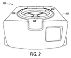
図2に示すように、流体分離システム200は、卓上型遠心分離機202と、回転軸206を中心にモータによって回転するように構成されているロータ組立体204と、ロータ組立体204に固定された少なくとも1つのモジュール式流体分離カセット208と、を含む。流体分離システム200の構成要素は協働して、無菌の使い捨ての流体分離システムを構成する。
As shown in FIG. 2, the
図2に示すように、遠心分離機202は卓上型遠心分離機である。好適な卓上型遠心分離機の例は一般によく知られており、当技術分野全体にわたって見出すことができる。好適な卓上型遠心分離機の1つの特定の例は、ThermoFischer Scientific社による小型卓上型遠心分離機である。
As shown in FIG. 2, the
実施形態では、卓上型遠心分離機202は、様々な容量のカセット208を収容することができ、据置型遠心分離機102又は他のものに適したサンプルの容量よりも少ない容量を有するサンプルの分離に適している。例えば、卓上型遠心分離機202は、0.05mlから125mlの全血を分離するようにそれぞれ構成された1又は複数のカセット208を収容することが可能である。より具体的には、実施形態は、0.05mlから2ml、1mlから10ml、及び40mlから100mlの全血を分離することが可能である。
In an embodiment, the
実施形態では、卓上型遠心分離機は、大型の遠心分離機システムに対していくつかの利点を提供することができる。特に、卓上型システムは、自立型システムに較べて、少ない量のサンプリングに適しており、またコストが大幅に低い。さらに、卓上型遠心分離機システムは、他のシステムよりも容易に拡張することができる。すなわち、複数の卓上型遠心分離機をコンピュータネットワークを介して互いにリンクさせて、試料処理の制御を向上させ及びカスタマイズすることができる。これら及び他の理由により、卓上型遠心分離機システムは小規模の実験室環境においてより広い用途がある。 In embodiments, the tabletop centrifuge can provide several advantages over large centrifuges systems. In particular, the desktop system is suitable for a small amount of sampling and the cost is significantly lower than that of the self-supporting system. In addition, desktop centrifuge systems can be expanded more easily than other systems. That is, a plurality of desktop centrifuges can be linked to each other via a computer network to improve and customize control of sample processing. For these and other reasons, desktop centrifuge systems have wider applications in small laboratory environments.
使用時には、据置型又は卓上型の遠心分離機システムのいずれかの実施形態は、遠心分離中にモジュール式流体分離カセットの釣り合いを必要とする場合がある。釣り合いをとる1つの方法は、カセットをロータ組立体の円周方向に互いに対向するように又は等距離に配置することを含む。このような釣り合いは、第1のモジュール式流体分離カセットと共に、他のモジュール式流体分離カセット、「ダミー」カセット(後述)、又は他の好適な釣合いおもり(1又は複数の微小遠心管(例えば、10mlのエッペンドルフ管)、クライオバイアル(Cryovial)等を収容することができる従来の固定角度構成又は揺動バケット構成を含むように構成されたカセット)(すなわち、「一般化」又は「従来の」カセット)をロータ組立体に取り付けることによって達成できる。異なるカセットタイプをロータ組立体に同時に接続できるということは、本明細書に記載のシステムが別々のワークフローを同時に実行することを好適に可能にする。特定の実施形態では、1又は複数の末梢血液単核細胞(PBMC)分離及び後処理ワークフローがこのように同時に行える。 At the time of use, either embodiment of the stationary or tabletop centrifuge system may require balancing of modular fluid separation cassettes during centrifugation. One method of balancing involves arranging the cassettes so that they face each other or equidistant from each other in the circumferential direction of the rotor assembly. Such a balance can be combined with the first modular fluid separation cassette, along with other modular fluid separation cassettes, "dummy" cassettes (discussed below), or other suitable balancing weights (eg, one or more microcentrifugal tubes (eg, eg)). A cassette configured to include a conventional fixed angle configuration or swing bucket configuration capable of accommodating a 10 ml Eppendorf tube), a cryovial, etc.) (ie, a "generalized" or "conventional" cassette. ) Can be achieved by attaching to the rotor assembly. The ability to connect different cassette types to the rotor assembly at the same time preferably allows the systems described herein to run different workflows at the same time. In certain embodiments, one or more peripheral blood mononuclear cell (PBMC) isolation and post-treatment workflows can thus be performed simultaneously.
据置型又は卓上型の遠心分離機システムのいずれかの実施形態では、カセットハウジング(図示せず)を任意で含めることができる。使用時には、カセットハウジングは、モジュール式流体分離カセット、ダミーカセット及び従来のカセットのいずれかと接続を行う際にロータ組立体を補助することができる。カセットハウジングは、カセットとの機械的又は電気的接続のための手段を任意に含み、流体の効率的な遠心分離をサポートする他の特徴を含んでよい。実施形態では、カセットハウジングは、ロータ組立体の一体部分を構成してもよい。他の実施形態では、カセットハウジングは、ロータ組立体に固定されている別体のシステム構成要素であってもよい。 In any embodiment of the stationary or desktop centrifuge system, a cassette housing (not shown) can optionally be included. In use, the cassette housing can assist the rotor assembly in making connections with any of the modular fluid separation cassettes, dummy cassettes and conventional cassettes. The cassette housing may optionally include means for mechanical or electrical connection to the cassette and may include other features that support efficient centrifugation of the fluid. In embodiments, the cassette housing may constitute an integral part of the rotor assembly. In other embodiments, the cassette housing may be a separate system component that is secured to the rotor assembly.
ロータ組立体は、モジュール式流体分離カセットの一部を形成してもよく、又は、1以上のモジュール式流体分離カセット、1以上の「ダミー」カセット(後述)、1以上の従来のカセット、又はそれらの任意の組み合わせ、に接続するための(任意で固定も行う)接続手段を有する剛性ディスクでもよい。ロータ組立体は再利用可能にしてもよい。 The rotor assembly may form part of a modular fluid separation cassette, or one or more modular fluid separation cassettes, one or more "dummy" cassettes (discussed below), or one or more conventional cassettes, or It may be a rigid disk having a connecting means (and optionally fixing) for connecting to any combination thereof. The rotor assembly may be reusable.
実施形態では、ロータ組立体は電子制御手段を含むことができ、電子通信手段を含むことができる。例えば、ロータ組立体は、ロータ組立体との間の一方向又は双方向通信を可能にし、ロータ組立体及びそれに取り付けられた任意のカセットの監視、評価及び制御を可能にし得る、1又は複数のプロセッサ、埋め込みコード、内蔵ハードワイヤリング又は回路、埋め込みセンサ、又は任意の他の電子手段を含み得る。 In embodiments, the rotor assembly can include electronic control means and can include electronic communication means. For example, the rotor assembly may allow one-way or two-way communication with the rotor assembly and may allow monitoring, evaluation and control of the rotor assembly and any cassette attached thereto. It may include a processor, embedded cord, built-in hard wiring or circuit, embedded sensor, or any other electronic means.
実施形態では、ロータ組立体は、その回転軸を構成するスピンドル又は中心シャフトを介して遠心分離機システムに電気的及び機械的に結合することができる。例えば、実施形態は、Evertet Charles TechnologiesによるPogo(登録商標)ピン、或いは遠心分離機のスピンドル又は中心シャフトへの電気的結合のための同様の接続を組み込んでもよい。或いは、端部接続は、スピンドルのいずれかと、ロータ組立体の外側端部と、又はそれに固定された任意のカセットと、行われてもよい。ロータとカセットとの間に電気的及び機械的結合を提供するために、他の様々な従来の手段が同様にロータ組立体に組み込まれてもよい。 In embodiments, the rotor assembly can be electrically and mechanically coupled to the centrifuge system via a spindle or central shaft that constitutes its axis of rotation. For example, embodiments may incorporate Pogo® pins by Evertet Charles Technologies, or similar connections for electrical coupling to the spindle or center shaft of the centrifuge. Alternatively, end connections may be made with any of the spindles, the outer end of the rotor assembly, or any cassette fixed to it. Various other conventional means may be incorporated into the rotor assembly as well to provide electrical and mechanical coupling between the rotor and the cassette.
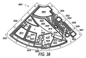
図3〜図6は、本出願の実施形態によるモジュール式流体分離カセットの例を示す図である。 3 to 6 are diagrams showing an example of a modular fluid separation cassette according to an embodiment of the present application.
図3〜図6の実施形態に関連して以下に提供される説明は、例示である。図3〜図6に示す実施形態の様々な特徴は、互いに排他的ではなく、任意に他の特徴と共に、互いに、又は単一のカセットに組み込まれてもよい。さらに、チャンバ、チャネル及び他のカセット構成要素の設計は、任意の流体に適合させることができ、全血の分離に限定されない。 The description provided below in connection with the embodiments of FIGS. 3-6 is exemplary. The various features of the embodiments shown in FIGS. 3-6 are not exclusive to each other and may optionally be incorporated together with other features or into a single cassette. In addition, the design of chambers, channels and other cassette components can be adapted to any fluid and is not limited to whole blood separation.
図3は、本願の一実施形態による無菌のオープンシステム型のモジュール式流体分離カセットを示す。 FIG. 3 shows a sterile open system modular fluid separation cassette according to an embodiment of the present application.
図3に示すように、カセット300は、無菌入口ポート302、分離チャンバ304、懸濁媒体チャンバ306、懸濁媒体チャンバポート308、緩衝液チャンバ310、緩衝液チャンバポート312、密度勾配媒体チャンバ314、密度勾配媒体チャンバポート316、流体収集チャンバ318、無菌流体収集チャンバポート320、1つ以上の取り外し可能な収集容器322、1つ以上の流体チャネル(図示せず)、及び1又は複数のバルブ(図示せず)を含む。
As shown in FIG. 3, the
図3を参照すると、最終製品(例えばPBMC又は他の流体成分)を取り外し可能な収集容器322に収集することができ、又は従来の手段を使用して無菌収集チャンバポート320を介して収集することができるので、モジュール式流体分離カセット300は開放型モジュール式流体分離カセットと呼ぶことができる。
With reference to FIG. 3, the final product (eg, PBMC or other fluid component) can be collected in a
より具体的には、開放型モジュール式流体分離カセット300では、全血を、ピペット移送や従来の移送技術等の従来の無菌プロセスを介して、無菌入口ポート302を通してモジュール式流体分離カセット300に導入又は「オンボード(onboarded)」することができる。同様に、媒体は、懸濁媒体チャンバポート308及び密度勾配媒体チャンバポート316を介して従来通りに搭載されてもよく、緩衝液チャンバポート312を介して緩衝液が導入されてもよい。或いは、実施形態では、媒体及び緩衝液のような特定の流体は、製造時にカセットに予め装填することができる。モジュール式流体分離カセット300からの流体収集又は「オフボード(offboarding)」は、無菌収集チャンバポート320又は収集容器322を介して行われてもよい。すなわち、ピペット移送のような従来の無菌移送技術を使用して、液体を収集用の収集チャンバポート320から収集してもよい。同様に、取り外し可能な微小遠心管(例えば、10mlエッペンドルフ管)、クライオバイアル、又は任意の他の好適な収集容器が、収集容器322として任意に使用されてもよい。そのような実施形態では、収集容器322を収容するために収集容器ポート(図示せず)がカセットの中に含まれる。
More specifically, in the open modular
収集容器322及び収集容器ポートの設計及び配置は限定されない。例えば、収集容器ポートは、回転軸に対して最も遠位のカセットの外側に配置されてもよく、任意の方法で(例えば、縦方向又は横方向に)収集容器322の挿入又は取り付けを可能にするように構成されてもよい。或いは、収集容器ポートは、回転軸に平行な方向でカセットの上面又は底面に配置されてもよく、同様に任意の方法で(例えば縦方向又は横方向に)収集容器322の挿入又は取り付けを可能にするように構成されてもよい。収集容器322と収集容器ポートとの間の取り付けを可能にするために任意の従来の手段を実施することができる。いくつかの実施形態では、収集容器も収集容器ポートもない。
The design and arrangement of the
前述の実施形態では、精製流体成分をその場で収集することができ、これは最終処理までカセット内に最終製品を保持する必要がある実施形態に較べて、利点をもたらすことができる。 In the aforementioned embodiments, the purified fluid components can be collected in-situ, which can provide advantages over embodiments where the final product needs to be retained in the cassette until final processing.
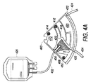
図4A及び図4Bは、本願の実施形態による、無菌の密閉システム型モジュール式流体分離カセットを示す。 4A and 4B show a sterile sealed system modular fluid separation cassette according to an embodiment of the present application.
図4A及び図4Bを参照すると、モジュール式流体分離カセット400は、入口管402、入口管スタブ404、分離チャンバ406、懸濁媒体チャンバ408、懸濁媒体チャンバポート410、緩衝液チャンバ412、緩衝液チャンバポート414、密度勾配媒体チャンバ416、密度勾配媒体チャンバポート418、流体収集チャンバ420、1以上の収集管スタブ422、1以上の収集管424、1つ以上の流体チャネル(図示せず)、及び1以上の複数のバルブ(図示せず)を有する。
With reference to FIGS. 4A and 4B, the modular
密閉システムタイプのカセットでは、カセット400への流体の導入及びカセット400からの流体の収集のそれぞれは、対象の流体が有害な細菌、ウイルス、又は他の微生物のいずれかによって引き起こされる汚染からフリーであるというさらなる保証を提供するタイプの滅菌接続を通して行われる。実施形態では、入口管402及び収集管424は、滅菌PVC管又は任意の好適な代替物を含む。実施形態では、ユーザは、流体オンボードのために入口管402を血液バッグ426に接続するため、又は流体オフボードのために収集管424をコレクションバッグ428に接続するために、滅菌ドッキングデバイス(図示せず)を利用することができる。これによって、汚染リスクに対する追加の保護手段を有する流体移送が可能となる。
In hermetically sealed system type cassettes, each of the introduction of fluid into the
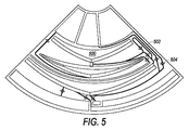
図5及び図6は、本願の実施形態に係る流体分離カセットを示す図である。 5 and 6 are views showing a fluid separation cassette according to an embodiment of the present application.
図5及び図6の分離カセットに示されるように、所与のチャンバ500、600は、円錐形の態様を組み込んでもよく、その上部又は下部よりも狭い中央部又は他の部分を含んでもよい。図5及び図6はまた、モジュール式流体分離カセットの様々な構成要素を接続する様々な流路502、602及びバルブ504、604を示す。
As shown in the separation cassettes of FIGS. 5 and 6, given
示されるように、図3〜図6に示されるモジュール式流体分離カセットは、携帯型である。すなわち、分離された流体成分が1つの物理的位置でモジュール式流体分離カセットの収集チャンバ内に得られると、モジュール式流体分離カセットは、分離された最終製品を含めて、所望成分の取り出し又は処理のために別の位置に携帯して移動される。実施形態では、所望の分離された流体用の収集チャンバは、保管及び輸送中に、PMBC血液成分のような収集された流体成分の完全性を維持するのを助けることができる収集媒体又は細胞保存媒体をさらに含む。そのような実施形態は、収集時に、精製された流体成分がすでに、サンプルの完全性を最大にすること及びマニュアルで行う処理後ステップ(例えば、マニュアルで行う収集やそれに続く凍結)、を省略することをアシストする媒体中に懸濁されている場合、現在の最先端技術に対して重要な利点をもたらす。さらに、製造された試料は輸送するのにより便利で安価である。 As shown, the modular fluid separation cassettes shown in FIGS. 3-6 are portable. That is, once the separated fluid components are obtained in one physical location in the collection chamber of the modular fluid separation cassette, the modular fluid separation cassette, including the separated final product, removes or processes the desired components. To be carried and moved to another position for. In embodiments, a collection chamber for the desired separated fluid can help maintain the integrity of the collected fluid components, such as PMBC blood components, during storage and transport, a collection medium or cell storage. Further includes media. Such embodiments omit, at the time of collection, the purified fluid components already maximizing sample integrity and manual post-treatment steps (eg, manual collection followed by freezing). When suspended in a medium that assists in doing so, it offers significant advantages over current state-of-the-art technology. In addition, the manufactured samples are more convenient and cheaper to transport.
本明細書に記載のモジュール式流体分離カセットの使用は、従来の流体分離プロセスを超えるいくつかの利点を付与し得る。例えば、従来の遠心分離システム及びプロセスは、安全な環境を維持するために、クラスII生物学的安全キャビネット(Class II Biological Safety Cabinet)又は他のベンチ及び換気システムのような追加の機器の使用を必要とする場合がある。対照的に、本明細書に記載のモジュール式流体分離カセットの実施形態の無菌の自己完結型の態様は、そのような機器によって軽減され、潜在的な曝露リスクを排除することができる。これにより、コストが削減され、曝露及びオペレータのミスの可能性が減少する。 The use of modular fluid separation cassettes described herein may provide several advantages over conventional fluid separation processes. For example, conventional centrifugation systems and processes use additional equipment such as Class II Biological Safety Cabinets or other benches and ventilation systems to maintain a safe environment. May be needed. In contrast, the aseptic, self-contained aspect of the modular fluid separation cassette embodiments described herein can be mitigated by such equipment to eliminate potential exposure risk. This reduces costs and reduces the likelihood of exposure and operator error.
他の利点は、本開示のモジュール式流体分離カセットは、特に、血液の生存細胞成分である生成物をもたらすことができるということである。関連技術において、ディスク又は同様の設計を使用する既知の遠心分離プロセスは、特定の流体を構成部分に効果的に分離することができる。しかしながら、そのようなプロセスは、全血の生存細胞成分の収集に類比することはできない。すなわち、全血の細胞成分は特に繊細又は脆弱であり、従って、劣化的な機械的プロセスに細胞をさらすことになる高速高G場環境において、細胞が様々な不規則な形状のチャネルやチャンバを通過しなければならない遠心分離プロセス中に細胞の完全性を維持することには比較的困難がある。 Another advantage is that the modular fluid separation cassettes of the present disclosure can, in particular, result in products that are viable cellular components of blood. In related art, known centrifugation processes using discs or similar designs can effectively separate a particular fluid into its components. However, such a process cannot be compared to the collection of whole blood viable cellular components. That is, the cellular components of whole blood are particularly delicate or fragile, and thus cells undergo various irregularly shaped channels and chambers in high-speed, high-G field environments that expose them to degrading mechanical processes. Maintaining cell integrity during the centrifugation process that must pass is relatively difficult.
本明細書に記載のモジュール式流体分離カセットの様々な実施形態内の流体の流れは、いくつかの独自の原理を用いて管理される。それら原理を同時に又は別々に適用する場合、それら原理によって、カセットの設計及び動作中にカセットを管理するために使用される関連ハードウェアの設計の両方は非常に単純化される。これらの原理を適切に使用することにより、分離プロセス中に使用される様々な流体のポンピング、レベルの感知、及び/又は体積の感知を行うための独立した機構が不要になる。さらに、これらの原理は、回転シール又はシールレス回転ループのような外部の流体接続を必要とせずに「ロータ上」の流れ管理を可能にする。 The flow of fluid within various embodiments of the modular fluid separation cassettes described herein is controlled using some unique principles. When these principles are applied simultaneously or separately, they greatly simplify both the design of the cassette and the design of the associated hardware used to manage the cassette during operation. Proper use of these principles eliminates the need for independent mechanisms for pumping, level sensing, and / or volume sensing of the various fluids used during the separation process. Moreover, these principles allow flow management "on the rotor" without the need for external fluid connections such as rotary seals or sealless rotary loops.
そのような1つの流体の流れの原理は、回転又は遠心操作中にカセット内の流体を能動的にポンピングする必要性を排除する。これは、カセット内の流体チャンバを適切に位置決めすることを伴う。流体チャンバは、チャンバ間のバルブを開くことによって一方のチャンバから他方のチャンバへの流れが促進されるように、異なる半径方向位置に配置される。一般に、チャンバは、バルブが開いている場合、流体はG場勾配に従って流下し、受容チャンバに流れ込むように配置されている。このようにして、チャンバ配置、チャンバ内の初期流体配置、接続流路配置、及びバルブ配置は、流体がG場の外側すなわち「下り坂」方向に流れるように予め位置決めされる。 The principle of one such fluid flow eliminates the need to actively pump the fluid in the cassette during rotational or centrifugal operations. This involves properly positioning the fluid chamber in the cassette. The fluid chambers are arranged in different radial positions so that opening the valves between the chambers facilitates the flow from one chamber to the other. Generally, the chamber is arranged so that when the valve is open, the fluid flows down according to the G field gradient and flows into the receiving chamber. In this way, the chamber arrangement, the initial fluid arrangement within the chamber, the connection flow path arrangement, and the valve arrangement are pre-positioned so that the fluid flows outside the G field, i.e., in the "downhill" direction.
他のそのような流体の流れの原理は、チャンバ間の流れを終わらせるためのバルブ及び/又はレベル検知の必要性を排除する。流体容積及びチャンバ容積は、2つのチャンバ間で流れが可能になった場合、適切な容積が流れたときに該チャンバ間の流れが自動的に終了するように選択することができる。2つの接続されたチャンバ内の液面が平衡径方向位置に達すると流れが止まる。各区画の液面の平衡径方向位置は、区画内に含まれる流体の密度に本質的に対応するであろう。すなわち、各区画内の流体の密度が同一であれば、区画の液面の径方向位置は同一になるであろう。1つの区画がより高密度の流体を含む場合、その自由表面の径方向位置は、第2の区画の表面の径方向位置よりも大きくなる。 Other such fluid flow principles eliminate the need for valves and / or level detection to terminate the flow between chambers. The fluid volume and chamber volume can be selected so that if flow is possible between the two chambers, the flow between the chambers will automatically end when the appropriate volume flows. The flow stops when the liquid level in the two connected chambers reaches the equilibrium radial position. The equilibrium radial position of the liquid level in each compartment will essentially correspond to the density of fluid contained within the compartment. That is, if the density of the fluid in each compartment is the same, the radial position of the liquid level in the compartment will be the same. If one compartment contains a denser fluid, the radial position of its free surface will be greater than the radial position of the surface of the second compartment.
本明細書に記載のモジュール式流体分離カセットの様々な実施形態はまた、容積一致の原理に基づいて動作する。すなわち、導入流体の容積は、特定のチャンバからの最終製品(例えば、廃棄物又は他の所望の最終製品)の容積と一致する。例えば、既知容積の高密度流体(例えば密度勾配媒体)をモジュール式流体分離カセット内の媒体チャンバに導入する。次いで、密度勾配媒体を、密度勾配媒体よりも密度が低い流体構成物(例えば全血)を保持するモジュール式流体分離カセット内の分離チャンバに導入する。遠心力Gの下では、密度勾配媒体がG場内の下り坂方向(すなわち回転軸から遠くなる方向)に移動すると、密度の高い密度勾配媒体は密度の低い全血成分を押しのける。押しのけられた成分は結果的にG場内で上り坂方向に移動し、その結果、既知の体積(すなわち導入された密度勾配媒体の体積;押しのけられる体積)で集められる。容量一致の原理を使用すれば、同様のレベルの純度で生成物収率の実質的な(例えば、25%)増加を得ることが可能である。同様に、同じ収集容量でより高い純度の収穫物を得ることが可能である。 Various embodiments of the modular fluid separation cassettes described herein also operate on the principle of volume matching. That is, the volume of the introduced fluid matches the volume of the final product (eg, waste or other desired final product) from a particular chamber. For example, a known volume of high density fluid (eg, density gradient medium) is introduced into the medium chamber within the modular fluid separation cassette. The density gradient medium is then introduced into a separation chamber within a modular fluid separation cassette that holds a fluid construct (eg, whole blood) that is less dense than the density gradient medium. Under centrifugal force G, as the density gradient medium moves downhill in the G field (ie, away from the axis of rotation), the dense density gradient medium pushes away the less dense whole blood components. The dispelled component eventually travels uphill in the G field and is thus collected in a known volume (ie, the volume of the introduced density gradient medium; the volume dispelled). Using the principle of volume matching, it is possible to obtain a substantial (eg, 25%) increase in product yield at similar levels of purity. Similarly, it is possible to obtain higher purity crops with the same collection capacity.
本願の実施形態に組み込むことができるさらなる独自の原理は、流体「プーリ(pulley)」及び流体「プッシュ(push)」の使用を含む。流体「プーリ」を使用して、G場内を「下り坂」方向に移動する第1のチャンバ内の遠隔流体の通常の圧力駆動流によって、第2のチャンバ内の所望の流体をG場において上方に移動させることができる。すなわち、チャネルを介して第2のチャンバの上部に接続された第1のチャンバ内における流体の通常の下り坂方向の流れを使用して、第2のチャンバ内に負圧を引き起こし、引き起こされた圧力勾配によってG場における上り方向に第2のチャンバ内の流体を「引き上げる」ことができる。実施形態では、2つのチャンバ間の唯一の接続は、空気が充填されたチャネルであり、これは、混合することなく流体の移動を可能にする。或いは、異なる構成を使用して、プッシュ原理を使用することができる。流体「プッシュ」原理を使用することによって、離れた位置の第1のチャンバのG場内を「下り坂」方向に移動する遠隔流体の通常の圧力駆動流によって、第2のチャンバ内の流体を、G場内の上り坂方向に「押し上げる」ことができる。この場合、チャネルは第1のチャンバを第2のチャンバの底部に接続し、第1のチャンバ内の増大した圧力は、チャネル内の空気の圧縮を使用して第2のチャンバ内の流体をG場における上り方向に押す。 Further unique principles that can be incorporated into embodiments of the present application include the use of the fluid "pulley" and the fluid "push". A fluid "pulley" is used to move the desired fluid in the second chamber upward in the G field by the normal pressure driven flow of the remote fluid in the first chamber moving "downhill" in the G field. Can be moved to. That is, the normal downhill flow of fluid in the first chamber connected to the top of the second chamber through the channel was used to create and cause a negative pressure in the second chamber. The pressure gradient allows the fluid in the second chamber to be "pulled up" in the up direction in the G field. In an embodiment, the only connection between the two chambers is an air-filled channel, which allows the movement of fluid without mixing. Alternatively, the push principle can be used with different configurations. By using the fluid "push" principle, the fluid in the second chamber is driven by the normal pressure-driven flow of remote fluid that moves "downhill" in the G field of the first chamber at a distance. It can be "pushed up" in the uphill direction in the G field. In this case, the channel connects the first chamber to the bottom of the second chamber, and the increased pressure in the first chamber uses the compression of air in the channel to G the fluid in the second chamber. Push in the up direction in the field.
実施形態では、「プーリ」及び「プッシュ」原理は、流体をチャンバ内に完全に移送し、続いて、該チャンバから、G場における「上り坂」方向に、流体を移送することを可能にすることができる。これは、より高い純度の収穫物を得ることに役立つ。これらの原理はまた、バルブを有さないより大きなチャネルを介した所望の流体の移送を可能にし、それによって移送中の剪断応力を最小にすることができる。「プーリ」及び「プッシュ」の原理は、流れを駆動するため、チャンバ間の相対圧力に依存しているので、これらの技術は任意の遠心速度で効果的に機能する。 In embodiments, the "pulley" and "push" principles allow the fluid to be completely transferred into the chamber and subsequently from the chamber in the "uphill" direction in the G field. be able to. This helps to obtain a higher purity harvest. These principles also allow the transfer of the desired fluid through a larger channel without a valve, thereby minimizing shear stress during transfer. These techniques work effectively at any centrifugal speed, as the "pulley" and "push" principles rely on the relative pressure between the chambers to drive the flow.
本明細書に記載のモジュール式流体分離カセットの例示的な実施形態は、1回使用(すなわち使い捨て)でもよいし、複数回使用でもよい。実施形態では、本明細書のモジュール式流体分離カセットは、様々なタイプ及びサイズのものであり得る。例えば、本明細書に記載のモジュール式流体分離カセットは、「くさび」、又はディスク形状のセグメントの形態を取り得る。そのような実施形態では、複数のカセットが一緒になって完全なディスク形状を形成してもよい。他の実施形態では、単一のカセットがディスク全体の形状を取ってもよい。実施形態では、本明細書に記載のモジュール式流体分離カセットは、積み重ね構成(すなわち、「パンケーキ型」構成)又は並列構成(すなわち、ロータ組立体の周囲の円周方向)において、ロータ組立体を中心に配置することができる。 An exemplary embodiment of the modular fluid separation cassette described herein may be single-use (ie, disposable) or multiple-use. In embodiments, the modular fluid separation cassettes herein can be of various types and sizes. For example, the modular fluid separation cassettes described herein can take the form of "wedges", or disc-shaped segments. In such an embodiment, the plurality of cassettes may be combined to form a complete disc shape. In other embodiments, a single cassette may take the shape of the entire disc. In embodiments, the modular fluid separation cassettes described herein are in a stacking configuration (ie, a "pancake-shaped" configuration) or a parallel configuration (ie, circumferential orientation around the rotor assembly). Can be placed in the center.
本明細書に記載の例示的な流体分離カセットは、任意の様々なセンサ又は検出手段をさらに含んでもよい。すなわち、分離中の特定の流体特性は、自動化をサポートするために、カセット中に配置されたセンサによってさらに感知される。例示的なセンサは、流体チャネル、チャンバ、チューブ、又は流体を保持又は輸送する他の任意のカセット構成要素を照射し、流体から反射又は透過してくる赤色光及び緑色光の比率を検出する。例えば、赤血球の存在は、特定の実施形態では、米国特許第5,734,464号明細書の関連技術に記載されている手段を使用して検出することができる。 The exemplary fluid separation cassettes described herein may further include any of the various sensors or detection means. That is, certain fluid properties during separation are further sensed by sensors placed in the cassette to support automation. An exemplary sensor illuminates a fluid channel, chamber, tube, or any other cassette component that holds or transports the fluid and detects the proportion of red and green light reflected or transmitted from the fluid. For example, the presence of red blood cells can, in certain embodiments, be detected using the means described in the relevant art of US Pat. No. 5,734,464.
本明細書に記載のモジュール式流体分離カセットは、既知の材料及び技術を用いて製造することができる。モジュール式流体分離カセット製造及び抵抗器アレイ(後述)の製造に使用される材料の例には、ポリプロピレン、ポリスチレン等のポリマーが挙げられる。モジュール式流体分離カセット及び抵抗器アレイの製造に使用される製造技術の例としては、(以下に記載される)3D印刷、射出成形、インサート成形、及び他の様々な従来の手段が挙げられる。カセットは疎水性でもよく、又は疎水性コーティング若しくは疎水性処理を行ってもよい。 The modular fluid separation cassettes described herein can be manufactured using known materials and techniques. Examples of materials used in the manufacture of modular fluid separation cassettes and resistor arrays (discussed below) include polymers such as polypropylene and polystyrene. Examples of manufacturing techniques used in the manufacture of modular fluid separation cassettes and resistor arrays include 3D printing (described below), injection molding, insert molding, and various other conventional means. The cassette may be hydrophobic, or may be hydrophobically coated or treated.
図7は、本願の一実施形態による砂時計形の分離チャンバを示す。 FIG. 7 shows an hourglass-shaped separation chamber according to an embodiment of the present application.
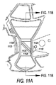
図7を参照すると、分離チャンバ700は、回転軸に最も近いチャンバの部分である上側セクション702と、中間セクション704と、回転軸に対して最も遠位の部分である下側セクション706と、入口ポート708と、出口ポート710と、を有する。
Referring to FIG. 7, the
図7に示すように、上側セクション702及び下側セクション706は、中間セクション704の断面積より大きい断面積を有する。実施形態では、このチャンバ設計は、滑らかな「砂時計」形状又は角のある「砂時計」形状に似ている。入口ポート708は、流体(例えば、細胞の懸濁液)を分離チャンバに導入するように構成されている。出口ポート710は、分離チャンバ700からの流体成分(例えば、分離されたPBMC)の取り出しを可能にするように構成される。分離チャンバ700は、懸濁液の残りの部分をチャンバから取り出すためのオーバーフローポート(図示せず)を任意に含んでよい。砂時計形状及び同様形状のチャンバ設計は、出口ポート710が配置されている中間セクション704において流体成分のより正確な分離を可能にする。砂時計形状の上側セクション702及び下側セクション706と中間セクション704との間のサイズ関係は、例えば、2対1(2:1)から10対1(10:1)とすることができる。例示的な実施形態では、中間セクション704の断面は、上側セクション及び下側セクションの断面の1/4のサイズである。改善された分離のための狭いチャンバ又は狭いチャネル部分の組み込みは、限定されず、他のチャネル、他のチャンバ及び他のシステム構成要素に組み込まれてもよい。
As shown in FIG. 7, the
図8A及び図8Bは、本願の一実施形態に係るモジュール式分離カセットの部分図内における他の砂時計形状の分離チャンバを示す。 8A and 8B show other hourglass-shaped separation chambers in a partial view of the modular separation cassette according to one embodiment of the present application.
図8Aは、モジュール式流体分離カセット800の斜視図である。該カセット800は、「砂時計」形状の分離チャンバ802、分離チャンバ出口ポート804、媒体チャンバ806、緩衝液チャンバ808、洗浄チャンバ810、及び収集チャンバ812を含む。図8Aにおいて、この図ではチャンバの蓋を示していないので、各チャンバの内部は露出されている。
FIG. 8A is a perspective view of the modular
図8Bは、各カセットチャンバを覆う、オプションであるチャンバ蓋812を含む、図8Aに示すカセットの斜視図である。
FIG. 8B is a perspective view of the cassette shown in FIG. 8A, including an
図8Aにおいて、分離チャンバ出口ポート804は、分離チャンバ802の中間の狭い部分の垂直壁に配置されている。出口ポート804は、特定の流体又は単核球(MNC)層のような流体成分を集めるために最適化された直径及び形状である。出口ポート804は、遠心力の方向に対して垂直に向いていてもよく、回転中心から相対的に外側(90度を超えて)に向いていてもよく、或いは回転中心に向かって相対的に内側(90度未満)に向いていてもよい。例えば、好ましい実施形態では、出口ポートは、回転中心に向かって相対的に内側に向いており、従って、出口ポートと遠心力に平行な線との間の角度は5度から60度、例えば30度から60度、又は40度から50度、である。図9A、図10A及び図11Aに示される出口ポートは、この後者の説明(すなわち、約45度の角度を有する)を示す。
In FIG. 8A, the separation chamber outlet port 804 is located on the vertical wall of the narrow portion in the middle of the
さらなる実施形態では、流体分離カセットは、出口ポートに近接して流体又は流体構成要素の層を集中させるための手段を有する流体分離チャンバを含んでもよい。出口ポート近傍において流体又は流体成分の層を集中させるためのそのような手段は、分離チャンバ内においてある角度で配置された平面、多平面又は同様に機能する面(すなわち「スキマーダム(skimmer dam)」)の形態をとることができる。例えば、スキマーダムは、チャンバ内の遠心力に平行な線に対して15度〜70度、例えば25度〜60度又は40度〜50度、の角度で配置される。スキマーダムの遠位端(すなわち、回転軸から最も遠い端、又は最も遠い「下り」部分)は、回転軸からの径方向距離が出口ポートの位置と略同じ距離で分離チャンバ内に配置される。スキマーダムの遠位端と出口ポートとの間の距離は、分離チャンバから出口ポートを介する特定の流体又は流体成分(例えば、MNC)の効率的な移動を容易にするように最適化される。スキマーダムは、分離チャンバの壁の間の全距離の略全体、又は全体未満を占める。すなわち、MNC及び血小板を上昇させ、RBC及び顆粒球を沈降させることを可能にするために、スキマーダムの片側又は両側と分離チャンバの垂直側壁との間に空間が存在する。 In a further embodiment, the fluid separation cassette may include a fluid separation chamber having means for concentrating a layer of fluid or fluid components in the vicinity of the outlet port. Such means for concentrating a layer of fluid or fluid component in the vicinity of the outlet port is a planar, multiplanar or similarly functional surface (ie, a "skimmer dam") arranged at an angle within the separation chamber. ) Can be taken. For example, the skimmer dam is placed at an angle of 15 to 70 degrees, for example 25 to 60 degrees or 40 to 50 degrees, with respect to a line parallel to the centrifugal force in the chamber. The distal end of the skimmer dam (ie, the farthest end from the axis of rotation, or the farthest "down" portion) is located in the separation chamber at a radial distance from the axis of rotation approximately equal to the location of the exit port. The distance between the distal end of the skimmer dam and the exit port is optimized to facilitate the efficient movement of a particular fluid or fluid component (eg, MNC) from the separation chamber through the exit port. The skimmer dam occupies approximately the entire distance, or less than, the total distance between the walls of the separation chamber. That is, there is a space between one or both sides of the skimmer dam and the vertical sidewall of the separation chamber to allow the MNC and platelets to rise and the RBC and granulocytes to settle.
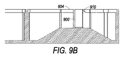
図9A及び図9Bは、本出願の一実施形態に係る分離チャンバ内に配置された平面スキマーダムを示す図である。図9A及び図9Bに示された実施形態は、分離チャンバの少なくとも2つの垂直側壁に接触しないように構成されている。 9A and 9B are views showing a planar skimmer dam arranged in a separation chamber according to an embodiment of the present application. The embodiments shown in FIGS. 9A and 9B are configured to avoid contact with at least two vertical sidewalls of the separation chamber.
図9Aは、分離チャンバの狭い部分の垂直壁902、904の間のスキマーダム900の上面図である。図9Aに示すように、垂直側壁902、904とスキマーダム900との間に空間906、908が存在する。また、回転軸からの径方向位置がスキマーダムの遠位端と略同じ位置に、分離チャンバの中間部分の前方に向かって配置された出口ポート910が示されている。出口ポート910の位置決めは様々でよいが、好ましくは、それら図に示されるように配置される。
FIG. 9A is a top view of the
図9Bは、スキマーダム900が単一の平面を含むことを示すために使用される平面スキマーダム900の断面図である。
FIG. 9B is a cross-sectional view of a
図10A及び図10Bは、本出願の一実施形態に係る分離チャンバ内に配置された多平面スキマーダムを示す図である。図10A及び図10Bの実施形態はまた、分離チャンバの少なくとも2つの垂直側壁と接触しないように構成されている。 10A and 10B are views showing a multi-plane skimmer dam arranged in a separation chamber according to an embodiment of the present application. The embodiments of FIGS. 10A and 10B are also configured to be out of contact with at least two vertical sidewalls of the separation chamber.
図10Aは、MNC又は血小板の上昇及びRBC又は顆粒球の沈降を可能にするように設計された間隙1006及び1008を除いて、分離チャンバの垂直側壁1002、1004と接触している多平面スキマーダム1000を示す上面図である。図9Aのように出口ポート1010も示されている。
FIG. 10A shows a
図10Bは、多平面スキマーダム1000の断面図である。この図は、スキマーダム1000が2つの平面を含むことを示すために使用される。
FIG. 10B is a cross-sectional view of the
ある実施形態では、「二重漏斗設計」が実施される。すなわち、スキマーダム及び分離チャンバが、互いに反対向き、すなわち1つは上向き、もう1つは下向き、の2つの漏斗に似るように及び/又は機能するように、変形される。実施形態では、この構成は、スキマーダムと分離チャンバの側壁との間の間隙を通過する特定の流体成分(例えば、MNC)の数又は割合を最小限にし、それによって、出口ポート付近の分離生成物(例えば、MNC)の濃度を最大にするように、設計される。この構成では、スキマーダムは、その端部の半分以上に沿って分離チャンバの垂直側壁と接触し、MNC又は血小板の上昇及びRBC又は顆粒球の沈降のために、各「漏斗」に存在する穴(又は間隙又は開口)のみを残すように、変形される。スキマーダムの両側の間隙の位置は、本明細書では限定されないが、成形が容易となるように、チャンバ間の流路に最も近い側であってよい。穴の大きさ及び幾何学的形状、特に、出口ポートからチャンバの反対側の穴の大きさ(すなわち、最も上り坂から離れた、すなわち回転軸に最も近い穴)は、初期の分離中に適度な速度で細胞を上昇させるのに十分な程度に大きく、MNC移動中に通過するMNCの数を最小にするように十分な程度に小さい。「二重漏斗」構成の実施形態では、ワックスバルブは、漏斗の1つの孔(例えば、回転軸に最も近い孔)だけを塞ぐように構成されてもよい。遠心分離中に回転軸に最も近い穴を閉じると、細胞移動中に、MNCをもう一方の「下り坂」側の穴に向かって移動させることができる。 In one embodiment, a "double funnel design" is performed. That is, the skimmer dam and the separation chamber are deformed to resemble and / or function as two funnels, one facing up and the other facing down. In embodiments, this configuration minimizes the number or proportion of specific fluid components (eg, MNCs) that pass through the gap between the skimmer dam and the sidewalls of the separation chamber, thereby minimizing the separation product near the outlet port. It is designed to maximize the concentration of (eg, MNC). In this configuration, the skimmer dam contacts the vertical sidewall of the separation chamber along more than half of its end and is a hole present in each "funnel" for MNC or platelet elevation and RBC or granulocyte sedimentation. Or it is deformed to leave only gaps or openings). The location of the gaps on either side of the skimmer dam is not limited herein and may be closest to the flow path between the chambers for ease of molding. The size and geometry of the holes, especially the size of the holes on the opposite side of the chamber from the exit port (ie, the holes farthest from the uphill, i.e. the holes closest to the axis of rotation) are moderate during the initial separation. Large enough to elevate cells at a high rate and small enough to minimize the number of MNCs passing through during MNC migration. In an embodiment of the "double funnel" configuration, the wax valve may be configured to close only one hole in the funnel (eg, the hole closest to the axis of rotation). Closing the hole closest to the axis of rotation during centrifugation allows the MNC to move towards the other "downhill" side hole during cell migration.
図11A及び図11Bは、本出願の実施形態に係る、分離チャンバ内に配置され、「二重漏斗」構成を形成する多平面スキマーダムを示す図である。 11A and 11B are views showing a multi-plane skimmer dam arranged in a separation chamber and forming a "double funnel" configuration according to an embodiment of the present application.
図11Aは、MNC又は血小板の上昇及びRBC又は顆粒球の沈降を可能にするように設計された間隙1106及び1108を除いて、分離チャンバの垂直側壁1102、1104と接触しているスキマーダム1100を示す上面図である。ここで、間隙1106、1108は、スキマーダム1100の平面と側壁1102、1104との間の交差部分に沿ってのみ生じ、より小さい流路を形成する。そのような実施形態は、スキマーダム1100の側面上の小さなフローチャネル、又はギャップの使用を介して、混合を最小限に抑え、適切な分離を確実にすることができる。出口ポート1110も示されている。
FIG. 11A shows a
図11Bは、二重漏斗構成の多平面スキマーダム1100の断面図である。この図は、スキマーダム1100が、図10A及び図10Bのスキマーダム1000よりも小さい流路を通って流体を流動させるように傾斜させた2つの平面を備えることを示すために使用される。
FIG. 11B is a cross-sectional view of the
さらなる実施形態では、ワックスバルブは、スキマーダムの両側の間隙に配置され、それらを塞ぐように構成される。一実施形態では、そのようなワックスバルブを使用して「多目的」チャンバを形成することができる。例えば、そのような多目的チャンバでは、本願を通して様々に説明されているように、常時開バルブ(NOV)を、スキマーダムと垂直側壁との間のギャップに近接する分離チャンバの各垂直側壁の外側に配置することができる。実施形態では、多目的チャンバは、様々な洗浄、すすぎ、分離、又は他の手順を可能にするために、2つ以上の流体入口ポート及び流体出口ポートを有することができる。実施形態では、洗浄、すすぎ、分離等に必要な複数のポートは、スキマーダムの遠位端の近くで、G場内のNOVの「上方」に(すなわち、回転中心側に)配置される。すなわち、複数のポートは、回転軸からの径方向距離がスキマーダムの遠位端の近くに配置されたNOVまでの距離よりも短い位置に配置されることが好ましい。 In a further embodiment, the wax valves are located in the gaps on either side of the skimmer dam and are configured to close them. In one embodiment, such a wax valve can be used to form a "multipurpose" chamber. For example, in such a multipurpose chamber, a always open valve (NOV) is placed outside each vertical side wall of the separation chamber close to the gap between the skimmer dam and the vertical side wall, as variously described throughout this application. can do. In embodiments, the multipurpose chamber can have two or more fluid inlet ports and fluid outlet ports to allow for various cleaning, rinsing, separation, or other procedures. In the embodiment, the plurality of ports required for cleaning, rinsing, separation, etc. are arranged "above" the NOV in the G field (ie, on the center of rotation side) near the distal end of the skimmer dam. That is, the plurality of ports are preferably arranged at positions where the radial distance from the axis of rotation is shorter than the distance to the NOV located near the distal end of the skimmer dam.
図12A及び図12Bは、本願の実施形態に係るNOVを含む多目的チャンバを示す。 12A and 12B show a multipurpose chamber containing a NOV according to an embodiment of the present application.
図12Aは、多目的チャンバ1200の上面図である。多目的チャンバ1200の狭い部分は、チャンバ側壁の少なくとも2つの部分に接触しないスキマーダム1202を含み、種々の操作中に流体の流れを可能にするため、スキマーダム1202の遠位端部と近位端部の両方に間隙1204、1206が形成されている。NOV1208、1210はそれぞれ、スキマーダム1202の両側の間隙1204、1206と同じ径方向位置において多目的チャンバ1200の外側壁に配置されている。作動すると、溶融材料がNOV1208、1210のいずれかから多目的チャンバ1200内に流れ込み、スキマーダム1202の両側の間隙1204、1206いずれかを閉塞することができるように、NOV1208、1210は、チャンバ1200と流体連通している。プロセスの必要に応じて、流体入口1212、流体出口1214、最終製品/移送出口1216を設けて、1つ又はいくつかの別のチャネルを形成する。
FIG. 12A is a top view of the
図12A及び図12Bは、多プロセス動作の種々のステージにある図12Aの多目的チャンバを示す。図12A及び図12Bの多目的チャンバを実施するための1つの例示的な方法又はワークフローは以下の通りである。まず、図12Aに示すチャンバ1200内の分離サイクルにおいて、全血の分離を行う。このサイクルでは、赤血球は、スキマーダム1202の遠位端の間隙1206を通って落下し、MNCは回転軸に最も近い間隙1204を通って上昇する。次に、分離サイクル中に流体成分を分離した後、各NOV1208、1210を図12Bに示すように作動させる。これにより、スキマーダム1202とチャンバ1200の垂直側壁との間の間隙1204、1206を閉塞することによって、分離チャンバ1200を、汚染されていない洗浄チャンバにする。次に、以下のようにして、従来の完全洗浄を完了させる。すなわち、流体入口1212を用いて洗浄流体を混合し、洗浄を行い、洗浄流体出口1214を介して廃棄物を排出する。次に廃棄物が排出された後、最終的なMNCは移送出口1216を介して収集される。最後に、MNCは、流体移送出口1216を介した移送の前に懸濁されてもよいし、或いは、移送前に1回以上の洗浄サイクルで洗浄されてもよい。ここで、MNCは、他の洗浄チャンバに移される前に洗浄液との混合物中に懸濁される。これによって、移送中の細胞における圧力降下の欠如に起因する血小板活性化を抑える。
12A and 12B show the multipurpose chamber of FIG. 12A at various stages of multi-process operation. One exemplary method or workflow for implementing the multipurpose chambers of FIGS. 12A and 12B is as follows. First, whole blood is separated in the separation cycle in
本明細書の実施形態は限定されない。すなわち、分離チャンバ又は多目的チャンバは、砂時計形状、略砂時計形状を有してもよく、或いは、図に示されるように、流体成分の効果的な分離を可能にするのであれば、他の任意の構成であってもよい。例えば、分離チャンバ又は多目的チャンバは、2部分チャンバとして構成されてもよく、その場合は、2つの部分は、流体チャネルを介して互いに流体連通する。そのような流路は、図に示されているように、1又は複数のバルブを任意に含むことができる。同様に、前述の構成は分離チャンバに限定されず、カセット内の任意のチャンバの構成でもよい。例えば、いくつかの実施形態は、従来のPBMC分離では使用されないが、エルトリエーションでは典型的な、円錐形状洗浄チャンバを採用する実施形態のような、チャンバの態様において円錐形状を組み込むことができる。 The embodiments of the present specification are not limited. That is, the separation chamber or multipurpose chamber may have an hourglass shape, a substantially hourglass shape, or any other as long as it allows for effective separation of fluid components, as shown in the figure. It may be a configuration. For example, the separation chamber or multipurpose chamber may be configured as a two-part chamber, in which case the two parts communicate with each other through a fluid channel. Such a flow path can optionally include one or more valves, as shown in the figure. Similarly, the above configuration is not limited to the separation chamber, and may be any chamber configuration in the cassette. For example, some embodiments are not used in conventional PBMC separation, but the conical shape can be incorporated in a chamber embodiment, such as the embodiment that employs a conical wash chamber, which is typical in eltriation.
ある実施形態では、スキマーダムは、分離時に、MNC層がスキマーダムの上方全体に配置されるように分離チャンバ内に配置される。この構成では、分離チャンバを排出すると、MNC層は落下し(すなわち、G場内を外側に向かって流れ)、スキマーダムの傾斜面に沿って出口に向かって押されて集まる。スキマーダムの片側又は両側と分離チャンバの垂直壁との間の間隙を少数のMNCが通過する場合があるが、MNCが出口ポートの径方向位置に達すると、MNCは出口ポートを介して分離チャンバから出る。ある実施形態では、スキマーダムの頂部(すなわち、G場内で最も高く且つ回転軸に最も近いスキマーダムの部分)は、入り口又はその下にある。 In one embodiment, the skimmer dam is placed in the separation chamber so that the MNC layer is placed entirely above the skimmer dam at the time of separation. In this configuration, when the separation chamber is ejected, the MNC layer falls (ie, flows outward through the G field) and is pushed toward the exit along the slope of the skimmer dam and gathers. A small number of MNCs may pass through the gap between one or both sides of the skimmer dam and the vertical wall of the separation chamber, but when the MNC reaches the radial position of the exit port, the MNC will exit the separation chamber through the exit port. Get out. In some embodiments, the top of the skimmer dam (ie, the portion of the skimmer dam that is highest in the G field and closest to the axis of rotation) is at or below the entrance.
本明細書に記載の分離チャンバ及びスキマーダムの様々な実施形態は、様々な利点をもたらす。例えば、分離チャンバの出口の近くにMNC層を集中させることは、より高い収率及び運転時間の短縮をもたらす。出口ポートに向かって流体又は流体成分の層を集めるための手段を追加することによっても、分離チャンバの狭い部分の必要性を排除することができ、それによって、より大きな設計自由度が可能になる。そのような構成は、所与のチャンバ容積に対して半径方向の高さを短くすることができ、従って全体として空間のより効率的な使用をもたらすことができる大容量カセットに関して特に有用である。加えて、MNC及び血小板の上昇並びに赤血球(RBC)の沈降が、分離チャンバの別々の領域で起こり、それによって、分離が加速される。 Various embodiments of the separation chamber and skimmer dam described herein provide various advantages. For example, concentrating the MNC layer near the outlet of the separation chamber results in higher yields and shorter operating times. The need for a narrow portion of the separation chamber can also be eliminated by adding means for collecting a layer of fluid or fluid component towards the outlet port, which allows for greater design freedom. .. Such a configuration is particularly useful for large capacity cassettes where the radial height can be shortened relative to a given chamber volume and thus can result in more efficient use of space as a whole. In addition, MNC and platelet elevation and red blood cell (RBC) sedimentation occur in separate regions of the separation chamber, thereby accelerating separation.
実施形態では、モジュール式流体分離カセットは、流体ラインとベントラインとを含むルアーテーパー接続を利用するように構成されたポート構成を含む。例示的なポートは、図3、図4A、図4B及び図8Bに示されている。実施形態では、スリップテーパ設計又はロック接続設計のいずれかを使用することができ、又はその修正版を使用することができる。そのような接続の例は、ベクトン・ディッキンソン アンド カンパニー社による「Luer−Lock」(登録商標)及び「Luer−Slip」(登録商標)スタイルのコネクタである。例えば、モジュール式流体分離カセットチャンバは、やはりベクトン・ディッキンソン アンド カンパニー社によるBD Vacutainer(登録商標)Venous Blood Collection Tubeのような真空チャンバの雌側端部と接続するように設計されたポートを有してもよい。他のLuer(登録商標)並びに同様のフィッティング及び接続を使用してもよいし、変更してもよいし、或いは、必要に応じて実施形態に組み込でもよい。 In an embodiment, the modular fluid separation cassette comprises a port configuration configured to utilize a luer taper connection that includes a fluid line and a vent line. Illustrative ports are shown in FIGS. 3, 4A, 4B and 8B. In embodiments, either a slip taper design or a lock connection design can be used, or a modified version thereof can be used. Examples of such connections are "Luer-Lock"® and "Luer-Slip"® style connectors by Becton Dickinson & Company. For example, a modular fluid separation cassette chamber has a port designed to connect to the female end of a vacuum chamber, such as the BD Vacutainer® Venous Blood Collection Tube, also by Becton Dickinson and Company. You may. Other Luer® and similar fittings and connections may be used, modified, or incorporated into embodiments as needed.
さらなる実施形態において、カセットの1又は複数のポートは、従来の設計であってもよい。例えば、単純な開口として設計されたポートは、従来のピペット流体導入及び収集を可能にするために利用される。そのようなポートは、ストップキャップ、又はオペレータが望み通りにポートを開いて再シールすることを可能にする他の従来の部材を使用して、開閉することができる。モジュール式流体分離カセットに対して流体を効果的にオンボード及びオフボードするために、他の任意の従来のポート設計を同様に実施形態に組み込んでもよい。 In a further embodiment, one or more ports of the cassette may be of conventional design. For example, a port designed as a simple opening is utilized to allow conventional pipette fluid introduction and collection. Such ports can be opened and closed using a stop cap, or other conventional member that allows the operator to open and reseal the port as desired. Any other conventional port design may be incorporated into the embodiment as well in order to effectively onboard and offboard the fluid to the modular fluid separation cassette.
本明細書に記載のカセットチャンバは、遠心分離を通して流体の流れを制御することができるように、バルブを配置することが可能な流体チャネルを介して様々に接続することができる。チャネル及びバルブは、製造時に流体分離カセットの中実体部分内に形成されてもよく、或いはカセットの他の部分又はその層(例えば、抵抗層組立体のシリコン層)に形成されるか又はそこから切り出し加工されて(例えばダイカット)、カセットの残りの部分と組み合わされる。流路のサイズ及び設計は限定されず、様々なバルブ設計及び材料を異なる実施形態で使用することができる。実施形態では、チャネルは、例えば0.5mmから1mmのように、0.3mmから2mmの断面を有する。例示的実施形態では、チャネルは、0.75mm(0.030×0.030インチ)の断面を有する。 The cassette chambers described herein can be variously connected via fluid channels in which valves can be placed so that fluid flow can be controlled through centrifugation. Channels and valves may be formed in the solid part of the fluid separation cassette during manufacture, or in or from other parts of the cassette or layers thereof (eg, the silicon layer of the resistance layer assembly). It is cut out (eg die cut) and combined with the rest of the cassette. The size and design of the flow path is not limited and various valve designs and materials can be used in different embodiments. In an embodiment, the channel has a cross section of 0.3 mm to 2 mm, for example 0.5 mm to 1 mm. In an exemplary embodiment, the channel has a cross section of 0.75 mm (0.030 x 0.030 inch).
実施形態では、モジュール式流体分離カセット内に、流体流量を制御するための新規な手段が含まれてもよい。すなわち、エルトリエーションのように非常に特殊な流量を必要とする多くの従来のプロセスでは、流量はポンプを使用して得られる。それにもかかわらず、従来のポンプをポンプレス流量制御手段で置き換えることが様々な理由で望ましい場合がある。この問題に対処するために、実施形態は、様々な異なる流速を達成するために、様々に組み合わせることができる特定の大きさを有する多数の流体チャネルを組み込んだ流体経路セクション又はチャネルセクションを含む。実施形態では、複数の流体チャネルは互いに平行でもよく、又は互いに別の関係をとってもよい。本明細書では、流量は、チャネルの直径、回転軸からのチャネルの距離、ロータのRPM、流体の特定の粘度及び比重等の様々な変数に基づいていると仮定される。 In embodiments, the modular fluid separation cassette may include novel means for controlling fluid flow rates. That is, in many conventional processes that require very specific flow rates, such as eltriation, the flow rate is obtained using a pump. Nevertheless, it may be desirable for a variety of reasons to replace conventional pumps with pumpless flow control means. To address this issue, embodiments include fluid pathway sections or channel sections that incorporate a large number of fluid channels of specific size that can be combined differently to achieve a variety of different flow velocities. In embodiments, the plurality of fluid channels may be parallel to each other or may have different relationships with each other. As used herein, it is assumed that the flow rate is based on various variables such as the diameter of the channel, the distance of the channel from the axis of rotation, the RPM of the rotor, the particular viscosity and specific density of the fluid.
図13は、本願の実施形態に係る、流量を制御するための平行流体チャネルの概略図である。 FIG. 13 is a schematic view of a parallel fluid channel for controlling the flow rate according to the embodiment of the present application.
図13を参照すると、異なる直径を有する4つの平行な流体チャネル1300のクラスター又は一群が示されている。ここで、流体は、G場においてエルトリエーションチャンバ(EC)1312より高い位置にある供給チャンバ(SC)1314からECに供給される。チャネルは流体流路に沿って互いに近接して配置されている。
With reference to FIG. 13, clusters or groups of four
図13の実施形態において、チャネル1302は、流体が毎分1mlで流れる。チャネル1304は、流体が毎分2mlで流れる。チャネル1306は、流体が毎分4mlで流れる。チャネル1308は、流体が毎分8mlで流れる。4つの平行な流体チャネルのそれぞれは、本明細書に記載された実施形態の中から選択された少なくとも1つのバルブ1310を含む。
In the embodiment of FIG. 13,
4つの平行な流体チャネル1302、1304、1306、1308内のバルブを作動させることによって、総流量を毎分1mlの単位で、毎分0mlから毎分15mlまで増減させることができる。例えば、チャネル1302のバルブが開、チャネル1304のバルブが閉、チャネル1306のバルブが開、チャネル1308のバルブが閉の場合、毎分5mlの総流量を達成することができる。同様に、チャネル1302のバルブが閉、チャネル1304のバルブが開、チャネル1306のバルブが閉、チャネル1308のバルブが開の場合、毎分10mlの総流量が達成される。前述の流量は単なる例であり、流量の任意の所望の組み合わせは、様々な流路構成及びバルブ閉鎖を利用することによって達成され得る。
By activating the valves in the four
実施形態では、流体チャネルは、0.02インチ〜0.05インチの直径を有してもよく、例えば、流体チャネルは、直径0.030インチ(約0.75mm)である。動作において、ロータのRPMは、1,000RPMから6,000RPMのように、200RPMから120,000RPMの範囲である。実施形態では、平行流体チャネルは、回転軸から1cmから15cmの距離で、より具体的には回転軸から2cmから10cmの距離で、ロータ組立体に配置される。 In embodiments, the fluid channel may have a diameter of 0.02 inch to 0.05 inch, for example, the fluid channel is 0.030 inch (about 0.75 mm) in diameter. In operation, the RPM of the rotor ranges from 200 RPM to 120,000 RPM, such as 1,000 RPM to 6,000 RPM. In an embodiment, the parallel fluid channel is located in the rotor assembly at a distance of 1 cm to 15 cm from the axis of rotation, more specifically at a distance of 2 cm to 10 cm from the axis of rotation.
実施形態では、流体チャネルは、平行、略平行であり、或いは互いに他の配向であってもよい。各チャネルは、同じ長さを有してもよく、或いは、互いに異なる長さを有してもよい。4つより多い又は少ない数の流体チャネルが使用されてもよい。本願を通して説明されるように、例示的なバルブタイプは限定されず、ワックスバルブ、機械式バルブ、又は他の任意の適切なタイプのバルブであってよい。ある実施形態では、特定のチャネルにバルブが存在しなくてもよい。 In embodiments, the fluid channels may be parallel, substantially parallel, or in other orientations to each other. Each channel may have the same length or may have different lengths from each other. More than four or fewer fluid channels may be used. As described throughout this application, exemplary valve types are not limited and may be wax valves, mechanical valves, or any other suitable type of valve. In certain embodiments, the valve may not be present in a particular channel.
チャンバ及び流路の設計は、特定の用途に従って変わるので、種々のバルブ構成が必要となる。特定のバルブ構成は、特定のワックスバルブのような熱膨張バルブを含む。熱膨張ワックスバルブの場合、好適なワックス材料の例としては、エチレンビニルアセテート(EVA)ワックス及びEVAブレンドが挙げられる。実施形態において、DuPont(商標)Elvax(登録商標)410(エチル−酢酸ビニル共重合体樹脂(ethyl−vinyl acetate copolymer resin))が好ましい。そのようなワックスは、狭い又は「鋭い」融点並びに好ましい柔軟性及び表面接着性を示す。EVAと同様の特性を有する他のワックスを使用してもよい。 The design of the chamber and flow path will vary according to the particular application and will require different valve configurations. Certain valve configurations include thermal expansion valves such as certain wax valves. For thermally expanded wax valves, examples of suitable wax materials include ethylene vinyl acetate (EVA) wax and EVA blends. In embodiments, DuPont ™ Elvax® 410 (ethyl-vinyl acetate copolymer resin) is preferred. Such waxes exhibit a narrow or "sharp" melting point as well as favorable flexibility and surface adhesion. Other waxes with properties similar to EVA may be used.
実施形態では、熱膨張材料は、バルブを作動させるために、放射熱を加えることができる熱吸収化合物をさらに含む。そのような構成は、マイクロ流体チャネルにおいて有用である。この実施形態の潜在的な利点は、熱膨張材料がチャネル内の流体と接触しないことにある。そのような接触は、汚染又は熱損傷を引き起こす場合がある。 In embodiments, the thermal expansion material further comprises a heat absorbing compound capable of applying radiant heat to actuate the valve. Such configurations are useful in microfluidic channels. A potential advantage of this embodiment is that the thermal expansion material does not come into contact with the fluid in the channel. Such contact can cause contamination or thermal damage.
実施形態では、温度変化を機械的運動に変換するのに適した様々な熱アクチュエータを、バルブとして作用するように、すなわち流体チャネルを開閉するように、適合させる。 In the embodiment, various thermal actuators suitable for converting temperature changes into mechanical motion are adapted to act as valves, i.e. to open and close fluid channels.
本出願の実施形態に係る様々なバルブ設計が以下では説明される。 Various valve designs according to embodiments of the present application are described below.
図14A及び図14Bは、本願の実施形態に係る「バックロード(back−loaded)」バルブを示す。 14A and 14B show a "back-loaded" valve according to an embodiment of the present application.
図14Aに示すように、バックロードバルブ1400は、流体チャネル1402、1404及び重力ウェル(gravity well)1406を含む。バックロードバルブを得るために、モジュール式流体分離カセットは、インサート成形プロセスによって製造されてもよい。このプロセスでは、カセットは、バルブ1400の重力ウェル1406内に堆積されるべきバルブ材料の移動のためのチャネル1402、1404を有する。製造時に、ワックス(例えば、EVA)又は他の好適なバルブ材料を、バルブ1400の「後方(back)」に導入される。すなわち、ワックスが重力ウェル1406内に堆積するまで、ワックスは導入され、チャネル1402に沿って流れる。図14Bに示すように、ウェル1406からの余分なワックスはチャネル1404内に流れる。このプロセスの注入後工程において、過剰のワックスはカセット上に保持される。実施形態では、製造時に、直径2mm(すなわち約4.2μl)のワックス液滴又は固形ワックスがバルブの「後方」に分注される。そして、ワックスが流動して約0.5μlの活性ワックス容量を達成する。
As shown in FIG. 14A, the
図15A及び図15Bは、本出願の一実施形態に係る「フロントロード」バルブを示す図である。 15A and 15B are views showing a "front load" valve according to an embodiment of the present application.
フロントロード(front−loaded)バルブは、ワックスをモジュール式流体分離カセットの特定の部分のみに直接付着させる製造工程から生じる。図15A及び図15Bに示されるように、フロントロードバルブ1500は、ワックスウェル1502を含み、任意にチャネル1504、1506を含む。製造時、ワックスはウェル1502の頂部にのみ堆積される。すなわち、図14A及び図14Bに関連して説明したように、流体ワックスをチャネル1402を介して押し入れ、バルブ1400の重力ウェル1404内に堆積させる「バックロード」プロセスとは対照的に、フロントロードバルブを得るためのこのプロセスは、ワックスをウェル1502内に直接堆積させる。例えば、フロントロードバルブの一実施形態は、1μlから2μlの液滴のように、約0.5μlの活性ワックス量を収容するために、EVAの小容量液滴を適所に分注及び溶融することから製造される。このプロセスの注入後ステップでは、余分なワックスをモジュール式流体分離カセットから削り取らなければならない。
The front-loaded valve results from a manufacturing process in which the wax adheres directly to only certain parts of the modular fluid separation cassette. As shown in FIGS. 15A and 15B, the
以下では、説明するのは、常時開バルブ(NOV)及び常時閉バルブ(NCV)の実施形態を含む様々なバルブ設計が説明される。NOVは、動作を行う前の、通常時は開いたままのバルブであり、一方、NCVは、通常時は閉じたままである。 Hereinafter, various valve designs will be described, including embodiments of a constantly open valve (NOV) and a normally closed valve (NCV). The NOV is a valve that normally remains open before operation, while the NCV remains normally closed.
図16A及び図16Bは、本出願の一実施形態に係る常時開バルブ(NOV)を示す図である。 16A and 16B are views showing a constantly open valve (NOV) according to an embodiment of the present application.
図16A及び図16Bに示されるように、バルブ1600は、チャネル1606の屈曲部1604と流体接続し、その下り側すなわち「アウトボード(outboard)」側(すなわち、G場内の下り坂側又はアウトボード側、或いは回転軸から遠位側)に設けられた重力ウェル1602を有する。ワックスは、重力ウェル1602を満たすように予め搭載されている。
As shown in FIGS. 16A and 16B, the
図16Aは、通常状態において開位置にあるバルブ1600を示す。この状態では、ワックスはウェル1602内に留まり、チャネル1606を邪魔しない。従って、この構成では、バルブ1600は「常時開」位置にある。図16Bに示すように、加熱状態又は活性化状態では、ワックスはチャネル1606内に膨張して該チャネルを塞ぎ、それによってバルブ1600は閉位置となる。この構成では、G力は開位置に向かってワックスに圧力を加えるので、バルブ1600が閉位置にあるとき、G力は、このバルブ構成の作動を補完することはできない。それにもかかわらず、この構成は特定の用途には好ましい。
FIG. 16A shows the
図17A及び図17Bは、本出願の一実施形態に係るさらに他のNOVを示す図である。 17A and 17B are diagrams showing yet another NOV according to one embodiment of the present application.
図17A及び図17Bに示すように、バルブ1700は、チャネル1706内の屈曲部1704と流体的に接続し、その上り坂側すなわち「インボード(inboard)」側(すなわち、G場における上り坂側又はインボード側、或いは回転軸から近位側)に設けられた重力ウェル1702を有する。ワックスは、重力ウェル1702を満たすように予め搭載される。
As shown in FIGS. 17A and 17B, the
図17Aは、通常状態において開位置にあるバルブ1700を示す。この状態では、ワックスはウェル1702内に留まり、チャネル1706を塞がない。図17Bは、ワックスがチャネル1706内に膨張してそれを塞いでいる加熱状態又は作動状態のバルブ1700を示す。この構成では、ワックスに対して閉位置に向かって圧力が加えられることによって、G力は、このバルブ1700の全閉状態への作動を補完することができる。
FIG. 17A shows the
図18A及び図18Bは、本願の実施形態に係る常時閉バルブ(NCV)を示す図である。 18A and 18B are diagrams showing a normally closed valve (NCV) according to the embodiment of the present application.
図18A及び図18Bに示すように、バルブ1800は、重力ウェル1802とフロースルー部分1804とを含む。ワックスは、予め装填され、重力ウェル1802を満たしている。図18Aは、常時閉位置にあるバルブ1800を示す。ここで、バルブは、通常状態では流体チャネル1806からオフセットしているフロースルー部分1804を含むことによりNCVである。通常状態では、ワックスはウェル1802内に留まり、バルブ1800に作用したり駆動したりすることはない。加熱状態又は作動状態では、ワックスは膨張してバルブ1800を駆動し、それによってバルブ1800を開位置にする。図18Bは、フロースルー部分1804が流体チャネル1806と一致するように作動した後の開位置にあるバルブ1800を示す。
As shown in FIGS. 18A and 18B, the
図19A及び図19Bは、本願の実施形態に係る他のNOVを示す図である。 19A and 19B are diagrams showing other NOVs according to the embodiment of the present application.
図19A及び図19Bは、図17A及び図17Bに示すものと同様であるが、常時開構成のバルブ設計を示す。示されるように、バルブ1900は、重力ウェル1902及びフロースルー部分1904を含む。ワックスは、重力ウェル1902を満たすように予め搭載されている。通常状態では、フロースルー部分1904は、流路1906と一直線上にある。加熱状態又は作動状態では、ワックスは膨張してバルブ1900を駆動し、それによって、フロースルー部分1904は流路1906からずれて、閉位置となる。
19A and 19B are similar to those shown in FIGS. 17A and 17B, but show a valve design with a always open configuration. As shown,
図20A及び図20Bは、本願の実施形態に係る回転バルブを示す図である。 20A and 20B are views showing a rotary valve according to an embodiment of the present application.
図20A及び図20Bに示すように、バルブ2000は、レバーチャンバ(lever chamber)2004と流体連通する重力ウェル2002を有する。バルブ2000はさらに、流体チャネル2010内に位置するフロースルー部分2006と、レバーチャンバ2004内に配置されるレバー部分2008とを有する。ワックスは重力ウェル2002を満たすように予め搭載されている。
As shown in FIGS. 20A and 20B, the
その通常状態では、図20Aに示すように、ワックスは、ウェル2002内に留まり、レバー部分2008に作用も駆動もしない。通常状態では、フロースルー部分2006は流体チャネル2010からずれており、流体は、流体チャネル2010に沿って流れることができない。図20Bは、ワックスが膨張してレバー部分2008を駆動し、バルブ2000を回してフロースルー部分2006をチャネル2010と一直線になるように位置決めして流体が流れる状態になっている作動状態又は開状態のバルブ2000を示す。
Under its normal state, as shown in FIG. 20A, the wax stays in the
図21A及び図21Bは、本願の実施形態に係る他の回転バルブを示す図である。 21A and 21B are views showing another rotary valve according to the embodiment of the present application.
図21A及び図21Bに示すように、バルブ2100は、レバーチャンバ2104と流体連通する重力ウェル2102を有する。バルブ2100はさらに、流体チャネル2110内に位置するフロースルー部分2106と、レバーチャンバ2104内に配置されたレバー部分2108とを有する。ワックスは、重力ウェル2102を満たすように予め搭載されている。
As shown in FIGS. 21A and 21B, the
その通常状態では、図21Aに示されるように、ワックスはウェル2102内に留まり、レバー部分2108に作用も駆動もしない。通常状態では、フロースルー部分2106は流体チャネル2110からずれており、流体は、流体チャネル2110に沿って流れることができない。図21Bは、ワックスが膨張してレバー部分2108を駆動し、バルブを回してフロースルー部分2106をチャネル2110と一直線になるように動かして流体が流れるようになった作動状態又は開状態のバルブ2100を示す。
In its normal state, as shown in FIG. 21A, the wax stays in the
ある実施形態では、熱活性化材料としてワックスを使用することは望ましくない場合がある。むしろ、形状記憶合金又は他の熱活性化記憶材料が好ましい場合がある。 In some embodiments, it may not be desirable to use wax as the heat activating material. Rather, shape memory alloys or other heat activated memory materials may be preferred.
図22A及び図22Bは、本出願の一実施形態による形状記憶合金バルブを示す図である。 22A and 22B are views showing a shape memory alloy valve according to an embodiment of the present application.
図22A及び図22Bに示すように、バルブ2200は、形状記憶合金2202、機械式バルブ部分2204、バルブチャンバ2206、及びフロースルー部分2208を含む。形状記憶合金2202は、流体チャネル2210と交差するバルブチャンバ2206を満たすように予め搭載されている。機械式バルブ部分2204はバルブチャンバ2206内に配置され、流体チャネル2210を開閉するように設計されている。図22Aに示すように、その通常状態又は圧縮状態では、フロースルー部分2208は流体チャネル2210と一直線上にある。ここでは、形状記憶合金2202はバルブチャンバ2206内に留まり、機械式バルブ部分2204に作用も駆動もしない。作動状態では、形状記憶合金2202は拡張してバルブ2200を駆動し、それによってバルブ2200は閉じられる。閉位置では、フロースルー部分2208は流体チャネル2210からオフセットしてチャネル2110内の流体の流れを止める。
As shown in FIGS. 22A and 22B, the
図23A及び図23Bは、本願の実施形態に係るソフトチューブバルブを示す。 23A and 23B show a soft tube valve according to an embodiment of the present application.
図23A及び図23Bに示すように、ソフトチューブバルブ2300は、ソフトチューブ材料2302と、流体チャネル2306の両側にウェル2304を有する。ワックスはウェル2304を満たすように予め搭載されている。通常状態又は開状態では、図23Aに示すように、ワックスはウェル2304内に留まり、バルブチューブ2302に作用したり、圧縮したりしない。加熱状態又は動作状態では、図23Bに示されるように、ワックスが膨張し、バルブチューブ2302を圧縮し又は挟み、バルブ2300を閉位置にする。
As shown in FIGS. 23A and 23B, the
図24A及び図24Bは、本願の実施形態に係る他のソフトチューブバルブを示す。 24A and 24B show other soft tube valves according to embodiments of the present application.
図24A及び図24Bは、ソフトチューブ2404を締め付けるために、熱活性化ワックスではなく、形状記憶合金2402を有する以外は、図23A及び図23Bに示すものと同様であるバルブ設計を示す。図24Aは、開位置にあるバルブ2400を示し、図24Bは、閉位置にあるバルブ2400を示す。
24A and 24B show valve designs similar to those shown in FIGS. 23A and 23B, except that they have
図25A及び図25Bは、本願の一実施形態に係るボール・シートバルブの設計を示す図である。 25A and 25B are diagrams showing the design of the ball / seat valve according to the embodiment of the present application.
図25A及び図25Bに示すように、バルブ2500は、流体チャネル2506と流体接続しているボール2504を含むワックスウェル2502を含む。この構成では、ワックスはウェル2502内に予め装填されている。ボール2504は、ウェル2502内のワックスの頂部に装填される。図25Aに示す通常状態又は冷却状態では、ワックスはウェル2502内に留まり、ボール2504に作用したりボール2504を駆動したりすることはない。図25Bに示す加熱状態又は動作状態では、ワックスが膨張してボール2504をチャネル2506内に押し込み、それによって、バルブ2500は閉じる。
As shown in FIGS. 25A and 25B, the
図26A及び図26Bは、本願の一実施形態に係るボールバルブを示す図である。 26A and 26B are views showing a ball valve according to an embodiment of the present application.
図26A及び図26Bに示されるように、バルブ2600は、ボール2602、流体チャネル2604、及び拡張チャネル部分2606を含む。図26Aに示すように、その通常状態では、バルブ2600は、ワックス内に着座したボール2602を有し、流体チャネル2604を塞いでいる。図26Bに示すように加熱状態又は動作状態では、ワックスは溶融してボール2602を拡張チャネル部分2606に解放し、これにより、流体はチャネル2604を通って流れることが可能になる。
As shown in FIGS. 26A and 26B, the
図27A及び図27Bは、本願の実施形態に係るさらに他のNCVを示す。 27A and 27B show yet another NCV according to an embodiment of the present application.
図27Aに示すように、バルブ2700は、バルブハウジング部分にバルブダム2702を有する。バルブダム2702は硬化ワックスで構成されている。通常の閉状態では、NCV2700は、流体経路2704を塞いでいる。図27Bに示すように、作動時には、バルブダム2702が落下し、流体は、流体経路2704に沿って流れるようになる。
As shown in FIG. 27A, the
図27A及び図27BのNCV2700は、その製造方法、その形状、又はその作動方法のいずれかに基づいた独自の利点を提供することができる。図27A及び図27Bのバルブ2700は、バルブ形状の微細制御を可能にするため、注入ワックスのインサート成形を使用して作られる。その結果、非常に薄くて長いワックスダムが流体チャネルを横切って形成される。加熱されると、流体はダムを押し崩し通過するか、又はチャネル内にオリフィスが形成され、流体が流れるようになる。
The NCV2700 of FIGS. 27A and 27B can provide unique advantages based on either its manufacturing method, its shape, or its operating method. The
以下に記載されるのは、他のNOV設計であり、結晶質及び非晶質の両方の熱活性化材料を利用するためのものを含む。以下に説明されるバルブ設計は、ワックスを動かすために膨張力と求心力の組み合わせを使用する。 Described below are other NOV designs, including those for utilizing both crystalline and amorphous heat-activating materials. The valve design described below uses a combination of expansion and centripetal forces to move the wax.
図28A〜図28Cは、結晶質の熱活性化材料を利用するように設計されたNOV2800を示す。 28A-28C show NOV2800 designed to utilize crystalline thermoactivated materials.
図28A〜図28Cに示すように、結晶材料(例えば、結晶ワックス)は、流路2804を介して流体チャネル2806に接続されているウェル2802内に堆積される。流路2804近傍の流体チャネル2806の領域は波形状(undulated)である。結晶性材料が加熱されると、それは膨張して流体チャネル2806を満たす。冷却されると、(波形状による)流路内の制限によって、ワックスの収縮が抑制され、確実にシールが保持される。この設計は、(以下の図29A〜図29Cに示すように)流体流路への単一のポートで達成することができるが、2ポート設計であれば、空気又は流体がワックスを移動させて、冷却時に圧力を確保することができる。この設計は、膨張と収縮の組み合わせを用いて、ワックスを動かすことができる。
As shown in FIGS. 28A-28C, the crystalline material (eg, crystalline wax) is deposited in the well 2802 connected to the
図29A〜図29Cは、非晶質熱活性化材料を利用するように設計されたNOVを示す。 29A-29C show NOVs designed to utilize amorphous heat activating materials.
図29A〜図29Cに示されるように、このバルブの設計は、図28A〜図28Cに示すものと本質的に同じである。図29A〜図29Cでは、非晶質材料(例えば、非晶質ワックス)が、チャネル2904を介して流体フローチャネル2906に接続されているウェル2902内に堆積されている。空気中では、ワックスが空気によって動かされると、ワックスは、「下側」(G場における下側、回転軸から離れた側)チャネル2904から流出し、流体フローチャネル2906を閉塞する(図29B)。流体中では、ワックスは流体よりも密度が低くてもよく、その場合、ワックスは、下側では高い密度の流体に置き換えられて、「上側」(すなわち、G場における上側;回転軸から遠くない側)チャネル2904から流出する(図29C)。非晶質ワックスは、収縮がないため、冷却時において、流体チャネルの壁との接触を確実に改善することができる。
As shown in FIGS. 29A-29C, the design of this valve is essentially the same as that shown in FIGS. 28A-28C. In FIGS. 29A-29C, an amorphous material (eg, amorphous wax) is deposited in well 2902 connected to the
図30A〜図30Cは、本願の実施形態に係る他のNOVを示す。 30A-30C show other NOVs according to embodiments of the present application.
図30A〜図30Cに示すバルブ3000は、予め成形されたワックスカートリッジ3002を組み込んでいる。カートリッジ3002は、カートリッジ3002と同等の形状及び容積を有するワックスチャンバ3004内に配置される。カートリッジ3002を加熱し溶融させると、溶融したワックスは、チャンバ3004から、チャンバ3004と遮断されるべき流体経路3008とを接合する逃がし口3006を通って流れる。この実施形態では、流体経路3008は波形状である。特に、流体経路3008の波状構造は、このバルブ及び本開示で説明される他のバルブにおける改善されたシールに対しては、余剰となる場合がある。
The
閉じ込めチャンバ3004内のワックスの相変化体積膨張のために、溶融ワックスは流体経路3008に流れ込み、それによって経路3008を閉塞する。経路3008の形状は、溶融ワックスの凍結動態(freezing dynamics)が制御されるように設計される。形状は、流路3008内で凍結した際に、相変化収縮によって経路が再開放されないことを確実にするように選択されなければならない。これは、経路3008内に領域を適切に配置して、他の領域が凍結するまでは、該領域の溶融ワックスを流体(未凍結)の状態に維持させることによって、達成することができる。該領域は最後に凍結するので、これらの所定の領域内に収縮空隙が形成される一方、最初に凍結する領域では収縮は起こらない。ワックスプラグ3002の完全性は、このようにして維持される。最初に凍結する領域は、一般に、局所的なワックス体積に対する局所的な表面積の比が大きくなるように形作られる。従って、溶融ワックスからの熱伝達は速い。最終凍結領域は、一般に、局所的なワックス体積に対する局所的な表面積の比が小さいように形作られる。従って、溶融ワックスからの熱伝達は遅くなり、従って凍結は遅くなる。チャンバ3004に供給される熱は、流体路3008内での凍結が生じている間に溶融ワックスが長期間維持されるように制御されてもよいことに留意されたい。これはさらに、流路3008内の収縮がチャンバ3004からの溶融ワックスで置き換えられることを保証する。
Due to the phase change volume expansion of the wax in the
以下では、関連する製造方法を含む、本願の実施形態に係る射出成形チャネル(Injectable Channel)(IC)タイプのNOVの実施形態の様々な図及び特徴が記載される。 In the following, various figures and features of the injection molded channel (IC) type NOV embodiment according to the embodiment of the present application, including the related manufacturing method, are described.
実施形態では、IC NOVは射出成形可能なチャネル設計を利用する。すなわち、射出プロセス中、チャネル(流路)構成部分を有するインジェクションプレート(injection plate)が注入キャビティ(injection cavity)(すなわちバルブウェル)の上に配置される。溶融した熱活性化材料(例えば、ワックス)がウェル内に導入されると、インジェクションプレートのチャネル構成部分がワックスを流体流路の形状に堰き止める。ワックスが冷却してインジェクションプレートが取り外されると、注入キャビティを満たす(すなわち、流体流路の形状のチャネル構成部分によって固化したワックスに生じた空隙を含む)固化したワックスがIC NOVを構成する。以下の図及び説明は、IC NOVをさらに詳細に記載する。 In embodiments, the IC NOV utilizes an injection-moldable channel design. That is, during the injection process, an injection plate having a channel component is placed on the injection cavity (ie, the valve well). When the molten heat-activating material (eg, wax) is introduced into the wells, the channel components of the injection plate block the wax in the shape of the fluid flow path. When the wax cools and the injection plate is removed, the solidified wax that fills the injection cavity (ie, contains the voids created in the wax solidified by the channel components in the shape of the fluid flow path) constitutes the IC NOV. The following figures and descriptions describe the IC NOV in more detail.
図31A及び図31Bは、本願の実施形態に係る、射出成形チャネル(IC)タイプのNOVを示す。 31A and 31B show injection molded channel (IC) type NOVs according to embodiments of the present application.
図31Aは、空の状態のIC NOV3100の上面図である。図31Aにおいて、IC NOV3100の注入キャビティ3102は、波状流体流路3104の形態の開口部を構成する。
FIG. 31A is a top view of the empty IC NOV3100. In FIG. 31A, the
図31Bは、空の状態のIC NOV3100の断面図である。図31Bでは、IC NOV3100は、注入キャビティ3102、(後述する)流路3212が溶融ワックス中に形成されることになる注入キャビティ3102の部分とは反対側に位置する拡張部分3110、注入ポート3106、及びベント3108を含むように示されている。注入ポート3106は、溶融した熱活性化材料(例えば、ワックス)の注入キャビティ3102への注入点である。ベント3108は、ワックスを注入キャビティ3102に導入する間に空気を逃がすことを可能にする。
FIG. 31B is a cross-sectional view of the IC NOV3100 in an empty state. In FIG. 31B, the
図32A〜図32Cは、本出願の一実施形態によるIC NOVの製造において、注入キャビティと組み合わせたインジェクションプレートを示す図である。 32A-32C are views showing an injection plate combined with an injection cavity in the manufacture of an IC NOV according to an embodiment of the present application.
図32Aは、インジェクションプレート3200が図31A及び図31Bの注入キャビティ3102の真上に配置された状態を示す正面断面図である。インジェクションプレート3200は、インジェクションプレートが注入キャビティ3102の溶融ワックスと接触して配置されたときに流路3212(以下に示す)を形成するための流路構成部分3202を有する。
FIG. 32A is a front sectional view showing a state in which the
図32Bは、インジェクションプレート3200が下方に押圧されて注入キャビティ3102と直接接触している状態を示す正面断面図である。図32Bに示されるように、インジェクションプレート3200は、流路構成部分3202を含む。注入キャビティ3102は、ベント3108及び注入ポート3106を含む。注入キャビティ3102はさらに、インジェクションプレート3200の流路構成部分3202の反対側に位置する拡張部分3110を含む。図32Bでは、ワックスが注入ポート3106を通って注入キャビティ3102を満たし、空気がベント3108を通って逃げる。溶融ワックスは、拡張部分3110を含む注入キャビティ3102を充填し、流路構成部分3202は溶融ワックス内に流路3212を形成する。このバルブ構成に拡張部分3110を組み込むことの利点としては、製造プロセスにおいて、ワックスを注入キャビティにより均等に充填することができること、及びより均一なワックス厚を達成することができることが挙げられる。
FIG. 32B is a front sectional view showing a state in which the
図32Cは、インジェクションプレート3200が注入キャビティ3102から分離した状態を示す。すなわち、ワックスは、十分に冷却されることで、IC NOV3100が形成され、インジェクションプレート3200は除去され、注入キャビティ3102(拡張部分3110を含む)は固化したワックスで充填され、流路構成部分3202の形状でワックス内に流路3112が形成される。
FIG. 32C shows the
図33A〜図33Dは、本出願の実施形態による種々の材料を含むIC NOVを示す図である。 33A-33D are diagrams showing IC NOVs containing various materials according to embodiments of the present application.
図33Aは、注入キャビティ3302及び波状流路部分3304、3406を含むIC NOV3300の上面図である。IC NOV3300は、開放モードで示されており、注入キャビティ3302は、本明細書に記載のワックス又は任意の好適な熱作動材料で充填されている。
FIG. 33A is a top view of the
図33Bは、作動後(すなわち、閉モード)のIC NOV3300の上面図である。この状態は、熱が加えられ、熱作動材料(すなわち、ワックス)が注入キャビティ3302内を移動し、流路3304、3306の隣接する波状部分の中へと移動した状態であり、流路は効果的につぶされてバルブ3300を閉塞する。
FIG. 33B is a top view of the IC NOV3300 after operation (that is, closed mode). This state is a state in which heat is applied and the thermoactive material (ie, wax) moves in the
図33Cは、熱作動材料(すなわち、ワックス)が流路内の流体よりも密度が低い場合のIC NOV3300の上面図である。この場合、IC NOV3300は、閉モードの作動状態が示されている。ここでは、熱が加えられてワックスが注入キャビティ3302を移動し、ワックスはさらに、注入キャビティ3302からインボード側にある回転軸寄りの隣接する流路領域3304のみに移動している。これは、G力がかかっている場合、低密度のワックスは、流路内の流体に「浮く」ためである。
FIG. 33C is a top view of the
図33Dは、空気経路に沿って使用されるIC NOV3300の上面図である。図33Dはまた、熱が加えられて作動させたワックスが注入キャビティ3302を移動した閉鎖モードに作動した後のIC NOV3300を示す。この場合、ワックスは、注入キャビティ3302からアウトボード側にある回転軸から離れた側の隣接する波状流路3306のみに移動している。これは、ワックスの密度が流路内の空気の密度よりも大きいため、G力がかかっている場合、ワックスは注入キャビティ3302から外側に向かって流れるようになるからである。
FIG. 33D is a top view of the IC NOV3300 used along the air path. FIG. 33D also shows the
特に、図33B〜図33Dのそれぞれに描かれているバルブは、各設計の動作は、閉塞された流路をもたらすので、閉モードにあるときの断面図は、互いに同じように見えるであろう。 In particular, for the valves depicted in FIGS. 33B-33D, the cross-sectional views when in closed mode will look similar to each other, as the operation of each design results in a closed flow path. ..
IC NOVには多くの利点と技術的な利点がある。特に、図31A〜図33Dに記載されているIC NOVは、凝集性に依存している。すなわち、溶融したワックスは、バルブ閉鎖機構を提供するために活性化されるとそれ自体に凝集する。この点に関して、IC NOVは、特定の熱作動材料の固有の親和性(natural affinity)を利用している。それは、バルブの完全性を改善し、より速い閉塞速度、及びより大きなバルブを効果的に閉じる能力をもたらす。それ自体に対するワックスのこの固有の親和性は、溶融状態において最も顕著である。この設計の他の潜在的に有利な態様は、それ自体に凝集する熱作動材料の各部分が作動中に同様の温度に加熱されることである。対照的に、他のタイプの熱作動式バルブは、接着(すなわち、ワックスが異なる材料に付着することによってワックスがチャネル閉鎖を行うこと)に依存する。作動中に異種材料が加熱されない場合、接着との区別が生じる。 IC NOVs have many advantages and technical advantages. In particular, the IC NOVs shown in FIGS. 31A-33D depend on cohesiveness. That is, the molten wax aggregates on itself when activated to provide a valve closing mechanism. In this regard, IC NOV utilizes the inherent affinity of certain thermoactive materials. It improves valve integrity, resulting in faster closing speeds and the ability to effectively close larger valves. This inherent affinity of wax for itself is most pronounced in the molten state. Another potentially advantageous aspect of this design is that each portion of the thermoactive material that aggregates on itself is heated to a similar temperature during operation. In contrast, other types of thermo-actuated valves rely on adhesion (ie, wax doing channel closure by adhering to different materials). If the dissimilar materials are not heated during operation, a distinction from adhesion occurs.
本明細書に記載されるIC NOV設計はまた、開状態における流路の空の容量よりも大きな容量のワックスを加熱することを可能にする。すなわち、IC NOVでは、他のバルブ設計と比較して、流路を取り囲む、より大量のワックスが、加熱され、それによって流路の壁を互いに内側に向かってより効果的に潰す。より具体的には、IC NOVの実施形態は、熱作動材料が一方向のみに進むか又はそれ自体に向かって進行しないバルブ設計、及び、熱作動材料が、異なるか又は異なる状態にある材料に付着すると予測されるバルブ設計、とは対照的である。IC NOVの前述の特徴は、他のバルブ設計を使用して小さなチャネルを閉じる場合と同じように効果的に大きなチャネルを閉じることを可能にする。さらに、上述のように、IC NOVのさらなる利点は、注入キャビティがインジェクションプレートのチャネル構成部分とは反対側に外側に突出する拡張部分(図31Bの3110参照)を利用することである。この外側への突出は、注入キャビティとインジェクションプレートが合わせられると、より均一な注入キャビティをもたらし、それによって、より迅速で均等且つ均一な充填を可能にする。他の利点としては、開放モードでは、IC NOVは、流路の他の部分と略同じ幾何学的形状及び容積を有する流路の一部と接触し、該一部を形成することである。この点に関して、マルチユースチャンバ内においてバルブを介して沈降する場合のように、遅い流量を含む用途に搭載された場合でも、IC NOVは、他の種類のバルブと違って、フローを妨げるようなことはない。さらに、IC NOV設計は、様々なアプリケーションにわたって様々な材料に対応する。例えば、結晶性のワックスを使用すると、作動時にワックスが隣接する流路領域にさらに膨張する。一方、非晶質のワックスの使用は、チャネル閉鎖を達成するため、G場におけるワックスの浮力又はワックスの重量を特徴づける。また、特定の用途のために特定のワックスを選択することによって、凝固中に注入キャビティの壁から離れたり又は割れたりしないワックスの使用を可能にし得る。これら及び他の理由により、IC NOVは改善された構造的完全性及びより信頼性の高いチャネル閉鎖を提供する。 The IC NOV design described herein also makes it possible to heat a volume of wax that is greater than the empty volume of the flow path in the open state. That is, in the IC NOV, a larger amount of wax surrounding the flow path is heated, thereby more effectively crushing the walls of the flow path inward of each other, as compared to other valve designs. More specifically, IC NOV embodiments include valve designs in which the thermoactive material travels in only one direction or does not travel toward itself, and materials in which the thermoactive materials are in different or different states. This is in contrast to the valve design, which is expected to adhere. The aforementioned features of the IC NOV make it possible to close large channels as effectively as closing small channels using other valve designs. Further, as mentioned above, a further advantage of the IC NOV is the utilization of an extension (see 3110 in FIG. 31B) in which the injection cavity projects outwardly opposite to the channel component of the injection plate. This outward protrusion provides a more uniform injection cavity when the injection cavity and injection plate are combined, thereby allowing for faster, more uniform and uniform filling. Another advantage is that in open mode, the IC NOV contacts and forms a portion of the channel that has substantially the same geometry and volume as the rest of the channel. In this regard, IC NOVs, unlike other types of valves, can impede flow even when mounted in applications involving slow flow rates, such as when settling through a valve in a multi-use chamber. There is no such thing. In addition, the IC NOV design accommodates a variety of materials across a variety of applications. For example, when crystalline wax is used, the wax further expands into the adjacent flow path region during operation. On the other hand, the use of amorphous wax characterizes the buoyancy of the wax or the weight of the wax in the G field to achieve channel closure. Also, by selecting a particular wax for a particular application, it may be possible to use a wax that does not separate from or crack the walls of the injection cavity during solidification. For these and other reasons, IC NOVs provide improved structural integrity and more reliable channel closure.
具体的に列挙されていない様々な実施形態及び特徴の組み合わせは、本開示の範囲内である。例えば、いくつかの実施形態は、膨張する熱作動材料を利用し得るが、他の実施形態は膨張を必要としない。他の例として、いくつかの実施形態は、バルブを閉じるのを助けるために、注入キャビティに隣接する流路部分の一方又は両方に異なる形状を利用してもよい。他の例として、いくつかの実施形態は、流路構造部分を有するインジェクションプレートを使用することとは対照的に、流路を形成するためにワックスから機械加工することを必要してもよい。他の例として、流路及び注入キャビティの向き及び配置は互いに対して調整されてもよい。同様に、様々な注入キャビティ設計を使用することができる。特定の例では、一実施形態は、比較的重いワックスと共に流路の内側に配置された比較的大きな注入キャビティ部を含んでもよい。そのような構成では、G場は、より大量のワックスを流路に向かって下り方向に「押し」、それによってより効果的に流路を閉じるであろう。本明細書でなされた開示によって、これら及び他の多くの組み合わせを容易に想定することができる。 Combinations of various embodiments and features not specifically listed are within the scope of the present disclosure. For example, some embodiments may utilize expanding thermoactive materials, while other embodiments do not require expansion. As another example, some embodiments may utilize different shapes for one or both of the flow path portions adjacent to the injection cavity to help close the valve. As another example, some embodiments may require machining from wax to form a flow path, as opposed to using an injection plate with a flow path structural portion. As another example, the orientation and placement of the flow path and injection cavity may be adjusted relative to each other. Similarly, various injection cavity designs can be used. In certain examples, one embodiment may include a relatively large injection cavity located inside the flow path with a relatively heavy wax. In such a configuration, the G-field would "push" a larger amount of wax down the flow path, thereby closing the flow path more effectively. The disclosures made herein make it easy to envision these and many other combinations.
本明細書に記載の任意の種類のバルブを含む様々な実施形態では、バルブ部分及びそれに関連する流体チャネルはさらに、流路を画定するそれぞれの側面に沿って隆起したバンクを組み込んでもよい。これらの隆起したバンクは、(後述する)抵抗器アレイ又はその層をモジュール式流体分離カセットに固定するのを助け、モジュール式流体分離カセットの製造及び使用を通して流体経路及びバルブ部分の一体性を維持するのに役立つ。例えば、盛り上がったバンクは、溶接又は他の好適な製造プロセス中に抵抗器アレイがモジュール式流体分離カセットの残りの部分と組み合わされるのを助けることができる。 In various embodiments, including any type of valve described herein, the valve portion and associated fluid channels may further incorporate raised banks along their respective sides defining the flow path. These raised banks help secure the resistor array or layer thereof (discussed below) to a modular fluid separation cassette and maintain integrity of the fluid path and valve section throughout the manufacture and use of the modular fluid separation cassette. Helps to do. For example, a raised bank can help the resistor array be combined with the rest of the modular fluid separation cassette during welding or other suitable manufacturing processes.
実施形態では、モジュール式流体分離カセットは、2つ以上のバルブタイプを組み込んでもよい。例えば、NOVは、モジュール式流体分離カセット内での廃棄物の分離又は製品の収集に使用されると同時に、NCVは、分離チャンバへの媒体の導入に使用される。同様に、単一のモジュール式流体分離カセットは、バックロードバルブタイプとフロントロードバルブタイプの一方又は両方を組み込んでもよく、或いは1つのタイプのバルブの変形形態を含んでもよく、複数のバルブを直列に実装してもよい。単一のモジュール式流体分離カセット内にいくつかの他のバルブ設計及び組み合わせを存在させてもよいし、好適なバルブ構成のいくつかの他の実施形態は容易に考えることができる。 In embodiments, the modular fluid separation cassette may incorporate two or more valve types. For example, NOVs are used to separate waste or collect products in modular fluid separation cassettes, while NCVs are used to introduce media into the separation chamber. Similarly, a single modular fluid separation cassette may incorporate one or both of the backload valve type and the frontload valve type, or may include variants of one type of valve, with multiple valves in series. It may be implemented in. Several other valve designs and combinations may be present within a single modular fluid separation cassette, and some other embodiments of suitable valve configurations can be readily considered.
実施形態では、各モジュール式流体分離カセットは任意の数のバルブを有することができる。例えば、モジュール式流体分離カセットは、1〜20個のバルブを含むことができ、より具体的には、単一のモジュール式流体分離カセットは、8個以下のバルブを含むことができる。例示的な熱膨張性ワックスは様々な形状及び寸法を構成することができる。例えば、ワックスプラグは、0.005インチから0.017インチの厚さ、より具体的には0.008インチから0.013インチの厚さの範囲である。 In embodiments, each modular fluid separation cassette can have any number of valves. For example, a modular fluid separation cassette can include 1 to 20 valves, and more specifically, a single modular fluid separation cassette can contain up to 8 valves. The exemplary thermally expandable wax can be configured in various shapes and dimensions. For example, wax plugs range in thickness from 0.005 "to 0.017", more specifically from 0.008 "to 0.013".
本明細書に記載のバルブタイプに使用されるワックス及び熱膨張材料は、特定の物理的特性を示し、特定の処理及び取り扱い温度の制約に関連づけられる。例えば、ワックス材料は、真空中、131°F(55℃)でのETO滅菌、又は273°F(134℃)且つ3バールの圧力での蒸気滅菌に適している。実施形態では、好適なワックス材料はまた、ASTM規格に従って貨物として輸送することが可能である。例えば、好適な材料は、104°F±4°F(40℃±2℃)及び90%±5%相対湿度(RH)の熱帯気候で、及び140°F±4°F(60℃±2℃)及び15%±5%RHの砂漠気候で、輸送することが可能である。実施形態では、ワックスに使用される材料は、粒子は目に見えず又は目にほとんど見えず、また変色を示さず又はほとんど示さない。 The waxes and thermal expansion materials used in the valve types described herein exhibit specific physical properties and are associated with specific treatment and handling temperature constraints. For example, the wax material is suitable for ETO sterilization in vacuum at 131 ° F (55 ° C.) or steam sterilization at 273 ° F (134 ° C.) and a pressure of 3 bar. In embodiments, suitable wax materials can also be transported as cargo according to ASTM standards. For example, suitable materials are in tropical climates of 104 ° F ± 4 ° F (40 ° C ± 2 ° C) and 90% ± 5% relative humidity (RH), and 140 ° F ± 4 ° F (60 ° C ± 2). It can be transported in a desert climate of ℃) and 15% ± 5% RH. In embodiments, the material used for the wax has particles that are invisible or barely visible, and show little or little discoloration.
熱膨張バルブを組み込んだ実施形態では、モジュール式流体分離カセットは、熱作動手段、すなわち加熱素子を含む。使用中、加熱素子は、バルブを「開」又は「閉」位置に作動させるために、重力ウェル内のワックスを加熱する働きをする。EVA製のバルブのようにワックスバルブが熱活性化される場合、バルブ材料を加熱するために抵抗器アレイ又は同様の熱作動手段を使用することができる。実施形態では、バルブの作動は、ワックスを保持する重力ウェルに近接するように抵抗器を配置することによって行われる。抵抗器をフィルム上に印刷し、モジュール式流体分離カセット内のワックスの上、下又は近傍に配置することができる。或いは、抵抗器をロータ組立体内に配置してもよい。動作中、電流は抵抗器に送られ、ワックスを溶かすのに十分な熱を発生させる。そして、ワックスはチャネル内に膨張して閉位置を達成するか、或いはチャネルを開けるように膨張する。 In embodiments incorporating a thermal expansion valve, the modular fluid separation cassette comprises a thermal actuating means, i.e. a heating element. During use, the heating element serves to heat the wax in the gravity well in order to operate the valve in the "open" or "closed" position. If the wax valve is thermally activated, such as an EVA valve, a resistor array or similar thermal actuating means can be used to heat the valve material. In the embodiment, the operation of the valve is performed by arranging the resistor in close proximity to the gravity well holding the wax. The resistor can be printed on the film and placed above, below or near the wax in the modular fluid separation cassette. Alternatively, the resistor may be placed within the rotor assembly. During operation, an electric current is sent to the resistor to generate enough heat to melt the wax. The wax then expands into the channel to achieve a closed position or expands to open the channel.
実施形態では、抵抗器アレイは、流体チャネル及びバルブ部分の構築後にカセットに組み込まれる、モジュール式流体分離カセットの一部を含む。該一部は、モジュール式流体分離カセットの上部を形成してもよい。抵抗器アレイは複数の層を含むことができる。例えば、抵抗器アレイは、抵抗層、絶縁層及び接着層(図示せず)を含む。任意選択で、層を少なくするため、これらの層及び他の層の任意の組み合わせを統合してもよい。 In an embodiment, the resistor array includes a portion of a modular fluid separation cassette that is incorporated into the cassette after construction of the fluid channel and valve portions. The part may form the upper part of the modular fluid separation cassette. The resistor array can include multiple layers. For example, a resistor array includes a resistance layer, an insulating layer and an adhesive layer (not shown). Arbitrarily, any combination of these layers and other layers may be integrated to reduce the number of layers.
実施形態では、抵抗層は、モジュール式流体分離カセットの外側に露出している上部を有する。抵抗層の上部は、視覚的に目立たせるために装飾されていてもよい。抵抗層は底部を有してもよい。抵抗層の底部は、印刷された抵抗器のアレイを含む印刷部分である。 In an embodiment, the resistance layer has an exposed top on the outside of the modular fluid separation cassette. The upper part of the resistance layer may be decorated to make it visually noticeable. The resistance layer may have a bottom. The bottom of the resistor layer is the printed portion that contains the array of printed resistors.
実施形態では、絶縁層は、接地を防ぐために露出した抵抗アレイを絶縁する働きをする。様々な実施形態において、絶縁層は、モジュール式流体分離カセットの残りの部分への抵抗器アレイの接合を容易にするために特定のコンプライアンス(compliance)特性を示す。 In embodiments, the insulating layer serves to insulate the exposed resistor array to prevent grounding. In various embodiments, the insulating layer exhibits certain compliance properties to facilitate the bonding of the resistor array to the rest of the modular fluid separation cassette.
実施形態において、接着層は、抵抗器アレイをモジュール式流体分離カセットの残りの部分に接着する働きをする。接着層は、接合を容易にする特定の感圧特性及び感熱特性を示す。接着層に使用される材料の例は、10mlのシリコン層のようなシリコンを含む。さらなる実施形態では、製造プロセスにおいて、チャネル及びバルブをシリコン層内に形成するか、又は切り出す(例えば、ダイカット)ことができる。従って、モジュール式流体分離カセットのチャンバ間に1つ又は複数の様々なチャネル又は流体流路が形成される。 In embodiments, the adhesive layer serves to bond the resistor array to the rest of the modular fluid separation cassette. The adhesive layer exhibits certain pressure-sensitive and heat-sensitive properties that facilitate bonding. Examples of materials used for the adhesive layer include silicon, such as a 10 ml silicon layer. In a further embodiment, channels and valves can be formed or cut out (eg, die-cut) in the silicon layer during the manufacturing process. Therefore, one or more various channels or fluid channels are formed between the chambers of the modular fluid separation cassette.
カセットのバルブ部分に配置された抵抗器とワックス堆積物との間の境界は、例えば、0.0001インチから0.015インチの範囲であり、例えば、抵抗器とワックスとは、0.005インチから0.010インチ離れている。実施形態では、10Vから20Vの間で抵抗器を作動させると、わずか5秒で約100℃の温度上昇が生じる可能性があり、より長い時間にわたる電圧の印加で、より大きな温度上昇を達成することができる。10Vと20Vの間の電圧は、15秒間で、例示的な抵抗器の温度を約60℃から165℃に上昇させることができる。 The boundary between the resistor and the wax deposit located on the valve portion of the cassette is, for example, in the range of 0.0001 inches to 0.015 inches, for example, the resistor and wax are 0.005 inches. 0.010 inches away from. In the embodiment, operating the resistor between 10V and 20V can result in a temperature rise of about 100 ° C. in just 5 seconds, achieving a larger temperature rise with the application of voltage over a longer period of time. be able to. A voltage between 10V and 20V can raise the temperature of an exemplary resistor from about 60 ° C to 165 ° C in 15 seconds.
実施形態では、抵抗器アレイは、様々な電子制御手段を含むか又は該手段によって制御され、さらに電子通信手段を含む。例えば、抵抗器アレイは、1又は複数のプロセッサ、埋め込みコード、内蔵ハードワイヤ又は回路、埋め込みセンサ、又は他の任意の電子手段のいずれかを含むか、それらによって制御することができる。それらは、抵抗器アレイとの間の一方向又は双方向通信を可能にし得る。さらに、それらは、ロータ組立体上の任意の抵抗器、抵抗器アレイ上の抵抗器、それらに固定された任意のカセット内のバルブ、チャンバ及びチャネル、並びにその他のシステム構成要素の監視、評価及び制御を可能にし得る。 In embodiments, the resistor array includes or is controlled by various electronic control means, further including electronic communication means. For example, the resistor array may include or be controlled by any one or more processors, embedded cords, built-in hard wires or circuits, embedded sensors, or any other electronic means. They may allow one-way or two-way communication with the resistor array. In addition, they monitor, evaluate and monitor any resistors on the rotor assembly, resistors on the resistor array, valves, chambers and channels in any cassettes fixed to them, and other system components. May be controllable.
図34〜図37は、本願の実施形態による抵抗器アレイを示す。 34-37 show a resistor array according to an embodiment of the present application.
図34を参照すると、抵抗器アレイ3400は、モジュール式流体分離カセット内のバルブを作動させるための加熱素子(すなわち抵抗器)3402を含むプリント回路層を構成する。抵抗器アレイ3400は円形であり、ディスク形状のカセットを収容する。
With reference to FIG. 34, the
図35を参照すると、抵抗器アレイ3500は、モジュール式流体分離カセット内のバルブを作動させるための加熱素子(すなわち抵抗器)3502を含むプリント回路層を構成する。抵抗器アレイ3500は円形であり、ディスク形状のカセットを収容する。図35の実施形態の抵抗器3502は、図34の抵抗器3402よりも内側にある。また、図35の抵抗器3502は、図34の実施形態に示す抵抗器3402よりも大きい。
With reference to FIG. 35, the
図36を参照すると、抵抗器アレイ3600は、モジュール式流体分離カセット内のバルブを作動させるための加熱素子(すなわち抵抗器)3602を含むプリント回路層を構成する。抵抗器アレイ3600は円形であり、ディスク形状のカセットを収容する。図36の実施形態の抵抗器3602は、図35の抵抗器3502よりも外側にある。また、図36の抵抗器3602は、図35に示す抵抗器3502よりも大きい。
With reference to FIG. 36, the
図37を参照すると、抵抗器アレイ3700は楔形構成で配置されている。抵抗器アレイ3700は、モジュール式流体分離カセット内のバルブを作動させるための加熱素子(すなわち抵抗器)3702を含むプリント回路層を構成する。図37の抵抗器アレイ3700は、図38に示すカセット3800に組み込むことができる抵抗器アレイの一例である。特に、図37の抵抗器3702の位置は、図38に示されるカセット3800のバルブ3826、3828の位置に対応する。各抵抗器3702は、該アレイがカセット3800又はその層に組み込まれた場合、バルブを熱的に作動させることができるように設計されている。
Referring to FIG. 37, the
動作では、本明細書に記載の抵抗器アレイがカセット又はその層に組み込まれると、抵抗器アレイの制御により、カセット全体にわたって様々に配置されたバルブの制御が可能になる。カセット全体にわたるバルブの制御は、遠心分離中にカセット全体にわたる流体の制御を可能にする。図34〜図37の各実施形態は、構成要素・素子のわずかに異なる形状及びわずかに異なる配置を利用する。抵抗アレイ上の素子の形状及び配置は、任意の特定の用途、設計又は材料の種類に対して様々に最適化することができる。 In operation, when the resistor arrays described herein are incorporated into a cassette or layer thereof, control of the resistor array allows control of valves that are variously arranged throughout the cassette. Valve control across the cassette allows control of fluid throughout the cassette during centrifugation. Each embodiment of FIGS. 34-37 utilizes slightly different shapes and slightly different arrangements of components / elements. The shape and arrangement of the elements on the resistor array can be variously optimized for any particular application, design or material type.
図38は、本出願の実施形態によるモジュール式流体分離カセットの上面図である。 FIG. 38 is a top view of the modular fluid separation cassette according to the embodiment of the present application.
図38に示すように、モジュール式流体分離カセット3800は、第1の分離媒体チャンバ3802と、洗浄槽3804と、分離/洗浄セクション又はチャンバ3808及び分離/重量廃棄物セクション又はチャンバ3810を含む2パート分離部分(図44に4406として示す)と、第1の軽量廃棄物チャンバ3812と、第2の軽量廃棄物チャンバ3814と、血漿チャンバ3816と、媒体チャンバ3818と、最終チャンバ3820と、プーリパワーチャンバ3822と、プーリ廃棄物チャンバ3824と、種々のNOV3826と、種々のNCV3828と、を含む。
As shown in FIG. 38, the modular
図38のカセットを使用するには、全血を、分離チャンバ3808の上側セクションに導入する。密度勾配媒体を、分離媒体チャンバ3802に導入する。リン酸緩衝生理食塩水(PBS)又は他の細胞洗浄媒体を、洗浄槽3804に導入する。細胞懸濁液又は貯蔵媒体を、媒体チャンバ3818に導入する。カセットを遠心分離機で回転させると、プーリパワーチャンバ3822に洗浄槽3804から流体が充填される。全血は、分離/洗浄セクション3808から2パート分離部分(図44において4406として示される)の分離/重量廃棄物セクション3810に流れ込み、分離/洗浄セクション3808は空になり、分離/重量廃棄物セクション3810内の血液細胞は沈降して血漿から分離する。次に、分離/重量廃棄物セクション3810と血漿チャンバ3816との間のNCV3828を開き、血漿層の一部を分離/重量廃棄物セクション3810から血漿チャンバ3816に移送する。次に、分離/重量廃棄物セクション3810と血漿チャンバ3816との間のNCV3828バルブを閉じて流体経路を遮断する。次に、分離媒体チャンバ3802と分離/重量廃棄物セクション3810との間のNCV3828を開いて、密度勾配媒体を分離/重量廃棄物セクション3810内の残りの全血の下に押し入れる。次に、分離媒体チャンバ3802と分離/重量廃棄物セクション3810との間のNOV3826を閉じて流体経路を遮断する。次に、単核細胞(PBMC)を赤血球(RBC)及び顆粒球から分離するために時間を経過させる。ここで、PBMCは分離/洗浄セクション3808内に上昇し、RBC及び顆粒球は分離/重量廃棄物セクション3810内に沈殿する。次に、2パート分離部分の分離/重量廃棄物セクション3810と分離/洗浄セクション3808との間のNOV3826を閉じて、これらのセクションを互いに分離する。次に、洗浄槽3804と分離/洗浄セクション3808との間のNCV3828バルブを開いて、分離/洗浄セクション3808(ここでは洗浄チャンバ)の内容物を洗浄媒体中に懸濁させる。次に、細胞が分離/洗浄セクション3808(すなわち洗浄チャンバ)内に沈降するように時間を経過させる。次に、洗浄チャンバ3803と軽量廃棄物チャンバ3812との間のNCV3828を開けて、洗浄チャンバ3808から軽量廃棄物チャンバ3812(LW1)に上澄み流体を排出する。次に、洗浄チャンバ3808と軽量廃棄物チャンバ3814との間のNOV3826が閉じられる。次に、洗浄槽3804と分離/洗浄セクション3808との間のNCV3828を開き、洗浄チャンバ3808の内容物を2回懸濁し、細胞が沈降するように時間を経過させる。次に、洗浄チャンバ3808と軽量廃棄物チャンバ3814(LW2)との間のNCV3828が開かれて、洗浄チャンバからLW2へ上澄み流体を排出する。次に、洗浄チャンバ3808と軽量廃棄物チャンバ3814(LW2)との間のNOV3826が閉じられる。次に、分離/洗浄セクション3808と媒体チャンバ3818との間のNCV3828を開いて、洗浄チャンバの内容物を懸濁/貯蔵媒体中に懸濁する。次に、洗浄槽3804とプーリパワーチャンバ3822との間のバルブを閉じて、洗浄槽をプーリパワーチャンバから隔離する。次に、最終チャンバ3820とプーリパワーチャンバ3822との間のNCV3828が開かれて、最終チャンバ3820とプーリパワーチャンバ3822とを接続するベントが開かれる。次に、プーリパワーチャンバ3822とプーリ廃棄物チャンバ3824との間のNCV3828が開かれて流体プーリを作動させ、プーリパワーチャンバ3822の内容物をプーリ廃棄物チャンバ3824に移送する。それによって、分離/洗浄セクション3808の内容物(最終PBMCペイロード(payload))を「堰(weir)」3830を越えて最終チャンバ3820へと、バルブのオリフィスを通過させることなく、移送する。次に、最終チャンバを密閉するために、最終チャンバ3820と分離/洗浄セクション3808との間のNOV3826が閉じられる。
To use the cassette of FIG. 38, whole blood is introduced into the upper section of the
特に、IC NOVの一用途において、図38のカセットは、複数のセクションを有し且つスキマーダム又は中間セクションの両側にIWC NOVを組み込む分離部分を示している。IC NOVの他の用途において、図38のカセットは、他のバルブ(例えばNCV)と直列のIC NOVの使用を示している。この構成では、流体チャネルは、閉位置から始まり、その後、NCVを作動させることによって開放されてもよく、次いで、IC NOVを作動させることによって閉塞されてもよい。 In particular, in one application of the IC NOV, the cassette of FIG. 38 shows a separation portion having multiple sections and incorporating the IWC NOV on either side of the skimmer dam or intermediate section. In other applications of IC NOV, the cassette of FIG. 38 demonstrates the use of IC NOV in series with other valves (eg NCV). In this configuration, the fluid channel may be opened from the closed position and then opened by activating the NCV and then blocked by activating the IC NOV.
実施形態では、本明細書に記載のモジュール式カセットは、複数の面又は層に存在する複数のバルブ、チャネル又はチャンバのうちの1つ又は複数を含み得る。例えば、1つのワークフロー又はプロセスのためのチャンバ、バルブ、及びチャネルの組み合わせは、カセットのベース部分にわたって及びカバープレート内に存在する。この構成では、シール膜は、ベース部分とカバープレートとの間に挟まれる。シール膜は、柔軟(compliant)部材であり、プリント回路又は抵抗器アレイを構成するか又は含み、流体が異なる面又は異なる層の構成要素間を流れることを可能にするため、シール膜は、切り欠き部分を含んでよい。 In embodiments, the modular cassettes described herein may include one or more of a plurality of valves, channels or chambers present in multiple faces or layers. For example, a combination of chambers, valves, and channels for one workflow or process resides across the base portion of the cassette and within the cover plate. In this configuration, the seal film is sandwiched between the base portion and the cover plate. The seal film is a compact member that constitutes or contains a printed circuit or resistor array, and the seal film is cut to allow fluid to flow between the components of different surfaces or layers. It may include a notch.
実施形態では、2つの別々のカセットのように2つの別々のワークフロー又はプロセスを一緒に挟むことができる。この構成では、シール膜は同様に柔軟部材であり、2つ以上のプリント回路又は抵抗器アレイを構成するか或いは含み、面又は層の間を流体が流れることを可能にする切欠部分を含む。 In embodiments, two separate workflows or processes can be sandwiched together, such as two separate cassettes. In this configuration, the seal film is also a flexible member, comprising or including two or more printed circuits or resistor arrays, including notches that allow fluid to flow between surfaces or layers.
任意選択で、チャンバ、バルブ、及びチャネルの複数の層又は面を、カセットの単一部分に同様に層状に重ね、それによってシール部分の必要性を少なくすることができる。 Optionally, multiple layers or surfaces of chambers, valves, and channels can be similarly layered on a single portion of the cassette, thereby reducing the need for sealing portions.
図39は、面又は層の間の流体の流れを可能にするために円筒形チャネルが切削形成されているシール層によって接続された2つの別々の層を含むカセットの部分断面図を示す。 FIG. 39 shows a partial cross-sectional view of a cassette containing two separate layers connected by a sealing layer in which cylindrical channels are machined to allow fluid flow between surfaces or layers.
図39に示すように、カセット3900は、最上層3902、シール層3904及び最下層3906を含む。最下層3906は、2つのチャネル3908を含む。最上層3902は、チャネル3912を含む。シール層3904は、切り欠き部3910を含む。これにより、最上層3902のチャネル3912と最下層3906のチャネル3908との間で流体が流れることが可能になる。
As shown in FIG. 39, the
図40A〜図40Dは、本出願の実施形態に係る、様々なカセットの組み合わせを示す図である。 40A-40D are diagrams showing various combinations of cassettes according to the embodiment of the present application.
図40A〜図40Dは、0個から4個のモジュール式流体分離カセットの使用を示す。図40Aの実施形態では、4つのカセットのそれぞれがモジュール式流体分離カセット4000である。図40Bの実施形態では、3つのカセットがモジュール式流体分離カセット4000であり、1つのカセットは、固定アングル又はスウィングバケット構成の1つ以上の分離チューブを収容する従来の遠心分離設計4002を利用する。図40Cの実施形態では、2つのカセットのみが使用され、互いに向かい合って釣り合いがとれるように配置されている。この実施形態では、モジュール式流体分離カセット4000は、「ダミー」カセット4004の反対側に示されている。図40Dの実施形態では、各モジュール式カセットは従来のカセット4002であり、モジュール式流体分離カセットもダミーカセットも含まれていない。
40A-40D show the use of 0 to 4 modular fluid separation cassettes. In the embodiment of FIG. 40A, each of the four cassettes is a modular
図40Aから図40Dに示すように、各カセットはモジュール式である。卓上型の流体分離システムは、モジュール式流体分離カセット4000、従来のカセット4002、及び「ダミー」カセット4004の任意の組み合わせを含むことができる。ダミーカセットは、当業者であれば適切な釣り合いであると認識される適切に重みがつけられたゴム又は他の材料等の任意の好適な材料を含む。
As shown in FIGS. 40A to 40D, each cassette is modular. The tabletop fluid separation system can include any combination of modular
図40A〜図40Dに示すように、各モジュール式流体分離カセット4000は、ロータ組立体の回転軸を中心とする円周方向に、ディスクのうちのある割合だけを占める「くさび」形状を形成するように設計されている。例えば、図40Aの実施形態では、遠心分離機は、その回転軸に対してロータ組立体を中心に径方向又は円周方向に整列した4つのモジュール式流体分離カセット4000(図示)を保持することができ、各カセットは、ロータ組立体の円周面積の約25%を占める。他の実施形態では、より少ない又はより多い数のモジュール式流体分離カセットが使用される。
As shown in FIGS. 40A-40D, each modular
さらなる実施形態では、2つ以上のモジュール式流体分離カセットは、回転軸に対して垂直方向又は「積み重ね可能」な方向(図示せず)に拡大縮小できるように、互いに固定されるか、又は互いに隣接して配置される。この構成は、口語的に「パンケーキ型」構成と呼ばれることがある。そのような実施形態では、1ml〜10mlの間の血液サンプルを処理する能力を有する少量タイプのモジュール式流体分離カセットを、数を増やして同時に処理することができる。このタイプの構成には、大量のドナーが関与し且つ迅速な評価が必要とされる非常事態や災害、又は戦場において、別々の少量サンプルを同時に処理することができる等、いくつかの利点がある。 In a further embodiment, the two or more modular fluid separation cassettes are fixed to each other or to each other so that they can be scaled perpendicular to the axis of rotation or in a "stackable" direction (not shown). Placed next to each other. This configuration is colloquially referred to as the "pancake-type" configuration. In such an embodiment, a small number of modular fluid separation cassettes capable of processing blood samples between 1 ml and 10 ml can be processed simultaneously in increasing numbers. This type of configuration has several advantages, including the ability to process separate small samples simultaneously in emergencies and disasters involving large numbers of donors and requiring rapid assessment, or on the battlefield. ..
図41A及び図41Bは、本出願の実施形態による2つのモジュール式流体分離カセットの断面比較を示す図である。 41A and 41B are diagrams showing a cross-sectional comparison of two modular fluid separation cassettes according to an embodiment of the present application.
図41A及び図41Bを参照すると、モジュール式流体分離カセットは、図41Aの実施形態のように1ml〜10mlの体積を有する液体の試料を処理するように構成されてもよく、又は図41Bの実施形態のように40ml〜125mlの液体の試料を処理するように構成されてもよい。すなわち、モジュール式流体分離カセットはサイズが拡大縮小可能である。実施形態では、個々のモジュール式流体分離カセットは、より大量の流体を処理するためにその容量を増加させることができる。モジュール式流体分離カセットの厚さ方向(すなわち、遠心力に垂直で回転軸に平行な方向)のサイズを大きくしても、遠心分離中の液体の流体動力学は実質的に変化しない。これは、背景技術の説明及び式で述べたように、流体に作用する遠心力を増大させるためには、モジュール式流体分離カセットの径を大きくする必要があるからである。ここで、モジュール式流体分離カセットの厚さ方向の容積を変えることは、カセットの半径を大きくする必要がないので、流体に作用する遠心力の大きさに実質的な変化をもたらさない。本開示では他の様々なカセット形状及びサイズも企図されており、本開示は決して本明細書で提供される任意の特定の例に限定されない。 With reference to FIGS. 41A and 41B, the modular fluid separation cassette may be configured to process a liquid sample having a volume of 1 ml to 10 ml as in the embodiment of FIG. 41A, or the embodiment of FIG. 41B. It may be configured to process a 40 ml to 125 ml liquid sample as in the form. That is, the modular fluid separation cassette can be scaled up and down in size. In embodiments, the individual modular fluid separation cassettes can be increased in capacity to handle larger volumes of fluid. Increasing the size of the modular fluid separation cassette in the thickness direction (ie, perpendicular to centrifugal force and parallel to the axis of rotation) does not substantially change the fluid dynamics of the liquid during centrifugation. This is because, as described in the explanation of the background technology and the equation, it is necessary to increase the diameter of the modular fluid separation cassette in order to increase the centrifugal force acting on the fluid. Here, changing the volume of the modular fluid separation cassette in the thickness direction does not bring about a substantial change in the magnitude of the centrifugal force acting on the fluid because it is not necessary to increase the radius of the cassette. Various other cassette shapes and sizes are also contemplated in this disclosure, and this disclosure is by no means limited to any particular example provided herein.
図42〜図44は、本出願の実施形態による流体分離プロセスの概略図である。 42 to 44 are schematic views of the fluid separation process according to the embodiment of the present application.
特定のシーケンス及びカセット構成要素は、図43から図45の概略図に関連して以下に記載されるが、本出願はそれらに限定されない。当業者は、同じ又は同様の目的を達成することができる様々なカセット設計及びプロセスの変形を理解することができる。同様に、以下に記載されるステップは、特定のカセットタイプに限定されず、くさびタイプカセット、ディスクタイプカセット又は他の任意のカセットタイプで行える(例えば、付録A参照)。以下に記載されるステップはまた、2つ以上のカセットにわたって、又は2つ以上の別々のシステムにおいて行ってもよく、また複数のプロセスを同じカセットに対して行ってもよい。 Specific sequences and cassette components are described below in connection with the schematics of FIGS. 43-45, but the application is not limited thereto. One of ordinary skill in the art can understand various cassette design and process variants that can achieve the same or similar objectives. Similarly, the steps described below are not limited to a particular cassette type and can be performed on wedge-type cassettes, disc-type cassettes or any other cassette type (see, eg, Appendix A). The steps described below may also be performed over two or more cassettes or in two or more separate systems, or multiple processes may be performed on the same cassette.
図42を参照すると、まず、全血が、ポート4201を通って分離チャンバC+E4202にロードされる。次に、密度勾配媒体が、媒体チャンバB4204にロードされ、チャネル長4206を満たし、密度勾配媒体シンク4208にオーバーフローするように調整される。次に、点A4210で、リン酸緩衝生理食塩水(PBS)が、緩衝溶液チャンバに導入される。次に、バルブ1(4212)を開いて、チャンバC4202内の全血の下に密度勾配媒体を押し入れる。次に、遠心分離機を強く回転させて赤血球(RBC)を血漿から分離する。次に、密度勾配媒体が点D4224で検出されるまで、バルブ2(4214)、バルブ3(4216)、バルブ5(4218)及びバルブ6(4220)を開けて、RBCを廃棄物チャンバF4222に押し入れる。次に、バルブ2(4214)及びバルブ5(4218)を閉じ、バルブ3(4216)を開けて、PBMCをチャンバC+E4202に押し戻す。次に、バルブ3(4216)が閉じられ、バルブ1(4212)、バルブ2(4214)及びバルブ5(4218)が開かれ(バルブ1(4212)が開かれてチャンバC+Eの底部へのすすぎが可能になる)、血漿、血小板及び密度勾配媒体は、廃棄物チャンバF4222に向かう。次に、バルブ1(4212)及びバルブ5(4218)が閉じられ、バルブ2〜4(それぞれ4214、4216、4226)及びバルブ6(4220)が開かれて、PBMCがチャンバG4228に向かう。
Referring to FIG. 42, whole blood is first loaded through
図43を参照すると、まず、全血が、ポートH4301から分離チャンバC4302にロードされる。次に、密度勾配媒体が、媒体チャンバB4304にロードされ、チャネル長4305を満たし、密度勾配媒体シンク4306にオーバーフローするように調整される。次に、PBSが緩衝液チャンバA4308にロードされる。次に、遠心分離機を回転させ、PBSをチャンバB4304に通して、密度勾配媒体をチャンバC4302内の全血の下に押し入れる。次に、バルブ1 4310を開き、PBSをチャンバC4302の頂部に入れる。次に、分離された流体(RBC、密度勾配媒体、MNC、血漿の順に流れる)は、界面を延長し且つ界面検出手段4312からのフィードバックに基づいて効果的なバルブ作動を可能にする薄いチャネル領域を通って流れる。次に、RBCが廃棄物領域F4314に向かう。次に、密度勾配媒体の一部、MNC及び血漿が洗浄チャンバE4316に向かう。次に、PBSがチャンバE4316の底部に導かれて密度勾配媒体及び血漿を洗い流す。次に、遠心分離機を、流体を流さずに「激しく回転」させる。次に、PBSをチャンバE4316の上部に向けて、MNCを収集領域G4318に押し入れる。
Referring to FIG. 43, first, whole blood is loaded from port H4301 into separation chamber C4302. The density gradient medium is then loaded into the medium chamber B4304 and adjusted to fill the
図44は、図38に示されるカセットの概略図である。 FIG. 44 is a schematic view of the cassette shown in FIG. 38.
図44に示されるように、図38に示されるカセットの概略図は、第1の分離媒体チャンバ4402と、洗浄槽4404と、分離/洗浄セクション又はチャンバ4408及び分離/重廃棄物セクション又はチャンバ4410を含む2パート分離部分4406と、第1の軽量廃棄物チャンバ4412と、第2の軽量廃棄物チャンバ4414と、血漿チャンバ4416と、媒体チャンバ4418と、最終チャンバ4420と、プーリパワーチャンバ4422と、プーリ廃棄物チャンバ4424と、複数のNOV4426及び複数のNCV4428と、を含む。
As shown in FIG. 44, a schematic representation of the cassette shown in FIG. 38 includes a first
この構成を使用するには、全血を、分離チャンバ4408の上側セクションに導入する。密度勾配媒体を、分離媒体チャンバ4402に導入する。リン酸緩衝生理食塩水(PBS)又は他の細胞洗浄媒体を、洗浄槽4404に導入する。細胞懸濁液又は貯蔵媒体を、媒体チャンバ4418に導入する。カセットを遠心分離機で回転させると、プーリパワーチャンバ4422に洗浄槽4404から流体が充填される。全血は、分離/洗浄セクション4408から2パート分離部分4406の分離/重量廃棄物セクション4410に流れ込み、分離/洗浄セクション4408は空になり、分離/重量廃棄物セクション4410内の血液細胞は沈降して血漿から分離する。次に、分離/重量廃棄物セクション4410と血漿チャンバ4416との間のNCV4428を開き、血漿層の一部を分離/重量廃棄物セクション4410から血漿チャンバ4416に移送する。次に、分離/重量廃棄物セクション4410と血漿チャンバ4416との間のNCV4428を閉じて流体経路を遮断する。次に、分離媒体チャンバ4402と分離/重量廃棄物セクション4410との間のNCV4428を開いて、密度勾配媒体を分離/重量廃棄物セクション4410内の残りの全血の下に押し入れる。次に、分離媒体チャンバ4402と分離/重量廃棄物セクション4410との間のNOV4426を閉じて流体経路を遮断する。次に、単核細胞(PBMC)を赤血球(RBC)及び顆粒球から分離するために時間を経過させる。ここで、PBMCは分離/洗浄セクション4408内に上昇し、RBC及び顆粒球は分離/重量廃棄物セクション4410内に沈殿する。次に、2パート分離部分4406の分離/重量廃棄物セクション4410と分離/洗浄セクション4408との間のNOV4426を閉じて、これらのセクションを互いに分離する。次に、洗浄槽4404と分離/洗浄セクション4408との間のNCV4428バルブを開いて、分離/洗浄セクション4408(ここでは洗浄チャンバ)の内容物を洗浄媒体中に懸濁させる。次に、細胞が分離/洗浄セクション4408(すなわち洗浄チャンバ)内に沈降するように時間を経過させる。次に、洗浄チャンバ4408と軽量廃棄物チャンバ4412との間のNCV4428を開けて、洗浄チャンバ4408から軽量廃棄物チャンバ4412(LW1)に上澄み流体を排出する。次に、洗浄チャンバ4408と軽量廃棄物チャンバ4414との間のNOV4426が閉じられる。次に、洗浄槽4404と分離/洗浄セクション4408との間のNCV4428を開き、洗浄チャンバ4408の内容物を2回懸濁し、細胞が沈降するように時間を経過させる。次に、洗浄チャンバ4408と軽量廃棄物チャンバ4414(LW2)との間のNCV4428が開かれて、洗浄チャンバからLW2へ上澄み流体を排出する。次に、洗浄チャンバ4408と軽量廃棄物チャンバ4414(LW2)との間のNOV4426が閉じられる。次に、分離/洗浄セクション4408と媒体チャンバ4418との間のNCV4428を開いて、洗浄チャンバの内容物を懸濁/貯蔵媒体中に懸濁する。次に、洗浄槽4404とプーリパワーチャンバ4422との間のバルブを閉じて、洗浄槽をプーリパワーチャンバ4422から隔離する。次に、最終チャンバ4420とプーリパワーチャンバ4422との間のNCV4428が開かれて、最終チャンバ4420とプーリパワーチャンバ4422とを接続するベントが開かれる。次に、プーリパワーチャンバ4422とプーリ廃棄物チャンバ4424との間のNCV4428が開かれて流体プーリを作動させ、プーリパワーチャンバ4422の内容物をプーリ廃棄物チャンバ4424に移送する。それによって、分離/洗浄セクション4408の内容物(最終PBMCペイロード(payload))を「堰(weir)」4430を越えて最終チャンバ4420へと、バルブのオリフィスを通過させることなく、移送する。次に、最終チャンバを密閉するために、最終チャンバ4420と分離/洗浄セクション4408との間のNOV4426が閉じられる。
To use this configuration, whole blood is introduced into the upper section of the
この構成におけるプーリの概念は、以下のように構成を変えることができる。すなわち、ペイロードを「堰」4430の上方へ乗り越えて移送するために減圧を使用する代わりに、分離/洗浄セクション4408内の高められた圧力によって、分離/洗浄セクション4408に接続された非ベントチャンバ(すなわち、プーリ廃棄)を満たすことによる空気の圧縮を使用することにより、上述の移送を「押し進める」ことができる。
The concept of the pulley in this configuration can be changed as follows. That is, instead of using decompression to transfer the payload over the "weir" 4430, a non-vent chamber connected to the separation /
図42から図44の概略図に示されるように、PBSがロードされ、G場内の高い点すなわち「内側」の点で始まる。廃棄物は、G場内のより低い、すなわち、より外側の地点に堆積する。これは遠心分離中にG場における流体の流れを制御することによって達成される。モジュール式流体分離カセット内の全ての機能は、カセット内の各チャンバ、バルブ、流体チャネル、センサ、加熱素子及び他の構成要素の適切な設計、位置決め及び配向によって実現され、それによって各カセット構成要素の監視・制御また回転時間及び回転速度の監視・制御が行われ、効果的な流体分離が実現される。上記の特徴及び方法ステップの設計、配置及び配向に関する様々な変形及び最適化は、この説明によって包含されることが、当業者によって理解されるであろう。 As shown in the schematics of FIGS. 42-44, PBS is loaded and begins at a high point or "inside" point within the G field. Waste accumulates at lower, or outer, points within the G field. This is achieved by controlling the flow of fluid in the G field during centrifugation. All functions within the modular fluid separation cassette are achieved by the proper design, positioning and orientation of each chamber, valve, fluid channel, sensor, heating element and other components within the cassette, thereby each cassette component. Monitoring and control of, and monitoring and control of rotation time and rotation speed are performed, and effective fluid separation is realized. It will be appreciated by those skilled in the art that various modifications and optimizations relating to the design, placement and orientation of the above features and method steps will be incorporated by this description.
図45は、本出願の一実施形態によるワークフローの流れ図である。 FIG. 45 is a workflow flow chart according to an embodiment of the present application.
図45を参照すると、ステップ4502で、モジュール式流体分離カセットが準備される。ステップ4504において、モジュール式流体分離カセットがセパレータに装填される。ステップ4506で、セパレータは開始される。ステップ4508で、パッケージ化されたPBMCサンプルが取り出される。ステップ4510で、モジュール式流体分離カセットは廃棄される。
Referring to FIG. 45, in
図45に示されるワークフローは、本出願に記載されるシステム及び構成要素の使用を必要とし、従って、本開示を通して提供される様々な理由から、全血からのPBMCの分離において使用される従来の技術に対する著しい進歩を表す。それらの列挙された利点の中には、伝統的な手動手順と比較して25%の明らかな収率増加がある。このような収量の増加は、部分的には、モジュール式流体分離カセット内の血液成分が遠心分離を通してG場に絶えず曝されることによって、ゼロGにおける成分の混合によって引き起こされる最終サンプル中の汚染の可能性が排除されることに起因する。 The workflow shown in FIG. 45 requires the use of the systems and components described in this application and is therefore conventional used in the separation of PBMCs from whole blood for a variety of reasons provided throughout this disclosure. Represents significant progress in technology. Among those listed advantages is a clear yield increase of 25% compared to traditional manual procedures. Such an increase in yield is partly due to the contamination in the final sample caused by the mixing of the components at zero G by the constant exposure of the blood components in the modular fluid separation cassette to the G field through centrifugation. Due to the exclusion of the possibility of.
コンピュータ処理を使用する本明細書に記載の様々なシステム及び構成要素の実施形態の自動化は、手動又は従来のプロセスを使用して現在達成可能であるよりも効率的で動的なサンプル及びプロセス追跡をさらに可能にする。例えば、実施形態は、機械及びサンプルを物理的に追跡するためのネットワーク化されたソフトウェア及びハードウェアと共に、粘着タイプのRFIDタグ、バーコード等を含んでよい。自動化は、ハードウェア及びソフトウェアを使用して、サンプリング手順の整合性を確保し、起こり得る問題についてオペレータに警告し、その他の方法でプロセスの進捗状況を監視及び記録し、レポートを生成する等のために、プロセスを追跡し制御することにおいて、有用である。 Automation of the various system and component embodiments described herein using computer processing is more efficient and dynamic sample and process tracking than currently achievable using manual or conventional processes. Is even more possible. For example, embodiments may include adhesive type RFID tags, barcodes, etc., as well as networked software and hardware for physically tracking machines and samples. Automation uses hardware and software to ensure the integrity of sampling procedures, alert operators to possible problems, otherwise monitor and record process progress, generate reports, etc. Therefore, it is useful in tracking and controlling the process.
本明細書に記載の実施形態のさらなる利点は、最終製品を、分離直後に媒体に浸漬される「すぐに使える」状態で収穫物を作製できることである。取り外し可能な収集容器を含むカセットの場合、そのような媒体は、収集容器に含まれていてもよい。取り外し可能な収集容器がない場合には、カセット内の収集チャンバが、媒体を含んでもよい。そのような実施形態は、収集後にオペレータが収穫物を媒体に入れることを必要とする従来の手順とは対照的である。従って、本明細書における実施形態は、細胞が分離及び収集後に生存可能である期間が延長される。 A further advantage of the embodiments described herein is that the final product can be prepared in a "ready-to-use" state where it is immersed in a medium immediately after separation. For cassettes that include a removable collection container, such medium may be included in the collection container. If there is no removable collection container, the collection chamber in the cassette may contain the medium. Such an embodiment contrasts with conventional procedures that require the operator to place the harvest in a medium after collection. Thus, embodiments herein extend the duration of cell viability after separation and collection.
様々な実施形態において、システム又はその個々の構成要素の動作は、その中に含まれる1つ又は複数のプロセッサによって制御することができ、コンピュータシステムの一部である複数の組み込みコンピュータプロセッサを備えることは好適である。コンピュータシステムはまた、ユーザがコンピュータシステムとインターフェースすることを可能にする構成要素を含んでもよい。すなわち、例えば、メモリ及び記憶装置(RAM、ROM(例えばCD-ROM、DVD)、磁気ドライブ、光学ドライブ、フラッシュメモリ)や、通信/ネットワーキングデバイス(例えば、モデム/ネットワークカード等の有線、又はWi-Fi等の無線)や、キーボード、タッチスクリーン、カメラ、マイク等の入力デバイスや、ディスプレイ等の出力装置や、オーディオシステム等を含んでもよい。その動作の様々な態様と共に本明細書において記載された遠心分離システムの操作者をアシストするために、そのような実施形態は、対話型タッチスクリーンを含むディスプレイを備えたグラフィカルユーザインターフェースを含んでもよい。 In various embodiments, the operation of the system or its individual components can be controlled by one or more processors contained therein and comprises a plurality of embedded computer processors that are part of a computer system. Is suitable. The computer system may also include components that allow the user to interface with the computer system. That is, for example, a memory and a storage device (RAM, ROM (for example, CD-ROM, DVD), a magnetic drive, an optical drive, a flash memory), a communication / networking device (for example, a modem / network card or the like, or a wired or Wi- It may include an input device such as a keyboard, a touch screen, a camera, and a microphone, an output device such as a display, an audio system, and the like. To assist the operator of the centrifuge system described herein with various aspects of its operation, such embodiments may include a graphical user interface with a display including an interactive touch screen. ..
本開示を通して列挙された様々な特定の実施形態にもかかわらず、当業者は、特定の用途に対して様々な変形及び最適化を実施することができることを理解するであろう。本出願は、本明細書に記載されたいかなる構成にも限定されないと理解されるべきである。例えば、遠心分離機においてより少ない又はより多い数のモジュール式流体分離カセットを使用することが望ましい場合がある。すなわち、特定のシナリオでは、各モジュール式流体分離カセットがロータ組立体の円周方向において60度の領域となる、6つのバランスさせたモジュール式流体分離カセットを実施することができる。同様に、3つのバランスさせたモジュール式流体分離カセットが実施されてもよい。この場合、各モジュール式流体分離カセットは、120度のロータ組立体の円周方向領域を含む。同様に、フロントロードタイプ及びバックロードタイプのNOV及びNCVバルブ構成の任意の組み合わせを含むモジュール式流体分離カセットが望まれる場合もある。同様に、バルブの数は特定の用途に合わせて調整されてもよい。本明細書に記載されているポンプレスフロー制御手段はまた、特定の用途のために様々な方式で組み込まれる。さらに、本出願は血液の分離に限定されない。すなわち、本願の原理は、多くの流体から特定の成分を分離又は除去するのに適用可能である。従って、本出願の方法及びシステムの構成、動作、及び詳細において様々な変形及び変更を行うことができることは、当業者には明らかであろう。 Despite the various specific embodiments listed throughout this disclosure, one of ordinary skill in the art will appreciate that various modifications and optimizations can be made for a particular application. It should be understood that this application is not limited to any of the configurations described herein. For example, it may be desirable to use fewer or more modular fluid separation cassettes in a centrifuge. That is, in a particular scenario, six balanced modular fluid separation cassettes can be implemented, where each modular fluid separation cassette is a region of 60 degrees in the circumferential direction of the rotor assembly. Similarly, three balanced modular fluid separation cassettes may be implemented. In this case, each modular fluid separation cassette includes a circumferential region of the rotor assembly at 120 degrees. Similarly, modular fluid separation cassettes containing any combination of front-load and back-load NOV and NCV valve configurations may be desired. Similarly, the number of valves may be adjusted for a particular application. The pumpless flow control means described herein are also incorporated in various ways for a particular application. Moreover, the application is not limited to blood separation. That is, the principles of the present application are applicable for separating or removing specific components from many fluids. Therefore, it will be apparent to those skilled in the art that various modifications and changes can be made in the configuration, operation, and details of the methods and systems of the present application.
Claims (31)
流体入口部分と、
少なくとも1つの流体分離部分と、
前記流体分離部分と流体連通する少なくとも1つの媒体チャンバと、
流体収集部分と、
前記カセットの少なくとも2つの構成要素間の流体連通を確立するように構成された少なくとも1つの流体チャネルと、
前記流体チャネルのうちの少なくとも1つを閉塞するように構成された少なくとも1つのワックスバルブと、
前記少なくとも1つのワックスバルブを動作させるように構成された少なくとも1つの加熱素子と、を備え、
前記ワックスバルブは、前記流体チャネルに連通しワックスが充填された貯留部を有しており、前記貯留部の上流側及び下流側に隣接する前記流体チャネルには波形状流路部分が形成され、前記波形状流路部分は、前記波形状流路部分を満たす前記ワックスが冷却されると前記ワックスの収縮を抑制して、前記流体チャネルのシールを保持するモジュール式カセット。
A modular cassette for separating a complex fluid into at least two components in a centrifuge.
The fluid inlet part and
With at least one fluid separation
At least one medium chamber that communicates with the fluid separation section,
With the fluid collection part,
With at least one fluid channel configured to establish fluid communication between at least two components of the cassette.
With at least one wax valve configured to block at least one of the fluid channels.
It comprises at least one heating element configured to operate the at least one wax valve.
The wax valve has a storage portion that communicates with the fluid channel and is filled with wax, and a wavy flow path portion is formed in the fluid channel adjacent to the upstream side and the downstream side of the storage portion . The corrugated flow path portion is a modular cassette that suppresses shrinkage of the wax when the wax that fills the corrugated flow path portion is cooled and holds a seal of the fluid channel.
前記流体分離部分は、第1容積を有する第1セクションを有し、
前記第1セクションは、第2容積を有する第2セクションと流体連通する、
モジュール式カセット。 In the modular cassette according to claim 1,
The fluid separation portion has a first section having a first volume and
The first section fluidly communicates with a second section having a second volume.
Modular cassette.
前記流体分離部分はさらに、前記第1容積及び前記第2容積よりも小さい第3容積を有する第3セクションを有する、
モジュール式カセット。 In the modular cassette according to claim 2.
The fluid separation portion further has a third section having a first volume and a third volume smaller than the second volume.
Modular cassette.
前記流体分離部分の前記第3セクションはさらに、スキマーダムを有する、
モジュール式カセット。 In the modular cassette according to claim 3,
The third section of the fluid separation portion further comprises a skimmer dam.
Modular cassette.
前記スキマーダムは、遠心分離中に前記モジュール式カセットにおいて生成される遠心力に平行な線に対して40度から50度の範囲の角度で配置される、
モジュール式カセット。 In the modular cassette according to claim 4,
The skimmer dam is arranged at an angle in the range of 40 to 50 degrees with respect to a line parallel to the centrifugal force generated in the modular cassette during centrifugation.
Modular cassette.
前記流体分離部分の前記第1セクションと前記流体分離部分の前記第2セクションは、ワックスバルブを有する少なくとも1つの流体チャネルによって互いに流体連通する、
モジュール式カセット。 In the modular cassette according to claim 2.
The first section of the fluid separation portion and the second section of the fluid separation portion communicate with each other by at least one fluid channel having a wax valve.
Modular cassette.
前記ワックスバルブは、射出成形チャネル(IC)タイプの常時開バルブ(NOV)である、
モジュール式カセット。 In the modular cassette according to claim 6,
The wax valve is an injection molded channel (IC) type always open valve (NOV).
Modular cassette.
前記少なくとも1つのワックスバルブは、波形状流路部分を有する、
モジュール式カセット。 In the modular cassette according to claim 1,
The at least one wax valve has a wavy flow path portion.
Modular cassette.
前記少なくとも1つのワックスバルブはさらに、注入キャビティを有する、
モジュール式カセット。 In the modular cassette according to claim 8.
The at least one wax valve further has an injection cavity.
Modular cassette.
前記注入キャビティは、少なくとも1つの注入ポートを有する、
モジュール式カセット。 In the modular cassette according to claim 9.
The injection cavity has at least one injection port.
Modular cassette.
前記注入キャビティはさらに、少なくとも1つのベントを有する、
モジュール式カセット。 In the modular cassette according to claim 10,
The injection cavity further has at least one vent.
Modular cassette.
前記注入キャビティはさらに、前記注入キャビティ内の流路の部分の体積と等しい体積の溶融ワックスを受け入れる拡張部分を有する、
モジュール式カセット。 In the modular cassette according to claim 11.
The injection cavity further has an expansion portion that receives a volume of molten wax equal to the volume of the portion of the flow path within the injection cavity.
Modular cassette.
前記少なくとも1つの流体チャネルは、2つのワックスバルブを直列に有する、
モジュール式カセット。 In the modular cassette according to claim 1,
The at least one fluid channel has two wax valves in series.
Modular cassette.
前記2つのワックスバルブのうちの少なくとも1つは、IC NOVである、
モジュール式カセット。 In the modular cassette according to claim 13.
At least one of the two wax valves is an IC NOV.
Modular cassette.
前記少なくとも1つの加熱素子は、少なくとも1つの抵抗器を有する、
モジュール式カセット。 In the modular cassette according to claim 1,
The at least one heating element has at least one resistor.
Modular cassette.
前記少なくとも1つの抵抗器は、抵抗器アレイの一部を構成する、
モジュール式カセット。 In the modular cassette according to claim 15,
The at least one resistor forms part of a resistor array.
Modular cassette.
前記抵抗器アレイは、単一層である、
モジュール式カセット。 In the modular cassette according to claim 16.
The resistor array is a single layer.
Modular cassette.
前記抵抗器アレイは、抵抗層と、絶縁層と、接着層と、を有する、
モジュール式カセット。 In the modular cassette according to claim 17,
The resistor array has a resistance layer, an insulating layer, and an adhesive layer.
Modular cassette.
前記接着層は、シリコンを有する、
モジュール式カセット。 In the modular cassette according to claim 18.
The adhesive layer has silicon.
Modular cassette.
前記接着層には、少なくとも1つの流体チャネルが形成されている、
モジュール式カセット。 In the modular cassette according to claim 18.
At least one fluid channel is formed in the adhesive layer.
Modular cassette.
前記少なくとも1つの抵抗器は、0.005インチから0.010インチの距離だけ離れたところから少なくとも1つのワックスバルブを動作させるように構成される、
モジュール式カセット。 In the modular cassette according to claim 15,
The at least one resistor is configured to operate at least one wax valve from a distance of 0.005 to 0.010 inch.
Modular cassette.
前記少なくとも1つの抵抗器は、少なくとも1つのワックスバルブを動作させるために、10ボルトから20ボルトの電圧を受容するように構成される、
モジュール式カセット。 In the modular cassette according to claim 15,
The at least one resistor is configured to receive a voltage of 10 to 20 volts to operate at least one wax valve.
Modular cassette.
前記複合流体を前記モジュール式カセットの前記流体分離部分に導入するステップと、
回転軸からの距離が前記流体分離部分よりも小さい位置に設けられた前記媒体チャンバに、前記複合流体よりも密度の大きい分離媒体を導入するステップと、
前記モジュール式カセットを遠心分離機に搭載するステップと、
前記モジュール式カセットを前記遠心分離機において回転させるステップと、
前記加熱素子を構成する電気抵抗器で、前記ワックスバルブを動作させて、前記分離媒体を前記媒体チャンバから前記流体分離部分へ放出し、それによって前記流体分離部分の前記複合流体を移送させるステップと、
前記流体分離部分において、前記複合流体を2つ以上の成分に分離するステップと、
前記モジュール式カセットから、前記複合流体から分離された1以上の成分を収集するステップと、
を有する方法。 A method of separating a composite fluid into at least two components using the modular cassette according to claim 1.
A step of introducing the complex fluid into the fluid separation portion of the modular cassette,
A step of introducing a separation medium having a density higher than that of the composite fluid into the medium chamber provided at a position where the distance from the rotation axis is smaller than that of the fluid separation portion.
The step of mounting the modular cassette on the centrifuge and
The step of rotating the modular cassette in the centrifuge and
A step of operating the wax valve with an electric resistor constituting the heating element to discharge the separation medium from the medium chamber to the fluid separation portion, thereby transferring the composite fluid of the fluid separation portion. ,
In the fluid separation portion, a step of separating the composite fluid into two or more components, and
A step of collecting one or more components separated from the complex fluid from the modular cassette,
Method to have.
前記複合流体を前記モジュール式カセットの前記流体分離部分に導入する前記ステップはさらに、前記複合流体を前記流体分離部分の第1セクションに導入するステップを含み、前記第1セクションは、第1容積を有し、前記第1セクションは、第2容積を有する第2セクションと流体連通する、
方法。 In the method of claim 23,
Wherein said step of introducing the composite fluid into the fluid separation portion of the modular cassette further comprises the step of introducing said composite fluid to the first section of the fluid separation portion, the first section, the first volume The first section has fluid communication with the second section having a second volume.
Method.
前記複合流体を2つ以上の成分に分離する前記ステップはさらに、前記流体分離部分の第3セクションにおいて前記複合流体を分離するステップを含み、前記第3セクションは、前記第1容積及び前記第2容積よりも小さい第3容積を有する、
方法。 In the method of claim 24,
The step of separating the composite fluid into two or more components further comprises a step of separating the composite fluid in a third section of the fluid separation portion, wherein the third section includes the first volume and the second. Has a third volume smaller than the volume,
Method.
前記複合流体を2つ以上の成分に分離する前記ステップはさらに、前記複合流体を前記第3セクションに位置付けられたスキマーダムを用いて分離するステップを含む、
方法。 In the method of claim 25,
The step of separating the complex fluid into two or more components further comprises a step of separating the complex fluid using a skimmer dam located in the third section.
Method.
前記複合流体を2つ以上の成分に分離する前記ステップはさらに、前記流体分離部分の前記第2セクションから前記流体分離部分の前記第1セクションを分離するように構成された少なくとも1つのワックスバルブを動作させるステップを含む、
方法。 In the method of claim 26,
Wherein the step of separating the composite fluid into two or more component further at least one wax valve that is configured to separate the first section of the fluid separation section from the second section of the fluid separation section Including steps to operate,
Method.
前記少なくとも1つのワックスバルブを動作させる前記ステップはさらに、射出成形チャネル(IC)タイプの常時開バルブ(NOV)を動作させるステップを含む、
方法。 In the method of claim 27,
The step of operating the at least one wax valve further comprises the step of operating an injection molded channel (IC) type always open valve (NOV).
Method.
前記IC NOVを動作させる前記ステップはさらに、溶融ワックスを前記IC NOVの少なくとも1つの波形状流路部分に流入させるステップを含む、
方法。 In the method of claim 28,
The step of operating the IC NOV further includes a step of flowing molten wax into at least one corrugated flow path portion of the IC NOV.
Method.
前記方法はさらに、連続する2つ以上のワックスバルブを用いて少なくとも1つの流体チャネルの開閉を順次行うステップを有する、
方法。 In the method of claim 23,
The method further comprises the step of sequentially opening and closing at least one fluid channel using two or more consecutive wax valves.
Method.
前記電気抵抗器で、前記ワックスバルブを動作させる前記ステップはさらに、プリント基板の一部から信号を受け取るステップを含む、
方法。 In the method of claim 23,
The step of operating the wax valve on the electrical resistor further comprises receiving a signal from a portion of the printed circuit board.
Method.
Applications Claiming Priority (7)
| Application Number | Priority Date | Filing Date | Title |
|---|---|---|---|
| US201662403312P | 2016-10-03 | 2016-10-03 | |
| US62/403,312 | 2016-10-03 | ||
| US201662416519P | 2016-11-02 | 2016-11-02 | |
| US62/416,519 | 2016-11-02 | ||
| US201762500021P | 2017-05-02 | 2017-05-02 | |
| US62/500,021 | 2017-05-02 | ||
| PCT/US2017/054134 WO2018067379A1 (en) | 2016-10-03 | 2017-09-28 | Centrifugal fluid separation device |
Publications (2)
| Publication Number | Publication Date |
|---|---|
| JP2019530574A JP2019530574A (en) | 2019-10-24 |
| JP6917451B2 true JP6917451B2 (en) | 2021-08-11 |
Family
ID=60081322
Family Applications (1)
| Application Number | Title | Priority Date | Filing Date |
|---|---|---|---|
| JP2019517960A Active JP6917451B2 (en) | 2016-10-03 | 2017-09-28 | Fluid centrifuge |
Country Status (6)
| Country | Link |
|---|---|
| US (2) | US11478792B2 (en) |
| EP (1) | EP3519005B1 (en) |
| JP (1) | JP6917451B2 (en) |
| CN (2) | CN115253383A (en) |
| ES (1) | ES2960079T3 (en) |
| WO (1) | WO2018067379A1 (en) |
Families Citing this family (7)
| Publication number | Priority date | Publication date | Assignee | Title |
|---|---|---|---|---|
| NO343863B1 (en) | 2017-11-09 | 2019-06-24 | Spinchip Diagnostics As | Centrifuge apparatus |
| JP6876010B2 (en) * | 2018-01-31 | 2021-05-26 | 株式会社エンプラス | Containment unit and fluid handling device |
| US20220112967A1 (en) * | 2019-03-01 | 2022-04-14 | Terumo Bct, Inc. | Centrifugal Cassette with Molded Insertable Valves |
| EP4132706A1 (en) * | 2020-04-10 | 2023-02-15 | The Regents of the University of California | Microfluidic phase-change membrane microvalves |
| CA3184792A1 (en) * | 2020-05-28 | 2021-12-02 | Minnetronix Neuro, Inc. | Filtering systems and filtering manifolds for use with filtering systems |
| KR20220135997A (en) * | 2021-03-31 | 2022-10-07 | 주식회사 씨티셀즈 | Apparatus to control cell separation |
| GB2621952A (en) * | 2021-06-11 | 2024-02-28 | Astaria Global Llc | System and method for isolating alpha 2M molecules |
Family Cites Families (31)
| Publication number | Priority date | Publication date | Assignee | Title |
|---|---|---|---|---|
| US3825175A (en) | 1973-06-06 | 1974-07-23 | Atomic Energy Commission | Centrifugal particle elutriator and method of use |
| US5733253A (en) | 1994-10-13 | 1998-03-31 | Transfusion Technologies Corporation | Fluid separation system |
| ATE291225T1 (en) | 1995-12-05 | 2005-04-15 | Gamera Bioscience Corp | DEVICE AND METHOD FOR MOVING FLUID USING CENTRIFUGAL ACCELERATION IN AUTOMATIC LABORATORY TREATMENT |
| US5734464A (en) | 1996-11-06 | 1998-03-31 | Cobe Laboratories, Inc. | Red blood cell spillover detection technique |
| US6632399B1 (en) * | 1998-05-22 | 2003-10-14 | Tecan Trading Ag | Devices and methods for using centripetal acceleration to drive fluid movement in a microfluidics system for performing biological fluid assays |
| JP3469585B2 (en) | 1997-05-23 | 2003-11-25 | ガメラ バイオサイエンス コーポレイション | Apparatus and method for using centripetal acceleration to drive flow motion in microfluidics systems |
| US6334842B1 (en) | 1999-03-16 | 2002-01-01 | Gambro, Inc. | Centrifugal separation apparatus and method for separating fluid components |
| EP1363739B1 (en) | 2000-11-02 | 2011-12-21 | CaridianBCT, Inc. | Fluid separation devices, systems and methods |
| US6852287B2 (en) * | 2001-09-12 | 2005-02-08 | Handylab, Inc. | Microfluidic devices having a reduced number of input and output connections |
| US6919058B2 (en) * | 2001-08-28 | 2005-07-19 | Gyros Ab | Retaining microfluidic microcavity and other microfluidic structures |
| WO2003089926A2 (en) | 2002-04-19 | 2003-10-30 | Mission Medical, Inc. | Integrated automatic blood processing unit |
| US6849039B2 (en) * | 2002-10-24 | 2005-02-01 | Baxter International Inc. | Blood processing systems and methods for collecting plasma free or essentially free of cellular blood components |
| US7322254B2 (en) * | 2003-12-12 | 2008-01-29 | 3M Innovative Properties Company | Variable valve apparatus and methods |
| GB2414059B (en) | 2004-05-10 | 2008-06-11 | E2V Tech Uk Ltd | Microfluidic device |
| KR100738113B1 (en) * | 2006-05-10 | 2007-07-12 | 삼성전자주식회사 | Phase transition type valve and the manufacturing method thereof |
| KR100763924B1 (en) * | 2006-08-16 | 2007-10-05 | 삼성전자주식회사 | Valve unit, reaction apparatus with the same, and valve forming method in channel |
| KR101258434B1 (en) | 2007-05-03 | 2013-05-02 | 삼성전자주식회사 | Microfluidic system and fabricating method of the same |
| TW200916402A (en) * | 2007-10-12 | 2009-04-16 | Univ Feng Chia | Conveying device and method for conveying fixed amount of liquid under centrifugal system |
| KR101563687B1 (en) * | 2008-09-02 | 2015-11-09 | 삼성전자주식회사 | Microfluidic cartridge for target molecule purification molecule purification apparatus using the same and molecule purification purification method |
| BRPI0921339B8 (en) | 2008-11-28 | 2021-06-22 | Terumo Corp | blood bag and cassette system |
| KR101578149B1 (en) * | 2009-01-29 | 2015-12-17 | 삼성전자주식회사 | Microfluidic valve unit for controlling fluid flow and method for fabricating the same |
| MY150339A (en) * | 2009-11-20 | 2013-12-31 | Mimos Berhad | Disposable paraffin microvalve for biomedical applications |
| MY160835A (en) | 2010-03-18 | 2017-03-31 | Syngen Inc | System for purifying certain cell populations in blood or bone marrow by depleting others |
| CA2825612C (en) * | 2011-01-24 | 2021-02-16 | Nils B. Adey | Devices, systems, and methods for extracting a material from a material sample |
| US9421318B2 (en) | 2012-01-16 | 2016-08-23 | Fenwal, Inc. | Blood bag systems for separation of whole blood and methods of use thereof |
| TWI475226B (en) * | 2012-08-01 | 2015-03-01 | Univ Feng Chia | The apparatus and methodology to carry out biochemical testing on a centrifugal platform using flow splitting techniques |
| US9211512B2 (en) * | 2012-11-28 | 2015-12-15 | Samsung Electronics Co., Ltd. | Microfluidic apparatus and method of enriching target cells by using the same |
| US9758764B2 (en) * | 2013-02-18 | 2017-09-12 | Terumo Bct, Inc. | Separating composite liquids |
| KR20150027939A (en) * | 2013-09-04 | 2015-03-13 | 삼성전자주식회사 | Microfluidic apparatus |
| KR102176587B1 (en) * | 2013-10-15 | 2020-11-10 | 삼성전자주식회사 | Sample analysis method, and dynamic valve operating method |
| KR20150099112A (en) | 2014-02-21 | 2015-08-31 | 삼성전자주식회사 | Test apparatus and control method thereof |
-
2017
- 2017-09-28 ES ES17783681T patent/ES2960079T3/en active Active
- 2017-09-28 EP EP17783681.4A patent/EP3519005B1/en active Active
- 2017-09-28 CN CN202210896955.4A patent/CN115253383A/en active Pending
- 2017-09-28 US US15/719,224 patent/US11478792B2/en active Active
- 2017-09-28 JP JP2019517960A patent/JP6917451B2/en active Active
- 2017-09-28 CN CN201780071790.4A patent/CN109982731B/en active Active
- 2017-09-28 WO PCT/US2017/054134 patent/WO2018067379A1/en active Application Filing
-
2022
- 2022-09-23 US US17/951,150 patent/US20230015292A1/en active Pending
Also Published As
| Publication number | Publication date |
|---|---|
| CN109982731B (en) | 2022-08-19 |
| US20230015292A1 (en) | 2023-01-19 |
| CN109982731A (en) | 2019-07-05 |
| ES2960079T3 (en) | 2024-02-29 |
| EP3519005B1 (en) | 2023-09-13 |
| JP2019530574A (en) | 2019-10-24 |
| EP3519005A1 (en) | 2019-08-07 |
| CN115253383A (en) | 2022-11-01 |
| US20180093270A1 (en) | 2018-04-05 |
| WO2018067379A1 (en) | 2018-04-12 |
| US11478792B2 (en) | 2022-10-25 |
Similar Documents
| Publication | Publication Date | Title |
|---|---|---|
| JP6917451B2 (en) | Fluid centrifuge | |
| CA2793648C (en) | System for purifying certain cell populations in blood or bone marrow by depleting others | |
| EP1454135B1 (en) | Methods and apparatus for separation of blood components | |
| US9186672B2 (en) | Microfluidic device for whole blood sample preparation | |
| EP2157987B1 (en) | Blood processing apparatus with flared cell capture chamber | |
| US8226537B2 (en) | Blood processing apparatus with cell separation chamber with baffles | |
| US7371330B2 (en) | Particle sedimentation apparatus and method for performing particle sedimentation | |
| CN110035779B (en) | Composite fluid separation | |
| WO2013146002A1 (en) | Blood component separation device | |
| CN114585844A (en) | Centrifugal unit for a microfluidic device for processing liquid samples | |
| JP2004290354A (en) | Centrifuge |
Legal Events
| Date | Code | Title | Description |
|---|---|---|---|
| A521 | Request for written amendment filed |
Free format text: JAPANESE INTERMEDIATE CODE: A523 Effective date: 20190827 |
|
| A621 | Written request for application examination |
Free format text: JAPANESE INTERMEDIATE CODE: A621 Effective date: 20190827 |
|
| A977 | Report on retrieval |
Free format text: JAPANESE INTERMEDIATE CODE: A971007 Effective date: 20200715 |
|
| A131 | Notification of reasons for refusal |
Free format text: JAPANESE INTERMEDIATE CODE: A131 Effective date: 20200901 |
|
| A521 | Request for written amendment filed |
Free format text: JAPANESE INTERMEDIATE CODE: A523 Effective date: 20201119 |
|
| A131 | Notification of reasons for refusal |
Free format text: JAPANESE INTERMEDIATE CODE: A131 Effective date: 20210511 |
|
| A521 | Request for written amendment filed |
Free format text: JAPANESE INTERMEDIATE CODE: A523 Effective date: 20210610 |
|
| TRDD | Decision of grant or rejection written | ||
| A01 | Written decision to grant a patent or to grant a registration (utility model) |
Free format text: JAPANESE INTERMEDIATE CODE: A01 Effective date: 20210706 |
|
| A61 | First payment of annual fees (during grant procedure) |
Free format text: JAPANESE INTERMEDIATE CODE: A61 Effective date: 20210719 |
|
| R150 | Certificate of patent or registration of utility model |
Ref document number: 6917451 Country of ref document: JP Free format text: JAPANESE INTERMEDIATE CODE: R150 |