JP6917174B2 - Lighting device, sensor unit, reader and image forming device - Google Patents

Lighting device, sensor unit, reader and image forming device Download PDF

Info

Publication number
JP6917174B2
JP6917174B2 JP2017076137A JP2017076137A JP6917174B2 JP 6917174 B2 JP6917174 B2 JP 6917174B2 JP 2017076137 A JP2017076137 A JP 2017076137A JP 2017076137 A JP2017076137 A JP 2017076137A JP 6917174 B2 JP6917174 B2 JP 6917174B2
Authority
JP
Japan
Prior art keywords
light
light guide
guide body
sensor unit
longitudinal direction
Prior art date
Legal status (The legal status is an assumption and is not a legal conclusion. Google has not performed a legal analysis and makes no representation as to the accuracy of the status listed.)
Active
Application number
JP2017076137A
Other languages
Japanese (ja)
Other versions
JP2017192128A5 (en
JP2017192128A (en
Inventor
英将 吉田
英将 吉田
慶彦 爪川
慶彦 爪川
聡人 竹下
聡人 竹下
Current Assignee (The listed assignees may be inaccurate. Google has not performed a legal analysis and makes no representation or warranty as to the accuracy of the list.)
Canon Components Inc
Original Assignee
Canon Components Inc
Priority date (The priority date is an assumption and is not a legal conclusion. Google has not performed a legal analysis and makes no representation as to the accuracy of the date listed.)
Filing date
Publication date
Application filed by Canon Components Inc filed Critical Canon Components Inc
Priority to US15/482,079 priority Critical patent/US10091382B2/en
Publication of JP2017192128A publication Critical patent/JP2017192128A/en
Publication of JP2017192128A5 publication Critical patent/JP2017192128A5/ja
Priority to JP2021081652A priority patent/JP7133681B2/en
Application granted granted Critical
Publication of JP6917174B2 publication Critical patent/JP6917174B2/en
Active legal-status Critical Current
Anticipated expiration legal-status Critical

Links

Images

Description

本発明は、照明装置、センサユニット、読取装置および画像形成装置に関する。 The present invention relates to a lighting device, a sensor unit, a reading device and an image forming device.

被照明体をライン状に照明する照明装置が知られている。
特許文献1に開示された照明装置は、端面から入射した照明光を光出射面から出射させる導光体を備えている。特許文献1の導光体は、直線状であって底面に凹球面が形成されている。
特許文献2に開示された導光体は、角錐部と扁平部とが組み合わされた構造であり、光入射部、傾斜面、光反射部、光出射部を有している。光出射部には、散乱手段としてのシボ部が設けられている。
特許文献3に開示された導光体は、入射面、反射面、出射面、側面などを有し、対峙する側面の間隔が入射面に向かうにしたがって広がるラッパ状に形成されている。反射面には、光を乱反射するようなパターン面が形成されている。
A lighting device that illuminates an illuminated body in a line shape is known.
The lighting device disclosed in Patent Document 1 includes a light guide body that emits illumination light incident from an end surface from a light emitting surface. The light guide body of Patent Document 1 is linear and has a concave spherical surface formed on the bottom surface.
The light guide body disclosed in Patent Document 2 has a structure in which a pyramid portion and a flat portion are combined, and has a light incident portion, an inclined surface, a light reflecting portion, and a light emitting portion. The light emitting portion is provided with a textured portion as a scattering means.
The light guide body disclosed in Patent Document 3 has an incident surface, a reflecting surface, an emitting surface, a side surface, and the like, and is formed in a trumpet shape in which the distance between the facing side surfaces increases toward the incident surface. A pattern surface that diffusely reflects light is formed on the reflecting surface.

米国特許出願公開第2006/0165370号明細書U.S. Patent Application Publication No. 2006/0165370 特開2010−21983号公報Japanese Unexamined Patent Publication No. 2010-21983 特開2013−5321号公報Japanese Unexamined Patent Publication No. 2013-5321

しかしながら、特許文献1の導光体は、断面形状が長手方向の何れの位置でも同一であるために光源からの光が長手方向に過度に導光され易く、光源側から出射される光量が減少してしまう。
また、特許文献2の導光体は、散乱手段が光反射部のみに設けられており、光源側から出射される光量が減少してしまう。
また、特許文献3の導光体は、パターン面が入射面側には形成されておらず、光源側から出射される光量が減少してしまう。
本発明は、上述したような問題点に鑑みてなされたものであり、導光体から出射される光のうち光源側から出射される光量の減少を抑制することを目的とする。
However, since the light guide body of Patent Document 1 has the same cross-sectional shape at any position in the longitudinal direction, the light from the light source is likely to be excessively guided in the longitudinal direction, and the amount of light emitted from the light source side is reduced. Resulting in.
Further, in the light guide body of Patent Document 2, the scattering means is provided only in the light reflecting portion, and the amount of light emitted from the light source side is reduced.
Further, in the light guide body of Patent Document 3, the pattern surface is not formed on the incident surface side, and the amount of light emitted from the light source side is reduced.
The present invention has been made in view of the above-mentioned problems, and an object of the present invention is to suppress a decrease in the amount of light emitted from the light source side among the light emitted from the light guide.

本発明の照明装置は、被照明体に光を照射する照明装置であって、光源からの光が入射する入射面、前記入射面から入射した光が拡散される拡散部が設けられた反射面、記拡散部で拡散された光が前記被照明体に出射される出射面、前記出射面および前記反射面とは異なる面であって前記出射面および前記反射面の長手方向に沿った第1側面、前記第1側面の反対側に第2側面、を有する棒状の導光体を備え、前記導光体は、前記第1側面および前記第2側面のうち前記第1側面のみ傾斜している部分を有しており、前記導光体は、更に、前記入射面の位置における、前記導光体の長手方向と垂直な断面積が、前記導光体の長手方向において前記入射面の位置からずれた途中位置における、前記断面積よりも大きく、且つ、前記反射面のうち前記入射面の位置から前記途中位置までの間に、前記拡散部が複数設けられていることを特徴とする。 The illuminating device of the present invention is an illuminating device that irradiates an illuminated body with light, and is provided with an incident surface on which light from a light source is incident and a reflecting surface on which light incident from the incident surface is diffused. , the light diffused in the previous SL diffusions along the longitudinal direction of the emission surface to be emitted to the illuminated object, the exit surface and the reflecting surface a surface different from that of the emitting surface and the reflecting surface A rod-shaped light guide body having one side surface and a second side surface on the opposite side of the first side surface is provided, and the light guide body is inclined only on the first side surface of the first side surface and the second side surface. has a portion that are, the light guide is further at the position of the incident surface, a longitudinal perpendicular cross-sectional area of the light guide, the position of the incident surface in the longitudinal direction of the light guide It is characterized in that a plurality of the diffusion portions are provided between the position of the incident surface and the intermediate position of the reflecting surface, which is larger than the cross-sectional area at the intermediate position deviated from the above.

本発明によれば、導光体から出射される光のうち光源側から出射される光量の減少を抑制することができる。 According to the present invention, it is possible to suppress a decrease in the amount of light emitted from the light source side among the light emitted from the light guide.

図1は、第1の実施形態の導光体20の構成を示す図である。FIG. 1 is a diagram showing a configuration of a light guide body 20 according to the first embodiment. 図2は、イメージセンサユニット10を備えたMFP100の外観を示す斜視図である。FIG. 2 is a perspective view showing the appearance of the MFP 100 including the image sensor unit 10. 図3は、MFP100の画像形成部113の構造を示す概略図である。FIG. 3 is a schematic view showing the structure of the image forming unit 113 of the MFP 100. 図4は、イメージセンサユニット10の分解斜視図である。FIG. 4 is an exploded perspective view of the image sensor unit 10. 図5は、イメージセンサユニット10の断面図である。FIG. 5 is a cross-sectional view of the image sensor unit 10. 図6は、光が反射される軌跡を示す図である。FIG. 6 is a diagram showing a trajectory in which light is reflected. 図7は、光が反射される軌跡を示す図である。FIG. 7 is a diagram showing a trajectory in which light is reflected. 図8は、相対照度を示すグラフである。FIG. 8 is a graph showing the relative illuminance. 図9は、第2の実施形態の導光体20の構成を示す図である。FIG. 9 is a diagram showing the configuration of the light guide body 20 of the second embodiment. 図10は、フラットベッド方式のスキャナの構成の一例を示す斜視図である。FIG. 10 is a perspective view showing an example of the configuration of a flatbed scanner. 図11は、シートフィード方式のスキャナの構成の一例を示す断面図である。FIG. 11 is a cross-sectional view showing an example of the configuration of a sheet feed type scanner.

以下、本発明を適用できる実施形態について、図面を参照して詳細に説明する。本実施形態は、照明装置と、この照明装置が適用されるイメージセンサユニット(イメージセンサ)10と、このイメージセンサユニット10が適用される画像読取装置(読取装置)および画像形成装置(形成装置)である。画像読取装置および画像形成装置では、イメージセンサユニット10が被照明体としての原稿Pに光を照射し、反射光を電気信号に変換することで画像を読取る(反射読取)。なお、被照明体は原稿Pに限られず、紙幣などの読取対象物に対しても適用できる。また、原稿Pを透過した透過光を電気信号に変換することで画像を読取る透過読取であっても適用できる。
以下の説明においては、三次元の各方向を、X,Y,Zの各矢印で示す。X方向が後述する導光体の長手方向であり、例えば主走査方向である。Y方向が主走査方向に直角な副走査方向である。Z方向が垂直方向(上下方向)である。
Hereinafter, embodiments to which the present invention can be applied will be described in detail with reference to the drawings. In this embodiment, a lighting device, an image sensor unit (image sensor) 10 to which the lighting device is applied, and an image reading device (reading device) and an image forming device (forming device) to which the image sensor unit 10 is applied. Is. In the image reading device and the image forming device, the image sensor unit 10 irradiates the document P as an illuminated object with light and converts the reflected light into an electric signal to read an image (reflection reading). The illuminated body is not limited to the original P, and can be applied to a reading object such as a banknote. Further, even a transmission reading that reads an image by converting the transmitted light transmitted through the document P into an electric signal can be applied.
In the following description, each direction in three dimensions is indicated by arrows X, Y, and Z. The X direction is the longitudinal direction of the light guide, which will be described later, and is, for example, the main scanning direction. The Y direction is the sub-scanning direction perpendicular to the main scanning direction. The Z direction is the vertical direction (vertical direction).

(第1の実施形態)
まず、本実施形態に係る画像読取装置または画像形成装置の一例である多機能プリンタ(MFP;Multi Function Printer)の構造について図2を参照して説明する。図2は、MFP100の外観を示す斜視図である。図2に示すように、MFP100は、原稿Pからの反射光を読取る画像読取手段としての画像読取部102と、記録媒体としてのシート101(記録紙)に原稿Pの画像を形成(印刷)する画像形成手段としての画像形成部113とを備えている。
(First Embodiment)
First, the structure of a multifunction printer (MFP; Multi Function Printer), which is an example of an image reading device or an image forming device according to the present embodiment, will be described with reference to FIG. FIG. 2 is a perspective view showing the appearance of the MFP 100. As shown in FIG. 2, the MFP 100 forms (prints) an image of the original P on an image reading unit 102 as an image reading means for reading the reflected light from the original P and a sheet 101 (recording paper) as a recording medium. It includes an image forming unit 113 as an image forming means.

画像読取部102はいわゆるイメージスキャナーの機能を有するものであり、例えば以下のように構成される。画像読取部102は、筐体103と、原稿載置部としてのガラス製の透明板からなるプラテンガラス104と、原稿Pを覆うことができるように筐体103に対して開閉自在に設けられるプラテンカバー105とを備えている。
筐体103の内部には、照明装置を備えたイメージセンサユニット10、保持部材106、イメージセンサユニットスライドシャフト107、イメージセンサユニット駆動モータ108、ワイヤ109、信号処理部110、回収ユニット111、給紙トレイ112などが収納されている。
The image reading unit 102 has a function of a so-called image scanner, and is configured as follows, for example. The image reading unit 102 is provided with the housing 103, a platen glass 104 made of a transparent glass plate as a document placing portion, and a platen openably and closably provided with respect to the housing 103 so as to cover the document P. It is provided with a cover 105.
Inside the housing 103, an image sensor unit 10 provided with a lighting device, a holding member 106, an image sensor unit slide shaft 107, an image sensor unit drive motor 108, a wire 109, a signal processing unit 110, a collection unit 111, and paper feeding A tray 112 and the like are stored.

イメージセンサユニット10は、例えば密着型イメージセンサ(CIS;Contact Image Sensor)ユニットである。保持部材106は、イメージセンサユニット10を囲むように保持する。イメージセンサユニットスライドシャフト107は、保持部材106をプラテンガラス104に沿って副走査方向に案内する。イメージセンサユニット駆動モータ108は、イメージセンサユニット10と原稿Pとを相対的に移動させる移動手段としての移動部であり、具体的には保持部材106に取り付けられたワイヤ109を動かす。回収ユニット111は筐体103に対して開閉自在に設けられ、印刷されたシート101を回収する。給紙トレイ112は、所定のサイズのシート101を収容する。 The image sensor unit 10 is, for example, a contact image sensor (CIS) unit. The holding member 106 is held so as to surround the image sensor unit 10. The image sensor unit slide shaft 107 guides the holding member 106 along the platen glass 104 in the sub-scanning direction. The image sensor unit drive motor 108 is a moving unit as a moving means for relatively moving the image sensor unit 10 and the document P, and specifically moves the wire 109 attached to the holding member 106. The collection unit 111 is provided so as to be openable and closable with respect to the housing 103, and collects the printed sheet 101. The paper feed tray 112 accommodates a sheet 101 of a predetermined size.

上述したように構成される画像読取部102では、イメージセンサユニット駆動モータ108がイメージセンサユニットスライドシャフト107に沿ってイメージセンサユニット10を副走査方向に移動させる。この際、イメージセンサユニット10はプラテンガラス104上に載置された原稿Pを光学的に読取って、電気信号に変換することで、画像の読取り動作を行う。 In the image reading unit 102 configured as described above, the image sensor unit drive motor 108 moves the image sensor unit 10 in the sub-scanning direction along the image sensor unit slide shaft 107. At this time, the image sensor unit 10 optically reads the document P placed on the platen glass 104 and converts it into an electric signal to perform an image reading operation.

図3は画像形成部113の構造を示す概略図である。
画像形成部113はいわゆるプリンタの機能を有するものであり、例えば以下のように構成される。画像形成部113は筐体103内部に収容されており、図3に示すように、搬送ローラ114と、記録ヘッド115とを備えている。記録ヘッド115は、例えばシアンC、マゼンタM、イエローY、黒Kのインクを備えたインクタンク116(116c,116m,116y,116k)と、これらのインクタンク116にそれぞれ設けられた吐出ヘッド117(117c,117m,117y,117k)から構成される。また、画像形成部113は、記録ヘッドスライドシャフト118、記録ヘッド駆動モータ119、記録ヘッド115に取り付けられたベルト120を有している。
FIG. 3 is a schematic view showing the structure of the image forming unit 113.
The image forming unit 113 has a so-called printer function, and is configured as follows, for example. The image forming unit 113 is housed inside the housing 103, and includes a transport roller 114 and a recording head 115 as shown in FIG. The recording head 115 includes, for example, an ink tank 116 (116c, 116m, 116y, 116k) provided with inks of cyan C, magenta M, yellow Y, and black K, and a discharge head 117 (116c, 116m, 116y, 116k) provided in each of these ink tanks 116. 117c, 117m, 117y, 117k). Further, the image forming unit 113 has a recording head slide shaft 118, a recording head drive motor 119, and a belt 120 attached to the recording head 115.

上述したように構成される画像形成部113では、給紙トレイ112から供給されたシート101は、搬送ローラ114によって記録位置まで搬送される。記録ヘッド115は、記録ヘッド駆動モータ119によりベルト120を機械的に動かすことで、記録ヘッドスライドシャフト118に沿って印刷方向に移動しつつ電気信号を基にシート101に対して印刷を行う。印刷終了まで上述した動作を繰り返した後、印刷されたシート101は搬送ローラ114によって回収ユニット111に排出される。
なお、画像形成部113としてインクジェット方式による画像形成装置を説明したが、電子写真方式、熱転写方式、ドットインパクト方式などどのような方式であっても構わない。
In the image forming unit 113 configured as described above, the sheet 101 supplied from the paper feed tray 112 is conveyed to the recording position by the conveying roller 114. The recording head 115 mechanically moves the belt 120 by the recording head drive motor 119 to print on the sheet 101 based on the electric signal while moving in the printing direction along the recording head slide shaft 118. After repeating the above-described operation until the end of printing, the printed sheet 101 is discharged to the collection unit 111 by the transport roller 114.
Although the image forming apparatus by the inkjet method has been described as the image forming unit 113, any method such as an electrophotographic method, a thermal transfer method, and a dot impact method may be used.

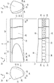
次に、本実施形態のイメージセンサユニット10について図1、図4、図5を参照して説明する。図1は、後述する導光体20の構成を示す図である。図1(a)は導光体20を主走査方向から見た図である。図1(b)は副走査方向から見た図である。図1(c)は導光体20の底面図である。図1(d)は導光体20を図1(a)の反対側の主走査方向から見た図である。図4はイメージセンサユニット10の分解斜視図である。図5はイメージセンサユニット10の断面図である。
イメージセンサユニット10は、フレーム11、導光体20、光源40、回路基板50、イメージセンサ(センサあるいはラインセンサ)60、集光体70などを備えている。これらの構成部材のうち、光源40および導光体20は、照明装置として機能する。また、上述した構成部材のうち、フレーム11、導光体20、回路基板50、イメージセンサ60、集光体70は、読取る原稿Pの主走査方向の寸法に応じた長さに形成される。
Next, the image sensor unit 10 of the present embodiment will be described with reference to FIGS. 1, 4, and 5. FIG. 1 is a diagram showing a configuration of a light guide body 20 described later. FIG. 1A is a view of the light guide body 20 as viewed from the main scanning direction. FIG. 1B is a view seen from the sub-scanning direction. FIG. 1C is a bottom view of the light guide body 20. FIG. 1D is a view of the light guide body 20 as viewed from the main scanning direction on the opposite side of FIG. 1A. FIG. 4 is an exploded perspective view of the image sensor unit 10. FIG. 5 is a cross-sectional view of the image sensor unit 10.
The image sensor unit 10 includes a frame 11, a light guide body 20, a light source 40, a circuit board 50, an image sensor (sensor or line sensor) 60, a light collector 70, and the like. Among these constituent members, the light source 40 and the light guide body 20 function as lighting devices. Further, among the above-mentioned constituent members, the frame 11, the light guide body 20, the circuit board 50, the image sensor 60, and the condensing body 70 are formed to have a length corresponding to the dimensions in the main scanning direction of the document P to be read.

フレーム11は、イメージセンサユニット10の各構成部材を収容するフレームであり、主走査方向を長手方向とする略直方体状に形成される。フレーム11は例えば、黒色に着色された遮光性を有するポリカーボネートなどの樹脂材料により形成される。
図5に示すように、フレーム11には、導光体20を収容する導光体収容部12が主走査方向に沿って形成される。また、図4に示すように、フレーム11の導光体収容部12には主走査方向に間隔をあけて、導光体20を着脱自在に支持する保持部13が複数、形成される。
The frame 11 is a frame that houses each component of the image sensor unit 10, and is formed in a substantially rectangular parallelepiped shape with the main scanning direction as the longitudinal direction. The frame 11 is formed of, for example, a resin material such as polycarbonate, which is colored black and has a light-shielding property.
As shown in FIG. 5, a light guide body accommodating portion 12 accommodating the light guide body 20 is formed in the frame 11 along the main scanning direction. Further, as shown in FIG. 4, a plurality of holding portions 13 for detachably supporting the light guide body 20 are formed in the light guide body accommodating portion 12 of the frame 11 at intervals in the main scanning direction.

フレーム11には、導光体収容部12に隣接して集光体70を収容する集光体収容部14が主走査方向に形成される。また、フレーム11の下面には、回路基板50を配置するための基板収容部15が主走査方向に沿ってフレーム11の外側から凹状に形成される。また、図4に示すように、フレーム11の主走査方向における一方側には、光源40が配置される光源収容部16が形成される。 In the frame 11, a condensing body accommodating portion 14 accommodating the condensing body 70 is formed adjacent to the light guide body accommodating portion 12 in the main scanning direction. Further, on the lower surface of the frame 11, a substrate accommodating portion 15 for arranging the circuit board 50 is formed in a concave shape from the outside of the frame 11 along the main scanning direction. Further, as shown in FIG. 4, a light source accommodating portion 16 in which the light source 40 is arranged is formed on one side of the frame 11 in the main scanning direction.

導光体20は、光源40が発光する光を原稿Pへと導くものであり、主走査方向を長手方向とする棒状に形成される。導光体20は、フレーム11の導光体収容部12の保持部13により位置決めされた状態で収容される。導光体20は例えば、アクリルやポリカーボネートなどの透明な樹脂材料により形成される。
図1および図4に示すように、導光体20は、主走査方向における一端面に光源40からの光を入射させる入射面21を有する。また、導光体20は、入射面21に対向する端面に平面状の他端面27を有する。また、導光体20は、原稿Pと対面する面に導光体20内に入射された光を原稿Pに向かって出射させる、凸の曲面状の出射面22を有する。また、導光体20は、出射面22と対向する面に入射面21から入射された光を反射させる平坦状の反射面23を有する。図1に示すように、反射面23には、入射面21から入射された光を出射面22に向かって拡散させる複数の拡散部24がドット状に形成される。本実施形態では、拡散部24は反射面23において、入射面21側から他端面27側までの全面に亘って形成される。
The light guide body 20 guides the light emitted by the light source 40 to the document P, and is formed in a rod shape having the main scanning direction as the longitudinal direction. The light guide body 20 is accommodated in a state of being positioned by the holding portion 13 of the light guide body accommodating portion 12 of the frame 11. The light guide body 20 is formed of, for example, a transparent resin material such as acrylic or polycarbonate.
As shown in FIGS. 1 and 4, the light guide body 20 has an incident surface 21 for incident light from the light source 40 on one end surface in the main scanning direction. Further, the light guide body 20 has a flat other end surface 27 on an end surface facing the incident surface 21. Further, the light guide body 20 has a convex curved exit surface 22 that emits light incident on the light guide body 20 toward the document P on a surface facing the document P. Further, the light guide body 20 has a flat reflecting surface 23 that reflects the light incident from the incident surface 21 on the surface facing the emitting surface 22. As shown in FIG. 1, a plurality of diffusing portions 24 for diffusing the light incident from the incident surface 21 toward the emitting surface 22 are formed in a dot shape on the reflecting surface 23. In the present embodiment, the diffusion portion 24 is formed on the reflection surface 23 over the entire surface from the incident surface 21 side to the other end surface 27 side.

拡散部24は反射面23から凹んだ湾曲状、具体的には球状に形成されている。拡散部24は複数、形成され、それぞれ大きさが同一である。ここで、拡散部24の大きさが同一とは、反射面23における拡散部24の外形、反射面23から拡散部24の最も深い位置までの距離、拡散部24が湾曲状あるいは球状である場合の曲率半径、の何れもが同一である。なお、拡散部24を成形する場合の製造誤差の範囲は同一の概念に含まれる。また、拡散部24は入射面21側では密度が小さく、他端面27側では密度が大きく形成されている。すなわち、反射面23では入射面21側から他端面27側に向かうにしたがって徐々に反射面23に対する拡散部24の密度が増大している。入射面21側は光源40から近いために光源40から到達する光量が多い。到達する光量が多い分、入射面21側では拡散部24の密度を小さくすることで到達した光を少なく拡散させて、所望する光量を入射面21側の出射面22から出射させている。一方、他端面27側では光源40から遠いために光源40から到達する光量が少ない。到達する光量が少ない分、他端面27側では拡散部24の密度を大きくすることで到達した光をより多く拡散させて、所望する光量を他端面27側の出射面22から出射させている。入射面21から入射された光は反射面23により反射されたり、拡散部24によって拡散されたりすることで、出射面22から出射され原稿Pにライン状の光が出射される。 The diffusion portion 24 is formed in a curved shape recessed from the reflection surface 23, specifically in a spherical shape. A plurality of diffusion portions 24 are formed, and each has the same size. Here, the same size of the diffusing portion 24 means that the outer shape of the diffusing portion 24 on the reflecting surface 23, the distance from the reflecting surface 23 to the deepest position of the diffusing portion 24, and the case where the diffusing portion 24 is curved or spherical. The radius of curvature of is the same. The range of manufacturing error when molding the diffusion portion 24 is included in the same concept. Further, the diffusion portion 24 has a low density on the incident surface 21 side and a high density on the other end surface 27 side. That is, in the reflecting surface 23, the density of the diffusing portion 24 with respect to the reflecting surface 23 gradually increases from the incident surface 21 side to the other end surface 27 side. Since the incident surface 21 side is close to the light source 40, a large amount of light reaches from the light source 40. Since the amount of light that reaches is large, the density of the diffusing portion 24 is reduced on the incident surface 21 side to diffuse the light that has reached less, and the desired amount of light is emitted from the exit surface 22 on the incident surface 21 side. On the other hand, on the other end surface 27 side, since it is far from the light source 40, the amount of light reaching from the light source 40 is small. Since the amount of light that reaches is small, the density of the diffusing portion 24 is increased on the other end surface 27 side to diffuse the reached light more, and the desired amount of light is emitted from the exit surface 22 on the other end surface 27 side. The light incident from the incident surface 21 is reflected by the reflecting surface 23 or diffused by the diffusing portion 24, so that the light is emitted from the emitting surface 22 and the line-shaped light is emitted to the document P.

また、導光体20は、出射面22と反射面23との間に第1側面25および第2側面26を有する。第1側面25および第2側面26は、出射面22および反射面23とは異なる面であって、それぞれ導光体20の長手方向に沿った面である。第1側面25および第2側面26は、互いに反対側に位置する。具体的には、第1側面25は、出射面22の長手方向に沿った一方側の端部と反射面23の長手方向に沿った一方側の端部とを繋ぐ、凸の曲面状に形成される。第1側面25は主に入射面21から入射された光を導光体20の長手方向に向かって反射させる反射面として機能する。第2側面26は、出射面22の長手方向に沿った他方側の端部と反射面23の長手方向に沿った他方側の端部とを繋ぐ、凸の曲面状に形成される。第2側面26は拡散部24によって拡散された光を所定の方向、具体的には出射面22の上側であって反射面23に対して略直交する方向(図5に示す読取ラインS)に反射させる反射面として機能する。ただし、第2側面26に入射される方向および角度によっては、第2側面26も第1側面25と同様に導光体20の長手方向に向かって反射させる。ここでは、第1側面25の曲率半径が、第2側面26の曲率半径よりも大きく設定されている。なお、導光体20が導光体収容部12に収容された状態では、第1側面25は集光体70側に位置し、集光体70に対してフレーム11を挟んで対面する。すなわち、導光体20が導光体収容部12に収容された状態では、第1側面25は第2側面26よりも集光体70に近接する。 Further, the light guide body 20 has a first side surface 25 and a second side surface 26 between the exit surface 22 and the reflection surface 23. The first side surface 25 and the second side surface 26 are surfaces different from the exit surface 22 and the reflection surface 23, and are surfaces along the longitudinal direction of the light guide body 20, respectively. The first side surface 25 and the second side surface 26 are located on opposite sides of each other. Specifically, the first side surface 25 is formed in a convex curved surface shape that connects one end of the exit surface 22 along the longitudinal direction and one end of the reflection surface 23 along the longitudinal direction. Will be done. The first side surface 25 mainly functions as a reflecting surface that reflects the light incident from the incident surface 21 toward the longitudinal direction of the light guide body 20. The second side surface 26 is formed in a convex curved surface shape that connects the other end portion along the longitudinal direction of the exit surface 22 and the other end portion along the longitudinal direction of the reflection surface 23. The second side surface 26 directs the light diffused by the diffusing portion 24 in a predetermined direction, specifically, in a direction above the emitting surface 22 and substantially orthogonal to the reflecting surface 23 (reading line S shown in FIG. 5). It functions as a reflecting surface to reflect. However, depending on the direction and angle of incident on the second side surface 26, the second side surface 26 also reflects toward the longitudinal direction of the light guide body 20 like the first side surface 25. Here, the radius of curvature of the first side surface 25 is set to be larger than the radius of curvature of the second side surface 26. In the state where the light guide body 20 is housed in the light guide body accommodating portion 12, the first side surface 25 is located on the light collector 70 side and faces the light collector 70 with the frame 11 interposed therebetween. That is, when the light guide body 20 is housed in the light guide body accommodating portion 12, the first side surface 25 is closer to the light collector 70 than the second side surface 26.

導光体20は金型を用いた射出成形によって製造することができる。すなわち、導光体20の原料となるアクリルやポリカーボネートなどを溶融して金型内に射出した後、冷却することで導光体20を製造する。金型は、導光体20と同様な形状の電極を用い、放電加工することにより作製する。金型は導光体20の凹凸が逆であるのに対して、電極は導光体20の凹凸と同様である。すなわち、電極のうち拡散部24に相当する形状も球状である。したがって、電極に対して球状の工具を用いて切削することで、容易に拡散部24に相当する形状を作製することが可能である。 The light guide body 20 can be manufactured by injection molding using a mold. That is, the light guide body 20 is manufactured by melting acrylic or polycarbonate, which is a raw material of the light guide body 20, and injecting it into a mold, and then cooling the light guide body 20. The mold is manufactured by electric discharge machining using electrodes having the same shape as the light guide body 20. In the mold, the unevenness of the light guide body 20 is reversed, whereas the electrode is the same as the unevenness of the light guide body 20. That is, the shape of the electrode corresponding to the diffusion portion 24 is also spherical. Therefore, it is possible to easily produce a shape corresponding to the diffusion portion 24 by cutting the electrode with a spherical tool.

光源40は、光を発光することで導光体20を介して原稿Pに光を照射する。光源40は、回路基板50に接続された状態でフレーム11の光源収容部16に収容される。光源40がフレーム11に収容された状態では、隙間を介して導光体20の入射面21と対面する。光源40は例えば、LEDパッケージ41が用いられる。LEDパッケージ41は、略矩形状に形成された筐体42と、筐体42から突出する複数のリード端子43とを備えている。筐体42は、導光体20の入射面21と対面する面に発光素子としてのLEDチップ44を複数、透明樹脂によって封止した状態で支持する。LEDチップ44には赤、緑、青、赤外、紫外などの発光波長を有するLEDチップを用いることができる。赤外、紫外の発光波長を有するLEDチップを用いるのは、セキュリティのために不可視インクが施された原稿Pを読取るためである。
なお、図5には、導光体20に対する光源40の配置が理解できるように、LEDパッケージ41およびLEDチップ44を想像線(二点鎖線)で図示している。
The light source 40 emits light to irradiate the document P with light via the light guide body 20. The light source 40 is housed in the light source accommodating portion 16 of the frame 11 in a state of being connected to the circuit board 50. When the light source 40 is housed in the frame 11, it faces the incident surface 21 of the light guide body 20 through a gap. As the light source 40, for example, the LED package 41 is used. The LED package 41 includes a housing 42 formed in a substantially rectangular shape, and a plurality of lead terminals 43 protruding from the housing 42. The housing 42 supports a plurality of LED chips 44 as light emitting elements in a state of being sealed with a transparent resin on the surface of the light guide body 20 facing the incident surface 21. As the LED chip 44, an LED chip having an emission wavelength such as red, green, blue, infrared, or ultraviolet can be used. The reason why the LED chip having infrared and ultraviolet emission wavelengths is used is to read the document P to which the invisible ink is applied for security.
In FIG. 5, the LED package 41 and the LED chip 44 are illustrated by an imaginary line (dashed line) so that the arrangement of the light source 40 with respect to the light guide body 20 can be understood.

回路基板50は、LEDチップ44を発光させるための駆動回路やイメージセンサ60などを実装する基板であり、長手方向を主走査方向とする平板状に形成される。回路基板50は、フレーム11の基板収容部15に収容される。回路基板50は例えば、ガラスエポキシ基板が用いられる。また、回路基板50の主走査方向における一方の端部には、LEDパッケージ41のリード端子43を接続するための挿入孔51が形成される。 The circuit board 50 is a board on which a drive circuit for causing the LED chip 44 to emit light, an image sensor 60, and the like are mounted, and is formed in a flat plate shape having a longitudinal direction as a main scanning direction. The circuit board 50 is housed in the board accommodating portion 15 of the frame 11. For the circuit board 50, for example, a glass epoxy board is used. Further, an insertion hole 51 for connecting the lead terminal 43 of the LED package 41 is formed at one end of the circuit board 50 in the main scanning direction.

イメージセンサ60は、原稿Pから反射され集光体70によって結像された反射光を受光して電気信号に変換する。イメージセンサ60は集光体70の光軸の延長線上に配置されるように、回路基板50が基板収容部15によって支持される。イメージセンサ60は、イメージセンサユニット10の読取りの解像度に応じた複数の受光素子(光電変換素子)から構成されるイメージセンサIC61の所定数を回路基板50の実装面上に主走査方向に直線状に配列して実装される。なお、イメージセンサ60は、原稿Pから反射された反射光を電気信号に変換できればよく、公知の各種イメージセンサICを用いることができる。 The image sensor 60 receives the reflected light reflected from the document P and formed by the condenser 70 and converts it into an electric signal. The circuit board 50 is supported by the substrate accommodating portion 15 so that the image sensor 60 is arranged on the extension line of the optical axis of the condenser 70. The image sensor 60 linearly forms a predetermined number of image sensor ICs 61 composed of a plurality of light receiving elements (photoelectric conversion elements) according to the reading resolution of the image sensor unit 10 on the mounting surface of the circuit board 50 in the main scanning direction. It is implemented by arranging it in. The image sensor 60 only needs to be able to convert the reflected light reflected from the document P into an electric signal, and various known image sensor ICs can be used.

集光体70は、原稿Pからの反射光をイメージセンサ60上に結像する光学部材であり、長手方向を主走査方向にして形成される。集光体70は、フレーム11の集光体収容部14に収容される。集光体70は例えば、複数の正立等倍結像型の結像素子(ロッドレンズ)が主走査方向に直線状に配列されるロッドレンズアレイが用いられる。なお、集光体70は、反射光をイメージセンサ60上に結像できればよく、ロッドレンズアレイに限られず、マイクロレンズアレイなど公知の各種集光機能を有する光学部材(例えばレンズアレイ)を用いることができる。 The condenser 70 is an optical member that forms an image of the reflected light from the document P on the image sensor 60, and is formed with the longitudinal direction as the main scanning direction. The condensing body 70 is housed in the condensing body accommodating portion 14 of the frame 11. As the condenser 70, for example, a rod lens array in which a plurality of upright equal-magnification imaging elements (rod lenses) are linearly arranged in the main scanning direction is used. The condensing body 70 is not limited to the rod lens array as long as the reflected light can be imaged on the image sensor 60, and an optical member (for example, a lens array) having various known condensing functions such as a microlens array is used. Can be done.

図5に示すように、上述したように構成されるイメージセンサユニット10では、フレーム11内に配置された光源40を発光させることにより導光体20から原稿Pの下面に対して矢印Lに示すように光を照射する。したがって、原稿Pには読取ラインS(主走査方向)に亘ってライン状に光が照射される。この光は原稿Pによって反射されることで、集光体70を介して反射光がイメージセンサ60上に結像される。イメージセンサ60は、結像された反射光を電気信号に変換することで、原稿Pの下面の画像を読取ることができる。 As shown in FIG. 5, in the image sensor unit 10 configured as described above, the light source 40 arranged in the frame 11 is made to emit light, so that the light guide 20 indicates the lower surface of the document P as indicated by an arrow L. Irradiate the light like this. Therefore, the document P is irradiated with light in a line shape over the reading line S (main scanning direction). When this light is reflected by the document P, the reflected light is imaged on the image sensor 60 via the condenser 70. The image sensor 60 can read an image of the lower surface of the document P by converting the formed reflected light into an electric signal.

イメージセンサ60が反射光を1走査ライン分読取ることで、原稿Pの主走査方向における1走査ラインの読取り動作を完了する。1走査ラインの読取り動作終了後、イメージセンサユニット10の副走査方向への相対的な移動に伴い、上述する動作と同様に次の1走査ライン分の読取り動作が行われる。このようにイメージセンサユニット10が副走査方向に移動しながら1走査ライン分ずつ読取り動作を繰り返すことで、原稿Pの全面が順次走査されて反射光により画像の読取りが行われる。 When the image sensor 60 reads the reflected light for one scanning line, the reading operation of one scanning line in the main scanning direction of the document P is completed. After the reading operation of one scanning line is completed, the reading operation for the next one scanning line is performed in the same manner as the above-described operation with the relative movement of the image sensor unit 10 in the sub-scanning direction. By repeating the reading operation for each scanning line while the image sensor unit 10 moves in the sub-scanning direction in this way, the entire surface of the document P is sequentially scanned and the image is read by the reflected light.

次に、本実施形態の導光体20において、導光体20の出射面22から出射される光のうち光源40側から出射される光量の減少を抑制できる構成について説明する。
図1に示すように、導光体20は入射面21側から長手方向において、途中まで傾斜していることで面積が小さくなっている。ここでの面積は、導光体20の長手方向に対して直交する方向に切断した場合の断面積をいう。
図1(c)に示すように、導光体20は、後述する第1の傾斜部33のように傾斜することで、第1側面25と第2側面26との間の幅が入射面21から途中まで徐々に狭くなり、途中から他端面27までは略一定である。また、図1(b)に示すように、導光体20は、後述する第2の傾斜部34のように傾斜することで、出射面22と反射面23との間の幅が入射面21から途中まで徐々に狭くなり、途中から他端面27まで略一定である。
本実施形態の導光体20は、導光体20の長手方向の位置によって断面形状および断面積が異なる形状変化部31と、導光体20の長手方向の何れの位置でも断面形状および断面積が同一(略同一を含む)である形状不変部32とを有する。
Next, in the light guide body 20 of the present embodiment, a configuration capable of suppressing a decrease in the amount of light emitted from the light source 40 side among the light emitted from the light emitting surface 22 of the light guide body 20 will be described.
As shown in FIG. 1, the light guide body 20 is inclined halfway from the incident surface 21 side in the longitudinal direction, so that the area is reduced. The area here refers to the cross-sectional area when the light guide body 20 is cut in a direction orthogonal to the longitudinal direction.
As shown in FIG. 1 (c), the light guide body 20 is inclined like the first inclined portion 33 described later, so that the width between the first side surface 25 and the second side surface 26 is the incident surface 21. It gradually narrows from the middle to the middle, and is substantially constant from the middle to the other end surface 27. Further, as shown in FIG. 1B, the light guide body 20 is inclined as in the second inclined portion 34 described later, so that the width between the emitting surface 22 and the reflecting surface 23 is reduced to the incident surface 21. It gradually narrows from the middle to the middle, and is substantially constant from the middle to the other end surface 27.
The light guide body 20 of the present embodiment has a shape changing portion 31 whose cross-sectional shape and cross-sectional area differ depending on the position of the light guide body 20 in the longitudinal direction, and the cross-sectional shape and cross-sectional area at any position in the longitudinal direction of the light guide body 20. Has a shape invariant portion 32 which is the same (including substantially the same).

形状変化部31は、入射面21側の長手方向における一定の範囲、具体的には入射面21から導光体20の長手方向における所定位置Aまでの範囲である。一方、形状不変部32は、他端面27側の長手方向における一定の範囲、具体的には所定位置Aから他端面27までの範囲である。
ここで、所定位置Aは、入射面21と他端面27との間の位置であって、中央よりも入射面21側に偏った位置である。本実施形態では、入射面21から所定位置Aまでの距離が略9mm、所定位置Aから他端面27までの距離が略218mmである。すなわち、入射面21から所定位置Aまでの距離と、所定位置Aから他端面27までの距離との比は、略1:24である。
The shape changing portion 31 is a certain range in the longitudinal direction on the incident surface 21 side, specifically, a range from the incident surface 21 to a predetermined position A in the longitudinal direction of the light guide body 20. On the other hand, the shape invariant portion 32 is a certain range in the longitudinal direction on the other end surface 27 side, specifically, a range from a predetermined position A to the other end surface 27.
Here, the predetermined position A is a position between the incident surface 21 and the other end surface 27, and is a position biased toward the incident surface 21 side from the center. In the present embodiment, the distance from the incident surface 21 to the predetermined position A is approximately 9 mm, and the distance from the predetermined position A to the other end surface 27 is approximately 218 mm. That is, the ratio of the distance from the incident surface 21 to the predetermined position A and the distance from the predetermined position A to the other end surface 27 is approximately 1:24.

形状変化部31は、入射面21側から所定位置Aに向かうにしたがって断面形状が変化しながら断面積が徐々に縮小する。すなわち、形状変化部31は、所定位置Aから入射面21側に向かうにしたがって断面積が徐々に拡大するベル(bell)形状である。本実施形態では、入射面21の面積が略8.5mm2であり、所定位置Aの断面積が略7.2mm2である。すなわち、入射面21の面積と所定位置Aの断面積との比は、略1:0.85である。
形状変化部31は外周の一部に傾斜部として、第1の傾斜部33および第2の傾斜部34を有することで、形状変化部31のベル形状を実現する。第1の傾斜部33および第2の傾斜部34は、導光体20の長手方向に沿った直線に対して傾斜する。出射面22および第2側面26は傾斜部を有さず、長手方向の何れの位置でも断面形状が同一(略同一を含む)である。
The cross-sectional area of the shape changing portion 31 gradually decreases while the cross-sectional shape changes from the incident surface 21 side toward the predetermined position A. That is, the shape changing portion 31 has a bell shape in which the cross-sectional area gradually expands from the predetermined position A toward the incident surface 21 side. In the present embodiment, the area of the incident surface 21 is approximately 8.5 mm 2 , and the cross-sectional area of the predetermined position A is approximately 7.2 mm 2 . That is, the ratio of the area of the incident surface 21 to the cross-sectional area of the predetermined position A is approximately 1: 0.85.
The shape-changing portion 31 has a first inclined portion 33 and a second inclined portion 34 as inclined portions on a part of the outer circumference, thereby realizing the bell shape of the shape-changing portion 31. The first inclined portion 33 and the second inclined portion 34 are inclined with respect to a straight line along the longitudinal direction of the light guide body 20. The exit surface 22 and the second side surface 26 do not have an inclined portion, and have the same cross-sectional shape (including substantially the same) at any position in the longitudinal direction.

第1の傾斜部33は曲面状であって、第1側面25に形成される。第1の傾斜部33は導光体20を長手方向から見ると、所定位置Aから入射面21側に向かうにしたがって、外側に向かって拡大しつつ、外形線の曲率半径が所定位置Aから徐々に小さくなる。入射面21における第1側面25の外形線は、出射面22の曲率半径と同一(略同一を含む)である。
一方、第2の傾斜部34は平面状であって、反射面23に形成される。第2の傾斜部34は導光体20を長手方向から見ると、所定位置Aから入射面21側に向かうにしたがって、外形線の位置が外側に向かいつつ第1側面25側に平行移動する。なお、第2の傾斜部34は、反射面23の一部であって、拡散部24が形成される。
導光体20がフレーム11の導光体収容部12に収容された状態では、副走査方向から見て、導光体20の形状変化部31および形状不変部32は集光体70およびイメージセンサ60と重なっている。
The first inclined portion 33 has a curved surface shape and is formed on the first side surface 25. When the light guide body 20 is viewed from the longitudinal direction, the first inclined portion 33 gradually expands outward from the predetermined position A toward the incident surface 21 side, and the radius of curvature of the outer line gradually increases from the predetermined position A. Becomes smaller. The outer line of the first side surface 25 on the incident surface 21 is the same as (including substantially the same) the radius of curvature of the exit surface 22.
On the other hand, the second inclined portion 34 is flat and is formed on the reflecting surface 23. When the light guide body 20 is viewed from the longitudinal direction, the second inclined portion 34 moves in parallel to the first side surface 25 side while the position of the outer line moves outward from the predetermined position A toward the incident surface 21 side. The second inclined portion 34 is a part of the reflecting surface 23, and the diffusion portion 24 is formed.
In a state where the light guide body 20 is housed in the light guide body accommodating portion 12 of the frame 11, the shape changing portion 31 and the shape immutable portion 32 of the light guide body 20 are the condensing body 70 and the image sensor when viewed from the sub-scanning direction. It overlaps with 60.

次に、発明例として形状変化部31を有する導光体20と、比較例として形状不変部32のみからなる導光体80と、を用いて光が反射される状態について説明する。
図6(a)は、比較例の導光体80において光が反射される軌跡を示す平面図および主走査方向から見た図である。導光体80の第1側面25には、第1の傾斜部33を有していない。ここで、光源40からの光のうち第1側面25に向かう光は、第1の傾斜部33がないことで第1側面25により反射される場合の反射角αが大きくなるために、導光体80の長手方向に向かって進行する。すなわち、導光体80の拡散部24のうち光源40側に配置された拡散部24に向かう光が減少する。そのため、光源40側の拡散部24によって拡散される光が少なくなり、導光体80のうち光源40側から出射される光量が減少してしまう。
Next, a state in which light is reflected will be described using a light guide body 20 having a shape changing portion 31 as an example of the invention and a light guide body 80 having only a shape unchanged portion 32 as a comparative example.
FIG. 6A is a plan view showing a locus of light reflected by the light guide body 80 of the comparative example and a view seen from the main scanning direction. The first side surface 25 of the light guide body 80 does not have the first inclined portion 33. Here, among the light from the light source 40, the light directed to the first side surface 25 is guided by a large reflection angle α when reflected by the first side surface 25 due to the absence of the first inclined portion 33. Proceed in the longitudinal direction of the body 80. That is, the light directed to the diffuser 24 arranged on the light source 40 side of the diffuser 24 of the light guide 80 is reduced. Therefore, the amount of light diffused by the diffusing unit 24 on the light source 40 side is reduced, and the amount of light emitted from the light source 40 side of the light guide body 80 is reduced.

図6(b)は、発明例の導光体20において光が反射される軌跡を示す平面図および正面図である。導光体20の形状変化部31および形状不変部32の何れにも拡散部24が設けられている。また、導光体20の第1側面25には、第1の傾斜部33を有している。ここで、光源40からの光のうち第1側面25に向かう光は、第1の傾斜部33により反射されることで反射角βが小さくなり、導光体20の長手方向への進行が抑制される。すなわち、導光体20の拡散部24のうち光源40側に配置された拡散部24に向かう光が増加する。そのため、光源40側の拡散部24によって拡散される光が増えることから、導光体20のうち光源40側から出射される光量の減少を抑制することができる。
なお、光源40からの光のうち第2の傾斜部34の反射面23によって反射される光は反射角が小さくなるために、第1の傾斜部33と同様に、導光体20の長手方向への進行が抑制される。
FIG. 6B is a plan view and a front view showing a locus of light reflected by the light guide body 20 of the invention example. A diffusion portion 24 is provided in both the shape changing portion 31 and the shape invariing portion 32 of the light guide body 20. Further, the first side surface 25 of the light guide body 20 has a first inclined portion 33. Here, among the light from the light source 40, the light directed to the first side surface 25 is reflected by the first inclined portion 33, so that the reflection angle β becomes smaller and the progress of the light guide body 20 in the longitudinal direction is suppressed. Will be done. That is, the light directed to the diffuser 24 arranged on the light source 40 side of the diffuser 24 of the light guide 20 increases. Therefore, since the amount of light diffused by the diffusing unit 24 on the light source 40 side increases, it is possible to suppress a decrease in the amount of light emitted from the light source 40 side of the light guide body 20.
Of the light from the light source 40, the light reflected by the reflecting surface 23 of the second inclined portion 34 has a small reflection angle, so that the light guide body 20 is in the longitudinal direction as in the case of the first inclined portion 33. Progression to is suppressed.

図7(a)、(b)はそれぞれ比較例の導光体80と発明例の導光体20とにおいて光が反射される場合の軌跡のシミュレーションを示す図である。
図7(b)に示す発明例の導光体20では、図7(a)に示す比較例の導光体80よりも、光の反射する位置がD1、D2、D3のように徐々に入射面21側に移行しており、導光体20の長手方向への光の進行が抑制される結果を得ることができた。
7 (a) and 7 (b) are diagrams showing simulations of trajectories when light is reflected by the light guide 80 of the comparative example and the light guide 20 of the invention, respectively.
In the light guide body 20 of the invention example shown in FIG. 7 (b), the light reflecting position is gradually incident as shown in D1, D2, and D3 as compared with the light guide body 80 of the comparative example shown in FIG. 7 (a). It has shifted to the surface 21 side, and it was possible to obtain the result that the progress of light in the longitudinal direction of the light guide body 20 is suppressed.

図8は、比較例の導光体80と発明例の導光体20とをそれぞれ用いて、図1の読取ラインSにおける照度を計測した場合の相対照度を示すグラフである。一点鎖線が比較例の導光体80を用いた場合の相対照度であり、実線が発明例の導光体20を用いた場合の相対照度である。ここで、縦軸は、比較例の導光体80において照度が略一定となる範囲内の平均照度を1とした場合の相対照度である。横軸は、導光体の長手方向における位置であり、0mmが導光体の入射面21である。なお、発明例の導光体20には、0mmから10mmに亘って形状変化部31が形成されている。
図8に示すように、比較例の導光体80では長手方向の24mm付近から相対照度が略1.0になるのに対して、発明例の導光体20では長手方向の6mm付近から相対照度が略1.0となる。図8に示すように、発明例の導光体20を用いることで、導光体20から出射される光のうち光源40側から出射される光量の減少を抑制することが確認できた。
FIG. 8 is a graph showing the relative illuminance when the illuminance at the reading line S of FIG. 1 is measured by using the light guide body 80 of the comparative example and the light guide body 20 of the invention example, respectively. The alternate long and short dash line is the relative illuminance when the light guide body 80 of the comparative example is used, and the solid line is the relative illuminance when the light guide body 20 of the invention example is used. Here, the vertical axis is the relative illuminance when the average illuminance within the range in which the illuminance is substantially constant in the light guide body 80 of the comparative example is 1. The horizontal axis is the position in the longitudinal direction of the light guide body, and 0 mm is the incident surface 21 of the light guide body. The light guide body 20 of the invention example has a shape changing portion 31 formed from 0 mm to 10 mm.
As shown in FIG. 8, in the light guide body 80 of the comparative example, the relative illuminance becomes approximately 1.0 from around 24 mm in the longitudinal direction, whereas in the light guide body 20 of the invention example, it is relative from around 6 mm in the longitudinal direction. The illuminance is approximately 1.0. As shown in FIG. 8, it was confirmed that by using the light guide body 20 of the invention example, the decrease in the amount of light emitted from the light source 40 side among the light emitted from the light guide body 20 was suppressed.

このように、光源40側から出射される光量の減少を抑制することで、導光体20を長手方向に亘って有効に利用することができる。すなわち、比較例の導光体80では長手方向の24mm付近からしか必要な照度が得られず、導光体80の長手方向の0mm〜24mm付近までの長さを有効に利用することができない。一方、発明例の導光体20では長手方向の7mm付近から必要な照度が得られ、導光体20の長手方向の0mm〜7mm付近までの長さを利用できないだけで、イメージセンサユニット10の読取り可能な長さを拡大することができる。換言すると、発明例の導光体20によれば、比較例の導光体80に比べて、長手方向の長さを短くしても必要な長さに亘って十分な照度を得られることから、照明装置あるいはイメージセンサユニット10を小型化することができる。 By suppressing the decrease in the amount of light emitted from the light source 40 side in this way, the light guide body 20 can be effectively used in the longitudinal direction. That is, in the light guide body 80 of the comparative example, the required illuminance can be obtained only from the vicinity of 24 mm in the longitudinal direction, and the length of the light guide body 80 from about 0 mm to 24 mm in the longitudinal direction cannot be effectively used. On the other hand, in the light guide body 20 of the invention example, the required illuminance can be obtained from the vicinity of 7 mm in the longitudinal direction, and the length from 0 mm to 7 mm in the longitudinal direction of the light guide body 20 cannot be used. The readable length can be increased. In other words, according to the light guide body 20 of the invention example, sufficient illuminance can be obtained over the required length even if the length in the longitudinal direction is shortened as compared with the light guide body 80 of the comparative example. , The lighting device or the image sensor unit 10 can be miniaturized.

本実施形態によれば、導光体20は、入射面21側から導光体20の長手方向において、途中まで傾斜していることで面積が小さくなり、入射面21側から途中までは反射面23に拡散部24が設けられている。このように、入射面21側から途中まで面積が小さくなるように傾斜していることで、入射面21から入射された光のうち傾斜している部分によって反射した光は、反射角が小さくなるので導光体20の長手方向への光の進行が抑制される。進行が抑制された光は、入射面21側から途中までに設けられた反射面23の拡散部24によって拡散される機会が増えることから、導光体20のうち光源40側から出射される光量の減少を抑制することができる。
ここで、傾斜している部分とは、第1の傾斜部33および第2の傾斜部34に相当する。ただし、傾斜している部分は第1の傾斜部33および第2の傾斜部34の何れか一方であってもよい。また、傾斜している部分は、第2側面26に有していてもよく、導光体20の全周に亘って有していてもよい。
According to the present embodiment, the light guide body 20 is inclined halfway from the incident surface 21 side in the longitudinal direction of the light guide body 20, so that the area becomes small, and the reflecting surface from the incident surface 21 side to the middle. A diffusion portion 24 is provided on the 23. In this way, by inclining so that the area becomes smaller from the incident surface 21 side to the middle, the light reflected by the inclined portion of the light incident from the incident surface 21 has a smaller reflection angle. Therefore, the progress of light in the longitudinal direction of the light guide body 20 is suppressed. The amount of light emitted from the light source 40 side of the light guide body 20 increases because the light whose progress is suppressed is more likely to be diffused by the diffusing portion 24 of the reflecting surface 23 provided halfway from the incident surface 21 side. Can be suppressed.
Here, the inclined portion corresponds to the first inclined portion 33 and the second inclined portion 34. However, the inclined portion may be either one of the first inclined portion 33 and the second inclined portion 34. Further, the inclined portion may be provided on the second side surface 26, or may be provided over the entire circumference of the light guide body 20.

また、本実施形態では、形状変化部31は、導光体20の外周の少なくとも一部であって、導光体20の長手方向に対して傾斜する第1の傾斜部33および第2の傾斜部34を有する。このように、形状変化部31が第1の傾斜部33および第2の傾斜部34を有することで、入射面21から入射された光のうち第1の傾斜部33および第2の傾斜部34によって反射される光は反射角が小さくなるので、導光体20の長手方向への光の進行が抑制される。なお、形状変化部31は、外周の一部に傾斜部を有する場合に限られず、全周に亘って傾斜部を有していてもよい。 Further, in the present embodiment, the shape changing portion 31 is at least a part of the outer circumference of the light guide body 20, and is the first inclined portion 33 and the second inclined portion 33 which are inclined with respect to the longitudinal direction of the light guide body 20. It has a part 34. As described above, since the shape changing portion 31 has the first inclined portion 33 and the second inclined portion 34, the first inclined portion 33 and the second inclined portion 34 of the light incident from the incident surface 21 are provided. Since the reflection angle of the light reflected by the light guide body 20 becomes small, the progress of the light in the longitudinal direction of the light guide body 20 is suppressed. The shape changing portion 31 is not limited to the case where the inclined portion is provided on a part of the outer circumference, and the shape changing portion 31 may have the inclined portion over the entire circumference.

また、本実施形態では、第1側面25および第2側面26のうち第1側面25のみに第1の傾斜部33を有する。換言すると、第2側面26に傾斜部を有しないことで、第2側面26によって光を所定の方向に反射させる機能を低下させないようにすることができる。なお、このような効果を目的とする場合には、導光体20は入射面21側から途中までの反射面23に拡散部24を設けなくてもよい。
また、本実施形態では、出射面22および反射面23のうち反射面23のみに第2の傾斜部34を有する。換言すると、出射面22に傾斜部を有しないことで、出射面22によって光を所定の方向に出射させる機能を低下させないようにすることができる。なお、このような効果を目的とする場合には、導光体20は入射面21側から途中までの反射面23に拡散部24を設けなくてもよい。
また、本実施形態では、導光体20の傾斜している部分は、副走査方向において集光体70およびイメージセンサ60と重なっている。したがって、導光体20のうち光源40側から出射される光も、原稿Sによって反射された後に、重なっている集光体70によってイメージセンサ60に結像させることができることから、有効読取り領域を広げることができる。
また、本実施形態では、拡散部24は複数、形成され、それぞれ大きさが同一である。したがって、拡散部24を有する導光体20を容易に製造することができる。
また、本実施形態では、導光体20は、入射面21側から導光体20の長手方向において、途中まで傾斜していることで面積が小さくなると共に、第1側面25および第2側面26のうち第1側面25のみ傾斜している部分を有する。したがって、導光体20の長手方向への光の進行を抑制させることができると共に、第2側面26によって光を所定の方向に反射させる機能を低下させないようにすることができる。
Further, in the present embodiment, the first inclined portion 33 is provided only on the first side surface 25 of the first side surface 25 and the second side surface 26. In other words, by not having the inclined portion on the second side surface 26, it is possible to prevent the second side surface 26 from deteriorating the function of reflecting light in a predetermined direction. For the purpose of such an effect, the light guide body 20 does not have to provide the diffusion portion 24 on the reflection surface 23 from the incident surface 21 side to the middle.
Further, in the present embodiment, of the exit surface 22 and the reflection surface 23, only the reflection surface 23 has the second inclined portion 34. In other words, by not having the inclined portion on the exit surface 22, it is possible to prevent the exit surface 22 from deteriorating the function of emitting light in a predetermined direction. For the purpose of such an effect, the light guide body 20 does not have to provide the diffusion portion 24 on the reflection surface 23 from the incident surface 21 side to the middle.
Further, in the present embodiment, the inclined portion of the light guide body 20 overlaps the light collector 70 and the image sensor 60 in the sub-scanning direction. Therefore, the light emitted from the light source 40 side of the light guide body 20 can also be imaged on the image sensor 60 by the overlapping light collector 70 after being reflected by the document S, so that the effective reading region can be set. Can be expanded.
Further, in the present embodiment, a plurality of diffusion portions 24 are formed and each has the same size. Therefore, the light guide body 20 having the diffusion portion 24 can be easily manufactured.
Further, in the present embodiment, the light guide body 20 is inclined halfway from the incident surface 21 side in the longitudinal direction of the light guide body 20, so that the area is reduced and the first side surface 25 and the second side surface 26 are formed. Of these, only the first side surface 25 has an inclined portion. Therefore, the progress of light in the longitudinal direction of the light guide body 20 can be suppressed, and the function of reflecting light in a predetermined direction by the second side surface 26 can be prevented from being deteriorated.

(第2の実施形態)
本実施形態では、導光体20に位置決め部90を形成する場合について説明する。なお、第1の実施形態と同様の構成は、同一符号を付して、その説明を省略する。
図9は、第2の実施形態の導光体20の構成を示す図である。
位置決め部90は、導光体20のうち第1の実施形態において入射面21であった位置に一体成形されている。本実施形態では、位置決め部90の端面が光源40からの光が入射される入射面91となる。位置決め部90は導光体20の長手方向から見て矩形状であり、導光体20の断面形状よりも大きい鍔部として機能する。すなわち、導光体20の位置決め部90をフレーム11の所定の位置に嵌め込むことで、導光体20をフレーム11に対して位置決めすることができる。一方、導光体20の他端面27をフレーム11に対して位置決めしないようにすることで、位置決め部90を固定端として、導光体20の他端面27を自由端とすることができる。したがって、環境温度の変化に応じて導光体20が伸縮した場合であっても、導光体20の他端面27側が導光体20の長手方向に移動するだけで、位置決め部90の入射面91と光源40との間の距離は一定に維持することができる。
(Second embodiment)
In this embodiment, a case where the positioning portion 90 is formed on the light guide body 20 will be described. The same components as those in the first embodiment are designated by the same reference numerals, and the description thereof will be omitted.
FIG. 9 is a diagram showing the configuration of the light guide body 20 of the second embodiment.
The positioning portion 90 is integrally molded at the position of the incident surface 21 in the first embodiment of the light guide body 20. In the present embodiment, the end surface of the positioning unit 90 is the incident surface 91 on which the light from the light source 40 is incident. The positioning portion 90 has a rectangular shape when viewed from the longitudinal direction of the light guide body 20, and functions as a collar portion larger than the cross-sectional shape of the light guide body 20. That is, the light guide body 20 can be positioned with respect to the frame 11 by fitting the positioning portion 90 of the light guide body 20 into a predetermined position of the frame 11. On the other hand, by preventing the other end surface 27 of the light guide body 20 from being positioned with respect to the frame 11, the positioning portion 90 can be a fixed end and the other end surface 27 of the light guide body 20 can be a free end. Therefore, even when the light guide body 20 expands and contracts in response to a change in the environmental temperature, the incident surface of the positioning portion 90 is simply moved in the longitudinal direction of the light guide body 20 by the other end surface 27 side of the light guide body 20. The distance between the 91 and the light source 40 can be maintained constant.

また、導光体20自体は、第1の実施形態と同様であり、入射面91側から導光体20の長手方向における所定位置Aに向かうにしたがって断面形状が変化しながら断面積が縮小する形状変化部31と、所定位置Aから他端面27側までの間で断面形状が同一の形状不変部32と、を有する。ここで、断面形状とは、出射面22、反射面23、第1側面25および第2側面26によって囲まれる形状であって、位置決め部90は含まない。換言すると、形状変化部31に位置決め部90は含まない。
本実施形態によれば、導光体20に位置決め部90を一体成形したので、導光体20をフレーム11に容易に位置決めすることができる。
Further, the light guide body 20 itself is the same as that of the first embodiment, and the cross-sectional area is reduced while the cross-sectional shape changes from the incident surface 91 side toward a predetermined position A in the longitudinal direction of the light guide body 20. It has a shape changing portion 31 and a shape unchanged portion 32 having the same cross-sectional shape between a predetermined position A and the other end surface 27 side. Here, the cross-sectional shape is a shape surrounded by the exit surface 22, the reflection surface 23, the first side surface 25, and the second side surface 26, and does not include the positioning portion 90. In other words, the shape changing portion 31 does not include the positioning portion 90.
According to the present embodiment, since the positioning portion 90 is integrally formed with the light guide body 20, the light guide body 20 can be easily positioned with the frame 11.

(第3の実施形態)
次に、上述したイメージセンサユニット10を画像読取装置としてのフラットベッド方式のスキャナ130に適用した構成について図10を参照して説明する。
図10は、フラットベッド方式のスキャナ130の構成の一例を示す斜視図である。
スキャナ130は、筺体131と、被照明体載置部としてのプラテンガラス132と、イメージセンサユニット10と、イメージセンサユニット10を駆動する駆動機構と、回路基板133と、プラテンカバー134とを有する。プラテンガラス132は、ガラスなどの透明板からなり、筺体131の上面に取り付けられる。プラテンカバー134は、プラテンガラス132に載置された原稿Pを覆うように、筺体131に対してヒンジ機構などを介して開閉可能に取り付けられる。イメージセンサユニット10と、イメージセンサユニット10を駆動するための駆動機構と、回路基板133とは、筺体131内に収容される。
(Third Embodiment)
Next, a configuration in which the above-mentioned image sensor unit 10 is applied to a flatbed scanner 130 as an image reading device will be described with reference to FIG.
FIG. 10 is a perspective view showing an example of the configuration of the flatbed scanner 130.
The scanner 130 includes a housing 131, a platen glass 132 as an illuminated body mounting portion, an image sensor unit 10, a drive mechanism for driving the image sensor unit 10, a circuit board 133, and a platen cover 134. The platen glass 132 is made of a transparent plate such as glass and is attached to the upper surface of the housing 131. The platen cover 134 is attached to the housing 131 so as to cover the document P placed on the platen glass 132 so as to be openable and closable via a hinge mechanism or the like. The image sensor unit 10, the drive mechanism for driving the image sensor unit 10, and the circuit board 133 are housed in the housing 131.

駆動機構は、保持部材135と、ガイドシャフト136と、駆動モータ137と、ワイヤ138とを含む。保持部材135は、イメージセンサユニット10を囲むように保持する。ガイドシャフト136は、保持部材135をプラテンガラス132に沿って読取方向(副走査方向)に移動可能にガイドする。駆動モータ137と保持部材135とはワイヤ138を介して連結されており、駆動モータ137の駆動力によってイメージセンサユニット10を保持する保持部材135を副走査方向に移動させる。そして、イメージセンサユニット10は、駆動モータ137の駆動力によって副走査方向に移動しながら、プラテンガラス132に載置された原稿Pを読取る。このように、イメージセンサユニット10と原稿Pとを相対的に移動させながら、原稿Pを読取る。 The drive mechanism includes a holding member 135, a guide shaft 136, a drive motor 137, and a wire 138. The holding member 135 is held so as to surround the image sensor unit 10. The guide shaft 136 guides the holding member 135 along the platen glass 132 so as to be movable in the reading direction (sub-scanning direction). The drive motor 137 and the holding member 135 are connected via a wire 138, and the holding member 135 holding the image sensor unit 10 is moved in the sub-scanning direction by the driving force of the drive motor 137. Then, the image sensor unit 10 reads the document P placed on the platen glass 132 while moving in the sub-scanning direction by the driving force of the drive motor 137. In this way, the document P is read while the image sensor unit 10 and the document P are relatively moved.

回路基板133には、イメージセンサユニット10が読取った画像に所定の画像処理を施す画像処理回路や、イメージセンサユニット10を含むスキャナ130の各部を制御する制御回路や、スキャナ130の各部に電力を供給する電源回路などが構築される。 The circuit board 133 includes an image processing circuit that performs predetermined image processing on the image read by the image sensor unit 10, a control circuit that controls each part of the scanner 130 including the image sensor unit 10, and electric power to each part of the scanner 130. The power supply circuit to be supplied is constructed.

(第4の実施形態)
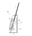
次に、上述したイメージセンサユニット10を画像読取装置としてのシートフィード方式のスキャナ140に適用した構成について図11を参照して説明する。
図11は、シートフィード方式のスキャナ140の構成の一例を示す断面図である。スキャナ140は、筺体141と、イメージセンサユニット10と、搬送ローラ142と、回路基板143とを有する。搬送ローラ142は、図示しない駆動機構によって回転し、原稿Pを挟んで搬送する。回路基板143には、イメージセンサユニット10を含むスキャナ140の各部を制御する制御回路や、スキャナ140の各部に電力を供給する電源回路などが構築される。
(Fourth Embodiment)
Next, a configuration in which the above-mentioned image sensor unit 10 is applied to a sheet feed type scanner 140 as an image reading device will be described with reference to FIG.
FIG. 11 is a cross-sectional view showing an example of the configuration of the sheet feed type scanner 140. The scanner 140 includes a housing 141, an image sensor unit 10, a transfer roller 142, and a circuit board 143. The transport roller 142 is rotated by a drive mechanism (not shown) to sandwich and transport the document P. On the circuit board 143, a control circuit for controlling each part of the scanner 140 including the image sensor unit 10, a power supply circuit for supplying electric power to each part of the scanner 140, and the like are constructed.

そして、スキャナ140は、搬送ローラ142によって原稿Pを読取り方向(副走査方向)に搬送しつつ、イメージセンサユニット10により原稿Pを読取る。すなわち、イメージセンサユニット10と原稿Pとを相対的に移動させながら、原稿Pを読取る。なお、図11では、原稿Pの片面を読取るスキャナ140の例を示すが、2つのイメージセンサユニット10が原稿Pの搬送経路を挟んで対向するように設けられ、原稿Pの両面を読取る構成であってもよい。 Then, the scanner 140 reads the document P by the image sensor unit 10 while transporting the document P in the reading direction (sub-scanning direction) by the transport roller 142. That is, the document P is read while the image sensor unit 10 and the document P are relatively moved. Although FIG. 11 shows an example of a scanner 140 that reads one side of the document P, two image sensor units 10 are provided so as to face each other with the transport path of the document P in between, and both sides of the document P are read. There may be.

以上、本発明を上述した実施形態により説明したが、本発明は上述した実施形態にのみ限定されるものではなく、本発明の範囲内で変更が可能である。
上述した実施形態では、拡散部24が反射面23に対して凹状の半球状である場合について説明したが、この場合に限られず、例えば、シルク印刷等によるドット状のパターン形状が施されていてもよい。
Although the present invention has been described above with respect to the above-described embodiment, the present invention is not limited to the above-described embodiment and can be modified within the scope of the present invention.
In the above-described embodiment, the case where the diffusing portion 24 has a concave hemispherical shape with respect to the reflecting surface 23 has been described, but the present invention is not limited to this case, and for example, a dot-shaped pattern shape by silk printing or the like is provided. May be good.

上述した実施形態では、導光体20が第1側面25および第2側面26などの反射面を有する場合について説明したが、この場合に限られず、その他の反射面を有していてもよい。また、第1側面25および第2側面26が、凸の曲面状である場合について説明したが、この場合に限られず、複数の平面が連続的につながった略曲面状であってもよく、平面状であってもよい。
上述した実施形態では、形状不変部32が導光体20の所定位置Aから他端面27までの範囲に設けられる場合について説明したが、この場合に限られない。例えば、他端面27に鍔部として機能する位置決め部などを有する場合には、形状不変部32は、所定位置Aから位置決め部を除く他端面27側までの範囲に設けることができる。
なお、移動手段としての移動部は、イメージセンサユニット10と原稿Pとの少なくとも何れかを相対的に移動させることができる。
In the above-described embodiment, the case where the light guide body 20 has a reflecting surface such as the first side surface 25 and the second side surface 26 has been described, but the present invention is not limited to this case, and other reflecting surfaces may be provided. Further, the case where the first side surface 25 and the second side surface 26 have a convex curved surface shape has been described, but the present invention is not limited to this case, and a plurality of planes may be continuously connected to have a substantially curved surface shape. It may be in the form.
In the above-described embodiment, the case where the shape invariant portion 32 is provided in the range from the predetermined position A of the light guide body 20 to the other end surface 27 has been described, but the case is not limited to this case. For example, when the other end surface 27 has a positioning portion or the like that functions as a collar portion, the shape invariant portion 32 can be provided in a range from the predetermined position A to the other end surface 27 side excluding the positioning portion.
The moving unit as the moving means can relatively move at least one of the image sensor unit 10 and the document P.

10:イメージセンサユニット 11:フレーム 12:導光体収容部 13:保持部 20:導光体 21:入射面 22:出射面 23:反射面 24:拡散部 27:他端面 28:傾斜部 31:形状変化部 32:形状不変部 33:第1の傾斜部 34:第2の傾斜部 40:光源 50:回路基板 60:イメージセンサ 70:集光体 100:MFP(画像読取装置、画像形成装置) 101:シート(記録媒体) 102:画像読取部 108:イメージセンサユニット駆動モータ 113:画像形成部 10: Image sensor unit 11: Frame 12: Light guide body accommodating part 13: Holding part 20: Light guide body 21: Incident surface 22: Ejecting surface 23: Reflecting surface 24: Diffusing part 27: Other end surface 28: Inclined part 31: Shape change part 32: Shape invariant part 33: First inclined part 34: Second inclined part 40: Light source 50: Circuit board 60: Image sensor 70: Condenser 100: MFP (image reader, image forming device) 101: Sheet (recording medium) 102: Image reading unit 108: Image sensor unit drive motor 113: Image forming unit

Claims (12)

被照明体に光を照射する照明装置であって、
光源からの光が入射する入射面、
前記入射面から入射した光が拡散される拡散部が設けられた反射面、
記拡散部で拡散された光が前記被照明体に出射される出射面
前記出射面および前記反射面とは異なる面であって前記出射面および前記反射面の長手方向に沿った第1側面、
前記第1側面の反対側に第2側面、を有する棒状の導光体を備え、
前記導光体は、
前記第1側面および前記第2側面のうち前記第1側面のみ傾斜している部分を有しており、
前記導光体は、更に、
前記入射面の位置における、前記導光体の長手方向と垂直な断面積が、前記導光体の長手方向において前記入射面の位置からずれた途中位置における、前記断面積よりも大きく、
且つ、
前記反射面のうち前記入射面の位置から前記途中位置までの間に、前記拡散部が複数設けられていることを特徴とする照明装置。
A lighting device that irradiates an illuminated body with light.
The incident surface where the light from the light source is incident,
A reflective surface provided with a diffusing portion that diffuses light incident from the incident surface,
Exit face light diffused in the previous SL diffusions is emitted the the illuminated object,
A first side surface that is different from the exit surface and the reflection surface and is along the longitudinal direction of the emission surface and the reflection surface.
A rod-shaped light guide body having a second side surface on the opposite side of the first side surface is provided.
The light guide body is
Of the first side surface and the second side surface, only the first side surface has an inclined portion.
The light guide further
The cross-sectional area perpendicular to the longitudinal direction of the light guide at the position of the incident surface is larger than the cross-sectional area at the intermediate position deviated from the position of the incident surface in the longitudinal direction of the light guide.
and,
A lighting device characterized in that a plurality of the diffusing portions are provided between the position of the incident surface and the intermediate position of the reflecting surface.
被照明体に光を照射する照明装置であって、A lighting device that irradiates an illuminated body with light.
光源からの光が入射する入射面、The incident surface where the light from the light source is incident,
前記入射面から入射した光が拡散される拡散部が設けられた反射面、A reflective surface provided with a diffusing portion that diffuses light incident from the incident surface,
前記拡散部で拡散された光が前記被照明体に出射される出射面、An exit surface where the light diffused by the diffuser is emitted to the illuminated body,
前記出射面および前記反射面とは異なる面であって前記出射面および前記反射面の長手方向に沿った第1側面、A first side surface that is different from the exit surface and the reflection surface and is along the longitudinal direction of the emission surface and the reflection surface.
前記第1側面の反対側に第2側面、を有する棒状の導光体を備え、A rod-shaped light guide body having a second side surface on the opposite side of the first side surface is provided.
前記導光体は、The light guide body is
前記入射面から途中位置までの形状変化部と、前記途中位置から前記導光体の長手方向における中央までの形状不変部とを有しており、It has a shape changing portion from the incident surface to an intermediate position and a shape unchanged portion from the intermediate position to the center in the longitudinal direction of the light guide body.
前記形状不変部においては、前記導光体の長手方向と垂直な断面積が変化せず、In the shape-invariant portion, the cross-sectional area perpendicular to the longitudinal direction of the light guide body does not change.
前記形状変化部においては、前記第1側面および前記第2側面のうち前記第1側面のみ傾斜している部分を有しており、前記入射面から遠ざかるにつれて前記断面積が小さくなるように構成されており、The shape-changing portion has a portion of the first side surface and the second side surface that is inclined only on the first side surface, and is configured such that the cross-sectional area becomes smaller as the distance from the incident surface increases. And
且つ、and,
前記反射面のうち前記入射面の位置から前記途中位置までの間に、前記拡散部が複数設けられていることを特徴とする照明装置。A lighting device characterized in that a plurality of the diffusing portions are provided between the position of the incident surface and the intermediate position of the reflecting surface.
前記第1側面は、
前記出射面の長手方向に沿った一方側の端部と前記反射面の長手方向に沿った一方側の端部とを繋ぐ面であり、
前記第2側面は、
前記出射面の長手方向に沿った他方側の端部と前記反射面の長手方向に沿った他方側の端部とを繋ぐ面であることを特徴とする請求項またはに記載の照明装置。
The first aspect is
It is a surface that connects one end of the exit surface along the longitudinal direction and one end of the reflection surface along the longitudinal direction.
The second aspect is
The illuminating device according to claim 1 or 2 , wherein the surface connects the other end portion along the longitudinal direction of the exit surface and the other end portion along the longitudinal direction of the reflection surface. ..
前記導光体は、
前記出射面および前記反射面のうち前記反射面のみに前記傾斜している部分を有していることを特徴とする請求項ないしの何れか1項に記載の照明装置。
The light guide body is
The lighting device according to any one of claims 1 to 3 , wherein the light emitting surface and the reflective surface have an inclined portion only on the reflective surface.
前記拡散部は、前記反射面から凹んだ湾曲状であることを特徴とする請求項1ないしの何れか1項に記載の照明装置。 The lighting device according to any one of claims 1 to 4 , wherein the diffusing portion has a curved shape recessed from the reflecting surface. 前記拡散部は、前記反射面の全面に設けられていることを特徴とする請求項1ないしの何れか1項に記載の照明装置。 The lighting device according to any one of claims 1 to 5 , wherein the diffusing portion is provided on the entire surface of the reflecting surface. 前記拡散部は、複数、設けられ、
前記複数の拡散部は、それぞれ大きさが同一であることを特徴とする請求項1ないし
の何れか1項に記載の照明装置。
A plurality of the diffusion portions are provided,
Claims 1 to 6, wherein the plurality of diffusers have the same size.
The lighting device according to any one of the above items.
請求項ないしの何れか1項に記載の照明装置と、
前記照明装置により被照明体に照射し、前記被照明体で反射した光を集光するレンズアレイと、
前記レンズアレイによって集光された光を電気信号に変換するセンサと、を備えることを特徴とするセンサユニット。
The lighting device according to any one of claims 1 to 7.
A lens array that illuminates the illuminated body with the lighting device and collects the light reflected by the illuminated body.
A sensor unit including a sensor that converts light collected by the lens array into an electric signal.
請求項1ないし7の何れか1項に記載の照明装置と、
前記照明装置により被照明体に照射し、前記被照明体で反射した光を集光するレンズアレイと、
前記レンズアレイによって集光された光を電気信号に変換するセンサと、を備え、
前記レンズアレイは、前記導光体のうち前記第1側面に近接して配置されていることを特徴とするセンサユニット。
The lighting device according to any one of claims 1 to 7.
A lens array that illuminates the illuminated body with the lighting device and collects the light reflected by the illuminated body.
A sensor that converts the light collected by the lens array into an electric signal is provided.
The lens array is a sensor unit characterized in that the lens array is arranged close to the first side surface of the light guide body.
前記傾斜している部分は、前記導光体の長手方向に対して直交する方向である副走査方向において前記レンズアレイと重なっていることを特徴とする請求項またはに記載のセンサユニット。 The sensor unit according to claim 8 or 9 , wherein the inclined portion overlaps with the lens array in a sub-scanning direction which is a direction orthogonal to the longitudinal direction of the light guide body. 請求項ないし10の何れか1項に記載のセンサユニットと、
前記センサユニットと前記被照明体との少なくとも何れかを相対的に移動させる移動手段と、を有していることを特徴とする読取装置。
The sensor unit according to any one of claims 8 to 10 and the sensor unit.
A reading device comprising: a moving means for relatively moving at least one of the sensor unit and the illuminated body.
請求項ないし10の何れか1項に記載のセンサユニットと、
前記センサユニットと前記被照明体との少なくとも何れかを相対的に移動させる移動手段と、
前記センサユニットにより読取られた画像を記録媒体に形成する画像形成手段と、を有していることを特徴とする画像形成装置。
The sensor unit according to any one of claims 8 to 10 and the sensor unit.
A moving means for relatively moving at least one of the sensor unit and the illuminated body, and
An image forming apparatus comprising: an image forming means for forming an image read by the sensor unit on a recording medium.
JP2017076137A 2016-04-08 2017-04-06 Lighting device, sensor unit, reader and image forming device Active JP6917174B2 (en)

Priority Applications (2)

Application Number Priority Date Filing Date Title
US15/482,079 US10091382B2 (en) 2016-04-08 2017-04-07 Illumination apparatus and sensor unit
JP2021081652A JP7133681B2 (en) 2016-04-08 2021-05-13 Lighting device, sensor unit, reading device and image forming device

Applications Claiming Priority (2)

Application Number Priority Date Filing Date Title
JP2016078209 2016-04-08

Related Child Applications (1)

Application Number Title Priority Date Filing Date
JP2021081652A Division JP7133681B2 (en) 2016-04-08 2021-05-13 Lighting device, sensor unit, reading device and image forming device

Publications (3)

Publication Number Publication Date
JP2017192128A JP2017192128A (en) 2017-10-19
JP2017192128A5 JP2017192128A5 (en) 2020-05-21
JP6917174B2 true JP6917174B2 (en) 2021-08-11

Family

ID=60085981

Family Applications (2)

Application Number Title Priority Date Filing Date
JP2017076137A Active JP6917174B2 (en) 2016-04-08 2017-04-06 Lighting device, sensor unit, reader and image forming device
JP2021081652A Active JP7133681B2 (en) 2016-04-08 2021-05-13 Lighting device, sensor unit, reading device and image forming device

Family Applications After (1)

Application Number Title Priority Date Filing Date
JP2021081652A Active JP7133681B2 (en) 2016-04-08 2021-05-13 Lighting device, sensor unit, reading device and image forming device

Country Status (1)

Country Link
JP (2) JP6917174B2 (en)

Families Citing this family (1)

* Cited by examiner, † Cited by third party
Publication number Priority date Publication date Assignee Title
CN110017895B (en) * 2019-03-26 2023-11-14 广州市轩士佳电子科技有限公司 Light source monitoring system

Family Cites Families (9)

* Cited by examiner, † Cited by third party
Publication number Priority date Publication date Assignee Title
JP3987838B2 (en) * 1997-03-04 2007-10-10 松下電器産業株式会社 Linear lighting device
JPH10285340A (en) * 1997-04-07 1998-10-23 Rohm Co Ltd Light guide unit, linear light source device and image reader provided with the same
JP4130054B2 (en) * 2000-08-01 2008-08-06 日本板硝子株式会社 Bar-shaped light guide, line illumination device incorporating the rod-shaped light guide, and contact image sensor incorporating the line illumination device
JP2002352603A (en) * 2001-05-22 2002-12-06 Stec:Kk Led lighting system
JP4093990B2 (en) * 2004-05-26 2008-06-04 日本板硝子株式会社 Light guide, line illumination device, and image reading device
JP2008219337A (en) * 2007-03-02 2008-09-18 Rohm Co Ltd Linear light source device
JP5126279B2 (en) * 2010-04-26 2013-01-23 コニカミノルタビジネステクノロジーズ株式会社 Image reading device
JP5820156B2 (en) * 2011-06-20 2015-11-24 ニスカ株式会社 Illumination apparatus and image reading apparatus using the illumination apparatus
JP5400188B2 (en) * 2011-05-11 2014-01-29 キヤノン・コンポーネンツ株式会社 Image sensor unit and image reading apparatus and image forming apparatus using the same

Also Published As

Publication number Publication date
JP7133681B2 (en) 2022-09-08
JP2021145347A (en) 2021-09-24
JP2017192128A (en) 2017-10-19

Similar Documents

Publication Publication Date Title
JP5933492B2 (en) Illumination apparatus, image sensor unit, image reading apparatus, and image forming apparatus
JP5529318B2 (en) Illumination device, image sensor unit, image reading device, and paper sheet discrimination device
JP5873907B2 (en) Illumination apparatus, image sensor unit, image reading apparatus, and image forming apparatus
JP6081407B2 (en) Image sensor unit, reading apparatus, image forming apparatus, and circuit board
JP5384707B2 (en) Image sensor unit and image reading apparatus using the same
US9838559B2 (en) Illumination apparatus, image sensor unit and image reading apparatus
JP6255313B2 (en) Image sensor unit, paper sheet identification apparatus, image reading apparatus, and image forming apparatus
JP5815782B2 (en) Image sensor unit, image reading apparatus, and image forming apparatus
JP5395204B2 (en) Image sensor unit, image reading apparatus, and image forming apparatus
CN103363351A (en) Illumination apparatus, image sensor unit, image reading apparatus, and image forming apparatus
JP5907935B2 (en) Illumination apparatus, image sensor unit, image reading apparatus, and image forming apparatus
JP7133681B2 (en) Lighting device, sensor unit, reading device and image forming device
US9247095B2 (en) Image sensor unit, image reading apparatus, and image forming apparatus
US10091382B2 (en) Illumination apparatus and sensor unit
JP6768586B2 (en) Lighting device, sensor unit, reader and image forming device
JP2017175289A (en) Illumination device, image sensor unit, image reading device, and image forming apparatus
US10323825B2 (en) Light guide, illumination device, sensor unit, reading apparatus, image forming apparatus, and paper sheet distinguishing apparatus
US10136019B2 (en) Illumination apparatus, sensor unit, and reading apparatus
JP2015195152A (en) Illuminating device, image sensor unit, image reading device, and image forming device
JP6630618B2 (en) Image sensor unit, paper sheet identification device, image reading device, image forming device
JP2016015645A (en) Illumination device, image sensor unit, image reading device, and image forming apparatus
JP2017046247A (en) Image sensor unit, paper sheet type discrimination device, image reading device, image formation device
JP2018026622A (en) Image sensor unit, paper sheet identification apparatus, image reading device

Legal Events

Date Code Title Description
A521 Request for written amendment filed

Free format text: JAPANESE INTERMEDIATE CODE: A523

Effective date: 20200403

A621 Written request for application examination

Free format text: JAPANESE INTERMEDIATE CODE: A621

Effective date: 20200403

A977 Report on retrieval

Free format text: JAPANESE INTERMEDIATE CODE: A971007

Effective date: 20201217

A131 Notification of reasons for refusal

Free format text: JAPANESE INTERMEDIATE CODE: A131

Effective date: 20210112

A601 Written request for extension of time

Free format text: JAPANESE INTERMEDIATE CODE: A601

Effective date: 20210309

A521 Request for written amendment filed

Free format text: JAPANESE INTERMEDIATE CODE: A523

Effective date: 20210513

TRDD Decision of grant or rejection written
A01 Written decision to grant a patent or to grant a registration (utility model)

Free format text: JAPANESE INTERMEDIATE CODE: A01

Effective date: 20210622

A61 First payment of annual fees (during grant procedure)

Free format text: JAPANESE INTERMEDIATE CODE: A61

Effective date: 20210719

R150 Certificate of patent or registration of utility model

Ref document number: 6917174

Country of ref document: JP

Free format text: JAPANESE INTERMEDIATE CODE: R150