JP6915585B2 - Valve gear and fuel evaporative gas purge system - Google Patents
Valve gear and fuel evaporative gas purge system Download PDFInfo
- Publication number
- JP6915585B2 JP6915585B2 JP2018084396A JP2018084396A JP6915585B2 JP 6915585 B2 JP6915585 B2 JP 6915585B2 JP 2018084396 A JP2018084396 A JP 2018084396A JP 2018084396 A JP2018084396 A JP 2018084396A JP 6915585 B2 JP6915585 B2 JP 6915585B2
- Authority
- JP
- Japan
- Prior art keywords
- port
- leak
- passage
- outflow
- fuel
- Prior art date
- Legal status (The legal status is an assumption and is not a legal conclusion. Google has not performed a legal analysis and makes no representation as to the accuracy of the status listed.)
- Active
Links
Images


Classifications
-
- F—MECHANICAL ENGINEERING; LIGHTING; HEATING; WEAPONS; BLASTING
- F02—COMBUSTION ENGINES; HOT-GAS OR COMBUSTION-PRODUCT ENGINE PLANTS
- F02M—SUPPLYING COMBUSTION ENGINES IN GENERAL WITH COMBUSTIBLE MIXTURES OR CONSTITUENTS THEREOF
- F02M25/00—Engine-pertinent apparatus for adding non-fuel substances or small quantities of secondary fuel to combustion-air, main fuel or fuel-air mixture
- F02M25/08—Engine-pertinent apparatus for adding non-fuel substances or small quantities of secondary fuel to combustion-air, main fuel or fuel-air mixture adding fuel vapours drawn from engine fuel reservoir
- F02M25/0836—Arrangement of valves controlling the admission of fuel vapour to an engine, e.g. valve being disposed between fuel tank or absorption canister and intake manifold
-
- F—MECHANICAL ENGINEERING; LIGHTING; HEATING; WEAPONS; BLASTING
- F02—COMBUSTION ENGINES; HOT-GAS OR COMBUSTION-PRODUCT ENGINE PLANTS
- F02D—CONTROLLING COMBUSTION ENGINES
- F02D41/00—Electrical control of supply of combustible mixture or its constituents
- F02D41/0025—Controlling engines characterised by use of non-liquid fuels, pluralities of fuels, or non-fuel substances added to the combustible mixtures
- F02D41/003—Adding fuel vapours, e.g. drawn from engine fuel reservoir
- F02D41/0032—Controlling the purging of the canister as a function of the engine operating conditions
- F02D41/0035—Controlling the purging of the canister as a function of the engine operating conditions to achieve a special effect, e.g. to warm up the catalyst
- F02D41/0037—Controlling the purging of the canister as a function of the engine operating conditions to achieve a special effect, e.g. to warm up the catalyst for diagnosing the engine
-
- F—MECHANICAL ENGINEERING; LIGHTING; HEATING; WEAPONS; BLASTING
- F02—COMBUSTION ENGINES; HOT-GAS OR COMBUSTION-PRODUCT ENGINE PLANTS
- F02D—CONTROLLING COMBUSTION ENGINES
- F02D41/00—Electrical control of supply of combustible mixture or its constituents
- F02D41/0025—Controlling engines characterised by use of non-liquid fuels, pluralities of fuels, or non-fuel substances added to the combustible mixtures
- F02D41/003—Adding fuel vapours, e.g. drawn from engine fuel reservoir
- F02D41/0032—Controlling the purging of the canister as a function of the engine operating conditions
- F02D41/004—Control of the valve or purge actuator, e.g. duty cycle, closed loop control of position
-
- F—MECHANICAL ENGINEERING; LIGHTING; HEATING; WEAPONS; BLASTING
- F02—COMBUSTION ENGINES; HOT-GAS OR COMBUSTION-PRODUCT ENGINE PLANTS
- F02M—SUPPLYING COMBUSTION ENGINES IN GENERAL WITH COMBUSTIBLE MIXTURES OR CONSTITUENTS THEREOF
- F02M25/00—Engine-pertinent apparatus for adding non-fuel substances or small quantities of secondary fuel to combustion-air, main fuel or fuel-air mixture
- F02M25/08—Engine-pertinent apparatus for adding non-fuel substances or small quantities of secondary fuel to combustion-air, main fuel or fuel-air mixture adding fuel vapours drawn from engine fuel reservoir
- F02M25/089—Layout of the fuel vapour installation
Description
この明細書における開示は、エンジンへの蒸発燃料の供給を制御可能な弁装置および燃料蒸発ガスパージシステムに関する。 The disclosure herein relates to a valve device and a fuel evaporative gas purging system capable of controlling the supply of evaporative fuel to the engine.
従来の特許文献1のシステムは、機関運転時に、パージ制御弁を開状態にし、パージポンプを正回転することにより、キャニスタ内の燃料ベーパをパージ通路を通じて機関の吸気通路に供給する。 In the conventional system of Patent Document 1, the fuel vapor in the canister is supplied to the intake passage of the engine through the purge passage by opening the purge control valve and rotating the purge pump in the forward direction during engine operation.
特許文献1のシステムでは、パージ制御弁を開いた状態でパージポンプを正回転しているときに仮に吸気通路に対してパージ制御弁が脱落した場合、脱落したままパージポンプの運転を継続すると、燃料ベーパを大気に放出してしまうという問題がある。 In the system of Patent Document 1, if the purge control valve is dropped from the intake passage while the purge pump is rotating in the forward direction with the purge control valve open, if the purge pump operation is continued with the purge control valve being dropped, the operation of the purge pump is continued. There is a problem that the fuel vapor is released into the atmosphere.
この明細書における開示の目的は、適正な装着状態が解除された場合に気体の外部漏洩を抑制可能な弁装置および燃料蒸発ガスパージシステムを提供することである。 An object of the disclosure in this specification is to provide a valve device and a fuel evaporative gas purging system capable of suppressing gas leakage to the outside when the proper mounting state is released.
この明細書に開示された複数の態様は、それぞれの目的を達成するために、互いに異なる技術的手段を採用する。また、特許請求の範囲およびこの項に記載した括弧内の符号は、ひとつの態様として後述する実施形態に記載の具体的手段との対応関係を示す一例であって、技術的範囲を限定するものではない。 The plurality of aspects disclosed herein employ different technical means to achieve their respective objectives. Further, the scope of claims and the reference numerals in parentheses described in this section are examples showing the correspondence with the specific means described in the embodiment described later as one embodiment, and limit the technical scope. is not it.
開示された弁装置のひとつは、燃料タンク(10)内から流出する蒸発燃料と燃焼用燃料とを混合して燃焼するエンジン(2)の吸気通路を形成する通路形成部材(22)に装着されて、蒸発燃料が吸気通路に流入することを許可する許可状態と阻止する阻止状態とに切り換える弁体(152)を有し、蒸発燃料の流れを制御する弁装置(15;115;215)であって、
蒸発燃料が流入する流入通路を有する流入ポート(154)と、流入ポートからの蒸発燃料が許可状態で流入し阻止状態で流入しない内部通路(153)を有する筒状の流出ポートであって、吸気通路に通じるように通路形成部材に形成されているエンジン側ポート(220,221;220,1221;220,2221,2222)に内挿された流出ポート(155;1155;2155)と、許可状態と阻止状態とにかかわらずに流入ポートからの蒸発燃料が流入可能なリーク通路(41;141;241)を有し、エンジン側ポートに内挿された筒状のリーク用ポート(4;104;204)と、流出ポートとエンジン側ポートとの密封状態を提供する流出側シール部材(1550;1550A)と、リーク用ポートとエンジン側ポートとの密封状態を提供するリーク側シール部材(40;140;240)と、を備え、
流出ポートおよびリーク用ポートがエンジン側ポートに対して離間する方向に移動した場合に、流出側シール部材はリーク側シール部材よりも先に密封状態が解除されるように設けられており、
弁体を駆動する駆動部が収容された第1の部材と、流出ポートおよびリーク用ポートを有するとともに、第1の部材に結合している第2の部材とを備える。
開示された弁装置のひとつは、燃料タンク(10)内から流出する蒸発燃料と燃焼用燃料とを混合して燃焼するエンジン(2)の吸気通路を形成する通路形成部材(22)に装着されて、蒸発燃料が吸気通路に流入することを許可する許可状態と阻止する阻止状態とに切り換える弁体(152)を有し、蒸発燃料の流れを制御する弁装置(15;115;215)であって、
蒸発燃料が流入する流入通路を有する流入ポート(154)と、流入ポートからの蒸発燃料が許可状態で流入し阻止状態で流入しない内部通路(153)を有する筒状の流出ポートであって、吸気通路に通じるように通路形成部材に形成されているエンジン側ポート(220,221;220,1221;220,2221,2222)に内挿された流出ポート(155;1155;2155)と、許可状態と阻止状態とにかかわらずに流入ポートからの蒸発燃料が流入可能なリーク通路(41;141;241)を有し、エンジン側ポートに内挿された筒状のリーク用ポート(4;104;204)と、流出ポートとエンジン側ポートとの密封状態を提供する流出側シール部材(1550;1550A)と、リーク用ポートとエンジン側ポートとの密封状態を提供するリーク側シール部材(40;140;240)と、を備え、
流出ポートおよびリーク用ポートがエンジン側ポートに対して離間する方向に移動した場合に、流出側シール部材はリーク側シール部材よりも先に密封状態が解除されるように設けられており、
流出ポートは、流出側シール部材が設けられているシール部位よりも外径が小さく、シール部位よりも吸気通路から離間した位置に形成されたくびれ部(158)を備える。
開示された弁装置のひとつは、燃料タンク(10)内から流出する蒸発燃料と燃焼用燃料とを混合して燃焼するエンジン(2)の吸気通路を形成する通路形成部材(22)に装着されて、蒸発燃料が吸気通路に流入することを許可する許可状態と阻止する阻止状態とに切り換える弁体(152)を有し、蒸発燃料の流れを制御する弁装置(115)であって、
蒸発燃料が流入する流入通路を有する流入ポート(154)と、流入ポートからの蒸発燃料が許可状態で流入し阻止状態で流入しない内部通路(153)を有する筒状の流出ポートであって、吸気通路に通じるように通路形成部材に形成されているエンジン側ポート(220,1221)に内挿された流出ポート(1155)と、許可状態と阻止状態とにかかわらずに流入ポートからの蒸発燃料が流入可能なリーク通路(141)を有し、エンジン側ポートに内挿された筒状のリーク用ポート(104)と、流出ポートとエンジン側ポートとの密封状態を提供する流出側シール部材(1550)と、リーク用ポートとエンジン側ポートとの密封状態を提供するリーク側シール部材(140)と、を備え、
流出ポートおよびリーク用ポートがエンジン側ポートに対して離間する方向に移動した場合に、流出側シール部材はリーク側シール部材よりも先に密封状態が解除されるように設けられており、
流出ポートの内部通路とリーク通路は、軸心が離間して並ぶように設置されており、
リーク側シール部材は、内部通路とリーク通路の両方を囲む環状である。
開示された弁装置のひとつは、燃料タンク(10)内から流出する蒸発燃料と燃焼用燃料とを混合して燃焼するエンジン(2)の吸気通路を形成する通路形成部材(22)に装着されて、蒸発燃料が吸気通路に流入することを許可する許可状態と阻止する阻止状態とに切り換える弁体(152)を有し、蒸発燃料の流れを制御する弁装置(215)であって、
蒸発燃料が流入する流入通路を有する流入ポート(154)と、流入ポートからの蒸発燃料が許可状態で流入し阻止状態で流入しない内部通路(153)を有する筒状の流出ポートであって、吸気通路に通じるように通路形成部材に形成されているエンジン側ポート(220,2221,2222)に内挿された流出ポート(2155)と、許可状態と阻止状態とにかかわらずに流入ポートからの蒸発燃料が流入可能なリーク通路(241)を有し、エンジン側ポートに内挿された筒状のリーク用ポート(204)と、流出ポートとエンジン側ポートとの密封状態を提供する流出側シール部材(1550A)と、リーク用ポートとエンジン側ポートとの密封状態を提供するリーク側シール部材(240)と、を備え、
流出ポートおよびリーク用ポートがエンジン側ポートに対して離間する方向に移動した場合に、流出側シール部材はリーク側シール部材よりも先に密封状態が解除されるように設けられており、
流出ポートの内部通路とリーク通路は、軸心が離間して並ぶように設置されており、
エンジン側ポートは、通路形成部材に形成された孔部であって流出ポートが内挿された状態で流出側シール部材によって流出ポートとの密封状態を提供する第1孔部(220)と、流出側シール部材よりも外部側に設けられた外部側孔部(2221)と、を有し、
流出ポートは、流出側シール部材よりも外部側に設けられた外部側シール部材によって外部側孔部との密封状態を形成し、
外部側孔部における外部側の開口端部と外部側シール部材との軸方向距離(L3)は、第1孔部における外部側の開口端部と流出側シール部材との軸方向距離(L2)よりも大きい。
One of the disclosed valve devices is attached to a passage forming member (22) that forms an intake passage of an engine (2) that mixes and burns evaporative fuel and combustion fuel flowing out of the fuel tank (10). A valve device (15; 115; 215) that has a valve body (152) that switches between a permit state that allows the evaporative fuel to flow into the intake passage and a blocking state that prevents the evaporative fuel from flowing into the intake passage, and controls the flow of the evaporative fuel. There,
An inflow port (154) having an inflow passage through which the evaporated fuel flows in, and a tubular outflow port (153) having an internal passage (153) in which the evaporated fuel from the inflow port flows in in a permitted state and does not flow in in a blocked state. The outflow port (155; 1155; 2155) inserted in the engine side port (220,221; 220,1221; 220,2221,222) formed in the passage forming member so as to lead to the passage, and the permitted state. It has a leak passage (41; 141; 241) through which fuel vapor from the inflow port can flow in regardless of the blocked state, and a tubular leak port (4; 104; 204) inserted in the engine side port. ), An outflow side seal member (1550; 1550A) that provides a sealed state between the outflow port and the engine side port, and a leak side seal member (40; 140;) that provides a sealed state between the leak port and the engine side port. 240) and
When the outflow port and the leak port move in a direction away from the engine side port, the outflow side seal member is provided so as to be released from the sealed state before the leak side seal member .
It includes a first member in which a driving unit for driving the valve body is housed, and a second member having an outflow port and a leak port and being coupled to the first member.
One of the disclosed valve devices is attached to a passage forming member (22) that forms an intake passage of an engine (2) that mixes and burns evaporative fuel and combustion fuel flowing out of the fuel tank (10). A valve device (15; 115; 215) that has a valve body (152) that switches between a permit state that allows the evaporative fuel to flow into the intake passage and a blocking state that prevents the evaporative fuel from flowing into the intake passage, and controls the flow of the evaporative fuel. There,
An inflow port (154) having an inflow passage through which the evaporated fuel flows in, and a tubular outflow port (153) having an internal passage (153) in which the evaporated fuel from the inflow port flows in in a permitted state and does not flow in in a blocked state. The outflow port (155; 1155; 2155) inserted in the engine side port (220,221; 220,1221; 220,2221,222) formed in the passage forming member so as to lead to the passage, and the permitted state. It has a leak passage (41; 141; 241) through which fuel vapor from the inflow port can flow in regardless of the blocked state, and a tubular leak port (4; 104; 204) inserted in the engine side port. ), An outflow side seal member (1550; 1550A) that provides a sealed state between the outflow port and the engine side port, and a leak side seal member (40; 140;) that provides a sealed state between the leak port and the engine side port. 240) and
When the outflow port and the leak port move in a direction away from the engine side port, the outflow side seal member is provided so as to be released from the sealed state before the leak side seal member.
The outflow port has a constricted portion (158) having a smaller outer diameter than the seal portion provided with the outflow side seal member and formed at a position separated from the intake passage by the seal portion.
One of the disclosed valve devices is attached to a passage forming member (22) that forms an intake passage of an engine (2) that mixes and burns evaporative fuel and combustion fuel flowing out of the fuel tank (10). A valve device (115) that has a valve body (152) that switches between a permitted state that allows the evaporated fuel to flow into the intake passage and a blocking state that blocks the flow of the evaporated fuel, and controls the flow of the evaporated fuel.
An inflow port (154) having an inflow passage through which the evaporated fuel flows in, and a tubular outflow port (153) having an internal passage (153) in which the evaporated fuel from the inflow port flows in in a permitted state and does not flow in in a blocked state. The outflow port (1155) inserted in the engine side port (220, 1221) formed in the passage forming member so as to lead to the passage, and the fuel evaporated from the inflow port regardless of the permitted state or the blocked state. An outflow side seal member (1550) having an inflowable leak passage (141) and providing a sealed state between the outflow port and the engine side port and the tubular leak port (104) inserted in the engine side port. ) And a leak-side seal member (140) that provides a sealed state between the leak port and the engine-side port.
When the outflow port and the leak port move in a direction away from the engine side port, the outflow side seal member is provided so as to be released from the sealed state before the leak side seal member.
The internal passage and the leak passage of the outflow port are installed so that the axes are separated from each other.
The leak side seal member is an annular shape that surrounds both the internal passage and the leak passage.
One of the disclosed valve devices is attached to a passage forming member (22) that forms an intake passage of an engine (2) that mixes and burns evaporative fuel and combustion fuel flowing out of the fuel tank (10). It is a valve device (215) that has a valve body (152) that switches between a permitted state that allows the evaporated fuel to flow into the intake passage and a blocking state that blocks the flow of the evaporated fuel, and controls the flow of the evaporated fuel.
An inflow port (154) having an inflow passage through which the evaporated fuel flows in, and a tubular outflow port (153) having an internal passage (153) in which the evaporated fuel from the inflow port flows in in a permitted state and does not flow in in a blocked state. Evaporation from the outflow port (2155) inserted in the engine side port (220,2221,222) formed in the passage forming member so as to lead to the passage, and from the inflow port regardless of the permitted state or the blocked state. An outflow side seal member having a leak passage (241) through which fuel can flow in and providing a sealed state between a tubular leak port (204) inserted in the engine side port and the outflow port and the engine side port. (1550A) and a leak-side seal member (240) that provides a sealed state between the leak port and the engine-side port.
When the outflow port and the leak port move in a direction away from the engine side port, the outflow side seal member is provided so as to be released from the sealed state before the leak side seal member.
The internal passage and the leak passage of the outflow port are installed so that the axes are separated from each other.
The engine side port is a first hole portion (220) formed in the passage forming member and providing a sealed state with the outflow port by the outflow side sealing member in a state where the outflow port is interpolated, and an outflow port. It has an outer side hole portion (2221) provided on the outer side of the side seal member, and has.
The outflow port is sealed with the outer side hole by the outer side seal member provided on the outer side of the outflow side seal member.
The axial distance (L3) between the outer side opening end portion and the outer side sealing member in the outer side hole portion is the axial distance (L2) between the outer side opening end portion and the outflow side sealing member in the first hole portion. Greater than.
この弁装置によれば、阻止状態において適正な装着状態が解除された場合に、流出ポートおよびリーク用ポートがエンジン側ポートに対して離間する方向に移動したとしても、流出側シール部材はリーク側シール部材よりも先に密封状態が解除される。これによれば、流出側シール部材の密封性能を失ってもリーク側シール部材の密封性能を維持しているので、リーク通路から流出した蒸発燃料等をエンジン側ポートから通路形成部材の外部に洩らさないで吸気通路に流出させるように構成できる。したがって、適正な装着状態が解除された場合に気体の外部漏洩を抑制可能な弁装置を提供できる。 According to this valve device, the outflow side seal member is on the leak side even if the outflow port and the leak port move in a direction away from the engine side port when the proper mounting state is released in the blocked state. The sealed state is released before the sealing member. According to this, even if the sealing performance of the outflow side sealing member is lost, the sealing performance of the leak side sealing member is maintained, so that the evaporated fuel or the like flowing out from the leak passage leaks from the engine side port to the outside of the passage forming member. It can be configured to flow out into the intake passage without spilling. Therefore, it is possible to provide a valve device capable of suppressing external leakage of gas when the proper mounting state is released.
開示された弁装置のひとつは、燃料タンク(10)内から流出する蒸発燃料と燃焼用燃料とを混合して燃焼するエンジン(2)の吸気通路を形成する通路形成部材(22)に装着されて、蒸発燃料が吸気通路に流入することを許可する許可状態と阻止する阻止状態とに切り換える弁体(152)を有し、蒸発燃料の流れを制御する弁装置(315)であって、
蒸発燃料が流入する流入通路を有する流入ポート(154)と、流入ポートからの蒸発燃料が許可状態で流入し阻止状態で流入しない内部通路(153)を有する筒状の流出ポートであって、吸気通路に通じるように通路形成部材に形成されている主エンジン側ポート(3221)に内挿された流出ポート(3155)と、許可状態と阻止状態とにかかわらずに流入ポートからの蒸発燃料が流入可能なリーク通路(241)を有する筒状のリーク用ポートであって、主エンジン側ポートとは独立して吸気通路に通じるように通路形成部材に形成されている副エンジン側ポート(3222)に内挿されたリーク用ポート(304)と、流出ポートと主エンジン側ポートとの密封状態を提供する流出側シール部材(1550)と、リーク用ポートと副エンジン側ポートとの密封状態を提供する第1のリーク側シール部材(340)と、リーク用ポートと副エンジン側ポートとの密封状態を提供する第2のリーク側シール部材(240)と、を備え、
流出ポートおよびリーク用ポートが主エンジン側ポートおよび副エンジン側ポートに対して離間する方向に移動した場合に、第1のリーク側シール部材は流出側シール部材および第2のリーク側シール部材よりも先に密封状態が解除されるように設けられている。
One of the disclosed valve devices is attached to a passage forming member (22) that forms an intake passage of an engine (2) that mixes and burns evaporative fuel and combustion fuel flowing out of the fuel tank (10). It is a valve device (315) that has a valve body (152) that switches between a permitted state that allows the evaporated fuel to flow into the intake passage and a blocking state that blocks the flow of the evaporated fuel, and controls the flow of the evaporated fuel.
An inflow port (154) having an inflow passage through which the evaporated fuel flows in, and a tubular outflow port (153) having an internal passage (153) in which the evaporated fuel from the inflow port flows in in a permitted state and does not flow in in a blocked state. Evaporated fuel flows in from the outflow port (3155) inserted in the main engine side port (3221) formed in the passage forming member so as to lead to the passage, and the inflow port regardless of the permitted state or the blocked state. A tubular leak port having a possible leak passage (241) to the sub-engine side port (3222) formed in the passage forming member so as to lead to the intake passage independently of the main engine side port. An inserted leak port (304), an outflow side sealing member (1550) that provides a sealed state between the outflow port and the main engine side port, and a sealed state between the leak port and the sub engine side port are provided. A first leak-side seal member (340) and a second leak-side seal member (240) that provides a sealed state between the leak port and the sub-engine side port are provided.
When the outflow port and the leak port move in a direction away from the main engine side port and the sub engine side port, the first leak side seal member is larger than the outflow side seal member and the second leak side seal member. It is provided so that the sealed state is released first.
この弁装置によれば、阻止状態において適正な装着状態が解除された場合に、流出ポートおよびリーク用ポートが各エンジン側ポートに対して離間する方向に移動したとしても、第1のリーク側シール部材は流出側シール部材と第2のリーク側シール部材よりも先に密封状態が解除される。これによれば、第1のリーク側シール部材の密封性能を失っても流出側シール部材と第2のリーク側シール部材とが密封性能を維持している。これにより、リーク通路から流出した蒸発燃料等を副エンジン側ポートから通路形成部材の外部に洩らさないで吸気通路に流出させるように構成できる。したがって、適正な装着状態が解除された場合に気体の外部漏洩を抑制可能な弁装置が得られる。
開示された燃料蒸発ガスパージシステムのひとつは、燃料を貯留する燃料タンク(10)と、燃料タンク内で発生する燃料蒸発ガスが取り込まれると蒸発燃料を吸着し、当該吸着した蒸発燃料を脱離可能なキャニスタ(13)と、少なくともキャニスタから脱離された蒸発燃料と燃焼用燃料とを混合して燃焼するエンジン(2)の吸気通路を形成する通路形成部材(22)と、前述した弁装置と、を備える。
According to this valve device, the first leak side seal is provided even if the outflow port and the leak port move in a direction away from each engine side port when the proper mounting state is released in the blocked state. The sealed state of the member is released before the outflow side sealing member and the second leak side sealing member. According to this, even if the sealing performance of the first leak-side sealing member is lost, the outflow-side sealing member and the second leak-side sealing member maintain the sealing performance. As a result, the evaporated fuel or the like that has flowed out of the leak passage can be configured to flow out from the sub-engine side port to the intake passage without leaking to the outside of the passage forming member. Therefore, a valve device capable of suppressing external leakage of gas when the proper mounting state is released can be obtained.
One of the disclosed fuel evaporative gas purge systems is a fuel tank (10) for storing fuel, and when the fuel evaporative gas generated in the fuel tank is taken in, the evaporative fuel is adsorbed and the adsorbed evaporative fuel can be desorbed. The canister (13), the passage forming member (22) forming the intake passage of the engine (2) that mixes and burns at least the evaporative fuel desorbed from the canister and the combustion fuel, and the valve device described above. , Equipped with.
以下に、図面を参照しながら本開示を実施するための複数の形態を説明する。各形態において先行する形態で説明した事項に対応する部分には同一の参照符号を付して重複する説明を省略する場合がある。各形態において構成の一部のみを説明している場合は、構成の他の部分については先行して説明した他の形態を適用することができる。各実施形態で具体的に組み合わせが可能であることを明示している部分同士の組み合わせばかりではなく、特に組み合わせに支障が生じなければ、明示していなくても実施形態同士を部分的に組み合せることも可能である。 Hereinafter, a plurality of modes for carrying out the present disclosure will be described with reference to the drawings. In each form, the same reference numerals may be attached to the parts corresponding to the matters described in the preceding forms, and duplicate explanations may be omitted. When only a part of the configuration is described in each form, the other forms described above can be applied to the other parts of the configuration. Not only the combinations of the parts that clearly indicate that they can be combined in each embodiment, but also the parts of the embodiments that are not explicitly combined unless there is a problem in the combination. It is also possible.
(第1実施形態)
第1実施形態に係る燃料蒸発ガスパージシステム1について、図1〜図6を参照しながら説明する。燃料蒸発ガスパージシステム1は、キャニスタ13に吸着した燃料中のHCガス等をエンジンの吸気通路に供給するものであり、燃料タンク10からの燃料蒸発ガス(以下、蒸発燃料ともいう)が大気に放出されることを防止するシステムである。以下に燃料蒸発ガスパージシステム1は、システム1と記載する場合がある。システム1は、図1に示すように、エンジン2の吸気通路を構成するエンジン2の吸気系と、蒸発燃料をエンジン2の吸気系に供給する蒸発燃料パージ系とを備えて構成される。
(First Embodiment)
The fuel evaporative gas purging system 1 according to the first embodiment will be described with reference to FIGS. 1 to 6. The fuel evaporative gas purge system 1 supplies HC gas or the like in the fuel adsorbed on the
エンジン2の吸気通路に導入された蒸発燃料は、インジェクタ等からエンジン2に供給される燃焼用燃料と混合されて、エンジン2のシリンダ内で燃焼される。エンジン2は少なくともキャニスタ13から脱離された蒸発燃料と燃焼用燃料とを混合して燃焼する。エンジン2の吸気系は、吸気マニホールド20に吸気管22が接続され、さらに吸気管22の途中にスロットルバルブ23、過給器21、エアフィルタ24等が設けられて構成されている。エンジン2の吸気通路は、吸気マニホールド20、吸気管22、スロットルバルブ23、過給器21、エアフィルタ24等を含んで構成される通路である。
The evaporated fuel introduced into the intake passage of the engine 2 is mixed with the combustion fuel supplied to the engine 2 from the injector or the like and burned in the cylinder of the engine 2. The engine 2 mixes and burns at least the evaporated fuel desorbed from the
蒸発燃料パージ系は、燃料タンク10とキャニスタ13がベーパ通路16を構成する配管で接続され、キャニスタ13と吸気管22がパージ通路17を構成する配管とパージバルブ15とを介して接続されている。パージ通路17の途中には、パージポンプ14が設けられている。パージ通路17には、パージポンプ14の内部通路とパージバルブ15の内部通路とが含まれる。吸気管22は、エンジン2の吸気通路を形成する通路形成部材の一例である。
In the evaporative fuel purge system, the
エアフィルタ24は、吸気管22の上流部に設けられ、吸気中の塵や埃等を捕捉する。スロットルバルブ23は、吸気マニホールド20の入口部における開度を調節して、吸気マニホールド20内に流入する吸気量を調節する吸気量調節弁である。過給器21は、エアフィルタ24を通過した吸気を加圧して吸気マニホールド20に供給する。吸気は、吸気通路をエアフィルタ24、過給器21、スロットルバルブ23の順に通過して吸気マニホールド20内に流入し、インジェクタ等から噴射される燃焼用燃料と所定の空燃比となるように混合されてシリンダ内で燃焼される。
The
燃料タンク10は、ガソリン等の燃料を貯留する容器である。燃料タンク10は、ベーパ通路16を形成する配管によってキャニスタ13の流入部に接続されている。キャニスタ13は、内部に活性炭等の吸着材が封入された容器であり、燃料タンク10内で発生する蒸発燃料を、ベーパ通路16を介して取り入れ、吸着材に一時的に吸着する。キャニスタ13には、バルブモジュール12が一体に設けられている。バルブモジュール12は、外部の新鮮な空気を吸入するための吸入部を開閉するキャニスタクローズバルブ120と、大気に対してガスを放出したり、大気を吸入したりすることが可能な内部ポンプ121と、が内蔵されている。キャニスタクローズバルブ120は、CCV120とも称する。キャニスタ13がCCV120を備えることにより、キャニスタ13内に大気圧を作用させることができる。キャニスタ13は、吸入された新鮮な空気によって吸着材に吸着した蒸発燃料を容易に脱離可能、すなわちパージすることができる。
The
キャニスタ13には、吸着材から脱離された蒸発燃料が流出される流出部にパージ通路17の一部を形成する配管の一端が接続されている。この配管の他端はパージポンプ14の流入部に接続されている。さらに、パージポンプ14とパージバルブ15は、パージ通路17の一部を形成する配管によって接続されている。パージポンプ14は、モータ等のアクチュエータによって回転するタービンを備えるパージ用の流体駆動装置であり、キャニスタ13からの蒸発燃料をエンジン2の吸気通路に向けて送る。
One end of a pipe forming a part of the purge passage 17 is connected to the
パージバルブ15は、パージ通路17を開閉する弁体152を有する開閉装置である。すなわち、パージバルブ15は、本体150の内部に設けられた燃料供給用通路153を開閉する弁体152を有する開閉装置でもあり、キャニスタ13からの蒸発燃料をエンジン2へ供給することを許可および阻止できる。パージバルブ15は、弁体152、電磁コイル151およびスプリングを備えた電磁弁装置によって構成される。
パージバルブ15は、制御装置3によって通電状態、非通電状態に切り替えられることで、燃料供給用通路153の全開状態から全閉状態にわたって開度が制御される。パージバルブ15は、通電状態、非通電状態に切り替えられることで、蒸発燃料が吸気通路に流入することを許可する許可状態と阻止する阻止状態とに切り換えることができる。パージバルブ15は、電磁コイル151を有する電気回路に通電されたときに発生する電磁力とスプリングの付勢力との差に応じて弁体152を移動させ、本体150の第2の部材150bに形成される弁座157から弁体152を離間して燃料供給用通路153を開放する。
The
The
パージバルブ15は、例えば通常時に燃料供給用通路153を閉じた状態を維持する弁装置である。パージバルブ15は、電圧が印加されていないときに燃料供給用通路153を閉じる閉状態であり、電圧が印加されたときに燃料供給用通路153を開く開状態に制御されるノーマルクローズ式の弁装置である。パージバルブ15は、燃料タンク10の内部からエンジン2の吸気通路との接続部まで延びるパージ通路から、蒸発燃料が吸気管22内の吸気通路へ流入することを許可可能および阻止可能とする弁装置の一例である。このような弁装置は、開度調整可能なパージバルブ15ではなく、全開状態と全閉状態とに切り換わる開閉弁によって構成することも可能である。この場合には、弁装置としての開閉弁が吸気管22に装着され、流量を調整可能とするパージバルブ15は燃料タンク10から開閉弁に至る通路に設置されることになる。
The
パージバルブ15は、制御装置3によって電気回路に通電が行われると、電磁力がスプリングの弾性力に打ち勝って弁体152が弁座157から離間し、燃料供給用通路153を開いた状態にする。制御装置3は、通電のオン時間とオフ時間とによって形成される1周期の時間に対するオン時間の比率、すなわちデューティ比を制御して電磁コイル151に通電を行う。パージバルブ15は、デューティコントロールバルブともいう。このようなパージバルブ15に対する通電制御により、燃料供給用通路153を流通する蒸発燃料の流量を調節することができる。
When the electric circuit of the
システム1は、吸気通路を構成する通路形成部材としての吸気管22に装着される弁装置を備える。弁装置の一例であるパージバルブ15について図2〜図4を参照して説明する。パージバルブ15は、その本体150が固定部156において吸気管22に固定される構成を有する。固定部156は、ねじ、ボルト、ブラケット等の締結手段に固定されている。本体150の内部には、電磁コイル151、電気回路、弁体152、燃料供給用通路153が設けられている。
The system 1 includes a valve device mounted on the
パージバルブ15は本体150を備える。本体150は、燃料供給用通路153、電磁コイル151等を内部に含む第1の部材150aと、第1の部材150aと結合している第2の部材150bとを少なくとも備えている。第1の部材150aと第2の部材150bのそれぞれは、樹脂材料によって形成されている。
第1の部材150aは、一端側に底部と流入ポート154を有し、一端側とは反対側である他端側に開口部を備えるカップ状体である。この開口部はトラック形状である。第1の部材150aは、開口部の全周において径外方向に放射状に突出するフランジ部を有している。第2の部材150bは、第1の部材150aのフランジ部に重ね合わされた状態で一体に接合されるフランジ部を有している。第2の部材150bは、トラック状のフランジ部において厚さ方向の一方側の面から突出する、環状突出部と筒状部を備えている。第2の部材150bの環状突出部は、第1の部材150aにおける他端側の内周壁面と嵌め合う部分である。第1の部材150aと第2の部材150bが結合した状態において、環状突出部の内側は第1の部材150aの内部通路と通じており、第1の部材150aと第2の部材150bはフィルタを挟んで支持している。フィルタは、第1の部材150aの内部通路における、流入ポート154内と燃料供給用通路153との間に設けられている。
第2の部材150bは、環状突出部の内側に、リーク通路41と燃料供給用通路153を形成する筒状部を有している。筒状部は、先端側に弁体152が接触する弁座157を有している。筒状部は、第1の部材150aと第2の部材150bが結合した状態において、第1の部材150aの内部に突出する形状であり、弁体152が開弁状態であるときに蒸発燃料が流入ポート154側から流入する燃料供給用通路153を内部に有している。
第1の部材150aは、キャニスタ13からの蒸発燃料が流入する流入通路を構成する流入ポート154を備える。第2の部材150bは、第1の部材150aの内部通路を介して流入ポート154に通じるとともに吸気通路に通じる流出ポート155を備える。流出ポート155は、流入ポート154からの蒸発燃料が許可状態で流入し阻止状態で流入しない通路を有する筒状である。さらに第2の部材150bは、第1の部材150aの内部に設けられた内部通路を介して流入ポート154に通じるとともに本体150の外部にも通じているリーク用ポート4を備える。リーク用ポート4のリーク通路41は、弁体152が弁座157から離間したときの燃料供給用通路153にもつながっている。リーク用ポート4は、内部のリーク通路41が本体150内の内部通路につながっており、第2の部材150bにおいて流出ポート155と同様に突出する筒状である。
The
The
The
The
リーク用ポート4と流出ポート155とは同軸状となるように一体化して本体150の第2の部材150bに設けられている。流出ポート155は、燃料供給用通路153を内部に有する。リーク用ポート4の内部には、筒状のリーク通路41が設けられている。リーク通路41は、流出ポート155内の燃料供給用通路153と同軸状になるように第2の部材150bに設けられ、円柱状の燃料供給用通路153の外側を囲む横断面が円環状の通路である。したがって、リーク用ポート4は、流出ポート155よりも大きな外径寸法を有する形状である。リーク用ポート4は、燃料供給用通路153の周囲に複数本設けられている構成でもよい。
流出ポート155の先端部は、リーク用ポート4よりも吸気通路寄りに突出している。流出ポート155は、リーク用ポート4よりも吸気通路寄りに突出している部分であって、シール部材1550が外嵌めされたシール部位よりも弁体152寄りに位置するくびれ部158を有している。くびれ部158は、リーク用ポート4およびシール部材1550が外嵌めされたシール部位よりも外径が小さい形状の部分である。くびれ部158は、流出ポート155の先端部とリーク用ポート4との間に位置する流出ポート155の一部に相当する。このように流出ポート155は、エンジン側ポートに設けられた内部側孔部220に内接する先端側部分よりもリーク用ポート4に近い部分の方が細くなっている。この構成によれば、リーク用ポート4に近い部分において撓みやすい流出ポート155を提供できる。
The
The tip of the
吸気管22は、パージバルブ15の内部通路と吸気通路とを連通させるエンジン側ポートを有する。エンジン側ポートは、流出ポート155が内挿される内部側孔部220と、内部側孔部220の外部側に隣接しリーク用ポート4が内挿される外部側孔部221と、を備えている。したがって、エンジン側ポートは、外部側から内部側にかけて、外部側孔部221に相当する凹部と、凹部の中央を貫通する内部側孔部220と、が順に形成された、吸気管22の管断面を貫通する貫通孔部を形成する。外部側は、通路形成部材の内部に設けられた吸気通路に対して外側である。
The
図2、図4に図示するように弁装置が吸気管22に適正に装着された状態では、流出ポート155は、吸気管22の外部と吸気通路とを連通する内部側孔部220および外部側孔部221の内側に内挿された状態で接続されている。流出ポート155の外周面と内部側孔部220の内周面との間は、流出ポート155の外周に装着されたOリング等のシール部材1550によって密封されている。シール部材1550は、流出ポート155とエンジン側ポートとに密着して両者間の密封状態を提供する流出側シール部材である。
When the valve device is properly attached to the
図2、図4のように弁装置が吸気管22に適正に装着された状態では、リーク用ポート4は、吸気管22の外部側孔部221に収まるように、外部側孔部221の内側に内挿された状態で設置されている。リーク用ポート4の外周面と外部側孔部221の内周面との間は、リーク用ポート4の外周に装着されたOリング等のシール部材40によって密封されている。シール部材40は、リーク用ポート4とエンジン側ポートとに密着して両者間の密封状態を提供するリーク側シール部材である。リーク通路41の吸気通路側の端部は、流出ポート155の内部通路における吸気通路側の端部よりも、パージ通路17側または外部側に位置している。したがって、この適正な装着状態では、内部通路を介して流入ポート154からリーク通路41へとつながる通路は、エンジン側ポートに接触するシール部材1550およびシール部材40によって行き止まりになる。このようにリーク用ポート4は、パージバルブ15が吸気管22に適正に装着されている場合に蒸発燃料や排ガスが外部へ洩れることを防止する洩れ防止構造を備えている。
When the valve device is properly attached to the
外部側孔部221におけるパージ通路17側または外部側の開口端部とシール部材40との軸方向距離L1は、内部側孔部220におけるパージ通路17側または外部側の開口端部とシール部材1550との軸方向距離L2よりも大きい寸法に設定されている。この構成によれば、吸気管22に対してパージバルブ15が外部に脱落するように軸方向に移動した場合、L2がL1よりも短いため、シール部材1550がシール部材40よりも先にエンジン側ポートから外れることになる。これにより、弁装置は、シール部材1550がシール性を失った状態でもシール部材40が密封状態を維持している。この状態でリーク通路41は吸気通路と連通するが、シール部材40の密封状態により吸気管22の外部と遮断されるため、パージ通路17のガスがリーク通路41を介して大気に流出することを阻止している。
The axial distance L1 between the purge passage 17 side or the outer side opening end in the
電気回路は、外部からの電流が供給される電線と結線するためのコネクタに接続されている。したがって、電気回路には、この電線を介して通電が行われる。電気回路は、コネクタで接続された電線を介して通電状態になり、電磁コイル151が電磁力を発生し、電磁力により弁体152が駆動されて燃料供給用通路153を開く。
The electric circuit is connected to a connector for connecting to an electric wire to which an external current is supplied. Therefore, the electric circuit is energized via this electric wire. The electric circuit is energized via an electric wire connected by a connector, an
制御装置3は、燃料蒸発ガスパージシステム1の電子制御ユニットである。制御装置3は、少なくともひとつの演算処理装置(CPU)と、プログラムとデータとを記憶する記憶媒体としての少なくともひとつのメモリ装置とを有する。制御装置3は、例えばコンピュータによって読み取り可能な記憶媒体を備えるマイクロコンピュータによって提供される。記憶媒体は、コンピュータによって読み取り可能なプログラムを非一時的に格納する非遷移的実体的記憶媒体である。記憶媒体は、半導体メモリまたは磁気ディスクなどによって提供されうる。制御装置3は、ひとつのコンピュータ、またはデータ通信装置によってリンクされた一組のコンピュータ資源によって提供されうる。プログラムは、制御装置3によって実行されることによって、制御装置3をこの明細書に記載される装置として機能させ、この明細書に記載される方法を実行するように制御装置3を機能させる。
The
制御システムが提供する手段および/または機能は、実体的なメモリ装置に記録されたソフトウェアおよびそれを実行するコンピュータ、ソフトウェアのみ、ハードウェアのみ、あるいはそれらの組合せによって提供することができる。例えば、制御装置3がハードウェアである電子回路によって提供される場合、それは多数の論理回路を含むデジタル回路、またはアナログ回路によって提供することができる。
The means and / or functions provided by the control system can be provided by the software recorded in the substantive memory device and the computer, software only, hardware only, or a combination thereof that executes the software. For example, when the
制御装置3は、システム1における燃料パージ等の基本制御を行う他、異常判定手段をなす異常判定回路30によって、蒸発燃料の洩れ等の異常の有無判定を実施する。異常有りの判定が行われるときは、流出ポート155とエンジン側ポートとのシールが解除されて、蒸発燃料がパージ通路17側からリーク通路41を通じて吸気通路側に流れる場合である。制御装置3は、パージポンプ14、パージバルブ15、CCV120、内部ポンプ121のそれぞれのアクチュエータに接続され、これらの作動を制御する。
The
制御装置3は、パージポンプ14のモータ等のアクチュエータに接続され、エンジン2の運転、停止に関係なく、モータを駆動してパージポンプ14の運転、停止を制御することができる。制御装置3は、内部ポンプ121のモータに接続され、エンジン2の運転、停止に関係なく、このモータを駆動して内部ポンプ121の運転、停止を制御することができる。制御装置3の入力ポートには、エンジン2の回転数、吸入空気量、冷却水温度、圧力センサ11による燃料タンク10の内部圧力に対応する信号等が入力される。
The
キャニスタ13から、吸気マニホールド20内に吸引された蒸発燃料は、インジェクタ等からエンジン2に供給される本来の燃焼用燃料と混合されて、エンジン2のシリンダ内で燃焼される。エンジン2のシリンダ内においては、燃焼用燃料と吸気との混合割合である空燃比が予め定めた所定の空燃比となるように制御される。制御装置3は、パージバルブ15の開閉時間をデューティ制御することにより、蒸発燃料をパージしても所定の空燃比が維持されるように蒸発燃料のパージ量を調節する。
The evaporated fuel sucked from the
燃料蒸発ガスパージシステム1は、燃料タンク10で発生した蒸発燃料の大気への放出を防止するシステムであるが、蒸発燃料パージ系に洩れ等が生じたり機器が脱落したりすると洩れ箇所から燃料蒸気が大気に放出されるという懸念がある。また、このような洩れ、孔等の異常が生じても、車両の運転者はこの異常に気づかないで放置する可能性がある。
The fuel evaporative gas purge system 1 is a system that prevents the evaporative fuel generated in the
そこで、第1実施形態のシステム1では、弁装置が通路形成部材から脱落してリーク通路41とエンジン側ポートとのシールが外れたか否かの異常有無の判定を行う。システム1は、リーク通路41とエンジン側ポートとのシールが外れた状態となる異常発生を早期に検出することができる。
Therefore, in the system 1 of the first embodiment, it is determined whether or not there is an abnormality as to whether or not the valve device has fallen off from the passage forming member and the seal between the
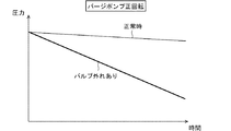
図5のフローチャートおよび図6のグラフを参照して、異常検出制御を説明する。制御装置3は、図5のフローチャートにしたがった処理を実行する。本フローチャートは、車両のエンジン2が運転している走行時、停止している駐車時にかかわらず作動する。システム1の異常検出制御は、エンジン2のオン、オフにかかわらず定期的に実行することができる。
The abnormality detection control will be described with reference to the flowchart of FIG. 5 and the graph of FIG. The
本フローチャートが開始されると、制御装置3は、ステップS10で電気回路に電流を供給しない状態にパージバルブ15を制御する。これにより、パージバルブ15は閉状態に制御される。制御装置3は、さらにステップS20で内部ポンプ121の運転を開始する。これにより、燃料タンク10の内部からパージバルブ15までの通路におけるガスは、内部ポンプ121によって外部に排出されるため、燃料タンク10の内部の圧力は大気圧に対して圧力が低い負圧状態になる。
When this flowchart is started, the
制御装置3は、この状態を一定時間継続して、弁装置であるパージバルブ15の脱落の有無が検出可能な判定可能状態にする。ステップS30では、制御装置3は、圧力センサ11によって検出される燃料タンク10の内圧に係る信号を取得し、異常判定回路30は、弁装置の正常条件が成立するか否かを判定する。弁装置の正常条件は、判定可能状態において、弁装置に脱落等の異常がない正常状態であるか否かを判定するための条件である。
The
この状態で、シール部材40,1550による密封状態が正常であると、圧力センサ11によって検出される圧力値は、図6において細線で図示する圧力変化のように、内部ポンプ121の運転によって大気圧から低下し続けるように変化する。逆にシール部材40,1550による密封状態が解除された異常時である場合には、リーク用ポート4から吸気通路にガスが排出されるため、検出される圧力値は、負圧状態が促進されずに図6の太線で示された「バルブ外れあり」のように正常時と比較して低下しないようになる。正常条件は、例えば、単位時間あたりの圧力変化(圧力変化率)の絶対値が予め定めた所定変化率以上である場合に、成立するものとする。したがって、異常判定回路30は、圧力変化率の絶対値が所定値未満である場合には異常があると判定し、所定変化率以上である場合には正常であると判定する。
In this state, if the sealing state by the sealing
異常判定回路30がステップS30で正常条件が成立していないと判定すると、ステップS35で、弁装置が異常状態であることを表示し、今回の異常検出制御を終了する。この表示に基づき、ユーザは修理を行うことができる。修理終了後、所定時間が経過すれば、再びステップS10を開始する。
When the
ステップS35の異常表示は、弁装置に異常があることを示すように、所定のランプを点灯または点滅することで実施したり、所定の画面に異常表示をしたりすることで実施する。また、この異常表示は、警報音や異常等の警告を報知する音声を発生することにより代用することもできる。 The abnormality display in step S35 is performed by turning on or blinking a predetermined lamp or by displaying an abnormality on a predetermined screen so as to indicate that there is an abnormality in the valve device. Further, this abnormality display can be substituted by generating an alarm sound or a voice for notifying a warning such as an abnormality.
異常判定回路30がステップS30で正常条件が成立していると判定すると、今回の判定結果は正常であるため、ステップS40で正常判定処理を実行して、今回の異常検出制御を終了する。また、終了後、所定時間が経過すれば、再びステップS10を開始する。このようにシステム1の異常検出制御は、エンジン2が運転しているか否かにかかわらず、所定時間間隔で実行されうる。
If the
この異常検出制御は、走行時、駐車時のいずれにおいても実施することができるが、駐車時に実行することが好ましい。駐車時は、エンジンが停止しているため、明確な圧力変化を検出しやすいからである。また、リークチェック時はパージ処理ができないため、駐車時に異常検出制御を実施することがシステム1の運転効率の観点からも有益である。 This abnormality detection control can be carried out at the time of traveling or at the time of parking, but it is preferable to carry out at the time of parking. This is because the engine is stopped when parking, so it is easy to detect a clear pressure change. Further, since the purge process cannot be performed at the time of leak check, it is beneficial from the viewpoint of the operation efficiency of the system 1 to perform the abnormality detection control at the time of parking.
次に、第1実施形態の弁装置がもたらす作用効果について説明する。パージバルブ15は、燃料タンク10内から流出する蒸発燃料と燃焼用燃料とを混合して燃焼するエンジン2の吸気通路を形成する通路形成部材に装着されている。パージバルブ15は、蒸発燃料が吸気通路に流入することを許可する許可状態と阻止する阻止状態とに切り換える弁体152を有し、蒸発燃料の流れを制御する弁装置である。弁装置は、流入ポート154と、流入ポート154からの蒸発燃料が許可状態で流入し阻止状態で流入しない内部通路を有する筒状の流出ポート155と、筒状のリーク用ポート4と、流出側シール部材と、リーク側シール部材と、を備える。流出ポート155は、吸気通路に通じるように通路形成部材に形成されているエンジン側ポートに内挿されている。リーク用ポート4は、許可状態と阻止状態とにかかわらずに流入ポート154からの蒸発燃料が流入可能なリーク通路41を有し、エンジン側ポートに内挿されている。流出側シール部材は、流出ポート155とエンジン側ポートとの密封状態を提供する。リーク側シール部材は、リーク用ポート4とエンジン側ポートとの密封状態を提供する。流出ポート155およびリーク用ポート4がエンジン側ポートに対して離間する方向に移動した場合に、流出側シール部材はリーク側シール部材よりも先に密封状態が解除されるように設けられている。
Next, the action and effect brought about by the valve device of the first embodiment will be described. The
この弁装置によれば、阻止状態において適正な装着状態が解除された場合に、流出ポート155およびリーク用ポート4がエンジン側ポートに対して離間する方向に移動したとしても、流出側シール部材はリーク側シール部材よりも先に密封状態が解除される。これにより、流出側シール部材の密封性能を失ってもリーク側シール部材の密封性能を維持しているので、リーク通路41から流出した蒸発燃料等をエンジン側ポートから外部に洩らさないで吸気通路に流出させるように構成できる。この構成によれば、適正な装着状態が解除された場合に気体の外部漏洩(大気への漏洩)を抑制可能な弁装置を提供できる。
According to this valve device, even if the
流出ポート155とリーク用ポート4は、同軸状となる位置関係で設けられている。これによれば、同一の塊となる物体の内部に、流出ポート155の燃料供給用通路153とリーク通路41とが位置することになる。弁装置が通路形成部材から脱落して流出ポート155の密封状態が解除されたときに、リーク通路41と内部側孔部220とが連通した状態にすることができる。したがって、弁装置が通路形成部材から脱落した場合に、リーク通路41とエンジン2の吸気通路とが連通するリーク状態を確実に検出可能なシステムを提供できる。
The
さらにリーク用ポート4は、同軸状に設置される流出ポート155よりも外部側に位置するように設けられている。これによれば、リーク通路41の通路断面積を大きく形成しやすいので、洩れ検出に用いる圧力変化を顕著に発生させることができるリーク用ポート4を提供できる。したがって、異常の有無判定を明確に実施できるリーク用ポート4を提供できる。
Further, the
流出ポート155とリーク用ポート4は、同軸状となる位置関係で一体に設けられているので、流出ポート155およびリーク用ポート4の寸法精度を確保しやすい。また、シール性能を得やすいエンジン側ポートの内周面形状を製作しやすい。これにより、流出ポート155およびリーク用ポート4のそれぞれとエンジン側ポートとのシール性能を確保しやすい構造を提供できる。
Since the
エンジン側ポートは、いずれも通路形成部材に形成された孔部であって、流出ポート155が内挿された状態で流出側シール部材によって流出ポート155との密封状態を提供する第1孔部である内部側孔部220と、第2孔部である外部側孔部221と、を備える。外部側孔部221は、リーク用ポート4が内挿された状態でリーク側シール部材によってリーク用ポート4との密封状態を提供する。外部側孔部221における外部側の開口端部とリーク側シール部材との軸方向距離L1は、内部側孔部220における外部側の開口端部と流出側シール部材との軸方向距離L2よりも大きい。
Each of the engine side ports is a hole formed in the passage forming member, and is a first hole portion that provides a sealed state with the
この構成によれば、流出ポート155およびリーク用ポート4がエンジン側ポートに対して離間する方向に移動した場合に、流出側シール部材がリーク側シール部材よりも先に密封状態が解除される構成を提供できる。これにより、流出側シール部材の密封性能を失ってもリーク側シール部材の密封性能を維持しているので、リーク通路41から流出した蒸発燃料等をエンジン側ポートから通路形成部材の外部に洩らさないで吸気通路に流出させる弁装置を提供できる。
According to this configuration, when the
流出ポート155とリーク用ポート4は同軸状の位置関係である。リーク通路41は、流出ポート155の内部通路を囲む筒状通路である。この構成によれば、リーク用ポート4における下流側端部を流出ポート155における下流側端部よりも外部側に配置する構成により、流出側シール部材がリーク側シール部材よりも先に密封状態が解除される構成を提供できる。したがって、所望の機能を発揮できるリーク用ポート4および流出ポート155を簡易な形状によって製造することができ、弁装置の生産性を高めることができる。
The
燃料蒸発ガスパージシステム1は、燃料タンク10と、キャニスタ13と、少なくともキャニスタ13から脱離された蒸発燃料と燃焼用燃料とを混合して燃焼するエンジン2の吸気通路を形成する通路形成部材と、この明細書に記載の弁装置と、を備える。これによれば、適正な装着状態が解除された場合に気体の外部漏洩(大気への漏洩)を抑制可能な燃料蒸発ガスパージシステム1を提供できる。
The fuel evaporative gas purge system 1 includes a
制御装置3は、弁体152を阻止状態に制御した状態で内部ポンプ121を運転し(ステップS10、ステップS20)、燃料タンク10の内部および給油口から弁装置に至るまでの通路に含まれる所定箇所の圧力を検出する。制御装置3は、このように検出して得られる圧力の変化率の絶対値が所定値未満である場合には異常があると判定する(ステップS30、ステップS35)。
The
このシステム1によれば、弁装置が適正に装着されている正常時であれば、通路に閉じ込められている蒸発燃料等のガスは、内部ポンプ121がガスを排出する場合、外部に排出され続けるため、検出される圧力は大気圧に対する負圧の度合いが大きくなっていく。さらに弁装置の異常時はリーク通路41が外部と連通するため、内部ポンプ121がガスを排出する場合、リーク通路41を通じて導入される大気が内部ポンプ121によって外部に排出され続けるので、検出される圧力は大気圧に対する負圧の度合いが小さくなる。これにより、制御装置3は検出される圧力の変化率の絶対値が所定値未満である場合には、弁装置が異常状態であることを適正に検出できる。このシステム1によれば、弁装置の異常状態検出について誤検出を抑制することができる。
流出ポート155は、流出側シール部材が設けられているシール部位よりも外径が小さく、シール部位よりも吸気通路から離間した位置に形成されたくびれ部158を備える。この構成によれば、流出ポート155をエンジン側ポートの内部側孔部220に挿入して設置する際にくびれ部158が撓みやすいことにより、流出ポート155とリーク用ポート4との同軸に関して必要な精度を緩和することができる。またこの構成によれば、エンジン側ポートに対する流出ポート155の設置作業性を向上することに貢献できる。
パージバルブ15は、弁体152を駆動する駆動部が収容された第1の部材150aと、流出ポート155およびリーク用ポート4を有するとともに、第1の部材150aに結合している第2の部材150bとを備える。この構成によれば、エンジン側ポートの仕様に合わせた流出ポート155やリーク用ポート4を有する第2の部材150bを準備するだけで、第1の部材150aを新作する必要がないパージバルブ15を提供できる。これにより、例えば、流出ポート155やリーク用ポート4に関する構成を変更可能なパージバルブ15を提供できる。またこのパージバルブ15は、様々な車両の製品仕様に対応可能な蒸発燃料処理システムに適用でき、蒸発燃料処理システムにおける部品管理工数を抑えることに貢献できる。
According to this system 1, under normal conditions when the valve device is properly installed, gas such as evaporative fuel confined in the passage continues to be discharged to the outside when the
The
The
(第2実施形態)
第2実施形態に係る異常検出制御について図5および図7を参照して説明する。第2実施形態で特に説明しない構成、作用、効果については、第1実施形態と同様であり、以下、第1実施形態と異なる点についてのみ説明する。
(Second Embodiment)
The abnormality detection control according to the second embodiment will be described with reference to FIGS. 5 and 7. The configurations, actions, and effects that are not particularly described in the second embodiment are the same as those in the first embodiment, and only the points different from those in the first embodiment will be described below.
第2実施形態の異常検出制御は、以下のように実施することもできる。第2実施形態の異常検出制御では、図5のステップS20において内部ポンプ121を外部からパージ通路に大気を取り入れるように運転する。これにより、燃料タンク10の内部からパージバルブ15までの通路には、内部ポンプ121によって大気が吸入されるため、燃料タンク10の内部の圧力は大気圧に対して圧力が高い正圧状態になる。
The abnormality detection control of the second embodiment can also be implemented as follows. In the abnormality detection control of the second embodiment, in step S20 of FIG. 5, the
制御装置3は、この状態を一定時間継続することで弁装置であるパージバルブ15の脱落の有無が検出可能な判定可能状態にする。ステップS30における弁装置の正常条件は、判定可能状態において弁装置に脱落等の異常がない正常状態であるか否かを判定するための条件である。
By continuing this state for a certain period of time, the
この状態で、シール部材40,1550による密封状態が正常であると、圧力センサ11によって検出される圧力値は、図7において細線で図示する圧力変化のように、内部ポンプ121の運転によって大気圧から増加し続けるように変化する。これは、通路に取り込まれた大気がシール部材40,1550と阻止状態の弁体152とによって行き場を失うからである。逆にシール部材40,1550による密封状態が解除された異常時である場合には、大気がリーク通路41を通じて吸気通路に排出されるため、圧力値は正圧状態が促進されずに図7の太線で示された「バルブ外れあり」のように正常時と比較して増加しないようになる。正常条件は、例えば、単位時間あたりの圧力変化(圧力変化率)の絶対値が予め定めた所定変化率以上である場合に成立する。したがって、異常判定回路30は、圧力変化率の絶対値が所定値未満である場合には異常と判定し、所定変化率以上である場合には正常と判定する。
In this state, if the sealing state by the sealing
システム1によれば、弁装置が適正に装着されている正常時であれば、通路に閉じ込められている蒸発燃料等のガスは内部ポンプ121が大気を通路に導入する場合、大気が通路に導入され続けるため、圧力検出値は大気圧に対する正圧の度合いが大きくなっていく。さらにリーク通路41が吸気通路と連通するほど弁装置が脱落した場合は、通路に導入された大気はリーク通路41を通じて吸気通路に排出され続ける。これにより、検出される圧力は大気圧に対する正圧の度合いが小さくなる。制御装置3は検出される圧力の変化率の絶対値が所定値未満である場合には弁装置の異常状態を適正に検出できる。したがって、大気を導入する内部ポンプ121を用いた弁装置の異常状態検出について誤検出を抑制することができる。
According to the system 1, if the valve device is properly installed and normally, the gas such as the vaporized fuel trapped in the passage is introduced into the passage when the
(第3実施形態)
第3実施形態に係る異常検出制御について図8および図9を参照して説明する。第3実施形態で特に説明しない構成、作用、効果については、第1実施形態と同様であり、以下、第1実施形態と異なる点についてのみ説明する。
(Third Embodiment)
The abnormality detection control according to the third embodiment will be described with reference to FIGS. 8 and 9. The configurations, actions, and effects that are not particularly described in the third embodiment are the same as those in the first embodiment, and only the points different from those in the first embodiment will be described below.
第3実施形態の異常検出制御におけるステップS100、S135、S140は、それぞれ第1実施形態のステップS10、S35、S40に相当し、同様の処理が行われる。 Steps S100, S135, and S140 in the abnormality detection control of the third embodiment correspond to steps S10, S35, and S40 of the first embodiment, respectively, and the same processing is performed.
本フローチャートが開始されると、制御装置3は、ステップS100で電気回路に電流を供給しない状態にパージバルブ15を制御し、パージバルブ15は閉状態になる。制御装置3は、さらにステップS105でCCV120を閉じるように制御し、ステップS120でパージポンプ14を正回転となるように運転する。これにより、パージバルブ15が適正に装着されている場合は、燃料タンク10の内部からパージバルブ15までの通路は閉じられた通路となる。パージポンプ14によってパージバルブ15側に送られるガスは、行き場を失うので、燃料タンク10の内部の圧力は大気圧に対してわずかに低い圧力状態になる。
When this flowchart is started, the
制御装置3は、ステップS130で圧力センサ11によって検出される燃料タンク10の内圧に係る信号を取得し、異常判定回路30は、弁装置の正常条件が成立するか否かを判定する。この状態で、シール部材40,1550による密封状態が正常であると、圧力センサ11によって検出される圧力値は、図9において細線で図示する圧力変化のように、パージポンプ14の運転によって大気圧からわずかに低下する。逆にシール部材40,1550による密封状態が解除された異常時である場合には、リーク用ポート4から外部にガスが排出されるため、検出される圧力値は、負圧状態が促進されずに図8の太線で示された「バルブ外れあり」のように正常時と比較して大きく低下する。正常条件は、例えば、単位時間あたりの圧力変化(圧力変化率)の絶対値が予め定めた所定変化率以下または未満である場合に、成立するものとする。したがって、異常判定回路30は、圧力変化率の絶対値が所定値以上の場合または超える場合には異常があると判定し、所定変化率以下または未満である場合には正常であると判定する。
The
異常判定回路30がステップS130で正常条件が成立していないと判定すると、ステップS135で、弁装置が異常状態であることを表示し、今回の異常検出制御を終了する。終了後、所定時間が経過すれば、再びステップS100を開始する。異常判定回路30がステップS130で正常条件が成立していると判定すると、今回の判定結果は正常であるため、ステップS140で正常判定処理を実行して、今回の異常検出制御を終了する。
When the
制御装置3は、CCV120を閉じ弁体152を阻止状態に制御した状態でパージポンプ14を正回転で運転し(ステップS100、S105、S20)、燃料タンク10の内部および給油口から弁装置に至るまでの通路に含まれる所定箇所の圧力を検出する。制御装置3は、このように検出して得られる圧力の変化率の絶対値が所定値以上である場合には異常があると判定する(ステップS130、S135)。
The
このシステム1によれば、弁装置が適正に装着されている正常時であれば、パージポンプ14が吸気通路側にガスを押し込む場合、通路の蒸発燃料は行き場がないため、検出される圧力は大気圧に対する負圧の度合いは小さくなる。さらにリーク通路41が吸気通路と連通するほど弁装置が脱落した場合は、パージポンプ14によって押し込まれるガスはリーク通路41を通じて吸気通路に排出され続けるため、圧力検出値は大気圧に対する負圧の度合いが大きくなっていく。このように制御装置3は検出される圧力の変化率の絶対値が所定値以上である場合には、弁装置が異常状態であることを適正に検出できる。このシステム1によれば、正回転するパージポンプ14を用いた弁装置の異常状態検出について誤検出を抑制することができる。
According to this system 1, under normal conditions when the valve device is properly installed, when the
(第4実施形態)
第4実施形態に係る異常検出制御について図8および図10を参照して説明する。第4実施形態で特に説明しない構成、作用、効果については、第3実施形態および第1実施形態と同様であり、以下、前述の実施形態と異なる点についてのみ説明する。
(Fourth Embodiment)
The abnormality detection control according to the fourth embodiment will be described with reference to FIGS. 8 and 10. The configurations, actions, and effects that are not particularly described in the fourth embodiment are the same as those in the third embodiment and the first embodiment, and only the points different from the above-described embodiments will be described below.
第4実施形態の異常検出制御は、以下のように実施することもできる。第4実施形態の異常検出制御では、図8のステップS120においてパージポンプ14を逆回転となるように運転する。この状態では、パージバルブ15が適正に装着されている場合は、燃料タンク10の内部からパージバルブ15までの通路は閉じられた通路となる。さらにパージポンプ14によって燃料タンク10側に送られるガスは行き場を失うので、燃料タンク10の内部の圧力は大気圧に対してわずかに高い圧力状態になる。
The abnormality detection control of the fourth embodiment can also be implemented as follows. In the abnormality detection control of the fourth embodiment, the
制御装置3は、この状態を一定時間継続した判定可能状態においてステップS130で、弁装置に脱落等の異常がない正常であるか否かを判定する。ステップS130において、シール部材40,1550による密封状態が正常であると、圧力センサ11によって検出される圧力値は、図10において細線で図示する圧力変化のように圧力が大気圧に対してわずかに高い低圧状態に変化する。
In step S130, the
逆にシール部材40,1550による密封状態が解除された異常時である場合には、流出ポート155から外部の空気がパージバルブ15等を介して燃料タンク10の内部に送り込まれ続ける。このため、圧力値は、図10の太線で示された「バルブ外れあり」のように正常時と比較して大きく増加するように変化する。正常条件は、例えば、単位時間あたりの圧力変化(圧力変化率)の絶対値が予め定めた所定変化率以下または未満である場合に成立する。したがって、異常判定回路30は、圧力変化率の絶対値が所定値以上の場合または超える場合には異常と判定し、所定変化率以下または未満である場合には正常と判定する。
On the contrary, in the case of an abnormal time when the sealed state by the sealing
制御装置3は、CCV120を閉じ弁体152を阻止状態に制御した状態でパージポンプ14を逆回転で運転し(ステップS100、S105、S20)、燃料タンク10の内部および給油口から弁装置に至るまでの通路に含まれる所定箇所の圧力を検出する。制御装置3は、この状態で検出できる圧力の変化率の絶対値が所定値以上である場合には異常があると判定する(ステップS130、S135)。
The
このシステム1によれば、弁装置が適正に装着されている正常時であれば、パージポンプ14が燃料タンク10側にガスを押し込む場合、検出される圧力は大気圧に対する正圧の度合いは小さくなる。さらにリーク通路41が吸気通路と連通するほど弁装置が脱落した場合は、パージポンプ14によって燃料タンク10に送られるガスはエンジン2側からリーク通路41を通じて導入され続けるため、圧力検出値は大気圧に対する正圧の度合いが大きくなっていく。このように制御装置3は圧力検出値の変化率の絶対値が所定値以上である場合には、弁装置が異常状態であることを適正に検出できる。このシステム1によれば、逆回転するパージポンプ14を用いた弁装置の異常状態検出について誤検出を抑制することができる。
According to this system 1, under normal conditions when the valve device is properly installed, when the
(第5実施形態)
第5実施形態に係る燃料蒸発ガスパージシステムの弁装置について図11〜図13を参照して説明する。各図において、第1実施形態と同様の構成であるものは同一の符号を付し、同様の作用、効果を奏するものである。第5実施形態で特に説明しない構成、作用、効果については、前述の実施形態と同様であり、以下、前述の実施形態と異なる点についてのみ説明する。第5実施形態において前述の実施形態と同様の構成を有するものは、前述の実施形態で説明した同様の作用、効果を奏するものとする。
(Fifth Embodiment)
The valve device of the fuel evaporative gas purging system according to the fifth embodiment will be described with reference to FIGS. 11 to 13. In each figure, those having the same configuration as that of the first embodiment are designated by the same reference numerals and have the same actions and effects. The configurations, actions, and effects that are not particularly described in the fifth embodiment are the same as those in the above-described embodiment, and only the points different from the above-described embodiments will be described below. In the fifth embodiment, those having the same configuration as the above-described embodiment shall exhibit the same actions and effects as described in the above-mentioned embodiment.
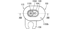
第5実施形態のパージバルブ115は、本体150の内部に設けられた内部通路を介して流入ポート154に通じるとともに本体150の外部にも通じているリーク用ポート104を備える。リーク用ポート104は、内部のリーク通路141が本体150内の内部通路につながっており、本体150から流出ポート1155と一体に設けられている。リーク用ポート104は、流出ポート1155の横に、燃料供給用通路153と同じ方向に延びるリーク通路141を有して本体150に設けられている。流出ポート1155の燃料供給用通路153とリーク通路141は、軸心が離間して並んでいる。リーク用ポート104は、横並びの燃料供給用通路153とリーク通路141とを囲む長円状の外周を有している。
パージバルブ115は本体150を備える。本体150は、燃料供給用通路153、電磁コイル151等を内部に含む第1の部材150aと、第1の部材150aと結合している第2の部材1150bとを少なくとも備えている。第1の部材150aと第2の部材1150bのそれぞれは、樹脂材料によって形成されている。
第2の部材1150bは、第1の部材150aのフランジ部に重ね合わされた状態で一体に接合されるフランジ部を有している。第2の部材1150bは、トラック状のフランジ部において厚さ方向の一方側の面から突出する筒状部を備えている。第1の部材150aと第2の部材1150bが結合した状態において、第1の部材150aと第2の部材1150bはフィルタを挟んで支持している。
第2の部材1150bは、燃料供給用通路153を形成する筒状部を有している。筒状部は、第1の部材150aと第2の部材1150bが結合した状態において、第1の部材150aの内部に突出する形状であり、弁体152が開弁状態であるときに蒸発燃料が流入ポート154側から流入する燃料供給用通路153を内部に有している。
第2の部材1150bは、第1の部材150aの内部通路を介して流入ポート154に通じるとともに吸気通路に通じる流出ポート1155を備える。さらに第2の部材1150bは、第1の部材150aの内部に設けられた内部通路を介して流入ポート154に通じるとともに本体150の外部にも通じているリーク用ポート104を備える。リーク用ポート104のリーク通路141は、弁体152が弁座157から離間したときの燃料供給用通路153にもつながっている。リーク用ポート104は、内部のリーク通路141が本体150内の内部通路につながっており、第2の部材1150bにおいて流出ポート1155と同様に突出する筒状である。
流出ポート1155の先端部は、リーク用ポート104よりも吸気通路寄りに突出している。流出ポート1155は、リーク用ポート104よりも吸気通路寄りに突出している部分であって、シール部材1550が外嵌めされたシール部位よりも弁体152寄りに位置するくびれ部158を有している。くびれ部158は、リーク用ポート104およびシール部材1550が外嵌めされたシール部位よりも外径が小さい形状の部分である。くびれ部158は、流出ポート1155の先端部とリーク用ポート104との間に位置する流出ポート1155の一部に相当する。このように流出ポート1155は、エンジン側ポートに設けられた内部側孔部220に内接する先端側部分よりもリーク用ポート104に近い部分の方が細くなっている。この構成によれば、リーク用ポート104に近い部分において撓みやすい流出ポート1155を提供できる。
The
The
The
The
The
The tip of the
吸気管22に設けられたエンジン側ポートは、流出ポート1155が内挿される内部側孔部220と、内部側孔部220の外部側に隣接し、横並びの燃料供給用通路153とリーク通路141とを囲むリーク用ポート104が内挿される外部側孔部1221と、を備える。したがって、エンジン側ポートは、外部側から内部側にかけて、外部側孔部1221に相当する凹部と、この凹部を貫通する内部側孔部220と、が順に形成された、吸気管22の管断面を貫通する貫通孔部を形成する。
The engine-side port provided in the
図11、図13に図示するように弁装置が吸気管22に適正に装着された状態では、流出ポート1155は、吸気管22の吸気通路側に設けられた内部側孔部220の内側に内挿された状態で接続されている。流出ポート1155の外周面と内部側孔部220の内周面との間は、流出ポート1155の外周に装着されたOリング等のシール部材1550によって密封されている。シール部材1550は、流出ポート1155とエンジン側ポートとに密着して両者間の密封状態を提供する流出側シール部材である。
When the valve device is properly mounted on the
図11、図13のように弁装置が吸気管22に適正に装着された状態では、リーク用ポート104は、外部側孔部1221に収まるように、外部側孔部1221の内側に内挿された状態で設置されている。リーク用ポート104の外周面と外部側孔部1221の内周面との間は、リーク用ポート104の外周に装着されたOリング等のシール部材140によって密封されている。シール部材140は、リーク用ポート104とエンジン側ポートとに密着して両者間の密封状態を提供するリーク側シール部材である。リーク通路141の吸気通路側の端部は、流出ポート1155の内部通路における吸気通路側の端部よりも、パージ通路17側または外部側に位置している。したがって、この適正な装着状態では、パージバルブ115の内部通路を介して流入ポート154からリーク通路141へとつながる通路は、エンジン側ポートに接触するシール部材1550およびシール部材140によって行き止まりになる。このようにリーク用ポート104は、パージバルブ115が吸気管22に適正に装着されている場合に蒸発燃料や排ガスが外部へ洩れることを防止する洩れ防止構造を備えている。
When the valve device is properly attached to the
外部側孔部1221におけるパージ通路17側または外部側の開口端部とシール部材140との軸方向距離L1は、内部側孔部220におけるパージ通路17側または外部側の開口端部とシール部材1550との軸方向距離L2よりも大きい寸法に設定されている。この構成によれば、吸気管22に対してパージバルブ115が外部に脱落するように軸方向に移動した場合、L2がL1よりも短いため、シール部材1550がシール部材140よりも先にエンジン側ポートから外れることになる。これにより、弁装置は、シール部材1550がシール性を失った状態でもシール部材140が密封状態を維持している。この状態でリーク通路141は吸気通路と連通するが、シール部材140の密封状態により吸気管22の外部と遮断されるため、パージ通路17のガスがリーク通路141を介して大気に流出することを阻止している。
The axial distance L1 between the purge passage 17 side or the outer side opening end in the
流出ポート1155の内部通路とリーク通路141は、横並びの位置関係で一体の構造物、例えば樹脂製構造物の内部に設けられているので、流出ポート1155およびリーク用ポート104の寸法精度を確保しやすい。また、シール性能を得やすいエンジン側ポートの内周面形状を製作しやすいので、流出ポート1155およびリーク用ポート104のそれぞれとエンジン側ポートとのシール性能を確保しやすい構造を提供できる。
Since the internal passage and the
流出ポート1155の内部通路とリーク通路141は、軸心が離間して並ぶように設置されている。シール部材140は、内部通路とリーク通路141の両方を囲む環状である。この構成によれば、所望の機能を発揮できるリーク用ポート104および流出ポート1155を簡易な形状によって製造することができ、弁装置の生産性を高めることができる。
流出ポート1155は、流出側シール部材が設けられているシール部位よりも外径が小さく、シール部位よりも吸気通路から離間した位置に形成されたくびれ部158を備える。この構成によれば、流出ポート1155をエンジン側ポートの内部側孔部220に挿入して設置する際にくびれ部158が撓むことにより、流出ポート1155とリーク用ポート104とに関して必要な寸法精度を緩和することができる。またこの構成によれば、エンジン側ポートに対する流出ポート1155の設置作業性を向上することに貢献できる。
パージバルブ115は、弁体152を駆動する駆動部が収容された第1の部材150aと、流出ポート1155およびリーク用ポート104を有するとともに、第1の部材150aに結合している第2の部材1150bとを備える。この構成によれば、エンジン側ポートの仕様に合わせた流出ポート1155やリーク用ポート104を有する第2の部材1150bを準備するだけで、第1の部材150aを新作する必要がないパージバルブ115を提供できる。これにより、例えば、流出ポート1155やリーク用ポート104に関する構成を変更可能なパージバルブ115を提供できる。またこのパージバルブ115は、様々な車両の製品仕様に対応可能な蒸発燃料処理システムに適用でき、蒸発燃料処理システムにおける部品管理工数を抑えることに貢献できる。
The internal passage and the
The
The
(第6実施形態)
第6実施形態に係る燃料蒸発ガスパージシステムの弁装置について図14〜図16を参照して説明する。図14〜図16の各図において、第1実施形態と同様の構成であるものは同一の符号を付し、同様の作用、効果を奏するものである。第6実施形態で特に説明しない構成、作用、効果については、前述の実施形態と同様であり、以下、前述の実施形態と異なる点についてのみ説明する。第6実施形態において前述の実施形態と同様の構成を有するものは、前述の実施形態で説明した同様の作用、効果を奏するものとする。
(Sixth Embodiment)
The valve device of the fuel evaporative gas purging system according to the sixth embodiment will be described with reference to FIGS. 14 to 16. In each of FIGS. 14 to 16, those having the same configuration as that of the first embodiment are designated by the same reference numerals and have the same actions and effects. The configurations, actions, and effects that are not particularly described in the sixth embodiment are the same as those in the above-described embodiment, and only the points different from the above-described embodiments will be described below. In the sixth embodiment, those having the same configuration as the above-described embodiment shall exhibit the same actions and effects as described in the above-mentioned embodiment.
第6実施形態のパージバルブ215は、本体150の内部に設けられた内部通路を介して流入ポート154に通じるとともに本体150の外部にも通じているリーク用ポート204を備える。リーク用ポート204は、内部のリーク通路241が本体150内の内部通路につながっており、流出ポート2155とは独立して本体150から突出している。流出ポート2155の燃料供給用通路153とリーク通路241は、軸心が離間して並んでいる。したがって、リーク用ポート204と流出ポート2155とは、本体150において離れた位置からそれぞれ突出する管部を構成する。
パージバルブ215は本体150を備える。本体150は、燃料供給用通路153、電磁コイル151等を内部に含む第1の部材150aと、第1の部材150aと結合している第2の部材2150bとを少なくとも備えている。第1の部材150aと第2の部材2150bのそれぞれは、樹脂材料によって形成されている。
第2の部材2150bは、第1の部材150aのフランジ部に重ね合わされた状態で一体に接合されるフランジ部を有している。第2の部材2150bは、トラック状のフランジ部において厚さ方向の一方側の面から突出する筒状部を備えている。第1の部材150aと第2の部材2150bが結合した状態において、第1の部材150aと第2の部材2150bはフィルタを挟んで支持している。
第2の部材2150bは、燃料供給用通路153を形成する筒状部を有している。筒状部は、第1の部材150aと第2の部材2150bが結合した状態において、第1の部材150aの内部に突出する形状であり、弁体152が開弁状態であるときに蒸発燃料が流入ポート154側から流入する燃料供給用通路153を内部に有している。
第2の部材2150bは、第1の部材150aの内部通路を介して流入ポート154に通じるとともに吸気通路に通じる流出ポート2155を備える。さらに第2の部材2150bは、第1の部材150aの内部に設けられた内部通路を介して流入ポート154に通じるとともに本体150の外部にも通じているリーク用ポート204を備える。リーク用ポート204のリーク通路241は、弁体152が弁座157から離間したときの燃料供給用通路153にもつながっている。リーク用ポート204は、内部のリーク通路241が本体150内の内部通路につながっており、第2の部材2150bにおいて流出ポート2155と同様に突出する筒状である。
流出ポート2155の先端部は、リーク用ポート204よりも吸気通路寄りに突出している。流出ポート2155は、リーク用ポート204よりも吸気通路寄りに突出している部分であって、シール部材1550Aが外嵌めされたシール部位よりも弁体152寄りに位置するくびれ部158を有している。くびれ部158は、シール部材1550Aが外嵌めされたシール部位よりも外径が小さい形状の部分である。くびれ部158は、流出ポート2155の先端部とシール部材1550Bが外嵌めされたシール部位との間に位置する流出ポート2155の一部に相当する。このように流出ポート2155は、エンジン側ポートに設けられた内部側孔部220に内接する先端側部分よりもシール部材1550Bが外嵌めされたシール部位に近い部分の方が細くなっている。この構成によれば、撓みやすい流出ポート2155を提供できる。
リーク用ポート204は、シール部材240が外嵌めされたシール部位よりも第1の部材150a寄りに位置するくびれ部159を有している。くびれ部159は、シール部材240が外嵌めされたシール部位よりも外径が小さい形状の部分である。くびれ部159は、リーク用ポート204の先端部と第2の部材2150bのフランジ部との間におけるリーク用ポート204の一部に相当する。
The
The
The
The
The
The tip of the
The
吸気管22に設けられたエンジン側ポートは、流出ポート2155の内部側部分が内挿される内部側孔部220と、流出ポート2155の外部側部分が内挿される外部側孔部2221と、リーク用ポート204が内挿されるリークポート用凹部2222と、を備える。内部側孔部220と外部側孔部2221とは、同程度の内径であり、同軸状に設けられている。吸気管22には、内部側孔部220と外部側孔部2221とによって、吸気管22の内外をつなげる貫通孔部が形成されている。リークポート用凹部2222は、外部側孔部2221の横に位置している。エンジン側ポートは、リークポート用凹部2222の底面側でリークポート用凹部2222と内部側孔部220とを連通する連絡通路2223を備えている。
The engine side port provided in the
図14、図16に図示するように弁装置が吸気管22に適正に装着された状態では、流出ポート2155の吸気通路側の部分、すなわち先端側の部分は、吸気管22の内部側孔部220の内側に内挿された状態で接続されている。流出ポート2155の外周面と内部側孔部220の内周面との間は、流出ポート2155の外周に装着されたOリング等のシール部材1550Aによって密封されている。流出ポート2155のパージ通路17側の部分、すなわち本体150側の部分は、吸気管22の外部側孔部2221の内側に内挿された状態で接続されている。シール部材1550Aは、流出ポート1155とエンジン側ポートとに密着して両者間の密封状態を提供する流出側シール部材である。流出ポート2155の外周面と外部側孔部2221の内周面との間は、流出ポート2155の外周に装着されたOリング等のシール部材1550Bによって密封されている。シール部材1550Bは、シール部材1550Aよりも外部側において、流出ポート2155とエンジン側ポートとのシール性を確保する外部側シール部材である。
As shown in FIGS. 14 and 16, when the valve device is properly mounted on the
図14、図16のように弁装置が吸気管22に適正に装着された状態では、リーク用ポート204は、リークポート用凹部2222に収まるように、リークポート用凹部2222の内側に内挿された状態で設置されている。リーク用ポート204の外周面とリークポート用凹部2222の内周面との間は、リーク用ポート204の外周に装着されたOリング等のシール部材240によって密封されている。シール部材240は、リーク用ポート204とエンジン側ポートとに密着して両者間の密封状態を提供するリーク側シール部材である。リーク通路241の吸気通路側の端部は、流出ポート2155の内部通路における吸気通路側の端部よりも、パージ通路17側または外部側に位置している。したがって、この適正な装着状態では、パージバルブ215の内部通路を介して流入ポート154からリーク通路241へとつながる通路は、エンジン側ポートに接触するシール部材1550A、シール部材1550Bおよびシール部材240によって行き止まりになる。このようにリーク用ポート204は、パージバルブ215が吸気管22に適正に装着されている場合に蒸発燃料や排ガスが外部へ洩れることを防止する洩れ防止構造を備えている。
When the valve device is properly attached to the
リークポート用凹部2222における外部側の開口端部とシール部材240との軸方向距離L1は、内部側孔部220における外部側の開口端部とシール部材1550Aとの軸方向距離L2よりも大きい寸法に設定されている。外部側孔部2221における外部側の開口端部とシール部材1550Bとの軸方向距離L3は、前述の軸方向距離L1よりも大きい寸法に設定されている。この構成によれば、吸気管22に対してパージバルブ215が外部に脱落するように軸方向に移動した場合、L2がL1よりも短いため、シール部材1550Aがシール部材240よりも先にエンジン側ポートから外れることになる。同様に、L2がL3よりも短いため、シール部材1550Aがシール部材1550Bよりも先にエンジン側ポートから外れることになる。これにより、弁装置は、シール部材1550Aがシール性を失った状態でもシール部材240とシール部材1550Bとが密封状態を維持している。この状態でリーク通路241は吸気通路と連通するが、シール部材240の密封状態とシール部材1550Bの密封状態により吸気管22の外部と遮断されるため、パージ通路17のガスがリーク通路241を介して大気に流出することを阻止している。
The axial distance L1 between the outer opening end of the
第6実施形態によれば、リークポート用凹部2222、内部側孔部220、外部側孔部2221それぞれの内径寸法が同程度に設定することができるので、3つのシール部材について同じサイズの共通品を使用することができる。これにより、シール部材の管理工数を低減でき、シール部材の種類を少なくできる弁装置を提供できる。
According to the sixth embodiment, the inner diameters of the
流出ポート2155の内部通路とリーク通路241は、軸心が離間して並ぶように設置されている。エンジン側ポートは、シール部材1550Aよりも外部側に設けられた外部側孔部2221を有する。流出ポート155は、シール部材1550Aよりも外部側に設けられたシール部材1550Bによって外部側孔部2221との密封状態を形成する。外部側孔部2221における外部側の開口端部とシール部材1550Bとの軸方向距離L3は、内部側孔部220における外部側の開口端部とシール部材1550Aとの軸方向距離L2よりも大きい。この構成によれば、流出ポート2155およびリーク用ポート204がエンジン側ポートに対して離間する方向に移動した場合に、シール部材1550Aがシール部材1550Bよりも先に密封状態が解除される構成を提供できる。これにより、シール部材1550Aの密封性能を失ってもシール部材1550Bの密封性能を維持しているので、リーク通路241から流出した蒸発燃料等をエンジン側ポートから外部に洩らせないで吸気通路に流出させる弁装置を提供できる。
流出ポート2155は、流出側シール部材が設けられているシール部位よりも外径が小さく、シール部位よりも吸気通路から離間した位置に形成されたくびれ部158を備える。この構成によれば、流出ポート2155をエンジン側ポートの内部側孔部220に挿入して設置する際にくびれ部158が撓みやすいことにより、流出ポート2155とリーク用ポート204とに関して必要な寸法精度を緩和することができる。またこの構成によれば、エンジン側ポートに対する流出ポート2155の設置作業性を向上することに貢献できる。
パージバルブ215は、弁体152を駆動する駆動部が収容された第1の部材150aと、流出ポート2155およびリーク用ポート204を有するとともに、第1の部材150aに結合している第2の部材2150bとを備える。この構成によれば、エンジン側ポートの仕様に合わせた流出ポート2155やリーク用ポート204を有する第2の部材2150bを準備するだけで、第1の部材150aを新作する必要がないパージバルブ215を提供できる。これにより、例えば、流出ポート2155やリーク用ポート204に関する構成を変更可能なパージバルブ215を提供できる。またこのパージバルブ215は、様々な車両の製品仕様に対応可能な蒸発燃料処理システムに適用でき、蒸発燃料処理システムにおける部品管理工数を抑えることに貢献できる。
The internal passage and the
The
The
(第7実施形態)
第7実施形態に係る燃料蒸発ガスパージシステムの弁装置について図17〜図19を参照して説明する。図17〜図19の各図において、第1実施形態と同様の構成であるものは同一の符号を付し、同様の作用、効果を奏するものである。第7実施形態で特に説明しない構成、作用、効果については、前述の実施形態と同様であり、以下、前述の実施形態と異なる点についてのみ説明する。第7実施形態において前述の実施形態と同様の構成を有するものは、前述の実施形態で説明した同様の作用、効果を奏するものとする。
(7th Embodiment)
The valve device of the fuel evaporative gas purging system according to the seventh embodiment will be described with reference to FIGS. 17 to 19. In each of the figures of FIGS. 17 to 19, those having the same configuration as that of the first embodiment are designated by the same reference numerals and have the same actions and effects. The configurations, actions, and effects that are not particularly described in the seventh embodiment are the same as those in the above-described embodiment, and only the points different from the above-described embodiments will be described below. In the seventh embodiment, those having the same configuration as the above-described embodiment shall exhibit the same actions and effects as described in the above-mentioned embodiment.
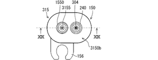
第7実施形態のパージバルブ315は、本体150の内部に設けられた内部通路を介して流入ポート154に通じるとともに本体150の外部にも通じているリーク用ポート304を備える。リーク用ポート304は、内部のリーク通路241が本体150内の内部通路につながっており、流出ポート3155とは独立して本体150の第2の部材3150bから突出している。したがって、リーク用ポート304と流出ポート3155とは、本体150において離れた位置からそれぞれ突出する管部を構成する。
パージバルブ315は本体150を備える。本体150は、燃料供給用通路153、電磁コイル151等を内部に含む第1の部材150aと、第1の部材150aと結合している第2の部材3150bとを少なくとも備えている。第1の部材150aと第2の部材3150bのそれぞれは、樹脂材料によって形成されている。
第2の部材3150bは、第1の部材150aのフランジ部に重ね合わされた状態で一体に接合されるフランジ部を有している。第2の部材3150bは、トラック状のフランジ部において厚さ方向の一方側の面から突出する筒状部を備えている。第1の部材150aと第2の部材3150bが結合した状態において、第1の部材150aと第2の部材3150bはフィルタを挟んで支持している。
第2の部材3150bは、燃料供給用通路153を形成する筒状部を有している。筒状部は、第1の部材150aと第2の部材3150bが結合した状態において、第1の部材150aの内部に突出する形状であり、弁体152が開弁状態であるときに蒸発燃料が流入ポート154側から流入する燃料供給用通路153を内部に有している。
第2の部材3150bは、第1の部材150aの内部通路を介して流入ポート154に通じるとともに吸気通路に通じる流出ポート3155を備える。さらに第2の部材3150bは、第1の部材150aの内部に設けられた内部通路を介して流入ポート154に通じるとともに本体150の外部にも通じているリーク用ポート304を備える。リーク用ポート304は、内部のリーク通路241が本体150内の内部通路につながっており、第2の部材3150bにおいて流出ポート3155と同様に突出する筒状である。
流出ポート3155の先端部は、リーク用ポート304よりも吸気通路寄りに突出している。流出ポート3155は、リーク用ポート304よりも吸気通路寄りに突出している部分であって、シール部材1550が外嵌めされたシール部位よりも第1の部材150a寄りに位置するくびれ部158を有している。このように流出ポート3155は、エンジン側ポートに設けられた貫通孔部3221に内接する先端側部分よりも第1の部材150aに近い部分の方が細くなっている。この構成によれば、撓みやすい流出ポート3155を提供できる。
リーク用ポート304は、シール部材240が外嵌めされたシール部位よりも第1の部材150a寄りに位置するくびれ部159を有している。くびれ部159は、リーク用ポート304の先端部と第2の部材2150bのフランジ部との間におけるリーク用ポート304の一部に相当する。
The
The
The
The
The
The tip of the
The
吸気管22には、流出ポート3155が内挿される貫通孔部3221と、リーク用ポート304が内挿されるリークポート用凹部3222と、が設けられている。リークポート用凹部3222は、貫通孔部3221の横に位置している。吸気管22は、リークポート用凹部3222の底面の一部において吸気通路まで貫通する連絡通路3223を備えている。貫通孔部3221は主エンジン側ポートであり、リークポート用凹部3222および連絡通路3223は副エンジン側ポートである。主エンジン側ポートと副エンジン側ポートとは、独立した通路をなしている。
The
図17、図19に図示するように弁装置が吸気管22に適正に装着された状態では、流出ポート3155の吸気通路側の部分、すなわち先端側の部分は、吸気管22の貫通孔部3221の内側に内挿された状態で接続されている。流出ポート3155の外周面と貫通孔部3221の内周面との間は、流出ポート3155の外周に装着されたOリング等のシール部材1550によって密封されている。
As shown in FIGS. 17 and 19, when the valve device is properly mounted on the
図17、図19のように弁装置が吸気管22に適正に装着された状態では、リーク用ポート304は、リークポート用凹部3222に収まるように、リークポート用凹部3222の内側に内挿された状態で設置されている。リーク用ポート304の外周面とリークポート用凹部3222の内周面との間は、リーク用ポート304の外周に装着されたOリング等のシール部材240によって密封されている。
When the valve device is properly attached to the
リークポート用凹部3222の底面には、リーク用ポート304の先端部に押されることで弾性変形可能なシール部材340が収容されている。シール部材240は、シール部材340よりも外部側に設けられており、リーク用ポート304と副エンジン側ポートとの密封状態を提供する第2のリーク側シール部材である。図17、図19のように弁装置が吸気管22に適正に装着された状態では、リークポート用凹部3222の底面とリーク用ポート304の先端部とはシール部材340を介して密着している。シール部材340は、リーク用ポート304と副エンジン側ポートとに密着して両者間の密封状態を提供する第1のリーク側シール部材である。したがって、リーク通路241とリークポート用凹部3222や連絡通路3223との間は、シール部材340によって密封されている。これにより、流入ポート154からリーク通路241へとつながる通路はシール部材340によって行き止まりになる。このようにリーク用ポート304は、パージバルブ315が吸気管22に適正に装着されている場合には蒸発燃料や排ガスが外部へ洩れることを防止する洩れ防止構造を備えている。
A
リーク用ポート304における洩れ防止構造を構成する第1のリーク側シール部材は、シール部材1550よりも外部側に設けられている。これによれば、パージバルブ315が吸気管22から脱落したときに、シール部材340の方をシール部材1550やシール部材240よりも先にその機能を発揮できない状態にすることができる。したがって、弁装置の脱落時に、リーク用ポート304の脱落を確実に実施でき、早期の洩れ検出を実現できる。
The first leak-side seal member constituting the leak-prevention structure in the
第7実施形態によれば、弁装置の脱落時に、真っ先にシール部材340の密封状態が解除されるため、各シール部材の位置関係を考慮した寸法設計を不要にできる。また、シール部材340はリーク用ポート304の先端によって軸方向に押されて弾性変形する構成であるため、弁装置の脱落時にわずかな軸方向移動によってシール機能を失う。このため、弁装置のわずかな外れでも、洩れ検出を実施できる弁装置を提供できる。
According to the seventh embodiment, when the valve device is dropped off, the sealed state of the
パージバルブ15は、主エンジン側ポートに内挿された流出ポート3155と、リーク通路241を有する筒状のリーク用ポート304と、を備える。リーク用ポート304は、主エンジン側ポートとは独立して吸気通路に通じるように通路形成部材に形成されている副エンジン側ポートに内挿されている。パージバルブ15は、流出ポート3155と主エンジン側ポートとの密封状態を提供する流出側シール部材と、リーク用ポート304と副エンジン側ポートとの密封状態を提供する第1のリーク側シール部材と、第2のリーク側シール部材とを備える。第2のリーク側シール部材は、リーク用ポート304と副エンジン側ポートとの密封状態を提供する。流出ポート3155およびリーク用ポート304が主エンジン側ポートおよび副エンジン側ポートに対して離間する方向に移動した場合に、第1のリーク側シール部材は流出側シール部材および第2のリーク側シール部材よりも先に密封状態が解除されるように設けられている。
The
この構成によれば、阻止状態において適正な装着状態が解除された場合に、流出ポート3155およびリーク用ポート304が各エンジン側ポートに対して離間する方向に移動したとしても、第1のリーク側シール部材は流出側シール部材と第2のリーク側シール部材よりも先に密封状態が解除される。これにより、第1のリーク側シール部材の密封性能を失っても流出側シール部材と第2のリーク側シール部材とが密封性能を維持している。このため、リーク通路241から流出した蒸発燃料等を副エンジン側ポートから通路形成部材の外部に洩らさないで吸気通路に流出させるように構成できる。この構成によれば、適正な装着状態が解除された場合に気体の外部漏洩を抑制可能な弁装置を提供できる。
According to this configuration, even if the
リーク通路241と流出ポート3155の内部通路は、軸心が離間して並ぶように設置されている。副エンジン側ポートは、第1のリーク側シール部材によってリーク用ポート304の先端部との密封状態を構成するリークポート用凹部3222を有する。第2のリーク側シール部材は、第1のリーク側シール部材よりも外部側に設けられた外部側シール部材である。
The
この構成によれば、第1のリーク側シール部材をリークポート用凹部3222において外部側シール部材よりも外部側に配置する構成を提供できる。これにより、流出ポート3155およびリーク用ポート304が各エンジン側ポートに対して離間する方向に移動した場合に、第1のリーク側シール部材による密封状態を即座に解除できる構成を提供できる。また、リーク用ポート304の先端部が第1のリーク側シール部材から離間して密封状態が解除されても、リーク用ポート304とリークポート用凹部3222との密封状態を外部側シール部材によって維持することができる。したがって、所望の機能を発揮できる弁装置を簡易な形状によって製造することができ、弁装置の生産性を高めることができる。
流出ポート3155は、流出側シール部材が設けられているシール部位よりも外径が小さく、シール部位よりも吸気通路から離間した位置に形成されたくびれ部158を備える。この構成によれば、流出ポート3155をエンジン側ポートの貫通孔部3221に挿入して設置する際にくびれ部158が撓みやすいことにより、流出ポート3155とリーク用ポート304とに関して必要な寸法精度を緩和することができる。またこの構成によれば、エンジン側ポートに対する流出ポート3155の設置作業性を向上することに貢献できる。
パージバルブ315は、弁体152を駆動する駆動部が収容された第1の部材150aと、流出ポート3155およびリーク用ポート304を有するとともに、第1の部材150aに結合している第2の部材3150bとを備える。この構成によれば、エンジン側ポートの仕様に合わせた流出ポート3155やリーク用ポート304を有する第2の部材3150bを準備するだけで、第1の部材150aを新作する必要がないパージバルブ315を提供できる。これにより、例えば、流出ポート3155やリーク用ポート304に関する構成を変更可能なパージバルブ315を提供できる。またこのパージバルブ315は、様々な車両の製品仕様に対応可能な蒸発燃料処理システムに適用でき、蒸発燃料処理システムにおける部品管理工数を抑えることに貢献できる。
According to this configuration, it is possible to provide a configuration in which the first leak-side seal member is arranged on the outer side of the outer-side seal member in the
The
The
(他の実施形態)
この明細書の開示は、例示された実施形態に制限されない。開示は、例示された実施形態と、それらに基づく当業者による変形態様を包含する。例えば、開示は、実施形態において示された部品、要素の組み合わせに限定されず、種々変形して実施することが可能である。開示は、多様な組み合わせによって実施可能である。開示は、実施形態に追加可能な追加的な部分をもつことができる。開示は、実施形態の部品、要素が省略されたものを包含する。開示は、ひとつの実施形態と他の実施形態との間における部品、要素の置き換え、または組み合わせを包含する。開示される技術的範囲は、実施形態の記載に限定されない。開示される技術的範囲は、特許請求の範囲の記載によって示され、さらに特許請求の範囲の記載と均等の意味および範囲内での全ての変更を含むものと解されるべきである。
(Other embodiments)
Disclosure of this specification is not limited to the illustrated embodiments. The disclosure includes exemplary embodiments and modifications by those skilled in the art based on them. For example, the disclosure is not limited to the combination of parts and elements shown in the embodiment, and can be implemented in various modifications. Disclosure can be carried out in various combinations. The disclosure can have additional parts that can be added to the embodiment. The disclosure includes parts and elements of the embodiment omitted. Disclosures include replacements or combinations of parts, elements between one embodiment and another. The technical scope disclosed is not limited to the description of the embodiments. The technical scope disclosed is indicated by the description of the scope of claims, and should be understood to include all modifications within the meaning and scope equivalent to the description of the scope of claims.
前述の実施形態において、流出ポートやリーク用ポートは、吸気管22に接続されているが、燃料供給用通路153とエンジンの吸気通路とがつながる形態であればよく、前述の実施形態に限定されない。つまり、弁装置は、吸気管22に直接装着される場合に限らず、吸気通路を形成する部材である通路形成部材に装着される構成であればよい。例えば、流出ポートやリーク用ポートは、吸気通路を形成する吸気マニホールド20に接続される形態でもよい。また、流出ポートやリーク用ポートは、吸気通路を形成するアタッチメント部材を介して吸気管22に接続される形態でもよい。
In the above-described embodiment, the outflow port and the leak port are connected to the
前述の実施形態において、圧力センサ11は、燃料タンク10の内部および給油口から弁装置であるパージバルブ15に至るまでの通路に含まれる所定箇所の圧力を検出する装置の一例である。したがって、所定箇所の圧力は、パージ通路17やベーパ通路16に設けられたセンサによって検出するように構成してもよい。
In the above-described embodiment, the
前述の実施形態では、吸気管22に装着する弁装置として、パージバルブを採用しているが、この弁装置はエンジン2の吸気通路に通じる通路を開く全開状態と閉じる全閉状態とに切り換え可能な弁を有する装置であればよい。例えば、弁装置は、全開状態と閉じる全閉状態とに切り換え可能な開閉弁であればよく、通路の開度を調整可能なパージバルブはこの弁装置よりもキャニスタ13寄りに設けるようにしてもよい。また、吸気通路に連絡するように設けられる弁装置は、内部にパージポンプ14やパージバルブを有する構成であってもよい。
In the above-described embodiment, a purge valve is adopted as a valve device attached to the
システム1が燃料タンク内を密閉する構成を有する場合は、燃料タンクを除く弁装置に至るまでのパージ通路において測定した圧力を用いて、前述の実施形態と同様の異常判定を行うことができる。 When the system 1 has a configuration in which the inside of the fuel tank is sealed, the abnormality determination similar to the above-described embodiment can be performed by using the pressure measured in the purge passage leading to the valve device excluding the fuel tank.
前述の実施形態において、システム1は、過給器やスロットルバルブを備えない構成でもよい。 In the above-described embodiment, the system 1 may be configured without a supercharger or a throttle valve.
2…エンジン、 4,104,204,304…リーク用ポート
10…燃料タンク、 15,115,215,315…パージバルブ(弁装置)
22…吸気管(通路形成部材)、 40,140…シール部材(リーク側シール部材)
41,141,241…リーク通路、 150a…第1の部材
150b…第2の部材、 152…弁体、 153…燃料供給用通路(内部通路)
1550,1550A…シール部材(流出側シール部材)
154…流入ポート、 155、1155,2155…流出ポート
220,1221…内部側孔部(エンジン側ポート)
221,2221…外部側孔部(エンジン側ポート)
240…シール部材(リーク側シール部材、第2のリーク側シール部材)
340…シール部材(第1のリーク側シール部材)
2222…リークポート用凹部(エンジン側ポート)
3221…貫通孔部(主エンジン側ポート)
3222…リークポート用凹部(副エンジン側ポート)
2 ... Engine, 4,104,204,304 ...
22 ... Intake pipe (passage forming member), 40, 140 ... Seal member (leak side seal member)
41, 141,241 ... Leak passage, 150a ...
1550, 1550A ... Seal member (outflow side seal member)
154 ... Inflow port, 155, 1155, 2155 ...
221,221 ... External side hole (engine side port)
240 ... Seal member (leak side seal member, second leak side seal member)
340 ... Seal member (first leak side seal member)
2222 ... Leak port recess (engine side port)
3221 ... Through hole (main engine side port)
3222 ... Leak port recess (secondary engine side port)
Claims (13)
前記蒸発燃料が流入する流入通路を有する流入ポート(154)と、
前記流入ポートからの前記蒸発燃料が前記許可状態で流入し前記阻止状態で流入しない内部通路(153)を有する筒状の流出ポートであって、前記吸気通路に通じるように前記通路形成部材に形成されているエンジン側ポート(220,221;220,1221;220,2221,2222)に内挿された流出ポート(155;1155;2155)と、
前記許可状態と前記阻止状態とにかかわらずに前記流入ポートからの前記蒸発燃料が流入可能なリーク通路(41;141;241)を有し、前記エンジン側ポートに内挿された筒状のリーク用ポート(4;104;204)と、
前記流出ポートと前記エンジン側ポートとの密封状態を提供する流出側シール部材(1550;1550A)と、
前記リーク用ポートと前記エンジン側ポートとの密封状態を提供するリーク側シール部材(40;140;240)と、
を備え、
前記流出ポートおよび前記リーク用ポートが前記エンジン側ポートに対して離間する方向に移動した場合に、前記流出側シール部材は前記リーク側シール部材よりも先に前記密封状態が解除されるように設けられており、
前記弁体を駆動する駆動部が収容された第1の部材と、前記流出ポートおよび前記リーク用ポートを有するとともに、前記第1の部材に結合している第2の部材とを備える弁装置。 It is attached to a passage forming member (22) forming an intake passage of an engine (2) that mixes and burns the evaporated fuel flowing out from the fuel tank (10) and the combustion fuel, and the evaporated fuel is attached to the intake passage. A valve device (15; 115; 215) that has a valve body (152) that switches between a permitted state that allows the fuel to flow into the fuel and a blocked state that blocks the inflow to the fuel, and controls the flow of the vaporized fuel.
An inflow port (154) having an inflow passage through which the evaporated fuel flows, and
A tubular outflow port having an internal passage (153) through which the evaporated fuel from the inflow port flows in in the permitted state and does not flow in in the blocked state, and is formed in the passage forming member so as to lead to the intake passage. Outflow ports (155; 1155; 2155) interpolated into the engine side ports (220, 221; 220, 1221; 220, 2221, 222)
A tubular leak interpolated into the engine-side port having a leak passage (41; 141; 241) through which the evaporated fuel can flow in from the inflow port regardless of the permitted state and the blocked state. Ports (4; 104; 204) and
An outflow side seal member (1550; 1550A) that provides a sealed state between the outflow port and the engine side port.
A leak-side seal member (40; 140; 240) that provides a sealed state between the leak port and the engine-side port.
With
When the outflow port and the leak port move in a direction away from the engine side port, the outflow side seal member is provided so that the sealed state is released before the leak side seal member. Has been
A first member driving unit for driving the valve body is accommodated, said outlet port and which has a port for the leakage, the first coupling members of to have the second member and Ru valve arrangement comprises a ..
前記蒸発燃料が流入する流入通路を有する流入ポート(154)と、
前記流入ポートからの前記蒸発燃料が前記許可状態で流入し前記阻止状態で流入しない内部通路(153)を有する筒状の流出ポートであって、前記吸気通路に通じるように前記通路形成部材に形成されているエンジン側ポート(220,221;220,1221;220,2221,2222)に内挿された流出ポート(155;1155;2155)と、
前記許可状態と前記阻止状態とにかかわらずに前記流入ポートからの前記蒸発燃料が流入可能なリーク通路(41;141;241)を有し、前記エンジン側ポートに内挿された筒状のリーク用ポート(4;104;204)と、
前記流出ポートと前記エンジン側ポートとの密封状態を提供する流出側シール部材(1550;1550A)と、
前記リーク用ポートと前記エンジン側ポートとの密封状態を提供するリーク側シール部材(40;140;240)と、
を備え、
前記流出ポートおよび前記リーク用ポートが前記エンジン側ポートに対して離間する方向に移動した場合に、前記流出側シール部材は前記リーク側シール部材よりも先に前記密封状態が解除されるように設けられており、
前記流出ポートは、前記流出側シール部材が設けられているシール部位よりも外径が小さく、前記シール部位よりも前記吸気通路から離間した位置に形成されたくびれ部(158)を備える弁装置。 It is attached to a passage forming member (22) forming an intake passage of an engine (2) that mixes and burns the evaporated fuel flowing out from the fuel tank (10) and the combustion fuel, and the evaporated fuel is attached to the intake passage. A valve device (15; 115; 215) that has a valve body (152) that switches between a permitted state that allows the fuel to flow into the fuel and a blocked state that blocks the inflow to the fuel, and controls the flow of the vaporized fuel.
An inflow port (154) having an inflow passage through which the evaporated fuel flows, and
A tubular outflow port having an internal passage (153) through which the evaporated fuel from the inflow port flows in in the permitted state and does not flow in in the blocked state, and is formed in the passage forming member so as to lead to the intake passage. Outflow ports (155; 1155; 2155) interpolated into the engine side ports (220, 221; 220, 1221; 220, 2221, 222)
A tubular leak interpolated into the engine-side port having a leak passage (41; 141; 241) through which the evaporated fuel can flow in from the inflow port regardless of the permitted state and the blocked state. Ports (4; 104; 204) and
An outflow side seal member (1550; 1550A) that provides a sealed state between the outflow port and the engine side port.
A leak-side seal member (40; 140; 240) that provides a sealed state between the leak port and the engine-side port.
With
When the outflow port and the leak port move in a direction away from the engine side port, the outflow side seal member is provided so that the sealed state is released before the leak side seal member. Has been
The outflow port is a valve device having a constricted portion (158) having an outer diameter smaller than that of a seal portion provided with the outflow side seal member and formed at a position separated from the intake passage by the seal portion.
前記第2孔部における外部側の開口端部と前記リーク側シール部材との軸方向距離(L1)は、前記第1孔部における外部側の開口端部と前記流出側シール部材との軸方向距離(L2)よりも大きい請求項1から請求項3のいずれか一項に記載の弁装置。 The engine-side port is a hole formed in the passage forming member, and the first hole portion that provides the sealed state with the outflow port by the outflow-side sealing member in a state where the outflow port is interpolated. A second hole portion formed in the passage forming member and providing the sealed state with the leak port by the leak side sealing member in a state where the leak port is interpolated. With
The axial distance (L1) between the outer opening end in the second hole and the leak-side sealing member is the axial direction between the outer opening in the first hole and the outflow-side sealing member. The valve device according to any one of claims 1 to 3, which is larger than the distance (L2).
前記蒸発燃料が流入する流入通路を有する流入ポート(154)と、
前記流入ポートからの前記蒸発燃料が前記許可状態で流入し前記阻止状態で流入しない内部通路(153)を有する筒状の流出ポートであって、前記吸気通路に通じるように前記通路形成部材に形成されているエンジン側ポート(220,1221)に内挿された流出ポート(1155)と、
前記許可状態と前記阻止状態とにかかわらずに前記流入ポートからの前記蒸発燃料が流入可能なリーク通路(141)を有し、前記エンジン側ポートに内挿された筒状のリーク用ポート(104)と、
前記流出ポートと前記エンジン側ポートとの密封状態を提供する流出側シール部材(1550)と、
前記リーク用ポートと前記エンジン側ポートとの密封状態を提供するリーク側シール部材(140)と、
を備え、
前記流出ポートおよび前記リーク用ポートが前記エンジン側ポートに対して離間する方向に移動した場合に、前記流出側シール部材は前記リーク側シール部材よりも先に前記密封状態が解除されるように設けられており、
前記流出ポートの前記内部通路と前記リーク通路は、軸心が離間して並ぶように設置されており、
前記リーク側シール部材は、前記内部通路と前記リーク通路の両方を囲む環状である弁装置。 It is attached to a passage forming member (22) forming an intake passage of an engine (2) that mixes and burns the evaporated fuel flowing out from the fuel tank (10) and the combustion fuel, and the evaporated fuel is attached to the intake passage. A valve device (115 ) having a valve body (152) for switching between a permitted state for permitting inflow to the fuel and a blocking state for blocking the inflow to the fuel, and controlling the flow of the vaporized fuel.
An inflow port (154) having an inflow passage through which the evaporated fuel flows, and
A tubular outflow port having an internal passage (153) through which the evaporated fuel from the inflow port flows in in the permitted state and does not flow in in the blocked state, and is formed in the passage forming member so as to lead to the intake passage. The outflow port ( 1155 ) interpolated into the engine side port ( 220, 1221 ) and
The vaporized fuel is have a flowing possible leak passage (141), before Symbol engine side port inserted in the the tubular port for leaks from the inlet port regardless of the said blocking state and the allowed state ( 104 ) and
An outflow side seal member (1550 ) that provides a sealed state between the outflow port and the engine side port.
And providing to ruri over click-side seal member (140) sealing state between the engine-side port and the leak port,
With
If the outlet port and said leak port is moved in a direction away against the engine side ports, the outflow-side sealing member wherein the sealing state is released prior to the rie click-side sealing member is provided so as to,
The internal passage and the leak passage of the outflow port are installed so that their axes are separated from each other.
The leak-side seal member is annular der Ru valve device surrounding both of the leak passage and the internal passage.
前記蒸発燃料が流入する流入通路を有する流入ポート(154)と、
前記流入ポートからの前記蒸発燃料が前記許可状態で流入し前記阻止状態で流入しない内部通路(153)を有する筒状の流出ポートであって、前記吸気通路に通じるように前記通路形成部材に形成されているエンジン側ポート(220,2221,2222)に内挿された流出ポート(2155)と、
前記許可状態と前記阻止状態とにかかわらずに前記流入ポートからの前記蒸発燃料が流入可能なリーク通路(241)を有し、前記エンジン側ポートに内挿された筒状のリーク用ポート(204)と、
前記流出ポートと前記エンジン側ポートとの密封状態を提供する流出側シール部材(1550A)と、
前記リーク用ポートと前記エンジン側ポートとの密封状態を提供するリーク側シール部材(240)と、
を備え、
前記流出ポートおよび前記リーク用ポートが前記エンジン側ポートに対して離間する方向に移動した場合に、前記流出側シール部材は前記リーク側シール部材よりも先に前記密封状態が解除されるように設けられており、
前記流出ポートの前記内部通路と前記リーク通路は、軸心が離間して並ぶように設置されており、
前記エンジン側ポートは、前記通路形成部材に形成された孔部であって前記流出ポートが内挿された状態で前記流出側シール部材によって前記流出ポートとの前記密封状態を提供する第1孔部(220)と、前記流出側シール部材よりも外部側に設けられた外部側孔部(2221)と、を有し、
前記流出ポートは、前記流出側シール部材よりも外部側に設けられた外部側シール部材によって前記外部側孔部との密封状態を形成し、
前記外部側孔部における外部側の開口端部と前記外部側シール部材との軸方向距離(L3)は、前記第1孔部における外部側の開口端部と前記流出側シール部材との軸方向距離(L2)よりも大きい弁装置。 It is attached to a passage forming member (22) forming an intake passage of an engine (2) that mixes and burns the evaporated fuel flowing out from the fuel tank (10) and the combustion fuel, and the evaporated fuel is attached to the intake passage. A valve device (215) having a valve body (152) for switching between a permitted state for permitting inflow to the fuel and a blocking state for blocking the inflow to the fuel, and controlling the flow of the vaporized fuel.
An inflow port (154) having an inflow passage through which the evaporated fuel flows, and
A tubular outflow port having an internal passage (153) through which the evaporated fuel from the inflow port flows in in the permitted state and does not flow in in the blocked state, and is formed in the passage forming member so as to lead to the intake passage. The outflow port (2155) inserted in the engine side port (220,2221,222) and
A tubular leak port (204) having a leak passage (241) through which the evaporated fuel can flow in from the inflow port regardless of the permitted state and the blocked state, and inserted into the engine side port. )When,
An outflow side seal member (1550A) that provides a sealed state between the outflow port and the engine side port,
A leak-side seal member (240) that provides a sealed state between the leak port and the engine-side port,
With
When the outflow port and the leak port move in a direction away from the engine side port, the outflow side seal member is provided so that the sealed state is released before the leak side seal member. Has been
The internal passage and the leak passage of the outflow port are installed so that their axes are separated from each other.
The engine-side port is a hole formed in the passage forming member, and the first hole portion that provides the sealed state with the outflow port by the outflow-side sealing member in a state where the outflow port is interpolated. (220) and an external hole portion (2221) provided on the outer side of the outflow side sealing member.
The outflow port is sealed with the external hole portion by an external seal member provided on the outer side of the outflow side seal member.
The axial distance (L3) between the outer side opening end portion in the outer side hole portion and the outer side sealing member is the axial direction between the outer side opening end portion and the outflow side sealing member in the first hole portion. A valve device larger than the distance (L2).
前記第2孔部における外部側の開口端部と前記リーク側シール部材との軸方向距離(L1)は、前記第1孔部における外部側の開口端部と前記流出側シール部材との軸方向距離(L2)よりも大きい請求項6または請求項7に記載の弁装置。 The engine-side port is a hole formed in the passage forming member, and the first hole portion that provides the sealed state with the outflow port by the outflow-side sealing member in a state where the outflow port is interpolated. (220) and a second hole formed in the passage forming member and providing the sealed state with the leak port by the leak side sealing member in a state where the leak port is interpolated. With a department,
The axial distance (L1) between the outer opening end in the second hole and the leak-side sealing member is the axial direction between the outer opening in the first hole and the outflow-side sealing member. The valve device according to claim 6 or 7 , which is larger than the distance (L2).
前記蒸発燃料が流入する流入通路を有する流入ポート(154)と、
前記流入ポートからの前記蒸発燃料が前記許可状態で流入し前記阻止状態で流入しない内部通路(153)を有する筒状の流出ポートであって、前記吸気通路に通じるように前記通路形成部材に形成されている主エンジン側ポート(3221)に内挿された流出ポート(3155)と、
前記許可状態と前記阻止状態とにかかわらずに前記流入ポートからの前記蒸発燃料が流入可能なリーク通路(241)を有する筒状のリーク用ポートであって、前記主エンジン側ポートとは独立して前記吸気通路に通じるように前記通路形成部材に形成されている副エンジン側ポート(3222)に内挿されたリーク用ポート(304)と、
前記流出ポートと前記主エンジン側ポートとの密封状態を提供する流出側シール部材(1550)と、
前記リーク用ポートと前記副エンジン側ポートとの密封状態を提供する第1のリーク側シール部材(340)と、
前記リーク用ポートと前記副エンジン側ポートとの密封状態を提供する第2のリーク側シール部材(240)と、
を備え、
前記流出ポートおよび前記リーク用ポートが前記主エンジン側ポートおよび前記副エンジン側ポートに対して離間する方向に移動した場合に、前記第1のリーク側シール部材は前記流出側シール部材および前記第2のリーク側シール部材よりも先に前記密封状態が解除されるように設けられている弁装置。 It is attached to a passage forming member (22) forming an intake passage of an engine (2) that mixes and burns the evaporated fuel flowing out from the fuel tank (10) and the combustion fuel, and the evaporated fuel is attached to the intake passage. A valve device (315) having a valve body (152) for switching between a permitted state for permitting inflow to the fuel and a blocking state for blocking the inflow to the fuel, and controlling the flow of the vaporized fuel.
An inflow port (154) having an inflow passage through which the evaporated fuel flows, and
A tubular outflow port having an internal passage (153) through which the evaporated fuel from the inflow port flows in in the permitted state and does not flow in in the blocked state, and is formed in the passage forming member so as to lead to the intake passage. The outflow port (3155) inserted in the main engine side port (3221) and
A tubular leak port having a leak passage (241) through which the evaporated fuel can flow in from the inflow port regardless of the permitted state and the blocked state, and is independent of the main engine side port. The leak port (304) inserted into the sub-engine side port (3222) formed in the passage forming member so as to communicate with the intake passage.
An outflow side seal member (1550) that provides a sealed state between the outflow port and the main engine side port.
A first leak-side seal member (340) that provides a sealed state between the leak port and the sub-engine-side port,
A second leak-side seal member (240) that provides a sealed state between the leak port and the sub-engine-side port,
With
When the outflow port and the leak port move in a direction away from the main engine side port and the sub engine side port, the first leak side seal member is the outflow side seal member and the second. A valve device provided so as to release the sealed state before the leak-side sealing member of the above.
前記副エンジン側ポートは、前記第1のリーク側シール部材によって前記リーク用ポートの先端部との密封状態を構成するリークポート用凹部を有し、
前記第2のリーク側シール部材は、前記第1のリーク側シール部材よりも外部側に設けられた外部側シール部材である請求項9に記載の弁装置。 The leak passage and the internal passage of the outflow port are installed so that their axes are separated from each other.
The sub-engine side port has a leak port recess that is sealed with the tip end portion of the leak port by the first leak side seal member.
The valve device according to claim 9, wherein the second leak-side seal member is an external-side seal member provided on the outer side of the first leak-side seal member .
前記燃料タンク内で発生する燃料蒸発ガスが取り込まれると蒸発燃料を吸着し、当該吸着した蒸発燃料を脱離可能なキャニスタ(13)と、 When the fuel evaporative gas generated in the fuel tank is taken in, the evaporative fuel is adsorbed, and the adsorbed evaporative fuel can be desorbed from the canister (13).
少なくとも前記キャニスタから脱離された蒸発燃料と燃焼用燃料とを混合して燃焼するエンジン(2)の吸気通路を形成する通路形成部材(22)と、 At least a passage forming member (22) forming an intake passage of the engine (2) that mixes and burns the evaporated fuel desorbed from the canister and the combustion fuel.
請求項1から請求項12のいずれか一項に記載の弁装置と、 The valve device according to any one of claims 1 to 12.
を備える燃料蒸発ガスパージシステム。 A fuel evaporative gas purge system equipped with.
Priority Applications (4)
| Application Number | Priority Date | Filing Date | Title |
|---|---|---|---|
| PCT/JP2018/020155 WO2018225540A1 (en) | 2017-06-07 | 2018-05-25 | Valve device and fuel evaporated gas purge system |
| DE112018002910.7T DE112018002910T5 (en) | 2017-06-07 | 2018-05-25 | Valve device and evaporative fuel purging system |
| CN201880037228.4A CN110741152B (en) | 2017-06-07 | 2018-05-25 | Valve device and fuel vapor discharge system |
| US16/695,372 US10961954B2 (en) | 2017-06-07 | 2019-11-26 | Valve device and fuel evaporation gas purge system |
Applications Claiming Priority (2)
| Application Number | Priority Date | Filing Date | Title |
|---|---|---|---|
| JP2017112951 | 2017-06-07 | ||
| JP2017112951 | 2017-06-07 |
Publications (3)
| Publication Number | Publication Date |
|---|---|
| JP2018204605A JP2018204605A (en) | 2018-12-27 |
| JP2018204605A5 JP2018204605A5 (en) | 2020-10-01 |
| JP6915585B2 true JP6915585B2 (en) | 2021-08-04 |
Family
ID=64956834
Family Applications (1)
| Application Number | Title | Priority Date | Filing Date |
|---|---|---|---|
| JP2018084396A Active JP6915585B2 (en) | 2017-06-07 | 2018-04-25 | Valve gear and fuel evaporative gas purge system |
Country Status (4)
| Country | Link |
|---|---|
| US (1) | US10961954B2 (en) |
| JP (1) | JP6915585B2 (en) |
| CN (1) | CN110741152B (en) |
| DE (1) | DE112018002910T5 (en) |
Families Citing this family (2)
| Publication number | Priority date | Publication date | Assignee | Title |
|---|---|---|---|---|
| DE102018111116B4 (en) * | 2018-05-09 | 2020-06-18 | Eagle Actuator Components Gmbh & Co. Kg | Arrangement for regenerating an activated carbon filter |
| DE102018119829A1 (en) * | 2018-08-15 | 2020-02-20 | Volkswagen Aktiengesellschaft | Tank ventilation device for a fuel tank and vehicle |
Family Cites Families (14)
| Publication number | Priority date | Publication date | Assignee | Title |
|---|---|---|---|---|
| JPH11132114A (en) * | 1997-10-29 | 1999-05-18 | Hitachi Ltd | Evaporation system diagnostic device |
| JP3709854B2 (en) * | 2001-04-03 | 2005-10-26 | 株式会社デンソー | Leak check system |
| US6604407B2 (en) * | 2001-04-03 | 2003-08-12 | Denso Corporation | Leak check apparatus for fuel vapor purge system |
| JP4082004B2 (en) | 2001-07-26 | 2008-04-30 | トヨタ自動車株式会社 | Canister purge system |
| US6695895B2 (en) | 2001-05-02 | 2004-02-24 | Toyota Jidosha Kabushiki Kaisha | Fuel vapor handling apparatus and diagnostic apparatus thereof |
| ITBO20110563A1 (en) * | 2011-10-03 | 2013-04-04 | Magneti Marelli Spa | CANISTER VALVE WITH REDUCED ACTUATION FORCE |
| JP5936985B2 (en) * | 2012-10-12 | 2016-06-22 | 愛三工業株式会社 | Evaporative fuel processing equipment |
| US9562499B2 (en) * | 2014-08-29 | 2017-02-07 | GM Global Technology Operations LLC | Purge valve detachment diagnostic systems and methods |
| US9683525B2 (en) * | 2014-09-11 | 2017-06-20 | Ford Global Technologies, Llc | Canister purge valve system |
| JP6506063B2 (en) * | 2015-03-24 | 2019-04-24 | 株式会社Subaru | Fuel control system for vehicles |
| US9752539B2 (en) * | 2015-06-18 | 2017-09-05 | GM Global Technology Operations LLC | Method for diagnosing leaks downstream of the purge flow control orifice |
| US9822738B2 (en) * | 2015-06-24 | 2017-11-21 | Eagle Actuator Components Gmbh & Co. Kg | Ejector and arrangement for use in a motor vehicle having a turbocharger |
| JP6508006B2 (en) * | 2015-11-10 | 2019-05-08 | 浜名湖電装株式会社 | Fuel evaporative gas purge system |
| JP6508028B2 (en) * | 2015-12-14 | 2019-05-08 | 浜名湖電装株式会社 | Fuel evaporative gas purge system |
-
2018
- 2018-04-25 JP JP2018084396A patent/JP6915585B2/en active Active
- 2018-05-25 CN CN201880037228.4A patent/CN110741152B/en active Active
- 2018-05-25 DE DE112018002910.7T patent/DE112018002910T5/en not_active Withdrawn
-
2019
- 2019-11-26 US US16/695,372 patent/US10961954B2/en active Active
Also Published As
| Publication number | Publication date |
|---|---|
| DE112018002910T5 (en) | 2020-02-20 |
| CN110741152B (en) | 2021-10-22 |
| JP2018204605A (en) | 2018-12-27 |
| US20200095958A1 (en) | 2020-03-26 |
| US10961954B2 (en) | 2021-03-30 |
| CN110741152A (en) | 2020-01-31 |
Similar Documents
| Publication | Publication Date | Title |
|---|---|---|
| US10352260B2 (en) | Fuel vapor purge system | |
| EP3168446B1 (en) | Fuel vapor gas purge system | |
| EP2975252B1 (en) | Abnormality sensing device for evaporation fuel purge system | |
| JP6319036B2 (en) | Fuel evaporative gas purge system | |
| US10760534B2 (en) | Fuel vapor processing apparatus | |
| US9752539B2 (en) | Method for diagnosing leaks downstream of the purge flow control orifice | |
| JP6915585B2 (en) | Valve gear and fuel evaporative gas purge system | |
| JP6354734B2 (en) | Abnormality detection device for internal combustion engine | |
| US10557442B2 (en) | Purge ejector assembly for an engine | |
| US6913002B2 (en) | Fuel feed system | |
| US20220252024A1 (en) | Fuel tank system | |
| US9970337B2 (en) | Actuator for valves in internal combustion engines | |
| US11698044B2 (en) | Fuel tank system | |
| US11458834B2 (en) | Fluid control valve and evaporated fuel processing device | |
| US10837409B2 (en) | Purge system malfunction diagnosis device | |
| WO2018225540A1 (en) | Valve device and fuel evaporated gas purge system | |
| US20220316429A1 (en) | Fuel tank system | |
| CN115977813A (en) | Evaporative emission monitoring method and system |
Legal Events
| Date | Code | Title | Description |
|---|---|---|---|
| A521 | Written amendment |
Free format text: JAPANESE INTERMEDIATE CODE: A523 Effective date: 20200824 |
|
| A621 | Written request for application examination |
Free format text: JAPANESE INTERMEDIATE CODE: A621 Effective date: 20200824 |
|
| TRDD | Decision of grant or rejection written | ||
| A01 | Written decision to grant a patent or to grant a registration (utility model) |
Free format text: JAPANESE INTERMEDIATE CODE: A01 Effective date: 20210615 |
|
| A61 | First payment of annual fees (during grant procedure) |
Free format text: JAPANESE INTERMEDIATE CODE: A61 Effective date: 20210628 |
|
| R150 | Certificate of patent or registration of utility model |
Ref document number: 6915585 Country of ref document: JP Free format text: JAPANESE INTERMEDIATE CODE: R150 |