CN110741152B - Valve device and fuel vapor discharge system - Google Patents
Valve device and fuel vapor discharge system Download PDFInfo
- Publication number
- CN110741152B CN110741152B CN201880037228.4A CN201880037228A CN110741152B CN 110741152 B CN110741152 B CN 110741152B CN 201880037228 A CN201880037228 A CN 201880037228A CN 110741152 B CN110741152 B CN 110741152B
- Authority
- CN
- China
- Prior art keywords
- port
- passage
- engine
- outflow
- state
- Prior art date
- Legal status (The legal status is an assumption and is not a legal conclusion. Google has not performed a legal analysis and makes no representation as to the accuracy of the status listed.)
- Expired - Fee Related
Links
- 239000000446 fuel Substances 0.000 title claims abstract description 186
- 238000007789 sealing Methods 0.000 claims abstract description 106
- 239000002828 fuel tank Substances 0.000 claims description 39
- 230000002265 prevention Effects 0.000 claims description 21
- 238000002485 combustion reaction Methods 0.000 claims description 14
- 238000001704 evaporation Methods 0.000 claims description 11
- 230000008020 evaporation Effects 0.000 claims description 11
- 230000000903 blocking effect Effects 0.000 abstract description 6
- 230000005856 abnormality Effects 0.000 description 53
- 239000007789 gas Substances 0.000 description 41
- 238000001514 detection method Methods 0.000 description 34
- 230000008859 change Effects 0.000 description 31
- 238000010926 purge Methods 0.000 description 27
- 230000002093 peripheral effect Effects 0.000 description 22
- 230000002159 abnormal effect Effects 0.000 description 16
- 230000000694 effects Effects 0.000 description 10
- 239000002737 fuel gas Substances 0.000 description 8
- 238000004891 communication Methods 0.000 description 6
- 238000010586 diagram Methods 0.000 description 6
- 238000003860 storage Methods 0.000 description 6
- 239000000463 material Substances 0.000 description 5
- 230000000149 penetrating effect Effects 0.000 description 5
- 239000011347 resin Substances 0.000 description 5
- 229920005989 resin Polymers 0.000 description 5
- 239000003463 adsorbent Substances 0.000 description 4
- 230000006872 improvement Effects 0.000 description 4
- 238000009434 installation Methods 0.000 description 4
- 238000002360 preparation method Methods 0.000 description 4
- 238000012545 processing Methods 0.000 description 4
- 230000009467 reduction Effects 0.000 description 4
- 230000007423 decrease Effects 0.000 description 3
- 238000000034 method Methods 0.000 description 3
- 238000012986 modification Methods 0.000 description 3
- 230000004048 modification Effects 0.000 description 3
- OKTJSMMVPCPJKN-UHFFFAOYSA-N Carbon Chemical compound [C] OKTJSMMVPCPJKN-UHFFFAOYSA-N 0.000 description 2
- 230000008569 process Effects 0.000 description 2
- 230000008439 repair process Effects 0.000 description 2
- 230000004397 blinking Effects 0.000 description 1
- 238000010276 construction Methods 0.000 description 1
- 239000000498 cooling water Substances 0.000 description 1
- 238000013461 design Methods 0.000 description 1
- 239000000428 dust Substances 0.000 description 1
- 239000012530 fluid Substances 0.000 description 1
- 239000003502 gasoline Substances 0.000 description 1
- 230000007246 mechanism Effects 0.000 description 1
- 239000000203 mixture Substances 0.000 description 1
- 238000003825 pressing Methods 0.000 description 1
- 239000004065 semiconductor Substances 0.000 description 1
- 238000006467 substitution reaction Methods 0.000 description 1
- 238000011144 upstream manufacturing Methods 0.000 description 1
Images


Classifications
-
- F—MECHANICAL ENGINEERING; LIGHTING; HEATING; WEAPONS; BLASTING
- F02—COMBUSTION ENGINES; HOT-GAS OR COMBUSTION-PRODUCT ENGINE PLANTS
- F02M—SUPPLYING COMBUSTION ENGINES IN GENERAL WITH COMBUSTIBLE MIXTURES OR CONSTITUENTS THEREOF
- F02M25/00—Engine-pertinent apparatus for adding non-fuel substances or small quantities of secondary fuel to combustion-air, main fuel or fuel-air mixture
- F02M25/08—Engine-pertinent apparatus for adding non-fuel substances or small quantities of secondary fuel to combustion-air, main fuel or fuel-air mixture adding fuel vapours drawn from engine fuel reservoir
- F02M25/0836—Arrangement of valves controlling the admission of fuel vapour to an engine, e.g. valve being disposed between fuel tank or absorption canister and intake manifold
-
- F—MECHANICAL ENGINEERING; LIGHTING; HEATING; WEAPONS; BLASTING
- F02—COMBUSTION ENGINES; HOT-GAS OR COMBUSTION-PRODUCT ENGINE PLANTS
- F02D—CONTROLLING COMBUSTION ENGINES
- F02D41/00—Electrical control of supply of combustible mixture or its constituents
- F02D41/0025—Controlling engines characterised by use of non-liquid fuels, pluralities of fuels, or non-fuel substances added to the combustible mixtures
- F02D41/003—Adding fuel vapours, e.g. drawn from engine fuel reservoir
- F02D41/0032—Controlling the purging of the canister as a function of the engine operating conditions
- F02D41/0035—Controlling the purging of the canister as a function of the engine operating conditions to achieve a special effect, e.g. to warm up the catalyst
- F02D41/0037—Controlling the purging of the canister as a function of the engine operating conditions to achieve a special effect, e.g. to warm up the catalyst for diagnosing the engine
-
- F—MECHANICAL ENGINEERING; LIGHTING; HEATING; WEAPONS; BLASTING
- F02—COMBUSTION ENGINES; HOT-GAS OR COMBUSTION-PRODUCT ENGINE PLANTS
- F02D—CONTROLLING COMBUSTION ENGINES
- F02D41/00—Electrical control of supply of combustible mixture or its constituents
- F02D41/0025—Controlling engines characterised by use of non-liquid fuels, pluralities of fuels, or non-fuel substances added to the combustible mixtures
- F02D41/003—Adding fuel vapours, e.g. drawn from engine fuel reservoir
- F02D41/0032—Controlling the purging of the canister as a function of the engine operating conditions
- F02D41/004—Control of the valve or purge actuator, e.g. duty cycle, closed loop control of position
-
- F—MECHANICAL ENGINEERING; LIGHTING; HEATING; WEAPONS; BLASTING
- F02—COMBUSTION ENGINES; HOT-GAS OR COMBUSTION-PRODUCT ENGINE PLANTS
- F02M—SUPPLYING COMBUSTION ENGINES IN GENERAL WITH COMBUSTIBLE MIXTURES OR CONSTITUENTS THEREOF
- F02M25/00—Engine-pertinent apparatus for adding non-fuel substances or small quantities of secondary fuel to combustion-air, main fuel or fuel-air mixture
- F02M25/08—Engine-pertinent apparatus for adding non-fuel substances or small quantities of secondary fuel to combustion-air, main fuel or fuel-air mixture adding fuel vapours drawn from engine fuel reservoir
- F02M25/089—Layout of the fuel vapour installation
Landscapes
- Engineering & Computer Science (AREA)
- Chemical & Material Sciences (AREA)
- Combustion & Propulsion (AREA)
- Mechanical Engineering (AREA)
- General Engineering & Computer Science (AREA)
- Chemical Kinetics & Catalysis (AREA)
- Supplying Secondary Fuel Or The Like To Fuel, Air Or Fuel-Air Mixtures (AREA)
Abstract
In the valve device, an outlet port (155) is inserted into an engine-side port formed in an intake pipe (22) and communicates with an intake passage. The leakage port (4) has a leakage passage (41) into which the evaporated fuel from the inflow port (154) can flow regardless of the permission state or the blocking state, and is inserted into the engine-side port. A sealing member (1550) provides a sealed state between the outflow port and the engine-side port. A seal member (40) provides a sealed state between the leakage port and the engine-side port. The seal member is configured to release the sealed state before the seal member when the outflow port and the leakage port move in a direction away from the engine-side port. This can suppress leakage of gas to the outside when the proper attachment state is released.
Description
Cross reference to related applications
The application takes Japanese patent application No. 2017-112951 filed on 6/7 in 2017 and Japanese patent application No. 2018-084396 filed on 4/25 in 2018 as basic applications, and the disclosures of the basic applications are all incorporated into the application by reference.
Technical Field
The present disclosure relates to a valve device and a fuel vapor gas discharge system that can control the supply of vaporized fuel to an engine.
Background
The system of prior patent document 1 supplies fuel vapor in a canister to an intake passage of an engine through a purge passage by opening a purge control valve and rotating a purge pump in a normal direction when the engine is operating.
Documents of the prior art
Patent document
Patent document 1: japanese patent application laid-open No. 4082004
Disclosure of Invention
In the system of patent document 1, when the purge pump is rotated in the normal direction in the open state of the purge control valve, if the purge pump is continued to be operated in the disengaged state when the purge control valve is disengaged from the intake passage, there is a possibility that the fuel vapor is released into the atmosphere.
An object of the present disclosure is to provide a valve device and a fuel vapor gas discharge system that can suppress gas leakage to the outside even when a properly mounted state is released.
According to one aspect of the present disclosure, a valve device for controlling a flow of evaporated fuel has a valve body that is mounted on a passage forming member forming an intake passage of an engine that mixes and burns evaporated fuel flowing out of a fuel tank and fuel for combustion and that is switchable between a permission state that permits the evaporated fuel to flow into the intake passage and a prevention state that prevents the evaporated fuel from flowing into the intake passage. The valve device includes: an inflow port having an inflow passage into which the evaporated fuel flows; an outlet port which is cylindrical, has an internal passage through which the evaporated fuel from the inlet port flows in a permitted state and does not flow in a blocked state, and which is inserted into an engine-side port formed in a passage forming member to communicate with the intake passage; a leak port having a cylindrical shape, having a leak passage through which the evaporated fuel from the inlet port can flow in regardless of the permission state or the blocking state, and inserted into the engine-side port; an outflow-side seal member that provides a sealed state between the outflow port and the engine-side port; and a leakage side seal member that provides a sealed state between the leakage port and the engine side port. The outflow port and the leakage port are configured to be released from the sealed state prior to the leakage seal member when the outflow port and the leakage port are moved in a direction away from the engine-side port.
According to this valve device, when the proper attachment state is released in the blocked state, even if the outflow port and the leak port move in a direction away from the engine-side port, the outflow-side seal member releases the sealed state before the leak-side seal member. Thus, even if the sealing performance of the outflow side seal member is lost, the sealing performance of the leakage side seal member can be maintained, and therefore, the evaporated fuel or the like flowing out of the leakage passage can be made to flow out into the intake passage without leaking out of the passage forming member from the engine side port. Therefore, the valve device can be provided which can suppress the leakage of gas to the outside even when the proper mounting state is released.
According to one aspect of the present disclosure, a valve device for controlling a flow of evaporated fuel has a valve body that is mounted on a passage forming member forming an intake passage of an engine that mixes and burns evaporated fuel flowing out of a fuel tank and fuel for combustion and that is switchable between a permission state that permits the evaporated fuel to flow into the intake passage and a prevention state that prevents the evaporated fuel from flowing into the intake passage. The valve device includes: an inflow port having an inflow passage into which the evaporated fuel flows; an outlet port which is cylindrical, has an internal passage through which the evaporated fuel from the inlet port flows in a permitted state and does not flow in a blocked state, and which is inserted into a main engine-side port formed in a passage forming member to communicate with the intake passage; a cylindrical leak port having a leak passage into which the evaporated fuel from the inflow port can flow regardless of the permission state or the blockage state, and inserted into a sub-engine-side port formed in the passage forming member so as to communicate with the intake passage independently of the main engine-side port; an outflow side seal member that provides a sealed state between the outflow port and the main engine side port; a first leakage side seal member that provides a sealed state between the leakage port and the sub-engine side port; and a second leakage side seal member that provides a sealed state between the leakage port and the sub-engine side port. The first leakage side seal member is configured to release the sealed state before the outflow side seal member and the second leakage side seal member when the outflow port and the leakage port move in a direction away from the main engine side port and the sub engine side port.
According to this valve device, even if the outflow port and the leak port move in a direction away from the respective engine-side ports when the valve device is released from the properly mounted state in the blocked state, the first leak-side seal member releases the sealed state before the outflow-side seal member and the second leak-side seal member. Thus, even if the sealing performance of the first leakage side seal member is lost, the outflow side seal member and the second leakage side seal member maintain the sealing performance. Thus, the evaporated fuel and the like flowing out from the leak passage can be made to flow out into the intake passage without leaking to the outside of the passage forming member from the sub-engine side port. Therefore, a valve device capable of suppressing gas leakage to the outside even when the proper attachment state is released can be obtained.
Drawings
Fig. 1 is a schematic diagram showing a fuel evaporation gas discharge system of a first embodiment.
Fig. 2 is a partial sectional view showing a connection structure between an exhaust valve and an intake pipe in the fuel evaporation gas exhaust system.
Fig. 3 is a plan view showing the discharge valve.
Fig. 4 is a sectional view showing a connection structure between the discharge valve and the intake pipe.
Fig. 5 is a flowchart showing abnormality detection control of leakage or the like in the evaporated fuel gas exhaust system of the first embodiment.
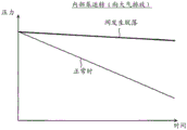
Fig. 6 is a schematic diagram showing changes in pressure at the time of normal operation and at the time of disengagement of the discharge valve in the first embodiment.
Fig. 7 is a schematic diagram showing changes in pressure at the time of normal operation and at the time of disengagement of the discharge valve in the second embodiment.
Fig. 8 is a flowchart showing abnormality detection control of leakage or the like in the evaporated fuel gas exhaust system of the third embodiment.
Fig. 9 is a schematic diagram showing changes in pressure at the time of normal operation and at the time of disengagement of the discharge valve in the third embodiment.
Fig. 10 is a schematic diagram showing changes in pressure at the time of normal operation and at the time of disengagement of the discharge valve in the fourth embodiment.
Fig. 11 is a partial sectional view showing a connection structure between an exhaust valve and an intake pipe in the evaporated fuel gas exhaust system in the fifth embodiment.
Fig. 12 is a plan view showing the discharge valve.
Fig. 13 is a sectional view showing a connection structure between the discharge valve and the intake pipe.
Fig. 14 is a partial sectional view showing a connection structure between an exhaust valve and an intake pipe in the evaporated fuel gas exhaust system of the sixth embodiment.
Fig. 15 is a plan view showing the discharge valve.
Fig. 16 is a sectional view showing a connection structure between the discharge valve and the intake pipe.
Fig. 17 is a partial sectional view showing a connection structure between an exhaust valve and an intake pipe in the evaporated fuel gas exhaust system of the seventh embodiment.
Fig. 18 is a plan view showing the discharge valve.
Fig. 19 is a sectional view showing a connection structure between the discharge valve and the intake pipe.
Detailed Description
Hereinafter, a plurality of embodiments for implementing the present disclosure will be described with reference to the drawings. In each of the embodiments, the same reference numerals are used for portions corresponding to the matters described in the previous embodiment, and redundant description may be omitted. In the case where only a part of the structure is described in each embodiment, other embodiments described above may be employed for other parts of the structure. In each embodiment, combinations of parts that can be combined are not specifically specified, and combinations of parts between embodiments can be combined even if not specified, as long as the combinations are not particularly hindered.
(first embodiment)
A fuel evaporation gas discharge system 1 of a first embodiment will be described with reference to fig. 1 to 6. The evaporative fuel gas emission system 1 is a system for supplying HC gas and the like in fuel adsorbed in the canister 13 to an intake passage of an engine and preventing evaporative fuel gas (hereinafter, also referred to as evaporative fuel) from the fuel tank 10 from being released into the atmosphere. Hereinafter, the fuel evaporation gas discharge system 1 is sometimes described as the system 1. The system 1 is configured, as shown in fig. 1, with an intake system of an engine 2 that constitutes an intake passage of the engine 2, and an evaporated fuel discharge system that supplies evaporated fuel to the intake system of the engine 2.
The evaporated fuel introduced into the intake passage of the engine 2 is mixed with fuel for combustion supplied from an injector or the like to the engine 2, and is combusted in the cylinder of the engine 2. The engine 2 mixes and burns at least the evaporated fuel and the combustion fuel that have come off from the canister 13. An intake system of the engine 2 is configured such that an intake pipe 22 is connected to an intake manifold 20, and a throttle 23, a supercharger 21, an air filter 24, and the like are provided midway in the intake pipe 22. The intake passage of the engine 2 includes an intake manifold 20, an intake pipe 22, a throttle 23, a supercharger 21, an air filter 24, and the like.
In the evaporated fuel drain system, the fuel tank 10 and the canister 13 are connected by a pipe constituting the vapor passage 16, and the canister 13 and the intake pipe 22 are connected by a pipe constituting the drain passage 17 and the drain valve 15. A discharge pump 14 is provided midway in the discharge passage 17. The discharge passage 17 includes an internal passage of the discharge pump 14 and an internal passage of the discharge valve 15. The intake pipe 22 is one example of a passage forming member that forms an intake passage of the engine 2.
An air filter 24 is provided at an upstream portion of the intake pipe 22 for trapping dust and the like in the intake air. The throttle valve 23 is an intake air amount adjusting valve that adjusts the amount of intake air flowing into the intake manifold 20 by adjusting the opening degree of the intake manifold 20 at the inlet portion. The supercharger 21 pressurizes intake air after passing through the air filter 24 and supplies it to the intake manifold 20. The intake air flows into the intake manifold 20 through the intake passage in the order of the air filter 24, the supercharger 21, and the throttle valve 23, is mixed with combustion fuel injected from an injector or the like at a predetermined air-fuel ratio, and is combusted in the cylinder.
The fuel tank 10 is a container for storing fuel such as gasoline. The fuel tank 10 is connected to an inflow portion of the canister 13 via a pipe forming a vapor passage 16. The canister 13 is a container in which an adsorbent such as activated carbon is sealed, and is configured to introduce evaporated fuel generated in the fuel tank 10 through the vapor passage 16 and temporarily adsorb the evaporated fuel onto the adsorbent. A valve module 12 is integrally provided in the tank 13. The valve module 12 includes a tank closing valve 120 that opens and closes an intake portion for sucking fresh outside air, and an internal pump 121 that can release gas to the atmosphere or suck in the atmosphere. The canister shutoff valve 120 is also referred to as a CCV 120. Since the tank 13 includes the CCV120, atmospheric pressure can be applied to the inside of the tank 13. The canister 13 can easily separate the evaporated fuel adsorbed on the adsorbent material, i.e., can be discharged, by the fresh air drawn in.
One end of a pipe forming a part of the discharge passage 17 in the tank 13 is connected to an outflow portion through which the evaporated fuel having desorbed from the adsorbent flows out. The other end of the pipe is connected to an inflow portion of the discharge pump 14. Further, the discharge pump 14 and the discharge valve 15 are connected by a pipe forming a part of the discharge passage 17. The purge pump 14 is a fluid drive device for purging, has a turbine rotated by an actuator such as an electric motor, and delivers the evaporated fuel from the tank 13 to an intake passage of the engine 2.
The discharge valve 15 is an opening/closing device having a valve body 152 that opens and closes the discharge passage 17. That is, the drain valve 15 is also an opening/closing device having a valve body 152 that opens and closes a fuel supply passage 153 provided inside the main body 150, and is capable of allowing or preventing the evaporated fuel from the tank 13 from being supplied to the engine 2. The discharge valve 15 is constituted by an electromagnetic valve device including a valve body 152, an electromagnetic coil 151, and a spring.
The drain valve 15 is switched between the energized state and the non-energized state by the control device 3, thereby realizing opening degree control in a range from the fully open state to the fully closed state of the fuel supply passage 153. The purge valve 15 is switched between a permission state for permitting the evaporated fuel to flow into the intake passage and a prevention state for preventing the evaporated fuel from flowing into the intake passage by being switched between an energization state and a non-energization state. The purge valve 15 moves the valve body 152 in accordance with a difference between an electromagnetic force generated when the electric circuit having the electromagnetic coil 151 is energized and a pressing force of a spring, separates the valve body 152 from the valve seat 157 formed in the second member 150b of the main body 150, and opens the fuel supply passage 153.
The discharge valve 15 is a valve device that normally maintains the closed state of the fuel supply passage 153, for example. The discharge valve 15 is a normally closed valve device that is in a closed state in which the fuel supply passage 153 is closed when no voltage is applied, and is controlled to an open state in which the fuel supply passage 153 is open when a voltage is applied. The purge valve 15 is one example of a valve device that can allow and block the evaporated fuel from a purge passage extending from the inside of the fuel tank 10 to a connection portion with the intake passage of the engine 2 to flow into the intake passage in the intake pipe 22. Such a valve device may be an opening/closing valve that switches between a fully open state and a fully closed state, instead of the drain valve 15 having an adjustable opening degree. In this case, an opening and closing valve as a valve device needs to be mounted on the intake pipe 22, and a discharge valve 15 capable of adjusting a flow rate needs to be provided on a passage from the fuel tank 10 to the opening and closing valve.
When the electric circuit is energized by the control device 3, the electromagnetic force of the discharge valve 15 overcomes the elastic force of the spring, and the valve body 152 is separated from the valve seat 157 to open the fuel supply passage 153. The control device 3 controls the ratio of the on time of the current to one cycle time formed by the on time and the off time, that is, the duty ratio, to supply the current to the electromagnetic coil 151. The discharge valve 15 is also referred to as a duty control valve. By controlling the energization of the purge valve 15 in this way, the flow rate of the evaporated fuel flowing through the fuel supply passage 153 can be adjusted.
The system 1 includes a valve device mounted to an intake pipe 22 as a passage forming member constituting an intake passage. Referring to fig. 2 to 4, the discharge valve 15, which is one example of the valve device, will be described. The main body 150 of the discharge valve 15 has a structure fixed to the intake pipe 22 at a fixing portion 156. The fixing portion 156 is fixed to a fastening mechanism such as a screw, a bolt, and a bracket. Inside the main body 150, an electromagnetic coil 151, an electric circuit, a valve body 152, and a fuel supply passage 153 are provided.
The discharge valve 15 includes a body 150. The main body 150 includes at least a first member 150a including a fuel supply passage 153 and an electromagnetic coil 151 therein, and a second member 150b coupled to the first member 150 a. The first member 150a and the second member 150b are respectively formed of a resin material.
The first member 150a is a cup-shaped body having a bottom portion and an inflow port 154 on one end side, and an opening portion on the opposite side of the one end side, i.e., the other end side. The opening is in the shape of a rail (track). The first member 150a has a flange portion radially protruding outward in the radial direction over the entire circumference of the opening portion. The second member 150b has a flange portion integrally joined to the flange portion of the first member 150a in a state of being overlapped therewith. The second member 150b is provided with an annular protruding portion and a cylindrical portion protruding from one side surface in the thickness direction on the rail-shaped flange portion. The annular protruding portion of the second member 150b is a portion that fits into the inner peripheral wall surface on the other end side of the first member 150 a. In a state where the first member 150a and the second member 150b are joined, the inside of the annular protrusion communicates with the internal passage of the first member 150a, and the first member 150a and the second member 150b sandwich and support the filter. The filter is provided between the inside of the inflow port 154 and the fuel supply passage 153 in the internal passage of the first member 150 a.
The second member 150b has a cylindrical portion forming the leakage passage 41 and the fuel supply passage 153 inside the annular protruding portion. The cylindrical portion has a valve seat 157 that contacts the valve body 152 on the distal end side. In a state where the first member 150a and the second member 150b are joined, the cylindrical portion has a shape protruding toward the inside of the first member 150a, and has a fuel supply passage 153 inside thereof through which the evaporated fuel flows from the side of the inlet port 154 when the valve body 152 is in an open state.
The first member 150a has an inflow port 154, and the inflow port 154 constitutes an inflow passage into which evaporated fuel from the tank 13 flows. The second member 150b has an outlet port 155, and the outlet port 155 communicates with the inlet port 154 via the internal passage of the first member 150a, and communicates with the intake passage. The outlet port 155 is cylindrical and has a passage through which the evaporated fuel from the inlet port 154 flows in a permitted state and does not flow in a blocked state. The second member 150b further includes a port 4 for leakage, and the port 4 for leakage communicates with the inflow port 154 via an internal passage provided inside the first member 150a, and also communicates with the outside of the main body 150. The leak passage 41 of the leak port 4 also communicates with the fuel supply passage 153 when the valve body 152 is separated from the valve seat 157. The leak port 4 has a cylindrical shape in which the leak passage 41 inside communicates with the internal passage inside the main body 150 and protrudes from the second member 150b in the same manner as the outflow port 155.
The leakage port 4 and the outflow port 155 are coaxially and integrally provided in the second member 150b of the main body 150. The outflow port 155 is provided with a fuel supply passage 153 therein. A cylindrical leak passage 41 is provided inside the leak port 4. The leak passage 41 is provided coaxially with the fuel supply passage 153 in the outlet port 155 in the second member 150b, and has an annular cross-section surrounding the outside of the cylindrical fuel supply passage 153. Therefore, the leakage port 4 has a larger outer diameter than the outflow port 155. The leak port 4 may be provided in plural numbers around the fuel supply passage 153.
The distal end of the outflow port 155 protrudes further into the intake passage than the leak port 4. The outlet port 155 is a portion protruding toward the intake passage from the leakage port 4, and has a reduced diameter portion 158 closer to the valve body 152 than a seal portion where the seal member 1550 is fitted. The reduced diameter portion 158 is a portion having an outer diameter smaller than the shape of the seal portion in which the leakage port 4 and the seal member 1550 are fitted. The reduced diameter portion 158 corresponds to a portion of the outflow port 155 located between the distal end of the outflow port 155 and the leakage port 4. In this way, the portion of the outlet port 155 closer to the leak port 4 is thinner than the portion inscribed in the tip end portion of the inner hole 220 provided in the engine-side port. According to this structure, the outflow port 155 which is easily bent can be provided at a portion close to the leakage port 4.
The intake pipe 22 has an engine-side port that communicates the internal passage of the discharge valve 15 with the intake passage. The engine-side port includes an inner side hole portion 220 into which the flow port 155 is insertable, and an outer side hole portion 221 adjacent to an outer side of the inner side hole portion 220 and into which the leak port 4 is insertable. Therefore, the engine-side port is formed with a through hole portion penetrating the pipe cross section of the intake pipe 22 from the outside to the inside, and the through hole portion is formed with a recessed portion corresponding to the outside hole portion 221 and an inside hole portion 220 penetrating the center of the recessed portion in this order. The outer side is an outer side with respect to an intake passage provided inside the passage forming member.
As shown in fig. 2 and 4, in a state where the valve device is properly attached to the intake pipe 22, the outlet port 155 is connected to the inside of the inner side hole 220 and the outer side hole 221, which communicate the outside of the intake pipe 22 with the intake passage, while being inserted inside. The space between the outer peripheral surface of the outlet port 155 and the inner peripheral surface of the inner side hole 220 is sealed by a sealing member 1550 such as an O-ring attached to the outer periphery of the outlet port 155. The sealing member 1550 is an outflow side sealing member that is in close contact with the outflow port 155 and the engine side port to provide a sealed state therebetween.
As shown in fig. 2 and 4, the leak port 4 is provided so as to be inserted into the outer side hole portion 221 of the intake pipe 22 in a state where the valve device is properly mounted in the intake pipe 22. A space between the outer peripheral surface of the leak port 4 and the inner peripheral surface of the outer side hole 221 is sealed by a sealing member 40 such as an O-ring attached to the outer periphery of the leak port 4. The seal member 40 is a leakage side seal member that is in close contact with the leakage port 4 and the engine side port to provide a sealed state therebetween. The end of the leak passage 41 on the intake passage side is closer to the discharge passage 17 side or the outer side than the end of the internal passage on the intake passage side of the outflow port 155. Therefore, in this properly mounted state, the passage leading from the inflow port 154 to the leak passage 41 via the internal passage is blocked by the seal member 1550 and the seal member 40 which are in contact with the engine-side port. In this way, the leakage port 4 has a leakage prevention structure for preventing the evaporated fuel or the exhaust gas from leaking to the outside when the discharge valve 15 is properly attached to the intake pipe 22.
The axial distance L1 between the discharge passage 17 side or the outer side opening end of the outer side hole portion 221 and the seal member 40 is set to be larger than the axial distance L2 between the discharge passage 17 side or the outer side opening end of the inner side hole portion 220 and the seal member 1550. According to this configuration, when the exhaust valve 15 is detached to the outside with respect to the intake pipe 22 and moved in the axial direction, the seal member 1550 is detached from the engine-side port earlier than the seal member 40 because L2 is shorter than L1. Thus, in the valve device, the sealing member 40 maintains the sealed state even if the sealing member 1550 loses the sealing performance. In this state, although the leak passage 41 communicates with the intake passage, the gas in the discharge passage 17 can be prevented from flowing out to the atmosphere via the leak passage 41 because the sealing member 40 is blocked from the outside of the intake pipe 22 due to its sealed state.
The circuit is connected to a connector for wiring with an electric wire that supplies an electric current from the outside. Therefore, in the circuit, the current is passed through the wire. The electric circuit is energized by an electric wire connected to a connector, and electromagnetic force is generated in the electromagnetic coil 151, and the valve body 152 is driven by the electromagnetic force, thereby opening the fuel supply passage 153.
The control device 3 is an electronic control unit of the fuel evaporation gas discharge system 1. The control device 3 has at least one arithmetic processing unit (CPU) and at least one memory device as a storage medium storing programs and data. The control device 3 is provided by, for example, a microcomputer including a computer-readable storage medium. The storage medium is a non-transitory tangible storage medium that non-temporarily stores a computer-readable program. The storage medium may be provided by a semiconductor memory, or a magnetic disk, or the like. The control means 3 may be provided by a computer or a set of computer resources linked by data communication equipment. The program is executed by the control device 3, so that the control device 3 functions as the device described in the present specification, and the control device 3 functions to execute the method described in the present specification.
The means and/or functions provided by the control system may be provided by software recorded in the physical storage device and a computer executing it, software only, hardware only, or a combination thereof. For example, when the control device 3 is provided by an electronic circuit as hardware, it may be provided by a digital circuit including a plurality of logic circuits, or an analog circuit.
The control device 3 performs basic control such as fuel emission in the system 1, and determines the presence or absence of an abnormality such as an evaporated fuel leak by an abnormality determination circuit 30 constituting an abnormality determination unit. When a determination is made that there is an abnormality, the seal between the outlet port 155 and the engine-side port is released, and the evaporated fuel flows from the discharge passage 17 side to the intake passage side via the leak passage 41. The control device 3 is connected to and controls the respective actuators of the discharge pump 14, the discharge valve 15, the CCV120, and the internal pump 121.
The control device 3 is connected to an actuator such as a motor of the drain pump 14, and can control the operation and stop of the drain pump 14 by driving the motor regardless of the operation and stop of the engine 2. The control device 3 is connected to the electric motor of the internal pump 121, and is capable of controlling the operation and stop of the internal pump 121 by driving the electric motor regardless of the operation and stop of the engine 2. Signals corresponding to the rotation speed of the engine 2, the intake air amount, the cooling water temperature, and the internal pressure of the fuel tank 10 detected by the pressure sensor 11, etc. may be input to the input port of the control device 3.
The evaporated fuel drawn from the canister 13 into the intake manifold 20 is mixed with the original combustion fuel supplied to the engine 2 from an injector or the like, and is combusted in the cylinders of the engine 2. In the cylinder of the engine 2, an air-fuel ratio, which is a mixture ratio of the combustion fuel and the intake air, is controlled to a predetermined air-fuel ratio. The control device 3 adjusts the discharge amount of the evaporated fuel by duty control of the opening and closing time of the discharge valve 15 so that a predetermined air-fuel ratio can be maintained even if the evaporated fuel is discharged.
The fuel vapor gas discharge system 1 is a system for preventing the evaporated fuel generated in the fuel tank 10 from being discharged to the atmosphere, but if a leak or the like occurs in the evaporated fuel gas discharge system or if equipment falls off, there is a possibility that fuel vapor is discharged from the leak portion to the atmosphere. Even if such an abnormality in the leakage, the hole, or the like occurs, the vehicle driver may not notice the abnormality and leave it.
Therefore, in the system 1 of the first embodiment, it is determined whether or not there is an abnormality in which the valve device is detached from the passage forming member and the seal between the leak passage 41 and the engine-side port is released. The system 1 can early detect the occurrence of an abnormality in which the seal between the leak passage 41 and the engine-side port is in a loose state.
The abnormality detection control will be described with reference to the flowchart of fig. 5 and the diagram of fig. 6. The control device 3 performs processing according to the flow shown in fig. 5. This flow is executed both during running when the vehicle engine 2 is operated and during stop when the vehicle is stopped. The abnormality detection control of the system 1 is periodically executed regardless of the operation and stop of the engine 2.
After the start of the present flow, the control device 3 controls the purge valve 15 to a state where no current is supplied to the circuit in step S10. Thereby, the discharge valve 15 is controlled to be in a closed state. Next, the control device 3 starts 121 the operation of the internal pump in step S20. Accordingly, the gas in the passage from the inside of the fuel tank 10 to the drain valve 15 is discharged to the outside by the internal pump 121, and therefore the pressure inside the fuel tank 10 becomes a negative pressure state with a lower pressure with respect to the atmospheric pressure.
The controller 3 continues this state for a certain period of time to set a detectable state in which the valve device, that is, the drain valve 15, is detectable for the presence or absence of the drop. In step S30, the control device 3 acquires a signal relating to the internal pressure of the fuel tank 10 detected by the pressure sensor 11, and the abnormality determination circuit 30 determines whether or not the normal condition of the valve device is satisfied. The normal condition of the valve device is a condition required for determining whether or not the valve device is in a normal state in which an abnormality such as falling-off does not occur in a determinable state.
In this state, if the sealing state by the sealing members 40 and 1550 is normal, the pressure value detected by the pressure sensor 11 changes so as to continuously decrease from the atmospheric pressure with the operation of the internal pump 121 as the pressure changes as indicated by the thin line in fig. 6. Conversely, when an abnormality occurs in which the sealed state is released by the seal member 40 or 1550, the gas is discharged from the leak port 4 to the intake passage, and therefore the detected pressure value does not promote the negative pressure state, but does not decrease as compared with the normal state as indicated by "valve drop-out" indicated by a thick line in fig. 6. The normal condition is established when, for example, the absolute value of the pressure change per unit time (pressure change rate) is equal to or greater than a predetermined change rate set in advance. Therefore, the abnormality determination circuit 30 determines that there is an abnormality when the absolute value of the pressure change rate is smaller than a predetermined value, and determines that it is normal when the absolute value is equal to or larger than the predetermined change rate.
If the abnormality determination circuit 30 determines in step S30 that the normal condition is not satisfied, it indicates in step S35 that the valve device is in an abnormal state, and ends the current abnormality detection control. Based on this display, the user can make repairs. After the repair is finished, the step S10 is restarted after a predetermined time has elapsed.
The abnormality display of step S35 is performed by lighting or blinking a predetermined lamp or by performing an abnormality display on a predetermined screen to show that there is an abnormality in the valve device. The abnormal display may be replaced by a warning sound such as an alarm sound or an abnormality notification.
If the abnormality determination circuit 30 determines in step S30 that the normal condition is satisfied, the current determination result is normal, and therefore the normal determination process is executed in step S40 to end the current abnormality detection control. After the end, a predetermined time elapses, and step S10 is restarted. In this way, the abnormality detection control of the system 1 can be executed at predetermined time intervals regardless of whether the engine 2 is operating.
The abnormality detection control may be executed in either case of traveling or parking, but is preferably executed during parking. This is because the engine is stopped at the time of parking, and a significant pressure change is easily detected. In addition, since the discharge processing cannot be performed at the time of the leak check, it is also advantageous to perform the abnormality detection control at the time of parking from the viewpoint of the operation efficiency of the system 1.
Next, the operation and effects of the valve device according to the first embodiment will be described. The purge valve 15 is attached to a passage forming member that forms an intake passage of the engine 2, and the engine 2 mixes and burns the evaporated fuel flowing out from the fuel tank 10 and the combustion fuel. The discharge valve 15 is a valve device that controls the flow of the evaporated fuel, and has a valve body 152 that switches between a permission state that permits the evaporated fuel to flow into the intake passage and a prevention state that prevents the evaporated fuel from flowing into the intake passage. The valve device includes: an inflow port 154; a cylindrical outflow port 155 having an internal passage through which the evaporated fuel from the inflow port 154 flows in a permitted state and does not flow in a blocked state; a cylindrical leak port 4; an outflow side seal member; and a leakage side seal member. The outlet port 155 is inserted at an engine-side port formed in the passage forming member to communicate with the intake passage. The leak port 4 has a leak passage 41 into which the evaporated fuel from the inlet port 154 can flow regardless of the permission state or the blockage state, and is inserted into the engine-side port. The outflow side seal member provides a sealed state between the outflow port 155 and the engine side port. The leak side seal member provides a sealed state between the leak port 4 and the engine side port. The valve device is arranged such that when the outflow port 155 and the leak port 4 move in a direction away from the engine-side port, the outflow-side seal member releases the sealed state before the leak-side seal member.
According to this valve device, even if the outflow port 155 and the leak port 4 move in a direction away from the engine-side port when the valve device is in the blocked state and the properly attached state is released, the outflow-side seal member releases the sealed state before the leak-side seal member. Thus, even if the sealing performance of the outflow side seal member is lost, the sealing performance of the leakage side seal member is maintained, and therefore, the evaporated fuel or the like flowing out of the leakage passage 41 can be configured to flow out into the intake passage without leaking to the outside from the engine side port. With this configuration, it is possible to provide a valve device that can suppress gas leakage to the outside (leakage to the atmosphere) even when the proper attachment state is released.
The outflow port 155 and the leak port 4 are provided in a coaxial positional relationship. Thus, the fuel supply passage 153 and the leak passage 41 of the outflow port 155 are positioned inside the same body. When the valve device is detached from the passage forming member and the sealing state of the outflow port 155 is released, the leak passage 41 and the inner side hole portion 220 can be brought into a state of communication. Therefore, it is possible to provide a system that can reliably detect a leak state in which the leak passage 41 communicates with the intake passage of the engine 2 in the case where the valve device is detached from the passage forming member.
The leak port 4 is provided on the outer side of the outflow port 155 provided coaxially therewith. Thus, since the passage cross-sectional area of the leak passage 41 can be easily formed large, the leak port 4 for significantly changing the pressure for leak detection can be provided. Therefore, the leak port 4 capable of clearly judging the presence or absence of an abnormality can be provided.
Since the outlet port 155 and the leak port 4 are provided integrally in a coaxial positional relationship, it is easy to ensure the dimensional accuracy of the outlet port 155 and the leak port 4. Further, the inner peripheral surface shape of the engine-side port, in which sealing performance is easily obtained, is easily manufactured. This makes it possible to provide a structure that easily ensures sealing performance between the outlet port 155 and the leak port 4, respectively, and the engine-side port.
The engine-side port includes a first hole portion, i.e., an inner side hole portion 220, and a second hole portion, i.e., an outer side hole portion 221, both of which are hole portions formed in the passage forming member, and the sealed state between the first hole portion, i.e., the inner side hole portion 220, and the outlet port 155 is provided by the outlet side sealing member in a state in which the outlet port 155 is inserted. In the outer hole 221, the leak port 4 is inserted, and a sealing state with the leak port 4 is provided by a leak side seal member. The axial distance L1 between the outer opening end of the outer hole 221 and the leakage seal member is greater than the axial distance L2 between the outer opening end of the inner hole 220 and the outflow seal member.
With this configuration, when the outflow port 155 and the leak port 4 are moved in a direction away from the engine-side port, the outflow-side seal member releases the sealed state before the leak-side seal member. Thereby, even if the sealing performance of the outflow side seal member is lost, the sealing performance of the leakage side seal member is maintained, and therefore it is possible to provide a valve device that allows the evaporated fuel or the like flowing out from the leakage passage 41 to flow out into the intake passage without leaking to the outside of the passage forming member from the engine side port.
The outflow port 155 and the leak port 4 are coaxially positioned. The leak passage 41 is a cylindrical passage surrounding the internal passage of the outflow port 155. According to this configuration, by the configuration in which the downstream end of the leakage port 4 is disposed on the outer side of the downstream end of the outflow port 155, the outflow seal member can be released from the sealed state before the leakage seal member. Therefore, the leakage port 4 and the outflow port 155 that can exhibit desired functions can be manufactured with simple shapes, and the productivity of the valve device can be improved.
The fuel evaporation gas discharge system 1 includes: a fuel tank 10; a tank 13; a passage forming member that forms an intake passage of the engine 2 that mixes and burns at least the evaporated fuel that has escaped from the canister 13 with the combustion fuel; and a valve device described in the present specification. Accordingly, it is possible to provide the fuel evaporation gas exhaust system 1 which can suppress the leakage of gas to the outside (to the atmosphere) even when the proper attachment state is released.
The control device 3 operates the internal pump 121 in a state where the valve body 152 is controlled to the blocking state (step S10, step S20), and detects the pressure at a predetermined portion included in the passage from the inside of the fuel tank 10 and the fuel supply port to the valve device. When the absolute value of the pressure change rate detected in this manner is smaller than the predetermined value, the control device 3 determines that there is an abnormality (step S30, step S35).
According to this system 1, if the valve device is properly mounted in a normal state, the gas such as the evaporated fuel sealed in the passage is continuously discharged to the outside when the internal pump 121 discharges the gas, and therefore the degree of negative pressure of the detected pressure with respect to the atmospheric pressure gradually increases. In addition, since the leak passage 41 communicates with the outside when the valve device is abnormal, when the internal pump 121 discharges gas, the atmosphere introduced through the leak passage 41 is continuously discharged to the outside by the internal pump 121, and the degree of negative pressure of the detected pressure with respect to the atmospheric pressure is reduced. Thus, the control device 3 can accurately detect that the valve device is in the abnormal state when the absolute value of the detected pressure change rate is lower than the predetermined value. According to the system 1, erroneous detection of the valve device in the detection of the abnormal state can be reduced.
The outlet port 155 includes a reduced diameter portion 158, and the reduced diameter portion 158 has an outer diameter smaller than that of a sealing portion where the outlet side sealing member is provided and is formed at a position farther from the intake passage than the sealing portion. According to this configuration, when the outlet port 155 is inserted and disposed in the inner side hole portion 220 of the engine side port, the reduced diameter portion 158 is easily bent, and therefore, the accuracy required for the coaxial connection of the outlet port 155 and the leak port 4 can be reduced. Further, according to this configuration, it is possible to contribute to improvement in the installation workability of the outlet port 155 with respect to the engine-side port.
The discharge valve 15 includes a first member 150a and a second member 150b, the first member 150a accommodating a driving portion for driving the valve body 152, the second member 150b having an outflow port 155 and a leakage port 4 and being coupled to the first member 150 a. According to this structure, it is possible to provide the discharge valve 15 which only requires preparation of the second member 150b having the outflow port 155 and the port for leakage 4 which meet the specifications of the engine-side port, without remanufacturing the first member 150 a. Thereby, it is possible to provide the discharge valve 15 in which the structure of the outflow port 155 or the leak port 4 can be changed. In addition, the discharge valve 15 can be applied to an evaporated fuel treatment system that can cope with product specifications of various vehicles, contributing to reduction of man-hours for component management in the evaporated fuel treatment system.
(second embodiment)
The abnormality detection control of the second embodiment will be described with reference to fig. 5 and 7. The configuration, operation, and effect not particularly described in the second embodiment are the same as those of the first embodiment, and only the portions different from the first embodiment will be described below.
The abnormality detection control of the second embodiment may be implemented as follows. In the abnormality detection control of the second embodiment, the internal pump 121 is operated to suck the atmospheric air into the discharge passage from the outside in step S20 of fig. 5. Accordingly, the atmosphere is sucked by the internal pump 121 in the passage from the inside of the fuel tank 10 to the purge valve 15, and the pressure inside the fuel tank 10 is in a positive pressure state in which the pressure is higher than the atmospheric pressure.
The controller 3 continues this state for a certain period of time to set a detectable state in which the valve device, that is, the drain valve 15, is detectable for the presence or absence of the drop. In step S30, the normal condition of the valve device is a condition required for determining whether or not the valve device is in a normal state in which an abnormality such as falling-off does not occur in the determinable state.
In this state, if the sealing state by the sealing members 40 and 1550 is normal, the pressure value detected by the pressure sensor 11 changes so as to increase from the atmospheric pressure with the operation of the internal pump 121 as shown by the pressure change indicated by the thin line in fig. 7. This is because the atmosphere entering the passage has no place to go due to the sealing member 40, 1550 and the valve body 152 in the blocking state. In contrast, in the abnormal state where the sealed state by the sealing members 40 and 1550 is released, the atmospheric air is discharged to the intake passage through the leak passage 4, and therefore the pressure value does not promote the positive pressure state but does not increase as compared with the normal state as "valve drop-out" indicated by a thick line in fig. 7. The normal condition is established when, for example, the absolute value of the pressure change per unit time (pressure change rate) is not lower than a predetermined change rate determined in advance. Therefore, the abnormality determination circuit 30 determines that it is abnormal when the absolute value of the pressure change rate is lower than a predetermined value, and determines it is normal when it is not lower than the predetermined change rate.
According to the system 1, if the valve device is properly mounted in the normal state, the gas such as the evaporated fuel sealed in the passage is continuously introduced into the passage while the internal pump 121 introduces the atmosphere into the passage, and therefore the degree of positive pressure of the pressure detection value with respect to the atmospheric pressure gradually increases. Further, when the valve device is dropped to such an extent that the leak passage 41 communicates with the intake passage, the atmospheric air introduced into the passage is continuously discharged into the intake passage through the leak passage 41. This reduces the degree of positive pressure of the detected pressure with respect to the atmospheric pressure. The control device 3 can accurately detect an abnormal state of the valve device when the absolute value of the detected pressure change rate is lower than a predetermined value. Therefore, erroneous detection of the valve device using the internal pump 121 for introducing the atmosphere in the abnormal state detection can be reduced.
(third embodiment)
The abnormality detection control of the third embodiment will be described with reference to fig. 8 and 9. The configuration, operation, and effect not particularly described in the third embodiment are the same as those of the first embodiment, and only the portions different from the first embodiment will be described below.
Steps S100, S135, and S140 in the abnormality detection control of the third embodiment correspond to steps S10, S35, and S40 of the first embodiment, respectively, and the same processing is performed.
After the start of the present flow, the control device 3 controls the discharge valve 15 to a state where no current is supplied to the circuit and the discharge valve 15 is in a closed state in step S100. Next, the control device 3 controls to close the CCV120 in step S105, and operates the drain pump 14 in the normal rotation manner in step S120. Thus, when the drain valve 15 is properly installed, the passage from the inside of the fuel tank 10 to the drain valve 15 becomes a closed passage. Since the gas sent to the purge valve 15 side by the purge pump 14 has no place to go, the pressure inside the fuel tank 10 becomes a pressure state slightly lower than the atmospheric pressure.
In step S130, the control device 3 acquires a signal relating to the internal pressure of the fuel tank 10 detected by the pressure sensor 11, and the abnormality determination circuit 30 determines whether or not the normal condition of the valve device is satisfied. In this state, if the sealing state of the sealing member 40, 1550 is normal, the pressure value detected by the pressure sensor 11 slightly decreases from the atmospheric pressure with the operation of the purge pump 14 as the pressure changes as indicated by the thin line in fig. 9. On the contrary, in the abnormal state where the sealed state by the sealing member 40 or 1550 is released, since the gas is discharged to the outside from the leakage port 4, the detected pressure value does not promote the negative pressure state, but is greatly reduced as compared with the normal state as "the valve is detached" indicated by a thick line in fig. 8. The normal condition is established when, for example, the absolute value of the pressure change per unit time (pressure change rate) is equal to or less than a predetermined change rate determined in advance. Therefore, the abnormality determination circuit 30 determines that there is an abnormality when the absolute value of the pressure change rate is equal to or greater than a predetermined value, and determines that it is normal when the absolute value is equal to or less than a predetermined change rate.
If the abnormality determination circuit 30 determines in step S130 that the normal condition is not satisfied, it indicates in step S135 that the valve device is in an abnormal state, and ends the current abnormality detection control. After the end, after a predetermined time, step S100 is started again. If the abnormality determination circuit 30 determines in step S130 that the normal condition is satisfied, the determination result of this time is normal, and therefore the normal determination process is executed in step S140 to end the abnormality detection control of this time.
The control device 3 operates the drain pump 14 in the normal rotation mode (steps S100, S105, and S20) in a state where the CCV120 is closed and the valve body 152 is controlled to the blocking state, and detects the pressure at a predetermined portion included in the passage from the inside of the fuel tank 10 and the fuel supply port to the valve device. When the absolute value of the pressure change rate detected in this way is equal to or greater than the predetermined value, the control device 3 determines that there is an abnormality (steps S130 and S135).
According to this system 1, if it is a normal state in which the valve device is properly mounted, when the purge pump 14 pushes the gas into the intake passage side, since the evaporated fuel of the passage has no place to go, the degree of negative pressure of the detected pressure with respect to the atmospheric pressure becomes small. Further, when the valve device is dropped to such a degree that the leak passage 41 communicates with the intake passage, the gas pressed in by the discharge pump 14 is continuously discharged to the intake passage through the leak passage 41, and therefore the degree of negative pressure of the pressure detection value with respect to the atmospheric pressure gradually becomes large. In this way, the control device 3 can accurately detect that the valve device is in the abnormal state when the absolute value of the detected pressure change rate is equal to or greater than the predetermined value. According to the system 1, it is possible to reduce false detection in abnormal state detection of the valve device using the normal rotation drain pump 14.
(fourth embodiment)
The abnormality detection control of the fourth embodiment will be described with reference to fig. 8 and 10. The configuration, operation, and effect not particularly described in the fourth embodiment are the same as those of the third embodiment and the first embodiment, and only the portions different from the foregoing embodiments will be described below.
The abnormality detection control of the fourth embodiment may be implemented as follows. In the abnormality detection control of the fourth embodiment, in step S120 of fig. 8, the drain pump 14 is operated in the reverse rotation manner. In this state, and the drain valve 15 is properly installed, the passage from the inside of the fuel tank 10 to the drain valve 15 becomes a closed passage. Further, since the gas sent to the fuel tank 10 side by the purge pump 14 has no place to go, the pressure inside the fuel tank 10 is in a state of a pressure slightly higher than the atmospheric pressure.
In a state where the state can be determined for a certain period of time, the control device 3 determines in step S130 whether or not the valve device is in a normal state in which an abnormality such as falling-off does not occur. In step S130, when the sealing state of the sealing member 40, 1550 is normal, the pressure value detected by the pressure sensor 11 changes to a low pressure state in which the pressure is slightly higher than the atmospheric pressure, as indicated by a pressure change indicated by a thin line in fig. 10.
Conversely, when an abnormality occurs in which the sealed state by the sealing members 40 and 1550 is released, the outside air is continuously sent from the outflow port 155 to the inside of the fuel tank 10 through the purge valve 15 and the like. Therefore, the pressure value changes more greatly than in a normal state, as indicated by the thick line in fig. 10, i.e., "the valve comes off". The normal condition is established when, for example, the absolute value of the pressure change per unit time (pressure change rate) is equal to or less than a predetermined change rate determined in advance. Therefore, the abnormality determination circuit 30 determines that the pressure is abnormal when the absolute value of the pressure change rate is equal to or greater than a predetermined value, and determines that the pressure is normal when the absolute value of the pressure change rate is equal to or less than a predetermined change rate.
The control device 3 operates the drain pump 14 in the reverse rotation manner (steps S100, S105, S20) in a state where the CCV120 is closed and the valve body 152 is controlled to the blocking state, and detects the pressure at a predetermined portion included in the passage from the inside of the fuel tank 10 and the fuel supply port to the valve device. When the absolute value of the pressure change rate detected in this state is equal to or greater than the predetermined value, the control device 3 determines that there is an abnormality (steps S130 and S135).
According to this system 1, if the valve device is properly mounted in the normal state, the positive pressure level of the detected pressure with respect to the atmospheric pressure becomes small when the purge pump 14 pushes the gas into the fuel tank 10 side. Further, when the valve device is disengaged to such an extent that the leak passage 41 communicates with the intake passage, the gas delivered to the fuel tank 10 by the purge pump 14 is continuously introduced from the engine 2 side via the leak passage 41, and therefore the degree of positive pressure of the pressure detection value with respect to the atmospheric pressure gradually increases. In this way, the control device 3 can accurately detect that the valve device is in the abnormal state when the absolute value of the rate of change in the pressure detection value is equal to or greater than the predetermined value. According to the system 1, it is possible to reduce false detection in abnormal state detection of the valve device using the inverted discharge pump 14.
(fifth embodiment)
A valve device of a fuel evaporation gas exhaust system according to a fifth embodiment will be described with reference to fig. 11 to 13. In the drawings, the same components as those of the first embodiment are denoted by the same reference numerals and exert the same operational effects. The structure, operation, and effects of the fifth embodiment that are not described in particular are the same as those of the above-described embodiment, and only the portions different from the above-described embodiment will be described below. In the fifth embodiment, the members having the same configurations as those of the above-described embodiments have the same operational advantages as those described in the above-described embodiments.
The discharge pump 115 of the fifth embodiment includes the leakage port 104, and the leakage port 104 communicates with the inflow port 154 through an internal passage provided inside the main body 150, and also communicates with the outside of the main body 150. The leak passage 141 in the leak port 104 communicates with an internal passage in the main body 150, and is provided integrally with the outlet port 1155 from the main body 150. The leakage port 104 has a leakage passage 141 extending in the same direction as the fuel supply passage 153 beside the outflow port 1155, and is provided in the main body 150. The fuel supply passage 153 and the leakage passage 141 of the outlet port 1155 are arranged so as to be axially spaced apart from each other. The leak port 104 has an elliptical outer periphery surrounding the fuel supply passage 153 and the leak passage 141 arranged in the lateral direction.
The discharge valve 115 includes a body 150. The main body 150 includes at least a first member 150a including a fuel supply passage 153, an electromagnetic coil 151, and the like therein, and a second member 1150b coupled to the first member 150 a. The first member 150a and the second member 1150b are respectively formed of a resin material.
The second member 1150b has a flange portion integrally joined in a state of being overlapped with the flange portion of the first member 150 a. The second member 1150b is provided with a cylindrical portion protruding from one side surface in the thickness direction on a rail-shaped flange portion. In a state where the first member 150a and the second member 1150b are joined, the first member 150a and the second member 1150b sandwich and support the filter.
The second member 1150b has a cylindrical portion forming the fuel supply passage 153. In a state where the first member 150a and the second member 1150b are joined, the cylindrical portion has a shape protruding toward the inside of the first member 150a, and has a fuel supply passage 153 therein through which the evaporated fuel flows from the inflow port 154 side when the valve body 152 is in the open valve state.
The second member 1150b has an outflow port 1155, and the outflow port 1155 communicates with the inflow port 154 via the internal passage of the first member 150a and communicates with the intake passage. The second member 1150b also includes a leakage port 104, and the leakage port 104 communicates with the inflow port 154 via an internal passage provided inside the first member 150a, and also communicates with the outside of the main body 150. The leak passage 141 of the leak port 104 also communicates with the fuel supply passage 153 when the valve body 152 is separated from the valve seat 157. The leak passage 141 in the leak port 104 communicates with the internal passage in the main body 150, and is in the second member 1150b, like the outflow port 1155, in a cylindrical shape.
The distal end of the outflow port 1155 protrudes into the intake passage more than the leak port 104. The outlet port 1155 is a portion protruding toward the intake passage from the leakage port 104, and has a reduced diameter portion 158 located closer to the valve body 152 than a seal portion where the seal member 1550 is fitted. The reduced diameter portion 158 is a portion having an outer diameter smaller than the shape of the seal portion in which the leakage port 104 and the seal member 1550 are externally fitted. The reduced diameter portion 158 corresponds to a portion of the outflow port 1155 located between the distal end of the outflow port 1155 and the leakage port 104. In this way, the outlet port 1155 is thinner at a portion closer to the leak port 104 than at a portion inscribed in the distal end portion of the inner hole 220 provided in the engine-side port. According to this structure, the outflow port 155 which is easily bent can be provided at a portion close to the leakage port 104.
The engine-side port provided on the intake pipe 22 includes an inner side hole portion 220 into which the outflow port 1155 is insertable, and an outer side hole portion 1221 adjacent to an outer side of the inner side hole portion 220 and into which the leak port 104 is insertable, the leak port 104 surrounding the fuel supply passage 153 and the leak passage 141 arranged in the lateral direction. Therefore, the engine-side port is formed with a through hole portion penetrating the pipe cross section of the intake pipe 22 from the outer side to the inner side, and the through hole portion is formed with a recessed portion corresponding to the outer side hole portion 1221 and the inner side hole portion 220 penetrating the recessed portion in this order.
As shown in fig. 11 and 13, in a state where the valve device is properly attached to the intake pipe 22, the outlet port 1155 is connected to be inserted into the inner side of the inner side hole portion 220 provided on the intake passage side of the intake pipe 22. The space between the outer peripheral surface of the outlet port 1155 and the inner peripheral surface of the inner side hole 220 is sealed by a sealing member 1550 such as an O-ring attached to the outer peripheral surface of the outlet port 1155. The seal member 1550 is an outflow side seal member that is brought into close contact with the outflow port 1155 and the engine side port to provide a sealed state therebetween.
As shown in fig. 11 and 13, the leak port 104 is inserted into the outer side hole 1221 in a state where the valve device is properly mounted in the intake pipe 22, and is accommodated in the outer side hole 1221. A space between the outer peripheral surface of the leak port 104 and the inner peripheral surface of the outer side hole 1221 is sealed by a sealing member 140 such as an O-ring attached to the outer periphery of the leak port 104. The seal member 140 is a leakage side seal member that is in close contact with the leakage port 104 and the engine side port to provide a sealed state therebetween. The end of the leak passage 141 on the intake passage side is closer to the discharge passage 17 side or the outer side than the end of the internal passage on the intake passage side of the outflow port 1155. Therefore, in this properly mounted state, the passage leading from the inflow port 154 to the leak passage 141 via the internal passage of the discharge pump 115 is blocked by the seal member 1550 and the seal member 140 which are in contact with the engine-side port. In this way, the leakage port 104 has a leakage prevention structure for preventing the evaporated fuel or the exhaust gas from leaking to the outside when the discharge valve 115 is properly attached to the intake pipe 22.
The axial distance L1 between the discharge passage 17 side or the outer side opening end of the outer side hole portion 1221 and the seal member 140 is set to a size larger than the axial distance L2 between the discharge passage 17 side or the outer side opening end of the inner side hole portion 220 and the seal member 1550. According to this configuration, when the exhaust valve 115 is detached to the outside with respect to the intake pipe 22 and moved in the axial direction, the seal member 1550 is detached from the engine-side port earlier than the seal member 140 because L2 is shorter than L1. Thus, in the valve device, the sealing member 140 maintains the sealed state even if the sealing member 1550 loses the sealing performance. In this state, although the leak passage 141 communicates with the intake passage, the gas in the discharge passage 17 can be prevented from flowing out to the atmosphere via the leak passage 141 because the sealing member 140 is blocked from the outside of the intake pipe 22 due to its sealed state.
Since the internal passage of the outlet port 1155 and the leak passage 141 are provided inside an integral structure such as a resin structure in a laterally aligned positional relationship, it is easy to ensure the dimensional accuracy of the outlet port 1155 and the leak port 104. Further, since the inner peripheral surface shape of the engine-side port, which is easy to obtain sealing performance, can be easily manufactured, a structure can be provided in which sealing performance between the outlet port 1155 and the leakage port 104, respectively, and the engine-side port can be easily ensured.
The internal channel of the outlet port 1155 and the leak channel 141 are arranged so as to be axially spaced apart. The sealing member 140 is annular surrounding both the internal passage and the leakage passage 141. With this configuration, the leak port 104 and the outflow port 1155 that can exhibit desired functions can be manufactured with simple shapes, and the productivity of the valve device can be improved.
The outflow port 1155 includes a reduced diameter portion 158, and the reduced diameter portion 158 has an outer diameter smaller than that of a sealing portion where the outflow-side sealing member is provided and is formed at a position farther from the intake passage than the sealing portion. According to this configuration, when the outlet port 1155 is inserted and provided in the inner side hole portion 220 of the engine side port, the reduced diameter portion 158 is bent, so that the dimensional accuracy required for the outlet port 1155 and the leak port 104 can be reduced. In addition, this configuration can contribute to improvement in workability of installation of the outlet port 1155 to the engine-side port.
The discharge valve 115 includes: a first member 150a that accommodates a driving portion for driving the valve body 152; and a second member 150b having an outflow port 1155 and a leakage port 104 and coupled to the first member 150 a. According to this structure, it is possible to provide the discharge valve 115 that only requires preparation of the second member 1150b having the outflow port 1155 and the port for leakage 104 that meet the specifications of the engine-side port, without remanufacturing the first member 150 a. Thus, a discharge valve 115 with a variable structure, such as the outflow port 1155 or the leak port 104, can be provided. In addition, the discharge valve 115 can be applied to an evaporated fuel treatment system that can cope with product specifications of various vehicles, contributing to reduction of man-hours for component management in the evaporated fuel treatment system.
(sixth embodiment)
Referring to fig. 14 to 16, a valve device of a fuel evaporation gas exhaust system according to a sixth embodiment will be described. In each of fig. 14 to 16, the same components as those of the first embodiment are denoted by the same reference numerals, and the same effects are obtained. The configuration, operation, and effect not particularly described in the sixth embodiment are the same as those of the above-described embodiment, and only the portions different from the above-described embodiment will be described below. In the sixth embodiment, the members having the same configurations as those of the above-described embodiments have the same operational advantages as those described in the above-described embodiments.
The drain pump 215 of the sixth embodiment includes a port 204 for leakage, and the port 204 for leakage communicates with the inflow port 154 through an internal passage provided inside the main body 150, and also communicates with the outside of the main body 150. The leak path 241 inside the leak port 204 communicates with the internal path inside the main body 150, and protrudes from the main body 150 independently of the outflow port 2155. The fuel supply passage 153 of the outlet port 2155 and the leak passage 241 are arranged so as to be axially spaced apart. Therefore, the leak port 204 and the outflow port 2155 form pipe portions that protrude from separate positions in the main body 150.
The discharge valve 215 includes a body 150. The main body 150 includes at least a first member 150a including the fuel supply passage 153, the electromagnetic coil 151, and the like therein, and a second member 2150b coupled to the first member 150 a. The first member 150a and the second member 2150b are respectively formed of a resin material.
The second member 2150b has a flange portion integrally joined to the flange portion of the first member 150a in a state of being overlapped therewith. The second member 2150b has a cylindrical portion protruding from one side surface in the thickness direction on a rail-shaped flange portion. In a state where the first member 150a and the second member 2150b are coupled, the first member 150a and the second member 2150b sandwich and support the filter.
The second member 2150b has a cylindrical portion forming the fuel supply passage 153. In a state where the first member 150a and the second member 2150b are joined, the cylindrical portion has a shape protruding into the first member 150a, and has a fuel supply passage 153 therein through which the evaporated fuel flows from the inlet port 154 side when the valve body 152 is in an open state.
The second member 2150b has an outlet port 2155, and the outlet port 2155 communicates with the inlet port 154 via the internal passage of the first member 150a and communicates with the intake passage. The second member 2150b further includes a leak port 204, and the leak port 204 communicates with the inflow port 154 via an internal passage provided inside the first member 150a, and also communicates with the outside of the main body 150. The leak passage 241 of the leak port 204 also communicates with the fuel supply passage 153 when the valve body 152 is separated from the valve seat 157. The leak passage 241 in the leak port 204 communicates with the internal passage in the main body 150, and is in the second member 2150b in a cylindrical shape protruding in the same manner as the outflow port 2155.
The distal end of the outflow port 2155 protrudes into the intake passage beyond the leak port 204. The outlet port 2155 is a portion that protrudes further into the intake passage than the leak port 204, and has a reduced diameter portion 158 that is closer to the valve body 152 than a seal portion where the seal member 1550A is fitted. The reduced diameter portion 158 is a portion having an outer diameter smaller than the shape of the sealing portion in which the sealing member 1550A is fitted. The reduced diameter portion 158 corresponds to a part of the outflow port 2155, and the outflow port 2155 is located between the tip end portion of the outflow port 2155 and the sealing portion in which the sealing member 1550B is fitted. In this way, the outlet port 2155 is narrower at a portion closer to the sealing portion where the sealing member 1550B is fitted than at the tip end portion inscribed in the inner hole 220 provided in the engine-side port. According to this structure, the outflow port 2155 which is easily bent can be provided.
The leakage port 204 has a reduced diameter portion 159, and the reduced diameter portion 159 is closer to the first member 150a than a sealing portion where the sealing member 240 is fitted. The reduced diameter portion 159 is a portion having an outer diameter smaller than the shape of the seal portion to which the seal member 240 is externally fitted. The reduced diameter portion 159 corresponds to a portion of the leak port 204 between the distal end portion of the leak port 204 and the flange portion of the second member 2150 b.
The engine-side port provided on the intake pipe 22 includes: an inner side hole 220 into which an inner side portion of the outlet port 2155 is insertable, an outer side hole 2221 into which an outer side portion of the outlet port 2155 is insertable, and a leak port recess 2222 into which the leak port 204 is insertable. The inner side hole portion 220 has the same inner diameter as the outer side hole portion 2221, and is provided coaxially. In the intake pipe 22, a through hole portion communicating the inside and outside of the intake pipe 22 is formed by the inner side hole portion 220 and the outer side hole portion 2221. The leak port recess 2222 is located beside the outer side hole portion 2221. The engine-side port has a communication passage 2223 that communicates the leak port recess 2222 with the inner side hole portion 220, and that opens to the bottom surface side of the leak port recess 2222.
As shown in fig. 14 and 16, in a state where the valve device is properly attached to the intake pipe 22, the portion of the outlet port 2155 on the intake passage side, i.e., the portion on the tip end side, is connected so as to be inserted inside the inner side hole portion 220 of the intake pipe 22. The space between the outer peripheral surface of the outlet port 2155 and the inner peripheral surface of the inner side hole 220 is sealed by a sealing member 1550A such as an O-ring attached to the outer periphery of the outlet port 2155. A portion of the outlet port 2155 on the discharge passage 17 side, i.e., a portion on the main body 150 side, is connected to the inside of the outer side hole portion 2221 of the air inlet pipe 22 in an inserted manner. The sealing member 1550A is an outflow side sealing member that is in close contact with the outflow port 1155 and the engine side port to provide a sealed state therebetween. The space between the outer peripheral surface of the outlet port 2155 and the inner peripheral surface of the outer side hole 2221 is sealed by a sealing member 1550B such as an O-ring attached to the outer periphery of the outlet port 2155. The seal member 1550B is closer to the outside than the seal member 1550A, and thus is an outside side seal member that ensures sealability between the outflow port 2155 and the engine side port.
As shown in fig. 14 and 16, in a state where the valve device is properly mounted in the intake pipe 22, the leak port 204 is provided in a state of being inserted inside the leak port recess 2222 so as to be accommodated in the leak port recess 2222. A space between the outer peripheral surface of the leak port 204 and the inner peripheral surface of the leak port recess 2222 is sealed by a sealing member 240 such as an O-ring attached to the outer periphery of the leak port 204. The seal member 240 is a leakage side seal member that is in close contact with the leakage port 204 and the engine side port to provide a sealed state therebetween. The end of the leak passage 241 on the intake passage side is closer to the discharge passage 17 side or the outside side than the end of the internal passage on the intake passage side of the outflow port 2155. Therefore, in this properly mounted state, the passage leading from the inflow port 154 to the leak passage 241 via the internal passage of the discharge pump 215 is blocked by the seal member 1550A, the seal member 1550B, and the seal member 240 that are in contact with the engine-side port. In this way, the leak port 204 has a leak prevention structure that prevents the evaporated fuel or the exhaust gas from leaking to the outside when the purge valve 215 is properly attached to the intake pipe 22.
The axial distance L1 between the outer opening end of the leak port recessed portion 2222 and the seal member 240 is set to be larger than the axial distance L2 between the outer opening end of the inner side hole portion 220 and the seal member 1550A. An axial distance L3 between the outer-side opening end of the outer-side hole portion 2221 and the seal member 1550B is set to be larger than the axial distance L1. According to this configuration, when the exhaust valve 215 is axially moved by dropping to the outside with respect to the intake pipe 22, the seal member 1550A is detached from the engine-side port earlier than the seal member 240 because L2 is shorter than L1. Likewise, since L2 is shorter than L3, the seal member 1550A disengages from the engine-side port earlier than the seal member 1550B. Thus, in the valve device, even when the sealing member 1550A loses its sealing performance, the sealing member 240 and the sealing member 1550B maintain the sealed state. In this state, although the leak passage 241 communicates with the intake passage, it is blocked from the outside of the intake pipe 22 due to the sealed state of the seal member 240 and the seal member 1550B, so that the gas in the discharge passage 17 can be prevented from flowing out to the atmosphere via the leak passage 241.
According to the sixth embodiment, since the respective inner diameter dimensions of the recessed portion 2222 for leak port, the inner side hole portion 220, and the outer side hole portion 2221 can be set to the same size, common members of the same size can be used for the three seal members. Thus, the number of man-hours for managing the sealing member can be reduced, and the number of types of sealing members can be reduced.
The internal passage of the outlet port 2155 is arranged in an axially spaced apart arrangement from the leak passage 241. The engine-side port has an outer-side hole portion 2221 disposed closer to the outer side than the seal member 1550A. The outflow port 155 is brought into a sealed state with the outer side hole portion 2221 by the seal member 1550B provided at the outer side than the seal member 1550A. An axial distance L3 between the outer-side opening end of the outer-side hole portion 2221 and the seal member 1550B is larger than an axial distance L2 between the outer-side opening end of the inner-side hole portion 220 and the seal member 1550A. According to this structure, when the outflow port 2155 and the leak port 204 move in a direction away from the engine-side port, the sealing member 1550A can be released from the sealing state before the sealing member 1550B. Thus, even when the sealing performance of the sealing member 1550A is lost, the sealing performance of the sealing member 1550B is maintained, and therefore, it is possible to provide a valve device in which the evaporated fuel or the like flowing out from the leak passage 241 is made to flow out to the intake passage without leaking to the outside from the engine-side port.
The outflow port 2155 includes a reduced diameter portion 158, and the reduced diameter portion 158 has an outer diameter smaller than that of a sealing portion where the outflow-side sealing member is provided, and is formed at a position farther from the intake passage than the sealing portion. According to this configuration, when the outlet port 2155 is inserted and disposed in the inner side hole portion 220 of the engine side port, the reduced diameter portion 158 is easily bent, and therefore, the dimensional accuracy required for the outlet port 2155 and the leak port 204 can be reduced. Further, this configuration can contribute to improvement in workability of installation of the outlet port 2155 on the engine-side port.
The discharge valve 215 includes: a first member 150a that accommodates a driving portion for driving the valve body 152; and a second member 2150b having the outflow port 2155 and the leak port 204 and coupled to the first member 150 a. According to this structure, it is possible to provide the discharge valve 215 that only requires preparation of the second member 2150b having the outflow port 2155 and the leak port 204 that meet the specifications of the engine-side port, without remanufacturing the first member 150 a. Thus, a discharge valve 215 with a variable related structure, such as the outflow port 2155 or the leak port 204, can be provided. In addition, the drain valve 215 can be applied to an evaporated fuel treatment system that can cope with product specifications of various vehicles, contributing to reduction of the number of man-hours for component management in the evaporated fuel treatment system.
(seventh embodiment)
A valve device of a fuel evaporation gas exhaust system according to a seventh embodiment will be described with reference to fig. 17 to 19. In each of fig. 17 to 19, the same components as those of the first embodiment are denoted by the same reference numerals, and the same operational effects are exhibited. The seventh embodiment has the same configurations, operations, and effects as those of the above-described embodiment, and only the portions different from the above-described embodiment will be described below. In the seventh embodiment, the members having the same configurations as those of the above-described embodiments have the same operational advantages as those described in the above-described embodiments.
The drain pump 315 of the seventh embodiment includes a leak port 304, and the leak port 304 communicates with the inflow port 154 through an internal passage provided inside the main body 150, and also communicates with the outside of the main body 150. The leak channel 241 inside the leak port 304 communicates with the internal channel inside the main body 150, and protrudes from the second member 3150b of the main body 150 independently of the outflow port 3155. Thus, the leak port 304 and the outflow port 3155 form tube portions that protrude from separate positions in the main body 150, respectively.
The discharge valve 315 includes a body 150. The main body 150 includes at least a first member 150a including a fuel supply passage 153, an electromagnetic coil 151, and the like, and a second member 3150b coupled to the first member 150 a. First member 150a and second member 3150b are each formed of a resin material.
The second member 3150b has a flange portion integrally joined to the flange portion of the first member 150a in a state of being overlapped therewith. The second member 3150b has a cylindrical portion protruding from one side surface in the thickness direction at a rail-shaped flange portion. In a state where first member 150a and second member 3150b are joined, first member 150a and second member 3150b sandwich and support the filter.
The second member 3150b has a cylindrical portion forming the fuel supply passage 153. In a state where the first member 150a and the second member 3150b are joined, the cylindrical portion has a shape protruding toward the inside of the first member 150a, and has a fuel supply passage 153 therein through which the evaporated fuel flows from the inflow port 154 side when the valve body 152 is in the open valve state.
The second member 3150b has an outflow port 3155, and the outflow port 3155 communicates with the inflow port 154 via the internal passage of the first member 150a and communicates with the intake passage. The second member 3150b further includes a leakage port 304, and the leakage port 304 communicates with the inflow port 154 via an internal passage provided inside the first member 150a, and also communicates with the outside of the main body 150. The leak path 241 in the leak port 304 communicates with the internal path in the main body 150, and is in a cylindrical shape protruding from the second member 3150b in the same manner as the outflow port 3155.
The distal end portion of the outflow port 3155 protrudes further into the intake passage than the leak port 304. The outflow port 3155 is a portion that protrudes toward the intake passage from the leakage port 304, and has a reduced diameter portion 158 that is closer to the first member 150a than a sealing portion where the sealing member 1550 is fitted. In this way, the outflow port 3155 is thinner at a portion closer to the first member 150a than at a distal end portion inscribed in the through hole 3221 provided in the engine-side port. According to this structure, the outflow port 3155 which is easily bent can be provided.
The leakage port 304 has a reduced diameter portion 159, and the reduced diameter portion 159 is closer to the first member 150a than a sealing portion where the sealing member 240 is fitted. The reduced diameter portion 159 corresponds to a portion of the leak port 304 between the distal end portion of the leak port 304 and the flange portion of the second member 2150 b.
The intake pipe 22 is provided with a through hole 3221 into which the outlet port 3155 can be inserted, and a leak port recess 3222 into which the leak port 304 can be inserted. The concave portion 3222 for leak port is located beside the through hole portion 3221. The intake pipe 22 is provided with a communication passage 3223 penetrating to the intake passage at a part of the bottom surface of the concave portion 3222 for leak port. The through hole portion 3221 is a primary engine-side port, while the recessed portion 3222 for a leak port and the communication passage 3223 are secondary engine-side ports. The primary engine side port and the secondary engine side port form independent channels.
As shown in fig. 17 and 19, in a state where the valve device is properly attached to the intake pipe 22, a portion of the outflow port 3155 on the intake passage side, that is, a portion on the tip end side is connected in a state of being inserted inside the through hole 3221 of the intake pipe 22. The space between the outer peripheral surface of the outflow port 3155 and the inner peripheral surface of the through hole 3221 is sealed by a sealing member 1550 such as an O-ring attached to the outer periphery of the outflow port 3155.
As shown in fig. 17 and 19, in a state where the valve device is properly mounted in the intake pipe 22, the leak port 304 is provided so as to be inserted inside the leak port recess 3222 and is accommodated in the leak port recess 3222. A space between the outer peripheral surface of the leak port 304 and the inner peripheral surface of the leak port concave portion 3222 is sealed by a sealing member 240 such as an O-ring attached to the outer periphery of the leak port 304.
The bottom surface of the concave portion 3222 for leak port accommodates a seal member 340 that can be elastically deformed by being pressed by the distal end portion of the leak port 304. The seal member 240 is provided on the outer side than the seal member 340, and is a second leakage side seal member that provides a sealed state between the leakage port 304 and the sub-engine side port. As shown in fig. 17 and 19, in a state where the valve device is properly attached to the intake pipe 22, the bottom surface of the concave portion 3222 for the leak port and the distal end portion of the leak port 304 are in close contact with each other via the seal member 340. The seal member 340 is a first leakage side seal member that is in close contact with the leakage port 304 and the sub-engine side port to provide a sealed state therebetween. Therefore, the leak passage 241 is sealed by the sealing member 340 with the leak port recess 3222 and the communication passage 3223. Thereby, the passage from the inflow port 154 to the leak passage 241 is blocked by the sealing member 340. In this manner, the leakage port 304 has a leakage prevention structure for preventing the evaporated fuel or the exhaust gas from leaking to the outside when the purge valve 315 is properly attached to the intake pipe 22.
The first leakage side seal member constituting the leakage prevention structure of the leakage port 304 is provided on the outer side of the seal member 1550. Accordingly, when the exhaust valve 315 is detached from the intake pipe 22, the seal member 340 can be set in a state incapable of functioning earlier than the seal member 1550 or the seal member 240. Therefore, when the valve device is detached, the detachment of the leak port 304 can be reliably performed, and early leak detection can be achieved.
According to the seventh embodiment, when the valve device is detached, the sealing state of the sealing member 340 is released first, and therefore, it is not necessary to design the dimensions in consideration of the positional relationship of the respective sealing members. Further, since the seal member 340 is configured to be elastically deformed by being pushed in the axial direction by the tip end of the leakage port 304, when the valve device is detached, the sealing function is lost due to a slight axial movement. Therefore, it is possible to provide a valve device capable of performing leak detection even if the valve device is slightly released.
The drain valve 15 includes an outlet port 3155 inserted into the main engine-side port, and a cylindrical leak port 304 having a leak passage 241. The leak port 304 is inserted in a sub-engine-side port formed on the passage forming member so as to communicate with the intake passage independently of the main engine-side port. The discharge valve 15 includes an outflow side seal member that provides a sealed state between the outflow port 3155 and the primary engine side port, a first leakage side seal member that provides a sealed state between the leakage port 304 and the secondary engine side port, and a second leakage side seal member. The second leakage side seal member provides a sealed state between the leakage port 304 and the sub-engine side port. The first leakage side seal member is configured to be released from a sealed state prior to the outflow side seal member and the second leakage side seal member when the outflow port 3155 and the leakage port 304 move in a direction away from the main engine side port and the sub engine side port.
According to this configuration, even if the outflow port 3155 and the leakage port 304 move in the direction away from the respective engine-side ports when the attachment state is released correctly in the blocked state, the first leakage-side seal member releases the sealed state before the outflow-side seal member and the second leakage-side seal member. Thus, even if the sealing performance of the first leakage side seal member is lost, the outflow side seal member and the second leakage side seal member maintain the sealing performance. Therefore, it is possible to form the evaporated fuel or the like flowing out from the leak passage 241 so as not to leak to the outside of the passage forming member from the sub-engine side port but to flow out into the intake passage. According to this configuration, it is possible to provide a valve device capable of suppressing gas leakage to the outside even when the proper attachment state is released.
The leak passage 241 and the inner passage of the outflow port 3155 are arranged so as to be axially spaced apart. The sub-engine-side port has a recessed portion 3222 for a leak port, which constitutes a sealed state with the tip end portion of the leak port 304 by the first leak-side seal member. And a second leakage side seal member which is an outer side seal member provided on an outer side than the first leakage side seal member.
According to this structure, the first leakage side seal member is disposed in the leakage port recess 3222 and is located on the outer side of the outer side seal member. Thus, a structure is provided in which the sealed state by the first leakage side seal member can be released immediately when the outflow port 3155 and the leakage port 304 move in the direction away from the respective engine side ports. Further, even if the tip end portion of the leakage port 304 is separated from the first leakage-side seal member and the sealed state is released, the sealed state between the leakage port 304 and the leakage port concave portion 3222 can be maintained by the outer-side seal member. Therefore, a valve device that can exhibit a desired function can be manufactured with a simple shape, and the productivity of the valve device can be improved.
The outflow port 3155 includes a reduced diameter portion 158, and the reduced diameter portion 158 has an outer diameter smaller than that of a sealing portion where the outflow-side sealing member is provided, and is formed at a position farther from the intake passage than the sealing portion. According to this configuration, when the outlet port 3155 is inserted and disposed in the through hole 3221 of the engine-side port, the reduced diameter portion 158 is easily bent, so that the dimensional accuracy required for the outlet port 3155 and the leakage port 304 can be reduced. Further, according to this configuration, it is possible to contribute to improvement in the installation workability of the outlet port 3155 with respect to the engine-side port.
The discharge valve 315 includes: a first member 150a that accommodates a driving portion for driving the valve body 152; and a second member 3150b having an outflow port 3155 and a leakage port 304 and coupled to the first member 150 a. According to this structure, it is possible to provide the discharge valve 315 that only requires preparation of the second member 3150b having the outflow port 3155 and the leakage port 304 that meet the specifications of the engine-side port, without remanufacturing the first member 150 a. Thus, a drain valve 315 with a variable configuration, such as the outflow port 3155 or the leak port 304, may be provided. In addition, the drain valve 315 can be applied to an evaporated fuel treatment system that can cope with product specifications of various vehicles, contributing to reduction of man-hours for component management in the evaporated fuel treatment system.
(other embodiments)
The invention of the present specification is not limited to the illustrated embodiments. The summary includes the embodiments listed and variations available to those skilled in the art based on them. For example, the present disclosure is not limited to the combinations of the components and elements disclosed in the embodiments, and can be implemented by various modifications. The invention can be implemented in a variety of combinations. The invention contents may have an additional portion that can be added to the embodiment. The summary of the invention includes embodiments in which components and elements are omitted from the embodiments. The summary of the invention includes substitutions and combinations of parts and elements between one embodiment and another embodiment. The technical scope of the disclosure is not limited to the description of the embodiments.
In the above embodiment, the outlet port and the leak port are connected to the intake pipe 22, but the present invention is not limited to the above embodiment, and any type may be used as long as the fuel supply passage 153 communicates with the intake passage of the engine. That is, the valve device is not limited to being directly attached to the intake pipe 22, and may be configured to be attached to a member forming the intake passage, that is, a passage forming member. For example, the outflow port and the leak port may also be means of connecting to the intake manifold 20 that forms the intake passage. Further, the outflow port and the leak port may be connected to the intake pipe 22 via an attachment member forming an intake passage.
In the foregoing embodiment, the pressure sensor 11 is one example of a device that detects the pressure at a predetermined site included in a passage from the inside of the fuel tank 10 and the fuel supply port up to the valve device, i.e., the drain valve 15. Therefore, the pressure at the predetermined portion can be detected by the sensors provided in the discharge passage 17 and the vapor passage 16.
In the above-described embodiment, the exhaust valve is used as the valve device attached to the intake pipe 22, but the valve device may be any device having a valve that can be switched between a fully open state in which a passage communicating with the intake passage of the engine 2 is opened and a fully closed state in which the passage is closed. For example, the valve device may be an on-off valve that can switch between a fully open state and a fully closed state, and the drain valve that can adjust the opening degree of the passage may be located closer to the tank 13 than the valve device. Further, the valve device communicating with the intake passage may have a structure having the discharge pump 14 and the discharge valve therein.
When the system 1 has a structure for sealing the inside of the fuel tank, the same abnormality determination as in the foregoing embodiment can be performed using the pressure measured in the drain passage leading to the valve device other than the fuel tank.
In the foregoing embodiment, the system 1 may be a structure without a supercharger and a throttle valve.
While the present invention has been described with reference to the embodiments, it is to be understood that the invention is not limited to the above embodiments and constructions. The present invention also includes various modifications and modifications within an equivalent range. In addition, while the various elements of the disclosure have been illustrated in various combinations and forms, other combinations and forms, including more or less elements or only one of the elements, are also within the scope and spirit of the invention.
Claims (13)
1. A valve device for controlling a flow of evaporated fuel and having a valve body (152) that is mounted on a passage forming member forming an intake passage of an engine (2) and that is capable of switching between a permission state of permitting the evaporated fuel to flow into the intake passage and a prevention state of preventing the evaporated fuel from flowing into the intake passage, the engine mixing and combusting the evaporated fuel flowing out of a fuel tank (10) and a fuel for combustion, the valve device comprising:
an inflow port (154) having an inflow passage into which the evaporated fuel flows;
an outlet port (155; 1155; 2155) having a cylindrical shape, having an internal passage through which the evaporated fuel from the inlet port flows in the permission state and does not flow in the prevention state, and being inserted into an engine-side port formed in the passage forming member to communicate with the intake passage;
a leak port (4; 104; 204) which is cylindrical, has a leak passage (41; 141; 241) through which the evaporated fuel from the inflow port can flow regardless of the permission state or the prevention state, and is inserted into the engine-side port;
an outflow side seal member (1550; 1550A) that provides a sealed state between the outflow port and the engine side port; and
a leak-side seal member (40; 140; 240) that provides a sealed state between the port for leakage and the engine-side port,
the outflow side seal member releases the sealed state before the leakage side seal member when the outflow port and the leakage port move in a direction away from the engine side port,
the valve device includes: a first member (150a) that houses a driving portion for driving the valve body; and a second member (150b, 1150b, 2150b, 3150b) that has the outflow port and the leakage port and is joined to the first member.
2. A valve device for controlling a flow of evaporated fuel and having a valve body (152) that is mounted on a passage forming member forming an intake passage of an engine (2) and that is capable of switching between a permission state of permitting the evaporated fuel to flow into the intake passage and a prevention state of preventing the evaporated fuel from flowing into the intake passage, the engine mixing and combusting the evaporated fuel flowing out of a fuel tank (10) and a fuel for combustion, the valve device comprising:
an inflow port (154) having an inflow passage into which the evaporated fuel flows;
an outlet port (155; 1155; 2155) having a cylindrical shape, having an internal passage through which the evaporated fuel from the inlet port flows in the permission state and does not flow in the prevention state, and being inserted into an engine-side port formed in the passage forming member to communicate with the intake passage;
a leak port (4; 104; 204) which is cylindrical, has a leak passage (41; 141; 241) through which the evaporated fuel from the inflow port can flow regardless of the permission state or the prevention state, and is inserted into the engine-side port;
an outflow side seal member (1550; 1550A) that provides a sealed state between the outflow port and the engine side port; and
a leak-side seal member (40; 140; 240) that provides a sealed state between the port for leakage and the engine-side port,
the outflow side seal member releases the sealed state before the leakage side seal member when the outflow port and the leakage port move in a direction away from the engine side port,
the outflow port includes a reduced diameter portion (158) having an outer diameter smaller than that of a sealing portion where the outflow-side sealing member is provided, and formed at a position farther from the intake passage than the sealing portion.
3. The valve device according to claim 1 or 2, wherein said engine-side port has: a first hole portion that is a hole portion formed in the passage forming member and that provides the sealed state between the outflow port and the outflow-side sealing member in a state in which the outflow port is inserted; and a second hole portion which is a hole portion formed in the passage forming member and in which the sealed state with the leak port is provided by the leak-side seal member in a state in which the leak port is inserted,
an axial distance (L1) between the outer-side opening end of the second hole and the leakage-side seal member is greater than an axial distance (L2) between the outer-side opening end of the first hole and the outflow-side seal member.
4. The valve device according to claim 1 or 2, wherein the outflow port and the leakage port are in a coaxial positional relationship, and the leakage passage is a cylindrical passage surrounding the internal passage of the outflow port.
5. The valve device according to claim 1 or 2, wherein the inner passage of the outflow port and the leak passage are arranged in an axially separated manner,
the leakage-side seal member is annular surrounding both the internal passage and the leakage passage.
6. The valve apparatus of claim 2, comprising: a first member (150a) that houses a driving portion for driving the valve body; and a second member (150b, 1150b, 2150b, 3150b) that has the outflow port and the leakage port and is joined to the first member.
7. A valve device for controlling a flow of evaporated fuel and having a valve body (152) that is mounted on a passage forming member forming an intake passage of an engine (2) and that is capable of switching between a permission state of permitting the evaporated fuel to flow into the intake passage and a prevention state of preventing the evaporated fuel from flowing into the intake passage, the engine mixing and combusting the evaporated fuel flowing out of a fuel tank (10) and a fuel for combustion, the valve device comprising:
an inflow port (154) having an inflow passage into which the evaporated fuel flows;
an outlet port (155; 1155; 2155) having a cylindrical shape, having an internal passage through which the evaporated fuel from the inlet port flows in the permission state and does not flow in the prevention state, and being inserted into an engine-side port formed in the passage forming member to communicate with the intake passage;
a leak port (4; 104; 204) which is cylindrical, has a leak passage (41; 141; 241) through which the evaporated fuel from the inflow port can flow regardless of the permission state or the prevention state, and is inserted into the engine-side port;
an outflow side seal member (1550; 1550A) that provides a sealed state between the outflow port and the engine side port; and
a leak-side seal member (40; 140; 240) that provides a sealed state between the port for leakage and the engine-side port,
the outflow side seal member releases the sealed state before the leakage side seal member when the outflow port and the leakage port move in a direction away from the engine side port,
the inner passage of the outflow port and the leak passage are arranged in an axially separated manner,
the engine-side port has: a first hole portion that is a hole portion formed on the passage forming member and that is provided with the sealing state between the outflow port and the outflow-side sealing member in a state in which the outflow port is inserted; and an outer side hole portion provided closer to an outer side than the outflow side seal member,
the outflow port is formed in a sealed state with the outer side hole portion by an outer side seal member (1550B) disposed closer to an outer side than the outflow side seal member,
an axial distance (L3) between an outer-side opening end of the outer-side hole portion and the outer-side seal member is greater than an axial distance (L2) between an outer-side opening end of the first hole portion and the outflow-side seal member.
8. The valve device according to claim 7, wherein said engine-side port has: a first hole portion that is a hole portion formed in the passage forming member and that provides the sealed state between the outflow port and the outflow-side sealing member in a state in which the outflow port is inserted; and a second hole portion which is a hole portion formed in the passage forming member and in which the sealed state with the leak port is provided by the leak-side seal member in a state in which the leak port is inserted,
an axial distance (L1) between the outer-side opening end of the second hole and the leakage-side seal member is greater than an axial distance (L2) between the outer-side opening end of the first hole and the outflow-side seal member.
9. A valve device for controlling a flow of evaporated fuel, the valve device having a valve body (152) that is mounted on a passage forming member forming an intake passage of an engine (2) and that is capable of switching between a permission state in which the evaporated fuel is permitted to flow into the intake passage and a prevention state in which the evaporated fuel is prevented from flowing into the intake passage, the engine mixing and combusting evaporated fuel flowing out of a fuel tank (10) and fuel for combustion, the valve device comprising:
an inflow port (154) having an inflow passage into which the evaporated fuel flows;
an outlet port (3155) which is cylindrical, has an internal passage through which the evaporated fuel from the inlet port flows in the permission state and does not flow in the prevention state, is inserted into a main engine-side port formed in the passage forming member, and communicates with the intake passage;
a leak port (304) which is formed in a cylindrical shape, has a leak passage (241) through which the evaporated fuel from the inflow port can flow regardless of the permission state or the prevention state, and is inserted into a sub-engine-side port formed in the passage forming member so as to communicate with the intake passage independently of the main engine-side port;
an outflow side seal member (1550) that provides a sealed state between the outflow port and the primary engine side port;
a first leakage side seal member (340) that provides a sealed state between the leakage port and the sub-engine side port; and
a second leakage side seal member (240) that provides a sealed state between the leakage port and the sub-engine side port,
the first leakage side seal member is configured to release the sealed state before the outflow side seal member and the second leakage side seal member when the outflow port and the leakage port move in a direction away from the main engine side port and the sub engine side port.
10. The valve apparatus of claim 9, wherein the leakage passage is disposed in an axially spaced apart arrangement from the internal passage of the outflow port,
the sub-engine-side port has a leak port recess portion that is in a sealed state with a tip end portion of the leak port by the first leak-side seal member,
the second leakage side seal member is an outer side seal member disposed on an outer side than the first leakage side seal member.
11. The valve device according to claim 9 or 10, wherein the outflow port includes a reduced diameter portion (158) having an outer diameter smaller than an outer diameter of a sealing portion where the outflow-side sealing member is provided, and formed at a position farther from the intake passage than the sealing portion.
12. A valve device according to claim 9 or 10, comprising: a first member (150a) that houses a driving portion for driving the valve body; and a second member (150b, 1150b, 2150b, 3150b) that has the outflow port and the leakage port and is joined to the first member.
13. A fuel vapor gas discharge system comprising:
a fuel tank (10) for storing fuel;
a canister (13) that adsorbs evaporated fuel when fuel evaporation gas generated in the fuel tank is sucked in, and that can desorb the adsorbed evaporated fuel;
a passage forming member that forms an intake passage of an engine (2) that mixes and burns at least the evaporated fuel that has escaped from the canister with a combustion fuel; and
the valve device of any one of claims 1 to 12.
Applications Claiming Priority (5)
| Application Number | Priority Date | Filing Date | Title |
|---|---|---|---|
| JP2017-112951 | 2017-06-07 | ||
| JP2017112951 | 2017-06-07 | ||
| JP2018084396A JP6915585B2 (en) | 2017-06-07 | 2018-04-25 | Valve gear and fuel evaporative gas purge system |
| JP2018-084396 | 2018-04-25 | ||
| PCT/JP2018/020155 WO2018225540A1 (en) | 2017-06-07 | 2018-05-25 | Valve device and fuel evaporated gas purge system |
Publications (2)
| Publication Number | Publication Date |
|---|---|
| CN110741152A CN110741152A (en) | 2020-01-31 |
| CN110741152B true CN110741152B (en) | 2021-10-22 |
Family
ID=64956834
Family Applications (1)
| Application Number | Title | Priority Date | Filing Date |
|---|---|---|---|
| CN201880037228.4A Expired - Fee Related CN110741152B (en) | 2017-06-07 | 2018-05-25 | Valve device and fuel vapor discharge system |
Country Status (4)
| Country | Link |
|---|---|
| US (1) | US10961954B2 (en) |
| JP (1) | JP6915585B2 (en) |
| CN (1) | CN110741152B (en) |
| DE (1) | DE112018002910T5 (en) |
Families Citing this family (2)
| Publication number | Priority date | Publication date | Assignee | Title |
|---|---|---|---|---|
| DE102018111116B4 (en) * | 2018-05-09 | 2020-06-18 | Eagle Actuator Components Gmbh & Co. Kg | Arrangement for regenerating an activated carbon filter |
| DE102018119829A1 (en) * | 2018-08-15 | 2020-02-20 | Volkswagen Aktiengesellschaft | Tank ventilation device for a fuel tank and vehicle |
Citations (5)
| Publication number | Priority date | Publication date | Assignee | Title |
|---|---|---|---|---|
| CN103047422A (en) * | 2011-10-03 | 2013-04-17 | 马涅蒂-马瑞利公司 | Low actuating force canister purge valve |
| CN105422321A (en) * | 2014-09-11 | 2016-03-23 | 福特环球技术公司 | Canister Purge Valve System |
| JP2016180371A (en) * | 2015-03-24 | 2016-10-13 | 富士重工業株式会社 | Oil feeding control device for vehicle |
| CN106257034A (en) * | 2015-06-18 | 2016-12-28 | 通用汽车环球科技运作有限责任公司 | For diagnosing the method that the downstream in purging flow control aperture is revealed |
| CN106677927A (en) * | 2015-11-10 | 2017-05-17 | 浜名湖电装株式会社 | Fuel vapor gas purification system |
Family Cites Families (9)
| Publication number | Priority date | Publication date | Assignee | Title |
|---|---|---|---|---|
| JPH11132114A (en) * | 1997-10-29 | 1999-05-18 | Hitachi Ltd | Evaporation system diagnostic device |
| JP3709854B2 (en) * | 2001-04-03 | 2005-10-26 | 株式会社デンソー | Leak check system |
| US6604407B2 (en) * | 2001-04-03 | 2003-08-12 | Denso Corporation | Leak check apparatus for fuel vapor purge system |
| US6695895B2 (en) | 2001-05-02 | 2004-02-24 | Toyota Jidosha Kabushiki Kaisha | Fuel vapor handling apparatus and diagnostic apparatus thereof |
| JP4082004B2 (en) | 2001-07-26 | 2008-04-30 | トヨタ自動車株式会社 | Canister purge system |
| JP5936985B2 (en) * | 2012-10-12 | 2016-06-22 | 愛三工業株式会社 | Evaporative fuel processing equipment |
| US9562499B2 (en) * | 2014-08-29 | 2017-02-07 | GM Global Technology Operations LLC | Purge valve detachment diagnostic systems and methods |
| US9822738B2 (en) * | 2015-06-24 | 2017-11-21 | Eagle Actuator Components Gmbh & Co. Kg | Ejector and arrangement for use in a motor vehicle having a turbocharger |
| JP6508028B2 (en) * | 2015-12-14 | 2019-05-08 | 浜名湖電装株式会社 | Fuel evaporative gas purge system |
-
2018
- 2018-04-25 JP JP2018084396A patent/JP6915585B2/en active Active
- 2018-05-25 CN CN201880037228.4A patent/CN110741152B/en not_active Expired - Fee Related
- 2018-05-25 DE DE112018002910.7T patent/DE112018002910T5/en not_active Withdrawn
-
2019
- 2019-11-26 US US16/695,372 patent/US10961954B2/en active Active
Patent Citations (5)
| Publication number | Priority date | Publication date | Assignee | Title |
|---|---|---|---|---|
| CN103047422A (en) * | 2011-10-03 | 2013-04-17 | 马涅蒂-马瑞利公司 | Low actuating force canister purge valve |
| CN105422321A (en) * | 2014-09-11 | 2016-03-23 | 福特环球技术公司 | Canister Purge Valve System |
| JP2016180371A (en) * | 2015-03-24 | 2016-10-13 | 富士重工業株式会社 | Oil feeding control device for vehicle |
| CN106257034A (en) * | 2015-06-18 | 2016-12-28 | 通用汽车环球科技运作有限责任公司 | For diagnosing the method that the downstream in purging flow control aperture is revealed |
| CN106677927A (en) * | 2015-11-10 | 2017-05-17 | 浜名湖电装株式会社 | Fuel vapor gas purification system |
Also Published As
| Publication number | Publication date |
|---|---|
| JP2018204605A (en) | 2018-12-27 |
| US10961954B2 (en) | 2021-03-30 |
| JP6915585B2 (en) | 2021-08-04 |
| DE112018002910T5 (en) | 2020-02-20 |
| US20200095958A1 (en) | 2020-03-26 |
| CN110741152A (en) | 2020-01-31 |
Similar Documents
| Publication | Publication Date | Title |
|---|---|---|
| CN106870208B (en) | Fuel vapor purge system | |
| US10294895B2 (en) | Abnormality sensing device for evaporation fuel purge system | |
| EP3168446B1 (en) | Fuel vapor gas purge system | |
| US9752539B2 (en) | Method for diagnosing leaks downstream of the purge flow control orifice | |
| JP2006118473A (en) | Evaporated fuel treatment device of internal combustion engine | |
| CN110741152B (en) | Valve device and fuel vapor discharge system | |
| US11719197B2 (en) | Fuel tank system | |
| JP3239436B2 (en) | Abnormality detection device for fuel evaporation prevention device | |
| US10774790B2 (en) | Purge system malfunction diagnosis device | |
| JP6971169B2 (en) | Vehicle control device | |
| CN111094732B (en) | Fuel evaporation gas emission suppressing device | |
| US20220268241A1 (en) | Fuel tank system | |
| US10837409B2 (en) | Purge system malfunction diagnosis device | |
| JP2015086773A (en) | Fuel evaporation gas discharge prevention system | |
| JP4567534B2 (en) | Vehicle control device | |
| WO2018225540A1 (en) | Valve device and fuel evaporated gas purge system | |
| US20220316429A1 (en) | Fuel tank system | |
| JPH11343929A (en) | Detector for abnormality for fuel transpiration preventing device | |
| KR100402778B1 (en) | Air Intake Control Method under the Idle Condition | |
| JPH11324828A (en) | Abnormal detecting device for fuel transpiration preventing device | |
| JP2000220535A (en) | Diagnosis device for control valve |
Legal Events
| Date | Code | Title | Description |
|---|---|---|---|
| PB01 | Publication | ||
| PB01 | Publication | ||
| SE01 | Entry into force of request for substantive examination | ||
| SE01 | Entry into force of request for substantive examination | ||
| GR01 | Patent grant | ||
| GR01 | Patent grant | ||
| CF01 | Termination of patent right due to non-payment of annual fee |
Granted publication date: 20211022 |