JP6915372B2 - Error correction method for memory cells, memory modules, information processing devices, and memory cells - Google Patents
Error correction method for memory cells, memory modules, information processing devices, and memory cells Download PDFInfo
- Publication number
- JP6915372B2 JP6915372B2 JP2017097095A JP2017097095A JP6915372B2 JP 6915372 B2 JP6915372 B2 JP 6915372B2 JP 2017097095 A JP2017097095 A JP 2017097095A JP 2017097095 A JP2017097095 A JP 2017097095A JP 6915372 B2 JP6915372 B2 JP 6915372B2
- Authority
- JP
- Japan
- Prior art keywords
- data
- electrode
- transistor
- memory cell
- check
- Prior art date
- Legal status (The legal status is an assumption and is not a legal conclusion. Google has not performed a legal analysis and makes no representation as to the accuracy of the status listed.)
- Active
Links
Images


Landscapes
- Detection And Correction Of Errors (AREA)
- For Increasing The Reliability Of Semiconductor Memories (AREA)
- Dram (AREA)
Description
この出願で言及する実施例は、メモリセル、メモリモジュール、情報処理装置およびメモリセルのエラー訂正方法に関する。 The embodiments referred to in this application relate to memory cells, memory modules, information processing devices, and error correction methods for memory cells.
従来、メモリ(例えば、DRAM:Dynamic Random Access Memory)からのデータ読み出し時には、エラー検出訂正コード(ECC:Error Check and Correct Code,Error Correction Code)を付加することで、外乱によるビット反転などのエラーを訂正できるようにしている。 Conventionally, when reading data from a memory (for example, DRAM: Dynamic Random Access Memory), an error such as bit inversion due to disturbance is caused by adding an error detection and correction code (ECC: Error Check and Correct Code, Error Correction Code). I am trying to correct it.
ところで、訂正符号の性質上、訂正可能なビット数には上限があり、この訂正可能上限ビット数以下のエラーを訂正可能エラー(CE:Correctable Error)と呼び、訂正可能上限ビット数を超過したエラーを訂正不能エラー(UE:Uncorrectable Error)と呼ぶ。なお、CEおよびUEは、読み出し時にECCをチェックする回路(ECCD:ECC Decoder)を経由することで検出する。 By the way, due to the nature of the correction code, there is an upper limit to the number of correctable bits, and an error less than or equal to the correctable upper limit number of bits is called a correctable error (CE), and an error exceeding the correctable upper limit number of bits. Is called an uncorrectable error (UE). The CE and UE are detected by passing through a circuit (ECCD: ECC Decoder) that checks ECC at the time of reading.
ここで、CEであれば、ECCD内部で訂正し、CPU(Central Processing Unit)へ転送することができる。しかしながら、UEの場合には、ECCDから訂正不能フラグをCPUへ送信し、エラーデータを破棄する。そして、ECCDから訂正不能フラグを受信したCPUは、処理を中断するか、或いは、UEとなったデータをメモリ書き込みから再実行する(以下、UEリトライとも称する)。このとき、UEリトライは、通常のデータ転送に比べて2倍の時間を要する。 Here, if it is CE, it can be corrected inside the ECCD and transferred to the CPU (Central Processing Unit). However, in the case of the UE, the ECCD sends an uncorrectable flag to the CPU and discards the error data. Then, the CPU that receives the uncorrectable flag from the ECCD interrupts the processing or re-executes the data that has become the UE from the memory write (hereinafter, also referred to as UE retry). At this time, the UE retry takes twice as long as the normal data transfer.
すなわち、メモリの構造上、書き込みと読み出しで共通のバスを使用するため、例えば、UE判定の読み出しと、本来のデータの読み書きを並列処理できないからである。さらに、書き込み時と読み出し時のどちらでUEとなったか判別できないため、書き込み時のUEと読み出し時のUEのいずれの場合においても、メモリへの書き込みから再実行することが求められる。 That is, because a common bus is used for writing and reading due to the structure of the memory, for example, reading of the UE determination and reading / writing of the original data cannot be processed in parallel. Further, since it is not possible to determine whether the UE has become a UE at the time of writing or at the time of reading, it is required to re-execute from writing to the memory in both the UE at the time of writing and the UE at the time of reading.
ところで、従来、メモリセルの構造を改良したメモリやメモリモジュールとしては、様々な提案がなされている。 By the way, conventionally, various proposals have been made as a memory or a memory module having an improved structure of a memory cell.
上述したように、例えば、CPUからメモリへのデータ書き込みと、UE判定のためのデータ読み出しのバス競合を避けるために、データチェック用バスを設けることが考えられる。 As described above, for example, in order to avoid bus conflict between writing data from the CPU to the memory and reading data for UE determination, it is conceivable to provide a data check bus.
しかしながら、例えば、メモリ(メモリセル)に対してデータを書き込んだ後、データエラーチェックを行うと、キャパシタの電荷が放電されるため、プリチャージ処理を行うことになる。すなわち、例えば、CPUがメモリからデータを読み出す場合、データチェック後と通常のデータ読み出し後の計2回プリチャージ処理が必要になり、レイテンシの増加を招く虞がある。 However, for example, if a data error check is performed after writing data to a memory (memory cell), the charge of the capacitor is discharged, so that a precharge process is performed. That is, for example, when the CPU reads data from the memory, the precharge process needs to be performed twice in total, after the data check and after the normal data read, which may lead to an increase in latency.
一実施形態によれば、積層された第1電極,第2電極および第3電極を含み、前記第1電極と前記第2電極間、並びに、前記第2電極と前記第3電極間に電荷を蓄積可能なキャパシタと、第1トランジスタと、第2トランジスタとを有するメモリセルが提供される。 According to one embodiment, the laminated first electrode, second electrode, and third electrode are included, and a capacitor is charged between the first electrode and the second electrode, and between the second electrode and the third electrode. A memory cell having a storable capacitor, a first transistor, and a second transistor is provided.
前記第1トランジスタは、制御線に接続された制御端子、データ信号線に接続された第1端子および前記第1電極に接続された第2端子を含む。前記第2トランジスタは、データチェック用制御線に接続された制御端子、前記第2電極に接続された第1端子および所定電位線に接続された第2端子を含む。前記第3電極は、データチェック用信号線に接続される。データ書き込み時には、前記データチェック用制御線の信号により前記第2トランジスタをオフし、前記制御線の信号に基づいて前記第1トランジスタを制御し、前記第1電極と前記第3電極の間に、前記データ信号線と前記データチェック用信号線の差電圧に基づく電荷の蓄積を制御する。チェック時には、前記制御線の信号により前記第1トランジスタをオフし、前記データチェック用制御線の信号に基づいて前記第2トランジスタを制御し、前記所定電位線に接続された前記第2電極と前記第3電極の間に蓄積された電荷に基づくデータを、前記データチェック用信号線から取り出す。 The first transistor includes a control terminal connected to a control line, a first terminal connected to a data signal line, and a second terminal connected to the first electrode. The second transistor includes a control terminal connected to a data check control line, a first terminal connected to the second electrode, and a second terminal connected to a predetermined potential line. The third electrode is connected to a data check signal line. At the time of data writing, the second transistor is turned off by the signal of the data check control line, the first transistor is controlled based on the signal of the control line, and between the first electrode and the third electrode, It controls the accumulation of charges based on the difference voltage between the data signal line and the data check signal line. At the time of checking, the first transistor is turned off by the signal of the control line, the second transistor is controlled based on the signal of the data check control line, and the second electrode connected to the predetermined potential line and the said. Data based on the charge accumulated between the third electrodes is taken out from the data check signal line.
開示のメモリセル、メモリモジュール、情報処理装置およびメモリセルのエラー訂正方法は、メモリに対するデータの書き込みチェック後のプリチャージ動作を不要としてレイテンシの増加を抑えることができるという効果を奏する。 The disclosed memory cell, memory module, information processing device, and error correction method for the memory cell have an effect that an increase in latency can be suppressed by eliminating the need for a precharge operation after checking the writing of data to the memory.
まず、メモリセル、メモリモジュール、情報処理装置およびメモリセルのエラー訂正方法の実施例を詳述する前に、メモリセルの一例、並びに、一般的なメモリモジュールおよびその変形例を、図1〜図6を参照して説明する。 First, before detailing an example of a memory cell, a memory module, an information processing device, and an error correction method for the memory cell, an example of the memory cell, a general memory module, and a modified example thereof are shown in FIGS. This will be described with reference to 6.
図1は、関連技術のメモリセルの一例を示す回路図であり、バス競合を回避することができるメモリセルmcの一例を示すものである。すなわち、図1に示すメモリセルmcは、2つのトランジスタ101,102並びにキャパシタ103を含み、例えば、CPUからメモリへのデータ書き込みと、UE(訂正不能エラー)判定のためのデータ読み出しのバス競合を避けるようになっている。ここで、トランジスタ101および102は、それぞれnチャネル型MOSトランジスタで形成され、キャパシタ103は、誘電体層133を2つの電極131および132で挟むようにして形成されるが、それらに限定されるものではない。
FIG. 1 is a circuit diagram showing an example of a memory cell of a related technique, and shows an example of a memory cell mc capable of avoiding bus contention. That is, the memory cell mc shown in FIG. 1 includes two
トランジスタ101のゲートGには、制御線wlが接続され、トランジスタ101のソースSには、データ信号線blが接続されている。また、トランジスタ101のドレインDには、キャパシタ103の一方の電極131およびトランジスタ102のソースSが接続されている。さらに、トランジスタ102のゲートGには、データチェック用制御線cwlが接続され、トランジスタ102のドレインDには、データチェック用信号線cblが接続されている。なお、キャパシタ103の他方の電極132は、接地(GND)されている。
A control line wl is connected to the gate G of the
すなわち、メモリセルmcには、例えば、CPUからメモリ(DRAM)に対するデータ書き込み用バス(データ信号線bl)およびチェック用バス(データチェック用信号線cbl)が設けられ、それぞれトランジスタ101および102により制御される。
That is, for example, the memory cell mc is provided with a data writing bus (data signal line bl) and a check bus (data check signal line cbl) from the CPU to the memory (DRAM), and are controlled by
図2は、図1に示すメモリセルを適用したメモリセルアレイの一例を示すブロック図であり、データチェック専用線(cbl,cwl)を有するメモリアレイの構成例を示すものである。なお、図2では、3つのメモリセルmc1〜mc3のみ描かれているが、実際には、多数のメモリセルmcがマトリクス状に配置されるのはいうまでもない。 FIG. 2 is a block diagram showing an example of a memory cell array to which the memory cell shown in FIG. 1 is applied, and shows a configuration example of a memory array having a data check dedicated line (cbl, cwl). Although only three memory cells mc1 to mc3 are drawn in FIG. 2, it goes without saying that a large number of memory cells mc are actually arranged in a matrix.
図2に示すメモリセルアレイは、通常のメモリ(DRAM)と同様に、制御線wl(wl1〜wl3)によるデータアクセスのためのメモリアドレス制御を行う。さらに、データ信号線bl(bl1〜bl3)によってメモリセルmc(mc1〜mc3)への書き込みを行った後、データチェック用制御線cwl(cw1〜cw3)とデータチェック用信号線cbl(cbl1〜cbl3)によるメモリのチェックを行う。このように、信号線をデータ信号線blとデータチェック用信号線cblに分けることでバスの競合を回避するようになっている。 The memory cell array shown in FIG. 2 performs memory address control for data access by the control lines wl (wl1 to wl3) in the same manner as a normal memory (DRAM). Further, after writing to the memory cells mc (mc1 to mc3) by the data signal line bl (bl1 to bl3), the data check control line cwl (cw1 to cw3) and the data check signal line cbl (cbl1 to cbl3) ) To check the memory. In this way, by dividing the signal line into a data signal line bl and a data check signal line cbl, bus contention is avoided.
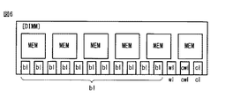
図3は、一般的なメモリモジュールの構成例を模式的に示すブロック図であり、図4は、図2に示すメモリセルアレイを適用したメモリモジュールの一例を模式的に示すブロック図である。なお、図3および図4は、DIMM(Dual Inline Memory Module)を模式的に示すものであり、データ信号線bl(データチェック用信号線cbl)を11本として描き、制御線wl(データチェック用制御線cwl)を1本として描いている。 FIG. 3 is a block diagram schematically showing a configuration example of a general memory module, and FIG. 4 is a block diagram schematically showing an example of a memory module to which the memory cell array shown in FIG. 2 is applied. Note that FIGS. 3 and 4 schematically show DIMMs (Dual Inline Memory Modules), in which 11 data signal lines bl (data check signal lines cbl) are drawn and control lines wl (data check) are drawn. The control line cwl) is drawn as one line.
図1および図2を参照して説明したように、バス競合を回避することができるメモリセルmcでは、4種類の信号線bl,wl,cbl,cwlが使用される。そのため、図4に示されるように、図2に示すメモリセルアレイを適用したメモリモジュールでは、図3の一般的なメモリモジュールに対して、2倍の信号線が使用されることになり、バス幅の増大を来すことになる。 As described with reference to FIGS. 1 and 2, four types of signal lines bl, wl, cbl, and cwl are used in the memory cell mc that can avoid bus contention. Therefore, as shown in FIG. 4, in the memory module to which the memory cell array shown in FIG. 2 is applied, twice the signal line is used as compared with the general memory module in FIG. 3, and the bus width is doubled. Will come to an increase.
これは、メモリモジュール(DIMM)のピン数の増加だけでなく、例えば、CPUでも、同様にバスを増設することが求められる。さらに、内蔵メモリとして適用する場合でも、バス幅の増大を来すのは同様であり、チップ面積の増大によるコスト上昇等を招くことになる。 This is not only required to increase the number of pins of the memory module (DIMM), but also to increase the number of buses in the CPU, for example. Further, even when it is applied as a built-in memory, the bus width is similarly increased, which leads to an increase in cost due to an increase in chip area.
図5は、図1に示すメモリセルを適用したメモリセルアレイの他の例を示すブロック図であり、チェック回路(チェックサム生成回路)CCを内蔵したメモリセルアレイを示すものである。図6は、図5に示すメモリセルアレイを適用したメモリモジュールの一例を模式的に示すブロック図である。 FIG. 5 is a block diagram showing another example of a memory cell array to which the memory cell shown in FIG. 1 is applied, and shows a memory cell array incorporating a check circuit (checksum generation circuit) CC. FIG. 6 is a block diagram schematically showing an example of a memory module to which the memory cell array shown in FIG. 5 is applied.
図5および図6と、前述した図2および図4の比較から明らかなように、チェック回路CCを内蔵したメモリセルアレイを適用したメモリモジュール(DIMM)では、例えば、11本のデータチェック用信号線cblを1本に低減することが可能なのが分かる。すなわち、メモリモジュール内にチェックサム生成回路(チェック回路)を増設することで、メモリモジュール内で複数のcbl(cbl1〜cbl3)を1つの信号線clにまとめてCPUに接続する。この手法を適用することにより、メモリモジュールのピン数(CPUのバス幅)を低減することができ、例えば、図3に示す一般的なDIMMに対してわずかな数の信号線を増設するだけでよいことになる。 As is clear from the comparison between FIGS. 5 and 6 and FIGS. 2 and 4 described above, in a memory module (DIMM) to which a memory cell array with a built-in check circuit CC is applied, for example, 11 data check signal lines are used. It can be seen that the cbl can be reduced to one. That is, by adding a checksum generation circuit (check circuit) in the memory module, a plurality of cbl (cbl1 to cbl3) are collectively connected to the CPU in one signal line cl in the memory module. By applying this method, the number of pins of the memory module (CPU bus width) can be reduced. For example, it is only necessary to add a small number of signal lines to the general DIMM shown in FIG. It will be good.
さらに、ECC(エラー検出訂正コード)とチェックサムの2種類のエラーチェックコードを用いることで、メモリへのデータ書き込み時のエラー、並びに、メモリからのデータ読み出し時のエラーを切り分けることが可能となる。すなわち、チェックサムによる検査時点でエラーを検出した場合には、書き込み時のエラーであり、ECCでエラー検出した場合には、読み出し時のエラーであると判別することができる。 Furthermore, by using two types of error check codes, ECC (error detection and correction code) and checksum, it is possible to isolate an error when writing data to the memory and an error when reading data from the memory. .. That is, if an error is detected at the time of inspection by the checksum, it can be determined that it is an error at the time of writing, and if an error is detected by ECC, it can be determined that it is an error at the time of reading.
しかしながら、図1に示すメモリセルを適用すると、例えば、データエラーチェックにより生じるレイテンシの増加を根本的に解決したことにはならない。すなわち、図1のメモリセルにおいて、データエラーチェックを行う場合、キャパシタ103の電荷が放電されることになるためプリチャージ処理が必要となり、この間、通常のデータ読み書きの処理を実行することが困難になる。換言すると、図1に示すメモリセル構造を適用した場合、例えば、CPUがメモリからデータを読み出す際に、データチェック後と通常のデータ読み出し後の計2回プリチャージ処理が必要になり、レイテンシの増加を招くことになる。
However, applying the memory cells shown in FIG. 1 does not fundamentally solve the increase in latency caused by, for example, data error checking. That is, when performing a data error check in the memory cell of FIG. 1, the charge of the
以下、メモリセル、メモリモジュール、情報処理装置およびメモリセルのエラー訂正方法の実施例を、添付図面を参照して詳述する。図7は、本実施例のメモリセルを示す回路図である。図7に示されるように、本実施例のメモリセルMCは、2つのトランジスタ1,2および三重構造のキャパシタ3を含む。
Hereinafter, examples of a memory cell, a memory module, an information processing device, and an error correction method for the memory cell will be described in detail with reference to the accompanying drawings. FIG. 7 is a circuit diagram showing a memory cell of this embodiment. As shown in FIG. 7, the memory cell MC of this embodiment includes two
すなわち、キャパシタ3は、積層された第1電極(導体)31,第2電極32および第3電極33を含む三重構造とされ、第1電極31と第2電極32間には、第1誘電体層34が設けられ、第2電極32と第3電極33間には、第2誘電体層35が設けられている。ここで、電極31〜33は、例えば、アルミニウムや銅といった金属、或いは、ポリシリコン等の導電性物質で形成され、また、誘電体層34,35は、例えば、酸化シリコンや窒化シリコン等の誘電体物質で形成される。
That is, the
トランジスタ(第1トランジスタ)1およびトランジスタ(第2トランジスタ)2は、例えば、nチャネル型MOSトランジスタで形成されるが、これに限定されないのはもちろんである。トランジスタ1において、ゲート(制御端子)Gは、制御線wlに接続され、ソース(第1端子)Sは、データ信号線blに接続され、そして、ドレイン(第2端子)Dは、キャパシタ3の第1電極31に接続されている。また、トランジスタ2において、ゲートGは、データチェック用制御線cwlに接続され、ソースSは、キャパシタ3の第2電極32に接続され、そして、ドレインDは、接地線(所定電位線)GNDに接続されている。ここで、キャパシタ3の第3電極33は、データチェック用信号線cblに接続されている。
The transistor (first transistor) 1 and the transistor (second transistor) 2 are formed of, for example, an n-channel type MOS transistor, but the transistor is not limited to this, of course. In
図8は、図1に示すメモリセルにおける電荷状態の遷移を説明するための図であり、図9は、図7に示すメモリセルにおける電荷状態の遷移を説明するための図である。すなわち、図7に示す本実施例のメモリセルMCの動作を、図1に示す関連技術のメモリセルの動作と比較して説明する。ここで、図8(a)および図9(a)は、データチェック前の充電状態を示し、図8(b)および図9(b)は、データチェック後の放電状態を示し、図8(c)は、プリチャージ後の充電状態を示し、そして、図8(d)および図9(c)は、データ読み出し後の放電状態を示す。なお、以下の説明では、トランジスタ1,2および101,102をnチャネル型MOSトランジスタとして説明するが、トランジスタの導電型および種類、並びに、制御信号のレベル等は、様々に変形および変更が可能なのはいうまでもない。
FIG. 8 is a diagram for explaining the transition of the charge state in the memory cell shown in FIG. 1, and FIG. 9 is a diagram for explaining the transition of the charge state in the memory cell shown in FIG. 7. That is, the operation of the memory cell MC of the present embodiment shown in FIG. 7 will be described in comparison with the operation of the memory cell of the related technique shown in FIG. Here, FIGS. 8 (a) and 9 (a) show the charging state before the data check, and FIGS. 8 (b) and 9 (b) show the discharging state after the data check. c) shows the charge state after precharging , and FIGS. 8 (d) and 9 (c) show the discharge state after reading the data. In the following description, the
最初に、図8(a)〜図8(d)を参照して、キャパシタ103が2枚の電極131,132の図1に示すメモリセルmcの動作を説明する。まず、データ書き込みは、例えば、データチェック用制御線cwlを低レベル『L』として、トランジスタ102をオフする。そして、一般的なDRAMセルと同様に、制御線wlを高レベル『H』として、トランジスタ101をオンし、データ信号線blと接地線GND間の電位差によりキャパシタ103に電荷を蓄積してデータ書き込みを行い、この状態を初期状態とする。なお、メモリセルmcに対するデータの書き込みを行った後、wlを『L』としてトランジスタ101もオフする。すなわち、図8(a)に示されるように、初期状態では、例えば、データ『1』に相当する充電状態(データチェック前の充電状態)となっており、キャパシタ103の電極131と132の間(誘電体層133)には、電荷が蓄積されている。
First, the operation of the memory cell mc shown in FIG. 1 of the
さらに、メモリセルmcに書き込まれたデータのエラーチェックを行うために、メモリセルmcのデータを読み出す。すなわち、wlを『L』としたまま、cwlを『H』として、トランジスタ102をオンし、キャパシタ103に蓄積された電荷を、データチェック用信号線cblから取り出す。これにより、図8(b)に示されるように、キャパシタ103の電極131と132の間の電荷は放電され、データチェック後の放電状態となる。
Further, in order to check the error of the data written in the memory cell mc, the data in the memory cell mc is read out. That is, the
そこで、wlを『L』とすると共に、wlを『H』としてプリチャージ処理を実行し、キャパシタ103を再充電する。すなわち、図8(c)に示されるように、プリチャージ処理により電極131と132の間に電荷が蓄積されてプリチャージ後の充電状態となり、例えば、CPUからメモリセル(メモリ)のデータを読み出すことが可能となる。
Therefore, the precharge process is executed with wl set to "L" and wl set to "H" to recharge the
メモリのデータ読み出しは、データ書き込みと同様に、cwlを『L』としてトランジスタ102をオフしたまま、wlを『H』としてトランジスタ101をオンし、キャパシタ103に蓄積された電荷を、blから読み出す。これにより、図8(d)に示されるように、キャパシタ103の電極131と132の間の電荷は放電され、データ読み出し後の放電状態となる。
Similar to the data writing, the memory data reading is performed by turning on the
次に、図9(a)〜図9(c)を参照して、キャパシタ3の電極が三重構造(電極(導体)31〜33)の図7に示すメモリセルMCの動作を説明する。まず、データ書き込みは、例えば、データチェック用制御線cwlを『L』としてトランジスタ2をオフし、中央の(第2)電極32をフローティング状態とし、この状態で、制御線wlを『H』としてトランジスタ1をオンする。そして、データ信号線blとデータチェック用信号線cblの電位差によりキャパシタ3に電荷を蓄積してデータ書き込みを行い、この状態を初期状態(データ『1』に相当する充電状態:データチェック前の充電状態)とする。換言すると、キャパシタ3において、第2電極はフローティング状態とされ、第1電極31および第3電極33により書き込みが行われる。すなわち、図9(a)に示されるように、初期状態では、キャパシタ3の電極31と32の間(第1誘電体層34)、および、電極32と33の間(第2誘電体層35)には、それぞれ電荷が蓄積されている。
Next, the operation of the memory cell MC shown in FIG. 7 in which the electrodes of the
さらに、メモリセルMCに書き込まれたデータのエラーチェックを行うために、メモリセルMCのデータ(第2誘電体層35に蓄積された電荷)を読み出す。すなわち、cwlを『H』としてトランジスタ2をオンして第2電極32を接地線GNDに接続し、wlを『L』としてトランジスタ1をオフし、第2誘電体層35に蓄積された電荷をデータチェック用信号線cblから取り出す。これにより、図9(b)に示されるように、キャパシタ3において、第2電極32と第3電極33の間(第2誘電体層35)の電荷は放電されるが、第1電極31と第2電極32の間(第1誘電体層34)の電荷はそのまま保持される。
Further, in order to perform an error check of the data written in the memory cell MC, the data of the memory cell MC (the electric charge accumulated in the second dielectric layer 35) is read out. That is, the transistor 2 is turned on with cwl set to "H", the
そして、メモリのデータ読み出しは、メモリセルMCのデータ(第1誘電体層34に蓄積された電荷)を読み出す。すなわち、cwlを『H』としてトランジスタ2をオンして第2電極32を接地線GNDに接続し、wlを『H』としてトランジスタ1をオンし、第1誘電体層34に蓄積された電荷をデータ信号線blから取り出す。これにより、図9(c)に示されるように、キャパシタ3において、第1電極31と第2電極32の間(第1誘電体層34)の電荷は放電され、データ読み出し後の放電状態となる。すなわち、キャパシタ3は、完全に放電状態となる。
Then, the data read of the memory reads the data of the memory cell MC (the electric charge accumulated in the first dielectric layer 34). That is, the transistor 2 is turned on with cwl set to "H", the
このように、図7に示す本実施例のメモリセルを適用することにより、例えば、図1に示す関連技術のメモリセルを適用した場合におけるデータチェック後のプリチャージ処理を不要とすることができる。すなわち、本実施例によれば、データチェック後のプリチャージ処理に要する時間を削減することができ、例えば、CPUからメモリへのアクセス時のレイテンシの増加を抑えることが可能となる。 As described above, by applying the memory cell of the present embodiment shown in FIG. 7, for example, when the memory cell of the related technique shown in FIG. 1 is applied, the precharge process after the data check can be eliminated. .. That is, according to this embodiment, it is possible to reduce the time required for the precharge process after the data check, and for example, it is possible to suppress an increase in latency when accessing the memory from the CPU.
図10は、図1に示すメモリセルを適用したメモリにおけるデータ書き込み動作を説明するための図であり、図11は、図1に示すメモリセルを適用したメモリにおけるデータ読み出し動作を説明するための図である。なお、図10および図11において、参照符号104はCPU、141はMAC(メモリアクセス制御回路:Memory Access Controller),142はECCD(Error Correction Code Decoder)、105はメモリ、そして、151はセルアレイを示す。
FIG. 10 is a diagram for explaining a data writing operation in the memory to which the memory cell shown in FIG. 1 is applied, and FIG. 11 is a diagram for explaining a data reading operation in the memory to which the memory cell shown in FIG. 1 is applied. It is a figure. In FIGS. 10 and 11,
まず、図10に示されるように、データ書き込みは、例えば、MAC141からセルアレイ(メモリセルアレイ)151に対して、wlを使用した書き込みデータアドレス情報とb1を使用した書き込み情報の2種類の信号を転送して、データ書き込みを行う。
First, as shown in FIG. 10, in data writing, for example, two types of signals, write data address information using wl and write information using b1, are transferred from
また、図11に示されるように、データ読み出しは、例えば、MAC141からセルアレイ151に対して、wlを使用した読み出しデータアドレス情報の信号を送信する(P11)。これに基づいて、セルアレイ151は、CPU104のECCD142に対して、b1を経由して読み出し情報(チェック用データ)を転送する(P12)。CPU104において、ECCD142は、読み出し情報のエラーチェックを実施した後、そのチェック済み情報をMAC141にデータ転送する(P13)。
Further, as shown in FIG. 11, for data reading, for example, a signal of read data address information using wl is transmitted from
次に、図12および図13を参照して、図7に示す本実施例のメモリセルを適用したメモリにおけるデータ書き込み動作およびデータ書き込み動作を説明する。図12は、図7に示すメモリセルを適用したメモリにおけるデータ書き込み動作を説明するための図であり、チェックサム専用線とメモリモジュール内チェック回路を使用したデータ書き込み動作を説明するためのものである。また、図13は、図7に示すメモリセルを適用したメモリにおけるデータ読み出し動作を説明するための図であり、チェックサム専用線とメモリモジュール内チェック回路を使用したデータ読み出し動作を説明するためのものである。 Next, a data writing operation and a data writing operation in the memory to which the memory cell of this embodiment shown in FIG. 7 is applied will be described with reference to FIGS. 12 and 13. FIG. 12 is a diagram for explaining a data writing operation in the memory to which the memory cell shown in FIG. 7 is applied, and is for explaining a data writing operation using a checksum dedicated line and a check circuit in a memory module. be. Further, FIG. 13 is a diagram for explaining a data read operation in the memory to which the memory cell shown in FIG. 7 is applied, and is for explaining a data read operation using the checksum dedicated line and the check circuit in the memory module. It is a thing.
ここで、図12および図13では、CPU4とメモリ5の間にチェックサム専用線(データチェック用信号線cbl)が設けられ、メモリ5にはチェック回路52が内蔵されている。なお、図12および図13において、参照符号4はCPU、41はMAC(メモリアクセス制御回路),42はECCD、43は比較回路、5はメモリ、51はセルアレイ、そして、52チェック回路を示す。
Here, in FIGS. 12 and 13, a checksum dedicated line (data check signal line cbl) is provided between the
図12に示されるように、書き込みは、例えば、CPU4のMAC41から、メモリ5のセルアレイ51に対して、wlを使用した書き込みデータアドレス情報とb1を使用した書き込み情報の2種類の信号を転送する(P1)。さらに、MAC41は、メモリ5(セルアレイ51)に書き込んだデータのチェックサムを算出してCPU4の比較回路43に送信し、同時に、セルアレイ51に対して、cwlを経由してチェック対象データのアドレス情報を送信する(P2)。
As shown in FIG. 12, for writing, for example, two types of signals, write data address information using wl and write information using b1, are transferred from the
セルアレイ51は、cwlを経由して受け取ったアドレス情報に基づいて、チェック回路52を使って対象データのチェックサムを計算し、チェック回路52は、計算した対象データのチェックサムを、cblを経由してCPU4の比較回路43に送信する(P3)。比較回路43では、MAC41からのチェックサムと、メモリ5(チェック回路52)からのチェックサムを比較することでデータの破損を検出する。そして、比較回路43がチェックサムに比較からデータの破損を検出すると、CPU4は、直ちにデータの再書き込みを行う。同時に、blからの書き込み対象のデータを、wlからのアドレス情報に基づいて格納する。
The
また、図13に示されるように、データ読み出しは、例えば、MAC41からセルアレイ51に対して、wlを使用した読み出しデータアドレス情報の信号を送信する(P4)。これに基づいて、セルアレイ51は、CPU4のECCD42に対して、b1を経由して読み出し情報を転送する(P5)。ECCD42は、読み出し情報のエラーチェックを実施した後、そのチェック済み情報をMAC41にデータ転送する(P5)。このように、図7に示す本実施例のメモリセルMCを適用したメモリによれば、メモリに対するデータの書き込みチェック後のプリチャージ動作が不要となり、レイテンシの増加を抑えることができることが分かる。
Further, as shown in FIG. 13, for data reading, for example, a signal of read data address information using wl is transmitted from the
以上において、本実施例のメモリセルMCを適用したメモリは、例えば、前述した図4に示すDIMM、チェック回路52(CC)を設けたDIMM、或いは、HBM(High Bandwidth Memory)といった様々なメモリモジュールに適用することができる。さらに、本実施例のメモリセルMCを適用したメモリは、メモリモジュールとして提供するものに限定されず、例えば、半導体集積回路の内蔵メモリとして利用することもできるのはいうまでもない。 In the above, the memory to which the memory cell MC of this embodiment is applied is, for example, various memory modules such as the DIMM shown in FIG. 4, the DIMM provided with the check circuit 52 (CC), or the HBM (High Bandwidth Memory). Can be applied to. Further, it goes without saying that the memory to which the memory cell MC of this embodiment is applied is not limited to the one provided as a memory module, and can be used, for example, as a built-in memory of a semiconductor integrated circuit.
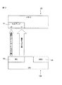
図14は、本実施例の情報処理装置の一例を示すブロック図である。図14において、参照符号6は情報処理装置、61は電源回路、62はハードディスクドライブ(HDD:Hard Disk Drive)/ソリッドステートドライブ(SSD:Solid State Drive)、63はチップセット、64はCPU、そして、65はDIMM/HBMを示す。すなわち、図14に示す情報処理装置6は、電源回路61、HDD/SSD62、チップセット63、CPU64およびDIMM/HBM65を含む。なお、上述した本実施例のメモリセルMC(メモリモジュール)は、DMM/HBM65に適用される。
FIG. 14 is a block diagram showing an example of the information processing apparatus of this embodiment. In FIG. 14,
図15は、本実施例の情報処理装置の他の例を示すブロック図であり、上述した図14に示す情報処理装置6を4つ設けて構成したものに相当する。すなわち、図16に示す情報処理装置60は、4つのブロック回路6a〜6dを含み、それぞれのブロック回路6a〜6dは、図14に示す情報処理装置6に対して、相互のブロック回路を接続するためのスイッチチップ66を内蔵するようになっている。なお、前述した本実施例のメモリセルMCは、それぞれのブロック回路6a〜6dにおけるDMM/HBM65に適用される。
FIG. 15 is a block diagram showing another example of the information processing apparatus of this embodiment, and corresponds to the configuration in which four
このように、本実施例のメモリセルMCおよびメモリモジュールは、様々な情報処理装置6,60に対して適用することができる。さらに、これは、DIMMやHBMといったメモリモジュールだけでなく、様々な半導体集積回路の内蔵メモリとして適用することも可能なのは、前述した通りである。
As described above, the memory cell MC and the memory module of this embodiment can be applied to various
以上、実施形態を説明したが、ここに記載したすべての例や条件は、発明および技術に適用する発明の概念の理解を助ける目的で記載されたものであり、特に記載された例や条件は発明の範囲を制限することを意図するものではない。また、明細書のそのような記載は、発明の利点および欠点を示すものでもない。発明の実施形態を詳細に記載したが、各種の変更、置き換え、変形が発明の精神および範囲を逸脱することなく行えることが理解されるべきである。 Although the embodiments have been described above, all the examples and conditions described here are described for the purpose of assisting the understanding of the concept of the invention applied to the invention and the technology, and the examples and conditions described in particular are described. It is not intended to limit the scope of the invention. Nor does such a statement in the specification indicate the advantages and disadvantages of the invention. Although embodiments of the invention have been described in detail, it should be understood that various modifications, replacements and modifications can be made without departing from the spirit and scope of the invention.
1 トランジスタ(第1トランジスタ)
2 トランジスタ(第2トランジスタ)
3 キャパシタ
4,64 CPU
5 メモリ
6,60 情報処理装置
6a〜6d ブロック回路
31 電極(第1電極)
32 電極(第2電極)
33 電極(第3電極)
34 誘電体層(第1誘電体層)
35 誘電体層(第2誘電体層)
41 MAC
42 ECCD
43 比較回路
51 セルアレイ
52 チェック回路
61 電源回路
62 HDD/SSD
63 チップセット
65 DIMM/HBM
1 transistor (first transistor)
2 transistors (2nd transistor)
3
5
32 electrode (second electrode)
33 Electrode (3rd electrode)
34 Dielectric layer (first dielectric layer)
35 Dielectric layer (second dielectric layer)
41 MAC
42 ECCD
43
63
Claims (14)
制御線に接続された制御端子、データ信号線に接続された第1端子および前記第1電極に接続された第2端子を含む第1トランジスタと、
データチェック用制御線に接続された制御端子、前記第2電極に接続された第1端子および所定電位線に接続された第2端子を含む第2トランジスタと、を有し、
前記第3電極は、データチェック用信号線に接続され、
データ書き込み時には、
前記データチェック用制御線の信号により前記第2トランジスタをオフし、
前記制御線の信号に基づいて前記第1トランジスタを制御し、前記第1電極と前記第3電極の間に、前記データ信号線と前記データチェック用信号線の差電圧に基づく電荷の蓄積を制御し、
チェック時には、
前記制御線の信号により前記第1トランジスタをオフし、
前記データチェック用制御線の信号に基づいて前記第2トランジスタを制御し、前記所定電位線に接続された前記第2電極と前記第3電極の間に蓄積された電荷に基づくデータを、前記データチェック用信号線から取り出す、
ことを特徴とするメモリセル。 A capacitor that includes a laminated first electrode, second electrode, and third electrode and is capable of accumulating charges between the first electrode and the second electrode, and between the second electrode and the third electrode.
A first transistor including a control terminal connected to a control line, a first terminal connected to a data signal line, and a second terminal connected to the first electrode.
It has a control terminal connected to a data check control line, a first terminal connected to the second electrode, and a second transistor including a second terminal connected to a predetermined potential line.
The third electrode is connected to a data check signal line and is connected to the data check signal line .
When writing data
The second transistor is turned off by the signal of the data check control line, and the second transistor is turned off.
The first transistor is controlled based on the signal of the control line, and the accumulation of electric charge based on the difference voltage between the data signal line and the data check signal line is controlled between the first electrode and the third electrode. death,
At the time of check
The first transistor is turned off by the signal of the control line, and the first transistor is turned off.
The second transistor is controlled based on the signal of the control line for data check, and the data based on the electric charge accumulated between the second electrode and the third electrode connected to the predetermined potential line is obtained as the data. Take out from the check signal line ,
A memory cell characterized by that.
前記第1電極と前記第2電極間に設けられた第1誘電体層と、
前記第2電極と前記第3電極間に設けられた第2誘電体層と、を含む、
ことを特徴とする請求項1に記載のメモリセル。 The capacitor is further
A first dielectric layer provided between the first electrode and the second electrode,
A second dielectric layer provided between the second electrode and the third electrode is included.
The memory cell according to claim 1.
ことを特徴とする請求項1または請求項2に記載のメモリセル。 The first transistor and the second transistor are n-channel type MOS transistors.
The memory cell according to claim 1 or 2, wherein the memory cell is characterized in that.
前記データチェック用信号線から取り出したデータが、前記データ書き込み時に書き込むデータと異なっているときは、データ書き込みを再度行う、
ことを特徴とする請求項1乃至請求項3のいずれか1項に記載のメモリセル。 At the time of the check
If the data taken out from the data check signal line is different from the data to be written at the time of writing the data, the data is written again.
The memory cell according to any one of claims 1 to 3, wherein the memory cell is characterized in that.
前記データチェック用制御線の信号により前記第2トランジスタをオンし、
前記制御線の信号に基づいて前記第1トランジスタを制御し、前記第2電極と前記第1電極の間に蓄積された電荷に基づくデータを、前記データ信号線から取り出す、
ことを特徴とする請求項1乃至請求項4のいずれか1項に記載のメモリセル。 When reading data
The second transistor is turned on by the signal of the data check control line, and the second transistor is turned on.
The first transistor is controlled based on the signal of the control line, and the data based on the charge accumulated between the second electrode and the first electrode is taken out from the data signal line.
Memory cell according to any one of claims 1 to 4, characterized in that.
ことを特徴とする請求項1乃至請求項5のいずれか1項に記載のメモリセル。 The memory cell is a DRAM cell.
The memory cell according to any one of claims 1 to 5, wherein the memory cell.
ことを特徴とするメモリモジュール。 The memory cell according to any one of claims 1 to 6.
A memory module characterized by that.
チェック時において、前記データチェック用信号線から取り出したデータが、データ書き込み時に書き込むデータと異なっているかどうかをチェックするチェック回路を有する、
ことを特徴とする請求項7に記載のメモリモジュール。 Moreover,
It has a check circuit for checking whether the data taken out from the data check signal line at the time of checking is different from the data written at the time of writing data.
The memory module according to claim 7.
ことを特徴とする請求項7または請求項8に記載のメモリモジュール。 The memory module is a DIMM.
The memory module according to claim 7 or 8.
ことを特徴とする情報処理装置。 A memory module according to any one of claims 7 to 9,
An information processing device characterized by this.
前記メモリセルは、
積層された第1電極,第2電極および第3電極を含み、前記第1電極と前記第2電極間、並びに、前記第2電極と前記第3電極間に電荷を蓄積可能なキャパシタと、
制御線に接続された制御端子、データ信号線に接続された第1端子および前記第1電極に接続された第2端子を含む第1トランジスタと、
データチェック用制御線に接続された制御端子、前記第2電極に接続された第1端子および所定電位線に接続された第2端子を含む第2トランジスタと、を有し、
前記第3電極は、データチェック用信号線に接続され、
データ書き込み時には、
前記データチェック用制御線の信号により前記第2トランジスタをオフし、
前記制御線の信号に基づいて前記第1トランジスタを制御し、前記第1電極と前記第3電極の間に、前記データ信号線と前記データチェック用信号線の差電圧に基づく電荷の蓄積を制御し、
チェック時には、
前記制御線の信号により前記第1トランジスタをオフし、
前記データチェック用制御線の信号に基づいて前記第2トランジスタを制御し、前記所定電位線に接続された前記第2電極と前記第3電極の間に蓄積された電荷に基づくデータを、前記データチェック用信号線から取り出し、
前記チェック時において、
前記データチェック用信号線から取り出したデータが、前記データ書き込み時に書き込むデータと異なっているときは、データ書き込みを再度行ってエラーを訂正する、
ことを特徴とするメモリセルのエラー訂正方法。 A error correction method of the eye Moriseru,
The memory cell is
A capacitor that includes a laminated first electrode, second electrode, and third electrode and is capable of accumulating charges between the first electrode and the second electrode, and between the second electrode and the third electrode.
A first transistor including a control terminal connected to a control line, a first terminal connected to a data signal line, and a second terminal connected to the first electrode.
It has a control terminal connected to a data check control line, a first terminal connected to the second electrode, and a second transistor including a second terminal connected to a predetermined potential line.
The third electrode is connected to a data check signal line and is connected to the data check signal line.
When writing data
The second transistor is turned off by the signal of the data check control line, and the second transistor is turned off.
The first transistor is controlled based on the signal of the control line, and the accumulation of electric charge based on the difference voltage between the data signal line and the data check signal line is controlled between the first electrode and the third electrode. death,
At the time of check
The first transistor is turned off by the signal of the control line, and the first transistor is turned off.
The second transistor is controlled based on the signal of the control line for data check, and the data based on the electric charge accumulated between the second electrode and the third electrode connected to the predetermined potential line is obtained as the data. Take out from the check signal line
At the time of the check
If the data taken out from the data check signal line is different from the data to be written at the time of writing the data, the data is written again to correct the error.
A memory cell error correction method characterized by this.
前記第1電極と前記第2電極間に設けられた第1誘電体層と、A first dielectric layer provided between the first electrode and the second electrode,
前記第2電極と前記第3電極間に設けられた第2誘電体層と、を含む、A second dielectric layer provided between the second electrode and the third electrode is included.
ことを特徴とする請求項11に記載のメモリセルのエラー訂正方法。The memory cell error correction method according to claim 11.
ことを特徴とする請求項11または請求項12に記載のメモリセルのエラー訂正方法。 The memory cell error correction method according to claim 11 or 12.
前記データチェック用制御線の信号により前記第2トランジスタをオンし、
前記制御線の信号に基づいて前記第1トランジスタを制御し、前記第2電極と前記第1電極の間に蓄積された電荷に基づくデータを、前記データ信号線から取り出し、
エラー検出訂正コードに基づくエラー訂正を行う、
ことを特徴とする請求項11乃至請求項13のいずれか1項に記載のメモリセルのエラー訂正方法。 When reading data
The second transistor is turned on by the signal of the data check control line, and the second transistor is turned on.
The first transistor is controlled based on the signal of the control line, and the data based on the charge accumulated between the second electrode and the first electrode is taken out from the data signal line.
Perform error correction based on the error detection correction code,
The memory cell error correction method according to any one of claims 11 to 13 , characterized in that.
Priority Applications (1)
| Application Number | Priority Date | Filing Date | Title |
|---|---|---|---|
| JP2017097095A JP6915372B2 (en) | 2017-05-16 | 2017-05-16 | Error correction method for memory cells, memory modules, information processing devices, and memory cells |
Applications Claiming Priority (1)
| Application Number | Priority Date | Filing Date | Title |
|---|---|---|---|
| JP2017097095A JP6915372B2 (en) | 2017-05-16 | 2017-05-16 | Error correction method for memory cells, memory modules, information processing devices, and memory cells |
Publications (3)
| Publication Number | Publication Date |
|---|---|
| JP2018195359A JP2018195359A (en) | 2018-12-06 |
| JP2018195359A5 JP2018195359A5 (en) | 2021-01-14 |
| JP6915372B2 true JP6915372B2 (en) | 2021-08-04 |
Family
ID=64570411
Family Applications (1)
| Application Number | Title | Priority Date | Filing Date |
|---|---|---|---|
| JP2017097095A Active JP6915372B2 (en) | 2017-05-16 | 2017-05-16 | Error correction method for memory cells, memory modules, information processing devices, and memory cells |
Country Status (1)
| Country | Link |
|---|---|
| JP (1) | JP6915372B2 (en) |
Family Cites Families (10)
| Publication number | Priority date | Publication date | Assignee | Title |
|---|---|---|---|---|
| JPH03138742A (en) * | 1989-10-25 | 1991-06-13 | Toshiba Corp | Memory system |
| JP3110032B2 (en) * | 1990-03-30 | 2000-11-20 | 株式会社東芝 | Ferroelectric memory |
| JPH0773698A (en) * | 1993-08-31 | 1995-03-17 | Mitsubishi Electric Corp | Multiport memory |
| JPH1093030A (en) * | 1996-09-17 | 1998-04-10 | Toshiba Corp | Ferroelectric nonvolatile memory |
| JP2001320030A (en) * | 2000-05-11 | 2001-11-16 | Nec Corp | Ferroelectric storage device and its manufacturing method |
| JP3938298B2 (en) * | 2001-11-22 | 2007-06-27 | 富士通株式会社 | Memory circuit having parity cell array |
| US7032142B2 (en) * | 2001-11-22 | 2006-04-18 | Fujitsu Limited | Memory circuit having parity cell array |
| US6809949B2 (en) * | 2002-05-06 | 2004-10-26 | Symetrix Corporation | Ferroelectric memory |
| US6750497B2 (en) * | 2002-08-22 | 2004-06-15 | Micron Technology, Inc. | High-speed transparent refresh DRAM-based memory cell |
| WO2011114866A1 (en) * | 2010-03-17 | 2011-09-22 | Semiconductor Energy Laboratory Co., Ltd. | Memory device and semiconductor device |
-
2017
- 2017-05-16 JP JP2017097095A patent/JP6915372B2/en active Active
Also Published As
| Publication number | Publication date |
|---|---|
| JP2018195359A (en) | 2018-12-06 |
Similar Documents
| Publication | Publication Date | Title |
|---|---|---|
| US11011248B2 (en) | DRAM retention test method for dynamic error correction | |
| KR102410566B1 (en) | Semiconductor memory devices, memory systems including the same and method of operating semiconductor memory devices | |
| US10431320B2 (en) | Semiconductor memory device, method of testing the same and method of operating the same | |
| US11188414B2 (en) | Memory system | |
| US20170185499A1 (en) | Memory device performing post package repair (ppr) operation | |
| US10614906B2 (en) | Semiconductor memory devices, memory systems and methods of operating semiconductor memory devices | |
| CN112384897B (en) | Apparatus and method for error correction coding and data bus inversion of semiconductor memory | |
| CN112116945A (en) | Semiconductor memory device and memory system | |
| CN110942798B (en) | Semiconductor memory device, memory system, and method of operating semiconductor memory device | |
| US10210942B2 (en) | Semiconductor memory device and method of operating the same | |
| US11270752B2 (en) | Semiconductor devices and refresh methods using the semiconductor devices | |
| CN112447224B (en) | Row hammer mitigation | |
| CN112631822A (en) | Memory, memory system having the same, and method of operating the same | |
| US7123501B2 (en) | Semiconductor memory device using ferroelectric capacitor, and semiconductor device with the same | |
| US20140068154A1 (en) | Semiconductor memory device | |
| CN107210060B (en) | Memory device, computing system and method of wordline down driving using virtual power network | |
| JP6915372B2 (en) | Error correction method for memory cells, memory modules, information processing devices, and memory cells | |
| US20170242754A1 (en) | Semiconductor device | |
| CN115148265A (en) | Memory device including calibration operation and transistor with adjustable threshold voltage | |
| JP2006338747A (en) | Ferroelectric memory device | |
| EP4312219A2 (en) | Memory system, operating method of the same, and controller of memory device | |
| US20230186960A1 (en) | Memory device, memory system having the same, and method of operating the same | |
| US20240170042A1 (en) | Memory device having architecture of voltage driver circuit and decoupling capacitor | |
| JP3858835B2 (en) | Memory cell capable of avoiding soft error and semiconductor memory device | |
| US9627020B1 (en) | Semiconductor device |
Legal Events
| Date | Code | Title | Description |
|---|---|---|---|
| A621 | Written request for application examination |
Free format text: JAPANESE INTERMEDIATE CODE: A621 Effective date: 20200213 |
|
| A521 | Written amendment |
Free format text: JAPANESE INTERMEDIATE CODE: A523 Effective date: 20201125 |
|
| A977 | Report on retrieval |
Free format text: JAPANESE INTERMEDIATE CODE: A971007 Effective date: 20201125 |
|
| A131 | Notification of reasons for refusal |
Free format text: JAPANESE INTERMEDIATE CODE: A131 Effective date: 20201215 |
|
| A521 | Written amendment |
Free format text: JAPANESE INTERMEDIATE CODE: A523 Effective date: 20210127 |
|
| TRDD | Decision of grant or rejection written | ||
| A01 | Written decision to grant a patent or to grant a registration (utility model) |
Free format text: JAPANESE INTERMEDIATE CODE: A01 Effective date: 20210615 |
|
| A61 | First payment of annual fees (during grant procedure) |
Free format text: JAPANESE INTERMEDIATE CODE: A61 Effective date: 20210628 |
|
| R150 | Certificate of patent or registration of utility model |
Ref document number: 6915372 Country of ref document: JP Free format text: JAPANESE INTERMEDIATE CODE: R150 |