JP6914911B2 - System for power exchange - Google Patents
System for power exchange Download PDFInfo
- Publication number
- JP6914911B2 JP6914911B2 JP2018506807A JP2018506807A JP6914911B2 JP 6914911 B2 JP6914911 B2 JP 6914911B2 JP 2018506807 A JP2018506807 A JP 2018506807A JP 2018506807 A JP2018506807 A JP 2018506807A JP 6914911 B2 JP6914911 B2 JP 6914911B2
- Authority
- JP
- Japan
- Prior art keywords
- vehicle
- power
- container
- strip
- power exchange
- Prior art date
- Legal status (The legal status is an assumption and is not a legal conclusion. Google has not performed a legal analysis and makes no representation as to the accuracy of the status listed.)
- Active
Links
- 230000007246 mechanism Effects 0.000 claims description 51
- 239000000446 fuel Substances 0.000 claims description 21
- 238000004891 communication Methods 0.000 claims description 17
- 239000000126 substance Substances 0.000 claims description 3
- 238000010348 incorporation Methods 0.000 claims 1
- 238000000034 method Methods 0.000 description 27
- 238000013461 design Methods 0.000 description 14
- 230000008569 process Effects 0.000 description 10
- 238000005516 engineering process Methods 0.000 description 8
- 230000003628 erosive effect Effects 0.000 description 6
- 230000006870 function Effects 0.000 description 5
- 238000000926 separation method Methods 0.000 description 5
- 230000008901 benefit Effects 0.000 description 3
- 238000013480 data collection Methods 0.000 description 3
- VNWKTOKETHGBQD-UHFFFAOYSA-N methane Chemical compound C VNWKTOKETHGBQD-UHFFFAOYSA-N 0.000 description 3
- 238000001514 detection method Methods 0.000 description 2
- 210000005069 ears Anatomy 0.000 description 2
- 238000009434 installation Methods 0.000 description 2
- 239000000463 material Substances 0.000 description 2
- 230000003287 optical effect Effects 0.000 description 2
- 239000003208 petroleum Substances 0.000 description 2
- 238000012545 processing Methods 0.000 description 2
- 229920000049 Carbon (fiber) Polymers 0.000 description 1
- 238000013459 approach Methods 0.000 description 1
- 230000001174 ascending effect Effects 0.000 description 1
- 238000003339 best practice Methods 0.000 description 1
- 239000004917 carbon fiber Substances 0.000 description 1
- 239000002826 coolant Substances 0.000 description 1
- 238000001816 cooling Methods 0.000 description 1
- 238000005260 corrosion Methods 0.000 description 1
- 230000007797 corrosion Effects 0.000 description 1
- 230000008878 coupling Effects 0.000 description 1
- 238000010168 coupling process Methods 0.000 description 1
- 238000005859 coupling reaction Methods 0.000 description 1
- 238000013500 data storage Methods 0.000 description 1
- 230000003247 decreasing effect Effects 0.000 description 1
- 238000011161 development Methods 0.000 description 1
- 230000018109 developmental process Effects 0.000 description 1
- 239000002283 diesel fuel Substances 0.000 description 1
- 238000007599 discharging Methods 0.000 description 1
- 230000005611 electricity Effects 0.000 description 1
- 210000000981 epithelium Anatomy 0.000 description 1
- 239000003502 gasoline Substances 0.000 description 1
- 230000005484 gravity Effects 0.000 description 1
- 230000006872 improvement Effects 0.000 description 1
- 238000003780 insertion Methods 0.000 description 1
- 230000037431 insertion Effects 0.000 description 1
- 238000004519 manufacturing process Methods 0.000 description 1
- 238000012986 modification Methods 0.000 description 1
- 230000004048 modification Effects 0.000 description 1
- 239000003345 natural gas Substances 0.000 description 1
- 230000008447 perception Effects 0.000 description 1
- 230000002093 peripheral effect Effects 0.000 description 1
- 238000002360 preparation method Methods 0.000 description 1
- 230000009467 reduction Effects 0.000 description 1
- 230000001172 regenerating effect Effects 0.000 description 1
- 230000008929 regeneration Effects 0.000 description 1
- 238000011069 regeneration method Methods 0.000 description 1
- 238000011160 research Methods 0.000 description 1
- 230000004044 response Effects 0.000 description 1
- 239000004576 sand Substances 0.000 description 1
- 230000006641 stabilisation Effects 0.000 description 1
- 238000011105 stabilization Methods 0.000 description 1
- 229910001220 stainless steel Inorganic materials 0.000 description 1
- 239000010935 stainless steel Substances 0.000 description 1
- 239000013589 supplement Substances 0.000 description 1
- 239000000725 suspension Substances 0.000 description 1
- 230000000007 visual effect Effects 0.000 description 1
- XLYOFNOQVPJJNP-UHFFFAOYSA-N water Substances O XLYOFNOQVPJJNP-UHFFFAOYSA-N 0.000 description 1
Images


Classifications
-
- B—PERFORMING OPERATIONS; TRANSPORTING
- B60—VEHICLES IN GENERAL
- B60L—PROPULSION OF ELECTRICALLY-PROPELLED VEHICLES; SUPPLYING ELECTRIC POWER FOR AUXILIARY EQUIPMENT OF ELECTRICALLY-PROPELLED VEHICLES; ELECTRODYNAMIC BRAKE SYSTEMS FOR VEHICLES IN GENERAL; MAGNETIC SUSPENSION OR LEVITATION FOR VEHICLES; MONITORING OPERATING VARIABLES OF ELECTRICALLY-PROPELLED VEHICLES; ELECTRIC SAFETY DEVICES FOR ELECTRICALLY-PROPELLED VEHICLES
- B60L53/00—Methods of charging batteries, specially adapted for electric vehicles; Charging stations or on-board charging equipment therefor; Exchange of energy storage elements in electric vehicles
- B60L53/80—Exchanging energy storage elements, e.g. removable batteries
-
- B—PERFORMING OPERATIONS; TRANSPORTING
- B60—VEHICLES IN GENERAL
- B60K—ARRANGEMENT OR MOUNTING OF PROPULSION UNITS OR OF TRANSMISSIONS IN VEHICLES; ARRANGEMENT OR MOUNTING OF PLURAL DIVERSE PRIME-MOVERS IN VEHICLES; AUXILIARY DRIVES FOR VEHICLES; INSTRUMENTATION OR DASHBOARDS FOR VEHICLES; ARRANGEMENTS IN CONNECTION WITH COOLING, AIR INTAKE, GAS EXHAUST OR FUEL SUPPLY OF PROPULSION UNITS IN VEHICLES
- B60K1/00—Arrangement or mounting of electrical propulsion units
- B60K1/04—Arrangement or mounting of electrical propulsion units of the electric storage means for propulsion
-
- B—PERFORMING OPERATIONS; TRANSPORTING
- B60—VEHICLES IN GENERAL
- B60L—PROPULSION OF ELECTRICALLY-PROPELLED VEHICLES; SUPPLYING ELECTRIC POWER FOR AUXILIARY EQUIPMENT OF ELECTRICALLY-PROPELLED VEHICLES; ELECTRODYNAMIC BRAKE SYSTEMS FOR VEHICLES IN GENERAL; MAGNETIC SUSPENSION OR LEVITATION FOR VEHICLES; MONITORING OPERATING VARIABLES OF ELECTRICALLY-PROPELLED VEHICLES; ELECTRIC SAFETY DEVICES FOR ELECTRICALLY-PROPELLED VEHICLES
- B60L53/00—Methods of charging batteries, specially adapted for electric vehicles; Charging stations or on-board charging equipment therefor; Exchange of energy storage elements in electric vehicles
- B60L53/30—Constructional details of charging stations
- B60L53/305—Communication interfaces
-
- B—PERFORMING OPERATIONS; TRANSPORTING
- B60—VEHICLES IN GENERAL
- B60L—PROPULSION OF ELECTRICALLY-PROPELLED VEHICLES; SUPPLYING ELECTRIC POWER FOR AUXILIARY EQUIPMENT OF ELECTRICALLY-PROPELLED VEHICLES; ELECTRODYNAMIC BRAKE SYSTEMS FOR VEHICLES IN GENERAL; MAGNETIC SUSPENSION OR LEVITATION FOR VEHICLES; MONITORING OPERATING VARIABLES OF ELECTRICALLY-PROPELLED VEHICLES; ELECTRIC SAFETY DEVICES FOR ELECTRICALLY-PROPELLED VEHICLES
- B60L53/00—Methods of charging batteries, specially adapted for electric vehicles; Charging stations or on-board charging equipment therefor; Exchange of energy storage elements in electric vehicles
- B60L53/60—Monitoring or controlling charging stations
- B60L53/65—Monitoring or controlling charging stations involving identification of vehicles or their battery types
-
- B—PERFORMING OPERATIONS; TRANSPORTING
- B60—VEHICLES IN GENERAL
- B60S—SERVICING, CLEANING, REPAIRING, SUPPORTING, LIFTING, OR MANOEUVRING OF VEHICLES, NOT OTHERWISE PROVIDED FOR
- B60S5/00—Servicing, maintaining, repairing, or refitting of vehicles
- B60S5/06—Supplying batteries to, or removing batteries from, vehicles
-
- B—PERFORMING OPERATIONS; TRANSPORTING
- B60—VEHICLES IN GENERAL
- B60K—ARRANGEMENT OR MOUNTING OF PROPULSION UNITS OR OF TRANSMISSIONS IN VEHICLES; ARRANGEMENT OR MOUNTING OF PLURAL DIVERSE PRIME-MOVERS IN VEHICLES; AUXILIARY DRIVES FOR VEHICLES; INSTRUMENTATION OR DASHBOARDS FOR VEHICLES; ARRANGEMENTS IN CONNECTION WITH COOLING, AIR INTAKE, GAS EXHAUST OR FUEL SUPPLY OF PROPULSION UNITS IN VEHICLES
- B60K1/00—Arrangement or mounting of electrical propulsion units
- B60K1/04—Arrangement or mounting of electrical propulsion units of the electric storage means for propulsion
- B60K2001/0405—Arrangement or mounting of electrical propulsion units of the electric storage means for propulsion characterised by their position
- B60K2001/0438—Arrangement under the floor
-
- B—PERFORMING OPERATIONS; TRANSPORTING
- B60—VEHICLES IN GENERAL
- B60K—ARRANGEMENT OR MOUNTING OF PROPULSION UNITS OR OF TRANSMISSIONS IN VEHICLES; ARRANGEMENT OR MOUNTING OF PLURAL DIVERSE PRIME-MOVERS IN VEHICLES; AUXILIARY DRIVES FOR VEHICLES; INSTRUMENTATION OR DASHBOARDS FOR VEHICLES; ARRANGEMENTS IN CONNECTION WITH COOLING, AIR INTAKE, GAS EXHAUST OR FUEL SUPPLY OF PROPULSION UNITS IN VEHICLES
- B60K1/00—Arrangement or mounting of electrical propulsion units
- B60K1/04—Arrangement or mounting of electrical propulsion units of the electric storage means for propulsion
- B60K2001/0455—Removal or replacement of the energy storages
- B60K2001/0472—Removal or replacement of the energy storages from below
-
- B—PERFORMING OPERATIONS; TRANSPORTING
- B60—VEHICLES IN GENERAL
- B60Y—INDEXING SCHEME RELATING TO ASPECTS CROSS-CUTTING VEHICLE TECHNOLOGY
- B60Y2200/00—Type of vehicle
- B60Y2200/90—Vehicles comprising electric prime movers
- B60Y2200/91—Electric vehicles
-
- Y—GENERAL TAGGING OF NEW TECHNOLOGICAL DEVELOPMENTS; GENERAL TAGGING OF CROSS-SECTIONAL TECHNOLOGIES SPANNING OVER SEVERAL SECTIONS OF THE IPC; TECHNICAL SUBJECTS COVERED BY FORMER USPC CROSS-REFERENCE ART COLLECTIONS [XRACs] AND DIGESTS
- Y02—TECHNOLOGIES OR APPLICATIONS FOR MITIGATION OR ADAPTATION AGAINST CLIMATE CHANGE
- Y02T—CLIMATE CHANGE MITIGATION TECHNOLOGIES RELATED TO TRANSPORTATION
- Y02T10/00—Road transport of goods or passengers
- Y02T10/60—Other road transportation technologies with climate change mitigation effect
- Y02T10/70—Energy storage systems for electromobility, e.g. batteries
-
- Y—GENERAL TAGGING OF NEW TECHNOLOGICAL DEVELOPMENTS; GENERAL TAGGING OF CROSS-SECTIONAL TECHNOLOGIES SPANNING OVER SEVERAL SECTIONS OF THE IPC; TECHNICAL SUBJECTS COVERED BY FORMER USPC CROSS-REFERENCE ART COLLECTIONS [XRACs] AND DIGESTS
- Y02—TECHNOLOGIES OR APPLICATIONS FOR MITIGATION OR ADAPTATION AGAINST CLIMATE CHANGE
- Y02T—CLIMATE CHANGE MITIGATION TECHNOLOGIES RELATED TO TRANSPORTATION
- Y02T10/00—Road transport of goods or passengers
- Y02T10/60—Other road transportation technologies with climate change mitigation effect
- Y02T10/7072—Electromobility specific charging systems or methods for batteries, ultracapacitors, supercapacitors or double-layer capacitors
-
- Y—GENERAL TAGGING OF NEW TECHNOLOGICAL DEVELOPMENTS; GENERAL TAGGING OF CROSS-SECTIONAL TECHNOLOGIES SPANNING OVER SEVERAL SECTIONS OF THE IPC; TECHNICAL SUBJECTS COVERED BY FORMER USPC CROSS-REFERENCE ART COLLECTIONS [XRACs] AND DIGESTS
- Y02—TECHNOLOGIES OR APPLICATIONS FOR MITIGATION OR ADAPTATION AGAINST CLIMATE CHANGE
- Y02T—CLIMATE CHANGE MITIGATION TECHNOLOGIES RELATED TO TRANSPORTATION
- Y02T90/00—Enabling technologies or technologies with a potential or indirect contribution to GHG emissions mitigation
- Y02T90/10—Technologies relating to charging of electric vehicles
- Y02T90/12—Electric charging stations
-
- Y—GENERAL TAGGING OF NEW TECHNOLOGICAL DEVELOPMENTS; GENERAL TAGGING OF CROSS-SECTIONAL TECHNOLOGIES SPANNING OVER SEVERAL SECTIONS OF THE IPC; TECHNICAL SUBJECTS COVERED BY FORMER USPC CROSS-REFERENCE ART COLLECTIONS [XRACs] AND DIGESTS
- Y02—TECHNOLOGIES OR APPLICATIONS FOR MITIGATION OR ADAPTATION AGAINST CLIMATE CHANGE
- Y02T—CLIMATE CHANGE MITIGATION TECHNOLOGIES RELATED TO TRANSPORTATION
- Y02T90/00—Enabling technologies or technologies with a potential or indirect contribution to GHG emissions mitigation
- Y02T90/10—Technologies relating to charging of electric vehicles
- Y02T90/14—Plug-in electric vehicles
-
- Y—GENERAL TAGGING OF NEW TECHNOLOGICAL DEVELOPMENTS; GENERAL TAGGING OF CROSS-SECTIONAL TECHNOLOGIES SPANNING OVER SEVERAL SECTIONS OF THE IPC; TECHNICAL SUBJECTS COVERED BY FORMER USPC CROSS-REFERENCE ART COLLECTIONS [XRACs] AND DIGESTS
- Y02—TECHNOLOGIES OR APPLICATIONS FOR MITIGATION OR ADAPTATION AGAINST CLIMATE CHANGE
- Y02T—CLIMATE CHANGE MITIGATION TECHNOLOGIES RELATED TO TRANSPORTATION
- Y02T90/00—Enabling technologies or technologies with a potential or indirect contribution to GHG emissions mitigation
- Y02T90/10—Technologies relating to charging of electric vehicles
- Y02T90/16—Information or communication technologies improving the operation of electric vehicles
- Y02T90/167—Systems integrating technologies related to power network operation and communication or information technologies for supporting the interoperability of electric or hybrid vehicles, i.e. smartgrids as interface for battery charging of electric vehicles [EV] or hybrid vehicles [HEV]
-
- Y—GENERAL TAGGING OF NEW TECHNOLOGICAL DEVELOPMENTS; GENERAL TAGGING OF CROSS-SECTIONAL TECHNOLOGIES SPANNING OVER SEVERAL SECTIONS OF THE IPC; TECHNICAL SUBJECTS COVERED BY FORMER USPC CROSS-REFERENCE ART COLLECTIONS [XRACs] AND DIGESTS
- Y04—INFORMATION OR COMMUNICATION TECHNOLOGIES HAVING AN IMPACT ON OTHER TECHNOLOGY AREAS
- Y04S—SYSTEMS INTEGRATING TECHNOLOGIES RELATED TO POWER NETWORK OPERATION, COMMUNICATION OR INFORMATION TECHNOLOGIES FOR IMPROVING THE ELECTRICAL POWER GENERATION, TRANSMISSION, DISTRIBUTION, MANAGEMENT OR USAGE, i.e. SMART GRIDS
- Y04S30/00—Systems supporting specific end-user applications in the sector of transportation
- Y04S30/10—Systems supporting the interoperability of electric or hybrid vehicles
- Y04S30/14—Details associated with the interoperability, e.g. vehicle recognition, authentication, identification or billing
Description
関連出願の相互参照
本出願は、2015年4月22日に出願された米国仮出願第62/150,937号及び2015年5月26日に出願された米国仮特許出願第62/166,339号の利益を請求し、これらの両出願は、参照により本明細書に組み込まれる。
Cross-reference to related applications This application is filed on April 22, 2015, US Provisional Application Nos. 62 / 150,937 and May 26, 2015, US Provisional Patent Application No. 62 / 166,339. Claiming the interests of No., both of these applications are incorporated herein by reference.
本発明は、バッテリなどの1つの電源を別の電源と置き換える(即ち、交換する)ことを含むがこれに限定されない、電源を交換するための方法及びシステムに関する。有利には、これは、電気自動車の電源の交換を含む。 The present invention relates to methods and systems for replacing power supplies, including but not limited to replacing (ie, replacing) one power source, such as a battery, with another. Advantageously, this involves replacing the power supply of the electric vehicle.
代替燃料自動車は、次第に一般的になっている。そのような車両は、ガソリンやディーゼル油などの従来の石油ではなく代替燃料源を使用する。幾つかの代替燃料源には、天然ガス、バッテリ/化学電源、燃料電池などが挙げられるが、これらに限定されない。従来車両と同様に、車両によって消費された燃料源を補給しなければならない。その結果、代替燃料自動車の燃料源を補給するための様々な補給、再充電、再生又は他の手段が開発された。 Alternative fuel vehicles are becoming more and more common. Such vehicles use alternative fuel sources rather than traditional petroleum such as gasoline and diesel oil. Some alternative fuel sources include, but are not limited to, natural gas, batteries / chemical power sources, fuel cells, and the like. As with conventional vehicles, the fuel source consumed by the vehicle must be replenished. As a result, various refueling, recharging, regeneration or other means have been developed to refuel the fuel sources of alternative fuel vehicles.
バッテリによって電力供給される代替燃料自動車は、多くの場合、車両に搭載されたバッテリを充電する適切な充電レセプタクルに車両を差し込むことによって充電される。これに対するひとつの最近の代替は、消耗した後の車両上のバッテリパックを満充電されたバッテリと交換することである。しかしながら、この分野で代替電動車両バッテリ交換を達成するための現在の技術は、バッテリ交換の際に車両を収容する設備の点で大きいインフラストラクチャと、一連の消耗バッテリを充電された交換用バッテリと交換するのに必要な機構とを必要とする。従って、そのようなシステムは、バッテリが消耗するたびに代替電動車両に補給する手段として実時間バッテリ交換を可能にする段階で経済的に実現できずかつ/又は開発されない。 Alternative fuel vehicles powered by batteries are often charged by plugging the vehicle into a suitable charging receptacle that charges the battery mounted on the vehicle. One recent alternative to this is to replace the exhausted battery pack on the vehicle with a fully charged battery. However, current technologies for achieving alternative electric vehicle battery replacement in this area include a large infrastructure in terms of equipment to accommodate the vehicle during battery replacement and a series of consumable batteries charged with replacement batteries. Requires the mechanism needed to replace it. Therefore, such a system cannot be economically realized and / or developed at the stage of enabling real-time battery replacement as a means of replenishing the alternative electric vehicle each time the battery is depleted.
この技術は、以下では自律型直線交換機構(Autonomous Linear Exchange)(ALE)として知られ、コンテナに収容された電源を有する車両の主電源を取り外し、受け取り、充電し、配置し、交換するための独特な方法及びシステムを含み、コンテナは、補助電力供給交換機構(Auxiliary Powered Exchange)を装備した車両の電源(バッテリバンク、燃料電池又は他の格納電源デバイス)を含む。これは、電気(例えば、バッテリ並びに燃料電池を利用するものを使用する)によって動作する装置を含む。より具体的には、この技術は、コンテナ又は他の交換式ユニット内に配置された電動車両の主駆動バッテリを交換するために使用されうる。しかしながら、この技術は、電気自動車を含む車両によって使用される様々なタイプの電源を含む任意の電源を交換するための使用に適応されうる。本発明は、前記電源、バッテリ又は燃料電池をきわめて高い効率及び単純さで受け取り、充電し、構成し、配置するように設計された据付型機器と、自動車設計に組み込むように意図され車両が据付型機器と相互作用することを可能にする構成要素及び専用モジュール式コンテナの両方に関する。 This technology, hereinafter referred to as the Autonomous Linear Exchange (ALE), is used to remove, receive, charge, place, and replace the main power of a vehicle with a power source housed in a container. Including unique methods and systems, the container includes vehicle power supplies (battery banks, fuel cells or other stored power devices) equipped with an Auxiliary Powered Exchange. This includes devices that are powered by electricity (eg, those that utilize batteries as well as fuel cells). More specifically, this technique can be used to replace the main drive battery of an electric vehicle located in a container or other replaceable unit. However, this technique can be adapted for use in replacing any power source, including the various types of power sources used by vehicles, including electric vehicles. The present invention includes stationary equipment designed to receive, charge, configure and deploy said power, battery or fuel cell with extremely high efficiency and simplicity, and vehicle installation intended to be incorporated into automotive design. It relates to both components and dedicated modular containers that allow it to interact with the type equipment.
1つの有利な形態では、適切な車両は、本開示で「コンテナ」と呼ばれる自律したバッテリバンク、バッテリパック、電力パック、セル(燃料電池などを含む)(集合的に1つ以上のセル又は別個電力ユニットを含みうる「電力セル」と一般に呼ばれる)を有する。また、このコンテナは、有利な実施形態では、オイル冷却器を含み、また、コンテナは、コンテナが主電力を車両に提供する自律型で取り外し可能な電源であることを可能にする他の要素を含みうる。このコンテナは、電力が消耗したときにこのシステムを使用して交換される。 In one advantageous form, suitable vehicles are autonomous battery banks, battery packs, power packs, cells (including fuel cells, etc.) (collectively one or more cells or separate cells) referred to herein as "containers". It has (commonly referred to as a "power cell") that can contain a power unit. The container also includes, in an advantageous embodiment, an oil cooler, and the container provides other elements that allow the container to be an autonomous, removable power source that provides main power to the vehicle. Can include. This container is replaced using this system when power is depleted.
更に、車両の主電源であるコンテナに加えて、車両は、コンテナ交換の際に支援する補助電源も有すると有利である。好ましくは、電力セル(コンテナ内)と補助電源は両方とも、車両を適切な充電コンセント/電源に差し込むことによって再充電されうる(メーカが望む場合はオプションとして)。 Further, in addition to the container which is the main power source of the vehicle, it is advantageous that the vehicle also has an auxiliary power source to assist in the container replacement. Preferably, both the power cell (inside the container) and the auxiliary power source can be recharged by plugging the vehicle into a suitable charging outlet / power source (optionally if the manufacturer so desires).
更に別の有利な形態では、車両内に交換コンテナを持ち上げる際にコンテナの電力セル内の電力を使用して電力が供給されうる。したがって、交換コンテナ内の電力セルは、車両の補助電源の使用を増強及び/又は置換する。 In yet another advantageous form, power can be supplied using the power in the container's power cell when lifting the replacement container into the vehicle. Therefore, the power cell in the replacement container enhances and / or replaces the use of the vehicle's auxiliary power supply.
本発明は、その一形態では、車両電力交換システムに関する。このシステムは、少なくとも1つの電力交換ストリップと、電力セルを有し少なくとも1つの電力交換ストリップと関連付けられた少なくとも1つの充電済みコンテナとを有する。無線通信装置が、少なくとも1つの電力交換ストリップと電力交換要求車両との間で通信するために、少なくとも1つの電力交換ストリップと作動的に関連付けられる。電力交換要求車両の機能を制御するために、プロセッサが、少なくとも1つの電力交換ストリップ及び無線通信装置と関連付けられる。 The present invention relates to a vehicle power exchange system in one form thereof. The system has at least one power exchange strip and at least one charged container having a power cell and associated with at least one power exchange strip. The wireless communication device is operably associated with at least one power exchange strip to communicate between the at least one power exchange strip and the power exchange requesting vehicle. A processor is associated with at least one power exchange strip and radio communication device to control the function of the power exchange request vehicle.
1つの更に他の形態では、少なくとも1つの電力交換ストリップが、電力交換要求車両から電力セルを有する消耗コンテナを受け取るための第1のステーションを有し、第2のステーションが、消耗コンテナが取り外された後で車両内にコンテナを取り付けるための充電済み電力セルを有する交換コンテナを有する。1つの更に有利な形態では、プロセッサは、第1のステーションと第2のステーションの間で車両の動きを制御する。 In one still other form, at least one power exchange strip has a first station for receiving a consumable container with a power cell from a power exchange requesting vehicle, and a second station has the consumable container removed. It has a replacement container with a charged power cell for later mounting the container in the vehicle. In one more advantageous form, the processor controls the movement of the vehicle between the first station and the second station.
代替の更に他の形態では、車両は、交換されるコンテナの電力セル内の電力に加えて、補助電源を有し、この補助電源は、消耗電力パックが車両から取り外された後で、第1のステーションから第2のステーションへの車両の動きに電力供給する。 In yet another form of alternative, the vehicle has an auxiliary power source in addition to the power in the power cell of the container to be replaced, the auxiliary power source being the first after the consumable power pack has been removed from the vehicle. Power the movement of the vehicle from the station to the second station.
代替形態では、車両により、電力セルは、化学電池パック又は燃料電池パックである。 In an alternative form, depending on the vehicle, the power cell is a chemical cell pack or a fuel cell pack.
本発明は、その別の形態では、電力交換のための車載システムに関する。車載システムは、基本的に車両の動きに電力供給するための電力セルを有する取外し式コンテナを有する。コンピュータプロセッサは、車両と関連付けられ、消耗コンテナの放出を含む電力交換の際の車両の必須機能、消耗電力パックが取り外された後の車両の動き、及び充電済み電力セルを有する交換コンテナの車両への挿入を制御する。消耗コンテナを放出するための投下機構が、コンピュータプロセッサと関連付けられる。充電済み電力セルを有する交換コンテナを車両に挿入するためのリフト機構が、コンピュータプロセッサと作動的に関連付けられる。 The present invention, in another form, relates to an in-vehicle system for power exchange. The in-vehicle system basically has a removable container having a power cell for powering the movement of the vehicle. The computer processor is associated with the vehicle and goes to the vehicle in a replacement container that has the vehicle's essential functions during power exchange, including the release of the consumable container, the movement of the vehicle after the consumable power pack is removed, and the charged power cell. Control the insertion of. A drop mechanism for discharging the consumable container is associated with the computer processor. A lift mechanism for inserting a replacement container with a charged power cell into the vehicle is operably associated with a computer processor.
1つの更に他の形態では、投下機構とリフト機構に電力供給する補助電源が車両に提供される。1つの更に他の形態では、補助電源は、消耗電力セルを有する取外し式コンテナが車両から取り外された後で第1の充電ステーションから、充電済み電力セルを有する交換コンテナが配置された第2のステーションへの車両の動きに電力供給する。 In one still other form, the vehicle is provided with an auxiliary power source that powers the drop and lift mechanisms. In one still other form, the auxiliary power source is a second charging station in which a replacement container with a charged power cell is placed from the first charging station after the removable container with the consumable power cell has been removed from the vehicle. Power the movement of the vehicle to the station.
本発明は、その別の形態では、車両電力交換方法に関する。この方法は、電力交換のための車両を電力交換ストリップに沿った第1の位置に受け取り、車両と電力交換ストリップとの間で無線通信接続を確立して電力交換の際に車両を制御することを含む。方法は、更に、無線通信接続を介して車両のコンピュータプロセッサに指示を通信して、消耗電力セルを有するコンテナを、電力ストリップに沿った第1の位置で車両から放出することを含む。次に、車両は、電力交換ストリップに沿った第2の位置に移動される。最後に、充電済み電力セルを有する交換コンテナが、車両に挿入され、交換コンテナが、電力交換ストリップの第2の位置で関連付けられる。この方法は、更に他の形態では、車両に搭載され取り外された電力セルの電力を補う補助電源を使用して、車両を電力交換ストリップに沿った第2の位置に移動させることを含む。 In another aspect, the present invention relates to a vehicle power exchange method. This method receives the vehicle for power exchange in a first position along the power exchange strip and establishes a wireless communication connection between the vehicle and the power exchange strip to control the vehicle during power exchange. including. The method further comprises communicating instructions to the vehicle's computer processor over a wireless communication connection to eject the container with the consumable power cell from the vehicle at a first position along the power strip. The vehicle is then moved to a second position along the power exchange strip. Finally, a replacement container with a charged power cell is inserted into the vehicle and the replacement container is associated at a second position on the power exchange strip. In yet another form, the method involves moving the vehicle to a second position along the power exchange strip using an auxiliary power source that supplements the power of the power cells mounted and removed from the vehicle.
1つの更に他の形態では、通信接続によって車両のコンピュータプロセッサに指示を通信することによって、電力交換ストリップに沿った第1の位置で車両から消耗コンテナが放出され、その結果、車両が消耗コンテナを放出する。 In one still other form, the vehicle discharges the consumable container at a first position along the power exchange strip by communicating instructions to the vehicle's computer processor via a communication connection, so that the vehicle disengages the consumable container. discharge.
この方法は、更に他の形態では、電力ストリップの第2の位置と関連付けられた充電済み電力セルを有するコンテナを、リフト機構を使用して充電コンテナと係合することによって車両に挿入することを含む。1つの更に他の有利な形態では、リフト機構は、車両に搭載される。 This method, in yet other embodiments, inserts a container having a charged power cell associated with a second position on the power strip into the vehicle by engaging with the charging container using a lift mechanism. include. In one yet other advantageous form, the lift mechanism is mounted on the vehicle.
使用において、適合車両が、充電ストリップの入口の所定範囲に近づき、車両は、自動的に停止し、通常運転制御が一時停止される。この時点で、充電ストリップからの無線通信が、車両の搭載コンピュータに、充電ストリップに沿ったどの端子に一時停止し相互作用するかの指示を提供する。指示を受け取った後、車両の自律制御システムは、人間対話を必要とせずに、車両と連動し、指示された空充電端子の上の正確な位置まで車両を駆動する。車両は、次に、その搭載補助電源に切り替わり、シャシロックを外し、搭載機構を使用して消耗電力セルを有するコンテナを空端子に降ろす。次に、コンテナを放出した後、車両は、ストリップとバンク列の上をもう一度通過するために搭載機構を引っ込める。次に、車両は、補助電源下で移動し、充電ストリップからの無線及び光学合図によって、自律式に、提供された指示によって指定された最大充電コンテナまで導かれる。次に、補助電源を使用して、搭載機構をもう一度下降させ、充電ストリップ上に横たわる充電済み電力セルを有する交換コンテナ内にロックする。次に、搭載機構は、コンテナを車両のシャシ内に持ち上げて所定の位置にしっかりと固定する。次に、車両は、主電力に切り替わり、自律制御下で、充電ストリップの出口に進む。車両が、ストリップの最後の端を通過すると、自動的に停止し、自律制御を一時停止し、通常制御を回復させる。車両は、車両のコンテナ内の充電済み電力セルによって通常制御下で充電トリップから進み、同時に消耗電力セルを有するコンテナを充電のためにストリップ上に残すことができる。 In use, the conforming vehicle approaches a predetermined range at the inlet of the charging strip, the vehicle automatically stops and normal driving control is suspended. At this point, wireless communication from the charging strip provides the vehicle's onboard computer with instructions on which terminals along the charging strip to pause and interact with. After receiving the instruction, the vehicle's autonomous control system works with the vehicle to drive the vehicle to the correct position above the indicated empty charging terminal, without the need for human dialogue. The vehicle then switches to its on-board auxiliary power supply, unlocks the chassis lock, and uses the on-board mechanism to lower the container with the consumable power cell to an empty terminal. Then, after releasing the container, the vehicle retracts the loading mechanism to pass over the strips and bank rows again. The vehicle then travels under auxiliary power and is autonomously guided by radio and optical cues from the charging strip to the maximum charging container specified by the instructions provided. The auxiliary power supply is then used to lower the mounting mechanism again and lock it into a replacement container with a charged power cell lying on the charging strip. The mounting mechanism then lifts the container into the chassis of the vehicle and secures it in place. The vehicle then switches to main power and, under autonomous control, proceeds to the exit of the charging strip. When the vehicle passes the last end of the strip, it automatically stops, suspends autonomous control and restores normal control. The vehicle can proceed from the charging trip under normal control by the charged power cells in the vehicle's container, while at the same time leaving the container with the consumable power cells on the strip for charging.
次に本発明の好ましい実施形態が、例として添付図面に関して説明される。 Next, preferred embodiments of the present invention will be described with reference to the accompanying drawings as an example.
以下の詳細な説明は、この方法及びシステムのよりよい理解を提供する。 The following detailed description provides a better understanding of this method and system.
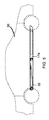
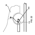
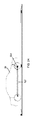
次に図面及び詳細には図1〜図4を参照すると、1つの例示的形態では、システム10などのこの技術の自律型直線交換機構(ALE)は、満充電電力セルを有するコンテナ17(例えば、図2〜図4のコンテナ17b及び17c)を、電気自動車30などの適切に構成された車両の消耗コンテナ(即ち、電力セルが消耗した車両30のコンテナ17a。図3と図4)と交換するために使用されうる。車両30などの適合車両は、ALEと、したがって以下で充電ストリップ12と呼ばれる据付型機器の使用を可能にする独特な属性(例えば、以下の考察を参照)を有する。充電ストリップ12は、一列に配置された一連の薄型充電端子14を連結し通電する薄型平坦電力コード13と、前述のシステムによって使用されるコンピュータ、通信装置、電力網接続及び補助端子を含む薄型モジュール15とを有する。充電ストリップ12は、その長さを可能にするモジュール式であり、それにより、補助端子をベース端子に対して追加又は除去することによってコンテナ17の配置(充電済み電力セルと消耗電力セルの両方と一緒に)の容量を容易に増減できる。
Next, with reference to the drawings and details in FIGS. , FIGS. 2 to 4) are replaced with consumable containers for properly configured vehicles such as the electric vehicle 30 (ie,
ベース端子18は、充電ストリップ12の一番最初にあるコンピュータ/通信/電力接続モジュール15によって補助端子と区別される。各モジュール式端子は、取り付けられた電気コードを収容する必要な長さの「ストリップ」を有し、ストリップ部分の端をストリップ上の最終端子に単純に差し込むことによって隣の端子に接続されうる。ベース端子又は部分は、端子18と反対側のストリップの端が、通信及び電力接続モジュール15によって占有されるのでこの能力を有していない。ベース端子は、通信モジュール15、必要な長さのストリップ、及びストリップの第1の充電端子18を含む。補助端子は、必要な長さのストリップと充電端子14だけを含む。初期ベース端子部分は、モジュールによってグリッド電源に接続されて、追加された端子列全体に通電する。
The
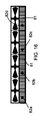
この構成の1つの重要なことは、コンテナ17がその電力セルと共に、平坦電力コード13の真上に適切な充電端子14と接して配置され、次に完全に乗り入れられ、車両30の左側タイヤと右側タイヤによって跨がれうることである。多くの場合、傾斜路又は凹状舗装道路は、区分16に沿って十分な隙間を提供することが必要になる。ALEシステム10が直線的であり、一列のコンテナ17(図2〜図4のコンテナ17b〜17c)の端と端を合わせるように端子が離間されているので、車両30は、充電ストリップ12と一列のコンテナ17(例えば、コンテナ17b,17c)の上に乗り入れることができ、コンテナ17を交換し構成するための高価な据付型ロボットオートメーションが不要になる。これは、図26に関する以下の検討で明らかになる。
One important aspect of this configuration is that the
基本的な理解は、ALE装備車両30自体が、幾つかの既知の技術が実施できる高価で複雑な据付型機器に置き換わることである。車両30は、消耗電力セルを有するそのコンテナ17(例えば、コンテナ17a)を、消耗電力セルを充電又は補給するために充電ストリップ12の空端子上に配置できる。次に、車両30は、充電ストリップ12上に配置された充電済み電力セルを有する一列のコンテナ17を跨ぎながら、補助電力セル31a,31bを使用して前進できる。最後に、車両30は、充電済み電力セルを有するコンテナ17(例えば、コンテナ17b)を取り込む。充電ストリップ12は、また、コンテナ17から情報を収集し、自律制御下で車両30を導き、コンテナ17交換を実行するために使用する短距離無線通信システム、ガイドマーク及びCPU15を含む。
The basic understanding is that the ALE-equipped
搭載機構、自律型構成要素及びAPEx
前述のようなALEと適合するために、車両30などの車両は、主電源が駆動システムから切断され車両から取り外されたときに、駆動システムに電気的に接続された搭載補助電源を使用して移動しロボット機能を実行できなければならない。この能力は、以下では、補助給電交換機構(Auxiliary Powered Exchange)又はAPExとして知られる。
On-board mechanism, autonomous components and APEx
To be compatible with ALE as described above, vehicles such as
この補助電源31a,31bは、主電源(即ち、車両のコンテナ17)が切断された後はストリップに沿って移動するのに必要なエネルギーが最小になるので、大きくかさばる必要はない。持ち上げるのに大量のエネルギーを必要とする大きいコンテナは、搭載機構のブームとの係合時にピックポイントで電気接触することによって、コンテナ自体内のエネルギーを使用する。補助電源を充電する標準的な方法は(車両から出さない)、回生制動によって生成されるエネルギーによる。この方法を使用すると、主電源からのエネルギーが浪費されず、代わりに通常使用中に車両のブレーキが適用されるたびに補助電源が充電される。
The
車両30は、また、適合性のある自律制御機器と、充電ストリップから情報を無線及び光学合図によって受け取り処理できるコンピュータ(プロセッサを備える)とを装備しなければならない。そのような指示に応じて、コンピュータプロセッサを備えた車両のコンピュータ内に記憶されたALEロジックが、自律制御機器及び車両のモータコントローラを活動化させて車両を充電ストリップに沿って前進又は後退させ、充電ストリップのロジックからの指示に従って適切な充電端子の上に一時停止し、車両を線形充電ストリップの上のちょうど中心に維持するように操縦する。そのような通信及び自律機能に加えて、車両30は、更に、主バッテリバンクを車両シャシからロック及びロック解除でき、かつバッテリバンクを充電ストリップに沿った指示位置に降下又は上昇できるロックシステム及びリフトを装備しなければならない。
The
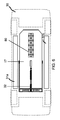
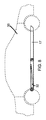
次に図5〜図8を参照すると、この技術の制限として理解するものではないが、ALE設計にとって最良の実施は、ホイールベース内のできるだけ低い箇所に位置された平坦な長方形バッテリバンク又は燃料電池コンテナであることが決定された(例えば、図5と図6を参照)。そのような構成は、ALE交換を行なうために最良に位置決めされた最小侵食性コンテナ17及びリフト32を可能にする。「シリーズ2」と呼ばれる一実施形態により、図4、図5、図6及び図8にコンテナ17及びリフト32が示される。比較のために、図7に「シリーズ1」が示される。
Next, with reference to FIGS. 5-8, although not understood as a limitation of this technique, the best practice for ALE design is a flat rectangular battery bank or fuel cell located as low as possible in the wheelbase. It was determined to be a container (see, eg, FIGS. 5 and 6). Such a configuration allows for the best positioned minimal
図5、図6及び図8に示されたユニットはシリーズ2であり、シリーズ1(図7)と多くの類似特徴を有する。シリーズ1及び2の実施形態の違いは、シリーズ1の車両40が、シリンダ(電気、空気、油圧又は他)動作のために幾何学的に改良されており(図7)、一方、シリーズ2の車両30が、動作のために埋込み式電気モータ及び遊星歯車減速を使用していることである(図8)。
The units shown in FIGS. 5, 6 and 8 are series 2 and have many similar features to series 1 (FIG. 7). The difference between
シリーズ2がシリーズ1よりも優れる1つの利点又は長所は、リフト及びコンテナから自動車設計への侵食の減少である。その結果、シリーズ2は、あまり侵食的でない点で望ましい。自動車メーカによるALE搭載ユニットの採用は、改善を必要とし、したがって、ユニットを薄型で、軽量で、その基本形状(即ち、平坦な長方形)に忠実にすることが好ましい。シリーズ1(図7)は、機能的に素晴らしいが、基本形状の上と下にそれぞれ延在するシリンダ41、ブームベース42、旋回点43及び44を含める必要がある。シリーズ2は、そのような工学的要求をなくす。
One advantage or advantage of Series 2 over
シリーズ2リフト機構の説明
シリーズ2(図9と図10)は、シリーズ1と同様に、コンテナ17の前方又は後方にあるベース板50とトルク管51と、トルク管51の中心からバッテリバンクの中央近くの点まで垂直に延在する作動ブーム52と、作動ブーム52の遠位端にありコンテナ17の上部54のスロットに入りコンテナ17のピックポイント55と係合するように設計された「T型ヘッド」53とを利用する。シリーズ2(車両30)のシリーズ1(車両40)との違いは、シリーズ2が、シリンダを備えておらず、トルク管51内に埋め込まれたモータ56と遊星歯車減速セット57によって作動されることである。
Series 2 Explanation of lift mechanism Series 2 (FIGS. 9 and 10) has a
最終歯車減速は、リング及びピニオンオフセット減速58であり、これにより、旋回軸及び駆動結合を、モータ及び遊星パワートレイン59の直列ピニオンよりも低くできる。ブームベース用のこの低い旋回軸は、シャシからの適切なコンテナ放出には優れていると判断された。この設計は、全体として、リフトとコンテナの上と下の望ましくない空間侵食を有効になくし、基本的な平坦長方形の中核工学的目標を達成するフラッシュデザインを提供する。シリーズ1及び2は両方とも、以下の全ての他の設計態様を共有する。
The final gear deceleration is the ring and pinion offset
次に図11と図12を参照すると、非侵食的平坦長方形リフト及びコンテナの必要性以上に、ユニット及びプロセスの機能に必要な多くのサテライト構成要素を平坦長方形内に維持することも重要である。そのような構成要素は、このシステムの範囲の限定と見なされるべきでなく、2つのカメラ60,61、4つのロック62a,62b,62c,62d、2つの距離計63,64、及びロードセル65を含む。カメラ60,61は、コンテナ17の前方と後方にそれぞれ配置され、車両30と搭載リフト機構に沿って中心に配置される。それらのカメラは、充電ストリップ12(図1)に沿って表示された色及び形状データを読み取るために下向きに取り付けられる。
Next, referring to FIGS. 11 and 12, it is also important to keep many satellite components necessary for the functioning of the unit and process within the flat rectangle, beyond the need for non-erosive flat rectangular lifts and containers. .. Such components should not be considered a limitation of the scope of this system, with two
カメラ60,61は、充電ストリップ12と係合時に開き離脱時に閉じるシャッタによって保護される。4つのロック62a,62b,62c,62dは、ユニットの前方62aと後方62b、及びユニットの左側62cと右側62dに配置される。これらのロックは、車両30が空端子(充電ストリップ12)の上に位置決めされた後で外れ、充電済み電力セルを有するコンテナ17がシャシ内で持ち上げられ収容されたときに係合する。ロードセル65は、リフト66のブームヘッドに組み込まれ、圧力検出フィードバックを搭載制御システムに送るために使用される。これにより、システム10は、ピックポイントによってブームに接続されたときにコンテナ17を検出でき、またコンテナ17又はブームが充電ストリップ12まで下がったときに着地を検出できる。2つの距離計63が、ユニットの左側と右側に位置決めされ、搭載制御システムに水準測量フィードバックを提供するために使用される。充電ストリップ12と無線結合したときに車両30が交換の準備をするために、制御可能な衝撃又は追加の懸架レベリング機器を使用する必要がある。ここに詳細に示されていない他の必要機器には、自動ステアリング及び制動ハードウェアと、ALEロジックが記憶され実行される搭載コンピュータ又はCANバスが挙げられる。有利には、車両のモータコントローラ(電気自動車)又はスロットル及びギアシフト制御機構(燃料自動車)は、充電ストリップに沿った車両の前進と後退を提供するために、ALEユニットのロジックに電子的にアクセス可能である。
The
ALEモジュール式電源コンテナの説明
(バッテリパック、バンク又は燃料電池)
次に図13と図14を参照すると、ALEコンテナ17は、非ALEコンテナと異なる幾つかの重要な副構成要素からなり、薄型で軽量になるように、またできるだけ基本的な平坦長方形に近づくように設計される。ほとんどの用途では、ステアリングホイールのための十分なクリアランスを可能にするために、平坦長方形形状の角部の面取り70が必要になる。構造的「背骨」71のまわりに、スロット72及びピックポイント73とサドル74用の取り付けポイントを提供すると共に、上昇及び降下プロセス中に長手方向の剛性を提供するチャネルからなる構造が設計される。背骨71は、また、長いパックを通し、ブームの基部にある前方ロック、ピックポイント及び後方ロック領域に配置された3つの個別端子に通電する電気バス75の通過と保護を提供する。これにより、自動車メーカは、駆動電力並びに追加の充電オプションのためにコンテナの前方、中心又は後方を利用できる。電気バスは、また、以下の開示でより詳細に検討されるように、コンテナ全体にわたってセンサからデータを収集し、そのデータをALEデータシステムに提供するデータ収集及び記憶モジュール76を含む。
Description of ALE modular power container (battery pack, bank or fuel cell)
Next, referring to FIGS. 13 and 14, the
次に図15、図16及び図17を参照すると、背骨71は、また、コンテナ17用のオイル冷却器80を収容する。オイル冷却器領域は、通常、コンテナ17のスロット、サドル及びピック領域の反対側の中心に位置決めされるが、コンテナ17内の任意の場所に配置されうる。冷却器80は、コンテナ17自体と同様に、幾つかのコア80aからなるモジュールである。各コア80は、サイズ適合ファン83に取り付けられた小さい耐石油ラジエータ81とマイクロポンプ82(82a〜82f)からなる(図17)。図16aと図17aは、コア80が実際にはコア80a〜80fからなり、したがってコアのモジュールシステムを構成する一連の個別コアからなることをより明瞭に強調するために個別コア80を示す。
Next, referring to FIGS. 15, 16 and 17, the
このシステムの1つの形態では、60kwhパックで5つの90mmファン及びラジエータが使用されるが、これは、本明細書で請求されるコンテナ取り付け冷却器の概念の範囲の限定と見なされるべきでない。冷却器サイズは、コンテナ形式の平均使用量に合わせられる。例えば、形式Aコンテナは、標準6コア冷却器を備え、形式A−HP(高性能)は、より高出力の駆動システムに対応するために12個のコア冷却器を備える可能性がある。冷却器のラジエータコアは、通常、コンテナ内に至る背骨チャネル内に配置された入口及び出口内に垂直にされ、石油又は類似の非導電性冷却剤が、解放循環系又は小型インラインポンプを介した閉鎖循環系を使用して流れうる。 In one form of this system, five 90mm fans and radiators are used in a 60kWh pack, but this should not be considered a limitation of the scope of the container-mounted cooler concept claimed herein. The cooler size is matched to the average usage of the container type. For example, a Type A container may have a standard 6-core cooler and a Type A-HP (high performance) may have 12 core coolers to accommodate higher power drive systems. The radiator core of the cooler is typically perpendicular to the inlet and outlet located within the spinal channel leading into the container, with petroleum or similar non-conductive coolant via an open circulation system or a small in-line pump. It can flow using a closed circulatory system.
次に図18と図19を参照すると、横材91が、背骨71の両側まで延びて「交差」型内部フレーム枠を作成し、各交差点の端が、コンテナ側ロックポイントの構造支持及び取り付け部になる。ロックポイントは、シャシロック92と係合するために、コンテナの左側と右側の、前方又はノーズロック93のためのリフト機構の反対端に配置される。背骨71と主中央横材91によって作成される交差は、燃料電池又はバッテリパックのための4つの四半分ゾーン94a〜94dを作成する。また、コンテナ17フレーム枠は、内向き耳95を備えた周囲チャネルを有し、この周囲チャネルは、主交差フレームに対する二次構造として働き、またパック内容物を側面衝撃から保護する。コンテナ17は、軽量の耐水及び耐油材料の蓋96で上部が覆われ、最初に周囲チャネル95の耳、中央横材91及び背骨71に密封材を塗布し、次に全ての接触点に沿って5cmなどの近い間隔で上皮又は蓋をリベット留め又はねじ留めすることによって油密封止が作成される。また、蓋96は、上側面に沿ってかつ充電ストリップ12の中央線と類似のコンテナ17の中心線に沿って中心に配置されたカラー及び形状マークを露出させ、それにより、充電ストリップの上に横たわるコンテナの上を通過する車両が、視覚的合図によって位置合わせを維持できる。底面又はパン97は、道路上の危険物による突刺や破損に耐えるために、ステンレス鋼や炭素繊維などのより耐久性の高い材料で作成される。また、油密又は水密封止を作成するために5cmなどの近い間隔で封止されリベット留めされるか、別の方法で留められる。これらは、第1の試作品ALEバッテリバンクコンテナ17の詳細であり、この設計の範囲を限定するものと理解されるべきでない。
Next, referring to FIGS. 18 and 19, the
「オフセンタピック」の説明
シリーズ1の開発前、降下及び上昇プロセス中のバッテリバンク安定化が課題であることが注目された。コンテナ17は、大きく平坦で重い物体なので、充電ストリップと自動車シャシの間で揺れ、震え、縦揺れし、又は捻れることがあってはならない。この特定の問題に対する解決策を考案するために、多くの他の設計が概念化された。それらの設計のそれぞれにおける問題は、コスト増大、寿命短縮及び耐久性低下としても理解されうる厄介な問題が増えることであった。
Explanation of "off-center pick" It was noted that pre-development of
次にパネルA〜Fを含む図20を参照すると、オフセンタピック構成は、シリーズ2の実施形態、シリーズ1の実施形態、又は他のそのように単純化された自由旋回ピックポイント55のコンテナ17への接続の実現を可能にし、したがって、前述の幾何学的に安定化されたブームヘッドが不要になる。コンテナ17を上昇及び降下させる前述のきわめて単純な方法は、コンテナ17上のピックポイントが、縦軸に沿った位置101で識別されたときに重心と僅かにずれているだけでよい。その結果、2段階の上昇及び降下プロセスとなり、バンク又はセルが、車両シャシ、充電ストリップ12又はその両方と常に接している。これは、常に最小3つの接点を提供し、2つの接点は、コンテナ17の端の左側と右側であり、3つ目はピックポイント55自体である。
Then referring to FIG. 20 including panels A to F, the off-center pick configuration is a
図20のパネルA〜Fは、オフセンタピックプロセスにおける車両30の電力交換プロセスに沿った一連の段階的な図である。パネルAで、最初のステップにおいて、車両30は、ロックが閉じられた状態の乗車位置でコンテナ17とリフトを有する。パネルBで、充電ストリップ12上の指定された空端子において、車両30は、正確な位置で停止し、ロックが外れ、搭載リフト機構が、コンテナの重量の100%を支える。コンテナ17上のピックポイントが、リフト側に偏心しており、ピックポイント55において動揺でき、また動揺作用の停止が、その基部近くでリフトのブーム52と接触するサドル台74によって達成されるので、このとき、コンテナ17は、ブームにより固定され、全ての力が、トルク管によって処理され、ベース板を介して車両に分散される。
Panels A to F of FIG. 20 are a series of stepwise views along the power exchange process of the
次にパネルCを参照すると、コンテナ17を配置するためにブームが充電ストリップ12の方に作動された後、コンテナのリフト側が僅かに移動し、同時に反対側の自由端(ブームピボットポイントの遠位端)が、充電ストリップ端子14と接触するまで下がる。次に、パネルDに示されたように、コンテナ17が端子と接触した後で、重い方の遠位端が支持され、コンテナの近位端は、充電ストリップ12の方に下がり続けるときにブームから離れるように回転する。
Then referring to panel C, after the boom is actuated towards the charging
次にパネルEを参照すると、近位端が遠位端と共に停止した後で、コンテナの重量が、充電ストリップによって完全に支持され、ブームが下がり続けるときにブームのT型ヘッドがピックポイントから自由になる。 Then referring to panel E, after the proximal end stops with the distal end, the weight of the container is fully supported by the charging strip and the T-head of the boom is free from the pick point as the boom continues to fall. become.
最後に、パネルFに示されたように、ブームが着地を検出した後で、車両30は、僅かに前方又は後方に移動するよう指示されて、T型ヘッドがスロットのどちらかの側のピックポイントを越え次いでブームが乗車位置へ上がり、充電ストリップ12上にコンテナを残す。次に、車両30は、補助電力下で充電又は補給済みコンテナを越えた適切な位置に移動し、前述のプロセスと逆にコンテナを取得して適所でロックし、次に充電ストリップから出る。
Finally, as shown on panel F, after the boom detects landing, the
コンテナ17の両端並びにピックポイントは、接触点を含み、この両端は、充電ストリップ上の適切な位置に横たわるときに充電端子に電気的に接続される。ピックポイントでの接触は、小さい補助電源が利用可能で更に主バンク(コンテナ)がきわめて重いときに利用される。この場合、ブームヘッドは、コンテナの電気バスと電気接触し、補助電源に依存する代わりに持ち上げているコンテナだけから電力を引き出すことができる。この設計は、完全に安定しかつ信頼でき、実証及び研究シャシ内で既に構成され試験で成功している。
Both ends of the
ノーズロック及びプラグイン充電オプションの説明
次に図21〜図24を参照すると、リフト機構32の反対側に、コンテナ17のノーズロック62aと呼ばれる主ロックがある。ノーズロック62aは、少数の重要な機能を実行する。ノーズロック62aは、コンテナ17をロックするだけでなく、コンテナ17をすくい上げ適所114で加圧する強力な顎型ロック動作を提供し、シャシ内への確実な設置を保証する。また、ノーズロック62aは、冷却器コア領域内への冷却空気の導入を提供すると同時に水分と道路砂をロック内の電気接続から分離する空気口115と、最も重要なことには、充電ストリップ12上に見られるものと類似の二重充電端子プラグとを有する。この充電端子プラグは、ノーズロック62aが取り付けられたときにコンテナ17上の端子タブ117の上に押し上げられ、タブ117を腐食から保護し、車両の駆動システムへの駆動電力の電気接点を提供し、また車両30上の標準化充電プラグ118に接続される。これは、ユーザが、ALE装備車両を、追加オプションとしてステージ1、2又は3の充電器に差し込むことを可能にする。実際に、ノーズロックシステムが車両のプラグイン使用を無期限に可能にするので、必要ない場合はバッテリコンテナを交換しなくてもよい。この内蔵オプションは、ALEを組み込むことを選択する自動車メーカのさらなる柔軟性を可能にする。
Description of Nose Lock and Plug-in Charging Option Next, referring to FIGS. 21 to 24, on the opposite side of the
その他の請求リフト構成
シリーズ1とシリーズ2について述べ、製造及び販売の現在望ましい選択肢を考察してきたが、この開示に従って多くの他のリフト構成及び修正が可能であることを理解することはきわめて容易である。これは、以下の注目に値する設計を含む。第1に、自動車シャシ及びバッテリバンク又は燃料電池に沿って長手方向に延在する電動アクメねじによって駆動されるシザーリフト。このリフトは、パックの中心に嵌まって、アクメ駆動シザーリフトを使用してシャシ内の適所に引き込まれるヘッドを有する。第2に、各円材とベースとヘッドの交点に旋回軸を有するツイン円材構造を有する関節式電気スタンドと全く同様に構成された平行四辺形ブーム。これによりブームのヘッドがシャシに対して常に平行に維持される。このユニットのヘッドは、アクメシザーリフトと同様に、設計の幾何学形状によって縦揺れ、振動又は捻れから制御される。第3に、コンテナ17のストリップ側全体にわたるトレイ121が、コンテナ17の交換側でロック解除され、コンテナ17の反対側で旋回し123、トレイの前方点と後方点の間の任意の点でラム124によって下降されるトレイシステム(図24と図25を参照)。
Other billing lift configurations Although we have described
この設計は、コンテナ17の保護能力が高く、オフロード又は過酷使用の車両に必要なことがある。第4に、既存のリフトに対する磁気ロックシステムが考案され、本明細書で請求される。この場合、ブームが降下し、ブームヘッド自体、バッテリバンク又は燃料電池ピックポイントに配置された電磁石を利用してバッテリ内にロックされる。磁石は、全ての設計において、中心決めと位置合わせ、及びあらゆる種類の一時的操作のために使用されうる。
This design provides high protection for the
充電及び補給プラザの説明
次に図26を参照すると、1つの有利な形態で、補給プラザ130は、コンクリート駐車場又は高速道路安全休憩所などの平坦面上に複数の充電ストリップ(例えば、12a〜122)が平行(幾何学的)に位置決めされた最も単純な形態で構成されうる。この場合、消耗電源を有する車両(例えば、30a〜30d)をプラザ132の片側に送り込み、車両を電力セルを有する適切なコンテナを収容する適切な充電ストリップ(例えば、126)に導き、次に交換が実行され出口135から出た後で充電ストリップ126の反対側133に車両を導く自律ルーティンが作成されうる。このプロセスは、また、手動操作車両と適合し、この場合、車両は、オペレータによって車両用の電力セルを有する適正なコンテナを収容する適切なストリップまで運転され、係合領域137でシステムによって係合されうる。充電ストリップ(12a〜12d)は、地域の車両電力要求に適合するように構成されうる。サイズ固有の充電ストリップが、異なる電力セルを有する様々なサイズのコンテナ17(例えば、コンテナ17d及び17g)にサービス提供できるが、どの充電ストリップも様々なサイズのコンテナにサービス提供できないことがある。
Description of Charging and Replenishment Plaza Next, referring to FIG. 26, in one advantageous form, the
このシステムの機能に重要なことは、各ストリップが複数の一固有形式の電源を含むことである。車両/電源の間違った組み合わせの回避は、最初の係合時の無線通信によって対応される。このシステムを使用することにより、1分当たりにサービス提供できる車両の量は、特定タイプの電源の充電又は補給時間をプラザ内の電源の数で割ることによって決定されうる。例えば、電気自動車が、満充電に1時間を必要とする電力セルを有するコンテナを備え、ストリップ上に10個のバンクがある場合、1時間/10バンク=6分当たり1台の車両がサービス提供される。高い頻度の交換を必要とする領域では、多数の平行ストリップ又は長いストリップは、電源準備の速さを劇的に高めることができる。 Important to the functioning of this system is that each strip contains a plurality of unique types of power supplies. Avoidance of incorrect vehicle / power combinations is addressed by wireless communication during initial engagement. By using this system, the amount of vehicles that can be serviced per minute can be determined by dividing the charging or replenishment time of a particular type of power supply by the number of power supplies in the plaza. For example, if an electric vehicle has a container with a power cell that requires 1 hour to fully charge and there are 10 banks on the strip, 1 hour / 10 banks = 1 vehicle per 6 minutes will serve. Will be done. In areas that require frequent replacement, a large number of parallel strips or long strips can dramatically increase the speed of power preparation.
ALEコンテナデータ収集システムの説明
ALEコンテナは全て、温度、出力、充電インジケータ及び多数の他のメタデータ関連入力を記録し報告するために多数の検出技術を利用する。また、ユニットは全て、タイムラインに沿ってそのセンサからのデータを記憶するための処理チップ、クロック及びメモリカードを備える。これは、パックの使用、その現状と充電、並びに起こりうる問題に関する詳細な履歴を提供する。次に、このデータは、車両が接続自動車ネットワークを装備している場合にそのネットワークを介して車両からパルス化されるか、非接続自動車の場合は、コンテナが充電ストリップに沿った端子に接続された後でデータが収集システムのサーバにアップロードされる。次に、データは、システムインタフェース又はAPIに記憶、解析、及び発射される。全てのユーザ及び自動車メーカがアクセスして世界中のコンテナネットワーク上の実時間データを引き出すことができる。次に、このデータをスマートフォン、PC又は車両情報娯楽システム内のアプリケーションが使用して、どのコンテナと係合すべきかを決定できる。多数の車両を使用している運輸会社が、このデータを更に綿密に使用することによって、移動距離全体に電力をより合理的に消費するために、乗員が遠くに移動しない1つの車両から乗員が遠くに移動する車両にコンテナを「ハンドオフ」できる。また、そのようなネットワークを、ALEデータ収集システムによって提供される実時間データと一緒に使用することによって、ALE装備車両を使用する緊急サービスが、充電済みバンクに優先的にアクセスできる。
Description of the ALE Container Data Collection System All ALE containers utilize a number of detection techniques to record and report temperature, output, charging indicators and numerous other metadata related inputs. Also, all units include a processing chip, clock and memory card for storing data from the sensor along the timeline. It provides a detailed history of pack usage, its current status and charging, as well as possible problems. This data is then pulsed from the vehicle through the network if the vehicle is equipped with a connected vehicle network, or in the case of unconnected vehicles, the container is connected to a terminal along the charging strip. After that, the data is uploaded to the server of the collection system. The data is then stored, analyzed, and launched into the system interface or API. It can be accessed by all users and car manufacturers to retrieve real-time data on container networks around the world. This data can then be used by an application within a smartphone, PC or vehicle information entertainment system to determine which container to engage with. By using this data more closely, transportation companies that use a large number of vehicles can more reasonably consume power over the entire distance traveled by occupants from a single vehicle that does not travel far. You can "hand off" the container to vehicles that move far away. Also, by using such a network in conjunction with real-time data provided by the ALE data collection system, emergency services using ALE-equipped vehicles can preferentially access charged banks.
必須電源を備えた電気自動車について述べたが、燃料電池を使用する車両を含む他の電動車両にこの技術を応用して使用できる。 Although we have described an electric vehicle with an essential power source, this technology can be applied to other electric vehicles, including vehicles that use fuel cells.
ALEシステムは、全く新規であり、EV技術はいうまでもなく自動車産業におけるいかなる他の技術とも異なる。EV販売は、航続距離と利便性の消極的市場認識によって制限されるが、業界は、まだ対応できないシステムを考え出す。特定のEVの独自開発の急速交換システムや現在閉鎖会社Better Placeなどの既存の技術は、経済学的側面に沿って発明できなかった。更に、1日当たり3台のEVにサービス提供するために地下ロボットに約50万ドル投資を支援する事業計画はない。互換性があり自律的な補助電力交換車両と協力するALE技術は、構成するのに非侵食的で、実質的に任意の地主又は管理者にとって財務的に取り組みやすい過渡的解決策を提供することによって、この難局を解決する。 The ALE system is completely new and differs from any other technology in the automotive industry, not to mention EV technology. EV sales are limited by negative market perceptions of range and convenience, but the industry comes up with systems that are not yet available. Existing technologies, such as the proprietary rapid exchange system for certain EVs and the currently closed company Better Place, could not be invented in line with economic aspects. In addition, there are no business plans to support an investment of about $ 500,000 in underground robots to serve three EVs per day. ALE technology, which works with compatible and autonomous auxiliary power exchange vehicles, provides a transitional solution that is non-erosive to configure and financially accessible to virtually any landowner or manager. Will solve this difficult situation.
更に、この方法及びシステムは、車両自体をプロセスの主機械化として使用することによって実現される既知の技術を上回る独特の利点を有し、それにより、コストが大幅に低減される。このALE方法及びシステムは、実質的に任意の資産に適合されうるので、様々な構成を有する一般事業主によって実現されうる。市場からの航続距離及び利便性の論点を打ち破るので、EV産業の漸進的成長を可能にし、また土地に急速交換機構を提供することに興味を持つ人にとって収益性の高い投資になる。最初に、低投資で単純で多数の急速交換場所が必要になる。電気自動車の次のステップは、接続自動車ネットワークによる急速交換の大量消費を迅速かつシームレスに整合できる情報技術との結合である。 Moreover, this method and system has unique advantages over known techniques realized by using the vehicle itself as the main mechanization of the process, thereby significantly reducing costs. This ALE method and system can be adapted to virtually any asset and can be implemented by general business owners with various configurations. Breaking down the range and convenience issues from the market makes it a profitable investment for anyone interested in enabling the gradual growth of the EV industry and providing a rapid exchange mechanism for land. First, it requires a low investment, simple, and numerous rapid exchange locations. The next step in electric vehicles is to combine them with information technology that can quickly and seamlessly align the mass consumption of rapid exchanges by connected vehicle networks.
当業者は、この開示内容の教示から逸脱することなく追加の実施形態が可能であることを理解するであろう。この詳細な説明及び特に本明細書に開示された例示的実施形態の特定の詳細は、主に理解を明確にするために示され、不必要な限定と理解されるべきでなく、修正は、この開示を読むことで当業者に明らかになり、またこの開示内容の趣旨及び範囲から逸脱せずに行われうる。 Those skilled in the art will appreciate that additional embodiments are possible without departing from the teachings of this disclosure. This detailed description and in particular the specific details of the exemplary embodiments disclosed herein are provided primarily for clarity of understanding and should not be understood as unnecessary limitations and amendments. Reading this disclosure will make it clear to those skilled in the art and may be made without departing from the spirit and scope of this disclosure.
10 ALEシステム
12 充電ストリップ
13 電力コード
14 充電端子
15 薄型モジュール
17 コンテナ
18 ベース端子
30 車両
31 補助電源
10
Claims (8)
前記少なくとも1つの電源交換ストリップに配置された少なくとも1つの充電済み電源セルと、
前記少なくとも1つの電源交換ストリップと電源交換要求車両の間で通信するために、少なくとも1つの電源交換ストリップにおいて作動可能に設けられた無線通信装置と、
前記少なくとも1つの電源交換ストリップ及び前記無線通信装置と関連付けられて、前記電源交換要求車両上の機能を制御するためのプロセッサとを含み、
前記プロセッサは、車両に設けられたリフト機構に対して前記無線通信装置を介して通信し、前記リフト機構を用いて、車両内の消耗電源セルを車両から分離して下降させた後、前記充電済み電源セルを車両内に上昇させる車両電源交換システム。 With at least one power exchange strip,
With at least one charged power cell located on the at least one power exchange strip,
A wireless communication device operably provided on at least one power exchange strip for communication between the at least one power exchange strip and the power exchange requesting vehicle.
Includes the at least one power exchange strip and a processor associated with the radio communication device to control a function on the power exchange request vehicle.
The processor communicates with a lift mechanism provided in the vehicle via the wireless communication device, and the lift mechanism is used to separate the consumable power cell in the vehicle from the vehicle and lower it, and then charge the battery. A vehicle power exchange system that raises a finished power cell into the vehicle.
Applications Claiming Priority (5)
| Application Number | Priority Date | Filing Date | Title |
|---|---|---|---|
| US201562150937P | 2015-04-22 | 2015-04-22 | |
| US62/150,937 | 2015-04-22 | ||
| US201562166339P | 2015-05-26 | 2015-05-26 | |
| US62/166,339 | 2015-05-26 | ||
| PCT/US2016/029011 WO2016172605A1 (en) | 2015-04-22 | 2016-04-22 | Method and system for power exchange |
Publications (3)
| Publication Number | Publication Date |
|---|---|
| JP2018524235A JP2018524235A (en) | 2018-08-30 |
| JP2018524235A5 JP2018524235A5 (en) | 2020-06-11 |
| JP6914911B2 true JP6914911B2 (en) | 2021-08-04 |
Family
ID=57143539
Family Applications (1)
| Application Number | Title | Priority Date | Filing Date |
|---|---|---|---|
| JP2018506807A Active JP6914911B2 (en) | 2015-04-22 | 2016-04-22 | System for power exchange |
Country Status (9)
| Country | Link |
|---|---|
| US (3) | US10308125B2 (en) |
| EP (1) | EP3286036B1 (en) |
| JP (1) | JP6914911B2 (en) |
| KR (1) | KR102634519B1 (en) |
| CN (1) | CN107735277B (en) |
| BR (1) | BR112017022791A2 (en) |
| CA (1) | CA2983278A1 (en) |
| HK (1) | HK1251525A1 (en) |
| WO (1) | WO2016172605A1 (en) |
Families Citing this family (13)
| Publication number | Priority date | Publication date | Assignee | Title |
|---|---|---|---|---|
| US10807492B1 (en) * | 2016-04-15 | 2020-10-20 | X Development Llc | Switchable magnetic battery docking |
| CN105895841A (en) * | 2016-04-29 | 2016-08-24 | 蔚来汽车有限公司 | Battery pack fixing structure and battery pack replacement apparatus |
| US10870365B2 (en) * | 2016-11-14 | 2020-12-22 | ATMO Auto Power LLC | Method and system for rapid power exchange |
| CA3075396A1 (en) | 2017-09-10 | 2019-03-14 | Orbit Fab, Inc. | Systems and methods for delivering, storing, and processing materials in space |
| US11034235B2 (en) | 2017-12-06 | 2021-06-15 | Orbit Fab, Inc. | Systems and methods for creating and automating an enclosed volume with a flexible fuel tank and propellant metering for machine operations |
| WO2019124898A1 (en) * | 2017-12-19 | 2019-06-27 | 이영조 | Electric car battery replacement system having energy saving system (ess) and method for operating same |
| JP7177550B2 (en) * | 2018-10-26 | 2022-11-24 | 青島聯合新能源汽車有限公司 | Electric vehicle with battery compartment |
| EP4070300A4 (en) * | 2019-12-05 | 2023-01-04 | Zircon Chambers Pty. Ltd. | Vehicle guidance, power, communication system and method |
| CN113043872A (en) * | 2019-12-26 | 2021-06-29 | 奥动新能源汽车科技有限公司 | Automatic temperature control tray, charging bin, power conversion station and energy storage station |
| CN112208335B (en) * | 2020-11-13 | 2022-04-12 | 湖北航天技术研究院特种车辆技术中心 | Vehicle-mounted high-voltage battery pack external throwing guide device and electric vehicle |
| CN112757947A (en) * | 2021-01-22 | 2021-05-07 | 恒大新能源汽车投资控股集团有限公司 | Electric vehicle mobile charging overall planning method, control method and mobile charging device |
| CN113022287B (en) * | 2021-03-01 | 2023-11-10 | 中京未来(北京)科技有限公司 | Continuous power conversion system with auxiliary driving mode and power conversion method |
| FR3138358A1 (en) * | 2022-07-26 | 2024-02-02 | Psa Automobiles Sa | MOUNTING SYSTEM FOR A POWER BATTERY OF AN ELECTRIC PROPULSION MOTOR VEHICLE ENGINE |
Family Cites Families (73)
| Publication number | Priority date | Publication date | Assignee | Title |
|---|---|---|---|---|
| US3799063A (en) | 1972-08-16 | 1974-03-26 | D Reed | Vehicle battery changing device |
| AT348875B (en) | 1975-12-24 | 1979-03-12 | Voith Gmbh J M | DEVICE FOR HORIZONTAL POSITIONING OF BATTERY OPERATED VEHICLES AT BATTERY CHANGE STATIONS |
| EP0575864A3 (en) * | 1992-06-16 | 1994-06-01 | Baer Hans | Method and device for energy supply |
| US5305513A (en) | 1992-09-24 | 1994-04-26 | Ford Motor Company | Vehicle battery decking device |
| JPH0717265A (en) * | 1993-07-06 | 1995-01-20 | Nippon Home Keizai Kenkyusho:Kk | Mounting device for secondary battery of electric automobile motive power, for automobile |
| US5711648A (en) | 1994-01-06 | 1998-01-27 | Unlimited Range Electric Car Systems Company | Battery charging and transfer system |
| US5549443A (en) * | 1994-01-06 | 1996-08-27 | Hammerslag; Julius G. | Battery charging and transfer system |
| US5927938A (en) * | 1994-01-06 | 1999-07-27 | Unlimited Range Electric Car Systems Company | Battery charging and transfer system for electrically powered vehicles |
| US5612606A (en) | 1994-09-15 | 1997-03-18 | David C. Guimarin | Battery exchange system for electric vehicles |
| US5598083A (en) | 1995-05-19 | 1997-01-28 | Stamler Corporation | Battery changing system for electrically powered vehicle |
| DE69711963T2 (en) * | 1996-01-30 | 2002-11-28 | Sumitomo Wiring Systems | Connection system and method for an electrically powered vehicle |
| DE19621668A1 (en) | 1996-05-30 | 1997-12-04 | Uwe Kochanneck | Multi=block robot system e.g. for logistics and power supply to electric vehicles |
| US5760569A (en) * | 1997-02-26 | 1998-06-02 | Chase, Jr.; Robert B. | Replaceable battery module for electric vehicle |
| JP3219039B2 (en) * | 1997-12-15 | 2001-10-15 | 富士電機株式会社 | Electric vehicle electric system |
| US5998963A (en) | 1998-06-11 | 1999-12-07 | Aarseth; Einar | Electric vehicle service center and method for exchanging and charging vehicle batteries |
| US6113342A (en) | 1998-08-12 | 2000-09-05 | Long-Airdox Company | Self-aligning battery changing system for electric battery-powered vehicles |
| TW412097U (en) | 1999-01-28 | 2000-11-11 | Ind Tech Res Inst | Select-type battery-charging station for managing and switching the batteries of electric vehicles |
| US6631775B1 (en) * | 2000-07-06 | 2003-10-14 | George T. Chaney | Electric vehicle chassis with removable battery module and a method for battery module replacement |
| CN100465012C (en) | 2000-09-13 | 2009-03-04 | 菲利普斯机械服务有限公司 | Battery powered shuttle car |
| JP4134344B2 (en) * | 2003-04-01 | 2008-08-20 | 智英 佐藤 | Standardized exchangeable secondary battery with watt-hour meter |
| JP2007087912A (en) * | 2005-09-16 | 2007-04-05 | Kozo Hayashi | Battery replenishing system for electric motorcar |
| US7602143B2 (en) | 2005-11-04 | 2009-10-13 | Peter David Capizzo | System for replenishing energy sources onboard different types of automotive vehicles |
| JP2007153006A (en) | 2005-12-01 | 2007-06-21 | Matsushita Electric Ind Co Ltd | Electric power source device for vehicle |
| US7868250B2 (en) * | 2006-08-01 | 2011-01-11 | Priority Worx, Llc | Power supply and cord management apparatus for electronic devices |
| DE102007032210B4 (en) * | 2007-04-19 | 2010-04-08 | Höltzel, Thomas | Method and device for replacing accumulators for electric vehicles |
| US20080294283A1 (en) * | 2007-05-25 | 2008-11-27 | Ronald Ligrano | Battery exchange station and a method of changing therein |
| JP4539887B2 (en) | 2008-01-31 | 2010-09-08 | トヨタ自動車株式会社 | Charging management method and system for self-propelled vehicles for transportation |
| US20090198372A1 (en) * | 2008-02-05 | 2009-08-06 | Unlimited Range Electric Car Systems Company | Battery charging and transfer system for electrically powered vehicles |
| IL190647A0 (en) | 2008-04-07 | 2008-12-29 | Davidovitch J | Replacing discharged batteries in electric vehicles |
| US7993155B2 (en) * | 2008-09-19 | 2011-08-09 | Better Place GmbH | System for electrically connecting batteries to electric vehicles |
| US8006793B2 (en) | 2008-09-19 | 2011-08-30 | Better Place GmbH | Electric vehicle battery system |
| US20110223459A1 (en) * | 2008-09-19 | 2011-09-15 | Yoav Heichal | Multi-Motor Latch Assembly |
| JP5212011B2 (en) * | 2008-10-22 | 2013-06-19 | トヨタ車体株式会社 | Battery powered car |
| US8146694B2 (en) | 2009-01-20 | 2012-04-03 | Vahid Hamidi | Swappable modulated battery packs system for electrically driven vehicle |
| FR2943022B1 (en) * | 2009-03-16 | 2012-07-13 | Peugeot Citroen Automobiles Sa | INTERACTIVE METHOD OF EXCHANGING AN ENERGY STORAGE SYSTEM OF AN ELECTRIC OR PARTIALLY ELECTRIC VEHICLE |
| DE102009025052A1 (en) | 2009-06-10 | 2011-04-28 | Gottwald Port Technology Gmbh | System for changing a battery of a ground-based transport vehicle, in particular a driverless heavy-duty transport vehicle for ISO containers |
| DE102009033235A1 (en) * | 2009-07-14 | 2011-01-20 | Conductix-Wampfler Ag | Energy supply unit, land vehicle, exchange station and method for exchanging a power supply unit contained in a land vehicle |
| JP5622518B2 (en) * | 2009-10-14 | 2014-11-12 | パナソニック株式会社 | Electric machine and battery system with battery pack |
| JP5136539B2 (en) * | 2009-11-06 | 2013-02-06 | 株式会社豊田自動織機 | Electric vehicle battery mounting structure |
| US8858152B1 (en) | 2010-05-06 | 2014-10-14 | Steven D. McDaniel | System for replacing batteries in electric cars |
| SE536036C2 (en) * | 2010-06-21 | 2013-04-09 | Sten Corfitsen | Procedure for replacing batteries in battery-powered vehicles. |
| JP2012008019A (en) * | 2010-06-25 | 2012-01-12 | Clarion Co Ltd | Battery replacement support system, on-vehicle device, and battery replacement support device |
| CN102452297B (en) | 2010-10-29 | 2014-07-09 | 杭州三花研究院有限公司 | Electric automobile and heat management system thereof |
| CN102139680B (en) | 2011-02-21 | 2012-12-26 | 谢子聪 | Power battery quick-changing system for multi-model electric passenger vehicle |
| JP5273187B2 (en) * | 2011-03-15 | 2013-08-28 | 株式会社豊田自動織機 | Vehicle battery exchange device |
| CN201970973U (en) | 2011-03-23 | 2011-09-14 | 北京理工华创电动车技术有限公司 | Fast pure electric vehicle power battery replacement station |
| US9123035B2 (en) | 2011-04-22 | 2015-09-01 | Angel A. Penilla | Electric vehicle (EV) range extending charge systems, distributed networks of charge kiosks, and charge locating mobile apps |
| US8868235B2 (en) | 2011-05-27 | 2014-10-21 | Shandong Electric Power Research Institute | Battery quick-change system for an electric passenger car chassis having a cartesian coordinate robot |
| KR101313279B1 (en) | 2011-06-01 | 2013-09-30 | 국민대학교산학협력단 | Battery Exchanging Method for Electric Vehicle |
| JP2013006568A (en) * | 2011-06-27 | 2013-01-10 | Toyota Industries Corp | Transfer device |
| FR2977219B1 (en) | 2011-07-01 | 2015-06-26 | Renault Sa | POSITIONING A MOTOR VEHICLE AND EXCHANGING THE VEHICLE'S POWER BATTERY |
| US20130041531A1 (en) * | 2011-08-09 | 2013-02-14 | Ryan Marc LaFrance | Vehicle controllers and methods for use in charging an electrically powered vehicle |
| KR101245571B1 (en) | 2012-01-31 | 2013-03-22 | 한국항공대학교산학협력단 | Electric bus battery exchanging station |
| KR101245566B1 (en) | 2012-01-31 | 2013-03-22 | 한국항공대학교산학협력단 | Electric bus and electric bus battery exchanging system |
| IL218924A (en) | 2012-03-29 | 2016-03-31 | Better Place GmbH | Battery exchange system and method for electric vehicles |
| IL218949A0 (en) * | 2012-03-29 | 2012-07-31 | Better Place GmbH | Vehicle alignment system for battery switch station |
| SE537055C2 (en) * | 2012-04-18 | 2014-12-23 | Sten Corfitsen | Device and method for replacing batteries in battery-powered vehicles |
| US8970341B2 (en) | 2012-06-25 | 2015-03-03 | Kookmin University Industry Academy Cooperation Foundation | Electric vehicle, battery charging station, battery exchanging reservation system comprising the same and method thereof |
| US8694155B2 (en) | 2012-06-26 | 2014-04-08 | Motex Products Co., Ltd. | System for auto-exchanging of electric vehicle battery |
| US9156360B2 (en) | 2012-07-01 | 2015-10-13 | Kookmin University Industry Academy Cooperation Foundation | Battery exchanging-type charging station system for electric vehicle |
| JP6048153B2 (en) * | 2013-01-11 | 2016-12-21 | 株式会社豊田自動織機 | Battery unit mounting device and battery unit mounting structure |
| JP2014147197A (en) * | 2013-01-29 | 2014-08-14 | Hitachi Automotive Systems Ltd | Battery control device |
| US8973254B2 (en) * | 2013-03-07 | 2015-03-10 | Jasper Ev Tech, Llc | System and method for rapid battery exchange in electric vehicles |
| US9511459B2 (en) | 2013-07-02 | 2016-12-06 | Denis Ernest Celestin BUFFET | Automatic system for quick dropping of the battery, integrated to an electrical or hybrid vehicle, and consequences on its maximum loading weight |
| CN105829160B (en) | 2013-08-06 | 2017-10-24 | 睿能创意公司 | The use of single or multiple battery units is the system and method that electric car is powered |
| US9358895B2 (en) * | 2013-10-28 | 2016-06-07 | Meir Avganim | Quick loading and unloading battery system for vehicles |
| WO2016002619A1 (en) * | 2014-06-30 | 2016-01-07 | 株式会社Ihi | Foreign-material-removing device, ground equipment for contactless electricity-supplying system, and contactless electricity-supplying system |
| CN106627082B (en) * | 2014-09-18 | 2018-11-16 | 浙江吉利控股集团有限公司 | A kind of electric vehicle |
| CN107848431A (en) * | 2015-06-10 | 2018-03-27 | 巴特斯韦普公司 | Battery swap system |
| TW201718295A (en) * | 2015-11-30 | 2017-06-01 | 鴻海精密工業股份有限公司 | Battery replacing system for electric vehicle and using method thereof |
| US9758030B2 (en) * | 2016-02-09 | 2017-09-12 | NextEv USA, Inc. | Replaceable battery assembly having a latching mechanism |
| US9873408B2 (en) * | 2016-05-11 | 2018-01-23 | Peter D. Capizzo | Device for refueling, exchanging, and charging power sources on remote controlled vehicles, UAVs, drones, or any type of robotic vehicle or machine with mobility |
| US10870365B2 (en) * | 2016-11-14 | 2020-12-22 | ATMO Auto Power LLC | Method and system for rapid power exchange |
-
2016
- 2016-04-22 CN CN201680031598.8A patent/CN107735277B/en active Active
- 2016-04-22 US US15/566,553 patent/US10308125B2/en active Active
- 2016-04-22 KR KR1020177031845A patent/KR102634519B1/en active IP Right Grant
- 2016-04-22 BR BR112017022791-6A patent/BR112017022791A2/en not_active Application Discontinuation
- 2016-04-22 WO PCT/US2016/029011 patent/WO2016172605A1/en unknown
- 2016-04-22 CA CA2983278A patent/CA2983278A1/en not_active Abandoned
- 2016-04-22 EP EP16784011.5A patent/EP3286036B1/en active Active
- 2016-04-22 JP JP2018506807A patent/JP6914911B2/en active Active
-
2018
- 2018-08-28 HK HK18111033.6A patent/HK1251525A1/en unknown
-
2019
- 2019-05-31 US US16/428,360 patent/US20190283618A1/en not_active Abandoned
-
2020
- 2020-12-14 US US17/121,156 patent/US20210101465A1/en not_active Abandoned
Also Published As
| Publication number | Publication date |
|---|---|
| JP2018524235A (en) | 2018-08-30 |
| EP3286036A4 (en) | 2019-04-10 |
| HK1251525A1 (en) | 2019-02-01 |
| CN107735277B (en) | 2021-04-27 |
| EP3286036B1 (en) | 2022-03-02 |
| US20210101465A1 (en) | 2021-04-08 |
| WO2016172605A1 (en) | 2016-10-27 |
| US20190283618A1 (en) | 2019-09-19 |
| US10308125B2 (en) | 2019-06-04 |
| EP3286036A1 (en) | 2018-02-28 |
| CN107735277A (en) | 2018-02-23 |
| US20180118044A1 (en) | 2018-05-03 |
| KR102634519B1 (en) | 2024-02-06 |
| CA2983278A1 (en) | 2016-10-27 |
| BR112017022791A2 (en) | 2018-07-17 |
| KR20180016977A (en) | 2018-02-20 |
Similar Documents
| Publication | Publication Date | Title |
|---|---|---|
| JP6914911B2 (en) | System for power exchange | |
| US9834183B2 (en) | Vehicular accessory | |
| US10549729B2 (en) | Vehicular accessory | |
| CN110248830B (en) | Method and system for fast power exchange | |
| US9827865B2 (en) | Systems and methods for recharging vehicle-mounted energy storage devices | |
| CN102390440B (en) | Movable automatic power charging and switching station as well as cell rapid replacement method for electric automobile | |
| CN109747456A (en) | mobile energy storage device | |
| CN103547475A (en) | Energy source systems having devices with differential states of charge | |
| JP2021514897A (en) | Detachment system for battery assembly | |
| JP2021514895A (en) | Alignment and locking mechanism for removable battery assembly | |
| CN111452664B (en) | Electric automobile battery replacement system and method in charging and replacing separation mode | |
| CN109760846A (en) | A kind of plant protection drone field automatically supplying apparatus and method | |
| CN104010884A (en) | Hydraulically powered hybrid vehicle with optimally situated electric energy store | |
| CN113874247A (en) | Battery loading mechanism for electric LHD mining machine | |
| CN108556813A (en) | A kind of automobile batteries replacement/charging system and control method | |
| CN213109074U (en) | Electric automobile battery replacement system in charging and replacing separation mode | |
| US20210178930A1 (en) | Combined Removable and Fixed Batteries in Powered Urban Mobility | |
| CN216300841U (en) | Battery changing station | |
| CN112060946B (en) | Unmanned aerial vehicle charging device and cluster operation system | |
| CN208198368U (en) | A kind of electric car parking system that novel applicability is good | |
| EA040328B1 (en) | LEVELING AND LOCKING MECHANISM FOR REMOVABLE BATTERY ASSEMBLY | |
| CN117341528A (en) | Lithium battery power conversion system based on automatic driving | |
| EA040335B1 (en) | BATTERY INSTALLATION AND REMOVAL SYSTEM FOR BATTERY ASSEMBLY |
Legal Events
| Date | Code | Title | Description |
|---|---|---|---|
| A621 | Written request for application examination |
Free format text: JAPANESE INTERMEDIATE CODE: A621 Effective date: 20190415 |
|
| A977 | Report on retrieval |
Free format text: JAPANESE INTERMEDIATE CODE: A971007 Effective date: 20191211 |
|
| A131 | Notification of reasons for refusal |
Free format text: JAPANESE INTERMEDIATE CODE: A131 Effective date: 20191217 |
|
| A601 | Written request for extension of time |
Free format text: JAPANESE INTERMEDIATE CODE: A601 Effective date: 20200317 |
|
| A524 | Written submission of copy of amendment under article 19 pct |
Free format text: JAPANESE INTERMEDIATE CODE: A524 Effective date: 20200423 |
|
| A131 | Notification of reasons for refusal |
Free format text: JAPANESE INTERMEDIATE CODE: A131 Effective date: 20200901 |
|
| A601 | Written request for extension of time |
Free format text: JAPANESE INTERMEDIATE CODE: A601 Effective date: 20201201 |
|
| A521 | Request for written amendment filed |
Free format text: JAPANESE INTERMEDIATE CODE: A523 Effective date: 20210121 |
|
| A131 | Notification of reasons for refusal |
Free format text: JAPANESE INTERMEDIATE CODE: A131 Effective date: 20210209 |
|
| A521 | Request for written amendment filed |
Free format text: JAPANESE INTERMEDIATE CODE: A523 Effective date: 20210420 |
|
| TRDD | Decision of grant or rejection written | ||
| A01 | Written decision to grant a patent or to grant a registration (utility model) |
Free format text: JAPANESE INTERMEDIATE CODE: A01 Effective date: 20210629 |
|
| A61 | First payment of annual fees (during grant procedure) |
Free format text: JAPANESE INTERMEDIATE CODE: A61 Effective date: 20210714 |
|
| R150 | Certificate of patent or registration of utility model |
Ref document number: 6914911 Country of ref document: JP Free format text: JAPANESE INTERMEDIATE CODE: R150 |