JP6914842B2 - Adaptive ablation and treatment systems and methods based on elastography monitoring - Google Patents
Adaptive ablation and treatment systems and methods based on elastography monitoring Download PDFInfo
- Publication number
- JP6914842B2 JP6914842B2 JP2017544961A JP2017544961A JP6914842B2 JP 6914842 B2 JP6914842 B2 JP 6914842B2 JP 2017544961 A JP2017544961 A JP 2017544961A JP 2017544961 A JP2017544961 A JP 2017544961A JP 6914842 B2 JP6914842 B2 JP 6914842B2
- Authority
- JP
- Japan
- Prior art keywords
- ablation
- parameters
- imaging
- rfa
- feedback
- Prior art date
- Legal status (The legal status is an assumption and is not a legal conclusion. Google has not performed a legal analysis and makes no representation as to the accuracy of the status listed.)
- Active
Links
- 238000002679 ablation Methods 0.000 title claims description 123
- 238000000034 method Methods 0.000 title claims description 62
- 238000011282 treatment Methods 0.000 title claims description 47
- 238000012544 monitoring process Methods 0.000 title claims description 16
- 238000002091 elastography Methods 0.000 title claims description 12
- 230000003044 adaptive effect Effects 0.000 title description 4
- 238000003384 imaging method Methods 0.000 claims description 50
- 238000005259 measurement Methods 0.000 claims description 46
- 230000008569 process Effects 0.000 claims description 19
- 238000011156 evaluation Methods 0.000 claims description 17
- 230000002123 temporal effect Effects 0.000 claims description 6
- 230000001225 therapeutic effect Effects 0.000 claims description 3
- 238000007674 radiofrequency ablation Methods 0.000 description 57
- 210000001519 tissue Anatomy 0.000 description 35
- 230000006378 damage Effects 0.000 description 29
- 238000002604 ultrasonography Methods 0.000 description 25
- 239000000523 sample Substances 0.000 description 21
- 230000008859 change Effects 0.000 description 18
- 208000027418 Wounds and injury Diseases 0.000 description 14
- 208000014674 injury Diseases 0.000 description 14
- 230000015572 biosynthetic process Effects 0.000 description 13
- 238000005755 formation reaction Methods 0.000 description 13
- 238000006073 displacement reaction Methods 0.000 description 11
- 238000010586 diagram Methods 0.000 description 10
- 238000002099 shear wave elastography Methods 0.000 description 10
- 238000010438 heat treatment Methods 0.000 description 9
- 238000004891 communication Methods 0.000 description 8
- 241000283690 Bos taurus Species 0.000 description 6
- 206010028980 Neoplasm Diseases 0.000 description 6
- 230000006870 function Effects 0.000 description 5
- 210000004185 liver Anatomy 0.000 description 5
- 230000001186 cumulative effect Effects 0.000 description 4
- 238000000151 deposition Methods 0.000 description 4
- 230000008021 deposition Effects 0.000 description 4
- 230000001338 necrotic effect Effects 0.000 description 4
- 230000007423 decrease Effects 0.000 description 3
- 230000000694 effects Effects 0.000 description 3
- 230000003287 optical effect Effects 0.000 description 3
- 238000005457 optimization Methods 0.000 description 3
- 230000005855 radiation Effects 0.000 description 3
- 206010067125 Liver injury Diseases 0.000 description 2
- 238000010317 ablation therapy Methods 0.000 description 2
- 238000011298 ablation treatment Methods 0.000 description 2
- 238000002591 computed tomography Methods 0.000 description 2
- 238000002474 experimental method Methods 0.000 description 2
- 231100000753 hepatic injury Toxicity 0.000 description 2
- 238000000338 in vitro Methods 0.000 description 2
- 230000003902 lesion Effects 0.000 description 2
- 210000005228 liver tissue Anatomy 0.000 description 2
- 238000002595 magnetic resonance imaging Methods 0.000 description 2
- 238000012986 modification Methods 0.000 description 2
- 230000004048 modification Effects 0.000 description 2
- 230000017074 necrotic cell death Effects 0.000 description 2
- 238000011002 quantification Methods 0.000 description 2
- 238000005070 sampling Methods 0.000 description 2
- 239000004065 semiconductor Substances 0.000 description 2
- 238000012800 visualization Methods 0.000 description 2
- 238000012404 In vitro experiment Methods 0.000 description 1
- 238000013019 agitation Methods 0.000 description 1
- 210000004204 blood vessel Anatomy 0.000 description 1
- 238000009529 body temperature measurement Methods 0.000 description 1
- 238000004590 computer program Methods 0.000 description 1
- 230000001276 controlling effect Effects 0.000 description 1
- 230000002596 correlated effect Effects 0.000 description 1
- 230000000875 corresponding effect Effects 0.000 description 1
- 238000000315 cryotherapy Methods 0.000 description 1
- 230000003247 decreasing effect Effects 0.000 description 1
- 238000011161 development Methods 0.000 description 1
- 238000004070 electrodeposition Methods 0.000 description 1
- 238000009472 formulation Methods 0.000 description 1
- 210000001035 gastrointestinal tract Anatomy 0.000 description 1
- 230000003993 interaction Effects 0.000 description 1
- 210000003734 kidney Anatomy 0.000 description 1
- 238000000608 laser ablation Methods 0.000 description 1
- 201000007270 liver cancer Diseases 0.000 description 1
- 208000014018 liver neoplasm Diseases 0.000 description 1
- 210000004072 lung Anatomy 0.000 description 1
- 230000007246 mechanism Effects 0.000 description 1
- 239000000203 mixture Substances 0.000 description 1
- 210000000056 organ Anatomy 0.000 description 1
- 230000001575 pathological effect Effects 0.000 description 1
- 230000002093 peripheral effect Effects 0.000 description 1
- 238000012545 processing Methods 0.000 description 1
- 230000004044 response Effects 0.000 description 1
- 238000004088 simulation Methods 0.000 description 1
- 210000004872 soft tissue Anatomy 0.000 description 1
- 238000001356 surgical procedure Methods 0.000 description 1
- 238000000015 thermotherapy Methods 0.000 description 1
- 230000000451 tissue damage Effects 0.000 description 1
- 231100000827 tissue damage Toxicity 0.000 description 1
- 230000032258 transport Effects 0.000 description 1
- 210000004881 tumor cell Anatomy 0.000 description 1
- 238000012285 ultrasound imaging Methods 0.000 description 1
- 210000000689 upper leg Anatomy 0.000 description 1
Images


Classifications
-
- A—HUMAN NECESSITIES
- A61—MEDICAL OR VETERINARY SCIENCE; HYGIENE
- A61B—DIAGNOSIS; SURGERY; IDENTIFICATION
- A61B8/00—Diagnosis using ultrasonic, sonic or infrasonic waves
- A61B8/08—Detecting organic movements or changes, e.g. tumours, cysts, swellings
-
- A—HUMAN NECESSITIES
- A61—MEDICAL OR VETERINARY SCIENCE; HYGIENE
- A61B—DIAGNOSIS; SURGERY; IDENTIFICATION
- A61B18/00—Surgical instruments, devices or methods for transferring non-mechanical forms of energy to or from the body
-
- A—HUMAN NECESSITIES
- A61—MEDICAL OR VETERINARY SCIENCE; HYGIENE
- A61B—DIAGNOSIS; SURGERY; IDENTIFICATION
- A61B18/00—Surgical instruments, devices or methods for transferring non-mechanical forms of energy to or from the body
- A61B18/04—Surgical instruments, devices or methods for transferring non-mechanical forms of energy to or from the body by heating
- A61B18/12—Surgical instruments, devices or methods for transferring non-mechanical forms of energy to or from the body by heating by passing a current through the tissue to be heated, e.g. high-frequency current
-
- A—HUMAN NECESSITIES
- A61—MEDICAL OR VETERINARY SCIENCE; HYGIENE
- A61B—DIAGNOSIS; SURGERY; IDENTIFICATION
- A61B34/00—Computer-aided surgery; Manipulators or robots specially adapted for use in surgery
- A61B34/10—Computer-aided planning, simulation or modelling of surgical operations
-
- A—HUMAN NECESSITIES
- A61—MEDICAL OR VETERINARY SCIENCE; HYGIENE
- A61B—DIAGNOSIS; SURGERY; IDENTIFICATION
- A61B34/00—Computer-aided surgery; Manipulators or robots specially adapted for use in surgery
- A61B34/25—User interfaces for surgical systems
-
- A—HUMAN NECESSITIES
- A61—MEDICAL OR VETERINARY SCIENCE; HYGIENE
- A61B—DIAGNOSIS; SURGERY; IDENTIFICATION
- A61B8/00—Diagnosis using ultrasonic, sonic or infrasonic waves
- A61B8/48—Diagnostic techniques
- A61B8/485—Diagnostic techniques involving measuring strain or elastic properties
-
- A—HUMAN NECESSITIES
- A61—MEDICAL OR VETERINARY SCIENCE; HYGIENE
- A61B—DIAGNOSIS; SURGERY; IDENTIFICATION
- A61B17/00—Surgical instruments, devices or methods, e.g. tourniquets
- A61B2017/00017—Electrical control of surgical instruments
- A61B2017/00137—Details of operation mode
- A61B2017/00154—Details of operation mode pulsed
- A61B2017/00181—Means for setting or varying the pulse energy
- A61B2017/0019—Means for setting or varying the pulse width
-
- A—HUMAN NECESSITIES
- A61—MEDICAL OR VETERINARY SCIENCE; HYGIENE
- A61B—DIAGNOSIS; SURGERY; IDENTIFICATION
- A61B18/00—Surgical instruments, devices or methods for transferring non-mechanical forms of energy to or from the body
- A61B2018/00571—Surgical instruments, devices or methods for transferring non-mechanical forms of energy to or from the body for achieving a particular surgical effect
- A61B2018/00577—Ablation
-
- A—HUMAN NECESSITIES
- A61—MEDICAL OR VETERINARY SCIENCE; HYGIENE
- A61B—DIAGNOSIS; SURGERY; IDENTIFICATION
- A61B18/00—Surgical instruments, devices or methods for transferring non-mechanical forms of energy to or from the body
- A61B2018/00636—Sensing and controlling the application of energy
- A61B2018/00642—Sensing and controlling the application of energy with feedback, i.e. closed loop control
-
- A—HUMAN NECESSITIES
- A61—MEDICAL OR VETERINARY SCIENCE; HYGIENE
- A61B—DIAGNOSIS; SURGERY; IDENTIFICATION
- A61B18/00—Surgical instruments, devices or methods for transferring non-mechanical forms of energy to or from the body
- A61B2018/00636—Sensing and controlling the application of energy
- A61B2018/00684—Sensing and controlling the application of energy using lookup tables
-
- A—HUMAN NECESSITIES
- A61—MEDICAL OR VETERINARY SCIENCE; HYGIENE
- A61B—DIAGNOSIS; SURGERY; IDENTIFICATION
- A61B18/00—Surgical instruments, devices or methods for transferring non-mechanical forms of energy to or from the body
- A61B2018/00636—Sensing and controlling the application of energy
- A61B2018/00696—Controlled or regulated parameters
- A61B2018/00702—Power or energy
-
- A—HUMAN NECESSITIES
- A61—MEDICAL OR VETERINARY SCIENCE; HYGIENE
- A61B—DIAGNOSIS; SURGERY; IDENTIFICATION
- A61B18/00—Surgical instruments, devices or methods for transferring non-mechanical forms of energy to or from the body
- A61B2018/00636—Sensing and controlling the application of energy
- A61B2018/00773—Sensed parameters
- A61B2018/00779—Power or energy
-
- A—HUMAN NECESSITIES
- A61—MEDICAL OR VETERINARY SCIENCE; HYGIENE
- A61B—DIAGNOSIS; SURGERY; IDENTIFICATION
- A61B18/00—Surgical instruments, devices or methods for transferring non-mechanical forms of energy to or from the body
- A61B2018/00636—Sensing and controlling the application of energy
- A61B2018/00773—Sensed parameters
- A61B2018/00791—Temperature
-
- A—HUMAN NECESSITIES
- A61—MEDICAL OR VETERINARY SCIENCE; HYGIENE
- A61B—DIAGNOSIS; SURGERY; IDENTIFICATION
- A61B18/00—Surgical instruments, devices or methods for transferring non-mechanical forms of energy to or from the body
- A61B2018/00636—Sensing and controlling the application of energy
- A61B2018/00773—Sensed parameters
- A61B2018/00886—Duration
-
- A—HUMAN NECESSITIES
- A61—MEDICAL OR VETERINARY SCIENCE; HYGIENE
- A61B—DIAGNOSIS; SURGERY; IDENTIFICATION
- A61B90/00—Instruments, implements or accessories specially adapted for surgery or diagnosis and not covered by any of the groups A61B1/00 - A61B50/00, e.g. for luxation treatment or for protecting wound edges
- A61B90/36—Image-producing devices or illumination devices not otherwise provided for
- A61B90/37—Surgical systems with images on a monitor during operation
- A61B2090/378—Surgical systems with images on a monitor during operation using ultrasound
Description
本開示は、アブレーションシステム、方法及び機器に関し、特に、医療アプリケーションにおいてアブレーションを最適化する弾性グラフィック測定に関する。 The present disclosure relates to ablation systems, methods and instruments, especially elastic graphic measurements that optimize ablation in medical applications.
サーマルアブレーション技法は、大手術に代わる優れた選択肢を提供するが、最も経験豊かな外科医にさえリスクを与えうる。これらの技法は、最小侵襲性であり、ニードル(例えば無線周波数(RF)、凍結療法及びマイクロ波アブレーション)のみ、又は例えば高密度焦点式超音波(HIFU)を使用するような非侵襲熱源のみを必要とする。大部分のプロシージャにおいて、がん組織は、60℃を超えるまで加熱され、凝固される。 Thermal ablation techniques offer a good alternative to major surgery, but can pose a risk to even the most experienced surgeons. These techniques are minimally invasive and use only needles (eg radio frequency (RF), cryotherapy and microwave ablation) or only non-invasive heat sources such as using high intensity focused ultrasound (HIFU). I need. In most procedures, the cancerous tissue is heated to above 60 ° C. and coagulates.
無線周波数アブレーション(RFA)は、今日、米国においてFDA承認された唯一の最小侵襲加熱療法である。それは、460−500kHzの交流が導通される能動電極チップを有するプローブを使用する。電流は、身体を通って、患者の背中又は大腿部に配置されるグランド接続パッドに伝播する。電流は、イオン性攪拌(ionic agitation)及び摩擦加熱を生じさせる。熱は、その後、熱伝導によって放散され、腫瘍をアブレートする。 Radiofrequency ablation (RFA) is the only FDA-approved minimally invasive heat therapy in the United States today. It uses a probe with an active electrode tip that conducts alternating current at 460-500 kHz. The current propagates through the body to a ground connection pad located on the patient's back or thigh. The electric current causes ionic agitation and frictional heating. The heat is then dissipated by heat conduction and ablate the tumor.
RFAは、肝癌を処置するために頻繁に使用される。今日の処置プロトコルは、デバイス製造業者の仕様から予測される単純な球面アブレーションボリュームを使用する。実際の処置ボリュームは、この予測から大幅に逸脱しており、その結果、大きい再発率(ほぼ35%)をもたらしている。 RFA is frequently used to treat liver cancer. Today's treatment protocols use simple spherical ablation volumes as predicted from the device manufacturer's specifications. The actual treatment volume deviates significantly from this prediction, resulting in a large recurrence rate (nearly 35%).
RFAは、一般に、超音波、コンピュータトモグラフィ(CT)又は磁気共鳴イメージング(MRI)ガイダンス下で行われる。高い再発率の1つの一般的な理由は、腫瘍細胞を適切に殺すためにアブレーションサイズを監視し制御することができないことである。臨床医へのリアルタイムのフィードバックは、今日、磁気共鳴(MR)ベースの温度イメージングにより合理的な正確さを伴って達成されることができる。しかしながら、磁気共鳴イメージング(MRI)は高価であり、容易に利用できないことがある。超音波は、ニードルの配置の最中に画像ガイダンスのために一般に使用される他のモダリティである。しかしながら、処置を監視するために超音波が今日使用される唯一のやり方は、Bモード画像上に高エコー損傷(hyperechoic lesions)を視覚化することによる。多くの場合、高エコー輝度は、RFAの最中の微小気泡の形成によるものであり、一時的な効果であって損傷境界と不十分に相関付けられる。従って、このような可視化は近似的なものであり、処置の有効性の良好なインジケータではない。 RFA is generally performed under ultrasound, computed tomography (CT) or magnetic resonance imaging (MRI) guidance. One common reason for high recurrence rates is the inability to monitor and control ablation size to properly kill tumor cells. Real-time feedback to clinicians can today be achieved with reasonable accuracy by magnetic resonance (MR) -based temperature imaging. However, magnetic resonance imaging (MRI) is expensive and may not be readily available. Ultrasound is another modality commonly used for image guidance during needle placement. However, the only way ultrasound is used today to monitor treatment is by visualizing hyperechoic lesions on B-mode images. High echo brightness is often due to the formation of microbubbles during RFA, which is a temporary effect and poorly correlated with the damage boundary. Therefore, such visualizations are approximate and are not good indicators of treatment effectiveness.
本原理により、アブレーションを実施するシステムは、アブレーションプロセス中に、制御パラメータに従って組織をアブレーションするとともに、測定を行うように構成されるアブレーション装置を有する。イメージングシステムは、アブレーション進行を監視するために、エラストグラフィ関連のパラメータを測定するよう構成される。パラメータ評価及び監視モジュールは、フィードバックを提供するために、アブレーションプロセス中の個々の異なる時間に、アブレーション装置からの測定及び/又はエラストグラフィ関連のパラメータを受け取り、イメージング装置のイメージングパラメータを最適に調整するように構成される。 According to this principle, the system performing the ablation has an ablation device configured to ablate the tissue according to the control parameters and make measurements during the ablation process. The imaging system is configured to measure elastography-related parameters to monitor the progress of ablation. The parameter evaluation and monitoring module receives measurements and / or elastography-related parameters from the ablation device at different times during the ablation process to optimally adjust the imaging parameters of the imaging device to provide feedback. It is configured as follows.
アブレーションを実施する他のシステムは、制御信号に従って組織をアブレートするように構成されるアブレーション装置を有する。イメージングシステムは、エラストグラフィ測定を行うように構成される。パラメータ評価及び監視モジュールは、イメージング装置からのフィードバックとしてエラストグラフィ測定情報を受け取り、エラストグラフィ測定情報に基づいて治療の目標(goals、ゴール)を達成するようアブレーション装置を制御するために制御信号を調整する。 Other systems that perform ablation have an ablation device configured to ablate the tissue according to a control signal. The imaging system is configured to make elastographic measurements. The parameter evaluation and monitoring module receives elastographic measurement information as feedback from the imaging device and adjusts the control signals to control the ablation device based on the elastographic measurement information to achieve the goals of treatment. do.
アブレーション方法は、アブレーションを開始するために、アブレーション装置及び超音波プローブを被検体内に位置付けるステップと、アブレーションプロセス中、アブレーション装置及び超音波スキャナの少なくとも一方からの情報を含む測定情報を、エラストグラフィ関連のパラメータを含むフィードバックとして生成するステップと、フィードバックに従って、超音波スキャナのイメージングパラメータ及び/又はアブレーション装置の制御信号の少なくとも一方を適応的に更新するステップと、処置目標が達成されると、アブレーションプロセスを完了するステップと、を含む。 The ablation method elastography of measurement information, including information from at least one of the ablation device and the ultrasonic scanner during the ablation process, and the step of positioning the ablation device and the ultrasonic probe in the subject to initiate ablation. Ablation when the treatment goal is achieved, the step of generating as feedback containing the relevant parameters, the step of adaptively updating at least one of the ultrasound scanner's imaging parameters and / or the ablation device's control signal according to the feedback. Includes steps to complete the process.
本開示のこれら及び他の目的、特徴及び利点は、添付の図面を参照して理解されることができるその例示の実施形態の以下の詳細な説明から明らかになる。 These and other objectives, features and advantages of the present disclosure will become apparent from the following detailed description of the exemplary embodiments which can be understood with reference to the accompanying drawings.
本開示は、添付の図面を参照して好適な実施形態の以下の説明を詳しく示す。 The present disclosure details the following description of preferred embodiments with reference to the accompanying drawings.
本原理に従って、アブレーションプロシージャ中にリアルタイムのフィードバックを臨床医又は他のオペレータに提供するシステム、方法及び機器が記述される。特に有用な実施形態において、システム、方法及び機器は、無線周波数アブレーション(RFA)プロシージャを監視するモダリティとして、せん断波エラストグラフィ(SWE)を使用する。RFAの間、組織の弾性特性は変化し、アブレートされた領域はまず軟化し、その後次第に硬化する。SWEは、基礎をなすスチフネスに対するせん断波速度の依存のため、損傷形成中にせん断弾性係数(shear modulus、せん断モジュラス)の変化を決定することによって、RFAの最中に損傷形成の範囲を分析することができる。損傷形成プロセスのさまざまな段階において、せん断弾性係数又は他のせん断波又は弾性パラメータのプッシュ及び追跡のためのさまざまなパラメータ組が、提供されることができる。 According to this principle, systems, methods and devices that provide real-time feedback to clinicians or other operators during ablation procedures are described. In a particularly useful embodiment, the system, method and equipment use shear wave elastography (SWE) as a modality to monitor radio frequency ablation (RFA) procedures. During RFA, the elastic properties of the tissue change, the ablated areas first soften and then gradually harden. SWE analyzes the extent of damage formation during RFA by determining changes in shear modulus during damage formation due to the dependence of shear wave velocity on the underlying stiffness. be able to. At various stages of the damage formation process, various parameter sets can be provided for pushing and tracking shear modulus or other shear waves or elastic parameters.
本原理に従って、システム、方法及び機器は、速度及びせん断弾性係数のより正確な評価を可能にすることによってRFAプロシージャの一層正確且つ信頼できる監視を可能にするために、プッシュパルス及び追跡パルスパラメータのリアルタイムの最適化を提供する。RFA処置は、評価されたせん断弾性係数に基づいて完全な腫瘍の滅失を達成するように制御されることができる。 According to this principle, systems, methods and instruments have push pulse and tracking pulse parameters to allow more accurate and reliable monitoring of RFA procedures by allowing more accurate evaluation of velocity and shear modulus. Provides real-time optimization. RFA treatment can be controlled to achieve complete tumor loss based on the assessed shear modulus.
本原理は、RFAシステムからの入力に基づいて、プッシュパルス及び追跡パルスのパラメータを自動的に変化させる。こうして、RFAのすべての段階において、信頼性が高い速度評価(及びそれゆえせん断弾性係数評価)が得られることができる。本システムは、RFAシステムと超音波(US)システムとの間の通信リンク(又はフィードバックループ)を有する。リアルタイムに最適化されるパラメータは、パルス繰返し周波数(PRF)、追跡ロケーションの数、追跡ビーム間の間隔を含むが、これらに限定されるものではない。例えば、RFAプロシージャの開始時に、パラメータベクトル「X」が利用されることができる。RFA経過時間(及び/又は出力パワー/電圧又は他の入力)から、パラメータベクトルが呼応的に変更される(まず「Y」の変更、その後「Z」に変更、等)。「X」、「Y」、「Z」等の値は経験的に決定されることができる。RFAシステムと超音波システムとの間のリンクの例は、イーサネットケーブル、インタフェースコンピュータ/回路基板などでありうる。 The principle automatically changes the parameters of the push pulse and tracking pulse based on the input from the RFA system. Thus, reliable velocity assessments (and therefore shear modulus assessments) can be obtained at all stages of RFA. The system has a communication link (or feedback loop) between the RFA system and the ultrasound (US) system. Parameters optimized in real time include, but are not limited to, pulse repetition frequency (PRF), number of tracking locations, and spacing between tracking beams. For example, the parameter vector "X" can be used at the beginning of the RFA procedure. From the RFA elapsed time (and / or output power / voltage or other input), the parameter vector is changed responsively (first change to "Y", then to "Z", etc.). Values such as "X", "Y", "Z" can be determined empirically. Examples of links between RFA systems and ultrasonic systems can be Ethernet cables, interface computers / circuit boards, and so on.
せん断弾性係数は、組織に固有の特性であり、多くの腫瘍との直接的な関係があり、組織損傷(壊死)の程度が存在する。処置に関連する判定は、このパラメータに基づくことができる。従来のRFAシステムは、いかなるフィードバックもなしに、又は、RFプローブの先端部の温度又は閉回路の電気インピーダンスの形の限定されたフィードバックを用いて、作動する。これらのフィードバック方法は共に間接的であり、それゆえ、処置の有効性を追跡するには最適以下となりやすい。例えば、プローブ先端部の温度は、全体の腫瘍が特に腫瘍マージンにおいて完全に破壊されたかどうかを十分に示すことができず、これは、局所的再発の最も一般的な臨床原因である。RFA処置を制御するためのより信頼できる基準は、自動化された適応的な処置ソリューションのために、組織において観察される実際の変化(例えばスチフネス又はせん断弾性係数の変化)に判定の基礎をおくことである。 The shear modulus is a tissue-specific property that is directly related to many tumors and has a degree of tissue damage (necrosis). Treatment-related decisions can be based on this parameter. Conventional RFA systems operate without any feedback or with limited feedback in the form of the temperature at the tip of the RF probe or the electrical impedance of the closed circuit. Both of these feedback methods are indirect and therefore tend to be suboptimal for tracking the effectiveness of treatment. For example, the temperature at the tip of the probe cannot adequately indicate whether the entire tumor has been completely destroyed, especially in the tumor margin, which is the most common clinical cause of local recurrence. A more reliable criterion for controlling RFA treatment is to base the judgment on the actual changes observed in the tissue (eg, changes in stiffness or shear modulus) for an automated and adaptive treatment solution. Is.
一実施形態において、自動化されたソリューションは、アブレーション中に評価される組織パラメータ(例えばせん断弾性係数)に基づいて、RFA処置をリアルタイムに適応させる。例えば、アブレーションされた(完全に壊死した)肝臓組織は、約5kPaの正常肝臓と比較して、20kPaより大きいせん断弾性係数を有する。せん断弾性係数は、組織の任意の所望のポイントにおいて評価されることができる。損傷境界におけるせん断弾性係数を評価することによって、RFA処置を適切に適応させる(例えば、アブレーション時間を増やす、アブレーションを停止する、RFプローブを再配置する)ための判定がなされることができる。例えば、意図された損傷境界における評価されたせん断弾性係数が10kPaである場合、当該ロケーションにおける組織は、完全に壊死しておらず、評価されたせん断弾性係数が20kPaになるまで、RFA処置が延長されることができると結論付けることができる。この実施形態は、超音波システムからRFAシステムへの通信リンクによって実現可能にされる。超音波システムによって評価されるせん断弾性係数(及び任意には他の関連するパラメータ)は、処置プロトコルを適応させるために、このリンクを通じてRFAシステムに伝達される。 In one embodiment, the automated solution adapts RFA treatment in real time based on tissue parameters evaluated during ablation (eg shear modulus). For example, ablated (completely necrotic) liver tissue has a shear modulus greater than 20 kPa compared to a normal liver of about 5 kPa. The shear modulus can be evaluated at any desired point in the structure. By assessing the shear modulus at the injury boundary, decisions can be made to properly adapt the RFA procedure (eg, increase ablation time, stop ablation, reposition RF probe). For example, if the assessed shear modulus at the intended injury boundary is 10 kPa, the tissue at that location is not completely necrotic and the RFA procedure is extended until the assessed modulus of shear modulus reaches 20 kPa. It can be concluded that it can be done. This embodiment is made feasible by a communication link from the ultrasonic system to the RFA system. The shear modulus (and optionally other related parameters) assessed by the ultrasound system is transmitted to the RFA system through this link to adapt the treatment protocol.
本発明は、医療機器に関して記述されるが、本発明の教示は、非常により広いものであり、任意のアブレーションシステム又は機器に適用できる。ある実施形態において、本原理は、生物学的組織を追跡し、処置し又は解析する際に用いられる。特に、本原理は、例えば肺、消化管、排出器官、肝臓、腎臓、血管などの身体のすべての領域の生物学的組織を処置し又は変更するためのプロシージャに適用できる。図面に示される構成要素は、ハードウェア及びソフトウェアのさまざまな組み合わせにおいて実現されることができ、単一の構成要素又は複数の構成要素に組み合わせられることができる機能を提供することができる。 Although the present invention is described with respect to medical devices, the teachings of the present invention are much broader and can be applied to any ablation system or device. In certain embodiments, this principle is used in tracking, treating or analyzing biological tissue. In particular, this principle can be applied to procedures for treating or altering biological tissues in all areas of the body, such as the lungs, gastrointestinal tract, excretory organs, liver, kidneys, blood vessels. The components shown in the drawings can be implemented in various combinations of hardware and software and can provide functionality that can be combined into a single component or multiple components.
図面に示されるさまざまな構成要素の機能は、適当なソフトウェアに関連してソフトウェアを実行することができるハードウェア及び専用のハードウェアの使用を通じて提供されることができる。プロセッサによって提供される場合、機能は、単一の専用プロセッサによって、単一の共用プロセッサによって、又は複数の個別のプロセッサによって提供されることができ、これらの幾つかは共用されることができる。更に、「プロセッサ」又は「コントローラ」という語の明示的な使用は、ソフトウェアを実行することができるハードウェアのみをさすと解釈されるべきでなく、暗示的に及び非制限的に、デジタル信号プロセッサ(「DSP」)ハードウェア、ソフトウェアを記憶するためのリードオンリメモリ(「ROM」)、ランダムアクセスメモリ(「RAM」)、不揮発性記憶装置、等を含む。 The functionality of the various components shown in the drawings can be provided through the use of hardware capable of running the software in connection with the appropriate software and dedicated hardware. When provided by a processor, functionality can be provided by a single dedicated processor, by a single shared processor, or by multiple individual processors, some of which can be shared. Moreover, the explicit use of the word "processor" or "controller" should not be construed as referring only to the hardware capable of running the software, implicitly and unrestrictedly, in a digital signal processor. (“DSP”) Includes hardware, read-only memory (“ROM”) for storing software, random access memory (“RAM”), non-volatile storage, and the like.
更に、本発明の原理、見地及び実施形態並びにその特定の例を列挙しているすべての記述は、その構造的及び機能的な等価物を含むことが意図される。更に、このような等価物は、現在知られている等価物及び将来開発される等価物(すなわち、構造に関わらず、同じ機能を実施する、開発される構成要素)の両方を含むことが意図される。こうして、例えば、ここに示されるブロック図は、例示のシステムコンポーネントの概念図及び/又は本発明の原理を具体化する回路を表現することが、当業者によって理解される。同様に、任意のフローチャート、フロー図等は、コンピュータ又はプロセッサが明示的に示されているか否かにかかわらず、コンピュータ可読の記憶媒体において実質的に表現されることができ、ゆえにコンピュータ又はプロセッサによって実行されることができるさまざまなプロセスを表現することが理解される。 Moreover, all descriptions enumerating the principles, viewpoints and embodiments of the present invention and specific examples thereof are intended to include their structural and functional equivalents. Furthermore, such equivalents are intended to include both currently known equivalents and future developed equivalents (ie, components developed that perform the same function regardless of structure). Will be done. Thus, for example, it will be understood by those skilled in the art that the block diagram presented herein represents a conceptual diagram of an exemplary system component and / or a circuit that embodies the principles of the present invention. Similarly, any flowchart, flow diagram, etc. can be substantially represented in a computer-readable storage medium, whether or not the computer or processor is explicitly indicated, and therefore by the computer or processor. It is understood to represent the various processes that can be performed.
更に、本発明の実施形態は、コンピュータ又は任意の命令実行システムにより又はそれに関連して使用されるプログラムコードを提供するコンピュータ使用可能な又はコンピュータ可読の記憶媒体からアクセス可能なコンピュータプログラムの形をとることができる。この記述の目的で、コンピュータ使用可能な又はコンピュータ可読の記憶媒体は、命令実行システム、装置又はデバイス用により又はそれに関連して使用されるプログラムを含み、記憶し、伝達し、伝播し、搬送することができる任意の装置でありうる。媒体は、電子、磁気、光学で、電磁、赤外線、又は半導体システム(又は装置又はデバイス)又は伝播媒体でありうる。コンピュータ可読媒体の例は、半導体又は固体メモリ、磁気テープ、取り外し可能なコンピュータディスケット、ランダムアクセスメモリ(RAM)、リードオンリメモリ(ROM)、剛体磁気ディスク及び光学ディスクを有する。光学ディスクの今日の例は、リードオンリメモリ(CD−ROM)のようなコンパクトディスクを有し、リード/ライト(CD−R/W)、ブルーレイ及びDVDのようなコンパクトディスクを有する。 Further, embodiments of the present invention take the form of computer programs accessible from computer-enabled or computer-readable storage media that provide program code used by or in connection with a computer or any instruction execution system. be able to. For the purposes of this description, computer-enabled or computer-readable storage media includes, stores, transmits, propagates, and transports programs used by or in connection with instruction execution systems, devices or devices. It can be any device that can be. The medium can be electronic, magnetic, optical, electromagnetic, infrared, or a semiconductor system (or device or device) or propagation medium. Examples of computer-readable media include semiconductor or solid-state memory, magnetic tape, removable computer diskettes, random access memory (RAM), read-only memory (ROM), rigid magnetic disks and optical disks. Today's examples of optical discs have compact discs such as read-only memory (CD-ROM) and compact discs such as read / write (CD-R / W), Blu-ray and DVD.
本原理の「一実施形態」、「ある実施形態」、及びそれらの他の表現例への明細書における言及は、その実施形態と関連して記述される特定の特徴、構造、特性、その他が、本原理のうちの少なくとも1つの実施形態に含まれることを意味する。こうして、明細書を通じてさまざまな個所に示される「一実施形態において」、「ある実施形態において」、又はそれらの他の表現例は必ずしもすべて同じ実施形態に言及しているわけではない。 References herein to "one embodiment", "an embodiment", and other examples of representation of this Principle include specific features, structures, properties, etc. described in connection with that embodiment. , Means included in at least one embodiment of this principle. Thus, "in one embodiment," "in one embodiment," or other examples of their representations, as shown elsewhere throughout the specification, do not necessarily refer to the same embodiment.
「A/B」、「A及び/又はB」、及び「A及びBの少なくとも1つ」の場合の「/」、「及び/又は」、「少なくとも1つ」は、列挙された第1の選択肢(A)のみの選択、又は列挙された第2の選択肢(B)のみの選択、又は両方の選択肢(A及びB)の選択を含むことを意図することが理解されるべきである。他の例として、「A、B及び/又はC」及び「A、B及びCの少なくとも1つ」の場合、このような表現は、列挙された第1の選択肢(A)のみの選択、又は列挙された第2の選択肢(B)のみの選択、又は列挙された第3の選択肢(C)のみの選択、又は列挙された第1及び第2の選択肢(A及びB)のみの選択、又は列挙された第1及び第3の選択肢(A及びC)のみの選択、又は列挙された第2及び第3の選択肢(B及びC)のみの選択、又はすべての3つの選択肢(A及びB及びC)の選択を含むことが意図される。これは、本技術及び関連技術分野の当業者によって直ちに明らかなように、列挙した多くの項目に関して拡張されることができる。 The "/", "and / or", and "at least one" in the case of "A / B", "A and / or B", and "at least one of A and B" are the first listed first. It should be understood that it is intended to include the selection of only option (A), the selection of only the enumerated second option (B), or the selection of both options (A and B). As another example, in the case of "A, B and / or C" and "at least one of A, B and C", such an expression is the selection of only the first option (A) listed, or Select only the listed second option (B), or select only the listed third option (C), or select only the listed first and second options (A and B), or Select only the listed first and third options (A and C), or select only the listed second and third options (B and C), or select all three options (A and B and). It is intended to include the selection of C). This can be extended with respect to many of the items listed, as will be immediately apparent by those skilled in the art and related arts.
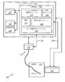
同様の数字は同じ又は同様の構成要素を表す図面を参照し、最初に図1を参照して、アブレーションを実施するシステム100が、一実施形態に従って一実施形態に従って示される。システム100は、ワークステーション又はコンソール112を有し、ワークステーション又はコンソール112から、プロシージャが監督され及び/又は管理される。ワークステーション112は、好適には、プログラム及びアプリケーションを記憶する1又は複数のプロセッサ114及びメモリ116を有する。メモリ116は、パラメータ評価の少なくとも一部を記憶することができ、監視モジュール115は、イメージングシステム104のイメージングパラメータ(例えば、プッシュパラメータ及び追跡パラメータ)を評価し/最適化するように、及び/又はアブレーション機器102のアブレーションパラメータ(例えば、アブレーション機器102を起動させ又は停止させるパラメータ)を評価し/最適化するように、構成される。超音波(US)装置又はシステム104からのフィードバック信号は、イメージングされた又は処置されたロケーションにおけるせん断弾性係数、せん断波速度、組織弾性又は他の特性を測定して、プロシージャの最中に進行及び処置エリアに関するリアルタイム情報を提供するために、使用される。パラメータ評価及び監視モジュール115は、ソフトウェア(例えば、パラメータを更新するためのプログラム)及び/又はハードウェア(例えば、イメージング装置104とアブレーション装置102の間のイーサネットリンク)を有することができる。
Similar numbers refer to drawings representing the same or similar components, first referring to FIG. 1, and the
計画モジュール122は、メモリ116に記憶されることができ、プロシージャを実施するための目的、目標及びタスクシーケンスを提供することができる。計画モジュール122は、閾値を記憶するとともに、測定され監視されたパラメータと閾値/基準との間の比較についての他の基準を記憶することができる。機器又はアブレーション装置102は、カテーテル、ガイドワイヤ、プローブ、内視鏡、ロボット、電極、フィルタ装置、バルーン装置、又はアブレーションを実行するための他の医療コンポーネントを有することができ、又はそれらの一部でありうる。アブレーションは、RFアブレーション、クライオアブレーション、高密度焦点式超音波(HIFU)、レーザアブレーション、マイクロ波、等を含むことができる。アブレーション装置102はアブレーションコントローラ126に接続され、アブレーションコントローラ126によって制御されることができるが、コントローラの機能は、ワークステーション112を使用して扱われることができる。アブレーション装置102及びコントローラ126(センサ又は同類のものを含むことができる)は、集合的にアブレーションシステム124と呼ばれる。本原理は、アブレーション治療のために使用される任意の商業的な装置にも適用可能であるアブレーション治療の適応制御を提供する。
The planning module 122 can be stored in
アブレーションシステム124は、アブレーション機器102及びアブレーションコントローラ126を有する。アブレーションシステム124は、ワークステーション112の一部でありえ、又はワークステーション112によって生成されるフィードバックを使用して制御される独立したユニットであってもよい。アブレーションシステム124と超音波システム104との間の通信リンク128は、プロシージャの最中にアブレーション及び他のパラメータの進行をより正確に評価するために、アブレーションシステム124及び/又はイメージングシステム104へのフィードバックを実現するよう提供されることができる。
The
一実施形態において、ワークステーション112は、超音波システム104を使用するプロシージャの最中に収集されるリアルタイム画像上で又はそれに対して測定されたパラメータを表示する画像生成モジュール148を有する。
In one embodiment, workstation 112 has an
エラストグラフィ情報(例えば、せん断弾性係数、せん断速度、弾性、等)は、超音波イメージングを使用して測定され/監視されるが、他のイメージングモダリティが、超音波に加えて又はその代わりに使用されるとともに、これら又は他のパラメータを測定してアブレーションプロセスに関するフィードバックを提供するよう適応されることができることが留意されるべきである。画像134は、弾性又はせん断パラメータを含み及びディスプレイ装置118に表示されるオーバレイにより変更され又はかかるオーバレイを提供されることができ、それにより、ユーザにリアルタイムのフィードバックを提供し、アブレーションプロシージャの進行を示すことができる。他のオーバレイ又は変更は、計画モジュール122に記憶された計画に従う目標又は基準を示すために、ディスプレイ118に表示されることができる。例えば、組織が処置されるにつれて、弾性の比較又は変更が測定され、表示されることができ、リアルタイムの視覚化の比較が、計画モジュール122に記憶される計画に従って表示されるように、処置されたエリアに対して行われることができる。こうして、処置されるべき残りのエリア及び処置されたカバレージエリアの即時の理解は、患者内の空間又はボリューム(被検体)131内で同時に知られる。
Elastographic information (eg, shear modulus, shear rate, elasticity, etc.) is measured / monitored using ultrasound imaging, but used by other imaging modalities in addition to or instead of ultrasound. It should be noted that these or other parameters can be measured and adapted to provide feedback on the ablation process.
ワークステーション112は、被検体(患者)又はボリューム131の1又は複数の内部画像134をビューするためのディスプレイ118を有する。ディスプレイ118は更に、ユーザが、ワークステーション112及びそのコンポーネント及び機能、又はシステム100内の他の任意の構成要素、とインタラクトすることを可能にすることができる。これは更に、ワークステーション112からのユーザフィードバック及びワークステーション112とのインタラクションを可能にするためにキーボード、マウス、ジョイスティック、ハプティック装置又は他の任意の周辺機器又は制御装置を有することができるインタフェース120によって容易にされる。
The workstation 112 has a
一実施形態において、アブレーションプロセスは、手動の態様を有することができる。このような例において、現在選択されたイメージングパラメータ及びせん断速度及びせん断弾性係数の結果的な評価は、オペレータをガイドするのを助けるためにディスプレイ118に表示されることができる。オペレータは、自動的に選ばれたイメージングパラメータ値をオーバーライドし、アブレーションシステム124及び/又は超音波システム104からのフィードバックによる手動操作を可能にするための機構(例えばソフト/仮想ボタン)(インタフェース120)を提供されることができる。
In one embodiment, the ablation process can have a manual aspect. In such an example, the currently selected imaging parameters and the resulting assessment of shear rate and shear modulus can be displayed on the
本原理により、せん断波エラストグラフィ(SWE)は、アブレーション及び特に無線周波数アブレーション(RFA)を監視するために使用されることができる。RFAの最中、組織の弾性特性が変化し、例えばアブレートされている領域は最初に柔らかくなり、それから次第により固くなる。SWEは、RFAの最中、基礎となるスチフネスに対するせん断波速度の依存により、損傷形成の範囲を分析する。局所スチフネスの変化の定量的尺度は、例えばせん断波から測定される放射力により誘導される変位及びタイムツーピーク(TTP)のようなパラメータから得られることができる。 According to this principle, shear wave elastography (SWE) can be used to monitor ablation and especially radio frequency ablation (RFA). During RFA, the elastic properties of the tissue change, for example, the ablated area first softens and then gradually hardens. During RFA, SWE analyzes the extent of damage formation by the dependence of shear wave velocity on the underlying stiffness. Quantitative measures of changes in local stiffness can be obtained from parameters such as radiation-induced displacement and time-to-peak (TTP) measured from shear waves.
パラメータ評価及び監視モジュール115は、RFAシステム124からの入力に基づいて、超音波システム104のプッシュパルス及び追跡パルスのパラメータを(例えば放射力により誘導される変位に関して)自動的に変化させる。このように、RFAのすべてのステージにおいて、信頼性が高い速度評価(及びゆえにせん断弾性係数評価)が得られることができる。RFAシステム124及び超音波システム104が別々のユニットである場合、リンク128は、RFAシステム124を超音波システム104(例えばスキャナコンソール)に接続することができる。代替として、RFAシステム124及び超音波システム104の両方が、ワークステーション112に接続されることができ、又はワークステーション112の一部でありえ、ワークステーション112は、両方のシステムからデータを収集する。このような場合、評価されたイメージングパラメータ(すなわち、プッシュパラメータ及び追跡パラメータ、アブレーション制御パラメータ、等)は、パラメータを調整するために、それぞれのシステム(例えば超音波システム104及び/又はアブレーションシステム124)に戻される。
The parameter evaluation and
RFAシステム124から抽出されることができる関連するパラメータは、例えば経過したRFA時間、累積的な堆積パワー、RFプローブ先端部の現在温度、各タイン(アブレーション機器102の電極)の、当該タインのロケーションにおける現在温度、を含むことができる。適当なイメージングパラメータ(すなわち、プッシュパラメータ及び追跡パラメータ)は、(例えば、予め規定されたルックアップテーブル、プログラム又は他のデータ構造又はモデル130を使用して)RFAシステム124からの入力に基づいて、それぞれ異なる時間に変化するように、パラメータ評価及び監視モジュール115によって選択されることができる、加えて、現在イメージングされている腫瘍又は組織のロケーションが更に、イメージングパラメータの選択の決定要因でありうる。例えば、損傷境界のより近くをイメージングすることは、RF損傷の中央をイメージングすることと比較して、異なるイメージング設定を必要としうる。
Related parameters that can be extracted from the
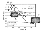
図2を参照して、ウシ肝臓組織に関する正規化された変位対処置時間(秒)のプロット202、204は、治療が進行するときの、損傷形成中のパラメータの変化を示す。を示す正規化された変位プロット202、204は、生体外ウシ肝臓において引き起こされる独立した損傷について最初の軟化及びその後の硬化を示す。はめ込み画像201、203は、肉眼的所見において視覚化される損傷を表現する。ウシ肝臓のRFアブレーションの最中、測定が、加熱ゾーンコアの近くの単一のロケーションにおいて実施された。2つのサンプルが、プロット202及び204に対応するように示されている。軟化による変位の最初の増加206、208の傾向の後に、硬化による正規化変位210、212の減少210、212が続く。ピーク値が常に1であるように、変位210、212は正規化されている。
With reference to FIG. 2, the normalized displacement vs. treatment time (seconds) plots 202, 204 for bovine liver tissue show changes in parameters during injury formation as treatment progresses. Normalized displacement plots 202, 204 show initial softening and subsequent hardening for independent damage caused in in vitro bovine liver. The
図3を参照して、例示として示されるプロット302、304及び306は、アブレーション電極から3mmのところにおける該電極に平行な面内における処置時間の関数としてのタイムツーピークの変化を示す。プロット302、304及び306は、プッシュフォーカスからの横方向追跡位置(距離を表す)を示す。アブレーションが進行し、損傷が形成されるにつれて、傾向は、予想されたものと一致する。タイムツーピーク変化は、せん断波がロケーションに到達するためにより長い時間がかかるので、初期の増加を示し、その後、硬化による増大される速度のため減少を示す。
With reference to FIG. 3,
有限要素シミュレーションは、せん断波変位曲線対伝搬時間の時間プロファイルが、軟組織(例えばスチフネスが約1.33kPaである)と硬組織(例えばスチフネスが約8kPaである)の間でどのように大きく異なるかを示す。正常組織のせん断弾性係数は、〜2kPaであり、アブレートされた組織の場合は40−50kPaに近く、ゆえに、差が重要である。正常組織に適当である固定サンプリングレート(又はパルス繰返し周波数(PRF))がアブレートされた組織についても使用される場合、アブレートされた組織のための変位曲線は、アンダーサンプリングされ、これは、誤ったタイムツーピーク(TTP)測定及びゆえにせん断弾性係数の不正確な評価につながる。 The finite element simulation shows how the time profile of the shear wave displacement curve vs. propagation time differs significantly between soft tissue (eg, stiffness is about 1.33 kPa) and hard tissue (eg, stiffness is about 8 kPa). Is shown. The shear modulus of normal tissue is ~ 2 kPa, which is close to 40-50 kPa for ablated tissue, so the difference is important. If a fixed sampling rate (or pulse repetition frequency (PRF)) suitable for normal tissue is also used for ablated tissue, the displacement curve for the ablated tissue is undersampled, which is incorrect. This leads to time-to-peak (TTP) measurements and therefore inaccurate assessment of shear modulus.
アブレーションの間、温度上昇組織が最初に軟化し、その後最終的に硬化すると、本原理は、この知識を使用して、タイムツーピークプロファイルの完全な完全性が処置の過程全体において維持されるようにパラメータを最適化する。タイムツーピークプロファイルの予想される変化についての知識に基づいて、処置のフェーズの関数として、例えばサンプリングレート(パルス繰返し周波数(PRF)としても知られる)及び追跡ロケーションの間の間隔のような、一連のパラメータを最適化することが有用である。これらの特徴は、処置中にオンザフライで実現され/選択されることができる。 As the temperature-increasing tissue softens first during ablation and then finally hardens, this principle uses this knowledge to ensure that the complete integrity of the time-to-peak profile is maintained throughout the course of treatment. Optimize the parameters to. Based on knowledge of the expected changes in the time-to-peak profile, a series of functions of the phase of treatment, such as the sampling rate (also known as pulse repetition frequency (PRF)) and the interval between tracking locations. It is useful to optimize the parameters of. These features can be realized / selected on the fly during the procedure.
組織のスチフネスは、温度上昇に応じた組織軟化により、加熱の開始時に低下する。組織の壊死閾値温度に達するにつれて、組織は硬化し始め、増大される熱曝露によって硬化し続ける。この変化を追跡することによって、治療の進行が評価されることができ、終了ポイントが決定されることができる。組織スチフネスは、せん断波イメージング(又はフィリップスのイメージングシステム上のフィリップElastPQ)を使用して測定されることができる。これらの技法は、音響放射力を使用して、スチフネス情報を得るために追跡される変位及びせん断波を生成する。 Tissue stiffness decreases at the start of heating due to tissue softening in response to increasing temperature. As the tissue necrosis threshold temperature is reached, the tissue begins to harden and continues to harden due to increased heat exposure. By tracking this change, the progression of treatment can be assessed and the end point can be determined. Tissue stiffness can be measured using shear wave imaging (or Philips ElastPQ on Philips imaging systems). These techniques use acoustic radiation to generate displacement and shear waves that are tracked to obtain stiffness information.
本願明細書に記述されるリアルタイム治療監視及びアセスメント技法は、治療デリバリパラメータの変更をオンザフライで実現して治療結果を最適化するために用いられる。現在の原理は、超音波スキャナからリアルタイムに取得されるせん断波/弾性係数及び/又はエラストグラフィ測定に基づいて、治療パラメータを調整する。これらのエラストグラフィ測定値は、処置ボリューム全体にわたって、複数の向きにおいて測定されることができ、通常のシステムと比較して処置の有効性のより完全な状態を提供することができる。 The real-time treatment monitoring and assessment techniques described herein are used to enable on-the-fly changes in treatment delivery parameters to optimize treatment outcomes. The current principle adjusts therapeutic parameters based on shear wave / modulus and / or elastography measurements obtained in real time from an ultrasonic scanner. These elastographic measurements can be measured in multiple orientations throughout the treatment volume, providing a more complete state of treatment effectiveness compared to conventional systems.
図4を参照して、22分のアブレーションの最中の異なる時点におけるタイムツーピークベースの(TTP)弾性マップを示すグラフが例として示されている。第1のマップ402は、10分のアブレーション後の弾性を示す。第2のマップ404は、14分のアブレーション後の弾性を示す。第3のマップ406は、18分のアブレーション後の弾性を示す。第4のマップ408は、22分のアブレーション後の弾性を示す。マップ402−408を通じて左へ移動する暗領域410は軟化を表し、右の暗領域412は、生体外ウシ肝臓の損傷の硬化を表す。破線414は、病理学的評価から算出される最終的な熱損傷境界を表す。
With reference to FIG. 4, a graph showing a time-to-peak based (TTP) elastic map at different time points during a 22 minute ablation is shown as an example. The
本原理により、RFAの間、損傷形成と同時のエラストグラフィ測定の有用性を示す実験が、本発明の発明者によって実施された。これらの実験において、追跡シーケンスは、プッシュビームから1.5mm離れたところに配される7つのロケーションを有した。アブレーションニードルが超音波画像上の断面内にあるように、超音波プローブは、アブレーションニードルに対して横断方向に向けられる。ElastPQウィンドウは、左端がアブレーションタインから10mmのところにあるように、スクリーン上で慎重に配置された。各プッシュ−追跡シーケンスに応じた生の超音波データは、処置の全過程の間、15秒毎に取得された。データは、アブレーションの全過程の間、タイムツーピーク(TTP)評価を取得するように処理された。TTP値は、3mmの軸方向間隔の各追跡ラインごとに取得された。このように、熱アブレーション治療を受けている領域全体にわたるTTPの変化を示す空間マップが取得された。 According to this principle, experiments demonstrating the usefulness of elastographic measurements at the same time as damage formation during RFA were carried out by the inventor of the present invention. In these experiments, the tracking sequence had seven locations located 1.5 mm away from the push beam. The ultrasound probe is oriented transversely to the ablation needle so that the ablation needle is within a cross section on the ultrasound image. The ElastPQ window was carefully placed on the screen so that the left edge was 10 mm from the ablation tine. Raw ultrasound data for each push-tracking sequence was acquired every 15 seconds during the entire course of treatment. The data were processed to obtain a time-to-peak (TTP) rating during the entire process of ablation. TTP values were obtained for each tracking line with an axial spacing of 3 mm. Thus, a spatial map showing changes in TTP over the area receiving heat ablation treatment was obtained.
瞬時のTTPマップ402、404、406、408から、TTP差分マップは、加熱前に取得された第1のTTPフレームと比較することによって取得される。それぞれ異なる時点のTTPマップ402、404、406、408が図示されている。アブレーションタインは、深さ45mm及び画像の右端から約2mmのところにあった。マップ上の正の値は、組織が硬化していることを示し(TTPが、現在のマップにおいて低下しているので)、負の値は、軟化していることを示す(TTPが、現在のマップにおいて増加している)。この取り決めによって、最初、組織は、アブレーションタインの近くで軟化し(10分)、この軟化は、右端(タインの近く)から左端(損傷の境界の近く)へ向けて徐々(14、18及び22分)に移動することが分かる。同時に、右端は、それがタインの近くにあるので、硬化し始める。加熱の間、硬化効果は更に、右から左へ、すなわち、タインにより近い組織から、形成している損傷の境界に一層近い領域へと、徐々に移動し始める。 From the instantaneous TTP maps 402, 404, 406, 408, the TTP difference map is obtained by comparing with the first TTP frame obtained before heating. TTP maps 402, 404, 406, 408 at different time points are shown. The ablation tine was at a depth of 45 mm and about 2 mm from the right edge of the image. Positive values on the map indicate that the tissue is hardened (because TTP is reduced in the current map) and negative values indicate softening (TTP is current). Increasing in the map). This arrangement initially softens the tissue near the ablation tine (10 minutes), and this softening gradually (14, 18 and 22) from the right edge (near the tine) to the left edge (near the injury boundary). You can see that it moves to minutes). At the same time, the right edge begins to cure because it is near the tine. During heating, the hardening effect further begins to gradually move from right to left, that is, from the tissue closer to Tyne to the region closer to the boundary of the forming damage.
損傷形成中のせん断弾性係数の大きい変化により、損傷形成プロセスのさまざまなステージにおいて、プッシュ及び追跡のためのそれぞれ異なるパラメータセットが最適である。最適化されることができるパラメータは、パルス繰返し周波数(PRF)、追跡ロケーションの数、追跡ビーム間の間隔等を含むことができる。しかしながら、これらのパラメータの変化は、経過したRFアブレーション時間に基づいて、オペレータによって手動で行われる必要がありうる。これらのパラメータを変更するための判断がユーザの裁量で主観的に行われうるので、これは不都合であり、最適でもない。これらのパラメータの最適値は、ラボでの生体外実験から、RFAプロセスの個々の異なるステージについて、経験的に導出される。これらの経験的に取得されたパラメータ値は、RFAプロセスの異なる特徴(例えば経過したRFA時間、累積的な出力パワー、RFプローブ先端部での温度、等)に関連することができる。自動化された態様でのこのようなメトリックの使用は、せん断速度及びせん断弾性係数の最適且つ正確な評価のために、イメージング(プッシュ及び追跡)パラメータをリアルタイムに最適化するために、本原理に従って使用されることができる。 Due to the large changes in shear modulus during damage formation, different parameter sets for push and tracking are optimal at different stages of the damage formation process. Parameters that can be optimized can include pulse repetition frequency (PRF), number of tracking locations, spacing between tracking beams, and the like. However, changes in these parameters may need to be made manually by the operator based on the elapsed RF ablation time. This is inconvenient and not optimal, as the decision to change these parameters can be made subjectively at the user's discretion. Optimal values for these parameters are empirically derived from in vitro experiments in the lab for individual different stages of the RFA process. These empirically obtained parameter values can be related to different characteristics of the RFA process (eg, RFA time elapsed, cumulative output power, temperature at the tip of the RF probe, etc.). The use of such metrics in an automated manner is used according to this principle to optimize imaging (push and tracking) parameters in real time for optimal and accurate assessment of shear rates and shear modulus. Can be done.
図5を参照して、ブロック/フロー図はシステム/方法500を示し、システム/方法500は、RFAシステム512と超音波システム516の間の(モジュール115を通じた)通信リンク(フィードバック)520/522を提供する。通信リンク又は接続520/522は、RFAシステム512からのパラメータを超音波システム516のパラメータに伝送し、それらのパラメータを調整するために、ハードウェア及びソフトウェアの組み合わせを有することができる。パラメータは、リンク520/522に沿って最適化部506を有するパラメータ評価及び監視モジュール115によって、リアルタイムに最適化される。最適化部506は、例えばパルス繰返し周波数(PRF)、追跡ロケーションの数、追跡ビームの間の間隔、又は他の任意の適切なパラメータのような、パラメータを最適化する。例えば、RFAプロシージャの開始時に、パラメータベクトル「X」が、接続520に沿ってモジュール506に伝送される。RFA経過時間(及び/又は出力パワー/電圧又は他の入力)から、パラメータベクトルが、それに応じて変更される(最初、「Y」に対する変更、その後、「Z」に対する変更、その他)。「X」、「Y」、「Z」の値は、モデル、ルックアップテーブル、公式又は他の評価技法を使用して、経験的に決定されることができる。一実施形態において、音響場測定(例えば、せん断波パラメータ、せん断計数、等)が実施されることができ、システム500が、パラメータ値を測定するためにRFAシステム512と協働して使用される。例えば、ベクトルXは、経過したRFA時間、累積的な堆積パワー、RFプローブ先端部の現在温度、各タインの当該タインのロケーションにおける現在温度、等を有しうる。これらの特徴は、超音波システム516への接続522にベクトルYを出力するために、モジュール506によって更新されることができる。接続520/522は、イーサネットケーブル、インタフェースするコンピュータ/回路基板、ワイヤレス通信リンク、その他を含むことができる。
With reference to FIG. 5, the block / flow diagram shows the system /
一実施形態において、RFAプローブ(102、図1)は、ブロック504においてアブレーションを開始するために、ブロック502において組織に挿入される。ブロック514において、超音波プローブ又は関心領域(ROI)が、SWEのために位置付けられ、設定される。適当なRFAパラメータが、RFAシステム512から連続的に読み込まれる。最適化部506は、RFA設定及び現在プローブロケーションの組み合わせに基づいて、その時点で使用すべき最適イメージング設定(例えばプッシュ及び追跡パラメータ設定)を提案する。これは、記憶された計画によって、又はオペレータ経験、その他に基づいて、決定されることができる。モジュール506は、新しいプッシュ及び追跡パラメータを計算する際に、せん断波イメージング出力を考慮する。パラメータ評価及び監視モジュール115は更に、所与のロケーションにおいて評価されたせん断弾性係数を、(例えば超音波システム516のスクリーン上、スタンドアロンのコンピュータスクリーン上、又はディスプレイ118上のいずれかに)表示するように構成される画像処理モジュール508(モジュール148、図1)を有する。更に、当該時点(モジュール506によって)に選ばれたイメージングパラメータが表示されることもできる。ユーザは更に、インタフェース120(図1)を使用して、任意の時点にパラメータの自己の選択を入力することによって、イメージングパラメータの自動選択をオーバーライドすることができる。
In one embodiment, the RFA probe (102, FIG. 1) is inserted into the tissue at block 502 to initiate ablation at
いつでも、オペレータは、超音波プローブ(又はSWE用のROI)を異なる別のロケーションへ移動させることができる(ブロック514)。アブレーション電極に関する新しいロケーションの空間座標についての知識に従って、イメージングパラメータが更新される。アブレーションプローブは更に、ブロック502において、新しいロケーションに位置付けし直されることができる。ブロック510において、アブレーションが停止され、プロセスは、プロシージャの1又は複数の目標が達成されるか又は他の基準は満たされるときに終了する。システム500は、自動化された態様で速度及びせん断弾性係数の正確な評価を可能にすることによって、RFAプロシージャのより正確且つ信頼性のある監視を可能にする。本原理は、超音波プラットホーム上のSWEモジュール(例えばPhilipsのElastPQ及び/又はせん断波イメージング(SWI))に組み込まれることができる。
At any time, the operator can move the ultrasonic probe (or ROI for the SWE) to another different location (block 514). The imaging parameters are updated according to the knowledge of the spatial coordinates of the new location for the ablation electrode. The ablation probe can also be repositioned at the new location in block 502. At
図6を参照して、別のブロック/フロー図は、超音波システム616からのフィードバック(画像及び/又はデータ)に基づいてRFAシステム612を制御するために通信リンク又は接続606を提供するシステム/方法600を示す。通信リンク又は接続606は、RFAシステム612のパラメータを伝送し、超音波システム616のパラメータからそれらを調整するためのハードウェア及びソフトウェアの組み合わせを有することができる。
With reference to FIG. 6, another block / flow diagram provides a communication link or connection 606 to control the RFA system 612 based on feedback (images and / or data) from the ultrasound system 616.
今日のアブレーション治療処方は、デバイスからの温度(又は製造業者のデバイス上のインピーダンス)測定値を使用することに依存する。温度測定値は、アブレーション電極の先端部に位置するまばらな熱電対の組から得られる。熱電対は、損傷の中心コアにおける温度上昇に関する局所情報を提供するが、境界における治療の有効性に関する価値ある情報に欠ける。 Today's ablation treatment formulations rely on the use of temperature (or impedance on the manufacturer's device) measurements from the device. Temperature measurements are obtained from a sparse set of thermocouples located at the tip of the ablation electrode. Thermocouples provide local information about temperature rise in the central core of injury, but lack valuable information about the effectiveness of treatment at the border.
本原理によれば、超音波システム616によるエラストグラフィイメージングは、損傷の範囲全体を囲む可能性として複数の空間次元において、治療により引き起こされる変化の直接的な効果を測定するやり方を提供する。超音波スキャナから導き出されるこの包括的な情報は、マルチ電極加熱構造において使用されるさまざまなアブレーション電極に出力される電力デリバリを最適化するために用いられることができる。 According to this principle, elastographic imaging with an ultrasonic system 616 provides a way to measure the direct effect of treatment-induced changes in multiple spatial dimensions that may surround the entire area of injury. This comprehensive information derived from the ultrasonic scanner can be used to optimize the power delivery output to the various ablation electrodes used in the multi-electrode heating structure.
このリアルタイム情報は、損傷のコアのみでなく、損傷の境界においても実施される包括的な測定に基づいて、パワーを選択的に増大させ又は低下させることによって、又はアブレーション電極のいくつかをオフにすることなどにより、治療デリバリパラメータを適応させるために使用される。 This real-time information is based on comprehensive measurements performed not only at the core of the damage, but also at the boundaries of the damage, by selectively increasing or decreasing the power, or by turning off some of the ablation electrodes. Used to adapt therapeutic delivery parameters, such as by doing so.
超音波システム616は、エラストグラフィイメージング/測定モジュール604を具備する超音波スキャナを有し、モジュール604は、アブレーション中にリアルタイムに局所スチフネス特性の評価を取得することができる。パラメータ評価及び監視モジュール115は更に、独立したソースからの入力(例えば超音波システム616及び/又はSWEモジュール604からの画像又はデータ)に基づいてパワー設定を動的に変更することができるアブレーション制御治療デバイス602を有することができる。アブレーション制御治療デバイス602は、制御論理又はプロセッサ(例えばワークステーション112、図1)を有することができ、制御論理又はプロセッサは、超音波システム616から、超音波を利用した測定(例えばせん断弾性係数又はエラストグラフィ評価)を受け取り、空間的及び/又は時間的(経時的)な測定マップ上の1又は複数ポイントにおいて満たされる予め決められた閾値に基づいて、アブレーション生成器モジュールのパワー設定又は動作モードを変更する。
The ultrasound system 616 has an ultrasound scanner with an elastography imaging / measurement module 604, which can acquire an assessment of local stiffness characteristics in real time during ablation. The parameter evaluation and
データリンク又は接続606は、(モジュール115を通じて)超音波システム616からの測定値がアブレーション装置612へ伝送されることを可能にする。 The data link or connection 606 allows measurements from the ultrasonic system 616 (through module 115) to be transmitted to the ablation device 612.
システム600は、例えば、RFアブレーション加熱中に得られたエラストグラフィ測定を用いる。一実施形態において、ElastPQ(Elastography Point Quantification)モードの変更されたバージョンが用いられ、それは、例えば、C5−1プローブを具備するiU−22超音波スキャナ上にありうる。本願明細書における実施形態は、超音波から導かれる特定のタイプの測定に言及しているが、本原理は、治療中に損傷の輪郭を提供することにまで拡張されることができる。損傷の中心及び損傷境界の近くの両方である個々の異なるロケーションで行われるエラストグラフィ測定(例えばElastPQ(point quantification)技法)は、損傷形成の進行を示す。治療の現在の状態を反映するこれらのリアルタイムのエラストグラフィに基づく測定が与えられるので、アブレーションゾーンの中心の及び周辺部の近くの幾つかの代表的な空間ポイントの選択が実施されることができ、TTP評価の展開(変化)が監視されることができる。
一実施形態において、実際のせん断弾性係数値(又はヤングモジュラス)は、プロセッサ/制御モジュール602への入力として使用されることができる。別の実施形態において、TTP評価の変化が用いられることができる。せん断速度等の他の制御パラメータが更に企図される。エラストグラフィパラメータは、処置される領域(ピクセル/ボクセル)を更新し、計画された処置ボリューム(PTV)と比較され、アブレーション装置612と関連するプロセッサに供給されるために、利用されることができる。プロセッサ又は制御モジュール602は、測定値をプリセット閾値と比較することによって、リアルタイムに、電力デリバリを停止するため又はパワー堆積プロファイルを変更するための判定を行うことができる。パワーを変更するためのアルゴリズム又はプログラム(130、図1)は、比例積分微分(PID)コントローラタイプのアルゴリズムに基づくことができる。複数の空間的又は時間的な測定値は、コントローラの意思決定倫理において用いられることができる。 In one embodiment, the actual shear modulus value (or Young Modulus) can be used as an input to the processor / control module 602. In another embodiment, changes in TTP assessment can be used. Other control parameters such as shear rate are further contemplated. Elastographic parameters can be utilized to update the area to be treated (pixels / voxels), compare it to the planned treatment volume (PTV), and feed it to the ablation device 612 and associated processor. .. The processor or control module 602 can make a determination in real time to stop power delivery or change the power deposition profile by comparing the measured value with a preset threshold. The algorithm or program for changing the power (130, FIG. 1) can be based on a proportional integral differential (PID) controller type algorithm. Multiple spatial or temporal measurements can be used in controller decision ethics.
別の実施形態において、システム600は、完全な損傷形成を確実にするために、アブレーションタインの(複数の)付加のロケーションを示唆することができる。例えば、エラストグラフィ測定は、所望の空間ロケーションにおいて行われることができる。測定値が、当該ロケーションの組織が、壊死しておらず、現在の電極位置に関するアブレーションパラメータの任意の変化によって壊死する見込みがないことを示す場合、システム600は、当該組織領域により近いタインの新しいロケーションを示すことができる。この情報は、インタフェース(例えばディスプレイ118、図1)を通じてユーザに提供されることができる。
In another embodiment, the
図7を参照して、アブレーションプロシージャのエラストグラフィフィードバックを用いる方法が、例示の実施形態により例示的に示される。ブロック702において、アブレーションプローブ又は(複数の)タイン及び超音波プローブが位置付けられ、アブレーションが開始される。ブロック704において、超音波弾性ベースの測定は、アブレーションされた領域について、1又は複数のロケーションにおいて行われる。ブロック706において、(複数の)弾性測定値がエンドポイントと比較される。エンドポイントは、処置エンドポイント、又は進行を評価するために事前の測定値を含むことができる。ブロック708において、処置エンドポイントが到達されたかどうか判定が行われる。処置エンドポイントが到達された場合、治療は、ブロック712において停止される。処置エンドポイントが到達されていない場合、ブロック710において、治療パラメータが必要に応じて更新され、プロセスはブロック704に戻る。更新されるパラメータは、例えば、パワー、持続時間、使用される加熱素子の数、タイン/加熱素子の位置付け、などを含みうる。
With reference to FIG. 7, a method of using elastographic feedback of an ablation procedure is exemplified by an exemplary embodiment. At
図8を参照して、エラストグラフィフィードバックを使用してアブレーションを実施する方法が例示的に示される。エラストグラフィフィードバックは、アブレーション装置パラメータ、イメージングパラメータ又はそれらの両方を調整するために用いられることができることが理解されるべきである。本原理は、プロシージャ、測定された閾値又は他の基準に依存して、断続的に適用されることができる。例えば、イメージングからのフィードバックは、アブレーションパラメータを変更するために用いられることができ、アブレーションパラメータは、イメージングパラメータを変更するために用いられることができ、必要に応じて、両方の変更が、同じプロシージャの最中に用いられることができる。 With reference to FIG. 8, a method of performing ablation using elastographic feedback is exemplified. It should be understood that elastographic feedback can be used to adjust ablation device parameters, imaging parameters, or both. This principle can be applied intermittently, depending on the procedure, measured thresholds or other criteria. For example, feedback from imaging can be used to change ablation parameters, ablation parameters can be used to change imaging parameters, and if necessary, both changes are in the same procedure. Can be used in the middle of.
ブロック802において、アブレーションを開始するために、アブレーション装置及び超音波プローブ(又はその複数)が、被検体内の処置されるべき領域に又はその近くに位置付けられる。別のイメージングモダリティが用いられる場合、超音波プローブは位置付けられる必要はない。ブロック804において、測定情報が、アブレーションプロセス中、エラストグラフィパラメータ(例えば、せん断波、せん断弾性係数、弾性/スチフネス、その他)又は関連するパラメータを含むフィードバックとして生成される。測定情報は、アブレーション装置(アブレーションパラメータ)、超音波スキャナ(イメージングパラメータ)、又はそれら両方からの情報を含む。フィードバック情報は、他のソース又は機器によっても供給されることができる。超音波スキャナの測定情報は、せん断弾性係数、タイムツーピーク評価、せん断速度などの1又は複数を含むことができる。アブレーション装置からの測定情報は、経過したアブレーション時間、累積的な堆積パワー、アブレーションプローブ先端温度、及び/又はアブレーションタインの現在温度のパラメータのうち1又は複数を含むことができる。
At
ブロック806において、超音波スキャナのイメージングパラメータ及び/又はアブレーション装置の制御信号の少なくとも1つが、フィードバックに従って適応的に更新される。イメージングパラメータは、プッシュ及び追跡パラメータを含むことができ、プッシュ及び追跡パラメータは、パルス繰返し周波数、追跡ロケーションの数及び/又は追跡ビームの間隔の1又は複数を含むことができる。超音波スキャナからのフィードバックは、空間的又は時間的な測定マップ上の1又は複数のポイントからのスチフネス測定を含むことができ、この場合、制御信号の調整は、空間的又は時間的な測定マップ上の1又は複数のポイントからのスチフネス測定を用いる。制御信号は、アブレーション装置のパワー設定の1又は複数及び/又はアブレーション装置の動作モードを調整するように構成されることができる。アブレーション装置の位置付け、処置持続時間、及び構成(素子の数、等)が更に制御されることができる。 At block 806, at least one of the ultrasonic scanner's imaging parameters and / or the ablation device's control signal is adaptively updated according to the feedback. Imaging parameters can include push and tracking parameters, and push and tracking parameters can include one or more of pulse repetition frequencies, number of tracking locations and / or interval of tracking beams. Feedback from the ultrasonic scanner can include stiffness measurements from one or more points on the spatial or temporal measurement map, in which case the adjustment of the control signal is a spatial or temporal measurement map. Use the stiffness measurement from one or more points above. The control signal can be configured to adjust one or more of the power settings of the ablation device and / or the operating mode of the ablation device. The positioning of the ablation device, treatment duration, and configuration (number of elements, etc.) can be further controlled.
ブロック808において、エラストグラフィな(せん断波又は関連する)パラメータが、ディスプレイ上に、イメージングされたロケーションに対して表示される。アブレーションパラメータ、イメージングパラメータ又は他の情報もまた表示されることができる。ブロック810において、アブレーション及び/又はイメージングパラメータは、インタフェースを通じて手動変更によって手動でオーバーライドされることができる。
At
ブロック812において、処置の目標が達成されると、アブレーションプロセスが完了される。ターゲット目標は、術前計画又は他の基準からの目標を含むことができる。
At
添付の請求項を解釈する際に、以下が理解されるべきである:
a)「含む、有する(comprising)」という語は、所与の請求項に列挙される以外の構成要素又は工程の存在を除外しない;
b)構成要素に先行する「a」又は「an」の語は、このような構成要素の複数の存在を除外しない;
c)請求項における参照符号は、それら請求項の範囲を制限しない;
d)いくつかの「手段」は、同じアイテムによって、又はハードウェア若しくはソフトウェア実現される構造又は機能によって、表されることができる;及び、
e)特に示されない限り、特定の工程シーケンスが必要とされることが意図されるものではない。
In interpreting the attached claims, the following should be understood:
a) The term "comprising" does not exclude the existence of components or processes other than those listed in a given claim;
b) The word "a" or "an" preceding a component does not exclude the existence of multiple such components;
c) The reference codes in the claims do not limit the scope of those claims;
d) Several "means" can be represented by the same item, or by the structure or function realized by the hardware or software; and
e) Unless otherwise indicated, it is not intended that a particular process sequence is required.
エラストグラフィ監視に基づく適応的なアブレーション及び治療ためのシステム及び方法の好適な実施形態(制限的ではなく説明的であることが意図される)が記述されているが、変更及び変形が、上述の教示を考慮して当業者によって行われることができることに注意されたい。従って、変更が、開示される開示の特定の実施形態において行われることができ、かかる変更は、添付の請求項によって示されるようにここに開示される実施形態の範囲内にある理解されるべきである。こうして特許法によって要求される詳細及び特殊性を記述したが、特許証によって保護されることが望まれ主張されることは、添付の請求項に記載される。 Suitable embodiments of systems and methods for adaptive ablation and treatment based on elastography monitoring (intended to be descriptive rather than restrictive) have been described, with modifications and variations described above. Note that it can be done by one of ordinary skill in the art in consideration of the teaching. Therefore, changes can be made in a particular embodiment of the disclosed disclosure, and such changes should be understood to be within the scope of the embodiments disclosed herein as set forth in the appended claims. Is. It is stated in the appended claims that the details and peculiarities required by patent law have been described in this way, but that it is desired and claimed to be protected by a patent certificate.
Claims (5)
制御信号に従って組織をアブレーションするアブレーション装置と、 An ablation device that ablates tissue according to control signals,
エラストグラフィ測定を行うイメージング装置と、 An imaging device that performs elastography measurement and
前記イメージング装置からのエラストグラフィ測定情報及び/又は前記アブレーション装置からの測定情報を、フィードバックとして受け取り、アブレーションプロセス中の個々の異なる時間に、前記フィードバックに応じて、前記イメージング装置のイメージングパラメータを調整するとともに、治療目標を達成するよう前記アブレーション装置を制御するために前記制御信号を調整する、パラメータ評価及び監視モジュールと、 The elastography measurement information from the imaging device and / or the measurement information from the ablation device is received as feedback, and the imaging parameters of the imaging device are adjusted according to the feedback at individual different times during the ablation process. Along with, a parameter evaluation and monitoring module that adjusts the control signal to control the ablation device to achieve a therapeutic goal.
を有し、Have,
前記パラメータ評価及び監視モジュールは、処置エンドポイントを決定するために前記エラストグラフィ測定情報を計画ボリュームと比較する、 The parameter evaluation and monitoring module compares the elastographic measurement information with the planned volume to determine the treatment endpoint.
システム。system.
Priority Applications (1)
| Application Number | Priority Date | Filing Date | Title |
|---|---|---|---|
| JP2021080094A JP7371058B2 (en) | 2015-02-27 | 2021-05-11 | Adaptive ablation and treatment systems and methods based on elastography monitoring |
Applications Claiming Priority (3)
| Application Number | Priority Date | Filing Date | Title |
|---|---|---|---|
| US201562121520P | 2015-02-27 | 2015-02-27 | |
| US62/121,520 | 2015-02-27 | ||
| PCT/IB2016/050806 WO2016135584A2 (en) | 2015-02-27 | 2016-02-16 | System and method for adaptive ablation and therapy based on elastography monitoring |
Related Child Applications (1)
| Application Number | Title | Priority Date | Filing Date |
|---|---|---|---|
| JP2021080094A Division JP7371058B2 (en) | 2015-02-27 | 2021-05-11 | Adaptive ablation and treatment systems and methods based on elastography monitoring |
Publications (3)
| Publication Number | Publication Date |
|---|---|
| JP2018511367A JP2018511367A (en) | 2018-04-26 |
| JP2018511367A5 JP2018511367A5 (en) | 2019-02-28 |
| JP6914842B2 true JP6914842B2 (en) | 2021-08-04 |
Family
ID=55521758
Family Applications (2)
| Application Number | Title | Priority Date | Filing Date |
|---|---|---|---|
| JP2017544961A Active JP6914842B2 (en) | 2015-02-27 | 2016-02-16 | Adaptive ablation and treatment systems and methods based on elastography monitoring |
| JP2021080094A Active JP7371058B2 (en) | 2015-02-27 | 2021-05-11 | Adaptive ablation and treatment systems and methods based on elastography monitoring |
Family Applications After (1)
| Application Number | Title | Priority Date | Filing Date |
|---|---|---|---|
| JP2021080094A Active JP7371058B2 (en) | 2015-02-27 | 2021-05-11 | Adaptive ablation and treatment systems and methods based on elastography monitoring |
Country Status (6)
| Country | Link |
|---|---|
| US (1) | US11832866B2 (en) |
| EP (2) | EP3878371A1 (en) |
| JP (2) | JP6914842B2 (en) |
| CN (1) | CN107427280B (en) |
| RU (1) | RU2707037C2 (en) |
| WO (1) | WO2016135584A2 (en) |
Families Citing this family (23)
| Publication number | Priority date | Publication date | Assignee | Title |
|---|---|---|---|---|
| JP6599885B2 (en) * | 2014-03-27 | 2019-10-30 | コーニンクレッカ フィリップス エヌ ヴェ | A method for thermal fracture mark size control based on normalized displacement difference |
| WO2016181320A1 (en) | 2015-05-12 | 2016-11-17 | Navix International Limited | Fiducial marking for image-electromagnetic field registration |
| RU2017140235A (en) | 2015-05-12 | 2019-06-13 | Навикс Интернэшнл Лимитед | Assessment of lesions by analyzing dielectric properties |
| EP3484362A1 (en) | 2016-07-14 | 2019-05-22 | Navix International Limited | Characteristic track catheter navigation |
| WO2018092071A1 (en) | 2016-11-16 | 2018-05-24 | Navix International Limited | Estimators for ablation effectiveness |
| US11284813B2 (en) | 2016-11-16 | 2022-03-29 | Navix International Limited | Real-time display of tissue deformation by interactions with an intra-body probe |
| CN110072449B (en) | 2016-11-16 | 2023-02-24 | 纳维斯国际有限公司 | Esophageal position detection by electrical mapping |
| WO2018092063A1 (en) | 2016-11-16 | 2018-05-24 | Navix International Limited | Real-time display of treatment-related tissue changes using virtual material |
| CN110177500B (en) | 2016-11-16 | 2022-03-04 | 纳维斯国际有限公司 | Dynamic visual rendering of tissue models |
| WO2018130976A1 (en) * | 2017-01-12 | 2018-07-19 | Navix International Limited | Estimation of effectiveness of ablation adjacency |
| JP6853145B2 (en) * | 2017-08-29 | 2021-03-31 | 日本ライフライン株式会社 | Ablation system |
| US10987171B2 (en) * | 2017-11-10 | 2021-04-27 | Smith & Nephew, Inc. | Orthopedic systems, components, and methods |
| EP3578226A1 (en) * | 2018-06-07 | 2019-12-11 | Koninklijke Philips N.V. | A temporal thermal ablation representation for therapy delivery |
| EP3618079A1 (en) * | 2018-08-30 | 2020-03-04 | Koninklijke Philips N.V. | Imaging method using pain sensor |
| CN112912762A (en) * | 2018-10-23 | 2021-06-04 | 皇家飞利浦有限公司 | Adaptive ultrasound flow imaging |
| WO2020171998A2 (en) * | 2019-02-21 | 2020-08-27 | St. Jude Medical, Cardiology Division, Inc. | Systems and methods for assessing ablation lesions |
| CN110368590A (en) * | 2019-08-02 | 2019-10-25 | 董彦英 | A kind of human body cell purification method, electronic equipment and computer readable storage medium based on wideband string wave energy technology |
| CN110755148B (en) * | 2019-09-20 | 2020-09-08 | 姚陈果 | Pulsed electric field tumor ablation parameter optimization system |
| CN111000627B (en) * | 2019-12-04 | 2020-11-20 | 南京航空航天大学 | Microwave ablation tissue Young modulus real-time evaluation method and device based on reduced scattering coefficient |
| CN110974412B (en) * | 2019-12-17 | 2021-01-08 | 南京航空航天大学 | Temperature-based real-time evaluation method and device for Young modulus of microwave ablation tissue |
| CN111243724A (en) * | 2020-01-06 | 2020-06-05 | 南京康友医疗科技有限公司 | Ablation instrument and medical record data monitoring and management system |
| CN116805308A (en) * | 2021-06-28 | 2023-09-26 | 杭州佳量医疗科技有限公司 | Laser ablation evaluation system based on magnetic resonance guidance |
| CN114587565B (en) * | 2022-03-01 | 2023-09-29 | 河南中医药大学 | Temperature control method and system in radio frequency ablation |
Family Cites Families (26)
| Publication number | Priority date | Publication date | Assignee | Title |
|---|---|---|---|---|
| JP2000175933A (en) * | 1998-12-15 | 2000-06-27 | Toshiba Corp | Ultrasonic cauterization therapeutic apparatus |
| US7166075B2 (en) * | 2002-03-08 | 2007-01-23 | Wisconsin Alumni Research Foundation | Elastographic imaging of in vivo soft tissue |
| US7306593B2 (en) | 2002-10-21 | 2007-12-11 | Biosense, Inc. | Prediction and assessment of ablation of cardiac tissue |
| US20050215899A1 (en) * | 2004-01-15 | 2005-09-29 | Trahey Gregg E | Methods, systems, and computer program products for acoustic radiation force impulse (ARFI) imaging of ablated tissue |
| WO2007134256A2 (en) * | 2006-05-11 | 2007-11-22 | Reliant Technologies, Inc. | Apparatus and method for ablation-related dermatological treatment of selected targets |
| US8556888B2 (en) | 2006-08-04 | 2013-10-15 | INTIO, Inc. | Methods and apparatuses for performing and monitoring thermal ablation |
| US7871406B2 (en) * | 2006-08-04 | 2011-01-18 | INTIO, Inc. | Methods for planning and performing thermal ablation |
| WO2008050276A1 (en) * | 2006-10-24 | 2008-05-02 | Koninklijke Philips Electronics, N.V. | Thermal imaging feedback for optimizing radio frequency ablation therapy |
| US10492854B2 (en) * | 2007-12-05 | 2019-12-03 | Biosense Webster, Inc. | Catheter-based acoustic radiation force impulse system |
| ES2736276T3 (en) * | 2008-07-14 | 2019-12-27 | Arizona Board Of Regents For And On Behalf Of Arizona State Univ | Cellular activity modulation devices using ultrasound |
| US9364194B2 (en) * | 2008-09-18 | 2016-06-14 | General Electric Company | Systems and methods for detecting regions of altered stiffness |
| EP2378976A1 (en) * | 2008-12-22 | 2011-10-26 | Koninklijke Philips Electronics N.V. | Ablation control device for real-time monitoring of tissue displacement in reaction to a force applied |
| US8328726B2 (en) * | 2009-04-01 | 2012-12-11 | Tomy Varghese | Method and apparatus for monitoring tissue ablation |
| US20100286520A1 (en) | 2009-05-11 | 2010-11-11 | General Electric Company | Ultrasound system and method to determine mechanical properties of a target region |
| WO2011098913A1 (en) | 2010-02-09 | 2011-08-18 | Oscillon Ltd. | Device for traversing vessel occlusions and method of use |
| US20120029498A1 (en) * | 2010-07-30 | 2012-02-02 | Daniel Igor Branovan | Bipolar Radio Frequency Ablation Instrument |
| US20120065506A1 (en) | 2010-09-10 | 2012-03-15 | Scott Smith | Mechanical, Electromechanical, and/or Elastographic Assessment for Renal Nerve Ablation |
| KR101194290B1 (en) | 2010-09-24 | 2012-10-29 | 삼성메디슨 주식회사 | 3d ultrasound system for using image filtering and method for operating 3d ultrasound system |
| US8824762B2 (en) | 2010-10-22 | 2014-09-02 | The Johns Hopkins University | Method and system for processing ultrasound data |
| JP2014516723A (en) | 2011-06-01 | 2014-07-17 | ボストン サイエンティフィック サイムド,インコーポレイテッド | Ablation probe with ultrasound imaging capability |
| US9239373B2 (en) * | 2011-11-16 | 2016-01-19 | Siemens Medical Solutions Usa, Inc. | Adaptive image optimization in induced wave ultrasound imaging |
| CN103156636B (en) * | 2011-12-15 | 2016-05-25 | 深圳迈瑞生物医疗电子股份有限公司 | A kind of supersonic imaging device and method |
| DE102012211581A1 (en) | 2012-07-04 | 2014-01-09 | Siemens Aktiengesellschaft | Procedure for elastography and magnetic resonance system |
| EP2999411B1 (en) * | 2013-05-23 | 2020-10-07 | Cardiosonic Ltd. | Devices for renal denervation and assessment thereof |
| JP6305699B2 (en) * | 2013-07-01 | 2018-04-04 | キヤノンメディカルシステムズ株式会社 | Ultrasonic diagnostic apparatus and ultrasonic imaging program |
| CN103720489B (en) * | 2013-12-30 | 2015-10-28 | 中国科学院深圳先进技术研究院 | Pathological tissues growth monitoring method and system |
-
2016
- 2016-02-16 RU RU2017133464A patent/RU2707037C2/en active
- 2016-02-16 EP EP21165943.8A patent/EP3878371A1/en active Pending
- 2016-02-16 EP EP16709137.0A patent/EP3261549B1/en active Active
- 2016-02-16 US US15/550,194 patent/US11832866B2/en active Active
- 2016-02-16 CN CN201680012093.7A patent/CN107427280B/en active Active
- 2016-02-16 WO PCT/IB2016/050806 patent/WO2016135584A2/en active Application Filing
- 2016-02-16 JP JP2017544961A patent/JP6914842B2/en active Active
-
2021
- 2021-05-11 JP JP2021080094A patent/JP7371058B2/en active Active
Also Published As
| Publication number | Publication date |
|---|---|
| RU2017133464A (en) | 2019-03-27 |
| EP3261549A2 (en) | 2018-01-03 |
| CN107427280B (en) | 2021-05-11 |
| JP2021120003A (en) | 2021-08-19 |
| EP3261549B1 (en) | 2021-08-04 |
| US11832866B2 (en) | 2023-12-05 |
| WO2016135584A2 (en) | 2016-09-01 |
| CN107427280A (en) | 2017-12-01 |
| JP2018511367A (en) | 2018-04-26 |
| RU2017133464A3 (en) | 2019-06-18 |
| RU2707037C2 (en) | 2019-11-21 |
| WO2016135584A3 (en) | 2016-11-03 |
| US20180271577A1 (en) | 2018-09-27 |
| JP7371058B2 (en) | 2023-10-30 |
| EP3878371A1 (en) | 2021-09-15 |
Similar Documents
| Publication | Publication Date | Title |
|---|---|---|
| JP7371058B2 (en) | Adaptive ablation and treatment systems and methods based on elastography monitoring | |
| US11395699B2 (en) | Systems and methods for energy delivery | |
| JP5948057B2 (en) | Method and system for ultrasound therapy | |
| Prakash et al. | Considerations for theoretical modelling of thermal ablation with catheter-based ultrasonic sources: Implications for treatment planning, monitoring and control | |
| JP5755325B2 (en) | Temperature distribution determination device | |
| US20240024023A1 (en) | Methods for monitoring ablation progress with doppler ultrasound | |
| JP6381995B2 (en) | Real-time prediction of steam pop phenomenon during ablation | |
| TW200835462A (en) | Thermal imaging feedback for optimizing radio frequency ablation therapy | |
| KR20140113172A (en) | Method and apparatus for making a plan of ultrasonic irradiation, and an ultrasonic irradiation method | |
| EP3451964B1 (en) | Systems facilitating application of an appropriate thermal dosage in microwave ablation procedures | |
| JP6599885B2 (en) | A method for thermal fracture mark size control based on normalized displacement difference | |
| Gandomi et al. | ICAP: Interactive Conformal Ablation Planning Toolkit with MR Thermometry Validation |
Legal Events
| Date | Code | Title | Description |
|---|---|---|---|
| A521 | Request for written amendment filed |
Free format text: JAPANESE INTERMEDIATE CODE: A523 Effective date: 20190117 |
|
| A621 | Written request for application examination |
Free format text: JAPANESE INTERMEDIATE CODE: A621 Effective date: 20190117 |
|
| A131 | Notification of reasons for refusal |
Free format text: JAPANESE INTERMEDIATE CODE: A131 Effective date: 20191029 |
|
| A977 | Report on retrieval |
Free format text: JAPANESE INTERMEDIATE CODE: A971007 Effective date: 20191031 |
|
| A601 | Written request for extension of time |
Free format text: JAPANESE INTERMEDIATE CODE: A601 Effective date: 20200123 |
|
| A521 | Request for written amendment filed |
Free format text: JAPANESE INTERMEDIATE CODE: A523 Effective date: 20200428 |
|
| A131 | Notification of reasons for refusal |
Free format text: JAPANESE INTERMEDIATE CODE: A131 Effective date: 20200602 |
|
| A601 | Written request for extension of time |
Free format text: JAPANESE INTERMEDIATE CODE: A601 Effective date: 20200901 |
|
| A02 | Decision of refusal |
Free format text: JAPANESE INTERMEDIATE CODE: A02 Effective date: 20210112 |
|
| A521 | Request for written amendment filed |
Free format text: JAPANESE INTERMEDIATE CODE: A523 Effective date: 20210511 |
|
| C60 | Trial request (containing other claim documents, opposition documents) |
Free format text: JAPANESE INTERMEDIATE CODE: C60 Effective date: 20210511 |
|
| A911 | Transfer to examiner for re-examination before appeal (zenchi) |
Free format text: JAPANESE INTERMEDIATE CODE: A911 Effective date: 20210518 |
|
| C21 | Notice of transfer of a case for reconsideration by examiners before appeal proceedings |
Free format text: JAPANESE INTERMEDIATE CODE: C21 Effective date: 20210520 |
|
| TRDD | Decision of grant or rejection written | ||
| A01 | Written decision to grant a patent or to grant a registration (utility model) |
Free format text: JAPANESE INTERMEDIATE CODE: A01 Effective date: 20210706 |
|
| A61 | First payment of annual fees (during grant procedure) |
Free format text: JAPANESE INTERMEDIATE CODE: A61 Effective date: 20210714 |
|
| R150 | Certificate of patent or registration of utility model |
Ref document number: 6914842 Country of ref document: JP Free format text: JAPANESE INTERMEDIATE CODE: R150 |