JP6913881B2 - Pachinko machine - Google Patents
Pachinko machine Download PDFInfo
- Publication number
- JP6913881B2 JP6913881B2 JP2020007189A JP2020007189A JP6913881B2 JP 6913881 B2 JP6913881 B2 JP 6913881B2 JP 2020007189 A JP2020007189 A JP 2020007189A JP 2020007189 A JP2020007189 A JP 2020007189A JP 6913881 B2 JP6913881 B2 JP 6913881B2
- Authority
- JP
- Japan
- Prior art keywords
- game
- control board
- main control
- sub
- main
- Prior art date
- Legal status (The legal status is an assumption and is not a legal conclusion. Google has not performed a legal analysis and makes no representation as to the accuracy of the status listed.)
- Active
Links
Images


Description
遊技機に関する。 Regarding gaming machines.
近年のぱちんこ遊技機としては、遊技盤面(遊技領域)上の始動口に遊技球が入球したことを契機として所定確率の大当り抽選がなされ、当該大当り抽選に当選した場合には大当り(特別遊技)状態へと移行し、遊技盤面に備えられた大入賞口が開放して大量の賞球を獲得できるぱちんこ遊技機が主流である。このように構成されたぱちんこ遊技機の内には、当該大当り抽選における当選確率を上昇させる確率変動遊技状態や当該大当り抽選における抽選結果を報知するための図柄変動の効率を上昇させる時間短縮遊技状態等を備え、これら遊技状態によって遊技者にとって有利な遊技進行状態を創り出すことで遊技の興趣性を高める遊技機も存在している。そして、音による演出効果を高めるため、遊技者が操作部材を操作することで再生する楽曲を選択可能とし、遊技の興趣性を更に高めるよう構成されたものも存在している。 In recent pachinko gaming machines, a jackpot lottery with a predetermined probability is performed when a game ball enters the starting port on the game board surface (game area), and if the jackpot lottery is won, a jackpot (special game) ) The mainstream is a pachinko machine that shifts to the state and can win a large number of prize balls by opening the large winning opening provided on the game board surface. Among the pachinko gaming machines configured in this way, a time-shortening gaming state that increases the efficiency of the probability fluctuation game state that increases the winning probability in the jackpot lottery and the symbol variation for notifying the lottery result in the jackpot lottery. There are also gaming machines that enhance the interest of the game by creating a game progress state that is advantageous to the player based on these gaming states. Then, in order to enhance the effect of the sound, the player can select the music to be played by operating the operation member, and there is also one configured to further enhance the interest of the game.
しかしながら、このような遊技機は従来から多く存在しているため、更なる斬新な遊技性が実現されるような機種の開発が望まれているという課題が存在する。 However, since many such gaming machines have existed in the past, there is a problem that it is desired to develop a model that realizes further novel game performance.
本態様に係る遊技機は、
遊技球が入球可能な第一始動口(例えば、第1主遊技始動口A10)と、
遊技球が入球可能な第二始動口(例えば、第2主遊技始動口B10)と、
遊技の進行に合わせて所定の演出を表示する演出表示装置(例えば、演出表示装置SG)と、
遊技者が操作可能な操作部材(例えば、サブ入力ボタンSB)と
を備え、
第一始動口又は第二始動口に入球したことに基づいて当否抽選を実行し、当否抽選に当選したことにより実行される特別遊技を有し、
操作部材の操作有効期間であることを示す操作示唆画像を演出表示装置に表示可能であり、
前記操作示唆画像は、操作部表示と有効期間表示から構成され、
第1タイミング及び第2タイミングのいずれにおいても操作示唆画像を表示可能であり、
操作示唆画像を表示可能な第1タイミングでは、
操作示唆画像の表示中に操作部材の操作が行われた場合、操作示唆画像の表示を終了するとともに新たに演出表示を行うよう構成され、
操作示唆画像の表示中に有効期間表示の表示態様が変化するよう制御され、
操作示唆画像を表示可能な第2タイミングでは、
操作示唆画像の表示中に有効期間表示の表示態様が変化することがなく、
操作示唆画像の表示中に操作部材を複数回操作可能であり、操作示唆画像を表示したまま操作部材の操作に基づいて演出表示を実行可能となり、
前記第1タイミングは、特別遊技の実行中ではない場合であり、
前記第2タイミングは、特別遊技の実行中であり、
特別遊技の実行中でない場合に表示され得る操作示唆画像の種類と特別遊技の実行中に表示され得る操作示唆画像の種類とでは、特別遊技の実行中でない場合に表示され得る操作示唆画像の種類の方が多くなる
よう構成されている
ことを特徴とする遊技機である。
The gaming machine according to this aspect
A first starting port (for example, the first main game starting port A10) into which a game ball can enter,
A second starting port (for example, a second main game starting port B10) into which a game ball can enter,
An effect display device (for example, an effect display device SG) that displays a predetermined effect according to the progress of the game, and
It is equipped with an operation member (for example, a sub input button SB) that can be operated by the player.
It has a special game that is executed by executing a winning / failing lottery based on entering the first starting opening or the second starting opening, and winning the winning / failing lottery.
It is possible to display an operation suggestion image indicating that the operation is valid for the operation member on the effect display device.
The operation suggestion image is composed of an operation unit display and a valid period display.
The operation suggestion image can be displayed at both the first timing and the second timing.
At the first timing when the operation suggestion image can be displayed,
When the operation member is operated while the operation suggestion image is being displayed, the display of the operation suggestion image is terminated and a new effect display is performed.
It is controlled so that the display mode of the validity period display changes during the display of the operation suggestion image.
At the second timing when the operation suggestion image can be displayed,
The display mode of the validity period display does not change during the display of the operation suggestion image,
Operating the operating member during the display of suggestion images are multiple possible action ensures Do can execute the effect display based on the operation of the left operating member displays an operation suggestion images,
The first timing is when the special game is not being executed.
The second timing is during the execution of a special game.
The types of operation suggestion images that can be displayed when the special game is not being executed and the types of operation suggestion images that can be displayed while the special game is being executed are the types of operation suggestion images that can be displayed when the special game is not being executed. It is a gaming machine characterized in that it is configured so that the number of players is larger.
本態様に係る遊技機によれば、遊技者にとって有利な遊技進行状態を創り出すという概念を採用した遊技機において、更なる斬新な遊技性を実現することができる。 According to the gaming machine according to this aspect, further novel game performance can be realized in a gaming machine that adopts the concept of creating a gaming progress state that is advantageous for the player.
はじめに、本明細書における各用語の意義について説明する。「入球」とは、賞球が払い出される入賞のみならず、賞球払い出しの無い「スルーチャッカー」への通過も含む。「識別情報」とは、五感(視覚、聴覚、触覚等)を通じて情報の種類を識別可能であればどのような形態でもよいが、好適には、視覚的なもの、例えば、数字、文字、図柄等の形状のあるものを挙げることができる。また、本明細書においては「識別情報」を、主遊技図柄・特別図柄(特図)や装飾図柄(装図)と呼ぶことがあるが、「特別図柄(特図)」は、主制御基板側にて表示制御される識別情報であり、「装飾図柄(装図)」は、副制御基板側にて表示される演出としての識別情報である。「識別情報を表示可能」とは、表示方法には何ら限定されず、例えば、発光手段(例えば液晶、LED、7セグ)の発光(発光の有無だけでなく、色の違いも含む)、物理的な表示(例えば、リール帯に描かれた図柄を所定位置に停止表示する)等、を挙げることができる。「演出」とは、遊技の興趣性を高める表示内容を指し、例えば、識別情報変動・停止や予告等をはじめ、アニメーションや実写等の動画像や絵、写真、文字等の静止画像又はこれらの組み合わせを挙げることができる。「開状態、開放状態」及び「閉状態、閉鎖状態」とは、例えば、一般的な大入
賞口(いわゆる、アタッカー)の構成においては、開状態=入賞容易状態であり、閉状態=入賞非容易状態となる。また、例えば、遊技盤(遊技者側)から突き出した状態(以下、進出状態と呼ぶことがある)と遊技盤内(遊技者側と反対側)に引っ込んだ状態(以下、退避状態と呼ぶことがある)とを採り得る構成(いわゆる、ベロ型アタッカー)においては、進出状態=入賞容易状態であり、退避状態=入賞非容易状態となる。「乱数」とは、ぱちんこ遊技機において何らかの遊技内容を決定するための抽選(電子計算機によるくじ)に使用される乱数であり、狭義の乱数の他に擬似乱数も含む(例えば、乱数としてはハード乱数、擬似乱数としてはソフト乱数)。例えば、遊技の結果に影響を与えるいわゆる「基本乱数」、具体的には、特別遊技の移行と関連した「当選乱数(当否抽選用乱数)」、識別図柄の変動態様(又は変動時間)を決定するための「変動態様決定乱数」、停止図柄を決定する「図柄決定乱数」、特別遊技後に特定遊技(例えば確率変動遊技)に移行するか否かを決定する「当り図柄決定乱数」等を挙げることができる。尚、変動態様の内容や確定識別情報の内容等を決定する際、これらすべての乱数を使用する必要はなく、互いに同一又は相違する、少なくとも一つの乱数を使用すればよい。また、本明細書では、乱数の数とか複数個の乱数、といった形で乱数を個数表示していることがあるが、乱数取得の契機となる入球口(例えば始動入球口)の一回の入球により取得された乱数を一個と称している(即ち、前記の例だと、当選乱数+変動態様決定乱数+図柄決定乱数・・・という乱数の束を一個の乱数と称している)。また、例えば、一種の乱数(例えば当選乱数)が、別種の乱数(例えば図柄決定乱数)を兼ねていてもよい。「遊技状態」とは、例えば、大入賞口が開放状態となり得る特別遊技状態、特別遊技状態への移行抽選確率が予め定められた値である非確率変動遊技状態よりも特別遊技状態への移行抽選確率が高い確率変動遊技状態、特別遊技への移行抽選契機となる始動口への入賞に対する補助が有る補助遊技状態(いわゆる、普通図柄時短状態、例えば、始動口に可変部材が取り付けられている場合では、可変部材の開放期間が長い、可変部材の開放当選確率が高い、可変部材の開放抽選の結果報知の時間が短い)、等の任意の一又は複数の組合せである。「音量レベルを調整」とは、出力され得る最大音量を含むすべての音量を変更することであり、例えば、音量レベルを調整することにより最大音量が「90dB」から「80dB」に変更された場合には、スーパーリーチ演出中等の最大の音量となる状況にて出力される音量が「90dB」から「80dB」となり、リーチ変動とならない装飾図柄の変動中に出力されている音量等は「50dB」から「40dB」となる等、最大音量も最大音量ではない音量も音量レベルを調整することにより変更される。「光量レベルを調整」とは、出力され得る最大光量を含むすべての光量を変更することであり、例えば、光量レベルを調整することにより最大光量が「輝度10」から「輝度7」に変更された場合には、スーパーリーチ演出中等の最大の光量となる状況における光量が「輝度10」から「輝度7」となり、リーチ変動とならない装飾図柄の変動中における光量等は「輝度7」から「輝度5」となる等、最大光量も最大光量ではない光量も光量レベルを調整することにより変更される。「自動操作状態」とは、オートボタン操作設定がオンである状態であり、ボタン有効期間にてサブ入力ボタンSBやレバーSB‐3を操作せずにカットイン演出等が実行される状態となっている。「非自動操作状態」とは、オートボタン操作設定がオフである状態であり、ボタン有効期間にてサブ入力ボタンSBやレバーSB‐3を操作しない限りカットイン演出等が実行されない状態となっている。
First, the meaning of each term in the present specification will be described. "Prize ball" includes not only a prize in which a prize ball is paid out, but also a passage to a "through chucker" in which a prize ball is not paid out. The "identification information" may be in any form as long as the type of information can be identified through the five senses (visual, auditory, tactile, etc.), but preferably visual information such as numbers, letters, and patterns. Those having a shape such as, etc. can be mentioned. Further, in the present specification, the "identification information" may be referred to as a main game symbol / special symbol (special symbol) or a decorative symbol (designation), but the "special symbol (special symbol)" is a main control board. The identification information is displayed and controlled on the side, and the "decorative pattern (designation)" is the identification information as an effect displayed on the sub-control board side. "Displayable identification information" is not limited to the display method, and includes, for example, light emission of light emitting means (for example, liquid crystal, LED, 7-segment display) (including not only the presence or absence of light emission but also the difference in color) and physics. Display (for example, the symbol drawn on the reel band is stopped and displayed at a predetermined position) and the like. "Direction" refers to the display content that enhances the enjoyment of the game, for example, moving images such as animations and live-action images, still images such as pictures, photographs, characters, etc., including identification information fluctuation / stop, notice, etc. Combinations can be mentioned. The "open state, open state" and "closed state, closed state" are, for example, in the configuration of a general large winning opening (so-called attacker), the open state = easy winning state, and the closed state = non-winning state. It will be in an easy state. Further, for example, a state of protruding from the game board (player side) (hereinafter, may be referred to as an advanced state) and a state of being retracted into the game board (the side opposite to the player side) (hereinafter, referred to as an evacuation state). In a configuration that can take (there is) (so-called tongue-type attacker), the advance state = the winning state is easy, and the evacuation state = the winning non-easy state. A "random number" is a random number used in a lottery (lottery by an electronic computer) for determining some game content in a pachinko game machine, and includes a pseudo-random number in addition to a random number in a narrow sense (for example, a hard random number). Random numbers, soft random numbers as pseudo-random numbers). For example, the so-called "basic random number" that affects the result of the game, specifically, the "winning random number (random number for winning / failing lottery)" related to the transition of the special game, and the variation mode (or variation time) of the identification symbol are determined. "Random number for determining variable mode", "Random number for determining stop symbol", "Random number for determining winning symbol" for determining whether to shift to a specific game (for example, probability variable game) after a special game, etc. be able to. It is not necessary to use all of these random numbers when determining the content of the variation mode, the content of the definite identification information, and the like, and at least one random number that is the same as or different from each other may be used. Further, in the present specification, the number of random numbers may be displayed in the form of the number of random numbers or a plurality of random numbers, but once the entry port (for example, the start entry port) that triggers the acquisition of random numbers. The random number obtained by entering the ball is called one (that is, in the above example, a bundle of random numbers such as winning random number + fluctuation mode determination random number + symbol determination random number ... is called one random number). .. Further, for example, a kind of random number (for example, a winning random number) may also serve as another kind of random number (for example, a symbol determination random number). The "gaming state" is, for example, a transition to a special gaming state in which the large winning opening can be opened, a transition to a special gaming state rather than a non-probability variable gaming state in which the lottery probability is a predetermined value. Probability fluctuation game state with high probability of lottery, transition to special game Auxiliary game state with assistance for winning a prize at the start port that triggers the lottery (so-called normal symbol time saving state, for example, a variable member is attached to the start port In some cases, it is any one or a plurality of combinations such as a long opening period of the variable member, a high probability of winning the opening of the variable member, and a short time of notifying the result of the opening lottery of the variable member). "Adjusting the volume level" is to change all the volumes including the maximum volume that can be output. For example, when the maximum volume is changed from "90 dB" to "80 dB" by adjusting the volume level. The volume output in the situation where the maximum volume is during super reach production is changed from "90 dB" to "80 dB", and the volume output during the fluctuation of the decorative pattern that does not cause the reach fluctuation is "50 dB". The maximum volume and the volume other than the maximum volume can be changed by adjusting the volume level, such as from "40 dB" to "40 dB". "Adjusting the amount of light" means changing all the amount of light including the maximum amount of light that can be output. For example, by adjusting the amount of light, the maximum amount of light is changed from "
以下の実施形態は、従来の第1種ぱちんこ遊技機を二つ混在させたような機種(第1種第1種複合機)である。但し、これには何ら限定されず、他の遊技機(例えば、従来の第1種、第2種、第3種、一般電役等のぱちんこ遊技機)に応用された場合も範囲内である。尚、本実施形態は、あくまで一例であり、各手段が存在する場所や機能等、各種処理に関しての各ステップの順序、フラグのオン・オフのタイミング、各ステップの処理を担う手段名等に関し、以下の態様に限定されるものではない。また、上記した実施形態や変更例は、特定のものに対して適用されると限定的に解すべきでなく、どのような組み合わせであってもよい。例えば、ある実施形態についての変更例は、別の実施形態の変更例であ
ると理解すべきであり、また、ある変更例と別の変更例が独立して記載されていたとしても、当該ある変更例と当該別の変更例を組み合わせたものも記載されていると理解すべきである。また、本実施形態では、各種テーブルに関し、抽選テーブルと参照テーブルとが存在するが、これらも限定的ではなく、抽選テーブルを参照テーブルとしたり或いはこの逆としてもよい。また、本例において「テーブル」という場合には、その形式に限定されるものではなく、一又は複数の情報に基づき、複数の選択候補の中から一又は複数の選択候補が選択されるように対応付けられている態様であると理解すべきである。更に、以下の実施形態や変更例において示す具体的一例としての数値{例えば、抽選実行時における当選確率、特別遊技時における最大ラウンド数、図柄変動時間、各遊技状態における継続回数、等}は、あくまで一例であり、特に、異なる条件下(例えば、第1主遊技側と第2主遊技側との条件別、確率変動遊技時と非確率変動遊技時との条件別、時間短縮遊技時と非時間短縮遊技時との条件別、等)において示した数値の大小関係や組み合わせは、以下の実施形態や変更例の趣旨を大きく逸脱しない限りにおいては、適宜変更してもよいものであると理解すべきである。例えば、第1主遊技側と第2主遊技側とで、抽選実行時における当選確率や特別遊技時における最大ラウンド数の期待値における大小関係が、第1主遊技側=第2主遊技側となるよう例示されていたとしても、当該大小関係を第1主遊技側<第2主遊技側とする、或いは、第1主遊技側>第2主遊技側とするといったように適宜変更してもよい(その他の数値、条件下についても同様)。また、例えば、確率変動遊技状態の継続回数として、次回大当りが発生するまで継続するとの趣旨に基づき構成するに際し、継続回数として「65535」をセットするのか(実質的に継続するよう構成する)、或いは、継続回数をセットせずに次回大当りが発生するまで確率変動遊技状態を維持する、といった同一趣旨に基づく実現方法の選択肢においても、以下の実施形態や変更例の趣旨を大きく逸脱しない限りにおいては、適宜変更してもよいものであると理解すべきである。
The following embodiment is a model (
ここで、各構成要素について説明する前に、本実施形態に係るぱちんこ遊技機の特徴(概略)を説明する。以下、図面を参照しながら、各要素について詳述する。 Here, before explaining each component, the features (outline) of the pachinko gaming machine according to the present embodiment will be described. Hereinafter, each element will be described in detail with reference to the drawings.
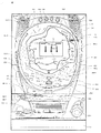
まず、図1を参照しながら、本実施形態に係るぱちんこ遊技機の前面側の基本構造を説明する。ぱちんこ遊技機は、主に遊技機枠と遊技盤D35で構成される。以下、これらを順に説明する。 First, with reference to FIG. 1, the basic structure on the front side of the pachinko gaming machine according to the present embodiment will be described. The pachinko gaming machine is mainly composed of a gaming machine frame and a gaming board D35. Hereinafter, these will be described in order.
はじめに、ぱちんこ遊技機の遊技機枠は、外枠D12、前枠D14、透明板D16、扉D18、上球皿D20、下球皿D22及び発射ハンドルD44を含む。まず、外枠D12は、ぱちんこ遊技機を設置すべき位置に固定するための枠体である。前枠D14は、外枠D12の開口部分に整合する枠体であり、図示しないヒンジ機構を介して外枠D12に開閉可能に取り付けられる。前枠D14は、遊技球を発射する機構、遊技盤D35を着脱可能に収容させるための機構、遊技球を誘導又は回収するための機構等を含む。透明板D16は、ガラス等により形成され、扉D18により支持される。扉D18は、図示しないヒンジ機構を介して前枠D14に開閉可能に取り付けられる。上球皿D20は、遊技球の貯留、発射レ−ルへの遊技球の送り出し、下球皿D22への遊技球の抜き取り等の機構を有する。下球皿D22は、遊技球の貯留、抜き取り等の機構を有する。また、遊技盤D35の右上方と左上方とにはスピーカD24が設けられており、遊技状態等に応じた効果音が出力される。 First, the gaming machine frame of the pachinko gaming machine includes an outer frame D12, a front frame D14, a transparent plate D16, a door D18, an upper ball plate D20, a lower ball plate D22, and a firing handle D44. First, the outer frame D12 is a frame body for fixing the pachinko gaming machine at a position where it should be installed. The front frame D14 is a frame body that matches the opening portion of the outer frame D12, and is attached to the outer frame D12 so as to be openable and closable via a hinge mechanism (not shown). The front frame D14 includes a mechanism for launching a game ball, a mechanism for detachably accommodating the game board D35, a mechanism for guiding or collecting the game ball, and the like. The transparent plate D16 is formed of glass or the like and is supported by the door D18. The door D18 is openably and closably attached to the front frame D14 via a hinge mechanism (not shown). The upper ball plate D20 has a mechanism for storing the game ball, sending the game ball to the launch rail, and extracting the game ball from the lower ball plate D22. The lower ball plate D22 has a mechanism for storing and extracting game balls. Further, speakers D24 are provided on the upper right and upper left of the game board D35, and sound effects according to the game state and the like are output.
遊技盤D35と遊技機の前面の透明板D16(例えば、ガラス板)とは、13mmを超え25mmを超えない距離(本例では、19mm)の距離を保ち並行になるように遊技機枠に取り付けられている。ここで、遊技盤D35は、容易に動揺しないように固定機構(不図示)によってしっかりと固定されている。 The game board D35 and the transparent plate D16 (for example, a glass plate) on the front surface of the game machine are attached to the game machine frame so as to maintain a distance of more than 13 mm and not more than 25 mm (19 mm in this example) and to be parallel to each other. Has been done. Here, the game board D35 is firmly fixed by a fixing mechanism (not shown) so as not to be easily shaken.
また、透明板D16(例えば、ガラス板)は、遊技盤の全体の構造の見通しを妨げず、遊技盤上の遊技球の位置を確認できるように遊技領域全体が無色透明で凹凸がないように形成されている。 Further, the transparent plate D16 (for example, a glass plate) does not obstruct the view of the entire structure of the game board, and the entire game area is colorless and transparent so that the position of the game ball on the game board can be confirmed so that there is no unevenness. It is formed.
球皿(例えば、上球皿D20、下球皿D22)は、球皿上の遊技球が遊技者にとって可視的(遊技球の数を概ね確認可能)であり、遊技者が受け皿に受けた遊技球の取り出しを阻害しないような形状(遊技球を自由に取り出せるような形状)になっている。 In the ball plate (for example, upper ball plate D20, lower ball plate D22), the game balls on the ball plate are visible to the player (the number of game balls can be roughly confirmed), and the game received by the player in the saucer. It has a shape that does not hinder the removal of the ball (a shape that allows the game ball to be freely taken out).
次に、遊技盤D35は、外レールD32と内レールD34とにより区画された遊技領域D30が形成されており、透明板D16を介して遊技盤D35上(遊技領域D30上)を流下する遊技球の位置を確認できるようになっている。遊技領域D30は、左打ち領域DL10と右打ち領域DR10とに大別される。そして、当該遊技領域D30には、図示しない複数の遊技釘及び風車等の機構や各種一般入賞口の他、左打ちルートML10、右打ちルートMR10、第1主遊技始動口A10、第2主遊技始動口B10、補助遊技始動口H10、第1大入賞口C10、第2大入賞口C20、第1主遊技図柄表示装置A20、第2主遊技図柄表示装置B20、演出表示装置SG、補助遊技図柄表示装置H20、センター飾りD38、可動体役物YK、右一般入賞口用ランプLP10、左一般入賞口P10、右一般入賞口P20、サブ入力ボタンSB及びアウト口D36が設置されている。尚、本実施形態においては、左打ちルートML10を第1流下ルートと称することがあり、右打ちルートMR10を第2流下ルートと称することがある。以下、各要素を順番に詳述する。 Next, in the game board D35, a game area D30 divided by an outer rail D32 and an inner rail D34 is formed, and a game ball that flows down on the game board D35 (on the game area D30) via the transparent plate D16. You can check the position of. The game area D30 is roughly divided into a left-handed area DL10 and a right-handed area DR10. Then, in the game area D30, in addition to mechanisms such as a plurality of game nails and windmills (not shown) and various general winning openings, a left-handed route ML10, a right-handed route MR10, a first main game starting port A10, and a second main game Starting port B10, auxiliary game starting port H10, first big winning opening C10, second big winning opening C20, first main game symbol display device A20, second main game symbol display device B20, effect display device SG, auxiliary game symbol A display device H20, a center decoration D38, a movable body accessory YK, a right general winning opening lamp LP10, a left general winning opening P10, a right general winning opening P20, a sub input button SB, and an out opening D36 are installed. In the present embodiment, the left-handed route ML10 may be referred to as a first flow-down route, and the right-handed route MR10 may be referred to as a second flow-down route. Hereinafter, each element will be described in detail in order.
次に、第1主遊技始動口A10は、第1主遊技に対応する始動入賞口として設置されている。具体的構成としては、第1主遊技始動口A10は、第1主遊技始動口入球検出装置A11sを備える。ここで、第1主遊技始動口入球検出装置A11sは、第1主遊技始動口A10への遊技球の入球を検出するセンサであり、入球時にその入球を示す第1主遊技始動口入球情報を生成する。 Next, the first main game start opening A10 is installed as a start winning opening corresponding to the first main game. As a specific configuration, the first main game start port A10 includes a first main game start port entry ball detection device A11s. Here, the first main game start port entry detection device A11s is a sensor that detects the entry of a game ball into the first main game start opening A10, and the first main game start indicating the entry at the time of entry. Generates mouth ball information.
次に、第2主遊技始動口B10は、第2主遊技に対応する始動入賞口として設置されている。具体的構成としては、第2主遊技始動口B10は、第2主遊技始動口入球検出装置B11sと、第2主遊技始動口電動役物B11dと、を備える。ここで、第2主遊技始動口入球検出装置B11sは、第2主遊技始動口B10への遊技球の入球を検出するセンサであり、入球時にその入球を示す第2主遊技始動口入球情報を生成する。次に、第2主遊技始動口電動役物B11dは、第2主遊技始動口B10に遊技球が入賞し難い閉鎖状態と当該閉鎖状態よりも遊技球が入賞し易い開放状態に可変する。 Next, the second main game start opening B10 is installed as a start winning opening corresponding to the second main game. As a specific configuration, the second main game start port B10 includes a second main game start port entry ball detection device B11s and a second main game start port electric accessory B11d. Here, the second main game start port entry detection device B11s is a sensor that detects the entry of the game ball into the second main game start port B10, and the second main game start indicating the entry at the time of entry. Generates mouth ball information. Next, the second main game start port electric accessory B11d is variable to a closed state in which the game ball is difficult to win in the second main game start port B10 and an open state in which the game ball is easier to win than the closed state.
ここで、本実施形態においては、第1主遊技始動口A10と第2主遊技始動口B10とが設けられており、遊技領域D30の左側(左打ち領域DL10)を流下する遊技球が第1主遊技始動口A10に誘導され易い一方、遊技領域D30の右側(右打ち領域DR10)を流下する遊技球は第1主遊技始動口A10に誘導され難いよう構成されている。また、遊技領域D30の左側を流下する遊技球と遊技領域D30の右側を流下する遊技球とのいずれも第2主遊技始動口B10に誘導され得るよう構成されている。 Here, in the present embodiment, the first main game start port A10 and the second main game start port B10 are provided, and the game ball flowing down the left side of the game area D30 (left-handed area DL10) is the first. While it is easy to be guided to the main game start port A10, the game ball flowing down the right side of the game area D30 (right-handed area DR10) is not easily guided to the first main game start port A10. Further, both the game ball flowing down the left side of the game area D30 and the game ball flowing down the right side of the game area D30 are configured to be guided to the second main game start port B10.
尚、本実施形態では、第2主遊技始動口B10側に電動役物を設けるよう構成したが、これには限定されず、第1主遊技始動口A10側に電動役物を設けるよう構成してもよい。更には、本実施形態では、第1主遊技始動口A10と第2主遊技始動口B10とが重ねるように配置されているが、これにも限定されず、第1主遊技始動口A10と第2主遊技始動口B10とを離隔して配置してもよい。 In the present embodiment, the electric accessory is provided on the second main game start port B10 side, but the present invention is not limited to this, and the electric accessory is provided on the first main game start port A10 side. You may. Further, in the present embodiment, the first main game start port A10 and the second main game start port B10 are arranged so as to overlap each other, but the present invention is not limited to this, and the first main game start port A10 and the first main game start port A10 and the first main game start port A10 are arranged so as to overlap each other. 2 The main game start port B10 may be separated from the main game start port B10.
次に、補助遊技始動口H10は、補助遊技始動口入球検出装置H11sを備える。ここ
で、補助遊技始動口入球検出装置H11sは、補助遊技始動口H10への遊技球の入球を検出するセンサであり、入球時にその入球を示す補助遊技始動口入球情報を生成する。尚、補助遊技始動口H10への遊技球の入球は、第2主遊技始動口B10の第2主遊技始動口電動役物B11dを拡開させるための抽選の契機となる。
Next, the auxiliary game start port H10 includes an auxiliary game start port entry ball detection device H11s. Here, the auxiliary game start opening ball entry detection device H11s is a sensor that detects the entry of a game ball into the auxiliary game start opening H10, and generates auxiliary game start opening entry information indicating the entry at the time of entry. do. The entry of the game ball into the auxiliary game start port H10 triggers a lottery for expanding the second main game start port electric accessory B11d of the second main game start port B10.
ここで、本実施形態においては、遊技領域D30の右側(遊技領域中央を基準)を流下する遊技球が補助遊技始動口H10に誘導され易く、遊技領域D30の左側(遊技領域中央を基準)を流下する遊技球が補助遊技始動口H10に誘導され難くなるよう構成されている。但し、これには限定されず、遊技領域D30の右側及び左側(遊技領域中央を基準)を流下する遊技球が、補助遊技始動口H10に誘導され得るよう構成されていてもよい。 Here, in the present embodiment, the game ball flowing down the right side of the game area D30 (based on the center of the game area) is easily guided to the auxiliary game start port H10, and the left side of the game area D30 (referenced to the center of the game area) is used. It is configured so that the flowing game ball is less likely to be guided to the auxiliary game start port H10. However, the present invention is not limited to this, and a game ball flowing down the right side and the left side of the game area D30 (based on the center of the game area) may be configured to be guided to the auxiliary game start port H10.
次に、左一般入賞口P10は、左一般入賞口入球検出装置P11sを備える。左一般入賞口入球検出装置P11sは、左一般入賞口P10への遊技球の入球を検出するセンサであり、入球時にその入球を示す左一般入賞口入球情報を生成する。尚、左一般入賞口P10への遊技球の入球によって、所定数(例えば、3球)の遊技球が賞球として払い出されることとなる。尚、遊技領域D30の左側(遊技領域中央を基準)を流下する遊技球は左一般入賞口P10に入球し易く、遊技領域D30の右側(遊技領域中央を基準)を流下する遊技球は左一般入賞口P10に入球し難いよう構成されている。即ち、左打ち(遊技領域D30の左側である左打ち領域DL10(左打ちルートML10)を遊技球が流下するよう、遊技球の発射強度を調節して遊技球を打ち出すこと)を実行した際に左一般入賞口P10に入球し易いよう構成されている。 Next, the left general winning opening P10 includes a left general winning opening ball detection device P11s. The left general winning opening ball detection device P11s is a sensor that detects the entry of a game ball into the left general winning opening P10, and generates left general winning opening entry information indicating the entry at the time of entry. By entering the game balls into the left general winning opening P10, a predetermined number (for example, 3 balls) of game balls will be paid out as prize balls. The game ball flowing down the left side of the game area D30 (based on the center of the game area) is easy to enter the left general winning opening P10, and the game ball flowing down the right side of the game area D30 (based on the center of the game area) is on the left. It is configured so that it is difficult to enter the general winning opening P10. That is, when a left-handed hit (to launch the game ball by adjusting the firing intensity of the game ball so that the game ball flows down the left-handed hit area DL10 (left-handed route ML10) on the left side of the game area D30) is executed. It is configured so that it is easy to enter the left general winning opening P10.
次に、右一般入賞口P20は、右一般入賞口入球検出装置P21sを備える。右一般入賞口入球検出装置P21sは、右一般入賞口P20への遊技球の入球を検出するセンサであり、入球時にその入球を示す右一般入賞口入球情報を生成する。ここで、右一般入賞口P20は、右打ち領域DR10に配置され、補助遊技乱数を取得するという補助遊技始動口の役割と、賞球が払い出されるという一般入賞口の役割との双方を兼ね備えている。換言すると、右一般入賞口入球検出装置P21sは、後述する補助遊技始動口センサと後述する一般入賞口センサとの双方を兼ねている。つまり、右一般入賞口P20への遊技球の入球は、第2主遊技始動口B10に取り付けられた第2主遊技始動口電動役物B11dを拡開させるための抽選の契機となる。また、右一般入賞口P20への遊技球の入球によって、所定数(例えば、2球)の遊技球が賞球として払い出されることとなる。尚、右一般入賞口P20への遊技球の入球によって、右一般入賞口P20から賞球として払い出される遊技球(例えば、2球)は、左一般入賞口P10への遊技球の入球によって、左一般入賞口P10から賞球として払い出される遊技球(例えば、3球)よりも少なくなるよう構成されている。尚、本実施形態においては、右打ちを実行した遊技球が右一般入賞口P20に入球し得るよう構成されている。即ち、右打ち(遊技領域D30の右側である右打ち領域DR10(右打ちルートMR10)を遊技球が流下するよう、遊技球の発射強度を調節して遊技球を打ち出すこと)を実行した際に右一般入賞口P20に入球し易いよう構成されている。 Next, the right general winning opening P20 includes a right general winning opening ball detection device P21s. The right general winning opening ball detection device P21s is a sensor that detects the entry of a game ball into the right general winning opening P20, and generates right general winning opening entry information indicating the entry at the time of entry. Here, the right general winning opening P20 is arranged in the right-handed area DR10, and has both the role of the auxiliary game starting opening for acquiring the auxiliary game random number and the role of the general winning opening for paying out the prize ball. There is. In other words, the right general winning opening ball detection device P21s serves as both an auxiliary game starting opening sensor described later and a general winning opening sensor described later. That is, the entry of the game ball into the right general winning opening P20 triggers a lottery for expanding the second main game starting opening electric accessory B11d attached to the second main game starting opening B10. In addition, a predetermined number (for example, 2 balls) of game balls will be paid out as prize balls by entering the game balls into the right general winning opening P20. The game ball (for example, 2 balls) paid out as a prize ball from the right general winning opening P20 by the entry of the game ball into the right general winning opening P20 is determined by the entry of the game ball into the left general winning opening P10. , It is configured to be less than the game balls (for example, 3 balls) paid out as prize balls from the left general winning opening P10. In this embodiment, the game ball that has been hit right can enter the right general winning opening P20. That is, when right-handed (to launch the game ball by adjusting the firing intensity of the game ball so that the game ball flows down the right-handed area DR10 (right-handed route MR10) on the right side of the game area D30) is executed. It is configured so that it is easy to enter the right general winning opening P20.
ここで、本実施形態においては、右打ちを実行した際に入球し得る入球口としては、上流から順に、「補助遊技始動口H10→右一般入賞口P20→第2大入賞口C20→第1大入賞口C10→第2主遊技始動口B10→アウト口D36」の順となっている。また、補助遊技始動口H10はゲートの形状をしているため、補助遊技始動口H10を通過した遊技球は遊技領域上を更に流下していくこととなり、下流にある入球口(上述した右一般入賞口P20等)に入球し得ることとなる。一方、右一般入賞口P20に入球した遊技球は遊技盤面奥側に流入することとなり、その後第1大入賞口C10や第2大入賞口C20に入球することはない(右打ちを実行して右一般入賞口P20に入球しなかった遊技球が
第1大入賞口C10又は第2大入賞口C20に入球し得ることとなる)。
Here, in the present embodiment, as the entry openings that can be entered when the right-handed hit is executed, in order from the upstream, "auxiliary game start opening H10 → right general winning opening P20 → second major winning opening C20 → The order is as follows: 1st big winning opening C10 → 2nd main game starting opening B10 → out opening D36 ”. Further, since the auxiliary game start port H10 has the shape of a gate, the game ball that has passed through the auxiliary game start port H10 will further flow down on the game area, and the ball entry port located downstream (the above-mentioned right). It will be possible to enter the general winning opening P20, etc.). On the other hand, the game ball that has entered the right general winning opening P20 will flow into the back side of the game board surface, and will not subsequently enter the first major winning opening C10 or the second major winning opening C20 (execute right-handed strike). Then, the game ball that did not enter the right general winning opening P20 can enter the first major winning opening C10 or the second major winning opening C20).
尚、非時間短縮遊技状態における左打ちの実行時には(非時間短縮遊技状態においては左打ちにて遊技を進行する)、補助遊技始動口H10(及び右一般入賞口P20)に遊技球が入球し難いため第2主遊技始動口電動役物B11dが開放し難く、主遊技側の始動口として主に第1主遊技始動口A10への入球によって遊技を進行していくこととなり、一方、時間短縮遊技状態における右打ちの実行時には(時間短縮遊技状態においては右打ちにて遊技を進行する)、補助遊技始動口H10(及び右一般入賞口P20)に遊技球が入球し易いため第2主遊技始動口電動役物B11dが開放し易く、主遊技側の始動口として主に第2主遊技始動口B10への入球によって遊技を進行していくこととなる。また、非時間短縮遊技状態において左打ちにて遊技球を発射し続けた場合の第1主遊技始動口A10への入球容易性よりも、時間短縮遊技状態において右打ちにて遊技球を発射し続けた場合の第2主遊技始動口B10への入球容易性の方が高い、換言すると、非時間短縮遊技状態において左打ちにて遊技球を発射し続けた場合の第1主遊技始動口A10又は第2主遊技始動口B10への入球容易性よりも、時間短縮遊技状態において右打ちにて遊技球を発射し続けた場合の第1主遊技始動口A10又は第2主遊技始動口B10への入球容易性の方が高くなる。そこで、本例においては、左打ち実行時の方が右打ち実行時よりも入球し易い左一般入賞口P10に入球した際の賞球数(本例では、3球)を、右打ち実行時の方が左打ち実行時よりも入球し易い右一般入賞口P20に入球した際の賞球数(本例では、2球)よりも多く設計することにより、非時間短縮遊技状態にて左打ちで遊技を進行した場合と、時間短縮遊技状態にて右打ちで遊技を進行した場合との、入賞口へ入球することにより払い出される平均の賞球数の差分、即ち、ベース値(特別遊技に当選していない状況において、発射した遊技球100球に対する、払い出される賞球払出数の期待値)の差分が大きくなりすぎることを防止することができる。 When the left-handed player is executed in the non-time-reduced game state (the game is advanced by the left-handed player in the non-time-reduced game state), the game ball enters the auxiliary game start opening H10 (and the right general winning opening P20). Since it is difficult to open the second main game start port, the electric accessory B11d is difficult to open, and the game proceeds mainly by entering the first main game start port A10 as the start port on the main game side. When right-handed is executed in the time-reduced game state (the game proceeds by right-handed in the time-reduced game state), the game ball easily enters the auxiliary game start opening H10 (and the right general winning opening P20). 2 Main game start port The electric accessory B11d is easy to open, and the game proceeds mainly by entering the second main game start port B10 as the start port on the main game side. In addition, the game ball is launched by right-handed in the time-reduced game state, rather than the ease of entering the first main game start port A10 when the game ball is continuously fired by left-handed in the non-time-reduced game state. It is easier to enter the second main game start port B10 when the game is continued, in other words, the first main game starts when the game ball is continuously fired by left-handed in the non-time shortened game state. The first main game start port A10 or the second main game start when the game ball is continuously fired by right-handed in a time-shortening game state rather than the ease of entering the mouth A10 or the second main game start port B10. The ease of entering the ball into the mouth B10 is higher. Therefore, in this example, the number of prize balls (3 balls in this example) when the ball is entered into the left general winning opening P10, which is easier to enter when the left-handed hit is executed, is right-handed. Non-time reduction game state by designing more than the number of prize balls (2 balls in this example) when entering the right general winning opening P20, which is easier to enter at the time of execution than at the time of left-handed execution. The difference between the average number of prize balls paid out by entering the winning opening, that is, the base It is possible to prevent the difference between the values (the expected value of the number of prize balls to be paid out with respect to the 100 game balls fired in the situation where the special game is not won) becomes too large.
また、右一般入賞口用ランプLP10は、例えば、液晶、LED等で構成されており、特別遊技の実行中に右一般入賞口に遊技球が入球することにより点灯し得るよう構成されている。また、右一般入賞口用ランプLP10の点灯色の違いにより特別遊技終了後に確率変動遊技状態に移行するか非確率変動遊技状態に移行するかを示唆し得るよう構成されている。具体的には、実行中の特別遊技の終了後に確率変動遊技状態となる場合には赤色に点灯し易く、実行中の特別遊技の終了後に非確率変動遊技状態となる場合には青色に点灯し易く構成することで、「赤色:特別遊技終了後に確率変動遊技状態となる期待度が高い、青色:特別遊技終了後に確率変動遊技状態となる期待度が低い」のように構成することができる。尚、右一般入賞口用ランプLP10の点灯色として、3種類以上の点灯色を設けてもよい。尚、右一般入賞口用ランプLP10は、遊技領域D30上の、左打ち領域DL10に設けても良いし右打ち領域DR10に設けても良い。また、遊技領域D30以外の領域に設けてもよい。尚、本例においては、非確率変動遊技状態を、通常状態、通常遊技状態、通常時、低確率、低確率状態、低確率遊技状態、低確率時、非確変、低確率抽選状態、低確中、通常中、低確率中、非確変中等と称することがある。また、確率変動遊技状態を、高確率、高確率状態、高確率遊技状態、高確率時、確変、高確率抽選状態、高確中、確変中等と称することがある。また、時間短縮遊技状態を、時短状態、時短中、時短、高ベース、電サポ中等と称することがある。また、非時間短縮遊技状態を、非時短状態、非時短中、非時短、低ベース中、非電サポ中等と称することがある。また、非確率変動遊技状態且つ非時間短縮遊技状態を、通常状態、通常遊技状態、通常時、通常モード等と称することがある。 Further, the right general winning opening lamp LP10 is composed of, for example, a liquid crystal, an LED, or the like, and is configured to be lit when a game ball enters the right general winning opening during execution of a special game. .. Further, it is configured so that it can be suggested whether to shift to the probability-variable gaming state or the non-probability-variable gaming state after the end of the special game depending on the difference in the lighting color of the right general winning opening lamp LP10. Specifically, it tends to light up in red when it becomes a probability-changing game state after the end of the special game being executed, and lights up in blue when it becomes a non-probability-variable game state after the end of the special game being executed. By easily configuring it, it can be configured as "red: high expectation of being in a probability-variable game state after the end of the special game, blue: low expectation of being in a probability-variable game state after the end of the special game". As the lighting color of the right general winning opening lamp LP10, three or more kinds of lighting colors may be provided. The right general winning opening lamp LP10 may be provided in the left-handed area DL10 or the right-handed area DR10 on the game area D30. Further, it may be provided in an area other than the game area D30. In this example, the non-probability variable gaming state is defined as a normal state, a normal gaming state, a normal time, a low probability, a low probability state, a low probability gaming state, a low probability time, a non-probability change, a low probability lottery state, and a low probability. It may be referred to as medium, normal, low probability, non-probability change, etc. Further, the probability fluctuating gaming state may be referred to as a high probability, a high probability state, a high probability gaming state, a high probability time, a probability change, a high probability lottery state, a high probability middle, a probability change middle, or the like. In addition, the time-saving game state may be referred to as a time-saving state, a time-saving medium, a time-saving, a high base, an electric support medium, or the like. In addition, the non-time saving game state may be referred to as a non-time saving state, a non-time saving medium, a non-time saving medium, a low base medium, a non-electric support medium, or the like. Further, the non-probability variable gaming state and the non-time shortening gaming state may be referred to as a normal state, a normal gaming state, a normal time, a normal mode, or the like.
また、右打ちルートMR10を流下した遊技球は、右打ちルート流出口D50を通過して右一般入賞口P20、第1大入賞口C10、第2大入賞口C20等の近傍に流下していくこととなる。 In addition, the game ball that has flowed down the right-handed route MR10 passes through the right-handed route outlet D50 and flows down to the vicinity of the right general winning opening P20, the first major winning opening C10, the second major winning opening C20, and the like. It will be.
次に、アウト口D36の右上方には、第1大入賞口C10と第2大入賞口C20とが設けられており、遊技領域D30の右側(遊技領域中央を基準)を流下する遊技球は、アウト口D36に到達する前に、第1大入賞口C10及び第2大入賞口C20が配置されている領域を通過し易いよう構成されている。 Next, the first big winning opening C10 and the second big winning opening C20 are provided on the upper right side of the out opening D36, and the game ball flowing down the right side of the game area D30 (based on the center of the game area) is , It is configured so that it can easily pass through the area where the first big winning opening C10 and the second big winning opening C20 are arranged before reaching the out opening D36.
次に、第1大入賞口C10は、第1主遊技図柄(特別図柄)又は第2主遊技図柄(特別図柄)が大当り図柄停止した場合に開状態となる、横長方形状を成しアウト口D36の右上方に位置した、主遊技に対応した入賞口である。具体的構成としては、第1大入賞口C10は、遊技球の入球を検出するための第1大入賞口入賞検出装置C11sと、第1大入賞口電動役物C11d{及び第1大入賞口電動役物ソレノイドC13}と、を備える。ここで、第1大入賞口入賞検出装置C11sは、第1大入賞口C10への遊技球の入球を検出するセンサであり、入球時にその入球を示す第1大入賞口入球情報を生成する。第1大入賞口電動役物C11dは、第1大入賞口C10に遊技球が入賞不能又は入賞困難な通常状態と遊技球が入賞し易い開放状態に第1大入賞口C10を可変させる(第1大入賞口電動役物ソレノイドC13を励磁して可変させる)。尚、本実施形態では、大入賞口の態様を、横長方形状を成し遊技球が入賞不能又は入賞困難な通常状態と遊技球が入賞し易い開放状態とに可変させる態様としているが、これには限定されない。その場合には、例えば、大入賞口内に設けられた棒状部材が遊技者側に突き出した状態である進出状態と遊技者側に対して引っ込んだ状態である退避状態とを採り得る態様(いわゆる、ベロ型アタッカ−)や、遊技球が転動可能な通路上の開口部を大入賞口とし、当該開口部を閉鎖する状態と開放する状態とを採り得る態様(いわゆる、スライド式アタッカー)としてもよく、大入賞口への入球数を所定数(例えば、10個)とすることを担保したい場合において好適である。 Next, the first big winning opening C10 has a horizontal rectangular shape and is an out opening that opens when the first main game symbol (special symbol) or the second main game symbol (special symbol) stops the big hit symbol. It is a winning opening corresponding to the main game, located on the upper right side of D36. As a specific configuration, the first large winning opening C10 includes a first large winning opening winning detection device C11s for detecting the entry of a game ball, a first large winning opening electric accessory C11d {and a first large winning opening. The mouth electric accessory solenoid C13} is provided. Here, the first large winning opening winning detection device C11s is a sensor that detects the entry of a game ball into the first large winning opening C10, and the first large winning opening entry information indicating the entry at the time of entry. To generate. The first large winning opening electric accessory C11d changes the first large winning opening C10 into a normal state in which the game ball cannot or is difficult to win in the first large winning opening C10 and an open state in which the game ball is easy to win (the first). 1 Grand prize opening Electric accessory solenoid C13 is excited and changed). In the present embodiment, the mode of the large winning opening is changed to a normal state in which the game ball has a horizontal rectangular shape and the game ball cannot win or is difficult to win, and an open state in which the game ball is easy to win. Not limited to. In that case, for example, an advance state in which the rod-shaped member provided in the large winning opening is projected toward the player side and an evacuation state in which the rod-shaped member is retracted toward the player side can be adopted (so-called so-called). A tongue-type attacker) or an opening on the passage where the game ball can roll is used as a large winning opening, and the opening can be closed or opened (so-called sliding attacker). It is often suitable when it is desired to ensure that the number of balls entered into the large winning opening is a predetermined number (for example, 10).
次に、第2大入賞口C20は、第1主遊技図柄(特別図柄)又は第2主遊技図柄(特別図柄)が大当り図柄で停止した場合に開状態となる、横長方形状を成しアウト口D36の右上方に位置した、主遊技に対応した入賞口である。具体的構成としては、第2大入賞口C20は、遊技球の入球を検出するための第2大入賞口入賞検出装置C21sと、第2大入賞口電動役物C21d{及び第2大入賞口電動役物ソレノイドC23}と、を備える。ここで、第2大入賞口入賞検出装置C21sは、第2大入賞口C20への遊技球の入球を検出するセンサであり、入球時にその入球を示す第2大入賞口入球情報を生成する。そして、第2大入賞口C20内に入球した遊技球は、第2大入賞口入賞検出装置C21sによって検出されるよう構成されている。次に、第2大入賞口電動役物C21dは、第2大入賞口C20に遊技球が入賞不能又は入賞困難な通常状態と遊技球が入賞し易い開放状態とに第2大入賞口C20を可変させる。尚、本実施形態では、大入賞口の態様を、横長方形状を成し遊技球が入賞不能又は入賞困難な通常状態と遊技球が入賞し易い開放状態とに可変させる態様としているが、これには限定されない。その場合には、例えば、大入賞口内に設けられた棒状部材が遊技者側に突き出した状態である進出状態と遊技者側に対して引っ込んだ状態である退避状態とを採り得る態様(いわゆる、ベロ型アタッカー)や、遊技球が転動可能な通路上の開口部を大入賞口とし、当該開口部を閉鎖する状態と開放する状態とを採り得る態様(いわゆる、スライド式アタッカー)としてもよく、大入賞口への入球数を所定数(例えば、10個)とすることを担保したい場合において好適である。 Next, the second big winning opening C20 forms a horizontal rectangular shape and is out, which is opened when the first main game symbol (special symbol) or the second main game symbol (special symbol) stops at the jackpot symbol. It is a winning opening corresponding to the main game, which is located on the upper right side of the opening D36. As a specific configuration, the second special winning opening C20 includes a second large winning opening winning detection device C21s for detecting the entry of a game ball, a second large winning opening electric accessory C21d {and a second large winning opening. The mouth electric accessory solenoid C23} is provided. Here, the second large winning opening winning detection device C21s is a sensor that detects the entry of a game ball into the second large winning opening C20, and the second large winning opening entry information indicating the entry at the time of entry. To generate. Then, the game ball that has entered the second special winning opening C20 is configured to be detected by the second large winning opening winning detection device C21s. Next, the second large winning opening electric accessory C21d has the second large winning opening C20 in a normal state in which the game ball cannot or is difficult to win in the second large winning opening C20 and in an open state in which the game ball is easy to win. Make it variable. In the present embodiment, the mode of the large winning opening is changed to a normal state in which the game ball has a horizontal rectangular shape and the game ball cannot win or is difficult to win, and an open state in which the game ball is easy to win. Not limited to. In that case, for example, an advance state in which the rod-shaped member provided in the large winning opening is projected toward the player side and an evacuation state in which the rod-shaped member is retracted toward the player side can be adopted (so-called so-called). A tongue-type attacker) or an opening on the passage where the game ball can roll is used as a large winning opening, and the opening may be closed or opened (so-called sliding attacker). , It is suitable when it is desired to ensure that the number of balls entered into the large winning opening is a predetermined number (for example, 10).
次に、第1主遊技図柄表示装置A20(第2主遊技図柄表示装置B20)は、第1主遊技(第2主遊技)に対応する第1主遊技図柄(第2主遊技図柄)に関連した表示等を実行する装置である。具体的構成としては、第1主遊技図柄表示装置A20(第2主遊技図柄表示装置B20)は、第1主遊技図柄表示部A21g(第2主遊技図柄表示部B21g)と、第1主遊技図柄保留表示部A21h(第2主遊技図柄保留表示部B21h)とを備える。ここで、第1主遊技図柄保留表示部A21h(第2主遊技図柄保留表示部B21h)は、4個のランプから構成され、当該ランプの点灯個数が、第1主遊技(第2主遊技)に
係る乱数の保留数(実行されていない主遊技図柄の変動数)に相当する。尚、第1主遊技図柄表示部A21g(第2主遊技図柄表示部B21g)は、例えば7セグメントLEDで構成され、第1主遊技図柄(第2主遊技図柄)は、「0」〜「9」の10種類の数字及びハズレの「−」で表示される{但し、これには限定されず、いずれの主遊技図柄が表示されたのかを遊技者が認識困難となるよう、7セグメントLEDを用いて記号等によって表示することが好適である。また、保留数表示においても、4個のランプから構成されていることには限定されず、最大4個分の保留数を表示可能に構成(例えば、1個のランプから構成されており、保留数1:点灯、保留数2:低速点滅、保留数3:中速点滅、保留数4:高速点滅、するよう構成)されていればよい}。
Next, the first main game symbol display device A20 (second main game symbol display device B20) is related to the first main game symbol (second main game symbol) corresponding to the first main game (second main game). It is a device that executes the displayed display. As a specific configuration, the first main game symbol display device A20 (second main game symbol display device B20) includes a first main game symbol display unit A21g (second main game symbol display unit B21g) and a first main game symbol display unit B21g. It is provided with a symbol hold display unit A21h (second main game symbol hold display unit B21h). Here, the first main game symbol hold display unit A21h (second main game symbol hold display unit B21h) is composed of four lamps, and the number of lamps lit is the first main game (second main game). Corresponds to the number of pending random numbers related to (the number of fluctuations in the main game symbol that has not been executed). The first main game symbol display unit A21g (second main game symbol display unit B21g) is composed of, for example, a 7-segment LED, and the first main game symbol (second main game symbol) is "0" to "9". It is displayed with 10 kinds of numbers of "" and "-" of the loss {However, it is not limited to this, and the 7-segment LED is displayed so that it becomes difficult for the player to recognize which main game symbol is displayed. It is preferable to use and display by a symbol or the like. Further, the holding number display is not limited to being composed of four lamps, and a maximum of four holding numbers can be displayed (for example, it is composed of one lamp and is held. Number 1: Lighting, Number of Holds 2: Blinking at low speed, Number of Holds 3: Blinking at medium speed, Number of Holds 4: Blinking at high speed).
尚、主遊技図柄は必ずしも演出的な役割を持つ必要が無いため、本実施形態では、第1主遊技図柄表示装置A20の大きさは、目立たない程度に設定されている。しかしながら、主遊技図柄自体に演出的な役割を持たせて装飾図柄を表示させないような手法を採用する場合には、後述する演出表示装置SGのような液晶ディスプレーに、主遊技図柄を表示させるように構成してもよい。 Since the main game symbol does not necessarily have to have a directing role, the size of the first main game symbol display device A20 is set to an inconspicuous degree in the present embodiment. However, when a method is adopted in which the main game symbol itself has a directing role and the decorative symbol is not displayed, the main game symbol is displayed on a liquid crystal display such as the effect display device SG described later. It may be configured as.
次に、演出表示装置SGは、主遊技図柄と連動して変動・停止する装飾図柄を含む演出画像の表示等を実行する装置である。ここで、具体的構成としては、演出表示装置SGは、装飾図柄の変動表示等を含めて演出が実行される表示領域SG10を備える。ここで、表示領域SG10は、例えば、スロットマシンのゲームを模した複数列の装飾図柄変動の動画像を表示する装飾図柄表示領域SG11と、主遊技保留情報を表示する第1保留表示部SG12及び第2保留表示部SG13と、を有している。尚、演出表示装置SGは、本実施形態では液晶ディスプレーで構成されているが、機械式のドラムやLED等の他の表示手段で構成されていてもよい。次に、第1保留表示部SG12及び第2保留表示部SG13は夫々4個のランプから構成され、当該ランプは、主遊技図柄の保留ランプと連動している。 Next, the effect display device SG is a device that displays an effect image including a decorative symbol that fluctuates and stops in conjunction with the main game symbol. Here, as a specific configuration, the effect display device SG includes a display area SG10 in which the effect is executed including the variable display of the decorative symbol. Here, the display area SG10 includes, for example, a decorative symbol display area SG11 for displaying a moving image of a plurality of rows of decorative symbol fluctuations imitating a game of a slot machine, a first hold display unit SG12 for displaying main game hold information, and the like. It has a second hold display unit SG13. Although the effect display device SG is composed of a liquid crystal display in the present embodiment, it may be composed of other display means such as a mechanical drum or an LED. Next, the first hold display unit SG12 and the second hold display unit SG13 are each composed of four lamps, and the lamps are interlocked with the hold lamps of the main game symbol.
次に、補助遊技図柄表示装置H20は、補助遊技図柄に関する表示等を実行する装置である。具体的構成としては、補助遊技図柄表示装置H20は、補助遊技図柄表示部H21gと、補助遊技図柄保留表示部H21hとを備える。ここで、補助遊技図柄保留表示部H21hは、4個のランプから構成され、当該ランプの点灯個数が、補助遊技図柄変動の保留数(実行されていない補助遊技図柄変動の数)に相当する。本実施形態においては、補助遊技乱数を取得し得る入球口として、補助遊技始動口H10と右一般入賞口P20との2つの入球口を有しており、当該2つの入球口のいずれに入球した場合にも、取得した補助遊技乱数に関する表示は補助遊技図柄表示装置H20に表示されることとなる。 Next, the auxiliary game symbol display device H20 is a device that executes display and the like related to the auxiliary game symbol. As a specific configuration, the auxiliary game symbol display device H20 includes an auxiliary game symbol display unit H21g and an auxiliary game symbol hold display unit H21h. Here, the auxiliary game symbol hold display unit H21h is composed of four lamps, and the number of lamps lit corresponds to the number of reserved auxiliary game symbol changes (the number of auxiliary game symbol changes that have not been executed). In the present embodiment, there are two entry ports, an auxiliary game start opening H10 and a right general winning opening P20, as entry openings for acquiring auxiliary game random numbers, and any of the two entry openings The display regarding the acquired auxiliary game random numbers will be displayed on the auxiliary game symbol display device H20 even when the ball is entered into the ball.
次に、センター飾りD38は、演出表示装置SGの周囲に設置され、遊技球の流路、演出表示装置SGの保護、装飾等の機能を有する。また、遊技効果ランプD26は、遊技領域D30及び/又は遊技領域D30以外の領域に設けられ、点滅等することで演出の役割を果たす。 Next, the center decoration D38 is installed around the effect display device SG, and has functions such as a flow path of a game ball, protection of the effect display device SG, and decoration. Further, the game effect lamp D26 is provided in an area other than the game area D30 and / or the game area D30, and plays a role of directing by blinking or the like.
次に、可動体役物YKは、演出表示装置SGの近傍に設置され、図柄変動に伴う演出実行の際に駆動して遊技を盛り上げる役割を担っている。上下方向に移動したり、回転駆動したり、点灯したりして、駆動したことが目立つよう構成し、且つ、大当り期待度の高い図柄変動にて駆動し易い構成することが好適である。 Next, the movable body accessory YK is installed in the vicinity of the effect display device SG, and plays a role of driving and enlivening the game when the effect is executed due to the symbol change. It is preferable that the device is moved in the vertical direction, driven by rotation, or lit so that the drive is conspicuous, and the drive is easy to drive due to a symbol variation with a high expectation of a big hit.
次に、サブ入力ボタンSBは、副制御基板Sと電気的に接続された、操作(押下)することによって当該操作に基づく演出が実行されることとなる操作部材である。尚、サブ入力ボタンSBの操作態様として、単発押し(短時間の1回のみサブ入力ボタンSBを押下する操作態様)と、連打(複数回サブ入力ボタンSBを押下する操作態様)と、長押し(
所定期間サブ入力ボタンSBを押し続ける操作態様)と、を有するよう構成されている。さらに、副制御基板Sと電気的に接続された、操作(押下)することによって当該操作に基づく演出が実行されることとなる操作部材はサブ入力ボタンSBのみには限定されず、上、下、左、右の4つの操作部を有しており、当該操作部を操作することにより、実行する演出(予告演出等)を選択可能に構成される十字キーSB‐2、手前に引くことにより演出(可動体役物が作動する、等)が実行されるレバーSB‐3を有するよう構成されている。
Next, the sub-input button SB is an operation member that is electrically connected to the sub-control board S, and by operating (pressing), an effect based on the operation is executed. The operation modes of the sub-input button SB include a single press (an operation mode in which the sub-input button SB is pressed only once for a short time), repeated hits (an operation mode in which the sub-input button SB is pressed multiple times), and a long press. (
It is configured to have an operation mode) in which the sub-input button SB is held down for a predetermined period of time. Further, the operating members electrically connected to the sub-control board S and for which the effect based on the operation is executed by operating (pressing) are not limited to the sub-input button SB, but are up and down. The cross key SB-2, which has four operation units, left and right, and is configured to be able to select the effect (notice effect, etc.) to be executed by operating the operation unit, by pulling it toward you. It is configured to have a lever SB-3 on which an effect (movable body accessory operates, etc.) is executed.
次に、アウト口D36は、遊技領域D30の下方に設けられた入球口であり、遊技領域D30に設けられたいずれの入賞口にも入球せずに流下した遊技球が入球する入球口であり、アウト口D36に遊技球が入球した場合には、乱数に基づく各種抽選や入球に基づく賞球等は実行されず、当該遊技球は遊技機外に排出されることとなる。尚、本実施例では、が遊技盤上の最下部にのみ、入賞口に入賞しなかった遊技球が入るアウト口D36が設けられているが、遊技盤の上部の所定箇所にアウト口を設けることも可能である。その場合には、当該入口が入賞口でないことを明らかにするため、シールを用いて、「OUT」を表示する等、入賞口と混同しないようにすることが望ましい。 Next, the out port D36 is an entry port provided below the game area D30, and the game ball that has flowed down without entering any winning opening provided in the game area D30 enters the ball. When a game ball enters the out port D36, which is a ball opening, various lottery based on random numbers and prize balls based on the entry ball are not executed, and the game ball is discharged to the outside of the game machine. Become. In this embodiment, the out port D36 for entering the game ball that did not win the winning opening is provided only at the bottom of the game board, but the out opening is provided at a predetermined position on the upper part of the game board. It is also possible. In that case, in order to clarify that the entrance is not a winning opening, it is desirable not to be confused with the winning opening, such as by using a sticker to display "OUT".
次に、節電モード表示用ランプ(例えば、LEDによって構成)D70は、節電モード(詳細は後述する)がオンであるかどうかに基づきに基づき点灯するよう構成されている。 Next, the power saving mode display lamp (for example, composed of LEDs) D70 is configured to light up based on whether or not the power saving mode (details will be described later) is on.
次に、図2を参照しながら、ぱちんこ遊技機の背面側における基本構造を説明する。ぱちんこ遊技機は、ぱちんこ遊技機の全体動作を制御し、特に第1主遊技始動口A10(第2主遊技始動口B10)へ入球したときの抽選等、遊技動作全般の制御(即ち、遊技者の利益と直接関係する制御)を行う主制御基板Mと、遊技内容に興趣性を付与する演出表示装置SG上での各種演出に係る表示制御等を行う演出制御手段(サブメイン制御部)SMと、主に演出表示を実行するサブサブ制御部SSと、賞球タンクKT、賞球レールKR及び各入賞口への入賞に応じて賞球タンクKTから供給される遊技球を上球皿D20へ払い出す払出ユニットKE10等を備える賞球払出装置(セット基盤)KEと、払出ユニットKE10による払出動作を制御する賞球払出制御基板KHと、上球皿D20の遊技球(貯留球)を遊技領域D30へ1球ずつ発射する発射装置D42と、発射装置D42の発射動作を制御する発射制御基板D40と、ぱちんこ遊技機の各部へ電力を供給する電源ユニットEと、ぱちんこ遊技機の電源をオン・オフするスイッチである電源スイッチEa等が、前枠D14裏面(遊技側と反対側)に設けられている。 Next, the basic structure on the back side of the pachinko gaming machine will be described with reference to FIG. The pachinko gaming machine controls the overall operation of the pachinko gaming machine, and controls the overall game operation (that is, the game, such as a lottery when the ball enters the first main game starting port A10 (second main game starting port B10). Main control board M that performs control that is directly related to the interests of the player, and production control means (sub-main control unit) that performs display control related to various effects on the effect display device SG that gives interest to the game content. The SM, the sub-sub control unit SS that mainly executes the effect display, the prize ball tank KT, the prize ball rail KR, and the game balls supplied from the prize ball tank KT according to the prizes in each winning opening are placed on the upper ball plate D20. The prize ball payout device (set base) KE provided with the payout unit KE10 and the like, the prize ball payout control board KH for controlling the payout operation by the payout unit KE10, and the game ball (storage ball) of the upper ball plate D20 are played. Turn on the launching device D42 that launches one ball at a time to the area D30, the launching control board D40 that controls the launching operation of the launching device D42, the power supply unit E that supplies power to each part of the pachinko gaming machine, and the power of the pachinko gaming machine. A power switch Ea or the like, which is a switch for turning off, is provided on the back surface of the front frame D14 (on the side opposite to the game side).
次に、図3は、本実施形態に係るサブ入力ボタンSBとレバーSB‐3の作用図である。サブ入力ボタンSBとレバーSB‐3とは、図1にて示すように、遊技機前面に配置されており、サブ入力ボタンSBとレバーSB‐3とで1つの部材となるように一体となって構成されている。まず、サブ入力ボタンSBの操作態様について詳述する。同図(a)に示すように、レバーSB‐3は上球皿D20を形成する部材の内部に収納されている(収納状態と称する)。尚、主遊技図柄停止中等、遊技中のほとんどの期間はレバーSB‐3は収納状態となっている。また、レバーSB‐3は収納状態にて操作しても操作を検知しない(操作することに基づく演出が実行されない)よう構成されている。一方、サブ入力ボタンSBは、レバーSB‐3が収納状態となっている場合に操作可能となっており、サブ入力ボタンSBを押下することにより、操作を検知し得るよう構成されている。後述する、ボタン単発押し演出の実行変動におけるボタン有効期間(後述する、ボタン単発押し演出、ボタン連打演出、ボタン長押し演出、又は、隠しボタン演出を実行する図柄変動にてサブ入力ボタンSBの操作を受け付ける期間=サブ入力ボタンSBを操作することによって演出が実行される期間)にてサブ入力ボタンSBを操作することによって、当該操作に基づく演出が実行されることとなる。尚、後述するレバー演出を実行する図柄変動に
てレバーSB‐3の操作を受け付ける期間をレバー有効期間と称している。
Next, FIG. 3 is an operation diagram of the sub-input button SB and the lever SB-3 according to the present embodiment. As shown in FIG. 1, the sub-input button SB and the lever SB-3 are arranged on the front surface of the gaming machine, and the sub-input button SB and the lever SB-3 are integrated so as to form one member. It is composed of. First, the operation mode of the sub-input button SB will be described in detail. As shown in FIG. 3A, the lever SB-3 is housed inside the member forming the upper ball dish D20 (referred to as a stored state). The lever SB-3 is in the retracted state for most of the period during the game, such as when the main game symbol is stopped. Further, the lever SB-3 is configured so that the operation is not detected even if the lever SB-3 is operated in the retracted state (the effect based on the operation is not executed). On the other hand, the sub-input button SB can be operated when the lever SB-3 is in the retracted state, and the operation can be detected by pressing the sub-input button SB. Operation of the sub-input button SB in the pattern variation that executes the button single-shot effect, button continuous press effect, button long-press effect, or hidden button effect, which will be described later. By operating the sub-input button SB in the period (the period during which the effect is executed by operating the sub-input button SB), the effect based on the operation is executed. The period during which the operation of the lever SB-3 is accepted due to the symbol variation for executing the lever effect described later is referred to as the lever effective period.
次に、レバーSB‐3の操作態様について詳述する。同図(c)は、同図(a)と同様の状態となっている。この状態においては、レバーSB‐3は操作できない、又は、操作しても演出が実行されないよう構成されている。次に、同図(d)に示すように、レバー演出が実行される図柄変動におけるレバー有効期間(レバーSB‐3の操作が有効となる期間)となると(レバー有効期間の1秒前のタイミング等としてもよい)、レバーSB‐3が上球皿D20を形成する部材から突き出すように駆動し(この状態を突出状態と称する)、同図(e)に示すように、レバーSB‐3は突出状態となることによって遊技者から見て手前方向に引っ張る操作が可能となる。レバー演出におけるレバー有効期間にてレバーSB‐3を引っ張ることにより、レバーSB‐3の入力が検知され、レバーSB‐3の操作に基づく演出が実行されることとなる。尚、図柄変動中にボタン単発演出が実行された場合の当該図柄変動の大当り期待度よりも、図柄変動中にレバー演出が実行された場合の当該図柄変動の大当り期待度の方が、高くなるよう構成することが望ましい。また、ボタン単発演出よりもレバー演出の方が遊技者にとって派手に見えるような演出態様とすることが好適である。尚、レバー有効期間におけるレバーSB‐3の操作態様として、単発引き(短時間の1回のみレバーSB‐3を引く操作態様)と、連続引き(複数回レバーSB‐3を引く操作態様)と、長引き(所定期間レバーSB‐3を引き続ける操作態様)と、を有している。また、単発引きを実行するレバー演出であるレバー単発引き演出と、連続引きを実行するレバー演出であるレバー連続引き演出と、長引きを実行するレバー演出であるレバー長引き演出とでは、実行中の図柄変動の大当り期待度が相違するよう構成してもよい。
Next, the operation mode of the lever SB-3 will be described in detail. FIG. 3C is in the same state as FIG. 6A. In this state, the lever SB-3 cannot be operated, or even if it is operated, the effect is not executed. Next, as shown in FIG. 3D, when the lever effective period (the period during which the operation of the lever SB-3 is effective) in the symbol variation in which the lever effect is executed is reached (
次に、図4のブロック図を参照しながら、本実施形態に係るぱちんこ遊技機の電気的な概略構成を説明する。はじめに、本実施形態に係るぱちんこ遊技機は、前述したように、遊技の進行を制御する主制御基板Mと、主制御基板Mからの情報(信号、コマンド等)に基づいて遊技球の払出を制御する賞球払出制御基板KHと、主制御基板Mからの情報(信号、コマンド等)に基づいて装飾図柄の変動・停止等の演出表示装置SG上での各種演出、スピーカD24からの音響、遊技効果ランプD26の点灯、エラー報知等の実行を制御する副制御基板S(本例では、サブメイン制御部SMとサブサブ制御部SSとが一つの基板上に配置されている)と、これらの制御基板を含む遊技機全体に電源を供給する電源供給ユニットEと、を主体として構成されている。ここで、副制御基板Sは、装飾図柄の変動・停止等の演出表示装置SG上での各種演出、スピーカD24からの音響、遊技効果ランプD26の点灯、エラー報知を制御するサブメイン制御部SMと、演出表示装置SG上での装飾図柄の変動表示・停止表示及び保留表示や予告表示等の表示処理を実行するサブサブ制御部SSの2つの制御部とを備えている。尚、主制御基板M、賞球払出制御基板KH、サブメイン制御部SM及びサブサブ制御部SSには、様々な演算処理を行うCPU、CPUの演算処理を規定したプログラムを予め記憶するROM、CPUが取り扱うデータ(遊技中に発生する各種データやROMから読み出されたコンピュータプログラム等)を一時的に記憶するRAMが搭載されている。以下、各基板の概略構成及び各基板・装置間の電気的な接続態様について概説する。 Next, the electrical schematic configuration of the pachinko gaming machine according to the present embodiment will be described with reference to the block diagram of FIG. First, as described above, the pachinko gaming machine according to the present embodiment pays out the game balls based on the main control board M that controls the progress of the game and the information (signals, commands, etc.) from the main control board M. Various effects on the effect display device SG such as fluctuation / stop of decorative symbols based on the information (signals, commands, etc.) from the prize ball payout control board KH to be controlled and the main control board M, the sound from the speaker D24, The sub-control board S (in this example, the sub-main control unit SM and the sub-sub control unit SS are arranged on one board) that controls the lighting of the game effect lamp D26 and the execution of error notification, etc., and these It is mainly composed of a power supply unit E that supplies power to the entire gaming machine including a control board. Here, the sub-control board S is a sub-main control unit SM that controls various effects on the effect display device SG such as fluctuation / stop of decorative symbols, sound from the speaker D24, lighting of the game effect lamp D26, and error notification. It is provided with two control units, a sub-sub control unit SS, which executes display processing such as variable display / stop display, hold display, and notice display of decorative symbols on the effect display device SG. The main control board M, the prize ball payout control board KH, the sub-main control unit SM, and the sub-sub control unit SS include a CPU that performs various arithmetic processes, a ROM that stores in advance a program that defines the arithmetic processing of the CPU, and a CPU. It is equipped with a RAM that temporarily stores the data handled by the CPU (various data generated during the game, computer programs read from the ROM, etc.). Hereinafter, the schematic configuration of each substrate and the electrical connection mode between each substrate / device will be outlined.
まず、主制御基板Mは、入賞口センサNs{前述した第1主遊技始動口入球検出装置A11s、第2主遊技始動口入球検出装置B11s、補助遊技始動口入球検出装置H11s、第1大入賞口入賞検出装置C11s、第2大入賞口入賞検出装置C21s、一般入賞検出装置(不図示であるが、一般入球口とは、賞球はあるが図柄抽選を行わない入球口である)}、図示略する駆動ソレノイド(前述した、第1大入賞口電動役物ソレノイドC13、第2大入賞口電動役物ソレノイドC23等)、情報表示LED(不図示)等、遊技の進行に必須となる入出力装置と電気的に接続され、各入力装置からの入力信号に基づいて遊技の進行を制御している。更に、主制御基板Mは、賞球払出制御基板KHと、副制御基板
S(サブメイン制御部SM・サブサブ制御部SS)とも電気的に接続されており、遊技進行に基づいて、賞球払出等に関する情報(コマンド)を賞球払出制御基板KHに、演出・遊技の進行状態等に関する情報(コマンド)を副制御基板Sにそれぞれ送信可能に構成されている。尚、主制御基板Mは、外部接続端子(不図示)を介してホールコンピュータHC等と接続可能となっており、外部接続端子を介してホールコンピュータHCと配線接続することで、主制御基板Mから外部の装置に対して遊技関連情報を出力できるよう構成されている。
First, the main control board M has a winning opening sensor Ns {the first main game starting port entry ball detection device A11s described above, the second main game start opening entry ball detection device B11s, the auxiliary game start opening entry ball detection device H11s, the first. 1 large winning opening winning detection device C11s, 2nd large winning opening winning detection device C21s, general winning detection device (not shown, the general winning opening is a entry opening that has a winning ball but does not perform a symbol lottery. The progress of the game, such as a drive solenoid (not shown), a drive solenoid (not shown), a drive solenoid (the above-mentioned first prize opening electric accessory solenoid C13, a second prize opening electric accessory solenoid C23, etc.), an information display LED (not shown), etc. It is electrically connected to the input / output device that is indispensable for the game, and controls the progress of the game based on the input signal from each input device. Further, the main control board M is also electrically connected to the prize ball payout control board KH and the sub control board S (sub-main control unit SM / sub-sub control unit SS), and the prize ball is paid out based on the progress of the game. Information (commands) related to the above and the like can be transmitted to the prize ball payout control board KH, and information (commands) related to the progress state of the production / game can be transmitted to the sub-control board S. The main control board M can be connected to the hall computer HC or the like via an external connection terminal (not shown), and the main control board M can be connected to the hall computer HC via an external connection terminal by wiring. It is configured to be able to output game-related information to an external device.
また、本実施形態では、図4の矢印表記の通り、主制御基板Mと賞球払出制御基板KHとは、双方向通信が可能となるよう構成されている一方、主制御基板Mとサブメイン制御部SMとは、主制御基板Mからサブメイン制御部SMへの一方向通信が可能となるよう構成されている(通信方法は、シリアル通信、パラレル通信のいずれを用いてもよい)。尚、制御基板間(制御装置間)の通信については一方向通信でも双方向通信でもよい。 Further, in the present embodiment, as shown by the arrows in FIG. 4, the main control board M and the prize ball payout control board KH are configured to enable bidirectional communication, while the main control board M and the sub-main are configured. The control unit SM is configured to enable one-way communication from the main control board M to the sub-main control unit SM (the communication method may be either serial communication or parallel communication). The communication between the control boards (between the control devices) may be one-way communication or two-way communication.
次に、賞球払出制御基板KHは、遊技球の払出を実行する賞球払出装置KEと、遊技者によって操作可能な装置であって遊技球の貸出要求を受付けて賞球払出制御基板KHに伝達する遊技球貸出装置Rとに接続されている。また、図示略するが、本実施形態では、賞球払出制御基板内に、発射装置の制御回路部が併設されており、賞球払出制御基板と発射装置(発射ハンドル・発射モータ・球送り装置等)とも接続されている。尚、本実施形態では、遊技球貸出装置Rを別体として遊技機に隣接する形態を採用しているが、遊技機と一体としてもよく、その場合には、賞球払出制御基板KHにより貸出制御及び電子マネー等貸出用の記録媒体の管理制御等を統括して行ってもよい。 Next, the prize ball payout control board KH is a prize ball payout device KE that executes the payout of game balls, and a device that can be operated by the player and receives a game ball lending request to the prize ball payout control board KH. It is connected to the game ball lending device R for transmission. Further, although not shown, in the present embodiment, a control circuit unit of the launching device is provided in the prize ball payout control board, and the prize ball payout control board and the launching device (launching handle, launching motor, ball feeding device) are provided. Etc.) are also connected. In the present embodiment, the game ball lending device R is separated from the game machine and adjacent to the game machine, but it may be integrated with the game machine. In that case, the game ball lending control board KH is used for lending. Control and management of recording media for lending electronic money and the like may be supervised.
次に、副制御基板Sは、前述したように装飾図柄等を表示する演出表示装置SGと、スピーカD24と、遊技効果ランプD26と、可動体役物YK等の演出用の駆動装置と、節電モード表示用ランプD70と、操作することによりスピーカD24から出力される音量を変更可能であり管理者のみが操作可能であるボリュームスイッチV10と、ボタン演出(ボタン単発押し演出、ボタン連打演出、ボタン長押し演出、隠しボタン演出)において操作することにより演出の実行態様が変化するよう構成されており、且つ、カスタマイズ実行中画面、音量調節画面、光量調節画面、等にて操作することにより遊技機の設定を変更する(詳細は後述する)ことができるよう構成されているサブ入力ボタンSBと十字キーSB‐2とレバーSB‐3と、接続されている(本例においては、操作部材は3つ設けられている)。尚、サブ入力ボタンSB及び十字キーSB‐2は押下することによってオンとなり得るよう構成されており、レバーSB‐3は遊技者から見て手前側にレバーを引くことによってオンとなるよう構成されており、前述したようにサブ入力ボタンSBとレバーSB‐3とは一体となって1つの機構となっている。本実施形態では、前述の通り、副制御基板S内にサブメイン制御部SMとサブサブ制御部SSとを有しており、サブメイン制御部SMによりスピーカD24から出力させる音声の制御、遊技効果(電飾)ランプD26の点灯制御並びに、演出表示装置上で表示する表示内容の決定制御が行われ、サブサブ制御部SSにより、演出表示装置上の表示制御(実体的な表示制御)が行われるように構成されている。尚、本実施形態では、サブメイン制御部SMとサブサブ制御部SSとを、副制御基板Sにて一体化されるよう構成されているが、これに限定されるわけではない(別基板として構成してもよいが、一体化するよう構成することでスペースメリットや配線等にノイズが混入してしまう事態を低減できるといったメリットが生ずる)。また、両制御部での作業分担についても、例えばサブサブ制御部SSにより音声制御を実行させる(VDPに音声制御回路が一体化されたものを採用する場合に好適)等、適宜変更できる。また、賞球として物理的な賞球を付与せずに電子的な価値を付与してもよい。 Next, as described above, the sub-control board S includes an effect display device SG for displaying decorative patterns and the like, a speaker D24, a game effect lamp D26, a drive device for effect such as a movable body accessory YK, and power saving. The mode display lamp D70, the volume switch V10 that can change the volume output from the speaker D24 by operating it and can be operated only by the administrator, and the button effect (single button press effect, button repeated press effect, button length). It is configured to change the execution mode of the effect by operating it in the push effect, hidden button effect), and by operating it on the customization execution screen, volume control screen, light amount adjustment screen, etc. The sub-input button SB, the cross key SB-2, and the lever SB-3, which are configured so that the settings can be changed (details will be described later), are connected (in this example, there are three operating members). It is provided). The sub-input button SB and the cross key SB-2 are configured to be turned on by pressing them, and the lever SB-3 is configured to be turned on by pulling the lever toward the front side when viewed from the player. As described above, the sub input button SB and the lever SB-3 are integrated into one mechanism. In the present embodiment, as described above, the sub-main control unit SM and the sub-sub control unit SS are provided in the sub-control board S, and the sub-main control unit SM controls the sound output from the speaker D24 and the game effect ( Illuminations) Lighting control of the lamp D26 and determination control of the display content to be displayed on the effect display device are performed, and display control (substantial display control) on the effect display device is performed by the sub-sub control unit SS. It is configured in. In the present embodiment, the sub-main control unit SM and the sub-sub control unit SS are configured to be integrated by the sub-control board S, but the present invention is not limited to this (configured as a separate board). It may be possible, but by configuring it to be integrated, there are merits such as space merit and reduction of the situation where noise is mixed in the wiring etc.). Further, the division of work between the two control units can be appropriately changed, for example, the voice control is executed by the sub-sub control unit SS (suitable when adopting a VDP integrated with a voice control circuit). Further, an electronic value may be given without giving a physical prize ball as a prize ball.
次に、本実施形態に係るぱちんこ遊技機の各種機能について説明する。はじめに、主制御基板Mは、遊技に係る遊技周辺機器(第1主遊技周辺機器A、第2主遊技周辺機器B、
第1・第2主遊技共用周辺機器C、補助遊技周辺機器H)、演出に係るサブメイン制御部SM(副遊技制御手段SM)、主制御基板Mからの払出指示に基づき所定数の賞球の払出制御を行う賞球払出制御基板KHと、情報伝達可能に接続されている。また、サブメイン制御部SM(副遊技制御手段SM)は、画像演出を実行するサブサブ制御部SS(演出表示手段SS)、各種遊技効果ランプD26(例えばサイドランプ)やスピーカD24等とも電気的に接続されている。更に、賞球払出制御基板KHは、ステッピングモータやスプロケット等を備えた賞球払出装置KEと電気的に接続されている。尚、主制御基板M、サブメイン制御部SM(副遊技制御手段SM)、サブサブ制御部SS(演出表示手段SS)、賞球払出制御基板KH等は、ハードウエア的にはデータやプログラムを格納するROMやRAM、演算処理に用いるCPU等の素子等から構成される。尚、以下で主制御基板Mに含まれるとする各手段を周辺機器(例えば、遊技周辺機器)に搭載される形で構成してもよい。例えば、周辺機器(例えば、遊技周辺機器)に含まれるとする各手段を主制御基板Mに搭載される形で構成してもよい。以下、上記各手段(装置)の詳細を説明する。
Next, various functions of the pachinko gaming machine according to the present embodiment will be described. First, the main control board M is a game peripheral device related to the game (first main game peripheral device A, second main game peripheral device B,
1st and 2nd main game shared peripheral device C, auxiliary game peripheral device H), sub-main control unit SM (sub-game control means SM) related to production, a predetermined number of prize balls based on payout instructions from the main control board M It is connected to the prize ball payout control board KH that controls the payout of the above ball so that information can be transmitted. Further, the sub-main control unit SM (sub-game control means SM) is electrically connected to the sub-sub control unit SS (effect display means SS) that executes the image effect, various game effect lamps D26 (for example, side lamps), the speaker D24, and the like. It is connected. Further, the prize ball payout control board KH is electrically connected to the prize ball payout device KE provided with a stepping motor, a sprocket, and the like. The main control board M, the sub-main control unit SM (secondary game control means SM), the sub-sub control unit SS (effect display means SS), the prize ball payout control board KH, etc. store data and programs in terms of hardware. It is composed of elements such as a ROM and RAM to be used, a CPU used for arithmetic processing, and the like. It should be noted that each means included in the main control board M below may be mounted on a peripheral device (for example, a game peripheral device). For example, each means included in the peripheral device (for example, a game peripheral device) may be mounted on the main control board M. Hereinafter, details of each of the above means (devices) will be described.
尚、本特許請求の範囲及び本明細書における「乱数」は、例えば、乱数の種類(例えば、当選乱数や変動態様決定乱数)により割り振られた「0」〜「65535」や「0」〜「255」といった所定範囲からランダムに選択された値である。また、乱数としては、数学的に発生させる乱数でなくともよく、ハードウエア乱数やソフトウエア乱数等により発生させる擬似乱数でもよい。例えば、乱数にある夫々の値の発現方式が、乱数の数列に沿って順々に値を発現させる方式(プラスワン方式)、乱数の数列の最終値が発現したときの次の値(初期値)を偶然性のある値によって定める方式(初期値更新方式)、これらの組み合わせ等を挙げることができる。 The scope of the claims and the "random numbers" in the present specification are, for example, "0" to "65535" and "0" to "0" to "random numbers" assigned according to the type of random number (for example, a winning random number or a random number for determining a variation mode). It is a value randomly selected from a predetermined range such as "255". Further, the random number does not have to be a mathematically generated random number, and may be a pseudo-random number generated by a hardware random number, a software random number, or the like. For example, the expression method of each value in the random number is a method in which the values are expressed in sequence along the sequence of random numbers (plus one method), and the next value (initial value) when the final value of the sequence of random numbers is expressed. ) Is determined by a random value (initial value update method), a combination thereof, and the like.
ここで、本実施形態に係るぱちんこ遊技機は、ゼロクリア可能な第1・第2主遊技図柄変動管理用タイマMP11t‐C(デクリメントカウンタ)を有している。更に、本実施形態に係るぱちんこ遊技機は、時間を計測可能な補助遊技図柄変動管理用タイマMP11t‐Hを更に備えている。また、本実施形態に係るぱちんこ遊技機は、第2主遊技始動口B10の電動役物B11dの駆動(開放)時間を計測する第2主遊技始動口電動役物開放タイマMP22t‐Bとを有している。また、本実施形態に係るぱちんこ遊技機は、第1大入賞口C10と第2大入賞口C20への入賞球を計測する入賞球カウンタMP33cを有している。特別遊技時間管理手段MP34は、ラウンド時間を管理する特別遊技用タイマMP34tを更に有している Here, the pachinko gaming machine according to the present embodiment has a timer MP11t-C (decrement counter) for managing fluctuations in the first and second main game symbols that can be cleared to zero. Further, the pachinko gaming machine according to the present embodiment further includes an auxiliary gaming symbol fluctuation management timer MP11t-H capable of measuring time. Further, the pachinko gaming machine according to the present embodiment has a second main game start port electric accessory opening timer MP22t-B for measuring the drive (opening) time of the electric accessory B11d of the second main game start port B10. is doing. Further, the pachinko gaming machine according to the present embodiment has a winning ball counter MP33c for measuring winning balls to the first special winning opening C10 and the second large winning opening C20. The special game time management means MP34 further has a special game timer MP34t for managing the round time.
ここで、本実施形態に係るぱちんこ遊技機は、時短回数をカウント可能な時短回数カウンタMP52cを有している。ここで、「特定遊技」とは、例えば、特別遊技への抽選確率が通常遊技時よりも高い確率変動遊技(確率変動遊技状態)や、主遊技図柄の変動時間が通常遊技時よりも相対的に短い時間短縮遊技(時間短縮遊技状態)や、第2主遊技始動口電動役物B11dの開放時間が通常遊技時よりも相対的に長い開放時間延長機能作動時を指す。 Here, the pachinko gaming machine according to the present embodiment has a time reduction counter MP52c capable of counting the number of time reductions. Here, the "specific game" is, for example, a probability fluctuating game (probability fluctuating game state) in which the lottery probability for a special game is higher than that in a normal game, or a fluctuation time of a main game symbol is relative to that in a normal game. It refers to a short time-shortening game (time-shortening game state) or a time when the opening time extension function is activated, in which the opening time of the second main game starting port electric accessory B11d is relatively longer than that during the normal game.
ここで、本実施形態においては、時間短縮遊技中には、非時間短縮遊技中と比較して、第1主遊技図柄及び第2主遊技図柄の変動時間が相対的に短縮される(時間短縮機能)。更に、補助遊技図柄の当選確率が確率変動遊技状態となる(補助遊技確変機能)。更に、補助遊技図柄の変動時間も相対的に短縮される(補助遊技時間短縮機能)と共に、第2主遊技始動口B10の電動役物B11dの開放延長時間が相対的に延長される(開放時間延長機能)。また、本実施形態における時間短縮遊技は、第1主遊技図柄の変動回数と第2主遊技図柄の変動回数の合計値が所定回数を超えた場合に終了する。即ち、時短回数は、第1主遊技図柄及び第2主遊技図柄の変動(停止)毎に減算されるよう構成されている。尚、本実施形態に係るぱちんこ遊技機は、例えば、図柄変動の度に所定確率で特定遊技(例えば確率変動遊技や時間短縮遊技)から通常遊技への移行抽選を行う機能を有していて
もよい(いわゆる、転落抽選機能を有するぱちんこ遊技機の場合)。
Here, in the present embodiment, the fluctuation time of the first main game symbol and the second main game symbol is relatively shortened (time reduction) during the time reduction game as compared with the non-time reduction game. function). Further, the winning probability of the auxiliary game symbol becomes the probability-variable game state (auxiliary game probability change function). Further, the fluctuation time of the auxiliary game symbol is also relatively shortened (auxiliary game time shortening function), and the opening extension time of the electric accessory B11d of the second main game start port B10 is relatively extended (opening time). Extension function). Further, the time reduction game in the present embodiment ends when the total value of the number of fluctuations of the first main game symbol and the number of fluctuations of the second main game symbol exceeds a predetermined number of times. That is, the number of time reductions is configured to be subtracted for each change (stop) of the first main game symbol and the second main game symbol. Even if the pachinko gaming machine according to the present embodiment has, for example, a function of performing a transition lottery from a specific game (for example, a probability-changing game or a time-saving game) to a normal game with a predetermined probability each time the symbol changes. Good (in the case of a so-called pachinko machine having a fall lottery function).
次に、遊技周辺機器について説明する。尚、一部の周辺機器については既に詳細構成を述べたので、残る構成について簡潔に説明する。まず、遊技周辺機器は、第1主遊技側の周辺機器である第1主遊技周辺機器Aと、第2主遊技側の周辺機器である第2主遊技周辺機器Bと、第1主遊技側と第2主遊技側の共用周辺機器である第1・第2主遊技共用周辺機器Cと、補助遊技に関する補助遊技周辺機器Hと、副遊技制御手段(サブメイン制御部)SM、サブサブ制御部SS(及び演出表示装置SG)等、を有している。ここで、サブメイン制御部SMにより制御される演出は、第1主遊技図柄及び第2主遊技図柄の変動と時間的に同期の取れた形での装飾図柄の変動を含め、遊技の結果に影響を与えない情報のみの表示に係るものである。以下、これらの周辺機器を順番に説明する。 Next, game peripherals will be described. Since the detailed configurations of some peripheral devices have already been described, the remaining configurations will be briefly described. First, the game peripherals include a first main game peripheral device A which is a peripheral device on the first main game side, a second main game peripheral device B which is a peripheral device on the second main game side, and a first main game side. The first and second main game shared peripheral devices C, which are the shared peripheral devices on the second main game side, the auxiliary game peripheral device H related to the auxiliary game, the sub-game control means (sub-main control unit) SM, and the sub-sub control unit. It has SS (and effect display device SG) and the like. Here, the effect controlled by the sub-main control unit SM includes the variation of the first main game symbol and the variation of the second main game symbol and the variation of the decorative symbol in a time-synchronized manner, and the result of the game. It is related to the display of only information that does not affect. Hereinafter, these peripheral devices will be described in order.
まず、第1主遊技周辺機器Aは、特別遊技移行の契機となる第1主遊技始動口A10と、第1主遊技図柄の停止表示及び変動表示が可能な第1主遊技図柄表示装置A20と、を有している。 First, the first main game peripheral device A includes a first main game start port A10 that triggers a transition to a special game, and a first main game symbol display device A20 capable of stopping display and variable display of the first main game symbol. ,have.
次に、第2主遊技周辺機器Bは、特別遊技移行の契機となる第2主遊技始動口B10と、第2主遊技図柄の停止表示及び変動表示が可能な第2主遊技図柄表示装置B20と、を有している。 Next, the second main game peripheral device B has a second main game start port B10 that triggers the transition to the special game, and a second main game symbol display device B20 capable of stopping display and variable display of the second main game symbol. And have.
次に、第1・第2主遊技共用周辺機器Cは、通常遊技の際には閉状態にあり、特別遊技(大当り)の際には所定条件下で開状態となる第1大入賞口C10及び第2大入賞口C20を有している。 Next, the first and second main game shared peripheral devices C are in a closed state during a normal game, and are opened under a predetermined condition during a special game (big hit). And has a second big winning opening C20.
次に、補助遊技周辺機器Hは、第2主遊技始動口B10の第2主遊技始動口電動役物B11dの開放の契機となる補助遊技始動口H10と、補助遊技図柄の停止表示及び変動表示が可能な補助遊技図柄表示装置H20とを有している。 Next, the auxiliary game peripheral device H has an auxiliary game start port H10 that triggers the opening of the second main game start port electric accessory B11d of the second main game start port B10, and a stop display and a variable display of the auxiliary game symbol. It has an auxiliary game symbol display device H20 capable of the above.
ここで、装図変動時間管理タイマSM21tは、装飾図柄の変動時間を計時するよう構成されている。 Here, the drawing fluctuation time management timer SM21t is configured to measure the fluctuation time of the decorative symbol.
また、演出表示手段(サブサブ制御部)SSは、演出表示手段(サブサブ制御部)SSからの情報に基づいて演出に係る画像を表示する演出表示装置SGと電気的に接続されている。ここで、演出表示装置SGは、画像を表示する表示領域SG10を有している。 Further, the effect display means (sub-sub control unit) SS is electrically connected to the effect display device SG that displays an image related to the effect based on the information from the effect display means (sub-sub control unit) SS. Here, the effect display device SG has a display area SG10 for displaying an image.
ここで、表示領域SG10は、装飾図柄を変動表示するための装飾図柄表示領域SG11と、主遊技保留情報を表示する第1保留表示部SG12(及び第2保留表示部SG13)と、を有している。 Here, the display area SG10 includes a decorative symbol display area SG11 for variablely displaying the decorative symbol, and a first hold display unit SG12 (and a second hold display unit SG13) for displaying the main game hold information. ing.
尚、第1主遊技図柄表示装置A20、第2主遊技図柄表示装置B20及び補助遊技図柄表示装置H20が、主制御基板Mと情報伝達可能に接続されており、残る演出表示手段(サブサブ制御部)SSが、副遊技制御手段(サブメイン制御部)SMと情報伝達可能に接続されている。即ち、第1主遊技図柄表示装置A20、第2主遊技図柄表示装置B20及び補助遊技図柄表示装置H20は、主制御基板Mにより制御され、演出表示手段(サブサブ制御部)SSは、副遊技制御手段(サブメイン制御部)SMにより制御されることを意味する。尚、主制御基板Mと片方向通信(一方向通信)により制御される他の周辺機器を介して、別の周辺機器を制御するように構成してもよい。 The first main game symbol display device A20, the second main game symbol display device B20, and the auxiliary game symbol display device H20 are connected to the main control board M so as to be able to transmit information, and the remaining effect display means (sub-sub control unit). ) SS is connected to the sub-game control means (sub-main control unit) SM so as to be able to transmit information. That is, the first main game symbol display device A20, the second main game symbol display device B20, and the auxiliary game symbol display device H20 are controlled by the main control board M, and the effect display means (sub-sub control unit) SS controls the sub-game. Means (sub-main control unit) It means that it is controlled by SM. The main control board M may be configured to control another peripheral device via another peripheral device controlled by one-way communication (one-way communication).
次に、図5は、チャンネル構成イメージ図である。まず、サブメイン制御部SM又はサブサブ制御部SSからサウンド制御部SOに音声再生コマンド(例えば、サウンド番号、
使用するチャンネル番号)が送信されると、サウンド制御部SOは、当該送信された音声再生コマンドに基づき(例えば、サウンド番号に基づき)、音源ROMから制御レジスタに対してサウンドデータをロードする{例えば、サウンド番号に対応した音源ファイル(例えば、WAVファイル)に収められたサウンドデータをロードする}。ここで、音源ROMには、「音源ROMデータイメージ」に示されるように、サウンド番号に対応する各種情報が収められており{例えば、当該サウンドデータが占有すべきチャンネル数(同時使用チャンネル数)、当該サウンドデータをすべて再生した後に先頭に戻って再生するか否かの指定(ループの有無)}、これらの各種情報に基づきサウンドデータの再生処理を実行可能に構成されている。そして、サウンドデータの再生処理は、当該ロードされたデジタル信号であるサウンドデータ(同図「デジタル信号イメージ」を参照)を、DACを
介してアナログ信号(同図「アナログ信号イメージ」参照)に変換して左スピーカSOsL及び/又は右スピーカSOsRに出力することで実現されることとなる。また、同図下段はチャンネルと制御レジスタとのイメージ図であり、制御レジスタから左スピーカSOsLと右スピーカSOsRとにかけて、夫々12チャンネルずつ合計24チャンネルが接続されているが故、モノラル出力(同時使用チャンネル数=1)であれば最大24種のサウンドデータを同時再生可能であり、ステレオ出力(同時使用チャンネル数=2)であれば最大12種のサウンドデータを同時再生可能となっている。尚、本例では、チャンネルの振り分けを、0〜11チャンネル=サブメイン制御部SMからのBGM(以降において、楽曲と称することもある)、予告効果音、等に係るサウンドの再生に対応、12〜23チャンネル=サブメイン制御部SMからのエラー報知の音、等に係るサウンドの再生と、サブサブ制御部SSからのサウンド(アニメーション動画像に対応した音、等)の再生とに対応、となっている。
Next, FIG. 5 is a channel configuration image diagram. First, a voice reproduction command (for example, a sound number, etc.) is sent from the sub-main control unit SM or the sub-sub control unit SS to the sound control unit SO.
When the channel number to be used) is transmitted, the sound control unit SO loads the sound data from the sound source ROM into the control register based on the transmitted sound reproduction command (for example, based on the sound number) {for example. , Load the sound data stored in the sound source file (for example, WAV file) corresponding to the sound number}. Here, as shown in the "sound source ROM data image", the sound source ROM contains various information corresponding to the sound number {for example, the number of channels to be occupied by the sound data (the number of simultaneously used channels). , Designation of whether or not to return to the beginning and reproduce after all the sound data is reproduced (presence or absence of a loop)}, and the sound data reproduction process can be executed based on these various pieces of information. Then, in the sound data reproduction process, the loaded digital signal sound data (see the figure "digital signal image") is converted into an analog signal (see the figure "analog signal image") via the DAC. Then, it is realized by outputting to the left speaker SOsL and / or the right speaker SOsR. The lower part of the figure is an image of the channels and the control register. Since a total of 24 channels are connected from the control register to the left speaker SOsL and the right speaker SOsR, 12 channels each, a total of 24 channels are connected, so monaural output (simultaneous use channels). If the number = 1), a maximum of 24 types of sound data can be simultaneously reproduced, and if the stereo output (number of simultaneously used channels = 2), a maximum of 12 types of sound data can be simultaneously reproduced. In this example, the distribution of channels corresponds to the reproduction of sounds related to
次に、図6は、主制御基板Mが行う一般的な処理の流れを示したメインフローチャートである。遊技機の電源投入後、同図(a)の処理が実行される。即ち、遊技機の電源投入後、初期設定を行った後(不図示)、ステップ1002で、主制御基板Mは、RAMクリアボタンの入力ポートを確認し、電源供給ユニットEのリセットボタン(RAMクリアボタン)が操作されたか否か、即ち、遊技場の管理者等によって意図的にRAMの内容をクリアさせる操作が行われたか否かを判定する。ステップ1002でYesの場合、ステップ1004で、主制御基板MのCPUMCは、主制御基板M側のRAM内容を全てクリアする。次に、ステップ1006で、主制御基板MのCPUMCは、主制御基板MのRAMをクリアしたことを示すRAMクリア情報(コマンド)をサブメイン制御部SM側に送信し(当該タイミングにて送信してもよいし、当該タイミングではコマンドをセットしておき後述する制御コマンド送信処理にて送信するよう構成してもよい)、ステップ1015の処理に移行する。他方、ステップ1002でNoの場合は、ステップ1007で、主制御基板MのCPUMCは、正常に電源断が行われたことを示す情報がRAMに保存されていないか否かを判定する。ステップ1007でYesの場合、ステップ1008で、主制御基板MのCPUMCは、主制御基板MにおけるRAM領域の内容をチェックする(例えば、電断時に記録されたチェックサムとRAM領域に保存されている情報量との比較を行う)。次に、ステップ1010で、主制御基板MのCPUMCは、当該チェック結果に基づきRAMの内容が正常でないか否か(正確に電断時の情報がRAMにバックアップされていないか否か)を判定する。ステップ1010でYes、即ちRAMにバックアップされていたデータが異常な場合には、ステップ1004の処理(前述したRAMクリア処理)に移行する。他方、ステップ1007でNo、即ちRAMに正常に電源断したことを示す情報が保存されていた場合、又は、ステップ1010でNo、即ちRAMにバックアップされていたデータが正常な場合、ステップ1012で、主制御基板MのCPUMCは、主制御基板MにおけるRAM内に記憶(バックアップ)されている電断時の各種情報コマンドを取得し、ステップ1014で、取得した各種情報コマンドをサブメイン制御部SM側に送信し(当該タイミングにて送信してもよいし、当該タイミングではコマンドをセットしておき後述する制御コマンド送信処理にて送信するよう構成してもよい)、ステップ
1014‐1で、主制御基板MのCPUMCは、ソレノイドの復帰設定{第2主遊技始動口B10の第2主遊技始動口電動役物B11d、大入賞口(例えば、第1大入賞口C10、第2大入賞口C20)及び可動片(例えば、後述する特定領域への入球を許容又は阻害する部材)の開放又は閉鎖状態を電源断前の状態に復帰させるため、第2主遊技始動口電動役物B11d、大入賞口、可動片の順に、ソレノイド作動ビットがオンか否かを判断し、オンの場合には、(電源断前に第2主遊技始動口/大入賞口/可動片が開放中と判断して、改めて開放させるために)ソレノイド作動フラグを対応するアドレスに格納する}を行い、ステップ1015の処理に移行する。ステップ1015で、主制御基板MのCPUMCは、正常に電源が投入されたことを示す情報をRAMに保存し、ステップ1016の処理に移行する。次に、ステップ1016で、主制御基板MのCPUMCは、図7(b)によって示される主制御基板M側のメイン処理に係る実行定時割り込み(例えば、約1.5ms毎のハードウエア割り込みを契機とするが、本例では、当該割り込み周期をTとする)を許可し{その結果、当該実行定時割り込みタイミング到達時には、図7(b)が実行されることとなる}、ステップ1018の処理に移行し、各種乱数更新処理を行う。尚、ステップ1018後は、次の定時割り込みタイミングに到達するまで、主制御基板MのCPUMCは、各種乱数更新処理(例えば、乱数カウンタのインクリメント処理)を繰り返し実行することとなる。
Next, FIG. 6 is a main flowchart showing a general flow of processing performed by the main control board M. After the power of the gaming machine is turned on, the process shown in FIG. That is, after the power of the gaming machine is turned on and the initial settings are performed (not shown), in
次に、図7は、主制御基板Mが行うタイマ割り込み処理の流れを示したフローチャートである。主制御基板MのCPUMCは、定時割り込みタイミングに到達した場合に発生する割り込み要求に基づいて、同図(b)の処理を実行する。即ち、定時割り込み周期Tの到達時(例えば、約1.5ms毎のハードウエア割り込み)を契機として、ステップ1000‐1で、主制御基板MのCPUMCは、後述の入力処理を実行する。次に、ステップ1000‐2で、主制御基板MのCPUMCは、後述の各種乱数更新処理を実行する。次に、ステップ1000‐3で、主制御基板MのCPUMCは、後述の初期値更新型乱数更新処理を実行する。次に、ステップ1000‐4で、主制御基板MのCPUMCは、後述の初期値乱数更新処理を実行する。次に、ステップ1000‐5で、主制御基板MのCPUMCは、後述のタイマ減算処理を実行する。次に、ステップ1000‐6で、主制御基板MのCPUMCは、後述の始動口2有効期間設定処理(第2主遊技始動口B10の有効期間を設定する処理)を実行する。次に、ステップ1000‐7で、主制御基板MのCPUMCは、後述の入賞監視処理を実行する。次に、ステップ3000で、主制御基板MのCPUMCは、後述の賞球払出コマンド送信制御処理を実行する。尚、各入賞口に遊技球が入賞した場合の賞球払出数は、第1主遊技始動口A10が4球、第2主遊技始動口B10が1球、第1大入賞口C10及び第2大入賞口C20が15球、左一般入賞口(一般入賞口とも称することがある)P10が3球、右一般入賞口P20が2球となっている。尚、これらの賞球払出数は一例であり、第1主遊技始動口A10に入球した場合と、第2主遊技始動口B10に入球した場合との賞球払出数が同じになるように構成してもよいし、第1大入賞口C10に入球した場合と、第2大入賞口C20に入球した場合との賞球払出数を異なるようにしてもよい。尚、左一般入賞口P10に遊技球が入球した場合には、当否抽選等の抽選は実行されず、所定の賞球払出数(本例では、3球)が遊技者に付与されるよう構成されている。また、右一般入賞口P20に遊技球が入球した場合には、補助遊技側の乱数を取得すると共に、所定の賞球払出数(本例では、2球)が遊技者に付与されるよう構成されている。但し、本例に係るぱちんこ遊技機に設けられている全ての入賞口の賞球個数は、1の入賞(入球)に対して15個を超えず、且つ、遊技状態に関わらず一定(異常状況下やエラー発生中等により無効化されている場合を除く)となるように構成され、また、入賞以外で賞球払出が行われないように構成されており、様々な遊技状態を実現しつつ、直接的な遊技の結果が「発射した遊技球が所定の入賞口に入賞するか否か」に集約されるようになっている。
Next, FIG. 7 is a flowchart showing the flow of timer interrupt processing performed by the main control board M. The CPUMC of the main control board M executes the process of FIG. 3B based on the interrupt request generated when the scheduled interrupt timing is reached. That is, when the scheduled interrupt cycle T is reached (for example, a hardware interrupt every about 1.5 ms), the CPU MC of the main control board M executes the input process described later in step 1000-1. Next, in step 1000-2, the CPUMC of the main control board M executes various random number update processes described later. Next, in step 1000-3, the CPUMC of the main control board M executes the initial value update type random number update process described later. Next, in step 1000-4, the CPU MC of the main control board M executes the initial value random number update process described later. Next, in step 1000-5, the CPU MC of the main control board M executes the timer subtraction process described later. Next, in step 1000-6, the CPUMC of the main control board M executes a
尚、本例では、具体的な賞球払出制御処理が主制御基板Mではなく賞球払出制御基板K
Hで行われるため、主制御基板Mでは、その払出制御の途中経過をリアルタイムで管理することが難しく、1個の遊技球の入賞に対する払出中に停電等の突発事項により障害があったときには、正確な個数の賞球が行えない場合がある。このため、本例では、改めて当該入賞に対する遊技球の払出しを行う異常時リトライ機能(例えば、第1主遊技始動口A10に遊技球が入賞して、1球の遊技球が払い出された時点で電源断が発生し、その後、電源復帰後に残りの3球の遊技球の払出を実行する機能)を有している。無論、賞球払出制御基板KHにバックアップ機能を付与することでこのような異常が発生した場合にも正確な個数の賞球払出を実現することも可能であり、この場合には、異常時リトライ機能を設けなくてもよい。
In this example, the specific prize ball payout control process is not the main control board M but the prize ball payout control board K.
Since it is performed in H, it is difficult for the main control board M to manage the progress of the payout control in real time. It may not be possible to make an accurate number of prize balls. Therefore, in this example, the retry function at the time of abnormality in which the game ball is paid out again for the prize (for example, when the game ball wins the first main game start port A10 and one game ball is paid out). It has a function of executing the payout of the remaining three game balls after the power is turned off and then the power is restored. Of course, by adding a backup function to the prize ball payout control board KH, it is possible to realize an accurate number of prize ball payouts even when such an abnormality occurs. In this case, retry at the time of abnormality is possible. It is not necessary to provide a function.
次に、ステップ2000で、主制御基板MのCPUMCは、後述の入球検出処理を実行する。次に、ステップ1100で、主制御基板MのCPUMCは、後述の補助遊技内容決定乱数取得処理を実行する。次に、ステップ1200で、主制御基板MのCPUMCは、後述の電動役物駆動判定処理を実行する。次に、ステップ1300で、主制御基板MのCPUMCは、後述の主遊技内容決定乱数取得処理を実行する。次に、ステップ1400で、主制御基板MのCPUMCは、後述の主遊技図柄表示処理を実行する。次に、ステップ1600で、主制御基板MのCPUMCは、後述の特別遊技制御処理を実行する。次に、ステップ1601で、主制御基板MのCPUMCは、後述の大入賞口有効期間設定処理を実行する。次に、ステップ1550で、主制御基板MのCPUMCは、後述の特別遊技作動条件判定処理を実行する。次に、ステップ1550‐1で、主制御基板MのCPUMCは、後述の異常検知処理を実行する。次に、ステップ1550‐2で、主制御基板MのCPUMCは、後述の入球通過時間異常検出処理を実行する。次に、ステップ1550‐3で、主制御基板MのCPUMCは、後述の遊技状態表示処理を実行する。次に、ステップ1550‐4で、主制御基板MのCPUMCは、後述のハンドル状態信号検査処理を実行する。次に、ステップ1550‐5で、主制御基板MのCPUMCは、後述のアウト口監視処理を実行する。次に、ステップ1550‐6で、主制御基板MのCPUMCは、後述のLED出力処理を実行する。次に、ステップ1900で、主制御基板MのCPUMCは、後述の不正検知情報管理処理を実行する。次に、ステップ1950で、主制御基板MのCPUMCは、後述のエラー管理処理を実行する。次に、ステップ1550‐7で、主制御基板MのCPUMCは、後述の発射制御信号出力処理を実行する。次に、ステップ1550‐8で、主制御基板MのCPUMCは、後述の試験信号出力処理を実行する。次に、ステップ1550‐9で、主制御基板MのCPUMCは、後述のソレノイド出力処理を実行する。次に、ステップ1999で、主制御基板MのCPUMCは、制御コマンド送信処理(前述の各処理でセットされたコマンドをサブメイン制御部側に送信する)を実行する。次に、ステップ3500で、主制御基板MのCPUMCは、後述の外部信号出力処理を実行する。次に、ステップ1550‐11で、主制御基板MのCPUMCは、タイマ割り込みの発生を許可するよう設定し、本割り込み処理の実行直前に実行されていた処理に復帰する。
Next, in
尚、入力処理とは、センサ等の入力装置から主制御基板Mに入力される信号を判定し、当該信号に対応するフラグ等を設定する処理であり、本例においては、遊技盤面に取り付けられているスイッチ(例えば、第1主遊技始動口入球検出装置A11s、第2主遊技始動口入球検出装置B11s、補助遊技始動口入球検出装置H11s、第1大入賞口入賞検出装置C11s、第2大入賞口入賞検出装置C21s、一般入賞検出装置等)、アウト口D36への入球を検出するアウト球カウントスイッチ、断線短絡電源異常検知信号、開放信号(例えば、前枠D14、扉D18等)、磁気検知信号1(例えば、磁気検出センサ1による検出信号)、電波検知信号、衝撃検知信号、タッチ状態信号及び磁気検知信号2(例えば、磁気検出センサ2による検出信号)の入力を監視する処理である。尚、本例においては、RAMクリアスイッチ等の特殊な入力については、当該入力処理とは別の処理により入力判定等が行われている。 The input process is a process of determining a signal input to the main control board M from an input device such as a sensor and setting a flag or the like corresponding to the signal. In this example, the input process is attached to the game board surface. Switches (for example, the first main game start opening ball entry detection device A11s, the second main game start opening ball entry detection device B11s, the auxiliary game start opening entry ball detection device H11s, the first major winning opening winning detection device C11s, 2nd big winning opening winning detection device C21s, general winning detection device, etc.), out ball count switch that detects entry into the out port D36, disconnection short circuit power supply abnormality detection signal, opening signal (for example, front frame D14, door D18) Etc.), magnetic detection signal 1 (for example, detection signal by magnetic detection sensor 1), radio wave detection signal, impact detection signal, touch state signal and magnetic detection signal 2 (for example, detection signal by magnetic detection sensor 2) are monitored. It is a process to do. In this example, for a special input such as a RAM clear switch, an input determination or the like is performed by a process different from the input process.
尚、各種乱数更新処理とは、出玉への影響が極めて低い抽選に用いられる乱数を比較的単純に更新(例えば、定数を加算)する処理であり、本例においては、普通図柄変動パターン乱数(例えば、補助遊技図柄変動態様乱数)及び変動パターン乱数(例えば、変動態様抽選乱数)を更新する処理である。 Note that the various random number update processes are processes in which the random numbers used in the lottery, which has an extremely low effect on the payout, are updated relatively simply (for example, a constant is added). In this example, the normal symbol variation pattern random numbers are used. (For example, the auxiliary game symbol variation mode random number) and the variation pattern random number (for example, the variation mode lottery random number) are updated.
尚、初期値更新型乱数更新処理とは、出玉への影響が一定程度生じる抽選に用いられる乱数を更新する処理(前述した、各種乱数更新処理とは異なる処理)であり、本例においては、普通図柄当り乱数(例えば、補助遊技図柄当選乱数)、普通図柄図柄乱数(例えば、補助遊技図柄停止図柄乱数)、特別図柄図柄乱数(例えば、図柄抽選乱数)、後述の特別図柄当りソフト乱数等を更新するための処理である。 The initial value update type random number update process is a process for updating a random number used in a lottery that affects the number of balls to a certain extent (a process different from the above-mentioned various random number update processes), and in this example, it is a process. , Ordinary symbol per random number (for example, auxiliary game symbol winning random number), normal symbol symbol random number (for example, auxiliary game symbol stop symbol random number), special symbol symbol random number (for example, symbol lottery random number), soft random number per special symbol described later, etc. It is a process for updating.
尚、初期値乱数更新処理とは、前述した出玉への影響が一定程度生じる抽選に用いられる初期値更新型乱数更新処理で更新される乱数の初期値決定用の乱数を更新する処理であり、本例における、更新する乱数の一例としては、普通図柄当り初期値乱数、普通図柄図柄初期値乱数、特別図柄図柄初期値乱数及び特別図柄当りソフト初期値乱数等が例示できる。尚、普通図柄当り初期値乱数及び普通図柄図柄初期値乱数は、補助遊技内容決定乱数を複数有するよう構成した場合に初期値乱数更新処理にて更新される乱数となっている。 The initial value random number update process is a process of updating the random number for determining the initial value of the random number updated by the initial value update type random number update process used in the lottery in which the above-mentioned influence on the payout occurs to some extent. As an example of the random number to be updated in this example, an initial value random number per ordinary symbol, an initial value random number of the ordinary symbol symbol, an initial value random number of the special symbol symbol, a soft initial value random number per the special symbol, and the like can be exemplified. The initial value random number per ordinary symbol and the initial value random number of the ordinary symbol symbol are random numbers updated by the initial value random number update process when a plurality of auxiliary game content determination random numbers are configured.
また、タイマ減算処理とは、2バイトタイマ(例えば、第1・第2主遊技図柄変動管理用タイマMP11t−C、第2主遊技始動口電動役物開放タイマMP22t−B、特別遊技用タイマMP34t、開放時間タイマ等)の更新を行う処理である。 The timer subtraction process includes a 2-byte timer (for example, a timer MP11t-C for managing fluctuations in the first and second main game symbols, an electric accessory opening timer MP22t-B for the second main game start port, and a timer MP34t for special games. , Open time timer, etc.) is updated.
また、始動口2有効期間設定処理とは、普通電動役物(例えば、第2主遊技始動口電動役物B11d)の作動状態により、普通電動役物が作動することにより入賞容易となる入賞口(例えば、第2主遊技始動口B10)の有効期間を設定する処理である。
Further, the
また、入賞監視処理とは、スイッチの通過カウンタの更新、外部端子板へ出力するセキュリティの出力要求の作成及び演出制御基板に送信するコマンドの送信要求を行う処理である。 The winning monitoring process is a process of updating the pass counter of the switch, creating a security output request to be output to the external terminal board, and requesting the transmission of a command to be transmitted to the effect control board.
また、大入賞口有効期間設定処理とは、大入賞口(例えば、第1大入賞口C10、第2大入賞口C20)の有効期間判定の結果を保存する処理である。尚、後述する第3実施形態のように、大入賞口内に特定領域C22を有するよう構成した場合には、大入賞口有効期間設定処理によって特定領域C22の有効期間判定の結果を保存するよう構成してもよい。 Further, the large winning opening valid period setting process is a process of saving the result of determining the valid period of the large winning opening (for example, the first large winning opening C10 and the second large winning opening C20). When the specific area C22 is configured to be included in the large winning opening as in the third embodiment described later, the result of the valid period determination of the specific area C22 is saved by the large winning opening valid period setting process. You may.
また、異常検知処理とは、磁気の監視、断線・短絡の監視・電源の監視、電波の監視、ガラス枠セット・遊技盤D35の枠の開閉状態の監視及び衝撃の監視等を行う処理である。 The abnormality detection process is a process for monitoring magnetism, disconnection / short circuit / power supply, radio wave, glass frame set / game board D35 frame open / closed state, impact monitoring, and the like. ..
また、入球通過時間異常検出処理とは、各種入球口(例えば、第1主遊技始動口A10)に遊技球が入球する際の入球通過時間異常の検出を行うため、各スイッチレベルの連続オン時間(入球センサの連続オン時間)の監視を行う処理である。 In addition, the ball entry passage time abnormality detection process is to detect the ball entry passage time abnormality when the game ball enters various entry ports (for example, the first main game start port A10), so that each switch level is used. It is a process of monitoring the continuous on-time of the ball (continuous on-time of the ball entry sensor).
また、遊技状態表示処理とは、特別電動役物が連続して作動する回数(大当りにおける実行ラウンド数)、エラー状態、普通図柄表示装置の作動保留球数(補助遊技図柄表示装置H20に表示される現在の補助遊技保留球数)及び特別図柄表示装置の作動保留球数(第1主遊技図柄表示装置A20又は第2主遊技図柄表示装置B20に表示される現在の主遊技保留球数)の表示要求を行う処理である。 Further, the game status display process is displayed on the number of times the special electric accessory is continuously operated (the number of execution rounds in the jackpot), the error status, and the number of balls on hold for operation of the normal symbol display device (auxiliary game symbol display device H20). (Current number of reserved balls for auxiliary games) and number of reserved balls for operation of the special symbol display device (current number of reserved balls for main game displayed on the first main game symbol display device A20 or the second main game symbol display device B20) This is a process for making a display request.
また、ハンドル状態信号検査処理とは、発射ハンドル(例えば、発射ハンドルD44)のタッチ状態の監視を行う処理である。 Further, the handle state signal inspection process is a process of monitoring the touch state of the launch handle (for example, the launch handle D44).
また、アウト口監視処理とは、セキュリティの出力要求の作成を行うため、アウト口(例えば、アウト口D36)の監視を行う処理である。 Further, the out port monitoring process is a process of monitoring the out port (for example, the out port D36) in order to create a security output request.
また、LED出力処理とは、特別図柄表示装置における表示(例えば、第1主遊技図柄表示装置A20における第1主遊技図柄の表示、第2主遊技図柄表示装置B20における第2主遊技図柄の表示、第1主遊技図柄表示装置A20における第1主遊技側の作動保留球数の表示、第2主遊技図柄表示装置B20における第2主遊技側の作動保留球数の表示)、普通図柄表示装置における表示(補助遊技図柄表示装置H20における補助図柄の表示、補助遊技図柄表示装置H20における補助遊技側の作動保留球数の表示)、エラー状態の表示、遊技状態の表示、打ち分けの表示(例えば、右打ちするべき状況、左打ちをするべき状況である旨を表示する)及び特別電動役物が連続して作動する回数の表示(大当りにおけるラウンド数の表示)を行うため、表示の初期化、表示データの出力等の主制御基板M側にて制御するLED出力の制御を順次行う処理である。 Further, the LED output processing is a display on the special symbol display device (for example, a display of the first main game symbol on the first main game symbol display device A20, a display of the second main game symbol on the second main game symbol display device B20). , Display of the number of operation-holding balls on the first main game side in the first main game symbol display device A20, display of the number of operation-holding balls on the second main game side in the second main game symbol display device B20), normal symbol display device (Display of auxiliary symbols on the auxiliary game symbol display device H20, display of the number of operation-holding balls on the auxiliary game side on the auxiliary game symbol display device H20), error status display, game status display, and separate display (for example). , Display that the situation should be right-handed, left-handed) and the number of times the special electric accessory operates continuously (display the number of rounds in the jackpot), so the display is initialized. This is a process for sequentially controlling the LED output controlled on the main control board M side such as the output of display data.
また、発射制御信号出力処理とは、遊技球の発射の禁止又は許可の信号を出力する処理であり、詳細については後述する。 Further, the launch control signal output process is a process of outputting a signal for prohibiting or permitting the launch of a game ball, and the details will be described later.
また、試験信号出力処理とは、遊技機外部の試験装置に出力する信号を作成し、対応した出力ポートに出力する処理である。 The test signal output process is a process of creating a signal to be output to a test device outside the gaming machine and outputting it to a corresponding output port.
また、ソレノイド出力処理とは、普通電動役物(例えば、第2主遊技始動口電動役物B11d)ソレノイド及び大入賞口(例えば、第1大入賞口C10、第2大入賞口C20)ソレノイドの出力データの出力を行う処理である。尚、後述する第3実施形態のように大入賞口内に特定領域C22を備え、特定領域C22への入球を困難又は容易にする遮蔽部材(上遮蔽部材C24、下遮蔽部材C25)を有するよう構成した場合には、ソレノイド出力処理にて可動片ソレノイドの出力データの出力を実行する。 Further, the solenoid output processing is a solenoid of an ordinary electric accessory (for example, the second main game start port electric accessory B11d) and a large winning opening (for example, the first large winning opening C10, the second major winning opening C20) solenoid. This is a process for outputting output data. It should be noted that, as in the third embodiment described later, a specific region C22 is provided in the large winning opening, and a shielding member (upper shielding member C24, lower shielding member C25) that makes it difficult or easy to enter the specific region C22 is provided. When configured, the output data of the movable single solenoid is output by the solenoid output process.
次に、図8は、主制御基板Mが行うNMI割り込み処理(電断時)の流れを示したメインフローチャートである。まず、NMI割り込み処理について説明する。前述の通り、主制御基板MのCPUMCは、リセットICからの電断信号がCPUのNMI端子に入力されるように構成されており、遊技機における電源断時において、同図(c)の処理が実行される。即ち、遊技機の電源断時(本例では、NMI割り込み時)において、ステップ1019‐1で、主制御基板MのCPUMCは、タイマ割り込み中ではないか否かを判定する。ステップ1019‐1でYesの場合、ステップ1019‐2で、主制御基板MのCPUMCは、正常に電源投入されたことを示す情報がRAMに保存されていないか否かを判定する。他方、ステップ1019‐1でNoの場合、再度ステップ1019‐1の処理を行う。ステップ1019‐2でYesの場合、ステップ1019‐3で、主制御基板MのCPUMCは、異常な電源断であることを示す情報をRAMに保存し、次のステップ1022に移行する。他方、ステップ1019‐2でNoの場合、ステップ1019‐4で、主制御基板MのCPUMCは、正常な電源断であることを示す情報をRAMに保存し、ステップ1020で、主制御基板MのCPUMCは、RAM領域の情報に基づき電断時情報(例えば、チェックサム)をセットする。次に、ステップ1022で、主制御基板MのCPUMCは、RAM領域への書き込みを禁止すると共に、タイマ割り込み処理を禁止し、電源断待ちループ処理に移行する。尚、電断信号がCPUのNMI端子に入力されることで電断処理(図8)を実行する例を説明したが、これに限らず、電断信号を特定の入力ポートに入力するように設定し、主制御基板側メイン処理(図6)やタイマ割り込み時処
理(図7)にて特定の入力ポートを監視することで電断を判断して電断処理を行うようにしてもよい。
Next, FIG. 8 is a main flowchart showing the flow of NMI interrupt processing (at the time of power interruption) performed by the main control board M. First, NMI interrupt processing will be described. As described above, the CPUMC of the main control board M is configured so that the power interruption signal from the reset IC is input to the NMI terminal of the CPU, and the processing shown in FIG. Is executed. That is, when the power of the gaming machine is turned off (in this example, when the NMI is interrupted), in step 1019-1, the CPUMC of the main control board M determines whether or not the timer is interrupted. In the case of Yes in step 1019-1, in step 1019-2, the CPUMC of the main control board M determines whether or not the information indicating that the power has been turned on normally is not stored in the RAM. On the other hand, if No in step 1019-1, the process of step 1019-1 is performed again. In the case of Yes in step 1019-2, in step 1019-3, the CPUMC of the main control board M saves the information indicating that the power is cut off abnormally in the RAM, and proceeds to the
次に、図9は、図7におけるステップ3000のサブルーチンに係る、賞球払出コマンド送信制御処理のフローチャートである。まず、ステップ3100で、主制御基板Mは、後述する対払出制御基板送信制御処理を実行する。次に、ステップ3200で、主制御基板Mは、後述する対払出制御基板受信制御処理を実行し、次の処理(ステップ2000の処理)に移行する。
Next, FIG. 9 is a flowchart of the prize ball payout command transmission control process according to the subroutine of
次に、図10は、図9のステップ3100のサブルーチンに係る、対払出制御基板送信制御処理のフローチャートを示したものである。まず、ステップ3105で、主制御基板MのCPUMCは、払出信号がOFFであるか否か、即ち、現在払出が実行されていないか否かを判定する。ステップ3105でYesの場合、ステップ3110で、主制御基板MのCPUMCは、未払出賞球(まだ賞球払出コマンドを賞球払出制御基板KH側に送信していない賞球)が存在するか否かを判定する。ステップ3110でYesの場合、ステップ3115で、主制御基板MのCPUMCは、賞球払出を行うことが不適なエラーである賞球払出関連エラー(例えば、払出モータの故障に関するエラー、上皿満タン、球切れエラー等)が発生していないか否かを判定する。ステップ3115でYesの場合、ステップ3120で、主制御基板MのCPUMCは、今回払出処理が実行される順番の未払出賞球情報に対応した賞球払出数分の賞球払出コマンド(図11参照)をセットする。そして、ステップ3125で、主制御基板MのCPUMCは、今回セットした賞球払出コマンドに対応する未払出賞球情報を消去し、以後の情報をシフトさせる処理を実行する。次に、ステップ3130で、主制御基板MのCPUMCは、セットした賞球払出コマンドを賞球払出制御基板KH側に送信し、次の処理(ステップ3200の対払出制御基板受信制御処理)に移行する。尚、ステップ3105、ステップ3110及びステップ3115でNoの場合にも、次の処理(ステップ3200の処理)に移行する。
Next, FIG. 10 shows a flowchart of the payout control board transmission control process according to the subroutine of step 3100 of FIG. First, in step 3105, the CPUMC of the main control board M determines whether or not the payout signal is OFF, that is, whether or not the payout is currently being executed. In the case of Yes in step 3105, in step 3110, the CPUMC of the main control board M determines whether or not there is an unpaid prize ball (a prize ball for which the prize ball payout command has not yet been transmitted to the prize ball payout control board KH side). Is determined. In the case of Yes in step 3110, in step 3115, the CPUMC of the main control board M is an error that is inappropriate for paying out the prize ball. , Ball out error, etc.) is determined. In the case of Yes in step 3115, in step 3120, the CPUMC of the main control board M is issued a prize ball payout command for the number of prize ball payouts corresponding to the unpaid prize ball information in the order in which the payout process is executed this time (see FIG. 11). ) Is set. Then, in
《主制御基板/払出制御基板間で送受信されるコマンド・情報の内容》
ここで、図11を参照しながら、主制御基板M及び賞球払出制御基板KH間で送受信されるコマンド及び情報の内容を説明する。ここで、本実施形態に係る主制御基板Mから賞球払出制御基板KHへのコマンドは、賞球払出コマンドであることの特定情報及び賞球個数の情報からなる。具体的には、ビット7〜4は、1001固定である(当該コマンドが賞球払出コマンドであることの識別情報)。次に、ビット3〜0は、賞球個数に関するものであり、例えば、0(0000)は賞球0個であることを意味し、15(1111)は賞球15個であることを意味する。
<< Contents of commands and information sent and received between the main control board / payout control board >>
Here, the contents of commands and information transmitted and received between the main control board M and the prize ball payout control board KH will be described with reference to FIG. Here, the command from the main control board M to the prize ball payout control board KH according to the present embodiment includes specific information indicating that the command is a prize ball payout command and information on the number of prize balls. Specifically,
次に、賞球払出制御基板KHから主制御基板M側に送信される払出関連情報を説明することとする。ここで、一例として、払出関連情報(賞球払出関連情報又は払出異常関連情報)は、固定値(スタートビット)、払出モータ動作エラー情報、過剰払出エラー情報、球経路エラー情報、払出モータエラー情報、賞球装置エラー情報、受け皿満タンエラー及び賞球払出完了情報からなる。ここで、夫々のエラー内容の詳細については後述するが、夫々のエラーに対応したビットは、「0」であれば当該エラーが発生していないことを意味し、「1」であれば当該エラーが発生していることを意味する。尚、ビット0は、賞球払出完了に関するものであり、「0」は賞球払出完了であることを意味し、「1」は賞球払出未完了であることを意味する。
Next, the payout-related information transmitted from the prize ball payout control board KH to the main control board M side will be described. Here, as an example, the payout-related information (prize ball payout-related information or payout abnormality-related information) includes a fixed value (start bit), payout motor operation error information, excessive payout error information, ball path error information, and payout motor error information. , Prize ball device error information, saucer full tank error, and prize ball payout completion information. Here, the details of each error content will be described later, but if the bit corresponding to each error is "0", it means that the error has not occurred, and if it is "1", the error is concerned. Means that is occurring. Note that
次に、図12は、図9のステップ3200のサブルーチンに係る、対払出制御基板受信制御処理のフローチャートを示したものである。まず、ステップ3205で、主制御基板MのCPUMCは、払出関連情報を受信したか否かを判定する。ステップ3205でYesの場合、ステップ3210で、主制御基板MのCPUMCは、受信した払出関連情報中
にエラー情報(球切れエラー、上皿満タンエラー、他の払出関連エラー)が存在するか否かを判定する。ステップ3210でYesの場合、ステップ3215で、主制御基板MのCPUMCは、該当するエラーに係るエラーフラグをオンにすることで、賞球払出制御基板KH側でのエラー情報を主制御基板M側でも管理(一元管理)する。他方、ステップ3210でNoの場合、ステップ3220で、主制御基板MのCPUMCは、賞球払出制御基板KH側でのエラーに係るエラーフラグをオフにする。そして、ステップ3225で、主制御基板MのCPUMCは、受信した払出関連情報中に賞球払出完了情報が存在するか否かを判定する。ステップ3225でYesの場合、ステップ3230で、主制御基板MのCPUMCは、セットされている賞球払出コマンド(今回の払出完了に係る賞球払出コマンド)をクリアし、次の処理(ステップ2000の処理)に移行する。尚、ステップ3205及びステップ3225でNoの場合にも、次の処理(ステップ2000の処理)に移行する。
Next, FIG. 12 shows a flowchart of the payout control board reception control process according to the subroutine of step 3200 of FIG. First, in step 3205, the CPUMC of the main control board M determines whether or not the payout-related information has been received. In the case of Yes in step 3205, in step 3210, the CPUMC of the main control board M determines whether or not error information (ball out error, upper plate full tank error, other payout related error) exists in the received payout related information. To judge. In the case of Yes in step 3210, in
次に、図13は、図7におけるステップ2000のサブルーチンに係る、入球検出処理のフローチャートである。まず、ステップ2100で、主制御基板MのCPUMCは、後述する補助遊技始動口入球検出処理を実行する。次に、ステップ2200で、主制御基板MのCPUMCは、後述する主遊技始動口入球検出処理を実行する。次に、ステップ2300で、入球判定手段は、後述する第1(第2)大入賞口入球検出処理を実行する。次に、ステップ2400で、主制御基板MのCPUMCは、後述する一般入賞口入球検出処理を実行する。次に、ステップ2500で、主制御基板MのCPUMCは、後述する排出球検出処理を実行する。次に、ステップ2600で、主制御基板MのCPUMCは、後述するアウト口入球検出処理を実行する。次に、ステップ2700で、主制御基板MのCPUMCは、後述する賞球決定処理を実行し、次の処理(ステップ1100の処理)に移行する。
Next, FIG. 13 is a flowchart of the ball entry detection process according to the subroutine of
次に、図14は、図13におけるステップ2100のサブルーチンに係る、補助遊技始動口入球検出処理のフローチャートである。まず、ステップ2102で、主制御基板MのCPUMCは、補助遊技始動口検出継続フラグがオフであるか否かを判定する。ステップ2102でYesの場合、ステップ2104で、主制御基板MのCPUMCは、補助遊技始動口入球検出装置H11sからの入力が入球検出時間(当該時間以上、補助遊技始動口入球検出装置H11sが入力を検知すると補助遊技始動口H10に入球があったとみなす時間)以上ONであるか否かを判定する。ステップ2104でYesの場合、ステップ2106で、主制御基板MのCPUMCは、補助遊技始動フラグをオンにする。次に、ステップ2108で、主制御基板MのCPUMCは、補助遊技始動口検出継続フラグをオンにし、次の処理(ステップ2200の処理)に移行する。他方、ステップ2102でNoの場合、ステップ2110で、主制御基板MのCPUMCは、補助遊技始動口入球検出装置H11sからの入力が検出終了時間(当該時間以上、補助遊技始動口入球検出装置H11sが入力を検知していない場合、遊技球が補助遊技始動口入球検出装置H11sを通過完了したとみなす時間)以上OFFであるか否かを判定する。ステップ2110でYesの場合、ステップ2112で、主制御基板MのCPUMCは、補助遊技始動口検出継続フラグをオフにし、次の処理(ステップ2200の処理)に移行する。尚、ステップ2104又はステップ2110でNoの場合にも、次の処理(ステップ2200の処理)に移行する。
Next, FIG. 14 is a flowchart of the auxiliary game start port entry ball detection process according to the subroutine of step 2100 in FIG. First, in step 2102, the CPUMC of the main control board M determines whether or not the auxiliary game start port detection continuation flag is off. In the case of Yes in step 2102, in step 2104, the CPUMC of the main control board M receives the input from the auxiliary game start opening ball entry detection device H11s for the ball entry detection time (the time or more, the auxiliary game start port entry ball detection device H11s). When the input is detected, it is determined whether or not it is ON for more than the time (time when it is considered that the ball has entered the auxiliary game start port H10). If Yes in step 2104, the CPUMC of the main control board M turns on the auxiliary game start flag in
次に、図15は、図13におけるステップ2200のサブルーチンに係る、主遊技始動口入球検出処理のフローチャートである。まず、ステップ2202で、主制御基板MのCPUMCは、第1主遊技始動口検出継続フラグがオフであるか否かを判定する。ステップ2202でYesの場合、ステップ2204で、主制御基板MのCPUMCは、第1主遊技始動口入球検出装置A11sからの入力は入球検出時間(当該時間以上、第1主遊技始動口入球検出装置A11sが入力を検知すると第1主遊技始動口A10に入球があったと
みなす時間)以上ONであるか否かを判定する。ステップ2204でYesの場合、ステップ2206で、主制御基板MのCPUMCは、第1主遊技始動フラグをオンにする。次に、ステップ2210で、主制御基板MのCPUMCは、第1主遊技始動口検出継続フラグをオンにする。次に、ステップ2211で、主制御基板MのCPUMCは、始動口入球数カウンタMJ12cのカウンタ値に1を加算(インクリメント)し、ステップ2216に移行する。
Next, FIG. 15 is a flowchart of the main game start port entry ball detection process according to the subroutine of
他方、ステップ2202でNoの場合、ステップ2212で、主制御基板MのCPUMCは、入球数カウンタMJ10cからの入力が検出時間(当該時間以上、第1主遊技始動口入球検出装置A11sが入力を検知していない場合、遊技球が第1主遊技始動口入球検出装置A11sを通過完了したとみなす時間)以上OFFであるか否かを判定する。次に、ステップ2214で、主制御基板MのCPUMCは、第1主遊技始動口検出継続フラグをオフにする。次に、ステップ2215で、主制御基板MのCPUMCは、第1主遊技始動口長時間検出フラグをオフにし、ステップ2216に移行する。尚、ステップ2204、ステップ2212でNoの場合にも、ステップ2216に移行する。
On the other hand, in the case of No in step 2202, in
次に、ステップ2216で、主制御基板MのCPUMCは、第1主遊技始動口確認センサが遊技球を検出したか否かを判定する。ステップ2216でYesの場合、ステップ2218で主制御基板MのCPUMCは、第1主遊技始動口確認カウンタ値に1を加算(インクリメント)し、ステップ2222に移行する。尚、ステップ2216でNoの場合にも、ステップ2222に移行する。
Next, in
次に、ステップ2222で、主制御基板MのCPUMCは、第2主遊技始動口検出継続フラグがオフであるか否かを判定する。ステップ2222でYesの場合、ステップ2224で、第2主遊技始動口入球判定手段MJ11‐Bは、第2主遊技始動口入球検出装置B11sからの入力は入球検出時間(当該時間以上、第2主遊技始動口入球検出装置B11sが入力を検知すると第2主遊技始動口B10に入球があったとみなす時間)以上ONであるか否かを判定する。ステップ2224でYesの場合、ステップ2225で、主制御基板MのCPUMCは、第2主遊技始動口有効期間中フラグがオンであるか否かを判定する。ステップ2225でYesの場合、ステップ2226で、主制御基板MのCPUMCは、第2主遊技始動フラグをオンにする。次に、ステップ2228で、主制御基板MのCPUMCは、入球数カウンタ値に1を加算(インクリメント)する。次に、ステップ2230で、主制御基板MのCPUMCは、第2主遊技始動口検出継続フラグをオンにし、ステップ2240に移行する。
Next, in step 2222, the CPU MC of the main control board M determines whether or not the second main game start port detection continuation flag is off. In the case of Yes in step 2222, in
他方、ステップ2225でNoの場合(第2主遊技始動口B10への入球が有効でない期間中に遊技球の入球を検出した場合)、ステップ2231で、主制御基板MのCPUMCは、第2主遊技始動口B10に不正な入球があったと判定し、第2主遊技始動口不正入球コマンド(副制御基板S側へのコマンド)をセットし、ステップ2240に移行する。尚、ステップ2224でNoの場合にも、ステップ2240に移行する。
On the other hand, if No in step 2225 (when the entry of the game ball is detected during the period when the entry into the second main game start port B10 is not valid), the CPUMC of the main control board M is the first in
他方、ステップ2222でNoの場合、ステップ2232で、主制御基板MのCPUMCは、第2主遊技始動口入球検出装置B11sからの入力が検出時間(当該時間以上、第2主遊技始動口入球検出装置B11sが入力を検知していない場合、遊技球が第2主遊技始動口入球検出装置B11sを通過完了したとみなす時間)以上OFFであるか否かを判定する。ステップ2232でYesの場合、ステップ2234で、主制御基板MのCPUMCは、第2主遊技始動口検出継続フラグをオフにする。次に、ステップ2238で、主制御基板MのCPUMCは、第2主遊技始動口長時間検出フラグをオフにし、ステップ2240に移行する。尚、ステップ2232でNoの場合にも、ステップ2240に移行する。
On the other hand, if No in step 2222, in step 2232, the CPUMC of the main control board M receives the input from the second main game start port entry detection device B11s for the detection time (the time or more, the second main game start port entry). When the ball detection device B11s does not detect the input, it is determined whether or not the game ball is OFF for more than the time (time when it is considered that the game ball has completed passing through the second main game start port entry ball detection device B11s). In the case of Yes in step 2232, in step 2234, the CPUMC of the main control board M turns off the second main game start port detection continuation flag. Next, in
次に、ステップ2240で、主制御基板MのCPUMCは、第1主遊技始動口入球検出装置A11s(第2主遊技始動口入球検出装置B11s)が不正検出時間(通常の入球として検出される時間を超えた時間であり、不正が行われていると判定する時間)以上ONとなっているか否かを判定する。ステップ2240でYesの場合、ステップ2242で、主制御基板MのCPUMCは、第1(第2)主遊技始動口長時間検出フラグをオンにし、次の処理(ステップ2300の処理)に移行する。他方、ステップ2240でNoの場合にも、次の処理(ステップ2300の処理)に移行する。 Next, in step 2240, the CPUMC of the main control board M detects the illegal detection time (detected as a normal ball entry) by the first main game start port entry ball detection device A11s (second main game start port entry ball detection device B11s). It is a time that exceeds the time to be performed, and it is determined whether or not it is ON for more than the time (time for determining that fraud is being performed). In the case of Yes in step 2240, in step 2242, the CPUMC of the main control board M turns on the first (second) main game start port long-time detection flag, and proceeds to the next process (process of step 2300). On the other hand, even if No in step 2240, the process proceeds to the next process (process in step 2300).
次に、図16は、図13におけるステップ2300のサブルーチンに係る、第1(第2)大入賞口入球検出処理のフローチャートである。まず、ステップ2302で、主制御基板MのCPUMCは、第1(第2)大入賞口検出継続フラグがオフであるか否かを判定する。ステップ2302でYesの場合、ステップ2304で、主制御基板MのCPUMCは、第1大入賞口入賞検出装置C11s(第2大入賞口入賞検出装置C21s)からの入力が入球検出時間(当該時間以上、入球検出装置が入力を検知すると、当該入球口に入球があったとみなす時間)以上ONであるか否かを判定する。ステップ2304でYesの場合、ステップ2305で、主制御基板MのCPUMCは、第1(第2)大入賞口有効期間中フラグがオンであるか否かを判定する。ステップ2305でYesの場合、ステップ2306で、主制御基板MのCPUMCは、第1(第2)大入賞口入球フラグをオンにする。次に、ステップ2308で、主制御基板MのCPUMCは、入球数カウンタ値に1を加算(インクリメント)する。次に、ステップ2310で、主制御基板MのCPUMCは、第1(第2)大入賞口検出継続フラグをオンにし、ステップ2320に移行する。
Next, FIG. 16 is a flowchart of the first (second) grand prize opening ball entry detection process according to the subroutine of
他方、ステップ2305でNoの場合(大入賞口への入球が有効でない期間中に遊技球の入球を検出した場合)、ステップ2311で、主制御基板MのCPUMCは、大入賞口に不正な入球があったと判定し、第1(第2)大入賞口不正入球コマンド(副制御基板S側へのコマンド)をセットし、ステップ2320に移行する。尚、ステップ2304でNoの場合にも、ステップ2320に移行する。
On the other hand, in the case of No in step 2305 (when the entry of the game ball is detected during the period when the entry into the large winning opening is not valid), the CPUMC of the main control board M is invalid in the large winning opening in
他方、ステップ2302でNoの場合、ステップ2312で、主制御基板MのCPUMCは、第1大入賞口入賞検出装置C11s(第2大入賞口入賞検出装置C21s)からの入力が検出時間{当該時間以上、第1大入賞口入賞検出装置C11s(第2大入賞口入賞検出装置C21s)が入力を検知していない場合、遊技球が第1大入賞口入賞検出装置C11s(第2大入賞口入賞検出装置C21s)を通過完了したとみなす時間}以上OFFであるか否かを判定する。ステップ2312でYesの場合、ステップ2314で、主制御基板MのCPUMCは、第1(第2)大入賞口検出継続フラグをオフにする。次に、ステップ2318で、主制御基板MのCPUMCは、第1(第2)大入賞口長時間検出フラグをオフにし、ステップ2320に移行する。他方、ステップ2312でNoの場合もステップ2320に移行する。
On the other hand, if No in
次に、ステップ2320で、主制御基板MのCPUMCは、第1大入賞口入賞検出装置C11s(第2大入賞口入賞検出装置C21s)からの入力が不正検出時間{当該時間以上、第1大入賞口入賞検出装置C11s(第2大入賞口入賞検出装置C21s)が入力を検知した場合、第1大入賞口C10(第2大入賞口C20)への不正な入球が検知されたとみなす時間}以上ONであるか否かを判定する。ステップ2320でYesの場合、ステップ2322で、主制御基板MのCPUMCは、第1(第2)大入賞口長時間検出フラグをオンにし、次の処理(ステップ2400の処理)に移行する。他方、ステップ2320でNoの場合にも、次の処理(ステップ2400の処理)に移行する。
Next, in
次に、図17は、図13におけるステップ2400のサブルーチンに係る、一般入賞口
入球検出処理のフローチャートである。尚、一般入賞口P10(左一般入賞口P10と右一般入賞口P20とを総称して一般入賞口P10を称することがある)は、遊技球が入球することで、賞球を払い出すが、遊技の進行には影響しない(遊技の進行に影響する抽選を実行しない)入球口であり、遊技球の入球を検出するセンサである一般入賞口入球検出装置P11s(本実施形態においては、左一般入賞口P10への遊技球の入球を検出するセンサである一般入賞口入球検出装置P11sと右一般入賞口P20への遊技球の入球を検出するセンサである一般入賞口入球検出装置P11sとの2つの一般入賞口入球検出装置P11sを有している)を備えている。
Next, FIG. 17 is a flowchart of the general winning opening winning ball detection process according to the subroutine of step 2400 in FIG. The general winning opening P10 (the left general winning opening P10 and the right general winning opening P20 may be collectively referred to as the general winning opening P10) pays out the winning ball when the game ball enters. , A general winning opening ball entry detection device P11s (in the present embodiment) which is a ball entry port that does not affect the progress of the game (does not execute a lottery that affects the progress of the game) and is a sensor that detects the entry of the game ball. Is a sensor that detects the entry of a game ball into the left general winning opening P10, a general winning opening entry detection device P11s, and a sensor that detects the entry of a game ball into the right general winning opening P20. It has two general winning opening ball entry detection devices P11s with the entry ball detection device P11s).
まず、ステップ2402で、主制御基板MのCPUMCは、一般入賞口検出継続フラグがオフであるか否かを判定する。ステップ2402でYesの場合、ステップ2404で、主制御基板MのCPUMCは、一般入賞口入球検出装置からの入力が入球検出時間(当該時間以上、一般入賞口入球検出装置が入力を検知すると一般入賞口に入球があったとみなす時間)以上ONであるか否かを判定する。ステップ2404でYesの場合、ステップ2406で、主制御基板MのCPUMCは、一般入賞口入球フラグをオンにする。次に、ステップ2408で、主制御基板MのCPUMCは、入球数カウンタ値に1を加算(インクリメント)する。次に、ステップ2410で、主制御基板MのCPUMCは、一般入賞口検出継続フラグをオンにし、ステップ2420に移行する。他方、ステップ2402でNoの場合、ステップ2412で、主制御基板MのCPUMCは、一般入賞口入球検出装置からの入力が入球検出時間(当該時間以上、一般入賞口入球検出装置が入力を検知しなかった場合、遊技球が一般入賞口入球検出装置を通過完了したとみなす時間)以上OFFであるか否かを判定する。ステップ2412でYesの場合、ステップ2414で、主制御基板MのCPUMCは、一般入賞口検出継続フラグをオフにする。次に、ステップ2418で、主制御基板MのCPUMCは、一般入賞口長時間検出フラグをオフにし、ステップ2420に移行する。尚、ステップ2404、ステップ2412でNoの場合にも、ステップ2420に移行する。
First, in step 2402, the CPUMC of the main control board M determines whether or not the general winning opening detection continuation flag is off. In the case of Yes in step 2402, in step 2404, the CPUMC of the main control board M receives the input from the general winning opening ball detection device for the entry detection time (the general winning opening ball detection device detects the input for that time or longer). Then, it is determined whether or not it is ON for more than the time (time when it is considered that the ball has entered the general winning opening). If Yes in step 2404, in step 2406, the CPUMC of the main control board M turns on the general winning opening entry flag. Next, in
次に、ステップ2420で、主制御基板MのCPUMCは、一般入賞口入球検出装置からの入力が不正検出時間{当該時間以上、一般入賞口入球検出装置が入力を検知した場合、一般入賞口への不正な入球が検知されたとみなす時間}以上ONであるか否かを判定する。ステップ2420でYesの場合、ステップ2422で、主制御基板MのCPUMCは、一般入賞口長時間検出フラグをオンにし、次の処理(ステップ2500の処理)に移行する。尚、ステップ2420でNoの場合にも、次の処理(ステップ2500の処理)に移行する。
Next, in
次に、図18は、図13におけるステップ2500のサブルーチンに係る、排出球検出処理のフローチャートである。まず、ステップ2502で、主制御基板MのCPUMCは、排出確認検出継続フラグがオフであるか否かを判定する。ステップ2502でYesの場合、ステップ2504で、主制御基板MのCPUMCは、総排出確認センサC90sからの入力が入球検出時間(当該時間以上、総排出確認センサC90sが入力を検知すると総排出確認センサC90sに入球があったとみなす時間)以上ONであるか否かを判定する。ステップ2504でYesの場合、ステップ2506で、主制御基板MのCPUMCは、排出確認検出継続フラグをオンにする。次に、ステップ2508で、主制御基板MのCPUMCは、総排出確認数カウンタMJ11c‐C90に1を加算(インクリメント)し、ステップ2520に移行する。
Next, FIG. 18 is a flowchart of the discharge ball detection process according to the subroutine of
他方、ステップ2502でNoの場合、ステップ2510で、主制御基板MのCPUMCは、総排出確認センサC90sからの入力が検出終了時間(当該時間以上、総排出確認センサC90sが入力を検知しなかった場合、遊技球が総排出確認センサC90sを通過完了したとみなす時間)以上OFFであるか否かを判定する。ステップ2510でYes
の場合、ステップ2512で、主制御基板MのCPUMCは、排出確認検出継続フラグをオフにする。次に、ステップ2514で、主制御基板MのCPUMCは、排出確認長時間検出フラグをオフにし、ステップ2520に移行する。尚、ステップ2504又はステップ2510でNoの場合にも、ステップ2520に移行する。
On the other hand, in the case of No in
In the case of, in step 2512, the CPUMC of the main control board M turns off the emission confirmation detection continuation flag. Next, in step 2514, the CPUMC of the main control board M turns off the emission confirmation long-time detection flag, and proceeds to step 2520. In addition, even if No in step 2504 or
次に、ステップ2520で、主制御基板MのCPUMCは、総排出確認センサC90sからの入力が不正検出時間以上ONであるか否かを判定する。ステップ2520でYesの場合、ステップ2522で、主制御基板MのCPUMCは、排出確認長時間検出フラグをオンにし、次の処理(ステップ2600の処理)に移行する。他方、ステップ2520でNoの場合にも次の処理(ステップ2600の処理)に移行する。
Next, in
次に、図19は、図13におけるステップ2600のサブルーチンに係る、アウト口入球検出処理のフローチャートである。まず、ステップ2602で、主制御基板MのCPUMCは、アウト口検出継続フラグがオフであるか否かを判定する。ステップ2602でYesの場合、ステップ2604で、主制御基板MのCPUMCは、アウト口入球検出装置C80sからの入力が入球検出時間(当該時間以上、アウト口入球検出装置C80sが入力を検知するとアウト口C80に入球があったとみなす時間)以上ONであるか否かを判定する。ステップ2604でYesの場合、ステップ2606で、主制御基板MのCPUMCは、アウト口検出継続フラグをオンにし、ステップ2608で、主制御基板MのCPUMCは、入球数カウンタ値に1を加算(インクリメント)し、ステップ2620の処理に移行する。
Next, FIG. 19 is a flowchart of the out-port / in-ball detection process according to the subroutine of
他方、ステップ2602でNoの場合、ステップ2610で、主制御基板MのCPUMCは、アウト口入球検出装置C80sからの入力が検出終了時間(当該時間以上、アウト口入球検出装置C80sが入力を検知していない場合、遊技球がアウト口入球検出装置C80sを通過完了したとみなす時間)以上OFFであるか否かを判定する。ステップ2610でYesの場合、ステップ2612で、主制御基板MのCPUMCは、アウト口検出継続フラグをオフにする。次に、ステップ2615で、主制御基板MのCPUMCは、アウト口長時間検出フラグをオフにし、ステップ2620に移行する。他方、ステップ2604又はステップ2610でNoの場合にも、ステップ2620に移行する。 On the other hand, if No in step 2602, in step 2610, the CPUMC of the main control board M receives the input from the out-port in-ball detection device C80s for the detection end time (the out-port in-ball detection device C80s inputs the input for that time or longer). If it is not detected, it is determined whether or not the game ball is OFF for more than the time (time when it is considered that the game ball has completed passing through the out-mouth / in-ball detection device C80s). In the case of Yes in step 2610, in step 2612, the CPUMC of the main control board M turns off the out port detection continuation flag. Next, in step 2615, the CPUMC of the main control board M turns off the out port long-time detection flag, and proceeds to step 2620. On the other hand, even if No in step 2604 or step 2610, the process proceeds to step 2620.
次に、ステップ2620で、主制御基板MのCPUMCは、アウト口入球検出装置C80sからの入力が不正検出時間(当該時間以上、アウト口入球検出装置C80sが入力を検知している場合に、アウト口C80への不正な入球が行われているとみなす時間)以上ONであるか否かを判定する。ステップ2620でYesの場合、ステップ2622で、主制御基板MのCPUMCは、アウト口長時間検出フラグをオンにし、次の処理(ステップ2700の処理)に移行する。他方、ステップ2620でNoの場合にも、次の処理(ステップ2700の処理)に移行する。 Next, in step 2620, the CPUMC of the main control board M determines that the input from the out-port entry ball detection device C80s is an illegal detection time (when the out-port entry ball detection device C80s has detected the input for that time or longer). , It is determined whether or not the ball is ON for more than the time (time when it is considered that an illegal entry into the out port C80 has been performed). In the case of Yes in step 2620, in step 2622, the CPUMC of the main control board M turns on the out port long-time detection flag, and proceeds to the next process (process of step 2700). On the other hand, even if No in step 2620, the process proceeds to the next process (process in step 2700).
次に、図20は、図13におけるステップ2700のサブルーチンに係る、賞球数決定処理のフローチャートである。まず、ステップ2702で、主制御基板MのCPUMCは、第1主遊技始動フラグがオンであるか否かを判定する。ステップ2702でYesの場合、ステップ2704で、主制御基板MのCPUMCは、賞球数カウンタMHcのカウンタ値に、第1主遊技始動口A10に係る賞球払出数(本例では、4)を加算する。次に、ステップ2708で、主制御基板MのCPUMCは、第1主遊技始動口A10に係る賞球を払い出す旨の情報(例えば、賞球払出数に係る情報)を一時記憶し、ステップ2712に移行する。他方、ステップ2702でNoの場合もステップ2712に移行する。
Next, FIG. 20 is a flowchart of the prize ball number determination process according to the subroutine of step 2700 in FIG. First, in
次に、ステップ2712で、主制御基板MのCPUMCは、第2主遊技始動フラグがオンであるか否かを判定する。ステップ2712でYesの場合、ステップ2714で、主
制御基板MのCPUMCは、賞球数カウンタMHcのカウンタ値に、第2主遊技始動口B10に係る賞球払出数(本例では、1)を加算する。次に、ステップ2718で、主制御基板MのCPUMCは、第2主遊技始動口B10に係る賞球を払い出す旨の情報(例えば、賞球払出数に係る情報)を一時記憶し、ステップ2722に移行する。他方、ステップ2712でNoの場合もステップ2722に移行する。
Next, in step 2712, the CPUMC of the main control board M determines whether or not the second main game start flag is on. In the case of Yes in step 2712, in step 2714, the CPUMC of the main control board M sets the counter value of the prize ball number counter MHc to the number of prize balls paid out (1 in this example) related to the second main game start port B10. to add. Next, in step 2718, the CPUMC of the main control board M temporarily stores information (for example, information related to the number of prize balls paid out) to pay out the prize balls related to the second main game start port B10, and steps 2722. Move to. On the other hand, if No in step 2712, the process proceeds to step 2722.
次に、ステップ2722で、主制御基板MのCPUMCは、第1(第2)大入賞口入球フラグがオンであるか否かを判定する。ステップ2722でYesの場合、ステップ2723で、主制御基板MのCPUMCは、第1(第2)大入賞口入球フラグをオフにする。次に、ステップ2724で、主制御基板MのCPUMCは、賞球数カウンタMHcのカウンタ値に第1大入賞口C10(第2大入賞口C20)に係る賞球払出数(本例では、15)を加算する。次に、ステップ2728で、主制御基板MのCPUMCは、第1大入賞口C10(第2大入賞口C20)に係る賞球を払い出す旨の情報(例えば、賞球払出数に係る情報)を一時記憶し、ステップ2732に移行する。他方、ステップ2722でNoの場合もステップ2732に移行する。
Next, in step 2722, the CPUMC of the main control board M determines whether or not the first (second) grand prize opening entry flag is on. In the case of Yes in step 2722, in step 2723, the CPUMC of the main control board M turns off the first (second) grand prize opening entry flag. Next, in step 2724, the CPUMC of the main control board M uses the counter value of the prize ball counter MHc as the number of prize balls paid out for the first prize opening C10 (second prize opening C20) (15 in this example). ) Is added. Next, in
次に、ステップ2732で、主制御基板MのCPUMCは、一般入賞口入球フラグがオンであるか否かを判定する。ステップ2732でYesの場合、ステップ2733で、主制御基板MのCPUMCは、一般入賞口入球フラグをオフにする。次に、ステップ2734で、主制御基板MのCPUMCは、賞球数カウンタMHcのカウンタ値に、一般入賞口に係る賞球払出数(本例では、左一般入賞口:3、右一般入賞口:2)を加算する。次に、ステップ2738で、主制御基板MのCPUMCは、一般入賞口に係る賞球を払い出す旨の情報(例えば、賞球払出数に係る情報)を一時記憶し、次の処理(ステップ1100の処理)に移行する。他方、ステップ2732でNoの場合にも、次の処理(ステップ1100の処理)に移行する。
Next, in step 2732, the CPUMC of the main control board M determines whether or not the general winning opening entry flag is on. In the case of Yes in step 2732, in step 2733, the CPUMC of the main control board M turns off the general winning opening entry flag. Next, in step 2734, the CPUMC of the main control board M sets the counter value of the prize ball number counter MHc to the number of prize balls paid out related to the general winning opening (in this example, the left general winning opening: 3, the right general winning opening). : Add 2). Next, in
次に、図21は、図7におけるステップ1100のサブルーチンに係る、補助遊技内容決定乱数取得処理のフローチャートである。まず、ステップ1102で、主制御基板MのCPUMCは、補助遊技始動口H10に遊技球が入球(流入、ゲートの場合は通過)したか否かを判定する。ステップ1102でYesの場合、ステップ1103で、主制御基板MのCPUMCは、補助遊技始動口H10に入球した旨に関するコマンドである補助遊技始動口入球コマンドをサブメイン制御部SMへ送信するためのコマンド送信用バッファMT10にセット(ステップ1999の制御コマンド送信処理によってサブメイン制御部SM側に送信される)し、ステップ1110の処理に移行する。他方、ステップ1102でNoの場合、ステップ1104で、主制御基板MのCPUMCは、右一般入賞口P20に入球したか否かを判定する。ステップ1104でYesの場合、ステップ1106で、主制御基板MのCPUMCは、特別遊技実行フラグがオンであるか否かを判定する。ステップ1106でYesの場合、ステップ1108で、主制御基板MのCPUMCは、右一般入賞口P20に入球した旨に関するコマンドである右一般入賞口入球コマンドをサブメイン制御部SMへ送信するためのコマンド送信用バッファMT10にセット(ステップ1999の制御コマンド送信処理によってサブメイン制御部SM側に送信される)し、ステップ1110の処理に移行する。尚、ステップ1106でNoの場合にも、ステップ1110の処理に移行する。次に、ステップ1110で、主制御基板MのCPUMCは、保留球が上限(例えば、4個)でないか否かを判定する。ステップ1110でYesの場合、ステップ1112で、主制御基板MのCPUMCは、補助遊技内容決定乱数(例えば、補助遊技図柄当選乱数)を取得する。次に、ステップ1114で、主制御基板MのCPUMCは、何個目の保留であるかという情報と共に、主制御基板MのRAM領域にセットする形で保留球を1加算し、次の処理(ステップ1200の処理)に移行する。尚、ステップ1104及びステップ1110でNoの場合も、次の処理(ステップ1200の処理)に移行する。ここで、本実施形態においては、補助遊技始動口H10又は右一般入賞口P20
に入球した場合に補助遊技側の乱数を取得し得るよう構成されている。また、補助遊技始動口H10はゲートの形状をしているため、補助遊技始動口H10に入球(補助遊技始動口H10を通過)した遊技球は、遊技盤面を引き続き流下することとなり補助遊技始動口H10よりも下流の入球口(右一般入賞口P20等)に入球し得る一方、右一般入賞口P20に入球した遊技球は、遊技盤面の奥に流下していき、以降他の入球口には入球しないよう構成されている。尚、詳細は後述することとなるが、補助遊技始動口H10に遊技球が入球(補助遊技始動口H10を遊技球が通過)しても賞球の払出はないが、右一般入賞口P20に遊技球が入球した場合には賞球の払出が発生するよう構成されている。
Next, FIG. 21 is a flowchart of the auxiliary game content determination random number acquisition process according to the subroutine of
It is configured so that a random number on the auxiliary game side can be obtained when the ball enters the ball. Further, since the auxiliary game start port H10 has the shape of a gate, the game ball that has entered the auxiliary game start port H10 (passes through the auxiliary game start port H10) will continue to flow down the game board surface, and the auxiliary game start. While it is possible to enter a ball entering a ball opening (right general winning opening P20, etc.) downstream of the opening H10, a game ball entering the right general winning opening P20 flows down to the back of the game board surface, and thereafter other It is configured not to enter the ball entrance. Although the details will be described later, even if the game ball enters the auxiliary game start port H10 (the game ball passes through the auxiliary game start port H10), the prize ball is not paid out, but the right general prize opening P20 It is configured so that the prize ball is paid out when the game ball enters the ball.
次に、図22は、図7におけるステップ1200のサブルーチンに係る、電動役物駆動判定処理のフローチャートである。まず、ステップ1202で、主制御基板MのCPUMCは、電動役物開放中フラグがオフであるか否かを判定する。ステップ1202でYesの場合、ステップ1204で、主制御基板MのCPUMCは、補助遊技図柄変動中フラグがオフであるか否かを判定する。ステップ1204でYesの場合、ステップ1206で、主制御基板MのCPUMCは、補助遊技図柄に関する保留球があるか否かを判定する。ステップ1206でYesの場合、ステップ1216で、主制御基板MのCPUMCは、補助遊技側の遊技状態(補助遊技時短フラグのフラグ状態)を取得すると共に、補助遊技図柄決定用抽選テーブルMN41ta−Hを参照し、当該取得した補助遊技側の遊技状態及び当該保留球に基づく補助遊技図柄当選乱数に基づき停止図柄を決定(例えば、補助遊技時短フラグがオンである場合には、オフである場合と比して高確率で当選図柄を選択)して主制御基板MのCPUMCのRAM領域に一時記憶する。
Next, FIG. 22 is a flowchart of the electric accessory drive determination process according to the subroutine of
ここで、同図右は、補助遊技停止図柄決定用抽選テーブルの一例である。同テーブルに示されるように、本例においては、停止図柄は「D0、D1、D2」が存在し、当り図柄となる停止図柄は「D1、D2」であり、夫々が停止したことに起因して開放することとなる電動役物の開放態様は、非時間短縮遊技時においては、停止した図柄が「D1」である場合、開放態様は(0.2秒間開放→閉鎖)であり、停止した図柄が「D2」である場合、開放態様は(0.2秒間開放→0.8秒間閉鎖→2.0秒間開放、閉鎖)である(最長開放)。また、時間短縮遊技時においては、停止した図柄が「D1」である場合、開放態様は(1秒間開放→1秒間閉鎖→1秒間開放→1秒間閉鎖→1秒間開放→閉鎖)であり、停止した図柄が「D2」である場合、開放態様は(0.2秒間開放→0.8秒間閉鎖→4.0秒間開放→閉鎖)であるよう構成されている。尚、非時間短縮遊技時には停止図柄はハズレ図柄「D0」となり易く、時間短縮遊技時には停止図柄は当り図柄「D1」となり易いよう構成されている。 Here, the right side of the figure is an example of a lottery table for determining an auxiliary game stop symbol. As shown in the table, in this example, the stop symbols are "D0, D1, D2", and the stop symbols that are the hit symbols are "D1, D2", which are caused by the fact that each of them has stopped. In the non-time reduction game, when the stopped symbol is "D1", the opening mode is (opening for 0.2 seconds → closing), and the electric accessory is stopped. When the symbol is "D2", the opening mode is (opening for 0.2 seconds → closing for 0.8 seconds → opening for 2.0 seconds, closing) (maximum opening). Further, in the time reduction game, when the stopped symbol is "D1", the opening mode is (1 second open → 1 second closed → 1 second open → 1 second closed → 1 second open → closed), and the game is stopped. When the symbol is "D2", the opening mode is configured to be (open for 0.2 seconds → closed for 0.8 seconds → open for 4.0 seconds → closed). It should be noted that the stop symbol is likely to be a lost symbol "D0" during the non-time reduction game, and the stop symbol is likely to be a hit symbol "D1" during the time reduction game.
次に、ステップ1218で、主制御基板MのCPUMCは、補助遊技側の遊技状態(補助遊技時短フラグのフラグ状態)に基づき、補助遊技図柄変動管理用タイマMP11t−Hに補助遊技図柄の変動時間に係る所定時間(例えば、補助遊技時短フラグがオンの場合には1秒、補助遊技時短フラグがオフの場合には10秒)をセットする。そして、ステップ1220で、主制御基板MのCPUMCは、補助遊技図柄変動中フラグをオンにする。次に、ステップ1222で、主制御基板MのCPUMCは、補助遊技図柄に関する当該保留球を1減算した上で主制御基板MのCPUMCのRAM領域に記録されている保留情報を更新すると共に、補助遊技図柄変動管理用タイマMP11t−Hをスタートした後、補助遊技図柄表示部H21g上で補助遊技図柄の変動表示を開始する。
Next, in
次に、ステップ1224で、主制御基板MのCPUMCは、補助遊技図柄変動管理用タイマMP11t−Hを参照して、補助遊技図柄の変動時間に係る所定時間に到達したか否かを判定する。ステップ1224でYesの場合、ステップ1226で、主制御基板MのCPUMCは、補助遊技図柄の停止図柄を取得すると共に、当該取得した補助遊技図柄の停止図柄を補助遊技図柄表示部H21g上で確定表示する。そして、ステップ1228で
、主制御基板MのCPUMCは、補助遊技図柄変動中フラグをオフにする。次に、ステップ1230で、主制御基板MのCPUMCは、当該補助遊技図柄の停止図柄が「当り」(本例では、D1・D2)であるか否かを判定する。ステップ1230でYesの場合、ステップ1232で、主制御基板MのCPUMCは、補助遊技側の当り図柄に基づき、開放態様(例えば、当り図柄「D1」の場合には、1秒間開放→1秒間閉鎖→1秒間開放→1秒間閉鎖→1秒間開放→閉鎖となる開放態様、当り図柄「D2」の場合には、0.2秒間開放、0.8秒間閉鎖、5秒間開放となる開放態様、)を決定し、第2主遊技始動口電動役物開放タイマMP22t−Bに電動役物の開放時間(開閉時間)に係る所定時間をセットする。次に、ステップ1234で、主制御基板MのCPUMCは、電動役物開放中フラグをオンにする。そして、ステップ1236で、主制御基板MのCPUMCは、第2主遊技始動口B10の第2主遊技始動口電動役物B11dを開放し、ステップ1242に移行する。尚、ステップ1202でNoの場合にも、ステップ1242に移行する。尚、本実施形態においては、主遊技時短フラグオフ且つ補助遊技停止図柄が所定の当り図柄(D2)である場合に第2主遊技始動口電動役物B11dを開放し続ける時間が最長となるよう構成されている。
Next, in
次に、ステップ1242で、主制御基板MのCPUMCは、第2主遊技始動口電動役物開放タイマMP22t−Bを参照して、電動役物の開放時間に係る所定時間に到達したか否かを判定する。ステップ1242でYesの場合、ステップ1244及びステップ1246で、主制御基板MのCPUMCは、第2主遊技始動口電動役物B11dを閉鎖すると共に、電動役物開放中フラグをオフにし、次の処理(ステップ1300の処理)に移行する。
Next, in
尚、ステップ1204でNoの場合にはステップ1224に移行し、ステップ1206、ステップ1224、ステップ1230及びステップ1242でNoの場合には次の処理(ステップ1300の処理)に移行する。
If No in
また、本フローチャートでは、便宜上、ステップ1226での停止図柄表示後、すぐに次のステップに移行しているが、これには限定されない。その場合には、500ms程度の停止表示固定時間を経てから次の処理に移行するよう構成してもよい(例えば、停止表示固定中フラグ及びタイマを利用して分岐処理を行うことによりこの処理を達成可能である)。また、補助遊技内容決定乱数は複数あってもよく、補助遊技の当否を決定するための補助遊技図柄当選乱数、補助遊技図柄の停止図柄を決定するための補助遊技図柄停止図柄乱数、補助遊技図柄の変動時間を決定するための補助遊技図柄変動態様乱数等を備えていてもよい。
Further, in this flowchart, for convenience, after the stop symbol is displayed in
尚、不図示であるが、第2主遊技始動口電動役物B11dの1回の開放動作(1回の補助遊技当り図柄の停止に基づく開放動作)において、第2主遊技始動口B10に遊技球が所定数(例えば、10球)入球した場合にも、第2主遊技始動口電動役物B11dの開放動作を終了するよう構成されている、即ち、時間短縮遊技状態(補助遊技時短フラグオン)の場合に補助遊技停止図柄「D2」に基づく第2主遊技始動口電動役物B11dの開放(最長開放)が実行された場合には、「0.2秒間開放→0.8秒間閉鎖→4秒間開放→閉鎖」の開放時間が終了する、或いは当該第2主遊技始動口電動役物B11dの開放期間中に前記所定数(例えば、10球)の遊技球が第2主遊技始動口B10に入球した場合のいずれか早い方の達成により、第2主遊技始動口電動役物B11dの開放(開放期間)が終了するよう構成されている。また、非時間短縮遊技状態(補助遊技時短フラグオフ)の場合に補助遊技停止図柄「D2」に基づく第2主遊技始動口電動役物B11dの開放(最長開放)が実行された場合には、「0.2秒間開放→0.8秒間閉鎖→2.0秒間開放→閉鎖」の開放時間が終了する、或いは当該第2主遊技始動口電動役物B11dの開放期間中に前記所定数(例えば、10球)の遊技球が第2主遊技始動口B10に入球した場合の
いずれか早い方の達成により、第2主遊技始動口電動役物B11dの開放(開放期間)が終了するよう構成されている。また、時間短縮遊技状態(補助遊技時短フラグオン)における最長開放時(補助遊技停止図柄が「D2」の場合)の普通電動役物が開放している時間の合計は4.2秒であり、非時間短縮遊技状態(補助遊技時短フラグオフ)における最長開放時(補助遊技停止図柄が「D2」の場合)の普通電動役物が開放している時間の合計は2.2秒であり、いずれの遊技状態においても、一回の最大開放時間が通じて6秒を超えないよう構成されていると共に、作動中の最大入賞数が概ね10個を超えないように遊技状態毎(時間短縮遊技状態であるか非時間短縮遊技状態であるか)に予め定められている。
Although not shown, in the one-time opening operation of the second main game starting port electric accessory B11d (opening operation based on the stop of the symbol per auxiliary game), the game is played at the second main game starting port B10. Even when a predetermined number of balls (for example, 10 balls) are entered, the opening operation of the second main game start port electric accessory B11d is terminated, that is, the time reduction game state (auxiliary game time reduction flag on). ), If the opening (longest opening) of the second main game start port electric accessory B11d based on the auxiliary game stop symbol "D2" is executed, "open for 0.2 seconds → close for 0.8 seconds → The opening time of "opening → closing for 4 seconds" ends, or during the opening period of the second main game starting port electric accessory B11d, the predetermined number (for example, 10 balls) of game balls are placed in the second main game starting port B10. The opening (opening period) of the second main game start port electric accessory B11d is configured to be completed by the achievement of the earlier of the cases when the ball enters the ball. In addition, when the second main game start port electric accessory B11d based on the auxiliary game stop symbol "D2" is opened (maximum open) in the non-time reduction game state (auxiliary game time reduction flag off), " The opening time of "opening for 0.2 seconds-> closing for 0.8 seconds-> opening for 2.0 seconds->closing" ends, or during the opening period of the second main game start port electric accessory B11d, the predetermined number (for example, The opening (opening period) of the second main game starting port electric accessory B11d is configured to be completed by achieving the earlier of the cases where the game ball (10 balls) enters the second main game starting port B10. ing. In addition, the total time during which the normal electric accessory is open at the maximum opening time (when the auxiliary game stop symbol is "D2") in the time-reduced game state (auxiliary game time reduction flag on) is 4.2 seconds, which is non-existent. The total time during which the normal electric accessory is open at the maximum opening time (when the auxiliary game stop symbol is "D2") in the time reduction game state (auxiliary game time reduction flag off) is 2.2 seconds, and any game Even in the state, it is configured so that the maximum opening time of one time does not exceed 6 seconds, and each game state (time shortening game state) so that the maximum number of winnings during operation does not exceed approximately 10. (Whether it is a non-time reduction game state).
また、本例では、普通電動役物(第2主遊技始動口電動役物B11d)の作動契機となっている普通図柄(補助遊技図柄)が当り態様で確定表示されると、ただちに(例えば、遊技機における最短の図柄変動時間より短い500ms以内)作動するように構成されており、普通電動役物がどの契機に基づいて作動しているのかが明確に対応づけられるようになっている。尚、普通電動役物(第2主遊技始動口電動役物B11d)の閉鎖動作中(開放→閉鎖となる動作の途中)に多数の遊技球が入賞することを抑止するために、普通電動役物(第2主遊技始動口電動役物B11d)が短時間で未作動中の状態に戻るように駆動源(ソレノイド)が選定されており、必要以上に遊技球が入賞してしまって出玉設計と大きく異なることがないようになっている。 Further, in this example, when the normal symbol (auxiliary game symbol) that triggers the operation of the normal electric accessory (second main game start port electric accessory B11d) is confirmed and displayed in the hit mode, it is immediately (for example, for example). It is configured to operate (within 500 ms, which is shorter than the shortest symbol fluctuation time in the gaming machine), and it is possible to clearly correspond to which trigger the ordinary electric accessory is operating. In addition, in order to prevent a large number of game balls from winning during the closing operation (during the operation of opening → closing) of the ordinary electric accessory (second main game start port electric accessory B11d), the ordinary electric accessory The drive source (solenoid) is selected so that the object (second main game start port electric accessory B11d) returns to the inactive state in a short time, and the game ball wins more than necessary and the ball is ejected. It is designed so that it does not differ significantly from the design.
次に、図23は、図7におけるステップ1300のサブルーチンに係る、主遊技内容決定乱数取得処理のフローチャートである。まず、ステップ1302で、主制御基板MのCPUMCは、第1主遊技始動口A10の第1主遊技始動口入球検出装置A11sから第1主遊技始動口入球情報を受信したか否かを判定する。ステップ1302でYesの場合、ステップ1303で、主制御基板MのCPUMCは、第1主遊技始動口A10に入球した旨に関するコマンドである第1主遊技始動口入球コマンドをサブメイン制御部SMへ送信するためのコマンド送信用バッファMT10にセット(ステップ1999の制御コマンド送信処理によってサブメイン制御部SM側に送信される)し、ステップ1304の処理に移行する。次に、ステップ1304で、主制御基板MのCPUMCは、主遊技(特に第1主遊技側)に関する保留球が上限(例えば4個)内であるか否かを判定する。ステップ1304でYesの場合、ステップ1306で、主制御基板MのCPUMCは、第1主遊技内容決定乱数を取得する。尚、本実施例では、第1主遊技内容決定乱数として、当否を決定するための当否抽選乱数、当り時の図柄を決定するための図柄抽選乱数、特別図柄の変動パターン(変動時間)を決定するための変動態様抽選乱数の3つの乱数を取得している。ちなみに、これら3つの乱数は夫々更新周期・乱数範囲の異なる乱数生成手段から生成され、本タイミングで一連的に取得するようになっている。次に、ステップ1308で、主制御基板MのCPUMCは、当該取得した乱数を主制御基板MのRAM領域に一時記憶(保留)する。次に、ステップ1310で、主制御基板MのCPUMCは、第1主遊技乱数が取得された旨の情報(保留発生コマンド)を、サブメイン制御部SMへ送信するためのコマンド送信用バッファMT10にセット(ステップ1999の制御コマンド送信処理によってサブメイン制御部SM側に送信される)する。
Next, FIG. 23 is a flowchart of the main game content determination random number acquisition process according to the subroutine of
尚、当否抽選乱数は、1つの乱数により構成されるものでもよいし、2つ以上の乱数により生成される乱数でもよい。2つ以上の乱数により生成される乱数として、CPUのクロックや外部クロックに基づいて更新されるCPU内蔵乱数とタイマ割り込み処理により更新される特別図柄(主遊技図柄)当りソフト乱数とを備え、双方を演算(例えば加算)した結果を用いる等していてもよい。 The winning / failing lottery random number may be composed of one random number or may be a random number generated by two or more random numbers. Random numbers generated by two or more random numbers include a CPU built-in random number that is updated based on the CPU clock or an external clock, and a soft random number per special symbol (main game symbol) that is updated by timer interrupt processing. You may use the result of calculation (for example, addition) of.
次に、ステップ1312で、主制御基板MのCPUMCは、第2主遊技始動口B10の第2主遊技始動口入球検出装置B11sから第2主遊技始動口入球情報を受信したか否か
を判定する。ステップ1312でYesの場合、ステップ1314で、主制御基板MのCPUMCは、主遊技(特に第2主遊技側)に関する保留球が上限(例えば4個)内であるか否かを判定する。ステップ1314でYesの場合、ステップ1316で、主制御基板MのCPUMCは、第2主遊技内容決定乱数を取得する。尚、本実施形態では、第2主遊技内容決定乱数として、第1主遊技側と同様に当否抽選乱数、図柄抽選乱数、変動態様抽選乱数の3つの乱数を取得している。ちなみに、第1主遊技側の各乱数の取得範囲と第2主遊技側の各乱数の取得範囲(例えば第1主遊技用の当否抽選乱数と第2主遊技用の当否抽選乱数の取得範囲)を同じに設定している。次に、ステップ1318で、主制御基板MのCPUMCは、当該取得した乱数をRAM領域に一時記憶(保留)する。次に、ステップ1320で、主制御基板MのCPUMCは、第2主遊技乱数が取得された旨の情報(保留発生コマンド)を、サブメイン制御部SMへ送信するためのコマンド送信用バッファMT10にセット(ステップ1999の制御コマンド送信処理によってサブメイン制御部SM側に送信される)し、次の処理(ステップ1400の処理)に移行する。尚、ステップ1302及びステップ1304でNoの場合にはステップ1312に移行し、ステップ1312及びステップ1314でNoの場合には次の処理(ステップ1400の処理)に移行する。
Next, in step 1312, whether or not the CPUMC of the main control board M has received the second main game start port entry information from the second main game start port entry detection device B11s of the second main game start port B10. To judge. In the case of Yes in step 1312, in step 1314, the CPUMC of the main control board M determines whether or not the number of reserved balls related to the main game (particularly the second main game side) is within the upper limit (for example, four). In the case of Yes in step 1314, in
次に、図24は、図7におけるステップ1400のサブルーチンに係る、主遊技図柄表示処理のフローチャートである。まず、ステップ1401で、主制御基板MのCPUMCは、主制御基板MのRAM領域を参照し、第2主遊技図柄の保留が存在していないか否かを確認する。ステップ1401でYesの場合、ステップ1400(1)で、主制御基板MのCPUMCは、後述の第1主遊技図柄表示処理を実行し、次の処理(ステップ1600の処理)に移行する。他方、ステップ1401でNoの場合、ステップ1400(2)で、主制御基板MのCPUMCは、後述の第2主遊技図柄表示処理を実行し、次の処理(ステップ1600の処理)に移行する。
Next, FIG. 24 is a flowchart of the main game symbol display process according to the subroutine of
このように、本実施形態においては、第2主遊技図柄の保留球が存在する場合には、第1主遊技図柄の保留球の存在に係らず(たとえ入賞順序が第1主遊技図柄の保留の方が先でも)、第2主遊技図柄の保留消化を優先して実行するよう構成されているが、これには限定されない(入賞順序に基づく保留消化や、双方の主遊技図柄を同時並行的に抽選する並列抽選を実行するよう構成してもよい)。 As described above, in the present embodiment, when the holding ball of the second main game symbol exists, regardless of the existence of the holding ball of the first main game symbol (even if the winning order is the holding of the first main game symbol). It is configured to prioritize the hold digestion of the second main game symbol (even if it comes first), but it is not limited to this (hold digestion based on the winning order and both main game symbols are performed in parallel at the same time). It may be configured to execute a parallel lottery to draw a lottery).
次に、図25は、図24におけるステップ1400(1){ステップ1400(2)}のサブルーチンに係る、第1主遊技図柄表示処理(第2主遊技図柄表示処理)のフローチャートである。尚、本処理は、第1主遊技図柄側と第2主遊技図柄とで略同一の処理となるため、第1主遊技図柄側について主に説明し、第2主遊技図柄側の処理については括弧書きとする。まず、ステップ1403で、主制御基板MのCPUMCは、変動開始条件が充足しているか否かを判定する。ここで、当該変動開始条件は、特別遊技中(又は条件装置作動中)でない、且つ、主遊技図柄変動中でない、且つ、主遊技図柄の保留が存在することが条件となる。尚、本例では図示していないが、変動固定時間(主遊技図柄の確定表示後、当該確定表示図柄を停止表示する時間)を設ける場合、変動固定時間中には、次変動の変動開始条件を満たさないよう構成してもよい。
Next, FIG. 25 is a flowchart of the first main game symbol display process (second main game symbol display process) related to the subroutine of step 1400 (1) {step 1400 (2)} in FIG. 24. Since this processing is substantially the same for the first main game symbol side and the second main game symbol, the first main game symbol side will be mainly described, and the processing on the second main game symbol side will be described. Write in parentheses. First, in
ステップ1403でYesの場合、ステップ1405及びステップ1406で、主制御基板MのCPUMCは、主制御基板MのRAM領域に一時記憶されている、今回の図柄変動に係る第1主遊技内容決定乱数(第2主遊技内容決定乱数)を読み出すと共に、主制御基板MのRAM領域から削除し、当該一時記憶されている残りの保留情報をシフトする(保留消化処理)。次に、ステップ1410−1で、主制御基板MのCPUMCは、各遊技状態に対応する主遊技テーブル1を参照し、第1主遊技内容決定乱数(第2主遊技内容決定乱数)(特に、当選抽選乱数)に基づき、主遊技図柄当否抽選を実行する。
In the case of Yes in
ここで、図26(主遊技テーブル1)は、第1主遊技用当否抽選テーブル(第2主遊技用当否抽選テーブル)の一例である。本例に示されるように、本実施形態においては、確率変動遊技状態時における大当り当選確率は、非確率変動遊技状態時における大当り当選確率よりも高確率となるよう構成されている。尚、当選確率はあくまでも一例であり、これには何ら限定されない。 Here, FIG. 26 (main game table 1) is an example of a first main game winning / failing lottery table (second main game winning / failing lottery table). As shown in this example, in the present embodiment, the jackpot winning probability in the probability-variable gaming state is configured to be higher than the jackpot winning probability in the non-probability-variable gaming state. The winning probability is just an example, and is not limited to this.
次に、ステップ1410−2で、主制御基板MのCPUMCは、第1主遊技図柄決定用抽選テーブル(第2主遊技図柄決定用抽選テーブル)を参照し、主遊技図柄当否抽選結果及び第1主遊技内容決定乱数(第2主遊技内容決定乱数)(特に、図柄抽選乱数)に基づいて主遊技図柄に関する停止図柄を決定し、これらをRAM領域に一時記憶する。 Next, in step 1410-2, the CPUMC of the main control board M refers to the first main game symbol determination lottery table (second main game symbol determination lottery table), and the main game symbol winning / failing result and the first A stop symbol related to the main game symbol is determined based on the main game content determination random number (second main game content determination random number) (particularly, the symbol lottery random number), and these are temporarily stored in the RAM area.
ここで、図26(主遊技テーブル2)は、第1主遊技図柄決定用抽選テーブル(第2主遊技図柄決定用抽選テーブル)の一例である。本例に示されるように、本実施形態においては、大当りに当選した場合、複数の主遊技図柄候補(本例では、「4A・5A・7A」及び「4B・5B・7B」)の内から一つの主遊技図柄が大当り図柄として決定されるよう構成されている。尚、当該主遊技図柄を参照して決定される特別遊技のラウンド数は、4A、4B、5A、5Bが4ラウンド、7A、7Bが10ラウンドとなっている。尚、乱数値や停止図柄の種類についても、あくまで一例であり、これには限定されない{例えば、ハズレ図柄は一種類の図柄であることには限定されず、複数種類の図柄を設けるよう構成してもよい}。 Here, FIG. 26 (main game symbol 2) is an example of the first main game symbol determination lottery table (second main game symbol determination lottery table). As shown in this example, in the present embodiment, when a big hit is won, from among a plurality of main game symbol candidates (in this example, "4A / 5A / 7A" and "4B / 5B / 7B"). It is configured so that one main game symbol is determined as a jackpot symbol. The number of special game rounds determined with reference to the main game symbol is 4 rounds for 4A, 4B, 5A, 5B, and 10 rounds for 7A, 7B. It should be noted that the random value and the type of the stop symbol are also examples, and are not limited to this. {For example, the lost symbol is not limited to one type of symbol, and a plurality of types of symbols are provided. May}.
次に、ステップ1412で、主制御基板MのCPUMCは、各遊技状態に対応する第1主遊技変動態様決定用抽選テーブル(第2主遊技変動態様決定用抽選テーブル)を参照し、主遊技図柄当否抽選結果及び第1主遊技内容決定乱数(第2主遊技内容決定乱数)(特に、変動態様抽選乱数)に基づいて主遊技図柄の変動態様を決定し、これらを主制御基板MのRAM領域に一時記憶して、ステップ1414に移行する。
Next, in
ここで、図26に示す主遊技テーブル3は、第1主遊技変動態様決定用抽選テーブル(第2主遊技変動態様決定用抽選テーブル)の一例である。本図に示されるように、本実施形態においては、主遊技図柄の当否抽選結果、主遊技時短フラグ状態に基づき、ある乱数値に対する主遊技図柄の変動態様(変動時間)が決定され得るよう構成されている。例えば、ある乱数値に関して、主遊技図柄の当否抽選結果が当りの場合には、相対的に変動時間が長時間となる変動態様が決定され易く、主遊技時短フラグがオンである場合(時間短縮遊技状態である場合)には、相対的に変動時間が短時間となる変動態様が決定され易いよう構成されている。尚、本例はあくまでも一例であり、変動態様(変動時間)の種類や選択率等には何ら限定されない。また、時間短縮遊技状態(主遊技時短フラグがオンの場合)における第1主遊技側の図柄変動時間が相対的に長時間となるよう構成してもよい{第2主遊技側での図柄変動が実行されることが遊技者にとって有利となるよう構成されていた際、第1主遊技側の図柄変動効率を低下させることで第2主遊技側の保留が生起し易い(遊技者にとって有利となる)状況を構築することを趣旨とするため、第1主遊技側の始動口と第2主遊技側の始動口とを打ち分けできない場合において特に効果を発揮する}。 Here, the main game table 3 shown in FIG. 26 is an example of the first main game variation mode determination lottery table (second main game variation mode determination lottery table). As shown in this figure, in the present embodiment, the variation mode (variation time) of the main game symbol with respect to a certain random number value can be determined based on the result of the winning / failing lottery of the main game symbol and the state of the main game time reduction flag. Has been done. For example, when the winning / failing lottery result of the main game symbol is a hit for a certain random number value, it is easy to determine the fluctuation mode in which the fluctuation time is relatively long, and when the main game time reduction flag is on (time reduction). In the game state), it is configured so that the variation mode in which the variation time is relatively short can be easily determined. It should be noted that this example is merely an example, and is not limited to the type of variation mode (variation time), the selectivity, and the like. Further, the symbol variation time on the first main game side in the time reduction game state (when the main game time reduction flag is on) may be configured to be relatively long {symbol variation on the second main game side. When is configured to be advantageous to the player, it is easy for the second main game side to hold the game by lowering the symbol fluctuation efficiency of the first main game side (advantageous to the player). Since the purpose is to build a situation, it is particularly effective when the starting port on the first main game side and the starting port on the second main game side cannot be separated}.
次に、ステップ1414で、主制御基板MのCPUMCは、主制御基板MのRAM領域に一時記憶された主遊技図柄に係るコマンド(停止図柄情報、停止図柄の属性情報、変動態様情報等)及び現在の遊技状態に係るコマンド(図柄変動表示開始指示コマンド)を、サブメイン制御部SM側に送信するためのコマンド送信用バッファMT10にセット(ステップ1999の制御コマンド送信処理によってサブメイン制御部SM側に送信される)する。次に、ステップ1415で、主制御基板MのCPUMCが、主遊技図柄の変動時間
に係る所定時間を第1・第2主遊技図柄変動管理用タイマMP11t−Cにセットする。次に、ステップ1416で、主制御基板MのCPUMCは、第1主遊技図柄表示装置A20(第2主遊技図柄表示装置B20)の第1主遊技図柄表示部A21g(第2主遊技図柄表示部B21g)上で、主制御基板MのRAM領域に記憶された変動態様に従い、主遊技図柄の変動表示を開始する。次に、ステップ1417で、主制御基板MのCPUMCは、変動中フラグをオンにし、ステップ1420に移行する。
Next, in
他方、ステップ1403でNoの場合、ステップ1419で、主制御基板MのCPUMCは、変動中フラグがオンであるか否かを判定する。ステップ1419でYesの場合にはステップ1420に移行し、ステップ1419でNoの場合には次の処理(ステップ1600の処理)に移行する。
On the other hand, if No in
次に、ステップ1420で、主制御基板MのCPUMCは、主遊技図柄の変動時間に係る所定時間に到達したか否かを判定する。ステップ1420でYesの場合、ステップ1422で、主制御基板MのCPUMCは、図柄変動が終了する旨の情報(図柄確定表示指示コマンド)を、サブメイン制御部SM側に送信するためのコマンド送信用バッファMT10にセット(ステップ1999の制御コマンド送信処理によってサブメイン制御部SM側に送信される)する。次に、ステップ1423で、主制御基板MのCPUMCは、第1主遊技図柄表示装置A20(第2主遊技図柄表示装置B20)の第1主遊技図柄表示部A21g(第2主遊技図柄表示部B21g)上での主遊技図柄の変動表示を停止し、主制御基板MのRAM領域に記憶されている停止図柄を確定停止図柄として表示制御する。次に、ステップ1424で、主制御基板MのCPUMCは、変動中フラグをオフにする。
Next, in
次に、ステップ1430で、主制御基板MのCPUMCは、主制御基板MのRAM領域を参照し、当該主遊技図柄の停止図柄が大当り図柄であるか否かを判定する。ステップ1430でYesの場合、ステップ1440で、主制御基板MのCPUMCは、条件装置作動フラグをオンにし、ステップ1500に移行する。他方、ステップ1430でNoの場合には、ステップ1500に移行する。 Next, in step 1430, the CPU MC of the main control board M refers to the RAM area of the main control board M, and determines whether or not the stop symbol of the main game symbol is a jackpot symbol. In the case of Yes in step 1430, in step 1440, the CPUMC of the main control board M turns on the condition device operation flag and proceeds to step 1500. On the other hand, if No in step 1430, the process proceeds to step 1500.
次に、ステップ1500で、主制御基板MのCPUMCは、後述の特定遊技終了判定処理を実行し、次の処理(ステップ1600の処理)に移行する。尚、ステップ1420でNoの場合にも、次の処理(ステップ1600の処理)に移行する。
Next, in
次に、図27は、図25におけるステップ1500のサブルーチンに係る、特定遊技終了判定処理のフローチャートである。まず、ステップ1506で、主制御基板MのCPUMCは、主遊技確変フラグがオフであるか判定する。ステップ1506でYesの場合、ステップ1510で、主制御基板MのCPUMCは、時短回数カウンタMP52cを参照し、当該カウンタ値が0より大きいか否かを判定する。ステップ1510でYesの場合、ステップ1512で、主制御基板MのCPUMCは、時短回数カウンタMP52cのカウンタ値を1減算(デクリメント)する。次に、ステップ1514で、主制御基板MのCPUMCは、時短回数カウンタMP52cを参照し、当該カウンタ値が0であるか否かを判定する。ステップ1514でYesの場合、ステップ1516で、主制御基板MのCPUMCは、主遊技時短フラグをオフにする。次に、ステップ1518で、主制御基板MのCPUMCは、補助遊技時短フラグをオフにし、次の処理(ステップ1600の処理)に移行する。尚、ステップ1506、ステップ1510又はステップ1514でNoの場合にも次の処理(ステップ1600の処理)に移行する。このように、本例においては、残り時短回数(特別遊技終了後からの図柄変動終了回数によって時間短縮遊技状態が終了することとなる残りの図柄変動回数)を副制御基板Sに送信するよう構成されている。
Next, FIG. 27 is a flowchart of the specific game end determination process according to the subroutine of
次に、図28は、図7におけるステップ1600のサブルーチンに係る、特別遊技制御
処理のフローチャートである。まず、ステップ1602で、主制御基板MのCPUMCは、特別遊技移行許可フラグがオンであるか否かを判定する。ステップ1602でYesの場合、ステップ1604及びステップ1606で、主制御基板MのCPUMCは、特別遊技移行許可フラグをオフにすると共に特別遊技実行フラグをオンにする。次に、ステップ1607で、主制御基板MのCPUMCは、ラウンド数カウンタ(不図示)に初期値(本例では、1)をセットする。次に、ステップ1608で、主制御基板MのCPUMCは、特別遊技を開始する旨の情報(特別遊技開始表示指示コマンド)を、サブメイン制御部側に送信するためのコマンド送信用バッファMT10にセット(ステップ1999の制御コマンド送信処理にて、サブメイン制御部SM側に送信される)し、ステップ1612に移行する。
Next, FIG. 28 is a flowchart of the special game control process according to the subroutine of
他方、ステップ1602でNoの場合、ステップ1610で、主制御基板MのCPUMCは、特別遊技実行フラグがオンであるか否かを判定する。そして、ステップ1610でYesの場合には、ステップ1612に移行する。尚、ステップ1610でNoの場合には、主制御基板MのCPUMCは、特別遊技の許可が下りていないと判定し、次の処理(ステップ1601の処理)に移行する。
On the other hand, if No in
次に、ステップ1612で、主制御基板MのCPUMCは、ラウンド継続フラグがオフであるか否か、換言すれば、各ラウンドの開始直前であるか否かを判定する。ステップ1612でYesの場合、即ち、各ラウンドの開始直前である場合、まず、ステップ1614で、セットした開放パターン(例えば、開放し続ける開放パターン、開放と閉鎖を複数回行うパターン)をセットする。次に、ステップ1616で、主制御基板MのCPUMCは、入賞球カウンタMP33cのカウンタ値をゼロクリアする。次に、ステップ1618で、主制御基板MのCPUMCは、ラウンド継続フラグをオンにする。次に、ステップ1620で、主制御基板MのCPUMCは、第1大入賞口C10の第1大入賞口電動役物C11d(又は第2大入賞口電動役物C21d)を駆動して第1大入賞口C10(又は第2大入賞口C20)を開放し、特別遊技用タイマMP34t(特に開放時間タイマ)に所定時間(例えば30秒)をセットしてスタートし、ステップ1622に移行する。他方、ステップ1612でNoの場合、即ち、大入賞口が開放中である場合、ステップ1614〜1620の処理を行うことなく、ステップ1622に移行する。
Next, in
次に、ステップ1622で、主制御基板MのCPUMCは、現在の特別遊技中に係る遊技状態コマンド(例えば、現在のラウンド数や遊技球の入賞個数等)を、サブメイン制御部SM側に送信するためのコマンド送信用バッファMT10にセット(ステップ1999の制御コマンド送信処理にて、サブメイン制御部SM側に送信される)する。次に、ステップ1624で、主制御基板MのCPUMCは、入賞球カウンタMP33cのカウンタ値を参照し、当該ラウンドで第1大入賞口C10(又は第2大入賞口C20)に所定個数(例えば、10球)の入賞球があったか否かを判定する。ステップ1624でYesの場合には、ステップ1628に移行する。他方、ステップ1624でNoの場合、ステップ1626で、主制御基板MのCPUMCは、特別遊技用タイマMP34t(特に開放時間タイマ)を参照して大入賞口の開放に係る所定時間(例えば、30秒)が経過したか否かを判定する。ステップ1626でYesの場合にも、ステップ1628に移行する。尚、ステップ1626でNoの場合には、次の処理(ステップ1601の処理)に移行する。
Next, in
次に、ステップ1628で、主制御基板MのCPUMCは、第1大入賞口C10の第1大入賞口電動役物C11d(又は第2大入賞口C20の第2大入賞口電動役物C21d)の駆動を停止して第1大入賞口C10(又は第2大入賞口C20)を閉鎖する。次に、ステップ1630で、主制御基板MのCPUMCは、特別遊技用タイマMP34t(特に開放時間タイマ)をリセットする。次に、ステップ1632で、主制御基板MのCPUMCは、ラウンド継続フラグをオフにする。次に、ステップ1633で、主制御基板MのCP
UMCは、ラウンド数カウンタ(不図示)のカウンタ値に1を加算する。次に、ステップ1634で、最終ラウンドが終了したか否か(例えば、ラウンド数カウンタ(不図示)のカウンタ値が最大ラウンド数を超過したか否か)を判定する。ステップ1634でYesの場合、ステップ1636で、主制御基板MのCPUMCは、特別遊技実行フラグをオフにする。次に、ステップ1638で、主制御基板MのCPUMCは、特別遊技を終了する旨の情報(特別遊技終了表示指示コマンド)を、サブメイン制御部SM側に送信するためのコマンド送信用バッファMT10にセット(ステップ1999の制御コマンド送信処理にて、サブメイン制御部SM側に送信される)する。そして、ステップ1650で、後述の特別遊技終了後の遊技状態決定処理を実行し、次の処理(ステップ1601の処理)に移行する。尚、ステップ1634でNoの場合にも、次の処理(ステップ1601の処理)に移行する。
Next, in step 1628, the CPUMC of the main control board M is the first large winning opening electric accessory C11d of the first large winning opening C10 (or the second large winning opening electric accessory C21d of the second large winning opening C20). 1st big winning opening C10 (or 2nd big winning opening C20) is closed. Next, in
UMC adds 1 to the counter value of the round number counter (not shown). Next, in
尚、本例では、1の単位遊技(1回のラウンドの実行)においてプログラム上として設定された遊技球の最大入賞数は、10個として設定されており、当該最大入賞数に達した場合には、大入賞口(例えば、第1大入賞口C10、第2大入賞口C20)を直ちに閉鎖するように制御し、最大入賞数を超える遊技球の入賞を阻止する一方、球がみ(大入賞口の閉鎖動作中に遊技球が扉と遊技盤との間で一時的に停留する)等の不測の事態によって最大入賞数を超えた場合でも、所定条件下(閉鎖後の所定期間内)に限り、当該最大入賞数を超えた入賞を有効な入賞として処理するようになっている。 In this example, the maximum number of winnings of the game balls set on the program in one unit game (execution of one round) is set as 10, and when the maximum number of winnings is reached. Controls to close the big winning opening (for example, the first big winning opening C10, the second big winning opening C20) immediately, and prevents the winning of the game ball exceeding the maximum number of winnings, while the ball is squeezed (large). Even if the maximum number of winnings is exceeded due to unforeseen circumstances such as the game ball temporarily stopping between the door and the game board during the closing operation of the winning opening, the specified conditions (within the specified period after closing) Only in the case, the prizes exceeding the maximum number of prizes are treated as valid prizes.
より具体的には、大当りにおける第1ラウンドで第1大入賞口C10が開放する場合、第1ラウンドにおいて第1大入賞口C10に所定個数(例えば、10球)の入賞があった場合に第1ラウンドが終了することとなるが、第1ラウンドにおいて第1大入賞口C10に9球の遊技球が入球した状況にて、第1大入賞口C10への10球目の入球と11球目の入球とが略同時に発生することによって、第1ラウンドが終了することとなる所定個数(例えば、10球)を超過した遊技球が第1大入賞口C10に入球した場合でも、入賞を有効として賞球払出を行うように構成されている。一方、大入賞口の駆動機構(ソレノイドや駆動伝達機構)や開閉部(扉等)は、過剰入賞(最大入賞数を超える入賞)を抑止するように、閉鎖処理の実行とリアルタイムに大入賞口が閉鎖し、閉鎖動作直前に複数の遊技球が開閉部材やその近傍に滞留しないよう構造設計、電気設計がなされている。これにより、出玉設計値と乖離した遊技性能となることを抑止しつつ、遊技者に不利となるようなことがないように構成されている。 More specifically, when the first big winning opening C10 is opened in the first round of the big hit, and when a predetermined number (for example, 10 balls) is won in the first big winning opening C10 in the first round, the first The first round will be completed, but in the situation where 9 game balls have entered the 1st prize opening C10 in the 1st round, the 10th ball and 11 will enter the 1st prize opening C10. Even if the number of game balls exceeding a predetermined number (for example, 10 balls) at which the first round ends due to the occurrence of the balls entering the ball substantially at the same time enters the first large winning opening C10. It is configured to pay out the prize balls with the winning as valid. On the other hand, the drive mechanism (solenoid and drive transmission mechanism) and the opening / closing part (door, etc.) of the large winning opening are closed and the large winning opening is executed in real time so as to prevent excessive winning (winning exceeding the maximum number of winnings). Is closed, and structural design and electrical design are made so that a plurality of game balls do not stay in or near the opening / closing member immediately before the closing operation. As a result, it is configured so as not to be disadvantageous to the player while suppressing the game performance from being different from the ball ejection design value.
また、1の単位遊技(1回のラウンドの実行)においてプログラム上として設定された最大開放時間は、1の単位遊技を通じて30秒以下となるように設定されており、最大開放時間経過前に大入賞口への遊技球の入賞数が最大入賞数に達した場合には、大入賞口を直ちに閉鎖するように制御し、最大開放時間経過後には、遊技球の入賞を阻止する一方、球がみ(大入賞口の閉鎖動作中に遊技球が扉と遊技盤との間で一時的に停留する)等の不測の事態によって最大開放時間経過後に入賞した場合でも、所定条件下(閉鎖後の所定期間内)に限り、当該入賞を有効な入賞として処理するようになっている。 In addition, the maximum opening time set as a program in one unit game (execution of one round) is set to be 30 seconds or less throughout one unit game, and is large before the maximum opening time elapses. When the number of winning game balls to the winning opening reaches the maximum number of winnings, the large winning opening is controlled to be closed immediately, and after the maximum opening time elapses, the winning of the game ball is blocked, while the ball Even if a prize is won after the maximum opening time has elapsed due to an unforeseen situation such as (the game ball temporarily stops between the door and the game board during the closing operation of the large winning opening), the specified conditions (after closing) Only within a predetermined period), the prize is treated as a valid prize.
より具体的には、大当りにおける1回のラウンドを実行する際の大入賞口の開放態様として、大当りの種類や単位遊技の回数(実行ラウンド数)に応じて「15秒開放→2秒閉鎖→14.5秒開放→閉鎖」、「29.5秒開放→閉鎖」等、複数の作動パターンのいずれかが設定されるようになっているが、いずれの作動パターンであっても大入賞口が開放している時間の合計が30秒以下となるよう構成され、1回のラウンドにおいて大入賞口の最大開放時間(29.5秒)が経過して、大入賞口の閉鎖処理中に遊技球が入球した場合であっても、有効期間(大入賞口の閉鎖処理終了後から1000ms程度)内であれば入賞を有効として賞球払出を行うように構成されている。一方、大入賞口の駆動機構(ソレノイドや駆動伝達機構)や開閉部(扉等)は、最大開放時間の経過後の入賞を抑止する
ように、閉鎖処理の実行とリアルタイムに大入賞口が閉鎖し、閉鎖動作直前に複数の遊技球が開閉部材やその近傍に滞留しないよう構造設計、電気設計がなされている。これにより、出玉設計値と乖離した遊技性能となることを抑止しつつ、遊技者に不利となるようなことがないように構成されている。
More specifically, as an opening mode of the big winning opening when executing one round in the big hit, "15 seconds open → 2 seconds closed → depending on the type of big hit and the number of unit games (number of execution rounds)". One of multiple operation patterns such as "14.5 seconds open → close", "29.5 seconds open → close", etc. is set, but the big prize opening is set regardless of the operation pattern. It is configured so that the total opening time is 30 seconds or less, the maximum opening time (29.5 seconds) of the big winning opening has passed in one round, and the game ball is being closed during the closing process of the big winning opening. Even if the ball is entered, the prize ball is paid out with the winning valid within the valid period (about 1000 ms after the closing process of the large winning opening). On the other hand, the drive mechanism (solenoid and drive transmission mechanism) and the opening / closing part (door, etc.) of the big prize opening are closed by executing the closing process and closing the big prize opening in real time so as to suppress the winning after the lapse of the maximum opening time. However, structural design and electrical design are made so that a plurality of game balls do not stay in or near the opening / closing member immediately before the closing operation. As a result, it is configured so as not to be disadvantageous to the player while suppressing the game performance from being different from the ball ejection design value.
次に、図29は、図28におけるステップ1650のサブルーチンに係る、特別遊技終了後の遊技状態決定処理のフローチャートである。まず、ステップ1652で、主制御基板MのCPUMCは、主遊技図柄の停止図柄は、確変大当り図柄(特別遊技終了後に確率変動遊技状態に移行することとなる大当り図柄であり、本例では、「5A・7A・5B・7B」)であるか否かを判定する。ステップ1652でYesの場合、ステップ1654で、主制御基板MのCPUMCは、主遊技確変フラグをオンにし、ステップ1656に移行する。他方、ステップ1652でNoの場合(本例では、特別遊技終了後に非確率変動遊技状態に移行することとなる大当り図柄である非確変大当り図柄が停止図柄の場合であり、本例では、「4A・4B」の場合)にも、ステップ1656に移行する。次に、ステップ1656で、主制御基板MのCPUMCは、時短回数カウンタMP52cに遊技状態と停止図柄に応じた時短回数をセットする。次に、ステップ1658で、主制御基板MのCPUMCは、主遊技時短フラグをオンにする。次に、ステップ1660で、主制御基板MのCPUMCは、補助遊技時短フラグをオンにし、次の処理(ステップ1601の処理)に移行する。
Next, FIG. 29 is a flowchart of the game state determination process after the end of the special game, which relates to the subroutine of
また、本例においては、大当りの終了に基づいてのみ電サポ遊技状態(普通電動役物に係る入賞口の開放等の時間、開放等までの時間、開放等の回数及び普通電動役物が作動することとなる図柄の組合せが表示される確率を入賞が容易となるように変動させる状態であり、時間短縮遊技状態、補助遊技時間短縮遊技状態とも称することがある)に新たに移行し、当該状態は、特別図柄の確率変動中(確率変動遊技状態である場合)を除き、遊技状態と停止図柄によって定められた所定回(例えば、100回、6回)の主遊技図柄の変動が行われるまで(所定回目の主遊技図柄の変動が終了するまで)の間に限られている。更に、他の入賞口への入賞と合わせて獲得される遊技球数が、発射された遊技球数と略同じ(出玉率が1を超えない)か、それ以下となるように電サポ遊技状態中の出玉設計(各入賞口の配置や普通電動役物の作動内容、補助遊技図柄の当り確率等が設計)されており、電サポ遊技状態の出玉性能が、大当りの出玉性能よりも高くならないようになっている。このように構成することで、主遊技図柄に関する遊技と補助遊技図柄に関する遊技とが遊技上の主従関係となり、遊技が必要以上に複雑化しない。 Further, in this example, the electric support game state (time for opening the winning opening related to the ordinary electric accessory, time until opening, the number of times of opening, etc., and the ordinary electric accessory are activated only based on the end of the big hit. It is a state in which the probability that the combination of symbols to be displayed is displayed is changed so as to facilitate winning, and it may be referred to as a time-shortened game state or an auxiliary game time-shortened game state). As for the state, the main game symbol is changed a predetermined number of times (for example, 100 times and 6 times) determined by the game state and the stop symbol, except during the probability variation of the special symbol (when the probability variation game state is used). It is limited to (until the change of the main game symbol of the predetermined time is completed). Furthermore, the number of game balls acquired in combination with the winning of other winning openings is approximately the same as the number of fired game balls (the ball output rate does not exceed 1) or less. The ball ejection performance in the state (the arrangement of each winning opening, the operation content of the ordinary electric accessory, the hit probability of the auxiliary game symbol, etc. are designed), and the ball ejection performance in the electric support game state is the jackpot ejection performance. It is designed not to be higher than. With this configuration, the game related to the main game symbol and the game related to the auxiliary game symbol become a master-slave relationship in the game, and the game is not complicated more than necessary.
次に、図30は、図7におけるステップ1550のサブルーチンに係る、特別遊技作動条件判定処理のフローチャートである。まず、ステップ1552で、主制御基板MのCPUMCは、条件装置作動フラグがオンであるか否かを判定する。ステップ1552でYesの場合、ステップ1554で、主制御基板MのCPUMCは、特定遊技フラグ(主遊技確変フラグ・主遊技時短フラグ・補助遊技時短フラグ)をオフにする。次に、ステップ1558で、主制御基板MのCPUMCは、時短回数カウンタMP52cの値をクリアする。次に、ステップ1560で、主制御基板MのCPUMCは、特別遊技移行許可フラグをオンにする。次に、ステップ1562で、主制御基板MのCPUMCは、条件装置作動フラグをオフにし、次の処理(ステップ1550‐1の処理)に移行する。尚、ステップ1552でNoの場合も、次の処理(ステップ1550‐1の処理)に移行する。
Next, FIG. 30 is a flowchart of the special game operating condition determination process according to the subroutine of
次に、図31は、図7におけるステップ1900のサブルーチンに係る、不正検知情報管理処理のフローチャートである。まず、ステップ1902で、主制御基板MのCPUMCは、不正電波センサを参照し、不正電波センサからの入力が所定回数連続でONであるか否かを判定する(例えば、当該処理はタイマ割り込み処理にて実行される処理であり、所定回数の割り込みにおいて連続でONとなっているか否かを判定することで、ノイズの
影響を除去する趣旨である、尚、以下、同図におけるの処理にて「所定回数連続で」という場合には、同様の趣旨である)。ステップ1902でYesの場合、ステップ1904で、主制御基板MのCPUMCは、不正電波が検出されたと判定し、不正電波検出フラグをオンにし、ステップ1912に移行する。他方、ステップ1902でNoの場合、ステップ1906で、主制御基板MのCPUMCは、不正電波センサを参照し、不正電波センサからの入力が所定回数連続でOFFであるか否かを判定する。ステップ1906でYesの場合、ステップ1908で、主制御基板MのCPUMCは、不正電波の検出が終了したと判定し、不正電波検出フラグをオフにし、ステップ1912に移行する。尚、ステップ1906でNoの場合にも、ステップ1912に移行する。
Next, FIG. 31 is a flowchart of fraud detection information management processing according to the subroutine of
次に、ステップ1912で、主制御基板MのCPUMCは、不正磁気センサを参照し、不正磁気センサからの入力が所定回数連続でONであるか否かを判定する。ステップ1912でYesの場合、ステップ1914で、主制御基板MのCPUMCは、不正磁気が検出されたと判定し、不正磁気検出フラグをオンにし、ステップ1922に移行する。他方、ステップ1912でNoの場合、ステップ1916で、主制御基板MのCPUMCは、不正磁気センサを参照し、不正磁気センサからの入力が所定回数連続でOFFであるか否かを判定する。ステップ1916でYesの場合、ステップ1918で、主制御基板MのCPUMCは、不正磁気の検出が終了したと判定し、不正磁気検出フラグをオフにし、ステップ1922に移行する。尚、ステップ1916でNoの場合にも、ステップ1922に移行する。
Next, in
次に、ステップ1922で、主制御基板MのCPUMCは、扉開放センサを参照し、扉開放センサからの入力が所定回数連続でONであるか否かを判定する。ステップ1922でYesの場合、ステップ1924で、主制御基板MのCPUMCは、扉ユニットD18が開放されたと判定し、扉開放中フラグをオンにし、ステップ1932に移行する。他方、ステップ1922でNoの場合、ステップ1926で、主制御基板MのCPUMCは、扉開放センサを参照し、扉開放センサからの入力が所定回数連続でOFFであるか否かを判定する。ステップ1926でYesの場合、ステップ1928で、主制御基板MのCPUMCは、扉ユニットD18が開放されたと判定し、扉開放中フラグをオフにし、ステップ1932に移行する。尚、ステップ1926でNoの場合にも、ステップ1932に移行する。 Next, in step 1922, the CPUMC of the main control board M refers to the door opening sensor and determines whether or not the input from the door opening sensor is ON continuously a predetermined number of times. In the case of Yes in step 1922, in step 1924, the CPUMC of the main control board M determines that the door unit D18 has been opened, turns on the door opening flag, and proceeds to step 1932. On the other hand, if No in step 1922, in step 1926, the CPUMC of the main control board M refers to the door opening sensor and determines whether or not the input from the door opening sensor is continuously turned off a predetermined number of times. In the case of Yes in step 1926, in step 1928, the CPUMC of the main control board M determines that the door unit D18 has been opened, turns off the door opening flag, and proceeds to step 1932. Even if No in step 1926, the process proceeds to step 1932.
次に、ステップ1932で、主制御基板MのCPUMCは、枠開放センサを参照し、枠開放センサからの入力が所定回数連続でONであるか否かを判定する。ステップ1932でYesの場合、ステップ1934で、主制御基板MのCPUMCは、遊技機枠Dが開放されたと判定し、枠開放中フラグをオンにし、ステップ1950に移行する。他方、ステップ1932でNoの場合、ステップ1936で、主制御基板MのCPUMCは、枠開放センサを参照し、枠開放センサからの入力が所定回数連続でOFFであるか否かを判定する。ステップ1936でYesの場合、ステップ1938で、主制御基板MのCPUMCは、遊技機枠Dが開放されたと判定し、枠開放中フラグをオフにし、次の処理(ステップ1950の処理)に移行する。尚、ステップ1936でNoの場合にも、次の処理(ステップ1950の処理)に移行する。
Next, in
次に、図32は、図7におけるステップ1950のサブルーチンに係る、エラー管理処理のフローチャートである。まず、ステップ1952で、主制御基板MのCPUMCは、エラー発生条件が充足されたか否かを判定する。ステップ1952でYesの場合、ステップ1954で、主制御基板MのCPUMCは、エラーが発生した旨及びエラー種別情報に係るコマンド(副制御基板S側へのコマンド)を送信する(ステップ1990の制御コマンド送信処理によってサブメイン制御部SM側に送信される)。次に、ステップ1956で、主制御基板MのCPUMCは、エラー解除条件が充足されたか否かを判定する。ス
テップ1956でYesの場合、ステップ1958で、主制御基板MのCPUMCは、エラーが解除された旨の情報に係るコマンド(副制御基板S側へのコマンド)を送信(ステップ1990の制御コマンド送信処理によってサブメイン制御部SM側に送信される)し、次の処理(ステップ1550‐7の処理)に移行する。尚、ステップ1952又はステップ1956でNoの場合にも次の処理(ステップ1550‐7の処理)に移行する。
Next, FIG. 32 is a flowchart of the error management process according to the subroutine of
次に、図33は、図7におけるステップ1550‐7のサブルーチンに係る、発射制御信号出力処理のフローチャートである。まず、ステップ1550‐7‐1で、主制御基板MのCPUMCは、払出制御基板(賞球払出制御基板KHと称することがある)と通信状態(BIT0)及び断線短絡電源異常(BIT1)を示すエラーフラグを取得する。通信状態を示すBIT0は、「00000000B」であれば正常を示し、「00000001B」であれば異常を示す。断線短絡電源異常を示すBIT1では、「00000000B」であれば正常を示し、「00000010B」であれば異常を示す。次に、ステップ1550‐7‐2で、主制御基板MのCPUMCは、ステップ1550‐7‐1で取得したエラーフラグと、判定データ(「00000011B」)の論理積を算出する。次に、ステップ1550‐7‐3で、主制御基板MのCPUMCは、発射許可信号ビットデータをセットする。例えば、出力ポートのBIT5が発射許可信号を示しており、「00000000B」であればエラー(異常)を示し、「00100000B」であれば正常を示す。次に、ステップ1550‐7‐4で、主制御基板MのCPUMCは、出力ポートへ出力し、次の処理(ステップ1550‐8の処理)に移行する。ここで出力ポートは、例えば、BIT0がデジット1ビットデータ、BIT1がデジット2ビットデータ、BIT2がデジット3ビットデータ、BIT3がデジット4ビットデータ、BIT4がデジット5ビットデータ、BIT5が発射許可信号ビットデータ、BIT6が演出ストローブビットデータ、BIT7がセキュリティビットのように構成されている。
Next, FIG. 33 is a flowchart of the emission control signal output process according to the subroutine of step 1550-7 in FIG. First, in step 1550-7-1, the CPUMC of the main control board M indicates the payout control board (sometimes referred to as the prize ball payout control board KH), the communication state (BIT0), and the disconnection short-circuit power supply error (BIT1). Get the error flag. As for BIT0 indicating the communication state, if it is "0000000000B", it indicates normality, and if it is "00000001B", it indicates an abnormality. In BIT1 indicating a disconnection short-circuit power supply abnormality, "0000000000B" indicates normality, and "00000010B" indicates an abnormality. Next, in step 1550-7-2, the CPUMC of the main control board M calculates the logical product of the error flag acquired in step 1550-7-1 and the determination data (“00000011B”). Next, in step 1550-7-3, the CPUMC of the main control board M sets the emission permission signal bit data. For example, BIT5 of the output port indicates a launch permission signal, and if it is "00000000000B", it indicates an error (abnormality), and if it is "001000000B", it indicates normality. Next, in step 1550-7-4, the CPUMC of the main control board M outputs to the output port and proceeds to the next process (process of step 1550-8). Here, the output port is, for example, BIT0 is
次に、図34は、図7におけるステップ3500のサブルーチンに係る、外部信号出力処理のフローチャートである。まず、ステップ3502で、主制御基板MのCPUMCは、遊技状態一時記憶手段MBを参照し、遊技機の状態を確認する。次に、ステップ3504で、主制御基板MのCPUMCは、外部端子送信内容決定テーブル1を参照して、当該確認した遊技機の状態に基づき、外部中継端子板Gを介して、ホールコンピュータHCに遊技機の状態を示す信号を出力し、次の処理(ステップ1550‐11の処理)に移行する。
Next, FIG. 34 is a flowchart of the external signal output process according to the subroutine of
(外部中継端子板)
ここで、同図下段(信号出力のイメージ図)を参照しながら、本実施形態に係る外部中継端子板Gを介しての信号出力について説明する。外部中継端子板Gには、各種ケーブルコネクタが接続される出力端子部としての複数の外部接続端子{例えば、賞球払出に関する情報、入賞や図柄停止に関する情報、現在の遊技状態(通常遊技状態、特定遊技状態、特別遊技状態等)に関する情報を出力するための遊技状態情報出力用の端子、扉が開放している際に開放検知センサ等によって検出される各種エラー情報を出力するためのエラー情報出力用の端子等}が設けられている。そして、後述するように、当該複数の出力端子は、ケーブルハーネスによってホールコンピュータHCと結線されることで、当該複数の出力端子からホールコンピュータHCへ情報出力可能に構成されている。ここで、本実施形態においては、賞球払出制御基板KHから出力される情報であって複数種類の情報である払出関連情報の出力用端子として、一の出力端子が割り当てられている。尚、当該一の出力端子以外の出力端子は主制御基板Mから出力される信号の出力用端子であり、例えば、大当り時に大当りの間信号を出力する大当り出力用端子(大当りの種類によって複数あり)、ガラス扉が開放している間信号を出力する扉開放出力用端子、始動口に入賞した際に信号を出力する始動口入賞時出力用端子、賞球タンクKTに球が不足している間信号を出力する球切れ時出力用端子、特別図柄確定停止時に信号を出力する特別図柄確定回数用
出力用端子等のように、遊技場運営者側にとって重要な情報である遊技関連情報の出力用端子である。即ち、当該払出関連情報の出力用端子を一の出力端子とすることで、これら重要な遊技関連情報の出力用端子が枯渇してしまうことを回避できるよう構成されているのである。
(External relay terminal board)
Here, the signal output via the external relay terminal plate G according to the present embodiment will be described with reference to the lower part of the figure (image diagram of the signal output). The external relay terminal plate G has a plurality of external connection terminals as output terminals to which various cable connectors are connected {for example, information on prize ball payout, information on winning or symbol stop, current gaming state (normal gaming state, Game state information output terminal for outputting information related to specific game state, special game state, etc., error information for outputting various error information detected by the open detection sensor when the door is open, etc. Output terminals, etc.} are provided. Then, as will be described later, the plurality of output terminals are connected to the hall computer HC by a cable harness so that information can be output from the plurality of output terminals to the hall computer HC. Here, in the present embodiment, one output terminal is assigned as an output terminal for payout-related information which is information output from the prize ball payout control board KH and is a plurality of types of information. The output terminals other than the one output terminal are output terminals for signals output from the main control board M. For example, there are a plurality of jackpot output terminals that output a signal during a jackpot at the time of a jackpot (there are a plurality of terminals depending on the type of jackpot). ), The door open output terminal that outputs a signal while the glass door is open, the start port winning output terminal that outputs a signal when the start port is won, and the prize ball tank KT are short of balls. Output of game-related information, which is important information for the game hall operator, such as an output terminal when the ball runs out, which outputs an interim signal, and an output terminal for the number of times the special symbol is confirmed, which outputs a signal when the special symbol is confirmed and stopped. It is a terminal for. That is, by setting the output terminal of the payout-related information as one output terminal, it is possible to prevent the output terminal of these important game-related information from being exhausted.
また、本実施形態においては、主制御基板M及び賞球払出制御基板KHは、外部中継端子板Gに対して遊技関連情報及び払出関連情報を一方向シリアル送信の形で送信するよう構成されている。即ち、外部中継端子板Gから主制御基板M及び賞球払出制御基板KHへは送信線が設けられていないのである(外部中継端子板GからホールコンピュータHCへの情報送信も同様)。 Further, in the present embodiment, the main control board M and the prize ball payout control board KH are configured to transmit game-related information and payout-related information to the external relay terminal board G in the form of one-way serial transmission. There is. That is, no transmission line is provided from the external relay terminal board G to the main control board M and the prize ball payout control board KH (the same applies to information transmission from the external relay terminal board G to the hall computer HC).
ここで、本実施形態に係るぱちんこ遊技機の情報伝達方式についての概略を説明すると、まず、主制御基板M及び賞球払出制御基板KHと外部中継端子板Gとの間、並びに外部中継端子板GとホールコンピュータHCとの間はケーブルハーネスによって結線されている。他方、本例に示すように、外部中継端子板Gは通信用継電器(所謂、リレー)によって構成されているため、主制御基板M及び賞球払出制御基板KHとホールコンピュータHCとは常時導通している訳ではない。即ち、主制御基板M及び賞球払出制御基板KHから外部中継端子板Gの入力端子に入力された電気的な信号(電圧がHiレベル/Lowレベルである2値論理の信号)が、当該リレー部によって一旦物理的な信号(スイッチ状態がオン/オフである2値論理の信号)に置き換えられた上で、外部中継端子板Gの出力端子からホールコンピュータHCへと出力されるのである。より具体的には、外部中継端子板Gは、夫々の入出力端子と対応した複数のリレーコイルG1及び接点部G2を有している。そして、入力端子に入力されたパルス信号に基づきリレーコイルG1を励磁すると磁力が発生し、当該発生した磁力によって接点部G2が閉状態となることで、出力端子とホールコンピュータHCが導通する。また、リレーコイルG1を消磁した場合には、接点部G2が開状態に復帰することで、出力端子とホールコンピュータHCが導通しなくなる。よって、ホールコンピュータHC側では、当該導通した期間を検出することで、外部中継端子板Gの入力端子に入力されたパルス信号と略同一のパルス信号を得ることができるのである。このような構成となっているため、主制御基板M及び賞球払出制御基板KHからホールコンピュータHCへの一方向通信を物理的に担保することができ、ホールコンピュータHC側から主制御基板M及び賞球払出制御基板KHを不正に操作するゴト行為(所謂、遠隔操作ゴト)を防止しているのである。尚、本例では、リレーコイルを用いた機構によって、ゴト行為を防止しつつ、ホールコンピュータHCへの一方向通信を可能に構成したが、これには限定されず、例えば、一対の発光部と受光部を持つフォトセンサによっても、一方向通信を可能に構成する(例えば、主制御基板M及び賞球払出制御基板KHに接続された発光部からの光を、ホールコンピュータHCに接続された受光部で読み取ることで、信号を受信する)ことができることを補足しておく。 Here, to explain the outline of the information transmission method of the pachinko gaming machine according to the present embodiment, first, between the main control board M and the prize ball payout control board KH and the external relay terminal board G, and the external relay terminal board. The G and the hall computer HC are connected by a cable harness. On the other hand, as shown in this example, since the external relay terminal board G is composed of a communication relay (so-called relay), the main control board M, the prize ball payout control board KH, and the hall computer HC are always conductive. I'm not. That is, the electrical signal (a binary logic signal whose voltage is Hi level / Low level) input from the main control board M and the prize ball payout control board KH to the input terminal of the external relay terminal board G is the relay. After being once replaced with a physical signal (a binary logic signal whose switch state is on / off) by the unit, it is output from the output terminal of the external relay terminal board G to the hall computer HC. More specifically, the external relay terminal plate G has a plurality of relay coils G1 and contact portions G2 corresponding to the respective input / output terminals. Then, when the relay coil G1 is excited based on the pulse signal input to the input terminal, a magnetic force is generated, and the contact portion G2 is closed by the generated magnetic force, so that the output terminal and the hall computer HC are electrically connected. Further, when the relay coil G1 is degaussed, the contact portion G2 returns to the open state, so that the output terminal and the hall computer HC do not conduct with each other. Therefore, on the hall computer HC side, by detecting the conduction period, it is possible to obtain a pulse signal substantially the same as the pulse signal input to the input terminal of the external relay terminal plate G. With such a configuration, one-way communication from the main control board M and the prize ball payout control board KH to the hall computer HC can be physically secured, and the main control board M and the main control board M from the hall computer HC side can be secured. This is to prevent the goto act (so-called remote control goto) of illegally operating the prize ball payout control board KH. In this example, a mechanism using a relay coil is configured to enable one-way communication to the hall computer HC while preventing a goto action, but the present invention is not limited to this, and for example, a pair of light emitting units and a pair of light emitting units are used. A photosensor having a light receiving unit also enables one-way communication (for example, the light from the light emitting unit connected to the main control board M and the prize ball payout control board KH is received by the hall computer HC. It should be added that the signal can be received by reading by the unit.
しかしながら、一旦物理的な信号(スイッチ状態がオン/オフ)に置き換えられる構成となるため、主制御基板M及び賞球払出制御基板KHからホールコンピュータHCに対して、外部中継端子板Gにおける一の入出力端子を用いて複雑な情報を送信することは困難であり、当該一の入出力端子を用いて一の種類の情報を送信する(例えば、特別図柄確定回数用出力用端子であれば、「特別図柄の1変動が終了」した旨の情報のみを送信可能とする)よう構成することが通例となっている。 However, since the configuration is such that the physical signal (switch state is on / off) is temporarily replaced, the main control board M and the prize ball payout control board KH are connected to the hall computer HC, so that the external relay terminal board G is one. It is difficult to transmit complicated information using the input / output terminals, and one type of information is transmitted using the one input / output terminal (for example, if it is an output terminal for the number of times the special symbol is fixed). It is customary to configure so that only the information that "one change of the special symbol has been completed" can be transmitted).
次に、図35〜図70を参照して、サブメイン制御部SM側で実行される制御処理を説明する。まず、図35は、本実施形態に係るぱちんこ遊技機における、副制御基板S側(特に、サブメイン制御部SM側)のメインフローチャートである。ここで、同図(a)の処理は、遊技機への電源投入時等のリセット後に実行されるサブメイン制御部SM側での処理である。即ち、遊技機への電源投入時において、ステップ2002で、サブメイン制
御部SMのCPUSCは、メイン側(主制御基板M側)から受信した情報に基づき、初期処理を実行する(例えば、RAMクリア情報を受信した場合→サブ側のRAMを初期化、各種情報コマンドを受信した場合→電断時の演出関連情報をサブ側のRAMに再セット)。次に、ステップ2004で、副制御基板SのCPUSCは、音量レベル及び光量レベルをデフォルト値に設定して、自動ボタンフラグをオフにする。尚、詳細は後述することとなるが、本実施形態においては、音量レベルと光量レベルと自動ボタン操作設定(自動ボタン設定をオンにすると操作部材を操作しなくとも操作した場合と同様の演出が実行される)とを遊技者が設定(変更)可能に構成されており、電源を「オフ→オン」とすると、以前の設定(遊技者が変更した設定及び管理者が変更した設定)に拘らずデフォルト値に設定されるよう構成されている。尚、本例に係るデフォルト値は、音量レベルが「ボリュームスイッチ大→5、中→1、小→4」、光量レベルが「中」、自動ボタン操作設定が「オフ」となっている(デフォルト値に設定することをデフォルト設定にすると称することがある)。次に、ステップ2050で、副制御基板SのCPUSCは、後述する、管理操作制御処理を実行する。尚、音量をデフォルト設定にした場合のdBは、ボリュームスイッチ大の場合が「95」、ボリュームスイッチ中の場合が「85」、ボリュームスイッチ小の場合が「82」、となっており、音量をデフォルト設定にした場合においても「ボリュームスイッチ大のdB>ボリュームスイッチ中のdB>ボリュームスイッチ小のdB」の関係性が保たれるよう構成されている。尚、本実施形態においては、電源を「オフ→オン」にすると、音量レベルと光量レベルと自動ボタン操作設定とをデフォルト設定にするよう構成したが、これには限定されず、電源のオン・オフの切り替えによっては、音量レベルと光量レベルと自動ボタン操作設定とは電源断以前の設定のままとなり、RAMクリアを実行することにより、音量レベルと光量レベルと自動ボタン操作設定とをデフォルト設定にするよう構成してもよい。その後、サブメイン制御部SMの繰り返し処理ルーチンである(b)を繰り返し実行するループ処理に移行する。ここで、(b)が実行された場合、同図(b)の処理に示されるように、まず、ステップ2150で、副制御基板SのCPUSCは、後述する非遊技期間制御処理を実行する。次に、ステップ3600で、副制御基板SのCPUSCは、後述するカスタマイズ制御処理を実行する。次に、ステップ3700で、副制御基板SのCPUSCは、後述する楽曲選択処理を実行する。次に、ステップ3800で、副制御基板SのCPUSCは、後述する保留情報管理処理を実行する。次に、ステップ3900で、副制御基板SのCPUSCは、後述する装飾図柄表示内容決定処理を実行する。次に、ステップ4000で、副制御基板SのCPUSCは、後述する装飾図柄表示制御処理を実行する。次に、ステップ2900で、副制御基板SのCPUSCは、後述する特別遊技関連表示制御処理を実行する。次に、ステップ4400で、副制御基板SのCPUSCは、後述する背景画像表示処理を実行する。次に、ステップ4500で、副制御基板SのCPUSCは、後述する電飾ランプ動作制御処理を実行する。次に、ステップ3250で、副制御基板SのCPUSCは、後述する音量制御処理を実行する。次に、ステップ2999で、副制御基板SのCPUSCは、表示コマンド送信制御処理(これら一連のサブルーチンでセットされたコマンドをサブサブ制御部SS側に送信する)を実行し、本繰り返し処理ルーチンを終了する。
Next, the control process executed on the sub-main control unit SM side will be described with reference to FIGS. 35 to 70. First, FIG. 35 is a main flowchart of the sub-control board S side (particularly, the sub-main control unit SM side) in the pachinko gaming machine according to the present embodiment. Here, the process of FIG. 3A is a process on the sub-main control unit SM side that is executed after a reset such as when the power is turned on to the gaming machine. That is, when the power is turned on to the gaming machine, in
以上のように、サブメイン制御部SMは、リセット後、サブメイン側ルーチン(S2150〜S2999)をループ処理する形態を採用している。また、同図(c)の処理は、サブメイン制御部SMの割り込み処理であり、前述した主制御基板MにおけるSTB信号線からの信号がサブメイン制御部SMのCPUの一端子(本例では、NMI端子)に接続されていた場合における処理フロー(c)である。即ち、サブメイン制御部SMにおいてNMI割り込みが発生した場合(STB信号線がオンとなった場合)、ステップ2005で、副制御基板SのCPUSCは、主制御基板M側からのコマンド入力ポート(前述したデータ信号線の入力ポート)を確認する。そして、ステップ2006で、副制御基板SのCPUSCは、当該確認結果に基づき、サブメイン制御部SM側のRAM領域に、主制御基板M側から送信されたコマンドを一時記憶し、本割り込み処理直前に実行されていた処
理へ復帰する。
As described above, the sub-main control unit SM adopts a form in which the sub-main side routines (S2150 to S2999) are looped after the reset. Further, the process of FIG. 3C is an interrupt process of the sub-main control unit SM, and the signal from the STB signal line on the main control board M described above is one terminal of the CPU of the sub-main control unit SM (in this example). , NMI terminal), which is the processing flow (c). That is, when an NMI interrupt occurs in the sub-main control unit SM (when the STB signal line is turned on), in
次に、図36は、図35におけるステップ2050のサブルーチンに係る、管理操作制御処理のフローチャートである。まず、ステップ2052で、副制御基板SのCPUSCは、管理メニュー画面の表示条件(本例では、RAMクリアボタンを押下しながら電源を投入)を充足したか否かを判定する。尚、管理メニュー画面の表示条件は、本例の条件には限定されず、管理者のみが操作可能な条件とすれば変更しても問題なく、例えば、扉D18を開放しない限り操作不可能なスイッチを設けて、当該スイッチとRAMクリアボタンとを押下しながら電源投入を管理メニュー画面の表示条件としてもよいし、サブ入力ボタンSBとRAMクリアボタンとを押下しながら電源投入を管理メニュー画面の表示条件としてもよい。また、扉D18を開放している状態にてサブ入力ボタンSBを押下した場合に管理メニュー画面が表示されるように構成してもよく、そのように構成した場合には、扉D18が閉鎖している状態ではサブ入力ボタンSBを押下することによりカスタマイズ実行中画面(遊技者が操作可能なメニュー画面)が表示され、扉D18が開放している状態ではサブ入力ボタンSBを押下することにより管理メニュー画面(管理者が操作可能なメニュー画面)が表示されることとなる。サブ入力ボタンSBを押下した場合に、遊技者が操作可能なメニュー画面と管理者が操作可能なメニュー画面とのいずれを表示するかを副制御基板S(サブ側)が判断する構成としては、(1)扉D18が開放している状態となるとサブ側に扉開放コマンドが送信され、副制御基板Sは、当該扉開放コマンドを受信していない場合にサブ入力ボタンSBの操作を検知すると遊技者が操作可能なメニュー画面を表示し、当該扉開放コマンドを受信した場合にサブ入力ボタンSBの操作を検知すると管理者が操作可能なメニュー画面を表示する、(2)扉D18が開放している状態となると扉開放フラグがオンとなり、副制御基板Sは、扉開放フラグがオフである場合にサブ入力ボタンSBの操作を検知すると遊技者が操作可能なメニュー画面を表示し、扉開放フラグがオンである場合にサブ入力ボタンSBの操作を検知すると管理者が操作可能なメニュー画面を表示する、ように構成してもよい。尚、扉開放中においては、常時ドア開放エラーに係る音が出力されており、当該ドア開放エラーに係る音量はボリュームスイッチ及び音量レベルの状態に拘らず一定の音量(本例では、85dB)となっている。ステップ2052でYesの場合、ステップ2054で、副制御基板SのCPUSCは、管理メニュー画面(図37を参照)を表示領域SG10の最前面に表示する。次に、ステップ2056で、副制御基板SのCPUSCは、管理メニュー画面における「実機の設定」を選択中にサブ入力ボタンSBが操作されたか否かを判定する。ステップ2056でYesの場合、ステップ2058で、副制御基板SのCPUSCは、管理メニュー画面を消去して実機の設定画面を表示領域SG10の最前面に表示する。尚、本実施形態においては、管理メニュー画面にて「実機の設定」を選択中にサブ入力ボタンを操作した場合に、管理メニュー画面を消去して実機の設定画面を表示するよう構成したが、これには限定されず、管理メニュー画面にて「実機の設定」を選択中にサブ入力ボタンを操作した場合には、管理メニュー画面を後面レイヤーに表示し、実機の設定画面を前面レイヤーに表示する、即ち、管理メニュー画面と実機の設定画面とのいずれも表示するよう構成してもよい。次に、ステップ2060で、副制御基板SのCPUSCは、サブ入力ボタンSBを十字キーSB‐2との操作に基づいて音量調節機能のオン・オフを決定する。尚、音量調節機能のオン・オフ以外の設定(例えば、自動ボタン操作設定)を変更可能にしても問題ないが、光量調節機能の設定はてんかん(慢性の脳疾患の一種)防止等のために遊技者によって調節できない設定(オフ設定)とすることが不可能となるよう構成することが好適である。次に、ステップ2062で、副制御基板SのCPUSCは、音量調節機能はオフに決定されたか否かを判定する。ステップ2062でYesの場合、ステップ2064で、副制御基板SのCPUSCは、音量調節防止フラグ(当該フラグがオンである場合には、遊技者は音量調節が実行できなくなる)をオンにし、次の処理(サブメイン側ルーチンのループ処理)に移行する。他方、ステップ2062でNoの場合、換言すると、音量調節機能がオンに決定された場合、ステップ2066で、副制御基板SのCPUSCは、音量調節禁止
フラグがオフにし、次の処理(サブメイン側ルーチンのループ処理)に移行する。
Next, FIG. 36 is a flowchart of the management operation control process according to the subroutine of
また、ステップ2056でNoの場合、ステップ2068で、副制御基板SのCPUSCは、管理メニュー画面における「省電力モードの設定」を選択中にサブ入力ボタンSBが操作されたか否かを判定する。ステップ2068でYesの場合、ステップ4100で、副制御基板SのCPUSCは、後述する節電モード切換制御処理を実行し、次の処理(サブメイン側ルーチンのループ処理)に移行する。他方、ステップ2068でNoの場合、ステップ2070で、副制御基板SのCPUSCは、サブ入力ボタンSBと十字キーSB‐2の操作に基づいて管理メニュー画面を表示する。次に、ステップ2072で、副制御基板SのCPUSCは、サブ入力ボタンSBと十字キーSB‐2の操作に基づいて遊技機の設定を決定し、次の処理(サブメイン側ルーチンのループ処理)に移行する。尚、ステップ2052でNoの場合にも次の処理(サブメイン側ルーチンのループ処理)に移行する。尚、音量調節禁止フラグがオンとなっている場合(管理者が音量調節を不可能に設定した場合)には、音量レベルはステップ2004にて前述したデフォルト設定のまま固定となるよう構成されている。尚、管理メニューによって音量調節機能をオフにした場合、即ち、音量調節禁止フラグをオンにした場合には、再度、管理メニューにて音量調節機能をオンにしない限りは、音量調節ができない状態が継続するよう構成されている。尚、管理メニューに係る構成としては、(1)エラー発生においては管理メニューの設定に拘らず音量・光量共にエラーに基づいた規定の値(最大音量、最大光量としてもよい)となる、(2)食事休憩の時間(離席時間)の計測、オーバー入賞音、ロゴ色カスタム、工場検査時に使用するメニュー、等も可能となっている、(3)音量の調節の可否と光量の調節の可否とを夫々個別に設定可能(音量の調節の可否と光量の調節の可否とを1つの操作にて同時に設定可能としてもよい)、(4)演出モードA、演出モードB、演出モードC、から演出モード(演出モードが相違すると特定の特定の演出の発生頻度が相違する)を選択可能とする等、演出傾向の設定が可能、のように構成してもよい。尚、上述した、食事休憩の時間(離席時間)の計測に係る構成の具体例としては、(1)「休憩時間」マークを選択し、「開始」マークをサブ入力ボタンで決定すると、計時(計測)がスタートする、(2)計時が所定時間に到達したら、演出表示装置SGや遊技効果ランプD26、スピーカD24から出力される音声などで報知可能、(3)前記所定時間は設定可能であり、10分〜60分の間で設定可能、(4)前記所定時間計時中に電源断が実行された場合には当該計時はクリアされる、よう構成してもよい。また、オーバー入賞音とは、或るラウンド実行中において、前述したステップ1624における所定個数である大入賞口の閉鎖契機(実行中のラウンドの終了契機)となる大入賞口への遊技球の入賞数を超過して遊技球が大入賞口に入球した場合に出力される音であり、オーバー入賞音は複数種類から選択でき、無音(演出なし)も選択可能である。また、上述した、ロゴとは、遊技機を作成した会社名を示すマークのことであり、大当りにおける最終ラウンド終了後の期間である特別遊技終了デモ時間や、待機デモ画面にて表示される。また、ロゴ色カスタムによって、ロゴの色やロゴの形状を変更することが可能となっている。
If No in
次に、図37は、本実施形態に係る、管理メニュー画面表示イメージ図である。まず、左側のイメージ図は、管理メニューを表示する画像であり、管理者が設定可能(遊技者は、設定不可能)な事項を表示する一例を示している。本例においては、実機の設定、日時の再設定、経過日数の初期化、省電力モードの設定が可能となるよう構成されている。この管理メニュー画面は、電源オフ状態において、RAMクリアボタンを押下しながら、電源投入することにより表示される。管理メニュー画面においては、十字キーSB‐2の上下ボタンを操作することにより、それぞれの設定項目を選択することができ(本例では、「実機の設定」が選択されている)、サブ入力ボタンSBを押下することで設定項目を決定することができる。それぞれの設定の終了後には、カーソルを一番下の「設定終了」に合わせ、サブ入力ボタンSBを押下することで、設定を終了することができるよう構成されている。尚、管理メニュー画面の終了方法はこれには限定されず、「実機の設定」等で
各種設定の変更を決定したことによっても終了するよう構成してもよい。尚、各メニューにおいて、サブ入力ボタンSBを押下することで設定項目を決定すれば、「設定終了」にてサブ入力ボタンSBを押下して管理メニュー画面の表示を終了しなくとも、決定した設定は実行されており、且つ、記憶されるよう構成されている。例えば、音量調節機能をオフ(調節不可能)に設定した後、管理メニュー画面が表示されている状況にて、電源をオフにしたり遊技球が主遊技始動口に入球したりすることにより管理メニューの表示が終了しても、決定した設定は反映されていることとなる。また、これには限定されず、「設定終了」にてサブ入力ボタンSBを押下して管理メニュー画面の表示を終了しなければ、決定した設定が反映されないよう構成してもよい。また、管理メニューの表示中にエラー(例えば、大当り中ではない状態にて大入賞口に所定個数の遊技球の入球が検出された場合に発生する不正入賞エラー)が発生した場合、管理メニューの表示を維持したままエラー発生に伴う画面表示及び音声の出力を実行するよう構成してもよい。そのように構成した場合には、エラー発生に伴う画面表示の方が管理メニュー画面の表示よりも表示優先度が高いため、エラー発生に伴う画面表示の方が管理メニュー画面の表示よりも前面レイヤーに表示される。尚、これには限定されず、管理メニューの表示中にエラーが発生した場合には、管理メニューの表示を消去してエラー発生に伴う画面を表示するよう構成してもよい。
Next, FIG. 37 is a management menu screen display image diagram according to the present embodiment. First, the image diagram on the left side is an image for displaying the management menu, and shows an example of displaying items that can be set by the administrator (cannot be set by the player). In this example, it is configured so that the actual machine can be set, the date and time can be reset, the elapsed days can be initialized, and the power saving mode can be set. This management menu screen is displayed by turning on the power while pressing the RAM clear button in the power off state. On the management menu screen, each setting item can be selected by operating the up and down buttons of the cross key SB-2 (in this example, "setting of the actual machine" is selected), and the sub input button. Setting items can be determined by pressing SB. After each setting is completed, the setting can be completed by moving the cursor to "End setting" at the bottom and pressing the sub input button SB. The method of terminating the management menu screen is not limited to this, and it may be configured to be terminated by deciding to change various settings in "setting of the actual machine" or the like. If the setting item is determined by pressing the sub input button SB in each menu, the determined setting is performed without pressing the sub input button SB in "End setting" to end the display of the management menu screen. Is running and configured to be remembered. For example, after setting the volume control function to off (unadjustable), it is managed by turning off the power or entering the game ball into the main game start port while the management menu screen is displayed. Even when the menu display ends, the determined settings are reflected. Further, the present invention is not limited to this, and the determined setting may not be reflected unless the display of the management menu screen is terminated by pressing the sub input button SB at "end of setting". In addition, if an error occurs while displaying the management menu (for example, an illegal winning error that occurs when a predetermined number of game balls are detected in the big winning opening without a big hit), the management menu It may be configured to execute screen display and audio output when an error occurs while maintaining the display of. In such a configuration, the screen display due to the error occurrence has a higher display priority than the display of the management menu screen, so the screen display due to the error occurrence is the front layer than the display of the management menu screen. Is displayed in. It should be noted that the present invention is not limited to this, and if an error occurs during the display of the management menu, the display of the management menu may be deleted and the screen accompanying the occurrence of the error may be displayed.
次に、右側のイメージ図は、「実機の設定」が選択された場合の表示画面の一例を示している。本例では、「音量調節機能」が設定可能となっており、十字キーSB‐2の上下ボタンを操作することにより、それぞれの設定項目を選択することができ(「音量調節機能」が選択されている)、十字キーSB‐2左右ボタンを操作することにより、機能のオン・オフを切り換えることができるよう構成されている。尚、「オン」に決定すると、音量調節禁止フラグがオフとなり、「オフ」に決定すると音量調節禁止フラグがオンとなる。尚、イベント2、イベント3、イベント4については、適宜設定可能な項目を設けてもよく、例えば、「自動ボタン操作設定」のオン・オフを切り換えることができるようにしてもよい。尚、本実施形態においては、「光量調節」の機能は、てんかん防止等を考慮して常に有効とし、オン・オフの選択ができないよう構成されている。尚、「光量調節」の機能についてオン・オフの設定が可能となるよう構成してもよいが、そのように構成した場合には、光量のデフォルト値は最大値にしない、「光量調節」の機能をオフにした場合は光量を最大値以外に設定する、等のように構成することが好適である。
Next, the image diagram on the right side shows an example of the display screen when "setting of the actual machine" is selected. In this example, the "volume control function" can be set, and each setting item can be selected by operating the up and down buttons of the cross key SB-2 ("volume control function" is selected. ), The cross key SB-2 is configured so that the function can be switched on and off by operating the left and right buttons. When it is determined to be "on", the volume control prohibition flag is turned off, and when it is determined to be "off", the volume control prohibition flag is turned on. For
次に、図38は、図36におけるステップ4100のサブルーチンに係る、節電モード切換制御処理のフローチャートである。まず、ステップ4102で、副制御基板SのCPUSCは、管理メニュー画面を消去して、実機の設定画面を表示領域SG10の最前面に表示する。次に、ステップ4104で、副制御基板SのCPUSCは、サブ入力ボタンSBと十字キーSB‐2との操作に基づいて、節電モードのオン・オフを決定する。次に、ステップ4106で、副制御基板SのCPUSCは、節電モードはオンに決定されたか否かを判定する。ステップ4106でYesの場合、ステップ4108で、副制御基板SのCPUSCは、節電モードをオンにセットする。次に、ステップ4110で、副制御基板SのCPUSCは、節電モード表示用ランプD70の表示色として緑色(節電モードがオンである場合の表示色)をセットし、ステップ4116に移行する。また、ステップ4106でNoの場合、換言すると、節電モードがオフに決定された場合、ステップ4112で、副制御基板SのCPUSCは、節電モードをオフにセットする。次に、ステップ4114で、副制御基板SのCPUSCは、節電モード表示用ランプD70の表示色として赤色(節電モードがオフである場合の表示色)をセットし、ステップ4116に移行する。次に、ステップ4116で、副制御基板SのCPUSCは、節電モードのオン・オフに基づき、確認用メッセージ(例えば、節電モードがオンとなった場合には、「節電動作モードがオンになりました」等のメッセージ)を表示領域SG10上に所定期間表示し、次の処理(サブメイン側ルーチンのループ処理)に移行する。
Next, FIG. 38 is a flowchart of the power saving mode switching control process according to the subroutine of step 4100 in FIG. 36. First, in step 4102, the CPUSC of the sub-control board S erases the management menu screen and displays the setting screen of the actual machine in the foreground of the display area SG10. Next, in step 4104, the CPU SC of the sub control board S determines on / off of the power saving mode based on the operation of the sub input button SB and the cross key SB-2. Next, in step 4106, the CPUSC of the sub-control board S determines whether or not the power saving mode is determined to be ON. If Yes in step 4106, the CPUSC of the sub-control board S sets the power saving mode to ON in step 4108. Next, in
次に、図39は、図35におけるステップ2150のサブルーチンに係る、非遊技期間制御処理のフローチャートである。まず、ステップ2152で、副制御基板SのCPUSCは、発射ハンドルD44の操作を検知したか否かを判定する。ステップ2152でYesの場合、ステップ2158に移行する。他方、ステップ2152でNoの場合、ステップ2154で、副制御基板SのCPUSCは、新たに図柄変動が開始したか否かを判定する。ステップ2154でYesの場合、ステップ2158に移行する。他方、ステップ2154でNoの場合、ステップ2156で、副制御基板SのCPUSCは、新たに主遊技保留が生起したか否かを判定する。ステップ2156でYesの場合、ステップ2158に移行する。他方、ステップ2156でNoの場合、ステップ2157で、副制御基板SのCPUSCは、大当り中であるか否かを判定する。ステップ2157でYesの場合、ステップ2158で、副制御基板SのCPUSCは、非遊技期間が終了したと判断し、非遊技期間計測タイマHY10t(非遊技状態である期間を計測する、ステップ2164、ステップ3618、ステップ4225及びステップ4048でスタートするインクリメントタイマ)を停止してリセットする。尚、本例においては、装飾図柄が停止し、且つ、保留が存在していない状態となった場合に非遊技状態と判定するよう構成されている(大当りの終了後に装飾図柄が停止しており、且つ、保留が存在していない状態も非遊技状態となる)。次に、ステップ2160で、副制御基板SのCPUSCは、待機デモ画面、節電中画面、第1カスタマイズ案内画面、第2カスタマイズ案内画面、カスタマイズ実行中画面、光量調節画面及び音量調節画面(各画面の表示イメージ及び役割については後述する)の表示を消去する。次に、ステップ2162で、副制御基板SのCPUSCは、節電中画面の表示が消去されたか否かを判定する。ステップ2162でYesの場合、ステップ2164で、副制御基板SのCPUSCは、非遊技期間計測タイマHY10t(インクリメントタイマ)をスタートし、次の処理(ステップ3600の処理)に移行する。尚、ステップ2157でNoの場合には、非遊技状態が終了していないと判断し、ステップ2158〜ステップ2164の処理を実行せずに次の処理(ステップ3600の処理)に移行する。また、ステップ2162でNoの場合にも次の処理(ステップ3600の処理)に移行する。このように、本実施形態においては、大当りの実行中においては、待機デモ画面、節電中画面、第1カスタマイズ案内画面、第2カスタマイズ案内画面、カスタマイズ実行中画面、光量調節画面及び音量調節画面を表示しないよう構成しており、同図においては、大当りの実行中にステップ2158とステップ2164の処理を実行し続けるよう図示しているが、これには限定されず、大当りの開始時にステップ2156とステップ2160の処理を実行し、当該大当りの実行中においては、非遊技期間計測タイマHY10tの計時を開始しないよう構成してもよい。
Next, FIG. 39 is a flowchart of the non-gaming period control process according to the subroutine of
次に、図40は、図35におけるステップ3600のサブルーチンに係る、カスタマイズ制御処理のフローチャートである。まず、ステップ3600‐1で、副制御基板SのCPUSCは、現在大当り中ではない、又は時短中(時間短縮遊技状態)ではないか否か、換言すると、大当りが実行されておらず、且つ非時短中(非時間短縮遊技状態)であるか否かを判定する。ステップ3600‐1でYesの場合、ステップ3601で、副制御基板SのCPUSCは、現在節電画面の表示中ではないか否かを判定する。ステップ3601でYesの場合、ステップ3602で、副制御基板SのCPUSCは、非遊技期間計測タイマ値が第1案内値(第1カスタマイズ案内画面が表示されるタイマ値であり、本例では、5秒)以上であるか否かを判定する。ステップ3602でYesの場合、ステップ3604で、副制御基板SのCPUSCは、第1カスタマイズ案内画面を表示領域SG10の最前面に表示する。尚、本例においては、遊技者によって音量レベル、光量レベル、自動ボタン操作設定(これらを総称して、遊技機カスタマイズと称することがある)を変更可能に構成されており、遊技機カスタマイズを実行する画面の移行条件を報知する表示をカスタマイズ案内画面と称している。尚、カスタマイズ案内画面は非遊技期間によって2段階の表示態様を有しており、非遊技期間が短時間で表示され得るものから、第1カスタ
マイズ案内画面→第2カスタマイズ案内画面となっている。尚、遊技機カスタマイズを実行する画面の移行条件を報知する態様はこれには限定されず、(1)非遊技期間計測タイマ値が5秒となったタイミングにて第1カスタマイズ案内画面を表示せずに、サブ入力ボタンSBと十字キーSB‐2とを点灯(サブ入力ボタンSB及び十字キーSB‐2に設けられたランプを点灯)し、非遊技期間計測タイマ値が75秒となったタイミングにて第2カスタマイズ案内画面を表示する、(2)非遊技期間が開始された(非遊技期間計測タイマ値=0、且つ、非遊技期間計測タイマHY10tの計測が開始した)タイミングにてサブ入力ボタンSBと十字キーSB‐2とを点灯する、よう構成してもよい。次に、ステップ3650で、副制御基板SのCPUSCは、後述する、カスタマイズ案内画面表示制御処理を実行する。次に、ステップ4200で、副制御基板SのCPUSCは、後述する、カスタマイズ実行中表示制御処理を実行し、ステップ3606に移行する。尚、ステップ3602でNoの場合、ステップ4250で、副制御基板SのCPUSCは、後述する遊技中カスタマイズ制御処理を実行し、ステップ3606に移行する。このように、本実施形態においては、非遊技期間が開始してから5秒経過後に第1カスタマイズ画面が表示されるよう構成されており、5秒経過以前にサブ入力ボタンSBを操作してもカスタマイズ画面を経由した、自動ボタン操作設定、音量レベル又は光量レベルの変更はできないよう構成されている(カスタマイズ画面を経由せずに、自動ボタン操作設定、音量レベル又は光量レベルの変更することは可能である)。尚、このような構成には限定されず、非遊技期間が開始してから5秒が経過するまでは、カスタマイズ画面の経由の有無に拘らず、自動ボタン操作設定、音量レベル又は光量レベルの変更はできないよう構成してもよい。尚、時短中にもカスタマイズ案内画面を表示し、音量、光量、自動ボタン操作設定のカスタマイズを可能に構成してもよく、時短中であれば変動停止中にサブ入力ボタンSB(又は、十字キーSB‐2)の操作があった場合にのみ光量のカスタマイズを可能とする(音量、自動ボタン操作設定は変動中も可能とする)構成としてもよい。
Next, FIG. 40 is a flowchart of the customized control process according to the subroutine of step 3600 in FIG. 35. First, in step 3600-1, whether or not the CPUSC of the sub-control board S is currently in the jackpot, or in the time saving (time reduction gaming state), in other words, the jackpot is not executed and is not. It is determined whether or not the time is shortened (non-time shortened game state). In the case of Yes in step 3600-1, in
次に、ステップ3606で、副制御基板SのCPUSCは、非遊技期間計測タイマ値がデフォルト設定値(本例では、900秒)以上であるか否かを判定する。ステップ3606でYesの場合、ステップ3608で、副制御基板SのCPUSCは、自動ボタンフラグをオフにする。次に、ステップ3610で、副制御基板SのCPUSCは、ボリュームスイッチV10が「大」であるか否かを判定する。ステップ3610でYesの場合、ステップ3612で、副制御基板SのCPUSCは、音量レベルをデフォルト値(本例では、「5」)に設定し、ステップ3614に移行する。尚、ステップ3610でNoの場合には音量レベルをデフォルト値に設定せずにステップ3614に移行する。次に、ステップ3614で、副制御基板SのCPUSCは、現在節電モードがオンであるか否かを判定する。ステップ3614でYesの場合、ステップ3616で、副制御基板SのCPUSCは、節電中画面を表示し、次の処理(ステップ3700の処理)に移行する。このように、節電中画面が表示された場合には、ステップ3601でNoとなり、後述するカスタマイズ実行中画面等の表示制御処理が実行されなくなる。尚、カスタマイズ画面等が表示されていた場合に節電中画面の表示条件を充足した場合には、表示されていたカスタマイズ実行中画面等は消去されることとなる(節電中画面を前面レイヤーに表示し、カスタマイズ実行中画面を後面レイヤーに表示してもよい)。他方、ステップ3614でNoの場合、ステップ3618で、副制御基板SのCPUSCは、非遊技期間計測タイマHY10t(インクリメントタイマ)をリセットしてスタートし、次の処理(ステップ3700の処理)に移行する。尚、ステップ3600‐1、ステップ3601、ステップ3606でNoの場合にも、次の処理(ステップ3700の処理)に移行する。ここで、本例においては、非遊技期間がデフォルト設定値となる900秒以上経過すると、自動ボタン操作設定と音量レベルをデフォルト設定に変更し得るよう構成されており、音量レベルに関してはボリュームスイッチV10が「大」である場合にのみ非遊技時間の経過によるデフォルト設定が実行可能となっている。すなわち、音量レベルのデフォルト設定に関しては、電源の「オフ→オン」が実行された場合には、ボリュームスイッチが「大・中・小」のすべ
ての場合において音量レベルがデフォルト値となる(デフォルト設定が実行される)のに対し、非遊技期間が900秒経過した場合には、ボリュームスイッチが「大」である場合にのみ音量レベルがデフォルト値となり、ボリュームスイッチが「中・小」である場合には音量レベルがデフォルト値とならない(デフォルト設定が実行されない)よう構成されている。また、節電モードがオンである場合には遊技機カスタマイズはすべて実行不可能に構成されており、不図示であるが、節電モードがオフとなった(例えば、サブ入力ボタンSBを操作することによりオフとなった)場合には、遊技機カスタマイズが実行可能となると共に、遊技機カスタマイズが実行可能となった旨が報知される(例えば、節電モードがオフとなったタイミングにて第1カスタマイズ案内画面が表示される)よう構成されている。
Next, in
次に、図41は、図40におけるステップ3650のサブルーチンに係る、カスタマイズ案内画面表示制御処理のフローチャートである。まず、ステップ3652で、副制御基板SのCPUSCは、十字キーSB‐2の上下ボタンの操作があったか否かを判定する。尚、十字キーSB‐2には操作可能なボタンとして、上ボタン、下ボタン、右ボタン、左ボタンの4つのボタンを有している。ステップ3652でYesの場合、ステップ3655で、副制御基板SのCPUSCは、カスタマイズ案内画面(第1カスタマイズ案内画面と第2カスタマイズ案内画面とを総称してカスタマイズ案内画面と称している)を表示中であるか否かを判定する。ステップ3655でYesの場合、ステップ3656で、副制御基板SのCPUSCは、表示されているカスタマイズ画面を消去し、光量調節画面を表示領域SG10の最前面に表示し、ステップ3668に移行する。他方、ステップ3655でNoの場合にも、ステップ3668に移行する。尚、待機デモ画面が表示されている状況において十字キーSB‐2の上下ボタンを操作した場合には、光量調節画面(光量調節を実行するための画面)は表示されないが、光量調節は可能となっている(後述する、遊技中カスタマイズ制御処理と同様の処理となっている)。
Next, FIG. 41 is a flowchart of the customized guidance screen display control process according to the subroutine of
また、ステップ3652でNoの場合、ステップ3658で、副制御基板SのCPUSCは、サブ入力ボタンSBの操作があったか否かを判定する。ステップ3658でYesの場合、ステップ3660で、副制御基板SのCPUSCは、表示されているカスタマイズ画面及び待機デモ画面を消去し、カスタマイズ実行中画面(自動ボタン操作設定のオン・オフを切り替えるための画面)を表示領域の最前面に表示し、ステップ3668に移行する。尚、本例に適用可能な待機デモ画面の構成としては、(1)待機デモ画面表示中の音量は相対的に小さい、又は、無音となっている(詳細は後述する)、(2)待機デモ表示期間(待機デモ画面が表示され得る期間のうち最大となる表示期間)はデモ開始値(240秒)よりも長時間となっている(例えば、660秒)、(3)待機デモ画面の表示中には主遊技始動口への遊技球の入球がなくても発射ハンドルD44の検知により、待機デモ画面の表示は終了する、(4)時間短縮遊技状態にて非遊技期間がデモ開始値(240秒)に到達しても、待機デモ画面は表示されず、音量のみが待機デモ画面表示中と同様となる、(5)右打ちを実行するべき状況(例えば、時間短縮遊技状態)であり、且つ、待機デモ画面表示中(又は非遊技期間の特定期間)、又は、出力し得る最大音量が相対的に小さい(消音状態でもよい)状態であるような場合に発射ハンドルD44の検知によって特定の右打ち指示表示を表示する又は音声を出力する(詳細は後述する)、(6)待機デモ画面表示中においては、サブ入力ボタンSBを操作するとカスタマイズ実行中画面が前面レイヤーに表示され、図柄変動停止表示画面(通常の装飾図柄の停止図柄が表示されている状態)が後面レイヤーに表示され、発射ハンドルD44の検知によっては図柄変動停止表示画面が表示され、十字キーSB‐2を操作すると待機デモ画面は表示され続けるが音量・光量が変更される、のように構成してもよい。尚、待機デモ画面の具体的な表示例としては、遊技説明を実行する動画像や、遊技機のモチーフ紹介(キャラクター紹介や予告紹介)を表示するよう構成してもよい。尚、待機デモ画面の表示条件としては、非遊技期間がデモ開始値(本例では、240秒)となったことのみには限定されず、例えば、発
射ハンドルD44の操作を検知していない時間(又は、遊技球を発射していない時間)が所定時間A(10秒)到達で待機デモ画面を表示し、待機デモ画面の最大の表示時間は所定時間B(100秒)であるよう構成してもよい。そのように構成した場合には、所定時間A(10秒)は、遊技機における最短変動時間(例えば、3秒)よりも長時間であり、最大変動時間(例えば、120秒)よりも短時間である。また、所定時間B(10秒)も、遊技機における最短変動時間(例えば、3秒)よりも長時間であり、最大変動時間(例えば、120秒)よりも短時間である。また、遊技球を遊技盤面に発射してからアウト口D36に流入するまでの平均時間よりも、発射ハンドルD44の操作を検知していない時間(又は、遊技球を発射していない時間)である所定時間A(10秒)の方が長時間であることが好適である(遊技者が遊技球を発射しているにも拘らず待機デモ画面が表示されてしまう事態を防ぐため)。
If No in
また、ステップ3658でNoの場合、ステップ3662で、副制御基板SのCPUSCは、十字キーSB‐2の左右ボタンの操作があったか否かを判定する。ステップ3662でYesの場合、ステップ3664で、副制御基板SのCPUSCは、音量調節禁止フラグがオフであるか否かを判定する。ステップ3664でYes場合、ステップ3665で、副制御基板SのCPUSCは、カスタマイズ案内画面が表示中であるか否かを判定する。ステップ3665でYesの場合、ステップ3666で、表示されているカスタマイズ画面を消去し、音量調節画面を表示領域SG10の最前面に表示し、ステップ3668に移行する。他方、ステップ3665でNoの場合も、ステップ3668に移行する。尚、待機デモ画面が表示されている状況において十字キーSB‐2の左右ボタンを操作した場合には、音量調節画面(音量調節を実行するための画面)は表示されないが、音量調節は可能となっている(後述する、遊技中カスタマイズ制御処理と同様の処理となっている)。また、図柄変動表示中、待機デモ画面の表示中、図柄変動停止表示画面の表示中においては、音量調節画面を非表示としてもよいし、図柄変動停止表示画面の表示中は常に音量調節画面を表示して、十字キーSB‐2で音量レベルの調節の実行と音量レベルに合わせた音量調節画面の表示変更が可能となるよう構成してもよいし、図柄変動表示中は常に音量調節画面を表示して、十字キーSB‐2で音量レベルの調節の実行と音量レベルに合わせた音量調節画面の表示変更が可能となるよう構成してもよい。
If No in
ここで、ステップ3662〜ステップ3666の処理を要約すると、
(1)第1カスタマイズ案内画面表示中、且つ、音量調節禁止フラグがオン、である場合に、十字キーSB‐2の左右ボタンを操作した場合→音量調節画面が表示されない、且つ、音量レベルの変更不可
(2)第1カスタマイズ案内画面表示中、且つ、音量調節禁止フラグがオフ、である場合に、十字キーSB‐2の左右ボタンを操作した場合→音量調節画面が表示され、当該表示に従って音量レベルの変更が可能
(3)待機デモ画面表示中、且つ、音量調節禁止フラグがオフ、である場合に、十字キーSB‐2の左右ボタンを操作した場合→音量調節画面が表示されない(待機デモ画面が表示されたままとなる)、且つ、音量レベルの変更が可能
となるよう構成されている。
Here, to summarize the processing of
(1) When the left and right buttons of the cross key SB-2 are operated while the first customization guidance screen is displayed and the volume adjustment prohibition flag is on → The volume adjustment screen is not displayed and the volume level is Cannot be changed (2) When the left and right buttons of the cross key SB-2 are operated while the 1st customization guidance screen is displayed and the volume adjustment prohibition flag is off → The volume adjustment screen is displayed and the volume adjustment screen is displayed according to the display. Volume level can be changed (3) When the left / right button of the cross key SB-2 is operated while the standby demo screen is displayed and the volume adjustment prohibition flag is off → The volume adjustment screen is not displayed (standby) The demo screen remains displayed), and the volume level can be changed.
次に、ステップ3668で、副制御基板SのCPUSCは、非遊技期間計測タイマ値がデモ開始値(240秒)以上となったか否かを判定する。ステップ3668でYesの場合、ステップ3670で、副制御基板SのCPUSCは、待機デモ画面を表示領域SG10の最前面に表示する。次に、ステップ3672で、副制御基板SのCPUSCは、サブ側遊技状態種別にデモ画面モードをセットし、次の処理(ステップ4200の処理)に移行する。尚、本実施形態においては、非遊技期間計測タイマ値がデモ開始値となった場合には待機デモ画面を表示するよう構成されているが、待機デモ画面の表示開始条件はこれには限定されず、例えば、非時間短縮遊技状態にて非遊技期間計測タイマ値がデモ開始値
となった場合には待機デモ画面を表示する一方、時間短縮遊技状態にて非遊技期間計測タイマ値がデモ開始値となった場合には待機デモ画面を表示しない(時間短縮遊技状態においては非遊技期間計測タイマ値に拘らず待機デモ画面とならない)よう構成してもよい。また、そのように構成した場合には、遊技状態に拘らず、非遊技期間計測タイマ値がデモ開始値となった場合に出力される音量は、デモ画面モードの音量である「1」(図45参照)又は無音となるよう構成する、即ち、現在の音量の設定値(ボリュームスイッチと音量レベルとから決定される音量)よりも低いもしくは無音とするよう構成してもよいし、光量についても同様に、現在の光量の設定値(光量レベルから決定される光量)よりも低いもしくは無音とするよう構成してもよい。また、時間短縮遊技状態においては、非遊技時間計測タイマHY10tの計測自体を行わない(タイマ値が常に0であり、計時しない)よう構成してもよい。
Next, in
また、ステップ3668でNoの場合、ステップ3674で、副制御基板SのCPUSCは、非遊技期間計測タイマ値が第2案内値(第2カスタマイズ案内画面が表示されるタイマ値であり、本例では、75秒)以上であるか否かを判定する。ステップ3674でYesの場合、ステップ3676で、副制御基板SのCPUSCは、第2カスタマイズ案内画面を表示領域SG10の最前面に表示し、次の処理(ステップ4200の処理)に移行する。尚、ステップ3664又はステップ3674でNoの場合にも、次の処理(ステップ4200の処理)に移行する。尚、待機デモ画面表示中においては、カスタマイズ案内画面が表示されないよう構成されているが、サブ入力ボタンSB及び十字キーSB‐2を点灯させる(サブ入力ボタンSB及び十字キーSB‐2の縁に点灯可能なランプが設けられている)よう構成してもよい(カスタマイズ画面表示中も点灯させる)。
If No in
次に、図42は、本実施形態に係る、カスタマイズ案内画面イメージ図の一例である。まず、左上部が第1カスタマイズ案内画面、右上部が第2カスタマイズ案内画面、左下部が待機デモ画面となっており、図柄変動の停止から、非遊技状状態にて5秒経過した場合に、第1カスタマイズ案内画面が表示される。第1カスタマイズ画面においては、サブ入力ボタンSBを押下することにより自動ボタン操作設定の変更が可能となる旨が表示されており、音量・光量の調節方法については表示されていない。尚、第1カスタマイズ画面の表示は半透明となっており、第1カスタマイズ案内画面の表示と装飾図柄とが重なって表示されていても、装飾図柄を視認可能に構成されている。また、第1カスタマイズ案内画面表示中にサブ入力ボタンSBを押下することにより、実機のカスタマイズ(自動ボタン操作設定の変更)が可能となる。 Next, FIG. 42 is an example of a customized guide screen image diagram according to the present embodiment. First, the upper left part is the first customization guidance screen, the upper right part is the second customization guidance screen, and the lower left part is the standby demo screen. The first customization guidance screen is displayed. On the first customization screen, it is displayed that the automatic button operation setting can be changed by pressing the sub input button SB, and the method of adjusting the volume and the amount of light is not displayed. The display of the first customization screen is semi-transparent, and even if the display of the first customization guidance screen and the decorative design are displayed so as to overlap each other, the decorative design can be visually recognized. Further, by pressing the sub input button SB while the first customization guidance screen is displayed, it is possible to customize the actual machine (change the automatic button operation setting).
次に、第1カスタマイズ案内画面が表示された後、更に、非遊技中状態にて70秒が経過した場合(非遊技期間となってから75秒が経過した場合)に第2カスタマイズ案内画面が表示される。第2カスタマイズ案内画面では、第1カスタマイズ案内画面の表示態様に加えて、表示領域SG10の下部に、音量調節の案内画像と光量調節の案内画像が付加された表示態様となっている。尚、第1カスタマイズ案内画面及び第2カスタマイズ案内画面は、第1カスタマイズ案内画面と同様に半透明である。 Next, after the first customization guidance screen is displayed, when 70 seconds have passed in the non-game state (75 seconds have passed since the non-game period), the second customization guidance screen is displayed. Is displayed. In the second customized guide screen, in addition to the display mode of the first customized guide screen, a guide image for adjusting the volume and a guide image for adjusting the amount of light are added to the lower part of the display area SG10. The first customization guidance screen and the second customization guidance screen are semi-transparent like the first customization guidance screen.
次に、第2カスタマイズ案内画面が表示された後、更に、非遊技中状態にて165秒が経過した場合に(非遊技期間となってから、240秒が経過した場合)、待機デモ画面が表示される。待機デモ画面では、第1カスタマイズ案内画面及び第2カスタマイズ案内画面の表示は消去され、ストーリー表示等が表示されるように構成されている。尚、待機デモ画面は、半透明とはなっておらず、待機デモ画面の表示と装飾図柄とが重なって表示された場合には、装飾図柄が視認不可能又は視認困難(装飾図柄の表示の方が待機デモ画面の表示よりも表示領域が小さい、装飾図柄の表示の方が待機デモ画面の表示よりも後面レイヤーに表示される、等)となるよう構成されている。尚、オン調節禁止フラグがオンである場合には、第2カスタマイズ案内画面にてオン調節にかかる表示はされないよう構成
されている。
Next, after the second customization guidance screen is displayed, when 165 seconds have passed in the non-game state (240 seconds have passed since the non-game period), the standby demo screen is displayed. Is displayed. In the standby demo screen, the display of the first customization guidance screen and the second customization guidance screen is deleted, and the story display and the like are displayed. The standby demo screen is not translucent, and when the display of the standby demo screen and the decorative symbol are displayed overlapping, the decorative symbol is invisible or difficult to see (display of the decorative symbol). The display area is smaller than the display of the standby demo screen, the display of the decorative pattern is displayed on the rear layer than the display of the standby demo screen, etc.). When the on-adjustment prohibition flag is on, the on-adjustment display is not displayed on the second customization guidance screen.
次に、図43は、図40におけるステップ4200のサブルーチンに係る、カスタマイズ実行中表示制御処理のフローチャートである。まず、ステップ4202で、副制御基板SのCPUSCは、光量調節画面を表示中であるか否かを判定する。ステップ4202でYesの場合、ステップ4204で、副制御基板SのCPUSCは、十字キーSB‐2の上下ボタンの操作があったか否かを判定する。ステップ4204でYesの場合、ステップ4206で、副制御基板SのCPUSCは、十字キーSB‐2の操作に基づいて、選択中の光量レベルを変更すると共に、確認用点灯パターンにて点灯を実行し、ステップ4220に移行する。本実施形態においては、光量レベルを調整する場合には、
(1)十字キーSB‐2にて光量レベルを選択した時に選択中の光量レベルに対応した確認用点灯パターンにて点灯する
(2)サブ入力ボタンSBにて光量レベルを決定した場合には、光量レベルがいずれに決定したかを報知する確認用報知表示が表示領域SG10にて表示される(音声を出力する)
(3)確認用点灯パターンの点灯態様は、図69における「電飾テーブル2」の「演出系統A」の点灯パターン及び点灯輝度と同様となっている(点灯パターン繰り返し回数は2回)。
以上のように構成されている。
Next, FIG. 43 is a flowchart of the customization execution display control process according to the subroutine of
(1) When the light intensity level is selected with the cross key SB-2, it lights up with a confirmation lighting pattern corresponding to the selected light intensity level. (2) When the light intensity level is determined with the sub input button SB, the light intensity level is determined. A confirmation notification display for notifying which light amount level has been determined is displayed in the display area SG10 (sound is output).
(3) The lighting mode of the confirmation lighting pattern is the same as the lighting pattern and the lighting brightness of the “directing system A” of the “illumination table 2” in FIG. 69 (the number of times the lighting pattern is repeated is 2).
It is configured as described above.
また、ステップ4202でNoの場合、ステップ4208で、副制御基板SのCPUSCは、音量調節画面を表示中であるか否かを判定する。ステップ4208でYesの場合、ステップ4210で、副制御基板SのCPUSCは、十字キーSB‐2の左右ボタンの操作があったか否かを判定する。ステップ4210でYesの場合、ステップ4212で、副制御基板SのCPUSCは、十字キーSB‐2の操作に基づいて、選択中の音量レベルを変更すると共に、確認用サウンドを出力し、ステップ4220に移行する。本実施形態においては、音量レベルを調整する場合には、
(1)十字キーSB‐2にて音量レベルを選択した時に選択中の音量レベルに対応した確認用サウンドを出力する
(2)サブ入力ボタンSBにて音量レベルを決定した場合には、音量レベルがいずれに決定したかを報知する確認用報知表示が表示領域SG10にて表示される(音声を出力する)
(3)確認用サウンドの音量は、図71における「非エラー時音量決定テーブル」と同様となっている。
以上のように構成されている。尚、上記の確認用サウンドを出力せずに、前述した音量調節画面を常時表示する(又は、図柄停止表示中、図柄変動表示中、等にて常時表示する)構成を適用してもよい。
If No in step 4202, the CPUSC of the sub-control board S determines in
(1) When the volume level is selected with the cross key SB-2, the confirmation sound corresponding to the selected volume level is output. (2) When the volume level is determined with the sub input button SB, the volume level A confirmation notification display for notifying which decision was made is displayed in the display area SG10 (sound is output).
(3) The volume of the confirmation sound is the same as that of the “non-error volume determination table” in FIG. 71.
It is configured as described above. It should be noted that the above-mentioned volume control screen may be always displayed (or always displayed during the symbol stop display, the symbol variation display, etc.) without outputting the above confirmation sound.
また、ステップ4208でNoの場合、ステップ4214で、副制御基板SのCPUSCは、カスタマイズ実行中画面を表示中であるか否かを判定する。ステップ4214でYesの場合、ステップ4216で、副制御基板SのCPUSCは、十字キーSB‐2の左右ボタンの操作があったか否かを判定する。ステップ4216でYesの場合、ステップ4218で、副制御基板SのCPUSCは、十字キーSB‐2の操作に基づいて、自動ボタン操作のオン・オフの選択を切り替え、ステップ4220に移行する。本実施形態においては、自動ボタン操作設定を変更する場合には、十字キーSB‐2にて自動ボタン操作設定のオン・オフを決定した時に、オン・オフに対応したアナウンスが表示される(オンの場合の表示例:「自動ボタン操作設定がオンとなりました、遊技中にボタンを押下することで自動ボタン操作設定がオフとなります」、オフの場合の表示例:「自動ボタン操作設定がオフとなりました、遊技中にボタンを長押しすることで自動ボタン操作設定がオンとなります」)よう構成されている。尚、ステップ4216でNoの場合にも、捨てぷ4
220に移行する。
If No in
Move to 220.
次に、ステップ4220で、副制御基板SのCPUSCは、サブ入力ボタンの操作があったか否か、換言すると、音量レベル、光量レベル又は自動ボタン操作設定の決定が行われたか否かを判定する。ステップ4220でYesの場合、ステップ4224に移行する。他方、ステップ4220でNoの場合、ステップ4222で、副制御基板SのCPUSCは、カスタマイズ画面表示開始から所定時間(本例では、5秒)が経過したか否かを判定する。ステップ4222でYesの場合、ステップ4224で、副制御基板SのCPUSCは、現在選択されている音量レベル、光量レベル又は自動ボタン操作設定(遊技機カスタマイズ設定)にて決定した後、カスタマイズ画面を消去する。このように本実施形態においては、サブ入力ボタンSBを操作した、又は、カスタマイズ画面にてサブ入力ボタンSBを操作せずに所定時間(5秒)が経過した、場合に遊技機カスタマイズ設定を決定するよう構成されているが、これには限定されず、(1)発射ハンドルD44の操作を検知した、(2)図柄変動が開始した、(3)所定の入球口(例えば、第1主遊技始動口A10)に遊技球が入球した、場合に遊技機カスタマイズ設定を決定するよう構成してもよい。また、カスタマイズ画面の表示中に装飾図柄の図柄変動が開始されても、カスタマイズ画面は表示されたままとなり(装飾図柄の変動表示よりも前面レイヤーにカスタマイズ画面が表示され)、遊技機カスタマイズが実行可能に構成してもよい。
Next, in
次に、ステップ4225で、副制御基板SのCPUSCは、非遊技期間計測タイマ(インクリメントタイマ)をリセットしてスタートする。このように、本実施形態においては、遊技機カスタマイズ設定を決定したタイミングからも非遊技期間が開始するよう判断している。次に、ステップ4226で、副制御基板SのCPUSCは、自動ボタン操作設定がオンに決定されたか否かを判定する。ステップ4226でYesの場合、ステップ4228で、副制御基板SのCPUSCは、自動ボタンフラグをオンにし、次の処理(ステップ3606の処理)に移行する。他方、ステップ4226でNoの場合、ステップ4230で、副制御基板SのCPUSCは、自動ボタン操作設定はオフに決定されたか否かを判定する。ステップ4230でYesの場合、ステップ4232で、副制御基板SのCPUSCは、自動ボタンフラグをオフにし、次の処理(ステップ3606の処理)に移行する。尚、ステップ4214、ステップ4222又はステップ4230でNoの場合にも、次の処理(ステップ3606の処理)に移行する。
Next, in step 4225, the CPUSC of the sub-control board S resets the non-game period measurement timer (increment timer) and starts. As described above, in the present embodiment, it is determined that the non-gaming period starts from the timing when the gaming machine customization setting is determined. Next, in
このように、本実施形態においては、非遊技期間の開始(非遊技期間計測タイマHY10tの計測が開始したタイミング)からの遊技機カスタマイズに係る表示態様は、「非遊技期間計測タイマ値=0秒→非遊技期間の開始」→「非遊技期間計測タイマ値=5秒→第1カスタマイズ案内画面の表示開始、カスタマイズ画面(カスタマイズ実行中画面と光量調節画面と音量調節画面とを総称してカスタマイズ画面としている)の移行可能期間開始」→「非遊技期間計測タイマ値=75秒→第2カスタマイズ案内画面の表示開始」→「非遊技期間計測タイマ値=240秒→待機デモ画面の表示開始、カスタマイズ画面の移行可能期間終了」→「非遊技期間計測タイマ値=900秒→デフォルト設定を実行、節電中画面の表示開始」となるよう構成したが、これには限定されず、例えば、「非遊技期間計測タイマ値=0秒→非遊技期間の開始」→「非遊技期間計測タイマ値=5秒→カスタマイズ画面の移行可能期間開始(画面表示は変化なし)」→「非遊技期間計測タイマ値=75秒→第2カスタマイズ案内画面の表示開始、サブ入力ボタンSB及び十字キーSB‐2に設けられたランプを点灯開始」→「非遊技期間計測タイマ値=240秒→待機デモ画面の表示開始、カスタマイズ画面の移行可能期間終了」→「非遊技期間計測タイマ値=900秒→デフォルト設定を実行、節電中画面の表示開始」となるよう構成してもよい。尚、カスタマイズ画面の移行可能期間開始とは、サブ入力ボタンSB又は十字キーSB‐2を操作することによってカスタマイズ画面が表示される期間が開始したこととなっている。 As described above, in the present embodiment, the display mode related to the game machine customization from the start of the non-game period (the timing when the measurement of the non-game period measurement timer HY10t starts) is "non-game period measurement timer value = 0 seconds". → Start of non-game period ”→“ Non-game period measurement timer value = 5 seconds → Start display of the first customization guidance screen, customization screen (customization execution screen, light amount adjustment screen, and volume control screen are collectively customized screens) (Assumed) "Start of transitionable period"-> "Non-game period measurement timer value = 75 seconds-> Start of display of second customization guidance screen"-> "Non-game period measurement timer value = 240 seconds-> Start of display of standby demo screen, customization It was configured to be "End of screen transitionable period"-> "Non-game period measurement timer value = 900 seconds-> Execute default setting, start displaying screen during power saving", but it is not limited to this, for example, "Non-game" Period measurement timer value = 0 seconds → Start of non-game period "→" Non-game period measurement timer value = 5 seconds → Start of transitionable period of customization screen (screen display does not change) "→" Non-game period measurement timer value = 75 seconds → Start displaying the second customization guidance screen, start lighting the lamps provided on the sub input button SB and cross key SB-2 ”→“ Non-game period measurement timer value = 240 seconds → Start displaying the standby demo screen, It may be configured to be "end of transitionable period of customization screen"-> "non-game period measurement timer value = 900 seconds-> execute default setting, start of display of power saving screen". The start of the transitionable period of the customization screen means that the period in which the customization screen is displayed by operating the sub input button SB or the cross key SB-2 has started.
次に、図44は、本実施形態に係る、カスタマイズ案内画面のイメージ図の一例である。まず、同図左部は、演出表示装置SG上にて第1カスタマイズ案内画面、又は、第2カスタマイズ案内画面が表示されている場合に、遊技者が十字キーSB‐2の左右ボタンを操作した場合に表示される、音量調節の設定画面の表示態様を示している。具体的には、第1カスタマイズ案内画面、又は、第2カスタマイズ案内画面が表示されている場合に、遊技者が十字キーSB‐2の左右ボタンを操作すると音量調節画面が表示され、音量調節画面の表示中に十字キーSB‐2の左ボタンを押下した場合には、スピーカーD24からの確認用サウンドが小さくなると共に、上側のスピーカー模式図の音量表示の点灯部分(白い部分)が減っていき(音量レベルが小さくなることを示している)、十字キーのSB‐2の右ボタンが押下された場合には、スピーカーD24からの確認用サウンドが大きくなると共に、上側のスピーカー模式図の音量表示の点灯部分(白い部分)が増えていき(音量レベルが大きくなることを示している)、サブ入力ボタンSBを押下することにより、選択中の音量レベルに決定されるように構成されている。 Next, FIG. 44 is an example of an image diagram of the customization guide screen according to the present embodiment. First, in the left part of the figure, when the first customized guidance screen or the second customized guidance screen is displayed on the effect display device SG, the player operates the left and right buttons of the cross key SB-2. The display mode of the volume control setting screen displayed in the case is shown. Specifically, when the first customization guidance screen or the second customization guidance screen is displayed, when the player operates the left and right buttons of the cross key SB-2, the volume control screen is displayed and the volume control screen is displayed. If the left button of the cross key SB-2 is pressed during the display of, the confirmation sound from the speaker D24 becomes smaller, and the lit part (white part) of the volume display in the upper speaker schematic diagram decreases. When the right button of SB-2 of the cross key is pressed (indicating that the volume level becomes smaller), the confirmation sound from the speaker D24 becomes louder and the volume display in the upper speaker schematic diagram is displayed. The lighting portion (white portion) of is increasing (indicating that the volume level is increased), and the volume level being selected is determined by pressing the sub input button SB.
次に、同図中部は、演出表示装置SG上にて第1カスタマイズ案内画面、又は、第2カスタマイズ案内画面が表示されている場合に、十字キーSB‐2の上下ボタンを操作した場合に表示される、光量調節の設定画面の表示態様を示している。具体的には、遊技者が十字キーSB‐2の上下ボタンを操作すると光量調節画面が表示され、光量調節画面の表示中に第1カスタマイズ案内画面、又は、第2カスタマイズ案内画面が表示されている場合に、十字キーSB‐2の上ボタンが押下された場合には、演出表示装置SG上に表示された花びら状の点灯部分が、「0個→6個→12個」の3段階で増えていき(光量レベルが大きくなることを示している)、十字キーのSB‐2の下ボタンが押下された場合には、演出表示装置SG上に表示された花びら状の点灯部分が、12個→6個→0個の3段階で減っていき(光量レベルが小さくなることを示している)、サブ入力ボタンSBを押下することにより、選択中の光量レベルに決定されるよう構成されている。尚、待機デモ画面が表示されている場合に十字キーSB‐2を操作しても、音量調節画面及び光量調節画面は表示されないが、音量レベル及び光量レベル自体は変更可能となっている。尚、同図においては、光量レベルに対応した表示を花びら状の表示とし、点灯部分が「0個→6個→12個」の3段階で増加していくよう構成したが、これには限定されず、点灯部分が「1個→2個→3個」の3段階で増加していくよう構成してもよいし、花びら状の表示を3つ設けて(表示領域の大きさの異なる、大・中・小の花びら3つ)、「小→中→大」の3段階で増加していくよう構成してもよい。 Next, the central part of the figure is displayed when the up / down button of the cross key SB-2 is operated when the first customized guidance screen or the second customized guidance screen is displayed on the effect display device SG. The display mode of the setting screen for adjusting the amount of light is shown. Specifically, when the player operates the up / down buttons of the cross key SB-2, the light amount adjustment screen is displayed, and the first customization guidance screen or the second customization guidance screen is displayed while the light amount adjustment screen is displayed. If the upper button of the cross key SB-2 is pressed, the petal-shaped lighting part displayed on the effect display device SG is in three stages of "0 → 6 → 12". When the number increases (indicating that the light intensity level increases) and the lower button of SB-2 of the cross key is pressed, the petal-shaped lighting part displayed on the effect display device SG becomes 12 It is configured to decrease in 3 steps of → 6 → 0 (indicating that the light level becomes smaller), and by pressing the sub input button SB, the selected light level is determined. There is. Even if the cross key SB-2 is operated when the standby demo screen is displayed, the volume control screen and the light amount control screen are not displayed, but the volume level and the light amount level itself can be changed. In the figure, the display corresponding to the light intensity level is a petal-shaped display, and the lighting part is configured to increase in three stages of "0 → 6 → 12", but this is limited. Instead, the lighting portion may be configured to increase in three stages of "1 → 2 → 3", or three petal-shaped displays may be provided (the size of the display area is different, It may be configured to increase in three stages of (three large, medium, and small petals) and "small → medium → large".
次に、同図右部は、演出表示装置SG上にて第1カスタマイズ案内画面、第2カスタマイズ案内画面又は待機デモ画面が表示されている場合に、サブ入力ボタンSBを操作した場合に表示される、カスタマイズ実行中画面の表示態様を示している。具体的には、遊技者がサブ入力ボタンSBを操作するとカスタマイズ画面が表示され、カスタマイズ画面にて十字キーSB‐2の左右ボタンを押下すると、自動ボタン操作設定の「ON」、「OFF」のカーソルが移動し、サブ入力ボタンSBの押下により、選択されているカーソルの設定に決定されるよう構成されている。ここで、「ON」で決定された場合、自動ボタン操作設定画面は消去され、「自動ボタン操作設定がオンになりました、遊技中のボタン押下によって自動ボタン操作がオフになります」と表示される。他方、「OFF」で決定された場合、自動ボタン操作設定画面は消え、「自動ボタン操作設定がオフになりました、遊技中のボタン長押しによって自動ボタン操作がオンになります」と表示される。 Next, the right part of the figure is displayed when the sub input button SB is operated when the first customization guidance screen, the second customization guidance screen, or the standby demo screen is displayed on the effect display device SG. The display mode of the customization execution screen is shown. Specifically, when the player operates the sub input button SB, the customization screen is displayed, and when the left and right buttons of the cross key SB-2 are pressed on the customization screen, the automatic button operation settings of "ON" and "OFF" are set. It is configured so that the cursor moves and the setting of the selected cursor is determined by pressing the sub input button SB. Here, if it is determined as "ON", the automatic button operation setting screen is deleted and "Automatic button operation setting is turned on, automatic button operation is turned off by pressing the button during the game" is displayed. Will be done. On the other hand, if it is decided as "OFF", the automatic button operation setting screen disappears and "Automatic button operation setting is turned off, automatic button operation is turned on by pressing and holding the button during the game" is displayed. NS.
次に、図45は、図40におけるステップ4250のサブルーチンに係る、遊技中カスタマイズ制御処理のフローチャートである。まず、ステップ4251で、副制御基板SのCPUSCは、自動ボタンフラグがオフであるか否かを判定する。ステップ4251でYesの場合、ステップ4252で、副制御基板SのCPUSCは、サブ入力ボタンSBの長押し(本処理では、1秒以上継続してサブ入力ボタンSBを押下したことを長押しとし
ている)を検出したか否かを判定する。尚、本実施形態においては、ステップ4252にて長押しを判定する操作部材はサブ入力ボタンSBとしたが、これには限定されず、レバーSB‐3としてもよいし、サブ入力ボタンSBとレバーSB‐3とのいずれの長押しも判定するよう構成してもよい。ステップ4252でYesの場合、ステップ4254で、副制御基板SのCPUSCは、当該長押しの期間はボタン有効期間(ボタン単発押し演出、ボタン連打演出、ボタン長押し演出、又は、隠しボタン演出を実行する図柄変動にてサブ入力ボタンSBの操作を受け付ける期間=サブ入力ボタンSBを操作することによって演出が実行される期間)又はレバー有効期間(レバー単発引き演出、レバー連続引き演出、レバー長引き演出、又は、隠しボタン演出を実行する図柄変動にてレバーSB‐3の操作を受け付ける期間=レバーSB‐3を操作することによって演出が実行される期間)を跨いでいないか否かを判定する。ここで、長押しの期間がボタン有効期間(又は、レバー有効期間)を跨ぐ場合とは、(1)ボタン有効期間(又は、レバー有効期間)の開始前にサブ入力ボタンSBの押下を開始し、その後サブ入力ボタンSBの押下を1秒維持し、当該1秒経過時にボタン有効期間中であった場合、(2)ボタン有効期間(又は、レバー有効期間)中にサブ入力ボタンSBの押下を開始し、その後サブ入力ボタンSBの押下を1秒維持し、当該1秒経過時にボタン有効期間(又は、レバー有効期間)ではなかった(ボタン有効期間が終了していた)場合、となっている。ステップ4254でYesの場合、ステップ4256で、副制御基板SのCPUSCは、非遊技期間計測タイマ値が第1案内値(本例では、5秒)よりも小さいか否かを判定する。このように、本実施形態においては、非遊技期間が5秒以上経過した場合には、第1カスタマイズ案内画面が表示されるため、サブ入力ボタンSBの長押しによる自動ボタン操作設定の変更は無効となっており、非遊技期間が5秒経過する前にサブ入力ボタンSBの押下を開始し、その後サブ入力ボタンSBの押下を1秒維持し、当該1秒経過時に非遊技期間が5秒以上経過していた場合にも、サブ入力ボタンSBの長押しによる自動ボタン操作設定の変更は無効となる。ステップ4256でYesの場合、ステップ4258で、副制御基板SのCPUSCは、隠しボタン演出を実行する図柄変動ではないか否かを判定する。ステップ4258でYesの場合、ステップ4260で、副制御基板SのCPUSCは、自動ボタンフラグをオンにし、ステップ4264に移行する。尚、ステップ4252、ステップ4254、ステップ4256又はステップ4258でNoの場合にも、ステップ4264に移行する。
Next, FIG. 45 is a flowchart of the in-game customized control process according to the subroutine of step 4250 in FIG. 40. First, in step 4251, the CPUSC of the sub-control board S determines whether or not the automatic button flag is off. In the case of Yes in step 4251, in step 4252, the CPUSC of the sub-control board S holds down the sub-input button SB (in this process, pressing and holding the sub-input button SB continuously for 1 second or longer is held down. ) Is detected or not. In the present embodiment, the operating member for determining the long press in step 4252 is the sub input button SB, but the present invention is not limited to this, and the lever SB-3 may be used, or the sub input button SB and the lever. It may be configured to determine any long press with SB-3. In the case of Yes in step 4252, in
また、ステップ4251でNoの場合、換言すると、自動ボタンフラグがオンである場合、ステップ4262で、副制御基板SのCPUSCは、サブ入力ボタンSBの操作を検出したか否かを判定する。ステップ4262でYesの場合、ステップ4263で、副制御基板SのCPUSCは、自動ボタンフラグをオフにし、ステップ4264に移行する。尚、ステップ4262でNoの場合にもステップ4264に移行する。尚、本実施形態においては、自動ボタンフラグがオンである場合にサブ入力ボタンを単発押しすると自動ボタンフラグがオフになるよう構成されており、サブ入力ボタンを長押しした場合においては、自動ボタンフラグがオフになるよう構成してもよいし、オフにならないよう構成してもよい。また、遊技中に自動ボタンフラグがオンである場合に、サブ入力ボタンSBを操作することにより自動ボタンフラグがオフとなる具体例としては、
(1)ボタン演出(ボタン単発押し演出、ボタン連打演出、ボタン長押し演出)実行時にボタン自動入力(自動ボタンフラグがオンであることにより、サブ入力ボタンSBを操作せずにボタン連打演出等が実行されることをボタン自動入力と称することがある)が実行される前に遊技者がサブ入力ボタンSBを操作した場合、
(2)ボタン連打演出又はボタン長押し演出におけるボタン自動入力中に遊技者がサブ入力ボタンSBを操作した場合、
(3)ボタン自動入力が実行されない予告演出の実行中に遊技者がサブ入力ボタンSBを操作した場合、
等が例示できる。
Further, in the case of No in step 4251, in other words, when the automatic button flag is on, in
(1) Button effect (single button press effect, button repeated press effect, button long press effect) Automatic button input at the time of execution (By turning on the automatic button flag, button continuous press effect, etc. can be performed without operating the sub input button SB. If the player operates the sub-input button SB before the execution (sometimes referred to as button auto-input) is executed.
(2) When the player operates the sub-input button SB during the automatic button input in the button continuous press effect or the button long press effect.
(3) When the player operates the sub-input button SB during the execution of the advance notice effect in which the automatic button input is not executed,
Etc. can be exemplified.
次に、ステップ4264で、副制御基板SのCPUSCは、十字キーSB‐2の上下ボタンの操作を検出したか否かを判定する。ステップ4264でYesの場合、ステップ4266で、副制御基板SのCPUSCは、十字キーSB‐2の操作に基づいて光量レベルを調節し、次の処理(ステップ3606の処理)に移行する。他方、ステップ4264でNoの場合、ステップ4268で、副制御基板SのCPUSCは、十字キーSB‐2の左右ボタンの操作を検出したか否かを判定する。ステップ4268でYesの場合、ステップ4270で、副制御基板SのCPUSCは、十字キーSB‐2の操作に基づいて音量レベルを調節し、次の処理(ステップ3606の処理)に移行する。尚、ステップ4269でNoの場合も、次の処理(ステップ3606の処理)に移行する。このように、本実施形態においては、非遊技期間でない場合にも十字キーSB‐2の操作によって光量レベル及び音量レベルの調節が可能に構成されており、具体的には、十字キーSB‐2の上ボタンで光量が1段階大きくなり、十字キーSB‐2の下ボタンで光量が1段階小さくなり、十字キーSB‐2の右ボタンで音量が1段階大きくなり、十字キーSB‐2の左ボタンで音量が1段階大きくなる。尚、本実施形態においては、遊技中の演出(例えば、ボタン演出)において十字キーSB‐2を操作する演出(十字キーSB‐2を操作することにより予告演出等が実行される演出)を設けていないが、そのような演出を設けるよう構成した場合には、当該演出における十字キーSB‐2の有効期間においては、十字キーSB‐2の操作によって光量レベル及び音量レベルの調節を不可能に構成することが望ましい。また、十字キーSB‐2の操作によって音量と光量以外を変更可能としてもよく、例えば、演出モード(変更することにより、特定の演出の発生確率が上下したり、実行される演出の傾向が相違する)を変更可能に構成してもよい。そのように構成した場合には、例えば、図柄変動中は十字キーSB‐2の操作によって音量と演出モードが変更可能であり、待機デモ画面表示中は十字キーSB‐2の操作によって音量と光量と演出モードが変更可能となるよう構成してもよい。また、図柄変動中(又は、図柄変動中と非遊技期間の開始から5秒経過前)においては、十字キーSB‐2の操作による音量レベルの調節は可能である一方、十字キーSB‐2の操作による光量レベルの調節は不可能とするよう構成してもよい。 Next, in step 4264, the CPUSC of the sub-control board S determines whether or not the operation of the up / down buttons of the cross key SB-2 has been detected. In the case of Yes in step 4264, in step 4266, the CPUSC of the sub-control board S adjusts the light intensity level based on the operation of the cross key SB-2, and proceeds to the next process (process of step 3606). On the other hand, if No in step 4264, in step 4268, the CPUSC of the sub-control board S determines whether or not the operation of the left and right buttons of the cross key SB-2 is detected. In the case of Yes in step 4268, in step 4270, the CPUSC of the sub-control board S adjusts the volume level based on the operation of the cross key SB-2, and proceeds to the next process (process of step 3606). Even if No in step 4269, the process proceeds to the next process (process in step 3606). As described above, in the present embodiment, the light amount level and the volume level can be adjusted by operating the cross key SB-2 even when it is not in the non-gaming period. Specifically, the cross key SB-2 is configured. The upper button increases the amount of light by one step, the lower button of the cross key SB-2 decreases the amount of light by one step, the right button of the cross key SB-2 increases the volume by one step, and the left of the cross key SB-2 increases the volume by one step. The volume is increased by one step with the button. In the present embodiment, an effect of operating the cross key SB-2 (an effect of executing a notice effect or the like by operating the cross key SB-2) is provided in the effect during the game (for example, a button effect). However, if such an effect is provided, it is impossible to adjust the light amount level and the volume level by operating the cross key SB-2 during the valid period of the cross key SB-2 in the effect. It is desirable to configure. Further, it may be possible to change other than the volume and the amount of light by operating the cross key SB-2. For example, the effect mode (by changing, the probability of occurrence of a specific effect increases or decreases, or the tendency of the effect to be executed differs. ) May be changeable. In such a configuration, for example, the volume and the effect mode can be changed by operating the cross key SB-2 while the symbol is changing, and the volume and the amount of light can be changed by operating the cross key SB-2 while the standby demo screen is displayed. And the effect mode may be changed. Further, during the symbol change (or during the symbol change and before 5 seconds have elapsed from the start of the non-game period), the volume level can be adjusted by operating the cross key SB-2, while the cross key SB-2 can be used. It may be configured so that the light intensity level cannot be adjusted by operation.
次に、図46は、図35におけるステップ3700のサブルーチンに係る、楽曲選択処理のフローチャートである。まず、ステップ3702で、副制御基板SのCPUSCは、楽曲選択可能な大当りの実行中であるか否かを判定する。つまり、実行される大当りの種類(大当り図柄の種類)と大当り当選した時(大当り図柄停止時)の遊技状態によって楽曲選択可能となるか、不可能となるかが異なり、例えば、時短中に停止図柄7B(第2主遊技停止図柄において10ラウンドの確率変動大当り)である場合にのみ楽曲選択を可能とし、その他の大当りにおいては楽曲選択不可能とするよう構成することができる。ステップ3702でYesの場合、ステップ3704で、副制御基板SのCPUSCは、後述する、大当り中に遊技者に楽曲を選択させるための処理である大当り中楽曲選択処理を実行する。他方、ステップ3702でNoの場合、ステップ3706で、副制御基板SのCPUSCは、現在時短中(非確率変動遊技状態且つ時間短縮遊技状態、又は、確率変動遊技状態且つ時間短縮遊技状態)であるか否かを判定する。ステップ3706でYesの場合、ステップ3708で、副制御基板SのCPUSCは、後述する、時短中(時間短縮遊技状態)に遊技者に楽曲を選択させるための処理である時短中楽曲選択処理を実行する。尚、ステップ3704の終了後、ステップ3708の終了後、又はステップ3706でNoの場合は、次の処理(ステップ3800の処理)に移行する。
Next, FIG. 46 is a flowchart of the music selection process according to the subroutine of
次に、図47は、図46におけるステップ3704のサブルーチンに係る、大当り中楽曲選択処理のフローチャートである。まず、ステップ3704‐1で、副制御基板SのCPUSCは、楽曲選択有効期間(楽曲選択が可能な期間)であるか否かを判定する。楽曲選択有効期間について補足すると、大当り開始デモ時間(大当りが開始してから当該大当りにおける1ラウンド目の大入賞口の開放が開始するまでの期間)及び大当り終了デモ時
間(大当りにおける最終ラウンドの大入賞口の開放が終了してから当該大当りが終了するまでの期間)においては、楽曲選択が不可能となっている。また、楽曲選択可能な大当りでは、大当り開始デモ時間終了後に所定時間(例えば、7秒)の選択時間が設定され、(1)楽曲を決定するためにサブ入力ボタンSBの押下がされた場合、(2)大当り開始デモ時間終了後からボタン操作(サブ入力ボタンSB、十字キーSB‐2の操作)が行われずに所定時間(例えば、7秒)が経過した場合、(3)十字キーSB‐2の上ボタン又は下ボタン(上下ボタンと称することがある)が操作された後、所定時間(例えば、7秒)が経過した場合、のいずれかの条件を満たした場合には、その時点でカーソルが位置している楽曲を決定し、楽曲選択有効期間が終了となる。つまり、大当りにおける1ラウンド目の大入賞口の開放開始から(大当り開始デモ時間終了から)十字キーSB‐2の上下ボタンを操作し、さらに、十字キーSB‐2の上下ボタンを操作してから所定時間(例えば、7秒)が経過する前に再度十字キーSB‐2の上下ボタンを操作することにより、ラウンドを跨いで楽曲選択有効期間が継続され、大当りにおける最終ラウンド終了まで楽曲選択有効期間を継続させることも可能である。仮に、特定ラウンド終了時にカーソルが位置する楽曲を強制的に決定する仕様とした場合、選択途中の楽曲が遊技者の意思に反して決定されることになるため、遊技者にとって望ましくない。特に、選択される楽曲が多ければ多いほど楽曲選択に時間を要することになるため(1曲あたりの曲確認時間×選択曲数=楽曲選択時間)、本発明のように楽曲選択時間を十分に確保できる構成は、効果的に作用する。尚、大当りにおける最終ラウンド終了まで楽曲が決定されなかった場合には、大当り開始時に決定されていた楽曲を大当り終了後の時間短縮遊技状態に引き継いで出力することとなる。すなわち、遊技者に選択の意思がなかったものと見做す処理となる。また、楽曲選択有効期間が残り5秒となると、残り時間を遊技者に報知するためにカウントダウンの表示を開始する。勿論、画像によるカウントダウンの表示に限られず、音声やLEDの点灯等で報知する構成、又は、これらを組み合わせて報知する構成としてもよい。
Next, FIG. 47 is a flowchart of the jackpot music selection process according to the subroutine of
ステップ3704‐1でYesの場合、ステップ3704‐2で、副制御基板SのCPUSCは、十字キーSB‐2の上下ボタンの操作があったか否かを判定する。ステップ3704‐2でYesの場合、ステップ3704‐3で、副制御基板SのCPUSCは、上下ボタンの操作に対応して楽曲(第1選択肢)を選択し、選択されている楽曲を出力し、ステップ3704‐4に移行する。このとき、選択されている楽曲の出力は、予め定められた楽曲の途中のポイント(例えば、サビまたはサビに入る直前)から開始される。尚、楽曲の途中のポイントから出力を開始する場合には、サビまたはサビに入る直前のように、遊技者が楽曲を聴くことですぐにどの楽曲か判別できるよう構成することが好適であり、そのように構成することで、遊技者は簡便に所望する楽曲を選択することができることとなる。特に、選択可能な楽曲が多い場合には遊技者による楽曲選択時間が長くなるため、より効果的に作用する。尚、遊技機側で楽曲を選択する「おまかせ」(第2選択肢)が選択されている場合には、「おまかせ」選択時、且つ、楽曲選択されていない(楽曲が決定されていない)場合にのみ出力される専用楽曲を出力し、前述の楽曲を決定するための条件である、(1)、(2)、(3)を満たした場合には、「おまかせ」が決定されたものと判断して、後述する「おまかせ」選択時の楽曲選択により楽曲を決定し、後述するステップ3704‐8で、決定された楽曲の出力が開始される。他方、ステップ3704‐2でNoの場合、ステップ3704‐4に移行する。尚、「おまかせ」選択時にのみ出力される専用楽曲を出力する際には、楽曲の最初から出力(頭出し)してもよいし、途中から出力してもよい。 In the case of Yes in step 3704-1, in step 3704-2, the CPUSC of the sub-control board S determines whether or not the up / down buttons of the cross key SB-2 have been operated. In the case of Yes in step 3704-2, in step 3704-3, the CPUSC of the sub-control board S selects a music (first option) corresponding to the operation of the up / down buttons, outputs the selected music, and outputs the selected music. The process proceeds to step 3704-4. At this time, the output of the selected song is started from a predetermined point in the middle of the song (for example, a chorus or just before entering the chorus). When the output is started from a point in the middle of the music, it is preferable to configure the music so that the player can immediately determine which music by listening to the music, such as just before entering the chorus or the chorus. With such a configuration, the player can easily select a desired music. In particular, when there are many selectable songs, the player selects the music for a long time, which works more effectively. When "Random" (second option) for selecting a song is selected on the gaming machine side, when "Random" is selected and the song is not selected (the song is not determined). If the dedicated music that is output only is output and the conditions (1), (2), and (3) for determining the above-mentioned music are satisfied, it is determined that "Random" has been determined. Then, the music is determined by the music selection at the time of selecting "Random" described later, and the output of the determined music is started in step 3704-8 described later. On the other hand, if No in step 3704-2, the process proceeds to step 3704-4. When outputting a dedicated song that is output only when "Random" is selected, it may be output (cue) from the beginning of the song or may be output from the middle.
尚、楽曲の途中のポイントは、例示したサビ又はサビに入る直前に限られず、その楽曲における特徴的なリフ(riff)から再生するよう構成することも可能である。また、サビから開始される楽曲の場合、楽曲の最初から出力(頭出し)=サビから開始、となるため、このような構成であっても良い。 It should be noted that the points in the middle of the music are not limited to the illustrated chorus or just before entering the chorus, and it is also possible to configure the music to be played from the characteristic riff of the music. Further, in the case of a music starting from a chorus, output (cueing) = starting from the chorus from the beginning of the music, so such a configuration may be used.
また、サビから開始する出力方法としては、
(1)1つの楽曲データを使用して、予め定めておいた再生ポイントから再生する方法
(2)サビから開始される楽曲データを別に設ける方法
の2パターンのいずれでも良い。また、後者の場合、遊技者が楽曲にカーソルにあわせてから決定するまでの時間が所定時間(7秒)に設定されているため、サビから開始される楽曲データとしては所定時間(7秒)を少し超える程度のデータを用意すれば十分である。
Also, as an output method starting from rust,
Either (1) a method of playing back from a predetermined playback point using one piece of music data (2) a method of separately providing music data starting from a chorus may be used. Further, in the latter case, since the time from when the player moves the cursor to the music to the determination is set to a predetermined time (7 seconds), the music data starting from the chorus is a predetermined time (7 seconds). It is sufficient to prepare data that slightly exceeds.
次に、ステップ3704で、十字キーSB‐2の左右ボタンの操作があったか否かを判定する。ステップ3704‐4でYesの場合、ステップ3704‐5で、副制御基板SのCPUSCは、十字キーSB‐2の左右ボタンの操作に対応して液晶に表示されているキャラクタを変更し、対応する楽曲の出力を開始する。このとき、十字キーSB‐2の上下ボタンが操作された場合と同様に、楽曲の出力は、予め定められた楽曲の途中のポイント(例えば、サビまたはサビに入る直前)から開始される。他方、ステップ3704‐4でNoの場合、ステップ3704‐6に移行する。
Next, in
次に、ステップ3704‐6で、副制御基板SのCPUSCは、サブ入力ボタンSBの操作があったか否かを判定する。ステップ3704‐6でYesの場合、ステップ3704‐8で、現在選択されている楽曲に決定し、決定された楽曲の出力を開始する。尚、ステップ3704‐8では、決定された楽曲の最初から出力を開始する。また、ステップ3704‐6でNoの場合、ステップ3704‐7で、副制御基板SのCPUSCは、楽曲選択有効期間終了のタイミングであるか否かを判定する。ステップ3704‐7でYesの場合にも、ステップ3704‐8に移行し、楽曲の決定及び出力を開始する。ステップ3704‐8の終了後、ステップ3704‐1でNoの場合、、ステップ3704‐7でNoの場合、ステップ3704‐9に移行する。 Next, in step 3704-6, the CPUSC of the sub-control board S determines whether or not the sub-input button SB has been operated. If Yes in step 3704-6, the currently selected song is determined in step 3704-8, and the output of the determined song is started. In step 3704-8, the output is started from the beginning of the determined music. If No in step 3704-6, in step 3704-7, the CPUSC of the sub-control board S determines whether or not it is the timing of the end of the music selection valid period. In the case of Yes in step 3704-7, the process proceeds to step 3704-8, and the determination and output of the music are started. After the end of step 3704-8, if the case is No in step 3704-1, and if the case is No in step 3704-7, the process proceeds to step 3704-9.
次に、ステップ3704‐9で、副制御基板SのCPUSCは、楽曲決定済みであるか否かを判定する。ステップ3704‐9でYesの場合、ステップ3704‐10で、副制御基板SのCPUSCは、演出(大当り中の演出であり、例えば、確変を報知するための演出、ラウンド昇格を報知するための演出)におけるボタン有効期間ではないか否かを判定する。ステップ3704‐10でYesの場合、ステップ3704‐12で、副制御基板SのCPUSCは、十字キーSB‐2の上下ボタンの操作があったか否かを判定する。ステップ3704‐12でYesの場合、ステップ3704‐13で、副制御基板SのCPUSCは、十キーSB‐2の上下ボタンの操作に対応して光量を変更し、光量を示す画像を液晶に表示(例えば、図44参照)した後、ステップ3704‐14に移行する。尚、ステップ3704‐12でNoの場合にも、ステップ3704‐14に移行する。次に、ステップ3704‐14で、副制御基板SのCPUSCは、十字キーSB‐2の左ボタン又は右ボタン(左右ボタンと称することがある)の操作があったか否かを判定する。ステップ3704‐14でYesの場合、ステップ3704‐15で、副制御基板SのCPUSCは、十字キーSB‐2の左右ボタンの操作に対応して音量を変更し、音量を示す画像を液晶(演出表示装置SG)に表示し(例えば、図44参照)、次の処理(ステップ3800の処理)に移行する。他方、ステップ3704‐10でNoの場合、ステップ3704‐11で、サブ入力ボタンSBの操作演出に対応した制御を実行し、次の処理(ステップ3800の処理)に移行する。尚、ステップ3704‐9でNoの場合、ステップ3704‐14でNoの場合にも、次の処理(ステップ3800)の処理に移行する。 Next, in step 3704-9, the CPUSC of the sub-control board S determines whether or not the music has been determined. In the case of Yes in step 3704-9, in step 3704-10, the CPUSC of the sub-control board S is an effect (an effect during a big hit, for example, an effect for notifying a probability change, an effect for notifying a round promotion). ) Is not the button validity period. In the case of Yes in step 3704-10, in step 3704-12, the CPUSC of the sub-control board S determines whether or not the up / down buttons of the cross key SB-2 have been operated. In the case of Yes in step 3704-12, in step 3704-13, the CPUSC of the sub-control board S changes the amount of light corresponding to the operation of the up and down buttons of the numeric keypad SB-2, and displays an image showing the amount of light on the liquid crystal. After (see, for example, FIG. 44), the process proceeds to step 3704-14. Even if No in step 3704-12, the process proceeds to step 3704-14. Next, in step 3704-14, the CPUSC of the sub-control board S determines whether or not the left button or the right button (sometimes referred to as a left / right button) of the cross key SB-2 has been operated. In the case of Yes in step 3704-14, in step 3704-15, the CPUSC of the sub-control board S changes the volume in response to the operation of the left and right buttons of the cross key SB-2, and displays an image showing the volume on the liquid crystal display (directing). It is displayed on the display device SG) (see, for example, FIG. 44), and the process proceeds to the next process (process of step 3800). On the other hand, if No in step 3704-10, the control corresponding to the operation effect of the sub-input button SB is executed in step 3704-11, and the process proceeds to the next process (process in step 3800). If No in step 3704-9 and No in step 3704-14, the process proceeds to the next process (step 3800).
尚、大当り中の楽曲未決定状態で(大当りが実行中であり、且つ楽曲が決定していない状況にて)電源断が発生し、その後電源復帰した場合には、以下のよう構成してもよい。
(1)電源復帰時専用の大当り演出が実行され(電源復帰時専用の大当り演出に対応したBGMが出力される)、楽曲選択が不可能となる。この場合、大当り終了後に時間短縮
遊技状態となった場合、電源復帰時専用の大当り演出に対応したBGMではなく、大当り開始時に選択されていた楽曲が出力される。
(2)電源復帰したラウンドでは、液晶画面(演出表示装置SGの表示領域SG10)の表示態様、サウンドの出力態様、LEDの点灯態様は電源復帰時専用の態様(例えば、液晶画面は「画面復帰中」、サウンドは出力されない、LEDは出力されない、等)となり、電源復帰したラウンドの次ラウンドになると、電源断発生前の液晶画面の表示態様、サウンドの出力態様、LEDの点灯態様を復帰させて、引き続き大当り演出が行われる。
If the power is cut off in the undecided state of the song during the big hit (in the situation where the big hit is being executed and the song is not decided), and then the power is restored, the following configuration may be performed. good.
(1) A dedicated jackpot effect is executed when the power is restored (BGM corresponding to the dedicated jackpot effect when the power is restored is output), and music selection becomes impossible. In this case, when the game is in a time-reduced game state after the end of the jackpot, the music selected at the start of the jackpot is output instead of the BGM corresponding to the jackpot effect dedicated to when the power is restored.
(2) In the round in which the power is restored, the display mode of the liquid crystal screen (display area SG10 of the effect display device SG), the sound output mode, and the LED lighting mode are the modes dedicated to the power return (for example, the liquid crystal screen is "screen return". "Medium", no sound is output, LED is not output, etc.), and in the next round of the round in which the power is restored, the display mode of the LCD screen before the power outage occurs, the sound output mode, and the LED lighting mode are restored. Then, the big hit production will continue.
次に、図48は、図46におけるステップ3708のサブルーチンに係る、時短中楽曲選択処理のフローチャートである。まず、ステップ3708‐1で、副制御基板SのCPUSCは、楽曲選択画面が表示されていないか否かを判定する。ステップ3708‐1でYesの場合、ステップ3708‐2で、副制御基板SのCPUSCは、楽曲選択画面表示タイミング(例えば、スーパーリーチが実行され、ハズレ図柄が停止し、その後の通常画面復帰タイミング、大当り終了デモ時間終了タイング、等)であるか否かを判定する。ステップ3708‐2でYesの場合、ステップ3708‐3で副制御基板SのCPUSCは、楽曲選択画面を表示し、ステップ3708‐4に移行する。他方、ステップ3708‐1でNoの場合、ステップ3708‐2でNoの場合にも、ステップ3708‐4に移行する。
Next, FIG. 48 is a flowchart of the time-saving and medium-time music selection process according to the subroutine of
次に、ステップ3708‐4で、副制御基板SのCPUSCは、楽曲選択が有効であるか否かを判定する。ステップ3708‐4でYesの場合、ステップ3708‐5で、副制御基板SのCPUSCは、特定演出(例えば、特定キャラクタゾーン、先読みゾーン演出であり、詳細は後述する)実行中ではないか否かを判定する。ステップ3708‐5でYesの場合、ステップ3708‐9に移行する。他方、ステップ3708‐5でNoの場合、ステップ3708‐6で副制御基板SのCPUSCは、楽曲選択画面を消去し、ステップ3708‐9に移行する。尚、特定演出中には液晶から楽曲選択画面を消去するが、楽曲選択は可能な状態となっている。但し、楽曲選択における楽曲は出力されず、特定演出に対応したBGMが出力さたままとなる。即ち、特定演出の実行中に遊技者が十字キーSB‐2を操作しても、特定演出に対応したBGMが出力されたままであるが、特定演出の実行終了後に出力される楽曲は、特定演出の実行開始前に出力されていた楽曲と相違し得ることとなる。また、特定演出の開始タイミングは、例えば、(1)変動開始、(2)変動開始から所定時間(例えば、0.3秒)経過後、(3)変動開始から所定時間より後の特定時間(例えば、3.15秒)経過後、などが挙げられる。他方、ステップ3708‐4でNoの場合、ステップ3708‐7で、副制御基板SのCPUSCは、BGM変化予告(変動開始からBGMが変化する予告であり、例えば、大当りとなることが略確定的であったり、大当り期待度が相対的に高くなっている)ではないか否かを判定する。ステップ3708‐7でYesの場合、ステップ3708‐8で、副制御基板SのCPUSCは、楽曲選択画面を消去し、ステップ3708‐9に移行する。尚、ステップ3708‐7でNoの場合にもステップ3708‐9に移行する。 Next, in step 3708-4, the CPUSC of the sub-control board S determines whether or not the music selection is effective. In the case of Yes in step 3708-4, in step 3708-5, whether or not the CPUSC of the sub-control board S is executing a specific effect (for example, a specific character zone and a look-ahead zone effect, the details of which will be described later). To judge. If Yes in step 3708-5, the process proceeds to step 3708-9. On the other hand, if No in step 3708-5, the CPUSC of the sub-control board S erases the music selection screen in step 3708-6, and proceeds to step 3708-9. The music selection screen is erased from the liquid crystal during the specific production, but the music can be selected. However, the music in the music selection is not output, and the BGM corresponding to the specific effect remains output. That is, even if the player operates the cross key SB-2 during the execution of the specific effect, the BGM corresponding to the specific effect is still output, but the music output after the execution of the specific effect is completed is the specific effect. It can be different from the music that was output before the start of execution of. The start timing of the specific effect is, for example, (1) the start of fluctuation, (2) a predetermined time (for example, 0.3 seconds) has elapsed from the start of fluctuation, and (3) a specific time after the start of fluctuation (3). For example, after 3.15 seconds) has passed. On the other hand, in the case of No in step 3708-4, in step 3708-7, the CPUSC of the sub-control board S is a BGM change notice (a notice that the BGM changes from the start of the fluctuation, for example, it is almost certain that it will be a big hit. Or the jackpot expectation is relatively high). In the case of Yes in step 3708-7, in step 3708-8, the CPUSC of the sub-control board S erases the music selection screen and proceeds to step 3708-9. In addition, even if No in step 3708-7, the process proceeds to step 3708-9.
次に、ステップ3708‐9で、副制御基板SのCPUSCは、十字キーSB‐2の上下ボタンの操作があったか否かを判定する。ステップ3708‐9でYesの場合、ステップ3708‐10で、副制御基板SのCPUSCは、十字キーSB‐2の上下ボタンの操作に対応して楽曲を選択(決定){時短中では、十字キーSB‐2の上下ボタンの操作による楽曲の選択=楽曲の決定、となり、以降において、「選択(決定)」と記載することがある}し、対応する楽曲の出力を開始する。このとき、楽曲の最初からではなく、予め定められた途中のポイント(例えば、サビ)から出力を開始する。尚、BGM変化予告の場合には、十字キーSB‐2の上下ボタンの操作があっても、楽曲の選択表示画面が変化せず、楽曲も変更されないよう構成してもよく、この場合、BGM変化予告は、通常の予告のときとは異なる態様(楽曲選択画面が表示されている状況において、通常の予告の
ときは上下ボタンの操作で楽曲選択ができるが、BGM変化のときは上下ボタンの操作で楽曲選択ができない)となるため、遊技者に、今回の変動が高期待度であることを示唆することとなる。尚、BGM変化予告の演出態様はこれには限定されず、BGM変化予告が実行された場合に、BGM変化予告の実行時専用のBGMが出力され、楽曲選択画面のカーソルが位置する楽曲名として当該BGM変化予告の実行時専用のBGMが表示され、且つ上下ボタンの操作で楽曲選択ができないよう構成してもよい。ステップ3708‐10の終了後、又はステップ3708‐9でNoの場合には、ステップ3708‐11に移行する。次に、ステップ3708‐11で、副制御基板SのCPUSCは、十字キーSB‐2の左右ボタンの操作があったか否かを判定する。ステップ3708‐11でYesの場合、ステップ3708‐12で、副制御基板SのCPUSCは、十字キーSB‐2の左右ボタンの操作に対応して音量を変更し、液晶に音量を示す画像を表示(例えば、図44を参照)し、ステップ3708‐13に移行する。他方、ステップ3708‐11でNoの場合も、ステップ3708‐13に移行する。次に、ステップ3708‐13で、副制御基板SのCPUSCは、楽曲変更があったか否かを判定する。ステップ3708‐13でYesの場合、ステップ3708‐14で、副制御基板SのCPUSCは、次変動の開始タイミングで、決定されている楽曲に対応する背景画像に切り替えるよう設定し、次変動の開始タイミングで背景画像を切り替える。ステップ3708‐14の終了後、または、ステップ3708‐13でNoの場合、次の処理(ステップ3800)に移行する。
Next, in step 3708-9, the CPUSC of the sub-control board S determines whether or not the up / down buttons of the cross key SB-2 have been operated. In the case of Yes in step 3708-9, in step 3708-10, the CPUSC of the sub-control board S selects (determines) a song corresponding to the operation of the up and down buttons of the cross key SB-2. Music selection by operating the up and down buttons of SB-2 = music determination, and thereafter, it may be described as "selection (decision)"}, and output of the corresponding music is started. At this time, the output is started not from the beginning of the music but from a predetermined intermediate point (for example, chorus). In the case of the BGM change notice, even if the up / down buttons of the cross key SB-2 are operated, the music selection display screen may not be changed and the music may not be changed. In this case, the BGM may be used. The change notice is different from the normal notice (in the situation where the song selection screen is displayed, the song can be selected by operating the up and down buttons during the normal notice, but when the BGM changes, the up and down buttons can be selected. Since the music cannot be selected by the operation), it is suggested to the player that this fluctuation has a high degree of expectation. The production mode of the BGM change notice is not limited to this, and when the BGM change notice is executed, a BGM dedicated to the execution of the BGM change notice is output, and the music name is used as the name of the music on which the cursor of the music selection screen is located. The BGM dedicated to the execution of the BGM change notice may be displayed, and the music may not be selected by operating the up and down buttons. After the completion of step 3708-10, or if No in step 3708-9, the process proceeds to step 3708-11. Next, in step 3708-11, the CPUSC of the sub-control board S determines whether or not the left and right buttons of the cross key SB-2 have been operated. In the case of Yes in step 3708-11, in step 3708-12, the CPUSC of the sub-control board S changes the volume in response to the operation of the left and right buttons of the cross key SB-2, and displays an image showing the volume on the liquid crystal. (See, for example, FIG. 44), and the process proceeds to step 3708-13. On the other hand, in the case of No in step 3708-11, the process proceeds to step 3708-13. Next, in step 3708-13, the CPUSC of the sub-control board S determines whether or not the music has been changed. In the case of Yes in step 3708-13, in step 3708-14, the CPUSC of the sub-control board S is set to switch to the background image corresponding to the determined music at the start timing of the next fluctuation, and the start of the next fluctuation is started. Switch the background image at the timing. After the end of step 3708-14, or if No in step 3708-13, the process proceeds to the next process (step 3800).
つまり、大当り中楽曲選択処理では、楽曲が決定されるまでは、十字キーSB‐2の上下ボタンは1曲ずつ楽曲を変更して選択するために用いられ(サブ入力ボタンSBの操作により楽曲が決定される)、左右ボタンはキャラクタを変更してキャラクタに対応する楽曲を変更して選択するために用いられ(キャラクタに対応する楽曲の最初の曲に変更される)、楽曲が決定された後は、十字キーSB‐2の上下ボタンがLEDの光量を変更するために用いられ、左右ボタンは音量を変更するために用いられるようになる。このように構成することで、多様な演出表示及びサウンド出力を、副制御基板S側に対応した操作部(例えば、ボタン)を必要以上に備えることなく実現することができる。時短中楽曲選択処理では、十字キーSB‐2の上下ボタンの操作のみで楽曲が選択(決定)され、大当り中より簡易な操作により楽曲変更が可能となっている。 That is, in the jackpot song selection process, the up and down buttons of the cross key SB-2 are used to change and select a song one by one until the song is determined (the song is selected by operating the sub input button SB). The left and right buttons are used to change the character and change and select the song corresponding to the character (changed to the first song of the song corresponding to the character), and after the song is decided The up and down buttons of the cross key SB-2 will be used to change the amount of light of the LED, and the left and right buttons will be used to change the volume. With this configuration, various effect displays and sound outputs can be realized without providing an operation unit (for example, a button) corresponding to the sub-control board S side more than necessary. In the time-saving and medium-time music selection process, the music is selected (determined) only by operating the up and down buttons of the cross key SB-2, and the music can be changed by a simpler operation than during the big hit.
上述の実施形態以外にも以下のように構成することも可能である。
(1)十字キーSB‐2(上下左右ボタン)とサブ入力ボタンSBの一方の操作中に他方の操作が行われた場合には、先に操作されたボタン操作(一方の操作)のみ有効であり、後に操作されたボタン操作(他方の操作)は無効となる。
(2)十字キーSB‐2(上下左右ボタン)とサブ入力ボタンSBの一方の操作中に他方の操作が行われた場合には、先に操作されたボタン操作(一方の操作)は、ボタン押下時点で操作があったものとして処理されているため、後に操作されたボタン操作(他方の操作)も有効となる。
(3)電源断が発生し、その後電源断復帰した際には、バックアップを備える構成であれば、電源断前に選択していた楽曲に復帰させてもよい。バックアップを備えない構成であれば、予め定められたデフォルト楽曲にて復帰させてもよい。
(4)電源断が発生し、その後電源復帰した際には、液晶画像とサウンド出力とでは、液晶画像の方が早く復帰するが、楽曲選択不可能である(楽曲選択可能としてもよい)。
(5)電源断が発生し、その後電断復帰した際には、液晶画像とサウンド出力とでは、サウンド出力の方が早く復帰し、楽曲選択不可能である(楽曲選択可能としてもよい)。
(6)時短中に電源断が発生し、その後電源復帰した後の所定期間(例えば、60秒)は、楽曲選択可能であるが、電源復帰時のサウンド出力が行われるため、選択楽曲が出力されない。
(7)時短中に電源断が発生し、その後電源復帰した後の所定期間(例えば、60秒)は、楽曲選択可能であり、電源復帰時のサウンド出力と共に、選択楽曲が出力される。
(8)時短中に電源断が発生し、その後電源復帰した後の所定期間(例えば、60秒)は、楽曲選択不可能であり、電源復帰時のサウンド出力が終了した後に楽曲選択が可能となる。
(9)選択した楽曲が出力されている状況では発生しない演出や動作しない可動体役物(可動体役物YK以外の可動体役物)が備えられている。例えば、時短中の楽曲が出力されている状況では、低確率且つ非時短(非確率変動遊技状態且つ非時間短縮遊技状態)にしか発生しない演出は当然行われることがなく、また、高期待度の演出によるBGMやSE(サウンドエフェクト)が出力されている場合にのみ動作する可動体役物を備えていてもよい。
(10)低確率且つ非時短(非確率変動遊技状態且つ非時間短縮遊技状態)におけるBGMの変化(通常の背景BGMから、テンパイ煽りBGM、リーチ発展時BGM、リーチ演出BGM、先読みステージBGM、擬似連BGM等への変化)は、図柄停止や図柄(装図)仮停止を契機とするが、時短中におけるBGMの変化は遊技者の操作により可能である。
(11)時短中(時間短縮遊技状態)において、変動停止中に十字ボタンSB‐2の上下ボタンにより楽曲を変更した場合には、背景画像を即座に変更してもよく、又は、次変動開始時に変更してもよい。
(12)十字キーSB‐2の操作によって楽曲を選択(又は決定)する構成ではなく、サブ入力ボタンSBの操作により楽曲を選択(又は決定)する構成でもよい。
(13)十字キーSB‐2やサブ入力ボタンSBの操作によって背景画像(所謂、演出ステージ、演出モード)を変更可能であり、背景画像に対応したBGMが出力される構成でもよい。
In addition to the above-described embodiment, it can be configured as follows.
(1) If the other operation is performed while one of the cross key SB-2 (up / down / left / right buttons) and the sub input button SB is being operated, only the previously operated button operation (one operation) is valid. Yes, the button operation (the other operation) that was operated later becomes invalid.
(2) If the other operation is performed during the operation of one of the cross key SB-2 (up / down / left / right buttons) and the sub input button SB, the button operation (one operation) that is operated earlier is a button. Since it is processed as if there was an operation at the time of pressing, the button operation (the other operation) operated later is also valid.
(3) When the power is turned off and then returned, the music selected before the power is turned off may be restored as long as the configuration includes backup. If the configuration does not have a backup, it may be restored with a predetermined default song.
(4) When the power is turned off and then the power is restored, the liquid crystal image and the sound output are restored earlier in the liquid crystal image, but the music cannot be selected (the music may be selectable).
(5) When the power is cut off and then the power is cut off, the sound output of the liquid crystal image and the sound output is restored earlier, and the music cannot be selected (the music may be selectable).
(6) Music can be selected for a predetermined period (for example, 60 seconds) after the power is cut off during the time reduction and then the power is restored, but the selected music is output because the sound is output when the power is restored. Not done.
(7) A music can be selected for a predetermined period (for example, 60 seconds) after the power is cut off during the time reduction and then the power is restored, and the selected music is output together with the sound output when the power is restored.
(8) Music cannot be selected for a predetermined period (for example, 60 seconds) after the power is cut off during the time reduction and then the power is restored, and the music can be selected after the sound output at the time of power restoration is completed. Become.
(9) The effect that does not occur in the situation where the selected music is output and the movable body accessory that does not operate (movable body accessory other than the movable body accessory YK) are provided. For example, in a situation where a music piece during a time reduction is output, a production that occurs only in a low probability and a non-time reduction (a non-probability variable game state and a non-time reduction game state) is not naturally performed, and a high expectation level is obtained. It may be provided with a movable body accessory that operates only when BGM or SE (sound effect) produced by the above is output.
(10) Change in BGM in low probability and non-time saving (non-probability variable gaming state and non-time shortening gaming state) (from normal background BGM, tempai fanning BGM, reach development BGM, reach production BGM, look-ahead stage BGM, pseudo (Change to continuous BGM, etc.) is triggered by a symbol stop or a temporary stop of the symbol (design), but the change in BGM during the time saving can be performed by the player's operation.
(11) If the music is changed by the up and down buttons of the cross-shaped button SB-2 while the fluctuation is stopped during the time reduction (time reduction game state), the background image may be changed immediately, or the next fluctuation starts. You may change it from time to time.
(12) Instead of the configuration in which the music is selected (or determined) by the operation of the cross key SB-2, the configuration in which the music is selected (or determined) by the operation of the sub input button SB may be used.
(13) The background image (so-called effect stage, effect mode) can be changed by operating the cross key SB-2 or the sub input button SB, and the BGM corresponding to the background image may be output.
次に、図49は、大当り中の楽曲選択画面イメージ図である。初めに、左側の図は、大当り開始デモ時間が終了すると表示される楽曲選択画面である。液晶画面の中段左側にキャラクタ(本図では、ゾウ)が表示されており、液晶画面の中段右側には複数の楽曲及び選択中の楽曲を示すカーソルが表示されている(本図では楽曲Aがカーソルに合わせられ、選択されている)。液晶画面の下段左には、キャラクタを選択可能であることを示す「キャラクタ選択」の文字画像と左右ボタンの操作が可能であることを示す左ボタン及び右ボタンが表示され、液晶画面の下段中央には、楽曲を選択可能であることを示す「楽曲選択」の文字画像と上下ボタンの操作が可能であることを示す上ボタン及び下ボタンが表示され、液晶画面の下段右には、楽曲を決定することを示す「決定」の文字画像とサブ入力ボタンSBの画像が表示されている。その他には、液晶画面上段の左に、ラウンド数の表示と連荘中(連荘とは、非確変且つ非時短で当選した大当りから再度非確変且つ非時短になるまでをいう。但し、潜伏モード(遊技状態を報知しないモードであり、例えば、確変且つ非時短にて潜伏モードとなるよう構成してもよい)等を備える場合には潜伏モードも連荘中とみなしてもよく、連荘終了とは、通常モードに戻った場合をいうこともある)に獲得した出玉数を示す総獲得数表示、液晶画面の上段中央に、「楽曲を選択して下さい」の文字画像、液晶画面の上段右に遊技盤の右側(右打ちルート)に遊技球を発射すべきであることを示す「→右打ち→」の画像表示(右打ち表示)が行われている。尚、キャラクタ選択の場合には、楽曲表示も変更され、キャラクタに対応する楽曲がカーソルに合わせられ、楽曲変更により対応するキャラクタが変更となる場合には、キャラクタの表示も変更される。また、本図では表示されていないが、総獲得数(表示)が所定数(例えば、5000個や10000個のように区切りがよい数)を超えると「5000 OVER」や
「10000 OVER」のように、所定数を超えたことを示す画像表示や音声(SE)
出力が行われる。このとき、楽曲の音量は小さくなり、所定数を超えたことを示す音声(SE)の音量が楽曲の音量よりも大きくなるよう構成してもよい(音声の出力が終了すると楽曲の音量が元に戻る)。さらに、表示される複数の楽曲表示として、未だ選択不可能な楽曲がある場合に「???」を表示してもよいし、「???」を表示せず、新たに追加されたときにのみ当該楽曲を表示するよう構成してもよい。「???」が表示される構成
とした場合、「???」は選択不可能であるため、「???」がカーソル位置に合うことがないようにしてもよい。具体的に説明すると、本図では現在楽曲Aが選択されている状況にあり、この状態で十字キーSB‐2の下ボタンが操作されると、楽曲が1つずつ下に移動するため、カーソル位置には「おまかせ」が合わせられることになる。ここで再度、十字キーSB‐2の下ボタンが操作されると、さらに楽曲が1つずつ下に移動するため、カーソル位置には「???」が合わせられることになるが、「???」は未だ選択不可能な楽曲であるため、「???」がカーソル位置に合うことなく(つまり、カーソルが「???」を飛び越える)次の表示順である別の楽曲{例えば、図52の楽曲リスト(通常選択時)の楽曲I}にカーソルが位置することとなる(十字キーSB‐2を1回操作することで楽曲2曲分カーソル位置が移動する)。尚、カーソルが「???」を飛び越えている間の音としては、以下のいずれであっても良い。
(1)カーソル移動効果音(楽曲は再生されない)
(2)「???」の前の楽曲をそのまま再生(「???」を飛び越え終えたら、次の楽曲を再生する)
(3)無音
ただし、例えば、「???」が数曲に亘って連続配置されている場合、カーソルが飛び越えるまでの時間がかかり、(3)無音とすると違和感が生じるため、(1)又は(2)のよう構成するのが望ましい。
Next, FIG. 49 is an image diagram of a music selection screen during a big hit. First, the figure on the left is a music selection screen that is displayed when the jackpot start demo time ends. A character (elephant in this figure) is displayed on the left side of the middle row of the LCD screen, and a cursor indicating a plurality of songs and the selected song is displayed on the right side of the middle row of the LCD screen (music A is displayed in this figure). Hover over and selected). On the lower left of the LCD screen, a character image of "Character selection" indicating that a character can be selected and a left button and a right button indicating that the left and right buttons can be operated are displayed, and the lower center of the LCD screen is displayed. Displays a character image of "tune selection" indicating that a song can be selected, and an upper button and a lower button indicating that the up and down buttons can be operated. The character image of "OK" indicating that the decision is made and the image of the sub input button SB are displayed. In addition, on the left side of the upper part of the LCD screen, the number of rounds is displayed and during the consecutive villas (the consecutive villas are from the big hit that was won with non-probability and non-time saving to the non-probability and non-time saving again, but latent. When a mode (a mode that does not notify the game state, for example, it may be configured to be a latent mode in a probabilistic and non-time saving manner) and the like, the latent mode may also be regarded as being in a continuous villa. "End" may mean returning to normal mode) Display of the total number of balls that have been won, the text image of "Please select a song", and the LCD screen in the upper center of the LCD screen. An image display (right-handed display) of "→ right-handed →" indicating that the game ball should be fired is displayed on the right side of the game board (right-handed route) on the upper right side. In the case of character selection, the music display is also changed, the music corresponding to the character is moved to the cursor, and when the corresponding character is changed by changing the music, the character display is also changed. In addition, although not displayed in this figure, when the total number of acquisitions (display) exceeds a predetermined number (for example, a number that is well separated such as 5000 or 10000), it becomes "5000 OVER" or "10000 OVER". Image display and audio (SE) indicating that the specified number has been exceeded.
Output is done. At this time, the volume of the music may be reduced, and the volume of the sound (SE) indicating that the predetermined number has been exceeded may be set to be higher than the volume of the music (when the output of the music is completed, the volume of the music is the original volume. Return to). Furthermore, as a plurality of displayed songs, "???" may be displayed when there is a song that cannot be selected yet, or "???" is not displayed and a new song is added. It may be configured to display the music only in. When "???" is displayed, "???" cannot be selected, so that "???" may not match the cursor position. Specifically, in this figure, music A is currently selected, and if the down button of the cross key SB-2 is operated in this state, the music moves down one by one, so the cursor "Random" will be adjusted to the position. Here, when the down button of the cross key SB-2 is operated again, the music moves down one by one, so that "???" is adjusted to the cursor position. Since "?" Is a song that cannot be selected yet, another song that has the next display order without "???" matching the cursor position (that is, the cursor jumps over "???") {for example, The cursor is positioned on the music I} in the music list (normally selected) of FIG. 52 (the cursor position is moved by two music by operating the cross key SB-2 once). The sound while the cursor is jumping over "???" may be any of the following.
(1) Cursor movement sound effect (music is not played)
(2) Play the song before "???" as it is (play the next song after jumping over "???")
(3) Silence However, for example, if "???" is continuously arranged over several songs, it takes time for the cursor to jump over, and (3) silence causes a sense of discomfort. Therefore, (1) or It is desirable to configure as in (2).
次に、右側の図は、楽曲が決定された後の大当り中の液晶画面である。楽曲選択画面が消去され、選択された楽曲(又はキャラクタ)に対応する表示(本図では、ゾウの大当り演出)が行われている。楽曲選択後に表示される画像として、液晶画面の上段中央に、ラウンドにおける残りカウント数(大入賞口に入球させることが可能な数)が「〇」で表示され、液晶画面の下段に楽曲の歌詞が表示される。その他のラウンド数の表示、総獲得数表示、右打ち表示は楽曲選択画面から継続して表示される。尚、残りカウント数を示す「〇」の表示は、大入賞口に入球するごとに1つずつ消去され、次ラウンドになると再度最大カウント数分の表示が行われる。このカウント数の表示は、楽曲選択が可能な大当りのときにのみ表示するようにしてもよいし、他の大当りのときにも表示するようにしてもよく、ラウンド数の表示や総獲得数表示は、出玉を獲得できる大当りであれば、いずれの大当りでも表示するようにしてもよい。 Next, the figure on the right is an LCD screen during a big hit after the music is decided. The music selection screen is erased, and the display corresponding to the selected music (or character) (in this figure, the elephant jackpot effect) is performed. As an image displayed after selecting a song, the remaining count number in the round (the number that can be entered in the big winning opening) is displayed as "○" in the upper center of the LCD screen, and the song is displayed in the lower part of the LCD screen. The lyrics are displayed. The display of the number of other rounds, the total number of acquisitions, and the right-handed display are continuously displayed from the music selection screen. The display of "○" indicating the remaining count number is deleted one by one each time the ball is entered into the big winning opening, and the maximum count number is displayed again in the next round. The display of the count number may be displayed only at the time of a big hit where music selection is possible, or may be displayed at the time of other big hits, and the number of rounds and the total number of acquisitions are displayed. May display any jackpot as long as it is a jackpot that can win a ball.
次に、図50は、時短中の楽曲選択画面イメージ図である。上段左の図は、変動中の時短中における楽曲選択画面を示す図であり、楽曲ナンバー09(「#09」)である楽曲Iが選択されている。楽曲Iに対応する背景画像はキリンである(楽曲と背景画像の対応関係は図52を参照)ため、背景画像としてキリンが表示されている。前回の大当りにより新たな楽曲が追加された場合には、新たに追加された楽曲のナンバーに「NEW」と表示され(本図では「#10」に「NEW」が表示されている)、遊技者が新たに追加された楽曲であること認識できるようになっている。尚、時短中は、変動停止中及び変動中に関わらず楽曲選択が可能となっているが、いずれの場合であっても背景画像(キャラクタ画像)の変更を次変動開始時とする(図48のステップ3708‐14等を参照)ことで、処理の簡素化を図ることできる。次に、上段右の図では、変動時間が終了し(ここでは5秒後)、十字キーSB‐2の上ボタンが操作され、楽曲がナンバー09の楽曲Iからナンバー10の楽曲Jに変更されている。「#10 楽曲J」がカーソル位置に表示され、
カーソル位置に合わせられたことで「NEW」の表示が消去されている。また、楽曲Jに対応する背景画像はゾウとライオンであるため、背景画像にはゾウとライオンが表示されている。尚、「NEW」の表示は、カーソル位置に合うだけでは消去されず、次回の大当りにより消去されるようにしてもよい。次に、下段(右側)の図は、時短中に背景画像が変化する特定演出(本図では、ペンギン演出)が発生した場合を示す図であり、特定演出中は楽曲選択画面が消去されている。しかしながら、楽曲選択画面が消去されても楽曲選択は可能となっている。尚、出力されるサウンドは、特定演出に対応するBGMであるた
め、楽曲選択によるBGMの音量はゼロとなっている。つまり、特定演出に対応するBGMやSEと楽曲選択による楽曲は異なるチャンネルで出力するよう構成することで、特定演出中であっても楽曲選択を可能とし、特定演出の終了後には選択した楽曲が出力可能となるように構成されている。尚、時短中には、選択された楽曲の歌詞が表示されないようになっている。また、図示していないが、時短中における通常変動中には保留表示が行われ、特定演出が発生すると保留表示が消去され、特定演出が終了すると再度保留表示が行われるよう構成してもよい。つまり、特定演出中に第2主遊技始動口B10(又は第1主遊技始動口A10)に遊技球が入球したとしても、第2主遊技図柄保留表示部B21h(又は第1主遊技図柄保留表示部A21h)には新たな保留が表示されるが、演出表示装置SGには新たな保留が表示されず、演出表示装置SGでは、特定演出が終了して保留表示が可能となるタイミングで新たに入球した保留が表示されることとなる。さらに、特定演出中は保留が表示されていないため、保留変化演出(演出表示装置SGに表示される保留表示の色や形状等が変化することで変化した保留における変動での大当りになる可能性を示唆する演出)が行われることもない。特定演出中に、保留変化されることが決定された場合には、特定演出が終了して保留表示が可能となるタイミングで保留変化した保留表示が行われることとなる。また、時短中における保留先読み演出は、第2主遊技図柄にかかる保留についてのみ発生可能であり、非時短中における保留先読み演出は、第1主遊技図柄にかかる保留についてのみ発生可能であるよう構成することも可能である。
Next, FIG. 50 is an image diagram of a music selection screen during a short time. The upper left figure is a diagram showing a music selection screen during a fluctuating time reduction, and music I having music number 09 (“# 09”) is selected. Since the background image corresponding to the music I is a giraffe (see FIG. 52 for the correspondence between the music and the background image), the giraffe is displayed as the background image. When a new song is added due to the previous jackpot, "NEW" is displayed in the number of the newly added song ("NEW" is displayed in "# 10" in this figure), and the game The person can recognize that it is a newly added song. During the time reduction, music selection is possible regardless of whether the fluctuation is stopped or during the fluctuation, but in either case, the background image (character image) is changed at the start of the next fluctuation (FIG. 48). By referring to step 3708-14 and the like in the above), the processing can be simplified. Next, in the upper right figure, when the fluctuation time ends (here, after 5 seconds), the upper button of the cross key SB-2 is operated, and the song is changed from the
The display of "NEW" is erased by adjusting to the cursor position. Further, since the background image corresponding to the music J is an elephant and a lion, the elephant and the lion are displayed in the background image. The display of "NEW" may not be erased just by aligning with the cursor position, but may be erased by the next big hit. Next, the lower (right) figure shows a case where a specific effect in which the background image changes during the time saving (penguins effect in this figure) occurs, and the music selection screen is erased during the specific effect. There is. However, even if the music selection screen is deleted, the music can be selected. Since the output sound is BGM corresponding to a specific effect, the volume of BGM by music selection is zero. That is, by configuring the BGM or SE corresponding to the specific production and the music selected by the music to be output on different channels, the music can be selected even during the specific production, and the selected music is released after the specific production is completed. It is configured to be able to output. The lyrics of the selected song are not displayed during the time saving. Further, although not shown, the hold display may be performed during the normal fluctuation during the time reduction, the hold display may be deleted when the specific effect occurs, and the hold display may be performed again when the specific effect ends. .. That is, even if the game ball enters the second main game start port B10 (or the first main game start port A10) during the specific effect, the second main game symbol hold display unit B21h (or the first main game symbol hold) A new hold is displayed on the display unit A21h), but the new hold is not displayed on the effect display device SG, and the effect display device SG newly displays the hold when the specific effect ends and the hold display becomes possible. The hold that entered the ball will be displayed. Furthermore, since the hold is not displayed during the specific effect, there is a possibility that the hold change effect (the color and shape of the hold display displayed on the effect display device SG may change, resulting in a big hit due to the change in the hold. There is no production that suggests. If it is determined that the hold change is made during the specific effect, the hold change display is performed at the timing when the specific effect ends and the hold display becomes possible. Further, the hold look-ahead effect during the time reduction can be generated only for the hold related to the second main game symbol, and the hold look-ahead effect during the non-time reduction can be generated only for the hold related to the first main game symbol. It is also possible to do.
次に、図51は、時短中に大当りした場合の液晶画面の遷移図である。まず、上段左の図では、時短中に楽曲Bを選択していることを示している。次に、大当りとなり、上段右の図に移行する。ここでは、大当り開始時の楽曲選択画面として、カーソル位置に楽曲Bが合わせられている。つまり、大当り開始前の時短中に選択していた楽曲(本図では楽曲B)が、大当り開始時の楽曲選択画面において、初期選択楽曲としてカーソル位置に表示されている。次に、下段左の図に移行する。ここでは、十字キーSB‐2の上ボタンの操作により、楽曲Cが選択(楽曲Bから楽曲Cに変更)されている。この後、サブ入力ボタンSBの操作により又は所定時間の経過(例えば、上下ボタンの操作から7秒)後に楽曲Cが決定される。次に、大当りが終了すると、下段右の図に移行する。大当り終了後の時短開始時の液晶画面であり、大当り中に決定した楽曲Cが、時短開始時の初期楽曲として表示されている(つまり、カーソル位置に楽曲Cが表示されている)。このように、時短中に遊技者が楽曲を選択した場合には、大当り中の楽曲選択画面として時短中に遊技者が選択した楽曲が初期楽曲としてカーソル位置に表示され、大当り中に遊技者が楽曲を選択及び決定した場合には、時短中の楽曲選択画面として大当り中に遊技者が決定した楽曲が初期楽曲としてカーソル位置に表示されるよう構成されている。このように構成することで、遊技者が自ら選択及び決定した楽曲を遊技機側で変更することなく、時短中と大当り中とで継続して同じ楽曲を出力することが可能となっている。 Next, FIG. 51 is a transition diagram of the liquid crystal screen when a big hit occurs during a short time. First, in the upper left figure, it is shown that the music B is selected during the time saving. Next, it becomes a big hit and moves to the upper right figure. Here, the music B is aligned with the cursor position as the music selection screen at the start of the big hit. That is, the music selected during the time reduction before the start of the big hit (music B in this figure) is displayed at the cursor position as the initial selection music on the music selection screen at the start of the big hit. Next, move to the lower left figure. Here, the music C is selected (changed from the music B to the music C) by operating the upper button of the cross key SB-2. After that, the music C is determined by operating the sub input button SB or after a predetermined time has elapsed (for example, 7 seconds after the operation of the up and down buttons). Next, when the big hit is finished, the figure shifts to the lower right figure. It is a liquid crystal screen at the start of the time reduction after the end of the big hit, and the music C determined during the big hit is displayed as the initial music at the start of the time reduction (that is, the music C is displayed at the cursor position). In this way, when the player selects a song during the time reduction, the music selected by the player during the time reduction is displayed at the cursor position as the initial music as the music selection screen during the big hit, and the player during the big hit When a song is selected and decided, the song decided by the player during the big hit is displayed at the cursor position as the initial song as the song selection screen during the time saving. With this configuration, it is possible to continuously output the same music during the time saving and during the big hit without changing the music selected and determined by the player on the gaming machine side.
次に、図52は、大当り中又は時短中の楽曲リストの一例である。まず、上段の楽曲リスト(選択不可時)は、楽曲選択が不可能な大当りの大当り演出において出力される楽曲と大当り終了デモ時間の仕様を示すものである。これらの大当り演出では、それぞれ対応する専用の大当り中楽曲が出力されるため、楽曲選択は不可能となっている。また、楽曲選択時においてこれらの大当り中楽曲が選択可能になることもない。初当り時(低確率且つ非時短からの大当り)は、必ず楽曲選択不可能な「CHALLENGE BONUS」となるよう構成されており、第2主遊技図柄の大当り(例えば、時短中であれば楽曲選択可能な「HYPER BONUS」となる停止図柄7B)であっても、楽曲選択は不可能である。また、高確率且つ時短から、出玉あり且つ確変継続となる第1主遊技図柄の確変大当り(例えば、停止図柄7Aによる大当り)であったとしても、楽曲選択不可能な大当り演出が実行されるよう構成されている。次に、中段の楽曲リスト(通常選択時)について説明する。当該楽曲リストが用いられるのは、楽曲選択可能時である。つまり、(1)第2主遊技図柄による大当り演出が「HYPER BONUS」のとき(時短中の停止図
柄7Bによる10ラウンド確変大当り)、(2)時短中(低確率且つ時短、又は、高確率且つ時短)、のいずれかの場合である。通常選択時には、楽曲選択画面に楽曲(又は楽曲ナンバー)が当該楽曲リストに示すナンバー順に表示されるよう構成されている。大当り中や時短中に十字キーSB‐2の上下ボタンが操作されると、当該楽曲リストに示すナンバー順に上下ボタンの操作に対応して楽曲の表示が変更される。また、大当り中の楽曲選択画面において、十字キーSB‐2の左右ボタンの操作によりキャラクタが変更された場合には、次のキャラクタの楽曲が選択されることとなる。例えば、キャラクタとしてゾウ・楽曲として楽曲Aが選択されている場合、十字キーSB‐2の右ボタンが操作されると、キャラクタとしてライオン・楽曲として楽曲Dが選択されることとなり、続いてもう一度右ボタンが操作されると、キャラクタとしてキリン・楽曲として楽曲Gが選択されることとなる。このように、十字キーSB‐2の操作(上下左右ボタン)によって、キャラクタによる選択と、楽曲ごとの選択が可能であるため、楽曲選択時の楽曲はキャラクタごとにまとめられていることが望ましい。尚、楽曲J〜楽曲Nは所定条件(開放条件)を満たした場合に選択可能となる楽曲である。
Next, FIG. 52 is an example of a music list during a big hit or a short time. First, the upper music list (when selection is not possible) shows the specifications of the music output in the jackpot production where the music cannot be selected and the jackpot end demo time. In these jackpot productions, the corresponding dedicated jackpot songs are output, so that it is impossible to select the music. In addition, these big hit songs cannot be selected at the time of selecting a song. At the time of the first hit (low probability and big hit from non-time saving), it is configured to be "CHALLENGE BONUS" where music selection is not possible, and the big hit of the second main game symbol (for example, music selection if the time is short). Even with the
次に、下段の楽曲リスト(「おまかせ」選択時の選択順序)について説明する。当該楽曲リストは、「おまかせ」が選択されている場合に、楽曲が選択される順序に並べられている。尚、初当り後、大当り中又は時短中に「おまかせ」が選択された際に、開始楽曲を抽選により決定し、以降、「おまかせ」が選択され続けている場合には、大当り開始時に当該楽曲リストの順序に従って楽曲が選択されることとなる。詳細な具体例は、次の図53にて説明する。尚、本実施形態では、時短中の獲得出玉期待度が一番高く且つ確変継続となる大当り(「HYPER BONUS」)でのみ楽曲選択可能となるよう構成したが、これに限られず、例えば、獲得出玉期待度が一番高い大当り(例えば、10ラウンド大当り)であれば楽曲選択可能であり、その他の大当り(例えば4ラウンド大当り)であれば楽曲選択不可能となるように構成してもよく、また、出玉が獲得できる且つ確変継続となる(大当り終了後に確率変動遊技状態となる)大当りで楽曲選択可能となるよう構成し、出玉が獲得し難い(大入賞口に向けて遊技球を発射し続けても大入賞口に少数の遊技球しか入球しない)大当り、大当り終了後に確率変動遊技状態とならない(非確率変動遊技状態になる)大当り、大当りの実行時間が相対的に短時間、又は大当りにて払い出す遊技球数が相対的に少ない大当りでは楽曲選択が不可能となるよう構成することも可能である。 Next, the lower music list (selection order when "Random" is selected) will be described. The music list is arranged in the order in which the music is selected when "Random" is selected. After the first hit, when "Random" is selected during the big hit or during the short time, the start song is decided by lottery, and if "Random" continues to be selected after that, the song at the start of the big hit. The songs will be selected according to the order of the list. A detailed specific example will be described with reference to FIG. 53 below. In the present embodiment, the music can be selected only by the big hit (“HYPER BONUS”), which has the highest expectation of winning balls during the short time and the probability change continues, but the present invention is not limited to this, for example. If the jackpot has the highest expectation of winning a ball (for example, a 10-round jackpot), the music can be selected, and if it is another jackpot (for example, a 4-round jackpot), the music cannot be selected. Well, it is also configured so that the music can be selected by the big hit (the probability fluctuates game state after the big hit), and it is difficult to get the big hit (the game toward the big winning opening). Even if you keep firing the balls, only a small number of game balls will enter the big prize opening) Big hit, the probability fluctuation game state does not occur after the big hit ends (it becomes a non-probability fluctuation game state) Big hit, the execution time of the big hit is relatively It is also possible to configure the music selection so that it is impossible to select a song in a short time or in a big hit where the number of game balls to be paid out in a big hit is relatively small.
次に、図53は、楽曲遷移の例を示した図である。まず、(a)について説明する。(a)は遊技者が楽曲選択を行わなかった(十字キーSB‐2やサブ入力ボタンSBを操作しなかった)場合の楽曲遷移となっている。具体的には、高確率且つ時短突入初期楽曲(大当り終了後に確率変動遊技状態且つ時間短縮遊技状態となった時に出力される楽曲)は、初当り(CHALLENGE BONUS)終了後のミッション(図83参照)のときに遊技者が選択したキャラクタに対応する楽曲となり、ここでは楽曲Aとなっている。次に、高確率且つ時短中に楽曲選択が行われなかったため、楽曲Aが引き続き選択されている。次に、大当り中の楽曲初期位置として「おまかせ」が選択され、「おまかせ」に関する開始楽曲の抽選により、楽曲Eが選択されることとなる。高確率且つ時短突入初期楽曲から変更されていなければ、大当り開始時に強制的に「おまかせ」に変更されるよう構成されている。次に、大当り中に楽曲変更は行われず、カーソルは「おまかせ」のままであり、高確率且つ時短中の楽曲初期位置として、大当り中の楽曲初期位置の楽曲Eが引き続き選択されている。高確率且つ時短中に楽曲の変更がなく、次の大当りが発生すると、大当り中の楽曲初期位置として「楽曲リスト(「おまかせ」選択時の選択順序)」(図52参照)に従って楽曲Dが選択されている。つまり、「おまかせ」選択時には、大当り開始時に楽曲が変更するよう構成されている。次に、大当り中に楽曲が変更されずに大当りが終了し、再度高確率且つ時短となる際の高確率且つ時短中の楽曲初期位置は、大当り中の楽曲初期位置の楽曲Dが引き続き選択されている。次に(b)の特徴点を説明する。(b
)では、高確率且つ時短突入初期楽曲として楽曲Aが選択され、その後、遊技者が楽曲選択として「おまかせ」を選択している。このとき、(a)と同様に開始楽曲の抽選が行われる(ここでは、楽曲Eに当選している)。そして、大当りが発生すると、大当り中の楽曲初期位置として、「楽曲リスト(「おまかせ」選択時の選択順序)」(図52参照)に従って楽曲Dが選択されている。次に、(c)について説明する。(c)では、高確率且つ時短突入初期楽曲として楽曲Aが選択され、その後、遊技者による楽曲選択として楽曲Kが選択されている。以降、遊技者が楽曲を変更するまで楽曲Kが選択され続けることになり、ここでは楽曲を変更していないため、楽曲Kが選択され続けている。次に、(d)について説明する。(d)では、高確率且つ時短突入初期楽曲として楽曲Aが選択され、その後、遊技者による楽曲選択として楽曲Kが選択されている。次に、大当りが発生するが、大当り中の楽曲初期位置は、高確率且つ時短中の楽曲として選択されていた楽曲Kが引き続き選択される。次に、大当り中に楽曲が変更され楽曲Mが選択されている。以降、遊技者が楽曲を変更するまで楽曲Mが選択され続けることになる。次に、(e)について説明する。(e)では、高確率且つ時短突入初期楽曲として楽曲Aが選択され、その後、遊技者による楽曲選択として楽曲Kが選択されている。次に、大当りが発生するが、大当り中の楽曲初期位置は、高確率且つ時短中の楽曲として選択されていた楽曲Kが引き続き選択される。次に、大当り中に遊技者による楽曲選択として「おまかせ」が選択され、開始楽曲の抽選により楽曲Eが選択されている。遊技者により楽曲が変更されなければ、大当りが発生する毎に、大当り中の楽曲初期位置として、「楽曲リスト(「おまかせ」選択時の選択順序)」(図52参照)に従って次の楽曲(ここでは楽曲D)が選択されることとなる。尚、楽曲が決定された際には決定音が「ピコーン」と出力されるよう構成されていてもよく、また、十字キーSB‐2の上下ボタンのみで楽曲が決定される場合には決定音が出力されないよう構成してもよい。例えば、大当り中はサブ入力ボタンSBの操作により楽曲が決定されるため、楽曲A→上ボタンの操作→楽曲B(サビから)→サブ入力ボタンSBの操作→決定音「ピコーン」→楽曲B(最初から)、といった流れで楽曲が変更され、時短中はサブ入力ボタンSBの操作によらず、十字キーSB‐2の上下ボタンのみで楽曲が決定されるため、楽曲A→上ボタンの操作→決定音「ピコーン」→楽曲B、といった流れで楽曲が変更される。前述した通り、時短中に上下ボタンを操作する毎に決定音が出力されると煩わしいため、時短中には上下ボタンの操作により楽曲が決定されるが、決定音が出力されないよう構成してもよい。
Next, FIG. 53 is a diagram showing an example of music transition. First, (a) will be described. (A) is a music transition when the player does not select a music (the cross key SB-2 or the sub input button SB is not operated). Specifically, the high-probability and short-time rush initial music (the music that is output when the probability-variable game state and the time-shortening game state are reached after the end of the big hit) is the mission after the end of the first hit (CHALLENGE BONUS) (see FIG. 83). ), The song corresponds to the character selected by the player, and here it is the song A. Next, since the music was not selected with high probability and in a short time, the music A is still selected. Next, "Random" is selected as the initial position of the song during the big hit, and the song E is selected by the lottery of the start song related to "Random". If there is no change from the high-probability and short-time rush initial song, it is configured to be forcibly changed to "Random" at the start of the big hit. Next, the music is not changed during the big hit, the cursor remains "Random", and the music E at the initial position of the music during the big hit is still selected as the initial position of the music with high probability and short time. If there is no change in the music during the high probability and the time reduction and the next big hit occurs, the music D is selected as the initial position of the music during the big hit according to the "music list (selection order when" Omakase "is selected)" (see FIG. 52). Has been done. In other words, when "Random" is selected, the song is configured to change at the start of the big hit. Next, when the jackpot ends without changing the song during the jackpot and the time is shortened again with a high probability, the song D at the initial position of the song during the jackpot is continuously selected as the initial position of the song during the jackpot. ing. Next, the feature point (b) will be described. (B
In), the music A is selected as the high-probability and time-saving initial music, and then the player selects "Random" as the music selection. At this time, a lottery for the starting song is performed in the same manner as in (a) (here, the song E is won). Then, when a big hit occurs, the music D is selected as the initial position of the music during the big hit according to the "music list (selection order when" Omakase "is selected)" (see FIG. 52). Next, (c) will be described. In (c), the music A is selected as the high-probability and time-saving initial music, and then the music K is selected as the music selection by the player. After that, the music K continues to be selected until the player changes the music, and since the music is not changed here, the music K continues to be selected. Next, (d) will be described. In (d), the music A is selected as the high-probability and time-saving initial music, and then the music K is selected as the music selection by the player. Next, a big hit occurs, but the song K, which has been selected as a song with a high probability and a short time, is continuously selected as the initial position of the song during the big hit. Next, the song is changed during the big hit and the song M is selected. After that, the music M will continue to be selected until the player changes the music. Next, (e) will be described. In (e), the music A is selected as the high-probability and time-saving initial music, and then the music K is selected as the music selection by the player. Next, a big hit occurs, but the song K, which has been selected as a song with a high probability and a short time, is continuously selected as the initial position of the song during the big hit. Next, "Random" is selected as the music selection by the player during the big hit, and the music E is selected by the lottery of the starting music. If the music is not changed by the player, each time a big hit occurs, the next music (here) is set as the initial position of the music during the big hit according to the "music list (selection order when" Omakase "is selected)" (see FIG. 52). Then, the music D) is selected. The decision sound may be output as "picone" when the song is decided, and when the song is decided only by the up and down buttons of the cross key SB-2, the decision sound may be output. May be configured so that is not output. For example, during a big hit, the song is determined by operating the sub-input button SB, so song A-> up button operation-> song B (from the chorus)-> sub-input button SB operation-> decision sound "picone"-> song B ( The song is changed in the flow of (from the beginning), and during the time saving, the song is determined only by the up and down buttons of the cross key SB-2, regardless of the operation of the sub input button SB, so the song A → operation of the upper button → The music is changed in the flow of the decision sound "picone" → music B. As mentioned above, it is troublesome to output the decision sound every time the up and down buttons are operated during the time saving, so the music is decided by the operation of the up and down buttons during the time saving, but even if it is configured so that the decision sound is not output. good.
ここで、図示していないが、時短中に「おまかせ」が複数回選択(決定)された場合について説明しておく(大当り中は、サブ入力ボタンSBの操作又は所定時間の経過で楽曲(「おまかせ」を含む)が決定されるため、一度しか楽曲が決定されることがない)。例えば、高確率且つ時短中に「おまかせ」が選択された際、開始楽曲の抽選によって楽曲Eが選択(決定)されたとする。次に、十字キーSB‐2の上下ボタンの操作により別の楽曲(例えば、楽曲D)に変更された場合、再度楽曲が変更されるまでは楽曲Dが出力されることとなる。この後、サブ入力ボタンSBの上下ボタンの操作により再度「おまかせ」が選択(決定)された場合には、このときも開始楽曲の抽選を行うこととなる。また、ここでは大当り開始デモ時間、大当り終了デモ時間に触れていないため補足しておくと、時短中から大当りになった場合の大当り開始デモ時間では、大当りの導入演出を行うため、選択されている楽曲は出力されない。しかし、大当り終了デモ時間においては、連チャン中の楽曲選択可能な大当りであれば、大当り終了デモ時間が短く設定されており、選択されている楽曲が出力され続け、そのまま時短に突入することとなる。また、ラウンド数が昇格するか否かを煽る(4ラウンドから10ラウンドになるかを煽る)昇格演出においては、煽り演出中は楽曲選択を不可能とし、昇格に成功した後又は失敗した後に楽曲選択を可能としてもよい。別の見方をすると、同じ10ラウンド大当りであっても、昇格演出が実行される大当りでは楽曲選択不可な期間が設けられ、昇格演出が実行されない大当りでは楽曲選択不可能な期間が設けられていないともいえる。さらに、リーチ演出ではなく、特定演出(楽曲選択画面が消去される演出)が実行された場合に、十字キーSB‐2の上
下ボタンの操作により、楽曲が変更された場合には、特定演出中は特定演出専用のBGMが出力され、特定演出が終了し、次変動開始から変更された楽曲の出力が開始されるよう構成してもよいし、特定演出が終了する(特定演出から通常画面に復帰する)と変更された楽曲の出力が開始されるよう構成してもよい。
Here, although not shown, a case where "Random" is selected (determined) multiple times during the time saving will be described (during the big hit, the music ("" Since "Random" is decided), the song can be decided only once). For example, it is assumed that when "Random" is selected with high probability and in a short time, the music E is selected (determined) by the lottery of the starting music. Next, when the music is changed to another music (for example, music D) by operating the up / down buttons of the cross key SB-2, the music D is output until the music is changed again. After that, when "Random" is selected (determined) again by operating the up and down buttons of the sub input button SB, the lottery of the start music is performed at this time as well. In addition, since the jackpot start demo time and jackpot end demo time are not mentioned here, it should be added that the jackpot start demo time when the jackpot starts from a short time is selected because the jackpot introduction effect is performed. The existing music is not output. However, in the jackpot end demo time, if it is a jackpot that allows selection of songs during consecutive chans, the jackpot end demo time is set short, the selected songs will continue to be output, and the time will be shortened as it is. Become. In addition, in the promotion production that encourages whether or not the number of rounds is promoted (inspires whether the number of rounds is changed from 4 to 10), it is impossible to select a song during the promotion, and the music is selected after the promotion is successful or unsuccessful. You may be able to make a choice. From another point of view, even in the same 10-round jackpot, there is a period during which music cannot be selected for the jackpot where the promotion effect is executed, and there is no period during which music cannot be selected for the jackpot where the promotion effect is not executed. It can be said that. Furthermore, when a specific effect (an effect in which the music selection screen is erased) is executed instead of a reach effect, and the music is changed by operating the up and down buttons of the cross key SB-2, the specific effect is in progress. May be configured so that the BGM dedicated to the specific effect is output, the specific effect ends, and the output of the changed music starts from the start of the next fluctuation, or the specific effect ends (from the specific effect to the normal screen). It may be configured so that the output of the changed music is started when (returns).
次に、同図下段の「時短中における楽曲変更と背景変更の遷移図」を用いて、時短中の1変動における楽曲及び背景画像の遷移について説明する。まず、変動開始時点では、楽曲Aが選択されており、背景画像は楽曲Aに対応するキャラクタAが表示されている。次に、変動中に遊技者の十字キーSB‐2の上下ボタンの操作により、変動中に楽曲Dに変更されている。ただし、背景画像は即座に変更されないため、キャラクタAのままである。次に、リーチ演出へと発展すると、変動開始時に選択されていた楽曲Aに対応するリーチ演出が行われるため、BGMも楽曲A対応のリーチ演出BGMに変更される。つまり、本実施形態においては、選択されている楽曲に対応するリーチ演出に発展するようになっているが、リーチ演出は変動開始時に決定されるため、変動中に楽曲が変更されたとしても変動開始時に選択されていた楽曲に対応するリーチ演出を実行することとなる。次に、リーチ演出がハズレとなると、当該変動中に通常画面に復帰ことになるが、このときBGMは出力されず(楽曲Dが出力されてもよい)、背景画像は未だ次変動になっていないのでキャラクタAとなる。次に、次変動開始時点となると、楽曲Dとなり、背景画像もキャラクタBが表示されることとなる。このように構成することで、リーチ演出直前に楽曲が変更されたとしても、問題なく且つ変動中の処理負担を増加させることなくリーチ演出が実行可能となっている。 Next, the transition of the music and the background image in one variation during the time reduction will be described with reference to the “transition diagram of the music change and the background change during the time reduction” in the lower part of the figure. First, at the start of the fluctuation, the music A is selected, and the character A corresponding to the music A is displayed in the background image. Next, the music is changed to the music D during the fluctuation by operating the up and down buttons of the player's cross key SB-2 during the fluctuation. However, since the background image is not changed immediately, it remains the character A. Next, when it develops into the reach production, the reach production corresponding to the music A selected at the start of the fluctuation is performed, so that the BGM is also changed to the reach production BGM corresponding to the music A. That is, in the present embodiment, the reach effect corresponding to the selected music is developed, but since the reach effect is determined at the start of the fluctuation, the music is changed even if the music is changed during the fluctuation. The reach effect corresponding to the music selected at the start will be executed. Next, if the reach effect is lost, the screen returns to the normal screen during the fluctuation, but at this time, the BGM is not output (the music D may be output), and the background image is still the next fluctuation. Since there is no character A, it becomes character A. Next, at the time when the next fluctuation starts, the music D is displayed, and the character B is also displayed as the background image. With this configuration, even if the music is changed immediately before the reach effect, the reach effect can be executed without any problem and without increasing the processing load during the fluctuation.
次に、図54は、図35におけるステップ3800のサブルーチンに係る、保留情報管理処理のフローチャートである。まず、ステップ3802で、副制御基板SのCPUSCは、主制御基板M側から新たな保留発生コマンド(第1主遊技図柄又は第2主遊技図柄に係る保留情報)を受信したか否かを判定する。ステップ3802でYesの場合、ステップ3804で、副制御基板SのCPUSCは、装図保留カウンタ(本例では、第1主遊技用が最大4個、第2主遊技用が最大4個)に「1」を加算(インクリメント)する。次に、ステップ3806で、副制御基板SのCPUSCは、主制御基板M側から送信された保留発生コマンドに基づき、保留情報(特に、主遊技図柄抽選に係る乱数値であり、例えば、当否抽選乱数・図柄抽選乱数・変動態様抽選乱数)を、副制御基板SのRAM領域に一時記憶しステップ3816に移行する。
Next, FIG. 54 is a flowchart of the pending information management process according to the subroutine of
他方、ステップ3802でNoの場合、ステップ3808で、副制御基板SのCPUSCは、主制御基板M側から図柄変動表示開始指示コマンドを受信したか否かを判定する。ステップ3808でYesの場合、ステップ3810で、副制御基板SのCPUSCは、装図保留カウンタから「1」を減算(デクリメント)する。次に、ステップ3812で、副制御基板SのCPUSCは、当該図柄変動に係る保留情報を、残りの保留情報をシフトする。次に、ステップ3814で、副制御基板SのCPUSCは、図柄内容決定許可フラグをオンにし、ステップ3816に移行する。尚、ステップ3808でNoの場合には、ステップ3810〜ステップ3814の処理を実行せずに、ステップ3816に移行する。次に、ステップ3816で、副制御基板SのCPUSCは、演出表示装置SG上(特に、第1保留表示部SG12、第2保留表示部SG13)に、装図保留カウンタ値と同数の保留表示ランプを点灯表示し、次の処理(ステップ3900の処理)に移行する。 On the other hand, if No in step 3802, in step 3808, the CPUSC of the sub-control board S determines whether or not the symbol variation display start instruction command has been received from the main control board M side. In the case of Yes in step 3808, in step 3810, the CPUSC of the sub-control board S subtracts (decrements) “1” from the drawing hold counter. Next, in step 3812, the CPUSC of the sub-control board S shifts the hold information related to the symbol variation and the remaining hold information. Next, in step 3814, the CPUSC of the sub-control board S turns on the symbol content determination permission flag, and proceeds to step 3816. If No in step 3808, the process proceeds to step 3816 without executing the processes of steps 381 to 3814. Next, in step 3816, the CPUSC of the sub-control board S displays the same number of hold display lamps as the drawing hold counter values on the effect display device SG (particularly, the first hold display unit SG12 and the second hold display unit SG13). Is lit and displayed, and the process proceeds to the next process (process of step 3900).
次に、図55は、図35におけるステップ3900のサブルーチンに係る、装飾図柄表示内容決定処理のフローチャートである。まず、ステップ3902で、副制御基板SのCPUSCは、図柄内容決定許可フラグがオンであるか否かを判定する。ステップ3902でYesの場合、ステップ3904で、副制御基板SのCPUSCは、図柄内容決定許可フラグをオフにする。次に、ステップ3906で、副制御基板SのCPUSCは、装飾図
柄の変動態様を決定し副制御基板SのRAM領域に一時記憶する。次に、ステップ2550で、副制御基板SのCPUSCは、後述する、演出動作内容決定処理を実行する。次に、ステップ3912で、副制御基板SのCPUSCは、図柄内容決定フラグをオンにし、次の処理(ステップ4000の処理)に移行する。尚、ステップ3902でNoの場合にも、次の処理(ステップ4000の処理)に移行する。
Next, FIG. 55 is a flowchart of the decorative symbol display content determination process according to the subroutine of
次に、図56は、図55におけるステップ2550のサブルーチンに係る、演出動作内容決定処理のフローチャートである。まず、ステップ2552で、副制御基板SのCPUSCは、副制御基板SのRAM領域に一時記憶されている現在設定されている光量レベルを参照する。次に、ステップ2554で、副制御基板SのCPUSCは、当該参照した光量レベルが「大」であるか否かを判定する。ステップ2554でYesの場合、ステップ2556で、副制御基板SのCPUSCは、装飾図柄の変動態様及びサブ側遊技状態種別に基づき、演出動作内容決定用抽選テーブル(演出テーブル0)を参照して演出パターンを抽選にて決定すると共に、当該決定した演出パターンを副制御基板SのRAM領域にセットし、ステップ2564に移行する。他方、ステップ2554でNoの場合、ステップ2558で、副制御基板SのCPUSCは、当該参照した光量レベルが「中」であるか否かを判定する。ステップ2558でYesの場合、ステップ2560で、副制御基板SのCPUSCは、装飾図柄の変動態様及びサブ側遊技状態種別に基づき、演出動作内容決定用抽選テーブル(演出テーブル1)を参照して演出パターンを抽選にて決定すると共に、当該決定した演出パターンを副制御基板SのRAM領域にセットし、ステップ2564に移行する。他方、ステップ2558でNoの場合、換言すれば、光量レベルが「小」である場合、ステップ2562で、副制御基板SのCPUSCは、装飾図柄の変動態様及びサブ側遊技状態種別に基づき、演出動作内容決定用抽選テーブル(演出テーブル2)を参照して演出パターンを抽選にて決定すると共に、当該決定した演出パターンを副制御基板SのRAM領域にセットし、ステップ2564に移行する。
Next, FIG. 56 is a flowchart of the effect operation content determination process according to the subroutine of
ここで、図57(演出テーブル0、1、2)は、演出動作内容決定用抽選テーブルの一例である。尚、以下の説明では、装飾図柄の変動態様が「スーパーリーチ」であった場合について例示しているが、他の装飾図柄の変動態様においても同様である。まず、本例に示されるように、本実施形態における演出パターンとは、演出画像再生タイミング、可動体役物駆動タイミング、電飾ランプ点灯・点滅タイミング等の演出動作に係る実行内容を一の内容として特定するものである。そして、任意のタイミングで取得した乱数値に基づき決定された演出パターンに基づき、当該特定された演出動作が実行されるよう構成されている。例えば、装飾図柄の変動態様が「スーパーリーチ」であって、取得乱数値が「100」であった場合には、演出パターン「演出A−5」が決定される。そして、演出パターン「演出A−5」に基づき、装飾図柄の変動開始時において「演出画像A−5」(例えば、装飾図柄変動の興趣性を高めるための一連の動画像であり、所謂リーチ演出画像を挙げることができる)の再生が開始され、装飾図柄変動開始後の30秒後において「電飾ランプ(本例では、遊技効果ランプD26)」の動作が開始され、装飾図柄変動開始後の55秒後において「可動体役物(本例では、可動体役物YK)」の動作が開始されることとなる。ここで、本実施形態における夫々の演出パターンは、当該演出パターンの設計意図に基づき主に3つの種類に分類することができる(以下、このような分類を、演出系統と呼ぶ)。 Here, FIG. 57 (effect tables 0, 1, 2) is an example of a lottery table for determining the content of the effect operation. In the following description, the case where the variation mode of the decorative symbol is "super reach" is illustrated, but the same applies to the variation mode of other decorative symbols. First, as shown in this example, the effect pattern in the present embodiment includes the execution content related to the effect operation such as the effect image reproduction timing, the movable body accessory drive timing, and the lighting / blinking timing of the illumination lamp. It is specified as. Then, the specified effect operation is executed based on the effect pattern determined based on the random number value acquired at an arbitrary timing. For example, when the variation mode of the decorative symbol is "super reach" and the acquired random number value is "100", the effect pattern "effect A-5" is determined. Then, based on the effect pattern "effect A-5", at the start of the change of the decorative pattern, the "effect image A-5" (for example, a series of moving images for enhancing the interest of the change of the decorative pattern, which is a so-called reach effect. (The image can be mentioned) playback is started, and 30 seconds after the start of the decorative symbol change, the operation of the "illuminated lamp (in this example, the game effect lamp D26)" is started, and after the start of the decorative symbol change. After 55 seconds, the operation of the "movable body accessory (in this example, the movable body accessory YK)" is started. Here, each effect pattern in the present embodiment can be mainly classified into three types based on the design intention of the effect pattern (hereinafter, such a classification is referred to as an effect system).
まず、1つ目の種類は「演出系統A(或いはベース演出と呼ぶ)」であり、当該種類に分類される演出パターンは、ぱちんこ遊技機における主要な演出パターンとなる。ここで、主要な演出パターンとは、当該ぱちんこ遊技機の演出に係る興趣性を左右する演出パターンという意味であり、より具体的には、例えば、ハズレ時の選択率及び大当り時の選択率が共に高くなるよう構成する(換言すれば、大当りへのメインルートである演出パターンとなる)例を挙げることができる。このような演出パターンの設計時においては、演出
に係る興趣性の向上を追求するため、一般的には、可動体役物駆動タイミングや電飾ランプ点灯・点滅タイミング、或いは演出パターンに割り当てられる乱数値範囲の設計に多大な時間を要することとなる。
First, the first type is "effect system A (or called base effect)", and the effect patterns classified into the type are the main effect patterns in the pachinko gaming machine. Here, the main production pattern means a production pattern that influences the interest of the production of the pachinko gaming machine, and more specifically, for example, the selection rate at the time of loss and the selection rate at the time of big hit. An example can be given in which both are configured to be high (in other words, it becomes a production pattern that is the main route to the big hit). At the time of designing such an effect pattern, in order to pursue the improvement of the interest related to the effect, in general, the timing of driving the movable body accessory, the timing of lighting / blinking the illumination lamp, or the disturbance assigned to the effect pattern. It takes a lot of time to design the numerical range.
次に、2つ目の種類は「演出系統B(或いは役物主体演出と呼ぶ)」であり、当該種類に分類される演出パターンは、遊技者に大当り期待度が高いことを報知する演出パターンとなる。また、大当り期待度が高いことを報知する意図にて設計されるため、他の分類と比較すると、可動体役物駆動タイミングや電飾ランプ点灯・点滅タイミングが相対的に多くなるよう設計されることとなる。尚、大当り期待度が高くなるよう設計するため、ハズレ時の選択率は極低く、当り時の選択率が高くなるよう構成する場合もある。 Next, the second type is "production system B (or called a character-based production)", and the production patterns classified into the type are production patterns that notify the player that the expectation of a big hit is high. It becomes. In addition, since it is designed with the intention of notifying that the expectation of big hits is high, it is designed so that the timing of driving movable objects and the timing of lighting / blinking of the illuminated lamps are relatively large compared to other classifications. It will be. In addition, since the design is made so that the expectation of a big hit is high, the selection rate at the time of loss is extremely low, and the selection rate at the time of hit may be high.
次に、3つ目の種類は「演出系統C(或いは電飾主体演出と呼ぶ)」であり、当該種類に分類される演出パターンは、演出系統A及びBの引き立て役となる演出パターンとなる。また、演出系統A及びBの引き立て役とする意図にて設計されるため、演出系統A及びBと比較すると、可動体役物駆動タイミングや電飾ランプ点灯・点滅タイミングが相対的に少なくなるよう設計されることとなる。尚、大当り期待度に関しては、ハズレ時の選択率が高く、当り時の選択率が極低くなるよう構成する場合もある。 Next, the third type is "production system C (or called an illumination-based production)", and the production patterns classified into the type are production patterns that complement the production systems A and B. .. In addition, since it is designed to serve as a complement to the production systems A and B, the timing of driving the movable body accessory and the timing of lighting / blinking the illumination lamp are relatively smaller than those of the production systems A and B. It will be designed. Regarding the degree of expectation of a big hit, the selection rate at the time of loss may be high, and the selection rate at the time of hit may be extremely low.
尚、本実施形態においては、「演出系統A〜C」の他に、更に「演出系統D」を設けるよう構成している。そして、光量レベルが「中」又は「小」である場合には、当該「演出系統D」に分類される演出パターンが選択され得るよう構成されており、当該「演出系統D」に分類される演出パターンが最も消費電力が少ない演出パターンとなっている。 In the present embodiment, in addition to the "directing systems A to C", the "directing system D" is further provided. When the light amount level is "medium" or "small", the effect pattern classified into the "effect system D" can be selected, and the effect pattern is classified into the "effect system D". The production pattern is the production pattern with the lowest power consumption.
図56のフローチャートの説明に戻ると、次に、ステップ2564で、副制御基板SのCPUSCは、当該決定した演出パターンに基づき、演出画像再生タイミング、可動体役物動作タイミング、電飾ランプ点灯・点滅動作タイミング(本例では、当該3種類のタイミングについてのみ例示しているが、これには限定されず、例えば、音声再生タイミングや所謂サブ入力ボタンの押下タイミング等を含めてもよい)、及び実行内容(演出画像であれば、例えば「演出画像A−5」の画像再生内容)を、副制御基板SのRAM領域に一時記憶(セット)し、次の処理(ステップ3912の処理)に移行する。
Returning to the explanation of the flowchart of FIG. 56, next, in
次に、図58は、図35におけるステップ4000のサブルーチンに係る、装飾図柄表示制御処理のフローチャートである。まず、ステップ4002で、副制御基板SのCPUSCは、図柄内容決定フラグがオンであるか否かを判定する。ステップ4002でYesの場合、ステップ4004で、副制御基板SのCPUSCは、図柄内容決定フラグをオフにする。次に、ステップ4006で、副制御基板SのCPUSCは、図柄変動中フラグをオンにする。次に、ステップ4009で、副制御基板SのCPUSCは、装図変動時間管理タイマSM21tをスタートし、ステップ4010に移行する。他方、ステップ4002でNoの場合にもステップ4010に移行する。
Next, FIG. 58 is a flowchart of the decorative symbol display control process according to the subroutine of
次に、ステップ4010で、副制御基板SのCPUSCは、図柄変動中フラグがオンであるか否かを判定する。ステップ4010でYesの場合、ステップ4011で、副制御基板SのCPUSCは、装図変動時間管理タイマSM21tのタイマ値を確認する。次にステップ4012で、副制御基板SのCPUSCは、装飾図柄の変動開始タイミングに到達したか否かを判定する。ステップ4012でYesの場合、ステップ4014で、副制御基板SのCPUSCは、装飾図柄の変動表示コマンドをセット(ステップ2999の表示コマンド送信制御処理にて、サブサブ制御部SS側に送信される)し、ステップ4026に移行する。
Next, in
他方、ステップ4012でNoの場合、ステップ4016で、副制御基板SのCPUS
Cは、装飾図柄の停止表示タイミング(仮停止表示タイミング)に到達したか否かを判定する。ステップ4016でYesの場合、ステップ4018で、副制御基板SのCPUSCは、装飾図柄の停止表示コマンド(仮停止表示コマンド)をセット(ステップ2999の表示コマンド送信制御処理にて、サブサブ制御部SS側に送信される)し、ステップ4026に移行する。
On the other hand, if No in step 4012, in
C determines whether or not the stop display timing (temporary stop display timing) of the decorative symbol has been reached. In the case of Yes in
他方、ステップ4016でNoの場合、ステップ4020で、副制御基板SのCPUSCは、副制御基板SのRAM領域に一時記憶された変動態様に基づき、予告画像又はリーチ画像表示タイミングに到達したか否かを判定する。ステップ4020でYesの場合、ステップ4022で、副制御基板SのCPUSCは、当該タイミングに係る画像表示コマンドをセット(ステップ2999の表示コマンド送信制御処理にて、サブサブ制御部SS側に送信される)し、ステップ4026に移行する。他方、ステップ4020でNoの場合にも、ステップ4026に移行する。
On the other hand, if No in
次に、ステップ4026で、副制御基板SのCPUSCは、当該変動がボタン演出実行変動である{本例では、主遊技図柄の変動中に、サブ入力ボタンSB、又は、レバーSB‐3を操作することに基づいて予告演出が実行され得る演出(ボタン演出)が実行される図柄変動を「ボタン演出実行変動」と称しており、主遊技図柄に係る変動時間が60秒の図柄変動の一部がボタン演出実行変動となっている}か否かを判定する。尚、詳細は後述するが、本実施形態に係るボタン演出として、単発押しボタン演出、連打ボタン演出、長押しボタン演出、隠しボタン演出を有している。ステップ4026でYesの場合、ステップ2650で、副制御基板SのCPUSCは、後述するボタン演出実行処理を実行し、ステップ4028に移行する。他方、ステップ4026でNoの場合にも、ステップ4028に移行する。次に、ステップ4028で、副制御基板SのCPUSCは、可動体役物YKの動作タイミングに到達したか否かを判定する。ステップ4028でYesの場合、ステップ4030で、副制御基板SのCPUSCは、所定の動作内容に基づき可動体役物YKの駆動を開始し、ステップ4032に移行する。他方、ステップ4028でNoの場合にも、ステップ4032に移行する。次に、ステップ4032で、副制御基板SのCPUSCは、電飾ランプの動作タイミングに到達したか否かを判定する。ステップ4032でYesの場合、ステップ4034で、副制御基板SのCPUSCは、演出用電飾動作許可フラグ(図68の電飾ランプ動作制御処理にて用いられるフラグ)をオンにし、ステップ4036に移行する。他方、ステップ4032でNoの場合にもステップ4036に移行する。
Next, in
次に、ステップ4036で、副制御基板SのCPUSCは、主遊技図柄が停止したか否かを判定する。ステップ4036でYesの場合、ステップ4038で、副制御基板SのCPUSCは、装飾図柄の停止表示コマンド(確定表示コマンド)をセット(ステップ2999の表示コマンド送信制御処理にてサブサブ制御部SS側に送信される)する。次に、ステップ4040で、副制御基板SのCPUSCは、装図変動時間タイマを停止してリセット(ゼロクリア)する。次に、ステップ4042で、副制御基板SのCPUSCは、演出動作実行中フラグをオフにする。次に、ステップ4044で、副制御基板SのCPUSCは、図柄変動中フラグをオフにする。次に、ステップ4046で、副制御基板SのCPUSCは、保留が存在していないか否かを判定する。ステップ4046でYesの場合、ステップ4048で、副制御基板SのCPUSCは、非遊技期間計測タイマHY10t(インクリメントタイマ)をリセット(ゼロクリア)してスタートし、次の処理(ステップ2900の処理)に移行する。尚、ステップ4010、ステップ4036又はステップ4046でNoの場合にも、次の処理(ステップ2900の処理)に移行する。このように、本実施形態においては、主遊技図柄が停止、且つ、保留が存在していない状況となった場合に、非遊技期間が開始したと判定するよう構成されている。
Next, in
次に、図59は、図58におけるステップ2650のサブルーチンに係る、ボタン演出実行処理のフローチャートである。まず、ステップ2652で、副制御基板SのCPUSCは、当該図柄変動にて実行される演出がボタン単発押し演出又はレバー演出であるか否かを判定する。ステップ2652でYesの場合、副制御基板SのCPUSCは、ステップ4300で、後述する単発押し演出実行処理を実行し、次の処理(ステップ4028の処理)に移行する。他方、ステップ2652でNoの場合、ステップ2654で、副制御基板SのCPUSCは、当該変動にて実行される演出が、ボタン連打演出であるか否かを判定する。ステップ2654でYesの場合、ステップ2750で、副制御基板SのCPUSCは、後述する連打演出実行処理を実行し、次の処理(ステップ4028の処理)に移行する。
Next, FIG. 59 is a flowchart of the button effect execution process according to the subroutine of
他方、ステップ2654でNoの場合、ステップ2656で、副制御基板SのCPUSCは、当該変動にて実行される演出が、ボタン長押し演出であるか否かを判定する。ステップ2656でYesの場合、ステップ2800で、後述する長押し演出実行処理を実行し、次の処理(ステップ4028の処理)に移行する。他方、ステップ2656でNoの場合、ステップ2658で、副制御基板SのCPUSCは、当該変動にて実行される演出が、隠しボタン演出であるか否かを判定する。ステップ2658でYesの場合、ステップ2850で、副制御基板SのCPUSCは、後述する隠しボタン演出実行処理を実行し、次の処理(ステップ4028の処理)に移行する。また、ステップ2658でNoの場合にも、次の処理(ステップ4028の処理)に移行する。
On the other hand, if No in
次に、図60は、図59における、ステップ4300のサブルーチンに係る、単発押し演出実行処理{ボタン単発押し演出(サブ入力ボタンSBを単発押しする演出)とレバー演出(レバーを単発引きする演出)とが、実行される場合に本処理が実行される。}のフローチャートである。尚、ボタン単発押し演出が実行される場合は、括弧内を除いた処理を実行(例えば、ステップ4302ではボタン有効期間か否かを判定する)し、レバー単発引き演出を実行する場合には括弧内に記載する処理を実行(例えば、ステップ4302ではレバー有効期間か否かを判定する)するよう構成されている。まず、ステップ4302で、副制御基板SのCPUSCは、ボタン有効期間(又は、レバー有効期間)であるか否かを判定する。ステップ4302でYesの場合、ステップ4304で、副制御基板SのCPUSCは、単発ボタン画像(又は、レバー画像)を表示する。次に、ステップ4306で、副制御基板SのCPUSCは、自動ボタンフラグがオフであるか否かを判定する。ステップ4306でYesの場合、ステップ4308で、副制御基板SのCPUSCは、サブ入力ボタンSB(又は、レバーSB‐3)の操作があったか否かを判定する。ステップ4308でYesの場合、ステップ4310で、副制御基板SのCPUSCは、表示されている単発ボタン画像(又は、レバー画像)を消去すると共に、カットイン演出を実行し、次の処理(ステップ4028の処理)に移行する。尚、カットイン演出(カットイン画像)とは、短時間表示される実行中の図柄変動の大当り期待度を示唆する演出であり、装飾図柄の表示よりも前面レイヤーに表示される(図65参照)。また、カットイン演出は複数種類あり、その種類に応じて大当り期待度が違う(例えば、背景色が「赤」→大当り期待度「大」、背景色が「黄色」→大当り期待度「中」、背景色が「青」→大当り期待度「小」、等)よう構成されている。
Next, FIG. 60 shows a single-shot push effect execution process {button single-shot effect (effect of pressing the sub-input button SB single-shot) and lever effect (effect of pulling the lever single-shot) according to the subroutine of
他方、ステップ4308でNoの場合、ステップ4312で、副制御基板SのCPUSCは、ボタン有効期間(又は、レバー有効期間)が終了したか否かを判定する。ステップ4312でYesの場合、ステップ4314で、副制御基板SのCPUSCは、表示されている単発ボタン画像(又は、レバー画像)を消去し、次の処理(ステップ4028の処理)に移行する。
On the other hand, if No in
また、ステップ4306でNoの場合、ステップ4316で、副制御基板SのCPUS
Cは、サブ入力ボタンSB(又は、レバーSB‐3)の操作があったか否かを判定する。ステップ4316でYesの場合、ステップ4318で、副制御基板SのCPUSCは、自動ボタンフラグをオフにする。次に、ステップ4320で、副制御基板SのCPUSCは、表示されている単発ボタン画像(又は、レバー画像)を消去すると共に、カットイン演出を実行し、次の処理(ステップ4028の処理)に移行する。他方、ステップ4316でNoの場合、ステップ4322で、副制御基板SのCPUSCは、単発ボタン有効期間が終了したか否かを判定する。ステップ4322でYesの場合、ステップ4324で、副制御基板SのCPUSCは、表示されている単発ボタン画像(又は、レバー画像)を消去すると共に、カットイン演出を実行し、次の処理(ステップ4028の処理)に移行する。尚、ステップ4302、ステップ4312、又は、ステップ4322でNoの場合にも、次の処理(ステップ4028の処理)に移行する。このように、自動ボタンフラグがオンである場合には、ボタン有効期間が終了するタイミングでカットイン演出が実行される、即ち、ボタン有効期間が終了するタイミングでサブ入力ボタンSBを操作したことと同様の処理となる(自動ボタン操作が実行されるとも称する)よう構成されている。尚、ボタン単発押し演出における自動ボタン操作実行タイミングはこれには限定されず、例えば、ボタン有効期間が5秒であった場合に、当該有効期間の開始から3秒後を自動ボタン操作実行タイミングとするよう構成してもよい。
If No in
C determines whether or not the sub input button SB (or the lever SB-3) has been operated. If Yes in
次に、図61は、図59における、ステップ2750のサブルーチンに係る、連打演出実行処理のフローチャートである。まず、ステップ2752で、副制御基板SのCPUSCは、ボタン有効期間であるか否かを判定する。ステップ2752でYesの場合、ステップ2754で、副制御基板SのCPUSCは、連打ボタン画像(遊技者にサブ入力ボタンの連打を促す画像)を表示する。次に、ステップ2756で、副制御基板SのCPUSCは、自動ボタンフラグがオフであるか否かを判定する。ステップ2756でYesの場合、ステップ2758で、副制御基板SのCPUSCは、サブ入力ボタンSBの操作があったか否かを判定する。ステップ2758でYesの場合、ステップ2760で、副制御基板SのCPUSCは、ボタン連打演出(サブ入力ボタンSBを連打操作することにより実行される演出であり、例えば、サブ入力ボタンSBを操作する毎にエフェクトが発生する)を実行し、ステップ2762に移行する。他方、2758でNoの場合にも、ステップ2762に移行する。
Next, FIG. 61 is a flowchart of the continuous hitting effect execution process according to the subroutine of
次に、ステップ2762で、副制御基板SのCPUSCは、ボタン有効期間にて所定回数(例えば、10回)のボタン連打演出が実行されたか否かを判定する。ステップ2762でYesの場合、ステップ2764で、副制御基板SのCPUSCは、表示されている連打ボタン画像を消去すると共に、カットイン演出を実行し、次の処理(ステップ4028の処理)に移行する。他方、ステップ2762でNoの場合、ステップ2766で、副制御基板SのCPUSCは、ボタン有効期間が終了したか否かを判定する。ステップ2766でYesの場合、ステップ2768で、副制御基板SのCPUSCは、表示されている連打ボタン画像を消去し、次の処理(ステップ4028の処理)に移行する。
Next, in step 2762, the CPUSC of the sub-control board S determines whether or not the button repeated hitting effect has been executed a predetermined number of times (for example, 10 times) during the button valid period. In the case of Yes in step 2762, in
また、ステップ2756でNoの場合、即ち、自動ボタンフラグがオンであった場合、ステップ2770で、副制御基板SのCPUSCは、サブ入力ボタンSBの操作があったか否かを判定する。ステップ2770でYesの場合、ステップ2772で、副制御基板SのCPUSCは、自動ボタンフラグをオフにする。次に、ステップ2774で、副制御基板SのCPUSCは、ボタン連打演出を実行し、ステップ2780に移行する。他方、ステップ2770でNoの場合、ステップ2776で、副制御基板SのCPUSCは、ボタン有効期間の開始から所定時間(本例では、0.5秒)経過したか否かを判定する。ステップ2776でYesの場合、ステップ2778で、副制御基板SのCPUSCは、所定時間(本例では、0.1秒)毎に、ボタン連打演出を実行し(自動ボタンフラグがオンの場合には、ボタン有効期間開始から0.5秒経過したタイミングから、0.1秒毎に1
回ボタン連打演出が実行されることとなる)、ステップ2780に移行する。このように、本実施形態においては、自動ボタンフラグがオンである場合には、ボタン有効期間の開始から0.5秒後にボタン連打演出(遊技者のサブ入力ボタンの操作を必要としないボタン連打演出)が0.1秒間隔で実行される。また、自動ボタンフラグがオンであり、且つ、ボタン有効期間である状況(又は、自動ボタンフラグがオンであり、且つ、ボタン有効期間であり、且つ、遊技者がサブ入力ボタンSBを操作せずにボタン連打演出が実行されている状況)にて遊技者がサブ入力ボタンSBを操作した場合には、自動ボタンフラグがオフとなり、以降のボタン連打演出は遊技者がサブ入力ボタンSBを操作することにより実行されることとなる。
If No in
The effect of repeatedly hitting the times button will be executed), and the process proceeds to step 2780. As described above, in the present embodiment, when the automatic button flag is turned on, the button repeated hitting effect (button repeated hitting that does not require the operation of the player's sub-input button) is performed 0.5 seconds after the start of the button validity period. Production) is executed at 0.1 second intervals. Further, the situation where the automatic button flag is on and the button is valid (or the automatic button flag is on and the button is valid, and the player does not operate the sub-input button SB). When the player operates the sub-input button SB in the situation where the button repeated hitting effect is executed), the automatic button flag is turned off, and the player operates the sub-input button SB in the subsequent button repeated hitting effect. It will be executed by.
次に、ステップ2780で、副制御基板SのCPUSCは、ボタン有効期間にて、所定回数(例えば、10回)のボタン連打演出が実行されたか否かを判定する。ステップ2780でYesの場合、ステップ2782で、副制御基板SのCPUSCは、表示されている連打ボタン画像を消去すると共に、カットイン演出を実行し、次の処理(ステップ4028の処理)に移行する。他方、ステップ2780でNoの場合、ステップ2784で、副制御基板SのCPUSCは、ボタン有効期間が終了したか否かを判定する。ステップ2784でYesの場合、ステップ2786で、副制御基板SのCPUSCは、カットイン演出を実行せずに表示されている連打ボタン画像を消去し、次の処理(ステップ4028の処理)に移行する。尚、ステップ2752、ステップ2776、ステップ2784、又は、ステップ2766でNoの場合にも、次の処理(ステップ4028の処理)に移行する。尚、本例においては、ボタン連打演出の演出態様として、ボタン有効期間にて所定回数のサブ入力ボタンSBの操作があった場合にカットイン演出を表示するよう構成したが、これには限定されず、例えば、連打ボタン画像としてメーターを表示し、ボタン有効期間にてサブ入力ボタンSBを操作する毎にボタン連打演出としてメーターの点灯表示が増加していき、ボタン有効期間にて所定回数のサブ入力ボタンSBの操作があった場合にメーターの点灯表示が満タンになり、その後カットイン演出を表示するよう構成してもよい(いわゆる、進行型のボタン連打演出)。尚、カットイン演出を実行せずに、ボタン有効期間にて所定回数のサブ入力ボタンSBの操作があった場合に現在のメーターの点灯表示がどこまで増加したかを表示するよう構成してもよい。そのように構成した場合には、メーターの点灯表示が多いほど当該図柄変動の大当り期待度が高くなるよう構成してもよい。
Next, in
次に、図62は、図59における、ステップ2800のサブルーチンに係る、長押し演出実行処理のフローチャートである。ステップ2802で、副制御基板SのCPUSCは、ボタン有効期間であるか否かを判定する。ステップ2802でYesの場合、ステップ2804で、副制御基板SのCPUSCは、長押しボタン画像(遊技者にサブ入力ボタンの長押しを促す画像)を表示する。次にステップ2806で、副制御基板SのCPUSCは、自動ボタンフラグがオフであるか否かを判定する。ステップ2806でYesの場合、ステップ2808で、副制御基板SのCPUSCは、サブ入力ボタンSBが操作されているか否かを判定する。ステップ2808でYesの場合、ステップ2810で、副制御基板SのCPUSCは、ボタン長押し演出(サブ入力ボタンSBを長押し操作することにより実行される演出であり、例えば、サブ入力ボタンSBを押下している間エフェクトが発生する)を実行し、ステップ2812に移行する。他方、ステップ2808でNoの場合にも、ステップ2812に移行する。
Next, FIG. 62 is a flowchart of the long press effect execution process according to the subroutine of
次に、ステップ2812で、副制御基板SのCPUSCは、ボタン有効期間にて所定時間のボタン長押し演出が実行されたか否かを判定する。ステップ2812でYesの場合、ステップ2814で、副制御基板SのCPUSCは、表示されている長押しボタン画像を消去すると共に、カットイン演出を実行し、次の処理(ステップ4028の処理)に移行する。他方、ステップ2812でNoの場合、ステップ2816で、副制御基板SのC
PUSCは、ボタン有効期間が終了したか否かを判定する。ステップ2816でYesの場合、ステップ2818で、副制御基板SのCPUSCは、表示されている長押しボタン画像を消去し、次の処理(ステップ4028の処理)に移行する。
Next, in
The PUSC determines whether the button validity period has expired. In the case of Yes in step 2816, in
また、ステップ2806でNoの場合、ステップ2820で、副制御基板SのCPUSCは、サブ入力ボタンSBが操作されているか否かを判定する。ステップ2820でYesの場合、ステップ2822で、副制御基板SのCPUSCは、自動ボタンフラグをオフにする。次に、ステップ2824で、副制御基板SのCPUSCは、ボタン長押し演出を実行し、ステップ2830に移行する。他方、ステップ2820でNoの場合、ステップ2826で、副制御基板SのCPUSCは、ボタン有効期間の開始から所定時間(本例では、0.5秒)経過したか否かを判定する。ステップ2826でYesの場合、ステップ2828で、副制御基板SのCPUSCは、ボタン長押し演出を実行(自動ボタンフラグがオンの場合には、ボタン有効期間開始から0.5秒経過したタイミングから、ボタン長押し演出が実行されることとなる)し、ステップ2830に移行する。
If No in
次に、ステップ2830で、副制御基板SのCPUSCは、ボタン有効期間にて所定時間のボタン長押し演出が実行されたか否かを判定する。ステップ2830でYesの場合、ステップ2832で、副制御基板SのCPUSCは、表示されている長押しボタン画像を消去すると共に、カットイン演出を実行し、次の処理(ステップ4028の処理)に移行する。他方、ステップ2830でNoの場合、ステップ2834で、副制御基板SのCPUSCは、ボタン有効期間が終了したか否かを判定する。ステップ2834でYesの場合、ステップ2836で、副制御基板SのCPUSCは、カットイン演出を実行せずに表示されている長押しボタン画像を消去し、次の処理(ステップ4028の処理)に移行する。尚、ステップ2802、ステップ2826、ステップ2834、又は、ステップ2816でNoの場合にも、次の処理(ステップ4028の処理)に移行する。尚、本例においては、ボタン長押し演出の演出態様として、ボタン有効期間にて所定時間のサブ入力ボタンSBの操作の維持があった場合にカットイン演出を表示するよう構成したが、これには限定されず、例えば、長押しボタン画像としてメーターを表示し、ボタン有効期間にてサブ入力ボタンSBの操作を維持し、当該維持する時間が経過する毎にボタン長押し演出としてメーターの点灯表示が増加していき、ボタン有効期間にて所定時間のサブ入力ボタンSBの長押しがあった場合にメーターの点灯表示が満タンになり、その後カットイン演出を表示するよう構成してもよい(いわゆる、進行型のボタン長押し演出)。尚、カットイン演出を実行せずに、ボタン有効期間にて所定時間のサブ入力ボタンSBの長押しがあった場合に現在のメーターの点灯表示がどこまで増加したかを表示するよう構成してもよい。そのように構成した場合には、メーターの点灯表示が多いほど当該図柄変動の大当り期待度が高くなるよう構成してもよい。
Next, in
次に、図63は、本実施形態に係る遊技機における、自動ボタン操作の実行イメージ図である。まず、同図上段は、ボタン単発押し演出が実行される場合における自動ボタン操作が実行され得るタイミングを示している(本例では、変動時間が60秒の場合を例示している)。具体的には、60秒の図柄変動における、ボタン有効期間とボタン自動入力(自動ボタンフラグがオンであることにより、サブ入力ボタンSBを操作せずにカットイン演出、ボタン連打演出等が実行されることをボタン自動入力と称することがある)が実行されるタイミングを示している。ボタン単発押し演出の実行時においては、ボタン有効期間が終了するタイミングにて、ボタン自動入力が実行されるよう構成されている。尚、ボタン自動入力が実行されるタイミングは、これに限定されず、例えば、ボタン有効期間の途中のタイミングで実行されるよう構成してもよい。 Next, FIG. 63 is an execution image diagram of an automatic button operation in the gaming machine according to the present embodiment. First, the upper part of the figure shows the timing at which the automatic button operation can be executed when the single button pressing effect is executed (in this example, the case where the fluctuation time is 60 seconds is illustrated). Specifically, the button validity period and button automatic input (by turning on the automatic button flag, a cut-in effect, a button repeated press effect, etc. are executed without operating the sub input button SB, etc., in the symbol variation of 60 seconds. This is sometimes referred to as button auto-filling) to indicate the timing of execution. At the time of executing the single button pressing effect, the automatic button input is executed at the timing when the button validity period ends. The timing at which the automatic button input is executed is not limited to this, and may be configured to be executed at a timing during the button validity period, for example.
次に、図63の下段は、ボタン連打演出又は、ボタン長押し演出の場合のボタン自動入力が実行され得るタイミングを示す作用図である。ボタン連打演出又は、ボタン長押し演
出の場合では、ボタン有効期間が開始されてから、0.5秒後のタイミングから、0.1秒毎にボタン自動入力が実行されるように構成されている。このように構成することで、ボタン単発押し演出よりも、ボタン連打演出又はボタン長押し演出の方が、ボタン有効期間に対するボタン自動入力の実行タイミングが早くなっており、且つ、図柄変動の期間に対するボタン有効期間が遅くなるよう構成されている。尚、本例では、ボタン連打演出とボタン長押し演出が実行される図柄変動にてボタン自動入力が実行されるタイミングを、いずれもボタン有効期間が開始されてから0.5秒後としたが、これには限定されず、例えば、ボタン連打演出が実行された場合よりもボタン長押し演出が実行された場合の方が大当り期待度が高くなるよう構成し、ボタン連打演出に係るボタン自動入力タイミングはボタン有効期間が開始されてから0.5秒後とし、ボタン長押し演出に係るボタン自動入力タイミングはボタン有効期間が開始されたタイミングとしてもよい。また、ボタン連打演出に係るボタン有効期間よりもボタン長押し演出に係るボタン有効期間の方が、図柄変動の期間に対するボタン有効期間が遅くなるよう構成してもよい。
Next, the lower part of FIG. 63 is an action diagram showing the timing at which the button automatic input can be executed in the case of the button continuous press effect or the button long press effect. In the case of the button repeated press effect or the button long press effect, the button automatic input is configured to be executed every 0.1 seconds from the timing 0.5 seconds after the button validity period is started. .. With this configuration, the button continuous press effect or the button long press effect has an earlier execution timing of the button automatic input for the button validity period than the button single press effect, and the symbol variation period. It is configured to delay the button validity period. In this example, the timing at which the button automatic input is executed due to the symbol variation in which the button repeated press effect and the button long press effect are executed is set to 0.5 seconds after the button validity period is started. , Not limited to this, for example, the jackpot expectation is higher when the button long press effect is executed than when the button continuous press effect is executed, and the button automatic input related to the button continuous press effect is performed. The timing may be 0.5 seconds after the button valid period is started, and the button automatic input timing related to the button long press effect may be the timing when the button valid period is started. Further, the button valid period related to the button long press effect may be configured so that the button valid period relative to the symbol variation period is later than the button valid period related to the button continuous press effect.
また、本実施形態においては、ボタン単発押し演出が実行された図柄変動の大当り期待度よりも、ボタン連打演出又はボタン長押し演出が実行された図柄変動の大当り期待度の方が高いように構成されている。即ち、大当り期待度の高いボタン連打演出又はボタン長押し演出の方が、大当り期待度の低いボタン単発押し演出よりも、図柄変動の期間に対するボタン有効期間が遅くなり、ボタン有効期間中のボタン自動入力の実行タイミングは、早くなることとなる。 Further, in the present embodiment, the jackpot expectation of the symbol variation in which the button continuous press effect or the button long press effect is executed is higher than the jackpot expectation of the symbol variation in which the single button press effect is executed. Has been done. That is, the button continuous pressing effect with a high jackpot expectation or the button long-pressing effect has a later button validity period for the symbol variation period than the button single-shot production with a low jackpot expectation, and the button is automatically activated during the button validity period. The input execution timing will be earlier.
また、同じボタン単発押し演出であっても、大当り期待度の高低に応じて、自動入力タイミング(サブ入力ボタンSBを操作せずにサブ入力ボタンSBを操作した場合と同様の演出=カットイン演出が実行されるタイミング)が異なるよう構成してもよい。具体的には、リーチ開始前のボタン有効期間にてサブ入力ボタンSBを単発押しすることによりセリフ予告(相対的に大当り期待度が低い予告演出)が実行された場合よりも、リーチ開始後のボタン有効期間にてサブ入力ボタンSBを単発押しすることによりカットイン演出(相対的に大当り期待度が高い予告演出)が実行された場合の方が、自動入力タイミングがボタン有効期間における後のタイミングとなる(前のタイミングとしてもよく、大当り期待度が相違することによってボタン有効期間における自動入力タイミングが相違するればよい)よう構成してもよい。また、そのような構成は、ボタン単発押し演出に限らず、ボタン連打演出、ボタン長押し演出、レバー演出、隠しボタン演出に適用してもよい。また、同じボタン単発押し演出であっても、ボタン有効期間の開始タイミングが早い方がボタン有効期間における自動入力タイミングが後になる(前のタイミングとしてもよく、ボタン有効期間の開始タイミングが相違することによってボタン有効期間における自動入力タイミングが相違すればよい)よう構成してもよい。また、そのような構成は、ボタン単発押し演出に限らず、ボタン連打演出、ボタン長押し演出、レバー演出、隠しボタン演出に適用してもよい。 In addition, even if the same button single-shot effect is used, the automatic input timing (the same effect as when the sub-input button SB is operated without operating the sub-input button SB = cut-in effect) according to the high or low degree of expectation of a big hit. May be configured so that the timing of execution) is different. Specifically, after the start of reach, the dialogue notice (notice effect with relatively low expectation of big hit) is executed by pressing the sub input button SB once during the button validity period before the start of reach. When the cut-in effect (notice effect with relatively high expectation of big hit) is executed by pressing the sub input button SB once during the button validity period, the automatic input timing is the later timing in the button validity period. (It may be the previous timing, and the automatic input timing in the button validity period may be different due to the difference in the jackpot expectation). Further, such a configuration is not limited to the single button pressing effect, and may be applied to a button continuous pressing effect, a button long pressing effect, a lever effect, and a hidden button effect. Further, even in the same single button pressing effect, the earlier the start timing of the button valid period is, the later the automatic input timing in the button valid period is later (the timing may be earlier, and the start timing of the button valid period is different). The automatic input timing in the button validity period may be different depending on the button.) Further, such a configuration is not limited to the single button pressing effect, and may be applied to a button continuous pressing effect, a button long pressing effect, a lever effect, and a hidden button effect.
図64は、図59における、ステップ2850のサブルーチンに係る、隠しボタン演出実行処理のフローチャートである。まず、ステップ2852で、副制御基板SのCPUSCは、ボタン有効期間(ボタン単発押し演出、ボタン連打演出、ボタン長押し演出、又は、隠しボタン演出を実行する図柄変動にてサブ入力ボタンSBの操作を受け付ける期間=サブ入力ボタンSBを操作することによって演出が実行される期間)であるか否かを判定する。ステップ2852でYesの場合、ステップ2854で、副制御基板SのCPUSCは、サブ入力ボタンSBの操作があったか否かを判定する。ステップ2854でYesの場合、ステップ2856で、副制御基板SのCPUSCは、ボタン連打演出を実行する。次に、ステップ2858で、副制御基板SのCPUSCは、連打ボタン画像を表示し、ステップ2860に移行する。他方、ステップ2854でNoの場合にも、ステップ2860に移行する。このように、隠しボタン演出実行時には遊技者にサブ入力ボタンSBの
連打操作を促す画像は表示されないが、遊技者がボタン有効期間にてサブ入力ボタンSBを操作することにより連打ボタン画像が表示されると共にボタン連打演出が実行されることとなる。より具体的には、遊技者がボタン有効期間にてサブ入力ボタンSBを操作することにより連打ボタン画像としてメーターが表示され、ボタン連打演出として点灯しているメーターが増加していく演出が実行されることとなる。
FIG. 64 is a flowchart of the hidden button effect execution process according to the subroutine of step 2850 in FIG. 59. First, in step 2852, the CPUSC of the sub-control board S operates the sub-input button SB by a symbol variation that executes a button validity period (single button press effect, button repeated press effect, button long press effect, or hidden button effect). It is determined whether or not the period for accepting the effect = the period during which the effect is executed by operating the sub input button SB). In the case of Yes in step 2852, in step 2854, the CPUSC of the sub-control board S determines whether or not the sub-input button SB has been operated. In the case of Yes in step 2854, in step 2856, the CPUSC of the sub-control board S executes the button repeated pressing effect. Next, in step 2858, the CPUSC of the sub-control board S displays a continuous hit button image, and the process proceeds to step 2860. On the other hand, even if No in step 2854, the process proceeds to step 2860. In this way, the image prompting the player to repeatedly hit the sub-input button SB is not displayed when the hidden button effect is executed, but the image of the repeated hit button is displayed when the player operates the sub-input button SB during the button validity period. At the same time, the button repeated hitting effect will be executed. More specifically, when the player operates the sub-input button SB during the button validity period, the meter is displayed as a continuous hit button image, and the lit meter is increased as the button continuous hit effect. The Rukoto.
次に、ステップ2860で、副制御基板SのCPUSCは、連打ボタン画像が表示されているか否かを判定する。ステップ2860でYesの場合、ステップ2862で、副制御基板SのCPUSCは、ボタン有効期間にて所定回数(例えば、10回)のボタン連打演出が実行されたか否かを判定する。ステップ2862でYesの場合、ステップ2864で、副制御基板SのCPUSCは、表示されている連打ボタン画像を消去すると共に、レバー画像を表示する。次に、ステップ2866で、副制御基板SのCPUSCは、レバー有効フラグをオンにし、ステップ2872の処理に移行する。
Next, in
他方、ステップ2860、又は、ステップ2862でNoの場合、ステップ2868で、副制御基板SのCPUSCは、ボタン有効期間が終了したか否かを判定する。ステップ2868でYesの場合、ステップ2870で、副制御基板SのCPUSCは、表示されている連打ボタン画像を消去し(連打ボタン画像が表示されていない場合には、処理を実行しない)、ステップ2872に移行する。尚、ステップ2852、又は、ステップ2868でNoの場合にも、ステップ2872に移行する。
On the other hand, if No in
次に、ステップ2872で、副制御基板SのCPUSCは、レバー有効フラグがオンであるか否かを判定する。ステップ2872でYesの場合、ステップ2874で、副制御基板SのCPUSCは、レバー有効期間にて、レバーSB‐3の操作があったか否かを判定する。ステップ2874でYesの場合、ステップ2876で、副制御基板SのCPUSCは、表示されているレバー画像を消去すると共に、カットイン演出を実行し、ステップ2880に移行する。他方、ステップ2874で、Noの場合、ステップ2878で、副制御基板SのCPUSCは、レバー有効期間が終了したか否かを判定する。ステップ2878でYesの場合、ステップ2880に移行する。次に、ステップ2880で、副制御基板SのCPUSCは、レバー有効フラグをオフにし、次の処理(ステップ4028の処理)に移行する。尚、ステップ2872、又は、ステップ2878でNoの場合にも、次の処理(ステップ4028の処理)に移行する。尚、本実施形態においては、隠しボタン演出を実行する図柄変動中にサブ入力ボタンSBを操作しても自動ボタンフラグのオン・オフは切り替わらないよう構成されている。このように構成することにより、例えば、自動ボタンフラグがオンである状況下において、遊技者が隠しボタン演出としてメーターを出現させるためにサブ入力ボタンSBを操作した場合に、自動ボタンフラグがオフとなってしまうような、遊技者の意図とは異なった事象が発生することを防ぐことができる。また、本実施形態においては、同図に示されるように、隠しボタン演出を実行する図柄変動においては、自動ボタンフラグがオンであっても、自動ボタン操作は実行されない、即ち、遊技者が自らサブ入力ボタンSBを操作しない限り、連打ボタン画像の表示及びボタン連打演出は実行されないよう構成されている。
Next, in step 2872, the CPUSC of the sub-control board S determines whether or not the lever enable flag is on. In the case of Yes in step 2872, in
次に、図65は、本例に係る遊技機における、隠しボタン演出イメージ図の一例である。まず、或る図柄変動においてスーパーリーチ演出が開始され、ボタン画像の演出表示はされていない状況となっている。次に、ボタン画像が表示されていない状況下、サブ入力ボタンSBを押下すると、隠しボタン演出としてボタン連打演出(メーターの表示となっている)と共に連打操作を遊技者に促す表示(本例では「連打しろ!!」と表示)が表示される。次に、サブ入力ボタンSBを連打操作していき、所定回数のサブ入力ボタンSBの押下により、メーターが満タンとなる。次に、サブ入力ボタンSBを所定回数押下したことによりメーターの表示が消去され、レバー画像が表示されると共にレバーの操作を遊
技者に促す表示(本例では、「レバーを引け!!」と表示)が表示される。その後、レバーSB‐3を操作することにより、演出表示装置SGにカットイン画像が表示され、装飾図柄の停止図柄として、大当り図柄が停止する。尚、前述したように、隠しボタン演出の実行時には自動ボタンフラグがオンであっても、ボタン自動入力は実行されない、即ち、遊技者が自らサブ入力ボタンSBを連打操作しない限り、メーター、レバー画像、カットイン演出は表示されないこととなる。尚、隠しボタン演出の実行態様は同図の態様には限定されず、例えば、
(1)リーチ演出が開始し、且つ、ボタン画像が非表示の状況にて、サブ入力ボタンSBを連打操作することによりメーターが表示される、
(2)その後、サブ入力ボタンSBを連打操作してメーターの点灯表示が満タンとなったことにより「レバー演出準備中」との表示が大きく表示(表示領域SG10の半分以上を占める大きさにて表示)、
(3)その後、「レバー演出準備中」との表示が小さくなり、表示領域SG10の右下に移動、
(4)その後、リーチ演出終盤にボタン単発押し又はレバー操作を実行する演出として当落分岐演出{実行中の図柄変動の大当り期待度を示唆する演出であり、例えば、「ボタンを押して役物を完成させろ!」の表示、カットイン演出、ボタン単発押し又はレバー単発引きを実行することにより数字ではない図柄である特定図柄が揃う、ボタン単発押し又はレバー単発引きを実行することにより大当り図柄が停止(仮停止)する(又は、揃わない)等}が実行される。
(5)当落分岐演出にてレバー操作を促す場合には「レバー準備中」が再度大きく表示され、その後、「レバー準備中」の表示が消去されてレバー画像が表示される。(当落分岐演出を実行する際には、ボタン画像が表示された場合よりもレバー画像が表示された場合の方が実行中の図柄変動の大当り期待度が高くなるよう構成することが好適であり、ボタン画像が表示された場合にはサブ入力ボタンSBの操作を促しており、レバー画像が表示された場合にはレバーSB‐3の操作を促している)。
(6)当落分岐演出が、レバーSB‐3を操作する演出であり、レバーSB‐3を操作することによってカットイン演出が実行された場合には、複数存在するカットイン演出のうち大当り期待度が最も低いカットイン演出は実行されない、又は、複数存在するカットイン演出のうち大当り期待度が最も低いカットイン演出が実行された場合には実行中の図柄変動は大当りとなることが確定的となるよう構成してもよい。
(7)尚、当落分岐演出におけるボタン画像(及びレバー画像)は複数種類(例えば、表示色が複数種類)存在しており(ボタン画像の種類によって大当り期待度が異なる)、ボタン有効期間(及びレバー有効期間)を示唆するインジケータ表示を表示する場合には、当該インジケータ表示もボタン画像(及びレバー画像)の種類に対応した表示となる{例えば、ボタン表示が「青」、「赤」、「麒麟柄」、「虹」の順に実行中の図柄変動の大当り期待度が高くなっていき(「虹」は大当り確定)、インジケータ(ボタン有効期間又はレバー有効期間を示唆する表示)の色も、ボタン表示の色に合わせて、「青」、「赤」、「麒麟柄」、「虹」としてもよい}。尚、当該インジケータは、ボタン有効期間(又は、レバー有効期間)の経過と共に表示部分が短くなっていく「バー」の形状をしており、当該「バー」の表示部分はボタン有効期間(又は、レバー有効期間)の残り時間を示唆している。また、ボタン画像(及びレバー画像)が出現する直前のエフェクト(光が集まってボタンが出現ような演出態様)が何色{「青」、「赤」、「麒麟柄」、「虹」の順に実行中の図柄変動の大当り期待度が高くなっていき(「虹」は大当り確定)}であるかによって、いずれの種類のボタン画像(及びレバー画像)が表示されるかに係る期待度や実行中の図柄変動の大当り期待度が相違する。
以上のように構成してもよい。
Next, FIG. 65 is an example of a hidden button effect image diagram in the gaming machine according to this example. First, the super reach effect is started in a certain symbol variation, and the effect display of the button image is not displayed. Next, when the sub-input button SB is pressed while the button image is not displayed, a display prompting the player to perform a continuous striking operation together with a continuous striking effect (which is a meter display) as a hidden button effect (in this example). "Strike repeatedly !!" is displayed). Next, the sub-input button SB is repeatedly pressed, and the meter is filled up by pressing the sub-input button SB a predetermined number of times. Next, by pressing the sub input button SB a predetermined number of times, the meter display is erased, a lever image is displayed, and a display prompting the player to operate the lever (in this example, "pull the lever !!" Display) is displayed. After that, by operating the lever SB-3, the cut-in image is displayed on the effect display device SG, and the jackpot symbol is stopped as the stop symbol of the decorative symbol. As described above, even if the automatic button flag is turned on when the hidden button effect is executed, the automatic button input is not executed, that is, unless the player repeatedly presses the sub input button SB by himself / herself, the meter and lever images. , The cut-in effect will not be displayed. The execution mode of the hidden button effect is not limited to the mode shown in the figure, for example.
(1) When the reach effect is started and the button image is not displayed, the meter is displayed by repeatedly pressing the sub input button SB.
(2) After that, the sub-input button SB was repeatedly pressed to fill up the lighting display of the meter, so that the display "Preparing for lever production" was displayed large (to occupy more than half of the display area SG10). Display),
(3) After that, the display "Preparing for lever production" becomes smaller and moves to the lower right of the display area SG10.
(4) After that, as an effect of executing a single button press or lever operation at the end of the reach effect, a winning branch effect {an effect that suggests the expectation of a big hit of the symbol change during execution, for example, "pressing the button to complete the character". By executing the display of "Let's do it!", Cut-in effect, single button push or single lever pull, specific symbols that are not numbers are aligned, and by executing single button push or single lever pull, the jackpot symbol stops ( Temporary stop) (or not aligned), etc.} is executed.
(5) When prompting the lever operation in the winning branch effect, "Lever preparing" is displayed in large size again, and then the "Lever preparing" display is deleted and the lever image is displayed. (When executing the winning branch effect, it is preferable to configure so that the jackpot expectation of the symbol fluctuation during execution is higher when the lever image is displayed than when the button image is displayed. , When the button image is displayed, the operation of the sub input button SB is urged, and when the lever image is displayed, the operation of the lever SB-3 is urged).
(6) When the winning branch effect is an effect of operating the lever SB-3 and the cut-in effect is executed by operating the lever SB-3, the jackpot expectation level among a plurality of cut-in effects exists. If the cut-in effect with the lowest is not executed, or if the cut-in effect with the lowest expectation of big hit is executed among multiple cut-in effects, it is certain that the symbol fluctuation during execution will be a big hit. It may be configured to be.
(7) There are multiple types of button images (and lever images) in the winning branch effect (for example, multiple types of display colors) (the jackpot expectation differs depending on the type of button image), and the button validity period (and When displaying an indicator display that suggests (lever validity period), the indicator display also corresponds to the type of button image (and lever image) {for example, the button display is "blue", "red", " The expectation of a big hit of the symbol fluctuation during execution increases in the order of "Kirin pattern" and "Rainbow"("Rainbow" is a big hit confirmed), and the color of the indicator (display suggesting the button validity period or lever validity period) is also It may be "blue", "red", "kirin pattern", or "rainbow" according to the color of the button display}. The indicator has a "bar" shape in which the display portion becomes shorter as the button validity period (or lever validity period) elapses, and the display portion of the "bar" is the button validity period (or the lever validity period). It suggests the remaining time of the lever validity period). In addition, what color is the effect immediately before the button image (and lever image) appears (the production mode in which the light gathers and the button appears) {"blue", "red", "kirin pattern", "rainbow" in that order? Depending on whether the jackpot expectation of the symbol change during execution is increasing (“rainbow” is the jackpot confirmed)}, the expectation and execution of which type of button image (and lever image) is displayed. The jackpot expectation of the symbol fluctuation inside is different.
It may be configured as described above.
次に、図66は、図35における、ステップ2900のサブルーチンに係る、特別遊技関連表示制御処理のフローチャートである。まず、ステップ2902で、副制御基板Sの
CPUSCは、特別遊技中フラグがオフであるか否かを判定する。ステップ2902でYesの場合、ステップ2904で、副制御基板SのCPUSCは、メイン側から特別遊技開始表示指示コマンドを受信したか否かを判定する。ステップ2904でYesの場合、ステップ2912で、副制御基板SのCPUSCは、特別遊技中フラグをオンにする。次に、ステップ2914で、副制御基板SのCPUSCは、演出表示装置SG上で大当り開始表示に係るコマンド(ステップ2999の表示コマンド送信制御処理にて、サブサブ制御部SS側に送信される)をセットする(大当りの種類に基づき適宜行う)。次に、ステップ2915で、副制御基板SのCPUSCは、サブ側遊技状態種別に特別遊技中演出モードをセットし、ステップ2916に移行する。尚、ステップ2902でNoの場合にも、ステップ2916に移行する。次に、ステップ2916で、副制御基板SのCPUSCは、ラウンド数と入賞個数を遂次表示するコマンドをセット(ステップ2999の表示コマンド送信制御処理にて、サブサブ制御部SS側に送信される)する。
Next, FIG. 66 is a flowchart of the special game-related display control process according to the subroutine of
次に、ステップ2926で、副制御基板SのCPUSCは、メイン側から特別遊技終了表示指示コマンドを受信したか否かを判定する。ステップ2926でYesの場合、ステップ2928で、副制御基板SのCPUSCは、大当り終了表示に係るコマンドをセット(ステップ2999の表示コマンド送信制御処理にて、サブサブ制御部SS側に送信される)する。次に、ステップ2930で、副制御基板SのCPUSCは、特別遊技中フラグをオフにし、次の処理(ステップ4400の処理)に移行する。尚、ステップ2904又はステップ2926でNoの場合にも、次の処理(ステップ4400の処理)に移行する。
Next, in step 2926, the CPUSC of the sub-control board S determines whether or not a special game end display instruction command has been received from the main side. In the case of Yes in step 2926, in step 2928, the CPUSC of the sub-control board S sets a command related to the jackpot end display (transmitted to the sub-sub control unit SS side in the display command transmission control process in step 2999). .. Next, in step 2930, the CPUSC of the sub-control board S turns off the special game in-game flag and shifts to the next process (process of step 4400). Even if No in
次に、図67は、図35における、ステップ4400のサブルーチンに係る、背景画像表示処理のフローチャートである。まず、ステップ4402で、副制御基板SのCPUSCは、現在の遊技状態が非時間短縮遊技状態から時間短縮遊技状態に移行したか否かを判定する。ステップ4402でYesの場合、ステップ4404で、副制御基板SのCPUSCは、サブ側遊技状態種別に時短演出モードをセットする。次に、ステップ4406で、副制御基板SのCPUSCは、演出表示装置SG上で時短演出モード用の背景画像を表示し、次の処理(ステップ4500の処理)に移行する。他方、ステップ4402でNoの場合、ステップ4408で、副制御基板SのCPUSCは、現在の遊技状態が時間短縮遊技状態から非時間短縮遊技状態に移行したか否かを判定する。ステップ4408でYesの場合、ステップ4410で、副制御基板SのCPUSCは、サブ側遊技状態種別として通常演出モードをセットする。次に、ステップ4412で、副制御基板SのCPUSCは、演出表示装置SG上で通常演出モード用の背景画像を表示し、次の処理(ステップ4500の処理)に移行する。尚、ステップ4408でNoの場合にも、次の処理(ステップ4500の処理)に移行する。
Next, FIG. 67 is a flowchart of the background image display process according to the subroutine of
次に、図68は、図35における、ステップ4500のサブルーチンに係る、電飾ランプ動作制御処理のフローチャートである。ステップ4502で、副制御基板SのCPUSCは、メイン側からエラー放置指示コマンドを受信したか否かを判定する。ステップ4502でYesの場合、ステップ4504で、副制御基板SのCPUSCは、発生したエラーの種類(本例では、ドア開放エラー、受け皿満タンエラー、振動検知エラー、又は、不正電波検知エラー)を取得する。次に、ステップ4510で、副制御基板SのCPUSCは、エラーの種類、現在の光量レベル(本例では、大・中・小)に基づき、点灯パターン及び点灯輝度を決定する(電飾テーブル1を参照)と共に、決定した内容を副制御基板SのRAM領域に一時記憶(セット)する。次に、ステップ4512で、副制御基板SのCPUSCは、エラー用電飾動作中フラグをオンにし、ステップ4514に移行する。尚、ステップ4502でNoの場合にも、ステップ4514に移行する。
Next, FIG. 68 is a flowchart of the illumination lamp operation control process according to the subroutine of
次に、ステップ4514で、副制御基板SのCPUSCは、エラー用電飾動作中フラグ
がオンであるか否かを判定する。ステップ4514で、Yesの場合、ステップ4516で、副制御基板SのCPUSCは、副制御基板SのRAM領域に一時記憶(セット)された点灯パターン、点灯輝度に基づき、所定の電飾ランプ(例えば、遊技効果ランプD26の所定部位)の点灯動作を実行する。次に、ステップ4518で、副制御基板SのCPUSCは、メイン側からエラー放置解除コマンドを受信したか否かを判定する。ステップ4518でYesの場合、ステップ4520で、副制御基板SのCPUSCは、エラー用電飾動作中フラグをオフにし、ステップ4522に移行する。尚、ステップ4514、又は、ステップ4518でNoの場合にも、ステップ4522に移行する。
Next, in
次に、ステップ4522で、副制御基板SのCPUSCは、エラー用電飾動作中フラグがオフであるか否かを判定する。ステップ4522でYesの場合、ステップ4524で、副制御基板SのCPUSCは、演出用電飾動作許可フラグがオンであるか否かを判定する。ステップ4524でYesの場合、ステップ4526で、副制御基板SのCPUSCは、演出用電飾動作許可フラグをオフにする。次に、ステップ4528で、副制御基板SのCPUSCは、演出系統、現在の光量レベルに基づき、点灯パターン及び点灯輝度を決定する(電飾テーブル2を参照)と共に、副制御基板SのRAM領域に一時記憶(セット)する。次に、ステップ4530で、副制御基板SのCPUSCは、演出用電飾動作中フラグをオンにし、ステップ4532に移行する。他方、ステップ4524でNoの場合にも、ステップ4532に移行する。
Next, in
次に、ステップ4532で、副制御基板SのCPUSCは、演出用電飾動作中フラグがオンであるか否かを判定する。ステップ4532でYesの場合、ステップ4534で、副制御基板SのCPUSCは、副制御基板SのRAM領域に一時記憶(セット)された点灯パターン、点灯輝度に基づき、所定の電飾ランプの点灯動作を実行する。次に、ステップ4536で、副制御基板SのCPUSCは、予定された全ての点灯動作が終了したか否かを判定する。ステップ4536でYesの場合、ステップ4538で、副制御基板SのCPUSCは、演出用電飾動作中フラグをオフにし、次の処理(ステップ3250の処理)に移行する。
Next, in
また、ステップ4532でNoの場合、ステップ4540で、副制御基板SのCPUSCは、演出動作実行中フラグがオフであるか否かを判定する。ステップ4540でYesの場合、ステップ4542で、副制御基板SのCPUSCは、現在のサブ側遊技状態種別、光量レベルに基づき、点灯パターン及び点灯輝度を決定する(電飾テーブル3を参照)と共に、決定した内容を副制御基板SのRAM領域に一時記憶(セット)する。次に、4544で、副制御基板SのCPUSCは、副制御基板SのRAM領域に一時記憶(セット)された点灯パターン、点灯輝度に基づき、所定の電飾ランプの点灯動作を実行し、次の処理(ステップ3250の処理)に移行する。尚、ステップ4522、ステップ4536、又は、ステップ4540でNoの場合にも、次の処理(ステップ3250の処理)に移行する。
If No in
次に、図69は、本例に係る電飾ランプ点灯パターン決定用参照テーブルの一例である。まず、電飾テーブル1は、エラー発生時に参照される電飾テーブルである。本例に示されるように、本実施形態において電飾ランプの点灯パターンは、点灯期間→消灯期間を1サイクルとし、当該1サイクルを所定回数繰り返す(回数制限の無い場合も含む)よう構成されている。また、点灯期間中における電飾ランプの輝度は、所定の段階数(本例では、10段階)の何れかの段階に基づき決定される(本例では、電飾ランプの輝度は、輝度1<輝度2<・・・<輝度10の順に高くなる)よう構成されている。尚、当該電飾ランプの点灯パターン及び輝度は、エラーの種類と現在の光量レベル毎に異なるよう構成されている。尚、本例においては、エラー発生時においても設定されている光量レベルによって電飾ランプの点灯輝度(及び点灯パターン)が相違し得るよう構成したが、これには限
定されず、エラー発生時には設定されている光量レベルにか拘らず常時一定の点灯輝度(及び点灯パターン)にて電飾ランプを点灯させるよう構成してもよい。
Next, FIG. 69 is an example of a reference table for determining the lighting pattern of the illuminated lamp according to this example. First, the illumination table 1 is an illumination table that is referred to when an error occurs. As shown in this example, in the present embodiment, the lighting pattern of the illumination lamp is configured such that the lighting period → the extinguishing period is one cycle, and the one cycle is repeated a predetermined number of times (including the case where there is no limit on the number of times). There is. Further, the brightness of the illuminated lamp during the lighting period is determined based on any of a predetermined number of steps (10 steps in this example) (in this example, the brightness of the illuminated lamp is 1 <brightness. It is configured so that the
次に、電飾テーブル2は、演出動作時に参照される電飾テーブルである。本例に示されるように、電飾ランプの点灯パターン及び輝度に係る構成は、電飾テーブル1における構成と同様である。また、当該電飾ランプの点灯パターン及び輝度は、演出系統と現在の光量レベル毎に異なるよう構成されている。 Next, the illumination table 2 is an illumination table that is referred to during the effect operation. As shown in this example, the configuration related to the lighting pattern and the brightness of the illumination lamp is the same as the configuration in the illumination table 1. Further, the lighting pattern and the brightness of the illumination lamp are configured to be different for each effect system and the current light intensity level.
次に、電飾テーブル3は、遊技状態報知時に参照される電飾テーブルである。本例に示されるように、電飾ランプの点灯パターン及び輝度に係る構成は、電飾テーブル1における構成と同様である。また、当該電飾ランプの点灯パターン及び輝度は、サブ側遊技状態種別と現在の光量レベル毎に異なるよう構成されている。 Next, the illumination table 3 is an illumination table that is referred to when the game state is notified. As shown in this example, the configuration related to the lighting pattern and the brightness of the illumination lamp is the same as the configuration in the illumination table 1. Further, the lighting pattern and the brightness of the illumination lamp are configured to be different for each sub-side gaming state type and the current light intensity level.
尚、本実施形態においては、光量レベルが相違することにより、電飾ランプの点灯パターンと点灯輝度とが相違し得るよう構成したが、これには限定されず、光量レベルが相違することにより、電飾ランプの点灯パターンは相違せず、電飾ランプの点灯輝度のみが相違し得るよう構成してもよい。また、本実施形態においては、光量レベルが相違することにより、エラー発生時の電飾ランプの点灯パターンと点灯輝度とが相違し得るよう構成したが、これには限定されず、エラー発生時においては、光量レベルに拘らず、発生したエラーの種類のみに基づいて電飾ランプの点灯パターンと点灯輝度を決定するよう構成してもよいし、発生したエラーの種類にも拘らず、エラー発生時には常に電飾ランプの点灯パターンを所定のパターンとし、電飾ランプの点灯輝度を所定の輝度とするよう構成してもよい。 In the present embodiment, the lighting pattern and the lighting brightness of the illumination lamp may be different due to the difference in the light amount level, but the present invention is not limited to this, and the light amount level is different. The lighting patterns of the illuminated lamps may not be different, and only the lighting brightness of the illuminated lamps may be different. Further, in the present embodiment, the lighting pattern and the lighting brightness of the illuminated lamp at the time of error occurrence may be different due to the difference in the light amount level, but the present invention is not limited to this, and when an error occurs, the lighting pattern is not limited to this. May be configured to determine the lighting pattern and lighting brightness of the illuminated lamp based only on the type of error that occurred, regardless of the light intensity level, or when an error occurs, regardless of the type of error that occurred. The lighting pattern of the illuminated lamp may always be a predetermined pattern, and the lighting brightness of the illuminated lamp may be set to a predetermined brightness.
次に、図70は、図35における、ステップ3250のサブルーチンに係る、音量制御処理のフローチャートである。まず、ステップ3252で、副制御基板SのCPUSCは、音量決定タイミング(例えば、大当り開始時、変動開始時、待機デモ画面開始時、ボリュームスイッチ変更決定時、又は、音量レべル変更決定時等)であるか否かを判定する。ステップ3252でYesの場合、ステップ3254で、副制御基板SのCPUSCは、メイン側からエラー報知指示コマンドを受信したか否かを判定する。ステップ3254でYesの場合、ステップ3256で、副制御基板SのCPUSCは、発生したエラーの種類を取得する。次に、ステップ3258で、副制御基板SのCPUSCは、エラーの種類、ボリュームスイッチ状況に基づき、音量を決定する(エラー時音量決定テーブル参照)と共に、決定した内容を副制御基板SのRAM領域に一時記憶(セット)し、ステップ3262に移行する。
Next, FIG. 70 is a flowchart of the volume control process according to the subroutine of
他方、ステップ3254でNoの場合、ステップ3260で、副制御基板SのCPUSCは、ボリュームスイッチ状況、決定されている音量レベルに基づき、出力する音量を決定する(非エラー時音量決定テーブル参照)と共に、決定した内容を副制御基板SのRAM領域に一時記憶(セット)し、ステップ3262に移行する。尚、ステップ3252でNoの場合にも、ステップ3262に移行する。次に、ステップ3262で、副制御基板SのCPUSCは、決定(セット)している音量に基づいたサウンドを出力し、次の処理(ステップ2999の処理)に移行する。
On the other hand, if No in step 3254, in step 3260, the CPUSC of the sub-control board S determines the output volume based on the volume switch status and the determined volume level (see the non-error volume determination table). , The determined content is temporarily stored (set) in the RAM area of the sub-control board S, and the process proceeds to step 3262. Even if No in step 3252, the process proceeds to step 3262. Next, in
次に、図71(非エラー時音量決定テーブル)は、本例に係る遊技機における、非エラー時に遊技機から出力される音量を決定するテーブルの一例である。本例に係る音量レベルは、レベル1〜レベル5の5段階に設定されており、遊技者が音量レベルを決定することにより設定可能に構成されている。また、ボリュームスイッチは、大、中、小の3段階に設定されており、管理者のみが、設定可能に構成されている(例えば、扉D18を開放しないと変更できない、等)。本例においては、音量レベルとボリュームスイッチとによ
り、遊技機から出力される最大音量(dB)が決定されるよう構成されている。例えば、音量レベルが「レベル3」、ボリュームスイッチが「中」に設定されている場合には、出力される音量の最高dBは、「95dB」となる。尚、ボリュームスイッチが「小」、且つ、音量レベルが「レベル1」又は「レベル2」の場合、又は、デモ画面モードの場合には、音量は、最低ボリューム値である「1」で固定される。また、ボリュームスイッチが「大」の場合とボリュームスイッチが「中」の場合とでは、音量レベルに対応した音量が同一となっている(音量レベルが同一である場合には音量が同一となっている)。このように構成することにより、出力されるサウンドの種類によって音量が異なるため、音量の最大値を同一にし、音量の最小値のみ(ボリュームスイッチが「小」の場合の音量レベル1と音量レベル2)を調整することで製番毎に音量レベルがばらつかないようにすることができる。
Next, FIG. 71 (non-error volume determination table) is an example of a table for determining the volume output from the gaming machine at the time of non-error in the gaming machine according to this example. The volume level according to this example is set in five stages of
次に、図71(エラー時音量決定テーブル)は、本例に係る遊技機における、エラー時に遊技機から出力される音量を決定するテーブルの一例である。尚、エラー時の音量は、遊技者は設定不可能に(音量レベルに関わらず決定されるよう)構成されており、管理者のみがボリュームスイッチで設定可能に構成されている。尚、横軸には、エラーの態様(本例では、ドア開放エラー、受け皿満タンエラー、振動検知エラー、及び、不正電波検知エラーが例示されている)が示されており、横軸のエラー種別と縦軸のボリュームスイッチにより、遊技機から出力される最大音量(dB)が決定されるよう構成されている。例えば、エラー種別が、「振動検知エラー」であり、ボリュームスイッチが「小」に設定されている場合には、出力される音量の最高dBは「78dB」となる。尚、不正電波検知エラーは、危険度の高いエラーであるため、音量レベルだけでなくボリュームスイッチの設定にも拘わらず、常時最大音量である「95dB」にて固定されている。このように構成することで、遊技機のエラーを報知する音量レベルは、遊技者にはカスタマイズできないようにすると共に、特に、危険度の高いエラーである、不正電波検知エラーについては、常時最大音量で出力されるよう構成されている。尚、本実施形態においては、エラー発生時の音量は、発生したエラーの種類やボリュームスイッチの状況に基づいて決定されるよう構成したが、これには限定されず、ボリュームスイッチの状況に拘らず、発生したエラーの種類によってのみ相違するよう構成してもよいし、ボリュームスイッチの状況にも発生したエラーの種類にも拘らず、エラー発生時には常に最大音量とするよう構成してもよい。 Next, FIG. 71 (error-time volume determination table) is an example of a table for determining the volume output from the game machine at the time of error in the gaming machine according to this example. The volume at the time of an error is configured so that the player cannot set it (so that it is determined regardless of the volume level), and only the administrator can set it with the volume switch. The horizontal axis shows the mode of the error (in this example, the door open error, the saucer full tank error, the vibration detection error, and the illegal radio wave detection error are exemplified), and the error type on the horizontal axis is shown. And the volume switch on the vertical axis are configured to determine the maximum volume (dB) output from the gaming machine. For example, when the error type is "vibration detection error" and the volume switch is set to "small", the maximum output volume dB is "78 dB". Since the fraudulent radio wave detection error is a high-risk error, it is always fixed at the maximum volume of "95 dB" regardless of not only the volume level but also the setting of the volume switch. With this configuration, the volume level for notifying the error of the gaming machine cannot be customized by the player, and the maximum volume is always set for the fraudulent radio wave detection error, which is a high-risk error. It is configured to be output with. In the present embodiment, the volume at the time of error occurrence is configured to be determined based on the type of error that has occurred and the status of the volume switch, but the present invention is not limited to this, and the volume is not limited to this, regardless of the status of the volume switch. , It may be configured to differ only depending on the type of error that has occurred, or it may be configured to always have the maximum volume when an error occurs, regardless of the status of the volume switch and the type of error that has occurred.
以上のように構成することで、本実施形態に係る遊技機においては、遊技者が操作部材(サブ入力ボタンSB、十字キーSB‐2、レバーSB‐3)を操作しなくとも操作部材を操作した場合と同様の演出が実行される(ボタン自動入力が実行される)よう構成し、音量に関する設定、光量に関する設定及び自動ボタン操作設定を変更可能に構成されている。また、光量に関する設定及び自動ボタン操作設定の変更態様として、遊技者が変更可能である要素と管理者のみが変更可能である要素を設けると共に、変更可能な状況や変更不可能な状況(ボタン演出中等)や変更方法の異なる状況(非遊技中と遊技中)を設けることにより、遊技性を損なわずに遊技者の趣向に合わせて遊技機カスタマイズを実行可能な、ユーザーフレンドリーであり、且つ興趣性の高い遊技機とすることができる。 With the above configuration, in the gaming machine according to the present embodiment, the player can operate the operating member without operating the operating member (sub-input button SB, cross key SB-2, lever SB-3). It is configured so that the same effect as in the case of the above is executed (automatic button input is executed), and the setting related to the volume, the setting related to the amount of light, and the automatic button operation setting can be changed. In addition, as a mode for changing the light amount setting and the automatic button operation setting, an element that can be changed by the player and an element that can be changed only by the administrator are provided, and a situation that can be changed or a situation that cannot be changed (button effect). It is user-friendly and entertaining, as it is possible to customize the gaming machine according to the player's taste without impairing the playability by providing situations (such as middle class) and different changing methods (during non-gaming and during playing). It can be a high-quality gaming machine.
(本実施形態からの変更例1)
ここで、本実施形態では、ボタン演出の実行時において、遊技者が操作部材を操作しなくとも操作部材を操作した場合と同様の演出が実行されることとなる自動ボタン設定を実行可能に構成したが、ボタン演出に係る操作部材の操作態様はこれには限定されない。そこで本実施形態とは異なるボタン演出実行時における操作部材の操作態様を適用した構成を本実施形態からの変更例1として、以下、本実施形態からの変更点についてのみ詳述する。
(Example 1 of change from this embodiment)
Here, in the present embodiment, at the time of executing the button effect, it is possible to execute the automatic button setting in which the same effect as when the player operates the operation member is executed without operating the operation member. However, the operation mode of the operation member related to the button effect is not limited to this. Therefore, a configuration to which the operation mode of the operation member at the time of executing the button effect different from the present embodiment is applied as a
はじめに、図72は、本実施形態からの変更例1における、サブメイン制御部側でのメインフローチャートである。本実施形態からの変更点は、ステップ3500(変1)であり、即ち、ステップ3250で音量制御処理を実行した後、ステップ3500(変1)で、副制御基板SのCPUSCは、後述する、右打ち指示表示制御処理を実行し、ステップ2999に移行する。
First, FIG. 72 is a main flowchart on the sub-main control unit side in the first modification from the present embodiment. The change from the present embodiment is step 3500 (variant 1), that is, after executing the volume control process in
次に、図73は、本実施形態からの変更例1における、図72でのステップ2150のサブルーチンに係る、非遊技期間制御処理のフローチャートである。本実施形態からの変更点は、ステップ2166(変1)及びステップ2168(変1)であり、即ち、ステップ2156で新たに主遊技保留が生起していない場合、ステップ2166(変1)で、副制御基板SのCPUSCは、新たに補助遊技保留が生起しているか否かを判定する。ステップ2166(変1)でYesの場合、ステップ2168(変1)で非遊技期間計測タイマHY10tを停止してリセットし、次の処理(ステップ3600の処理)に移行する。尚、ステップ2162(変1)でNoの場合にも、次の処理(ステップ3600の処理)に移行する。このように、本実施形態からの変更例1においては、発射ハンドルD44の操作を検知した場合と、図柄変動が開始した場合と、新たに主遊技保留が生起した場合と、新たに補助遊技保留が生起した場合とで、非遊技期間が終了したと判定し、非遊技期間計測タイマHY10tをリセットすることとなるが、当該リセットする際において、発射ハンドルD44の操作を検知した場合と、図柄変動が開始した場合と、新たに主遊技保留が生起した場合と、では、待機デモ画面、第1カスタマイズ案内画面、第2カスタマイズ案内画面、カスタマイズ実行中画面、光量調節画面及び音量調節画面の表示を消去する一方、新たに補助遊技保留が生起した場合には、待機デモ画面、第1カスタマイズ案内画面、第2カスタマイズ案内画面、カスタマイズ実行中画面、光量調節画面及び音量調節画面の表示は消去されないよう構成されている。尚、本実施形態からの変更例1においては、待機デモ画面に移行する条件は、非遊技期間計測タイマ値がデモ開始値(240秒)以上となることとなっており、非遊技期間計測タイマ値の計測が開始される=非遊技期間が開始されるのは、遊技機カスタマイズ設定が変更(決定)されたタイミングと図柄変動が停止且つ主遊技保留が存在しない状態となったタイミングとなっている。非遊技期間計測タイマ値がリセットされる条件は、図柄変動が開始した、発射ハンドルD44の操作を検知した、主遊技保留が生起した、又は、補助遊技保留が生起した(補助遊技始動口H10を遊技球が通過した、としてもよい)ことが条件となっている。また、待機デモ画面の表示が終了する条件は、同図によって示された、発射ハンドルD44の操作の検知、図柄変動の開始、主遊技保留の生起、補助遊技保留の生起のうち、2つ以上が成立していることを条件としてもよく、そのように構成した場合には、当該2つ以上の成立している条件に図柄変動の開始が含まれていることが好適である。
Next, FIG. 73 is a flowchart of the non-gaming period control process according to the subroutine of
次に、図74は、本実施形態からの変更例1における、図72でのステップ3500(変1)のサブルーチンに係る、右打ち指示表示制御処理のフローチャートである。まず、ステップ3502で、副制御基板SのCPUSCは、特別遊技を実行中であるか否かを判定する。ステップ3502でYesの場合にはステップ3508に移行する。他方、ステップ3502でNoの場合、ステップ3504で、副制御基板SのCPUSCは、現在の遊技状態は時間短縮遊技状態であるか否かを判定する。ステップ3504でYesの場合、ステップ3505で、副制御基板SのCPUSCは、非遊技期間計測タイマ値が所定値(本例では、5秒)以上であるか否かを判定する。ステップ3505でYesの場合、ステップ3506で、副制御基板SのCPUSCは、発射ハンドルD44の操作を検知していないか否かを判定する。ステップ3506でYesの場合にはステップ3510に移行する。尚、ステップ3505でNoの場合にもステップ3510に移行する。他方、ステップ3506でNoの場合、ステップ3508で、副制御基板SのCPUSCは、第1右打ち指示表示及び第2右打ち指示表示を表示するコマンドをセットし、次の処理(ステップ2999の処理)に移行する。また、ステップ3510では、副制御基板SのCPUS
Cは、第1右打ち指示表示を表示するコマンドをセットし、次の処理(ステップ2999の処理)に移行する。ここで、同図右上段は、右打ち指示表示の表示イメージ図である。同図に示されるように、本実施形態からの変更例1においては、遊技者に右打ち(遊技盤面の右側に向かって遊技球を発射する遊技方法であり、発射ハンドルD44の発射強度を相対的に大きくすると右打ちとなる)を促す演出表示装置SG上の表示として、第1右打ち指示表示と第2右打ち指示表示との2つの右打ち指示表示を有している。また、第2右打ち指示表示の方が第1右打ち指示表示よりも表示面積が大きく、遊技者に視認容易となる(目立つ)よう構成されている。このように構成することによって、図柄変動に伴う演出を強調したい場合等には第1右打ち指示表示を表示し、右打ちを実行しなかった場合に遊技者に不利益となる場合等には第2右打ち指示表示(又は、第1右打ち指示表示と第2右打ち指示表示との双方を表示してもよい。)を表示するよう構成できることとなる。
Next, FIG. 74 is a flowchart of the right-handed instruction display control process according to the subroutine of step 3500 (variation 1) in FIG. 72 in the
C sets a command for displaying the first right-handed instruction display, and proceeds to the next process (process in step 2999). Here, the upper right corner of the figure is a display image diagram of a right-handed instruction display. As shown in the figure, in the first modification from the present embodiment, the player is hit right-handed (a game method in which a game ball is launched toward the right side of the game board surface, and the firing intensity of the firing handle D44 is relative to each other. There are two right-handed instruction displays, a first right-handed instruction display and a second right-handed instruction display, as displays on the effect display device SG that encourages right-handedness when the size is increased. Further, the second right-handed instruction display has a larger display area than the first right-handed instruction display, and is configured to be easily visible (conspicuous) to the player. By configuring in this way, the first right-handed instruction display is displayed when it is desired to emphasize the effect accompanying the symbol change, and when the player is disadvantaged if the right-handed player is not executed. The second right-handed instruction display (or both the first right-handed instruction display and the second right-handed instruction display may be displayed) can be configured to be displayed.
また、ステップ3504でNoの場合、ステップ3512で、副制御基板SのCPUSCは、第1右打ち指示表示及び第2右打ち指示表示を消去する(表示されていない右打ち指示表示に対しては処理を実行しない)コマンドをセットする。次に、ステップ3513で、副制御基板SのCPUSCは、非遊技期間計測タイマ値が所定値(本例では、5秒)以上であるか否かを判定する。ステップ3513でYesの場合、ステップ3514で、副制御基板SのCPUSCは、発射ハンドルD44の操作を検知したか否かを判定する。ステップ3514でYesの場合、ステップ3516で、副制御基板SのCPUSCは、所定の演出(発射ハンドルD44を操作した場合にのみ実行される演出であり、例えば、「ファイト!」と表示)を演出表示装置SG上に表示するコマンドをセットし、次の処理(ステップ2999の処理)に移行する。尚、ステップ3513又はステップ3514でNoの場合には、所定の演出を実行せずに次の処理(ステップ2999の処理)に移行する。このように、本実施形態からの変更例1においては、非遊技状態となってから所定時間(5秒)が経過しており、且つ、非時間短縮遊技状態であり、且つ、特別遊技実行中でない場合に発射ハンドルD44を操作した場合には、発射ハンドルD44を操作した場合にのみ実行され得る所定の演出を実行可能に構成されている。尚、所定時間は5秒よりも長時間(例えば、30秒)としてもよいし、待機デモ画面が表示開始される時間(例えば、240秒であり、待機デモの実行中に発射ハンドルD44を操作することにより所定の演出が実行され得る)としてもよいし、待機デモ画面が表示終了する時間(例えば、900秒であり、待機デモの表示終了後に発射ハンドルD44を操作することにより所定の演出が実行され得る)としてもよい。また、非遊技状態となってから所定時間(5秒)が経過しており、且つ、時間短縮遊技状態であり、且つ、特別遊技実行中でない場合に発射ハンドルD44を操作した場合には、第1右打ち指示表示と第2右打ち指示表示との双方を表示するよう構成されている。尚、前記所定の演出は複数種類存在しており、抽選によっていずれの演出を実行するかを決定するよう構成してもよい。
If No in
次に、図75は、本実施形態からの変更例1における、図59でのステップ2750のサブルーチンに係る、連打演出実行処理のフローチャートである。まず、ステップ2788‐1で、副制御基板SのCPUSCは、現在ボタン連打有効期間(サブ入力ボタンSBを押下することによって連打演出が表示される期間)であるか否かを判定する。ステップ2788‐1でYesの場合、ステップ2788‐2で、連打ボタン画像を表示する。次に、ステップ2788‐3で、副制御基板SのCPUSCは、サブ入力ボタンSBが新たに長押しされたか否かを判定する(サブ入力ボタンSBがオフ→オンとなってからオンの状態が0.5秒継続した場合に長押しされたと判定している)。ステップ2788‐3でYesの場合、ステップ2788‐4で、副制御基板SのCPUSCは、オート連打有効フラグ(当該フラグがオンとなっており、且つ、ボタン連打有効期間である場合には、オート連打演出が実行されることとなる)をオンにし、ステップ2788‐5に移行する。尚、ステップ22788‐3でNoの場合にも、ステップ2788‐5に移行する。
Next, FIG. 75 is a flowchart of the continuous hitting effect execution process according to the subroutine of
次に、ステップ2788‐5で、副制御基板SのCPUSCは、オート連打有効フラグがオンであるか否かを判定する。ステップ2788‐5でYesの場合、ステップ2788‐6で、オート連打演出を実行し、ステップ2788‐9に移行する。尚、オート連打演出とは、遊技者がサブ入力ボタンSBを長押しすることによって、連打ボタン画像と重複して発生するエフェクトのような演出であり、遊技者がサブ入力ボタンSBを長押しし続けた場合には0.2秒毎に1回の連打演出が連続して実行される(エフェクトが発生する)こととなる。尚、オート連打演出の演出態様と後述する単発連打演出の演出態様とは同一の演出態様となっており、総称して連打演出と称することもある。他方、ステップ2788‐5でNoの場合、ステップ2788‐7で、副制御基板SのCPUSCは、サブ入力ボタンSBに対する単発押し操作があったか否かを判定する(サブ入力ボタンSBがオフ→オンとなってからオンの状態が0.5秒継続せずに再度オフとなった場合に単発押し操作があったと判定する)。ステップ2788‐7でYesの場合、ステップ2788‐8で、副制御基板SのCPUSCは、単発連打演出を実行し、ステップ2788‐9に移行する。ステップ2788‐7でNoの場合にも、ステップ2788‐9に移行する。尚、単発連打演出とは、遊技者がサブ入力ボタンSBを単発押しすることによって、連打ボタン画像と重複して発生するエフェクトのような演出であり、遊技者がサブ入力ボタンSBに対して単発押しを1回実行する毎に1回の連打演出が実行される(エフェクトが発生する)こととなる。次に、ステップ2788‐9で、副制御基板SのCPUSCは、1回のボタン連打有効期間にて所定回数の連打演出が実行されたか否かを判定する。尚、所定回数の連打とは、オート連打演出にて実行された連打演出の回数と単発連打演出にて実行された連打演出の回数との合計数が所定回数となっていればよく、本例では10回となっている。ステップ2788‐9でYesの場合にはステップ2790‐2に移行する。他方、ステップ2788‐9でNoの場合、ステップ2790‐1で、副制御基板SのCPUSCは、ボタン連打有効期間の終了タイミング(本例では、ボタン連打有効期間の開始タイミングから4秒後)に到達したか否かを判定する。ステップ2790‐1でYesの場合にはステップ2790‐2に移行し、Noの場合にはステップ2790‐7に移行する。次に、ステップ2790‐2で、副制御基板SのCPUSCは、カットイン演出を表示し、ステップ2790‐7に移行する。 Next, in step 2788-5, the CPUSC of the sub-control board S determines whether or not the auto-continuous hitting enable flag is on. In the case of Yes in step 2788-5, in step 2788-6, the automatic continuous striking effect is executed, and the process proceeds to step 2788-9. The auto-continuous hitting effect is an effect like an effect that occurs when the player presses and holds the sub-input button SB, which overlaps with the continuous-hit button image, and the player presses and holds the sub-input button SB for a long time. If it is continued, one continuous hitting effect is continuously executed (effect is generated) every 0.2 seconds. It should be noted that the production mode of the automatic continuous striking effect and the production mode of the single-shot continuous striking effect described later are the same production mode, and may be collectively referred to as a continuous striking effect. On the other hand, if No in step 2788-5, in step 2788-7, the CPUSC of the sub-control board S determines whether or not there is a single press operation on the sub-input button SB (the sub-input button SB is turned off → on). If the on state does not continue for 0.5 seconds and then turns off again, it is determined that there was a single push operation). In the case of Yes in step 2788-7, in step 2788-8, the CPUSC of the sub-control board S executes the single-shot continuous striking effect, and proceeds to step 2788-9. Even if No in step 2788-7, the process proceeds to step 2788-9. The single-shot continuous hitting effect is an effect like an effect that occurs when the player presses the sub-input button SB in a single shot, and the player presses the sub-input button SB in a single shot. Each time the push is executed, the continuous hitting effect is executed (effect is generated). Next, in step 2788-9, the CPUSC of the sub-control board S determines whether or not a predetermined number of repeated hitting effects have been executed in one button repeated hitting valid period. It should be noted that the predetermined number of repeated hits means that the total number of the number of repeated hits performed by the automatic continuous hit effect and the number of repeated hits executed by the single-shot continuous hit effect may be a predetermined number. Then it is 10 times. If Yes in step 2788-9, the process proceeds to step 2790-2. On the other hand, in the case of No in step 2788-9, in step 2790-1, the CPUSC of the sub-control board S is set to the end timing of the button continuous striking valid period (in this example, 4 seconds after the start timing of the button continuous striking valid period). Determine if it has been reached. If Yes in step 2790-1, the process proceeds to step 2790-2, and if No, the process proceeds to step 2790-7. Next, in step 2790-2, the CPUSC of the sub-control board S displays the cut-in effect, and the process proceeds to step 2790-7.
また、ステップ2788‐1でNoの場合、ステップ2790‐3で、副制御基板SのCPUSCは、現在オート連打受付期間(サブ入力ボタンSBを長押しすることによって連打演出が連続して表示されることとなる期間)であるか否かを判定する。尚、本例においては、図柄変動期間におけるボタン連打有効期間ではない期間にもオート連打受付期間を設けるよう構成したが、これには限定されず、ボタン連打有効期間ではない期間にオート連打受付期間を設けないよう構成してもよいし、一部の図柄変動においては常にボタン連打有効期間且つオート連打受付期間とするよう構成してもよく、例えば、非確率変動遊技状態且つ非時間短縮遊技状態時の図柄変動や、所定時間以上の図柄変動、所定時間以下の図柄変動、等の変動時間においては常にボタン連打有効期間且つオート連打受付期間としてもよい。また、一部の状況以外は常にボタン連打有効期間且つオート連打受付期間としてもよく、例えば、大当り開始デモ時間中、大当り終了デモ時間中、変動固定時間中、以外の期間は常にボタン連打有効期間且つオート連打有効期間としてもよい。また、サブ入力ボタンSBを長押ししている期間はすべてオート連打受付期間としてもよい(ボタン連打有効期間は連打演出が実行される図柄変動における一部の期間となっている)。ステップ2790‐3でYesの場合、ステップ2790‐4で、副制御基板SのCPUSCは、連打ボタン画像を表示する。次に、ステップ2790‐5で、副制御基板SのCPUSCは、サブ入力ボタンSBが新たに長押しされたか否かを判定する。ステップ2790‐5でYesの場合、ステップ2790‐6で、副制御基板SのCPUSCは、オート連打有効フラグをオンにし、ステップ2790‐7に移行する。尚、ステップ2790‐3又は、ステップ2790‐5でNoの場合にも、ステップ2790‐7に移行する。 Further, in the case of No in step 2788-1, in step 2790-3, the CPUSC of the sub control board S is currently in the auto continuous hit acceptance period (by pressing and holding the sub input button SB, the continuous hit effect is continuously displayed. It is determined whether or not it is a different period). In this example, the auto-repeated hit acceptance period is set to be provided even during the period other than the button continuous striking valid period in the symbol fluctuation period, but the present invention is not limited to this, and the auto-repeated hit acceptance period is not limited to the button continuous striking valid period. It may be configured not to provide, or it may be configured so that the button continuous hit valid period and the automatic continuous hit acceptance period are always set in some symbol fluctuations. In the fluctuation time such as the symbol fluctuation at the time, the symbol fluctuation of the predetermined time or more, the symbol fluctuation of the predetermined time or less, etc., the button continuous striking valid period and the auto continuous striking acceptance period may always be set. In addition, except for some situations, the button repeated hit valid period and the automatic continuous hit acceptance period may always be used. Moreover, the automatic continuous hitting valid period may be set. In addition, the period during which the sub-input button SB is held down may be the automatic continuous hit acceptance period (the button repeated hit valid period is a part of the symbol variation in which the continuous hit effect is executed). In the case of Yes in step 2790-3, in step 2790-4, the CPUSC of the sub-control board S displays the continuous hit button image. Next, in step 2790-5, the CPUSC of the sub-control board S determines whether or not the sub-input button SB is newly pressed and held. In the case of Yes in step 2790-5, in step 2790-6, the CPUSC of the sub-control board S turns on the auto-continuous hitting enable flag, and proceeds to step 2790-7. In addition, even if No in step 2790-3 or step 2790-5, the process proceeds to step 2790-7.
次に、ステップ2790‐7で、副制御基板SのCPUSCは、オート連打有効フラグがオンであるか否かを判定する。ステップ2790‐7でYesの場合、ステップ2790‐8で、副制御基板SのCPUSCは、サブ入力ボタンSBがオフであるか否か(長押しされていないか否かとしてもよい)を判定する。ステップ2790‐8でYesの場合、ステップ2790‐9で、副制御基板SのCPUSCは、オート連打有効フラグをオフにし、次の処理(ステップ4028の処理)に移行する。尚、ステップ2790‐7又はステップ2790‐8でNoの場合にも、次の処理(ステップ4028の処理)に移行する。 Next, in step 2790-7, the CPUSC of the sub-control board S determines whether or not the auto-continuous hitting enable flag is on. In the case of Yes in step 2790-7, in step 2790-8, the CPUSC of the sub-control board S determines whether or not the sub-input button SB is off (may be not long-pressed). .. In the case of Yes in step 2790-8, in step 2790-9, the CPUSC of the sub-control board S turns off the auto-continuous hitting enable flag, and proceeds to the next process (process of step 4028). Even if No in step 2790-7 or step 2790-8, the process proceeds to the next process (process in step 4028).
ここで、同図下段はボタン演出実行期間イメージ図である。同図においては、60秒の変動時間であるボタン連打演出が実行される図柄変動について例示している。まず、図柄変動が開始されてから3秒間はサブ入力ボタンSBは無効となっており、装飾図柄が変動している。その後、図柄変動開始から3秒後のタイミングからオート連打受付期間が開始される。尚、当該タイミングにおいてはまだボタン連打有効期間は開始されていない。その後、2秒後に1回目のボタン連打有効期間が開始されることとなる(ボタン連打有効期間は1回の図柄変動に3回設けられている)。このように、本実施形態からの変更例1においては、1回目のボタン連打有効期間の開始タイミングよりも前からオート連打受付期間が設けられており、例えば、1回目のボタン連打有効期間の開始タイミングの1秒前にサブ入力ボタンSBの長押しを開始したとしても1回目のボタン連打有効期間の開始タイミングからオート連打演出が開始されることとなる。その後1回目のボタン連打有効期間の開始タイミングから4秒後に1回目のボタン連打有効期間が終了することとなるが、オート連打受付期間は継続している。その後、1回目のボタン連打有効期間の終了タイミングから2秒間ボタン連打有効期間ではなくなり、その後4秒間2回目のボタン連打有効期間となり、その後2回目のボタン連打有効期間の終了タイミングから2秒間ボタン連打有効期間ではなくなり、その後4秒間3回目のボタン連打有効期間となるよう構成されている。また、オート連打受付期間は3回目のボタン連打有効期間の終了タイミングまで継続することとなる。このように、本実施形態からの変更例1においては、1回の図柄変動において3回のボタン連打有効期間が設けられており、オート連打受付期間は1回目のボタン連打有効期間の開始タイミングよりも2秒前のタイミングから3回目のボタン連打有効期間の終了タイミングまで継続して設けられている、即ち、或るボタン連打有効期間と次のボタン連打有効期間(例えば、1回目のボタン連打有効期間と2回目のボタン連打有効期間)との間のボタン連打有効期間ではない期間もオート連打受付期間となっている。尚、隠しボタン演出を実行する図柄変動中にサブ入力ボタンを長押ししてもオート連打演出は実行されないよう構成されている。尚、本例においては、ボタン連打有効期間より前に設けられたオート連打受付期間にてサブ入力ボタンSBの長押しを開始した場合にオート連打演出が実行されるよう構成したが、これには限定されず、ボタン連打有効期間より前にサブ入力ボタンSBの長押しを開始した場合にはオート連打演出が実行されないよう構成してもよい。
Here, the lower part of the figure is an image diagram of the button effect execution period. In the figure, a symbol variation in which a button repeated striking effect is executed, which is a variation time of 60 seconds, is illustrated. First, the sub-input button SB is disabled for 3 seconds after the symbol change is started, and the decorative symbol is changed. After that, the auto-continuous hit acceptance period starts from the
以上のように構成することで、本実施形態からの変更例1に係る遊技機においては、ボタン演出実行時(ボタン連打演出実行時)において、サブ入力ボタンを長押しすることによって遊技者が連打操作した場合と同様の演出が実行されることとなるオート連打機能を実行可能に構成し、且つ、オート連打受付期間をボタン連打有効期間よりも前に設けることにより、オート連打機能がオンとなっている状況においては、ボタン連打有効期間よりも前のタイミングでサブ入力ボタンの長押しを開始したとしてもオート連打演出が実行されるよう構成することにより、ボタン連打有効期間よりも前にサブ入力ボタンを長押ししておけばすべての連打演出が実行されることとなり、わざわざ連打操作を実行しなくてもよい点でユーザーフレンドリーな遊技機とすることができると共に、興趣性の高いボタン連打演出の実行時における演出表示装置上の演出に対して、遊技者をより注目させることができることとなる。 With the above configuration, in the gaming machine according to the change example 1 from the present embodiment, the player repeatedly hits the sub-input button by pressing and holding the sub-input button when the button effect is executed (when the button is repeatedly pressed). The auto-continuous hitting function is turned on by configuring the auto-continuous hitting function that will execute the same effect as when operating, and by setting the auto-continuous hitting acceptance period before the button repeated hitting valid period. In this situation, even if the long press of the sub-input button is started at a timing before the button continuous hit valid period, the auto continuous hit effect is executed, so that the sub-input is performed before the button repeated hit valid period. If you press and hold the button for a long time, all the continuous hitting effects will be executed, and you can make it a user-friendly gaming machine in that you do not have to bother to perform the repeated hitting operation, and at the same time, you can make the button repeated hitting effect highly interesting. It is possible to draw more attention to the player with respect to the effect on the effect display device at the time of execution.
尚、本実施形態からの変更例1においては、オート連打演出実行時には常に0.2秒毎にオート連打演出が実行されるよう構成したが、オート連打演出の実行態様はこれには限定されず、隠しボタン演出の実行変動においてもオート連打演出が実行され得るよう構成した遊技機において、実行される演出が相違した場合に、オート連打演出の実行間隔を相違させてもよい。具体的には、隠しボタン演出実行時においては、0.5秒毎にオート連打演出を実行するのに対し、ボタン連打演出実行時には0.2秒毎にオート連打演出を実行するよう構成してもよい。尚、そのように構成した場合には、隠しボタン演出におけるボタン連打有効期間の開始タイミングをリーチ演出の実行開始タイミングよりも後に設けてもよいし、隠しボタン演出におけるボタン連打有効期間はボタン連打演出におけるボタン連打有効期間よりも長時間となるよう構成してもよい。また、ボタン連打演出として、ボタン連打演出Aとボタン連打演出Bとを有しており、ボタン連打演出A実行時には0.5秒毎にオート連打演出を実行するのに対し、ボタン連打演出B実行時には0.2秒毎にオート連打演出を実行する(ボタン連打演出の種類によってオート連打演出の実行間隔が相違する)よう構成してもよい。尚、そのように構成した場合には、ボタン連打演出Aのボタン有効期間とボタン連打演出Bのボタン有効期間とは有効期間の長さが相違するよう構成してもよい。また、ボタン連打演出Aとボタン連打演出Bとでは、ステップ2788‐9における所定回数(カットイン演出が実行されることとなる連打操作の回数)が相違するよう構成してもよく、そのように構成した場合には、ボタン連打演出Aとボタン連打演出Bとではオート連打演出の実行間隔が相違するよう構成してもよい。 In the first modification from the present embodiment, the automatic continuous hitting effect is always executed every 0.2 seconds when the automatic continuous hitting effect is executed, but the execution mode of the automatic continuous hitting effect is not limited to this. In a gaming machine configured so that the automatic continuous hitting effect can be executed even when the execution variation of the hidden button effect is different, the execution interval of the automatic continuous hitting effect may be different when the executed effect is different. Specifically, when the hidden button effect is executed, the auto-repeated effect is executed every 0.5 seconds, whereas when the button-repeated effect is executed, the auto-repeated effect is executed every 0.2 seconds. May be good. In addition, in such a configuration, the start timing of the button continuous striking valid period in the hidden button effect may be set after the execution start timing of the reach effect, and the button continuous striking valid period in the hidden button effect may be set after the button continuous striking effect. It may be configured to be longer than the effective period of repeated button presses in. Further, as the button continuous striking effect, the button continuous striking effect A and the button continuous striking effect B are provided. Occasionally, the automatic continuous striking effect may be executed every 0.2 seconds (the execution interval of the automatic continuous striking effect differs depending on the type of the button continuous striking effect). In addition, in such a configuration, the length of the valid period may be different between the button valid period of the button continuous striking effect A and the button valid period of the button continuous striking effect B. Further, the button continuous striking effect A and the button continuous striking effect B may be configured so that the predetermined number of times (the number of continuous striking operations for which the cut-in effect is executed) in step 2788-9 is different. When configured, the execution interval of the automatic continuous striking effect may be different between the button continuous striking effect A and the button continuous striking effect B.
次に、図76は、本例の遊技機に適用可能な、表示プライオリティの一例である。同図においては、演出表示装置SGに表示され得る表示内容を列挙しており。表示優先度の高いものが上段に、表示優先度の低いものが下段に示されている。尚、表示優先度が高い表示内容と表示優先度が低い表示内容とが重ねて表示された場合、具体的には、例えば、右打ち指示表示と装飾図柄が重ねて表示された場合には、当該重なっている部分の表示については、表示優先度の高い右打ち指示表示が手前側に表示され(視認可能となるよう表示され)、表示優先度の低い装飾図柄が奥側に表示される(右打ち指示表示の表示に隠れて視認不能となる)。尚、本例における表示優先度は高いものから、「エラー表示→右打ち指示表示→節電中表示→待機デモ画面→楽曲選択画面表示→カスタマイズ実行中画面表示→カスタマイズ案内画面表示(自動ボタン操作設定画面)→音量・光量調節画面表示→カスタマイズ案内画面表示(音量・光量)→スペック帯表示→信号機→第2装飾図柄→装飾図柄→保留表示」となっている。第2装飾図柄とは、スーパーリーチ等が実行されている場合に動画像を遊技者に見せるために通常の装飾図柄(第1装飾図柄と称する)が非表示となることがあり、そのような場合にもユーザーフレンドリーの観点からどの装飾図柄に係るリーチであるか等を遊技者が認識可能となるように表示領域SG10の隅等に表示する装飾図柄の表示であり、第2装飾図柄の表示面積よりも第1装飾図柄の表示面積の方が大きいよう構成されている。尚、表示優先度は変更してもよく、例えば、「エラー表示→右打ち指示表示→節電中表示→楽曲選択画面表示→カスタマイズ実行中画面表示→スペック帯表示→待機デモ画面→カスタマイズ案内画面表示(自動ボタン操作設定画面)→音量・光量調節画面表示→カスタマイズ案内画面表示(音量・光量)→信号機→第2装飾図柄→保留表示→装飾図柄」としてもよい。但し、「エラー表示」、「右打ち指示表示」、「節電中表示」に関しては、遊技者の利益への影響が大きいため、表示優先度を変更することは望ましくない。また、「装飾図柄」、「保留表示」に関しては、非遊技期間(非遊技期間計測タイマHY10t>0)と遊技中(非遊技期間計測タイマHY10t=0)とで表示優先度が相違するよう構成してもよく、例えば、非遊技期間においては、表示優先度が高いものから、「装飾図柄→保留表示」となっていることに対し、遊技中においては、表示優先度が高いものから、「保留表示→装飾図柄」となるよう構成してもよい。このように構成することにより、装飾図柄の変動中に保留先読み演出として保留表示が変化した場合に、遊技者が保留表示を視認不能となる事態を防止することができる。 Next, FIG. 76 is an example of the display priority applicable to the gaming machine of this example. In the figure, the display contents that can be displayed on the effect display device SG are listed. Those with high display priority are shown in the upper row, and those with low display priority are shown in the lower row. When the display content having a high display priority and the display content having a low display priority are displayed in an overlapping manner, specifically, for example, when a right-handed instruction display and a decorative symbol are displayed in an overlapping manner, the display content is displayed in an overlapping manner. Regarding the display of the overlapping part, the right-handed instruction display with high display priority is displayed on the front side (displayed so that it can be visually recognized), and the decorative design with low display priority is displayed on the back side (displayed so that it can be visually recognized). It becomes invisible because it is hidden behind the right-handed instruction display). In addition, from the one with the highest display priority in this example, "Error display-> Right-handed instruction display-> Power saving display-> Standby demo screen-> Music selection screen display-> Customization execution screen display-> Customization guidance screen display (automatic button operation setting) Screen) → Volume / light amount adjustment screen display → Customization guidance screen display (volume / light amount) → Spec band display → Traffic light → 2nd decorative design → Decorative design → Hold display ”. The second decorative symbol is a normal decorative symbol (referred to as the first decorative symbol) that may be hidden in order to show the moving image to the player when the super reach or the like is executed. Even in this case, from the viewpoint of user-friendliness, it is a display of the decorative symbol to be displayed in the corner of the display area SG10 so that the player can recognize which decorative symbol the reach is related to, and the display of the second decorative symbol. The display area of the first decorative pattern is configured to be larger than the area. The display priority may be changed, for example, "Error display-> Right-handed instruction display-> Power saving display-> Music selection screen display-> Customization execution screen display-> Spec band display-> Standby demo screen-> Customization guidance screen display (Automatic button operation setting screen)-> Volume / light amount adjustment screen display-> Customization guidance screen display (volume / light amount)-> Traffic light-> Second decorative symbol-> Hold display-> Decorative symbol. However, it is not desirable to change the display priority of the "error display", "right-handed instruction display", and "power saving display" because it has a large effect on the profit of the player. Further, regarding the "decorative symbol" and the "hold display", the display priority is configured to be different between the non-game period (non-game period measurement timer HY10t> 0) and the game (non-game period measurement timer HY10t = 0). For example, in the non-game period, the display priority is changed from the one with the highest display priority to "decorative symbol → hold display", whereas during the game, the display priority is changed to ". It may be configured to be "hold display-> decorative pattern". With this configuration, it is possible to prevent the player from becoming invisible when the hold display is changed as the hold look-ahead effect while the decorative symbol is changing.
次に、図77は、本例に係る遊技機に適用可能な、隠しボタン演出のイメージ図である。同図においては、或る図柄変動において、スーパーリーチ前半演出とスーパーリーチ後半演出が実行されるよう構成されている。尚、スーパーリーチ前半演出とスーパーリーチ後半演出の実行される具体例としては、或るハズレに係る図柄変動においてはスーパーリーチ前半演出が実行され、当該スーパーリーチ前半演出の結果としてハズレ図柄が仮停止する。このような場合に、スーパーリーチ前半演出終了時に確定停止図柄としてハズレ図柄が停止する場合と、スーパーリーチ前半演出終了時に仮停止していたハズレ図柄が再変動してスーパーリーチ後半演出が実行される場合とを有している(スーパーリーチ前半演出終了時にハズレ図柄が仮停止せずにスーパーリーチ後半演出が実行されるよう構成してもよい)。尚、スーパーリーチ前半演出終了時に図柄変動が終了する場合よりも、スーパーリーチ後半演出終了時に図柄変動が終了する場合の方が大当り期待度が高くなっている。図面の説明に戻ると、まず、或る図柄変動において演出表示装置SGにスーパーリーチ前半演出が開始され、ボタン画像が表示されていない状況となっている。その後、ボタン画像が表示されていない状況にてサブ入力ボタンSBを押下すると、隠しボタン演出として、ボタン連打演出(メーター)と共に連打操作を遊技者に促す表示(本例では「連打しろ!!」と表示)が表示される。ここで、同図における遊技機はオート連打機能(本実施形態からの変更例1と同様の構成)を有しているが、同図において図示している隠しボタン演出の実行時においては、遊技者がサブ入力ボタンSBを長押ししてもオート連打演出は実行されない(遊技者が自ら連打操作する必要がある)よう構成されている。その後、遊技者がサブ入力ボタンSBを連打操作することにより、サブ入力ボタンSBの押下回数が所定回数に到達すると、メーターが満タンとなる。その後、サブ入力ボタンSBの押下回数が所定回数に到達したことによりメーターの表示が消去され、レバー画像が表示される共にレバーSB‐3の操作を遊技者に促す表示(本例では、「レバーを引け!!」と表示)が表示される。その後、レバーSB‐3を操作することにより、演出表示装置SGにカットイン画像が表示されると共に、スーパーリーチが継続する(スーパーリーチ後半演出が実行される)旨の表示がされる。その後、スーパーリーチ後半演出が開始されることとなる。スーパーリーチ後半演出においては、連打操作を実行する隠しボタン演出は実行されない。尚、同図における隠しボタン演出に適用可能な構成としては、(1)隠しボタン演出の演出結果に応じて実行中の図柄変動の大当り期待度が相違する、(2)隠しボタン演出の演出結果に応じてスーパーリーチ後半演出が実行される期待度が相違する、ような構成となっている。 Next, FIG. 77 is an image diagram of a hidden button effect applicable to the gaming machine according to this example. In the figure, the super reach first half effect and the super reach second half effect are executed in a certain symbol variation. As a specific example in which the super reach first half effect and the super reach second half effect are executed, the super reach first half effect is executed in the symbol fluctuation related to a certain loss, and the loss symbol is temporarily stopped as a result of the super reach first half effect. do. In such a case, the lost symbol is stopped as a fixed stop symbol at the end of the first half of the super reach effect, and the lost symbol that was temporarily stopped at the end of the first half of the super reach effect is re-variated to execute the second half of the super reach effect. It has a case (may be configured so that the lost symbol is not temporarily stopped at the end of the first half of the super reach effect and the second half of the super reach effect is executed). It should be noted that the expectation of a big hit is higher when the symbol variation ends at the end of the super reach second half effect than when the symbol variation ends at the end of the super reach first half effect. Returning to the explanation of the drawing, first, in a certain symbol variation, the effect display device SG starts the effect of the first half of the super reach, and the button image is not displayed. After that, when the sub-input button SB is pressed in a situation where the button image is not displayed, as a hidden button effect, a display prompting the player to perform a continuous hit operation together with a button repeated hit effect (meter) (in this example, "continuous hit !!" Is displayed) is displayed. Here, the gaming machine in the figure has an automatic continuous hitting function (the same configuration as in the first modification from the present embodiment), but when the hidden button effect shown in the figure is executed, the gaming machine is played. Even if a person presses and holds the sub-input button SB for a long time, the automatic continuous hitting effect is not executed (the player needs to perform the continuous hitting operation by himself / herself). After that, when the player repeatedly hits the sub-input button SB and the number of times the sub-input button SB is pressed reaches a predetermined number of times, the meter becomes full. After that, when the number of times the sub-input button SB is pressed reaches a predetermined number of times, the meter display is erased, a lever image is displayed, and a display prompting the player to operate the lever SB-3 (in this example, "lever". !! ”is displayed. After that, by operating the lever SB-3, the cut-in image is displayed on the effect display device SG, and a display indicating that the super reach continues (the second half effect of the super reach is executed) is displayed. After that, the second half of Super Reach production will start. In the second half of the super reach effect, the hidden button effect that executes the repeated hit operation is not executed. In addition, as the configuration applicable to the hidden button effect in the figure, (1) the jackpot expectation of the symbol fluctuation during execution differs depending on the effect result of the hidden button effect, and (2) the effect result of the hidden button effect. The composition is such that the degree of expectation that the second half of the super reach production will be executed differs depending on the situation.
次に、図78は、本例に係る遊技機に適用可能な、隠しボタン演出のイメージ図である。まず、或る図柄変動にてスーパーリーチ演出が開始され、ボタン画像は表示されていない状況となっている。次に、サブ入力ボタンSBを押下すると、隠しボタン演出として、連打ボタン画像(メーター演出)が表示されると共に連打操作を遊技者に促す表示(本例では「連打しろ!!」と表示)が表示される。尚、図77の構成と同様に、同図における遊技機はオート連打機能を有しているが、隠しボタン演出の実行変動においては遊技者がサブ入力ボタンSBを長押ししてもオート連打演出が実行されない(遊技者が自ら連打操作する必要がある)よう構成されている。次に、遊技者がサブ入力ボタンSBを連打操作するが、メーターが満タンとはならずにメーターの表示が消去され、演出表示装置SGにて失敗演出(メーターが満タンにならなかった旨を示唆する演出)が表示される。本例においては、隠しボタン演出のボタン連打演出(メーター演出)に失敗した場合(失敗演出が実行された場合)は、隠しボタン演出のボタン連打演出(メーター演出)に成功した場合(カットイン演出が実行された場合)よりも大当り期待度が低くなるように構成されている。尚、隠しボタン演出における連打演出に失敗してもスーパーリーチ後半が実行され得ることとなるが、隠しボタン演出における連打演出に成功した方が失敗するよりもスーパーリーチ後半が実行易いよう構成されている。尚、図77及び図78においては、隠しボタン演出としてボタン連打演出(メーター表示)が発生し、メーターが満タンとなるか
否かのみによって実行中の図柄変動の大当り期待度を示唆するよう構成したが、これには限定されず、遊技者がサブ入力ボタンSBを連打操作することによりメーターの表示が段階的に増加していって、所定回数の連打操作、又は、ボタン有効期間の終了時におけるメーター表示がどれだけ増加したかによって実行中の図柄変動の大当り期待度(又は、スーパーリーチ後半が実行される期待度)を示唆するよう構成してもよい(メーター表示が多いほど、大当り期待度、又は、スーパーリーチ後半の実行期待度が高くなる)。また、メーター表示が増加していく演出態様のみには限定されず、例えば、エフェクトが連打演出として表示され、連打操作をする毎に段階的にエフェクトの色が変化していく(「青→黄→緑→赤」のように大当り期待度がより高い色へと変化していく)よう構成してもよい。
Next, FIG. 78 is an image diagram of a hidden button effect applicable to the gaming machine according to this example. First, the super reach effect is started due to a certain symbol change, and the button image is not displayed. Next, when the sub-input button SB is pressed, a continuous hit button image (meter effect) is displayed as a hidden button effect, and a display prompting the player to perform a continuous hit operation (in this example, "continuous hit !!" is displayed) is displayed. Is displayed. Similar to the configuration of FIG. 77, the gaming machine in the figure has an auto-continuous hitting function, but in the execution variation of the hidden button effect, even if the player presses and holds the sub-input button SB, the auto-continuous hitting effect is produced. Is not executed (the player must perform the continuous striking operation by himself / herself). Next, the player repeatedly presses the sub-input button SB, but the meter display is erased without the meter becoming full, and the effect display device SG fails the effect (indicating that the meter is not full). The effect suggesting) is displayed. In this example, when the button repeated hitting effect (meter effect) of the hidden button effect fails (when the failure effect is executed), when the button repeated hitting effect (meter effect) of the hidden button effect succeeds (cut-in effect). Is configured to have a lower jackpot expectation than (when is executed). In addition, even if the continuous hitting effect in the hidden button production fails, the latter half of the super reach can be executed, but it is configured so that the successful continuous hitting production in the hidden button production makes it easier to execute the latter half of the super reach than the failure. There is. In addition, in FIGS. 77 and 78, a button repeated hitting effect (meter display) is generated as a hidden button effect, and the jackpot expectation of the symbol fluctuation during execution is suggested only by whether or not the meter is full. However, the present invention is not limited to this, and the meter display is gradually increased by the player repeatedly hitting the sub input button SB, and at the end of the predetermined number of repeated hits or the button validity period. It may be configured to suggest the jackpot expectation of the symbol fluctuation during execution (or the expectation that the latter half of the super reach will be executed) depending on how much the meter display in Degree, or the degree of expectation for execution in the latter half of Super Reach will increase). In addition, the effect is not limited to the effect mode in which the meter display increases. For example, the effect is displayed as a continuous hit effect, and the color of the effect changes stepwise each time the continuous hit operation is performed (“blue → yellow”). It may be configured to change to a color with a higher expectation of big hits such as "→ green → red").
次に、図79は、本例に係る遊技機に適用可能な、隠しボタン演出のイメージ図である。まず、或る図柄変動においてスーパーリーチ演出が開始され、ボタン画像が表示されていない状況となっている。次に、サブ入力ボタンSBを押下すると、隠しボタン演出として、連打ボタン画像(メーター演出)が表示されると共に、連打操作を遊技者に促す表示(本例では「連打しろ!!」と表示)が表示される。ここで、同図における遊技機はオート連打機能(本実施形態からの変更例1と同様の構成)を有しており、同図において図示している隠しボタン演出の実行時においても、遊技者がサブ入力ボタンSBを長押しすることによりオート連打演出が実行され得る(遊技者が自ら連打操作してもよい)よう構成されている。尚、同図においては遊技者がサブ入力ボタンSBを連打操作した場合を括弧なしで説明し、遊技者がサブ入力ボタンSBを長押しした場合を括弧内にて説明している。その後、サブ入力ボタンSBの連打操作(又は、長押し)を開始すると、メーターの表示中、即ち、ボタン連打有効期間中において、ボタン演出として、ボタン単発押し演出に係るボタン画像が表示される(ボタン連打演出とボタン単発押し演出とが重複して実行される)。その後、メーターとボタン画像とが表示されている状況にて、連打操作を継続する(又は、長押しを継続する)ことにより、ボタン単発押し演出として、1回目のカットイン演出が実行される(連打演出に係るボタン連打有効期間は継続している)。その後、サブ入力ボタンSBの連打操作を継続することにより(又は、長押しを継続することにより)、メーターの表示が満タンになり、その後、メーターの表示が消去され、レバー画像が表示されると共に、レバーSB‐3の操作を遊技者に促す表示(本例では「レバーを引け!!」と表示)が表示される。次に、レバーSB‐3を操作することにより、2回目のカットイン演出が表示され、その後、装飾図柄の停止図柄として大当り図柄が停止する。このように、同図においては隠しボタン演出の実行時において、メーターの表示中(ボタン連打有効期間中)にボタン画像が表示されるよう構成されており、1回の図柄変動にて3回の操作部材(サブ入力ボタンSB又はレバーSB‐3)を操作する演出が実行されることとなる(1回目のボタン連打演出と2回目のボタン単発押し演出とが実行され、3回目のレバー演出が実行されないよう構成してもよい)。また、同図においては、隠しボタン演出の実行変動においても、オート連打機能が実行可能となっているため、隠しボタン演出が実行された図柄変動にて遊技者がサブ入力ボタンSBを長押しし続けた場合には、ボタン連打演出とボタン単発押し演出とが実行される(メーターが増加していくと共に、ボタン単発押しに係るカットイン演出が実行される)よう構成されており、遊技者は演出に集中できることとなる。 Next, FIG. 79 is an image diagram of a hidden button effect applicable to the gaming machine according to this example. First, the super reach effect is started in a certain symbol change, and the button image is not displayed. Next, when the sub input button SB is pressed, a continuous hit button image (meter effect) is displayed as a hidden button effect, and a display prompting the player to perform a continuous hit operation (in this example, "continuous hit !!" is displayed). Is displayed. Here, the gaming machine in the figure has an automatic continuous hitting function (the same configuration as in the first modification from the present embodiment), and even when the hidden button effect shown in the figure is executed, the player Is configured so that the automatic continuous striking effect can be executed by pressing and holding the sub input button SB (the player may perform the continuous striking operation by himself / herself). In the figure, the case where the player repeatedly presses the sub-input button SB is described without parentheses, and the case where the player presses and holds the sub-input button SB is described in parentheses. After that, when the continuous pressing operation (or long pressing) of the sub input button SB is started, the button image related to the single button pressing effect is displayed as the button effect while the meter is being displayed, that is, during the button continuous pressing valid period ( The repeated button press effect and the single button press effect are executed in duplicate). After that, in the situation where the meter and the button image are displayed, the first cut-in effect is executed as the button single-shot effect by continuing the continuous striking operation (or continuing the long press) ( The valid period of the button repeated hits related to the repeated hits production continues). After that, by continuing the continuous pressing operation of the sub input button SB (or by continuing to press and hold it), the meter display becomes full, and then the meter display is erased and the lever image is displayed. At the same time, a display prompting the player to operate the lever SB-3 (in this example, "pull the lever !!" is displayed) is displayed. Next, by operating the lever SB-3, the second cut-in effect is displayed, and then the jackpot symbol is stopped as the stop symbol of the decorative symbol. In this way, in the figure, when the hidden button effect is executed, the button image is displayed while the meter is being displayed (during the effective period of repeated button presses), and one symbol change is performed three times. The effect of operating the operation member (sub input button SB or lever SB-3) is executed (the first button repeated hitting effect and the second button single pressing effect are executed, and the third lever effect is executed. It may be configured not to be executed). Further, in the figure, since the automatic continuous striking function can be executed even when the hidden button effect is executed, the player presses and holds the sub input button SB when the hidden button effect is executed. If it continues, the button repeated hitting effect and the button single-shot pressing effect are executed (as the meter increases, the cut-in effect related to the button single-shot pressing is executed), and the player is configured to execute. You will be able to concentrate on the production.
次に、図80は、本例に係る遊技機に適用可能な、隠しボタン演出のイメージ図である。同図上段は、隠しボタン演出実行時におけるボタン有効期間にて、所定回数以上のサブ入力ボタンSBの操作の実行後に表示されているメーター画像である。左側は、メーターの表示が1段階まで点灯している場合であり、中央の表示がメーターの表示が4段階まで点灯している場合であり、右側の表示が7段階(満タン)まで点灯している場合である。その後、サブ入力ボタンSBが所定回数以上操作された、又は、ボタン連打有効期間が経過し)ことによりメーターの表示が消去され、レバー画像が表示されると共に、レバーSB‐3の操作を遊技者に促す表示(本例では「レバーを引け!!」と表示)が表示され、
その後図柄変動が終了することにより装飾図柄の停止図柄が表示されることとなるが、所定回数以上のサブ入力ボタンSBの操作を実行した、又は、ボタン連打有効期間が経過した場合のメーターの表示(これ以上連打操作しても増加しない当該変動における最大のメーターの表示)による実行中の図柄変動の大当り期待度は、メーターが1段階で終了(大当り期待度=大)>メーターが7段階(満タン)で終了(大当り期待度=中)>メーターが4段階で終了(大当り期待度=小)となるよう構成されている。このように、同図においては、隠しボタン演出が実行される図柄変動の実行時における、所定回数以上のサブ入力ボタンSBの操作を実行した、又は、ボタン連打有効期間が経過した場合のメーターの表示(これ以上連打操作しても増加しない当該変動における最大のメーターの表示)による実行中の図柄変動の大当り期待度は、メーターが増加している段階が多い方が大当り期待度が高くなる傾向(4段階よりも7段階の方が大当り期待度が高い)となっているが、最も大当り期待度が高いのはメーターが増加している段階が1段階となっている。このように、基本的に連打操作することによりメーターの段階が増加していく演出の実行時において、連打操作を実行してもメーターの段階がまったく増加しない場合(遊技者にとって意外な展開となる場合、遊技者が違和感を感じる場合)には、当該図柄変動に係る大当り期待度が高くなる、又は、当該図柄変動が大当りとなることが確定的となる(いわゆる、プレミア演出)よう構成してもよい。
Next, FIG. 80 is an image diagram of a hidden button effect applicable to the gaming machine according to this example. The upper part of the figure is a meter image displayed after the operation of the sub-input button SB is executed more than a predetermined number of times during the button validity period when the hidden button effect is executed. The left side is the case where the meter display is lit up to 1 level, the center display is the case where the meter display is lit up to 4 levels, and the right side display is lit up to 7 levels (full tank). If you are. After that, when the sub-input button SB is operated more than a predetermined number of times, or the button repeated pressing valid period has elapsed), the meter display is erased, the lever image is displayed, and the player operates the lever SB-3. (In this example, "Pull the lever !!" is displayed) is displayed.
After that, when the symbol change ends, the stop symbol of the decorative symbol is displayed, but the meter is displayed when the operation of the sub-input button SB is executed more than a predetermined number of times or the effective period of repeated button presses has elapsed. The jackpot expectation of the symbol fluctuation during execution due to (display of the maximum meter in the fluctuation that does not increase even if the repeated hits are performed) ends in one step of the meter (big hit expectation = large)> 7 steps of the meter ( It is configured so that the end (full tank) ends (big hit expectation = medium)> the meter ends in 4 stages (big hit expectation = small). As described above, in the figure, when the hidden button effect is executed and the sub-input button SB is operated more than a predetermined number of times when the symbol change is executed, or when the button repeated press valid period has elapsed, the meter As for the jackpot expectation of the symbol fluctuation during execution by the display (display of the maximum meter in the fluctuation that does not increase even if the meter is repeatedly hit), the jackpot expectation tends to be higher when there are many stages where the meter is increasing. (7 stages have higher expectation of big hits than 4 stages), but the highest expectation of big hits is 1 stage when the meter is increasing. In this way, when the stage of the meter is basically increased by the continuous striking operation, the stage of the meter is not increased at all even if the continuous striking operation is executed (a surprising development for the player). In this case, if the player feels uncomfortable), the expectation of a big hit related to the symbol change becomes high, or it is definite that the symbol change becomes a big hit (so-called premier production). May be good.
次に、図81は、本例に係る遊技機に適用可能な、カスタマイズ案内画面のイメージ図である。まず、同図左上段から説明すると、非遊技中状態(非遊技期間)にて、装飾図柄が停止表示されている場合に、サブ入力ボタンSBを操作することにより、右上段のような遊技者選択画面(第2カスタマイズ案内画面)が表示される(遊技者が設定可能な設定項目が表示されており、本例では、「自動ボタン操作設定」、「光量調節機能」、「音量調節機能」が表示可能となっている)。遊技者選択画面の表示中に、遊技者はサブ入力ボタンSB又は十字キーSB‐2を操作することで、設定したい項目を選択でき、サブ入力ボタンSBを操作することで「自動ボタン操作設定」、「光量調節機能」、又は、「音量調節機能」を調節できるよう構成されている。 Next, FIG. 81 is an image diagram of a customized guide screen applicable to the gaming machine according to this example. First, to explain from the upper left of the figure, when the decorative symbol is stopped and displayed in the non-gaming state (non-gaming period), by operating the sub input button SB, the player as shown in the upper right. The selection screen (second customization guidance screen) is displayed (setting items that can be set by the player are displayed. In this example, "automatic button operation setting", "light intensity adjustment function", "volume adjustment function" Can be displayed). While the player selection screen is displayed, the player can select the item to be set by operating the sub input button SB or the cross key SB-2, and by operating the sub input button SB, "automatic button operation setting". , "Light intensity adjustment function" or "volume adjustment function" can be adjusted.
また、サブ入力ボタンSBを操作して「自動ボタン操作設定」を設定する場合には、右下段のように、前述したカスタマイズ実行中画面として、自動ボタン操作設定画面が表示され、十字キーSB‐2の左右ボタンにより、自動ボタン操作設定の「ON」、「OFF」を選択でき、サブ入力ボタンSBの操作により、自動ボタン操作設定の「ON」、「OFF」を決定することができるよう構成されている。同様に、光量調節機能、音量調節機能設定等も光量調節画面、音量調節画面として表示され、遊技機カスタマイズが可能となっている。尚、同図においては、待機デモ画面の表示中にてサブ入力ボタンSBを操作した場合及び遊技者選択画面にて自動ボタン操作設定を選択した場合には、自動ボタン操作設定画面を表示するよう構成したがこれには限定されず、複数の項目から設定変更したい項目を選択可能なメニュー画面を表示するよう構成してもよく、メニュー画面にて設定変更可能な項目としては、演出モード(背景演出、演出傾向)の選択、保留先読み演出の発生頻度選択、特定の演出実行頻度(特に、保留変化演出以外の大当り期待度が相対的に高い当該変動の大当り期待度を示唆する予告演出、可動体役物を使用したインパクトのある演出の発生頻度)を変更可能に構成してもよい。また、或る演出の実行頻度を増加させた場合には当該或る演出発生時の大当り期待度は低下し、或る演出の実行頻度を低下させた場合には当該或る演出発生時の大当り期待度は増加するよう構成されている。尚、演出頻度として大当り確定時にしか特定の演出が発生しないよう調節できるよう構成してもよい。 Further, when the sub input button SB is operated to set the "automatic button operation setting", the automatic button operation setting screen is displayed as the above-mentioned customization execution screen as shown in the lower right row, and the cross key SB- The left and right buttons of 2 can be used to select "ON" or "OFF" for the automatic button operation setting, and the sub-input button SB can be used to determine "ON" or "OFF" for the automatic button operation setting. Has been done. Similarly, the light amount adjustment function, the volume adjustment function setting, etc. are also displayed as the light amount adjustment screen and the volume adjustment screen, and the gaming machine can be customized. In the figure, when the sub input button SB is operated while the standby demo screen is displayed, or when the automatic button operation setting is selected on the player selection screen, the automatic button operation setting screen is displayed. Although it is configured, it is not limited to this, and it may be configured to display a menu screen in which the item to be changed from a plurality of items can be selected. The item whose setting can be changed on the menu screen is the effect mode (background). Selection of production, production tendency), selection of occurrence frequency of hold look-ahead effect, advance notice production suggesting jackpot expectation of the fluctuation with relatively high jackpot expectation other than hold change production, movable The frequency of occurrence of high-impact effects using physical objects) may be changed. Further, when the execution frequency of a certain effect is increased, the expectation of a big hit when the certain effect occurs decreases, and when the execution frequency of a certain effect is decreased, the big hit when the certain effect occurs Expectations are configured to increase. It should be noted that the effect frequency may be adjusted so that a specific effect occurs only when the big hit is confirmed.
次に、左下段を説明すると、待機デモ画面が表示されている場合において、サブ入力ボタンSBを操作した場合、カスタマイズ実行中画面として、自動ボタン操作設定画面が表示され、自動ボタン操作設定に係る遊技機カスタマイズが可能となる。このように、待機
デモ画面が表示されている場合にサブ入力ボタンSBを操作した場合には遊技者選択画面は表示されずに(遊技者選択画面を介さずに)カスタマイズ実行中画面が表示されるよう構成されている。また、待機デモ画面が表示されている場合において、十字キーSB‐2の上下ボタンを操作することにより光量調節画面が表示され、十字キーSB‐2の左右ボタンの操作により音量調節画面が表示されるよう構成されている(画面は表示されずに音量調節と光量調節のみ実行可能に構成してもよい)。このように、同図においては、非遊技中の装飾図柄が停止表示されている場合と待機デモ画面が表示されている場合とで、サブ入力ボタンSBを操作した時の画面表示制御が相違するよう構成されている。尚、サブ入力ボタンSBを操作した時の画面表示制御が相違する構成は同図の構成には限定されず、待機デモ画面が表示されている場合にサブ入力ボタンSBを操作することにより遊技者選択画面(第2カスタマイズ案内画面)が表示され、非遊技中の装飾図柄が停止表示されている場合にサブ入力ボタンSBを操作することによりカスタマイズ実行中画面が表示されるよう構成することにより、非遊技中の装飾図柄が停止表示されている場合と待機デモ画面が表示されている場合とで、サブ入力ボタンSBを操作した時の画面表示制御が相違するよう構成してもよい。
Next, to explain the lower left row, when the standby demo screen is displayed and the sub input button SB is operated, the automatic button operation setting screen is displayed as the customization execution screen, which is related to the automatic button operation setting. The game machine can be customized. In this way, if the sub-input button SB is operated while the standby demo screen is displayed, the player selection screen is not displayed and the customization execution screen is displayed (without going through the player selection screen). Is configured to. In addition, when the standby demo screen is displayed, the light intensity adjustment screen is displayed by operating the up and down buttons of the cross key SB-2, and the volume adjustment screen is displayed by operating the left and right buttons of the cross key SB-2. (The screen may not be displayed and only volume control and light intensity control may be enabled). As described above, in the figure, the screen display control when the sub input button SB is operated differs between the case where the decorative symbol during non-game is stopped and displayed and the case where the standby demo screen is displayed. It is configured as. The configuration in which the screen display control differs when the sub input button SB is operated is not limited to the configuration shown in the figure, and the player can operate the sub input button SB when the standby demo screen is displayed. By configuring the selection screen (second customization guidance screen) to be displayed and the customization execution screen to be displayed by operating the sub-input button SB when the non-game decorative symbol is stopped and displayed. The screen display control when the sub-input button SB is operated may be different depending on whether the decorative symbol during non-game is stopped or displayed and the standby demo screen is displayed.
次に、図82は、本例(特に、本実施形態からの変更例1と同様にオート連打演出を実行可能に構成した場合)に適用可能なオート連打演出が適用可能な演出の種類数の一例である。同図に示されるように、本例においては、オート連打演出が実行され得る遊技の状態として、非時間短縮遊技状態である場合と、時間短縮遊技状態である場合と、特別遊技実行中である場合との3つの状態を比較している。各状態における、オート連打演出が適用可能な演出の種類数(実行され得るオート連打演出の種類数)は、非時間短縮遊技状態である場合が4種類、時間短縮遊技状態である場合が3種類、特別遊技実行中である場合が2種類となっており、時間短縮遊技状態である場合よりも非時間短縮遊技状態である場合の方が種類数が多い。また、各状態における、オート連打演出のボタン連打有効期間が所定時間(本例では、5秒)以上となるオート連打演出が適用可能な演出の種類数は、非時間短縮遊技状態である場合が1種類、時間短縮遊技状態である場合が1種類、特別遊技実行中である場合が2種類となっており、特別遊技中である場合が最も多い種類数となっている。また、オート連打演出が成功(サブ入力ボタンSBを長押しして実行されるオート連打演出によって特定条件を充足する結果や表示態様となった場合に成功とし、サブ入力ボタンSBを長押しして実行されるオート連打演出によって特定条件を充足しない結果や表示態様となった場合に失敗とする)した場合に当該図柄変動が大当りとなることが確定的となるオート連打演出の種類数は、非時間短縮遊技状態である場合が1種類、時間短縮遊技状態である場合が2種類となっており、非時間短縮遊技状態である場合よりも時間短縮遊技状態である場合の方が種類数が多い。また、特別遊技中のオート連打演出が成功(サブ入力ボタンSBを長押しして実行されるオート連打演出によって特定条件を充足する結果や表示態様となった場合に成功とする)した場合には、当該特別遊技終了後の遊技状態が確率変動遊技状態{時間短縮遊技状態(開放延長機能作動時)でもよい}となることが確定的となる。尚、上記の一例においては、オート連打演出の有効期間終了後に実行され得るカットイン演出を複数有しており、当該複数のカットイン演出が成功演出と失敗演出とに仕分けされるよう構成し、成功演出が実行される場合の当該図柄変動の大当り期待度が、失敗演出が実行される場合の当該図柄変動の大当り期待度よりも高くなるよう構成した場合を例示している。尚、オート連打演出の演出結果として最終的にある結果(例えば、連打操作に応じて段階的に変化するものであり、その連打結果に応じて変化したうえでの最終的な表示)になり、当該最終結果が大当りとなることが確定的であることを報知する表示が出現する割合は、時間短縮遊技状態である場合の方が非時間短縮遊技状態である場合よりも高い。 Next, FIG. 82 shows the number of types of effects to which the auto-continuous hitting effect can be applied, which is applicable to this example (particularly, when the auto-continuous hitting effect is configured to be executable as in the first modification from the present embodiment). This is an example. As shown in the figure, in this example, the game states in which the automatic continuous striking effect can be executed include a non-time reduction game state, a time reduction game state, and a special game execution. We are comparing the three states with the case. In each state, the number of types of effects to which the automatic continuous hitting effect can be applied (the number of types of automatic continuous hitting effects that can be executed) is 4 types in the non-time reduction game state and 3 types in the time reduction game state. , There are two types of cases where the special game is being executed, and there are more types in the non-time reduction game state than in the time reduction game state. Further, in each state, the number of types of effects to which the automatic continuous hitting effect for which the button repeated hitting effective period of the automatic continuous hitting effect is a predetermined time (5 seconds in this example) or more can be applied may be in the non-time reduction game state. There is one type, one type in the time-reduced game state, and two types in the case where the special game is being executed, and the number of types is the largest when the special game is in progress. In addition, the auto-continuous striking effect is successful (when the result or display mode that satisfies a specific condition is achieved by the auto-continuous striking effect executed by pressing and holding the sub-input button SB, it is considered successful, and the sub-input button SB is pressed and held for a long time. The number of types of auto-repeated effects that make it certain that the symbol variation will be a big hit when the result or display mode that does not satisfy the specific conditions is obtained by the executed auto-repeated effects is non-existent. There is one type in the time-saving game state and two types in the time-saving game state, and there are more types in the time-saving game state than in the non-time-saving game state. .. In addition, when the automatic continuous hitting effect during the special game is successful (it is considered successful when the result or display mode that satisfies the specific condition is obtained by the automatic continuous hitting effect executed by pressing and holding the sub input button SB). , It becomes definite that the game state after the end of the special game becomes the probability-variable game state {the time shortening game state (when the open extension function is activated) may be used}. In the above example, there are a plurality of cut-in effects that can be executed after the valid period of the automatic continuous hitting effect ends, and the plurality of cut-in effects are classified into a success effect and a failure effect. An example is illustrated in a case where the jackpot expectation of the symbol variation when the success effect is executed is configured to be higher than the jackpot expectation of the symbol variation when the failure effect is executed. It should be noted that the final result of the automatic continuous striking effect is a certain result (for example, it changes stepwise according to the continuous striking operation, and the final display is changed according to the continuous striking result). The rate at which a display notifying that the final result is definite to be a big hit appears is higher in the time-reduced gaming state than in the non-time-reducing gaming state.
尚、本例に係る遊技機においては、てんかん防止の観点(ユーザーフレンドリーの観点)から光量調整を禁止にしないよう構成したが、このように構成した場合の電源断発生時
の処理として、光量の設定(電源断前の光量レベル)は一時記憶するのに対し、音量の設定(電源断前の音量レベル)は一時記憶しないよう構成してもよい(いずれも一時記憶するよう構成してもよい)。
In the gaming machine according to this example, the light amount adjustment is not prohibited from the viewpoint of epilepsy prevention (user-friendly viewpoint), but as a process when the power is cut off in such a configuration, the light amount is increased. While the setting (light level before power off) is temporarily stored, the volume setting (volume level before power off) may be configured not to be temporarily stored (both may be configured to be temporarily stored). ).
また、本例に係る遊技機においては、第1演出表示装置SGと第2演出表示装置SG−2とを設けるといったように、演出表示装置を複数設けるよう構成してもよく、具体的には、第1演出表示装置SGが本実施形態と同様の役割を担い、第2演出表示装置SG−2は第1演出表示装置SGよりも表示領域が小さくなるよう構成し、第1演出表示装置SGにて待機デモ画面を表示している際には、第2演出表示装置SGにて音量レベルと光量レベルを常時表示し(保留は存在しないため表示しない)、図柄変動中においては、第2演出表示装置SG−2にて保留表示を実行するよう構成してもよい。尚、第2演出表示装置SG−2は可動体役物YKのように可動可能に構成してもよい。尚、図柄変動中において第2演出表示装置SG−2に表示するものとしては、保留表示には限定されず、予告演出と表示してもよい。また、装飾図柄の表示は、非遊技状態であっても第1演出表示装置SGにて常時表示しており(待機デモ画面の表示中は除く)、第2演出表示装置SG−2では装飾図柄の停止中においても当該装飾図柄の停止図柄(又は、保留表示)は表示されておらず、音量レベルと光量レベルを表示している。即ち、装飾図柄の表示は非遊技状態においては遊技者がしっかり視認できるように第1演出表示装置SGに表示されており、当該装飾図柄の表示を行わない第2演出表示装置においては音量レベルと光量レベルを表示することにより、遊技の進行にとって重要な表示がより視認し易くなるよう構成することができユーザーフレンドリーな遊技機とすることができる。 Further, in the gaming machine according to this example, a plurality of effect display devices may be provided, such as a first effect display device SG and a second effect display device SG-2. , The first effect display device SG plays the same role as in the present embodiment, and the second effect display device SG-2 is configured so that the display area is smaller than that of the first effect display device SG, and the first effect display device SG When the standby demo screen is displayed at, the volume level and the light amount level are always displayed on the second effect display device SG (there is no hold, so it is not displayed), and when the symbol is changing, the second effect is displayed. The display device SG-2 may be configured to execute the hold display. The second effect display device SG-2 may be configured to be movable like the movable body accessory YK. The display on the second effect display device SG-2 during the symbol change is not limited to the hold display, and may be displayed as a notice effect. Further, the decorative symbol is always displayed on the first effect display device SG (except during the display of the standby demo screen) even in the non-gaming state, and the decorative symbol is displayed on the second effect display device SG-2. The stop symbol (or hold display) of the decorative symbol is not displayed even while the display is stopped, and the volume level and the light intensity level are displayed. That is, the display of the decorative symbol is displayed on the first effect display device SG so that the player can clearly see it in the non-gaming state, and the volume level is displayed on the second effect display device that does not display the decorative symbol. By displaying the light amount level, it is possible to configure the display that is important for the progress of the game to be easier to see, and it is possible to make the game machine user-friendly.
また、本例に係る遊技機においては、遊技者が変更可能な要素として、特別遊技中に演出表示装置SGに表示される遊技球数を、大入賞口への入賞により払い出された遊技球数とするか、大入賞口への入賞により払い出された遊技球数から特別遊技中に遊技者が発射した遊技球数を減算した、特別遊技中に増加した遊技球数とするかを変更可能に構成してもよい。具体的には、カスタマイズ画面にて変更する、又は、大当り開始時、大当り中、特定の図柄変動中(例えば、時間短縮遊技状態における図柄変動中)にサブ入力ボタンSBや十字キーSB‐2を操作して変更可能に構成してもよい。また、特別遊技中に演出表示装置SGに表示される遊技球数を、大入賞口への入賞により払い出された遊技球数とするか、大入賞口への入賞により払い出された遊技球数から特別遊技中に遊技者が発射した遊技球数を減算した、特別遊技中に増加した遊技球数とするかを管理者が変更可能としてもよい(管理者のみが変更可能としてもよいし、遊技者と管理者とのどちらも変更可能としてもよい)。具体的には、管理メニュー画面にてサブ入力ボタンSBや十字キーSB‐2を操作して変更するよう構成してもよい。 Further, in the gaming machine according to this example, as an element that can be changed by the player, the number of gaming balls displayed on the effect display device SG during the special game is paid out by winning a prize in the large winning opening. Change whether to use the number or the number of game balls increased during the special game by subtracting the number of game balls fired by the player during the special game from the number of game balls paid out by winning the big prize opening. It may be configured as possible. Specifically, change on the customize screen, or press the sub-input button SB or cross key SB-2 at the start of the big hit, during the big hit, or during a specific symbol change (for example, during the symbol change in the time reduction game state). It may be configured to be changeable by operation. In addition, the number of game balls displayed on the effect display device SG during the special game is the number of game balls paid out by winning a prize in the large winning opening, or the number of game balls paid out by winning a prize in the large winning opening. The administrator may be able to change whether the number of game balls increased during the special game is obtained by subtracting the number of game balls fired by the player during the special game from the number (may be changed only by the administrator). , Both the player and the administrator may be changeable). Specifically, it may be configured to change by operating the sub input button SB or the cross key SB-2 on the management menu screen.
次に、図83は、本実施形態における遊技フローである。ここで、主となる遊技の流れについて説明する。まず、低確率且つ非時短(通常モード)においては、第1主遊技始動口A10への入球を狙って遊技機球を発射し(左打ち)、第1主遊技始動口A10に遊技球が入球することで第1主遊技図柄よる遊技を行う。第1主遊技図柄が大当り(初当り)となった場合、低確率且つ時短となる大当り(大当り終了後に非確率変動遊技状態且つ時間短縮遊技状態に移行することとなる大当り)又は高確率且つ時短となる大当り(大当り終了後に確率変動遊技状態且つ時間短縮遊技状態に移行することとなる大当り)、のいずれかとなり得る。大当り中は盤面の右側に遊技球を発射し(右打ち)、第1大入賞口C10又は第2大入賞口C20に遊技球を入球させる。大当りが終了すると、大当り終了後ミッションに突入する。このときの遊技状態は、低確率且つ時短又は高確率且つ時短のいずれかであり、ミッションに成功すると、高確率且つ時短であったことを示す確変モードへ移行する。他方、ミッションに失敗すると、時短が終了し、低確率且つ非時短又は高確率且つ非時短である潜伏モードへ移行する。潜伏モードから再度大当りになれば、初当り時と同様となり、潜伏モードが終了すると、低確率且つ非時短である通常モードとなる。確
変モードでは、右打ちして遊技球を第2主遊技始動口B10に入球させ、第2主遊技図柄にて遊技を行う。第2主遊技図柄にて確変大当り(高確率となる大当り)となり、大当りが終了すると再度確変モードとなる。他方、第2主遊技図柄にて非確変大当り(低確率となる大当り)となると、大当り終了後、低確率且つ時短である時短モードへ移行する。ここで、時短が終了(本例では100回)すると低確率且つ時短である通常モードへ移行し、再度、第1主遊技始動口A10への入球を狙い(左打ち)、第1主遊技図柄にて遊技を行うこととなる。
Next, FIG. 83 is a game flow in the present embodiment. Here, the main flow of the game will be described. First, in a low probability and non-time saving (normal mode), a game machine ball is launched aiming at entering the first main game start port A10 (left-handed), and the game ball is placed at the first main game start port A10. By entering the ball, a game is performed according to the first main game symbol. When the first main game symbol becomes a big hit (first hit), a big hit with a low probability and a short time (a big hit that shifts to a non-probability variable game state and a time-shortened game state after the big hit ends) or a high probability and a short time. It can be either a jackpot (a jackpot that shifts to a probability-variable gaming state and a time-shortening gaming state after the jackpot ends). During the big hit, the game ball is fired on the right side of the board (right-handed), and the game ball is put into the first big winning opening C10 or the second big winning opening C20. When the big hit is over, the mission is started after the big hit is over. The gaming state at this time is either low probability and time reduction or high probability and time reduction, and when the mission is successful, the game state shifts to the probability variation mode indicating that the time is high probability and time reduction. On the other hand, if the mission fails, the time saving ends, and the mode shifts to a low probability and non-time saving mode or a high probability and non-time saving mode. If it becomes a big hit again from the latent mode, it becomes the same as the first hit, and when the latent mode ends, it becomes a normal mode with a low probability and a non-time saving. In the probabilistic mode, the game ball is hit right to enter the second main game start port B10, and the game is played with the second main game symbol. In the second main game symbol, it becomes a probabilistic big hit (a big hit with a high probability), and when the big hit ends, it becomes a probabilistic change mode again. On the other hand, when the second main game symbol becomes a non-probability variable jackpot (a jackpot with a low probability), after the jackpot ends, the mode shifts to a time saving mode with a low probability and a time saving. Here, when the time reduction is completed (100 times in this example), the mode shifts to the normal mode, which has a low probability and the time reduction, and again aims at entering the first main game start port A10 (left-handed), the first main game. The game will be played with the design.
(まとめ)
以上のように、本実施形態では、大当り中と時短中において遊技者による楽曲選択が可能に構成されており、大当り中と時短中の楽曲選択時の楽曲決定方法が異なっている。さらに、楽曲選択時の楽曲の再生開始ポイントも異なっており、同じ楽曲選択という操作でありながらもバリエーションに富んだ操作態様を提供することが可能となっている。また、楽曲を選択しない遊技者であっても「おまかせ」を選択することで、様々な楽曲を簡単に楽しめるよう構成されている。
(summary)
As described above, in the present embodiment, the player can select the music during the big hit and during the time reduction, and the music determination method at the time of selecting the music during the big hit and during the time reduction is different. Further, the playback start points of the music at the time of selecting the music are also different, and it is possible to provide a wide variety of operation modes even though the operation is the same music selection. In addition, even a player who does not select a song can easily enjoy various songs by selecting "Random".
(変形例)
ここで、本実施形態から変更可能な構成について変形例として説明する。
(1)確変モードの所定回数(例えば、20回)は平均変動時間が短く設定されているステージとし、このときは専用のBGMとし、楽曲選択を不可能としてもよい。この場合、所定回数を経過すると(ここでは、21回以降)、楽曲選択が可能となるよう構成することも可能である。
(2)確変が所定回数(例えば、100回)で終了する遊技機(所謂ST機)において、確変が残り5回の期間において特殊な演出を行うために、残り5回専用の変動態様テーブルを参照するよう構成し、この際にも楽曲選択を不可能としてもよい。この場合、(1)と組み合わせると、確変1〜20回:楽曲選択不可能、21〜95回:楽曲選択可能、96〜100回:楽曲選択不可能、となる。
(3)複数の大当りとして、大当りA:楽曲選択可能な10ラウンド大当り、大当りB:昇格前は楽曲選択不可で、昇格後は楽曲選択可となる10ラウンド大当り、大当りC:楽曲選択不可である10ラウンド大当り、を備える構成としてもよい。
(Modification example)
Here, a configuration that can be changed from the present embodiment will be described as a modified example.
(1) The predetermined number of times (for example, 20 times) of the probability variation mode may be a stage in which the average fluctuation time is set short, and in this case, a dedicated BGM may be used to make music selection impossible. In this case, it is also possible to configure the music so that the music can be selected after a predetermined number of times (here, after 21 times).
(2) In a gaming machine (so-called ST machine) in which the probability change is completed within a predetermined number of times (for example, 100 times), in order to perform a special effect in the period of the remaining 5 times of the probability change, a variation mode table dedicated to the remaining 5 times is provided. It may be configured to be referred to, and music selection may be impossible at this time as well. In this case, when combined with (1), the
(3) As multiple jackpots, jackpot A: 10 round jackpot that allows music to be selected, jackpot B: music cannot be selected before promotion, and music can be selected after promotion. Jackpot C: music cannot be selected. It may be configured to include a 10-round jackpot.
(第2実施形態)
尚、本実施形態においては、小当りを設けておらず、仮に設けていてもよいが、それだけでは、大当りに係る特別遊技中の大入賞口C10への入球によって賞球を獲得することが主であるため、小当りによる賞球獲得はあくまでオマケ的な要素に過ぎない。そこで、小当りによって多くの賞球を獲得可能な構成を、第2実施形態とし、以下、本実施形態との相違点について詳述する。
(Second Embodiment)
In the present embodiment, the small hit is not provided and may be provided temporarily, but with that alone, the prize ball can be obtained by entering the large winning opening C10 during the special game related to the big hit. Since it is the main game, winning a prize ball by a small hit is just a bonus element. Therefore, a configuration in which a large number of prize balls can be obtained by a small hit is defined as the second embodiment, and the differences from the present embodiment will be described in detail below.
図84は、第2実施形態に係る主遊技図柄抽選のテーブル構成図である。本実施形態との相違点は、第2主遊技における小当り確率、大当り図柄、及び小当り時の変動態様(変動時間)である。まず、第2主遊技における小当り確率は1004/1024となっており、第2主遊技側での図柄変動は高確率で小当りとなるよう構成されている。 FIG. 84 is a table configuration diagram of the main game symbol lottery according to the second embodiment. The differences from the present embodiment are the small hit probability, the big hit symbol, and the variation mode (variation time) at the time of the small hit in the second main game. First, the small hit probability in the second main game is 1004/1024, and the symbol variation on the second main game side is configured to be a small hit with a high probability.
次に、大当り図柄については、第1主遊技側では5A・7A、第2主遊技側では5Bから選択されることとなっており、いずれの大当り図柄による大当りであっても、特別遊技終了後には回数制限付きの確率変動遊技状態(いわゆる、ST)へと移行するよう構成されている。尚、5A及び5Bに係る特別遊技では、2ラウンド大当り(特に図示していないが、大入賞口C10を短開放させるため、遊技球の入球が困難)、7Aに係る特別遊技では、4ラウンド大当り(特に図示していないが、大入賞口C10を長開放させるため、遊技球の入球が容易)が実行されることとなる。尚、いずれの大当り図柄による大当りで
あっても、特別遊技終了後には回数制限付きの確率変動遊技状態へと移行する構成でなくともよく、本実施形態のように、大当り図柄によって確率変動遊技状態へ移行するか否かが異なる構成としてもよい。
Next, the jackpot symbol is to be selected from 5A / 7A on the first main game side and 5B on the second main game side, and no matter which jackpot symbol is the jackpot, after the special game is completed. Is configured to transition to a probability-variable gaming state (so-called ST) with a limited number of times. In the special game related to 5A and 5B, it is a big hit in 2 rounds (not shown, but it is difficult to enter the game ball because the big winning opening C10 is opened shortly), and in the special game related to 7A, 4 rounds. A big hit (not shown in particular, but since the big winning opening C10 is opened for a long time, it is easy to enter a game ball) will be executed. It should be noted that the jackpot by any of the jackpot symbols does not have to be configured to shift to the probability-variable gaming state with a limited number of times after the end of the special game, and the probability-variable gaming state is changed depending on the jackpot symbol as in the present embodiment. The configuration may be different depending on whether or not to shift to.
また、本例では、7A又は5Bに係る特別遊技の終了後に、時間短縮遊技状態(本例では、特に、補助遊技時短フラグがオンである状態を指す)に移行し得るよう構成されている。本例はあくまで一例であり、これには限定されず、例えば、第2主遊技側での大当りでも、時間短縮遊技状態(本例では、特に、補助遊技時短フラグがオンである状態を指す)に移行しない大当りを備えるよう構成してもよい。 Further, in this example, after the end of the special game related to 7A or 5B, it is configured to be able to shift to the time shortening game state (in this example, in particular, it refers to the state in which the auxiliary game time reduction flag is on). This example is merely an example, and the present invention is not limited to this. It may be configured to have a jackpot that does not shift to.
また、第2主遊技側での変動時間は、確率変動遊技時且つ時間短縮遊技時(高確率且つ時短時)にのみ相対的に短い時間が決定されるよう構成されている。例えば、非確率変動遊技時且つ非時間短縮遊技時(低確率且つ非時短時)、又は、確率変動遊技時且つ非時間短縮遊技時(高確率且つ非時短時)では、第2主遊技側にて小当りとなる場合、Bkx(75秒)、Bky(85秒)、Bkz(95秒)の内から変動態様が決定されることとなる。この場合、変動時間が相対的に長時間であり、且つ、3パターンの中からランダムに変動時間が決定されるため、確率変動遊技時且つ時間短縮遊技時(高確率且つ時短時)以外の遊技状態時には、遊技者は小当りによって賞球を得ようとしても効率が悪く、第1主遊技側での遊技を実行することとなる。他方、確率変動遊技時且つ時間短縮遊技時(高確率且つ時短時)には、第2主遊技側で小当りとなる場合、一律でBk2(1秒)の変動態様が選択される(また、第2主遊技側では高確率で小当りに当選する)。このようなテーブル構成により、遊技者は、確率変動遊技時且つ時間短縮遊技時(高確率且つ時短時)において、第2主遊技側の遊技を実行し、小当り遊技によって効率よく賞球を獲得することが可能となるのである。尚、ハズレ変動においても、非確率変動遊技時且つ非時間短縮遊技時(低確率且つ非時短時)、又は、確率変動遊技時且つ非時間短縮遊技時(高確率且つ非時短時)は、確率変動遊技時且つ時間短縮遊技時(高確率且つ時短時)よりも変動時間が相対的に長い変動態様が選択されるよう構成されている。 Further, the fluctuation time on the second main game side is configured so that a relatively short time is determined only during the probability fluctuation game and the time reduction game (high probability and time reduction). For example, during non-probability variable game and non-time reduction game (low probability and non-time reduction), or during probability variation game and non-time reduction game (high probability and non-time reduction), the second main game side In the case of a small hit, the variation mode is determined from Bkx (75 seconds), Bky (85 seconds), and Bkz (95 seconds). In this case, since the fluctuation time is relatively long and the fluctuation time is randomly determined from the three patterns, the game other than the probability fluctuation game and the time reduction game (high probability and time reduction). In the state, the player is inefficient even if he / she tries to obtain a prize ball by a small hit, and the player executes the game on the first main game side. On the other hand, during the probability fluctuation game and the time reduction game (high probability and time reduction), when a small hit is made on the second main game side, the variation mode of Bk2 (1 second) is uniformly selected (and the variation mode of Bk2 (1 second) is uniformly selected. On the second main game side, there is a high probability that a small hit will be won). With such a table configuration, the player executes the game on the second main game side during the probability fluctuation game and the time reduction game (high probability and time reduction), and efficiently obtains the prize ball by the small hit game. It becomes possible to do. Even in the case of loss fluctuation, the probability is high during non-probability fluctuation games and non-time reduction games (low probability and non-time reduction), or during probability fluctuation games and non-time reduction games (high probability and non-time reduction). It is configured so that a variation mode in which the variation time is relatively longer than that during the variation game and the time reduction game (high probability and time reduction) is selected.
次に、図85は、時短中に小当りが発生した場合の楽曲選択画面イメージ図である。まず、上段左の図では、時短中における楽曲選択画面が表示されている。次に、上段右の図に移行すると、装飾図柄が「AAA」で停止することで、小当りの発生を示している。このときも楽曲選択が可能となっている。次に、下段の図に移行すると、小当りにより開放された大入賞口(第1大入賞口C10又は第2大入賞口C20)に遊技球が入球したことにより、大入賞口に1球入球した場合の賞球数である15球を示す「+15」が液晶画面の略中央に表示されている。尚、総獲得数表示も更新されている。このときも楽曲選択が可能となっており、小当りが終了すると次変動が開始され、上段左の図に戻ることとなる。つまり、小当りの場合には、楽曲選択が継続して可能であり、選択された楽曲も継続して出力されることとなる。ただし、大入賞口に入球した際に「+15」の表示とともに入球したことを示すSEを出力する場合には、楽曲の音量を下げ、SEの音量を強調するようにする(つまり音量は、SE>楽曲となる)のが好ましい。 Next, FIG. 85 is an image diagram of a music selection screen when a small hit occurs during a short time. First, in the upper left figure, the music selection screen during the time saving is displayed. Next, moving to the upper right figure, the decorative symbol stops at "AAA", indicating the occurrence of a small hit. At this time as well, music selection is possible. Next, moving to the lower figure, one ball is inserted into the large winning opening (1st large winning opening C10 or 2nd large winning opening C20) opened by a small hit. "+15" indicating 15 balls, which is the number of prize balls when the ball is entered, is displayed in the substantially center of the liquid crystal screen. The total number of acquisitions has also been updated. At this time as well, music selection is possible, and when the small hit ends, the next fluctuation starts, and the figure returns to the upper left figure. That is, in the case of a small hit, the music can be continuously selected, and the selected music is also continuously output. However, if you want to output an SE that indicates that you have entered the ball with the display of "+15" when you enter the big winning opening, lower the volume of the song and emphasize the volume of the SE (that is, the volume is , SE> Music) is preferable.
(第3実施形態)
はじめに、第3実施形態に係る遊技機は、第2大入賞口C20の内部に、遊技球が入球可能な特定領域C22を有している。また、第3実施形態に係る遊技機は特別遊技実行中に特定領域C22に遊技球が入球することにより、当該特別遊技終了後に確率変動遊技状態に移行するような構成(いわゆる、VST機、玉確機)となっている。
(Third Embodiment)
First, the gaming machine according to the third embodiment has a specific area C22 into which a gaming ball can enter inside the second major winning opening C20. Further, the gaming machine according to the third embodiment has a configuration (so-called VST machine, so-called VST machine) in which the gaming ball enters the specific area C22 during the execution of the special game and the game shifts to the probability-variable gaming state after the completion of the special game. It is a ball confirmation machine).
図86は、第3実施形態における、主制御基板側での第1(第2)主遊技図柄表示処理にて用いられる主遊技テーブル構成図である。本実施形態との相違点は、大当りとなる主遊技図柄の組み合わせが異なる点と、各変動態様決定テーブルの構成を変更した点である
。尚、大当りとなる主遊技図柄のうち、特定領域C22に遊技球が入球容易となる特別遊技が実行されることとなる主遊技図柄は「5A・7A・3B・5B・7B」であり、特定領域C22に遊技球が入球困難となる特別遊技が実行されることとなる主遊技図柄は「2A」となっている。
FIG. 86 is a configuration diagram of a main game table used in the first (second) main game symbol display process on the main control board side in the third embodiment. The difference from this embodiment is that the combination of the main game symbols that are the big hits is different, and the configuration of each variation mode determination table is changed. Among the main game symbols that are big hits, the main game symbols that facilitate the entry of the game ball into the specific area C22 are "5A, 7A, 3B, 5B, 7B". The main game symbol in which a special game that makes it difficult for the game ball to enter the specific area C22 is executed is "2A".
次に、図87は、第3実施形態における、図28のステップ1600のサブルーチンに係る、特別遊技制御処理のフローチャートである。はじめに、本実施形態との相違点は、ステップ1611(第3)及びステップ1850(第3)であり、その目的は、振分遊技(特定領域C22を有する第2大入賞口C20を開放する単位遊技)を実行し得るよう構成することである。即ち、ステップ1608でサブ側への特別遊技開始表示指示コマンドをセットした後、又は、ステップ1610で特別遊技実行フラグがオンであった場合、ステップ1611(第3)で、主制御基板MのCPUMCは、現在実行するラウンドが振分遊技実行ラウンド(本例では第2ラウンド、4ラウンド)であるか否かを判定する。ステップ1611(第3)でYesの場合、ステップ1850(第3)で、主制御基板MのCPUMCは、後述する振分遊技実行処理を実行し、ステップ1634に移行する。他方、ステップ1611(第3)でNoの場合には、ステップ1612に移行する。
Next, FIG. 87 is a flowchart of the special game control process according to the subroutine of
次に、図88は、第3実施形態における、図87のステップ1850(第3)のサブルーチンに係る、振分遊技実行処理のフローチャートである。まず、ステップ1852で、主制御基板MのCPUMCは、振分遊技実行中フラグがオンであるか否かを判定する。ステップ1852でYesの場合、ステップ1866に移行する。他方、ステップ1852でNoの場合、ステップ1854で、主制御基板MのCPUMCは、停止している主遊技図柄は長開放図柄(振分遊技実行ラウンドにおいて第2大入賞口C20が相対的に長時間開放する大当り図柄であり、本例では、3B・5A・5B・7A・7B)であるか否かを判定する。ステップ1854でYesの場合、ステップ1856で、主制御基板MのCPUMCは、特定領域C22を有する第2大入賞口C20の開放パターンとして、長開放パターン(例えば、15秒間の開放であって、特定領域C22への入球が確定的となるよう設計された開放パターン)をセットし、ステップ1860に移行する。ステップ1854でNoの場合、換言すると、停止図柄が2Aの場合、ステップ1858で、主制御基板MのCPUMCは、特定領域C22を有する第2大入賞口C20の開放パタ‐ンとして、短開放パタ‐ン(例えば、0.1秒間の開放であって、特定領域C22への非入球が確定的となるよう設計された開放パターン)をセットし、ステップ1860に移行する。尚、第3実施形態においては、第1主遊技側の長開放図柄は「5A・7A」となっており、大当り時に選択される割合は「524/1024」となっており、第2主遊技側の長開放図柄は「3B・5B・7B」となっており、大当り時に選択される割合は「1024/1024」となっているため、第1主遊技側の大当りよりも第2主遊技側の大当りの方が振分遊技実行ラウンドにおいて第2大入賞口C20が長開放となる割合が高い、即ち、大当り時に特定領域C22に遊技球が入球し易いよう構成されている。
Next, FIG. 88 is a flowchart of the distribution game execution process according to the subroutine of step 1850 (third) of FIG. 87 in the third embodiment. First, in
次に、ステップ1860で、主制御基板MのCPUMCは、入賞球カウンタMP33cのカウンタ値をクリアする。次に、ステップ1862で、主制御基板MのCPUMCは、振分遊技継続フラグをオンにする。次に、ステップ1864で、主制御基板MのCPUMCは、セットされた開放パターンにて第2大入賞口C20を開放し、ステップ1866に移行する。
Next, in
次に、ステップ1866で、主制御基板MのCPUMCは、入賞球カウンタMP33cのカウンタ値を確認し、第2大入賞口C20に遊技球が所定個数(10個)入賞したか否かを判定する。ステップ1866でYesの場合、ステップ1870に移行する。他方、ステップ1866でNoの場合には、ステップ1868で、主制御基板MのCPUMCは、第2大入賞口C20の開放期間(セットされた開放パターン)が終了したか否かを判定
する。ステップ1868でYesの場合、ステップ1870に移行する。次に、ステップ1870で、主制御基板MのCPUMCは、第2大入賞口C20を閉鎖する。次に、ステップ1872で、主制御基板MのCPUMCは、振分遊技実行中フラグをオフにする。次に、ステップ1874で、主制御基板MのCPUMCは、当該振分遊技の実行ラウンドにおいて特定領域C22への遊技球の入球があったか否かを判定する。ステップ1874でYesの場合、ステップ1876で、主制御基板MのCPUMCは、主遊技確変移行予約フラグをオンにし、ステップ1878に移行する。尚、ステップ1874でNoの場合も、ステップ1878に移行する。次に、ステップ1878で、主制御基板MのCPUMCは、ラウンド数カウンタに1を加算し(振分遊技の実行ラウンドを終了し)、次の処理(ステップ1634の処理)に移行する。尚、ステップ1868でNoの場合にも、次の処理(ステップ1634の処理)に移行する。
Next, in step 1866, the CPUMC of the main control board M confirms the counter value of the winning ball counter MP33c, and determines whether or not a predetermined number (10) of game balls have been won in the second large winning opening C20. .. If Yes in step 1866, the process proceeds to step 1870. On the other hand, if No in step 1866, in
次に、図89は、第3実施形態における、図87のステップ1650のサブルーチンに係る特別遊技終了後の遊技状態決定処理のフローチャートである。はじめに、本実施形態との相違点は、ステップ1680(第3)、ステップ1682(第3)、ステップ1653(第3)、ステップ1684(第3)及びステップ1686(第3)についてであり、その目的は、第3実施形態にて実行する振分遊技において、特定領域C22への入球があったか否かによって、確率変動遊技状態への移行可否及び時間短縮遊技状態における変動回数の上限値を異ならせることである。即ち、本サブルーチンの実行時、ステップ1680(第3)で、主制御基板MのCPUMCは、主遊技確変移行予約フラグがオンであるか否かを判定する。ステップ1680(第3)でYesの場合、ステップ1682(第3)で、主制御基板MのCPUMCは、主遊技確変移行予約フラグをオフにする。次に、ステップ1653(第3)及びステップ1654で、主制御基板MのCPUMCは、確変回数カウンタMP51cに所定回数(本例では、80回)をセットすると共に、主遊技確変フラグをオンにする。次に、ステップ1684(第3)で、主制御基板MのCPUMCは、限定頻度カウンタMN52cに所定回数(本例では、80回)をセットする。次に、ステップ1656で、主制御基板MのCPUMCは、時短回数カウンタMP52cに所定回数A(本例では、80回)をセットしてステップ1658に移行し、以降、ステップ1658及びステップ1660にて、本実施形態と同様の処理を実行する。
Next, FIG. 89 is a flowchart of the game state determination process after the end of the special game according to the subroutine of
他方、ステップ1680(第3)でNoの場合、ステップ1686(第3)で、主制御基板MのCPUMCは、時短回数カウンタMP52cに所定回数B(本例では、50回であるが、これには限定されない。尚、所定回数A以下の値が好適である。)をセットし、ステップ1658に移行する。 On the other hand, in the case of No in step 1680 (third), in step 1686 (third), the CPUMC of the main control board M tells the time reduction counter MP52c a predetermined number of times B (in this example, 50 times, but this is Is not limited. A value of A or less is preferable for a predetermined number of times), and the process proceeds to step 1658.
ここで、第3実施形態においては、特別遊技中における特定領域C22への入球有無に拘らず、特別遊技終了後には時間短縮遊技状態に移行するよう構成されている。また、特別遊技中に特定領域C22への遊技球の入球があった場合には当該特別遊技後にて時間短縮遊技状態となる変動回数が、確率変動遊技状態となる変動回数と同じ所定回数A(本例では80回)となり、特別遊技中に特定領域C22への遊技球の入球がなかった場合には当該特別遊技後にて時間短縮遊技状態となる変動回数が所定回数Aとは異なる(少ない)回数である所定回数B(本例では50回)となるように構成されている。これにより、万一、特定領域C22への入球が容易となる特別遊技中に特定領域C22を通過しなかった場合でも、一定程度の有利期間を提供でき、特定領域C22を通過しなかった場合の興趣低下の抑止が期待できる。また、時間短縮遊技状態時の主遊技図柄の変動態様は、所定回数Aの時間短縮遊技状態時においては3段階の限定頻度テーブル(限定頻度テーブル1、限定頻度テーブル2及び限定頻度テーブル3)が参照され、所定回数Bの時間短縮遊技状態時においては主遊技テーブル3‐2が参照され、また、演出内容も異なるテーブルを参照するよう構成されている。尚、当該構成は特別遊技の実行契機となった大当り図柄が同一の場合にも相違する場合にも適用される(例えば、同一の大当り図柄を契機とした特別
遊技であっても、特別遊技実行中に特定領域C22に入球するか否かによって時短回数が相違する、等)。尚、本例はあくまで一例であり、これには限定されず、例えば、時間短縮遊技の変動上限回数が、大当り時の図柄に基づいて決定されるよう構成してもよい(例えば、特別遊技中に特定領域C22への入球がなされなかった場合、大当り図柄によって時間短縮遊技の変動上限回数が決定される、等)。
Here, in the third embodiment, regardless of whether or not the ball has entered the specific area C22 during the special game, the game is configured to shift to the time-shortened game state after the end of the special game. Further, when the game ball enters the specific area C22 during the special game, the number of fluctuations in the time-shortened game state after the special game is the same as the number of fluctuations in the probability-variable game state A. (80 times in this example), and if the game ball does not enter the specific area C22 during the special game, the number of fluctuations in the time-reduced game state after the special game is different from the predetermined number A (80 times). It is configured to be a predetermined number of times B (50 times in this example), which is a small number of times. As a result, even if the ball does not pass through the specific area C22 during the special game that facilitates entry into the specific area C22, a certain degree of advantageous period can be provided, and if the ball does not pass through the specific area C22. It can be expected to deter the decline in interest. Further, as for the variation mode of the main game symbol in the time-reduced game state, the three-stage limited frequency table (limited frequency table 1, limited frequency table 2 and limited frequency table 3) is used in the time-reduced game state of the predetermined number of times A. It is configured to refer to the main game table 3-2 in the time-reduced game state of a predetermined number of times B, and to refer to a table having a different effect content. It should be noted that the configuration is applied regardless of whether the jackpot symbols that triggered the execution of the special game are the same or different (for example, even if the special game is triggered by the same jackpot symbol, the special game is executed. The number of time reductions differs depending on whether or not the ball enters the specific area C22, etc.). Note that this example is merely an example, and the present invention is not limited to this. For example, the upper limit of the number of fluctuations in the time-saving game may be determined based on the symbol at the time of the big hit (for example, during the special game). If the ball is not entered in the specific area C22, the maximum number of fluctuations in the time-saving game is determined by the jackpot symbol, etc.).
次に、図90は、第3実施形態における大当り中のBGMの音量を示すタイムチャートである。まず、(1)のタイミングで、大当り中の所定ラウンド(例えば、4ラウンド目)に設けられたV入球ラウンド(遊技球が特定領域C22へ入球するか否かを煽るラウンド)が開始する。このとき、BGMの音量はラウンド開始から徐々に小さくなっていく。次に、(2)のタイミングで、特定領域C22(V)に入球し、入球したことを示すSEが出力される。このとき、特定領域C22(V)に入球したことを示すSEの音量は、BGMの音量よりも大きくなるよう構成されている。特定領域C22(V)に入球したことを示すSEの出力が終了すると、BGMの音量は徐々に大きくなり、V入球ラウンド開始前の音量と同じ音量となる。次に、(3)のタイミングで、大当り終了デモ時間となっている。大当り終了デモ時間になると、BGMの音量が少し小さくなっている。次に、(4)のタイミングで、変動開始タイミングとなると、さらに音量が小さくなっている。つまり、大当り中と時短中において同じ楽曲が出力されるにあたり、楽曲の音量は「ラウンド中>大当り終了デモ中>変動中」となっている。また、時短1回転目開始時点の音量は大当り終了デモ中の音量と同じ大きさであり、時短1回転目開始時点と時短2回転目開始時点における音量は異なっている(時短1回転目開始時点>時短2回転目開始時点)。 Next, FIG. 90 is a time chart showing the volume of BGM during the jackpot in the third embodiment. First, at the timing of (1), the V entry round (a round that encourages whether or not the game ball enters the specific area C22) started in a predetermined round (for example, the fourth round) during the big hit. .. At this time, the volume of the BGM gradually decreases from the start of the round. Next, at the timing of (2), the ball enters the specific region C22 (V), and an SE indicating that the ball has entered is output. At this time, the volume of the SE indicating that the ball has entered the specific region C22 (V) is configured to be higher than the volume of the BGM. When the output of the SE indicating that the ball has entered the specific area C22 (V) is completed, the volume of the BGM gradually increases to the same volume as the volume before the start of the V entry round. Next, at the timing of (3), the big hit end demo time is reached. At the end of the jackpot demo time, the volume of BGM is a little low. Next, at the timing of (4), when the fluctuation start timing is reached, the volume is further reduced. That is, when the same song is output during the big hit and during the time saving, the volume of the song is "during the round> during the big hit end demo> changing". In addition, the volume at the start of the first rotation of the time reduction is the same as the volume during the big hit end demonstration, and the volume at the start of the first rotation of the time reduction and the start of the second rotation of the time reduction are different (at the start of the first rotation of the time reduction). > At the start of the second rotation in a short time).
尚、初当り時の大当り終了デモ時間において、メーカーロゴ表示やカード排出注意喚起が行われるよう構成し、初当り時の大当り終了デモ時間では、BGMの音量が小さくなるよう構成し、連チャン2回目以降の大当りでは、BGM(楽曲)の音量が小さくならないよう構成してもよい。ここで、BGM(楽曲)の音量と同時に出力され得る音声(SE等)の音量についてまとめておくと、(1)効果音であるSEや「右打ち」等の指示音声の音量は、BGM(楽曲)の音量よりも大きい、(2)特定領域C22(V)入球時のSEの音量は、大当り中のBGM(楽曲)の音量よりも大きい、(3)大当り中にエラーが発生した場合(例えば、電源復帰、扉開放エラー、磁気検出エラー、電波検出エラー、球皿満タンエラー等)には、エラー音以外の音声(BGM等)の音量はゼロとなる。又は、エラー音の音量は、エラー音以外の音声の音量よりも大きくなるよう構成することが可能である。 In addition, during the big hit end demo time at the time of the first hit, the maker logo is displayed and the card ejection warning is alerted, and at the big hit end demo time at the first hit, the volume of the BGM is configured to be low. In the big hit after the first time, the volume of the BGM (musical piece) may not be reduced. Here, the volume of the sound (SE, etc.) that can be output at the same time as the volume of the BGM (musical piece) can be summarized. It is louder than the volume of the music), (2) the volume of the SE when entering the specific area C22 (V) is louder than the volume of the BGM (music) during the jackpot, and (3) when an error occurs during the jackpot. (For example, power recovery, door opening error, magnetic detection error, radio wave detection error, ball plate full tank error, etc.), the volume of the sound (BGM, etc.) other than the error sound becomes zero. Alternatively, the volume of the error sound can be configured to be louder than the volume of the voice other than the error sound.
(第4実施形態)
次に、図91は、ボタン画像の使用例を示した図である。遊技者がサブ入力ボタンSBを操作可能な場合に、ボタン画像(操作部材表示)及びインジケータ画像(ゲージ表示)を1つの画像として液晶に表示することにより、サブ入力ボタンSBを操作可能であることを示唆している。ボタン画像(操作部材表示)とインジケータ画像(ゲージ表示)を別の画像で記憶しておくと、都度、2つの画像を表示する制御を行う必要があり、画像を記憶する画像ROMの容量の圧迫、及び、処理負担の増加となってしまう。そこで、ボタン画像(操作部材表示)とインジケータ画像(ゲージ表示)とを1つの画像として記憶することにより、これらの課題を解決することが可能となる。具体的な使用例としては、(a)大当り中以外での表示、に示すように、1回のみサブ入力ボタンSBの操作が可能な場合には、有効期間に応じてインジケータ部分にゲージが減っていくよう画像処理を行うことで、有効期間が減っていることを遊技者に示唆するよう構成し、(b)大当り中の表示、に示すように、大当り中に何度もサブ入力ボタンSBの操作が可能な場合(ボタン連打が可能)には、ボタン(操作部材表示)とインジケータ(ゲージ表示)で構成された1つの画像を表示し、ゲージが減っていく画像処理を行いよう構成することで、(a)、(b)のいずれの場合であっても、共通する1つの画像(操作部材表示とゲージ表示で構成さ
れた画像)を使用することが可能となる。尚、これらはあくまで例であり、大当り中以外であっても(b)の画像を表示し、サブ入力ボタンSBを連打可能であることを示唆してもよく、また、大当り中に(a)のように、1回のみサブ入力ボタンSBの操作が可能であることを示してもよい。さらに、サブ入力ボタンSBを連打可能である場合に、全体の有効期間を示すために(a)のように有効期間を示すよう構成してもよい。また、大当り中以外(例えば、通常状態)の表示においては、ボタンの色として、大当り期待度が高い順に、虹色>金色>赤色>緑色>青色と、5種類が設けられているのに対し、大当り中の表示においては確変期待度やラウンド昇格期待度が高い順に、赤色>青色の、2種類のみが設けられるよう構成してもよい。尚、(b)のボタン画像の使用例としては、ボタンの有効期間が特定ラウンドの終了時に設定されている場合(例えば2ラウンド終了時)に特に効果的である
(Fourth Embodiment)
Next, FIG. 91 is a diagram showing a usage example of the button image. When the player can operate the sub-input button SB, the sub-input button SB can be operated by displaying the button image (operation member display) and the indicator image (gauge display) on the liquid crystal as one image. It suggests. If the button image (operation member display) and the indicator image (gauge display) are stored as separate images, it is necessary to control the display of the two images each time, which puts pressure on the capacity of the image ROM that stores the images. , And the processing load will increase. Therefore, by storing the button image (operation member display) and the indicator image (gauge display) as one image, it is possible to solve these problems. As a specific usage example, as shown in (a) Display other than during big hit, when the sub input button SB can be operated only once, the gauge is reduced in the indicator part according to the validity period. By performing image processing so as to go, it is configured to suggest to the player that the validity period is decreasing, and as shown in (b) Display during big hit, sub-input button SB many times during big hit. When the operation of is possible (buttons can be repeatedly pressed), one image composed of a button (operation member display) and an indicator (gauge display) is displayed, and image processing is performed so that the gauge decreases. This makes it possible to use one common image (an image composed of an operating member display and a gauge display) in any of the cases (a) and (b). It should be noted that these are just examples, and the image of (b) may be displayed even if it is not during the big hit, suggesting that the sub input button SB can be repeatedly hit, and (a) during the big hit. It may be shown that the sub-input button SB can be operated only once. Further, when the sub input button SB can be repeatedly hit, the valid period may be indicated as shown in (a) in order to indicate the entire valid period. In addition, in the display other than during the jackpot (for example, in the normal state), five types of button colors are provided in descending order of expectation of jackpot: rainbow color> gold color> red color> green color> blue color. In the display during the big hit, only two types, red> blue, may be provided in descending order of probability change expectation and round promotion expectation. As an example of using the button image in (b), it is particularly effective when the validity period of the button is set at the end of a specific round (for example, at the end of two rounds).
また、以下のような構成とすることも可能である。
(1)インジケータ(ゲージ表示)のメモリが0を示す表示でも良い。
(2)サブ入力ボタンSBを連打可能な演出に限られず、サブ入力ボタンSBを用いて遊技者に選択させるような演出(例えば、ボタンを押す毎にキャラクタが切替わる、等)に適用してもよい。
(3)インジケータ(ゲージ表示)に限られず、数字によるカウントダウン表示等でも良い。この構成を(b)に適用した場合、常にカウントダウンの最大値を表示するか、もしくは、常にカウントダウンの最小値を表示するのが望ましい。
(4)(a)と(b)でボタン(操作部材表示)とインジケータ(ゲージ表示)で構成された同じ画像を用いていれば、仮に、一方のボタンの表示態様(色、大きさ、点滅、等)が異なっていてもよい。
It is also possible to have the following configuration.
(1) The memory of the indicator (gauge display) may be displayed as 0.
(2) Not limited to the effect that the sub input button SB can be repeatedly hit, it is applied to the effect that the player is made to select by using the sub input button SB (for example, the character is switched each time the button is pressed). May be good.
(3) Not limited to the indicator (gauge display), a numerical countdown display or the like may be used. When this configuration is applied to (b), it is desirable to always display the maximum value of the countdown or always display the minimum value of the countdown.
(4) If the same image composed of a button (operating member display) and an indicator (gauge display) is used in (a) and (b), the display mode (color, size, blinking) of one button is assumed. , Etc.) may be different.
尚、本例においては、ぱちんこ遊技機における構成を例示しているが、これには限定されず、回胴式遊技機にて音量レベルの調節、光量レベルの調節、又は、自動ボタン操作のオン・オフ、を可能にする構成を適用してもよいし、上述したサブ入力ボタンSB、十字キーSB‐2、レバーSB‐3を使用した演出態様についての構成を適用してもよい。ここで、周知の回胴式遊技機について補足説明しておく。 In this example, the configuration of the pachinko gaming machine is illustrated, but the configuration is not limited to this, and the volume level adjustment, the light amount level adjustment, or the automatic button operation is turned on in the rotating cylinder type gaming machine. The configuration that enables off may be applied, or the configuration for the effect mode using the sub-input button SB, the cross key SB-2, and the lever SB-3 described above may be applied. Here, a supplementary explanation will be given to a well-known spinning machine.
まず、周知の回胴式遊技機には、遊技の進行を司る主遊技制御部としてのメイン基板と、演出の実行を司る副遊技制御部としてのサブ基板と、主遊技用識別情報を表示するための主遊技用識別情報表示部として複数の識別情報が夫々外周上に配置された複数列(一般には3列)のリールと、遊技者によって操作可能であって遊技開始を指示する主遊技開始指示装置としてのスタートレバーと、遊技者によって操作可能であって遊技進行を指示する主遊技進行指示装置としてのストップボタンと、を有している。そして、メイン基板には、スタートレバーが操作されたことを契機として主遊技用乱数を取得する主遊技用乱数取得手段と、主遊技用乱数取得手段が取得した乱数に基づき一又は複数の停止識別情報を暫定的に決定する主遊技用識別情報表示内容決定手段(例えば、小役や特別役物等の当選役を内部的に決定する表示内容決定手段)と、主遊技用識別情報表示内容決定手段により暫定的に決定された一又は複数の停止識別情報とストップボタンの操作タイミングとに基づき、一の停止識別情報を主遊技用識別情報表示部であるリール上に確定表示するよう制御する主遊技用識別情報表示制御手段(例えば、内部的に決定された当選役とストップボタンが押圧されたタイミングとに基づき、所定の位置でリールを停止するリール制御手段)と、主遊技用識別情報表示部であるリール上にて停止識別情報として所定態様が表示された場合、特別遊技に移行させるよう制御する特別遊技実行制御手段(例えば、「777等」が所定の有効ライン上に並んだことを契機として、特別役物を作動させる特別役物作動手段)と、主遊技用乱数取得手段が取得した主遊技用乱数に関する情報を副遊技制御部側に送信する主遊技側情報送信制御手段と、を有している。 First, a well-known reel-type gaming machine displays a main board as a main game control unit that controls the progress of a game, a sub-board as a sub-game control unit that controls the execution of an effect, and identification information for the main game. A plurality of rows (generally three rows) of reels in which a plurality of identification information is arranged on the outer circumference as an identification information display unit for the main game, and a main game start that can be operated by the player and instructs the start of the game. It has a start lever as an instruction device and a stop button as a main game progress instruction device that can be operated by the player and instructs the game progress. Then, on the main board, a random number acquisition means for the main game that acquires a random number for the main game when the start lever is operated, and one or a plurality of stop identifications based on the random number acquired by the random number acquisition means for the main game. Identification information display content determination means for the main game that provisionally determines information (for example, display content determination means that internally determines the winning combination such as a small winning combination or special accessory) and identification information display content determination for the main game Based on one or more stop identification information tentatively determined by the means and the operation timing of the stop button, the main player controls to confirm and display one stop identification information on the reel which is the main game identification information display unit. Game identification information display control means (for example, reel control means that stops the reel at a predetermined position based on an internally determined winning combination and the timing at which the stop button is pressed) and main game identification information display. When a predetermined mode is displayed as stop identification information on the reel, which is a unit, special game execution control means (for example, "777 etc.") for controlling the transition to the special game are lined up on the predetermined effective line. As an opportunity, the special character operating means for operating the special character), the main game side information transmission control means for transmitting the information regarding the main game random number acquired by the main game random number acquisition means to the sub-game control unit side, and the main game side information transmission control means. have.
このような周知構成の回胴式遊技機における副遊技制御部側について、本実施形態のサブ入力ボタン(サブ入力ボタンSB、十字キーSB‐2、レバーSB‐3を総称してサブ入力ボタンと称することがある)を操作する演出に係る構成を適用することができるのである。具体的には、サブ入力ボタンを押下し続けた場合にオート連打演出が実行される構成、オート連打受付期間にサブ入力ボタンの押下を開始し、当該サブ入力ボタンの押下を維持した場合に、ボタン連打有効期間の開始タイミングから連打演出が実行される構成、遊技者がサブ入力ボタンを操作しなくともボタン連打演出等のサブ入力ボタンを操作した場合に実行される演出をサブ入力ボタンの操作をせずに実行可能な構成、隠しボタン演出を実行可能な構成、等が回胴式遊技機にも適用可能となっている。尚、回胴式遊技機に適用する場合には、ベットボタン{賭け数(ベット数)の入力を可能にするための機構}をサブ入力ボタンと同様の役割を担うよう構成する等、1つの機構に複数の用途を設定するよう構成してもよい。 Regarding the sub-game control unit side of the rotating drum type gaming machine having such a well-known configuration, the sub-input buttons (sub-input button SB, cross key SB-2, lever SB-3) of the present embodiment are collectively referred to as sub-input buttons. It is possible to apply a configuration related to an effect of operating (sometimes referred to as). Specifically, in a configuration in which the auto-continuous hitting effect is executed when the sub-input button is continuously pressed, when the sub-input button is started to be pressed during the auto-continuous hitting acceptance period and the pressing of the sub-input button is maintained, the pressing of the sub-input button is maintained. The operation of the sub-input button is such that the continuous striking effect is executed from the start timing of the button continuous striking validity period, and the effect executed when the player operates the sub-input button such as the button continuous striking effect without operating the sub-input button. The configuration that can be executed without doing the above, the configuration that can execute the hidden button effect, etc. can also be applied to the spinning machine. When applied to a rotating machine, one bet button {a mechanism for enabling input of the number of bets (number of bets)} is configured to play the same role as the sub input button. The mechanism may be configured to have multiple uses.
尚、各実施形態及び本明細書に記載してある構成は、それぞれ組み合わせてもよく、例えば、本実施形態と第2実施形態とを組み合わせることで、第2主遊技側で小当りが頻発し、且つ、楽曲選択可能な遊技機を提供することができ、本実施形態と第3実施形態とを組み合わせることで、VST機、且つ、楽曲選択可能な遊技機を提供することができる。 In addition, each embodiment and the configuration described in this specification may be combined respectively. For example, by combining the present embodiment and the second embodiment, small hits frequently occur on the second main game side. Moreover, it is possible to provide a gaming machine capable of selecting music, and by combining the present embodiment and the third embodiment, it is possible to provide a VST machine and a gaming machine capable of selecting music.
M 主制御基板、
MP11t‐H 補助遊技図柄変動管理用タイマ、MP11t‐C 第1・第2主遊技図柄変動管理用タイマ
MP11t‐C1 第1主遊技タイマ、MP11t‐C2 第2主遊技タイマ
MP22t‐B 第2主遊技始動口電動役物開放タイマ、MP33c 入賞球カウンタ
MP34t 特別遊技用タイマ、MP52c 時短回数カウンタ
A 第1主遊技周辺機器
A10 第1主遊技始動口(第1主遊技始動口A)、A11s 第1主遊技始動口入球検出装置
A20 第1主遊技図柄表示装置、A21g 第1主遊技図柄表示部
A21h 第1主遊技図柄保留表示部、B 第2主遊技周辺機器
B10 第2主遊技始動口、B11s 第2主遊技始動口入球検出装置
B11d 第2主遊技始動口電動役物、B20 第2主遊技図柄表示装置
B21g 第2主遊技図柄表示部、B21h 第2主遊技図柄保留表示部
C 第1・第2主遊技共用周辺機器、C10 第1大入賞口
C11s 第1大入賞口入賞検出装置、C11d 第1大入賞口電動役物
C20 第2大入賞口、C21s 第2大入賞口入賞検出装置
C21d 第2大入賞口電動役物、YK 可動体役物
H 補助遊技周辺機器、H10 補助遊技始動口
H11s 補助遊技始動口入球検出装置、H20 補助遊技図柄表示装置
H21g 補助遊技図柄表示部、H21h 補助遊技図柄保留表示部
S 副制御基板、SM 演出表示制御手段(サブメイン制御基板)
SM21t 装図変動時間管理タイマ、
SS 演出表示手段(サブサブ制御部)、SG 演出表示装置
SG10 表示領域、SG11 装飾図柄表示領域
SG12 第1保留表示部、SG13 第2保留表示部
SB サブ入力ボタン、SB‐2 十字キー
SB‐3 レバー、HY10t 非遊技期間計測タイマ
ME10t エラー状態保持期間タイマ、D26 遊技効果ランプ
D70 節電モード表示用ランプ、D42 発射ハンドル
KH 賞球払出制御基板
KE 賞球払出装置、MT10 コマンド送信用バッファ
M main control board,
MP11t-H Auxiliary game symbol fluctuation management timer, MP11t-C 1st and 2nd main game symbol fluctuation management timer MP11t-C1 1st main game timer, MP11t-C2 2nd main game timer MP22t-B 2nd main game Start port Electric accessory release timer, MP33c Winning ball counter MP34t Special game timer, MP52c Time reduction counter A 1st main game peripheral device A10 1st main game start port (1st main game start port A), A11s 1st main Game start port entry ball detection device A20 1st main game symbol display device, A21g 1st main game symbol display unit A21h 1st main game symbol hold display unit, B 2nd main game peripheral device B10 2nd main game symbol display unit, B11s 2nd main game start port entry ball detection device B11d 2nd main game start port electric accessory, B20 2nd main game symbol display device B21g 2nd main game symbol display unit, B21h 2nd main game symbol hold display unit C 1st・ 2nd main game shared peripheral device, C10 1st big winning opening C11s 1st big winning opening winning detection device, C11d 1st big winning opening electric accessory C20 2nd big winning opening, C21s 2nd big winning opening winning detection device C21d 2nd prize opening Electric accessory, YK movable accessory H Auxiliary game peripheral device, H10 Auxiliary game start port H11s Auxiliary game start port entry ball detection device, H20 Auxiliary game symbol display device H21g Auxiliary game symbol display unit, H21h Auxiliary game symbol hold display unit S Sub control board, SM effect display control means (sub main control board)
SM21t map fluctuation time management timer,
SS effect display means (sub-sub control unit), SG effect display device SG10 display area, SG11 decorative symbol display area SG12 1st hold display unit, SG13 2nd hold display unit SB sub input button, SB-2 cross key SB-3 lever , HY10t Non-game period measurement timer ME10t Error state retention period timer, D26 Game effect lamp D70 Power saving mode display lamp, D42 Launch handle KH Prize ball payout control board KE Prize ball payout device, MT10 Command transmission buffer
Claims (1)
遊技球が入球可能な第二始動口と、
遊技の進行に合わせて所定の演出を表示する演出表示装置と、
遊技者が操作可能な操作部材と
を備え、
第一始動口又は第二始動口に入球したことに基づいて当否抽選を実行し、当否抽選に当選したことにより実行される特別遊技を有し、
操作部材の操作有効期間であることを示す操作示唆画像を演出表示装置に表示可能であり、
前記操作示唆画像は、操作部表示と有効期間表示から構成され、
第1タイミング及び第2タイミングのいずれにおいても操作示唆画像を表示可能であり、
操作示唆画像を表示可能な第1タイミングでは、
操作示唆画像の表示中に操作部材の操作が行われた場合、操作示唆画像の表示を終了するとともに新たに演出表示を行うよう構成され、
操作示唆画像の表示中に有効期間表示の表示態様が変化するよう制御され、
操作示唆画像を表示可能な第2タイミングでは、
操作示唆画像の表示中に有効期間表示の表示態様が変化することがなく、
操作示唆画像の表示中に操作部材を複数回操作可能であり、操作示唆画像を表示したまま操作部材の操作に基づいて演出表示を実行可能となり、
前記第1タイミングは、特別遊技の実行中ではない場合であり、
前記第2タイミングは、特別遊技の実行中であり、
特別遊技の実行中でない場合に表示され得る操作示唆画像の種類と特別遊技の実行中に表示され得る操作示唆画像の種類とでは、特別遊技の実行中でない場合に表示され得る操作示唆画像の種類の方が多くなるよう構成されている
ことを特徴とする遊技機。 The first starting port where the game ball can enter and
The second starting port where the game ball can enter and
An effect display device that displays a predetermined effect according to the progress of the game,
Equipped with operating members that can be operated by the player
It has a special game that is executed by executing a winning / failing lottery based on entering the first starting opening or the second starting opening, and winning the winning / failing lottery.
It is possible to display an operation suggestion image indicating that the operation is valid for the operation member on the effect display device.
The operation suggestion image is composed of an operation unit display and a valid period display.
The operation suggestion image can be displayed at both the first timing and the second timing.
At the first timing when the operation suggestion image can be displayed,
When the operation member is operated while the operation suggestion image is being displayed, the display of the operation suggestion image is terminated and a new effect display is performed.
It is controlled so that the display mode of the validity period display changes during the display of the operation suggestion image.
At the second timing when the operation suggestion image can be displayed,
The display mode of the validity period display does not change during the display of the operation suggestion image,
Operating the operating member during the display of suggestion images are multiple possible action ensures Do can execute the effect display based on the operation of the left operating member displays an operation suggestion images,
The first timing is when the special game is not being executed.
The second timing is during the execution of a special game.
The types of operation suggestion images that can be displayed when the special game is not being executed and the types of operation suggestion images that can be displayed while the special game is being executed are the types of operation suggestion images that can be displayed when the special game is not being executed. A gaming machine characterized in that it is configured so that there are more players.
Priority Applications (1)
| Application Number | Priority Date | Filing Date | Title |
|---|---|---|---|
| JP2020007189A JP6913881B2 (en) | 2017-09-04 | 2020-01-21 | Pachinko machine |
Applications Claiming Priority (2)
| Application Number | Priority Date | Filing Date | Title |
|---|---|---|---|
| JP2017169713A JP2019042234A (en) | 2017-09-04 | 2017-09-04 | Game machine |
| JP2020007189A JP6913881B2 (en) | 2017-09-04 | 2020-01-21 | Pachinko machine |
Related Parent Applications (1)
| Application Number | Title | Priority Date | Filing Date |
|---|---|---|---|
| JP2017169713A Division JP2019042234A (en) | 2017-09-04 | 2017-09-04 | Game machine |
Publications (3)
| Publication Number | Publication Date |
|---|---|
| JP2020062508A JP2020062508A (en) | 2020-04-23 |
| JP2020062508A5 JP2020062508A5 (en) | 2020-11-19 |
| JP6913881B2 true JP6913881B2 (en) | 2021-08-04 |
Family
ID=70387981
Family Applications (1)
| Application Number | Title | Priority Date | Filing Date |
|---|---|---|---|
| JP2020007189A Active JP6913881B2 (en) | 2017-09-04 | 2020-01-21 | Pachinko machine |
Country Status (1)
| Country | Link |
|---|---|
| JP (1) | JP6913881B2 (en) |
Families Citing this family (6)
| Publication number | Priority date | Publication date | Assignee | Title |
|---|---|---|---|---|
| JP7423449B2 (en) * | 2020-06-24 | 2024-01-29 | 株式会社三共 | gaming machine |
| JP7423446B2 (en) * | 2020-06-24 | 2024-01-29 | 株式会社三共 | gaming machine |
| JP7423450B2 (en) * | 2020-06-24 | 2024-01-29 | 株式会社三共 | gaming machine |
| JP7423445B2 (en) * | 2020-06-24 | 2024-01-29 | 株式会社三共 | gaming machine |
| JP7423448B2 (en) * | 2020-06-24 | 2024-01-29 | 株式会社三共 | gaming machine |
| JP7413160B2 (en) * | 2020-06-25 | 2024-01-15 | 株式会社三共 | gaming machine |
Family Cites Families (5)
| Publication number | Priority date | Publication date | Assignee | Title |
|---|---|---|---|---|
| JP4909728B2 (en) * | 2006-12-13 | 2012-04-04 | 株式会社大都技研 | Amusement stand |
| JP5764778B2 (en) * | 2010-10-25 | 2015-08-19 | 株式会社高尾 | Bullet ball machine |
| JP6519160B2 (en) * | 2014-12-01 | 2019-05-29 | 株式会社三洋物産 | Gaming machine |
| JP6146514B2 (en) * | 2016-06-08 | 2017-06-14 | サミー株式会社 | Bullet ball machine |
| JP6314360B2 (en) * | 2016-08-31 | 2018-04-25 | 株式会社大都技研 | Amusement stand |
-
2020
- 2020-01-21 JP JP2020007189A patent/JP6913881B2/en active Active
Also Published As
| Publication number | Publication date |
|---|---|
| JP2020062508A (en) | 2020-04-23 |
Similar Documents
| Publication | Publication Date | Title |
|---|---|---|
| JP6792164B2 (en) | Game machine | |
| JP6912720B2 (en) | Pachinko machine | |
| JP2019042234A (en) | Game machine | |
| JP6913881B2 (en) | Pachinko machine | |
| JP6409788B2 (en) | Game machine | |
| JP6390630B2 (en) | Pachinko machine | |
| JP6558416B2 (en) | Game machine | |
| JP2017123945A (en) | Pachinko game machine | |
| JP6390632B2 (en) | Pachinko machine | |
| JP6390631B2 (en) | Pachinko machine | |
| JP2018161523A (en) | Game machine | |
| JP6792165B2 (en) | Game machine | |
| JP6390629B2 (en) | Pachinko machine | |
| JP2017123947A (en) | Pachinko game machine | |
| JP6558415B2 (en) | Game machine | |
| JP6565696B2 (en) | Game machine | |
| JP6912719B2 (en) | Pachinko machine | |
| JP6725857B2 (en) | Amusement machine | |
| JP6871516B2 (en) | Game machine | |
| JP6181782B2 (en) | Pachinko machine | |
| JP7022293B2 (en) | Pachinko machine | |
| JP7016021B2 (en) | Pachinko machine | |
| JP2019042224A (en) | Game machine | |
| JP2017123938A (en) | Game machine | |
| JP2017123935A (en) | Game machine |
Legal Events
| Date | Code | Title | Description |
|---|---|---|---|
| A621 | Written request for application examination |
Free format text: JAPANESE INTERMEDIATE CODE: A621 Effective date: 20200219 |
|
| A521 | Written amendment |
Free format text: JAPANESE INTERMEDIATE CODE: A523 Effective date: 20201007 |
|
| A131 | Notification of reasons for refusal |
Free format text: JAPANESE INTERMEDIATE CODE: A131 Effective date: 20210318 |
|
| TRDD | Decision of grant or rejection written | ||
| A01 | Written decision to grant a patent or to grant a registration (utility model) |
Free format text: JAPANESE INTERMEDIATE CODE: A01 Effective date: 20210611 |
|
| A61 | First payment of annual fees (during grant procedure) |
Free format text: JAPANESE INTERMEDIATE CODE: A61 Effective date: 20210624 |
|
| R150 | Certificate of patent or registration of utility model |
Ref document number: 6913881 Country of ref document: JP Free format text: JAPANESE INTERMEDIATE CODE: R150 |