JP6912417B2 - Vehicle roof reinforcements made of different materials - Google Patents
Vehicle roof reinforcements made of different materials Download PDFInfo
- Publication number
- JP6912417B2 JP6912417B2 JP2018084777A JP2018084777A JP6912417B2 JP 6912417 B2 JP6912417 B2 JP 6912417B2 JP 2018084777 A JP2018084777 A JP 2018084777A JP 2018084777 A JP2018084777 A JP 2018084777A JP 6912417 B2 JP6912417 B2 JP 6912417B2
- Authority
- JP
- Japan
- Prior art keywords
- vehicle roof
- frp
- metal
- transition structure
- vehicle
- Prior art date
- Legal status (The legal status is an assumption and is not a legal conclusion. Google has not performed a legal analysis and makes no representation as to the accuracy of the status listed.)
- Active
Links
Images


Classifications
-
- B—PERFORMING OPERATIONS; TRANSPORTING
- B62—LAND VEHICLES FOR TRAVELLING OTHERWISE THAN ON RAILS
- B62D—MOTOR VEHICLES; TRAILERS
- B62D25/00—Superstructure or monocoque structure sub-units; Parts or details thereof not otherwise provided for
- B62D25/06—Fixed roofs
-
- B—PERFORMING OPERATIONS; TRANSPORTING
- B29—WORKING OF PLASTICS; WORKING OF SUBSTANCES IN A PLASTIC STATE IN GENERAL
- B29C—SHAPING OR JOINING OF PLASTICS; SHAPING OF MATERIAL IN A PLASTIC STATE, NOT OTHERWISE PROVIDED FOR; AFTER-TREATMENT OF THE SHAPED PRODUCTS, e.g. REPAIRING
- B29C70/00—Shaping composites, i.e. plastics material comprising reinforcements, fillers or preformed parts, e.g. inserts
- B29C70/02—Shaping composites, i.e. plastics material comprising reinforcements, fillers or preformed parts, e.g. inserts comprising combinations of reinforcements, e.g. non-specified reinforcements, fibrous reinforcing inserts and fillers, e.g. particulate fillers, incorporated in matrix material, forming one or more layers and with or without non-reinforced or non-filled layers
- B29C70/021—Combinations of fibrous reinforcement and non-fibrous material
- B29C70/023—Combinations of fibrous reinforcement and non-fibrous material with reinforcing inserts
-
- B—PERFORMING OPERATIONS; TRANSPORTING
- B29—WORKING OF PLASTICS; WORKING OF SUBSTANCES IN A PLASTIC STATE IN GENERAL
- B29C—SHAPING OR JOINING OF PLASTICS; SHAPING OF MATERIAL IN A PLASTIC STATE, NOT OTHERWISE PROVIDED FOR; AFTER-TREATMENT OF THE SHAPED PRODUCTS, e.g. REPAIRING
- B29C70/00—Shaping composites, i.e. plastics material comprising reinforcements, fillers or preformed parts, e.g. inserts
- B29C70/04—Shaping composites, i.e. plastics material comprising reinforcements, fillers or preformed parts, e.g. inserts comprising reinforcements only, e.g. self-reinforcing plastics
- B29C70/28—Shaping operations therefor
- B29C70/30—Shaping by lay-up, i.e. applying fibres, tape or broadsheet on a mould, former or core; Shaping by spray-up, i.e. spraying of fibres on a mould, former or core
- B29C70/304—In-plane lamination by juxtaposing or interleaving of plies, e.g. scarf joining
-
- B—PERFORMING OPERATIONS; TRANSPORTING
- B29—WORKING OF PLASTICS; WORKING OF SUBSTANCES IN A PLASTIC STATE IN GENERAL
- B29C—SHAPING OR JOINING OF PLASTICS; SHAPING OF MATERIAL IN A PLASTIC STATE, NOT OTHERWISE PROVIDED FOR; AFTER-TREATMENT OF THE SHAPED PRODUCTS, e.g. REPAIRING
- B29C70/00—Shaping composites, i.e. plastics material comprising reinforcements, fillers or preformed parts, e.g. inserts
- B29C70/04—Shaping composites, i.e. plastics material comprising reinforcements, fillers or preformed parts, e.g. inserts comprising reinforcements only, e.g. self-reinforcing plastics
- B29C70/28—Shaping operations therefor
- B29C70/54—Component parts, details or accessories; Auxiliary operations, e.g. feeding or storage of prepregs or SMC after impregnation or during ageing
-
- B—PERFORMING OPERATIONS; TRANSPORTING
- B60—VEHICLES IN GENERAL
- B60J—WINDOWS, WINDSCREENS, NON-FIXED ROOFS, DOORS, OR SIMILAR DEVICES FOR VEHICLES; REMOVABLE EXTERNAL PROTECTIVE COVERINGS SPECIALLY ADAPTED FOR VEHICLES
- B60J7/00—Non-fixed roofs; Roofs with movable panels, e.g. rotary sunroofs
-
- B—PERFORMING OPERATIONS; TRANSPORTING
- B62—LAND VEHICLES FOR TRAVELLING OTHERWISE THAN ON RAILS
- B62D—MOTOR VEHICLES; TRAILERS
- B62D27/00—Connections between superstructure or understructure sub-units
- B62D27/02—Connections between superstructure or understructure sub-units rigid
- B62D27/026—Connections by glue bonding
-
- B—PERFORMING OPERATIONS; TRANSPORTING
- B62—LAND VEHICLES FOR TRAVELLING OTHERWISE THAN ON RAILS
- B62D—MOTOR VEHICLES; TRAILERS
- B62D29/00—Superstructures, understructures, or sub-units thereof, characterised by the material thereof
- B62D29/001—Superstructures, understructures, or sub-units thereof, characterised by the material thereof characterised by combining metal and synthetic material
-
- B—PERFORMING OPERATIONS; TRANSPORTING
- B29—WORKING OF PLASTICS; WORKING OF SUBSTANCES IN A PLASTIC STATE IN GENERAL
- B29K—INDEXING SCHEME ASSOCIATED WITH SUBCLASSES B29B, B29C OR B29D, RELATING TO MOULDING MATERIALS OR TO MATERIALS FOR MOULDS, REINFORCEMENTS, FILLERS OR PREFORMED PARTS, e.g. INSERTS
- B29K2105/00—Condition, form or state of moulded material or of the material to be shaped
- B29K2105/06—Condition, form or state of moulded material or of the material to be shaped containing reinforcements, fillers or inserts
- B29K2105/08—Condition, form or state of moulded material or of the material to be shaped containing reinforcements, fillers or inserts of continuous length, e.g. cords, rovings, mats, fabrics, strands or yarns
-
- B—PERFORMING OPERATIONS; TRANSPORTING
- B29—WORKING OF PLASTICS; WORKING OF SUBSTANCES IN A PLASTIC STATE IN GENERAL
- B29K—INDEXING SCHEME ASSOCIATED WITH SUBCLASSES B29B, B29C OR B29D, RELATING TO MOULDING MATERIALS OR TO MATERIALS FOR MOULDS, REINFORCEMENTS, FILLERS OR PREFORMED PARTS, e.g. INSERTS
- B29K2313/00—Use of textile products or fabrics as reinforcement
-
- B—PERFORMING OPERATIONS; TRANSPORTING
- B29—WORKING OF PLASTICS; WORKING OF SUBSTANCES IN A PLASTIC STATE IN GENERAL
- B29K—INDEXING SCHEME ASSOCIATED WITH SUBCLASSES B29B, B29C OR B29D, RELATING TO MOULDING MATERIALS OR TO MATERIALS FOR MOULDS, REINFORCEMENTS, FILLERS OR PREFORMED PARTS, e.g. INSERTS
- B29K2705/00—Use of metals, their alloys or their compounds, for preformed parts, e.g. for inserts
-
- B—PERFORMING OPERATIONS; TRANSPORTING
- B29—WORKING OF PLASTICS; WORKING OF SUBSTANCES IN A PLASTIC STATE IN GENERAL
- B29L—INDEXING SCHEME ASSOCIATED WITH SUBCLASS B29C, RELATING TO PARTICULAR ARTICLES
- B29L2031/00—Other particular articles
- B29L2031/30—Vehicles, e.g. ships or aircraft, or body parts thereof
- B29L2031/3002—Superstructures characterized by combining metal and plastics, i.e. hybrid parts
-
- B—PERFORMING OPERATIONS; TRANSPORTING
- B29—WORKING OF PLASTICS; WORKING OF SUBSTANCES IN A PLASTIC STATE IN GENERAL
- B29L—INDEXING SCHEME ASSOCIATED WITH SUBCLASS B29C, RELATING TO PARTICULAR ARTICLES
- B29L2031/00—Other particular articles
- B29L2031/30—Vehicles, e.g. ships or aircraft, or body parts thereof
- B29L2031/3055—Cars
-
- B—PERFORMING OPERATIONS; TRANSPORTING
- B62—LAND VEHICLES FOR TRAVELLING OTHERWISE THAN ON RAILS
- B62D—MOTOR VEHICLES; TRAILERS
- B62D29/00—Superstructures, understructures, or sub-units thereof, characterised by the material thereof
- B62D29/008—Superstructures, understructures, or sub-units thereof, characterised by the material thereof predominantly of light alloys, e.g. extruded
Description
本発明は、異種材料製の、車両ルーフ補強具に関する。 The present invention relates to vehicle roof reinforcements made of dissimilar materials.
従来の車両のルーフは、金属製の補強部品を備える。該金属製の補強部品は、比較的薄いルーフパネルの構造的な支持となり、車両が形状を維持することに役立つ。しかしながら、該金属製の補強部品は、車両の重心より上で該車両にかなりの重量を加えることになる。従って、金属製の補強部品の大きな重量は、車両の重心を上げることなくルーフ下でもたらされる軽量化分を、減じさせる。 Traditional vehicle roofs are equipped with metal reinforcements. The metal reinforcements provide structural support for the relatively thin roof panel and help the vehicle maintain its shape. However, the metal reinforcements add significant weight to the vehicle above the center of gravity of the vehicle. Therefore, the large weight of the metal reinforcements reduces the weight savings that are brought under the roof without raising the center of gravity of the vehicle.
上記に鑑み、車両ルーフ補強具を改良する必要性がある。下記の開示から、さらなる効果が明らかとなるであろう。 In view of the above, it is necessary to improve the vehicle roof reinforcement. Further effects will be apparent from the disclosure below.
本概要は、下記の「発明を実施するための形態」においてさらに詳細に説明される概念の幾つかを簡略的に紹介するものである。本概要は、請求項に記載される発明の主題の主要な特徴を特定することを意図するものでなく、請求項に記載される発明の主題の範囲を定める一助として用いられることも意図しない。 This overview briefly introduces some of the concepts described in more detail in the "Modes for Carrying Out the Invention" below. This summary is not intended to identify the main features of the subject matter of the claimed invention, nor is it intended to be used as an aid in defining the scope of the subject matter of the claimed invention.
ある態様において、本発明は、車両ルーフ補強具を提供する。車両ルーフ補強具は、金属又は合金で構成される少なくとも1つの移行構造を含む繊維強化ポリマ(FRP)部を含んでもよい。前記FRP部の少なくとも一部の繊維は、前記移行構造に埋め込まれる。車両ルーフ補強具は、FRP部の移行構造に固定される少なくとも1つの金属部又は合金部を含んでもよい。 In some embodiments, the present invention provides vehicle roof reinforcements. The vehicle roof reinforcement may include a fiber reinforced polymer (FRP) portion containing at least one transition structure made of metal or alloy. At least a part of the fibers of the FRP portion is embedded in the transition structure. The vehicle roof reinforcing tool may include at least one metal part or alloy part fixed to the transition structure of the FRP part.
本開示に特徴的と考えられる新規の特徴事項は、添付の請求項に記載される。以下の説明において、明細書及び図面全体を通じて同様な構成要素は、それぞれ同一の参照符号で示される。図面は、必ずしも一定の縮尺で描かれておらず、ある図面は、明確化・簡略化のため、強調され、あるいは一般化された形式で示される可能性がある。しかしながら、その好ましい使用の態様、さらなる目的、効果とともに、本開示自体は、本開示の例証となる態様に関する以下の詳細な説明を添付の図面を参照して読むことにより最もよく理解されよう。 New features that are considered characteristic of this disclosure are set forth in the appended claims. In the following description, similar components throughout the specification and drawings are designated by the same reference numerals. Drawings are not always drawn to a certain scale, and some drawings may be shown in an emphasized or generalized format for clarity and simplification. However, the disclosure itself, along with its preferred embodiments, additional objectives, and effects, will be best understood by reading the following detailed description of the exemplary embodiments of the disclosure with reference to the accompanying drawings.
以下の記載は、本明細書で用いられる選定された文言の定義を含む。その定義には、文言の範疇に入るとともに実施する際に用いられることが可能な構成要素の様々な例及び/又は形態が含まれる。それらの例は、限定することを意図しない。 The following description includes definitions of selected language as used herein. The definition includes various examples and / or forms of components that can be used in the context of the wording and in practice. Those examples are not intended to be limiting.
本明細書で用いられる「車両」は、何らかの形態のエネルギによって駆動され移動可能な有人又は無人の何らかの構成を指す。文言「車両」は、車、トラック、バン、ミニバン、SUV、オートバイ、スクータ、ボート、個人用船舶、潜水艦、飛行機、宇宙船を含むが、これに限定されない。ある場合において、自動車は、1つ又は複数のエンジンを含む。 As used herein, "vehicle" refers to any manned or unmanned configuration that is driven by some form of energy and is mobile. The wording "vehicle" includes, but is not limited to, cars, trucks, vans, minivans, SUVs, motorcycles, scooters, boats, personal vessels, submarines, planes, spacecraft. In some cases, the vehicle comprises one or more engines.
本明細書の記載及び図面は、単に例示にすぎず、本開示から逸脱しないで、開示された構成上の様々な改変及び変更が可能であることを理解すべきである。一般的に、例示的な車両ルーフ構造の図面は、一定の縮尺で描かれていない。本明細書で用いられる通り、横方向は、車両を横切る方向であり、左右方向を指す。同様に、長手方向は、車両が走行する前後方向を指し、鉛直方向は、高さ、すなわち上下方向に関する。本明細書に開示される例示的な車両ルーフ構造の特定される様々な構成要素は、製造業者によって変わる可能性のある専門用語(terms of art)で示されており、本開示を限定すると考えるべきでないことは理解されよう。 It should be understood that the description and drawings herein are merely exemplary and that various modifications and changes in the disclosed configuration are possible without departing from this disclosure. In general, illustrations of exemplary vehicle roof structures are not drawn to a constant scale. As used herein, the lateral direction is the direction across the vehicle and refers to the left-right direction. Similarly, the longitudinal direction refers to the front-rear direction in which the vehicle travels, and the vertical direction relates to the height, that is, the vertical direction. The various identified components of the exemplary vehicle roof structure disclosed herein are set forth in terms of art that may vary from manufacturer to manufacturer and are considered to limit this disclosure. It will be understood that it should not be.
一般的に、本開示は、少なくとも1つの繊維強化ポリマ(FRP)部に接合される少なくとも1つの金属部を含む車両ルーフ補強具を提供する。当該少なくとも1つの金属部及びFRP部は、そこに埋め込まれた繊維を含む金属製又は合金製移行構造によって接合されてもよい。その移行構造は、インサート又はタブの形状であってもよい。その移行構造は、本明細書においてタブとして記載されるが、その移行構造は、如何なる形状又は構造(geometry)にも限定されない。繊維は、金属タブから延在してもよい。FRP部は、移行構造の繊維がFRPの層に挟み込まれる(interleaved)ようにFRPの複数の層を含んでもよい。従って、その移行構造は、FRP部の半永久的統合化の特徴を有してもよい。その移行構造は金属製なので、例えば抵抗スポット溶接にて金属部に溶接してもよい。従って、金属部とFRP部とが強固で半永久的に取り付けられ、ルーフ補強具に構造上の剛性が付与されてもよい。ある態様において、FRP部は、炭素繊維を含んでもよい。使用可能な他の繊維には、ガラス繊維、アラミド繊維、ポリパラフェニレン−ベンゾビスエチアゾール(polyparaphenylene-benzobisethiazole)(PBO)繊維、SiCのようなセラミック繊維、及びその如何なる組み合わせも含まれてよい。 In general, the present disclosure provides vehicle roof reinforcements that include at least one metal part that is joined to at least one fiber reinforced polymer (FRP) part. The at least one metal part and the FRP part may be joined by a metal or alloy transition structure containing fibers embedded therein. The transition structure may be in the form of inserts or tabs. The transition structure is described herein as a tab, but the transition structure is not limited to any geometry. The fibers may extend from the metal tabs. The FRP portion may include a plurality of layers of FRP so that the fibers of the transition structure are interleaved. Therefore, the transition structure may have the feature of semi-permanent integration of the FRP part. Since the transition structure is made of metal, it may be welded to the metal portion by, for example, resistance spot welding. Therefore, the metal portion and the FRP portion may be firmly and semi-permanently attached, and structural rigidity may be imparted to the roof reinforcing tool. In some embodiments, the FRP moiety may include carbon fibers. Other fibers that can be used may include glass fibers, aramid fibers, polyparaphenylene-benzobisethiazole (PBO) fibers, ceramic fibers such as SiC, and any combination thereof.
従来のルーフ補強具が金属を使用する部分にFRP部を使用することで、ルーフ補強具の重量を低減させてもよい。金属タブ内に埋め込まれた繊維を含む統合化された移行構造を使用することで、FRP部を損傷しない金属同士の接合技術の使用を可能にしてもよい。従って、FRP部の構造的特性は、中実の金属製ルーフ補強具の構造的特性より優れている可能性がある。さらに、FRP部は、変形動作(例えば、対向する角部がつぶれて開くこと)に対し、金属製ルーフ補強具より耐性があり、ボディの剛性の増加に貢献する可能性がある。変形動作を受けたルーフ補強具700の例が図16に示される。
The weight of the roof reinforcing tool may be reduced by using the FRP portion in the portion where the conventional roof reinforcing tool uses metal. By using an integrated transition structure that includes fibers embedded within the metal tabs, it may be possible to use metal-to-metal bonding techniques that do not damage the FRP section. Therefore, the structural properties of the FRP section may be superior to the structural properties of the solid metal roof reinforcement. Further, the FRP portion is more resistant to deformation movements (for example, the facing corners are crushed and opened) than the metal roof reinforcing tool, and may contribute to an increase in the rigidity of the body. An example of the
図に関し、同じ参照符号が同じ構成要素を参照している。図1は、例示的な車両ボディ104を示し、当該車両ボディ104は、合金製車両ボディ104に取り付けられる合金製車両ルーフ構造(不図示)を支持することが可能である。図1に概略的に示される通り、車両ボディ104は、横方向に離間する一対のボディ部材112、114を含み、両ボディ部材112、114間に広がる客室116、フロントルーフレール118及びリアルーフレール120の側部を規定する。フロント及びリアルーフレール118、120間に配設される交差部材すなわちルーフボウ122は、離間するボディ部材112、114の間に延在する。フロント及びリアルーフレール118、120とともに、ボディ部材112、114は、客室116を覆う車両ルーフ構造を支持する。離間するボディ部材112、114は、部分的にドアフレームを規定する。
With respect to the figure, the same reference numerals refer to the same components. FIG. 1 shows an
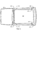
図2は例示的な車両ルーフ補強具200を示す。車両ルーフ補強具200は、互いに接合されて中央開口部260を規定する金属製側部210、フロントFRP部220、及びリアFRP部240を含んでもよい。金属製側部210は、車両ルーフ補強具の側部を形成してもよく、長手方向の車両軸に略並行に延在してもよい。すなわち、金属製側部210は、前方から後方に車両の側部に沿って延在してもよい。フロントFRP部220は、車両ルーフの前部で長手方向の車両軸を横切って延在してもよい。リアFRP部240は、ルーフ用構造支持部の後部として長手方向の車両軸を横切って延在してもよい。
FIG. 2 shows an exemplary
各金属製側部210は、略チャネル状(channel-like)構造を有する略長尺なフレーム部材であってもよい。例えば、金属製側部210は、内側リップ212、凹状中央チャネル214、及び外側リップ216を含んでもよい。金属製側部210のチャネル状構造は、ルーフ組立体を補強するのに役立つ構造上の剛性を付与してもよい。金属製側部210は、金属板のスタンピング等、従来の金属加工処理を用いて形成されてもよい。金属製側部210は、本明細書に開示される技術と適合する如何なる金属又は金属の組み合わせによって形成されてもよい。例えば、金属製側部210は、鋼鉄、アルミニウム、マグネシウム、チタン、コバルト、ベリリウム、ニッケル、コロンビウム、タンタル、タングステン、及びその合金、又は他の構造合金製でもよい。
Each
フロントFRP部220は、略チャネル状構造を有する略長尺なフレーム部材であってもよい。例えば、フロントFRP部220は、内側リップ222、凹状中央チャネル224、及び外側リップ226を含んでもよい。フロントFRP部220のチャネル状構造は、ルーフ組立体を補強するのに役立つ構造上の剛性を付与してもよい。フロントFRP部220は、ルーフ補強具200の2つのフロント角部を含んでもよい。フロントFRP部220は、ルーフ補強具200の前方全体にわたって延在してもよい。フロントFRP部220は、リア凸部228を含み、フロントFRP部220の端部が長手方向後方を向き、リア凸部228の縁部が長手方向の軸を横切るように設けられてもよい。従って、リア凸部228は、金属製側部210の前方側の端部と結合されてもよい。
The
フロントFRP部220は、金属タブ内に埋め込まれた繊維トウを有する1つ又は複数の移行構造を含んでもよい。例えば、フロントFRP部220は、リア凸部228に配置される内側移行構造232、中間移行構造234、及び外側移行構造236を含んでもよい。内側移行構造232は、内側リップ222の端部に配置されてもよい。中間移行構造234は、中央チャネル224の端部に配置されてもよい。外側移行構造236は、外側リップ226の端部に配置されてもよい。ある態様において、外側移行構造236は、フロントFRP部220の側部全体に沿って延在する長尺な移行構造であってもよい。以下さらに詳細に論じられる通り、移行構造236は、車両フレーム部材に溶接されてもよい。
The
ある態様において、本明細書に記載される移行構造は、超音波付加製造(ultrasonic additive manufacturing、UAM)を用いて埋め込まれた繊維トウを含んでもよい。繊維を埋め込むためのUAM技術は、例えば、ハーンレン及びダピノ(Hahnlen and Dapino)による「超音波付加製造による埋め込みスマート材料を有する活性金属基複合材料(“Active Metal-matrix Composites with Embedded Smart Materials by Ultrasonic Additive Manufacturing”)」、SPIE(国際光工学会)議事録、7645:15、2010年3月、に記載されており、ここに参照することによりその内容が組み込まれる。金属タブは、上記議事録に開示される技術と適合する、如何なる金属にて形成されてもよい。例えば、金属タブは、鋼鉄、アルミニウム、マグネシウム、チタン、コバルト、ベリリウム、ニッケル、コロンビウム、タンタル、タングステン、及びその合金、又は他の構造合金製でもよい。繊維トウは、金属タブの縁部から延出してもよい。移行構造は、フロントFRP部220の製造中に該フロントFRP部220内に埋め込まれてもよい。例えば、繊維トウは、繊維織物を一体化(consolidate)する前に、フロントFRP部220を形成するその繊維織物に挟み込んでもよい。従って、金属タブは、フロントFRP部220の統合化部を形成してもよい。金属タブの表面は、露出していてもよい。ある態様において、金属タブの、1つ又は複数の縁部(edge)がフロントFRP部220の縁部を形成してもよい。
In some embodiments, the transitional structures described herein may include fibrous tow embedded using ultrasonic additive manufacturing (UAM). UAM technology for embedding fibers includes, for example, "Active Metal-matrix Composites with Embedded Smart Materials by Ultrasonic Additive" by Hahnlen and Dapino. "Manufacturing") ", SPIE (International Society of Optical Engineering) minutes, 7645:15, March 2010, the contents of which are incorporated by reference here. The metal tabs may be made of any metal that is compatible with the techniques disclosed in the minutes above. For example, the metal tabs may be made of steel, aluminum, magnesium, titanium, cobalt, beryllium, nickel, colombium, tantalum, tungsten, and alloys thereof, or other structural alloys. The fiber tow may extend from the edge of the metal tab. The transition structure may be embedded in the
リアFRP部240も、フロントFRP部220と同様に、略チャネル状構造を有する略長尺なフレーム部材であってもよい。例えば、リアFRP部240は、内側リップ242、凹状中央チャネル244、及び外側リップ246を含んでもよい。リアFRP部240は、金属タブ内に埋め込まれた繊維トウを有する1つ又は複数の移行構造も含んでもよい。例えば、リアFRP部240は、内側移行構造252、中間移行構造254、及び外側移行構造256を含んでもよい。内側移行構造252は、内側リップ242の端部に配置されてもよい。中間移行構造254は、中央チャネル244の端部に配置されてもよい。外側移行構造256は、外側リップ246の端部に配置されてもよい。ある態様において、外側移行構造256は、リアFRP部240の側部全体に沿って延在する長尺な移行構造であってもよい。以下さらに詳細に論じられる通り、移行構造256は、車両フレーム部材に溶接されてもよい。移行構造252、254、256は、それぞれ対応する移行構造232、234、236と同様な形状及び構成を有してもよい。
Like the
移行構造232、234、236、252、254、256は、金属製側部210と接合(例えば溶接)されて、ルーフ補強具200を形成してもよい。例えば、ルーフ補強具は、略台形又は略四角形であって、中央開口部260を規定してもよい。ルーフ補強具200は、車両フレームに装着され、ルーフパネルを支持してもよい。ルーフ補強具200は、パノラマルーフ、サンルーフ、ムーンルーフのようなガラス組立体を支持してもよい。
The
図3を参照すると、例示的な車両ルーフ補強具200がルーフパネル270に取り付けられてもよい。例えば、ルーフパネル270は、(例えば、内側リップ212、222、242及び外側リップ216、226、246に沿って)ルーフ補強具200の上面に接合されてもよい。ルーフパネル270は、支持部無しに、ルーフ補強具200から(例えば後方へ)延在してもよい。ルーフパネル270の延在部は、(例えば、溶接又は他の金属同士の接合技術によって)車両フレームに取り付けられてもよい。ある態様において、ルーフパネル270は、アルミニウム又はその合金であって、移行構造236、256に溶接で接合されてもよい。
With reference to FIG. 3, an exemplary
図3にも視認されるように、金属フランジ218が金属製側部210の端部にある。金属フランジ218は、金属製側部210がフロントFRP部220又はリアFRP部240と重なる場所に配置されてもよい。金属フランジ218は、金属製側部210の残余の部分からオフセットして、各フロントFRP部220及びリアFRP部240を受容してもよい。移行構造(視認不可)が金属フランジ218の上面に接合(例えば、溶接)されてもよい。金属フランジ218及びFRP部の相対配置は反対であってもよく、金属フランジ218が上面側で、移行構造を含むFRP部が底面側に配置されてもよいことは理解すべきである。ある態様において、長尺な外側移行構造236、256が各FRP部の側部縁を形成する場合、各金属フランジ218から角部へ延在する長尺な外側移行構造236、256の一部がルーフ補強具200の底面を形成してもよい。
As is also visible in FIG. 3, a
図4は、本開示の態様による、部分的な車両フレーム302に接合される例示的な車両ルーフ補強具200を示す。車両フレーム302は、側部ボディ部材312を含み、該側部ボディ部材312はボディ部材112に対応してもよい(図1)。側部ボディ部材312は、ドアフレーム340を支持するフロントピラー342(同義的に「Aピラー」とも参照される)、ピラー344(同義的に「Bピラー」とも参照される)、リアピラー346(同義的に「Cピラー」とも参照される)を含んでもよい。ルーフ補強具200は、ドアフレーム340において車両フレーム302に接合されてもよい。
FIG. 4 shows an exemplary
FRPと金属のような異なる材料を接合することには、様々な問題がある。特に、ボルトやリベットのようなFRPを貫通する留め具を用いる場合、FRPの構造上の一体性(integrity)を低減させる可能性がある。そのような留め具を収容するためにFRPの厚い層を用いる構成を採用してもよいが、厚い層は重量が増し、コストがかかる。移行構造336、356を統合することは、ルーフ補強具のFRP部を、従来の金属同士の接合技術を用いて車両フレームに取り付けることを可能にする。そのような接合技術には、以下に限定されないが、抵抗スポット溶接、ミグ(MIG、金属不活性ガス)溶接、その他の溶接、ろう付け、留め具(例えば、ねじ、ボルト、リベット)、加締め(clinching)、縁曲げ(hemming)等がある。ある態様において、車両フレーム302は、鋼鉄を含んでもよく、金属製側部210は、アルミニウム製でもよく、移行構造236、256はアルミニウムを含んでもよい。アルミニウム部は、鋼鉄製車両フレーム302に接着剤及び留め具を用いて接合してもよい。
There are various problems in joining FRP and different materials such as metal. In particular, when fasteners that penetrate the FRP, such as bolts and rivets, are used, the structural integrity of the FRP may be reduced. A configuration may be adopted in which a thick layer of FRP is used to accommodate such fasteners, but the thick layer is heavy and costly. The integration of the transition structures 336 and 356 makes it possible to attach the FRP portion of the roof reinforcement to the vehicle frame using conventional metal-to-metal joining techniques. Such joining techniques include, but are not limited to, resistance spot welding, MIG (MIG, metal inert gas) welding, other welding, brazing, fasteners (eg, screws, bolts, rivets), crimping. There are (clinching), edge bending (hemming), etc. In some embodiments, the
図4は、ルーフ補強具200に装着されるガラス組立体320も示す。例えば、ガラス組立体320は、パノラマガラス組立体でもよい。ガラス組立体320は、ルーフ補強具200の中央開口部260内に配置されてもよい。ガラス組立体320は、フレーム324に支持される1つ又は複数のガラス面322を含んでもよい。フレーム324は、(例えば、サンルーフを開くために)1つ又は複数のガラス面322を引き込むことを可能にしてもよい。フレーム324は、該フレーム324の周囲及びルーフ補強具200の内側リップ212、222、242に沿って、ルーフ補強具200に取り付けられてもよい。フレーム324は、異なる技術及び/又は留め具を用いて、金属製側部210及びFRP部220、240に装着されてもよい。例えば、フレーム324は、該フレーム324及び金属製側部210の両方の孔部を貫通するリベット又はナット及びボルト等の留め具328を用いて、金属製側部210に装着されてもよい。FRP部220、240は、該FRP部の表面に接着剤を用いて結合されるTスタッド326を含んでもよい。Tスタッド326は、略平面の結合面及び結合面から垂直に延在するねじ付き軸を有してもよい。ねじ付き軸は、フレーム324内の孔部を通じて配置されナットによって固定されてもよい。ガラス組立体320は車両の構造部材ではないので、接着剤は十分な強さを有する可能性がある。Tスタッドを使用すれば、FRP部に孔を開ける必要性はなくなる。
FIG. 4 also shows the
図5は、例示的な車両ルーフ補強具200と、車両フレーム302との間のインターフェース部の斜視図である。ドアフレーム340は、外側リップ216に沿って金属製側部210に接触してもよく、金属同士の技術(例えば、スポット溶接部)にて固定してもよい。同様に、ドアフレーム340は、長尺な外側移行構造236、256と接触してもよく、金属同士の技術(例えば、スポット溶接部)にて固定してもよい。ある態様において、ルーフ補強具200をドアフレーム340又はピラー(例えば、リアピラー346)に固定するために、ブラケット348を用いてもよい。図5に示される通り、ブラケット348は、リアFRP部240に装着されてもよい。上述の通り、FRP部240は、ブラケット348の領域に更なる層を含み、十分な構造上の一体性(integrity)を具備してもよい。他の態様において、埋め込まれた繊維を含む1つ又は複数の移行構造がブラケット348への接続部に配置されてもよい。例えば、1つ又は複数の移行構造がFRP部240の中間部に統合化されてもよい。それから、ブラケット348は、その移行構造に溶接又は固定されてもよい。
FIG. 5 is a perspective view of an interface portion between the exemplary
図6は、本開示の態様による他の例示的な車両ルーフ補強具400の斜視図である。図7は、例示的な車両ルーフ補強具400の上面図である。ルーフ補強具400は、金属製側部210、フロントFRP部220、リアFRP部240にそれぞれ対応可能な金属製側部410、フロントFRP部420、リアFRP部440を含んでもよい。ルーフ補強具400は、ガラス組立体320を装着可能な中央開口部460を規定してもよい。ルーフ補強具400は、金属製側部410がルーフ補強具400のリア角部まで延在可能な点で、ルーフ補強具200と異なってもよい。金属製側部410とFRP部440との接合部は、ルーフ補強具400の後ろ側に配置されてもよい。リアFRP部440は略直線状であってもよく、両端に配置される内側移行構造452、中間移行構造454、及び外側移行構造456を含んでもよい。外側移行構造256と対照的に、ルーフ補強具400が金属製側部410のリアフランジ462に沿って車両フレームに接合されてもよいので、外側移行構造456は、比較的短くともよい。例えば、外側移行構造456は、中間移行構造454と略同じ長さであってもよい。さらに、金属製側部410は、ブラケット348に取り付けるための貫通孔464を含んでもよい。従って、ルーフ補強具400には、リアFRP部440を通じて留め具を配置しなくともよい。
FIG. 6 is a perspective view of another exemplary
図8は、例示的な車両ルーフ補強具400のリア角部の分解上面斜視図である。図9は、例示的な車両ルーフ補強具400のリア角部の分解底面斜視図である。金属製側部410は、フランジ472を含んでもよい。フランジ472は、金属製側部410から横方向内側に延在してもよい。フランジ472は、移行構造452、454、456を含むリアFRP部440の端部底面に対応した形状を有してもよい。フランジ472の長さは、1つ又は複数の移行構造452、454、456の長さと略等しくともよい。フランジ472の上面は、リアFRP部440の厚さと略等しい距離だけオフセット(例えば、低く)してもよい。従って、リアFRP部440がフランジ472に接合される場合、リアFRP部440の上面は、金属製側部410の上面と同じ高さとなってもよい。図9に最も良く示される通り、移行構造452、454、456は、FRP部440の下面に露出し、フランジ472と接触する。
FIG. 8 is an exploded top perspective view of the rear corner portion of the exemplary
図10は、例示的な車両ルーフ補強具400のフロント角部の分解上面斜視図である。図11は、例示的な車両ルーフ補強具400のフロント角部の分解底面斜視図である。車両ルーフ補強具200のフロント角部は、車両ルーフ補強具400のフロント角部と同様であってよい。金属製側部410は、フロント端部にフランジ476を含んでもよい。フランジ476は、移行構造432、434、436を含むフロントFRP部420の端部に対応した形状を有してもよい。フランジ472と同様に、フランジ476は、フロントFRP部420の端部がフランジ476上に受容され、フロントFRP部420の上面と金属製側部410の上面とが同じ高さとなるように、オフセットしてもよい。移行構造432、434、436の底面は、フランジ476に接触して固定されてもよい。外側移行構造436は、フランジ476よりかなり長く、フロントFRP部420のフロント角部まで延在してもよいことは留意すべきである。すなわち、外側移行構造436の第1部分は、フランジ476に接触して接合されてもよく、外側移行構造436の第2部分は、フランジ476を越えて延在し、車両フレーム(例えば、ドアフレーム340)に固定されてもよい。
FIG. 10 is an exploded top perspective view of the front corner portion of the exemplary
図12は、フロントFRP部420と金属製側部410との間のインターフェース部の側面斜視図である。図13は、図10のFRP部品と金属部品との間のインターフェース部の底面斜視図である。同様なインターフェース部が金属製側部210とフロントFRP部220との間に存在してもよい。図10に最も良く示される通り、内側移行構造432は、該内側移行構造432の上面がフロントFRP部420の上面と同じ高さとなるように、フロントFRP部420内に統合化されてもよい。同様に、外側移行構造436は、フロントFRP部420内に統合化されて、上面が同じ高さとなるようにしてもよい。さらに、フランジ476がオフセットして、フロントFRP部420がフランジ476上に着座し、フロントFRP部420の上面と金属製側部410の上面とが同じ高さとなることを可能にする。図11に最も良く示される通り、外側移行構造436は、一端部においてフランジ476と接合され、フランジ476を越えて延在してもよい。従って、外側移行構造436の底面は、車両フレームと接合するために露出してもよい。フロントFRP部420は、各移行構造432、434、436において、金属製側部410のフランジ476へ溶接にて(例えば、抵抗スポット溶接を用いて)接合されてもよい。さらに、接着剤又はシーラントが、フロントFRP部420とフランジ476との間に配置されてもよい。同様な技術が、例示的な車両ルーフ補強具200、400における金属製側部410とFRP部との間の各インターフェース部で用いられてもよい。
FIG. 12 is a side perspective view of the interface portion between the
図14は、例示的な車両ルーフ補強具400のインターフェース領域500内に配置される移行構造のさらなる詳細を示す。移行構造は、計画した接合技術のために構成されてもよい。例えば、スポット溶接が用いられる場合、移行構造は、1つ又は複数のスポット溶接箇所を収容するように構成されてもよい。例えば、内側移行構造432は、3つの辺部502から延在する繊維を有してもよい。フロントFRP部420の縁部を形成する4つめの辺部504は、繊維を含まなくともよい。繊維は、繊維の輪(ループ)が金属タブ及びFRPの両方の内部に埋め込まれるように、金属タブの3つの辺部502から内側に延在してもよい。ある形態において、内側移行構造432の金属タブは、略25mm×25mmの大きさであってもよく、中央繊維フリー領域506内に中央スポット溶接部を収容してもよい。他の形態において、金属タブの長さを延長し、2つ又はそれ以上のスポット溶接部を可能にしてもよい。同様に、中間移行構造434は、3つの辺部512に埋め込まれた繊維と、フロントFRP部420の縁部を形成する自由辺部514とを含んでもよい。凹状中央チャネル424は、内側リップ422より大きくてもよく、それにより長尺な金属タブが長手方向又は横方向の何れかを指向してもよい。ある態様において、スポット溶接部が意図される箇所516には、繊維への損傷を防ぐために、繊維を設けないようにしてもよい(繊維フリー)。例えば、長手方向を指向する金属タブは、少なくとも50mm、好ましくは略60mmの長さを有し、好ましくは略25mmの幅を有してもよい。金属タブの縁部から数えて、最初の12mmに繊維が埋め込まれ、それから第1繊維フリー領域518が略5mm設けられ、そして25mmにわたって繊維が埋め込まれ、次に第2繊維フリー領域518が略5mm設けられ、そして金属タブの辺部及び端部に沿って繊維が埋め込まれてもよい。従って、中間移行構造434の長手方向を指向する例示的なタブは、スポット溶接部用の2つの箇所516を有してもよい。例示的な外側移行構造436は、長縁部522の1つに沿って埋め込まれた繊維を有してもよい。残りの辺部524は、フロントFRP部420の角部を形成してもよく、埋め込まれる繊維が無くともよい。例えば、外側移行構造436は、フロントFRP部420の長手方向の縁部に沿って外側リップ426全体を形成してもよい。外側移行構造436は、その全体の長さに沿って、離間するスポット溶接部を有してもよい。例示的なタブの形状が示されたが、接合される金属部及びFRP部の具体的な構造によってさらなるタブ形状が構成されてよいことは理解すべきである。例えば、図2の移行構造に繊維が配置されて、スポット溶接用箇所を収容してもよい。
FIG. 14 shows further details of the transition structure located within the
図15は、車両ルーフを製造する例示的な方法600を示すフローチャートである。車両ルーフは、ルーフ補強具200、400を含んでもよい。方法600は、超音波溶接機並びに本発明の技術分野で知られている他の製造用工具及び装置を含む設備を用いて、作業者によって行われてよい。方法600は、作業者によって行われる動作に関して以下に説明されるが、そこで説明される1つ又は複数の工程が(例えば、ロボットアームにより)自動化されてもよい。
FIG. 15 is a flowchart showing an
ブロック602において、方法600は、金属タブ内に埋め込まれた繊維を含む、ルーフ補強具の少なくとも1つのFRP部を設ける工程を含んでもよい。ある態様において、例えば、1つ又は複数のフロントFRP部220、420、及び/又は、1つ又は複数のリアFRP部240、440が設けられてもよい。例えば、1つのフロントFRP部220及び1つのリアFRP部240が、ルーフ補強具200を形成するために設けられてもよい。少なくとも1つのFRP部を設けることは、ブロック604、606、608で示される様に、該少なくとも1つのFRP部を製造することを含んでもよい。
At
ブロック604において、ブロック602は、金属タブから延在するように埋め込まれた繊維トウを有する複数の金属タブを含む複数の移行部品を供給することを含んでもよい。上述の通り、複数の移行部品は、各金属タブ内に繊維トウを埋め込むために、UAMを用いて製造されてもよい。繊維トウは、FRP部に接触する金属タブの辺部から延在してもよい。繊維トウは、織物を形成するように織られもよく、又は織物トウが金属タブ内に埋め込まれてもよい。
In
ブロック606において、ブロック602は、繊維織物の層で繊維トウを挟むことを含んでもよい。例えば、ある態様において、繊維織物の層は、FRP部の形状に切断された炭素繊維織物であってもよい。その層は、移行構造の場所に切り欠き部を含んでもよい。移行部品の金属タブは、炭素繊維織物の層へ繊維トウが延出するように、前記切り欠き部に配置されてもよい。それから、炭素繊維織物の他の層が、繊維トウ上に配置されてもよい。複数の層は、移行部品と繊維層とを統合化するために挟み込まれてもよい。
In
ブロック608において、ブロック602は、繊維織物の層を一体化してFRP部を形成することを含んでもよい。例えば、ある態様において、一体化することは、FRP部品を製造するために用いられる繊維層を結合(bind)するための如何なるプロセス(工程)も含んでもよい。例えば、一体化することは、繊維層に樹脂をしみ込ませ、オートクレーブ又はホットプレス型を用いて樹脂を硬化させることを含んでもよい。形成されるFRP部品は、ルーフ補強具のFRP部であってもよい。
In
ブロック610において、方法600は、FRP部を金属部に接合することを含んでもよい。例えば、フロントFRP部220、420及び/又はリアFRP部240、440は、1つ又は複数の金属製側部210、410に接合されてもよい。ブロック612において、ブロック610は、移行部品を金属部にスポット溶接することを含んでもよい。例えば、フロントFRP部420は、各移行構造432、434、436において、金属製側部410のフランジ476へスポット溶接にて(例えば、抵抗スポット溶接を用いて)接合されてもよい。あるいは、他の既知の金属同士の接合技術(例えば、ミグ溶接、ろう付け、留め具、加締め、縁曲げ等であって、それらは接着剤又はシーラーを併用してもよく、又はしなくともよい)が用いられてもよい。さらに、ブロック610は、接着剤又はシーラントを、フロントFRP部420とフランジ476との間、及びリアFRP部240又はリアFRP部440とフランジ472との間に付与してもよい。
At
ブロック614において、方法600は、選択的に、車両組立施設にルーフ補強具を供給することを含んでもよい。例えば、ある態様において、1つ又は複数のルーフ補強具200、400が車両組立施設に供給されてもよい。ルーフ補強具200、400は、既存の車両組立ラインに適合させてもよい。従って、ルーフ補強具200、400は、従来の工具を用いて車両に装着してもよい。
At
ブロック616において、方法600は、選択的に、車両フレームにルーフ補強具を装着することを含んでもよい。例えば、ある態様において、ルーフ補強具200、400は、車両フレーム302に装着してもよい。実施する際には、ルーフ補強具200、400は、外側リップ216、416、及び/又は、リアフランジ462及び移行構造236、256、436、456に沿って、スポット溶接部を用いて車両フレーム302に取り付けられてもよい。ルーフ補強具200、400は、留め具を用いて1つ又は複数のブラケット348に取り付けられてもよい。
At
ブロック618において、方法600は、選択的に、ルーフ補強具にルーフパネルを装着することを含んでもよい。例えば、ある態様において、ルーフパネルは、移行構造において、ルーフ補強具200、400に溶接されてもよい。例えば、スポット溶接部は金属製側部210に沿って、且つ補強具、ルーフ外板(roof skin)、ドアフレーム/車両構造間の移行構造236、256に配置されてもよい。また、ルーフ外板は、内側リップ212、222、242の自由縁で形成される内側縁部に沿って、ルーフ補強具200に縁曲げで取り付けられてもよい。
At
上記に開示された特徴及び機能の様々な実施形態、並びに他の特徴及び機能の様々な実施形態、又はその代替、改変は、好適に組み合わされて、他の多くの異なるシステムとなり、又はその応用が可能であることが理解されよう。また、現時点で予見又は予期できない本発明の代替、改変、変更、又は改良が後に当業者によってなされる可能性があり、これらも以下の請求項によって包含されることが意図される、ということが理解されよう。 Various embodiments of features and functions disclosed above, as well as various embodiments of other features and functions, or alternatives or modifications thereof, are suitably combined into many other different systems, or applications thereof. Will be understood that is possible. It is also intended that at this time foreseeable or unforeseen alternatives, modifications, modifications, or improvements to the invention may be made later by one of ordinary skill in the art, which are also intended to be incorporated by the following claims. Will be understood.
Claims (14)
前記FRP部の前記移行構造に固定される少なくとも1つの金属部又は合金部と、を備え、
前記FRP部の少なくとも一部の繊維が前記移行構造に埋め込まれ、
前記少なくとも1つの金属部と前記少なくとも1つのFRP部との間のインターフェース部は、前記少なくとも1つの金属部内にオフセットされたフランジを含み、前記移行構造は、オフセットされた部分のうち、前記オフセットされたフランジと前記少なくとも1つの金属部の上面との間の少なくとも一部を満たす、
ことを特徴とする車両ルーフ補強具。 A fiber reinforced polymer (FRP) portion containing at least one transition structure composed of a metal or alloy, and
A metal portion or an alloy portion fixed to the transition structure of the FRP portion is provided.
At least a part of the fibers of the FRP portion is embedded in the transition structure,
The interface portion between the at least one metal portion and the at least one FRP portion includes a flange offset in the at least one metal portion, and the transition structure is offset in the offset portion. Fills at least a portion between the offset flange and the top surface of the at least one metal portion.
A vehicle roof reinforcement that is characterized by this.
前記少なくとも1つの金属部及び前記少なくとも1つのFRP部は、中央開口部を規定する、
ことを特徴とする車両ルーフ補強具。 In the vehicle roof reinforcing tool according to claim 1,
The at least one metal part and the at least one FRP part define a central opening.
A vehicle roof reinforcement that is characterized by this.
さらに、前記中央開口部に近接した前記FRP部の表面に取り付けられる、ガラス組立体を装着するためのスタッドを備える、
ことを特徴とする車両ルーフ補強具。 In the vehicle roof reinforcing tool according to claim 2.
Further, a stud for mounting the glass assembly, which is attached to the surface of the FRP portion in the vicinity of the central opening, is provided.
A vehicle roof reinforcement that is characterized by this.
さらに、前記中央開口部に近接した少なくとも1つの金属部を貫通して延在し、前記ガラス組立体を装着するための留め具を備える、
ことを特徴とする車両ルーフ補強具。 In the vehicle roof reinforcement according to claim 3,
Further, a fastener is provided which extends through at least one metal portion in the vicinity of the central opening and for mounting the glass assembly.
A vehicle roof reinforcement that is characterized by this.
さらに、少なくとも1つの長尺な移行構造を備え、
前記FRP部の少なくとも一部の前記繊維は、前記FRP部の縁部に沿って延在する前記長尺な移行構造の金属タブ又は合金タブ内に埋め込まれる、
ことを特徴とする車両ルーフ補強具。 In the vehicle roof reinforcing tool according to claim 1,
In addition, it has at least one long transition structure
At least a part of the fibers of the FRP portion is embedded in a metal tab or alloy tab of the long transition structure extending along the edge of the FRP portion.
A vehicle roof reinforcement that is characterized by this.
さらに、前記少なくとも1つの長尺な移行構造に取り付けられる車両フレームを備え、
前記車両フレームは合金製で、前記少なくとも1つの長尺な移行構造はアルミニウム製である、
ことを特徴とする車両ルーフ補強具。 In the vehicle roof reinforcement according to claim 5,
In addition, it comprises a vehicle frame that can be attached to the at least one elongated transition structure.
The vehicle frame is made of alloy and the at least one elongated transition structure is made of aluminum.
A vehicle roof reinforcement that is characterized by this.
さらに、前記少なくとも1つの長尺な移行構造に溶接される車両ルーフパネルを備え、
前記車両ルーフパネルは、アルミニウム製であり、前記少なくとも1つの長尺な移行構造はアルミニウム製である、
ことを特徴とする車両ルーフ補強具。 In the vehicle roof reinforcement according to claim 5,
In addition, a vehicle roof panel welded to the at least one elongated transition structure is provided.
The vehicle roof panel is made of aluminum and the at least one elongated transition structure is made of aluminum.
A vehicle roof reinforcement that is characterized by this.
前記移行構造は、少なくとも1つのスポット溶接部を介して前記少なくとも1つの金属部に接続される、
ことを特徴とする車両ルーフ補強具。 In the vehicle roof reinforcing tool according to claim 1,
The transition structure is connected to the at least one metal portion via at least one spot weld.
A vehicle roof reinforcement that is characterized by this.
前記少なくとも1つの金属部は、車両の長手方向の軸に平行に延在し、前記少なくとも1つのFRP部は、前記長手方向の軸を横切って延在する、
ことを特徴とする車両ルーフ補強具。 In the vehicle roof reinforcing tool according to claim 1,
The at least one metal portion extends parallel to the longitudinal axis of the vehicle, and the at least one FRP portion extends across the longitudinal axis.
A vehicle roof reinforcement that is characterized by this.
前記少なくとも1つのFRP部は、フロントFRP部及びリアFRP部を含む、
ことを特徴とする車両ルーフ補強具。 In the vehicle roof reinforcing tool according to claim 9.
The at least one FRP section includes a front FRP section and a rear FRP section.
A vehicle roof reinforcement that is characterized by this.
前記フロントFRP部は、前記車両ルーフ補強具の2つの角部を形成し、前記リアFRP部は、前記車両ルーフ補強具の2つの角部を形成し、前記少なくとも1つの金属部は、前記車両ルーフ補強具の側部を形成する2つの金属部を含む、
ことを特徴とする車両ルーフ補強具。 In the vehicle roof reinforcing tool according to claim 10,
The front FRP portion forms two corner portions of the vehicle roof reinforcing tool, the rear FRP portion forms two corner portions of the vehicle roof reinforcing tool, and the at least one metal portion forms the vehicle. Includes two metal parts that form the sides of the roof reinforcement,
A vehicle roof reinforcement that is characterized by this.
前記少なくとも1つの移行構造は、それぞれ、前記車両ルーフ補強具の前記側部の1つに配置される、
ことを特徴とする車両ルーフ補強具。 In the vehicle roof reinforcing tool according to claim 11.
Each of the at least one transition structure is located on one of the sides of the vehicle roof reinforcement.
A vehicle roof reinforcement that is characterized by this.
前記フロントFRP部は、前記車両ルーフ補強具の2つの角部を形成し、前記少なくとも1つの金属部は、前記車両ルーフ補強具の側部を形成する2つの金属部を含み、前記側部は延在して前記車両ルーフ補強具のリア角部を形成する、
ことを特徴とする車両ルーフ補強具。 In the vehicle roof reinforcing tool according to claim 10,
The front FRP portion forms two corner portions of the vehicle roof reinforcing tool, the at least one metal portion includes two metal portions forming a side portion of the vehicle roof reinforcing tool, and the side portion includes the side portion. Extending to form the rear corner of the vehicle roof reinforcement,
A vehicle roof reinforcement that is characterized by this.
前記少なくとも1つの移行構造は、埋め込まれる繊維が無い領域を含み、前記移行構造は、前記領域において前記少なくとも1つの金属部に接合される、
ことを特徴とする車両ルーフ補強具。 In the vehicle roof reinforcing tool according to claim 1,
The at least one transition structure includes a region without fibers to be embedded, and the transition structure is joined to the at least one metal portion in the region.
A vehicle roof reinforcement that is characterized by this.
Applications Claiming Priority (2)
| Application Number | Priority Date | Filing Date | Title |
|---|---|---|---|
| US15/610,146 | 2017-05-31 | ||
| US15/610,146 US10661838B2 (en) | 2017-05-31 | 2017-05-31 | Multi-material vehicle roof stiffener |
Publications (3)
| Publication Number | Publication Date |
|---|---|
| JP2018203230A JP2018203230A (en) | 2018-12-27 |
| JP2018203230A5 JP2018203230A5 (en) | 2021-07-29 |
| JP6912417B2 true JP6912417B2 (en) | 2021-08-04 |
Family
ID=64279454
Family Applications (1)
| Application Number | Title | Priority Date | Filing Date |
|---|---|---|---|
| JP2018084777A Active JP6912417B2 (en) | 2017-05-31 | 2018-04-26 | Vehicle roof reinforcements made of different materials |
Country Status (4)
| Country | Link |
|---|---|
| US (2) | US10661838B2 (en) |
| JP (1) | JP6912417B2 (en) |
| CN (1) | CN108974130B (en) |
| DE (1) | DE102018204280A1 (en) |
Families Citing this family (13)
| Publication number | Priority date | Publication date | Assignee | Title |
|---|---|---|---|---|
| US11351590B2 (en) | 2017-08-10 | 2022-06-07 | Honda Motor Co., Ltd. | Features of dissimilar material-reinforced blanks and extrusions for forming |
| US10532421B2 (en) | 2017-08-29 | 2020-01-14 | Honda Motor Co., Ltd. | UAM resistance spot weld joint transition for multimaterial automotive structures |
| US10421496B2 (en) * | 2017-09-15 | 2019-09-24 | Honda Motor Co., Ltd. | Panoramic roof stiffener reinforcement |
| US10604191B2 (en) * | 2017-11-29 | 2020-03-31 | Honda Motor Co., Ltd. | Vehicle frame construction and method |
| KR102429065B1 (en) * | 2017-12-15 | 2022-08-04 | 현대자동차주식회사 | Roof panel assembly of vehicle |
| US10870166B2 (en) | 2018-02-01 | 2020-12-22 | Honda Motor Co., Ltd. | UAM transition for fusion welding of dissimilar metal parts |
| EP3566930B1 (en) * | 2018-05-08 | 2021-09-29 | Volvo Car Corporation | Vehicle structure |
| US11298775B2 (en) | 2018-05-24 | 2022-04-12 | Honda Motor Co., Ltd. | Continuous ultrasonic additive manufacturing |
| JP7196695B2 (en) * | 2019-03-06 | 2022-12-27 | マツダ株式会社 | vehicle roof structure |
| JP7435341B2 (en) | 2019-07-30 | 2024-02-21 | マツダ株式会社 | vehicle roof structure |
| US11465390B2 (en) | 2020-03-02 | 2022-10-11 | Honda Motor Co., Ltd. | Post-process interface development for metal-matrix composites |
| US11541939B2 (en) * | 2021-01-05 | 2023-01-03 | GM Global Technology Operations LLC | Laminate composite roof panels with internal localized structural reinforcements for motor vehicles |
| US11420683B2 (en) * | 2021-01-20 | 2022-08-23 | GM Global Technology Operations LLC | Fiber-reinforced polymer composite components for vehicle body structures and methods of making the same |
Family Cites Families (51)
| Publication number | Priority date | Publication date | Assignee | Title |
|---|---|---|---|---|
| US1475765A (en) | 1920-12-27 | 1923-11-27 | London General Omnibus Co | Slatted floor, deck, or the like |
| DE3202594A1 (en) | 1982-01-27 | 1983-08-11 | Ford-Werke AG, 5000 Köln | MOTOR VEHICLE BODY WITH A FIXED CONNECTED COMPOSITE ROOF |
| JPS5911975A (en) | 1982-07-13 | 1984-01-21 | Nissan Motor Co Ltd | Roof reinforcing structure of car |
| DE3838153A1 (en) | 1988-11-10 | 1990-05-31 | Schuetz Werke Gmbh Co Kg | LIGHTWEIGHT MATERIAL AND METHOD AND SYSTEM FOR PRODUCING HONEYCOMB STRUCTURES FROM THE LIGHTWEIGHT MATERIAL |
| EP0694726A1 (en) * | 1994-07-19 | 1996-01-31 | Ameron, Inc. | High strength pipe joint with pressed key groove |
| DE19709016C2 (en) | 1997-03-06 | 1999-05-27 | Rockwell International Gmbh | Vehicle roof and method for mounting the vehicle roof on a body |
| US7076877B2 (en) * | 1998-06-18 | 2006-07-18 | Alcan Technology & Management, Ltd. | Roof unit and floor unit for a road vehicle |
| EP1026071A1 (en) * | 1999-02-05 | 2000-08-09 | Alusuisse Technology & Management AG | Structural beam |
| CA2332442C (en) * | 1999-03-19 | 2008-01-15 | Toray Industries, Inc. | Frp roofing member manufacturing method, and its connecting structure and connecting method |
| JP2000336777A (en) * | 1999-03-19 | 2000-12-05 | Toray Ind Inc | Frp made joined structural body |
| US20050003195A1 (en) * | 1999-12-02 | 2005-01-06 | Joseph Brian E. | Carbon foam composite tooling and methods for using the same |
| US6467834B1 (en) | 2000-02-11 | 2002-10-22 | L&L Products | Structural reinforcement system for automotive vehicles |
| DE10060042A1 (en) * | 2000-12-02 | 2002-06-06 | Inst Konstruktion Und Verbundb | Fiber reinforced metal and plastic component for high loads on machines and vehicles has long fibers extending from a metal into a plastic part |
| CA2405341A1 (en) | 2001-09-28 | 2003-03-28 | Intier Automotive Inc. | Conductive headliner layers |
| DE102004016854A1 (en) | 2004-04-06 | 2005-10-27 | Bayerische Motoren Werke Ag | Process to make lightweight aluminium and plastic e.g. carbon fibre sandwich panels for e.g. automotive applications |
| TWI353303B (en) | 2004-09-07 | 2011-12-01 | Toray Industries | Sandwich structure and integrated molding using th |
| US20060141260A1 (en) | 2004-12-29 | 2006-06-29 | Enamul Haque | Sandwich composite material using an air-laid process and wet glass |
| CA2688900C (en) * | 2005-11-21 | 2012-01-03 | Faroex Ltd. | Assembled structure of a sandwich panel and a connecting member using adhesive attachment |
| DE102008027429B4 (en) * | 2008-06-09 | 2016-01-28 | Daimler Ag | Method for producing a bodyshell structure for a motor vehicle |
| FR2937609B1 (en) * | 2008-10-27 | 2012-12-21 | Plastic Omnium Cie | VEHICLE HOOD LINING |
| US20100231007A1 (en) * | 2009-03-13 | 2010-09-16 | Ford Global Technologies Llc | Sunroof Reinforcement Assembly |
| US9085327B2 (en) | 2009-06-10 | 2015-07-21 | Ford Global Technologies, Llc | Vehicle roof reinforcement |
| JP2011111141A (en) * | 2009-11-30 | 2011-06-09 | Hitachi Ltd | Chassis frame for electric vehicle, and electric vehicle |
| US9522512B2 (en) * | 2010-08-17 | 2016-12-20 | The Boeing Company | Methods for making composite structures having composite-to-metal joints |
| US8993084B2 (en) * | 2010-08-17 | 2015-03-31 | The Boeing Company | Multi-layer metallic structure and composite-to-metal joint methods |
| US8652606B2 (en) * | 2010-08-17 | 2014-02-18 | The Boeing Company | Composite structures having composite-to-metal joints and method for making the same |
| GB2484107A (en) * | 2010-09-29 | 2012-04-04 | Nenuphar | Modular wind turbine blade for a vertical axis wind turbine |
| DE102010054935B4 (en) * | 2010-12-17 | 2013-11-28 | Daimler Ag | Body module component |
| DE102011104483A1 (en) * | 2011-06-17 | 2012-12-20 | MAN Truck & Bus Aktiengesellschaft | Frame longitudinal support structure for chassis frames of commercial vehicles, in particular of trucks and / or buses |
| DE102011106151B3 (en) | 2011-06-30 | 2012-07-19 | Daimler Ag | Method for producing an outer module with an outer panel for a modular housing component |
| CN202294194U (en) * | 2011-09-29 | 2012-07-04 | 浙江吉利汽车研究院有限公司 | Reinforcing board for top cover skylight |
| DE102011119246B4 (en) * | 2011-11-22 | 2013-09-19 | Daimler Ag | Lightweight construction element for a body |
| DE102012010424B4 (en) * | 2012-05-23 | 2014-02-13 | Technische Universität Dresden | A method for producing a composite component and a composite component produced by the method |
| US9120276B2 (en) * | 2012-07-25 | 2015-09-01 | The Boeing Company | Laminated composite bending and stiffening members with reinforcement by inter-laminar metal sheets |
| CN203032017U (en) | 2012-11-30 | 2013-07-03 | 南京航空航天大学 | Impact-resistant light foam metal sandwich plate |
| DE102013200677A1 (en) * | 2013-01-17 | 2014-07-17 | Bayerische Motoren Werke Aktiengesellschaft | Body structure element and method of manufacturing a body structure element |
| US8820824B1 (en) | 2013-03-14 | 2014-09-02 | Honda Motor Co., Ltd. | Vehicle roof structure |
| DE102013106073A1 (en) * | 2013-06-12 | 2014-12-18 | Leichtbau-Zentrum Sachsen Gmbh | Integral side member for motor vehicles |
| DE102013106070C5 (en) * | 2013-06-12 | 2019-10-24 | Leichtbau-Zentrum Sachsen Gmbh | Sidewall group for passenger cars |
| US9114836B1 (en) | 2014-02-06 | 2015-08-25 | Honda Motor Co., Ltd. | Vehicle roof structure |
| US9376074B2 (en) | 2014-04-25 | 2016-06-28 | GM Global Technology Operations LLC | Architected automotive impact beam |
| CN104986196A (en) | 2015-08-04 | 2015-10-21 | 成都国光电气股份有限公司 | Handcart |
| JP6654008B2 (en) * | 2015-08-24 | 2020-02-26 | 株式会社神戸製鋼所 | Structure and structural member including joining structure of different materials |
| CA2997903A1 (en) * | 2015-09-08 | 2017-03-16 | Wabash National, L.P. | Joining a rail member to a composite trailer structure |
| DE102015119437B4 (en) * | 2015-11-11 | 2019-06-19 | Fraunhofer-Gesellschaft zur Förderung der angewandten Forschung e.V. | Process for producing a fiber-reinforced composite component and fiber-reinforced composite component |
| CN108778840A (en) * | 2016-02-01 | 2018-11-09 | Ses解决方案股份有限公司 | Folded bicycle top case for motor vehicles |
| KR101884170B1 (en) * | 2016-11-18 | 2018-09-21 | 재단법인 한국탄소융합기술원 | Method for manufacturing carbon fiber reinforced plastic roof rail |
| US10065694B1 (en) * | 2017-05-18 | 2018-09-04 | Honda Motor Co., Ltd. | Vehicle assembly |
| US10421496B2 (en) * | 2017-09-15 | 2019-09-24 | Honda Motor Co., Ltd. | Panoramic roof stiffener reinforcement |
| DE102017221048A1 (en) * | 2017-11-24 | 2019-05-29 | Airbus Operations Gmbh | METHOD FOR PRODUCING A FRAME COMPONENT FOR A DOOR FRAMEWORK OF AN AIRCRAFT, FRAME COMPONENT AND DOOR FRAME STRUCTURE |
| US11787914B2 (en) * | 2020-12-01 | 2023-10-17 | The Boeing Company | Expandable media with flexible skin as tooling for composite parts |
-
2017
- 2017-05-31 US US15/610,146 patent/US10661838B2/en active Active
-
2018
- 2018-03-20 DE DE102018204280.2A patent/DE102018204280A1/en not_active Withdrawn
- 2018-04-04 CN CN201810297092.2A patent/CN108974130B/en active Active
- 2018-04-26 JP JP2018084777A patent/JP6912417B2/en active Active
-
2020
- 2020-04-22 US US16/855,590 patent/US11634179B2/en active Active
Also Published As
| Publication number | Publication date |
|---|---|
| CN108974130B (en) | 2022-07-29 |
| US10661838B2 (en) | 2020-05-26 |
| DE102018204280A1 (en) | 2018-12-06 |
| JP2018203230A (en) | 2018-12-27 |
| US11634179B2 (en) | 2023-04-25 |
| US20200247474A1 (en) | 2020-08-06 |
| US20180346034A1 (en) | 2018-12-06 |
| CN108974130A (en) | 2018-12-11 |
Similar Documents
| Publication | Publication Date | Title |
|---|---|---|
| JP6912417B2 (en) | Vehicle roof reinforcements made of different materials | |
| JP7001567B2 (en) | Reinforcement of panoramic roof reinforcement | |
| CN106864223B (en) | Method for manufacturing vehicle door and vehicle door manufactured by the method | |
| US9233719B2 (en) | Vehicle body front structure for automobile | |
| US8690218B2 (en) | Vehicle body structure with body reinforcement behind the second row of seats | |
| JP5302973B2 (en) | Railway vehicle structure and manufacturing method thereof | |
| US8215708B2 (en) | Roof construction of a vehicle body | |
| CN107922011B (en) | Structure body and structural member including joint structure of dissimilar materials | |
| JP2009190050A (en) | Joining method of vehicle body | |
| KR20160070830A (en) | Reinforcement for vehicle seat structures and components | |
| US20100231007A1 (en) | Sunroof Reinforcement Assembly | |
| CN106853846B (en) | Vehicle body component | |
| US8511740B2 (en) | Vehicle door reinforcement | |
| US20170197659A1 (en) | Vehicle frame assembly | |
| JP4688023B2 (en) | Vehicle panel reinforcement structure | |
| CN218702645U (en) | Door assembly and vehicle that has it | |
| JP7277201B2 (en) | Composite elongate member and method of forming same | |
| JP6631878B2 (en) | Bonded structure between cab members | |
| JP2019018737A (en) | Reinforcing structure of vehicle center pillar | |
| WO2020209381A1 (en) | Joining structure, method for manufacturing joining structure, and vehicle body | |
| CN106566996A (en) | High-strength sheet metal component used for automobile | |
| JP2021091322A (en) | Reinforcement unit of door for motor vehicle and door for motor vehicle | |
| JP5459160B2 (en) | Vehicle front pillar structure and vehicle front pillar manufacturing method | |
| CN115635829A (en) | Door assembly and vehicle that has it | |
| JP5699947B2 (en) | Body front structure |
Legal Events
| Date | Code | Title | Description |
|---|---|---|---|
| A521 | Request for written amendment filed |
Free format text: JAPANESE INTERMEDIATE CODE: A523 Effective date: 20210426 |
|
| A621 | Written request for application examination |
Free format text: JAPANESE INTERMEDIATE CODE: A621 Effective date: 20210426 |
|
| A871 | Explanation of circumstances concerning accelerated examination |
Free format text: JAPANESE INTERMEDIATE CODE: A871 Effective date: 20210426 |
|
| A521 | Request for written amendment filed |
Free format text: JAPANESE INTERMEDIATE CODE: A523 Effective date: 20210428 |
|
| TRDD | Decision of grant or rejection written | ||
| A01 | Written decision to grant a patent or to grant a registration (utility model) |
Free format text: JAPANESE INTERMEDIATE CODE: A01 Effective date: 20210615 |
|
| A61 | First payment of annual fees (during grant procedure) |
Free format text: JAPANESE INTERMEDIATE CODE: A61 Effective date: 20210708 |
|
| R150 | Certificate of patent or registration of utility model |
Ref document number: 6912417 Country of ref document: JP Free format text: JAPANESE INTERMEDIATE CODE: R150 |