JP6911645B2 - Physical quantity sensor, manufacturing method of physical quantity sensor, composite sensor, inertial measurement unit, portable electronic device, electronic device and mobile body - Google Patents
Physical quantity sensor, manufacturing method of physical quantity sensor, composite sensor, inertial measurement unit, portable electronic device, electronic device and mobile body Download PDFInfo
- Publication number
- JP6911645B2 JP6911645B2 JP2017165161A JP2017165161A JP6911645B2 JP 6911645 B2 JP6911645 B2 JP 6911645B2 JP 2017165161 A JP2017165161 A JP 2017165161A JP 2017165161 A JP2017165161 A JP 2017165161A JP 6911645 B2 JP6911645 B2 JP 6911645B2
- Authority
- JP
- Japan
- Prior art keywords
- movable body
- physical quantity
- quantity sensor
- support substrate
- protrusion
- Prior art date
- Legal status (The legal status is an assumption and is not a legal conclusion. Google has not performed a legal analysis and makes no representation as to the accuracy of the status listed.)
- Active
Links
Images


Classifications
-
- G—PHYSICS
- G01—MEASURING; TESTING
- G01C—MEASURING DISTANCES, LEVELS OR BEARINGS; SURVEYING; NAVIGATION; GYROSCOPIC INSTRUMENTS; PHOTOGRAMMETRY OR VIDEOGRAMMETRY
- G01C19/00—Gyroscopes; Turn-sensitive devices using vibrating masses; Turn-sensitive devices without moving masses; Measuring angular rate using gyroscopic effects
- G01C19/56—Turn-sensitive devices using vibrating masses, e.g. vibratory angular rate sensors based on Coriolis forces
- G01C19/5642—Turn-sensitive devices using vibrating masses, e.g. vibratory angular rate sensors based on Coriolis forces using vibrating bars or beams
- G01C19/5656—Turn-sensitive devices using vibrating masses, e.g. vibratory angular rate sensors based on Coriolis forces using vibrating bars or beams the devices involving a micromechanical structure
-
- G—PHYSICS
- G01—MEASURING; TESTING
- G01P—MEASURING LINEAR OR ANGULAR SPEED, ACCELERATION, DECELERATION, OR SHOCK; INDICATING PRESENCE, ABSENCE, OR DIRECTION, OF MOVEMENT
- G01P15/00—Measuring acceleration; Measuring deceleration; Measuring shock, i.e. sudden change of acceleration
- G01P15/02—Measuring acceleration; Measuring deceleration; Measuring shock, i.e. sudden change of acceleration by making use of inertia forces using solid seismic masses
- G01P15/08—Measuring acceleration; Measuring deceleration; Measuring shock, i.e. sudden change of acceleration by making use of inertia forces using solid seismic masses with conversion into electric or magnetic values
- G01P15/0802—Details
-
- G—PHYSICS
- G01—MEASURING; TESTING
- G01P—MEASURING LINEAR OR ANGULAR SPEED, ACCELERATION, DECELERATION, OR SHOCK; INDICATING PRESENCE, ABSENCE, OR DIRECTION, OF MOVEMENT
- G01P15/00—Measuring acceleration; Measuring deceleration; Measuring shock, i.e. sudden change of acceleration
- G01P15/02—Measuring acceleration; Measuring deceleration; Measuring shock, i.e. sudden change of acceleration by making use of inertia forces using solid seismic masses
- G01P15/08—Measuring acceleration; Measuring deceleration; Measuring shock, i.e. sudden change of acceleration by making use of inertia forces using solid seismic masses with conversion into electric or magnetic values
- G01P15/125—Measuring acceleration; Measuring deceleration; Measuring shock, i.e. sudden change of acceleration by making use of inertia forces using solid seismic masses with conversion into electric or magnetic values by capacitive pick-up
-
- B—PERFORMING OPERATIONS; TRANSPORTING
- B81—MICROSTRUCTURAL TECHNOLOGY
- B81B—MICROSTRUCTURAL DEVICES OR SYSTEMS, e.g. MICROMECHANICAL DEVICES
- B81B3/00—Devices comprising flexible or deformable elements, e.g. comprising elastic tongues or membranes
- B81B3/0018—Structures acting upon the moving or flexible element for transforming energy into mechanical movement or vice versa, i.e. actuators, sensors, generators
-
- B—PERFORMING OPERATIONS; TRANSPORTING
- B81—MICROSTRUCTURAL TECHNOLOGY
- B81B—MICROSTRUCTURAL DEVICES OR SYSTEMS, e.g. MICROMECHANICAL DEVICES
- B81B5/00—Devices comprising elements which are movable in relation to each other, e.g. comprising slidable or rotatable elements
-
- G—PHYSICS
- G01—MEASURING; TESTING
- G01C—MEASURING DISTANCES, LEVELS OR BEARINGS; SURVEYING; NAVIGATION; GYROSCOPIC INSTRUMENTS; PHOTOGRAMMETRY OR VIDEOGRAMMETRY
- G01C19/00—Gyroscopes; Turn-sensitive devices using vibrating masses; Turn-sensitive devices without moving masses; Measuring angular rate using gyroscopic effects
- G01C19/56—Turn-sensitive devices using vibrating masses, e.g. vibratory angular rate sensors based on Coriolis forces
- G01C19/5607—Turn-sensitive devices using vibrating masses, e.g. vibratory angular rate sensors based on Coriolis forces using vibrating tuning forks
- G01C19/5628—Manufacturing; Trimming; Mounting; Housings
-
- G—PHYSICS
- G01—MEASURING; TESTING
- G01C—MEASURING DISTANCES, LEVELS OR BEARINGS; SURVEYING; NAVIGATION; GYROSCOPIC INSTRUMENTS; PHOTOGRAMMETRY OR VIDEOGRAMMETRY
- G01C19/00—Gyroscopes; Turn-sensitive devices using vibrating masses; Turn-sensitive devices without moving masses; Measuring angular rate using gyroscopic effects
- G01C19/56—Turn-sensitive devices using vibrating masses, e.g. vibratory angular rate sensors based on Coriolis forces
- G01C19/5642—Turn-sensitive devices using vibrating masses, e.g. vibratory angular rate sensors based on Coriolis forces using vibrating bars or beams
- G01C19/5663—Manufacturing; Trimming; Mounting; Housings
-
- B—PERFORMING OPERATIONS; TRANSPORTING
- B81—MICROSTRUCTURAL TECHNOLOGY
- B81B—MICROSTRUCTURAL DEVICES OR SYSTEMS, e.g. MICROMECHANICAL DEVICES
- B81B2201/00—Specific applications of microelectromechanical systems
- B81B2201/02—Sensors
- B81B2201/0228—Inertial sensors
- B81B2201/0235—Accelerometers
-
- B—PERFORMING OPERATIONS; TRANSPORTING
- B81—MICROSTRUCTURAL TECHNOLOGY
- B81B—MICROSTRUCTURAL DEVICES OR SYSTEMS, e.g. MICROMECHANICAL DEVICES
- B81B2203/00—Basic microelectromechanical structures
- B81B2203/04—Electrodes
-
- G—PHYSICS
- G01—MEASURING; TESTING
- G01P—MEASURING LINEAR OR ANGULAR SPEED, ACCELERATION, DECELERATION, OR SHOCK; INDICATING PRESENCE, ABSENCE, OR DIRECTION, OF MOVEMENT
- G01P15/00—Measuring acceleration; Measuring deceleration; Measuring shock, i.e. sudden change of acceleration
- G01P15/02—Measuring acceleration; Measuring deceleration; Measuring shock, i.e. sudden change of acceleration by making use of inertia forces using solid seismic masses
- G01P15/08—Measuring acceleration; Measuring deceleration; Measuring shock, i.e. sudden change of acceleration by making use of inertia forces using solid seismic masses with conversion into electric or magnetic values
- G01P2015/0805—Measuring acceleration; Measuring deceleration; Measuring shock, i.e. sudden change of acceleration by making use of inertia forces using solid seismic masses with conversion into electric or magnetic values being provided with a particular type of spring-mass-system for defining the displacement of a seismic mass due to an external acceleration
- G01P2015/0822—Measuring acceleration; Measuring deceleration; Measuring shock, i.e. sudden change of acceleration by making use of inertia forces using solid seismic masses with conversion into electric or magnetic values being provided with a particular type of spring-mass-system for defining the displacement of a seismic mass due to an external acceleration for defining out-of-plane movement of the mass
- G01P2015/0825—Measuring acceleration; Measuring deceleration; Measuring shock, i.e. sudden change of acceleration by making use of inertia forces using solid seismic masses with conversion into electric or magnetic values being provided with a particular type of spring-mass-system for defining the displacement of a seismic mass due to an external acceleration for defining out-of-plane movement of the mass for one single degree of freedom of movement of the mass
- G01P2015/0831—Measuring acceleration; Measuring deceleration; Measuring shock, i.e. sudden change of acceleration by making use of inertia forces using solid seismic masses with conversion into electric or magnetic values being provided with a particular type of spring-mass-system for defining the displacement of a seismic mass due to an external acceleration for defining out-of-plane movement of the mass for one single degree of freedom of movement of the mass the mass being of the paddle type having the pivot axis between the longitudinal ends of the mass, e.g. see-saw configuration
-
- G—PHYSICS
- G01—MEASURING; TESTING
- G01P—MEASURING LINEAR OR ANGULAR SPEED, ACCELERATION, DECELERATION, OR SHOCK; INDICATING PRESENCE, ABSENCE, OR DIRECTION, OF MOVEMENT
- G01P15/00—Measuring acceleration; Measuring deceleration; Measuring shock, i.e. sudden change of acceleration
- G01P15/02—Measuring acceleration; Measuring deceleration; Measuring shock, i.e. sudden change of acceleration by making use of inertia forces using solid seismic masses
- G01P15/08—Measuring acceleration; Measuring deceleration; Measuring shock, i.e. sudden change of acceleration by making use of inertia forces using solid seismic masses with conversion into electric or magnetic values
- G01P2015/0862—Measuring acceleration; Measuring deceleration; Measuring shock, i.e. sudden change of acceleration by making use of inertia forces using solid seismic masses with conversion into electric or magnetic values being provided with particular means being integrated into a MEMS accelerometer structure for providing particular additional functionalities to those of a spring mass system
- G01P2015/0871—Measuring acceleration; Measuring deceleration; Measuring shock, i.e. sudden change of acceleration by making use of inertia forces using solid seismic masses with conversion into electric or magnetic values being provided with particular means being integrated into a MEMS accelerometer structure for providing particular additional functionalities to those of a spring mass system using stopper structures for limiting the travel of the seismic mass
Description
本発明は、物理量センサー、物理量センサーの製造方法、複合センサー、慣性計測ユニット、携帯型電子機器、電子機器及び移動体に関する。 The present invention relates to a physical quantity sensor, a method for manufacturing a physical quantity sensor, a composite sensor, an inertial measurement unit, a portable electronic device, an electronic device, and a mobile body.
従来、物理量としての加速度を検出する方法として、ロッカーレバー原理に従って構成され、垂直方向に加わる加速度に伴って変化する静電容量から加速度を検出する物理量センサーが知られていた。例えば、特許文献1には、可動電極部を備えた可動体と、可動体を支持する梁部と、基板に可動電極部と対向配置される固定電極とで構成された物理量センサーが開示されている。物理量センサーは、物理量センサーを備えた装置の落下衝撃などにより過大な加速度が加わった際に、可動体が大きくシーソー揺動(変位)し、可動体が基板と衝突して破損することを防ぐ必要がある。特許文献1に記載の物理量センサーには、可動体の変位を制限するための突起が基板(支持基板)上に設けられていた。
Conventionally, as a method of detecting acceleration as a physical quantity, a physical quantity sensor that is configured according to the rocker lever principle and detects acceleration from a capacitance that changes with acceleration applied in the vertical direction has been known. For example,
一方、物理量センサーには、加速度の検出感度を向上させる工夫が施されている。例えば、特許文献2に記載の物理量センサーには、可動体が固定電極の配置された基板に向かって変位した時に、可動体と基板との間に生じるエアーによる抗力(スクイーズフィルムダンピング:以下、ダンピングと記す)を低減するために、可動体を貫通する開口が設けられていた。 On the other hand, the physical quantity sensor is devised to improve the detection sensitivity of acceleration. For example, in the physical quantity sensor described in Patent Document 2, when a movable body is displaced toward a substrate on which a fixed electrode is arranged, a drag force due to air generated between the movable body and the substrate (squeeze film damping: hereinafter, damping). In order to reduce (described as), an opening was provided to penetrate the movable body.
特許文献1に記載の物理量センサーには、可動体にダンピングを低減する開口が設けられていなかったので、加速度の検出感度が低かった。また、特許文献2に記載の物理量センサーには、可動体の全面に開口が設けられており、この物理量センサーの支持基板に特許文献1に記載の突起を設けて可動体の変位を制限させた場合、隣り合う開口によって形成される格子状の枠部と突起とが局所的に接触した際に、可動体の枠部が容易に破損しやすいという課題があった。すなわち、検出感度と信頼性とを向上させた物理量センサーを提供することが困難であった。
Since the physical quantity sensor described in
本発明は、上述の課題の少なくとも一部を解決するためになされたものであり、以下の形態または適用例として実現することが可能である。 The present invention has been made to solve at least a part of the above-mentioned problems, and can be realized as the following forms or application examples.
[適用例1]本適用例に係る物理量センサーは、平板状であり、当該平板状の平板面を貫通する方向に複数の開口を有し、回転軸を中心に揺動可能な可動体と、前記可動体の前記平板面と間隙を隔てて支持するために、前記平板面の一部と支柱で連結されてなる支持基板と、前記支持基板を前記平板面に対して垂直方向に見たときにおいて、前記支持基板の前記可動体と間隙を隔てて重なっている領域に、前記可動体側に突出して設けられる突起と、を含み、前記支持基板を前記平板面に対して垂直方向に見たときにおいて、前記突起の最大外形寸法をDとした時、前記開口は、前記突起の外周から外側に向かってD/2の範囲を除く領域に設けられていることを特徴とする。 [Application Example 1] The physical quantity sensor according to this application example has a flat plate shape, has a plurality of openings in a direction penetrating the flat plate surface, and has a movable body that can swing around a rotation axis. When the support substrate connected to a part of the flat plate surface by a support column and the support substrate are viewed in a direction perpendicular to the flat plate surface in order to support the movable body with a gap from the flat plate surface. In the above, when the support substrate is viewed in the direction perpendicular to the flat plate surface, including a protrusion provided so as to project toward the movable body in a region overlapping the movable body of the support substrate with a gap. In the above, when the maximum external dimension of the protrusion is D, the opening is provided in a region excluding the range of D / 2 from the outer periphery of the protrusion toward the outside.
本適用例によれば、物理量センサーの可動体は、平板状の平板面を貫通する方向に複数の開口を有している。可動体は、平板面の一部と支持基板とが支柱で連結され、支持基板と間隔を隔てて支持されている。支持基板を平板面に対して垂直方向に見たとき、支持基板の可動体と重なる領域には、可動体側に突出する突起が設けられている。突起の最大外形寸法をDとした時、可動体の開口は、突起の外周から外側に向かってD/2の範囲以外の領域に設けられている。換言すると、可動体が揺動し、可動体と突起とが接触する領域には、開口が設けられていないので、当該領域の剛性が向上する。これにより、物理量センサーに過大な加速度が加わって可動体と突起とが接触した場合に、可動体が損傷することを抑制することができる。また、可動体には、突起の外周から外側に向かってD/2の範囲以外の領域に、開口が設けられているので、可動体のダンピングが低減され物理量を検出する感度が向上する。したがって、信頼性と検出感度とを向上させた物理量センサーを提供することができる。 According to this application example, the movable body of the physical quantity sensor has a plurality of openings in the direction of penetrating the flat plate surface. In the movable body, a part of the flat plate surface and the support substrate are connected by columns, and the movable body is supported at a distance from the support substrate. When the support substrate is viewed in the direction perpendicular to the flat plate surface, a protrusion protruding toward the movable body is provided in a region overlapping the movable body of the support substrate. When the maximum external dimension of the protrusion is D, the opening of the movable body is provided in a region other than the range of D / 2 from the outer circumference of the protrusion to the outside. In other words, the region where the movable body swings and the movable body and the protrusions come into contact with each other is not provided with an opening, so that the rigidity of the region is improved. As a result, when an excessive acceleration is applied to the physical quantity sensor and the movable body comes into contact with the protrusion, it is possible to prevent the movable body from being damaged. Further, since the movable body is provided with an opening in a region other than the range of D / 2 from the outer circumference of the protrusion to the outside, damping of the movable body is reduced and the sensitivity for detecting a physical quantity is improved. Therefore, it is possible to provide a physical quantity sensor with improved reliability and detection sensitivity.
[適用例2]上記適用例に記載の物理量センサーにおいて、前記突起は、複数設けられていることが好ましい。 [Application Example 2] In the physical quantity sensor described in the above application example, it is preferable that a plurality of the protrusions are provided.
本適用例によれば、支持基板から可動体側に突出する突起は、複数設けられている。これにより、可動体と突起とが接触した際に受ける衝撃を分散することができる。 According to this application example, a plurality of protrusions protruding from the support substrate toward the movable body side are provided. As a result, the impact received when the movable body and the protrusion come into contact with each other can be dispersed.
[適用例3]上記適用例に記載の物理量センサーにおいて、前記突起は、前記回転軸の軸方向における前記可動体を2等分する中心線に対して対称に設けられていることが好ましい。 [Application Example 3] In the physical quantity sensor described in the above application example, it is preferable that the protrusions are provided symmetrically with respect to the center line that divides the movable body into two equal parts in the axial direction of the rotation axis.
本適用例によれば、支持基板から可動体側に突出する突起は、回転軸の軸方向における可動体を2等分する中心線に対して対称に設けられている。これにより、可動体と突起とが接触した際に可動体が捩れることにより、可動体が破損することを抑制することができる。 According to this application example, the protrusions protruding from the support substrate toward the movable body are provided symmetrically with respect to the center line that divides the movable body into two equal parts in the axial direction of the rotation axis. As a result, it is possible to prevent the movable body from being damaged due to the twisting of the movable body when the movable body and the protrusion come into contact with each other.
[適用例4]上記適用例に記載の物理量センサーにおいて、前記突起は、前記回転軸の軸方向と交差する方向において、前記回転軸と前記可動体の端部との間隔の1/2以内に設けられていることが好ましい。 [Application Example 4] In the physical quantity sensor described in the above application example, the protrusion is within 1/2 of the distance between the rotation axis and the end of the movable body in a direction intersecting the axial direction of the rotation axis. It is preferable that it is provided.
本適用例によれば、支持基板から可動体側に突出する突起は、回転軸の軸方向と交差する方向において、回転軸と可動体の端部との間隔の1/2以内に設けられている。可動体の受けるダンピングは、可動体の端部に向かう程大きくなる。そのため、突起に対応する、開口の設けられない領域をダンピングの影響が小さい回転軸側に形成することにより、可動体の受けるダンピングを低減することができる。 According to this application example, the protrusion protruding from the support substrate toward the movable body is provided within 1/2 of the distance between the rotating shaft and the end of the movable body in the direction intersecting the axial direction of the rotating shaft. .. The damping received by the movable body increases toward the end of the movable body. Therefore, it is possible to reduce the damping received by the movable body by forming the region having no opening corresponding to the protrusion on the rotation shaft side where the influence of damping is small.
[適用例5]本適用例に係る物理量センサーの製造方法は、平板状であり、当該平板状の平板面を貫通する方向に複数の開口を有し、回転軸を中心に揺動可能な可動体と、前記可動体の前記平板面と間隙を隔てて支持するために、前記平板面の一部と支柱で連結されてなる支持基板と、前記支持基板を前記平板面に対して垂直方向に見たときにおいて、前記支持基板の前記可動体と間隙を隔てて重なっている領域に、前記可動体側に突出して設けられる突起と、を含み、前記支持基板を前記平板面に対して垂直方向に見たときにおいて、前記突起の最大外形寸法をDとした時、前記開口は、前記突起の外周から外側に向かってD/2の範囲を除く領域に設けられている物理量センサーの製造方法であって、前記支持基板及び前記突起を形成する支持基板形成工程、前記支持基板とシリコン基板とを接合する基板接合工程、前記シリコン基板から前記開口を有する前記可動体を形成する可動体形成工程、を含むことを特徴とする。 [Application Example 5] The method for manufacturing a physical quantity sensor according to this application example is a flat plate shape, has a plurality of openings in a direction penetrating the flat plate surface of the flat plate shape, and is movable around a rotation axis. A support substrate connected to a part of the flat plate surface by a support column in order to support the body and the flat plate surface of the movable body with a gap, and the support substrate in a direction perpendicular to the flat plate surface. When viewed, the support substrate includes a protrusion provided so as to project toward the movable body in a region overlapping the movable body with a gap thereof, and the support substrate is provided in a direction perpendicular to the flat plate surface. When viewed, when the maximum external dimension of the protrusion is D, the opening is a method for manufacturing a physical quantity sensor provided in a region excluding the range of D / 2 from the outer periphery of the protrusion toward the outside. A support substrate forming step of forming the support substrate and the protrusion, a substrate bonding step of joining the support substrate and the silicon substrate, and a movable body forming step of forming the movable body having the opening from the silicon substrate. It is characterized by including.
本適用例によれば、物理量センサーの製造方法は、支持基板及び突起を形成する支持基板形成工程、支持基板とシリコン基板とを接合する基板接合工程、シリコン基板から開口を有する可動体を形成する可動体形成工程を含んでいる。まず、支持基板形成工程にて支持基板に可動体が揺動可能な空間(キャビティ)及びそのキャビティ内に突起を形成する。次に、基板接合工程にて、可動体の原材料であるシリコン基板を支持基板に接合する。そして、可動体形成工程にて、可動体の外形及び開口を形成する。本適用例の製造方法では、支持基板にキャビティを形成した後に、開口を形成する。 According to this application example, the manufacturing method of the physical quantity sensor includes a support substrate forming step of forming a support substrate and protrusions, a substrate bonding step of joining the support substrate and the silicon substrate, and forming a movable body having an opening from the silicon substrate. It includes a movable body forming step. First, in the support substrate forming step, a space (cavity) in which the movable body can swing and a protrusion are formed in the cavity. Next, in the substrate bonding step, the silicon substrate, which is the raw material of the movable body, is bonded to the support substrate. Then, in the movable body forming step, the outer shape and the opening of the movable body are formed. In the manufacturing method of this application example, an opening is formed after forming a cavity in the support substrate.
一方、物理量センサーの製造方法としては、犠牲層を形成させたシリコン基板と支持基板とを犠牲層を介して接合し、犠牲層に可動体が揺動可能なキャビティを形成する方法がある。この製造方法では、シリコン基板に可動体を形成した後、可動体に形成された開口から犠牲層をエッチングする。このため、可動体に開口を隙間なく設けておく必要があった。 On the other hand, as a method for manufacturing a physical quantity sensor, there is a method in which a silicon substrate on which a sacrificial layer is formed and a support substrate are joined via the sacrificial layer to form a cavity in the sacrificial layer in which a movable body can swing. In this manufacturing method, after forming a movable body on a silicon substrate, a sacrificial layer is etched from an opening formed in the movable body. Therefore, it is necessary to provide an opening in the movable body without a gap.
本適用例の製造方法は、キャビティを形成後にシリコン基板を接合し、可動体及び開口を形成する。これにより、支持基板を平板面に対して垂直方向に見たときにおいて、突起の最大外形寸法をDとした時、突起の外周から外側に向かってD/2の範囲を除く領域に開口を設けた構成にすることができる。換言すると、可動体と突起とが接触する領域に開口を設けない構成にすることができる。これにより、可動体と突起とが接触する領域の剛性が向上するので、物理量センサーに過大な加速度が加わって可動体と突起とが接触した場合に、可動体が損傷することを抑制することができる。また、可動体には、突起の外周から外側に向かってD/2の範囲以外の領域に、開口が設けられるので、可動体のダンピングが低減され物理量を検出する感度が向上する。したがって、信頼性と検出感度とを向上させた物理量センサーの製造方法を提供することができる。 In the manufacturing method of this application example, a silicon substrate is joined after forming a cavity to form a movable body and an opening. As a result, when the support substrate is viewed in the direction perpendicular to the flat plate surface, when the maximum external dimension of the protrusion is D, an opening is provided in a region excluding the range of D / 2 from the outer circumference of the protrusion to the outside. Can be configured. In other words, it is possible to make a configuration in which an opening is not provided in the area where the movable body and the protrusion come into contact with each other. As a result, the rigidity of the area where the movable body and the protrusion contact is improved, so that damage to the movable body can be suppressed when the movable body and the protrusion come into contact with each other due to excessive acceleration applied to the physical quantity sensor. can. Further, since the movable body is provided with an opening in a region other than the range of D / 2 from the outer circumference of the protrusion to the outside, damping of the movable body is reduced and the sensitivity for detecting a physical quantity is improved. Therefore, it is possible to provide a method for manufacturing a physical quantity sensor with improved reliability and detection sensitivity.
[適用例6]本適用例に係る複合センサーは、上記適用例に記載の物理量センサーと、角速度センサー素子と、を備えることを特徴とする。 [Application Example 6] The composite sensor according to the present application example is characterized by including the physical quantity sensor and the angular velocity sensor element described in the above application example.
本適用例によれば、複合センサーを容易に構成することができ、例えば加速度データや角速度データを取得することができる。 According to this application example, the composite sensor can be easily configured, and for example, acceleration data and angular velocity data can be acquired.
[適用例7]本適用例に係る慣性計測ユニットは、上記適用例のいずれか一例に記載の物理量センサーと、角速度センサーと、前記物理量センサーおよび前記角速度センサーを制御する制御部と、を備えることを特徴とする。 [Application Example 7] The inertial measurement unit according to this application example includes a physical quantity sensor according to any one of the above application examples, an angular velocity sensor, and a control unit that controls the physical quantity sensor and the angular velocity sensor. It is characterized by.
本適用例によれば、耐衝撃性を向上させた物理量センサーにより、さらに高信頼性の慣性計測ユニットを提供することができる。 According to this application example, it is possible to provide a highly reliable inertial measurement unit by means of a physical quantity sensor having improved impact resistance.
[適用例8]本適用例に係る携帯型電子機器は、上記適用例のいずれか一例に記載の物理量センサーと、前記物理量センサーが収容されているケースと、前記ケースに収容され、前記物理量センサーからの出力データを処理する処理部と、前記ケースに収容されている表示部と、前記ケースの開口部を塞いでいる透光性カバーと、を備えることを特徴とする。 [Application Example 8] The portable electronic device according to this application example includes the physical quantity sensor according to any one of the above application examples, a case in which the physical quantity sensor is housed, and a case in which the physical quantity sensor is housed in the physical quantity sensor. It is characterized by including a processing unit for processing output data from the case, a display unit housed in the case, and a translucent cover that closes an opening of the case.
本適用例によれば、耐衝撃性を向上させた物理量センサーの出力データにより、さらに制御の信頼性を高めた高信頼性の携帯型電子機器を提供することができる。 According to this application example, it is possible to provide a highly reliable portable electronic device with further improved control reliability by using the output data of the physical quantity sensor with improved impact resistance.
[適用例9]本適用例に係る電子機器は、上記適用例に記載の物理量センサーと、前記物理量センサーから出力された検出信号に基づいて制御を行う制御部と、を備えていることを特徴とする。 [Application Example 9] The electronic device according to the present application example is characterized by including the physical quantity sensor described in the above application example and a control unit that controls based on a detection signal output from the physical quantity sensor. And.
本適用例によれば、物理量を検出する感度と信頼性とを向上させた物理量センサーを備えた電子機器を提供することができる。 According to this application example, it is possible to provide an electronic device provided with a physical quantity sensor having improved sensitivity and reliability for detecting a physical quantity.
[適用例10]本適用例に係る移動体は、上記適用例に記載の物理量センサーと、前記物理量センサーから出力された検出信号に基づいて制御を行う制御部と、を備えていることを特徴とする。 [Application Example 10] The moving body according to the present application example is characterized by including the physical quantity sensor described in the above application example and a control unit that controls based on a detection signal output from the physical quantity sensor. And.
本適用例によれば、物理量を検出する感度と信頼性とを向上させた物理量センサーを備えた移動体を提供することができる。 According to this application example, it is possible to provide a moving body provided with a physical quantity sensor having improved sensitivity and reliability for detecting a physical quantity.
以下、本発明の実施形態について、図面を参照して説明する。なお、以下の各図においては、各層や各部材を認識可能な程度の大きさにするため、各層や各部材の尺度を実際とは異ならせている。
また、図1から図6及び図8から図14では、説明の便宜上、互いに直交する、X軸、Y軸及びZ軸の3軸を図示しており、軸方向を図示した矢印の先端側を「+側」、基端側を「−側」としている。また、以下では、X軸に平行な方向を「X軸方向」、Y軸に平行な方向を「Y軸方向」、Z軸に平行な方向を「Z軸方向」という。
Hereinafter, embodiments of the present invention will be described with reference to the drawings. In each of the following figures, the scale of each layer and each member is different from the actual scale in order to make each layer and each member recognizable in size.
Further, in FIGS. 1 to 6 and 8 to 14, for convenience of explanation, three axes, an X-axis, a Y-axis, and a Z-axis, which are orthogonal to each other, are shown, and the tip side of the arrow showing the axial direction is shown. The "+ side" and the base end side are the "-side". Further, in the following, the direction parallel to the X-axis is referred to as "X-axis direction", the direction parallel to the Y-axis is referred to as "Y-axis direction", and the direction parallel to the Z-axis is referred to as "Z-axis direction".
(実施形態)
<物理量センサーの構成>
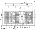
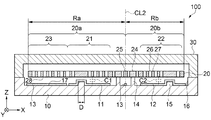
図1は、実施形態に係る物理量センサーを模式的に示す平面図である。図2は、図1におけるA−A線での断面図である。まず、実施形態に係る物理量センサー100の概略構成について、図1及び図2を参照して説明する。なお、図1においては、説明の便宜上、蓋体30の図示を省略している。
(Embodiment)
<Structure of physical quantity sensor>
FIG. 1 is a plan view schematically showing a physical quantity sensor according to an embodiment. FIG. 2 is a cross-sectional view taken along the line AA in FIG. First, the schematic configuration of the
本実施形態の物理量センサー100は、例えば、慣性センサーとして利用することができる。具体的には、例えば、鉛直方向(Z軸方向)の加速度を測定するための加速度センサー(静電容量型加速度センサー、静電容量型MEMS加速度センサー)として利用することができる。なお、本実施形態では、鉛直方向をZ軸、後述する回転軸(梁部25)の軸方向をY軸、Z軸及びY軸の双方と交差する方向をX軸という。
The
図1及び図2に示すように、物理量センサー100は、平板状をなし、平板状の平板面28を有する可動体20、可動体20を支持する支持基板10、支持基板10と共に可動体20を内包する蓋体30を含んでいる。
As shown in FIGS. 1 and 2, the
支持基板10は、凹状のキャビティ16を有している。キャビティ16内の主面17上には、第1固定電極11、第2固定電極12が備えられている。さらに、第1固定電極11と第2固定電極12との間には、可動体20の平板面28と間隔を隔てて支持するための支柱14が設けられている。また、支柱14のX軸方向における両側には、可動体20側(+Z軸側)に突出する突起15が設けられている。支柱14及び突起15は、支持基板10と一体で形成される。支持基板10の材料は、特に限定されないが、本実施形態では、好適例として、絶縁性材料であるホウ珪酸ガラス(以下、ガラスという)を採用している。
The
第1固定電極11は、Y軸方向からの側面視において、支柱14の−X軸側に位置し、Z軸方向からの平面視において、後述する第1質量部21と重なる領域に、設けられている。第2固定電極12は、Y軸方向からの側面視において、支柱14の+X軸側に位置し、Z軸方向からの平面視において、後述する第2質量部22と重なる領域に、設けられている。第1、第2固定電極11,12の材料としては、例えば、Pt(プラチナ)、Al(アルミニウム)、Mo(モリブデン)、Cr(クロム)、Ti(チタン)、Ni(ニッケル)、Cu(銅)、Ag(銀)、Au(金)、または、ITO(Indium Tin Oxide)などの導電膜を採用することができる。
The first
可動体20は、支持部24、回転軸としての梁部25を含んでいる。支持部24は、平板面28の一部であり、支柱14で支持基板10と連結されている。梁部25は、支持部24に支持され、支持部24からY軸方向に伸びている。梁部25は、所謂ねじりばねとしての機能を有している。梁部25は、支持部24及び支柱14を介し支持基板10に対して可動体20全体を揺動可能に支持している。
The
可動体20は、第1可動体20aと第2可動体20bとを有している。第1可動体20aは、梁部25の回転中心となる中心線CL2から−X軸方向側の領域であり、第2可動体20bは、梁部25の回転中心となる中心線CL2から+X軸方向側の領域である。第1可動体20aには、梁部25から−X軸方向に向かって、第1質量部21と、第3質量部23とが順に設けられている。第2可動体20bには、第2質量部22が設けられている。Z軸方向からの平面視において、第1質量部21は第1固定電極11と重なる領域に位置し、第2質量部22は第2固定電極12と重なる領域に位置している。
The
可動体20の材料は、特に限定されないが、本実施形態では、好適例として、導電性材料であるシリコンを採用している。可動体20に導電性材料を用いることで、第1質量部21と第2質量部22とに電極としての機能を持たせることができる。なお、可動体に非電導性の基板を用いて、第1、第2質量部を非導電性の基板の上に設けられた導電性の電極層で形成させてもよい。
The material of the
可動体20は、梁部25によって支持され、梁部25を回転軸として揺動可能である。可動体20が、梁部25を支点としてシーソー揺動(傾倒)することで、第1質量部21と第1固定電極11との間隙(距離)、及び第2質量部22と第2固定電極12との間隙(距離)が変化する。物理量センサー100は、可動体20の傾倒に応じて、第1質量部21と第1固定電極11との間、及び第2質量部22と第2固定電極12との間で生じる静電容量C1,C2の変化から加速度を求める。
The
可動体20に鉛直方向の加速度(例えば重力加速度)が加わった場合、第1可動体20aと第2可動体20bの各々に回転モーメント(力のモーメント)が生じる。ここで、第1可動体20aの回転モーメント(例えば反時計回りの回転モーメント)と、第2可動体20bの回転モーメント(例えば時計回りの回転モーメント)と、が均衡した場合には、可動体20の傾きに変化が生じず、加速度を検出することができない。したがって、鉛直方向の加速度が加わった時に、第1可動体20aの回転モーメントと、第2可動体20bの回転モーメントとが均衡せず、可動体20に所定の傾きが生じるように、可動体20が設計されている。
When a vertical acceleration (for example, gravitational acceleration) is applied to the
物理量センサー100は、梁部25を、可動体20のX軸方向の重心から外れた位置に配置させている。換言すると、第1可動体20aには、第3質量部23が設けられているので、梁部25の回転軸となる中心線CL2から第1可動体20aの端面までの距離Raと、中心線CL2から第2可動体20bの端面までとの距離Rbが異なっている。これにより、第1可動体20aと第2可動体20bとが互いに異なる質量を有する。すなわち、可動体20は、梁部25の中心線CL2を起点にして、一方側(第1可動体20a)と他方側(第2可動体20b)とで質量が異なる。このように、第1可動体20aと第2可動体20bとの質量を異ならせることにより、可動体20に鉛直方向の加速度が加わった時に生じる、第1可動体20aの回転モーメントと、第2可動体20bの回転モーメントと、を不均衡にすることができる。これにより、物理量センサー100に鉛直方向の加速度が加わった時、可動体20が傾倒する。
The
第1質量部21と第1固定電極11との間には、静電容量(可変静電容量)C1が構成される。また、第2質量部22と第2固定電極12との間には、静電容量(可変静電容量)C2が構成される。静電容量C1は、第1質量部21と第1固定電極11との間隙(距離)に応じて静電容量が変化し、静電容量C2は、第2質量部22と第2固定電極12との間隙(距離)に応じて静電容量が変化する。
A capacitance (variable capacitance) C1 is formed between the
例えば、可動体20が支持基板10に対して水平の場合、静電容量C1,C2は、互いに略等しい静電容量値となる。詳しくは、Z軸方向からの平面視で、第1質量部21と第1固定電極11との重なり合う面積と、第2質量部22と第2固定電極12との重なり合う面積と、が等しく、Y方向からの側面視で、第1質量部21と第1固定電極11との間隙と、第2質量部22と第2固定電極12との間隙と、が等しくなっているため、静電容量C1,C2の静電容量値も等しくなる。また、例えば、可動体20に鉛直方向の加速度が加わり、梁部25を回転軸として可動体20が傾倒すると、静電容量C1,C2は、可動体20の傾倒に応じて、静電容量C1,C2の静電容量値が変化する。可動体20が傾倒した場合、第1質量部21と第1固定電極11との間隙と、第2質量部22と第2固定電極12との間隙と、が異なるため、静電容量C1,C2の静電容量値も異なる。
For example, when the
図3〜図6は、物理量センサーの動作を模式的に示す断面図である。ここで、物理量センサーの動作と静電容量の関係について図3から図6を参照して説明する。なお、図3から図6では、動作の説明に必要のない構成の図示を省略している。 3 to 6 are cross-sectional views schematically showing the operation of the physical quantity sensor. Here, the relationship between the operation of the physical quantity sensor and the capacitance will be described with reference to FIGS. 3 to 6. In addition, in FIGS. 3 to 6, the illustration of the configuration which is not necessary for the explanation of the operation is omitted.
図3は、支持基板10に対して可動体20が、略水平状態に位置している状態を示している。この状態の物理量センサー100に、+Z軸方向の加速度αuが加わった場合を説明する。
可動体20は、一様の厚さ(Z軸方向の寸法)を有する平板状の長方形をなしている。第1可動体20aは質量m1を有し、その重心G1は支持部24に回転可能に支持されている梁部25の中心Qから−X軸方向の距離r1に位置している。第2可動体20bは質量m2を有し、その重心G2は梁部25の中心Qから+X軸方向の距離r2に位置している。第1可動体20aは、第3質量部23を有し、第2可動体20bよりもX軸方向に長い長方形の形状をなしている。このため、第1可動体20aの質量m1は第2可動体20bの質量m2よりも重く、第1可動体20aの重心G1の位置する距離r1は、第2可動体20bの重心G2の位置する距離r2よりも長い。
FIG. 3 shows a state in which the
The
物理量センサー100に対して、−Z軸方向から+Z軸方向に向かう加速度αuが加わると、第1可動体20aには、質量m1と、加速度αuと、距離r1との積に相当する第1回転モーメントNu1が、梁部25の中心Qを回転軸として反時計回りの方向に作用する。他方、第2可動体20bには、質量m2と、加速度αuと、距離r2との積に相当する第2回転モーメントNu2が、梁部25の中心Qを回転軸として時計回りの方向に作用する。第1可動体20aの質量m1は第2可動体20bの質量m2よりも重く、第1可動体20aの重心G1の位置する距離r1は、第2可動体20bの重心G2の位置する距離r2よりも長いため、第1可動体20aに作用する第1回転モーメントNu1は、第2可動体20bに作用する第2回転モーメントNu2よりも、大きい。
When the acceleration αu from the −Z axis direction to the + Z axis direction is applied to the
これにより、図4に示すように、梁部25には、第1回転モーメントNu1(図3参照)と第2回転モーメントNu2(図3参照)の差に相当するトルクNuが、梁部25の中心Qを回転軸として反時計回りの方向に作用し、可動体20は、反時計回りに傾倒する。これにより、第1可動体20aの第1質量部21と第1固定電極11との間隙が小さく(狭く)なり、第1質量部21と第1固定電極11との間で形成される静電容量C1の静電容量値が増加する。他方、第2可動体20bの第2質量部22と第2固定電極12との間隙が大きく(広く)なり、第2質量部22と第2固定電極12との間で形成される静電容量C2の静電容量値が減少する。
As a result, as shown in FIG. 4, the
図5は、支持基板10に対して可動体20が、略水平状態に位置している状態を示している。この状態の物理量センサー100に、−Z軸方向の加速度αdが加わった場合を説明する。
物理量センサー100に対して、+Z軸方向から−Z軸方向に向かう加速度αdが加わると、第1可動体20aには、質量m1と、加速度αdと、距離r1との積に相当する第1回転モーメントNd1が、梁部25の中心Qを回転軸として時計回りの方向に作用する。他方、第2可動体20bには、質量m2と、加速度αdと、距離r2との積に相当する第2回転モーメントNd2が、梁部25の中心Qを回転軸として反時計回りの方向に作用する。第1可動体20aの質量m1は第2可動体20bの質量m2よりも重く、第1可動体20aの重心G1の位置する距離r1は、第2可動体20bの重心G2の位置する距離r2よりも長いため、第1可動体20aに作用する第1回転モーメントNd1は、第2可動体20bに作用する第2回転モーメントNd2よりも、大きい。
FIG. 5 shows a state in which the
When the acceleration αd from the + Z-axis direction to the −Z-axis direction is applied to the
これにより、図6に示すように、梁部25には、第1回転モーメントNd1(図5参照)と第2回転モーメントNd2(図5参照)の差に相当するトルクNdが、梁部25の中心Qを回転軸として時計回りの方向に作用し、可動体20は、時計回りに傾倒する。これにより、第1可動体20aの第1質量部21と第1固定電極11との間隙が大きく(広く)なり、第1質量部21と第1固定電極11との間で形成される静電容量C1の静電容量値が減少する。他方、第2可動体20bの第2質量部22と第2固定電極12との間隙が小さく(狭く)なり、第2質量部22と第2固定電極12との間で形成される静電容量C2の静電容量値が増加する。
As a result, as shown in FIG. 6, the
物理量センサー100は、梁部25に作用するトルクNu,Ndを大きくすること、すなわち、第1可動体20aと第2可動体20bとの質量差を拡大すること、梁部25から第1可動体20aの重心G1までの距離r1と梁部25から第2可動体20bの重心G2までの距離r2との差を拡大することで、可動体20を大きく傾倒させることができる。これにより静電容量C1,C2の静電容量値の増減が大きくなるため、物理量センサー100の物理量を検出する感度を向上させることができる。また、物理量センサー100は、ねじりばねとして機能する梁部25のX軸方向の幅を狭くして、ばねの靱性を低下させることで、可動体20の傾倒を大きくさせることができる。これにより、物理量の検出感度を向上させることもできる。
The
次に、可動体に設けられる開口、及び支持基板に設けられる突起について説明する。図1及び図2に示すように、物理量センサー100は、過大な加速度が加わった際に、可動体20と支持基板10とが接触することを防止するために、可動体20の変位を制限する突起15を支持基板10の主面17に有している。突起15は、支持基板10を平板面28に対して垂直方向(Z軸方向)に見たときにおいて、支持基板10の可動体20と間隔を隔てて重なっている領域に設けられている。
Next, the openings provided in the movable body and the protrusions provided in the support substrate will be described. As shown in FIGS. 1 and 2, the
本実施形態では、突起15は、支持基板10上において、第1質量部21と重なる領域、及び第2質量部22と重なる領域に複数(各2個)設けられている。突起15は、円柱状をなし、その直径は、略3〜5μmである。これにより、可動体20の端部が、支持基板10に衝突して破損することを抑制している。また、突起15を複数設けることにより、可動体20と突起15とが接触した際に受ける衝撃を分散することができる。なお、本実施形態では、第1、第2質量部21,22に対応する位置に各2個の突起15が設けられた構成を示したが、これに限定するものではない。突起15が、各1個設けられた構成や各3個以上設けられた構成であってもよい。また、第1可動体20a側における突起15は、第3質量部23に対応する位置に設けられた構成であってもよい。また、突起の形状は、円柱状をなしているものと説明したが、三角柱や四角柱などの多角柱であってもよし、上面が面取りされた形状であってもよい。また、突起15の表面に、絶縁性の保護膜が形成されていてもよい。これにより、第1、第2質量部21,22と突起15とが接触した際の電気的短絡を防ぐことができる。
In the present embodiment, a plurality of protrusions 15 (two each) are provided on the
一方、可動体20には、可動体20に鉛直方向の加速度が加わり、可動体20が揺動する際に、気体の粘性により生じるダンピング(可動体の動きを止めようとする働き、流動抵抗)を低減するために、平板面28を貫通する方向(Z軸方向)に複数の開口26が設けられている。開口26は、支持基板10を平板面28に対して垂直方向(Z軸方向)に見たときにおいて、突起15の最大外形寸法をDとした時、突起15の外周から外側に向かってD/2の範囲(突起15の中心から2Dの範囲)を除く領域に設けられている。これにより、可動体20のダンピングが低減され物理量を検出する感度が向上する。
On the other hand, in the
本実施形態では、Z軸方向からの平面視にて、突起15の中心から2Dの範囲を除く領域に、正方形の開口26がマトリックス状に配置されている。換言すると、物理量センサー100に過大な加速度が加わった際に、可動体20が揺動し、可動体20と突起15とが接触する領域には、開口26が設けられていない。
In the present embodiment,
逆に、突起15の中心から2Dの範囲内にも開口26が設けられていた場合には、隣り合う開口26によって形成される格子状の枠部27と突起15とが局所的に接触した際に、可動体20の枠部27が容易に破損する恐れがあった。本実施形態の物理量センサー100は、突起15と接触する領域に開口26は設けられていないので、当該領域の剛性が向上している。これにより、物理量センサー100に過大な加速度が加わって可動体20と突起15とが接触した場合に、可動体20が損傷することを抑制することができる。なお、複数の開口26は、個々に異なる形状であってもよい。また、開口26を配置する位置や数量も自由に設定することができる。
On the contrary, when the
なお、本実施形態では、可動体20は、支持基板10に設けられている支柱14などを介して支持される梁部25によって揺動可能に設けられているものとして説明したが、この構成に限定されるものではない。例えば、可動体は、Z軸方向からの平面視にて、可動体の外周を取り囲み、可動体と所定の間隔を有して設けられた枠状の支持体からY軸方向に伸びる梁部によって揺動可能に設けられた構成であってもよい。
In the present embodiment, it has been described that the
<物理量センサーの製造方法>
図7は、物理量センサーの製造工程を説明するフローチャート図である。図8〜図12は、物理量センサーの各製造工程における断面図である。次に、物理量センサー100の製造方法について図7から図12を参照して説明する。
<Manufacturing method of physical quantity sensor>
FIG. 7 is a flowchart illustrating a manufacturing process of the physical quantity sensor. 8 to 12 are cross-sectional views taken in each manufacturing process of the physical quantity sensor. Next, a method of manufacturing the
ステップS1は、支持基板10及び突起15を形成する支持基板形成工程である。まず、ガラス基板を用意する。支持基板形成工程では、ガラス基板をフォトリソグラフィー技法およびエッチング技法を用いてパターニングすることで支持基板10及び突起15を形成する。例えば、ガラス基板は、フッ酸系エッチャントを用いることでウェットエッチングすることができる。これにより、図8に示すようなガラス基板に凹状のキャビティ16、支柱14及び突起15が形成された支持基板10を得ることができる。
Step S1 is a support substrate forming step for forming the
ステップS2は、第1、第2固定電極11,12を形成する固定電極形成工程である。固定電極形成工程では、スパッタ法等により支持基板10の主面17上に導電膜を成膜した後、導電膜をフォトリソグラフィー技法およびエッチング技法(ドライエッチング、ウェットエッチング等)を用いてパターニングすることで第1、第2固定電極11,12を形成する。これにより、図9に示すように、支持基板10のキャビティ16内の主面17上に第1、第2固定電極11,12を設けることができる。
Step S2 is a fixed electrode forming step of forming the first and second
ステップS3は、支持基板10とシリコン基板20Sを接合する基板接合工程である。図10に示すように、基板接合工程では、例えば、陽極接合、直接接合、又は接着剤を用いて支持基板10とシリコン基板20Sとを接合する。
Step S3 is a substrate bonding step of bonding the
ステップS4は、シリコン基板20Sから開口26を有する可動体20を形成する可動体形成工程である。可動体形成工程では、シリコン基板20Sを、例えば、研削機を用いて研削し、所定の厚さに薄膜化する。そして、シリコン基板20Sをフォトリソグラフィー技法およびエッチング技法を用いてパターニングすることで可動体20を形成する。例えば、シリコン基板20Sは、RIE(Reactive Ion Etching)装置を用いたボッシュプロセスによってエッチングすることができる。これにより、図11に示すように、開口26、支持部24及び梁部25を含む可動体20が一体で形成される。
Step S4 is a movable body forming step of forming the
ステップS5は、可動体20を封止する封止工程である。封止工程では、支持基板10に蓋体30を接合して、支持基板10及び蓋体30によって形成される空間に可動体20を収容する。支持基板10と蓋体30とは、例えば、陽極接合や接着剤等を用いて接合する。以上により、図12に示すように、物理量センサー100が得られる。
Step S5 is a sealing step of sealing the
本実施形態では、支持基板10に可動体20が揺動可能なキャビティ16を形成する物理量センサー100の製造方法を示した。一方、物理量センサーの製造方法としては、犠牲層を形成させたシリコン基板と支持基板とを犠牲層を介して接合し、犠牲層に可動体が揺動可能なキャビティを形成する方法もある。この製造方法の場合、シリコン基板に可動体を形成させた後、同時に形成させた可動体の開口からシリコン基板と支持基板とに挟まれた犠牲層をエッチングすることにより、犠牲層に可動体が揺動可能なキャビティを形成している。このため、可動体に開口をマトリックス状に隙間なく設けておく必要があった。換言すると、可動体と突起とが接触する領域に開口を設けない構成にすることができなかった。
In the present embodiment, a method for manufacturing a
本実施形態の製造方法は、支持基板形成工程にて支持基板10にキャビティ16と突起15を形成した後に、基板接合工程にて支持基板10とシリコン基板20Sとを接合し、最後に可動体20及び開口26を形成する。この製造方法によれば、可動体20と突起15とが接触する領域に開口26を設けない構成にすることができる。これにより、可動体20と突起15とが接触する領域の剛性が向上するので、物理量センサー100に過大な加速度が加わって可動体20と突起15とが接触した場合に、可動体20が損傷することを抑制することができる。また、可動体20には、突起15の外周から外側に向かってD/2の範囲以外の領域に、開口26が設けられるので、可動体20のダンピングが低減され物理量を検出する感度が向上する。
In the manufacturing method of the present embodiment, the
以上述べたように、本実施形態に係る物理量センサー100によれば、以下の効果を得ることができる。
物理量センサー100は、支持基板10上から可動体20側に突出する突起15を有している。また、可動体20には、平板面28を貫通する複数の開口26が設けられている。突起15は、支持基板10を平板面28に対して垂直方向に見たときにおいて、支持基板10の可動体20と間隔を隔てて重なっている領域に設けられている。開口26は、支持基板10を平板面28に対して垂直方向に見たときにおいて、突起15の最大外形寸法をDとした時、突起15の中心から2Dの範囲を除く領域に設けられている。換言すると、開口26は、突起15の中心から2Dの範囲、すなわち突起15と接触する位置には設けられていない。これにより、当該領域の剛性が向上するので、可動体20と突起15とが接触した場合に、可動体20が損傷することを抑制することができる。また、可動体20の受けるダンピングは、突起15の中心から2Dを除く範囲に設けられた複数の開口26によって低減されるので、物理量センサー100の検出感度が向上する。したがって、信頼性と検出感度とを向上させた物理量センサー100を提供することができる。
As described above, according to the
The
また、支持基板10から可動体20側に突出する突起15は、複数設けられているので、可動体20が突起15と接触した際に受ける衝撃を分散することができる。
Further, since a plurality of
物理量センサー100の製造方法は、支持基板10及び突起15を形成する支持基板形成工程、支持基板10とシリコン基板20Sとを接合する基板接合工程、シリコン基板20Sから開口26を有する可動体20を形成する可動体形成工程を含んでいる。本製造方法は、支持基板形成工程にて支持基板10にキャビティ16と突起15を形成した後に、基板接合工程にて支持基板10とシリコン基板20Sとを接合し、最後に可動体20及び開口26を形成する。この製造方法によれば、可動体20と突起15とが接触する領域(突起15の中心から2Dの領域)に開口26を設けない構成にすることができる。これにより、当該領域の剛性が向上するので、可動体20と突起15とが接触した場合に、可動体20が損傷することを抑制することができる。また、可動体20の受けるダンピングは、突起15の中心から2Dの範囲を除く領域に設けられた複数の開口26によって低減されるので、物理量センサー100の検出感度が向上する。したがって、信頼性と検出感度とを向上させる物理量センサー100の製造方法を提供することができる。
The manufacturing method of the
なお、本発明は上述した実施形態に限定されず、上述した実施形態に種々の変更や改良などを加えることが可能である。 The present invention is not limited to the above-described embodiment, and various changes and improvements can be added to the above-described embodiment.
(変形例)
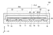
図13は、変形例に係る物理量センサーを模式的に示す平面図である。図14は、図13におけるB−B線での断面図である。以下、変形例1に係る物理量センサー200について説明する。なお、実施形態と同一の構成部位については、同一の符号を使用し、重複する説明は省略する。本変形例の物理量センサー200は、実施形態で説明した物理量センサー100と突起215の位置が異なっている。
(Modification example)
FIG. 13 is a plan view schematically showing the physical quantity sensor according to the modified example. FIG. 14 is a cross-sectional view taken along the line BB in FIG. Hereinafter, the
図13及び図14に示すように、物理量センサー200は、過大な加速度が加わった際に、可動体20と支持基板10とが接触することを防止するために、可動体20の変位を制限する突起215を支持基板10の主面17に有している。突起215は、回転軸としての梁部25の軸方向(Y軸方向)と交差するX軸方向において、梁部25の中心線CL2と可動体20の端部との距離Raの1/2以内に設けられている。
As shown in FIGS. 13 and 14, the
詳しくは、本変形例では、突起215は、支持基板10上において、第1質量部21と重なる領域、及び第2質量部22と重なる領域に各2個設けられている。第1質量部21と重なる突起215は、中心線CL2から−X軸方向に距離R1離れた位置に設けられている。中心線CL2と突起215との距離R1は、中心線CL2と第1可動体20aの端部との距離Raの1/2よりも短い。第2質量部22と重なる突起215は、中心線CL2から+X軸方向に距離R2離れた位置に設けられている。中心線CL2と突起215との距離R2は、中心線CL2と第2可動体20bの端部との距離Rbの1/2よりも短い。本変形例では、距離R1と距離R2は、同じ距離に設定されている。すなわち、突起215は、中心線CL2に関して線対称に設けられている。
Specifically, in this modification, two
可動体20の移動速度は、梁部25の中心(中心線CL2)からの距離が長くなるほど早くなるので、可動体20の受けるダンピングは、可動体の端部に向かう程大きくなる。本変形例の突起215に対応する、開口26の設けられない領域(突起215の中心から2Dの範囲)は、X軸方向においてダンピングの影響が小さい、距離Ra/2以内及び距離Rb/2以内の梁部25側に位置しているので、可動体20の受けるダンピングをさらに低減することができる。
Since the moving speed of the
また、突起215は、回転軸としての梁部25の軸方向(Y軸方向)における可動体20を2等分する中心線CL1に対して対称の距離R3の位置に設けられている。これにより、可動体20と突起215とが接触した際に可動体20が捩れることにより、可動体20が破損することを抑制することができる。
Further, the
(複合センサー)
次に、図15を参照して、前述の物理量センサー100,200を備えた複合センサーの構成例について説明する。図15は、複合センサーの概略構成を示す機能ブロック図である。なお、以下では、物理量センサー100を用いた例を示して説明する。
(Composite sensor)
Next, with reference to FIG. 15, a configuration example of the composite sensor including the above-mentioned
図15に示すように、複合センサー900は、上述したようなZ軸方向の加速度を測定するための加速度センサーである物理量センサー100と、X軸方向の加速度を測定するための加速度センサーである物理量センサー101と、Y軸方向の加速度を測定するための加速度センサーである物理量センサー102と、角速度センサー103と、を備えている。角速度センサー103は、必要とする一軸方向の角速度を効率よく且つ高精度に検出することができる。なお、角速度センサー103は、三軸方向の角速度を測定するために、それぞれの軸方向に対応した三つの角速度センサー103を備えることもできる。また、複合センサー900は、例えば、物理量センサー100,101,102や角速度センサー103を駆動する駆動回路や、物理量センサー100,101,102や角速度センサー103からの信号に基づいてX軸、Y軸およびZ軸の各軸方向の加速度や角速度を検出する検出回路(信号処理部45a)や、検出回路からの信号を所定の信号に変換して出力する出力回路(出力部46a)等を含むIC40aを備えることができる。
As shown in FIG. 15, the
物理量センサー100,101,102と、角速度センサー103と、によって容易に複合センサー900を構成することができ、一つのセンサーによって複数の物理量データ、例えば加速度データや角速度データを容易に取得することができる。
The
(慣性計測ユニット)
次に、図16および図17を参照して、慣性計測ユニット(IMU:Inertial Measurement Unit)について説明する。図16は、慣性計測ユニットの概略構成を示す分解斜視図である。図17は、慣性計測ユニットの慣性センサー素子の配置例を示す斜視図である。なお、以下では、物理量センサー100を用いた例を示して説明する。
(Inertial measurement unit)
Next, an inertial measurement unit (IMU) will be described with reference to FIGS. 16 and 17. FIG. 16 is an exploded perspective view showing a schematic configuration of the inertial measurement unit. FIG. 17 is a perspective view showing an arrangement example of the inertial sensor element of the inertial measurement unit. In the following, an example using the
図16に示すように、慣性計測ユニット3000は、アウターケース301、接合部材310、慣性センサー素子を含むセンサーモジュール325などから構成されている。換言すれば、アウターケース301の内部303に、接合部材310を介在させて、センサーモジュール325を篏合(挿入)した構成となっている。センサーモジュール325は、インナーケース320と、基板315とから構成されている。なお、説明を解り易くするために、部位名をアウターケース、インナーケースとしているが、第1ケース、第2ケースと呼び換えても良い。
As shown in FIG. 16, the
アウターケース301は、アルミニウムを箱状に削り出した台座である。材質は、アルミニウムに限定するものではなく、亜鉛やステンレスなど他の金属や、樹脂、または、金属と樹脂の複合材などを用いても良い。アウターケース301の外形は、前述した慣性計測ユニット3000の全体形状と同様に、平面形状が略正方形の直方体であり、正方形の対角線方向に位置する2ヶ所の頂点近傍に、それぞれ通し孔(馬鹿孔)302が形成されている。なお、通し孔(馬鹿孔)302に限定するものではなく、例えば、ネジによりネジ止めすることが可能な切り欠き(通し孔(馬鹿孔)302の位置するアウターケース301のコーナー部に切り欠きを形成する構造)を形成してネジ止めする構成としてもよいし、あるいは、アウターケース301の側面にフランジ(耳)を形成して、フランジ部分をネジ止めする構成としても良い。
The
アウターケース301は、外形が直方体で蓋のない箱状であり、その内部303(内側)は、底壁305と側壁304とで囲まれた内部空間(容器)となっている。換言すれば、アウターケース301は、底壁305と対向する一面を開口面とする箱状をなしており、その開口面の開口部のほとんどを覆うように(開口部を塞ぐように)センサーモジュール325が収納され、センサーモジュール325が開口部から露出した状態となる(不図示)。ここで、底壁305と対向する開口面とは、アウターケース301の上面307と同一面である。また、アウターケース301の内部303の平面形状は、正方形の二つの頂点部分の角を面取りした六角形であり、面取りされた二つの頂点部分は通し孔(馬鹿孔)302の位置に対応している。また、内部303の断面形状(厚さ方向)において、底壁305には、内部303、即ち内部空間における周縁部に中央部よりも一段高い底壁としての第1接合面306が形成されている。即ち、第1接合面306は、底壁305の一部であり、平面的に底壁305の中央部を囲ってリング状に形成された一段の階段状の部位であり、底壁305よりも開口面(上面307と同一面)からの距離が小さい面である。
The
なお、アウターケース301の外形が、平面形状が略正方形の直方体で蓋のない箱状である一例について説明したが、これに限らず、アウターケース301の外形の平面形状は、例えば六角形や八角形などの多角形であってもよいし、その多角形の頂点部分の角が面取りされていたり、各辺が曲線である平面形状であったりしてもよい。また、アウターケース301の内部303(内側)の平面形状も、上述した六角形に限らず、正方形などの方形(四角形)や、八角形などの他の多角形状であってもよい。また、アウターケース301の外形と内部303の平面形状とは相似形であってもよいし、相似形でなくてもよい。
Although an example has been described in which the outer shape of the
インナーケース320は、基板315を支持する部材であり、アウターケース301の内部303に収まる形状となっている。詳しくは、平面的には、正方形の二つの頂点部分の角を面取りした六角形であり、その中に長方形の貫通穴である開口部321と、基板315を支持する側の面に設けられた凹部331とが形成されている。面取りされた二つの頂点部分はアウターケース301の通し孔(馬鹿孔)302の位置に対応している。厚さ方向(Z軸方向)の高さは、アウターケース301の上面307から第1接合面306までの高さよりも、低くなっている。好適例では、インナーケース320もアルミニウムを削り出して形成しているが、アウターケース301と同様に他の材質を用いても良い。
The
インナーケース320の裏面(アウターケース301側の面)には、基板315を位置決めするための案内ピンや、支持面(いずれも図示せず)が形成されている。基板315は、当該案内ピンや、支持面にセット(位置決め搭載)されてインナーケース320の裏面に接着される。なお、基板315の詳細については後述する。インナーケース320の裏面の周縁部は、リング状の平面からなる第2接合面322となっている。第2接合面322は、平面的にアウターケース301の第1接合面306と略同様な形状であり、インナーケース320をアウターケース301にセットした際には、接合部材310を挟持した状態で二つの面が向い合うことになる。なお、アウターケース301およびインナーケース320の構造については、一実施例であり、この構造に限定されるものではない。
A guide pin for positioning the
図17を参照して、慣性センサーが実装された基板315の構成について説明する。図17に示すように、基板315は、複数のスルーホールが形成された多層基板であり、ガラスエポキシ基板(ガラエポ基板)を用いている。なお、ガラエポ基板に限定するものではなく、複数の慣性センサーや、電子部品、コネクターなどを実装可能なリジット基板であれば良い。例えば、コンポジット基板や、セラミック基板を用いても良い。
The configuration of the
基板315の表面(インナーケース320側の面)には、コネクター316、角速度センサー317z、上述したZ軸方向の加速度を測定するための加速度センサーである物理量センサー100を含む加速度検出ユニット1などが実装されている。コネクター316は、プラグ型(オス)のコネクターであり、X軸方向に等ピッチで配置された二列の接続端子を備えている。好適には、一列10ピンで二列の合計20ピンの接続端子としているが、端子数は、設計仕様に応じて適宜変更しても良い。
On the surface of the substrate 315 (the surface on the
慣性センサーとしての角速度センサー317zは、Z軸方向における1軸の角速度を検出するジャイロセンサーである。好適例として、水晶を振動子として用い、振動する物体に加わるコリオリの力から角速度を検出する振動ジャイロセンサーを用いている。なお、振動ジャイロセンサーに限定するものではなく、角速度を検出可能なセンサーで有れば良い。例えば、振動子としてセラミックや、シリコンを用いたセンサーを用いても良い。
The
また、基板315のX軸方向の側面には、実装面(搭載面)がX軸と直交するように、X軸方向における1軸の角速度を検出する角速度センサー317xが実装されている。同様に、基板315のY軸方向の側面には、実装面(搭載面)がY軸と直交するように、Y軸方向における1軸の角速度を検出する角速度センサー317yが実装されている。
Further, on the side surface of the
なお、角速度センサー317x,317y,317zは、X軸、Y軸、Z軸の軸ごとの三つの角速度センサーを用いる構成に限定するものではなく、3軸の角速度が検出可能なセンサーであれば良く、例えば、一つのデバイス(パッケージ)で3軸の角速度が検出(検知)可能なセンサーデバイスを用いても良い。
The
加速度検出ユニット1は、上述したZ軸方向の加速度を測定するための加速度センサーである物理量センサー100を少なくとも含み、必要に応じて、一軸方向(例えばZ軸方向)の加速度したり、二軸方向(例えばZ軸、Y軸、あるいはX軸、Y軸)や三軸方向(X軸、Y軸、Z軸)の加速度を検出したりすることができる。
The
基板315の裏面(アウターケース301側の面)には、制御部としての制御IC319が実装されている。制御IC319は、MCU(Micro Controller Unit)であり、不揮発性メモリーを含む記憶部や、A/Dコンバーターなどを内蔵しており、慣性計測ユニット3000の各部を制御する。記憶部には、加速度、および角速度を検出するための順序と内容を規定したプログラムや、検出データをデジタル化してパケットデータに組込むプログラム、付随するデータなどが記憶されている。なお、基板315には、その他にも複数の電子部品が実装されている。
A
このような慣性計測ユニット3000によれば、物理量センサー100を含む加速度検出ユニット1を用いているため、耐衝撃性に優れ、信頼性を向上させた慣性計測ユニット3000を提供することができる。
According to such an
(携帯型電子機器)
次に、物理量センサー100,200を用いた携帯型電子機器について、図18および図19に基づき、詳細に説明する。なお、以下では、物理量センサー100を用いた例を示して説明する。以下、携帯型電子機器の一例として、腕時計型の活動計(アクティブトラッカー)を示して説明する。
(Portable electronic device)
Next, the portable electronic device using the
腕時計型の活動計(アクティブトラッカー)であるリスト機器2000は、図18に示すように、バンド62,67等によってユーザーの手首等の部位(被検体)に装着され、デジタル表示の表示部150を備えるとともに無線通信が可能である。上述した本発明に係る物理量センサー100は、加速度を測定するセンサーや角速度を計測するセンサーの一つとしてリスト機器2000に組込まれている。
As shown in FIG. 18, the
リスト機器2000は、少なくとも物理量センサー100が収容されているケース60と、ケース60に収容され、物理量センサー100からの出力データを処理する処理部190(図19参照)と、ケース60に収容されている表示部150と、ケース60の開口部を塞いでいる透光性カバー71と、を備えている。ケース60の透光性カバー71のケース60の外側には、ベゼル78が設けられている。ケース60の側面には、複数の操作ボタン80,81が設けられている。以下、図19も併せて参照しながら、さらに詳細に説明する。
The
物理量センサー100を含む加速度センサー113は、互いに交差する(理想的には直交する)3軸方向の各々の加速度を検出し、検出した3軸加速度の大きさ、および向きに応じた信号(加速度信号)を出力する。また、角速度センサー114は、互いに交差する(理想的には直交する)3軸方向の各々の角速度を検出し、検出した3軸角速度の大きさ及び向きに応じた信号(角速度信号)を出力する。
The acceleration sensor 113 including the
表示部150を構成する液晶ディスプレイ(LCD)では、種々の検出モードに応じて、例えば、GPSセンサー110や地磁気センサー111を用いた位置情報、移動量や物理量センサー100に含まれる加速度センサー113や角速度センサー114などを用いた運動量などの運動情報、脈拍センサー115などを用いた脈拍数などの生体情報、もしくは現在時刻などの時刻情報などが表示される。なお、温度センサー116を用いた環境温度を表示することもできる。
In the liquid crystal display (LCD) constituting the
通信部170は、ユーザー端末と図示しない情報端末との間の通信を成立させるための各種制御を行う。通信部170は、例えば、Bluetooth(登録商標)(BTLE:Bluetooth Low Energyを含む)、Wi−Fi(登録商標)(Wireless Fidelity)、Zigbee(登録商標)、NFC(Near field communication)、ANT+(登録商標)等の近距離無線通信規格に対応した送受信機や通信部170はUSB(Universal Serial Bus)等の通信バス規格に対応したコネクターを含んで構成される。
The
処理部190(プロセッサー)は、例えば、MPU(Micro Processing Unit)、DSP(Digital Signal Processor)、ASIC(Application Specific Integrated Circuit)等により構成される。処理部190は、記憶部140に格納されたプログラムと、操作部120(例えば操作ボタン80,81)から入力された信号とに基づき、各種の処理を実行する。処理部190による処理には、GPSセンサー110、地磁気センサー111、圧力センサー112、加速度センサー113、角速度センサー114、脈拍センサー115、温度センサー116、計時部130の各出力信号に対するデータ処理、表示部150に画像を表示させる表示処理、音出力部160に音を出力させる音出力処理、通信部170を介して情報端末(不図示)と通信を行う通信処理、バッテリー180からの電力を各部へ供給する電力制御処理などが含まれる。
The processing unit 190 (processor) is composed of, for example, an MPU (Micro Processing Unit), a DSP (Digital Signal Processor), an ASIC (Application Specific Integrated Circuit), or the like. The
このようなリスト機器2000では、少なくとも以下のような機能を有することができる。
1.距離:高精度のGPS機能により計測開始からの合計距離を計測する。
2.ペース:ペース距離計測から、現在の走行ペースを表示する。
3.平均スピード:平均スピード走行開始から現在までの平均スピードを算出し表示する。
4.標高:GPS機能により、標高を計測し表示する。
5.ストライド:GPS電波が届かないトンネル内などでも歩幅を計測し表示する。
6.ピッチ:1分あたりの歩数を計測し表示する。
7.心拍数:脈拍センサーにより心拍数を計測し表示する。
8.勾配:山間部でのトレーニングやトレイルランにおいて、地面の勾配を計測し表示する。
9.オートラップ:事前に設定した一定距離や一定時間を走った時に、自動でラップ計測を行う。
10.運動消費カロリー:消費カロリーを表示する。
11.歩数:運動開始からの歩数の合計を表示する。
Such a
1. 1. Distance: The total distance from the start of measurement is measured by the high-precision GPS function.
2. Pace: Displays the current running pace from the pace distance measurement.
3. 3. Average speed: Average speed Calculates and displays the average speed from the start of running to the present.
4. Elevation: The GPS function measures and displays the altitude.
5. Stride: Measures and displays stride length even in tunnels where GPS radio waves do not reach.
6. Pitch: Measures and displays the number of steps per minute.
7. Heart rate: The heart rate is measured and displayed by the pulse sensor.
8. Gradient: Measures and displays the slope of the ground during training and trail running in the mountains.
9. Auto lap: Automatically measures laps when running a preset distance or time.
10. Exercise calories burned: Shows calories burned.
11. Steps: Displays the total number of steps since the start of exercise.
なお、リスト機器2000は、ランニングウォッチ、ランナーズウォッチ、デュアスロンやトライアスロン等マルチスポーツ対応のランナーズウォッチ、アウトドアウォッチ、および衛星測位システム、例えばGPSを搭載したGPSウォッチ、等に広く適用できる。
The
また、上述では、衛星測位システムとしてGPS(Global Positioning System)を用いて説明したが、他の全地球航法衛星システム(GNSS:Global Navigation Satellite System)を利用してもよい。例えば、EGNOS(European Geostationary-Satellite Navigation Overlay Service)、QZSS(Quasi Zenith Satellite System)、GLONASS(GLObal NAvigation Satellite System)、GALILEO、BeiDou(BeiDou Navigation Satellite System)、等の衛星測位システムのうち1又は2以上を利用してもよい。また、衛星測位システムの少なくとも1つにWAAS(Wide Area Augmentation System)、EGNOS(European Geostationary-Satellite Navigation Overlay Service)等の静止衛星型衛星航法補強システム(SBAS:Satellite-based Augmentation System)を利用してもよい。 Further, in the above description, GPS (Global Positioning System) has been used as the satellite positioning system, but another Global Navigation Satellite System (GNSS) may be used. For example, one or more of satellite positioning systems such as EGNOS (European Geostationary-Satellite Navigation Overlay Service), QZSS (Quasi Zenith Satellite System), GLONASS (GLObal NAvigation Satellite System), GALILEO, BeiDou (BeiDou Navigation Satellite System), etc. May be used. In addition, at least one of the satellite positioning systems uses a geostationary satellite navigation reinforcement system (SBAS: Satellite-based Augmentation System) such as WAAS (Wide Area Augmentation System) and EGNOS (European Geostationary-Satellite Navigation Overlay Service). May be good.
このような携帯型電子機器(リスト機器2000)は、物理量センサー100、および処理部190を備えているので、耐衝撃性などの優れた信頼性を有している。
Since such a portable electronic device (wrist device 2000) includes a
(電子機器)
次に、本発明の実施形態に係る物理量センサー100,200を備えた電子機器について図20から図22を参照して説明する。なお、以下では、物理量センサー100を用いた例を示して説明する。
(Electronics)
Next, the electronic device provided with the
図20は、本発明の実施形態に係る物理量センサーを備える電子機器としてのモバイル型(又はノート型)のパーソナルコンピューターの概略構成を示す斜視図である。この図において、パーソナルコンピューター1100は、キーボード1102を備えた本体部1104と、表示部1000を備えた表示ユニット1106とにより構成され、表示ユニット1106は、本体部1104に対しヒンジ構造部を介して揺動可能に支持されている。このようなパーソナルコンピューター1100には、加速度センサーなどとして機能する物理量センサー100が内蔵されており、物理量センサー100からの検出信号に基づいて制御部(不図示)が、例えば姿勢制御などの制御を行なうことができる。
FIG. 20 is a perspective view showing a schematic configuration of a mobile (or notebook) personal computer as an electronic device including a physical quantity sensor according to an embodiment of the present invention. In this figure, the
図21は、本発明の実施形態に係る物理量センサーを備える電子機器としての携帯電話機(PHSも含む)の概略構成を示す斜視図である。この図において、携帯電話機1200は、複数の操作ボタン1202、受話口1204及び送話口1206を備え、操作ボタン1202と受話口1204との間には、表示部1000が配置されている。このような携帯電話機1200には、加速度センサーなどとして機能する物理量センサー100が内蔵されており、この物理量センサー100からの検出信号に基づいて制御部(不図示)が、例えば携帯電話機1200の姿勢や、挙動を認識して、表示部1000に表示されている表示画像を変化させたり、警告音や、効果音を鳴らしたり、振動モーターを駆動して本体を振動させることができる。
FIG. 21 is a perspective view showing a schematic configuration of a mobile phone (including PHS) as an electronic device including a physical quantity sensor according to an embodiment of the present invention. In this figure, the
図22は、本発明の実施形態に係る物理量センサーを備える電子機器としてのデジタルスチルカメラの概略構成を示す斜視図である。なお、この図には、外部機器との接続についても簡易的に示されている。ここで、従来のフィルムカメラは、被写体の光像により銀塩写真フィルムを感光するのに対し、デジタルスチルカメラ1300は、被写体の光像をCCD(Charge Coupled Device)等の撮像素子により光電変換して撮像信号(画像信号)を生成する。
デジタルスチルカメラ1300におけるケース(ボディー)1302の背面には、表示部1000が設けられ、CCDによる撮像信号に基づいて表示を行う構成になっており、表示部1000は、被写体を電子画像として表示するファインダーとして機能する。また、ケース1302の正面側(図中裏面側)には、光学レンズ(撮像光学系)やCCD等を含む受光ユニット1304が設けられている。
撮影者が表示部1000に表示された被写体像を確認し、シャッターボタン1306を押下すると、その時点におけるCCDの撮像信号が、メモリー1308に転送・格納される。また、このデジタルスチルカメラ1300においては、ケース1302の側面に、ビデオ信号出力端子1312と、データ通信用の入出力端子1314とが設けられている。そして、図示されるように、ビデオ信号出力端子1312にはテレビモニター1430が、データ通信用の入出力端子1314にはパーソナルコンピューター1440が、それぞれ必要に応じて接続される。さらに、所定の操作により、メモリー1308に格納された撮像信号が、テレビモニター1430や、パーソナルコンピューター1440に出力される構成になっている。このようなデジタルスチルカメラ1300には、加速度センサーなどとして機能する物理量センサー100が内蔵されており、物理量センサー100からの検出信号に基づいて制御部(不図示)が、例えば手振れ補正などの制御を行なうことができる。
FIG. 22 is a perspective view showing a schematic configuration of a digital still camera as an electronic device including a physical quantity sensor according to an embodiment of the present invention. Note that this figure also briefly shows the connection with an external device. Here, while the conventional film camera sensitizes the silver halide photographic film by the light image of the subject, the
A
When the photographer confirms the subject image displayed on the
以上のような電子機器1100,1200,1300は、信頼性と検出感度とを向上することが可能な物理量センサー100を含んでいる。これにより、電子機器1100,1200,1300は、高い信頼性と検出感度とを有することができる。
The
なお、本発明の実施形態に係る物理量センサー100は、図20のパーソナルコンピューター1100(モバイル型パーソナルコンピューター)、図21の携帯電話機1200、図22のデジタルスチルカメラ1300の他にも、例えば、インクジェット式吐出装置(例えばインクジェットプリンター)、ラップトップ型パーソナルコンピューター、テレビ、ビデオカメラ、ビデオテープレコーダー、カーナビゲーション装置、ページャー、電子手帳(通信機能付も含む)、電子辞書、電卓、電子ゲーム機器、ワードプロセッサー、ワークステーション、テレビ電話、防犯用テレビモニター、電子双眼鏡、POS端末、医療機器(例えば電子体温計、血圧計、血糖計、心電図計測装置、超音波診断装置、電子内視鏡)、魚群探知機、各種測定機器、計器類(例えば、車両、航空機、船舶の計器類)、フライトシミュレーター等の電子機器に適用することができる。
The
(移動体)
次に、本発明の実施形態に係る物理量センサー100,200を備えた移動体について図23を参照して説明する。なお、以下では、物理量センサー100を用いた例を示して説明する。
図23は、本発明の実施形態に係る物理量センサーを備える移動体としての自動車を概略的に示す斜視図である。自動車1500には実施形態に係る物理量センサー100が搭載されている。例えば、図23に示すように、移動体としての自動車1500には、物理量センサー100を内蔵してタイヤなどを制御する制御部としての電子制御ユニット1510が車体に搭載されている。また、物理量センサー100は、他にもキーレスエントリー、イモビライザー、カーナビゲーションシステム、カーエアコン、アンチロックブレーキシステム(ABS)、エアバック、タイヤ・プレッシャー・モニタリング・システム(TPMS:Tire Pressure Monitoring System)、エンジンコントロール、ハイブリッド自動車や電気自動車の電池モニター、車体姿勢制御システム、等の電子制御ユニット(ECU:Electronic Control Unit)に広く適用できる。
(Mobile)
Next, a moving body including the
FIG. 23 is a perspective view schematically showing an automobile as a moving body including a physical quantity sensor according to an embodiment of the present invention. The
10…支持基板、11…第1固定電極、12…第2固定電極、14…支柱、15,215…突起、16…キャビティ、17…主面、20…可動体、20S…シリコン基板、20a…第1可動体、20b…第2可動体、21…第1質量部、22…第2質量部、23…第3質量部、24…支持部、25…梁部、26…開口、27…枠部、28…平板面、30…蓋体、100,200…物理量センサー、900…複合センサー、1100…パーソナルコンピューター、1200…携帯電話機、1300…デジタルスチルカメラ、1500…自動車、2000…携帯型電子機器としてのリスト機器、3000…慣性計測ユニット。 10 ... Support substrate, 11 ... First fixed electrode, 12 ... Second fixed electrode, 14 ... Support, 15,215 ... Projection, 16 ... Cavity, 17 ... Main surface, 20 ... Movable body, 20S ... Silicon substrate, 20a ... 1st movable body, 20b ... 2nd movable body, 21 ... 1st mass part, 22 ... 2nd mass part, 23 ... 3rd mass part, 24 ... support part, 25 ... beam part, 26 ... opening, 27 ... frame Part, 28 ... Flat plate surface, 30 ... Lid, 100, 200 ... Physical quantity sensor, 900 ... Composite sensor, 1100 ... Personal computer, 1200 ... Mobile phone, 1300 ... Digital still camera, 1500 ... Automobile, 2000 ... Portable electronic device As a wrist device, 3000 ... inertial measurement unit.
Claims (11)
に揺動可能な可動体と、
前記可動体の前記平板面と間隙を隔てて支持するために、前記平板面の一部と支柱で連
結されてなる支持基板と、
前記支持基板を前記平板面に対して垂直方向に見たときにおいて、前記支持基板の前記
可動体と間隙を隔てて重なっている領域に、前記可動体側に突出して設けられる突起と、
を含み、
前記支持基板を前記平板面に対して垂直方向に見たときにおいて、前記突起の最大外形
寸法をDとした時、前記開口は、前記突起の外周から外側に向かってD/2の範囲を除く
領域に設けられていることで、前記可動体は前記開口が設けられていない領域を有し、
前記突起が前記回転軸に関して線対称に設けられていることで、前記開口が設けられて
いない領域は前記回転軸に関して線対称に設けれてなることを特徴とする物理量センサー
。 A movable body that is flat, has a plurality of openings in a direction penetrating the flat flat surface, and can swing around a rotation axis.
A support substrate formed by connecting a part of the flat plate surface with a support column in order to support the movable body with a gap from the flat plate surface.
When the support substrate is viewed in a direction perpendicular to the flat plate surface, a protrusion provided so as to project toward the movable body in a region of the support substrate that overlaps the movable body with a gap.
Including
When the support substrate is viewed in the direction perpendicular to the flat plate surface, when the maximum external dimension of the protrusion is D, the opening excludes the range of D / 2 from the outer circumference of the protrusion to the outside. By being provided in the region, the movable body has a region in which the opening is not provided.
Since the protrusions are provided line-symmetrically with respect to the rotation axis, the opening is provided.
A physical quantity sensor characterized in that the non-region is provided line-symmetrically with respect to the rotation axis.
に設けられていることを特徴とする請求項1又は請求項2に記載の物理量センサー。 The physical quantity sensor according to claim 1 or 2, wherein the protrusions are provided symmetrically with respect to a center line that divides the movable body into two equal parts in the axial direction of the rotation axis.
端部との間隔の1/2以内に設けられていることを特徴とする請求項1から請求項3のい
ずれか一項に記載の物理量センサー。 Claims 1 to claim that the protrusion is provided within 1/2 of the distance between the rotating shaft and the end of the movable body in a direction intersecting the axial direction of the rotating shaft. The physical quantity sensor according to any one of 3.
前記可動体を貫通する方向に設けられた複数の開口と、
前記可動体の一部と支柱で連結されてなる支持基板と、
前記支持基板の前記可動体と間隙を隔てて重なっている領域に、前記可動体側に突出し
て設けられる突起と、
を含み、
前記突起の最大外形寸法をDとした時、前記突起の外周から外側に向かってD/2の範
囲を除く領域に前記複数の開口が設けられていることで、前記可動体は前記開口が設けら
れていない領域を有し、
前記突起が前記回転軸に関して線対称に設けられていることで、前記開口が設けられて
いない領域は前記回転軸に関して線対称に設けれてなることを特徴とする物理量センサー
。 A movable body that can swing around the axis of rotation,
A plurality of openings provided in a direction penetrating the movable body, and
A support substrate connected to a part of the movable body by a support column,
A protrusion provided on the support substrate so as to project toward the movable body in a region overlapping the movable body with a gap.
Including
When the maximum external dimension of the protrusion is D, the movable body is provided with the opening because the plurality of openings are provided in a region excluding the range of D / 2 from the outer circumference of the protrusion to the outside. and others
Has an area that is not
Since the protrusions are provided line-symmetrically with respect to the rotation axis, the opening is provided.
A physical quantity sensor characterized in that the non-region is provided line-symmetrically with respect to the rotation axis.
に揺動可能な可動体と、前記可動体の前記平板面と間隙を隔てて支持するために、前記平
板面の一部と支柱で連結されてなる支持基板と、前記支持基板を前記平板面に対して垂直
方向に見たときにおいて、前記支持基板の前記可動体と間隙を隔てて重なっている領域に
、前記可動体側に突出して設けられる突起と、を含み、前記支持基板を前記平板面に対し
て垂直方向に見たときにおいて、前記突起の最大外形寸法をDとした時、前記開口は、前
記突起の外周から外側に向かってD/2の範囲を除く領域に設けられていることで、前記
可動体は前記開口が設けられていない領域を有し、前記突起が前記回転軸に関して線対称
に設けられていることで、前記開口が設けられていない領域は前記回転軸に関して線対称
に設けれてなる物理量センサーの製造方法であって、
前記支持基板及び前記突起を形成する支持基板形成工程、
前記支持基板とシリコン基板とを接合する基板接合工程、
前記シリコン基板から前記開口を有する前記可動体を形成する可動体形成工程、
を含むことを特徴とする物理量センサーの製造方法。 A movable body that is flat, has a plurality of openings in a direction penetrating the flat plate surface, and can swing around a rotation axis, and supports the movable body with a gap from the flat surface. Therefore, when the support substrate is connected to a part of the flat plate surface by a support column and the support substrate is viewed in the direction perpendicular to the flat plate surface, the support substrate is separated from the movable body of the support substrate. When the overlapping region includes a protrusion provided so as to project toward the movable body side, and the maximum external dimension of the protrusion is D when the support substrate is viewed in the direction perpendicular to the flat plate surface, the opening, said from the outer periphery of the protrusion toward the outside by being provided in a region except for the range of D / 2, wherein
The movable body has a region where the opening is not provided, and the protrusion is line-symmetrical with respect to the rotation axis.
The region where the opening is not provided is line-symmetrical with respect to the rotation axis.
It is a manufacturing method of the physical quantity sensor provided in
A support substrate forming step for forming the support substrate and the protrusions,
Wafer bonding step of joining the support substrate and the silicon substrate,
A movable body forming step of forming the movable body having the opening from the silicon substrate,
A method for manufacturing a physical quantity sensor, which comprises.
角速度センサーと、
を備えることを特徴とする複合センサー。 The physical quantity sensor according to any one of claims 1 to 5.
Angular velocity sensor and
A composite sensor characterized by being equipped with.
角速度センサーと、
前記物理量センサーおよび前記角速度センサーを制御する制御部と、
を備えることを特徴とする慣性計測ユニット。 The physical quantity sensor according to any one of claims 1 to 5.
Angular velocity sensor and
A control unit that controls the physical quantity sensor and the angular velocity sensor,
Inertial measurement unit characterized by being equipped with.
前記物理量センサーが収容されているケースと、
前記ケースに収容され、前記物理量センサーからの出力データを処理する処理部と、
前記ケースに収容されている表示部と、
前記ケースの開口部を塞いでいる透光性カバーと、
を備えることを特徴とする携帯型電子機器。 The physical quantity sensor according to any one of claims 1 to 5.
The case where the physical quantity sensor is housed and
A processing unit housed in the case and processing output data from the physical quantity sensor,
The display unit housed in the case and
A translucent cover that closes the opening of the case,
A portable electronic device characterized by being equipped with.
前記物理量センサーから出力された検出信号に基づいて制御を行う制御部と、
を備えていることを特徴とする電子機器。 The physical quantity sensor according to any one of claims 1 to 5.
A control unit that controls based on the detection signal output from the physical quantity sensor,
An electronic device characterized by being equipped with.
前記物理量センサーから出力された検出信号に基づいて制御を行う制御部と、
を備えていることを特徴とする移動体。 The physical quantity sensor according to any one of claims 1 to 5.
A control unit that controls based on the detection signal output from the physical quantity sensor,
A mobile body characterized by being equipped with.
Priority Applications (4)
| Application Number | Priority Date | Filing Date | Title |
|---|---|---|---|
| JP2017165161A JP6911645B2 (en) | 2017-08-30 | 2017-08-30 | Physical quantity sensor, manufacturing method of physical quantity sensor, composite sensor, inertial measurement unit, portable electronic device, electronic device and mobile body |
| EP18191138.9A EP3450993B1 (en) | 2017-08-30 | 2018-08-28 | Physical quantity sensor, method for manufacturing physical quantity sensor, complex sensor, inertia measurement unit, portable electronic apparatus, electronic apparatus, and vehicle |
| CN201810986948.7A CN109425334B (en) | 2017-08-30 | 2018-08-28 | Physical quantity sensor, method for manufacturing the same, composite sensor, and inertial measurement unit |
| US16/115,629 US10996237B2 (en) | 2017-08-30 | 2018-08-29 | Physical quantity sensor, method for manufacturing physical quantity sensor, complex sensor, inertia measurement unit, portable electronic apparatus, electronic apparatus, and vehicle |
Applications Claiming Priority (1)
| Application Number | Priority Date | Filing Date | Title |
|---|---|---|---|
| JP2017165161A JP6911645B2 (en) | 2017-08-30 | 2017-08-30 | Physical quantity sensor, manufacturing method of physical quantity sensor, composite sensor, inertial measurement unit, portable electronic device, electronic device and mobile body |
Publications (3)
| Publication Number | Publication Date |
|---|---|
| JP2019045167A JP2019045167A (en) | 2019-03-22 |
| JP2019045167A5 JP2019045167A5 (en) | 2020-08-13 |
| JP6911645B2 true JP6911645B2 (en) | 2021-07-28 |
Family
ID=63442450
Family Applications (1)
| Application Number | Title | Priority Date | Filing Date |
|---|---|---|---|
| JP2017165161A Active JP6911645B2 (en) | 2017-08-30 | 2017-08-30 | Physical quantity sensor, manufacturing method of physical quantity sensor, composite sensor, inertial measurement unit, portable electronic device, electronic device and mobile body |
Country Status (4)
| Country | Link |
|---|---|
| US (1) | US10996237B2 (en) |
| EP (1) | EP3450993B1 (en) |
| JP (1) | JP6911645B2 (en) |
| CN (1) | CN109425334B (en) |
Families Citing this family (9)
| Publication number | Priority date | Publication date | Assignee | Title |
|---|---|---|---|---|
| US11820648B2 (en) * | 2018-05-15 | 2023-11-21 | Murata Manufacturing Co., Ltd. | Vibration damping in MEMS acceleration sensors |
| JP2020159917A (en) * | 2019-03-27 | 2020-10-01 | セイコーエプソン株式会社 | Inertia sensor, electronic apparatus, and moving body |
| JP2021004791A (en) * | 2019-06-26 | 2021-01-14 | セイコーエプソン株式会社 | Inertial sensor, electronic equipment, and moving body |
| JP7383978B2 (en) * | 2019-10-23 | 2023-11-21 | セイコーエプソン株式会社 | Physical quantity sensors, electronic devices and moving objects |
| JP2021071394A (en) * | 2019-10-31 | 2021-05-06 | セイコーエプソン株式会社 | Physical quantity sensor, electronic apparatus, and mobile body |
| JP2021117070A (en) * | 2020-01-24 | 2021-08-10 | セイコーエプソン株式会社 | Vibration device, electronic apparatus, and moving body |
| CN113325200B (en) | 2020-02-28 | 2024-04-05 | 精工爱普生株式会社 | Physical quantity sensor, electronic device, and moving object |
| JP2021173536A (en) | 2020-04-20 | 2021-11-01 | セイコーエプソン株式会社 | Inertia sensor, electronic device, and mobile object |
| JP2021173700A (en) | 2020-04-28 | 2021-11-01 | セイコーエプソン株式会社 | Physical quantity sensor, electronic apparatus, and mobile body |
Family Cites Families (12)
| Publication number | Priority date | Publication date | Assignee | Title |
|---|---|---|---|---|
| DE102008043788A1 (en) | 2008-11-17 | 2010-05-20 | Robert Bosch Gmbh | Micromechanical component |
| JP2012135819A (en) | 2010-12-24 | 2012-07-19 | Toyota Central R&D Labs Inc | Mems device |
| US8555720B2 (en) * | 2011-02-24 | 2013-10-15 | Freescale Semiconductor, Inc. | MEMS device with enhanced resistance to stiction |
| DE102011057110A1 (en) * | 2011-12-28 | 2013-07-04 | Maxim Integrated Products, Inc. | MEMS Accelerometer |
| JP5935402B2 (en) | 2012-03-08 | 2016-06-15 | セイコーエプソン株式会社 | Physical quantity sensor and electronic equipment |
| JP5943192B2 (en) * | 2012-04-10 | 2016-06-29 | セイコーエプソン株式会社 | PHYSICAL QUANTITY SENSOR, MANUFACTURING METHOD THEREOF, AND ELECTRONIC DEVICE |
| JP6146565B2 (en) * | 2013-08-06 | 2017-06-14 | セイコーエプソン株式会社 | Physical quantity sensors, electronic devices, and moving objects |
| JP2015072188A (en) * | 2013-10-03 | 2015-04-16 | セイコーエプソン株式会社 | Physical quantity detection element, physical quantity detection device, electronic apparatus and moving body |
| DE102015209941A1 (en) * | 2015-05-29 | 2016-12-01 | Robert Bosch Gmbh | Micromechanical acceleration sensor |
| US20170023606A1 (en) * | 2015-07-23 | 2017-01-26 | Freescale Semiconductor, Inc. | Mems device with flexible travel stops and method of fabrication |
| JP6661941B2 (en) * | 2015-09-29 | 2020-03-11 | セイコーエプソン株式会社 | Physical quantity sensor, method for manufacturing physical quantity sensor, sensor device, electronic device, and moving object |
| US10502759B2 (en) * | 2017-10-24 | 2019-12-10 | Nxp Usa, Inc. | MEMS device with two-stage motion limit structure |
-
2017
- 2017-08-30 JP JP2017165161A patent/JP6911645B2/en active Active
-
2018
- 2018-08-28 EP EP18191138.9A patent/EP3450993B1/en active Active
- 2018-08-28 CN CN201810986948.7A patent/CN109425334B/en active Active
- 2018-08-29 US US16/115,629 patent/US10996237B2/en active Active
Also Published As
| Publication number | Publication date |
|---|---|
| EP3450993A1 (en) | 2019-03-06 |
| EP3450993B1 (en) | 2020-01-22 |
| CN109425334A (en) | 2019-03-05 |
| JP2019045167A (en) | 2019-03-22 |
| CN109425334B (en) | 2023-10-03 |
| US10996237B2 (en) | 2021-05-04 |
| US20190064201A1 (en) | 2019-02-28 |
Similar Documents
| Publication | Publication Date | Title |
|---|---|---|
| CN109425333B (en) | Physical quantity sensor, composite sensor, inertial measurement unit, and electronic device | |
| JP6911645B2 (en) | Physical quantity sensor, manufacturing method of physical quantity sensor, composite sensor, inertial measurement unit, portable electronic device, electronic device and mobile body | |
| CN109425755B (en) | Physical quantity and composite sensor, inertial measurement unit, electronic apparatus, and moving object | |
| US10974957B2 (en) | Physical quantity sensor, complex sensor, inertial measurement unit, portable electronic device, electronic device, and vehicle | |
| JP6943130B2 (en) | MEMS devices, inertial measurement units, mobile positioning devices, portable electronic devices, electronic devices, and mobile objects | |
| JP7139661B2 (en) | physical quantity sensor, physical quantity sensor device, composite sensor device, inertial measurement device, electronic equipment and moving object | |
| US11754594B2 (en) | Physical quantity sensor, composite sensor, inertial measurement unit, portable electronic apparatus, electronic apparatus, and vehicle | |
| US11448506B2 (en) | Inertial sensor, method for manufacturing inertial sensor, inertial measurement unit, portable electronic apparatus, electronic apparatus, and vehicle | |
| US11852652B2 (en) | Angular velocity sensor, electronic apparatus, and vehicle | |
| JP2019132593A (en) | MEMS device, inertial measurement device, mobile body positioning device, portable electronic device, electronic device, and mobile body | |
| JP2019109141A (en) | Physical quantity sensor, complex sensor, inertial measurement unit, portable electronic apparatus, electronic apparatus, moving body, and manufacturing method of physical quantity sensor | |
| JP2019113330A (en) | Physical quantity sensor, composite sensor, inertial measurement unit, mobile electronic device, electronic device, moving body, and physical quantity sensor manufacturing method | |
| JP2019060737A (en) | Physical quantity sensor, inertia measuring device, moving body positioning device, portable electronic apparatus, electronic apparatus, and moving body | |
| JP7135291B2 (en) | Physical quantity sensors, inertial measurement devices, mobile positioning devices, electronic devices and mobile objects | |
| JP2021006827A (en) | Physical quantity sensor, complex sensor, inertial measurement unit, portable electronic apparatus, electronic apparatus, and moving body | |
| JP2019060736A (en) | Physical quantity sensor, inertia measuring device, moving body positioning device, portable electronic apparatus, electronic apparatus, and moving body |
Legal Events
| Date | Code | Title | Description |
|---|---|---|---|
| RD05 | Notification of revocation of power of attorney |
Free format text: JAPANESE INTERMEDIATE CODE: A7425 Effective date: 20180910 |
|
| RD03 | Notification of appointment of power of attorney |
Free format text: JAPANESE INTERMEDIATE CODE: A7423 Effective date: 20190920 |
|
| RD03 | Notification of appointment of power of attorney |
Free format text: JAPANESE INTERMEDIATE CODE: A7423 Effective date: 20191209 |
|
| A521 | Request for written amendment filed |
Free format text: JAPANESE INTERMEDIATE CODE: A523 Effective date: 20200622 |
|
| A621 | Written request for application examination |
Free format text: JAPANESE INTERMEDIATE CODE: A621 Effective date: 20200622 |
|
| RD07 | Notification of extinguishment of power of attorney |
Free format text: JAPANESE INTERMEDIATE CODE: A7427 Effective date: 20200803 |
|
| A977 | Report on retrieval |
Free format text: JAPANESE INTERMEDIATE CODE: A971007 Effective date: 20210310 |
|
| A131 | Notification of reasons for refusal |
Free format text: JAPANESE INTERMEDIATE CODE: A131 Effective date: 20210323 |
|
| A521 | Request for written amendment filed |
Free format text: JAPANESE INTERMEDIATE CODE: A523 Effective date: 20210520 |
|
| TRDD | Decision of grant or rejection written | ||
| A01 | Written decision to grant a patent or to grant a registration (utility model) |
Free format text: JAPANESE INTERMEDIATE CODE: A01 Effective date: 20210608 |
|
| A61 | First payment of annual fees (during grant procedure) |
Free format text: JAPANESE INTERMEDIATE CODE: A61 Effective date: 20210621 |
|
| R150 | Certificate of patent or registration of utility model |
Ref document number: 6911645 Country of ref document: JP Free format text: JAPANESE INTERMEDIATE CODE: R150 |