JP6910397B2 - Traumatic Fracture Repair System and Methods - Google Patents
Traumatic Fracture Repair System and Methods Download PDFInfo
- Publication number
- JP6910397B2 JP6910397B2 JP2019147711A JP2019147711A JP6910397B2 JP 6910397 B2 JP6910397 B2 JP 6910397B2 JP 2019147711 A JP2019147711 A JP 2019147711A JP 2019147711 A JP2019147711 A JP 2019147711A JP 6910397 B2 JP6910397 B2 JP 6910397B2
- Authority
- JP
- Japan
- Prior art keywords
- implant
- truss
- bone
- struts
- dimensional
- Prior art date
- Legal status (The legal status is an assumption and is not a legal conclusion. Google has not performed a legal analysis and makes no representation as to the accuracy of the status listed.)
- Active
Links
Images


Classifications
-
- A—HUMAN NECESSITIES
- A61—MEDICAL OR VETERINARY SCIENCE; HYGIENE
- A61F—FILTERS IMPLANTABLE INTO BLOOD VESSELS; PROSTHESES; DEVICES PROVIDING PATENCY TO, OR PREVENTING COLLAPSING OF, TUBULAR STRUCTURES OF THE BODY, e.g. STENTS; ORTHOPAEDIC, NURSING OR CONTRACEPTIVE DEVICES; FOMENTATION; TREATMENT OR PROTECTION OF EYES OR EARS; BANDAGES, DRESSINGS OR ABSORBENT PADS; FIRST-AID KITS
- A61F2/00—Filters implantable into blood vessels; Prostheses, i.e. artificial substitutes or replacements for parts of the body; Appliances for connecting them with the body; Devices providing patency to, or preventing collapsing of, tubular structures of the body, e.g. stents
- A61F2/02—Prostheses implantable into the body
- A61F2/30—Joints
- A61F2/30767—Special external or bone-contacting surface, e.g. coating for improving bone ingrowth
- A61F2/30907—Nets or sleeves applied to surface of prostheses or in cement
-
- A—HUMAN NECESSITIES
- A61—MEDICAL OR VETERINARY SCIENCE; HYGIENE
- A61B—DIAGNOSIS; SURGERY; IDENTIFICATION
- A61B17/00—Surgical instruments, devices or methods
- A61B17/56—Surgical instruments or methods for treatment of bones or joints; Devices specially adapted therefor
- A61B17/58—Surgical instruments or methods for treatment of bones or joints; Devices specially adapted therefor for osteosynthesis, e.g. bone plates, screws or setting implements
- A61B17/68—Internal fixation devices, including fasteners and spinal fixators, even if a part thereof projects from the skin
- A61B17/686—Plugs, i.e. elements forming interface between bone hole and implant or fastener, e.g. screw
-
- A—HUMAN NECESSITIES
- A61—MEDICAL OR VETERINARY SCIENCE; HYGIENE
- A61B—DIAGNOSIS; SURGERY; IDENTIFICATION
- A61B17/00—Surgical instruments, devices or methods
- A61B17/56—Surgical instruments or methods for treatment of bones or joints; Devices specially adapted therefor
- A61B17/58—Surgical instruments or methods for treatment of bones or joints; Devices specially adapted therefor for osteosynthesis, e.g. bone plates, screws or setting implements
- A61B17/68—Internal fixation devices, including fasteners and spinal fixators, even if a part thereof projects from the skin
- A61B17/80—Cortical plates, i.e. bone plates; Instruments for holding or positioning cortical plates, or for compressing bones attached to cortical plates
- A61B17/8095—Wedge osteotomy devices
-
- A—HUMAN NECESSITIES
- A61—MEDICAL OR VETERINARY SCIENCE; HYGIENE
- A61B—DIAGNOSIS; SURGERY; IDENTIFICATION
- A61B17/00—Surgical instruments, devices or methods
- A61B17/56—Surgical instruments or methods for treatment of bones or joints; Devices specially adapted therefor
- A61B17/58—Surgical instruments or methods for treatment of bones or joints; Devices specially adapted therefor for osteosynthesis, e.g. bone plates, screws or setting implements
- A61B17/68—Internal fixation devices, including fasteners and spinal fixators, even if a part thereof projects from the skin
- A61B17/84—Fasteners therefor or fasteners being internal fixation devices
- A61B17/86—Pins or screws or threaded wires; nuts therefor
- A61B17/866—Material or manufacture
-
- A—HUMAN NECESSITIES
- A61—MEDICAL OR VETERINARY SCIENCE; HYGIENE
- A61B—DIAGNOSIS; SURGERY; IDENTIFICATION
- A61B17/00—Surgical instruments, devices or methods
- A61B17/56—Surgical instruments or methods for treatment of bones or joints; Devices specially adapted therefor
- A61B17/58—Surgical instruments or methods for treatment of bones or joints; Devices specially adapted therefor for osteosynthesis, e.g. bone plates, screws or setting implements
- A61B17/68—Internal fixation devices, including fasteners and spinal fixators, even if a part thereof projects from the skin
- A61B17/84—Fasteners therefor or fasteners being internal fixation devices
- A61B17/86—Pins or screws or threaded wires; nuts therefor
- A61B17/869—Pins or screws or threaded wires; nuts therefor characterised by an open form, e.g. wire helix
-
- A—HUMAN NECESSITIES
- A61—MEDICAL OR VETERINARY SCIENCE; HYGIENE
- A61F—FILTERS IMPLANTABLE INTO BLOOD VESSELS; PROSTHESES; DEVICES PROVIDING PATENCY TO, OR PREVENTING COLLAPSING OF, TUBULAR STRUCTURES OF THE BODY, e.g. STENTS; ORTHOPAEDIC, NURSING OR CONTRACEPTIVE DEVICES; FOMENTATION; TREATMENT OR PROTECTION OF EYES OR EARS; BANDAGES, DRESSINGS OR ABSORBENT PADS; FIRST-AID KITS
- A61F2/00—Filters implantable into blood vessels; Prostheses, i.e. artificial substitutes or replacements for parts of the body; Appliances for connecting them with the body; Devices providing patency to, or preventing collapsing of, tubular structures of the body, e.g. stents
- A61F2/02—Prostheses implantable into the body
- A61F2/30—Joints
- A61F2/44—Joints for the spine, e.g. vertebrae, spinal discs
- A61F2/4455—Joints for the spine, e.g. vertebrae, spinal discs for the fusion of spinal bodies, e.g. intervertebral fusion of adjacent spinal bodies, e.g. fusion cages
- A61F2/447—Joints for the spine, e.g. vertebrae, spinal discs for the fusion of spinal bodies, e.g. intervertebral fusion of adjacent spinal bodies, e.g. fusion cages substantially parallelepipedal, e.g. having a rectangular or trapezoidal cross-section
-
- A—HUMAN NECESSITIES
- A61—MEDICAL OR VETERINARY SCIENCE; HYGIENE
- A61F—FILTERS IMPLANTABLE INTO BLOOD VESSELS; PROSTHESES; DEVICES PROVIDING PATENCY TO, OR PREVENTING COLLAPSING OF, TUBULAR STRUCTURES OF THE BODY, e.g. STENTS; ORTHOPAEDIC, NURSING OR CONTRACEPTIVE DEVICES; FOMENTATION; TREATMENT OR PROTECTION OF EYES OR EARS; BANDAGES, DRESSINGS OR ABSORBENT PADS; FIRST-AID KITS
- A61F2/00—Filters implantable into blood vessels; Prostheses, i.e. artificial substitutes or replacements for parts of the body; Appliances for connecting them with the body; Devices providing patency to, or preventing collapsing of, tubular structures of the body, e.g. stents
- A61F2/02—Prostheses implantable into the body
- A61F2/30—Joints
- A61F2/46—Special tools for implanting artificial joints
- A61F2/4603—Special tools for implanting artificial joints for insertion or extraction of endoprosthetic joints or of accessories thereof
- A61F2/4611—Special tools for implanting artificial joints for insertion or extraction of endoprosthetic joints or of accessories thereof of spinal prostheses
-
- A—HUMAN NECESSITIES
- A61—MEDICAL OR VETERINARY SCIENCE; HYGIENE
- A61F—FILTERS IMPLANTABLE INTO BLOOD VESSELS; PROSTHESES; DEVICES PROVIDING PATENCY TO, OR PREVENTING COLLAPSING OF, TUBULAR STRUCTURES OF THE BODY, e.g. STENTS; ORTHOPAEDIC, NURSING OR CONTRACEPTIVE DEVICES; FOMENTATION; TREATMENT OR PROTECTION OF EYES OR EARS; BANDAGES, DRESSINGS OR ABSORBENT PADS; FIRST-AID KITS
- A61F2/00—Filters implantable into blood vessels; Prostheses, i.e. artificial substitutes or replacements for parts of the body; Appliances for connecting them with the body; Devices providing patency to, or preventing collapsing of, tubular structures of the body, e.g. stents
- A61F2/02—Prostheses implantable into the body
- A61F2/28—Bones
- A61F2/2803—Bones for mandibular reconstruction
-
- A—HUMAN NECESSITIES
- A61—MEDICAL OR VETERINARY SCIENCE; HYGIENE
- A61F—FILTERS IMPLANTABLE INTO BLOOD VESSELS; PROSTHESES; DEVICES PROVIDING PATENCY TO, OR PREVENTING COLLAPSING OF, TUBULAR STRUCTURES OF THE BODY, e.g. STENTS; ORTHOPAEDIC, NURSING OR CONTRACEPTIVE DEVICES; FOMENTATION; TREATMENT OR PROTECTION OF EYES OR EARS; BANDAGES, DRESSINGS OR ABSORBENT PADS; FIRST-AID KITS
- A61F2/00—Filters implantable into blood vessels; Prostheses, i.e. artificial substitutes or replacements for parts of the body; Appliances for connecting them with the body; Devices providing patency to, or preventing collapsing of, tubular structures of the body, e.g. stents
- A61F2/02—Prostheses implantable into the body
- A61F2/28—Bones
- A61F2002/2835—Bone graft implants for filling a bony defect or an endoprosthesis cavity, e.g. by synthetic material or biological material
-
- A—HUMAN NECESSITIES
- A61—MEDICAL OR VETERINARY SCIENCE; HYGIENE
- A61F—FILTERS IMPLANTABLE INTO BLOOD VESSELS; PROSTHESES; DEVICES PROVIDING PATENCY TO, OR PREVENTING COLLAPSING OF, TUBULAR STRUCTURES OF THE BODY, e.g. STENTS; ORTHOPAEDIC, NURSING OR CONTRACEPTIVE DEVICES; FOMENTATION; TREATMENT OR PROTECTION OF EYES OR EARS; BANDAGES, DRESSINGS OR ABSORBENT PADS; FIRST-AID KITS
- A61F2/00—Filters implantable into blood vessels; Prostheses, i.e. artificial substitutes or replacements for parts of the body; Appliances for connecting them with the body; Devices providing patency to, or preventing collapsing of, tubular structures of the body, e.g. stents
- A61F2/02—Prostheses implantable into the body
- A61F2/30—Joints
- A61F2002/30001—Additional features of subject-matter classified in A61F2/28, A61F2/30 and subgroups thereof
- A61F2002/30108—Shapes
- A61F2002/3011—Cross-sections or two-dimensional shapes
- A61F2002/30138—Convex polygonal shapes
- A61F2002/30153—Convex polygonal shapes rectangular
-
- A—HUMAN NECESSITIES
- A61—MEDICAL OR VETERINARY SCIENCE; HYGIENE
- A61F—FILTERS IMPLANTABLE INTO BLOOD VESSELS; PROSTHESES; DEVICES PROVIDING PATENCY TO, OR PREVENTING COLLAPSING OF, TUBULAR STRUCTURES OF THE BODY, e.g. STENTS; ORTHOPAEDIC, NURSING OR CONTRACEPTIVE DEVICES; FOMENTATION; TREATMENT OR PROTECTION OF EYES OR EARS; BANDAGES, DRESSINGS OR ABSORBENT PADS; FIRST-AID KITS
- A61F2/00—Filters implantable into blood vessels; Prostheses, i.e. artificial substitutes or replacements for parts of the body; Appliances for connecting them with the body; Devices providing patency to, or preventing collapsing of, tubular structures of the body, e.g. stents
- A61F2/02—Prostheses implantable into the body
- A61F2/30—Joints
- A61F2002/30001—Additional features of subject-matter classified in A61F2/28, A61F2/30 and subgroups thereof
- A61F2002/30108—Shapes
- A61F2002/3011—Cross-sections or two-dimensional shapes
- A61F2002/30138—Convex polygonal shapes
- A61F2002/30156—Convex polygonal shapes triangular
-
- A—HUMAN NECESSITIES
- A61—MEDICAL OR VETERINARY SCIENCE; HYGIENE
- A61F—FILTERS IMPLANTABLE INTO BLOOD VESSELS; PROSTHESES; DEVICES PROVIDING PATENCY TO, OR PREVENTING COLLAPSING OF, TUBULAR STRUCTURES OF THE BODY, e.g. STENTS; ORTHOPAEDIC, NURSING OR CONTRACEPTIVE DEVICES; FOMENTATION; TREATMENT OR PROTECTION OF EYES OR EARS; BANDAGES, DRESSINGS OR ABSORBENT PADS; FIRST-AID KITS
- A61F2/00—Filters implantable into blood vessels; Prostheses, i.e. artificial substitutes or replacements for parts of the body; Appliances for connecting them with the body; Devices providing patency to, or preventing collapsing of, tubular structures of the body, e.g. stents
- A61F2/02—Prostheses implantable into the body
- A61F2/30—Joints
- A61F2002/30001—Additional features of subject-matter classified in A61F2/28, A61F2/30 and subgroups thereof
- A61F2002/30108—Shapes
- A61F2002/3011—Cross-sections or two-dimensional shapes
- A61F2002/30138—Convex polygonal shapes
- A61F2002/30158—Convex polygonal shapes trapezoidal
-
- A—HUMAN NECESSITIES
- A61—MEDICAL OR VETERINARY SCIENCE; HYGIENE
- A61F—FILTERS IMPLANTABLE INTO BLOOD VESSELS; PROSTHESES; DEVICES PROVIDING PATENCY TO, OR PREVENTING COLLAPSING OF, TUBULAR STRUCTURES OF THE BODY, e.g. STENTS; ORTHOPAEDIC, NURSING OR CONTRACEPTIVE DEVICES; FOMENTATION; TREATMENT OR PROTECTION OF EYES OR EARS; BANDAGES, DRESSINGS OR ABSORBENT PADS; FIRST-AID KITS
- A61F2/00—Filters implantable into blood vessels; Prostheses, i.e. artificial substitutes or replacements for parts of the body; Appliances for connecting them with the body; Devices providing patency to, or preventing collapsing of, tubular structures of the body, e.g. stents
- A61F2/02—Prostheses implantable into the body
- A61F2/30—Joints
- A61F2002/30001—Additional features of subject-matter classified in A61F2/28, A61F2/30 and subgroups thereof
- A61F2002/30108—Shapes
- A61F2002/3011—Cross-sections or two-dimensional shapes
- A61F2002/30159—Concave polygonal shapes
- A61F2002/30179—X-shaped
-
- A—HUMAN NECESSITIES
- A61—MEDICAL OR VETERINARY SCIENCE; HYGIENE
- A61F—FILTERS IMPLANTABLE INTO BLOOD VESSELS; PROSTHESES; DEVICES PROVIDING PATENCY TO, OR PREVENTING COLLAPSING OF, TUBULAR STRUCTURES OF THE BODY, e.g. STENTS; ORTHOPAEDIC, NURSING OR CONTRACEPTIVE DEVICES; FOMENTATION; TREATMENT OR PROTECTION OF EYES OR EARS; BANDAGES, DRESSINGS OR ABSORBENT PADS; FIRST-AID KITS
- A61F2/00—Filters implantable into blood vessels; Prostheses, i.e. artificial substitutes or replacements for parts of the body; Appliances for connecting them with the body; Devices providing patency to, or preventing collapsing of, tubular structures of the body, e.g. stents
- A61F2/02—Prostheses implantable into the body
- A61F2/30—Joints
- A61F2002/30001—Additional features of subject-matter classified in A61F2/28, A61F2/30 and subgroups thereof
- A61F2002/30108—Shapes
- A61F2002/30199—Three-dimensional shapes
- A61F2002/30273—Three-dimensional shapes pyramidal
- A61F2002/30275—Three-dimensional shapes pyramidal tetrahedral, i.e. having a triangular basis
-
- A—HUMAN NECESSITIES
- A61—MEDICAL OR VETERINARY SCIENCE; HYGIENE
- A61F—FILTERS IMPLANTABLE INTO BLOOD VESSELS; PROSTHESES; DEVICES PROVIDING PATENCY TO, OR PREVENTING COLLAPSING OF, TUBULAR STRUCTURES OF THE BODY, e.g. STENTS; ORTHOPAEDIC, NURSING OR CONTRACEPTIVE DEVICES; FOMENTATION; TREATMENT OR PROTECTION OF EYES OR EARS; BANDAGES, DRESSINGS OR ABSORBENT PADS; FIRST-AID KITS
- A61F2/00—Filters implantable into blood vessels; Prostheses, i.e. artificial substitutes or replacements for parts of the body; Appliances for connecting them with the body; Devices providing patency to, or preventing collapsing of, tubular structures of the body, e.g. stents
- A61F2/02—Prostheses implantable into the body
- A61F2/30—Joints
- A61F2002/30001—Additional features of subject-matter classified in A61F2/28, A61F2/30 and subgroups thereof
- A61F2002/30108—Shapes
- A61F2002/30199—Three-dimensional shapes
- A61F2002/3028—Three-dimensional shapes polyhedral different from parallelepipedal and pyramidal
- A61F2002/30281—Three-dimensional shapes polyhedral different from parallelepipedal and pyramidal wedge-shaped
-
- A—HUMAN NECESSITIES
- A61—MEDICAL OR VETERINARY SCIENCE; HYGIENE
- A61F—FILTERS IMPLANTABLE INTO BLOOD VESSELS; PROSTHESES; DEVICES PROVIDING PATENCY TO, OR PREVENTING COLLAPSING OF, TUBULAR STRUCTURES OF THE BODY, e.g. STENTS; ORTHOPAEDIC, NURSING OR CONTRACEPTIVE DEVICES; FOMENTATION; TREATMENT OR PROTECTION OF EYES OR EARS; BANDAGES, DRESSINGS OR ABSORBENT PADS; FIRST-AID KITS
- A61F2/00—Filters implantable into blood vessels; Prostheses, i.e. artificial substitutes or replacements for parts of the body; Appliances for connecting them with the body; Devices providing patency to, or preventing collapsing of, tubular structures of the body, e.g. stents
- A61F2/02—Prostheses implantable into the body
- A61F2/30—Joints
- A61F2002/30001—Additional features of subject-matter classified in A61F2/28, A61F2/30 and subgroups thereof
- A61F2002/30316—The prosthesis having different structural features at different locations within the same prosthesis; Connections between prosthetic parts; Special structural features of bone or joint prostheses not otherwise provided for
- A61F2002/30535—Special structural features of bone or joint prostheses not otherwise provided for
- A61F2002/30593—Special structural features of bone or joint prostheses not otherwise provided for hollow
-
- A—HUMAN NECESSITIES
- A61—MEDICAL OR VETERINARY SCIENCE; HYGIENE
- A61F—FILTERS IMPLANTABLE INTO BLOOD VESSELS; PROSTHESES; DEVICES PROVIDING PATENCY TO, OR PREVENTING COLLAPSING OF, TUBULAR STRUCTURES OF THE BODY, e.g. STENTS; ORTHOPAEDIC, NURSING OR CONTRACEPTIVE DEVICES; FOMENTATION; TREATMENT OR PROTECTION OF EYES OR EARS; BANDAGES, DRESSINGS OR ABSORBENT PADS; FIRST-AID KITS
- A61F2/00—Filters implantable into blood vessels; Prostheses, i.e. artificial substitutes or replacements for parts of the body; Appliances for connecting them with the body; Devices providing patency to, or preventing collapsing of, tubular structures of the body, e.g. stents
- A61F2/02—Prostheses implantable into the body
- A61F2/30—Joints
- A61F2002/30001—Additional features of subject-matter classified in A61F2/28, A61F2/30 and subgroups thereof
- A61F2002/30316—The prosthesis having different structural features at different locations within the same prosthesis; Connections between prosthetic parts; Special structural features of bone or joint prostheses not otherwise provided for
- A61F2002/30535—Special structural features of bone or joint prostheses not otherwise provided for
- A61F2002/30599—Special structural features of bone or joint prostheses not otherwise provided for stackable
-
- A—HUMAN NECESSITIES
- A61—MEDICAL OR VETERINARY SCIENCE; HYGIENE
- A61F—FILTERS IMPLANTABLE INTO BLOOD VESSELS; PROSTHESES; DEVICES PROVIDING PATENCY TO, OR PREVENTING COLLAPSING OF, TUBULAR STRUCTURES OF THE BODY, e.g. STENTS; ORTHOPAEDIC, NURSING OR CONTRACEPTIVE DEVICES; FOMENTATION; TREATMENT OR PROTECTION OF EYES OR EARS; BANDAGES, DRESSINGS OR ABSORBENT PADS; FIRST-AID KITS
- A61F2/00—Filters implantable into blood vessels; Prostheses, i.e. artificial substitutes or replacements for parts of the body; Appliances for connecting them with the body; Devices providing patency to, or preventing collapsing of, tubular structures of the body, e.g. stents
- A61F2/02—Prostheses implantable into the body
- A61F2/30—Joints
- A61F2/30721—Accessories
- A61F2/30734—Modular inserts, sleeves or augments, e.g. placed on proximal part of stem for fixation purposes or wedges for bridging a bone defect
- A61F2002/30736—Augments or augmentation pieces, e.g. wedges or blocks for bridging a bone defect
-
- A—HUMAN NECESSITIES
- A61—MEDICAL OR VETERINARY SCIENCE; HYGIENE
- A61F—FILTERS IMPLANTABLE INTO BLOOD VESSELS; PROSTHESES; DEVICES PROVIDING PATENCY TO, OR PREVENTING COLLAPSING OF, TUBULAR STRUCTURES OF THE BODY, e.g. STENTS; ORTHOPAEDIC, NURSING OR CONTRACEPTIVE DEVICES; FOMENTATION; TREATMENT OR PROTECTION OF EYES OR EARS; BANDAGES, DRESSINGS OR ABSORBENT PADS; FIRST-AID KITS
- A61F2/00—Filters implantable into blood vessels; Prostheses, i.e. artificial substitutes or replacements for parts of the body; Appliances for connecting them with the body; Devices providing patency to, or preventing collapsing of, tubular structures of the body, e.g. stents
- A61F2/02—Prostheses implantable into the body
- A61F2/30—Joints
- A61F2/30767—Special external or bone-contacting surface, e.g. coating for improving bone ingrowth
- A61F2/30771—Special external or bone-contacting surface, e.g. coating for improving bone ingrowth applied in original prostheses, e.g. holes or grooves
- A61F2002/30772—Apertures or holes, e.g. of circular cross section
-
- A—HUMAN NECESSITIES
- A61—MEDICAL OR VETERINARY SCIENCE; HYGIENE
- A61F—FILTERS IMPLANTABLE INTO BLOOD VESSELS; PROSTHESES; DEVICES PROVIDING PATENCY TO, OR PREVENTING COLLAPSING OF, TUBULAR STRUCTURES OF THE BODY, e.g. STENTS; ORTHOPAEDIC, NURSING OR CONTRACEPTIVE DEVICES; FOMENTATION; TREATMENT OR PROTECTION OF EYES OR EARS; BANDAGES, DRESSINGS OR ABSORBENT PADS; FIRST-AID KITS
- A61F2/00—Filters implantable into blood vessels; Prostheses, i.e. artificial substitutes or replacements for parts of the body; Appliances for connecting them with the body; Devices providing patency to, or preventing collapsing of, tubular structures of the body, e.g. stents
- A61F2/02—Prostheses implantable into the body
- A61F2/30—Joints
- A61F2/30767—Special external or bone-contacting surface, e.g. coating for improving bone ingrowth
- A61F2/30771—Special external or bone-contacting surface, e.g. coating for improving bone ingrowth applied in original prostheses, e.g. holes or grooves
- A61F2002/30841—Sharp anchoring protrusions for impaction into the bone, e.g. sharp pins, spikes
-
- A—HUMAN NECESSITIES
- A61—MEDICAL OR VETERINARY SCIENCE; HYGIENE
- A61F—FILTERS IMPLANTABLE INTO BLOOD VESSELS; PROSTHESES; DEVICES PROVIDING PATENCY TO, OR PREVENTING COLLAPSING OF, TUBULAR STRUCTURES OF THE BODY, e.g. STENTS; ORTHOPAEDIC, NURSING OR CONTRACEPTIVE DEVICES; FOMENTATION; TREATMENT OR PROTECTION OF EYES OR EARS; BANDAGES, DRESSINGS OR ABSORBENT PADS; FIRST-AID KITS
- A61F2/00—Filters implantable into blood vessels; Prostheses, i.e. artificial substitutes or replacements for parts of the body; Appliances for connecting them with the body; Devices providing patency to, or preventing collapsing of, tubular structures of the body, e.g. stents
- A61F2/02—Prostheses implantable into the body
- A61F2/30—Joints
- A61F2/30767—Special external or bone-contacting surface, e.g. coating for improving bone ingrowth
- A61F2/30771—Special external or bone-contacting surface, e.g. coating for improving bone ingrowth applied in original prostheses, e.g. holes or grooves
- A61F2002/3085—Special external or bone-contacting surface, e.g. coating for improving bone ingrowth applied in original prostheses, e.g. holes or grooves with a threaded, e.g. self-tapping, bone-engaging surface, e.g. external surface
-
- A—HUMAN NECESSITIES
- A61—MEDICAL OR VETERINARY SCIENCE; HYGIENE
- A61F—FILTERS IMPLANTABLE INTO BLOOD VESSELS; PROSTHESES; DEVICES PROVIDING PATENCY TO, OR PREVENTING COLLAPSING OF, TUBULAR STRUCTURES OF THE BODY, e.g. STENTS; ORTHOPAEDIC, NURSING OR CONTRACEPTIVE DEVICES; FOMENTATION; TREATMENT OR PROTECTION OF EYES OR EARS; BANDAGES, DRESSINGS OR ABSORBENT PADS; FIRST-AID KITS
- A61F2/00—Filters implantable into blood vessels; Prostheses, i.e. artificial substitutes or replacements for parts of the body; Appliances for connecting them with the body; Devices providing patency to, or preventing collapsing of, tubular structures of the body, e.g. stents
- A61F2/02—Prostheses implantable into the body
- A61F2/30—Joints
- A61F2/30767—Special external or bone-contacting surface, e.g. coating for improving bone ingrowth
- A61F2/30907—Nets or sleeves applied to surface of prostheses or in cement
- A61F2002/30909—Nets
- A61F2002/30914—Details of the mesh structure, e.g. disposition of the woven warp and weft wires
-
- A—HUMAN NECESSITIES
- A61—MEDICAL OR VETERINARY SCIENCE; HYGIENE
- A61F—FILTERS IMPLANTABLE INTO BLOOD VESSELS; PROSTHESES; DEVICES PROVIDING PATENCY TO, OR PREVENTING COLLAPSING OF, TUBULAR STRUCTURES OF THE BODY, e.g. STENTS; ORTHOPAEDIC, NURSING OR CONTRACEPTIVE DEVICES; FOMENTATION; TREATMENT OR PROTECTION OF EYES OR EARS; BANDAGES, DRESSINGS OR ABSORBENT PADS; FIRST-AID KITS
- A61F2/00—Filters implantable into blood vessels; Prostheses, i.e. artificial substitutes or replacements for parts of the body; Appliances for connecting them with the body; Devices providing patency to, or preventing collapsing of, tubular structures of the body, e.g. stents
- A61F2/02—Prostheses implantable into the body
- A61F2/30—Joints
- A61F2/30767—Special external or bone-contacting surface, e.g. coating for improving bone ingrowth
- A61F2002/3092—Special external or bone-contacting surface, e.g. coating for improving bone ingrowth having an open-celled or open-pored structure
-
- A—HUMAN NECESSITIES
- A61—MEDICAL OR VETERINARY SCIENCE; HYGIENE
- A61F—FILTERS IMPLANTABLE INTO BLOOD VESSELS; PROSTHESES; DEVICES PROVIDING PATENCY TO, OR PREVENTING COLLAPSING OF, TUBULAR STRUCTURES OF THE BODY, e.g. STENTS; ORTHOPAEDIC, NURSING OR CONTRACEPTIVE DEVICES; FOMENTATION; TREATMENT OR PROTECTION OF EYES OR EARS; BANDAGES, DRESSINGS OR ABSORBENT PADS; FIRST-AID KITS
- A61F2/00—Filters implantable into blood vessels; Prostheses, i.e. artificial substitutes or replacements for parts of the body; Appliances for connecting them with the body; Devices providing patency to, or preventing collapsing of, tubular structures of the body, e.g. stents
- A61F2/02—Prostheses implantable into the body
- A61F2/30—Joints
- A61F2/3094—Designing or manufacturing processes
- A61F2/30942—Designing or manufacturing processes for designing or making customized prostheses, e.g. using templates, CT or NMR scans, finite-element analysis or CAD-CAM techniques
- A61F2002/30943—Designing or manufacturing processes for designing or making customized prostheses, e.g. using templates, CT or NMR scans, finite-element analysis or CAD-CAM techniques using mathematical models
-
- A—HUMAN NECESSITIES
- A61—MEDICAL OR VETERINARY SCIENCE; HYGIENE
- A61F—FILTERS IMPLANTABLE INTO BLOOD VESSELS; PROSTHESES; DEVICES PROVIDING PATENCY TO, OR PREVENTING COLLAPSING OF, TUBULAR STRUCTURES OF THE BODY, e.g. STENTS; ORTHOPAEDIC, NURSING OR CONTRACEPTIVE DEVICES; FOMENTATION; TREATMENT OR PROTECTION OF EYES OR EARS; BANDAGES, DRESSINGS OR ABSORBENT PADS; FIRST-AID KITS
- A61F2/00—Filters implantable into blood vessels; Prostheses, i.e. artificial substitutes or replacements for parts of the body; Appliances for connecting them with the body; Devices providing patency to, or preventing collapsing of, tubular structures of the body, e.g. stents
- A61F2/02—Prostheses implantable into the body
- A61F2/30—Joints
- A61F2/3094—Designing or manufacturing processes
- A61F2/30942—Designing or manufacturing processes for designing or making customized prostheses, e.g. using templates, CT or NMR scans, finite-element analysis or CAD-CAM techniques
- A61F2002/30952—Designing or manufacturing processes for designing or making customized prostheses, e.g. using templates, CT or NMR scans, finite-element analysis or CAD-CAM techniques using CAD-CAM techniques or NC-techniques
-
- A—HUMAN NECESSITIES
- A61—MEDICAL OR VETERINARY SCIENCE; HYGIENE
- A61F—FILTERS IMPLANTABLE INTO BLOOD VESSELS; PROSTHESES; DEVICES PROVIDING PATENCY TO, OR PREVENTING COLLAPSING OF, TUBULAR STRUCTURES OF THE BODY, e.g. STENTS; ORTHOPAEDIC, NURSING OR CONTRACEPTIVE DEVICES; FOMENTATION; TREATMENT OR PROTECTION OF EYES OR EARS; BANDAGES, DRESSINGS OR ABSORBENT PADS; FIRST-AID KITS
- A61F2/00—Filters implantable into blood vessels; Prostheses, i.e. artificial substitutes or replacements for parts of the body; Appliances for connecting them with the body; Devices providing patency to, or preventing collapsing of, tubular structures of the body, e.g. stents
- A61F2/02—Prostheses implantable into the body
- A61F2/30—Joints
- A61F2/3094—Designing or manufacturing processes
- A61F2/30942—Designing or manufacturing processes for designing or making customized prostheses, e.g. using templates, CT or NMR scans, finite-element analysis or CAD-CAM techniques
- A61F2002/30953—Designing or manufacturing processes for designing or making customized prostheses, e.g. using templates, CT or NMR scans, finite-element analysis or CAD-CAM techniques using a remote computer network, e.g. Internet
-
- A—HUMAN NECESSITIES
- A61—MEDICAL OR VETERINARY SCIENCE; HYGIENE
- A61F—FILTERS IMPLANTABLE INTO BLOOD VESSELS; PROSTHESES; DEVICES PROVIDING PATENCY TO, OR PREVENTING COLLAPSING OF, TUBULAR STRUCTURES OF THE BODY, e.g. STENTS; ORTHOPAEDIC, NURSING OR CONTRACEPTIVE DEVICES; FOMENTATION; TREATMENT OR PROTECTION OF EYES OR EARS; BANDAGES, DRESSINGS OR ABSORBENT PADS; FIRST-AID KITS
- A61F2/00—Filters implantable into blood vessels; Prostheses, i.e. artificial substitutes or replacements for parts of the body; Appliances for connecting them with the body; Devices providing patency to, or preventing collapsing of, tubular structures of the body, e.g. stents
- A61F2/02—Prostheses implantable into the body
- A61F2/30—Joints
- A61F2/3094—Designing or manufacturing processes
- A61F2/30942—Designing or manufacturing processes for designing or making customized prostheses, e.g. using templates, CT or NMR scans, finite-element analysis or CAD-CAM techniques
- A61F2002/30957—Designing or manufacturing processes for designing or making customized prostheses, e.g. using templates, CT or NMR scans, finite-element analysis or CAD-CAM techniques using a positive or a negative model, e.g. moulds
-
- A—HUMAN NECESSITIES
- A61—MEDICAL OR VETERINARY SCIENCE; HYGIENE
- A61F—FILTERS IMPLANTABLE INTO BLOOD VESSELS; PROSTHESES; DEVICES PROVIDING PATENCY TO, OR PREVENTING COLLAPSING OF, TUBULAR STRUCTURES OF THE BODY, e.g. STENTS; ORTHOPAEDIC, NURSING OR CONTRACEPTIVE DEVICES; FOMENTATION; TREATMENT OR PROTECTION OF EYES OR EARS; BANDAGES, DRESSINGS OR ABSORBENT PADS; FIRST-AID KITS
- A61F2/00—Filters implantable into blood vessels; Prostheses, i.e. artificial substitutes or replacements for parts of the body; Appliances for connecting them with the body; Devices providing patency to, or preventing collapsing of, tubular structures of the body, e.g. stents
- A61F2/02—Prostheses implantable into the body
- A61F2/30—Joints
- A61F2/3094—Designing or manufacturing processes
- A61F2/30942—Designing or manufacturing processes for designing or making customized prostheses, e.g. using templates, CT or NMR scans, finite-element analysis or CAD-CAM techniques
- A61F2002/30962—Designing or manufacturing processes for designing or making customized prostheses, e.g. using templates, CT or NMR scans, finite-element analysis or CAD-CAM techniques using stereolithography
-
- A—HUMAN NECESSITIES
- A61—MEDICAL OR VETERINARY SCIENCE; HYGIENE
- A61F—FILTERS IMPLANTABLE INTO BLOOD VESSELS; PROSTHESES; DEVICES PROVIDING PATENCY TO, OR PREVENTING COLLAPSING OF, TUBULAR STRUCTURES OF THE BODY, e.g. STENTS; ORTHOPAEDIC, NURSING OR CONTRACEPTIVE DEVICES; FOMENTATION; TREATMENT OR PROTECTION OF EYES OR EARS; BANDAGES, DRESSINGS OR ABSORBENT PADS; FIRST-AID KITS
- A61F2/00—Filters implantable into blood vessels; Prostheses, i.e. artificial substitutes or replacements for parts of the body; Appliances for connecting them with the body; Devices providing patency to, or preventing collapsing of, tubular structures of the body, e.g. stents
- A61F2/02—Prostheses implantable into the body
- A61F2/30—Joints
- A61F2/3094—Designing or manufacturing processes
- A61F2002/30968—Sintering
-
- A—HUMAN NECESSITIES
- A61—MEDICAL OR VETERINARY SCIENCE; HYGIENE
- A61F—FILTERS IMPLANTABLE INTO BLOOD VESSELS; PROSTHESES; DEVICES PROVIDING PATENCY TO, OR PREVENTING COLLAPSING OF, TUBULAR STRUCTURES OF THE BODY, e.g. STENTS; ORTHOPAEDIC, NURSING OR CONTRACEPTIVE DEVICES; FOMENTATION; TREATMENT OR PROTECTION OF EYES OR EARS; BANDAGES, DRESSINGS OR ABSORBENT PADS; FIRST-AID KITS
- A61F2/00—Filters implantable into blood vessels; Prostheses, i.e. artificial substitutes or replacements for parts of the body; Appliances for connecting them with the body; Devices providing patency to, or preventing collapsing of, tubular structures of the body, e.g. stents
- A61F2/02—Prostheses implantable into the body
- A61F2/30—Joints
- A61F2/3094—Designing or manufacturing processes
- A61F2002/3097—Designing or manufacturing processes using laser
-
- A—HUMAN NECESSITIES
- A61—MEDICAL OR VETERINARY SCIENCE; HYGIENE
- A61F—FILTERS IMPLANTABLE INTO BLOOD VESSELS; PROSTHESES; DEVICES PROVIDING PATENCY TO, OR PREVENTING COLLAPSING OF, TUBULAR STRUCTURES OF THE BODY, e.g. STENTS; ORTHOPAEDIC, NURSING OR CONTRACEPTIVE DEVICES; FOMENTATION; TREATMENT OR PROTECTION OF EYES OR EARS; BANDAGES, DRESSINGS OR ABSORBENT PADS; FIRST-AID KITS
- A61F2/00—Filters implantable into blood vessels; Prostheses, i.e. artificial substitutes or replacements for parts of the body; Appliances for connecting them with the body; Devices providing patency to, or preventing collapsing of, tubular structures of the body, e.g. stents
- A61F2/02—Prostheses implantable into the body
- A61F2/30—Joints
- A61F2/44—Joints for the spine, e.g. vertebrae, spinal discs
- A61F2002/448—Joints for the spine, e.g. vertebrae, spinal discs comprising multiple adjacent spinal implants within the same intervertebral space or within the same vertebra, e.g. comprising two adjacent spinal implants
-
- A—HUMAN NECESSITIES
- A61—MEDICAL OR VETERINARY SCIENCE; HYGIENE
- A61F—FILTERS IMPLANTABLE INTO BLOOD VESSELS; PROSTHESES; DEVICES PROVIDING PATENCY TO, OR PREVENTING COLLAPSING OF, TUBULAR STRUCTURES OF THE BODY, e.g. STENTS; ORTHOPAEDIC, NURSING OR CONTRACEPTIVE DEVICES; FOMENTATION; TREATMENT OR PROTECTION OF EYES OR EARS; BANDAGES, DRESSINGS OR ABSORBENT PADS; FIRST-AID KITS
- A61F2310/00—Prostheses classified in A61F2/28 or A61F2/30 - A61F2/44 being constructed from or coated with a particular material
- A61F2310/00005—The prosthesis being constructed from a particular material
- A61F2310/00011—Metals or alloys
- A61F2310/00017—Iron- or Fe-based alloys, e.g. stainless steel
-
- A—HUMAN NECESSITIES
- A61—MEDICAL OR VETERINARY SCIENCE; HYGIENE
- A61F—FILTERS IMPLANTABLE INTO BLOOD VESSELS; PROSTHESES; DEVICES PROVIDING PATENCY TO, OR PREVENTING COLLAPSING OF, TUBULAR STRUCTURES OF THE BODY, e.g. STENTS; ORTHOPAEDIC, NURSING OR CONTRACEPTIVE DEVICES; FOMENTATION; TREATMENT OR PROTECTION OF EYES OR EARS; BANDAGES, DRESSINGS OR ABSORBENT PADS; FIRST-AID KITS
- A61F2310/00—Prostheses classified in A61F2/28 or A61F2/30 - A61F2/44 being constructed from or coated with a particular material
- A61F2310/00005—The prosthesis being constructed from a particular material
- A61F2310/00011—Metals or alloys
- A61F2310/00023—Titanium or titanium-based alloys, e.g. Ti-Ni alloys
-
- A—HUMAN NECESSITIES
- A61—MEDICAL OR VETERINARY SCIENCE; HYGIENE
- A61F—FILTERS IMPLANTABLE INTO BLOOD VESSELS; PROSTHESES; DEVICES PROVIDING PATENCY TO, OR PREVENTING COLLAPSING OF, TUBULAR STRUCTURES OF THE BODY, e.g. STENTS; ORTHOPAEDIC, NURSING OR CONTRACEPTIVE DEVICES; FOMENTATION; TREATMENT OR PROTECTION OF EYES OR EARS; BANDAGES, DRESSINGS OR ABSORBENT PADS; FIRST-AID KITS
- A61F2310/00—Prostheses classified in A61F2/28 or A61F2/30 - A61F2/44 being constructed from or coated with a particular material
- A61F2310/00005—The prosthesis being constructed from a particular material
- A61F2310/00011—Metals or alloys
- A61F2310/00029—Cobalt-based alloys, e.g. Co-Cr alloys or Vitallium
-
- A—HUMAN NECESSITIES
- A61—MEDICAL OR VETERINARY SCIENCE; HYGIENE
- A61F—FILTERS IMPLANTABLE INTO BLOOD VESSELS; PROSTHESES; DEVICES PROVIDING PATENCY TO, OR PREVENTING COLLAPSING OF, TUBULAR STRUCTURES OF THE BODY, e.g. STENTS; ORTHOPAEDIC, NURSING OR CONTRACEPTIVE DEVICES; FOMENTATION; TREATMENT OR PROTECTION OF EYES OR EARS; BANDAGES, DRESSINGS OR ABSORBENT PADS; FIRST-AID KITS
- A61F2310/00—Prostheses classified in A61F2/28 or A61F2/30 - A61F2/44 being constructed from or coated with a particular material
- A61F2310/00005—The prosthesis being constructed from a particular material
- A61F2310/00011—Metals or alloys
- A61F2310/00035—Other metals or alloys
- A61F2310/00047—Aluminium or Al-based alloys
-
- A—HUMAN NECESSITIES
- A61—MEDICAL OR VETERINARY SCIENCE; HYGIENE
- A61F—FILTERS IMPLANTABLE INTO BLOOD VESSELS; PROSTHESES; DEVICES PROVIDING PATENCY TO, OR PREVENTING COLLAPSING OF, TUBULAR STRUCTURES OF THE BODY, e.g. STENTS; ORTHOPAEDIC, NURSING OR CONTRACEPTIVE DEVICES; FOMENTATION; TREATMENT OR PROTECTION OF EYES OR EARS; BANDAGES, DRESSINGS OR ABSORBENT PADS; FIRST-AID KITS
- A61F2310/00—Prostheses classified in A61F2/28 or A61F2/30 - A61F2/44 being constructed from or coated with a particular material
- A61F2310/00005—The prosthesis being constructed from a particular material
- A61F2310/00179—Ceramics or ceramic-like structures
-
- A—HUMAN NECESSITIES
- A61—MEDICAL OR VETERINARY SCIENCE; HYGIENE
- A61F—FILTERS IMPLANTABLE INTO BLOOD VESSELS; PROSTHESES; DEVICES PROVIDING PATENCY TO, OR PREVENTING COLLAPSING OF, TUBULAR STRUCTURES OF THE BODY, e.g. STENTS; ORTHOPAEDIC, NURSING OR CONTRACEPTIVE DEVICES; FOMENTATION; TREATMENT OR PROTECTION OF EYES OR EARS; BANDAGES, DRESSINGS OR ABSORBENT PADS; FIRST-AID KITS
- A61F2310/00—Prostheses classified in A61F2/28 or A61F2/30 - A61F2/44 being constructed from or coated with a particular material
- A61F2310/00389—The prosthesis being coated or covered with a particular material
- A61F2310/00592—Coating or prosthesis-covering structure made of ceramics or of ceramic-like compounds
- A61F2310/00598—Coating or prosthesis-covering structure made of compounds based on metal oxides or hydroxides
-
- A—HUMAN NECESSITIES
- A61—MEDICAL OR VETERINARY SCIENCE; HYGIENE
- A61F—FILTERS IMPLANTABLE INTO BLOOD VESSELS; PROSTHESES; DEVICES PROVIDING PATENCY TO, OR PREVENTING COLLAPSING OF, TUBULAR STRUCTURES OF THE BODY, e.g. STENTS; ORTHOPAEDIC, NURSING OR CONTRACEPTIVE DEVICES; FOMENTATION; TREATMENT OR PROTECTION OF EYES OR EARS; BANDAGES, DRESSINGS OR ABSORBENT PADS; FIRST-AID KITS
- A61F2310/00—Prostheses classified in A61F2/28 or A61F2/30 - A61F2/44 being constructed from or coated with a particular material
- A61F2310/00389—The prosthesis being coated or covered with a particular material
- A61F2310/00592—Coating or prosthesis-covering structure made of ceramics or of ceramic-like compounds
- A61F2310/00796—Coating or prosthesis-covering structure made of a phosphorus-containing compound, e.g. hydroxy(l)apatite
-
- A—HUMAN NECESSITIES
- A61—MEDICAL OR VETERINARY SCIENCE; HYGIENE
- A61F—FILTERS IMPLANTABLE INTO BLOOD VESSELS; PROSTHESES; DEVICES PROVIDING PATENCY TO, OR PREVENTING COLLAPSING OF, TUBULAR STRUCTURES OF THE BODY, e.g. STENTS; ORTHOPAEDIC, NURSING OR CONTRACEPTIVE DEVICES; FOMENTATION; TREATMENT OR PROTECTION OF EYES OR EARS; BANDAGES, DRESSINGS OR ABSORBENT PADS; FIRST-AID KITS
- A61F2310/00—Prostheses classified in A61F2/28 or A61F2/30 - A61F2/44 being constructed from or coated with a particular material
- A61F2310/00389—The prosthesis being coated or covered with a particular material
- A61F2310/00958—Coating or prosthesis-covering structure made of bone or of bony tissue
-
- A—HUMAN NECESSITIES
- A61—MEDICAL OR VETERINARY SCIENCE; HYGIENE
- A61F—FILTERS IMPLANTABLE INTO BLOOD VESSELS; PROSTHESES; DEVICES PROVIDING PATENCY TO, OR PREVENTING COLLAPSING OF, TUBULAR STRUCTURES OF THE BODY, e.g. STENTS; ORTHOPAEDIC, NURSING OR CONTRACEPTIVE DEVICES; FOMENTATION; TREATMENT OR PROTECTION OF EYES OR EARS; BANDAGES, DRESSINGS OR ABSORBENT PADS; FIRST-AID KITS
- A61F2310/00—Prostheses classified in A61F2/28 or A61F2/30 - A61F2/44 being constructed from or coated with a particular material
- A61F2310/00389—The prosthesis being coated or covered with a particular material
- A61F2310/0097—Coating or prosthesis-covering structure made of pharmaceutical products, e.g. antibiotics
-
- A—HUMAN NECESSITIES
- A61—MEDICAL OR VETERINARY SCIENCE; HYGIENE
- A61F—FILTERS IMPLANTABLE INTO BLOOD VESSELS; PROSTHESES; DEVICES PROVIDING PATENCY TO, OR PREVENTING COLLAPSING OF, TUBULAR STRUCTURES OF THE BODY, e.g. STENTS; ORTHOPAEDIC, NURSING OR CONTRACEPTIVE DEVICES; FOMENTATION; TREATMENT OR PROTECTION OF EYES OR EARS; BANDAGES, DRESSINGS OR ABSORBENT PADS; FIRST-AID KITS
- A61F2310/00—Prostheses classified in A61F2/28 or A61F2/30 - A61F2/44 being constructed from or coated with a particular material
- A61F2310/00389—The prosthesis being coated or covered with a particular material
- A61F2310/00976—Coating or prosthesis-covering structure made of proteins or of polypeptides, e.g. of bone morphogenic proteins BMP or of transforming growth factors TGF
Landscapes
- Health & Medical Sciences (AREA)
- Orthopedic Medicine & Surgery (AREA)
- Engineering & Computer Science (AREA)
- Biomedical Technology (AREA)
- Life Sciences & Earth Sciences (AREA)
- Neurology (AREA)
- Heart & Thoracic Surgery (AREA)
- Veterinary Medicine (AREA)
- Public Health (AREA)
- General Health & Medical Sciences (AREA)
- Animal Behavior & Ethology (AREA)
- Transplantation (AREA)
- Surgery (AREA)
- Vascular Medicine (AREA)
- Oral & Maxillofacial Surgery (AREA)
- Cardiology (AREA)
- Nuclear Medicine, Radiotherapy & Molecular Imaging (AREA)
- Medical Informatics (AREA)
- Molecular Biology (AREA)
- Physical Education & Sports Medicine (AREA)
- Prostheses (AREA)
- Plastic & Reconstructive Surgery (AREA)
Description
本発明は、概して、医療装置、より具体的にはインプラントに関する。 The present invention generally relates to medical devices, more specifically implants.
関連出願の説明
インプラントは、ヒト及び/または動物において1つ以上の骨を支持及び/または固定するために使用され得る。例えば、インプラントは脊椎において使用されて、脊椎の椎骨間の損傷した組織を支持及び/または置換し得る。インプラントが、2つの椎骨間に埋め込まれると、その2つの椎骨間に支持体を提供し得、骨成長が、長期の支持のために、これら2つの椎骨を少なくとも部分的に融着するためにインプラント周辺及びインプラントを通って生じ得る。インプラントは、剛性材料と共に、例えば、端板と相互作用する範囲の50%を覆い得る比較的大きなリムを含み得る。リムは、インプラントと椎骨の端板との間の接触範囲を提供し得る。大きなリムは、いくつかの欠点を有し得る。例えば、大きなリムは、骨成長を妨げ得、上位椎体及び下位椎体を融着する骨柱のサイズを低減し得る。
Description of Related Applications Implants can be used to support and / or immobilize one or more bones in humans and / or animals. For example, implants can be used in the spine to support and / or replace damaged tissue between the vertebrae of the spine. When the implant is implanted between the two vertebrae, it may provide a support between the two vertebrae so that bone growth can at least partially fuse the two vertebrae for long-term support. It can occur around and through the implant. The implant may include a rigid material as well as a relatively large rim that can cover, for example, 50% of the area that interacts with the end plate. The rim may provide a range of contact between the implant and the end plate of the vertebra. Large rims can have some drawbacks. For example, a large rim can impede bone growth and reduce the size of the column that fuses the superior and inferior vertebral bodies.
脊椎インプラントは、支持リムの中心を上位/下位方向に通る開口チャネルを含み得る。開口チャネルの設計は、椎骨の端板の間の圧縮力を吸収するために、椎骨の端板と相互作用するリムを分離するインプラントの部材を必要とし得る。これは、椎骨の端板のより小さい範囲において圧を増加し得、椎骨の端板に応力集中部をもたらし得る。さらに、骨移植材料は、骨成長を促すために、インプラントと合わせてしばしば使用されるが、インプラントの開口柱型設計は、良好な融着を促進しない、生体力学的協同作用をもたらし得る骨移植材料自体のインプラントへの固定の可能性を低減し得る。 Spinal implants may include an open channel that passes through the center of the supporting rim in the superior / inferior direction. The design of the open channel may require a member of the implant that separates the rim that interacts with the vertebral end plate to absorb the compressive force between the vertebral end plates. This can increase pressure in smaller areas of the vertebral end plate and can result in stress concentrations in the vertebral end plate. In addition, bone graft materials are often used in conjunction with implants to promote bone growth, but the implant's open columnar design does not promote good fusion and can provide biodynamic cooperation. The possibility of fixation of the material itself to the implant can be reduced.
骨移植材料は、椎骨の端板の間に配置されながら骨移植材料がインプラントから出ることを防止するために高圧状態でインプラント中に詰められ得る。高圧状態は、インプラントと椎骨の端板との間の動き、またはインプラントの定着中に受ける圧縮力に因って骨移植材料が緩む可能性も低減する。加えて、高圧環境は、骨移植材料が再構築し、より高い強度で融着することを可能にし得る。しかし、高圧状態は、インプラント内の骨移植材料に関して、生成及び維持するのを困難にし得る。 The bone graft material can be packed into the implant under high pressure to prevent the bone graft material from coming out of the implant while being placed between the end plates of the vertebrae. High pressure also reduces the likelihood of loosening of the bone graft material due to the movement between the implant and the end plate of the vertebrae, or the compressive forces applied during implantation of the implant. In addition, a high pressure environment may allow the bone graft material to reconstruct and fuse with higher strength. However, high pressure conditions can make it difficult to produce and maintain the bone graft material within the implant.
インプラントシステム及び関連装置の種々の実施形態、ならびにそれらの操作の方法は、本明細書に記載される。種々の実施形態において、骨構造と接合するためのインプラントは、ヒト骨組織と接合するように構成される、立体トラスを含むウェブ構造を含む。立体トラスは、節点で連接された複数の支柱を有する2つ以上の平面トラスユニットを含む。 Various embodiments of the implant system and related devices, as well as methods of their operation, are described herein. In various embodiments, implants for joining bone structures include web structures, including three-dimensional trusses, that are configured to join human bone tissue. A three-dimensional truss includes two or more planar truss units having a plurality of columns connected at a node.
実施形態において、骨構造と接合するためのインプラントは、節点で連接された複数の支柱を有する2つ以上の平面トラスユニットから構成される立体トラスを含むウェブ構造であって、ヒト骨組織と接合するように構成される、ウェブ構造と、ウェブ構造内に形成される1つ以上のチャネルであって、ウェブ構造を通って延在し、ウェブ構造の少なくとも2つの側面においてチャネル出口を有する、1つ以上のチャネルと、を含む。1つ以上の締結具は、チャネル内に位置付けが可能であり、使用中に締結具は、ウェブ構造を骨に連結する。 In an embodiment, the implant for joining to a bone structure is a web structure comprising a three-dimensional truss composed of two or more planar truss units having a plurality of struts connected at a node and joined to human bone tissue. A web structure and one or more channels formed within the web structure that extend through the web structure and have channel exits on at least two aspects of the web structure. Includes one or more channels. One or more fasteners can be positioned within the channel and during use the fasteners connect the web structure to the bone.
別の実施形態において、インプラントは、遠位端及び近位端を含み、近位端が、節点で連接された複数の支柱を有する2つ以上の平面トラスユニットを備える立体トラスを備え、立体トラスが、ヒト骨組織と接合するように構成され、遠位端が、インプラントが骨構造中にねじ込まれることを可能にするねじ切り部を備える。代替実施形態において、インプラントは、節点で連接された複数の支柱を有する2つ以上の平面トラスユニットを有する立体トラスを含み、立体トラスが、ヒト骨組織と接合するように構成され、立体トラスの外側が、インプラントが骨構造中にねじ込まれることを可能にするねじ切り部を備える。 In another embodiment, the implant comprises a steric truss, including a distal end and a proximal end, the proximal end comprising two or more planar truss units having multiple struts articulated at the nodes. Is configured to join with human bone tissue and the distal end comprises a threaded portion that allows the implant to be screwed into the bone structure. In an alternative embodiment, the implant comprises a three-dimensional truss having two or more planar truss units with multiple struts articulated at the nodes, the three-dimensional truss being configured to join human bone tissue, of the three-dimensional truss. The outside is provided with a threaded portion that allows the implant to be screwed into the bone structure.
別の実施形態において、インプラントが節点で連接された複数の支柱を有する2つ以上の平面トラスユニットを有する立体トラスと、立体トラスによって少なくとも部分的に包囲されるロッドとを備える。 In another embodiment, the implant comprises a three-dimensional truss having two or more planar truss units with a plurality of struts articulated at the nodes and a rod at least partially surrounded by the three-dimensional truss.
本発明のさらなる理解は、以下の詳細な説明が以下の図面と合わせて考慮されるとき、取得され得る。 Further understanding of the present invention may be obtained when the following detailed description is taken into account in conjunction with the following drawings.
本発明は、種々の修正及び代替的な形態を受け入れる余地があるが、それらの具体的な実施形態が、実施例として図面に示され、本明細書で詳細に記載される。しかし、図面及びそれらの詳細な説明は、開示される特定の形態に本発明を限定することを意図するものではなく、反対に、添付の特許請求の範囲によって定義される本発明の趣旨及び範囲内に収まる全ての修正形態、均等形態、及び代替形態を網羅することが意図されることを理解されたい。見出しは、単に構成上の目的であり、説明または特許請求の範囲を限定または解釈するために使用されるものではないことを留意されたい。 Although the present invention has room for accepting various modifications and alternative embodiments, specific embodiments thereof are shown in the drawings as examples and are described in detail herein. However, the drawings and their detailed description are not intended to limit the invention to the particular embodiments disclosed, and conversely, the gist and scope of the invention as defined by the appended claims. It should be understood that it is intended to cover all modified, equal, and alternative forms that fit within. Please note that the headings are for structural purposes only and are not used to limit or interpret the scope of the description or claims.
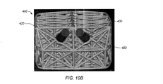
図1A〜1Bは、ある実施形態による、インプラント100の図を例示する。具体的に示されるインプラント100は、例えば、前方椎体間固定術(ALIF)または後方椎体間固定術(PLIF)において使用され得るが、インプラント100が、骨融着用途のために好適な様々な形状を有することを理解されたい。いくつかの実施形態において、インプラント100は、1つ以上のトラス102(例えば、平面及び立体トラス)を含むウェブ構造を含み得る。インプラント100は、脊椎インプラント、椎体切除術装置、膝置換材、股接合点置換材、長骨再構築スキャフォールド、及び頭蓋顎顔面インプラント等のヒトまたは動物のための種々の種類のインプラントにおいて使用され得る。他のインプラントの使用も企図される。
FIGS. 1A-1B exemplify a diagram of the
本明細書で使用される場合、「トラス構造」は、節点として称される接合点で連接された1つ以上の伸長支柱を有する構造である。トラスは、プラットトラス、キングポストトラス、クィーンポストトラス、タウン格子トラス、平面トラス、立体トラス、及び/またはフィーレンデールトラスの変形を含み得る(他のトラスも使用され得る)。「トラスユニット」は、3つ以上の伸長支柱によって画定される周囲を有する構造である。 As used herein, a "truss structure" is a structure having one or more extension struts connected at a junction referred to as a node. Trusses can include variants of platform trusses, kingpost trusses, queenpost trusses, town grid trusses, flat trusses, solid trusses, and / or feelendale trusses (other trusses may also be used). A "truss unit" is a structure having a perimeter defined by three or more extension struts.
本明細書で使用される場合、「平面トラス」は、支柱及び節点の全てが、実質的に単一の二次元平面に位置するトラス構造である。例えば、平面トラスは、1つ以上の「トラスユニット」を含み得、ここで支柱の各々は、1つ以上のトラスユニットの支柱及び節点の全体が実質的に同じ平面に位置するように、実質的に一直線の部材である。支柱の各々が実質的に一直線の支柱であり、トラスユニットの支柱及び節点の全体が、実質的に同じ平面に位置する、トラスユニットは、「平面トラスユニット」として称される。 As used herein, a "planar truss" is a truss structure in which all of the columns and nodes are located in substantially a single two-dimensional plane. For example, a planar truss can include one or more "truss units", where each of the struts is substantially so that the entire stanchion and node of one or more truss units are located in substantially the same plane. It is a straight member. A truss unit in which each of the struts is a substantially straight stanchion and the entire struts and nodes of the truss unit are located in substantially the same plane is referred to as a "planar truss unit".
本明細書で使用される場合、「立体トラス」は、実質的に単一の二次元平面に制限される支柱及び節点を有するトラスである。立体トラスは、2つ以上の平面トラス(例えば、平面トラスユニット)含み得、2つ以上の平面トラスのうちの少なくとも1つが、他の2つ以上の平面トラスのうちの少なくとも1つ以上の平面に対して実質的に平行でない平面に位置する。立体トラスは、例えば、互いに隣接する(例えば、共通の支柱を共有する)2つの平面トラスユニットを含み得、平面トラスユニットの各々は、互いに対して角度を有する(例えば、互いに対して平行ではない)別個の平面に位置する。 As used herein, a "three-dimensional truss" is a truss with struts and nodes that are restricted to a substantially single two-dimensional plane. A three-dimensional truss can include two or more plane trusses (eg, plane truss units), where at least one of the two or more plane trusses is at least one or more planes of the other two or more plane trusses. It is located on a plane that is not substantially parallel to. A three-dimensional truss can include, for example, two planar truss units that are adjacent to each other (eg, share a common strut), and each of the planar truss units is angled with respect to each other (eg, not parallel to each other). ) Located on a separate plane.
本明細書で使用される場合、「三角トラス」は、節点として称される接合点で連接された3つの直線の支柱によって形成される1つ以上の三角ユニットを有する構造である。例えば、三角トラスは、三角形状のトラスを形成するために3つの節点において互いに連結された3つの一直線の伸長支柱の部材を含み得る。本明細書で使用される場合、「平面三角トラス」は、三角トラス構造であり、ここで、支柱及び節点の全ては、実質的に単一の二次元平面に位置する。各三角ユニットは、「三角トラスユニット」として称され得る。支柱の各々が、三角トラスユニットの支柱及び節点の全体が実質的に同じ平面に位置するように実質的に一直線の部材である三角トラスユニットは、「平面三角トラスユニット」として称される。本明細書で使用される場合、「三角立体トラス」は、1つ以上の三角トラスユニットを含む立体トラスである。 As used herein, a "triangular truss" is a structure having one or more triangular units formed by three straight columns connected at a junction referred to as a node. For example, a triangular truss may include members of three straight extension struts connected to each other at three nodes to form a triangular truss. As used herein, a "planar triangular truss" is a triangular truss structure, where all struts and nodes are located in substantially a single two-dimensional plane. Each triangular unit may be referred to as a "triangular truss unit". A triangular truss unit in which each of the columns is a substantially linear member such that the entire columns and nodes of the triangular truss unit are located in substantially the same plane is referred to as a "planar triangular truss unit". As used herein, a "triangular three-dimensional truss" is a three-dimensional truss that includes one or more triangular truss units.
種々の実施形態において、ウェブ構造のトラス102は、種々の節点において連接された一直線または湾曲/弓なりの部材(例えば、支柱)で構築される1つ以上の平面トラスユニット(例えば、平面三角トラスユニット)を含み得る。いくつかの実施形態において、トラス102は、マイクロトラスであり得る。「マイクロトラス」は、複数のマイクロトラスが、実質的にウェブ構造の全てがインプラント位置(例えば、2つの脊椎間)中に挿入され得るように、十分に小さい全寸法(例えば、高さ、長さ、及び幅)を有するウェブ構造を形成するために組み立てられ得るか、またはそうでない場合、互いに連結され得るように十分に小さい寸法を有するトラスである。よって、かかるウェブ構造及びそのマイクロトラスを用いて、周辺の組織(例えば脊椎、骨等)の負荷を受け、これをウェブ構造全体に分配することができる。一実施形態において、マイクロトラスを形成する支柱の直径は、直径約0.25ミリメートル(mm)〜5mm(例えば、直径約0.25mm、0.5mm、0.6mm、0.7mm、0.8mm、0.9mm、1mm、2mm、3mm、4mm、または5mm)であり得る。一実施形態において、マイクロトラスは、約1インチ未満(例えば、約0.9インチ、0.8インチ、0.7インチ、0.6インチ、0.5インチ、0.4インチ、0.3インチ、0.2インチ、0.1インチ未満の長さ)の全長または全幅を有し得る。
In various embodiments, the web-structured
描写されるように、例えば、図1A〜1Bにおいて、ウェブ構造は、インプラント100全体(インプラント100の中央部分を含む)に延在して、インプラント100全体に支持体を提供し得る。よって、インプラント100のトラス102は、引張力、圧縮力、及びせん断力に対してインプラント100を支持し得る。また、ウェブ構造は、多数の平面に沿って、インプラント100を補強し得る。外部トラス構造は、例えば、インプラントの垂直方向に作用する引張力及び圧縮力に対して支持体を提供し得、内部ウェブ構造は、それぞれのトラスを含む種々の平面に沿った、引張力、圧縮力、及びせん断力に対して支持体を提供し得る。いくつかの実施形態において、ウェブ構造は、多数の支柱(例えば、支柱103a〜f)(支柱は、概して、本明書において「支柱103」として称される)で三角のウェブ構造を形成するトラス102を含む。
As depicted, for example, in FIGS. 1A-1B, the web structure may extend throughout the
一実施形態において、インプラント100のウェブ構造は、外部トラス構造によって少なくとも部分的に包含される内部ウェブ構造を含み得る。例えば、一実施形態において、ウェブ構造101は、実質的に単一の平面に位置する複数の平面トラスユニットで形成される1つ以上の平面トラスを含む、外部トラス構造によって包囲される立体トラスの少なくとも一部分を有する立体トラスを含む内部ウェブ構造を含み得る。図1Aは、内部ウェブ構造104及び外部トラス構造105を有するインプラント100の実施形態を描写する。例示される実施形態において、内部ウェブ構造104は、各隣接するトラスユニットが、各隣接するトラスユニットと共平面ではなくなるように、互いに対してある角度で連結された複数の平面トラスユニット106によって画定される立体トラスを含む。隣接するトラスユニットは、支柱及び共有される支柱の端でそれぞれ2つの節点を共有する2つのトラスユニットを含み得る。
In one embodiment, the web structure of
一実施形態において、外部トラス構造105は、インプラントの外側、内側、または他の部分辺りで連結される複数の平面トラスを含む。例えば、例示される実施形態において、外部トラス構造105は、互いに連結された一連の平面トラス107a、bを含む。平面トラス107aは、破線[−−−−−]によって表示され、平面トラス107bは、点破線[−・−・−]によって表示される。各平面トラスは、複数の平面トラスユニット(例えば、三角平面トラスユニット)から形成される。描写されるように、平面トラス107aは、共通の頂点110を有し、単一の共通の平面に位置する概して矩形な構造を形成するために配設された4つの三角平面トラスユニット108a、b、c、dを含む。言い換えれば、この4つの三角平面トラスユニットは、配設されて、矩形構造の1つの角からその矩形構造の反対の角に延在して、「X」の形状の支柱を有する実質的に矩形な構造を形成する。描写されるように、実質的に矩形な構造は、台形の形状を含み得る。下記でより詳細に記載されるように、台形の形状は、脊柱前弯を含むインプラントを提供することに貢献し得る。脊柱前弯は、インプラントが、脊柱の弯曲を支持することに貢献するように、インプラントの前方領域及び後方領域の厚みに差異を提供する、インプラントの角度付き表面配向(例えば、上面及び底面)を含み得る。
In one embodiment, the
一実施形態において、外部トラスを形成する平面トラスは、互いに連結され、かつ少なくとも1つの軸に沿って揃えられる。例えば、図1Aにおいて、平面トラス区域107aは、隣接する平面トラス107bに連結される。平面トラス区域107a、bは、全ての方向において平行ではない。しかし、平面トラス区域107a、bは、少なくとも1つの方向(例えば、インプラント100の上面と底面との間の垂直方向)において互いに平行に配設される。例えば、平面トラス107a、b、及び追加の平面トラスは、互いに対して角度を有して、系列をなして配設されて、垂直方向に配設された平面トラス及び平面トラスユニットによって画定される実質的に垂直な壁を有する概して円形または多角形の囲いを形成する。
In one embodiment, the planar trusses forming the outer truss are connected to each other and aligned along at least one axis. For example, in FIG. 1A, the
一実施形態において、外部トラス部分は、インプラントの側、上、及び/または底を包含し得る。例えば、一実施形態において、外部トラス部分は、上部領域、側部領域、及び/または底部領域を含み得る。図1Aは、インプラント100の実施形態を描写し、外部トラス部分105は、上部領域111、底部領域112、及び側部領域113を含む。上述されるように、側部領域113は、垂直に配設されて、インプラント100の中央部分に配置された立体トラスの周囲を完全にまたは少なくとも部分的に包囲する円形/多角形の環のような構造を形成する一連の平面トラスを含む。描写される実施形態において、外部トラス構造105の上部分111は、互いに連結されて、内部ウェブ構造104の上部領域を実質的に全て覆う平面トラスを形成する複数のトラスユニットを含む。例示される実施形態において、上部分111は、外部トラス構造105の側部分113の上縁間の範囲全体に及ぶ。例示される実施形態において、上部分111は、実質的に同じ平面に位置する複数のトラスユニットを含む単一の平面トラスから形成される。言い換えれば、上部分111の平面トラスは、概して平らな表面を画定する。図1では見え難いが、インプラント100の下側は、上部分111の構成に類似した構成を有する底部分112を含み得る。他の実施形態において、外部トラス構造105は、部分的な側部、上部、及び/または底部の外部トラス部分を含み得る。または、側部、上部、及び底部の外部トラス部分のうちの1つ以上を含み得ない。例えば、下記でより詳細に記載されるように、図2Cは、立体トラスから形成された内部ウェブ構造を含み、外部トラス構造を有しないインプラント100の実施形態を描写する。
In one embodiment, the external truss portion may include the side, top, and / or bottom of the implant. For example, in one embodiment, the external truss portion may include a top region, a side region, and / or a bottom region. FIG. 1A illustrates an embodiment of
いくつかの実施形態において、インプラント100は、チタン合金(例えば、γチタンアルミナイド)、コバルト、クロム、ステンレス鋼、ポリエーテルエーテルケトン(PEEK)、セラミックス等の生体適合性材料から形成され得る。他の材料も、企図される。いくつかの実施形態において、インプラント100は、以下でさらに記載されるような高速プロトタイピングプロセス(例えば、電子ビーム溶解(EBM)プロセス)によって作成され得る。他のプロセス(例えば、射出成型、鋳造、焼結、選択的レーザー焼結(SLS)、直接金属レーザー焼結(DMLS)等)も可能である。SLSは、米国ミシガン州ノバイに本社を置くEOS of North America,Inc.によって提供されるような高性能ポリマーのレーザー焼結を含み得る。高性能ポリマーは、種々の形態のPEEK(例えば、最大約95メガパスカル(MPa)の引張強度及び最大約4400MPaのヤング率、ならびに約180℃(356°F)から260℃(500°F)の連続動作温度を有するHP3)を含み得る。他の材料は、EOS of North America,Inc.によって提供されるPA12及びPA11を含み得る。
In some embodiments, the
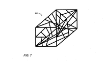
上述されるように、いくつかの実施形態において、ウェブ構造は、複数の三角平面トラスユニットから形成され得る。いくつかの実施形態において、平面トラスユニットは、互いに連結されて、多面体を画定し得、これが内部ウェブ構造を画定する。平面トラスユニットを連接することによって生成され得る多面体構造の例として、四面体、五面体、六面体、七面体、角錐、八面体、十二面体、二十面体、及び球状フラーレンが挙げられるが、これらに限定されない。上述されるもの等のいくつかの実施形態において、ウェブ構造の立体トラスは、四面体構造ブロックの多数の中心点を連接し得、互いに隣接して配設された四面体ブロックの規則的パターンを含み得る。いくつかの実施形態において、ウェブ構造は、幾何学的な構造ブロックのパターンを含み得ない。例えば、図7は、インプラント905において使用され得る支柱の非規則的パターンを例示する。他のウェブ構造も企図される。ウェブ構造から構成されるインプラントの例は、米国公開特許出願第2010/0161061号、同第2011/0196495号、同第20110313532号、及び同第2013/0030529号に記載され、それらの各々が、参照により本明細書に組み込まれる。
As mentioned above, in some embodiments, the web structure can be formed from multiple triangular plane truss units. In some embodiments, the planar truss units can be connected to each other to define a polyhedron, which defines the internal web structure. Examples of polyhedral structures that can be generated by connecting planar truss units include tetrahedrons, pentahedrons, hexahedrons, heptahedrons, pyramids, octahedrons, dodecahedrons, icosahedrons, and spherical fullerene. Not limited to. In some embodiments, such as those described above, a web-structured three-dimensional truss may connect a large number of center points of a tetrahedral block to form a regular pattern of tetrahedral blocks arranged adjacent to each other. Can include. In some embodiments, the web structure cannot contain a pattern of geometric structural blocks. For example, FIG. 7 illustrates an irregular pattern of struts that can be used in
図3A〜3Bは、三角平面トラスユニットから形成された立体ユニットで形成された内部ウェブ構造の一部分の概略図を例示する。三角平面トラスユニットは、1つに連接されて、構造ブロックとしても使用され得る四面体300a、bを形成し得る(三角平面トラスユニットの他のパターンも企図される)。他の構造ブロック(例えば、四角形の構造ブロック)も企図される。いくつかの実施形態において、ウェブ構造は、四面体300aまたは300b等の単一の四面体を単独でまたは1つ以上の他の多面体と合わせて含み得る。いくつかの実施形態において、ウェブ構造は、2つ以上の四面体300a、bを含み得る。四面体300aは、4つの三角面を含み得、そこにおいて4つの三角面のうち3つが各頂点で合する。いくつかの実施形態において、2つの四面体300a及び300bは、2つの隣接する面で1つになるように配置されて、六面体状の枠組み(6つの面を含む)を有する立体トラス313を形成し得る。六面体状の立体トラス313は、第1の頂点301、第2の頂点309、第3の頂点303、第4の頂点305、及び第5の頂点307を含み得る。共通する平面311は、2つの四面体によって共有されて(例えば、共通する平面311は、第3の頂点303、第4の頂点305、及び第5の頂点307を含み得る)、共通する平面311から離間する、第1の頂点301及び第2の頂点309を有する六面体を形成し得る。描写されるように、三角形状の構造ブロックの中央部分は、そこを通って延在する一切の追加の部材を含まず(例えば、三角形状の構造ブロックを形成する支柱以外の部材が無い)、その中心において空洞領域を有し得る。
3A-3B exemplify a schematic view of a portion of an internal web structure formed by a three-dimensional unit formed from a triangular plane truss unit. The triangular plane truss units can be joined together to form
図3Bにおいて示されるように、いくつかの実施形態において、多数の六面体状の立体トラス313は、横並びに配設され得る。インプラント100の2つの立体トラス313は、それらの第1の頂点301a、bを介して支柱103rによって連接され得、それらの第2の頂点309a、bを介して支柱103tによって連接され得る。同様に、2つの立体トラス313は、それらの第1の頂点301c、dを介して支柱103pによって連接され得、それらの第2の頂点309c、dを介して支柱103sによって連接され得る。他の連接部も可能である。例えば、立体トラス313は、側部の頂点によって(例えば、対応する頂点(頂点303a、b等の)、及び/または共通する支柱(支柱103u等の)を共有して)、及び/または側面(例えば、側面111a、b)によって直接連接し得る。
As shown in FIG. 3B, in some embodiments, a large number of hexahedral three-
図4Aは、インプラント100において4つの六面体状の立体トラスの第1の頂点(それぞれ301a、301b、301c、及び301dと表示される)を連接する追加の支柱103(例えば、支柱103p及び103r)を例示する。図4Bは、インプラント100中の4つの六面体状の立体トラスの第2の頂点309(それぞれ309a、309b、309c、及び309dと表示される)を連接する追加の支柱103(例えば、支柱103s及び103t)を例示する。いくつかの実施形態において、追加の支柱103は、ウェブ構造の1つ以上の頂点間の内部でも使用されて、追加のトラスを形成し得る(例えば、図1A〜2Bのウェブ構造を参照されたい)(他の構造も可能である)。
FIG. 4A includes additional struts 103 (eg, struts 103p and 103r) connecting the first vertices of the four hexahedral three-dimensional trusses (denoted as 301a, 301b, 301c, and 301d, respectively) in the
図1Aに示されるように、インプラント100の上面115a及び底面115bは、三角、四角、円、または他の形状(例えば、無作為のまたは特注設計)を含み得る。上面及び底面115a、bは、インプラント100のウェブ構造において使用される種々の幾何学的な構造ブロックの上部及び底部の頂点を連接するために使用され得る。例えば、各頂点は、支柱によって他の幾何学的な構造ブロックの隣接する頂点に連接され得る。上面115aは、他の支柱のネットワーク及び/または連接部を含み得る。いくつかの実施形態において、底面115bは、上面に類似しても(及び/または他の設計を有しても)よい。いくつかの実施形態において、上面115a及び底面115bは、インプラント100が埋め込まれるとき、2つの隣接する椎骨のそれぞれの表面を係合してもよい。
As shown in FIG. 1A, the
図1Bに描写されるように、インプラント100は、埋め込まれるとき、隣接する椎骨をさらに支持するために脊柱前弯(例えば、上面及び/または底面115a、bにおいて、およそ4〜15度(4、5、6、7、8、9、10、11、12、13、14、または15度等の)の範囲の角度)を含み得る。上述されるように、脊柱前弯は、インプラントが、脊柱の弯曲を支持することに貢献するように、インプラントの前方部分及び後方部分の厚みに差異を提供する角度付き表面配向(例えば、上面及び底面)を含み得る。例示される実施形態において、インプラント100の厚みは、そのインプラントの前方部分118においてまたはその近傍でより大きく、そのインプラントの後方部分120においてまたはその近傍でより小さい。例示される実施形態において、外部トラス構造の側部分は、実質的に垂直に配設され、脊柱前弯は、外部トラス構造の上部分111及び底部分112の角度によって形成される。例えば、例示される実施形態において、外部トラス構造の上部分111及び底部分112は、側部分113によって画定される垂直平面に対して垂直ではない。むしろ、上部分111及び底部分112は、インプラント100の前方領域118においてまたはその近傍で、側部分113の垂直平面に対して鋭角に、かつインプラント100の後方領域120においてまたはその近傍で、側部分113の垂直平面に対して鈍角に配設される。描写されるように、インプラント100の後方領域120近接の外部トラス構造の側部分113の平面トラスを形成する垂直な支柱は、インプラント100の前方領域118近接の外部トラス構造の側部分を形成する支柱よりも短い。垂直トラスが実質的に均等な間隔である例示される実施形態において、インプラント100の後方領域120近接の側部平面トラスの「X」クロス部材を形成する支柱は、インプラント100の前方領域118近接の側部平面トラスの「X」クロス部材を形成する支柱よりも短い。他の実施形態は、様々な構成のインプラントを提供するために、トラスの配設のバリエーションを含み得る。例えば、いくつかの実施形態において、上部及び底部外部トラス部分の1つのみまたはその両方が、インプラントの前方及び後方部分近接の外部トラスの側部分に対して垂直でなくてもよい。さらに、側部、上部、及び/または底部は、互いに対して任意の配向で角度を有する複数の平面トラスを含んでいてもよい。例えば、各々が複数のトラスユニットで形成される上部または底部は、部分(複数可)が、錐体様の形状を含むように4つの平面トラスを含んでもよい。
As depicted in FIG. 1B, the
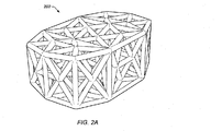
いくつかの実施形態において、インプラントは脊柱前弯を含まなくてもよい。例えば、図2A〜2Bは、脊柱前弯を有さないインプラント200の実施形態の2つの図を例示する。いくつかの実施形態において、上面及び底面は、連接する支柱を含み得ない。例えば、図2C〜2Dは、外側支柱を有さないインプラント250の2つの図を例示する(例えば、平面トラスによって形成される外部トラス部分が無い)。例示される実施形態において、インプラント250は、内部ウェブ構造を含み、外部トラス構造を含まない。例えば、例示される実施形態において、インプラント250の外面は、複数のトラスユニットによって画定され、それらは、その隣接するトラスユニットの各々に対する角度を有する。トラスユニットの相対的な並びは、複数の鋭利な接合点を含む非平面の外側をもたらす。鋭利な接合点(例えば鋭利な接合点201)は、(例えばインプラントを椎体部分切除術用デバイスにおいて使用している場合)インプラントを正しい位置に保持するために周囲を取り囲む骨の中を掘り進んで動作し得る。
In some embodiments, the implant may not include lordosis. For example, FIGS. 2A-2B illustrate two diagrams of an embodiment of an
図5A〜5Cは、ある実施形態による、インプラント100の内部構造を示す、インプラント100の異なる高さの断面図を例示する。図5Aは、インプラント100のより下の部分の断面図を例示する。底面115bは、底面115bから上向きに延在する種々の支柱(例えば、支柱103)と共に示される。図5Bは、インプラント100のおよそ真ん中を通る断面図を例示する。ウェブ構造において積み重ねられた種々の四面体で共有される支柱103e、f等の支柱が示される。いくつかの支柱は、インプラント100の中央部分501a及び/または501bを通って延在する。図5Bは、インプラント100の中央部分501a、bも描写する。いくつかの実施形態において、中央部分501aは、インプラントの幅のおよそ50%の幅、インプラントの高さのおよそ50%の高さ、及びインプラントの長さのおよそ50%の長さを有し、インプラント100の中心に位置する矩形領域を含み得る。いくつかの実施形態において、中央部分501bは、インプラント100の幅のおよそ半分、長さのおよそ半分、及び高さのおよそ半分に位置する場所(すなわち、インプラント100の中心)の周辺で、インプラント100の幅のおよそ1/8〜1/4の半径の領域(例えば、球形領域、四角領域等)を包含し得る。他の中央部分も企図される。例えば、中央部分は、インプラントの幅のおよそ半分、長さのおよそ半分、及び高さのおよそ半分の位置の周辺で、四角領域の辺のうちの1辺の長さが、インプラント100の幅のおよそ1/4〜1/2である四角領域を含み得る。高さ502a、幅502b、及び長さ502cの例は、図5Dに示される。いくつかの実施形態において、高さは、最大約75mm以上であり得る。長骨再構築のために使用されるもの等のいくつかの実施形態において、幅及び/または長さは、およそ7インチ以上であり得る。いくつかの実施形態において、幅、長さ、及び/または高さは、インプラント100に応じて変化し得る(例えば高さは、インプラントが脊柱前弯を含む場合、変化し得る)。高さは、インプラント100の対向する側部のうちの1つや中間部で測定されてもよく、及び/またはインプラント100の長さに沿った1つ以上の高さの平均であってもよい。ウェブ構造は、インプラントの中央部分501a、bを通って延在し得る(例えば、ウェブ構造の少なくとも1つの支柱が、中央部分501a、bを少なくとも部分的に通って進み得る)。図5Cは、ウェブ構造内の上部の四面体の断面図を示す別の断面図を例示する。図5Dは、頂点301a〜dを有する上面115aを含むインプラント100の全体図を示す。
5A-5C illustrate cross-sectional views of
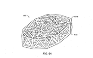
図6A〜6Dは、インプラントの代替実施形態を例示する。いくつかの実施形態において、六面体状の幾何学的設計の異なる区域が使用され得る。例えば、図6Aに示されるように、六面体状の幾何学的設計の下半分(下側四面体構造を主に含む)が使用され得る。設計の下半分を使用する場合、インプラント600は、六面体状の幾何学的設計と同様の全体寸法を有するために比例的に拡張され得る(例えば、四面体は、六面体状の幾何学的設計において、四面体の高さのおよそ2倍に拡張されて、六面体状の幾何学的設計とおよそ同じ高さのインプラント600を供し得る)。いくつかの実施形態において、インプラント600は、いくつかの実施形態において、椎骨の端板間により良好な嵌合を有するために、脊柱前弯をインプラント600に提供するために(例えば、上面601a及び/または底面601bにおいて)角度も有してよい。上面601a及び/または底面601bは、インプラント600の節点を連接するための支柱も含み得る(例えば、図6aの上面の支柱ネットワークを参照されたい)。上面601a及び/または底面601bの支柱の他のパターンも使用され得る。いくつかの実施形態において、インプラント600は、支柱間に負角を含み得ず、よって、鋳造プロセスまたは成型プロセスによってより容易に生成可能となる。
6A-6D illustrate alternative embodiments of implants. In some embodiments, different areas of hexahedral geometric design may be used. For example, as shown in FIG. 6A, the lower half of the hexahedral geometric design (including primarily the lower tetrahedral structure) can be used. When using the lower half of the design, the
図6C〜6Dは、インプラントの別の代替実施形態を例示する。いくつかの実施形態において、六面体状の幾何学的設計の中間部のおよそ40〜60パーセントが、インプラント650において使用され得る。例えば、六面体状の幾何学的設計の全高がおよそ37mmの場合、設計の底部のおよそ10mm、及び設計の上部のおよそ10mmが取り除かれ得、設計の中間部のおよそ17mmがインプラント用に使用され得る。次に、インプラント650の中間部は、拡張された設計のおよその高さがおよそ37mm(または必要に応じて異なる高さ)になり得るように比例的に拡張される。上面651a及び底面651bは、支柱のネット―ワークを含み得る(例えば、図6Cの上面651aの支柱を参照されたい)(支柱の他のネットワークも企図される)。インプラント用の設計の他の部分(例えば、図1Aに示される設計の上半分、図1Aに示される設計の下半分等)も企図される。設計部分は、特定の寸法(例えば、特定の高さ、幅、及び長さ)に合うように比例的に拡張され得る。いくつかの実施形態において、いくつかの支柱が、より大きな直径を有し得るように、かついくつかの支柱が、より小さな直径を有し得るように(例えば、異なる直径は、異なる方向の力に対して補強し得る)、インプラント内の支柱の量が低減され得るか、またはインプラント内の材料が再分配され得る。いくつかの実施形態において、(例えば、構造が四面体を含むように、ウェブ構造の半分と共に)部分設計ケージが、使用され得る。さらに、いくつかの実施形態において、インプラントは、椎骨の端板間に埋め込まれるインプラントに脊柱前弯を提供するために角度付き表面(例えば、角度付き上面651a及び/または角度付き底面651b)を含み得る。
6C-6D illustrate another alternative embodiment of the implant. In some embodiments, approximately 40-60 percent of the middle part of the hexahedral geometric design can be used in the
いくつかの実施形態において、インプラントのウェブ構造は、埋め込まれたとき、インプラント全体に力を分配し得る。例えば、ウェブ構造の連接支柱は、インプラントの中心全体に延在し得、支柱の相互連接性が、圧縮力の負荷をインプラント全体に分散して、応力集中部の可能性を低減し得る(インプラント全体への力の分配は、椎骨の1つ以上の部分への負荷の集中を防止し得、そうでない場合、椎骨の損傷を引き起こし得る)。 In some embodiments, the web structure of the implant may distribute force throughout the implant when implanted. For example, web-structured articulated struts can extend throughout the center of the implant, and the articulation of the struts can disperse compressive loads throughout the implant, reducing the potential for stress concentrations (implants). Distributing force to the whole can prevent the concentration of load on one or more parts of the vertebrae, otherwise it can cause damage to the vertebrae).
いくつかの実施形態において、インプラントのウェブ構造(例えば、インプラントの外部及び内部の支柱)は、表面範囲に骨移植融着も提供する。例えば、インプラント全体に延在するウェブ構造は、骨移植材料に融着するための追加の表面範囲を(例えば、インプラントを作製する支柱の表面上に)追加し得、骨移植材料の緩み、または骨移植材料がインプラントから移動するのを防止し得る。いくつかの実施形態において、ウェブ構造は、骨の成長も支持し得る。例えば、インプラントが埋め込まれるとき、隣接する骨(例えば、インプラントが、脊椎インプラントとして使用される場合は隣接する椎骨)は、インプラントの支柱の少なくとも一部分にわたって成長し得る。骨成長、及び骨成長とインプラントとの間の係合は、インプラントをさらに安定し得る。いくつかの実施形態において、インプラントの表面は、骨成長の接着を補助するために、粗面で形成され得る。 In some embodiments, the web structure of the implant (eg, the external and internal struts of the implant) also provides bone graft fusion to the surface area. For example, a web structure that extends throughout the implant may add an additional surface area (eg, on the surface of the strut in which the implant is made) to fuse to the bone graft material, resulting in loosening of the bone graft material, or It can prevent the bone graft material from moving from the implant. In some embodiments, the web structure can also support bone growth. For example, when an implant is implanted, adjacent bones (eg, adjacent vertebrae when the implant is used as a spinal implant) can grow over at least a portion of the implant's struts. Bone growth, and the engagement between bone growth and the implant, can further stabilize the implant. In some embodiments, the surface of the implant can be formed with a rough surface to aid in the adhesion of bone growth.
いくつかの実施形態において、支柱は、およそ約0.025〜5ミリメートル(mm)の範囲(例えば、1.0mm、1.5mm、3mm等)の直径を有し得る。他の直径(例えば、5mm超)も企図される。いくつかの実施形態において、支柱は、(例えば、椎骨の端板間の空隙を嵌合するために必要とされるインプラントのサイズに応じて)およそ0.5〜20mmの範囲の長さを有し得る。別の例として、支柱は、股関節インプラント用ではおよそ30〜40mmの範囲の長さを有し得る。いくつかの実施形態において、ウェブ構造の低減された支柱サイズは、インプラント100の開口セルが骨成長を促進することを可能にし得る(例えば、骨は、インプラント100が体内に埋め込まれると、開口セルを通って成長し得る)。インプラントの平均的な沈下は、手術後、最初の3週間以内でおよそ1.5mmであり得る(他の沈下(例えば、およそ0.5〜2.5mm)も可能性がある)。この沈下にほぼ適合する支柱サイズ(例えば、直径およそ1.5mmの支柱サイズ及びおよそ1.5mmの沈下)は、インプラントが埋め込まれた位置で定着後、正味0のインピーダンス(例えば、支柱周辺で成長する骨成長)をもたらし得る。インプラント/椎骨の端板接合の全表面の範囲全体の正味0インピーダンスは、より大きな骨の融着柱をもたらし得、これはより安定した融着をもたらし得る。他の融着柱サイズも企図される。インプラントの構成は、インプラント全体に金属を再分配し得る。いくつかの実施形態において、リムは、インプラント上で含まれないことがある(いくつかの実施形態において、リムは、含まれ得る)。得られる骨成長(例えば、脊椎柱)は、インプラントを通って成長し得る。
In some embodiments, the stanchions may have a diameter in the range of approximately 0.025-5 mm (mm) (eg, 1.0 mm, 1.5 mm, 3 mm, etc.). Other diameters (eg, greater than 5 mm) are also contemplated. In some embodiments, the struts have a length in the range of approximately 0.5-20 mm (eg, depending on the size of the implant required to fit the gap between the end plates of the vertebrae). Can be done. As another example, the struts can have lengths in the range of approximately 30-40 mm for hip implants. In some embodiments, the reduced strut size of the web structure may allow the opening cell of the
いくつかの実施形態において、インプラント100の内側容積の50%超が開口であり得る。いくつかの実施形態において、インプラント100の60%超、70%超、及び/または80%超(例えば、95%)が、開口であり得る。いくつかの実施形態において、開口容積は、骨成長の材料によって充填され得る。例えば、海綿骨は、インプラントの開口/内部領域中に詰められ得る。
In some embodiments, more than 50% of the medial volume of
いくつかの実施形態において、インプラントの表面の少なくとも一部分は、骨成長及び/もしくは骨接着を促進することを目的とした材料、ならびに/または感染症を防止するための抗菌剤でコーティング/処理され得る。例えば、いくつかの実施形態において、支柱の表面は、生物学的因子及び/または骨成長因子でコーティングされ得る。いくつかの実施形態において、生物学的因子は、ヒドロキシアパタイト、骨形態形成タンパク質(BMP)、インスリン様成長因子I及びII、形質転換成長因子ベータ、酸及び塩基フィブロブラスト成長因子、血小板由来成長因子、ならびに/または骨成長とインプラントの表面との間の良好な生物学的固定を促進する同様の骨成長刺激剤等のコーティングを含み得る。いくつかの実施形態において、骨成長因子は、細胞成長、分芽増殖、及び細胞分化を刺激できる、自然発生する物質(例えばタンパク質またはステロイドホルモン)を含み得る。いくつかの実施形態において、インプラントの表面(例えば、支柱、外部トラス構造等)は、膠原質でコーティングされ得る。 In some embodiments, at least a portion of the surface of the implant may be coated / treated with a material intended to promote bone growth and / or bone adhesion and / or an antibacterial agent to prevent infection. .. For example, in some embodiments, the surface of the strut may be coated with biological and / or bone growth factors. In some embodiments, the biological factors are hydroxyapatite, bone morphogenetic protein (BMP), insulin-like growth factors I and II, transformed growth factor beta, acid and base fibroblast growth factors, platelet-derived growth factors. And / or coatings such as similar bone growth stimulants that promote good biological fixation between bone growth and the surface of the implant may be included. In some embodiments, bone growth factors can include naturally occurring substances (eg, proteins or steroid hormones) that can stimulate cell growth, sprouting, and cell differentiation. In some embodiments, the surface of the implant (eg, struts, external truss structure, etc.) can be coated with collagen.
いくつかの実施形態において、生物学的因子及び/または成長因子は、インプラントの中央領域に固定され得る。例えば、いくつかの実施形態において、生物学的因子または成長因子は、図5Bを参照のように、インプラント100の中央部分501a及び/または501bを通って延在する支柱の少なくとも一部分上に提供され得る。かかる実施形態は、生物学的因子及びまたは成長因子をインプラントの中央部分に送達することが可能であり得る。例えば、生物学的因子または成長因子は、生物学的因子及び/または成長因子の物理的取り付けのために、インプラント内に提供された支柱を含まない開口容積に詰められるのとは反対に、インプラントの中央部分の支柱内に物理的に固定され得る。
In some embodiments, biological and / or growth factors can be immobilized in the central region of the implant. For example, in some embodiments, the biological or growth factor is provided on at least a portion of a strut that extends through the
インプラントが、埋め込みの場所に定着すると、沈下は、追加の圧を骨移植材料にかけ(既にインプラント内の圧縮力の下であり得る)、骨移植材料を、インプラントの側部に向かって押圧するように作用し得る(隣接する材料のブジネスクの理論によると、力が、他の材料(砂、汚物、または骨移植材料等の)に隣接する部材に適用されると、この部材に対する力が、隣接する材料に増加された圧(例えば、60度)の領域を生成する)。インプラントの支柱は、ウェブ構造の側面からの骨移植材料の突出に耐えることができ、骨移植材料の圧力を増加し得る。骨移植材料は、強度な骨成長に貢献するための環境を生成するために高圧の環境で埋め込まれる必要があり得る(例えば、ウォルフ法によると、健常なヒトまたは動物の骨は、骨移植材料が配置される下の負荷に適合する)。よって、ウェブ構造は、より強度な融着の可能性を増加し得る。 Once the implant has settled at the site of implantation, subsidence will apply additional pressure to the bone graft material (which may already be under compressive force within the implant), pushing the bone graft material towards the sides of the implant. When a force is applied to a member adjacent to another material (such as sand, filth, or bone graft material), the force on this member is adjacent. Creates a region of increased pressure (eg, 60 degrees) on the material to be implanted). The implant struts can withstand the protrusion of the bone graft material from the sides of the web structure and can increase the pressure of the bone graft material. Bone graft material may need to be implanted in a high pressure environment to create an environment that contributes to strong bone growth (eg, according to the Wolff method, healthy human or animal bone is a bone graft material. Fits the load below where it is placed). Thus, the web structure can increase the possibility of stronger fusion.
他のトラス構成から形成されるウェブ構造も企図される。例えば、トラスは、一連の充填三角形、2ウェブ式トラス、3ウェブ式トラス等を含み得る。さらに、インプラント用のウェブ構造は、2005年8月23日発行の「Web Structure and Method For Making the Same」と題する米国特許第6,931,812号に記載されるような1つ以上のトラスを含み得、本明細書に十分に及び完全に記載されるように、その全体が参照により本明細書に組み込まれる。 Web structures formed from other truss configurations are also contemplated. For example, the truss may include a series of filled triangles, a two-web truss, a three-web truss, and the like. In addition, the web structure for implants includes one or more trusses as described in US Pat. No. 6,931,812, entitled "Web Structure and Method For Making the Same," published August 23, 2005. It may be included and is incorporated herein by reference in its entirety, as fully and fully described herein.
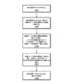
図8は、インプラントを作製するための方法の流れ図を例示する。いくつかの実施形態において、インプラントは、高速プロトタイピング(例えば、電子ビーム溶解、レーザー焼結等)によって作成され得る。以下に記載される本方法の種々の実施形態において、記載される要素のうちの1つ以上は、示されるのとは異なる順番で同時に実行され得るか、または全体的に削除されてもよいことを留意されたい。他の追加の要素も、所望であれば実行されてよい。いくつかの実施形態において、方法の一部分または全体が、コンピュータシステムによって自動的に実行され得る。 FIG. 8 illustrates a flow chart of a method for making an implant. In some embodiments, the implant can be made by high speed prototyping (eg electron beam melting, laser sintering, etc.). In various embodiments of the method described below, one or more of the described elements may be performed simultaneously in a different order than shown, or may be removed altogether. Please note. Other additional elements may be performed if desired. In some embodiments, some or all of the methods may be performed automatically by the computer system.
1001において、インプラントの三次元モデルが生成され、インプラント製プロセスを制御するのに操作可能な制御装置にアクセス可能な記憶媒体内に記憶される。1003において、材料(例えば、粉末、液体等)の層が、支持体に適用される。いくつかの実施形態において、その粉末は、高強度/低重量の材料であり得るγTiAl(γチタンアルミナイド)を含み得る。他の材料も使用され得る。粉末は、ガス噴霧プロセスを使用して形成され得、およそ20〜200マイクロメートル(μm)の範囲(例えば、およそ80μm)の直径を有する微粒を含み得る。粉末は、分配装置を通って支持体に送達され得る(例えば、保管容器からの送達)。分配装置及び/または支持体は、支持体に(例えば、粉末の)層を適用するために、分配中移動し得る。いくつかの実施形態において、層は、およそ均一の厚みであり得る(例えば、平均20〜200マイクロメートル(μm)の厚みを有する)。いくつかの実施形態において、分配装置及び支持体は、移動し得ない(例えば、材料が支持体上に噴霧され得る)。1005において、制御装置が、材料層に電子ビームを移動する。いくつかの実施形態において、電子ビーム生成器が移動され得、いくつかの実施形態において、支持体が移動され得る。材料が、γTiAlの場合、およそ摂氏1200〜1800度の範囲(例えば、摂氏1500度)の融解温度が、電子ビームと材料との間で取得され得る。1007において、各電子ビームの通過の間に、追加の材料が、分配装置によって適用され得る。1009において、非融解材料は除去され、インプラントは(例えば、冷却不活性ガスを用いて)冷却される。いくつかの実施形態において、インプラントの縁は、(例えば、ダイヤモンド研磨機を用いて)滑らかにされて、粗縁を除去し得る。いくつかの実施形態において、インプラントは、粗縁を含み、インプラントと包囲する骨との間で摩擦を増加させて、インプラントの骨への接着を増加させ得る。 At 1001, a three-dimensional model of the implant is generated and stored in a storage medium accessible to a control device that can be operated to control the implant manufacturing process. At 1003, a layer of material (eg, powder, liquid, etc.) is applied to the support. In some embodiments, the powder may contain γTiAl (γ-titanium aluminide), which can be a high-strength / low-weight material. Other materials may also be used. The powder can be formed using a gas spraying process and may contain fine particles having a diameter in the range of approximately 20 to 200 micrometers (μm) (eg, approximately 80 μm). The powder can be delivered to the support through a distributor (eg, delivered from a storage container). The distributor and / or support may move during distribution to apply a layer (eg, powder) to the support. In some embodiments, the layers can be approximately uniform thickness (eg, have an average thickness of 20-200 micrometers (μm)). In some embodiments, the distributor and support are immobile (eg, material can be sprayed onto the support). At 1005, the control device moves the electron beam to the material layer. In some embodiments, the electron beam generator can be moved, and in some embodiments, the support can be moved. If the material is γTiAl, a melting temperature in the range of approximately 1200-1800 degrees Celsius (eg 1500 degrees Celsius) can be obtained between the electron beam and the material. At 1007, additional material may be applied by the distributor during the passage of each electron beam. At 1009, the non-melting material is removed and the implant is cooled (eg, with a cooling inert gas). In some embodiments, the edges of the implant can be smoothed (eg, using a diamond grinding machine) to remove rough edges. In some embodiments, the implant comprises a rough edge and may increase friction between the implant and the surrounding bone to increase the adhesion of the implant to the bone.
インプラントの他の作製方法も企図される。例えば、インプラントは、鋳造または射出成型され得る。いくつかの実施形態において、多数の部品は、鋳造または射出成型され得、(例えば、溶接、融解等によって)1つに連接され得る。いくつかの実施形態において、インプラントを形成する個別の支柱は、(例えば、鋳造、射出成型等によって)別個に生成され得、1つに溶接されてインプラントを形成し得る。いくつかの実施形態において、異なるサイズの多数のインプラントが構築され得、1つのキット中に送達され得る。医学医療専門家は、手術中、インプラントを(例えば、必要とするサイズに応じて)選択してもよい。いくつかの実施形態において、多数のインプラントは、埋め込みの場所で使用され得る。 Other methods of making implants are also contemplated. For example, the implant can be cast or injection molded. In some embodiments, a large number of parts can be cast or injection molded and joined together (eg, by welding, melting, etc.). In some embodiments, the individual struts that form the implant can be generated separately (eg, by casting, injection molding, etc.) and welded together to form the implant. In some embodiments, multiple implants of different sizes can be constructed and delivered in one kit. Medical medical professionals may select implants (eg, depending on the size required) during surgery. In some embodiments, a large number of implants can be used at the site of implantation.
特定の用具が、本明細書に記載されるインプラントを挿入するために使用され得る。使用され得る用具の例は、米国公開特許出願第2010/0161061号、同第2011/0196495号、同第20110313532号、及び同第2013/0030529号に記載され、それらの各々が、参照により本明細書に組み込まれる。 Certain tools can be used to insert the implants described herein. Examples of tools that may be used are described in US Publication Patent Applications 2010/0161061, 2011/0196495, 20110313532, and 2013/0030529, each of which is described herein by reference. Incorporated into the book.
図9は、ある実施形態による、脊椎インプラントを埋め込むための方法の流れ図を例示する。以下に記載される本方法の種々の実施形態において、記載される要素のうちの1つ以上は、示されるのとは異なる順番で同時に実行され得るか、または全体的に削除されてもよいことを留意されたい。他の追加の要素も、所望であれば実行されてよい。いくつかの実施形態において、方法の一部分または全体が、コンピュータシステムによって自動的に実行され得る。 FIG. 9 illustrates a flow chart of a method for implanting a spinal implant according to an embodiment. In various embodiments of the method described below, one or more of the described elements may be performed simultaneously in a different order than shown, or may be removed altogether. Please note. Other additional elements may be performed if desired. In some embodiments, some or all of the methods may be performed automatically by the computer system.
ステップ1301において、体内空間がアクセスされる。例えば、前方開口部は、患者の体内で、前方椎体間固定術(ALIF)手法のために作成され得るか、または後方開口部は後方椎体間固定術(PLIF)手法のために作成され得る。1303において、体内空間の少なくとも一部分が、切除されて、体内空間内に空洞を形成する。1305において、インプラントは、体内空間の空洞中に挿入される。いくつかの実施形態において、ハンドラー、またはいくつかの他の装置が、インプラントを把持するために使用され得る。いくつかの実施形態において、力は、(例えば、ハンマーによって)インプラントに適用されて、インプラントを空洞中に挿入し得る。1307において、インプラントの挿入前及び/または後に、インプラント及び/または空洞内の空間は、骨移植材料で詰められ得る。1309において、体内空間へのアクセス点は、(例えば、縫合糸を用いて)塞がられ得る。
In
いくつかの実施形態において、インプラントはカスタマイズされてもよい。例えば、三次元計測及び/またはインプラントの形状は、三次元形状設計全体にウェブ構造を分配するインプラントを構築するために使用され得る。 In some embodiments, the implant may be customized. For example, 3D measurements and / or implant shapes can be used to build implants that distribute the web structure throughout the 3D shape design.
いくつかの実施形態において、トラス/ウェブ構造は、インプラントの少なくとも一部分上に配置されて、隣接する構造へのインプラントの連結を促進し得る。例えば、インプラントが、隣接する骨構造に埋め込まれる場合、1つ以上のトラス構造が、使用中に骨構造に接触する、及びそれに少なくとも部分的に接着することが意図されるインプラントの表面(例えば、接合平板)上に配置され得る、及び/またはそこから延在し得る。最中に2つの隣接する椎骨の端板間に配置される椎骨インプラントを含む実施形態等の、いくつかの実施形態において、1つ以上のトラス構造は、椎間インプラントの接触表面上に配置されて、椎間インプラントの骨構造への連結を向上させる骨成長を促進し得る。例えば、トラス構造は、接触表面から画定の開口空間までを通る骨成長のためにそこを通って延在する1つ以上の支柱を含み得、それによって、骨が成長して、骨構造とトラス構造とを互いに連結させて、インプラントを接触表面でまたはその近傍で骨構造と連結させることを可能にする。かかる骨成長による連結は、インプラントと骨構造との間の動きを阻止し得、そうでない場合、目的の位置からのインプラントの緩み、移動、沈下、または外れを引き起こす可能性がある。同様の技術は、組織及び/または骨構造と接合することが意図されるものを含む種々の種類のインプラントと共に用いられ得る。例えば、トラス構造は、膝インプラントの接触表面上で、脊椎固定術装置において、股接合点置換材において、膝置換材において、長骨再構築スキャフォールドにおいて、または頭蓋顎顔面インプラント、股関節インプラント、顎インプラント、長骨再構築用インプラント、足及び足首インプラント、肩インプラント、もしくは他の関節置換術インプラント、または隣接する骨構造または組織へのインプラントの接着を向上させるようなものにおいて用いられ得る。隣接する構造へのインプラントの連結を促進するためのインプラントの表面から延在し得るトラス構造及び別の構造の例は、米国公開特許出願第2011/0313532号に記載され、参照により本明細書に組み込まれる。 In some embodiments, the truss / web structure can be placed on at least a portion of the implant to facilitate the connection of the implant to adjacent structures. For example, if the implant is implanted in an adjacent bone structure, the surface of the implant (eg, for example, where one or more truss structures are intended to contact, and at least partially adhere to, the bone structure during use. It can be placed on and / or extend from it. In some embodiments, such as embodiments that include a vertebral implant placed between the end plates of two adjacent vertebrae in the middle, one or more truss structures are placed on the contact surface of the facet implant. It can promote bone growth that improves the connection of the facet implant to the bone structure. For example, a truss structure may include one or more struts that extend through it for bone growth through the contact surface to the defined open space, whereby the bone grows and the bone structure and truss The structures are connected to each other, allowing the implant to be connected to the bone structure at or near the contact surface. Such bone growth connections can block the movement between the implant and the bone structure, otherwise it can cause the implant to loosen, move, sink, or disengage from its desired position. Similar techniques can be used with various types of implants, including those intended to join tissue and / or bone structure. For example, truss structures can be used on the contact surface of knee implants, in spinal fusion devices, in hip replacements, in knee replacements, in long bone reconstruction scaffolds, or in craniofacial implants, hip implants, jaws. It can be used in implants, long bone reconstruction implants, foot and ankle implants, shoulder implants, or other joint replacement implants, or anything that improves the adhesion of the implant to adjacent bone structures or tissues. Examples of truss structures and other structures that may extend from the surface of the implant to facilitate the connection of the implant to adjacent structures are described in US Publication No. 2011/0313532, which is hereby referenced. Be incorporated.
本明細書に記載されるインプラントは、実質的に一直線の支柱から構成されると描写されるが、支柱は、湾曲、弓形及び弓なりの形状を含むが、これらに限定されない、直線ではない可能性もあることを理解されたい。直線ではない支柱を有するインプラントの例は、米国特許出願第13/668,968号に記載され、参照により本明細書に組み込まれる。 The implants described herein are described as consisting of substantially straight struts, which struts may be non-straight, including, but not limited to, curved, arched and arched shapes. Please understand that there is also. Examples of implants with non-straight struts are described in US Patent Application No. 13 / 668,968 and are incorporated herein by reference.
いくつかの実施形態において、1つ以上の締結具(例えば、ねじ)を使用して、インプラントが骨に固定されることが望ましい。締結具は、インプラント構造の任意の部に連結されて、インプラントを骨に固定し得る。締結具を受容する1つ以上のチャネルを有するインプラントの実施形態は、図10A、10B、及び10Cに描写される。一実施形態において、インプラント400は、節点で連接された複数の支柱を有する2つ以上の平面トラスユニットから形成された立体トラス410を含むウェブ構造から構成される。1つ以上のチャネル420は、ウェブ構造内に形成される。チャネルは、チャネル出口425a、bがウェブ構造の少なくとも2つの側面に存在するようにウェブ構造を通って延在する(図10Cを参照されたい)。チャネルは、1つ以上の隣接する平面トラスユニットに連結された1つ以上の実質的に弓形及び/または円形の支柱422によって画定され得る。
In some embodiments, it is desirable to use one or more fasteners (eg, screws) to secure the implant to the bone. Fasteners can be attached to any part of the implant structure to secure the implant to the bone. Embodiments of implants with one or more channels that accept fasteners are depicted in FIGS. 10A, 10B, and 10C. In one embodiment, the
チャネルは、円柱状の締結具430(例えば、骨ねじ)を受容するために実質的に管状であり得る。締結具430は、チャネル420内で移動し得、このため締結具の側部は、立体トラス410に取り付けられていない。かかる実施形態において、締結具430は、インプラント400の表面と接触して、インプラントを骨に固定させる頭部(示されない)を含み得る。あるいは、チャネル420は、実質的にねじ式であり得、骨ねじのねじ切り部に対して相補的なねじ切り部を有する。使用中、骨ねじは、骨ねじをチャネルのねじ切り部と一つにすることによってチャネル420に連結される。チャネル420のねじ切り部は、骨ねじに連結されるとき、インプラントから締結具が引出されることを防止するのに役立つ。
The channel can be substantially tubular to receive the columnar fastener 430 (eg, bone screw). The
外部支持体450も、図11に描写されるように、インプラント400を骨構造に固定するのに使用され得る。外部支持体450は、1つ以上の締結具430を使用して、インプラント400のウェブ構造に連結され得る。それゆえ、締結具430は、外部支持体450を通って、チャネル420中及び骨構造中に進み、インプラント400及び外部支持体を骨に固定し得る。外部支持体450は、インプラント400内に配置されたチャネル420の位置に対応する1つ以上の開口部452を含み得る。外部支持体450は、追加の開口部454を含み得、これは支持体が独立して骨構造に連結されることを可能にする。配置される外部支持体は、インプラントシステムの別個の構成要素として描写されるが、インプラント400と一体化されて、外部支持体に取り付けられる立体トラスを含む一体のインプラントを形成し得ることを理解されたい。
The
一実施形態において、骨構造は、インプラント400を使用して修復され得る。インプラント400は、修復が必要な骨構造に近接して、またはそれらと接触して配置され得る。締結具430は、1つ以上のチャネル420内に位置付けられ得、骨構造に連結され得る。いくつかの実施形態において、締結具430は、骨ねじである。骨ねじは、チャネル420中に挿入され得、骨ねじを骨構造中にねじ込むことによって骨に締結され得る。いくつかの実施形態において、チャネル420は、骨ねじがインプラントならびに骨構造に連結されるように骨ねじのねじ切り部に相補的なねじ切り部を有し得る。
In one embodiment, the bone structure can be repaired using the
いくつかの実施形態において、外部支持体450は、インプラントを骨構造に固定するために使用され得る。インプラント400は、骨構造に近接して配置され得る。外部支持体450は、外部支持体450上の開口部452のうちの少なくともいくつかがインプラントの1つ以上のチャネル420と揃うようにインプラント400に近接して、または接触して配置され得る。締結具(例えば、骨ねじ)は、開口部452を通って、チャネル420中に位置付けられ得、下部の骨構造に連結され得る。追加の締結具は、1つ以上の追加の開口部454内に位置付けられ得、骨構造の外側部分に連結されて、追加の支持体をインプラントに提供し得る。
In some embodiments, the
代替方法において、外部構造450は、チャネルを有さないインプラント内にチャネルを形成するためのガイドとして使用され得る。インプラント100等のインプラントは、修復が必要な骨構造に近接して、またはそれらと接触して位置付けられ得る。外部支持体450は、骨構造及びインプラント100に近接して、またはそれらと接触して配置され得る。外部構造450の開口部452のうちの少なくとも一部分は、インプラントの一部分と揃えられる。ドリル、または他の切断装置が、インプラント内にチャネルを形成するために使用され得、これには、チャネルをどこに形成するかを決定するためのガイドとして、外部支持体を使用する。チャネルを形成するために使用される外部支持体の開口部は、ドリルビットのためのガイドを提供することによってチャネルが穿設される角度を制御するのに十分な深さを有する。インプラントのチャネルは、開口部を有する外部支持体を選択することによって埋め込み中にカスタムメイドで作製され得、これは、望ましい位置及び角度でチャネルを生成することになる。
In an alternative method, the
いくつかの実施形態において、骨ねじが、骨構造を通って進んだ後に、骨ねじをインプラント(例えば、インプラント400)のチャネル内に据え付けることが必要であり得る。ねじが、インプラント中にまたはそこを通って配置される前に、インプラントが、骨構造内に位置されるため、骨ねじがインプラントのチャネルと適切に揃うことを達成させるのは困難である可能性がある。図19は、インプラント中への1つ以上の骨ねじの配置を導くことを目的に使用され得る軌跡ガイド装置1500を描写する。軌跡ガイド1500は、連結区域1510及びガイド1520を含む。連結区域は、1つ以上の締結具1515を含み、これは、インプラント上で対応する締結具と連結する。ガイド1520は、患者の皮膚に対して添えられ、ガイドとして作用し、1つ以上の骨ねじの配置を導く。ガイド1520は、骨ねじまたは他の締結装置が、通って、対象の皮膚及びその下にある骨の中に挿入される、1つ以上のチャネル1530を含む。チャネルは、ガイドを通って対象場所中に挿入される締結具がインプラントのチャネルと揃うように位置付けられる。
In some embodiments, it may be necessary to install the bone screw within the channel of the implant (eg, implant 400) after the bone screw has traveled through the bone structure. It can be difficult to achieve proper alignment of the bone screw with the implant's channel because the implant is located within the bone structure before the screw is placed in or through the implant. There is. FIG. 19 depicts a
実施形態において、インプラント700は、遠位端720及び近位端710を含み、近位端は、節点で連接された複数の支柱を有する2つ以上の平面トラスユニットを備える立体トラス715を備える。立体トラスは、ヒト骨組織と接合するように構成される。遠位端720は、インプラントが骨構造中にねじ込まれることを可能にするねじ切り部725を含む。いくつかの実施形態において、ねじ式遠位端は、実質的に剛性である。いくつかの実施形態において、ねじ式遠位端は、外側ねじ切り部を有する立体トラスである。溝730は、骨ねじを骨構造中に挿入するために使用され得る。
In an embodiment, the
図20は、近位端1610及び遠位端1620を含む骨ねじ1600の実施形態を描写する。近位端1610は、節点で連接された複数の支柱を有する2つ以上の平面トラスユニットを備える立体トラス1615を含む。立体トラスは、ヒト骨組織と接合するように構成される。近位端1610は、インプラントが骨構造中にねじ込まれることを可能にするねじ切り部1625を含む。遠位端は、骨ねじを骨構造中に挿入するために使用され得る溝1630を含む。骨ねじ1600をロッドまたはいくつかの他の連接具(かかる骨ねじは椎弓根ねじとして作用する)に連結するために使用され得る開口部1640、またはいくつかの他の連接部は、遠位端に形成される。開口部1640は、近位端が骨の中に配置された後に骨から延在する遠位端部に配置される。近位端におけるトラス構造の使用は、骨ねじが骨構造中に吸収されることを可能にし、これは、ねじ式骨ねじにより確実な連接を提供する。立体トラスの使用は、対象の通常の動きに因って骨ねじ上にかかる力に因り骨ねじが引き出されることを防止することにも役立つ。
FIG. 20 depicts an embodiment of a
図21は、近位端1660及び遠位端1670を含む骨ねじ1650の実施形態を描写する。近位端1660は、節点で連接された複数の支柱を有する2つ以上の平面トラスユニットを備える立体トラス1665を含む。立体トラスは、ヒト骨組織と接合するように構成される。近位端1660は、インプラントが骨構造中にねじ込まれることを可能にするねじ切り部1675を含む。遠位端は、2つの骨区分を1つに連結して挿入するために使用され得る頭部1680を含む。使用中、頭部1680は、骨構造と接触し、近位端が骨の中にねじ込まれる際、その頭部と接触する骨区分が、近位頭部がはめ込まれる骨区分の方に向かって牽引される。
FIG. 21 depicts an embodiment of a
図22は、近位端1710及び遠位端1720を含む骨ねじ1700の実施形態を描写する。近位端1710は、立体トラス1715を含み得るか、または実質的に剛性であり得る(示されない)。立体トラスは存在する場合、ヒト骨組織と接合するように構成される。近位端1710は、インプラントが骨構造中にねじ込まれることを可能にする第1の間隔を有するねじ切り部1725を含む。遠位端は、近位端上のねじ切り部と異なる第2の間隔を有するねじ切り部1730も含む。骨ねじ1700は、2つの骨区分を1つに連結するために使用され得る。使用中、案内孔は、第1の骨構造を通って穿設され、これは、近位端1710が第1の骨構造を通って進むことを可能にする。次に、近位端は、第2の骨区分と接触し、第2の骨区分中にねじ込まれる。近位端が第2の骨区分中にねじ込まれる際、遠位端上のねじ切りは、第1の骨区分と係合し、第2の骨区分を第1の骨区分に向かわせる。骨ねじ1700は、第2の骨区分中に十分に挿入されると、2つの骨構造を互いに接触した状態に保つ。
FIG. 22 depicts an embodiment of a
代替実施形態において、全ての骨ねじは、使用中に骨ねじが骨に吸収されることを可能にするためにウェブ構造から形成され得る。図12Bは、骨ねじ750の実施形態を描写する。骨ねじ750は、節点で連接された複数の支柱を有する2つ以上の平面トラスユニットを備える立体トラス755から構成される。立体トラス755は、ヒト骨組織と接合するように構成される。ねじ切り部775は、立体トラス周辺に位置付けられ、骨ねじが骨構造中にねじ込まれることを可能にする。端760は、溝765、または締結用具(例えば、ねじ回し)によって遠位端と連結することが可能であるいくつかの他の構造もしくは形状を含む。締結用具は、使用者が骨ねじ750を回転することを可能にすることでねじ切り部775を骨構造中に固定するために使用される。描写されるように、骨ねじは、立体トラス755に連結されるねじ切り部を有する。しかし、立体トラス755のトラスユニットのうちの1つ以上が、1つ以上の湾曲支柱を有し得、これは共にねじ切り部775を形成することを理解されたい。
In an alternative embodiment, all bone threads can be formed from a web structure to allow the bone screws to be absorbed into the bone during use. FIG. 12B illustrates an embodiment of a
骨ねじ750は、少なくとも骨ねじ用の案内孔として作用するのに十分な開口部を骨構造内に形成することによって骨構造中に挿入され得る。骨ねじは、開口部に接触して配置され、締結用具をその端上に連結させることによって(例えば、溝765通って)回転される。骨ねじ750の回転は、ねじ切が骨構造に接触することを可能にし、インプラントを骨構造中に固定する。骨ねじ750は、股関節、膝、肩、肘、脊椎の骨構造を含むが、これに限定されない様々な骨構造に対して使用され得る。
The
近位の上腕骨骨折は、骨折の粉砕、良好でない骨の品質、及び再構築されるのには解剖学的構造が複雑であることが原因で修復する上で課題を残す。種々の骨接合装置、例えば、キルシュナー鋼線、平板及びねじ、骨髄内釘、平板を固着する固定角度付き薄型平板、ならびに解剖学的または逆上腕骨人工関節等が、転位骨折に対して利用可能である。しかし、これらの手順の効果は、一貫性がなく、用いられる手術技術及び外科医の技能に大きく依存する。 Proximal humerus fractures leave challenges in repair due to fracture crushing, poor bone quality, and complex anatomical structures to be reconstructed. Various osteosynthesis devices such as Kirschner wire, flat plates and screws, intramedullary nails, fixed angled thin flat plates to secure the flat plates, and anatomical or inverted humerus prostheses are available for dislocation fractures. Is. However, the effectiveness of these procedures is inconsistent and largely depends on the surgical technique used and the skill of the surgeon.
図13に描写される実施形態において、骨接合インプラント800は、上腕骨近位端複雑骨折の治療に使用され得る。インプラント800は、平面トラス810から構成される三角柱である。これは、近位上腕骨空洞に挿入されて、上腕頭及び結節を安定させる。立体トラス構造は、他の同様のインプラントと比較して、装置の骨統合を改善する。
In the embodiment depicted in FIG. 13, the
図14に描写される実施形態において、骨接合インプラント850は、不成功の人工足関節全置換術の修正手術のために使用され得る。インプラント850は、全人工足関節の除去によって残された構造欠陥を克服するために使用され得る。インプラント850は、平面トラス860から構成される文字Uの形状に切り取られたブロックである。
In the embodiment depicted in FIG. 14, the
図15は、締結具を受容することができる1つ以上のチャネルを有するインプラントの実施形態を描写する。一実施形態において、インプラント1100は、節点で連接された複数の支柱を有する2つ以上の平面トラスユニットから形成された立体トラス1110を含むウェブ構造から構成される。1つ以上のチャネル1120は、ウェブ構造内に形成される。チャネルは、チャネル出口がウェブ構造の少なくとも2つの側面に存在するようにウェブ構造を通って延在する。チャネルは、1つ以上の隣接する平面トラスユニットに連結されたチャネル構造1125によって画定され得る。
FIG. 15 depicts an embodiment of an implant having one or more channels capable of receiving fasteners. In one embodiment, the
チャネルは、円柱状の締結具(例えば、骨ねじ)を受容するために実質的に管状であり得る。締結具は、チャネル1120内で移動し得、このため締結具の側部は、立体トラス1110に取り付けられていない。かかる実施形態において、締結具は、インプラント1100の表面に接触して、インプラントを骨に固定させる頭部(示されない)を含み得る。あるいは、チャネル構造造1125は、骨ねじのねじ切り部に相補的なねじ切り部1130を含み得る。使用中、骨ねじは、骨ねじをチャネルのねじ切り部と一つにすることによってチャネル1120に連結される。チャネル1120のねじ切り部は、骨ねじに連結されると、締結具がインプラントから引出されることを防止するのに役立つ。
The channel can be substantially tubular to receive a columnar fastener (eg, a bone screw). The fasteners can move within the
図16は、締結具を受容することができる1つ以上のチェネルを有するインプラントの実施形態を描写する。一実施形態において、インプラント1150は、節点で連接された複数の支柱を有する2つ以上の平面トラスユニットから形成された立体トラス1160を含むウェブ構造から構成される。1つ以上のチャネル1170は、ウェブ構造内に形成される。チャネルは、チャネル出口がウェブ構造の少なくとも2つの側面に存在するようにウェブ構造を通って延在する。チャネルは、1つ以上の隣接する平面トラスユニットに連結されたチャネル構造1175によって画定され得る。
FIG. 16 depicts an embodiment of an implant having one or more channels capable of receiving fasteners. In one embodiment, the
チャネルは、円柱状の締結具(例えば、骨ねじ)を受容するために実質的に管状であり得る。締結具は、チャネル1170内で移動し得、これにより締結具の側部は、立体トラス1160に取り付けられていない。かかる実施形態において、締結具は、インプラント1150の表面に接触して、インプラントを骨に固定させる頭部(示されない)を含み得る。あるいは、チャネル構造造1175は、骨ねじのねじ切り部に相補的なねじ切り部1180を含み得る。使用中、骨ねじは、骨ねじをチャネルのねじ切り部と一つにすることによってチャネル1170に連結される。チャネル1170のねじ切り部は、骨ねじに連結されると、締結具がインプラントから引出されることを防止するのに役立つ。
The channel can be substantially tubular to receive a columnar fastener (eg, a bone screw). The fasteners can move within the
いくつかの長骨の骨折において、骨端を揃える最善の方法は、通常いくつかの骨髄を含む骨の中空部を通してロッドまたはくぎを挿入することによる。しかし、ほとんどの骨ロッドは、骨に十分吸着されず、これは典型的に生体不活性材料から形成される。図17に描写される実施形態において、インプラント1200は、立体トラス1220によって少なくとも部分的に包含される骨ロッド1210を含む。使用中、インプラント1200の端1230及び1235は、骨の中に挿入され得る。立体トラス1220も骨の中に挿入され得るか、または骨折した骨片の間の空間を満たし得る。立体トラス1220は、対象の骨構造中への骨ロッドのより良好な組み込みを可能にする。
For some long bone fractures, the best way to align the epiphysis is by inserting a rod or nail through the hollow part of the bone, which usually contains some bone marrow. However, most bone rods are not well adsorbed to the bone, which is typically formed from a bioinert material. In the embodiment depicted in FIG. 17, the
図18は、平板1420に連接されたウェブ構造1410を含むインプラント1400の実施形態の上面図を描写する。平板1420は、骨ねじがインプラント1400を骨の外側に固定するために使用されることを可能にする1つ以上のねじ穴1430を含む。使用中、ウェブ構造1410は、骨内に形成される空間、自然空間(例えば、椎間板置換装置として)、または2つの別個の骨区分の間に配置され得る。任意の適用において、平板1420は、骨の外側に添えられ、使用者がインプラントを骨に固定することを可能にする2つのねじ穴1430を提供する。この方法において、対象が通常の動きをする間、インプラントが骨区域から引き出される可能性は低い。
FIG. 18 depicts a top view of an embodiment of
図23は、骨折した骨構造用の外側支持体を形成するために使用されるトラス鋳造物の概略図を描写する。実施形態において、トラス鋳造物は、互いに連結される単一のトラス構造または複数の立体トラスを備える。トラス鋳造物は、骨折した骨周辺で包まれ得るように形成され、骨折した骨区分を正しい位置に保持するための鋳造物として作用する。図23に描写される実施形態において、トラス鋳造物1750は、3つの立体トラス1760、1765、及び1770を含む。立体トラスは、可動性連接具1780及び1782を用いて互いに連結される。可動性連接具は、立体トラスが互いに対して少なくとも90度回転することを可能にする。トラス鋳造物1750は、第1の立体トラス1760から第3の立体トラス1770まで延在する連接具1790を含む。使用中、トラス鋳造物は、骨折の場所において骨1785周辺で包まれる。連接具は、立体トラス1760及び1770に締結されて、トラス鋳造物を正しい位置に保持する。実施形態において、連接具は、2つの立体トラス1760及び1770を1つに連結して、トラス鋳造物を骨に対して固定する張力調整装置を含み得る。トラス鋳造物は、3つの立体トラスを有するように描写されるが、それよりも多いまたは少ない立体トラスが使用され得ることを理解されたい。一実施形態において、単一の立体トラスがトラス鋳造物として使用される。単一の立体トラスは、実質的に可動性のある材料で形成され得、これは連接具の引張りにより骨折した骨区分周辺で立体トラスが牽引されることを可能にする。
FIG. 23 depicts a schematic of a truss casting used to form an outer support for a fractured bone structure. In embodiments, the truss casting comprises a single truss structure or a plurality of three-dimensional trusses connected to each other. The truss casting is formed so that it can be wrapped around the fractured bone and acts as a casting to hold the fractured bone compartment in place. In the embodiment depicted in FIG. 23, the
本特許において、ある特定の米国特許、米国特許出願、及び他の資料(例えば、記事)が参照により組み込まれている。しかし、かかる米国特許、米国特許出願、及びその他の資料の本文は、かかる本文と本明細書に記載される他の文言及び図面との間に矛盾が発生しない範囲のみで参照により組み込まれる。かかる矛盾が発生する場合、米国特許、米国特許出願、及びその他の資料中のかかる参照により組み込まれたいずれのかかる矛盾する本文も明確に、参照により本特許に組み込まれない。 Certain US patents, US patent applications, and other sources (eg, articles) are incorporated by reference in this patent. However, the text of such US patents, US patent applications, and other materials is incorporated by reference only to the extent that there is no conflict between such text and the other language and drawings described herein. In the event of such inconsistency, any such inconsistent text incorporated by such reference in the US patent, US patent application, and other material is not expressly incorporated into this patent by reference.
以上の説明に従って、種々の実施形態において、インプラントは、ウェブ構造を含み得る。インプラントのためのウェブ構造は、マイクロトラス設計を含み得る。いくつかの実施形態において、マイクロトラス設計は、多数の支柱を含むウェブ構造を含み得る。他のウェブ構造も企図される。ウェブ構造は、(インプラントの中央部分を含む)インプラント全体に延在し得る。よって、ウェブ構造は、インプラントを多数の平面に沿って補強し得(内部インプラント耐荷重を含む)、骨移植融着に対する増加した範囲を提供し得る。ウェブ構造は、脊椎インプラント、脊椎固定術装置、股接合点置換材、膝置換材、長骨再構成スキャフォールド、及び頭蓋顎顔面インプラント等のインプラントにおいて使用され得る。他のインプラントの使用も企図される。いくつかの実施形態において、インプラントのためのウェブ構造は、1つ以上の幾何学的物体(例えば、多面体)を含み得る。いくつかの実施形態において、ウェブ構造は、幾何学的な構造ブロックのパターン(例えば、インプラントにおいて使用され得る支柱の非規則的パターン)を含み得ない。いくつかの実施形態において、ウェブ構造は、2つ以上の四面体を含む三角のウェブ構造を含み得る。四面体は、4つの三角面を含み得、そこにおいて4つの三角面のうち3つが各頂点で合する。ウェブ構造は、2つの隣接する面で1つになるように配置されて、六面体状の枠組み(6つの面を含む)を有するウェブ構造を形成する2つの四面体をさらに含み得る。いくつかの実施形態において、多数の六面体状のウェブ構造が横並びに配設され得る。ウェブ構造は、側頂点によって直接連接し得る(例えば、2つ以上の六面体状のウェブ構造は、頂点を共有し得る)。いくつかの実施形態において、ウェブ構造は、インプラントに脊柱前弯を提供するために角度を有し得る。 According to the above description, in various embodiments, the implant may include a web structure. The web structure for the implant may include a microtruss design. In some embodiments, the microtruss design may include a web structure that includes a large number of struts. Other web structures are also conceived. The web structure can extend throughout the implant (including the central portion of the implant). Thus, the web structure can reinforce the implant along multiple planes (including internal implant load capacity) and can provide an increased range for bone graft fusion. Web structures can be used in implants such as spinal implants, spinal fusion devices, hip replacements, knee replacements, long bone reconstruction scaffolds, and craniofacial implants. The use of other implants is also envisioned. In some embodiments, the web structure for the implant may include one or more geometric objects (eg, polyhedra). In some embodiments, the web structure cannot include patterns of geometric structural blocks (eg, irregular patterns of struts that can be used in implants). In some embodiments, the web structure may include a triangular web structure that includes two or more tetrahedra. A tetrahedron may include four triangular faces, where three of the four triangular faces meet at each vertex. The web structure may further include two tetrahedra that are arranged together on two adjacent faces to form a web structure with a hexahedral framework (including six faces). In some embodiments, a large number of hexahedral web structures may be arranged side by side. Web structures can be directly connected by side vertices (eg, two or more hexahedral web structures can share vertices). In some embodiments, the web structure may have an angle to provide the implant with lordosis.
本発明の種々の態様のさらなる修正及び代替実施形態は、本説明の視点から、当業者には明らかであり得る。例えば、特定の実施形態において、支柱は、実質的に一直線の伸長される部材であるように記載及び描写されているが、支柱は、伸長される部材の長さの少なくとも一部分に沿って湾曲/弓なりである部材を含み得る。したがって、本説明は、単に例示的であると解釈されるべきであり、本発明を実行する一般的な方法を当業者に教示することを目的とする。本明細書に示され、かつ記載される本発明の形態は、実施形態としてとらえられると理解されよう。要素及び材料は本明細書に例示及び記載されるものと置換され得、部品及びプロセスは入れ替えられ得、本発明の特定の特徴は独立して用いられ得、全ては、本発明の本明細書の利益を有した後に当業者に明らかとなるであろう。本明細書に記載される要素の変更は、以下の特許請求の範囲で記載される本発明の趣旨及び範囲から逸脱することなく行われる。さらに、留意されよう。単語「であり得る」は、本出願全体を通して、許容の意味(すなわち、可能性を有し、することができる)で使用され、強制の意味(すなわち、しなければならない)では使用されていない。用語「含む」及びそれの派生語は、「を含むが、限定はされない」ことを意味する。本明細書及び特許請求の範囲で使用される場合、単数形「a」、「an」、及び「the」は、文脈が別途明らかに示していない限り複数の指示物を含む。よって、例えば、「1つの支柱」に対する言及は、2つ以上の支柱の組み合わせを含む。用語「連結される」は、「直接的または間接的に連接される」ことを意味する。 Further modifications and alternative embodiments of various aspects of the invention may be apparent to those skilled in the art from the perspective of this description. For example, in certain embodiments, the struts are described and described as being substantially straight stretched members, but the struts are curved / along at least a portion of the length of the stretched members. It may include members that are bow-shaped. Therefore, this description should be construed as merely exemplary and is intended to teach those skilled in the art general methods of carrying out the present invention. It will be understood that the embodiments of the invention shown and described herein are taken as embodiments. Elements and materials can be replaced with those exemplified and described herein, parts and processes can be interchanged, certain features of the invention can be used independently, all of which are described herein. Will be apparent to those skilled in the art after having the benefit of. Modifications of the elements described herein are made without departing from the spirit and scope of the invention described in the claims below. In addition, it will be noted. The word "can be" is used throughout the application in an acceptable sense (ie, has and can be) and not in a coercive sense (ie, must). .. The term "contains" and its derivatives mean "contains, but is not limited to". As used herein and in the claims, the singular forms "a", "an", and "the" include multiple referents unless the context explicitly indicates otherwise. Thus, for example, the reference to "one strut" includes a combination of two or more strut. The term "connected" means "directly or indirectly connected".
Claims (9)
Applications Claiming Priority (3)
| Application Number | Priority Date | Filing Date | Title |
|---|---|---|---|
| US201361801524P | 2013-03-15 | 2013-03-15 | |
| US61/801,524 | 2013-03-15 | ||
| JP2016503373A JP6573598B2 (en) | 2013-03-15 | 2014-03-17 | Traumatic fracture repair system and method |
Related Parent Applications (1)
| Application Number | Title | Priority Date | Filing Date |
|---|---|---|---|
| JP2016503373A Division JP6573598B2 (en) | 2013-03-15 | 2014-03-17 | Traumatic fracture repair system and method |
Publications (2)
| Publication Number | Publication Date |
|---|---|
| JP2019213896A JP2019213896A (en) | 2019-12-19 |
| JP6910397B2 true JP6910397B2 (en) | 2021-07-28 |
Family
ID=51538492
Family Applications (2)
| Application Number | Title | Priority Date | Filing Date |
|---|---|---|---|
| JP2016503373A Active JP6573598B2 (en) | 2013-03-15 | 2014-03-17 | Traumatic fracture repair system and method |
| JP2019147711A Active JP6910397B2 (en) | 2013-03-15 | 2019-08-09 | Traumatic Fracture Repair System and Methods |
Family Applications Before (1)
| Application Number | Title | Priority Date | Filing Date |
|---|---|---|---|
| JP2016503373A Active JP6573598B2 (en) | 2013-03-15 | 2014-03-17 | Traumatic fracture repair system and method |
Country Status (7)
| Country | Link |
|---|---|
| US (1) | US9636226B2 (en) |
| EP (2) | EP2967873B1 (en) |
| JP (2) | JP6573598B2 (en) |
| KR (1) | KR20150130528A (en) |
| CN (1) | CN105555233B (en) |
| CA (1) | CA2911880C (en) |
| WO (1) | WO2014145529A2 (en) |
Families Citing this family (116)
| Publication number | Priority date | Publication date | Assignee | Title |
|---|---|---|---|---|
| US7537664B2 (en) | 2002-11-08 | 2009-05-26 | Howmedica Osteonics Corp. | Laser-produced porous surface |
| US20060147332A1 (en) | 2004-12-30 | 2006-07-06 | Howmedica Osteonics Corp. | Laser-produced porous structure |
| US9949843B2 (en) | 2004-08-09 | 2018-04-24 | Si-Bone Inc. | Apparatus, systems, and methods for the fixation or fusion of bone |
| US20180228621A1 (en) | 2004-08-09 | 2018-08-16 | Mark A. Reiley | Apparatus, systems, and methods for the fixation or fusion of bone |
| US8728387B2 (en) | 2005-12-06 | 2014-05-20 | Howmedica Osteonics Corp. | Laser-produced porous surface |
| CN102626338B (en) | 2008-01-14 | 2014-11-26 | 康文图斯整形外科公司 | Apparatus and methods for fracture repair |
| US8430930B2 (en) | 2008-12-18 | 2013-04-30 | 4-Web, Inc. | Truss implant |
| US12279964B2 (en) | 2008-12-18 | 2025-04-22 | 4Web, Llc | Implants having bone growth promoting agents and methods of using such implants to repair bone structures |
| US9220547B2 (en) | 2009-03-27 | 2015-12-29 | Spinal Elements, Inc. | Flanged interbody fusion device |
| US10363140B2 (en) | 2012-03-09 | 2019-07-30 | Si-Bone Inc. | Systems, device, and methods for joint fusion |
| US9044321B2 (en) | 2012-03-09 | 2015-06-02 | Si-Bone Inc. | Integrated implant |
| US9135374B2 (en) | 2012-04-06 | 2015-09-15 | Howmedica Osteonics Corp. | Surface modified unit cell lattice structures for optimized secure freeform fabrication |
| US9180010B2 (en) | 2012-04-06 | 2015-11-10 | Howmedica Osteonics Corp. | Surface modified unit cell lattice structures for optimized secure freeform fabrication |
| WO2013166496A1 (en) | 2012-05-04 | 2013-11-07 | Si-Bone Inc. | Fenestrated implant |
| CA2889063C (en) | 2012-09-25 | 2021-10-26 | 4Web, Inc. | Programmable implants and methods of using programmable implants to repair bone structures |
| US12115071B2 (en) | 2012-09-25 | 2024-10-15 | 4Web, Llc | Programmable intramedullary implants and methods of using programmable intramedullary implants to repair bone structures |
| WO2014145902A1 (en) | 2013-03-15 | 2014-09-18 | Si-Bone Inc. | Implants for spinal fixation or fusion |
| EP2967873B1 (en) | 2013-03-15 | 2024-09-25 | 4-web, Inc. | Traumatic bone fracture repair systems |
| DE202014003441U1 (en) * | 2013-08-14 | 2014-11-18 | Joimax Gmbh | Intervertebral Cup |
| WO2015057866A1 (en) | 2013-10-15 | 2015-04-23 | Si-Bone Inc. | Implant placement |
| US11147688B2 (en) | 2013-10-15 | 2021-10-19 | Si-Bone Inc. | Implant placement |
| CN104665906B (en) * | 2013-11-26 | 2017-09-08 | 财团法人工业技术研究院 | Bionic fixing device |
| CN104665913B (en) | 2013-11-26 | 2017-06-06 | 财团法人工业技术研究院 | Bionic fixing device and pulling-out device thereof |
| CN104207867B (en) * | 2014-08-13 | 2017-02-22 | 中国科学院福建物质结构研究所 | Low-modulus medical implant porous scaffold structure |
| US11090168B2 (en) * | 2014-08-29 | 2021-08-17 | Newsouth Innovations Pty Limited | Fusion device |
| ES3030703T3 (en) * | 2014-09-18 | 2025-07-01 | Si Bone Inc | Matrix implant |
| US10166033B2 (en) | 2014-09-18 | 2019-01-01 | Si-Bone Inc. | Implants for bone fixation or fusion |
| US10751185B2 (en) * | 2014-10-23 | 2020-08-25 | Spinesmith Partners, L.P. | Treatment of skeletal voids with implantable substrate hydrated with bone marrow concentrate |
| CA2917503A1 (en) | 2015-01-14 | 2016-07-14 | Stryker European Holdings I, Llc | Spinal implant with fluid delivery capabilities |
| AU2016200179B2 (en) | 2015-01-14 | 2020-09-17 | Stryker European Operations Holdings Llc | Spinal implant with porous and solid surfaces |
| US10070962B1 (en) | 2015-02-13 | 2018-09-11 | Nextstep Arthropedix, LLC | Medical implants having desired surface features and methods of manufacturing |
| US10376206B2 (en) | 2015-04-01 | 2019-08-13 | Si-Bone Inc. | Neuromonitoring systems and methods for bone fixation or fusion procedures |
| US10709570B2 (en) | 2015-04-29 | 2020-07-14 | Institute for Musculoskeletal Science and Education, Ltd. | Implant with a diagonal insertion axis |
| US10449051B2 (en) | 2015-04-29 | 2019-10-22 | Institute for Musculoskeletal Science and Education, Ltd. | Implant with curved bone contacting elements |
| US10492921B2 (en) | 2015-04-29 | 2019-12-03 | Institute for Musculoskeletal Science and Education, Ltd. | Implant with arched bone contacting elements |
| US9918849B2 (en) | 2015-04-29 | 2018-03-20 | Institute for Musculoskeletal Science and Education, Ltd. | Coiled implants and systems and methods of use thereof |
| CA2930123A1 (en) | 2015-05-18 | 2016-11-18 | Stryker European Holdings I, Llc | Partially resorbable implants and methods |
| EP3297553B1 (en) * | 2015-05-22 | 2020-10-14 | Stryker European Operations Limited | Joint or segmental bone implant for deformity correction |
| US20170258606A1 (en) | 2015-10-21 | 2017-09-14 | Thomas Afzal | 3d printed osteogenesis scaffold |
| BR112018012191B1 (en) | 2015-12-16 | 2022-12-13 | Nuvasive, Inc | SURGICAL IMPLANT |
| US10660764B2 (en) * | 2016-06-14 | 2020-05-26 | The Trustees Of The Stevens Institute Of Technology | Load sustaining bone scaffolds for spinal fusion utilizing hyperbolic struts and translational strength gradients |
| CN106037993A (en) * | 2016-07-08 | 2016-10-26 | 北京大学人民医院 | Sacrum prosthesis |
| US10478312B2 (en) | 2016-10-25 | 2019-11-19 | Institute for Musculoskeletal Science and Education, Ltd. | Implant with protected fusion zones |
| US11033394B2 (en) | 2016-10-25 | 2021-06-15 | Institute for Musculoskeletal Science and Education, Ltd. | Implant with multi-layer bone interfacing lattice |
| EP3582722A4 (en) | 2017-02-16 | 2021-03-17 | Paragon 28, Inc. | IMPLANTS, DEVICES, SYSTEMS, KITS AND PROCEDURES FOR IMPLANTING |
| US10213317B2 (en) | 2017-03-13 | 2019-02-26 | Institute for Musculoskeletal Science and Education | Implant with supported helical members |
| US10667924B2 (en) | 2017-03-13 | 2020-06-02 | Institute for Musculoskeletal Science and Education, Ltd. | Corpectomy implant |
| US10512549B2 (en) | 2017-03-13 | 2019-12-24 | Institute for Musculoskeletal Science and Education, Ltd. | Implant with structural members arranged around a ring |
| US10357377B2 (en) | 2017-03-13 | 2019-07-23 | Institute for Musculoskeletal Science and Education, Ltd. | Implant with bone contacting elements having helical and undulating planar geometries |
| US10064726B1 (en) * | 2017-04-18 | 2018-09-04 | Warsaw Orthopedic, Inc. | 3D printing of mesh implants for bone delivery |
| CN107137166B (en) * | 2017-05-09 | 2024-03-29 | 王文军 | Personalized 3D printing spine reconstruction device and preparation method thereof |
| WO2018209177A1 (en) | 2017-05-12 | 2018-11-15 | Cutting Edge Spine Llc | Implants for tissue fixation and fusion |
| US11298747B2 (en) | 2017-05-18 | 2022-04-12 | Howmedica Osteonics Corp. | High fatigue strength porous structure |
| KR101806140B1 (en) | 2017-06-29 | 2017-12-15 | 주식회사 멘티스로지텍 | Spinal implant with unit structure printed 3d printer |
| US10918426B2 (en) | 2017-07-04 | 2021-02-16 | Conventus Orthopaedics, Inc. | Apparatus and methods for treatment of a bone |
| KR101960952B1 (en) * | 2017-08-11 | 2019-03-26 | 원광대학교산학협력단 | Biodegradable/biocompatible kagome cage with enhanced a mechanical property for spinal fusion |
| EP3459502B1 (en) | 2017-09-20 | 2024-05-22 | Stryker European Operations Holdings LLC | Spinal implants |
| EP3687422A4 (en) | 2017-09-26 | 2021-09-22 | SI-Bone, Inc. | Systems and methods for decorticating the sacroiliac joint |
| US10940015B2 (en) | 2017-11-21 | 2021-03-09 | Institute for Musculoskeletal Science and Education, Ltd. | Implant with improved flow characteristics |
| US10744001B2 (en) | 2017-11-21 | 2020-08-18 | Institute for Musculoskeletal Science and Education, Ltd. | Implant with improved bone contact |
| US20190167433A1 (en) * | 2017-12-04 | 2019-06-06 | Duke University | Orthopedic implant for sustained drug release |
| US10695192B2 (en) | 2018-01-31 | 2020-06-30 | Institute for Musculoskeletal Science and Education, Ltd. | Implant with internal support members |
| US11147679B2 (en) * | 2018-02-05 | 2021-10-19 | Paragon Advanced Technologies, Inc. | Bone fixation device |
| USD870890S1 (en) | 2018-03-02 | 2019-12-24 | Restor3D, Inc. | Spiral airway stent |
| USD870888S1 (en) | 2018-03-02 | 2019-12-24 | Restor3D, Inc. | Accordion airway stent |
| USD871577S1 (en) | 2018-03-02 | 2019-12-31 | Restor3D, Inc. | Studded airway stent |
| USD870889S1 (en) | 2018-03-02 | 2019-12-24 | Restor3D, Inc. | Cutout airway stent |
| US10183442B1 (en) | 2018-03-02 | 2019-01-22 | Additive Device, Inc. | Medical devices and methods for producing the same |
| AU2019244702B2 (en) | 2018-03-26 | 2024-07-04 | DePuy Synthes Products, Inc. | Three-dimensional porous structures for bone ingrowth and methods for producing |
| EP4516267A3 (en) | 2018-03-28 | 2025-05-21 | SI-Bone, Inc. | Threaded implants and methods of use across bone segments |
| WO2019186503A1 (en) * | 2018-03-30 | 2019-10-03 | DePuy Synthes Products, Inc. | Surface textures for three-dimensional porous structures for bone ingrowth and methods for producing |
| US10524927B2 (en) | 2018-05-08 | 2020-01-07 | Globus Medical, Inc. | Intervertebral spinal implant |
| US10682238B2 (en) | 2018-05-08 | 2020-06-16 | Globus Medical, Inc. | Intervertebral spinal implant |
| US10744003B2 (en) | 2018-05-08 | 2020-08-18 | Globus Medical, Inc. | Intervertebral spinal implant |
| CA3111008A1 (en) | 2018-09-20 | 2020-03-26 | Spinal Elements, Inc. | Spinal implant device |
| CN109397656A (en) * | 2018-11-15 | 2019-03-01 | 北京化工大学 | A kind of truss-like front mould board of injection machine |
| CN109925097B (en) * | 2019-01-28 | 2020-12-18 | 国家康复辅具研究中心 | Octahedral rod structural unit, bone implant and evaluation method of mass transfer performance |
| US11039931B2 (en) | 2019-02-01 | 2021-06-22 | Globus Medical, Inc. | Intervertebral spinal implant |
| ES3053909T3 (en) | 2019-02-14 | 2026-01-27 | Si Bone Inc | Implants for spinal fixation and or fusion |
| US11369419B2 (en) | 2019-02-14 | 2022-06-28 | Si-Bone Inc. | Implants for spinal fixation and or fusion |
| US10889053B1 (en) | 2019-03-25 | 2021-01-12 | Restor3D, Inc. | Custom surgical devices and method for manufacturing the same |
| CN109984871B (en) * | 2019-04-16 | 2021-06-01 | 华南协同创新研究院 | Porous implant structure and processing method for repairing bone damage |
| AU2020355342B2 (en) * | 2019-09-25 | 2025-07-10 | Depuy Ireland Unlimited Company | Three-dimensional porous structures for bone ingrowth and methods for producing |
| WO2021061205A1 (en) * | 2019-09-25 | 2021-04-01 | Mirus, Llc | Interbody lattice structure |
| CA3159552A1 (en) * | 2019-10-30 | 2021-05-06 | 4Web, Inc. | Programmable intramedullary implants and methods of using programmable intramedullary implants to repair bone structures |
| CA3158456A1 (en) | 2019-11-15 | 2021-05-20 | Jessee Hunt | Piezoelectric coated implants and methods of using piezoelectric coated implants to repair bone structures |
| AU2020386985A1 (en) | 2019-11-21 | 2022-06-02 | Si-Bone Inc. | Rod coupling assemblies for bone stabilization constructs |
| ES3042147T3 (en) | 2019-11-27 | 2025-11-18 | Si Bone Inc | Bone stabilizing implants across si joints |
| WO2021119126A1 (en) | 2019-12-09 | 2021-06-17 | Si-Bone Inc. | Sacro-iliac joint stabilizing implants and methods of implantation |
| USD920517S1 (en) | 2020-01-08 | 2021-05-25 | Restor3D, Inc. | Osteotomy wedge |
| USD920516S1 (en) | 2020-01-08 | 2021-05-25 | Restor3D, Inc. | Osteotomy wedge |
| US10772732B1 (en) | 2020-01-08 | 2020-09-15 | Restor3D, Inc. | Sheet based triply periodic minimal surface implants for promoting osseointegration and methods for producing same |
| USD920515S1 (en) | 2020-01-08 | 2021-05-25 | Restor3D, Inc. | Spinal implant |
| AU2021244477B2 (en) * | 2020-03-23 | 2026-03-12 | 4Web, Inc. | Sacroiliac joint fusion systems and methods |
| CN111714254B (en) * | 2020-06-02 | 2024-07-16 | 广东施泰宝医疗科技有限公司 | Gradually-changed porous bone induction structure based on tetrahedron |
| CN113749831B (en) * | 2020-06-04 | 2024-04-26 | 上海凯利泰医疗科技股份有限公司 | Balloon scaffold, inflatable device and application thereof |
| CA3183956A1 (en) | 2020-07-08 | 2022-01-13 | Jessee Hunt | Implants having bone growth promoting agents contained within biodegradable materials |
| USD942623S1 (en) | 2020-11-13 | 2022-02-01 | Mirus Llc | Spinal implant |
| USD944400S1 (en) | 2020-11-13 | 2022-02-22 | Mirus Llc | Spinal implant |
| USD942011S1 (en) | 2020-11-13 | 2022-01-25 | Mirus Llc | Spinal implant |
| USD942624S1 (en) | 2020-11-13 | 2022-02-01 | Mirus Llc | Spinal implant |
| WO2022109524A1 (en) | 2020-11-19 | 2022-05-27 | Spinal Elements, Inc. | Curved expandable interbody devices and deployment tools |
| US12347100B2 (en) | 2020-11-19 | 2025-07-01 | Mazor Robotics Ltd. | Systems and methods for generating virtual images |
| JP2023553120A (en) | 2020-12-09 | 2023-12-20 | エスアイ-ボーン・インコーポレイテッド | Sacroiliac joint stabilization implants and implant methods |
| US12279969B2 (en) | 2020-12-17 | 2025-04-22 | Spinal Elements, Inc. | Spinal implant device |
| WO2023102533A1 (en) | 2021-12-03 | 2023-06-08 | Si-Bone Inc. | Fusion cages and methods for sacro-iliac joint stabilization |
| WO2023182916A1 (en) * | 2022-03-22 | 2023-09-28 | Cavix Ab | Resorbable interbody fusion cage |
| US11850144B1 (en) | 2022-09-28 | 2023-12-26 | Restor3D, Inc. | Ligament docking implants and processes for making and using same |
| US11806028B1 (en) | 2022-10-04 | 2023-11-07 | Restor3D, Inc. | Surgical guides and processes for producing and using the same |
| USD1051384S1 (en) | 2023-03-24 | 2024-11-12 | Restor3D, Inc. | Bone fixation pin |
| USD1053353S1 (en) | 2023-03-24 | 2024-12-03 | Restor3D, Inc. | Orthopedic screw |
| USD1118931S1 (en) | 2023-03-31 | 2026-03-17 | Restor3D, Inc. | Orthopedic implant |
| USD1052732S1 (en) | 2023-05-25 | 2024-11-26 | Restor3D, Inc. | Subtalar wedge |
| WO2025038769A1 (en) | 2023-08-15 | 2025-02-20 | Si-Bone Inc. | Pelvic stabilization implants, methods of use and manufacture |
| US11960266B1 (en) | 2023-08-23 | 2024-04-16 | Restor3D, Inc. | Patient-specific medical devices and additive manufacturing processes for producing the same |
| WO2025090846A1 (en) * | 2023-10-27 | 2025-05-01 | 4Web, Llc | Devices for securing implants to bone tissue |
Family Cites Families (105)
| Publication number | Priority date | Publication date | Assignee | Title |
|---|---|---|---|---|
| SE391122B (en) | 1971-01-25 | 1977-02-07 | Cutter Lab | PROTESTS IN THE FORM OF A SPINE BONIC DISC AND PROCEDURES FOR MANUFACTURE THEREOF |
| US3840904A (en) | 1973-04-30 | 1974-10-15 | R Tronzo | Acetabular cup prosthesis |
| GB8333442D0 (en) | 1983-12-15 | 1984-01-25 | Showell A W Sugicraft Ltd | Devices for spinal fixation |
| US5030233A (en) | 1984-10-17 | 1991-07-09 | Paul Ducheyne | Porous flexible metal fiber material for surgical implantation |
| DE3637314A1 (en) | 1986-11-03 | 1988-05-11 | Lutz Biedermann | SPACE HOLDER IMPLANT |
| GB8718627D0 (en) | 1987-08-06 | 1987-09-09 | Showell A W Sugicraft Ltd | Spinal implants |
| DE8712578U1 (en) | 1987-09-17 | 1987-12-17 | Howmedica GmbH, 2314 Schönkirchen | Femoral part of a hip joint endoprosthesis |
| US5609635A (en) | 1988-06-28 | 1997-03-11 | Michelson; Gary K. | Lordotic interbody spinal fusion implants |
| US5171276A (en) | 1990-01-08 | 1992-12-15 | Caspari Richard B | Knee joint prosthesis |
| US5201768A (en) | 1990-01-08 | 1993-04-13 | Caspari Richard B | Prosthesis for implant on the tibial plateau of the knee |
| US5147402A (en) | 1990-12-05 | 1992-09-15 | Sulzer Brothers Limited | Implant for ingrowth of osseous tissue |
| DE4133877C1 (en) | 1991-10-12 | 1993-05-19 | S + G Implants Gmbh, 2400 Luebeck, De | |
| US5282861A (en) | 1992-03-11 | 1994-02-01 | Ultramet | Open cell tantalum structures for cancellous bone implants and cell and tissue receptors |
| DE4208247C1 (en) | 1992-03-14 | 1993-10-14 | Eska Medical Gmbh & Co | Bone replacement implant |
| ATE163529T1 (en) | 1993-06-11 | 1998-03-15 | Hillway Surgical Ltd | SURGICAL IMPLANT |
| DE4323034C1 (en) | 1993-07-09 | 1994-07-28 | Lutz Biedermann | Placeholders, especially for an intervertebral disc |
| US6290726B1 (en) | 2000-01-30 | 2001-09-18 | Diamicron, Inc. | Prosthetic hip joint having sintered polycrystalline diamond compact articulation surfaces |
| AU713540B2 (en) | 1994-10-25 | 1999-12-02 | Osteonics Corp. | Interlocking structural elements and method for bone repair, augmentation and replacement |
| DE19504867C1 (en) | 1995-02-14 | 1996-02-29 | Harms Juergen | Position retainer for spine |
| DE19519101B4 (en) | 1995-05-24 | 2009-04-23 | Harms, Jürgen, Prof. Dr. | Height adjustable vertebral body replacement |
| US5702449A (en) | 1995-06-07 | 1997-12-30 | Danek Medical, Inc. | Reinforced porous spinal implants |
| US7291149B1 (en) | 1995-06-07 | 2007-11-06 | Warsaw Orthopedic, Inc. | Method for inserting interbody spinal fusion implants |
| US6149689A (en) | 1995-11-22 | 2000-11-21 | Eska Implants Gmbh & Co. | Implant as bone replacement |
| US5709683A (en) | 1995-12-19 | 1998-01-20 | Spine-Tech, Inc. | Interbody bone implant having conjoining stabilization features for bony fusion |
| DE69823955T2 (en) | 1997-03-04 | 2005-06-16 | Technology Finance Corp. (Pty.) Ltd., Sandton | AS BONE IMPLANT SUITABLE PRODUCT |
| IL128261A0 (en) | 1999-01-27 | 1999-11-30 | Disc O Tech Medical Tech Ltd | Expandable element |
| US5954504A (en) | 1997-03-31 | 1999-09-21 | Biohorizons Implants Systems | Design process for skeletal implants to optimize cellular response |
| DE19721661A1 (en) | 1997-05-23 | 1998-11-26 | Zimmer Markus | Bone and cartilage replacement structures |
| US6585770B1 (en) | 1997-06-02 | 2003-07-01 | Sdgi Holdings, Inc. | Devices for supporting bony structures |
| US5897556A (en) | 1997-06-02 | 1999-04-27 | Sdgi Holdings, Inc. | Device for supporting weak bony structures |
| WO1999001090A1 (en) | 1997-07-04 | 1999-01-14 | Eska Implants Gmbh & Co. | Shankless knee joint endoprosthesis |
| DE29720022U1 (en) | 1997-11-12 | 1998-01-15 | SCHÄFER micomed GmbH, 73035 Göppingen | Intervertebral implant |
| DE19903683C1 (en) | 1999-02-01 | 2000-11-09 | Eska Implants Gmbh & Co | Hollow rasp |
| ES2238290T3 (en) | 1999-06-04 | 2005-09-01 | Sdgi Holdings, Inc. | IMPLANT OF ARTIFICIAL DISK. |
| US6991643B2 (en) | 2000-12-20 | 2006-01-31 | Usgi Medical Inc. | Multi-barbed device for retaining tissue in apposition and methods of use |
| US6464727B1 (en) | 1999-09-01 | 2002-10-15 | Hugh R. Sharkey | Intervertebral spacer implant |
| US6866682B1 (en) | 1999-09-02 | 2005-03-15 | Stryker Spine | Distractable corpectomy device |
| US6264695B1 (en) | 1999-09-30 | 2001-07-24 | Replication Medical, Inc. | Spinal nucleus implant |
| US6494883B1 (en) * | 2000-05-26 | 2002-12-17 | Bret A. Ferree | Bone reinforcers |
| US6206924B1 (en) * | 1999-10-20 | 2001-03-27 | Interpore Cross Internat | Three-dimensional geometric bio-compatible porous engineered structure for use as a bone mass replacement or fusion augmentation device |
| US6379385B1 (en) | 2000-01-06 | 2002-04-30 | Tutogen Medical Gmbh | Implant of bone matter |
| AU2001273356A1 (en) | 2000-07-10 | 2002-01-21 | Gary K. Michelson | Flanged interbody spinal fusion implants |
| US6660008B1 (en) | 2001-06-07 | 2003-12-09 | Opus Medical, Inc. | Method and apparatus for attaching connective tissues to bone using a suture anchoring device |
| US6761738B1 (en) | 2000-09-19 | 2004-07-13 | Sdgi Holdings, Inc. | Reinforced molded implant formed of cortical bone |
| DE60122027T2 (en) | 2000-10-11 | 2007-03-01 | Michael D. Dover Mason | Spinal fusion device |
| FR2817462B1 (en) | 2000-12-05 | 2003-08-08 | Stryker Spine Sa | IN SITU INTERSOMATIC SPINAL IMPLANT WITH HARD PASSAGE POINTS |
| US6931812B1 (en) | 2000-12-22 | 2005-08-23 | Stephen Leon Lipscomb | Web structure and method for making the same |
| US6972019B2 (en) | 2001-01-23 | 2005-12-06 | Michelson Gary K | Interbody spinal implant with trailing end adapted to receive bone screws |
| ES2262621T3 (en) | 2001-01-30 | 2006-12-01 | Synthes Ag Chur | IMPLANT OF OSTEOSYNTHESIS, IN SPECIAL INTERVERTEBRAL IMPLANT. |
| FI20010523A0 (en) | 2001-03-16 | 2001-03-16 | Yli Urpo Antti | Treatment of sols, gels and mixtures thereof |
| US20020183858A1 (en) * | 2001-06-05 | 2002-12-05 | Contiliano Joseph H. | Attachment of absorbable tissue scaffolds to scaffold fixation devices |
| FR2833480B1 (en) | 2001-12-13 | 2004-01-30 | Fixano | WRIST JOINT PROSTHESIS AND SET OF ELEMENTS FOR MAKING THIS PROSTHESIS |
| US6923830B2 (en) | 2002-02-02 | 2005-08-02 | Gary K. Michelson | Spinal fusion implant having deployable bone engaging projections |
| CA2477535C (en) | 2002-02-28 | 2008-01-29 | Wm. Marsh Rice University | Pre-fabricated tissue-engineered plug |
| US6712852B1 (en) | 2002-09-30 | 2004-03-30 | Depuy Spine, Inc. | Laminoplasty cage |
| US20060147332A1 (en) | 2004-12-30 | 2006-07-06 | Howmedica Osteonics Corp. | Laser-produced porous structure |
| USD493533S1 (en) | 2003-02-14 | 2004-07-27 | Nuvasive, Inc. | Intervertebral implant |
| CA2545515C (en) | 2003-06-25 | 2012-03-27 | Baylor College Of Medicine | Tissue integration design for seamless implant fixation |
| ES2546329T3 (en) | 2003-07-24 | 2015-09-22 | Tecomet Inc. | Assembled non-random foams |
| US8062365B2 (en) | 2003-08-04 | 2011-11-22 | Warsaw Orthopedic, Inc. | Bone supporting devices with bio-absorbable end members |
| US20050222683A1 (en) | 2004-03-31 | 2005-10-06 | Sdgi Holdings | Shape memory alloy disc replacement device |
| US9463012B2 (en) | 2004-10-26 | 2016-10-11 | P Tech, Llc | Apparatus for guiding and positioning an implant |
| US7799078B2 (en) | 2004-11-12 | 2010-09-21 | Warsaw Orthopedic, Inc. | Implantable vertebral lift |
| US7578850B2 (en) | 2005-04-18 | 2009-08-25 | Uni-Knee, Llc | Unicondylar knee implant |
| US8292967B2 (en) * | 2005-04-21 | 2012-10-23 | Biomet Manufacturing Corp. | Method and apparatus for use of porous implants |
| EP1874954B1 (en) | 2005-04-27 | 2017-12-27 | Stout Medical Group, L.P. | Expandable support device |
| US7572293B2 (en) | 2005-06-30 | 2009-08-11 | Depuy Products, Inc. | Tibial insert and associated surgical method |
| US20090054987A1 (en) * | 2005-07-05 | 2009-02-26 | Spinefrontier Lls | Spinal fusion assembly |
| US20070027544A1 (en) | 2005-07-28 | 2007-02-01 | Altiva Corporation | Spinal cage implant |
| US7862619B2 (en) | 2005-08-05 | 2011-01-04 | Vot, Llc | Knee joint prosthesis |
| US7569075B2 (en) | 2005-08-26 | 2009-08-04 | Johnson James F | Thrust plate hip prosthesis |
| EP1942837B1 (en) | 2005-09-26 | 2012-01-04 | Warsaw Orthopedic, Inc. | Anterior hybrid implant |
| DE102005061932A1 (en) | 2005-12-23 | 2007-07-05 | Biedermann Motech Gmbh | Placeholder for implantation to the human vertebrae has three tubular bodies having different lengths and diameters that are inserted and connected to each other by pins so that they project over the edges of the next larger tubular body |
| US7850736B2 (en) | 2006-04-13 | 2010-12-14 | Warsaw Orthopedic, Inc. | Vertebral fusion implants and methods of use |
| ES2381854T3 (en) | 2006-07-14 | 2012-06-01 | Avioprop S.r.l. | Serial production of three-dimensional articles made of intermetallic compounds |
| EP3628244A1 (en) | 2006-07-24 | 2020-04-01 | Centinel Spine Schweiz GmbH | Intervertebral implant with keel |
| WO2008022206A2 (en) | 2006-08-15 | 2008-02-21 | Motionback Llc | Spinal implant |
| US20080154314A1 (en) * | 2006-08-16 | 2008-06-26 | Mcdevitt Dennis M | Composite interference screw for attaching a graft ligament to a bone, and other apparatus for making attachments to bone |
| DE102006047663A1 (en) | 2006-09-29 | 2008-04-03 | Aesculap Ag & Co. Kg | Augmentation component for bone implant is constructed on bone implant from connected bridges that form cavities between them of dimensions between 0.5 and 6 mm |
| US20100174380A1 (en) | 2006-11-13 | 2010-07-08 | Lewis Ralph H | Extended range of motion, constrained prosthetic hip-joint |
| JP2010528765A (en) | 2007-06-07 | 2010-08-26 | スミス アンド ネフュー インコーポレーテッド | Reticulated particle porous coating for medical implant applications |
| US8211182B2 (en) | 2007-09-17 | 2012-07-03 | Linares Medical Devices, Llc | Hip socket with assembleable male ball shape having integrally formed ligament and female receiver and installation kit |
| WO2009111266A2 (en) | 2008-02-29 | 2009-09-11 | Vot, Llc | Femoral prosthesis |
| CN201164511Y (en) | 2008-03-03 | 2008-12-17 | 曼德卡姆有限公司 | Artificial hip joint acetabulum outer lining |
| CN201200499Y (en) | 2008-05-19 | 2009-03-04 | 曼德卡姆有限公司 | Latticed metal orthopedic implant |
| US8430930B2 (en) | 2008-12-18 | 2013-04-30 | 4-Web, Inc. | Truss implant |
| US8353966B2 (en) * | 2009-01-15 | 2013-01-15 | The Curators Of The University Of Missouri | Scaffold for bone and tissue repair in mammals |
| US8945184B2 (en) * | 2009-03-13 | 2015-02-03 | Spinal Simplicity Llc. | Interspinous process implant and fusion cage spacer |
| PL2253291T3 (en) | 2009-05-19 | 2016-09-30 | A bone implant with a surface anchoring structure | |
| US9399086B2 (en) | 2009-07-24 | 2016-07-26 | Warsaw Orthopedic, Inc | Implantable medical devices |
| US8858636B2 (en) | 2010-04-09 | 2014-10-14 | DePuy Synthes Products, LLC | Intervertebral implant |
| US20110313532A1 (en) | 2010-06-18 | 2011-12-22 | Jessee Hunt | Bone implant interface system and method |
| EP2667809B1 (en) * | 2011-01-25 | 2015-11-04 | Synthes GmbH | Expandable bone fixation implant |
| US9005292B2 (en) * | 2011-05-10 | 2015-04-14 | Hooman M. MELAMED | Vertebral spacer |
| WO2013006778A2 (en) * | 2011-07-07 | 2013-01-10 | 4-Web, Inc. | Foot and ankle implant system and method |
| US9186252B2 (en) * | 2011-07-26 | 2015-11-17 | Rita Leibinger GmbH & Co. KG | Tibia implant for tightening the patella tendons |
| US20130030529A1 (en) | 2011-07-29 | 2013-01-31 | Jessee Hunt | Implant interface system and method |
| WO2013067528A1 (en) | 2011-11-03 | 2013-05-10 | 4-Web, Inc. | Method of length preservation during bone repair |
| CN102429716A (en) * | 2011-12-19 | 2012-05-02 | 北京爱康宜诚医疗器材股份有限公司 | Integrated-type internal set screw for vertebral column |
| JP2015511838A (en) | 2012-02-08 | 2015-04-23 | フォー−ウェブ・インコーポレイテッド | Prosthetic implant for acetabular joint and method of using the same |
| CA2889063C (en) | 2012-09-25 | 2021-10-26 | 4Web, Inc. | Programmable implants and methods of using programmable implants to repair bone structures |
| FR2997623B1 (en) * | 2012-11-05 | 2015-12-18 | Lavigne Sainte Suzanne Christophe De | INTRAOSSIBLE SCREW FOR ATTACHING TO A BONE A BONE FRAGMENT OR TRANSPLANT AND METHOD OF MAKING SUCH AN INTRAOSSEVER SCREW |
| US20140288650A1 (en) | 2013-03-15 | 2014-09-25 | 4Web, Inc. | Motion preservation implant and methods |
| EP2967873B1 (en) | 2013-03-15 | 2024-09-25 | 4-web, Inc. | Traumatic bone fracture repair systems |
| ES3042147T3 (en) * | 2019-11-27 | 2025-11-18 | Si Bone Inc | Bone stabilizing implants across si joints |
-
2014
- 2014-03-17 EP EP14762747.5A patent/EP2967873B1/en active Active
- 2014-03-17 WO PCT/US2014/030319 patent/WO2014145529A2/en not_active Ceased
- 2014-03-17 CA CA2911880A patent/CA2911880C/en active Active
- 2014-03-17 JP JP2016503373A patent/JP6573598B2/en active Active
- 2014-03-17 KR KR1020157029384A patent/KR20150130528A/en not_active Ceased
- 2014-03-17 CN CN201480026652.0A patent/CN105555233B/en active Active
- 2014-03-17 EP EP24200812.6A patent/EP4458325A3/en active Pending
- 2014-03-17 US US14/215,961 patent/US9636226B2/en active Active
-
2019
- 2019-08-09 JP JP2019147711A patent/JP6910397B2/en active Active
Also Published As
| Publication number | Publication date |
|---|---|
| EP2967873B1 (en) | 2024-09-25 |
| EP4458325A3 (en) | 2025-01-22 |
| EP2967873A4 (en) | 2017-03-01 |
| CN105555233A (en) | 2016-05-04 |
| WO2014145529A2 (en) | 2014-09-18 |
| EP2967873A2 (en) | 2016-01-20 |
| JP2016513572A (en) | 2016-05-16 |
| CN105555233B (en) | 2018-06-05 |
| CA2911880C (en) | 2022-02-08 |
| CA2911880A1 (en) | 2014-09-18 |
| WO2014145529A3 (en) | 2015-05-28 |
| US20140288649A1 (en) | 2014-09-25 |
| JP2019213896A (en) | 2019-12-19 |
| JP6573598B2 (en) | 2019-09-11 |
| KR20150130528A (en) | 2015-11-23 |
| US9636226B2 (en) | 2017-05-02 |
| EP4458325A2 (en) | 2024-11-06 |
Similar Documents
| Publication | Publication Date | Title |
|---|---|---|
| JP6910397B2 (en) | Traumatic Fracture Repair System and Methods | |
| AU2021244477B2 (en) | Sacroiliac joint fusion systems and methods | |
| US11510787B2 (en) | Implant having a shaft coated with a web structure | |
| JP6177788B2 (en) | How to preserve length during bone repair | |
| US20170319344A1 (en) | Prosthetic implant for ball and socket joints and method of use | |
| JP6310922B2 (en) | Programmable graft and method of using a programmable graft to repair bone structure | |
| CA3170877C (en) | Sacroiliac joint fusion systems and methods |
Legal Events
| Date | Code | Title | Description |
|---|---|---|---|
| A621 | Written request for application examination |
Free format text: JAPANESE INTERMEDIATE CODE: A621 Effective date: 20190814 |
|
| A977 | Report on retrieval |
Free format text: JAPANESE INTERMEDIATE CODE: A971007 Effective date: 20200722 |
|
| A131 | Notification of reasons for refusal |
Free format text: JAPANESE INTERMEDIATE CODE: A131 Effective date: 20200803 |
|
| A601 | Written request for extension of time |
Free format text: JAPANESE INTERMEDIATE CODE: A601 Effective date: 20201005 |
|
| A521 | Request for written amendment filed |
Free format text: JAPANESE INTERMEDIATE CODE: A523 Effective date: 20210202 |
|
| TRDD | Decision of grant or rejection written | ||
| A01 | Written decision to grant a patent or to grant a registration (utility model) |
Free format text: JAPANESE INTERMEDIATE CODE: A01 Effective date: 20210607 |
|
| A61 | First payment of annual fees (during grant procedure) |
Free format text: JAPANESE INTERMEDIATE CODE: A61 Effective date: 20210706 |
|
| R150 | Certificate of patent or registration of utility model |
Ref document number: 6910397 Country of ref document: JP Free format text: JAPANESE INTERMEDIATE CODE: R150 |
|
| R250 | Receipt of annual fees |
Free format text: JAPANESE INTERMEDIATE CODE: R250 |
|
| R250 | Receipt of annual fees |
Free format text: JAPANESE INTERMEDIATE CODE: R250 |