JP6909714B2 - Squeeze pin controller and die casting machine with it - Google Patents
Squeeze pin controller and die casting machine with it Download PDFInfo
- Publication number
- JP6909714B2 JP6909714B2 JP2017225886A JP2017225886A JP6909714B2 JP 6909714 B2 JP6909714 B2 JP 6909714B2 JP 2017225886 A JP2017225886 A JP 2017225886A JP 2017225886 A JP2017225886 A JP 2017225886A JP 6909714 B2 JP6909714 B2 JP 6909714B2
- Authority
- JP
- Japan
- Prior art keywords
- port
- switching valve
- piston
- communicates
- detection
- Prior art date
- Legal status (The legal status is an assumption and is not a legal conclusion. Google has not performed a legal analysis and makes no representation as to the accuracy of the status listed.)
- Active
Links
Images


Description
本発明は、スクイズピン制御装置およびそのスクイズピン制御装置を有するダイカストマシンに関する。 The present invention relates to a squeeze pin control device and a die casting machine having the squeeze pin control device.
引用文献1に、金型のキャビティに充填された溶湯を局所的に加圧する加圧ピンの制御装置が開示されている。この制御装置は、ロッドの先端に加圧ピンが設けられたシリンダに作動油を供給する増圧器を有している。増圧器は、片ロッドシリンダからなり、増圧ピストンを有している。制御装置は、増圧器に設けられたセンサによって増圧ピストンの位置を検出し、増圧ピストンの位置に基づいてシリンダのロッドが後退したか否かを確認する。 Reference 1 discloses a control device for a pressure pin that locally pressurizes the molten metal filled in the cavity of the mold. This control device has a pressure booster that supplies hydraulic oil to a cylinder provided with a pressure pin at the tip of the rod. The pressure booster consists of a single rod cylinder and has a pressure boosting piston. The control device detects the position of the pressure boosting piston by a sensor provided in the pressure booster, and confirms whether or not the rod of the cylinder has retracted based on the position of the pressure boosting piston.
上述した制御装置では、シリンダおよび増圧器のそれぞれについて動作終了時に原点に復帰させて次回の動作に備える。そのため、加圧動作時は増圧器とシリンダとを直列に接続し、原点復帰動作時は増圧器とシリンダとを並列に接続する。しかしながら、上述した制御装置では、回路を切り換えるための複数の開閉弁が必要であり、回路構成が複雑であった。 In the control device described above, each of the cylinder and the booster is returned to the origin at the end of the operation to prepare for the next operation. Therefore, the pressure booster and the cylinder are connected in series during the pressurization operation, and the pressure booster and the cylinder are connected in parallel during the origin return operation. However, in the above-mentioned control device, a plurality of on-off valves for switching the circuit are required, and the circuit configuration is complicated.
そこで、本発明は、簡易な回路構成を有するスクイズピン制御装置およびそのスクイズピン制御装置を有するダイカストマシンを提供することを目的とする。 Therefore, an object of the present invention is to provide a squeeze pin control device having a simple circuit configuration and a die casting machine having the squeeze pin control device.
上記目的を達成するために、本発明の一態様に係るスクイズピン制御装置は
スクイズピンを進退させる加圧ピストンを収容した加圧シリンダと、
検出ピストンを収容した検出シリンダと、
前記検出ピストンの位置を検出する位置センサと、
Aポート、Bポート、PポートおよびTポートを有し、AポートとTポートとを連通しかつBポートとPポートとを連通する並列接続位置およびAポートとPポートとを連通しかつBポートとTポートとを切断する直列接続位置を少なくとも有する接続切換弁と、
Aポート、Bポート、PポートおよびTポートを有し、AポートとPポートとを連通しかつBポートとTポートとを連通する後退流動位置およびAポートとTポートとを連通しかつBポートとPポートとを連通する前進流動位置を少なくとも有する方向切換弁と、
前記加圧シリンダの後油室と前記方向切換弁のBポートとを接続する第1流路と、
前記加圧シリンダの前油室と前記接続切換弁のPポートとを接続する第2流路と、
前記検出シリンダの後油室と前記接続切換弁のAポートとを接続する第3流路と、
前記検出シリンダの前油室と前記接続切換弁のBポートと前記方向切換弁のAポートとを接続する第4流路と、
制御部と、を有し、
前記方向切換弁のPポートが、作動油を供給するポンプに接続され、
前記方向切換弁のTポートおよび前記接続切換弁のTポートが、作動油が排出されるタンクに接続され、
前記制御部が、
(1)前記加圧ピストンを前進させるとき、前記接続切換弁が直列接続位置となりかつ前記方向切換弁が前進流動位置となるように制御し、
(2)前記加圧ピストンを後退させるとき、前記接続切換弁が直列接続位置となりかつ前記方向切換弁が後退流動位置となるように制御し、
(3)前記加圧ピストンおよび前記検出ピストンを原点復帰させるとき、前記接続切換弁が並列接続位置となりかつ前記方向切換弁が後退流動位置となるように制御し、
(4)前記位置センサによって検出された前記検出ピストンの位置に基づいて前記加圧ピストンの動作状態を検出することを特徴とする。
In order to achieve the above object, the squeeze pin control device according to one aspect of the present invention includes a pressure cylinder containing a pressure piston for advancing and retreating the squeeze pin.
A detection cylinder containing a detection piston and
A position sensor that detects the position of the detection piston and
It has A port, B port, P port and T port, and has a parallel connection position that communicates A port and T port and communicates B port and P port, and communicates A port and P port and B port. A connection switching valve that has at least a communication position that disconnects the T port and the T port.
It has A port, B port, P port and T port, and has a backward flow position that communicates A port and P port and communicates between B port and T port, and communicates between A port and T port and B port. A directional control valve that has at least a forward flow position that communicates with the P port,
A first flow path connecting the rear oil chamber of the pressure cylinder and the B port of the direction switching valve,
A second flow path connecting the front oil chamber of the pressure cylinder and the P port of the connection switching valve, and
A third flow path connecting the rear oil chamber of the detection cylinder and the A port of the connection switching valve, and
A fourth flow path connecting the front oil chamber of the detection cylinder, the B port of the connection switching valve, and the A port of the directional switching valve,
Has a control unit,
The P port of the directional control valve is connected to a pump that supplies hydraulic oil.
The T port of the direction switching valve and the T port of the connection switching valve are connected to the tank from which the hydraulic oil is discharged.
The control unit
(1) When the pressurizing piston is advanced, the connection switching valve is controlled to be in the series connection position and the direction switching valve is controlled to be in the forward flow position.
(2) When the pressurizing piston is retracted, the connection switching valve is controlled to be in the series connection position and the direction switching valve is controlled to be in the retracting flow position.
(3) When the pressurizing piston and the detection piston are returned to the origin, the connection switching valve is controlled to be in the parallel connection position and the direction switching valve is controlled to be in the backward flow position.
(4) The operation state of the pressurizing piston is detected based on the position of the detection piston detected by the position sensor.
上記目的を達成するために、本発明の他の一態様に係るスクイズピン制御装置は
スクイズピンを進退させる加圧ピストンを収容した加圧シリンダと、
検出ピストンを収容した検出シリンダと、
前記検出ピストンの位置を検出する位置センサと、
Aポート、Bポート、PポートおよびTポートを有し、AポートとTポートとを連通しかつBポートとPポートとを連通する並列接続位置およびAポートとPポートとを連通しかつBポートとTポートとを切断する直列接続位置を少なくとも有する接続切換弁と、
Aポート、Bポート、PポートおよびTポートを有し、AポートとPポートとを連通しかつBポートとTポートとを連通する後退流動位置およびAポートとTポートとを連通しかつBポートとPポートとを連通する前進流動位置を少なくとも有する方向切換弁と、
前記検出シリンダの後油室と前記方向切換弁のBポートとを接続する第1流路と、
前記検出シリンダの前油室と前記接続切換弁のPポートとを接続する第2流路と、
前記加圧シリンダの後油室と前記接続切換弁のAポートとを接続する第3流路と、
前記加圧シリンダの前油室と前記接続切換弁のBポートと前記方向切換弁のAポートとを接続する第4流路と、
制御部と、を有し、
前記方向切換弁のPポートが、作動油を供給するポンプに接続され、
前記方向切換弁のTポートおよび前記接続切換弁のTポートが、作動油が排出されるタンクに接続され、
前記制御部が、
(1)前記加圧ピストンを前進させるとき、前記接続切換弁が直列接続位置となりかつ前記方向切換弁が前進流動位置となるように制御し、
(2)前記加圧ピストンを後退させるとき、前記接続切換弁が直列接続位置となりかつ前記方向切換弁が後退流動位置となるように制御し、
(3)前記加圧ピストンおよび前記検出ピストンを原点復帰させるとき、前記接続切換弁が並列接続位置となりかつ前記方向切換弁が後退流動位置となるように制御し、
(4)前記位置センサによって検出された前記検出ピストンの位置に基づいて前記加圧ピストンの動作状態を検出することを特徴とする。
In order to achieve the above object, the squeeze pin control device according to another aspect of the present invention includes a pressure cylinder containing a pressure piston for advancing and retreating the squeeze pin.
A detection cylinder containing a detection piston and
A position sensor that detects the position of the detection piston and
It has A port, B port, P port and T port, and has a parallel connection position that communicates A port and T port and communicates B port and P port, and communicates A port and P port and B port. A connection switching valve that has at least a communication position that disconnects the T port and the T port.
It has A port, B port, P port and T port, and has a backward flow position that communicates A port and P port and communicates between B port and T port, and communicates between A port and T port and B port. A directional control valve that has at least a forward flow position that communicates with the P port,
A first flow path connecting the rear oil chamber of the detection cylinder and the B port of the direction switching valve,
A second flow path connecting the front oil chamber of the detection cylinder and the P port of the connection switching valve, and
A third flow path connecting the rear oil chamber of the pressure cylinder and the A port of the connection switching valve,
A fourth flow path connecting the front oil chamber of the pressurizing cylinder, the B port of the connection switching valve, and the A port of the directional switching valve,
Has a control unit,
The P port of the directional control valve is connected to a pump that supplies hydraulic oil.
The T port of the direction switching valve and the T port of the connection switching valve are connected to the tank from which the hydraulic oil is discharged.
The control unit
(1) When the pressurizing piston is advanced, the connection switching valve is controlled to be in the series connection position and the direction switching valve is controlled to be in the forward flow position.
(2) When the pressurizing piston is retracted, the connection switching valve is controlled to be in the series connection position and the direction switching valve is controlled to be in the retracting flow position.
(3) When the pressurizing piston and the detection piston are returned to the origin, the connection switching valve is controlled to be in the parallel connection position and the direction switching valve is controlled to be in the backward flow position.
(4) The operation state of the pressurizing piston is detected based on the position of the detection piston detected by the position sensor.
本発明においては、前記方向切換弁が、前記作動油の流量を調整する流量調整部を有し、前記制御部が、前記加圧ピストンの動作状態として前記加圧ピストンの前進速度を検出し、当該前進速度が設定速度に近づくように前記方向切換弁の流量調整部をフィードバック制御することが好ましい。 In the present invention, the direction switching valve has a flow rate adjusting unit for adjusting the flow rate of the hydraulic oil, and the control unit detects the advancing speed of the pressure piston as an operating state of the pressure piston. It is preferable to feedback-control the flow rate adjusting unit of the direction switching valve so that the advancing speed approaches the set speed.
本発明においては、前記制御部が、前記加圧ピストンの過去の前進終了位置に基づいて前記設定速度を変更することが好ましい。 In the present invention, it is preferable that the control unit changes the set speed based on the past forward end position of the pressure piston.
本発明においては、前記制御部が、前記加圧ピストンの前進速度が時間ごとまたは位置ごとに設定された正常範囲内にあるか否かを判定し、正常範囲内にないときに異常を通知することが好ましい。 In the present invention, the control unit determines whether or not the forward speed of the pressurizing piston is within the normal range set for each time or position, and notifies an abnormality when it is not within the normal range. Is preferable.
上記目的を達成するために、本発明の他の一態様に係るダイカストマシンは、金型を開閉する型締装置と、前記型締装置に型閉された金型のキャビティに溶湯を射出する射出装置と、前記金型のキャビティにスクイズピンを進退させるスクイズピン制御装置と、を有するダイカストマシンであって、前記スクイズピン制御装置が、上記スクイズピン制御装置で構成されていることを特徴とする。 In order to achieve the above object, the die casting machine according to another aspect of the present invention includes a mold clamping device for opening and closing a mold and an injection for injecting molten metal into a cavity of the mold closed in the mold clamping device. A die casting machine including a device and a squeeze pin control device for moving a squeeze pin back and forth into the cavity of the mold, wherein the squeeze pin control device is composed of the squeeze pin control device. ..
本発明によれば、それぞれ4つのポートを有する接続切換弁および方向切換弁によって、加圧シリンダと検出シリンダとを直列接続および並列接続に切り換えるとともに作動油の流動方向を正方向(前進)および逆方向(後退)に切り換えることができる。そのため、簡易な回路で加圧ピストンの位置検出が可能な構成を実現できる。 According to the present invention, the pressurizing cylinder and the detection cylinder are switched between series connection and parallel connection by the connection switching valve and the direction switching valve having four ports, respectively, and the flow direction of the hydraulic oil is changed in the forward direction (forward) and in the reverse direction. You can switch to the direction (backward). Therefore, it is possible to realize a configuration in which the position of the pressure piston can be detected with a simple circuit.
以下、本発明の一実施形態に係るダイカストマシンについて、図1〜図3を参照して説明する。 Hereinafter, the die casting machine according to the embodiment of the present invention will be described with reference to FIGS. 1 to 3.
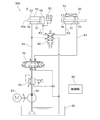
図1は、本発明の一実施形態に係るダイカストマシンの要部断面図である。図2は、スクイズピンを金型のキャビティに挿入する様子を説明する一部断面図である。図2(a)は挿入前を示し、図2(b)は挿入後を示す。図3〜図6は、スクイズピン制御装置の動作(準備動作、前進動作、後退動作および原点復帰動作)を説明する回路図である。 FIG. 1 is a cross-sectional view of a main part of a die casting machine according to an embodiment of the present invention. FIG. 2 is a partial cross-sectional view illustrating how the squeeze pin is inserted into the cavity of the mold. FIG. 2 (a) shows before insertion, and FIG. 2 (b) shows after insertion. 3 to 6 are circuit diagrams for explaining the operations of the squeeze pin control device (preparatory operation, forward operation, backward operation, and origin return operation).
本実施形態のダイカストマシン1は、型締装置10と、射出装置20と、スクイズピン制御装置30と、制御部90とを有している。
The die casting machine 1 of the present embodiment includes a
型締装置10は、固定金型K1が取り付けられる固定ダイプレート11と、移動金型K2が取り付けられる移動ダイプレート12と、を有している。固定ダイプレート11は、円筒状の射出スリーブ13を有している。射出スリーブ13は、給湯口14が上部に形成されており、図示しないラドルによって金属溶湯Mが注がれる。型締装置10は、固定金型K1と移動金型K2とを型閉および型開する。型閉された固定金型K1および移動金型K2の内部にキャビティCが形成される。
The
射出装置20は、先端にプランジャチップ21が取り付けられた射出ピストン22と、射出ピストン22を進退させる図示しない射出シリンダと、を有している。プランジャチップ21は、射出スリーブ13内に配置されている。射出装置20は、射出ピストン22を前進させることにより、射出スリーブ13内の金属溶湯MをキャビティCに射出充填する。
The
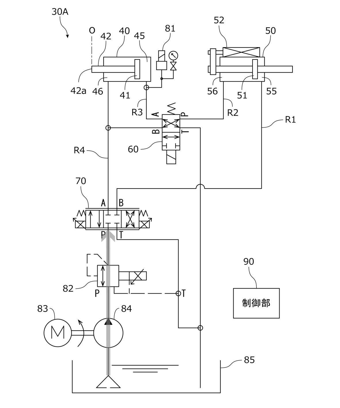
スクイズピン制御装置30は、加圧シリンダ40と、検出シリンダ50と、接続切換弁60と、方向切換弁70と、を有している。
The squeeze
加圧シリンダ40は、固定金型K1内部に配置されている。加圧シリンダ40は、加圧ピストン41を収容している。加圧ピストン41は、スクイズピン42が固定されている。加圧シリンダ40に供給される作動油によって加圧ピストン41が進退されると、スクイズピン42も進退される。スクイズピン42の先端42aは、原点O(オー)および前進終了位置Lの間を移動されて、キャビティCに挿抜される。
The
検出シリンダ50は、検出ピストン51を収容している。検出シリンダ50には、検出ピストン51の位置を検出するリニアエンコーダなどからなる位置センサ52が設けられている。
The
接続切換弁60は、ソレノイドにより弁体位置を切り換える電磁弁である。接続切換弁60は、Aポート、Bポート、PポートおよびTポートの4つのポートを有している。接続切換弁60は、弁体位置として、AポートとTポートとを連通しかつBポートとPポートとを連通する並列接続位置およびAポートとPポートとを連通しかつBポートとTポートとを切断する直列接続位置を有している。接続切換弁60は、弁体位置が切り換えられることにより、加圧シリンダ40および検出シリンダ50を並列および直列に接続する。接続切換弁60は、全てのポート間を切断した中立位置を有していてもよく、少なくとも並列接続位置および直列接続位置を有していればよい。
The
方向切換弁70は、ソレノイドにより弁体位置を切り換える電磁弁である。方向切換弁70は、Aポート、Bポート、PポートおよびTポートの4つのポートを有している。方向切換弁70は、弁体位置として、AポートとPポートとを連通しかつBポートとTポートとを連通する後退流動位置と、AポートとTポートとを連通しかつBポートとPポートとを連通する前進流動位置と、全てのポート間を切断した中立位置と、を有している。方向切換弁70は、弁体位置が切り換えられることにより、作動油の流動方向を正方向(スクイズピン前進)および逆方向(スクイズピン後退)に切り換える。方向切換弁70は少なくとも、後退流動位置および前進流動位置を有していればよい。
The
方向切換弁70は、入力電流に応じて、内部を流れる作動油の流量を調整する流量調整部を有している。
The
加圧シリンダ40の後油室45と方向切換弁70のBポートとは、第1流路R1によって接続されている。加圧シリンダ40の前油室46と接続切換弁60のPポートとは、第2流路R2によって接続されている。検出シリンダ50の後油室55と接続切換弁60のAポートとは、第3流路R3によって接続されている。検出シリンダ50の前油室56と接続切換弁60のBポートと方向切換弁70のAポートとは、第4流路R4によって接続されている。加圧シリンダ40の後油室45の作動油の圧力を検出する圧力センサ81が、第1流路R1に設けられている。
The
方向切換弁70のPポートは、減圧弁82を介して、モータ83によって駆動されるポンプ84に接続されている。減圧弁82は、入力電流に応じて、方向切換弁70のPポートに流れる作動油の圧力を制限する。接続切換弁60のTポートおよび方向切換弁70のTポートは、作動油が排出されるタンク85に接続されている。
The P port of the
ダイカストマシン1は、全体の動作を司る制御部90を有している。制御部90は、例えば、CPU、ROM、RAM、EEPROM、各種I/Oインタフェースなどを有する組み込み機器用のマイクロコンピュータを有している。制御部90は、各装置が有する各種駆動部を制御することにより、型閉工程、注湯工程、射出工程、増圧工程(保圧・冷却工程)、型開工程および製品押出工程などを実行する。
The die casting machine 1 has a
ダイカストマシン1は、製品を成形する一連の動作において、まず、移動ダイプレート12を移動して固定金型K1および移動金型K2を型締する(型閉工程)。次いで、固定ダイプレート11の射出スリーブ13に金属溶湯Mを注入する(注湯工程)。そして、射出ピストン22を前進させ、プランジャチップ21により射出スリーブ13内の金属溶湯MをキャビティCに射出充填する(射出工程)。さらに、プランジャチップ21により金属溶湯Mを押圧してキャビティCに押し込む(増圧工程)。その後、金型を開いて(型開工程)、キャビティから製品を押し出す(製品押出工程)。また、ダイカストマシン1は、増圧工程と並行して、スクイズピンにより局所的に加圧する(局所加圧工程)。
In a series of operations for molding a product, the die casting machine 1 first moves the moving
本実施形態において、制御部90は、スクイズピン制御装置30の接続切換弁60、方向切換弁70、減圧弁82およびモータ83に接続されており、これらに対して制御信号を送信して制御する。制御部90は、位置センサ52および圧力センサ81に接続されており、これらから検出信号を受信して、検出信号に基づき検出ピストンの位置および速度、ならびに加圧シリンダ40の後油室45の圧力を検出する。
In the present embodiment, the
次に、上述した本実施形態のダイカストマシン1の制御部90における本発明に係る局所加圧処理(局所加圧工程)の一例について、表1および図3〜図6を参照して説明する。各図において、灰色の太矢印は作動油の流れを模式的に示す。局所加圧処理の初期状態において、スクイズピン42の先端42aは原点Oにある。
Next, an example of the local pressurization process (local pressurization step) according to the present invention in the
(1)図3に示すように、射出工程が終了する前に、準備動作として、制御部90は、接続切換弁60の弁体位置を並列接続位置にするとともに、方向切換弁70の弁体位置を中立位置にする。そして、制御部90は、減圧弁82に方向切換弁70のPポートに流れる作動油の上限圧力を設定する。制御部90は、作動油のモータ83の動作を開始してポンプ84を駆動する。これにより、作動油が、タンク85から減圧弁82を通り方向切換弁70のPポートまで流れるが、その先は回路が切断されており流動が規制される。
(1) As shown in FIG. 3, before the injection process is completed, as a preparatory operation, the
(2)図4に示すように、射出工程が終了して増圧工程を開始すると、前進動作として、制御部90は、接続切換弁60の弁体位置を直列接続位置にするとともに、方向切換弁70の弁体位置を前進流動位置にする。
(2) As shown in FIG. 4, when the injection process is completed and the pressure boosting process is started, as a forward operation, the
これにより、作動油が、方向切換弁70のPポートおよびBポートならびに第1流路R1を通って加圧シリンダ40の後油室45に流れ込み、加圧ピストン41が前進(図の左方向に移動)する。加圧ピストン41の前進により、加圧シリンダ40の前油室46の作動油が、第2流路R2、接続切換弁60のPポートおよびAポートならびに第3流路R3を通って検出シリンダ50の後油室55に流れ込み、検出ピストン51が前進する。検出ピストン51の前進により、検出シリンダ50の前油室56の作動油が、第4流路R4ならびに方向切換弁70のAポートおよびTポートを通って最終的にタンク85に排出される。作動油の流動により、加圧ピストン41が、原点Oから前進終了位置Lまで移動し、その状態を所定時間保持する。
As a result, the hydraulic oil flows into the
このとき、制御部90は、位置センサ52の検出信号に基づいて加圧ピストン41の動作状態としての前進速度を検出し、この前進速度が設定速度に近づくように方向切換弁70の流量調整部をフィードバック制御(PID制御)して、方向切換弁70を流れる作動油の流量を調整する。本実施形態において、設定速度は、加圧ピストン41の位置ごとに設定されている。または、設定速度は、加圧ピストン41の前進開始時点からの時間ごとに設定されていてもよい。そして、制御部90は、設定速度を中心に±10%の範囲を正常範囲とし、加圧ピストン41の前進速度が位置ごとまたは時間ごとに正常範囲内にあるか否かを判定し、正常範囲内にないときに、ブザー等により警報を鳴動させるなどして異常を通知する。制御部90は、加圧ピストン41の前進速度が正常範囲内にない場合を複数回検出したときに、異常を通知するようにしてもよい。
At this time, the
または、制御部90は、圧力センサ81の検出信号に基づいて加圧シリンダ40の後油室の圧力を検出し、前進速度と同様に、この圧力が設定圧力に近づくように方向切換弁70の流量調整部をフィードバック制御して、方向切換弁70を流れる作動油の流量を調整するようにしてもよい。設定圧力は、設定速度と同様に、加圧ピストン41の位置ごとまたは加圧ピストン41の前進開始時点からの時間ごとに設定されていてもよい。そして、制御部90は、設定圧力を中心に±10%の範囲を正常範囲とし、加圧ピストン41の後油室45の圧力が位置ごとまたは時間ごとに正常範囲内にあるか否かを判定し、正常範囲内にないときに、ブザー等により警報を鳴動させるなどして異常を通知してもよい。
Alternatively, the
(3)図5に示すように、前進動作が終了すると、後退動作として、制御部90は、接続切換弁60の弁体位置を直列接続位置のままにし、方向切換弁70の弁体位置を後退流動位置にする。
(3) As shown in FIG. 5, when the forward operation is completed, as a backward operation, the
これにより、作動油が、方向切換弁70のPポートおよびAポートならびに第4流路R4を通って検出シリンダ50の前油室56に流れ込み、検出ピストン51が後退(図の右方向に移動)する。検出ピストン51の後退により、検出シリンダ50の後油室55の作動油が、第3流路R3、接続切換弁60のAポートおよびPポートならびに第2流路R2を通って加圧シリンダ40の前油室46に流れ込み、加圧ピストン41が後退する。加圧ピストン41の後退により、加圧シリンダ40の後油室45の作動油が、第1流路R1ならびに方向切換弁70のBポートおよびTポートを通って最終的にタンク85に排出される。作動油の流動により、加圧ピストン41が、前進終了位置Lから原点Oに向けて移動する。このとき、加圧シリンダ40および検出シリンダ50の構造の違いや、作動油の漏洩などにより、加圧ピストン41が原点Oに正確に復帰せず、原点近傍O’にとどまることがある。
As a result, the hydraulic oil flows into the
また、制御部90は、位置センサ52の検出信号に基づいて加圧ピストン41の位置を検出し、加圧ピストン41が後退しているか否かを判定する。制御部90は、加圧ピストン41が後退していないと判定すると、異常を通知する。
Further, the
(4)図6に示すように、後退動作が終了すると、原点復帰動作として、制御部90は、接続切換弁60の弁体位置を並列接続位置にするとともに、方向切換弁70の弁体位置を後退流動位置のままにする。
(4) As shown in FIG. 6, when the retracting operation is completed, the
これにより、作動油が、方向切換弁70のPポートおよびAポートならびに第4流路R4を通って加圧シリンダ40の前油室46および検出シリンダ50の前油室56に流れ込み、加圧ピストン41および検出ピストン51が後退する。また、加圧ピストン41の後退により、加圧シリンダ40の後油室45の作動油が、第1流路R1ならびに方向切換弁70のBポートおよびTポートを通って最終的にタンク85に排出される。また、検出ピストン51の後退により、検出シリンダ50の後油室55の作動油が、第3流路R3、接続切換弁60のAポートおよびTポートを通って最終的にタンク85に排出される。作動油の流動により、加圧ピストン41および検出ピストン51が、図示しないストッパに突き当たるまで後退して、加圧ピストン41の位置が原点Oに復帰する。同様に、検出ピストン51の位置も原点に復帰する。
As a result, the hydraulic oil flows into the
表1に、局所加圧処理における各動作と、接続切換弁60および方向切換弁70の弁体位置との関係を示す。
Table 1 shows the relationship between each operation in the local pressurization process and the valve body positions of the
以上より、本実施形態のダイカストマシン1によれば、スクイズピン制御装置30が、接続切換弁60および方向切換弁70によって、加圧シリンダ40と検出シリンダ50とを直列接続および並列接続に切り換えるとともに作動油の流動方向を正方向(前進)および逆方向(後退)に切り換えることができる。そのため、切換弁を2つのみ有する簡易な回路で加圧ピストン41の位置検出が可能な構成を実現できる。
From the above, according to the die casting machine 1 of the present embodiment, the squeeze
また、方向切換弁70が、作動油の流量を調整する流量調整部を有し、制御部90が、加圧ピストン41の前進速度を検出し、当該前進速度が設定速度に近づくように方向切換弁70の流量調整部をフィードバック制御する。そのため、前進速度をより効果的に設定速度に近づけることができ、精度よくスクイズピンを制御できる。
Further, the
また、制御部90が、加圧ピストン41の前進速度が時間ごとまたは位置ごとに設定された正常範囲内にあるか否かを判定し、正常範囲内にないときに異常を通知する。そのため、装置の動作異常およびそれに起因する製品不良を早期に検出することができる。
Further, the
上述した実施形態のダイカストマシン1は、加圧シリンダ40と検出シリンダ50とを直列に接続する際、加圧シリンダ40の前油室46と検出シリンダ50の後油室55とを接続するスクイズピン制御装置30を有する構成であった。しかしながら、この構成に限定されるものではない。例えば、図7〜図10に示すように、加圧シリンダ40と検出シリンダ50とを直列に接続する際、検出シリンダ50の前油室56と加圧シリンダ40の後油室45とを接続するスクイズピン制御装置30Aを有する構成であってもよい。スクイズピン制御装置30Aは、加圧シリンダ40と検出シリンダ50とを入れ替えかつ圧力センサ81を第3流路R3に設けた以外は、スクイズピン制御装置30と同一の構成を有する。また、スクイズピン制御装置30Aは、スクイズピン制御装置30と同様に、局所加圧処理において、上記(1)〜(4)の動作を行うため、詳細説明は省略する。このスクイズピン制御装置30Aを有するダイカストマシンも、上述した実施形態のダイカストマシン1と同様の効果を奏する。
In the die casting machine 1 of the above-described embodiment, when the pressurizing
また、上述した実施形態のダイカストマシン1において、制御部90が、加圧ピストン41の過去の前進終了位置Lに基づいて加圧ピストン41設定速度を変更するようにしてもよい。加圧ピストン41の前進終了位置Lは種々の条件(季節、時間帯、装置起動からの経過時間、経年によるポンプ吐出量やバルブ流量の変動、作動油フィルタの目詰まりなど)により、バラツキが生じることがある。そのため、例えば、制御部90は、過去の1〜数回分の前進終了位置Lを記憶しておき、その変動傾向(前進終了位置Lが原点Oに近づく傾向にあるのか、遠ざかる傾向にあるのか)を検出する。そして、変動傾向から、次回の前進終了位置Lを予測して、この前進終了位置Lにおいて加圧ピストン41が止まるように設定速度または設定圧力を調整する。例えば、加圧ピストン41の位置ごとに設定された設定速度を全体的に増減する、一部区間のみ設定速度を増減する、加速区間と定速区間との割合を変更する。このようにすることで、前進終了位置Lのバラツキを抑制することができる。また、長期的に前進終了位置Lを記憶するとともにその変動傾向を学習し、学習結果に基づき設定速度または設定圧力を調整するようにしてもよい。
Further, in the die casting machine 1 of the above-described embodiment, the
また、上述した実施形態のダイカストマシン1は、マシン起動直後に、動作を安定させるための複数回の予備的な成形動作(打ち捨て成形動作)を行う。この予備的な成形動作において、制御部90が、マシン起動直前のマシン停止時間の長さに応じて、スクイズピン42の前進終了位置Lを徐々に変化させることにより、スクイズピン42による加圧効果を徐々に上げていくようにしてもよい。具体的には、マシン停止時間が長いほど前進終了位置Lの変化量を小さくし、マシン停止時間が短いほど前進終了位置Lの変化量を大きくする。このようにすることで、より効果的に動作を安定させることができ、不良品の発生を抑制できる。
Further, the die casting machine 1 of the above-described embodiment performs a plurality of preliminary molding operations (discard molding operation) for stabilizing the operation immediately after the machine is started. In this preliminary molding operation, the
上記に本発明の実施形態を説明したが、本発明はこれらの例に限定されるものではない。前述の実施形態に対して、当業者が適宜、構成要素の追加、削除、設計変更を行ったものや、実施形態の特徴を適宜組み合わせたものも、本発明の要旨を備えている限り、本発明の範囲に含まれる。 Although embodiments of the present invention have been described above, the present invention is not limited to these examples. As long as the gist of the present invention is provided, a person skilled in the art appropriately adding, deleting, or changing the design of the above-described embodiment, or combining the features of the embodiment as appropriate is also present. Included in the scope of the invention.
1…ダイカストマシン、10…型締装置、11…固定ダイプレート、12…移動ダイプレート、13…射出スリーブ、14…給湯口、20…射出装置、21…プランジャチップ、22…射出ピストン、30、30A…スクイズピン制御装置、40…加圧シリンダ、41…加圧ピストン、42…スクイズピン、42a…スクイズピンの先端、45…加圧シリンダの後油室、46…加圧シリンダの前油室、50…検出シリンダ、51…検出ピストン、52…位置センサ、55…検出シリンダの後油室、56…検出シリンダの前油室、60…接続切換弁、70…方向切換弁、81…圧力センサ、82…減圧弁、83…モータ、84…ポンプ、85…タンク、90…制御部、K1…固定金型、K2…移動金型、C…キャビティ、M…金属溶湯、R1…第1流路、R2…第2流路、R3…第3流路、R4…第4流路、O…加圧ピストンの原点、L…加圧ピストンの前進終了位置 1 ... Die casting machine, 10 ... Mold clamping device, 11 ... Fixed die plate, 12 ... Moving die plate, 13 ... Injection sleeve, 14 ... Hot water supply port, 20 ... Injection device, 21 ... Plunger tip, 22 ... Injection piston, 30, 30A ... Squeeze pin control device, 40 ... Pressurized cylinder, 41 ... Pressurized piston, 42 ... Squeeze pin, 42a ... Squeeze pin tip, 45 ... Pressurized cylinder rear oil chamber, 46 ... Pressurized cylinder front oil chamber , 50 ... detection cylinder, 51 ... detection piston, 52 ... position sensor, 55 ... detection cylinder rear oil chamber, 56 ... detection cylinder front oil chamber, 60 ... connection switching valve, 70 ... direction switching valve, 81 ... pressure sensor , 82 ... Pressure reducing valve, 83 ... Motor, 84 ... Pump, 85 ... Tank, 90 ... Control unit, K1 ... Fixed mold, K2 ... Moving mold, C ... Cavity, M ... Metal molten metal, R1 ... First flow path , R2 ... 2nd flow path, R3 ... 3rd flow path, R4 ... 4th flow path, O ... origin of pressurizing piston, L ... forward end position of pressurizing piston
Claims (6)
検出ピストンを収容した検出シリンダと、
前記検出ピストンの位置を検出する位置センサと、
Aポート、Bポート、PポートおよびTポートを有し、AポートとTポートとを連通しかつBポートとPポートとを連通する並列接続位置およびAポートとPポートとを連通しかつBポートとTポートとを切断する直列接続位置を少なくとも有する接続切換弁と、
Aポート、Bポート、PポートおよびTポートを有し、AポートとPポートとを連通しかつBポートとTポートとを連通する後退流動位置およびAポートとTポートとを連通しかつBポートとPポートとを連通する前進流動位置を少なくとも有する方向切換弁と、
前記加圧シリンダの後油室と前記方向切換弁のBポートとを接続する第1流路と、
前記加圧シリンダの前油室と前記接続切換弁のPポートとを接続する第2流路と、
前記検出シリンダの後油室と前記接続切換弁のAポートとを接続する第3流路と、
前記検出シリンダの前油室と前記接続切換弁のBポートと前記方向切換弁のAポートとを接続する第4流路と、
制御部と、を有し、
前記方向切換弁のPポートが、作動油を供給するポンプに接続され、
前記方向切換弁のTポートおよび前記接続切換弁のTポートが、作動油が排出されるタンクに接続され、
前記制御部が、
(1)前記加圧ピストンを前進させるとき、前記接続切換弁が直列接続位置となりかつ前記方向切換弁が前進流動位置となるように制御し、
(2)前記加圧ピストンを後退させるとき、前記接続切換弁が直列接続位置となりかつ前記方向切換弁が後退流動位置となるように制御し、
(3)前記加圧ピストンおよび前記検出ピストンを原点復帰させるとき、前記接続切換弁が並列接続位置となりかつ前記方向切換弁が後退流動位置となるように制御し、
(4)前記位置センサによって検出された前記検出ピストンの位置に基づいて前記加圧ピストンの動作状態を検出することを特徴とするスクイズピン制御装置。 A pressure cylinder containing a pressure piston that advances and retreats the squeeze pin,
A detection cylinder containing a detection piston and
A position sensor that detects the position of the detection piston and
It has A port, B port, P port and T port, and has a parallel connection position that communicates A port and T port and communicates B port and P port, and communicates A port and P port and B port. A connection switching valve that has at least a communication position that disconnects the T port and the T port.
It has A port, B port, P port and T port, and has a backward flow position that communicates A port and P port and communicates between B port and T port, and communicates between A port and T port and B port. A directional control valve that has at least a forward flow position that communicates with the P port,
A first flow path connecting the rear oil chamber of the pressure cylinder and the B port of the direction switching valve,
A second flow path connecting the front oil chamber of the pressure cylinder and the P port of the connection switching valve, and
A third flow path connecting the rear oil chamber of the detection cylinder and the A port of the connection switching valve, and
A fourth flow path connecting the front oil chamber of the detection cylinder, the B port of the connection switching valve, and the A port of the directional switching valve,
Has a control unit,
The P port of the directional control valve is connected to a pump that supplies hydraulic oil.
The T port of the direction switching valve and the T port of the connection switching valve are connected to the tank from which the hydraulic oil is discharged.
The control unit
(1) When the pressurizing piston is advanced, the connection switching valve is controlled to be in the series connection position and the direction switching valve is controlled to be in the forward flow position.
(2) When the pressurizing piston is retracted, the connection switching valve is controlled to be in the series connection position and the direction switching valve is controlled to be in the retracting flow position.
(3) When the pressurizing piston and the detection piston are returned to the origin, the connection switching valve is controlled to be in the parallel connection position and the direction switching valve is controlled to be in the backward flow position.
(4) A squeeze pin control device characterized in that the operating state of the pressurizing piston is detected based on the position of the detection piston detected by the position sensor.
検出ピストンを収容した検出シリンダと、
前記検出ピストンの位置を検出する位置センサと、
Aポート、Bポート、PポートおよびTポートを有し、AポートとTポートとを連通しかつBポートとPポートとを連通する並列接続位置およびAポートとPポートとを連通しかつBポートとTポートとを切断する直列接続位置を少なくとも有する接続切換弁と、
Aポート、Bポート、PポートおよびTポートを有し、AポートとPポートとを連通しかつBポートとTポートとを連通する後退流動位置およびAポートとTポートとを連通しかつBポートとPポートとを連通する前進流動位置を少なくとも有する方向切換弁と、
前記検出シリンダの後油室と前記方向切換弁のBポートとを接続する第1流路と、
前記検出シリンダの前油室と前記接続切換弁のPポートとを接続する第2流路と、
前記加圧シリンダの後油室と前記接続切換弁のAポートとを接続する第3流路と、
前記加圧シリンダの前油室と前記接続切換弁のBポートと前記方向切換弁のAポートとを接続する第4流路と、
制御部と、を有し、
前記方向切換弁のPポートが、作動油を供給するポンプに接続され、
前記方向切換弁のTポートおよび前記接続切換弁のTポートが、作動油が排出されるタンクに接続され、
前記制御部が、
(1)前記加圧ピストンを前進させるとき、前記接続切換弁が直列接続位置となりかつ前記方向切換弁が前進流動位置となるように制御し、
(2)前記加圧ピストンを後退させるとき、前記接続切換弁が直列接続位置となりかつ前記方向切換弁が後退流動位置となるように制御し、
(3)前記加圧ピストンおよび前記検出ピストンを原点復帰させるとき、前記接続切換弁が並列接続位置となりかつ前記方向切換弁が後退流動位置となるように制御し、
(4)前記位置センサによって検出された前記検出ピストンの位置に基づいて前記加圧ピストンの動作状態を検出することを特徴とするスクイズピン制御装置。 A pressure cylinder containing a pressure piston that advances and retreats the squeeze pin,
A detection cylinder containing a detection piston and
A position sensor that detects the position of the detection piston and
It has A port, B port, P port and T port, and has a parallel connection position that communicates A port and T port and communicates B port and P port, and communicates A port and P port and B port. A connection switching valve that has at least a communication position that disconnects the T port and the T port.
It has A port, B port, P port and T port, and has a backward flow position that communicates A port and P port and communicates between B port and T port, and communicates between A port and T port and B port. A directional control valve that has at least a forward flow position that communicates with the P port,
A first flow path connecting the rear oil chamber of the detection cylinder and the B port of the direction switching valve,
A second flow path connecting the front oil chamber of the detection cylinder and the P port of the connection switching valve, and
A third flow path connecting the rear oil chamber of the pressure cylinder and the A port of the connection switching valve,
A fourth flow path connecting the front oil chamber of the pressurizing cylinder, the B port of the connection switching valve, and the A port of the directional switching valve,
Has a control unit,
The P port of the directional control valve is connected to a pump that supplies hydraulic oil.
The T port of the direction switching valve and the T port of the connection switching valve are connected to the tank from which the hydraulic oil is discharged.
The control unit
(1) When the pressurizing piston is advanced, the connection switching valve is controlled to be in the series connection position and the direction switching valve is controlled to be in the forward flow position.
(2) When the pressurizing piston is retracted, the connection switching valve is controlled to be in the series connection position and the direction switching valve is controlled to be in the retracting flow position.
(3) When the pressurizing piston and the detection piston are returned to the origin, the connection switching valve is controlled to be in the parallel connection position and the direction switching valve is controlled to be in the backward flow position.
(4) A squeeze pin control device characterized in that the operating state of the pressurizing piston is detected based on the position of the detection piston detected by the position sensor.
前記制御部が、前記加圧ピストンの動作状態として前記加圧ピストンの前進速度を検出し、当該前進速度が設定速度に近づくように前記方向切換弁の流量調整部をフィードバック制御することを特徴とする請求項1または請求項2に記載のスクイズピン制御装置。 The direction switching valve has a flow rate adjusting unit for adjusting the flow rate of the hydraulic oil.
The control unit detects the advancing speed of the pressurizing piston as the operating state of the pressurizing piston, and feedback-controls the flow rate adjusting unit of the direction switching valve so that the advancing speed approaches the set speed. The squeeze pin control device according to claim 1 or 2.
前記スクイズピン制御装置が、請求項1〜請求項5のいずれか一項に記載のスクイズピン制御装置で構成されていることを特徴とするダイカストマシン。
A mold clamping device for opening and closing the mold, an injection device for injecting molten metal into the cavity of the mold closed in the mold clamping device, and a squeeze pin control device for advancing and retreating the squeeze pin into the cavity of the mold. It is a die casting machine that has
A die casting machine characterized in that the squeeze pin control device is composed of the squeeze pin control device according to any one of claims 1 to 5.
Priority Applications (2)
| Application Number | Priority Date | Filing Date | Title |
|---|---|---|---|
| JP2017225886A JP6909714B2 (en) | 2017-11-24 | 2017-11-24 | Squeeze pin controller and die casting machine with it |
| CN201811409102.3A CN109909476B (en) | 2017-11-24 | 2018-11-23 | Extrusion pin control device and die casting machine having the same |
Applications Claiming Priority (1)
| Application Number | Priority Date | Filing Date | Title |
|---|---|---|---|
| JP2017225886A JP6909714B2 (en) | 2017-11-24 | 2017-11-24 | Squeeze pin controller and die casting machine with it |
Publications (2)
| Publication Number | Publication Date |
|---|---|
| JP2019093427A JP2019093427A (en) | 2019-06-20 |
| JP6909714B2 true JP6909714B2 (en) | 2021-07-28 |
Family
ID=66959764
Family Applications (1)
| Application Number | Title | Priority Date | Filing Date |
|---|---|---|---|
| JP2017225886A Active JP6909714B2 (en) | 2017-11-24 | 2017-11-24 | Squeeze pin controller and die casting machine with it |
Country Status (2)
| Country | Link |
|---|---|
| JP (1) | JP6909714B2 (en) |
| CN (1) | CN109909476B (en) |
Families Citing this family (4)
| Publication number | Priority date | Publication date | Assignee | Title |
|---|---|---|---|---|
| CN110548854B (en) * | 2019-10-23 | 2021-12-10 | 广东宝洋科技有限公司 | Forging control method for metal product |
| CN111151723A (en) * | 2020-01-06 | 2020-05-15 | 肇庆谊龙科技有限公司 | Local pressurization system |
| CN112872322A (en) * | 2021-02-23 | 2021-06-01 | 广州和德轻量化成型技术有限公司 | Local extrusion device of indirect extrusion casting die and preparation method thereof |
| CN114101623A (en) * | 2021-11-26 | 2022-03-01 | 广东鸿图科技股份有限公司 | Local pressurizing device for die casting |
Family Cites Families (16)
| Publication number | Priority date | Publication date | Assignee | Title |
|---|---|---|---|---|
| JPH0767610B2 (en) * | 1989-02-28 | 1995-07-26 | 宇部興産株式会社 | Injection molding method |
| JPH0773788B2 (en) * | 1990-09-05 | 1995-08-09 | 東芝機械株式会社 | Method of controlling die pressure pin of pressure casting machine |
| JPH0549158U (en) * | 1991-12-11 | 1993-06-29 | 株式会社日立製作所 | Local pressure device for die casting machine |
| JPH05208254A (en) * | 1992-01-30 | 1993-08-20 | Nippondenso Co Ltd | Casting device for die casting |
| JPH05337623A (en) * | 1992-06-10 | 1993-12-21 | Toyota Motor Corp | Casting apparatus |
| JPH06142884A (en) * | 1992-10-28 | 1994-05-24 | Toshiba Mach Co Ltd | Injection device of die casting machine |
| JPH06226417A (en) * | 1993-02-05 | 1994-08-16 | Toyota Motor Corp | Method for controlling pressurizing pin |
| JP3640704B2 (en) * | 1994-08-18 | 2005-04-20 | トヨタ自動車株式会社 | Pressure casting method |
| JPH08309503A (en) * | 1995-05-18 | 1996-11-26 | Toyota Motor Corp | Press casting method |
| JP2000005857A (en) * | 1998-06-22 | 2000-01-11 | Toyota Autom Loom Works Ltd | Press casting machine |
| JP4520007B2 (en) * | 2000-09-26 | 2010-08-04 | 豊興工業株式会社 | Pressure pin control device |
| JP4443794B2 (en) * | 2001-06-26 | 2010-03-31 | 豊興工業株式会社 | Pressure pin control device |
| JP4883557B2 (en) * | 2006-02-21 | 2012-02-22 | 東芝機械株式会社 | Method for detecting abnormality of squeeze pin and molding machine |
| JP2008055473A (en) * | 2006-08-31 | 2008-03-13 | Mitsubishi Heavy Ind Ltd | Method and apparatus for manufacturing aluminum die-cast product |
| JP6450147B2 (en) * | 2014-11-04 | 2019-01-09 | 東洋機械金属株式会社 | In-mold monitoring device for die casting machine |
| CN105179342B (en) * | 2015-08-13 | 2017-07-18 | 湖南三一石油科技有限公司 | Oil cylinder synchronization hydraulic system, Work machine and hydraulic oil cylinder driving method |
-
2017
- 2017-11-24 JP JP2017225886A patent/JP6909714B2/en active Active
-
2018
- 2018-11-23 CN CN201811409102.3A patent/CN109909476B/en active Active
Also Published As
| Publication number | Publication date |
|---|---|
| CN109909476B (en) | 2021-07-06 |
| JP2019093427A (en) | 2019-06-20 |
| CN109909476A (en) | 2019-06-21 |
Similar Documents
| Publication | Publication Date | Title |
|---|---|---|
| JP6909714B2 (en) | Squeeze pin controller and die casting machine with it | |
| DE102004023150B4 (en) | Injection system and casting method of a casting machine | |
| JP4883557B2 (en) | Method for detecting abnormality of squeeze pin and molding machine | |
| JP5905617B1 (en) | Injection device and molding device | |
| JP3506800B2 (en) | Injection control method and apparatus for die casting machine | |
| JP2008105055A (en) | Die casting machine and die casting method | |
| CN113677456B (en) | Die casting machine, die casting machine with die, control device for die casting machine, and die casting method | |
| KR101506921B1 (en) | Hydraulic circuit of injection cylinder in die casting apparatus | |
| JP2011131225A (en) | Injection device and injection controlling method of die casting machine | |
| US20070267166A1 (en) | Die casting machine | |
| KR100523172B1 (en) | Method for controlling injection in a die casting machine and apparatus for the same | |
| TW443958B (en) | Method and device for controlling mold clamping pressure in straight-hydraulic mold clamping system | |
| US2671246A (en) | Mold overload compensator | |
| JP5381161B2 (en) | Die casting machine and die casting method | |
| JPH06198414A (en) | Method for cooling plunger tip in die casting machine | |
| JP2009107010A (en) | Injection apparatus in die casting machine and control method thereof | |
| JP7118670B2 (en) | Die casting machine and its control method | |
| JP5372626B2 (en) | Injection molding apparatus and injection molding method | |
| JP4657251B2 (en) | Die casting machine control method | |
| JP6429923B2 (en) | Method of operating an injection device comprising a plasticizing device and a plunger type injection device | |
| JP2002283425A (en) | Mold opening/closing device of injection foam molding machine | |
| EP2769822A1 (en) | Injection molding machine | |
| JP2020062671A (en) | Die casting machine | |
| JP7294821B2 (en) | Injection unit and die casting machine | |
| WO2023074851A1 (en) | Local pressurization device, molding machine, and molding method |
Legal Events
| Date | Code | Title | Description |
|---|---|---|---|
| A621 | Written request for application examination |
Free format text: JAPANESE INTERMEDIATE CODE: A621 Effective date: 20200918 |
|
| A977 | Report on retrieval |
Free format text: JAPANESE INTERMEDIATE CODE: A971007 Effective date: 20210615 |
|
| TRDD | Decision of grant or rejection written | ||
| A01 | Written decision to grant a patent or to grant a registration (utility model) |
Free format text: JAPANESE INTERMEDIATE CODE: A01 Effective date: 20210629 |
|
| A61 | First payment of annual fees (during grant procedure) |
Free format text: JAPANESE INTERMEDIATE CODE: A61 Effective date: 20210705 |
|
| R150 | Certificate of patent or registration of utility model |
Ref document number: 6909714 Country of ref document: JP Free format text: JAPANESE INTERMEDIATE CODE: R150 |