[1.パチンコ機の全体構造]
本発明の遊技機としての一実施形態であるパチンコ機1について、図面を参照して詳細に説明する。まず、図1乃至図10を参照して本実施形態のパチンコ機1の全体構成について説明する。
[1. Overall structure of pachinko machine]
The pachinko machine 1 according to the embodiment of the gaming machine of the present invention will be described in detail with reference to the drawings. First, the overall configuration of the pachinko machine 1 of the present embodiment will be described with reference to FIGS. 1 to 10.
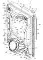
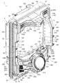
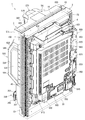
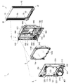
図1は本発明の一実施形態であるパチンコ機の正面図である。図2はパチンコ機の右側面図であり、図3はパチンコ機の左側面図であり、図4はパチンコ機の背面図である。図5はパチンコ機を右前から見た斜視図であり、図6はパチンコ機を左前から見た斜視図であり、図7はパチンコ機を後ろから見た斜視図である。また、図8は本体枠から扉枠を開放させると共に、外枠から本体枠を開放させた状態で前から見たパチンコ機の斜視図である。図9はパチンコ機を扉枠、遊技盤、本体枠、及び外枠に分解して前から見た分解斜視図であり、図10はパチンコ機を扉枠、遊技盤、本体枠、及び外枠に分解して後ろから見た分解斜視図である。
FIG. 1 is a front view of a pachinko machine according to an embodiment of the present invention. FIG. 2 is a right side view of the pachinko machine, FIG. 3 is a left side view of the pachinko machine, and FIG. 4 is a rear view of the pachinko machine. FIG. 5 is a perspective view of the pachinko machine viewed from the front right, FIG. 6 is a perspective view of the pachinko machine viewed from the front left, and FIG. 7 is a perspective view of the pachinko machine viewed from the back. Further, FIG. 8 is a perspective view of the pachinko machine viewed from the front with the door frame opened from the main body frame and the main body frame opened from the outer frame. FIG. 9 is an exploded perspective view of the pachinko machine disassembled into a door frame, a game board, a main body frame, and an outer frame, and FIG. 10 is an exploded perspective view of the pachinko machine as a door frame, a game board, a main body frame, and an outer frame. It is an exploded perspective view seen from the back by disassembling into.
本実施形態のパチンコ機1は、遊技ホールの島設備(図示しない)に設置される枠状の外枠2と、外枠2の前面を開閉可能に閉鎖する扉枠3と、扉枠3を開閉可能に支持していると共に外枠2に開閉可能に取付けられている本体枠4と、本体枠4に前側から着脱可能に取付けられると共に扉枠3を通して遊技者側から視認可能とされ遊技者によって遊技球が打込まれる遊技領域5aを有した遊技盤5と、を備えている。
The pachinko machine 1 of the present embodiment includes a frame-shaped outer frame 2 installed in an island facility (not shown) of a game hall, a door frame 3 for opening and closing the front surface of the outer frame 2, and a door frame 3. The main body frame 4 which is supported so as to be openable and closable and is attached to the outer frame 2 so as to be openable and closable, and the main body frame 4 which is detachably attached from the front side and can be visually recognized from the player side through the door frame 3. It is provided with a game board 5 having a game area 5a into which a game ball is hit.
パチンコ機1の外枠2は、図9及び図10等に示すように、上下に離間しており左右に延びている上枠部材10及び下枠部材20と、上枠部材10及び下枠部材20の両端同士を連結しており上下に延びている左枠部材30及び右枠部材40と、を備えている。上枠部材10、下枠部材20、左枠部材30、及び右枠部材40は、前後の幅が同じ幅に形成されている。また、上枠部材10及び下枠部材20の左右の長さに対して、左枠部材30及び右枠部材40の上下の長さが、長く形成されている。
As shown in FIGS. 9 and 10, the outer frame 2 of the pachinko machine 1 includes an upper frame member 10 and a lower frame member 20 which are vertically separated and extend to the left and right, and an upper frame member 10 and a lower frame member. The left frame member 30 and the right frame member 40, which are connected to each other at both ends of the 20 and extend vertically, are provided. The upper frame member 10, the lower frame member 20, the left frame member 30, and the right frame member 40 are formed to have the same width in the front and rear. Further, the vertical lengths of the left frame member 30 and the right frame member 40 are formed longer than the left and right lengths of the upper frame member 10 and the lower frame member 20.
また、外枠2は、左枠部材30及び右枠部材40の下端同士を連結し下枠部材20の前側に取付けられる幕板部材50と、上枠部材10の正面視左端部側に取付けられている外枠側上ヒンジ部材60と、幕板部材50の正面視左端側上部と左枠部材30とに取付けられている外枠側下ヒンジ部材70と、を備えている。外枠2の外枠側上ヒンジ部材60と外枠側下ヒンジ部材70とによって、本体枠4及び扉枠3が開閉可能に取付けられている。
Further, the outer frame 2 is attached to the curtain plate member 50 which connects the lower ends of the left frame member 30 and the right frame member 40 and is attached to the front side of the lower frame member 20 and to the left end side of the upper frame member 10 in the front view. The outer frame side upper hinge member 60 and the outer frame side lower hinge member 70 attached to the upper left end side of the curtain plate member 50 and the left frame member 30 are provided. The main body frame 4 and the door frame 3 are attached to the outer frame 2 so as to be openable and closable by the outer frame side upper hinge member 60 and the outer frame side lower hinge member 70.
パチンコ機1の扉枠3は、正面視の外形が上下に延びた四角形で前後に貫通している貫通口111を有した枠状の扉枠ベースユニット100と、扉枠ベースユニット100の貫通口111よりも下側で前面右下隅に取付けられており遊技球を遊技盤5の遊技領域5a内へ打込むために遊技者が操作可能なハンドルユニット300と、扉枠ベースユニット100の貫通口111よりも下側で前面下部に取付けられている皿ユニット320と、皿ユニット320の中央に取付けられており遊技領域5a内に遊技球が打込まれることで変化する遊技状態に応じて遊技者に参加型の演出を提示することが可能な演出操作ユニット400と、皿ユニット320の上側で扉枠ベースユニット100における貫通口111よりも左側の前面左部に取付けられている扉枠左サイドユニット530と、皿ユニット320の上側で扉枠ベースユニット100における貫通口111よりも右側の前面右部に取付けられている扉枠右サイドユニット550と、扉枠左サイドユニット530及び扉枠右サイドユニット550の上側で扉枠ベースユニット100における貫通口111よりも上側の前面上部に取付けられている扉枠トップユニット570と、を備えている。
The door frame 3 of the pachinko machine 1 has a frame-shaped door frame base unit 100 having a through-hole 111 having a front-view outer shape extending vertically and penetrating back and forth, and a through-hole of the door frame base unit 100. A handle unit 300 that is attached to the lower right corner of the front surface below 111 and can be operated by the player to drive the game ball into the game area 5a of the game board 5, and a through hole 111 of the door frame base unit 100. The dish unit 320, which is attached to the lower part of the front surface below the door, and the player, which is attached to the center of the dish unit 320 and is attached to the center of the dish unit 320, according to the game state that changes when the game ball is driven into the game area 5a. The effect operation unit 400 capable of presenting a participatory effect, and the door frame left side unit 530 attached to the front left portion on the upper side of the dish unit 320 and on the left side of the through hole 111 in the door frame base unit 100. And, the door frame right side unit 550 attached to the front right part on the upper side of the dish unit 320 and on the right side of the through hole 111 in the door frame base unit 100, the door frame left side unit 530, and the door frame right side unit 550. The door frame top unit 570 is attached to the upper part of the front surface of the door frame base unit 100 on the upper side of the door frame base unit 100.
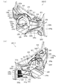
パチンコ機1の本体枠4は、一部が外枠2の枠内に挿入可能とされると共に遊技盤5の外周を支持可能とされた枠状の本体枠ベース600と、本体枠ベース600の正面視左側の上下両端に取付けられ外枠2の外枠側上ヒンジ部材60及び外枠側下ヒンジ部材70に夫々回転可能に取付けられると共に扉枠3の扉枠側上ヒンジ部材140及び扉枠側下ヒンジ部材150が夫々回転可能に取付けられる本体枠側上ヒンジ部材620及び本体枠側下ヒンジ部材640と、本体枠ベース600の正面視左側面に取付けられる補強フレーム660と、本体枠ベース600の前面下部に取付けられており遊技盤5の遊技領域5a内に遊技球を打込むための球発射装置680と、本体枠ベース600の正面視右側面に取付けられており外枠2と本体枠4、及び扉枠3と本体枠4の間を施錠する施錠ユニット700と、本体枠ベース600の正面視上辺及び左辺に沿って後側に取付けられており遊技者側へ遊技球を払出す逆L字状の払出ユニット800と、本体枠ベース600の後面下部に取付けられている基板ユニット900と、本体枠ベース600の後側に開閉可能に取付けられ本体枠ベース600に取付けられた遊技盤5の後側を覆う裏カバー980と、を備えている。
The main body frame 4 of the pachinko machine 1 has a frame-shaped main body frame base 600 and a main body frame base 600 that can be partially inserted into the frame of the outer frame 2 and can support the outer periphery of the game board 5. It is attached to both the upper and lower ends on the left side of the front view and is rotatably attached to the outer frame side upper hinge member 60 and the outer frame side lower hinge member 70, respectively, and the door frame side upper hinge member 140 and the door frame of the door frame 3 are attached. The main body frame side upper hinge member 620 and the main body frame side lower hinge member 640 to which the lower side hinge member 150 is rotatably attached, the reinforcing frame 660 attached to the front left side surface of the main body frame base 600, and the main body frame base 600. A ball launcher 680 for driving a game ball into the game area 5a of the game board 5 and an outer frame 2 and a main body frame attached to the right side surface of the main body frame base 600 when viewed from the front. 4. And the locking unit 700 that locks between the door frame 3 and the main body frame 4, and the reverse side that is attached to the rear side along the front view upper side and the left side of the main body frame base 600 and pays out the game ball to the player side. The L-shaped payout unit 800, the board unit 900 attached to the lower part of the rear surface of the main body frame base 600, and the game board 5 attached to the rear side of the main body frame base 600 so as to be openable and closable. It includes a back cover 980 that covers the rear side.
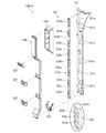
本体枠4の払出ユニット800は、本体枠ベース600の後側に取付けられる逆L字状の払出ユニットベース801と、払出ユニットベース801の上部に取付けられており上方へ開放された左右に延びた箱状で図示しない島設備から供給される遊技球を貯留する球タンク802と、球タンク802の下側で払出ユニットベース801に取付けられており球タンク802内の遊技球を正面視左方向へ誘導する左右に延びたタンクレール803と、払出ユニットベース801における正面視左側上部の後面に取付けられタンクレール803からの遊技球を蛇行状に下方へ誘導する球誘導ユニット820と、球誘導ユニット820の下側で払出ユニットベース801から着脱可能に取付けられており球誘導ユニット820により誘導された遊技球を払出制御基板ボックス950に収容された払出制御基板951からの指示に基づいて一つずつ払出す払出装置830と、払出ユニットベース801の後面に取付けられ払出装置830によって払出された遊技球を下方へ誘導すると共に皿ユニット320における上皿321での遊技球の貯留状態に応じて遊技球を通常放出口850d又は満タン放出口850eの何れかから放出させる上部満タン球経路ユニット850と、払出ユニットベース801の下端に取付けられ上部満タン球経路ユニット850の通常放出口850dから放出された遊技球を前方へ誘導して前端から扉枠3の貫通球通路273へ誘導する通常誘導路861及び満タン放出口850eから放出された遊技球を前方へ誘導して前端から扉枠3の満タン球受口274へ誘導する満タン誘導路862を有した下部満タン球経路ユニット860と、を備えている。
The payout unit 800 of the main body frame 4 is attached to the upper part of the inverted L-shaped payout unit base 801 attached to the rear side of the main body frame base 600 and the payout unit base 801 and extends to the left and right open upward. A box-shaped ball tank 802 for storing game balls supplied from island equipment (not shown) and a game ball attached to the payout unit base 801 under the ball tank 802, and the game balls in the ball tank 802 are viewed to the left in the front view. A tank rail 803 extending to the left and right to guide, a ball guiding unit 820 attached to the rear surface of the upper left side of the front view of the payout unit base 801 and guiding the game ball from the tank rail 803 downward in a meandering manner, and a ball guiding unit 820. The game balls, which are detachably attached from the payout unit base 801 on the lower side and are guided by the ball guide unit 820, are paid out one by one based on the instruction from the payout control board 951 housed in the payout control board box 950. The payout device 830 and the game ball attached to the rear surface of the payout unit base 801 and paid out by the payout device 830 are guided downward, and the game ball is stored according to the storage state of the game ball in the upper plate 321 in the plate unit 320. It was discharged from the upper full tank path unit 850 to be discharged from either the normal discharge port 850d or the full tank discharge port 850e, and the normal discharge port 850d of the upper full tank path unit 850 attached to the lower end of the payout unit base 801. The normal guide path 861 that guides the game ball forward and guides it from the front end to the through ball passage 273 of the door frame 3 and the game ball released from the full tank discharge port 850e are guided forward and the door frame 3 is full from the front end. It is provided with a lower full tank path unit 860 having a full tank guide path 862 for guiding to the tank ball receiving port 274.
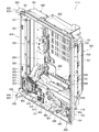
本体枠4の基板ユニット900は、本体枠ベース600の後側に取付けられる基板ユニットベース910と、基板ユニットベース910の正面視左側で本体枠ベース600の後側に取付けられ内部に低音用のスピーカ921を有したスピーカユニット920と、基板ユニットベース910の後側で正面視右側に取付けられ内部に電源基板が収容されている電源基板ボックス930と、スピーカユニット920の後側に取付けられており内部にインターフェイス制御基板が収容されているインターフェイス制御基板ボックス940と、電源基板ボックス930及びインターフェイス制御基板ボックス940に跨って取付けられており内部に遊技球の払出しを制御する払出制御基板951が収容された払出制御基板ボックス950と、を備えている。
The board unit 900 of the main body frame 4 is a board unit base 910 attached to the rear side of the main body frame base 600 and a speaker for bass inside which is attached to the rear side of the main body frame base 600 on the left side of the front view of the board unit base 910. The speaker unit 920 having 921, the power supply board box 930 mounted on the right side of the front view on the rear side of the board unit base 910 and accommodating the power supply board inside, and the power supply board box 930 mounted on the rear side of the speaker unit 920 and inside. The interface control board box 940 in which the interface control board is housed, and the payout control board 951 which is mounted across the power supply board box 930 and the interface control board box 940 and controls the payout of the game balls are housed therein. It includes a payout control board box 950.
パチンコ機1の遊技盤5は、図9及び図10等に示すように、遊技球が打込まれる遊技領域5aの外周を区画し球発射装置680から発射された遊技球を遊技領域5aの上部に案内する外レール1001及び内レール1002を有した前構成部材1000と、前構成部材1000の後側に取付けられると共に遊技領域5aの後端を区画する平板状の遊技パネル1100と、を備えている。
As shown in FIGS. 9 and 10, the game board 5 of the pachinko machine 1 divides the outer circumference of the game area 5a into which the game ball is hit, and the game ball launched from the ball launcher 680 is placed on the upper part of the game area 5a. A front component 1000 having an outer rail 1001 and an inner rail 1002 to guide the player, and a flat plate-shaped game panel 1100 attached to the rear side of the front component 1000 and partitioning the rear end of the game area 5a. There is.
本実施形態のパチンコ機1は、上皿321に遊技球を貯留した状態で、遊技者がハンドル302を回転操作すると、球発射装置680によってハンドル302の回転角度に応じた強さで遊技球が遊技盤5の遊技領域5a内へ打込まれる。そして、遊技領域5a内に打込まれた遊技球が、入賞口に受入れられると、受入れられた入賞口に応じて、所定数の遊技球が払出装置830によって上皿321に払出される。この遊技球の払出しによって遊技者の興趣を高めることができるため、上皿321内の遊技球を遊技領域5a内へ打込ませることができ、遊技者に遊技を楽しませることができる。
In the pachinko machine 1 of the present embodiment, when the player rotates the handle 302 with the game ball stored in the upper plate 321, the ball launching device 680 causes the game ball to have a strength corresponding to the rotation angle of the handle 302. It is driven into the game area 5a of the game board 5. Then, when the game balls driven into the game area 5a are received in the winning opening, a predetermined number of game balls are paid out to the upper plate 321 by the payout device 830 according to the received winning opening. Since the player's interest can be enhanced by paying out the game ball, the game ball in the upper plate 321 can be driven into the game area 5a, and the player can enjoy the game.
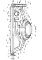
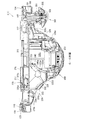
[2.外枠の全体構成]
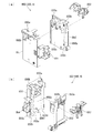
パチンコ機1の外枠2について、図11乃至図16を参照して説明する。図11はパチンコ機における外枠の正面図であり、図12は外枠の右側面図である。また、図13は外枠を前から見た斜視図であり、図14は外枠を後ろから見た斜視図である。図15は、外枠を分解して前から見た分解斜視図である。図16(a)は外枠における外枠側上ヒンジ部材の部位を、左枠部材を省略して下側から見た斜視図であり、(b)は(a)を分解して示す分解斜視図である。外枠2は、遊技ホール等のパチンコ機1が設置される島設備(図示は省略)に取付けられるものである。
[2. Overall composition of the outer frame]
The outer frame 2 of the pachinko machine 1 will be described with reference to FIGS. 11 to 16. FIG. 11 is a front view of the outer frame of the pachinko machine, and FIG. 12 is a right side view of the outer frame. Further, FIG. 13 is a perspective view of the outer frame viewed from the front, and FIG. 14 is a perspective view of the outer frame viewed from the back. FIG. 15 is an exploded perspective view of the outer frame viewed from the front by disassembling the outer frame. FIG. 16A is a perspective view of a portion of the outer frame side upper hinge member in the outer frame as viewed from below with the left frame member omitted, and FIG. 16B is an exploded perspective view showing (a) in an exploded manner. It is a figure. The outer frame 2 is attached to an island facility (not shown) in which a pachinko machine 1 is installed, such as a game hall.
外枠2は、図示するように、上下に離間しており左右に延びている上枠部材10及び下枠部材20と、上枠部材10及び下枠部材20の両端同士を連結しており上下に延びている左枠部材30及び右枠部材40と、を備えている。上枠部材10、下枠部材20、左枠部材30、及び右枠部材40は、前後の幅が同じ幅に形成されている。また、上枠部材10及び下枠部材20の左右の長さに対して、左枠部材30及び右枠部材40の上下の長さが、長く形成されている。また、外枠2は、上枠部材10及び下枠部材20の左右両端面と、左枠部材30及び右枠部材40の左右方向の外側を向いた側面とが、同一面となるように組立てられている。
As shown in the figure, the outer frame 2 connects the upper frame member 10 and the lower frame member 20 which are vertically separated and extend to the left and right, and both ends of the upper frame member 10 and the lower frame member 20. A left frame member 30 and a right frame member 40 extending to the left frame member 30 are provided. The upper frame member 10, the lower frame member 20, the left frame member 30, and the right frame member 40 are formed to have the same width in the front and rear. Further, the vertical lengths of the left frame member 30 and the right frame member 40 are formed longer than the left and right lengths of the upper frame member 10 and the lower frame member 20. Further, the outer frame 2 is assembled so that the left and right end surfaces of the upper frame member 10 and the lower frame member 20 and the side surfaces of the left frame member 30 and the right frame member 40 facing outward in the left-right direction are flush with each other. Has been done.
また、外枠2は、上枠部材10の正面視左端部側に取付けられている外枠側上ヒンジ部材60と、外枠側上ヒンジ部材60の下面に取付けられているロック部材66と、幕板部材50の正面視左端側上部と左枠部材30とに取付けられている外枠側下ヒンジ部材70と、を備えている。外枠2の外枠側上ヒンジ部材60と外枠側下ヒンジ部材70とによって、本体枠4及び扉枠3を開閉可能に取付けることができる。
Further, the outer frame 2 includes an outer frame side upper hinge member 60 attached to the front left end side of the upper frame member 10, a lock member 66 attached to the lower surface of the outer frame side upper hinge member 60, and the like. The curtain plate member 50 includes an upper portion on the left end side of the front view and an outer frame side lower hinge member 70 attached to the left frame member 30. The main body frame 4 and the door frame 3 can be opened and closed by the outer frame side upper hinge member 60 and the outer frame side lower hinge member 70 of the outer frame 2.
また、外枠2は、左枠部材30及び右枠部材40の下端同士を連結し下枠部材20の前側に取付けられる幕板部材50と、幕板部材50の後側に取付けられていると共に両端が左枠部材30及び右枠部材40に夫々取付けられる幕板補強部材80と、幕板部材50の上面における左右中央から左寄りの位置に取付けられている平板状の左滑り部材81と、幕板部材50の上面における右端付近の位置に取付けられている平板状の右滑り部材82と、を備えている。幕板補強部材80は、中実の部材(例えば、木材、合板、等)によって形成されており、下枠部材20、左枠部材30、及び右枠部材40に、取付けられている。
Further, the outer frame 2 is attached to the curtain plate member 50 which connects the lower ends of the left frame member 30 and the right frame member 40 to each other and is attached to the front side of the lower frame member 20, and is attached to the rear side of the curtain plate member 50. A curtain plate reinforcing member 80 whose both ends are attached to the left frame member 30 and the right frame member 40, respectively, a flat plate-shaped left sliding member 81 attached to a position on the upper surface of the curtain plate member 50 to the left from the center of the left and right, and a curtain. A flat plate-shaped right-sliding member 82 attached to a position near the right end on the upper surface of the plate member 50 is provided. The curtain plate reinforcing member 80 is formed of a solid member (for example, wood, plywood, etc.) and is attached to the lower frame member 20, the left frame member 30, and the right frame member 40.
更に、外枠2は、上枠部材10と左枠部材30、上枠部材10と右枠部材40、下枠部材20と左枠部材30、及び下枠部材20と右枠部材40を、夫々連結している連結部材85を備えている。また、外枠2は、右枠部材40の内側(左側面側)に取付けられており後述する施錠ユニット700の外枠用鉤703が係止される上鉤掛部材90及び下鉤掛部材91を、備えている。
Further, the outer frame 2 includes an upper frame member 10 and a left frame member 30, an upper frame member 10 and a right frame member 40, a lower frame member 20 and a left frame member 30, and a lower frame member 20 and a right frame member 40, respectively. It includes a connecting member 85 that is connected. Further, the outer frame 2 is attached to the inside (left side surface side) of the right frame member 40, and the upper hook hook member 90 and the lower hook hook member 91 to which the hook 703 for the outer frame of the locking unit 700, which will be described later, is locked. , Prepared.
[2−1.上枠部材]
外枠2の上枠部材10は、所定厚さの無垢(中実)の材料(例えば、木材、合板、等)によって形成されている。この上枠部材10は、左右両端における前後方向の中央に、上下に貫通しており左右方向中央側へ窪んだ係合切欠部11を備えている。この係合切欠部11内には、連結部材85の後述する左上連結部材85A及び右上連結部材85Bの上横固定部87が取付けられる。また、上枠部材10は、正面視左側端部の上面と前面に、一般面よりも窪んだ取付段部12を備えている。この取付段部12には、外枠側上ヒンジ部材60が取付けられる。
[2-1. Upper frame member]
The upper frame member 10 of the outer frame 2 is formed of a solid (solid) material (for example, wood, plywood, etc.) having a predetermined thickness. The upper frame member 10 includes an engaging notch 11 that penetrates vertically and is recessed toward the center side in the left-right direction at the center in the front-rear direction at both left and right ends. The upper left connecting member 85A and the upper right connecting member 85B of the connecting member 85, which will be described later, are mounted in the engaging notch 11. Further, the upper frame member 10 is provided with mounting steps 12 recessed from the general surface on the upper surface and the front surface of the left end portion in the front view. An outer frame side upper hinge member 60 is attached to the attachment step portion 12.
[2−2.下枠部材]
外枠2の下枠部材20は、所定厚さの無垢(中実)の材料(例えば、木材、合板、等)によって形成されている。この下枠部材20は、左右の長さ及び上下の厚さが、上枠部材10の左右の長さ及び上下の厚さと同じ寸法に形成されていると共に、前後の幅が、上枠部材10の前後の幅よりも長く形成されている。下枠部材20は、左右両端における前後方向の中央よりも後側寄りの位置に、上下に貫通しており左右方向中央側へ窪んだ係合切欠部21を備えている。この係合切欠部21内には、連結部材85の後述する左下連結部材85C及び右下連結部材85Dの下横固定部88が取付けられる。
[2-2. Lower frame member]
The lower frame member 20 of the outer frame 2 is made of a solid (solid) material (for example, wood, plywood, etc.) having a predetermined thickness. The lower frame member 20 is formed so that the left and right lengths and the upper and lower thicknesses are the same as the left and right lengths and the upper and lower thicknesses of the upper frame member 10, and the front and rear widths of the upper frame member 10 are the same. It is formed longer than the width before and after. The lower frame member 20 is provided with an engaging notch 21 that penetrates vertically and is recessed toward the center side in the left-right direction at a position closer to the rear side than the center in the front-rear direction at both left and right ends. The lower left connecting member 85C and the lower right connecting member 85D of the connecting member 85, which will be described later, are mounted in the engaging notch 21.
また、下枠部材20は、左右両端の前面から後方へ窪んだ前端切欠部22を備えている。下枠部材20において、前端切欠部22の後端から下枠部材20の後面までの前後方向の幅が、上枠部材10の前後方向の幅と同じ寸法に形成されている。この下枠部材20は、外枠2に組立てた状態で、左右の前端切欠部22同士の間の部位が、幕板部材50内に挿入される。
Further, the lower frame member 20 includes front end notches 22 recessed from the front surfaces of both left and right ends to the rear. In the lower frame member 20, the width in the front-rear direction from the rear end of the front end notch portion 22 to the rear surface of the lower frame member 20 is formed to have the same dimensions as the width in the front-rear direction of the upper frame member 10. In the state where the lower frame member 20 is assembled to the outer frame 2, a portion between the left and right front end notches 22 is inserted into the curtain plate member 50.
[2−3.左枠部材及び右枠部材]
外枠2の左枠部材30及び右枠部材40は、一定の断面形状で上下に延びており、アルミ合金等の金属の押出形材によって形成されている。左枠部材30及び右枠部材40は、平面視において互いに対称の形状に形成されている。左枠部材30及び右枠部材40は、外枠2として組立てた時に、左右方向の外側となる側面において、前後方向中央に対して後寄りの位置から後端付近までの間に、内側へ窪んだ凹部31,41と、凹部31,41の反対側の側面から膨出しており内部が空洞に形成されている突出部32,42と、を備えている。この左枠部材30及び右枠部材40は、突出部32,42によって、強度・剛性が高められている。また、突出部32,42内には、連結部材85の後述する左上連結部材85A及び右上連結部材85Bの後側の下横固定部88が挿入されて取付けられる。
[2-3. Left frame member and right frame member]
The left frame member 30 and the right frame member 40 of the outer frame 2 extend vertically with a constant cross-sectional shape, and are formed of an extruded metal material such as an aluminum alloy. The left frame member 30 and the right frame member 40 are formed in a shape symmetrical to each other in a plan view. When the left frame member 30 and the right frame member 40 are assembled as the outer frame 2, they are recessed inward from a position rearward to the center in the front-rear direction to the vicinity of the rear end on the outer side surface in the left-right direction. It is provided with recesses 31 and 41 and protrusions 32 and 42 that bulge from the opposite side surfaces of the recesses 31 and 41 and have a hollow inside. The strength and rigidity of the left frame member 30 and the right frame member 40 are increased by the protrusions 32 and 42. Further, in the protruding portions 32 and 42, the lower left lateral fixing portion 88 on the rear side of the upper left connecting member 85A and the upper right connecting member 85B described later of the connecting member 85 is inserted and attached.
また、左枠部材30及び右枠部材40は、表面に上下に延びた複数の溝が形成されている。この複数の溝によって、パチンコ機1を遊技ホール等の島設備に設置したり運搬したりする等の際に、作業者の指掛りとなってパチンコ機1を持ち易くすることができると共に、パチンコ機1の外観の意匠性を高めることとができる。
Further, the left frame member 30 and the right frame member 40 are formed with a plurality of grooves extending vertically on the surface thereof. With these plurality of grooves, when the pachinko machine 1 is installed or transported in an island facility such as a game hall, the pachinko machine 1 can be easily held by a worker and the pachinko machine 1 can be easily held. It is possible to enhance the design of the appearance of the machine 1.
[2−4.幕板部材]
外枠2の幕板部材50は、後側が開放された箱状に形成されている。幕板部材50は、上面における正面視左端付近に後方へ平板状に延出している後方延出部51と、後方延出部51の左端から遊技球が通過可能な大きさでU字状に切欠かれており上下に貫通している左排出孔52と、後方延出部51における左排出孔52の右側において遊技球が通過可能な大きさで上下に貫通している右排出孔53と、後方延出部51の後端を含む幕板部材50の上面の後端から上方へ平板状に延出している立壁部54と、立壁部54の上端付近から前方へ膨出しており前面が上方へ向かうに従って後方へ向かうように傾斜している返し部55と、を備えている。
[2-4. Curtain board member]
The curtain plate member 50 of the outer frame 2 is formed in a box shape with the rear side open. The curtain plate member 50 has a rear extending portion 51 extending rearward in a flat plate shape near the left end of the front view on the upper surface, and a U-shape having a size that allows a game ball to pass from the left end of the rear extending portion 51. A left discharge hole 52 that is notched and penetrates vertically, and a right discharge hole 53 that penetrates vertically on the right side of the left discharge hole 52 in the rear extension portion 51 so that the game ball can pass through. A standing wall portion 54 extending upward from the rear end of the upper surface of the curtain plate member 50 including the rear end of the rear extending portion 51 in a flat plate shape, and a standing wall portion 54 protruding forward from the vicinity of the upper end of the standing wall portion 54 and the front surface upward It is provided with a return portion 55, which is inclined toward the rear toward the rear.
幕板部材50は、後方延出部51の前側の上面と、後方延出部51の上面とに、外枠側下ヒンジ部材70が載置されるように、外枠側下ヒンジ部材70の後述する水平部71が取付けられる。また、幕板部材50の左排出孔52は、外枠2に組立てた状態で外枠側下ヒンジ部材70の後述する排出孔74と一致する位置に形成されている。また、右排出孔53は、外枠2に組立てた状態で外枠側下ヒンジ部材70よりも右側となる位置に形成されている。右排出孔53は、左排出孔52よりも大きく形成されている。
The curtain plate member 50 is a lower hinge member 70 on the outer frame side so that the lower hinge member 70 on the outer frame side is placed on the upper surface of the front side of the rear extension portion 51 and the upper surface of the rear extension portion 51. A horizontal portion 71, which will be described later, is attached. Further, the left discharge hole 52 of the curtain plate member 50 is formed at a position corresponding to the discharge hole 74 described later of the outer frame side lower hinge member 70 in a state of being assembled to the outer frame 2. Further, the right discharge hole 53 is formed at a position on the right side of the outer frame side lower hinge member 70 in a state of being assembled to the outer frame 2. The right discharge hole 53 is formed larger than the left discharge hole 52.
また、幕板部材50は、後方延出部51よりも右側の上面が、前端側が低くなるように傾斜している。また、幕板部材50は、上面における後方延出部51よりも右側の部位に左滑り部材81を取付けるための左取付部56と、上面における右端付近に右滑り部材82を取付けるための右取付部57と、を備えている。幕板部材50は、上面に、左滑り部材81及び右滑り部材82を介して本体枠4の下面が載置される。
Further, the curtain plate member 50 is inclined so that the upper surface on the right side of the rear extending portion 51 is lower on the front end side. Further, the curtain plate member 50 has a left mounting portion 56 for mounting the left sliding member 81 on a portion on the right side of the rear extending portion 51 on the upper surface and a right mounting portion for mounting the right sliding member 82 near the right end on the upper surface. A unit 57 and a unit 57 are provided. The lower surface of the main body frame 4 is placed on the upper surface of the curtain plate member 50 via the left sliding member 81 and the right sliding member 82.
この幕板部材50は、図示するように、前面に浅いレリーフ状の装飾が形成されている。また、幕板部材50は、図示は省略するが、箱状の内部が複数のリブによって格子状に仕切られており、強度・剛性が高められている。また、幕板部材50は、幕板補強部材80の前側半分を、内部に収容可能に形成されている。
As shown in the figure, the curtain plate member 50 has a shallow relief-like decoration formed on the front surface. Further, although not shown, the curtain plate member 50 has a box-shaped interior partitioned by a plurality of ribs in a grid pattern to increase the strength and rigidity. Further, the curtain plate member 50 is formed so that the front half of the curtain plate reinforcing member 80 can be accommodated inside.
[2−5.外枠側上ヒンジ部材]
外枠2の外枠側上ヒンジ部材60は、図示するように、水平に延びた平板状で外形が四角形の上固定部61と、上固定部61の前端から前方へ延出している平板状の前方延出部62と、前方延出部62の右端から前方へ向かうに従って前方延出部62の左右中央へ延びており上下に貫通している軸受溝63と、上固定部61の平面視左辺から下方へ延びている平板状の横固定部64と、前方延出部62の左端から前端を周って軸受溝63が開口している部位までの端辺から下方へ延びており横固定部64と連続している平板状の垂下部65と、を備えている(図16(b)等を参照)。
[2-5. Upper hinge member on the outer frame side]
As shown in the figure, the outer frame side upper hinge member 60 of the outer frame 2 has a horizontally extending flat plate-shaped upper fixing portion 61 having a quadrangular outer shape and a flat plate shape extending forward from the front end of the upper fixing portion 61. A plan view of the front extension portion 62, the bearing groove 63 extending vertically from the right end of the front extension portion 62 to the left and right center of the front extension portion 62 and penetrating vertically, and the upper fixing portion 61. A flat plate-shaped horizontal fixing portion 64 extending downward from the left side and a horizontal fixing portion extending downward from the end side extending from the left end to the front end of the front extending portion 62 to the portion where the bearing groove 63 is opened. A flat plate-shaped hanging portion 65 continuous with the portion 64 is provided (see FIG. 16B and the like).
外枠側上ヒンジ部材60は、外枠2が組立てられた状態で、上固定部61が、上枠部材10の取付段部12の上面に載置されており、図示しないビスによって固定されている。また、前方延出部62は、上枠部材10の前端よりも前方へ延出している。また、横固定部64は、左枠部材30の外側側面の凹部31内に上側から挿入された状態で、ビスによって左枠部材30に固定されている。
In the outer frame side upper hinge member 60, the upper fixing portion 61 is placed on the upper surface of the mounting step portion 12 of the upper frame member 10 in a state where the outer frame 2 is assembled, and is fixed by screws (not shown). There is. Further, the front extending portion 62 extends forward from the front end of the upper frame member 10. Further, the lateral fixing portion 64 is fixed to the left frame member 30 by screws in a state of being inserted from above into the recess 31 on the outer side surface of the left frame member 30.
この外枠側上ヒンジ部材60は、軸受溝63内に本体枠側上ヒンジ部材620の本体枠上ヒンジピン622を挿入させることで、外枠側下ヒンジ部材70と協働して本体枠4を開閉可能に支持することができる。この外枠側上ヒンジ部材60は、金属板をプレス成型により屈曲させて形成されている。
The outer frame side upper hinge member 60 cooperates with the outer frame side lower hinge member 70 by inserting the main body frame upper hinge pin 622 of the main body frame side upper hinge member 620 into the bearing groove 63 to form the main body frame 4. It can be supported so that it can be opened and closed. The outer frame side upper hinge member 60 is formed by bending a metal plate by press molding.
[2−6.ロック部材]
外枠2のロック部材66は、図16に示すように、左右が所定幅で前後に延びている帯板状のロック本体66aと、ロック本体66aの後端から右方へ突出している操作部66bと、ロック本体66aの後端から左方へ延びた後に斜め左前方へ延びている弾性変形可能な棒状の弾性部66cと、ロック本体66aの後端付近で上下に貫通している取付孔66dと、を備えている。このロック部材66は、合成樹脂によって形成されている。ロック部材66は、取付ビス67によって、外枠側上ヒンジ部材60における前方延出部62の下面に回動可能に取付けられる。
[2-6. Lock member]
As shown in FIG. 16, the lock member 66 of the outer frame 2 has a strip-shaped lock body 66a whose left and right sides extend back and forth with a predetermined width, and an operation unit protruding to the right from the rear end of the lock body 66a. 66b, an elastically deformable rod-shaped elastic portion 66c extending diagonally to the left front after extending to the left from the rear end of the lock main body 66a, and a mounting hole penetrating up and down near the rear end of the lock main body 66a. It is equipped with 66d. The lock member 66 is made of synthetic resin. The lock member 66 is rotatably attached to the lower surface of the front extension portion 62 of the outer frame side upper hinge member 60 by the attachment screw 67.
このロック部材66は、取付孔66dを通して、ロック本体66aの後端が、外枠側上ヒンジ部材60の前方延出部62における軸受溝63よりも後側の位置に取付けられる。また、ロック部材66を外枠側上ヒンジ部材60に取付けた状態では、ロック本体66aが、平面視で軸受溝63を遮ることができると共に、前端付近の右側面が、外枠側上ヒンジ部材60の垂下部65における軸受溝63の開口まで延びている部位と当接可能となるように前方へ延びている(図18を参照)。
The lock member 66 is mounted at a position where the rear end of the lock body 66a is rearward of the bearing groove 63 in the front extending portion 62 of the outer frame side upper hinge member 60 through the mounting hole 66d. Further, in a state where the lock member 66 is attached to the outer frame side upper hinge member 60, the lock body 66a can block the bearing groove 63 in a plan view, and the right side surface near the front end is the outer frame side upper hinge member. It extends forward so that it can come into contact with a portion of the hanging portion 65 of 60 that extends to the opening of the bearing groove 63 (see FIG. 18).
また、ロック本体66aの後端から左方へ延びている弾性部66cの先端は、外枠側上ヒンジ部材60における垂下部65の内周面に当接している。このロック部材66は、弾性部66cの付勢力によって取付孔66dを中心に、前端が左方へ回動する方向に付勢されている。従って、通常の状態では、ロック部材66のロック本体66aの前端付近の右側面が、垂下部65に当接している(図18を参照)。この状態では、軸受溝63におけるロック本体66aよりも前側の部位に、本体枠側上ヒンジ部材620の後述する本体枠上ヒンジピン622を収容可能な空間が形成される。
Further, the tip of the elastic portion 66c extending to the left from the rear end of the lock body 66a is in contact with the inner peripheral surface of the hanging portion 65 of the outer frame side upper hinge member 60. The lock member 66 is urged by the urging force of the elastic portion 66c in a direction in which the front end rotates to the left around the mounting hole 66d. Therefore, in a normal state, the right side surface of the lock member 66 near the front end of the lock body 66a is in contact with the hanging portion 65 (see FIG. 18). In this state, a space in the bearing groove 63 on the front side of the lock main body 66a is formed so as to accommodate the hinge pin 622 on the main body frame, which will be described later, of the hinge member 620 on the main body frame side.
このロック部材66は、操作部66bを操作することで、弾性部66cの付勢力に抗してロック本体66aを回動させることができる。そして、操作部66bの操作によって、ロック本体66aを、その前端が左方へ移動する方向へ回動させることで、平面視において軸受溝63からロック本体66aを後退させることができ、軸受溝63が全通している状態とすることができる。これにより、軸受溝63内に本体枠上ヒンジピン622を挿入したり、軸受溝63内から本体枠上ヒンジピン622を外したりすることができる。
By operating the operation portion 66b, the lock member 66 can rotate the lock body 66a against the urging force of the elastic portion 66c. Then, by operating the operation unit 66b, the lock body 66a is rotated in the direction in which the front end thereof moves to the left, so that the lock body 66a can be retracted from the bearing groove 63 in a plan view, and the bearing groove 63 can be retracted. Can be in a state of being fully passed. As a result, the hinge pin 622 on the main body frame can be inserted into the bearing groove 63, and the hinge pin 622 on the main body frame can be removed from the bearing groove 63.
[2−7.外枠側下ヒンジ部材]
外枠2の外枠側下ヒンジ部材70は、図示するように、水平に延びている平板状の水平部71と、水平部71の左辺において前後方向中央よりも後側の部位から上方へ立上っている平板状の立上り部72と、水平部71の前端付近から上方へ突出している外枠下ヒンジピン73と、水平部71を上下に貫通しており遊技球が一つのみ通過可能な大きさの排出孔74と、を備えている。この外枠側下ヒンジ部材70は、金属板をプレス成型により屈曲させて形成されている。
[2-7. Outer frame side lower hinge member]
As shown in the figure, the outer frame side lower hinge member 70 of the outer frame 2 stands upward from a horizontally extending flat plate-shaped horizontal portion 71 and a portion on the left side of the horizontal portion 71 that is posterior to the center in the front-rear direction. Only one game ball can pass through the rising flat rising portion 72, the hinge pin 73 under the outer frame protruding upward from the vicinity of the front end of the horizontal portion 71, and the horizontal portion 71 up and down. It is provided with a discharge hole 74 having a size. The outer frame side lower hinge member 70 is formed by bending a metal plate by press molding.
外枠側下ヒンジ部材70の水平部71は、平面視において、左辺を底辺とした台形に形成されている。外枠下ヒンジピン73は、円柱状で、上下方向中央よりも上部が、上端が窄まった円錐台状に形成されている。この外枠下ヒンジピン73は、水平部71の前端付近における左寄りの位置に取付けられている。排出孔74は、水平部71において、立上り部72の前後方向中央の部位と接し、水平部71の左辺から右方へ逆U字状に延びるように形成されている。この排出孔74は、幕板部材50の左排出孔52と、略同じ大きさに形成されている。
The horizontal portion 71 of the outer frame side lower hinge member 70 is formed in a trapezoidal shape with the left side as the base in a plan view. The lower hinge pin 73 of the outer frame has a columnar shape, and is formed in a truncated cone shape in which the upper end is narrowed above the center in the vertical direction. The lower hinge pin 73 of the outer frame is attached to a position on the left side near the front end of the horizontal portion 71. The discharge hole 74 is formed in the horizontal portion 71 so as to be in contact with the central portion of the rising portion 72 in the front-rear direction and extend from the left side of the horizontal portion 71 to the right in an inverted U shape. The discharge hole 74 is formed to have substantially the same size as the left discharge hole 52 of the curtain plate member 50.
外枠側下ヒンジ部材70は、外枠2が組立てられた状態では、水平部71が、幕板部材50の左端付近の上面と後方延出部51上に載置されており、水平部71が、幕板部材50の上面を貫通する図示しないビスによって幕板補強部材80に固定されている。また、外枠2が組立てられた状態では、立上り部72が、左枠部材30の内側側面における突出部32よりも前側の部位に、図示しないビスによって取付けられている。この外枠側下ヒンジ部材70は、外枠下ヒンジピン73を、本体枠4の本体枠側下ヒンジ部材640における本体枠用下ヒンジ孔(図示は省略)に挿通させることで、外枠側上ヒンジ部材60と協働して本体枠4を開閉可能に取付けることができる。
In the outer frame side lower hinge member 70, when the outer frame 2 is assembled, the horizontal portion 71 is placed on the upper surface near the left end of the curtain plate member 50 and on the rear extending portion 51, and the horizontal portion 71. Is fixed to the curtain plate reinforcing member 80 by a screw (not shown) penetrating the upper surface of the curtain plate member 50. Further, in the state where the outer frame 2 is assembled, the rising portion 72 is attached to a portion of the inner side surface of the left frame member 30 on the inner side surface of the left frame member 30 on the front side of the protruding portion 32 by a screw (not shown). The outer frame side lower hinge member 70 is formed by inserting the outer frame lower hinge pin 73 into the main body frame lower hinge hole (not shown) in the main body frame side lower hinge member 640 of the main body frame 4. The main body frame 4 can be attached so as to be openable and closable in cooperation with the hinge member 60.
また、外枠2が組立てられた状態では、排出孔74が、幕板部材50の左排出孔52と一致している。これにより、水平部71上の遊技球を、排出孔74及び左排出孔52を通して、幕板部材50の後側へ落下(排出)させることができる。詳述すると、外枠2に対して本体枠4を閉じる時に、外枠2と本体枠4との間に落下した遊技球が、本体枠4が閉じられるのに従って、外枠2と本体枠4との間が徐々に狭くなることから、間隔が広い後方側へ転動とすることとなり、排出孔74から排出させることができる。この際に、排出孔74が、パチンコ機1に組立てた状態で、外枠2に対して本体枠4を閉じた時に、本体枠4の後端と略同じとなる位置に形成されているため、外枠2と本体枠4との間に落下した遊技球を、排出孔74から排出させることで本体枠4よりも後側へ転動するのを阻止し易くすることができ、外枠側下ヒンジ部材70の部位に遊技球が留まり難くすることができる。
Further, in the state where the outer frame 2 is assembled, the discharge hole 74 coincides with the left discharge hole 52 of the curtain plate member 50. As a result, the game ball on the horizontal portion 71 can be dropped (discharged) to the rear side of the curtain plate member 50 through the discharge hole 74 and the left discharge hole 52. More specifically, when the main body frame 4 is closed with respect to the outer frame 2, the game ball that has fallen between the outer frame 2 and the main body frame 4 is closed, and the outer frame 2 and the main body frame 4 are closed. Since the space between the two and the cloaca gradually narrows, the vehicle rolls to the rear side where the interval is wide, and the cloaca can be discharged from the discharge hole 74. At this time, since the discharge hole 74 is formed at a position substantially the same as the rear end of the main body frame 4 when the main body frame 4 is closed with respect to the outer frame 2 in the state of being assembled in the pachinko machine 1. By discharging the game ball that has fallen between the outer frame 2 and the main body frame 4 from the discharge hole 74, it is possible to easily prevent the game ball from rolling to the rear side of the main body frame 4, and the outer frame side. It is possible to make it difficult for the game ball to stay at the portion of the lower hinge member 70.
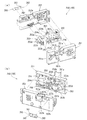
[2−8.連結部材]
外枠2の連結部材85は、上枠部材10と左枠部材30とを連結する左上連結部材85Aと、上枠部材10と右枠部材40とを連結する右上連結部材85Bと、下枠部材20と左枠部材30とを連結する左下連結部材85Cと、下枠部材20と右枠部材40とを連結する右下連結部材85Dと、がある。
[2-8. Connecting member]
The connecting member 85 of the outer frame 2 includes an upper left connecting member 85A that connects the upper frame member 10 and the left frame member 30, an upper right connecting member 85B that connects the upper frame member 10 and the right frame member 40, and a lower frame member. There is a lower left connecting member 85C that connects 20 and the left frame member 30, and a lower right connecting member 85D that connects the lower frame member 20 and the right frame member 40.
連結部材85は、水平に延びた平板状の水平固定部86と、水平固定部86の左右側辺の何れか一方から上方へ延出している平板状の上横固定部87と、水平固定部86における上横固定部87が延出している部位と同じ側から下方へ延出している平板状の下横固定部88と、を備えている。この連結部材85は、平板状の金属板を屈曲させて形成されている。
The connecting member 85 includes a flat plate-shaped horizontal fixing portion 86 extending horizontally, a flat plate-shaped upper-horizontal fixing portion 87 extending upward from either the left or right side of the horizontal fixing portion 86, and a horizontal fixing portion. The upper horizontal fixing portion 87 in 86 includes a flat plate-shaped lower horizontal fixing portion 88 extending downward from the same side as the extending portion. The connecting member 85 is formed by bending a flat metal plate.
左上連結部材85A及び右上連結部材85Bでは、水平固定部86の前後方向の中央から上横固定部87が上方へ延出していると共に、上横固定部87の前後両側から下横固定部88が下方へ延出している。つまり、左上連結部材85A及び右上連結部材85Bでは、下横固定部88が前後に離間して二つ備えられている。左上連結部材85A及び右上連結部材85Bの水平固定部86は、上枠部材10の下面に当接した状態で上枠部材10に固定される。また、左上連結部材85A及び右上連結部材85Bの上横固定部87は、上枠部材10の係合切欠部21内に挿入されて、上枠部材10の左右方向の端部に固定される。また、左上連結部材85A及び右上連結部材85Bの前側の下横固定部88は、左枠部材30及び右枠部材40の突出部32,42よりも前側の内側側面に夫々固定される。更に、左上連結部材85A及び右上連結部材85Bの後側の下横固定部88は、左枠部材30及び右枠部材40の突出部32,42内に挿入されて外側側面から捩じ込まれるビスにより左枠部材30及び右枠部材40に夫々固定される。
In the upper left connecting member 85A and the upper right connecting member 85B, the upper horizontal fixing portion 87 extends upward from the center of the horizontal fixing portion 86 in the front-rear direction, and the lower horizontal fixing portion 88 extends from both front and rear sides of the upper horizontal fixing portion 87. It extends downward. That is, the upper left connecting member 85A and the upper right connecting member 85B are provided with two lower horizontal fixing portions 88 separated from each other in the front-rear direction. The horizontal fixing portion 86 of the upper left connecting member 85A and the upper right connecting member 85B is fixed to the upper frame member 10 in a state of being in contact with the lower surface of the upper frame member 10. Further, the upper horizontal fixing portion 87 of the upper left connecting member 85A and the upper right connecting member 85B is inserted into the engaging notch 21 of the upper frame member 10 and fixed to the end portion of the upper frame member 10 in the left-right direction. Further, the lower lateral fixing portion 88 on the front side of the upper left connecting member 85A and the upper right connecting member 85B is fixed to the inner side surfaces on the front side of the left frame member 30 and the right frame member 40, respectively. Further, the lower lateral fixing portion 88 on the rear side of the upper left connecting member 85A and the upper right connecting member 85B is a screw inserted into the protruding portions 32 and 42 of the left frame member 30 and the right frame member 40 and screwed from the outer side surface. Is fixed to the left frame member 30 and the right frame member 40, respectively.
左下連結部材85C及び右下連結部材85Dでは、上横固定部87の後端が、水平固定部86の後端よりも後方へ突出していると共に、上横固定部87の水平固定部86よりも後方へ突出している部位の下端から下横固定部88が水平固定部86よりも下方へ延出している。また、左下連結部材85C及び右下連結部材85Dでは、上横固定部87の後端から水平固定部86と同じ側へ突出している屈曲部89を更に備えている。左下連結部材85C及び右下連結部材85Dの水平固定部86は、下枠部材20の上面に当接した状態で固定される。また、左下連結部材85C及び右下連結部材85Dの上横固定部87は、左枠部材30及び右枠部材40の突出部32,42よりも前側の内側側面に夫々固定される。更に、左下連結部材85C及び右下連結部材85Dの下横固定部88は、下枠部材20の係合切欠部21内に挿入されて下枠部材20の左右方向の端部面に夫々固定される。
In the lower left connecting member 85C and the lower right connecting member 85D, the rear end of the upper horizontal fixing portion 87 protrudes rearward from the rear end of the horizontal fixing portion 86 and more than the horizontal fixing portion 86 of the upper horizontal fixing portion 87. The lower lateral fixing portion 88 extends downward from the horizontal fixing portion 86 from the lower end of the portion protruding rearward. Further, the lower left connecting member 85C and the lower right connecting member 85D further include a bent portion 89 projecting from the rear end of the upper horizontal fixing portion 87 to the same side as the horizontal fixing portion 86. The horizontal fixing portion 86 of the lower left connecting member 85C and the lower right connecting member 85D is fixed in a state of being in contact with the upper surface of the lower frame member 20. Further, the upper and horizontal fixing portions 87 of the lower left connecting member 85C and the lower right connecting member 85D are fixed to the inner side surfaces of the left frame member 30 and the right frame member 40 on the front side of the protruding portions 32 and 42, respectively. Further, the lower horizontal fixing portion 88 of the lower left connecting member 85C and the lower right connecting member 85D is inserted into the engaging notch 21 of the lower frame member 20 and fixed to the end surface of the lower frame member 20 in the left-right direction. NS.
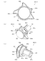
[2−9.外枠側上ヒンジ部材のロック機構]
次に、本実施形態のパチンコ機1の外枠2において、外枠側上ヒンジ部材60におけるロック部材66による本体枠4の本体枠側上ヒンジ部材620に対するロック機構について、図17及び図18を参照して説明する。図17(a)は外枠の外枠側上ヒンジ部材に対して本体枠の本体枠側上ヒンジ部材が取外されている状態を拡大して示す斜視図であり、(b)は外側上ヒンジ部材に本体側上ヒンジ部材が取付けられている状態を拡大して示す斜視図である。図18は、外枠におけるロック部材の作用を示す説明図である。
[2-9. Lock mechanism for upper hinge member on the outer frame side]
Next, in the outer frame 2 of the pachinko machine 1 of the present embodiment, FIGS. 17 and 18 are shown with respect to the locking mechanism of the main body frame 4 with respect to the main body frame side upper hinge member 620 by the lock member 66 in the outer frame side upper hinge member 60. It will be explained with reference to. FIG. 17 (a) is an enlarged perspective view showing a state in which the main body frame side upper hinge member of the main body frame is removed with respect to the outer frame side upper hinge member of the outer frame, and FIG. It is an enlarged perspective view which shows the state which the hinge member on the main body side is attached to the hinge member. FIG. 18 is an explanatory view showing the action of the lock member on the outer frame.
外枠2におけるロック部材66は、外枠側上ヒンジ部材60の前方延出部62に取付けた状態(通常の状態)では、弾性部66cの先端が垂下部65の内周面と当接しており、ロック本体66aがく字状に屈曲した軸受溝63の一部を閉塞するようになっていると共に、ロック本体66aの先端部分が、軸受溝63の最深部分を閉塞した状態とはならず、軸受溝63の最深部分に本体枠4の本体枠側上ヒンジ部材620の本体枠上ヒンジピン622を挿入可能な空間が形成された状態となっている。
When the lock member 66 in the outer frame 2 is attached to the front extending portion 62 of the outer frame side upper hinge member 60 (normal state), the tip of the elastic portion 66c comes into contact with the inner peripheral surface of the hanging portion 65. The lock body 66a does not block a part of the bearing groove 63 bent in a dogleg shape, and the tip portion of the lock body 66a does not block the deepest part of the bearing groove 63. A space is formed in the deepest portion of the bearing groove 63 into which the hinge pin 622 on the main body frame of the main body frame side upper hinge member 620 of the main body frame 4 can be inserted.
本実施形態における外枠側上ヒンジ部材60とロック部材66とを用いた本体枠上ヒンジピン622の支持機構は、本体枠上ヒンジピン622が軸受溝63の最深部分に挿入されてロック本体66aの前端の右側面が、右側の垂下部65と接近している状態(この状態ではロック本体66aの前端の右側面と右側の垂下部65との間に僅かな隙間があり当接した状態となっていない)である通常の軸支状態においては、屈曲している軸受溝63の最深部分に位置する本体枠上ヒンジピン622とロック本体66aの前端面との夫々の中心が斜め方向にずれて対向した状態となっている。
In the support mechanism of the hinge pin 622 on the main body frame using the outer frame side upper hinge member 60 and the lock member 66 in the present embodiment, the hinge pin 622 on the main body frame is inserted into the deepest portion of the bearing groove 63 and the front end of the lock main body 66a. The right side surface of the lock body 66a is in close contact with the right side hanging portion 65 (in this state, there is a slight gap between the right side surface of the front end of the lock body 66a and the right side hanging portion 65, and they are in contact with each other. In the normal axial support state, the centers of the hinge pin 622 on the main body frame located at the deepest part of the bent bearing groove 63 and the front end surface of the lock main body 66a are obliquely opposed to each other. It is in a state.
そして、この通常の軸支状態においては、重量のある本体枠4を軸支している本体枠上ヒンジピン622が軸受溝63の前端部分に当接した状態となっているので、本体枠上ヒンジピン622からロック本体66aの前端面への負荷がほとんどかかっていない。つまり、ロック部材66の弾性部66cに対し負荷がかかっていない状態となっている。なお、ロック本体66aの前端面が円弧状に形成されているため、ロック部材66を回動させるために操作部66bを回動操作した時に、ロック部材66がスムーズに回動するようになっている。また、図示では、ロック本体66aの前端面の円弧中心が、取付孔66dの中心(ロック部材66の回転中心)とされている。
In this normal axial support state, the hinge pin 622 on the main body frame that pivotally supports the heavy main body frame 4 is in contact with the front end portion of the bearing groove 63, so that the hinge pin on the main body frame is in contact with the front end portion. Almost no load is applied from 622 to the front end surface of the lock body 66a. That is, no load is applied to the elastic portion 66c of the lock member 66. Since the front end surface of the lock body 66a is formed in an arc shape, the lock member 66 rotates smoothly when the operation portion 66b is rotated to rotate the lock member 66. There is. Further, in the figure, the arc center of the front end surface of the lock body 66a is the center of the mounting hole 66d (the center of rotation of the lock member 66).
従って、本体枠上ヒンジピン622がく字状に形成された軸受溝63の傾斜に沿って抜ける方向に作用力Fがかかって、ロック本体66aの円弧状の前端面に当接したとき、その作用力Fを、本体枠上ヒンジピン622と円弧状の前端面との当接部分に作用する分力F1(ロック本体66aの前端面の円弧の法線方向)と、本体枠上ヒンジピン622と軸受溝63の一側内面との当接部分に作用する分力F2と、に分けたときに、分力F1の方向が取付孔66d(取付ビス67)の中心(ロック部材66の回転中心)を向くため、ロック部材66のロック本体66aの前端が、右側の垂下部65から離れる方向に回転させるモーメントが働かず、本体枠上ヒンジピン622がロック部材66のロック本体66aの前端部と軸受溝63の一側内面との間に挟持された状態が保持される。
Therefore, when the acting force F is applied in the direction in which the hinge pin 622 on the main body frame comes out along the inclination of the bearing groove 63 formed in a dogleg shape and comes into contact with the arcuate front end surface of the lock main body 66a, the acting force is applied. The component force F1 (in the normal direction of the arc of the front end surface of the lock body 66a) acting on the contact portion between the hinge pin 622 on the main body frame and the arc-shaped front end surface, and the hinge pin 622 on the main body frame and the bearing groove 63. When divided into a component force F2 that acts on the contact portion with the inner surface on one side, the direction of the component force F1 faces the center of the mounting hole 66d (mounting screw 67) (the center of rotation of the lock member 66). , The front end of the lock body 66a of the lock member 66 does not have a moment to rotate in the direction away from the hanging portion 65 on the right side, and the hinge pin 622 on the body frame is one of the front end of the lock body 66a of the lock member 66 and the bearing groove 63. The state of being sandwiched between the side inner surface is maintained.
このため、通常の軸支状態、或は、本体枠上ヒンジピン622の作用力がロック部材66にかかった状態でも、ロック部材66の弾性部66cに常時負荷がかからず、合成樹脂で一体形成される弾性部66cのクリープによる塑性変形を防止し、長期間に亘って本体枠上ヒンジピン622の軸受溝63からの脱落を防止することができる。なお、仮に無理な力がかかってロック部材66のロック本体66aの前端部が右方へ移動する方向へ回転させられても、ロック本体66aの前端右側面が垂下部65に当接してそれ以上回転しないので、ロック部材66が前方延出部62の外側にはみ出ないようになっている。
Therefore, even in a normal bearing state or in a state where the acting force of the hinge pin 622 on the main body frame is applied to the lock member 66, the elastic portion 66c of the lock member 66 is not constantly loaded and is integrally formed of synthetic resin. It is possible to prevent the elastic portion 66c from being plastically deformed due to creep, and to prevent the hinge pin 622 on the main body frame from falling off from the bearing groove 63 for a long period of time. Even if an unreasonable force is applied and the front end portion of the lock body 66a of the lock member 66 is rotated in the direction of moving to the right, the right side surface of the front end of the lock body 66a abuts on the hanging portion 65 and further. Since it does not rotate, the lock member 66 does not protrude to the outside of the forward extending portion 62.
なお、ロック本体66aの前端面の形状は円弧状でなくても、上記した分力F1の作用により回転モーメントが生じない位置又はロック部材66をその前端部が前方延出部62の外側に向って回転させる回転モーメントが生ずる位置にロック部材66の回転中心(取付ビス67により固定される軸)を位置させることにより、常時ロック部材66の弾性部66cに対しても負荷がかかることはないし、ロック部材66が回転してもロック本体66aの前端の右側面が垂下部65に当接するだけであるため、ロック部材66が前方延出部62の外側にはみ出ることもない。
Even if the shape of the front end surface of the lock body 66a is not arcuate, the position where the rotational moment is not generated by the action of the above-mentioned component force F1 or the front end portion of the lock member 66 faces the outside of the front extending portion 62. By locating the rotation center of the lock member 66 (the shaft fixed by the mounting screw 67) at a position where a rotational moment is generated, no load is always applied to the elastic portion 66c of the lock member 66. Even if the lock member 66 rotates, the right side surface of the front end of the lock body 66a only abuts on the hanging portion 65, so that the lock member 66 does not protrude to the outside of the front extending portion 62.
外枠側上ヒンジ部材60の軸受溝63に、本体枠側上ヒンジ部材620の本体枠上ヒンジピン622を支持させる場合は、軸受溝63の開放されている側から軸受溝63内に本体枠上ヒンジピン622を挿入する。軸受溝63内に本体枠上ヒンジピン622を挿入すると、ロック部材66のロック本体66aの右側面に本体枠上ヒンジピン622が当接し、弾性部66cの付勢力に抗してロック本体66aの前端が左方へ移動するようにロック部材66が取付ビス67を中心に回動する。これにより、軸受溝63を閉鎖していたロック本体66aが後退して軸受溝63が開放され、軸受溝63の最深部(前端)へ本体枠上ヒンジピン622を移動させることができるようになる。
When the bearing groove 63 of the outer frame side upper hinge member 60 supports the hinge pin 622 on the main body frame of the main body frame side upper hinge member 620, the bearing groove 63 is placed in the bearing groove 63 from the open side on the main body frame. Insert the hinge pin 622. When the hinge pin 622 on the main body frame is inserted into the bearing groove 63, the hinge pin 622 on the main body frame comes into contact with the right side surface of the lock main body 66a of the lock member 66, and the front end of the lock main body 66a resists the urging force of the elastic portion 66c. The lock member 66 rotates about the mounting screw 67 so as to move to the left. As a result, the lock main body 66a that has closed the bearing groove 63 is retracted to open the bearing groove 63, and the hinge pin 622 on the main body frame can be moved to the deepest portion (front end) of the bearing groove 63.
そして、軸受溝63の最深部に本体枠上ヒンジピン622を移動させると、本体枠上ヒンジピン622とロック部材66のロック本体66aとの当接が解除され、弾性部66cの付勢力によってロック本体66aの前端が右方へ移動するようにロック部材66が回動し、ロック部材66が通常の状態に復帰する。これにより、本体枠上ヒンジピン622が、軸受溝63内におけるロック本体66aの前端よりも前側の空間に収容された状態となり、本体枠上ヒンジピン622が、軸受溝63の最深部において回動可能な状態で保持(ロック)された状態となる。
Then, when the hinge pin 622 on the main body frame is moved to the deepest portion of the bearing groove 63, the contact between the hinge pin 622 on the main body frame and the lock main body 66a of the lock member 66 is released, and the locking main body 66a is released by the urging force of the elastic portion 66c. The lock member 66 rotates so that the front end of the lock member 66 moves to the right, and the lock member 66 returns to the normal state. As a result, the hinge pin 622 on the main body frame is accommodated in the space on the front side of the lock main body 66a in the bearing groove 63, and the hinge pin 622 on the main body frame can rotate in the deepest portion of the bearing groove 63. It becomes a held (locked) state in the state.
軸受溝63内から本体枠上ヒンジピン622を取外す場合は、ロック部材66の操作部66bを操作して、ロック本体66aの前端が左方へ移動するようにロック部材66を回動させ、弾性部66cの付勢力に抗して軸受溝63からロック本体66aを後退させる。これにより、軸受溝63の最深部と開口部とが連通した状態となり、軸受溝63から本体枠上ヒンジピン622を取外すことができる。
When removing the hinge pin 622 on the main body frame from the bearing groove 63, the operation portion 66b of the lock member 66 is operated to rotate the lock member 66 so that the front end of the lock main body 66a moves to the left, and the elastic portion The lock body 66a is retracted from the bearing groove 63 against the urging force of 66c. As a result, the deepest portion of the bearing groove 63 and the opening are in communication with each other, and the hinge pin 622 on the main body frame can be removed from the bearing groove 63.
[2−10.外枠側下ヒンジ部材の部位における防犯機構と球噛み防止機構]
本実施形態のパチンコ機1における外枠2の外枠側下ヒンジ部材70の部位における防犯機構と外枠2と本体枠4との間に遊技球が挟まれるのを防止するための球噛み防止機構について説明する。
[2-10. Security mechanism and ball biting prevention mechanism at the lower hinge member on the outer frame side]
Prevention of ball biting to prevent the game ball from being pinched between the security mechanism and the outer frame 2 and the main body frame 4 at the portion of the outer frame side lower hinge member 70 of the outer frame 2 in the pachinko machine 1 of the present embodiment. The mechanism will be described.
外枠2は、組立てた状態では、幕板部材50の上面における正面視左端部に外枠側下ヒンジ部材70が取付けられている。外枠側下ヒンジ部材70の水平部71は、幕板部材50の上面の左端付近と後方延出部51の上面とに載置された状態で取付けられている。この幕板部材50には、上面の後端から上方へ立上っている立壁部54を備えている。これにより、外枠側下ヒンジ部材70と本体枠側下ヒンジ部材640との間の隙間を通して、本体枠4(パチンコ機1)の後側へピアノ線等の不正な工具を侵入させようとしても、不正な工具の先端が幕板部材50の上面の後端から上方へ延出している立壁部54に当接するため、不正な工具がこれ以上後側へ挿入されるのを阻止することができ、外枠側下ヒンジ部材70の部位を介して不正行為が行われるのを防止することができる。
In the assembled state of the outer frame 2, the outer frame side lower hinge member 70 is attached to the left end portion in the front view on the upper surface of the curtain plate member 50. The horizontal portion 71 of the outer frame side lower hinge member 70 is mounted in a state of being placed near the left end of the upper surface of the curtain plate member 50 and the upper surface of the rear extending portion 51. The curtain plate member 50 includes a standing wall portion 54 that rises upward from the rear end of the upper surface. As a result, even if an illegal tool such as a piano wire is to be inserted into the rear side of the main body frame 4 (pachinko machine 1) through the gap between the outer frame side lower hinge member 70 and the main body frame side lower hinge member 640. Since the tip of the illegal tool comes into contact with the vertical wall portion 54 extending upward from the rear end of the upper surface of the curtain plate member 50, it is possible to prevent the illegal tool from being further inserted to the rear side. , It is possible to prevent fraudulent acts from being performed through the portion of the lower hinge member 70 on the outer frame side.
また、立壁部54の上端に、前方へ延出している返し部55を備えているため、立壁部54に当接した不正な工具が上方へ曲がった場合、返し部55によって不正な工具の先端を更に前方へ折返させることができるため、本体枠4の後側に不正な工具が侵入させられるのを阻止することができ、外枠側下ヒンジ部材70の部位を介して不正行為が行われるのを確実に阻止することができる。
Further, since the return portion 55 extending forward is provided at the upper end of the standing wall portion 54, when an illegal tool in contact with the standing wall portion 54 bends upward, the tip of the illegal tool is provided by the return portion 55. Can be further turned forward, so that it is possible to prevent an unauthorized tool from entering the rear side of the main body frame 4, and an illegal act is performed through the portion of the outer frame side lower hinge member 70. Can be reliably prevented.
ところで、幕板部材50の上面の後端に上方へ延出している立壁部54を備えるようにした場合、外枠2に対して本体枠4を開いている状態で、遊技球が外枠側下ヒンジ部材70(水平部71)上に落下した場合、水平部71上の遊技球が、立壁部54の存在によって水平部71の後端から後方へ排出されないため、外枠2と本体枠4との間に挟まれてしまう虞がある。これに対して、本実施形態では、外枠側下ヒンジ部材70の水平部71と、幕板部材50の後方延出部51とに、遊技球が通過可能な排出孔74、左排出孔52、及び右排出孔53を備えているため、外枠側下ヒンジ部材70の水平部71上の遊技球を、排出孔74等から下方へ排出することができ、外枠2と本体枠4との間に遊技球が挟まれるのを低減させることができる。
By the way, when the vertical wall portion 54 extending upward is provided at the rear end of the upper surface of the curtain plate member 50, the game ball is on the outer frame side with the main body frame 4 open with respect to the outer frame 2. When the game ball falls on the lower hinge member 70 (horizontal portion 71), the game ball on the horizontal portion 71 is not discharged rearward from the rear end of the horizontal portion 71 due to the presence of the vertical wall portion 54, so that the outer frame 2 and the main body frame 4 There is a risk of being caught between. On the other hand, in the present embodiment, the horizontal portion 71 of the outer frame side lower hinge member 70 and the rear extending portion 51 of the curtain plate member 50 have a discharge hole 74 and a left discharge hole 52 through which the game ball can pass. And, since the right discharge hole 53 is provided, the game ball on the horizontal portion 71 of the outer frame side lower hinge member 70 can be discharged downward from the discharge hole 74 or the like, and the outer frame 2 and the main body frame 4 can be discharged. It is possible to reduce the possibility that the game ball is pinched between the two.
従って、外枠2と本体枠4との間に遊技球が挟まれることで、外枠側下ヒンジ部材70の周りが破損したり、本体枠4が正常な状態で閉まらずに外枠2と本体枠4との間に隙間ができてしまい、その隙間を使って不正行為が行われてしまったりするのを防止することができる。
Therefore, when the game ball is sandwiched between the outer frame 2 and the main body frame 4, the circumference of the outer frame side lower hinge member 70 is damaged, or the main body frame 4 is not closed in a normal state and is not closed with the outer frame 2. A gap is created between the main body frame 4 and the gap, and it is possible to prevent fraudulent acts from being performed using the gap.
[3.扉枠の全体構成]
パチンコ機1の扉枠3について、図19乃至図30を参照して説明する。図19はパチンコ機における扉枠の正面図であり、図20は扉枠の右側面図であり、図21は扉枠の左側面図であり、図22は扉枠の背面図である。図23は扉枠を右前から見た斜視図であり、図24は扉枠を左前から見た斜視図であり、図25は扉枠を後ろから見た斜視図である。図26は図19におけるA−A線で切断した断面図であり、図27は図19におけるB−B線で切断した断面図であり、図28は図19におけるC−C線で切断した断面図である。図29は扉枠を主な部材毎に分解して前から見た分解斜視図であり、図30は扉枠を主な部材毎に分解して後ろから見た分解斜視図である。
[3. Overall configuration of door frame]
The door frame 3 of the pachinko machine 1 will be described with reference to FIGS. 19 to 30. 19 is a front view of the door frame in the pachinko machine, FIG. 20 is a right side view of the door frame, FIG. 21 is a left side view of the door frame, and FIG. 22 is a rear view of the door frame. FIG. 23 is a perspective view of the door frame viewed from the front right, FIG. 24 is a perspective view of the door frame viewed from the front left, and FIG. 25 is a perspective view of the door frame viewed from the back. 26 is a cross-sectional view taken along the line AA in FIG. 19, FIG. 27 is a cross-sectional view taken along the line BB in FIG. 19, and FIG. 28 is a cross-sectional view cut along the line CC in FIG. It is a figure. FIG. 29 is an exploded perspective view of the door frame disassembled for each main member and viewed from the front, and FIG. 30 is an exploded perspective view of the door frame disassembled for each main member and viewed from the rear.
扉枠3は、図29及び図30等に示すように、正面視の外形が上下に延びた四角形で枠状の扉枠ベースユニット100と、扉枠ベースユニット100の前面右下隅に取付けられているハンドルユニット300と、扉枠ベースユニット100の前面下部に取付けられている皿ユニット320と、皿ユニット320の中央に取付けられている演出操作ユニット400と、皿ユニット320の上側で扉枠ベースユニット100の前面左部に取付けられている扉枠左サイドユニット530と、皿ユニット320の上側で扉枠ベースユニット100の前面右部に取付けられている扉枠右サイドユニット550と、扉枠左サイドユニット530及び扉枠右サイドユニット550の上側で扉枠ベースユニット100の前面上部に取付けられている扉枠トップユニット570と、を備えている。
As shown in FIGS. 29 and 30, the door frame 3 is attached to a square and frame-shaped door frame base unit 100 whose outer shape in front view extends vertically, and to the lower right corner of the front surface of the door frame base unit 100. The handle unit 300, the plate unit 320 attached to the lower part of the front surface of the door frame base unit 100, the effect operation unit 400 installed in the center of the plate unit 320, and the door frame base unit above the plate unit 320. The door frame left side unit 530 attached to the front left side of the 100, the door frame right side unit 550 attached to the front right part of the door frame base unit 100 above the dish unit 320, and the door frame left side. The door frame top unit 570 is attached to the upper part of the front surface of the door frame base unit 100 on the upper side of the unit 530 and the door frame right side unit 550.
扉枠3の扉枠ベースユニット100は、詳細は後述するが、正面視の外形が上下に延びた長方形(四角形)で前後に貫通している貫通口111を有した板状の扉枠ベース110と、扉枠ベース110の後側に取付けられている枠状の補強ユニット130と、補強ユニット130の正面視左端側の上下両端に取付けられており本体枠4に対してヒンジ回転可能に取付けられる扉枠側上ヒンジ部材140及び扉枠側下ヒンジ部材150と、扉枠ベース110の後面に取付けられ貫通口111を閉鎖するガラスユニット190と、ガラスユニット190の後面下部を覆う防犯カバー200と、扉枠ベース110の後面に扉枠ベース110を貫通して前方に突出するように取付けられ開閉可能とされている扉枠3と本体枠4、及び本体枠4と外枠2との間を施錠するための開閉シリンダユニット210と、扉枠ベース110の後面下部に取付けられ遊技球を球発射装置680に送るための球送りユニット250と、扉枠ベース110の後面下部に取付けられ球発射装置680により発射されて遊技領域5a内に到達しなかった遊技球を受けて下皿322へ排出させるファールカバーユニット270と、を備えている。
The door frame base unit 100 of the door frame 3 will be described in detail later, but the plate-shaped door frame base 110 having a through-hole 111 having a front-view outer shape extending vertically and penetrating back and forth in a rectangular shape (square). The frame-shaped reinforcing unit 130 attached to the rear side of the door frame base 110 and the upper and lower ends of the reinforcing unit 130 on the left end side in the front view are attached to the main body frame 4 so as to be hinge rotatable. A door frame side upper hinge member 140, a door frame side lower hinge member 150, a glass unit 190 attached to the rear surface of the door frame base 110 to close the through hole 111, and a security cover 200 covering the lower rear surface of the glass unit 190. Locks between the door frame 3 and the main body frame 4, and between the main body frame 4 and the outer frame 2 which are attached to the rear surface of the door frame base 110 so as to penetrate the door frame base 110 and project forward so as to be openable and closable. The opening / closing cylinder unit 210 for opening and closing, the ball feed unit 250 attached to the lower rear surface of the door frame base 110 to send the game ball to the ball launcher 680, and the ball launcher 680 attached to the lower rear surface of the door frame base 110. It is provided with a foul cover unit 270 that receives a game ball that has not reached the game area 5a and is discharged to the lower plate 322.
扉枠3のハンドルユニット300は、詳細は後述するが、回転可能なハンドル302を遊技者が回転操作することで、上皿321内に貯留されている遊技球を、ハンドル302の回転角度に応じた強さで遊技盤5の遊技領域5a内に打込むことができるものである。
The handle unit 300 of the door frame 3 will be described in detail later, but when the player rotates the rotatable handle 302, the game ball stored in the upper plate 321 is adjusted according to the rotation angle of the handle 302. It can be driven into the game area 5a of the game board 5 with a strong strength.
扉枠3の皿ユニット320は、詳細は後述するが、扉枠ベースユニット100における扉枠ベース110の前面において貫通口111の下側の部位に取付けられ、前面が前方へ膨出していると共に、左右方向中央の前端に演出操作ユニット400が取付けられる。皿ユニット320は、遊技領域5a内に打込むための遊技球を貯留する上皿321と、上皿321の下側に配置されており上皿321やファールカバーユニット270から供給される遊技球を貯留可能な下皿322と、上皿321に貯留されている遊技球を下皿322へ抜くための上皿球抜きボタン327と、球貸機に投入した現金やプリペイドカードの残金の範囲内で遊技者に遊技球を貸し出すための球貸ボタン328と、球貸機から貸出された遊技球の分を差し引いた現金やプリペイドカードを返却させるための返却ボタン329と、球貸機に投入した現金やプリペイドカードの残数等を表示する球貸返却表示部330と、演出提示時に遊技者の操作が受付可能とされている演出選択左ボタン331及び演出選択右ボタン332と、下皿322内の遊技球を皿ユニット320の下方へ排出するための下皿球抜きボタン333と、を備えている。
Although the details of the dish unit 320 of the door frame 3 will be described later, the dish unit 320 is attached to a portion below the through-hole 111 on the front surface of the door frame base 110 of the door frame base unit 100, and the front surface bulges forward. The effect operation unit 400 is attached to the front end at the center in the left-right direction. The plate unit 320 has an upper plate 321 for storing game balls for driving into the game area 5a, and a game ball arranged under the upper plate 321 and supplied from the upper plate 321 and the foul cover unit 270. Within the range of the lower plate 322 that can be stored, the upper plate ball removal button 327 for pulling out the game ball stored in the upper plate 321 to the lower plate 322, and the balance of cash and prepaid card put into the ball lending machine. A ball lending button 328 for lending a game ball to a player, a return button 329 for returning cash or a prepaid card after deducting the amount of the game ball lent from the ball lending machine, and cash put into the ball lending machine. The ball lending display unit 330 that displays the remaining number of prepaid cards, etc., the effect selection left button 331 and the effect selection right button 332 that can accept the player's operation when presenting the effect, and the lower plate 322. It is provided with a lower plate ball removal button 333 for discharging the game ball below the plate unit 320.
扉枠3の演出操作ユニット400は、皿ユニット320の正面視左右方向中央の前部に取付けられるものであり、遊技者が押圧操作することができると共に、遊技者に対して演出画像を提示することができるものである。この演出操作ユニット400は、詳細は後述するが、遊技者が操作可能な大型の操作ボタン410と、操作ボタン410内に遊技者側から視認可能に配置され演出画像を表示可能な扉枠側演出表示装置460と、を備えている。
The effect operation unit 400 of the door frame 3 is attached to the front portion of the plate unit 320 in the center in the left-right direction in the front view, and can be pressed by the player and presents the effect image to the player. It is something that can be done. The effect operation unit 400 will be described in detail later, but has a large operation button 410 that can be operated by the player, and a door frame side effect that is visibly arranged in the operation button 410 from the player side and can display an effect image. It includes a display device 460.
扉枠3の扉枠左サイドユニット530は、詳細な内容は後述するが、皿ユニット320の上側で扉枠ベースユニット100における貫通口111よりも左側の前面左部に取付けられ、貫通口111(遊技領域5a)の左外側を装飾するものである。扉枠左サイドユニット530は、発光装飾可能な左ユニット装飾レンズ部材(図示は省略)を備えている。
Although the details of the door frame left side unit 530 of the door frame 3 will be described later, the door frame left side unit 530 is attached to the front left portion on the upper side of the dish unit 320 and on the left side of the through hole 111 in the door frame base unit 100. It decorates the left outer side of the game area 5a). The door frame left side unit 530 includes a left unit decorative lens member (not shown) capable of emitting and decorating.
扉枠3の扉枠右サイドユニット550は、詳細な内容は後述するが、皿ユニット320の上側で扉枠ベースユニット100における貫通口111よりも右側の前面右部に取付けられ、貫通口111(遊技領域5a)の右外側を装飾するものである。この扉枠右サイドユニット550は、扉枠左サイドユニット530よりも前方へ大きく突出しており、左右両面側に備えられている右ユニット左装飾部材554及び右ユニット右装飾部材557と、前端に備えられている右ユニット装飾レンズ部材561と、を備えている。扉枠右サイドユニット550は、右ユニット左装飾部材554、右ユニット右装飾部材557、及び右ユニット装飾レンズ部材561を発光装飾させることができる。
The door frame right side unit 550 of the door frame 3 is attached to the front right portion on the upper side of the dish unit 320 and on the right side of the through hole 111 in the door frame base unit 100, although the details will be described later. It decorates the right outer side of the game area 5a). The door frame right side unit 550 projects far forward from the door frame left side unit 530, and is provided with a right unit left decorative member 554 and a right unit right decorative member 557 provided on both the left and right sides, and at the front end. The right unit decorative lens member 561 and the door are provided. The door frame right side unit 550 can illuminate the right unit left decorative member 554, the right unit right decorative member 557, and the right unit decorative lens member 561.
扉枠3の扉枠トップユニット570は、扉枠左サイドユニット530及び扉枠右サイドユニット550の上側で扉枠ベースユニット100の扉枠ベース110の前面における貫通口111の上側に取付けられ、扉枠3の上部を装飾するものである。扉枠トップユニット570は、詳細な内容は後述するが、左右に離間した一対の上部スピーカ573と、前面中央で前方へ突出しているトップ中装飾部材576と、トップ中装飾部材576の左右両側を装飾しているトップ左装飾レンズ部材579及びトップ右装飾レンズ部材580と、を備えている。扉枠トップユニット570は、トップ中装飾部材576、トップ左装飾レンズ部材579、及びトップ右装飾レンズ部材580を発光装飾させることができる。
The door frame top unit 570 of the door frame 3 is attached to the upper side of the door frame left side unit 530 and the door frame right side unit 550 and above the through hole 111 on the front surface of the door frame base 110 of the door frame base unit 100. It decorates the upper part of the frame 3. The details of the door frame top unit 570 will be described later, but the pair of upper speakers 573 separated to the left and right, the top middle decoration member 576 protruding forward at the center of the front surface, and the left and right sides of the top middle decoration member 576 are It includes a top left decorative lens member 579 and a top right decorative lens member 580 that are decorated. The door frame top unit 570 can illuminate the top middle decorative member 576, the top left decorative lens member 579, and the top right decorative lens member 580.
[3−1.扉枠ベースユニットの全体構成]
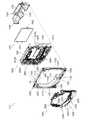
扉枠3の扉枠ベースユニット100について、図31乃至図33を参照して詳細に説明する。図31(a)は扉枠における扉枠ベースユニットを前から見た斜視図であり、(b)は扉枠ベースユニットを後ろから見た斜視図である。図32は扉枠ベースユニットを主な部材毎に分解して前から見た分解斜視図であり、図33は扉枠ベースユニットを主な部材毎に分解して後ろから見た分解斜視図である。
[3-1. Overall configuration of door frame base unit]
The door frame base unit 100 of the door frame 3 will be described in detail with reference to FIGS. 31 to 33. FIG. 31 (a) is a perspective view of the door frame base unit in the door frame as viewed from the front, and FIG. 31 (b) is a perspective view of the door frame base unit as viewed from the rear. FIG. 32 is an exploded perspective view of the door frame base unit disassembled for each main member and viewed from the front, and FIG. 33 is an exploded perspective view of the door frame base unit disassembled for each main member and viewed from the rear. be.
扉枠ベースユニット100は、正面視左辺側が本体枠4の前面を閉鎖するように本体枠4に対して開閉可能(ヒンジ回転可能)に取付けられるものである。扉枠ベースユニット100は、前面下隅にハンドルユニット300が、貫通口111の下側前面に演出操作ユニット400が取付けられる皿ユニット320が、貫通口111の左外側前面に扉枠左サイドユニット530が、貫通口111の右外側前面に扉枠右サイドユニット550が、貫通口111の上外側前面に扉枠トップユニット570が、夫々取付けられるものである。
The door frame base unit 100 is attached so as to be openable / closable (hinge rotatable) with respect to the main body frame 4 so that the left side side of the front view closes the front surface of the main body frame 4. The door frame base unit 100 has a handle unit 300 in the lower front corner, a dish unit 320 in which the effect operation unit 400 is attached to the lower front surface of the through hole 111, and a door frame left side unit 530 in the left outer front surface of the through port 111. The door frame right side unit 550 is attached to the right outer front surface of the through opening 111, and the door frame top unit 570 is attached to the upper outer front surface of the through opening 111, respectively.
扉枠ベースユニット100は、図32及び図33に等に示すように、正面視の外形が上下に延びた長方形で前後に貫通している貫通口111を有した板状の扉枠ベース110と、扉枠ベース110の後側に取付けられている枠状の補強ユニット130と、補強ユニット130の正面視左端側の上下両端に取付けられており扉枠ベース110から前方へ突出して本体枠4の本体枠側上ヒンジ部材620及び本体枠側下ヒンジ部材640に回転可能に取付けられる扉枠側上ヒンジ部材140及び扉枠側下ヒンジ部材150と、扉枠ベース110の前面で貫通口111の正面視左側に取付けられており前面に複数のLEDが実装されている扉枠左サイド装飾基板160と、扉枠ベース110の後側に回動可能に取付けられておりガラスユニット190を着脱可能に取付けるためのガラスユニット取付部材170と、を備えている。
As shown in FIGS. 32 and 33, the door frame base unit 100 includes a plate-shaped door frame base 110 having a rectangular outer shape extending vertically and having a through hole 111 penetrating back and forth. , The frame-shaped reinforcing unit 130 attached to the rear side of the door frame base 110, and the main body frame 4 which is attached to the upper and lower ends of the reinforcing unit 130 on the left end side of the front view and protrudes forward from the door frame base 110. The door frame side upper hinge member 140 and the door frame side lower hinge member 150 rotatably attached to the main body frame side upper hinge member 620 and the main body frame side lower hinge member 640, and the front surface of the through hole 111 on the front surface of the door frame base 110. The door frame left side decorative board 160, which is mounted on the left side of the door and has a plurality of LEDs mounted on the front surface, and the glass unit 190, which is rotatably mounted on the rear side of the door frame base 110, are detachably attached. A glass unit mounting member 170 for the door is provided.
また、扉枠ベースユニット100は、扉枠ベース110の前面で正面視右下隅に取付けられておりハンドルユニット300を取付けるための筒状のハンドル取付部材180と、扉枠ベース110の後面に取付けられ貫通口111を閉鎖するガラスユニット190と、ガラスユニット190の後面下部を覆う防犯カバー200と、扉枠ベース110の後面に扉枠ベース110を貫通して前方に突出するように取付けられる開閉シリンダユニット210と、扉枠ベース110の後面下部に取付けられる球送りユニット250と、扉枠ベース110の後面下部に取付けられるファールカバーユニット270と、を備えている。
Further, the door frame base unit 100 is attached to the lower right corner of the front view on the front surface of the door frame base 110, and is attached to the tubular handle attachment member 180 for attaching the handle unit 300 and the rear surface of the door frame base 110. A glass unit 190 that closes the through hole 111, a security cover 200 that covers the lower part of the rear surface of the glass unit 190, and an opening / closing cylinder unit that is attached to the rear surface of the door frame base 110 so as to penetrate the door frame base 110 and project forward. It includes 210, a ball feed unit 250 attached to the lower rear surface of the door frame base 110, and a foul cover unit 270 attached to the lower rear surface of the door frame base 110.
更に、扉枠ベースユニット100は、図示は省略するが、扉枠3に備えられている各種の装飾基板、球送ソレノイド255、ハンドル回転検知センサ307、ハンドルタッチセンサ310、単発ボタン操作センサ312、球貸ボタン328、返却ボタン329、球貸返却表示部330、演出選択左ボタン331、演出選択右ボタン332、振動モータ424、押圧検知センサ440、扉枠側演出表示装置460(液晶表示装置461)、上部スピーカ573、等と、本体枠4における基板ユニット900の扉枠用中継基板911との接続を中継するための扉本体中継基板を備えている。
Further, although not shown, the door frame base unit 100 includes various decorative substrates provided in the door frame 3, a ball feed solenoid 255, a handle rotation detection sensor 307, a handle touch sensor 310, a single-shot button operation sensor 312, and the like. Ball rental button 328, return button 329, ball rental display unit 330, effect selection left button 331, effect selection right button 332, vibration motor 424, pressure detection sensor 440, door frame side effect display device 460 (liquid crystal display device 461) , The upper speaker 573, and the like are provided with a door main body relay board for relaying the connection between the main body frame 4 and the door frame relay board 911 of the board unit 900.
[3−1a.扉枠ベース]
扉枠3における扉枠ベースユニット100の扉枠ベース110について、主に図31乃至図33を参照して詳細に説明する。扉枠ベース110は、正面視の外形が上下に延びた四角形(長方形)に形成されている。扉枠ベース110は、前後に貫通しており、正面視における内周形状が上下に延びた略四角形に形成された貫通口111を備えている。貫通口111は、内周を形成している上辺及び左右両辺が、扉枠ベース110の外周辺に夫々接近しており、内周を形成している下辺が、扉枠ベース110の下端から上下方向の約1/3の高さに位置している。従って、扉枠ベース110は、前後に貫通している貫通口111により全体が枠状に形成されている。この扉枠ベース110は、合成樹脂により一体成形されている。
[3-1a. Door frame base]
The door frame base 110 of the door frame base unit 100 in the door frame 3 will be described in detail mainly with reference to FIGS. 31 to 33. The door frame base 110 is formed in a quadrangle (rectangle) whose outer shape in front view extends vertically. The door frame base 110 penetrates in the front-rear direction, and includes a through-hole 111 formed in a substantially quadrangular shape having an inner peripheral shape extending vertically in a front view. In the through-hole 111, the upper side and the left and right sides forming the inner circumference are close to the outer periphery of the door frame base 110, respectively, and the lower side forming the inner circumference is up and down from the lower end of the door frame base 110. It is located at a height of about 1/3 in the direction. Therefore, the door frame base 110 is formed in a frame shape as a whole by the through openings 111 penetrating the front and rear. The door frame base 110 is integrally molded with a synthetic resin.
扉枠ベース110は、前面における正面視右下隅に形成されており左端側が右端側よりも前方へやや突出するように傾斜しているハンドル取付座面112と、ハンドル取付座面112と貫通口111との間で正面視右端付近に後面から前方へ向かって窪み、開閉シリンダユニット210のシリンダ取付板金213が取付けられるシリンダ取付部113と、シリンダ取付部113において前後に貫通しており開閉シリンダユニット210のシリンダ錠211が挿通されるシリンダ挿通孔114と、シリンダ挿通孔114及びハンドル取付座面112の正面視左側で前後に貫通しており球送りユニット250の進入口251a及び球抜口251bを前方に臨ませるための球送り開口115と、を備えている。
The door frame base 110 is formed in the lower right corner of the front view and is inclined so that the left end side slightly protrudes forward from the right end side, the handle mounting seat surface 112, the handle mounting seat surface 112, and the through hole 111. The opening / closing cylinder unit 210 is recessed from the rear surface to the front near the right end of the front view, and penetrates back and forth between the cylinder mounting portion 113 to which the cylinder mounting sheet metal 213 of the opening / closing cylinder unit 210 is mounted and the cylinder mounting portion 113. The cylinder insertion hole 114 into which the cylinder lock 211 of the above is inserted, and the cylinder insertion hole 114 and the handle mounting seat surface 112 penetrate the front and rear on the left side of the front view, and the entry entrance 251a and the ball outlet 251b of the ball feed unit 250 are forward. It is equipped with a ball feed opening 115 for facing the cylinder.
また、扉枠ベース110は、扉枠ベース110の左右方向中央より左寄りで且つハンドル取付座面112と略同じ高さで前後に貫通しておりファールカバーユニット270の球放出口276を前方に臨ませる下皿用通過口116と、扉枠ベース110の正面視左端付近で貫通口111の下辺に隣接するように前後に貫通しておりファールカバーユニット270の貫通球通路273を前方に臨ませる上皿用通過口117と、貫通口111の内周に沿って後面から前方へ向かって窪み、ガラスユニット190のガラス枠191が挿入されるガラスユニット取付部118と、扉枠ベース110の左右両上隅において前後に貫通しており扉枠トップユニット570の上部スピーカ573の後端が挿通されるスピーカ挿通口119と、を備えている。
Further, the door frame base 110 is to the left of the center of the door frame base 110 in the left-right direction and penetrates back and forth at substantially the same height as the handle mounting seat surface 112, and faces the ball discharge port 276 of the foul cover unit 270 forward. It penetrates back and forth between the lower plate passage port 116 and the door frame base 110 near the left end of the front view so as to be adjacent to the lower side of the through hole 111, so that the through ball passage 273 of the foul cover unit 270 faces forward. The dish passage port 117, the glass unit mounting portion 118 into which the glass frame 191 of the glass unit 190 is inserted, and the left and right upper sides of the door frame base 110, which are recessed from the rear surface to the front along the inner circumference of the through port 111. It is provided with a speaker insertion port 119 that penetrates back and forth in the corner and through which the rear end of the upper speaker 573 of the door frame top unit 570 is inserted.
[3−1b.補強ユニット]
扉枠ベースユニット100の補強ユニット130について、図31及び図33等を参照して詳細に説明する。補強ユニット130は、扉枠ベース110の後側に取付けられることで扉枠ベース110を補強して、扉枠ベース110(扉枠3)の強度剛性を高めている。補強ユニット130は、扉枠ベース110の後面における上辺に沿って取付けられる左右に延びた上補強板金131と、扉枠ベース110の後面における貫通口111の下側に取付けられる左右に延びた中補強板金132と、扉枠ベース110の後面における正面視左辺に沿って取付けられる上下に延びた左補強板金133と、扉枠ベース110の後面における正面視右辺に沿って取付けられる上下に延びた右補強板金134と、右補強板金134の後面に取付けられており施錠ユニット700の扉枠用鉤702が係止される施錠係止部135と、を備えている。
[3-1b. Reinforcement unit]
The reinforcing unit 130 of the door frame base unit 100 will be described in detail with reference to FIGS. 31 and 33 and the like. The reinforcing unit 130 is attached to the rear side of the door frame base 110 to reinforce the door frame base 110 and increase the strength and rigidity of the door frame base 110 (door frame 3). The reinforcing unit 130 includes a left-right extending upper reinforcing sheet metal 131 attached along the upper side of the rear surface of the door frame base 110 and a left-right extending middle reinforcement attached to the lower side of the through hole 111 on the rear surface of the door frame base 110. The sheet metal 132, the vertically extending left reinforcing sheet metal 133 attached along the left side of the front view on the rear surface of the door frame base 110, and the vertically extending right reinforcement attached along the right side of the front view on the rear surface of the door frame base 110. It includes a sheet metal 134 and a locking locking portion 135 that is attached to the rear surface of the right reinforcing sheet metal 134 and locks the door frame hook 702 of the locking unit 700.
補強ユニット130は、上補強板金131の左右両端が左補強板金133及び右補強板金134の夫々の上端にビスによって連結固定されており、中補強板金132の左端が左補強板金133にビスによって連結固定されている。中補強板金132の右端は、後述する開閉シリンダユニット210のシリンダ取付板金213を介して右補強板金134に連結固定されている。従って、補強ユニット130は、上補強板金131、中補強板金132、左補強板金133、及び右補強板金134等によって、枠状に形成されている。
In the reinforcing unit 130, the left and right ends of the upper reinforcing sheet metal 131 are connected and fixed to the upper ends of the left reinforcing sheet metal 133 and the right reinforcing sheet metal 134 by screws, and the left end of the middle reinforcing sheet metal 132 is connected to the left reinforcing sheet metal 133 by screws. It is fixed. The right end of the middle reinforcing sheet metal 132 is connected and fixed to the right reinforcing sheet metal 134 via the cylinder mounting sheet metal 213 of the opening / closing cylinder unit 210 described later. Therefore, the reinforcing unit 130 is formed in a frame shape by the upper reinforcing sheet metal 131, the middle reinforcing sheet metal 132, the left reinforcing sheet metal 133, the right reinforcing sheet metal 134, and the like.
補強ユニット130の上補強板金131、中補強板金132、左補強板金133、右補強板金134、及び施錠係止部135は、夫々金属板を適宜屈曲させて形成されている。中補強板金132は、扉枠ベース110の上皿用通過口117と対応する位置に、前後に貫通した切欠部132aが形成されている。
The upper reinforcing sheet metal 131, the middle reinforcing sheet metal 132, the left reinforcing sheet metal 133, the right reinforcing sheet metal 134, and the locking locking portion 135 of the reinforcing unit 130 are each formed by appropriately bending a metal plate. The middle reinforcing sheet metal 132 has a cutout portion 132a penetrating in the front-rear direction at a position corresponding to the upper plate passage port 117 of the door frame base 110.
補強ユニット130は、詳細な図示は省略するが、各上補強板金131、中補強板金132、左補強板金133、及び右補強板金134において、夫々前後方向に屈曲された部位を有しており、その部位によって、強度剛性が高められていると共に、外部からのピアノ線やマイナスドライバー等の不正な工具の侵入を防止している。
Although detailed illustration is omitted, the reinforcing unit 130 has a portion bent in the front-rear direction in each of the upper reinforcing sheet metal 131, the middle reinforcing sheet metal 132, the left reinforcing sheet metal 133, and the right reinforcing sheet metal 134. The strength and rigidity are enhanced by the part, and the intrusion of an illegal tool such as a piano wire or a flat-blade screwdriver from the outside is prevented.
[3−1c.扉枠側上ヒンジ部材]
扉枠ベースユニット100の扉枠側上ヒンジ部材140について、主に図31乃至図33等を参照して詳細に説明する。扉枠側上ヒンジ部材140は、扉枠ベース110に取付けられ上下に離間している一対の突出片141aを有した扉枠上ヒンジ軸ブラケット141と、扉枠上ヒンジ軸ブラケット141の一対の突出片141aを貫通しており、上端が本体枠側上ヒンジ部材620の扉枠用上ヒンジ孔623に挿入される円柱状の扉枠上ヒンジピン142と、扉枠上ヒンジピン142における一対の突出片141aの間の位置に取付けられている円盤状の鍔部材143と、鍔部材143と一対の突出片141aのうちの下側の突出片141aとの間に介装されていると共に扉枠上ヒンジピン142が挿通されており、扉枠上ヒンジピン142を上方へ付勢しているロックバネ144と、を備えている。
[3-1c. Door frame side upper hinge member]
The door frame side upper hinge member 140 of the door frame base unit 100 will be described in detail mainly with reference to FIGS. 31 to 33 and the like. The door frame side upper hinge member 140 is a pair of protrusions of the door frame upper hinge shaft bracket 141 having a pair of projecting pieces 141a attached to the door frame base 110 and separated vertically, and the door frame upper hinge shaft bracket 141. A pair of projecting pieces 141a in the columnar door frame upper hinge pin 142 and the door frame upper hinge pin 142 that penetrate the piece 141a and whose upper end is inserted into the door frame upper hinge hole 623 of the main body frame side upper hinge member 620. A disk-shaped flange member 143 attached at a position between the door frame and a hinge pin 142 on the door frame while being interposed between the flange member 143 and the lower protruding piece 141a of the pair of protruding pieces 141a. Is inserted, and is provided with a lock spring 144 that urges the hinge pin 142 on the door frame upward.
扉枠上ヒンジ軸ブラケット141は、図示は省略するが一対の突出片141aの後端同士を連結している平板状の取付片を有しており、側面視の形状が前方へ開放されたコ字状に形成されている。扉枠上ヒンジ軸ブラケット141は、一対の突出片141a同士を連結している取付片が、ビスによって扉枠ベース110の後面に取付けられている。
Although not shown, the hinge shaft bracket 141 on the door frame has a flat plate-shaped mounting piece that connects the rear ends of the pair of projecting pieces 141a, and the shape of the side view is open to the front. It is formed in a character shape. In the door frame upper hinge shaft bracket 141, a mounting piece connecting a pair of projecting pieces 141a to each other is mounted on the rear surface of the door frame base 110 by a screw.
扉枠上ヒンジピン142は、上側の突出片141aよりも上方に突出している部位(上端)が、本体枠側上ヒンジ部材620の扉枠用上ヒンジ孔623に対して回転可能に挿入される。また、扉枠上ヒンジピン142は、図示は省略するが、下側の突出片141aよりも下方に突出している部位が水平方向に屈曲している。この屈曲している部位が下側の突出片141aの下面に当接することで、扉枠上ヒンジピン142の上方への移動を規制している。
In the door frame upper hinge pin 142, a portion (upper end) protruding upward from the upper protruding piece 141a is rotatably inserted into the door frame upper hinge hole 623 of the main body frame side upper hinge member 620. Further, although not shown, the hinge pin 142 on the door frame has a portion protruding downward from the lower protruding piece 141a bent in the horizontal direction. The bent portion abuts on the lower surface of the lower protruding piece 141a to restrict the upward movement of the hinge pin 142 on the door frame.
鍔部材143は、Eリングとされており、扉枠上ヒンジピン142の外周に形成されている溝内に挿入保持されている。ロックバネ144は、扉枠上ヒンジピン142を挿通可能なコイルスプリングとされており、上端が鍔部材143に当接していると共に、下端が下側の突出片141aに当接している。このロックバネ144は、鍔部材143と下側の突出片141aとの間に、圧縮された状態で介装されており、鍔部材143を介して扉枠上ヒンジピン142を上方へ付勢している。
The collar member 143 is an E-ring, and is inserted and held in a groove formed on the outer periphery of the hinge pin 142 on the door frame. The lock spring 144 is a coil spring through which the hinge pin 142 on the door frame can be inserted, and the upper end is in contact with the flange member 143 and the lower end is in contact with the lower protruding piece 141a. The lock spring 144 is interposed between the collar member 143 and the lower protruding piece 141a in a compressed state, and urges the hinge pin 142 on the door frame upward via the collar member 143. ..
扉枠側上ヒンジ部材140は、扉枠上ヒンジピン142がロックバネ144により上方へ付勢された状態となっており、扉枠上ヒンジピン142における下端の水平に屈曲している部位が下側の突出片141aの下面に当接することで、これ以上の上方への移動が規制されている。この状態では、扉枠上ヒンジピン142の上端が、上側の突出片141aの上面よりも所定量上方に突出している。
The door frame upper hinge member 140 is in a state in which the door frame upper hinge pin 142 is urged upward by the lock spring 144, and the horizontally bent portion of the lower end of the door frame upper hinge pin 142 protrudes downward. Further upward movement is restricted by abutting on the lower surface of the piece 141a. In this state, the upper end of the hinge pin 142 on the door frame protrudes above the upper surface of the upper protruding piece 141a by a predetermined amount.
扉枠側上ヒンジ部材140は、扉枠上ヒンジピン142における下端の水平に屈曲している部位を作業者が持って、ロックバネ144の付勢力に抗してその部位を下方へ引っ張ると、扉枠上ヒンジピン142を全体的に下方へ移動させることができ、扉枠上ヒンジピン142の上端を、上側の突出片141aの上面よりも下方へ没入させることができる。従って、扉枠側上ヒンジ部材140は、扉枠上ヒンジピン142の上端を、本体枠側上ヒンジ部材620の扉枠用上ヒンジ孔623に対して下方から挿入させたり、下方へ抜いたりすることができる。これにより、扉枠側上ヒンジ部材140の扉枠上ヒンジピン142の上端を、本体枠側上ヒンジ部材620の扉枠用上ヒンジ孔623に挿入させることで、扉枠3の正面視上部左端を、本体枠4に対してヒンジ回転可能に支持させることができる。
The door frame side upper hinge member 140 has a horizontally bent portion of the lower end of the door frame upper hinge pin 142 when the operator holds the portion and pulls the portion downward against the urging force of the lock spring 144. The upper hinge pin 142 can be moved downward as a whole, and the upper end of the hinge pin 142 on the door frame can be immersed below the upper surface of the upper protruding piece 141a. Therefore, the door frame side upper hinge member 140 has the upper end of the door frame upper hinge pin 142 inserted into the door frame upper hinge hole 623 of the main body frame side upper hinge member 620 from below or pulled out downward. Can be done. As a result, the upper end of the door frame upper hinge pin 142 of the door frame side upper hinge member 140 is inserted into the door frame upper hinge hole 623 of the main body frame side upper hinge member 620, so that the upper left end of the door frame 3 in front view can be inserted. , The hinge can be rotatably supported with respect to the main body frame 4.
また、扉枠側上ヒンジ部材140は、扉枠上ヒンジピン142における扉枠上ヒンジ軸ブラケット141の一対の突出片141aにより支持されている部位が、後述する扉枠側下ヒンジ部材150の扉枠下ヒンジピン152と同軸上に支持されている。これにより、扉枠側上ヒンジ部材140と扉枠側下ヒンジ部材150とによって、扉枠3を本体枠4に対して良好な状態でヒンジ回転させることができる。
Further, in the door frame side upper hinge member 140, the portion of the door frame upper hinge pin 142 supported by the pair of protruding pieces 141a of the door frame upper hinge shaft bracket 141 is the door frame of the door frame side lower hinge member 150, which will be described later. It is supported coaxially with the lower hinge pin 152. As a result, the door frame side upper hinge member 140 and the door frame side lower hinge member 150 can rotate the door frame 3 with respect to the main body frame 4 in a good state.
[3−1d.扉枠側下ヒンジ部材]
扉枠ベースユニット100の扉枠側下ヒンジ部材150について、主に図31及び図32等を参照して詳細に説明する。扉枠側下ヒンジ部材150は、扉枠ベース110に取付けられ前方に延出している平板状の延出片151aを有している扉枠下ヒンジ軸ブラケット151と、扉枠下ヒンジ軸ブラケットにおける延出片151aの前端部付近から下方に突出している円柱状の扉枠下ヒンジピン152(図21及び図22を参照)と、を備えている。
[3-1d. Door frame side lower hinge member]
The door frame side lower hinge member 150 of the door frame base unit 100 will be described in detail mainly with reference to FIGS. 31 and 32. The door frame side lower hinge member 150 is in the door frame lower hinge shaft bracket 151 having a flat plate-shaped extension piece 151a attached to the door frame base 110 and extending forward, and the door frame lower hinge shaft bracket. A cylindrical door frame lower hinge pin 152 (see FIGS. 21 and 22) projecting downward from the vicinity of the front end portion of the extension piece 151a is provided.
扉枠下ヒンジ軸ブラケット151は、水平に延びた平板状の延出片151aの後端から上方に延出した平板状の取付片(図示は省略)を有しており、側面視の全体形状が略L字状に形成されている。この扉枠下ヒンジ軸ブラケット151は、図示しない取付片がビスによって扉枠ベース110の後面に取付けられている。
The hinge shaft bracket 151 under the door frame has a flat plate-shaped mounting piece (not shown) extending upward from the rear end of the horizontally extending flat plate-shaped extending piece 151a, and has an overall shape in a side view. Is formed in a substantially L shape. A mounting piece (not shown) is attached to the rear surface of the door frame base 110 by screws in the door frame lower hinge shaft bracket 151.
扉枠下ヒンジピン152は、下端部が、下方へ向かうほど窄まる円錐台状に形成されている。この扉枠下ヒンジピン152は、後述する本体枠4における本体枠側下ヒンジ部材640の扉枠用ヒンジ孔644に、上方から回転可能に挿入される。扉枠下ヒンジピン152は、扉枠側上ヒンジ部材140の扉枠上ヒンジピン142と同軸上に配置されている。
The lower end of the door frame lower hinge pin 152 is formed in a truncated cone shape in which the lower end portion narrows toward the bottom. The door frame lower hinge pin 152 is rotatably inserted from above into the door frame hinge hole 644 of the main body frame side lower hinge member 640 in the main body frame 4, which will be described later. The door frame lower hinge pin 152 is arranged coaxially with the door frame upper hinge pin 142 of the door frame side upper hinge member 140.
この扉枠側下ヒンジ部材150は、扉枠下ヒンジピン152が本体枠側下ヒンジ部材640の扉枠用ヒンジ孔644に挿入されることで、扉枠3を本体枠4に対してヒンジ回転可能に支持することができる。
In the door frame side lower hinge member 150, the door frame 3 can be hinged with respect to the main body frame 4 by inserting the door frame lower hinge pin 152 into the door frame hinge hole 644 of the main body frame side lower hinge member 640. Can be supported by.
[3−1e.扉枠左サイド装飾基板]
扉枠ベースユニット100の扉枠左サイド装飾基板160について、主に図31及び図32等を参照して詳細に説明する。扉枠左サイド装飾基板160は、扉枠ベース110の前面において、貫通口111の正面視左側に取付けられている。扉枠左サイド装飾基板160は、扉枠ベース110における正面視左側のスピーカ挿通口119よりも下側の位置の高さから貫通口111の上下方向の中央付近の高さまで上下に延びている扉枠左サイド上装飾基板161と、扉枠左サイド上装飾基板161の下側の位置の高さから上皿用通過口117の下端と略同じ高さまで上下に延びている扉枠左サイド下装飾基板162と、を備えている。
[3-1e. Door frame left side decorative board]
The door frame left side decorative substrate 160 of the door frame base unit 100 will be described in detail mainly with reference to FIGS. 31 and 32. The door frame left side decorative substrate 160 is attached to the front surface of the door frame base 110 on the left side of the through hole 111 when viewed from the front. The door frame left side decorative substrate 160 is a door extending vertically from a height lower than the speaker insertion port 119 on the left side of the front view of the door frame base 110 to a height near the center in the vertical direction of the through hole 111. The lower decoration on the left side of the door frame extends vertically from the height of the lower side of the upper decorative board 161 on the left side of the frame and the upper decorative board 161 on the left side of the door frame to approximately the same height as the lower end of the passage port 117 for the upper plate. The board 162 and the like are provided.
扉枠左サイド装飾基板160の扉枠左サイド上装飾基板161及び扉枠左サイド下装飾基板162は、夫々前面に、前方へ光を照射可能な複数のLED161a,162aを備えている。これらLED161a,162aは、フルカラーLEDとされている。
The door frame left side upper decorative substrate 161 and the door frame left side lower decorative substrate 162 of the door frame left side decorative substrate 160 are each provided with a plurality of LEDs 161a and 162a capable of irradiating light forward on the front surface. These LEDs 161a and 162a are full-color LEDs.
扉枠左サイド装飾基板160は、扉枠3を組立てた状態で、後述する扉枠左サイドユニット530の後方に位置しており、前面に備えられた(実装された)複数のLED161a,162aを適宜発光させることで、扉枠左サイドユニット530の左ユニット装飾レンズ部材を発光装飾させることができる。
The door frame left side decorative substrate 160 is located behind the door frame left side unit 530, which will be described later, in a state where the door frame 3 is assembled, and has a plurality of (mounted) LEDs 161a and 162a provided on the front surface. The left unit decorative lens member of the door frame left side unit 530 can be light-emitting and decorated by appropriately emitting light.
[3−1f.ガラスユニット取付部材]
扉枠ベースユニット100のガラスユニット取付部材170について、主に図31(b)等を参照して詳細に説明する。ガラスユニット取付部材170は、扉枠ベース110の後側に回動可能に取付けられておりガラスユニット190を着脱可能に取付けるためのものである。ガラスユニット取付部材170は、扉枠ベース110の後側で前後に延びた軸線周りに対して回転可能に取付けられる円盤状の基部171と、基部171から回転軸線に対して直角方向へ棒状に突出している突出部172と、を有している。
[3-1f. Glass unit mounting member]
The glass unit mounting member 170 of the door frame base unit 100 will be described in detail mainly with reference to FIG. 31 (b) and the like. The glass unit mounting member 170 is rotatably mounted on the rear side of the door frame base 110, and is for mounting the glass unit 190 detachably. The glass unit mounting member 170 has a disk-shaped base 171 that is rotatably mounted around an axis extending back and forth on the rear side of the door frame base 110, and a rod-shaped protrusion from the base 171 in a direction perpendicular to the rotation axis. It has a protruding portion 172 and a protruding portion 172.
ガラスユニット取付部材170は、扉枠ベース110の後面における一対のスピーカ挿通口119の下側で、ガラスユニット取付部118よりも外側の部位に、夫々回転可能に取付けられている。
The glass unit mounting member 170 is rotatably mounted on the rear surface of the door frame base 110 at a portion outside the pair of speaker insertion ports 119 and outside the glass unit mounting portion 118, respectively.
ガラスユニット取付部材170は、突出部172が基部171から上方へ突出するように回転させた状態とすることで、背面視において扉枠ベース110のガラスユニット取付部118よりも突出部172が外側に位置した状態となり、扉枠ベース110のガラスユニット取付部118に対してガラスユニット190を挿入したり、ガラスユニット取付部118からガラスユニット190を取外したりすることができる。
The glass unit mounting member 170 is in a state in which the protruding portion 172 is rotated so as to project upward from the base portion 171 so that the protruding portion 172 is outside the glass unit mounting portion 118 of the door frame base 110 when viewed from the rear. In the positioned state, the glass unit 190 can be inserted into the glass unit mounting portion 118 of the door frame base 110, or the glass unit 190 can be removed from the glass unit mounting portion 118.
ガラスユニット取付部材170は、ガラスユニット190を扉枠ベース110のガラスユニット取付部118に挿入させた状態で、突出部172が基部171から下方へ突出するように回転させると、突出部172がガラスユニット190の取付片191aの後側と当接し、ガラスユニット190上部の後方への移動を規制した状態となり、ガラスユニット190を扉枠ベース110に取付けることができる。
When the glass unit mounting member 170 is rotated so that the protruding portion 172 protrudes downward from the base 171 in a state where the glass unit 190 is inserted into the glass unit mounting portion 118 of the door frame base 110, the protruding portion 172 becomes glass. The glass unit 190 can be attached to the door frame base 110 in a state where it comes into contact with the rear side of the attachment piece 191a of the unit 190 and the rearward movement of the upper portion of the glass unit 190 is restricted.
ガラスユニット取付部材170は、扉枠ベース110に回転可能に取付けられる円盤状の基部171から突出部172が突出しているため、ガラスユニット取付部材170の重心位置が突出部172内に位置している。このことから、ガラスユニット取付部材170が自由に回転できる状態では、突出部172が基部171から下方へ突出した状態で安定することとなる。そして、ガラスユニット取付部材170では、突出部172が基部171から下方へ突出している回転位置の時に、突出部172によりガラスユニット190の後方への移動を規制させるようにしているため、ガラスユニット取付部材170に振動等が作用しても、突出部172が基部171から上方へ突出するように全体が回転することはなく、ガラスユニット190の後方への移動の規制が自然に解除されることはない。
Since the protruding portion 172 of the glass unit mounting member 170 protrudes from the disk-shaped base 171 that is rotatably mounted on the door frame base 110, the center of gravity of the glass unit mounting member 170 is located in the protruding portion 172. .. From this, in a state where the glass unit mounting member 170 can rotate freely, the protruding portion 172 is stable in a state of protruding downward from the base portion 171. Then, in the glass unit mounting member 170, when the protruding portion 172 is in the rotational position protruding downward from the base portion 171, the protruding portion 172 regulates the backward movement of the glass unit 190, so that the glass unit is mounted. Even if vibration or the like acts on the member 170, the entire protrusion 172 does not rotate upward from the base 171 and the restriction on the rearward movement of the glass unit 190 is naturally lifted. do not have.
なお、扉枠ベース110からガラスユニット190を取外す場合は、ガラスユニット取付部材170を、突出部172が基部171から上方へ突出するように回転させて、突出部172をガラスユニット190の取付片191aよりも外側へ移動させることで、ガラスユニット190の上部側を後方へ移動させることができるようになり、扉枠ベース110からガラスユニット190を取外すことができる。
When removing the glass unit 190 from the door frame base 110, the glass unit mounting member 170 is rotated so that the protruding portion 172 projects upward from the base 171 so that the protruding portion 172 is mounted on the glass unit 190 mounting piece 191a. By moving the glass unit 190 to the outside, the upper side of the glass unit 190 can be moved to the rear, and the glass unit 190 can be removed from the door frame base 110.
[3−1g.ハンドル取付部材]
扉枠ベースユニット100のハンドル取付部材180について、主に図31乃至図33等を参照して詳細に説明する。ハンドル取付部材180は、扉枠ベース110の前面にハンドルユニット300を取付けるためのものである。ハンドル取付部材180は、図32及び図33等に示すように、前後方向へ延びた円筒状の筒部181と、筒部181の後端から筒部181の軸に対して直角方向外方へ延びた円環状のフランジ部182と、筒部181内に突出していると共に筒部181の軸方向全長に亘って延びており筒部181の周方向に対して不等間隔に配置された複数(本例では三つ)の突条183と、筒部181の外周面とフランジ部182の前面とを繋ぎ、筒部181の周方向に対して複数配置された補強リブ184と、を備えている。
[3-1 g. Handle mounting member]
The handle mounting member 180 of the door frame base unit 100 will be described in detail mainly with reference to FIGS. 31 to 33 and the like. The handle mounting member 180 is for mounting the handle unit 300 on the front surface of the door frame base 110. As shown in FIGS. 32 and 33, the handle mounting member 180 has a cylindrical tubular portion 181 extending in the front-rear direction and an outward direction perpendicular to the axis of the tubular portion 181 from the rear end of the tubular portion 181. An annular flange portion 182 that extends, and a plurality of flange portions 182 that project into the tubular portion 181 and extend over the entire axial length of the tubular portion 181 and are arranged at unequal intervals with respect to the circumferential direction of the tubular portion 181. In this example, it is provided with three) ridges 183, and a plurality of reinforcing ribs 184 arranged in the circumferential direction of the cylinder portion 181 by connecting the outer peripheral surface of the cylinder portion 181 and the front surface of the flange portion 182. ..
ハンドル取付部材180は、フランジ部182の後面を、扉枠ベース110におけるハンドル取付座面112の前面に当接させた状態で、ビスによってハンドル取付座面112に取付けられる。
The handle mounting member 180 is mounted on the handle mounting seat surface 112 with screws in a state where the rear surface of the flange portion 182 is in contact with the front surface of the handle mounting seat surface 112 on the door frame base 110.
筒部181は、内径がハンドルユニット300におけるハンドルベース301の基部301aの外径よりも若干大きく形成されている。三つの突条183は、一つが筒部181内の上側に備えられており、残り二つが筒部181内の下側に備えられている。これら三つの突条183は、ハンドルベース301における三つの溝部301cと対応する位置に形成されている。従って、ハンドル取付部材180は、三つの突条183と、ハンドルベース301の三つの溝部301cとを一致させた状態でのみ、筒部181内にハンドルベース301の基部301aを挿入させることができ、扉枠ベース110に対してハンドルベース301(ハンドルユニット300)の回転位置を規制することができる。
The inner diameter of the tubular portion 181 is formed to be slightly larger than the outer diameter of the base portion 301a of the handle base 301 in the handle unit 300. One of the three ridges 183 is provided on the upper side in the tubular portion 181 and the other two are provided on the lower side in the tubular portion 181. These three ridges 183 are formed at positions corresponding to the three grooves 301c in the handle base 301. Therefore, the handle mounting member 180 can insert the base portion 301a of the handle base 301 into the tubular portion 181 only when the three ridges 183 and the three groove portions 301c of the handle base 301 are aligned with each other. The rotation position of the handle base 301 (handle unit 300) can be regulated with respect to the door frame base 110.
なお、ハンドル取付部材180は、フランジ部182の後面に対して、筒部181の軸線が垂直に延びていることから、扉枠ベース110の傾斜したハンドル取付座面112に取付けることで、筒部181の軸線が右前方へ延びるように傾いた状態となり、ハンドルユニット300を同様に傾いた状態で扉枠ベース110に取付けることができる。
Since the axis of the cylinder portion 181 extends vertically to the rear surface of the flange portion 182, the handle mounting member 180 can be attached to the inclined handle mounting seat surface 112 of the door frame base 110 to form the cylinder portion. The axis of 181 is tilted so as to extend to the front right, and the handle unit 300 can be attached to the door frame base 110 in the same tilted state.
[3−1h.ガラスユニット]
扉枠ベースユニット100のガラスユニット190について、主に図31乃至図33等を参照して詳細に説明する。ガラスユニット190は、扉枠ベース110の貫通口111を、前方から後方が視認できるように閉鎖するものである。ガラスユニット190は、扉枠ベース110の貫通口111の内周形状よりも大きくガラスユニット取付部118に取付可能な枠状のガラス枠191と、ガラス枠191の枠内を閉鎖し外周がガラス枠191に取付けられている透明な二つのガラス板192と、を備えている。二つのガラス板192は、ガラス枠191の前端側と後端側とに夫々取付けられており、互いの間に空間が形成されるように前後に離間している(図26等を参照)。
[3-1h. Glass unit]
The glass unit 190 of the door frame base unit 100 will be described in detail mainly with reference to FIGS. 31 to 33 and the like. The glass unit 190 closes the through-hole 111 of the door frame base 110 so that the rear can be seen from the front. The glass unit 190 has a frame-shaped glass frame 191 that is larger than the inner peripheral shape of the through hole 111 of the door frame base 110 and can be attached to the glass unit mounting portion 118, and the glass frame 191 is closed and the outer periphery is a glass frame. It comprises two transparent glass plates 192 attached to 191. The two glass plates 192 are attached to the front end side and the rear end side of the glass frame 191 respectively, and are separated from each other in the front-rear direction so as to form a space between them (see FIG. 26 and the like).
ガラス枠191は、正面視左右上隅よりも下側の位置から外方へ平板状に延出している一対の取付片191aと、下端から下方へ突出していると共に下辺に沿って延びている帯板状の係止片191bと、を有している。ガラス枠191の取付片191aは、ガラスユニット取付部材170の突出部172と当接可能とされている。係止片191bは、扉枠ベース110と補強ユニット130の中補強板金132との間の空間内に挿入可能とされている(図26を参照)。
The glass frame 191 includes a pair of mounting pieces 191a extending outward in a flat plate shape from a position below the upper left and right corners in the front view, and a band extending downward from the lower end and extending along the lower side. It has a plate-shaped locking piece 191b and. The mounting piece 191a of the glass frame 191 can be brought into contact with the protruding portion 172 of the glass unit mounting member 170. The locking piece 191b can be inserted into the space between the door frame base 110 and the intermediate reinforcing sheet metal 132 of the reinforcing unit 130 (see FIG. 26).
このガラスユニット190は、扉枠ベース110の後側から、ガラス枠191の係止片191bを、扉枠ベース110と補強ユニット130の中補強板金132との間の隙間に上方から挿入した上で、ガラス枠191の前端を扉枠ベース110のガラスユニット取付部118の後面に当接させ、ガラスユニット取付部材170を回転させてガラスユニット取付部材170の突出部172をガラス枠191の取付片191aの後面と当接させることで、扉枠ベース110に取付けられる。
In the glass unit 190, the locking piece 191b of the glass frame 191 is inserted from above into the gap between the door frame base 110 and the middle reinforcing sheet metal 132 of the reinforcing unit 130 from the rear side of the door frame base 110. , The front end of the glass frame 191 is brought into contact with the rear surface of the glass unit mounting portion 118 of the door frame base 110, the glass unit mounting member 170 is rotated, and the protruding portion 172 of the glass unit mounting member 170 is brought into contact with the mounting piece 191a of the glass frame 191. It is attached to the door frame base 110 by being brought into contact with the rear surface.
ガラスユニット190を扉枠ベース110から取外す場合は、上記と逆の手順により、取外すことができる。これにより、ガラスユニット190は、扉枠ベース110に対して着脱可能となっている。
When the glass unit 190 is removed from the door frame base 110, it can be removed by the reverse procedure of the above. As a result, the glass unit 190 can be attached to and detached from the door frame base 110.
[3−1i.防犯カバー]
扉枠ベースユニット100の防犯カバー200について、主に図31乃至図33等を参照して詳細に説明する。防犯カバー200は、ガラスユニット190の後面下部を覆うように扉枠ベース110の後側に取付けられ、透明な合成樹脂により形成されている。防犯カバー200は、外周が所定形状に形成された平板状の本体部201と、本体部201の外周縁に沿って後方へ短く突出した平板状の後方突片202と、左右に離間して配置され本体部201よりも前方に突出し、扉枠ベース110の後側に係止可能とされている一対の係止片203と、を備えている。
[3-1i. Security cover]
The security cover 200 of the door frame base unit 100 will be described in detail with reference to FIGS. 31 to 33 and the like. The security cover 200 is attached to the rear side of the door frame base 110 so as to cover the lower portion of the rear surface of the glass unit 190, and is made of a transparent synthetic resin. The security cover 200 is arranged so as to be separated from each other to the left and right by a flat plate-shaped main body 201 having an outer periphery formed in a predetermined shape and a flat plate-shaped rear projecting piece 202 protruding rearward along the outer peripheral edge of the main body 201. It is provided with a pair of locking pieces 203 that protrude forward from the main body 201 and are lockable on the rear side of the door frame base 110.
防犯カバー200の本体部201は、扉枠ベース110に取付けた状態で下端がガラスユニット190の下端よりも下方へ突出するように形成されている。また、本体部201は、上端が、パチンコ機1に組立てた状態で、遊技盤5における遊技領域5aの下端に沿った形状に形成されている。詳述すると、本体部201の上端は、後述する前構成部材1000の内レール1002の一部、アウト誘導部1003、右下レール1004の一部、及び右レール1005に沿った形状に形成されており、パチンコ機1に組立てた状態で遊技領域5a内に突出しないように形成されている。
The main body 201 of the security cover 200 is formed so that the lower end thereof protrudes downward from the lower end of the glass unit 190 when attached to the door frame base 110. Further, the upper end of the main body 201 is formed in a shape along the lower end of the game area 5a in the game board 5 in a state where the upper end is assembled in the pachinko machine 1. More specifically, the upper end of the main body 201 is formed in a shape along a part of the inner rail 1002 of the front component 1000 described later, an out guide part 1003, a part of the lower right rail 1004, and the right rail 1005. The rails are formed so as not to protrude into the game area 5a when assembled in the pachinko machine 1.
後方突片202は、本体部201の外周縁の略全周に亘って形成されている。従って、防犯カバー200は、本体部201と後方突片202とによって、後方へ開放された浅い箱状に形成されており、強度・剛性が高くなっている。また、後方突片202は、図33に示すように、本体部201の外周縁とは異なる本体部201の後面の一部からも後方に突出している。この本体部201の後面の一部から後方に突出している後方突片202は、パチンコ機1に組立てた状態で遊技盤5の前構成部材1000における外レール1001の一部と沿うように形成されている。
The rear projecting piece 202 is formed over substantially the entire circumference of the outer peripheral edge of the main body portion 201. Therefore, the security cover 200 is formed in a shallow box shape that is opened rearward by the main body portion 201 and the rear projecting piece 202, and has high strength and rigidity. Further, as shown in FIG. 33, the rear projecting piece 202 projects rearward from a part of the rear surface of the main body 201, which is different from the outer peripheral edge of the main body 201. The rear projecting piece 202 projecting rearward from a part of the rear surface of the main body 201 is formed along a part of the outer rail 1001 in the front component 1000 of the game board 5 in a state of being assembled in the pachinko machine 1. ing.
なお、後方突片202は、パチンコ機1に組立てた状態で、遊技盤5における外レール1001と内レール1002との間に位置する部位には形成されていない。これにより、外レール1001と内レール1002との間を通る遊技球(球発射装置680により発射された遊技球)が、防犯カバー200の後方突片202に当接することはなく、遊技領域5a内への遊技球の打込みを阻害することはない。
The rear projecting piece 202 is not formed at a portion of the game board 5 located between the outer rail 1001 and the inner rail 1002 in a state of being assembled on the pachinko machine 1. As a result, the game ball (the game ball launched by the ball launcher 680) passing between the outer rail 1001 and the inner rail 1002 does not come into contact with the rear projecting piece 202 of the security cover 200, and is inside the game area 5a. It does not hinder the driving of the game ball into the ball.
一対の係止片203は、扉枠ベース110の後側に弾性係止される。これにより、防犯カバー200は、扉枠ベース110に対して容易に着脱することができる。
The pair of locking pieces 203 are elastically locked to the rear side of the door frame base 110. As a result, the security cover 200 can be easily attached to and detached from the door frame base 110.
防犯カバー200は、パチンコ機1に組立てた状態で、本体部201の前面がガラスユニット190の後面(ガラス枠191の後端)と当接し、本体部201の下辺から後方へ突出している部位を除いた後方突片202が、後述する前構成部材1000の防犯凹部1008内に挿入された状態となる。また、防犯カバー200は、本体部201の下辺から後方に突出している後方突片202が、前構成部材1000の下面と接するように前構成部材1000の前面よりも後方へ突出している状態となる。これにより、防犯カバー200と遊技盤5(前構成部材1000)との間が、防犯カバー200の後方突片202と前構成部材1000の防犯凹部1008とによって複雑に屈曲した状態となるため、遊技盤5の前面下方より防犯カバー200と前構成部材1000との間を通してピアノ線等の不正な工具を遊技領域5a内に侵入させようとしても、後方突片202や防犯凹部1008に阻まれることとなり、遊技領域5a内への不正な工具の侵入を阻止することができる。
When the security cover 200 is assembled in the pachinko machine 1, the front surface of the main body 201 is in contact with the rear surface of the glass unit 190 (the rear end of the glass frame 191), and the portion protruding rearward from the lower side of the main body 201 is formed. The removed rear projecting piece 202 is in a state of being inserted into the security recess 10008 of the front component 1000, which will be described later. Further, the security cover 200 is in a state in which the rear projecting piece 202 projecting rearward from the lower side of the main body 201 projects rearward from the front surface of the front component 1000 so as to be in contact with the lower surface of the front component 1000. .. As a result, the space between the security cover 200 and the game board 5 (front component 1000) is complicatedly bent by the rear projecting piece 202 of the security cover 200 and the security recess 1008 of the front component 1000. Even if an unauthorized tool such as a piano wire is attempted to enter the game area 5a from below the front surface of the board 5 through between the security cover 200 and the front component 1000, it will be blocked by the rear projecting piece 202 and the security recess 1008. , It is possible to prevent an unauthorized tool from entering the game area 5a.
[3−1j.開閉シリンダユニット]
扉枠ベースユニット100の開閉シリンダユニット210について、主に図31乃至図33等を参照して説明する。開閉シリンダユニット210は、正面視において扉枠ベース110の右端付近で貫通口111とハンドル取付座面112との間の位置のシリンダ取付部113に後側から取付けられ、後述する施錠ユニット700と協働して、扉枠3と本体枠4との開閉、及び、外枠2と本体枠4との開閉に使用されるものである。
[3-1j. Open / close cylinder unit]
The opening / closing cylinder unit 210 of the door frame base unit 100 will be described mainly with reference to FIGS. 31 to 33 and the like. The opening / closing cylinder unit 210 is attached from the rear side to the cylinder mounting portion 113 located between the through hole 111 and the handle mounting seat surface 112 near the right end of the door frame base 110 in the front view, and cooperates with the locking unit 700 described later. It works and is used for opening and closing the door frame 3 and the main body frame 4, and opening and closing the outer frame 2 and the main body frame 4.
開閉シリンダユニット210は、前面に鍵穴211aを有し前後に延びた円筒状のシリンダ錠211と、シリンダ錠211の後端に取付けられており鍵穴211aに挿入された鍵の回動操作を施錠ユニット700の鍵シリンダ710に伝達させる回転伝達部材212と、シリンダ錠211を扉枠ベース110(補強ユニット130)に取付けるシリンダ取付板金213と、を備えている。
The opening / closing cylinder unit 210 has a cylindrical cylinder lock 211 having a keyhole 211a on the front surface and extending forward and backward, and a locking unit that is attached to the rear end of the cylinder lock 211 and rotates a key inserted into the keyhole 211a. It includes a rotation transmission member 212 that transmits to the key cylinder 710 of 700, and a cylinder mounting sheet metal 213 that mounts the cylinder lock 211 to the door frame base 110 (reinforcing unit 130).
シリンダ錠211は、対応する鍵(図示は省略)を鍵穴211aに差し込むことで、鍵を回転させることができるものであり、対応する鍵であれば、正面視において時計回り及び反時計回りの何れの方向へも所定角度回転させることができる。
The cylinder lock 211 can rotate the key by inserting the corresponding key (not shown) into the keyhole 211a, and the corresponding key can be either clockwise or counterclockwise when viewed from the front. It can also be rotated by a predetermined angle in the direction of.
回転伝達部材212は、後方が開放された円筒状(詳しくは、後方へ向かうに従って直径が大きくなる円錐筒状)に形成されており、中心軸を挟んで対向した位置に後端から前方へ向かって切欠かれた一対の切欠部212aを有している。この回転伝達部材212は、本体枠4における施錠ユニット700の鍵シリンダ710が後方から挿入されるように形成されており、施錠ユニット700の鍵シリンダ710の突起が一対の切欠部212a内に挿入されることで、回転伝達部材212(シリンダ錠211の鍵穴211aに挿入された鍵)の回転を、施錠ユニット700の鍵シリンダ710に伝達させて鍵シリンダ710を回転させることができる。
The rotation transmission member 212 is formed in a cylindrical shape with an open rear (specifically, a conical cylinder whose diameter increases toward the rear), and faces forward from the rear end to positions facing each other across the central axis. It has a pair of notched portions 212a that are notched. The rotation transmission member 212 is formed so that the key cylinder 710 of the locking unit 700 in the main body frame 4 is inserted from behind, and the protrusion of the key cylinder 710 of the locking unit 700 is inserted into the pair of notches 212a. As a result, the rotation of the rotation transmission member 212 (the key inserted into the keyhole 211a of the cylinder lock 211) can be transmitted to the key cylinder 710 of the locking unit 700 to rotate the key cylinder 710.
シリンダ取付板金213は、一枚の金属板を屈曲させて形成されており、平面視の形状が前方へ突出している凸形状に形成されている。詳述すると、シリンダ取付板金213は、正面視において上下に延びた長方形で平板状の前板部213aと、前板部213aの左右両辺から後方へ平板状に延出している一対の側板部213bと、一対の側板部213bの夫々の後辺から互いに遠ざかる方向へ平板状に延出している一対の取付板部213cと、を備えている。シリンダ取付板金213の前板部213aは、上下方向略中央の位置で後方からシリンダ錠211が貫通し、前板部213aの後面にシリンダ錠211の後端が取付けられる。シリンダ取付板金213の一対の取付板部213cは、正面視左側の取付板部213cが補強ユニット130の中補強板金132の右端部に取付けられ、正面視右側の取付板部213cが補強ユニット130の右補強板金134に取付けられる。これにより、シリンダ取付板金213によって、補強ユニット130の中補強板金132と右補強板金134とが連結される。
The cylinder mounting sheet metal 213 is formed by bending a single metal plate, and is formed in a convex shape in which the shape in a plan view protrudes forward. More specifically, the cylinder mounting sheet metal 213 has a rectangular flat plate-shaped front plate portion 213a extending vertically when viewed from the front, and a pair of side plate portions 213b extending rearward from both the left and right sides of the front plate portion 213a. And a pair of mounting plate portions 213c extending in a rectangular shape in a direction away from each other from the rear side of each of the pair of side plate portions 213b. The front plate portion 213a of the cylinder mounting sheet metal 213 is penetrated by the cylinder lock 211 from the rear at a position substantially central in the vertical direction, and the rear end of the cylinder lock 211 is attached to the rear surface of the front plate portion 213a. In the pair of mounting plate portions 213c of the cylinder mounting sheet metal 213, the mounting plate portion 213c on the left side in the front view is attached to the right end portion of the middle reinforcing sheet metal 132 in the reinforcing unit 130, and the mounting plate portion 213c on the right side in the front view is the reinforcing unit 130. It is attached to the right reinforcing sheet metal 134. As a result, the cylinder mounting sheet metal 213 connects the middle reinforcing sheet metal 132 and the right reinforcing sheet metal 134 of the reinforcing unit 130.
開閉シリンダユニット210は、扉枠ベースユニット100に組立てた状態では、シリンダ取付板金213の前板部213aから前方に突出しているシリンダ錠211の前端が、扉枠ベース110の後側からシリンダ挿通孔114に挿通されて扉枠ベース110の前方へ突出していると共に、シリンダ取付板金213の前板部213a及び一対の側板部213bが後方へ開放されている箱状のシリンダ取付部113内に収容されている。
When the opening / closing cylinder unit 210 is assembled to the door frame base unit 100, the front end of the cylinder lock 211 protruding forward from the front plate portion 213a of the cylinder mounting sheet metal 213 is a cylinder insertion hole from the rear side of the door frame base 110. It is inserted through 114 and protrudes forward of the door frame base 110, and the front plate portion 213a and the pair of side plate portions 213b of the cylinder mounting sheet metal 213 are housed in the box-shaped cylinder mounting portion 113 which is open to the rear. ing.
[3−1k.球送りユニット]
扉枠ベースユニット100の球送りユニット250について、主に図34及び図35を参照して詳細に説明する。図34(a)は扉枠ベースユニットの球送りユニットを前から見た斜視図であり、(b)は球送りユニットを後ろから見た斜視図である。図35(a)は球送りユニットを分解して前から見た分解斜視図であり、(b)は球送りユニットの後ケースと不正防止部材を外して後から見た分解斜視図である。球送りユニット250は、皿ユニット320の上皿321から供給される遊技球を一つずつ球発射装置680へ供給することができると共に、上皿321内に貯留された遊技球を、上皿球抜きボタン327の操作によって下皿へ抜くことができるものである。
[3-1k. Ball feed unit]
The ball feed unit 250 of the door frame base unit 100 will be described in detail mainly with reference to FIGS. 34 and 35. FIG. 34A is a perspective view of the ball feed unit of the door frame base unit viewed from the front, and FIG. 34B is a perspective view of the ball feed unit viewed from the back. FIG. 35 (a) is an exploded perspective view of the ball feed unit disassembled and viewed from the front, and FIG. 35 (b) is an exploded perspective view of the ball feed unit after removing the rear case and the fraud prevention member. The ball feeding unit 250 can supply the game balls supplied from the upper plate 321 of the plate unit 320 to the ball launcher 680 one by one, and the game balls stored in the upper plate 321 can be used as the upper plate balls. It can be pulled out to the lower plate by operating the pull-out button 327.
球送りユニット250は、皿ユニット320の上皿321に貯留された遊技球が、皿ユニットベース323の上皿球送り口323d及び扉枠ベース110の球送り開口115を通して供給され前後方向に貫通した進入口251a、及び進入口251aの下側に開口する球抜口251bを有し後方が開放された箱状の前カバー251と、前カバー251の後端を閉鎖すると共に前方が開放された箱状で、前後方向に貫通している前カバー251の進入口251aから進入した遊技球を球発射装置680へ供給するための打球供給口252aを有した後カバー252と、後カバー252及び前カバー251の間で前後方向へ延びた軸周りに回動可能に軸支され前カバー251の後側で進入口251aと球抜口251bとの間を仕切る仕切部253aを有した球抜き部材253と、球抜き部材253の仕切部253a上の遊技球を一つずつ後カバー252の打球供給口252aへ送り、前カバー251と後カバー252との間で上下方向へ延びた軸周りに回動可能に支持された球送り部材254と、球送り部材254を回動させる球送ソレノイド255と、を備えている。
In the ball feed unit 250, the game balls stored in the upper plate 321 of the plate unit 320 are supplied through the upper plate ball feed port 323d of the plate unit base 323 and the ball feed opening 115 of the door frame base 110 and penetrate in the front-rear direction. A box-shaped front cover 251 having an entrance 251a and a ball outlet 251b that opens below the entrance 251a and whose rear is open, and a box in which the rear end of the front cover 251 is closed and the front is open. A rear cover 252 having a hitting ball supply port 252a for supplying a game ball that has entered from the entrance 251a of the front cover 251 penetrating in the front-rear direction to the ball launcher 680, a rear cover 252, and a front cover. With a ball pulling member 253 having a partition portion 253a which is rotatably supported around an axis extending in the front-rear direction between 251 and which partitions the entrance 251a and the ball pulling port 251b on the rear side of the front cover 251. , The game balls on the partition portion 253a of the ball removing member 253 are sent one by one to the hit ball supply port 252a of the rear cover 252, and can rotate around the axis extending in the vertical direction between the front cover 251 and the rear cover 252. The ball feed member 254 supported by the ball feed member 254 and the ball feed solenoid 255 for rotating the ball feed member 254 are provided.
この球送りユニット250は、図示するように、正面視で、球送り部材254が進入口251aの右側に配置されており、球送り部材254の左側に球抜き部材253が、球送り部材254の右側に球送ソレノイド255が夫々配置されている。
As shown in the figure, in the ball feed unit 250, the ball feed member 254 is arranged on the right side of the entrance 251a in the front view, and the ball feed member 253 is on the left side of the ball feed member 254 of the ball feed member 254. Ball feed solenoids 255 are arranged on the right side, respectively.
球送りユニット250の前カバー251は、正面視で球抜口251bの左側に、球抜き部材253の回転中心に対して同心円状に形成された円弧状のスリット251cを備えており、このスリット251cから後述する球抜き部材253の作動棹253cが前方へ延びだすようになっている。また、前カバー251は、進入口251aの上縁から上側が上方へ延びだしており、扉枠3を組立てた際に、皿ユニットベース323の球送り誘導路323e及び球抜き誘導路323fの上流端側の後方へ開放されている部位を後側から閉鎖するように形成されている。
The front cover 251 of the ball feed unit 250 is provided with an arcuate slit 251c formed concentrically with respect to the rotation center of the ball extraction member 253 on the left side of the ball extraction port 251b when viewed from the front, and the slit 251c is provided. The working rod 253c of the ball removing member 253, which will be described later, extends forward. Further, the front cover 251 extends upward from the upper edge of the entrance 251a, and when the door frame 3 is assembled, the front cover 251 is upstream of the ball feed guide path 323e and the ball removal guide path 323f of the dish unit base 323. It is formed so as to close the portion that is open to the rear of the end side from the rear side.
球抜き部材253は、進入口251aよりも下側で進入口251aと球抜口251bとの間を仕切り上面が球送り部材254の方向へ向かって低くなる仕切部253aと、仕切部253aの球送り部材254とは反対側の端部から下方へ延出すると共に上下方向の中間付近から球抜口251bの下側中央へ向かってく字状に屈曲し下端が前後方向へ延びた軸周りに回動可能に支持される回動棹部253bと、回動棹部253bの上端から前方へ向かって突出する棒状の作動棹253cと、作動棹253cよりも下側で回動棹部253bの側面から仕切部253aとは反対側へ突出した錘部253dと、を備えている。球抜き部材253の作動棹253cは、前カバー251に形成された円弧状のスリット251cを通して前方へ突出するように形成されている(図34(a)を参照)。作動棹253cは、扉枠ベース110の球送り開口115を介して皿ユニット320の上皿球抜きボタン327の押圧操作によって動作する作動伝達部327aの上端と当接する。
The ball pulling member 253 has a partition portion 253a whose upper surface is lowered toward the ball feed member 254 and a ball of the partition portion 253a, which is below the entrance 251a and is partitioned between the entrance 251a and the ball ejection port 251b. It extends downward from the end opposite to the feed member 254, bends in a dogleg shape from the middle of the vertical direction toward the lower center of the ball outlet 251b, and rotates around the axis whose lower end extends in the front-rear direction. From the side surface of the rotating rod portion 253b that is movably supported, the rod-shaped operating rod 253c that protrudes forward from the upper end of the rotating rod portion 253b, and the rotating rod portion 253b below the operating rod 253c. It is provided with a weight portion 253d projecting to the side opposite to the partition portion 253a. The working paddle 253c of the ball pulling member 253 is formed so as to project forward through the arcuate slit 251c formed in the front cover 251 (see FIG. 34 (a)). The actuating paddle 253c comes into contact with the upper end of the actuating transmission unit 327a operated by pressing the upper plate ball pulling button 327 of the plate unit 320 via the ball feed opening 115 of the door frame base 110.
球送り部材254は、進入口251a及び球抜き部材253の仕切部253aの方を向き上下方向へ延びた回転軸芯を中心とした平面視が扇状の遮断部254aと、遮断部254aの後端から回転軸芯側へ円弧状に窪んだ球保持部254bと、球保持部254bの後端から下方へ延出する棒状の棹部254cと、を備えている。球送り部材254における遮断部254aと球保持部254bは、夫々回転軸芯を中心とした約180゜の角度範囲内に隣接して形成されている。また、球送り部材254の球保持部254bは、一つの遊技球を保持可能な大きさとされている。球送り部材254は、球送ソレノイド255の駆動によって回転軸芯と偏芯した位置に配置された棹部254cが左右方向へ移動させられることで、回転軸芯周りに回動する。
The ball feeding member 254 has a fan-shaped blocking portion 254a centered on a rotation axis extending in the vertical direction toward the partition portion 253a of the entrance 251a and the ball pulling member 253, and the rear end of the blocking portion 254a. It is provided with a ball holding portion 254b recessed in an arc shape toward the center of rotation axis, and a rod-shaped paddle portion 254c extending downward from the rear end of the ball holding portion 254b. The blocking portion 254a and the ball holding portion 254b of the ball feeding member 254 are formed adjacent to each other within an angle range of about 180 ° about the center of rotation axis. Further, the ball holding portion 254b of the ball feeding member 254 has a size capable of holding one game ball. The ball feed member 254 rotates around the rotation shaft core by moving the paddle portion 254c arranged at a position eccentric to the rotation shaft core in the left-right direction by driving the ball feed solenoid 255.
この球送り部材254は、遮断部254aが仕切部253aの方向を向くと同時に球保持部254bが打球供給口252aと連通した方向を向いた供給位置と、球保持部254bが仕切部253aの方向へ向いた保持位置との間で回動するようになっている。球送り部材254が供給位置の時には、球保持部254bに保持された遊技球が、打球供給口252aから球発射装置680へ供給されると共に、進入口251aから仕切部253a上に進入した遊技球が、遮断部254aによって球保持部254b(打球供給口252a)側への移動が遮断されて仕切部253a上に留まった状態となる。一方、球送り部材254が保持位置へ回動すると、球保持部254bが仕切部253aの方向を向くと共に、球保持部254bの棹部254c側の端部が打球供給口252aを閉鎖した状態となり、仕切部253a上の遊技球が一つだけ球保持部254b内に保持される。
The ball feed member 254 has a supply position in which the blocking portion 254a faces the direction of the partition portion 253a and at the same time the ball holding portion 254b faces the direction in which the ball holding portion 254b communicates with the hit ball supply port 252a, and the ball holding portion 254b faces the direction of the partition portion 253a. It is designed to rotate with and from the holding position facing toward. When the ball feed member 254 is in the supply position, the game ball held by the ball holding portion 254b is supplied from the hit ball supply port 252a to the ball launching device 680, and the game ball that has entered the partition portion 253a from the entrance 251a. However, the blocking portion 254a blocks the movement of the ball holding portion 254b (ball hitting port 252a) side, and the ball stays on the partition portion 253a. On the other hand, when the ball feed member 254 rotates to the holding position, the ball holding portion 254b faces the direction of the partition portion 253a, and the end of the ball holding portion 254b on the paddle portion 254c side closes the ball hitting supply port 252a. , Only one game ball on the partition portion 253a is held in the ball holding portion 254b.
また、球送りユニット250は、球送ソレノイド255の駆動(通電)によって先端が上下方向へ揺動する球送り作動桿256と、球送り作動桿256における上下方向へ揺動する先端の動きによって前後方向へ延びた軸周りに回動すると共に、球送り部材254を上下方向へ延びた軸周りに回動させる球送りクランク257と、を備えている。球送りクランク257は、球送り作動桿256の上下動する先端と係合可能とされ左右方向へ延びた係合部257aと、係合部257aの球送り作動桿256と係合する側とは反対側に配置され前カバー251と後カバー252との間で前後方向へ延びた軸周りに回動可能に軸支される軸部257bと、軸部257bから上方へ延出しており、球送り部材254における回動中心に対して偏芯した位置から下方へ突出する棒状の棹部254c(図35(b)を参照)と係合する伝達部257cと、を備えている。
Further, the ball feed unit 250 has a ball feed operating rod 256 whose tip swings in the vertical direction by driving (energizing) the ball feed solenoid 255, and a ball feed operating rod 256 that swings back and forth due to the movement of the tip swinging in the vertical direction. It includes a ball feed crank 257 that rotates around an axis extending in the direction and rotates the ball feed member 254 around an axis extending in the vertical direction. The ball feed crank 257 has an engaging portion 257a extending in the left-right direction so as to be able to engage with the vertically moving tip of the ball feed operating rod 256, and a side of the engaging portion 257a that engages with the ball feed operating rod 256. A shaft portion 257b that is arranged on the opposite side and is rotatably supported around an axis extending in the front-rear direction between the front cover 251 and the rear cover 252, and a shaft portion 257b that extends upward from the shaft portion 257b and feeds the ball. The member 254 includes a transmission portion 257c that engages with a rod-shaped rod portion 254c (see FIG. 35B) that protrudes downward from a position eccentric with respect to the center of rotation.
この球送りユニット250は、球送り作動桿256及び球送りクランク257によって、上下方向へ進退する球送ソレノイド255の駆動により揺動する球送り作動桿256の動きを伝達させて球送り部材254を回動させることができる。なお、球送ソレノイド255の非駆動時(通常時)では、球送り作動桿256が球送ソレノイド255の下端から離れて先端が下方へ位置した状態となり、この状態では球送り部材254が供給位置に位置した状態となる。また、球送ソレノイド255の駆動時では、球送り作動桿256が球送ソレノイド255の下端に吸引されて先端が上方へ位置した状態となり、球送り部材254が保持位置へ回動する。つまり、球送ソレノイド255が駆動される(ONの状態)と、球送り部材254が遊技球を一つ受入れ、球送ソレノイド255の駆動が解除される(OFFの状態)と、球送り部材254が受入れた遊技球を球発射装置680側へ送る(供給する)ことができる。この球送りユニット250における球送ソレノイド255の駆動は、払出制御基板951の発射制御部(図示は省略)により発射ソレノイド682の駆動制御と同期して制御される。
The ball feed unit 250 transmits the movement of the ball feed operating rod 256 that swings by the drive of the ball feed solenoid 255 that advances and retreats in the vertical direction by the ball feed operation rod 256 and the ball feed crank 257 to transmit the ball feed member 254. It can be rotated. When the ball feed solenoid 255 is not driven (normal time), the ball feed operating rod 256 is separated from the lower end of the ball feed solenoid 255 and the tip is positioned downward. In this state, the ball feed member 254 is in the supply position. It will be in the state of being located in. Further, when the ball feed solenoid 255 is driven, the ball feed operating rod 256 is attracted to the lower end of the ball feed solenoid 255 and the tip is positioned upward, and the ball feed member 254 rotates to the holding position. That is, when the ball feed solenoid 255 is driven (ON state), the ball feed member 254 receives one game ball, and when the drive of the ball feed solenoid 255 is released (OFF state), the ball feed member 254 is released. The game ball received by the solenoid can be sent (supplied) to the ball launcher 680 side. The drive of the ball feed solenoid 255 in the ball feed unit 250 is controlled by the launch control unit (not shown) of the payout control board 951 in synchronization with the drive control of the launch solenoid 682.
また、球送りユニット250における回動可能に軸支された球抜き部材253は、錘部253dによって正面視反時計周りの方向へ回転するようなモーメントがかかるようになっているが、前方へ突出した作動棹253cが皿ユニット320の上皿球抜きボタン327の押圧操作によって動作する作動伝達部327aの上端と当接することで、その回動が規制されるため、通常時では、球抜き部材253の仕切部253aが進入口251aと球抜口251bとの間を仕切っており、球抜口251b側へ遊技球が侵入することはない。
Further, the ball pulling member 253 rotatably supported by the ball feed unit 250 is subjected to a moment such that the weight portion 253d rotates counterclockwise when viewed from the front, but the ball feeding member 253 projects forward. The operation rod 253c is brought into contact with the upper end of the operation transmission unit 327a operated by the pressing operation of the upper plate ball removal button 327 of the plate unit 320, so that its rotation is restricted. The partition portion 253a of the above partitions between the entrance 251a and the ball outlet 251b, so that the game ball does not invade the ball outlet 251b side.
そして、遊技者が、皿ユニット320の上皿球抜きボタン327を下方へ押圧操作すると、上皿球抜きスライダ327bが作動伝達部327aと共に下方へスライドして、作動伝達部327aの下方への移動に伴って作動棹253cも相対的に下方へ移動することとなる。作動伝達部327aと共に作動棹253cが下方へ移動すると、球抜き部材253が正面視反時計周りの方向へ回動し、仕切部253aによる進入口251aと球抜口251bとの間の仕切りが解除される。これにより、進入口251aから進入した遊技球が、球抜口251bから皿ユニット320の球抜き誘導路323fへと排出され、下皿球供給口323cを介して下皿322へ排出(供給)させることができる。
Then, when the player presses the upper plate ball removal button 327 of the plate unit 320 downward, the upper plate ball removal slider 327b slides downward together with the operation transmission unit 327a and moves downward of the operation transmission unit 327a. Along with this, the operating rod 253c also moves relatively downward. When the operating rod 253c moves downward together with the operation transmitting portion 327a, the ball pulling member 253 rotates in the counterclockwise direction when viewed from the front, and the partition between the entrance 251a and the ball pulling port 251b by the partition portion 253a is released. Will be done. As a result, the game ball that has entered from the entrance 251a is discharged from the ball outlet 251b to the ball extraction guide path 323f of the plate unit 320, and is discharged (supplied) to the lower plate 322 via the lower plate ball supply port 323c. be able to.
なお、球抜き部材253の作動棹253cが当接する作動伝達部327aが形成されている上皿球抜きスライダ327bは、上皿球抜きバネ327cによって上方へ付勢されているので、仕切部253a上に遊技球が勢い良く供給されても、その衝撃を、作動棹253cを介して上皿球抜きバネ327cによって吸収させることができ、球抜き部材253等が破損するのを防止することができると共に、遊技球が仕切部253aで跳ね返るのを防止することができる。
Since the upper plate ball removal slider 327b on which the operation transmission portion 327a with which the operation rod 253c of the ball removal member 253 abuts is formed is urged upward by the upper plate ball removal spring 327c, it is above the partition portion 253a. Even if the game ball is vigorously supplied, the impact can be absorbed by the upper plate ball pulling spring 327c via the operating pad 253c, and it is possible to prevent the ball pulling member 253 and the like from being damaged. , It is possible to prevent the game ball from bouncing off at the partition portion 253a.
また、球送りユニット250は、後カバー252における打球供給口252aの背面視で右上に前方へ窪んだ矩形状の取付凹部252b(図35(b)等を参照)が形成されていると共に、その取付凹部252b内に不正防止部材260が取付けられている。球送りユニット250の不正防止部材260は、工具鋼やステンレス等の硬質の金属板により形成されており、後カバー252の取付凹部252b内に対して後側から脱着可能に取付けられている。
Further, the ball feed unit 250 is formed with a rectangular mounting recess 252b (see FIG. 35B and the like) recessed forward in the upper right when viewed from the rear of the ball hitting supply port 252a in the rear cover 252, and the ball feeding unit 250 is formed. The fraud prevention member 260 is mounted in the mounting recess 252b. The fraud prevention member 260 of the ball feed unit 250 is formed of a hard metal plate such as tool steel or stainless steel, and is detachably attached to the inside of the mounting recess 252b of the rear cover 252 from the rear side.
不正防止部材260は、正面視の外形が左右に延びた長方形状に形成されており、右辺から左方へ所定距離の間において、上下方向略中央で上下に分離している上片部261及び下片部262と、上片部261及び下片部262の互いに対向している辺の先端側(正面視右端側)でC面取り状に夫々形成されている傾斜部263と、を備えている。不正防止部材260の上片部261は、不正防止部材260の一般面に対して、正面視右端が後方へ突出するように屈曲させられている。下片部262は、不正防止部材260の一般面と同一面上に延びている。これにより、平面視において、上片部261と下片部262とによって、右方に向かうに従って広がるV字状の溝を形成している。
The fraud prevention member 260 is formed in a rectangular shape in which the outer shape of the front view extends to the left and right, and the upper piece portion 261 and the upper piece portion 261 which are separated vertically at substantially the center in the vertical direction within a predetermined distance from the right side to the left. The lower piece portion 262 and the inclined portion 263 formed in a C chamfer shape on the tip side (right end side in the front view) of the sides of the upper piece portion 261 and the lower piece portion 262 facing each other are provided. .. The upper piece 261 of the fraud prevention member 260 is bent so that the right end of the front view projects rearward with respect to the general surface of the fraud prevention member 260. The lower piece portion 262 extends on the same surface as the general surface of the fraud prevention member 260. As a result, in a plan view, the upper piece portion 261 and the lower piece portion 262 form a V-shaped groove that expands toward the right.
不正防止部材260は、後カバー252の取付凹部252bに取付けられることで、上片部261と下片部262とで形成されるV字状の溝が、打球供給口252a内と連通した状態となる。
The fraud prevention member 260 is attached to the mounting recess 252b of the rear cover 252 so that the V-shaped groove formed by the upper piece portion 261 and the lower piece portion 262 communicates with the inside of the ball striking supply port 252a. Become.
この不正防止部材260によれば、紐を取付けた不正な遊技球を、上皿321から球送りユニット250を介して球発射装置680により遊技領域5a内に打込み、不正な遊技球に取付けられた紐を操作して、不正な遊技球を第一始動口2002等に出し入れさせるような不正行為が行われる際に、球発射装置680により発射(打球)された不正な遊技球の勢いによって、不正な遊技球に取付けられた紐を、上片部261と下片部262との間に挿入させた上で、上片部261と下片部262とによって形成されたV字状の狭くなった部位により切断させることができ、紐を取付けた不正な遊技球を用いた不正行為が行われるのを防止することができる。
According to the fraud prevention member 260, an illegal game ball to which a string is attached is driven into the game area 5a from the upper plate 321 via the ball feed unit 250 by the ball launcher 680, and is attached to the illegal game ball. When a fraudulent act such as manipulating a string to move an illegal game ball in and out of the first starting port 2002 or the like is performed, the momentum of the illegal game ball launched (struck) by the ball launcher 680 causes fraud. A string attached to the game ball was inserted between the upper piece 261 and the lower piece 262, and then the V-shape formed by the upper piece 261 and the lower piece 262 became narrower. It can be cut depending on the part, and it is possible to prevent fraudulent acts using a fraudulent game ball with a string attached.
[3−1l.ファールカバーユニット]
扉枠ベースユニット100のファールカバーユニット270について、図36乃至図38を参照して詳細に説明する。図36(a)は扉枠ベースユニットのファールカバーユニットを前から見た斜視図であり、(b)はファールカバーユニットを後ろから見た斜視図である。また、図37(a)はファールカバーユニットを蓋部材を外して前から見た分解斜視図であり、(b)はファールカバーユニットを蓋部材を外して後ろから見た分解斜視図である。更に、図38は、蓋部材を外した状態のファールカバーユニットの正面図である。
[3-1l. Foul cover unit]
The foul cover unit 270 of the door frame base unit 100 will be described in detail with reference to FIGS. 36 to 38. FIG. 36A is a perspective view of the foul cover unit of the door frame base unit as viewed from the front, and FIG. 36B is a perspective view of the foul cover unit as viewed from the rear. Further, FIG. 37 (a) is an exploded perspective view of the foul cover unit viewed from the front with the lid member removed, and FIG. 37 (b) is an exploded perspective view of the foul cover unit viewed from the rear with the lid member removed. Further, FIG. 38 is a front view of the foul cover unit with the lid member removed.
ファールカバーユニット270は、図示するように、扉枠ベース110の後側に取付けられ前側が開放された浅い箱状のユニット本体271と、ユニット本体271の前面に取付けられている平板状の蓋部材272と、を備えている。ファールカバーユニット270は、正面視左上隅において前後に貫通しており本体枠4の下部満タン球経路ユニット860の通常誘導路861と皿ユニット320の上皿球供給口323aとを連通させる貫通球通路273と、貫通球通路273の正面視右下側で後方へ向かって開口しており本体枠4の下部満タン球経路ユニット860の満タン誘導路862と連通可能な満タン球受口274と、を備えている。
As shown in the figure, the foul cover unit 270 includes a shallow box-shaped unit main body 271 attached to the rear side of the door frame base 110 and the front side open, and a flat plate-shaped lid member attached to the front surface of the unit main body 271. 272 and. The foul cover unit 270 penetrates back and forth in the upper left corner of the front view, and is a penetrating ball that communicates the normal guide path 861 of the lower full tank path unit 860 of the main body frame 4 and the upper dish ball supply port 323a of the dish unit 320. A full-tank ball receiving port 274 that opens rearward on the lower right side of the passage 273 and the through-ball passage 273 in the front view and can communicate with the full-tank guide path 862 of the lower full-tank ball path unit 860 of the main body frame 4. And have.
また、ファールカバーユニット270は、満タン球受口274の正面視右側で上方へ向かって開口しており本体枠4の球発射装置680により発射されにも関わらず遊技領域5a内へ到達しなかった遊技球(ファール球)を受けるファール球受口275と、正面視右下隅付近で前方へ向かって開口しており満タン球受口274及びファール球受口275に受入れられた遊技球を前方へ放出すると共に皿ユニット320の下皿球供給口323cと連通する球放出口276と、を備えている。
Further, the foul cover unit 270 opens upward on the right side of the front view of the full tank ball receiving port 274 and does not reach the game area 5a even though it is fired by the ball launching device 680 of the main body frame 4. The foul ball socket 275 that receives the game ball (foul ball) and the game ball that is open forward near the lower right corner of the front view and are received by the full tank ball socket 274 and the foul ball socket 275 are forward. It is provided with a ball discharge port 276 that discharges to and communicates with the lower plate ball supply port 323c of the dish unit 320.
更に、ファールカバーユニット270は、ユニット本体271及び蓋部材272によって、満タン球受口274及びファール球受口275と球放出口276との間に形成されており所定量の遊技球を貯留可能な広さを有している貯留通路277と、貯留通路277の内壁の一部を構成しており下端が回動可能にユニット本体271に取付けられている平板状の可動片278と、可動片278の貯留通路277から遠ざかる方向への回動を検知する満タン検知センサ279と、可動片278を貯留通路277の中心側へ付勢しているバネ280と、を備えている。
Further, the foul cover unit 270 is formed between the full tank ball receiving port 274 and the foul ball receiving port 275 and the ball discharging port 276 by the unit main body 271 and the lid member 272, and can store a predetermined amount of game balls. A storage passage 277 having a large size, a flat plate-shaped movable piece 278 that constitutes a part of the inner wall of the storage passage 277 and whose lower end is rotatably attached to the unit main body 271, and a movable piece. It includes a full tank detection sensor 279 that detects rotation of the 278 in the direction away from the storage passage 277, and a spring 280 that urges the movable piece 278 toward the center of the storage passage 277.
このファールカバーユニット270は、皿ユニット320の下皿322内が遊技球で一杯になって、球放出口276から遊技球が下皿322側へ放出されなくなると、貯留通路277内にある程度の数の遊技球を貯留することができる。そして、貯留通路277内にある程度の数の遊技球が貯留されると、遊技球の重さによって可動片278の上端がバネ280の付勢力に抗して貯留通路277から遠ざかる方向へ移動するように可動片278が回動し、その回動が満タン検知センサ279によって検知される。これにより、下皿322が遊技球で満タンになっていると判断することができるため、満タン検知センサ279により満タンが検知されると、これ以上の遊技球の払出しを停止させると共に、その旨を遊技者や遊技ホールの係員等に報知して、下皿322の満タンを解消させるように促すことができる。
When the lower plate 322 of the plate unit 320 is filled with the game balls and the game balls are not discharged from the ball discharge port 276 to the lower plate 322 side, the foul cover unit 270 has a certain number in the storage passage 277. The game ball can be stored. Then, when a certain number of game balls are stored in the storage passage 277, the upper end of the movable piece 278 moves in the direction away from the storage passage 277 against the urging force of the spring 280 due to the weight of the game balls. The movable piece 278 rotates, and the rotation is detected by the full tank detection sensor 279. As a result, it can be determined that the lower plate 322 is full with the game balls. Therefore, when the full tank detection sensor 279 detects that the lower plate 322 is full, the payout of the game balls is stopped and the payout of the game balls is stopped. It is possible to notify the player, the staff of the game hall, and the like to that effect, and urge the player to eliminate the fullness of the lower plate 322.
また、ファールカバーユニット270は、ユニット本体271の後側で貫通球通路273の下側に取付けられており、本体枠4の後述する払出ユニット800における下部満タン球経路ユニット860の誘導路開閉扉863の作動突部863eが当接可能な扉開閉当接部281を備えている(図112を参照)。扉開閉当接部281は、後面が下方へ向かうに従って前方へ移動するように傾斜している。この扉開閉当接部281は、本体枠4に対して扉枠3を閉じると、誘導路開閉扉863の作動突部863eが当接するように形成されている。この扉開閉当接部281に誘導路開閉扉863の作動突部863eが当接することで、誘導路開閉扉863が回動して通常誘導路861及び満タン誘導路862の下流端(前側開口)を開放させることができる。
Further, the foul cover unit 270 is attached to the lower side of the through ball passage 273 on the rear side of the unit main body 271, and the guide path opening / closing door of the lower full tank path unit 860 in the payout unit 800 described later in the main body frame 4. The door opening / closing contact portion 281 to which the working protrusion 863e of the 863 can come into contact is provided (see FIG. 112). The door opening / closing contact portion 281 is inclined so as to move forward as the rear surface moves downward. The door opening / closing contact portion 281 is formed so that when the door frame 3 is closed with respect to the main body frame 4, the operating protrusion 863e of the guide path opening / closing door 863 comes into contact with the main body frame 4. When the actuating protrusion 863e of the guideway opening / closing door 863 comes into contact with the door opening / closing contact portion 281, the guideway opening / closing door 863 rotates and the downstream ends (front opening) of the normal guideway 861 and the full tank guideway 862. ) Can be released.
[3−2.ハンドルユニット]
扉枠3のハンドルユニット300について、主に図39及び図40を参照して詳細に説明する。図39(a)は扉枠におけるハンドルユニットの正面図であり、(b)はハンドルユニットを前から見た斜視図であり、(b)はハンドルユニットを後ろから見た斜視図である。また、図40(a)はハンドルユニットを分解して前から見た分解斜視図であり、(b)はハンドルユニットを分解して後ろから見た分解斜視図である。ハンドルユニット300は、扉枠ベースユニット100のハンドル取付部材180に取付けられ、遊技者が操作することで、上皿321内の遊技球を遊技盤5の遊技領域5a内に打込むことができるものである。
[3-2. Handle unit]
The handle unit 300 of the door frame 3 will be described in detail mainly with reference to FIGS. 39 and 40. 39 (a) is a front view of the handle unit in the door frame, (b) is a perspective view of the handle unit viewed from the front, and FIG. 39 (b) is a perspective view of the handle unit viewed from the back. Further, FIG. 40A is an exploded perspective view of the handle unit disassembled and viewed from the front, and FIG. 40B is an exploded perspective view of the handle unit disassembled and viewed from the rear. The handle unit 300 is attached to the handle mounting member 180 of the door frame base unit 100, and by being operated by the player, the game ball in the upper plate 321 can be driven into the game area 5a of the game board 5. Is.
ハンドルユニット300は、扉枠ベースユニット100におけるハンドル取付部材180の筒部181に取付けられるハンドルベース301と、ハンドルベース301の前端に回転可能に取付けられるハンドル302と、ハンドル302の前端側を覆うようにハンドルベース301に取付けられるハンドルカバー303と、を備えている。
The handle unit 300 covers the handle base 301 attached to the tubular portion 181 of the handle mounting member 180 in the door frame base unit 100, the handle 302 rotatably attached to the front end of the handle base 301, and the front end side of the handle 302. It is provided with a handle cover 303 that can be attached to the handle base 301.
また、ハンドルユニット300は、ハンドル302の後側でハンドルベース301の前面に取付けられるインナーベース304と、前端にハンドル302が取付けられると共にインナーベース304とハンドルベース301とによって回転可能に取付けられ外周に駆動ギア部305aを有している軸部材305と、軸部材305の駆動ギア部305aと噛合している伝達ギア306と、伝達ギア306と一体回転する検知軸307aを有しハンドルベース301とインナーベースとの間に挟持されているハンドル回転検知センサ307と、を備えている。
Further, the handle unit 300 is rotatably attached to the outer periphery by the inner base 304 attached to the front side of the handle base 301 on the rear side of the handle 302 and the handle 302 attached to the front end and rotatably attached by the inner base 304 and the handle base 301. The handle base 301 and the inner have a shaft member 305 having a drive gear portion 305a, a transmission gear 306 meshing with the drive gear portion 305a of the shaft member 305, and a detection shaft 307a rotating integrally with the transmission gear 306. It includes a handle rotation detection sensor 307 sandwiched between the base and the base.
更に、ハンドルユニット300は、一端側がハンドルベース301に取付けられると共に他端側がハンドル302に取付けられハンドル302を初期回転位置(正面視で反時計周りの方向への回転端)へ復帰させるように付勢しているハンドル復帰バネ308と、一端側がインナーベース304に取付けられると共に他端側が伝達ギア306に取付けられ伝達ギア306を介してハンドル回転検知センサ307の検知軸307aを正面視で時計回りの方向へ付勢している補助バネ309と、インナーベース304の後方でハンドルベース301に取付けられているハンドルタッチセンサ310と、先端側がハンドルベース301の前端外周面の正面視おける左側から外方に突出していると共に基端側がインナーベース304の後方でハンドルベース301に前後に延びた軸周りに回転可能に取付けられている単発ボタン311と、単発ボタン311の押圧操作を検知しハンドルベース301に取付けられている単発ボタン操作センサ312と、を備えている。
Further, the handle unit 300 is attached so that one end side is attached to the handle base 301 and the other end side is attached to the handle 302 so that the handle 302 is returned to the initial rotation position (rotation end in the counterclockwise direction when viewed from the front). The steering wheel return spring 308 and the other end side are attached to the inner base 304 and the other end side are attached to the transmission gear 306, and the detection shaft 307a of the handle rotation detection sensor 307 is clockwise in front view via the transmission gear 306. Auxiliary spring 309 urging in the direction, handle touch sensor 310 attached to handle base 301 behind the inner base 304, and the tip side from the left side of the outer peripheral surface of the front end of the handle base 301 from the left side to the outside. The single-shot button 311 that protrudes and the base end side is rotatably attached to the handle base 301 behind the inner base 304 around the axis extending back and forth, and the single-shot button 311 that detects the pressing operation and is attached to the handle base 301. It is equipped with a single-shot button operation sensor 312.
ハンドルユニット300のハンドルベース301は、前後に延びた円筒状の基部301aと、基部301aの前端から半径方向へ突出している円盤状の前端部301bと、円筒状の基部301aの外周面から窪んでいると共に軸方向に延びており周方向へ不等間隔で三つ形成されている溝部301cと、を備えている。ハンドルベース301の基部301aは、外径がハンドル取付部材180の筒部181の内径よりも若干小さく形成されている。また、三つの溝部301cは、ハンドル取付部材180における筒部181の三つの突条183と対応した位置に形成されている。従って、三つの溝部301cを三つの突条183と一致させた状態で、基部301aをハンドル取付部材180の筒部181内に挿入させることができると共に、三つの溝部301c内に夫々突条183が挿入されることで、ハンドルベース301がハンドル取付部材180に対して相対回転不能な状態となる。
The handle base 301 of the handle unit 300 is recessed from the outer peripheral surface of the cylindrical base 301a extending in the front-rear direction, the disc-shaped front end 301b protruding radially from the front end of the base 301a, and the cylindrical base 301a. It also has three groove portions 301c that extend in the axial direction and are formed at irregular intervals in the circumferential direction. The outer diameter of the base portion 301a of the handle base 301 is formed to be slightly smaller than the inner diameter of the tubular portion 181 of the handle mounting member 180. Further, the three groove portions 301c are formed at positions corresponding to the three ridges 183 of the tubular portion 181 of the handle mounting member 180. Therefore, with the three groove portions 301c aligned with the three ridges 183, the base portion 301a can be inserted into the tubular portion 181 of the handle mounting member 180, and the ridges 183 are formed in the three groove portions 301c, respectively. When inserted, the handle base 301 becomes unable to rotate relative to the handle mounting member 180.
ハンドル302は、外周面から周方向に離れて外方へ突出している四つの第一突起302a、第二突起302b、第三突起302c、及び第四突起302dと、回転軸(軸部材305)を中心として円弧状に延びていると共に前後方向に貫通している二つのスリット302eと、スリット302eよりも回転中心に対して内側の位置から後方に突出しておりハンドル復帰バネ308の他端側が係止される係止突部302fと、を備えている。
The handle 302 has four first protrusions 302a, a second protrusion 302b, a third protrusion 302c, and a fourth protrusion 302d protruding outward from the outer peripheral surface in the circumferential direction, and a rotation shaft (shaft member 305). Two slits 302e extending in an arc shape as the center and penetrating in the front-rear direction, and protruding rearward from a position inside the rotation center with respect to the slit 302e, the other end side of the handle return spring 308 is locked. The locking protrusion 302f is provided.
四つの第一突起302a、第二突起302b、第三突起302c、及び第四突起302dは、正面視において時計回りの方向に順番に備えられている。詳述すると、第一突起302aは、ハンドル302の一般外周面から最も突出した部位の正面視時計回りの方向の側面が、外側へ膨らむように膨出しており、反対側である反都決周りの方向の側面が、内側へ湾曲するように凹んでいる(抉れている)。第二突起302bは、ハンドル302の一般外周面から最も突出した部位が、第一突起302aの最も突出した部位から時計回りの方向へ約85度の回転角度で離れており、第一突起302aよりはやや低く突出している。この第二突起302bは、最も突出した部位の正面視時計回りの方向の側面が、外側へ膨らむように膨出しており、反対側である反都決周りの方向の側面が、内側へ湾曲するように凹んでおり、第一突起302aと相似した形状に形成されている。
The four first protrusions 302a, the second protrusion 302b, the third protrusion 302c, and the fourth protrusion 302d are provided in order in the clockwise direction in the front view. More specifically, the first protrusion 302a has a side surface in the front-view clockwise direction of the portion most protruding from the general outer peripheral surface of the handle 302, which bulges outward so as to bulge outward, and is the opposite side around the anti-city decision. The side surface in the direction of is dented (cut) so as to curve inward. In the second protrusion 302b, the most protruding portion from the general outer peripheral surface of the handle 302 is separated from the most protruding portion of the first protrusion 302a in the clockwise direction at a rotation angle of about 85 degrees, and the second protrusion 302b is separated from the first protrusion 302a. It protrudes slightly low. The side surface of the second protrusion 302b in the clockwise direction of the front view of the most protruding portion bulges outward, and the side surface in the direction around the anti-city decision, which is the opposite side, curves inward. It is recessed so as to be formed in a shape similar to the first protrusion 302a.
第三突起302cは、ハンドル302の一般外周面から最も突出した部位が、第二突起302bの最も突出した部位から時計回りの方向へ約70度の回転角度で離れており、第一突起302aの約半分の高さで突出している。この第三突起302cは、両側の側面が略直線状に傾斜しており、時計回りの方向の側面が反対側である反時計回りの方向の側面よりもなだらかに傾斜している。第四突起302dは、ハンドル302の一般外周面から最も突出した部位が、第三突起302cの最も突出した部位から時計回りの方向へ約55度の回転角度で離れており、第一突起302aよりもやや高く突出している。この第四突起302dは、両側の側面が略直線状に傾斜しており、略二等辺三角形に形成されている。
In the third protrusion 302c, the portion most protruding from the general outer peripheral surface of the handle 302 is separated from the most protruding portion of the second protrusion 302b in the clockwise direction at a rotation angle of about 70 degrees, and the first protrusion 302a It protrudes at about half the height. The side surfaces of the third protrusion 302c are inclined substantially linearly on both sides, and the side surface in the clockwise direction is inclined more gently than the side surface in the counterclockwise direction on the opposite side. In the fourth protrusion 302d, the most protruding portion from the general outer peripheral surface of the handle 302 is separated from the most protruding portion of the third protrusion 302c in the clockwise direction at a rotation angle of about 55 degrees, and the fourth protrusion 302d is separated from the first protrusion 302a. It protrudes slightly higher. The fourth protrusion 302d has side surfaces on both sides that are inclined in a substantially straight line, and is formed in a substantially isosceles triangle.
ハンドルカバー303は、前面の中心が丸く前方へ膨出しており、後方へ突出している三つの取付ボス303aを備えている。三つの取付ボス303aは、ハンドル302のスリット302eを前方から貫通してハンドルベース301の前面に取付けられる。ハンドルカバー303の取付ボス303aが、ハンドル302のスリット302eを貫通していることから、取付ボス303aがスリット302eの周方向端部に当接することとなり、ハンドル302の回転角度を規制している。本例では、ハンドル302を、約120度の回転角度の範囲内で回転させることができる。
The handle cover 303 has three mounting bosses 303a whose front center is round and bulges forward and projects rearward. The three mounting bosses 303a penetrate the slit 302e of the handle 302 from the front and are mounted on the front surface of the handle base 301. Since the mounting boss 303a of the handle cover 303 penetrates the slit 302e of the handle 302, the mounting boss 303a comes into contact with the circumferential end of the slit 302e, which regulates the rotation angle of the handle 302. In this example, the handle 302 can be rotated within a rotation angle of about 120 degrees.
このハンドルユニット300は、扉枠ベース110のハンドル取付座面112に対して、ハンドル取付部材180を介して取付けられる。この扉枠ベース110のハンドル取付座面112は、平面視において、右端側が左端側よりも後方に位置するように傾斜しており、外側(開放側)を向いているため、ハンドル取付部材180を介して取付けられるハンドルユニット300も平面視で外側に傾斜(換言すると、パチンコ機1の前面に直交する線に対してその先端部がパチンコ機1の外側に向かうように傾斜している。)して扉枠3に取付固定される。これにより、遊技者がハンドルユニット300のハンドル302が握り易く、違和感がなく回動操作を行わせることができる。
The handle unit 300 is attached to the handle mounting seat surface 112 of the door frame base 110 via the handle mounting member 180. The handle mounting seat surface 112 of the door frame base 110 is inclined so that the right end side is located behind the left end side in a plan view and faces the outside (open side). Therefore, the handle mounting member 180 is attached. The handle unit 300 attached via the slingshot unit 300 is also tilted outward in a plan view (in other words, its tip is tilted toward the outside of the pachinko machine 1 with respect to a line orthogonal to the front surface of the pachinko machine 1). It is attached and fixed to the door frame 3. As a result, the player can easily grip the handle 302 of the handle unit 300 and perform the rotation operation without any discomfort.
ハンドルユニット300のハンドル回転検知センサ307は、可変抵抗器とされており、ハンドル302を回転させると、軸部材305及び伝達ギア306を介してハンドル回転検知センサ307の検知軸307aが回転する。この検知軸307aの回転角度に応じてハンドル回転検知センサ307の内部抵抗が変化し、ハンドル回転検知センサ307の内部抵抗に応じて後述する球発射装置680における発射ソレノイド682の駆動力が変化して、ハンドル302の回転角度に応じた強さで遊技球が遊技領域5a内へ打込まれる。
The handle rotation detection sensor 307 of the handle unit 300 is a variable resistor, and when the handle 302 is rotated, the detection shaft 307a of the handle rotation detection sensor 307 rotates via the shaft member 305 and the transmission gear 306. The internal resistance of the handle rotation detection sensor 307 changes according to the rotation angle of the detection shaft 307a, and the driving force of the launch solenoid 682 in the ball launcher 680 described later changes according to the internal resistance of the handle rotation detection sensor 307. , The game ball is driven into the game area 5a with a strength corresponding to the rotation angle of the handle 302.
ハンドル302やハンドルカバー303の外周表面は、導電性のメッキが施されており、遊技者がハンドル302等に接触することでハンドルタッチセンサ310が接触を検出する。そして、ハンドルタッチセンサ310が遊技者の接触を検出している時に、ハンドル302を回動させると、ハンドル回転検知センサ307の検知が受付けられ、ハンドル302の回転角度に応じた強さで発射ソレノイド682の駆動が制御されて、遊技球を打込むことができる。つまり、遊技者がハンドル302に触れずに、何らかの方法でハンドル302を回転させて遊技球を遊技領域5a内に打込もうとしても、発射ソレノイド682は駆動されず、遊技球を打込むことができないようになっている。これにより、遊技者が本来とは異なる方法でハンドル302を回転させて遊技が行われるのを防止することができ、パチンコ機1を設置する遊技ホールに係る負荷(負担)を軽減させることができる。
The outer peripheral surfaces of the handle 302 and the handle cover 303 are conductively plated, and the handle touch sensor 310 detects the contact when the player comes into contact with the handle 302 or the like. Then, when the handle 302 is rotated while the handle touch sensor 310 is detecting the contact of the player, the detection of the handle rotation detection sensor 307 is received, and the firing solenoid has a strength corresponding to the rotation angle of the handle 302. The drive of 682 is controlled, and a game ball can be hit. That is, even if the player tries to drive the game ball into the game area 5a by rotating the handle 302 in some way without touching the handle 302, the launch solenoid 682 is not driven and the game ball can be driven. It is not possible. As a result, it is possible to prevent the player from rotating the handle 302 in a manner different from the original one to play the game, and it is possible to reduce the load (burden) on the game hall in which the pachinko machine 1 is installed. ..
また、ハンドルユニット300は、遊技者がハンドル302を回転操作中に、単発ボタン311を押圧すると、単発ボタン操作センサ312が単発ボタン311の操作を検知し、払出制御基板951の発射制御部(図示は省略)によって発射ソレノイド682の回転駆動が停止させられる。これにより、ハンドル302の回転操作を戻さなくても、遊技球の発射を一時的に停止させることができると共に、単発ボタン311の押圧操作を解除することで、単発ボタン311を操作する前の打込み強さで再び遊技球を遊技領域5a内に打込むことができる。
Further, in the handle unit 300, when the player presses the single-shot button 311 while the player is rotating the handle 302, the single-shot button operation sensor 312 detects the operation of the single-shot button 311 and the launch control unit of the payout control board 951 (illustrated). Is omitted) to stop the rotational drive of the firing solenoid 682. As a result, it is possible to temporarily stop the firing of the game ball without returning the rotation operation of the handle 302, and by releasing the pressing operation of the single-shot button 311 the driving before operating the single-shot button 311. The game ball can be hit into the game area 5a again with strength.
更に、ハンドルユニット300は、ハンドル302に、四つの第一突起302a、第二突起302b、第三突起302c、及び第四突起302dを備えており、ハンドル302を正面視時計回りの方向へ最も回転させて、遊技球を最も強く遊技領域5a内に打込むようにした(所謂、「右打ち」した)時に、第四突起302dが、ハンドル302を回転させていない時の第一突起302aの位置と、略同じ位置となるため、第四突起302dを第一突起302aとしてハンドル302を持ち替えることで、遊技者が楽な状態で「右打ち」の位置でハンドル302を維持させることができ、遊技者の疲労感を軽減させて遊技に対する興趣の低下を抑制させることができる。
Further, the handle unit 300 includes four first protrusions 302a, second protrusions 302b, third protrusions 302c, and fourth protrusions 302d on the handle 302, and rotates the handle 302 most in the front-view clockwise direction. When the game ball is driven into the game area 5a most strongly (so-called "right-handed"), the fourth protrusion 302d is the position of the first protrusion 302a when the handle 302 is not rotated. By changing the handle 302 with the fourth protrusion 302d as the first protrusion 302a, the player can maintain the handle 302 in the "right-handed" position in a comfortable state. It is possible to reduce the feeling of fatigue of the person and suppress the decline in the interest in the game.
[3−3.皿ユニットの全体構成]
扉枠3における皿ユニット320について、主に図41乃至図45を参照して詳細に説明する。図41(a)は扉枠の皿ユニットを右前から見た斜視図であり、(b)は皿ユニットを左前から見た斜視図である。また、図42(a)は皿ユニットを右上後ろから見た斜視図であり、(b)は皿ユニットを左下後から見た斜視図である。図43は皿ユニットを主な部材毎に分解して前から見た分解斜視図であり、図44は皿ユニットを主な部材毎に分解して後ろから見た分解斜視図である。図45は、図28の断面図において下皿カバーを外した状態で下皿の部位を拡大して示す説明図である。皿ユニット320は、扉枠ベースユニット100における扉枠ベース110の前面において貫通口111の下側の部位に取付けられ、前面が前方へ膨出している。皿ユニット320の前面には、後述する演出操作ユニット400が取付けられる。
[3-3. Overall configuration of the dish unit]
The dish unit 320 in the door frame 3 will be described in detail mainly with reference to FIGS. 41 to 45. FIG. 41 (a) is a perspective view of the plate unit of the door frame viewed from the front right, and FIG. 41 (b) is a perspective view of the plate unit viewed from the front left. Further, FIG. 42A is a perspective view of the dish unit viewed from the upper right rear, and FIG. 42B is a perspective view of the dish unit viewed from the lower left rear. FIG. 43 is an exploded perspective view of the dish unit disassembled for each main member and viewed from the front, and FIG. 44 is an exploded perspective view of the dish unit disassembled for each main member and viewed from the rear. FIG. 45 is an explanatory view showing an enlarged portion of the lower plate with the lower plate cover removed in the cross-sectional view of FIG. 28. The dish unit 320 is attached to a portion of the door frame base unit 100 below the through-hole 111 on the front surface of the door frame base 110, and the front surface bulges forward. An effect operation unit 400, which will be described later, is attached to the front surface of the plate unit 320.
皿ユニット320は、遊技領域5a内に打込むための遊技球を貯留する上皿321と、上皿321の下側に配置されており上皿321やファールカバーユニット270から供給される遊技球を貯留可能な下皿322と、を備えている。
The plate unit 320 has an upper plate 321 for storing game balls for driving into the game area 5a, and a game ball arranged under the upper plate 321 and supplied from the upper plate 321 and the foul cover unit 270. A lower plate 322 that can be stored is provided.
皿ユニット320は、扉枠ベースユニット100の扉枠ベース110に取付けられる平板状の皿ユニットベース323と、皿ユニットベース323の前面上部に取付けられると共に左右中央より左側が前方へ大きく膨出しており上皿321を形成している上皿本体324と、皿ユニットベース323の前面下部で左右中央よりも左側に取付けられると共に前方へ大きく膨出しており下皿322を形成している下皿本体325と、上皿本体324及び下皿本体325の前側を覆うように皿ユニットベース323の前面に取付けられている皿ユニットカバー326と、を備えている。
The plate unit 320 is attached to the flat plate-shaped plate unit base 323 attached to the door frame base 110 of the door frame base unit 100 and the upper part of the front surface of the plate unit base 323, and the left side from the center of the left and right bulges forward greatly. The upper plate body 324 forming the upper plate 321 and the lower plate main body 325 which is attached to the left side of the center of the left and right at the lower part of the front surface of the plate unit base 323 and bulges forward greatly to form the lower plate 322. And a plate unit cover 326 attached to the front surface of the plate unit base 323 so as to cover the front side of the upper plate main body 324 and the lower plate main body 325.
また、皿ユニット320は、皿ユニットカバー326の上面における上皿321の正面視右方で上方から押圧操作可能に取付けられている上皿球抜きボタン327と、上皿球抜きボタン327の正面視右方で皿ユニットカバー326の上面に取付けられている球貸ボタン328と、球貸ボタン328の正面視右方で皿ユニットカバー326の上面に取付けられている返却ボタン329と、球貸ボタン328及び返却ボタン329の後方で皿ユニットカバー326の上面に取付けられている球貸返却表示部330と、上皿321の前方で皿ユニットカバー326の前面における皿前上装飾部326bに取付けられている演出選択左ボタン331及び演出選択右ボタン332と、下皿322の前方で皿ユニットカバー326の前面から前方に突出しており前方から押圧操作可能に取付けられている下皿球抜きボタン333と、を備えている。
Further, the plate unit 320 is a front view of the upper plate ball removal button 327 and the upper plate ball removal button 327, which are attached so that they can be pressed from above on the right side of the front view of the upper plate 321 on the upper surface of the plate unit cover 326. The ball lending button 328 attached to the upper surface of the plate unit cover 326 on the right side, the return button 329 attached to the upper surface of the plate unit cover 326 on the right side when viewed from the front of the ball lending button 328, and the ball lending button 328. And the ball rental display unit 330 attached to the upper surface of the plate unit cover 326 behind the return button 329, and the plate front upper decoration portion 326b on the front surface of the plate unit cover 326 in front of the upper plate 321. The effect selection left button 331 and the effect selection right button 332, and the lower plate ball removal button 333 that protrudes forward from the front of the plate unit cover 326 in front of the lower plate 322 and is attached so that it can be pressed from the front. I have.
[3−3a.上皿]
皿ユニット320の上皿321について、主に図41及び図44等を参照して詳細に説明する。皿ユニット320の上皿321は、皿ユニットベース323と上皿本体324とによって形成されており、正面視左右の中央より左側の方が大きく前方へ膨出し、上方へ開放された容器状に形成されている。上皿321(上皿本体324)は、扉枠3の左右方向の幅に対して左端から右方へ約1/3の部位が最も前方に膨出している。上皿321は、最も膨出した部位から正面視右方へ向かうに従って、前端が後方へ後退しており、前後方向の奥行が遊技球の外径よりも若干大きい誘導通路部321aが形成されている。上皿321は、誘導通路部321aを含む底面の全体が、右端側が低くなるように傾斜しており、誘導通路部321aの正面視右端側が、皿ユニットカバー326の上面(上皿球抜きボタン327)の下方へ潜り込んでいる(図44を参照)。
[3-3a. Upper plate]
The upper plate 321 of the plate unit 320 will be described in detail mainly with reference to FIGS. 41 and 44 and the like. The upper plate 321 of the plate unit 320 is formed by the plate unit base 323 and the upper plate main body 324, and the left side side bulges forward more than the center of the left and right sides of the front view, and is formed in a container shape open upward. Has been done. In the upper plate 321 (upper plate main body 324), a portion of about 1/3 from the left end to the right with respect to the width of the door frame 3 in the left-right direction bulges most forward. The front end of the upper plate 321 recedes backward from the most bulging portion toward the right in the front view, and a guide passage portion 321a having a depth in the front-rear direction slightly larger than the outer diameter of the game ball is formed. There is. The entire bottom surface of the upper plate 321 including the guide passage portion 321a is inclined so that the right end side is lowered, and the front view right end side of the guide passage portion 321a is the upper surface of the plate unit cover 326 (upper plate ball removal button 327). ) (See FIG. 44).
上皿321は、皿ユニットベース323に組立てた状態で、その底面が、皿ユニットベース323の上皿球供給口323aよりも下側の位置から上皿球送り口323dの上端に対して遊技球の外径よりも若干下側の位置へ向かって低くなるように傾斜している。これにより、上皿球供給口323aから前方へ放出された遊技球が、上皿321内に受けられて貯留させることができると共に、受けられた遊技球を誘導通路部321aの右端側から上皿球送り口323dへ供給させることができる。
The upper plate 321 is assembled on the plate unit base 323, and the bottom surface of the upper plate 321 is a game ball from a position lower than the upper plate ball supply port 323a of the plate unit base 323 with respect to the upper end of the upper plate ball feed port 323d. It is inclined so that it becomes slightly lower than the outer diameter of. As a result, the game balls discharged forward from the upper plate ball supply port 323a can be received and stored in the upper plate 321 and the received game balls can be stored in the upper plate 321a from the right end side of the guide passage portion 321a. It can be supplied to the ball feed port 323d.
上皿321は、上述したように、前後方向の奥行が狭くなる誘導通路部321aにおいて、その底面が下方へ向かって低くなるように形成されている。つまり、上皿321の一部が、後述する演出操作ユニット400(第二演出操作ユニット400A)が取付けられる皿ユニットカバー326の取付空間326j内へ、上方から突出している。従って、上皿321において、遊技球の貯留量を十分に確保することができるようになっている。なお、上皿321(上皿本体324)は、皿ユニットカバー326の取付空間326j内へ、演出操作ユニット400(第二演出操作ユニット400A)と接触しないように突出している。
As described above, the upper plate 321 is formed so that the bottom surface of the guide passage portion 321a whose depth in the front-rear direction becomes narrower becomes lower toward the lower side. That is, a part of the upper plate 321 protrudes from above into the mounting space 326j of the plate unit cover 326 to which the effect operation unit 400 (second effect operation unit 400A) described later is attached. Therefore, in the upper plate 321, a sufficient amount of storage of the game ball can be secured. The upper plate 321 (upper plate main body 324) protrudes into the mounting space 326j of the plate unit cover 326 so as not to come into contact with the effect operation unit 400 (second effect operation unit 400A).
なお、誘導通路部321aには、パチンコ機1において電気的に接地(アース)されている金属製のアース金具321bが備えられており、遊技球が接触(転動)することで、遊技球に帯電した静電気を除去させることができる。
The guide passage portion 321a is provided with a metal ground fitting 321b that is electrically grounded in the pachinko machine 1, and when the game ball comes into contact with (rolls), it becomes a game ball. The charged static electricity can be removed.
[3−3b.下皿]
皿ユニット320の下皿322について、主に図41乃至図45等を参照して詳細に説明する。下皿322は、上皿321の下方で、正面視おいて皿ユニット320(扉枠3)の左右方向中央よりも左側に配置されている。下皿322は、遊技球を貯留可能な容器状に形成されており、底壁部325aに上下に貫通し遊技球を排出可能とされた下皿球抜き孔322aと、皿ユニットカバー326に取付けられた演出操作ユニット400(第二演出操作ユニット400A)との接触を回避させるための逃し部322bと、を備えている。下皿322の逃し部322bは、右前隅が、後方へ向かって円弧状に窪むように形成されている。
[3-3b. Lower plate]
The lower plate 322 of the plate unit 320 will be described in detail mainly with reference to FIGS. 41 to 45 and the like. The lower plate 322 is arranged below the upper plate 321 and on the left side of the center of the plate unit 320 (door frame 3) in the left-right direction when viewed from the front. The lower plate 322 is formed in a container shape capable of storing game balls, and is attached to a lower plate ball extraction hole 322a that penetrates vertically through the bottom wall portion 325a and allows the game balls to be discharged, and a plate unit cover 326. It is provided with a relief portion 322b for avoiding contact with the effect effect operation unit 400 (second effect effect operation unit 400A). The relief portion 322b of the lower plate 322 is formed so that the right front corner is recessed in an arc shape toward the rear.
下皿322は、上方及び後方が開放されている下皿本体325と、下皿本体325の左端側から上方を覆っている皿ユニットカバー326の下皿カバー部326kと、下皿本体325の開放されている後方を閉鎖している皿ユニットベース323と、下皿本体325における演出操作ユニット取付部326a内に突出している部位の上側を覆う下皿カバー340とによって、形成されており、皿ユニットカバー326の下皿開口部326dから外方に臨んでいる。下皿322は、図28及び図45に示すように、平面視の外周形状が、左右に延びた四角形と、その四角形の前辺を底辺とし底辺よりも短い上辺が前方側に配置された台形と、を組合せたような形状に形成されており、台形の斜めに延びた左右の辺が後方へ凹むように湾曲している。この下皿322は、平面視において、前方から後方へ向かうに従って、左右方向の幅が大きくなるように形成されている。
In the lower plate 322, the lower plate main body 325 whose upper and rear sides are open, the lower plate cover portion 326k of the plate unit cover 326 covering the upper side from the left end side of the lower plate main body 325, and the lower plate main body 325 are opened. The dish unit is formed by a dish unit base 323 that closes the rear side, and a lower dish cover 340 that covers the upper side of a portion protruding into the effect operation unit mounting portion 326a in the lower dish body 325. It faces outward from the lower plate opening 326d of the cover 326. As shown in FIGS. 28 and 45, the lower plate 322 is a trapezoid in which the outer peripheral shape in a plan view is a quadrangle extending to the left and right, and the front side of the quadrangle is the base and the upper side shorter than the base is arranged on the front side. It is formed in a shape that looks like a combination of and, and the left and right sides of the trapezoid that extend diagonally are curved so as to be recessed rearward. The lower plate 322 is formed so that the width in the left-right direction increases from the front to the rear in a plan view.
下皿本体325は、図43及び図44等に示すように、上方及び後方が開放された容器状に形成されている。下皿本体325は、平板状の底壁部325aと、底壁部325aの後端辺を除いた外周端から上方へ延出している本体立壁部325bと、底壁部325aを遊技球が通過可能な大きさで上下に貫通している下皿球抜き孔322aと、を備えている。底壁部325aの外周形状は、左右に延びた四角形と、その四角形の前辺を底辺とし底辺よりも短い上辺が前方側に配置され斜めに延びた左右の辺が後方へ凹むように湾曲した台形と、を組合せたような形状に形成されている。底壁部325a(の上面)は、下皿球抜き孔322aへ向かって低くなるように傾斜している。本体立壁部325bは、底壁部325aから上方へ、遊技球の直径の2倍〜5倍の高さで立上っている。下皿球抜き孔322aは、下皿本体325(底壁部325a)の左右方向中央よりも右寄りの位置に形成されている。下皿本体325では、底壁部325a及び本体立壁部325bにおける正面視右前隅の湾曲している部位が、逃し部322bに相当している。
As shown in FIGS. 43 and 44, the lower plate main body 325 is formed in a container shape with the upper and rear sides open. The lower plate main body 325 has a flat bottom wall portion 325a, a main body standing wall portion 325b extending upward from the outer peripheral end excluding the rear end side of the bottom wall portion 325a, and a game ball passing through the bottom wall portion 325a. It is provided with a lower plate ball extraction hole 322a that penetrates up and down in a possible size. The outer peripheral shape of the bottom wall portion 325a is curved so that a quadrangle extending to the left and right and an upper side shorter than the base are arranged on the front side with the front side of the quadrangle as the base and the left and right sides extending diagonally are recessed rearward. It is formed in a shape that looks like a combination of a trapezoid and a trapezoid. The bottom wall portion 325a (upper surface) is inclined so as to be lowered toward the lower plate ball extraction hole 322a. The main body standing wall portion 325b rises upward from the bottom wall portion 325a at a height of 2 to 5 times the diameter of the game ball. The lower plate ball extraction hole 322a is formed at a position to the right of the center of the lower plate main body 325 (bottom wall portion 325a) in the left-right direction. In the lower plate main body 325, the curved portion of the front right corner of the front view on the bottom wall portion 325a and the main body standing wall portion 325b corresponds to the relief portion 322b.
下皿カバー340は、下皿本体325の上方のおよそ右半部を覆うように形成されている。下皿カバー340は、図43及び図44等に示すように、下皿本体325の本体立壁部325bの上端から上方へ立上っているカバー立壁部340aと、カバー立壁部340aの上端から略水平に延びている天井部340bと、を備えている。カバー立壁部340aは、下皿本体325の本体立壁部325bにおける前辺側の一部から右辺の後端までの部位から立上っている。下皿カバー340は、皿ユニット320に組立てた状態で、カバー立壁部340a及び天井部340bの後端が、皿ユニットベース323の前面に当接している。また、カバー立壁部340aの前端(前辺における左端側)が、皿ユニットカバー326の下皿開口部326dの右端辺と当接している。更に、天井部340bの左端が、皿ユニットカバー326の下皿カバー部326kの右端に当接している。この下皿カバー340では、カバー立壁部340aにおける湾曲面状の部位と、その後側においてカバー立壁部340aと天井部340bとの間で斜めに延びている部位とが、逃し部322bに相当している。
The lower plate cover 340 is formed so as to cover an approximately right half portion above the lower plate main body 325. As shown in FIGS. 43 and 44, the lower plate cover 340 is abbreviated from the cover standing wall portion 340a rising upward from the upper end of the main body standing wall portion 325b of the lower plate main body 325 and the upper end of the cover standing wall portion 340a. It is provided with a horizontally extending ceiling portion 340b. The cover standing wall portion 340a rises from a portion of the main body standing wall portion 325b of the lower plate main body 325 from a part on the front side to the rear end on the right side. When the lower plate cover 340 is assembled to the plate unit 320, the rear ends of the cover standing wall portion 340a and the ceiling portion 340b are in contact with the front surface of the plate unit base 323. Further, the front end (left end side in the front side) of the cover standing wall portion 340a is in contact with the right end side of the lower plate opening 326d of the plate unit cover 326. Further, the left end of the ceiling portion 340b is in contact with the right end of the lower plate cover portion 326k of the plate unit cover 326. In the lower plate cover 340, the curved surface-shaped portion of the cover standing wall portion 340a and the portion diagonally extending between the cover standing wall portion 340a and the ceiling portion 340b on the rear side correspond to the relief portion 322b. There is.
下皿322は、前端側の左右に短く延びている部位の正面視左端付近から右側が、皿ユニットカバー326(演出操作ユニット400)によって覆われており、正面視において半分以上が演出操作ユニット400の後方に位置している。つまり、下皿322は、右半分が、演出操作ユニット400の後方へ回り込むように形成されている。従って、下皿322は、図45に示すように、後述する皿ユニットカバー326の下皿開口部326dの後方に位置する下皿第一領域A1(図45においてクロスハッチの領域)と、下皿開口部326dよりも右側(演出操作ユニット400、皿ユニットカバー326における演出操作ユニット取付部326a、及び下皿カバー340の前端側)の後方に位置する下皿第二領域A2(図45において網掛けの領域)と、を有している。換言すると、下皿322は、遊技球を貯留可能な貯留領域(平面視における貯留面積に相当し、下皿第一領域A1と下皿第二領域A2とを合せた領域)の半分以上が、演出操作ユニット400の後方に位置している。なお、図45において点線ハッチの領域は、皿ユニットカバー326における取付空間326jの残りの空間(領域)である。
The lower plate 322 is covered by the plate unit cover 326 (directing operation unit 400) from the vicinity of the left end of the front end to the right side of the portion extending shortly to the left and right on the front end side, and more than half of the lower plate 322 is the directing operation unit 400 in the front view. It is located behind. That is, the lower plate 322 is formed so that the right half wraps around the rear of the effect operation unit 400. Therefore, as shown in FIG. 45, the lower plate 322 includes the lower plate first region A1 (the crosshatch region in FIG. 45) located behind the lower plate opening 326d of the plate unit cover 326 described later, and the lower plate. Lower plate second region A2 (shaded in FIG. 45) located behind the opening 326d (the effect operation unit 400, the effect operation unit mounting portion 326a in the plate unit cover 326, and the front end side of the lower plate cover 340). Area) and. In other words, the lower plate 322 has more than half of the storage area (corresponding to the storage area in the plan view, which is the combination of the lower plate first region A1 and the lower plate second region A2) in which the game balls can be stored. It is located behind the production operation unit 400. In FIG. 45, the area of the dotted line hatch is the remaining space (area) of the mounting space 326j in the dish unit cover 326.
下皿322は、後壁を形成している皿ユニットベース323の下皿球供給口323cが、後壁の正面視左右方向中央よりも右側に開口している。更に詳述すると、下皿322の下皿球供給口323cは、演出操作ユニット400、皿ユニットカバー326における演出操作ユニット取付部326a(下皿開口部326dの右外側)、下皿カバー340の前端側、等の後方となる下皿第二領域A2に配置されている。これにより、扉枠3を正面から見た時に、下皿球供給口323cが下皿開口部326dを通して遊技者側から見えないようになっている(図19等を参照)。従って、下皿322は、前方に膨出している皿ユニット320(皿ユニットカバー326)の左側面の下皿開口部326dから演出操作ユニット400の後方へ向かって抉れるように形成されており、正面から見える範囲よりも遊技球の貯留容積が大きく形成されている。換言すると、下皿322は、下皿第一領域A1よりも下皿第二領域A2の方が大きく形成されている。これにより、外側(遊技者側)から下皿322を見た時に、見た目以上に下皿322内に多くの遊技球を貯留させることができる。
In the lower plate 322, the lower plate ball supply port 323c of the plate unit base 323 forming the rear wall opens to the right side of the center of the rear wall in the left-right direction in the front view. More specifically, the lower plate ball supply port 323c of the lower plate 322 is the effect operation unit 400, the effect operation unit mounting portion 326a (right outside of the lower plate opening 326d) in the plate unit cover 326, and the front end of the lower plate cover 340. It is arranged in the lower plate second region A2 which is behind the side, etc. As a result, when the door frame 3 is viewed from the front, the lower plate ball supply port 323c cannot be seen from the player side through the lower plate opening 326d (see FIG. 19 and the like). Therefore, the lower plate 322 is formed so as to be scooped out from the lower plate opening 326d on the left side surface of the plate unit 320 (dish unit cover 326) that bulges forward toward the rear of the effect operation unit 400. The storage volume of the game ball is formed larger than the range that can be seen from the front. In other words, the lower plate 322 is formed larger in the lower plate second region A2 than in the lower plate first region A1. As a result, when the lower plate 322 is viewed from the outside (player side), more game balls can be stored in the lower plate 322 than it looks.
下皿322は、下皿本体325の左右方向の右側半分(下皿第二領域A2)が、図41(a)に示すように、皿ユニットカバー326の演出操作ユニット取付部326a(取付空間326j)内に突出しており、下皿本体325における演出操作ユニット取付部326a内に突出している部位の上側を、下皿カバー340が覆っている。この下皿カバー340により、下皿開口部326dから下皿322内に遊技者が手指を挿入した時に、その指先が演出操作ユニット400(第二演出操作ユニット400A)の後側に触れるのを阻止することができる。
In the lower plate 322, the right half of the lower plate main body 325 in the left-right direction (lower plate second region A2) is, as shown in FIG. 41 (a), the effect operation unit mounting portion 326a (mounting space 326j) of the plate unit cover 326. ), And the lower plate cover 340 covers the upper side of the portion of the lower plate main body 325 that protrudes into the effect operation unit mounting portion 326a. The lower plate cover 340 prevents the fingertips from touching the rear side of the effect operation unit 400 (second effect operation unit 400A) when the player inserts a finger into the lower plate 322 through the lower plate opening 326d. can do.
下皿322は、下皿第二領域A2内である下皿球供給口323cの真正面に、上下に貫通している下皿球抜き孔322aを備えている。下皿322の底面は、下皿球抜き孔322aへ向かって低くなるように傾斜している。下皿322の下皿球抜き孔322aは、下皿球抜きボタン333の押圧操作によって動作する蓋部材334によって開閉可能に閉鎖されている。下皿322は、通常の状態では、下皿球抜き孔322aが蓋部材334によって閉鎖されており、下皿322内に遊技球を貯留させることができる。そして、下皿球抜きボタン333を押圧操作して蓋部材334を開動作させると、下皿322内の遊技球を、下皿球抜き孔322aから皿ユニット320の下方へ排出させることができる。
The lower plate 322 is provided with a lower plate ball extraction hole 322a penetrating vertically in front of the lower plate ball supply port 323c in the lower plate second region A2. The bottom surface of the lower plate 322 is inclined so as to be lowered toward the lower plate ball punching hole 322a. The lower plate ball removal hole 322a of the lower plate 322 is closed so as to be openable and closable by a lid member 334 operated by pressing the lower plate ball removal button 333. In the lower plate 322, under a normal state, the lower plate ball extraction hole 322a is closed by the lid member 334, and the game ball can be stored in the lower plate 322. Then, when the lid member 334 is opened by pressing the lower plate ball removal button 333, the game ball in the lower plate 322 can be discharged from the lower plate ball removal hole 322a to the lower side of the plate unit 320.
下皿322の下皿球抜き孔322aは、下皿322の後壁を形成している皿ユニットベース323の下皿球供給口323cの前方(真正面)に配置されている。従って、扉枠3に組立てた状態では、下皿球抜き孔322aが、皿ユニットカバー326の下皿開口部326dよりも右側で演出操作ユニット400におけるフレームユニット415の後方に位置しているため、遊技者(正面)側からは見えないようになっている。
The lower plate ball extraction hole 322a of the lower plate 322 is arranged in front (directly in front of) the lower plate ball supply port 323c of the plate unit base 323 forming the rear wall of the lower plate 322. Therefore, in the state of being assembled to the door frame 3, the lower plate ball extraction hole 322a is located on the right side of the lower plate opening 326d of the plate unit cover 326 and behind the frame unit 415 in the effect operation unit 400. It is not visible from the player (front) side.
この下皿322は、上述したように、外周形状が、左右に延びた四角形の前側に、前方側が窄まった台形を組合せた形状に形成されていると共に、底面が、下皿球抜き孔322aへ向かって低くなるように傾斜している。従って、蓋部材334が開いて下皿球抜き孔322aが開放されている状態で、下皿球供給口323cから下皿322内へ供給された遊技球は、下皿球供給口323cの真正面に開口している下皿球抜き孔322aから即座に下方へ排出される。この下皿球抜き孔322aの左端は、下皿球供給口323cの左端よりも若干左方に位置していることから、下皿球抜き孔322aが開放されている状態では、下皿球供給口323cから下皿322へ供給された遊技球が、下皿322内における下皿球抜き孔322aよりも左側の領域へ直接流通することはなく、下皿球抜き孔322aから排出されることとなる。
As described above, the lower plate 322 is formed in a shape in which the outer peripheral shape is a combination of a trapezoid with a narrowed front side on the front side of a quadrangle extending to the left and right, and the bottom surface is a lower plate ball extraction hole 322a. It is inclined so that it becomes lower toward. Therefore, in a state where the lid member 334 is opened and the lower plate ball extraction hole 322a is opened, the game ball supplied from the lower plate ball supply port 323c into the lower plate 322 is directly in front of the lower plate ball supply port 323c. It is immediately discharged downward from the open lower plate ball extraction hole 322a. Since the left end of the lower plate ball extraction hole 322a is located slightly to the left of the left end of the lower plate ball supply port 323c, the lower plate ball supply is provided when the lower plate ball extraction hole 322a is open. The game ball supplied from the mouth 323c to the lower plate 322 does not directly flow to the area on the left side of the lower plate ball extraction hole 322a in the lower plate 322, but is discharged from the lower plate ball extraction hole 322a. Become.
一方、下皿球抜き孔322aの右端は、下皿球供給口323cの右端よりも左方に位置していることから、下皿球供給口323cの右端付近から下皿322へ供給された遊技球が、本体立壁部325bにおける下皿322の右側の立壁を形成している部位に当接することとなる。この下皿322の右側の立壁は、下皿球抜き孔322aの方向を向くように前後方向に対して斜めに湾曲しているため、下皿球供給口323cから供給された遊技球が、この傾斜している部位に当接すると、下皿球抜き孔322aの方向へ反射することとなり、下皿球抜き孔322aよりも左側の領域へ行くことなく、下皿球抜き孔322aから排出される(図45を参照)。
On the other hand, since the right end of the lower plate ball extraction hole 322a is located to the left of the right end of the lower plate ball supply port 323c, the game supplied to the lower plate 322 from the vicinity of the right end of the lower plate ball supply port 323c. The sphere comes into contact with the portion of the main body standing wall portion 325b that forms the right standing wall of the lower plate 322. Since the standing wall on the right side of the lower plate 322 is curved diagonally with respect to the front-rear direction so as to face the direction of the lower plate ball extraction hole 322a, the game ball supplied from the lower plate ball supply port 323c is the game ball. When it comes into contact with an inclined portion, it reflects in the direction of the lower plate ball extraction hole 322a, and is discharged from the lower plate ball extraction hole 322a without going to the area on the left side of the lower plate ball extraction hole 322a. (See FIG. 45).
このように、本実施形態の下皿322は、下皿球供給口323cから供給された遊技球を、下皿球抜き孔322aへ誘導するように形成しているため、下皿球抜き孔322aが開放されている状態では、下皿球供給口323cから供給された遊技球を、下皿322における下皿球抜き孔322aの左側の領域へ侵入させることなく、直ちに下皿球抜き孔322aから下方(ドル箱)へ排出させることができる。これにより、下皿球抜き孔322aを開いたままの状態とすると、遊技者側からは下皿322上を流通している遊技球が見えないため、上皿321や払出装置830から払出された遊技球等が、直接ドル箱へ排出されているように錯覚させることができ、遊技球が下皿322を通る煩わしさを感じさせ難くすることで、遊技者を遊技(遊技球の打込操作や演出画像等)に専念させて興趣の低下を抑制させることができる。
As described above, since the lower plate 322 of the present embodiment is formed so as to guide the game ball supplied from the lower plate ball supply port 323c to the lower plate ball extraction hole 322a, the lower plate ball extraction hole 322a In the open state, the game ball supplied from the lower plate ball supply port 323c does not enter the area on the left side of the lower plate ball extraction hole 322a in the lower plate 322, and immediately from the lower plate ball extraction hole 322a. It can be discharged downward (dollar box). As a result, if the lower plate ball extraction hole 322a is left open, the player cannot see the game balls circulating on the lower plate 322, so that the lower plate 321 and the payout device 830 are used for payout. It is possible to give the illusion that the game ball or the like is directly discharged to the dollar box, and by making it difficult for the game ball to feel the troublesomeness of passing through the lower plate 322, the player can play the game (the operation of driving the game ball). And directing images, etc.) can be devoted to suppressing the decline in interest.
また、本実施形態の下皿322は、下皿本体325の本体立壁部325bと、本体立壁部325bの上端から上方へ延出した下皿カバー340,340Aとを備えているため、下皿322内に供給され遊技球が、下皿322内で跳ねて飛び上がっても、下皿322内から取付空間326j側へ遊技球が侵入するのを防止することができ、下皿322内の遊技球が演出操作ユニット400(第二演出操作ユニット400A)の後側に接触するのを阻止することができる。従って、下皿322内に供給された遊技球や下皿322に貯留されている遊技球が、演出操作ユニット400(第二演出操作ユニット400A)の後側に当接したり押圧したりするのを防止することができ、遊技球によって演出操作ユニット400(第二演出操作ユニット400A)の後側が破損するのを防止することができる。
Further, since the lower plate 322 of the present embodiment includes the main body standing wall portion 325b of the lower plate main body 325 and the lower plate covers 340 and 340A extending upward from the upper end of the main body standing wall portion 325b, the lower plate 322 Even if the game ball supplied to the inside jumps up in the lower plate 322, it is possible to prevent the game ball from invading the mounting space 326j side from the lower plate 322, and the game ball in the lower plate 322 can be prevented. It is possible to prevent the effect operation unit 400 (second effect operation unit 400A) from coming into contact with the rear side. Therefore, the game balls supplied in the lower plate 322 and the game balls stored in the lower plate 322 are prevented from coming into contact with or pressing against the rear side of the effect operation unit 400 (second effect operation unit 400A). It is possible to prevent the game ball from damaging the rear side of the effect operation unit 400 (second effect operation unit 400A).
更に、下皿322において、下皿球供給口323cの前方に下皿球抜き孔322aを備えていることから、下皿球抜き孔322aが開いている状態では、下皿球供給口323cから放出された遊技球をそのまま下皿球抜き孔322aに進入させて下方(ドル箱)へ排出させることができるため、遊技球を下皿本体325の本体立壁部325bの前端側に到達し難くすることができる。また、下皿322の前端付近の下皿本体325の底壁部325aが、前方へ向かうほど高くなっているため、下皿本体325の本体立壁部325bの前端側へ向かう遊技球が、傾斜した底面を登ることとなり、遊技球の移動速度を減衰させることができる。従って、下皿球供給口323cから下皿322内に放出された遊技球が、下皿カバー340,340Aや本体立壁部325bに当接した時の衝撃を小さくすることができ、それらを破損し難くすることができる。
Further, since the lower plate 322 is provided with the lower plate ball extraction hole 322a in front of the lower plate ball supply port 323c, it is discharged from the lower plate ball supply port 323c when the lower plate ball extraction hole 322a is open. Since the game ball can be directly entered into the lower plate ball extraction hole 322a and discharged downward (dollar box), it is difficult for the game ball to reach the front end side of the main body standing wall portion 325b of the lower plate main body 325. Can be done. Further, since the bottom wall portion 325a of the lower plate main body 325 near the front end of the lower plate 322 becomes higher toward the front, the game ball toward the front end side of the main body standing wall portion 325b of the lower plate main body 325 is inclined. By climbing the bottom surface, the moving speed of the game ball can be attenuated. Therefore, the impact when the game ball discharged from the lower plate ball supply port 323c into the lower plate 322 can reduce the impact when it comes into contact with the lower plate covers 340, 340A and the main body standing wall portion 325b, and damages them. It can be difficult.
なお、本実施形態では、上皿球抜きボタン327に対して、下皿球抜き孔322aを閉鎖している蓋部材334を連動させるようにしても良い。これにより、上皿球抜きボタン327を操作すると、蓋部材334も可動して下皿球抜き孔322aが開くため、上皿321から下皿322へ排出された遊技球が、更に下皿球抜き孔322aから下方のドル箱へ排出されることとなる。つまり、上皿321から遊技球を抜くために上皿球抜きボタン327を操作すると、下皿球抜きボタン333を操作していないにも関わらず、上皿321の遊技球がドル箱に排出されるため、遊技者に対して上皿321の遊技球が直接ドル箱に排出されているように強く錯覚させることができ、上述した作用効果をより一層発揮させることができる。なお、上皿321及び下皿322の球抜きの同時開放は、モータやソレノイド等の駆動源の駆動による同時開放であっても良いし、機械的なリンク機構による同時開放であっても良い。
In the present embodiment, the lid member 334 that closes the lower plate ball removal hole 322a may be interlocked with the upper plate ball removal button 327. As a result, when the upper plate ball removal button 327 is operated, the lid member 334 also moves and the lower plate ball removal hole 322a is opened, so that the game ball discharged from the upper plate 321 to the lower plate 322 is further removed from the lower plate ball. It will be discharged from the hole 322a to the lower dollar box. That is, when the upper plate ball removal button 327 is operated to remove the game ball from the upper plate 321, the game ball of the upper plate 321 is discharged to the dollar box even though the lower plate ball removal button 333 is not operated. Therefore, it is possible to give the player a strong illusion that the game ball of the upper plate 321 is directly discharged to the dollar box, and the above-mentioned action and effect can be further exerted. The upper plate 321 and the lower plate 322 may be simultaneously opened by driving a drive source such as a motor or a solenoid, or may be simultaneously opened by a mechanical link mechanism.
また、本実施形態では、下皿322を構成している下皿本体325と下皿カバー340とが分解可能な別体のものを示したが、下皿本体325と下皿カバー340とが分解不能な一体のものとしても良い。また、下皿カバー340のカバー立壁部340aが、下皿本体325の本体立壁部325bの上端から立上った例を示したが、下皿本体325の底壁部325aから下皿カバー340のカバー立壁部340aが立上っていても良い。また、下皿カバー340の天井部340bが、カバー立壁部340aの上端から略水平に延びた例を示したが、下皿カバー340の天井部340bが、下皿本体325の本体立壁部325bの上端から略水平に延びるようにしても良い。
Further, in the present embodiment, the lower plate main body 325 and the lower plate cover 340 constituting the lower plate 322 are shown as separate bodies that can be disassembled, but the lower plate main body 325 and the lower plate cover 340 are disassembled. It may be an impossible one. Further, although an example is shown in which the cover standing wall portion 340a of the lower plate cover 340 rises from the upper end of the main body standing wall portion 325b of the lower plate main body 325, the lower plate cover 340 rises from the bottom wall portion 325a of the lower plate main body 325. The cover standing wall portion 340a may stand up. Further, an example is shown in which the ceiling portion 340b of the lower plate cover 340 extends substantially horizontally from the upper end of the cover standing wall portion 340a, but the ceiling portion 340b of the lower plate cover 340 is the main body standing wall portion 325b of the lower plate main body 325. It may extend substantially horizontally from the upper end.
更に、本実施形態では、下皿322の演出操作ユニット400(第二演出操作ユニット400A)との接触を回避させるための逃し部322bを備えた例を示したが、逃し部322bを備えていない下皿322としても良い。
Further, in the present embodiment, an example is shown in which a relief portion 322b for avoiding contact with the effect operation unit 400 (second effect operation unit 400A) of the lower plate 322 is provided, but the relief portion 322b is not provided. It may be a lower plate 322.
また、本実施形態では、下皿322(下皿本体325や下皿カバー340等)として、貫通した孔の無い一様な面状のものを示したが、遊技球が通過不能な複数の貫通した孔を有するものであっても良い。具体的には、下皿322の底壁部325a、本体立壁部325b、カバー立壁部340a、天井部340b等の少なくとも一部を、遊技球が通過不能な隙間を有した、柵状に形成したものや網状に形成したものとしても良い。なお、皿ユニットカバー326(取付空間326j)内に、LED等の発光体を配置し、下皿322の柵状や網状の隙間を通して下皿322内を照らす(発光装飾させる)ようにしても良い。
Further, in the present embodiment, the lower plate 322 (lower plate main body 325, lower plate cover 340, etc.) is shown to have a uniform surface shape without a through hole, but a plurality of penetrations through which the game ball cannot pass. It may have a hole. Specifically, at least a part of the bottom wall portion 325a, the main body standing wall portion 325b, the cover standing wall portion 340a, the ceiling portion 340b, etc. of the lower plate 322 is formed in a fence shape having a gap through which the game ball cannot pass. It may be a thing or a thing formed in a net shape. A light emitting body such as an LED may be arranged in the dish unit cover 326 (mounting space 326j) to illuminate the inside of the lower dish 322 through a fence-like or mesh-like gap of the lower dish 322 (to illuminate the inside of the lower dish 322). ..
なお、本実施形態では、夫々別体に形成された下皿本体325、下皿カバー340、皿ユニットベース323、及び皿ユニットカバー326(下皿カバー部326k)によって、下皿322を形成したものを示したが、それら四つの部材が適宜の組合せで一体とされて下皿322を形成するようにしても良い。具体的には、下皿カバー340と下皿本体325とが一体とされたもの、下皿カバー340と皿ユニットカバー326とが一体とされたもの、下皿本体325と皿ユニットカバー326とが一体とされたもの、下皿カバー340と皿ユニットベース323とが一体とされたもの、下皿本体325と皿ユニットベース323とが一体とされたもの、皿ユニットベース323と皿ユニットカバー326とが一体とされたもの、下皿本体325と下皿カバー340と皿ユニットベース323とが一体とされたもの、下皿本体325と下皿カバー340と皿ユニットカバー326とが一体とされたもの、下皿カバー340と皿ユニットベース323と皿ユニットカバー326とが一体とされたもの、下皿本体325と皿ユニットベース323と皿ユニットカバー326とが一体とされたもの、下皿本体325と下皿カバー340と皿ユニットベース323と皿ユニットカバー326とが一体とされたもの、等としても良い。
In the present embodiment, the lower plate 322 is formed by the lower plate main body 325, the lower plate cover 340, the plate unit base 323, and the plate unit cover 326 (lower plate cover portion 326k), which are separately formed. However, the four members may be integrated to form the lower plate 322 in an appropriate combination. Specifically, the lower plate cover 340 and the lower plate main body 325 are integrated, the lower plate cover 340 and the plate unit cover 326 are integrated, and the lower plate main body 325 and the plate unit cover 326 are integrated. Integrated, lower plate cover 340 and plate unit base 323 integrated, lower plate body 325 and plate unit base 323 integrated, plate unit base 323 and plate unit cover 326 The lower plate body 325, the lower plate cover 340, and the plate unit base 323 are integrated, and the lower plate main body 325, the lower plate cover 340, and the plate unit cover 326 are integrated. , The lower plate cover 340, the plate unit base 323, and the plate unit cover 326 are integrated, the lower plate body 325, the plate unit base 323, and the plate unit cover 326 are integrated, and the lower plate body 325 and The lower plate cover 340, the plate unit base 323, and the plate unit cover 326 may be integrated, or the like.
[3−3b−1.下皿の球誘導部]
皿ユニット320の下皿322において、下皿球供給口323cから下皿球抜き孔322aへ遊技球を誘導する球誘導部322c等を備えた実施形態について、図46を参照して詳細に説明する。図46(a)は下皿に球誘導部を備えた例を概略で示す説明図であり、(b)は下皿に(a)とは異なる球誘導部を備えた例を概略で示す説明図であり、(c)は更に異なる球誘導部を備えた例を概略で示す説明図である。図46では、上記と同じ構成については、同一の符号を付してある。
[3-3b-1. Ball guidance part of the lower plate]
An embodiment of the lower plate 322 of the plate unit 320 including a ball guide portion 322c for guiding a game ball from the lower plate ball supply port 323c to the lower plate ball extraction hole 322a will be described in detail with reference to FIG. .. FIG. 46 (a) is an explanatory view schematically showing an example in which the lower plate is provided with a ball guide portion, and FIG. 46 (b) is an explanatory view schematically showing an example in which the lower plate is provided with a ball guide portion different from (a). It is a figure, (c) is explanatory drawing which shows the example which provided the ball guide part further different. In FIG. 46, the same components as described above are designated by the same reference numerals.
図46(a)の下皿322の例は、下皿322の底面における下皿球供給口323cと下皿球抜き孔322aとの間の部位に、下皿球抜き孔322aの直径と略同じ距離で左右に離間して配置された一対の球誘導部322cを備えている。一対の球誘導部322cは、下皿322の底面から突出した状態で前後に延びたレール状(突条)に形成されている。また、下皿322は、底面が下皿球抜き孔322aへ向かって低くなるように傾斜している。従って、下皿球供給口323cから下皿322内へ供給された遊技球は、球誘導部322cを乗り越えることなく、一対の球誘導部322cにより下皿球抜き孔322aへ誘導され、下皿球抜き孔322aから下方(ドル箱)へ排出される。
In the example of the lower plate 322 of FIG. 46 (a), the diameter of the lower plate ball extraction hole 322a is substantially the same as the diameter of the lower plate ball extraction hole 322a at the portion between the lower plate ball supply port 323c and the lower plate ball extraction hole 322a on the bottom surface of the lower plate 322. It is provided with a pair of ball guiding portions 322c arranged apart from each other on the left and right at a distance. The pair of ball guide portions 322c are formed in a rail shape (protrusion) extending back and forth in a state of protruding from the bottom surface of the lower plate 322. Further, the lower plate 322 is inclined so that the bottom surface thereof becomes lower toward the lower plate ball extraction hole 322a. Therefore, the game ball supplied from the lower plate ball supply port 323c into the lower plate 322 is guided to the lower plate ball extraction hole 322a by the pair of ball guide portions 322c without getting over the ball guide portion 322c, and the lower plate ball It is discharged downward (dollar box) from the punch hole 322a.
そして、この例の下皿322は、上記と同様に、皿ユニットカバー326の下皿開口部326dよりも右側の後方(下皿第二領域A2)に、下皿球供給口323cと下皿球抜き孔322aとが前後方向へ直線状に並んで配置されている。従って、下皿球供給口323c及び下皿球抜き孔322aは、演出操作ユニット400、皿ユニットカバー326における演出操作ユニット取付部326a、及び下皿カバー340の前端側等の被覆壁の後方に位置しており、正面からは見えないようになっている。
Then, in the same manner as described above, the lower plate 322 of this example has the lower plate ball supply port 323c and the lower plate ball behind the lower plate opening 326d of the plate unit cover 326 (lower plate second region A2). The punch holes 322a are arranged so as to be linearly arranged in the front-rear direction. Therefore, the lower plate ball supply port 323c and the lower plate ball extraction hole 322a are located behind the covering wall such as the effect operation unit 400, the effect operation unit mounting portion 326a in the plate unit cover 326, and the front end side of the lower plate cover 340. It is not visible from the front.
このように、本例の下皿322は、一対の球誘導部322cを備えているため、下皿球抜き孔322aが開放されている状態では、下皿球供給口323cから供給された遊技球を、下皿322における下皿球抜き孔322aの左側の領域へ侵入させることなく、直ちに下皿球抜き孔322aから下方(ドル箱)へ排出させることができる。そして、遊技者側からは下皿322上を流通している遊技球が見えないため、上皿321や払出装置830から払出された遊技球等が、直接ドル箱へ排出されているように錯覚させることができ、遊技球が下皿322を通る煩わしさを感じさせ難くすることで、遊技者を遊技(遊技球の打込操作や演出画像等)に専念させて興趣の低下を抑制させることができる。
As described above, since the lower plate 322 of this example includes a pair of ball guide portions 322c, the game ball supplied from the lower plate ball supply port 323c in the state where the lower plate ball extraction hole 322a is open. Can be immediately discharged downward (dollar box) from the lower plate ball extraction hole 322a without invading the area on the left side of the lower plate ball extraction hole 322a in the lower plate 322. Since the player cannot see the game balls circulating on the lower plate 322, it is an illusion that the upper plate 321 and the game balls paid out from the payout device 830 are directly discharged to the dollar box. By making it difficult for the game ball to feel the annoyance of passing through the lower plate 322, the player can concentrate on the game (driving operation of the game ball, directing image, etc.) and suppress the decline in interest. Can be done.
この図46(a)の例では、球誘導部322cとして、レール状のものを示したが、これに限らず、下皿球抜き孔322aへ向かって延びた溝のように、遊技球を下皿球抜き孔322aへ誘導できるものであれば良い。
In the example of FIG. 46 (a), a rail-shaped ball guide portion 322c is shown, but the present invention is not limited to this, and the game ball is lowered like a groove extending toward the lower plate ball extraction hole 322a. Anything that can be guided to the countersunk hole 322a may be used.
次に、図46(b)の下皿322の例は、下皿322における下皿球抜き孔322aの右側の壁部を、下皿球供給口323cから右斜め前方へ放出された遊技球が、下皿球抜き孔322aの方向へ反射するような形状に形成していると共に、遊技球が当接する部位に緩衝部322dを備えるようにしたものである。この緩衝部322dは、ゴムや発泡体等で形成されている。
Next, in the example of the lower plate 322 of FIG. 46 (b), the game ball discharged diagonally forward to the right from the lower plate ball supply port 323c is formed on the right wall portion of the lower plate ball extraction hole 322a in the lower plate 322. The lower plate ball extraction hole 322a is formed so as to reflect in the direction of the lower plate ball extraction hole 322a, and a cushioning portion 322d is provided at a portion where the game ball abuts. The buffer portion 322d is made of rubber, foam, or the like.
本例の下皿322も上記と同様に、下皿球供給口323cの真正面に下皿球抜き孔322aが配置されていると共に、下皿322の底面が下皿球抜き孔322aへ向かって低くなるように傾斜している。従って。下皿球供給口323cから真直ぐに前方へ放出された遊技球は、そのまま下皿球抜き孔322aから下方(ドル箱)へ排出される。一方、下皿球供給口323cから右前方へ放出された遊技球は、緩衝部322dで下皿球抜き孔322aの方向へ反射して、下皿球抜き孔322aから下方(ドル箱)へ排出される。この際に、遊技球が緩衝部322dに当接して反射するため、反射時の衝突音が低減される。
Similarly to the above, the lower plate 322 of this example also has the lower plate ball extraction hole 322a arranged directly in front of the lower plate ball supply port 323c, and the bottom surface of the lower plate 322 is lowered toward the lower plate ball extraction hole 322a. It is tilted so that it becomes. Therefore. The game ball discharged straight forward from the lower plate ball supply port 323c is discharged downward (dollar box) from the lower plate ball extraction hole 322a as it is. On the other hand, the game ball discharged to the right front from the lower plate ball supply port 323c is reflected in the direction of the lower plate ball extraction hole 322a by the buffer portion 322d, and is discharged downward (dollar box) from the lower plate ball extraction hole 322a. Will be done. At this time, since the game ball abuts on the buffer portion 322d and is reflected, the collision sound at the time of reflection is reduced.
更に、この例の下皿322も上記と同様に、皿ユニットカバー326の下皿開口部326dよりも右側の後方(下皿第二領域A2である演出操作ユニット400、皿ユニットカバー326における演出操作ユニット取付部326a、及び下皿カバー340の前端側等の被覆壁の後方)に配置されており、正面からは見えないようになっている。
Further, the lower plate 322 of this example is also rearward to the right side of the lower plate opening 326d of the plate unit cover 326 (the effect operation in the effect operation unit 400 and the plate unit cover 326 which is the lower plate second region A2) in the same manner as described above. It is arranged behind the covering wall such as the unit mounting portion 326a and the front end side of the lower plate cover 340) so that it cannot be seen from the front.
このように、本例の下皿322は、遊技球を反射させる壁部に緩衝部322dを備えているため、下皿球供給口323cから遊技球が真直ぐに前方へ放出されなかった場合でも、緩衝部322dにより音もなく下皿球抜き孔322aの方向へ反射させて下方(ドル箱)へ排出させることができる。従って、上皿321や払出装置830から払出された遊技球等がドル箱へ排出される際に、下皿322から遊技球の衝突音が聞こえないため、恰も直接ドル箱へ排出されているように錯覚させることができ、遊技球が下皿322を通る煩わしさを感じさせ難くすることで、遊技者を遊技(遊技球の打込操作や演出画像等)に専念させて興趣の低下を抑制させることができる。
As described above, since the lower plate 322 of this example is provided with the cushioning portion 322d on the wall portion that reflects the game ball, even if the game ball is not discharged straight forward from the lower plate ball supply port 323c. The buffer portion 322d can reflect the sound in the direction of the lower plate ball extraction hole 322a and discharge it downward (dollar box) without sound. Therefore, when the game balls and the like paid out from the upper plate 321 and the payout device 830 are discharged to the dollar box, the collision sound of the game balls cannot be heard from the lower plate 322, so that the game balls are directly discharged to the dollar box. By making it difficult for the game ball to feel the annoyance of passing through the lower plate 322, the player can concentrate on the game (driving operation of the game ball, directing image, etc.) and suppress the decline in interest. Can be made to.
続いて、図46(c)の下皿322の例は、下皿322の底面(底壁部325a)における下皿球抜き孔322aを間にして下皿球供給口323cとは反対側の部位から上方へ突出し、下皿球抜き孔322aを飛び越えた遊技球を下皿球抜き孔322a側へ反射させる返し部322eを備えたものである。なお、返し部322eは、下皿322を形成している素材と同じ素材を用いても良いし、ゴムや発泡体等の反射時の衝突音を緩和させる緩衝材を用いても良い。また、返し部322eは、下皿322の側壁を構成していないものとしても良いし、下皿322の側壁(本体立壁部325b)の一部を構成するものとしても良い。
Subsequently, in the example of the lower plate 322 of FIG. 46 (c), the portion of the bottom surface (bottom wall portion 325a) of the lower plate 322 opposite to the lower plate ball supply port 323c with the lower plate ball extraction hole 322a in between. It is provided with a return portion 322e that projects upward from the plate and reflects the game ball that has jumped over the lower plate ball extraction hole 322a toward the lower plate ball extraction hole 322a. For the return portion 322e, the same material as the material forming the lower plate 322 may be used, or a cushioning material such as rubber or foam that alleviates the collision sound at the time of reflection may be used. Further, the return portion 322e may not form the side wall of the lower plate 322, or may form a part of the side wall (main body standing wall portion 325b) of the lower plate 322.
この下皿322では、下皿球供給口323c、下皿球抜き孔322a、及び返し部322eが、後方から前方へ向かって順番に直線上に配置されていると共に、皿ユニットカバー326の下皿開口部326dよりも右側の後方(下皿第二領域A2である演出操作ユニット400、皿ユニットカバー326における演出操作ユニット取付部326a、及び下皿カバー340の前端側等の被覆壁の後方)に配置されており、正面からは見えないようになっている。この下皿322では、下皿球供給口323cから下皿球抜き孔322aへ流通する遊技球が、万が一、下皿球抜き孔322aを飛び越えても、返し部322eにより下皿球抜き孔322a側へ反射させて、下皿球抜き孔322aから下方(ドル箱)へ排出させることができる。従って、上記と同様の作用効果を奏することができる。
In the lower plate 322, the lower plate ball supply port 323c, the lower plate ball extraction hole 322a, and the return portion 322e are arranged in a straight line from the rear to the front, and the lower plate of the plate unit cover 326. Behind the right side of the opening 326d (the effect operation unit 400 which is the lower plate second region A2, the effect operation unit mounting portion 326a in the plate unit cover 326, and the rear of the covering wall such as the front end side of the lower plate cover 340). It is arranged so that it cannot be seen from the front. In this lower plate 322, even if the game ball flowing from the lower plate ball supply port 323c to the lower plate ball extraction hole 322a jumps over the lower plate ball extraction hole 322a, the return portion 322e allows the lower plate ball extraction hole 322a side. It can be reflected downward (dollar box) from the lower plate ball extraction hole 322a. Therefore, the same action and effect as described above can be obtained.
なお、本実施形態では、下皿322に対して、上記の球誘導部322cと緩衝部322dとを、適宜に組合せても良い。これにより、上記と同様の作用効果を奏することができる。
In this embodiment, the ball guiding portion 322c and the buffering portion 322d may be appropriately combined with the lower plate 322. Thereby, the same action and effect as described above can be obtained.
[3−3b−2.下皿の別の実施形態]
皿ユニット320の下皿322の別の実施形態について、図47を参照して説明する。図47(a)は分割可能とした下皿を概略で示す説明図であり、(b)は演出操作ユニットの後方の空間の大きさに応じて下皿の貯留領域を拡張した状態を概略で示す説明図であり、(c)は(b)の下皿を概略の斜視図で示す説明図である。図47に示す下皿322は、下皿本体325が下皿第二領域A2内に配置された分割線PLを境に分割可能とされているものである。なお、図47において点線ハッチで示す領域は、取付空間326jの残りの空間を示している。
[3-3b-2. Another embodiment of the lower plate]
Another embodiment of the lower plate 322 of the plate unit 320 will be described with reference to FIG. 47. FIG. 47 (a) is an explanatory view schematically showing a splittable lower plate, and FIG. 47 (b) is a schematic view showing a state in which the storage area of the lower plate is expanded according to the size of the space behind the effect operation unit. It is explanatory drawing which shows, (c) is the explanatory view which shows the lower plate of (b) in a schematic perspective view. In the lower plate 322 shown in FIG. 47, the lower plate main body 325 can be divided with the dividing line PL arranged in the lower plate second region A2 as a boundary. The area indicated by the dotted line hatch in FIG. 47 indicates the remaining space of the mounting space 326j.
まず、図47(a)に示す下皿本体325(下皿322)は、下皿第一領域A1及び下皿第二領域A2の一部を構成し下皿球抜き孔322aを有している本体部325Aと、本体部325Aの右側に取付けられており下皿第二領域A2の残りの領域を構成している第一増設部325Bとを備えている。第一増設部325Bは、本体部325Aよりも更に、演出操作ユニット400(第二演出操作ユニット400A)が収容される取付空間326jの残りの空間(演出操作ユニット400や第二演出操作ユニット400Aの後方の空間)内へ突出している。この第一増設部325Bは、図示するように、前方から後方へ向かうに従って、左右方向の幅が大きくなるように形成されている。また、第一増設部325Bは、右前隅に、第二演出操作ユニット400Aとの接触を回避させるための逃し部322bが形成されている。
First, the lower plate main body 325 (lower plate 322) shown in FIG. 47 (a) constitutes a part of the lower plate first region A1 and the lower plate second region A2, and has a lower plate ball extraction hole 322a. It includes a main body portion 325A and a first extension portion 325B which is attached to the right side of the main body portion 325A and constitutes the remaining area of the lower plate second area A2. The first extension unit 325B is more than the main body unit 325A, and is the remaining space of the mounting space 326j in which the effect operation unit 400 (second effect operation unit 400A) is accommodated (the effect operation unit 400 and the second effect operation unit 400A). It protrudes into the rear space). As shown in the figure, the first extension portion 325B is formed so that the width in the left-right direction increases from the front to the rear. Further, in the first extension unit 325B, a relief portion 322b for avoiding contact with the second effect operation unit 400A is formed in the right front corner.
次に、図47(b)及び図47(c)の例は、演出操作ユニット400の後端が、下皿322の前端よりも後方へ突出しておらず、図47(a)の例よりも、演出操作ユニット400の後方の空間(取付空間326jの残りの空間)が広くなっている。そして、この下皿本体325(下皿322)は、下皿第一領域A1及び下皿第二領域A2の一部を構成し下皿球抜き孔322aを有している本体部325Aと、本体部325Aの右側に取付けられていると共に下皿第二領域A2の残りの領域を構成しており第一増設部325Bよりも大きい第二増設部325Cとを備えている。この第二増設部325Cは、図示するように、前端から後端までの左右方向の幅が一定に形成されており、第一増設部325Bよりも遊技球の貯留領域が大きく形成されている。また、この下皿322は、第二増設部325Cの形状と対応した形状の下皿カバー340Aが取付けられている(図47(c)を参照)。
Next, in the examples of FIGS. 47 (b) and 47 (c), the rear end of the effect operation unit 400 does not protrude rearward from the front end of the lower plate 322, and is more than the example of FIG. 47 (a). , The space behind the effect operation unit 400 (the remaining space of the mounting space 326j) is widened. The lower plate main body 325 (lower plate 322) is a main body portion 325A that forms a part of the lower plate first region A1 and the lower plate second region A2 and has the lower plate ball extraction hole 322a, and the main body. It is attached to the right side of the part 325A and constitutes the remaining area of the lower plate second area A2, and includes a second extension part 325C which is larger than the first extension part 325B. As shown in the figure, the width of the second extension portion 325C in the left-right direction from the front end to the rear end is formed to be constant, and the storage area of the game ball is formed larger than that of the first extension portion 325B. Further, the lower plate cover 340A having a shape corresponding to the shape of the second extension portion 325C is attached to the lower plate 322 (see FIG. 47 (c)).
図47に示した例では、本体部325Aに第一増設部325Bや第二増設部325Cを取付けることで、夫々の遊技球の貯留領域同士が連続(連通)した状態となり、遊技球の貯留領域が拡大する。また、本体部325Aと、第一増設部325Bや第二増設部325Cとの境が、分割線PLとなっている。また、下皿本体325における第一増設部325B及び第二増設部325Cは、演出操作ユニット400や第二演出操作ユニット400Aの後面との間に、所定の隙間(取付空間326jと連通している空間)が生じるように形成されている。
In the example shown in FIG. 47, by attaching the first extension unit 325B and the second extension unit 325C to the main body portion 325A, the storage areas of the respective game balls are in a continuous (communication) state, and the storage areas of the game balls are connected. Expands. Further, the boundary between the main body portion 325A and the first extension portion 325B and the second extension portion 325C is a dividing line PL. Further, the first extension unit 325B and the second extension unit 325C in the lower plate main body 325 communicate with a predetermined gap (mounting space 326j) between the effect operation unit 400 and the rear surface of the second effect operation unit 400A. Space) is formed so as to occur.
このように、上記の例では、下皿本体325(下皿322)を分割可能な構成とすると共に、分割された部材の少なくとも一方を交換可能としていることから、下皿322内における遊技球の貯留領域を、必要に応じて、大きくしたり、小さくしたりすることができる。また、下皿本体325(下皿322)を分割可能な構成としているため、皿ユニットカバー326に取付けられる演出操作ユニット400(第二演出操作ユニット400A)の後方(取付空間326j内)への突出量に応じた大きさの増設部(第一増設部325B又は第二増設部325C)を取付けることができる。
As described above, in the above example, since the lower plate main body 325 (lower plate 322) has a structure that can be divided and at least one of the divided members can be exchanged, the game ball in the lower plate 322 can be replaced. The storage area can be increased or decreased as needed. Further, since the lower plate main body 325 (lower plate 322) can be divided, the effect operation unit 400 (second effect operation unit 400A) attached to the plate unit cover 326 protrudes rearward (inside the mounting space 326j). An extension part (first extension part 325B or second extension part 325C) having a size corresponding to the amount can be attached.
なお、上記の実施形態では、演出操作ユニット400(第二演出操作ユニット400A)の後方となる下皿第二領域A2内に分割線PLを配置したものを示したが、分割線PLを、下皿第一領域A1と下皿第二領域A2との境界線上に配置しても良いし、下皿第一領域A1内に配置しても良い。
In the above embodiment, the dividing line PL is arranged in the lower plate second region A2 behind the effect operation unit 400 (second effect operation unit 400A), but the dividing line PL is below. It may be arranged on the boundary line between the plate first region A1 and the lower plate second region A2, or may be arranged in the lower plate first region A1.
また、上記の実施形態では、下皿本体325(下皿322)における本体部325Aに、下皿球抜き孔322aを備えたものを示したが、第一増設部325Bや第二増設部325Cに下皿球抜き孔322aを備えるようにしても良い。
Further, in the above embodiment, the main body portion 325A of the lower plate main body 325 (lower plate 322) is provided with the lower plate ball extraction hole 322a, but the first extension portion 325B and the second extension portion 325C The lower plate ball extraction hole 322a may be provided.
また、上記の実施形態では、下皿本体325の本体部325Aの右側に、第一増設部325Bや第二増設部325Cを取付けたものを示したが、本体部325Aの右側に、遊技球の貯留領域を有しない、平板状の閉鎖部材を取付けるようにしても良い。
Further, in the above embodiment, the first extension portion 325B and the second extension portion 325C are attached to the right side of the main body portion 325A of the lower plate main body 325, but the game ball is on the right side of the main body portion 325A. A flat plate-shaped closing member that does not have a storage area may be attached.
更に、上記の実施形態では、下皿322における下皿本体325について説明したが、下皿カバー340についても、下皿本体325と同様に分割可能としたり、第一増設部325Bや第二増設部325Cの大きさに合せた形状としたりしても良い。
Further, in the above embodiment, the lower plate main body 325 in the lower plate 322 has been described, but the lower plate cover 340 can also be divided in the same manner as the lower plate main body 325, and the first extension portion 325B and the second extension portion can be divided. The shape may be adjusted to the size of 325C.
[3−3c.皿ユニットベース]
皿ユニット320の皿ユニットベース323について、主に図41乃至図44等を参照して詳細に説明する。皿ユニットベース323は、扉枠ベースユニット100の扉枠ベース110の前面における貫通口111の下側に取付けられ、扉枠ベース110の全幅に亘って左右に延びた平板状(後方が開放された浅い箱状)に形成されている。
[3-3c. Dish unit base]
The dish unit base 323 of the dish unit 320 will be described in detail mainly with reference to FIGS. 41 to 44 and the like. The dish unit base 323 is attached to the lower side of the through hole 111 on the front surface of the door frame base 110 of the door frame base unit 100, and has a flat plate shape (rear is opened) extending to the left and right over the entire width of the door frame base 110. It is formed in a shallow box shape).
皿ユニットベース323は、正面視左上隅付近で前後に貫通していると共に後方へ筒状に延びている上皿球供給口323aと、上皿球供給口323aの下側で前後に貫通していると共に上下に延びている複数の長穴からなるスピーカスリット323bと、正面視左右中央から左寄りの下部において前後に貫通していると共に後方へ筒状に延びている下皿球供給口323cと、下皿球供給口323cの正面視右上側で前後に貫通していると共に上下に延びており上部が上皿本体324の右端に位置する上皿球送り口323dと、を備えている。
The plate unit base 323 penetrates back and forth near the upper left corner of the front view and also penetrates back and forth under the upper plate ball supply port 323a and the upper plate ball supply port 323a extending rearward in a tubular shape. A speaker slit 323b composed of a plurality of elongated holes extending vertically and vertically, and a lower plate ball supply port 323c penetrating back and forth and extending rearward in a tubular shape at the lower part on the left side from the center of the left and right in the front view. The lower plate ball supply port 323c is provided with an upper plate ball feed port 323d which penetrates back and forth on the upper right side of the front view and extends vertically and whose upper portion is located at the right end of the upper plate main body 324.
また、皿ユニットベース323は、上皿球送り口323dを通って皿ユニットベース323の後側に送られた遊技球を球送りユニット250の進入口251aへ誘導する球送り誘導路323eと、球送り誘導路323eの下側から垂下した後に下皿球供給口323cの筒状の正面視右側面へ向かって低くなるように略L字状に延びており球送りユニット250の球抜口251bから放出された遊技球を下皿球供給口323cへ誘導する球抜き誘導路323fと、球送り誘導路323eの正面視左方で且つ球送り誘導路323eの下端と球抜き誘導路323fの上端との間の高さの位置で前後に貫通しており球送りユニット250の作動棹253cと当接し上皿球抜きボタン327により動作する作動伝達部327aが後方へ臨むように突出する開口部323gと、を備えている。球抜き誘導路323fは、下流端が下皿球供給口323cにおける筒状の部位内に開口している。
Further, the dish unit base 323 includes a ball feed guide path 323e that guides a game ball sent to the rear side of the dish unit base 323 through the upper dish ball feed port 323d to the entrance 251a of the ball feed unit 250, and a ball. After hanging from the lower side of the feed guide path 323e, it extends in a substantially L shape so as to be lowered toward the right side surface of the tubular front view of the lower plate ball supply port 323c, and is from the ball outlet 251b of the ball feed unit 250. The ball-extracting guide path 323f that guides the released game ball to the lower plate ball supply port 323c, the lower end of the ball-feeding guide path 323e and the upper end of the ball-extracting guide path 323f on the left side of the front view of the ball feed guide path 323e. With an opening 323g that penetrates back and forth at a height between the two, comes into contact with the taxiing 253c of the ball feed unit 250, and the taxiing portion 327a that operates by the upper plate ball removal button 327 projects rearward. , Is equipped. The downstream end of the ball removal guide path 323f is open in the tubular portion of the lower plate ball supply port 323c.
更に、皿ユニットベース323は、正面視右下隅で前後に貫通しており扉枠ベースユニット100のハンドル取付部材180の筒部181が挿通されるハンドル挿通口323hと、正面視右隅付近で前後に貫通しており開閉シリンダユニット210のシリンダ錠211が挿通されるシリンダ挿通口323iと、を備えている。
Further, the dish unit base 323 penetrates back and forth at the lower right corner of the front view, and the handle insertion port 323h through which the cylinder portion 181 of the handle mounting member 180 of the door frame base unit 100 is inserted and the front and rear near the right corner of the front view. 323i is provided with a cylinder insertion port 323i through which the cylinder lock 211 of the opening / closing cylinder unit 210 is inserted.
皿ユニットベース323の上皿球供給口323aは、扉枠3に組立てた状態で、前端が上皿321の後壁に開口し、筒状の後端が扉枠ベース110の上皿用通過口117を前側から貫通してファールカバーユニット270の貫通球通路273の前端と接続している。これにより、払出ユニット800から払出された遊技球が、上皿球供給口323aを通って上皿321内に供給(払出)される。
The upper plate ball supply port 323a of the plate unit base 323 is assembled to the door frame 3, and the front end opens to the rear wall of the upper plate 321 and the tubular rear end is the upper plate passage port of the door frame base 110. It penetrates 117 from the front side and is connected to the front end of the through ball passage 273 of the foul cover unit 270. As a result, the game balls paid out from the payout unit 800 are supplied (paid out) into the upper plate 321 through the upper plate ball supply port 323a.
下皿球供給口323cは、扉枠3に組立てた状態で、前端が下皿322の後壁に開口し、筒状の後端が扉枠ベース110の下皿用通過口116を前側から貫通してファールカバーユニット270の球放出口276の前端と接続している。これにより、ファールカバーユニット270の貯留通路277内を流通する遊技球が、下皿球供給口323cを通って下皿322内に供給される。この下皿球供給口323cは、演出操作ユニット400、皿ユニットカバー326における演出操作ユニット取付部326a(下皿開口部326dの右外側)、下皿カバー340の前端側、等の後方に配置されており、扉枠3を正面から見た時に、下皿開口部326dを通して遊技者側から見えないようになっている。
The lower plate ball supply port 323c, in a state of being assembled to the door frame 3, has a front end opening to the rear wall of the lower plate 322 and a tubular rear end penetrating the lower plate passage port 116 of the door frame base 110 from the front side. Then, it is connected to the front end of the ball discharge port 276 of the foul cover unit 270. As a result, the game balls circulating in the storage passage 277 of the foul cover unit 270 are supplied into the lower plate 322 through the lower plate ball supply port 323c. The lower plate ball supply port 323c is arranged behind the effect operation unit 400, the effect operation unit mounting portion 326a (right outside of the lower plate opening 326d) in the plate unit cover 326, the front end side of the lower plate cover 340, and the like. When the door frame 3 is viewed from the front, it cannot be seen from the player side through the lower plate opening 326d.
[3−3d.皿ユニットカバー]
皿ユニット320の皿ユニットカバー326について、主に図41乃至図44等を参照して詳細に説明する。皿ユニットカバー326は、上皿本体324及び下皿本体325の前側を覆うように皿ユニットベース323の前面に取付けられる。皿ユニットカバー326は、左右方向中央が前方へ膨出しており左右方向中央に前方へ大きく開口し演出操作ユニット400が取付けられる演出操作ユニット取付部326aと、演出操作ユニット取付部326aの左右両側における上皿321と略同じ高さに形成されている皿前上装飾部326bと、左右の皿前上装飾部326bの夫々の下側に形成されている皿前下装飾部326cと、を備えている。
[3-3d. Dish unit cover]
The dish unit cover 326 of the dish unit 320 will be described in detail mainly with reference to FIGS. 41 to 44 and the like. The plate unit cover 326 is attached to the front surface of the plate unit base 323 so as to cover the front side of the upper plate main body 324 and the lower plate main body 325. The dish unit cover 326 is provided on both the left and right sides of the effect operation unit mounting portion 326a to which the effect operation unit 400 is mounted and the effect operation unit mounting portion 326a in which the center in the left-right direction bulges forward and opens wide in the front in the left-right direction. A plate front upper decoration portion 326b formed at substantially the same height as the upper plate 321 and a plate front lower decoration portion 326c formed below each of the left and right plate front upper decoration portions 326b are provided. There is.
演出操作ユニット取付部326aは、左右方向が皿ユニット320の左右方向の全幅に対して約1/3の大きさに形成されていると共に、上下方向が皿ユニット320の上下方向の高さと略同じ高さに形成されている。また、演出操作ユニット取付部326aは、前端が上方へ向かうに従って後方へ移動するように傾斜している。詳しくは、演出操作ユニット取付部326aの前端は、垂直線に対して27度の角度で傾斜している。
The effect operation unit mounting portion 326a is formed so that the left-right direction is about 1/3 of the total width of the dish unit 320 in the left-right direction, and the up-down direction is substantially the same as the height of the dish unit 320 in the up-down direction. It is formed at a height. Further, the effect operation unit mounting portion 326a is inclined so that the front end moves rearward as the front end moves upward. Specifically, the front end of the effect operation unit mounting portion 326a is inclined at an angle of 27 degrees with respect to the vertical line.
皿前上装飾部326bは、前面が、皿ユニットカバー326の左右方向中央側から左右両端側へ向かうに従って後方へ移動しており、皿ユニットカバー326の左右方向中央側の端部と左右両端側の端部とを結んだ平面に対して、中間部が前方へやや膨出した湾曲面状に形成されている。また、皿前上装飾部326bは、下端が、皿ユニットカバー326の左右方向中央側から左右両端側へ向かうに従って上方へ移動するように傾斜しており、皿ユニットカバー326の左右方向中央側(演出操作ユニット取付部326a側)から左右両端側へ向かって上下方向が窄まるように形成されている。皿ユニットカバー326は、正面視左側の皿前上装飾部326bに、演出選択左ボタン331及び演出選択右ボタン332が取付けられている。
The front surface of the plate front upper decorative portion 326b moves rearward from the left-right center side of the plate unit cover 326 toward the left and right end sides, and the end portion of the plate unit cover 326 on the left-right direction center side and the left and right end sides. The middle part is formed in a curved surface shape that slightly bulges forward with respect to the plane connecting the ends of the. Further, the lower end of the plate front upper decorative portion 326b is inclined so as to move upward from the left-right center side of the plate unit cover 326 toward the left and right end sides, and the plate unit cover 326 is inclined so as to move upward in the left-right direction (center side in the left-right direction). It is formed so as to narrow in the vertical direction from the effect operation unit mounting portion 326a side) toward the left and right end sides. In the plate unit cover 326, an effect selection left button 331 and an effect selection right button 332 are attached to the plate front upper decorative portion 326b on the left side of the front view.
皿前下装飾部326cは、前面が、皿ユニットカバー326の左右方向中央側から左右両端側へ向かうに従って後方へ移動しており、皿ユニットカバー326の左右方向中央側の端部と左右両端側の端部とを結んだ平面に対して、中間部が後方へ窪むような湾曲面状に形成されている。
The front surface of the dish front lower decorative portion 326c moves rearward from the left-right center side of the dish unit cover 326 toward the left-right end sides, and the left-right center end and the left-right end side of the dish unit cover 326. It is formed in a curved surface shape such that the middle part is recessed rearward with respect to the flat surface connecting the ends of the above.
正面視左側の皿前下装飾部326cには、前後に貫通している下皿開口部326dが形成されており、下皿開口部326dから下皿322が前方に臨んでいる。正面視左側の皿前下装飾部326cでは、下皿開口部326dの下側前面から下皿球抜きボタン333が前方へ突出している。また、正面視左側の皿前下装飾部326cにおける下皿開口部326dの左側には、パンチングメタルからなる下スピーカ口326eが形成されている。下スピーカ口326eは、皿ユニット320に組立てた状態で、皿ユニットベース323のスピーカスリット323bの前方に位置している。
A lower plate opening 326d penetrating the front and back is formed in the lower plate front and lower decorative portion 326c on the left side of the front view, and the lower plate 322 faces forward from the lower plate opening 326d. In the lower plate front and lower decorative portion 326c on the left side of the front view, the lower plate ball removal button 333 projects forward from the lower front surface of the lower plate opening 326d. Further, a lower speaker opening 326e made of punching metal is formed on the left side of the lower plate opening 326d in the plate front lower decorative portion 326c on the left side of the front view. The lower speaker port 326e is located in front of the speaker slit 323b of the dish unit base 323 in a state of being assembled in the dish unit 320.
正面視右側の皿前下装飾部326cには、正面視右下隅で前後に貫通しており扉枠ベースユニット100のハンドル取付部材180の筒部181が挿通されるハンドル挿通口326fと、正面視右隅付近におけるハンドル挿通口326fの上側で前後に貫通しており開閉シリンダユニット210のシリンダ錠211が挿通されるシリンダ挿通口326gと、が形成されている。
The front lower right decorative portion 326c on the right side of the front view has a handle insertion port 326f that penetrates back and forth at the lower right corner of the front view and into which the cylinder portion 181 of the handle mounting member 180 of the door frame base unit 100 is inserted. A cylinder insertion port 326g, which penetrates back and forth above the handle insertion port 326f near the right corner and into which the cylinder lock 211 of the opening / closing cylinder unit 210 is inserted, is formed.
皿ユニットカバー326は、正面視右側の皿前上装飾部326bの上端から皿ユニットベース323の前端まで延びた板状の天板部326hを有しており、天板部326hにより上皿321の右側上方を覆っている。この天板部326hに、上皿球抜きボタン327、球貸ボタン328、返却ボタン329、及び球貸返却表示部330が取付けられている。
The plate unit cover 326 has a plate-shaped top plate portion 326h extending from the upper end of the plate front upper decoration portion 326b on the right side of the front view to the front end of the plate unit base 323, and the top plate portion 326h causes the upper plate 321 to have a plate-like top plate portion 326h. It covers the upper right side. An upper plate ball removal button 327, a ball lending button 328, a return button 329, and a ball lending return display unit 330 are attached to the top plate portion 326h.
皿ユニットカバー326は、皿前下装飾部326cの下端から皿ユニットベース323の前面まで延びている平板状の底板部326iを備えている。この底板部326iにより皿ユニット320の下側が閉鎖されている。なお、底板部326iは、下皿322の下方に位置する部位が下方から上方へ凹むように段状に形成されており、その部位に後述する下皿球抜きベース335が取付けられている。また、底板部326iには、下皿322の下皿球抜き孔322aと対応した位置に、上下に貫通した孔が形成されている。
The dish unit cover 326 includes a flat bottom plate portion 326i extending from the lower end of the dish front lower decorative portion 326c to the front surface of the dish unit base 323. The lower side of the dish unit 320 is closed by the bottom plate portion 326i. The bottom plate portion 326i is formed in a stepped shape so that a portion located below the lower plate 322 is recessed from the lower side to the upper side, and a lower plate ball removing base 335 described later is attached to the portion. Further, in the bottom plate portion 326i, a hole penetrating vertically is formed at a position corresponding to the lower plate ball extraction hole 322a of the lower plate 322.
皿ユニットカバー326は、演出操作ユニット取付部326aの部位で前方へ開口しており演出操作ユニット400(第二演出操作ユニット400A)の後側が挿入(収容)される取付空間326jを備えている。また、皿ユニットカバー326は、下皿開口部326dの左辺及び上辺から後方へ平板状に延出しており、下皿322を覆っている下皿カバー部326kを備えている(図44を参照)。下皿カバー部326kは、左端に、下皿本体325における本体立壁部325bの左辺の上端が当接していると共に、右端に、下皿カバー340における天井部340bの左端が当接するようになっている。
The dish unit cover 326 is provided with a mounting space 326j that is open forward at the portion of the effect operating unit mounting portion 326a and the rear side of the effect operation unit 400 (second effect operation unit 400A) is inserted (accommodated). Further, the plate unit cover 326 extends in a flat plate shape from the left side and the upper side of the lower plate opening 326d to the rear, and includes a lower plate cover portion 326k that covers the lower plate 322 (see FIG. 44). .. The lower plate cover portion 326k is in contact with the upper end of the left side of the main body standing wall portion 325b of the lower plate main body 325, and the left end of the ceiling portion 340b of the lower plate cover 340 is in contact with the right end. There is.
[3−3e.上皿球抜きボタン]
皿ユニット320の上皿球抜きボタン327について、主に図41乃至図44等を参照して詳細に説明する。上皿球抜きボタン327は、上皿321の正面視右側で、皿ユニットカバー326の天板部326hに取付けられており、押圧操作することで、上皿321内の遊技球を下皿322へ抜くことができるものである。上皿球抜きボタン327は、詳細な図示は省略するが、皿ユニットカバー326の天板部326hの下側に取付けられている球抜きボタンホルダによって、天板部326hの下方で後端側が左右に延びた軸周りに回転可能に取付けられている。上皿球抜きボタン327は、その前端下面に、上下に延びている球抜きレバーの上端が当接している。この球抜きレバーは、上皿球抜きボタン327の下方で皿ユニットベース323の前面に取付けられている球抜きベースによって上下方向へスライド可能に取付けられている。
[3-3e. Upper plate ball removal button]
The upper plate ball removal button 327 of the plate unit 320 will be described in detail mainly with reference to FIGS. 41 to 44 and the like. The upper plate ball removal button 327 is attached to the top plate portion 326h of the plate unit cover 326 on the right side of the front view of the upper plate 321. By pressing the upper plate 321, the game ball in the upper plate 321 is moved to the lower plate 322. It can be pulled out. Although detailed illustration of the upper plate ball removal button 327 is omitted, the rear end side is left and right below the top plate portion 326h by the ball removal button holder attached to the lower side of the top plate portion 326h of the plate unit cover 326. It is rotatably mounted around an axis that extends to. The upper end of the ball pulling lever extending vertically is in contact with the lower surface of the front end of the upper plate ball pulling button 327. The ball pulling lever is slidably attached in the vertical direction by a ball pulling base attached to the front surface of the dish unit base 323 below the upper dish ball pulling button 327.
そして、上皿球抜きボタン327の前端下面に上端が当接している球抜きレバーは、皿ユニットベース323によって上下にスライド可能に取付けられている上皿球抜きスライダ327bの上部に上側から当接している。この上皿球抜きスライダ327bは、後面から後方に突出している作動伝達部327aを備えており、扉枠3を組立てた状態で、この作動伝達部327aが、皿ユニットベース323における開口部323gから臨むように後方に突出すると共に、球送りユニット250における球抜き部材253の作動棹253cに下方から当接する。なお、上皿球抜きスライダ327bは、上皿球抜きバネ327cにより上方へ付勢されており、この上皿球抜きバネ327cの付勢力により、上皿球抜きスライダ327b及び球抜きレバーを介して上皿球抜きボタン327が上昇端に位置している。
Then, the ball pulling lever whose upper end is in contact with the lower surface of the front end of the upper dish ball pulling button 327 is brought into contact with the upper portion of the upper dish ball pulling slider 327b slidably attached up and down by the dish unit base 323 from above. ing. The upper plate ball removing slider 327b includes an operation transmission portion 327a projecting rearward from the rear surface, and in a state where the door frame 3 is assembled, the operation transmission portion 327a is formed from the opening 323g in the plate unit base 323. It projects rearward so as to face it, and abuts from below on the operating rod 253c of the ball removing member 253 in the ball feeding unit 250. The upper plate ball removing slider 327b is urged upward by the upper plate ball removing spring 327c, and by the urging force of the upper plate ball removing spring 327c, the upper plate ball removing slider 327b and the ball removing lever are used. The upper plate ball removal button 327 is located at the rising end.
従って、上皿球抜きボタン327を、上皿球抜きバネ327cの付勢力に抗して下方へ押圧すると、上皿球抜きスライダ327bの作動伝達部327aが下方へ移動し、作動伝達部327aの上端側に当接している球抜き部材253の作動棹253cも相対的に下方へ移動することとなるため、球抜き部材253が正面視反時計周りの方向へ回動し、仕切部253aによる進入口251aと球抜口251bとの間の仕切りが解除され、それらが互いに連通した状態となる。これにより、上皿321内の遊技球が、球送りユニット250の球抜口251bから皿ユニット320の球抜き誘導路323fへと排出され、下皿球供給口323cを介して下皿322へ排出(供給)させることができる。
Therefore, when the upper plate ball removing button 327 is pressed downward against the urging force of the upper plate ball removing spring 327c, the operation transmitting portion 327a of the upper plate ball removing slider 327b moves downward, and the operation transmitting portion 327a of the upper plate ball removing slider 327b moves downward. Since the operating rod 253c of the ball pulling member 253 that is in contact with the upper end side also moves relatively downward, the ball pulling member 253 rotates in the counterclockwise direction when viewed from the front, and the partition portion 253a enters. The partition between the mouth 251a and the ball ejection port 251b is released, and they are in a state of communicating with each other. As a result, the game ball in the upper plate 321 is discharged from the ball outlet 251b of the ball feed unit 250 to the ball extraction guide path 323f of the plate unit 320, and is discharged to the lower plate 322 via the lower plate ball supply port 323c. Can be (supplied).
なお、上皿球抜きボタン327を操作すると、下皿球抜き孔322aを閉鎖している蓋部材334が連動して可動するようにしても良い。これにより、上皿球抜きボタン327を操作すると、蓋部材334も可動して下皿球抜き孔322aが開くため、上皿321から下皿322へ排出された遊技球が、更に下皿球抜き孔322aから下方のドル箱へ排出されることとなる。つまり、上皿321から遊技球を抜くために上皿球抜きボタン327を操作すると、下皿球抜きボタン333を操作していないにも関わらず、上皿321の遊技球がドル箱に排出されるため、遊技者に対して上皿321の遊技球が直接ドル箱に排出されているように強く錯覚させることができ、遊技球が下皿322を通る煩わしさを感じさせ難くすることで、遊技者を遊技(遊技球の打込操作や演出画像等)に専念させて興趣の低下を抑制させることができる。なお、上皿321及び下皿322の球抜きの同時開放は、モータやソレノイド等の駆動源の駆動による同時開放であっても良いし、機械的なリンク機構による同時開放であっても良い。
When the upper plate ball removal button 327 is operated, the lid member 334 closing the lower plate ball removal hole 322a may be moved in conjunction with the operation. As a result, when the upper plate ball removal button 327 is operated, the lid member 334 also moves and the lower plate ball removal hole 322a is opened, so that the game ball discharged from the upper plate 321 to the lower plate 322 is further removed from the lower plate ball. It will be discharged from the hole 322a to the lower dollar box. That is, when the upper plate ball removal button 327 is operated to remove the game ball from the upper plate 321, the game ball of the upper plate 321 is discharged to the dollar box even though the lower plate ball removal button 333 is not operated. Therefore, it is possible to give the player a strong illusion that the game ball of the upper plate 321 is directly discharged to the dollar box, and it is difficult to make the player feel the troublesomeness of the game ball passing through the lower plate 322. It is possible to concentrate the player on the game (driving operation of the game ball, production image, etc.) and suppress the deterioration of the interest. The upper plate 321 and the lower plate 322 may be simultaneously opened by driving a drive source such as a motor or a solenoid, or may be simultaneously opened by a mechanical link mechanism.
[3−3f.球貸ボタン、返却ボタン、及び球貸返却表示部]
皿ユニット320の球貸ボタン328、返却ボタン329、及び球貸返却表示部330について、主に図41を参照して詳細に説明する。球貸ボタン328、返却ボタン329、及び球貸返却表示部330は、図示するように、皿ユニットカバー326の天板部326hにおける上皿球抜きボタン327の正面視右側で、円形状の装飾内に取付けられている。
[3-3f. Ball lending button, return button, and ball lending display section]
The ball lending button 328, the return button 329, and the ball lending return display unit 330 of the plate unit 320 will be described in detail mainly with reference to FIG. 41. As shown in the figure, the ball lending button 328, the return button 329, and the ball lending return display unit 330 are inside the circular decoration on the right side of the front view of the upper plate ball removing button 327 on the top plate portion 326h of the plate unit cover 326. It is attached to.
球貸ボタン328は、パチンコ機1に隣接して設けられた球貸機(図示は省略)に対して現金やプリペイドカードを投入した上で、押圧操作することで、所定数の遊技球を皿ユニット320の上皿321内へ貸出す(払出す)ものである。返却ボタン329は、球貸機に投入された現金やプリペイドカードを投入した状態で押圧操作すると、貸出された遊技球の分を差し引いた上で、現金やプリペイドカードを返却するものである。
The ball lending button 328 inserts cash or a prepaid card into a ball lending machine (not shown) provided adjacent to the pachinko machine 1 and then presses it to plate a predetermined number of game balls. It is rented (paid out) into the upper plate 321 of the unit 320. When the return button 329 is pressed while the cash or prepaid card inserted in the ball lending machine is inserted, the cash or prepaid card is returned after deducting the amount of the lent game ball.
球貸返却表示部330は、図示は省略するが、透明な表面の下側に三桁の7セグメントLEDが配置されており、球貸機に投入した現金やプリペイドカードの残数、或は、球貸機が故障した時のエラーコード等、を表示するものである。
Although not shown, the ball lending display unit 330 has a three-digit 7-segment LED arranged under the transparent surface, and the remaining number of cash or prepaid cards inserted into the ball lending machine, or It displays an error code, etc. when the ball lending machine breaks down.
[3−3g.演出選択左ボタン及び演出選択右ボタン]
皿ユニット320の演出選択左ボタン331及び演出選択右ボタン332について、主に図41等を参照して詳細に説明する。演出選択左ボタン331及び演出選択右ボタン332は、図示するように、皿ユニットカバー326における正面視左側の皿前上装飾部326bにおける演出操作ユニット取付部326aに近い右端付近に取付けられている。演出選択左ボタン331は、一つの頂点を左方へ向けた三角形状に形成されている。演出選択右ボタン332は、演出選択左ボタン331の右方で一つの頂点を右方へ向けた三角形状に形成されている。
[3-3 g. Production selection left button and production selection right button]
The effect selection left button 331 and the effect selection right button 332 of the plate unit 320 will be described in detail mainly with reference to FIG. 41 and the like. As shown in the figure, the effect selection left button 331 and the effect selection right button 332 are attached to the plate unit cover 326 near the right end of the plate front upper decorative portion 326b on the left side of the front view near the effect operation unit mounting portion 326a. The effect selection left button 331 is formed in a triangular shape with one apex facing left. The effect selection right button 332 is formed in a triangular shape with one apex directed to the right on the right side of the effect selection left button 331.
演出選択左ボタン331及び演出選択右ボタン332は、正面視において遊技領域5a内に配置された遊技盤側演出表示装置1600や演出操作ユニット400の扉枠側演出表示装置460等において、遊技者に対して選択を促す演出画像が表示されると、押圧操作が受付可能となり、所定時間内に演出選択左ボタン331や演出選択右ボタン332を操作して所望の選択肢を選択するためのものである。
The effect selection left button 331 and the effect selection right button 332 can be used by the player in the game board side effect display device 1600 or the door frame side effect display device 460 of the effect operation unit 400 arranged in the game area 5a in front view. On the other hand, when the effect image prompting the selection is displayed, the pressing operation can be accepted, and the effect selection left button 331 and the effect selection right button 332 are operated within a predetermined time to select the desired option. ..
[3−3h.下皿球抜きボタン]
皿ユニット320の下皿球抜きボタン333について、主に図41乃至図44等を参照して詳細に説明する。下皿球抜きボタン333は、下皿322の前方となる皿ユニットカバー326における下皿開口部326dの下側で、正面視左側の皿前下装飾部326cの前面下端から前方に突出している。この下皿球抜きボタン333は、押圧操作することで、下皿322の下皿球抜き孔322aを閉鎖している蓋部材334を回動させることができ、蓋部材334が回動することで下皿球抜き孔322aが開放されて、下皿322内に貯留されている遊技球を、皿ユニット320の下方へ排出させることができる。
[3-3h. Lower plate ball removal button]
The lower plate ball removal button 333 of the plate unit 320 will be described in detail mainly with reference to FIGS. 41 to 44 and the like. The lower plate ball removal button 333 is below the lower plate opening 326d in the plate unit cover 326 which is the front of the lower plate 322, and projects forward from the lower front lower end of the lower plate front lower decoration portion 326c on the left side of the front view. By pressing the lower plate ball removal button 333, the lid member 334 that closes the lower plate ball removal hole 322a of the lower plate 322 can be rotated, and the lid member 334 rotates. The lower plate ball extraction hole 322a is opened, and the game ball stored in the lower plate 322 can be discharged below the plate unit 320.
下皿球抜きボタン333は、下皿本体325の下側で皿ユニットカバー326の底板部326iに取付けられている下皿球抜きベース335(図42(b)を参照)によって前後方向へスライド可能に取付けられている。下皿球抜きボタン333は、下皿322の下皿球抜き孔322aに対して左方に配置されている(図28等を参照)。
The lower plate ball removal button 333 can be slid in the front-rear direction by the lower plate ball removal base 335 (see FIG. 42 (b)) attached to the bottom plate portion 326i of the plate unit cover 326 on the lower side of the lower plate body 325. It is attached to. The lower plate ball removal button 333 is arranged to the left of the lower plate ball removal hole 322a of the lower plate 322 (see FIG. 28 and the like).
下皿球抜きベース335には、皿ユニットカバー326の底板部326iにおいて、下皿322の下方の位置で下方から上方へ凹むように段状に形成されている部位に収容されるように、底板部326iに取付けられている。下皿球抜きベース335は、下皿322の下皿球抜き孔322aの直下となる位置に、下皿球抜き孔322aと同じ大きさで上下に貫通している排出口335aが形成されている。蓋部材334は、詳細な図示は省略するが、下皿本体325と下皿球抜きベース335との間に配置されている。これにより、下皿322の下皿球抜き孔322aを閉鎖している蓋部材334を開くと、下皿球抜きベース335の排出口335aも開くこととなり、下皿球抜き孔322aと排出口335aとが互いに連通した状態となる。
The lower plate ball removal base 335 has a bottom plate so as to be accommodated in a portion of the bottom plate portion 326i of the plate unit cover 326 that is formed in a stepped shape so as to be recessed from the lower side to the upper side at a position below the lower plate 322. It is attached to the portion 326i. The lower plate ball removing base 335 has a discharge port 335a having the same size as the lower plate ball removing hole 322a and penetrating vertically at a position directly below the lower plate ball removing hole 322a of the lower plate 322. .. Although detailed illustration is omitted, the lid member 334 is arranged between the lower plate main body 325 and the lower plate ball removing base 335. As a result, when the lid member 334 that closes the lower plate ball removal hole 322a of the lower plate 322 is opened, the discharge port 335a of the lower plate ball removal base 335 is also opened, and the lower plate ball removal hole 322a and the discharge port 335a are also opened. And are in a state of communicating with each other.
蓋部材334は、図示は省略するが、平面視において、下皿球抜きボタン333よりも左方の位置を中心として回動可能に下皿球抜きベース335に取付けられている。下皿球抜きボタン333には、蓋部材334における下皿球抜き孔322aを閉鎖する部位と、下皿球抜きベース335により回動可能に取付けられる部位との間の部位が連結されている。これにより、下皿球抜きボタン333を前後方向へ移動させると、蓋部材334が上下に延びた軸周りに回動し、下皿球抜き孔322a(排出口335a)を開閉させることができる。
Although not shown, the lid member 334 is rotatably attached to the lower plate ball removal base 335 about a position to the left of the lower plate ball removal button 333 in a plan view. The lower plate ball removal button 333 is connected to a portion of the lid member 334 that closes the lower plate ball removal hole 322a and a portion that is rotatably attached by the lower plate ball removal base 335. As a result, when the lower plate ball removal button 333 is moved in the front-rear direction, the lid member 334 rotates around an axis extending vertically, and the lower plate ball removal hole 322a (discharge port 335a) can be opened and closed.
下皿球抜きベース335には、図示は省略するが、下皿球抜きボタン333を後方へ押圧して移動させた時に、下皿球抜きボタン333を保持する保持装置と、下皿球抜きボタン333を前方へ付勢している下皿球抜きバネと、が取付けられている。下皿球抜きボタン333が前方に突出して下皿球抜き孔322aを蓋部材334により閉鎖している状態で、下皿球抜きボタン333を押圧して後方へ移動させると、蓋部材334が回動して下皿球抜き孔322aが開くと共に、下皿球抜きボタン333が保持装置に保持されて、後方へ移動したままの状態となる。この状態で、下皿球抜きボタン333の押圧を放しても、下皿球抜きボタン333が前方へ移動することはなく、下皿球抜き孔322aが開いたままの状態で維持され、下皿322内の遊技球を下皿球抜き孔322a及び排出口335aを通して皿ユニット320の下方へ排出させることができる。
Although not shown, the lower plate ball removing base 335 has a holding device for holding the lower plate ball removing button 333 when the lower plate ball removing button 333 is pushed backward and moved, and a lower plate ball removing button. A lower plate ball pulling spring that urges the 333 forward is attached. When the lower plate ball removal button 333 protrudes forward and the lower plate ball removal hole 322a is closed by the lid member 334, when the lower plate ball removal button 333 is pressed and moved backward, the lid member 334 rotates. As the lower plate ball removal hole 322a is opened by moving, the lower plate ball removal button 333 is held by the holding device and remains moved to the rear. In this state, even if the lower plate ball removal button 333 is released, the lower plate ball removal button 333 does not move forward, and the lower plate ball removal hole 322a is maintained in an open state, and the lower plate is maintained. The game ball in the 322 can be discharged below the plate unit 320 through the lower plate ball extraction hole 322a and the discharge port 335a.
そして、下皿球抜きボタン333が保持装置に保持されて下皿球抜き孔322aが開いている状態で、下皿球抜きボタン333を後方へ押圧すると、保持装置による保持が解除される。この状態で、下皿球抜きボタン333の押圧を放すと、下皿球抜きボタン333が下皿球抜きバネの付勢力により前方へ移動し、突出した状態に復帰すると共に、蓋部材334が回動して下皿球抜き孔322a(排出口335a)が閉鎖された状態となる。これにより、下皿322内に遊技球を貯留させることができる。
Then, when the lower plate ball removal button 333 is held by the holding device and the lower plate ball removal hole 322a is open, the lower plate ball removal button 333 is pressed backward to release the holding by the holding device. In this state, when the pressure of the lower plate ball removing button 333 is released, the lower plate ball removing button 333 moves forward by the urging force of the lower plate ball removing spring, returns to the protruding state, and the lid member 334 rotates. By moving, the lower plate ball extraction hole 322a (discharge port 335a) is closed. As a result, the game ball can be stored in the lower plate 322.
なお、下皿球抜きボタン333の押圧操作とは別に、上皿球抜きボタン327の押圧操作によっても、下皿球抜き孔322a(排出口335a)を閉鎖している蓋部材334が可動して下皿球抜き孔322aが開くようにしても良い。これにより、上皿321に貯留された遊技球を皿ユニット320の下方に配置されたドル箱に排出させたい時に、上皿球抜きボタン327を操作するだけで、下皿322を介してドル箱に排出させることができ、球抜きに係る手間を簡素化することができる。なお、上皿321及び下皿322の球抜きの同時開放は、モータやソレノイド等の駆動源の駆動による同時開放であっても良いし、機械的なリンク機構による同時開放であっても良い。
In addition to the pressing operation of the lower plate ball removing button 333, the pressing operation of the upper plate ball removing button 327 also moves the lid member 334 that closes the lower plate ball removing hole 322a (discharge port 335a). The lower plate ball extraction hole 322a may be opened. As a result, when it is desired to discharge the game balls stored in the upper plate 321 to the dollar box arranged below the plate unit 320, simply operating the upper plate ball removal button 327 causes the dollar box via the lower plate 322. It is possible to simplify the time and effort involved in removing the ball. The upper plate 321 and the lower plate 322 may be simultaneously opened by driving a drive source such as a motor or a solenoid, or may be simultaneously opened by a mechanical link mechanism.
[3−4.演出操作ユニットの全体構成]
扉枠3における演出操作ユニット400の全体構成について、主に図48乃至図55等を参照して詳細に説明する。図48(a)は扉枠における演出操作ユニットの正面図であり、(b)は演出操作ユニットの右側面図である。また、図49(a)は演出操作ユニットを前から見た斜視図であり、(b)は演出操作ユニットを後ろから見た斜視図である。図50は、演出操作ユニットを操作ボタンの中心軸の延びている方向から見た説明図である。図51は図48(a)におけるD−D線で切断した断面図であり、図52は図48(b)におけるE−E線で切断した断面図である。図53(a)は図48(b)におけるF−F線で切断した断面図であり、(b)は(a)におけるA部の拡大図である。図54は演出操作ユニットを主な部材毎に分解して前から見た分解斜視図であり、図55は演出操作ユニットを主な部材毎に分解して後ろから見た分解斜視図である。演出操作ユニット400は、皿ユニット320の正面視左右方向中央の前部に取付けられるものであり、遊技者が押圧操作することができると共に、遊技者に対して演出画像を提示することができるものである。
[3-4. Overall configuration of the production operation unit]
The overall configuration of the effect operation unit 400 in the door frame 3 will be described in detail with reference to FIGS. 48 to 55 and the like. FIG. 48A is a front view of the effect operation unit in the door frame, and FIG. 48B is a right side view of the effect operation unit. Further, FIG. 49A is a perspective view of the effect operation unit viewed from the front, and FIG. 49B is a perspective view of the effect operation unit viewed from the back. FIG. 50 is an explanatory view of the effect operation unit as viewed from the direction in which the central axis of the operation button extends. FIG. 51 is a cross-sectional view taken along the line DD in FIG. 48 (a), and FIG. 52 is a cross-sectional view taken along the line EE in FIG. 48 (b). FIG. 53 (a) is a cross-sectional view taken along the line FF in FIG. 48 (b), and FIG. 53 (b) is an enlarged view of part A in FIG. 48 (a). FIG. 54 is an exploded perspective view of the effect operation unit disassembled for each main member and viewed from the front, and FIG. 55 is an exploded perspective view of the effect operation unit disassembled for each main member and viewed from the rear. The effect operation unit 400 is attached to the front portion of the plate unit 320 in the center in the left-right direction in the front view, and can be pressed by the player and can present the effect image to the player. Is.
演出操作ユニット400は、外形が円形で外周縁を除いた中央側が透明に形成されており遊技者が押圧操作可能な操作ボタン410と、操作ボタン410の外周を囲み皿ユニットカバー326の演出操作ユニット取付部326aに取付けられる枠状のフレームユニット415と、操作ボタン410よりも後方に配置されており操作ボタン410の外周縁及びフレームユニット415を発光装飾させることが可能な装飾基板ユニット420と、フレームユニット415の後側に取付けられており操作ボタン410及び装飾基板ユニット420が前面に取付けられているベースユニット430と、操作ボタン410を通して遊技者側から視認可能にベースユニット430に取付けられており演出画像を表示可能な扉枠側演出表示装置460と、を備えている。
The effect operation unit 400 has a circular outer shape and a transparent central side excluding the outer peripheral edge, and the operation button 410 that can be pressed and operated by the player, and the effect operation unit of the plate unit cover 326 that surrounds the outer periphery of the operation button 410. A frame-shaped frame unit 415 attached to the mounting portion 326a, a decorative substrate unit 420 arranged behind the operation button 410 and capable of emitting and decorating the outer peripheral edge of the operation button 410 and the frame unit 415, and a frame. The base unit 430, which is attached to the rear side of the unit 415 and the operation button 410 and the decorative board unit 420 are attached to the front side, and the base unit 430, which is visible from the player side through the operation button 410, are attached to the effect. It is equipped with a door frame side effect display device 460 capable of displaying an image.
[3−4a.操作ボタン]
演出操作ユニット400の操作ボタン410について、主に図53乃至図56等を参照して詳細に説明する。図56(a)は操作ボタンを分解して前から見た分解斜視図であり、(b)は操作ボタンを分解して後ろから見た分解斜視図である。操作ボタン410は、外形が皿ユニット320の上下方向の高さよりも若干小さい直径の円形に形成されており、外周縁を除いた中央側が透明に形成されている。操作ボタン410は、外周が円形で中央側が前方へ膨出するように湾曲面状(球面の一部の形状)に形成されている透明なボタンレンズ411と、ボタンレンズ411の外周縁の前側に取付けられている円環状のボタンフレーム412と、ボタンフレーム412の後側にボタンレンズ411の外周縁を挟持するように取付けられている円筒状のボタンベース413と、を備えている。ボタンフレーム412及びボタンベース413は、光を通し難い部材によって形成されている。
[3-4a. Manual operation button]
The operation buttons 410 of the effect operation unit 400 will be described in detail with reference to FIGS. 53 to 56 and the like. FIG. 56A is an exploded perspective view of the operation button disassembled and viewed from the front, and FIG. 56B is an exploded perspective view of the operation button disassembled and viewed from the rear. The operation button 410 is formed in a circular shape having an outer shape slightly smaller than the height of the dish unit 320 in the vertical direction, and the central side excluding the outer peripheral edge is transparently formed. The operation button 410 is formed on a transparent button lens 411 having a circular outer circumference and a curved surface shape (a part of a spherical surface) so that the central side bulges forward, and on the front side of the outer peripheral edge of the button lens 411. It includes an annular button frame 412 that is attached, and a cylindrical button base 413 that is attached to the rear side of the button frame 412 so as to sandwich the outer peripheral edge of the button lens 411. The button frame 412 and the button base 413 are formed of members that do not allow light to pass through.
ボタンレンズ411は、全体が略一定の厚さに形成されている。また、ボタンレンズ411は、表面側が凹凸の無い滑らかな湾曲面状に形成されている。ボタンレンズ411は、ボタンフレーム412の内周側となる位置に裏面から断面W字状に窪んだ状態で中央側(内側)へ所定長さで延びていると共に周方向に列設されている第一ボタン装飾部411aと、第一ボタン装飾部411aよりも外周側の位置に裏面から断面円弧状に窪んだ状態で中央側へ向かう軸線上に延びていると共に周方向に所定角度範囲内で列設されている複数(六つ)の第二ボタン装飾部411bと、を備えている。
The button lens 411 is formed to have a substantially constant thickness as a whole. Further, the button lens 411 is formed on the surface side in a smooth curved surface shape without unevenness. The button lens 411 extends from the back surface to the center side (inside) with a predetermined length at a position on the inner peripheral side of the button frame 412 in a W-shaped cross section, and is arranged in a row in the circumferential direction. The one-button decorative portion 411a and the first button decorative portion 411a extend along the axis toward the center in a state of being recessed from the back surface in an arc shape at a position on the outer peripheral side, and are arranged in a predetermined angle range in the circumferential direction. It is provided with a plurality of (six) second button decoration portions 411b provided.
ボタンレンズ411の第一ボタン装飾部411aは、図示するように、操作ボタン410に組立てた状態では、ボタンフレーム412の内周から中央側へ延びており、左右両側の一群が、上下両側の一群よりも中央側へ長く延びている。
As shown in the figure, the first button decoration portion 411a of the button lens 411 extends from the inner circumference of the button frame 412 to the center side when assembled to the operation button 410, and a group on both the left and right sides is a group on both the upper and lower sides. It extends longer to the center than.
ボタンレンズ411の複数の第二ボタン装飾部411bは、夫々が同一の円周上において円弧状に延びており、左右両側に夫々三つずつ形成されている。これらの第二ボタン装飾部411bは、ボタンフレーム412のフレーム開口部412aから臨むように形成されていると共に、前面側がボタンフレーム412の前面と略同一面上となるように前方へ突出している。
The plurality of second button decorative portions 411b of the button lens 411 extend in an arc shape on the same circumference, and are formed three on each of the left and right sides. These second button decoration portions 411b are formed so as to face the frame opening 412a of the button frame 412, and project forward so that the front surface side is substantially flush with the front surface of the button frame 412.
ボタンレンズ411は、第一ボタン装飾部411a及び第二ボタン装飾部411bの部位において、裏面に形成されている断面W字状や断面円弧状の凹凸により、光が屈折するレンズ効果が発揮されるため、後側が明瞭に見えないようになっている。
The button lens 411 exhibits a lens effect in which light is refracted due to irregularities having a W-shaped cross section or an arc-shaped cross section formed on the back surface of the first button decoration portion 411a and the second button decoration portion 411b. Therefore, the rear side is not clearly visible.
ボタンフレーム412は、円環状に形成されており、前後方向に貫通し周方向へ所定長さで円弧状に延びた複数(六つ)のフレーム開口部412aを備えている。六つのフレーム開口部412aは、左右両側に夫々三つずつ備えられており、ボタンレンズ411の六つの第二ボタン装飾部411bと対応している。このボタンフレーム412は、表面に金属光沢を有したメッキ層を備えている。
The button frame 412 is formed in an annular shape, and includes a plurality (six) frame openings 412a that penetrate in the front-rear direction and extend in an arc shape with a predetermined length in the circumferential direction. The six frame openings 412a are provided on each of the left and right sides, respectively, and correspond to the six second button decorative portions 411b of the button lens 411. The button frame 412 has a plating layer having a metallic luster on its surface.
ボタンベース413は、前後方向に短く延びた略円筒状の本体部413aと、本体部413aの前端から外方へ突出している円環状のフランジ部413bと、フランジ部413bの後側から本体部413aの外周に沿って後方へ円柱状に突出しており周方向に略等間隔で複数(四つ)配置されているガイドボス部413cと、フランジ部413bの後側から本体部413aの外周に沿って後方へ帯板状に突出しており周方向に複数(三つ)配置されている検知片413dと、本体部413aよりも外側でフランジ部413bを前後に貫通していると共に外周に沿って所定長さで延びており周方向に複数(六つ)形成されているベース開口部413eと、本体部413aの前端から前方へ筒状に延出しており前端側がボタンレンズ411の内面に沿うように内側(中央側)へ窄まっている内側延出部413fと、を備えている。
The button base 413 has a substantially cylindrical main body portion 413a extending shortly in the front-rear direction, an annular flange portion 413b protruding outward from the front end of the main body portion 413a, and a main body portion 413a from the rear side of the flange portion 413b. Along the outer circumference of the main body 413a from the rear side of the guide boss portions 413c and the flange portions 413b, which project rearward in a columnar shape along the outer circumference of the flange portion 413b and are arranged at substantially equal intervals in the circumferential direction. The detection pieces 413d, which project rearward in a strip shape and are arranged in a plurality (three) in the circumferential direction, penetrate the flange portion 413b in the front-rear direction on the outside of the main body portion 413a and have a predetermined length along the outer circumference. A plurality (six) base openings 413e extending in the circumferential direction and a tubular opening extending forward from the front end of the main body 413a, and the front end side is inside along the inner surface of the button lens 411. It is provided with an inner extending portion 413f that is narrowed to (center side).
ボタンベース413における内側延出部413fの外周面と、フランジ部413bの前面とにボタンレンズ411の外周縁及びボタンフレーム412が取付けられる。四つのガイドボス部413cは、本体部413aの周方向に対して、上下左右の四隅に相当する部位に夫々配置されている。これら四つのガイドボス部413cは、ベースユニット430におけるユニットベース431の保持孔431b内に夫々摺動可能に挿入される。三つの検知片413dは、本体部413aの周方向に対して、上側に二つ、下側に一つ、配されるように、周方向へ略等間隔に配置されている。これら三つの検知片413dは、操作ボタン410が押圧されると、ベースユニット430の押圧検知センサ440により検知される。
The outer peripheral edge of the button lens 411 and the button frame 412 are attached to the outer peripheral surface of the inner extending portion 413f of the button base 413 and the front surface of the flange portion 413b. The four guide boss portions 413c are arranged at portions corresponding to the four corners of the upper, lower, left, and right sides with respect to the circumferential direction of the main body portion 413a. These four guide boss portions 413c are slidably inserted into the holding holes 431b of the unit base 431 in the base unit 430. The three detection pieces 413d are arranged at substantially equal intervals in the circumferential direction so that two detection pieces 413d are arranged on the upper side and one on the lower side with respect to the circumferential direction of the main body portion 413a. When the operation button 410 is pressed, these three detection pieces 413d are detected by the push detection sensor 440 of the base unit 430.
六つのベース開口部413eは、左右両側に夫々三つずつ備えられており、ボタンレンズ411の第二ボタン装飾部411b及びボタンフレーム412のフレーム開口部412aと対応している。ボタンベース413におけるベース開口部413eの部位では、本体部413a及び内側延出部413fの一部が、外周側から内側へ窪んでいる。内側延出部413fは、内側へ窄まっている前端の内径が、ボタンフレーム412の内径と略一致している。
The six base openings 413e are provided on each of the left and right sides, respectively, and correspond to the second button decoration portion 411b of the button lens 411 and the frame opening 412a of the button frame 412. At the portion of the base opening 413e in the button base 413, a part of the main body portion 413a and the inner extending portion 413f is recessed from the outer peripheral side to the inner side. The inner diameter of the front end of the inner extending portion 413f, which is narrowed inward, substantially coincides with the inner diameter of the button frame 412.
この操作ボタン410は、前面が前方へ湾曲面状(略球面の一部の形状)に膨出していると共に、透明に形成されており、後側に配置されている扉枠側演出表示装置460の表示画面を前方から視認することができる。操作ボタン410は、四つのガイドボス部413cがベースユニット430におけるユニットベース431の保持孔431bに摺動可能に挿入されていると共に、ユニットベース431の保持孔に431bに挿入されている操作ボタンバネ438により前方へ付勢されている。操作ボタン410は、ベースユニット430の操作ボタンバネ438の付勢力により、外周縁の前面側がフレームユニット415に当接することで、前方へのこれ以上の移動が規制されており、操作ボタンバネ438の付勢力に抗して押圧操作することで、後端がベースユニット430の前面に当接するまで後方へ移動する。操作ボタン410は、押圧操作して後方へ移動させると、三つの検知片413dの少なくとも一つがベースユニット430の押圧検知センサ440に検知される。この押圧検知センサ440による検知片413dの検知によって、操作ボタン410が操作されたこととなる。
The front surface of the operation button 410 bulges forward in a curved surface shape (a part of a substantially spherical surface) and is transparently formed. The door frame side effect display device 460 is arranged on the rear side. The display screen of is visible from the front. The operation button 410 has four guide boss portions 413c slidably inserted into the holding hole 431b of the unit base 431 in the base unit 430, and the operation button spring 438 inserted into the holding hole 431b of the unit base 431. Is being urged forward by. The operation button 410 is restricted from moving further forward by the urging force of the operation button spring 438 of the base unit 430, which causes the front side of the outer peripheral edge to abut against the frame unit 415, and the urging force of the operation button spring 438. By pressing against the above, the rear end moves rearward until it comes into contact with the front surface of the base unit 430. When the operation button 410 is pressed and moved backward, at least one of the three detection pieces 413d is detected by the pressure detection sensor 440 of the base unit 430. The operation button 410 is operated by the detection of the detection piece 413d by the push detection sensor 440.
また、操作ボタン410は、演出操作ユニット400を組立てた状態で、透明なボタンレンズ411におけるボタンフレーム412の内周端から中央側へ延びるように全周に亘って形成されている第一ボタン装飾部411aによって、ボタンベース413の内周面と、ベースユニット430の操作ボタン内装飾部材432との間の隙間を、遊技者側から見え難くすることができる。
Further, the operation button 410 is a first button decoration formed over the entire circumference of the transparent button lens 411 so as to extend from the inner peripheral end to the central side of the button frame 412 in the assembled state of the effect operation unit 400. The portion 411a makes it difficult for the player to see the gap between the inner peripheral surface of the button base 413 and the decorative member 432 inside the operation button of the base unit 430.
更に、操作ボタン410は、円筒状のボタンベース413の前端開口を、ボタンレンズ411とボタンフレーム412とで閉鎖しており、ボタンレンズ411の外周縁に取付けられているボタンフレーム412により、操作ボタン410の外径に対して、後方が視認可能な透明な部分が、外周から内側へ窄まったように形成されている。このボタンフレーム412の存在によっても、ボタンベース413の内周面と、ベースユニット430の操作ボタン内装飾部材432との間の隙間を、遊技者側から見え難くしている。
Further, the operation button 410 closes the front end opening of the cylindrical button base 413 with the button lens 411 and the button frame 412, and the operation button is provided by the button frame 412 attached to the outer peripheral edge of the button lens 411. With respect to the outer diameter of 410, a transparent portion whose rear is visible is formed so as to be narrowed from the outer circumference to the inside. The presence of the button frame 412 also makes it difficult for the player to see the gap between the inner peripheral surface of the button base 413 and the decorative member 432 inside the operation button of the base unit 430.
また、操作ボタン410は、演出操作ユニット400に組立てた状態では、筒状のボタンベース413(本体部413a)の後端が、装飾基板ユニット420の内周側を通して装飾基板ユニット420の前面よりも後方へ突出した状態となる。これにより、装飾基板ユニット420の操作ボタン左外装飾基板422及び操作ボタン右外装飾基板423に夫々実装されている第一LED422a,423a及び第二LED422b,423bから前方へ照射された光が、ボタンベース413の外側から内側へ漏れるのを防止することができると共に、ベースユニット430の操作ボタン左内装飾基板433、操作ボタン右内装飾基板434、操作ボタン上内装飾基板435、及び操作ボタン下内装飾基板436に実装されたLEDから前方へ照射された光がボタンベース413の内側から外側へ漏れるのを防止することができる。従って、装飾基板ユニット420の第一LED422a,423a及び第二LED422b,423bやベースユニット430の操作ボタン左内装飾基板433、操作ボタン右内装飾基板434、操作ボタン上内装飾基板435、及び操作ボタン下内装飾基板436に実装されたLEDが、発光装飾対象としている部位以外が発光装飾されてしまうのを防止することができ、見栄え良く発光装飾を行うことができる。
Further, when the operation button 410 is assembled to the effect operation unit 400, the rear end of the tubular button base 413 (main body portion 413a) passes through the inner peripheral side of the decorative substrate unit 420 and is closer to the front surface of the decorative substrate unit 420. It will be in a state of protruding backward. As a result, the light radiated forward from the first LEDs 422a, 423a and the second LEDs 422b, 423b mounted on the operation button left outer decorative board 422 and the operation button right outer decorative board 423 of the decorative board unit 420, respectively, is a button. It is possible to prevent leakage from the outside to the inside of the base 413, and the operation button left inner decorative board 433, the operation button right inner decorative board 434, the operation button upper inner decorative board 435, and the operation button lower inner of the base unit 430. It is possible to prevent the light emitted forward from the LED mounted on the decorative substrate 436 from leaking from the inside to the outside of the button base 413. Therefore, the first LEDs 422a, 423a and the second LEDs 422b, 423b of the decorative board unit 420, the operation button left inner decorative board 433 of the base unit 430, the operation button right inner decorative board 434, the operation button upper inner decorative board 435, and the operation button It is possible to prevent the LED mounted on the lower inner decorative substrate 436 from being luminescently decorated except for the portion targeted for luminescent decoration, and it is possible to perform luminescent decoration with good appearance.
[3−4b.フレームユニット]
演出操作ユニット400のフレームユニット415について、主に図53乃至図55等を参照して詳細に説明する。フレームユニット415は、操作ボタン410の前方側から外周を囲むように、皿ユニット320における皿ユニットカバー326の演出操作ユニット取付部326aに前側から取付けられ、操作ボタン410の外側を装飾している。フレームユニット415は、外形が演出操作ユニット取付部326aの前端側に合せた形状に形成されている。
[3-4b. Frame unit]
The frame unit 415 of the effect operation unit 400 will be described in detail with reference to FIGS. 53 to 55 and the like. The frame unit 415 is attached from the front side to the effect operation unit mounting portion 326a of the plate unit cover 326 of the plate unit 320 so as to surround the outer circumference from the front side of the operation button 410, and decorates the outside of the operation button 410. The outer shape of the frame unit 415 is formed so as to match the front end side of the effect operation unit mounting portion 326a.
フレームユニット415は、皿ユニット320における皿ユニットカバー326の演出操作ユニット取付部326aに取付けられ円形の中央開口部416aを有する枠状のフレーム本体416と、中央開口部416aの左右両側でフレーム本体416に後側から取付けられる透光性を有した一対のフレームサイドレンズ417と、中央開口部416aの上側でフレーム本体416に前側から取付けられる透光性を有したフレームトップレンズ418と、を備えている。
The frame unit 415 is a frame-shaped frame body 416 that is attached to the effect operation unit mounting portion 326a of the dish unit cover 326 of the dish unit 320 and has a circular central opening 416a, and the frame body 416 on both the left and right sides of the central opening 416a. A pair of translucent frame side lenses 417 attached from the rear side, and a translucent frame top lens 418 attached to the frame body 416 above the central opening 416a from the front side. There is.
フレーム本体416は、操作ボタン410の外径よりも小径で前後に貫通している円形の中央開口部416aと、中央開口部416aよりも左右両外側で前後に貫通していると共に中央開口部416aの周縁に沿って円弧状に延びており周方向に列設されている複数(六つ)の外周開口部416bと、中央開口部416aの上側前面において所定幅で切欠かれている切欠部416cと、を備えている。中央開口部416aは、操作ボタン410におけるボタンフレーム412のフレーム開口部412aの外周側の直径と略同じ大きさに形成されている。これにより、フレーム開口部412aの外周後側に操作ボタン410におけるボタンベース413のフランジ部413bの前端側が当接できるようになっている。
The frame body 416 has a circular central opening 416a having a diameter smaller than the outer diameter of the operation button 410 and penetrating back and forth, and the center opening 416a penetrating back and forth on both the left and right sides of the center opening 416a. A plurality of (six) outer peripheral openings 416b extending in an arc shape along the peripheral edge of the central opening 416a and a notch 416c notched with a predetermined width on the upper front surface of the central opening 416a. , Is equipped. The central opening 416a is formed to have substantially the same size as the diameter on the outer peripheral side of the frame opening 412a of the button frame 412 in the operation button 410. As a result, the front end side of the flange portion 413b of the button base 413 of the operation button 410 can come into contact with the outer peripheral rear side of the frame opening 412a.
六つの外周開口部416bは、中央開口部416aの左右両外側に、夫々三つずつ備えられており、後側からフレームサイドレンズ417によって閉鎖されている。切欠部416cは、前後方向にも貫通しており、前側からフレームトップレンズ418が嵌込まれている。
The six outer peripheral openings 416b are provided on both the left and right outer sides of the central opening 416a, three each, and are closed by a frame side lens 417 from the rear side. The notch 416c also penetrates in the front-rear direction, and the frame top lens 418 is fitted from the front side.
また、フレーム本体416は、中央開口部416aの周縁よりも若干外側の位置から後方へ延出している略筒状の内側筒部416dを備えている。内側筒部416dは、中央開口部416aと外周開口部416bとの間の位置から後方へ延出しており、切欠部416cと対応している部位が切欠かれている。内側筒部416dは、演出操作ユニット400を組立てた状態では、装飾基板ユニット420の操作ボタン左外装飾基板422及び操作ボタン右外装飾基板423における夫々の第一LED422a,423aと第二LED422b,423bとの間に位置しており、第一LED422a,423aと第二LED422b,423bとの間を仕切っている(図52を参照)。
Further, the frame main body 416 includes a substantially tubular inner tubular portion 416d extending rearward from a position slightly outside the peripheral edge of the central opening 416a. The inner tubular portion 416d extends rearward from a position between the central opening 416a and the outer peripheral opening 416b, and a portion corresponding to the notch 416c is notched. In the state where the effect operation unit 400 is assembled, the inner cylinder portion 416d has the first LEDs 422a, 423a and the second LEDs 422b, 423b of the operation button left outer decorative board 422 and the operation button right outer decorative board 423 of the decorative board unit 420, respectively. It is located between the first LED 422a and 423a and the second LED 422b and 423b (see FIG. 52).
更に、フレーム本体416は、外周の左右両側上部において夫々外方へ延出しており、皿ユニット320の皿ユニットカバー326の演出操作ユニット取付部326aに取付けられる一対の取付部416eを備えている。フレーム本体416(演出操作ユニット400)は、一対の取付部416eと切欠部416cの左右両側の部位が、皿ユニット320における皿ユニットカバー326の演出操作ユニット取付部326aに取付けられる。
Further, the frame main body 416 extends outward on each of the upper left and right sides of the outer circumference, and includes a pair of mounting portions 416e to be mounted on the effect operation unit mounting portion 326a of the dish unit cover 326 of the dish unit 320. In the frame body 416 (effect operation unit 400), the pair of mounting portions 416e and the left and right side portions of the cutout portion 416c are mounted on the effect operation unit mounting portion 326a of the dish unit cover 326 of the dish unit 320.
フレーム本体416は、中央開口部416aを間にして切欠部416c側(フレームトップレンズ418が取付けられる側)とは反対側で切欠部416cと同じ幅の部位を除いて、表面の略全体に金属光沢を有したメッキ層が形成されている。
The frame body 416 is made of metal on substantially the entire surface except for a portion having the same width as the notch 416c on the side opposite to the notch 416c side (the side where the frame top lens 418 is attached) with the central opening 416a in between. A glossy plating layer is formed.
フレームサイドレンズ417は、フレーム本体416の左右に夫々三つずつ形成されている外周開口部416bを後側から閉鎖している。フレームサイドレンズ417は、前面側が凹凸の無い滑らかな面に形成されており、後面側に中央開口部416aの周縁に沿った複数の凹凸が形成されている(図53及び図63を参照)。これら複数の凹凸によって光が屈折することで、フレームサイドレンズ417の後側が見えないようになっている。
The frame side lens 417 closes the outer peripheral opening 416b formed on each of the left and right sides of the frame body 416 from the rear side. The front surface side of the frame side lens 417 is formed on a smooth surface without unevenness, and a plurality of irregularities along the peripheral edge of the central opening 416a are formed on the rear surface side (see FIGS. 53 and 63). Light is refracted by these plurality of irregularities so that the rear side of the frame side lens 417 cannot be seen.
フレームトップレンズ418は、フレーム本体416の切欠部416cに前側から嵌込まれるように、外形が略四角形に形成されている。フレームトップレンズ418は、前面側が滑らかに形成されている。また、フレームトップレンズ418は、後面側に中央開口部416aの周縁に沿ってジグザグ状に延びた複数の凹凸が中央開口部416aの半径方向に複数列設されている(図51及び図63を参照)。これら複数の凹凸によって光が屈折することで、フレームトップレンズ418の後側が見えないようになっている。
The frame top lens 418 is formed in a substantially quadrangular outer shape so as to be fitted into the notch 416c of the frame body 416 from the front side. The front side of the frame top lens 418 is smoothly formed. Further, in the frame top lens 418, a plurality of irregularities extending in a zigzag shape along the peripheral edge of the central opening 416a are arranged in a plurality of rows in the radial direction of the central opening 416a on the rear surface side (FIGS. 51 and 63). reference). Light is refracted by these plurality of irregularities so that the rear side of the frame top lens 418 cannot be seen.
フレームユニット415は、演出操作ユニット400を組立てた状態で、一対のフレームサイドレンズ417が装飾基板ユニット420の操作ボタン左外装飾基板422及び操作ボタン右外装飾基板423における夫々の第二LED422b,423bの前方に位置すると共に、フレームトップレンズ418がベースユニット430のフレームトップレンズ装飾基板437の前方に位置し、それらに実装されている第二LED422b,423b等によって夫々が発光装飾可能となっている。
In the frame unit 415, with the effect operation unit 400 assembled, the pair of frame side lenses 417 are the second LEDs 422b and 423b of the operation button left outer decorative board 422 and the operation button right outer decorative board 423 of the decorative board unit 420, respectively. The frame top lens 418 is located in front of the frame top lens decorative substrate 437 of the base unit 430, and the second LEDs 422b, 423b, etc. mounted on them enable light emission decoration. ..
[3−4c.装飾基板ユニット]
演出操作ユニット400の装飾基板ユニット420について、主に図53乃至図57等を参照して詳細に説明する。図57は、演出操作ユニットの装飾基板ユニットを分解して前から見た分解斜視図である。装飾基板ユニット420は、フレームユニット415の下方でベースユニット430の前面に取付けられ、操作ボタン410の第二ボタン装飾部411b及びフレームユニット415のフレームサイドレンズ417を発光装飾させることができると共に、演出操作ユニット400に振動を付与させることができるものである。
[3-4c. Decorative board unit]
The decorative substrate unit 420 of the effect operation unit 400 will be described in detail with reference to FIGS. 53 to 57 and the like. FIG. 57 is an exploded perspective view of the decorative substrate unit of the effect operation unit as viewed from the front by disassembling it. The decorative substrate unit 420 is attached to the front surface of the base unit 430 below the frame unit 415, and can illuminate and decorate the second button decorative portion 411b of the operation button 410 and the frame side lens 417 of the frame unit 415. Vibration can be applied to the operation unit 400.
装飾基板ユニット420は、上方側が開放されたC字状の基板ベース421と、基板ベース421における左右両側の前面に夫々取付けられている操作ボタン左外装飾基板422及び操作ボタン右外装飾基板423と、基板ベース421の前面下部に取付けられている振動モータ424と、振動モータ424の前側を覆うように基板ベース421の前面に取付けられているモータカバー425と、を備えている。
The decorative board unit 420 includes a C-shaped board base 421 with an open upper side, an operation button left outer decorative board 422 and an operation button right outer decorative board 423 attached to the front surfaces of the left and right sides of the board base 421, respectively. A vibration motor 424 attached to the lower part of the front surface of the substrate base 421 and a motor cover 425 attached to the front surface of the substrate base 421 so as to cover the front side of the vibration motor 424 are provided.
基板ベース421は、内周側が操作ボタン410のボタンベース413における筒状の本体部413aの外径よりも若干大きく形成されていると共に、外周側がボタンベース413におけるフランジ部413bの外径よりも大きく且つフレームユニット415の外径よりも小さく形成されている。
The inner peripheral side of the board base 421 is formed to be slightly larger than the outer diameter of the tubular main body 413a of the button base 413 of the operation button 410, and the outer peripheral side is larger than the outer diameter of the flange portion 413b of the button base 413. Moreover, it is formed to be smaller than the outer diameter of the frame unit 415.
操作ボタン左外装飾基板422は、基板ベース421の前面に沿って円弧状に延びている。操作ボタン左外装飾基板422は、前面側に、基板ベース421の内周に沿って実装された複数の第一LED422aと、複数の第一LED422aよりも半径方向外側で基板ベース421の内周に沿って実装された複数の第二LED422bと、を備えている。操作ボタン右外装飾基板423は、基板ベース421の前面に沿って円弧状に延びている。操作ボタン右外装飾基板423は、前面側に、基板ベース421の内周に沿って実装された複数の第一LED423aと、複数の第一LED423aよりも半径方向外側で基板ベース421の内周に沿って実装された複数の第二LED423bと、を備えている。これら操作ボタン左外装飾基板422及び操作ボタン右外装飾基板423は、前後両面が白色とされている。
The left outer decorative substrate 422 of the operation button extends in an arc shape along the front surface of the substrate base 421. The left outer decorative board 422 of the operation button is on the front side of the plurality of first LEDs 422a mounted along the inner circumference of the board base 421 and on the inner circumference of the board base 421 radially outside the plurality of first LEDs 422a. It includes a plurality of second LEDs 422b mounted along the line. The right outer decorative substrate 423 of the operation button extends in an arc shape along the front surface of the substrate base 421. The right outer decorative board 423 of the operation button is on the front side of the plurality of first LEDs 423a mounted along the inner circumference of the board base 421 and on the inner circumference of the board base 421 radially outside the plurality of first LEDs 423a. It includes a plurality of second LEDs 423b mounted along the line. The front and rear sides of the operation button left outer decorative board 422 and the operation button right outer decorative board 423 are white.
振動モータ424は、回転軸に偏芯した錘424aが取付けられており、この錘424aを回転させることで振動を発生させることができる。
A weight 424a eccentric to the rotation shaft is attached to the vibration motor 424, and vibration can be generated by rotating the weight 424a.
装飾基板ユニット420は、演出操作ユニット400に組立てた状態では、基板ベース421の内側に、操作ボタン410におけるボタンベース413の筒状の本体部413a後端側が挿入されている。また、装飾基板ユニット420は、操作ボタン左外装飾基板422及び操作ボタン右外装飾基板423における夫々の第一LED422a,423aが操作ボタン410の第二ボタン装飾部411bの後方に位置し、夫々の第二LED422b,423bがフレームユニット415のフレームサイドレンズ417の後方に位置している。また、演出操作ユニット400に組立てた状態では、操作ボタン左外装飾基板422及び操作ボタン右外装飾基板423の夫々の第一LED422a,423aと、夫々の第二LED422b,423bとの間に、フレームユニット415の内側筒部416dが位置している(図52を参照)。
When the decorative board unit 420 is assembled to the effect operation unit 400, the rear end side of the tubular main body 413a of the button base 413 of the operation button 410 is inserted inside the board base 421. Further, in the decorative substrate unit 420, the first LEDs 422a and 423a of the operation button left outer decorative substrate 422 and the operation button right outer decorative substrate 423 are located behind the second button decorative portion 411b of the operation button 410, respectively. The second LEDs 422b and 423b are located behind the frame side lens 417 of the frame unit 415. Further, in the state of being assembled to the effect operation unit 400, a frame is placed between the first LEDs 422a and 423a of the operation button left outer decorative board 422 and the operation button right outer decorative board 423 and the second LEDs 422b and 423b, respectively. The inner cylinder portion 416d of the unit 415 is located (see FIG. 52).
従って、装飾基板ユニット420は、操作ボタン左外装飾基板422及び操作ボタン右外装飾基板423における夫々の第一LED422a,423aからの光によって操作ボタン410の第二ボタン装飾部411bのみを発光装飾させることができると共に、夫々の第二LED422b,423bからの光によってフレームユニット415のフレームサイドレンズ417のみを発光装飾させることができる。
Therefore, the decorative substrate unit 420 emits and decorates only the second button decorative portion 411b of the operation button 410 by the light from the first LEDs 422a and 423a of the operation button left outer decorative substrate 422 and the operation button right outer decorative substrate 423, respectively. At the same time, only the frame side lens 417 of the frame unit 415 can be light-emitting and decorated by the light from the second LEDs 422b and 423b, respectively.
また、装飾基板ユニット420は、振動モータ424の錘424aを回転させることで、振動を発生させて、演出操作ユニット400全体を振動させることができる。
Further, the decorative substrate unit 420 can generate vibration by rotating the weight 424a of the vibration motor 424 to vibrate the entire effect operation unit 400.
[3−4d.ベースユニット]
演出操作ユニット400のベースユニット430について、主に図58乃至図60等を参照して詳細に説明する。図58(a)は演出操作ユニットのベースユニットを前から見た斜視図であり、(b)は演出操作ユニットのベースユニットを後ろから見た斜視図である。図59は、演出操作ユニットのベースユニットを分解して前から見た分解斜視図である。また、図60は、演出操作ユニットのベースユニットを分解して後ろから見た分解斜視図である。演出操作ユニット400のベースユニット430は、操作ボタン410を前後方向へ進退可能に取付けていると共に、フレームユニット415の後側に取付けられるものである。
[3-4d. Base unit]
The base unit 430 of the effect operation unit 400 will be described in detail with reference to FIGS. 58 to 60 and the like. FIG. 58 (a) is a perspective view of the base unit of the effect operation unit as viewed from the front, and FIG. 58 (b) is a perspective view of the base unit of the effect operation unit as viewed from the back. FIG. 59 is an exploded perspective view of the base unit of the effect operation unit as viewed from the front by disassembling it. Further, FIG. 60 is an exploded perspective view of the base unit of the effect operation unit as viewed from behind by disassembling. The base unit 430 of the effect operation unit 400 is attached to the operation button 410 so as to be able to advance and retreat in the front-rear direction, and is attached to the rear side of the frame unit 415.
ベースユニット430は、フレームユニット415の後側に取付けられ中央部において上下に延びた略四角形に貫通している貫通孔431a、及び貫通孔431aの外側で前方に開放された止り孔からなる四つの保持孔431bを有する環状のユニットベース431と、ユニットベース431の前面で貫通孔431aを覆うように取付けられており前後に短く筒状延びた透光性を有する操作ボタン内装飾部材432と、操作ボタン内装飾部材432の後方でユニットベース431の前面における貫通孔431aの左右両側に夫々取付けられている操作ボタン左内装飾基板433及び操作ボタン右内装飾基板434と、操作ボタン内装飾部材432の後方でユニットベース431の前面における貫通孔431aの上下両側に取付けられている操作ボタン上内装飾基板435及び操作ボタン下内装飾基板436と、ユニットベース431の前面上部に取付けられているフレームトップレンズ装飾基板437と、を備えている。
The base unit 430 consists of four through holes 431a attached to the rear side of the frame unit 415 and penetrating in a substantially quadrangular shape extending vertically at the center, and four stop holes opened forward on the outside of the through holes 431a. An annular unit base 431 having a holding hole 431b, and an operation button internal decoration member 432 which is attached so as to cover the through hole 431a on the front surface of the unit base 431 and has a short tubular shape in the front-rear direction and has translucency. The operation button left inner decorative board 433, the operation button right inner decorative board 434, and the operation button inner decorative member 432, which are attached to the left and right sides of the through holes 431a on the front surface of the unit base 431 behind the button inner decorative member 432, respectively. The operation button upper inner decorative board 435 and the operation button lower inner decorative board 436 attached to the upper and lower sides of the through hole 431a on the front surface of the unit base 431 at the rear, and the frame top lens attached to the upper front surface of the unit base 431. It includes a decorative substrate 437.
また、ベースユニット430は、ユニットベース431の四つの保持孔431b内に夫々挿入されている四つの操作ボタンバネ438と、ユニットベース431の前面に取付けられている三つのセンサホルダ439と、各センサホルダ439に夫々取付けられており操作ボタン410の押圧操作を検知する三つの押圧検知センサ440と、ユニットベース431の後側に取付けられている演出操作ユニット中継基板441と、演出操作ユニット中継基板441の後側を覆うようにユニットベース431の後側に取付けられている中継基板カバー442と、を備えている。
Further, the base unit 430 includes four operation button springs 438 inserted into the four holding holes 431b of the unit base 431, three sensor holders 439 mounted on the front surface of the unit base 431, and each sensor holder. Three pressure detection sensors 440, which are attached to the 439 respectively to detect the pressing operation of the operation button 410, the effect operation unit relay board 441 attached to the rear side of the unit base 431, and the effect operation unit relay board 441. A relay board cover 442 attached to the rear side of the unit base 431 so as to cover the rear side is provided.
ユニットベース431は、外形が略円形状で、フレームユニット415の外形よりも若干小さく形成されている。ユニットベース431は、中央において前後に貫通しており、上下に延びた略四角形の貫通孔431aが形成されている。この貫通孔431aは、操作ボタン410のボタンベース413における筒状の本体部413a内に収まる大きさで、扉枠側演出表示装置460の表示画面が挿通可能な大きさに形成されている。このユニットベース431の後側に扉枠側演出表示装置460が取付けられる。
The outer shape of the unit base 431 is substantially circular, and is formed to be slightly smaller than the outer shape of the frame unit 415. The unit base 431 penetrates back and forth at the center, and a substantially quadrangular through hole 431a extending vertically is formed. The through hole 431a has a size that fits within the tubular main body 413a of the button base 413 of the operation button 410, and is formed to a size that allows the display screen of the door frame side effect display device 460 to be inserted. A door frame side effect display device 460 is attached to the rear side of the unit base 431.
ユニットベース431の四つの保持孔431bは、貫通孔431aの外側の上下左右の四隅で、操作ボタン410におけるボタンベース413の四つのガイドボス部413cと対応する位置に形成されている。これら保持孔431bは、内径がガイドボス部413cの外径よりも若干大きく形成されており、ガイドボス部413cを摺動可能に挿入させることができる。
The four holding holes 431b of the unit base 431 are formed at the four corners on the outer side of the through hole 431a at the upper, lower, left, and right corners at positions corresponding to the four guide boss portions 413c of the button base 413 of the operation button 410. The inner diameter of these holding holes 431b is formed to be slightly larger than the outer diameter of the guide boss portion 413c, and the guide boss portion 413c can be slidably inserted.
更に詳述すると、四つの保持孔431bのうちの左上側の保持孔431bは、ユニットベース431の中心(操作ボタン410の中心)を通る上下に延びた中心線から、ユニットベース431の中心に対して反時計周りの方向へ約30度回転した位置に形成されている。また、四つの保持孔431bのうちの右上側の保持孔431bは、ユニットベース431の中心(操作ボタン410の中心)を通る上下に延びた中心線から、ユニットベース431の中心に対して時計周りの方向へ約47度回転した位置に形成されている。一方、四つの保持孔431bのうちの下側に配置されている二つの保持孔431bは、上側の二つの保持孔431bに対してユニットベース431の中心の反対側の位置に夫々形成されている。
More specifically, the holding hole 431b on the upper left side of the four holding holes 431b is from the vertically extending center line passing through the center of the unit base 431 (the center of the operation button 410) to the center of the unit base 431. It is formed at a position rotated about 30 degrees in the counterclockwise direction. Further, the holding hole 431b on the upper right side of the four holding holes 431b is clockwise from the center line extending vertically through the center of the unit base 431 (the center of the operation button 410) with respect to the center of the unit base 431. It is formed at a position rotated about 47 degrees in the direction of. On the other hand, the two holding holes 431b arranged on the lower side of the four holding holes 431b are formed at positions opposite to the center of the unit base 431 with respect to the upper two holding holes 431b, respectively. ..
また、ユニットベース431は、前面上部において、操作ボタン上内装飾基板435が取付けられる部位と、フレームトップレンズ装飾基板437が取付けられる部位との間から平板状に前方へ突出している遮光壁部431cを備えている。この遮光壁部431cにより、フレームトップレンズ装飾基板437のみによってフレームトップレンズ418を発光装飾させることができる。
Further, the unit base 431 has a light-shielding wall portion 431c that protrudes forward in a flat plate shape from the portion where the inner decorative substrate 435 on the operation button is attached and the portion where the frame top lens decorative substrate 437 is attached in the upper front surface. It has. With this light-shielding wall portion 431c, the frame top lens 418 can be light-emitting decorated only by the frame top lens decorative substrate 437.
操作ボタン内装飾部材432は、前後方向へ短く延びた略円筒状の周壁部432aと、周壁部432aの前端側を閉鎖しており中央が前方へ突出するように湾曲面状に形成されている前板部432bと、前板部432bを前後に貫通しており上下延びた四角形状の開口部432cと、周壁部432aの後端から外方へ延出しているフランジ部432dと、フランジ部432dから後方へ突出しておりユニットベース431に取付けられる複数の取付ボス432eと、を備えている。
The decorative member 432 inside the operation button is formed in a curved surface shape so that the substantially cylindrical peripheral wall portion 432a extending shortly in the front-rear direction and the front end side of the peripheral wall portion 432a are closed and the center protrudes forward. A front plate portion 432b, a rectangular opening 432c that penetrates the front plate portion 432b in the front-rear direction and extends vertically, a flange portion 432d that extends outward from the rear end of the peripheral wall portion 432a, and a flange portion 432d. It is provided with a plurality of mounting bosses 432e, which project rearward from the surface and are mounted on the unit base 431.
操作ボタン内装飾部材432の周壁部432aは、外径が操作ボタン410におけるボタンフレーム412の内径と略同じ大きさに形成されている。前板部432bを貫通している開口部432cは、扉枠側演出表示装置460の表示画面と略同じ大きさに形成されている。
The outer diameter of the peripheral wall portion 432a of the operation button inner decorative member 432 is formed to be substantially the same as the inner diameter of the button frame 412 of the operation button 410. The opening 432c penetrating the front plate portion 432b is formed to have substantially the same size as the display screen of the door frame side effect display device 460.
操作ボタン内装飾部材432は、周壁部432aの外周面と、前板部432bの前面が、凹凸のない滑らかな面に形成されている。
In the operation button interior decorative member 432, the outer peripheral surface of the peripheral wall portion 432a and the front surface of the front plate portion 432b are formed on a smooth surface without unevenness.
操作ボタン内装飾部材432は、周壁部432aの内周面に形成されており、円弧状に窪んでいると共に前後方向へ延びており、周方向に複数備えられた第一ボタン内装飾部432fと、前板部432bの後面に形成されており、円弧状に膨出し、前板部432bの中央を中心とするような変八角形状に延びていると共に、前板部432bの中央を中心として同心円状に複数備えられている第二ボタン内装飾部432g(図63を参照)と、を備えている。第二ボタン内装飾部432gは、開口部432cの四つの内周辺と平行に延びている部位を有するように形成されている。
The operation button internal decoration member 432 is formed on the inner peripheral surface of the peripheral wall portion 432a, is recessed in an arc shape and extends in the front-rear direction, and has a plurality of first button internal decoration portions 432f provided in the circumferential direction. , It is formed on the rear surface of the front plate portion 432b, bulges in an arc shape, extends into a variable octagonal shape centered on the center of the front plate portion 432b, and is concentric circles centered on the center of the front plate portion 432b. It is provided with a second button internal decoration portion 432 g (see FIG. 63), which is provided in a plurality of shapes. The second button inner decorative portion 432g is formed so as to have a portion extending parallel to the four inner periphery of the opening 432c.
操作ボタン内装飾部材432は、透明な部材によって形成されている。操作ボタン内装飾部材432は、周壁部432aの第一ボタン内装飾部432fと、前板部432bの第二ボタン内装飾部432gとによるレンズ効果により、後方が明瞭に視認できないようになっている。
The decorative member 432 inside the operation button is formed of a transparent member. The rear part of the operation button interior decoration member 432 cannot be clearly seen due to the lens effect of the first button interior decoration portion 432f of the peripheral wall portion 432a and the second button interior decoration portion 432g of the front plate portion 432b. ..
操作ボタン左内装飾基板433、操作ボタン右内装飾基板434、操作ボタン上内装飾基板435、及び操作ボタン下内装飾基板436は、夫々前面側に複数のLEDが実装されており、それらLEDを発光させることで操作ボタン内装飾部材432を発光装飾させることができる。この操作ボタン内装飾部材432を発光装飾させることで、操作ボタン410内や扉枠側演出表示装置460の外側を発光装飾させることができる。
The operation button left inner decorative board 433, the operation button right inner decorative board 434, the operation button upper inner decorative board 435, and the operation button lower inner decorative board 436 each have a plurality of LEDs mounted on the front side, and these LEDs are mounted. By emitting light, the decorative member 432 inside the operation button can be made to emit light. By luminescent decoration of the operation button interior decoration member 432, the inside of the operation button 410 and the outside of the door frame side effect display device 460 can be luminescently decorated.
フレームトップレンズ装飾基板437は、前面に複数のLEDが実装されており、それらLEDを発光させることで、フレームユニット415におけるフレームトップレンズ418を発光装飾させることができる。
A plurality of LEDs are mounted on the front surface of the frame top lens decoration substrate 437, and the frame top lens 418 in the frame unit 415 can be light-emitting and decorated by emitting light from these LEDs.
操作ボタン左内装飾基板433、操作ボタン右内装飾基板434、操作ボタン上内装飾基板435、操作ボタン下内装飾基板436、及びフレームトップレンズ装飾基板437に実装されているLEDは、夫々フルカラーLEDとされている。また、操作ボタン左内装飾基板433、操作ボタン右内装飾基板434、操作ボタン上内装飾基板435、操作ボタン下内装飾基板436、及びフレームトップレンズ装飾基板437は、前面が白色とされている。
The LEDs mounted on the operation button left inner decorative board 433, the operation button right inner decorative board 434, the operation button upper inner decorative board 435, the operation button lower inner decorative board 436, and the frame top lens decorative board 437 are full-color LEDs, respectively. It is said that. The front surface of the operation button left inner decorative board 433, the operation button right inner decorative board 434, the operation button upper inner decorative board 435, the operation button lower inner decorative board 436, and the frame top lens decorative board 437 is white. ..
操作ボタンバネ438は、コイルバネとされており、ユニットベース431における四つの保持孔431b内に前方から挿入されている。操作ボタンバネ438は、演出操作ユニット400に組立てた状態では、後端が保持孔431bの底面に当接しており、前端が操作ボタン410におけるボタンベース413の本体部413aから後方へ突出しているガイドボス部413cの後端に当接している。これら操作ボタンバネ438により、操作ボタン410を前方へ付勢している。
The operation button spring 438 is a coil spring, and is inserted from the front into the four holding holes 431b in the unit base 431. When the operation button spring 438 is assembled to the effect operation unit 400, the rear end is in contact with the bottom surface of the holding hole 431b, and the front end is a guide boss projecting rearward from the main body 413a of the button base 413 of the operation button 410. It is in contact with the rear end of the portion 413c. These operation button springs 438 urge the operation button 410 forward.
三つの押圧検知センサ440は、操作ボタン410におけるボタンベース413の三つの検知片413dと対応している位置に配置されている。詳述すると、三つの押圧検知センサ440は、ユニットベース431の前面において、一つが左上の保持孔431bの左下側に、もう一つが右上の保持孔431bの右下側に、残りの一つが左下の保持孔431bの右下側に夫々センサホルダ439を介して取付けられている。三つの押圧検知センサ440は、ユニットベース431の中央を中心として周方向へ略等間隔に取付けられている。これら三つの押圧検知センサ440は、操作ボタン410の三つの検知片413dを検知することができる。
The three pressure detection sensors 440 are arranged at positions corresponding to the three detection pieces 413d of the button base 413 on the operation button 410. More specifically, in the front surface of the unit base 431, one of the three pressure detection sensors 440 is on the lower left side of the upper left holding hole 431b, the other is on the lower right side of the upper right holding hole 431b, and the other one is on the lower left side. It is attached to the lower right side of the holding hole 431b of the above via the sensor holder 439, respectively. The three pressure detection sensors 440 are mounted at substantially equal intervals in the circumferential direction around the center of the unit base 431. These three pressure detection sensors 440 can detect the three detection pieces 413d of the operation button 410.
演出操作ユニット中継基板441は、ユニットベース431の後側において、背面視で貫通孔431aの左側(正面視右側)に取付けられている。演出操作ユニット中継基板441は、操作ボタン左外装飾基板422、操作ボタン右外装飾基板423、振動モータ424、操作ボタン左内装飾基板433、操作ボタン右内装飾基板434、操作ボタン上内装飾基板435、操作ボタン下内装飾基板436、フレームトップレンズ装飾基板437、押圧検知センサ440、及び扉枠側演出表示装置460と、扉枠ベースユニット100の扉本体中継基板との接続を中継するためのものである。
The effect operation unit relay board 441 is attached to the rear side of the unit base 431 on the left side (right side of the front view) of the through hole 431a in the rear view. The effect operation unit relay board 441 includes an operation button left outer decorative board 422, an operation button right outer decorative board 423, a vibration motor 424, an operation button left inner decorative board 433, an operation button right inner decorative board 434, and an operation button upper inner decorative board. 435, decorative board under the operation button 436, frame top lens decorative board 437, pressure detection sensor 440, and door frame side effect display device 460 for relaying the connection between the door frame base unit 100 and the door body relay board. It is a thing.
中継基板カバー442は、演出操作ユニット中継基板441の後側を覆う部位の下端から正面視左方に延びており、ユニットベース431の後面下部に取付けられる脚部442aを備えている。中継基板カバー442の脚部442aは、扉枠3に組立てた状態では、下面が略水平に延びていると共に、皿ユニット320における皿ユニットカバー326の底面を形成している底板部326iとの間で僅かな隙間を形成している(図26を参照)。これにより、操作ボタン410やフレームユニット415を強く下方へ押圧したり叩いたりした時に、脚部442aの下面が皿ユニットカバー326の底板部326iの上面に当接するまでの間では、フレームユニット415の取付部416eや皿ユニットカバー326の演出操作ユニット取付部326a等が下方へ撓むことで衝撃を吸収することができる。そして、脚部442aの下面が底板部326iの上面に当接した後では、演出操作ユニット400の下方へ移動が規制され、フレームユニット415の取付部416eや皿ユニットカバー326の演出操作ユニット取付部326a等に無理な力が作用するのを回避させて、それらの破損を防止することができる。
The relay board cover 442 extends from the lower end of the portion covering the rear side of the effect operation unit relay board 441 to the left in the front view, and includes a leg portion 442a attached to the lower rear surface of the unit base 431. The leg portion 442a of the relay board cover 442 extends substantially horizontally on the lower surface when assembled on the door frame 3, and is between the leg portion 442a and the bottom plate portion 326i forming the bottom surface of the plate unit cover 326 of the plate unit 320. A slight gap is formed in (see FIG. 26). As a result, when the operation button 410 or the frame unit 415 is strongly pressed or hit downward, the frame unit 415 is used until the lower surface of the leg portion 442a comes into contact with the upper surface of the bottom plate portion 326i of the dish unit cover 326. The impact can be absorbed by bending the mounting portion 416e, the effect operation unit mounting portion 326a of the dish unit cover 326, and the like downward. After the lower surface of the leg portion 442a comes into contact with the upper surface of the bottom plate portion 326i, the movement of the effect operation unit 400 is restricted downward, and the effect unit mounting portion of the frame unit 415 mounting portion 416e and the dish unit cover 326 is restricted. It is possible to prevent the 326a and the like from being subjected to an unreasonable force and prevent their damage.
[3−4e.扉枠側演出表示装置]
演出操作ユニット400の扉枠側演出表示装置460について、主に図54及び図55等を参照して詳細に説明する。扉枠側演出表示装置460は、表示画面がベースユニット430における操作ボタン内装飾部材432の開口部432cから前方へ臨むようにユニットベース431の後側に取付けられており、操作ボタン410の透明な中央部分を通して前方側(遊技者側)から表示画面を視認することができると共に、表示画面に演出画像を表示させることができるものである。
[3-4e. Door frame side production display device]
The door frame side effect display device 460 of the effect operation unit 400 will be described in detail mainly with reference to FIGS. 54 and 55. The door frame side effect display device 460 is attached to the rear side of the unit base 431 so that the display screen faces forward from the opening 432c of the operation button interior decorative member 432 in the base unit 430, and the operation button 410 is transparent. The display screen can be visually recognized from the front side (player side) through the central portion, and the effect image can be displayed on the display screen.
扉枠側演出表示装置460は、前面に四角形の表示画面を有した液晶表示装置461と、液晶表示装置461の後側に取付けられていると共に、ベースユニット430のユニットベース431の後側に取付けられる有底角筒状の取付ブラケット462と、を備えている。液晶表示装置461は、縦横の比が、16:9で、対角線の長さが、約4.3inchの市販のカラー液晶ディスプレイである。取付ブラケット462は、外周が液晶表示装置461の外周と同じ形状に形成されており、有底筒状の底部が液晶表示装置461の後面と当接するように取付けられている。
The door frame side effect display device 460 is attached to the rear side of the liquid crystal display device 461 having a square display screen on the front side and the liquid crystal display device 461, and is attached to the rear side of the unit base 431 of the base unit 430. It is provided with a bottomed square tubular mounting bracket 462. The liquid crystal display device 461 is a commercially available color liquid crystal display having an aspect ratio of 16: 9 and a diagonal length of about 4.3 inches. The outer circumference of the mounting bracket 462 is formed to have the same shape as the outer circumference of the liquid crystal display device 461, and the bottom portion of the bottomed tubular shape is attached so as to be in contact with the rear surface of the liquid crystal display device 461.
扉枠側演出表示装置460は、演出操作ユニット400に組立てた状態では、液晶表示装置461がユニットベース431の貫通孔431aを後側から貫通して、操作ボタン内装飾部材432の周壁部432a内に突出している(図51を参照)。液晶表示装置461の前面(表示画面)は、操作ボタン内装飾部材432の周壁部432aの前端付近に位置しており、前板部432bを貫通している開口部432cから前方に臨んでいる。
When the door frame side effect display device 460 is assembled to the effect operation unit 400, the liquid crystal display device 461 penetrates the through hole 431a of the unit base 431 from the rear side, and the inside of the peripheral wall portion 432a of the decorative member 432 inside the operation button. (See FIG. 51). The front surface (display screen) of the liquid crystal display device 461 is located near the front end of the peripheral wall portion 432a of the decorative member 432 inside the operation button, and faces forward from the opening 432c penetrating the front plate portion 432b.
扉枠側演出表示装置460は、液晶表示装置461において周辺制御基板1510からの制御信号に基づいた所定の演出画像を表示することができる。
The door frame side effect display device 460 can display a predetermined effect image based on the control signal from the peripheral control board 1510 on the liquid crystal display device 461.
[3−4f.演出操作ユニットの作用効果]
演出操作ユニット400の作用効果について、主に図61乃至図63等を参照して詳細に説明する。図61は、図51の演出操作ユニットの断面図において操作ボタンを押圧した状態を示す説明図である。図62(a)は演出操作ユニットを操作ボタンの中心軸の延びている方向から見た図において操作ボタンの一部を切欠いて操作ボタンの第一ボタン装飾部やボタンフレーム等によって隠そうとしている部位を示す説明図であり、(b)は演出操作ユニットの断面図において操作ボタンの第一ボタン装飾部やボタンフレーム等によって隠そうとしている部位を示す説明図である。図63(a)は演出操作ユニットの外観を前から見た斜視図で示す説明図であり、(b)は演出操作ユニットの外観を操作ボタンの中心軸の延びている方向から見た説明図である。
[3-4f. Effect of production operation unit]
The operation and effect of the effect operation unit 400 will be described in detail mainly with reference to FIGS. 61 to 63 and the like. FIG. 61 is an explanatory view showing a state in which the operation button is pressed in the cross-sectional view of the effect operation unit of FIG. 51. FIG. 62A shows a production operation unit viewed from the direction in which the central axis of the operation button extends, and a part of the operation button is cut out to be hidden by a first button decoration part of the operation button, a button frame, or the like. It is explanatory drawing which shows the part, (b) is explanatory drawing which shows the part to hide by the 1st button decoration part of the operation button, the button frame, etc. in the cross-sectional view of the effect operation unit. FIG. 63 (a) is an explanatory view showing the appearance of the effect operation unit as a perspective view seen from the front, and FIG. 63 (b) is an explanatory view showing the appearance of the effect operation unit from the direction in which the central axis of the operation button extends. Is.
本実施形態の演出操作ユニット400は、遊技盤5の遊技領域5a内に遊技球が打込まれることで変化する遊技状態に応じて演出画像を遊技者に見せることができると共に、遊技者に操作ボタン410の操作をさせて遊技者に提示した演出に遊技者を参加させて楽しませることができるものである。
The effect operation unit 400 of the present embodiment can show the effect image to the player according to the game state that changes when the game ball is driven into the game area 5a of the game board 5, and is operated by the player. It is possible to entertain the player by having the player participate in the effect presented to the player by operating the button 410.
演出操作ユニット400は、全高が、扉枠3の扉枠ベースユニット100における扉枠ベース110の貫通口111の下側の部位の高さと略同じ高さに形成されている。また、演出操作ユニット400は、全幅が、扉枠3の全幅の1/3よりも若干大きく形成されている。演出操作ユニット400は、正面視において、遊技領域5a(扉枠ベース110の貫通口111)の下側で左右方向の中央に配置されている。
The total height of the effect operation unit 400 is formed to be substantially the same as the height of the portion below the through-hole 111 of the door frame base 110 in the door frame base unit 100 of the door frame 3. Further, the total width of the effect operation unit 400 is formed to be slightly larger than 1/3 of the total width of the door frame 3. The effect operation unit 400 is arranged in the center in the left-right direction on the lower side of the game area 5a (the through hole 111 of the door frame base 110) in the front view.
演出操作ユニット400は、フレームユニット415のフレーム本体416の上部が、皿ユニット320における皿ユニットカバー326の演出操作ユニット取付部326aに取付けられている。演出操作ユニット400は、皿ユニット320に取付けた状態で、底面となる中継基板カバー442の脚部442aの下面が、皿ユニット320の皿ユニットカバー326における底板部326iの上面との間に、隙間が形成されている。つまり、演出操作ユニット400は、皿ユニット320に対して上部のみが取付けられており、吊下げられた状態に取付けられている。
In the effect operation unit 400, the upper portion of the frame body 416 of the frame unit 415 is attached to the effect operation unit mounting portion 326a of the plate unit cover 326 of the plate unit 320. When the effect operation unit 400 is attached to the plate unit 320, a gap is provided between the lower surface of the leg portion 442a of the relay board cover 442, which is the bottom surface, and the upper surface of the bottom plate portion 326i of the plate unit cover 326 of the plate unit 320. Is formed. That is, the effect operation unit 400 is attached only to the upper part of the dish unit 320, and is attached in a suspended state.
また、演出操作ユニット400は、フレームユニット415の前面(フレーム本体416の中央開口部416aの前端内周により形成される面)が、演出操作ユニット取付部326aの前端開口の傾斜面と平行になるように取付けられている。これにより、演出操作ユニット400は、湾曲面状(略球面の一部の形状)に前方へ膨出している透明な操作ボタン410の中心軸線CLが、垂直線に対して63度の角度で、前方へ向かうに従って上方へ移動するように傾斜している。これにより、本パチンコ機1を用いて遊技を行うために本パチンコ機1の前で遊技者が着座すると、遊技者の頭部が皿ユニット320(演出操作ユニット400)の上方に配置されている遊技盤5における遊技領域5aの中央の前方に位置するため、操作ボタン410の中心軸線CLが、遊技者の頭部付近を通ることとなる。従って、遊技者が遊技領域5aから演出操作ユニット400(操作ボタン410)に視線を落すと、操作ボタン410がその正面視(中心軸線CLと平行な方向からの投影視)に可及的に近い状態で見えることとなり、操作ボタン410や操作ボタン410内の扉枠側演出表示装置460等を良好な状態で視認することができる。
Further, in the effect operation unit 400, the front surface of the frame unit 415 (the surface formed by the inner circumference of the front end of the central opening 416a of the frame body 416) is parallel to the inclined surface of the front end opening of the effect operation unit mounting portion 326a. It is installed like this. As a result, in the effect operation unit 400, the central axis CL of the transparent operation button 410 that bulges forward in a curved surface shape (a part of a substantially spherical surface) is at an angle of 63 degrees with respect to the vertical line. It is tilted so that it moves upward as it goes forward. As a result, when the player sits in front of the pachinko machine 1 in order to play a game using the pachinko machine 1, the player's head is arranged above the plate unit 320 (directing operation unit 400). Since it is located in front of the center of the game area 5a on the game board 5, the central axis CL of the operation button 410 passes near the player's head. Therefore, when the player looks down from the game area 5a to the effect operation unit 400 (operation button 410), the operation button 410 is as close as possible to the front view (projected view from a direction parallel to the central axis CL). It can be seen in a state, and the operation button 410, the door frame side effect display device 460 in the operation button 410, and the like can be visually recognized in a good state.
演出操作ユニット400は、操作ボタン410の四つのガイドボス部413cがベースユニット430の四つの保持孔431bに夫々摺動可能に挿入されていると共に、操作ボタンバネ438により前方へ付勢されている。演出操作ユニット400は、通常の状態(操作ボタン410を押圧操作していない状態)では、操作ボタンバネ438の付勢力によって、操作ボタン410のボタンベース413のフランジ部413bの前端が、フレームユニット415のフレーム本体416の後面における中央開口部416a付近の部位に当接している。
In the effect operation unit 400, the four guide boss portions 413c of the operation button 410 are slidably inserted into the four holding holes 431b of the base unit 430, and are urged forward by the operation button spring 438. In the normal state (when the operation button 410 is not pressed), the effect operation unit 400 causes the front end of the flange portion 413b of the button base 413 of the operation button 410 to be the frame unit 415 due to the urging force of the operation button spring 438. It is in contact with a portion of the rear surface of the frame body 416 near the central opening 416a.
演出操作ユニット400は、通常の状態では、操作ボタン410におけるボタンフレーム412の内周付近から中央側(中心軸線CL側)が、フレームユニット415におけるフレーム本体416の中央開口部416aから前方へ突出している。換言すると、操作ボタン410における湾曲面状(略球面の一部の形状)に前方へ膨出している透明なボタンレンズ411において、ボタンフレーム412の内周(内側)から前方へ突出している部位が、フレームユニット415のフレーム本体416の中央開口部416aから前方へ突出している(図51等を参照)。
In a normal state, the effect operation unit 400 projects forward from the vicinity of the inner circumference of the button frame 412 of the operation button 410 to the center side (center axis CL side) from the central opening 416a of the frame body 416 of the frame unit 415. There is. In other words, in the transparent button lens 411 that bulges forward in the shape of a curved surface (a part of a substantially spherical surface) of the operation button 410, the portion that protrudes forward from the inner circumference (inside) of the button frame 412 is , The frame unit 415 projects forward from the central opening 416a of the frame body 416 (see FIG. 51 and the like).
因みに、本実施形態では、フレームユニット415におけるフレーム本体416の中央開口部416aの直径が約15cmとされており、操作ボタン410の中心軸線CL方向に対してボタンレンズ411(の前端)がフレームユニット415の前面から約4cm前方へ突出している。
Incidentally, in the present embodiment, the diameter of the central opening 416a of the frame body 416 in the frame unit 415 is about 15 cm, and the button lens 411 (front end) is the frame unit with respect to the central axis CL direction of the operation button 410. It protrudes about 4 cm forward from the front surface of the 415.
通常の状態において、遊技者が演出操作ユニット400の操作ボタン410を押圧操作すると、操作ボタン410は操作ボタンバネ438の付勢力に抗して中心軸線CLに沿って後方へ移動する。そして、操作ボタン410の後端がベースユニット430のユニットベース431の前面に当接すると、後方への移動が規制されて操作ボタン410の後方への移動が停止する。遊技者が操作ボタン410を押圧操作する時には、湾曲面状(略球面の一部の形状)に前方へ膨出しているボタンレンズ411を押圧する。
In a normal state, when the player presses the operation button 410 of the effect operation unit 400, the operation button 410 moves backward along the central axis CL against the urging force of the operation button spring 438. Then, when the rear end of the operation button 410 comes into contact with the front surface of the unit base 431 of the base unit 430, the rearward movement is restricted and the rearward movement of the operation button 410 is stopped. When the player presses the operation button 410, he presses the button lens 411 that bulges forward in a curved surface shape (a shape of a part of a substantially spherical surface).
この操作ボタン410は、従来のパチンコ機に備えられている演出用の操作ボタンと比較して、外径が非常に大きく形成されているため、ボタンレンズ411の中央部分から離れた周縁付近が押圧される可能性が高い。詳述すると、従来のパチンコ機における演出用の操作ボタンは、その中心軸線が垂直線と略平行に延びるように取付けられているのに対して、本実施形態の演出操作ユニット400の操作ボタン410は、中心軸線CLが垂直線に対して傾いて取付けられているため、遊技者が従来のパチンコ機と同様に上方から操作ボタン410を押圧すると、図61において白抜きの矢印で示すように、操作ボタン410の中心軸線CLから離れた部位を押圧することとなる。
Since the outer diameter of the operation button 410 is formed to be much larger than that of the operation button for production provided in the conventional pachinko machine, the vicinity of the peripheral edge away from the central portion of the button lens 411 is pressed. It is likely to be done. More specifically, the operation buttons for effect in the conventional pachinko machine are attached so that the central axis extends substantially parallel to the vertical line, whereas the operation buttons 410 of the effect operation unit 400 of the present embodiment. Since the central axis CL is attached at an angle with respect to the vertical line, when the player presses the operation button 410 from above as in the conventional pachinko machine, as shown by the white arrow in FIG. The portion of the operation button 410 away from the central axis CL is pressed.
ところで、従来のパチンコ機における演出用の操作ボタンは、遊技者が押圧操作する面が平坦な面に形成されていることから、押圧操作する部位を平坦な面としたまま操作ボタンを大きくした場合、操作ボタンの中央から外れた部位を押圧すると、その押圧された部位が先に後退するように押圧操作する面が傾いてしまい、操作ボタンが真直ぐに後退することができなくなって、操作ボタンを押圧操作することができなくなる虞がある。
By the way, since the surface of the conventional pachinko machine for directing is formed on a flat surface, when the operation button is enlarged while the part to be pressed is a flat surface. , If you press a part that is off the center of the operation button, the surface to be pressed will tilt so that the pressed part will retract first, and the operation button will not be able to retract straight, so you can press the operation button. There is a risk that the pressing operation will not be possible.
これに対して、本実施形態の演出操作ユニット400の操作ボタン410は、遊技者が押圧操作する部位(ボタンレンズ411)が、前方へ膨出した湾曲面状(略球面の一部の形状)としているため、操作ボタン410の中央から離れた位置を押圧操作した場合、その力が操作ボタン410の全体に分散されて操作ボタン410が傾き難くなり、操作ボタン410が真直ぐに後方へ移動することができる。従って、操作ボタン410の前面側のどの位置を押圧操作しても、操作ボタン410が傾くことなくスムーズに後退することができるため、押圧操作を確実に検知させることができ、操作ボタン410を押圧操作する演出を十分に楽しませることができる。
On the other hand, the operation button 410 of the effect operation unit 400 of the present embodiment has a curved surface shape (a part of a substantially spherical surface) in which a portion (button lens 411) to be pressed by the player is bulged forward. Therefore, when a position away from the center of the operation button 410 is pressed, the force is distributed to the entire operation button 410 to make it difficult for the operation button 410 to tilt, and the operation button 410 moves straight backward. Can be done. Therefore, no matter which position on the front side of the operation button 410 is pressed, the operation button 410 can be smoothly retracted without tilting, so that the pressing operation can be reliably detected and the operation button 410 is pressed. You can fully enjoy the production of operation.
また、演出操作ユニット400は、装飾基板ユニット420における基板ベース421の前面下部に振動モータ424が取付けられている上で、上述したように、演出操作ユニット400が吊下げられるように上部のみが皿ユニットカバー326の演出操作ユニット取付部326aに取付けられているため、振動モータ424により錘424aを回転させて振動を発生させると、取付けられている部位から最も離れた部位で振動が発生することから、演出操作ユニット400全体を大きく(強く)振動させることができ、演出操作ユニット400に触れている遊技者に対して振動を伝達させることができる。また、振動モータ424を、比較的遊技者が押圧操作し易い位置(図61において白抜きの矢印の位置)の直下に配置しているため、操作ボタン410を押圧操作している遊技者に対して強い振動を伝達させることができ、遊技者を驚かせて演出を楽しませることができる。
Further, in the effect operation unit 400, the vibration motor 424 is attached to the lower part of the front surface of the substrate base 421 of the decorative substrate unit 420, and as described above, only the upper part is a plate so that the effect operation unit 400 can be hung. Since it is attached to the effect operation unit mounting portion 326a of the unit cover 326, when the weight 424a is rotated by the vibration motor 424 to generate vibration, the vibration is generated at the part farthest from the mounted part. , The entire effect operation unit 400 can be vibrated greatly (strongly), and the vibration can be transmitted to the player who is in contact with the effect operation unit 400. Further, since the vibration motor 424 is arranged directly under the position (the position of the white arrow in FIG. 61) where the player is relatively easy to press, the operation button 410 is pressed against the player. It is possible to transmit strong vibrations, which can surprise the player and entertain the production.
更に、演出操作ユニット400は、吊下げられたような状態で皿ユニットカバー326に取付けられていると共に、下面を形成している中継基板カバー442の脚部442aの下面と皿ユニットカバー326の底板部326iの上面との間に隙間が形成されているため、操作ボタン410を強く下方へ押圧したり叩いたりした時に、脚部442aの下面が底板部326iの上面に当接するまでの間、フレームユニット415の取付部416eや皿ユニットカバー326の演出操作ユニット取付部326a等が下方へ撓むことで衝撃を吸収することができる。また、脚部442aの下面が底板部326iの上面に当接した後では、演出操作ユニット400の下方への移動を規制し、フレームユニット415の取付部416eや皿ユニットカバー326の演出操作ユニット取付部326a等に無理な力が作用するのを回避させることができ、演出操作ユニット400等の破損を防止することができる。従って、演出操作ユニット400の操作ボタン410を押圧操作する演出を遊技者に提示した時等に、強い力で操作ボタン410が押圧操作されたり叩かれたりしても、操作ボタン410や演出操作ユニット400等が破損することはないため、破損による遊技の中断を回避させることができ、遊技者の興趣の低下を抑制させることができると共に、破損し難くすることで遊技ホール側の負担の増加を抑制させることができる。
Further, the effect operation unit 400 is attached to the dish unit cover 326 in a suspended state, and the lower surface of the leg portion 442a of the relay board cover 442 forming the lower surface and the bottom plate of the dish unit cover 326. Since a gap is formed between the upper surface of the portion 326i and the upper surface of the bottom plate portion 326i, the frame is formed until the lower surface of the leg portion 442a abuts on the upper surface of the bottom plate portion 326i when the operation button 410 is strongly pressed or hit. The impact can be absorbed by bending the mounting portion 416e of the unit 415, the effect operation unit mounting portion 326a of the dish unit cover 326, and the like downward. Further, after the lower surface of the leg portion 442a abuts on the upper surface of the bottom plate portion 326i, the downward movement of the effect operation unit 400 is restricted, and the effect operation unit attachment of the frame unit 415 attachment portion 416e and the dish unit cover 326 is restricted. It is possible to prevent an unreasonable force from acting on the portion 326a or the like, and it is possible to prevent damage to the effect operation unit 400 or the like. Therefore, even if the operation button 410 is pressed or hit with a strong force when the player is presented with an effect of pressing the operation button 410 of the effect operation unit 400, the operation button 410 or the effect operation unit Since the 400 etc. are not damaged, it is possible to avoid interruption of the game due to the damage, suppress the deterioration of the player's interest, and increase the burden on the game hall side by making it hard to be damaged. It can be suppressed.
なお、上述したように、遊技者が押圧操作する操作ボタン410のボタンレンズ411を、前方へ突出している湾曲面状(略球面の一部の形状)に形成しているため、平板状とした場合と比較して強度・剛性が高くなっていると共に、強く叩かれても、その衝撃をボタンレンズ411全体へ分散させることができ、破損し難くなっている。
As described above, since the button lens 411 of the operation button 410 that the player presses and operates is formed in a curved surface shape (a shape of a part of a substantially spherical surface) protruding forward, it is made into a flat plate shape. The strength and rigidity are higher than in the case, and even if the lens is hit strongly, the impact can be dispersed over the entire button lens 411, and the lens is less likely to be damaged.
また、演出操作ユニット400は、図63に示すように、ボタンレンズ411、フレームサイドレンズ417、フレームトップレンズ418、及び操作ボタン内装飾部材432が、透明な部材で構成されているため、それらの裏面側に形成されている第一ボタン装飾部411a、第二ボタン装飾部411b、第一ボタン内装飾部432f、及び第二ボタン内装飾部432g等の凹凸による装飾が、前方側(遊技者側)から視認することができる。また、それら凹凸の装飾が形成されている部位では、板厚が変化していることら光が複雑に屈折するため、凹凸の装飾が形成されている部位を通しては後側が視認し難くなっている。
Further, as shown in FIG. 63, in the effect operation unit 400, the button lens 411, the frame side lens 417, the frame top lens 418, and the operation button interior decorative member 432 are made of transparent members. The front side (player side) is decorated with irregularities such as the first button decoration portion 411a, the second button decoration portion 411b, the first button inner decoration portion 432f, and the second button inner decoration portion 432g formed on the back surface side. ) Can be visually recognized. In addition, in the part where the uneven decoration is formed, the light is refracted in a complicated manner due to the change in the plate thickness, so that it is difficult to see the rear side through the part where the uneven decoration is formed. ..
演出操作ユニット400は、操作ボタン410のボタンレンズ411におけるボタンフレーム412の内周から中央側へ延びている第一ボタン装飾部411aを備えているため、この第一ボタン装飾部411aの凹凸の装飾によりボタンレンズ411の内側となる部位の外周縁の部位において後方を見え辛くすることができる。第一ボタン装飾部411aが形成されている部位の後方(中心軸線CL方向の後方)には、操作ボタン410のボタンベース413の本体部413aの内周面と操作ボタン内装飾部材432の周壁部432aの外周面との間の隙間が位置しているが、その隙間の前方に位置する第一ボタン装飾部411aによって前方側(遊技者側)から、操作ボタン内装飾部材432の外周の隙間を見え難くすることができる。これにより、押圧操作可能な操作ボタン410内に、位置が固定されている操作ボタン内装飾部材432を備えても、操作ボタン410の見栄えの悪化を防止することができ、操作ボタン410を見た遊技者が不快感を抱くのを防止することができると共に、透明な操作ボタン410内に操作ボタン内装飾部材432を問題なく配置することができ、操作ボタン410の見栄えを良くすることができる。
Since the effect operation unit 400 includes a first button decoration portion 411a extending from the inner circumference of the button frame 412 in the button lens 411 of the operation button 410 toward the center side, the uneven decoration of the first button decoration portion 411a is provided. This makes it difficult to see the rear part of the outer peripheral edge of the part inside the button lens 411. Behind the portion where the first button decoration portion 411a is formed (rear in the central axis CL direction), the inner peripheral surface of the main body portion 413a of the button base 413 of the operation button 410 and the peripheral wall portion of the operation button inner decoration member 432. A gap is located between the outer peripheral surface of the 432a, but the first button decorative portion 411a located in front of the gap allows the outer peripheral gap of the decorative member 432 inside the operation button to be opened from the front side (player side). It can be difficult to see. As a result, even if the operation button internal decoration member 432 having a fixed position is provided in the operation button 410 that can be pressed, it is possible to prevent the operation button 410 from deteriorating in appearance, and the operation button 410 is seen. It is possible to prevent the player from feeling uncomfortable, and the decorative member 432 inside the operation button can be arranged without any problem in the transparent operation button 410, so that the appearance of the operation button 410 can be improved.
詳述すると、演出操作ユニット400は、操作ボタン410におけるボタンレンズ411の第一ボタン装飾部411a、第二ボタン装飾部411b、及びボタンフレーム412によって、ベースユニット430の操作ボタン内装飾部材432の外周よりも外側で後方側(奥側)にあるユニットベース431や装飾基板ユニット420等が、透明なボタンレンズ411を通して遊技者側から見えないように形成されている。具体的には、図62において、一点鎖線で囲んだクロスハッチの部位が、遊技者側から見えないようにしている。このように、操作ボタン410に第一ボタン装飾部411a、第二ボタン装飾部411b、及びボタンフレーム412等を備えているため、操作ボタン内装飾部材432の外側や奥側を見え難くして隠すことができ、操作ボタン410、ひいては、演出操作ユニット400全体の見栄えを良くすることができる。
More specifically, the effect operation unit 400 is formed by the first button decoration portion 411a, the second button decoration portion 411b, and the button frame 412 of the button lens 411 in the operation button 410, thereby forming the outer periphery of the operation button inner decoration member 432 of the base unit 430. The unit base 431, the decorative substrate unit 420, and the like, which are on the outer side and on the rear side (back side), are formed so as not to be seen from the player side through the transparent button lens 411. Specifically, in FIG. 62, the portion of the cross hatch surrounded by the alternate long and short dash line is hidden from the player side. As described above, since the operation button 410 is provided with the first button decoration portion 411a, the second button decoration portion 411b, the button frame 412, and the like, the outside and the back side of the operation button interior decoration member 432 are obscured and hidden. This makes it possible to improve the appearance of the operation button 410 and, by extension, the effect operation unit 400 as a whole.
また、演出操作ユニット400は、操作ボタン410におけるボタンレンズ411の第一ボタン装飾部411aが、操作ボタン410の中心軸線CLへ向かうように延びていると共に周方向に列設されているのに対して、操作ボタン410の内側後方に配置されている操作ボタン内装飾部材432の前板部432bに形成されている第二ボタン内装飾部432gが中心軸線CLを中心とした変八角形状に延びていると共に同心円状に列設されているため、図63に示すように、第一ボタン装飾部411aの凹凸線と第二ボタン内装飾部432gの凹凸線とが交差することとなり、幾何学的な装飾を遊技者に見せることができる。
Further, in the effect operation unit 400, the first button decoration portion 411a of the button lens 411 of the operation button 410 extends toward the central axis CL of the operation button 410 and is arranged in a row in the circumferential direction. The second button inner decoration portion 432g formed on the front plate portion 432b of the operation button inner decoration member 432 arranged behind the inside of the operation button 410 extends into a variable octagonal shape centered on the central axis CL. As shown in FIG. 63, the uneven line of the first button decorative portion 411a and the concave-convex line of the second button inner decorative portion 432g intersect with each other and are geometrically arranged. The decoration can be shown to the player.
また、演出操作ユニット400は、第一ボタン装飾部411aと第二ボタン内装飾部432gとが、前後方向(中心軸線CLの延びている方向)に離れているため、第一ボタン装飾部411aと第二ボタン内装飾部432gとによって奥行のある立体的な感じの幾何学模様を遊技者に見せることができ、操作ボタン410内を含む装飾を楽しませることができる。
Further, in the effect operation unit 400, since the first button decoration portion 411a and the second button inner decoration portion 432g are separated from each other in the front-rear direction (the direction in which the central axis CL extends), the effect operation unit 400 is separated from the first button decoration portion 411a. With the decoration portion 432g inside the second button, it is possible to show the player a geometric pattern having a three-dimensional feeling with depth, and it is possible to enjoy the decoration including the inside of the operation button 410.
更に、演出操作ユニット400では、第一ボタン装飾部411aと第二ボタン内装飾部432gとが前後方向に離れているため、遊技者の目の位置が移動すると、第一ボタン装飾部411aの凹凸線と、第二ボタン内装飾部432gの凹凸線との重なり具合が変化するため、動きのある装飾を遊技者に見せることができ、遊技者を楽しませることができる。
Further, in the effect operation unit 400, since the first button decoration portion 411a and the second button inner decoration portion 432g are separated in the front-rear direction, when the position of the player's eyes moves, the unevenness of the first button decoration portion 411a Since the degree of overlap between the line and the uneven line of the decorative portion 432 g in the second button changes, the moving decoration can be shown to the player, and the player can be entertained.
このように、演出操作ユニット400は、操作ボタン410の第一ボタン装飾部411aと操作ボタン内装飾部材432の第二ボタン内装飾部432gとによって、動きがあり立体感のある装飾を遊技者に見せることができるため、遊技者の関心を強く引付けることができ、訴求力の高いパチンコ機1とすることができる。
In this way, the effect operation unit 400 gives the player a moving and three-dimensional decoration by the first button decoration part 411a of the operation button 410 and the second button inner decoration part 432g of the operation button inner decoration member 432. Since it can be shown, it is possible to strongly attract the interest of the player, and it is possible to make the pachinko machine 1 with high appealing power.
また、演出操作ユニット400は、操作ボタン410内(ボタンフレーム412の内側)で、操作ボタン内装飾部材432の後方には、操作ボタン左内装飾基板433、操作ボタン右内装飾基板434、操作ボタン上内装飾基板435、及び操作ボタン下内装飾基板436が配置されており、それらの前面に実装されている複数のLEDを発光させることで、操作ボタン410内の操作ボタン内装飾部材432を発光装飾させることができる。つまり、操作ボタン左内装飾基板433、操作ボタン右内装飾基板434、操作ボタン上内装飾基板435、及び操作ボタン下内装飾基板436によって、操作ボタン410内を発光装飾させることができる。これら操作ボタン左内装飾基板433、操作ボタン右内装飾基板434、操作ボタン上内装飾基板435、及び操作ボタン下内装飾基板436の前面に実装されているLEDは、図52に示すように、中心軸線CLの延びている方向から見て、操作ボタン410のボタンベース413における筒状の本体部413aの内側に配置されているため、それらからの光が本体部413aの外側に漏れることはなく、操作ボタン410内のみを良好に発光装飾させることができる。
Further, the effect operation unit 400 is inside the operation button 410 (inside the button frame 412), and behind the operation button inner decoration member 432, the operation button left inner decoration board 433, the operation button right inner decoration board 434, and the operation button. The upper inner decorative board 435 and the lower inner decorative board 436 are arranged, and by making a plurality of LEDs mounted on the front surface of them emit light, the operation button inner decorative member 432 in the operation button 410 is emitted. Can be decorated. That is, the inside of the operation button 410 can be light-emitting decorated by the operation button left inner decoration board 433, the operation button right inner decoration board 434, the operation button upper inner decoration board 435, and the operation button lower inner decoration board 436. As shown in FIG. 52, the LEDs mounted on the front surfaces of the operation button left inner decorative board 433, the operation button right inner decorative board 434, the operation button upper inner decorative board 435, and the operation button lower inner decorative board 436 are as shown in FIG. Since the operation buttons 410 are arranged inside the tubular main body 413a of the button base 413 when viewed from the extending direction of the central axis CL, the light from them does not leak to the outside of the main body 413a. , Only the inside of the operation button 410 can be luminescent and decorated satisfactorily.
また、演出操作ユニット400は、操作ボタン410の外周付近に位置するボタンフレーム412のフレーム開口部412aから臨む第二ボタン装飾部411bの後方に、装飾基板ユニット420における操作ボタン左外装飾基板422の第一LED422a及び操作ボタン右外装飾基板423の第一LED423aが配置されており、それら第一LED422a,423aを発光させることで、操作ボタン410の六つの第二ボタン装飾部411bを発光装飾させることができる。操作ボタン左外装飾基板422の第一LED422a及び操作ボタン右外装飾基板423の第一LED423aは、図52に示すように、操作ボタン410のボタンベース413における筒状の本体部413aと、フレームユニット415のフレーム本体416における筒状の内側筒部416dとの間に位置しており、第一LED422a,423aからの光が本体部413aの内側や内側筒部416dの外側へ漏れることはなく、操作ボタン410の第二ボタン装飾部411bのみを良好に発光装飾させることができる。
Further, the effect operation unit 400 is located behind the second button decorative portion 411b facing from the frame opening 412a of the button frame 412 located near the outer periphery of the operation button 410, and the operation button left outer decorative substrate 422 of the decorative substrate unit 420. The first LED 422a and the first LED 423a of the operation button right outer decorative substrate 423 are arranged, and by causing the first LEDs 422a and 423a to emit light, the six second button decoration portions 411b of the operation button 410 are light-emitting and decorated. Can be done. As shown in FIG. 52, the first LED 422a of the operation button left outer decorative board 422 and the first LED 423a of the operation button right outer decorative board 423 are the tubular main body 413a of the button base 413 of the operation button 410 and the frame unit. It is located between the tubular inner cylinder portion 416d of the frame body 416 of the 415, and the light from the first LEDs 422a and 423a does not leak to the inside of the main body portion 413a or the outside of the inner cylinder portion 416d, and the operation is performed. Only the second button decoration portion 411b of the button 410 can be satisfactorily luminescent and decorated.
更に、演出操作ユニット400は、フレームユニット415におけるフレーム本体416の六つの外周開口部416bから臨むフレームサイドレンズ417の後方に、操作ボタン左外装飾基板422の第二LED422b及び操作ボタン右外装飾基板423の第二LED423bが配置されており、それら第二LED422b,423bを発光させることでフレームサイドレンズ417を発光装飾させることができる。操作ボタン左外装飾基板422の第二LED422b及び操作ボタン右外装飾基板423の第二LED423bは、フレームユニット415のフレーム本体416における筒状の内側筒部416dとフレーム本体416の外周との間に位置しており、第二LED422b,423bからの光が内側筒部416dの内側やフレーム本体416の外側へ漏れることはなく、フレームユニット415のフレームサイドレンズ417のみを良好に発光装飾させることができる。
Further, the effect operation unit 400 has a second LED 422b of the operation button left outer decoration board 422 and an operation button right outer decoration board behind the frame side lens 417 facing from the six outer peripheral openings 416b of the frame body 416 in the frame unit 415. The second LED 423b of the 423 is arranged, and the frame side lens 417 can be light-emitting and decorated by emitting light of the second LEDs 422b and 423b. The second LED 422b of the operation button left outer decorative board 422 and the second LED 423b of the operation button right outer decorative board 423 are located between the tubular inner tubular portion 416d of the frame body 416 of the frame unit 415 and the outer periphery of the frame body 416. It is located so that the light from the second LEDs 422b and 423b does not leak to the inside of the inner cylinder portion 416d or the outside of the frame body 416, and only the frame side lens 417 of the frame unit 415 can be luminescently decorated satisfactorily. ..
また、演出操作ユニット400は、フレームユニット415のフレームトップレンズ418の後方に、ベースユニット430におけるフレームトップレンズ装飾基板437が配置されており、フレームトップレンズ装飾基板437の前面に実装されている複数のLEDを発光させることで、フレームトップレンズ418を発光装飾させることができる。ベースユニット430におけるユニットベース431のフレームトップレンズ装飾基板437が取付けられている部位の下側からは、フレームトップレンズ418の下端後方付近まで平板状の遮光壁部431cが前方へ突出しており、フレームトップレンズ装飾基板437のLEDからの光が操作ボタン410やフレームサイドレンズ417側へ漏れることはなく、フレームユニット415のフレームトップレンズ418のみを良好に発光装飾させることができる。
Further, the effect operation unit 400 has a plurality of frame top lens decorative substrates 437 in the base unit 430 arranged behind the frame top lens 418 of the frame unit 415 and mounted on the front surface of the frame top lens decorative substrate 437. The frame top lens 418 can be light-emitting and decorated by emitting light from the LED. From the lower side of the portion of the base unit 430 where the frame top lens decorative substrate 437 of the unit base 431 is attached, a flat plate-shaped light-shielding wall portion 431c projects forward to the vicinity of the lower end rear of the frame top lens 418, and the frame. The light from the LED of the top lens decorative substrate 437 does not leak to the operation button 410 or the frame side lens 417 side, and only the frame top lens 418 of the frame unit 415 can be satisfactorily luminescent and decorated.
[3−4g.演出操作ユニットの第二実施形態の全体構成]
次に、上記の演出操作ユニット400の第二実施形態である第二演出操作ユニット400Aについて、主に図64乃至図71等を参照して詳細に説明する。図64(a)は図48乃至図63の演出操作ユニットとは実施形態の異なる第二演出操作ユニットの正面図であり、(b)は第二演出操作ユニットの右側面図である。図65(a)は第二演出操作ユニットを前から見た斜視図であり、(b)は第二演出操作ユニットを後ろから見た斜視図である。図66は、第二演出操作ユニットを操作ボタンの中心軸の延びている方向から見た説明図である。図67は、図64(a)におけるG−G線で切断した断面図である。図68は、図64(b)におけるH−H線で切断した断面図である。図69(a)は図64(b)におけるI−I線で切断した断面図であり、(b)は(a)におけるA部の拡大図である。図70は第二演出操作ユニットを主な部材毎に分解して前から見た分解斜視図であり、図71は第二演出操作ユニットを主な部材毎に分解して後ろから見た分解斜視図である。
[3-4 g. Overall configuration of the second embodiment of the production operation unit]
Next, the second effect operation unit 400A, which is the second embodiment of the effect operation unit 400, will be described in detail with reference to FIGS. 64 to 71 and the like. FIG. 64 (a) is a front view of the second effect operation unit having a different embodiment from the effect operation unit of FIGS. 48 to 63, and FIG. 64 (b) is a right side view of the second effect operation unit. FIG. 65 (a) is a perspective view of the second effect operation unit viewed from the front, and FIG. 65 (b) is a perspective view of the second effect operation unit viewed from the back. FIG. 66 is an explanatory view of the second effect operation unit as viewed from the direction in which the central axis of the operation button extends. FIG. 67 is a cross-sectional view taken along the line GG in FIG. 64 (a). FIG. 68 is a cross-sectional view taken along the line HH in FIG. 64 (b). 69 (a) is a cross-sectional view taken along the line I-I in FIG. 64 (b), and FIG. 69 (b) is an enlarged view of part A in (a). FIG. 70 is an exploded perspective view of the second effect operation unit disassembled for each main member and viewed from the front, and FIG. 71 is an exploded perspective view of the second effect operation unit disassembled for each main member and viewed from behind. It is a figure.
第二演出操作ユニット400Aは、上記の演出操作ユニット400に替えて皿ユニット320の演出操作ユニット取付部326aに取付けることができるものである。この第二演出操作ユニット400Aは、演出操作ユニット400と同様に、遊技者が押圧操作することができると共に、遊技者に対して演出画像を提示することができるものである。以下では、第二演出操作ユニット400Aにおいて、演出操作ユニット400と同一の構成部材については、同一の符号を付して説明する。
The second effect operation unit 400A can be attached to the effect operation unit mounting portion 326a of the dish unit 320 in place of the above effect operation unit 400. Similar to the effect operation unit 400, the second effect operation unit 400A can be pressed by the player and can present the effect image to the player. Hereinafter, in the second effect operation unit 400A, the same components as the effect operation unit 400 will be described with the same reference numerals.
第二演出操作ユニット400Aは、外形が円形で外周縁を除いた中央側が透明に形成されており遊技者が押圧操作可能な操作ボタン410と、操作ボタン410の外周を囲み皿ユニットカバー326の演出操作ユニット取付部326aに取付けられる枠状のフレームユニット415と、操作ボタン410よりも後方に配置されており操作ボタン410の外周縁及びフレームユニット415を発光装飾させることが可能な装飾基板ユニット420と、フレームユニット415の後側に取付けられており操作ボタン410及び装飾基板ユニット420が前面に取付けられている第二ベースユニット450と、操作ボタン410を通して遊技者側から視認可能に第二ベースユニット450に取付けられており演出画像を表示可能な扉枠側第二演出表示装置460Aと、扉枠側第二演出表示装置460Aの下面に取付けられている緩衝ユニット510と、を備えている。
The second effect operation unit 400A has a circular outer shape and a transparent central side excluding the outer peripheral edge, and the operation button 410 that can be pressed and operated by the player, and the plate unit cover 326 that surrounds the outer periphery of the operation button 410. A frame-shaped frame unit 415 attached to the operation unit mounting portion 326a, and a decorative substrate unit 420 arranged behind the operation button 410 and capable of emitting and decorating the outer peripheral edge of the operation button 410 and the frame unit 415. The second base unit 450, which is mounted on the rear side of the frame unit 415 and has the operation button 410 and the decorative board unit 420 mounted on the front side, and the second base unit 450, which is visible from the player side through the operation button 410. The door frame side second effect display device 460A, which is attached to the door frame side second effect display device 460A, and the buffer unit 510 attached to the lower surface of the door frame side second effect display device 460A are provided.
また、第二演出操作ユニット400Aは、扉枠側第二演出表示装置460Aの正面視右側面に取付けられている第二演出操作ユニット中継基板515と、第二演出操作ユニット中継基板515の表面を覆うように扉枠側第二演出表示装置460Aの正面視右側面に取付けられている中継基板カバー516と、を備えている。第二演出操作ユニット中継基板515及び中継基板カバー516は、扉枠側第二演出表示装置460Aにおけるプロジェクタ取付部材505の正面視右側面に取付けられている。
Further, the second effect operation unit 400A covers the surfaces of the second effect operation unit relay board 515 and the second effect operation unit relay board 515 attached to the right side surface of the door frame side second effect display device 460A in the front view. A relay board cover 516 attached to the right side surface of the door frame side second effect display device 460A so as to cover it is provided. The second effect operation unit relay board 515 and the relay board cover 516 are attached to the right side surface of the projector mounting member 505 of the door frame side second effect display device 460A in the front view.
第二演出操作ユニット中継基板515は、操作ボタン左外装飾基板422、操作ボタン右外装飾基板423、振動モータ424、押圧検知センサ454、フレームトップレンズ装飾基板482、切替駆動モータ492、プロジェクタ500、及び回転検知センサ507と、扉枠ベースユニット100の扉本体中継基板との接続を中継するためのものである。
The second production operation unit relay board 515 includes an operation button left outer decorative board 422, an operation button right outer decorative board 423, a vibration motor 424, a pressure detection sensor 454, a frame top lens decorative board 482, a switching drive motor 492, and a projector 500. The purpose is to relay the connection between the rotation detection sensor 507 and the door body relay board of the door frame base unit 100.
[3−4g−1.操作ボタン]
第二演出操作ユニット400Aの操作ボタン410について、主に図69乃至図72等を参照して詳細に説明する。図72(a)は第二演出操作ユニットの操作ボタンを分解して前から見た分解斜視図であり、(b)は第二演出操作ユニットの操作ボタンを分解して後ろから見た分解斜視図である。第二演出操作ユニット400Aの操作ボタン410は、外形が皿ユニット320の上下方向の高さよりも若干小さい直径の円形に形成されており、外周縁を除いた中央側が透明に形成されている。この操作ボタン410は、外周が円形で中央側が前方へ膨出するように湾曲面状(略球面の一部の形状)に形成されている透明なボタンレンズ411と、ボタンレンズ411の外周縁の前側に取付けられている円環状のボタンフレーム412と、ボタンフレーム412の後側にボタンレンズ411の外周縁を挟持するように取付けられている円筒状のボタンベース413と、を備えており、演出操作ユニット400の操作ボタン410と略同一の構成である。
[3-4g-1. Manual operation button]
The operation button 410 of the second effect operation unit 400A will be described in detail with reference to FIGS. 69 to 72 and the like. FIG. 72 (a) is an exploded perspective view of the operation button of the second effect operation unit disassembled and viewed from the front, and FIG. 72 (b) is an exploded perspective view of the operation button of the second effect operation unit disassembled and viewed from behind. It is a figure. The operation button 410 of the second effect operation unit 400A is formed in a circular shape having an outer shape slightly smaller than the height of the dish unit 320 in the vertical direction, and the central side excluding the outer peripheral edge is transparently formed. The operation button 410 has a transparent button lens 411 formed in a curved surface shape (a shape of a part of a substantially spherical surface) so that the outer circumference is circular and the central side bulges forward, and the outer peripheral edge of the button lens 411. It is provided with an annular button frame 412 attached to the front side and a cylindrical button base 413 attached to the rear side of the button frame 412 so as to sandwich the outer peripheral edge of the button lens 411. It has substantially the same configuration as the operation button 410 of the operation unit 400.
具体的な相違点は、第二演出操作ユニット400Aの操作ボタン410と、演出操作ユニット400の操作ボタン410とでは、ボタンレンズ411の第一ボタン装飾部411aの模様と、ボタンベース413のガイドボス部413cの形状が異なっている。
The specific difference is that the operation button 410 of the second effect operation unit 400A and the operation button 410 of the effect operation unit 400 have the pattern of the first button decoration portion 411a of the button lens 411 and the guide boss of the button base 413. The shape of the portion 413c is different.
詳述すると、図示するように、第二演出操作ユニット400Aにおける操作ボタン410の第一ボタン装飾部411aは、ボタンフレーム412の内周と接する部位に、ボタンレンズ411の中央側へ一つの頂点を向けた三角形と、中央とは反対側へ一つの頂点を向けた三角形とが、周方向へ交互に全周に亘って複数列設されたトラス状の模様と、トラス状の模様におけるボタンレンズ411の中央側を向いている底辺と、その底辺の両端からボタンレンズ411の中央側へ延びた辺と、その辺の先端から底辺の中央へ延びている斜辺とで構成された直角三角形状の模様と、直角三角形状の模様の斜辺と、トラス状の模様の三角形の底辺の中央からボタンレンズ411の中央側へ直角三角形状の模様よりも長く延びた辺と、その辺の先端から直角三角形状の模様の斜辺の先端へ延びた辺とで構成された変二等辺三角形状の模様と、で形成されている。
More specifically, as shown in the figure, the first button decorative portion 411a of the operation button 410 in the second effect operation unit 400A has one apex toward the center side of the button lens 411 at a portion in contact with the inner circumference of the button frame 412. A right-angled triangle and a triangle with one apex facing away from the center are arranged in multiple rows alternately over the entire circumference in the circumferential direction, and a button lens 411 in the truss-shaped pattern. A right-angled triangular pattern composed of a base facing the center side of the surface, a side extending from both ends of the base toward the center of the button lens 411, and an oblique side extending from the tip of the side to the center of the base. And the diagonal side of the right-angled triangle pattern, the side extending from the center of the base of the triangle of the truss-like pattern to the center side of the button lens 411 longer than the right-angled triangle pattern, and the right-angled triangle shape from the tip of that side. It is formed by a modified isosceles triangular pattern composed of a side extending to the tip of the diagonal side of the pattern of.
つまり、この第一ボタン装飾部411aは、複数の三角形の組合せによって構成されている。なお、図示は省略するが、第一ボタン装飾部411aを構成している各三角形は、夫々の面が異なる方向を向いており、多面体状に形成されている。これにより、ボタンレンズ411の表面側が滑らかな湾曲面状に形成されているのに対して、裏面側が第一ボタン装飾部411aの部位において多面体状に形成されているため、第一ボタン装飾部411aの部位では、ボタンレンズ411の板厚が複雑に変化しており、この部位を通る光が乱屈折することとなる。従って、第一ボタン装飾部411aの部位では、複数の三角形が組合わされた幾何学模様を遊技者に見せることができると同時に、乱屈折により後側の部材を見え難くすることができる。
That is, the first button decoration portion 411a is composed of a combination of a plurality of triangles. Although not shown, each triangle constituting the first button decorative portion 411a has its own surface facing in a different direction and is formed in a polyhedral shape. As a result, the front surface side of the button lens 411 is formed in a smooth curved surface shape, whereas the back surface side is formed in a polyhedral shape at the portion of the first button decoration portion 411a, so that the first button decoration portion 411a is formed. The plate thickness of the button lens 411 changes in a complicated manner at this portion, and the light passing through this portion is diffusely refracted. Therefore, at the portion of the first button decoration portion 411a, it is possible to show the player a geometric pattern in which a plurality of triangles are combined, and at the same time, it is possible to make the rear member difficult to see due to diffuse refraction.
第二演出操作ユニット400Aのボタンベース413におけるガイドボス部413cは、後方が開放されている円筒状に形成されている。このガイドボス部413cは、第二ベースユニット450の保持孔451d内に挿入されると共に、筒状の内部に第二ベースユニット450におけるユニットベース451の保持孔451d内に保持されているボタンシャフト452が摺動可能に挿入される。本例では、操作ボタン410が、ガイドボス部413c内に後方から挿入される第二ベースユニット450のボタンシャフト452によって前後方向へ進退可能に取付けられる。
The guide boss portion 413c in the button base 413 of the second effect operation unit 400A is formed in a cylindrical shape with the rear side open. The guide boss portion 413c is inserted into the holding hole 451d of the second base unit 450, and the button shaft 452 is held inside the holding hole 451d of the unit base 451 of the second base unit 450 inside the tubular shape. Is slidably inserted. In this example, the operation button 410 is attached to the guide boss portion 413c so as to be able to advance and retreat in the front-rear direction by the button shaft 452 of the second base unit 450 inserted from the rear.
[3−4g−2.フレームユニット]
第二演出操作ユニット400Aのフレームユニット415について、主に図69乃至図71等を参照して説明する。フレームユニット415は、操作ボタン410の前方側から外周を囲むように、皿ユニット320における皿ユニットカバー326の演出操作ユニット取付部326aに前側から取付けられ、操作ボタン410の外側を装飾している。フレームユニット415は、外形が演出操作ユニット取付部326aの前端側に合せた形状に形成されている。
[3-4g-2. Frame unit]
The frame unit 415 of the second effect operation unit 400A will be described mainly with reference to FIGS. 69 to 71 and the like. The frame unit 415 is attached from the front side to the effect operation unit mounting portion 326a of the plate unit cover 326 of the plate unit 320 so as to surround the outer circumference from the front side of the operation button 410, and decorates the outside of the operation button 410. The outer shape of the frame unit 415 is formed so as to match the front end side of the effect operation unit mounting portion 326a.
第二演出操作ユニット400Aのフレームユニット415は、演出操作ユニット400のフレームユニット415と同一の構成であり、同一の符号を付すと共に、詳細な説明は省略する。
The frame unit 415 of the second effect operation unit 400A has the same configuration as the frame unit 415 of the effect operation unit 400, and is designated by the same reference numerals, and detailed description thereof will be omitted.
[3−4g−3.装飾基板ユニット]
第二演出操作ユニット400Aの装飾基板ユニット420について、主に図57、図69乃至図71等を参照して説明する。装飾基板ユニット420は、フレームユニット415の下方で第二ベースユニット450の前面に取付けられ、操作ボタン410の第二ボタン装飾部411b及びフレームユニット415のフレームサイドレンズ417を発光装飾させることができると共に、第二演出操作ユニット400Aに振動を付与させることができるものである。
[3-4g-3. Decorative board unit]
The decorative substrate unit 420 of the second effect operation unit 400A will be described mainly with reference to FIGS. 57, 69 to 71 and the like. The decorative substrate unit 420 is attached to the front surface of the second base unit 450 below the frame unit 415, and can illuminate the second button decorative portion 411b of the operation button 410 and the frame side lens 417 of the frame unit 415. , The second effect operation unit 400A can be made to vibrate.
装飾基板ユニット420は、上方側が開放されたC字状の基板ベース421と、基板ベース421における左右両側の前面に夫々取付けられている操作ボタン左外装飾基板422及び操作ボタン右外装飾基板423と、基板ベース421の前面下部に取付けられている振動モータ424と、振動モータ424の前側を覆うように基板ベース421の前面に取付けられているモータカバー425と、を備えている。
The decorative board unit 420 includes a C-shaped board base 421 with an open upper side, an operation button left outer decorative board 422 and an operation button right outer decorative board 423 attached to the front surfaces of the left and right sides of the board base 421, respectively. A vibration motor 424 attached to the lower part of the front surface of the substrate base 421 and a motor cover 425 attached to the front surface of the substrate base 421 so as to cover the front side of the vibration motor 424 are provided.
第二演出操作ユニット400Aの装飾基板ユニット420は、演出操作ユニット400の装飾基板ユニット420と同一の構成であり、同一の符号を付すと共に、詳細な説明は省略する。
The decorative substrate unit 420 of the second effect operation unit 400A has the same configuration as the decorative substrate unit 420 of the effect operation unit 400, and is designated by the same reference numerals, and detailed description thereof will be omitted.
[3−4g−4.第二ベースユニット]
第二演出操作ユニット400Aの第二ベースユニット450について、主に図73等を参照して詳細に説明する。図73は、第二演出操作ユニットの第二ベースユニットを前から見た斜視図である。第二演出操作ユニット400Aの第二ベースユニット450は、操作ボタン410を前後方向へ進退可能に取付けていると共に、扉枠側第二演出表示装置460Aが取付けられ、フレームユニット415の後側に取付けられるものである。
[3-4g-4. Second base unit]
The second base unit 450 of the second effect operation unit 400A will be described in detail mainly with reference to FIG. 73 and the like. FIG. 73 is a perspective view of the second base unit of the second effect operation unit as viewed from the front. The second base unit 450 of the second effect operation unit 400A is attached with the operation button 410 so as to be able to move forward and backward, and the door frame side second effect display device 460A is attached to the rear side of the frame unit 415. It is something that can be done.
第二ベースユニット450は、フレームユニット415の後側に取付けられるユニットベース451と、ユニットベース451の前面から突出しており操作ボタン410のボタンベース413における円筒状の四つのガイドボス部413c内に後方から摺動可能に夫々挿入される円柱状の四つのボタンシャフト452と、四つのボタンシャフト452の夫々が挿通され操作ボタン410のガイドボス部413cの後端を前方へ付勢している操作ボタンバネ(図示は省略)と、ユニットベース451の前面に取付けられており、操作ボタン410におけるボタンベース413の三つの検知片413dを夫々検知する三つの押圧検知センサ454と、を備えている。
The second base unit 450 protrudes from the front surface of the unit base 451 attached to the rear side of the frame unit 415 and the rear of the four cylindrical guide boss portions 413c in the button base 413 of the operation button 410. An operation button spring through which four cylindrical button shafts 452 and four button shafts 452, which are slidably inserted from each other, are inserted and the rear end of the guide boss portion 413c of the operation button 410 is urged forward. (Not shown), and three pressure detection sensors 454, which are attached to the front surface of the unit base 451 and detect each of the three detection pieces 413d of the button base 413 on the operation button 410.
第二ベースユニット450のユニットベース451は、円環状の本体部451aと、本体部451aの内周縁から後方へ半球状に突出しているカバー部451bと、本体部451aの前面に対して垂直方向から見た時に上下に延びた略四角形でカバー部451bを前後に貫通している貫通口451cと、本体部451aの前面から後方へ止り孔状に窪んでいる四つの保持孔451dと、本体部451aの上部において前面から後方へ向かって半円状(U字状)に窪んでいる上軸受部451eと、本体部451aの下部において前面から後方へ向かって上軸受部451eと同軸上で半円状(U字状)に窪んでいる下軸受部451fと、本体部451aの上部前面で上軸受部451eの左右両側に形成されておりスクリーンユニット470の回動を規制する一対の回動規制部451gと、を備えている。
The unit base 451 of the second base unit 450 has an annular main body 451a, a cover portion 451b that hemispherically protrudes rearward from the inner peripheral edge of the main body 451a, and a direction perpendicular to the front surface of the main body 451a. A through-hole 451c that is a substantially quadrangular shape that extends vertically when viewed and penetrates the cover portion 451b back and forth, four holding holes 451d that are recessed from the front surface to the rear of the main body portion 451a in the shape of a blind hole, and the main body portion 451a. The upper bearing portion 451e, which is recessed in a semicircular shape (U-shape) from the front to the rear in the upper part of the main body portion 451a, and the upper bearing portion 451e, which is vertically recessed from the front to the rear in the lower part of the main body portion 451a A pair of rotation restricting portions 451g that are formed on both the left and right sides of the upper bearing portion 451e on the upper front surface of the main body portion 451a and the lower bearing portion 451f that is recessed in a (U shape) to regulate the rotation of the screen unit 470. And have.
ユニットベース451の円環状の本体部451aは、内周と外周とが、C字状に形成されている装飾基板ユニット420の基板ベース421と略同じ大きさに形成されている。この本体部451aの前面に装飾基板ユニット420が取付けられる。カバー部451bは、上軸受部451e及び下軸受部451fにより回転可能に取付けられる扉枠側第二演出表示装置460Aのスクリーンユニット470が回転した時に接触せずに収容可能な大きさに形成されている。貫通口451cは、扉枠側第二演出表示装置460Aのプロジェクタ500が後方から通過可能な大きさに形成されている。
The annular main body portion 451a of the unit base 451 has an inner circumference and an outer circumference formed in substantially the same size as the substrate base 421 of the decorative substrate unit 420 formed in a C shape. The decorative substrate unit 420 is attached to the front surface of the main body portion 451a. The cover portion 451b is formed in a size that can be accommodated without contact when the screen unit 470 of the door frame side second effect display device 460A, which is rotatably attached by the upper bearing portion 451e and the lower bearing portion 451f, rotates. There is. The through-hole 451c is formed in a size that allows the projector 500 of the door frame side second effect display device 460A to pass through from behind.
ユニットベース451の四つの保持孔451dは、本体部451aの前面の上下左右の四隅で、操作ボタン410におけるボタンベース413の四つのガイドボス部413cと対応する位置に形成されている。これら保持孔451dは、内径がガイドボス部413cの外径よりも大きく形成されており、ガイドボス部413cを挿入させることができる。これら四つの保持孔451d内には、その中心軸と同軸上にボタンシャフト452が取付けられている。保持孔451dに取付けられたボタンシャフト452の前端は、本体部451aの前面よりも前方へ突出している。保持孔451dに取付けられたボタンシャフト452が操作ボタン410の筒状のガイドボス部413c内に挿入されることで、ガイドボス部413cを介して操作ボタン410を前後方向へ摺動可能に取付けることができる。
The four holding holes 451d of the unit base 451 are formed at the four corners of the front surface of the main body portion 451a at the upper, lower, left, and right corners at positions corresponding to the four guide boss portions 413c of the button base 413 of the operation button 410. The inner diameter of these holding holes 451d is larger than the outer diameter of the guide boss portion 413c, and the guide boss portion 413c can be inserted. A button shaft 452 is mounted coaxially with the central axis of these four holding holes 451d. The front end of the button shaft 452 attached to the holding hole 451d protrudes forward from the front surface of the main body portion 451a. By inserting the button shaft 452 attached to the holding hole 451d into the tubular guide boss portion 413c of the operation button 410, the operation button 410 can be slidably attached in the front-rear direction via the guide boss portion 413c. Can be done.
四つの保持孔451dのうちの左上側の保持孔451dは、ユニットベース451の中心(操作ボタン410の中心)を通る上下に延びた中心線から、ユニットベース451の中心に対して反時計周りの方向へ約30度回転した位置に形成されている。また、四つの保持孔451dのうちの右上側の保持孔451dは、ユニットベース451の中心(操作ボタン410の中心)を通る上下に延びた中心線から、ユニットベース451の中心に対して時計周りの方向へ約47度回転した位置に形成されている。一方、四つの保持孔451dのうちの下側に配置されている二つの保持孔451dは、上側の二つの保持孔451dに対してユニットベース451の中心の反対側の位置に夫々形成されている。
The upper left holding hole 451d of the four holding holes 451d is counterclockwise with respect to the center of the unit base 451 from the vertically extending center line passing through the center of the unit base 451 (the center of the operation button 410). It is formed at a position rotated about 30 degrees in the direction. Further, the holding hole 451d on the upper right side of the four holding holes 451d is clockwise from the center line extending vertically through the center of the unit base 451 (the center of the operation button 410) with respect to the center of the unit base 451. It is formed at a position rotated about 47 degrees in the direction of. On the other hand, the two holding holes 451d arranged on the lower side of the four holding holes 451d are formed at positions opposite to the center of the unit base 451 with respect to the upper two holding holes 451d. ..
また、四つの保持孔451d内には、図示しない操作ボタンバネが夫々挿入されており、これら操作ボタンバネの前端がガイドボス部413cの後端に当接することで、ガイドボス部413cを介して操作ボタン410を前方へ付勢している。
Further, operation button springs (not shown) are inserted into the four holding holes 451d, respectively, and the front ends of these operation button springs come into contact with the rear ends of the guide boss portion 413c, so that the operation buttons are inserted through the guide boss portion 413c. It is urging 410 forward.
ユニットベース451の上軸受部451e及び下軸受部451fは、前方が開放されて後方へ延びたU字状に形成されている。上軸受部451e及び下軸受部451fは、半円弧状に延びている部位の中心が同軸上に位置している。上軸受部451e及び下軸受部451fは、前方から扉枠側第二演出表示装置460Aの上軸部材473及び下軸部材474が挿入されたうえで、前側から上部軸受部材480及び下部軸受部材485が本体部451aの前面に取付けられることで、扉枠側第二演出表示装置460Aのスクリーンユニット470を回転可能に支持することができる。
The upper bearing portion 451e and the lower bearing portion 451f of the unit base 451 are formed in a U shape with the front open and extending rearward. The upper bearing portion 451e and the lower bearing portion 451f are coaxially located at the center of a portion extending in a semicircular shape. In the upper bearing portion 451e and the lower bearing portion 451f, the upper shaft member 473 and the lower shaft member 474 of the door frame side second effect display device 460A are inserted from the front side, and then the upper bearing member 480 and the lower bearing member 485 are inserted from the front side. Is attached to the front surface of the main body portion 451a, so that the screen unit 470 of the door frame side second effect display device 460A can be rotatably supported.
ユニットベース451の一対の回動規制部451gは、夫々の前面が、その延長線(面)が、U字状に後方へ窪んでいる上軸受部451eにおける半円形状の部位の中心軸を通るように形成されており、中心軸を中心として所定角度周方向へ離反している。これら一対の回動規制部451gは、第二演出操作ユニット400Aに組立てた状態で、スクリーンユニット470における作動ギア部材475のストッパ475bが当接することで、スクリーンユニット470の回動範囲を規制している。本実施形態では、一対の回動規制部451gによりスクリーンユニット470の回動範囲を、90度の角度範囲に規制している。
The pair of rotation restricting portions 451g of the unit base 451 pass through the central axis of the semicircular portion of the upper bearing portion 451e in which the extension lines (faces) thereof are recessed rearward in a U shape on the front surfaces thereof. It is formed so as to be separated from each other in a predetermined angle circumferential direction with the central axis as the center. The pair of rotation restricting portions 451g regulate the rotation range of the screen unit 470 by abutting the stopper 475b of the operating gear member 475 in the screen unit 470 in a state of being assembled to the second effect operation unit 400A. There is. In the present embodiment, the rotation range of the screen unit 470 is restricted to an angle range of 90 degrees by a pair of rotation restricting portions 451g.
なお、図示は省略するが、一対の回動規制部451g内には、夫々磁石が埋設されており、ストッパ475bに取付けられている鉄板と磁着することで、回動規制部451gに当接しているストッパ475bを回動規制部451gから離れ難くしている。従って、回動規制部451g内の磁石と、ストッパ475bの鉄板とによって、スクリーンユニット470において、メインスクリーン471を前方へ向けた第一位置の状態、或いは、サブスクリーン472を前方へ向けた第二位置の状態、の何れかにスクリーンユニット470を保持することができ、操作ボタン410の押圧操作や振動モータ424等による振動によって、スクリーンユニット470が回動しようとする動きを抑制して扉枠側第二演出表示装置460Aによる演出画像を良好な状態で楽しませることができる。
Although not shown, magnets are embedded in each pair of rotation restricting portions 451g, and by magnetically adhering to an iron plate attached to the stopper 475b, they come into contact with the rotation restricting portions 451g. The stopper 475b is made difficult to separate from the rotation restricting portion 451g. Therefore, the magnet in the rotation restricting portion 451g and the iron plate of the stopper 475b allow the screen unit 470 to be in the first position with the main screen 471 facing forward, or the second with the sub screen 472 facing forward. The screen unit 470 can be held in either the position state, and the movement of the screen unit 470 to rotate due to the pressing operation of the operation button 410 or the vibration by the vibration motor 424 is suppressed on the door frame side. The effect image by the second effect display device 460A can be enjoyed in a good state.
三つの押圧検知センサ454は、ユニットベース451の本体部451aの前面において、操作ボタン410におけるボタンベース413の三つの検知片413dと対応している位置に取付けられている。詳述すると、三つの押圧検知センサ454は、ユニットベース451の本体部451aの前面において、一つが左上の保持孔451dの左下側に、もう一つが右上の保持孔451dの右下側に、残りの一つが左下の保持孔451dの右下側に夫々取付けられている。三つの押圧検知センサ454は、ユニットベース451の中央を中心として周方向へ略等間隔に取付けられている。これら三つの押圧検知センサ454は、操作ボタン410の三つの検知片413dを検知することができる。
The three pressure detection sensors 454 are attached to the front surface of the main body portion 451a of the unit base 451 at positions corresponding to the three detection pieces 413d of the button base 413 on the operation button 410. More specifically, the three pressure detection sensors 454 remain on the front surface of the main body 451a of the unit base 451, one on the lower left side of the upper left holding hole 451d and the other on the lower right side of the upper right holding hole 451d. One of them is attached to the lower right side of the lower left holding hole 451d, respectively. The three pressure detection sensors 454 are mounted at substantially equal intervals in the circumferential direction around the center of the unit base 451. These three pressure detection sensors 454 can detect the three detection pieces 413d of the operation button 410.
[3−4g−5.扉枠側第二演出表示装置]
第二演出操作ユニット400Aの扉枠側第二演出表示装置460Aについて、主に図70及び図71等を参照視して詳細に説明する。扉枠側第二演出表示装置460Aは、第二ベースユニット450に取付けられており操作ボタン410の透明な部位を通して遊技者に演出画像を見せることができるものである。扉枠側第二演出表示装置460Aは、第二ベースユニット450の上軸受部451e及び下軸受部451fにより上下に延びた軸線周りを回動可能に取付けられているスクリーンユニット470と、第二ベースユニット450の前面上部に取付けられておりスクリーンユニット470の上部側を第二ベースユニット450と協働して回転可能に取付けている上部軸受部材480と、第二ベースユニット450の前面下部に取付けられておりスクリーンユニット470の下部側を第二ベースユニット450と協働して回転可能に取付けている下部軸受部材485と、を備えている。
[3-4g-5. Door frame side second production display device]
The door frame side second effect display device 460A of the second effect operation unit 400A will be described in detail mainly with reference to FIGS. 70 and 71. The door frame side second effect display device 460A is attached to the second base unit 450 and can show the effect image to the player through the transparent portion of the operation button 410. The door frame side second effect display device 460A includes a screen unit 470 rotatably attached around an axis extending vertically by an upper bearing portion 451e and a lower bearing portion 451f of the second base unit 450, and a second base. The upper bearing member 480, which is mounted on the upper front surface of the unit 450 and rotatably mounts the upper side of the screen unit 470 in cooperation with the second base unit 450, and the lower front surface of the second base unit 450 are mounted. It includes a lower bearing member 485 that rotatably attaches the lower side of the screen unit 470 in cooperation with the second base unit 450.
また、扉枠側第二演出表示装置460Aは、スクリーンユニット470を回転駆動させ第二ベースユニット450の上部に取付けられている回動駆動ユニット490と、第二ベースユニット450のカバー部451b内に配置され後方からスクリーンユニット470に演出画像を投影表示可能なプロジェクタ500と、プロジェクタ500が取付けられていると共に第二ベースユニット450のカバー部451bを後側から覆うようにユニットベース451の後面取付けられており前方が開放されている箱状のプロジェクタ取付部材505と、第二ベースユニット450の上部における回動駆動ユニット490の正面視左側でスクリーンユニット470の作動ギア部材475を上方から覆うように取付けられている上部カバー506と、上部カバー506に取付けられておりスクリーンユニット470の回動位置(回転位置)を検知する二つの回転検知センサ507と、を備えている。
Further, the second effect display device 460A on the door frame side rotates the screen unit 470 and is installed in the rotation drive unit 490 attached to the upper part of the second base unit 450 and in the cover portion 451b of the second base unit 450. A projector 500 that is arranged and capable of projecting an effect image onto the screen unit 470 from the rear, and a projector 500 are attached, and the rear surface of the unit base 451 is attached so as to cover the cover portion 451b of the second base unit 450 from the rear side. The box-shaped projector mounting member 505 whose front is open and the operating gear member 475 of the screen unit 470 are mounted so as to cover from above on the left side of the rotation drive unit 490 in the upper part of the second base unit 450 when viewed from the front. The upper cover 506 is provided, and two rotation detection sensors 507 attached to the upper cover 506 and detecting the rotation position (rotation position) of the screen unit 470 are provided.
[3−4g−5a.スクリーンユニット]
扉枠側第二演出表示装置460Aのスクリーンユニット470について、主に図70及び図71等を参照して詳細に説明する。扉枠側第二演出表示装置460Aのスクリーンユニット470は、第二ベースユニット450に上下に延びた軸周りに対して回転可能に取付けられており、プロジェクタ500から演出画像が投射されることで、その演出画像を遊技者から視認可能に表示(投影表示)することができるものである。
[3-4g-5a. Screen unit]
The screen unit 470 of the door frame side second effect display device 460A will be described in detail mainly with reference to FIGS. 70 and 71. The screen unit 470 of the door frame side second effect display device 460A is rotatably attached to the second base unit 450 around an axis extending vertically, and the effect image is projected from the projector 500. The effect image can be displayed (projected) so as to be visible to the player.
スクリーンユニット470は、半円筒状に形成されており乳白色で透光性を有しているメインスクリーン471と、メインスクリーン471の軸方向一端側を外周の一部としている円盤状で中央部が軸方向外方へ膨出するように湾曲しており乳白色で透光性を有しているサブスクリーン472と、メインスクリーン471の両端部の軸方向中央から軸直角方向外方へ夫々円柱状に突出している上軸部材473及び下軸部材474と、上軸部材473の先端に取付けられており外周の略半周に亘ってギア歯475aが形成されている作動ギア部材475と、サブスクリーン472を貫通する透明で所定のキャラクタ(ドクロ)を模したレリーフ状に形成されているサブスクリーン装飾部材476(図74及び図75等を参照)と、サブスクリーン472の裏面側に取付けられておりサブスクリーン472と対向する面に複数のLED477aが実装されているサブスクリーン装飾基板477(図75等を参照)と、メインスクリーン471のサブスクリーン472とは反対側の端部からメインスクリーン471の中心軸へ向かって短く延びている半円弧状の周縁装飾部材478と、を備えている。
The screen unit 470 has a semi-cylindrical shape, a milky white and translucent main screen 471, and a disk shape having one end side in the axial direction of the main screen 471 as a part of the outer circumference, and the central portion is an axis. The sub-screen 472, which is curved so as to bulge outward in the direction, is milky white and has translucency, and the main screen 471 protrudes in a columnar shape from the center of both ends in the axial direction to the outward in the direction perpendicular to the axis. It penetrates the upper shaft member 473 and the lower shaft member 474, the operating gear member 475 which is attached to the tip of the upper shaft member 473 and has gear teeth 475a formed over substantially half of the outer circumference, and the sub screen 472. A sub-screen decorative member 476 (see FIGS. 74 and 75, etc.) formed in a relief shape that is transparent and imitates a predetermined character (skull), and a sub-screen 472 that is attached to the back surface side of the sub-screen 472. The sub-screen decorative substrate 477 (see FIG. 75, etc.) on which a plurality of LEDs 477a are mounted on the surface facing the screen and the end of the main screen 471 opposite to the sub-screen 472 toward the central axis of the main screen 471. It is provided with a semi-arc-shaped peripheral decorative member 478 that extends shortly.
スクリーンユニット470の半円筒状のメインスクリーン471は、半径が第二ベースユニット450のユニットベース451における円環状の本体部451aの内径よりも小さい大きさに形成されている。メインスクリーン471は、軸方向の長さが、半円筒状の半径の約4/3倍の大きさに形成されている。メインスクリーン471は、軸方向の両端が、サブスクリーン472の周縁装飾部472aと周縁装飾部材478とによって、縁取られるように装飾されている。
The semi-cylindrical main screen 471 of the screen unit 470 is formed to have a radius smaller than the inner diameter of the annular main body 451a of the unit base 451 of the second base unit 450. The length of the main screen 471 in the axial direction is formed to be about 4/3 times the radius of the semi-cylindrical shape. The main screen 471 is decorated so that both ends in the axial direction are bordered by the peripheral decoration portion 472a of the sub screen 472 and the peripheral decoration member 478.
サブスクリーン472は、その中心軸が延びている方向から見た時に、外形が半円筒状のメインスクリーン471の半径と一致している円形状に形成されている(図74(b)を参照)。サブスクリーン472は、外周から中心側へ所定幅で円環状に形成されており四角錘状の凹凸が周方向に複数列設されている周縁装飾部472aと、周縁装飾部472aの内側を閉鎖している湾曲面状のスクリーン部472bと、を備えている。サブスクリーン472の周縁装飾部472aは、内周側がメインスクリーン471から遠ざかる方向へ突出するように全体が円錐台状に形成されている。スクリーン部472bは、メインスクリーン471から遠ざかる方向へ、半円筒状のメインスクリーン471の半径よりも大きい半径の球面状に膨出している。サブスクリーン472のスクリーン部472bには、貫通した穴が形成されており、その穴を閉鎖するようにサブスクリーン装飾部材476が取付けられている。
The sub-screen 472 is formed in a circular shape whose outer shape coincides with the radius of the semi-cylindrical main screen 471 when viewed from the direction in which the central axis extends (see FIG. 74 (b)). .. The sub-screen 472 is formed in an annular shape with a predetermined width from the outer circumference to the center side, and the peripheral decoration portion 472a in which a plurality of square pyramid-shaped irregularities are arranged in the circumferential direction and the inside of the peripheral decoration portion 472a are closed. It is provided with a curved surface-shaped screen portion 472b. The peripheral decorative portion 472a of the sub screen 472 is formed in a truncated cone shape as a whole so that the inner peripheral side projects in a direction away from the main screen 471. The screen portion 472b bulges in a spherical shape having a radius larger than the radius of the semi-cylindrical main screen 471 in the direction away from the main screen 471. A through hole is formed in the screen portion 472b of the sub screen 472, and a sub screen decorative member 476 is attached so as to close the hole.
上軸部材473及び下軸部材474は、夫々第二ベースユニット450におけるユニットベース451の上軸受部451e及び下軸受部451f内に夫々前方から挿入されて回転可能に取付けられる。
The upper shaft member 473 and the lower shaft member 474 are respectively inserted from the front into the upper bearing portion 451e and the lower bearing portion 451f of the unit base 451 in the second base unit 450 and are rotatably attached.
作動ギア部材475は、回動駆動ユニット490の第二伝達ギア495と噛合し略半周に亘って形成されているギア歯475aと、ギア歯475aの周方向端部の一方から外方へ突出しているストッパ475bと、ギア歯475aの周方向端部のストッパ475bとは反対側から外方へ平板状に突出している検知片475cと、を備えている。作動ギア部材475のストッパ475bは、第二演出操作ユニット400Aに組立てた状態で、上軸部材473の軸芯を中心として円弧状に窪んでいる上部軸受部材480の凹部481a内に位置しており、凹部481a内の両端部に位置している第二ベースユニット450におけるユニットベース451の一対の回動規制部451gに当接することでスクリーンユニット470の回動範囲が規制される。
The operating gear member 475 protrudes outward from one of the gear teeth 475a formed over substantially half a circumference by meshing with the second transmission gear 495 of the rotary drive unit 490 and the circumferential end of the gear teeth 475a. The stopper 475b is provided with a detection piece 475c that protrudes outward in a flat plate shape from the side opposite to the stopper 475b at the circumferential end of the gear tooth 475a. The stopper 475b of the operating gear member 475 is located in the recess 481a of the upper bearing member 480 which is recessed in an arc shape about the axis of the upper shaft member 473 in the state of being assembled in the second effect operation unit 400A. The rotation range of the screen unit 470 is restricted by contacting the pair of rotation restricting portions 451g of the unit base 451 in the second base unit 450 located at both ends in the recess 481a.
なお、詳細な図示は省略するが、ストッパ475bにおける回動規制部451gと当接する部位には、鉄板が取付けられており、この鉄板が回動規制部451gに埋設されている磁石と磁着できるようになっている。
Although detailed illustration is omitted, an iron plate is attached to a portion of the stopper 475b that comes into contact with the rotation restricting portion 451g, and this iron plate can be magnetized with a magnet embedded in the rotation restricting portion 451g. It has become like.
このスクリーンユニット470は、メインスクリーン471を前方へ向けた第一位置と、サブスクリーン472を前方へ向けた第二位置との間で回動することができる。検知片475cは、上部カバー506に取付けられている回転検知センサ507により検知される。
The screen unit 470 can rotate between a first position with the main screen 471 facing forward and a second position with the subscreen 472 facing forward. The detection piece 475c is detected by the rotation detection sensor 507 attached to the upper cover 506.
サブスクリーン装飾部材476は、サブスクリーン472におけるスクリーン部472bに取付けられている。サブスクリーン装飾部材476は、透明な部材によりドクロを模したレリーフ状に形成されており、その板厚が複雑に変化していることから、透過する光が複雑に乱屈折し、後方が視認し難くなっている。なお、詳細な図示は省略するが、サブスクリーン装飾部材476は、ドクロを模したレリーフ内に「PUSH」の文字が形成されている。
The sub-screen decorative member 476 is attached to the screen portion 472b of the sub-screen 472. The sub-screen decorative member 476 is formed in a relief shape imitating a skull by a transparent member, and since the plate thickness thereof changes in a complicated manner, the transmitted light is intricately refracted and the rear can be visually recognized. It's getting harder. Although detailed illustration is omitted, the sub-screen decorative member 476 has the characters "PUSH" formed in a relief imitating a skull.
サブスクリーン装飾基板477は、サブスクリーン472の裏面側に、サブスクリーン472との間に隙間が形成されるように取付けられており、前面側(サブスクリーン472を向いている側)に複数のLED477aが実装されている。サブスクリーン装飾基板477は、外形がサブスクリーン装飾部材476よりも小さく形成されており、表面が白色とされている。このサブスクリーン装飾基板477のLED477aを発光させることで、サブスクリーン装飾部材476及びサブスクリーン472を発光装飾させることができる。詳述すると、サブスクリーン装飾基板477は、LED477aを発光させることで、ドクロの「目」の部分と「PUSH」の文字の部分とを、強く発光装飾させることができる。
The sub-screen decorative substrate 477 is attached to the back surface side of the sub-screen 472 so as to form a gap between the sub-screen decorative substrate 477 and the sub-screen 472, and a plurality of LEDs 477a are attached to the front surface side (the side facing the sub-screen 472). Is implemented. The outer shape of the sub-screen decorative substrate 477 is smaller than that of the sub-screen decorative member 476, and the surface of the sub-screen decorative substrate 477 is white. By emitting light from the LED 477a of the sub-screen decorative substrate 477, the sub-screen decorative member 476 and the sub-screen 472 can be light-emitting and decorated. More specifically, the sub-screen decorative substrate 477 can strongly illuminate the "eyes" portion of the skull and the character portion of "PUSH" by emitting light from the LED 477a.
また、サブスクリーン装飾基板477は、サブスクリーン472に対して比較的接近させて配置していると共に、サブスクリーン472との間に光を拡散させる部材を備えていないことから、LED477aを発光させると、LED477aの点光源を遊技者が認識することができるようになっている。更に、サブスクリーン装飾基板477は、プロジェクタ500からの光を遮ることができる。従って、プロジェクタ500によって、サブスクリーン472にサブスクリーン装飾基板477の影を投影させることができる。
Further, since the sub-screen decorative substrate 477 is arranged relatively close to the sub-screen 472 and does not have a member for diffusing light between the sub-screen decorative substrate 477 and the sub-screen 472, the LED 477a is made to emit light. , The player can recognize the point light source of the LED 477a. Further, the subscreen decorative substrate 477 can block the light from the projector 500. Therefore, the projector 500 can project the shadow of the subscreen decorative substrate 477 on the subscreen 472.
周縁装飾部材478は、サブスクリーン472の周縁装飾部472aの一部と同じ形状に形成されており、周縁装飾部472aと同様に四角錘状の凹凸が円弧の周方向に複数列設されている。
The peripheral decoration member 478 is formed in the same shape as a part of the peripheral decoration portion 472a of the sub-screen 472, and similarly to the peripheral decoration portion 472a, a plurality of square pyramid-shaped irregularities are provided in a row in the circumferential direction of the arc. ..
[3−4g−5b.上部軸受部材及び下部軸受部材]
扉枠側第二演出表示装置460Aの上部軸受部材480及び下部軸受部材485について、主に図70及び図71を参照して詳細に説明する。上部軸受部材480及び下部軸受部材485は、第二ベースユニット450のユニットベース451における前方へ開放されている上軸受部451e及び下軸受部451fの前側を閉鎖するように、ユニットベース451の本体部451aの前面に取付けられるものである。また、上部軸受部材480及び下部軸受部材485は、ユニットベース451の上軸受部451e及び下軸受部451fに、スクリーンユニット470の上軸部材473及び下軸部材474を夫々前方から挿入させた状態で、ユニットベース451の前面に取付けることで、上軸部材473及び下軸部材474を第二ベースユニット450に対して回転可能に取付けることができる。
[3-4g-5b. Upper bearing member and lower bearing member]
The upper bearing member 480 and the lower bearing member 485 of the door frame side second effect display device 460A will be described in detail mainly with reference to FIGS. 70 and 71. The upper bearing member 480 and the lower bearing member 485 are the main body portions of the unit base 451 so as to close the front side of the upper bearing portion 451e and the lower bearing portion 451f which are open to the front in the unit base 451 of the second base unit 450. It is attached to the front surface of the 451a. Further, in the upper bearing member 480 and the lower bearing member 485, the upper shaft member 473 and the lower shaft member 474 of the screen unit 470 are inserted into the upper bearing portion 451e and the lower bearing portion 451f of the unit base 451 from the front, respectively. By attaching to the front surface of the unit base 451 the upper shaft member 473 and the lower shaft member 474 can be rotatably attached to the second base unit 450.
上部軸受部材480は、第二ベースユニット450のユニットベース451の本体部451aの上部に、前方側が開放されている上軸受部451eの前方側を閉鎖するように取付けられる軸受部材481と、軸受部材481の上部前面に取付けられるフレームトップレンズ装飾基板482と、を備えている。軸受部材481は、左右方向中央が最も深くなるように、後面から前方へ向かって円弧状に窪んでいる凹部481aを有している。上部軸受部材480における軸受部材481の凹部481aは、第二演出操作ユニット400Aに組立てた状態で、スクリーンユニット470の上軸部材473の軸芯を中心とした円弧状に窪んでおり、内部にスクリーンユニット470における作動ギア部材475のストッパ475bが挿入配置されていると共に、凹部481aの円弧の両端にユニットベース451の一対の回動規制部451gが位置している。この円弧状に窪んだ凹部481aにより、作動ギア部材475のストッパ475bが、一対の回動規制部451gの間で良好に回動することができる。
The upper bearing member 480 is a bearing member 481 attached to the upper portion of the main body portion 451a of the unit base 451 of the second base unit 450 so as to close the front side of the upper bearing portion 451e whose front side is open, and the bearing member. It includes a frame top lens decorative substrate 482 attached to the upper front surface of the 481. The bearing member 481 has a recess 481a that is recessed in an arc shape from the rear surface to the front so that the center in the left-right direction is the deepest. The recess 481a of the bearing member 481 in the upper bearing member 480 is recessed in an arc shape centered on the shaft core of the upper shaft member 473 of the screen unit 470 in a state of being assembled in the second effect operation unit 400A, and the screen is internally formed. A stopper 475b of the operating gear member 475 in the unit 470 is inserted and arranged, and a pair of rotation restricting portions 451g of the unit base 451 are located at both ends of the arc of the recess 481a. The arc-shaped recessed 481a allows the stopper 475b of the operating gear member 475 to rotate satisfactorily between the pair of rotation restricting portions 451g.
上部軸受部材480のフレームトップレンズ装飾基板482は、表面側に複数のLEDが実装されており、第二演出操作ユニット400Aに組立てた状態で、フレームユニット415のフレームトップレンズ418の後方に位置している。これにより、フレームトップレンズ装飾基板482のLEDを発光させることで、フレームトップレンズ418を発光装飾させることができる。
The frame top lens decorative substrate 482 of the upper bearing member 480 has a plurality of LEDs mounted on the surface side, and is located behind the frame top lens 418 of the frame unit 415 in a state of being assembled to the second production operation unit 400A. ing. As a result, the frame top lens 418 can be light-emitting and decorated by emitting the LED of the frame top lens decoration substrate 482.
下部軸受部材485は、略平板状に形成されており、第二ベースユニット450のユニットベース451における本体部451aの前面に、下軸受部451fの前方を閉鎖するように取付けられる。スクリーンユニット470の下軸部材474を、第二ベースユニット450におけるユニットベース451の下軸受部451fに挿入させた状態で、下部軸受部材485をユニットベース451の前面に取付けることで、下軸部材474を回転可能に取付けることができる。
The lower bearing member 485 is formed in a substantially flat plate shape, and is attached to the front surface of the main body portion 451a of the unit base 451 of the second base unit 450 so as to close the front of the lower bearing portion 451f. By attaching the lower bearing member 485 to the front surface of the unit base 451 in a state where the lower shaft member 474 of the screen unit 470 is inserted into the lower bearing portion 451f of the unit base 451 in the second base unit 450, the lower shaft member 474 Can be mounted rotatably.
[3−4g−5c.回動駆動ユニット]
扉枠側第二演出表示装置460Aの回動駆動ユニット490について、主に図70及び図71を参照して詳細に説明する。回動駆動ユニット490は第二ベースユニット450のユニットベース451の上面に取付けられ、スクリーンユニット470を回動駆動させることができるものである。回動駆動ユニット490は、ユニットベース451の上面に取付けられ内部が中空のユニットケース491と、ユニットケース491の下面に取付けられており回転軸がユニットケース491内に突出している切替駆動モータ492と、切替駆動モータの回転軸に固定されている平歯車状の駆動ギア(図示は省略)と、駆動ギアと噛合しておりユニットケース491内に回転可能に取付けられている平歯車状の第一伝達ギア(図示は省略)と、第一伝達ギアと噛合していると共にスクリーンユニット470における作動ギア部材475のギア歯475aと噛合可能とされておりユニットケース491内に回転可能に取付けられている平歯車状の第二伝達ギア495と、を備えている。
[3-4g-5c. Rotation drive unit]
The rotation drive unit 490 of the door frame side second effect display device 460A will be described in detail mainly with reference to FIGS. 70 and 71. The rotation drive unit 490 is attached to the upper surface of the unit base 451 of the second base unit 450, and can rotate the screen unit 470. The rotary drive unit 490 includes a unit case 491 that is mounted on the upper surface of the unit base 451 and has a hollow inside, and a switching drive motor 492 that is mounted on the lower surface of the unit case 491 and whose rotary shaft projects into the unit case 491. , A spur gear-shaped drive gear fixed to the rotating shaft of the switching drive motor (not shown) and a spur gear-shaped first spur gear that meshes with the drive gear and is rotatably mounted in the unit case 491. The transmission gear (not shown) meshes with the first transmission gear and is rotatably mounted in the unit case 491 so that it can mesh with the gear teeth 475a of the operating gear member 475 in the screen unit 470. It is provided with a spur gear-shaped second transmission gear 495.
回動駆動ユニット490は、第二演出操作ユニット400Aに組立てた状態で、第二伝達ギア495が、スクリーンユニット470における作動ギア部材475のギア歯475aと噛合している。回動駆動ユニット490は、切替駆動モータ492を回転駆動させることで、駆動ギア、第一伝達ギア、第二伝達ギア495、及びギア歯475aを介してスクリーンユニット470を前後に延びた軸周りに回動させることができる。
The rotation drive unit 490 is assembled in the second effect operation unit 400A, and the second transmission gear 495 meshes with the gear teeth 475a of the operating gear member 475 in the screen unit 470. The rotary drive unit 490 rotates the switching drive motor 492 to rotate the screen unit 470 around the axis extending back and forth via the drive gear, the first transmission gear, the second transmission gear 495, and the gear teeth 475a. It can be rotated.
[3−4g−5d.プロジェクタ]
扉枠側第二演出表示装置460Aのプロジェクタ500について、主に図70及び図71等を参照して詳細に説明する。プロジェクタ500は、第二ベースユニット450におけるユニットベース451の半球状のカバー部451b内に配置されており、プロジェクタ取付部材505を介してユニットベース451の後側に取付けられている。プロジェクタ500は、スクリーンユニット470のメインスクリーン471又はサブスクリーン472へ向かって演出画像を照射することで、メインスクリーン471又はサブスクリーン472に演出画像を投影表示させることができる。
[3-4g-5d. projector]
The projector 500 of the door frame side second effect display device 460A will be described in detail mainly with reference to FIGS. 70 and 71. The projector 500 is arranged in the hemispherical cover portion 451b of the unit base 451 in the second base unit 450, and is mounted on the rear side of the unit base 451 via the projector mounting member 505. The projector 500 can project and display the effect image on the main screen 471 or the sub screen 472 by irradiating the effect image toward the main screen 471 or the sub screen 472 of the screen unit 470.
プロジェクタ500は、プロジェクタ取付部材505に取付けられる立方体状のプロジェクタ本体501と、プロジェクタ本体501から円柱状に前方へ突出しており前端から演出画像を前方へ照射するレンズ部502と、を備えている。
The projector 500 includes a cubic projector body 501 that is attached to the projector mounting member 505, and a lens unit 502 that projects forward in a columnar shape from the projector body 501 and irradiates an effect image forward from the front end.
このプロジェクタ500は、プロジェクタ本体501の後部がプロジェクタ取付部材505に取付けられ、レンズ部502及びプロジェクタ本体501が、ユニットベース451の貫通口451cを後側から通って、カバー部451b内に配置されるように取付けられる。
In this projector 500, the rear portion of the projector main body 501 is attached to the projector mounting member 505, and the lens portion 502 and the projector main body 501 are arranged in the cover portion 451b through the through hole 451c of the unit base 451 from the rear side. It is installed like this.
プロジェクタ500は、スクリーンユニット470のメインスクリーン471やサブスクリーン472の略前面に亘って演出画像を投影させることができ、演出画像として、静止画や動画を投影表示させることができる。このプロジェクタ500は、市販の液晶型プロジェクタとされており、自動焦点機能を有している。
The projector 500 can project an effect image over substantially the front surface of the main screen 471 and the sub screen 472 of the screen unit 470, and can project and display a still image or a moving image as the effect image. The projector 500 is a commercially available liquid crystal projector and has an autofocus function.
[3−4g−5e.プロジェクタ取付部材]
扉枠側第二演出表示装置460Aのプロジェクタ取付部材505について、主に図70及び図71等を参照して詳細に説明する。プロジェクタ取付部材505は、前方が開放された箱状に形成されており、内部にプロジェクタ500が取付けられると共に、第二ベースユニット450のユニットベース451の後側に取付けられるものである。このプロジェクタ取付部材505は、第二ベースユニット450のユニットベース451の後側に取付けられることで、ユニットベース451のカバー部451b及びプロジェクタ500の後側を覆うことができる。
[3-4g-5e. Projector mounting member]
The projector mounting member 505 of the door frame side second effect display device 460A will be described in detail mainly with reference to FIGS. 70 and 71. The projector mounting member 505 is formed in a box shape with an open front, and the projector 500 is mounted inside and is mounted on the rear side of the unit base 451 of the second base unit 450. By mounting the projector mounting member 505 on the rear side of the unit base 451 of the second base unit 450, it is possible to cover the cover portion 451b of the unit base 451 and the rear side of the projector 500.
プロジェクタ取付部材505は、底壁が水平方向に延びていると共に、後壁が垂直方向に延びており、プロジェクタ500を、操作ボタン410の傾きと一致するように傾斜させた状態で取付けることができる。プロジェクタ取付部材505の後壁には、前後に貫通している複数のスリット505aが形成されており、プロジェクタ500から放出される熱を、スリット505aを通して外部へ排出させることができる。
The projector mounting member 505 has a bottom wall extending in the horizontal direction and a rear wall extending in the vertical direction, so that the projector 500 can be mounted in a state of being tilted so as to match the tilt of the operation button 410. .. A plurality of slits 505a penetrating the front and rear are formed on the rear wall of the projector mounting member 505, and the heat released from the projector 500 can be discharged to the outside through the slits 505a.
プロジェクタ取付部材505の正面視右側面には、第二演出操作ユニット中継基板515及び中継基板カバー516が取付けられる。
The second effect operation unit relay board 515 and the relay board cover 516 are mounted on the right side surface of the projector mounting member 505 when viewed from the front.
[3−4g−5f.上部カバー及び回転検知センサ]
扉枠側第二演出表示装置460Aの上部カバー506及び回転検知センサ507について、主に図70及び図71等を参照して詳細に説明する。上部カバー506は、スクリーンユニット470の作動ギア部材475の上方を覆うように、第二ベースユニット450におけるユニットベース451の本体部451aの上面に取付けられている。回転検知センサ507は、スクリーンユニット470の回転位置を検知するためのものであり、上部カバー506の下面に、互いに離間している状態で二つ取付けられている。
[3-4g-5f. Top cover and rotation detection sensor]
The upper cover 506 and the rotation detection sensor 507 of the door frame side second effect display device 460A will be described in detail mainly with reference to FIGS. 70 and 71. The upper cover 506 is attached to the upper surface of the main body portion 451a of the unit base 451 in the second base unit 450 so as to cover the upper side of the operating gear member 475 of the screen unit 470. The rotation detection sensor 507 is for detecting the rotation position of the screen unit 470, and is attached to the lower surface of the upper cover 506 in a state of being separated from each other.
二つの回転検知センサ507は、詳細な図示は省略するが、スクリーンユニット470の回転軸を中心にして周方向へ互いに90度の回転角度離れた位置に取付けられており、スクリーンユニット470における作動ギア部材475の検知片475cを検知することができる。具体的には、二つの回転検知センサ507は、スクリーンユニット470のメインスクリーン471が前方を向いている第一位置の時の検知片475cと、サブスクリーン472が前方を向いている第二位置の時の検知片475cと、を夫々検知することができる。これら二つの回転検知センサ507による検知片475cの検知信号に基づいて、回動駆動ユニット490の切替駆動モータ492の回転駆動が制御されている。
Although detailed illustrations are omitted, the two rotation detection sensors 507 are mounted at positions separated from each other by a rotation angle of 90 degrees in the circumferential direction about the rotation axis of the screen unit 470, and the operating gear in the screen unit 470. The detection piece 475c of the member 475 can be detected. Specifically, the two rotation detection sensors 507 are the detection piece 475c when the main screen 471 of the screen unit 470 is in the first position facing forward, and the detection piece 475c in the second position where the sub screen 472 is facing forward. The time detection piece 475c and the time detection piece 475c can be detected respectively. The rotation drive of the switching drive motor 492 of the rotation drive unit 490 is controlled based on the detection signals of the detection piece 475c by these two rotation detection sensors 507.
[3−4g−6.緩衝ユニット]
第二演出操作ユニット400Aの緩衝ユニット510について、主に図70及び図71等を参照して詳細に説明する。緩衝ユニット510は、扉枠側第二演出表示装置460Aの下面に取付けられており、上方から第二演出操作ユニット400Aが叩かれたりした時の衝撃を緩和させて、皿ユニット320における皿ユニットカバー326の底板部326iに伝達させるものである。
[3-4g-6. Buffer unit]
The buffer unit 510 of the second effect operation unit 400A will be described in detail mainly with reference to FIGS. 70 and 71. The buffer unit 510 is attached to the lower surface of the second effect display device 460A on the door frame side, and cushions the impact when the second effect operation unit 400A is hit from above to reduce the impact of the dish unit cover in the dish unit 320. It is transmitted to the bottom plate portion 326i of 326.
緩衝ユニット510は、上面が扉枠側第二演出表示装置460Aにおけるプロジェクタ取付部材505の下面に接触している弾性変形可能な平板状の緩衝部材511と、緩衝部材511の下面に当接しておりプロジェクタ取付部材505の下面に対して相対的に接近可能に取付けられている緩衝ベース512と、を備えている。
The cushioning unit 510 is in contact with the elastically deformable flat cushioning member 511, whose upper surface is in contact with the lower surface of the projector mounting member 505 in the door frame side second effect display device 460A, and the lower surface of the cushioning member 511. It includes a cushioning base 512 that is mounted so as to be relatively accessible to the lower surface of the projector mounting member 505.
緩衝ユニット510の緩衝ベース512は、緩衝部材511の下面と当接する平板状の本体部512aと、本体部512aの正面視左右両端辺から下方へ突出していると共に前後方向に延びている脚片部512bと、を備えている。緩衝ベース512の脚片部512bは、扉枠3に組立てた状態で、皿ユニット320における皿ユニットカバー326の底板部326iの上面に接触している。
The cushioning base 512 of the cushioning unit 510 includes a flat plate-shaped main body 512a that abuts on the lower surface of the cushioning member 511 and a leg piece that projects downward from both left and right sides of the main body 512a and extends in the front-rear direction. 512b and. The leg piece portion 512b of the cushioning base 512 is in contact with the upper surface of the bottom plate portion 326i of the dish unit cover 326 of the dish unit 320 in a state of being assembled to the door frame 3.
この緩衝ユニット510は、操作ボタン410やフレームユニット415を強く下方へ押圧したり叩いたりした時に、ベースユニット430に取付けられているプロジェクタ取付部材505が、緩衝ユニット510における緩衝部材511を圧縮するように下方へ移動する。この緩衝部材511が圧縮されることで衝撃が吸収される。そして、プロジェクタ取付部材505が更に下方へ移動した場合、プロジェクタ取付部材505の下面が緩衝ベース512の本体部512aの上面側に当接する。この本体部512aは、左右の脚片部512bによって、皿ユニットカバー326の底板部326iの上面との間に隙間が形成されているため、本体部512aの上面側に当接しているプロジェクタ取付部材505が更に下方へ移動すると、平板状の本体部512aが撓むこととなり、本体部512aの撓みによっても衝撃を吸収することができる。更に、プロジェクタ取付部材505が下方へ移動した場合、下方へ撓んでいる本体部512aの下面が、皿ユニットカバー326の底板部326iの上面に当接し、本体部512aのこれ以上の撓みが規制され、衝撃が皿ユニットカバー326に伝達されることとなる。このように、操作ボタン410やフレームユニット415を上方から強く叩かれた時に、その衝撃を多段階で吸収させることができ、フレームユニット415の取付部416eや皿ユニットカバー326の演出操作ユニット取付部326a等に無理な力が作用するのを回避させて、それらの破損を防止することができる。
In this cushioning unit 510, when the operation button 410 or the frame unit 415 is strongly pressed or hit downward, the projector mounting member 505 attached to the base unit 430 compresses the cushioning member 511 in the cushioning unit 510. Move down to. The impact is absorbed by compressing the cushioning member 511. Then, when the projector mounting member 505 moves further downward, the lower surface of the projector mounting member 505 comes into contact with the upper surface side of the main body portion 512a of the cushioning base 512. Since the left and right leg pieces 512b form a gap between the main body 512a and the upper surface of the bottom plate 326i of the dish unit cover 326, the projector mounting member is in contact with the upper surface side of the main body 512a. When the 505 moves further downward, the flat plate-shaped main body 512a bends, and the impact can be absorbed by the bending of the main body 512a. Further, when the projector mounting member 505 moves downward, the lower surface of the main body portion 512a that is bent downward comes into contact with the upper surface of the bottom plate portion 326i of the dish unit cover 326, and further bending of the main body portion 512a is restricted. , The impact will be transmitted to the dish unit cover 326. In this way, when the operation button 410 or the frame unit 415 is strongly hit from above, the impact can be absorbed in multiple stages, and the mounting portion 416e of the frame unit 415 or the effect operating unit mounting portion of the dish unit cover 326 can be absorbed. It is possible to prevent the 326a and the like from being subjected to an unreasonable force and prevent their damage.
[3−4g−7.第二演出操作ユニットの作用効果]
第二演出操作ユニット400Aの作用効果について、主に図74乃至図77等を参照して詳細に説明する。図74(a)はスクリーンユニットのメインスクリーンを前方へ向けた状態で操作ボタンの中心軸が延びている方向から第二演出操作ユニットを見た説明図であり、(b)はスクリーンユニットのサブスクリーンを前方へ向けた状態で操作ボタンの中心軸が延びている方向から第二演出操作ユニットを見た説明図である。また、図75(a)は図74(a)におけるJ−J線で切断した断面図であり、(b)は図74(b)におけるK−K線で切断した断面図である。図76(a)はメインスクリーンを前方へ向けた状態で第二演出操作ユニットを操作ボタンの中心軸の延びている方向から見た図において操作ボタンの第一ボタン装飾部やボタンフレーム等によって隠そうとしている部位を示す説明図であり、(b)は(a)の状態の第二演出操作ユニットの断面図において操作ボタンの第一ボタン装飾部やボタンフレーム等によって隠そうとしている部位を示す説明図である。図77(a)はサブスクリーンを前方へ向けた状態で第二演出操作ユニットを操作ボタンの中心軸の延びている方向から見た図において操作ボタンの第一ボタン装飾部やボタンフレーム等によって隠そうとしている部位を示す説明図であり、(b)は(a)の状態の第二演出操作ユニットの断面図において操作ボタンの第一ボタン装飾部やボタンフレーム等によって隠そうとしている部位を示す説明図である。
[3-4g-7. Action effect of the second production operation unit]
The operation and effect of the second effect operation unit 400A will be described in detail mainly with reference to FIGS. 74 to 77 and the like. FIG. 74 (a) is an explanatory view of the second effect operation unit viewed from the direction in which the central axis of the operation button extends with the main screen of the screen unit facing forward, and FIG. 74 (b) is a sub of the screen unit. It is explanatory drawing which saw the 2nd effect operation unit from the direction which the central axis of the operation button extends with the screen facing forward. Further, FIG. 75 (a) is a cross-sectional view taken along the line JJ in FIG. 74 (a), and FIG. 75 (b) is a cross-sectional view taken along the line KK in FIG. 74 (b). FIG. 76 (a) shows the second effect operation unit hidden by the first button decoration part of the operation button, the button frame, etc. in the view seen from the extending direction of the central axis of the operation button with the main screen facing forward. It is explanatory drawing which shows the part which is trying to show, (b) shows the part which is going to hide by the 1st button decoration part of the operation button, the button frame, etc. It is explanatory drawing. FIG. 77 (a) shows the second effect operation unit hidden by the first button decoration part of the operation button, the button frame, etc. in the view seen from the extending direction of the central axis of the operation button with the sub screen facing forward. It is explanatory drawing which shows the part which is trying to show, (b) shows the part which is going to hide by the 1st button decoration part of the operation button, the button frame, etc. It is explanatory drawing.
本実施形態の第二演出操作ユニット400Aは、遊技盤5の遊技領域5a内に遊技球が打込まれることで変化する遊技状態に応じて、操作ボタン410内の装飾を変化させたり、操作ボタン410内に演出画像を表示させたりして遊技者を楽しませることができると共に、遊技者に操作ボタン410の操作をさせて、遊技者に提示した演出に遊技者を参加させることができるものである。
The second effect operation unit 400A of the present embodiment changes the decoration in the operation button 410 or changes the operation button according to the game state that changes when the game ball is driven into the game area 5a of the game board 5. The effect image can be displayed in the 410 to entertain the player, and the player can be made to operate the operation button 410 to participate in the effect presented to the player. be.
第二演出操作ユニット400Aは、全高が、扉枠3の扉枠ベースユニット100における扉枠ベース110の貫通口111の下側の部位の高さと略同じ高さに形成されている。また、第二演出操作ユニット400Aは、全幅が、扉枠3の全幅の1/3よりも若干大きく形成されている。第二演出操作ユニット400Aは、正面視において、遊技領域5a(扉枠ベース110の貫通口111)の下側で左右方向の中央に配置されている。
The total height of the second effect operation unit 400A is formed to be substantially the same as the height of the portion below the through hole 111 of the door frame base 110 in the door frame base unit 100 of the door frame 3. Further, the total width of the second effect operation unit 400A is formed to be slightly larger than 1/3 of the total width of the door frame 3. The second effect operation unit 400A is arranged in the center in the left-right direction below the game area 5a (the through-hole 111 of the door frame base 110) in the front view.
第二演出操作ユニット400Aは、フレームユニット415のフレーム本体416の上部が、皿ユニット320における皿ユニットカバー326の演出操作ユニット取付部326aに取付けられている。第二演出操作ユニット400Aは、皿ユニット320に取付けた状態で、緩衝ユニット510の緩衝ベース512の脚片部512bの下端と、皿ユニット320の皿ユニットカバー326における底板部326iの上面との間に、隙間が形成されている。つまり、第二演出操作ユニット400Aは、皿ユニット320に対して上部のみが取付けられており、吊下げられた状態に取付けられている。
In the second effect operation unit 400A, the upper portion of the frame body 416 of the frame unit 415 is attached to the effect operation unit mounting portion 326a of the plate unit cover 326 of the plate unit 320. The second effect operation unit 400A is between the lower end of the leg piece portion 512b of the cushioning base 512 of the cushioning unit 510 and the upper surface of the bottom plate portion 326i of the dish unit cover 326 of the dish unit 320 in a state of being attached to the dish unit 320. A gap is formed in. That is, the second effect operation unit 400A is attached only to the upper part of the dish unit 320, and is attached in a suspended state.
また、第二演出操作ユニット400Aは、フレームユニット415の前面(フレーム本体416の中央開口部416aの前端内周により形成される面)が、演出操作ユニット取付部326aの前端開口の傾斜面と平行になるように取付けられている。これにより、第二演出操作ユニット400Aは、湾曲面状(略球面の一部の形状)に前方へ膨出している透明な操作ボタン410の中心軸線CL(図67を参照)が、垂直線に対して63度の角度で、前方へ向かうに従って上方へ移動するように傾斜している。これにより、本パチンコ機1を用いて遊技を行うために本パチンコ機1の前で遊技者が着座すると、遊技者の頭部が皿ユニット320(第二演出操作ユニット400A)の上方に配置されている遊技盤5における遊技領域5aの中央の前方に位置するため、操作ボタン410の中心軸線CLが、遊技者の頭部付近を通ることとなる。従って、遊技者が遊技領域5aから第二演出操作ユニット400A(操作ボタン410)に視線を落すと、操作ボタン410がその正面視(中心軸線CLと平行な方向からの投影視)に可及的に近い状態で見えることとなり、操作ボタン410や操作ボタン410内の扉枠側第二演出表示装置460A等を良好な状態で視認することができる。
Further, in the second effect operation unit 400A, the front surface of the frame unit 415 (the surface formed by the inner circumference of the front end of the central opening 416a of the frame body 416) is parallel to the inclined surface of the front end opening of the effect operation unit mounting portion 326a. It is installed so that it becomes. As a result, in the second effect operation unit 400A, the central axis CL (see FIG. 67) of the transparent operation button 410 that bulges forward in a curved surface shape (a shape of a part of a substantially spherical surface) becomes a vertical line. It is tilted at an angle of 63 degrees so that it moves upward as it moves forward. As a result, when the player sits in front of the pachinko machine 1 in order to play a game using the pachinko machine 1, the player's head is arranged above the plate unit 320 (second production operation unit 400A). Since it is located in front of the center of the game area 5a on the game board 5, the central axis CL of the operation button 410 passes near the player's head. Therefore, when the player drops his / her line of sight from the game area 5a to the second effect operation unit 400A (operation button 410), the operation button 410 is as good as possible for the front view (projective view from a direction parallel to the central axis CL). The operation button 410 and the door frame side second effect display device 460A in the operation button 410 can be visually recognized in a good state.
第二演出操作ユニット400Aは、操作ボタン410の四つの筒状のガイドボス部413cに、第二ベースユニット450におけるユニットベース451の四つの保持孔451d内に保持されているボタンシャフト452が夫々摺動可能に挿入されていると共に、図示しない操作ボタンバネにより前方へ付勢されている。第二演出操作ユニット400Aは、通常の状態(操作ボタン410を押圧操作していない状態)では、操作ボタンバネの付勢力によって、操作ボタン410のボタンベース413のフランジ部413bの前端が、フレームユニット415のフレーム本体416の後面における中央開口部416a付近の部位に当接している。
In the second effect operation unit 400A, the button shaft 452 held in the four holding holes 451d of the unit base 451 in the second base unit 450 is slid on the four tubular guide boss portions 413c of the operation button 410, respectively. It is movably inserted and is urged forward by an operation button spring (not shown). In the normal state (when the operation button 410 is not pressed), the second effect operation unit 400A causes the front end of the flange portion 413b of the button base 413 of the operation button 410 to be the frame unit 415 due to the urging force of the operation button spring. It is in contact with a portion of the rear surface of the frame body 416 near the central opening 416a.
第二演出操作ユニット400Aは、通常の状態では、操作ボタン410におけるボタンフレーム412の内周付近から中央側(中心軸線CL側)が、フレームユニット415におけるフレーム本体416の中央開口部416aから前方へ突出している。換言すると、操作ボタン410における湾曲面状(略球面の一部の形状)に前方へ膨出している透明なボタンレンズ411において、ボタンフレーム412の内周(内側)から前方へ突出している部位が、フレームユニット415のフレーム本体416の中央開口部416aから前方へ突出している(図67等を参照)。
In the normal state, the second effect operation unit 400A has the center side (central axis CL side) from the vicinity of the inner circumference of the button frame 412 of the operation button 410 forward from the central opening 416a of the frame body 416 of the frame unit 415. It is protruding. In other words, in the transparent button lens 411 that bulges forward in the shape of a curved surface (a part of a substantially spherical surface) of the operation button 410, the portion that protrudes forward from the inner circumference (inside) of the button frame 412 is , The frame unit 415 projects forward from the central opening 416a of the frame body 416 (see FIG. 67 and the like).
因みに、本実施形態では、フレームユニット415におけるフレーム本体416の中央開口部416aの直径が約15cmとされており、操作ボタン410の中心軸線CL方向に対してボタンレンズ411(の前端)がフレームユニット415の前面から約4cm前方へ突出している。
Incidentally, in the present embodiment, the diameter of the central opening 416a of the frame body 416 in the frame unit 415 is about 15 cm, and the button lens 411 (front end) is the frame unit with respect to the central axis CL direction of the operation button 410. It protrudes about 4 cm forward from the front surface of the 415.
通常の状態において、遊技者が第二演出操作ユニット400Aの操作ボタン410を押圧操作すると、操作ボタン410は操作ボタンバネの付勢力に抗して中心軸線CLに沿って後方へ移動する。そして、操作ボタン410の後端が第二ベースユニット450のユニットベース451における本体部451aの前面に当接すると、後方への移動が規制されて操作ボタン410の後方への移動が停止する。遊技者が操作ボタン410を押圧操作する時には、湾曲面状(略球面の一部の形状)に前方へ膨出しているボタンレンズ411を押圧する。
In a normal state, when the player presses the operation button 410 of the second effect operation unit 400A, the operation button 410 moves backward along the central axis CL against the urging force of the operation button spring. Then, when the rear end of the operation button 410 comes into contact with the front surface of the main body portion 451a of the unit base 451 of the second base unit 450, the rearward movement is restricted and the rearward movement of the operation button 410 is stopped. When the player presses the operation button 410, he presses the button lens 411 that bulges forward in a curved surface shape (a shape of a part of a substantially spherical surface).
この操作ボタン410は、従来のパチンコ機に備えられている演出用の操作ボタンと比較して、外径が非常に大きく形成されているため、ボタンレンズ411の中央部分から離れた周縁付近が押圧される可能性が高い。詳述すると、従来のパチンコ機における演出用の操作ボタンは、その中心軸線が垂直線と略平行に延びるように取付けられているのに対して、本実施形態の第二演出操作ユニット400Aの操作ボタン410は、中心軸線CLが垂直線に対して傾いて取付けられているため、遊技者が従来のパチンコ機と同様に上方から操作ボタン410を押圧すると、操作ボタン410の中心軸線CLから離れた部位を押圧することとなる(図61を参照)。
Since the outer diameter of the operation button 410 is formed to be much larger than that of the operation button for production provided in the conventional pachinko machine, the vicinity of the peripheral edge away from the central portion of the button lens 411 is pressed. It is likely to be done. More specifically, the operation buttons for effect in the conventional pachinko machine are attached so that the central axis extends substantially parallel to the vertical line, whereas the operation of the second effect operation unit 400A of the present embodiment is performed. Since the central axis CL of the button 410 is attached at an angle with respect to the vertical line, when the player presses the operation button 410 from above as in the conventional pachinko machine, the button 410 is separated from the central axis CL of the operation button 410. The part will be pressed (see FIG. 61).
ところで、従来のパチンコ機における演出用の操作ボタンは、遊技者が押圧操作する面が平坦な面に形成されていることから、押圧操作する部位を平坦な面としたまま操作ボタンを大きくした場合、操作ボタンの中央から外れた部位を押圧すると、その押圧された部位が先に後退するように押圧操作する面が傾いてしまい、操作ボタンが真直ぐに後退することができなくなって、操作ボタンを押圧操作することができなくなる虞がある。
By the way, since the surface of the conventional pachinko machine for directing is formed on a flat surface, when the operation button is enlarged while the part to be pressed is a flat surface. , If you press a part that is off the center of the operation button, the surface to be pressed will tilt so that the pressed part will retract first, and the operation button will not be able to retract straight, so you can press the operation button. There is a risk that the pressing operation will not be possible.
これに対して、本実施形態の第二演出操作ユニット400Aの操作ボタン410は、遊技者が押圧操作する部位(ボタンレンズ411)が、前方へ膨出した湾曲面状(略球面の一部の形状)としているため、操作ボタン410の中央から離れた位置を押圧操作した場合、その力が操作ボタン410の全体に分散されて操作ボタン410が傾き難くなり、操作ボタン410が真直ぐに後方へ移動することができる。従って、操作ボタン410の前面側のどの位置を押圧操作しても、操作ボタン410が傾くことなくスムーズに後退することができるため、押圧操作を確実に検知させることができ、操作ボタン410を押圧操作する演出を十分に楽しませることができる。
On the other hand, the operation button 410 of the second effect operation unit 400A of the present embodiment has a curved surface shape (a part of a substantially spherical surface) in which the portion (button lens 411) to be pressed by the player is bulged forward. Therefore, when a position away from the center of the operation button 410 is pressed, the force is distributed to the entire operation button 410, the operation button 410 becomes difficult to tilt, and the operation button 410 moves straight backward. can do. Therefore, no matter which position on the front side of the operation button 410 is pressed, the operation button 410 can be smoothly retracted without tilting, so that the pressing operation can be reliably detected and the operation button 410 is pressed. You can fully enjoy the production of operation.
また、第二演出操作ユニット400Aは、装飾基板ユニット420における基板ベース421の前面下部に振動モータ424が取付けられている上で、上述したように、第二演出操作ユニット400Aが吊下げられるように上部のみが皿ユニットカバー326の演出操作ユニット取付部326aに取付けられているため、振動モータ424により錘424aを回転させて振動を発生させると、取付けられている部位から最も離れた部位で振動が発生することから、第二演出操作ユニット400A全体を大きく(強く)振動させることができ、第二演出操作ユニット400Aに触れている遊技者に対して振動を伝達させることができる。また、振動モータ424を、比較的遊技者が押圧操作し易い位置(操作ボタン410の上部付近)の直下に配置しているため、操作ボタン410を押圧操作している遊技者に対して強い振動を伝達させることができ、遊技者を驚かせて演出を楽しませることができる。
Further, in the second effect operation unit 400A, the vibration motor 424 is attached to the lower part of the front surface of the board base 421 of the decorative substrate unit 420, and as described above, the second effect operation unit 400A is suspended. Since only the upper part is attached to the effect operation unit mounting portion 326a of the dish unit cover 326, when the weight 424a is rotated by the vibration motor 424 to generate vibration, the vibration is generated at the part farthest from the mounted part. Since it is generated, the entire second effect operation unit 400A can be vibrated greatly (strongly), and the vibration can be transmitted to the player who is in contact with the second effect operation unit 400A. Further, since the vibration motor 424 is arranged directly under the position (near the upper part of the operation button 410) where the player can relatively easily press the operation button, the player who presses the operation button 410 vibrates strongly. Can be transmitted, and the player can be surprised and entertained.
更に、第二演出操作ユニット400Aは、吊下げられたような状態で皿ユニットカバー326に取付けられていると共に、扉枠側第二演出表示装置460Aのプロジェクタ取付部材505と皿ユニットカバー326の底板部326iの上面との間に、緩衝ユニット510を配置している。この緩衝ユニット510は、弾性変形可能な緩衝部材511を備えていると共に、緩衝部材511が上面に当接している本体部512aと皿ユニットカバー326の底板部326iとの間に隙間を形成しているため、操作ボタン410やフレームユニット415を強く下方へ押圧したり叩いたりした時に、その衝撃を緩衝部材511の弾性変形(圧縮)や、緩衝ベース512の本体部512aの撓み等によって多段階に吸収することができ、フレームユニット415の取付部416eや皿ユニットカバー326の演出操作ユニット取付部326a等に無理な力が作用するのを回避させることができ、第二演出操作ユニット400A等の破損を防止することができる。従って、第二演出操作ユニット400Aの操作ボタン410を押圧操作する演出を遊技者に提示した時等に、強い力で操作ボタン410やフレームユニット415が押圧操作されたり叩かれたりしても、操作ボタン410や第二演出操作ユニット400A等が破損することはないため、破損による遊技の中断を回避させることができ、遊技者の興趣の低下を抑制させることができると共に、破損し難くすることで遊技ホール側の負担の増加を抑制させることができる。
Further, the second effect operation unit 400A is attached to the dish unit cover 326 in a suspended state, and the projector mounting member 505 of the door frame side second effect display device 460A and the bottom plate of the dish unit cover 326. A buffer unit 510 is arranged between the upper surface of the portion 326i and the upper surface thereof. The cushioning unit 510 includes a cushioning member 511 that is elastically deformable, and forms a gap between the main body portion 512a in which the cushioning member 511 is in contact with the upper surface and the bottom plate portion 326i of the dish unit cover 326. Therefore, when the operation button 410 or the frame unit 415 is strongly pressed or hit downward, the impact is applied in multiple stages due to elastic deformation (compression) of the cushioning member 511, bending of the main body 512a of the cushioning base 512, and the like. It can be absorbed, and it is possible to prevent an unreasonable force from acting on the mounting portion 416e of the frame unit 415, the effect operating unit mounting portion 326a of the dish unit cover 326, etc., and the second effect operating unit 400A, etc. is damaged. Can be prevented. Therefore, even if the operation button 410 or the frame unit 415 is pressed or hit with a strong force when the player is presented with an effect of pressing the operation button 410 of the second effect operation unit 400A, the operation is performed. Since the button 410, the second production operation unit 400A, etc. are not damaged, it is possible to avoid interruption of the game due to the damage, suppress the deterioration of the player's interest, and make it difficult to be damaged. It is possible to suppress an increase in the burden on the game hall side.
なお、遊技者が押圧操作する操作ボタン410のボタンレンズ411を、前方へ突出している湾曲面状(略球面の一部の形状)に形成しているため、平板状とした場合と比較して強度・剛性が高くなっていると共に、強く叩かれても、その衝撃をボタンレンズ411全体へ分散させることができ、破損し難くなっている。
Since the button lens 411 of the operation button 410 that the player presses and operates is formed in a curved surface shape (a shape of a part of a substantially spherical surface) that protrudes forward, it is compared with the case where it is made into a flat plate shape. The strength and rigidity are high, and even if the lens is hit hard, the impact can be dispersed throughout the button lens 411, making it less likely to be damaged.
また、第二演出操作ユニット400Aは、ボタンレンズ411、フレームサイドレンズ417、及びフレームトップレンズ418が、透明な部材で構成されているため、それらの裏面側に形成されている第一ボタン装飾部411a、及び第二ボタン装飾部411b等の凹凸による装飾が、前方側(遊技者側)から視認することができる(図63を参照)。また、それら凹凸の装飾が形成されている部位では、板厚が変化していることら光が複雑に屈折するため、凹凸の装飾が形成されている部位を通しては後側が視認し難くなっている。
Further, in the second effect operation unit 400A, since the button lens 411, the frame side lens 417, and the frame top lens 418 are made of transparent members, the first button decoration portion formed on the back surface side thereof. The decoration due to the unevenness of the 411a, the second button decoration portion 411b, and the like can be visually recognized from the front side (player side) (see FIG. 63). In addition, in the part where the uneven decoration is formed, the light is refracted in a complicated manner due to the change in the plate thickness, so that it is difficult to see the rear side through the part where the uneven decoration is formed. ..
第二演出操作ユニット400Aは、操作ボタン410のボタンレンズ411におけるボタンフレーム412の内周から中央側へ延びている第一ボタン装飾部411aを備えているため、この第一ボタン装飾部411aの複数の三角形を組合せた凹凸の装飾によりボタンレンズ411の内側となる部位の外周縁の部位において後方を見え辛くすることができる。第一ボタン装飾部411aが形成されている部位の後方(中心軸線CL方向の後方)には、操作ボタン410のボタンベース413の本体部413aの内周面と、扉枠側第二演出表示装置460Aのスクリーンユニット470の外周との間の隙間が位置しているが、その隙間の前方に位置する第一ボタン装飾部411aによって前方側(遊技者側)から、スクリーンユニット470の外側や後側の部材を見え難くすることができる。これにより、押圧操作可能な操作ボタン410内に、扉枠側第二演出表示装置460Aを備えても、操作ボタン410の見栄えの悪化を防止することができ、操作ボタン410を見た遊技者が不快感を抱くのを防止することができると共に、透明な操作ボタン410内に扉枠側第二演出表示装置460Aを問題なく配置することができ、操作ボタン410の見栄えを良くすることができる。
Since the second effect operation unit 400A includes a first button decoration portion 411a extending from the inner circumference of the button frame 412 in the button lens 411 of the operation button 410 toward the center side, a plurality of the first button decoration portions 411a are provided. By decorating the unevenness by combining the triangles of the above, it is possible to make it difficult to see the rear part at the outer peripheral edge part of the part inside the button lens 411. Behind the portion where the first button decorative portion 411a is formed (rearward in the CL direction of the central axis), the inner peripheral surface of the main body portion 413a of the button base 413 of the operation button 410 and the second effect display device on the door frame side. A gap is located between the 460A and the outer periphery of the screen unit 470, but the first button decoration portion 411a located in front of the gap allows the front side (player side) to be seen from the front side (player side) to the outside or rear side of the screen unit 470. Members can be made difficult to see. As a result, even if the door frame side second effect display device 460A is provided in the operation button 410 that can be pressed, it is possible to prevent the appearance of the operation button 410 from deteriorating, and the player who sees the operation button 410 can see the operation button 410. It is possible to prevent discomfort, and the door frame side second effect display device 460A can be arranged without any problem in the transparent operation button 410, so that the appearance of the operation button 410 can be improved.
詳述すると、第二演出操作ユニット400Aは、操作ボタン410におけるボタンレンズ411の第一ボタン装飾部411a、第二ボタン装飾部411b、及びボタンフレーム412によって、扉枠側第二演出表示装置460Aにおけるメインスクリーン471やサブスクリーン472等の外周よりも外側で後方側(奥側)にある第二ベースユニット450、上軸部材473及び下軸部材474等が、透明なボタンレンズ411を通して遊技者側から見えないように形成されている。具体的には、スクリーンユニット470のメインスクリーン471を前方へ向けた第一位置の状態では、メインスクリーン471の上下外側、サブスクリーン472の周縁装飾部472aの左外側、及び周縁装飾部材478の右外側の部位(図76において、一点鎖線で囲んだクロスハッチの部位)が、遊技者側から見えないようにしている。
More specifically, the second effect operation unit 400A is attached to the door frame side second effect display device 460A by the first button decoration part 411a, the second button decoration part 411b, and the button frame 412 of the button lens 411 in the operation button 410. The second base unit 450, the upper shaft member 473, the lower shaft member 474, etc., which are located on the rear side (back side) outside the outer circumference of the main screen 471, the sub screen 472, etc., pass through the transparent button lens 411 from the player side. It is formed so that it cannot be seen. Specifically, in the state of the first position with the main screen 471 of the screen unit 470 facing forward, the upper and lower outer sides of the main screen 471, the left outer side of the peripheral decorative portion 472a of the sub screen 472, and the right side of the peripheral decorative member 478. The outer part (the part of the crosshatch surrounded by the alternate long and short dash line in FIG. 76) is hidden from the player side.
一方、スクリーンユニット470のサブスクリーン472を前方へ向けた第二位置の状態では、サブスクリーン472の円環状の周縁装飾部472aの外側の部位(図76において、一点鎖線で囲んだクロスハッチの部位)が、遊技者側から見えないようにしている。このように、操作ボタン410に第一ボタン装飾部411a、第二ボタン装飾部411b、及びボタンフレーム412等を備えているため、メインスクリーン471やサブスクリーン472の外側や奥側を見え難くして隠すことができ、操作ボタン410、ひいては、第二演出操作ユニット400A全体の見栄えを良くすることができる。
On the other hand, in the state of the second position with the sub-screen 472 of the screen unit 470 facing forward, the outer portion of the annular peripheral decoration portion 472a of the sub-screen 472 (in FIG. 76, the portion of the cross hatch surrounded by the alternate long and short dash line). ) Is hidden from the player's side. As described above, since the operation button 410 is provided with the first button decoration portion 411a, the second button decoration portion 411b, the button frame 412, and the like, it is difficult to see the outside and the back side of the main screen 471 and the sub screen 472. It can be hidden, and the appearance of the operation button 410 and, by extension, the second production operation unit 400A as a whole can be improved.
また、メインスクリーン471が前方を向いている第一位置の状態では、ボタンレンズ411の第一ボタン装飾部411a、第二ボタン装飾部411b、及びボタンフレーム412等によって、サブスクリーン472のスクリーン部472b及びサブスクリーン装飾部材476や、上軸部材473及び下軸部材474が、見え難くなっている(図76を参照)。これにより、遊技者が、サブスクリーン472の存在や、メインスクリーン471が回転可能であること等に、気付き難くなるため、スクリーンユニット470を回転させてメインスクリーン471からサブスクリーン472に切替えると、操作ボタン410内において遊技者の予想を超えた動きが行われることで遊技者に強いインパクトを与えることができ、遊技者を楽しませて興趣の低下を抑制させることができる。
Further, in the state of the first position where the main screen 471 faces forward, the screen portion 472b of the sub screen 472 is formed by the first button decoration portion 411a, the second button decoration portion 411b, the button frame 412, etc. of the button lens 411. And the sub-screen decorative member 476, the upper shaft member 473 and the lower shaft member 474 are difficult to see (see FIG. 76). This makes it difficult for the player to notice the existence of the sub screen 472 and the fact that the main screen 471 can be rotated. Therefore, when the screen unit 470 is rotated to switch from the main screen 471 to the sub screen 472, the operation is performed. A movement exceeding the player's expectation can be performed in the button 410 to give a strong impact to the player, entertain the player, and suppress a decrease in interest.
更に、サブスクリーン472が前方を向いている第二位置の状態では、ボタンレンズ411の第一ボタン装飾部411a、第二ボタン装飾部411b、及びボタンフレーム412等によって、上軸部材473及び下軸部材474が見え難くなっている(図77を参照)。これにより、遊技者が、サブスクリーン472(サブスクリーン装飾部材476)が回転可能であることに気付き難くなるため、サブスクリーン472(スクリーンユニット470)を回転させた時のインパクトを高めることができ、遊技者を楽しませることができる。
Further, in the state of the second position in which the sub screen 472 faces forward, the upper shaft member 473 and the lower shaft are formed by the first button decoration portion 411a, the second button decoration portion 411b, the button frame 412, and the like of the button lens 411. The member 474 is difficult to see (see FIG. 77). This makes it difficult for the player to notice that the sub-screen 472 (sub-screen decorative member 476) is rotatable, so that the impact when the sub-screen 472 (screen unit 470) is rotated can be increased. It can entertain the player.
また、第二演出操作ユニット400Aは、操作ボタン410における後側に配置されている扉枠側第二演出表示装置460Aを視認することができるボタンレンズ411において、ボタンフレーム412の内周から中心側へ所定幅の範囲内に、複数の三角形状の面を組合せた多面体状の第一ボタン装飾部411aを備えていると共に、操作ボタン410の内側後方に配置されている扉枠側第二演出表示装置460Aに、複数の四角錘を列設したサブスクリーン472の周縁装飾部472aや、周縁装飾部材478を備えている。これにより、前側に配置された三角形からなる装飾(第一ボタン装飾部411a)と後側に配置された四角形からなる装飾(周縁装飾部472a及び周縁装飾部材478)とが、交差するように重なって見えることとなり、複雑な幾何学模様を遊技者に見せることができ、見栄えを良くして遊技者の興趣の低下を抑制させることができる。
Further, the second effect operation unit 400A is a button lens 411 capable of visually recognizing the door frame side second effect display device 460A arranged on the rear side of the operation button 410, from the inner circumference to the center side of the button frame 412. A polyhedral first button decorative portion 411a that combines a plurality of triangular surfaces within a predetermined width is provided, and a door frame side second effect display arranged behind the inside of the operation button 410 is provided. The device 460A is provided with a peripheral decoration portion 472a of a sub-screen 472 in which a plurality of square weights are arranged in a row, and a peripheral decoration member 478. As a result, the triangular decoration (first button decoration portion 411a) arranged on the front side and the quadrangular decoration (peripheral decoration portion 472a and peripheral decoration member 478) arranged on the rear side overlap each other so as to intersect with each other. It is possible to show the complicated geometric pattern to the player, improve the appearance, and suppress the deterioration of the player's interest.
また、上述したように、三角形を主体とした第一ボタン装飾部411aと、四角形を主体とした周縁装飾部472a及び周縁装飾部材478とが、前後方向に離れているため、遊技者の目の位置が移動すると、それらの重なり具合が変化するため、重なって見える幾何学模様が変化して動きのある装飾を遊技者に見せることができると共に、奥行きのある立体的な感じの装飾を遊技者に見せることができ、遊技者を楽しませることができる。
Further, as described above, since the first button decoration portion 411a mainly composed of a triangle, the peripheral decoration portion 472a mainly composed of a quadrangle, and the peripheral decoration member 478 are separated in the front-rear direction, the player's eyes As the position moves, the degree of overlap between them changes, so the geometric patterns that appear to overlap change, making it possible to show the player a moving decoration, and at the same time, the player can create a deep, three-dimensional decoration. It can be shown to the player and can entertain the player.
更に、操作ボタン410の内側後方に配置されている扉枠側第二演出表示装置460Aでは、切替駆動モータ492の駆動によりスクリーンユニット470を回動させてメインスクリーン471を前方へ向けたり、サブスクリーン472を前方へ向けたりすることができ、複数の四角形からなる装飾を変化させることができる。詳述すると、メインスクリーン471を前方へ向けた状態では、図74(a)に示すように、周縁装飾部472a及び周縁装飾部材478が左右に離間して上下に延びている状態となり、上下に列設された複数の四角錘からなる装飾が、ボタンレンズ411における第一ボタン装飾部411aの円環状に列設された複数の三角形からなる装飾を縦断しているような幾何学模様の装飾を遊技者に見せることができる。一方、サブスクリーン472を前方へ向けた状態では、図74(b)に示すように、周縁装飾部472aが円環状の延びている状態となり、環状に列設された複数の四角錘からなる装飾が、ボタンレンズ411における第一ボタン装飾部411aの円環状に列設された複数の三角形からなる装飾と重なった幾何学模様の装飾を遊技者に見せることができる。従って、スクリーンユニット470を回動させることで、操作ボタン410の装飾(物理的な装飾)を変化させることができるため、装飾の変化によって遊技者の関心を操作ボタン410に引付けたり、装飾の変化によって遊技者にチャンスの到来等を示唆させたりすることができ、遊技者を楽しませて興趣の低下を抑制させることができる。
Further, in the door frame side second effect display device 460A arranged behind the inside of the operation button 410, the screen unit 470 is rotated by the driving of the switching drive motor 492 to turn the main screen 471 forward, or the sub screen. The 472 can be turned forward, and the decoration consisting of a plurality of squares can be changed. More specifically, when the main screen 471 is directed forward, as shown in FIG. 74 (a), the peripheral decorative portion 472a and the peripheral decorative member 478 are separated from each other to the left and right and extend vertically, and are vertically extended. A geometric pattern decoration in which the decoration consisting of a plurality of square pyramids arranged in a row traverses the decoration consisting of a plurality of triangles arranged in an annular shape of the first button decoration portion 411a in the button lens 411. It can be shown to the player. On the other hand, when the sub-screen 472 is directed forward, as shown in FIG. 74 (b), the peripheral decorative portion 472a is in a state in which the peripheral decorative portion 472a is elongated in an annular shape, and the decoration is composed of a plurality of square weights arranged in a circular shape. However, it is possible to show the player the decoration of the geometric pattern that overlaps with the decoration consisting of a plurality of triangles arranged in an annular shape of the first button decoration portion 411a of the button lens 411. Therefore, by rotating the screen unit 470, the decoration (physical decoration) of the operation button 410 can be changed, so that the player's interest can be attracted to the operation button 410 by the change of the decoration, or the decoration can be changed. The change can make the player suggest the arrival of an opportunity, etc., and can entertain the player and suppress the decline in interest.
また、第二演出操作ユニット400Aは、操作ボタン410内に備えられている扉枠側第二演出表示装置460Aに、切替可能な形態の異なるスクリーン(メインスクリーン471及びサブスクリーン472)を有したスクリーンユニット470と、スクリーンユニット470に演出画像を投影表示させるプロジェクタ500と、を備えているため、液晶表示装置による演出画像の表示とは全く異なる演出画像を表示させることができ、遊技者に強いインパクトを与えて楽しませることができる。詳述すると、スクリーンユニット470は、半円筒状のメインスクリーン471と、円盤状で中央にレリーフ状のサブスクリーン装飾部材476を有するサブスクリーン472とが、上軸部材473及び下軸部材474の中心軸を中心として90度の回転角度周方向へ離間して備えられている。
Further, the second effect operation unit 400A is a screen having different screens (main screen 471 and sub screen 472) that can be switched to the door frame side second effect display device 460A provided in the operation button 410. Since the unit 470 and the projector 500 for projecting and displaying the effect image on the screen unit 470 are provided, it is possible to display the effect image completely different from the display of the effect image by the liquid crystal display device, which has a strong impact on the player. Can be given and entertained. More specifically, in the screen unit 470, the semi-cylindrical main screen 471 and the sub-screen 472 having the disk-shaped and relief-shaped sub-screen decorative member 476 in the center are the centers of the upper shaft member 473 and the lower shaft member 474. It is provided so as to be separated from the axis by a rotation angle of 90 degrees in the circumferential direction.
そして、扉枠側第二演出表示装置460Aにおいて、スクリーンユニット470のメインスクリーン471を前方へ向けた第一位置の状態では、半円筒状の中心軸が左右方向へ延びるように位置しており、正面から見ると上下に延びた四角形(長方形)に見える(図74(a)を参照)。このメインスクリーン471の後方に配置されているプロジェクタ500から演出画像を前方へ照射すると、その演出画像がメインスクリーン471の後面に投影され(図75(a)を参照)、透光性を有する乳白色のメインスクリーン471を通して、前方側から投影された演出画像を視認することができる。このメインスクリーン471は、表面が滑らかな半円筒状に形成されていることから、演出画像が表示画面も半円筒状に湾曲している。これにより、一般的な液晶表示装置の表示画面が平面であるのに対して、メインスクリーン471の表示画面が半円筒状に湾曲しているため、遊技者に対して一見して従来の表示画面とは異なるものであることを認識させることができ、遊技者を驚かせることができると共に、遊技者をメインスクリーン471に注目させることができ、メインスクリーン471に投影表示される演出画像を楽しませることができる。
Then, in the door frame side second effect display device 460A, in the state of the first position where the main screen 471 of the screen unit 470 is directed forward, the semi-cylindrical central axis is positioned so as to extend in the left-right direction. When viewed from the front, it looks like a quadrangle (rectangle) extending vertically (see FIG. 74 (a)). When the effect image is projected forward from the projector 500 arranged behind the main screen 471, the effect image is projected on the rear surface of the main screen 471 (see FIG. 75 (a)), and is milky white having translucency. Through the main screen 471 of the above, the effect image projected from the front side can be visually recognized. Since the surface of the main screen 471 is formed in a semi-cylindrical shape with a smooth surface, the display screen of the effect image is also curved in a semi-cylindrical shape. As a result, while the display screen of a general liquid crystal display device is flat, the display screen of the main screen 471 is curved in a semi-cylindrical shape, so that the player can see the conventional display screen at first glance. It is possible to recognize that it is different from the above, to surprise the player, and to draw the player's attention to the main screen 471, and to entertain the effect image projected on the main screen 471. be able to.
一方、スクリーンユニット470のサブスクリーン472を前方へ向けた第二位置の状態では、円盤状の中心軸が操作ボタン410の中心軸と略一致しており、正面から見ると円形の操作ボタン410の中央にドクロを模したサブスクリーン装飾部材476が位置した状態に見える(図74(b)を参照)。この状態で後方に配置されているプロジェクタ500から前方へ演出画像を照射すると、その演出画像がサブスクリーン472の後面に投影される。ところで、サブスクリーン472の後側には平板状で不透光性のサブスクリーン装飾基板477が取付けられているため、このサブスクリーン装飾基板477の部位ではプロジェクタ500から照射された演出画像(光)が遮られることとなり、サブスクリーン472の後面の中央部分には、サブスクリーン装飾基板477の影が投影されることとなる(図75(b)を参照)。従って、サブスクリーン472では、サブスクリーン装飾基板477の影が投影される中央部分を除いた外周の部分に、プロジェクタ500からの演出画像が投影表示される。この際に、サブスクリーン装飾基板477の前面に実装されているLED477aを発光させると、その光によってサブスクリーン472の中央部分を発光装飾させることができ、サブスクリーン472の中央に備えられているサブスクリーン装飾部材476を発光装飾させることができる。また、サブスクリーン装飾基板477のLED477aを発光させることで、プロジェクタ500からの光によりサブスクリーン472の後面に投影されるサブスクリーン装飾基板477の影を見え難くすることができ、サブスクリーン472の前面側全体を明るく発光装飾させることができる。
On the other hand, in the state of the second position with the sub-screen 472 of the screen unit 470 facing forward, the disk-shaped central axis substantially coincides with the central axis of the operation button 410, and the circular operation button 410 is viewed from the front. A sub-screen decorative member 476 that imitates a skull appears to be located in the center (see FIG. 74 (b)). When the effect image is projected forward from the projector 500 arranged at the rear in this state, the effect image is projected on the rear surface of the sub screen 472. By the way, since the flat and translucent sub-screen decorative substrate 477 is attached to the rear side of the sub-screen 472, the effect image (light) emitted from the projector 500 at the portion of the sub-screen decorative substrate 477. Is blocked, and the shadow of the sub-screen decorative substrate 477 is projected on the central portion of the rear surface of the sub-screen 472 (see FIG. 75 (b)). Therefore, on the sub-screen 472, the effect image from the projector 500 is projected and displayed on the outer peripheral portion excluding the central portion where the shadow of the sub-screen decorative substrate 477 is projected. At this time, when the LED 477a mounted on the front surface of the sub-screen decorative substrate 477 is made to emit light, the central portion of the sub-screen 472 can be light-emitting and decorated by the light, and the sub provided in the center of the sub-screen 472 can be made to emit light. The screen decoration member 476 can be light-emitting decorated. Further, by emitting the LED 477a of the sub-screen decorative substrate 477, the shadow of the sub-screen decorative substrate 477 projected on the rear surface of the sub-screen 472 by the light from the projector 500 can be made difficult to see, and the front surface of the sub-screen 472 can be made difficult to see. The entire side can be brightly decorated with light emission.
この扉枠側第二演出表示装置460Aは、スクリーンユニット470のサブスクリーン472を前方へ向けた状態で、サブスクリーン装飾基板477のLED477aを発光させると共に、プロジェクタ500から前方へ演出画像(動画)を照射させると、サブスクリーン472におけるサブスクリーン装飾基板477の影が投影されていない部位、つまり、ドクロを模した装飾からなるサブスクリーン装飾部材476の外側の部位に、演出画像が表示され、演出画像の内側となるサブスクリーン装飾部材476がサブスクリーン装飾基板477のLED477aによって発光装飾される。この状態では、固定されたサブスクリーン装飾部材476の発光装飾の外側が、演出画像(動画)によって装飾されることとなり、これまでのパチンコ機における装飾部材の発光装飾とは全く異なった装飾演出を遊技者に見せることができ、遊技者に強いインパクトを与えることができると共に、サブスクリーン472に対して遊技者を強く注目させることができる。また、この状態では、演出画像の内側において、LED477aの光が、演出画像の明るさよりも明るく(高輝度で)輝くため、従来の液晶表示装置では成し得ない部分的に高輝度な演出画像を表示させることができ、遊技者の関心を強く引付けることができると共に、遊技者をより楽しませられる演出画像を表示させることができる。
The second effect display device 460A on the door frame side emits LED 477a of the sub screen decorative substrate 477 with the sub screen 472 of the screen unit 470 facing forward, and outputs an effect image (moving image) forward from the projector 500. When irradiated, the effect image is displayed on the part of the subscreen 472 where the shadow of the subscreen decorative substrate 477 is not projected, that is, the part outside the subscreen decoration member 476 made of decoration imitating a skull. The sub-screen decorative member 476, which is inside the sub-screen decorative member 476, is luminescently decorated by the LED 477a of the sub-screen decorative substrate 477. In this state, the outside of the light emitting decoration of the fixed sub-screen decorative member 476 is decorated with the effect image (moving image), and the decorative effect is completely different from the light emitting decoration of the decorative member in the conventional pachinko machine. It can be shown to the player, can give a strong impact to the player, and can strongly draw the player's attention to the sub-screen 472. Further, in this state, the light of the LED 477a shines brighter (with higher brightness) than the brightness of the production image inside the production image, so that the production image is partially bright, which cannot be achieved by the conventional liquid crystal display device. Can be displayed, the player's interest can be strongly attracted, and a production image that makes the player more entertaining can be displayed.
このように、第二演出操作ユニット400Aは、操作ボタン410の第一ボタン装飾部411aと扉枠側第二演出表示装置460Aにおけるスクリーンユニット470の装飾(周縁装飾部472a及び周縁装飾部材478)とによって、動きがあり立体感のある装飾を遊技者に見せることができるため、遊技者の関心を強く引付けることができ、訴求力の高いパチンコ機1とすることができる。
As described above, the second effect operation unit 400A includes the decoration of the screen unit 470 in the first button decoration portion 411a of the operation button 410 and the door frame side second effect display device 460A (peripheral decoration portion 472a and peripheral decoration member 478). As a result, it is possible to show the player a moving and three-dimensional decoration, so that the player's interest can be strongly attracted, and the pachinko machine 1 with high appeal can be obtained.
また、第二演出操作ユニット400Aは、操作ボタン410内(ボタンフレーム412の内側)の後方には、前面にLED477aが実装されているサブスクリーン装飾基板477や前方へ演出画像等の光を照射可能なプロジェクタ500を有する扉枠側第二演出表示装置460Aを備えており、扉枠側第二演出表示装置460Aによって操作ボタン410内を良好に発光装飾させることができる。
Further, the second effect operation unit 400A can irradiate the sub-screen decorative substrate 477 on which the LED 477a is mounted on the front surface and the light such as the effect image to the front behind the operation button 410 (inside the button frame 412). The door frame side second effect display device 460A is provided with the projector 500, and the inside of the operation button 410 can be satisfactorily luminescent and decorated by the door frame side second effect display device 460A.
また、第二演出操作ユニット400A、操作ボタン410の外周付近に位置するボタンフレーム412のフレーム開口部412aから臨む第二ボタン装飾部411bの後方に、装飾基板ユニット420における操作ボタン左外装飾基板422の第一LED422a及び操作ボタン右外装飾基板423の第一LED423aが配置されており、それら第一LED422a,423aを発光させることで、操作ボタン410の六つの第二ボタン装飾部411bを発光装飾させることができる。操作ボタン左外装飾基板422の第一LED422a及び操作ボタン右外装飾基板423の第一LED423aは、図68に示すように、操作ボタン410のボタンベース413における筒状の本体部413aと、フレームユニット415のフレーム本体416における筒状の内側筒部416dとの間に位置しており、第一LED422a,423aからの光が本体部413aの内側や内側筒部416dの外側へ漏れることはなく、操作ボタン410の第二ボタン装飾部411bのみを良好に発光装飾させることができる。
Further, behind the second button decorative portion 411b facing from the frame opening 412a of the button frame 412 located near the outer periphery of the second effect operation unit 400A and the operation button 410, the operation button left outer decorative substrate 422 of the decorative substrate unit 420 The first LED 422a and the first LED 423a of the operation button right outer decorative substrate 423 are arranged, and by causing the first LEDs 422a and 423a to emit light, the six second button decoration portions 411b of the operation button 410 are light-emitting and decorated. be able to. As shown in FIG. 68, the first LED 422a of the operation button left outer decorative board 422 and the first LED 423a of the operation button right outer decorative board 423 are the tubular main body 413a of the button base 413 of the operation button 410 and the frame unit. It is located between the tubular inner cylinder portion 416d of the frame body 416 of the 415, and the light from the first LEDs 422a and 423a does not leak to the inside of the main body portion 413a or the outside of the inner cylinder portion 416d, and the operation is performed. Only the second button decoration portion 411b of the button 410 can be satisfactorily luminescent and decorated.
更に、第二演出操作ユニット400Aは、フレームユニット415におけるフレーム本体416の六つの外周開口部416bから臨むフレームサイドレンズ417の後方に、操作ボタン左外装飾基板422の第二LED422b及び操作ボタン右外装飾基板423の第二LED423bが配置されており、それら第二LED422b,423bを発光させることでフレームサイドレンズ417を発光装飾させることができる。操作ボタン左外装飾基板422の第二LED422b及び操作ボタン右外装飾基板423の第二LED423bは、フレームユニット415のフレーム本体416における筒状の内側筒部416dとフレーム本体416の外周との間に位置しており、第二LED422b,423bからの光が内側筒部416dの内側やフレーム本体416の外側へ漏れることはなく、フレームユニット415のフレームサイドレンズ417のみを良好に発光装飾させることができる。
Further, the second effect operation unit 400A is behind the frame side lens 417 facing from the six outer peripheral openings 416b of the frame body 416 in the frame unit 415, the second LED 422b of the operation button left outer decorative substrate 422 and the operation button right outside. The second LED 423b of the decorative substrate 423 is arranged, and the frame side lens 417 can be light-emitting and decorated by emitting light of the second LEDs 422b and 423b. The second LED 422b of the operation button left outer decorative board 422 and the second LED 423b of the operation button right outer decorative board 423 are located between the tubular inner tubular portion 416d of the frame body 416 of the frame unit 415 and the outer periphery of the frame body 416. It is located so that the light from the second LEDs 422b and 423b does not leak to the inside of the inner cylinder portion 416d or the outside of the frame body 416, and only the frame side lens 417 of the frame unit 415 can be luminescently decorated satisfactorily. ..
また、第二演出操作ユニット400Aは、フレームユニット415のフレームトップレンズ418の後方に、扉枠側第二演出表示装置460Aにおける上部軸受部材480のフレームトップレンズ装飾基板482が配置されており、フレームトップレンズ装飾基板482の前面に実装されている複数のLEDを発光させることで、フレームトップレンズ418を良好に発光装飾させることができる。
Further, in the second effect operation unit 400A, the frame top lens decorative substrate 482 of the upper bearing member 480 in the door frame side second effect display device 460A is arranged behind the frame top lens 418 of the frame unit 415, and the frame. By emitting light from a plurality of LEDs mounted on the front surface of the top lens decoration substrate 482, the frame top lens 418 can be satisfactorily luminescent and decorated.
また、第二演出操作ユニット400Aは、操作ボタン410の内側後方に配置されている扉枠側第二演出表示装置460Aのスクリーンユニット470を回動させることで、互いに形態の異なる表示画面を有したメインスクリーン471又はサブスクリーン472に切替えて演出画像を表示させることができ、表示画面の形状が変化する(切替わる)と言う従来のパチンコ機で有りえない演出を遊技者に提示することができ、遊技者に強いインパクトを与えて楽しませることができる。
Further, the second effect operation unit 400A has display screens having different forms from each other by rotating the screen unit 470 of the door frame side second effect display device 460A arranged behind the inside of the operation button 410. The effect image can be displayed by switching to the main screen 471 or the sub screen 472, and the player can be presented with an effect that the shape of the display screen changes (switches), which is not possible with a conventional pachinko machine. , Can give a strong impact to the player and entertain.
[3−5.扉枠左サイドユニット]
扉枠3の扉枠左サイドユニット530について、主に図78乃至図81を参照して詳細に説明する。図78(a)は扉枠における扉枠左サイドユニットの正面図であり、(b)は扉枠左サイドユニットを前から見た斜視図であり、(c)は扉枠左サイドユニットを後ろから見た斜視図である。図79は扉枠左サイドユニットを分解して前から見た分解斜視図であり、図80は扉枠左サイドユニットを分解して後ろから見た分解斜視図である。図81は図78(a)におけるL−L線で切断した断面図である。扉枠左サイドユニット530は、皿ユニット320の上側で扉枠左サイド上装飾基板161及び扉枠左サイド下装飾基板162(扉枠左サイド装飾基板160)の前側を覆うように扉枠ベースユニット100における貫通口111よりも左側の前面左部に取付けられるものである。扉枠左サイドユニット530は、扉枠ベース110の貫通口111の正面視左側を装飾するためのものである。
[3-5. Door frame left side unit]
The door frame left side unit 530 of the door frame 3 will be described in detail mainly with reference to FIGS. 78 to 81. FIG. 78A is a front view of the door frame left side unit in the door frame, FIG. 78B is a perspective view of the door frame left side unit as viewed from the front, and FIG. 78C is a rear view of the door frame left side unit. It is a perspective view seen from. FIG. 79 is an exploded perspective view of the door frame left side unit disassembled and viewed from the front, and FIG. 80 is an exploded perspective view of the door frame left side unit disassembled and viewed from the rear. FIG. 81 is a cross-sectional view taken along the line LL in FIG. 78 (a). The door frame left side unit 530 is a door frame base unit that covers the front side of the door frame left side upper decorative substrate 161 and the door frame left side lower decorative substrate 162 (door frame left side decorative substrate 160) on the upper side of the dish unit 320. It is attached to the front left portion on the left side of the through hole 111 in 100. The door frame left side unit 530 is for decorating the front left side of the through hole 111 of the door frame base 110.
扉枠左サイドユニット530は、扉枠ベースユニット100における扉枠ベース110の前面で貫通口111の正面視左側に取付けられる上下に延びた帯板状の左ユニットベース531と、左ユニットベース531の前面に取付けられている透明な帯板状の左ユニット拡散レンズ部材532と、左ユニット拡散レンズ部材532の前方に配置されており前端部に多面体状の装飾を有している透光性を有する左ユニット装飾レンズ部材(図示は省略)と、左ユニット装飾レンズ部材の前側から左ユニットベース531の前面上部に取付けられており前方へ筒枠状に突出していると共に上下に延びている左ユニット上装飾ベース534と、左ユニット装飾レンズ部材の前側から左ユニットベース531の前面下部に取付けられており左ユニット上装飾ベース534よりも短く前方へ枠状に突出している左ユニット下装飾ベース535と、左ユニット上装飾ベース534及び左ユニット下装飾ベース535の前側から左ユニット装飾レンズ部材の前端側を覆うように左ユニットベース531の前側に取付けられている透明な左ユニット装飾カバー536と、左ユニット装飾カバー536の前側に取付けられている複数の飾り部材537と、を備えている。
The door frame left side unit 530 is a strip-shaped left unit base 531 extending vertically and attached to the front surface of the door frame base 110 in the door frame base unit 100 on the left side of the front view of the through hole 111, and the left unit base 531. It has a transparent strip-shaped left unit diffuser lens member 532 attached to the front surface and a translucent one that is arranged in front of the left unit diffuser lens member 532 and has a polyhedron-like decoration at the front end. On the left unit decorative lens member (not shown) and on the left unit which is attached to the upper front surface of the left unit base 531 from the front side of the left unit decorative lens member and protrudes forward in a tubular frame shape and extends vertically. The decorative base 534, the left unit lower decorative base 535, which is attached to the lower part of the front surface of the left unit base 531 from the front side of the left unit decorative lens member, and is shorter than the left unit upper decorative base 534 and protrudes forward in a frame shape. A transparent left unit decorative cover 536 attached to the front side of the left unit base 531 so as to cover the front end side of the left unit decorative lens member from the front side of the left unit upper decorative base 534 and the left unit lower decorative base 535, and the left unit. It includes a plurality of decorative members 537 attached to the front side of the decorative cover 536.
扉枠左サイドユニット530の左ユニットベース531は、後側が開放された浅い箱状に形成されており、前面に前後に貫通している複数の開口部531aを有している。複数の開口部531aは、図示するように、円形状の穴と、上下に延びた四角形状の穴とがある。左ユニットベース531は、扉枠左サイド装飾基板160(扉枠左サイド上装飾基板161及び扉枠左サイド下装飾基板162)の前面に実装されているLED161a,162aが、複数の開口部531aから前方へ臨むように、扉枠ベース110の前面左側に取付けられる。左ユニットベース531の各開口部531aは、扉枠3に組立てた時に、扉枠左サイド装飾基板160の各LED161a,162aが上下方向の略中央に位置するように夫々形成されている。この左ユニットベース531は、不透光性の部材によって形成されている。
The left unit base 531 of the door frame left side unit 530 is formed in a shallow box shape with the rear side open, and has a plurality of openings 531a penetrating the front and rear in the front surface. As shown in the figure, the plurality of openings 531a have a circular hole and a quadrangular hole extending vertically. In the left unit base 531, LEDs 161a and 162a mounted on the front surface of the door frame left side decorative substrate 160 (door frame left side upper decorative substrate 161 and door frame left side lower decorative substrate 162) are formed from a plurality of openings 531a. It is attached to the front left side of the door frame base 110 so as to face forward. Each opening 531a of the left unit base 531 is formed so that the LEDs 161a and 162a of the door frame left side decorative substrate 160 are located substantially in the center in the vertical direction when assembled into the door frame 3. The left unit base 531 is formed of a translucent member.
左ユニット拡散レンズ部材532は、透明な部材によって形成されており、上拡散レンズ部材532Aと下拡散レンズ部材532Bとに上下に分割されている。左ユニット拡散レンズ部材532は、左ユニットベース531における円形状の開口部531aと対応している正面視円形の円形レンズ部532aと、四角形状の開口部531aと対応している正面視四角形の角形レンズ部532bと、を備えている。扉枠左サイドユニット530は、扉枠3に組立てた状態で、円形レンズ部532a及び角形レンズ部532bの中央の直後に、扉枠左サイド装飾基板160の夫々のLED161a,162aが位置するように形成されている。
The left unit diffusing lens member 532 is formed of a transparent member, and is vertically divided into an upper diffusing lens member 532A and a lower diffusing lens member 532B. The left unit diffuser lens member 532 has a circular lens portion 532a with a circular front view corresponding to the circular opening 531a in the left unit base 531 and a square front view quadrangle corresponding to the quadrangular opening 531a. It includes a lens unit 532b. When the door frame left side unit 530 is assembled to the door frame 3, the LEDs 161a and 162a of the door frame left side decorative substrate 160 are located immediately after the center of the circular lens portion 532a and the square lens portion 532b. It is formed.
左ユニット拡散レンズ部材532の円形レンズ部532aは、前面及び後面が滑らかな凸レンズ状に形成されている。この円形レンズ部532aによって、後方に配置されているLED161a,162aからの光を、点状のまま前方へ照射させることができる。この円形レンズ部532aから前方へ照射された光によって、左ユニット装飾レンズ部材の円形装飾部を発光装飾させることができる。
The circular lens portion 532a of the left unit diffusion lens member 532 is formed in a convex lens shape with smooth front and rear surfaces. The circular lens portion 532a can irradiate the light from the LEDs 161a and 162a arranged at the rear to the front in the form of dots. The circular decorative portion of the left unit decorative lens member can be luminescently decorated by the light radiated forward from the circular lens portion 532a.
左ユニット拡散レンズ部材532の角形レンズ部532bは、前面中央において円錐状に後方へ窪んだ中央拡散反射部532cと、前面における中央拡散反射部532cの外側に形成されている前面拡散レンズ部532dと、後面中央(中央拡散反射部532cの直後)において湾曲面状に後方へ膨出している入力レンズ部532eと、後面における入力レンズ部532eの外側で全体的に入力レンズ部532eから遠ざかるに従って前方へ移動するように傾斜している前方反射部532fと、を備えている。
The square lens portion 532b of the left unit diffuser lens member 532 includes a central diffuse reflection portion 532c that is recessed rearward in a conical shape at the center of the front surface, and a front diffusion lens portion 532d formed outside the central diffusion reflection portion 532c on the front surface. The input lens portion 532e that bulges rearward in a curved surface shape at the center of the rear surface (immediately after the central diffusion reflection portion 532c) and the input lens portion 532e on the rear surface as a whole, moving forward as the distance from the input lens portion 532e increases. It includes a front reflecting portion 532f that is inclined so as to move.
角形レンズ部532bの前面拡散レンズ部532dは、中央拡散反射部532cを中心にした放射状に延びている線により周方向へ分割されている同心円弧状の複数の溝により形成されている。更に詳述すると、前面拡散レンズ部532dは、半径方向に沿って切断した時の断面形状に、溝の部分が後方へ円弧状に窪んでおり、溝と溝の間の山の部分が前方へ円弧状に膨出しており、前面が滑らかな波状に形成されている。また、前面拡散レンズ部532dは、周方向へ分割している放射状に延びた線を境に、溝の部分と山の部分とが周方向へ交互に位置するように形成されている。
The front diffusion lens portion 532d of the square lens portion 532b is formed by a plurality of concentric arc-shaped grooves divided in the circumferential direction by radially extending lines centered on the central diffusion reflection portion 532c. More specifically, in the front diffusion lens portion 532d, the groove portion is recessed rearward in an arc shape in the cross-sectional shape when cut along the radial direction, and the mountain portion between the grooves is forward. It bulges in an arc shape, and the front surface is formed in a smooth wavy shape. Further, the front diffusion lens portion 532d is formed so that the groove portion and the mountain portion are alternately positioned in the circumferential direction with the radially extending line divided in the circumferential direction as a boundary.
角形レンズ部532bの前方反射部532fは、入力レンズ部532eを中心にした放射状に延びている線により周方向へ分割されている同心円弧状の複数の溝により形成されている。これら複数の溝は、後方から前方へ向かってV字状に窪んでおり、最深部が円弧状に形成されている。前方反射部532fは、半径方向に沿って切断した時の断面形状が、溝と溝との間の山の部分が後方へ尖った三角形状に形成されており、鋸状に形成されている。前方反射部532fは、中心から遠ざかるに従って溝及び山の部分が前方へ移動するように形成されている。また、前方反射部532fは、周方向へ分割している放射状に延びた線を境に、溝の部分と山の部分とが周方向へ交互に位置するように形成されている。この周方向へ分割している放射状に延びた線は、前面拡散レンズ部532dにおける放射状に延びた分割線と一致している。
The front reflection portion 532f of the square lens portion 532b is formed by a plurality of concentric arc-shaped grooves divided in the circumferential direction by a line extending radially around the input lens portion 532e. These plurality of grooves are recessed in a V shape from the rear to the front, and the deepest portion is formed in an arc shape. The front reflecting portion 532f has a cross-sectional shape when cut along the radial direction, in which the mountain portion between the grooves is formed in a triangular shape with a pointed rearward portion, and is formed in a saw shape. The front reflecting portion 532f is formed so that the groove and the mountain portion move forward as the distance from the center increases. Further, the front reflecting portion 532f is formed so that the groove portion and the mountain portion are alternately positioned in the circumferential direction with the line extending radially extending in the circumferential direction as a boundary. The line extending radially extending in the circumferential direction coincides with the dividing line extending radially in the front diffusion lens portion 532d.
この角形レンズ部532bは、扉枠3に組立てた状態で、入力レンズ部532eの直後に、扉枠左サイド装飾基板160の対応しているLED161a,162aが位置している。
The square lens portion 532b is assembled on the door frame 3, and the corresponding LEDs 161a and 162a of the door frame left side decorative substrate 160 are located immediately after the input lens portion 532e.
角形レンズ部532bは、LED161a,162aから前方へ照射された光が、入力レンズ部532eから角形レンズ部532b内に入力される。この入力レンズ部532eは、後方へ湾曲面状(凸レンズ状)に膨出していることから、LED161a,162aから前方へ広がる光を、前方へ平行に進むように屈折させて、入力された光の略全てを円錐状の中央拡散反射部532cへ導くことができる。そして、中央拡散反射部532cへ導かれた光は、中央拡散反射部532cの傾斜している円錐面により、前後に延びた軸線に対して直角方向(扉枠左サイド装飾基板160の前面と平行な方向)へ拡散するように反射させられ、角形レンズ部532b内をその前面に沿って中央側から外側へ向かって進むこととなる。また、中央拡散反射部532cで反射した光は、角形レンズ部532bの前後方向の厚さ全体に亘って、中央側から外側(中央拡散反射部532cの中心線から遠ざかる方向)へ進む。
In the square lens unit 532b, the light radiated forward from the LEDs 161a and 162a is input from the input lens unit 532e into the square lens unit 532b. Since the input lens unit 532e bulges rearward in a curved surface shape (convex lens shape), the light spreading forward from the LEDs 161a and 162a is refracted so as to travel parallel to the front, and the input light is transmitted. Almost everything can be guided to the conical central diffuse reflector 532c. Then, the light guided to the central diffuse reflector 532c is perpendicular to the axis extending in the front-rear direction (parallel to the front surface of the door frame left side decorative substrate 160) due to the inclined conical surface of the central diffuse reflector 532c. It is reflected so as to be diffused in the above direction), and travels in the square lens portion 532b from the center side to the outside along the front surface thereof. Further, the light reflected by the central diffuse reflection unit 532c travels from the central side to the outside (direction away from the center line of the central diffuse reflection unit 532c) over the entire thickness of the square lens unit 532b in the front-rear direction.
角形レンズ部532b内を扉枠左サイド装飾基板160の前面と略平行に中央側から外側へ向かって反射した光が、鋸状の前方反射部532fに到達すると、前方反射部532fの面により前方側へ反射する。この際に、前方反射部532fは、後面が中央拡散反射部532cから遠ざかるに従って前方へ移動するように傾斜していることから、角形レンズ部532bの前後方向の厚が、中央から遠ざかるに従って薄くなっている(図81を参照)。これにより、中央拡散反射部532cにおいて角形レンズ部532bの前後方向の厚さ全体に亘って外側へ向かって反射している光を、中心側から外側へ向かうに従って、前方反射部532fにより順次前方へ反射させることができる。
When the light reflected from the center side to the outside in the square lens portion 532b substantially parallel to the front surface of the door frame left side decorative substrate 160 reaches the saw-shaped front reflecting portion 532f, it is forward by the surface of the front reflecting portion 532f. It reflects to the side. At this time, since the rear surface of the front reflecting portion 532f is inclined so as to move forward as the distance from the central diffuse reflection portion 532c increases, the thickness of the square lens portion 532b in the front-rear direction becomes thinner as the distance from the center increases. (See FIG. 81). As a result, the light reflected outward by the central diffuse reflection unit 532c over the entire thickness of the square lens unit 532b in the front-rear direction is sequentially forwarded by the front reflection unit 532f from the center side to the outside. Can be reflected.
そして、前方反射部532fにより前方へ向かって反射させられた光は、前面拡散レンズ部532dを通って角形レンズ部532bから前方へ照射される。この際に、前面拡散レンズ部532dは、断面が波状に形成されているため、前方反射部532fで前方へ向かって反射させられた光を様々な方向へ拡散させることができ、角形レンズ部532bの前面から略均一に光を前方(左ユニット装飾レンズ部材の後面)へ照射させることができる。
Then, the light reflected forward by the front reflecting portion 532f is emitted forward from the square lens portion 532b through the front diffusion lens portion 532d. At this time, since the front diffusion lens portion 532d has a wavy cross section, the light reflected forward by the front reflection portion 532f can be diffused in various directions, and the square lens portion 532b It is possible to irradiate the front surface (the rear surface of the left unit decorative lens member) substantially uniformly from the front surface of the lens.
この角形レンズ部532bは、前面拡散レンズ部532d及び前方反射部532fでは、同心円状の複数の溝を放射状に延びた複数の線で分割した上で、分割線を境に同心円弧状の複数の溝を半径方向へずらして、同心円弧状の溝を周方向において交互に配置するようにしているため、角形レンズ部532bの前面から前方へ照射される光が、同心円状の縞模様の濃淡を有した光となるのを回避させることができ、より濃淡の均一な光を前方へ照射させることができる。これにより、左ユニット装飾レンズ部材における角形レンズ部532bの前方の多面装飾部を略均一に発光装飾させることができる。
In the front diffuser lens portion 532d and the front reflection portion 532f, the square lens portion 532b is formed by dividing a plurality of concentric grooves by a plurality of radially extending lines, and then dividing a plurality of concentric arcuate grooves with the dividing line as a boundary. Is arranged in the radial direction so that the concentric arcuate grooves are alternately arranged in the circumferential direction. Therefore, the light emitted from the front surface to the front of the square lens portion 532b has a concentric striped pattern. It is possible to prevent the light from becoming light, and it is possible to irradiate the light with a more uniform shade forward. As a result, the multi-faceted decorative portion in front of the square lens portion 532b in the left unit decorative lens member can be luminescent and decorated substantially uniformly.
図示しない左ユニット装飾レンズ部材は、左ユニット装飾カバー536の前面に沿うように形成されている。左ユニット装飾レンズ部材は、左ユニット拡散レンズ部材532の円形レンズ部532aの前方の位置する部位に形成されている円形装飾部と、左ユニット拡散レンズ部材532の角形レンズ部532bの前方に位置する部位に形成されている多面装飾部と、を備えている。円形装飾部は、前面が窪み前後に短く延びた円柱状の部位の外周に三角形のリブを周方向に複数備えた形状に形成されている。多面装飾部は、上下に延びた直方体の前面に四角錘状の部位が上下方向に複数列設されていると共に、直方体の部位の左右両側に複数の三角形からなる多面体が上下方向に複数列設したような形状に形成されている。円形装飾部及び多面装飾部は、扉枠右サイドユニット550における右ユニット装飾レンズ部材561の円形装飾部561a及び多面装飾部561bと、同じ形状に形成されている。
The left unit decorative lens member (not shown) is formed along the front surface of the left unit decorative cover 536. The left unit decorative lens member is located in front of the circular decorative portion formed in the front position of the circular lens portion 532a of the left unit diffuser lens member 532 and the square lens portion 532b of the left unit diffuser lens member 532. It is equipped with a multi-faceted decorative part formed on the part. The circular decorative portion is formed in a shape in which a plurality of triangular ribs are provided in the circumferential direction on the outer circumference of a columnar portion whose front surface is recessed and extends shortly before and after. In the polyhedral decoration part, a plurality of square pyramid-shaped parts are arranged in the vertical direction on the front surface of the rectangular parallelepiped extending vertically, and a polyhedron consisting of a plurality of triangles is arranged in the vertical direction on both left and right sides of the rectangular parallelepiped part. It is formed in a shape like that. The circular decorative portion and the multifaceted decorative portion are formed in the same shape as the circular decorative portion 561a and the multifaceted decorative portion 561b of the right unit decorative lens member 561 in the door frame right side unit 550.
左ユニット装飾レンズ部材は、透明な左ユニット装飾カバー536を通して前方側(遊技者側)から視認することができる。また、左ユニット装飾レンズ部材は、円形装飾部が左ユニット拡散レンズ部材532の円形レンズ部532aから前方へ照射された光により、多面装飾部が左ユニット拡散レンズ部材532の角形レンズ部532bから前方へ照射された光により、夫々発光装飾させられる。
The left unit decorative lens member can be visually recognized from the front side (player side) through the transparent left unit decorative cover 536. Further, in the left unit decorative lens member, the multifaceted decorative portion is forward from the square lens portion 532b of the left unit diffuser lens member 532 by the light radiated forward from the circular lens portion 532a of the left unit diffuser lens member 532. Each lens is decorated with light emitted from the lens.
左ユニット上装飾ベース534は、正面視の形状が上下に延びた四角形で、前後に延びた角筒状に形成されている。左ユニット上装飾ベース534は、外周における下面を構成する部位が、前端側から後端側へ向かうに従って下方へ突出するように傾斜していおり、その部位の下部が前後に貫通している。この左ユニット上装飾ベース534は、不透光性の部材によって形成されている。
The decorative base 534 on the left unit is a quadrangle whose front view shape extends vertically, and is formed in a square tubular shape extending back and forth. The portion of the outer peripheral surface of the decorative base 534 on the left unit is inclined so as to project downward from the front end side to the rear end side, and the lower portion of the portion penetrates back and forth. The decorative base 534 on the left unit is formed of a translucent member.
左ユニット下装飾ベース535は、正面視の形状が、上方へ開放されているコ字状に形成されている。左ユニット下装飾ベース535は、前端における上下方向略中央から上側が、上方へ向かうに従って後方へ移動するように後端まで傾斜している。この左ユニット下装飾ベース535は、不透光性の部材によって形成されている。
The front view of the decorative base 535 under the left unit is formed in a U shape that is open upward. The lower decorative base 535 of the left unit is inclined from substantially the center in the vertical direction at the front end to the rear end so that the upper side moves backward as it goes upward. The decorative base 535 under the left unit is formed of a translucent member.
左ユニット装飾カバー536は、扉枠左サイドユニット530の全高に亘って上下に延びている。左ユニット装飾カバー536は、上下方向の中間部が後方へ凹むように屈曲しており、左ユニット上装飾ベース534の前端に沿うように下部が後方へ折れ曲がっているく字状の部位と、左ユニット下装飾ベース535の前端に沿うように上部が後方へ折れ曲がっているく字状の部位と、上側のく字状の部位の下端と下側のく字状の部位の上端とを結んでいる直線状の部位と、で構成されている。
The left unit decorative cover 536 extends vertically over the entire height of the door frame left side unit 530. The left unit decorative cover 536 is bent so that the middle portion in the vertical direction is recessed rearward, and the lower portion is bent rearward along the front end of the upper decorative base 534 of the left unit, and the left It connects the dogleg-shaped part whose upper part is bent backward along the front end of the lower decorative base 535 of the unit, the lower end of the upper doglegged part, and the upper end of the lower doglegged part. It is composed of a linear part.
左ユニット装飾カバー536は、上下両端が左ユニット上装飾ベース534の前面と、左ユニット下装飾ベース535の前面とに夫々取付けられる。この左ユニット装飾カバー536は、透明な部材によって形成されており、後側に配置されている左ユニット装飾レンズ部材を前方側から視認することができる。
The upper and lower ends of the left unit decorative cover 536 are attached to the front surface of the left unit upper decorative base 534 and the front surface of the left unit lower decorative base 535, respectively. The left unit decorative cover 536 is formed of a transparent member, and the left unit decorative lens member arranged on the rear side can be visually recognized from the front side.
飾り部材537は、上下に短く延びており、上下方向へ所定間隔で左ユニット装飾カバー536の前面に取付けられている。飾り部材537は、不透光性の部材によって形成されている。
The decorative member 537 extends vertically and shortly, and is attached to the front surface of the left unit decorative cover 536 at predetermined intervals in the vertical direction. The decorative member 537 is formed of a translucent member.
[3−6.扉枠右サイドユニット]
扉枠3の扉枠右サイドユニット550について、主に図82乃至図86等を参照して詳細に説明する。図82(a)は扉枠における扉枠右サイドユニットの正面図であり、(b)は扉枠右サイドユニットを前から見た斜視図であり、(c)は扉枠右サイドユニットを後ろから見た斜視図である。図83は扉枠右サイドユニットを分解して前から見た分解斜視図であり、図84は扉枠右サイドユニットを分解して後ろから見た分解斜視図である。図85は、図82(a)におけるM−M線で切断した断面図である。図86(a)は図82(a)におけるN−N線で切断した断面図であり、(b)は図82(a)におけるO−O線で切断した断面図である。扉枠右サイドユニット550は、皿ユニット320の上側で扉枠ベースユニット100の扉枠ベース110の前面における貫通口111の右側に取付けられるものである。
[3-6. Door frame right side unit]
The door frame right side unit 550 of the door frame 3 will be described in detail with reference to FIGS. 82 to 86 and the like. 82 (a) is a front view of the door frame right side unit in the door frame, (b) is a perspective view of the door frame right side unit as viewed from the front, and (c) is a rear view of the door frame right side unit. It is a perspective view seen from. FIG. 83 is an exploded perspective view of the door frame right side unit disassembled and viewed from the front, and FIG. 84 is an exploded perspective view of the door frame right side unit disassembled and viewed from the rear. FIG. 85 is a cross-sectional view taken along the line MM in FIG. 82 (a). FIG. 86 (a) is a cross-sectional view taken along the line NN in FIG. 82 (a), and FIG. 86 (b) is a cross-sectional view taken along the line OO in FIG. 82 (a). The door frame right side unit 550 is attached to the upper side of the dish unit 320 and to the right side of the through hole 111 on the front surface of the door frame base 110 of the door frame base unit 100.
扉枠右サイドユニット550は、扉枠ベースユニット100における扉枠ベース110の前面で貫通口111の正面視右側に取付けられる上下に延びた箱状の右ユニットベース551と、右ユニットベース551の前面に取付けられている扉枠右サイド装飾基板552と、扉枠右サイド装飾基板552の前側で右ユニットベース551の前面における正面視中央より左側に取付けられており上下方向及び前後方向に延びている透明平板状の右ユニット左拡散レンズ部材553と、右ユニット左拡散レンズ部材553の左側面に取付けられており装飾が施されているシート状の右ユニット左装飾部材554と、右ユニット左装飾部材554の左側を覆うように右ユニット左拡散レンズ部材553に取付けられている透明平板状の右ユニット左カバー555と、を備えている。
The door frame right side unit 550 includes a vertically extending box-shaped right unit base 551 attached to the front surface of the door frame base 110 in the door frame base unit 100 and attached to the right side of the front view of the through hole 111, and the front surface of the right unit base 551. The door frame right side decorative board 552 and the door frame right side decorative board 552 are attached to the left side from the center of the front view on the front side of the right unit base 551 and extend in the vertical direction and the front-rear direction. A transparent flat plate-shaped right unit left diffusing lens member 553, a sheet-shaped right unit left decorative member 554 attached to the left side surface of the right unit left diffusing lens member 553 and decorated, and a right unit left decorative member. It includes a transparent flat plate-shaped right unit left cover 555 attached to the right unit left diffusion lens member 553 so as to cover the left side of the 554.
また、扉枠右サイドユニット550は、扉枠右サイド装飾基板552の前側且つ右ユニット左拡散レンズ部材553の正面視右側で右ユニットベース551の前面における正面視中央より右側と右ユニット左拡散レンズ部材553とに取付けられており上下方向及び前後方向に延びている透明平板状の右ユニット右拡散レンズ部材556と、右ユニット右拡散レンズ部材556の右側面に取付けられており装飾が施されているシート状の右ユニット右装飾部材557と、右ユニット右装飾部材557の右側を覆うように右ユニット右拡散レンズ部材556に取付けられている透明平板状の右ユニット右カバーと558、を備えている。
Further, the door frame right side unit 550 is located on the front side of the door frame right side decorative substrate 552 and on the right side of the front view of the right unit left diffuser lens member 553, and on the right side of the front view center of the right unit base 551 and the right unit left diffuser lens. It is attached to the member 553 and is attached to the right side surface of the transparent flat plate-shaped right unit right diffusion lens member 556 extending in the vertical direction and the front-rear direction and the right unit right diffusion lens member 556 and is decorated. It is provided with a sheet-shaped right unit right decorative member 557 and a transparent flat plate-shaped right unit right cover and 558 attached to the right unit right diffuser lens member 556 so as to cover the right side of the right unit right decorative member 557. There is.
更に、扉枠右サイドユニット550は、右ユニット左拡散レンズ部材553と右ユニット右拡散レンズ部材556との間に配置されており前方及び右方が開放された上下方向及び前後方向に延びた浅い箱状で不透光性の右ユニット左遮光部材559と、右ユニット右拡散レンズ部材556の左側で右ユニット左遮光部材559の開放されている右側を閉鎖するように取付けられている不透光性で平板状の右ユニット右遮光部材560と、を備えている。
Further, the door frame right side unit 550 is arranged between the right unit left diffusion lens member 553 and the right unit right diffusion lens member 556, and is shallow extending in the vertical direction and the front-rear direction in which the front and right sides are open. The box-shaped, opaque right unit left light-shielding member 559 and the right unit right diffuser lens member 556 are attached so as to close the open right side of the right unit left light-shielding member 559. It is provided with a flat plate-shaped right unit right light-shielding member 560.
また、扉枠右サイドユニット550は、右ユニット左拡散レンズ部材553及び右ユニット右拡散レンズ部材556の前端に取付けられており前端部に多面体状の装飾を有している透光性を有する右ユニット装飾レンズ部材561と、右ユニット装飾レンズ部材561の左右両側と右ユニット左拡散レンズ部材553及び右ユニット右拡散レンズ部材556の前端側を覆うように右ユニットベース551の前面に取付けられている前後に貫通した枠状の右ユニット装飾ベース562と、右ユニット装飾ベース562の前端開口を閉鎖するように右ユニット装飾ベース562の前側に取付けられている透明な右ユニットカバー563と、右ユニットカバー563の前側に取付けられている複数の飾り部材564と、を備えている。なお、図示は省略するが、扉枠右サイドユニット550は、右ユニットベース551を上下に貫通するように取付けられ、扉枠ベースユニット100の扉本体中継基板と、扉枠トップユニット570の扉枠トップユニット中継基板589とを接続するための接続ケーブルを備えている。
Further, the door frame right side unit 550 is attached to the front end of the right unit left diffusion lens member 553 and the right unit right diffusion lens member 556, and has a translucent right having a polyhedron-like decoration at the front end. The unit decorative lens member 561 is attached to the front surface of the right unit base 551 so as to cover the left and right sides of the right unit decorative lens member 561, the right unit left diffuser lens member 553, and the front end side of the right unit right diffuser lens member 556. A frame-shaped right unit decorative base 562 that penetrates back and forth, a transparent right unit cover 563 that is attached to the front side of the right unit decorative base 562 so as to close the front end opening of the right unit decorative base 562, and a right unit cover. It includes a plurality of decorative members 564 attached to the front side of the 563. Although not shown, the door frame right side unit 550 is attached so as to penetrate the right unit base 551 vertically, and the door body relay board of the door frame base unit 100 and the door frame of the door frame top unit 570. A connection cable for connecting to the top unit relay board 589 is provided.
扉枠右サイドユニット550の右ユニットベース551は、正面視の形状が上下に長く延びた四角形で、前後に短く角筒状に延びており、前後方向の中央付近が閉鎖された箱状に形成されている。この右ユニットベース551は、不透光性の部材によって形成されている。
The right unit base 551 of the door frame right side unit 550 is a quadrangle whose front view is elongated vertically, is short in the front-rear direction and extends in a square tube shape, and is formed in a box shape in which the vicinity of the center in the front-rear direction is closed. Has been done. The right unit base 551 is formed of a translucent member.
扉枠右サイド装飾基板552は、上下に延びた帯板状に形成されている。扉枠右サイド装飾基板552は、前面における左右方向中央より左側に実装されている複数の左LED552aと、前面における左右方向中央より右側に実装されている右LED552bと、前面における左右方向中央に実装されている複数の中LED552cと、を備えている。扉枠右サイド装飾基板552の左LED552aは、右ユニット左拡散レンズ部材553を介して右ユニット左装飾部材554を発光装飾させためのものである。また、右LED552bは、右ユニット右拡散レンズ部材556を介して右ユニット右装飾部材557を発光装飾させるためのものである。中LED552cは、右ユニット装飾レンズ部材561を発光装飾させるためのものである。
The decorative substrate 552 on the right side of the door frame is formed in the shape of a strip extending vertically. The door frame right side decorative substrate 552 is mounted on a plurality of left LEDs 552a mounted on the left side of the center in the left-right direction on the front surface, a right LED 552b mounted on the right side of the center in the left-right direction on the front surface, and a center in the left-right direction on the front surface. It is provided with a plurality of medium LEDs 552c and the like. The left LED 552a of the door frame right side decorative substrate 552 is for causing the right unit left decorative member 554 to emit light and decorate via the right unit left diffusion lens member 553. Further, the right LED 552b is for causing the right unit right decorative member 557 to emit light and decorate via the right unit right diffusion lens member 556. The middle LED 552c is for illuminating and decorating the right unit decorative lens member 561.
扉枠右サイド装飾基板552は、前後両面が白色に形成されている。扉枠右サイド装飾基板552は、上側の扉枠右サイド上装飾基板552Aと、下側の扉枠右サイド下装飾基板552Bとに上下に分割されている。図示は省略するが、扉枠右サイド下装飾基板552Bは、扉枠ベースユニット100の扉本体中継基板に接続されており、扉枠右サイド上装飾基板552Aは、扉枠右サイド下装飾基板552Bに接続されている。
The front and rear sides of the door frame right side decorative substrate 552 are formed in white. The door frame right side decorative substrate 552 is vertically divided into an upper door frame right side upper decorative substrate 552A and a lower door frame right side lower decorative substrate 552B. Although not shown, the decorative substrate 552B on the lower right side of the door frame is connected to the relay substrate of the door body of the door frame base unit 100, and the decorative substrate 552A on the upper right side of the door frame is the decorative substrate 552B on the lower right side of the door frame. It is connected to the.
右ユニット左拡散レンズ部材553は、上下方向及び前後方向に延びた平板状の本体部553aと、本体部553aの後辺から正面視右方へ短く平板状に突出している後壁部553bと、後壁部553bの正面視右端側から左方へ四角形状に切欠かれており上下方向に所定間隔で複数形成されている切欠部553cと、本体部553aの正面視左面側において右ユニット左装飾部材554を収容可能に浅く窪んでいる収容凹部553dと、本体部553aの後端面から後方へ突出しており上下方向に複数備えられている入力レンズ部553eと、本体部553aの正面視右面側において各入力レンズ部553eが上下方向の中央となるように上下方向に複数配置されている側面反射部553fと、を備えている。
The right unit left diffuser lens member 553 includes a flat plate-shaped main body portion 553a extending in the vertical and front-rear directions, and a rear wall portion 553b protruding shortly from the rear side of the main body portion 553a to the right in the front view. The rear wall portion 553b is cut out in a quadrangular shape from the right end side in the front view to the left, and a plurality of cutout portions 553c are formed in the vertical direction at predetermined intervals, and the right unit left decorative member on the left surface side in the front view of the main body portion 553a. A housing recess 553d that is shallowly recessed to accommodate 554, an input lens portion 553e that protrudes rearward from the rear end surface of the main body 553a and is provided in a plurality of vertical directions, and a front view right side of the main body 553a, respectively. A plurality of side reflecting portions 553f arranged in the vertical direction so that the input lens portion 553e is centered in the vertical direction are provided.
右ユニット左拡散レンズ部材553の本体部553aは、側面視の形状が、上下に延びた四角形の前端側の上隅がC面取り状に斜めに切欠かれていると共に、下辺が前方へ向かうに従って上方へ移動するように傾斜している形状に形成されている。また、本体部553aは、図86に示すように、後端側から前方へ向かうに従って、正面視右方へ移動するように全体が、扉枠右サイド装飾基板552の前面の垂直線に対して僅かに傾斜している。本体部553aの前端は、扉枠3に組立てた状態で、扉枠左サイドユニット530の前端よりも大きく前方へ突出している。
The main body 553a of the right unit left diffusion lens member 553 has a side view shape in which the upper corner on the front end side of a quadrangle extending vertically is notched diagonally in a C chamfer shape, and the lower side is upward as it goes forward. It is formed in a shape that is inclined so as to move to. Further, as shown in FIG. 86, the main body portion 553a is entirely moved to the right in the front view from the rear end side to the front with respect to the vertical line on the front surface of the door frame right side decorative substrate 552. It is slightly inclined. The front end of the main body portion 553a protrudes forward more than the front end of the door frame left side unit 530 in a state of being assembled to the door frame 3.
後壁部553bは、扉枠右サイドユニット550に組立てた状態で、その右端が、右ユニットベース551の左右方向略中央まで延びている。この後壁部553bの右端には、右ユニット右拡散レンズ部材556の後壁部556bの左端が当接する。
The rear wall portion 553b is assembled to the door frame right side unit 550, and its right end extends to substantially the center in the left-right direction of the right unit base 551. The left end of the rear wall portion 556b of the right unit right diffusion lens member 556 abuts on the right end of the rear wall portion 553b.
複数の切欠部553cは、上下方向へ所定間隔で複数形成されており、一部が扉枠右サイド装飾基板552の中LED552cと対応している。扉枠右サイドユニット550に組立てた状態では、複数の切欠部553cから扉枠右サイド装飾基板552の中LED552cが前方に臨んでおり、複数の中LED552cによって右ユニット装飾レンズ部材561を良好に発光装飾させることができる。
A plurality of the plurality of notches 553c are formed at predetermined intervals in the vertical direction, and a part thereof corresponds to the LED 552c in the decorative substrate 552 on the right side of the door frame. In the state of being assembled to the door frame right side unit 550, the middle LED 552c of the door frame right side decorative substrate 552 faces forward from the plurality of notches 553c, and the right unit decorative lens member 561 is satisfactorily emitted by the plurality of middle LEDs 552c. Can be decorated.
収容凹部553dは、底面が平坦面に形成されており、外周の形状が右ユニット左装飾部材554の外形形状に略一致している。これにより、右ユニット左装飾部材554を収容することができる。
The bottom surface of the accommodating recess 553d is formed on a flat surface, and the outer peripheral shape substantially matches the outer shape of the right unit left decorative member 554. Thereby, the right unit left decorative member 554 can be accommodated.
複数の入力レンズ部553eは、本体部553aの後端面から上下方向へ所定間隔で後方へ突出している。具体的には、右ユニット左拡散レンズ部材553を上下方向へ6等分した時の夫々の上下方向略中央に形成されている。入力レンズ部553eは、詳細な図示は省略するが、上下に延びた四角形が後方へ突出した直方体の部位と、その直方体の部位の後面から球面状に湾曲するように前方へ向かって窪んでいる部位と、を有している。これら入力レンズ部553eは、扉枠右サイドユニット550に組立てた状態で、扉枠右サイド装飾基板552の左LED552aの直前に夫々位置している。これにより、左LED552aからの光を、本体部553a内で広く拡散されるように入力させることができる。
The plurality of input lens portions 553e project rearward at predetermined intervals in the vertical direction from the rear end surface of the main body portion 553a. Specifically, the right unit left diffusion lens member 553 is formed substantially in the center of each of the vertical direction when the left diffuser lens member 553 is divided into six equal parts in the vertical direction. Although detailed illustration is omitted, the input lens portion 553e is recessed forward so as to be curved in a spherical shape from a rectangular parallelepiped portion in which a vertically extending quadrangle protrudes rearward and the rear surface of the rectangular parallelepiped portion. It has a site and. These input lens portions 553e are respectively located immediately before the left LED 552a of the door frame right side decorative substrate 552 in a state of being assembled to the door frame right side unit 550. As a result, the light from the left LED 552a can be input so as to be widely diffused in the main body portion 553a.
側面反射部553fは、上下方向に複数(六つ)備えられている。各側面反射部553fは、入力レンズ部553eを中心にした放射状に延びている線により周方向へ分割されている同心円弧状の複数の溝により形成されている。これら同心円弧状の複数の溝は、夫々の溝において、入力レンズ部553eに近い側の面が本体部553aの面に対して傾斜していると共に、入力レンズ部553eから遠い側の面が本体部553aの面に対して垂直に延びており、最深部が円弧状に形成されている。側面反射部553fは、入力レンズ部553eを中心とした半径方向に切断した時に断面形状が、溝と溝との間の山の部分が中心側へ向くような尖った三角形状に形成されており、全体が鋸状に形成されている。また、側面反射部553fは、複数の同心円弧状の溝を周方向に分割している放射状の線を境に、溝の部分と山の部分とが周方向へ交互に配置されるように形成されている。
A plurality (six) of side reflecting portions 553f are provided in the vertical direction. Each side reflection portion 553f is formed by a plurality of concentric arc-shaped grooves divided in the circumferential direction by a line extending radially around the input lens portion 553e. In each of these concentric arcuate grooves, the surface on the side closer to the input lens portion 553e is inclined with respect to the surface on the main body portion 553a, and the surface on the side far from the input lens portion 553e is the main body portion. It extends perpendicular to the surface of 553a, and the deepest part is formed in an arc shape. The side reflecting portion 553f has a cross-sectional shape formed into a sharp triangular shape such that the mountain portion between the grooves faces the center side when cut in the radial direction about the input lens portion 553e. , The whole is formed in a saw shape. Further, the side reflecting portion 553f is formed so that the groove portion and the mountain portion are alternately arranged in the circumferential direction with the radial line dividing the plurality of concentric arc-shaped grooves in the circumferential direction as a boundary. ing.
この右ユニット左拡散レンズ部材553は、扉枠右サイド装飾基板552の左LED552aから前方へ照射された光が、入力レンズ部553eの後面から右ユニット左拡散レンズ部材553の本体部553a内へと入射される。この入力レンズ部553eの後端は、前方へ向かって湾曲状に窪んでいることから、その湾曲面により左LED552aからの光が広がるように屈折し、本体部553a内において、各入力レンズ部553eを中心として前方へ向かって放射状に拡散することとなる。
In the right unit left diffusion lens member 553, the light radiated forward from the left LED 552a of the door frame right side decorative substrate 552 flows from the rear surface of the input lens portion 553e into the main body portion 553a of the right unit left diffusion lens member 553. Being incident. Since the rear end of the input lens portion 553e is recessed in a curved shape toward the front, the curved surface refracts the light from the left LED 552a so as to spread, and in the main body portion 553a, each input lens portion 553e It will diffuse radially forward around the center.
本体部553aは、全体が前方へ向かうに従って正面視右方へ移動するように、扉枠右サイド装飾基板552の前面から垂直に延びている線に対して僅かに傾斜しているため、扉枠右サイド装飾基板552の前面に実装されている左LED552aから照射されて入力レンズ部553eから本体部553a内に入射された光が、本体部553a内の平坦な左面に当ることとなる。しかしながら、左LED552aからの直接光は、本体部553aの左面に対する入射角度の関係で、本体部553aの左面から外部へ放射されることはなく、左面の内面で側面反射部553f側へ反射することとなる。
Since the main body portion 553a is slightly inclined with respect to the line extending vertically from the front surface of the door frame right side decorative substrate 552 so that the whole body moves to the right in the front view toward the front, the door frame The light emitted from the left LED 552a mounted on the front surface of the right side decorative substrate 552 and incident from the input lens portion 553e into the main body portion 553a hits the flat left surface in the main body portion 553a. However, the direct light from the left LED 552a is not radiated from the left surface of the main body 553a to the outside due to the angle of incidence with respect to the left surface of the main body 553a, but is reflected to the side reflecting portion 553f side on the inner surface of the left surface. It becomes.
そして、入力レンズ部553eから本体部553a内に前方へ向かって入射された光は、鋸状の側面反射部553fに当ることで正面視左方へ反射し、本体部553aの左面から外方へ照射されることとなる。なお、本体部553aの右面(側面反射部553f)からも外方(正面視右方)へ光が照射されるが、本体部553aの右側に配置されている右ユニット左遮光部材559が白色の部材とされているため、右ユニット左遮光部材559の左面が明るく照らされることとなり、右ユニット左遮光部材559で反射した間接光が本体部553aを通って左方側へ照射されることとなる。従って、本体部553aの左面からは、本体部553a内において側面反射部553fにより左方へ反射された光と、側面反射部553fから右方へ照射されて右ユニット左遮光部材559の左面で左方へ反射して本体部553aを通過した光とが、左方へ照射されるため、本体部553aの左側に取付けられている右ユニット左装飾部材554を良好な明るさで発光装飾させることができる。
Then, the light incident forward from the input lens portion 553e into the main body portion 553a is reflected to the left in the front view by hitting the saw-shaped side reflecting portion 553f, and is reflected outward from the left surface of the main body portion 553a. It will be irradiated. Light is also emitted from the right surface (side reflection portion 553f) of the main body portion 553a to the outside (right side when viewed from the front), but the right unit left light shielding member 559 arranged on the right side of the main body portion 553a is white. Since it is a member, the left surface of the right unit left light-shielding member 559 is brightly illuminated, and the indirect light reflected by the right unit left light-shielding member 559 is emitted to the left side through the main body portion 553a. .. Therefore, from the left surface of the main body portion 553a, the light reflected to the left by the side reflecting portion 553f in the main body portion 553a and the light irradiated to the right from the side reflecting portion 553f to the left on the left surface of the right unit left shading member 559. Since the light that reflects toward the main body and passes through the main body 553a is emitted to the left, the right unit left decorative member 554 attached to the left side of the main body 553a can be light-emitting and decorated with good brightness. can.
また、側面反射部553fでは、同心円状の複数の溝を放射状に延びた複数の線で分割した上で、分割線を境に同心円弧状の複数の溝を半径方向へずらして、同心円弧状の溝を周方向において交互に配置するようにしているため、本体部553aの左面から外方(左方)へ照射される光が、同心円状の縞模様の濃淡を有した光となるのを回避させることができ、より濃淡の均一な光を左方へ照射させることができる。これにより、本体部553aの左面の収容凹部553dに収容されている右ユニット左装飾部材554を、略均一に発光装飾させることができる。
Further, in the side reflecting portion 553f, a plurality of concentric grooves are divided by a plurality of radially extending lines, and then the plurality of concentric arc-shaped grooves are shifted in the radial direction with the dividing line as a boundary to form a concentric arc-shaped groove. Are arranged alternately in the circumferential direction, so that the light emitted from the left surface of the main body 553a to the outside (left side) is prevented from becoming light having concentric striped shades. It is possible to irradiate more uniform light to the left. As a result, the left decorative member 554 of the right unit housed in the storage recess 553d on the left side of the main body 553a can be lightly decorated substantially uniformly.
なお、右ユニット左拡散レンズ部材553は、透明な部材により形成されているため、本体部553aの正面視左側(収容凹部553dが形成されている側)から、反対側に形成されている側面反射部553fの複数の同心円弧状の溝と放射状に延びている線とからなる模様を視認することができる。従って、右ユニット左装飾部材554において、透明な部分を形成した場合、その透明な部分を通して右ユニット左拡散レンズ部材553の側面反射部553fの模様が視認できることとなり、右ユニット左装飾部材554における透明な部分を側面反射部553fによって装飾することができる。
Since the right unit left diffusion lens member 553 is formed of a transparent member, side reflections formed on the opposite side from the front left side (the side where the accommodating recess 553d is formed) of the main body portion 553a. A pattern composed of a plurality of concentric arcuate grooves and radially extending lines of the portion 553f can be visually recognized. Therefore, when a transparent portion is formed in the right unit left decorative member 554, the pattern of the side reflecting portion 553f of the right unit left diffusion lens member 553 can be visually recognized through the transparent portion, and the transparent portion in the right unit left decorative member 554 is transparent. Can be decorated by the side reflecting portion 553f.
右ユニット左装飾部材554は、薄いシート状に形成されており、パチンコ機1のメーカーロゴや、遊技盤5において遊技者に提示する演出のコンセプトに沿ったロゴ、等の装飾が、透光性を有するように施されている。右ユニット左カバー555は、扉枠右サイドユニット550に組立てた状態で、右ユニット左装飾部材554の外面を保護している。
The right unit left decorative member 554 is formed in the shape of a thin sheet, and decorations such as the maker logo of the pachinko machine 1 and the logo in line with the production concept presented to the player on the game board 5 are translucent. It is given to have. The right unit left cover 555 protects the outer surface of the right unit left decorative member 554 in a state of being assembled to the door frame right side unit 550.
右ユニット右拡散レンズ部材556は、右ユニット左拡散レンズ部材553とは略左右対称に形成されており、同じような構成を備えている。詳述すると、右ユニット右拡散レンズ部材556は、上下方向及び前後方向に延びた平板状の本体部556aと、本体部556aの後辺から正面視左方へ短く平板状に突出している後壁部556bと、後壁部556bの正面視左端側から右方へ四角形状に切欠かれており上下方向に所定間隔で複数形成されている切欠部556cと、本体部556aの正面視右面側において右ユニット右装飾部材557を収容可能に浅く窪んでいる収容凹部556dと、本体部556aの後端面から後方へ突出しており上下方向に複数備えられている入力レンズ部556eと、本体部556aの正面視左面側において各入力レンズ部556eが上下方向の中央となるように上下方向に複数配置されている側面反射部556fと、を備えている。
The right unit right diffusion lens member 556 is formed substantially symmetrically with the right unit left diffusion lens member 553, and has a similar configuration. More specifically, the right unit right diffusion lens member 556 includes a flat plate-shaped main body portion 556a extending in the vertical and front-rear directions, and a rear wall protruding shortly from the rear side of the main body portion 556a to the left in the front view. The portion 556b and the rear wall portion 556b are notched from the left end side in the front view to the right in a quadrangular shape, and a plurality of notches portions 556c formed at predetermined intervals in the vertical direction and the right side of the main body portion 556a in the front view Front view of the housing recess 556d, which is shallowly recessed to accommodate the unit right decorative member 557, the input lens portion 556e, which protrudes rearward from the rear end surface of the main body portion 556a and is provided in the vertical direction, and the main body portion 556a. On the left side, each input lens unit 556e is provided with a plurality of side reflection units 556f arranged in the vertical direction so as to be centered in the vertical direction.
右ユニット右拡散レンズ部材556の本体部556aは、側面視の形状が、上下に延びた四角形の前端側の上隅がC面取り状に斜めに切欠かれていると共に、下辺が前方へ向かうに従って上方へ移動するように傾斜している形状に形成されており、右ユニット左拡散レンズ部材553の本体部553aと外形が略同じ形状に形成されている。また、本体部556aは、図86に示すように、後端側から前方へ向かうに従って、正面視左方へ移動するように全体が、扉枠右サイド装飾基板552の前面の垂直線に対して僅かに傾斜している。本体部556aの前端は、扉枠3に組立てた状態で、扉枠左サイドユニット530の前端よりも大きく前方へ突出している。
Right unit The main body of the right diffusion lens member 556a has a side view shape in which the upper corner of the front end side of a quadrangle extending vertically is notched diagonally in a C chamfer shape, and the lower side is upward as it goes forward. It is formed in a shape that is inclined so as to move to, and has substantially the same outer shape as the main body portion 553a of the right unit left diffusion lens member 553. Further, as shown in FIG. 86, the main body portion 556a is entirely moved to the left in the front view from the rear end side to the front with respect to the vertical line on the front surface of the door frame right side decorative substrate 552. It is slightly tilted. The front end of the main body portion 556a protrudes forward more than the front end of the door frame left side unit 530 in a state of being assembled to the door frame 3.
後壁部556bは、扉枠右サイドユニット550に組立てた状態で、その左端が、右ユニットベース551の左右方向略中央まで延びている。この後壁部556bの左端には、右ユニット左拡散レンズ部材553の後壁部553bの右端が当接する。
The rear wall portion 556b is assembled to the door frame right side unit 550, and its left end extends to substantially the center in the left-right direction of the right unit base 551. The right end of the rear wall portion 553b of the right unit left diffusion lens member 553 comes into contact with the left end of the rear wall portion 556b.
複数の切欠部556cは、上下方向へ所定間隔で複数形成されており、一部が扉枠右サイド装飾基板552の中LED552cと対応している。これら複数の切欠部556cは、右ユニット左拡散レンズ部材553の複数の切欠部553cと対応した位置に形成されている。従って、扉枠右サイドユニット550に組立てた状態では、右ユニット左拡散レンズ部材553の切欠部553cと、右ユニット右拡散レンズ部材556の切欠部556cとで、前後に貫通している四角い開口部が形成され、その開口部から扉枠右サイド装飾基板552の中LED552cが前方に臨み、複数の中LED552cによって右ユニット装飾レンズ部材561を良好に発光装飾させることができる。
A plurality of the plurality of notches 556c are formed at predetermined intervals in the vertical direction, and a part thereof corresponds to the LED 552c in the decorative substrate 552 on the right side of the door frame. These plurality of notch portions 556c are formed at positions corresponding to the plurality of notch portions 553c of the right unit left diffusion lens member 553. Therefore, in the state of being assembled to the door frame right side unit 550, the cutout portion 553c of the right unit left diffusion lens member 553 and the notch portion 556c of the right unit right diffusion lens member 556 have a square opening penetrating back and forth. Is formed, and the middle LED 552c of the door frame right side decorative substrate 552 faces forward from the opening, and the right unit decorative lens member 561 can be satisfactorily luminescent and decorated by the plurality of middle LEDs 552c.
収容凹部556dは、底面が平坦面に形成されており、外周の形状が右ユニット右装飾部材557の外形形状に略一致している。これにより、右ユニット右装飾部材557を収容することができる。
The bottom surface of the accommodating recess 556d is formed on a flat surface, and the shape of the outer periphery substantially matches the outer shape of the right decorative member 557 of the right unit. As a result, the right unit right decorative member 557 can be accommodated.
複数の入力レンズ部556eは、本体部556aの後端面から上下方向へ所定間隔で後方へ突出している。具体的には、右ユニット右拡散レンズ部材556を上下方向へ6等分した時の夫々の上下方向略中央に形成されている。入力レンズ部556eは、詳細な図示は省略するが、上下に延びた四角形が後方へ突出した直方体の部位と、その直方体の部位の後面から球面状に湾曲するように前方へ向かって窪んでいる部位と、を有している。これら入力レンズ部556eは、扉枠右サイドユニット550に組立てた状態で、扉枠右サイド装飾基板552の右LED552bの直前に夫々位置している。これにより、右LED552bからの光を、本体部556a内で広く拡散されるように入力させることができる。
The plurality of input lens portions 556e project rearward at predetermined intervals in the vertical direction from the rear end surface of the main body portion 556a. Specifically, the right unit right diffusion lens member 556 is formed substantially in the center of each of the vertical directions when the right diffusion lens member 556 is divided into six equal parts in the vertical direction. Although detailed illustration is omitted, the input lens portion 556e is recessed forward so as to be curved in a spherical shape from a rectangular parallelepiped portion in which a vertically extending quadrangle protrudes rearward and the rear surface of the rectangular parallelepiped portion. It has a site and. These input lens portions 556e are respectively located immediately before the right LED 552b of the door frame right side decorative substrate 552 in a state of being assembled to the door frame right side unit 550. As a result, the light from the right LED 552b can be input so as to be widely diffused in the main body portion 556a.
側面反射部556fは、上下方向に複数(六つ)備えられている。各側面反射部556fは、入力レンズ部556eを中心にした放射状に延びている線により周方向へ分割されている同心円弧状の複数の溝により形成されている。これら同心円弧状の複数の溝は、夫々の溝において、入力レンズ部556eに近い側の面が本体部556aの面に対して傾斜していると共に、入力レンズ部556eから遠い側の面が本体部556aの面に対して垂直に延びており、最深部が円弧状に形成されている。側面反射部556fは、入力レンズ部556eを中心とした半径方向に切断した時に断面形状が、溝と溝との間の山の部分が中心側へ向くような尖った三角形状に形成されており、全体が鋸状に形成されている。また、側面反射部556fは、複数の同心円弧状の溝を周方向に分割している放射状の線を境に、溝の部分と山の部分とが周方向へ交互に配置されるように形成されている。
A plurality (six) of side reflecting portions 556f are provided in the vertical direction. Each side reflection portion 556f is formed by a plurality of concentric arc-shaped grooves divided in the circumferential direction by a line extending radially around the input lens portion 556e. In each of these concentric arcuate grooves, the surface on the side closer to the input lens portion 556e is inclined with respect to the surface on the main body portion 556a, and the surface on the side far from the input lens portion 556e is the main body portion. It extends perpendicular to the surface of 556a, and the deepest part is formed in an arc shape. The side reflecting portion 556f has a cross-sectional shape formed into a sharp triangular shape such that the mountain portion between the grooves faces the center side when cut in the radial direction about the input lens portion 556e. , The whole is formed in a saw shape. Further, the side reflecting portion 556f is formed so that the groove portion and the mountain portion are alternately arranged in the circumferential direction with the radial line dividing the plurality of concentric arc-shaped grooves in the circumferential direction as a boundary. ing.
この右ユニット右拡散レンズ部材556は、扉枠右サイド装飾基板552の右LED552bから前方へ照射された光が、入力レンズ部556eの後面から右ユニット右拡散レンズ部材556の本体部556a内へと入射される。この入力レンズ部556eの後端は、前方へ向かって湾曲状に窪んでいることから、その湾曲面により右LED552bからの光が広がるように屈折し、本体部556a内において、各入力レンズ部556eを中心として前方へ向かって放射状に拡散することとなる。
In the right unit right diffusion lens member 556, the light radiated forward from the right LED 552b of the door frame right side decorative substrate 552 flows from the rear surface of the input lens portion 556e into the main body portion 556a of the right unit right diffusion lens member 556. Being incident. Since the rear end of the input lens portion 556e is recessed in a curved shape toward the front, the curved surface refracts the light from the right LED 552b so as to spread, and in the main body portion 556a, each input lens portion 556e It will diffuse radially forward around the center.
本体部556aは、全体が前方へ向かうに従って正面視左方へ移動するように、扉枠右サイド装飾基板552の前面から垂直に延びている線に対して僅かに傾斜しているため、扉枠右サイド装飾基板552の前面に実装されている右LED552bから照射されて入力レンズ部556eから本体部556a内に入射された光が、本体部556a内の平坦な右面に当ることとなる。しかしながら、右LED552bからの直接光は、本体部556aの右面に対する入射角度の関係で、本体部556aの左面から外部へ放射されることはなく、右面の内面で側面反射部556f側へ反射することとなる。
Since the main body portion 556a is slightly inclined with respect to the line extending vertically from the front surface of the door frame right side decorative substrate 552 so that the whole body moves to the left in the front view as the whole moves forward, the door frame The light emitted from the right LED 552b mounted on the front surface of the right side decorative substrate 552 and incident from the input lens portion 556e into the main body portion 556a hits the flat right surface in the main body portion 556a. However, the direct light from the right LED 552b is not radiated from the left surface of the main body 556a to the outside due to the angle of incidence with respect to the right surface of the main body 556a, but is reflected to the side reflecting portion 556f side on the inner surface of the right surface. It becomes.
そして、入力レンズ部556eから本体部556a内に前方へ向かって入射された光は、鋸状の側面反射部556fに当ることで正面視右方へ反射し、本体部556aの右面から外方へ照射されることとなる。なお、本体部556aの右面(側面反射部556f)からも外方(正面視左方)へ光が照射されるが、本体部556aの左側に配置されている右ユニット右遮光部材560が白色の部材とされているため、右ユニット右遮光部材560の右面が明るく照らされることとなり、右ユニット右遮光部材560で反射した間接光が本体部556aを通って右方側へ照射されることとなる。従って、本体部556aの右面からは、本体部556a内において側面反射部556fにより右方へ反射された光と、側面反射部556fから左方へ照射されて右ユニット右遮光部材560の右面で右方へ反射して本体部556aを通過した光とが、右方へ照射されるため、本体部556aの右側に取付けられている右ユニット右装飾部材557を良好な明るさで発光装飾させることができる。
Then, the light incident forward from the input lens portion 556e into the main body portion 556a is reflected to the right in the front view by hitting the saw-shaped side reflecting portion 556f, and is reflected outward from the right surface of the main body portion 556a. It will be irradiated. Light is also emitted from the right surface (side reflection portion 556f) of the main body portion 556a to the outside (left side when viewed from the front), but the right unit right shading member 560 arranged on the left side of the main body portion 556a is white. Since it is a member, the right surface of the right light-shielding member 560 of the right unit is brightly illuminated, and the indirect light reflected by the right light-shielding member 560 of the right unit is irradiated to the right side through the main body portion 556a. .. Therefore, from the right side of the main body portion 556a, the light reflected to the right by the side reflecting portion 556f in the main body portion 556a and the light emitted to the left from the side reflecting portion 556f are emitted to the left on the right side of the right unit right shading member 560. Since the light that reflects toward the body and passes through the main body 556a is emitted to the right, the right unit right decorative member 557 attached to the right side of the main body 556a can be light-emitting and decorated with good brightness. can.
また、側面反射部556fでは、同心円状の複数の溝を放射状に延びた複数の線で分割した上で、分割線を境に同心円弧状の複数の溝を半径方向へずらして、同心円弧状の溝を周方向において交互に配置するようにしているため、本体部556aの右面から外方(右方)へ照射される光が、同心円状の縞模様の濃淡を有した光となるのを回避させることができ、より濃淡の均一な光を右方へ照射させることができる。これにより、本体部556aの右面の収容凹部556dに収容されている右ユニット右装飾部材557を、略均一に発光装飾させることができる。
Further, in the side reflecting portion 556f, a plurality of concentric grooves are divided by a plurality of radially extending lines, and then the plurality of concentric arc-shaped grooves are shifted in the radial direction with the dividing line as a boundary to form a concentric arc-shaped groove. Are arranged alternately in the circumferential direction, so that the light radiated from the right surface of the main body portion 556a to the outside (right side) is prevented from becoming light having concentric striped shades. It is possible to irradiate more uniform light to the right. As a result, the right unit right decorative member 557 housed in the storage recess 556d on the right side of the main body 556a can be lightly and uniformly decorated.
なお、右ユニット右拡散レンズ部材556は、透明な部材により形成されているため、本体部556aの正面視右側(収容凹部556dが形成されている側)から、反対側に形成されている側面反射部556fの複数の同心円弧状の溝と放射状に延びている線とからなる模様を視認することができる。従って、右ユニット右装飾部材557において、透明な部分を形成した場合、その透明な部分を通して右ユニット右拡散レンズ部材556の側面反射部556fの模様が視認できることとなり、右ユニット右装飾部材557における透明な部分を側面反射部556fによって装飾することができる。
Since the right unit right diffusion lens member 556 is formed of a transparent member, the side reflection formed on the opposite side from the front view right side (the side where the accommodating recess 556d is formed) of the main body portion 556a. A pattern composed of a plurality of concentric arcuate grooves and radially extending lines of the portion 556f can be visually recognized. Therefore, when a transparent portion is formed in the right decorative member 557 of the right unit, the pattern of the side reflecting portion 556f of the right diffuser lens member 556 can be visually recognized through the transparent portion, and the transparent portion of the right decorative member 557 of the right unit is transparent. Can be decorated by the side reflecting portion 556f.
右ユニット右装飾部材557は、薄いシート状に形成されており、パチンコ機1のメーカーロゴや、遊技盤5において遊技者に提示する演出のコンセプトに沿ったロゴ、等の装飾が、透光性を有するように施されている。右ユニット右カバー558は、扉枠右サイドユニット550に組立てた状態で、右ユニット右装飾部材557の外面を保護している。右ユニット右装飾部材557及び右ユニット右カバー558は、右ユニット左装飾部材554及び右ユニット左カバー555とは、略左右対称に形成されている。また、右ユニット左装飾部材554と右ユニット右装飾部材557とに施される装飾は、同じ装飾であっても良いし、異なる装飾であっても良い。
The right unit right decorative member 557 is formed in the shape of a thin sheet, and decorations such as the maker logo of the pachinko machine 1 and the logo in line with the production concept presented to the player on the game board 5 are translucent. It is given to have. The right unit right cover 558 protects the outer surface of the right unit right decorative member 557 in a state of being assembled to the door frame right side unit 550. The right unit right decorative member 557 and the right unit right cover 558 are formed substantially symmetrically with the right unit left decorative member 554 and the right unit left cover 555. Further, the decorations applied to the right unit left decorative member 554 and the right unit right decorative member 557 may be the same decoration or different decorations.
右ユニット左遮光部材559は、側面視の形状が右ユニット左拡散レンズ部材553及び右ユニット右拡散レンズ部材556の側面視の形状と、略同じ形状に形成されている。右ユニット左遮光部材559は、前方及び右方が開放された浅い箱状に形成されている。右ユニット左遮光部材559は、上下方向及び前後方向に延びた平板状の本体部559aと、本体部559aの後辺から正面視右方へ短く平板状に突出している後壁部559bと、後壁部559bの正面視右端側から左方へ四角形状に切欠かれており上下方向に所定間隔で複数形成されている切欠部559cと、本体部559aの右面から右方へ延出していると共に後壁部559bから本体部559aの前端まで延びている平板状の複数の補強部559dと、を備えている。
The right unit left light shielding member 559 is formed so that the side view shape is substantially the same as the side view shape of the right unit left diffusion lens member 553 and the right unit right diffusion lens member 556. The right unit left light-shielding member 559 is formed in a shallow box shape with the front and right sides open. The right unit left light-shielding member 559 includes a flat plate-shaped main body portion 559a extending in the vertical and front-rear directions, a rear wall portion 559b protruding from the rear side of the main body portion 559a to the right in the front view in a short flat plate shape, and rear. The wall portion 559b is cut out in a quadrangular shape from the right end side to the left in the front view, and a plurality of cutout portions 559c are formed in the vertical direction at predetermined intervals, and the main body portion 559a extends from the right side to the right and is rearward. It includes a plurality of flat plate-shaped reinforcing portions 559d extending from the wall portion 559b to the front end of the main body portion 559a.
右ユニット左遮光部材559の本体部559aは、側面視の形状が、上下に延びた四角形の前端側の上隅がC面取り状に斜めに切欠かれていると共に、下辺が前方へ向かうに従って上方へ移動するように傾斜している形状に形成されており、右ユニット左拡散レンズ部材553及び右ユニット右拡散レンズ部材556の本体部553a,556aと外形が略同じ形状に形成されている。
The main body 559a of the right unit left light-shielding member 559 has a side view shape in which the upper corner on the front end side of a quadrangle extending vertically is notched diagonally in a C chamfer shape, and the lower side is upward as it goes forward. It is formed in a shape that is inclined so as to move, and has substantially the same outer shape as the main bodies 553a and 556a of the right unit left diffusion lens member 553 and the right unit right diffusion lens member 556.
後壁部559bは、扉枠右サイドユニット550に組立てた状態で、その左端が、右ユニットベース551の左右方向略中央よりも右側へ延出している。この後壁部559bの右端には、右ユニット右遮光部材560の左面が当接する。
The rear wall portion 559b is assembled to the door frame right side unit 550, and its left end extends to the right side of the right unit base 551 substantially in the left-right direction. The left surface of the right unit right shading member 560 abuts on the right end of the rear wall portion 559b.
複数の切欠部559cは、上下方向へ所定間隔で複数形成されており、一部が扉枠右サイド装飾基板552の中LED552cと対応している。これら複数の切欠部559cは、右ユニット左拡散レンズ部材553及び右ユニット右拡散レンズ部材556の複数の切欠部553c,556cと対応した位置に形成されている。従って、扉枠右サイドユニット550に組立てた状態では、複数の切欠部559cから扉枠右サイド装飾基板552の中LED552cが前方に臨み、複数の中LED552cによって右ユニット装飾レンズ部材561を良好に発光装飾させることができる。
A plurality of the plurality of notches 559c are formed at predetermined intervals in the vertical direction, and a part thereof corresponds to the LED 552c in the decorative substrate 552 on the right side of the door frame. These plurality of notched portions 559c are formed at positions corresponding to the plurality of notched portions 553c and 556c of the right unit left diffusion lens member 553 and the right unit right diffusion lens member 556. Therefore, in the state of being assembled to the door frame right side unit 550, the middle LEDs 552c of the door frame right side decorative substrate 552 face forward from the plurality of notches 559c, and the right unit decorative lens member 561 is satisfactorily emitted by the plurality of middle LEDs 552c. Can be decorated.
複数の補強部559dは、左右の幅と略同じ高さで上下方向に離間している一対の補強部559dを一組として、上下方向へ所定距離離間して三組備えられている。各組の補強部559dは、右ユニットカバー563に取付けられる飾り部材564の後方となる位置に夫々形成されている。これら複数の補強部559dによって、扉枠右サイドユニット550の全体の強度・剛性を高めている。
The plurality of reinforcing portions 559d are provided with a pair of reinforcing portions 559d separated in the vertical direction at substantially the same height as the left and right widths as a set, and three sets separated in the vertical direction by a predetermined distance. The reinforcing portion 559d of each set is formed at a position behind the decorative member 564 attached to the right unit cover 563, respectively. These plurality of reinforcing portions 559d enhance the overall strength and rigidity of the door frame right side unit 550.
右ユニット右遮光部材560は、側面視の形状が、上下に延びた四角形の前端側の上隅がC面取り状に斜めに切欠かれていると共に、下辺が前方へ向かうに従って上方へ移動するように傾斜している形状に形成されており、右ユニット左遮光部材559における本体部559aと略同じ形状に形成されている。右ユニット右遮光部材560は、扉枠右サイドユニット550に組立てた状態で、浅い箱状に形成されている右ユニット左遮光部材559の右方へ開放されている右側開口を閉鎖している。
The right light-shielding member 560 has a side view shape such that the upper corner on the front end side of a quadrangle extending vertically is notched diagonally in a C-chamfer shape, and the lower side moves upward as it moves forward. It is formed in an inclined shape, and is formed in substantially the same shape as the main body portion 559a in the right unit left light shielding member 559. The right unit right light-shielding member 560 closes the right opening opened to the right of the right unit left light-shielding member 559 formed in a shallow box shape in a state of being assembled to the door frame right side unit 550.
右ユニット左遮光部材559及び右ユニット右遮光部材560は、白色の部材によって夫々形成されている。右ユニット左遮光部材559及び右ユニット右遮光部材560は、図86に示すように、扉枠右サイドユニット550に組立てた状態で、夫々の本体部559a及び右ユニット右遮光部材560が、右ユニット左拡散レンズ部材553及び右ユニット右拡散レンズ部材556の本体部553a,556aと近接するように配置されている。これにより、右ユニット左遮光部材559の本体部559a及び右ユニット右遮光部材560同士が左右方向に離間しており、左右方向に所定幅で上下方向及び前後方向に延びた空間を形成している。この右ユニット左遮光部材559の本体部559a及び右ユニット右遮光部材560同士の間に形成された空間を通して、扉枠右サイド装飾基板552の中LED552cから前方へ放射された光が、右ユニット装飾レンズ部材561の後側に照射される。
The right unit left light-shielding member 559 and the right unit right light-shielding member 560 are each formed of white members. As shown in FIG. 86, the right unit left light-shielding member 559 and the right unit right light-shielding member 560 are assembled into the door frame right side unit 550, and the main body 559a and the right unit right light-shielding member 560 are the right units. The left diffusion lens member 553 and the right unit right diffusion lens member 556 are arranged so as to be close to the main bodies 553a and 556a. As a result, the main body portion 559a of the right unit left shading member 559 and the right unit right shading member 560 are separated from each other in the left-right direction, forming a space extending in the up-down direction and the front-back direction with a predetermined width in the left-right direction. .. The light radiated forward from the LED 552c in the door frame right side decorative substrate 552 through the space formed between the main body portion 559a of the right unit left shading member 559 and the right unit right shading member 560 is used to decorate the right unit. The rear side of the lens member 561 is irradiated.
また、右ユニット左遮光部材559及び右ユニット右遮光部材560は、不透光性の部材によって形成されており、扉枠右サイド装飾基板552における左LED552a、中LED552c、右LED552bから夫々前方へ照射される光が、互いに干渉するのを防止しており、右ユニット左装飾部材554、右ユニット右装飾部材557、及び右ユニット装飾レンズ部材561を、夫々対応している左LED552a、右LED552b、及び中LED552cによってのみ発光装飾させることができる。
Further, the right unit left light-shielding member 559 and the right unit right light-shielding member 560 are formed of a translucent member, and illuminate forward from the left LED 552a, the middle LED 552c, and the right LED 552b on the door frame right side decorative substrate 552, respectively. The left LED 552a, the right LED 552b, and the right LED 552b corresponding to the right unit left decorative member 554, the right unit right decorative member 557, and the right unit decorative lens member 561 are prevented from interfering with each other. The light emitting decoration can be made only by the medium LED 552c.
更に、右ユニット左遮光部材559及び右ユニット右遮光部材560は、三組の補強部559dによって内部空間が上下方向へ四つに分割されているため、分割された夫々の空間の後側に配置されている扉枠右サイド装飾基板552の中LED552cによって、各空間同士の間で光が干渉しないようにすることができ、右ユニット装飾レンズ部材561の各空間の前方に位置している部位を、夫々独立して発光装飾させることができる。つまり、扉枠右サイドユニット550の前端側において、上下方向へ複数(四つ)の領域に分割して夫々を独立して発光装飾させることができる。
Further, the right unit left light-shielding member 559 and the right unit right light-shielding member 560 are arranged behind each of the divided spaces because the internal space is divided into four in the vertical direction by three sets of reinforcing portions 559d. The LED 552c in the right side decorative substrate 552 of the door frame can prevent light from interfering with each other, and the portion of the right unit decorative lens member 561 located in front of each space can be prevented. , Each can be independently luminescent and decorated. That is, on the front end side of the door frame right side unit 550, it is possible to divide the door frame into a plurality of (four) regions in the vertical direction and independently illuminate each region.
右ユニット装飾レンズ部材561は、右ユニット左拡散レンズ部材553及び右ユニット右拡散レンズ部材556の前端形状に沿った形状に形成されている。右ユニット装飾レンズ部材561は、正面視において円形状に形成されている円形装飾部561aと、上下に延びており複数の多面体が形成されている多面装飾部561bと、を備えている。円形装飾部561aは、前面が窪み前後に短く延びた円柱状の部位の外周に三角形のリブを周方向に複数備えた形状に形成されている。多面装飾部561bは、上下に延びた直方体の前面に四角錘状の部位が上下方向に複数列設されていると共に、直方体の部位の左右両側に複数の三角形からなる多面体が上下方向に複数列設したような形状に形成されている。
The right unit decorative lens member 561 is formed in a shape that follows the front end shape of the right unit left diffusion lens member 553 and the right unit right diffusion lens member 556. The right unit decorative lens member 561 includes a circular decorative portion 561a formed in a circular shape in a front view, and a polyhedral decorative portion 561b extending vertically and forming a plurality of polyhedra. The circular decorative portion 561a is formed in a shape provided with a plurality of triangular ribs in the circumferential direction on the outer periphery of a columnar portion whose front surface is recessed and extends shortly in the front-rear direction. In the polyhedron decorative portion 561b, a plurality of square pyramid-shaped parts are arranged in a vertical direction on the front surface of a rectangular parallelepiped extending vertically, and a polyhedron composed of a plurality of triangles is vertically arranged in a plurality of rows on the left and right sides of the rectangular parallelepiped part. It is formed in a shape as if it were installed.
詳述すると、右ユニット装飾レンズ部材561は、複数の円形装飾部561a及び多面装飾部561bが、右ユニット左遮光部材559における三組の補強部559dによって四つに分割されている夫々の空間の前方に位置する部位において、上から三つの部位では、上下方向の中央に配置された円形装飾部561aの上下両側に一つずつ多面装飾部561bが配置され、最も下側の部位では、多面装飾部561bのみが配置されるように形成されている。
More specifically, in the right unit decorative lens member 561, a plurality of circular decorative portions 561a and multifaceted decorative portions 561b are divided into four by three sets of reinforcing portions 559d in the right unit left light shielding member 559. Among the parts located in the front, one multi-faceted decorative portion 561b is arranged on each of the upper and lower sides of the circular decorative portion 561a arranged in the center in the vertical direction in the three parts from the top, and one multi-faceted decorative portion 561b is arranged in the lowermost part. It is formed so that only the portion 561b is arranged.
右ユニット装飾レンズ部材561は、右ユニット左拡散レンズ部材553及び右ユニット右拡散レンズ部材556の前端に取付けられている。右ユニット装飾レンズ部材561は、透明な右ユニットカバー563を通して前方側(遊技者側)から視認することができる。この右ユニット装飾レンズ部材561は、後方に配置されている扉枠右サイド装飾基板552の中LED552cによって、発光装飾させられる。
The right unit decorative lens member 561 is attached to the front end of the right unit left diffusion lens member 553 and the right unit right diffusion lens member 556. The right unit decorative lens member 561 can be visually recognized from the front side (player side) through the transparent right unit cover 563. The right unit decorative lens member 561 is light-emitting decorated by the LED 552c in the door frame right side decorative substrate 552 arranged at the rear.
右ユニット装飾ベース562は、前後方向に貫通している筒枠状に形成されている。右ユニット装飾ベース562は、右ユニット左拡散レンズ部材553及び右ユニット右拡散レンズ部材556の前端及び上端の形状に沿った形状に形成されている。右ユニット装飾ベース562は、右ユニット左拡散レンズ部材553及び右ユニット右拡散レンズ部材556における前端付近の左右両外側と、右ユニット装飾レンズ部材561の左右両側を被覆可能に形成されている。扉枠右サイドユニット550に組立てた状態で、右ユニット装飾ベース562の前端よりも、右ユニット装飾レンズ部材561の前端が、僅かに前方へ突出している。この右ユニット装飾ベース562は、不透光性の部材によって形成されている。
The right unit decorative base 562 is formed in a tubular frame shape penetrating in the front-rear direction. The right unit decorative base 562 is formed in a shape that follows the shapes of the front end and the upper end of the right unit left diffusion lens member 553 and the right unit right diffusion lens member 556. The right unit decorative base 562 is formed so as to cover both the left and right outer sides of the right unit left diffuser lens member 553 and the right unit right diffuser lens member 556 near the front end and the left and right sides of the right unit decorative lens member 561. In the state of being assembled to the door frame right side unit 550, the front end of the right unit decorative lens member 561 protrudes slightly forward from the front end of the right unit decorative base 562. The right unit decorative base 562 is formed of a translucent member.
右ユニットカバー563は、右ユニット装飾ベース562の前端開口を閉鎖可能に形成されている。この右ユニットカバー563は、透明な部材によって形成されており、後側に配置されている右ユニット装飾レンズ部材561を前方側から視認することができる。
The right unit cover 563 is formed so that the front end opening of the right unit decorative base 562 can be closed. The right unit cover 563 is formed of a transparent member, and the right unit decorative lens member 561 arranged on the rear side can be visually recognized from the front side.
飾り部材564は、上下に短く延びており、上下方向へ所定間隔で右ユニットカバー563の前面に取付けられている。飾り部材564は、不透光性の部材によって形成されている。三つの飾り部材564は、右ユニットカバー563(右ユニット装飾レンズ部材561)を上下方向へ四つに分割している。
The decorative member 564 extends shortly in the vertical direction and is attached to the front surface of the right unit cover 563 at predetermined intervals in the vertical direction. The decorative member 564 is formed of a translucent member. The three decorative members 564 divide the right unit cover 563 (right unit decorative lens member 561) into four in the vertical direction.
扉枠右サイドユニット550は、扉枠3に組立てた状態で、扉枠左サイドユニット530よりも前方へ大きく板状に突出しており、皿ユニット320の上皿321前端よりも若干前方へ突出している。扉枠右サイドユニット550は、突出した左右両面側に備えられている右ユニット左装飾部材554及び右ユニット右装飾部材557と、前端に備えられている右ユニット装飾レンズ部材561と、を夫々独立して発光装飾させることができる。
The door frame right side unit 550, in the state of being assembled to the door frame 3, protrudes forward in a large plate shape from the door frame left side unit 530, and slightly protrudes forward from the front end of the upper plate 321 of the plate unit 320. There is. The door frame right side unit 550 is independent of the right unit left decorative member 554 and the right unit right decorative member 557 provided on both the left and right protruding sides, and the right unit decorative lens member 561 provided at the front end. It can be luminescent and decorated.
扉枠右サイドユニット550は、板状で前方へ大きく突出していることから、本パチンコ機1を遊技ホールの島設備に設置すると、扉枠右サイドユニット550が右側に隣接しているパチンコ機との間で仕切りのような作用効果を発揮することができる。これにより、本パチンコ機1で遊技する遊技者に対して、個室で遊技しているように錯覚させることができ、周りの他の遊技者に気兼ねすることなくリラックスした雰囲気で遊技を行わせることができる。
Since the door frame right side unit 550 is plate-shaped and protrudes greatly forward, when this pachinko machine 1 is installed in the island equipment of the game hall, the door frame right side unit 550 is adjacent to the pachinko machine on the right side. It can exert an action effect like a partition between them. As a result, the player playing the pachinko machine 1 can be made to have the illusion that he / she is playing in a private room, and other players around him / her can play the game in a relaxed atmosphere without hesitation. Can be done.
また、扉枠右サイドユニット550は、前方へ大きく突出していることから、パチンコ機1が並んだ状態で設置される遊技ホールでは、本パチンコ機1の前方に位置していなくても、島設備に沿った横方向からでも視認することができ、多数のパチンコ機が列設されている遊技ホール内において本パチンコ機1を目立たせることができる。従って、扉枠右サイドユニット550の左右両面側の右ユニット左装飾部材554や右ユニット右装飾部材557を発光装飾させると、本パチンコ機1の前方近辺に位置していなくても、遠くから本パチンコ機1の存在を知らせることができ、遊技者に対する訴求力の高いパチンコ機1とすることができる。
Further, since the door frame right side unit 550 protrudes greatly forward, in the game hall where the pachinko machines 1 are installed side by side, even if the pachinko machines 1 are not located in front of the pachinko machines 1, the island equipment It can be visually recognized even from the lateral direction along the line, and the pachinko machine 1 can be made to stand out in the game hall where a large number of pachinko machines are arranged in a row. Therefore, if the right unit left decorative member 554 and the right unit right decorative member 557 on both the left and right sides of the door frame right side unit 550 are light-emitting decorated, the book can be viewed from a distance even if it is not located near the front of the pachinko machine 1. It is possible to notify the existence of the pachinko machine 1 and to make the pachinko machine 1 highly appealing to the player.
更に、扉枠右サイドユニット550において、本パチンコ機1で球詰りやエラー等の不具合が発生した時に、左右両面側の右ユニット左装飾部材554や右ユニット右装飾部材557、及び右ユニット装飾レンズ部材561等を特有な態様で発光装飾させるようにすることで、遊技ホールの係員に対して、不具合の発生を直ち知らせて認識させることができ、不具合に対して素早い対応ができるようになることから、遊技者の遊技の中断を早期に解決させることができ、遊技者が苛立ちを覚えて遊技に対する興趣の低下を抑制させることができる。
Further, in the door frame right side unit 550, when a problem such as a ball jam or an error occurs in the pachinko machine 1, the right unit left decorative member 554, the right unit right decorative member 557, and the right unit decorative lens on both the left and right sides are used. By illuminating and decorating the member 561 and the like in a peculiar manner, it is possible to immediately notify and recognize the occurrence of a defect to the staff of the game hall, and it becomes possible to quickly respond to the defect. Therefore, the interruption of the game of the player can be resolved at an early stage, and the player can be frustrated and suppress the decline in the interest in the game.
[3−7.扉枠トップユニット]
扉枠3の扉枠トップユニット570について、主に図87乃至図90等を参照して詳細に説明する。図87(a)は扉枠における扉枠トップユニットの正面図であり、(b)は扉枠トップユニットを前から見た斜視図であり、(c)は扉枠トップユニットを後ろから見た斜視図である。図88は扉枠トップユニットを分解して前から見た分解斜視図であり、図89は扉枠トップユニットを分解して後ろから見た分解斜視図である。図90は、図87におけるP−P線で切断した断面図である。扉枠トップユニット570は、扉枠左サイドユニット530及び扉枠右サイドユニット550の上側で扉枠ベースユニット100の扉枠ベース110の前面における貫通口111の上側に取付けられるものである。
[3-7. Door frame top unit]
The door frame top unit 570 of the door frame 3 will be described in detail with reference to FIGS. 87 to 90 and the like. FIG. 87A is a front view of the door frame top unit in the door frame, FIG. 87B is a perspective view of the door frame top unit as viewed from the front, and FIG. 87C is a perspective view of the door frame top unit as viewed from the back. It is a perspective view. FIG. 88 is an exploded perspective view of the door frame top unit disassembled and viewed from the front, and FIG. 89 is an exploded perspective view of the door frame top unit disassembled and viewed from the rear. FIG. 90 is a cross-sectional view taken along the line PP in FIG. 87. The door frame top unit 570 is attached to the upper side of the door frame left side unit 530 and the door frame right side unit 550 and above the through hole 111 on the front surface of the door frame base 110 of the door frame base unit 100.
扉枠トップユニット570は、扉枠ベースユニット100の扉枠ベース110の前面における貫通口111の上側で左右方向の中央に取付けられる中央ベース571と、中央ベース571の左右両側に取付けられていると共に扉枠ベース110の前面に取付けられる一対のサイドベース572と、一対のサイドベース572の前面に夫々取付けられている一対の上部スピーカ573と、左右に延びていると共に左右方向中央が前方へ突出しており後方が開放されている箱状で一対の上部スピーカ573の前方位置で前後に夫々貫通している一対の開口部574a、及び一対の開口部574aよりも左右方向中央寄りの位置から中央付近まで夫々延びていると共に前後方向に夫々貫通しており上下に離間している複数(左右夫々三つ)のスリット574bを有しており中央ベース571及び一対のサイドベース572の前側に取付けられているユニット本体271と、一対の上部スピーカ573の前側に夫々配置されており一対の開口部574aを閉鎖するようにユニット本体271の後側に取付けられているパンチングメタルからなるスピーカカバー575と、を備えている。
The door frame top unit 570 is attached to the central base 571 which is attached to the center in the left-right direction on the upper side of the through-hole 111 on the front surface of the door frame base 110 of the door frame base unit 100, and to the left and right sides of the central base 571. A pair of side bases 572 attached to the front surface of the door frame base 110, a pair of upper speakers 573 attached to the front surfaces of the pair of side bases 572, and a pair of upper speakers 573 extending to the left and right and the center in the left-right direction protruding forward. From the position closer to the center in the left-right direction to the vicinity of the center than the pair of openings 574a and the pair of openings 574a, which are box-shaped with the rear part open and penetrate the front and rear of the pair of upper speakers 573. It has a plurality of slits 574b (three on each side) that extend and penetrate each other in the front-rear direction and are separated from each other in the vertical direction, and are attached to the front side of the central base 571 and the pair of side bases 572. It includes a unit body 271 and a speaker cover 575 made of punching metal, which is arranged on the front side of the pair of upper speakers 573 and attached to the rear side of the unit body 271 so as to close the pair of openings 574a. ing.
また、扉枠トップユニット570は、ユニット本体271の左右方向中央の前面に取付けられており透光性を有しているトップ中装飾部材576と、トップ中装飾部材576の後側に取付けられており前面に複数のLEDが実装されている扉枠トップ中装飾基板577と、ユニット本体271の前面に夫々取付けられており複数のスリット574bを夫々閉鎖していると共にトップ中装飾部材576の左右両端付近から開口部574aを跨いでユニット本体271の左右両端付近まで夫々延びている透明平板状の複数(左右夫々三つ)の導光部材578と、ユニット本体271の前面におけるトップ中装飾部材576の左右両側に夫々取付けられており複数(三つ)の導光部材578の前面を夫々覆っているトップ左装飾レンズ部材579及びトップ右装飾レンズ部材580と、トップ左装飾レンズ部材579及びトップ右装飾レンズ部材580の夫々の前方側からユニット本体271の前面に夫々取付けられておりトップ中装飾部材576の左右両側から開口部574aの中央側端部付近まで夫々延びているトップ中左装飾部材581及びトップ中右装飾部材582と、を備えている。
Further, the door frame top unit 570 is attached to the front surface of the center of the unit body 271 in the left-right direction and has translucency, and is attached to the rear side of the top middle decoration member 576 and the top middle decoration member 576. The door frame top middle decoration board 577 on which multiple LEDs are mounted on the front of the cage, and the left and right ends of the top middle decoration member 576, which are attached to the front of the unit body 271 and close the plurality of slits 574b respectively. A plurality of transparent flat plate-shaped light guide members (three on each side) extending from the vicinity to the vicinity of both left and right ends of the unit body 271 straddling the opening 574a, and a top middle decoration member 576 on the front surface of the unit body 271. Top left decorative lens member 579 and top right decorative lens member 580, top left decorative lens member 579 and top right decoration, which are attached to both the left and right sides and cover the front surfaces of a plurality (three) light guide members 578, respectively. The top middle left decorative member 581 and the top middle left decorative member 581, which are attached to the front surface of the unit body 271 from the front side of each of the lens members 580 and extend from the left and right sides of the top middle decorative member 576 to the vicinity of the central side end of the opening 574a, respectively. It is provided with a top middle right decorative member 582.
更に、扉枠トップユニット570は、ユニット本体271における左右両側面の内側に夫々取付けられており複数(三つ)の導光部材578における左右方向外側端部と対面する部位にLEDが夫々実装されている扉枠トップ左装飾基板583及び扉枠トップ右装飾基板584と、ユニット本体271の後側における左右方向中央の左右両側に夫々形成されている複数(三つの)スリット574bが貫通している部位に夫々取付けられている一対の基板ベース585と、一対の基板ベース585の前面に夫々取付けられておりユニット本体271のスリット574bの後方となる位置に複数のLED586a,587aが実装されている扉枠トップ中左装飾基板586及び扉枠トップ中右装飾基板587と、扉枠トップ中左装飾基板586及び扉枠トップ中右装飾基板587の前側でユニット本体271の後側に夫々取付けられている一対の遮光部材588と、を備えている。
Further, the door frame top unit 570 is attached to the inside of each of the left and right side surfaces of the unit body 271, and LEDs are mounted on the portions of the plurality (three) light guide members 578 facing the left and right outer ends. The door frame top left decorative board 583 and the door frame top right decorative board 584, and a plurality (three) slits 574b formed on the left and right sides of the center in the left-right direction on the rear side of the unit body 271 penetrate through each other. A pair of board bases 585 that are attached to each part, and a door that is attached to the front surface of the pair of board bases 585 and has a plurality of LEDs 586a and 587a mounted at positions behind the slit 574b of the unit main body 271. The frame top middle left decorative board 586 and the door frame top middle right decorative board 587, and the door frame top middle left decorative board 586 and the door frame top middle right decorative board 587 are attached to the rear side of the unit main body 271 respectively. It includes a pair of light-shielding members 588.
また、扉枠トップユニット570は、ユニット本体271内で中央ベース571の前面に取付けられている扉枠トップユニット中継基板589と、扉枠トップユニット中継基板589の前面を覆うように中央ベース571に取付けられている中継基板カバー590と、ユニット本体271の上開口部574cを閉鎖するようにユニット本体271に取付けられている上カバー591と、ユニット本体271の下開口部574dを閉鎖するようにユニット本体271に取付けられている下カバー592と、を備えている。
Further, the door frame top unit 570 is attached to the door frame top unit relay board 589 mounted on the front surface of the central base 571 in the unit main body 271 and the central base 571 so as to cover the front surface of the door frame top unit relay board 589. The unit so as to close the attached relay board cover 590, the upper cover 591 attached to the unit main body 271 so as to close the upper opening 574c of the unit main body 271, and the lower opening 574d of the unit main body 271. It includes a lower cover 592 attached to the main body 271.
扉枠トップユニット570の中央ベース571は、正面視の形状が左右に延びた四角形に形成されている。中央ベース571は、後方へ開放された箱状に形成されており、前面に複数の凹凸を備えている。一対のサイドベース572は、中央ベース571の左右両端に夫々取付けられる。一対の上部スピーカ573は、各サイドベース572の前面に夫々取付けられる。一対の上部スピーカ573は、扉枠トップユニット570に組立てた状態で、夫々の前面が、扉枠トップユニット570の左右方向中央に近い側が後方へ移動するように斜めに取付けられている。一対の上部スピーカ573は、広い周波数帯域で音を出力可能なフルレンジのコーン型スピーカである。
The central base 571 of the door frame top unit 570 is formed in a quadrangle whose front view shape extends to the left and right. The central base 571 is formed in a box shape that is open to the rear, and has a plurality of irregularities on the front surface. The pair of side bases 572 are attached to the left and right ends of the central base 571, respectively. The pair of upper speakers 573 are attached to the front surface of each side base 572, respectively. The pair of upper speakers 573 are attached obliquely so that the front surfaces of the door frame top unit 570 move rearward on the side closer to the center in the left-right direction in the state of being assembled to the door frame top unit 570. The pair of upper speakers 573 are full-range cone-type speakers capable of outputting sound in a wide frequency band.
ユニット本体271は、正面視の形状が、左右に延びた四角形の左右両端付近の下部が下方へ膨出したような形状に形成されている。換言すると、ユニット本体271は、正面視の形状が、左右に延びた四角形を、下端辺側から上方へ窄まった台形で切欠いたような形状に形成されている。ユニット本体271は、平面視の形状が、左右に延びた四角形と、その四角形の前端辺側における左右方向中央を中心にして全幅(左右方向の長さ)の約1/2の部位を底辺とする前方へ突出した台形と、その台形の前端辺を長辺として前方へ短く突出した四角形と、を組合せた形状に形成されている。従って、ユニット本体271は、前面における左右方向中央で前方へ突出した部位の両側が、ユニット本体271の左右方向の端部と、前方へ突出した部位の前端の左右方向端部とを結んだ線よりも後方に位置している(窪んでいる)。
The unit main body 271 is formed so that the shape of the front view is such that the lower portion of the quadrangle extending to the left and right near both left and right ends bulges downward. In other words, the unit main body 271 is formed so that the shape of the front view is such that a quadrangle extending to the left and right is cut out in a trapezoidal shape narrowed upward from the lower end side. The unit body 271 has a quadrangle whose shape in a plan view extends to the left and right, and a portion having about 1/2 of the total width (length in the left and right direction) centered on the center of the front end side of the quadrangle as the base. It is formed in a shape that combines a trapezoid that protrudes forward and a quadrangle that protrudes forward shortly with the front end side of the trapezoid as the long side. Therefore, in the unit main body 271, both sides of the portion protruding forward in the center in the left-right direction on the front surface connect the left-right end portion of the unit main body 271 and the left-right end portion of the front end of the portion protruding forward. It is located behind (recessed).
ユニット本体271は、前面における左右方向両端から前方へ突出している部位よりも外側の位置までの部位に、夫々前後に貫通している開口部574aが形成されている。また、ユニット本体271は、前面における前方へ台形に突出している部位の斜めに延びている部位に、上下方向に所定の高さで左右に延びていると共に前後方向に貫通している複数のスリット574bが形成されている。複数のスリット574bは、ユニット本体271の前面における前方へ斜めに延びている部位の前端付近から、開口部574a付近まで左右に延びている。また、複数のスリット574bは、ユニット本体271の左右方向中央の両側に、夫々三つずつ上下に離間して形成されている。
The unit main body 271 is formed with openings 574a penetrating back and forth, respectively, at a portion on the front surface from both ends in the left-right direction to a position outside the portion protruding forward. Further, the unit main body 271 has a plurality of slits extending in the vertical direction at a predetermined height to the left and right and penetrating in the front-rear direction in a portion extending diagonally in a portion protruding forward in a trapezoidal shape on the front surface. 574b is formed. The plurality of slits 574b extend left and right from the vicinity of the front end of the portion of the front surface of the unit main body 271 that extends diagonally forward to the vicinity of the opening 574a. Further, the plurality of slits 574b are formed on both sides of the center of the unit main body 271 in the left-right direction, three each vertically separated from each other.
また、ユニット本体271は、上面における左右方向中央に後端から前方へ向かって四角く切欠かれた上開口部574cと、下面における左右方向に後端から前方へ向かって切欠かれた下開口部574dと、を備えている。ユニット本体271の上開口部574cは、上カバー591によって閉鎖される。また、下開口部574dは、下カバー592によって閉鎖される。
Further, the unit main body 271 has an upper opening 574c notched from the rear end to the front in the center in the left-right direction on the upper surface, and a lower opening 574d notched from the rear end to the front in the left-right direction on the lower surface. , Is equipped. The upper opening 574c of the unit body 271 is closed by the upper cover 591. Further, the lower opening 574d is closed by the lower cover 592.
また、ユニット本体271は、左右両端に上下に延びたトップ左装飾部574e及びトップ右装飾部574fを備えている。トップ左装飾部574eは、その前面が、開口部574aの形成されている部位の前面と、前後方向が略同じ位置に形成されている。トップ右装飾部574fは、その前面が、開口部574aの形成されている部位の前面よりも前方へ位置するように形成されている。このユニット本体271は、不透光性の部材によって形成されている。
Further, the unit main body 271 includes a top left decorative portion 574e and a top right decorative portion 574f extending vertically at both left and right ends. The front surface of the top left decorative portion 574e is formed at a position substantially the same in the front-rear direction as the front surface of the portion where the opening 574a is formed. The top right decorative portion 574f is formed so that the front surface thereof is located in front of the front surface of the portion where the opening 574a is formed. The unit body 271 is formed of a translucent member.
トップ中装飾部材576は、ユニット本体271の前面における左右方向中央において前方へ突出している部位の前端に取付けられる。トップ中装飾部材576は、正面視の形状が、略正方形の下辺の左右方向中央部が下方へ位置するように折れ曲がった変五角形と、変五角形の左右の辺の上端から左右方向外側へ延出した辺の先端と辺五角形の左右の辺の下端とを結んだ略直角三角形と、を組合せたような形状に形成されている。トップ中装飾部材576は、前面の変五角形の部位が、下方へ向かうに従って後方へ移動するように傾斜している。このトップ中装飾部材576は、全体が立体的な形状に形成されており、透光性を有している。
The top middle decorative member 576 is attached to the front end of a portion of the front surface of the unit body 271 that projects forward in the center in the left-right direction. The top middle decorative member 576 has a deformed pentagon whose front view shape is bent so that the central part of the lower side of the substantially square in the left-right direction is located downward, and a deformed pentagon extending outward from the upper ends of the left and right sides of the deformed pentagon. It is formed in a shape that looks like a combination of a substantially right triangle connecting the tip of the side and the lower ends of the left and right sides of the pentagon. The top middle decorative member 576 is inclined so that the variable pentagonal portion on the front surface moves backward as it goes downward. The top middle decorative member 576 is formed in a three-dimensional shape as a whole and has translucency.
扉枠トップ中装飾基板577は、前面が、トップ中装飾部材576の変五角形の部位の前面と沿うように、下方へ向かうに従って後方へ移動するように傾斜した状態でトップ中装飾部材576の後側に取付けられる。扉枠トップ中装飾基板577は、前面に複数のLEDが実装されており、それらLEDを発光させることで、トップ中装飾部材576を発光装飾させることができる。
The front surface of the door frame top interior decorative substrate 577 is tilted so as to move backward as it goes downward so as to be along the front surface of the modified pentagonal portion of the top interior decorative member 576. Attached to the side. A plurality of LEDs are mounted on the front surface of the door frame top middle decoration substrate 577, and by making these LEDs emit light, the top middle decoration member 576 can be light-emittingly decorated.
導光部材578は、透明な部材によって形成されている。導光部材578は、ユニット本体271の前面における前方へ突出した部位の前端よりも左右両外側の形状に沿った形状に形成されている。ユニット本体271の左右方向両端部に近い側を端部側、中央に近い側を中央側として説明すると、導光部材578は、端部側から中央側へ向かって左右に真っすぐに延びた直部578aと、直部578aの中央側の端部側から中央側へ向かうに従って前方へ移動するように半径の大きい円弧状に延びた円弧部578bと、で構成されている。導光部材578は、直部578aでは前後方向の奥行きが上下方向の高さよりも小さく形成されており、円弧部578bでは前後方向の奥行きが上下方向の高さよりも大きく形成されている。また、導光部材578は、直部578aでは上下方向の高さが一定に形成されており、円弧部578bでは上下方向の高さが中央側へ向かうに従って小さくなるように形成されている。導光部材578は、扉枠トップユニット570に組立てた状態で、直部578aがユニット本体271の開口部574aの直前に位置し、円弧部578bがユニット本体271のスリット574bを前方から閉鎖している。
The light guide member 578 is formed of a transparent member. The light guide member 578 is formed in a shape that follows the shape on both the left and right sides of the front end of the portion of the front surface of the unit main body 271 that protrudes forward. Explaining that the side of the unit body 271 close to both ends in the left-right direction is the end side and the side close to the center is the center side, the light guide member 578 is a straight portion extending straight to the left and right from the end side toward the center side. It is composed of 578a and an arc portion 578b extending in an arc shape having a large radius so as to move forward from the end side on the center side of the straight portion 578a toward the center side. The light guide member 578 is formed so that the depth in the front-rear direction is smaller than the height in the vertical direction in the straight portion 578a, and the depth in the front-rear direction is formed to be larger than the height in the vertical direction in the arc portion 578b. Further, the light guide member 578 is formed so that the height in the vertical direction is constant in the straight portion 578a and the height in the vertical direction becomes smaller in the arc portion 578b toward the center side. In the state where the light guide member 578 is assembled to the door frame top unit 570, the straight portion 578a is located immediately before the opening 574a of the unit main body 271, and the arc portion 578b closes the slit 574b of the unit main body 271 from the front. There is.
導光部材578は、直部578aの後面に形成されている鋸状の凹凸からなる拡散反射部578cと、円弧部578bの後面側に形成されている複数の凹凸からなる拡散入力部578dと、を備えている。
The light guide member 578 includes a diffuse reflection portion 578c formed on the rear surface of the straight portion 578a and a diffusion input portion 578d composed of a plurality of irregularities formed on the rear surface side of the arc portion 578b. It has.
導光部材578は、扉枠トップユニット570に組立てた状態で、左右方向両外側の端部が、扉枠トップ左装飾基板583又は扉枠トップ右装飾基板584のLED583a,584aと対面していると共に、拡散入力部578dが扉枠トップ中左装飾基板586又は扉枠トップ中右装飾基板587のLED586a,587aと対面している。この導光部材578は、左右方向両外側の端部から、扉枠トップ左装飾基板583又は扉枠トップ右装飾基板584のLED583a,584aからの光が入射されると、その光が直部578a内を中央側へ進むと共に、直部578aの後面に形成されている拡散反射部578cにより端部側から順次前方へ反射され、直部578aの前面全体から光が前方へ照射される。導光部材578の前方にはトップ左装飾レンズ部材579又はトップ右装飾レンズ部材580が配置されており、それらのうちの直部578aの前方となる部位が発光装飾させられる。
When the light guide member 578 is assembled on the door frame top unit 570, both outer ends in the left-right direction face the LEDs 583a and 584a of the door frame top left decorative substrate 583 or the door frame top right decorative substrate 584. At the same time, the diffusion input unit 578d faces the LEDs 586a and 587a of the door frame top middle left decorative substrate 586 or the door frame top middle right decorative substrate 587. When light from the LEDs 583a and 584a of the door frame top left decorative substrate 583 or the door frame top right decorative substrate 584 is incident on the light guide member 578 from both outer ends in the left-right direction, the light is emitted from the straight portion 578a. As it advances toward the center side, it is sequentially reflected forward from the end side by the diffuse reflection portion 578c formed on the rear surface of the straight portion 578a, and light is emitted forward from the entire front surface of the straight portion 578a. A top left decorative lens member 579 or a top right decorative lens member 580 is arranged in front of the light guide member 578, and a portion of them in front of the straight portion 578a is light-emitting decorated.
また、導光部材578は、円弧部578bの後面に形成されている拡散入力部578dから、扉枠トップ中左装飾基板586又は扉枠トップ中右装飾基板587のLED586a,587aからの光が入射されると、その光が拡散入力部578dの凹凸により円弧部578b内へ広く拡散され、円弧部578bの前面全体から光が前方へ照射される。これにより、トップ左装飾レンズ部材579又はトップ右装飾レンズ部材580における円弧部578bの前方に位置している部位を発光装飾させることができる。
Further, the light guide member 578 receives light from the LEDs 586a and 587a of the door frame top middle left decorative substrate 586 or the door frame top middle right decorative substrate 587 from the diffusion input portion 578d formed on the rear surface of the arc portion 578b. Then, the light is widely diffused into the arc portion 578b due to the unevenness of the diffusion input portion 578d, and the light is radiated forward from the entire front surface of the arc portion 578b. As a result, the portion of the top left decorative lens member 579 or the top right decorative lens member 580 located in front of the arc portion 578b can be light-emitting decorated.
このように、導光部材578は、扉枠トップ左装飾基板583及び扉枠トップ中左装飾基板586のLED583a,586a、又は、扉枠トップ右装飾基板584及び扉枠トップ中右装飾基板587のLED584a,587a、からの光を導いて、前方に配置されているトップ左装飾レンズ部材579又はトップ右装飾レンズ部材580の全体を良好(均一)な状態で発光装飾させることができる。
As described above, the light guide member 578 is the LED 583a, 586a of the door frame top left decorative substrate 583 and the door frame top middle left decorative substrate 586, or the door frame top right decorative substrate 584 and the door frame top middle right decorative substrate 587. Light from the LEDs 584a and 587a can be guided to illuminate and decorate the entire top left decorative lens member 579 or top right decorative lens member 580 arranged in front in a good (uniform) state.
トップ左装飾レンズ部材579は、ユニット本体271の前面における左右方向中央より左側に配置される三つの導光部材578の前方を覆うように、ユニット本体271の前面に取付けられる。トップ左装飾レンズ部材579は、三つの導光部材578を夫々独立して前方から収容する三つの装飾レンズ部579aを有している。トップ左装飾レンズ部材579の装飾レンズ部579aは、導光部材578に倣った形状に形成されており、導光部材578の前面及び上下両面を被覆している。各装飾レンズ部579aの前面には、前方へ突出した四角錘台の凹凸が左右に列設されている。
The top left decorative lens member 579 is attached to the front surface of the unit body 271 so as to cover the front of the three light guide members 578 arranged on the left side of the center in the left-right direction on the front surface of the unit body 271. The top left decorative lens member 579 has three decorative lens portions 579a that independently accommodate the three light guide members 578 from the front. The decorative lens portion 579a of the top left decorative lens member 579 is formed in a shape that resembles the light guide member 578, and covers the front surface and both the upper and lower surfaces of the light guide member 578. On the front surface of each decorative lens portion 579a, the unevenness of the square pyramid protruding forward is arranged in rows on the left and right.
トップ左装飾レンズ部材579は、扉枠トップユニット570におけるトップ中装飾部材576の左端から、ユニット本体271のトップ左装飾部574eの右端まで延びている。つまり、トップ左装飾レンズ部材579は、扉枠トップユニット570におけるトップ中装飾部材576よりも左側の略全体を装飾している。このトップ左装飾レンズ部材579は、三つの導光部材578を介して扉枠トップ左装飾基板583及び扉枠トップ中左装飾基板586のLED583a,586aによって発光装飾させられる。
The top left decorative lens member 579 extends from the left end of the top middle decorative member 576 of the door frame top unit 570 to the right end of the top left decorative portion 574e of the unit body 271. That is, the top left decorative lens member 579 decorates substantially the entire left side of the top middle decorative member 576 in the door frame top unit 570. The top left decorative lens member 579 is light-emittingly decorated by the LEDs 583a and 586a of the door frame top left decorative substrate 583 and the door frame top middle left decorative substrate 586 via three light guide members 578.
トップ右装飾レンズ部材580は、ユニット本体271の前面における左右方向中央より右側に配置される三つの導光部材578の前方を覆うように、ユニット本体271の前面に取付けられる。トップ右装飾レンズ部材580は、三つの導光部材578を夫々独立して前方から収容する三つの装飾レンズ部580aを有している。トップ右装飾レンズ部材580の装飾レンズ部580aは、導光部材578に倣った形状に形成されており、導光部材578の前面及び上下両面を被覆している。各装飾レンズ部580aの前面には、前方へ突出した四角錘台の凹凸が左右に列設されている。
The top right decorative lens member 580 is attached to the front surface of the unit body 271 so as to cover the front of the three light guide members 578 arranged on the right side of the center in the left-right direction on the front surface of the unit body 271. The top right decorative lens member 580 has three decorative lens portions 580a that independently accommodate the three light guide members 578 from the front. The decorative lens portion 580a of the top right decorative lens member 580 is formed in a shape that resembles the light guide member 578, and covers the front surface and both the upper and lower surfaces of the light guide member 578. On the front surface of each decorative lens portion 580a, irregularities of a square weight stand protruding forward are arranged in rows on the left and right.
トップ右装飾レンズ部材580は、扉枠トップユニット570におけるトップ中装飾部材576の右端から、ユニット本体271のトップ右装飾部574fの左端まで延びている。つまり、トップ右装飾レンズ部材580は、扉枠トップユニット570におけるトップ中装飾部材576よりも右側の略全体を装飾している。このトップ右装飾レンズ部材580は、三つの導光部材578を介して扉枠トップ右装飾基板584及び扉枠トップ中右装飾基板587のLED584a,587aによって発光装飾させられる。
The top right decorative lens member 580 extends from the right end of the top middle decorative member 576 in the door frame top unit 570 to the left end of the top right decorative portion 574f of the unit main body 271. That is, the top right decorative lens member 580 decorates substantially the entire right side of the top middle decorative member 576 in the door frame top unit 570. The top right decorative lens member 580 is light-emittingly decorated by the LEDs 584a and 587 of the door frame top right decorative substrate 584 and the door frame top middle right decorative substrate 587 via three light guide members 578.
トップ中左装飾部材581は、ユニット本体271の前面における左側の開口部574aとトップ中装飾部材576との間で、トップ左装飾レンズ部材579の前方からユニット本体271の前面に取付けられる。トップ中左装飾部材581は、扉枠トップユニット570に組立てた状態で、トップ左装飾レンズ部材579の三つの装飾レンズ部579aの間を埋めるように取付けられており、前面の中央寄りがトップ左装飾レンズ部材579の前面よりも前方に突出している。このトップ中左装飾部材581は、不透光性の部材によって形成されている。
The top middle left decorative member 581 is attached to the front surface of the unit main body 271 from the front of the top left decorative lens member 579 between the left opening 574a on the front surface of the unit main body 271 and the top middle decorative member 576. The top middle left decorative member 581 is attached so as to fill the space between the three decorative lens portions 579a of the top left decorative lens member 579 in a state of being assembled to the door frame top unit 570, and the front center side is the top left. It protrudes forward from the front surface of the decorative lens member 579. The top middle left decorative member 581 is formed of a translucent member.
トップ中右装飾部材582は、ユニット本体271の前面における右側の開口部574aとトップ中装飾部材576との間で、トップ右装飾レンズ部材580の前方からユニット本体271の前面に取付けられる。トップ中右装飾部材582は、扉枠トップユニット570に組立てた状態で、トップ右装飾レンズ部材580の三つの装飾レンズ部580aの間を埋めるように取付けられており、前面の中央寄りがトップ右装飾レンズ部材580の前面よりも前方に突出している。このトップ中右装飾部材582は、不透光性の部材によって形成されている。
The top middle right decorative member 582 is attached to the front surface of the unit main body 271 from the front of the top right decorative lens member 580 between the right opening 574a on the front surface of the unit main body 271 and the top middle right decorative member 576. The top middle right decorative member 582 is attached so as to fill the space between the three decorative lens portions 580a of the top right decorative lens member 580 in a state of being assembled to the door frame top unit 570, and the front center side is the top right. It protrudes forward from the front surface of the decorative lens member 580. The top middle right decorative member 582 is formed of a translucent member.
扉枠トップ左装飾基板583は、ユニット本体271内における左側面(トップ左装飾部574e)の内側に、LED583aが実装されている面を右方へ向けて取付けられている。扉枠トップ左装飾基板583は、ユニット本体271の左右方向中央より左側の前面に取付けられている三つの導光部材578の左端面と対向する位置にLED583aが実装されている(図90を参照)。三つのLED583aは、夫々独立して発光させることができる。扉枠トップ左装飾基板583のLED583aにより、三つの導光部材578の直部578aを介して、トップ左装飾レンズ部材579におけるユニット本体271の左側の開口部574aの前方に位置している部位を発光装飾させることができる。
The door frame top left decorative substrate 583 is attached to the inside of the left side surface (top left decorative portion 574e) in the unit main body 271 with the surface on which the LED 583a is mounted facing to the right. In the door frame top left decorative substrate 583, the LED 583a is mounted at a position facing the left end surface of the three light guide members 578 attached to the front surface on the left side from the center in the left-right direction of the unit body 271 (see FIG. 90). ). Each of the three LEDs 583a can emit light independently. The LED 583a of the door frame top left decorative substrate 583 allows a portion of the top left decorative lens member 579 located in front of the left opening 574a of the unit body 271 via the straight portion 578a of the three light guide members 578. It can be luminescent and decorated.
扉枠トップ右装飾基板584は、ユニット本体271内における右側面(トップ右装飾部574f)の内側に、LED584aが実装されている面を左方へ向けて取付けられている。扉枠トップ右装飾基板584は、ユニット本体271の左右方向中央より右側の前面に取付けられている三つの導光部材578の右端面と対向する位置にLED584aが実装されている(図90を参照)。三つのLED584aは、夫々独立して発光させることができる。扉枠トップ右装飾基板584のLED584aにより、三つの導光部材578の直部578aを介して、トップ右装飾レンズ部材580におけるユニット本体271の右側の開口部574aの前方に位置している部位を発光装飾させることができる。
The door frame top right decorative substrate 584 is attached to the inside of the right side surface (top right decorative portion 574f) in the unit main body 271 with the surface on which the LED 584a is mounted facing left. In the door frame top right decorative substrate 584, the LED 584a is mounted at a position facing the right end surface of the three light guide members 578 attached to the front surface on the right side of the center in the left-right direction of the unit body 271 (see FIG. 90). ). Each of the three LEDs 584a can emit light independently. The LED 584a of the door frame top right decorative substrate 584 allows a portion of the top right decorative lens member 580 located in front of the right opening 574a of the unit body 271 via the straight portion 578a of the three light guide members 578. It can be luminescent and decorated.
一対の基板ベース585は、ユニット本体271内における複数のスリット574bが形成されている部位の後側に取付けられるものである。一対の基板ベース585は、互いが略左右対称に形成されている。基板ベース585は、上下及び前後に延びた辺を有する側面視略正方形の側壁と、側壁の後辺から直角に左右方向外方へ延びた正面視四角形の後壁と、側壁の上辺の前端から側壁の上辺途中までを結んだ線を斜辺として側壁と後壁の上辺同士を結んでいる略直角三角形の上壁と、上壁とは反対側で側壁と後壁の下辺同士を結んでいる略直角三角形の下壁と、を備え、上下の斜辺同士の間が開放された三角柱状の箱状に形成されている。基板ベース585は、開放されている部位が、ユニット本体271によって閉鎖されるようにユニット本体271に取付けられる。この基板ベース585は、開放されている部位が閉鎖されるように、扉枠トップ中左装飾基板586又は扉枠トップ中右装飾基板587が取付けられる。
The pair of substrate bases 585 are attached to the rear side of the portion where the plurality of slits 574b are formed in the unit main body 271. The pair of substrate bases 585 are formed substantially symmetrically with each other. The substrate base 585 is formed from a side wall having a substantially square side view having sides extending vertically and front and back, a rear wall of a front view square extending outward at right triangles from the rear side of the side wall, and the front end of the upper side of the side wall. An abbreviation that connects the upper wall of a substantially right triangle that connects the side wall and the upper side of the rear wall with the line connecting the upper side of the side wall as a hypotenuse, and the lower side of the side wall and the rear wall on the opposite side of the upper wall. It is formed in the shape of a triangular columnar box with a right triangle lower wall and an open space between the upper and lower hypotenuses. The substrate base 585 is attached to the unit body 271 so that the open portion is closed by the unit body 271. The door frame top middle left decorative board 586 or the door frame top middle right decorative board 587 is attached to the board base 585 so that the open portion is closed.
扉枠トップ中左装飾基板586は、ユニット本体271における左右中央より左側の後側に取付けられる基板ベース585において、箱状の開放されている部位を前方から閉鎖するように、基板ベース585に取付けられる。扉枠トップ中左装飾基板586は、基板ベース585の前面に取付けられることで、前面が、ユニット本体271の左右方向中央側へ向かうに従って前方へ移動するように、左右に延びた面に対して傾斜した状態となる。これにより、扉枠トップ中左装飾基板586は、扉枠トップユニット570に組立てた状態で、その前面が、ユニット本体271の左右方向中央より左側の三つのスリット574bが形成されている部位の面と略平行な状態となる。
The middle left decorative board 586 of the door frame top is attached to the board base 585 so as to close the box-shaped open portion from the front in the board base 585 attached to the rear side on the left side from the left and right center of the unit main body 271. Be done. The door frame top middle left decorative board 586 is attached to the front surface of the board base 585 so that the front surface moves forward toward the center side in the left-right direction of the unit body 271 with respect to the surface extending to the left and right. It will be in a tilted state. As a result, the door frame top middle left decorative substrate 586 is assembled on the door frame top unit 570, and the front surface thereof is the surface of the portion where the three slits 574b on the left side of the center of the unit body 271 in the left-right direction are formed. It becomes a state almost parallel to.
扉枠トップ中左装飾基板586は、ユニット本体271の三つのスリット574bと対応している位置に、複数のLED586aが実装されている。これにより、扉枠トップ中左装飾基板586は、扉枠トップユニット570に組立てた状態で、ユニット本体271の中央より左側の三つのスリット574bから、複数のLED586aが前方に臨んだ状態となる。扉枠トップ中左装飾基板586は、複数のLED586aを発光させることで、導光部材578の円弧部578bを介して、トップ左装飾レンズ部材579のトップ中装飾部材576に近い部位を発光装飾させることができる。
A plurality of LEDs 586a are mounted on the middle left decorative substrate 586 of the door frame top at positions corresponding to the three slits 574b of the unit main body 271. As a result, the door frame top middle left decorative substrate 586 is in a state in which a plurality of LEDs 586a face forward from the three slits 574b on the left side of the center of the unit main body 271 in a state of being assembled to the door frame top unit 570. The door frame top middle left decorative substrate 586 emits light from a plurality of LEDs 586a to illuminate and decorate a portion of the top left decorative lens member 579 close to the top middle decorative member 576 via the arc portion 578b of the light guide member 578. be able to.
扉枠トップ中右装飾基板587は、ユニット本体271における左右中央より右側の後側に取付けられる基板ベース585において、箱状の開放されている部位を前方から閉鎖するように、基板ベース585に取付けられる。扉枠トップ中右装飾基板587は、基板ベース585の前面に取付けられることで、前面が、ユニット本体271の左右方向中央側へ向かうに従って前方へ移動するように、左右に延びた面に対して傾斜した状態となる。これにより、扉枠トップ中右装飾基板587は、扉枠トップユニット570に組立てた状態で、その前面が、ユニット本体271の左右方向中央より右側の三つのスリット574bが形成されている部位の面と略平行な状態となる。
The middle right decorative board 587 of the door frame top is attached to the board base 585 so as to close the box-shaped open portion from the front in the board base 585 attached to the rear side on the right side from the center of the left and right in the unit main body 271. Be done. The door frame top middle right decorative board 587 is attached to the front surface of the board base 585 so that the front surface moves forward toward the center side in the left-right direction of the unit body 271 with respect to the surface extending to the left and right. It will be in a tilted state. As a result, the door frame top middle right decorative substrate 587 is assembled on the door frame top unit 570, and the front surface thereof is the surface of the portion where the three slits 574b on the right side of the center of the unit body 271 in the left-right direction are formed. It becomes a state almost parallel to.
扉枠トップ中右装飾基板587は、ユニット本体271の三つのスリット574bと対応している位置に、複数のLED587aが実装されている。これにより、扉枠トップ中右装飾基板587は、扉枠トップユニット570に組立てた状態で、ユニット本体271の中央より右側の三つのスリット574bから、複数のLED587aが前方に臨んだ状態となる。扉枠トップ中右装飾基板587は、複数のLED587aを発光させることで、導光部材578の円弧部578bを介して、トップ右装飾レンズ部材580のトップ中装飾部材576に近い部位を発光装飾させることができる。
A plurality of LEDs 587a are mounted on the door frame top middle right decorative substrate 587 at positions corresponding to the three slits 574b of the unit main body 271. As a result, the door frame top middle right decorative substrate 587 is in a state in which a plurality of LEDs 587a face forward from the three slits 574b on the right side of the center of the unit main body 271 in a state of being assembled to the door frame top unit 570. The door frame top middle right decorative substrate 587 emits light from a plurality of LEDs 587a to illuminate and decorate a portion of the top right decorative lens member 580 close to the top middle decorative member 576 via the arc portion 578b of the light guide member 578. be able to.
一対の遮光部材588は、扉枠トップ中左装飾基板586及び扉枠トップ中右装飾基板587とユニット本体271との間の位置で、ユニット本体271の前面後側に取付けられるものである。一対の遮光部材588は、不透光性の部材によって、互いが略左右対称に形成されている。遮光部材588は、ユニット本体271における三つのスリット574bと対応して列設されている扉枠トップ中左装飾基板586及び扉枠トップ中右装飾基板587の複数のLED586a,587aの上下の間を仕切っている。この遮光部材588により、各導光部材578の直後に位置しているLED586a,587aによってのみ、その導光部材578により光を前方へ誘導させることができ、トップ左装飾レンズ部材579及びトップ右装飾レンズ部材580の夫々の装飾レンズ部579a,580aを夫々独立させた状態で良好に発光装飾させることができる。
The pair of light-shielding members 588 are attached to the front rear side of the unit main body 271 at a position between the door frame top middle left decorative board 586 and the door frame top middle right decorative board 587 and the unit main body 271. The pair of light-shielding members 588 are formed substantially symmetrically with each other by a translucent member. The light-shielding member 588 is placed between the upper and lower sides of the plurality of LEDs 586a and 587a of the door frame top middle left decorative substrate 586 and the door frame top middle right decorative substrate 587 arranged in a row corresponding to the three slits 574b in the unit main body 271. It is partitioning. With this light-shielding member 588, light can be guided forward by the light guide member 578 only by the LEDs 586a and 587 located immediately after each light guide member 578, and the top left decorative lens member 579 and the top right decoration The decorative lens portions 579a and 580a of the lens member 580 can be satisfactorily luminescent and decorated in an independent state.
扉枠トップユニット中継基板589は、中央ベース571の前面に取付けられている。扉枠トップユニット中継基板589は、一対の上部スピーカ573、扉枠トップ中装飾基板577、扉枠トップ左装飾基板583、扉枠トップ右装飾基板584、扉枠トップ中左装飾基板586、及び扉枠トップ中右装飾基板587と、扉枠ベースユニット100の扉本体中継基板との接続を中継している。扉枠トップユニット中継基板589は、扉枠右サイドユニット550に備えられている図示しない接続ケーブルを介して、扉本体中継基板と接続されている。この扉枠トップユニット中継基板589は、前側が中継基板カバー590によって覆われている。
The door frame top unit relay board 589 is attached to the front surface of the central base 571. The door frame top unit relay board 589 includes a pair of upper speakers 573, a door frame top middle decorative board 577, a door frame top left decorative board 583, a door frame top right decorative board 584, a door frame top middle left decorative board 586, and a door. The connection between the right decorative board 587 on the top of the frame and the door body relay board of the door frame base unit 100 is relayed. The door frame top unit relay board 589 is connected to the door body relay board via a connection cable (not shown) provided on the door frame right side unit 550. The front side of the door frame top unit relay board 589 is covered with a relay board cover 590.
この扉枠トップユニット570は、左右方向中央において前方へ突出したトップ中装飾部材576を備えていると共に、トップ中装飾部材576の左右両側の前面が後方へ抉れているように湾曲しているため、トップ中装飾部材576のみが前方へ大きく突出しているように遊技者を錯覚させることができ、遊技者の関心を本パチンコ機1に対して強く引付けさせることができる。
The door frame top unit 570 includes a top middle decoration member 576 that protrudes forward in the center in the left-right direction, and is curved so that the front surfaces of the top middle decoration member 576 on both the left and right sides are hollowed out rearward. Therefore, the player can be illusioned that only the decorative member 576 in the top protrudes greatly forward, and the player's interest can be strongly attracted to the pachinko machine 1.
また、扉枠トップユニット570は、中央に配置されているトップ中装飾部材576の左右両側を装飾しているトップ左装飾レンズ部材579及びトップ右装飾レンズ部材580を、トップ中装飾部材576の左右両側から、ユニット本体271の左右両端に形成されているトップ左装飾部574e及びトップ右装飾部574fまで延びるように形成している。これにより、扉枠トップユニット570によって、扉枠3の前面上部を全体的に装飾することができる。
Further, the door frame top unit 570 includes a top left decorative lens member 579 and a top right decorative lens member 580 that decorate the left and right sides of the top middle decorative member 576 arranged in the center, and left and right of the top middle decorative member 576. It is formed so as to extend from both sides to the top left decorative portion 574e and the top right decorative portion 574f formed on the left and right ends of the unit main body 271. Thereby, the upper part of the front surface of the door frame 3 can be totally decorated by the door frame top unit 570.
この際に、扉枠トップユニット570では、トップ左装飾レンズ部材579及びトップ右装飾レンズ部材580が配置されている左右方向両端付近の夫々の後方に、パンチングメタルからなるスピーカカバー575により前面が保護された上部スピーカ573を備え、トップ左装飾レンズ部材579及びトップ右装飾レンズ部材580の上下に離間している三つの装飾レンズ部579a,580aの間からスピーカカバー575が前方へ臨むようにしているため、左右の上部スピーカ573から出力されるサウンドを、良好な状態で遊技者に聴かせることができ、良質なステレオサウンドを楽しませることができる。
At this time, in the door frame top unit 570, the front surface is protected by a speaker cover 575 made of punching metal behind each of the top left decorative lens member 579 and the top right decorative lens member 580 near both ends in the left-right direction. Since the upper speaker 573 is provided and the speaker cover 575 faces forward from between the three decorative lens portions 579a and 580a that are separated from each other above and below the top left decorative lens member 579 and the top right decorative lens member 580. The sound output from the left and right upper speakers 573 can be heard by the player in a good state, and a high-quality stereo sound can be enjoyed.
また、扉枠トップユニット570は、トップ左装飾レンズ部材579及びトップ右装飾レンズ部材580の後側に備えられた複数の導光部材578により、扉枠トップ左装飾基板583、扉枠トップ右装飾基板584、扉枠トップ中左装飾基板586、及び扉枠トップ中右装飾基板587からの光を、トップ左装飾レンズ部材579及びトップ右装飾レンズ部材580に導くことができ、トップ左装飾レンズ部材579及びトップ右装飾レンズ部材580の前面全体を良好に発光装飾させることができる。従って、扉枠トップユニット570は、左右の上部スピーカ573の前方を含む扉枠3の上部の前面全体を発光装飾させることができる。
Further, the door frame top unit 570 includes a door frame top left decorative substrate 583 and a door frame top right decoration by a plurality of light guide members 578 provided on the rear side of the top left decorative lens member 579 and the top right decorative lens member 580. Light from the substrate 584, the door frame top middle left decorative substrate 586, and the door frame top middle right decorative substrate 587 can be guided to the top left decorative lens member 579 and the top right decorative lens member 580, and the top left decorative lens member. The entire front surface of the 579 and the top right decorative lens member 580 can be luminescently decorated satisfactorily. Therefore, the door frame top unit 570 can illuminate and decorate the entire front surface of the upper part of the door frame 3 including the front of the left and right upper speakers 573.
[3−8.扉枠の作用効果]
扉枠3の作用効果について説明する。本実施形態のパチンコ機1における扉枠3は、扉枠ベースユニット100における扉枠ベース110の前後に貫通している貫通口111を、従来のパチンコ機よりは上下及び左右方向へ大きくしており、貫通口111の拡大に合せて、皿ユニット320及び扉枠トップユニット570の上下方向の高さを小さくしていると共に、扉枠左サイドユニット530及び扉枠右サイドユニット550の左右方向の幅を小さくしている。これにより、貫通口111(ガラスユニット190)を通して、本体枠4に取付けられた遊技盤5(遊技領域5a)の前面を、可及的に広く遊技者(前方)から見えるようにすることができ、遊技領域5aの広い遊技盤5に対応している。
[3-8. Door frame action effect]
The operation and effect of the door frame 3 will be described. In the door frame 3 of the pachinko machine 1 of the present embodiment, the through holes 111 penetrating the front and rear of the door frame base 110 of the door frame base unit 100 are made larger in the vertical and horizontal directions than those of the conventional pachinko machine. The height of the dish unit 320 and the door frame top unit 570 in the vertical direction is reduced in accordance with the expansion of the through hole 111, and the width of the door frame left side unit 530 and the door frame right side unit 550 in the horizontal direction. Is made smaller. As a result, the front surface of the game board 5 (game area 5a) attached to the main body frame 4 can be seen as widely as possible from the player (front) through the through hole 111 (glass unit 190). , Corresponds to the game board 5 having a wide game area 5a.
扉枠3は、貫通口111の下側において、前方へ膨出している皿ユニット320の左右方向中央に大きな半球面状の操作ボタン410を有した演出操作ユニット400(第二演出操作ユニット400A)を備え、演出操作ユニット400の左右両側における下半分(上皿321よりも下側の部分)の前面(皿前下装飾部326cの前面)を、後方へ抉れるように窪んだ形状(皿ユニット320の左右両端の前端と、演出操作ユニット400の左右両端の前端とを結んだ直線よりも、演出操作ユニット400の左右両側の前面が後方へ位置するように凹状に湾曲した形状)に形成されている。これにより、皿ユニット320の左右方向中央の前面に取付けられている演出操作ユニット400が前方へ大きく突出しているように見えるため、遊技者に対して演出操作ユニット400を目立たせて強調して見せることができ、演出操作ユニット400に強く注目させることができる。
The door frame 3 is an effect operation unit 400 (second effect operation unit 400A) having a large hemispherical operation button 410 in the center in the left-right direction of the dish unit 320 that bulges forward under the through-hole 111. The front surface (front surface of the front and lower decorative portion 326c of the plate) of the lower half (the portion below the upper plate 321) on both the left and right sides of the effect operation unit 400 is recessed so as to be recessed rearward (dish unit). It is formed in a concavely curved shape so that the front surfaces of the left and right sides of the effect operation unit 400 are located rearward from the straight line connecting the front ends of the left and right ends of the 320 and the front ends of the left and right ends of the effect operation unit 400). ing. As a result, the effect operation unit 400 attached to the front surface of the dish unit 320 in the center in the left-right direction appears to protrude greatly forward, so that the player is made to stand out and emphasize the effect operation unit 400. It is possible to draw a strong attention to the effect operation unit 400.
扉枠3は、貫通口111よりも下側の皿ユニット320の前面に配置されている演出操作ユニット400を、大きな半球面状の透明な操作ボタン410が、斜め上前方を向くように傾けた状態で取付けているため、本パチンコ機1の前で遊技者が着座すると、操作ボタン410が遊技者の頭部(顔)を向いた状態となり、遊技者が視線を落として演出操作ユニット400を見ると、操作ボタン410が略正面に近い状態で見えることとなり、大きくて丸い操作ボタン410を強烈に視認させることができ、操作ボタン410を用いた演出に対して期待感を高めさせることができると共に、透明な操作ボタン410内に配置されている扉枠側演出表示装置460に表示される演出画像を良好な状態で視認させることができ、演出画像を十分に楽しませることができる。
The door frame 3 tilts the effect operation unit 400 arranged in front of the dish unit 320 below the through hole 111 so that the large hemispherical transparent operation button 410 faces diagonally upward and forward. Since it is installed in the state, when the player sits in front of the pachinko machine 1, the operation button 410 is in a state of facing the player's head (face), and the player drops his / her line of sight to display the production operation unit 400. When you look at it, you can see the operation button 410 in a state close to the front, and you can see the large and round operation button 410 intensely, and you can raise the expectation for the production using the operation button 410. At the same time, the effect image displayed on the door frame side effect display device 460 arranged in the transparent operation button 410 can be visually recognized in a good state, and the effect image can be fully enjoyed.
また、扉枠3は、皿ユニット320の全高と略同じ直径の大きくて前方へ丸く膨出した操作ボタン410を備えているため、操作ボタン410を操作する際に、短い距離の手の移動で操作ボタン410の何れかの部位に触れることができ、操作ボタン410の「早押し」を比較的容易に行うことができる。また、大径で前方へ丸く膨出した操作ボタン410を、傾けた状態で取付けているため、従来のパチンコ機の操作ボタンのように上から押圧操作することができるだけでなく、左方や右方、或いは、前方からでも良好に操作することができ、操作性の良い操作ボタン410によって操作ボタン410を用いた演出をより楽しませることができる。
Further, since the door frame 3 is provided with an operation button 410 having a diameter substantially the same as the total height of the plate unit 320 and bulging forward in a round shape, when operating the operation button 410, a short distance of hand movement is required. Any part of the operation button 410 can be touched, and the "quick press" of the operation button 410 can be performed relatively easily. In addition, since the operation button 410, which has a large diameter and bulges forward in a round shape, is attached in an inclined state, it can be pressed from above like the operation buttons of a conventional pachinko machine, and it can be pressed to the left or right. It can be operated satisfactorily from the front or the front, and the operation button 410 having good operability makes it possible to further enjoy the production using the operation button 410.
また、扉枠3は、皿ユニット320によって演出操作ユニット400を、吊り下げたような状態で取付けていると共に、演出操作ユニット400の下部に振動を発生させる振動モータ424を備えているため、遊技状態に応じて振動モータ424を回転させて振動を発生させると、操作ボタン410の上部に触れている遊技者の手に対して、強い振動を伝達させることができ、遊技者を驚かせて操作ボタン410を用いた演出をより一層楽しませることができる。
Further, the door frame 3 is attached with the effect operation unit 400 in a suspended state by the plate unit 320, and is provided with a vibration motor 424 that generates vibration at the lower part of the effect operation unit 400. When the vibration motor 424 is rotated according to the state to generate vibration, strong vibration can be transmitted to the player's hand touching the upper part of the operation button 410, which surprises the player and operates the operation button. The production using 410 can be further enjoyed.
更に、扉枠3は、皿ユニット320の前面中央に、皿ユニット320の全高に亘る大きな操作ボタン410(演出操作ユニット400)を備えていることから、従来のパチンコ機と比較して上皿321の下にある下皿322が目立ち難くなるため、従来のパチンコ機を見慣れた遊技者に対して、明らかに異なっていると認識させ易くすることができ、遊技者の関心を強く引付けられる訴求力の高いパチンコ機1とすることができる。
Further, since the door frame 3 is provided with a large operation button 410 (directing operation unit 400) over the entire height of the plate unit 320 in the center of the front surface of the plate unit 320, the upper plate 321 is compared with the conventional pachinko machine. Since the lower plate 322 underneath is less noticeable, it is possible to make it easier for a player who is accustomed to seeing a conventional pachinko machine to recognize that it is clearly different, and an appeal that strongly attracts the player's attention. It can be a powerful pachinko machine 1.
また、扉枠3は、皿ユニット320の前面における演出操作ユニット400の左側に開口している下皿開口部326dに対して、下皿322を、演出操作ユニット400の後側へ回り込むように形成しているため、下皿開口部326dの大きさに対して、下皿322の容積を大きくすることができ、下皿322での遊技球の貯留数を十分に確保することができる。また、下皿322の後部が演出操作ユニット400の後側へ回り込んでいることから、遊技者が下皿322内に左手を入れたり、下皿開口部326dに左手の指を掛けたりした時に、指先が下皿322の後の壁に触れ難くなるため、遊技者に対して違和感を与え難くすることができ、遊技に対する興趣の低下を抑制させることができると共に、下皿開口部326dの大きさに比べて下皿322の容積が大きいことを触覚でも認識させることができる。
Further, the door frame 3 is formed so that the lower plate 322 wraps around to the rear side of the effect operation unit 400 with respect to the lower plate opening 326d which is opened on the left side of the effect operation unit 400 on the front surface of the plate unit 320. Therefore, the volume of the lower plate 322 can be increased with respect to the size of the lower plate opening 326d, and a sufficient number of game balls stored in the lower plate 322 can be secured. Further, since the rear part of the lower plate 322 wraps around to the rear side of the effect operation unit 400, when the player puts his left hand in the lower plate 322 or puts his left hand finger on the lower plate opening 326d. Since it is difficult for the fingertips to touch the wall behind the lower plate 322, it is possible to make it difficult for the player to feel uncomfortable, it is possible to suppress a decrease in interest in the game, and the size of the lower plate opening 326d is large. It is possible to recognize by touch that the volume of the lower plate 322 is larger than that of the lower plate 322.
更に、扉枠3は、上皿321からの遊技球が下皿322に放出される下皿球供給口323cと下皿322の遊技球を皿ユニット320の下方のドル箱等に抜くための下皿球抜き孔322aとを、前後に直線状に配置すると共に、正面視において下皿開口部326dの右外側(演出操作ユニット400のフレームユニット415の左端よりも右側)に配置している。つまり、下皿球供給口323c及び下皿球抜き孔322aを、演出操作ユニット400、皿ユニットカバー326における演出操作ユニット取付部326a(下皿開口部326dの右外側)、下皿カバー340の前端側、等の後方に配置しているため、遊技者側から下皿球供給口323cや下皿球抜き孔322aが見えず、皿ユニット320(パチンコ機1)の外観をスッキリさせることができ、パチンコ機1の見栄えを良くすることができる。
Further, the door frame 3 is a lower portion for pulling out the lower plate ball supply port 323c at which the game balls from the upper plate 321 are discharged to the lower plate 322 and the game balls of the lower plate 322 into a dollar box or the like below the plate unit 320. The countersunk ball extraction holes 322a are arranged in a straight line in the front-rear direction, and are arranged on the right outer side of the lower plate opening 326d (on the right side of the left end of the frame unit 415 of the effect operation unit 400) in the front view. That is, the lower plate ball supply port 323c and the lower plate ball extraction hole 322a are provided with the effect operation unit 400, the effect operation unit mounting portion 326a (right outside of the lower plate opening 326d) in the plate unit cover 326, and the front end of the lower plate cover 340. Since it is arranged behind the side, etc., the lower plate ball supply port 323c and the lower plate ball extraction hole 322a cannot be seen from the player side, and the appearance of the plate unit 320 (pachinko machine 1) can be refreshed. The appearance of the pachinko machine 1 can be improved.
また、扉枠3は、下皿322において、下皿球供給口323cの前方(真正面)の下方に下皿球抜き孔322aを配置しているため、下皿球抜き孔322aを開いた状態とすると、上皿321等から下皿322へ放出された遊技球が、下皿322に入ると直ぐに下皿球抜き孔322aから下方のドル箱等へ排出されることとなる。この際に、遊技者側からは、下皿球供給口323cや下皿球抜き孔322aが見えないため、上皿321等から下皿322を通ってドル箱へ排出される遊技球の流れも見ることができない。これにより、遊技者に対して上皿321の遊技球や上皿321が満タンな状態で払出装置830から払出された遊技球等が、直接ドル箱へ排出されているように錯覚させることができるため、遊技球が下皿322を通る煩わしさを感じさせ難くすることができ、遊技者を遊技(遊技球の打込操作や演出画像等)に専念させて興趣の低下を抑制させることができる。
Further, since the door frame 3 has the lower plate ball extraction hole 322a arranged below the front (direct front) of the lower plate ball supply port 323c in the lower plate 322, the lower plate ball extraction hole 322a is opened. Then, the game ball discharged from the upper plate 321 or the like to the lower plate 322 is immediately discharged from the lower plate ball extraction hole 322a to the lower dollar box or the like as soon as it enters the lower plate 322. At this time, since the lower plate ball supply port 323c and the lower plate ball extraction hole 322a cannot be seen from the player side, the flow of the game ball discharged from the upper plate 321 or the like through the lower plate 322 to the dollar box also I can't see it. As a result, it is possible to give the player the illusion that the game ball of the upper plate 321 and the game ball paid out from the payout device 830 in a state where the upper plate 321 is full are directly discharged to the dollar box. Therefore, it is possible to make it difficult for the game ball to feel the annoyance of passing through the lower plate 322, and it is possible to concentrate the player on the game (driving operation of the game ball, directing image, etc.) and suppress the deterioration of the interest. can.
また、扉枠3は、下皿322において、下皿球供給口323cの前方左寄りの位置に下皿球抜き孔322aを配置すると共に、下皿球抜き孔322aよりも右側の下皿322の立上った壁部を下皿球抜き孔322aの方向を向くように斜めに湾曲させているため、下皿球供給口323cから下皿322へ供給された遊技球を、直接的に下皿球抜き孔322aへ誘導したり、右側の壁部に反射させて間接的に下皿球抜き孔322aへ誘導したりすることができる。これにより、下皿球抜き孔322aが開いたままの状態では、下皿球供給口323cから下皿322に供給された遊技球が、下皿322における下皿球抜き孔322aよりも左側の領域(下皿第一領域A1)へ侵入することなく、下皿球抜き孔322aから下方へ排出させることができるため、下皿322内を流通する遊技球を遊技者に見せることなく下皿322の下方(ドル箱)へ遊技球を排出させることができ、上述と同様の作用効果を奏することができる。
Further, in the door frame 3, the lower plate ball supply port 323c has the lower plate ball extraction hole 322a arranged at a position on the front left side of the lower plate 322, and the lower plate 322 stands on the right side of the lower plate ball extraction hole 322a. Since the raised wall portion is curved diagonally so as to face the direction of the lower plate ball extraction hole 322a, the game ball supplied from the lower plate ball supply port 323c to the lower plate 322 can be directly fed to the lower plate ball. It can be guided to the punching hole 322a, or can be reflected on the right wall portion and indirectly guided to the lower plate ball punching hole 322a. As a result, in the state where the lower plate ball extraction hole 322a remains open, the game ball supplied to the lower plate 322 from the lower plate ball supply port 323c is in the area on the left side of the lower plate ball extraction hole 322a in the lower plate 322. Since it can be discharged downward from the lower plate ball extraction hole 322a without invading (lower plate first region A1), the lower plate 322 does not show the game balls circulating in the lower plate 322 to the player. The game ball can be discharged downward (dollar box), and the same effect as described above can be obtained.
また、扉枠3は、下皿322が前方へ臨む皿ユニットカバー326の下皿開口部326dを、演出操作ユニット取付部326a(演出操作ユニット400)と下スピーカ口326eとの間に備えているため、遊技者が下皿開口部326dに手を掛けたり、下皿322に手を入れたりしても、下スピーカ口326eの前方が遊技者の手によって遮られることはないため、本体枠4の基板ユニット900におけるスピーカ921からのサウンドを、良好に前方へ出力させることができ、本パチンコ機1によるサウンドを楽しませることができる。また、遊技者が下皿322に手を入れたり近付けたりすると、下スピーカ口326eから前方へ出力されるスピーカ921からの重低音による振動を、遊技者に触覚的に感じさせることができ、遊技者を楽しませて興趣の低下を抑制させることができる。
Further, the door frame 3 is provided with a lower plate opening 326d of the plate unit cover 326 with the lower plate 322 facing forward between the effect operation unit mounting portion 326a (effect operation unit 400) and the lower speaker port 326e. Therefore, even if the player puts his / her hand on the lower plate opening 326d or puts his / her hand on the lower plate 322, the front of the lower speaker opening 326e is not blocked by the player's hand. The sound from the speaker 921 in the board unit 900 can be satisfactorily output forward, and the sound produced by the pachinko machine 1 can be enjoyed. Further, when the player puts his or her hand on or approaches the lower plate 322, the player can feel the vibration due to the deep bass from the speaker 921 output forward from the lower speaker port 326e, and the game can be played. It is possible to entertain people and suppress the decline in interest.
また、扉枠3は、貫通口111の右側から板状で前方へ大きく突出している扉枠右サイドユニット550を備えていることから、本パチンコ機1を遊技ホールの島設備に設置すると、扉枠右サイドユニット550が右側に隣接しているパチンコ機との間で仕切りのような作用効果を発揮することができるため、本パチンコ機1で遊技する遊技者に対して、個室で遊技しているような感じに錯覚させることができ、周りの他の遊技者に気兼ねすることなくリラックスした雰囲気で遊技を行わせることができる。
Further, since the door frame 3 includes a door frame right side unit 550 which is plate-shaped and greatly protrudes forward from the right side of the through hole 111, when the pachinko machine 1 is installed in the island facility of the game hall, the door Since the right side unit 550 of the frame can exert an action effect like a partition between the pachinko machine adjacent to the right side, the player playing with the pachinko machine 1 can play in a private room. You can make the player feel as if you are there, and you can let other players around you play the game in a relaxed atmosphere without hesitation.
更に、扉枠3は、板状で前方へ大きく突出している扉枠右サイドユニット550の前端や左右両面を、発光装飾させることができるため、パチンコ機1が並んだ状態で設置される遊技ホール内において、本パチンコ機1の前方に位置していなくても、島設備に沿った横方向から等の遠くからでも本パチンコ機1の存在を知らせることができ、遊技者に対する訴求力の高いパチンコ機1とすることができる。
Further, since the door frame 3 can be light-emittingly decorated on the front end and the left and right sides of the door frame right side unit 550, which is plate-shaped and protrudes greatly forward, a game hall in which the pachinko machines 1 are installed side by side. Even if the pachinko machine 1 is not located in front of the pachinko machine 1, the presence of the pachinko machine 1 can be notified even from a distance such as from the lateral direction along the island equipment, and the pachinko machine has a high appeal to the player. It can be machine 1.
また、扉枠3は、貫通口111の上側の扉枠トップユニット570において、左右方向中央で前方へ突出しているトップ中装飾部材576を備えると共に、トップ中装飾部材576の左右両側の前面を、後方へ抉れるように窪んだ形状(扉枠トップユニット570の左右両端の前端と、トップ中装飾部材576の左右両端の前端とを結んだ直線よりも、扉枠トップユニット570におけるトップ中装飾部材576の左右両側の前面が後方へ位置するように凹状に湾曲した形状)に形成されている。これにより、扉枠トップユニット570のトップ中装飾部材576のみが前方へ大きく突出しているように見えるため、遊技者に対してトップ中装飾部材576を目立たせて強調して見せることができ、トップ中装飾部材576に強く注目させることができる。
Further, the door frame 3 includes a top middle decoration member 576 that protrudes forward in the center in the left-right direction in the door frame top unit 570 on the upper side of the through opening 111, and fronts on both left and right sides of the top middle decoration member 576. The shape is recessed so as to be hollowed out to the rear (the top middle decoration member of the door frame top unit 570 is more than the straight line connecting the front ends of the left and right ends of the door frame top unit 570 and the front ends of the left and right ends of the top middle decoration member 576. It is formed in a concavely curved shape so that the front surfaces on both the left and right sides of the 576 are located rearward. As a result, only the top middle decoration member 576 of the door frame top unit 570 seems to protrude greatly forward, so that the top middle decoration member 576 can be highlighted and emphasized to the player. The interior decorative member 576 can be strongly noticed.
ところで、従来のパチンコ機における扉枠の上部には、左右に離間した一対の上部スピーカが備えられており二つの上部スピーカが目立っていた。これに対して、本実施形態の扉枠3は、貫通口111の上側に取付けられている扉枠トップユニット570において、左右両端にパンチングメタルからなるスピーカカバー575により前面が保護された一対の上部スピーカ573を備えた上で、中央のトップ中装飾部材576の左右両側からスピーカカバー575の前を通って左右方向両端まで延びたトップ左装飾レンズ部材579及びトップ右装飾レンズ部材580を備え、トップ左装飾レンズ部材579及びトップ右装飾レンズ部材580の前面全体を、発光装飾できるようにしている。これにより、扉枠3の前面上部を全体的に装飾することができるため、扉枠3の上部において、一対の上部スピーカ573が目立たなくなり、従来のパチンコ機とは明らかに異なる装飾が施されていることを一見して遊技者に認識させることができ、遊技者に対する訴求力の高いパチンコ機1とすることができると共に、一対の上部スピーカ573により良質なステレオサウンドを遊技者に楽しませることができる。
By the way, in the upper part of the door frame in the conventional pachinko machine, a pair of upper speakers separated from each other on the left and right are provided, and the two upper speakers are conspicuous. On the other hand, the door frame 3 of the present embodiment is a pair of upper parts of the door frame top unit 570 attached to the upper side of the through hole 111, whose front surfaces are protected by speaker covers 575 made of punching metal on both left and right ends. A top with a speaker 573, a top left decorative lens member 579 and a top right decorative lens member 580 extending from both left and right sides of the central top middle decorative member 576 to both ends in the left-right direction through the front of the speaker cover 575, and a top. The entire front surface of the left decorative lens member 579 and the top right decorative lens member 580 can be luminescently decorated. As a result, the upper part of the front surface of the door frame 3 can be totally decorated, so that the pair of upper speakers 573 becomes inconspicuous at the upper part of the door frame 3, and the decoration is clearly different from that of the conventional pachinko machine. At first glance, the player can be made aware of the fact that the pachinko machine 1 has a high appeal to the player, and the pair of upper speakers 573 can entertain the player with a high-quality stereo sound. can.
このように、本実施形態の扉枠3は、貫通口111より下側と上側において、皿ユニット320に取付けられている演出操作ユニット400と、扉枠トップユニット570のトップ中装飾部材576とが、夫々左右方向の中央で前方へ大きく突出しているため、左右方向中央を通る仮想線が目立つような上下において統一感のある装飾を遊技者に見せることができると共に、洗練された感じの装飾により他のパチンコ機よりも目立たせることができ、訴求力の高いパチンコ機1とすることができる。
As described above, in the door frame 3 of the present embodiment, the effect operation unit 400 attached to the dish unit 320 and the top interior decorative member 576 of the door frame top unit 570 are formed below and above the through hole 111. Since each of them protrudes greatly forward in the center of the left-right direction, it is possible to show the player a unified decoration at the top and bottom where the virtual line passing through the center of the left-right direction stands out, and the decoration has a sophisticated feel. The pachinko machine 1 can be made more prominent than other pachinko machines and has high appeal.
また、扉枠3は、左右方向の中央において上下に配置されている扉枠トップユニット570のトップ中装飾部材576と演出操作ユニット400とを、前方へ突出させているため、トップ中装飾部材576及び演出操作ユニット400を発光装飾させると、扉枠3の前面の左右方向中央で上下に延びたような発光ラインを遊技者に見せることができ、遊技者の視線を左右方向中央に配置された演出操作ユニット400の操作ボタン410等に誘導させることができる。
Further, in the door frame 3, since the top middle decoration member 576 of the door frame top unit 570 and the effect operation unit 400, which are arranged vertically in the center in the left-right direction, are projected forward, the top middle decoration member 576. And when the effect operation unit 400 is light-emittingly decorated, it is possible to show the player a light-emitting line extending vertically at the center of the front surface of the door frame 3 in the left-right direction, and the line of sight of the player is arranged in the center of the left-right direction. It can be guided to the operation button 410 or the like of the effect operation unit 400.
[4.本体枠の全体構成]
本実施形態のパチンコ機1における本体枠4について、図91乃至図94を参照して説明する。図91は本体枠を前から見た斜視図であり、図92は本体枠を後ろから見た斜視図である。また、図93は本体枠を主な部材毎に分解して前から見た分解斜視図であり、図94は本体枠を主な部材毎に分解して後ろから見た分解斜視図である。本実施形態の本体枠4は、図示するように、前方が開放された箱状に形成されており、内部に遊技盤5が着脱可能に収容される。この本体枠4は、正面左辺側前端の上下において、遊技ホールの島設備に取付けられる枠状の外枠2に開閉可能に取付けられると共に、開放された前面側が閉鎖されるように扉枠3が開閉可能に取付けられるものである。
[4. Overall configuration of the main body frame]
The main body frame 4 of the pachinko machine 1 of the present embodiment will be described with reference to FIGS. 91 to 94. FIG. 91 is a perspective view of the main body frame viewed from the front, and FIG. 92 is a perspective view of the main body frame viewed from the back. Further, FIG. 93 is an exploded perspective view of the main body frame disassembled for each main member and viewed from the front, and FIG. 94 is an exploded perspective view of the main body frame disassembled for each main member and viewed from the rear. As shown in the figure, the main body frame 4 of the present embodiment is formed in a box shape with an open front, and the game board 5 is detachably housed inside. The main body frame 4 is vertically attached to the frame-shaped outer frame 2 attached to the island equipment of the game hall above and below the front end on the left side of the front, and the door frame 3 is closed so that the opened front side is closed. It can be installed so that it can be opened and closed.
本実施形態の本体枠4は、一部が外枠2の枠内に挿入可能とされると共に遊技盤5の外周を支持可能とされた枠状の本体枠ベース600と、本体枠ベース600の正面視左側の上下両端に取付けられ外枠2の外枠側上ヒンジ部材60及び外枠側下ヒンジ部材70に夫々回転可能に取付けられると共に扉枠3の扉枠側上ヒンジ部材140及び扉枠側下ヒンジ部材150が夫々回転可能に取付けられる本体枠側上ヒンジ部材620及び本体枠側下ヒンジ部材640と、本体枠ベース600の正面視左側面に取付けられる補強フレーム660と、を備えている。
The main body frame 4 of the present embodiment has a frame-shaped main body frame base 600 and a main body frame base 600 that can be partially inserted into the frame of the outer frame 2 and can support the outer periphery of the game board 5. It is attached to both the upper and lower ends on the left side of the front view and is rotatably attached to the outer frame side upper hinge member 60 and the outer frame side lower hinge member 70, respectively, and the door frame side upper hinge member 140 and the door frame of the door frame 3 It includes a main body frame side upper hinge member 620 and a main body frame side lower hinge member 640 to which the lower side hinge member 150 is rotatably attached, and a reinforcing frame 660 attached to the front left side surface of the main body frame base 600. ..
また、本体枠4は、本体枠ベース600の前面下部に取付けられており遊技盤5の遊技領域5a内に遊技球を打込むための球発射装置680と、本体枠ベース600の正面視右側面に取付けられており外枠2と本体枠4、及び扉枠3と本体枠4の間を施錠する施錠ユニット700と、本体枠ベース600の正面視上辺及び左辺に沿って後側に取付けられており遊技者側へ遊技球を払出す逆L字状の払出ユニット800と、本体枠ベース600の後面下部に取付けられている基板ユニット900と、本体枠ベース600の後側に開閉可能に取付けられ本体枠ベース600に取付けられた遊技盤5の後側を覆う裏カバー980と、を備えている。
Further, the main body frame 4 is attached to the lower part of the front surface of the main body frame base 600, and is a ball launching device 680 for driving a game ball into the game area 5a of the game board 5, and a front view right side surface of the main body frame base 600. The locking unit 700 that locks between the outer frame 2 and the main body frame 4, the door frame 3 and the main body frame 4, and the main body frame base 600 are attached to the rear side along the upper side and the left side of the main body frame base 600. An inverted L-shaped payout unit 800 that pays out the game ball to the player side, a board unit 900 that is attached to the lower part of the rear surface of the main body frame base 600, and an openable and closable attachment to the rear side of the main body frame base 600. It includes a back cover 980 that covers the rear side of the game board 5 attached to the main body frame base 600.
[4−1.本体枠ベース]
本実施形態における本体枠4の本体枠ベース600は、図91乃至図94に示すように、正面視の形状が上下に延びた長方形に形成されている。この本体枠ベース600は、上端よりやや下側の位置から全高の約3/4の高さの範囲で前後に貫通しており遊技盤5が前側から挿入される遊技盤挿入口601と、遊技盤挿入口601の下辺を形成しており遊技盤5が載置される遊技盤載置部602と、遊技盤載置部602の左右方向中央から上方へ突出しており遊技盤5の下端の左右及び後方への移動を規制する遊技盤規制部603と、を備えている。
[4-1. Body frame base]
As shown in FIGS. 91 to 94, the main body frame base 600 of the main body frame 4 in the present embodiment is formed in a rectangular shape having a front view extending vertically. The main body frame base 600 penetrates back and forth within a height range of about 3/4 of the total height from a position slightly below the upper end, and the game board insertion port 601 into which the game board 5 is inserted from the front side and a game. The game board mounting portion 602, which forms the lower side of the board insertion slot 601 and on which the game board 5 is mounted, and the game board mounting portion 602 project upward from the center in the left-right direction and are left and right at the lower end of the game board 5. And a game board regulation unit 603 that regulates the movement to the rear.
また、本体枠ベース600は、遊技盤載置部602の正面視右下側に形成されている球発射装置680を取付けるための発射装置取付部604と、発射装置取付部604の正面視右側で前後に貫通しており施錠ユニット700の鍵シリンダ710が挿通されるシリンダ挿通口605と、遊技盤載置部602の正面視左右中央から左寄り下側で前後に貫通しており基板ユニット900の扉枠用中継基板911を前方へ臨ませる接続用開口部606と、遊技盤載置部602の正面視左下側で前後に貫通しており基板ユニット900におけるスピーカユニット920を前方へ臨ませる円形状のスピーカ用開口部607と、を備えている。
Further, the main body frame base 600 is provided on the right side of the front view of the launcher mounting portion 604 for mounting the ball launcher 680 formed on the lower right side of the game board mounting portion 602 and the launch device mounting portion 604. The cylinder insertion port 605 through which the key cylinder 710 of the locking unit 700 is inserted, and the door of the board unit 900 which penetrates back and forth from the center of the front view of the game board mounting portion 602 to the left and below. A circular shape that penetrates back and forth between the connection opening 606 that allows the frame relay board 911 to face forward and the lower left side of the game board mounting section 602 when viewed from the front, and allows the speaker unit 920 of the board unit 900 to face forward. It includes an opening 607 for a speaker.
更に、本体枠ベース600は、遊技盤挿入口601の正面視右辺から後方へ板状に延出しており、右側面に施錠ユニット700が取付けられると共に、後端に裏カバー980が回動可能に取付けられる後方延出部608を備えている。また、本体枠4の本体枠ベース600は、後面における正面視左端の上下両端部付近に形成されており、本体枠側上ヒンジ部材620及び本体枠側下ヒンジ部材640を取付けるための上ヒンジ取付部609及び下ヒンジ取付部610を備えている。
Further, the main body frame base 600 extends from the right side of the game board insertion port 601 to the rear in a plate shape, the locking unit 700 is attached to the right side surface, and the back cover 980 can be rotated at the rear end. It includes a rear extension 608 that can be attached. Further, the main body frame base 600 of the main body frame 4 is formed near both upper and lower ends of the left end of the front view on the rear surface, and is attached to the upper hinge for attaching the upper hinge member 620 on the main body frame side and the lower hinge member 640 on the main body frame side. A portion 609 and a lower hinge mounting portion 610 are provided.
また、本体枠ベース600は、接続用開口部606を開閉可能に閉鎖する開口カバー615と、遊技盤載置部602の正面視左右中央より左側でやや下側の位置に回動可能に取付けられ、遊技盤挿入口601に挿通された遊技盤5の前方への移動を規制可能な遊技盤ロック部材616と、を備えている。
Further, the main body frame base 600 is rotatably attached to an opening cover 615 that closes the connection opening 606 so as to be openable and closable, and a position slightly lower on the left side of the front left and right center of the game board mounting portion 602. A game board lock member 616 capable of restricting the forward movement of the game board 5 inserted through the game board insertion port 601 is provided.
[4−2.本体枠側上ヒンジ部材及び本体枠側下ヒンジ部材]
本実施形態における本体枠4の本体枠側上ヒンジ部材620と本体枠側下ヒンジ部材640について、図91乃至図94を参照して説明する。この本体枠側上ヒンジ部材620及び本体枠側下ヒンジ部材640は、本体枠ベース600の上ヒンジ取付部609及び下ヒンジ取付部610に取付けられるものである。
[4-2. Main body frame side upper hinge member and main body frame side lower hinge member]
The main body frame side upper hinge member 620 and the main body frame side lower hinge member 640 of the main body frame 4 in the present embodiment will be described with reference to FIGS. 91 to 94. The main body frame side upper hinge member 620 and the main body frame side lower hinge member 640 are attached to the upper hinge mounting portion 609 and the lower hinge mounting portion 610 of the main body frame base 600.
本体枠側上ヒンジ部材620は、水平に延びた平板状の板材の後部が下方へL字状に折り曲げられている上ヒンジ本体621と、上ヒンジ本体621の前端から上方へ円柱状に突出しており外枠側上ヒンジ部材60に軸支される本体枠上ヒンジピン622と、本体枠上ヒンジピン622の正面視左側で上ヒンジ本体621を貫通しており扉枠側上ヒンジ部材140を軸支するための扉枠用上ヒンジ孔623と、を備えている。本体枠側上ヒンジ部材620は、上ヒンジ本体621における下方へ折り曲げられた部位が、本体枠ベース600の上ヒンジ取付部609に取付けられる。
The upper hinge member 620 on the main body frame side has an upper hinge main body 621 in which the rear portion of a horizontally extending flat plate material is bent downward in an L shape, and the upper hinge main body 621 protrudes upward in a columnar shape from the front end. The hinge pin 622 on the main body frame, which is pivotally supported by the upper hinge member 60 on the outer frame side, and the upper hinge main body 621, which penetrates the upper hinge main body 621 on the left side of the front view of the hinge pin 622 on the main body frame, pivotally support the upper hinge member 140 on the door frame side. It is provided with an upper hinge hole 623 for the door frame for the purpose. The downwardly bent portion of the upper hinge main body 621 of the main body frame side upper hinge member 620 is attached to the upper hinge mounting portion 609 of the main body frame base 600.
本体枠側下ヒンジ部材640は、水平に延びた平板状の板材の後部が上方へL字状に折り曲げられている下ヒンジ第一本体641と、下ヒンジ第一本体641の前端で上下に貫通しており外枠2の外枠側下ヒンジ部材70に軸支される外枠用下ヒンジ孔(図示は省略)と、下ヒンジ第一本体641の上側に配置されており水平に延びた平板状の板材の後部が上方へL字状に折り曲げられている下ヒンジ第二本体643と、下ヒンジ第二本体643の前端で上下に貫通しており扉枠3の扉枠側下ヒンジ部材150を軸支するための扉枠用ヒンジ孔644と、下ヒンジ第二本体643の水平に延びている部位における扉枠用ヒンジ孔644よりも後側で左端から上方へ延出しており扉枠3の回動範囲を規制するための規制片645と、を備えている。
The lower hinge member 640 on the main body frame side penetrates vertically through the lower hinge first main body 641 in which the rear portion of the horizontally extending flat plate material is bent upward in an L shape and the front end of the lower hinge first main body 641. A lower hinge hole for the outer frame (not shown) that is pivotally supported by the lower hinge member 70 on the outer frame side of the outer frame 2, and a flat plate that is arranged above the lower hinge first main body 641 and extends horizontally. The lower hinge second main body 643 in which the rear portion of the shaped plate is bent upward in an L shape, and the lower hinge member 150 on the door frame side of the door frame 3 which penetrates vertically at the front end of the lower hinge second main body 643. The hinge hole 644 for the door frame for axially supporting the door frame and the hinge hole 644 for the door frame at the horizontally extending portion of the lower hinge second main body 643 extend upward from the left end on the rear side of the door frame 3 It is provided with a regulation piece 645 for restricting the rotation range of the.
下ヒンジ第二本体643は、水平に延びた部位が、下ヒンジ第一本体641の水平に延びた部位の上側に一定の間隔を開けた状態で、上方へ折り曲げられた部位が下ヒンジ第一本体641の上方へ折り曲げられた部位の前面に当接している。この本体枠側下ヒンジ部材640は、下ヒンジ第一本体641及び下ヒンジ第二本体643の上方へ折り曲げられた部位が、本体枠ベース600の下ヒンジ取付部610に取付けられる。
In the lower hinge second main body 643, the horizontally extended portion is above the horizontally extended portion of the lower hinge first main body 641 with a certain interval, and the portion bent upward is the lower hinge first body. It is in contact with the front surface of the upwardly bent portion of the main body 641. In the main body frame side lower hinge member 640, the portions of the lower hinge first main body 641 and the lower hinge second main body 643 that are bent upward are attached to the lower hinge mounting portion 610 of the main body frame base 600.
[4−3.補強フレーム]
本実施形態における本体枠4の補強フレーム660について、図91乃至図94を参照して説明する。補強フレーム660は、本体枠ベース600の左側面に取付けられるものである。この補強フレーム660は、平面視の断面形状が、右側が開放されたコ字状に形成されており、一定の断面形状で上下に延びている。また、補強フレーム660には、前端から右方へ延びている部位の後側に、本体枠ベース600の遊技盤挿入口601に挿入された遊技盤5が前方及び上下に移動するのを規制する左位置決め部材661が、上下に離間して一組取付けられている。
[4-3. Reinforcement frame]
The reinforcing frame 660 of the main body frame 4 in the present embodiment will be described with reference to FIGS. 91 to 94. The reinforcing frame 660 is attached to the left side surface of the main body frame base 600. The reinforcing frame 660 has a cross-sectional shape in a plan view formed in a U-shape with the right side open, and extends vertically with a constant cross-sectional shape. Further, the reinforcing frame 660 restricts the game board 5 inserted into the game board insertion port 601 of the main body frame base 600 from moving forward and up and down on the rear side of the portion extending to the right from the front end. A set of left positioning members 661 are attached vertically separated from each other.
この補強フレーム660によって本体枠ベース600のヒンジ側(正面視左側)を補強することができると共に、外枠2と本体枠4の間を通した左側からの本体枠4内(遊技盤5)への不正な工具の差し込みを防止することができる。
The hinge side (left side when viewed from the front) of the main body frame base 600 can be reinforced by this reinforcing frame 660, and the inside of the main body frame 4 (game board 5) from the left side passing between the outer frame 2 and the main body frame 4 can be reinforced. It is possible to prevent unauthorized insertion of tools.
[4−4.球発射装置]
本実施形態における本体枠4の球発射装置680について、図91、図93及び図94を参照して説明する。球発射装置680は、皿ユニット320の上皿321に貯留されている遊技球を、本体枠4に取付けられた遊技盤5の遊技領域5a内に打込むための装置である。この球発射装置680は、扉枠3の前面右下隅のハンドルユニット300のハンドル302の回動角度に応じて、遊技球の打込強さが変化する。
[4-4. Ball launcher]
The ball launcher 680 of the main body frame 4 in the present embodiment will be described with reference to FIGS. 91, 93 and 94. The ball launching device 680 is a device for driving a game ball stored in the upper plate 321 of the plate unit 320 into the game area 5a of the game board 5 attached to the main body frame 4. In this ball launching device 680, the driving strength of the game ball changes according to the rotation angle of the handle 302 of the handle unit 300 in the lower right corner of the front surface of the door frame 3.
球発射装置680は、本体枠ベース600の発射装置取付部604に取付けられる平板状の発射ベース681と、発射ベース681の正面視右部の後面に取付けられており回動軸が発射ベース681を貫通して前方へ延出しているロータリーソレノイドからなる発射ソレノイド682と、発射ソレノイド682の回転軸に基端が取付けられている打球槌683と、打球槌683の先端付近から左斜め上方へ延出するように発射ベース681の前面に取付けられており遊技球が転動可能な発射レール684と、を備えている。
The ball launcher 680 is attached to a flat plate-shaped launch base 681 attached to the launcher attachment portion 604 of the main body frame base 600 and a rear surface of the right portion of the launch base 681 when viewed from the front, and the rotation shaft is attached to the launch base 681. A launch solenoid 682 consisting of a rotary solenoid that penetrates and extends forward, a ball hammer 683 whose base end is attached to the rotation axis of the launch solenoid 682, and a ball hammer 683 that extends diagonally upward to the left from the vicinity of the tip. It is equipped with a launch rail 684, which is attached to the front surface of the launch base 681 so that the game ball can roll.
この球発射装置680は、扉枠3の球送りユニット250から遊技球が発射レール684の上面右端に供給されるようになっており、発射レール684の上面右端に遊技球が供給されている状態で、ハンドル302を回動操作すると、その回動操作角度に応じた強さで発射ソレノイド682が駆動して、打球槌683により遊技球を打球する。そして、打球槌683により打たれた遊技球は、発射レール684を通って遊技盤5の外レール1001及び内レール1002に案内されて遊技領域5a内に打込まれる。
In this ball launching device 680, a game ball is supplied from the ball feed unit 250 of the door frame 3 to the upper right end of the launch rail 684, and the game ball is supplied to the upper right end of the launch rail 684. Then, when the handle 302 is rotated, the firing solenoid 682 is driven with a strength corresponding to the rotation operation angle, and the game ball is hit by the hitting mallet 683. Then, the game ball struck by the ball hammer 683 is guided through the launch rail 684 by the outer rail 1001 and the inner rail 1002 of the game board 5 and is driven into the game area 5a.
なお、遊技球の打込強さ等の関係で、打球した遊技球が遊技領域5a内に到達しなかった場合は、発射レール684と遊技盤5(外レール1001及び内レール1002)との間から、下方のファールカバーユニット270のファール球受口275へ落下し、ファールカバーユニット270内を通って下皿322に排出される。
If the hit game ball does not reach the game area 5a due to the driving strength of the game ball, etc., between the launch rail 684 and the game board 5 (outer rail 1001 and inner rail 1002). Then, it falls into the foul ball receiving port 275 of the lower foul cover unit 270, passes through the inside of the foul cover unit 270, and is discharged to the lower plate 322.
[4−5.施錠ユニット]
本実施形態における本体枠4の施錠ユニット700について、図91乃至図94を参照して説明する。本実施形態の施錠ユニット700は、本体枠4の本体枠ベース600に取付けられ、本体枠4と扉枠3、本体枠4と外枠2、との間を施錠することができる。施錠ユニット700は、本体枠ベース600の後方延出部608の右側面に取付けられ上下に延びているユニットベース701と、ユニットベース701から前方へ突出しており扉枠3と係止可能な複数の扉枠用鉤702と、ユニットベース701から後方へ突出しており外枠2と係止可能な複数の外枠用鉤703と、ユニットベース701の下部にから前方に円柱状に突出していると共に、前端部から軸直角方向へ突起が突出しており、扉枠3の開閉シリンダユニット210の回転伝達部材212と係合することでシリンダ錠211の回転が伝達され、鍵の回動方向に応じて扉枠用鉤702又は外枠用鉤703の何れかの係止を開錠させる鍵シリンダ710と、を備えている。
[4-5. Locking unit]
The locking unit 700 of the main body frame 4 in the present embodiment will be described with reference to FIGS. 91 to 94. The locking unit 700 of the present embodiment is attached to the main body frame base 600 of the main body frame 4, and can lock between the main body frame 4 and the door frame 3, and between the main body frame 4 and the outer frame 2. The locking unit 700 includes a unit base 701 that is attached to the right side surface of the rear extension portion 608 of the main body frame base 600 and extends vertically, and a plurality of lock units 701 that protrude forward from the unit base 701 and can be locked to the door frame 3. The door frame hook 702, a plurality of outer frame hooks 703 protruding rearward from the unit base 701 and lockable to the outer frame 2, and a columnar projecting forward from the lower part of the unit base 701. A protrusion protrudes from the front end in a direction perpendicular to the axis, and the rotation of the cylinder lock 211 is transmitted by engaging with the rotation transmission member 212 of the opening / closing cylinder unit 210 of the door frame 3, and the door is transmitted according to the rotation direction of the key. It includes a key cylinder 710 that unlocks either the frame hook 702 or the outer frame hook 703.
[4−6.払出ユニット]
本実施形態における本体枠4の払出ユニット800について、図95乃至図113を参照して説明する。図95は払出ユニットを前から見た斜視図であり、図96は払出ユニットを後ろから見た斜視図である。また、図97は払出ユニットを主な構成毎に分解して前から見た分解斜視図であり、図98は払出ユニットを主な構成毎に分解して後ろから見た分解斜視図である。また、図99(a)は払出ユニットの球誘導ユニットを前から見た斜視図であり、(b)は球誘導ユニットを後ろから見た斜視図である。更に、図100は、球誘導ユニットの分解斜視図である。また、図101(a)は払出ユニットの払出装置を前から見た斜視図であり、(b)は払出装置を後ろから見た斜視図である。また、図102は払出装置を分解して前から見た分解斜視図であり、図103は払出装置を分解して後ろから見た分解斜視図である。更に、図104(a)は払出装置の正面図であり、(b)は(a)におけるQ−Q線で切断した断面図である。また、図105(a)は払出装置において球抜き可動片により球抜き通路を閉鎖した状態を示す説明図であり、(b)は球抜き可動片により球抜き通路を開放した状態を示す説明図である。
[4-6. Payout unit]
The payout unit 800 of the main body frame 4 in the present embodiment will be described with reference to FIGS. 95 to 113. FIG. 95 is a perspective view of the payout unit as viewed from the front, and FIG. 96 is a perspective view of the payout unit as viewed from the back. Further, FIG. 97 is an exploded perspective view of the payout unit disassembled for each main configuration and viewed from the front, and FIG. 98 is an exploded perspective view of the payout unit disassembled for each main configuration and viewed from the rear. Further, FIG. 99A is a perspective view of the ball guiding unit of the payout unit as viewed from the front, and FIG. 99B is a perspective view of the ball guiding unit as viewed from the rear. Further, FIG. 100 is an exploded perspective view of the ball guidance unit. Further, FIG. 101 (a) is a perspective view of the payout device of the payout unit as viewed from the front, and FIG. 101 (b) is a perspective view of the payout device as viewed from the back. Further, FIG. 102 is an exploded perspective view of the payout device disassembled and viewed from the front, and FIG. 103 is an exploded perspective view of the payout device disassembled and viewed from the rear. Further, FIG. 104 (a) is a front view of the payout device, and FIG. 104 (b) is a cross-sectional view taken along the line QQ in (a). Further, FIG. 105 (a) is an explanatory view showing a state in which the ball pulling passage is closed by the ball pulling movable piece in the payout device, and FIG. 105 (b) is an explanatory view showing a state in which the ball pulling passage is opened by the ball pulling movable piece. Is.
また、図106(a)は払出ユニットにおける上部満タン球経路ユニットを前から見た斜視図であり、(b)は上部満タン球経路ユニットを後ろから見た斜視図である。また、図107(a)は上部満タン球経路ユニットを分解して前から見た分解斜視図であり、(b)は上部満タン球経路ユニットを分解して後ろから見た分解斜視図である。更に、図108(a)は払出ユニットにおける下部満タン球経路ユニットを前から見た斜視図であり、(b)は下部満タン球経路ユニットを後ろから見た斜視図である。また、図109は下部満タン球経路ユニットを分解して前から見た分解斜視図であり、図110は下部満タン球経路ユニットを分解して後ろから見た分解斜視図である。更に、図111(a)は下部満タン球経路ユニットにおいて誘導路開閉扉が閉じている状態を示す説明図であり、(b)は誘導路開閉扉が開いている状態を示す説明図である。また、図112は、扉枠のファールカバーユニットと下部満タン球経路ユニットとの関係を示す説明図である。図113は、払出ユニットにおける遊技球の流れを示す説明図である。
Further, FIG. 106 (a) is a perspective view of the upper full tank path unit in the payout unit as viewed from the front, and FIG. 106 (b) is a perspective view of the upper full tank path unit as viewed from the rear. Further, FIG. 107 (a) is an exploded perspective view of the upper full tank path unit disassembled and viewed from the front, and FIG. 107 (b) is an exploded perspective view of the upper full tank path unit disassembled and viewed from the rear. be. Further, FIG. 108 (a) is a perspective view of the lower full-filled ball path unit in the payout unit as viewed from the front, and FIG. 108 (b) is a perspective view of the lower full-filled ball path unit as viewed from the rear. Further, FIG. 109 is an exploded perspective view of the lower full tank path unit disassembled and viewed from the front, and FIG. 110 is an exploded perspective view of the lower full tank path unit disassembled and viewed from the rear. Further, FIG. 111 (a) is an explanatory diagram showing a state in which the guide path opening / closing door is closed in the lower full taxiing path unit, and FIG. 111 (b) is an explanatory view showing a state in which the guide path opening / closing door is open. .. Further, FIG. 112 is an explanatory diagram showing the relationship between the foul cover unit of the door frame and the lower full tank path unit. FIG. 113 is an explanatory diagram showing the flow of the game ball in the payout unit.
本実施形態の払出ユニット800は、図95及び図96等に示すように、本体枠ベース600の後側に取付けられる逆L字状の払出ユニットベース801と、払出ユニットベース801の上部に取付けられており上方へ開放された左右に延びた箱状で図示しない遊技ホールの島設備から供給される遊技球を貯留する球タンク802と、球タンク802の下側で払出ユニットベース801に取付けられており球タンク802内の遊技球を正面視左方向へ誘導する左右に延びたタンクレール803と、を備えている。タンクレール803内では、遊技球を左方へ誘導させながら、上方から揺動可能に垂下している球均し部材804(図113を参照)によって、前後二列に整列させる。
As shown in FIGS. 95 and 96, the payout unit 800 of the present embodiment is attached to the inverted L-shaped payout unit base 801 attached to the rear side of the main body frame base 600 and the upper part of the payout unit base 801. It is attached to the ball tank 802 that stores the game balls supplied from the island equipment of the game hall (not shown) in the shape of a box that extends upward and to the left and right, and the payout unit base 801 under the ball tank 802. It is provided with a tank rail 803 extending to the left and right to guide the game ball in the cage ball tank 802 to the left in the front view. In the tank rail 803, the game balls are guided to the left and aligned in two front-rear rows by a ball leveling member 804 (see FIG. 113) that hangs swingably from above.
また、払出ユニット800は、払出ユニットベース801における正面視左側上部の後面に取付けられタンクレール803からの遊技球を蛇行状に下方へ誘導する球誘導ユニット820と、球誘導ユニット820の下側で払出ユニットベース801から着脱可能に取付けられており球誘導ユニット820により誘導された遊技球を払出制御基板ボックス950に収容された払出制御基板951からの指示に基づいて一つずつ払出す払出装置830と、を備えている。タンクレール803から払出装置830までは、遊技球が二列で流通し、払出装置830からは、遊技球が一つずつ払出される。
Further, the payout unit 800 is attached to the rear surface of the upper left side of the front view of the payout unit base 801 and guides the game ball from the tank rail 803 downward in a meandering manner. A payout device 830 that is detachably attached to the payout unit base 801 and pays out game balls guided by the ball guidance unit 820 one by one based on an instruction from the payout control board 951 housed in the payout control board box 950. And have. Game balls are distributed in two rows from the tank rail 803 to the payout device 830, and the game balls are paid out one by one from the payout device 830.
更に、払出ユニット800は、払出ユニットベース801の後面に取付けられ払出装置830によって払出された遊技球を下方へ誘導すると共に皿ユニット320における上皿321での遊技球の貯留状態に応じて遊技球を通常放出口850d又は満タン放出口850eの何れかから放出させる上部満タン球経路ユニット850と、払出ユニットベース801の下端に取付けられ上部満タン球経路ユニット850の通常放出口850dから放出された遊技球を前方へ誘導して前端から扉枠3の貫通球通路273へ誘導する通常誘導路861、満タン放出口850eから放出された遊技球を前方へ誘導して前端から扉枠3の満タン球受口274へ誘導する満タン誘導路862、及び通常誘導路861及び満タン誘導路862の前端開口を本体枠4に対する扉枠3の開閉に応じて開閉する誘導路開閉扉863、を有した下部満タン球経路ユニット860と、を備えている。
Further, the payout unit 800 guides the game balls paid out by the payout device 830 attached to the rear surface of the payout unit base 801 downward, and also guides the game balls downward according to the storage state of the game balls in the upper plate 321 in the plate unit 320. Is discharged from either the normal discharge port 850d or the full tank discharge port 850e, and the normal discharge port 850d of the upper full tank path unit 850 attached to the lower end of the payout unit base 801. The normal guide path 861 that guides the taxiing ball forward and guides it from the front end to the through ball passage 273 of the door frame 3, and guides the taxiing ball released from the full tank discharge port 850e forward and guides the taxiing ball forward from the front end of the door frame 3. A guide path opening / closing door 863 that opens and closes the front end opening of the full tank guide path 862 that guides the taxiing ball receiving port 274, and the normal guide path 861 and the full tank guide path 862 according to the opening and closing of the door frame 3 with respect to the main body frame 4. It is provided with a lower full taxiing path unit 860 and the like.
[4−6a.球誘導ユニット]
本実施形態における払出ユニット800の球誘導ユニット820について、図99及び図100を参照して説明する。球誘導ユニット820は、上下に延びており後側が開放された箱状の前ケース821と、前ケース821の後側に取付けられており前側が開放された箱状の後ケース822と、前ケース821と後ケース822との間に取付けられており前ケース821と後ケース822と間を仕切る平板状の仕切板823と、仕切板823を貫通して前後両端が前ケース821及び後ケース822に取付けられている棒状の軸部材824と、軸部材824によって回動可能に取付けられており前ケース821内及び後ケース822内に夫々配置されている一対の可動片部材前825及び可動片部材後826と、前ケース821内に取付けられており一対の可動片部材前825及び可動片部材後826の回動位置を検知可能な球切れ検知センサ827と、を備えている。
[4-6a. Ball guidance unit]
The ball guidance unit 820 of the payout unit 800 in the present embodiment will be described with reference to FIGS. 99 and 100. The ball guidance unit 820 includes a box-shaped front case 821 that extends vertically and has an open rear side, a box-shaped rear case 822 that is attached to the rear side of the front case 821 and has an open front side, and a front case. A flat partition plate 823 that is attached between the 821 and the rear case 822 and separates the front case 821 and the rear case 822, and the front and rear ends are connected to the front case 821 and the rear case 822 through the partition plate 823. A pair of movable piece members front 825 and rear movable piece members that are rotatably attached by the attached rod-shaped shaft member 824 and are arranged in the front case 821 and the rear case 822, respectively. It includes an 826 and a ball breakage detection sensor 827 that is mounted in the front case 821 and can detect the rotational positions of a pair of movable piece member front 825 and movable piece member rear 826.
前ケース821は、右側面の上部において遊技球が通過可能に開口している球誘導入口821aと、底面の左右方向中央よりも右寄りの位置で遊技球が通過可能に開口している球誘導出口821bと、球誘導入口821aと球誘導出口821bとを連通しており遊技球が流通可能な誘導通路821cと、を備えている。誘導通路821cは、球誘導入口821aから左端付近まで水平に対して小さい角度で低くなるように斜めに延びている導入部821dと、導入部821dから前ケース821の左辺に沿って高さの中央付近まで下方へ真っ直ぐ延びている検知部821eと、検知部821eから前ケース821の左右の幅で蛇行状に延びている蛇行部821fと、で構成されている。また、前ケース821は、誘導通路821cにおける検知部821eの正面視右側の壁に切欠部821gを備えている。
The front case 821 has a ball guidance inlet 821a that is open so that the game ball can pass in the upper part of the right side surface, and a ball guidance outlet that is open so that the game ball can pass through at a position to the right of the center in the left-right direction of the bottom surface. The 821b is provided with a guide passage 821c that communicates the ball guide inlet 821a and the ball guide outlet 821b and allows the game ball to circulate. The guide passage 821c has an introduction portion 821d extending diagonally from the ball guidance inlet 821a to the vicinity of the left end at a small angle with respect to the horizontal, and a center of height along the left side of the front case 821 from the introduction portion 821d. It is composed of a detection unit 821e that extends straight downward to the vicinity and a meandering unit 821f that extends from the detection unit 821e in a meandering manner with the left and right widths of the front case 821. Further, the front case 821 is provided with a notch 821g on the wall on the right side of the front view of the detection unit 821e in the guidance passage 821c.
後ケース822は、右側面の上部において遊技球が通過可能に開口している球誘導入口822aと、底面の左右方向中央よりも右寄りの位置で遊技球が通過可能に開口している球誘導出口822bと、球誘導入口822aと球誘導出口822bとを連通しており遊技球が流通可能な誘導通路822cと、を備えている。誘導通路822cは、球誘導入口822aから左端付近まで水平に対して小さい角度で低くなるように斜めに延びている導入部822dと、導入部822dから後ケース822の左辺に沿って高さの中央付近まで下方へ真っ直ぐ延びている検知部822eと、検知部822eから後ケース822の左右の幅で蛇行状に延びている蛇行部822fと、で構成されている。また、後ケース822は、誘導通路822cにおける検知部822eの正面視右側の壁に切欠部822gを備えている。
The rear case 822 has a ball guidance inlet 822a that is open so that the game ball can pass in the upper part of the right side surface, and a ball guidance outlet that is open so that the game ball can pass through at a position to the right of the center in the left-right direction of the bottom surface. It is provided with a guide passage 822c that communicates the 822b, the ball guidance inlet 822a, and the ball guidance outlet 822b, and allows the game ball to circulate. The guide passage 822c has an introduction portion 822d extending diagonally from the ball guidance inlet 822a to the vicinity of the left end at a small angle with respect to the horizontal, and a center of height along the left side of the rear case 822 from the introduction portion 822d. It is composed of a detection unit 822e that extends straight downward to the vicinity and a meandering unit 822f that extends from the detection unit 822e in a meandering manner with the left and right widths of the rear case 822. Further, the rear case 822 is provided with a notch 822g on the wall on the right side of the front view of the detection unit 822e in the guidance passage 822c.
この後ケース822は、前ケース821に対して左右に略対称に形成されており、球誘導ユニット820に組立てた状態で、誘導通路821cと誘導通路822cとが前後に一致するように形成されている。
After this, the rear case 822 is formed substantially symmetrically to the left and right with respect to the front case 821, and in a state of being assembled to the ball guidance unit 820, the guidance passage 821c and the guidance passage 822c are formed so as to coincide with each other in the front-rear direction. There is.
軸部材824は、前ケース821及び後ケース822における切欠部821g,822gの上端の下側且つ誘導通路821c,822cの外側の位置に前後の端部が取付けられている。
The front and rear ends of the shaft member 824 are attached below the upper ends of the notches 821g and 822g in the front case 821 and the rear case 822 and outside the guide passages 821c and 822c.
可動片部材前825は、上下に延びた平板状の可動片825aと、可動片825aの右側の面の上端で前後に貫通しており軸部材824が挿通される軸孔825bと、可動片825aの上端から可動片825aの右面に対して直角に右方向へ延びている延出部825cと、延出部825cと可動片825aとを連結しており軸孔825bを中心に扇状に延びている連結部825dと、延出部825cの上部及び連結部825dの外周の中央付近から外方へ夫々突出しており前後に貫通している貫通孔を有した錘取付部825eと、延出部825cの右側先端から外方へ平板状に延出しており球切れ検知センサ827により検知可能な検知片825fと、連結部825dの外周における可動片825aに近い位置から外方へ平板状に延出しているストッパ片825gと、を備えている。
The movable piece member front 825 has a flat plate-shaped movable piece 825a extending vertically, a shaft hole 825b that penetrates back and forth at the upper end of the right-angled surface of the movable piece 825a and through which the shaft member 824 is inserted, and the movable piece 825a. The extension portion 825c extending to the right at right angles to the right surface of the movable piece 825a from the upper end of the movable piece 825c, and the extending portion 825c and the movable piece 825a are connected to each other and extend in a fan shape around the shaft hole 825b. The connecting portion 825d, the weight mounting portion 825e having a through hole protruding outward from the vicinity of the center of the upper portion of the extending portion 825c and the outer periphery of the connecting portion 825d and penetrating back and forth, and the extending portion 825c. The detection piece 825f, which extends outward from the tip on the right side and can be detected by the ball breakage detection sensor 827, and the movable piece 825a on the outer circumference of the connecting portion 825d, extend outward in a flat plate shape. It is provided with a stopper piece of 825 g.
この可動片部材前825は、軸孔825bに軸部材824を通すと、その自重によって、連結部825dの外周から突出している錘取付部825eが、軸孔825bの直下に位置するように回動し、可動片825aが軸孔825bの部位から斜め下方へ延出した状態となる。従って、球誘導ユニット820を組立てた状態では、連結部825dが前ケース821の切欠部821gに挿通されて、可動片825aの下端が誘導通路821c内に突出した状態となると共に、ストッパ片825gが誘導通路821c(検知部821e)の外壁に当接した状態となる。このストッパ片825gが誘導通路821cの外壁に当接することで、可動片825aの下端が、誘導通路821c内へ突出する方向(正面視左方向)へこれ以上回動するのが規制される。また、可動片部材前825は、可動片825aの下端を、誘導通路821cの壁に接近させる方向(正面視右方向)へ回動させると、可動片825aの左側の面が、誘導通路821cの内面と一致する。この状態では、可動片部材前825の検知片825fは、球切れ検知センサ827に対して非検知の状態となる。つまり、誘導通路821c内に遊技球がある時は、球切れ検知センサ827が非検知となる。
When the shaft member 824 is passed through the shaft hole 825b, the movable piece member front 825 rotates so that the weight mounting portion 825e protruding from the outer circumference of the connecting portion 825d is located directly below the shaft hole 825b due to its own weight. Then, the movable piece 825a is in a state of extending diagonally downward from the portion of the shaft hole 825b. Therefore, in the state where the ball guidance unit 820 is assembled, the connecting portion 825d is inserted into the notch portion 821g of the front case 821, the lower end of the movable piece 825a protrudes into the guidance passage 821c, and the stopper piece 825g is provided. It is in a state of being in contact with the outer wall of the guide passage 821c (detection unit 821e). When the stopper piece 825g comes into contact with the outer wall of the guidance passage 821c, the lower end of the movable piece 825a is restricted from further rotating in the direction of projecting into the guidance passage 821c (leftward in front view). Further, when the lower end of the movable piece 825a is rotated in the direction (to the right in the front view) of the movable piece member front 825 so as to approach the wall of the guide passage 821c, the left surface of the movable piece 825a becomes the guide passage 821c. Match the inner surface. In this state, the detection piece 825f in front of the movable piece member 825 is in a non-detection state with respect to the ball breakage detection sensor 827. That is, when there is a game ball in the guidance passage 821c, the ball breakage detection sensor 827 does not detect it.
可動片部材後826は、上下に延びた平板状の可動片826aと、可動片826aの右側の面の上端で前後に貫通しており軸部材824が挿通される軸孔826bと、可動片826aの上端から可動片826aの右面に対して直角に右方向へ延びている延出部826cと、延出部826cと可動片826aとを連結しており軸孔826bを中心に扇状に延びている連結部826dと、延出部826cの上部及び連結部826dの外周の中央付近から外方へ夫々突出しており前後に貫通している貫通孔を有した錘取付部826eと、延出部826cの右側先端から外方へ平板状に延出しており球切れ検知センサ827により検知可能な検知片826fと、連結部826dの外周における可動片826aに近い位置から外方へ平板状に延出しているストッパ片826gと、を備えている。
The movable piece member rear 826 has a flat plate-shaped movable piece 826a extending vertically, a shaft hole 826b penetrating back and forth at the upper end of the right-angled surface of the movable piece 826a through which the shaft member 824 is inserted, and the movable piece 826a. The extension portion 826c extending to the right at right angles to the right surface of the movable piece 826a from the upper end of the movable piece 826a, and the extending portion 826c and the movable piece 826a are connected to each other and extend in a fan shape around the shaft hole 826b. The connecting portion 826d, the weight mounting portion 826e having a through hole that protrudes outward from the vicinity of the center of the upper portion of the extending portion 826c and the outer periphery of the connecting portion 826d and penetrates back and forth, and the extending portion 826c. The detection piece 826f, which extends outward from the tip on the right side and can be detected by the ball breakage detection sensor 827, and the movable piece 826a on the outer circumference of the connecting portion 826d, extend outward in a flat plate shape. It is provided with a stopper piece of 826 g.
この可動片部材後826は、軸孔826bに軸部材824を通すと、その自重によって、連結部826dの外周から突出している錘取付部826eが、軸孔826bの直下に位置するように回動し、可動片826aが軸孔826bの部位から斜め下方へ延出した状態となる。従って、球誘導ユニット820を組立てた状態では、連結部826dが後ケース822の切欠部822gに挿通されて、可動片826aの下端が誘導通路822c内に突出した状態となると共に、ストッパ片826gが誘導通路822c(検知部822e)の外壁に当接した状態となる。このストッパ片826gが誘導通路822cの外壁に当接することで、可動片826aの下端が、誘導通路822c内へ突出する方向(正面視左方向)へこれ以上回動するのが規制される。また、可動片部材後826は、可動片826aの下端を、誘導通路822cの壁に接近させる方向(正面視右方向)へ回動させると、可動片826aの左側の面が、誘導通路822cの内面と一致する。この状態では、可動片部材後826の検知片826fは、球切れ検知センサ827に対して非検知の状態となる。つまり、誘導通路822c内に遊技球がある時は、球切れ検知センサ827が非検知となる。
When the shaft member 824 is passed through the shaft hole 826b, the movable piece member rear 826 rotates so that the weight mounting portion 826e protruding from the outer circumference of the connecting portion 826d is located directly below the shaft hole 826b due to its own weight. Then, the movable piece 826a is in a state of extending diagonally downward from the portion of the shaft hole 826b. Therefore, in the state where the ball guidance unit 820 is assembled, the connecting portion 826d is inserted into the notch portion 822g of the rear case 822, the lower end of the movable piece 826a protrudes into the guidance passage 822c, and the stopper piece 826g It is in a state of being in contact with the outer wall of the guidance passage 822c (detection unit 822e). When the stopper piece 826g comes into contact with the outer wall of the guidance passage 822c, the lower end of the movable piece 826a is restricted from further rotating in the direction of projecting into the guidance passage 822c (leftward in front view). Further, when the lower end of the movable piece 826a is rotated in the direction (to the right in the front view) of the movable piece member 826 so as to approach the wall of the guide passage 822c, the left surface of the movable piece 826a becomes the guide passage 822c. Match the inner surface. In this state, the detection piece 826f of the movable piece member 826 is in a non-detection state with respect to the ball breakage detection sensor 827. That is, when there is a game ball in the guidance passage 822c, the ball out detection sensor 827 is not detected.
本実施形態の球誘導ユニット820は、タンクレール803によって複数の遊技球が前後に夫々一列で並ばされた状態で供給され、複数の遊技球が一列に並んだ状態で、前ケース821及び後ケース822によって、前後に二列の状態で下方の払出装置830へ誘導することができる(図113を参照)。この際に、前ケース821と後ケース822とは仕切板823によって仕切られているため、夫々の誘導通路821c,822cを流通する遊技球が、互いに干渉し合うことはなく、良好に流通することができる。
The ball guidance unit 820 of the present embodiment is supplied with a plurality of game balls arranged in a row in the front-rear direction by a tank rail 803, and the front case 821 and the rear case are in a state in which the plurality of game balls are arranged in a row. The 822 can guide the lower payout device 830 in two rows back and forth (see FIG. 113). At this time, since the front case 821 and the rear case 822 are separated by a partition plate 823, the game balls circulating in the respective guide passages 821c and 822c do not interfere with each other and are satisfactorily distributed. Can be done.
また、球誘導ユニット820の誘導通路821c,822c内を遊技球が流通すると、遊技球が可動片部材前825及び可動片部材後826の可動片825a,826aに当接し、可動片825a,826aが誘導通路821c,822cの壁面と一致する方向へ可動片部材前825及び可動片部材後826が回動する。これにより、可動片部材前825及び可動片部材後826の検知片825f,826fが球切れ検知センサ827に対して非検知の状態となり、誘導通路821c,822c内に遊技球があることが判る。
Further, when the game ball circulates in the guide passages 821c and 822c of the ball guidance unit 820, the game ball comes into contact with the movable pieces 825a and 826a of the movable piece member front 825 and the movable piece member rear 826, and the movable pieces 825a and 826a come into contact with each other. The front 825 of the movable piece member and the rear 826 of the movable piece member rotate in the direction corresponding to the wall surfaces of the guide passages 821c and 822c. As a result, the detection pieces 825f and 826f of the movable piece member front 825 and the movable piece member rear 826 are not detected by the ball breakage detection sensor 827, and it can be seen that the game balls are in the guide passages 821c and 822c.
そして、球誘導ユニット820の下流側の払出装置830により遊技球の払出し等が行われると、誘導通路821c,822c内の遊技球が下流へ流れることとなる。誘導通路821c,822c内を遊技球が流れると、導入部821d,822dを流れる遊技球の勢いが強くなり、導入部821d,822dを流れた遊技球が、検知部821e,822eの上部で可動片825a,826a側へ跳ね返り、可動片825a,826aに当接することとなる。この遊技球の当接により、可動片825a,826aが振動することとなるため、その振動により可動片825a,826aと誘導通路821c,822cの切欠部821g,822gとの間に挟まれたり侵入したりした埃やゴミ等を除去することができ、自重等によって可動片825a,826aが良好に回動できるようになる。
Then, when the game ball is paid out by the payout device 830 on the downstream side of the ball guidance unit 820, the game ball in the guidance passages 821c and 822c flows downstream. When the game ball flows through the guide passages 821c and 822c, the momentum of the game ball flowing through the introduction portions 821d and 822d becomes stronger, and the game ball flowing through the introduction portions 821d and 822d becomes a movable piece at the upper part of the detection units 821e and 822e. It bounces toward the 825a and 826a sides and comes into contact with the movable pieces 825a and 826a. Since the movable pieces 825a and 826a vibrate due to the contact of the game balls, the movable pieces 825a and 826a are sandwiched or intruded between the movable pieces 825a and 826a and the notches 821g and 822g of the guide passages 821c and 822c. It is possible to remove dust and dirt, and the movable pieces 825a and 826a can be satisfactorily rotated by their own weight or the like.
また、球誘導ユニット820は、各誘導通路821c,822c内を流通する遊技球を夫々別々の可動片部材前825及び可動片部材後826によって検知するようにしていると共に、可動片部材前825及び可動片部材後826の夫々の検知片825f,826fを一つの球切れ検知センサ827で検知するようにしているため、何れかの誘導通路821c,822c内の遊技球がなくなると、可動片部材前825又は可動片部材後826の可動片825a,826aが誘導通路821c,822c内へ突出するように回動し、遊技球のなくなった側の検知片825f,826fが球切れ検知センサ827で検知される。従って、遊技球の球切れを早期に検知することができるため、速やかに遊技球を補充させることができ、遊技が中断する時間を可及的に短くすることで、遊技者の興趣の低下を抑制することができる。
Further, the ball guidance unit 820 detects the game balls circulating in the guide passages 821c and 822c by the separate movable piece member front 825 and the movable piece member rear 826, and also detects the movable piece member front 825 and the movable piece member rear 826. Since each of the detection pieces 825f and 826f of 826 after the movable piece member is detected by one ball breakage detection sensor 827, when the game balls in any of the guide passages 821c and 822c are exhausted, the movable piece member is in front. The movable pieces 825a and 826a of the 825 or the movable piece member 826 rotate so as to protrude into the guide passages 821c and 822c, and the detection pieces 825f and 826f on the side where the game ball has disappeared are detected by the ball breakage detection sensor 827. NS. Therefore, since the out-of-ball of the game ball can be detected at an early stage, the game ball can be replenished promptly, and the time during which the game is interrupted can be shortened as much as possible, thereby reducing the interest of the player. It can be suppressed.
更に、可動片部材前825及び可動片部材後826の錘取付部825e,826eに、錘として金属ビスを捩じ込んで取付けることで、可動片部材前825及び可動片部材後826と錘の重量とによって、可動片825a,826aの下端側を、誘導通路821c,822c内に突出する方向へ回動させ易くすることができる。また、可動片825a,826aの上端を誘導通路821c,822cの外側で回動可能に取付けて、下端側が誘導通路821c,822c内に突出するようにしているため、誘導通路821c,822c内の埃やゴミ等が、可動片825a,826aの上端や下端に付着することがない。従って、可動片825a,826aが誘導通路821c,822cの壁側に回動しても、可動片825a,826aの下端と壁との間に埃やゴミ等が噛み込むことはないため、自重等によって良好に回動することができ、可動片825a,826aが回動しなくなるような不具合の発生を抑制することができる。
Further, by screwing a metal screw as a weight into the weight mounting portions 825e and 826e of the movable piece member front 825 and the movable piece member rear 826, the weight of the movable piece member front 825 and the movable piece member rear 826 and the weight of the weight Therefore, the lower end side of the movable pieces 825a and 826a can be easily rotated in the direction of projecting into the guide passages 821c and 822c. Further, since the upper ends of the movable pieces 825a and 826a are rotatably attached to the outside of the guide passages 821c and 822c so that the lower end side protrudes into the guide passages 821c and 822c, dust in the guide passages 821c and 822c is formed. And dust do not adhere to the upper and lower ends of the movable pieces 825a and 826a. Therefore, even if the movable pieces 825a and 826a rotate toward the wall side of the guide passages 821c and 822c, dust and dirt do not get caught between the lower ends of the movable pieces 825a and 826a and the wall. It is possible to rotate the movable pieces 825a and 826a satisfactorily, and it is possible to suppress the occurrence of a problem that the movable pieces 825a and 826a do not rotate.
このように、本実施形態の球誘導ユニット820は、自重によって下端側が遊技球の流通する誘導通路821c,822c内へ突出する可動片部材前825及び可動片部材後826の可動片825a,826aにおいて、遊技球と当接する面の反対側の錘取付部825e,826eに金属ビスからなる錘を取付けることで、可動片部材前825及び可動片部材後826の自重と錘の重量とによって、可動片825a,826aの下端側を誘導通路821c,822c内に回動(突出)させ易くすることができる。また、可動片825a,826aの上端を誘導通路821c,822cの外側で回動可能に取付けて、下端側が誘導通路821c,822c内に突出するようにしているため、誘導通路821c,822c内の埃やゴミ等が、可動片825a,826aの上端や下端に付着することがない。従って、可動片825a,826aが誘導通路821c,822cの壁側に回動しても、可動片825a,826aの下端と壁との間に埃やゴミ等が噛み込むことはないため、自重等によって良好に回動することができ、可動片825a,826a(可動片部材前825及び可動片部材後826)が回動しなくなるような不具合の発生を抑制することができる。
As described above, in the ball guidance unit 820 of the present embodiment, in the movable pieces 825a and 826a of the movable piece member front 825 and the movable piece member rear 826 whose lower end side protrudes into the guide passages 821c and 822c through which the game ball flows due to its own weight. By attaching a weight made of metal screws to the weight mounting portions 825e and 826e on the opposite side of the surface that comes into contact with the game ball, the movable piece depends on the weight of the movable piece member front 825 and the movable piece member rear 826 and the weight of the weight. The lower end side of the 825a and 826a can be easily rotated (protruded) into the guide passages 821c and 822c. Further, since the upper ends of the movable pieces 825a and 826a are rotatably attached to the outside of the guide passages 821c and 822c so that the lower end side protrudes into the guide passages 821c and 822c, dust in the guide passages 821c and 822c is formed. And dust do not adhere to the upper and lower ends of the movable pieces 825a and 826a. Therefore, even if the movable pieces 825a and 826a rotate toward the wall side of the guide passages 821c and 822c, dust and dirt do not get caught between the lower ends of the movable pieces 825a and 826a and the wall. It is possible to suppress the occurrence of a problem that the movable pieces 825a and 826a (825 in front of the movable piece member and 826 after the movable piece member) do not rotate.
また、錘としての金属ビスを、貫通孔とされた錘取付部825e,826eに捩じ込んで取付けるため、可動片部材前825及び可動片部材後826が頻繁に回動しても、錘が可動片部材前825及び可動片部材後826(錘取付部825e,826e)から外れることがなく、長期に亘って可動片部材前825及び可動片部材後826を良好な状態に維持することができる。また、錘取付部825e,826eに金属ビスを捩じ込むだけで、可動片部材前825及び可動片部材後826に錘を容易に取付けることができるため、錘の取付けの手間を簡略化することができ、パチンコ機1の組立てに係るコストを低減させることができる。
Further, since the metal screw as the weight is screwed into the weight mounting portions 825e and 826e which are the through holes, the weight is attached even if the movable piece member front 825 and the movable piece member rear 826 rotate frequently. The front 825 of the movable piece member and the rear 826 of the movable piece member (weight mounting portions 825e, 826e) do not come off, and the front 825 of the movable piece member and the rear 826 of the movable piece member can be maintained in good condition for a long period of time. .. Further, the weight can be easily attached to the front 825 of the movable piece member and the rear 826 of the movable piece member simply by screwing the metal screws into the weight attachment portions 825e and 826e, so that the time and effort for attaching the weight can be simplified. This makes it possible to reduce the cost associated with assembling the pachinko machine 1.
更に、誘導通路821c,822c内において可動片825a,826aが内部に突出する部位よりも上流側に、可動片825a,826aへ向かって遊技球を誘導させる導入部821d,822dを備えていることから、誘導通路821c,822c内を遊技球が流れることで、遊技球が可動片825a,826aに当接するため、遊技球の当接によって可動片825a,826aを振動させることができる。従って、可動片825a,826aの振動により、可動片825a,826aと誘導通路821c,822cの壁との間に挟まれたり侵入したりした埃やゴミ等を除去することができ、自重等によって可動片部材前825及び可動片部材後826が良好に回動するようにできる。
Further, since the introduction portions 821d and 822d for guiding the game ball toward the movable pieces 825a and 826a are provided on the upstream side of the portion where the movable pieces 825a and 826a project inward in the guide passages 821c and 822c. As the game ball flows in the guide passages 821c and 822c, the game ball comes into contact with the movable pieces 825a and 826a, so that the movable pieces 825a and 826a can be vibrated by the contact of the game balls. Therefore, due to the vibration of the movable pieces 825a and 826a, dust and dirt that are sandwiched or invaded between the movable pieces 825a and 826a and the walls of the guide passages 821c and 822c can be removed, and the movable pieces can be moved by their own weight or the like. The front 825 of the single member and the 826 after the movable single member can be made to rotate satisfactorily.
従って、可動片部材前825及び可動片部材後826を良好に回動させることができるため、誘導通路821c,822c内の遊技球の状態(有無)を確実に検知させることができ、遊技球の誤検知等による不具合の発生を抑制させることができる。また、払出装置830へ供給される遊技球が誘導通路821c,822c内からなくなっても、可動片825a,826aを介して確実に誘導通路821c,822c内の有無を検知することができるため、速やかに遊技球を補充させることができ、遊技が中断する時間を可及的に短くすることで、遊技者の興趣の低下を抑制することができる。
Therefore, since the front 825 of the movable piece member and the rear 826 of the movable piece member can be satisfactorily rotated, the state (presence or absence) of the game ball in the guide passages 821c and 822c can be reliably detected, and the game ball can be reliably detected. It is possible to suppress the occurrence of defects due to false positives and the like. Further, even if the game ball supplied to the payout device 830 disappears from the guide passages 821c and 822c, the presence or absence in the guide passages 821c and 822c can be reliably detected via the movable pieces 825a and 826a, so that the presence or absence of the game balls can be quickly detected. By replenishing the game balls and shortening the time during which the game is interrupted as much as possible, it is possible to suppress a decrease in the interest of the player.
[4−6b.払出装置]
本実施形態における払出ユニット800の払出装置830について、図101乃至図105を参照して説明する。払出装置830は、後側が開放されている箱状で、上面における左右方向中央に遊技球が通過可能に開口している払出入口831a、底面における正面視左端付近で遊技球が通過可能に開口している払出出口831b、底面における正面視右端付近で遊技球が通過可能に開口している球抜き出口831c、払出入口831aと払出出口831bとを連通しており遊技球が流通可能な払出通路831d、及び払出通路831dの途中から分岐して球抜き出口831cと連通しており遊技球が流通可能な球抜き通路831e、を有している前箱831と、前箱831の後側に取付けられており前側が開放されている箱状で、上面における左右方向中央に遊技球が通過可能に開口している払出入口832a、底面における正面視左端付近で遊技球が通過可能に開口している払出出口832b、底面における正面視右端付近で遊技球が通過可能に開口している球抜き出口832c、払出入口832aと払出出口832bとを連通しており遊技球が流通可能な払出通路832d、及び払出通路832dの途中から分岐して球抜き出口832cと連通しており遊技球が流通可能な球抜き通路832e、を有している後箱832、を備えている。
[4-6b. Payout device]
The payout device 830 of the payout unit 800 in the present embodiment will be described with reference to FIGS. 101 to 105. The payout device 830 has a box shape with the rear side open, and has a payout entrance 831a that is open so that the game ball can pass through in the center of the upper surface in the left-right direction, and a game ball is open so that the game ball can pass near the left end of the front view on the bottom surface. The payout outlet 831b, the ball outlet 831c that is open so that the game ball can pass near the right end of the front view on the bottom surface, the payout entrance 831a and the payout outlet 831b are connected to each other, and the game ball can be distributed to the payout passage 831d. , And a front box 831 having a ball removal passage 831e, which branches from the middle of the payout passage 831d and communicates with the ball removal outlet 831c and allows game balls to circulate, and is attached to the rear side of the front box 831. A box-shaped product with an open front side, a payout entrance 832a that is open so that the game ball can pass through in the center of the upper surface in the left-right direction, and a payout that is open so that the game ball can pass near the left end of the front view on the bottom surface. The exit 832b, the ball ejection outlet 832c that is open so that the game ball can pass near the right end of the front view on the bottom surface, the payout passage 832d that communicates the payout entrance 832a and the payout outlet 832b, and the payout passage 832d that allows the game ball to circulate. It is provided with a rear box 832 having a ball-extracting passage 832e, which branches from the middle of the passage 832d and communicates with the ball-extracting outlet 832c so that game balls can be distributed.
また、払出装置830は、前箱831の前側に取付けられており後側が開放されている浅い箱状の前カバー833と、前箱831内に取付けられており回転軸が前箱831を貫通して前カバー833内に延出している払出モータ834と、払出モータ834の回転軸に取付けられている駆動ギア835と、駆動ギア835と噛合しており前箱831と前カバー833とで回転可能に取付けられている平歯車状の中間ギア836と、中間ギア836と噛合している従動ギア837と、従動ギア837が回転可能に貫通しており前端が前カバー833に取付けられていると共に後端が前箱831を貫通して後箱832に取付けられている軸部材838と、軸部材838を貫通して回転可能に取付けられていると共に前箱831及び後箱832の払出通路831d,832d内に配置されており従動ギア837と一体回転する払出羽根839と、前箱831と後箱832との間に取付けられており払出羽根839の回転を検知する羽根回転検知センサ840と、を備えている。
Further, the payout device 830 is mounted on the front side of the front box 831 and has a shallow box-shaped front cover 833 whose rear side is open, and is mounted in the front box 831 so that the rotating shaft penetrates the front box 831. The payout motor 834 extending into the front cover 833, the drive gear 835 attached to the rotating shaft of the payout motor 834, and the drive gear 835 mesh with each other and can rotate with the front box 831 and the front cover 833. The spur gear-shaped intermediate gear 836 attached to the intermediate gear 836, the driven gear 837 meshing with the intermediate gear 836, and the driven gear 837 rotatably penetrate, and the front end is attached to the front cover 833 and the rear end is attached to the rear. The shaft member 838 whose end penetrates the front box 831 and is attached to the rear box 832, and the shaft member 838 which is rotatably attached through the shaft member 838 and the payout passages 831d and 832d of the front box 831 and the rear box 832. It is equipped with a payout blade 839 that is arranged inside and rotates integrally with the driven gear 837, and a blade rotation detection sensor 840 that is attached between the front box 831 and the rear box 832 and detects the rotation of the payout blade 839. ing.
更に、払出装置830は、前箱831と後箱832の間に取付けられており前箱831の払出通路831dと後箱832の払出通路832dとを仕切る平板状の仕切板841と、前箱831と後箱832との間に取付けられており払出羽根839の回転により払出されて払出出口831b,832bから放出される遊技球を検知する払出検知センサ842と、払出通路831d,832dと球抜き通路831e,832eとが分岐している部位で前箱831と後箱832とによって回動可能に取付けられており球抜き通路831e,832eを閉鎖可能な球抜き可動片843と、前箱831及び後箱832の正面視右側面上部で上下にスライド可能に取付けられており球抜き可動片843を回動可能又は回動不能とする球抜きレバー844と、を備えている。
Further, the payout device 830 is attached between the front box 831 and the rear box 832, and has a flat plate-shaped partition plate 841 that separates the payout passage 831d of the front box 831 and the payout passage 832d of the rear box 832, and the front box 831. The payout detection sensor 842, which is attached between the box and the rear box 832 and detects the game ball that is paid out by the rotation of the payout blade 839 and is discharged from the payout outlets 831b and 832b, and the payout passages 831d, 832d and the ball removal passage. A movable ball removal piece 843 that is rotatably attached by the front box 831 and the rear box 832 at the portion where the 831e and 832e are branched and can close the ball removal passages 831e and 832e, and the front box 831 and the rear. The box 832 is provided with a ball pulling lever 844 that is slidably attached up and down on the upper right side of the front view and makes the ball pulling movable piece 843 rotatable or non-rotatable.
前箱831の払出通路831dは、払出入口831aから球抜き出口831cへ向かうように正面視右下へ斜めに延び、前箱831の全高に対して上面から約1/3の高さのところで下方へ垂直に延びるように折れ曲がり、全高の中央付近で左方へ略水平に延びるように曲がった後に、前箱831の左右の幅に対して左端から約1/3のところで再び下方へ垂直に延びるように折れ曲がっており、前箱831の全高に対して底面から約1/4の高さのところで払出出口831bの直上へ位置するようにクランク状に折れ曲がって払出出口831bへ垂直に延びている。払出通路831d内のクランク状に折れ曲がっている部位に払出羽根839が配置される。
The payout passage 831d of the front box 831 extends diagonally to the lower right of the front view from the payout entrance 831a toward the ball ejection port 831c, and is downward at a height of about 1/3 from the upper surface with respect to the total height of the front box 831. It bends so that it extends vertically to, and after bending so that it extends almost horizontally to the left near the center of the total height, it extends vertically again downward about 1/3 from the left end with respect to the left and right width of the front box 831. It is bent in a crank shape so as to be located directly above the payout outlet 831b at a height of about 1/4 from the bottom surface with respect to the total height of the front box 831 and extends vertically to the payout outlet 831b. The payout blade 839 is arranged at a crank-shaped bent portion in the payout passage 831d.
一方、球抜き通路831eは、払出通路831dにおいて払出入口831aから右下へ斜めに延びている部位を更に延長する形態で、前箱831の全高に対して上面から約1/3の高さから中央付近の高さまでの間で分岐している。
On the other hand, the ball removing passage 831e is a form in which the portion of the payout passage 831d extending diagonally from the payout entrance 831a to the lower right is further extended, and is about 1/3 of the total height of the front box 831 from the upper surface. It branches up to the height near the center.
また、前箱831は、払出通路831d内の払出出口831bへ向かって垂直に延びている部位において下方へ向かうに従って後方へ突出している誘導棚831fと、正面視右側面の上部に形成されており球抜きレバー844を上下にスライド可能に取付けるためのレバー取付部831gと、を備えている。
Further, the front box 831 is formed on a guide shelf 831f that protrudes rearward as it goes downward at a portion of the payout passage 831d that extends vertically toward the payout outlet 831b, and on the upper part of the right side surface in the front view. It is provided with a lever mounting portion 831 g for mounting the ball pulling lever 844 so as to be slidable up and down.
後箱832の払出通路832dは、払出入口832aから球抜き出口832cへ向かうように正面視右下へ斜めに延び、後箱832の全高に対して上面から約1/3の高さのところで下方へ垂直に延びるように折れ曲がり、全高の中央付近で左方へ略水平に延びるように曲がった後に、後箱832の左右の幅に対して左端から約1/3のところで再び下方へ垂直に延びるように折れ曲がっており、後箱832の全高に対して底面から約1/4の高さのところで払出出口832bの直上へ位置するようにクランク状に折れ曲がって払出出口832bへ垂直に延びている。払出通路832d内のクランク状に折れ曲がっている部位に払出羽根839が配置される。
The payout passage 832d of the rear box 832 extends diagonally to the lower right of the front view from the payout entrance 832a toward the ball ejection port 832c, and is downward at a height of about 1/3 from the upper surface with respect to the total height of the rear box 832. It bends so that it extends vertically to, and after bending so that it extends almost horizontally to the left near the center of the total height, it extends vertically again downward about 1/3 from the left end with respect to the left and right width of the rear box 832. It is bent in a crank shape so as to be located directly above the payout outlet 832b at a height of about 1/4 from the bottom surface with respect to the total height of the rear box 832, and extends vertically to the payout outlet 832b. The payout blade 839 is arranged at a portion of the payout passage 832d that is bent like a crank.
一方、球抜き通路832eは、払出通路832dにおいて払出入口832aから右下へ斜めに延びている部位を更に延長する形態で、後箱832の全高に対して上面から約1/3の高さから中央付近の高さまでの間で分岐している。
On the other hand, the ball removing passage 832e is a form in which the portion of the payout passage 832d extending diagonally to the lower right from the payout entrance 832a is further extended from a height of about 1/3 from the upper surface with respect to the total height of the rear box 832. It branches up to the height near the center.
また、後箱832は、払出通路832d内の払出出口832bへ向かって垂直に延びている部位において下方へ向かうに従って前方へ突出している誘導棚832fと、正面視右側面の上部に形成されており球抜きレバー844を上下にスライド可能に取付けるためのレバー取付部832gと、を備えている。
Further, the rear box 832 is formed on a guide shelf 832f that protrudes forward as it goes downward at a portion of the payout passage 832d that extends vertically toward the payout outlet 832b, and on the upper part of the right side surface in the front view. It is provided with a lever mounting portion 832 g for slidably mounting the ball pulling lever 844 up and down.
前箱831及び後箱832の払出通路831d,832dと球抜き通路831e,832eは、同じ形状に形成されている。払出通路831d,832dは、払出羽根839が配置されている部位の上流までが仕切板841によって仕切られている。また、誘導棚831f,832fと払出出口831b,832bとの間に、払出検知センサ842が取付けられている。つまり、前箱831の払出通路831dを流通した遊技球と、後箱832の払出通路832dを流通した遊技球とは、夫々の誘導棚831f,832fによって前箱831と後箱832との前後の境界付近に寄せられて、一つの払出検知センサ842により検知される。
The payout passages 831d, 832d and the ball removal passages 831e, 832e of the front box 831 and the rear box 832 are formed in the same shape. The payout passages 831d and 832d are partitioned by a partition plate 841 up to the upstream of the portion where the payout blade 839 is arranged. Further, a payout detection sensor 842 is attached between the guide shelves 831f, 832f and the payout outlets 831b, 832b. That is, the game ball that circulates through the payout passage 831d of the front box 831 and the game ball that circulates through the payout passage 832d of the rear box 832 are before and after the front box 831 and the rear box 832 by the guide shelves 831f and 832f, respectively. It is brought close to the boundary and detected by one payout detection sensor 842.
従動ギア837は、中間ギア836と噛合する平歯車状のギア部837aと、ギア部837aの後面から周方向へ60度の角度の間隔で放射状に突出しており羽根回転検知センサ840によって検知可能な複数の検知片837bと、ギア部837aの中心から後方へ円筒状に突出していると共に後端の周面に凹凸が形成されており払出羽根839と連結可能な連結部837cと、を備えている。
The driven gear 837 protrudes radially from the rear surface of the spur gear-shaped gear portion 837a that meshes with the intermediate gear 836 and the rear surface of the gear portion 837a at an interval of 60 degrees in the circumferential direction, and can be detected by the blade rotation detection sensor 840. It includes a plurality of detection pieces 837b, and a connecting portion 837c that projects rearward from the center of the gear portion 837a in a cylindrical shape and has irregularities formed on the peripheral surface of the rear end so that it can be connected to the payout blade 839. ..
払出羽根839は、前後に円筒状に延びており軸部材838が挿通されるベース筒部839aと、ベース筒部839aの前端から周方向に一定間隔でベース筒部839aの軸直角方向へ突出している複数(三つ)の前羽根839bと、ベース筒部839aの後端から前羽根839bとは互い違いとなるように周方向に一定間隔でベース筒部839aの軸直角方向へ突出している複数(三つ)の後羽根839cと、ベース筒部839aの前端から前方へ筒状に突出していると共に前端の周面に従動ギア837の連結部837cと連結可能な凹凸が形成されている被連結部839dと、を備えている。
The payout blades 839 extend in a cylindrical shape in the front-rear direction and project from the front end of the base cylinder portion 839a through which the shaft member 838 is inserted and the base cylinder portion 839a in the direction perpendicular to the axis at regular intervals in the circumferential direction. The plurality (three) front blades 839b and the plurality (three) of the front blades 839b project from the rear end of the base cylinder 839a in the direction perpendicular to the axis of the base cylinder 839a at regular intervals in the circumferential direction so as to be staggered. 3) The rear blade 839c and the connected portion which protrudes forward from the front end of the base tubular portion 839a in a tubular shape and has irregularities that can be connected to the connecting portion 837c of the driven gear 837 on the peripheral surface of the front end. It is equipped with 839d.
払出羽根839の前羽根839b及び後羽根839cは、周方向へ120度の角度の間隔で夫々三つずつ備えられており、互い違いとなるように、前羽根839bに対して後羽根839cが、周方向へ60度の角度でオフセットして外方へ延出している。本実施形態の払出羽根839は、三つの前羽根839b(後羽根839c)同士の間が中心側へ窪んだ円弧によって結ばれており、その円弧の直径が遊技球の直径と同じか若干大きい。これにより、前羽根839b(後羽根839c)同士の間には、遊技球が一つのみ収容することが可能な球収容部839eが形成されている。
The front blades 839b and the rear blades 839c of the payout blades 839 are provided with three each at an interval of 120 degrees in the circumferential direction, and the rear blades 839c rotate with respect to the front blades 839b so as to be staggered. It is offset in the direction at an angle of 60 degrees and extends outward. In the payout blade 839 of the present embodiment, the three front blades 839b (rear blades 839c) are connected by an arc recessed toward the center, and the diameter of the arc is the same as or slightly larger than the diameter of the game ball. As a result, a ball accommodating portion 839e capable of accommodating only one game ball is formed between the front blades 839b (rear blades 839c).
また、三つの前羽根839b及び後羽根839cは、ベース筒部839aの軸を中心としたそれらの外周の直径D1が、遊技球の外径の1〜1.4倍に形成されている。また、前羽根839b(後羽根839c)同士の間の円弧の部位(球収容部839e)におけるベース筒部839aの軸に最も接近した部位までの、ベース筒部839aの軸を中心とした直径D2は、遊技球の外径の約0.3〜0.4倍に形成されている。つまり、前羽根839b及び後羽根839cの外周から球収容部839eの最も凹んだ部位までの深さ[(直径D1−直径D2)/2]が、遊技球の外径の0.1〜0.4倍とされている。
Further, the diameter D1 of the outer circumferences of the three front blades 839b and the rear blades 839c centered on the axis of the base cylinder portion 839a is formed to be 1 to 1.4 times the outer diameter of the game ball. Further, the diameter D2 centered on the axis of the base cylinder portion 839a up to the portion closest to the axis of the base cylinder portion 839a in the arc portion (ball accommodating portion 839e) between the front blades 839b (rear blades 839c). Is formed to be about 0.3 to 0.4 times the outer diameter of the game ball. That is, the depth [(diameter D1-diameter D2) / 2] from the outer circumferences of the front blades 839b and the rear blades 839c to the most recessed portion of the ball accommodating portion 839e is 0.1 to 0. It is said to be four times.
従って、前羽根839b(後羽根839c)同士の間の円弧の部位(球収容部839e)により、遊技球の外周の約3/10(1/4〜1/3の間)を保持することができる。換言すると、遊技球の外径の約1/5(1/7〜1/4)の深さを収容することができる。これにより、払出通路831d,832d内の遊技球を、速やかに前羽根839b(後羽根839c)同士の間(球収容部839e)に収容することができる。
Therefore, the arc portion (ball accommodating portion 839e) between the front blades 839b (rear blades 839c) can hold about 3/10 (between 1/4 and 1/3) of the outer circumference of the game ball. can. In other words, it can accommodate a depth of about 1/5 (1/7 to 1/4) of the outer diameter of the game ball. As a result, the game balls in the payout passages 831d and 832d can be quickly accommodated between the front blades 839b (rear blades 839c) (ball accommodating portion 839e).
本実施形態の払出羽根839は、払出装置830を組立てた状態で、前羽根839bが前箱831の払出通路831d内に、後羽根839cが後箱832の払出通路832d内に位置し、夫々の払出通路831d,832d内の遊技球を、夫々払出すことができる。また、払出羽根839は、払出通路831d,832dにおいて、前箱831及び後箱832の全高の中央よりも下側でクランク状に折れ曲がっている部位に配置されている。詳しくは、払出通路831d,832dにおいて、前箱831及び後箱832の全高の中央付近から下方へ垂直に延びている部位の直下に、払出羽根839の回転中心が位置している。そして、払出通路831d,832dのクランク状に折れ曲がっている部位では、払出羽根839から遠い側の壁(内壁)が、払出羽根839の回転中心を中心とし、前羽根839b及び後羽根839cの外周から遊技球の外径よりも小さい距離Sだけ離れた円弧状に形成されている。なお、本実施形態では、距離Sが、遊技球の外径の0.7〜0.9倍とされている。換言すると、球収容部839eの最も凹んだ部位から払出通路831d,832dの円弧状に形成されている部位までの距離が、遊技球の外径の1.03〜1.1倍とされている。
In the payout blade 839 of the present embodiment, the front blade 839b is located in the payout passage 831d of the front box 831 and the rear blade 839c is located in the payout passage 832d of the rear box 832 in a state where the payout device 830 is assembled. The game balls in the payout passages 831d and 832d can be paid out, respectively. Further, the payout blades 839 are arranged in the payout passages 831d and 832d at locations where the front box 831 and the rear box 832 are bent in a crank shape below the center of the total height. Specifically, in the payout passages 831d and 832d, the rotation center of the payout blade 839 is located directly below the portion extending vertically downward from the vicinity of the center of the total height of the front box 831 and the rear box 832. Then, at the crank-shaped bent portions of the payout passages 831d and 832d, the wall (inner wall) on the side far from the payout blade 839 is centered on the rotation center of the payout blade 839, and from the outer periphery of the front blade 839b and the rear blade 839c. It is formed in an arc shape separated by a distance S smaller than the outer diameter of the game ball. In the present embodiment, the distance S is 0.7 to 0.9 times the outer diameter of the game ball. In other words, the distance from the most recessed portion of the ball accommodating portion 839e to the arc-shaped portions of the payout passages 831d and 832d is 1.03 to 1.1 times the outer diameter of the game ball. ..
これにより、払出装置830は、払出羽根839上に流下してきた遊技球が、前羽根839b及び後羽根839cの外周に当接すると、払出通路831d,832dのクランク状に折れ曲がっている部位を通ることができず、払出出口831b,832bから下方へ放出されることはない。一方、遊技球が、球収容部839eに収容されると、払出羽根839の回転と共に移動し、払出通路831d,832dのクランク状に折れ曲がっている部位を通ることができ、払出出口831b,832bから下方へ放出される。
As a result, when the game ball flowing down on the payout blade 839 comes into contact with the outer circumferences of the front blade 839b and the rear blade 839c, the payout device 830 passes through the crank-shaped bent portions of the payout passages 831d and 832d. It cannot be discharged from the outlets 831b and 832b downward. On the other hand, when the game ball is accommodated in the ball accommodating portion 839e, it moves with the rotation of the payout blade 839 and can pass through the crank-shaped bent portions of the payout passages 831d and 832d from the payout outlets 831b and 832b. It is released downward.
また、払出装置830では、前羽根839b及び後羽根839cの直径D1を、遊技球の外径の約1.2〜1.4倍とすると共に、球収容部839eにより遊技球の外径の1/7〜1/4の深さを収容するようにしているため、払出羽根839の外径を可及的に小さくしつつ、遊技球の収容にかかる時間を短くすることができる。これにより、払出羽根839を速く回転させても、球収容部839eに遊技球を収容させて、払出出口831b,832b側へ送ることができる。従って、従来よりも単位時間当りの遊技球の払出数を多くすることができ、遊技球の払出しにかかる時間を短縮することができる。
Further, in the payout device 830, the diameter D1 of the front blade 839b and the rear blade 839c is set to about 1.2 to 1.4 times the outer diameter of the game ball, and the ball accommodating portion 839e makes the diameter D1 1 of the outer diameter of the game ball. Since the depth of / 7 to 1/4 is accommodated, the time required for accommodating the game ball can be shortened while the outer diameter of the payout blade 839 is made as small as possible. As a result, even if the payout blade 839 is rotated at high speed, the game ball can be accommodated in the ball accommodating portion 839e and sent to the payout outlets 831b and 832b. Therefore, the number of game balls to be paid out per unit time can be increased as compared with the conventional case, and the time required to pay out the game balls can be shortened.
球抜き可動片843は、上下及び前後に板状に延びており下部が折れ曲がって正面視く字状に形成されている本体部843aと、本体部843aの上端で前後に筒状に延びており両端が夫々前箱831及び後箱832に回動可能に取付けられる軸筒部843bと、本体部843aのく字状に折れ曲がっている外側面の上部から突出している突出部843cと、本体部843aのく字状に折れ曲がっている下部において前後に貫通している貫通孔からなる錘取付部843d(図105を参照)と、を備えている。
The ball-pulling movable piece 843 extends in a plate shape in the vertical and front-rear directions, and has a main body portion 843a in which the lower portion is bent to form a front view shape and a tubular shape extending in the front-rear direction at the upper end of the main body portion 843a. A barrel portion 843b whose both ends are rotatably attached to the front box 831 and the rear box 832, a protruding portion 843c protruding from the upper part of the outer surface of the main body portion 843a which is bent in a dogleg shape, and a main body portion 843a. It is provided with a weight mounting portion 843d (see FIG. 105), which is formed of a through hole penetrating back and forth at a lower portion that is bent in a dogleg shape.
球抜き可動片843は、払出装置830を組立てた状態では、本体部843aの下部が正面視斜め左下へ延びるような向きで、上端の軸筒部843bが、前箱831及び後箱832の払出通路831d,832dにおいて、払出入口831a,832aから正面視右下へ斜めに延びている部位で、且つ、下方へ折れ曲がる部位よりもやや上側の正面視右側の壁の外側の位置で、回動可能に取付けられている。
In the state where the payout device 830 is assembled, the ball pulling movable piece 843 is oriented so that the lower part of the main body part 843a extends diagonally to the lower left in the front view, and the upper end shaft tube part 843b pays out the front box 831 and the rear box 832. In the passages 831d and 832d, the rotation is possible at a portion extending diagonally to the lower right of the front view from the outlets 831a and 832a and at a position outside the wall on the right side of the front view slightly above the portion that bends downward. It is attached to.
本実施形態の払出装置830は、通常の状態では、球抜きレバー844を下方へスライドさせた状態としており、球抜きレバー844の下部が球抜き可動片843の突出部843cに正面視右側から当接している。これにより、球抜き可動片843は、正面視反時計回りへの回動が規制されている(図105(a)を参照)。
In the normal state, the payout device 830 of the present embodiment is in a state in which the ball pulling lever 844 is slid downward, and the lower portion of the ball pulling lever 844 hits the protruding portion 843c of the ball pulling movable piece 843 from the right side when viewed from the front. I'm in contact. As a result, the ball-extracting movable piece 843 is restricted from rotating counterclockwise when viewed from the front (see FIG. 105 (a)).
この通常の状態では、球抜き可動片843のく字状に折れ曲がっている本体部843aにおいて、曲がっている部位よりも上側が垂直に延びていると共に、曲がっている部位の下側が正面視斜め左下へ延びている。そして、本体部843aの下端は、払出通路831d,832dと球抜き通路831e,832eとが分岐している部位の近傍に位置している。従って、球抜き可動片843(本体部843a)によって、球抜き通路831e,832eを閉鎖していると共に、本体部843aの左側を向いた面が、払出通路831d,832dの一部の壁を形成している。
In this normal state, in the main body portion 843a which is bent in a dogleg shape of the ball-extracting movable piece 843, the upper side extends vertically from the bent part, and the lower side of the bent part is diagonally lower left in front view. Extends to. The lower end of the main body portion 843a is located in the vicinity of the portion where the payout passages 831d and 832d and the ball removal passages 831e and 832e are branched. Therefore, the ball pulling passages 831e and 832e are closed by the ball pulling movable piece 843 (main body portion 843a), and the surface of the main body portion 843a facing the left side forms a part of the wall of the payout passages 831d and 832d. is doing.
本実施形態の球抜き可動片843は、通常の状態において、球抜き可動片843の重心が、軸筒部843bの中心を通る垂直線の正面視左側に位置するように形成されており、自重によって正面視反時計回りに回転させようとする力が作用しているが、球抜きレバー844によって反時計回りへの回動が規制されているため、通常の状態が維持される。
The ball pulling movable piece 843 of the present embodiment is formed so that the center of gravity of the ball pulling movable piece 843 is located on the left side of the front view of the vertical line passing through the center of the barrel portion 843b under a normal state, and its own weight. A force is acting to rotate the ball counterclockwise when viewed from the front, but the ball pulling lever 844 regulates the rotation counterclockwise, so that the normal state is maintained.
通常の状態から、球抜きレバー844を上方へスライドさせると、球抜きレバー844の下部が、球抜き可動片843の突出部843cから離れ、球抜き可動片843の正面視反時計回りへの回動の規制が解除される。従って、球抜き可動片843は、重心が軸筒部843bの直下へ位置するように、自重によって反時計回りへ回動することとなる。なお、球抜き可動片843は、本体部843aの下部の右側側面が、前箱831及び後箱832の右側面を形成している部材の左面に当接するまで、反時計回りに回動することができる(図105(b)を参照)。これにより、球抜き通路831e,832eが開放された状態となり、払出入口831a,832aから進入した遊技球が、払出通路831d,832dの途中で、球抜き可動片843の本体部843aに当接して球抜き可動片843を正面視反時計回りへ回動させて球抜き通路831e,832eを開放し、開放された球抜き通路831e,832eを流通して球抜き出口831c,832cから下方へ放出されることとなる。
When the ball pulling lever 844 is slid upward from the normal state, the lower part of the ball pulling lever 844 separates from the protruding portion 843c of the ball pulling movable piece 843, and the ball pulling movable piece 843 is rotated counterclockwise when viewed from the front. The regulation of movement is lifted. Therefore, the ball-extracting movable piece 843 rotates counterclockwise due to its own weight so that the center of gravity is located directly below the barrel portion 843b. The ball-extracting movable piece 843 rotates counterclockwise until the lower right side surface of the main body portion 843a comes into contact with the left surface of the member forming the right side surface of the front box 831 and the rear box 832. (See FIG. 105 (b)). As a result, the ball pulling passages 831e and 832e are opened, and the game balls entering from the payout entrances 831a and 832a come into contact with the main body portion 843a of the ball pulling movable piece 843 in the middle of the payout passages 831d and 832d. The ball-extracting movable piece 843 is rotated counterclockwise when viewed from the front to open the ball-extracting passages 831e and 832e, and the ball-extracting passages 831e and 832e are circulated and discharged downward from the ball-extracting outlets 831c and 832c. The Rukoto.
本実施形態では、球抜き可動片843に錘取付部843dを備えているため、この錘取付部843dに金属ビスからなる錘を捩じ込んで取付けることで、球抜きレバー844を上方へスライドさせて、正面視反時計回りへの回動の規制を解除した時に、球抜き可動片843の自重と錘の重量とによって、球抜き可動片843の下端を球抜き通路831e,832e内へ突出する方向へ(正面視反時計回りに)回動させ易くすることができる。
In the present embodiment, since the ball pulling movable piece 843 is provided with a weight mounting portion 843d, the ball pulling lever 844 is slid upward by screwing and mounting a weight made of a metal screw into the weight mounting portion 843d. When the restriction on the counterclockwise rotation in the front view is lifted, the lower end of the ball-extracting movable piece 843 protrudes into the ball-extracting passages 831e and 832e due to the weight of the ball-extracting movable piece 843 and the weight of the weight. It can be easily rotated in the direction (counterclockwise when viewed from the front).
また、球抜きレバー844を下方へスライドさせて球抜き通路831e,832eを閉鎖している通常の状態において、払出入口831a,832aから進入した遊技球が、球抜き可動片843の本体部843aに当接するようにしているため、遊技球の当接によって球抜き可動片843を振動させることができる。従って、球抜き可動片843の下端と球抜き通路831e,832eの内面との間に挟まれたり侵入したりした埃やゴミ等を、球抜き可動片843の振動によって除去することができ、埃やゴミ等を噛み込んで球抜き可動片843が回動できなくなるのを防止することができる。
Further, in a normal state in which the ball pulling lever 844 is slid downward to close the ball pulling passages 831e and 832e, the game ball entering from the payout ports 831a and 832a enters the main body portion 843a of the ball pulling movable piece 843. Since the contact is made, the ball-pulling movable piece 843 can be vibrated by the contact of the game ball. Therefore, dust and dirt that are sandwiched or invaded between the lower end of the ball-extracting movable piece 843 and the inner surfaces of the ball-extracting passages 831e and 832e can be removed by the vibration of the ball-extracting movable piece 843, and dust can be removed. It is possible to prevent the ball-extracting movable piece 843 from being unable to rotate due to biting dust or the like.
また、錘としての金属ビスを、貫通孔とされた錘取付部843dに捩じ込んで取付けることができるため、球抜き可動片843が頻繁に回動しても、錘が球抜き可動片843(錘取付部843d)から外れることがなく、長期に亘って球抜き可動片843を良好な状態に維持することができる。また、錘取付部843dに金属ビスを捩じ込むだけで、球抜き可動片843に錘を容易に取付けることができるため、錘の取付けの手間を簡略化することができ、パチンコ機1の組立てに係るコストを低減させることができる。
Further, since the metal screw as a weight can be screwed into the weight mounting portion 843d which is a through hole and mounted, even if the ball pulling movable piece 843 rotates frequently, the weight can be pulled out and the ball pulling movable piece 843. The ball-extracting movable piece 843 can be maintained in a good state for a long period of time without coming off from the (weight mounting portion 843d). Further, since the weight can be easily attached to the ball-extracting movable piece 843 simply by screwing the metal screw into the weight attachment portion 843d, the time and effort for attaching the weight can be simplified, and the pachinko machine 1 can be assembled. It is possible to reduce the cost related to.
ところで、球抜き可動片843によって球抜き通路831e,832eを長期に亘って閉鎖していると、球抜き可動片843の回転軸に微細な埃が付着したり回転軸が錆びたりして、球抜き可動片843が回動し辛くなることがある。これに対して、本実施形態では、払出入口831a,832aから進入した遊技球が、球抜き可動片843の本体部843aに当接するようにしているため、球抜き可動片843により球抜き通路831e,832eを閉鎖している状態から、閉鎖を解除する球抜きレバー844を上方へスライドさせてロックを外した時に、遊技球が球抜き可動片843に当接することで、その当接の衝撃によって球抜き可動片843を回動させることができ、球抜き通路831e,832eを確実に開放させることができる。
By the way, when the ball pulling passages 831e and 832e are closed for a long period of time by the ball pulling movable piece 843, fine dust adheres to the rotating shaft of the ball pulling movable piece 843 or the rotating shaft rusts, resulting in a ball. The pull-out movable piece 843 may be difficult to rotate. On the other hand, in the present embodiment, since the game ball entering from the payout entrances 831a and 832a is brought into contact with the main body portion 843a of the ball pulling movable piece 843, the ball pulling passage 831e is provided by the ball pulling movable piece 843. , 832e is closed, and when the ball pulling lever 844 to release the closing is slid upward to unlock, the game ball comes into contact with the ball pulling movable piece 843, and the impact of the contact causes the game ball to come into contact with it. The ball pulling movable piece 843 can be rotated, and the ball pulling passages 831e and 832e can be reliably opened.
従って、球抜きレバー844を操作して球抜き通路831e,832eを開放させる際に、球抜き可動片843が良好に回動することができるため、遊技球の抜取り作業を確実に行うことができ、メンテナンス等の際の作業性を良くすることができる。
Therefore, when the ball pulling lever 844 is operated to open the ball pulling passages 831e and 832e, the ball pulling movable piece 843 can rotate satisfactorily, so that the game ball can be pulled out reliably. , Workability at the time of maintenance etc. can be improved.
[4−6c.上部満タン球経路ユニット]
本実施形態における払出ユニット800の上部満タン球経路ユニット850について、図106及び図107を参照して詳細に説明する。上部満タン球経路ユニット850は、払出ユニットベース801において、払出装置830の下側の位置に取付けられるものである。この上部満タン球経路ユニット850は、払出ユニットベース801に取付けられ後側が開放された箱状の上部満タンベース851と、上部満タンベース851の後側に取付けられており前側が開放された箱状の上部満タンカバー852と、上部満タンカバー852の後側に回転可能に取付けられており払出装置830を上方へ押圧可能な払出装置押圧部材853と、を備えている。
[4-6c. Upper full tank path unit]
The upper full tank path unit 850 of the payout unit 800 in the present embodiment will be described in detail with reference to FIGS. 106 and 107. The upper full tank path unit 850 is attached to the payout unit base 801 at a position below the payout device 830. The upper full tank path unit 850 is attached to the payout unit base 801 and has a box-shaped upper full tank base 851 with the rear side open, and the upper full tank base 851 is attached to the rear side and the front side is open. It includes a box-shaped upper full tank cover 852 and a payout device pressing member 853 that is rotatably attached to the rear side of the upper full tank cover 852 and can press the payout device 830 upward.
また、上部満タン球経路ユニット850は、上面における正面視左右中央から左側の部位で遊技球が通過可能に上方へ開口している上部払出球受口850aと、上面における正面視左右中央から右側の部位で遊技球が通過可能に上方へ開口している上部球抜き入口850bと、上部満タンベース851と上部満タンカバー852との間に形成されており上部払出球受口850aに受けられた遊技球が流通する所定広さの上部球貯留通路850cと、上部球貯留通路850cの下端における上部払出球受口850aの直下の部位で下方へ開口している通常放出口850dと、上部球貯留通路850cの下端における通常放出口850dを除いた部位で下方へ開口している満タン放出口850eと、通常放出口850dと満タン放出口850eとの間から上方へ突出しており上部球貯留通路850c内の下部を左右に仕切っている仕切片850fと、を備えている。
Further, the upper full tank path unit 850 has an upper payout ball receiving port 850a that opens upward so that a game ball can pass through a portion on the left side from the center on the left and right in front view on the upper surface, and a right side from the center on the left and right in front view on the upper surface. It is formed between the upper full tank base 851 and the upper full tank cover 852, and is received by the upper payout ball receiving port 850a. An upper ball storage passage 850c having a predetermined size for distributing game balls, a normal discharge port 850d opening downward at a portion directly below the upper payout ball receiving port 850a at the lower end of the upper ball storage passage 850c, and an upper ball storage. The full tank discharge port 850e, which is open downward at the lower end of the passage 850c except for the normal discharge port 850d, and the upper ball storage passage which protrudes upward from between the normal discharge port 850d and the full tank discharge port 850e. It is provided with a partition section 850f that partitions the lower part of the 850c to the left and right.
また、上部満タン球経路ユニット850は、上部球抜き入口850bから進入した遊技球を下方へ誘導する上部球抜き通路850gと、上部球抜き通路850gの下端で下方へ向かって開口している上部球抜き出口850hと、を備えている。この上部満タン球経路ユニット850は、正面視で左側から、通常放出口850d、満タン放出口850e、上部球抜き出口850hが順に並んで下方へ開口している。また、上部満タン球経路ユニット850は、上部満タンベース851の右端に裏カバー980を取付けるための裏カバー取付部854を備えている。
Further, the upper full tank path unit 850 has an upper ball pulling passage 850 g that guides the game ball that has entered from the upper ball pulling entrance 850b downward, and an upper portion that opens downward at the lower end of the upper ball pulling passage 850 g. It is equipped with a ball removal outlet 850h. The upper full tank path unit 850 is opened downward with the normal discharge port 850d, the full tank discharge port 850e, and the upper ball extraction outlet 850h arranged in this order from the left side when viewed from the front. Further, the upper full tank path unit 850 is provided with a back cover mounting portion 854 for mounting the back cover 980 at the right end of the upper full tank base 851.
この上部満タン球経路ユニット850は、払出ユニット800に組立てた状態で、上部払出球受口850aが、払出装置830の払出出口831b,832bの直下に位置していると共に、上部球抜き入口850bが、払出装置830の球抜き出口831c,832cの直下に位置している。また、上部満タン球経路ユニット850は、払出ユニット800に組立てた状態で、通常放出口850d、満タン放出口850e、及び上部球抜き出口850hは、下部満タン球経路ユニット860の通常誘導路861、満タン誘導路862、及び下部球抜き誘導路865の夫々後端開口の直上に夫々開口している(図113を参照)。
In the upper full tank path unit 850, the upper payout ball receiving port 850a is located directly under the payout outlets 831b and 832b of the payout device 830 in a state of being assembled to the payout unit 800, and the upper ball ejection port 850b. Is located directly below the ball ejection ports 831c and 832c of the payout device 830. Further, in a state where the upper full taxiing path unit 850 is assembled in the payout unit 800, the normal discharge port 850d, the full tank discharge port 850e, and the upper ball ejection port 850h are the normal guide paths of the lower full taxiing path unit 860. The 861, the full tank guide path 862, and the lower taxiing guide path 865 each have an opening directly above the rear end opening (see FIG. 113).
上部満タン球経路ユニット850は、払出装置830によって払出されて払出出口831b,832bから下方へ放出された遊技球が、上部払出球受口850aから上部球貯留通路850c内へ進入する。上部球貯留通路850cの下端の通常放出口850dが閉鎖されていない状態では、上部払出球受口850aから上部球貯留通路850c内へ進入した遊技球が、上部払出球受口850aの直下に開口している通常放出口850dから放出される。
In the upper full tank path unit 850, the game balls discharged downward from the payout outlets 831b and 832b, which are paid out by the payout device 830, enter the upper ball storage passage 850c from the upper payout ball receiving port 850a. When the normal discharge port 850d at the lower end of the upper ball storage passage 850c is not closed, the game ball that has entered the upper ball storage passage 850c from the upper payout ball receiving port 850a opens directly below the upper payout ball receiving port 850a. It is discharged from the normal discharge port 850d.
扉枠3の上皿321内が遊技球で満たされて遊技球を貯留させることができなくなり、更に、下部満タン球経路ユニット860の通常誘導路861内が遊技球で満たされると、通常放出口850dが閉鎖された状態となる。この状態で上部球貯留通路850c内に遊技球が進入すると、通常放出口850dの上側に貯留される。そして、通常放出口850dの上側に貯留されている遊技球の量が、仕切片850fよりも高くなると、新たに上部球貯留通路850c内に進入してきた遊技球は、仕切片850fを乗り越えて満タン放出口850eから下方へ放出されることとなり、下部満タン球経路ユニット860の満タン誘導路862を通って下皿322に送られることとなる。
When the upper plate 321 of the door frame 3 is filled with the game balls and the game balls cannot be stored, and the normal guide path 861 of the lower full tank path unit 860 is filled with the game balls, the door frame 3 is normally released. The exit 850d is closed. When a game ball enters the upper ball storage passage 850c in this state, it is normally stored above the discharge port 850d. Then, when the amount of the game balls stored above the normal discharge port 850d becomes higher than the taxiing 850f, the game balls newly entering the upper ball storage passage 850c get over the taxiing 850f and become full. It will be discharged downward from the tongue discharge port 850e, and will be sent to the lower plate 322 through the full tank guide path 862 of the lower full tank ball path unit 860.
このように、上部満タン球経路ユニット850は、払出装置830から払出された遊技球を、扉枠3における上皿321での遊技球の貯留量に応じて、自動的に上皿321から下皿322へ振分けることができる。
In this way, the upper full tank path unit 850 automatically lowers the game balls paid out from the payout device 830 from the upper plate 321 according to the amount of the game balls stored in the upper plate 321 in the door frame 3. It can be distributed to the plate 322.
[4−6d.下部満タン球経路ユニット]
本実施形態における払出ユニット800の下部満タン球経路ユニット860について、図108乃至図112を参照して詳細に説明する。下部満タン球経路ユニット860は、払出ユニットベース801における上部満タン球経路ユニット850の下側に取付けられるものである。下部満タン球経路ユニット860は、上部満タン球経路ユニット850の通常放出口850dから放出された遊技球を前方へ誘導して前端から扉枠3の貫通球通路273へ誘導する通常誘導路861と、上部満タン球経路ユニット850の満タン放出口850eから放出された遊技球を前方へ誘導して前端から扉枠3の満タン球受口274へ誘導する満タン誘導路862と、通常誘導路861及び満タン誘導路862の前端開口を本体枠4に対する扉枠3の開閉に応じて開閉する誘導路開閉扉863と、誘導路開閉扉863を通常誘導路861及び満タン誘導路862の前端開口を閉鎖する方向へ付勢している閉鎖バネ864と、を備えている。
[4-6d. Lower full tank path unit]
The lower full tank path unit 860 of the payout unit 800 in the present embodiment will be described in detail with reference to FIGS. 108 to 112. The lower full tank path unit 860 is attached to the lower side of the upper full tank path unit 850 in the payout unit base 801. The lower full taxiing path unit 860 guides the game ball released from the normal taxiing port 850d of the upper full taxiing path unit 850 forward and guides the game ball from the front end to the through ball passage 273 of the door frame 3 in the normal taxiing path 861. A full taxiing path 862 that guides the game ball released from the full taxiing port 850e of the upper full taxiing path unit 850 forward and guides it from the front end to the full taxiing port 274 of the door frame 3 and the normal taxiing path 862. The guide path opening / closing door 863 that opens and closes the front end opening of the guide path 861 and the full tank guide path 862 according to the opening / closing of the door frame 3 with respect to the main body frame 4, and the guide path opening / closing door 863 are normally used as the guide path 861 and the full tank guide path 862. It is provided with a closing spring 864, which is urged in the direction of closing the front end opening of the door.
また、下部満タン球経路ユニット860は、上部満タン球経路ユニット850の上部球抜き出口850hから放出された遊技球を前方へ誘導し前後方向の中央右端から基板ユニット900の基板ユニットベース910上へ放出する下部球抜き誘導路865を、備えている。
Further, the lower full tank path unit 860 guides the game ball discharged from the upper ball extraction outlet 850h of the upper full tank path unit 850 forward, and is above the substrate unit base 910 of the substrate unit 900 from the central right end in the front-rear direction. It is provided with a lower ball pulling guide path 865 for discharging to.
下部満タン球経路ユニット860は、通常誘導路861、満タン誘導路862、及び下部球抜き誘導路865が、正面視において、左側から順に右側へ並んでいる。これら通常誘導路861、満タン誘導路862、及び下部球抜き誘導路865は、後端が上方へ向かって開口している。また、通常誘導路861、及び満タン誘導路862は、左右に遊技球が複数並ぶ幅で、前端側が低くなるように本体枠4の前端付近まで前方へ延びている。更に、満タン誘導路862は、通常誘導路861よりも低い位置で前方へ延びている。これら通常誘導路861、満タン誘導路862、及び下部球抜き誘導路865は、図示するように、上下に分割可能な上ケース866及び下ケース867によって形成されている。
In the lower taxiing path unit 860, the normal taxiing path 861, the full taxiing path 862, and the lower taxiing guiding path 865 are arranged in order from the left side to the right side in the front view. The rear ends of these normal guide paths 861, full tank guide paths 862, and lower taxiing guide paths 865 are open upward. Further, the normal guide path 861 and the full tank guide path 862 have a width in which a plurality of game balls are lined up on the left and right, and extend forward to the vicinity of the front end of the main body frame 4 so that the front end side is lowered. Further, the full taxiing path 862 extends forward at a position lower than that of the normal taxiing path 861. The normal guide path 861, the full tank guide path 862, and the lower taxiing guide path 865 are formed by an upper case 866 and a lower case 867 that can be divided into upper and lower parts as shown in the figure.
誘導路開閉扉863は、下ケース867の前端における通常誘導路861と満タン誘導路862との間の部位に、回動可能に取付けられており、閉鎖バネ864によって正面視時計回りの方向へ付勢されている。更に詳述すると、下部満タン球経路ユニット860の前端において、正面視で通常誘導路861の前端開口の右側に開口している満タン誘導路862は、通常誘導路861に対して一つの遊技球の高さ分低い位置に配置されている。そして、誘導路開閉扉863は、通常誘導路861の下側で、且つ、満タン誘導路862の左側の位置で、前後に延びた軸周りに対して回動可能に取付けられている。
The guide path opening / closing door 863 is rotatably attached to a portion between the normal guide path 861 and the full taxiing path 862 at the front end of the lower case 867, and is rotatably attached in the front view clockwise direction by the closing spring 864. Being urged. More specifically, at the front end of the lower full taxiing path unit 860, the full taxiing path 862, which is open to the right of the front end opening of the normal taxiing path 861 in front view, is one game with respect to the normal taxiing path 861. It is placed at a position lower than the height of the sphere. The guide path opening / closing door 863 is normally attached below the guide path 861 and at a position on the left side of the full taxiing path 862 so as to be rotatable around an axis extending back and forth.
誘導路開閉扉863は、回転可能に取付けられる円盤状の基部863aと、基部863aから斜め左上側に平板状に延びており通常誘導路861の前端開口を閉鎖可能な第一扉板部863bと、基部863aから右側に平板状に延びており満タン誘導路862の前端開口を閉鎖可能な第二扉板部863cと、基部863aから斜め左下側に平板状に延びている延出部863dと、延出部863dの先端部前面から前方へ突出しており扉枠3におけるファールカバーユニット270の扉開閉当接部281と当接可能な作動突部863eと、を備えている。
The guideway opening / closing door 863 includes a disk-shaped base portion 863a that is rotatably attached, and a first door plate portion 863b that extends diagonally to the upper left side from the base portion 863a in a flat plate shape and can normally close the front end opening of the guideway 861. A second door plate portion 863c that extends from the base portion 863a to the right in a flat plate shape and can close the front end opening of the full tank guide path 862, and an extension portion 863d that extends diagonally from the base portion 863a to the lower left side in a flat plate shape. The extension portion 863d is provided with an actuating protrusion 863e that protrudes forward from the front surface of the tip portion and is capable of contacting the door opening / closing contact portion 281 of the foul cover unit 270 in the door frame 3.
ここで、通常誘導路861及び満タン誘導路862の前端開口を閉鎖するとは、開口を密閉する必要はなく、遊技球が通過不能となれば良いことである。作動突部863eは、正面視の形状が、基部863aを中心とした短い円弧状に形成されており、前端面が、反時計回りの方向の端部側へ近付くに従って前方へ突出するように傾斜している。
Here, closing the front end openings of the normal guide path 861 and the full tank guide path 862 means that it is not necessary to close the openings and it is sufficient that the game ball cannot pass through. The actuating protrusion 863e is formed in a short arc shape centered on the base portion 863a in a front view, and is inclined so that the front end surface protrudes forward as it approaches the end side in the counterclockwise direction. is doing.
誘導路開閉扉863は、閉鎖バネ864によって正面視時計回りの方向へ付勢されており、第二扉板部863cが、下ケース867の前端における満タン誘導路862の前端開口の下側から前方へ突出しているボス部867aに当接することで、時計回りの方向への回動が規制される。
The guideway opening / closing door 863 is urged in the front view clockwise direction by the closing spring 864, and the second door plate portion 863c is from the lower side of the front end opening of the full tank guideway 862 at the front end of the lower case 867. By abutting on the boss portion 867a protruding forward, rotation in the clockwise direction is restricted.
本実施形態の下部満タン球経路ユニット860は、パチンコ機1を組立てた状態で、前端が、扉枠3のファールカバーユニット270における貫通球通路273、満タン球受口274、及び扉開閉当接部281と対向する位置に取付けられている(図112を参照)。そして、誘導路開閉扉863は、本体枠4に対して扉枠3が開いている状態では、作動突部863eに何も当接していないため、誘導路開閉扉863は閉鎖バネ864の付勢力によって、正面視時計回りの方向へ回動させられ、第二扉板部863cが下ケース867のボス部867aに当接した状態で停止する。この状態では、第一扉板部863bと第二扉板部863cが、通常誘導路861と満タン誘導路862の前端開口の前面に位置しており、前端開口を閉鎖している(図111(a)を参照)。従って、この状態では、通常誘導路861及び満タン誘導路862内の遊技球が、前端開口から前方へ移動することができず、扉枠3を開けても、通常誘導路861や満タン誘導路862から遊技球がこぼれることはない。
The lower full tank path unit 860 of the present embodiment has the pachinko machine 1 assembled, and the front end thereof is the through ball passage 273, the full tank socket 274, and the door opening / closing contact in the foul cover unit 270 of the door frame 3. It is mounted at a position facing the contact portion 281 (see FIG. 112). When the door frame 3 is open with respect to the main body frame 4, the guideway opening / closing door 863 does not come into contact with the actuating protrusion 863e. Therefore, the guideway opening / closing door 863 has an urging force of the closing spring 864. The second door plate portion 863c is rotated in the clockwise direction in the front view, and stops in a state where the second door plate portion 863c is in contact with the boss portion 867a of the lower case 867. In this state, the first door plate portion 863b and the second door plate portion 863c are located in front of the front end openings of the normal guide path 861 and the full tank guide path 862, and close the front end openings (FIG. 111). (A). Therefore, in this state, the game ball in the normal guide path 861 and the full tank guide path 862 cannot move forward from the front end opening, and even if the door frame 3 is opened, the normal guide path 861 and the full tank guide No game ball spills from Road 862.
そして、本体枠4に対して扉枠3を閉じると、誘導路開閉扉863の作動突部863eの前端面に、扉枠3におけるファールカバーユニット270の扉開閉当接部281が当接し、作動突部863eの前端面の傾斜によって、閉鎖バネ864の付勢力に抗して誘導路開閉扉863を正面視反時計回りの方向へ回動させようとする力が作用する。これにより、通常誘導路861及び満タン誘導路862の前端開口を閉鎖していた第一扉板部863bと第二扉板部863cが、前端開口から離れる方向へ回動し、通常誘導路861及び満タン誘導路862の前端開口が開放された状態となる(図111(b)を参照)。この状態では、図示するように、第一扉板部863bが通常誘導路861の前端開口の下側に、第二扉板部863cが満タン誘導路862の前端開口の上側に位置している。
Then, when the door frame 3 is closed with respect to the main body frame 4, the door opening / closing contact portion 281 of the foul cover unit 270 in the door frame 3 comes into contact with the front end surface of the operating protrusion 863e of the guide path opening / closing door 863 and operates. Due to the inclination of the front end surface of the protrusion 863e, a force that tends to rotate the guide path opening / closing door 863 in the counterclockwise direction when viewed from the front acts against the urging force of the closing spring 864. As a result, the first door plate portion 863b and the second door plate portion 863c that closed the front end openings of the normal guide path 861 and the full tank guide path 862 rotate in a direction away from the front end opening, and the normal guide path 861 And the front end opening of the full taxiing path 862 is opened (see FIG. 111 (b)). In this state, as shown in the figure, the first door plate portion 863b is located below the front end opening of the normal guide path 861, and the second door plate portion 863c is located above the front end opening of the full tank guide path 862. ..
この通常誘導路861及び満タン誘導路862の前端開口を開放させた状態では、本体枠4に対して扉枠3が完全に閉じられた状態となっていると共に、通常誘導路861及び満タン誘導路862の前端開口の前側に、扉枠3におけるファールカバーユニット270の貫通球通路273及び満タン球受口274が位置しており、通常誘導路861及び満タン誘導路862側から、貫通球通路273及び満タン球受口274側へ遊技球を受渡すことができる。
In the state where the front end opening of the normal guide path 861 and the full tank guide path 862 is opened, the door frame 3 is completely closed with respect to the main body frame 4, and the normal guide path 861 and the full tank guide path 861 and the full tank are filled. The penetrating ball passage 273 and the full taxiing port 274 of the foul cover unit 270 in the door frame 3 are located on the front side of the front end opening of the taxiing path 862, and penetrate from the normal taxiing path 861 and the full taxiing path 862 side. The game ball can be delivered to the ball passage 273 and the full tank receiving port 274 side.
このように、通常誘導路861及び満タン誘導路862の前端開口を上下方向に異ならせると共に、誘導路開閉扉863を回動させることで通常誘導路861及び満タン誘導路862の前端開口を開閉させるようにしているため、誘導路開閉扉863の動作範囲を可及的に狭くすることができ、通常誘導路861及び満タン誘導路862の開閉機構を小型化することができる。従って、相対的に他の部材のためのスペースを広くすることができ、パチンコ機1の内部空間をより有効活用することができる。
In this way, the front end openings of the normal guide path 861 and the full tank guide path 862 are different in the vertical direction, and the front end openings of the normal guide path 861 and the full tank guide path 862 are opened by rotating the guide path opening / closing door 863. Since the doors are opened and closed, the operating range of the guideway opening / closing door 863 can be narrowed as much as possible, and the opening / closing mechanisms of the normal guideway 861 and the full tank guideway 862 can be miniaturized. Therefore, the space for other members can be relatively widened, and the internal space of the pachinko machine 1 can be used more effectively.
本実施形態の払出ユニット800は、扉枠3の上皿321が遊技球で一杯になり、上皿321へ遊技球を放出することができなくなった状態で、払出装置830から更に多くの遊技球が払出されると、下部満タン球経路ユニット860の通常誘導路861内が遊技球で一杯になるまで遊技球を貯留することができる。そして、通常誘導路861が遊技球で一杯になった状態で払出装置830から更に遊技球が払出されると、上部満タン球経路ユニット850の上部球貯留通路850c内において、遊技球が通常放出口850dよりも上側に留って仕切片850fを超えると、満タン放出口850e側へ流通するようになり、満タン放出口850eから、下部満タン球経路ユニット860の満タン誘導路862、ファールカバーユニット270を通って下皿322へ遊技球の払出しが自動的に切換えられる。その後、払出装置830から更に遊技球が払出されて、上皿321に加えて下皿322も遊技球で一杯になって下皿322へ遊技球を供給することができなくなると、ファールカバーユニット270の貯留通路277内に遊技球が貯留される。そして、貯留通路277内に遊技球が貯留されることで可動片278が回動して満タン検知センサ279により検知されると、上皿321及び下皿322が遊技球で満タンであることが報知されると共に、満タン検知センサ279による可動片278の検知が解除されるまで払出装置830による遊技球の払出しが一時的に停止される。
In the payout unit 800 of the present embodiment, more game balls are released from the payout device 830 in a state where the upper plate 321 of the door frame 3 is filled with the game balls and the game balls cannot be discharged to the upper plate 321. Is paid out, the game balls can be stored until the inside of the normal guide path 861 of the lower full tank path unit 860 is filled with the game balls. Then, when the game ball is further discharged from the payout device 830 in a state where the normal guide path 861 is full of the game ball, the game ball is normally released in the upper ball storage passage 850c of the upper full tank ball path unit 850. If it stays above the outlet 850d and exceeds the taxiing section 850f, it will flow to the full tank discharge port 850e side, and from the full tank discharge port 850e, the full tank guide path 862 of the lower full tank path unit 860, The payout of the game ball is automatically switched to the lower plate 322 through the foul cover unit 270. After that, when the game ball is further paid out from the payout device 830 and the lower plate 322 is filled with the game ball in addition to the upper plate 321 and the game ball cannot be supplied to the lower plate 322, the foul cover unit 270 The game ball is stored in the storage passage 277 of the above. Then, when the movable piece 278 rotates due to the game ball being stored in the storage passage 277 and is detected by the full tank detection sensor 279, the upper plate 321 and the lower plate 322 are full with the game ball. Is notified, and the payout of the game ball by the payout device 830 is temporarily stopped until the detection of the movable piece 278 by the full tank detection sensor 279 is canceled.
なお、満タン検知センサ279による可動片278の検知に対する払出装置830による遊技球の払出しの停止を、例えば、ファールカバーユニット270の貯留通路277内に可動片278が検知されるまで遊技球が貯留されている状態で、その上流側の貯留通路277、下部満タン球経路ユニット860の満タン誘導路862、及び上部満タン球経路ユニット850の上部球貯留通路850c内を満たすことが可能な数の遊技球が払出されると、払出装置830による遊技球の払出しを停止させるようにしても良い。これにより、従来のパチンコ機よりも多くの遊技球を貯留することができるため、大当り遊技中等の多くの遊技球が払出される遊技状態において、遊技球の払出しによって上皿321や下皿322が遊技球で一杯になることに対して気に掛ける必要を低減させることができ、遊技者を大当り遊技に専念させて楽しませることができる。
It should be noted that the payout device 830 stops the payout of the game ball in response to the detection of the movable piece 278 by the full tank detection sensor 279, for example, the game ball is stored until the movable piece 278 is detected in the storage passage 277 of the foul cover unit 270. The number of storage passages 277 on the upstream side, the full tank guide path 862 of the lower full tank path unit 860, and the upper ball storage passage 850c of the upper full ball path unit 850 can be filled in the state of being. When the game ball is paid out, the payout of the game ball by the payout device 830 may be stopped. As a result, more game balls can be stored than in the conventional pachinko machine. Therefore, in a game state in which a large number of game balls are paid out, such as during a big hit game, the upper plate 321 and the lower plate 322 are paid out by paying out the game balls. It is possible to reduce the need to worry about being full of game balls, and it is possible to dedicate the player to the jackpot game and entertain it.
[4−7.基板ユニット]
本実施形態における本体枠4の基板ユニット900について、図91乃至図94を参照して説明する。本体枠4の基板ユニット900は、本体枠ベース600の後側に取付けられる基板ユニットベース910と、基板ユニットベース910の正面視左側で本体枠ベース600の後側に取付けられ内部に低音用のスピーカ921を有したスピーカユニット920と、基板ユニットベース910の後側で正面視右側に取付けられ内部に電源基板が収容されている電源基板ボックス930と、スピーカユニット920の後側に取付けられており内部にインターフェイス制御基板が収容されているインターフェイス制御基板ボックス940と、電源基板ボックス930及びインターフェイス制御基板ボックス940に跨って取付けられており内部に遊技球の払出しを制御する払出制御基板951が収容された払出制御基板ボックス950と、を備えている。
[4-7. Board unit]
The substrate unit 900 of the main body frame 4 in the present embodiment will be described with reference to FIGS. 91 to 94. The board unit 900 of the main body frame 4 is mounted on the rear side of the main body frame base 600 on the left side of the front view of the board unit base 910 attached to the rear side of the main body frame base 600 and the speaker for bass inside. The speaker unit 920 having 921, the power supply board box 930 mounted on the right side of the front view on the rear side of the board unit base 910 and accommodating the power supply board inside, and the power supply board box 930 mounted on the rear side of the speaker unit 920 and inside. The interface control board box 940 in which the interface control board is housed, and the payout control board 951 which is mounted across the power supply board box 930 and the interface control board box 940 and controls the payout of the game balls are housed therein. The payout control board box 950 and the like are provided.
基板ユニット900は、基板ユニットベース910の前面で、本体枠ベース600の接続用開口部606から前方へ臨むように取付けられている扉枠用中継基板911を備えている。この扉枠用中継基板911は、払出制御基板951、主制御基板1310、及び周辺制御基板1510と、扉枠3の扉枠ベースユニット100に取付けられている扉本体中継基板との接続を中継するためのものである。払出制御基板ボックス950内に収容された払出制御基板951によって、払出装置830が制御されている。
The board unit 900 includes a door frame relay board 911 attached to the front surface of the board unit base 910 so as to face forward from the connection opening 606 of the main body frame base 600. The door frame relay board 911 relays the connection between the payout control board 951, the main control board 1310, and the peripheral control board 1510 and the door body relay board attached to the door frame base unit 100 of the door frame 3. Is for. The payout device 830 is controlled by the payout control board 951 housed in the payout control board box 950.
[5.遊技盤の全体構成]
次に、パチンコ機1の遊技盤5の全体構成について、図114乃至図120等を参照して詳細に説明する。図114は、遊技盤の正面図である。図115は遊技盤を主な構成毎に分解して前から見た分解斜視図であり、図116は遊技盤を主な構成毎に分解して後ろから見た分解斜視図である。図117は表ユニットと裏ユニットを除いた遊技盤の正面図であり、図118は図117の遊技盤を分解して前から見た分解斜視図であり、図119は図117の遊技盤を分解して後ろから見た分解斜視図である。図120は、遊技盤をパチンコ機に取付けた状態で機能表示ユニットの部位を正面から拡大して示す説明図である。
[5. Overall configuration of the game board]
Next, the overall configuration of the game board 5 of the pachinko machine 1 will be described in detail with reference to FIGS. 114 to 120 and the like. FIG. 114 is a front view of the game board. FIG. 115 is an exploded perspective view of the game board disassembled for each main configuration and viewed from the front, and FIG. 116 is an exploded perspective view of the game board disassembled for each main configuration and viewed from the rear. FIG. 117 is a front view of the game board excluding the front unit and the back unit, FIG. 118 is an exploded perspective view of the game board of FIG. 117 disassembled and viewed from the front, and FIG. 119 shows the game board of FIG. 117. It is an exploded perspective view which was disassembled and seen from the back. FIG. 120 is an explanatory view showing a portion of the function display unit enlarged from the front with the game board attached to the pachinko machine.
遊技盤5は、遊技者がハンドルユニット300のハンドル302を操作することで遊技球が打込まれる遊技領域5aを有している。また、遊技盤5は、遊技領域5aの外周を区画し外形が正面視略四角形状とされた前構成部材1000と、前構成部材1000の後側に取付けられており遊技領域5aの後端を区画する板状の遊技パネル1100と、遊技パネル1100の後側下部に取付けられている基板ホルダ1200と、基板ホルダ1200の後面に取付けられており遊技球を遊技領域5a内へ打込むことで行われる遊技内容を制御する主制御基板1310を有している主制御ユニット1300と、を備えている。遊技パネル1100の前面において遊技領域5a内となる部位には、遊技球と当接する複数の障害釘が所定のゲージ配列で植設されている(図示は省略)。
The game board 5 has a game area 5a in which a game ball is hit by a player operating the handle 302 of the handle unit 300. Further, the game board 5 is attached to the front component 1000, which divides the outer periphery of the game area 5a and has a substantially square outer shape in front view, and the rear end of the game area 5a, which is attached to the rear side of the front component 1000. A plate-shaped game panel 1100 to be partitioned, a board holder 1200 attached to the lower rear side of the game panel 1100, and a game ball attached to the rear surface of the board holder 1200 by driving the game ball into the game area 5a. It includes a main control unit 1300 having a main control board 1310 for controlling the game content. A plurality of obstacle nails that come into contact with the game ball are planted in a predetermined gauge arrangement in a portion of the front surface of the game panel 1100 that is within the game area 5a (not shown).
また、遊技盤5は、主制御基板1310からの制御信号に基づいて遊技状況を表示し前構成部材1000の左下隅に遊技者側へ視認可能に取付けられている機能表示ユニット1400と、遊技パネル1100の後側に取付けられている周辺制御ユニット1500と、正面視において遊技領域5aの中央に配置されており所定の演出画像を表示可能な遊技盤側演出表示装置1600と、遊技パネル1100の前面に取付けられる表ユニット2000と、遊技パネル1100の後面に取付けられる裏ユニット3000と、を更に備えている。裏ユニット3000の後面に遊技盤側演出表示装置1600が取付けられていると共に、遊技盤側演出表示装置1600の後面に周辺制御ユニット1500が取付けられている。
Further, the game board 5 displays a game status based on a control signal from the main control board 1310, and has a function display unit 1400 and a game panel visibly attached to the player side in the lower left corner of the front component 1000. The peripheral control unit 1500 mounted on the rear side of the 1100, the game board side effect display device 1600 arranged in the center of the game area 5a in front view and capable of displaying a predetermined effect image, and the front surface of the game panel 1100. The front unit 2000 attached to the game panel 1100 and the back unit 3000 attached to the rear surface of the game panel 1100 are further provided. The game board side effect display device 1600 is attached to the rear surface of the back unit 3000, and the peripheral control unit 1500 is attached to the rear surface of the game board side effect display device 1600.
遊技パネル1100は、外周が枠状の前構成部材1000の内周よりもやや大きく形成されていると共に透明な平板状のパネル板1110と、パネル板1110の外周を保持しており前構成部材1000の後側に取付けられると共に後面に裏ユニット3000が取付けられる枠状のパネルホルダ1120と、を備えている。
The game panel 1100 holds the transparent flat plate-shaped panel plate 1110 and the outer circumference of the panel plate 1110, which are formed to be slightly larger than the inner circumference of the frame-shaped front component 1000, and the front component 1000. It is provided with a frame-shaped panel holder 1120 that is attached to the rear side and to which the back unit 3000 is attached to the rear surface.
表ユニット2000は、遊技領域5a内に打込まれた遊技球を受入可能に常時開口している複数の一般入賞口2001と、複数の一般入賞口2001とは遊技領域5a内の異なる位置で遊技球を受入可能に常時開口している第一始動口2002と、遊技領域5a内の所定位置に取付けられており遊技球の通過を検知するゲート部2003と、遊技球がゲート部2003を通過することにより抽選される普通抽選結果に応じて遊技球の受入れが可能となる第二始動口2004と、第一始動口2002又は第二始動口2004への遊技球の受入れにより抽選される第一特別抽選結果又は第二特別抽選結果に応じて遊技球の受入れが何れかにおいて可能となる大入賞口2005と、を備えている。
The table unit 2000 has a plurality of general winning openings 2001 that are always open so that game balls driven into the game area 5a can be received, and the plurality of general winning openings 2001 are played at different positions in the game area 5a. The first starting port 2002, which is always open so that the ball can be received, the gate portion 2003, which is attached at a predetermined position in the game area 5a and detects the passage of the game ball, and the game ball passes through the gate portion 2003. The second start port 2004, which enables the acceptance of game balls according to the result of the ordinary lottery, and the first special, which is drawn by accepting the game balls to the first start port 2002 or the second start port 2004. It is provided with a large winning opening 2005 in which game balls can be accepted depending on the lottery result or the second special lottery result.
また、表ユニット2000は、遊技領域5a内の左右方向中央でアウト口1126の直上に取付けられており第一始動口2002及び大入賞口2005を有している始動口ユニット2100と、始動口ユニット2100の正面視左方で内レール1002に沿って取付けられており複数の一般入賞口2001を有しているサイドユニット下2200と、サイドユニット下2200の正面視左端上方に取付けられているサイドユニット上2300と、遊技領域5a内の略中央に取付けられておりゲート部2003、及び第二始動口2004を有している枠状のセンター役物2500と、を備えている。
Further, the front unit 2000 is a start port unit 2100 which is mounted directly above the out port 1126 in the center of the game area 5a in the left-right direction and has a first start port 2002 and a grand prize opening 2005, and a start port unit. The side unit lower 2200 mounted along the inner rail 1002 on the left side of the front view of the 2100 and having a plurality of general winning openings 2001, and the side unit mounted above the left end of the front view of the side unit lower 2200. It includes an upper 2300, a gate portion 2003 attached substantially in the center of the game area 5a, and a frame-shaped center accessory 2500 having a second starting port 2004.
裏ユニット3000は、パネルホルダ1120の後面に取付けられ前方が開放されている箱状で後壁に四角い開口部3010aを有している裏箱3010と、裏箱3010の後面に取付けられており遊技盤側演出表示装置1600を着脱可能に取付けるためのロック機構3020と、を備えている。
The back unit 3000 is attached to the rear surface of the panel holder 1120 and is attached to the rear surface of the back box 3010 which is box-shaped and has a square opening 3010a in the rear wall and is attached to the rear surface of the back box 3010. It is provided with a lock mechanism 3020 for detachably attaching the board-side effect display device 1600.
更に、裏ユニット3000は、裏箱3010内の前端で正面視左辺側の上下方向中央から上寄りに取付けられている裏左中装飾ユニット3050と、裏箱3010内における開口部3010aの下方で裏箱3010の後壁付近に取付けられている裏下後可動演出ユニット3100と、裏箱3010内における開口部3010aの上方で正面視左側に取付けられている裏上左可動演出ユニット3200と、裏箱3010内で開口部3010aの正面視左側に取付けられている裏左可動演出ユニット3300と、裏箱3010内における開口部3010aの上方で左右方向中央から正面視右端までにかけて取付けられている裏上中可動演出ユニット3400と、裏箱3010内における開口部3010aの下方で裏下後可動演出ユニット3100の前方に取付けられている裏下前可動演出ユニット3500と、を備えている。
Further, the back unit 3000 has a back left middle decorative unit 3050 attached upward from the center in the vertical direction on the left side side of the front view at the front end in the back box 3010, and a back unit below the opening 3010a in the back box 3010. The back bottom rear movable production unit 3100 mounted near the rear wall of the box 3010, the back top left movable production unit 3200 mounted above the opening 3010a in the back box 3010 and on the left side of the front view, and the back box. The back left movable effect unit 3300 installed on the left side of the front view of the opening 3010a in 3010, and the back top middle mounted from the center in the left-right direction to the right end of the front view above the opening 3010a in the back box 3010. It includes a movable effect unit 3400 and a back lower front movable effect unit 3500 attached in front of the back lower rear movable effect unit 3100 below the opening 3010 a in the back box 3010.
[5−1.前構成部材]
次に、前構成部材1000について、主に図118及び図119等を参照して説明する。前構成部材1000は、正面視の外形が略正方形とされ、内形が略円形状に前後方向へ貫通しており、内形の内周によって遊技領域5aの外周を区画している。この前構成部材1000は、正面視で左右方向中央から左寄りの下端から時計回りの周方向へ沿って円弧状に延び正面視左右方向中央上端を通り過ぎて右斜め上部まで延びた外レール1001と、外レール1001に略沿って前構成部材1000の内側に配置され正面視左右方向中央下部から正面視左斜め上部まで円弧状に延びた内レール1002と、内レール1002の下端の正面視右側で遊技領域5aの最も低くなった位置に形成されており後方へ向かって低くなるように傾斜しているアウト誘導部1003と、を備えている。
[5-1. Front component]
Next, the front component 1000 will be described mainly with reference to FIGS. 118 and 119. The front component 1000 has a substantially square outer shape when viewed from the front, and has a substantially circular inner shape penetrating in the front-rear direction, and the outer circumference of the game area 5a is divided by the inner circumference of the inner shape. The front component 1000 includes an outer rail 1001 that extends in an arc shape from the lower end to the left from the center in the left-right direction in the front view in an arc shape along the clockwise circumferential direction, passes through the upper end in the center in the left-right direction in the front view, and extends diagonally to the upper right. The game is played on the inner rail 1002, which is arranged inside the front component 1000 substantially along the outer rail 1001 and extends in an arc shape from the lower center in the left-right direction in the front view to the diagonally upper left side in the front view, and the right side in the front view of the lower end of the inner rail 1002. It includes an out-guide portion 1003, which is formed at the lowest position of the region 5a and is inclined so as to be lowered toward the rear.
また、前構成部材1000は、アウト誘導部1003の正面視右端から前構成部材1000の右辺付近まで右端側が僅かに高くなるように直線状に傾斜している右下レール1004と、右下レール1004の右端から前構成部材1000の右辺に沿って外レール1001の上端の下側まで延びており上部が前構成部材1000の内側へ湾曲している右レール1005と、右レール1005の上端と外レール1001の上端とを繋いでおり外レール1001に沿って転動して来た遊技球が当接する衝止部1006と、を備えている。
Further, the front component 1000 has a lower right rail 1004 and a lower right rail 1004 that are linearly inclined so that the right end side is slightly higher from the right end of the out guide portion 1003 in the front view to the vicinity of the right side of the front component 1000. Right rail 1005 extending from the right end of the front component 1000 to the lower side of the upper end of the outer rail 1001 along the right side of the front component 1000, and the upper end curved inward of the front component 1000, and the upper end and outer rail of the right rail 1005. It is provided with an abutting portion 1006 that is connected to the upper end of the 1001 and is in contact with a game ball that has rolled along the outer rail 1001.
また、前構成部材1000は、内レール1002の上端に回動可能に軸支され、外レール1001との間を閉鎖するように内レール1002の上端から上方へ延出した閉鎖位置と正面視時計回りの方向へ回動して外レール1001との間を開放した開放位置との間でのみ回動可能とされると共に閉鎖位置側へ復帰するように図示しないバネによって付勢された逆流防止部材1007を、備えている。
Further, the front component 1000 is rotatably supported by the upper end of the inner rail 1002, and extends upward from the upper end of the inner rail 1002 so as to close between the front constituent member 1000 and the front view clock. A backflow prevention member urged by a spring (not shown) so that it can rotate only with the open position that rotates in the circumferential direction and opens between the outer rail 1001 and returns to the closed position side. It is equipped with 1007.
更に、前構成部材1000は、外レール1001及び内レール1002における下端から略垂直に延びた付近の部位の外側、アウト誘導部1003及び右下レール1004の下側、及び右レール1005の外側、の夫々の部位において、前端から後方へ窪んだ防犯凹部1008を備えている。この防犯凹部1008は、遊技盤5を本体枠4に取付けて、本体枠4に対して扉枠3を閉じた状態とすると、扉枠3における防犯カバー200の後方へ突出した後方突片202が挿入された状態となる。これにより、防犯カバー200と遊技盤5(前構成部材1000)との間が、防犯カバー200の後方突片202と前構成部材1000の防犯凹部1008とによって複雑に屈曲した状態となるため、遊技盤5の前面下方より防犯カバー200と前構成部材1000との間を通してピアノ線等の不正な工具を遊技領域5a内に侵入させようとしても、後方突片202や防犯凹部1008に阻まれることとなり、遊技領域5a内への不正な工具の侵入を阻止することができる。
Further, the front component 1000 is formed on the outside of the portion of the outer rail 1001 and the inner rail 1002 that extends substantially vertically from the lower end, the lower side of the out guide portion 1003 and the lower right rail 1004, and the outer side of the right rail 1005. Each portion is provided with a security recess 1008 recessed from the front end to the rear. When the game board 5 is attached to the main body frame 4 and the door frame 3 is closed with respect to the main body frame 4, the security recess 1008 has a rear projecting piece 202 protruding rearward of the security cover 200 in the door frame 3. It will be in the inserted state. As a result, the space between the security cover 200 and the game board 5 (front component 1000) is complicatedly bent by the rear projecting piece 202 of the security cover 200 and the security recess 1008 of the front component 1000. Even if an unauthorized tool such as a piano wire is attempted to enter the game area 5a from below the front surface of the board 5 through between the security cover 200 and the front component 1000, it will be blocked by the rear projecting piece 202 and the security recess 1008. , It is possible to prevent an unauthorized tool from entering the game area 5a.
また、前構成部材1000は、内レール1002の後端から後方へ突出している複数の位置決め突起1009を備えている。これら位置決め突起1009は、遊技パネル1100におけるパネル板1110に形成されている内レール固定孔1116に挿入させることで、内レール1002をパネル板1110の前面に位置決め固定することができる。
Further, the front component 1000 includes a plurality of positioning protrusions 1009 protruding rearward from the rear end of the inner rail 1002. By inserting these positioning protrusions 1009 into the inner rail fixing holes 1116 formed in the panel plate 1110 of the game panel 1100, the inner rail 1002 can be positioned and fixed to the front surface of the panel plate 1110.
更に、前構成部材1000は、後面から後方へ突出している複数の取付ボス1010を備えている。複数の取付ボス1010は、遊技パネル1100におけるパネルホルダ1120の取付孔1128に挿入されることで、パネルホルダ1120(遊技パネル1100)との間を位置決めすることができる。
Further, the front component 1000 includes a plurality of mounting bosses 1010 projecting rearward from the rear surface. By inserting the plurality of mounting bosses 1010 into the mounting holes 1128 of the panel holder 1120 in the game panel 1100, the plurality of mounting bosses 1010 can be positioned between the mounting bosses 1010 and the panel holder 1120 (game panel 1100).
また、前構成部材1000は、正面視左下隅において下端から上方へ切欠かれている切欠部1011を備えている。この切欠部1011は、遊技パネル1100におけるパネルホルダ1120の切欠部1127と一致しており、遊技盤5を本体枠4に取付けた時に、これら切欠部1011,1127を貫通して下部満タン球経路ユニット860の通常誘導路861及び満タン誘導路862の前端開口が前方へ臨むようになっている。
Further, the front component 1000 includes a notch portion 1011 notched upward from the lower end in the lower left corner of the front view. This notch 1011 coincides with the notch 1127 of the panel holder 1120 in the game panel 1100, and when the game board 5 is attached to the main body frame 4, it penetrates these notches 1011 and 1127 and is a lower full tank path. The front end openings of the normal guide path 861 and the full tank guide path 862 of the unit 860 face forward.
[5−2.遊技パネル]
次に、遊技パネル1100について、主に図115及び図116、図118及び図119等を参照して説明する。遊技パネル1100は、外周が枠状の前構成部材1000の内周よりもやや大きく形成されていると共に透明な合成樹脂で形成されている平板状のパネル板1110と、パネル板1110の外周を保持しており前構成部材1000の後側に取付けられると共に後面に裏ユニット3000が取付けられる枠状のパネルホルダ1120と、を備えている。
[5-2. Game panel]
Next, the game panel 1100 will be described mainly with reference to FIGS. 115 and 116, 118 and 119, and the like. The game panel 1100 holds a flat plate-shaped panel plate 1110 whose outer circumference is slightly larger than the inner circumference of the frame-shaped front component 1000 and is made of a transparent synthetic resin, and the outer circumference of the panel plate 1110. It is provided with a frame-shaped panel holder 1120 which is attached to the rear side of the front component 1000 and to which the back unit 3000 is attached to the rear surface.
遊技パネル1100のパネル板1110は、アクリル樹脂、ポリカーボネイト樹脂、ポリアリレート樹脂、メタクリル樹脂等の合成樹脂板や、ガラスや金属等の無機質板により形成されている。このパネル板1110の板厚は、パネルホルダ1120(遊技パネル1150)よりも薄く、障害釘を前面に植設したり表ユニット2000を取付けたりしても十分に保持可能な必要最低限の厚さ(8〜10mm)とされている。なお、本例では、透明な合成樹脂板によってパネル板1110が形成されている。
The panel plate 1110 of the game panel 1100 is formed of a synthetic resin plate such as an acrylic resin, a polycarbonate resin, a polyarylate resin, or a methacrylic resin, or an inorganic plate such as glass or metal. The plate thickness of this panel plate 1110 is thinner than that of the panel holder 1120 (game panel 1150), and is the minimum necessary thickness that can be sufficiently held even if an obstacle nail is planted on the front surface or the front unit 2000 is attached. It is said to be (8 to 10 mm). In this example, the panel plate 1110 is formed of a transparent synthetic resin plate.
パネル板1110は、遊技領域5a内において最も低い位置となる部位に下端から上方へ窪んだアウト凹部1111が形成されている。また、パネル板1110には、前後に貫通しており表ユニット2000を取付けるための開口部1112が複数形成されている。
The panel plate 1110 is formed with an out recess 1111 recessed upward from the lower end at the lowest position in the game area 5a. Further, the panel plate 1110 is formed with a plurality of openings 1112 that penetrate the panel plate 1110 in the front-rear direction and for mounting the table unit 2000.
また、パネル板1110は、外周近傍に配置され前後方向に貫通する丸孔からなる複数の嵌合孔1113と、左下部の外周近傍に配置され前後方向に貫通し上下方向に延びる長孔1114と、を備えている。これら嵌合孔1113及び長孔1114は、遊技領域5aよりも外側に配置されており、パネルホルダ1120との位置決めを行うものである。また、パネル板1110は、上辺の両端と下辺の両端に、前側が窪んだ段状の係合段部1115が夫々備えられている。これら係合段部1115は、パネル板1110の板厚の略半分まで切欠いた形態とされると共に、嵌合孔1113及び長孔1114と同様に、遊技領域5aよりも外側に配置されており、パネル板1110をパネルホルダ1120へ係合固定するためのものである。
Further, the panel plate 1110 has a plurality of fitting holes 1113 arranged in the vicinity of the outer periphery and formed of round holes penetrating in the front-rear direction, and elongated holes 1114 arranged in the vicinity of the outer periphery of the lower left portion and penetrating in the front-rear direction and extending in the vertical direction. , Is equipped. These fitting holes 1113 and elongated holes 1114 are arranged outside the game area 5a and are positioned with the panel holder 1120. Further, the panel plate 1110 is provided with stepped engaging step portions 1115 having a recessed front side at both ends of the upper side and both ends of the lower side, respectively. These engaging step portions 1115 are formed so as to be cut out to approximately half the thickness of the panel plate 1110, and are arranged outside the game area 5a like the fitting holes 1113 and the elongated holes 1114. This is for engaging and fixing the panel plate 1110 to the panel holder 1120.
また、パネル板1110は、所定位置に内レール固定孔1116が複数備えられている。この内レール固定孔1116に内レール1002の後側から突出する位置決め突起1009を嵌合固定させることで、内レール1002を所定の位置に固定することができる。
Further, the panel plate 1110 is provided with a plurality of inner rail fixing holes 1116 at predetermined positions. The inner rail 1002 can be fixed at a predetermined position by fitting and fixing the positioning protrusion 1009 protruding from the rear side of the inner rail 1002 to the inner rail fixing hole 1116.
遊技パネル1100のパネルホルダ1120は、パネル板1110を包含する大きさで外形が略四角形状とされ、パネル板1110よりも厚く(本例では、約20mm)形成されている。パネルホルダ1120は、合成樹脂(例えば、熱可塑性合成樹脂)により形成されている。このパネルホルダ1120は、パネル板1110を着脱可能に保持し前面側から後方側に向かって凹んだ保持段部1121と、保持段部1121の内側において略遊技領域5aと同等の大きさで前後方向に貫通する貫通口1122と、を備えている。
The panel holder 1120 of the game panel 1100 has a size including the panel plate 1110 and has a substantially quadrangular outer shape, and is formed to be thicker than the panel plate 1110 (about 20 mm in this example). The panel holder 1120 is made of a synthetic resin (for example, a thermoplastic synthetic resin). The panel holder 1120 has a holding step portion 1121 that holds the panel plate 1110 detachably and is recessed from the front side to the rear side, and the inside of the holding step portion 1121 having a size substantially equal to that of the game area 5a in the front-rear direction. It is provided with a through-hole 1122 that penetrates into the.
パネルホルダ1120の保持段部1121は、前面からの深さがパネル板1110の厚さと略同じ深さとされており、保持段部1121内に保持されたパネル板1110の前面が、パネルホルダ1120の前面と略同一面となる。また、保持段部1121は、その前側内周面が、パネル板1110の外周面に対して所定量のクリアランスが形成される大きさに形成されている。このクリアランスにより、温度変化や経時変化により相対的にパネル板1110が伸縮しても、その伸縮を吸収できるようになっている。
The depth from the front surface of the holding step portion 1121 of the panel holder 1120 is substantially the same as the thickness of the panel plate 1110, and the front surface of the panel plate 1110 held in the holding step portion 1121 is the panel holder 1120. It is almost the same surface as the front surface. Further, the holding step portion 1121 is formed so that the front inner peripheral surface thereof has a size such that a predetermined amount of clearance is formed with respect to the outer peripheral surface of the panel plate 1110. Due to this clearance, even if the panel plate 1110 expands and contracts relatively due to changes in temperature and aging, the expansion and contraction can be absorbed.
また、パネルホルダ1120は、保持段部1121に保持されるパネル板1110に形成されている嵌合孔1113及び長孔1114と対応する位置に配置され、保持段部1121の前面から前方に向かって延びており、パネル板1110の嵌合孔1113及び長孔1114に嵌合及び挿通可能な複数の突出ピン1123を備えている。これらの突出ピン1123をパネル板1110の嵌合孔1113及び長孔1114に嵌合及び挿通することで、パネルホルダ1120とパネル板1110とを互いに位置決めすることができる。
Further, the panel holder 1120 is arranged at a position corresponding to the fitting hole 1113 and the elongated hole 1114 formed in the panel plate 1110 held by the holding step portion 1121, and is arranged from the front surface of the holding step portion 1121 toward the front. It extends and includes a plurality of protruding pins 1123 that can be fitted and inserted into the fitting holes 1113 and the elongated holes 1114 of the panel plate 1110. By fitting and inserting these protruding pins 1123 into the fitting holes 1113 and the elongated holes 1114 of the panel plate 1110, the panel holder 1120 and the panel plate 1110 can be positioned with each other.
更に、パネルホルダ1120は、パネル板1110の係合段部1115と対応する位置に、係合段部1115と係合する係合爪1124及び係合片1125を備えている。詳述すると、係合爪1124は、パネルホルダ1120の保持段部1121の上部に配置されており、パネル板1110における上側の係合段部1115と対応し、保持段部1121の前面から前方に向かって突出し、係合段部1115と弾性係合するようになっている。この係合爪1124は、先端がパネルホルダ1120の前面から突出しない大きさとされている。
Further, the panel holder 1120 is provided with an engaging claw 1124 and an engaging piece 1125 that engage with the engaging step portion 1115 at a position corresponding to the engaging step portion 1115 of the panel plate 1110. More specifically, the engaging claw 1124 is arranged above the holding step 1121 of the panel holder 1120, corresponds to the upper engaging step 1115 of the panel plate 1110, and is forward from the front of the holding step 1121. It projects toward and elastically engages with the engaging step portion 1115. The engaging claw 1124 has a size such that the tip does not protrude from the front surface of the panel holder 1120.
パネルホルダ1120の係合片1125は、パネルホルダ1120の保持段部1121の下部に配置され、パネル板1110における下側の係合段部1115と対応している。この係合片1125は、保持段部1121の前面との間にパネル板1110の係合段部1115が挿入可能な大きさの隙間を形成した状態で、パネルホルダ1120の前面に沿って上側(中心側)に向かって所定量延びている。これら係合爪1124及び係合片1125にパネル板1110の係合段部1115を係合させることで、パネル板1110がパネルホルダ1120に対して着脱可能に保持される。
The engaging piece 1125 of the panel holder 1120 is arranged below the holding step portion 1121 of the panel holder 1120 and corresponds to the lower engaging step portion 1115 of the panel plate 1110. The engaging piece 1125 is placed on the upper side (upper side) along the front surface of the panel holder 1120 with a gap formed between the front surface of the holding step portion 1121 and the engaging step portion 1115 of the panel plate 1110 so as to be inserted. It extends by a predetermined amount toward the center side). By engaging the engaging step portion 1115 of the panel plate 1110 with the engaging claw 1124 and the engaging piece 1125, the panel plate 1110 is detachably held with respect to the panel holder 1120.
また、パネルホルダ1120は、遊技領域5a内において最も低い位置となる部位に前後に貫通しているアウト口1126を備えている。パネルホルダ1120は、アウト口1126の後面下側が、アウト口1126と同じ幅で下端まで前方へ窪んでいる。
Further, the panel holder 1120 is provided with an out port 1126 that penetrates back and forth at the lowest position in the game area 5a. In the panel holder 1120, the lower side of the rear surface of the out port 1126 is recessed forward to the lower end with the same width as the out port 1126.
更に、パネルホルダ1120は、正面視左下隅において下端から上方へ切欠かれている切欠部1127を備えている。この切欠部1127は、前構成部材1000の切欠部1011と一致しており、遊技盤5を本体枠4に取付けた時に、これら切欠部1011,1127を貫通して下部満タン球経路ユニット860の通常誘導路861及び満タン誘導路862の前端開口が前方へ臨むようになっている。
Further, the panel holder 1120 includes a notch 1127 that is notched upward from the lower end in the lower left corner of the front view. The cutout portion 1127 coincides with the cutout portion 1011 of the front component 1000, and when the game board 5 is attached to the main body frame 4, the cutout portion 1127 penetrates the cutout portions 1011 and 1127 of the lower full tank path unit 860. The front end openings of the normal guideway 861 and the full tank guideway 862 face forward.
また、パネルホルダ1120は、前構成部材1000における複数の取付ボス1010と対応している位置に、前後に貫通した複数の取付孔1128を備えている。これら複数の取付孔1128に、前構成部材1000の取付ボス1010を挿入することで、パネルホルダ1120を前構成部材1000の後側に取付けることができると共に、前構成部材1000との間でパネルホルダ1120(遊技パネル1100)を位置決めすることができる。
Further, the panel holder 1120 is provided with a plurality of mounting holes 1128 penetrating in the front-rear direction at positions corresponding to the plurality of mounting bosses 1010 in the front component 1000. By inserting the mounting boss 1010 of the front component 1000 into these plurality of mounting holes 1128, the panel holder 1120 can be mounted on the rear side of the front component 1000, and the panel holder is connected to the front component 1000. The 1120 (game panel 1100) can be positioned.
また、パネルホルダ1120は、切欠部1127の上側で前後方向に貫通している四角い挿通孔1129を備えている。この挿通孔1129は、機能表示ユニット1400の後端が挿通される。
Further, the panel holder 1120 is provided with a square insertion hole 1129 that penetrates in the front-rear direction on the upper side of the notch 1127. The rear end of the function display unit 1400 is inserted through the insertion hole 1129.
遊技パネル1100は、前構成部材1000の後側に取付けた状態では、前構成部材1000のアウト誘導部1003の後側にパネルホルダ1120のアウト口1126が開口した状態となる。これにより、遊技領域5aの下端へ流下した遊技球が、アウト誘導部1003によって後側のアウト口1126へ誘導され、アウト口1126を通って遊技パネル1100の後側へ排出される。
When the game panel 1100 is attached to the rear side of the front component 1000, the out port 1126 of the panel holder 1120 is opened on the rear side of the out guide portion 1003 of the front component 1000. As a result, the game ball that has flowed down to the lower end of the game area 5a is guided to the rear out port 1126 by the out guidance unit 1003, and is discharged to the rear side of the game panel 1100 through the out port 1126.
[5−2a.遊技パネルの第二実施形態]
次に、上記の遊技パネル1100とは異なる実施形態の遊技パネル1150について、主に図121及び図122を参照して詳細に説明する。図121は、図117とは異なる形態の遊技パネルを、前構成部材、基板ホルダ、及び主制御ユニットと共に前から見た分解斜視図である。図122は、図121を後ろから見た分解斜視図である。この遊技パネル1150は、所定厚さ(例えば、18mm〜21mm)のベニヤ合板等の木質板材によって形成されている。この遊技パネル1150は、上記の遊技パネル1100のパネルホルダ1120と同じ厚さに形成されている。
[5-2a. Second Embodiment of the game panel]
Next, the game panel 1150 of the embodiment different from the above game panel 1100 will be described in detail mainly with reference to FIGS. 121 and 122. FIG. 121 is an exploded perspective view of a game panel having a form different from that of FIG. 117, viewed from the front together with a front component, a substrate holder, and a main control unit. FIG. 122 is an exploded perspective view of FIG. 121 as viewed from behind. The game panel 1150 is made of a wood board material such as veneer plywood having a predetermined thickness (for example, 18 mm to 21 mm). The game panel 1150 is formed to have the same thickness as the panel holder 1120 of the game panel 1100.
遊技パネル1150は、外形が前構成部材1000の外形と略同形状に形成されている。遊技パネル1150は、正面視左右方向略中央の下部で前構成部材1000のアウト誘導部1003と対応した位置に前後方向へ貫通するアウト口1151を備えている。遊技パネル1150は、アウト口1151の後面下側が、アウト口1151と同じ幅で下端まで前方へ窪んでいる。
The outer shape of the game panel 1150 is formed to have substantially the same shape as the outer shape of the front component 1000. The game panel 1150 is provided with an out port 1151 that penetrates in the front-rear direction at a position corresponding to the out-guide portion 1003 of the front component 1000 at a lower portion substantially in the center in the left-right direction in the front view. In the game panel 1150, the lower side of the rear surface of the out port 1151 is recessed forward to the lower end with the same width as the out port 1151.
また、遊技パネル1150は、下端の正面視左側に前後方向へ横長に貫通すると共に下方へ開放され前構成部材1000の切欠部1011と同形状の切欠部1152と、切欠部1152の上側で上下方向に貫通しており機能表示ユニット1400の後端が挿通される四角い挿通孔1153と、を備えている。
Further, the game panel 1150 penetrates horizontally to the left side of the lower end in the front-rear direction and is opened downward, and has a notch 1152 having the same shape as the notch 1011 of the front component 1000 and a notch 1152 above the notch 1152 in the vertical direction. It is provided with a square insertion hole 1153 through which the rear end of the function display unit 1400 is inserted.
また、遊技パネル1150は、前構成部材1000の内レール1002から後方へ突出している複数の位置決め突起1009と対応する位置に、位置決め突起1009を嵌合可能な前後に貫通している複数の内レール固定孔1154を備えている。また、遊技パネル1150は、前構成部材1000における複数の取付ボス1010と対応している位置に、前後に貫通した複数の取付孔1155を備えている。これら複数の取付孔1155に、前構成部材1000の取付ボス1010を挿入することで、遊技パネル1150を前構成部材1000の後側に取付けることができると共に、前構成部材1000との間で遊技パネル1150を位置決めすることができる。
Further, the game panel 1150 has a plurality of inner rails penetrating the front and rear positions where the positioning protrusions 1009 can be fitted at positions corresponding to the plurality of positioning protrusions 1009 protruding rearward from the inner rails 1002 of the front component 1000. It is provided with a fixing hole 1154. Further, the game panel 1150 is provided with a plurality of mounting holes 1155 penetrating in the front-rear direction at positions corresponding to the plurality of mounting bosses 1010 in the front component 1000. By inserting the mounting boss 1010 of the front component 1000 into these plurality of mounting holes 1155, the game panel 1150 can be mounted on the rear side of the front component 1000, and the game panel is connected to the front component 1000. The 1150 can be positioned.
更に、遊技パネル1150は、図示は省略するが、上記の遊技パネル1100におけるパネル板1110の開口部1112と同様に、表ユニット2000を取付けるための前後に貫通している複数の開口部が備えられている。
Further, although not shown, the game panel 1150 is provided with a plurality of openings penetrating the front and rear for mounting the front unit 2000, similarly to the opening 1112 of the panel plate 1110 in the game panel 1100. ing.
遊技パネル1150は、前構成部材1000の後側に取付けた状態で、前構成部材1000のアウト誘導部1003の後側にアウト口1151が開口した状態となる。これにより、遊技領域5aの下端へ流下した遊技球が、アウト誘導部1003によって後側のアウト口1151へ誘導され、アウト口1151を通って遊技パネル1150の後側へ排出される。
The game panel 1150 is attached to the rear side of the front component 1000, and the out port 1151 is opened to the rear side of the out guide portion 1003 of the front component 1000. As a result, the game ball that has flowed down to the lower end of the game area 5a is guided to the rear out port 1151 by the out guide unit 1003, and is discharged to the rear side of the game panel 1150 through the out port 1151.
[5−3.基板ホルダ]
次に、基板ホルダ1200について、主に図118乃至図119等を参照して説明する。基板ホルダ1200は、上方及び前方が開放された横長の箱状に形成されており、底面が左右方向中央へ向かって低くなるように傾斜している。この基板ホルダ1200は、遊技盤5に組立てた状態で、遊技パネル1100の後側に取付けられている裏ユニット3000の下部を下側から覆うことができる。これにより、アウト口1126を通って遊技パネル1100の後側へ排出された遊技球、及び、表ユニット2000及び裏ユニット3000から下方へ排出された遊技球、を全て受けることができ、底面に形成された排出部1201から下方へ排出させることができる。
[5-3. Board holder]
Next, the substrate holder 1200 will be described mainly with reference to FIGS. 118 to 119 and the like. The substrate holder 1200 is formed in a horizontally long box shape with the upper side and the front side open, and the bottom surface is inclined so as to be lowered toward the center in the left-right direction. The board holder 1200 can cover the lower part of the back unit 3000 attached to the rear side of the game panel 1100 from the lower side in a state of being assembled on the game board 5. As a result, all the game balls discharged to the rear side of the game panel 1100 through the out port 1126 and the game balls discharged downward from the front unit 2000 and the back unit 3000 can be received and formed on the bottom surface. It can be discharged downward from the discharged unit 1201.
[5−4.主制御基板ユニット]
次に、主制御ユニット1300について、主に図118乃至図119等を参照して説明する。主制御ユニット1300は、基板ホルダ1200の後面に着脱可能に取付けられている。この主制御ユニット1300は、遊技内容及び遊技球の払出し等を制御する主制御基板1310と、主制御基板1310を収容しており基板ホルダ1200に取付けられる主制御基板ボックス1320と、を備えている。
[5-4. Main control board unit]
Next, the main control unit 1300 will be described mainly with reference to FIGS. 118 to 119 and the like. The main control unit 1300 is detachably attached to the rear surface of the board holder 1200. The main control unit 1300 includes a main control board 1310 that controls game contents, payout of game balls, and the like, and a main control board box 1320 that houses the main control board 1310 and is attached to the board holder 1200. ..
主制御基板ボックス1320は、複数の封印機構を備えており、一つの封印機構を用いて主制御基板ボックス1320を閉じると、次に、主制御基板ボックス1320を開けるためにはその封印機構を破壊する必要があり、主制御基板ボックス1320の開閉の痕跡を残すことができる。従って、開閉の痕跡を見ることで、主制御基板ボックス1320の不正な開閉を発見することができ、主制御基板1310への不正行為に対する抑止力が高められている。
The main control board box 1320 is provided with a plurality of sealing mechanisms, and when the main control board box 1320 is closed by using one sealing mechanism, the sealing mechanism is destroyed in order to open the main control board box 1320. It is necessary to leave a trace of opening and closing of the main control board box 1320. Therefore, by looking at the traces of opening and closing, it is possible to detect unauthorized opening and closing of the main control board box 1320, and the deterrent force against illegal acts on the main control board 1310 is enhanced.
[5−5.機能表示ユニット]
次に、機能表示ユニット1400について、主に図118乃至図120等を参照して説明する。機能表示ユニット1400は、図示するように、遊技領域5aの外側で前構成部材1000の左下隅に取付けられている。機能表示ユニット1400は、遊技盤5をパチンコ機1に組立てた状態で、扉枠3の貫通口111を通して前方(遊技者側)から視認することができる(図120を参照)。この機能表示ユニット1400は、主制御基板1310からの制御信号に基づき複数のLEDを用いて、遊技状態(遊技状況)や、普通抽選結果や特別抽選結果等を表示するものである。
[5-5. Function display unit]
Next, the function display unit 1400 will be described mainly with reference to FIGS. 118 to 120 and the like. As shown in the figure, the function display unit 1400 is attached to the lower left corner of the front component 1000 on the outside of the game area 5a. The function display unit 1400 can be visually recognized from the front (player side) through the through hole 111 of the door frame 3 in a state where the game board 5 is assembled in the pachinko machine 1 (see FIG. 120). The function display unit 1400 uses a plurality of LEDs based on control signals from the main control board 1310 to display a game state (game status), a normal lottery result, a special lottery result, and the like.
機能表示ユニット1400は、図120に示すように、遊技状態を表示する一つのLEDからなる状態表示器1401と、ゲート部2003に対する遊技球の通過により抽選される普通抽選結果を表示する四つのLEDからなる普通図柄表示器1402と、ゲート部2003に対する遊技球の通過に係る保留数を表示する二つのLEDからなる普通保留表示器1408と、第一始動口2002への遊技球の受入れにより抽選された第一特別抽選結果を表示する八つのLEDからなる第一特別図柄表示器1403と、第一始動口2002への遊技球の受入れに係る保留数を表示する二つのLEDからなる第一特別保留数表示器1404と、第二始動口2004への遊技球の受入れにより抽選された第二特別抽選結果を表示する八つのLEDからなる第二特別図柄表示器1405と、第二始動口2004への遊技球の受入れに係る保留数を表示する二つのLEDからなる第二特別保留数表示器1406と、第一特別抽選結果又は第二特別抽選結果が「大当り」等の時に、大入賞口2005の開閉パターンの繰返し回数(ラウンド数)を表示する三つのLEDからなるラウンド表示器1407と、を主に備えている。
As shown in FIG. 120, the function display unit 1400 includes a status indicator 1401 composed of one LED for displaying the game status, and four LEDs for displaying the normal lottery result drawn by the passage of the game ball to the gate portion 2003. A lottery is made by accepting a normal symbol display 1402 consisting of a normal symbol display 1402, a normal hold display 1408 consisting of two LEDs for displaying the number of holdings related to the passage of the game ball to the gate portion 2003, and the first starting port 2002. The first special symbol display 1403 consisting of eight LEDs displaying the result of the first special lottery, and the first special holding consisting of two LEDs displaying the number of holdings related to the acceptance of the game ball to the first starting port 2002. To the number display 1404, the second special symbol display 1405 consisting of eight LEDs displaying the result of the second special lottery drawn by accepting the game ball to the second starting port 2004, and the second starting port 2004. When the second special hold number indicator 1406 consisting of two LEDs indicating the number of holds related to the acceptance of the game ball and the first special lottery result or the second special lottery result is a "big hit" or the like, the big winning opening 2005 It mainly includes a round indicator 1407 composed of three LEDs for displaying the number of repetitions (number of rounds) of the opening / closing pattern.
この機能表示ユニット1400では、備えられているLEDを、適宜、点灯、消灯、及び、点滅、等させることにより、保留数や図柄等を表示することができる。
In this function display unit 1400, the number of holds, symbols, and the like can be displayed by appropriately turning on, turning off, blinking, and the like the LEDs provided.
[5−6.周辺制御ユニット]
次に、周辺制御ユニット1500について、図116を参照して説明する。周辺制御ユニット1500は、裏ユニット3000の裏箱3010の後面に取付けられる遊技盤側演出表示装置1600の後側に取付けられている。周辺制御ユニット1500は、主制御基板1310からの制御信号に基いて遊技者に提示する演出を制御する周辺制御基板1510と、周辺制御基板1510を収容している周辺制御基板ボックス1520と、を備えている。周辺制御基板1510は、図示は省略するが、発光演出、サウンド演出、及び可動演出、等を制御するための周辺制御部と、演出画像を制御するための演出表示制御部と、を備えている。
[5-6. Peripheral control unit]
Next, the peripheral control unit 1500 will be described with reference to FIG. 116. The peripheral control unit 1500 is attached to the rear side of the game board side effect display device 1600 attached to the rear surface of the back box 3010 of the back unit 3000. The peripheral control unit 1500 includes a peripheral control board 1510 that controls an effect presented to the player based on a control signal from the main control board 1310, and a peripheral control board box 1520 that houses the peripheral control board 1510. ing. Although not shown, the peripheral control board 1510 includes a peripheral control unit for controlling light emission effect, sound effect, movable effect, etc., and an effect display control unit for controlling an effect image. ..
[5−7.遊技盤側演出表示装置]
次に、遊技盤側演出表示装置1600について、図115乃至図116を参照して説明する。遊技盤側演出表示装置1600は、正面視において遊技領域5aの中央に配置されており、遊技パネル1100の後側に、裏ユニット3000の裏箱3010を介して取付けられている。詳述すると、遊技盤側演出表示装置1600は、裏箱3010の後壁の略中央の後面に対して、着脱可能に取付けられている。この遊技盤側演出表示装置1600は、遊技盤5を組立てた状態で、枠状のセンター役物2500の枠内を通して、前側(遊技者側)から視認することができる。この遊技盤側演出表示装置1600は、白色LEDをバックライトとしたフルカラーの液晶表示装置であり、静止画像や動画を表示することができる。
[5-7. Game board side production display device]
Next, the game board side effect display device 1600 will be described with reference to FIGS. 115 to 116. The game board side effect display device 1600 is arranged in the center of the game area 5a in the front view, and is attached to the rear side of the game panel 1100 via the back box 3010 of the back unit 3000. More specifically, the game board side effect display device 1600 is detachably attached to the rear surface at the substantially center of the rear wall of the back box 3010. The game board side effect display device 1600 can be visually recognized from the front side (player side) through the frame of the frame-shaped center accessory 2500 in a state where the game board 5 is assembled. The game board side effect display device 1600 is a full-color liquid crystal display device backed by a white LED, and can display a still image or a moving image.
遊技盤側演出表示装置1600は、正面視左側面から外方へ突出している二つの左固定片1601と、正面視右側面から外方へ突出している右固定片1602と、を備えている。この遊技盤側演出表示装置1600は、液晶画面を前方へ向けた状態で、後述する裏箱3010の枠状の液晶取付部3010b内の正面視左内周面に開口している二つの固定溝3010cに、裏箱3010の斜め後方から二つの左固定片1601を挿入した上で、右固定片1602側を前方へ移動させて、右固定片1602をロック機構3020の開口部内に挿入し、ロック機構3020を下方へスライドさせることにより、裏箱3010に取付けられる。
The game board side effect display device 1600 includes two left fixed pieces 1601 protruding outward from the left side surface in front view, and a right fixed piece 1602 protruding outward from the right side surface in front view. The game board side effect display device 1600 has two fixing grooves opened on the left inner peripheral surface of the front view in the frame-shaped liquid crystal mounting portion 3010b of the back box 3010, which will be described later, with the liquid crystal screen facing forward. After inserting the two left fixing pieces 1601 into the 3010c diagonally from the rear of the back box 3010, the right fixing piece 1602 side is moved forward, and the right fixing piece 1602 is inserted into the opening of the lock mechanism 3020 to lock. The mechanism 3020 is attached to the back box 3010 by sliding it downward.
[5−8.表ユニット]
次に、表ユニット2000について、図114乃至図116を参照して説明する。遊技盤5の表ユニット2000は、遊技パネル1100におけるパネル板1110に、前方から取付けられており、前端がパネル板1110の前面よりも前方へ突出していると共に、後端が開口部1112を貫通してパネル板1110の後面よりも後方へ突出している。
[5-8. Table unit]
Next, the table unit 2000 will be described with reference to FIGS. 114 to 116. The front unit 2000 of the game board 5 is attached to the panel plate 1110 of the game panel 1100 from the front, the front end protrudes forward from the front surface of the panel plate 1110, and the rear end penetrates the opening 1112. It protrudes rearward from the rear surface of the panel plate 1110.
本実施形態の表ユニット2000は、遊技領域5a内に打込まれた遊技球を受入可能としており常時開口している複数の一般入賞口2001と、複数の一般入賞口2001とは遊技領域5a内の異なる位置で遊技球を受入可能に常時開口している第一始動口2002と、遊技領域5a内の所定位置に取付けられており遊技球の通過を検知するゲート部2003と、遊技球がゲート部2003を通過することにより抽選される普通抽選結果に応じて遊技球の受入れが可能となる第二始動口2004と、第一始動口2002又は第二始動口2004への遊技球の受入れにより抽選される第一特別抽選結果又は第二特別抽選結果に応じて遊技球の受入れが可能となる大入賞口2005と、を備えている。
The table unit 2000 of the present embodiment has a plurality of general winning openings 2001 that are always open and can accept game balls driven into the game area 5a, and the plurality of general winning openings 2001 are in the game area 5a. The first start port 2002, which is always open so that the game ball can be received at different positions, the gate portion 2003, which is installed at a predetermined position in the game area 5a and detects the passage of the game ball, and the game ball is a gate. A lottery is made by accepting game balls into the second starting port 2004 and the first starting port 2002 or the second starting port 2004, which enables the acceptance of game balls according to the result of the ordinary lottery drawn by passing through the section 2003. It is provided with a large winning opening 2005 that enables acceptance of game balls according to the result of the first special lottery or the result of the second special lottery.
複数の一般入賞口2001は、遊技領域5a内の下部に配置されている。第一始動口2002は、遊技領域5a内の左右方向中央でアウト口1126の直上に配置されている。ゲート部2003は、遊技領域5a内における正面視右上で衝止部1006の略直下に配置されている。第二始動口2004は、ゲート部2003の直下から正面視右寄りに配置されている。大入賞口2005は、第一始動口2002とアウト口1126との間に配置されている。
The plurality of general winning openings 2001 are arranged at the lower part in the game area 5a. The first starting port 2002 is arranged at the center in the left-right direction in the game area 5a and directly above the out port 1126. The gate portion 2003 is arranged in the game area 5a at the upper right of the front view and substantially directly below the abutment portion 1006. The second starting port 2004 is arranged on the right side of the front view from directly below the gate portion 2003. The big winning opening 2005 is arranged between the first starting opening 2002 and the out opening 1126.
また、表ユニット2000は、遊技領域5a内の左右方向中央でアウト口1126の直上に取付けられており第一始動口2002及び大入賞口2005を有している始動口ユニット2100と、始動口ユニット2100の正面視左方で内レール1002に沿って取付けられており複数の一般入賞口2001を有しているサイドユニット下2200と、サイドユニット下2200の正面視左端上方に取付けられているサイドユニット上2300と、遊技領域5a内の略中央に取付けられており、ゲート部2003、及び第二始動口2004を有している枠状のセンター役物2500と、を備えている。
Further, the front unit 2000 is a start port unit 2100 which is mounted directly above the out port 1126 in the center of the game area 5a in the left-right direction and has a first start port 2002 and a grand prize opening 2005, and a start port unit. The side unit lower 2200 mounted along the inner rail 1002 on the left side of the front view of the 2100 and having a plurality of general winning openings 2001, and the side unit mounted above the left end of the front view of the side unit lower 2200. It includes an upper 2300, a frame-shaped center accessory 2500 which is attached to a substantially center in the game area 5a and has a gate portion 2003 and a second starting port 2004.
始動口ユニット2100は、遊技領域5a内において、左右方向中央の下端部付近でアウト口1126の直上に配置されており、パネル板1110に前方から取付けられている。この始動口ユニット2100は、第一始動口2002が、遊技球を一度に一つのみ受入可能な大きさで上方に向かって開口しており、大入賞口2005が、遊技球を一度に複数(例えば、4個〜6個)受入可能な大きさで左右に延びており、遊技状態に応じて開閉可能に形成されている。
The start port unit 2100 is arranged in the game area 5a near the lower end portion in the center in the left-right direction and directly above the out port 1126, and is attached to the panel plate 1110 from the front. In this starting port unit 2100, the first starting port 2002 opens upward with a size capable of accepting only one game ball at a time, and the large winning opening 2005 opens a plurality of game balls at a time ( (For example, 4 to 6) It extends to the left and right with a size that can be accepted, and is formed so that it can be opened and closed according to the game state.
サイドユニット下2200は、遊技領域5a内において、始動口ユニット2100の左方で内レール1002に沿って円弧状に延びており、パネル板1110に前方から取付けられている。サイドユニット下2200は、常時遊技球を受入可能な複数の一般入賞口2001を有している。
The side unit lower 2200 extends in an arc shape along the inner rail 1002 on the left side of the starting port unit 2100 in the game area 5a, and is attached to the panel plate 1110 from the front. The side unit lower 2200 has a plurality of general winning openings 2001 capable of always accepting a game ball.
サイドユニット上2300は、遊技領域5a内において、サイドユニット下2200の正面視左上方で上下方向中央からやや下寄りに前方からパネル板1110に取付けられている。サイドユニット上2300は、パネル板1110の前面に取付けた状態で、棚部の左端が内レール1002に接近しており、内レール1002に沿って流下してきた遊技球を、右方(遊技領域5aの左右方向中央)へ誘導させることができる。
The side unit upper 2300 is attached to the panel plate 1110 from the front slightly downward from the center in the vertical direction in the upper left of the front view of the side unit lower 2200 in the game area 5a. The side unit upper 2300 is attached to the front surface of the panel plate 1110, and the left end of the shelf is close to the inner rail 1002, and the game ball that has flowed down along the inner rail 1002 is moved to the right (game area 5a). Can be guided to the center in the left-right direction of.
センター役物2500は、遊技領域5a内において、始動口ユニット2100、及びサイドユニット下2200よりも上方で、正面視略中央やや上寄りに配置されており、遊技パネル1100のパネル板1110の前面に取付けられている。センター役物2500は、枠状に形成されており、枠内を通して遊技パネル1100の後方に配置された遊技盤側演出表示装置1600や裏ユニット3000に備えられている演出ユニット等を前方から視認することができる。センター役物2500は、ゲート部2003、及び第二始動口2004を有している。
The center accessory 2500 is arranged in the game area 5a above the start port unit 2100 and the side unit lower 2200, slightly above the center of the front view, and is located in front of the panel plate 1110 of the game panel 1100. It is installed. The center accessory 2500 is formed in a frame shape, and the effect unit and the like provided on the game board side effect display device 1600 and the back unit 3000 arranged behind the game panel 1100 are visually recognized from the front through the frame. be able to. The center accessory 2500 has a gate portion 2003 and a second starting port 2004.
枠状のセンター役物2500は、下辺を除いた全周が、遊技パネル1100のパネル板1110の前面よりも前方へ突出しており、遊技領域5a内に打込まれた遊技球が、枠内に侵入できないようになっている。
The entire circumference of the frame-shaped center accessory 2500 except for the lower side protrudes forward from the front surface of the panel plate 1110 of the game panel 1100, and the game ball driven into the game area 5a is inside the frame. It cannot be invaded.
センター役物2500は、正面視左側の外周面に、遊技領域5a内の遊技球が進入可能に開口しているワープ入口2520と、ワープ入口2520に進入した遊技球を放出可能とされ枠内に開口しているワープ出口2522と、ワープ出口2522から放出された遊技球を左右方向に転動させた後に遊技領域5a内へ放出するステージ2530と、を備えている。ステージ2530の直下に始動口ユニット2100が配置されており、ステージ2530の中央から遊技球が下方へ放出されると、極めて高い確率で第一始動口2002に遊技球が受入れられる。
The center accessory 2500 has a warp entrance 2520 that is open so that the game ball in the game area 5a can enter and a game ball that has entered the warp entrance 2520 on the outer peripheral surface on the left side of the front view. It includes an open warp outlet 2522 and a stage 2530 that rolls the game ball discharged from the warp outlet 2522 in the left-right direction and then discharges it into the game area 5a. The start port unit 2100 is arranged directly under the stage 2530, and when the game ball is discharged downward from the center of the stage 2530, the game ball is received by the first start port 2002 with an extremely high probability.
[5−9.裏ユニット]
次に、遊技盤5における裏ユニット3000について、図114乃至図116を参照して説明する。裏ユニット3000は、遊技パネル1100におけるパネルホルダ1120の後面に取付けられている。また、裏ユニット3000の後側に遊技盤側演出表示装置1600及び周辺制御ユニット1500が取付けられている。
[5-9. Back unit]
Next, the back unit 3000 in the game board 5 will be described with reference to FIGS. 114 to 116. The back unit 3000 is attached to the rear surface of the panel holder 1120 in the game panel 1100. Further, a game board side effect display device 1600 and a peripheral control unit 1500 are attached to the rear side of the back unit 3000.
裏ユニット3000は、パネルホルダ1120の後面に取付けられ前方が開放されている箱状で後壁に四角い開口部3010aを有している裏箱3010と、裏箱3010の後面で開口部3010aの下辺に沿って左右に延びた軸周りに回動可能に取付けられており演出駆動基板を収容している箱状の演出駆動基板ボックス3042と、を備えている。
The back unit 3000 is a box-shaped back box 3010 attached to the rear surface of the panel holder 1120 and having a square opening 3010a on the rear wall, and a lower side of the opening 3010a on the rear surface of the back box 3010. It is provided with a box-shaped effect drive board box 3042 that is rotatably attached around an axis extending to the left and right along the above and houses the effect drive board.
また、裏ユニット3000は、裏箱3010内の前端で正面視左辺側の上下方向中央から上寄りに取付けられている裏左中装飾ユニット3050と、裏箱3010内における開口部3010aの下方で裏箱3010の後壁付近に取付けられている裏下後可動演出ユニット3100と、裏箱3010内における開口部3010aの上方で正面視左側に取付けられている裏上左可動演出ユニット3200と、裏箱3010内で開口部3010aの正面視左側に取付けられている裏左可動演出ユニット3300と、裏箱3010内における開口部3010aの上方で左右方向中央から正面視右端までにかけて取付けられている裏上中可動演出ユニット3400と、裏箱3010内における開口部3010aの下方で裏下後可動演出ユニット3100の前方に取付けられている裏下前可動演出ユニット3500と、を備えている。
Further, the back unit 3000 is a back left middle decorative unit 3050 mounted upward from the center in the vertical direction on the left side side of the front view at the front end in the back box 3010, and the back unit 3000 below the opening 3010a in the back box 3010. The back bottom rear movable production unit 3100 mounted near the rear wall of the box 3010, the back top left movable production unit 3200 mounted above the opening 3010a in the back box 3010 and on the left side of the front view, and the back box. The back left movable effect unit 3300 installed on the left side of the front view of the opening 3010a in 3010, and the back top middle mounted from the center in the left-right direction to the right end of the front view above the opening 3010a in the back box 3010. It includes a movable effect unit 3400 and a back lower front movable effect unit 3500 attached in front of the back lower rear movable effect unit 3100 below the opening 3010 a in the back box 3010.
裏ユニット3000の裏箱3010は、前方が開放されている箱状で後壁に四角く貫通している開口部3010aと、開口部3010aの周縁から間隔を開けて後方へ突出している平板枠状の液晶取付部3010bと、液晶取付部3010bにおける背面視左辺において枠内の内側から外方へ向かって窪んでおり遊技盤側演出表示装置1600の左固定片1601が挿入される二つの固定溝3010cと、液晶取付部3010bの背面視右辺の上下方向中央において後端から裏箱3010の後壁まで切欠かれロック機構3020が取付けられる切欠部3010dと、を備えている。
The back box 3010 of the back unit 3000 has a box-shaped opening 3010a having an open front and a square penetrating rear wall, and a flat plate frame-shaped opening protruding rearward at a distance from the peripheral edge of the opening 3010a. The liquid crystal mounting portion 3010b and the two fixing grooves 3010c that are recessed from the inside to the outside in the frame on the left side of the liquid crystal mounting portion 3010b and into which the left fixing piece 1601 of the game board side effect display device 1600 is inserted. The liquid crystal mounting portion 3010b is provided with a cutout portion 3010d in which a lock mechanism 3020 is mounted by being cut out from the rear end to the rear wall of the back box 3010 at the center in the vertical direction on the right side of the rear view.
開口部3010aは、遊技盤側演出表示装置1600の表示画面と略同じ大きさに形成されている。また、液晶取付部3010bは、枠内に遊技盤側演出表示装置1600を嵌め込むことが可能な大きさに形成されている。裏箱3010は、後面における切欠部3010dの背面視左側にロック機構3020が上下にスライド可能に取付けられる。
The opening 3010a is formed to have substantially the same size as the display screen of the game board side effect display device 1600. Further, the liquid crystal mounting portion 3010b is formed in a size capable of fitting the game board side effect display device 1600 into the frame. The lock mechanism 3020 is slidably attached to the back box 3010 on the left side of the notch 3010d on the rear surface when viewed from the rear.
また、裏箱3010は、前端から外方へ延出している平板状の固定片部3010eを備えている。この固定片部3010eは、前面が遊技パネル1100のパネルホルダ1120の後面に当接した状態で、パネルホルダ1120に取付けられる。裏箱3010は、各可動演出ユニット等を取付けるためのボスや取付孔等が適宜位置に形成されている。
Further, the back box 3010 includes a flat plate-shaped fixed piece portion 3010e extending outward from the front end. The fixed piece portion 3010e is attached to the panel holder 1120 with the front surface in contact with the rear surface of the panel holder 1120 of the game panel 1100. The back box 3010 is formed with bosses, mounting holes, and the like for mounting the movable effect units and the like at appropriate positions.
裏ユニット3000は、裏下後可動演出ユニット3100、裏上左可動演出ユニット3200、裏左可動演出ユニット3300、裏上中可動演出ユニット3400、及び裏下前可動演出ユニット3500、等を適宜用いて、発光演出、可動演出、表示演出、等を行うことが可能であり、各種の演出によっても遊技者を楽しませることができ、遊技者の遊技に対する興趣が低下するのを抑制することができる。
As the back unit 3000, the back bottom rear movable production unit 3100, the back top left movable production unit 3200, the back left movable production unit 3300, the back top middle movable production unit 3400, the back bottom front movable production unit 3500, and the like are appropriately used. , Light emission effect, movable effect, display effect, etc. can be performed, and the player can be entertained by various effects, and it is possible to suppress the player's interest in the game from being lowered.
[6.遊技内容]
次に、本実施形態のパチンコ機1による遊技内容について、図114等を参照して説明する。本実施形態のパチンコ機1は、扉枠3の前面右下隅に配置されたハンドルユニット300のハンドル302を遊技者が回転操作することで、皿ユニット320の上皿321に貯留された遊技球が、遊技盤5における外レール1001と内レール1002との間を通って遊技領域5a内の上部へと打ち込まれて、遊技球による遊技が開始される。遊技領域5a内の上部へ打ち込まれた遊技球は、その打込強さによってセンター役物2500の左側、或いは、右側の何れかを流下する。なお、遊技球の打込み強さは、ハンドル302の回転量によって調整することができ、時計回りの方向へ回転させるほど強く打込むことができ、連続で一分間に最大100個の遊技球、つまり、0.6秒間隔で遊技球を打込むことができる。
[6. Game content]
Next, the content of the game by the pachinko machine 1 of the present embodiment will be described with reference to FIG. 114 and the like. In the pachinko machine 1 of the present embodiment, the game ball stored in the upper plate 321 of the plate unit 320 is generated by the player rotating the handle 302 of the handle unit 300 arranged in the lower right corner of the front surface of the door frame 3. , The game is driven into the upper part of the game area 5a through between the outer rail 1001 and the inner rail 1002 on the game board 5, and the game by the game ball is started. The game ball driven into the upper part in the game area 5a flows down either the left side or the right side of the center accessory 2500 depending on the driving strength. The driving strength of the game ball can be adjusted by the amount of rotation of the handle 302, and the stronger the ball can be driven by rotating it in the clockwise direction, that is, a maximum of 100 game balls per minute in a row, that is, , You can hit the game ball at intervals of 0.6 seconds.
また、遊技領域5a内には、適宜位置に所定のゲージ配列で複数の障害釘(図示は省略)が遊技パネル1100(パネル板1110)の前面に植設されており、遊技球が障害釘に当接することで、遊技球の流下速度が抑制されると共に、遊技球に様々な動きが付与されて、その動きを楽しませられるようになっている。また、遊技領域5a内には、障害釘の他に、遊技球の当接により回転する風車(図示は省略)が適宜位置に備えられている。
Further, in the game area 5a, a plurality of obstacle nails (not shown) are planted in front of the game panel 1100 (panel plate 1110) in a predetermined gauge arrangement at appropriate positions, and the game ball becomes an obstacle nail. By abutting, the flow speed of the game ball is suppressed, and various movements are given to the game ball so that the movement can be enjoyed. Further, in the game area 5a, in addition to the obstacle nail, a windmill (not shown) that rotates due to the contact of the game ball is provided at an appropriate position.
センター役物2500の上部へ打込まれた遊技球は、センター役物2500の外周面のうち、最も高くなった部位よりも正面視左側へ進入すると、図示しない複数の障害釘に当接しながら、センター役物2500よりも左側の領域を流下することとなる。そして、センター役物2500の左側の領域を流下する遊技球が、センター役物2500の外周面に開口しているワープ入口2520に進入すると、ワープ出口2522からステージ2530に供給される。
When the game ball driven into the upper part of the center accessory 2500 enters the left side of the front view from the highest portion of the outer peripheral surface of the center accessory 2500, it comes into contact with a plurality of obstacle nails (not shown). It will flow down the area on the left side of the center accessory 2500. Then, when the game ball flowing down the area on the left side of the center accessory 2500 enters the warp inlet 2520 opened on the outer peripheral surface of the center accessory 2500, it is supplied from the warp outlet 2522 to the stage 2530.
ステージ2530に供給された遊技球は、ステージ2530上を転動して左右に行ったり来たりして前方へ放出される。ステージ2530の中央から遊技球が遊技領域5a内に放出されと、第一始動口2002の直上に位置していることから、高い確率で第一始動口2002に受入れられる。この第一始動口2002に遊技球が受入れられると、主制御基板1310及び払出制御基板951を介して払出装置830から所定数(例えば、3個)の遊技球が、上皿321に払出される。
The game ball supplied to the stage 2530 rolls on the stage 2530 and moves back and forth to the left and right to be released forward. When the game ball is released into the game area 5a from the center of the stage 2530, it is located directly above the first start port 2002, so that it is accepted by the first start port 2002 with high probability. When the game balls are received in the first starting port 2002, a predetermined number (for example, three) of game balls are paid out to the upper plate 321 from the payout device 830 via the main control board 1310 and the payout control board 951. ..
ステージ2530を転動している遊技球が、中央以外から遊技領域5a内に放出されと、始動口ユニット2100へ向かって流下する。センター役物2500のステージ2530から遊技領域5a内に放出された遊技球は、始動口ユニット2100の第一始動口2002や、開状態の大入賞口2005等に受入れられる可能性がある。
When the game ball rolling on the stage 2530 is released into the game area 5a from other than the center, it flows down toward the start port unit 2100. The game ball released into the game area 5a from the stage 2530 of the center accessory 2500 may be accepted by the first start port 2002 of the start port unit 2100, the large winning opening 2005 in the open state, or the like.
ところで、センター役物2500の左側へ流下した遊技球が、ワープ入口2520に進入しなかった場合、サイドユニット上2300により左右方向中央側へ寄せられ、サイドユニット下2200の一般入賞口2001や第一始動口2002等に受入れられる可能性がある。そして、一般入賞口2001に遊技球が受入れられると、主制御基板1310及び払出制御基板951を介して払出装置830から所定数(例えば、10個)の遊技球が、上皿321に払出される。
By the way, when the game ball that has flowed down to the left side of the center accessory 2500 does not enter the warp entrance 2520, it is moved to the center side in the left-right direction by the side unit upper 2300, and the general winning opening 2001 or the first of the side unit lower 2200. There is a possibility that it will be accepted at the start port 2002 or the like. Then, when the game balls are received in the general winning opening 2001, a predetermined number (for example, 10) of game balls are paid out to the upper plate 321 from the payout device 830 via the main control board 1310 and the payout control board 951. ..
一方、遊技領域5a内においてセンター役物2500の上部に打込まれた遊技球が、センター役物2500の外周面の最も高くなった部位よりも右側に進入する(所謂、右打ちする)と、その下流側に、ゲート部2003と第二始動口2004とが備えられている領域を流下することとなる。
On the other hand, when the game ball driven into the upper part of the center accessory 2500 in the game area 5a enters the right side of the highest portion of the outer peripheral surface of the center accessory 2500 (so-called right-handed strike), On the downstream side thereof, the area provided with the gate portion 2003 and the second starting port 2004 will flow down.
そして、右打した遊技球が、ゲート部2003を通過すると、主制御基板1310において普通抽選が行われ、抽選された普通抽選結果が「普通当り」の場合、第二始動口2004が所定時間(例えば、0.3〜10秒)の間、開状態となり、第二始動口2004への遊技球の受入れが可能となる。そして、第二始動口2004に遊技球が受入れられると、主制御基板1310及び払出制御基板951を介して払出装置830から所定数(例えば、4個)の遊技球が、上皿321に払出される。
Then, when the right-handed game ball passes through the gate portion 2003, a normal lottery is performed on the main control board 1310, and when the lottery normal lottery result is "normal hit", the second starting port 2004 is set for a predetermined time ( For example, it will be in the open state for 0.3 to 10 seconds), and the game ball can be accepted into the second starting port 2004. Then, when the game balls are received in the second starting port 2004, a predetermined number (for example, four) of game balls are paid out to the upper plate 321 from the payout device 830 via the main control board 1310 and the payout control board 951. NS.
本実施形態では、ゲート部2003を遊技球が通過することで行われる普通抽選において、普通抽選を開始してから普通抽選結果を示唆するまでにある程度の時間を設定している(例えば、0.01〜60秒、普通変動時間とも称す)。この普通抽選結果の示唆は、遊技盤5の機能表示ユニット1400に表示される。第二始動口2004では、普通変動時間の経過後に開状態となる。
In the present embodiment, in the ordinary lottery performed by passing the game ball through the gate portion 2003, a certain amount of time is set from the start of the ordinary lottery until the result of the ordinary lottery is suggested (for example, 0. 01 to 60 seconds, also called normal fluctuation time). The suggestion of the normal lottery result is displayed on the function display unit 1400 of the game board 5. The second starting port 2004 is normally opened after the lapse of the fluctuation time.
また、遊技球がゲート部2003を通過してから普通抽選結果が示唆されるまでの間に、遊技球がゲート部2003を通過すると、普通抽選結果の示唆を開始することができないため、普通抽選結果の示唆の開始を、先の普通抽選結果の示唆が終了するまで保留するようにしている。また、普通抽選結果の保留数は、4つまでを上限とし、それ以上については、ゲート部2003を遊技球が通過しても、保留せずに破棄している。これにより、保留が貯まることで遊技ホール側の負担の増加を抑制している。
Further, if the game ball passes through the gate portion 2003 between the time when the game ball passes through the gate portion 2003 and the time when the normal lottery result is suggested, the suggestion of the normal lottery result cannot be started, so that the normal lottery result cannot be started. The start of the suggestion of the result is suspended until the suggestion of the previous ordinary lottery result is completed. In addition, the maximum number of pending lottery results is four, and more than that, even if the game ball passes through the gate portion 2003, it is discarded without being reserved. As a result, the increase in the burden on the game hall side is suppressed by accumulating the hold.
本実施形態のパチンコ機1は、第一始動口2002及び第二始動口2004に遊技球が受入れられると、主制御基板1310において、遊技者に有利な有利遊技状態(例えば、「大当り」、「中当り」、「小当り」、「確率変動当り」、「時間短縮当り」、等)を発生させる特別抽選結果の抽選が行われる。そして、抽選された特別抽選結果を、所定時間(例えば、0.1〜360秒、特別変動時間とも称す)かけて遊技者に示唆する。なお、第一始動口2002及び第二始動口2004に遊技球が受入れられることで抽選される特別抽選結果には、「ハズレ」、「小当り」、「2R大当り」、「5R大当り」、「15R大当り」、「確変(確率変更)当り」、「時短(時間短縮)当り」、「確変時短当り」、「確変時短無し当り」、等がある。
In the pachinko machine 1 of the present embodiment, when the game balls are received in the first start port 2002 and the second start port 2004, the main control board 1310 has an advantageous gaming state (for example, "big hit", "big hit", " A lottery of special lottery results that generate "medium hits", "small hits", "probability fluctuation hits", "time reduction hits", etc.) is performed. Then, the lottery special lottery result is suggested to the player over a predetermined time (for example, 0.1 to 360 seconds, also referred to as a special fluctuation time). In addition, the special lottery results drawn by accepting the game balls in the first starting port 2002 and the second starting port 2004 include "loss", "small hit", "2R big hit", "5R big hit", and "5R big hit". There are "15R big hit", "probability change (probability change) hit", "time reduction (time reduction) hit", "probability change time reduction hit", "probability change time reduction no hit", and the like.
第一始動口2002及び第二始動口2004への遊技球の受入れにより抽選された特別抽選結果(第一特別抽選結果及び第二特別抽選結果)が、有利遊技状態を発生させる特別抽選結果の場合、特別変動時間の経過後に、大入賞口2005が所定の開閉パターンで遊技球の受入れが可能な状態となる。大入賞口2005が開状態の時に、大入賞口2005に遊技球が受入れられると、主制御基板1310及び払出基板によって払出装置830から所定数(例えば、10個、又は、13個)の遊技球が、上皿321に払出される。従って、大入賞口2005が遊技球を受入可能としている時に、大入賞口2005に遊技球を受入れさせることで、多くの遊技球を払出させることができ、遊技者を楽しませることができる。
When the special lottery result (first special lottery result and second special lottery result) drawn by accepting the game balls to the first starting port 2002 and the second starting port 2004 is a special lottery result that causes an advantageous gaming state. After the lapse of the special fluctuation time, the large winning opening 2005 is in a state where the game ball can be accepted in a predetermined opening / closing pattern. When a game ball is received in the large prize opening 2005 when the large prize opening 2005 is open, a predetermined number (for example, 10 or 13) of game balls are received from the payout device 830 by the main control board 1310 and the payout board. Is paid out to the upper plate 321. Therefore, when the large winning opening 2005 is capable of accepting the game balls, by accepting the game balls in the large winning opening 2005, a large number of game balls can be paid out and the player can be entertained.
特別抽選結果が「小当り」の場合、大入賞口2005が、所定短時間(例えば、0.2秒〜0.6秒の間)の間、遊技球を受入可能な開状態となってから閉鎖する開閉パターンを複数回(例えば、2回)繰返す。一方、特別抽選結果が「大当り」の場合、大入賞口2005が、遊技球を受入可能な開状態となった後に、所定時間(例えば、約30秒)経過、或いは、大入賞口2005への所定個数(例えば、10個)の遊技球の受入れ、の何れかの条件が充足すると、遊技球を受入不能な閉状態とする開閉パターン(一回の開閉パターンを1ラウンドと称す)を、所定回数(所定ラウンド数)繰返す。例えば、「2R大当り」であれば2ラウンド、「5R大当り」であれば5ラウンド、「15R大当り」であれば15ラウンド、夫々繰返して、遊技者に有利な有利遊技状態を発生させる。
When the special lottery result is "small hit", after the big winning opening 2005 is in an open state where a game ball can be accepted for a predetermined short time (for example, between 0.2 seconds and 0.6 seconds). The closing opening / closing pattern is repeated a plurality of times (for example, twice). On the other hand, when the special lottery result is "big hit", a predetermined time (for example, about 30 seconds) has elapsed after the big winning opening 2005 is in an open state where the game ball can be accepted, or the big winning opening 2005 is entered. When any of the conditions of accepting a predetermined number (for example, 10) of game balls is satisfied, an opening / closing pattern (one opening / closing pattern is referred to as one round) that makes the game balls unacceptable in a closed state is specified. Repeat the number of times (predetermined number of rounds). For example, "2R jackpot" is repeated for 2 rounds, "5R jackpot" is for 5 rounds, and "15R jackpot" is for 15 rounds, respectively, to generate an advantageous gaming state advantageous to the player.
なお、「大当り」では、大当り遊技の終了後に、「大当り」等の特別抽選結果が抽選される確率を変更(「確変当り」)したり、特別抽選結果を示唆する演出画像の表示時間を変更(「時短当り」)したりする「当り」がある。
In "big hit", after the big hit game is finished, the probability that the special lottery result such as "big hit" will be drawn is changed ("probability change hit"), or the display time of the effect image suggesting the special lottery result is changed. ("Time saving hit") There is a "hit".
本実施形態では、第一始動口2002及び第二始動口2004への遊技球の受入れにより特別抽選の開始から抽選された特別抽選結果が示唆されるまでの間に、第一始動口2002及び第二始動口2004に遊技球が受入れられると、特別抽選結果の示唆を開始することができないため、先に抽選された特別抽選結果の示唆が完了するまで、特別抽選結果の示唆の開始が保留される。この保留される特別抽選結果の保留数は、第一始動口2002及び第二始動口2004に対して、夫々4つまでを上限とし、それ以上については、第一始動口2002及び第二始動口2004に遊技球が受入れられても特別抽選結果を保留せずに、破棄している。これにより、保留が貯まることで遊技ホール側の負担の増加を抑制している。
In the present embodiment, the first starting port 2002 and the first starting port 2002 and the first starting port 2002 and the first starting port 2002 and the second starting port 2002 are between the start of the special lottery and the suggestion of the lottery special lottery result by accepting the game balls to the first starting port 2002 and the second starting port 2004. (Ii) When the game ball is accepted in the starting port 2004, the suggestion of the special lottery result cannot be started. Therefore, the start of the suggestion of the special lottery result is suspended until the suggestion of the special lottery result previously drawn is completed. NS. The number of reserved special lottery results is limited to four for each of the first starting port 2002 and the second starting port 2004, and for more than that, the first starting port 2002 and the second starting port 2004. Even if the game ball is accepted in 2004, the special lottery result is not reserved and is discarded. As a result, the increase in the burden on the game hall side is suppressed by accumulating the hold.
この特別抽選結果の示唆は、機能表示ユニット1400と遊技盤側演出表示装置1600とで行われる。機能表示ユニット1400では、主制御基板1310によって直接制御されて特別抽選結果の示唆が行われる。機能表示ユニット1400での特別抽選結果の示唆は、複数のLEDを、点灯・消灯を繰返して所定時間点滅させ、その後に、点灯しているLEDの組合せによって特別抽選結果を示唆する。
The suggestion of the special lottery result is made by the function display unit 1400 and the game board side effect display device 1600. In the function display unit 1400, the special lottery result is suggested by being directly controlled by the main control board 1310. The suggestion of the special lottery result in the function display unit 1400 suggests the special lottery result by repeatedly turning on and off the plurality of LEDs to blink for a predetermined time and then by combining the lit LEDs.
一方、遊技盤側演出表示装置1600では、主制御基板1310からの制御信号に基いて、周辺制御基板1510によって間接的に制御され演出画像として特別抽選結果の示唆が行われる。遊技盤側演出表示装置1600での特別抽選結果を示唆する演出画像は、複数の図柄からなる図柄列を、左右方向へ三つ並べて表示した状態で、各図柄列を変動させ、変動表示されている図柄列を順次停止表示させ、停止表示される三つの図柄列の図柄が、特別抽選結果と対応した組合せとなるように夫々の図柄列が停止表示される。特別抽選結果が「ハズレ」以外の場合は、三つの図柄列が停止して各図柄が停止表示された後に、特別抽選結果を示唆する確定画像が遊技盤側演出表示装置1600に表示されて、抽選された特別抽選結果に応じた有利遊技状態(例えば、小当り遊技、大当り遊技、等)が発生する。
On the other hand, in the game board side effect display device 1600, based on the control signal from the main control board 1310, it is indirectly controlled by the peripheral control board 1510, and the special lottery result is suggested as the effect image. The effect image suggesting the result of the special lottery on the game board side effect display device 1600 is displayed in a variable manner by changing each symbol sequence in a state where three symbol rows consisting of a plurality of symbols are displayed side by side in the left-right direction. The existing symbol rows are sequentially stopped and displayed, and each of the three symbol rows that are stopped and displayed is stopped and displayed so that the symbols correspond to the special lottery result. If the special lottery result is other than "missing", after the three symbol rows are stopped and each symbol is stopped and displayed, a definite image suggesting the special lottery result is displayed on the game board side effect display device 1600. An advantageous gaming state (for example, a small hit game, a big hit game, etc.) occurs according to the result of the special lottery.
なお、機能表示ユニット1400での特別抽選結果を示唆する時間(LEDの点滅時間(変動時間))と、遊技盤側演出表示装置1600での特別抽選結果を示唆する時間(図柄列が変動して確定画像が表示されるまでの時間)とは、異なっており、機能表示ユニット1400の方が長い時間に設定されている。
The time suggesting the special lottery result in the function display unit 1400 (LED blinking time (variable time)) and the time suggesting the special lottery result in the game board side effect display device 1600 (the symbol sequence fluctuates). It is different from the time until the confirmed image is displayed), and the function display unit 1400 is set to a longer time.
また、周辺制御基板1510では、遊技盤側演出表示装置1600による特別抽選結果を示唆するための演出画像の表示の他に、抽選された特別抽選結果に応じて、扉枠3における演出操作ユニット400の操作ボタン410や扉枠側演出表示装置460、センター役物2500の各種装飾体、裏ユニット3000の各種装飾体、裏下後可動演出ユニット3100、裏上左可動演出ユニット3200、裏左可動演出ユニット3300、裏上中可動演出ユニット3400、及び裏下前可動演出ユニット3500、等を適宜用いて、発光演出、可動演出、表示演出、等を行うことが可能であり、各種の演出によっても遊技者を楽しませることができ、遊技者の遊技に対する興趣が低下するのを抑制することができる。
Further, in the peripheral control board 1510, in addition to displaying the effect image for suggesting the special lottery result by the game board side effect display device 1600, the effect operation unit 400 in the door frame 3 is displayed according to the lottery special lottery result. Operation button 410, door frame side effect display device 460, various decorations of center accessory 2500, various decorations of back unit 3000, back bottom rear movable production unit 3100, back top left movable production unit 3200, back left movable production It is possible to perform light emission effect, movable effect, display effect, etc. by appropriately using the unit 3300, the back upper middle movable effect unit 3400, the back lower front movable effect unit 3500, etc. It is possible to entertain the person and suppress the decrease in the player's interest in the game.
[本実施形態と本発明の関係]
本実施形態における扉枠3は本発明の扉ユニットに、本実施形態における本体枠4は本発明の本体ユニットに、本実施形態の扉枠3における扉枠ベースユニット100の貫通口111は本発明の窓部に、本実施形態の扉枠3における皿ユニット320の皿ユニットカバー326は本発明の膨出部に、本実施形態の演出操作ユニット400及び第二演出操作ユニット400Aにおける操作ボタン410のボタンレンズ411は本発明の第一装飾体に、本実施形態におけるボタンレンズ411の第一ボタン装飾部411aは本発明の第一装飾部に、夫々相当している。
[Relationship between the present embodiment and the present invention]
The door frame 3 in the present embodiment is the door unit of the present invention, the main body frame 4 in the present embodiment is the main body unit of the present invention, and the through hole 111 of the door frame base unit 100 in the door frame 3 of the present invention is the present invention. The plate unit cover 326 of the plate unit 320 in the door frame 3 of the present invention is attached to the bulging portion of the present invention of the operation buttons 410 of the effect operation unit 400 and the second effect operation unit 400A of the present invention. The button lens 411 corresponds to the first decorative part of the present invention, and the first button decorative part 411a of the button lens 411 in the present embodiment corresponds to the first decorative part of the present invention, respectively.
また、本実施形態におけるベースユニットの操作ボタン内装飾部材、扉枠側第二演出表示装置460Aにおけるスクリーンユニット470のメインスクリーン471及びサブスクリーン472は本発明の第二装飾体に、本実施形態における操作ボタン内装飾部材432の第二ボタン内装飾部432g、スクリーンユニット470の周縁装飾部472a、サブスクリーン装飾部材476、及び周縁装飾部材478は本発明の第二装飾部に、夫々相当している。
Further, the decorative member inside the operation button of the base unit in the present embodiment, the main screen 471 and the sub screen 472 of the screen unit 470 in the door frame side second effect display device 460A are used as the second decorative body of the present invention in the present embodiment. The second button inner decoration portion 432g of the operation button inner decoration member 432, the peripheral decoration portion 472a of the screen unit 470, the sub-screen decoration member 476, and the peripheral decoration member 478 correspond to the second decoration portion of the present invention, respectively. ..
更に、本実施形態における操作ボタン左内装飾基板433、操作ボタン右内装飾基板434、操作ボタン上内装飾基板435、及び操作ボタン下内装飾基板436に実装されている各LEDとサブスクリーン装飾基板477のLED477aとは本発明の発光体に、本実施形態における扉枠側演出表示装置460は本発明の奥側装飾手段に、本実施形態におけるフレームユニット415、ベースユニット430のユニットベース431、及び第二ベースユニット450のユニットベース451は本発明のベース部に、夫々相当している。
Further, each LED and subscreen decorative board mounted on the operation button left inner decorative board 433, the operation button right inner decorative board 434, the operation button upper inner decorative board 435, and the operation button lower inner decorative board 436 in the present embodiment. The LED 477a of 477 is used as a light emitting body of the present invention, and the door frame side effect display device 460 of the present invention is used as a back decoration means of the present invention. The unit base 451 of the second base unit 450 corresponds to the base portion of the present invention, respectively.
[8.本実施形態の特徴的な作用効果]
このように、本実施形態のパチンコ機1によると、扉枠3における前方に膨出している皿ユニット320の前面に取付けられている演出操作ユニット400(或いは、第二演出操作ユニット400A)の操作ボタン410のボタンレンズ411を外方から見ると、第一ボタン装飾部411aと操作ボタン内装飾部材432の第二ボタン内装飾部432g(或いは、扉枠側第二演出表示装置460Aにおけるスクリーンユニット470の周縁装飾部472a、サブスクリーン装飾部材476、周縁装飾部材478、等)とが重なった装飾、第一ボタン装飾部411aと扉枠側演出表示装置460とが重なった装飾、等のこれまでにない遠近感のある装飾性に溢れた装飾を遊技者に見せることができるため、遊技者の関心を強く引付けることができ、他のパチンコ機との差別化を図ることが可能な訴求力の高いパチンコ機1とすることができる。
[8. Characteristic effects of this embodiment]
As described above, according to the pachinko machine 1 of the present embodiment, the operation of the effect operation unit 400 (or the second effect operation unit 400A) attached to the front surface of the dish unit 320 that bulges forward in the door frame 3 When the button lens 411 of the button 410 is viewed from the outside, the screen unit 470 in the first button decoration portion 411a and the second button interior decoration portion 432g of the operation button interior decoration member 432 (or the door frame side second effect display device 460A). 472a, sub-screen decoration member 476, peripheral decoration member 478, etc.), and the first button decoration part 411a and the door frame side effect display device 460 overlap. Since it is possible to show the player a decorative decoration with a sense of perspective, it is possible to strongly attract the attention of the player and to differentiate it from other pachinko machines. It can be a high pachinko machine 1.
また、ボタンレンズ411(操作ボタン410)の移動方向に操作ボタン内装飾部材432(或いは、扉枠側第二演出表示装置460A(スクリーンユニット470))、及び扉枠側演出表示装置460等を配置していると共に、ユニットベース431(ユニットベース451)によりボタンレンズ411を遊技者の操作によって移動させることができるように支持されているため、遊技者がボタンレンズ411を操作(押圧)して移動させると、第一ボタン装飾部411aと第二ボタン内装飾部432g(或いは、周縁装飾部472a、サブスクリーン装飾部材476、周縁装飾部材478、等)とが近付いたり離れたりすることとなるため、第一ボタン装飾部411aと第二ボタン内装飾部432g(或いは、周縁装飾部472a、サブスクリーン装飾部材476、周縁装飾部材478、等)との距離の変化により第一ボタン装飾部411aと第二ボタン内装飾部432g(或いは、周縁装飾部472a、サブスクリーン装飾部材476、周縁装飾部材478、等)とが重なって見える装飾の遠近感を変化させることが可能となり、第一ボタン装飾部411aと第二ボタン内装飾部432g(或いは、周縁装飾部472a、サブスクリーン装飾部材476、周縁装飾部材478、等)とによる装飾(交差態様)を、遊技者自身によって変化させることができ、遊技者を楽しませて興趣の低下を抑制させることができる。
Further, the operation button interior decorative member 432 (or the door frame side second effect display device 460A (screen unit 470)), the door frame side effect display device 460, etc. are arranged in the moving direction of the button lens 411 (operation button 410). At the same time, since the unit base 431 (unit base 451) supports the button lens 411 so that it can be moved by the operation of the player, the player operates (presses) the button lens 411 to move the button lens 411. Then, the first button decorative portion 411a and the second button inner decorative portion 432 g (or the peripheral decorative portion 472a, the sub-screen decorative member 476, the peripheral decorative member 478, etc.) come close to each other or separate from each other. The first button decoration part 411a and the second button decoration part 411a and the second by changing the distance between the first button decoration part 411a and the second button inner decoration part 432g (or the peripheral decoration part 472a, the subscreen decoration member 476, the peripheral decoration member 478, etc.) It is possible to change the perspective of the decoration that appears to overlap with the decorative portion 432g inside the button (or the peripheral decorative portion 472a, the sub-screen decorative member 476, the peripheral decorative member 478, etc.), and the first button decorative portion 411a The decoration (intersection mode) with the decoration portion 432g inside the second button (or the peripheral decoration portion 472a, the sub-screen decorative member 476, the peripheral decoration member 478, etc.) can be changed by the player himself, and the player can be changed. It can be entertained and the decline in interest can be suppressed.
また、ボタンレンズ411の中央を、操作ボタン内装飾部材432(或いは、扉枠側第二演出表示装置460A)とは反対側となる外方へ膨出させていることから、第一装飾体と第二装飾体との間に空間が形成されることとなるため、遊技者から見た時に、ボタンレンズ411の第一ボタン装飾部411aまでの距離と、操作ボタン内装飾部材432の第二ボタン内装飾部432g(或いは、スクリーンユニット470の周縁装飾部472a、サブスクリーン装飾部材476、周縁装飾部材478、等)までの距離とが、より大きく異なることとなり、ボタンレンズ411を操作して移動させていない状態でも、遊技者の目の位置が移動すると、第一ボタン装飾部411aと第二ボタン内装飾部432g(或いは、周縁装飾部472a、サブスクリーン装飾部材476、周縁装飾部材478、等)との交差態様(重なり具合)が変化するため、動きのある装飾を遊技者に見せることができ、遊技者の関心を強く引付けることができる。
Further, since the center of the button lens 411 is bulged outward on the side opposite to the decorative member 432 (or the second effect display device 460A on the door frame side) inside the operation button, the first decorative body is used. Since a space is formed between the second decorative body and the second decorative body, the distance to the first button decorative portion 411a of the button lens 411 and the second button of the decorative member 432 inside the operation button when viewed from the player. The distance to the inner decoration portion 432g (or the peripheral decoration portion 472a of the screen unit 470, the sub-screen decorative member 476, the peripheral decoration member 478, etc.) will be significantly different, and the button lens 411 will be operated to move the distance. When the position of the player's eyes moves even when the player is not in the state, when the position of the player's eyes moves, the first button decoration part 411a and the second button inner decoration part 432g (or the peripheral decoration part 472a, the sub-screen decoration member 476, the peripheral decoration member 478, etc.) Since the crossing mode (overlapping condition) with and is changed, the moving decoration can be shown to the player, and the player's interest can be strongly attracted.
更に、透明なボタンレンズ411の外周縁に、中央へ向かう放射状の装飾を有した第一ボタン装飾部411aを備えているため、ボタンレンズ411における第一ボタン装飾部411aが備えられていない中央側を通して奥側の操作ボタン内装飾部材432(或いは、扉枠側第二演出表示装置460A)や扉枠側演出表示装置460を、良好に視認させることができると共に、第一ボタン装飾部411aの放射状の装飾によって遊技者の視線をボタンレンズ411の中央へ向けさせることができ、透明なボタンレンズ411の中央を通して操作ボタン内装飾部材432(或いは、扉枠側第二演出表示装置460A)や扉枠側演出表示装置460に対して遊技者の関心を強く向けさせることができる。
Further, since the first button decoration portion 411a having a radial decoration toward the center is provided on the outer peripheral edge of the transparent button lens 411, the central side of the button lens 411 not provided with the first button decoration portion 411a. The decorative member 432 inside the operation button on the back side (or the second effect display device 460A on the door frame side) and the effect display device 460 on the door frame side can be visually recognized well, and the first button decoration portion 411a is radial. The decoration of the player can direct the player's line of sight to the center of the button lens 411, and the decorative member 432 (or the second effect display device 460A on the door frame side) or the door frame inside the operation button is passed through the center of the transparent button lens 411. It is possible to strongly direct the player's attention to the side effect display device 460.
また、操作ボタン内装飾部材432に、中央を中心とした同心円状の複数の多角形の装飾を有した第二ボタン内装飾部432gを備えているため、外方から見た時に、ボタンレンズ411の第一ボタン装飾部411aの装飾と、操作ボタン内装飾部材432の第二ボタン内装飾部432gの装飾とが、互いに交差することとなり、第一ボタン装飾部411aと第二ボタン内装飾部432gとによる装飾の遠近感を確実に発揮させることができ、第一ボタン装飾部411aと第二ボタン内装飾部432gとによる装飾を目立たせて遊技者に対する訴求力の高いパチンコ機1とすることができる。
Further, since the operation button interior decoration member 432 is provided with a second button interior decoration portion 432 g having a plurality of concentric polygonal decorations centered on the center, the button lens 411 is viewed from the outside. The decoration of the first button decoration part 411a and the decoration of the second button inner decoration part 432g of the operation button inner decoration member 432 intersect with each other, and the first button decoration part 411a and the second button inner decoration part 432g The perspective of the decoration can be surely exhibited, and the decoration by the first button decoration part 411a and the second button inner decoration part 432g can be made conspicuous to make the pachinko machine 1 highly appealing to the player. can.
また、操作ボタン内装飾部材432の第二ボタン内装飾部432gの装飾に、中央を中心とした同心円状の複数の多角形の装飾を有するようにしているため、第二ボタン内装飾部432gの装飾によって遊技者の視線や関心を操作ボタン内装飾部材432の中央に見える扉枠側演出表示装置460へ向けさせることができ、扉枠側演出表示装置の装飾(演出画像)を楽しませることができる。
Further, since the decoration of the second button inner decoration portion 432 g of the operation button inner decoration member 432 is provided with a plurality of concentric polygonal decorations centered on the center, the second button inner decoration portion 432 g. By decoration, the player's line of sight and interest can be directed to the door frame side effect display device 460 that can be seen in the center of the decoration member 432 inside the operation button, and the decoration (effect image) of the door frame side effect display device can be enjoyed. can.
更に、操作ボタン左内装飾基板433、操作ボタン右内装飾基板434、操作ボタン上内装飾基板435、及び操作ボタン下内装飾基板436に実装されている各LED(或いは、サブスクリーン装飾基板477のLED477a)を発光させると、その光によって操作ボタン内装飾部材432(或いは、サブスクリーン装飾部材476)を発光装飾させることができると共に、更に、ボタンレンズ411も発光装飾させることができるため、第一ボタン装飾部411aや第二ボタン内装飾部432g(或いは、サブスクリーン装飾部材476)の装飾に加えて発光装飾によっても遊技者を楽しませることができる。この際に、第二ボタン内装飾部432g(或いは、サブスクリーン装飾部材476)によって操作ボタン左内装飾基板433、操作ボタン右内装飾基板434、操作ボタン上内装飾基板435、及び操作ボタン下内装飾基板436の各LED(或いは、LED477a)からの光を拡散させることができることから、第二ボタン内装飾部432gでは、操作ボタン左内装飾基板433、操作ボタン右内装飾基板434、操作ボタン上内装飾基板435、及び操作ボタン下内装飾基板436の各LED(或いは、LED477a)からの直接的な光により発光装飾させられるのに対して、第一ボタン装飾部411aでは、第二ボタン内装飾部432g(或いは、サブスクリーン装飾部材476)により拡散された間接的な光により発光装飾させられることとなり、第二ボタン内装飾部432g(サブスクリーン装飾部材476)が強く発光装飾されるのに対して第一ボタン装飾部411aが弱く発光装飾されるため、操作ボタン左内装飾基板433、操作ボタン右内装飾基板434、操作ボタン上内装飾基板435、及び操作ボタン下内装飾基板436の各LED(或いは、LED477a)を発光させた状態で、外方から第一ボタン装飾部411aと第二ボタン内装飾部432g(或いは、サブスクリーン装飾部材476)とを見ると、より遠近感が強調された装飾を遊技者に見せることができ、遊技者の関心を強く引付けさせられる訴求力の高いパチンコ機1とすることができる。
Further, each LED (or subscreen decorative board 477) mounted on the operation button left inner decorative board 433, the operation button right inner decorative board 434, the operation button upper inner decorative board 435, and the operation button lower inner decorative board 436. When the LED 477a) is made to emit light, the decorative member 432 (or the sub-screen decorative member 476) inside the operation button can be made to emit light by the light, and the button lens 411 can also be made to emit light. In addition to the decoration of the button decoration portion 411a and the decoration portion 432g inside the second button (or the sub-screen decoration member 476), the light emitting decoration can also entertain the player. At this time, the operation button left inner decoration board 433, the operation button right inner decoration board 434, the operation button upper inner decoration board 435, and the operation button lower inside by the second button inner decoration portion 432 g (or the sub-screen decoration member 476). Since the light from each LED (or LED477a) of the decorative board 436 can be diffused, in the decoration portion 432g inside the second button, the operation button left inner decorative board 433, the operation button right inner decorative board 434, and the operation button are on. The interior decoration board 435 and the inner decoration board 436 under the operation button are light-emitting and decorated by direct light, whereas the first button decoration section 411a is decorated inside the second button. The indirect light diffused by the portion 432 g (or the sub-screen decorative member 476) is used for light emission decoration, whereas the second button internal decoration portion 432 g (sub-screen decorative member 476) is strongly luminescent and decorated. Since the first button decoration portion 411a is weakly light-emittingly decorated, each LED of the operation button left inner decoration board 433, the operation button right inner decoration board 434, the operation button upper inner decoration board 435, and the operation button lower inner decoration board 436. (Or, when the first button decorative portion 411a and the second button inner decorative portion 432 g (or the sub-screen decorative member 476) are viewed from the outside with the LED 477a emitted from the outside, the perspective is further emphasized. The decoration can be shown to the player, and the pachinko machine 1 having a high appealing power that strongly attracts the player's attention can be obtained.
また、ボタンレンズ411の移動する方向に操作ボタン内装飾部材432(或いは、扉枠側第二演出表示装置460A)を配置しているため、ボタンレンズ411や操作ボタン内装飾部材432(或いは、扉枠側第二演出表示装置460A)の外周りよも外側の部位に、ボタンレンズ411が移動するためのスペースを確保する必要がなく、ボタンレンズ411や操作ボタン内装飾部材432(或いは、扉枠側第二演出表示装置460A)を外側に広げて、可及的に大きくすることが可能となり、大型化できることでボタンレンズ411や操作ボタン内装飾部材432(或いは、扉枠側第二演出表示装置460A)を目立たせることができる。また、上述したように、ボタンレンズ411の外側に、移動させるためのスペースを確保する必要がないため、ボタンレンズ411の外側の部位に、フレームユニット415を配置することで、パチンコ機1全体の装飾性を高めることができ、見栄えを良くして遊技者の関心を強く引付けられる訴求力の高いパチンコ機1とすることができる。
Further, since the operation button interior decoration member 432 (or the door frame side second effect display device 460A) is arranged in the moving direction of the button lens 411, the button lens 411 and the operation button interior decoration member 432 (or the door) are arranged. It is not necessary to secure a space for the button lens 411 to move outside the outer periphery of the frame side second effect display device 460A), and the button lens 411 and the decorative member 432 (or the door frame) inside the operation button do not need to be secured. The second effect display device on the side (460A) can be expanded outward to make it as large as possible, and the size can be increased so that the button lens 411 and the decorative member 432 inside the operation button (or the second effect display device on the door frame side) can be enlarged. 460A) can be made to stand out. Further, as described above, since it is not necessary to secure a space for moving the button lens 411 outside, by arranging the frame unit 415 on the outside portion of the button lens 411, the pachinko machine 1 as a whole can be arranged. It is possible to make the pachinko machine 1 with high appeal, which can enhance the decorativeness, improve the appearance, and strongly attract the attention of the player.
また、ボタンレンズ411の中央を外方へ膨出させていることから、遊技者がボタンレンズ411を叩いたりして表面の一部に衝撃を加えた場合、ボタンレンズ411を平坦な形状とした場合と比較して、加えられた衝撃力が、ボタンレンズ411の全体に分散し易くなるため、ボタンレンズ411を壊れ難く(破損し難く)することができる。従って、遊技中にボタンレンズ411が破損することで、遊技が中断してしまい、遊技者によっては苛立ちを覚えて興趣を低下させてしまうのを回避させることができると共に、ボタンレンズ411が破損し難くなることで、本パチンコ機1を設置している遊技ホール側の負担の増加を抑制させることができる。
Further, since the center of the button lens 411 is bulged outward, when the player hits the button lens 411 to give an impact to a part of the surface, the button lens 411 has a flat shape. Compared with the case, the applied impact force is easily dispersed over the entire button lens 411, so that the button lens 411 can be made hard to break (hard to break). Therefore, if the button lens 411 is damaged during the game, the game is interrupted, and it is possible to prevent some players from becoming frustrated and deteriorating their interest, and the button lens 411 is damaged. By making it difficult, it is possible to suppress an increase in the burden on the game hall side where the pachinko machine 1 is installed.
更に、本実施形態のパチンコ機1によると、本体枠4内に配置されている遊技盤5の遊技領域5aを、前方から貫通口111を通して視認可能としている扉枠3において、貫通口111の下側で前方に膨出している皿ユニット320の皿ユニットカバー326に取付けられている演出操作ユニット400(第二演出操作ユニット400A)のユニットベース431(第二ベースユニット450)に、外径が10cm〜30cmの範囲内である約15cmの円形状で遊技者が操作することで可動する(進退する)操作ボタン410と、操作ボタン410の透明なボタンレンズ411を通して前方から視認可能な操作ボタン内装飾部材432及び扉枠側演出表示装置460(扉枠側第二演出表示装置460A)と、操作ボタン410が枠内に配置される枠状のフレームユニット415と、を取付けていることから、従来のパチンコ機において遊技球の貯留皿が目立った位置に、可及的に大きな操作ボタン410を有した演出操作ユニット400(第二演出操作ユニット400A)が見えるため、遊技者に対して一見しただけで従来のパチンコ機とは異なっていることを認識させることができ、訴求力の高いパチンコ機1とすることができる。そして、フレームユニット415に透光性を有したフレームサイドレンズ417を備えると共に、フレームサイドレンズ417と隣接するように操作ボタン410(ボタンレンズ411)の外縁に透光性を有した第二ボタン装飾部411bを備え、フレームサイドレンズ417と第二ボタン装飾部411bの後側でユニットベース431(第二ベースユニット450)に取付けられた操作ボタン左外装飾基板422及び操作ボタン右外装飾基板423に第二ボタン装飾部411bを発光装飾させるための第一LED422a,423aと、フレームサイドレンズ417を発光装飾させるための第二LED422b,423bと、を備えた上で、フレームサイドレンズ417と第二ボタン装飾部411bとの間を仕切るフレーム本体416の内側筒部416dと、第二ボタン装飾部411bとボタンレンズ411の中央側とを仕切るボタンベース413の本体部413a及び内側延出部413fとを備えるようにしているため、内側筒部416dと本体部413a及び内側延出部413fとにより、第一LED422a,423aからの光がフレームサイドレンズ417やボタンレンズ411の中央側を照らしたり、第二LED422b,423bからの光が第二ボタン装飾部411bを照らしたりするのを防止することができ、隣接しているフレームサイドレンズ417と第二ボタン装飾部411bとを夫々独立させて発光装飾させることができる。従って、フレームサイドレンズ417や第二ボタン装飾部411bを、夫々くっきりと発光装飾させることができ、見栄えの良い発光演出を行うことができる。また、隣接しているフレームサイドレンズ417と第二ボタン装飾部411bとに対して、消灯、点灯、点滅、明るさ、色、等を適宜組合せることで、多彩なパターンの発光演出を行うことができ、遊技者を飽きさせ難くすることができると共に、遊技者を楽しませることができ、遊技者の遊技に対する興趣の低下を抑制させることができる。
Further, according to the pachinko machine 1 of the present embodiment, in the door frame 3 in which the game area 5a of the game board 5 arranged in the main body frame 4 is visible from the front through the through hole 111, below the through hole 111. The outer diameter is 10 cm on the unit base 431 (second base unit 450) of the effect operation unit 400 (second effect operation unit 400A) attached to the plate unit cover 326 of the plate unit 320 that bulges forward on the side. The operation button 410, which is movable (advance / retreat) by the player's operation in a circular shape of about 15 cm, which is within the range of ~ 30 cm, and the operation button interior decoration that can be seen from the front through the transparent button lens 411 of the operation button 410. Since the member 432, the door frame side effect display device 460 (door frame side second effect display device 460A), and the frame-shaped frame unit 415 in which the operation button 410 is arranged in the frame are attached, it is conventional. In the pachinko machine, the production operation unit 400 (second production operation unit 400A) having the largest possible operation button 410 can be seen at the position where the storage plate of the game ball stands out, so the player can see it at a glance. It is possible to recognize that the pachinko machine is different from the conventional pachinko machine, and the pachinko machine 1 has a high appealing power. The frame unit 415 is provided with a translucent frame side lens 417, and the outer edge of the operation button 410 (button lens 411) is provided with a translucent second button decoration so as to be adjacent to the frame side lens 417. The operation button left outer decorative board 422 and the operation button right outer decorative board 423, which are provided with the part 411b and are attached to the unit base 431 (second base unit 450) behind the frame side lens 417 and the second button decorative part 411b. The frame side lens 417 and the second button are provided with the first LEDs 422a and 423a for luminescent decoration of the second button decoration portion 411b and the second LEDs 422b and 423b for luminescent decoration of the frame side lens 417. It includes an inner tubular portion 416d of the frame main body 416 that partitions the decorative portion 411b, and a main body portion 413a and an inner extending portion 413f of the button base 413 that separates the second button decorative portion 411b and the central side of the button lens 411. Therefore, the light from the first LEDs 422a and 423a illuminates the center side of the frame side lens 417 and the button lens 411 by the inner cylinder portion 416d, the main body portion 413a, and the inner extending portion 413f, or the second LED 422b. , 423b can prevent the light from illuminating the second button decoration portion 411b, and the adjacent frame side lens 417 and the second button decoration portion 411b can be independently emitted and decorated. can. Therefore, the frame side lens 417 and the second button decoration portion 411b can be clearly luminescent and decorated, respectively, and a good-looking luminescent effect can be produced. In addition, various patterns of light emission can be produced by appropriately combining extinguishing, lighting, blinking, brightness, color, etc. with respect to the adjacent frame side lens 417 and the second button decorative portion 411b. It is possible to make the player less likely to get bored, to entertain the player, and to suppress a decrease in the player's interest in the game.
また、操作ボタン410の第二ボタン装飾部411bを発光装飾させる第一LED422a,423aと、フレームユニット415のフレームサイドレンズ417を発光装飾させる第二LED422b,423bとを、一つの操作ボタン左外装飾基板422及び操作ボタン右外装飾基板423に備え、操作ボタン左外装飾基板422及び操作ボタン右外装飾基板423をユニットベース431(第二ベースユニット450)に取付けているため、第二ボタン装飾部411b(操作ボタン410)に基板を備えた場合と比較して、第二ボタン装飾部411bから第一LED422a,423aを可及的に遠ざけることができ、第一LED422a,423aからの光を十分に拡散させた状態で第二ボタン装飾部411bに照射させることができる。従って、第二ボタン装飾部411bを均一に発光装飾させることができるため、第二ボタン装飾部411bやフレームサイドレンズ417の発光装飾の見栄えを良くすることができ、遊技者の関心を強く引付けさせることができると共に、遊技者を楽しませることができ、遊技者の興趣の低下を抑制させることができる。
Further, the first LEDs 422a and 423a for emitting and decorating the second button decoration portion 411b of the operation button 410 and the second LEDs 422b and 423b for emitting and decorating the frame side lens 417 of the frame unit 415 are decorated on the left outside of one operation button. Since the operation button left outer decorative board 422 and the operation button right outer decorative board 423 are attached to the unit base 431 (second base unit 450) in preparation for the board 422 and the operation button right outer decorative board 423, the second button decorative part Compared with the case where the substrate is provided on the 411b (operation button 410), the first LEDs 422a and 423a can be kept as far away as possible from the second button decoration portion 411b, and the light from the first LEDs 422a and 423a can be sufficiently diverted. The second button decorative portion 411b can be irradiated in a diffused state. Therefore, since the second button decoration portion 411b can be uniformly luminescent and decorated, the appearance of the luminescent decoration of the second button decoration portion 411b and the frame side lens 417 can be improved, which strongly attracts the interest of the player. At the same time, it is possible to entertain the player and suppress the deterioration of the player's interest.
更に、操作ボタン左外装飾基板422及び操作ボタン右外装飾基板423を、ユニットベース431(第二ベースユニット450)に取付けているため、操作ボタン410の進退に伴って操作ボタン左外装飾基板422及び操作ボタン右外装飾基板423に接続されている配線が屈曲したり伸展したりすることはなく、疲労による配線の断線を無くすことができる。従って、操作ボタン410(第二ボタン装飾部411b)を可動させても、配線が断線することはないため、操作ボタン410の可動(操作)や、フレームサイドレンズ417及び第二ボタン装飾部411bの発光装飾を、問題なく遊技者に楽しませることができ、遊技者の興趣の低下を抑制させることができる。
Further, since the operation button left outer decorative board 422 and the operation button right outer decorative board 423 are attached to the unit base 431 (second base unit 450), the operation button left outer decorative board 422 is attached as the operation button 410 moves forward and backward. And the wiring connected to the operation button right outer decorative substrate 423 does not bend or extend, and the disconnection of the wiring due to fatigue can be eliminated. Therefore, even if the operation button 410 (second button decoration portion 411b) is moved, the wiring is not broken. Therefore, the operation button 410 can be moved (operation), and the frame side lens 417 and the second button decoration portion 411b can be moved. The luminous decoration can be entertained by the player without any problem, and the deterioration of the player's interest can be suppressed.
また、操作ボタン410の透明なボタンレンズ411の外縁に第二ボタン装飾部411bが備えられていることから、透明なボタンレンズ411を通して後方の操作ボタン内装飾部材432及び扉枠側演出表示装置460(扉枠側第二演出表示装置460A)を見た時に、操作ボタン内装飾部材432及び扉枠側演出表示装置460(扉枠側第二演出表示装置460A)の外縁を第二ボタン装飾部411bが装飾している状態となり、パチンコ機1の見栄えを良くすることができる。そして、第一LED422a,423aや第二LED422b,423bを適宜発光させることで、後方に操作ボタン内装飾部材432及び扉枠側演出表示装置460(扉枠側第二演出表示装置460A)が見える透明なボタンレンズ411の外縁を装飾している第二ボタン装飾部411bやフレームサイドレンズ417を、上述したように、様々なパターンで発光装飾させることができるため、遊技者の関心を操作ボタン410や扉枠側演出表示装置460(扉枠側第二演出表示装置460A)に強く引付けさせることができ、発光演出や操作ボタン410の操作、及び扉枠側演出表示装置460(扉枠側第二演出表示装置460A)による演出画像等を楽しませて興趣の低下を抑制させることができる。
Further, since the second button decoration portion 411b is provided on the outer edge of the transparent button lens 411 of the operation button 410, the rear operation button inner decoration member 432 and the door frame side effect display device 460 are provided through the transparent button lens 411. When looking at (door frame side second effect display device 460A), the outer edge of the operation button inner decoration member 432 and the door frame side effect display device 460 (door frame side second effect display device 460A) is set to the second button decoration portion 411b. Is in a decorated state, and the appearance of the pachinko machine 1 can be improved. Then, by appropriately emitting the first LED 422a, 423a and the second LED 422b, 423b, the decorative member 432 inside the operation button and the door frame side effect display device 460 (door frame side second effect display device 460A) can be seen transparently. As described above, the second button decoration portion 411b and the frame side lens 417 that decorate the outer edge of the button lens 411 can be light-emitting decorated in various patterns, so that the player's interest can be focused on the operation button 410 and the operation button 410. It can be strongly attracted to the door frame side effect display device 460 (door frame side second effect display device 460A), and can be used for light emission effect, operation of the operation button 410, and door frame side effect display device 460 (door frame side second effect display device 460A). It is possible to entertain the effect image or the like by the effect display device 460A) and suppress the deterioration of the interest.
また、外縁に第二ボタン装飾部411bが備えられたボタンレンズ411(操作ボタン410)を、遊技者によって操作可能としているため、遊技者参加型演出の実行中に、操作ボタン410を遊技者に操作させるようにすることで、遊技者に対して操作ボタン410の操作(遊技者参加型演出)を楽しませることができ、遊技者の遊技に対する興趣の低下を抑制させることができる。そして、遊技者参加型演出の実行時に、操作ボタン410の第二ボタン装飾部411bやフレームユニット415のフレームサイドレンズ417を発光装飾させることで、遊技者の関心を操作ボタン410に引付けることができるため、遊技者に対して操作ボタン410の操作を促すことができ、遊技者を遊技者参加型演出に参加させて楽しませることができる。
Further, since the button lens 411 (operation button 410) provided with the second button decoration portion 411b on the outer edge can be operated by the player, the operation button 410 is used by the player during the execution of the player participation type production. By allowing the player to operate the operation button 410, it is possible to entertain the player with the operation of the operation button 410 (player participation type production), and it is possible to suppress a decrease in the interest of the player in the game. Then, when the player participation type production is executed, the player's interest can be attracted to the operation button 410 by illuminating the second button decoration portion 411b of the operation button 410 and the frame side lens 417 of the frame unit 415. Therefore, it is possible to urge the player to operate the operation button 410, and the player can be entertained by participating in the player participation type production.
更に、操作ボタン410の第二ボタン装飾部411bのみを第一LED422a,423aによって発光装飾可能としている不透光性の本体部413a及び内側延出部413fを備えていため、操作ボタン410における第二ボタン装飾部411bよりも中央側の部位が第一LED422a,423aによって発光装飾させられる(照らされる)ことはなく、操作ボタン410(ボタンレンズ411)の中央側が明るくなることで後方に配置されている操作ボタン内装飾部材432及び扉枠側演出表示装置460(扉枠側第二演出表示装置460A)が前方から見辛くなるのを防止することができる。従って、第二ボタン装飾部411bを良好な状態で発光装飾させることができると共に、透明なボタンレンズ411を通して後方の操作ボタン内装飾部材432及び扉枠側演出表示装置460(扉枠側第二演出表示装置460A)を良好な状態で視認させることができ、遊技者に対して装飾や発光演出等を十分に楽しませて遊技に対する興趣の低下を抑制させることができる。
Further, since it is provided with a translucent main body portion 413a and an inner extending portion 413f that allow only the second button decoration portion 411b of the operation button 410 to be light-emitting and decorated by the first LEDs 422a and 423a, the second button decoration portion 413f of the operation button 410 The portion on the center side of the button decoration portion 411b is not illuminated (illuminated) by the first LEDs 422a and 423a, and is arranged behind by brightening the center side of the operation button 410 (button lens 411). It is possible to prevent the decorative member 432 inside the operation button and the door frame side effect display device 460 (door frame side second effect display device 460A) from becoming difficult to see from the front. Therefore, the second button decoration portion 411b can be light-emitting decorated in a good state, and the rear operation button interior decoration member 432 and the door frame side effect display device 460 (door frame side second effect) can be decorated by emitting light through the transparent button lens 411. The display device 460A) can be visually recognized in a good state, and the player can sufficiently enjoy the decoration, the light emitting effect, and the like, and can suppress the deterioration of the interest in the game.
また、内側筒部416dを、フレームサイドレンズ417を備えたフレームユニット415の後側から延びるようにしているため、フレームユニット415の後側では、フレームサイドレンズ417と操作ボタン410の第二ボタン装飾部411bとの間を内側筒部416dによって完全に仕切ることができる。一方、内側筒部416dにおける操作ボタン左外装飾基板422及び操作ボタン右外装飾基板423に近い側の端部(後端部)では、第一LED422a,423aや第二LED422b,423bからの光が拡散範囲よりも内側筒部416dの後端が、操作ボタン左外装飾基板422及び操作ボタン右外装飾基板423に近い側に位置しているため、操作ボタン左外装飾基板422及び操作ボタン右外装飾基板423の前面との間に隙間が形成されていても、第一LED422a,423aからの光がフレームサイドレンズ417を照らしたり、第二LED422b423bからの光が第二ボタン装飾部411bを照らしたりすることはない。従って、内側筒部416dによって光を確実に遮ることができ、上述した作用効果を確実に奏するパチンコ機1を具現化することができる。
Further, since the inner cylinder portion 416d is extended from the rear side of the frame unit 415 provided with the frame side lens 417, the second button decoration of the frame side lens 417 and the operation button 410 is provided on the rear side of the frame unit 415. It can be completely separated from the portion 411b by the inner tubular portion 416d. On the other hand, at the end (rear end) near the operation button left outer decorative board 422 and the operation button right outer decorative board 423 in the inner cylinder portion 416d, light from the first LEDs 422a, 423a and the second LEDs 422b, 423b is emitted. Since the rear end of the inner cylinder portion 416d is located closer to the operation button left outer decorative board 422 and the operation button right outer decorative board 423 than the diffusion range, the operation button left outer decorative board 422 and the operation button right outer Even if a gap is formed between the decorative substrate 423 and the front surface, the light from the first LEDs 422a and 423a illuminates the frame side lens 417, and the light from the second LED 422b423b illuminates the second button decorative portion 411b. There is nothing to do. Therefore, the pachinko machine 1 can be realized in which the light can be reliably blocked by the inner cylinder portion 416d and the above-mentioned effects can be reliably achieved.
また、ボタンベース413の本体部413a及び内側延出部413fを、操作ボタン410(ボタンレンズ411)の後側から延びるようにしているため、操作ボタン410の後側では、第二ボタン装飾部411bとボタンレンズ411の中央側との間を、本体部413a及び内側延出部413fによって完全に仕切ることができる。一方、本体部413aにおける操作ボタン左外装飾基板422及び操作ボタン右外装飾基板423に近い側の端部(後端部)では、操作ボタン左外装飾基板422及び操作ボタン右外装飾基板423よりも後方へ延びているため、第一LED422a,423aからの光が本体部413aの後端を潜ることはなく、操作ボタン410のボタンレンズ411の中央側への光の浸入を完全に遮断することができる。従って、第一LED422a,423aによって第二ボタン装飾部411bを良好な状態で発光装飾させることができると共に、透明なボタンレンズ411を通して後方の操作ボタン内装飾部材432及び扉枠側演出表示装置460(扉枠側第二演出表示装置460A)を良好な状態で視認させることができ、遊技者に対して装飾や発光演出等を十分に楽しませて遊技に対する興趣の低下を抑制させることができる。
Further, since the main body portion 413a and the inner extending portion 413f of the button base 413 are extended from the rear side of the operation button 410 (button lens 411), the second button decoration portion 411b is on the rear side of the operation button 410. And the center side of the button lens 411 can be completely partitioned by the main body portion 413a and the inner extending portion 413f. On the other hand, at the end (rear end) near the operation button left outer decorative board 422 and the operation button right outer decorative board 423 in the main body 413a, the operation button left outer decorative board 422 and the operation button right outer decorative board 423 The light from the first LEDs 422a and 423a does not go under the rear end of the main body 413a, and the light from the operation button 410 is completely blocked from entering the center side of the button lens 411. Can be done. Therefore, the first LEDs 422a and 423a can illuminate and decorate the second button decoration portion 411b in a good state, and through the transparent button lens 411, the rear operation button interior decoration member 432 and the door frame side effect display device 460 ( The door frame side second effect display device 460A) can be visually recognized in a good state, and the player can sufficiently enjoy the decoration, the light emitting effect, and the like, and can suppress the deterioration of the interest in the game.
また、前方から見た時に、操作ボタン410(ボタンレンズ411)の後方に配置された操作ボタン内装飾部材432(扉枠側第二演出表示装置460A)の外側の部位の前方に第二ボタン装飾部411bが位置することとなるため、ボタンレンズ411と操作ボタン内装飾部材432(扉枠側第二演出表示装置460A)との間の隙間から、操作ボタン内装飾部材432(扉枠側第二演出表示装置460A)の外側にあるの部材や後側(奥側)を第二ボタン装飾部411bによって見え難くすることができ、操作ボタン410の見栄えの悪化を防止することができる。また、この際に、第一LED422a,423aによって第二ボタン装飾部411bを発光装飾させると、第二ボタン装飾部411bの明るさに対して、操作ボタン内装飾部材432(扉枠側第二演出表示装置460A)の外側や後側が相対的に暗くなるため、操作ボタン内装飾部材432(扉枠側第二演出表示装置460A)の外側や後側にある部材を見え難くすることができる。従って、操作ボタン410、フレームユニット415、操作ボタン内装飾部材432及び扉枠側演出表示装置460(扉枠側第二演出表示装置460A)、等の見栄えをより向上させることができ、遊技者の興趣の低下を抑制させることができる。
Further, when viewed from the front, the second button is decorated in front of the outer portion of the operation button internal decoration member 432 (door frame side second effect display device 460A) arranged behind the operation button 410 (button lens 411). Since the portion 411b is located, the operation button interior decorative member 432 (door frame side second) is provided through the gap between the button lens 411 and the operation button interior decoration member 432 (door frame side second effect display device 460A). The members on the outside of the effect display device 460A) and the rear side (back side) can be made difficult to see by the second button decorative portion 411b, and the appearance of the operation button 410 can be prevented from deteriorating. Further, at this time, when the second button decoration portion 411b is light-emittingly decorated by the first LEDs 422a and 423a, the decoration member 432 inside the operation button (the second effect on the door frame side) is compared with the brightness of the second button decoration portion 411b. Since the outside and the rear side of the display device 460A) are relatively dark, it is possible to make it difficult to see the members on the outside and the rear side of the operation button internal decoration member 432 (door frame side second effect display device 460A). Therefore, the appearance of the operation button 410, the frame unit 415, the decorative member 432 inside the operation button, the door frame side effect display device 460 (door frame side second effect display device 460A), etc. can be further improved, and the appearance of the player can be further improved. It is possible to suppress the decline in interest.
また、操作ボタン410の外周形状を円形状としているため、操作ボタン410(ボタンレンズ411)の外縁に備えられている第二ボタン装飾部411bと、第二ボタン装飾部411bに隣接しているフレームサイドレンズ417が、円弧状に延びた形態となる。従って、第一LED422a,423aや第二LED422b,423bを適宜発光させることで、操作ボタン410の外縁を光がグルグル回るような発光演出や、操作ボタン410の内側から外側へ光が広がるような発光演出や、操作ボタン410の外側から内側へ光が収束するような発光演出、等を遊技者に見せることができるため、多彩な発光演出によって遊技者を飽き難くさせることができ、遊技者を楽しませて興趣の低下を抑制させることができる。
Further, since the outer peripheral shape of the operation button 410 is circular, the second button decoration portion 411b provided on the outer edge of the operation button 410 (button lens 411) and the frame adjacent to the second button decoration portion 411b The side lens 417 has an arcuate shape. Therefore, by appropriately causing the first LEDs 422a and 423a and the second LEDs 422b and 423b to emit light, a light emission effect in which the light circulates around the outer edge of the operation button 410 and a light emission in which the light spreads from the inside to the outside of the operation button 410. Since it is possible to show the player the effect, the light emission effect that the light converges from the outside to the inside of the operation button 410, etc., the player can not get bored with the various light emission effects, and the player can enjoy it. However, it is possible to suppress the decline in interest.
更に、本実施形態のパチンコ機1によると、扉枠3における皿ユニット320の皿ユニットカバー326に、貯留されている遊技球が遊技領域5a内に打込まれて遊技に用いられる上皿321を取付けると共に、上皿321の前側且つ下方に演出操作ユニット400(第二演出操作ユニット400A)を着脱可能に取付けて演出操作ユニット400(第二演出操作ユニット400A)の後方に所定広さの取付空間326jの残りの空間を形成し、その取付空間326jの残りの空間の左側に下皿本体325における下皿第一領域A1に対応する部位を配置すると共に、その部位から取付空間326jの残りの空間内に下皿本体325における下皿第二領域A2に対応する部位を延出させて遊技球を貯留可能な下皿322を取付けるようにしているため、前方から見た時に下皿322が小さく見えることとなり、下皿322を目立ち難くすることができ、相対的に演出操作ユニット400(第二演出操作ユニット400A)を目立ち易くすることができる。従って、本パチンコ機1を前方から見た時に、従来のパチンコ機では上皿と下皿とが上下に並んで見えていた位置に、演出操作ユニット400(第二演出操作ユニット400A)が見えるため、遊技者に対して一見しただけで従来のパチンコ機とは異なっていることを認識させることができ、遊技者の関心を強く引付けることが可能な訴求力の高いパチンコ機1とすることができる。
Further, according to the pachinko machine 1 of the present embodiment, the upper plate 321 used for the game is driven into the game area 5a by the stored game ball in the plate unit cover 326 of the plate unit 320 in the door frame 3. Along with mounting, the effect operation unit 400 (second effect operation unit 400A) is detachably attached to the front side and the lower side of the upper plate 321 to attach a predetermined size of installation space behind the effect operation unit 400 (second effect operation unit 400A). The remaining space of 326j is formed, and the portion corresponding to the lower plate first region A1 in the lower plate main body 325 is arranged on the left side of the remaining space of the mounting space 326j, and the remaining space of the mounting space 326j is arranged from that portion. Since the lower plate 322 that can store the game ball is attached by extending the portion of the lower plate main body 325 corresponding to the lower plate second region A2, the lower plate 322 looks small when viewed from the front. Therefore, the lower plate 322 can be made inconspicuous, and the effect operation unit 400 (second effect operation unit 400A) can be made relatively inconspicuous. Therefore, when the pachinko machine 1 is viewed from the front, the effect operation unit 400 (second effect operation unit 400A) can be seen at a position where the upper plate and the lower plate can be seen side by side in the conventional pachinko machine. It is possible to make the pachinko machine 1 with high appeal that can make the player recognize that it is different from the conventional pachinko machine at first glance and can strongly attract the attention of the player. can.
また、下皿322の下皿本体325における下皿第二領域A2の部位において、外周から上方へ延出した本体立壁部325bの上端から上方へ延出し、取付空間326jの残りの空間側への遊技球の移動を規制する下皿カバー340,340Aを備えているため、下皿322内の遊技球が演出操作ユニット400(第二演出操作ユニット400A)の後側に接触するのを阻止することができ、下皿322内に供給された遊技球や下皿322に貯留されている遊技球が、演出操作ユニット400(第二演出操作ユニット400A)の後側に当接したり押圧したりするのを防止することができる。従って、遊技球が演出操作ユニット400(第二演出操作ユニット400A)の後側に当接することはなく、遊技球によって演出操作ユニット400(第二演出操作ユニット400A)の後側が破損することはないため、演出操作ユニット400(第二演出操作ユニット400A)の破損により遊技が中断することで遊技者の興趣を低下させてしまうのを防止することができると共に、本パチンコ機1を設置している遊技ホール側の負担の増加を抑制させることができる。
Further, at the portion of the lower plate second region A2 in the lower plate main body 325 of the lower plate 322, the lower plate second region A2 extends upward from the upper end of the main body standing wall portion 325b extending upward from the outer circumference, and extends upward from the upper end of the mounting space 326j toward the remaining space side. Since the lower plate covers 340 and 340A that regulate the movement of the game balls are provided, the game balls in the lower plate 322 are prevented from coming into contact with the rear side of the effect operation unit 400 (second effect operation unit 400A). The game ball supplied in the lower plate 322 and the game ball stored in the lower plate 322 come into contact with or press the rear side of the effect operation unit 400 (second effect operation unit 400A). Can be prevented. Therefore, the game ball does not come into contact with the rear side of the effect operation unit 400 (second effect operation unit 400A), and the game ball does not damage the rear side of the effect operation unit 400 (second effect operation unit 400A). Therefore, it is possible to prevent the player's interest from being lowered due to the interruption of the game due to the damage of the effect operation unit 400 (second effect operation unit 400A), and the pachinko machine 1 is installed. It is possible to suppress an increase in the burden on the game hall side.
また、下皿322の下皿本体325における下皿第二領域A2の部位に、本体立壁部325bと取付空間326jの残りの空間側へ遊技球が移動するのを規制する下皿カバー340,340Aとを備えているため、遊技球が下皿本体325から取付空間326jの残りの空間内へ侵入する(こぼれる)のを防止することがでる。従って、遊技球が取付空間326jの残りの空間内に侵入することで、遊技者が損した気分になったり、不快な気分になったりするのを防止することができ、遊技者の遊技に対する興趣の低下を抑制させることができる。
Further, the lower plate covers 340 and 340A that regulate the movement of the game ball to the portion of the lower plate second region A2 in the lower plate main body 325 of the lower plate 322 to the remaining space side of the main body standing wall portion 325b and the mounting space 326j. It is possible to prevent the game ball from invading (spilling) from the lower plate main body 325 into the remaining space of the mounting space 326j. Therefore, it is possible to prevent the player from feeling lost or uncomfortable when the game ball invades the remaining space of the mounting space 326j, and the player's interest in the game can be prevented. Can be suppressed.
また、下皿カバー340,340Aによって、下皿322における下皿本体325の下皿第二領域A2の部位を覆っているため、下皿322内に供給され遊技球が、下皿322内で跳ねて飛び上がっても、取付空間326jの残りの空間側へ侵入するのを確実に防止することができ、上述した作用効果を確実に奏することができる。また、下皿カバー340,340Aによって下皿本体325の下皿第二領域A2の部位を覆っていることから、遊技者が、下皿本体325の下皿第一領域A1側(下皿開口部326d)から下皿第二領域A2の部位内に手を入れた時に、下皿カバー340,340Aにより指先等が取付空間326jの残りの空間側へ侵入するのを規制することができるため、指先等が上皿321の下面や演出操作ユニット400(第二演出操作ユニット400A)の後側等に触れて怪我をするのを防止することができ、遊技者に対して安全な状態で遊技させることができる。
Further, since the lower plate covers 340 and 340A cover the portion of the lower plate second region A2 of the lower plate main body 325 in the lower plate 322, the game ball supplied into the lower plate 322 bounces in the lower plate 322. Even if it jumps up, it can be surely prevented from invading the remaining space side of the mounting space 326j, and the above-mentioned action and effect can be surely achieved. Further, since the lower plate covers 340 and 340A cover the lower plate second region A2 of the lower plate main body 325, the player can perform the lower plate first region A1 side (lower plate opening) of the lower plate main body 325. When a hand is put into the portion of the lower plate second region A2 from 326d), the lower plate covers 340 and 340A can prevent the fingertips and the like from invading the remaining space side of the mounting space 326j. It is possible to prevent the player from being injured by touching the lower surface of the upper plate 321 or the rear side of the effect operation unit 400 (second effect operation unit 400A), and allowing the player to play in a safe state. Can be done.
更に、下皿カバー340,340Aと演出操作ユニット400(第二演出操作ユニット400A)との間に隙間を有しているため、下皿カバー340,340Aに遊技球の当接による衝撃や圧力等が作用しても、下皿カバー340,340Aから演出操作ユニット400(第二演出操作ユニット400A)へ伝達されることはなく、演出操作ユニット400(第二演出操作ユニット400A)の破損を確実に防止することができる。
Further, since there is a gap between the lower plate covers 340 and 340A and the effect operation unit 400 (second effect operation unit 400A), the impact and pressure due to the contact of the game ball with the lower plate covers 340 and 340A, etc. Is not transmitted from the lower plate covers 340 and 340A to the effect operation unit 400 (second effect operation unit 400A), and the effect operation unit 400 (second effect operation unit 400A) is surely damaged. Can be prevented.
また、下皿322の下皿本体325における下皿第二領域A2の部位において、下皿球供給口323cの前方に下皿球抜き孔322aを備えているため、下皿球抜き孔322aが開いている状態では、下皿球供給口323cから放出された遊技球をそのまま下皿球抜き孔322aに進入させて下方(ドル箱)へ排出させることができ、遊技球を下皿本体325の本体立壁部325bの前端側に到達し難くすることができる。たとえ、遊技球が下皿球抜き孔322aを飛び越えたとしても、上述したように下皿カバー340,340Aを備えていることから、遊技球が演出操作ユニット400(第二演出操作ユニット400A)の後側に当接するのを阻止することができるため、演出操作ユニット400(第二演出操作ユニット400A)の破損を防止することができ、遊技の中断を低減させて遊技者の遊技に対する興趣の低下を抑制させることができる。
Further, since the lower plate ball extraction hole 322a is provided in front of the lower plate ball supply port 323c at the portion of the lower plate second region A2 in the lower plate main body 325 of the lower plate 322, the lower plate ball extraction hole 322a is opened. In this state, the game ball released from the lower plate ball supply port 323c can be directly entered into the lower plate ball extraction hole 322a and discharged downward (dollar box), and the game ball can be discharged downward (dollar box). It is possible to make it difficult to reach the front end side of the vertical wall portion 325b. Even if the game ball jumps over the lower plate ball extraction hole 322a, since the lower plate covers 340 and 340A are provided as described above, the game ball is the effect operation unit 400 (second effect operation unit 400A). Since it is possible to prevent the player from coming into contact with the rear side, it is possible to prevent the effect operation unit 400 (second effect operation unit 400A) from being damaged, reduce the interruption of the game, and reduce the player's interest in the game. Can be suppressed.
また、下皿322の前端付近の下皿本体325の底壁部325aが、前方へ向かうほど高くなっているため、下皿本体325の本体立壁部325bの前端側へ向かう遊技球が、傾斜した底面を登ることとなり、遊技球の移動速度を減衰させることができる。従って、下皿カバー340,340Aに当接する遊技球の速度を遅くすることができるため、下皿カバー340,340Aによって遊技球が取付空間326jの残りの空間側へ移動するのを確実に規制することができると共に、遊技球が下皿カバー340,340Aや本体立壁部325bに当接した時の衝撃を小さくしてそれらが破損するのを抑制させることができる。
Further, since the bottom wall portion 325a of the lower plate main body 325 near the front end of the lower plate 322 becomes higher toward the front, the game ball toward the front end side of the main body standing wall portion 325b of the lower plate main body 325 is inclined. By climbing the bottom surface, the moving speed of the game ball can be attenuated. Therefore, since the speed of the game ball in contact with the lower plate covers 340 and 340A can be slowed down, the lower plate covers 340 and 340A reliably restrict the movement of the game ball to the remaining space side of the mounting space 326j. At the same time, the impact when the game ball comes into contact with the lower plate covers 340, 340A and the main body standing wall portion 325b can be reduced to prevent them from being damaged.
また、少なくとも下皿カバー340,340Aを別部材としているため、下皿カバー340,340Aが破損した時に、下皿カバー340,340Aを交換するだけで、容易に修復することができ、本パチンコ機1を設置している遊技ホール側の負担の増加を軽減させることができる。
Further, since at least the lower plate covers 340 and 340A are used as separate members, when the lower plate covers 340 and 340A are damaged, they can be easily repaired by simply replacing the lower plate covers 340 and 340A. It is possible to reduce the increase in the burden on the game hall side in which 1 is installed.
更に、本実施形態のパチンコ機1によると、一般入賞口2001等に遊技球を受入させるような遊技が行われる遊技盤5の遊技領域5aの下方に、前面の左右方向中央が最も前方へ膨出した皿ユニット320の皿ユニットカバー326に備えた上で、その最も前方へ膨出した部位に演出操作ユニット400や第二演出操作ユニット400A着脱可能に取付けると共に、皿ユニットカバー326に上皿321と下皿322とからなる遊技球を貯留可能な貯留皿を備え、貯留皿(上皿321及び下皿322)に、正面視において演出操作ユニット400(第二演出操作ユニット400A)の外方に位置する下皿第一領域A1と正面視において演出操作ユニット400(第二演出操作ユニット400A)の後方となる取付空間326jの後部の空間内に位置する下皿第二領域A2とを有するようにしているため、前方から見た時に、演出操作ユニット400(第二演出操作ユニット400A)を目立たせることができると共に、貯留皿(上皿321及び下皿322)を小さく見せて目立ち難くすることができる。従って、従来のパチンコ機では上皿と下皿とが見えていた部位に目立つ演出操作ユニット400(第二演出操作ユニット400A)が見えるため、遊技者に対して従来のパチンコ機とは異なる遊技機であることを一見して認識させることができ、遊技者の関心を強く引付けることが可能な訴求力の高いパチンコ機1とすることができる。
Further, according to the pachinko machine 1 of the present embodiment, the center in the left-right direction of the front surface bulges most forward below the game area 5a of the game board 5 in which the game is performed so as to accept the game ball into the general winning opening 2001 or the like. The plate unit cover 326 of the plate unit 320 is provided, and the effect operation unit 400 and the second effect operation unit 400A are detachably attached to the most forwardly bulging part, and the upper plate 321 is attached to the plate unit cover 326. A storage plate capable of storing a game ball composed of a lower plate 322 and a lower plate 322 is provided, and the storage plates (upper plate 321 and lower plate 322) are placed outside the effect operation unit 400 (second effect operation unit 400A) when viewed from the front. It has a lower plate first area A1 located and a lower plate second area A2 located in the space behind the mounting space 326j which is behind the effect operation unit 400 (second effect operation unit 400A) in the front view. Therefore, when viewed from the front, the effect operation unit 400 (second effect operation unit 400A) can be made to stand out, and the storage dishes (upper plate 321 and lower plate 322) can be made small to be inconspicuous. can. Therefore, in the conventional pachinko machine, the effect operation unit 400 (second effect operation unit 400A) that stands out can be seen in the part where the upper plate and the lower plate are visible, so that the player can see the game machine different from the conventional pachinko machine. It is possible to make the pachinko machine 1 having a high appealing power, which can be recognized at a glance and can strongly attract the attention of the player.
また、皿ユニットカバー326の前面の左右方向中央に演出操作ユニット400(第二演出操作ユニット400A)が取付けられていることから、皿ユニットカバー326の表面における下皿322が開口している部位が小さくなるが、正面視において演出操作ユニット400(第二演出操作ユニット400A)の後方となる取付空間326jの後部の空間内に位置する下皿第二領域A2を有した下皿本体325の第一増設部325B、第二増設部325C、及び下皿カバー340,340Aを、備えているため、下皿322における前方から見えない範囲(下皿第二領域A2)にも遊技球を貯留することができる。従って、前方からの見た目に反して遊技球の貯留量を十分に確保することができるため、遊技者に対して、下皿322内における遊技球の残量を気にさせることなく遊技に専念させることができ、遊技を楽しませて興趣の低下を抑制させることができる。
Further, since the effect operation unit 400 (second effect operation unit 400A) is attached to the center of the front surface of the plate unit cover 326 in the left-right direction, the portion of the surface of the plate unit cover 326 where the lower plate 322 is open is open. Although it becomes smaller, the first of the lower plate main body 325 having the lower plate second region A2 located in the space behind the mounting space 326j which is behind the effect operation unit 400 (second effect operation unit 400A) in the front view. Since the extension unit 325B, the second extension unit 325C, and the lower plate covers 340 and 340A are provided, the game balls can be stored in the lower plate 322 in a range that cannot be seen from the front (lower plate second area A2). can. Therefore, contrary to the appearance from the front, a sufficient amount of storage of the game ball can be secured, so that the player can concentrate on the game without worrying about the remaining amount of the game ball in the lower plate 322. It is possible to entertain the game and suppress the decline in interest.
更に、下皿第一領域A1を有している下皿本体325や本体部325Aに、下皿第二領域A2を有している下皿カバー340,340Aや第一増設部325B及び第二増設部325Cを取付けて(組合せて)下皿322を構成しているため、予め大きさの異なる複数の下皿カバー340,340Aや第一増設部325B及び第二増設部325C等を用意しておき、パチンコ機1のコンセプトや皿ユニットカバー326内の取付空間326jの広さ等に応じた大きさの下皿カバー340,340Aや第一増設部325B及び第二増設部325Cを取付けることで、下皿322の容積を最適なものとすることができる。また、上述したように、下皿カバー340,340Aや第一増設部325B及び第二増設部325Cを組替える(取替える)ことで、取付空間326jの後部の空間の広さに対応させることができ、この後部の空間の広さが演出操作ユニット400(第二演出操作ユニット400A)の後方への突出量に依存していることから、後方の突出量の異なる様々な演出操作ユニット400(第二演出操作ユニット400A)に対応可能な下皿322とすることができ、パチンコ機1の汎用性を高めることができる。
Further, the lower plate main body 325 and the main body portion 325A having the lower plate first region A1, the lower plate covers 340, 340A having the lower plate second region A2, the first extension portion 325B, and the second extension are added. Since the lower plate 322 is configured by attaching (combining) the parts 325C, a plurality of lower plate covers 340, 340A, the first extension part 325B, the second extension part 325C, etc. having different sizes are prepared in advance. By installing the lower plate covers 340, 340A, the first extension part 325B, and the second extension part 325C, which are sized according to the concept of the pachinko machine 1 and the size of the mounting space 326j in the dish unit cover 326, etc. The volume of the dish 322 can be optimized. Further, as described above, by rearranging (replacing) the lower plate covers 340, 340A, the first extension portion 325B, and the second extension portion 325C, it is possible to correspond to the size of the rear space of the mounting space 326j. Since the size of the space at the rear depends on the amount of protrusion of the effect operation unit 400 (second effect operation unit 400A) to the rear, various effect operation units 400 (second) having different amounts of protrusion to the rear. The lower plate 322 that can be used for the effect operation unit 400A) can be used, and the versatility of the pachinko machine 1 can be enhanced.
また、下皿322に、底壁部325aと、底壁部325aの外周端から立上った本体立壁部325bとを備えているため、下皿322が下方へ窪んだ容器状となり、遊技球を確実に貯留させることができる。また、下皿カバー340,340Aに、下皿本体325の本体立壁部325bの上端から立上ったカバー立壁部340aを有しているため、予め様々な形状の下皿カバー340,340Aを用意しておき、パチンコ機1のコンセプトや取付空間326jの後部の空間の広さ(形状)等に応じた形状の下皿カバー340,340Aを組合せる(取付ける)ことで、様々な形態に対応させることができ、上述と同様の作用効果を奏することができる。
Further, since the lower plate 322 is provided with the bottom wall portion 325a and the main body standing wall portion 325b rising from the outer peripheral end of the bottom wall portion 325a, the lower plate 322 becomes a container shape recessed downward and is a game ball. Can be reliably stored. Further, since the lower plate covers 340 and 340A have the cover standing wall portion 340a rising from the upper end of the main body standing wall portion 325b of the lower plate main body 325, various shapes of lower plate covers 340 and 340A are prepared in advance. By combining (mounting) the lower plate covers 340 and 340A, which have shapes according to the concept of the pachinko machine 1 and the size (shape) of the space behind the mounting space 326j, various forms can be supported. It is possible to obtain the same effects as described above.
また、下皿本体325と下皿カバー340,340Aとで構成されている下皿322において、下皿本体325の本体立壁部325bの上端に下皿カバー340,340Aを組合せて(取付けて)いることから、下皿322における遊技球が載置される部位が下皿本体325となるため、貯留により多くの遊技球の荷重がかかる部位に、下皿本体325と下皿カバー340,340Aとの境界(繋ぎ目、分割線PL)が位置することはない。従って、貯留された遊技球の荷重を下皿本体325でのみ受けることとなるため、多くの遊技球を貯留させても下皿本体325から下皿カバー340,340Aが引離されるような力が作用することはなく、下皿本体325から下皿カバー340,340Aが外れるのを防止することができる。
Further, in the lower plate 322 composed of the lower plate main body 325 and the lower plate covers 340 and 340A, the lower plate covers 340 and 340A are combined (attached) to the upper end of the main body standing wall portion 325b of the lower plate main body 325. Therefore, since the portion of the lower plate 322 on which the game ball is placed is the lower plate main body 325, the lower plate main body 325 and the lower plate covers 340 and 340A are placed on the portion where more game balls are loaded due to storage. Boundaries (joints, dividing lines PL) are never located. Therefore, since the load of the stored game balls is received only by the lower plate main body 325, even if many game balls are stored, the lower plate covers 340 and 340A are separated from the lower plate main body 325. It does not act, and it is possible to prevent the lower plate covers 340 and 340A from coming off from the lower plate main body 325.
更に、本実施形態のパチンコ機1によると、一般入賞口2001等に遊技球を受入させるような遊技が行われる遊技盤5の遊技領域5aの下方且つ前方に、遊技球を貯留可能な上皿321と下皿322とを備えていると共に、左右方向中央に配置された演出操作ユニット400(第二演出操作ユニット400A)によって下皿322内の下皿球供給口323cと下皿球抜き孔322aとを含む下皿322の半分以上を前方(遊技者)から視認困難としている(見え難くしている)ため、パチンコ機1の外観をすっきりさせて見栄えを良くすることができ、遊技者の関心を強く引付けることが可能な訴求力の高いパチンコ機1とすることができる。また、演出操作ユニット400(第二演出操作ユニット400A)によって下皿球供給口323cから下皿球抜き孔322aへ向かう遊技球を視認困難としているため、遊技者に対して下皿322内における遊技球の流れに気付かせ難くして気が散るのを防止することができ、遊技に対する興趣の低下を抑制させることができる。
Further, according to the pachinko machine 1 of the present embodiment, an upper plate capable of storing the game balls is located below and in front of the game area 5a of the game board 5 in which the game is performed so as to accept the game balls in the general winning opening 2001 or the like. The lower plate ball supply port 323c and the lower plate ball extraction hole 322a in the lower plate 322 are provided by the effect operation unit 400 (second effect operation unit 400A) arranged in the center in the left-right direction while having 321 and the lower plate 322. Since more than half of the lower plate 322 including and is difficult to see (make it difficult to see) from the front (player), the appearance of the pachinko machine 1 can be made clear and the appearance can be improved, which is of interest to the player. It can be a highly appealing pachinko machine 1 that can strongly attract. Further, since it is difficult for the effect operation unit 400 (second effect operation unit 400A) to visually recognize the game ball from the lower plate ball supply port 323c to the lower plate ball extraction hole 322a, the player can play the game in the lower plate 322. It is possible to prevent the flow of the ball from being noticed and distracted, and it is possible to suppress a decrease in the interest in the game.
また、演出操作ユニット400(第二演出操作ユニット400A)によって、下皿球供給口323cから下皿球抜き孔322aへ遊技球を誘導する下皿322における底面の下皿球供給口323cと下皿球抜き孔322aとの間の部位、球誘導部322c及び緩衝部322d等の誘導手段により誘導されている遊技球を視認困難としているため、下皿球抜き孔322aを開いたままの状態とすると、下皿球供給口323cから下皿322に供給された遊技球が、誘導手段に誘導されてスムーズ(即座)に下皿球抜き孔322aから下方へ排出されることとなり、遊技者に対して下皿322を通ることなく遊技球が下皿322の下方(ドル箱)へ排出されているように錯覚させることができる。これにより、遊技者に対して、遊技球が下皿322を通る煩わしさを感じさせ難くすることができ、遊技者を遊技に専念させて興趣の低下を抑制させることができる。
Further, the lower plate ball supply port 323c and the lower plate on the bottom surface of the lower plate 322 that guide the game ball from the lower plate ball supply port 323c to the lower plate ball extraction hole 322a by the effect operation unit 400 (second effect operation unit 400A). Since it is difficult to see the game ball guided by the guiding means such as the ball guiding portion 322c and the buffering portion 322d, the portion between the ball pulling hole 322a, the lower plate ball pulling hole 322a is left open. , The game ball supplied from the lower plate ball supply port 323c to the lower plate 322 is guided by the guiding means and smoothly (immediately) discharged downward from the lower plate ball extraction hole 322a. It is possible to make the illusion that the game ball is discharged to the lower side (dollar box) of the lower plate 322 without passing through the lower plate 322. As a result, it is possible to make it difficult for the player to feel the annoyance of the game ball passing through the lower plate 322, and it is possible to concentrate the player on the game and suppress the deterioration of the interest.
更に、演出操作ユニット400(第二演出操作ユニット400A)によって、下皿球供給口323cや下皿球抜き孔322a等を含む下皿322の半分以上を前方から視認困難としていることから、蓋然的に、下皿球供給口323cや下皿球抜き孔322a等が演出操作ユニット400(第二演出操作ユニット400A)の後方に位置している。つまり、下皿322の半分以上を、演出操作ユニット400(第二演出操作ユニット400A)の後方へ回り込ませるようにしているため、前方から見える下皿322の大きさに対して、実際の下皿322の大きさ(容量)が大きくなっているため、見た目に比べて下皿322内における遊技球の貯留量を十分に確保することができる。
Further, since the effect operation unit 400 (second effect operation unit 400A) makes it difficult to see more than half of the lower plate 322 including the lower plate ball supply port 323c and the lower plate ball extraction hole 322a from the front, it is probable. In addition, the lower plate ball supply port 323c, the lower plate ball extraction hole 322a, and the like are located behind the effect operation unit 400 (second effect operation unit 400A). That is, since more than half of the lower plate 322 is made to wrap around to the rear of the effect operation unit 400 (second effect operation unit 400A), the actual lower plate is larger than the size of the lower plate 322 that can be seen from the front. Since the size (capacity) of the 322 is large, it is possible to sufficiently secure the storage amount of the game balls in the lower plate 322 as compared with the appearance.
また、下皿球抜き孔322aが開いている状態では、下皿球供給口323cから下皿322内に放出された遊技球を、下皿322における底面の下皿球供給口323cと下皿球抜き孔322aとの間の部位、球誘導部322c及び緩衝部322d等の誘導手段によって下皿球抜き孔322aへスムーズに誘導して下皿322の下方(ドル箱)へ排出させることができるため、遊技球が下皿322内を回るように流通するのを防止することができ、下皿322内を流通する遊技球を前方(遊技者)から確実に視認困難な状態とすることができる。従って、遊技者に対して下皿322内における遊技球の流れに気付かせ難くすることができ、遊技者の気が散るのを防止して遊技に対する興趣の低下を抑制させることができる。
Further, in the state where the lower plate ball extraction hole 322a is open, the game balls discharged from the lower plate ball supply port 323c into the lower plate 322 are brought into the lower plate ball supply port 323c and the lower plate ball on the bottom surface of the lower plate 322. Because it can be smoothly guided to the lower plate ball extraction hole 322a by the guiding means such as the portion between the extraction hole 322a, the ball guide portion 322c and the buffer portion 322d, and discharged below the lower plate 322 (dollar box). , It is possible to prevent the game ball from circulating in the lower plate 322, and it is possible to make sure that the game ball circulating in the lower plate 322 is in a state where it is difficult to see from the front (player). Therefore, it is possible to make it difficult for the player to notice the flow of the game ball in the lower plate 322, prevent the player from being distracted, and suppress the deterioration of the interest in the game.
更に、下皿球抜き孔322aを開いたままの状態とすると、下皿球供給口323cから下皿322に供給された遊技球を、球誘導部322c等によって遊技者に気付かせることなく即座に下皿球抜き孔322aから下方へ排出させることができるため、遊技者に対して下皿322を通ることなく遊技球が下皿322の下方(ドル箱)へ排出されているように錯覚させることができる。これにより、遊技者に対して、遊技球が下皿322を通る煩わしさを感じさせ難くすることができ、遊技者を遊技に専念させて興趣の低下を抑制させることができる。
Further, if the lower plate ball extraction hole 322a is left open, the game ball supplied from the lower plate ball supply port 323c to the lower plate 322 is immediately noticed by the ball guide portion 322c or the like without being noticed by the player. Since it can be discharged downward from the lower plate ball extraction hole 322a, it is possible to give the player the illusion that the game ball is discharged downward (dollar box) of the lower plate 322 without passing through the lower plate 322. Can be done. As a result, it is possible to make it difficult for the player to feel the annoyance of the game ball passing through the lower plate 322, and it is possible to concentrate the player on the game and suppress the deterioration of the interest.
また、演出操作ユニット400(第二演出操作ユニット400A)によって、下皿322の平面視における遊技球の貯留領域(貯留面積)の半分以上を前方から視認困難としていることから、前方から見える下皿322の大きさに対して、実際の下皿322は、見える大きさの倍以上あるため、従来のパチンコ機の下皿と同様に、遊技球の貯留量を十分に確保することができる。
Further, since the effect operation unit 400 (second effect operation unit 400A) makes it difficult to see more than half of the storage area (storage area) of the game ball in the plan view of the lower plate 322 from the front, the lower plate can be seen from the front. Since the actual lower plate 322 is more than twice the visible size with respect to the size of 322, it is possible to secure a sufficient storage amount of game balls as in the lower plate of a conventional pachinko machine.
更に、本実施形態のパチンコ機1によると、一般入賞口2001等に遊技球を受入させるような遊技が行われる遊技盤5の遊技領域5aの正面視下方で前方へ膨出している扉枠3の皿ユニット320における皿ユニットカバー326の前面の左右方向中央に、皿ユニットカバー326の全高と同じ高さの大型の演出操作ユニット400(第二演出操作ユニット400A)を取付けるための演出操作ユニット取付部326aを備えていると共に、皿ユニットカバー326の前面における演出操作ユニット取付部326aの左右両側で上下方向略中央よりも下側の皿前下装飾部326cを、後方へ抉れるように凹んだ形状としているため、演出操作ユニット取付部326aに取付けられた演出操作ユニット400(第二演出操作ユニット400A)が、前方へ大きく突出しているように見せることができ、演出操作ユニット400(第二演出操作ユニット400A)を目立たせることができる。従って、従来のパチンコ機において上皿と下皿とが上下に並んで見えていた位置に、大型の演出操作ユニット400(第二演出操作ユニット400A)が強調された状態で見えるため、遊技者に対して一見しただけで従来のパチンコ機とは異なっていることを認識させることができ、訴求力の高いパチンコ機1とすることができる。そして、皿ユニットカバー326の前面における演出操作ユニット400(第二演出操作ユニット400A)の左右両外側で後方へ凹んでいる皿前下装飾部326cから、下皿322を後方へ窪ませていると共に一部を演出操作ユニット400(第二演出操作ユニット400A)の後方へ回り込ませており、下皿322内における遊技球の貯留量(下皿322の容積)を十分に確保することができるため、下皿322が遊技球で満杯になるのを気にしながら遊技しなくても良く、遊技者を遊技に専念させることができ、遊技を楽しませて興趣の低下を抑制させることができる。
Further, according to the pachinko machine 1 of the present embodiment, the door frame 3 that bulges forward below the front view of the game area 5a of the game board 5 in which a game in which a game ball is received by a general winning opening 2001 or the like is performed. A large-scale production operation unit 400 (second production operation unit 400A) having the same height as the total height of the plate unit cover 326 is attached to the center of the front surface of the plate unit cover 326 in the plate unit 320 in the left-right direction. In addition to being provided with a portion 326a, the plate front lower decorative portion 326c below the center in the vertical direction is recessed on both the left and right sides of the effect operation unit mounting portion 326a on the front surface of the plate unit cover 326 so as to be scooped backward. Due to the shape, the effect operation unit 400 (second effect operation unit 400A) attached to the effect operation unit mounting portion 326a can be made to appear to protrude greatly forward, and the effect operation unit 400 (second effect) can be made to appear. The operation unit 400A) can be made to stand out. Therefore, in the conventional pachinko machine, the upper plate and the lower plate can be seen side by side, and the large production operation unit 400 (second production operation unit 400A) can be seen in an emphasized state, so that the player can see it. On the other hand, at first glance, it is possible to recognize that the pachinko machine is different from the conventional pachinko machine, and the pachinko machine 1 with high appeal can be obtained. Then, the lower plate 322 is recessed rearward from the plate front lower decorative portion 326c which is recessed rearward on both the left and right outer sides of the effect operation unit 400 (second effect operation unit 400A) on the front surface of the plate unit cover 326. A part of the game ball is wrapped around the rear of the effect operation unit 400 (second effect operation unit 400A), and a sufficient amount of game balls stored in the lower plate 322 (volume of the lower plate 322) can be sufficiently secured. It is not necessary to play while worrying that the lower plate 322 is full of game balls, and the player can concentrate on the game, entertain the game, and suppress the decline in interest.
また、下皿322の一部が演出操作ユニット400(第二演出操作ユニット400A)の後方へ回り込んでいるため、遊技者が前方から下皿322内に手を入れた時に、指先が下皿322の後壁(皿ユニットベース323の前面)や下皿カバー340等に触れ難くすることができる。これにより、遊技者に対して触覚でも遊技球の貯留量が十分に確保されていることを認識させることができると共に、下皿322内に遊技球が貯留されている状態では、下皿322内に多くの遊技球が貯留されていることを認識できるため、遊技者に対して満足感を付与させることができ、遊技を楽しませて興趣の低下を抑制させることができる。また、下皿322に入れた手の指先が、下皿322の後壁や下皿カバー340等に触れ難いことから、遊技者に対して従来のパチンコ機における下皿と同じような感覚を与えることができるため、従来のパチンコ機に慣れた遊技者に対して、違和感を与えてしまうのを低減させることができ、遊技者を安心させて遊技に対する興趣の低下を抑制させることができる。
Further, since a part of the lower plate 322 wraps around behind the effect operation unit 400 (second effect operation unit 400A), when the player puts his / her hand into the lower plate 322 from the front, his / her fingertips are on the lower plate. It is possible to make it difficult to touch the rear wall of 322 (the front surface of the plate unit base 323), the lower plate cover 340, and the like. As a result, the player can be made to recognize that the stored amount of the game ball is sufficiently secured even by touch, and when the game ball is stored in the lower plate 322, the inside of the lower plate 322 is stored. Since it is possible to recognize that a large number of game balls are stored in the player, it is possible to give the player a sense of satisfaction, to entertain the game, and to suppress a decline in interest. Further, since the fingertips of the hands placed in the lower plate 322 do not easily touch the rear wall of the lower plate 322, the lower plate cover 340, etc., the player is given the same feeling as the lower plate in the conventional pachinko machine. Therefore, it is possible to reduce the feeling of discomfort to the player who is accustomed to the conventional pachinko machine, and it is possible to reassure the player and suppress the decline in the interest in the game.
更に、下皿322を、奥側(後方)へ行くほど広くなるように形成しているため、前側が小さくても、遊技球の貯留量を十分に確保することができる。換言すると、下皿322の前端側の部位を小さくしているため、下皿322が開口している皿ユニットカバー326の前面(皿前下装飾部326c)において、下皿322を目立ち難くすることができ、相対的に、演出操作ユニット400(第二演出操作ユニット400A)を目立ち易くすることができる。従って、下皿322における遊技球の貯留量を十分に確保しつつ演出操作ユニット400(第二演出操作ユニット400A)を備えることができ、遊技者に対する訴求力を高めることができると共に、遊技者を楽しませて興趣の低下を抑制させることができる。
Further, since the lower plate 322 is formed so as to become wider toward the back side (rear side), a sufficient storage amount of the game ball can be secured even if the front side is small. In other words, since the portion on the front end side of the lower plate 322 is made smaller, the lower plate 322 is made inconspicuous on the front surface of the plate unit cover 326 (the plate front lower decorative portion 326c) where the lower plate 322 is open. This makes it possible to make the effect operation unit 400 (second effect operation unit 400A) relatively conspicuous. Therefore, the effect operation unit 400 (second effect operation unit 400A) can be provided while sufficiently securing the storage amount of the game ball in the lower plate 322, and the appealing power to the player can be enhanced, and the player can be provided. It can be entertained and the decline in interest can be suppressed.
また、下皿322における演出操作ユニット400(第二演出操作ユニット400A)の後方に回り込んでいる部位の側方及び上方を下皿カバー340で覆っているため、遊技者が下皿322内に手を入れた時に、指先等が皿ユニットカバー326の内面や演出操作ユニット400(第二演出操作ユニット400A)の後面等に触れて怪我をするのを防止することができ、遊技者に対して安全な状態で遊技させることができる。また、下皿カバー340により、下皿322から皿ユニットカバー326内へ遊技球が侵入する(こぼれる)のを防止することができる。
Further, since the side and the upper side of the portion of the lower plate 322 that wraps around behind the effect operation unit 400 (second effect operation unit 400A) is covered with the lower plate cover 340, the player can enter the lower plate 322. It is possible to prevent the fingertips and the like from touching the inner surface of the plate unit cover 326 and the rear surface of the effect operation unit 400 (second effect operation unit 400A) and injuring the player when the hand is put in. You can play in a safe state. Further, the lower plate cover 340 can prevent the game ball from entering (spilling) from the lower plate 322 into the plate unit cover 326.
更に、演出操作ユニット400(第二演出操作ユニット400A)を、皿ユニットカバー326の前面の左右方向中央に配置しているため、遊技者側から演出操作ユニット400(第二演出操作ユニット400A)をより目立たせることができ、遊技者の関心を強く引付けることが可能な訴求力の高いパチンコ機1とすることができると共に、演出操作ユニット400(第二演出操作ユニット400A)による装飾を見え易くするとことができ、演出操作ユニット400(第二演出操作ユニット400A)の装飾や演出を楽しませて遊技者の興趣の低下を抑制させることができる。
Further, since the effect operation unit 400 (second effect operation unit 400A) is arranged in the center of the front surface of the plate unit cover 326 in the left-right direction, the effect operation unit 400 (second effect operation unit 400A) can be moved from the player side. It can be a pachinko machine 1 with high appeal that can make it stand out more and attract the attention of the player, and the decoration by the production operation unit 400 (second production operation unit 400A) is easy to see. Then, it is possible to entertain the decoration and production of the production operation unit 400 (second production operation unit 400A) and suppress the deterioration of the player's interest.
また、下皿322に、上皿321と連通可能な下皿球供給口323cと、開閉可能に上下へ貫通している下皿球抜き孔322aと、を備えていることから、従来のパチンコ機における下皿と同じ機能を有しているため、従来のパチンコ機に慣れた遊技者が、本パチンコ機1で遊技した時に、下皿322の機能に対して戸惑うことはなく、従来と同じような感じで遊技を行うことができ、遊技者を遊技に専念させて遊技を楽しませることができる。また、下皿球供給口323cと下皿球抜き孔322aとを演出操作ユニット400(第二演出操作ユニット400A)の後方に夫々配置しているため、正面から見ると下皿球供給口323cと下皿球抜き孔322aとが、遊技者側から見えず、パチンコ機1の外観をすっきりさせて見栄えを良くすることができ、遊技者の関心を強く引付けることが可能な訴求力の高いパチンコ機1とすることができる。
Further, since the lower plate 322 is provided with a lower plate ball supply port 323c that can communicate with the upper plate 321 and a lower plate ball extraction hole 322a that can be opened and closed and penetrates up and down, it is a conventional pachinko machine. Since it has the same function as the lower plate in the above, a player who is accustomed to the conventional pachinko machine does not get confused about the function of the lower plate 322 when playing with this pachinko machine 1, and is the same as the conventional one. You can play the game with a sense of humor, and you can dedicate the player to the game and enjoy the game. Further, since the lower plate ball supply port 323c and the lower plate ball extraction hole 322a are arranged behind the effect operation unit 400 (second effect operation unit 400A), respectively, the lower plate ball supply port 323c and the lower plate ball supply port 323c are arranged when viewed from the front. The lower plate ball punching hole 322a is not visible from the player side, and the appearance of the pachinko machine 1 can be made clearer to improve the appearance, and the pachinko machine with high appeal that can strongly attract the attention of the player. It can be machine 1.
更に、本実施形態のパチンコ機1によると、扉枠3における遊技領域5aが臨むの扉枠ベースユニット100の扉枠ベース110の貫通口111の下側で、前方に膨出している皿ユニット320の皿ユニットカバー326に取付けられている演出操作ユニット400(第二演出操作ユニット400A)のベースユニット430(第二ベースユニット450)に、遊技者に演出を提示可能な扉枠側演出表示装置460の外側を装飾している操作ボタン内装飾部材432(扉枠側第二演出表示装置460Aのスクリーンユニット470)を取付けると共に、操作ボタン内装飾部材432(スクリーンユニット470)の外周を囲むように外径が約15cmで中央がベースユニット430(第二ベースユニット450)から遠ざかる方向(外方)へ膨出している透明なボタンレンズ411を有した操作ボタン410を取付け、ボタンレンズ411の外周縁に第一ボタン装飾部411a、第二ボタン装飾部411b、及びボタンフレーム412を備えていると共に、ボタンレンズ411側からベースユニット430(第二ベースユニット450)側へ突出している筒状のボタンベース413を備えているため、第一ボタン装飾部411aやボタンベース413等によってボタンレンズ411と操作ボタン内装飾部材432(スクリーンユニット470)との間の隙間から操作ボタン内装飾部材432(扉枠側第二演出表示装置460Aのスクリーンユニット470)の外縁や奥側(後側)等が見えるのを低減させることができ、操作ボタン410の見栄えを良くすることができる。従って、操作ボタン410や内部に備えられた操作ボタン内装飾部材432や扉枠側演出表示装置460(扉枠側第二演出表示装置460A)等の見栄えをより向上させることができ、遊技者の興趣の低下を抑制させることができる。
Further, according to the pachinko machine 1 of the present embodiment, the dish unit 320 that bulges forward under the through hole 111 of the door frame base 110 of the door frame base unit 100 facing the game area 5a in the door frame 3. Door frame side effect display device 460 that can present the effect to the player on the base unit 430 (second base unit 450) of the effect operation unit 400 (second effect operation unit 400A) attached to the plate unit cover 326. The operation button interior decoration member 432 (screen unit 470 of the door frame side second effect display device 460A) that decorates the outside of the operation button is attached, and the outside is surrounded by the outer periphery of the operation button interior decoration member 432 (screen unit 470). An operation button 410 having a transparent button lens 411 having a diameter of about 15 cm and a center bulging away from the base unit 430 (second base unit 450) (outward) is attached to the outer peripheral edge of the button lens 411. A tubular button base 413 that includes a first button decoration portion 411a, a second button decoration portion 411b, and a button frame 412, and projects from the button lens 411 side to the base unit 430 (second base unit 450) side. The operation button interior decoration member 432 (door frame side first) is provided through the gap between the button lens 411 and the operation button interior decoration member 432 (screen unit 470) by the first button decoration portion 411a, the button base 413, or the like. (Ii) It is possible to reduce the visibility of the outer edge and the back side (rear side) of the screen unit 470) of the effect display device 460A, and it is possible to improve the appearance of the operation button 410. Therefore, the appearance of the operation button 410, the decorative member 432 provided inside the operation button, the door frame side effect display device 460 (door frame side second effect display device 460A), and the like can be further improved, and the player's appearance can be further improved. It is possible to suppress the decline in interest.
また、操作ボタン410における第一ボタン装飾部411a、第二ボタン装飾部411b、ボタンフレーム412、及びボタンベース413によってボタンレンズ411と操作ボタン内装飾部材432(スクリーンユニット470)との間の隙間から操作ボタン内装飾部材432(スクリーンユニット470)の外縁や奥側等を見え難くすることができることから、操作ボタン410の外径を大きくすることでボタンレンズ411と操作ボタン内装飾部材432(スクリーンユニット470)との間の隙間が相対的に大きくなっても、第一ボタン装飾部411a等によって良好に隠すことができるため、見栄えの悪化を防止しつも、外径が約15cmの大型の操作ボタン410(ボタンレンズ411)を問題なく具現化することができる。従って、操作ボタン410や扉枠側演出表示装置460(扉枠側第二演出表示装置460A)を大型化することができるため、本パチンコ機1を目立たせることができ、遊技者の関心を強く引付けて訴求力の高いパチンコ機1とすることができる。
Further, from the gap between the button lens 411 and the operation button internal decoration member 432 (screen unit 470) by the first button decoration portion 411a, the second button decoration portion 411b, the button frame 412, and the button base 413 of the operation button 410. Since it is possible to make it difficult to see the outer edge and the back side of the operation button interior decoration member 432 (screen unit 470), the button lens 411 and the operation button interior decoration member 432 (screen unit) can be increased by increasing the outer diameter of the operation button 410. Even if the gap between the lens and the 470) becomes relatively large, it can be well hidden by the first button decorative portion 411a or the like, so that a large operation button having an outer diameter of about 15 cm can be prevented from deteriorating the appearance. The 410 (button lens 411) can be embodied without any problem. Therefore, since the operation button 410 and the door frame side effect display device 460 (door frame side second effect display device 460A) can be enlarged, the pachinko machine 1 can be made to stand out, and the player's interest is strong. It can be a pachinko machine 1 that attracts and has high appeal.
更に、ボタンレンズ411側からベースユニット430(第二ベースユニット450)側へ筒状に突出しているボタンベース413(本体部413a)を備えているため、ボタンレンズ411と操作ボタン内装飾部材432(スクリーンユニット470)の間の隙間を斜めから見た時に、ボタンベース413の内壁によって操作ボタン内装飾部材432(スクリーンユニット470)よりも外側にあるものを遮蔽して見えなくすることができ、操作ボタン410の見栄えをより一層良くすることができる。
Further, since the button base 413 (main body portion 413a) protruding from the button lens 411 side to the base unit 430 (second base unit 450) side in a tubular shape is provided, the button lens 411 and the operation button interior decorative member 432 ( When the gap between the screen units 470) is viewed from an angle, the inner wall of the button base 413 can block the outer side of the operation button interior decorative member 432 (screen unit 470) to make it invisible. The appearance of the button 410 can be further improved.
また、透明なボタンレンズ411を、ベースユニット430(第二ベースユニット450)から遠ざかる方向(外方)へ膨出した立体形状(半球面体状)としていることから、ボタンレンズ411の外周縁付近の表面が、ボタンベース413の前端側の開口により形成される平面(ベースユニット430(第二ベースユニット450)とボタンレンズ411とが並んでいる方向と直交する平面、つまり、操作ボタン410の進退方向と直交する平面)に対して傾斜している状態となるため、遊技者側から見ると光が屈折し易くなる。従って、外周縁に備えられている第一ボタン装飾部411a、第二ボタン装飾部411b、及びボタンフレーム412とボタンベース413とを合せて、ボタンレンズ411と操作ボタン内装飾部材432(スクリーンユニット470)との間の隙間から操作ボタン内装飾部材432(スクリーンユニット470)の外縁や奥側等を見え難くすることができ、上述した作用効果を確実に奏することができる。
Further, since the transparent button lens 411 has a three-dimensional shape (hemispherical shape) that bulges in the direction away from the base unit 430 (second base unit 450) (outward), it is near the outer peripheral edge of the button lens 411. The surface is a plane formed by the opening on the front end side of the button base 413 (a plane orthogonal to the direction in which the base unit 430 (second base unit 450) and the button lens 411 are lined up, that is, the advancing / retreating direction of the operation button 410. Since it is in a state of being inclined with respect to (a plane orthogonal to), the light is easily refracted when viewed from the player side. Therefore, the button lens 411 and the operation button inner decoration member 432 (screen unit 470) are combined with the first button decoration portion 411a, the second button decoration portion 411b, the button frame 412, and the button base 413 provided on the outer peripheral edge. ), The outer edge and the back side of the operation button inner decorative member 432 (screen unit 470) can be made difficult to see, and the above-mentioned action and effect can be surely achieved.
また、ボタンレンズ411を外方へ膨出した立体形状に形成していることから、操作ボタン410内の容積が大きくなるため、操作ボタン410内に配置される操作ボタン内装飾部材432や扉枠側演出表示装置460(扉枠側第二演出表示装置460A)を、より大きくしたり可動させ易くしたりすることが可能となり、操作ボタン410内により遊技者を楽しませられる扉枠側演出表示装置460(扉枠側第二演出表示装置460A)を備え易くすることができ、より遊技者を楽しませられるパチンコ機1を具現化することができる。
Further, since the button lens 411 is formed in a three-dimensional shape that bulges outward, the volume inside the operation button 410 becomes large, so that the operation button interior decorative member 432 and the door frame arranged in the operation button 410 are arranged. The side effect display device 460 (door frame side second effect display device 460A) can be made larger or easier to move, and the door frame side effect display device can entertain the player with the operation button 410. The 460 (door frame side second effect display device 460A) can be easily provided, and the pachinko machine 1 that can more entertain the player can be realized.
更に、ボタンレンズ411を立体形状に形成しているため、操作ボタン410に意匠性(装飾性)が付与されることとなるため、本パチンコ機1において操作ボタン410を目立たせて遊技者の関心を向けさせることができ、遊技するパチンコ機として本パチンコ機1を選択させ易くすることができる。
Further, since the button lens 411 is formed in a three-dimensional shape, the operation button 410 is given a design (decorative property). Therefore, the operation button 410 is made to stand out in the pachinko machine 1 and is of interest to the player. This pachinko machine 1 can be easily selected as the pachinko machine to be played.
また、ボタンレンズ411の外周縁に備えられている第一ボタン装飾部411a、第二ボタン装飾部411b、及びボタンフレーム412において、ボタンフレーム412を不透明としているため、ボタンフレーム412の部位では、ボタンレンズ411と操作ボタン内装飾部材432(スクリーンユニット470)との間の隙間から操作ボタン410や操作ボタン内装飾部材432(スクリーンユニット470)等の奥側が見えるのを確実に隠すことができ、操作ボタン410等の見栄えの悪化を低減させて見栄えを良くすることができる。
Further, since the button frame 412 is opaque in the first button decoration portion 411a, the second button decoration portion 411b, and the button frame 412 provided on the outer peripheral edge of the button lens 411, the button is formed at the portion of the button frame 412. It is possible to reliably hide the back side of the operation button 410 and the operation button interior decoration member 432 (screen unit 470) from the gap between the lens 411 and the operation button interior decoration member 432 (screen unit 470). It is possible to improve the appearance by reducing the deterioration of the appearance of the button 410 and the like.
また、ボタンレンズ411の外周端から内側へ所定幅で全周に亘って不透明なボタンフレーム412を備えており、第一ボタン装飾部411a及び第二ボタン装飾部411bと協働して、遊技者側から操作ボタン410におけるボタンベース413の本体部413aと操作ボタン内装飾部材432(スクリーンユニット470)との間の隙間を見え難くすることができるため、本体部413aと操作ボタン内装飾部材432(スクリーンユニット470)との間の隙間を大きくすることが可能となり、その分、操作ボタン410や扉枠側第二演出表示装置460Aのスクリーンユニット470が動くスペースを確保し易くすることができ、それらを良好に可動させることができる。
Further, a button frame 412 that is opaque from the outer peripheral end to the inside of the button lens 411 with a predetermined width over the entire circumference is provided, and the player cooperates with the first button decoration portion 411a and the second button decoration portion 411b. Since the gap between the main body 413a of the button base 413 and the decorative member 432 (screen unit 470) inside the operation button on the operation button 410 can be made difficult to see from the side, the gap between the main body 413a and the decorative member 432 inside the operation button (screen unit 470) can be made difficult to see. It is possible to increase the gap between the screen unit 470) and the screen unit 470 of the operation button 410 and the door frame side second effect display device 460A. Can be moved well.
更に、ボタンレンズ411の外周を円筒状としているため、多角形状とした場合と比較して、外周に方向性が無くなることから操作ボタン410をスムーズに可動させ易くすることができる。従って、操作ボタン410を大型化しても問題なく押圧操作することができ、遊技者に対して操作ボタン410を用いる遊技者参加型演出を確実に楽しませて興趣の低下を抑制させることができる。
Further, since the outer circumference of the button lens 411 is cylindrical, the outer circumference has no directionality as compared with the case of having a polygonal shape, so that the operation button 410 can be easily moved smoothly. Therefore, even if the operation button 410 is enlarged, the pressing operation can be performed without any problem, and the player can surely enjoy the player participation type production using the operation button 410 and suppress the deterioration of the interest.
また、操作ボタン410を大型化していることから、遊技者に対して操作ボタン410を操作させる遊技者参加型演出を実行した時に、操作ボタン410の位置を確認しながら操作しなくても容易に操作ボタン410に触れて押圧操作させ易くすることができるため、遊技者に対して操作ボタン410を用いた遊技者参加型演出に参加させ易くすることができ、遊技者を楽しませて興趣の低下を抑制させることができる。
Further, since the operation button 410 is enlarged, it is easy to operate the operation button 410 without checking the position of the operation button 410 when the player participates in the operation. Since it is possible to easily touch and press the operation button 410, it is possible to make it easier for the player to participate in the player participation type production using the operation button 410, which entertains the player and reduces the interest. Can be suppressed.
更に、操作ボタン410内に扉枠側演出表示装置460(扉枠側第二演出表示装置460A)を備えているため、遊技状態に応じて演出画像を提示することで、遊技者の関心を操作ボタン410内の扉枠側演出表示装置460(扉枠側第二演出表示装置460A)に強く引付けさせることができ、扉枠側演出表示装置460(扉枠側第二演出表示装置460A)による演出を楽しませることができると共に、扉枠側演出表示装置460(扉枠側第二演出表示装置460A)による演出画像や発光演出等により遊技者に対して操作ボタン410の操作を促すことができ、遊技者参加型演出に遊技者を積極的に参加させて楽しませることで興趣の低下を抑制させることができる。また、操作ボタン410内で演出が実行されることで、遊技者によっては何か良いことがあるのではないかと思わせることができ、遊技に対する期待感を高めさせて興趣の低下を抑制させることができる。
Further, since the door frame side effect display device 460 (door frame side second effect display device 460A) is provided in the operation button 410, the player's interest can be operated by presenting the effect image according to the game state. It can be strongly attracted to the door frame side effect display device 460 (door frame side second effect display device 460A) in the button 410, by the door frame side effect display device 460 (door frame side second effect display device 460A). In addition to being able to entertain the production, it is possible to encourage the player to operate the operation button 410 by the production image and the light emission effect by the door frame side effect display device 460 (door frame side second effect display device 460A). , By actively participating the player in the player participation type production and entertaining it, it is possible to suppress the deterioration of the interest. In addition, by executing the production in the operation button 410, it is possible to make the player think that there is something good, and to raise the expectation for the game and suppress the decline in the interest. Can be done.
また、大型の操作ボタン410の透明なボタンレンズ411(第一ボタン装飾部411aよりも内側の部位)を通して扉枠側演出表示装置460(扉枠側第二演出表示装置460A)を視認することができるため、遊技者に対して本パチンコ機1の操作ボタン410が、従来のパチンコ機の操作ボタンとは明らかに異なるものであることを即座に認識させることができ、遊技者に対する訴求力の高いパチンコ機1とすることができると共に、遊技者の操作ボタン410や操作ボタン410内の扉枠側演出表示装置460(扉枠側第二演出表示装置460A)を用いた演出に対する期待感を高めさせることができ、遊技者の興趣の低下を抑制させることができる。
In addition, the door frame side effect display device 460 (door frame side second effect display device 460A) can be visually recognized through the transparent button lens 411 (the part inside the first button decoration portion 411a) of the large operation button 410. Therefore, it is possible to immediately make the player recognize that the operation button 410 of the pachinko machine 1 is clearly different from the operation button of the conventional pachinko machine, and the appeal to the player is high. The pachinko machine 1 can be used, and the player's operation button 410 and the door frame side effect display device 460 (door frame side second effect display device 460A) in the operation button 410 raise expectations for the effect. It is possible to suppress the deterioration of the player's interest.
以上、本発明について好適な実施形態を挙げて説明したが、本発明はこれらの実施形態に限定されるものではなく、以下に示すように、本発明の要旨を逸脱しない範囲において、種々の改良及び設計の変更が可能である。
Although the present invention has been described above with reference to preferred embodiments, the present invention is not limited to these embodiments, and as shown below, various improvements are made without departing from the gist of the present invention. And the design can be changed.
すなわち、上記の実施形態では、遊技機としてパチンコ機1に適用したものを示したが、これに限定するものではなく、パチスロ機や、パチンコ機とパチスロ機とを融合させてなる遊技機に、適用しても良く、この場合でも、上記と同様の作用効果を奏することができる。
That is, in the above embodiment, the one applied to the pachinko machine 1 as a gaming machine is shown, but the present invention is not limited to this, and the pachinko machine or a gaming machine obtained by fusing a pachinko machine and a pachislot machine can be used. It may be applied, and even in this case, the same action and effect as described above can be obtained.
また、上記の実施形態では、操作ボタン410におけるボタンレンズ411において、ボタンフレーム412の内周側となる部位に第一ボタン装飾部411aを形成したものを示したが、これに限定するものではなく、第一ボタン装飾部411aが形成されていないボタンレンズ411しても良い。
Further, in the above embodiment, in the button lens 411 of the operation button 410, the first button decoration portion 411a is formed on the inner peripheral side of the button frame 412, but the present invention is not limited to this. , The button lens 411 in which the first button decorative portion 411a is not formed may be used.
また、上記の実施形態では、操作ボタン410におけるボタンレンズ411の外周縁に不透明なボタンフレーム412を取付けたものを示したが、これに限定するものではなく、ボタンフレーム412を取付けずに、ボタンレンズ411におけるボタンフレーム412と対応する部位に、全周に亘って後側を隠すための装飾部を形成するようにしても良い。
Further, in the above embodiment, an opaque button frame 412 is attached to the outer peripheral edge of the button lens 411 of the operation button 410, but the present invention is not limited to this, and the button is not attached to the button frame 412. A decorative portion for hiding the rear side may be formed on the portion of the lens 411 corresponding to the button frame 412 over the entire circumference.
更に、上記の実施形態では、操作ボタン410において、ボタンレンズ411の外周縁から操作ボタン内装飾部材432や扉枠側第二演出表示装置460Aの外周の全周を囲むようにベースユニット430(第二ベースユニット450)側へ筒状に突出したボタンベース413(本体部413a)を備えたものを示したが、これに限定するものではなく、操作ボタン内装飾部材432や扉枠側第二演出表示装置460Aの外周の全周に対して一部のみ囲むように少なくとも一つベースユニット430(第二ベースユニット450)側へ突出したものであっても良い。このボタンベース413の形状としては、ボタンレンズ411の外周に沿った形状としても良いし、ボタンレンズ411の外周に沿っていない形状としても良い。ボタンベース413は、少なくとも内壁側に装飾(シールの貼付けや印刷等による平面的な装飾、レリーフ等の凹凸による立体的な装飾)を有していても良い。更に、ボタンベース413は、透光性であっても良いし、不透光性であっても良い。また、ボタンベース413は、有色であっても良いし、無色透明であっても良い。また、ボタンベース413を透明とした場合、内壁側又は外壁側の少なくとも一方に、シボ、スリット、プリズム、等の光拡散加工を施すことが望ましい。
Further, in the above embodiment, in the operation button 410, the base unit 430 (the first) so as to surround the entire outer periphery of the operation button inner decorative member 432 and the door frame side second effect display device 460A from the outer peripheral edge of the button lens 411. (2) A button base 413 (main body 413a) that protrudes in a tubular shape toward the base unit 450) is shown, but the present invention is not limited to this, and the decorative member 432 inside the operation button and the second effect on the door frame side are shown. At least one of the display devices 460A may project toward the base unit 430 (second base unit 450) so as to partially surround the entire circumference of the outer circumference of the display device 460A. The shape of the button base 413 may be a shape along the outer circumference of the button lens 411 or a shape not along the outer circumference of the button lens 411. The button base 413 may have at least decoration (flat decoration by sticking a sticker, printing, etc., three-dimensional decoration by unevenness such as relief) on the inner wall side. Further, the button base 413 may be translucent or opaque. Further, the button base 413 may be colored or may be colorless and transparent. When the button base 413 is transparent, it is desirable to perform light diffusion processing such as grain, slit, prism, etc. on at least one of the inner wall side and the outer wall side.
また、上記の実施形態では、下皿322が、皿ユニットカバー326の前面における演出操作ユニット400(第二演出操作ユニット400A)の左外側の部位からのみ後方へ窪んだ例を示したが、これに限定するものではなく、演出操作ユニット400(第二演出操作ユニット400A)の左右両側から後方へ窪み、演出操作ユニット400(第二演出操作ユニット400A)の後方において互いに繋がっているような下皿322としても良いし、演出操作ユニット400(第二演出操作ユニット400A)の右外側の部位からのみ後方へ窪み、一部が演出操作ユニット400(第二演出操作ユニット400A)の後方へ回り込んでいるようにしても良い。
Further, in the above embodiment, an example is shown in which the lower plate 322 is recessed rearward only from the left outer portion of the effect operation unit 400 (second effect operation unit 400A) on the front surface of the plate unit cover 326. The lower plate is not limited to, but is recessed from the left and right sides of the production operation unit 400 (second production operation unit 400A) to the rear, and is connected to each other behind the production operation unit 400 (second production operation unit 400A). It may be set to 322, or it may be recessed rearward only from the right outer part of the production operation unit 400 (second production operation unit 400A), and a part of it wraps around behind the production operation unit 400 (second production operation unit 400A). You may want to be there.
更に、上記の実施形態では、皿ユニットカバー326の前面における下皿322が後方へ窪んでいる部位(皿前下装飾部326c)の形状(下皿322の前端の形状)を、後方へ湾曲面状に凹んだ例を示したが、これに限定するものではなく、多角柱面状、或いは、多面体状に凹んだ前面としても良い。
Further, in the above embodiment, the shape (shape of the front end of the lower plate 322) of the portion (the shape of the front end of the lower plate 322) in which the lower plate 322 is recessed rearward on the front surface of the plate unit cover 326 is curved rearward. Although an example of denting in a shape is shown, the present invention is not limited to this, and the front surface may be dented in a polygonal prismatic shape or a polyhedron shape.
また、上記の実施形態では、皿ユニットカバー326の前面に演出操作ユニット400(第二演出操作ユニット400A)を取付けた例を示したが、これに限定するものではなく、「操作ダイヤル、タッチパネル等の操作装置を備えたもの」、「表面に装飾を有した回転体を備えたもの」、「装飾を有した装飾体と、装飾体を可動させる可動装置と、を備えたもの」、「遊技機のコンセプトに沿ったキャラクタ、アイテム、ロゴ、及びシーン(ジオラマ)等を立体的に模した装飾体を備えたもの」、「遊技機のコンセプトに沿ったキャラクタ、アイテム、ロゴや、所定の模様、等の装飾がシールや印刷等によって施されたもの」、等を備えたユニット或いはパネル等の部材を取付けても良い。また、取付空間326j(演出操作ユニット取付部326a)に取付けられる部材は、一つである必要はなく、複数(二つ以上)の部材を取付けても良い。例えば、取付空間326jの上半分に取付けられる部材と、取付空間326jの下半分に取付けられる部材とのように、別々の部材を取付けるようにしても良い。
Further, in the above embodiment, an example in which the effect operation unit 400 (second effect operation unit 400A) is attached to the front surface of the plate unit cover 326 is shown, but the present invention is not limited to this, and "operation dial, touch panel, etc." "Equipped with an operating device", "Equipped with a rotating body with decoration on the surface", "Equipped with a decorative body with decoration and a movable device for moving the decorative body", "Game Characters, items, logos, and decorations that imitate scenes (dioramas) in three dimensions according to the concept of the machine "," Characters, items, logos, and predetermined patterns according to the concept of the gaming machine , Etc. are decorated by a sticker, printing, etc. ”, etc., and a member such as a unit or a panel may be attached. Further, the member to be attached to the attachment space 326j (effect operation unit attachment portion 326a) does not have to be one, and a plurality (two or more) members may be attached. For example, separate members may be attached, such as a member attached to the upper half of the attachment space 326j and a member attached to the lower half of the attachment space 326j.
また、上記の実施形態では、皿ユニットカバー326に、演出操作ユニット400(第二演出操作ユニット400A)を取付けるための前方へ開口した演出操作ユニット取付部326aを形成したものを示したが、これに限定するものではなく、演出操作ユニット400(第二演出操作ユニット400A)を取付けるための開口(演出操作ユニット取付部326a)を有していない皿ユニットカバー(例えば、パネル状のカバー部)とし、皿ユニットカバーの後方に、取付空間326j(或いは、取付空間326jの残りの空間)に相当する空間を形成する構成としても良い。なお、このような皿ユニットカバーの前面には、遊技機のコンセプトに沿ったキャラクタ、アイテム、ロゴ、所定の模様、等の装飾を、シール、印刷、装飾部材の取付け、等によって施すことが望ましい。
Further, in the above embodiment, the dish unit cover 326 is provided with the effect operation unit mounting portion 326a which is open forward for mounting the effect operation unit 400 (second effect operation unit 400A). A dish unit cover (for example, a panel-shaped cover portion) that does not have an opening (effect operation unit mounting portion 326a) for mounting the effect operation unit 400 (second effect operation unit 400A) is used. , A space corresponding to the mounting space 326j (or the remaining space of the mounting space 326j) may be formed behind the dish unit cover. It is desirable that the front surface of such a dish unit cover be decorated with characters, items, logos, predetermined patterns, etc. in accordance with the concept of the gaming machine by stickers, printing, attachment of decorative members, etc. ..
更に、上記の実施形態では、下皿322の平面視における遊技球の貯留領域(貯留面積)の半分よりも若干大きい領域を、被覆部としての演出操作ユニット400(第二演出操作ユニット400A)により前方から視認困難に被覆する例を示したが、これに限定するものではなく、下皿322における遊技球の貯留領域の半分以下の領域を前方から視認困難とするようにしても良いし、下皿322の全体を前方から視認困難とするようにしても良い。
Further, in the above embodiment, the effect operation unit 400 (second effect operation unit 400A) as the covering portion covers an area slightly larger than half of the storage area (storage area) of the game ball in the plan view of the lower plate 322. An example of covering the lower plate with difficulty in seeing from the front is shown, but the present invention is not limited to this, and an area of less than half of the storage area of the game ball in the lower plate 322 may be made difficult to see from the front. The entire plate 322 may be difficult to see from the front.
また、上記の実施形態では、操作ボタン410の第二ボタン装飾部411b、及びフレームユニット415のフレームサイドレンズ417を、周方向に対して部分的に備えた円弧状のものを示したが、これに限定するものではなく、第二ボタン装飾部411bやフレームサイドレンズ417が全周に亘って延びた円環状のものとしても良い。
Further, in the above embodiment, the arc-shaped one in which the second button decorative portion 411b of the operation button 410 and the frame side lens 417 of the frame unit 415 are partially provided in the circumferential direction is shown. The second button decorative portion 411b and the frame side lens 417 may be an annular shape extending over the entire circumference.
また、上記の実施形態では、演出操作ユニット400における操作ボタン内装飾部材432の第二ボタン内装飾部432gとして、中央を中心とした同心円状の複数の多角形を有した装飾を示したが、これに限定するものではなく、第二ボタン内装飾部432gとして、中央を中心とした同心円状の複数の円形(楕円形を含む)を有した装飾としても良い。
Further, in the above embodiment, as the second button inner decoration portion 432g of the operation button inner decoration member 432 in the effect operation unit 400, a decoration having a plurality of concentric polygons centered on the center is shown. The present invention is not limited to this, and the decoration portion 432g inside the second button may be a decoration having a plurality of concentric circles (including an ellipse) centered on the center.
更に、上記の実施形態では、操作ボタン410の透明なボタンレンズ411(前部材)を通して、後側に配置された操作ボタン内装飾部材432や扉枠側演出表示装置460、扉枠側第二演出表示装置460A等の後部材が常に視認できるようにしたものを示したが、これに限定するものではなく、前後(又は上下)に配置された、前部材及び後部材の少なくとも一方を、所定条件の充足により後側が視認可能となる可変光透過手段を有した構成としても良い。ここで、可変光透過手段としては、「マジックミラーのように、前側と後側の明るさの違いにより後側が視認可能となるもの」、「液晶フィルムのように、電源のON/OFFにより透明となったり不透明となったりして後側が視認可能となるもの」、等が挙げられる。なお、前部材と後部材とは、相対的に移動可能としても良いし、相対的に移動できないようにしても良い。
Further, in the above embodiment, the decorative member 432 inside the operation button, the door frame side effect display device 460, and the door frame side second effect arranged on the rear side through the transparent button lens 411 (front member) of the operation button 410. Although the rear member of the display device 460A or the like is shown so as to be always visible, the present invention is not limited to this, and at least one of the front member and the rear member arranged in the front and rear (or up and down) is subject to predetermined conditions. A configuration may be provided in which a variable light transmitting means is provided so that the rear side can be visually recognized by satisfying the above. Here, as the variable light transmitting means, "a magic mirror that makes the rear side visible due to the difference in brightness between the front side and the rear side" and "a liquid crystal film that is transparent by turning the power on / off". The rear side can be seen by becoming opaque or opaque. " The front member and the rear member may be relatively movable or may not be relatively movable.
前部材及び後部材の少なくとも一方に可変光透過手段を有するようにすることで、通常の状態では、前部材のみが、或いは、前部材と後部材とが、視認可能な状態となっており、視認可能な部材の装飾を遊技者に見せることができる。そして、特別な状態では、所定条件を充足させることで、通常の状態では見えなかった後側の部材(後部材、或いは、後部材の後側に配置されている部材)が見えることで、前部材と後部材が、或いは、前部材と後部材と後部材の後側の部材とが、重なった装飾を見せることができる。従って、前部材と後部材とを用いて様々な装飾(装飾演出)を遊技者に見せることができ、遊技者を飽きさせ難くすることができると共に、遊技者を楽しませることができ、遊技者の興趣の低下を抑制させることができる。
By providing the variable light transmitting means on at least one of the front member and the rear member, only the front member or the front member and the rear member can be visually recognized in a normal state. The decoration of the visible member can be shown to the player. Then, in a special state, by satisfying a predetermined condition, a rear member (a rear member or a member arranged behind the rear member) that cannot be seen in the normal state can be seen, and thus the front member can be seen. The member and the rear member, or the front member, the rear member, and the rear member of the rear member can show an overlapping decoration. Therefore, various decorations (decorative effects) can be shown to the player by using the front member and the rear member, the player can be less likely to get bored, and the player can be entertained. It is possible to suppress the decline in the interest of the.
具体的に詳述すると、例えば、前部材にマジックミラーのような可変光透過手段を有するようにした場合、通常の状態では、前部材の後側を暗くすることで、前部材の装飾のみを遊技者に視認させることができる。そして、前部材と後部材との間、或いは、後部材の後側、をLED等の発光部の光により明るくすると、前部材における可変光透過手段の充足条件が満たされて、前部材を通して後部材が視認できるようになり、前部材の装飾と後部材の装飾とが重なった装飾を遊技者に見せることができる。
More specifically, for example, when the front member is provided with a variable light transmitting means such as a magic mirror, under a normal state, the rear side of the front member is darkened to decorate only the front member. It can be visually recognized by the player. Then, when the space between the front member and the rear member or the rear side of the rear member is brightened by the light of a light emitting portion such as an LED, the satisfaction condition of the variable light transmitting means in the front member is satisfied, and the rear member is passed through the front member. The members can be visually recognized, and the player can see the decoration in which the decoration of the front member and the decoration of the rear member overlap.
或いは、前部材を透明とし、後部材にマジックミラーのような可変光透過手段を有するようにした場合、通常の状態では、前部材を通して後部材の表面が見えるため、前部材の装飾と後部材の表面とによる装飾を遊技者に見せることができる。そして、後部材の後側を、LED等の発光部の光により明るくすると、後部材における可変光透過手段の充足条件が満たされて、後部材を通して後側が視認できるようになり、前部材及び後部材を通して、後部材の後側の部材(例えば、表示装置、キャラクタ等の装飾体)を遊技者に見せることができる。
Alternatively, when the front member is transparent and the rear member has a variable light transmitting means such as a magic mirror, the surface of the rear member can be seen through the front member under normal conditions, so that the decoration of the front member and the rear member can be seen. The decoration by the surface of the can be shown to the player. Then, when the rear side of the rear member is brightened by the light of a light emitting portion such as an LED, the satisfaction condition of the variable light transmitting means in the rear member is satisfied, and the rear side can be visually recognized through the rear member, and the front member and the rear member Through the member, the member on the rear side of the rear member (for example, a display device, a decorative body such as a character) can be shown to the player.
更には、前部材と後部材の両方に、マジックミラーのような可変光透過手段を有するようにした場合、通常の状態では、前部材の装飾のみを遊技者に見せることができ、前部材と後部材との間を、LED等の発光部の光により明るくすると、前部材における可変光透過手段の充足条件が満たされて、前部材を通して後部材の表面が視認できるようになり、前部材と後部材とによる装飾を遊技者に見せることができる。一方、後部材の後側を、LED等の発光部の光により明るくする(或いは、前部材と後部材との間と後部材の後側とを同時に、LED等の発光部の光により明るくする)と、前部材及び後部材における夫々の可変光透過手段の充足条件が夫々満たされて、前部材及び後部材を通して、後部材の後側の部材(例えば、表示装置、キャラクタ等の装飾体)を遊技者に見せることができる。これにより、発光部の光により明るくする部位を適宜選択することで、視認可能となる範囲を多段階に変化させることができ、多彩な装飾を遊技者に楽しませることができる。
Furthermore, when both the front member and the rear member are provided with variable light transmitting means such as a magic mirror, under normal conditions, only the decoration of the front member can be shown to the player, and the front member and the rear member When the space between the rear member and the rear member is brightened by the light of a light emitting portion such as an LED, the condition for satisfying the variable light transmitting means in the front member is satisfied, and the surface of the rear member can be visually recognized through the front member. The decoration with the rear member can be shown to the player. On the other hand, the rear side of the rear member is brightened by the light of the light emitting portion of the LED or the like (or, the space between the front member and the rear member and the rear side of the rear member are simultaneously brightened by the light of the light emitting portion of the LED or the like. ) And the conditions for satisfying the variable light transmitting means in the front member and the rear member, respectively, and the member on the rear side of the rear member (for example, a decorative body such as a display device or a character) is passed through the front member and the rear member. Can be shown to the player. As a result, the visible range can be changed in multiple stages by appropriately selecting the portion to be brightened by the light of the light emitting portion, and various decorations can be enjoyed by the player.
なお、上記の具体例では、可変光透過手段を、マジックミラーのようなものとしていることから、後側を暗くしている状態では、鏡のように見えるため、前部材や後部材の表面においてキラキラした装飾を遊技者に見せることができる。
In the above specific example, since the variable light transmitting means is like a magic mirror, it looks like a mirror when the rear side is darkened. Therefore, on the surface of the front member or the rear member. The glittering decoration can be shown to the player.
また、上記の具体例では、可変光透過手段を、マジックミラーのようなものとして説明したが、液晶フィルムのようなものとした場合でも、同様の作用効果を奏することができる。また、液晶フィルムのようなものを可変光透過手段とした場合、不透明な状態でも光を透過させることができる(透光性を有している)ため、前部材と後部材との間や後部材の後側を、LED等の発光部の光により明るくさせる(又は、発光装飾させる)ことができるようにすれば、より多彩な発光演出や装飾演出等の演出を遊技者に見せることができる。
Further, in the above specific example, the variable light transmitting means has been described as something like a magic mirror, but even if it is made like a liquid crystal film, the same effect can be obtained. Further, when a liquid crystal film or the like is used as a variable light transmitting means, light can be transmitted even in an opaque state (it has translucency), so that it can be transmitted between the front member and the rear member or after. If the rear side of the member can be brightened (or luminescent and decorated) by the light of a light emitting portion such as an LED, it is possible to show the player a wider variety of luminescent effects and decorative effects. ..
[7.主制御基板、払出制御基板及び周辺制御基板]
次に、パチンコ機1の各種制御を行う制御基板について、図123〜図128を参照して説明する。図123は主制御基板、払出制御基板及び周辺制御基板のブロック図であり、図124は図123のつづきを示すブロック図であり、図125は主基板を構成する払出制御基板とCRユニット及び度数表示板との電気的な接続を中継する遊技球等貸出装置接続端子板に入出力される各種検出信号の概略図であり、図126は図123のつづきを示すブロック図であり、図127は周辺制御MPUの概略を示すブロック図であり、図128は液晶表示制御部における音源内蔵VDP周辺のブロック図である。
[7. Main control board, payout control board and peripheral control board]
Next, the control board that performs various controls of the pachinko machine 1 will be described with reference to FIGS. 123 to 128. FIG. 123 is a block diagram of a main control board, a payout control board, and a peripheral control board, FIG. 124 is a block diagram showing a continuation of FIG. 123, and FIG. 125 is a payout control board, a CR unit, and a frequency constituting the main board. FIG. 126 is a schematic diagram of various detection signals input / output to / from a game ball rental device connection terminal board that relays an electrical connection with a display board, FIG. 126 is a block diagram showing a continuation of FIG. 123, and FIG. 127 is a block diagram. It is a block diagram which shows the outline of a peripheral control MPU, and FIG. 128 is a block diagram around a VDP with a built-in sound source in a liquid crystal display control unit.
パチンコ機1の制御構成は、図123に示すように、主制御基板1310、払出制御基板951及び周辺制御基板1510から主として構成されており、各種制御が分担されている。まず、主制御基板1310について説明し、続いて払出制御基板951、電源基板931、そして周辺制御基板1510について説明する。
As shown in FIG. 123, the control configuration of the pachinko machine 1 is mainly composed of the main control board 1310, the payout control board 951, and the peripheral control board 1510, and various controls are shared. First, the main control board 1310 will be described, and then the payout control board 951, the power supply board 931, and the peripheral control board 1510 will be described.
[7−1.主制御基板]
遊技の進行を制御する主制御基板1310は、図123に示すように、電源投入時に実行される電源投入時処理を制御するとともに電源投入時から所定時間が経過した後に実行されるとともに遊技動作を制御するメイン制御プログラムなどの各種制御プログラムや各種コマンドを記憶するROMや一時的にデータを記憶するRAM等が内蔵されるマイクロプロセッサである主制御MPU1310aと、各種検出スイッチからの検出信号が入力される主制御入力回路1310bと、各種信号を外部の基板等へ出力するための主制御出力回路1310cと、各種ソレノイドを駆動するための主制御ソレノイド駆動回路1310dと、予め定めた電圧の停電又は瞬停の兆候を監視する停電監視回路1310eと、を主として備えている。
[7-1. Main control board]
As shown in FIG. 123, the main control board 1310 that controls the progress of the game controls the power-on processing executed at the time of power-on, and is executed after a predetermined time has elapsed from the time of power-on, and also performs the game operation. The detection signals from the main control MPU1310a, which is a microprocessor with a built-in various control programs such as the main control program to be controlled, a ROM for storing various commands, and a RAM for temporarily storing data, and various detection switches are input. Main control input circuit 1310b, main control output circuit 1310c for outputting various signals to an external board, etc., main control solenoid drive circuit 1310d for driving various solenoids, and a power failure or momentary voltage of a predetermined voltage. It is mainly equipped with a power failure monitoring circuit 1310e for monitoring signs of stoppage.
主制御MPU1310aには、その内蔵されているRAM(以下、「主制御内蔵RAM」と記載する。)や、その内蔵されているROM(以下、「主制御内蔵ROM」と記載する。)のほかに、その動作(システム)を監視するウォッチドックタイマ1310af(以下、「主制御内蔵WDT1310af」と記載する。)や不正を防止するための機能等も内蔵されている。
In addition to the built-in RAM (hereinafter, referred to as "main control built-in RAM") and the built-in ROM (hereinafter, referred to as "main control built-in ROM") of the main control MPU 1310a. It also has a built-in watchdog timer 1310af (hereinafter referred to as "main control built-in WDT 1310af") for monitoring its operation (system) and a function for preventing fraud.
また、主制御MPU1310aは、不揮発性のRAMが内蔵されている。この不揮発性のRAMには、主制御MPU1310aを製造したメーカによって個体を識別するためのユニークな符号(世界で1つしか存在しない符号)が付された固有のIDコードが予め記憶されている。この一度付されたIDコードは、不揮発性のRAMに記憶されるため、外部装置を用いても書き換えることができない。主制御MPU1310aは、不揮発性のRAMからIDコードを取り出して参照することができるようになっている。
Further, the main control MPU 1310a has a built-in non-volatile RAM. In this non-volatile RAM, a unique ID code with a unique code (a code that exists only once in the world) for identifying an individual by the manufacturer of the main control MPU 1310a is stored in advance. Since the ID code once attached is stored in the non-volatile RAM, it cannot be rewritten even by using an external device. The main control MPU 1310a can take out an ID code from the non-volatile RAM and refer to it.
また、主制御MPU1310aは、遊技に関する各種乱数のうち、大当り遊技状態を発生させるか否かの決定に用いるための大当り判定用乱数をハードウェアにより更新するハード乱数回路1310an(以下、「主制御内蔵ハード乱数回路1310an」と記載する。)が内蔵されている。この主制御内蔵ハード乱数回路1310anは、予め定めた数値範囲(本実施形態では、最小値として値0〜最大値として値32767という数値範囲が予め設定されている。)内において乱数を生成し、初期値として予め定めた値が固定されておらず(つまり、初期値が固定されておらず)、主制御MPU1310aがリセットされるごとに異なる値がセットされるように回路構成されている。具体的には、主制御内蔵ハード乱数回路1310anは、主制御MPU1310aがリセットされると、まず、予め定めた数値範囲内における一の値を初期値として、主制御MPU1310aに入力されるクロック信号(後述する主制御水晶発振器から出力されるクロック信号)に基づいて高速に予め定めた数値範囲内における他の値を重複することなく次々に抽出し、予め定めた数値範囲内におけるすべての値を抽出し終えると、再び、予め定めた数値範囲内における一の値を抽出して、主制御MPU1310aに入力されるクロック信号に基づいて高速に予め定めた数値範囲内における他の値を重複することなく次々に抽出する。このような高速な抽選を主制御内蔵ハード乱数回路1310anが繰り返し行い、主制御MPU1310aは、主制御内蔵ハード乱数回路1310anから値を取得する時点における主制御内蔵ハード乱数回路1310anが抽出した値を大当り判定用乱数としてセットするようになっている。
Further, the main control MPU 1310a is a hard random number circuit 1310an (hereinafter, "built-in main control") that updates a big hit determination random number to be used for determining whether or not to generate a big hit game state among various random numbers related to the game by hardware. It is described as "hard random number circuit 1310an"). The main control built-in hard random number circuit 1310an generates a random number within a predetermined numerical range (in the present embodiment, a numerical range of a value 0 to a maximum value of 32767 is preset). The circuit is configured so that a predetermined value is not fixed as the initial value (that is, the initial value is not fixed), and a different value is set each time the main control MPU 1310a is reset. Specifically, when the main control MPU 1310a is reset, the main control built-in hard random number circuit 1310an first sets a clock signal (1 value within a predetermined numerical range) as an initial value and is input to the main control MPU 1310a. Based on the clock signal output from the main control crystal oscillator, which will be described later, other values within the predetermined numerical range are extracted one after another at high speed without duplication, and all the values within the predetermined numerical range are extracted. When this is completed, one value within the predetermined numerical range is extracted again, and the other values within the predetermined numerical range are extracted at high speed based on the clock signal input to the main control MPU 1310a without duplication. Extract one after another. The main control built-in hard random number circuit 1310an repeatedly performs such a high-speed lottery, and the main control MPU 1310a hits the value extracted by the main control built-in hard random number circuit 1310an at the time of acquiring the value from the main control built-in hard random number circuit 1310an. It is designed to be set as a random number for judgment.
主制御入力回路1310bは、その各種入力端子に各種検出スイッチからの検出信号がそれぞれ入力された情報を強制的にリセットするためのリセット端子が設けられず、リセット機能を有していない。このため、主制御入力回路1310bは、後述する主制御システムリセットからのシステムリセット信号が入力されない回路として構成されている。つまり、主制御入力回路1310bは、その各種入力端子に入力されている各種検出スイッチからの検出信号に基づく情報が後述する主制御システムリセットによりリセットされないことによって、その情報に基づく各種信号がその各種出力端子から出力される回路として構成されている。
The main control input circuit 1310b is not provided with a reset terminal for forcibly resetting the information in which the detection signals from the various detection switches are input to the various input terminals, and does not have a reset function. Therefore, the main control input circuit 1310b is configured as a circuit in which the system reset signal from the main control system reset described later is not input. That is, in the main control input circuit 1310b, the information based on the detection signals from the various detection switches input to the various input terminals is not reset by the main control system reset described later, so that the various signals based on the information are various. It is configured as a circuit that is output from the output terminal.
主制御出力回路1310cは、エミッタ端子がグランド(GND)と接地されたオープンコレクタ出力タイプとして回路構成されており、その各種入力端子に各種信号を外部の基板等へ出力するための各種信号が入力された情報を強制的にリセットするためのリセット端子が設けられるリセット機能を有するリセット機能付き主制御出力回路1310caと、リセット端子が設けられていないリセット機能を有しないリセット機能なし主制御出力回路1310cbと、から構成されている。リセット機能付き主制御出力回路1310caは、後述する主制御システムリセットからのシステムリセット信号が入力される回路として構成されている。つまり、リセット機能付き主制御出力回路1310caは、その各種入力端子に入力されている各種信号を外部の基板等へ出力するための情報が後述する主制御システムリセットによりリセットされることによって、その情報に基づく信号がその各種出力端子から全く出力されない回路として構成されている。これに対して、リセット機能なし主制御出力回路1310cbは、後述する主制御システムリセットからのシステムリセット信号が入力されない回路として構成されている。つまり、リセット機能なし主制御出力回路1310cbは、その各種入力端子に入力されている各種信号を外部の基板等へ出力するための情報が後述する主制御システムリセットによりリセットされないことによって、その情報に基づく信号がその各種出力端子から出力される回路として構成されている。
The main control output circuit 1310c is configured as an open collector output type in which the emitter terminal is grounded to the ground (GND), and various signals for outputting various signals to an external board or the like are input to the various input terminals. The main control output circuit 1310ca with a reset function having a reset function provided with a reset terminal for forcibly resetting the input information, and the main control output circuit 1310cc without a reset function having no reset function without a reset terminal. It is composed of and. The main control output circuit 1310ca with a reset function is configured as a circuit to which a system reset signal from the main control system reset described later is input. That is, the main control output circuit 1310ca with a reset function has the information for outputting various signals input to the various input terminals to an external board or the like by being reset by the main control system reset described later. It is configured as a circuit in which signals based on the above are not output at all from the various output terminals. On the other hand, the main control output circuit 1310cc without the reset function is configured as a circuit in which the system reset signal from the main control system reset described later is not input. That is, the main control output circuit 1310cc without a reset function is converted to the information because the information for outputting various signals input to the various input terminals to an external board or the like is not reset by the main control system reset described later. It is configured as a circuit in which the based signal is output from its various output terminals.
図123に示すように、図114に示した、第一始動口2002に入球した遊技球を検出する第一始動口センサ4002、第二始動口2004に入球した遊技球を検出する第二始動口センサ4004、及び一般入賞口2001に入球した遊技球を検出する一般入賞口センサ4020からの検出信号や停電監視回路1310eからの信号は、主制御入力回路1310bを介して主制御MPU1310aの所定の入力ポートの入力端子に入力されている。また、図114に示した、ゲート部2003を通過した遊技球を検出するゲートセンサ4003、大入賞口2005に入球した遊技球を検出するカウントセンサ4005、図9に示した裏ユニット3000に取り付けられて磁石を用いた不正行為を検出する磁気検出センサ4024、遊技機を揺らしたり叩くなどして遊技球の落下に影響を与える不正行為を検出する振動検出センサ4026からの検出信号は、遊技盤5に取り付けられたパネル中継基板4161、そして主制御入力回路1310bを介して主制御MPU1310aの所定の入力ポートの入力端子に入力されている。
As shown in FIG. 123, the first start port sensor 4002 for detecting the game ball entering the first start port 2002 and the second game ball for detecting the game ball entering the second start port 2004 shown in FIG. 114. The detection signal from the start port sensor 4004 and the general winning port sensor 4020 for detecting the game ball that has entered the general winning port 2001 and the signal from the power failure monitoring circuit 1310e are transmitted from the main control MPU 1310a via the main control input circuit 1310b. It is input to the input terminal of the specified input port. Further, it is attached to the gate sensor 4003 for detecting the game ball that has passed through the gate portion 2003, the count sensor 4005 for detecting the game ball that has entered the grand prize opening 2005, and the back unit 3000 shown in FIG. The detection signals from the magnetic detection sensor 4024, which detects fraudulent activity using magnets, and the vibration detection sensor 4026, which detects fraudulent activity that affects the fall of the game ball by shaking or hitting the gaming machine, are the detection signals of the gaming board. It is input to the input terminal of the predetermined input port of the main control MPU 1310a via the panel relay board 4161 attached to 5 and the main control input circuit 1310b.
主制御MPU1310aは、これらの各スイッチからの検出信号に基づいて、その所定の出力ポートの出力端子からリセット機能付き主制御出力回路1310caに駆動信号を出力することにより、リセット機能付き主制御出力回路1310caから主制御ソレノイド駆動回路1310dに制御信号を出力し、主制御ソレノイド駆動回路1310dからパネル中継基板4161を介して始動口ソレノイド2107及びアタッカソレノイド2108に駆動信号を出力したり、その所定の出力ポートの出力端子からリセット機能付き主制御出力回路1310caに駆動信号を出力することにより、リセット機能付き主制御出力回路1310caからパネル中継基板4161、そして機能表示ユニット1400を介して第一特別図柄表示器1403、第二特別図柄表示器1405、第一特別保留数表示器1404、第二特別保留数表示器1406、普通図柄表示器1402、状態表示器1401、及びラウンド表示器1407に駆動信号を出力したりする。
The main control MPU 1310a is a main control output circuit with a reset function by outputting a drive signal from the output terminal of the predetermined output port to the main control output circuit 1310ca with a reset function based on the detection signals from each of these switches. A control signal is output from 1310ca to the main control solenoid drive circuit 1310d, and a drive signal is output from the main control solenoid drive circuit 1310d to the start port solenoid 2107 and the attacker solenoid 2108 via the panel relay board 4161, or a predetermined output port thereof. By outputting a drive signal from the output terminal of the main control output circuit 1310ca with a reset function, the first special symbol display 1403 is transmitted from the main control output circuit 1310ca with a reset function to the panel relay board 4161 and the function display unit 1400. , 2nd special symbol display 1405, 1st special hold number indicator 1404, 2nd special hold number indicator 1406, normal symbol display 1402, status indicator 1401, and round indicator 1407. do.
また、主制御MPU1310aは、その所定の出力ポートの出力端子からリセット機能付き主制御出力回路1310caに遊技に関する各種情報(遊技情報)を出力することにより、リセット機能付き主制御出力回路1310caから払出制御基板951に遊技に関する各種情報(遊技情報)を出力したり、その所定の出力ポートの出力端子からリセット機能付き主制御出力回路1310caに信号(停電クリア信号)を出力することにより、リセット機能付き主制御出力回路1310caから停電監視回路1310eに信号(停電クリア信号)を出力したりする。
Further, the main control MPU 1310a outputs various information (game information) related to the game from the output terminal of the predetermined output port to the main control output circuit 1310ca with a reset function, thereby controlling the payout from the main control output circuit 1310ca with a reset function. By outputting various information (game information) related to the game to the board 951 and outputting a signal (power failure clear signal) to the main control output circuit 1310ca with a reset function from the output terminal of the predetermined output port, the main with a reset function A signal (power failure clear signal) is output from the control output circuit 1310ca to the power failure monitoring circuit 1310e.
なお、本実施形態おいて、第一始動口センサ4002、第二始動口センサ4004、ゲートセンサ4003、及びカウントセンサ4005には、非接触タイプの電磁式の近接スイッチを用いているのに対して、一般入賞口センサ4020,4020には、接触タイプのON/OFF動作式のメカニカルスイッチを用いている。これは、遊技球が第一始動口2002や第二始動口2004に頻繁に入球するし、ゲート部2003を頻繁に通過するため、第一始動口センサ4002、第二始動口センサ4004、及びゲートセンサ4003による遊技球の検出も頻繁に発生する。このため、第一始動口センサ4002、第二始動口センサ4004、及びゲートセンサ4003には、寿命の長い近接スイッチを用いている。また、遊技者にとって有利となる大当り遊技状態が発生すると、大入賞口2005が開放されて遊技球が頻繁に入球するため、カウントセンサ4005による遊技球の検出も頻繁に発生する。このため、カウントセンサ4005にも、寿命の長い近接スイッチを用いている。これに対して、遊技球が頻繁に入球しない一般入賞口2001,2201には、一般入賞口センサ4020,4020による検出も頻繁に発生しない。このため、一般入賞口センサ4020,4020には、近接スイッチより寿命が短いメカニカルスイッチを用いている。
In the present embodiment, the first start port sensor 4002, the second start port sensor 4004, the gate sensor 4003, and the count sensor 4005 use a non-contact type electromagnetic proximity switch. A contact type ON / OFF operation type mechanical switch is used for the general winning opening sensors 4020 and 4020. This is because the game ball frequently enters the first start port 2002 and the second start port 2004 and frequently passes through the gate portion 2003, so that the first start port sensor 4002, the second start port sensor 4004, and The detection of the game ball by the gate sensor 4003 also frequently occurs. Therefore, a proximity switch having a long life is used for the first start port sensor 4002, the second start port sensor 4004, and the gate sensor 4003. Further, when a big hit game state that is advantageous for the player occurs, the big winning opening 2005 is opened and the game ball frequently enters, so that the count sensor 4005 also frequently detects the game ball. Therefore, the count sensor 4005 also uses a proximity switch having a long life. On the other hand, the general winning opening sensors 4020 and 4020 do not frequently detect the general winning openings 2001 and 2,201 in which the game ball does not enter frequently. For this reason, mechanical switches having a shorter life than proximity switches are used for the general winning opening sensors 4020 and 4020.
また、主制御MPU1310aは、その所定のシリアル出力ポートの出力端子からリセット機能なし主制御出力回路1310cbに払い出しに関する各種コマンドをシリアルデータとして送信することにより、リセット機能なし主制御出力回路1310cbから払出制御基板951に各種コマンドをシリアルデータとして送信する。払出制御基板951は、主制御基板1310からの各種コマンドをシリアルデータとして正常受信完了すると、その旨を伝える信号(払主ACK信号)を主制御基板1310に出力する。この信号(払主ACK信号)が主制御入力回路1310bを介して主制御MPU1310aの所定の入力ポートの入力端子に入力されるようになっている。
Further, the main control MPU 1310a sends various commands related to payout as serial data from the output terminal of the predetermined serial output port to the main control output circuit 1310 cab without a reset function, thereby controlling the payout from the main control output circuit 1310 cc without a reset function. Various commands are transmitted as serial data to the board 951. When the payout control board 951 normally completes receiving various commands from the main control board 1310 as serial data, the payout control board 951 outputs a signal (payer ACK signal) to that effect to the main control board 1310. This signal (payer ACK signal) is input to the input terminal of a predetermined input port of the main control MPU 1310a via the main control input circuit 1310b.
また、主制御MPU1310aは、払出制御基板951からのパチンコ機1の状態に関する各種コマンドをシリアルデータとして主制御入力回路1310bで受信することにより、主制御入力回路1310bからその所定のシリアル入力ポートの入力端子で各種コマンドをシリアルデータとして受信する。主制御MPU1310aは、払出制御基板951からの各種コマンドをシリアルデータとして正常受信完了すると、その旨を伝える信号(主払ACK信号)を、その所定の出力ポートの出力端子からリセット機能付き主制御出力回路1310caに出力し、リセット機能付き主制御出力回路1310caから払出制御基板951に信号(主払ACK信号)を出力する。
Further, the main control MPU 1310a receives various commands related to the state of the pachinko machine 1 from the payout control board 951 as serial data in the main control input circuit 1310b, so that the main control input circuit 1310b inputs the predetermined serial input port. Receive various commands as serial data at the terminal. When the main control MPU 1310a normally receives various commands from the payout control board 951 as serial data, the main control MPU 1310a outputs a signal (main payment ACK signal) to that effect from the output terminal of the predetermined output port with a reset function. It is output to the circuit 1310ca, and a signal (main payment ACK signal) is output from the main control output circuit 1310ca with a reset function to the payout control board 951.
また、主制御MPU1310aは、その所定のシリアル出力ポートの出力端子からリセット機能なし主制御出力回路1310cbに遊技演出の制御に関する各種コマンド及びパチンコ機1の状態に関する各種コマンドをシリアルデータとして送信することにより、リセット機能なし主制御出力回路1310cbから周辺制御基板1510に各種コマンドをシリアルデータとして送信する。
Further, the main control MPU 1310a transmits various commands related to the control of the game effect and various commands related to the state of the pachinko machine 1 as serial data from the output terminal of the predetermined serial output port to the main control output circuit 1310 bb without the reset function. , No reset function Various commands are transmitted as serial data from the main control output circuit 1310cc to the peripheral control board 1510.
ここで、周辺制御基板1510へ各種コマンドをシリアルデータとして送信する主周シリアル送信ポートについて簡単に説明する。主制御MPU1310aは、主制御CPUコア1310aaを中心として構成されており、主制御内蔵RAMのほかに、主制御各種シリアルI/Oポートの1つである主周シリアル送信ポート1310ae等がバス1310ahを介して回路接続されている(図133を参照)。主周シリアル送信ポート1310aeは、周辺制御基板1510へ各種コマンドを主周シリアルデータとして送信するものであり、送信シフトレジスタ1310aea、送信バッファレジスタ1310aeb、シリアル管理部1310aec等を主として構成されている(図133を参照)。主制御CPUコア1310aaは、コマンドを送信バッファレジスタ1310aebにセットして送信開始信号をシリアル管理部1310aecに出力すると、このシリアル管理部1310aecが送信バッファレジスタ1310aebにセットされたコマンドを送信バッファレジスタ1310aebから送信シフトレジスタ1310aeaに転送して主周シリアルデータとして周辺制御基板1510に送信開始する。本実施形態では、送信バッファレジスタ1310aebの記憶容量として32バイトを有している。主制御CPUコア1310aaは、送信バッファレジスタ1310aebに複数のコマンドをセットした後にシリアル管理部1310aecに送信開始信号を出力することによって複数のコマンドを連続的に周辺制御基板1510に送信している。
Here, the main peripheral serial transmission port that transmits various commands as serial data to the peripheral control board 1510 will be briefly described. The main control MPU 1310a is configured around the main control CPU core 1310aa, and in addition to the main control built-in RAM, the main peripheral serial transmission port 1310ae, which is one of the main control serial I / O ports, provides a bus 1310ah. The circuit is connected via (see FIG. 133). The main peripheral serial transmission port 1310ae transmits various commands to the peripheral control board 1510 as main peripheral serial data, and is mainly composed of a transmission shift register 1310aea, a transmission buffer register 1310aeb, a serial management unit 1310aec, and the like (FIG. FIG. See 133). When the main control CPU core 1310aa sets a command in the transmission buffer register 1310aeb and outputs a transmission start signal to the serial management unit 1310aec, the serial management unit 1310aec outputs a command set in the transmission buffer register 1310aeb from the transmission buffer register 1310aeb. The data is transferred to the transmission shift register 1310aea and transmitted to the peripheral control board 1510 as main peripheral serial data. In this embodiment, the transmission buffer register 1310aeb has 32 bytes as a storage capacity. The main control CPU core 1310aa continuously transmits a plurality of commands to the peripheral control board 1510 by outputting a transmission start signal to the serial management unit 1310aec after setting a plurality of commands in the transmission buffer register 1310aeb.
なお、主制御基板1310に各種電圧を供給する電源基板931は、電源遮断時にでも所定時間、主制御基板1310に電力を供給するためのバックアップ電源としての電気二重層キャパシタ(以下、単に「キャパシタ」と記載する。)BC0(図129を参照)を備えている。このキャパシタBC0により主制御MPU1310aは、電源遮断時にでも電源断時処理において各種情報を主制御内蔵RAMに記憶することができるようになっている。主制御内蔵RAMに記憶される各種情報は、電源投入時から予め定めた期間内に後述する払出制御基板951の操作スイッチ954が操作されると、操作スイッチ954からの操作信号(RAMクリア信号)が払出制御基板951から出力され、主制御入力回路1310bを介して、主制御MPU1310aの所定の入力ポートの入力端子に入力され、これを契機として、主制御MPU1310aによって主制御内蔵RAMから完全に消去(クリア)されるようになっている。
The power supply board 931 that supplies various voltages to the main control board 1310 is an electric double layer capacitor (hereinafter, simply "capacitor") as a backup power source for supplying power to the main control board 1310 for a predetermined time even when the power is cut off. BC0 (see FIG. 129) is provided. The capacitor BC0 allows the main control MPU 1310a to store various information in the main control built-in RAM in the power off processing even when the power is cut off. Various information stored in the main control built-in RAM is an operation signal (RAM clear signal) from the operation switch 954 when the operation switch 954 of the payout control board 951 described later is operated within a predetermined period from the time when the power is turned on. Is output from the payout control board 951 and is input to the input terminal of the predetermined input port of the main control MPU 1310a via the main control input circuit 1310b. It is supposed to be (cleared).
[7−2.払出制御基板]
遊技球の払い出し等を制御する払出制御基板951は、図124に示すように、払い出しに関する各種制御を行う払出制御部952と、各種機能を兼用する操作スイッチ954と、パチンコ機1の状態を表示するエラーLED表示器860bと、を備えている。また、RAMクリアスイッチとしての機能を兼ね備える操作スイッチ954は、操作されることによって出力された検出信号に基づいて、主制御MPU1310aに内蔵されているRAM(以下、「主制御内蔵RAM」と記載する。)に記憶された情報を完全に消去するためのRAMクリア信号を出力する。
[7-2. Payout control board]
As shown in FIG. 124, the payout control board 951 that controls the payout of the game ball displays the state of the payout control unit 952 that performs various controls related to the payout, the operation switch 954 that also has various functions, and the pachinko machine 1. The error LED display 860b and the like are provided. Further, the operation switch 954 having a function as a RAM clear switch is described as a RAM built in the main control MPU 1310a (hereinafter, referred to as "main control built-in RAM") based on a detection signal output by the operation. .) Outputs a RAM clear signal for completely erasing the information stored in.
[7−2−1.払出制御部]
払い出しに関する各種制御を行う払出制御部952は、図124に示すように、電源投入時に実行される電源投入時処理を制御するとともに電源投入時から所定時間が経過した後に実行される遊技媒体の払出動作を制御する払出制御プログラムを含む各種制御プログラムや各種コマンドを記憶するROMや一時的にデータを記憶するRAM等が内蔵されるマイクロプロセッサである払出制御MPU952aと、払い出しに関する各種検出スイッチからの検出信号が入力される払出制御入力回路952bと、各種信号を外部の基板等へ出力するための払出制御出力回路952cと、図103に示した払出装置830の払出モータ834に駆動信号を出力するための払出モータ駆動回路952dと、CRユニット6との各種信号をやり取りするためのCRユニット入出力回路952eと、を備えている。払出制御MPU952aには、その内蔵されているRAM(以下、「払出制御内蔵RAM」と記載する。)や、その内蔵されているROM(以下、「払出制御内蔵ROM」と記載する。)のほかに、その動作(システム)を監視するウォッチドックタイマや不正を防止するための機能等も内蔵されている。
[7-2-1. Payout control unit]
As shown in FIG. 124, the payout control unit 952 that performs various controls related to payout controls the power-on processing executed at the time of power-on and pays out the game medium executed after a predetermined time has elapsed from the time of power-on. Detection from the payout control MPU952a, which is a microprocessor with built-in various control programs including a payout control program that controls operation, a ROM that stores various commands, and a RAM that temporarily stores data, and various detection switches related to payout. To output a drive signal to a payout control input circuit 952b into which signals are input, a payout control output circuit 952c for outputting various signals to an external board or the like, and a payout motor 834 of the payout device 830 shown in FIG. 103. The payout motor drive circuit 952d and the CR unit input / output circuit 952e for exchanging various signals with the CR unit 6 are provided. The payout control MPU952a includes a built-in RAM (hereinafter, referred to as "payout control built-in RAM"), a built-in ROM thereof (hereinafter, referred to as "payout control built-in ROM"), and the like. It also has a built-in watchdog timer that monitors its operation (system) and a function to prevent fraud.
払出制御プログラムは、払出制御MPU952aの制御によって、主制御基板1310からの遊技に関する各種情報(遊技情報)及び払い出しに関する各種コマンドをそれぞれ払出制御入力回路952bを介して主払シリアルデータ受信信号としてシリアル方式でシリアルデータを受信する。また、払出制御プログラムは、遊技球の払出動作にエラーが発生したことを契機として枠状態1コマンド(第1のエラー発生コマンドに相当)を生成したり、エラー解除部としての操作スイッチ954の操作信号(検出信号)に基づいて16ビット(2バイト)のエラー解除ナビコマンド(第1のエラー解除コマンドに相当)を作成し、これらエラー発生コマンド及びエラー解除ナビコマンドをそれぞれ、払主シリアルデータ送信信号としてシリアル方式のシリアルデータとして、払出制御I/Oポート952bを介して主制御基板1310の受信ポートに対して出力する(コマンド送信手段)。また、この払出制御プログラムは、電源投入時から所定時間が経過した後、即ち、払出制御部メイン処理が実行されたり払出制御部タイマ割り込み処理が実行されて払出制御が開始された後に、その払出動作に関してエラーが発生した場合、操作スイッチ954の操作に伴って発生した検出信号に基づいて当該エラーを解除するとともに当該エラーに応じた警告情報の出力などを停止させる(エラー解除制御手段)。
Under the control of the payout control MPU952a, the payout control program serializes various information (game information) related to the game from the main control board 1310 and various commands related to the payout as main payout serial data reception signals via the payout control input circuit 952b. Receive serial data with. Further, the payout control program generates a frame state 1 command (corresponding to the first error occurrence command) when an error occurs in the payout operation of the game ball, or operates the operation switch 954 as an error canceling unit. A 16-bit (2-byte) error release navigation command (corresponding to the first error release command) is created based on the signal (detection signal), and these error occurrence commands and error release navigation commands are transmitted to the payer serial data, respectively. As a signal, serial data is output to the receiving port of the main control board 1310 via the payout control I / O port 952b (command transmission means). Further, this payout control program pays out after a predetermined time has elapsed from the time when the power is turned on, that is, after the payout control unit main process is executed or the payout control unit timer interrupt process is executed and the payout control is started. When an error occurs in operation, the error is canceled based on the detection signal generated by the operation of the operation switch 954, and the output of warning information corresponding to the error is stopped (error cancellation control means).
また、この払出制御プログラムは、扉枠開放スイッチ618からその開放操作に伴う検出信号(扉枠開放検出信号)が入力されると扉枠開放コマンドの(第1の扉開放コマンド)を出力するともに、本体枠開放スイッチ619からその開放操作に伴う検出信号(本体枠開放検出信号)が入力されると本体枠開放コマンド(第1の本体枠開放コマンド)を出力する。一方、また、この払出制御プログラムは、扉枠開放スイッチ618からその閉鎖操作に伴う検出信号(扉枠閉鎖検出信号)が入力されると扉枠閉鎖コマンド(第1の扉枠閉鎖コマンド)のを出力するともに、本体枠開放スイッチ619からその閉鎖操作に伴う検出信号(本体枠閉鎖検出信号)が入力されると本体枠閉鎖コマンド(第1の本体枠閉鎖コマンド)を出力する。
Further, this payout control program outputs a door frame opening command (first door opening command) when a detection signal (door frame opening detection signal) accompanying the opening operation is input from the door frame opening switch 618. When a detection signal (main body frame opening detection signal) accompanying the opening operation is input from the main body frame opening switch 619, a main body frame opening command (first main body frame opening command) is output. On the other hand, this payout control program also issues a door frame closing command (first door frame closing command) when a detection signal (door frame closing detection signal) accompanying the closing operation is input from the door frame opening switch 618. At the same time, when the detection signal (main body frame closing detection signal) accompanying the closing operation is input from the main body frame opening switch 619, the main body frame closing command (first main body frame closing command) is output.
払出制御入力回路952bは、その各種入力端子に各種検出スイッチからの検出信号がそれぞれ入力された情報を強制的にリセットするためのリセット端子が設けられず、リセット機能を有していない。このため、払出制御入力回路952bは、後述する払出制御システムリセットからのシステムリセット信号が入力されない回路として構成されている。つまり、払出制御入力回路952bは、その各種入力端子に入力されている各種検出スイッチからの検出信号に基づく情報が後述する払出制御システムリセットによりリセットされないことによって、その情報に基づく各種信号がその各種出力端子から出力される回路として構成されている。
The payout control input circuit 952b is not provided with a reset terminal for forcibly resetting the information in which the detection signals from the various detection switches are input to the various input terminals, and does not have a reset function. Therefore, the payout control input circuit 952b is configured as a circuit in which the system reset signal from the payout control system reset described later is not input. That is, in the payout control input circuit 952b, the information based on the detection signals from the various detection switches input to the various input terminals is not reset by the payout control system reset described later, so that the various signals based on the information are various. It is configured as a circuit that is output from the output terminal.
払出制御出力回路952cは、エミッタ端子がグランド(GND)と接地されたオープンコレクタ出力タイプとして回路構成されており、その各種入力端子に各種信号を外部の基板等へ出力するための各種信号が入力された情報を強制的にリセットするためのリセット端子が設けられるリセット機能を有するリセット機能付き払出制御出力回路952caと、リセット端子が設けられていないリセット機能を有しないリセット機能なし払出制御出力回路952cbと、から構成されている。リセット機能付き払出制御出力回路952caは、後述する払出制御システムリセットからのシステムリセット信号が入力される回路として構成されている。つまり、リセット機能付き払出制御出力回路952caは、その各種入力端子に入力されている各種信号を外部の基板等へ出力するための情報が後述する払出制御システムリセットによりリセットされることによって、その情報に基づく信号がその各種出力端子から全く出力されない回路として構成されている。これに対して、リセット機能なし払出制御出力回路952cbは、後述する払出制御システムリセットからのシステムリセット信号が入力されない回路として構成されている。つまり、リセット機能なし払出制御出力回路952cbは、その各種入力端子に入力されている各種信号を外部の基板等へ出力するための情報が後述する払出制御システムリセットによりリセットされないことによって、その情報に基づく信号がその各種出力端子から出力される回路として構成されている。
The payout control output circuit 952c is configured as an open collector output type in which the emitter terminal is grounded to the ground (GND), and various signals for outputting various signals to an external board or the like are input to the various input terminals. A payout control output circuit 952ca with a reset function having a reset function provided with a reset terminal for forcibly resetting the input information, and a payout control output circuit 952cc without a reset function having no reset function without a reset terminal. It is composed of and. The payout control output circuit 952ca with a reset function is configured as a circuit to which a system reset signal from the payout control system reset described later is input. That is, the payout control output circuit 952ca with a reset function is reset by the payout control system reset described later, so that the information for outputting various signals input to the various input terminals to an external board or the like is reset. It is configured as a circuit in which signals based on the above are not output at all from the various output terminals. On the other hand, the payout control output circuit 952 kb without the reset function is configured as a circuit in which the system reset signal from the payout control system reset described later is not input. That is, the payout control output circuit 952 kb without the reset function is converted to the information because the information for outputting the various signals input to the various input terminals to the external board or the like is not reset by the payout control system reset described later. It is configured as a circuit in which the based signal is output from its various output terminals.
払出ユニット800の球誘導ユニット820の供給通路内の遊技球の球切れを検知する球切れ検知センサ827、及び払出装置830の払出出口831b,832bから放出される遊技球を検知する払出検知センサ842、払出羽根839の回転を検知する羽根回転検知センサ840からの検出信号は、払出制御入力回路952bを介して払出制御MPU952aの所定の入力ポートの入力端子に入力されている。なお、後述の説明上、羽根回転検知センサ840を、この明細書において単に回転検知センサ840ということにする。
The ball out detection sensor 827 that detects the out of the game ball in the supply passage of the ball guidance unit 820 of the payout unit 800, and the payout detection sensor 842 that detects the game ball discharged from the payout ports 831b and 832b of the payout device 830. The detection signal from the blade rotation detection sensor 840 that detects the rotation of the payout blade 839 is input to the input terminal of the predetermined input port of the payout control MPU952a via the payout control input circuit 952b. In the description described later, the blade rotation detection sensor 840 will be simply referred to as a rotation detection sensor 840 in this specification.
また、本体枠4に対する扉枠3の開放を検出する扉枠開放スイッチ618、及び外枠2に対する本体枠4の開放を検出する本体枠開放スイッチ619からの検出信号は、払出制御入力回路952bを介して払出制御MPU952aの所定の入力ポートの入力端子に入力されている。
Further, the detection signal from the door frame opening switch 618 for detecting the opening of the door frame 3 with respect to the main body frame 4 and the main body frame opening switch 619 for detecting the opening of the main body frame 4 with respect to the outer frame 2 is a payout control input circuit 952b. It is input to the input terminal of a predetermined input port of the payout control MPU952a via the payout control MPU952a.
また、図1に示したファールカバーユニット270の収容空間が貯留された遊技球で満タンであるか否かを検出する満タン検知センサ279からの検出信号は、まずハンドル中継端子板315、電源基板931、そして払出制御入力回路952bを介して払出制御MPU952aの所定の入力ポートの入力端子に入力されている。
Further, the detection signal from the full tank detection sensor 279 that detects whether or not the game ball in which the accommodation space of the foul cover unit 270 shown in FIG. 1 is full is full is first the handle relay terminal board 315 and the power supply. It is input to the input terminal of a predetermined input port of the payout control MPU952a via the board 931 and the payout control input circuit 952b.
払出制御MPU952aは、主制御基板1310からの払い出しに関する各種コマンドを、払出制御入力回路952bを介して、そのシリアル入力ポートの入力端子でシリアルデータ方式で受信したり、操作スイッチ954の操作信号(検出信号)を払出制御入力回路952bを介して主制御基板1310に対して出力する。払出制御MPU952aは、主制御基板1310からの各種コマンドをシリアルデータとして正常受信完了すると、その旨を伝える信号(払主ACK信号)を、その所定の出力ポートの出力端子からリセット機能付き払出制御出力回路952caに出力することにより、リセット機能付き払出制御出力回路952caから主制御基板1310に信号(払主ACK信号)を出力する。
The payout control MPU952a receives various commands related to payout from the main control board 1310 via the payout control input circuit 952b at the input terminal of the serial input port in a serial data manner, or receives an operation signal (detection) of the operation switch 954. The signal) is output to the main control board 1310 via the payout control input circuit 952b. When the payout control MPU952a normally receives various commands from the main control board 1310 as serial data, the payout control MPU952a outputs a signal (payer ACK signal) to that effect from the output terminal of the predetermined output port with a reset function. By outputting to the circuit 952ca, a signal (payer ACK signal) is output from the payout control output circuit 952ca with a reset function to the main control board 1310.
また、払出制御MPU952aは、そのシリアル出力ポートの出力端子から、パチンコ機1の状態を示すための各種コマンドをシリアルデータとしてリセット機能なし払出制御出力回路952cbに送信することにより、リセット機能なし払出制御出力回路952cbから主制御基板1310に各種コマンドをシリアルデータとして送信する。主制御基板1310は、払出制御基板951からの各種コマンドをシリアルデータとして正常受信完了すると、その旨を伝える信号(主払ACK信号)を払出制御基板951に出力する。この信号(主払ACK信号)が払出制御入力回路952bを介して払出制御MPU952aの所定の入力ポートの入力端子に入力されるようになっている。
Further, the payout control MPU952a transmits various commands for indicating the state of the pachinko machine 1 as serial data from the output terminal of the serial output port to the payout control output circuit 952 kb without a reset function, thereby performing payout control without a reset function. Various commands are transmitted as serial data from the output circuit 952 kb to the main control board 1310. When the main control board 1310 normally completes receiving various commands from the payout control board 951 as serial data, the main control board 1310 outputs a signal (main payout ACK signal) to that effect to the payout control board 951. This signal (main payment ACK signal) is input to the input terminal of a predetermined input port of the payout control MPU952a via the payout control input circuit 952b.
また、払出制御MPU952aは、その所定の出力ポートの出力端子から、払出モータ834を駆動するための駆動信号をリセット機能付き払出制御出力回路952caに出力することにより、リセット機能付き払出制御出力回路952caから駆動信号を払出モータ駆動回路952dに出力し、払出モータ駆動回路952dから駆動信号を払出モータ834に出力したり、その所定の出力ポートの出力端子から、パチンコ機1の状態をエラーLED表示器860bに表示するための駆動信号をリセット機能付き払出制御出力回路952caに出力することにより、リセット機能付き払出制御出力回路952caから駆動信号をエラーLED表示器860bに出力したりする。
Further, the payout control MPU952a outputs a drive signal for driving the payout motor 834 from the output terminal of the predetermined output port to the payout control output circuit 952ca with a reset function, whereby the payout control output circuit 952ca with a reset function is output. Outputs the drive signal from the payout motor drive circuit 952d to the payout motor drive circuit 952d, outputs the drive signal from the payout motor drive circuit 952d to the payout motor 834, and outputs the status of the pachinko machine 1 from the output terminal of the predetermined output port to the error LED display. By outputting the drive signal to be displayed on the 860b to the payout control output circuit 952ca with the reset function, the drive signal is output from the payout control output circuit 952ca with the reset function to the error LED display 860b.
エラーLED表示器860bは、セグメント表示器であり、英数字や図形等を表示してパチンコ機1の状態を表示している。エラーLED表示器860bが表示して報知する内容としては、次のようなものがある。例えば、図形「−」が表示されているときには「正常」である旨を報知し、数字「0」が表示されているときには「接続異常」である旨(具体的には、主制御基板1310と払出制御基板951との基板間において電気的な接続に異常が生じている旨)を報知し、数字「1」が表示されているときには「球切れ」である旨(具体的には、球切れ検知センサ827からの検出信号に基づいて払出装置830の供給通路内に遊技球がない旨)を報知し、数字「2」が表示されているときには「球がみ」である旨(具体的には、回転検知センサ840からの検出信号に基づいて払出装置830の供給通路と連通する振分空間の入り口において払出回転体と遊技球とがその入り口近傍でかみ合って払出回転体が回転困難となっている旨)を報知し、数字「3」が表示されているときには「払出検知センサエラー」である旨(具体的には、払出検知センサ842からの検出信号に基づいて払出検知センサ842に不具合が生じている旨)を報知し、数字「5」が表示されているときには「リトライエラー」である旨(具体的には、払い出し動作のリトライ回数が予め設定された上限値に達した旨)を報知し、数字「6」が表示されているときには「満タン」である旨(具体的には、満タン検知センサ279からの検出信号に基づいてファールカバーユニット270の収容空間が貯留された遊技球で満タンである旨)を報知し、数字「7」が表示されているときには「CR未接続」である旨(払出制御基板951からCRユニット6までに亘るいずれかにおいて電気的な接続が切断されている旨)を報知し、数字「9」が表示されているときには「ストック中(賞球ストック(未払出)あり)」である旨(具体的には、まだ払い出していない遊技球の球数が予め定めた球数に達している旨)を報知している。
The error LED display 860b is a segment display, and displays alphanumeric characters, figures, and the like to display the status of the pachinko machine 1. The contents displayed and notified by the error LED display 860b are as follows. For example, when the figure "-" is displayed, it is notified that it is "normal", and when the number "0" is displayed, it means that it is "connection abnormality" (specifically, with the main control board 1310). Notifies that there is an abnormality in the electrical connection between the payout control board 951 and the board, and when the number "1" is displayed, it means that the ball is out (specifically, the ball is out). Based on the detection signal from the detection sensor 827, it notifies that there is no game ball in the supply passage of the payout device 830), and when the number "2" is displayed, it means that it is a "ball" (specifically). In When the number "3" is displayed, it means that there is a "payout detection sensor error" (specifically, there is a problem with the payout detection sensor 842 based on the detection signal from the payout detection sensor 842). Is occurring), and when the number "5" is displayed, it means that there is a "retry error" (specifically, the number of retries for the payout operation has reached a preset upper limit). When the number "6" is displayed, it means that the tank is "full" (specifically, the accommodation space of the foul cover unit 270 is stored based on the detection signal from the full tank detection sensor 279. Notifies that the game ball is full), and when the number "7" is displayed, it means that "CR is not connected" (electrical connection in any of the payout control board 951 to CR unit 6). Is disconnected), and when the number "9" is displayed, it means "in stock (there is a prize ball stock (unpaid))" (specifically, a game ball that has not been paid out yet). The number of balls has reached a predetermined number).
また、払出制御MPU952aは、その所定の出力ポートの出力端子から、実際に払い出した遊技球の球数等をリセット機能付き払出制御出力回路952caに出力することにより、リセット機能付き払出制御出力回路952caから図示しない抵抗を介して外部端子板784に実際に払い出した遊技球の球数等を出力したりする。
Further, the payout control MPU952a outputs the number of balls of the game ball actually paid out from the output terminal of the predetermined output port to the payout control output circuit 952ca with a reset function, whereby the payout control output circuit 952ca with a reset function is output. The number of game balls actually paid out is output to the external terminal board 784 via a resistor (not shown).
また、払出制御基板951は、主制御基板1310からの遊技に関する各種情報(遊技情報)を図示しない抵抗を介して外部端子板784に出力している。外部端子板784は、図示しない複数のフォトカプラ(赤外LEDとフォトICとが内蔵されて構成されている。)が設けられており、これらの複数のフォトカプラを介して、遊技場(ホール)に設置されたホールコンピュータに遊技球の球数等及び各種情報(遊技情報、遊技球の払出動作に関するエラー内容或いはエラーがあった旨)をそれぞれ伝えるようになっている。外部端子板784とホールコンピュータとは、複数のフォトカプラにより電気的に絶縁された状態となっており、パチンコ機1の外部端子板784を経由してホールコンピュータへ異常な電圧が印加されてホールコンピュータが誤動作したり故障したりしないようになっているし、ホールコンピュータからパチンコ機1の外部端子板784を経由して遊技を進行する主制御基板1310や払出等を制御する払出制御基板951に異常な電圧が印加されて誤動作したり故障したりしなしようになっている。ホールコンピュータは、パチンコ機1が払い出した遊技球の球数等やパチンコ機1の遊技情報を把握することにより遊技者の遊技を監視している。
Further, the payout control board 951 outputs various information (game information) related to the game from the main control board 1310 to the external terminal board 784 via a resistor (not shown). The external terminal board 784 is provided with a plurality of photocouplers (which are configured by incorporating an infrared LED and a photo IC) (not shown), and the playground (hall) is provided through the plurality of photocouplers. ), The number of game balls and various other information (game information, error details related to the payout operation of the game balls, or the fact that there was an error) are transmitted to the hall computer installed in). The external terminal plate 784 and the hall computer are electrically insulated by a plurality of photocouplers, and an abnormal voltage is applied to the hall computer via the external terminal plate 784 of the pachinko machine 1 to perform a hall. The computer does not malfunction or break down, and the main control board 1310 that advances the game from the hall computer via the external terminal plate 784 of the pachinko machine 1 and the payout control board 951 that controls the payout, etc. An abnormal voltage is applied to prevent malfunction or failure. The hall computer monitors the player's game by grasping the number of game balls paid out by the pachinko machine 1 and the game information of the pachinko machine 1.
球貸ボタン328からの遊技球の球貸要求信号、及び返却ボタン329からのプリペイドカードの返却要求信号は、まず度数表示板365、主扉中継端子板880、そして遊技球等貸出装置接続端子板869を介してCRユニット6に入力されるようになっている。CRユニット6は、球貸要求信号に従って貸し出す遊技球の球数を指定した信号を、遊技球等貸出装置接続端子板869を介して払出制御基板951にシリアル方式で送信し、この信号がCRユニット入出力回路952eを介して払出制御MPU952aの所定の入力ポートの入力端子に入力されるようになっている。また、CRユニット6は、貸し出した遊技球の球数に応じて挿入されたプリペイドカードの残度を更新するとともに、その残度を球貸返却表示部330に表示するための信号を、遊技球等貸出装置接続端子板869、主扉中継端子板880、そして度数表示板365に出力し、この信号が球貸返却表示部330に入力されるようになっている。また、球貸返却表示部330に隣接するCRユニットランプ365dは、CRユニット6からの供給電圧が遊技球等貸出装置接続端子板869そして主扉中継端子板880を介して入力されるようになっている。
The ball lending request signal for the game ball from the ball lending button 328 and the return request signal for the prepaid card from the return button 329 are, first, the frequency display board 365, the main door relay terminal board 880, and the game ball lending device connection terminal board. It is designed to be input to the CR unit 6 via 869. The CR unit 6 serially transmits a signal specifying the number of game balls to be rented according to the ball lending request signal to the payout control board 951 via the game ball lending device connection terminal board 869, and this signal is the CR unit. It is input to the input terminal of a predetermined input port of the payout control MPU952a via the input / output circuit 952e. Further, the CR unit 6 updates the remaining amount of the prepaid card inserted according to the number of balls of the rented game ball, and sends a signal for displaying the remaining amount on the ball lending display unit 330. It is output to the equal rental device connection terminal board 869, the main door relay terminal board 880, and the frequency display board 365, and this signal is input to the ball rental device return display unit 330. Further, in the CR unit lamp 365d adjacent to the ball rental display unit 330, the supply voltage from the CR unit 6 is input via the game ball rental device connection terminal board 869 and the main door relay terminal board 880. ing.
なお、払出制御基板951に各種電圧を供給する電源基板931は、電源遮断時にでも所定時間、払出制御基板951に電力を供給するためのバックアップ電源としてのキャパシタBC1(図129を参照)を備えている。このキャパシタBC1により払出制御MPU952aは、電源遮断時にでも電源断時処理において各種情報を払出制御内蔵RAM(払出記憶部)に記憶することができるようになっている。払出制御内蔵RAMに記憶される各種情報は、電源投入時から予め定めた期間内に操作スイッチ954が操作されると、その操作信号が払出制御入力回路952bを介して、払出制御MPU952aの所定の入力ポートの入力端子に入力され、払出制御MPU952aは払出制御内蔵RAMに記憶された情報を完全に消去するためのRAMクリア信号として判断し、これを契機として、払出制御MPU952aによって払出制御内蔵RAMから完全に消去(クリア)されるようになっている。この操作信号(RAMクリア信号)は、リセット機能なし払出制御出力回路952cbに出力され、リセット機能なし払出制御出力回路952cbから主制御基板1310に出力されるようにもなっている。
The power supply board 931 that supplies various voltages to the payout control board 951 includes a capacitor BC1 (see FIG. 129) as a backup power source for supplying power to the payout control board 951 for a predetermined time even when the power supply is cut off. There is. With the capacitor BC1, the payout control MPU952a can store various information in the payout control built-in RAM (payout storage unit) in the power off processing even when the power is cut off. When the operation switch 954 is operated within a predetermined period from the time when the power is turned on, the various information stored in the payout control built-in RAM is sent to the predetermined payout control MPU952a via the payout control input circuit 952b. The payout control MPU952a, which is input to the input terminal of the input port, determines as a RAM clear signal for completely erasing the information stored in the payout control built-in RAM, and with this as an opportunity, the payout control MPU952a uses the payout control built-in RAM to determine the signal. It is designed to be completely erased (cleared). This operation signal (RAM clear signal) is also output to the payout control output circuit 952 kb without the reset function, and is also output to the main control board 1310 from the payout control output circuit 952 cc without the reset function.
[7−2−2.遊技球等貸出装置接続端子板との各種信号のやり取り]
ここで、払出制御部952とCRユニット6とにおける各種信号のやり取り、及びCRユニット6と度数表示板365とにおける各種信号のやり取りについて、図125に基づいて説明する。遊技球等貸出装置接続端子板869は、図125に示すように、CRユニット6と払出制御基板951との基板間の電気的な接続を中継するほかに、CRユニット6と度数表示板365との基板間の電気的な接続も中継している(正確には、遊技球等貸出装置接続端子板869は、主扉中継端子板880を介して度数表示板365と電気的に接続されており、CRユニット6と遊技球等貸出装置接続端子板869とが電気的に接続され、遊技球等貸出装置接続端子板869と主扉中継端子板880とが電気的に接続され、そして主扉中継端子板880と度数表示板365とが電気的に接続されている)。CRユニット6と遊技球等貸出装置接続端子板869との基板間、遊技球等貸出装置接続端子板869と払出制御基板951との基板間、遊技球等貸出装置接続端子板869と主扉中継端子板880との基板間、及び遊技球等貸出装置接続端子板869と度数表示板365との基板間は、各配線(ハーネス)によって電気的にそれぞれ接続されている。また、電源基板931からの後述するAC24Vが遊技球等貸出装置接続端子板869を介してCRユニット6に供給されている。CRユニット6は、この供給されたAC24Vから所定電圧VL(本実施形態では、直流+12V(DC+12V、以下「+12V」記載する。))を、内蔵する図示しない電圧作成回路により作成してグランドLGとともに、遊技球等貸出装置接続端子板869を介して払出制御基板951に供給する一方、遊技球等貸出装置接続端子板869そして主扉中継端子板880を介して度数表示板365に供給している。
[7-2-2. Exchange of various signals with the terminal board for renting game balls, etc.]
Here, the exchange of various signals between the payout control unit 952 and the CR unit 6 and the exchange of various signals between the CR unit 6 and the frequency display board 365 will be described with reference to FIG. 125. As shown in FIG. 125, the game ball rental device connection terminal board 869 relays the electrical connection between the CR unit 6 and the payout control board 951 as well as the CR unit 6 and the frequency display board 365. (To be exact, the game ball rental device connection terminal board 869 is electrically connected to the frequency display board 365 via the main door relay terminal board 880. , The CR unit 6 and the game ball rental device connection terminal board 869 are electrically connected, the game ball rental device connection terminal board 869 and the main door relay terminal board 880 are electrically connected, and the main door relay. The terminal board 880 and the frequency display board 365 are electrically connected). Between the boards of the CR unit 6 and the game ball rental device connection terminal board 869, between the boards of the game ball rental device connection terminal board 869 and the payout control board 951, the game ball rental device connection terminal board 869 and the main door relay The boards of the terminal board 880 and the boards of the game ball rental device connection terminal board 869 and the frequency display board 365 are electrically connected by each wiring (harness). Further, AC24V, which will be described later, from the power supply board 931 is supplied to the CR unit 6 via a game ball or the like rental device connection terminal board 869. The CR unit 6 creates a predetermined voltage VL (in this embodiment, DC + 12V (hereinafter referred to as “+ 12V”)) from the supplied AC24V by a built-in voltage creation circuit (not shown) together with the ground LG. , The game ball rental device connection terminal board 869 is supplied to the payout control board 951, while the game ball rental device connection terminal board 869 and the main door relay terminal board 880 are supplied to the frequency display board 365. ..
度数表示板365は、その部品面に、の球貸ボタン328と対応する位置に押ボタンスイッチである球貸ボタン328が実装され、貸球ユニット360の返却ボタン329と対応する位置に押ボタンスイッチである返却ボタン329が実装され、貸球ユニット360の貸出残表示部363と対応する位置にセグメント表示器である球貸返却表示部330が実装されている。
The frequency display board 365 has a push button switch 328 mounted on the component surface at a position corresponding to the ball lending button 328, and a push button switch at a position corresponding to the return button 329 of the ball lending unit 360. The return button 329 is mounted, and the ball lending display unit 330, which is a segment display, is mounted at a position corresponding to the lending balance display unit 363 of the ball lending unit 360.
球貸ボタン328及び返却ボタン329は、CRユニット6からのグランドLGが遊技球等貸出装置接続端子板869そして主扉中継端子板880を介して電気的に接続されている。球貸ボタン328は、球貸ボタン328が押圧操作されると、球貸ボタン328のスイッチが入り(ONし)、球貸ボタン328からの球貸操作信号TDSが主扉中継端子板880そして遊技球等貸出装置接続端子板869を介してCRユニット6に入力されるようになっている。返却ボタン329は、返却ボタン329が押圧操作されると、返却ボタン329のスイッチが入り(ONし)、返却ボタン329からの返却操作信号RESが主扉中継端子板880そして遊技球等貸出装置接続端子板869を介してCRユニット6に入力されるようになっている。
In the ball lending button 328 and the return button 329, the ground LG from the CR unit 6 is electrically connected via the game ball lending device connection terminal board 869 and the main door relay terminal board 880. When the ball lending button 328 is pressed, the ball lending button 328 is switched on (ON), and the ball lending operation signal TDS from the ball lending button 328 is the main door relay terminal board 880 and the game. It is designed to be input to the CR unit 6 via the ball rental device connection terminal board 869. When the return button 329 is pressed, the return button 329 is switched on (ON), and the return operation signal RES from the return button 329 is connected to the main door relay terminal board 880 and the game ball rental device. It is designed to be input to the CR unit 6 via the terminal board 869.
球貸返却表示部330は、セグメント表示器が3個一列に並設されたものであり、これら3桁のセグメント表示器のうち1桁のセグメント表示器ずつ順次駆動する、いわゆるダイナミック点灯方式によって3桁のセグメント表示器が点灯制御されるようになっている。このような点灯制御によって、球貸返却表示部330は、CRユニット6に挿入されたプリペイドカードの残額を表示したり、CRユニット6のエラーを表示したりする。球貸返却表示部330は、3桁のセグメント表示器のうち1桁のセグメント表示器を指定するためのデジット信号DG0〜DG2(計3本の信号)と、この指定した1桁のセグメント表示器を点灯させて表示させる内容を指定するためのセグメント駆動信号SEG−A〜SEG−G(計7本の信号)と、がCRユニット6から遊技球等貸出装置接続端子板869そして主扉中継端子板880を介して入力されると、この入力された、デジット信号DG0〜DG2及びセグメント駆動信号SEG−A〜SEG−Gに従って1桁のセグメント表示器が順次発光され、これらの3桁のセグメント表示器の発光による内容が貸出残表示部363を通して視認することができるようになっている。
The ball return display unit 330 has three segment indicators arranged side by side in a row, and one of these three-digit segment indicators is sequentially driven by one digit segment indicator, which is a so-called dynamic lighting method. The digit segment display is controlled to light up. By such lighting control, the ball lending / returning display unit 330 displays the remaining amount of the prepaid card inserted in the CR unit 6 or displays the error of the CR unit 6. The ball return display unit 330 includes digit signals DG0 to DG2 (three signals in total) for designating a one-digit segment display among the three-digit segment display, and the designated one-digit segment display. Segment drive signals SEG-A to SEG-G (7 signals in total) for designating the contents to be displayed by lighting up, are from the CR unit 6 to the game ball rental device connection terminal board 869 and the main door relay terminal. When input is performed via the board 880, the 1-digit segment display is sequentially emitted according to the input digit signals DG0 to DG2 and the segment drive signals SEG-A to SEG-G, and these 3-digit segment display is displayed. The contents of the light emitted from the vessel can be visually recognized through the loan balance display unit 363.
なお、球貸返却表示部330に隣接してCRユニットランプ365dが度数表示板365に実装されている。このCRユニットランプ365dは、CRユニット6からの所定電圧VLが遊技球等貸出装置接続端子板869そして主扉中継端子板880を介して入力されている。所定電圧VLは、CRユニットランプ365dを介して遊技球等貸出装置接続端子板869に実装された電流制限抵抗を通って球貸可能信号TDLとしてCRユニット6に入力されている。CRユニット6は、内蔵する電圧作成回路で電源基板931から供給されたAC24Vから所定電圧VLを作成しており、球貸ボタン328及び返却ボタン329が有効である球貸可能な状態である場合には球貸可能信号TDLの論理を制御してCRユニットランプ365dを発光させ、この発光が貸出残表示部363を通して視認することができるようになっている。また、セグメント駆動信号SEG−A〜SEG−Gは、遊技球等貸出装置接続端子板869に実装された電流制限抵抗を通って球貸返却表示部330に入力されている。
A CR unit lamp 365d is mounted on the frequency display board 365 adjacent to the ball return display unit 330. In this CR unit lamp 365d, a predetermined voltage VL from the CR unit 6 is input via a game ball or the like rental device connection terminal board 869 and a main door relay terminal board 880. The predetermined voltage VL is input to the CR unit 6 as a ball lending signal TDL through a current limiting resistor mounted on the game ball lending device connection terminal board 869 via the CR unit lamp 365d. The CR unit 6 creates a predetermined voltage VL from AC24V supplied from the power supply board 931 by the built-in voltage creation circuit, and the ball lending button 328 and the return button 329 are in a valid ball lending state. Controls the logic of the ball lending signal TDL to make the CR unit lamp 365d emit light, and this light emission can be visually recognized through the loan remaining display unit 363. Further, the segment drive signals SEG-A to SEG-G are input to the ball rental display unit 330 through the current limiting resistor mounted on the game ball rental device connection terminal board 869.
CRユニット6は、球貸ボタン328が押圧操作されて球貸ボタン328からの球貸操作信号TDSが度数表示板365から主扉中継端子板880そして遊技球等貸出装置接続端子板869を介して入力されると、貸球要求信号であるBRDYを、遊技球等貸出装置接続端子板869を介して、払出制御基板951(払出制御MPU952a)に出力するようになっている。そしてCRユニット6は、1回の払出動作で所定の貸球数(本実施形態では、25球であり、金額として100円に相当する。)を払い出すための1回の払出動作開始要求信号であるBRQを、遊技球等貸出装置接続端子板869を介して、払出制御基板951(払出制御MPU952a)に出力するようになっている。BRDY及びBRQが入力される払出制御基板951(払出制御MPU952a)は、1回の払出動作を開始した旨又は終了した旨を伝えるための信号であるEXSを、遊技球等貸出装置接続端子板869を介して、CRユニット6に出力したり、貸球を払い出すための払出動作が可能である旨又は不可能である旨を伝えるための信号であるPRDYを、遊技球等貸出装置接続端子板869を介して、CRユニット6に出力したりする。なお、例えば、球貸ボタン328が押圧操作されると、200円分の遊技球が払い出されるように、ホールの店員等がCRユニット6に予め設定している場合には、1回の払出動作が連続して2回行われるようになっており、100円分の25球が払い出されると、続けて100円分の25球が払い出され、計200円分の50球が払い出されることとなる。
In the CR unit 6, the ball lending button 328 is pressed and the ball lending operation signal TDS from the ball lending button 328 is transmitted from the frequency display board 365 via the main door relay terminal board 880 and the game ball lending device connection terminal board 869. When input, BRDY, which is a ball lending request signal, is output to the payout control board 951 (payout control MPU952a) via the game ball or the like lending device connection terminal board 869. Then, the CR unit 6 is a one-time payout operation start request signal for paying out a predetermined number of loaned balls (in this embodiment, 25 balls, which corresponds to an amount of 100 yen) in one payout operation. The BRQ is output to the payout control board 951 (payout control MPU952a) via the game ball or the like rental device connection terminal board 869. The payout control board 951 (payout control MPU952a) into which BRDY and BRQ are input sends an EXS, which is a signal for notifying that one payout operation has started or ended, to a game ball or the like rental device connection terminal board 869. PRDY, which is a signal for outputting to the CR unit 6 or for notifying that the payout operation for paying out the ball rental is possible or impossible, is transmitted to the game ball rental device connection terminal board. It is output to the CR unit 6 via 869. For example, if the hall clerk or the like presets the CR unit 6 so that 200 yen worth of game balls are paid out when the ball lending button 328 is pressed, one payout operation is performed. Is to be performed twice in a row, and if 25 balls for 100 yen are paid out, 25 balls for 100 yen will be paid out in succession, and 50 balls for a total of 200 yen will be paid out. Become.
CRユニット6は、返却ボタン329が押圧操作されて返却ボタン329からの返却操作信号RESが度数表示板365から主扉中継端子板880そして遊技球等貸出装置接続端子板869を介して入力されると、プリペイドカードを図示しない挿入口から排出して返却するようになっている。この返却されたプリペイドカードは、球貸ボタン328が押圧操作された結果、払い出された遊技球の球数に相当する金額が減算された残額が記憶されている。
In the CR unit 6, the return button 329 is pressed and the return operation signal RES from the return button 329 is input from the frequency display board 365 via the main door relay terminal board 880 and the game ball rental device connection terminal board 869. The prepaid card is ejected from an insertion slot (not shown) and returned. The returned prepaid card stores the remaining amount obtained by subtracting the amount corresponding to the number of balls of the game ball paid out as a result of pressing the ball lending button 328.
[7−3.電源基板931]
次に、電源基板931について簡単に説明する。電源基板931は、パチンコ島設備から供給され交流24ボルト(AC24V)を電気的に接続したり、電気的に遮断したりすることができる電源スイッチ934と、各種電源を生成する電源制御部935と、図5に示した打球発射装置650の発射ソレノイド682による発射制御及び図1に示した球送りユニット250の球送ソレノイド255による球送制御を行う発射制御部953と、を備えている。
[7-3. Power supply board 931]
Next, the power supply board 931 will be briefly described. The power supply board 931 includes a power supply switch 934 supplied from the pachinko island equipment and capable of electrically connecting or electrically shutting off AC 24 volts (AC24V), and a power supply control unit 935 that generates various power sources. A launch control unit 953 that controls launch by the launch solenoid 682 of the ball launching device 650 shown in FIG. 5 and ball feed control by the ball feed solenoid 255 of the ball feed unit 250 shown in FIG. 1 is provided.
[7−3−1.電源制御部]
電源制御部935は、電源スイッチ934が操作されてパチンコ島設備から供給される交流24ボルト(AC24V)を整流する同期整流回路935aと、同期整流回路935aで整流された電力の力率を改善する力率改善回路935bと、力率改善回路935bで力率が改善された電力を平滑化する平滑化回路935cと、平滑化回路935cで平滑化された電力から各種基板に供給するための各種直流電源を作成する電源作成回路935dと、を備えている。
[7-3-1. Power control unit]
The power control unit 935 improves the power factor of the power rectified by the synchronous rectifier circuit 935a and the synchronous rectifier circuit 935a in which the power switch 934 is operated to rectify the AC 24 volt (AC24V) supplied from the Pachinko Island facility. The power factor improvement circuit 935b, the smoothing circuit 935c for smoothing the power with the power factor improved by the power factor improvement circuit 935b, and various alternating currents for supplying the power smoothed by the smoothing circuit 935c to various substrates. It includes a power supply creation circuit 935d for creating a power source.
[7−3−2.発射制御部]
発射ソレノイド682による発射制御と、球送ソレノイド255による球送制御と、を行う発射制御部953は、発射制御回路953aを主として構成されている。発射制御回路953aは、ハンドル302の回転位置に応じて遊技球を遊技領域5aに向かって打ち出す強度(発射強度)を電気的に調節するハンドル回転検知センサ307からの操作信号と、ハンドル302に手のひらや指が触れているか否かを検出するハンドルタッチセンサ310からの検出信号と、遊技者の意志によって遊技球の打ち出し(発射)を強制的に停止するか否かを検出する単発ボタン操作センサ312からの検出信号と、がハンドル中継端子板315を介して、入力されている。また、発射制御回路953aは、CRユニット6と遊技球等貸出装置接続端子板869とが電気的に接続されると、その旨を伝えるCR接続信号が払出制御基板951を介して入力されている。
[7-3-2. Launch control unit]
The launch control unit 953 that performs launch control by the launch solenoid 682 and ball feed control by the ball feed solenoid 255 mainly includes a launch control circuit 953a. The launch control circuit 953a includes an operation signal from the handle rotation detection sensor 307 that electrically adjusts the strength (launch intensity) of launching the game ball toward the game area 5a according to the rotation position of the handle 302, and a palm on the handle 302. A detection signal from the handle touch sensor 310 that detects whether or not the player is touching or a finger, and a single-shot button operation sensor 312 that detects whether or not the launch (launch) of the game ball is forcibly stopped by the player's will. Is input via the handle relay terminal plate 315. Further, in the launch control circuit 953a, when the CR unit 6 and the game ball rental device connection terminal board 869 are electrically connected, a CR connection signal to that effect is input via the payout control board 951. ..
発射制御回路953aは、ハンドル回転検知センサ307からの操作信号に基づいて遊技球を遊技領域5aに向かって打ち出す(発射する)ための駆動電流を調整して発射ソレノイド682に出力する制御を行っている一方、ハンドル中継端子板315を介して球送ソレノイド255に一定電流を出力することにより球送りユニット250の球送部材が皿ユニット320の上皿321に貯留された遊技球を1球受け入れ、球送部材が受け入れた遊技球を打球発射装置650側へ送る制御を行っている。
The launch control circuit 953a adjusts the drive current for launching (launching) the game ball toward the game area 5a based on the operation signal from the handle rotation detection sensor 307, and controls the output to the launch solenoid 682. On the other hand, by outputting a constant current to the ball feed solenoid 255 via the handle relay terminal plate 315, the ball feed member of the ball feed unit 250 receives one game ball stored in the upper plate 321 of the plate unit 320. The game ball received by the ball feeding member is controlled to be sent to the hitting ball launching device 650 side.
[7−4.周辺制御基板]
周辺制御基板1510は、図126に示すように、主制御基板1310からの各種コマンドに基づいて演出制御を行い、かつ、図19に示す扉枠側演出表示装置460の表示領域の描画を行う演出表示駆動基板4450と制御コマンドや各種情報(各種データ)をやり取りする周辺制御部1511と、遊技盤側演出表示装置1600及び扉枠側演出表示装置460の描画制御を行う一方、スピーカ921及び上部スピーカ573から流れる音楽や効果音等の音制御を行う液晶表示制御部1512と、年月日を特定するカレンダー情報と時分秒を特定する時刻情報とを保持するリアルタイムクロック(以下、「RTC」と記載する。)制御部4165と、スピーカ921及び上部スピーカ573から流れる音楽や効果音等の音量をつまみ部を回動操作することにより調節する音量調整ボリューム1510aと、を備えている。
[7-4. Peripheral control board]
As shown in FIG. 126, the peripheral control board 1510 performs effect control based on various commands from the main control board 1310, and draws a display area of the door frame side effect display device 460 shown in FIG. While performing drawing control of the peripheral control unit 1511 that exchanges control commands and various information (various data) with the display drive board 4450, the game board side effect display device 1600, and the door frame side effect display device 460, the speaker 921 and the upper speaker A real-time clock (hereinafter referred to as "RTC") that holds a liquid crystal display control unit 1512 that controls sounds such as music and sound effects flowing from 573, calendar information that specifies the date, and time information that specifies the hour, minute, and second. A control unit 4165 and a volume adjusting volume 1510a for adjusting the volume of music, sound effects, etc. flowing from the speaker 921 and the upper speaker 573 by rotating the knob unit are provided.
[7−4−1.周辺制御部]
演出制御を行う周辺制御部1511は、図126に示すように、マイクロプロセッサとしての周辺制御MPU1511aと、電源投入時に実行される電源投入時処理を制御するとともに電源投入時から所定時間が経過した後に実行されるとともに演出動作を制御するサブ制御プログラムなどの各種制御プログラム、各種データ、各種制御データ及び各種スケジュールデータを記憶する周辺制御ROM1511bと、後述する液晶表示制御部1512の音源内蔵VDP1512aからのVブランク信号が入力されるごとに実行される周辺制御部定常処理をまたいで継続される各種情報(例えば、遊技盤側演出表示装置1600に描画する画面を規定するスケジュールデータや各種LED等の発光態様を規定するスケジュールデータなどを管理するための情報など)を記憶する周辺制御RAM1511cと、日をまたいで継続される各種情報(例えば、大当り遊技状態が発生した履歴を管理するための情報や特別な演出フラグの管理するための情報など)を記憶する周辺制御SRAM1511dと、周辺制御MPU1511aが正常に動作しているか否かを監視するための周辺制御外部ウォッチドックタイマ1511e(以下、「周辺制御外部WDT1511e」と記載する。)と、を備えている。
[7-4-1. Peripheral control unit]
As shown in FIG. 126, the peripheral control unit 1511 that performs the effect control controls the peripheral control MPU 1511a as a microprocessor and the power-on processing executed at the time of power-on, and after a predetermined time has elapsed from the time of power-on. Peripheral control ROM 1511b that stores various control programs such as sub-control programs that are executed and controls the production operation, various data, various control data, and various schedule data, and V from the sound source built-in VDP 1512a of the liquid crystal display control unit 1512 described later. Various information (for example, schedule data defining a screen to be drawn on the game board side effect display device 1600, various LEDs, and other light emitting modes) that are continued across the peripheral control unit steady processing that is executed each time a blank signal is input. Peripheral control RAM 1511c that stores information for managing schedule data, etc. that defines the above, and various information that continues over days (for example, information for managing the history of occurrence of jackpot game states and special Peripheral control SRAM 1511d that stores information for managing effect flags, and peripheral control external watch dock timer 1511e (hereinafter, "peripheral control external WDT1511e") for monitoring whether peripheral control MPU1511a is operating normally. ”) And.
周辺制御RAM1511cは、瞬停が発生して電力がすぐ復帰する程度の時間しか記憶された内容を保持することができず、電力が長時間遮断された状態(長時間の電断が発生した場合)ではその内容を失うのに対して、周辺制御SRAM1511dは、電源基板931に設けられた図示しない大容量の電解コンデンサ(以下、「SRAM用電解コンデンサ」と記載する。)によりバックアップ電源が供給されることにより、記憶された内容を50時間程度、保持することができるようになっている。電源基板931にSRAM用電解コンデンサが設けられることにより、遊技盤5をパチンコ機1から取り外した場合には、周辺制御SRAM1511dにバックアップ電源が供給されなくなるため、周辺制御SRAM1511dは、記憶された内容を保持することができなくなってその内容を失う。
The peripheral control RAM 1511c can hold the stored contents only for a period of time when a momentary power failure occurs and the power is immediately restored, and the power is cut off for a long time (when a long-time power failure occurs). ), The peripheral control SRAM 1511d is supplied with backup power by a large-capacity electrolytic capacitor (hereinafter, referred to as "electrolytic capacitor for SRAM") provided on the power supply board 931. As a result, the stored contents can be retained for about 50 hours. Since the power supply board 931 is provided with the electrolytic capacitor for SRAM, when the game board 5 is removed from the pachinko machine 1, backup power is not supplied to the peripheral control SRAM 1511d. Therefore, the peripheral control SRAM 1511d stores the stored contents. You can no longer hold it and lose its contents.
周辺制御外部WDT1511eは、周辺制御MPU1511aのシステムが暴走していないかを監視するためのタイマであり、このタイマがタイマアップすると、ハードウェア的にリセットをかけるようになっている。つまり、周辺制御MPU1511aは、一定期間内(タイマがタイマアップするまで)に周辺制御外部WDT1511eのタイマをクリアするクリア信号を周辺制御外部WDT1511eに出力しないときには、リセットがかかることとなる。周辺制御MPU1511aは、一定期間内にクリア信号を周辺制御外部WDT1511eに出力するときには、周辺制御外部WDT1511eのタイマカウントを再スタートさせることができるため、リセットがかからない。
The peripheral control external WDT1511e is a timer for monitoring whether the system of the peripheral control MPU1511a is out of control, and when the timer is up, it is reset by hardware. That is, if the peripheral control MPU1511a does not output a clear signal for clearing the timer of the peripheral control external WDT1511e to the peripheral control external WDT1511e within a certain period of time (until the timer starts up), the peripheral control MPU1511a is reset. When the peripheral control MPU1511a outputs a clear signal to the peripheral control external WDT1511e within a certain period of time, the timer count of the peripheral control external WDT1511e can be restarted, so that the reset is not applied.
周辺制御MPU1511aは、パラレルI/Oポート、シリアルI/Oポート等を複数内蔵しており、主制御基板1310からの各種コマンドを受信すると、この各種コマンドに基づいて、遊技盤5の各装飾基板に設けた複数のLED等への点灯信号、点滅信号又は階調点灯信号を出力するための遊技盤側発光データをランプ駆動基板用シリアルI/Oポートから図示しない周辺制御出力回路を介してランプ駆動基板4170に送信したり、遊技盤5に設けた各種可動体を作動させるモータやソレノイド等の電気的駆動源への駆動信号を出力するための遊技盤側モータ駆動データをモータ駆動基板用シリアルI/Oポートから周辺制御出力回路を介してモータ駆動基板4180に送信したり、扉枠3に設けたダイヤル駆動モータ414等の電気的駆動源への駆動信号を出力するための扉側モータ駆動データを枠装飾駆動アンプ基板モータ用シリアルI/Oポートから周辺制御出力回路、枠周辺中継端子板868、そして周辺扉中継端子板882を介して枠装飾駆動アンプ基板194に送信したり、扉枠3の各装飾基板に設けた複数のLED等への点灯信号、点滅信号又は階調点灯信号を出力するための扉側発光データを枠装飾駆動アンプ基板LED用シリアルI/Oポートから周辺制御出力回路、枠周辺中継端子板868、そして周辺扉中継端子板882を介して枠装飾駆動アンプ基板194に送信したりする。
The peripheral control MPU 1511a has a plurality of parallel I / O ports, serial I / O ports, etc. built-in, and when various commands from the main control board 1310 are received, each decorative board of the game board 5 is based on these various commands. The game board side light emission data for outputting the lighting signal, blinking signal, or gradation lighting signal to a plurality of LEDs provided in the lamp is transmitted from the serial I / O port for the lamp drive board via a peripheral control output circuit (not shown). Serial for motor drive board to transmit game board side motor drive data for transmission to drive board 4170 and output drive signals to electrical drive sources such as motors and solenoids that operate various movable bodies provided on game board 5. Door-side motor drive for transmitting from the I / O port to the motor drive board 4180 via the peripheral control output circuit, or for outputting a drive signal to an electrical drive source such as the dial drive motor 414 provided on the door frame 3. Data can be transmitted from the serial I / O port for the frame decoration drive amplifier board motor to the frame decoration drive amplifier board 194 via the peripheral control output circuit, the frame peripheral relay terminal board 868, and the peripheral door relay terminal board 882, or the door frame. Peripheral control output of light emission data on the door side for outputting lighting signals, blinking signals, or gradation lighting signals to a plurality of LEDs provided on each decorative board of 3 from the serial I / O port for frame decoration drive amplifier board LED. It is transmitted to the frame decoration drive amplifier board 194 via the circuit, the frame peripheral relay terminal plate 868, and the peripheral door relay terminal plate 882.
主制御基板1310からの各種コマンドは、図示しない周辺制御入力回路を介して、周辺制御MPU1511aの主制御基板用シリアルI/Oポートに入力されている。また、演出操作ユニット400に設けられた、ダイヤル操作部401の回転(回転方向)を検出するための回転検出スイッチからの検出信号、及び操作ボタン410の押圧操作を検出するための押圧検出センサ440からの検出信号は、枠装飾駆動アンプ基板194に設けた図示しない扉側シリアル送信回路でシリアル化され、このシリアル化された演出操作ユニット検出データが扉側シリアル送信回路から、周辺扉中継端子板882、枠周辺中継端子板868、そして周辺制御入力回路を介して、周辺制御MPU1511aの演出操作ユニット検出用シリアルI/Oポートに入力されている。
Various commands from the main control board 1310 are input to the main control board serial I / O port of the peripheral control MPU 1511a via a peripheral control input circuit (not shown). Further, a detection signal from a rotation detection switch for detecting the rotation (rotation direction) of the dial operation unit 401 provided in the effect operation unit 400, and a pressure detection sensor 440 for detecting the pressing operation of the operation button 410. The detection signal from is serialized by a door-side serial transmission circuit (not shown) provided on the frame decoration drive amplifier board 194, and this serialized production operation unit detection data is transmitted from the door-side serial transmission circuit to the peripheral door relay terminal board. It is input to the serial I / O port for detecting the effect operation unit of the peripheral control MPU 1511a via the 882, the frame peripheral relay terminal board 868, and the peripheral control input circuit.
遊技盤5に設けた各種可動体の原位置や可動位置等を検出するための各種検出スイッチ(例えば、フォトセンサなど。)からの検出信号は、モータ駆動基板4180に設けた図示しない遊技盤側シリアル送信回路でシリアル化され、このシリアル化された可動体検出データが遊技盤側シリアル送信回路から周辺制御入力回路を介して、周辺制御MPU1511aのモータ駆動基板用シリアルI/Oポートに入力されている。周辺制御MPU1511aは、モータ駆動基板用シリアルI/Oポートの入出力を切り替えることにより周辺制御基板1510とモータ駆動基板4180との基板間における各種データのやり取りを行うようになっている。
Detection signals from various detection switches (for example, a photo sensor) for detecting the original position, movable position, etc. of various movable bodies provided on the game board 5 are on the game board side (not shown) provided on the motor drive board 4180. It is serialized by the serial transmission circuit, and this serialized movable body detection data is input from the game board side serial transmission circuit to the serial I / O port for the motor drive board of the peripheral control MPU1511a via the peripheral control input circuit. There is. The peripheral control MPU 1511a exchanges various data between the peripheral control board 1510 and the motor drive board 4180 by switching the input / output of the serial I / O port for the motor drive board.
なお、周辺制御MPU1511aは、ウォッチドックタイマを内蔵(以下、「周辺制御内蔵WDT」と記載する。)しており、周辺制御内蔵WDTと周辺制御外部WDT1511eとを併用して自身のシステムが暴走しているか否かを診断している。
The peripheral control MPU1511a has a built-in watchdog timer (hereinafter referred to as "peripheral control built-in WDT"), and its own system goes out of control by using the peripheral control built-in WDT and the peripheral control external WDT1511e together. I am diagnosing whether or not it is.
[7−4−1a.周辺制御MPU]
次に、マイクロコンピュータである周辺制御MPU1511aについて説明する。周辺制御MPU1511aは、図127に示すように、周辺制御CPUコア1511aaを中心として、周辺制御内蔵RAM1511ab、周辺制御DMA(Direct Memory Accessの略)コントローラ1511ac、周辺制御バスコントローラ1511ad、周辺制御各種シリアルI/Oポート1511ae、周辺制御内蔵WDT1511af、周辺制御各種パラレルI/Oポート1511ag、及び周辺制御アナログ/デジタルコンバータ(以下、周辺制御A/Dコンバータと記載する)1511ak等から構成されている。
[7-4-1a. Peripheral control MPU]
Next, the peripheral control MPU1511a, which is a microcomputer, will be described. As shown in FIG. 127, the peripheral control MPU 1511a is centered on the peripheral control CPU core 1511aa, has a peripheral control built-in RAM 1511ab, a peripheral control DMA (abbreviation of Direct Memory Access) controller 1511ac, a peripheral control bus controller 1511ad, and various peripheral control serials I. It is composed of a / O port 1511ae, a WDT1511af with built-in peripheral control, various parallel I / O ports for peripheral control 1511ag, a peripheral control analog / digital converter (hereinafter referred to as a peripheral control A / D converter) 1511ak, and the like.
周辺制御CPUコア1511aaは、周辺制御内蔵RAM1511ab、周辺制御DMAコントローラ1511acに対して、内部バス1511ahを介して、各種データを読み書きする一方、周辺制御各種シリアルI/Oポート1511ae、周辺制御内蔵WDT1511af、周辺制御各種パラレルI/Oポート1511ag、及び周辺制御A/Dコンバータ1511akに対して、内部バス1511ah、周辺制御バスコントローラ1511ad、そして周辺バス1511aiを介して、各種データを読み書きする。
Peripheral control CPU core 1511aa reads and writes various data to peripheral control built-in RAM 1511ab and peripheral control DMA controller 1511ac via the internal bus 1511ah, while peripheral control various serial I / O ports 1511ae, peripheral control built-in WDT1511af, Peripheral control Various data are read and written to the various parallel I / O ports 1511ag and the peripheral control A / D converter 1511ak via the internal bus 1511ah, the peripheral control bus controller 1511ad, and the peripheral bus 1511ai.
また、周辺制御CPUコア1511aaは、周辺制御ROM1511bに対して、内部バス1511ah、周辺制御バスコントローラ1511ad、そして外部バス1511hを介して、各種データを読み込む一方、周辺制御RAM1511c、及び周辺制御SRAM1511dに対して、内部バス1511ah、周辺制御バスコントローラ1511ad、そして外部バス1511hを介して、各種データを読み書きする。
Further, the peripheral control CPU core 1511aa reads various data to the peripheral control ROM 1511b via the internal bus 1511ah, the peripheral control bus controller 1511ad, and the external bus 1511h, while reading the peripheral control RAM 1511c and the peripheral control SRAM 1511d. Then, various data are read and written via the internal bus 1511ah, the peripheral control bus controller 1511ad, and the external bus 1511h.
周辺制御DMAコントローラ1511acは、周辺制御内蔵RAM1511ab、周辺制御ROM1511b、周辺制御RAM1511c、及び周辺制御SRAM1511d等の記憶装置と、周辺制御各種シリアルI/Oポート1511ae、周辺制御内蔵WDT1511af、周辺制御各種パラレルI/Oポート1511ag、及び周辺制御A/Dコンバータ1511ak等の入出力装置と、の装置間において、周辺制御CPUコア1511aaを介すことなく、独立してデータ転送を行う専用のコントローラであり、DMA0〜DMA3という4つのチャンネルを有している。
The peripheral control DMA controller 1511ac includes storage devices such as peripheral control built-in RAM 1511ab, peripheral control ROM 1511b, peripheral control RAM 1511c, and peripheral control SRAM 1511d, peripheral control various serial I / O ports 1511ae, peripheral control built-in WDT1511af, and peripheral control parallel I. It is a dedicated controller that independently transfers data between the / O port 1511ag and the input / output devices such as the peripheral control A / D converter 1511ak without going through the peripheral control CPU core 1511aa, and is DMA0. It has four channels, ~ DMA3.
具体的には、周辺制御DMAコントローラ1511acは、周辺制御MPU1511aに内蔵される周辺制御内蔵RAM1511abの記憶装置と、周辺制御MPU1511aに内蔵される、周辺制御各種シリアルI/Oポート1511ae、周辺制御内蔵WDT1511af、周辺制御各種パラレルI/Oポート1511ag、及び周辺制御A/Dコンバータ1511ak等の入出力装置と、の装置間において、周辺制御CPUコア1511aaを介すことなく、独立してデータ転送を行うために、周辺制御内蔵RAM1511abの記憶装置に対して、内部バス1511ahを介して、読み書きする一方、周辺制御各種シリアルI/Oポート1511ae、周辺制御内蔵WDT1511af、周辺制御各種パラレルI/Oポート1511ag、及び周辺制御A/Dコンバータ1511ak等の入出力装置に対して、周辺制御バスコントローラ1511ad及び周辺バス1511aiを介して、読み書きする。
Specifically, the peripheral control DMA controller 1511ac includes a storage device of the peripheral control built-in RAM 1511ab built in the peripheral control MPU 1511a, various peripheral control serial I / O ports 1511ae built in the peripheral control MPU 1511a, and a peripheral control built-in WDT1511af. , Peripheral control Various parallel I / O ports 1511ag, and input / output devices such as peripheral control A / D converter 1511ak, to perform data transfer independently without going through the peripheral control CPU core 1511aa. In addition, while reading and writing to the storage device of the RAM 1511ab with built-in peripheral control via the internal bus 1511ah, various serial I / O ports 1511ae with peripheral control, WDT1511af with built-in peripheral control, parallel I / O ports 1511ag with peripheral control, and Reads and outputs to / from an input / output device such as a peripheral control A / D converter 1511ak via the peripheral control bus controller 1511ad and the peripheral bus 1511ai.
また、周辺制御DMAコントローラ1511acは、周辺制御MPU1511aに外付けされる、周辺制御ROM1511b、周辺制御RAM1511c、及び周辺制御SRAM1511d等の記憶装置と、周辺制御MPU1511aに内蔵される、周辺制御各種シリアルI/Oポート1511ae、周辺制御内蔵WDT1511af、周辺制御各種パラレルI/Oポート1511ag、及び周辺制御A/Dコンバータ1511ak等の入出力装置と、の装置間において、周辺制御CPUコア1511aaを介すことなく、独立してデータ転送を行うために、周辺制御ROM1511b、周辺制御RAM1511c、及び周辺制御SRAM1511d等の記憶装置に対して、周辺制御バスコントローラ1511ad及び外部バス1511hを介して、読み書きする一方、周辺制御各種シリアルI/Oポート1511ae、周辺制御内蔵WDT1511af、周辺制御各種パラレルI/Oポート1511ag、及び周辺制御A/Dコンバータ1511ak等の入出力装置に対して、周辺制御バスコントローラ1511ad及び周辺バス1511aiを介して、読み書きする。
Further, the peripheral control DMA controller 1511ac includes a storage device such as a peripheral control ROM 1511b, a peripheral control RAM 1511c, and a peripheral control SRAM 1511d externally attached to the peripheral control MPU 1511a, and various peripheral control serial I / Os built in the peripheral control MPU 1511a. Between the O port 1511ae, the WDT1511af with built-in peripheral control, the various parallel I / O ports 1511ag for peripheral control, and the input / output devices such as the peripheral control A / D converter 1511ak, without going through the peripheral control CPU core 1511aa. In order to perform data transfer independently, while reading and outputting to storage devices such as peripheral control ROM 1511b, peripheral control RAM 1511c, and peripheral control SRAM 1511d via peripheral control bus controller 1511ad and external bus 1511h, various peripheral controls are performed. For input / output devices such as serial I / O port 1511ae, WDT1511af with built-in peripheral control, various parallel I / O ports 1511ag for peripheral control, and peripheral control A / D converter 1511ak, via peripheral control bus controller 1511ad and peripheral bus 1511ai. Read and write.
周辺制御バスコントローラ1511adは、内部バス1511ah、周辺バス1511ai、及び外部バス1511hをコントロールして周辺制御MPUコア1511aaの中央処理装置と、周辺制御内蔵RAM1511ab、周辺制御ROM1511b、周辺制御RAM1511c、及び周辺制御SRAM1511d等の記憶装置と、周辺制御各種シリアルI/Oポート1511ae、周辺制御内蔵WDT1511af、周辺制御各種パラレルI/Oポート1511ag、及び周辺制御A/Dコンバータ1511ak等の入出力装置と、の各種装置間において、各種データのやり取りを行う専用のコントローラである。
The peripheral control bus controller 1511ad controls the internal bus 1511ah, the peripheral bus 1511ai, and the external bus 1511h to control the central processing device of the peripheral control MPU core 1511aa, the peripheral control built-in RAM 1511ab, the peripheral control ROM 1511b, the peripheral control RAM 1511c, and the peripheral control. Various devices such as a storage device such as SRAM 1511d, various peripheral control serial I / O ports 1511ae, WDT1511af with built-in peripheral control, various parallel I / O ports 1511ag for peripheral control, and input / output devices such as peripheral control A / D converter 1511ak. It is a dedicated controller that exchanges various data between them.
周辺制御各種シリアルI/Oポート1511aeは、ランプ駆動基板用シリアルI/Oポート、モータ駆動基板用シリアルI/Oポート、枠装飾駆動アンプ基板モータ用シリアルI/Oポート、枠装飾駆動アンプ基板LED用シリアルI/Oポート、枠装飾駆動アンプ基板モータ用シリアルI/Oポート、主制御基板用シリアルI/Oポート、演出操作ユニット情報取得用シリアルI/Oポートを有している。
Peripheral control Various serial I / O ports 1511ae are serial I / O ports for lamp drive boards, serial I / O ports for motor drive boards, serial I / O ports for frame decoration drive amplifier boards, and frame decoration drive amplifier board LEDs. It has a serial I / O port for, a serial I / O port for a frame decoration drive amplifier board motor, a serial I / O port for a main control board, and a serial I / O port for acquiring information on an effect operation unit.
周辺制御内蔵ウォッチドックタイマ(周辺制御内蔵WDT)1511afは、周辺制御MPU1511aのシステムが暴走していないかを監視するためのタイマであり、このタイマがタイマアップすると、ハードウェア的にリセットをかけるようになっている。つまり、周辺制御CPUコア1511aaは、ウォッチドックタイマをスタートさせた場合には、一定期間内(タイマがタイマアップするまで)にそのタイマをクリアするクリア信号を周辺制御内蔵WDT1511afに出力しないときには、リセットがかかることとなる。周辺制御CPUコア1511aaは、ウォッチドックタイマをスタートさせて一定期間内にクリア信号を周辺制御内蔵WDT1511afに出力するときには、タイマカウントを再スタートさせることができるため、リセットがかからない。
The peripheral control built-in watchdog timer (WDT with built-in peripheral control) 1511af is a timer for monitoring whether the system of the peripheral control MPU 1511a is out of control. It has become. That is, the peripheral control CPU core 1511aa resets when the watchdog timer is started and does not output a clear signal for clearing the timer within a certain period of time (until the timer is up) to the peripheral control built-in WDT1511af. Will be required. When the peripheral control CPU core 1511aa starts the watchdog timer and outputs a clear signal to the peripheral control built-in WDT1511af within a certain period of time, the timer count can be restarted, so that the reset is not applied.
周辺制御各種パラレルI/Oポート1511agは、遊技盤側モータ駆動ラッチ信号、扉側モータ駆動発光ラッチ信号等の各種ラッチ信号を出力するほかに、周辺制御外部WDT1511eにクリア信号を出力したり、遊技盤5に設けた各種可動体の原位置や可動位置等を検出するための各種検出スイッチからの検出信号をモータ駆動基板4180に設けた図示しない遊技盤側シリアル送信回路でシリアル化して、このシリアル化された可動体検出データを遊技盤側シリアル送信回路から周辺制御MPU1511aのモータ駆動基板用シリアルI/Oポートで受信するための可動体情報取得ラッチ信号を出力したりする。このLEDは、高輝度の白色LEDであり、大当り遊技状態の発生が確定している旨を伝えるための確定告知ランプとなっている。本実施形態では、LEDと周辺制御各種パラレルI/Oポート1511agとが電気的に直接接続された構成を採用することにより、LEDと周辺制御各種パラレルI/Oポート1511agとの経路を短くすることで遊技上重量な意味を持つLEDの点灯制御についてノイズ対策を講ずることができる。なお、LEDの点灯制御については、後述する周辺制御部1msタイマ割り込み処理において実行されるようになっており、このLEDを除く他のLED等は、後述する周辺制御部定常処理において実行されるようになっている。
Peripheral control Various parallel I / O ports 1511ag output various latch signals such as game board side motor drive latch signal and door side motor drive light emission latch signal, as well as output clear signal to peripheral control external WDT1511e, and play games. The detection signals from various detection switches for detecting the original position, movable position, etc. of various movable bodies provided on the board 5 are serialized by a game board side serial transmission circuit provided on the motor drive board 4180, and this serialization is performed. A movable body information acquisition latch signal for receiving the converted movable body detection data from the game board side serial transmission circuit at the serial I / O port for the motor drive board of the peripheral control MPU1511a is output. This LED is a high-brightness white LED, and is a confirmation lamp for notifying that the occurrence of the big hit game state is confirmed. In the present embodiment, the path between the LED and the peripheral control parallel I / O ports 1511ag is shortened by adopting a configuration in which the LED and the peripheral control various parallel I / O ports 1511ag are directly connected electrically. It is possible to take noise countermeasures for LED lighting control, which has a heavy meaning in terms of games. The LED lighting control is executed in the peripheral control unit 1 ms timer interrupt process described later, and other LEDs and the like other than this LED are executed in the peripheral control unit steady process described later. It has become.
周辺制御A/Dコンバータ1511akは、音量調整ボリューム1510aと電気的に接続されており、音量調整ボリューム1510aのつまみ部が回動操作されることにより抵抗値が可変し、つまみ部の回転位置における抵抗値により分圧された電圧を、アナログ値からデジタル値に変換して、値0〜値1023までの1024段階の値に変換している。本実施形態では、1024段階の値を7つに分割して基板ボリューム0〜6として管理している。基板ボリューム0では消音、基板ボリューム6では最大音量に設定されており、基板ボリューム0から基板ボリューム6に向かって音量が大きくなるようにそれぞれ設定されている。基板ボリューム0〜6に設定された音量となるように液晶表示制御部1512(後述する音源内蔵VDP1512a)を制御してスピーカ921及び上部スピーカ573から音楽や効果音が流れるようになっている。このように、つまみ部の回動操作に基づく音量調整によりスピーカ921及び上部スピーカ573から音楽や効果音が流れるようになっている。
The peripheral control A / D converter 1511ak is electrically connected to the volume adjustment volume 1510a, and the resistance value is changed by rotating the knob portion of the volume adjustment volume 1510a, and the resistance at the rotation position of the knob portion is changed. The voltage divided by the value is converted from an analog value to a digital value and converted into a value in 1024 steps from a value to a value of 1023. In the present embodiment, the value of 1024 steps is divided into seven and managed as the substrate volumes 0 to 6. The board volume 0 is set to mute, the board volume 6 is set to the maximum volume, and the volume is set to increase from the board volume 0 to the board volume 6. The liquid crystal display control unit 1512 (VDP1512a with a built-in sound source, which will be described later) is controlled so that the volume is set to the board volumes 0 to 6, and music and sound effects are played from the speaker 921 and the upper speaker 573. In this way, music and sound effects are played from the speaker 921 and the upper speaker 573 by adjusting the volume based on the rotation operation of the knob portion.
なお、本実施形態では、音楽や効果音のほかに、パチンコ機1の不具合の発生やパチンコ機1に対する不正行為をホールの店員等に報知するための報知音や、遊技演出に関する内容等を告知する(例えば、遊技盤側演出表示装置1600に繰り広げられている画面をより迫力あるものとして演出したり、遊技者にとって有利な遊技状態に移行する可能性が高いこと告知したりする等。)ための告知音もスピーカ921及び上部スピーカ573から流れるが、報知音や告知音は、つまみ部の回動操作に基づく音量調整に全く依存されずに流れる仕組みとなっており、消音から最大音量までの音量をプログラムにより液晶表示制御部1512(後述する音源内蔵VDP1512a)を制御して調整することができるようになっている。このプログラムにより調整される音量は、上述した7段階に分けられた基板ボリュームと異なり、消音から最大音量までを滑らかに変化させることができるようになっている。
In the present embodiment, in addition to music and sound effects, a notification sound for notifying the clerk of the hall of the occurrence of a malfunction of the pachinko machine 1 or an illegal act against the pachinko machine 1 and contents related to the game production are announced. (For example, the screen unfolded on the game board side effect display device 1600 is produced as more powerful, or it is announced that there is a high possibility that the game state will be favorable to the player). The notification sound also flows from the speaker 921 and the upper speaker 573, but the notification sound and the notification sound flow without depending on the volume adjustment based on the rotation operation of the knob part, from mute to the maximum volume. The volume can be adjusted by controlling the liquid crystal display control unit 1512 (VDP1512a with a built-in sound source, which will be described later) by a program. The volume adjusted by this program is different from the substrate volume divided into the above-mentioned seven stages, and can smoothly change from mute to maximum volume.
これにより、例えば、ホールの店員等が音量調整ボリューム1510aのつまみ部を回動操作して音量を小さく設定した場合であっても、スピーカ921及び上部スピーカ573から流れる音楽や効果音等の演出音が小さくなるものの、パチンコ機1に不具合が発生しているときや遊技者が不正行為を行っているときには大音量(本実施形態では、最大音量)に設定した報知音を流すことができる。したがって、演出音の音量を小さくしても、報知音によりホールの店員等が不具合の発生や遊技者の不正行為を気付き難くなることを防止することができる。また、つまみ部の回動操作に基づく音量調整により設定されている現在の基板ボリュームに基づいて、広告音を流す音量を小さくして音楽や効果音の妨げとならないようにしたりする一方、広告音を流す音量を大きくして音楽や効果音に加えて遊技盤側演出表示装置1600で繰り広げられている画面をより迫力あるものとして演出したり、遊技者にとって有利な遊技状態に移行する可能性が高いこと告知したりすることもできる。
As a result, for example, even when a hall clerk or the like rotates the knob portion of the volume adjustment volume 1510a to set the volume to a low level, the production sound such as music or sound effect flowing from the speaker 921 and the upper speaker 573 is produced. However, when a problem occurs in the pachinko machine 1 or when the player is cheating, a notification sound set to a loud volume (maximum volume in the present embodiment) can be played. Therefore, even if the volume of the effect sound is reduced, it is possible to prevent the hall clerk and the like from being less likely to notice the occurrence of a problem or the cheating of the player due to the notification sound. In addition, based on the current board volume set by adjusting the volume based on the rotation operation of the knob, the volume at which the advertising sound is played is reduced so as not to interfere with music and sound effects, while the advertising sound is played. In addition to music and sound effects, there is a possibility that the screen unfolded by the game board side effect display device 1600 will be produced as more powerful, or the game will shift to a game state that is advantageous to the player. You can also announce that it is expensive.
[7−4−1b.周辺制御ROM]
周辺制御ROM1511bは、周辺制御部1511、液晶表示制御部1512、RTC制御部4165等を制御する各種制御プログラム、各種データ、各種制御データ、及び各種スケジュールデータを予め記憶されている。各種スケジュールデータには、遊技盤側演出表示装置1600及び扉枠側演出表示装置460に描画する画面を生成する画面生成用スケジュールデータ、各種LEDの発光態様を生成する発光態様生成用スケジュールデータ、音楽や効果音等を生成する音生成用スケジュールデータ、及びモータやソレノイド等の電気的駆動源の駆動態様を生成する電気的駆動源スケジュールデータ等がある。画面生成用スケジュールデータは、画面の構成を規定する画面データが時系列に配列されて構成されており、遊技盤側演出表示装置1600及び扉枠側演出表示装置460に描画する画面の順序が規定されている。発光態様生成用スケジュールデータは、各種LEDの発光態様を規定する発光データが時系列に配列されて構成されている。音生成用スケジュールデータは、音指令データが時系列に配列されて構成されており、音楽や効果音が流れる順番が規定されている。この音指令データには、後述する液晶表示制御部1512の音源内蔵VDP1512aの内蔵音源における複数の出力チャンネルのうち、どの出力チャンネルを使用するのかを指示するための出力チャンネル番号と、音源内蔵VDP1512aの内蔵音源における複数のトラックのうち、どのトラックに音楽及び効果音等の音データを組み込むのかを指示するためのトラック番号と、が規定されている。電気的駆動源スケジュールデータは、モータやソレノイド等の電気的駆動源の駆動データが時系列に配列されて構成されており、モータやソレノイド等の電気的駆動源の動作が規定されている。
[7-4-1b. Peripheral control ROM]
The peripheral control ROM 1511b stores in advance various control programs, various data, various control data, and various schedule data for controlling the peripheral control unit 1511, the liquid crystal display control unit 1512, the RTC control unit 4165, and the like. The various schedule data include screen generation schedule data for generating screens to be drawn on the game board side effect display device 1600 and door frame side effect display device 460, light emission mode generation schedule data for generating light emission modes of various LEDs, and music. There are schedule data for sound generation that generates sound effects and the like, and schedule data for electric drive sources that generate drive modes of electric drive sources such as motors and solenoids. The screen generation schedule data is configured by arranging screen data that defines the screen configuration in chronological order, and defines the order of screens to be drawn on the game board side effect display device 1600 and the door frame side effect display device 460. Has been done. The light emission mode generation schedule data is configured by arranging light emission data defining the light emission modes of various LEDs in a time series. The sound generation schedule data is composed of sound command data arranged in chronological order, and the order in which music and sound effects are played is defined. The sound command data includes an output channel number for instructing which output channel to use among a plurality of output channels in the built-in sound source of the sound source built-in VDP1512a of the liquid crystal display control unit 1512, which will be described later, and the sound source built-in VDP1512a. Of the plurality of tracks in the built-in sound source, a track number for instructing which track to incorporate sound data such as music and sound effects is specified. The electric drive source schedule data is composed of drive data of electric drive sources such as motors and solenoids arranged in chronological order, and the operation of electric drive sources such as motors and solenoids is specified.
なお、周辺制御ROM1511bに記憶されている各種制御プログラムは、周辺制御ROM1511bから直接読み出されて実行されるものもあれば、後述する周辺制御RAM1511cの各種制御プログラムコピーエリアに電源投入時等においてコピーされたものが読み出されて実行されるものもある。また周辺制御ROM1511bに記憶されている、各種データ、各種制御データ及び各種スケジュールデータも、周辺制御ROM1511bから直接読み出されるものもあれば、後述する周辺制御RAM1511cの各種制御データコピーエリアに電源投入時等においてコピーされたものが読み出されるものもある。
Some of the control programs stored in the peripheral control ROM 1511b are directly read from the peripheral control ROM 1511b and executed, and some are copied to the various control program copy areas of the peripheral control RAM 1511c, which will be described later, when the power is turned on. Some of them are read out and executed. Further, various data, various control data, and various schedule data stored in the peripheral control ROM 1511b may be directly read from the peripheral control ROM 1511b, or when the power is turned on in the various control data copy areas of the peripheral control RAM 1511c described later. In some cases, the copy is read out.
また、周辺制御ROM1511bには、RTC制御部4165を制御する各種制御プログラムの1つとして、遊技盤側演出表示装置1600の使用時間に応じて遊技盤側演出表示装置1600の輝度を補正するための輝度補正プログラムが含まれている。この輝度補正プログラムは、遊技盤側演出表示装置1600のバックライトがLEDタイプのものが装着されている場合には、遊技盤側演出表示装置1600の経年変化にともなう輝度低下を補正するものであり、後述するRTC制御部4165の内蔵RAMから遊技盤側演出表示装置1600を最初に電源投入した日時、現在の日時、輝度設定情報等を取得して、この取得した輝度設定情報を補正情報に基づいて補正する。この補正情報は、周辺制御ROM1511bに予め記憶されている。輝度設定情報は、後述するように、遊技盤側演出表示装置1600のバックライトであるLEDの輝度が100%〜70%までに亘る範囲を5%刻みで調節するための輝度調節情報と、現在設定されている遊技盤側演出表示装置1600のバックライトであるLEDの輝度と、が含まれているものであり、例えば、遊技盤側演出表示装置1600を最初に電源投入した日時と現在の日時とから、遊技盤側演出表示装置1600を最初に電源投入した日時からすでに6月を経過している場合には、周辺制御ROM1511bから対応する補正情報(例えば、5%)を取得するとともに、輝度設定情報に含まれるLEDの輝度が75%で遊技盤側演出表示装置1600のバックライトを点灯するときには、この75%に対して取得した補正情報である5%だけさらに上乗せした80%の輝度となるように、輝度設定情報に含まれる輝度調節情報に基づいて遊技盤側演出表示装置1600のバックライトの輝度を調節して点灯し、遊技盤側演出表示装置1600を最初に電源投入した日時からすでに12月を経過している場合には、周辺制御ROM1511bから対応する補正情報(例えば、10%)を取得するとともに、輝度設定情報に含まれるLEDの輝度が75%で遊技盤側演出表示装置1600のバックライトを点灯するときには、この75%に対して取得した補正情報である10%だけさらに上乗せした85%の輝度となるように、輝度設定情報に含まれる輝度調節情報に基づいて遊技盤側演出表示装置1600のバックライトの輝度を調節して点灯する。
Further, the peripheral control ROM 1511b is used as one of various control programs for controlling the RTC control unit 4165 to correct the brightness of the game board side effect display device 1600 according to the usage time of the game board side effect display device 1600. A brightness correction program is included. This brightness correction program corrects the decrease in brightness due to aging of the game board side effect display device 1600 when the backlight of the game board side effect display device 1600 is equipped with an LED type. , The date and time when the game board side effect display device 1600 was first turned on, the current date and time, the brightness setting information, etc. are acquired from the built-in RAM of the RTC control unit 4165, which will be described later, and the acquired brightness setting information is based on the correction information. To correct. This correction information is stored in advance in the peripheral control ROM 1511b. As will be described later, the brightness setting information includes brightness adjustment information for adjusting the brightness of the LED, which is the backlight of the game board side effect display device 1600, in 5% increments, and the current brightness setting information. The brightness of the LED that is the backlight of the game board side effect display device 1600 that has been set is included. For example, the date and time when the game board side effect display device 1600 is first turned on and the current date and time. Therefore, if six months have already passed since the date and time when the game board side effect display device 1600 was first turned on, the corresponding correction information (for example, 5%) is acquired from the peripheral control ROM 1511b and the brightness is increased. When the brightness of the LED included in the setting information is 75% and the backlight of the game board side effect display device 1600 is turned on, the brightness is 80%, which is an additional 5% of the correction information acquired for this 75%. The brightness of the backlight of the game board side effect display device 1600 is adjusted and turned on based on the brightness adjustment information included in the brightness setting information, and the power is turned on from the date and time when the game board side effect display device 1600 is first turned on. If December has already passed, the corresponding correction information (for example, 10%) is acquired from the peripheral control ROM 1511b, and the brightness of the LED included in the brightness setting information is 75%, which is the effect display device on the game board side. When the 1600 backlight is turned on, the game board is based on the brightness adjustment information included in the brightness setting information so that the brightness is 85%, which is an additional 10% of the correction information acquired for this 75%. The brightness of the backlight of the side effect display device 1600 is adjusted and turned on.
[7−4−1c.周辺制御RAM]
周辺制御MPU1511aに外付けされる周辺制御RAM1511cは、図127に示すように、各種制御プログラムが実行されることにより更新される各種情報のうち、バックアップ対象となっているものを専用に記憶するバックアップ管理対象ワークエリア1511caと、このバックアップ管理対象ワークエリア1511caに記憶されている各種情報がコピーされたものを専用に記憶するバックアップ第1エリア1511cb及びバックアップ第2エリア1511ccと、周辺制御ROM1511bに記憶されている各種制御プログラムがコピーされたものを専用に記憶する各種制御プログラムコピーエリア1511cdと、周辺制御ROM1511bに記憶されている、各種データ、各種制御データ、及び各種スケジュールデータ等がコピーされたものを専用に記憶する各種制御データコピーエリア1511ceと、各種制御プログラムが実行されることにより更新される各種情報のうち、バックアップ対象となっていないものを専用に記憶するバックアップ非管理対象ワークエリア1511cfと、が設けられている。
[7-4-1c. Peripheral control RAM]
As shown in FIG. 127, the peripheral control RAM 1511c externally attached to the peripheral control MPU 1511a is a backup that exclusively stores various information that is updated by executing various control programs and is to be backed up. It is stored in the management target work area 1511ca, the backup first area 1511cc and the backup second area 1511cc, and the peripheral control ROM 1511b, which exclusively store a copy of various information stored in the backup management target work area 1511ca. Various control program copy areas 1511cd that exclusively store copies of various control programs, and various data, various control data, various schedule data, etc. stored in the peripheral control ROM 1511b are copied. Various control data copy areas 1511ce that are exclusively stored, and backup unmanaged work area 1511cf that exclusively stores information that is not backed up among various information that is updated when various control programs are executed. Is provided.
なお、パチンコ機1の電源投入時(瞬停や停電による復電時も含む。)には、バックアップ非管理対象ワークエリア1511cfに対して値0が強制的に書き込まれてゼロクリアされる一方、バックアップ管理対象ワークエリア1511ca、バックアップ第1エリア1511cb、及びバックアップ第2エリア1511ccについては、パチンコ機1の電源投入時に主制御基板1310からの電源投入時状態コマンド(図143を参照)がRAMクリア演出開始及び遊技状態を指示するものである(例えば、電源投入時から予め定めた期間内に図123に示した操作スイッチ954が操作された時における演出の開始を指示したりするものである)であるときにはゼロクリアされる。
When the power of the pachinko machine 1 is turned on (including when the power is restored due to a momentary power failure or a power failure), a value 0 is forcibly written to the backup unmanaged work area 1511cf and cleared to zero, while backup is performed. For the managed work area 1511ca, the backup first area 1511cc, and the backup second area 1511cc, the power-on state command (see FIG. 143) from the main control board 1310 starts the RAM clear effect when the pachinko machine 1 is powered on. (For example, it instructs the start of the effect when the operation switch 954 shown in FIG. 123 is operated within a predetermined period from the time when the power is turned on). Sometimes it is cleared to zero.
バックアップ管理対象ワークエリア1511caは、後述する液晶表示制御部1512の音源内蔵VDP1512aからのVブランク信号が入力されるごとに実行される周辺制御部定常処理において更新される各種情報である演出情報(1fr)をバックアップ対象として専用に記憶するBank0(1fr)と、後述する1msタイマ割り込みが発生するごとに実行される周辺制御部1msタイマ割り込み処理において更新される各種情報である演出情報(1ms)をバックアップ対象として専用に記憶するBank0(1ms)と、から構成されている。ここで、Bank0(1fr)及びBank0(1ms)の名称について簡単に説明すると、「Bank」とは、各種情報を記憶するための記憶領域の大きさを表す最小管理単位であり、「Bank」に続く「0」は、各種制御プログラムが実行されることにより更新される各種情報を記憶するための通常使用する記憶領域であることを意味している。つまり「Bank0」とは、通常使用する記憶領域の大きさを最小管理単位としているという意味である。そして、後述するバックアップ第1エリア1511cbからバックアップ第2エリア1511ccに亘るエリアに設けられる、「Bank1」、「Bank2」、「Bank3」、及び「Bank4」とは、「Bank0」と同一の記憶領域の大きさを有していることを意味している。「(1fr)」は、後述するように、音源内蔵VDP1512aが1画面分(1フレーム分)の描画データを遊技盤側演出表示装置1600及び扉枠側演出表示装置460に出力すると、周辺制御MPU1511aからの画面データを受け入れることができる状態である旨を伝えるVブランク信号を周辺制御MPU1511aに出力するようになっているため、Vブランク信号が入力されるごとに、換言すると、1フレーム(1frame)ごとに周辺制御部定常処理が実行されるところから、「Bank0」、「Bank1」、「Bank2」、「Bank3」、及び「Bank4」にそれぞれ付記されている(演出情報(1fr)や後述する演出バックアップ情報(1fr)についても、同一の意味で用いる)。「(1ms)」は、後述するように、1msタイマ割り込みが発生するごとに周辺制御部1msタイマ割り込み処理が実行されるところから、「Bank0」、「Bank1」、「Bank2」、「Bank3」、及び「Bank4」にそれぞれ付記されている(演出情報(1ms)や後述する演出バックアップ情報(1ms)についても、同一の意味で用いる)。
The backup management target work area 1511ca is a production information (1fr) which is various information updated in the peripheral control unit steady processing executed every time a V blank signal is input from the sound source built-in VDP 1512a of the liquid crystal display control unit 1512, which will be described later. ) Is backed up as Bank0 (1fr), which is exclusively stored as a backup target, and production information (1ms), which is various information updated in the peripheral control unit 1ms timer interrupt processing that is executed every time a 1ms timer interrupt, which will be described later, occurs. It is composed of Bank0 (1 ms), which is exclusively stored as an object. Here, to briefly explain the names of Bank0 (1fr) and Bank0 (1ms), "Bank" is a minimum management unit representing the size of a storage area for storing various information, and is referred to as "Bank". The following "0" means that it is a normally used storage area for storing various information updated by executing various control programs. That is, "Bank 0" means that the size of the storage area normally used is set as the minimum management unit. The "Bank1", "Bank2", "Bank3", and "Bank4" provided in the area extending from the backup first area 1511cc to the backup second area 1511cc, which will be described later, are the same storage areas as the "Bank0". It means that it has a size. As will be described later, when the sound source built-in VDP1512a outputs the drawing data for one screen (one frame) to the game board side effect display device 1600 and the door frame side effect display device 460, the peripheral control MPU1511a Since the V-blank signal indicating that the screen data from the above can be accepted is output to the peripheral control MPU1511a, in other words, one frame (1 frame) each time the V-blank signal is input. Since the peripheral control unit routine processing is executed for each, it is added to "Bank0", "Bank1", "Bank2", "Bank3", and "Bank4", respectively (effect information (1fr) and effects described later). Backup information (1fr) is also used with the same meaning). As described later, "(1ms)" is defined as "Bank0", "Bank1", "Bank2", "Bank3", since the peripheral control unit 1ms timer interrupt processing is executed every time a 1ms timer interrupt is generated. And "Bank 4", respectively (the effect information (1 ms) and the effect backup information (1 ms) described later are also used with the same meaning).
Bank0(1fr)には、ランプ駆動基板側送信データ記憶領域1511caa、枠装飾駆動アンプ基板側LED用送信データ記憶領域1511cab、受信コマンド記憶領域1511cac、RTC情報取得記憶領域1511cad、及びスケジュールデータ記憶領域1511cae等が設けられている。ランプ駆動基板側送信データ記憶領域1511caaには、遊技盤5の各装飾基板に設けた複数のLEDへの点灯信号、点滅信号又は階調点灯信号を出力するための遊技盤側発光データSL−DATがセットされる記憶領域であり、枠装飾駆動アンプ基板側LED用送信データ記憶領域1511cabには、扉枠3の各装飾基板に設けた複数のLED等への点灯信号、点滅信号又は階調点灯信号を出力するための扉側発光データSTL−DATがセットされる記憶領域であり、受信コマンド記憶領域1511cacには、主制御基板1310から送信される各種コマンドを受信してその受信した各種コマンドがセットされる記憶領域であり、RTC情報取得記憶領域1511cadには、RTC制御部4165(後述するRTC4165aのRTC内蔵RAM4165aa)から取得した各種情報がセットされる記憶領域であり、スケジュールデータ記憶領域1511caeには、主制御基板1310(主制御MPU1310a)から受信したコマンドに基づいて、この受信したコマンドと対応する各種スケジュールデータがセットされる記憶領域である。スケジュールデータ記憶領域1511caeには、周辺制御ROM1511bから各種制御データコピーエリア1511ceにコピーされた各種スケジュールデータが読み出されてセットされるものもあれば、周辺制御ROM1511bから各種スケジュールデータが直接読み出されてセットされるものもある。
Bank0 (1fr) includes a lamp drive board side transmission data storage area 1511caa, a frame decoration drive amplifier board side LED transmission data storage area 1511cab, a reception command storage area 1511cac, an RTC information acquisition storage area 1511cad, and a schedule data storage area 1511cae. Etc. are provided. In the lamp drive board side transmission data storage area 1511caa, the game board side light emission data SL-DAT for outputting a lighting signal, a blinking signal, or a gradation lighting signal to a plurality of LEDs provided on each decorative board of the game board 5. Is a storage area in which is set, and in the transmission data storage area 1511cab for the LED on the frame decoration drive amplifier board side, a lighting signal, a blinking signal, or a gradation lighting for a plurality of LEDs provided on each decoration board of the door frame 3 is lit. It is a storage area in which the door-side light emission data STL-DAT for outputting a signal is set, and in the reception command storage area 1511cc, various commands transmitted from the main control board 1310 are received and the received various commands are stored. It is a storage area to be set, and the RTC information acquisition storage area 1511cad is a storage area in which various information acquired from the RTC control unit 4165 (RTC built-in RAM4165aa of RTC4165a described later) is set, and is stored in the schedule data storage area 1511cae. Is a storage area in which various schedule data corresponding to the received command are set based on the command received from the main control board 1310 (main control MPU 1310a). In the schedule data storage area 1511cae, various schedule data copied from the peripheral control ROM 1511b to the various control data copy areas 1511ce are read and set, and various schedule data are directly read from the peripheral control ROM 1511b. Some are set.
Bank0(1ms)には、枠装飾駆動アンプ基板側モータ用送信データ記憶領域1511caf、モータ駆動基板側送信データ記憶領域1511cag、可動体情報取得記憶領域1511cah、及び演出操作ユニット情報取得記憶領域1511cai、及び描画状態情報取得記憶領域1511cak等が設けられている。枠装飾駆動アンプ基板側モータ用送信データ記憶領域1511cafには、扉枠3に設けたダイヤル駆動モータ414等の電気的駆動源への駆動信号を出力するための扉側モータ駆動データSTM−DATがセットされる記憶領域であり、モータ駆動基板側送信データ記憶領域1511cagには、遊技盤5に設けた各種可動体を作動させるモータやソレノイド等の電気的駆動源への駆動信号を出力するための遊技盤側モータ駆動データSM−DATがセットされる記憶領域であり、可動体情報取得記憶領域1511cahには、遊技盤5に設けた各種検出スイッチからの検出信号に基づいて遊技盤5に設けた各種可動体の原位置や可動位置等を取得した各種情報がセットされる記憶領域であり、演出操作ユニット情報取得記憶領域1511caiには、演出操作ユニット400に設けられた各種検出スイッチからの検出信号に基づいてダイヤル操作部401の回転(回転方向)及び押圧操作部405の操作等を取得した各種情報(例えば、演出操作ユニット400に設けられた各種検出スイッチからの検出信号に基づいて作成するダイヤル操作部401の回転(回転方向)履歴情報、及び押圧操作部405の操作履歴情報など。)がセットされる記憶領域であり、描画状態情報取得記憶領域1511cakには、演出表示駆動基板4450が周辺制御基板1510の音源内蔵VDP1512aからの描画データを受信し、この受信した描画データが異常なデータであると判断すると、その旨を伝えるために出力する後述するLOCKN信号に基づいて周辺制御基板1510と演出表示駆動基板4450との接続間における不具合の頻度や不具合の発生状態を取得した各種情報がセットされる記憶領域である。
Bank0 (1 ms) includes a frame decoration drive amplifier board side motor transmission data storage area 1511 caf, a motor drive board side transmission data storage area 1511 cag, a movable body information acquisition storage area 1511 cah, and an effect operation unit information acquisition storage area 1511 cai. A drawing state information acquisition storage area 1511 cap and the like are provided. In the transmission data storage area 1511 caf for the frame decoration drive amplifier board side motor, the door side motor drive data STM-DAT for outputting a drive signal to an electric drive source such as the dial drive motor 414 provided in the door frame 3 is provided. It is a storage area to be set, and is for outputting a drive signal to an electric drive source such as a motor or a solenoid for operating various movable bodies provided on the game board 5 in the transmission data storage area 1511bag on the motor drive board side. It is a storage area in which the motor drive data SM-DAT on the game board side is set, and the movable body information acquisition storage area 1511cah is provided in the game board 5 based on the detection signals from various detection switches provided in the game board 5. It is a storage area in which various information acquired such as the original position and the movable position of various movable bodies is set. In the effect operation unit information acquisition storage area 1511 kai, detection signals from various detection switches provided in the effect operation unit 400 are set. Dial created based on various information acquired from the rotation (rotation direction) of the dial operation unit 401, the operation of the pressing operation unit 405, etc. (for example, detection signals from various detection switches provided in the effect operation unit 400). It is a storage area in which the rotation (rotation direction) history information of the operation unit 401, the operation history information of the pressing operation unit 405, etc.) are set. When drawing data from the sound source built-in VDP1512a of the control board 1510 is received and it is determined that the received drawing data is abnormal data, the peripheral control board 1510 and the peripheral control board 1510 are output based on the LOCKN signal to be output to convey that fact. This is a storage area in which various information obtained by acquiring the frequency of defects and the occurrence state of defects during connection with the effect display drive board 4450 is set.
なお、Bank0(1fr)のランプ駆動基板側送信データ記憶領域1511caa及び枠装飾駆動アンプ基板側LED用送信データ記憶領域1511cabと、Bank0(1ms)の枠装飾駆動アンプ基板側モータ用送信データ記憶領域1511caf及びモータ駆動基板側送信データ記憶領域1511cagとは、第1領域及び第2領域という2つの領域にそれぞれ分割されている。
Bank0 (1fr) lamp drive board side transmission data storage area 1511caa, frame decoration drive amplifier board side LED transmission data storage area 1511cab, and Bank0 (1ms) frame decoration drive amplifier board side motor transmission data storage area 1511caf. The transmission data storage area 1511bag on the motor drive board side is divided into two areas, a first area and a second area, respectively.
ランプ駆動基板側送信データ記憶領域1511caaは、後述する周辺制御部定常処理が実行されると、ランプ駆動基板側送信データ記憶領域1511caaの第1領域に、遊技盤側発光データSL−DATがセットされ、次の周辺制御部定常処理が実行されると、ランプ駆動基板側送信データ記憶領域1511caaの第2領域に遊技盤側発光データSL−DATがセットされるようになっており、周辺制御部定常処理が実行されるごとに、ランプ駆動基板側送信データ記憶領域1511caaの第1領域、第2領域に遊技盤側発光データSL−DATが交互にセットされる。周辺制御部定常処理が実行され、例えば、今回の周辺制御部定常処理においてランプ駆動基板側送信データ記憶領域1511caaの第2領域に遊技盤側発光データSL−DATがセットされるときには、前回の周辺制御部定常処理が実行された際に、ランプ駆動基板側送信データ記憶領域1511caaの第1領域にセットした遊技盤側発光データSL−DATに基づいて処理を進行するようになっている。
In the lamp drive board side transmission data storage area 1511caa, when the peripheral control unit steady processing described later is executed, the game board side light emission data SL-DAT is set in the first area of the lamp drive board side transmission data storage area 1511caa. When the next peripheral control unit steady processing is executed, the game board side light emission data SL-DAT is set in the second area of the lamp drive board side transmission data storage area 1511caa, and the peripheral control unit steady processing. Each time the process is executed, the game board side emission data SL-DAT is alternately set in the first area and the second area of the lamp drive board side transmission data storage area 1511caa. Peripheral control unit steady processing is executed. For example, when the game board side light emission data SL-DAT is set in the second area of the lamp drive board side transmission data storage area 1511caa in the current peripheral control unit steady processing, the previous peripheral area is executed. When the control unit steady-state processing is executed, the processing proceeds based on the game board side light emission data SL-DAT set in the first area of the lamp drive board side transmission data storage area 1511caa.
枠装飾駆動アンプ基板側LED用送信データ記憶領域1511cabは、周辺制御部定常処理が実行されると、枠装飾駆動アンプ基板側LED用送信データ記憶領域1511cabの第1領域に、扉側発光データSTL−DATがセットされ、次の周辺制御部定常処理が実行されると、枠装飾駆動アンプ基板側LED用送信データ記憶領域1511cabの第2領域に扉側発光データSTL−DATがセットされるようになっており、周辺制御部定常処理が実行されるごとに、枠装飾駆動アンプ基板側LED用送信データ記憶領域1511cabの第1領域、第2領域に扉側発光データSTL−DATが交互にセットされる。周辺制御部定常処理が実行され、例えば、今回の周辺制御部定常処理において枠装飾駆動アンプ基板側LED用送信データ記憶領域1511cabの第2領域に扉側発光データSTL−DATがセットされるときには、前回の周辺制御部定常処理が実行された際に、枠装飾駆動アンプ基板側LED用送信データ記憶領域1511cabの第1領域にセットした扉側発光データSTL−DATに基づいて処理を進行するようになっている。
When the peripheral control unit steady processing is executed, the frame decoration drive amplifier board side LED transmission data storage area 1511cab is stored in the first area of the frame decoration drive amplifier board side LED transmission data storage area 1511cab. When -DAT is set and the next peripheral control unit steady processing is executed, the door side light emission data STL-DAT is set in the second area of the transmission data storage area 1511cab for the frame decoration drive amplifier board side LED. The door side emission data STL-DAT is alternately set in the first area and the second area of the frame decoration drive amplifier board side LED transmission data storage area 1511cab every time the peripheral control unit steady processing is executed. NS. Peripheral control unit steady processing is executed, for example, when the door side light emission data STL-DAT is set in the second area of the frame decoration drive amplifier board side LED transmission data storage area 1511cab in the peripheral control unit steady processing this time. When the previous peripheral control unit steady processing is executed, the processing proceeds based on the door side emission data STL-DAT set in the first area of the transmission data storage area 1511cab for the frame decoration drive amplifier board side LED. It has become.
枠装飾駆動アンプ基板側モータ用送信データ記憶領域1511cafは、後述する周辺制御部1msタイマ割り込み処理が実行されると、枠装飾駆動アンプ基板側モータ用送信データ記憶領域1511cafの第1領域に、扉側モータ駆動データSTM−DATがセットされ、次の周辺制御部1msタイマ割り込み処理が実行されると、枠装飾駆動アンプ基板側モータ用送信データ記憶領域1511cafの第2領域に扉側モータ駆動データSTM−DATがセットされるようになっており、周辺制御部1msタイマ割り込み処理が実行されるごとに、枠装飾駆動アンプ基板側モータ用送信データ記憶領域1511cafの第1領域、第2領域に扉側モータ駆動データSTM−DATが交互にセットされる。周辺制御部1msタイマ割り込み処理が実行され、例えば、今回の周辺制御部1msタイマ割り込み処理において枠装飾駆動アンプ基板側モータ用送信データ記憶領域1511cafの第2領域に扉側モータ駆動データSTM−DATがセットされるときには、前回の周辺制御部1msタイマ割り込み処理が実行された際に、枠装飾駆動アンプ基板側モータ用送信データ記憶領域1511cafの第1領域にセットした扉側モータ駆動データSTM−DATに基づいて処理を進行するようになっている。
The frame decoration drive amplifier board side motor transmission data storage area 1511caf is opened to the first area of the frame decoration drive amplifier board side motor transmission data storage area 1511caf when the peripheral control unit 1ms timer interrupt processing described later is executed. When the side motor drive data STM-DAT is set and the next peripheral control unit 1 ms timer interrupt process is executed, the door side motor drive data STM is stored in the second area of the frame decoration drive amplifier board side motor transmission data storage area 1511 caf. -DAT is set, and each time the peripheral control unit 1ms timer interrupt processing is executed, the door side is in the first and second areas of the transmission data storage area 1511caf for the frame decoration drive amplifier board side motor. The motor drive data STM-DAT is set alternately. Peripheral control unit 1ms timer interrupt processing is executed. For example, in the peripheral control unit 1ms timer interrupt processing this time, the door side motor drive data STM-DAT is stored in the second area of the frame decoration drive amplifier board side motor transmission data storage area 1511 caf. When set, the door side motor drive data STM-DAT set in the first area of the frame decoration drive amplifier board side motor transmission data storage area 1511 caf when the previous peripheral control unit 1 ms timer interrupt process was executed. The process is to proceed based on this.
モータ駆動基板側送信データ記憶領域1511cagは、周辺制御部1msタイマ割り込み処理が実行されると、モータ駆動基板側送信データ記憶領域1511cagの第1領域に、遊技盤側モータ駆動データSM−DATがセットされ、次の周辺制御部1msタイマ割り込み処理が実行されると、モータ駆動基板側送信データ記憶領域1511cagの第2領域に遊技盤側モータ駆動データSM−DATがセットされるようになっており、周辺制御部1msタイマ割り込み処理が実行されるごとに、モータ駆動基板側送信データ記憶領域1511cagの第1領域、第2領域に遊技盤側モータ駆動データSM−DATが交互にセットされる。周辺制御部1msタイマ割り込み処理が実行され、例えば、今回の周辺制御部1msタイマ割り込み処理においてモータ駆動基板側送信データ記憶領域1511cagの第2領域に遊技盤側モータ駆動データSM−DATがセットされるときには、前回の周辺制御部1msタイマ割り込み処理が実行された際に、モータ駆動基板側送信データ記憶領域1511cagの第1領域にセットした遊技盤側モータ駆動データSM−DATに基づいて処理を進行するようになっている。
When the peripheral control unit 1 ms timer interrupt process is executed, the motor drive board side transmission data storage area 1511 cag sets the game board side motor drive data SM-DAT in the first area of the motor drive board side transmission data storage area 1511 cag. Then, when the next peripheral control unit 1 ms timer interrupt process is executed, the game board side motor drive data SM-DAT is set in the second area of the motor drive board side transmission data storage area 1511 cag. Every time the peripheral control unit 1ms timer interrupt process is executed, the game board side motor drive data SM-DAT is alternately set in the first area and the second area of the motor drive board side transmission data storage area 1511 cag. Peripheral control unit 1ms timer interrupt processing is executed. For example, in the peripheral control unit 1ms timer interrupt processing this time, the game board side motor drive data SM-DAT is set in the second area of the motor drive board side transmission data storage area 1511 cag. Occasionally, when the previous peripheral control unit 1 ms timer interrupt process is executed, the process proceeds based on the game board side motor drive data SM-DAT set in the first area of the motor drive board side transmission data storage area 1511 cag. It has become like.
次に、バックアップ管理対象ワークエリア1511caに記憶されている各種情報である演出情報がコピーされたものを専用に記憶するバックアップ第1エリア1511cb及びバックアップ第2エリア1511ccについて説明する。バックアップ第1エリア1511cb及びバックアップ第2エリア1511ccは、2つのバンクを1ペアとする2ペアが1ページとして管理されている。通常使用する記憶領域であるBank0(1fr)に記憶される内容である演出情報(1fr)は、演出バックアップ情報(1fr)として、1フレーム(1frame)ごとに周辺制御部定常処理が実行されるごとに、バックアップ第1エリア1511cb及びバックアップ第2エリア1511ccに周辺制御DMAコントローラ1511acにより高速にコピーされるとともに、通常使用する記憶領域であるBank0(1ms)に記憶される内容である演出情報(1ms)は、演出バックアップ情報(1ms)として、1msタイマ割り込みが発生するごとに周辺制御部1msタイマ割り込み処理が実行されるごとに、バックアップ第1エリア1511cb及びバックアップ第2エリア1511ccに周辺制御DMAコントローラ1511acにより高速にコピーされる。1ページの整合性は、そのページを構成する2つのバンクの内容が一致しているか否かにより行う。
Next, the backup first area 1511cc and the backup second area 1511cc, which exclusively store the copy of the effect information which is various information stored in the backup management target work area 1511ca, will be described. In the backup first area 1511cc and the backup second area 1511cc, two pairs with two banks as one pair are managed as one page. The effect information (1fr), which is the content stored in Bank0 (1fr), which is a normally used storage area, is used as the effect backup information (1fr) every time the peripheral control unit steady processing is executed for each frame (1frame). The effect information (1 ms) is copied to the backup first area 1511 cc and the backup second area 1511 cc by the peripheral control DMA controller 1511ac at high speed and is stored in the normally used storage area Bank0 (1 ms). Is used as the effect backup information (1 ms) by the peripheral control DMA controller 1511ac in the backup first area 1511 cc and the backup second area 1511 cc each time the peripheral control unit 1 ms timer interrupt process is executed every time a 1 ms timer interrupt is generated. It is copied at high speed. Consistency of one page is determined by whether or not the contents of the two banks constituting the page match.
具体的には、バックアップ第1エリア1511cbは、Bank1(1fr)及びBank2(1fr)を1ペアとし、Bank1(1ms)及びBank2(1ms)を1ペアとする、計2ペアが1ページとして管理されている。通常使用する記憶領域であるBank0(1fr)に記憶される内容は、1フレーム(1frame)ごとに周辺制御部定常処理が実行されるごとに、Bank1(1fr)及びBank2(1fr)に周辺制御DMAコントローラ1511acにより高速にコピーされるとともに、通常使用する記憶領域であるBank0(1ms)に記憶される記憶は、1msタイマ割り込みが発生するごとに周辺制御部1msタイマ割り込み処理が実行されるごとに、Bank1(1ms)及びBank2(1ms)に周辺制御DMAコントローラ1511acにより高速にコピーされ、このページの整合性は、Bank1(1fr)及びBank2(1fr)の内容が一致しているか否かにより行うとともに、Bank1(1ms)及びBank2(1ms)の内容が一致しているか否かにより行う。
Specifically, in the backup first area 1511cc, Bank1 (1fr) and Bank2 (1fr) are set as one pair, and Bank1 (1ms) and Bank2 (1ms) are set as one pair, for a total of two pairs managed as one page. ing. The contents stored in Bank0 (1fr), which is a normally used storage area, are stored in Bank1 (1fr) and Bank2 (1fr) every time the peripheral control unit routine processing is executed for each frame (1frame). The memory that is copied at high speed by the controller 1511ac and stored in Bank0 (1ms), which is a normally used storage area, is stored every time a 1ms timer interrupt is generated and every time the peripheral control unit 1ms timer interrupt processing is executed. It is copied to Bank1 (1ms) and Bank2 (1ms) at high speed by the peripheral control DMA controller 1511ac, and the consistency of this page is determined by whether or not the contents of Bank1 (1fr) and Bank2 (1fr) match. This is performed depending on whether or not the contents of Bank 1 (1 ms) and Bank 2 (1 ms) match.
また、バックアップ第2エリア1511ccは、Bank3(1fr)及びBank4(1fr)を1ペアとし、Bank3(1ms)及びBank4(1ms)を1ペアとする、計2ペアが1ページとして管理されている。通常使用する記憶領域であるBank0(1fr)に記憶される内容は、1フレーム(1frame)ごとに周辺制御部定常処理が実行されるごとに、Bank3(1fr)及びBank4(1fr)に周辺制御DMAコントローラ1511acにより高速にコピーされるとともに、通常使用する記憶領域であるBank0(1ms)に記憶される記憶は、1msタイマ割り込みが発生するごとに周辺制御部1msタイマ割り込み処理が実行されるごとに、Bank3(1ms)及びBank4(1ms)に周辺制御DMAコントローラ1511acにより高速にコピーされ、このページの整合性は、Bank3(1fr)及びBank4(1fr)の内容が一致しているか否かにより行うとともに、Bank3(1ms)及びBank4(1ms)の内容が一致しているか否かにより行う。
Further, in the backup second area 1511cc, Bank3 (1fr) and Bank4 (1fr) are set as one pair, and Bank3 (1ms) and Bank4 (1ms) are set as one pair, so that a total of two pairs are managed as one page. The content stored in Bank0 (1fr), which is a normally used storage area, is stored in Bank3 (1fr) and Bank4 (1fr) every time the peripheral control unit routine processing is executed for each frame (1frame). The memory that is copied at high speed by the controller 1511ac and stored in Bank0 (1ms), which is a normally used storage area, is stored every time a 1ms timer interrupt is generated and every time the peripheral control unit 1ms timer interrupt processing is executed. It is copied to Bank3 (1ms) and Bank4 (1ms) at high speed by the peripheral control DMA controller 1511ac, and the consistency of this page is determined by whether or not the contents of Bank3 (1fr) and Bank4 (1fr) match. This is performed depending on whether or not the contents of Bank 3 (1 ms) and Bank 4 (1 ms) match.
このように、本実施形態では、バックアップ第1エリア1511cbは、Bank1(1fr)及びBank2(1fr)を1ペアとし、Bank1(1ms)及びBank2(1ms)を1ペアとする、計2ペアを1ページとして管理するためのエリアであり、バックアップ第2エリア1511ccは、Bank3(1fr)及びBank4(1fr)を1ペアとし、Bank3(1ms)及びBank4(1ms)を1ペアとする、計2ペアを1ページとして管理するためのエリアである。各ページの先頭と終端とには、つまりバックアップ第1エリア1511cb及びバックアップ第2エリア1511ccの先頭と終端とには、それぞれ異なるIDコートが記憶されるようになっている。
As described above, in the present embodiment, the backup first area 1511cc has Bank1 (1fr) and Bank2 (1fr) as one pair, and Bank1 (1ms) and Bank2 (1ms) as one pair, for a total of two pairs. This is an area for managing as a page, and the backup second area 1511cc has a total of two pairs, with Bank3 (1fr) and Bank4 (1fr) as one pair, and Bank3 (1ms) and Bank4 (1ms) as one pair. This is an area for managing as one page. Different ID coats are stored at the beginning and end of each page, that is, at the beginning and end of the backup first area 1511cc and the backup second area 1511cc.
また、本実施形態では、通常使用する記憶領域であるBank0(1fr)に記憶される内容である演出情報(1fr)は、演出バックアップ情報(1fr)として、1フレーム(1frame)ごとに周辺制御部定常処理が実行されるごとに、バックアップ第1エリア1511cb及びバックアップ第2エリア1511ccに周辺制御DMAコントローラ1511acにより高速にコピーされるとともに、通常使用する記憶領域であるBank0(1ms)に記憶される内容である演出情報(1ms)は、演出バックアップ情報(1ms)として、1msタイマ割り込みが発生するごとに周辺制御部1msタイマ割り込み処理が実行されるごとに、バックアップ第1エリア1511cb及びバックアップ第2エリア1511ccに周辺制御DMAコントローラ1511acにより高速にコピーされるようになっているが、これらの周辺制御DMAコントローラ1511acによる高速コピーを実行するプログラムは共通化されている。つまり本実施形態では、演出情報(1fr)、演出情報(1ms)を、共通の管理手法(共通のプログラムの実行)で情報を管理している。
Further, in the present embodiment, the effect information (1fr), which is the content stored in the normally used storage area Bank0 (1fr), is used as the effect backup information (1fr) in the peripheral control unit for each frame (1frame). Every time the steady processing is executed, the contents are copied to the backup first area 1511cc and the backup second area 1511cc by the peripheral control DMA controller 1511ac at high speed, and are stored in the normally used storage area Bank0 (1ms). The effect information (1 ms) is the effect backup information (1 ms), and each time a 1 ms timer interrupt is generated and each time the peripheral control unit 1 ms timer interrupt process is executed, the backup first area 1511 cc and the backup second area 1511 cc The peripheral control DMA controller 1511ac makes a high-speed copy, but the programs that execute the high-speed copy by these peripheral control DMA controllers 1511ac are standardized. That is, in the present embodiment, the effect information (1fr) and the effect information (1 ms) are managed by a common management method (execution of a common program).
[7−4−1d.周辺制御SRAM]
周辺制御MPU1511aに外付けされる周辺制御SRAM1511dは、各種制御プログラムが実行されることにより更新される各種情報のうち、バックアップ対象となっているものを専用に記憶するバックアップ管理対象ワークエリア1511daと、このバックアップ管理対象ワークエリア1511daに記憶されている各種情報がコピーされたものを専用に記憶するバックアップ第1エリア1511db及びバックアップ第2エリア1511dcと、が設けられている。なお、周辺制御SRAM1511dに記憶された内容は、パチンコ機1の電源投入時(瞬停や停電による復電時も含む。)に主制御基板1310からの電源投入時状態コマンド(図143を参照)がRAMクリア演出開始及び遊技状態を指示するものである(例えば、電源投入時から予め定めた期間内に図123に示した操作スイッチ954が操作された時における演出の開始を指示したりするものである)ときにおいても、ゼロクリアされない。この点については、上述した周辺制御RAM1511cのバックアップ管理対象ワークエリア1511ca、バックアップ第1エリア1511cb、及びバックアップ第2エリア1511ccがゼロクリアされる点と、全く異なる。また、パチンコ機1の電源投入後、所定時間内において、演出操作ユニット400のダイヤル操作部401や押圧操作部405を操作すると、設定モードを行うための画面が遊技盤側演出表示装置1600に表示されるようになっている。この設定モードの画面に従って演出操作ユニット400のダイヤル操作部401や押圧操作部405を操作することで、周辺制御SRAM1511dに記憶されている内容(項目)ごとに(例えば、大当り遊技状態が発生した履歴など。)クリアすることができる一方、周辺制御RAM1511cに記憶されている内容(項目)については、全く表示されず、設定モードにおいてクリアすることができないようになっている。この点についても、周辺制御RAM1511cと周辺制御SRAM1511dとで全く異なる。
[7-4-1d. Peripheral control SRAM]
The peripheral control SRAM 1511d externally attached to the peripheral control MPU 1511a includes a backup management target work area 1511da that exclusively stores the information to be backed up among various information updated by executing various control programs. A backup first area 1511db and a backup second area 1511dc are provided for exclusively storing a copy of various information stored in the backup management target work area 1511da. The content stored in the peripheral control SRAM 1511d is a power-on state command from the main control board 1310 when the pachinko machine 1 is turned on (including when the power is restored due to a momentary power failure or a power failure) (see FIG. 143). Indicates the start of the RAM clear effect and the gaming state (for example, the start of the effect when the operation switch 954 shown in FIG. 123 is operated within a predetermined period from the time when the power is turned on. Even at that time, it is not cleared to zero. This point is completely different from the above-mentioned point that the backup management target work area 1511ca, the backup first area 1511cc, and the backup second area 1511cc of the peripheral control RAM 1511c are cleared to zero. Further, when the dial operation unit 401 or the pressing operation unit 405 of the effect operation unit 400 is operated within a predetermined time after the power of the pachinko machine 1 is turned on, a screen for performing the setting mode is displayed on the game board side effect display device 1600. It is supposed to be done. By operating the dial operation unit 401 and the pressing operation unit 405 of the effect operation unit 400 according to the screen of this setting mode, the history of occurrence of the jackpot game state for each content (item) stored in the peripheral control SRAM 1511d (for example, the history of the occurrence of the jackpot game state). Etc.) On the other hand, the contents (items) stored in the peripheral control RAM 1511c are not displayed at all and cannot be cleared in the setting mode. This point is also completely different between the peripheral control RAM 1511c and the peripheral control SRAM 1511d.
バックアップ管理対象ワークエリア1511daは、日をまたいで継続される各種情報である演出情報(SRAM)(例えば、大当り遊技状態が発生した履歴を管理するための情報や特別な演出フラグの管理するための情報など)をバックアップ対象として専用に記憶するBank0(SRAM)から構成されている。ここで、Bank0(SRAM)の名称について簡単に説明すると、「Bank」とは、上述したように、各種情報を記憶するための記憶領域の大きさを表す最小管理単位であり、「Bank」に続く「0」は、各種制御プログラムが実行されることにより更新される各種情報を記憶するための通常使用する記憶領域であることを意味している。つまり「Bank0」とは、通常使用する記憶領域の大きさを最小管理単位としているという意味である。そして、後述するバックアップ第1エリア1511dbからバックアップ第2エリア1511dcに亘るエリアに設けられる、「Bank1」、「Bank2」、「Bank3」、及び「Bank4」とは、「Bank0」と同一の記憶領域の大きさを有していることを意味している。「(SRAM)」は、周辺制御MPU1511aに外付けされる周辺制御SRAM1511dに記憶されている各種情報がバックアップ対象となっていることから、「Bank0」、「Bank1」、「Bank2」、「Bank3」、及び「Bank4」にそれぞれ付記されている(演出情報(SRAM)や後述する演出バックアップ情報(SRAM)についても、同一の意味で用いる)。
The backup management target work area 1511da is used to manage various information such as effect information (SRAM) (for example, information for managing the history of occurrence of a jackpot game state and a special effect flag), which is various information that is continued over days. It is composed of Bank0 (SRAM) that exclusively stores information) as a backup target. Here, briefly explaining the name of Bank0 (SRAM), as described above, "Bank" is a minimum management unit representing the size of a storage area for storing various information, and is referred to as "Bank". The following "0" means that it is a normally used storage area for storing various information updated by executing various control programs. That is, "Bank 0" means that the size of the storage area normally used is set as the minimum management unit. The "Bank1", "Bank2", "Bank3", and "Bank4" provided in the area extending from the backup first area 1511db to the backup second area 1511dc, which will be described later, are the same storage areas as the "Bank0". It means that it has a size. Since various information stored in the peripheral control SRAM 1511d externally attached to the peripheral control SRAM 1511a is backed up in "(RAM)", "Bank0", "Bank1", "Bank2", and "Bank3" , And "Bank 4", respectively (the effect information (SRAM) and the effect backup information (SRAM) described later are also used with the same meaning).
次に、バックアップ管理対象ワークエリア1511daに記憶されている各種情報である演出情報(SRAM)がコピーされたものを専用に記憶するバックアップ第1エリア1511db及びバックアップ第2エリア1511dcについて説明する。バックアップ第1エリア1511db及びバックアップ第2エリア1511dcは、2つのバンクを1ペアとする、この1ペアを1ページとして管理されている。通常使用する記憶領域であるBank0(SRAM)に記憶される内容である演出情報(SRAM)は、演出バックアップ情報(SRAM)として、1フレーム(1frame)ごとに周辺制御部定常処理が実行されるごとに、バックアップ第1エリア1511db及びバックアップ第2エリア1511dcに周辺制御DMAコントローラ1511acにより高速にコピーされる。1ページの整合性は、そのページを構成する2つのバンクの内容が一致しているか否かにより行う。
Next, the backup first area 1511db and the backup second area 1511dc, which exclusively store the copy of the effect information (SRAM) which is various information stored in the backup management target work area 1511da, will be described. The backup first area 1511db and the backup second area 1511dc have two banks as one pair, and this one pair is managed as one page. The effect information (SRAM), which is the content stored in Bank0 (SRAM), which is a normally used storage area, is used as the effect backup information (SRAM) every time the peripheral control unit steady processing is executed for each frame (1 frame). In addition, it is copied to the backup first area 1511db and the backup second area 1511dc at high speed by the peripheral control DMA controller 1511ac. Consistency of one page is determined by whether or not the contents of the two banks constituting the page match.
具体的には、バックアップ第1エリア1511dbは、Bank1(SRAM)及びBank2(SRAM)を1ペアとする、この1ペアが1ページとして管理されている。通常使用する記憶領域であるBank0(SRAM)に記憶される内容は、1フレーム(1frame)ごとに周辺制御部定常処理が実行されるごとに、Bank1(SRAM)及びBank2(SRAM)に周辺制御DMAコントローラ1511acにより高速にコピーされ、このページの整合性は、Bank1(SRAM)及びBank2(SRAM)の内容が一致しているか否かにより行う。
Specifically, the backup first area 1511db has Bank1 (SRAM) and Bank2 (SRAM) as one pair, and this one pair is managed as one page. The contents stored in Bank0 (SRAM), which is a normally used storage area, are stored in Bank1 (SRAM) and Bank2 (SRAM) every time the peripheral control unit routine processing is executed for each frame (1 frame). It is copied at high speed by the controller 1511ac, and the consistency of this page is determined by whether or not the contents of Bank1 (SRAM) and Bank2 (SRAM) match.
また、バックアップ第2エリア1511dcは、Bank3(SRAM)及びBank4(SRAM)を1ペアとする、この1ペアが1ページとして管理されている。通常使用する記憶領域であるBank0(SRAM)に記憶される内容は、1フレーム(1frame)ごとに周辺制御部定常処理が実行されるごとに、Bank3(SRAM)及びBank4(SRAM)に周辺制御DMAコントローラ1511acにより高速にコピーされ、このページの整合性は、Bank3(SRAM)及びBank4(SRAM)の内容が一致しているか否かにより行う。
Further, in the backup second area 1511dc, Bank3 (SRAM) and Bank4 (SRAM) are set as one pair, and this one pair is managed as one page. The contents stored in Bank0 (SRAM), which is a normally used storage area, are stored in Bank3 (SRAM) and Bank4 (SRAM) every time the peripheral control unit routine processing is executed for each frame (1 frame). It is copied at high speed by the controller 1511ac, and the consistency of this page is determined by whether or not the contents of Bank3 (SRAM) and Bank4 (SRAM) match.
このように、本実施形態では、バックアップ第1エリア1511dbは、Bank1(SRAM)及びBank2(SRAM)を1ペアとする、この1ペアを1ページとして管理するためのエリアであり、バックアップ第2エリア1511dcは、Bank3(SRAM)及びBank4(SRAM)を1ペアとする、この1ペアを1ページとして管理するためのエリアである。各ページの先頭と終端とには、つまりバックアップ第1エリア1511db及びバックアップ第2エリア1511dcの先頭と終端とには、それぞれ異なるIDコートが記憶されるようになっている。
As described above, in the present embodiment, the backup first area 1511db is an area for managing Bank1 (SRAM) and Bank2 (SRAM) as one pair, and managing this one pair as one page, and the backup second area. 1511dc is an area for managing Bank3 (SRAM) and Bank4 (SRAM) as one pair, and managing this one pair as one page. Different ID coats are stored at the beginning and end of each page, that is, at the beginning and end of the backup first area 1511db and the backup second area 1511dc.
[7−4−2.液晶表示制御部]
遊技盤側演出表示装置1600及び扉枠側演出表示装置460の描画制御とスピーカ921及び上部スピーカ573から流れる音楽や効果音等の音制御とを行う液晶表示制御部1512は、図126に示すように、音楽や効果音等の音制御を行うための音源が内蔵(以下、「内蔵音源」と記載する。)されるとともに遊技盤側演出表示装置1600及び扉枠側演出表示装置460の描画制御を行う音源内蔵VDP(Video Display Processorの略)1512aと、遊技盤側演出表示装置1600及び扉枠側演出表示装置460に表示される画面の各種キャラクタデータに加えて音楽や効果音等の各種音データを記憶する液晶及び音制御ROM1512bと、シリアル化された音楽や効果音等をオーディオデータとして枠装飾駆動アンプ基板194に向かって送信するオーディオデータ送信IC1512cと、扉枠側演出表示装置460へシリアル化された描画データを扉枠3の皿ユニット320の右側に取り付けられている扉枠側演出表示装置460の下方近傍に配置されて皿ユニット320内に収納される演出表示駆動基板4450へ向かって送信する扉枠側演出用トランスミッタIC1512dと、周辺制御部1511の周辺制御MPU1511aから出力されるシリアルデータであるLOCKN信号出力要求データをプラス信号とマイナス信号とに差動化する差動化回路1512eと、扉枠側演出用トランスミッタIC1512dから出力される信号のほかに、差動化回路1512eからの信号が入力されるとともに、差動化回路1512eからの信号が入力されているときには、この信号を伝送するように回路接続する一方、差動化回路1512eからの信号が入力されていないときには、扉枠側演出用トランスミッタIC1512dから出力される信号を伝送するように回路接続する強制切替回路1512fと、を備えている。この液晶及び音制御ROM1512bには、後述する画面や画像の表示に用いるスプライトデータとして、例えばリング状表示物(環状の表示物)の表示に用いる環状画像データ、後述する操作メニュー背景画像の表示に用いる操作メニュー背景画像データ、後述する少なくとも1つの選択表示物の表示に用いる選択表示物画像データ、後述するボリュームスケールを含む音量調整画面の表示に用いる音調調整背景画像データ、後述する音量調整アイコンの表示に用いる音量設定アイコン画像データ等の他、遊技者から見て本体枠4の背面における各部位の位置が視認可能な本体枠背面画像の表示に用いる本体枠背面画像データ、サービスモード画面の表示に用いるサービスモード画面画像データ、休憩タイマー設定画面の表示に用いる休憩タイマー設定画面画像データ、及び、休憩中画面の表示に用いる休憩中画面画像データが格納されている。なお、液晶及び音制御ROM1512bは、演出操作ユニット400の押圧操作部405(操作部)を操作すべき旨を促すための示唆表示物の表示に用いる示唆表示物画像データをも格納している。
[7-4-2. Liquid crystal display control unit]
As shown in FIG. 126, the liquid crystal display control unit 1512 that controls the drawing of the game board side effect display device 1600 and the door frame side effect display device 460 and controls the sounds such as music and sound effects flowing from the speaker 921 and the upper speaker 573 is shown in FIG. In addition, a sound source for controlling sounds such as music and sound effects is built-in (hereinafter, referred to as "built-in sound source"), and drawing control of the game board side effect display device 1600 and the door frame side effect display device 460. VDP (abbreviation of Video Display Processor) 1512a with built-in sound source, various sound such as music and sound effects in addition to various character data of the screen displayed on the game board side effect display device 1600 and the door frame side effect display device 460. Serial to the liquid crystal and sound control ROM 1512b for storing data, the audio data transmission IC 1512c for transmitting serialized music, sound effects, etc. as audio data toward the frame decoration drive amplifier board 194, and the door frame side effect display device 460. The converted drawing data is arranged near the lower side of the door frame side effect display device 460 attached to the right side of the plate unit 320 of the door frame 3 toward the effect display drive board 4450 stored in the plate unit 320. A speaker IC 1512d for directing the door frame side to transmit, and a differential circuit 1512e that differentiates the LOCKN signal output request data, which is serial data output from the peripheral control MPU 1511a of the peripheral control unit 1511, into a positive signal and a negative signal. In addition to the signal output from the door frame side effect transmitter IC 1512d, the signal from the differential circuit 1512e is input, and when the signal from the differential circuit 1512e is input, this signal is transmitted. On the other hand, when the signal from the differential circuit 1512e is not input, the forced switching circuit 1512f is connected so as to transmit the signal output from the door frame side effect transmitter IC 1512d. I have. In the liquid crystal and sound control ROM 1512b, as sprite data used for displaying screens and images described later, for example, ring-shaped image data used for displaying a ring-shaped display object (annular display object), and operation menu background image described later can be displayed. Operation menu background image data to be used, selection display image data used to display at least one selected display object described later, tone adjustment background image data used to display a volume adjustment screen including a volume scale described later, volume adjustment icon described later. Volume setting icon used for display In addition to image data, etc., the position of each part on the back of the main body frame 4 can be visually recognized from the player's point of view. The service mode screen image data used for the above, the break timer setting screen image data used for displaying the break timer setting screen, and the break screen image data used for displaying the break screen are stored. The liquid crystal and the sound control ROM 1512b also store the suggestion display object image data used for displaying the suggestion display object for prompting that the pressing operation unit 405 (operation unit) of the effect operation unit 400 should be operated.
周辺制御部1511の周辺制御MPU1511aは、主制御基板1310からのコマンドと対応する画面生成用スケジュールデータを、周辺制御部1511の周辺制御ROM1511b又は周辺制御RAM1511cの各種制御データコピーエリア1511ceから抽出して周辺制御RAM1511cのスケジュールデータ記憶領域に1511caeにセットし、このスケジュールデータ記憶領域1511caeにセットされた画面生成用スケジュールデータの先頭の画面データを、周辺制御部1511の周辺制御ROM1511b又は周辺制御RAM1511cの各種制御データコピーエリア1511ceから抽出して音源内蔵VDP1512aに出力した後に、後述するVブランク信号が入力されたことを契機として、スケジュールデータ記憶領域1511caeにセットされた画面生成用スケジュールデータに従って先頭の画面データに続く次の画面データを、周辺制御部1511の周辺制御ROM1511b又は周辺制御RAM1511cの各種制御データコピーエリア1511ceから抽出して音源内蔵VDP1512aに出力する。このように、周辺制御MPU1511aは、スケジュールデータ記憶領域1511caeにセットされた画面生成用スケジュールデータに従って、この画面生成用スケジュールデータに時系列に配列された画面データを、Vブランク信号が入力されるごとに、先頭の画面データから1つずつ音源内蔵VDP1512aに出力する。
The peripheral control MPU 1511a of the peripheral control unit 1511 extracts the screen generation schedule data corresponding to the command from the main control board 1310 from the peripheral control ROM 1511b of the peripheral control unit 1511 or various control data copy areas 1511ce of the peripheral control RAM 1511c. The schedule data storage area of the peripheral control RAM 1511c is set to 1511cae, and the first screen data of the screen generation schedule data set in the schedule data storage area 1511cae is set to the peripheral control ROM 1511b of the peripheral control unit 1511 or various types of peripheral control RAM 1511c. After extracting from the control data copy area 1511ce and outputting it to the sound source built-in VDP1512a, the first screen data according to the screen generation schedule data set in the schedule data storage area 1511cae triggered by the input of the V blank signal described later. The next screen data following is extracted from the peripheral control ROM 1511b of the peripheral control unit 1511 or various control data copy areas 1511ce of the peripheral control RAM 1511c and output to the sound source built-in VDP1512a. In this way, the peripheral control MPU 1511a displays the screen data arranged in time series in the screen generation schedule data according to the screen generation schedule data set in the schedule data storage area 1511 cage, each time a V blank signal is input. The first screen data is output to the built-in sound source VDP1512a one by one.
また、周辺制御MPU1511aは、主制御基板1310からのコマンドと対応する音生成用スケジュールデータの先頭の音指令データを、周辺制御部1511の周辺制御ROM1511b又は周辺制御RAM1511cの各種制御データコピーエリア1511ceから抽出して周辺制御RAM1511cのスケジュールデータ記憶領域に1511caeにセットし、このスケジュールデータ記憶領域1511caeにセットされた音生成用スケジュールデータの先頭の音指令データを、周辺制御部1511の周辺制御ROM1511b又は周辺制御RAM1511cの各種制御データコピーエリア1511ceから抽出して音源内蔵VDP1512aに出力した後に、Vブランク信号が入力されたことを契機として、スケジュールデータ記憶領域1511caeにセットされた音生成用スケジュールデータに従って先頭の音指令データに続く次の音指令データを、周辺制御部1511の周辺制御ROM1511b又は周辺制御RAM1511cの各種制御データコピーエリア1511ceから抽出して音源内蔵VDP1512aに出力する。このように、周辺制御MPU1511aは、スケジュールデータ記憶領域1511caeにセットされた音生成用スケジュールデータに従って、この音生成用スケジュールデータに時系列に配列された音指令データを、Vブランク信号が入力されるごとに、先頭の音指令データから1つずつ音源内蔵VDP1512aに出力する。
Further, the peripheral control MPU 1511a transfers the sound command data at the head of the sound generation schedule data corresponding to the command from the main control board 1310 from the peripheral control ROM 1511b of the peripheral control unit 1511 or various control data copy areas 1511ce of the peripheral control RAM 1511c. Extracted and set in the schedule data storage area of the peripheral control RAM 1511c to 1511cae, and set the sound command data at the beginning of the sound generation schedule data set in the schedule data storage area 1511cae to the peripheral control ROM 1511b or the periphery of the peripheral control unit 1511. After extracting from various control data copy areas 1511ce of the control RAM 1511c and outputting to the sound source built-in VDP1512a, when a V blank signal is input, the head is headed according to the sound generation schedule data set in the schedule data storage area 1511cae. The next sound command data following the sound command data is extracted from the peripheral control ROM 1511b of the peripheral control unit 1511 or various control data copy areas 1511ce of the peripheral control RAM 1511c and output to the sound source built-in VDP 1512a. In this way, the peripheral control MPU 1511a inputs the sound command data arranged in time series into the sound generation schedule data according to the sound generation schedule data set in the schedule data storage area 1511cae, and the V blank signal is input. Each time, the first sound command data is output to the built-in sound source VDP1512a one by one.
[7−4−2a.音源内蔵VDP]
音源内蔵VDP1512aは、上述した内蔵音源のほかに、周辺制御MPU1511aから画面データが入力されると、この入力された画面データに基づいて、図128に示すように、液晶及び音制御ROM1512bから遊技盤側キャラクタデータ及び上皿側キャラクタデータを抽出してスプライトデータを作成して遊技盤側演出表示装置1600及び扉枠側演出表示装置460に表示する1画面分(1フレーム分)の描画データを生成するためのVRAMも内蔵(以下、「内蔵VRAM」と記載する。)している。音源内蔵VDP1512aは、内蔵VRAM上に生成した描画データのうち、遊技盤側演出表示装置1600に対する描画データをチャンネルCH1から遊技盤側演出表示装置1600に出力するとともに、扉枠側演出表示装置460に対する描画データをチャンネルCH2から、図示しない周辺制御出力回路、枠周辺中継端子板868、周辺扉中継端子板882、そして扉枠3の皿ユニット320内に収納される演出表示駆動基板4450を介して、扉枠側演出表示装置460に出力(送信)することで、遊技盤側演出表示装置1600と扉枠側演出表示装置460との同期化を図っている。
[7-4-2a. VDP with built-in sound source]
When screen data is input from the peripheral control MPU1511a in addition to the above-mentioned built-in sound source, the sound source built-in VDP1512a is a game board from the liquid crystal and sound control ROM 1512b as shown in FIG. 128 based on the input screen data. The side character data and the upper plate side character data are extracted to create sprite data, and drawing data for one screen (one frame) to be displayed on the game board side effect display device 1600 and the door frame side effect display device 460 is generated. It also has a built-in VRAM (hereinafter referred to as "built-in VRAM"). The sound source built-in VDP1512a outputs the drawing data for the game board side effect display device 1600 from the channel CH1 to the game board side effect display device 1600 among the drawing data generated on the built-in VRAM, and also for the door frame side effect display device 460. Drawing data is transmitted from channel CH2 via a peripheral control output circuit (not shown), a frame peripheral relay terminal plate 868, a peripheral door relay terminal plate 882, and an effect display drive board 4450 housed in the plate unit 320 of the door frame 3. By outputting (transmitting) to the door frame side effect display device 460, the game board side effect display device 1600 and the door frame side effect display device 460 are synchronized.
チャンネルCH1から出力される描画データは、周辺制御基板1510から遊技盤側演出表示装置1600に出力されるのに対して、チャンネルCH2から出力される描画データは、周辺制御基板1510から、枠周辺中継端子板868、周辺扉中継端子板882、そして扉枠3の皿ユニット320の右側に取り付けられている扉枠側演出表示装置460の下方近傍に配置されて皿ユニット320内に収納される演出表示駆動基板4450を介して扉枠側演出表示装置460に出力(送信)される。このように、チャンネルCH1から出力される描画データは、上述したように、周辺制御基板1510から遊技盤側演出表示装置1600に出力されるため、周辺制御基板1510及び遊技盤側演出表示装置1600は遊技盤5にそれぞれ取り付けられていることによりチャンネルCH1から遊技盤側演出表示装置1600までの経路に要する配線の長さが短いものの、チャンネルCH2から出力される描画データは、上述したように、周辺制御基板1510から扉枠3の皿ユニット320内に収納される演出表示駆動基板4450を介して扉枠側演出表示装置460に出力されるため、周辺制御基板1510は遊技盤5に取り付けられているのに対して、演出表示駆動基板4450は扉枠3の皿ユニット320内に収納されていることによりチャンネルCH2から枠周辺中継端子板868、周辺扉中継端子板882、そして演出表示駆動基板4450までの経路に要する配線の長さがチャンネルCH1と比べて極めて長くなることでノイズの影響を極めて受けやすくなる。このため、描画データを送るための配線の長さがチャンネルCH1と比べて極めて長くなるというチャンネルCH2に対しては、扉枠側演出用トランスミッタIC1512dにおいてザインエレクトロニクス株式会社の「V−by−One(登録商標)」というディファレンシャル方式の通信を採用することにより、ノイズの影響を受け難い仕組みとなっている。
The drawing data output from the channel CH1 is output from the peripheral control board 1510 to the game board side effect display device 1600, whereas the drawing data output from the channel CH2 is relayed from the peripheral control board 1510 to the periphery of the frame. The effect display arranged in the terminal plate 868, the peripheral door relay terminal plate 882, and the lower side of the door frame side effect display device 460 attached to the right side of the plate unit 320 of the door frame 3 and stored in the plate unit 320. It is output (transmitted) to the door frame side effect display device 460 via the drive board 4450. As described above, the drawing data output from the channel CH1 is output from the peripheral control board 1510 to the game board side effect display device 1600, so that the peripheral control board 1510 and the game board side effect display device 1600 Although the length of the wiring required for the route from the channel CH1 to the game board side effect display device 1600 is short because they are attached to the game board 5, the drawing data output from the channel CH2 is peripheral as described above. Since the control board 1510 outputs the output to the door frame side effect display device 460 via the effect display drive board 4450 housed in the dish unit 320 of the door frame 3, the peripheral control board 1510 is attached to the game board 5. On the other hand, since the effect display drive board 4450 is housed in the dish unit 320 of the door frame 3, from the channel CH2 to the frame peripheral relay terminal board 868, the peripheral door relay terminal board 882, and the effect display drive board 4450. Since the length of the wiring required for the path of is extremely long as compared with the channel CH1, it becomes extremely susceptible to noise. For this reason, for channel CH2 in which the length of the wiring for sending drawing data is extremely longer than that of channel CH1, "V-by-One (V-by-One) of THine Electronics Inc. is used in the door frame side effect transmitter IC1512d. By adopting a differential communication system called "registered trademark)", the system is less susceptible to noise.
チャンネルCH1は、LVDS(Low Voltage Differential
Signaling)というシリアル方式による差動インターフェースを使用しているのに対して、チャンネルCH2は、パラレル方式によるインターフェースを使用している。チャンネルCH2から出力される描画データは、赤色映像信号、緑色映像信号、及び青色映像信号という3つの映像信号と、水平同期信号、垂直同期信号、及びクロック信号という3つの同期信号と、から構成されており、扉枠側演出用トランスミッタIC4610dでシリアル化されて、図示しない周辺制御出力回路、枠周辺中継端子板868、周辺扉中継端子板882、そして扉枠3の皿ユニット320内に収納される演出表示駆動基板4450に送信される。そして、このシリアル化された各種信号は、演出表示駆動基板4450においてパラレル信号に復元されて扉枠側演出表示装置460に出力されるようになっている。
Channel CH1 is LVDS (Low Voltage Differential).
While a differential interface based on a serial system called Signaling) is used, the channel CH2 uses an interface based on a parallel system. The drawing data output from the channel CH2 is composed of three video signals, a red video signal, a green video signal, and a blue video signal, and three sync signals, a horizontal sync signal, a vertical sync signal, and a clock signal. It is serialized by the door frame side production transmitter IC4610d, and is housed in a peripheral control output circuit (not shown), a frame peripheral relay terminal board 868, a peripheral door relay terminal board 882, and a dish unit 320 of the door frame 3. It is transmitted to the effect display drive board 4450. Then, the various serialized signals are restored to parallel signals on the effect display drive board 4450 and output to the door frame side effect display device 460.
このように、周辺制御MPU1511aが遊技盤側演出表示装置1600及び扉枠側演出表示装置460に表示する1画面分(1フレーム分)の画面データを音源内蔵VDP1512aに出力すると、音源内蔵VDP1512aは、この入力された画面データに基づいて液晶及び音制御ROM1512bからキャラクタデータを抽出してスプライトデータを作成して遊技盤側演出表示装置1600及び扉枠側演出表示装置460に表示する1画面分(1フレーム分)の描画データを内蔵VRAM上で生成し、この生成した描画データうち、遊技盤側演出表示装置1600に対する画像データをチャンネルCH1から遊技盤側演出表示装置1600に出力するとともに、扉枠側演出表示装置460に対する画像データをチャンネルCH2から図示しない周辺制御出力回路、枠周辺中継端子板868、周辺扉中継端子板882、そして扉枠3の皿ユニット320内に収納される演出表示駆動基板4450を介して扉枠側演出表示装置460に出力(送信)する。つまり、「1画面分(1フレーム分)の画面データ」とは、遊技盤側演出表示装置1600及び扉枠側演出表示装置460に表示する1画面分(1フレーム分)の描画データを内蔵VRAM上で生成するためのデータのことである。
In this way, when the peripheral control MPU1511a outputs the screen data for one screen (one frame) displayed on the game board side effect display device 1600 and the door frame side effect display device 460 to the sound source built-in VDP1512a, the sound source built-in VDP1512a becomes Character data is extracted from the liquid crystal and sound control ROM 1512b based on the input screen data, sprite data is created, and one screen is displayed on the game board side effect display device 1600 and the door frame side effect display device 460 (1). The drawing data for the frame) is generated on the built-in VRAM, and among the generated drawing data, the image data for the game board side effect display device 1600 is output from the channel CH1 to the game board side effect display device 1600, and the door frame side. Image data for the effect display device 460 is stored from channel CH2 in a peripheral control output circuit (not shown), a frame peripheral relay terminal plate 868, a peripheral door relay terminal plate 882, and a plate unit 320 of the door frame 3 effect display drive board 4450. Is output (transmitted) to the door frame side effect display device 460 via. That is, the "screen data for one screen (one frame)" is the built-in VRAM containing the drawing data for one screen (one frame) to be displayed on the game board side effect display device 1600 and the door frame side effect display device 460. It is the data to be generated above.
また、音源内蔵VDP1512aは、1画面分(1フレーム分)の描画データを、チャンネルCH1から遊技盤側演出表示装置1600に出力するとともに、扉枠側演出表示装置460に対する画像データをチャンネルCH2から図示しない周辺制御出力回路、枠周辺中継端子板868、周辺扉中継端子板882、そして扉枠3の皿ユニット320内に収納される演出表示駆動基板4450を介して扉枠側演出表示装置460に出力(送信)すると、周辺制御MPU1511aからの画面データを受け入れることができる状態である旨を伝えるVブランク信号を周辺制御MPU1511aに出力する。本実施形態では、遊技盤側演出表示装置1600及び扉枠側演出表示装置460のフレーム周波数(1秒間あたりの画面更新回数)として概ね秒間30fpsに設定しているため、Vブランク信号が出力される間隔は、約33.3ms(=1000ms÷30fps)となっている。周辺制御MPU1511aは、このVブランク信号が入力されたことを契機として、後述する周辺制御部Vブランク信号割り込み処理を実行するようになっている。ここで、Vブランク信号が出力される間隔は、遊技盤側演出表示装置1600及び扉枠側演出表示装置460の液晶サイズによって多少変化する。また、周辺制御MPU1511aと音源内蔵VDP1512aとが実装された周辺制御基板1510の製造ロットにおいてもVブランク信号が出力される間隔が多少変化する場合がある。
Further, the VDP1512a with a built-in sound source outputs drawing data for one screen (one frame) from the channel CH1 to the game board side effect display device 1600, and displays image data for the door frame side effect display device 460 from the channel CH2. Output to the door frame side effect display device 460 via the peripheral control output circuit, the frame peripheral relay terminal plate 868, the peripheral door relay terminal plate 882, and the effect display drive board 4450 housed in the plate unit 320 of the door frame 3. When (transmitted), a V blank signal indicating that the screen data from the peripheral control MPU1511a can be accepted is output to the peripheral control MPU1511a. In the present embodiment, since the frame frequency (the number of screen updates per second) of the game board side effect display device 1600 and the door frame side effect display device 460 is set to approximately 30 fps per second, a V blank signal is output. The interval is about 33.3 ms (= 1000 ms ÷ 30 fps). Peripheral control MPU1511a is configured to execute peripheral control unit V blank signal interrupt processing, which will be described later, when the V blank signal is input. Here, the interval at which the V blank signal is output varies slightly depending on the liquid crystal size of the game board side effect display device 1600 and the door frame side effect display device 460. Further, even in the manufacturing lot of the peripheral control board 1510 on which the peripheral control MPU 1511a and the sound source built-in VDP1512a are mounted, the interval at which the V blank signal is output may change slightly.
なお、音源内蔵VDP1512aは、フレームバッファ方式が採用されている。この「フレームバッファ方式」とは、遊技盤側演出表示装置1600及び扉枠側演出表示装置460の画面に描画する1画面分(1フレーム分)の描画データをフレームバッファ(内蔵VRAM)に保持し、このフレームバッファ(内蔵VRAM)に保持した1画面分(1フレーム分)の描画データを、遊技盤側演出表示装置1600及び扉枠側演出表示装置460に出力する方式である。
The sound source built-in VDP1512a employs a frame buffer method. This "frame buffer method" means that the drawing data for one screen (one frame) to be drawn on the screens of the game board side effect display device 1600 and the door frame side effect display device 460 is held in the frame buffer (built-in VRAM). This is a method of outputting the drawing data for one screen (one frame) held in the frame buffer (built-in VRAM) to the game board side effect display device 1600 and the door frame side effect display device 460.
また、音源内蔵VDP1512aは、主制御基板1310からのコマンドに基づいて周辺制御MPU1511aから上述した音指令データが入力されると、図128に示すように、液晶及び音制御ROM1512bに記憶されている音楽や効果音等の音データを抽出して内蔵音源を制御することにより、音指令データに規定された、トラック番号に従って音楽及び効果音等の音データをトラックに組み込むとともに、出力チャンネル番号に従って使用する出力チャンネルを設定してスピーカ921及び上部スピーカ573から流れる音楽や効果音等をシリアル化してオーディオデータとしてオーディオデータ送信IC1512cに出力する。
Further, in the sound effect built-in VDP1512a, when the above-mentioned sound command data is input from the peripheral control MPU1511a based on the command from the main control board 1310, as shown in FIG. 128, the music stored in the liquid crystal and the sound control ROM 1512b. By extracting sound data such as sound effects and sound effects and controlling the built-in sound source, sound data such as music and sound effects are incorporated into the track according to the track number specified in the sound command data, and used according to the output channel number. The output channel is set, and the music, sound effects, etc. flowing from the speaker 921 and the upper speaker 573 are serialized and output as audio data to the audio data transmission IC 1512c.
なお、音指令データには、音データを組み込むトラックの音量を調節するためのサブボリューム値も含まれており、音源内蔵VDP1512aの内蔵音源における複数のトラックには、音楽や効果音等の演出音の音データとその音量を調節するサブボリューム値のほかに、パチンコ機1の不具合の発生やパチンコ機1に対する不正行為をホールの店員等に報知するための報知音の音データとその音量を調節するサブボリューム値が組み込まれる。具体的には、演出音に対しては、上述した、音量調整ボリューム1510aのつまみ部が回動操作されて調節された基板ボリュームがサブボリューム値として設定され、報知音に対しては、音量調整ボリューム1510aのつまみ部の回動操作に基づく音量調整に全く依存されず最大音量がサブボリューム値として設定されるようになっている。演出音のサブボリューム値は、演出操作ユニット400のダイヤル操作部401や押圧操作部405を操作することで後述する設定モードへ移行して調節することができるようになっている。
The sound command data also includes a sub-volume value for adjusting the volume of the track that incorporates the sound data, and multiple tracks in the built-in sound source of the built-in sound source VDP1512a include directing sounds such as music and sound effects. In addition to the sound data of and the sub-volume value that adjusts the volume, the sound data of the notification sound and its volume are adjusted to notify the clerk of the hall of the occurrence of a malfunction of the pachinko machine 1 or an illegal act against the pachinko machine 1. Subvolume value to be included. Specifically, for the production sound, the substrate volume adjusted by rotating the knob portion of the volume adjustment volume 1510a described above is set as the sub-volume value, and for the notification sound, the volume is adjusted. The maximum volume is set as the sub-volume value without being completely dependent on the volume adjustment based on the rotation operation of the knob portion of the volume 1510a. The sub-volume value of the effect sound can be adjusted by operating the dial operation unit 401 or the press operation unit 405 of the effect operation unit 400 to shift to the setting mode described later.
また、音指定データには、出力するチャンネルの音量を調節するためのマスターボリューム値も含まれており、音源内蔵VDP1512aの内蔵音源における複数の出力チャンネルには、音源内蔵VDP1512aの内蔵音源における複数のトラックうち、使用するトラックに組み込まれた演出音の音データと、使用するトラックに組み込まれた演出音の音量を調節するサブボリューム値と、を合成して、この合成した演出音の音量を、実際に、スピーカ921及び上部スピーカ573から流れる音量となるマスターボリューム値まで増幅し、この増幅した演出音をシリアル化してオーディオデータとしてオーディオデータ送信IC1512cに出力するようになっている。
In addition, the sound designation data also includes a master volume value for adjusting the volume of the output channel, and the plurality of output channels in the built-in sound source of the built-in sound source VDP1512a include a plurality of multiple output channels in the built-in sound source of the built-in sound source VDP1512a. Of the tracks, the sound data of the production sound incorporated in the track to be used and the sub-volume value for adjusting the volume of the production sound incorporated in the track to be used are combined, and the volume of the combined production sound is calculated. Actually, it is amplified to the master volume value which is the volume flowing from the speaker 921 and the upper speaker 573, and the amplified production sound is serialized and output as audio data to the audio data transmission IC 1512c.
本実施形態では、マスターボリューム値は一定値に設定されており、合成した演出音の音量が最大音量であるときに、マスターボリューム値まで増幅されることにより、スピーカ921及び上部スピーカ573から流れる音量が許容最大音量となるように設定されている。具体的には、演出音に対しては、複数のトラックのうち、使用するトラックに組み込まれた演出音の音データと、使用するトラックに組み込まれた演出音の音量を調節するサブボリューム値として設定された音量調整ボリューム1510aのつまみ部が回動操作されて調節された基板ボリュームと、を合成して、この合成した演出音の音量を、実際に、スピーカ921及び上部スピーカ573から流れる音量となるマスターボリューム値まで増幅し、この増幅した演出音をシリアル化してオーディオデータとしてオーディオデータ送信IC1512cに出力し、報知音に対しては、使用するトラックに組み込まれた報知音の音データと、使用するトラックに組み込まれた報知音の音量を調節するサブボリューム値として設定された音量調整ボリューム1510aのつまみ部の回動操作に基づく音量調整に全く依存されず最大音量と、を合成して、この合成した報知音の音量を、実際に、スピーカ921及び上部スピーカ573から流れる音量となるマスターボリューム値まで増幅し、この増幅した報知音をシリアル化してオーディオデータとしてオーディオデータ送信IC1512cに出力する。
In the present embodiment, the master volume value is set to a constant value, and when the volume of the combined effect sound is the maximum volume, the volume flows from the speaker 921 and the upper speaker 573 by being amplified to the master volume value. Is set to the maximum allowable volume. Specifically, for the effect sound, as a sub-volume value for adjusting the sound data of the effect sound incorporated in the track to be used and the volume of the effect sound incorporated in the track to be used among a plurality of tracks. The knob portion of the set volume adjustment volume 1510a is rotated to adjust the substrate volume, and the combined production sound volume is actually combined with the volume actually flowing from the speaker 921 and the upper speaker 573. The amplified production sound is serialized and output to the audio data transmission IC1512c as audio data. For the notification sound, the sound data of the notification sound incorporated in the track to be used and the sound data used are used. The maximum volume, which is completely independent of the volume adjustment based on the rotation operation of the knob of the volume adjustment volume 1510a set as the sub-volume value for adjusting the volume of the notification sound incorporated in the track to be used, is combined and this is combined. The volume of the synthesized notification sound is actually amplified to the master volume value which is the volume flowing from the speaker 921 and the upper speaker 573, and the amplified notification sound is serialized and output to the audio data transmission IC 1512c as audio data.
ここで、演出音がスピーカ921及び上部スピーカ573から流れている場合に、パチンコ機1の不具合の発生やパチンコ機1に対する不正行為をホールの店員等に報知するため報知音を流す制御について簡単に説明すると、まず演出音が組み込まれているトラックのサブボリューム値を強制的に消音に設定し、この演出音が組み込まれたトラックの音データと、その消音に設定したサブボリューム値と、報知音が組み込まれたトラックの音データと、報知音の音量が最大音量に設定されたサブボリューム値と、を合成し、この合成した演出音の音量と報知音の音量とを、実際に、スピーカ921及び上部スピーカ573から流れる音量となるマスターボリューム値まで増幅し、この増幅した演出音及び報知音をシリアル化してオーディオデータとしてオーディオデータ送信IC1512cに出力する。
Here, when the production sound is flowing from the speaker 921 and the upper speaker 573, the control of playing the notification sound in order to notify the clerk of the hall of the occurrence of a malfunction of the pachinko machine 1 or the fraudulent act against the pachinko machine 1 is briefly described. To explain, first, the sub-volume value of the track in which the effect sound is incorporated is forcibly set to mute, the sound data of the track in which this effect sound is incorporated, the sub-volume value set for the mute, and the notification sound. The sound data of the track in which is incorporated and the sub-volume value in which the volume of the notification sound is set to the maximum volume are combined, and the volume of the combined production sound and the volume of the notification sound are actually combined with the speaker 921. And the master volume value which is the volume flowing from the upper speaker 573 is amplified, and the amplified production sound and the notification sound are serialized and output to the audio data transmission IC 1512c as audio data.
つまり、実際に、スピーカ921及び上部スピーカ573から流れる音は、最大音量の報知音だけが流れることとなる。このとき、演出音は消音となっているため、スピーカ921及び上部スピーカ573から流れないものの、演出音は、上述した音生成用スケジュールデータに従って進行している。本実施形態では、報知音は所定期間(例えば、90秒)だけスピーカ921及び上部スピーカ573から流れるようになっており、この所定期間経過すると、これまで消音に強制的に設定された音生成用スケジュールデータに従って進行している演出音の音量が、音量調整ボリューム1510aのつまみ部が回動操作されて調節された基板ボリュームがサブボリューム値として再び設定され(このとき、演出操作ユニット400のダイヤル操作部401や押圧操作部405を操作することで設定モードへ移行して調節されている場合には、その調節された演出音のサブボリューム値に設定され)、スピーカ921及び上部スピーカ573から流れるようになっている。
That is, as for the sound actually flowing from the speaker 921 and the upper speaker 573, only the maximum volume notification sound is played. At this time, since the effect sound is muted, the effect sound does not flow from the speaker 921 and the upper speaker 573, but the effect sound proceeds according to the above-mentioned sound generation schedule data. In the present embodiment, the notification sound flows from the speaker 921 and the upper speaker 573 for a predetermined period (for example, 90 seconds), and after the predetermined period elapses, the sound is forcibly set to mute. The volume of the effect sound progressing according to the schedule data is set again as the sub-volume value of the board volume adjusted by rotating the knob portion of the volume adjustment volume 1510a (at this time, the dial operation of the effect operation unit 400 is performed. If the mode is adjusted by operating the unit 401 or the pressing operation unit 405, the sub-volume value of the adjusted production sound is set), and the sound flows from the speaker 921 and the upper speaker 573. It has become.
このように、演出音がスピーカ921及び上部スピーカ573から流れている場合に、パチンコ機1の不具合の発生やパチンコ機1に対する不正行為をホールの店員等に報知するため報知音が流れるときには、演出音の音量が消音になって報知音がスピーカ921及び上部スピーカ573から流れるものの、この消音となった演出音は、音生成用スケジュールデータに従って進行しているため、報知音が所定期間経過してスピーカ921及び上部スピーカ573から流れなくなると、演出音は、報知音が流れ始めたところから再び流れ始めるのではなく、報知音が流れ始めて所定期間経過した時点まで音生成用スケジュールデータに従って進行したところから再び流れ始めるようになっている。
In this way, when the production sound is flowing from the speaker 921 and the upper speaker 573, and the notification sound is played to notify the clerk of the hall of the occurrence of a malfunction of the pachinko machine 1 or an illegal act against the pachinko machine 1, the production is produced. Although the volume of the sound is muted and the notification sound flows from the speaker 921 and the upper speaker 573, the muted production sound is proceeding according to the sound generation schedule data, so that the notification sound has elapsed for a predetermined period of time. When the sound stops flowing from the speaker 921 and the upper speaker 573, the production sound does not start flowing again from the place where the notification sound starts to flow, but progresses according to the sound generation schedule data until the time when the notification sound starts to flow and a predetermined period elapses. It has come to start flowing again from.
[7−4−2b.液晶及び音制御ROM]
液晶及び音制御ROM1512bは、図128に示すように、遊技盤側演出表示装置1600の表示領域に描画するための遊技盤側キャラクタデータと、扉枠側演出表示装置460の表示領域に描画するための上皿側キャラクタデータと、が予め記憶されるとともに、音楽、効果音、報知音、及び告知音等の各種の音データも予め記憶されている。
[7-4-2b. LCD and sound control ROM]
As shown in FIG. 128, the liquid crystal and the sound control ROM 1512b are for drawing on the game board side character data for drawing in the display area of the game board side effect display device 1600 and in the display area of the door frame side effect display device 460. The upper plate side character data is stored in advance, and various sound data such as music, sound effects, notification sounds, and notification sounds are also stored in advance.
[7−4−2c.オーディオデータ送信IC]
オーディオデータ送信IC1512cは、音源内蔵VDP1512aからのシリアル化したオーディオデータが入力されると、右側オーディオデータをプラス信号、マイナス信号とする差分方式のシリアルデータとして、図示しない周辺制御出力回路、枠周辺中継端子板868、そして周辺扉中継端子板882を介して、枠装飾駆動アンプ基板194に送信するとともに、左側オーディオデータをプラス信号、マイナス信号とする差分方式のシリアルデータとして、図示しない周辺制御出力回路、枠周辺中継端子板868、そして周辺扉中継端子板882を介して、枠装飾駆動アンプ基板194に送信する。これにより、スピーカ921及び上部スピーカ573から各種演出に合わせた音楽や効果音等がステレオ再生されるようになっている。
[7-4-2c. Audio data transmission IC]
When the serialized audio data from the VDP1512a with a built-in sound source is input, the audio data transmission IC 1512c uses the right side audio data as a positive signal and a negative signal as differential serial data, which is not shown in the peripheral control output circuit and the frame peripheral relay. Peripheral control output circuit (not shown) that is transmitted to the frame decoration drive amplifier board 194 via the terminal plate 868 and the peripheral door relay terminal plate 882, and the left side audio data is used as a positive signal and a negative signal as differential serial data. , The frame peripheral relay terminal plate 868, and the peripheral door relay terminal plate 882 are transmitted to the frame decoration drive amplifier board 194. As a result, music, sound effects, and the like that match various effects are reproduced in stereo from the speaker 921 and the upper speaker 573.
なお、オーディオデータ送信IC1512cは、周辺制御基板1510から枠装飾駆動アンプ基板194に亘る基板間を、左右それぞれ差分方式のシリアルデータとしてオーディオデータを出力することにより、例えば、左側オーディオデータのプラス信号、マイナス信号にノイズの影響を受けても、プラス信号に乗ったノイズ成分と、マイナス信号に乗ったノイズ成分と、を枠装飾駆動アンプ基板194で合成して1つの左側オーディオデータにする際に、互いにキャンセルし合ってノイズ成分が除去されるようになっているため、ノイズ対策を講じることができる。
The audio data transmission IC 1512c outputs audio data as serial data of the difference method between the left and right sides of the board extending from the peripheral control board 1510 to the frame decoration drive amplifier board 194, so that, for example, a positive signal of the left side audio data can be obtained. Even if the negative signal is affected by noise, when combining the noise component on the positive signal and the noise component on the negative signal on the frame decoration drive amplifier board 194 to make one left side audio data, Since the noise components are removed by canceling each other, noise countermeasures can be taken.
[7−4−2d.扉枠側演出用トランスミッタIC]
扉枠側演出用トランスミッタIC1512dは、図128に示すように、音源内蔵VDP1512aのチャンネルCH2から出力される描画データが入力されている。チャンネルCH2は、上述したように、パラレル方式によるインターフェースが使用されている。描画データは、赤色映像信号、緑色映像信号、及び青色映像信号という3つの映像信号と、水平同期信号、垂直同期信号、及びクロック信号という3つの同期信号と、から構成されており、赤色映像信号、緑色映像信号、及び青色映像信号がそれぞれ8ビット、計24ビットで構成されている。本実施形態では、扉枠側演出用トランスミッタIC1512dに入力可能な赤色映像信号、緑色映像信号、及び青色映像信号がそれぞれ6ビット、計18ビットであるため、各映像信号における上位6ビットが扉枠側演出用トランスミッタIC1512dに入力されている。下位2ビットは、人間の目にとって判別困難な極めて微弱な色情報であるため、音源内蔵VDP1512aから出力されているものの、微弱な色情報を含む下位2ビットを無効化している。
[7-4-2d. Door frame side production transmitter IC]
As shown in FIG. 128, drawing data output from channel CH2 of the sound source built-in VDP1512a is input to the door frame side effect transmitter IC1512d. As described above, the channel CH2 uses a parallel interface. The drawing data is composed of three video signals, a red video signal, a green video signal, and a blue video signal, and three sync signals, a horizontal sync signal, a vertical sync signal, and a clock signal, and is a red video signal. , The green video signal, and the blue video signal are each composed of 8 bits, for a total of 24 bits. In the present embodiment, the red video signal, the green video signal, and the blue video signal that can be input to the door frame side effect transmitter IC1512d are each 6 bits, for a total of 18 bits, so that the upper 6 bits of each video signal are the door frame. It is input to the side effect transmitter IC1512d. Since the lower 2 bits are extremely weak color information that is difficult for the human eye to distinguish, the lower 2 bits including the weak color information are invalidated although they are output from the sound source built-in VDP1512a.
音源内蔵VDP1512aのチャンネルCH2から出力される描画データである、赤色映像信号、緑色映像信号、及び青色映像信号という3つの映像信号と、水平同期信号、垂直同期信号、及びクロック信号という3つの同期信号と、が扉枠側演出用トランスミッタIC1512dに入力されると、扉枠側演出用トランスミッタIC1512dは、赤色映像信号、緑色映像信号、及び青色映像信号という3つの映像信号と、水平同期信号、垂直同期信号、及びクロック信号という3つの同期信号と、がザインエレクトロニクス株式会社の「V−by−One(登録商標)」というディファレンシャル方式のシリアル信号(シリアルデータ)にシリアル化して差動1ペアケーブルのみでこれらの各種信号を、周辺制御基板1510から枠周辺中継端子板868、周辺扉中継端子板882、そして扉枠3の皿ユニット320内に収納される演出表示駆動基板4450に送信する。
Three video signals, red video signal, green video signal, and blue video signal, which are drawing data output from channel CH2 of VDP1512a with built-in sound source, and three sync signals, horizontal sync signal, vertical sync signal, and clock signal. When is input to the door frame side effect transmitter IC1512d, the door frame side effect transmitter IC1512d has three image signals, a red image signal, a green image signal, and a blue image signal, and a horizontal synchronization signal and a vertical synchronization signal. Three synchronous signals, a signal and a clock signal, are serialized into a differential serial signal (serial data) called "V-by-One (registered trademark)" of Zain Electronics Co., Ltd. with only a differential 1-pair cable. These various signals are transmitted from the peripheral control board 1510 to the frame peripheral relay terminal board 868, the peripheral door relay terminal board 882, and the effect display drive board 4450 housed in the dish unit 320 of the door frame 3.
上述したように、音源内蔵VDP1512aのチャンネルCH1から出力される描画データは、周辺制御基板1510から遊技盤側演出表示装置1600に出力されるため、チャンネルCH1から遊技盤側演出表示装置1600までの経路(第1経路)に要する配線の長さが短いものの、音源内蔵VDP1512aのチャンネルCH2から出力される描画データは、周辺制御基板1510から枠周辺中継端子板868、周辺扉中継端子板882、そして扉枠3の皿ユニット320内に収納される演出表示駆動基板4450を介して扉枠側演出表示装置460に出力(送信)されるため、チャンネルCH2から扉枠側演出表示装置460までの経路(第2経路)に要する配線の長さが第1経路に要する配線の長さより極めて長くなることによりノイズの影響を極めて受けやすくなる。
As described above, since the drawing data output from the channel CH1 of the sound source built-in VDP1512a is output from the peripheral control board 1510 to the game board side effect display device 1600, the route from the channel CH1 to the game board side effect display device 1600. Although the wiring length required for (first path) is short, the drawing data output from the channel CH2 of the VDP1512a with a built-in sound source is obtained from the peripheral control board 1510, the frame peripheral relay terminal board 868, the peripheral door relay terminal board 882, and the door. Since it is output (transmitted) to the door frame side effect display device 460 via the effect display drive board 4450 housed in the plate unit 320 of the frame 3, the route from channel CH2 to the door frame side effect display device 460 (No. 1). Since the length of the wiring required for the second path) is extremely longer than the length of the wiring required for the first path, it becomes extremely susceptible to noise.
具体的には、図1に示した本体枠4に対して開閉自在に扉枠3が軸支されているため、本体枠4の開放側辺に沿って図5に示した施錠ユニット700の反対側である閉塞側に、例えば本体枠4に装着される遊技盤5に備える周辺制御基板1510から扉枠3に備える皿ユニット320に収納される演出表示駆動基板4450などの、本体枠4側に備える各種基板と扉枠3側に備える各種基板とを電気的に接続する各種配線を通す必要がある。ところが、本体枠4の閉塞側には、払出装置830のほかに、この払出装置830によって払出された遊技球を、皿ユニット320の上皿321へ誘導することができると共に上皿321が遊技球で満タンになると払出された遊技球を下皿322側へ分岐誘導することができる満タン分岐ユニット770が配置されている。また、本体枠4の下側には、パチンコ島設備から電源が供給される図6に示した電源基板931等を一纏めにしてユニット化した図5に示した払出ユニット800が配置されている。このように、本体枠4側に備える各種基板と扉枠3側に備える各種基板とを電気的に接続する各種配線は、払出装置830、満タン分岐ユニット770、電源基板931等の近傍に引き回されることとなり、払出装置830に備える払出モータ834が駆動されることによるノイズのほかに、遊技球による静電放電によるノイズやパチンコ機1が設置されるパチンコ島設備から供給される電源ラインに侵入したノイズ等を受ける環境下にある。
Specifically, since the door frame 3 is pivotally supported with respect to the main body frame 4 shown in FIG. 1, the opposite of the locking unit 700 shown in FIG. 5 along the open side of the main body frame 4. On the closed side, which is the side, for example, from the peripheral control board 1510 provided on the game board 5 mounted on the main body frame 4 to the effect display drive board 4450 housed in the dish unit 320 provided on the door frame 3, the main body frame 4 side. It is necessary to pass various wirings that electrically connect the various substrates provided and the various substrates provided on the door frame 3 side. However, on the closed side of the main body frame 4, in addition to the payout device 830, the game ball paid out by the payout device 830 can be guided to the upper plate 321 of the plate unit 320, and the upper plate 321 is the game ball. A full tank branch unit 770 that can branch and guide the paid-out game ball to the lower plate 322 side when the tank is full is arranged. Further, on the lower side of the main body frame 4, the payout unit 800 shown in FIG. 5 in which the power supply board 931 and the like shown in FIG. 6 to which power is supplied from the pachinko island facility is unitized is arranged. In this way, the various wirings that electrically connect the various boards provided on the main body frame 4 side and the various boards provided on the door frame 3 side are drawn in the vicinity of the payout device 830, the full tank branch unit 770, the power supply board 931 and the like. In addition to the noise caused by driving the payout motor 834 provided in the payout device 830, the noise caused by electrostatic discharge from the game ball and the power supply line supplied from the pachinko island facility where the pachinko machine 1 is installed. The environment is such that it receives noise that has invaded the machine.
このため、描画データを送るための配線の長さがチャンネルCH1と比べて極めて長くなるというチャンネルCH2に対しては、周辺制御基板1510に備える扉枠側演出用トランスミッタIC1512dにおいてザインエレクトロニクス株式会社の「V−by−One(登録商標)」というディファレンシャル方式の通信を採用することにより、ノイズの影響を受け難い仕組みとなっている。本実施形態では、周辺制御基板1510に備える扉枠側演出用トランスミッタIC1512dと、扉枠3の皿ユニット320内に収納される演出表示駆動基板4450に備える後述する扉枠側演出用レシーバICSDIC0と、の接続間、つまりトランスミッタとレシーバとの間を電気的に接続するための配線として、上述したように、差動1ペアケーブルを用いているが、この差動1ペアケーブルは、2本の配線が単に平行に設けられる平行線ではなく、ツイストペアケーブルである。このツイストペアケーブルは、2本の配線を撚り合わせたケーブルであって、撚り対線とも呼ばれるものである。
For this reason, for channel CH2 in which the length of the wiring for sending drawing data is extremely longer than that of channel CH1, the door frame side directing transmitter IC1512d provided in the peripheral control board 1510 is described by THine Electronics Inc. By adopting a differential type communication called "V-by-One (registered trademark)", the mechanism is less susceptible to noise. In the present embodiment, the door frame side effect transmitter IC1512d provided in the peripheral control board 1510, and the door frame side effect receiver ICSDIC0 described later in the effect display drive board 4450 housed in the plate unit 320 of the door frame 3 are used. As described above, a differential 1-pair cable is used as wiring for electrically connecting between the connections of the above, that is, between the transmitter and the receiver. However, this differential 1-pair cable has two wirings. Is not just a parallel wire provided in parallel, but a twisted pair cable. This twisted pair cable is a cable in which two wires are twisted together, and is also called a twisted pair wire.
ここで、トランスミッタとレシーバとの間を電気的に接続する差動1ペアケーブルとして平行線を採用した場合について簡単に説明する。描画データを送るための配線の長さが音源内蔵VDP1512aのチャンネルCH1と比べて極めて長くなるという音源内蔵VDP1512aのチャンネルCH2に対して、周辺制御基板1510に備える扉枠側演出用トランスミッタIC1512dにおいてザインエレクトロニクス株式会社の「V−by−One(登録商標)」というディファレンシャル方式の通信を採用してノイズの影響を受け難い仕組みとしても、このようなハードウェアによる構成だけでは、遊技球の静電放電によるノイズ、パチンコ機1が設置されるパチンコ島設備から供給される電源ラインに侵入したノイズ等により、平行線におけるシリアルデータが影響を受けると、扉枠3の皿ユニット320内に収納される演出表示駆動基板4450に備える扉枠側演出用レシーバICSDIC0で受信する際にそのノイズがキャンセル(除去)されないため、シリアルデータが影響を受けた状態のまま扉枠側演出用レシーバICSDIC0で受信されることとなり、音源内蔵VDP1512aのチャンネルCH2から出力される描画データが正規なものと異なる乱れたものとして扉枠側演出用レシーバICSDIC0で受信され、扉枠側演出表示装置460の表示領域では、いわゆる砂嵐のような画像が表示されて何の画像であるのかを全く認識することができなくなるという問題がある。
Here, a case where a parallel wire is adopted as a differential paired cable that electrically connects the transmitter and the receiver will be briefly described. For channel CH2 of VDP1512a with built-in sound source, the length of the wiring for sending drawing data is extremely longer than that of channel CH1 of VDP1512a with built-in sound source. Even if the mechanism is less susceptible to noise by adopting the differential communication method called "V-by-One (registered trademark)" of Co., Ltd., the configuration with such hardware alone is due to the electrostatic discharge of the game ball. When the serial data on the parallel lines is affected by noise, noise that has entered the power supply line supplied from the Pachinko Island facility where the pachinko machine 1 is installed, etc., the effect display is stored in the dish unit 320 of the door frame 3. Since the noise is not canceled (removed) when the noise is received by the door frame side effect receiver ICSDIC0 provided in the drive board 4450, the serial data is received by the door frame side effect receiver ICSDIC0 while being affected. , The drawing data output from the channel CH2 of the VDP1512a with built-in sound source is received by the door frame side effect receiver ICSDIC0 as a disordered one different from the normal one, and in the display area of the door frame side effect display device 460, it looks like a so-called sandstorm. There is a problem that various images are displayed and it becomes impossible to recognize what kind of image it is.
そこで、本実施形態では、描画データを送るための配線の長さが音源内蔵VDP1512aのチャンネルCH1と比べて極めて長くなるという音源内蔵VDP1512aのチャンネルCH2に対して、周辺制御基板1510に備える扉枠側演出用トランスミッタIC1512dにおいてザインエレクトロニクス株式会社の「V−by−One(登録商標)」というディファレンシャル方式の通信を採用してノイズの影響を受け難い仕組みとするとともに、このようなハードウェアによる構成に加えて、ディファレンシャル方式によるシリアルデータが配線に侵入したノイズの影響を受けたとしても受信側においてそのノイズをキャンセル(除去)することができるツイストペアケーブルを、トランスミッタとレシーバとの間を電気的に接続する差動1ペアケーブルとして採用した。これにより、遊技球の静電放電によるノイズ、パチンコ機1が設置されるパチンコ島設備から供給される電源ラインに侵入したノイズ等により、ツイストペアケーブルにおいてシリアルデータが影響を受けたとしても、扉枠3の皿ユニット320内に収納される演出表示駆動基板4450に備える扉枠側演出用レシーバICSDIC0で受信する際にそのノイズがキャンセル(除去)されるようになっているため、音源内蔵VDP1512aのチャンネルCH2から出力される描画データは、扉枠3の皿ユニット320内に収納される演出表示駆動基板4450に備える扉枠側演出用レシーバICSDIC0で確実に受信されて扉枠側演出表示装置460に出力されることにより、扉枠側演出表示装置460において、液晶表示制御部1512の音源内蔵VDP1512aが生成した画像を確実に表示することができる。ノイズをキャンセル(除去)することにより、砂嵐のような何の画像であるのかを全く認識することができなくなるような画像が扉枠側演出表示装置460で表示されることを防止することができるため、遊技者の遊技意欲の低下を抑制することができる。したがって、ノイズの影響による遊技者の遊技意欲の低下を抑制することができる。
Therefore, in the present embodiment, the door frame side provided in the peripheral control board 1510 is provided with respect to the channel CH2 of the sound source built-in VDP1512a in which the length of the wiring for sending the drawing data is extremely longer than the channel CH1 of the sound source built-in VDP1512a. The production transmitter IC1512d adopts a differential type communication called "V-by-One (registered trademark)" of Zain Electronics Co., Ltd. to make it less susceptible to noise, and in addition to such a hardware configuration. Therefore, even if the serial data by the differential method is affected by the noise that has entered the wiring, a twisted pair cable that can cancel (remove) the noise on the receiving side is electrically connected between the transmitter and the receiver. It was adopted as a differential 1-pair cable. As a result, even if the serial data in the twist pair cable is affected by noise due to electrostatic discharge of the game ball, noise invading the power supply line supplied from the pachinko island facility where the pachinko machine 1 is installed, etc., the door frame Since the noise is canceled (removed) when the noise is received by the door frame side effect receiver ICSDIC0 provided in the effect display drive board 4450 housed in the plate unit 320 of 3, the channel of the sound source built-in VDP1512a The drawing data output from CH2 is reliably received by the door frame side effect receiver ICSDIC0 provided in the effect display drive board 4450 stored in the dish unit 320 of the door frame 3, and is output to the door frame side effect display device 460. By doing so, the door frame side effect display device 460 can reliably display the image generated by the sound source built-in VDP1512a of the liquid crystal display control unit 1512. By canceling (removing) the noise, it is possible to prevent an image such as a sandstorm that cannot be recognized at all from being displayed on the door frame side effect display device 460. Therefore, it is possible to suppress a decrease in the player's motivation to play. Therefore, it is possible to suppress a decrease in the player's willingness to play due to the influence of noise.
なお、本実施形態では、周辺制御基板1510に備える扉枠側演出用トランスミッタIC1512dと、扉枠3の皿ユニット320内に収納される演出表示駆動基板4450に備える後述する扉枠側演出用レシーバICSDIC0と、の接続間、つまりトランスミッタとレシーバとの間においては、枠周辺中継端子板868、そして周辺扉中継端子板882が介在している。これは、本体枠4と扉枠3とが一体的に構成されるものではなく、別々に組み立てられたものを、本体枠4に扉枠3を取り付けるという構造を採用しているため、本体枠4に扉枠3を取り付ける作業のあとに、扉枠3側に備える各種基板からのハーネスやツイストケーブルなどの各種配線を本体枠4側に備える周辺扉中継端子板882に電気的に接続することによって、本体枠4側に備える各種基板と、扉枠3側に備える各種基板と、を電気的に接続することができるようになっている。このような構成により、本体枠4から扉枠3を開放して各種配線を取り外す作業を行ったあとに、本体枠4から扉枠3を取り外すことで、本体枠4や扉枠3のメンテナンスを行うことができるし、扉枠3に生じた不具合が解消することができない場合には、この不具合のある扉枠3に替えて他の扉枠3’を本体枠4に取り付けて、扉枠3’側に備える各種基板からの各種配線を本体枠4側に備える周辺扉中継端子板882に電気的に接続することによって、本体枠4側に備える各種基板と、扉枠3’側に備える各種基板と、を電気的に接続することができる。
In the present embodiment, the door frame side effect transmitter IC1512d provided in the peripheral control board 1510 and the door frame side effect receiver ICSDIC0 provided in the effect display drive board 4450 housed in the dish unit 320 of the door frame 3 will be described later. And, that is, between the transmitter and the receiver, the frame peripheral relay terminal board 868 and the peripheral door relay terminal board 882 are interposed. This is because the main body frame 4 and the door frame 3 are not integrally configured, but a structure in which the door frame 3 is attached to the main body frame 4 after being assembled separately is adopted. After the work of attaching the door frame 3 to the door frame 3, various wirings such as harnesses and twisted cables from various boards provided on the door frame 3 side are electrically connected to the peripheral door relay terminal plate 882 provided on the main body frame 4 side. As a result, various substrates provided on the main body frame 4 side and various substrates provided on the door frame 3 side can be electrically connected. With such a configuration, the door frame 3 is opened from the main body frame 4 to remove various wirings, and then the door frame 3 is removed from the main body frame 4, so that the main body frame 4 and the door frame 3 can be maintained. If the problem that has occurred in the door frame 3 cannot be resolved, another door frame 3'is attached to the main body frame 4 in place of the door frame 3 having the problem, and the door frame 3 is used. By electrically connecting various wirings from various boards provided on the'side to the peripheral door relay terminal plate 882 provided on the main body frame 4 side, various boards provided on the main body frame 4 side and various types provided on the door frame 3'side. It can be electrically connected to the substrate.
また、本実施形態では、上述したように、周辺制御基板1510に備える扉枠側演出用トランスミッタIC1512dにおいてザインエレクトロニクス株式会社の「V−by−One(登録商標)」というディファレンシャル方式の通信を採用してノイズの影響を受け難い仕組みとするとともに、このようなハードウェアによる構成に加えて、ディファレンシャル方式によるシリアルデータが配線に侵入したノイズの影響を受けたとしても受信側においてそのノイズをキャンセル(除去)することができるツイストペアケーブルを、トランスミッタとレシーバとの間を電気的に接続する差動1ペアケーブルとして採用した。具体的には、周辺制御基板1510と枠周辺中継端子板868との基板間、枠周辺中継端子板868と周辺扉中継端子板882との基板間、そして周辺扉中継端子板882と演出表示駆動基板4450との基板間においては、それぞれツイストペアケーブルにより電気的に接続されているのに対して、電源配線やその他の各種信号を伝える配線においては、それぞれハーネスにより電気的に接続されている。これにより、枠周辺中継端子板868と周辺扉中継端子板882とには、扉枠側演出用トランスミッタIC1512dにより送信されるディファレンシャル方式によるシリアルデータを伝送するための映像伝送用配線パターンのほかに、電源用配線パターンやその他の各種信号を伝送するための各種信号用配線パターンと、が混在している。このため、枠周辺中継端子板868、及び周辺扉中継端子板882には、電源用配線パターンや各種信号用配線パターンから所定寸法だけ離して上述した映像伝送用配線パターンがそれぞれ形成されている。トランスミッタからレシーバまでの経路には、枠周辺中継端子板868、及び周辺扉中継端子板882という複数の中継端子板をまたぐこととなるため、これらの複数の中継端子板に形成される映像伝送用配線パターンの入出力間において、扉枠側演出用トランスミッタIC1512dにより送信されるディファレンシャル方式によるシリアルデータを伝送する信号の一部が反射されてノイズとなったり、その信号の出力レベルが低下するという問題が生ずる。そこで、本実施形態では、これらの複数の中継端子板に形成される映像伝送用配線パターンには、インピーダンス整合が施されている。
Further, in the present embodiment, as described above, the door frame side directing transmitter IC1512d provided in the peripheral control board 1510 employs differential communication called "V-by-One (registered trademark)" of Zain Electronics Co., Ltd. In addition to the hardware configuration, even if the serial data by the differential method is affected by the noise that has entered the wiring, the noise is canceled (removed) on the receiving side. A twisted pair cable that can be used is used as a differential 1-pair cable that electrically connects the transmitter and receiver. Specifically, between the boards of the peripheral control board 1510 and the frame peripheral relay terminal board 868, between the boards of the frame peripheral relay terminal board 868 and the peripheral door relay terminal board 882, and between the peripheral door relay terminal board 882 and the effect display drive. The boards with the board 4450 are electrically connected by twisted pair cables, whereas the power supply wiring and other wirings that transmit various signals are electrically connected by harnesses. As a result, in addition to the video transmission wiring pattern for transmitting the serial data by the differential method transmitted by the door frame side production transmitter IC1512d, the frame peripheral relay terminal board 868 and the peripheral door relay terminal board 882 are combined with the wiring pattern for video transmission. Wiring patterns for power supplies and other wiring patterns for various signals for transmitting various signals are mixed. Therefore, the above-mentioned video transmission wiring pattern is formed on the frame peripheral relay terminal board 868 and the peripheral door relay terminal board 882, respectively, separated from the power supply wiring pattern and various signal wiring patterns by a predetermined dimension. Since the path from the transmitter to the receiver straddles a plurality of relay terminal boards called a frame peripheral relay terminal board 868 and a peripheral door relay terminal board 882, it is used for video transmission formed on these plurality of relay terminal boards. Between the input and output of the wiring pattern, there is a problem that a part of the signal for transmitting the serial data by the differential method transmitted by the door frame side effect transmitter IC1512d is reflected and becomes noise, or the output level of the signal is lowered. Occurs. Therefore, in the present embodiment, impedance matching is applied to the video transmission wiring patterns formed on these plurality of relay terminal boards.
また、本実施形態では、上述したように、周辺制御基板1510と枠周辺中継端子板868との基板間、枠周辺中継端子板868と周辺扉中継端子板882との基板間、そして周辺扉中継端子板882と演出表示駆動基板4450との基板間においては、それぞれツイストペアケーブルにより電気的に接続されているのに対して、電源配線やその他の各種信号を伝える配線においては、それぞれハーネスにより電気的に接続されているが、ツイストペアケーブルのうち、一方の配線を赤色とし、他方の配線を灰色とするとともに、ハーネスのうち、電源を供給する配線を赤色とし、他の複数の配線を灰色としている。なお、電源を供給する配線を赤色とせず、黄色としてもよい。
Further, in the present embodiment, as described above, between the boards of the peripheral control board 1510 and the frame peripheral relay terminal board 868, between the boards of the frame peripheral relay terminal board 868 and the peripheral door relay terminal board 882, and the peripheral door relay. The terminals 882 and the effect display drive board 4450 are electrically connected by twisted pair cables, whereas the power supply wiring and other wiring that transmits various signals are electrically connected by harnesses. One of the twisted pair cables is red and the other is gray, and the harness that supplies power is red and the other wires are gray. .. The wiring for supplying power may be yellow instead of red.
[7−4−2e.強制切替回路、差動化回路]
扉枠側演出用トランスミッタIC1512dから出力される信号は、強制切替回路1512f、図示しない周辺制御出力回路、枠周辺中継端子板868、周辺扉中継端子板882、そして扉枠3の皿ユニット320内に収納される演出表示駆動基板4450に送信されるようになっている。この強制切替回路1512fには、扉枠側演出用トランスミッタIC1512dから出力される信号のほかに、周辺制御基板1510の周辺制御部1511の周辺制御MPU1511aから出力されるシリアルデータであるLOCKN信号出力要求データが差動化回路1512eにおいてプラス信号とマイナス信号とに差動化されて入力されている。この差動化回路1512eでは、LOCKN信号出力要求データをディファレンシャル方式のシリアル信号(シリアルデータ)にシリアル化している。このLOCKN信号出力要求データは、パチンコ機1の電源投入時における起動画面を遊技盤側演出表示装置1600に表示している期間や、客待ち状態となって遊技盤側演出表示装置1600によるデモンストレーションを行っている期間において、周辺制御基板1510に備える扉枠側演出用トランスミッタIC1512dと、扉枠3の皿ユニット320内に収納される演出表示駆動基板4450に備える後述する扉枠側演出用レシーバICSDIC0と、の接続間、つまりトランスミッタとレシーバとの間の接続に不具合が発生しているか否かを確認するために、扉枠側演出表示装置460の動作確認要求として送信されるものである。強制切替回路1512fは、差動化回路1512eにおいてプラス信号とマイナス信号とに差動化された2つの信号が入力されているときには、この2つの信号を伝送するように回路接続する一方、差動化回路1512eにおいてプラス信号とマイナス信号とに差動化された2つの信号が入力されていないときには、扉枠側演出用トランスミッタIC1512dから出力される信号を伝送するように回路接続するように回路構成されている。これにより、差動化回路1512eにおいてプラス信号とマイナス信号とに差動化された2つの信号が入力されているときには、その2つの信号を伝送するように回路接続するため、その2つの信号が、周辺制御基板1510から枠周辺中継端子板868、周辺扉中継端子板882、そして扉枠3の皿ユニット320内に収納される演出表示駆動基板4450に送信される一方、差動化回路1512eにおいてプラス信号とマイナス信号とに差動化された2つの信号が入力されていないときには、扉枠側演出用トランスミッタIC1512dから出力される信号を伝送するように回路接続するため、扉枠側演出用トランスミッタIC1512dから出力される信号が、周辺制御基板1510から枠周辺中継端子板868、周辺扉中継端子板882、そして扉枠3の皿ユニット320内に収納される演出表示駆動基板4450に送信される。周辺制御MPU1511aは、パチンコ機1の電源投入時における起動画面を遊技盤側演出表示装置1600に表示している期間や、客待ち状態となって遊技盤側演出表示装置1600によるデモンストレーションを行っている期間において、LOCKN信号出力要求データを、扉枠3の皿ユニット320内に収納される演出表示駆動基板4450(実際には、周辺制御基板1510に備える差動化回路1512e)に向かって送信する。
[7-4-2e. Forced switching circuit, differential circuit]
The signal output from the door frame side effect transmitter IC 1512d is in the forced switching circuit 1512f, the peripheral control output circuit (not shown), the frame peripheral relay terminal board 868, the peripheral door relay terminal board 882, and the dish unit 320 of the door frame 3. It is designed to be transmitted to the effect display drive board 4450 to be housed. In this forced switching circuit 1512f, in addition to the signal output from the door frame side effect transmitter IC 1512d, the LOCKN signal output request data which is serial data output from the peripheral control MPU 1511a of the peripheral control unit 1511 of the peripheral control board 1510. Is input as a positive signal and a negative signal in the differential circuit 1512e. In this differential circuit 1512e, the LOCKN signal output request data is serialized into a differential type serial signal (serial data). This LOCKN signal output request data is used for a period during which the start-up screen when the power of the pachinko machine 1 is turned on is displayed on the game board side effect display device 1600, and a demonstration by the game board side effect display device 1600 in a customer waiting state. During this period, the door frame side effect transmitter IC1512d provided on the peripheral control board 1510 and the door frame side effect receiver ICSDIC0 provided on the effect display drive board 4450 housed in the dish unit 320 of the door frame 3 , That is, it is transmitted as an operation confirmation request of the door frame side effect display device 460 in order to confirm whether or not a problem has occurred in the connection between the transmitter and the receiver. When two signals differentiated into a plus signal and a minus signal are input in the differential circuit 1512e, the forced switching circuit 1512f is circuit-connected so as to transmit these two signals, while being differential. When two signals differentiated into a plus signal and a minus signal are not input in the conversion circuit 1512e, the circuit is configured so as to transmit the signal output from the door frame side effect transmitter IC 1512d. Has been done. As a result, when two signals differentiated into a plus signal and a minus signal are input in the differential circuit 1512e, the two signals are connected in a circuit so as to transmit the two signals, so that the two signals are connected. , It is transmitted from the peripheral control board 1510 to the frame peripheral relay terminal board 868, the peripheral door relay terminal board 882, and the effect display drive board 4450 housed in the dish unit 320 of the door frame 3, while in the differential circuit 1512e. When two differential signals, a positive signal and a negative signal, are not input, a circuit connection is made so as to transmit the signal output from the door frame side effect transmitter IC1512d, so that the door frame side effect transmitter is transmitted. The signal output from the IC 1512d is transmitted from the peripheral control board 1510 to the frame peripheral relay terminal board 868, the peripheral door relay terminal board 882, and the effect display drive board 4450 housed in the dish unit 320 of the door frame 3. Peripheral control MPU1511a is demonstrating by the game board side effect display device 1600 during the period when the start screen when the power of the pachinko machine 1 is turned on is displayed on the game board side effect display device 1600 or in the customer waiting state. During the period, the LOCKN signal output request data is transmitted toward the effect display drive board 4450 (actually, the differential circuit 1512e provided in the peripheral control board 1510) housed in the dish unit 320 of the door frame 3.
扉枠3の皿ユニット320内に収納される演出表示駆動基板4450は、周辺制御基板1510からのシリアル信号(シリアルデータ)を後述する扉枠側演出用レシーバICSDIC0で受信すると、シリアル化された各種信号をパラレル信号に復元して扉枠側演出表示装置460に出力する液晶モジュール回路4450Vと、から主として構成されている。
When the effect display drive board 4450 housed in the dish unit 320 of the door frame 3 receives the serial signal (serial data) from the peripheral control board 1510 by the door frame side effect receiver ICSDIC0 described later, various serialized effects are generated. It is mainly composed of a liquid crystal module circuit 4450V that restores a signal to a parallel signal and outputs it to the door frame side effect display device 460.
扉枠側演出用レシーバICSDIC0は、音源内蔵VDP1512aからの描画データを受信し、この受信した描画データが異常なデータであると判断すると、その旨を伝える後述するLOCKN信号を周辺扉中継端子板882、そして枠周辺中継端子板868を介して、周辺制御基板1510に出力する。このLOCKN信号は、周辺制御基板1510の図示しない周辺制御入力回路を介して、周辺制御基板1510の周辺制御部1511の周辺制御MPU1511aに入力される。周辺制御MPU1511aは、入力されるLOCKN信号に基づいて、所定の条件が成立すると、その旨を伝えるための画像を音源内蔵VDP1512aを制御して生成して遊技盤側演出表示装置1600に出力することにより遊技盤側演出表示装置1600の表示領域に表示して報知する。
The door frame side effect receiver ICSDIC0 receives drawing data from the VDP1512a with a built-in sound source, and if it determines that the received drawing data is abnormal data, it transmits a LOCKN signal to that effect, which will be described later, to the peripheral door relay terminal board 882. , And output to the peripheral control board 1510 via the frame peripheral relay terminal board 868. This LOCKN signal is input to the peripheral control MPU 1511a of the peripheral control unit 1511 of the peripheral control board 1510 via a peripheral control input circuit (not shown) of the peripheral control board 1510. Based on the input LOCKN signal, the peripheral control MPU1511a controls the sound source built-in VDP1512a to generate an image for notifying that when a predetermined condition is satisfied, and outputs the image to the game board side effect display device 1600. It is displayed in the display area of the game board side effect display device 1600 and notified.
また、扉枠側演出用レシーバICSDIC0は、受信したその2つの信号がLOCKN信号出力要求データであると判断したときには、後述するLOCKN信号を周辺扉中継端子板882、そして枠周辺中継端子板868を介して、周辺制御基板1510に出力する。このLOCKN信号は、周辺制御基板1510の図示しない周辺制御入力回路を介して、周辺制御基板1510の周辺制御部1511の周辺制御MPU1511aに入力される。これにより、周辺制御MPU1511aは、LOCKN信号出力要求データの送信に対する応答信号として、LOCKN信号が入力されているときにはトランスミッタとレシーバとの間の接続に不具合が発生していないとして扉枠3の皿ユニット320内に収納される演出表示駆動基板4450に不具合が発生していないと判断することができる一方、LOCKN信号が入力されていないときにはトランスミッタとレシーバとの間の接続に不具合が発生しているとして扉枠3の皿ユニット320内に収納される演出表示駆動基板4450に不具合が発生していると判断して、その旨を伝える報知画像(例えば、「上皿側液晶表示装置に不具合が発生しました。店員をお呼びください。」)を、音源内蔵VDP1512aを制御して遊技盤側演出表示装置1600に出力するとともに、その旨を伝える報知音(例えば、「上皿側液晶表示装置に不具合が発生しています。」)を、音源内蔵VDP1512aを制御してオーディオデータ送信IC1512cに出力することにより扉枠3に設けたスピーカから報知音が流れる。これにより、遊技盤側演出表示装置1600の表示領域に表示される報知画像と、扉枠3に設けたスピーカ等から繰り返し流れる報知音と、により報知を行うことができるようになっている。このとき、扉枠3に備える発光装飾用のLEDや遊技盤5に備える各種装飾基板に実装される各種LEDをすべて点灯してもよい。
Further, when the door frame side effect receiver ICSDIC0 determines that the two received signals are the LOCKN signal output request data, the LOCKN signal described later is transmitted to the peripheral door relay terminal board 882 and the frame peripheral relay terminal board 868. It is output to the peripheral control board 1510 via. This LOCKN signal is input to the peripheral control MPU 1511a of the peripheral control unit 1511 of the peripheral control board 1510 via a peripheral control input circuit (not shown) of the peripheral control board 1510. As a result, the peripheral control MPU1511a considers that there is no problem in the connection between the transmitter and the receiver when the LOCKN signal is input as a response signal to the transmission of the LOCKN signal output request data, and the dish unit of the door frame 3 It can be determined that there is no problem with the effect display drive board 4450 housed in the 320, but when the LOCKN signal is not input, it is assumed that there is a problem with the connection between the transmitter and the receiver. It is determined that a problem has occurred in the effect display drive board 4450 housed in the plate unit 320 of the door frame 3, and a notification image (for example, "a problem has occurred in the upper plate side liquid crystal display device") to convey the problem. (Please call a clerk. ”) Is output to the game board side production display device 1600 by controlling the VDP1512a with a built-in sound source, and a notification sound to that effect (for example,“ a problem has occurred in the upper plate side liquid crystal display device. ” By controlling the VDP1512a with a built-in sound source and outputting it to the audio data transmission IC1512c, a notification sound flows from the speaker provided in the door frame 3. As a result, the notification image displayed in the display area of the game board side effect display device 1600 and the notification sound repeatedly flowing from the speaker or the like provided on the door frame 3 can be used for notification. At this time, all the LEDs for light emitting decoration provided in the door frame 3 and the various LEDs mounted on the various decorative boards provided in the game board 5 may be turned on.
[7−4−3.RTC制御部]
年月日を特定するカレンダー情報と時分秒を特定する時刻情報とを保持するRTC制御部4165は、図126に示すように、RTC4165aを中心として構成されている。このRTC4165aには、カレンダー情報と時刻情報とが保持されるRAM4165aaが内蔵(以下、「RTC内蔵RAM4165aa」と記載する。)されている。RTC4165aは、駆動用電源及びRTC内蔵RAM4165aaのバックアップ用電源として電池4165b(本実施形態では、ボタン電池を採用している。)から電力が供給されるようになっている。つまりRTC4165aは、周辺制御基板1510(パチンコ機1)からの電力が全く供給されずに、周辺制御基板1510(パチンコ機1)と独立して電池4165bから電力が供給されている。これにより、RTC4165aは、パチンコ機1の電力が遮断されても、電池4165bからの電力供給により、カレンダー情報や時刻情報を更新保持することができるようになっている。
[7-4-3. RTC control unit]
As shown in FIG. 126, the RTC control unit 4165 that holds the calendar information that specifies the date and the time information that specifies the hour, minute, and second is configured around the RTC4165a. The RTC4165a has a built-in RAM4165aa that holds calendar information and time information (hereinafter, referred to as "RTC built-in RAM4165aa"). The RTC4165a is supplied with power from a battery 4165b (a button battery is adopted in this embodiment) as a drive power source and a backup power source for the RTC built-in RAM4165aa. That is, the RTC4165a is not supplied with power from the peripheral control board 1510 (pachinko machine 1) at all, but is supplied with power from the battery 4165b independently of the peripheral control board 1510 (pachinko machine 1). As a result, even if the power of the pachinko machine 1 is cut off, the RTC4165a can update and hold the calendar information and the time information by the power supply from the battery 4165b.
周辺制御部1511の周辺制御MPU1511aは、RTC4165aのRTC内蔵RAM4165aaからカレンダー情報や時刻情報を取得して上述した周辺制御RAM1511cのRTC情報取得記憶領域1511cadにセットし、この取得したカレンダー情報や時刻情報に基づく演出を遊技盤側演出表示装置1600及び扉枠側演出表示装置460で繰り広げることができるようになっている。このような演出としては、例えば、12月25日であればクリスマスツリーやトナカイの画面が遊技盤側演出表示装置1600及び扉枠側演出表示装置460で繰り広げられたり、大晦日であれば新年カウントダウンを実行する画面が遊技盤側演出表示装置1600及び扉枠側演出表示装置460で繰り広げられたりする等を挙げることができる。カレンダー情報や時刻情報は、工場出荷時に設定される。
The peripheral control MPU 1511a of the peripheral control unit 1511 acquires calendar information and time information from the RTC built-in RAM4165aa of the RTC4165a, sets them in the RTC information acquisition storage area 1511cad of the peripheral control RAM 1511c described above, and uses the acquired calendar information and time information as the peripheral control MPU1511a. Based on the effect, the game board side effect display device 1600 and the door frame side effect display device 460 can be used to develop the effect. As such an effect, for example, on December 25, the screen of the Christmas tree or reindeer is unfolded by the game board side effect display device 1600 and the door frame side effect display device 460, or on New Year's Eve, the New Year countdown is performed. It can be mentioned that the screen to be executed is unfolded by the game board side effect display device 1600 and the door frame side effect display device 460. Calendar information and time information are set at the time of shipment from the factory.
なお、RTC内蔵RAM4165aaには、カレンダー情報や時刻情報のほかに、遊技盤側演出表示装置1600のバックライトがLEDタイプのものが装着されている場合にはLEDの輝度設定情報が記憶保持されている。周辺制御MPU1511aは、遊技盤側演出表示装置1600のバックライトがLEDタイプのものが装着されている場合には、RTC内蔵RAM4165aaから輝度設定情報を取得してバックライトの輝度調整をPWM制御により行う。輝度設定情報は、遊技盤側演出表示装置1600のバックライトであるLEDの輝度が100%〜70%までに亘る範囲を5%刻みで調節するための輝度調節情報と、現在設定されている遊技盤側演出表示装置1600及び扉枠側演出表示装置460のバックライトであるLEDの輝度と、が含まれている。
In addition to the calendar information and the time information, the RTC built-in RAM4165aa stores and holds the LED brightness setting information when the backlight of the game board side effect display device 1600 is an LED type. There is. When the backlight of the game board side effect display device 1600 is an LED type, the peripheral control MPU1511a acquires the brightness setting information from the RTC built-in RAM4165aa and adjusts the brightness of the backlight by PWM control. .. The brightness setting information includes brightness adjustment information for adjusting the brightness of the LED, which is the backlight of the game board side effect display device 1600, in 5% increments in a range of 100% to 70%, and the game currently set. The brightness of the LED, which is the backlight of the panel-side effect display device 1600 and the door frame-side effect display device 460, is included.
また、RTC内蔵RAM4165aaには、カレンダー情報、時刻情報や輝度設定情報のほかに、カレンダー情報、時刻情報、及び輝度設定情報をRTC内蔵RAM4165aaに最初に記憶した年月日及び時分秒の情報として入力日時情報も記憶されている。
Further, in addition to the calendar information, the time information and the brightness setting information, the RTC built-in RAM4165aa also stores the calendar information, the time information and the brightness setting information as the date and hour, minute and second information first stored in the RTC built-in RAM4165aa. The input date and time information is also stored.
周辺制御MPU1511aは、遊技盤側演出表示装置1600及び扉枠側演出表示装置460のバックライトが冷陰極管タイプのものが装着されている場合には、バックライトのON/OFF制御もしくはONのみとするようになっている。
When the backlight of the game board side effect display device 1600 and the door frame side effect display device 460 is a cold cathode tube type, the peripheral control MPU1511a can be turned on / off or only turned on. It is designed to do.
RTC内蔵RAM4165aaに記憶される、カレンダー情報、時刻情報、輝度設定情報、及び入力日時情報等の各種情報は、遊技機メーカの製造ラインにおいて設定される。製造ラインにおいては、例えば遊技盤側演出表示装置1600の表示テスト等の各種テストを行うため、遊技盤側演出表示装置1600を最初に電源投入した日時として入力日時情報が製造ラインで入力された年月日及び時分秒である製造日時に設定される。
Various information such as calendar information, time information, brightness setting information, and input date / time information stored in the RTC built-in RAM4165aa are set in the manufacturing line of the game machine manufacturer. In the production line, for example, in order to perform various tests such as a display test of the game board side effect display device 1600, the year when the input date and time information was input on the production line as the date and time when the game board side effect display device 1600 was first turned on. It is set to the manufacturing date and time, which is the month, day, hour, minute, and second.
このように、RTC内蔵RAM4165aaには、カレンダー情報や時刻情報のほかに、遊技盤側演出表示装置1600のバックライトがLEDタイプのものが装着されている場合における輝度設定情報、及び入力日時情報等、パチンコ機1の機種情報(例えば、低確率や高確率における大当り遊技状態が発生する確率など)とは独立して維持が必要な情報を記憶保持することができるようになっている。
As described above, in addition to the calendar information and the time information, the RTC built-in RAM4165aa has the brightness setting information when the backlight of the game board side effect display device 1600 is of the LED type, the input date and time information, and the like. , Information that needs to be maintained can be stored and retained independently of the model information of the pachinko machine 1 (for example, the probability that a big hit game state occurs at a low probability or a high probability).
また、RTC内蔵RAM4165aaに記憶保持される輝度設定情報等は、パチンコ機1が設置されるホールの環境によっては製造日時に設定された遊技盤側演出表示装置1600のバックライトの輝度では明るすぎたり、暗すぎたりする場合もある。そこで、演出操作ユニット400のダイヤル操作部401や押圧操作部405を操作することで設定モードへ移行してバックライトの輝度を所定の輝度に調節することができるようになっている。パチンコ機1の電源投入後、所定時間内において、演出操作ユニット400のダイヤル操作部401や押圧操作部405を操作すると、設定モードを行うための画面が遊技盤側演出表示装置1600に表示されるほかに、客待ち状態となって遊技盤側演出表示装置1600によるデモンストレーションが行われている期間内において、演出操作ユニット400のダイヤル操作部401や押圧操作部405を操作すると、設定モードを行うための画面が遊技盤側演出表示装置1600に表示されるようになっている。この設定モードの画面に従って演出操作ユニット400のダイヤル操作部401や押圧操作部405を操作することでカレンダー情報、時刻情報を再設定したり、遊技盤側演出表示装置1600のバックライトの輝度を所望の輝度に調節したりすることができる。この調節された遊技盤側演出表示装置1600のバックライトの所望の輝度は、輝度設定情報に記憶されるLEDの輝度としてそれぞれ上書き(更新記憶)されるようになっている。
Further, the brightness setting information and the like stored and stored in the RTC built-in RAM4165aa may be too bright with the brightness of the backlight of the game board side effect display device 1600 set at the manufacturing date and time depending on the environment of the hall where the pachinko machine 1 is installed. , It may be too dark. Therefore, by operating the dial operation unit 401 and the pressing operation unit 405 of the effect operation unit 400, it is possible to shift to the setting mode and adjust the brightness of the backlight to a predetermined brightness. When the dial operation unit 401 or the pressing operation unit 405 of the effect operation unit 400 is operated within a predetermined time after the power of the pachinko machine 1 is turned on, the screen for performing the setting mode is displayed on the game board side effect display device 1600. In addition, if the dial operation unit 401 or the pressing operation unit 405 of the effect operation unit 400 is operated during the period during which the pachinko / pachislot machine side effect display device 1600 is performing the demonstration while waiting for customers, the setting mode is performed. Screen is displayed on the game board side effect display device 1600. By operating the dial operation unit 401 and the pressing operation unit 405 of the effect operation unit 400 according to the screen of this setting mode, the calendar information and the time information can be reset, and the brightness of the backlight of the game board side effect display device 1600 is desired. It can be adjusted to the brightness of. The desired brightness of the backlight of the adjusted game board side effect display device 1600 is overwritten (updated and stored) as the brightness of the LED stored in the brightness setting information.
なお、設定モードでは、周辺制御MPU1511aは、上述した輝度補正プログラムを実行することにより、遊技盤側演出表示装置1600のバックライトがLEDタイプのものが装着されている場合には、遊技盤側演出表示装置1600の経年変化にともなう輝度低下を補正する。周辺制御MPU1511aは、RTC制御部4165のRTC内蔵RAM4165aaから、入力日時情報を取得して遊技盤側演出表示装置1600を最初に電源投入した日時を特定し、年月日を特定するカレンダー情報と時分秒を特定する時刻情報とを取得して現在の日時を特定し、遊技盤側演出表示装置1600のバックライトであるLEDの輝度が100%〜70%までに亘る範囲を5%刻みで調節するための輝度調節情報と現在設定されている遊技盤側演出表示装置1600のバックライトであるLEDの輝度とを有する輝度設定情報を取得する。この取得した輝度設定情報を周辺制御ROM1511bに予め記憶されている補正情報に基づいて補正する。
In the setting mode, the peripheral control MPU1511a executes the above-mentioned luminance correction program to produce the game board side effect when the backlight of the game board side effect display device 1600 is an LED type. The decrease in brightness due to the aging of the display device 1600 is corrected. The peripheral control MPU1511a acquires input date and time information from the RTC built-in RAM4165aa of the RTC control unit 4165, specifies the date and time when the game board side effect display device 1600 is first turned on, and specifies the date and time as calendar information and time. The current date and time is specified by acquiring the time information that specifies the minutes and seconds, and the brightness of the LED, which is the backlight of the game board side effect display device 1600, is adjusted in 5% increments from 100% to 70%. The brightness setting information having the brightness adjustment information for the purpose and the brightness of the LED which is the backlight of the game board side effect display device 1600 currently set is acquired. The acquired luminance setting information is corrected based on the correction information stored in advance in the peripheral control ROM 1511b.
例えば、遊技盤側演出表示装置1600を最初に電源投入した日時と現在の日時とから、遊技盤側演出表示装置1600を最初に電源投入した日時からすでに6月を経過している場合には、周辺制御ROM1511bから対応する補正情報(例えば、5%)を取得するとともに、輝度設定情報に含まれるLEDの輝度が75%で遊技盤側演出表示装置1600のバックライトを点灯するときには、この75%に対して取得した補正情報である5%だけさらに上乗せした80%の輝度となるように、輝度設定情報に含まれる輝度調節情報に基づいて遊技盤側演出表示装置1600のバックライトの輝度を調節して点灯し、遊技盤側演出表示装置1600を最初に電源投入した日時からすでに12月を経過している場合には、周辺制御ROM1511bから対応する補正情報(例えば、10%)を取得するとともに、輝度設定情報に含まれるLEDの輝度が75%で遊技盤側演出表示装置1600のバックライトを点灯するときには、この75%に対して取得した補正情報である10%だけさらに上乗せした85%の輝度となるように、輝度設定情報に含まれる輝度調節情報に基づいて遊技盤側演出表示装置1600のバックライトの輝度を調節して点灯する。
For example, if six months have already passed from the date and time when the game board side effect display device 1600 was first turned on and the current date and time, and from the date and time when the game board side effect display device 1600 was first turned on. When the corresponding correction information (for example, 5%) is acquired from the peripheral control ROM 1511b and the brightness of the LED included in the brightness setting information is 75% and the backlight of the game board side effect display device 1600 is turned on, this 75%. The brightness of the backlight of the game board side effect display device 1600 is adjusted based on the brightness adjustment information included in the brightness setting information so that the brightness is 80%, which is an additional 5% of the correction information acquired for the above. When 12 months have already passed since the date and time when the power of the game board side effect display device 1600 was first turned on, the corresponding correction information (for example, 10%) is acquired from the peripheral control ROM 1511b. When the brightness of the LED included in the brightness setting information is 75% and the backlight of the game board side effect display device 1600 is turned on, the correction information acquired for this 75% is added by 10% to 85%. The brightness of the backlight of the game board side effect display device 1600 is adjusted and turned on based on the brightness adjustment information included in the brightness setting information so as to be the brightness.
なお、RTC制御部4165のRTC内蔵RAM4165aaから、直接、年月日を特定するカレンダー情報と時分秒を特定する時刻情報とを取得して現在の日時を特定してもいいし、後述する周辺制御部電源投入時処理におけるステップS1002の現在時刻情報取得処理において周辺制御RAM1511cのRTC情報取得記憶領域1511cadにおける、カレンダー情報記憶部にセットされて周辺制御基板1510のシステムにより更新される現在のカレンダー情報と、時刻情報記憶部にセットされて周辺制御基板1510のシステムにより更新される現在の時刻情報と、を取得して現在の日時を特定してもいい。
The current date and time may be specified by directly acquiring the calendar information for specifying the date and the time information for specifying the hour, minute, and second from the RTC built-in RAM4165aa of the RTC control unit 4165. Current calendar information set in the calendar information storage unit and updated by the system of the peripheral control board 1510 in the RTC information acquisition storage area 1511cad of the peripheral control RAM 1511c in the current time information acquisition process of step S1002 in the control unit power-on processing. The current time information set in the time information storage unit and updated by the system of the peripheral control board 1510 may be acquired to specify the current date and time.
[834.音量調整ボリューム]
音量調整ボリューム1510aは、上述したように、スピーカ921及び上部スピーカ573から流れる音楽や効果音等の音量をつまみ部を回動操作することにより調節することができるようになっている。音量調整ボリューム1510aは、上述したように、そのつまみ部が回動操作されることにより抵抗値が可変するようになっており、電気的に接続された周辺制御A/Dコンバータ1511akがつまみ部の回転位置における抵抗値により分圧された電圧を、アナログ値からデジタル値に変換して、値0〜値1023までの1024段階の値に変換している。本実施形態では、上述したように、1024段階の値を7つに分割して基板ボリューム0〜6として管理している。基板ボリューム0では消音、基板ボリューム6では最大音量に設定されており、基板ボリューム0から基板ボリューム6に向かって音量が大きくなるようにそれぞれ設定されている。基板ボリューム0〜6に設定された音量となるように液晶表示制御部1512(音源内蔵VDP1512a)を制御してスピーカ921及び上部スピーカ573から音楽や効果音が流れるようになっている。
[834. Volume adjustment volume]
As described above, the volume adjusting volume 1510a can adjust the volume of music, sound effects, etc. flowing from the speaker 921 and the upper speaker 573 by rotating the knob portion. As described above, the volume adjustment volume 1510a has a variable resistance value when the knob portion is rotated, and an electrically connected peripheral control A / D converter 1511ak is used as the knob portion. The voltage divided by the resistance value at the rotation position is converted from an analog value to a digital value and converted into a value in 1024 steps from a value to a value of 1023. In the present embodiment, as described above, the value of 1024 steps is divided into seven and managed as the substrate volumes 0 to 6. The board volume 0 is set to mute, the board volume 6 is set to the maximum volume, and the volume is set to increase from the board volume 0 to the board volume 6. The liquid crystal display control unit 1512 (VDP1512a with a built-in sound source) is controlled so that the volume is set to the board volumes 0 to 6, and music and sound effects are played from the speaker 921 and the upper speaker 573.
このように、つまみ部の回動操作に基づく音量調整によりスピーカ921及び上部スピーカ573から音楽や効果音が流れるようになっている。また、本実施形態では、上述したように、音楽や効果音のほかに、パチンコ機1の不具合の発生やパチンコ機1に対する不正行為をホールの店員等に報知するための報知音や、遊技演出に関する内容等を告知する(例えば、遊技盤側演出表示装置1600に繰り広げられている画面をより迫力あるものとして演出したり、遊技者にとって有利な遊技状態に移行する可能性が高いこと告知したり等。)ための告知音もスピーカ921及び上部スピーカ573から流れるが、報知音や告知音は、つまみ部の回動操作に基づく音量調整に全く依存されずに流れる仕組みとなっており、消音から最大音量までの音量をプログラムにより液晶表示制御部1512(音源内蔵VDP1512a)を制御して調整することができるようになっている。
In this way, music and sound effects are played from the speaker 921 and the upper speaker 573 by adjusting the volume based on the rotation operation of the knob portion. Further, in the present embodiment, as described above, in addition to the music and sound effects, a notification sound for notifying the clerk of the hall of the occurrence of a malfunction of the pachinko machine 1 or an illegal act against the pachinko machine 1 and a game production (For example, the screen unfolded on the game board side effect display device 1600 is produced as more powerful, or there is a high possibility that the game state will be favorable to the player. Etc.), but the notification sound and the notification sound also flow from the speaker 921 and the upper speaker 573, but the notification sound and the notification sound flow without depending on the volume adjustment based on the rotation operation of the knob part, and from the mute. The volume up to the maximum volume can be adjusted by controlling the liquid crystal display control unit 1512 (VDP1512a with built-in sound source) by a program.
このプログラムにより調整される音量は、上述した7段階に分けられた基板ボリュームと異なり、消音から最大音量までを滑らかに変化させることができるようになっている。これにより、例えば、ホールの店員等が音量調整ボリューム1510aのつまみ部を回動操作して音量を小さく設定した場合であっても、スピーカ921及び上部スピーカ573から流れる音楽や効果音等の演出音が小さくなるものの、パチンコ機1に不具合が発生しているときや遊技者が不正行為を行っているときには大音量(本実施形態では、最大音量)に設定した報知音を流すことができる。したがって、演出音の音量を小さくしても、報知音によりホールの店員等が不具合の発生や遊技者の不正行為を気付き難くなることを防止することができる。
The volume adjusted by this program is different from the substrate volume divided into the above-mentioned seven stages, and can smoothly change from mute to maximum volume. As a result, for example, even when a hall clerk or the like rotates the knob portion of the volume adjustment volume 1510a to set the volume to a low level, the production sound such as music or sound effect flowing from the speaker 921 and the upper speaker 573 is produced. However, when a problem occurs in the pachinko machine 1 or when the player is cheating, a notification sound set to a loud volume (maximum volume in the present embodiment) can be played. Therefore, even if the volume of the effect sound is reduced, it is possible to prevent the hall clerk and the like from being less likely to notice the occurrence of a problem or the cheating of the player due to the notification sound.
また、つまみ部の回動操作に基づく音量調整により設定されている現在の基板ボリュームに基づいて、広告音を流す音量を小さくして音楽や効果音の妨げとならないようにしたりする一方、広告音を流す音量を大きくして音楽や効果音に加えて遊技盤側演出表示装置1600及び扉枠側演出表示装置460で繰り広げられている画面をより迫力あるものとして演出したり、遊技者にとって有利な遊技状態に移行する可能性が高いこと告知したりすることもできる。
In addition, based on the current board volume set by adjusting the volume based on the rotation operation of the knob, the volume at which the advertisement sound is played is reduced so as not to interfere with music and sound effects, while the advertisement sound is played. In addition to music and sound effects, the screen unfolded by the game board side effect display device 1600 and the door frame side effect display device 460 can be produced as more powerful, which is advantageous for the player. It is also possible to announce that there is a high possibility of shifting to the gaming state.
なお、本実施形態では、音量調整ボリューム1510aのつまみ部を回動操作することにより音楽や効果音の音量を調節するようになっていることに加えて、演出操作ユニット400のダイヤル操作部401や押圧操作部405を操作することで設定モードへ移行して音楽や効果音の音量を調節することができるようになっている。パチンコ機1の電源投入後、所定時間内において、演出操作ユニット400のダイヤル操作部401や押圧操作部405を操作すると、設定モードを行うための画面が遊技盤側演出表示装置1600に表示されるほかに、客待ち状態となって遊技盤側演出表示装置1600によるデモンストレーションが行われている期間内において、演出操作ユニット400のダイヤル操作部401や押圧操作部405を操作すると、設定モードを行うための画面が遊技盤側演出表示装置1600に表示されるようになっている。この設定モードの画面に従って演出操作ユニット400のダイヤル操作部401や押圧操作部405を操作することで音楽や効果音の音量を所望の音量に調節することができる。具体的には、音量調整ボリューム1510aのつまみ部の回転位置における抵抗値により分圧された電圧を、周辺制御A/Dコンバータ1511akがアナログ値からデジタル値に変換して、この変換した値に対して、演出操作ユニット400のダイヤル操作部401や押圧操作部405の操作に応じて所定値を加算又は減算することによって、基板ボリュームの値を増やしたり、又は減らしたりすることができるようになっている。この調節された音量は、音源内蔵VDP1512aの内蔵音源における複数のトラックのうち、音楽や効果音等の演出音の音データが組み込まれたトラックに対して、サブボリューム値として設定更新されて演出音の音量の調節に反映されるものの、上述した報知音や告知音の音量に調節に反映されないようになっている。
In the present embodiment, in addition to adjusting the volume of music and sound effects by rotating the knob portion of the volume adjustment volume 1510a, the dial operation portion 401 of the production operation unit 400 and the dial operation unit 401 By operating the pressing operation unit 405, it is possible to shift to the setting mode and adjust the volume of music and sound effects. When the dial operation unit 401 or the pressing operation unit 405 of the effect operation unit 400 is operated within a predetermined time after the power of the pachinko machine 1 is turned on, the screen for performing the setting mode is displayed on the game board side effect display device 1600. In addition, if the dial operation unit 401 or the pressing operation unit 405 of the effect operation unit 400 is operated during the period during which the pachinko / pachislot machine side effect display device 1600 is performing the demonstration while waiting for customers, the setting mode is performed. Screen is displayed on the game board side effect display device 1600. The volume of music and sound effects can be adjusted to a desired volume by operating the dial operation unit 401 and the pressing operation unit 405 of the effect operation unit 400 according to the screen of this setting mode. Specifically, the peripheral control A / D converter 1511ak converts the voltage divided by the resistance value at the rotation position of the knob portion of the volume adjustment volume 1510a from an analog value to a digital value, and the converted value is obtained. Therefore, the value of the board volume can be increased or decreased by adding or subtracting a predetermined value according to the operation of the dial operation unit 401 or the pressing operation unit 405 of the effect operation unit 400. There is. This adjusted volume is set and updated as a sub-volume value for the track in which the sound data of the production sound such as music or sound effect is incorporated among the plurality of tracks in the built-in sound source of the built-in sound source VDP1512a. Although it is reflected in the adjustment of the volume of the above-mentioned notification sound and the notification sound, it is not reflected in the adjustment.
このように、本実施形態では、音量調整ボリューム1510aのつまみ部を直接回動操作することにより音楽や効果音の音量を調節する場合と、演出操作ユニット400のダイヤル操作部401や押圧操作部405の操作に応じて所定値を加算又は減算することによって、基板ボリュームの値を増やしたり、又は減らしたりすることにより音楽や効果音の音量を調節する場合と、の2つの方法がある。音量調整ボリューム1510aは、周辺制御基板1510に実装されているため、本体枠4を外枠2から必ず開放した状態にする必要がある。そうすると、音量調整ボリューム1510aのつまみ部を回動操作することができるのは、ホールの店員となる。ところが、ホールの店員が調節した音量では、遊技者にとって小さく感じて音楽や効果音を聞き取り難い場合もあるし、遊技者にとって大きく感じて音楽や効果音をうるさく感じる場合もある。そこで、パチンコ機1の電源投入後、所定時間内において、演出操作ユニット400のダイヤル操作部401や押圧操作部405を操作したり、客待ち状態となって遊技盤側演出表示装置1600によるデモンストレーションが行われている期間内において、演出操作ユニット400のダイヤル操作部401や押圧操作部405を操作したりした場合には、設定モードを行うための画面が遊技盤側演出表示装置1600に表示され、この設定モードの画面に従って演出操作ユニット400のダイヤル操作部401や押圧操作部405を操作することで音楽や効果音の音量を所望の音量に調節することができるようになっている。これにより、遊技者は所望の音量に音楽や効果音の音量を調節することができるため、ホールの店員が調節した音量を小さく感じて音楽や効果音を聞き取り難い場合には、演出操作ユニット400のダイヤル操作部401や押圧操作部405を操作して所望の音量まで大きくすることができるし、ホールの店員が調節した音量を大きく感じて音楽や効果音をうるさく感じる場合には、演出操作ユニット400のダイヤル操作部401や押圧操作部405を操作して所望の音量まで小さくすることができる。
As described above, in the present embodiment, there are cases where the volume of music and sound effects is adjusted by directly rotating the knob portion of the volume adjusting volume 1510a, and cases where the dial operation unit 401 and the pressing operation unit 405 of the effect operation unit 400 are operated. There are two methods, one is to adjust the volume of music and sound effects by increasing or decreasing the value of the substrate volume by adding or subtracting a predetermined value according to the operation of. Since the volume adjusting volume 1510a is mounted on the peripheral control board 1510, it is necessary to make sure that the main body frame 4 is opened from the outer frame 2. Then, it is the clerk in the hall who can rotate the knob portion of the volume adjustment volume 1510a. However, at the volume adjusted by the clerk in the hall, the player may feel small and it may be difficult to hear the music or sound effect, or the player may feel loud and the music or sound effect may be noisy. Therefore, after the power of the pachinko machine 1 is turned on, within a predetermined time, the dial operation unit 401 and the pressing operation unit 405 of the effect operation unit 400 are operated, or the pachinko machine 1 is in a waiting state and a demonstration is performed by the game board side effect display device 1600. When the dial operation unit 401 or the pressing operation unit 405 of the effect operation unit 400 is operated within the period during which the effect is being performed, a screen for performing the setting mode is displayed on the game board side effect display device 1600. By operating the dial operation unit 401 and the pressing operation unit 405 of the effect operation unit 400 according to the screen of this setting mode, the volume of music and sound effects can be adjusted to a desired volume. As a result, the player can adjust the volume of the music or sound effect to a desired volume. Therefore, if the volume adjusted by the hall clerk feels low and it is difficult to hear the music or sound effect, the production operation unit 400 You can operate the dial operation unit 401 and the pressing operation unit 405 to increase the volume to the desired level, and if you feel the volume adjusted by the hall clerk is loud and the music or sound effects are noisy, the production operation unit The dial operation unit 401 and the pressing operation unit 405 of the 400 can be operated to reduce the volume to a desired level.
また、本実施形態では、パチンコ機1において遊技が行われていない状態が所定時間継続され、客待ち状態となって遊技盤側演出表示装置1600によるデモンストレーションが繰り返し行われると(例えば、10回)、前回、パチンコ機1の前面に着座して遊技を行っていた遊技者が調節した音量がキャンセルされて、音量が初期化されるようになっている。この音量の初期化では、ホールの店員が調節した音量、つまりホールの店員が音量調整ボリューム1510aのつまみ部を直接回動操作して調節した音量となるようになっている。これにより、前回、パチンコ機1の前面に着座して遊技を行っていた遊技者が調節した音量を小さく感じて音楽や効果音を聞き取り難い場合には、今回、パチンコ機1の前面に着座して遊技を行う遊技者が演出操作ユニット400のダイヤル操作部401や押圧操作部405を操作して所望の音量まで大きくすることができるし、前回、パチンコ機1の前面に着座して遊技を行っていた遊技者が調節した音量を大きく感じて音楽や効果音をうるさく感じる場合には、今回、パチンコ機1の前面に着座して遊技を行う遊技者が演出操作ユニット400のダイヤル操作部401や押圧操作部405を操作して所望の音量まで小さくすることができる。
Further, in the present embodiment, when the state in which the pachinko machine 1 is not playing is continued for a predetermined time, the pachinko machine 1 is in the waiting state for customers, and the demonstration by the game board side effect display device 1600 is repeatedly performed (for example, 10 times). , The volume adjusted by the player who was sitting in front of the pachinko machine 1 and playing the game last time is canceled and the volume is initialized. In this volume initialization, the volume is adjusted by the hall clerk, that is, the volume adjusted by the hall clerk by directly rotating the knob portion of the volume adjusting volume 1510a. As a result, if the player who was sitting in front of the pachinko machine 1 last time feels that the volume adjusted is low and it is difficult to hear music or sound effects, he / she will be seated in the front of the pachinko machine 1 this time. The player who plays the game can operate the dial operation unit 401 and the pressing operation unit 405 of the effect operation unit 400 to increase the volume to a desired level, and last time, the player sits on the front of the pachinko machine 1 and plays the game. If the player who was playing the game feels the volume adjusted loudly and the music or sound effects are noisy, this time, the player who sits in front of the pachinko machine 1 and plays the game can use the dial operation unit 401 of the production operation unit 400 or The pressing operation unit 405 can be operated to reduce the volume to a desired level.
[8.電源システム]
次に、パチンコ機1の電源システムについて、図129及び図130を参照して説明する。図129はパチンコ機の電源システムを示すブロック図であり、図130は図129のつづきを示すブロック図である。まず、電源基板931について説明し、続いて各制御基板等に供給される電源について説明する。なお、各種基板のグランド(GND)や各種端子板のグランド(GND)は、電源基板931のグランド(GND)と電気的に接続されており、同一グランド(GND)となっている。
[8. Power system]
Next, the power supply system of the pachinko machine 1 will be described with reference to FIGS. 129 and 130. FIG. 129 is a block diagram showing a power supply system of a pachinko machine, and FIG. 130 is a block diagram showing a continuation of FIG. 129. First, the power supply board 931 will be described, and then the power supply supplied to each control board and the like will be described. The grounds (GNDs) of various boards and the grounds (GNDs) of various terminal boards are electrically connected to the grounds (GNDs) of the power supply board 931 and are the same grounds (GNDs).
[8−1.電源基板931]
電源基板931は、電源コードと電気的に接続されており、この電源コードのプラグがパチンコ島設備の電源コンセントに差し込まれている。電源スイッチ934を操作すると、パチンコ島設備から供給されている電力が電源基板931に供給され、パチンコ機1の電源投入を行うことができる。
[8-1. Power supply board 931]
The power supply board 931 is electrically connected to the power supply cord, and the plug of the power supply cord is plugged into the power outlet of the pachinko island equipment. When the power switch 934 is operated, the electric power supplied from the pachinko island equipment is supplied to the power supply board 931, and the pachinko machine 1 can be turned on.
電源基板931は、図129に示すように、電源制御部935、発射制御部953を備えている。電源制御部935は、パチンコ島設備から供給される交流24ボルト(AC24V)から各種直流電圧を作成したり、主制御基板1310や払出制御基板951へのバックアップ電源を供給する回路であり、発射制御部953は、図5に示した打球発射装置650の発射ソレノイド682や図1に示した球送りユニット250の球送ソレノイド255を駆動制御する回路である。
As shown in FIG. 129, the power supply board 931 includes a power supply control unit 935 and a launch control unit 953. The power supply control unit 935 is a circuit that creates various DC voltages from AC 24 volts (AC24V) supplied from the Pachinko Island facility and supplies backup power to the main control board 1310 and the payout control board 951. Section 953 is a circuit that drives and controls the launch solenoid 682 of the ball launching device 650 shown in FIG. 5 and the ball feed solenoid 255 of the ball feed unit 250 shown in FIG.
電源制御部935は、同期整流回路935a、力率改善回路935b、平滑化回路935c、電源作成回路935d、キャパシタBC0,BC1を備えている。パチンコ島設備から供給されているAC24Vは、電源基板931を介して遊技球等貸出装置接続端子板869に供給されるとともに、同期整流回路935aに供給されている。この同期整流回路935aは、パチンコ島設備から供給され交流24ボルト(AC24V)を整流して力率改善回路935bに供給している。この力率改善回路935bは、整流された電力の力率を改善して直流+37V(DC+37V、以下、「+37V」と記載する。)を作成して平滑化回路935cに供給している。この平滑化回路935cは、供給される+37Vのリップルを除去して+37Vを平滑化させて発射制御部953の発射制御回路953a及び電源作成回路935dにそれぞれ供給している。
The power supply control unit 935 includes a synchronous rectifier circuit 935a, a power factor improvement circuit 935b, a smoothing circuit 935c, a power supply creation circuit 935d, and capacitors BC0 and BC1. The AC24V supplied from the pachinko island facility is supplied to the game ball rental device connection terminal plate 869 via the power supply board 931 and also to the synchronous rectifier circuit 935a. The synchronous commutator circuit 935a is supplied from the pachinko island facility, rectifies AC 24 volts (AC24V), and supplies the power factor improvement circuit 935b. The power factor improving circuit 935b improves the power factor of the rectified electric power to create DC + 37V (DC + 37V, hereinafter referred to as “+ 37V”) and supplies it to the smoothing circuit 935c. The smoothing circuit 935c removes the supplied + 37V ripple, smoothes the + 37V, and supplies the + 37V to the launch control circuit 953a and the power supply creation circuit 935d of the launch control unit 953, respectively.
キャパシタBC0は、主制御基板1310の主制御MPU1310aに内蔵されたRAM(主制御内蔵RAM)へのバックアップ電源を供給し、キャパシタBC1は、払出制御基板951における払出制御部952の払出制御MPU952aに内蔵されたRAM(払出制御内蔵RAM)へのバックアップ電源を供給している。
The capacitor BC0 supplies backup power to the RAM (main control built-in RAM) built in the main control MPU 1310a of the main control board 1310, and the capacitor BC1 is built in the payout control MPU 952a of the payout control unit 952 in the payout control board 951. It supplies backup power to the RAM (RAM with built-in payout control).
発射制御部953の発射制御回路953aは、平滑化回路935cから供給される+37Vを駆動電源として、ハンドル302の回転位置に見合う打ち出し強度(発射強度)で遊技球を図1に示した遊技領域5aに向かって打ち出す(発射する)ための駆動電流を調整して発射ソレノイド682に出力する制御を行う一方、球送りユニット250の球送ソレノイド255に一定電流を出力することにより球送りユニット250の球送部材が皿ユニット320の上皿321に貯留された遊技球を1球受け入れ、球送部材が受け入れた遊技球を打球発射装置650側へ送る制御を行う。
The launch control circuit 953a of the launch control unit 953 uses + 37 V supplied from the smoothing circuit 935c as a drive power source, and has a launch strength (launch strength) commensurate with the rotational position of the handle 302. While controlling the drive current for launching (launching) toward the launching solenoid 682 and outputting it to the firing solenoid 682, the ball of the ball feeding unit 250 is output by outputting a constant current to the ball feeding solenoid 255 of the ball feeding unit 250. The feeding member receives one game ball stored in the upper plate 321 of the plate unit 320, and controls to send the game ball received by the ball feeding member to the hitting ball launching device 650 side.
電源作成回路935dは、平滑化回路935cから供給される+37Vから直流+5V(DC+5V、以下、「+5V」と記載する。)、直流+12V(DC+12V、以下、「+12V」と記載する。)、及び直流+24V(DC+24V、以下、「+24V」と記載する。)をそれぞれ作成して払出制御基板951及び枠周辺中継端子板868にそれぞれ供給している。+5Vが印加されて供給される電源系統が+5V電源ライン、+12Vが印加されて供給される電源系統が+12V電源ライン、そして+24Vが印加されて供給される電源系統が+24V電源ラインとなる。
The power supply creation circuit 935d is supplied from the smoothing circuit 935c from + 37V to DC + 5V (DC + 5V, hereinafter referred to as “+ 5V”), DC + 12V (DC + 12V, hereinafter referred to as “+ 12V”), and DC. + 24V (DC + 24V, hereinafter referred to as “+ 24V”) is created and supplied to the payout control board 951 and the frame peripheral relay terminal board 868, respectively. The power supply system to which + 5V is applied and supplied is the + 5V power supply line, the power supply system to which + 12V is applied and supplied is the + 12V power supply line, and the power supply system to which + 24V is applied and supplied is the + 24V power supply line.
電源作成回路935dで作成される+5Vは、後述するように、払出制御基板951に供給されている。払出制御基板951に供給される+5Vは、払出制御フィルタ回路951aを介して払出制御MPU952aの電源端子に印加されるとともに、ダイオードPD0を介して払出制御内蔵RAMの電源端子に印加されるようになっている。電源作成回路935dで作成される+12Vは、払出制御基板951を介して主制御基板1310の+5V作成回路1310gに供給されている。この+5V作成回路1310gは、払出制御基板951からの+12Vから主制御MPU1310aの制御基準電圧である+5Vを作成している。+5V作成回路1310gで作成される+5Vは、主制御フィルタ回路1310hを介して主制御MPU1310aの電源端子に供給されるとともに、ダイオードMD0を介して主制御内蔵RAMの電源端子に供給されるようになっている。
The + 5V created by the power supply creation circuit 935d is supplied to the payout control board 951 as described later. The + 5V supplied to the payout control board 951 is applied to the power supply terminal of the payout control MPU952a via the payout control filter circuit 951a, and is also applied to the power supply terminal of the payout control built-in RAM via the diode PD0. ing. The + 12V created by the power supply creation circuit 935d is supplied to the + 5V creation circuit 1310g of the main control board 1310 via the payout control board 951. The + 5V creation circuit 1310g creates + 5V, which is the control reference voltage of the main control MPU 1310a, from + 12V from the payout control board 951. The + 5V created by the + 5V creation circuit 1310g is supplied to the power supply terminal of the main control MPU 1310a via the main control filter circuit 1310h, and is also supplied to the power supply terminal of the main control built-in RAM via the diode MD0. ing.
電源基板931のキャパシタBC1のマイナス端子は、グランド(GND)と接地される一方、キャパシタBC1のプラス端子は、払出制御基板951の払出制御内蔵RAMの電源端子と電気的に接続されるとともに、払出制御基板951のダイオードPD0のカソード端子とも電気的に接続されている。つまり、電源基板931の電源作成回路935dで作成される+5Vは、払出制御MPU952aの電源端子に向かって電流が流れるとともに、ダイオードPD0により順方向である払出制御内蔵RAMの電源端子と、キャパシタBC1のプラス端子と、に向かって電流が流れるようになっている。このように、キャパシタBC1は、電源基板931の電源作成回路935dで作成される+5Vが払出制御基板951、そして再び払出制御基板951から電源基板931に戻ってくるという電気的な接続方法により、+5Vが供給されて充電することができるようになっている。これにより、電源作成回路935dで作成される+5Vが払出制御基板951に供給されなくなった場合には、キャパシタBC1に充電された電荷が払VBBとして払出制御基板951に供給されるようになっているため、払出制御MPU952aの電源端子にはダイオードPD0により電流が妨げられて流れず払出制御MPU952aが作動しないものの、払出制御内蔵RAMの電源端子には払VBBが供給されることにより記憶内容が保持されるようになっている。
The negative terminal of the capacitor BC1 of the power supply board 931 is grounded to the ground (GND), while the positive terminal of the capacitor BC1 is electrically connected to the power supply terminal of the payout control built-in RAM of the payout control board 951 and is paid out. It is also electrically connected to the cathode terminal of the diode PD0 of the control board 951. That is, the + 5V created by the power supply creation circuit 935d of the power supply board 931 causes a current to flow toward the power supply terminal of the payout control MPU952a, and the power supply terminal of the payout control built-in RAM and the capacitor BC1 which are in the forward direction by the diode PD0. A current flows toward the positive terminal. In this way, the capacitor BC1 is + 5V by an electrical connection method in which + 5V created by the power supply creation circuit 935d of the power supply board 931 is returned from the payout control board 951 and the power supply board 931 again. Is supplied and can be charged. As a result, when the + 5V created by the power supply creation circuit 935d is no longer supplied to the payout control board 951, the electric charge charged in the capacitor BC1 is supplied to the payout control board 951 as the payout VBB. Therefore, although the current is blocked by the diode PD0 and does not flow to the power supply terminal of the payout control MPU952a and the payout control MPU952a does not operate, the stored contents are retained by supplying the payout VBB to the power supply terminal of the payout control built-in RAM. It has become so.
電源基板931のキャパシタBC0のマイナス端子は、グランド(GND)と接地される一方、キャパシタBC0のプラス端子は、払出制御基板951を介して主制御基板1310の主制御内蔵RAMの電源端子と電気的に接続されるとともに、主制御基板1310のダイオードMD0のカソード端子とも電気的に接続されている。つまり、+5V作成回路1310gで作成される+5Vは、主制御MPU1310aの電源端子に向かって電流が流れるとともに、ダイオードMD0により順方向である主制御内蔵RAMの電源端子と、キャパシタBC0のプラス端子と、に向かって電流が流れるようになっている。このように、キャパシタBC0は、+5V作成回路1310gで作成される+5Vが主制御基板1310、そして払出制御基板951から電源基板931に供給されるという電気的な接続方法により、+5Vが供給されて充電することができるようになっている。これにより、電源基板931の電源作成回路935dで作成される+12Vが払出制御基板951を介して主制御基板1310の+5V作成回路1310gに供給されなくなって+5V作成回路1310gが+5Vを作成することができなくなった場合には、キャパシタBC0に充電された電荷が主VBBとして、払出制御基板951を介して、主制御基板1310に供給されるようになっているため、主制御MPU1310aの電源端子にはダイオードMD0により電流が妨げられて流れず主制御MPU1310aが作動しないものの、主制御内蔵RAMの電源端子には主VBBが供給されることにより記憶内容が保持されるようになっている。
The negative terminal of the capacitor BC0 of the power supply board 931 is grounded to the ground (GND), while the positive terminal of the capacitor BC0 is electrically connected to the power supply terminal of the main control built-in RAM of the main control board 1310 via the payout control board 951. It is also electrically connected to the cathode terminal of the diode MD0 of the main control board 1310. That is, in the + 5V created by the + 5V creation circuit 1310g, a current flows toward the power supply terminal of the main control MPU 1310a, and the power supply terminal of the main control built-in RAM in the forward direction by the diode MD0, the positive terminal of the capacitor BC0, and the positive terminal of the capacitor BC0. The current is flowing toward. In this way, the capacitor BC0 is charged with + 5V supplied by the electrical connection method in which + 5V created by the + 5V creation circuit 1310g is supplied from the main control board 1310 and the payout control board 951 to the power supply board 931. You can do it. As a result, + 12V created by the power supply creation circuit 935d of the power supply board 931 is not supplied to the + 5V creation circuit 1310g of the main control board 1310 via the payout control board 951, and the + 5V creation circuit 1310g can create + 5V. When it is exhausted, the charge charged in the capacitor BC0 is supplied to the main control board 1310 as the main VBB via the payout control board 951. Therefore, a diode is connected to the power supply terminal of the main control MPU 1310a. Although the main control MPU1310a does not operate because the current is obstructed by MD0 and does not flow, the stored contents are retained by supplying the main VBB to the power supply terminal of the main control built-in RAM.
[8−2.各制御基板等に供給される電圧]
次に、各制御基板等に供給される電圧についての概要を説明し、続いて、主として払出制御基板に供給される電圧、そして主制御基板に供給される電圧について説明する。
[8-2. Voltage supplied to each control board, etc.]
Next, the outline of the voltage supplied to each control board and the like will be described, and then the voltage mainly supplied to the payout control board and the voltage supplied to the main control board will be described.
電源基板931の電源作成回路935dで作成された+5V、+12V、及び+24Vという3種類の電圧は、図129に示すように、払出制御基板951に供給され、これら3種類の電圧のうち、+12V及び+24Vという2種類の電圧は、払出制御基板951を介して主制御基板1310に供給されている。また電源基板931の電源作成回路935dで作成された+5V、+12V、及び+24Vという3種類の電圧は、枠周辺中継端子板868に供給されるとともに、この枠周辺中継端子板868を介して、周辺制御基板1510及び周辺扉中継端子板882にそれぞれ供給されている。
As shown in FIG. 129, three types of voltages of + 5V, + 12V, and + 24V created by the power supply creation circuit 935d of the power supply board 931 are supplied to the payout control board 951, and of these three types of voltages, + 12V and Two types of voltages, + 24V, are supplied to the main control board 1310 via the payout control board 951. Further, three types of voltages, + 5V, + 12V, and + 24V, created by the power supply creation circuit 935d of the power supply board 931 are supplied to the frame peripheral relay terminal board 868, and are peripheral through the frame peripheral relay terminal board 868. It is supplied to the control board 1510 and the peripheral door relay terminal board 882, respectively.
周辺制御基板1510に供給される+5V、+12V、及び+24Vという3種類の電圧は、図130(a)に示すように、ランプ駆動基板4170のランプ駆動回路4170a及びモータ駆動基板4180の駆動源駆動回路4180aにそれぞれ供給されている。ランプ駆動基板4170のランプ駆動回路4170aは、遊技盤5の各種装飾基板に点灯信号、点滅信号や階調点灯信号等の各種信号を出力し、モータ駆動基板4180の駆動源駆動回路4180aは、遊技盤5のモータやソレノイド等の電気的駆動源に駆動信号を出力する。
As shown in FIG. 130A, the three types of voltages of + 5V, + 12V, and + 24V supplied to the peripheral control board 1510 are the lamp drive circuit 4170a of the lamp drive board 4170 and the drive source drive circuit of the motor drive board 4180. It is supplied to each of the 4180a. The lamp drive circuit 4170a of the lamp drive board 4170 outputs various signals such as a lighting signal, a blinking signal, and a gradation lighting signal to various decorative boards of the game board 5, and the drive source drive circuit 4180a of the motor drive board 4180 is a game. A drive signal is output to an electric drive source such as a motor or a solenoid of the board 5.
周辺制御基板1510は、枠周辺中継端子板868から供給される+5Vから直流3.3V(DC+3.3V、以下、「+3.3V」と記載する。)を作成する+3.3V作成回路1510bを備えている。+3.3V作成回路1510bが作成する+3.3Vは、遊技盤側演出表示装置1600の液晶モジュール1600aに供給されている。また、周辺制御基板1510に供給される+12Vは、遊技盤側演出表示装置1600のバックライト電源1600bに供給されている。
The peripheral control board 1510 includes a + 3.3V creation circuit 1510b that creates DC 3.3V (DC + 3.3V, hereinafter referred to as “+ 3.3V”) from + 5V supplied from the frame peripheral relay terminal board 868. ing. The + 3.3V created by the + 3.3V creation circuit 1510b is supplied to the liquid crystal module 1600a of the game board side effect display device 1600. Further, + 12V supplied to the peripheral control board 1510 is supplied to the backlight power supply 1600b of the game board side effect display device 1600.
これに対して、周辺扉中継端子板882に供給される+5V、+12V、及び+24Vという3種類の電圧は、図130(b)に示すように、枠装飾駆動アンプ基板194に供給されている。枠装飾駆動アンプ基板194は、周辺扉中継端子板882から供給される+12Vから直流+9V(DC+9V、以下、「+9V」と記載する。)を作成する+9V作成回路194aを備えている。+9V作成回路194aが作成する+9Vとともに、周辺扉中継端子板882から供給される+5V、+12V、及び+24Vという計4種類の電圧が扉枠3の各種装飾基板等に供給されている。
On the other hand, three types of voltages, + 5V, + 12V, and + 24V, which are supplied to the peripheral door relay terminal board 882, are supplied to the frame decoration drive amplifier board 194 as shown in FIG. 130 (b). The frame decoration drive amplifier board 194 includes a + 9V creation circuit 194a that creates DC + 9V (DC + 9V, hereinafter referred to as “+ 9V”) from + 12V supplied from the peripheral door relay terminal board 882. Along with + 9V created by the + 9V creation circuit 194a, a total of four types of voltages of + 5V, + 12V, and + 24V supplied from the peripheral door relay terminal board 882 are supplied to various decorative substrates of the door frame 3.
また、周辺扉中継端子板882に供給される+12Vは、上皿側液晶モジュール電源回路4450xに供給されている。上皿側液晶モジュール電源回路4450xは、+12Vから+3.3Vを作成している。上皿側液晶モジュール電源回路4450xが作成した+3.3Vは、図128に示した液晶モジュール回路4450Vを構成する各種電子部品にそれぞれ供給されているほかに、上皿側液晶モジュールバックライト電源回路4450yや扉枠側演出表示装置460にそれぞれ供給されている。上皿側液晶モジュールバックライト電源回路4450yが作成した電圧は、扉枠側演出表示装置460に供給されている。
Further, + 12V supplied to the peripheral door relay terminal board 882 is supplied to the upper plate side liquid crystal module power supply circuit 4450x. The upper plate side liquid crystal module power supply circuit 4450x creates + 13.V from + 12V. The + 3.3V created by the upper plate side liquid crystal module power supply circuit 4450x is supplied to each of the various electronic components constituting the liquid crystal module circuit 4450V shown in FIG. 128, and the upper plate side liquid crystal module backlight power supply circuit 4450y. And the door frame side effect display device 460, respectively. The voltage created by the upper plate side liquid crystal module backlight power supply circuit 4450y is supplied to the door frame side effect display device 460.
[8−2−1.払出制御基板に供給される電圧]
払出制御基板951は、図129に示すように、払出制御MPU952a等のほかに、払出制御フィルタ回路951a等を備えている。この払出制御フィルタ回路951aは、電源基板931からの+5Vが供給されており、この+5Vからノイズを除去している。この+5Vは、ダイオードPD0を介して電源基板931のキャパシタBC1に供給されるほかに、例えば、払出制御部952の払出制御MPU952a等に供給されている。電源基板931からの+12Vは、例えば、払出制御部952の払出制御入力回路952b等に供給されるとともに、払出制御基板951を介して、外部端子板784の外部通信回路784aに供給されている。この外部端子板784の外部通信回路784aは、パチンコ機1が払い出した遊技球の球数やパチンコ機1の遊技情報等を伝える信号を遊技場(ホール)に設置されたホールコンピュータへ出力する回路である。ホールコンピュータは、外部通信回路784aから出力される信号から、パチンコ機1が払い出した遊技球の球数やパチンコ機1の遊技情報等を把握することにより遊技者の遊技を監視している。なお、電源基板931からの+24は、払出制御基板951において何ら使用されずに、払出制御基板951を介して、主制御基板1310に供給されている。
[8-2-1. Voltage supplied to the payout control board]
As shown in FIG. 129, the payout control board 951 includes a payout control filter circuit 951a and the like in addition to the payout control MPU952a and the like. The payout control filter circuit 951a is supplied with + 5V from the power supply board 931 and removes noise from the + 5V. This + 5V is supplied to the capacitor BC1 of the power supply board 931 via the diode PD0, and is also supplied to, for example, the payout control MPU952a of the payout control unit 952. The + 12V from the power supply board 931 is supplied to, for example, the payout control input circuit 952b of the payout control unit 952, and is also supplied to the external communication circuit 784a of the external terminal board 784 via the payout control board 951. The external communication circuit 784a of the external terminal board 784 is a circuit that outputs a signal for transmitting the number of game balls paid out by the pachinko machine 1 and the game information of the pachinko machine 1 to a hall computer installed in the game hall. Is. The hall computer monitors the player's game by grasping the number of game balls paid out by the pachinko machine 1 and the game information of the pachinko machine 1 from the signal output from the external communication circuit 784a. The +24 from the power supply board 931 is supplied to the main control board 1310 via the payout control board 951 without being used in the payout control board 951 at all.
[8−2−2.主制御基板に供給される電圧]
主制御基板1310は、図129に示すように、主制御MPU1310a等のほかに、+5V作成回路1310g、主制御フィルタ回路1310h、停電監視回路1310e等を備えている。+5V作成回路1310gは、電源基板931からの+12Vが払出制御基板951を介して供給され、この+12Vから主制御MPU1310aの制御基準電圧である+5Vを作成している。主制御基板1310において、+5V作成回路1310gが作成する+5Vが印加されて供給される電源系統が+5V電源ラインとなる。本実施形態では、電源基板931の電源作成回路935dで作成される+5V電源ラインと、主制御基板1310の+5V作成回路1310gで作成される+5V電源ラインと、が電気的に接続されることがないように回路構成されているため、電源基板931の電源作成回路935dで作成される+5V電源ラインが主制御基板1310の各種電子部品と電気的に接続されることがないし、主制御基板1310の+5V作成回路1310gで作成される+5V電源ラインが主制御基板1310を除く他の基板等の各種電子部品と電気的に接続されることもない。
[8-2-2. Voltage supplied to the main control board]
As shown in FIG. 129, the main control board 1310 includes a + 5V creation circuit 1310g, a main control filter circuit 1310h, a power failure monitoring circuit 1310e, and the like, in addition to the main control MPU 1310a and the like. In the + 5V creation circuit 1310g, + 12V from the power supply board 931 is supplied via the payout control board 951, and + 5V, which is the control reference voltage of the main control MPU 1310a, is created from this + 12V. In the main control board 1310, the power supply system to which + 5V created by the + 5V creation circuit 1310g is applied and supplied becomes the + 5V power supply line. In the present embodiment, the + 5V power supply line created by the power supply creation circuit 935d of the power supply board 931 and the + 5V power supply line created by the + 5V creation circuit 1310g of the main control board 1310 are not electrically connected. Since the circuit is configured as described above, the + 5V power supply line created by the power supply creation circuit 935d of the power supply board 931 is not electrically connected to various electronic components of the main control board 1310, and + 5V of the main control board 1310. The + 5V power supply line created by the creation circuit 1310g is not electrically connected to various electronic components such as other boards other than the main control board 1310.
主制御フィルタ回路1310hは、+5V作成回路1310gで作成される+5Vが供給されており、この+5Vからノイズを除去している。この+5Vは、ダイオードMD0を介して電源基板931のキャパシタBC0に供給されるほかに、例えば、主制御MPU1310a等に供給されている。払出制御基板951からの+12Vは、例えば、主制御入力回路1310b等に供給され、払出制御基板951からの+24Vは、例えば、主制御ソレノイド駆動回路1310d等に供給されている。
The main control filter circuit 1310h is supplied with + 5V created by the + 5V creation circuit 1310g, and noise is removed from this + 5V. This + 5V is supplied to the capacitor BC0 of the power supply board 931 via the diode MD0, and is also supplied to, for example, the main control MPU1310a. The + 12V from the payout control board 951 is supplied to, for example, the main control input circuit 1310b, and the + 24V from the payout control board 951 is supplied to, for example, the main control solenoid drive circuit 1310d.
停電監視回路1310eは、電源基板931からの+12V及び+24Vが払出制御基板951を介して供給されており、これら+12V及び+24Vの停電又は瞬停の兆候を監視している。停電監視回路1310eは、+12V及び+24Vの停電又は瞬停の兆候を検出すると、停電予告として停電予告信号を主制御MPU1310aに出力する。停電予告信号は、主制御基板1310、そして払出制御基板951の払出制御入力回路952bを介して払出制御MPU952aに入力される。また、停電予告信号は、主制御基板1310を介して周辺制御基板1510に入力される。また、停電予告信号は、周辺制御基板1510、枠周辺中継端子板868、そして周辺扉中継端子板882を介して、図130(b)に示すように、枠装飾駆動アンプ基板194に入力されるとともに、この枠装飾駆動アンプ基板194を介して、扉枠の装飾基板等にそれぞれ入力されるようになっている。
In the power failure monitoring circuit 1310e, + 12V and + 24V from the power supply board 931 are supplied via the payout control board 951, and the signs of a power failure or momentary power failure of these + 12V and + 24V are monitored. When the power failure monitoring circuit 1310e detects a sign of a power failure or momentary power failure of + 12V and + 24V, it outputs a power failure warning signal to the main control MPU 1310a as a power failure warning. The power failure warning signal is input to the payout control MPU952a via the payout control input circuit 952b of the main control board 1310 and the payout control board 951. Further, the power failure warning signal is input to the peripheral control board 1510 via the main control board 1310. Further, the power failure warning signal is input to the frame decoration drive amplifier board 194 as shown in FIG. 130B via the peripheral control board 1510, the frame peripheral relay terminal board 868, and the peripheral door relay terminal board 882. At the same time, the input is input to the decorative substrate of the door frame or the like via the frame decorative drive amplifier substrate 194.
本実施形態では、停電監視回路1310eは、+12V電源ラインと+24V電源ラインとの2つの電源ラインに印加される電圧をそれぞれ監視することによって、+12V電源ライン又は+24V電源ラインの一方の電源ラインに印加される電圧を監視する場合と比べて、停電又は瞬停等の電源断の兆候をより正確に把握することができる。
In the present embodiment, the power failure monitoring circuit 1310e applies to one of the + 12V power supply line or the + 24V power supply line by monitoring the voltage applied to each of the two power supply lines, the + 12V power supply line and the + 24V power supply line. Compared with the case of monitoring the voltage to be output, it is possible to more accurately grasp the signs of power failure such as power failure or momentary power failure.
[9.主制御基板の回路]
次に、図123に示した主制御基板1310の回路等について、図131〜図133を参照して説明する。図131は主制御基板の回路を示す回路図であり、図132は停電監視回路を示す回路図であり、図133は主制御基板と周辺制御基板との基板間の通信用インターフェース回路を示す回路図である。まず、図129に示した主制御フィルタ回路1310hについて説明し、続いて主制御基板1310で作成された電源、主制御システムリセット、主制御水晶発振器、主制御入力回路、停電監視回路、主制御MPUへの各種入出力信号、そして主制御基板1310と周辺制御基板1510との基板間の通信用インターフェース回路について説明する。
[9. Main control board circuit]
Next, the circuit and the like of the main control board 1310 shown in FIG. 123 will be described with reference to FIGS. 131 to 133. FIG. 131 is a circuit diagram showing a circuit of the main control board, FIG. 132 is a circuit diagram showing a power failure monitoring circuit, and FIG. 133 is a circuit showing a communication interface circuit between the main control board and the peripheral control board. It is a figure. First, the main control filter circuit 1310h shown in FIG. 129 will be described, and then the power supply, main control system reset, main control crystal oscillator, main control input circuit, power failure monitoring circuit, and main control MPU created by the main control board 1310 will be described. Various input / output signals to and from the main control board 1310 and a communication interface circuit between the boards of the main control board 1310 and the peripheral control board 1510 will be described.
主制御基板1310は、図123及び図129に示した、主制御MPU1310a、主制御入力回路1310b、主制御出力回路1310c、主制御ソレノイド駆動回路1310d、停電監視回路1310e、+5V作成回路1310g、及び主制御フィルタ回路1310hのほかに、周辺回路として、図131に示すように、リセット信号を出力する主制御システムリセットMIC1、クロック信号を出力する主制御水晶発振器MX0(本実施形態では、24メガヘルツ(MHz))を主として構成されている。
The main control board 1310 includes the main control MPU 1310a, the main control input circuit 1310b, the main control output circuit 1310c, the main control solenoid drive circuit 1310d, the power failure monitoring circuit 1310e, the + 5V creation circuit 1310g, and the main control board 1310g shown in FIGS. 123 and 129. In addition to the control filter circuit 1310h, as peripheral circuits, as shown in FIG. 131, a main control system reset MIC1 that outputs a reset signal and a main control crystal oscillator MX0 that outputs a clock signal (24 megahertz (MHz in this embodiment)). )) Is mainly composed.
[9−1.主制御フィルタ回路]
主制御フィルタ回路1310hは、図131に示すように、主制御3端子フィルタMIC0を主として構成されている。この主制御3端子フィルタMIC0は、T型フィルタ回路であり、フェライトで磁気シールドした減衰特性の優れたものである。主制御3端子フィルタMIC0は、その1番端子に、+5V作成回路1310gで作成される+5Vが印加され、その2番端子がグランド(GND)と接地され、その3番端子からノイズ成分を除去した+5Vが出力されている。1番端子に印加される+5Vは、一端がグランド(GND)と接地されるコンデンサMC0の他端と電気的に接続されることにより、まずリップル(電圧に畳重された交流成分)が除去されて平滑化されている。
[9-1. Main control filter circuit]
As shown in FIG. 131, the main control filter circuit 1310h mainly comprises the main control 3-terminal filter MIC0. This main control 3-terminal filter MIC0 is a T-type filter circuit, which is magnetically shielded with ferrite and has excellent attenuation characteristics. In the main control 3-terminal filter MIC0, + 5V created by the + 5V creation circuit 1310g was applied to the 1st terminal, the 2nd terminal was grounded to the ground (GND), and the noise component was removed from the 3rd terminal. + 5V is output. The + 5V applied to the 1st terminal is first electrically removed from the ripple (AC component folded by the voltage) by being electrically connected to the other end of the capacitor MC0 whose one end is grounded to ground (GND). Is smoothed.
3番端子から出力される+5Vは、一端がグランド(GND)と接地される、コンデンサMC1及び電解コンデンサMC2(本実施形態では、静電容量:470マイクロファラッド(μF))の他端とそれぞれ電気的に接続されることにより、さらにリップルが除去されて平滑化されている。この平滑化された+5Vは、主制御システムリセットMIC1の電源端子、主制御水晶発振器MX0の電源端子であるVDD端子、主制御MPU1310aの電源端子であるVDD端子等にそれぞれ印加されている。なお、主制御MPU1310aの電源端子であるVDD端子には、停電又は瞬停が発生してパチンコ島設備からの電源が遮断された場合に、電解コンデンサMC2に充電された電荷が停電又は瞬停が発生してから約7ミリ秒(ms)という期間に亘って+5Vとして印加されるようになっている。
The + 5V output from the 3rd terminal is electrically connected to the other end of the capacitor MC1 and the electrolytic capacitor MC2 (capacitance: 470 microfarad (μF) in this embodiment), one end of which is grounded to ground (GND). By connecting to, the ripple is further removed and smoothed. This smoothed + 5V is applied to the power supply terminal of the main control system reset MIC1, the VDD terminal which is the power supply terminal of the main control crystal oscillator MX0, the VDD terminal which is the power supply terminal of the main control MPU 1310a, and the like. When a power failure or momentary power failure occurs at the VDD terminal, which is the power supply terminal of the main control MPU 1310a, and the power supply from the pachinko island equipment is cut off, the electric charge charged in the electrolytic capacitor MC2 causes a power failure or momentary power failure. It is applied as + 5V over a period of about 7 milliseconds (ms) after it is generated.
主制御MPU1310aのVDD端子は一端がグランド(GND)と接地されるコンデンサMC3の他端と電気的に接続され、VDD端子に印加される+5Vはさらにリップルが除去されて平滑化されている。主制御MPU1310aの接地端子であるVSS端子はグランド(GND)と接地されている。
The VDD terminal of the main control MPU 1310a is electrically connected to the other end of the capacitor MC3 whose one end is grounded to ground (GND), and the + 5V applied to the VDD terminal is further stripped of ripples and smoothed. The VSS terminal, which is the ground terminal of the main control MPU 1310a, is grounded to the ground (GND).
また、主制御MPU1310aのVDD端子は、コンデンサMC3と電気的に接続されるほかに、ダイオードMD0のアノード端子と電気的に接続されている。ダイオードMD0のカソード端子は、主制御MPU1310aに内蔵されているRAM(主制御内蔵RAM)の電源端子であるVBB端子と電気的に接続されるとともに、一端がグランド(GND)と接地されるコンデンサMC4の他端と電気的に接続されている。この主制御内蔵RAMのVBB端子は、ダイオードMD0のカソード端子及びコンデンサMC4の他端と電気的に接続されるほかに、抵抗MR0を介して、図129に示した電源基板931のキャパシタBC0のプラス端子と電気的に接続されている。つまり、主制御フィルタ回路1310hによりノイズ成分が除去されて平滑化された+5Vは、主制御MPU1310aのVDD端子に印加されるとともに、ダイオードMD0を介して、主制御内蔵RAMのVBB端子と、キャパシタBC0のプラス端子と、に印加されるようになっている。これにより、上述したように、図129に示した電源基板931の電源作成回路935dで作成される+12Vが払出制御基板951を介して主制御基板1310の+5V作成回路1310gに供給されなくなって+5V作成回路1310gが+5Vを作成することができなくなった場合には、キャパシタBC0に充電された電荷が主VBBとして主制御基板1310に供給されるようになっているため、主制御MPU1310aのVDD端子にはダイオードMD0により電流が妨げられて流れず主制御MPU1310aが作動しないものの、主制御内蔵RAMのVBB端子には主VBBが印加されることにより記憶内容が保持されるようになっている。
Further, the VDD terminal of the main control MPU 1310a is electrically connected to the anode terminal of the diode MD0 in addition to being electrically connected to the capacitor MC3. The cathode terminal of the diode MD0 is electrically connected to the VBB terminal, which is the power supply terminal of the RAM (main control built-in RAM) built in the main control MPU1310a, and one end of the capacitor MC4 is grounded to ground (GND). It is electrically connected to the other end of the. The VBB terminal of the main control built-in RAM is electrically connected to the cathode terminal of the diode MD0 and the other end of the capacitor MC4, and is also the plus of the capacitor BC0 of the power supply board 931 shown in FIG. 129 via the resistor MR0. It is electrically connected to the terminal. That is, + 5V smoothed by removing the noise component by the main control filter circuit 1310h is applied to the VDD terminal of the main control MPU 1310a, and is applied to the VBB terminal of the main control built-in RAM and the capacitor BC0 via the diode MD0. It is designed to be applied to the positive terminal of. As a result, as described above, + 12V created by the power supply creation circuit 935d of the power supply board 931 shown in FIG. 129 is not supplied to the + 5V creation circuit 1310g of the main control board 1310 via the payout control board 951 and + 5V is created. When the circuit 1310g cannot create + 5V, the charge charged in the capacitor BC0 is supplied to the main control board 1310 as the main VBB, so that the VDD terminal of the main control MPU 1310a Although the main control MPU1310a does not operate because the current is obstructed by the diode MD0 and does not flow, the stored contents are retained by applying the main VBB to the VBB terminal of the main control built-in RAM.
[9−2.主制御システムリセット]
主制御フィルタ回路1310hによりノイズ成分が除去されて平滑化された+5Vは、図131に示すように、主制御システムリセットMIC1の電源端子に印加されている。主制御システムリセットMIC1は、主制御MPU1310a及びリセット機能付き主制御出力回路1310caにそれぞれリセットをかけるものであり、遅延回路が内蔵されている。主制御システムリセットMIC1の遅延容量端子には、一端がグランド(GND)と接地されるコンデンサMC5の他端と電気的に接続されており、このコンデンサMC5の容量によって遅延回路による遅延時間を設定することができるようになっている。具体的には、主制御システムリセットMIC1は、電源端子に入力された+5Vがしきい値(例えば、4.25V)に達すると、遅延時間経過後に出力端子からシステムリセット信号を出力する。
[9-2. Main control system reset]
As shown in FIG. 131, + 5V smoothed by removing the noise component by the main control filter circuit 1310h is applied to the power supply terminal of the main control system reset MIC1. The main control system reset MIC1 resets the main control MPU 1310a and the main control output circuit 1310ca with a reset function, respectively, and has a built-in delay circuit. One end of the delay capacitance terminal of the main control system reset MIC1 is electrically connected to the other end of the capacitor MC5 which is grounded to ground (GND), and the delay time by the delay circuit is set by the capacitance of this capacitor MC5. You can do it. Specifically, when the + 5V input to the power supply terminal reaches the threshold value (for example, 4.25V), the main control system reset MIC1 outputs a system reset signal from the output terminal after the delay time elapses.
主制御システムリセットMIC1の出力端子は、主制御MPU1310aのリセット端子であるSRST端子及びリセット機能付き主制御出力回路1310caのリセット端子とそれぞれ電気的に接続されている。出力端子は、オープンコレクタ出力タイプであり、一端が+5V電源ラインと電気的に接続されるプルアップ抵抗MR1の他端と電気的に接続されるとともに、一端がグランド(GND)と接地されるコンデンサMC6の他端と電気的に接続されている。このコンデンサMC6によりリップルが除去されて平滑化されている。出力端子は、電源端子に入力される電圧がしきい値より大きいときにはプルアップ抵抗MR1により+5V側に引き上げられて論理がHIとなり、この論理が主制御MPU1310aのSRST端子及びリセット機能付き主制御出力回路1310caのリセット端子にそれぞれ入力される一方、電源端子に入力される電圧がしきい値より小さいときには論理がLOWとなり、この論理が主制御MPU1310aのSRST端子及びリセット機能付き主制御出力回路1310caのリセット端子にそれぞれ入力される。主制御MPU1310aのSRST端子及びリセット機能付き主制御出力回路1310caのリセット端子はそれぞれ負論理入力であるため、電源端子に入力される電圧がしきい値より小さい状態となると、主制御MPU1310a及びリセット機能付き主制御出力回路1310caにリセットがかかる。なお、電源端子は一端がグランド(GND)と接地されるコンデンサMC7の他端と電気的に接続されており、電源端子に入力される+5Vはリップルが除去されて平滑化されている。また、接地端子はグラント(GND)と接地されており、NC端子は外部と電気的に未接続の状態となっている。
The output terminal of the main control system reset MIC1 is electrically connected to the SRST terminal which is the reset terminal of the main control MPU 1310a and the reset terminal of the main control output circuit 1310ca with a reset function. The output terminal is an open collector output type, and is a capacitor whose one end is electrically connected to the other end of the pull-up resistor MR1 which is electrically connected to the + 5V power supply line and one end is grounded to ground (GND). It is electrically connected to the other end of the MC6. Ripple is removed and smoothed by this capacitor MC6. When the voltage input to the power supply terminal is larger than the threshold value, the output terminal is pulled up to the + 5V side by the pull-up resistor MR1 and the logic becomes HI, and this logic becomes the SRST terminal of the main control MPU1310a and the main control output with a reset function. While each is input to the reset terminal of the circuit 1310ca, when the voltage input to the power supply terminal is smaller than the threshold value, the logic becomes LOW, and this logic becomes the SRST terminal of the main control MPU 1310a and the main control output circuit 1310ca with a reset function. It is input to each reset terminal. Since the SRST terminal of the main control MPU 1310a and the reset terminal of the main control output circuit 1310ca with a reset function are negative logic inputs, respectively, when the voltage input to the power supply terminal becomes smaller than the threshold value, the main control MPU 1310a and the reset function The main control output circuit 1310ca is reset. The power supply terminal is electrically connected to the other end of the capacitor MC7 whose one end is grounded to ground (GND), and the + 5V input to the power supply terminal is smoothed by removing ripples. Further, the ground terminal is grounded to the grant (GND), and the NC terminal is in a state of being electrically unconnected to the outside.
[9−3.主制御水晶発振器]
主制御フィルタ回路1310hによりノイズ成分が除去されて平滑化された+5Vは、図131に示すように、主制御水晶発振器MX0の電源端子であるVDD端子に印加されている。このVDD端子は、一端がグランド(GND)と接地されるコンデンサMC8の他端と電気的に接続されており、VDD端子に入力される+5Vは、さらにリップルが除去されて平滑化されている。また、この平滑化された+5Vは、VDD端子のほかに、出力周波数選択端子であるA端子、B端子、C端子及びST端子にもそれぞれ印加されている。主制御水晶発振器MX0は、これらのA端子、B端子、C端子及びST端子に+5Vがそれぞれ印加されることにより、24MHzのクロック信号を出力端子であるF端子から出力する。
[9-3. Main control crystal oscillator]
As shown in FIG. 131, + 5V smoothed by removing the noise component by the main control filter circuit 1310h is applied to the VDD terminal which is the power supply terminal of the main control crystal oscillator MX0. This VDD terminal is electrically connected to the other end of the capacitor MC8 whose one end is grounded to ground (GND), and the + 5V input to the VDD terminal is further stripped of ripples and smoothed. Further, this smoothed + 5V is applied not only to the VDD terminal but also to the A terminal, the B terminal, the C terminal, and the ST terminal, which are output frequency selection terminals, respectively. The main control crystal oscillator MX0 outputs a 24 MHz clock signal from the F terminal, which is an output terminal, by applying + 5 V to these A terminal, B terminal, C terminal, and ST terminal, respectively.
主制御水晶発振器MX0のF端子は、主制御MPU1310aのクロック端子であるCLK端子と電気的に接続されており、24MHzのクロック信号が入力されている。なお、主制御水晶発振器MX0の接地端子であるGND端子はグランド(GND)と接地されており、主制御水晶発振器MX0のF端子の分周波を出力するD端子は外部と電気的に未接続の状態となっている。
The F terminal of the main control crystal oscillator MX0 is electrically connected to the CLK terminal, which is the clock terminal of the main control MPU 1310a, and a 24 MHz clock signal is input. The GND terminal, which is the ground terminal of the main control crystal oscillator MX0, is grounded to ground (GND), and the D terminal, which outputs the frequency division of the F terminal of the main control crystal oscillator MX0, is not electrically connected to the outside. It is in a state.
[9−4.主制御入力回路]
主制御入力回路1310bは、図123に示した、一般入賞口センサ4020,4020、第一始動口センサ4002、第二始動口センサ4004、磁気検出センサ4024、カウントセンサ4005、ゲートセンサ4003からの検出信号のほかに、図124に示した払出制御基板951に備える操作スイッチ954からの操作信号(RAMクリア信号)等が入力される回路である。各スイッチからの検出信号が入力される回路構成は、同一であるため、ここでは、操作スイッチ954からの操作信号(RAMクリア信号)が入力される回路について説明する。
[9-4. Main control input circuit]
The main control input circuit 1310b detects from the general winning opening sensors 4020 and 4020, the first starting port sensor 4002, the second starting port sensor 4004, the magnetic detection sensor 4024, the count sensor 4005, and the gate sensor 4003 shown in FIG. 123. In addition to the signal, this is a circuit in which an operation signal (RAM clear signal) or the like from the operation switch 954 provided in the payout control board 951 shown in FIG. 124 is input. Since the circuit configuration in which the detection signal from each switch is input is the same, a circuit in which the operation signal (RAM clear signal) from the operation switch 954 is input will be described here.
[9−4−1.操作スイッチからの操作信号(RAMクリア信号)が入力される回路]
まず、操作スイッチ954は、上述したように、電源投入時から予め定めた期間内において払出制御基板951の払出制御MPU952aに内蔵されるRAM(払出制御内蔵RAM)、及び主制御基板1310の主制御MPU1310aに内蔵されるRAM(主制御内蔵RAM)をクリアする場合に操作されたり、電源投入後においてエラー報知されている際に、そのエラーを解除するために操作されたりするようになっており、電源投入時から予め定めた期間内におけるRAMクリアを行う機能と、電源投入後(RAMクリアとして機能を奏する期間を経過した後、つまり電源投入時から予め定めた期間が経過した後)におけるエラー解除を行う機能と、を有している。主制御基板1310には、払出制御基板951が有するエラー解除を行う機能を有していないため、電源投入時から予め定めた期間内に操作スイッチ954からの操作信号が入力されると、主制御内蔵RAMをクリアするためのRAMクリア信号として判断して主制御内蔵RAMをクリアする処理を行う。
[9-4-1. Circuit to which the operation signal (RAM clear signal) from the operation switch is input]
First, as described above, the operation switch 954 is the RAM (RAM with built-in payout control) built into the payout control MPU952a of the payout control board 951 and the main control of the main control board 1310 within a predetermined period from the time when the power is turned on. It is operated when clearing the RAM (main control built-in RAM) built in the MPU 1310a, or when an error is notified after the power is turned on, it is operated to clear the error. A function to clear the RAM within a predetermined period from the time the power is turned on, and an error cancellation after the power is turned on (after the period during which the function as RAM clear is performed, that is, after the predetermined period has passed from the time the power is turned on). It has a function to perform. Since the main control board 1310 does not have the function of canceling the error of the payout control board 951, the main control is performed when the operation signal from the operation switch 954 is input within a predetermined period from the time when the power is turned on. It is determined as a RAM clear signal for clearing the built-in RAM, and the main control built-in RAM is cleared.
主制御基板1310には、操作スイッチ954が操作されていないときには払出制御基板951から論理がLOWとなった操作信号が入力される一方、操作スイッチ954が操作されているときには払出制御基板951から論理がHIとなった操作信号が払出制御基板951から入力されるようになっている(この点の詳細な説明について後述する)。
When the operation switch 954 is not operated, an operation signal whose logic is LOW is input to the main control board 1310, while when the operation switch 954 is operated, the logic is input from the payout control board 951. The operation signal in which is HI is input from the payout control board 951 (a detailed description of this point will be described later).
電源投入時から予め定めた期間内において払出制御基板951に備える操作スイッチ954からの操作信号を伝える伝送ラインは、図131に示すように、一端が+12V電源ラインと電気的に接続されるプルアップ抵抗MR2の他端と電気的に接続されるとともに抵抗MR3を介してトランジスタMTR0のベース端子と電気的に接続されている。トランジスタMTR0のベース端子は、抵抗MR3と電気的に接続されるほかに、一端がグランド(GND)と接地される抵抗MR4の他端と電気的に接続されている。トランジスタMTR0のエミッタ端子は、グランド(GND)と接地され、トランジスタMTR0のコレクタ端子は、一端が+5V電源ラインと電気的に接続される抵抗MR5の他端と電気的に接続されるとともに非反転バッファICMIC10(非反転バッファICMIC10は、8つの非反転バッファ回路を備えており、その1つ(MIC10A)に入力された信号波形の論理を反転させることなく整形して出力する。)を介して主制御MPU1310aの入力ポートPAの入力端子PA0と電気的に接続されている。
As shown in FIG. 131, the transmission line for transmitting the operation signal from the operation switch 954 provided on the payout control board 951 within a predetermined period from the time when the power is turned on is a pull-up in which one end is electrically connected to the + 12V power supply line. It is electrically connected to the other end of the resistor MR2 and is also electrically connected to the base terminal of the transistor MTR0 via the resistor MR3. In addition to being electrically connected to the resistor MR3, the base terminal of the transistor MTR0 is electrically connected to the other end of the resistor MR4 whose one end is grounded to ground (GND). The emitter terminal of the transistor MTR0 is grounded to ground (GND), and the collector terminal of the transistor MTR0 is electrically connected to the other end of the resistor MR5, one end of which is electrically connected to the + 5V power supply line, and a non-inverting buffer. Main control via ICMIC10 (non-inverting buffer ICMIC10 includes eight non-inverting buffer circuits, and formats and outputs the logic of the signal waveform input to one of them (MIC10A) without inverting it). It is electrically connected to the input terminal PA0 of the input port PA of the MPU 1310a.
払出制御基板951における操作スイッチ954からの操作信号を出力する回路は、エミッタ端子がグランド(GND)と接地されるオープンコレクタ出力タイプとして回路構成されており、操作スイッチ954からの操作信号を伝える伝送ラインがプルアップ抵抗MR2により+12V側に引き上げられている。主制御基板1310は、操作スイッチ954が操作されていないときには払出制御基板951からの操作信号がグランド(GND)側に引き下げられて論理がLOWとなって入力される一方、操作スイッチ954が操作されているときには払出制御基板951からの操作信号がプルアップ抵抗MR2により+12V側に引き上げられて論理がHIとなって入力される。
The circuit that outputs the operation signal from the operation switch 954 on the payout control board 951 is configured as an open collector output type in which the emitter terminal is grounded to ground (GND), and the transmission that transmits the operation signal from the operation switch 954. The line is pulled up to the + 12V side by the pull-up resistor MR2. In the main control board 1310, when the operation switch 954 is not operated, the operation signal from the payout control board 951 is pulled down to the ground (GND) side and the logic is input as LOW, while the operation switch 954 is operated. At this time, the operation signal from the payout control board 951 is pulled up to the + 12V side by the pull-up resistor MR2, and the logic is input as HI.
抵抗MR3,MR4、及びトランジスタMTR0から構成される回路は、操作スイッチ954からの操作信号によりON/OFFするスイッチ回路である。
The circuit composed of the resistors MR3 and MR4 and the transistor MTR0 is a switch circuit that is turned ON / OFF by an operation signal from the operation switch 954.
操作スイッチ954が操作されていないときには、論理がLOWとなった操作信号がトランジスタMTR0のベース端子に入力されることでトランジスタMTR0がOFFし、スイッチ回路もOFFすることとなる。これにより、トランジスタMTR0のコレクタ端子に印加される電圧が抵抗MR5により+5V側に引き上げられて論理がHIとなった操作スイッチ954からの操作信号が主制御MPU1310aの入力ポートPAの入力端子PA0に入力される。主制御MPU1310aは、入力端子PA0に入力される操作スイッチ954からの操作信号の論理値がHIであるときには主制御内蔵RAMに記憶される情報を消去するRAMクリアを行うことを指示するものでないと判断する。
When the operation switch 954 is not operated, the operation signal whose logic is LOW is input to the base terminal of the transistor MTR0, so that the transistor MTR0 is turned off and the switch circuit is also turned off. As a result, the voltage applied to the collector terminal of the transistor MTR0 is pulled up to the + 5V side by the resistor MR5, and the operation signal from the operation switch 954 whose logic becomes HI is input to the input terminal PA0 of the input port PA of the main control MPU1310a. Will be done. The main control MPU 1310a must instruct to clear the RAM that erases the information stored in the main control built-in RAM when the logical value of the operation signal from the operation switch 954 input to the input terminal PA0 is HI. to decide.
一方、操作スイッチ954が操作されているときには、プルアップ抵抗MR2により+12V側に引き上げられて論理がHIとなった操作信号がトランジスタMTR0のベース端子に入力されることでトランジスタMTR0がONし、スイッチ回路もONすることとなる。これにより、トランジスタMTR0のコレクタ端子に印加される電圧がグランド(GND)側に引き下げられて論理がLOWとなった操作スイッチ954からの操作信号が主制御MPU1310aの入力ポートPAの入力端子PA0に入力される。主制御MPU1310aは、入力端子PA0に入力される操作スイッチ954からの操作信号の論理値がLOWであるときには主制御内蔵RAMに記憶される情報を消去するRAMクリアを行うことを指示するものであると判断する。
On the other hand, when the operation switch 954 is operated, the transistor MTR0 is turned on by inputting the operation signal whose logic is HI by being pulled up to the + 12V side by the pull-up resistor MR2 to the base terminal of the transistor MTR0, and the switch is switched. The circuit will also be turned on. As a result, the voltage applied to the collector terminal of the transistor MTR0 is lowered to the ground (GND) side, and the operation signal from the operation switch 954 whose logic is LOW is input to the input terminal PA0 of the input port PA of the main control MPU1310a. Will be done. The main control MPU 1310a instructs to clear the RAM that erases the information stored in the main control built-in RAM when the logical value of the operation signal from the operation switch 954 input to the input terminal PA0 is LOW. Judge.
なお、操作スイッチ954からの操作信号は、プルアップ抵抗MR2により+12V側に引き上げられている。これは、操作スイッチ954からの操作信号が払出制御基板951を介して入力されているためである。つまり、主制御基板1310と払出制御基板951との基板間においては、基板間を電気的に接続する配線(ハーネス)に侵入するノイズの影響を抑えるために、制御基準電圧である+5Vよりも高い電圧である+12Vを用いて信号の信頼性を高めている。そこで、本実施形態では、主制御基板1310に直接入力される、一般入賞口センサ4020、第一始動口センサ4002、及び第二始動口センサ4004からの検出信号は、プルアップ抵抗により+5V側に引き上げられる一方、図123に示したパネル中継基板4161を介して入力される、磁気検出センサ4024、振動検出センサ4026、カウントセンサ4005、一般入賞口センサ4020、及びゲートセンサ4003からの検出信号は、主制御基板1310に直接入力されないため、操作スイッチ954からの操作信号と同様に、プルアップ抵抗により+12V側に引き上げられている。
The operation signal from the operation switch 954 is pulled up to the + 12V side by the pull-up resistor MR2. This is because the operation signal from the operation switch 954 is input via the payout control board 951. That is, the voltage between the main control board 1310 and the payout control board 951 is higher than the control reference voltage of + 5V in order to suppress the influence of noise invading the wiring (harness) that electrically connects the boards. The reliability of the signal is enhanced by using + 12V, which is a voltage. Therefore, in the present embodiment, the detection signals from the general winning port sensor 4020, the first starting port sensor 4002, and the second starting port sensor 4004, which are directly input to the main control board 1310, are moved to the + 5V side by the pull-up resistance. While being pulled up, the detection signals from the magnetic detection sensor 4024, the vibration detection sensor 4026, the count sensor 4005, the general winning opening sensor 4020, and the gate sensor 4003, which are input via the panel relay board 4161 shown in FIG. 123, are Since it is not directly input to the main control board 1310, it is pulled up to the + 12V side by the pull-up resistance like the operation signal from the operation switch 954.
[9−5.停電監視回路]
主制御基板1310は、図129に示したように、電源基板931から+12V及び+24Vという2種類の電圧が払出制御基板951を介して供給されており、+12V及び+24Vが停電監視回路1310eに入力されている。停電監視回路1310eは、+12V及び+24Vの停電又は瞬停の兆候を監視しており、停電又は瞬停の兆候を検出すると、停電予告として停電予告信号を、主制御MPU1310aのほかに、払出制御基板951の払出制御MPU952aや周辺制御基板1510に出力する。ここでは、まず停電監視回路の構成について説明し、続いて+24Vの停電又は瞬停の監視、+12Vの停電又は瞬停の監視、そして停電予告信号の出力について説明する。
[9-5. Power failure monitoring circuit]
As shown in FIG. 129, the main control board 1310 is supplied with two types of voltages, + 12V and + 24V, from the power supply board 931 via the payout control board 951, and + 12V and + 24V are input to the power failure monitoring circuit 1310e. ing. The power failure monitoring circuit 1310e monitors signs of a power failure or momentary power failure of + 12V and + 24V, and when it detects a sign of power failure or momentary power failure, it sends a power failure warning signal as a power failure warning, in addition to the main control MPU 1310a, a payout control board. It is output to the payout control MPU952a of 951 and the peripheral control board 1510. Here, the configuration of the power failure monitoring circuit will be described first, followed by the monitoring of + 24V power failure or momentary power failure, the monitoring of + 12V power failure or momentary power failure, and the output of the power failure warning signal.
[9−5−1.停電監視回路の構成]
停電監視回路1310eは、図132に示すように、シャント式安定化電源回路MIC20、オープンコレクタ出力タイプのコンパレータMIC21、DタイプフリップフロップMIC22、トランジスタMTR20〜MTR23を主として構成されている。
[9-5-1. Power failure monitoring circuit configuration]
As shown in FIG. 132, the power failure monitoring circuit 1310e mainly includes a shunt type stabilized power supply circuit MIC20, an open collector output type comparator MIC21, a D type flip-flop MIC22, and transistors MTR20 to MTR23.
シャント式安定化電源回路MIC20の基準電圧入力端子であるREF端子、及びカソード端子であるK端子は、一端が+5V電源ラインと電気的に接続される抵抗MR20の他端と電気的に接続されて+5Vが印加されており、REF端子に入力される電流が抵抗MR20により制限されている。K端子は、コンパレータMIC21の比較基準電圧となるリファレンス電圧Vref(本実施形態では、2.495Vが設定されている。)を出力する。K端子は、一端がグランド(GND)と接地されるコンデンサMC20の他端と電気的に接続されており、K端子から出力されるリファレンス電圧Vrefは、コンデンサMC20によりリップル(電圧に畳重された交流成分)が除去されて平滑化されている。なお、シャント式安定化電源回路MIC20のアノード端子であるA端子はグランド(GND)と接地されている。
The REF terminal, which is the reference voltage input terminal of the shunt-type regulated power supply circuit MIC20, and the K terminal, which is the cathode terminal, are electrically connected to the other end of the resistor MR20, one end of which is electrically connected to the + 5V power supply line. + 5V is applied, and the current input to the REF terminal is limited by the resistor MR20. The K terminal outputs a reference voltage Vref (2.495V is set in this embodiment) which is a comparison reference voltage of the comparator MIC21. The K terminal is electrically connected to the other end of the capacitor MC20 whose one end is grounded to ground (GND), and the reference voltage Vref output from the K terminal is rippled (folded over the voltage) by the capacitor MC20. The AC component) has been removed and smoothed. The A terminal, which is the anode terminal of the shunt-type regulated power supply circuit MIC20, is grounded to ground (GND).
コンパレータMIC21は、2つの電圧比較回路を備えており、その1つ(MIC21A)を、+24Vの監視電圧V1とリファレンス電圧Vrefとを比較するために用いているとともに、残りの1つ(MIC21B)を、+12Vの監視電圧V2とリファレンス電圧Vrefとを比較するために用いている。MIC21Aのプラス端子である3番端子は、+24Vの監視電圧V1が印加され、MIC21Aのマイナス端子である2番端子は、リファレンス電圧Vrefが印加されている。MIC21Bのプラス端子である5番端子は、+12Vの監視電圧V2が印加され、MIC21Bのマイナス端子である6番端子は、リファレンス電圧Vrefが印加されている。これらの比較結果は、DタイプフリップフロップMIC22に入力されている。このDタイプフリップフロップMIC22は、2つのDタイプフリップフロップ回路を備えており、その1つ(MIC22A)を本実施形態に用いている。コンパレータMIC21の電源端子であるVcc端子は、一端がグランド(GND)と接地されるコンデンサMC21の他端と電気的に接続されており、コンパレータMIC21の電源端子であるVcc端子に印加される+5Vは、コンデンサMC21によりリップルが除去されて平滑化され、コンパレータMIC21のグランド端子であるGND端子は、グランド(GND)と接地されている。
The comparator MIC21 includes two voltage comparison circuits, one of which (MIC21A) is used to compare the + 24V monitoring voltage V1 with the reference voltage Vref, and the remaining one (MIC21B). , + 12V monitoring voltage V2 and reference voltage Vref are used for comparison. A monitoring voltage V1 of + 24V is applied to the positive terminal 3 of the MIC 21A, and a reference voltage Vref is applied to the negative terminal 2 of the MIC 21A. A monitoring voltage V2 of + 12V is applied to the 5th terminal which is a positive terminal of the MIC21B, and a reference voltage Vref is applied to the 6th terminal which is a negative terminal of the MIC21B. The results of these comparisons are input to the D-type flip-flop MIC22. This D-type flip-flop MIC 22 includes two D-type flip-flop circuits, one of which (MIC 22A) is used in the present embodiment. The Vcc terminal, which is the power supply terminal of the comparator MIC21, is electrically connected to the other end of the capacitor MC21 whose one end is grounded to ground (GND), and + 5V applied to the Vcc terminal which is the power supply terminal of the comparator MIC21 is Ripple is removed and smoothed by the capacitor MC21, and the GND terminal, which is the ground terminal of the comparator MIC21, is grounded to the ground (GND).
[9−5−2.+24Vの停電又は瞬停の監視]
+24Vの停電又は瞬停の監視は、上述したように、コンパレータMIC21のMIC21Aが+24Vの監視電圧V1とリファレンス電圧Vrefとを比較することにより行われている。+24Vの監視電圧V1が印加されるコンパレータMIC21のMIC21Aのプラス端子である3番端子は、図132に示すように、一端が+24V電源ラインと電気的に接続される抵抗MR21の他端と、一端がグランド(GND)に接地される抵抗MR22の他端と、が電気的に接続されるとともに抵抗MR21,MR22の他端と、一端がグランド(GND)と接地されるコンデンサMC23の他端と、が電気的に接続されている。コンパレータMIC21のMIC21Aのプラス端子である3番端子に印加される+24Vの監視電圧V1は、抵抗MR21,MR22による抵抗比によって+24Vが分圧され、コンデンサMC23によりリップルが除去されて平滑化されている。抵抗MR21,MR22の値は、+24Vが停電又は瞬停した際に、その電圧が+24Vから落ち始めて予め設定した停電検知電圧V1pf(本実施形態では、21.40Vに設定されている。)となったときに、+24Vの監視電圧V1がリファレンス電圧Vrefと同値になるように設定されている。
[9-5-2. + 24V power outage or momentary power failure monitoring]
Monitoring of a + 24V power failure or momentary power failure is performed by comparing the monitoring voltage V1 of + 24V with the reference voltage Vref by the MIC21A of the comparator MIC21, as described above. As shown in FIG. 132, the third terminal, which is the positive terminal of the MIC21A of the comparator MIC21 to which the monitoring voltage V1 of + 24V is applied, has the other end and one end of the resistor MR21 whose one end is electrically connected to the + 24V power supply line. Is electrically connected to the other end of the resistor MR22 which is grounded to the ground (GND), the other end of the resistors MR21 and MR22, and the other end of the capacitor MC23 whose one end is grounded to the ground (GND). Are electrically connected. The + 24V monitoring voltage V1 applied to the 3rd terminal, which is the positive terminal of the MIC21A of the comparator MIC21, is divided by + 24V by the resistance ratio of the resistors MR21 and MR22, and the ripple is removed by the capacitor MC23 and smoothed. .. The values of the resistors MR21 and MR22 are the power failure detection voltage V1pf (set to 21.40V in this embodiment) set in advance when the voltage starts to drop from + 24V when + 24V has a power failure or momentary power failure. At that time, the monitoring voltage V1 of + 24V is set to be the same value as the reference voltage Vref.
コンパレータMIC21のMIC21Aの出力端子である1番端子は、オープンコレクタ出力となっており、一端が+5V電源ラインと電気的に接続されるプルアップ抵抗MR23の他端と電気的に接続されるとともに、一端がグランド(GND)と接地されるコンデンサMC24の他端と電気的に接続されてDタイプフリップフロップMIC22のプリセット端子であるPR端子と電気的に接続されている。コンデンサMC24は、ローパスフィルタとしての役割を担っている。
The first terminal, which is the output terminal of the MIC21A of the comparator MIC21, has an open collector output, and one end is electrically connected to the other end of the pull-up resistor MR23 which is electrically connected to the + 5V power supply line. One end is electrically connected to the other end of the capacitor MC24 which is grounded to the ground (GND), and is electrically connected to the PR terminal which is a preset terminal of the D type flip flop MIC22. The capacitor MC24 plays a role as a low-pass filter.
+24Vの電圧が停電検知電圧V1pfより大きいときには、+24Vの監視電圧V1がリファレンス電圧Vrefより大きくなり、コンパレータMIC21のMIC21Aの出力端子である1番端子に印加される電圧は、プルアップ抵抗MR23により+5V側に引き上げられ、論理がHIとなった信号がDタイプフリップフロップMIC22のプリセット端子であるPR端子に入力される。
When the + 24V voltage is larger than the power failure detection voltage V1pf, the + 24V monitoring voltage V1 becomes larger than the reference voltage Vref, and the voltage applied to the first terminal, which is the output terminal of the MIC21A of the comparator MIC21, is + 5V due to the pull-up resistor MR23. The signal pulled up to the side and the logic becomes HI is input to the PR terminal which is the preset terminal of the D type flip-flop MIC22.
一方、+24Vの電圧が停電検知電圧V1pfより小さいときには、+24Vの監視電圧V1がリファレンス電圧Vrefより小さくなり、コンパレータMIC21のMIC21Aの出力端子である1番端子に印加される電圧は、グランド(GND)側に引き下げられ、論理がLOWとなった信号がDタイプフリップフロップMIC22のプリセット端子であるPR端子に入力される。
On the other hand, when the voltage of + 24V is smaller than the power failure detection voltage V1pf, the monitoring voltage V1 of + 24V becomes smaller than the reference voltage Vref, and the voltage applied to the first terminal which is the output terminal of the MIC21A of the comparator MIC21 is ground (GND). The signal pulled down to the side and the logic becomes LOW is input to the PR terminal which is the preset terminal of the D type flip-flop MIC22.
[9−5−3.+12Vの停電又は瞬停の監視]
+12Vの停電又は瞬停の監視は、上述したように、コンパレータMIC21のMIC21Bが+12Vの監視電圧V2とリファレンス電圧Vrefとを比較することにより行われている。+12Vの監視電圧V2が印加されるコンパレータMIC21のMIC21Bのプラス端子である5番端子は、図132に示すように、一端が+12V電源ラインと電気的に接続される抵抗MR24の他端と、一端がグランド(GND)に接地される抵抗MR25の他端と、が電気的に接続されるとともに抵抗MR24,MR25の他端と、一端がグランド(GND)と接地されるコンデンサMC25の他端と、が電気的に接続されている。コンパレータMIC21のMIC21Bのプラス端子である5番端子に印加される+12Vの監視電圧V2は、抵抗MR24,MR25による抵抗比によって+12Vが分圧され、コンデンサMC25によりリップルが除去されて平滑化されている。抵抗MR24,MR25の値は、+12Vが停電又は瞬停した際に、その電圧が+12Vから落ち始めて予め設定した停電検知電圧V2pf(本実施形態では、10.47Vに設定されている。)となったときに、+12Vの監視電圧V2がリファレンス電圧Vrefと同値になるように設定されている。
[9-5-3. + 12V power outage or momentary power failure monitoring]
Monitoring of a + 12V power failure or momentary power failure is performed by comparing the monitoring voltage V2 of + 12V with the reference voltage Vref by the MIC21B of the comparator MIC21, as described above. As shown in FIG. 132, the fifth terminal, which is the positive terminal of the MIC21B of the comparator MIC21 to which the monitoring voltage V2 of + 12V is applied, has one end and the other end of the resistor MR24 electrically connected to the + 12V power supply line. Is electrically connected to the other end of the resistor MR25 which is grounded to the ground (GND), the other end of the resistors MR24 and MR25, and the other end of the capacitor MC25 whose one end is grounded to the ground (GND). Are electrically connected. The + 12V monitoring voltage V2 applied to the 5th terminal, which is the positive terminal of the MIC21B of the comparator MIC21, is divided by the resistance ratio of the resistors MR24 and MR25 to + 12V, and the ripple is removed by the capacitor MC25 and smoothed. .. The values of the resistors MR24 and MR25 become the power failure detection voltage V2pf (set to 10.47V in this embodiment) set in advance when the voltage starts to drop from + 12V when + 12V has a power failure or momentary power failure. At that time, the monitoring voltage V2 of + 12V is set to be the same value as the reference voltage Vref.
コンパレータMIC21のMIC21Bの出力端子である7番端子は、オープンコレクタ出力となっており、上述したMIC21Aの出力端子である1番端子と電気的に接続されているため、一端が+5V電源ラインと電気的に接続されるプルアップ抵抗MR23の他端と電気的に接続されるとともに、一端がグランド(GND)と接地されるコンデンサMC24の他端と電気的に接続されてDタイプフリップフロップMIC22のプリセット端子であるPR端子と電気的に接続されている。コンデンサMC24は、上述したように、ローパスフィルタとしての役割を担っている。
The 7th terminal, which is the output terminal of the MIC21B of the comparator MIC21, has an open collector output and is electrically connected to the 1st terminal, which is the output terminal of the MIC21A described above. The preset of the D type flip flop MIC22 is electrically connected to the other end of the pull-up resistor MR23 and is electrically connected to the other end of the capacitor MC24 whose one end is grounded to the ground (GND). It is electrically connected to the PR terminal, which is a terminal. As described above, the capacitor MC24 plays a role as a low-pass filter.
+12Vの電圧が停電検知電圧V2pfより大きいときには、+12Vの監視電圧V2がリファレンス電圧Vrefより大きくなり、コンパレータMIC21のMIC21Bの出力端子である7番端子に印加される電圧は、プルアップ抵抗MR23により+5V側に引き上げられ、論理がHIとなった信号がDタイプフリップフロップMIC22のプリセット端子であるPR端子に入力される。
When the + 12V voltage is larger than the power failure detection voltage V2pf, the + 12V monitoring voltage V2 becomes larger than the reference voltage Vref, and the voltage applied to the 7th terminal, which is the output terminal of the MIC21B of the comparator MIC21, is + 5V due to the pull-up resistor MR23. The signal pulled up to the side and the logic becomes HI is input to the PR terminal which is the preset terminal of the D type flip-flop MIC22.
一方、+12Vの電圧が停電検知電圧V2pfより小さいときには、+12Vの監視電圧V2がリファレンス電圧Vrefより小さくなり、コンパレータMIC21のMIC21Bの出力端子である7番端子に印加される電圧は、グランド(GND)側に引き下げられ、論理がLOWとなった信号がDタイプフリップフロップMIC22のプリセット端子であるPR端子に入力される。
On the other hand, when the + 12V voltage is smaller than the power failure detection voltage V2pf, the + 12V monitoring voltage V2 becomes smaller than the reference voltage Vref, and the voltage applied to the 7th terminal which is the output terminal of the MIC21B of the comparator MIC21 is ground (GND). The signal pulled down to the side and the logic becomes LOW is input to the PR terminal which is the preset terminal of the D type flip-flop MIC22.
[9−5−4.停電予告信号の出力]
DタイプフリップフロップMIC22は、クロック入力端子である1CK端子に入力されるクロック信号のエッジの変化により、D入力端子である1D端子に入力される信号の値(論理)を記憶し、この記憶値(論理)を、出力端子である1Q端子から出力するとともに、その記憶値(論理)を反転させた値を、出力端子である負論理1Q端子から出力する。また、DタイプフリップフロップMIC22は、クリア端子であるCLR端子に論理がLOWとなった信号が入力されると、ラッチ状態を解除してプリセット端子であるPR端子に入力されている信号の論理を反転させた信号を出力端子である1Q端子から出力する(このとき、1Qから出力される信号の論理を反転させた信号、つまりプリセット端子であるPR端子に入力されている信号の論理と同一の論理となった信号を負論理1Q端子から出力する)一方、クリア端子であるCLR端子に論理がHIとなった信号が入力されると、ラッチ状態をセットする。また、DタイプフリップフロップMIC22は、クリア端子であるCLR端子に論理がHIとなった信号が入力されてラッチ状態をセットするようになっている際に、プリセット端子であるPR端子に論理がLOWとなった信号が入力されると、論理をHIとする信号を出力端子である1Q端子から出力する状態を維持する(このとき、1Qから出力される信号の論理を反転させた信号を負論理1Q端子から出力する状態を維持する)。
[9-5-4. Output of power failure warning signal]
The D-type flip-flop MIC22 stores the value (logic) of the signal input to the 1D terminal, which is the D input terminal, due to the change in the edge of the clock signal input to the 1CK terminal, which is the clock input terminal, and this stored value. (Logic) is output from the 1Q terminal which is an output terminal, and the value obtained by inverting the stored value (logic) is output from the negative logic 1Q terminal which is an output terminal. Further, when a signal whose logic is LOW is input to the CLR terminal which is a clear terminal, the D type flip-flop MIC 22 releases the latch state and transfers the logic of the signal input to the PR terminal which is a preset terminal. The inverted signal is output from the 1Q terminal which is the output terminal (at this time, the logic of the signal output from 1Q is inverted, that is, the same as the logic of the signal input to the PR terminal which is the preset terminal. (The logical signal is output from the negative logic 1Q terminal) On the other hand, when the signal whose logic is HI is input to the CLR terminal which is the clear terminal, the latch state is set. Further, in the D type flip-flop MIC22, when a signal whose logic is HI is input to the CLR terminal which is a clear terminal and the latch state is set, the logic is LOW to the PR terminal which is a preset terminal. When the signal becomes, the state of outputting the signal whose logic is HI from the 1Q terminal which is the output terminal is maintained (at this time, the signal obtained by inverting the logic of the signal output from 1Q is negative logic. Maintain the state of output from the 1Q terminal).
DタイプフリップフロップMIC22は、本実施形態において、D入力端子である1D端子、及びクロック入力端子である1CK端子は、グランド(GND)とそれぞれ接地されているため、クロック入力端子である1CK端子に入力されるクロック信号のエッジの変化がなく、D入力端子である1D端子に入力される信号の値(論理)を記憶して出力端子である1Q端子から出力することがないように回路構成されている。DタイプフリップフロップMIC22は、プリセット端子であるPR端子に、上述したように、+24Vの停電又は瞬停の監視を行うコンパレータMIC21のMIC21Aの出力端子である1番端子からの信号と、+12Vの停電又は瞬停の監視を行うコンパレータMIC21のMIC21Bの出力端子である7番端子からの信号と、が入力され、これらの信号に基づいて、出力端子である1Q端子から信号を出力する。なお、電源端子であるVcc端子は、一端がグランド(GND)と接地されるコンデンサMC22の他端と電気的に接続されており、DタイプフリップフロップMIC22の電源端子であるVcc端子に印加される+5Vは、コンデンサMC22によりリップルが除去されて平滑化され、接地端子であるGND端子は、グランド(GND)と接地され、出力端子である1Q端子の論理を反転する負論理1Q端子は外部と電気的に未接続の状態となっている。
In the D-type flip-flop MIC22, in the present embodiment, the 1D terminal which is the D input terminal and the 1CK terminal which is the clock input terminal are grounded to the ground (GND), respectively, so that the 1CK terminal which is the clock input terminal can be used. The circuit is configured so that the edge of the input clock signal does not change, and the value (logic) of the signal input to the 1D terminal, which is the D input terminal, is not stored and output from the 1Q terminal, which is the output terminal. ing. As described above, the D-type flip-flop MIC22 has a signal from the output terminal 1 of the MIC21A of the comparator MIC21 that monitors a + 24V power failure or a momentary power failure and a + 12V power failure at the PR terminal which is a preset terminal. Alternatively, signals from the 7th terminal, which is the output terminal of the MIC21B of the comparator MIC21 that monitors the momentary power failure, are input, and based on these signals, a signal is output from the 1Q terminal, which is the output terminal. The Vcc terminal, which is a power supply terminal, is electrically connected to the other end of the capacitor MC22 whose one end is grounded to ground (GND), and is applied to the Vcc terminal which is the power supply terminal of the D type flip flop MIC22. + 5V is smoothed by removing ripples by the capacitor MC22, the GND terminal, which is the ground terminal, is grounded to ground (GND), and the negative logic 1Q terminal, which inverts the logic of the 1Q terminal, which is the output terminal, is electrical to the outside. It is in an unconnected state.
DタイプフリップフロップMIC22は、本実施形態において、クリア端子であるCLR端子に主制御MPU1310aからの停電クリア信号がリセット機能付き主制御出力回路1310caを介して入力されている。この停電クリア信号は、主制御MPU1310aが行う後述する主制御側電源投入時処理において、出力開始されて所定時間経過後に停止されるようになっている。CLR端子は負論理入力であるため、主制御MPU1310aからの停電クリア信号は、リセット機能付き主制御出力回路1310caを介してその論理がLOWとなってCLR端子に入力される。DタイプフリップフロップMIC22は、CLR端子に停電クリア信号が入力されると、ラッチ状態を解除するようになっており、このとき、プリセット端子であるPR端子に入力された論理を反転して出力端子である1Q端子から出力する。
In the D-type flip-flop MIC22, in the present embodiment, a power failure clear signal from the main control MPU 1310a is input to the CLR terminal, which is a clear terminal, via the main control output circuit 1310ca with a reset function. The power failure clear signal is output started and stopped after a predetermined time has elapsed in the main control side power-on processing described later performed by the main control MPU 1310a. Since the CLR terminal is a negative logic input, the power failure clear signal from the main control MPU 1310a is input to the CLR terminal with its logic set to LOW via the main control output circuit 1310ca with a reset function. The D-type flip-flop MIC22 is designed to release the latch state when a power failure clear signal is input to the CLR terminal. At this time, the logic input to the PR terminal, which is a preset terminal, is inverted and the output terminal is output. Output from the 1Q terminal.
一方、主制御MPU1310aからの停電クリア信号の出力が停止されると、リセット機能付き主制御出力回路1310caを介してその論理がHIとなってCLR端子に入力される。DタイプフリップフロップMIC22は、CLR端子に停電クリア信号が入力されないときには、ラッチ状態をセットするようになっており、PR端子に論理がLOWとなって入力された状態をラッチする。
On the other hand, when the output of the power failure clear signal from the main control MPU 1310a is stopped, the logic becomes HI and is input to the CLR terminal via the main control output circuit 1310ca with a reset function. The D-type flip-flop MIC 22 is designed to set a latch state when a power failure clear signal is not input to the CLR terminal, and latches the state in which the logic is LOW and is input to the PR terminal.
DタイプフリップフロップMIC22の出力端子である1Q端子は、主制御入力回路1310bを介して主制御MPU1310aの入力ポートPAの入力端子PA1と電気的に接続され、DタイプフリップフロップMIC22の出力端子である1Q端子から出力される信号が停電予告信号として主制御MPU1310aの入力ポートPAの入力端子PA1に入力されるようになっている。また、DタイプフリップフロップMIC22の出力端子である1Q端子は、リセット機能なし主制御出力回路1310cbと電気的に接続され、DタイプフリップフロップMIC22の出力端子である1Q端子から出力される信号をリセット機能なし主制御出力回路1310cbから払出制御基板951に払出停電予告信号として出力するとともに、周辺制御基板1510に周辺停電予告信号として出力する。
The 1Q terminal, which is the output terminal of the D-type flip flop MIC 22, is electrically connected to the input terminal PA1 of the input port PA of the main control MPU 1310a via the main control input circuit 1310b, and is an output terminal of the D-type flip flop MIC 22. The signal output from the 1Q terminal is input to the input terminal PA1 of the input port PA of the main control MPU 1310a as a power failure warning signal. Further, the 1Q terminal, which is the output terminal of the D-type flip-flop MIC22, is electrically connected to the main control output circuit 1310cc without a reset function, and resets the signal output from the 1Q terminal, which is the output terminal of the D-type flip-flop MIC22. No function The main control output circuit 1310cc outputs the payout power failure warning signal to the payout control board 951 and outputs the peripheral power failure warning signal to the peripheral control board 1510.
DタイプフリップフロップMIC22の出力端子である1Q端子と、主制御MPU1310aの入力ポートPAの入力端子PA1と、を電気的に接続する主制御入力回路1310bは、図132に示すように、DタイプフリップフロップMIC22の出力端子である1Q端子が、一端が+5V電源ラインと電気的に接続される抵抗MR26の他端と電気的に接続されるとともに抵抗MR27を介してトランジスタMTR20のベース端子と電気的に接続されている。トランジスタMTR20のベース端子は、抵抗MR27と電気的に接続されるほかに、一端がグランド(GND)と接地される抵抗MR28の他端と電気的に接続されている。トランジスタMTR20のエミッタ端子は、グランド(GND)と接地され、トランジスタMTR20のコレクタ端子は、一端が+5V電源ラインと電気的に接続される抵抗MR29の他端と電気的に接続されるとともに非反転バッファICMIC23(非反転バッファICMIC23は、8つの非反転バッファ回路を備えており、その1つ(MIC23A)に入力された信号波形の論理を反転させることなく整形して出力する。)を介して主制御MPU1310aの入力ポートPAの入力端子PA1と電気的に接続されている。
As shown in FIG. 132, the main control input circuit 1310b that electrically connects the 1Q terminal which is the output terminal of the D type flip-flop MIC22 and the input terminal PA1 of the input port PA of the main control MPU 1310a is a D type flip-flop. The 1Q terminal, which is the output terminal of the MIC22, is electrically connected to the other end of the resistor MR26, one end of which is electrically connected to the + 5V power supply line, and electrically to the base terminal of the transistor MTR20 via the resistor MR27. It is connected. In addition to being electrically connected to the resistor MR27, the base terminal of the transistor MTR20 is electrically connected to the other end of the resistor MR28, one end of which is grounded to ground (GND). The emitter terminal of the transistor MTR20 is grounded to ground (GND), and the collector terminal of the transistor MTR20 is electrically connected to the other end of the resistor MR29, one end of which is electrically connected to the + 5V power supply line, and a non-inverting buffer. Main control via ICMIC23 (non-inverting buffer ICMIC23 includes eight non-inverting buffer circuits, and formats and outputs the logic of the signal waveform input to one of them (MIC23A) without inverting it). It is electrically connected to the input terminal PA1 of the input port PA of the MPU 1310a.
抵抗MR27,MR28、及びトランジスタMTR20から構成される回路は、DタイプフリップフロップMIC22の出力端子である1Q端子から出力される信号によりON/OFFするスイッチ回路である。
The circuit composed of the resistors MR27, MR28, and the transistor MTR20 is a switch circuit that is turned ON / OFF by a signal output from the 1Q terminal which is the output terminal of the D type flip-flop MIC22.
DタイプフリップフロップMIC22の出力端子である1Q端子から出力される信号の論理がLOWであるときには、トランジスタMTR20のベース端子に印加される電圧がグランド(GND)側に引き下げられてトランジスタMTR20がOFFし、スイッチ回路もOFFすることとなる。一方、DタイプフリップフロップMIC22の出力端子である1Q端子から出力される信号の論理がHIであるときには、トランジスタMTR20のベース端子に印加される電圧が+5V側に引き上げられてトランジスタMTR20がONし、スイッチ回路もONすることとなる。
When the logic of the signal output from the 1Q terminal, which is the output terminal of the D-type flip-flop MIC22, is LOW, the voltage applied to the base terminal of the transistor MTR20 is lowered to the ground (GND) side, and the transistor MTR20 is turned off. , The switch circuit will also be turned off. On the other hand, when the logic of the signal output from the 1Q terminal, which is the output terminal of the D type flip-flop MIC22, is HI, the voltage applied to the base terminal of the transistor MTR20 is raised to the + 5V side, and the transistor MTR20 is turned on. The switch circuit will also be turned on.
+24Vの電圧が停電検知電圧V1pfより大きいという条件、及び+12Vの電圧が停電検知電圧V2pfより大きいという条件の両方の条件が成立したときには、論理がHIとなった信号がDタイプフリップフロップMIC22のプリセット端子であるPR端子に入力されるため、DタイプフリップフロップMIC22の出力端子である1Q端子から出力される信号がその論理がLOWとなってトランジスタMTR20のベース端子に入力されることでトランジスタMTR20がOFFする。これにより、トランジスタMTR20のコレクタ端子に印加される電圧が抵抗MR29により+5V側に引き上げられて非反転バッファICMIC23を介して論理がHIとなった停電予告信号が主制御MPU1310aの入力ポートPAの入力端子PA1に入力される。
When both the condition that the voltage of + 24V is larger than the power failure detection voltage V1pf and the condition that the voltage of + 12V is larger than the power failure detection voltage V2pf are satisfied, the signal whose logic is HI is the preset of the D type flip-flop MIC22. Since it is input to the PR terminal, which is a terminal, the signal output from the 1Q terminal, which is the output terminal of the D-type flip-flop MIC22, has its logic as LOW and is input to the base terminal of the transistor MTR20, so that the transistor MTR20 is Turn off. As a result, the voltage applied to the collector terminal of the transistor MTR20 is pulled up to the + 5V side by the resistor MR29, and the power failure warning signal whose logic becomes HI via the non-inverting buffer ICMIC23 is the input terminal of the input port PA of the main control MPU1310a. It is input to PA1.
一方、+24Vの電圧が停電検知電圧V1pfより小さいという条件、及び+12Vの電圧が停電検知電圧V2pfより小さいという条件のうち、いずれか一方の条件が成立したときには、論理がLOWとなった信号がDタイプフリップフロップMIC22のプリセット端子であるPR端子に入力されるため、DタイプフリップフロップMIC22の出力端子である1Q端子から出力される信号がその論理がHIとなってトランジスタMTR20のベース端子に入力されることでトランジスタMTR20がONする。これにより、トランジスタMTR20のコレクタ端子に印加される電圧がグランド(GND)側に引き下げられて非反転バッファICMIC23を介して論理がLOWとなった停電予告信号が主制御MPU1310aの入力ポートPAの入力端子PA1に入力される。
On the other hand, when either of the condition that the voltage of + 24V is smaller than the power failure detection voltage V1pf and the condition that the voltage of + 12V is smaller than the power failure detection voltage V2pf is satisfied, the signal whose logic is LOW is D. Since it is input to the PR terminal which is the preset terminal of the type flip-flop MIC22, the signal output from the 1Q terminal which is the output terminal of the D type flip-flop MIC22 becomes HI and is input to the base terminal of the transistor MTR20. As a result, the transistor MTR20 is turned on. As a result, the voltage applied to the collector terminal of the transistor MTR20 is lowered to the ground (GND) side, and the power failure warning signal whose logic becomes LOW via the non-inverting buffer ICMIC23 is the input terminal of the input port PA of the main control MPU1310a. It is input to PA1.
また、DタイプフリップフロップMIC22の出力端子である1Q端子から出力される信号を払出制御基板951に払出停電予告信号として出力するリセット機能なし主制御出力回路1310cbは、図132に示すように、オープンコレクタ出力タイプとして回路構成されており、DタイプフリップフロップMIC22の出力端子である1Q端子が上述した主制御入力回路1310bの抵抗MR26と電気的に接続されて抵抗MR30を介して前段のトランジスタMTR21のベース端子と電気的に接続されている。前段のトランジスタMTR21のベース端子は、抵抗MR30と電気的に接続されるほかに、一端がグランド(GND)と接地される抵抗MR31の他端と電気的に接続されている。前段のトランジスタMTR21のエミッタ端子は、グランド(GND)と接地され、前段のトランジスタMTR21のコレクタ端子は、一端が+5V電源ラインと電気的に接続される抵抗MR32の他端と電気的に接続されるとともに抵抗MR33を介して後段のトランジスタMTR22のベース端子と電気的に接続されている。後段のトランジスタMTR22のベース端子は、抵抗MR33と電気的に接続されるほかに、一端がグランド(GND)と接地される抵抗MR34の他端と電気的に接続されている。後段のトランジスタMTR22のエミッタ端子は、グランド(GND)と接地され、後段のトランジスタMTR22のコレクタ端子は、一端がグランド(GND)と接地されるコンデンサMC26の他端と電気的に接続され、そして配線(ハーネス)を介して払出制御基板951と電気的に接続されている。なお、後段のトランジスタMTR22のコレクタ端子は、配線(ハーネス)を介して、払出制御基板951と電気的に接続されると、払出制御基板951における図124に示した払出制御部952の払出制御入力回路952bにおいて、一端が+12V電源ラインと電気的に接続される図示しないプルアップ抵抗の他端と電気的に接続されるとともに図124に示した払出制御MPU952aの所定の入力ポートの入力端子と電気的に接続される。
Further, the main control output circuit 1310cc without a reset function that outputs a signal output from the 1Q terminal, which is the output terminal of the D-type flip-flop MIC 22, to the payout control board 951 as a payout failure warning signal is open as shown in FIG. 132. The circuit is configured as a collector output type, and the 1Q terminal, which is the output terminal of the D type flip-flop MIC22, is electrically connected to the resistor MR26 of the main control input circuit 1310b described above, and the transistor MTR21 in the previous stage is connected via the resistor MR30. It is electrically connected to the base terminal. The base terminal of the transistor MTR21 in the previous stage is electrically connected to the resistor MR30, and is also electrically connected to the other end of the resistor MR31 whose one end is grounded to ground (GND). The emitter terminal of the transistor MTR21 in the previous stage is grounded to ground (GND), and the collector terminal of the transistor MTR21 in the previous stage is electrically connected to the other end of the resistor MR32 whose one end is electrically connected to the + 5V power supply line. At the same time, it is electrically connected to the base terminal of the transistor MTR22 in the subsequent stage via the resistor MR33. The base terminal of the transistor MTR22 in the subsequent stage is electrically connected to the resistor MR33, and is also electrically connected to the other end of the resistor MR34 whose one end is grounded to ground (GND). The emitter terminal of the latter transistor MTR22 is grounded to ground (GND), and the collector terminal of the latter transistor MTR22 is electrically connected to the other end of the capacitor MC26, one end of which is grounded to ground (GND), and wiring. It is electrically connected to the payout control board 951 via (harness). When the collector terminal of the transistor MTR22 in the subsequent stage is electrically connected to the payout control board 951 via wiring (harness), the payout control input of the payout control unit 952 shown in FIG. 124 on the payout control board 951. In circuit 952b, one end is electrically connected to the other end of a pull-up resistor (not shown) that is electrically connected to the + 12V power supply line, and the input terminal and electricity of a predetermined input port of the payout control MPU952a shown in FIG. Is connected.
抵抗MR30,MR31、及び前段のトランジスタMTR21から構成される回路は前段のスイッチ回路であり、抵抗MR33,MR34、及び後段のトランジスタMTR22から構成される回路は後段のスイッチ回路であり、DタイプフリップフロップMIC22の出力端子である1Q端子から出力される信号によりON/OFFするものである。
The circuit composed of the resistors MR30, MR31, and the transistor MTR21 in the front stage is the switch circuit in the front stage, and the circuit composed of the resistors MR33, MR34, and the transistor MTR22 in the rear stage is the switch circuit in the rear stage, and is a D type flip-flop. It is turned ON / OFF by the signal output from the 1Q terminal which is the output terminal of the MIC 22.
DタイプフリップフロップMIC22の出力端子である1Q端子から出力される信号の論理がLOWであるときには、前段のトランジスタMTR21のベース端子に印加される電圧がグランド(GND)側に引き下げられて前段のトランジスタMTR21がOFFし、前段のスイッチ回路もOFFすることとなり、後段のトランジスタMTR22のベース端子に印加される電圧である、前段のトランジスタMTR21のコレクタ端子に印加される電圧が抵抗MR32により+5V側に引き上げられることで後段のトランジスタMTR22がONし、後段のスイッチ回路もONすることとなる。一方、DタイプフリップフロップMIC22の出力端子である1Q端子から出力される信号の論理がHIであるときには、トランジスタMTR21のベース端子に印加される電圧が+5V側に引き上げられてトランジスタMTR21がONし、前段のスイッチ回路もONすることとなり、後段のトランジスタMTR22のベース端子に印加される電圧である、前段のトランジスタMTR21のコレクタ端子に印加される電圧がグランド(GND)側に引き下げられることで後段のトランジスタMTR22がOFFし、後段のスイッチ回路もOFFすることとなる。
When the logic of the signal output from the 1Q terminal, which is the output terminal of the D-type flip flop MIC22, is LOW, the voltage applied to the base terminal of the transistor MTR21 in the previous stage is lowered to the ground (GND) side, and the transistor in the previous stage The MTR21 is turned off, the switch circuit in the front stage is also turned off, and the voltage applied to the collector terminal of the transistor MTR21 in the front stage, which is the voltage applied to the base terminal of the transistor MTR22 in the rear stage, is raised to the + 5V side by the resistor MR32. As a result, the transistor MTR22 in the subsequent stage is turned on, and the switch circuit in the subsequent stage is also turned on. On the other hand, when the logic of the signal output from the 1Q terminal, which is the output terminal of the D type flip flop MIC22, is HI, the voltage applied to the base terminal of the transistor MTR21 is raised to the + 5V side, and the transistor MTR21 is turned on. The switch circuit in the front stage is also turned on, and the voltage applied to the collector terminal of the transistor MTR21 in the front stage, which is the voltage applied to the base terminal of the transistor MTR22 in the rear stage, is lowered to the ground (GND) side, so that the switch circuit in the rear stage The transistor MTR22 is turned off, and the switch circuit in the subsequent stage is also turned off.
+24Vの電圧が停電検知電圧V1pfより大きいという条件、及び+12Vの電圧が停電検知電圧V2pfより大きいという条件の両方の条件が成立したときには、論理がHIとなった信号がDタイプフリップフロップMIC22のプリセット端子であるPR端子に入力されるため、DタイプフリップフロップMIC22の出力端子である1Q端子から出力される信号がその論理がLOWとなって前段のトランジスタMTR21のベース端子に入力されることで前段のトランジスタMTR21がOFFする。これにより、前段のトランジスタMTR21のコレクタ端子に印加される電圧が抵抗MR32により+5V側に引き上げられて後段のトランジスタMTR22のベース端子に印加されることで後段のトランジスタMTR22がONする。これにより、後段のトランジスタMTR22のコレクタ端子に印加される電圧が配線(ハーネス)を介して払出制御基板951においてグランド(GND)側に引き下げられることで論理がLOWとなった払出停電予告信号が払出制御基板951に入力される。
When both the condition that the voltage of + 24V is larger than the power failure detection voltage V1pf and the condition that the voltage of + 12V is larger than the power failure detection voltage V2pf are satisfied, the signal whose logic is HI is the preset of the D type flip-flop MIC22. Since it is input to the PR terminal, which is a terminal, the signal output from the 1Q terminal, which is the output terminal of the D-type flip-flop MIC22, has its logic set to LOW and is input to the base terminal of the transistor MTR21 in the previous stage. Transistor MTR21 is turned off. As a result, the voltage applied to the collector terminal of the transistor MTR21 in the front stage is pulled up to the + 5V side by the resistor MR32 and applied to the base terminal of the transistor MTR22 in the rear stage, so that the transistor MTR22 in the rear stage is turned on. As a result, the voltage applied to the collector terminal of the transistor MTR22 in the subsequent stage is lowered to the ground (GND) side in the payout control board 951 via the wiring (harness), so that the payout power failure warning signal whose logic is LOW is paid out. It is input to the control board 951.
一方、+24Vの電圧が停電検知電圧V1pfより小さいという条件、及び+12Vの電圧が停電検知電圧V2pfより小さいという条件のうち、いずれか一方の条件が成立したときには、論理がLOWとなった信号がDタイプフリップフロップMIC22のプリセット端子であるPR端子に入力されるため、DタイプフリップフロップMIC22の出力端子である1Q端子から出力される信号がその論理がHIとなって前段のトランジスタMTR21のベース端子に入力されることで前段のトランジスタMTR21がONする。これにより、前段のトランジスタMTR21のコレクタ端子に印加される電圧がグランド(GND)に引き下げられて後段のトランジスタMTR22のベース端子に印加されることで後段のトランジスタMTR22がOFFする。これにより、後段のトランジスタMTR22のコレクタ端子に印加される電圧が配線(ハーネス)を介して払出制御基板951における払出制御部952の払出制御入力回路952bにおいてプルアップ抵抗により+12V側に引き上げられることで論理がHIとなった払出停電予告信号が払出制御基板951に入力される。
On the other hand, when either of the condition that the voltage of + 24V is smaller than the power failure detection voltage V1pf and the condition that the voltage of + 12V is smaller than the power failure detection voltage V2pf is satisfied, the signal whose logic is LOW is D. Since it is input to the PR terminal, which is the preset terminal of the type flip-flop MIC22, the signal output from the 1Q terminal, which is the output terminal of the D-type flip-flop MIC22, has its logic as HI and becomes the base terminal of the transistor MTR21 in the previous stage. Upon input, the transistor MTR21 in the previous stage is turned on. As a result, the voltage applied to the collector terminal of the transistor MTR 21 in the previous stage is lowered to ground (GND) and applied to the base terminal of the transistor MTR 22 in the subsequent stage, so that the transistor MTR 22 in the subsequent stage is turned off. As a result, the voltage applied to the collector terminal of the transistor MTR22 in the subsequent stage is pulled up to the + 12V side by the pull-up resistor in the payout control input circuit 952b of the payout control unit 952 in the payout control board 951 via the wiring (harness). A payout power failure warning signal whose logic is HI is input to the payout control board 951.
また、DタイプフリップフロップMIC22の出力端子である1Q端子から出力される信号を周辺制御基板1510に周辺停電予告信号として出力するリセット機能なし主制御出力回路1310cbは、図132に示すように、オープンコレクタ出力タイプとして回路構成されており、DタイプフリップフロップMIC22の出力端子である1Q端子が上述した主制御入力回路1310bの抵抗MR26と電気的に接続されて抵抗MR35を介してトランジスタMTR23のベース端子と電気的に接続されている。トランジスタMTR23のベース端子は、抵抗MR35と電気的に接続されるほかに、一端がグランド(GND)と接地される抵抗MR36の他端と電気的に接続されている。トランジスタMTR23のエミッタ端子は、グランド(GND)と接地され、トランジスタMTR23のコレクタ端子は、配線(ハーネス)を介して周辺制御基板1510と電気的に接続されている。なお、トランジスタMTR23のコレクタ端子は、配線(ハーネス)を介して周辺制御基板1510と電気的に接続されると、図126に示した周辺制御基板1510における周辺制御部1511の図示しない周辺制御入力回路において、一端が+12V電源ラインと電気的に接続される図示しないプルアップ抵抗の他端と電気的に接続されるとともに図126に示した周辺制御MPU1511aの所定の入力ポートの入力端子と電気的に接続される。
Further, the main control output circuit 1310cc without a reset function that outputs a signal output from the 1Q terminal, which is the output terminal of the D-type flip-flop MIC 22, to the peripheral control board 1510 as a peripheral power failure warning signal is open as shown in FIG. 132. The circuit is configured as a collector output type, and the 1Q terminal, which is the output terminal of the D type flip-flop MIC22, is electrically connected to the resistor MR26 of the main control input circuit 1310b described above, and is the base terminal of the transistor MTR23 via the resistor MR35. Is electrically connected to. In addition to being electrically connected to the resistor MR35, the base terminal of the transistor MTR23 is electrically connected to the other end of the resistor MR36 whose one end is grounded to ground (GND). The emitter terminal of the transistor MTR23 is grounded to ground (GND), and the collector terminal of the transistor MTR23 is electrically connected to the peripheral control board 1510 via wiring (harness). When the collector terminal of the transistor MTR23 is electrically connected to the peripheral control board 1510 via wiring (harness), a peripheral control input circuit (not shown) of the peripheral control unit 1511 in the peripheral control board 1510 shown in FIG. 126 is shown. In the above, one end is electrically connected to the other end of a pull-up resistor (not shown) which is electrically connected to the + 12V power supply line, and is electrically connected to the input terminal of the predetermined input port of the peripheral control MPU 1511a shown in FIG. Be connected.
抵抗MR35,MR36、及びトランジスタMTR23から構成される回路は、DタイプフリップフロップMIC22の出力端子である1Q端子から出力される信号によりON/OFFするスイッチ回路である。
The circuit composed of the resistors MR35, MR36, and the transistor MTR23 is a switch circuit that turns ON / OFF by a signal output from the 1Q terminal which is the output terminal of the D type flip-flop MIC22.
DタイプフリップフロップMIC22の出力端子である1Q端子から出力される信号の論理がLOWであるときには、トランジスタMTR23のベース端子に印加される電圧がグランド(GND)側に引き下げられてトランジスタMTR23がOFFし、スイッチ回路もOFFすることとなる。一方、DタイプフリップフロップMIC22の出力端子である1Q端子から出力される信号の論理がHIであるときには、トランジスタMTR23のベース端子に印加される電圧が+5V側に引き上げられてトランジスタMTR23がONし、スイッチ回路もONすることとなる。
When the logic of the signal output from the 1Q terminal, which is the output terminal of the D-type flip-flop MIC22, is LOW, the voltage applied to the base terminal of the transistor MTR23 is lowered to the ground (GND) side, and the transistor MTR23 is turned off. , The switch circuit will also be turned off. On the other hand, when the logic of the signal output from the 1Q terminal, which is the output terminal of the D type flip-flop MIC22, is HI, the voltage applied to the base terminal of the transistor MTR23 is raised to the + 5V side, and the transistor MTR23 is turned on. The switch circuit will also be turned on.
+24Vの電圧が停電検知電圧V1pfより大きいという条件、及び+12Vの電圧が停電検知電圧V2pfより大きいという条件の両方の条件が成立したときには、論理がHIとなった信号がDタイプフリップフロップMIC22のプリセット端子であるPR端子に入力されるため、DタイプフリップフロップMIC22の出力端子である1Q端子から出力される信号がその論理がLOWとなってトランジスタMTR23のベース端子に入力されることでトランジスタMTR23がOFFする。これにより、トランジスタMTR23のコレクタ端子に印加される電圧が配線(ハーネス)を介して周辺制御基板1510における周辺制御部1511の払出制御入力回路においてプルアップ抵抗により+12V側に引き上げられることで論理がHIとなった周辺停電予告信号が周辺制御基板1510に入力される。
When both the condition that the voltage of + 24V is larger than the power failure detection voltage V1pf and the condition that the voltage of + 12V is larger than the power failure detection voltage V2pf are satisfied, the signal whose logic is HI is the preset of the D type flip-flop MIC22. Since it is input to the PR terminal, which is a terminal, the signal output from the 1Q terminal, which is the output terminal of the D-type flip-flop MIC22, has its logic as LOW and is input to the base terminal of the transistor MTR23, so that the transistor MTR23 becomes Turn off. As a result, the voltage applied to the collector terminal of the transistor MTR23 is pulled up to the + 12V side by the pull-up resistor in the payout control input circuit of the peripheral control unit 1511 on the peripheral control board 1510 via the wiring (harness), so that the logic is HI. The peripheral power failure warning signal is input to the peripheral control board 1510.
一方、+24Vの電圧が停電検知電圧V1pfより小さいという条件、及び+12Vの電圧が停電検知電圧V2pfより小さいという条件のうち、いずれか一方の条件が成立したときには、論理がLOWとなった信号がDタイプフリップフロップMIC22のプリセット端子であるPR端子に入力されるため、DタイプフリップフロップMIC22の出力端子である1Q端子から出力される信号がその論理がHIとなってトランジスタMTR23のベース端子に入力されることでトランジスタMTR23がONする。これにより、トランジスタMTR23のコレクタ端子に印加される電圧が配線(ハーネス)を介して周辺制御基板1510においてグランド(GND)側に引き下げられることで論理がLOWとなった周辺停電予告信号が周辺制御基板1510に入力される。
On the other hand, when either of the condition that the voltage of + 24V is smaller than the power failure detection voltage V1pf and the condition that the voltage of + 12V is smaller than the power failure detection voltage V2pf is satisfied, the signal whose logic is LOW is D. Since it is input to the PR terminal which is the preset terminal of the type flip-flop MIC22, the signal output from the 1Q terminal which is the output terminal of the D type flip-flop MIC22 becomes HI and is input to the base terminal of the transistor MTR23. As a result, the transistor MTR23 is turned on. As a result, the voltage applied to the collector terminal of the transistor MTR23 is lowered to the ground (GND) side in the peripheral control board 1510 via the wiring (harness), so that the peripheral power failure warning signal whose logic is LOW is sent to the peripheral control board. It is input to 1510.
このように、DタイプフリップフロップMIC22の出力端子である1Q端子から出力される信号を主制御MPU1310aに停電予告信号として伝える主制御入力回路1310bと、DタイプフリップフロップMIC22の出力端子である1Q端子から出力される信号を周辺制御基板1510に周辺停電予告信号として出力するリセット機能なし主制御出力回路1310cbと、にはトランジスタがそれぞれ1つであり、主制御MPU1310aに入力される停電予告信号と周辺制御基板1510に入力される周辺停電予告信号との論理が同一論理となっているのに対して、DタイプフリップフロップMIC22の出力端子である1Q端子から出力される信号を払出制御基板951に払出停電予告信号として出力するリセット機能なし主制御出力回路1310cbにはトランジスタが前段と後段との2つであり、払出停電予告信号の論理は、主制御MPU1310aに入力される停電予告信号の論理と周辺制御基板1510に入力される周辺停電予告信号の論理とを反転させた論理となっており、停電予告信号の論理及び周辺停電予告信号の論理と異なっている。
In this way, the main control input circuit 1310b that transmits the signal output from the 1Q terminal, which is the output terminal of the D type flip flop MIC22, to the main control MPU 1310a as a power failure warning signal, and the 1Q terminal, which is the output terminal of the D type flip flop MIC22. There is no reset function that outputs the signal output from the peripheral control board 1510 as a peripheral power failure warning signal. The main control output circuit 1310cc has one transistor each, and the power failure warning signal and the peripherals input to the main control MPU 1310a. While the logic is the same as the peripheral power failure warning signal input to the control board 1510, the signal output from the 1Q terminal, which is the output terminal of the D type flip flop MIC 22, is paid out to the payout control board 951. There is no reset function to output as a power failure warning signal. The main control output circuit 1310cc has two transistors, the front stage and the rear stage, and the logic of the payout power failure warning signal is the logic of the power failure warning signal input to the main control MPU 1310a and its surroundings. The logic is the reverse of the logic of the peripheral power failure warning signal input to the control board 1510, which is different from the logic of the power failure warning signal and the logic of the peripheral power failure warning signal.
また、主制御入力回路1310bのトランジスタMTR20のコレクタ端子は、一端が+5V電源ラインと電気的に接続される抵抗MR29の他端と電気的に接続されるとともに非反転バッファICMIC23を介して主制御MPU1310aの入力ポートPAの入力端子PA1と電気的に接続されているのに対して、リセット機能なし主制御出力回路1310cbの後段のトランジスタMTR22のコレクタ端子は、配線(ハーネス)を介して、払出制御基板951における払出制御部952の払出制御入力回路952bにおいて、一端が+12V電源ラインと電気的に接続されるプルアップ抵抗の他端と電気的に接続されているとともに、リセット機能なし主制御出力回路1310cbのトランジスタMTR23のコレクタ端子は、配線(ハーネス)を介して、周辺制御基板1510における周辺制御部1511の払出制御入力回路において、一端が+12V電源ラインと電気的に接続されるプルアップ抵抗と電気的に接続されている。これは、主制御入力回路1310bのトランジスタMTR20のコレクタ端子と主制御MPU1310aの入力ポートPAの入力端子PA1との端子間においては、主制御入力回路1310bのトランジスタMTR20と主制御MPU1310aとが主制御基板1310に実装されているため、主制御MPU1310aの制御基準電圧である+5Vを用いた停電予告信号の論理(ON/OFF信号)によって停電予告を行うのに対して、主制御基板1310と払出制御基板951との基板間、及び主制御基板1310と周辺制御基板1510との基板間においては、基板間を電気的に接続する配線(ハーネス)に侵入するノイズの影響を抑えるために、主制御MPU1310a、払出制御MPU952a、及び周辺制御MPU1511aの制御基準電圧である+5Vよりも高い電圧である+12Vを用いた停電予告信号の論理(ON/OFF信号)によって停電予告を行っている。
Further, the collector terminal of the transistor MTR20 of the main control input circuit 1310b is electrically connected to the other end of the resistor MR29 whose one end is electrically connected to the + 5V power supply line, and the main control MPU1310a is electrically connected via the non-inverting buffer ICMIC23. The collector terminal of the transistor MTR22 in the subsequent stage of the main control output circuit 1310cc without the reset function is electrically connected to the input terminal PA1 of the input port PA of the above, and is a payout control board via a wiring (harness). In the payout control input circuit 952b of the payout control unit 952 in 951, one end is electrically connected to the other end of the pull-up resistor electrically connected to the + 12V power supply line, and the main control output circuit 1310cc without a reset function. The collector terminal of the transistor MTR23 of the above is a pull-up resistor and an electrical one end of which is electrically connected to a + 12V power supply line in the payout control input circuit of the peripheral control unit 1511 in the peripheral control board 1510 via a wiring (harness). It is connected to the. This is because the transistor MTR20 of the main control input circuit 1310b and the main control MPU 1310a are the main control boards between the collector terminal of the transistor MTR20 of the main control input circuit 1310b and the input terminal PA1 of the input port PA of the main control MPU 1310a. Since it is mounted on the 1310, the power failure warning is given by the logic (ON / OFF signal) of the power failure warning signal using + 5V, which is the control reference voltage of the main control MPU 1310a, whereas the main control board 1310 and the payout control board are used. In order to suppress the influence of noise invading the wiring (harness) that electrically connects the boards between the boards of the 951 and the boards of the main control board 1310 and the peripheral control board 1510, the main control MPU 1310a, A power failure warning is given by the logic (ON / OFF signal) of the power failure warning signal using + 12V, which is a voltage higher than the control reference voltage of + 5V, which is the control reference voltage of the payout control MPU952a and the peripheral control MPU1511a.
[9−6.主制御MPUへの各種入出力信号]
次に、主制御MPU1310aへの各種入出力信号について、図131を参照して説明する。主制御MPU1310aのシリアル入力ポートのシリアルデータ入力端子であるRXA端子は、図123に示した払出制御基板951からのシリアルデータが主制御入力回路1310bを介して払主シリアルデータ受信信号として受信される。一方、主制御MPU1310aのシリアル出力ポートのシリアルデータ出力端子であるTXA端子及びTXB端子は、TXA端子から、払出制御基板951に送信するシリアルデータを主払シリアルデータ送信信号としてリセット機能なし主制御出力回路1310cbに送信してリセット機能なし主制御出力回路1310cbから払出制御基板951に主払シリアルデータ送信信号を送信し、TXB端子から、図123に示した周辺制御基板1510に送信するシリアルデータを主周シリアルデータ送信信号としてリセット機能なし主制御出力回路1310cbに送信してリセット機能なし主制御出力回路1310cbから周辺制御基板1510に主周シリアルデータ送信信号を送信する。
[9-6. Various input / output signals to the main control MPU]
Next, various input / output signals to the main control MPU 1310a will be described with reference to FIG. 131. At the RXA terminal, which is the serial data input terminal of the serial input port of the main control MPU 1310a, the serial data from the payout control board 951 shown in FIG. 123 is received as the payer serial data reception signal via the main control input circuit 1310b. .. On the other hand, the TXA terminal and the TXB terminal, which are the serial data output terminals of the serial output port of the main control MPU 1310a, use the serial data transmitted from the TXA terminal to the payout control board 951 as the main pay serial data transmission signal without the reset function. No reset function by transmitting to circuit 1310cc The main control output circuit 1310cc transmits the main payment serial data transmission signal to the payout control board 951, and the TXB terminal mainly transmits the serial data to be transmitted to the peripheral control board 1510 shown in FIG. 123. As a peripheral serial data transmission signal, it is transmitted to the main control output circuit 1310cc without a reset function, and a main control output circuit 1310cc without a reset function transmits a main peripheral serial data transmission signal to the peripheral control board 1510.
主制御MPU1310aの所定の入力ポートの各入力端子には、上述した操作信号(RAMクリア信号)が入力されるほかに、例えば、上述した主払シリアルデータ受信信号の正常受信完了の旨を伝える払出制御基板951からの払主ACK信号が主制御入力回路1310bを介して入力されたり、図123に示した第一始動口センサ4002等の各種スイッチからの検出信号が主制御入力回路1310bを介してそれぞれ入力されたり等する。
In addition to the above-mentioned operation signal (RAM clear signal) being input to each input terminal of the predetermined input port of the main control MPU 1310a, for example, a payout notifying that the above-mentioned main payment serial data reception signal has been normally received. The payer ACK signal from the control board 951 is input via the main control input circuit 1310b, and the detection signals from various switches such as the first start port sensor 4002 shown in FIG. 123 are input via the main control input circuit 1310b. Each is entered, etc.
一方、主制御MPU1310aの所定の出力ポートの各出力端子からは、例えば、上述した払主シリアルデータ受信信号の正常受信完了の旨を伝える主払ACK信号をリセット機能付き主制御出力回路1310caに出力してリセット機能付き主制御出力回路1310caから主払ACK信号を払出制御基板951に出力したり、図123に示した、始動口ソレノイド2107に対して、リセット機能付き主制御出力回路1310caに駆動信号を出力してリセット機能付き主制御出力回路1310caから主制御ソレノイド駆動回路1310dを介して始動口ソレノイド2107に駆動信号を出力したり、図123に示した第一特別図柄表示器1403等の各種表示器に対して、リセット機能付き主制御出力回路1310caにそれぞれ駆動信号を出力してリセット機能付き主制御出力回路1310caから各種表示器に駆動信号をそれぞれ出力したり、遊技に関する各種情報(遊技情報)をリセット機能付き主制御出力回路1310caに出力してリセット機能付き主制御出力回路1310caから遊技に関する各種情報(遊技情報)を払出制御基板951に出力したり等する。
On the other hand, from each output terminal of the predetermined output port of the main control MPU 1310a, for example, the main payment ACK signal for notifying the completion of normal reception of the above-mentioned payer serial data reception signal is output to the main control output circuit 1310ca with a reset function. Then, the main control output circuit 1310ca with a reset function outputs a main payment ACK signal to the payout control board 951, or the drive signal to the main control output circuit 1310ca with a reset function is provided to the start port solenoid 2107 shown in FIG. 123. Is output and a drive signal is output from the main control output circuit 1310ca with a reset function to the start port solenoid 2107 via the main control solenoid drive circuit 1310d, and various displays such as the first special symbol display 1403 shown in FIG. 123 are displayed. A drive signal is output to the main control output circuit 1310ca with a reset function, and a drive signal is output from the main control output circuit 1310ca with a reset function to various indicators, and various information related to the game (game information). Is output to the main control output circuit 1310ca with a reset function, and various information (game information) related to the game is output from the main control output circuit 1310ca with a reset function to the payout control board 951.
[9−7.主制御基板と周辺制御基板との基板間の通信用インターフェース回路]
次に、主制御基板1310と周辺制御基板1510との基板間の通信用インターフェース回路について、図133を参照して説明する。主制御基板1310は、図129に示した電源基板931からの+12Vが払出制御基板951を介して供給され、+5V作成回路1310gは、この+12Vから主制御MPU1310aの制御基準電圧である+5Vを作成している。主制御基板1310から周辺制御基板1510へ送信される主周シリアルデータ送信信号は、主制御基板1310と周辺制御基板1510との基板間を電気的に接続する配線(ハーネス)に侵入するノイズの影響を抑えるために、主制御MPU1310aの制御基準電圧である+5Vよりも高い電圧である+12Vを用いて送信されることによってその信頼性が高められている。
[9-7. Interface circuit for communication between the main control board and the peripheral control board]
Next, the communication interface circuit between the main control board 1310 and the peripheral control board 1510 will be described with reference to FIG. 133. In the main control board 1310, + 12V from the power supply board 931 shown in FIG. 129 is supplied via the payout control board 951, and the + 5V creation circuit 1310g creates + 5V, which is the control reference voltage of the main control MPU 1310a, from this + 12V. ing. The main peripheral serial data transmission signal transmitted from the main control board 1310 to the peripheral control board 1510 is affected by noise that invades the wiring (harness) that electrically connects the main control board 1310 and the peripheral control board 1510. The reliability is enhanced by transmitting using + 12V, which is a voltage higher than + 5V, which is the control reference voltage of the main control MPU 1310a, in order to suppress the above.
具体的には、主制御基板1310は、リセット機能なし主制御出力回路1310cbを通信用インターフェース回路として機能させており、通信用インターフェース回路は、抵抗MR50、抵抗MR51,MR52、及びトランジスタMTR50を主として構成されている。これに対して、周辺制御基板1510には、通信用インターフェース回路として、ダイオードAD10、電解コンデンサAC10(本実施形態では、静電容量:47μF)、フォトカプラAIC10(赤外LEDとフォトICとが内蔵されて構成されている。)を主として構成されている。
Specifically, the main control board 1310 makes the main control output circuit 1310cc without a reset function function as a communication interface circuit, and the communication interface circuit mainly comprises resistors MR50, resistors MR51, MR52, and a transistor MTR50. Has been done. On the other hand, the peripheral control board 1510 includes a diode AD10, an electrolytic capacitor AC10 (capacitance: 47 μF in this embodiment), and a photocoupler AIC10 (infrared LED and photoIC) as communication interface circuits. It is mainly composed of.).
主制御基板1310のダイオードMD50のアノード端子には、電源基板931から供給される+12Vが払出制御基板951を介して印加され、ダイオードMD50のカソード端子には、マイナス端子がグランド(GND)と接地される電解コンデンサMC50(本実施形態では、静電容量:220マイクロファラッド(μF))のプラス端子と電気的に接続されている。ダイオードMD50のカソード端子は、電解コンデンサMC50のプラス端子と電気的に接続されるほかに、配線(ハーネス)を介して、周辺制御基板1510のフォトカプラAIC10のアノード端子(1番端子)と電気的に接続されている。これにより、例えば停電又は瞬停が発生することにより、電源基板931からの電力が払出制御基板951を介して主制御基板1310に供給されなくなった場合には、電解コンデンサMC50に充電された電荷が+12Vとして主制御基板1310から周辺制御基板1510のフォトカプラAIC10のアノード端子に印加し続けることができるようになっている。
+ 12V supplied from the power supply board 931 is applied to the anode terminal of the diode MD50 of the main control board 1310 via the payout control board 951, and the negative terminal is grounded to the ground (GND) to the cathode terminal of the diode MD50. It is electrically connected to the positive terminal of the electrolytic capacitor MC50 (capacitance: 220 microfarad (μF) in this embodiment). The cathode terminal of the diode MD50 is electrically connected to the positive terminal of the electrolytic capacitor MC50, and is also electrically connected to the anode terminal (terminal 1) of the photocoupler AIC10 of the peripheral control board 1510 via wiring (harness). It is connected to the. As a result, when the power from the power supply board 931 is not supplied to the main control board 1310 via the payout control board 951 due to, for example, a power failure or a momentary power failure, the charge charged in the electrolytic capacitor MC50 is charged. As + 12V, it can be continuously applied from the main control board 1310 to the anode terminal of the photocoupler AIC10 of the peripheral control board 1510.
このように、主制御MPU1310aの電源端子であるVDD端子には、停電又は瞬停が発生した場合に、図131に示した電解コンデンサMC2(本実施形態では、静電容量:470μF)に充電された電荷が+5Vとして印加されるようになっているため、主制御MPU1310aに内蔵される主周シリアル送信ポート1310aeは、少なくとも、その送信バッファレジスタ1310aebに主制御CPUコア1310aaがセットしたコマンドをシリアル管理部1310aecにより送信シフトレジスタ41aeaに転送して送信シフトレジスタ1310aeaから主周シリアルデータとして送信完了することができる。
As described above, the VDD terminal, which is the power supply terminal of the main control MPU 1310a, is charged to the electrolytic capacitor MC2 (capacity: 470 μF in this embodiment) shown in FIG. 131 when a power failure or a momentary power failure occurs. Since the charged charge is applied as + 5V, the main peripheral serial transmission port 1310ae built in the main control MPU 1310a serially manages at least the command set by the main control CPU core 1310aa in the transmission buffer register 1310aeb. The unit 1310aec can transfer the data to the transmission shift register 41aea and complete the transmission as main peripheral serial data from the transmission shift register 1310aea.
主制御基板1310から周辺制御基板1510へ送信される主周シリアルデータ送信信号は、上述したように、主制御基板1310と周辺制御基板1510との基板間を電気的に接続する配線(ハーネス)に侵入するノイズの影響を抑えるために、主制御MPU1310aの制御基準電圧である+5Vよりも高い電圧である+12Vを用いて送信されることによってその信頼性が高められている。
As described above, the main peripheral serial data transmission signal transmitted from the main control board 1310 to the peripheral control board 1510 is connected to the wiring (harness) that electrically connects the boards between the main control board 1310 and the peripheral control board 1510. In order to suppress the influence of invading noise, the reliability is enhanced by transmitting using + 12V, which is a voltage higher than the control reference voltage of the main control MPU 1310a, which is + 5V.
そこで、本実施形態では、停電又は瞬停が発生した場合に、電解コンデンサMC50に充電された電荷が+12Vとして主制御基板1310から周辺制御基板1510のフォトカプラAIC10のアノード端子に印加されるようになっているため、主制御MPU1310aに内蔵される主周シリアル送信ポート1310aeは、その送信バッファレジスタ1310aebに主制御CPUコア1310aaがセットしたコマンドをシリアル管理部1310aecにより送信シフトレジスタ41aeaに転送して送信シフトレジスタ1310aeaから主周シリアルデータとして送信すると、トランジスタMTR50のコレクタ端子から+12Vにより論理をHIとする主周シリアルデータ送信信号を送信することができるようになっている。
Therefore, in the present embodiment, when a power failure or a momentary power failure occurs, the charge charged in the electrolytic capacitor MC50 is applied as + 12V from the main control board 1310 to the anode terminal of the photocoupler AIC10 of the peripheral control board 1510. Therefore, the main peripheral serial transmission port 1310ae built in the main control MPU 1310a transfers the command set by the main control CPU core 1310aa to the transmission buffer register 1310aeb to the transmission shift register 41aea by the serial management unit 1310aec and transmits the command. When transmitted as main-circle serial data from the shift register 1310aea, a main-circle serial data transmission signal whose logic is HI can be transmitted from the collector terminal of the transistor MTR50 by + 12V.
なお、本実施形態では、主制御MPU1310aに内蔵される主周シリアル送信ポート1310aeの送信バッファレジスタ1310aebの記憶容量が32バイトを有しており、また1パケットが3バイトのデータから構成されているため、送信バッファレジスタ1310aebに最大で10パケット分のデータが記憶されるようになっている。また、本実施形態では、主制御MPU1310aから送信される主周シリアルデータの転送ビットレートが19200bpsに設定されている。
In the present embodiment, the storage capacity of the transmission buffer register 1310aeb of the main peripheral serial transmission port 1310ae built in the main control MPU 1310a has 32 bytes, and one packet is composed of 3 bytes of data. Therefore, a maximum of 10 packets of data are stored in the transmission buffer register 1310aeb. Further, in the present embodiment, the transfer bit rate of the main peripheral serial data transmitted from the main control MPU 1310a is set to 19,200 bps.
フォトカプラAIC10のカソード端子(3番端子)は、抵抗AR10、そしてその配線(ハーネス)を介して、主制御基板1310のトランジスタMTR50のコレクタ端子と電気的に接続されている。周辺制御基板1510の抵抗AR10は、フォトカプラAIC10の内蔵赤外LEDに流れる電流を制限するための制限抵抗である。
The cathode terminal (terminal No. 3) of the photocoupler AIC10 is electrically connected to the collector terminal of the transistor MTR50 of the main control board 1310 via the resistor AR10 and its wiring (harness). The resistor AR10 of the peripheral control board 1510 is a limiting resistor for limiting the current flowing through the built-in infrared LED of the photocoupler AIC10.
図131に示した主制御MPU1310aから主周シリアルデータ送信信号を出力するTXB端子は、一端が+5V電源ラインと電気的に接続される抵抗MR50の他端と電気的に接続されるとともに抵抗MR51を介してトランジスタMTR50のベース端子と電気的に接続されている。トランジスタMTR50のベース端子は、抵抗MR51と電気的に接続されるほかに、一端がグランド(GND)と接地される抵抗MR52の他端と電気的に接続されている。トランジスタMTR50のエミッタ端子は、グランド(GND)と接地されている。
The TXB terminal that outputs the main peripheral serial data transmission signal from the main control MPU 1310a shown in FIG. 131 is electrically connected to the other end of the resistor MR50, one end of which is electrically connected to the + 5V power supply line, and the resistor MR51. It is electrically connected to the base terminal of the transistor MTR50 via. In addition to being electrically connected to the resistor MR51, the base terminal of the transistor MTR50 is electrically connected to the other end of the resistor MR52 whose one end is grounded to ground (GND). The emitter terminal of the transistor MTR50 is grounded to ground (GND).
抵抗MR51,MR52、及びトランジスタMTR50から構成される回路はスイッチ回路であり、主周シリアルデータ送信信号の論理がHIであるときには、トランジスタMTR50のベース端子に印加される電圧がグランド(GND)側に引き下げられてトランジスタMTR50がOFFし、スイッチ回路もOFFすることとなる。これにより、周辺制御基板1510のフォトカプラAIC10の内蔵赤外LEDに順方向の電流が流れないため、フォトカプラAIC10がOFFする。一方、主周シリアルデータ送信信号の論理がLOWであるときには、トランジスタMTR50のベース端子に印加される電圧が抵抗MR50により+5V側に引き上げられてトランジスタMTR50がONし、スイッチ回路もONすることとなる。これにより、周辺制御基板1510のフォトカプラAIC10の内蔵赤外LEDに順方向の電流が流れるため、フォトカプラAIC10がONする。
The circuit composed of the resistors MR51, MR52, and the transistor MTR50 is a switch circuit, and when the logic of the main peripheral serial data transmission signal is HI, the voltage applied to the base terminal of the transistor MTR50 is on the ground (GND) side. When it is pulled down, the transistor MTR50 is turned off, and the switch circuit is also turned off. As a result, no forward current flows through the built-in infrared LED of the photocoupler AIC10 of the peripheral control board 1510, so that the photocoupler AIC10 is turned off. On the other hand, when the logic of the main peripheral serial data transmission signal is LOW, the voltage applied to the base terminal of the transistor MTR50 is pulled up to the + 5V side by the resistor MR50, the transistor MTR50 is turned on, and the switch circuit is also turned on. .. As a result, a forward current flows through the built-in infrared LED of the photocoupler AIC10 of the peripheral control board 1510, so that the photocoupler AIC10 is turned on.
周辺制御基板1510のダイオードAD10のアノード端子には、電源基板931から供給される+5Vが枠周辺中継端子板868を介して印加されて、ダイオードAD10のカソード端子が、マイナス端子がグランド(GND)と接地される電解コンデンサAC10のプラス端子と電気的に接続されている。ダイオードAD10のカソード端子は、電解コンデンサAC10のプラス端子と電気的に接続されるほかに、フォトカプラAIC10の電源端子であるVcc端子(6番端子)と電気的に接続されている。フォトカプラAIC10のエミッタ端子(4番端子)は、グランド(GND)と接地され、フォトカプラAIC10のコレクタ端子(5番端子)は、電解コンデンサAC10のプラス端子と電気的に接続されるプルアップ抵抗AR11により+5V側に引き上げられて周辺制御MPU1511aの主制御基板用シリアルI/Oポートの入力端子と電気的に接続されている。フォトカプラAIC10がON/OFFすることによりフォトカプラAIC10のコレクタ端子から出力される信号の論理が変化し、その信号が主周シリアルデータ送信信号として周辺制御MPU1511aの主制御基板用シリアルI/Oポートの入力端子に入力される。
+ 5V supplied from the power supply board 931 is applied to the anode terminal of the diode AD10 of the peripheral control board 1510 via the frame peripheral relay terminal plate 868, and the cathode terminal of the diode AD10 and the negative terminal are grounded (GND). It is electrically connected to the positive terminal of the grounded electrolytic capacitor AC10. The cathode terminal of the diode AD10 is electrically connected to the positive terminal of the electrolytic capacitor AC10, and is also electrically connected to the Vcc terminal (terminal 6) which is the power supply terminal of the photocoupler AIC10. The emitter terminal (terminal 4) of the photocoupler AIC10 is grounded to ground (GND), and the collector terminal (terminal 5) of the photocoupler AIC10 is a pull-up resistor that is electrically connected to the positive terminal of the electrolytic capacitor AC10. It is pulled up to the + 5V side by AR11 and is electrically connected to the input terminal of the serial I / O port for the main control board of the peripheral control MPU1511a. When the photocoupler AIC10 is turned ON / OFF, the logic of the signal output from the collector terminal of the photocoupler AIC10 changes, and the signal is used as the main peripheral serial data transmission signal for the serial I / O port for the main control board of the peripheral control MPU1511a. It is input to the input terminal of.
これにより、上述したように、例えば停電又は瞬停が発生することにより、電源基板931から供給される+5Vが枠周辺中継端子板868を介して周辺制御基板1510に供給されなくなった場合には、電解コンデンサAC10に充電された電荷が+5VとしてフォトカプラAIC10のVcc端子に印加し続けることができるようになっている。電又は瞬停が発生した際に、電解コンデンサAC10からの+5Vが印加されることにより、主制御MPU1310aのTXB端子から周辺制御基板1510へ送信される主周シリアルデータ送信信号は、主制御MPU1310aに内蔵される主周シリアル送信ポート1310aeの送信バッファレジスタ1310aebにセットされたデータが送信完了することができるようになっており、送信途中の主周シリアルデータ送信信号、つまり主周シリアルデータが寸断されることなく、また欠落されることなく周辺制御基板1510で確実に受信されるようになっている。
As a result, as described above, when + 5V supplied from the power supply board 931 is no longer supplied to the peripheral control board 1510 via the frame peripheral relay terminal board 868 due to, for example, a power failure or a momentary power failure. The electric charge charged in the electrolytic capacitor AC10 can be continuously applied to the Vcc terminal of the photocoupler AIC10 as + 5V. When + 5V is applied from the electrolytic capacitor AC10 when an electric power or momentary power failure occurs, the main peripheral serial data transmission signal transmitted from the TXB terminal of the main control MPU 1310a to the peripheral control board 1510 is sent to the main control MPU 1310a. The data set in the transmission buffer register 1310aeb of the built-in main-circle serial transmission port 1310ae can be completed, and the main-circle serial data transmission signal during transmission, that is, the main-circle serial data is cut off. The peripheral control board 1510 ensures that the data is received without any omission or omission.
主制御MPU1310aのTXB端子から周辺制御基板1510へ送信される主周シリアルデータ送信信号の論理がHIであるときには、トランジスタMTR50のベース端子に印加される電圧がグランド(GND)側に引き下げられてトランジスタMTR50がOFFすることでフォトカプラAIC10がOFFするようになっているため、フォトカプラAIC10のコレクタ端子に印加される電圧がプルアップ抵抗AR11により+5V側に引き上げられて論理がHIとなった主周シリアルデータ送信信号が周辺制御MPU1511aの主制御基板用シリアルI/Oポートの入力端子に入力される一方、主制御MPU1310aのTXB端子から周辺制御基板1510へ送信される主周シリアルデータ送信信号の論理がLOWであるときには、トランジスタMTR50のベース端子に印加される電圧が抵抗MR50により+5V側に引き上げられてトランジスタMTR50がONすることでフォトカプラAIC10がONするようになっているため、フォトカプラAIC10のコレクタ端子に印加される電圧がグランド(GND)側に引き下げられて論理がLOWとなった主周シリアルデータ送信信号が周辺制御MPU1511aの主制御基板用シリアルI/Oポートの入力端子に入力される。このように、フォトカプラAIC10のコレクタ端子から出力される主周シリアルデータ送信信号の論理は、主制御MPU1310aのTXB端子から周辺制御基板1510へ送信される主周シリアルデータ送信信号の論理と、同一の論理となっている。
When the logic of the main peripheral serial data transmission signal transmitted from the TXB terminal of the main control MPU 1310a to the peripheral control board 1510 is HI, the voltage applied to the base terminal of the transistor MTR50 is lowered to the ground (GND) side and the transistor. Since the photocoupler AIC10 is turned off when the MTR50 is turned off, the voltage applied to the collector terminal of the photocoupler AIC10 is pulled up to the + 5V side by the pull-up resistor AR11, and the logic becomes HI. The logic of the main peripheral serial data transmission signal transmitted from the TXB terminal of the main control MPU 1310a to the peripheral control board 1510 while the serial data transmission signal is input to the input terminal of the serial I / O port for the main control board of the peripheral control MPU 1511a. When is LOW, the voltage applied to the base terminal of the transistor MTR50 is pulled up to the + 5V side by the resistor MR50, and when the transistor MTR50 is turned on, the photocoupler AIC10 is turned on, so that the photocoupler AIC10 is turned on. The voltage applied to the collector terminal is lowered to the ground (GND) side, and the main peripheral serial data transmission signal whose logic is LOW is input to the input terminal of the serial I / O port for the main control board of the peripheral control MPU1511a. .. As described above, the logic of the main peripheral serial data transmission signal output from the collector terminal of the photocoupler AIC10 is the same as the logic of the main peripheral serial data transmission signal transmitted from the TXB terminal of the main control MPU 1310a to the peripheral control board 1510. It is the logic of.
このように、本実施形態では、主制御MPU1310aの制御基準電圧である+5Vが印加される+5V電源ラインと、ダイオードMD50を介して印加される通信用電圧である+12Vが印加される+12V電源ラインと、が停電又は瞬停が発生して制御基準電圧及び通信用電圧が低下した際の対策が施されている。つまり、主制御MPU1310aに内蔵される主周シリアル送信ポート1310aeに対しては、+5V電源ラインと、主制御フィルタ回路1310hの電解コンデンサMC2を第1の補助電源とする電解コンデンサMC2のプラス端子と、が電気的に並列接続されることにより、停電又は瞬停が発生して+5V電源ラインから印加される制御基準電圧が低下しても、第1の補助電源である主制御フィルタ回路1310hの電解コンデンサMC2のプラス端子からの制御基準電圧が印加されることによって、制御基準電圧が印加された状態を維持することができるようになっているし、抵抗MR50、抵抗MR51,MR52、及びトランジスタMTR50から構成されて通信用インターフェース回路として機能させるリセット機能なし主制御出力回路1310cbに対しては、+12V電源ラインに印加される+12Vが通信用電圧としてダイオードMD50のアノード端子に印加され、このダイオードMD50のカソード端子と、第2の補助電源である電解コンデンサMC50のプラス端子と、が電気的に並列接続されることにより、停電又は瞬停が発生して+12V電源ラインからダイオードMD50を介して印加される通信用電圧が低下しても、第2の補助電源である電解コンデンサMC50のプラス端子からの通信用電圧が印加されることによって、通信用電圧が印加された状態を維持することができるようになっている。これにより、主制御基板1310から周辺制御基板1510へ送信中のコマンドの寸断を防止することができ、また欠落を防止することができるため、周辺制御基板1510は、送信中のコマンドを確実に受信することができる。したがって、停電の発生直後や瞬停時におけるコマンドの取りこぼしを解消することができる。
As described above, in the present embodiment, the + 5V power supply line to which the control reference voltage of the main control MPU 1310a is applied and the + 12V power supply line to which the communication voltage of + 12V applied via the diode MD50 is applied. However, measures are taken when a power failure or momentary power failure occurs and the control reference voltage and communication voltage drop. That is, for the main peripheral serial transmission port 1310ae built in the main control MPU 1310a, a + 5V power supply line, a positive terminal of the electrolytic capacitor MC2 using the electrolytic capacitor MC2 of the main control filter circuit 1310h as the first auxiliary power supply, and Even if the control reference voltage applied from the + 5V power supply line drops due to a power failure or momentary power failure due to the electrical parallel connection, the electrolytic capacitor of the main control filter circuit 1310h, which is the first auxiliary power supply. By applying the control reference voltage from the positive terminal of the MC2, the state in which the control reference voltage is applied can be maintained, and it is composed of the resistors MR50, the resistors MR51, MR52, and the transistor MTR50. No reset function to function as a communication interface circuit For the main control output circuit 1310cc, + 12V applied to the + 12V power supply line is applied to the anode terminal of the diode MD50 as a communication voltage, and the cathode terminal of this diode MD50. And the positive terminal of the electrolytic capacitor MC50, which is the second auxiliary power supply, are electrically connected in parallel, so that a power failure or momentary power failure occurs and the power is applied from the + 12V power supply line via the diode MD50. Even if the voltage drops, the communication voltage from the positive terminal of the electrolytic capacitor MC50, which is the second auxiliary power source, is applied, so that the state in which the communication voltage is applied can be maintained. There is. As a result, it is possible to prevent the command being transmitted from the main control board 1310 to the peripheral control board 1510 to be interrupted, and it is possible to prevent the command from being missing. Therefore, the peripheral control board 1510 reliably receives the command being transmitted. can do. Therefore, it is possible to eliminate the missing command immediately after the occurrence of a power failure or at the time of a momentary power failure.
また、主制御MPU1310aに内蔵される主周シリアル送信ポート1310aeの送信バッファレジスタ1310aebにセットされた複数のコマンドを主周シリアルデータとしてすべて、抵抗MR50、抵抗MR51,MR52、及びトランジスタMTR50から構成されて通信用インターフェース回路として機能させるリセット機能なし主制御出力回路1310cbを介して、周辺制御基板1510へ送信完了することができるように、主制御フィルタ回路1310hの電解コンデンサMC2の静電容量として470μFが設定され、電解コンデンサMC50の静電容量として220μFが設定されている。これにより、主制御基板1310から周辺制御基板1510へ送信中に停電又は瞬停が発生しても、送信バッファレジスタ1310aebにセットされた複数のコマンドを主周シリアルデータとしてすべてインターフェース回路として機能させるリセット機能なし主制御出力回路1310cbを介して周辺制御基板1510へ送信完了することができるため、周辺制御基板1510は、送信バッファレジスタ1310aebにセットされた複数のコマンドを寸断することなく、また欠落することなく確実に受信することができる。
Further, a plurality of commands set in the transmission buffer register 1310aeb of the main peripheral serial transmission port 1310ae built in the main control MPU 1310a are all composed of resistors MR50, resistors MR51, MR52, and a transistor MTR50 as main peripheral serial data. No reset function to function as a communication interface circuit 470 μF is set as the capacitance of the electrolytic capacitor MC2 of the main control filter circuit 1310h so that transmission to the peripheral control board 1510 can be completed via the main control output circuit 1310 cc. Therefore, 220 μF is set as the capacitance of the electrolytic capacitor MC50. As a result, even if a power failure or momentary power failure occurs during transmission from the main control board 1310 to the peripheral control board 1510, all the commands set in the transmission buffer register 1310aeb are reset to function as an interface circuit as main peripheral serial data. Since transmission to the peripheral control board 1510 can be completed via the main control output circuit 1310 cc without a function, the peripheral control board 1510 does not interrupt a plurality of commands set in the transmission buffer register 1310aeb and is missing. It can be received reliably without any problems.
[10.払出制御基板の回路]
次に、図124に示した払出制御基板951の回路等について、図134〜図139を参照して説明する。図134は払出制御部の回路等を示す回路図であり、図135は払出制御入力回路を示す回路図であり、図136は図135の続きを示す回路図であり、図137は払出モータ駆動回路を示す回路図であり、図138はCRユニット入出力回路を示す回路図であり、図139は主制御基板との各種入出力信号、及び外部端子板への各種出力信号を示す入出力図である。まず、払出制御フィルタ回路について説明し、続いて払出制御部の回路、そして主制御基板との各種入出力信号及び外部端子板への各種出力信号について説明する。
[10. Payout control board circuit]
Next, the circuit and the like of the payout control board 951 shown in FIG. 124 will be described with reference to FIGS. 134 to 139. FIG. 134 is a circuit diagram showing a circuit of the payout control unit and the like, FIG. 135 is a circuit diagram showing a payout control input circuit, FIG. 136 is a circuit diagram showing a continuation of FIG. 135, and FIG. 137 is a payout motor drive. FIG. 138 is a circuit diagram showing a circuit, FIG. 138 is a circuit diagram showing a CR unit input / output circuit, and FIG. 139 is an input / output diagram showing various input / output signals to and from the main control board and various output signals to an external terminal board. Is. First, the payout control filter circuit will be described, and then the payout control unit circuit, various input / output signals with the main control board, and various output signals to the external terminal board will be described.
[10−1.払出制御フィルタ回路]
払出制御フィルタ回路951aは、図134に示すように、払出制御3端子フィルタPIC0を主として構成されている。この払出制御3端子フィルタPIC0は、T型フィルタ回路であり、フェライトで磁気シールドした減衰特性の優れたものである。払出制御3端子フィルタPIC0の1番端子は、図129に示した電源基板931からの+5Vが印加されるとともに、一端がグランド(GND)と接地されるコンデンサPC0の他端と電気的に接続されており、電源基板931からの+5VがコンデンサPC0により、まずリップル(電圧に畳重された交流成分)が除去されて平滑化されている。払出制御3端子フィルタPIC0の2番端子は、グランド(GND)と接地され、払出制御3端子フィルタPIC0の3番端子は、ノイズ成分を除去した+5Vを出力している。
[10-1. Payout control filter circuit]
As shown in FIG. 134, the payout control filter circuit 951a mainly includes the payout control 3-terminal filter PIC0. The payout control 3-terminal filter PIC0 is a T-type filter circuit, which is magnetically shielded with ferrite and has excellent attenuation characteristics. + 5V from the power supply board 931 shown in FIG. 129 is applied to the 1st terminal of the payout control 3-terminal filter PIC0, and one end is electrically connected to the other end of the capacitor PC0 grounded to the ground (GND). + 5V from the power supply board 931 is first smoothed by removing ripples (AC components folded by the voltage) by the capacitor PC0. The 2nd terminal of the payout control 3 terminal filter PIC0 is grounded to ground (GND), and the 3rd terminal of the payout control 3 terminal filter PIC0 outputs + 5V from which the noise component is removed.
払出制御3端子フィルタPIC0の3番端子は、一端がグランド(GND)と接地される、コンデンサPC1、及び電解コンデンサPC2(本実施形態では、静電容量:180マイクロファラッド(μF))の他端とそれぞれ電気的に接続されることにより、払出制御3端子フィルタPIC0の3番端子から出力される+5Vからさらにリップルが除去されて平滑化されている。この平滑化された+5Vは、後述する、払出制御システムリセットPIC1の電源端子、払出制御水晶発振器PX0の電源端子であるVCC端子、払出制御MPU952aの電源端子であるVDD端子等にそれぞれ印加されている。なお、払出制御MPU952aの電源端子であるVDD端子には、停電又は瞬停が発生してパチンコ島設備からの電源が遮断された場合に、電解コンデンサPC2に充電された電荷が停電又は瞬停が発生してから約7ミリ秒(ms)という期間に亘って+5Vとして印加されるようになっている。
The third terminal of the payout control three-terminal filter PIC0 is the other end of the capacitor PC1 and the electrolytic capacitor PC2 (capacitance: 180 microfarad (μF) in this embodiment) whose one end is grounded to ground (GND). By being electrically connected to each other, ripples are further removed from + 5V output from the 3rd terminal of the payout control 3-terminal filter PIC0 to smooth the filter. This smoothed + 5V is applied to the power supply terminal of the payout control system reset PIC1, the VCS terminal which is the power supply terminal of the payout control crystal oscillator PX0, the VDD terminal which is the power supply terminal of the payout control MPU952a, and the like, which will be described later. .. In the VDD terminal, which is the power supply terminal of the payout control MPU952a, when a power failure or a momentary power failure occurs and the power supply from the pachinko island facility is cut off, the electric charge charged in the electrolytic capacitor PC2 causes a power failure or a momentary power failure. It is applied as + 5V over a period of about 7 milliseconds (ms) after it is generated.
払出制御MPU952aのVDD端子は、一端がグランド(GND)と接地されるコンデンサPC3の他端と電気的に接続され、VDD端子に印加される+5VはコンデンサPC3によりさらにリップルが除去されて平滑化されている。払出制御MPU952aの接地端子であるVSS端子はグランド(GND)と接地されている。
The VDD terminal of the payout control MPU952a is electrically connected to the other end of the capacitor PC3 whose one end is grounded to ground (GND), and the + 5V applied to the VDD terminal is further stripped of ripples by the capacitor PC3 and smoothed. ing. The VSS terminal, which is the ground terminal of the payout control MPU952a, is grounded to ground (GND).
また、払出制御MPU952aのVDD端子は、コンデンサPC3と電気的に接続されるほかに、ダイオードPD0のアノード端子と電気的に接続されている。ダイオードPD0のカソード端子は、払出制御MPU952aに内蔵されているRAM(払出制御内蔵RAM)の電源端子であるVBB端子と電気的に接続されるとともに、一端がグランド(GND)と接地されるコンデンサPC4の他端と電気的に接続されている。この払出制御内蔵RAMのVBB端子は、ダイオードPD0のカソード端子及びコンデンサPC4の他端と電気的に接続されるほかに、抵抗PR0を介して、図129に示した電源基板931のキャパシタBC1のプラス端子と電気的に接続されている。つまり、払出制御フィルタ回路951aによりノイズ成分が除去されて平滑化された+5Vは、払出制御MPU952aのVDD端子に印加されるとともに、ダイオードPD0を介して、払出制御内蔵RAMのVBB端子と、キャパシタBC1のプラス端子と、に印加されるようになっている。これにより、上述したように、図129に示した電源基板931の電源作成回路935dで作成される+5Vが払出制御基板951に供給されなくなった場合には、キャパシタBC1に充電された電荷が払VBBとして払出制御基板951に供給されるようになっているため、払出制御MPU952aのVDD端子にはダイオードPD0により電流が妨げられて流れず払出制御MPU952aが作動しないものの、払出制御内蔵RAMのVBB端子には払VBBが印加されることにより記憶内容が保持されるようになっている。
Further, the DDR terminal of the payout control MPU952a is electrically connected to the anode terminal of the diode PD0 in addition to being electrically connected to the capacitor PC3. The cathode terminal of the diode PD0 is electrically connected to the VBB terminal, which is the power supply terminal of the RAM (RAM with built-in payout control) built in the payout control MPU952a, and one end of the capacitor PC4 is grounded to ground (GND). It is electrically connected to the other end of the. The VBB terminal of the RAM with built-in payout control is electrically connected to the cathode terminal of the diode PD0 and the other end of the capacitor PC4, and is also connected to the plus of the capacitor BC1 of the power supply board 931 shown in FIG. 129 via the resistor PR0. It is electrically connected to the terminal. That is, + 5V smoothed by removing the noise component by the payout control filter circuit 951a is applied to the VDD terminal of the payout control MPU952a, and is applied to the VBB terminal of the payout control built-in RAM and the capacitor BC1 via the diode PD0. It is designed to be applied to the positive terminal of. As a result, as described above, when the + 5V created by the power supply creation circuit 935d of the power supply board 931 shown in FIG. 129 is no longer supplied to the payout control board 951, the charge charged in the capacitor BC1 is paid VBB. Since the electric charge is supplied to the payout control board 951 as a result, the current is blocked by the diode PD0 and does not flow to the VDD terminal of the payout control MPU952a, and the payout control MPU952a does not operate. The stored contents are retained by applying the pay VBB.
[10−2.払出制御部の回路]
払出制御部952は、払出制御MPU952a、払出制御入力回路952b、払出制御出力回路952c、払出モータ駆動回路952d、CRユニット入出力回路952eのほかに、周辺回路として、図134に示すように、リセット信号を出力する払出制御システムリセットPIC1、クロック信号を出力する払出制御水晶発振器PX0(本実施形態では、8メガヘルツ(MHz))を主として構成されている。ここでは、まず払出制御システムリセットについて説明し、続いて払出制御水晶発振器、払出制御入力回路、払出モータ駆動回路、CRユニット入出力回路、そして払出制御MPUへの各種入出力信号について説明する。
[10-2. Payout control unit circuit]
In addition to the payout control MPU 952a, the payout control input circuit 952b, the payout control output circuit 952c, the payout motor drive circuit 952d, and the CR unit input / output circuit 952e, the payout control unit 952 resets as peripheral circuits as shown in FIG. It mainly consists of a payout control system reset PIC1 that outputs a signal and a payout control crystal oscillator PX0 (8 megahertz (MHz) in this embodiment) that outputs a clock signal. Here, the payout control system reset will be described first, and then the payout control crystal oscillator, the payout control input circuit, the payout motor drive circuit, the CR unit input / output circuit, and various input / output signals to the payout control MPU will be described.
[10−2−1.払出制御システムリセット]
払出制御フィルタ回路951aによりノイズ成分が除去されて平滑化された+5Vは、図134に示すように、払出制御システムリセットPIC1の電源端子に印加されている。払出制御システムリセットPIC1は、払出制御MPU952a及びリセット機能付き払出制御出力回路952caにそれぞれリセットをかけるものであり、遅延回路が内蔵されている。払出制御システムリセットPIC1の遅延容量端子には、一端がグランド(GND)と接地されるコンデンサPC5の他端と電気的に接続されており、このコンデンサPC5の容量によって遅延回路による遅延時間を設定することができるようになっている。具体的には、払出制御システムリセットPIC1は、電源端子に入力された+5Vがしきい値(例えば、4.25V)に達すると、遅延時間経過後に出力端子からシステムリセット信号を出力する。
[10-2-1. Payout control system reset]
The + 5V smoothed by removing the noise component by the payout control filter circuit 951a is applied to the power supply terminal of the payout control system reset PIC1 as shown in FIG. 134. The payout control system reset PIC1 resets the payout control MPU952a and the payout control output circuit 952ca with a reset function, respectively, and has a built-in delay circuit. The delay capacitance terminal of the payout control system reset PIC1 is electrically connected to the other end of the capacitor PC5 whose one end is grounded to ground (GND), and the delay time by the delay circuit is set by the capacitance of this capacitor PC5. You can do it. Specifically, the payout control system reset PIC1 outputs a system reset signal from the output terminal after the delay time elapses when the + 5V input to the power supply terminal reaches a threshold value (for example, 4.25V).
払出制御システムリセットPIC1の出力端子は、払出制御MPU952aのリセット端子であるSRT0端子及びリセット機能付き払出制御出力回路952caのリセット端子とそれぞれ電気的に接続されている。出力端子は、オープンコレクタ出力タイプであり、一端が+5V電源ラインと電気的に接続されるプルアップ抵抗PR1の他端と電気的に接続されるとともに、一端がグランド(GND)と接地されるコンデンサPC6の他端と電気的に接続されている。このコンデンサPC6は、ローパスフィルタとしての役割を担っている。出力端子は、電源端子に入力される電圧がしきい値より大きいときにはプルアップ抵抗PR1により+5V側に引き上げられて論理がHIとなり、この論理が払出制御MPU952aのSRT0端子及びリセット機能付き払出制御出力回路952caのリセット端子にそれぞれ入力される一方、電源端子に入力される電圧がしきい値より小さいときには論理がLOWとなり、この論理が払出制御MPU952aのSRT0端子及びリセット機能付き払出制御出力回路952caのリセット端子にそれぞれ入力される。払出制御MPU952aのSRT0端子及びリセット機能付き払出制御出力回路952caのリセット端子はそれぞれ負論理入力であるため、電源端子に入力される電圧がしきい値より小さい状態となると、払出制御MPU952a及びリセット機能付き払出制御出力回路952caにリセットがかかる。なお、電源端子は一端がグランド(GND)と接地されるコンデンサPC7の他端と電気的に接続されており、電源端子に入力される+5Vはリップルが除去されて平滑化されている。また、接地端子はグラント(GND)と接地されており、NC端子は外部と電気的に未接続の状態となっている。
The output terminal of the payout control system reset PIC1 is electrically connected to the SRT0 terminal, which is the reset terminal of the payout control MPU952a, and the reset terminal of the payout control output circuit 952ca with a reset function. The output terminal is an open collector output type, and is a capacitor whose one end is electrically connected to the other end of the pull-up resistor PR1 which is electrically connected to the + 5V power supply line, and one end is grounded to ground (GND). It is electrically connected to the other end of the PC 6. This capacitor PC6 plays a role as a low-pass filter. When the voltage input to the power supply terminal is larger than the threshold value, the output terminal is pulled up to the + 5V side by the pull-up resistor PR1 and the logic becomes HI, and this logic becomes the SRT0 terminal of the payout control MPU952a and the payout control output with a reset function. While each is input to the reset terminal of the circuit 952ca, when the voltage input to the power supply terminal is smaller than the threshold value, the logic becomes LOW, and this logic is the SRT0 terminal of the payout control MPU952a and the payout control output circuit 952ca with a reset function. It is input to each reset terminal. Since the SRT0 terminal of the payout control MPU952a and the reset terminal of the payout control output circuit 952ca with a reset function are negative logic inputs, respectively, when the voltage input to the power supply terminal becomes smaller than the threshold value, the payout control MPU952a and the reset function The payout control output circuit 952ca is reset. The power supply terminal is electrically connected to the other end of the capacitor PC7 whose one end is grounded to ground (GND), and the + 5V input to the power supply terminal is smoothed by removing ripples. Further, the ground terminal is grounded to the grant (GND), and the NC terminal is in a state of being electrically unconnected to the outside.
[10−2−2.払出制御水晶発振器]
払出制御フィルタ回路951aによりノイズ成分が除去されて平滑化された+5Vは、図134に示すように、払出制御水晶発振器PX0の電源端子であるVCC端子に入力されている。このVCC端子は、一端がグランド(GND)と接地されるコンデンサPC8の他端と電気的に接続されており、VCC端子に入力される+5Vはさらにリップルが除去されて平滑化されている。また、この平滑化された+5Vは、VCC端子のほかに、払出制御水晶発振器PX0の出力許可(Output Enable)端子であるOE端子にも印加されている。払出制御水晶発振器PX0は、そのOE端子に+5Vが印加されることにより、8MHzのクロック信号を出力端子であるOUT端子から出力する。
[10-2-2. Payout control crystal oscillator]
As shown in FIG. 134, + 5V smoothed by removing the noise component by the payout control filter circuit 951a is input to the VCS terminal which is the power supply terminal of the payout control crystal oscillator PX0. This VCS terminal is electrically connected to the other end of the capacitor PC8 whose one end is grounded to ground (GND), and the + 5V input to the VCS terminal is further stripped of ripples and smoothed. Further, this smoothed + 5V is applied not only to the VCS terminal but also to the OE terminal which is the output enable terminal of the payout control crystal oscillator PX0. The payout control crystal oscillator PX0 outputs an 8 MHz clock signal from the OUT terminal, which is an output terminal, by applying + 5 V to its OE terminal.
払出制御水晶発振器PX0のOUT端子は、払出制御MPU952aのクロック端子であるMCLK端子と電気的に接続されており、8MHzのクロック信号が払出制御MPU952aに入力されている。なお、払出制御水晶発振器PX0の接地端子であるGND端子はグラント(GND)と接地されている。
The OUT terminal of the payout control crystal oscillator PX0 is electrically connected to the MCLK terminal, which is the clock terminal of the payout control MPU952a, and an 8 MHz clock signal is input to the payout control MPU952a. The GND terminal, which is the ground terminal of the payout control crystal oscillator PX0, is grounded to the grant (GND).
[10−2−3.払出制御入力回路]
払出制御入力回路952bは、図124に示した、扉枠開放スイッチ618、本体枠開放スイッチ619、図129に示した主制御基板1310に備える停電監視回路1310eからの払出停電予告信号が入力される回路、図124に示したハンドル中継端子板315、そして電源基板931を介して満タン検知センサ279からの検出信号が入力される回路、操作スイッチ954からの操作信号が入力される回路等である。まず、扉枠開放スイッチからの検出信号が入力される回路について説明し、続いて本体枠開放スイッチからの検出信号が入力される回路、停電監視回路からの払出停電予告信号が入力される回路、満タン検知センサからの検出信号が入力される回路、そして操作スイッチからの操作信号が入力される回路について説明する。なお、満タン検知センサ279や、図124に示した、球切れ検知センサ827、払出検知センサ842、回転検知センサ840等の各種検出スイッチは、出力端子がオープンコレクタ出力タイプであるため、各種検出スイッチからの検出信号が入力される回路構成はほぼ同一であるため、ここでは、満タン検知センサからの検出信号が入力される回路について説明する。
[10-2-3. Payout control input circuit]
The payout control input circuit 952b receives a payout power failure warning signal from the power failure monitoring circuit 1310e provided in the door frame opening switch 618, the main body frame opening switch 619, and the main control board 1310 shown in FIG. 124. The circuit, the handle relay terminal plate 315 shown in FIG. 124, the circuit in which the detection signal from the full tank detection sensor 279 is input via the power supply board 931, the circuit in which the operation signal from the operation switch 954 is input, and the like. .. First, the circuit in which the detection signal from the door frame open switch is input will be described, then the circuit in which the detection signal from the main body frame open switch is input, the circuit in which the payout power failure warning signal from the power failure monitoring circuit is input, and the circuit in which the payout power failure warning signal from the power failure monitoring circuit is input. A circuit in which a detection signal from a full tank detection sensor is input and a circuit in which an operation signal from an operation switch is input will be described. Since the output terminals of various detection switches such as the full tank detection sensor 279, the ball burnout detection sensor 827, the payout detection sensor 842, and the rotation detection sensor 840 shown in FIG. 124 are open collector output types, various detections are made. Since the circuit configuration in which the detection signal from the switch is input is almost the same, a circuit in which the detection signal from the full tank detection sensor is input will be described here.
[10−2−3(a).扉枠開放スイッチからの検出信号が入力される回路]
扉枠開放スイッチ618は、常閉形(ノーマルクローズ(NC))を用いており、図1に示した、扉枠3が本体枠4から開放された状態でスイッチがON(導通)し、扉枠3が本体枠4に閉鎖された状態でスイッチがOFF(切断)するようになっている。扉枠開放スイッチ618の2番端子は、グランド(GND)に接地される一方、扉枠開放スイッチ618の1番端子は、一端が+5V電源ラインと電気的に接続されるプルアップ抵抗PR20の他端と電気的に接続されるとともに抵抗PR21を介してトランジスタPTR20のベース端子と電気的に接続されている。トランジスタPTR20のベース端子は抵抗PR21と電気的に接続されるほかに、一端がグランド(GND)と接地される抵抗PR22の他端と電気的に接続されている。また、扉枠開放スイッチ618の1番端子は、プルアップ抵抗PR20と電気的に接続されるほかに、一端がグランド(GND)と接地されるコンデンサPC20の他端と電気的に接続されている。トランジスタPTR20のエミッタ端子は、グランド(GND)と接地され、トランジスタPTR20のコレクタ端子は、一端が+5V電源ラインと電気的に接続される抵抗PR23の他端と電気的に接続されるとともに非反転バッファICPIC20(非反転バッファICPIC20は、8つの非反転バッファ回路を備えており、その1つ(PIC20A)に入力された信号波形の論理を反転させることなく整形して出力する。)を介して払出制御MPU952aの入力ポートPAの入力端子PA0と電気的に接続されている。トランジスタPTR20がON/OFFすることによりトランジスタPTR20のコレクタ端子から出力される信号の論理が変化し、その信号が扉開放信号として払出制御MPU952aの入力ポートPAの入力端子PA0に入力される。
[10-2-3 (a). Circuit to which the detection signal from the door frame open switch is input]
The door frame opening switch 618 uses a normally closed type (normally closed (NC)), and the switch is turned on (conducting) with the door frame 3 released from the main body frame 4 as shown in FIG. 1, and the door frame is turned on. The switch is turned off (disconnected) when 3 is closed to the main body frame 4. The second terminal of the door frame opening switch 618 is grounded to the ground (GND), while the first terminal of the door frame opening switch 618 has a pull-up resistor PR20 whose one end is electrically connected to the + 5V power supply line. It is electrically connected to the end and is also electrically connected to the base terminal of the transistor PTR20 via a resistor PR21. In addition to being electrically connected to the resistor PR21, the base terminal of the transistor PTR20 is electrically connected to the other end of the resistor PR22 whose one end is grounded to ground (GND). Further, the first terminal of the door frame opening switch 618 is electrically connected to the pull-up resistor PR20, and is also electrically connected to the other end of the capacitor PC20 whose one end is grounded to the ground (GND). .. The emitter terminal of the transistor PTR20 is grounded to ground (GND), and the collector terminal of the transistor PTR20 is electrically connected to the other end of the resistor PR23, one end of which is electrically connected to the + 5V power supply line, and a non-inverting buffer. Payout control via ICPIC20 (non-inverting buffer ICPIC20 includes eight non-inverting buffer circuits, and formats and outputs the logic of the signal waveform input to one of them (PIC20A) without inverting it). It is electrically connected to the input terminal PA0 of the input port PA of the MPU952a. When the transistor PTR 20 is turned ON / OFF, the logic of the signal output from the collector terminal of the transistor PTR 20 changes, and the signal is input to the input terminal PA0 of the input port PA of the payout control MPU952a as a door opening signal.
また、扉枠開放スイッチ618の1番端子は、プルアップ抵抗PR20により+5V側に引き上げられて抵抗PR21を介してトランジスタPTR20のベース端子と電気的に接続されるほか、プルアップ抵抗PR20により+5V側に引き上げられて抵抗PR24を介してトランジスタPTR21のベース端子と電気的に接続されている。トランジスタPTR21のベース端子は抵抗PR24と電気的に接続されるほかに、一端がグランド(GND)と接地される抵抗PR25の他端と電気的に接続されている。トランジスタPTR21のエミッタ端子は、グランド(GND)と接地され、トランジスタPTR21のコレクタ端子は、配線(ハーネス)を介して外部端子板784と電気的に接続されている。なお、トランジスタPTR21のコレクタ端子は、配線(ハーネス)を介して外部端子板784と電気的に接続されると、外部端子板784において、一端が+12V電源ラインと電気的に接続される図示しないプルアップ抵抗の他端と電気的に接続される。トランジスタPTR21がON/OFFすることによりトランジスタPTR21のコレクタ端子から出力される信号の論理が変化し、その信号が外端枠扉開放情報出力信号として外部端子板784に入力される。
Further, the first terminal of the door frame opening switch 618 is pulled up to the + 5V side by the pull-up resistor PR20 and electrically connected to the base terminal of the transistor PTR20 via the resistor PR21, and is also connected to the base terminal of the transistor PTR20 by the pull-up resistor PR20 on the + 5V side. It is pulled up to and electrically connected to the base terminal of the transistor PTR21 via a resistor PR24. In addition to being electrically connected to the resistor PR24, the base terminal of the transistor PTR21 is electrically connected to the other end of the resistor PR25, one end of which is grounded to ground (GND). The emitter terminal of the transistor PTR21 is grounded to ground (GND), and the collector terminal of the transistor PTR21 is electrically connected to the external terminal board 784 via wiring (harness). When the collector terminal of the transistor PTR21 is electrically connected to the external terminal board 784 via wiring (harness), one end of the external terminal board 784 is electrically connected to the + 12V power supply line, which is not shown. It is electrically connected to the other end of the up resistor. When the transistor PTR21 is turned ON / OFF, the logic of the signal output from the collector terminal of the transistor PTR21 is changed, and the signal is input to the external terminal board 784 as an outer end frame door opening information output signal.
更に、扉枠開放スイッチ618の1番端子は、プルアップ抵抗PR20により+5V側に引き上げられて抵抗PR21を介してトランジスタPTR20のベース端子と電気的に接続されるとともに、プルアップ抵抗PR20により+5V側に引き上げられて抵抗PR24を介してトランジスタPTR21のベース端子と電気的に接続されるほか、プルアップ抵抗PR20により+5V側に引き上げられて抵抗PR26を介してトランジスタPTR22のベース端子と電気的に接続されている。トランジスタPTR22のベース端子は抵抗PR26と電気的に接続されるほかに、一端がグランド(GND)と接地される抵抗PR27の他端と電気的に接続されている。トランジスタPTR22のエミッタ端子は、グランド(GND)と接地され、トランジスタPTR22のコレクタ端子は、配線(ハーネス)を介して図123に示した主制御基板1310と電気的に接続されている。なお、トランジスタPTR22のコレクタ端子は、配線(ハーネス)を介して主制御基板1310と電気的に接続されると、図123に示した主制御基板1310の主制御入力回路1310bにおいて、一端が+12V電源ラインと電気的に接続される図示しないプルアップ抵抗の他端と電気的に接続される。トランジスタPTR22がON/OFFすることによりトランジスタPTR22のコレクタ端子から出力される信号の論理が変化し、その信号が主枠扉開放信号として主制御基板1310に入力される。
Further, the first terminal of the door frame opening switch 618 is pulled up to the + 5V side by the pull-up resistor PR20 and electrically connected to the base terminal of the transistor PTR20 via the resistor PR21, and is also electrically connected to the + 5V side by the pull-up resistor PR20. In addition to being pulled up to the base terminal of the transistor PTR21 via the resistor PR24, it is pulled up to the + 5V side by the pull-up resistor PR20 and electrically connected to the base terminal of the transistor PTR22 via the resistor PR26. ing. In addition to being electrically connected to the resistor PR26, the base terminal of the transistor PTR22 is electrically connected to the other end of the resistor PR27, one end of which is grounded to ground (GND). The emitter terminal of the transistor PTR22 is grounded to ground (GND), and the collector terminal of the transistor PTR22 is electrically connected to the main control board 1310 shown in FIG. 123 via wiring (harness). When the collector terminal of the transistor PTR22 is electrically connected to the main control board 1310 via wiring (harness), one end of the main control input circuit 1310b of the main control board 1310 shown in FIG. 123 is a + 12V power supply. It is electrically connected to the other end of a pull-up resistor (not shown) that is electrically connected to the line. When the transistor PTR22 is turned ON / OFF, the logic of the signal output from the collector terminal of the transistor PTR22 changes, and the signal is input to the main control board 1310 as a main frame door opening signal.
プルアップ抵抗PR20及びコンデンサPC20から構成される回路は、スイッチ信号発生回路であり、扉枠3が本体枠4から開放される際に、又は扉枠3が本体枠4に閉鎖される際に、扉枠開放スイッチ618を構成する接点が短時間ON/OFFを繰り返すバタつき現象による扉枠開放スイッチ618からの電圧の変動を吸収する機能も有する回路として構成されている。
The circuit composed of the pull-up resistor PR20 and the capacitor PC20 is a switch signal generation circuit, and when the door frame 3 is opened from the main body frame 4 or when the door frame 3 is closed by the main body frame 4. It is configured as a circuit having a function of absorbing voltage fluctuations from the door frame opening switch 618 due to a fluttering phenomenon in which the contacts constituting the door frame opening switch 618 are repeatedly turned on and off for a short time.
抵抗PR21,PR22、及びトランジスタPTR20から構成される回路と、抵抗PR24,PR25、及びトランジスタPTR21から構成される回路と、抵抗PR26,PR27、及びトランジスタPTR22から構成される回路と、は扉枠開放スイッチ618からの検出信号によりON/OFFするスイッチ回路である。
The circuit composed of the resistors PR21, PR22 and the transistor PTR20, the circuit composed of the resistors PR24, PR25 and the transistor PTR21, and the circuit composed of the resistors PR26, PR27 and the transistor PTR22 are door frame opening switches. It is a switch circuit that turns ON / OFF according to the detection signal from 618.
扉枠3が本体枠4から開放された状態では、扉枠開放スイッチ618がONしているため、トランジスタPTR20のベース端子に印加される電圧がグランド(GND)側に引き下げられることでトランジスタPTR20がOFFし、スイッチ回路もOFFすることとなる。これにより、トランジスタPTR20のコレクタ端子に印加される電圧がプルアップ抵抗PR23により+5V側に引き上げられて論理がHIとなった扉枠開放信号が払出制御MPU952aの入力ポートPAの入力端子PA0に入力される。また、扉枠3が本体枠4から開放された状態では、扉枠開放スイッチ618がONしているため、トランジスタPTR21のベース端子に印加される電圧がグランド(GND)側に引き下げられることでトランジスタPTR21がOFFし、スイッチ回路もOFFすることとなる。これにより、トランジスタPTR21のコレクタ端子に印加される電圧が配線(ハーネス)を介して外部端子板784のプルアップ抵抗により+12V側に引き上げられて論理がHIとなった外端枠扉開放情報出力信号が外部端子板784に入力される。また、扉枠3が本体枠4から開放された状態では、扉枠開放スイッチ618がONしているため、トランジスタPTR22のベース端子に印加される電圧がグランド(GND)側に引き下げられることでトランジスタPTR22がOFFし、スイッチ回路もOFFすることとなる。これにより、トランジスタPTR22のコレクタ端子に印加される電圧が配線(ハーネス)を介して主制御基板1310の主制御入力回路1310bのプルアップ抵抗により+12V側に引き上げられて論理がHIとなった主枠扉開放信号が主制御基板1310に入力される。
When the door frame 3 is opened from the main body frame 4, the door frame opening switch 618 is ON, so that the voltage applied to the base terminal of the transistor PTR 20 is lowered to the ground (GND) side, so that the transistor PTR 20 is opened. It turns off, and the switch circuit also turns off. As a result, the voltage applied to the collector terminal of the transistor PTR20 is pulled up to the + 5V side by the pull-up resistor PR23, and the door frame opening signal whose logic is HI is input to the input terminal PA0 of the input port PA of the payout control MPU952a. NS. Further, in the state where the door frame 3 is opened from the main body frame 4, since the door frame opening switch 618 is ON, the voltage applied to the base terminal of the transistor PTR21 is lowered to the ground (GND) side, so that the transistor The PTR21 is turned off, and the switch circuit is also turned off. As a result, the voltage applied to the collector terminal of the transistor PTR21 is pulled up to the + 12V side by the pull-up resistance of the external terminal board 784 via the wiring (harness), and the logic becomes HI. Is input to the external terminal board 784. Further, in the state where the door frame 3 is opened from the main body frame 4, since the door frame opening switch 618 is ON, the voltage applied to the base terminal of the transistor PTR22 is lowered to the ground (GND) side, so that the transistor The PTR 22 is turned off, and the switch circuit is also turned off. As a result, the voltage applied to the collector terminal of the transistor PTR22 is pulled up to the + 12V side by the pull-up resistance of the main control input circuit 1310b of the main control board 1310 via the wiring (harness), and the logic becomes HI. The door opening signal is input to the main control board 1310.
一方、扉枠3が本体枠4から閉鎖された状態では、扉枠開放スイッチ618がOFFしているため、トランジスタPTR20のベース端子に印加される電圧がプルアップ抵抗PR20により+5V側に引き上げられることでトランジスタPTR20がONし、スイッチ回路もONすることとなる。これにより、トランジスタPTR20のコレクタ端子に印加される電圧がグランド(GND)側に引き下げられて論理がLOWとなった扉枠開放信号が払出制御MPU952aの入力ポートPAの入力端子PA0に入力される。また、扉枠3が本体枠4から閉鎖された状態では、扉枠開放スイッチ618がOFFしているため、トランジスタPTR21のベース端子に印加される電圧が+5V側に引き上げられることでトランジスタPTR21がONし、スイッチ回路もONすることとなる。これにより、トランジスタPTR21のコレクタ端子に印加される電圧がグランド(GND)側に引き下げられて論理がLOWとなった外端枠扉開放情報出力信号が外部端子板784に入力される。また、扉枠3が本体枠4から閉鎖された状態では、扉枠開放スイッチ618がOFFしているため、トランジスタPTR22のベース端子に印加される電圧が+5V側に引き上げられることでトランジスタPTR22がONし、スイッチ回路もONすることとなる。これにより、トランジスタPTR22のコレクタ端子に印加される電圧がグランド(GND)側に引き下げられて論理がLOWとなった主枠扉開放信号が主制御基板1310に入力される。
On the other hand, when the door frame 3 is closed from the main body frame 4, the door frame opening switch 618 is turned off, so that the voltage applied to the base terminal of the transistor PTR 20 is pulled up to the + 5V side by the pull-up resistor PR20. Then, the transistor PTR20 is turned on, and the switch circuit is also turned on. As a result, the voltage applied to the collector terminal of the transistor PTR 20 is lowered to the ground (GND) side, and the door frame opening signal whose logic is LOW is input to the input terminal PA0 of the input port PA of the payout control MPU952a. Further, when the door frame 3 is closed from the main body frame 4, the door frame opening switch 618 is turned off, so that the voltage applied to the base terminal of the transistor PTR 21 is raised to the + 5 V side, so that the transistor PTR 21 is turned on. However, the switch circuit will also be turned on. As a result, the voltage applied to the collector terminal of the transistor PTR21 is lowered to the ground (GND) side, and the outer end frame door opening information output signal whose logic is LOW is input to the external terminal board 784. Further, when the door frame 3 is closed from the main body frame 4, the door frame opening switch 618 is turned off, so that the voltage applied to the base terminal of the transistor PTR 22 is raised to the + 5 V side, so that the transistor PTR 22 is turned on. However, the switch circuit will also be turned on. As a result, the voltage applied to the collector terminal of the transistor PTR 22 is lowered to the ground (GND) side, and the main frame door opening signal whose logic is LOW is input to the main control board 1310.
このように、扉枠3が本体枠4から開放された状態では、扉枠開放スイッチ618がONすることにより、論理がHIとなった扉枠開放信号が払出制御MPU952aの入力ポートPAの入力端子PA0に入力され、論理がHIとなった外端枠扉開放情報出力信号が外部端子板784に入力され、論理がHIとなった主枠扉開放信号が主制御基板1310に入力される一方、扉枠3が本体枠4に閉鎖された状態では、扉枠開放スイッチ618がOFFすることにより、論理がLOWとなった扉枠開放信号が払出制御MPU952aの入力ポートPAの入力端子PA0に入力され、論理がLOWとなった外端枠扉開放情報出力信号が外部端子板784に入力され、論理がLOWとなった主枠扉開放信号が主制御基板1310に入力される。
In this way, when the door frame 3 is opened from the main body frame 4, when the door frame opening switch 618 is turned on, the door frame opening signal whose logic is HI is the input terminal of the input port PA of the payout control MPU952a. The outer end frame door opening information output signal input to PA0 and whose logic is HI is input to the external terminal board 784, and the main frame door opening signal whose logic is HI is input to the main control board 1310. When the door frame 3 is closed to the main body frame 4, the door frame opening switch 618 is turned off, so that the door frame opening signal whose logic is LOW is input to the input terminal PA0 of the input port PA of the payout control MPU952a. , The outer end frame door opening information output signal whose logic is LOW is input to the external terminal board 784, and the main frame door opening signal whose logic is LOW is input to the main control board 1310.
[10−2−3(b).本体枠開放スイッチからの検出信号が入力される回路]
本体枠開放スイッチ619は、常閉形(ノーマルクローズ(NC))を用いており、図1に示した、本体枠4が外枠2から開放された状態でスイッチがON(導通)し、本体枠4が外枠2に閉鎖された状態でスイッチがOFF(切断)するようになっている。本体枠開放スイッチ619の2番端子は、グランド(GND)に接地される一方、本体枠開放スイッチ619の1番端子は、一端が+5V電源ラインと電気的に接続されるプルアップ抵抗PR28の他端と電気的に接続されるとともに抵抗PR29を介してトランジスタPTR23のベース端子と電気的に接続されている。トランジスタPTR23のベース端子は抵抗PR29と電気的に接続されるほかに、一端がグランド(GND)と接地される抵抗PR30の他端と電気的に接続されている。また、本体枠開放スイッチ619の1番端子は、プルアップ抵抗PR28と電気的に接続されるほかに、一端がグランド(GND)と接地されるコンデンサPC21の他端と電気的に接続されている。トランジスタPTR23のエミッタ端子は、グランド(GND)と接地され、トランジスタPTR23のコレクタ端子は、上述したトランジスタPTR21のコレクタ端子と電気的に接続されるとともに、配線(ハーネス)を介して外部端子板784と電気的に接続されている。なお、トランジスタPTR23のコレクタ端子は、配線(ハーネス)を介して外部端子板784と電気的に接続されると、外部端子板784において、一端が+12V電源ラインと電気的に接続される図示しないプルアップ抵抗の他端と電気的に接続される。トランジスタPTR23がON/OFFすることによりトランジスタPTR23のコレクタ端子から出力される信号の論理が変化し、その信号が外端枠扉開放情報出力信号として外部端子板784に入力される。
[10-2-3 (b). Circuit to which the detection signal from the main body frame release switch is input]
The main body frame release switch 619 uses a normally closed type (normally closed (NC)), and the switch is turned on (conducting) with the main body frame 4 released from the outer frame 2 as shown in FIG. 1, and the main body frame is turned on. The switch is turned off (disconnected) when 4 is closed to the outer frame 2. The 2nd terminal of the main body frame opening switch 619 is grounded to the ground (GND), while the 1st terminal of the main body frame opening switch 619 has a pull-up resistor PR28 whose one end is electrically connected to the + 5V power supply line. It is electrically connected to the end and is also electrically connected to the base terminal of the transistor PTR23 via a resistor PR29. The base terminal of the transistor PTR23 is electrically connected to the resistor PR29, and is also electrically connected to the other end of the resistor PR30 whose one end is grounded to ground (GND). In addition to being electrically connected to the pull-up resistor PR28, the first terminal of the main body frame release switch 619 is electrically connected to the other end of the capacitor PC21 whose one end is grounded to ground (GND). .. The emitter terminal of the transistor PTR23 is grounded to ground (GND), and the collector terminal of the transistor PTR23 is electrically connected to the collector terminal of the transistor PTR21 described above, and is connected to the external terminal board 784 via wiring (harness). It is electrically connected. When the collector terminal of the transistor PTR23 is electrically connected to the external terminal board 784 via wiring (harness), one end of the external terminal board 784 is electrically connected to the + 12V power supply line, which is not shown. It is electrically connected to the other end of the up resistor. When the transistor PTR23 is turned ON / OFF, the logic of the signal output from the collector terminal of the transistor PTR23 is changed, and the signal is input to the external terminal board 784 as the outer end frame door opening information output signal.
また、本体枠開放スイッチ619の1番端子は、プルアップ抵抗PR28により+5V側に引き上げられて抵抗PR29を介してトランジスタPTR23のベース端子と電気的に接続されるほか、プルアップ抵抗PR28により+5V側に引き上げられて抵抗PR31を介してトランジスタPTR24のベース端子と電気的に接続されている。トランジスタPTR24のベース端子は抵抗PR31と電気的に接続されるほかに、一端がグランド(GND)と接地される抵抗PR32の他端と電気的に接続されている。トランジスタPTR24のエミッタ端子は、グランド(GND)と接地され、トランジスタPTR24のコレクタ端子は、上述したトランジスタPTR22のコレクタ端子と電気的に接続されるとともに、配線(ハーネス)を介して図123に示した主制御基板1310と電気的に接続されている。なお、トランジスタPTR24のコレクタ端子は、配線(ハーネス)を介して主制御基板1310と電気的に接続されると、図123に示した主制御基板1310の主制御入力回路1310bにおいて、一端が+12V電源ラインと電気的に接続される図示しないプルアップ抵抗の他端と電気的に接続される。トランジスタPTR24がON/OFFすることによりトランジスタPTR24のコレクタ端子から出力される信号の論理が変化し、その信号が主枠扉開放信号として主制御基板1310に入力される。
Further, the first terminal of the main body frame opening switch 619 is pulled up to the + 5V side by the pull-up resistor PR28 and electrically connected to the base terminal of the transistor PTR23 via the resistor PR29, and is also connected to the base terminal of the transistor PTR23 by the pull-up resistor PR28 on the + 5V side. It is pulled up to and electrically connected to the base terminal of the transistor PTR24 via a resistor PR31. In addition to being electrically connected to the resistor PR31, the base terminal of the transistor PTR24 is electrically connected to the other end of the resistor PR32, one end of which is grounded to ground (GND). The emitter terminal of the transistor PTR24 is grounded to ground (GND), and the collector terminal of the transistor PTR24 is electrically connected to the collector terminal of the transistor PTR22 described above, and is shown in FIG. 123 via wiring (harness). It is electrically connected to the main control board 1310. When the collector terminal of the transistor PTR24 is electrically connected to the main control board 1310 via wiring (harness), one end of the main control input circuit 1310b of the main control board 1310 shown in FIG. 123 is a + 12V power supply. It is electrically connected to the other end of a pull-up resistor (not shown) that is electrically connected to the line. When the transistor PTR24 is turned ON / OFF, the logic of the signal output from the collector terminal of the transistor PTR24 changes, and the signal is input to the main control board 1310 as a main frame door opening signal.
プルアップ抵抗PR28及びコンデンサPC21から構成される回路は、スイッチ信号発生回路であり、本体枠4が外枠2から開放される際に、又は本体枠4が外枠2に閉鎖される際に、本体枠開放スイッチ619を構成する接点が短時間ON/OFFを繰り返すバタつき現象による本体枠開放スイッチ619からの電圧の変動を吸収する機能も有する回路として構成されている。
The circuit composed of the pull-up resistor PR28 and the capacitor PC21 is a switch signal generation circuit, and when the main body frame 4 is released from the outer frame 2 or when the main body frame 4 is closed by the outer frame 2. The circuit is configured to have a function of absorbing voltage fluctuations from the main body frame opening switch 619 due to a fluttering phenomenon in which the contacts constituting the main body frame opening switch 619 are repeatedly turned on and off for a short time.
抵抗PR29,PR30、及びトランジスタPTR23から構成される回路と、抵抗PR31,PR32、及びトランジスタPTR24から構成される回路と、は本体枠開放スイッチ619からの検出信号によりON/OFFするスイッチ回路である。
The circuit composed of the resistors PR29 and PR30 and the transistor PTR23 and the circuit composed of the resistors PR31, PR32 and the transistor PTR24 are switch circuits that are turned ON / OFF by a detection signal from the main body frame opening switch 619.
本体枠4が外枠2から開放された状態では、本体枠開放スイッチ619がONしているため、トランジスタPTR23のベース端子に印加される電圧がグランド(GND)側に引き下げられることでトランジスタPTR23がOFFし、スイッチ回路もOFFすることとなる。これにより、トランジスタPTR23のコレクタ端子に印加される電圧が配線(ハーネス)を介して外部端子板784のプルアップ抵抗により+12V側に引き上げられて論理がHIとなった外端枠扉開放情報出力信号が外部端子板784に入力される。また、本体枠4が外枠2から開放された状態では、本体枠開放スイッチ619がONしているため、トランジスタPTR24のベース端子に印加される電圧がグランド(GND)側に引き下げられることでトランジスタPTR24がOFFし、スイッチ回路もOFFすることとなる。これにより、トランジスタPTR24のコレクタ端子に印加される電圧が配線(ハーネス)を介して主制御基板1310の主制御入力回路1310bのプルアップ抵抗により+12V側に引き上げられて論理がHIとなった主枠扉開放信号が主制御基板1310に入力される。
When the main body frame 4 is released from the outer frame 2, the main body frame release switch 619 is ON, so that the voltage applied to the base terminal of the transistor PTR23 is lowered to the ground (GND) side, so that the transistor PTR23 is opened. It turns off, and the switch circuit also turns off. As a result, the voltage applied to the collector terminal of the transistor PTR23 is pulled up to the + 12V side by the pull-up resistance of the external terminal board 784 via the wiring (harness), and the logic becomes HI. Is input to the external terminal board 784. Further, in the state where the main body frame 4 is opened from the outer frame 2, since the main body frame opening switch 619 is ON, the voltage applied to the base terminal of the transistor PTR24 is lowered to the ground (GND) side, so that the transistor The PTR24 is turned off, and the switch circuit is also turned off. As a result, the voltage applied to the collector terminal of the transistor PTR24 is pulled up to the + 12V side by the pull-up resistance of the main control input circuit 1310b of the main control board 1310 via the wiring (harness), and the logic becomes HI. The door opening signal is input to the main control board 1310.
一方、本体枠4が外枠2に閉鎖された状態では、本体枠開放スイッチ619がOFFしているため、トランジスタPTR23のベース端子に印加される電圧がプルアップ抵抗PR28により+5V側に引き上げられることでトランジスタPTR23がONし、スイッチ回路もONすることとなる。これにより、トランジスタPTR23のコレクタ端子に印加される電圧が配線(ハーネス)を介して外部端子板784においてグランド(GND)側に引き下げられて論理がLOWとなった外端枠扉開放情報出力信号が外部端子板784に入力される。また、本体枠4が外枠2に閉鎖された状態では、本体枠開放スイッチ619がOFFしているため、トランジスタPTR24のベース端子に印加される電圧がプルアップ抵抗PR28により+5V側に引き上げられることでトランジスタPTR24がONし、スイッチ回路もONすることとなる。これにより、トランジスタPTR24のコレクタ端子に印加される電圧が配線(ハーネス)を介して主制御基板1310においてグランド(GND)側に引き下げられて論理がLOWとなった主枠扉開放信号が主制御基板1310に入力される。
On the other hand, when the main body frame 4 is closed to the outer frame 2, since the main body frame opening switch 619 is OFF, the voltage applied to the base terminal of the transistor PTR23 is pulled up to the + 5V side by the pull-up resistor PR28. Then, the transistor PTR23 is turned on, and the switch circuit is also turned on. As a result, the voltage applied to the collector terminal of the transistor PTR23 is lowered to the ground (GND) side in the external terminal board 784 via the wiring (harness), and the logic becomes LOW. It is input to the external terminal board 784. Further, in the state where the main body frame 4 is closed to the outer frame 2, since the main body frame opening switch 619 is OFF, the voltage applied to the base terminal of the transistor PTR24 is pulled up to the + 5V side by the pull-up resistor PR28. Then, the transistor PTR24 is turned on, and the switch circuit is also turned on. As a result, the voltage applied to the collector terminal of the transistor PTR24 is lowered to the ground (GND) side in the main control board 1310 via the wiring (harness), and the main frame door opening signal whose logic becomes LOW is the main control board. It is input to 1310.
このように、本体枠4が外枠2から開放された状態では、本体枠開放スイッチ619がONすることにより、論理がHIとなった外端枠扉開放情報出力信号が外部端子板784に入力され、論理がHIとなった主枠扉開放信号が主制御基板1310に入力される一方、本体枠4が外枠2に閉鎖された状態では、本体枠開放スイッチ619がOFFすることにより、論理がLOWとなった外端枠扉開放情報出力信号が外部端子板784に入力され、論理がLOWとなった主枠扉開放信号が主制御基板1310に入力される。
In this way, when the main body frame 4 is released from the outer frame 2, the main body frame opening switch 619 is turned on, so that the outer end frame door opening information output signal whose logic is HI is input to the external terminal board 784. The main frame door opening signal whose logic is HI is input to the main control board 1310, while when the main body frame 4 is closed to the outer frame 2, the main frame opening switch 619 is turned off to perform logic. The outer end frame door opening information output signal whose logic is LOW is input to the external terminal board 784, and the main frame door opening signal whose logic is LOW is input to the main control board 1310.
本実施形態では、上述したように、扉枠3が本体枠4に閉鎖された状態と、本体枠4が外枠2から開放された状態と、のうち、いずれか一方の状態又は両方の状態となった場合でも、主制御基板1310に対しては主枠扉開放信号が入力されるようになっているため、図123に示した主制御基板1310の主制御MPU1310aは、主枠扉開放信号に基づいて、扉枠3が本体枠4から開放された状態であるか、それとも本体枠4が外枠2から開放された状態であるかを判別することができないものの、扉枠3及び/又は本体枠4が開放されているという遊技者が通常遊技中に生じない状態が発生していることを判断することができるし、外部端子板784に対しては外端枠扉開放情報出力信号が入力されるようになっているため、この外端枠扉開放情報出力信号が外部端子板784を介してホールコンピュータに伝わり、ホールコンピュータは、外端枠扉開放情報出力信号に基づいて、扉枠3が本体枠4から開放された状態であるか、それとも本体枠4が外枠2から開放された状態であるかを判別することができないものの、扉枠3及び/又は本体枠4が開放されているという遊技者が通常遊技中に生じない状態が発生していることを判断することができる。
In the present embodiment, as described above, one or both of the state in which the door frame 3 is closed to the main body frame 4 and the state in which the main body frame 4 is opened from the outer frame 2 are in the present embodiment. Even in the case of, since the main frame door opening signal is input to the main control board 1310, the main control MPU 1310a of the main control board 1310 shown in FIG. 123 is the main frame door opening signal. Although it is not possible to determine whether the door frame 3 is open from the main body frame 4 or the main body frame 4 is open from the outer frame 2, the door frame 3 and / or The player can determine that the main body frame 4 is open, which does not occur during the normal game, and the outer end frame door opening information output signal is sent to the external terminal plate 784. Since it is input, this outer end frame door opening information output signal is transmitted to the hall computer via the external terminal plate 784, and the hall computer uses the outer end frame door opening information output signal to transmit the door frame. Although it is not possible to determine whether 3 is in the state of being released from the main body frame 4 or the main body frame 4 is in the state of being released from the outer frame 2, the door frame 3 and / or the main body frame 4 is opened. It is possible to determine that the player who says that the door is in a state that does not occur during the normal game.
また、本実施形態では、上述したように、扉枠開放スイッチ618、本体枠開放スイッチ619をノーマルクローズのスイッチを採用したことにより、何らかの原因により扉枠開放スイッチ618が短絡してスイッチがON(導通)する状態となっても、扉枠3が本体枠4から開放された状態となり、何らかの原因により本体枠開放スイッチ619が短絡してスイッチがON(導通)する状態となっても、本体枠4が外枠2から開放された状態となる。このように、扉枠開放スイッチ618及び本体枠開放スイッチ619をノーマルクローズのスイッチを採用することにより、短絡時にでも、主枠扉開放信号を主制御基板1310に出力することができるとともに、外端枠扉開放情報出力信号を外部端子板784を介してホールコンピュータに伝えることができる。
Further, in the present embodiment, as described above, by adopting the normally closed switch for the door frame opening switch 618 and the main body frame opening switch 619, the door frame opening switch 618 is short-circuited for some reason and the switch is turned on ( Even if the door frame 3 is released from the main body frame 4 and the main body frame opening switch 619 is short-circuited for some reason and the switch is turned on (conducting), the main body frame is turned on. 4 is released from the outer frame 2. In this way, by adopting the normally closed switch for the door frame opening switch 618 and the main body frame opening switch 619, the main frame door opening signal can be output to the main control board 1310 even at the time of a short circuit, and the outer end can be output. The frame door opening information output signal can be transmitted to the hall computer via the external terminal board 784.
なお、扉枠開放スイッチ618及び本体枠開放スイッチ619をノーマルクローズのスイッチから、常開形(ノーマルオープン(NO))のスイッチ(扉枠開放スイッチ618’及び本体枠開放スイッチ619’)に替えると、扉枠開放スイッチ618’は、扉枠3が本体枠4から閉鎖された状態でスイッチがON(導通)し、扉枠3が本体枠4に開放された状態でスイッチがOFF(切断)する。本体枠開放スイッチ619’は、本体枠4が外枠2から閉鎖された状態でスイッチがON(導通)し、本体枠4が外枠2に開放された状態でスイッチがOFF(切断)する。そうすると、何らかの原因により扉枠開放スイッチ618’が断線してスイッチがOFF(切断)する状態となっても、扉枠3が本体枠4から開放された状態となるし、また、何らかの原因により本体枠開放スイッチ619’が断線してスイッチがOFF(切断)する状態となっても、本体枠4が外枠2から開放された状態となる。このように、扉枠開放スイッチ618’及び本体枠開放スイッチ619’をノーマルオープンのスイッチを採用しても、断線時にでも、主枠扉開放信号を主制御基板1310に出力することができるとともに、外端枠扉開放情報出力信号を外部端子板784を介してホールコンピュータに伝えることができる。
If the door frame opening switch 618 and the main body frame opening switch 619 are changed from the normally closed switch to the normally open type (normally open (NO)) switch (door frame opening switch 618'and main body frame opening switch 619'), , The door frame opening switch 618'turns on (conducts) when the door frame 3 is closed from the main body frame 4, and turns off (disconnects) when the door frame 3 is opened to the main body frame 4. .. The main body frame opening switch 619'turns on (conducts) when the main body frame 4 is closed from the outer frame 2, and turns off (disconnects) when the main body frame 4 is opened to the outer frame 2. Then, even if the door frame opening switch 618'is disconnected for some reason and the switch is turned off (disconnected), the door frame 3 is released from the main body frame 4, and the main body is released for some reason. Even if the frame opening switch 619'is disconnected and the switch is turned off (disconnected), the main body frame 4 is released from the outer frame 2. In this way, even if the door frame opening switch 618'and the main body frame opening switch 619'are adopted as normally open switches, the main frame door opening signal can be output to the main control board 1310 even when the wire is broken. The outer end frame door opening information output signal can be transmitted to the hall computer via the external terminal board 784.
[10−2−3(c).停電監視回路からの払出停電予告信号が入力される回路]
主制御基板1310に備える停電監視回路1310eからの払出停電予告信号を伝える伝送ラインは、一端が+12V電源ラインと電気的に接続されるプルアップ抵抗PR40の他端と電気的に接続されるとともに抵抗PR41を介してトランジスタPTR40のベース端子と電気的に接続されている。トランジスタPTR40のベース端子は抵抗PR41と電気的に接続されるほかに、一端がグランド(GND)と接地される抵抗PR42の他端と電気的に接続されている。トランジスタPTR40のエミッタ端子は、グランド(GND)と接地され、トランジスタPTR40のコレクタ端子は、一端が+5V電源ラインと電気的に接続される抵抗PR43の他端と電気的に接続されるとともに非反転バッファICPIC40(非反転バッファICPIC40は、8つの非反転バッファ回路を備えており、その1つ(PIC40A)に入力された信号波形の論理を反転させることなく整形して出力する。)を介して払出制御MPU952aの入力ポートPAの入力端子PA1と電気的に接続されている。トランジスタPTR40がON/OFFすることによりトランジスタPTR40のコレクタ端子から出力される信号の論理が変化し、その信号が払出停電予告信号として払出制御MPU952aの入力ポートPAの入力端子PA1に入力される。
[10-2-3 (c). A circuit to which a power outage warning signal is input from the power outage monitoring circuit]
The transmission line for transmitting the payout power failure warning signal from the power failure monitoring circuit 1310e provided in the main control board 1310 is electrically connected to and resists the other end of the pull-up resistor PR40 whose one end is electrically connected to the + 12V power supply line. It is electrically connected to the base terminal of the transistor PTR40 via PR41. In addition to being electrically connected to the resistor PR41, the base terminal of the transistor PTR40 is electrically connected to the other end of the resistor PR42, one end of which is grounded to ground (GND). The emitter terminal of the transistor PTR40 is grounded to ground (GND), and the collector terminal of the transistor PTR40 is electrically connected to the other end of the resistor PR43, one end of which is electrically connected to the + 5V power supply line, and a non-inverting buffer. Payout control via ICPIC40 (non-inverting buffer ICPIC40 includes eight non-inverting buffer circuits, and shapes and outputs the logic of the signal waveform input to one of them (PIC40A) without inverting it). It is electrically connected to the input terminal PA1 of the input port PA of the MPU952a. When the transistor PTR40 is turned ON / OFF, the logic of the signal output from the collector terminal of the transistor PTR40 changes, and the signal is input to the input terminal PA1 of the input port PA of the payout control MPU952a as a payout power failure warning signal.
抵抗PR41,PR42、及びトランジスタPTR40から構成される回路は、主制御基板1310に備える停電監視回路1310eからの払出停電予告信号によりON/OFFするスイッチ回路である。
The circuit composed of the resistors PR41, PR42, and the transistor PTR40 is a switch circuit that is turned ON / OFF by a payout power failure warning signal from the power failure monitoring circuit 1310e provided in the main control board 1310.
停電監視回路1310eは、上述したように、電源基板931からの+12V及び+24Vという2種類の電圧の停電又は瞬停の兆候を監視しており、停電又は瞬停の兆候を検出すると、リセット機能なし主制御出力回路1310cbを介して停電予告として払出停電予告信号を払出制御基板951に出力する。停電監視回路1310eは、+12V及び+24Vの電圧の停電又は瞬停の兆候を監視し、上述したように、+24Vの電圧が停電検知電圧V1pfより大きいという条件、及び+12Vの電圧が停電検知電圧V2pfより大きいという条件の両方の条件が成立したときには、後段のトランジスタMTR22のコレクタ端子に印加される電圧が配線(ハーネス)を介して払出制御基板951においてグランド(GND)側に引き下げられて論理がLOWとなった払出停電予告信号が払出制御基板951に入力される一方、+24Vの電圧が停電検知電圧V1pfより小さいという条件、及び+12Vの電圧が停電検知電圧V2pfより小さいという条件のうち、いずれか一方の条件が成立したときには、後段のトランジスタMTR22のコレクタ端子に印加される電圧が配線(ハーネス)を介して上述したプルアップ抵抗PR40により+12V側に引き上げられることで論理がHIとなった払出停電予告信号が払出制御基板951に入力される。
As described above, the power failure monitoring circuit 1310e monitors signs of power failure or momentary power failure of two types of voltages, + 12V and + 24V, from the power supply board 931. When the power failure or momentary power failure sign is detected, there is no reset function. A payout power failure warning signal is output to the payout control board 951 as a power failure notice via the main control output circuit 1310 cc. The power failure monitoring circuit 1310e monitors signs of power failure or momentary power failure of + 12V and + 24V voltages, and as described above, the condition that the voltage of + 24V is larger than the power failure detection voltage V1pf, and the voltage of + 12V is higher than the power failure detection voltage V2pf. When both of the conditions of being large are satisfied, the voltage applied to the collector terminal of the transistor MTR22 in the subsequent stage is lowered to the ground (GND) side on the payout control board 951 via the wiring (harness), and the logic becomes LOW. While the payout power failure warning signal is input to the payout control board 951, one of the conditions that the + 24V voltage is smaller than the power failure detection voltage V1pf and the + 12V voltage is smaller than the power failure detection voltage V2pf. When the condition is satisfied, the voltage applied to the collector terminal of the transistor MTR22 in the subsequent stage is pulled up to the + 12V side by the pull-up resistor PR40 described above via the wiring (harness), and the logic becomes HI. Is input to the payout control board 951.
+24Vの電圧が停電検知電圧V1pfより大きいという条件、及び+12Vの電圧が停電検知電圧V2pfより大きいという条件の両方の条件が成立したときには、つまり+12V及び+24Vの電圧の停電又は瞬停の兆候がないときには、論理がLOWとなった払出停電予告信号が払出制御基板951に入力されるため、トランジスタPTR40のベース端子に印加される電圧がグランド(GND)側に引き下げられることでトランジスタPTR40がOFFし、トランジスタPTR40のコレクタ端子に印加される電圧が抵抗PR43により+5V側に引き上げられる。これにより、トランジスタPTR40のコレクタ端子から論理がHIとなった払出停電予告信号が払出制御MPU952aの入力ポートPAの入力端子PA1に入力される。
When both the condition that the voltage of + 24V is larger than the power failure detection voltage V1pf and the condition that the voltage of + 12V is larger than the power failure detection voltage V2pf are satisfied, that is, there is no sign of power failure or momentary power failure of the + 12V and + 24V voltages. Occasionally, since the payout power failure warning signal whose logic is LOW is input to the payout control board 951, the voltage applied to the base terminal of the transistor PTR40 is lowered to the ground (GND) side, so that the transistor PTR40 is turned off. The voltage applied to the collector terminal of the transistor PTR40 is raised to the + 5V side by the resistor PR43. As a result, the payout power failure warning signal whose logic is HI is input from the collector terminal of the transistor PTR40 to the input terminal PA1 of the input port PA of the payout control MPU952a.
一方、+24Vの電圧が停電検知電圧V1pfより小さいという条件、及び+12Vの電圧が停電検知電圧V2pfより小さいという条件のうち、いずれか一方の条件が成立したときには、つまり+12V及び/又は+24Vの電圧の停電又は瞬停の兆候があるときには、論理がHIとなった払出停電予告信号が払出制御基板951に入力されるため、停電監視回路1310eからの払出停電予告信号によりトランジスタPTR40のベース端子に印加される電圧がプルアップ抵抗PR40により+12V側に引き上げられることでトランジスタPTR40がONし、トランジスタPTR40のコレクタ端子に印加される電圧がグランド(GND)側に引き下げられる。これにより、トランジスタPTR40のコレクタ端子の論理がLOWとなった払出停電予告信号が払出制御MPU952aの入力ポートPAの入力端子PA1に入力される。
On the other hand, when either of the condition that the voltage of + 24V is smaller than the power failure detection voltage V1pf and the condition that the voltage of + 12V is smaller than the power failure detection voltage V2pf is satisfied, that is, the voltage of + 12V and / or + 24V When there is a sign of power failure or momentary power failure, the payout power failure warning signal whose logic is HI is input to the payout control board 951, so that the payout power failure warning signal from the power failure monitoring circuit 1310e is applied to the base terminal of the transistor PTR40. The voltage applied to the collector terminal of the transistor PTR40 is lowered to the ground (GND) side by turning on the transistor PTR40 by raising the voltage to the + 12V side by the pull-up resistance PR40. As a result, the payout power failure warning signal in which the logic of the collector terminal of the transistor PTR40 is LOW is input to the input terminal PA1 of the input port PA of the payout control MPU952a.
このように、+12V及び/又は+24Vの電圧の停電又は瞬停の兆候があるときには、論理がHIとなった払出停電予告信号が払出制御MPU952aの入力ポートPAの入力端子PA1に入力される一方、+12V及び+24Vの電圧の停電又は瞬停の兆候がないときには、論理がLOWとなった払出停電予告信号が払出制御MPU952aの入力ポートPAの入力端子PA1に入力されるようになっている。これは、上述したように、+12V及び/又は+24Vの電圧の停電又は瞬停の兆候があるときには、論理がHIとなった停電予告信号が主制御MPU1310aの入力ポートPAの入力端子PA1に入力される一方、+12V及び+24Vの電圧の停電又は瞬停の兆候がないときには、停電予告信号が主制御MPU1310aの入力ポートPAの入力端子PA1に入力されるようになっているため、停電監視回路1310eからの停電予告による、払出制御MPU952aに入力される払出停電予告信号の論理と、主制御MPU1310aに入力される停電予告信号の論理と、が同一論理となっている。
In this way, when there is a sign of power failure or momentary power failure of + 12V and / or + 24V voltage, the payout power failure warning signal whose logic is HI is input to the input terminal PA1 of the input port PA of the payout control MPU952a, while When there is no sign of a power failure or momentary power failure of the + 12V and + 24V voltages, the payout power failure warning signal whose logic is LOW is input to the input terminal PA1 of the input port PA of the payout control MPU952a. As described above, when there is a sign of a power failure or momentary power failure of + 12V and / or + 24V, a power failure warning signal whose logic is HI is input to the input terminal PA1 of the input port PA of the main control MPU 1310a. On the other hand, when there is no sign of power failure or momentary power failure of + 12V and + 24V voltage, the power failure warning signal is input to the input terminal PA1 of the input port PA of the main control MPU 1310a, so that the power failure monitoring circuit 1310e The logic of the payout power failure warning signal input to the payout control MPU952a and the logic of the power failure warning signal input to the main control MPU1310a are the same logic.
[10−2−3(d).満タン検知センサからの検出信号が入力される回路]
図1に示したファールカバーユニット270に備える満タン検知センサ279からの検出信号は、図1に示したハンドル中継端子板315、そして図6に示した電源基板931を介して、払出制御基板951に入力されている。この満タン検知センサ279の出力端子は、エミッタ端子がグランド(GND)と接地されるオープンコレクタ出力タイプとして回路構成されており、払出制御基板951において、一端が+12V電源ラインと電気的に接続されるプルアップ抵抗PR44aの他端と電気的に接続されるとともに満タン検知センサ用3端子フィルタPIC50の1番端子と電気的に接続されている。この満タン検知センサ用3端子フィルタPIC50は、T型フィルタ回路であり、フェライトで磁気シールドした減衰特性の優れたものである。
[10-2-3 (d). Circuit to which the detection signal from the full tank detection sensor is input]
The detection signal from the full tank detection sensor 279 provided in the foul cover unit 270 shown in FIG. 1 is passed through the handle relay terminal board 315 shown in FIG. 1 and the power supply board 931 shown in FIG. Has been entered in. The output terminal of the full tank detection sensor 279 is configured as an open collector output type in which the emitter terminal is grounded to ground (GND), and one end of the payout control board 951 is electrically connected to the + 12V power supply line. It is electrically connected to the other end of the pull-up resistor PR44a and is also electrically connected to the first terminal of the 3-terminal filter PIC50 for a full tank detection sensor. The 3-terminal filter PIC50 for a full tank detection sensor is a T-type filter circuit, which is magnetically shielded with ferrite and has excellent attenuation characteristics.
満タン検知センサ用3端子フィルタPIC50の2番端子は、グランド(GND)と接地され、満タン検知センサ用3端子フィルタPIC50の3番端子は、抵抗PR44bを介して、満タン検知センサ用3端子フィルタPIC50の1番端子と電気的に接続されるとともに、抵抗PR45を介してトランジスタPTR41のベース端子と電気的に接続されている。これにより、満タン検知センサ279の検出信号は、満タン検知センサ用3端子フィルタPIC50において、ノイズ成分が除去されてトランジスタPTR41のベース端子に入力される。トランジスタPTR41のベース端子は、抵抗PR45が電気的に接続されるほかに、一端がグランド(GND)に接地される抵抗PR46の他端と電気的に接続されるとともに、一端がグランド(GND)と電気的に接続されるコンデンサPC40の他端と電気的に接続されている。コンデンサPC40は、ローパスフィルタとしての役割を担っている。トランジスタPTR41のエミッタ端子は、グランド(GND)に接地され、トランジスタPTR41のコレクタ端子は、一端が+5V電源ラインと電気的に接続される抵抗PR47の他端と電気的に接続されるとともに非反転バッファICPIC40(非反転バッファICPIC40は、8つの非反転バッファ回路を備えており、その1つ(PIC40B)に入力された信号波形の論理を反転させることなく整形して出力する。)を介して払出制御MPU952aの入力ポートPAの入力端子PA2と電気的に接続されている。トランジスタPTR41がON/OFFすることによりトランジスタPTR41のコレクタ端子から出力される信号の論理が変化し、その信号が満タン信号として払出制御MPU952aの入力ポートPAの入力端子PA2に入力される。
The 2nd terminal of the 3-terminal filter PIC50 for the full tank detection sensor is grounded to the ground (GND), and the 3rd terminal of the 3-terminal filter PIC50 for the full tank detection sensor is 3 for the full tank detection sensor via the resistor PR44b. It is electrically connected to the first terminal of the terminal filter PIC50 and is also electrically connected to the base terminal of the transistor PTR41 via the resistor PR45. As a result, the detection signal of the full tank detection sensor 279 is input to the base terminal of the transistor PTR41 after removing the noise component in the 3-terminal filter PIC50 for the full tank detection sensor. In addition to being electrically connected to the resistor PR45, the base terminal of the transistor PTR41 is electrically connected to the other end of the resistor PR46, one end of which is grounded to ground (GND), and one end to ground (GND). It is electrically connected to the other end of the electrically connected capacitor PC40. The capacitor PC 40 plays a role as a low-pass filter. The emitter terminal of the transistor PTR41 is grounded to ground (GND), and the collector terminal of the transistor PTR41 is electrically connected to the other end of the resistor PR47, one end of which is electrically connected to the + 5V power supply line, and a non-inverting buffer. Payout control via ICPIC40 (non-inverting buffer ICPIC40 includes eight non-inverting buffer circuits, and shapes and outputs the logic of the signal waveform input to one of them (PIC40B) without inverting it). It is electrically connected to the input terminal PA2 of the input port PA of the MPU952a. When the transistor PTR41 is turned ON / OFF, the logic of the signal output from the collector terminal of the transistor PTR41 changes, and the signal is input to the input terminal PA2 of the input port PA of the payout control MPU952a as a full tank signal.
抵抗PR45,PR46、及びトランジスタPTR41から構成される回路は、満タン検知センサ279からの検出信号によりON/OFFするスイッチ回路である。
The circuit composed of the resistors PR45 and PR46 and the transistor PTR41 is a switch circuit that is turned ON / OFF by a detection signal from the full tank detection sensor 279.
満タン検知センサ279は、上述したように、ファールカバーユニット270の第二球通路における収容空間が貯留された遊技球で満タンとなっているか否かを検出するものである。本実施形態では、収容空間が貯留された遊技球で満タンとなっていないときには、満タン検知センサ279の出力端子に印加される電圧がハンドル中継端子板315、そして電源基板931を介して、払出制御基板951においてプルアップ抵抗44aにより+12V側に引き上げられて論理がHIとなった信号が払出制御基板951に入力される一方、収容空間が貯留された遊技球で満タンとなっているときには、満タン検知センサ279の出力端子に印加される電圧がハンドル中継端子板315、そして電源基板931を介して、払出制御基板951においてグランド(GND)側に引き下げられて論理がLOWとなった信号が払出制御基板951に入力される。
As described above, the full tank detection sensor 279 detects whether or not the game ball in which the accommodation space in the second ball passage of the foul cover unit 270 is stored is full. In the present embodiment, when the accommodation space is not full in the stored game ball, the voltage applied to the output terminal of the full tank detection sensor 279 is applied to the output terminal of the full tank detection sensor 279 via the handle relay terminal plate 315 and the power supply board 931. When the payout control board 951 is pulled up to the + 12V side by the pull-up resistor 44a and the signal whose logic is HI is input to the payout control board 951, the accommodation space is filled with the stored game balls. , The voltage applied to the output terminal of the full tank detection sensor 279 is lowered to the ground (GND) side on the payout control board 951 via the handle relay terminal board 315 and the power supply board 931, and the logic becomes LOW. Is input to the payout control board 951.
収容空間が貯留された遊技球で満タンとなっていないときには、満タン検知センサ279の出力端子に印加される電圧がハンドル中継端子板315、そして電源基板931を介して、払出制御基板951においてプルアップ抵抗44aにより+12V側に引き上げられて論理がHIとなった信号が上述したトランジスタPTR41のベース端子に入力されることでトランジスタPTR41がONし、スイッチ回路もONすることとなる。これにより、トランジスタPTR41のコレクタ端子に印加される電圧がグランド(GND)側に引き下げられて論理がLOWとなった満タン信号が払出制御MPU952aの入力ポートPAの入力端子PA2に入力される。
When the accommodation space is not full in the stored game ball, the voltage applied to the output terminal of the full tank detection sensor 279 is applied to the payout control board 951 via the handle relay terminal board 315 and the power supply board 931. When the signal pulled up to the + 12V side by the pull-up resistor 44a and the logic becomes HI is input to the base terminal of the above-mentioned transistor PTR41, the transistor PTR41 is turned on and the switch circuit is also turned on. As a result, the voltage applied to the collector terminal of the transistor PTR41 is lowered to the ground (GND) side, and the full tank signal whose logic is LOW is input to the input terminal PA2 of the input port PA of the payout control MPU952a.
一方、収容空間が貯留された遊技球で満タンとなっているときには、満タン検知センサ279の出力端子に印加される電圧がハンドル中継端子板315、そして電源基板931を介して、払出制御基板951においてグランド(GND)側に引き下げられて論理がLOWとなった信号が上述したトランジスタPTR41のベース端子に入力されることでトランジスタPTR41がOFFし、スイッチ回路もOFFすることとなる。これにより、トランジスタPTR41のコレクタ端子に印加される電圧が抵抗PR47により+5V側に引き上げられて論理がHIとなった満タン信号が払出制御MPU952aの入力ポートPAの入力端子PA2に入力される。
On the other hand, when the game ball in which the accommodation space is stored is full, the voltage applied to the output terminal of the full tank detection sensor 279 is passed through the handle relay terminal board 315 and the power supply board 931 to the payout control board. In 951, when the signal pulled down to the ground (GND) side and the logic becomes LOW is input to the base terminal of the transistor PTR41 described above, the transistor PTR41 is turned off and the switch circuit is also turned off. As a result, the voltage applied to the collector terminal of the transistor PTR41 is pulled up to the + 5V side by the resistor PR47, and the full tank signal whose logic is HI is input to the input terminal PA2 of the input port PA of the payout control MPU952a.
なお、本実施形態では、満タン検知センサ279からの検出信号は、満タン検知センサ用3端子フィルタPIC50を介して、抵抗PR45、抵抗PR46、及びトランジスタPTR41から構成されるスイッチ回路に入力される回路構成としていたが、図124に示した、球切れ検知センサ827、払出検知センサ842等の各種検出スイッチからの検出信号は、満タン検知センサ用3端子フィルタPIC50のようなT型フィルタ回路を介さずに各スイッチ回路に直接入力される回路構成となっている。満タン検知センサ279は、扉枠3に取り付けられるファールカバーユニット270に設けられているため、本体枠4に取り付けられる払出装置830に設けられる球切れ検知センサ827、払出検知センサ842等と比べると、検出信号を伝送する経路が極めて長くなり、ノイズの影響を極めて受けやすい。
In the present embodiment, the detection signal from the full tank detection sensor 279 is input to the switch circuit composed of the resistor PR45, the resistor PR46, and the transistor PTR41 via the 3-terminal filter PIC50 for the full tank detection sensor. Although the circuit configuration was used, the detection signals from various detection switches such as the ball burnout detection sensor 827 and the payout detection sensor 842 shown in FIG. 124 are T-type filter circuits such as the 3-terminal filter PIC50 for the full tank detection sensor. The circuit configuration is such that it is directly input to each switch circuit without going through it. Since the full tank detection sensor 279 is provided in the foul cover unit 270 attached to the door frame 3, it is compared with the ball-out detection sensor 827 and the payout detection sensor 842 provided in the payout device 830 attached to the main body frame 4. , The path for transmitting the detection signal becomes extremely long, and it is extremely susceptible to noise.
満タン検知センサ279は、ファールカバーユニット270の第二球通路における収容空間が貯留された遊技球で満タンとなっているか否かを検出するものであり、払出制御MPU952aは、満タン検知センサ279からの検出信号に基づいて、収容空間が貯留された遊技球で満タンであると判断すると、払出モータ834の駆動制御を強制的に停止して払出回転体による遊技球の払い出しを停止する制御を行うようになっている。つまり、満タン検知センサ279からの検出信号を伝える伝送経路(伝送ライン)にノイズが侵入すると、払出制御MPU952aは、収容空間が貯留された遊技球で満タンでもないのに、払出モータ834の駆動制御を強制的に停止して払出回転体による遊技球の払い出しを停止するという場合もあるし、収容空間が貯留された遊技球で満タンであるにもかからず、払出モータ834を駆動制御して払出回転体を回転させて遊技球の払い出しを継続することにより上述した賞球通路の上流側まで遊技球で満たされると、払出回転体そのものが回転することができなくなって払出モータ834に負荷が異常にかかり、払出モータ834が過負荷となって異常発熱して故障したり、払出モータ834の回転軸を払出回転体の回転運動に伝達する機構等が故障したりするという場合もある。そこで、本実施形態では、このような問題が発生しないように、満タン検知センサ279からの検出信号を、まず満タン検知センサ用3端子フィルタPIC50において、ノイズ成分が除去するように回路構成を採用した。
The full tank detection sensor 279 detects whether or not the game ball in which the accommodation space in the second ball passage of the foul cover unit 270 is stored is full, and the payout control MPU952a is a full tank detection sensor. When it is determined that the game ball in which the accommodation space is stored is full based on the detection signal from 279, the drive control of the payout motor 834 is forcibly stopped to stop the payout of the game ball by the payout rotating body. It is designed to control. That is, when noise invades the transmission path (transmission line) that transmits the detection signal from the full tank detection sensor 279, the payout control MPU952a is a game ball in which the accommodation space is stored and is not full, but the payout motor 834 In some cases, the drive control is forcibly stopped to stop the payout of the game ball by the payout rotating body, and even though the game ball in which the accommodation space is stored is full, the payout motor 834 is driven. When the game ball is filled up to the upstream side of the prize ball passage described above by controlling and rotating the payout rotating body to continue paying out the game ball, the payout rotating body itself cannot rotate and the payout motor 834 In some cases, the load is abnormally applied to the payout motor 834, causing abnormal heat generation and failure, or the mechanism for transmitting the rotating shaft of the payout motor 834 to the rotational movement of the payout rotating body breaks down. be. Therefore, in the present embodiment, in order to prevent such a problem from occurring, the circuit configuration is configured so that the detection signal from the full tank detection sensor 279 is first removed by the noise component in the 3-terminal filter PIC50 for the full tank detection sensor. Adopted.
[10−2−3(e).操作スイッチからの操作信号が入力される回路]
操作スイッチ954の出力端子である1番端子及び2番端子は、グランド(GND)に接地され、操作スイッチ954の出力端子である3番端子及び4番端子は、プルアップ抵抗PR48により+5V側に引き上げられて抵抗PR49を介して前段のトランジスタPTR42のベース端子と電気に接続されている。前段のトランジスタPTR42のベース端子は、抵抗PR49と電気的に接続されるほかに、一端がグランド(GND)と接地される抵抗PR50の他端と電気的に接続されている。また、操作スイッチ954の出力端子である4番端子は、プルアップ抵抗PR48と電気的に接続されるほかに、一端がグランド(GND)と接地されるコンデンサPC41の他端と電気的に接続されている。前段のトランジスタPTR42のエミッタ端子は、グランド(GND)と接地され、前段のトランジスタPTR42のコレクタ端子は、一端が+5V電源ラインと電気的に接続される抵抗PR51の他端と電気的に接続されるとともに抵抗PR52を介して後段のトランジスタPTR43のベース端子と電気的に接続されている。後段のトランジスタPTR43のベース端子は、抵抗PR52と電気的に接続されるほかに、一端がグランド(GND)と接地される抵抗PR53の他端と電気的に接続されている。後段のトランジスタPTR43のエミッタ端子は、グランド(GND)と接地され、後段のトランジスタPTR43のコレクタ端子は、一端が+5V電源ラインと電気的に接続される抵抗PR54の他端と電気的に接続されるとともに非反転バッファICPIC40(非反転バッファICPIC40は、8つの非反転バッファ回路を備えており、その1つ(PIC40C)に入力された信号波形の論理を反転させることなく整形して出力する。)を介して払出制御MPU952aの入力ポートPAの入力端子PA3と電気的に接続されている。前段及び後段のトランジスタPTR42,PTR43がON/OFFすることにより後段のトランジスタPTR43のコレクタ端子から出力される信号の論理が変化し、その信号がRWMCLR信号として払出制御MPU952aの入力ポートPAの入力端子PA3に入力される。
[10-2-3 (e). Circuit to which the operation signal from the operation switch is input]
The 1st and 2nd terminals, which are the output terminals of the operation switch 954, are grounded to the ground (GND), and the 3rd and 4th terminals, which are the output terminals of the operation switch 954, are moved to the + 5V side by the pull-up resistor PR48. It is pulled up and connected to the base terminal of the transistor PTR42 in the previous stage via a resistor PR49 and electrically. In addition to being electrically connected to the resistor PR49, the base terminal of the transistor PTR42 in the previous stage is electrically connected to the other end of the resistor PR50 whose one end is grounded to ground (GND). In addition to being electrically connected to the pull-up resistor PR48, the fourth terminal, which is the output terminal of the operation switch 954, is electrically connected to the other end of the capacitor PC41 whose one end is grounded to ground (GND). ing. The emitter terminal of the transistor PTR42 in the previous stage is grounded to ground (GND), and the collector terminal of the transistor PTR42 in the previous stage is electrically connected to the other end of the resistor PR51 whose one end is electrically connected to the + 5V power supply line. At the same time, it is electrically connected to the base terminal of the transistor PTR43 in the subsequent stage via the resistor PR52. The base terminal of the transistor PTR43 in the subsequent stage is electrically connected to the resistor PR52, and is also electrically connected to the other end of the resistor PR53 whose one end is grounded to ground (GND). The emitter terminal of the latter transistor PTR43 is grounded to ground (GND), and the collector terminal of the latter transistor PTR43 is electrically connected to the other end of the resistor PR54, one end of which is electrically connected to the + 5V power supply line. The non-inverting buffer ICPIC40 (the non-inverting buffer ICPIC40 includes eight non-inverting buffer circuits, and formats and outputs the logic of the signal waveform input to one of them (PIC40C) without inverting it). It is electrically connected to the input terminal PA3 of the input port PA of the payout control MPU952a via. When the first-stage and second-stage transistors PTR42 and PTR43 are turned ON / OFF, the logic of the signal output from the collector terminal of the second-stage transistor PTR43 changes, and the signal becomes the RWMCLR signal as the input terminal PA3 of the input port PA of the payout control MPU952a. Is entered in.
また、操作スイッチ954の出力端子である3番端子及び4番端子は、プルアップ抵抗PR48により+5V側に引き上げられて抵抗PR49を介して前段のトランジスタPTR42のベース端子と電気に接続されるほか、プルアップ抵抗PR48により+5V側に引き上げられて抵抗PR55を介してトランジスタPTR44のベース端子と電気に接続されている。トランジスタPTR44のベース端子は、抵抗PR55と電気的に接続されるほかに、一端がグランド(GND)と接地される抵抗PR56の他端と電気的に接続されている。トランジスタPTR44のエミッタ端子は、グランド(GND)と接地され、トランジスタPTR44のコレクタ端子は、配線(ハーネス)を介して主制御基板1310と電気的に接続されている。なお、トランジスタPTR44のコレクタ端子は、配線(ハーネス)を介して主制御基板1310と電気的に接続されると、図131に示した、主制御基板1310の主制御入力回路1310bにおいて、一端が+12V電源ラインと電気的に接続されるプルアップ抵抗MR2の他端と電気的に接続される。トランジスタPTR44がON/OFFすることによりトランジスタPTR44のコレクタ端子から出力される信号の論理が変化し、その信号がRAMクリア信号として主制御MPU1310aの入力ポートPAの入力端子PA0に入力される。
In addition, the 3rd and 4th terminals, which are the output terminals of the operation switch 954, are pulled up to the + 5V side by the pull-up resistor PR48 and are electrically connected to the base terminal of the transistor PTR42 in the previous stage via the resistor PR49. It is pulled up to the + 5V side by the pull-up resistor PR48 and is electrically connected to the base terminal of the transistor PTR44 via the resistor PR55. In addition to being electrically connected to the resistor PR55, the base terminal of the transistor PTR44 is electrically connected to the other end of the resistor PR56, one end of which is grounded to ground (GND). The emitter terminal of the transistor PTR44 is grounded to ground (GND), and the collector terminal of the transistor PTR44 is electrically connected to the main control board 1310 via wiring (harness). When the collector terminal of the transistor PTR44 is electrically connected to the main control board 1310 via wiring (harness), one end of the main control input circuit 1310b of the main control board 1310 shown in FIG. 131 is + 12V. It is electrically connected to the other end of the pull-up resistor MR2 that is electrically connected to the power supply line. When the transistor PTR44 is turned ON / OFF, the logic of the signal output from the collector terminal of the transistor PTR44 changes, and the signal is input to the input terminal PA0 of the input port PA of the main control MPU1310a as a RAM clear signal.
プルアップ抵抗PR48及びコンデンサPC41から構成される回路は、スイッチ信号発生回路であり、操作スイッチ954が押圧操作される際に、操作スイッチ954を構成する接点が短時間ON/OFFを繰り返すバタつき現象による操作スイッチ954からの電圧の変動を吸収する機能も有する回路として構成されている。
The circuit composed of the pull-up resistor PR48 and the capacitor PC41 is a switch signal generation circuit, and when the operation switch 954 is pressed, the contacts constituting the operation switch 954 repeatedly turn on and off for a short time. It is configured as a circuit having a function of absorbing the fluctuation of the voltage from the operation switch 954 by the above.
抵抗PR49,PR50、及びトランジスタPTR42から構成される回路は前段のスイッチ回路であり、抵抗PR52,PR53、及びトランジスタPTR43から構成される回路は後段のスイッチ回路であり、抵抗PR55,PR56、及びトランジスタPTR44から構成される回路はスイッチ回路であり、操作スイッチ954からの操作信号によりON/OFFするものである。
The circuit composed of the resistors PR49, PR50, and the transistor PTR42 is the switch circuit in the front stage, and the circuit composed of the resistors PR52, PR53, and the transistor PTR43 is the switch circuit in the rear stage, and the resistors PR55, PR56, and the transistor PTR44. The circuit composed of is a switch circuit, which is turned on / off by an operation signal from the operation switch 954.
操作スイッチ954は、上述したように、電源投入時から予め定めた期間内において払出制御基板951の払出制御MPU952aに内蔵されるRAM(払出制御内蔵RAM)、及び主制御基板1310の主制御MPU1310aに内蔵されるRAM(主制御内蔵RAM)をクリアする場合に操作されたり、電源投入後においてエラー報知されている際に、そのエラーを解除するために操作されたりするようになっており、電源投入時から予め定めた期間内におけるRAMクリアを行う機能と、電源投入後(RAMクリアとして機能を奏する期間を経過した後、つまり電源投入時から予め定めた期間が経過した後)におけるエラー解除を行う機能と、を有している。操作スイッチ954からの操作信号は、電源投入時から予め定めた期間内におけるRAMクリアを行う機能においては、RAMクリア信号となる一方、電源投入後(電源投入時から予め定めた期間が経過した後)におけるエラー解除を行う機能においては、エラー解除信号となる。
As described above, the operation switch 954 is used in the RAM (RAM with built-in payout control) built in the payout control MPU 952a of the payout control board 951 and the main control MPU 1310a of the main control board 1310 within a predetermined period from the time when the power is turned on. It is operated to clear the built-in RAM (main control built-in RAM), or when an error is notified after the power is turned on, it is operated to clear the error, and the power is turned on. The function to clear the RAM within a predetermined period from time and the error cancellation after the power is turned on (after the period during which the function as RAM clear is performed, that is, after the predetermined period has elapsed from the time when the power is turned on). It has a function. The operation signal from the operation switch 954 is a RAM clear signal in the function of clearing the RAM within a predetermined period from the time when the power is turned on, while after the power is turned on (after a predetermined period has elapsed from the time when the power is turned on). In the function of canceling the error in), it becomes an error clearing signal.
操作スイッチ954が操作されていないときには、操作スイッチ954の出力端子である3番端子及び4番端子がプルアップ抵抗PR48により+5V側に引き上げられることで論理がHIとなった操作信号が前段のトランジスタPTR42のベース端子に入力されて前段のトランジスタPTR42がONし、前段のスイッチ回路もONすることとなり、後段のトランジスタPTR43のベースに印加される電圧である、前段のトランジスタPTR43のコレクタ端子に印加される電圧がグランド(GND)側に引き下げられることで後段のトランジスタPTR43がOFFし、後段のスイッチ回路もOFFすることとなる。これにより、後段のトランジスタPTR43のコレクタ端子に印加される電圧が抵抗PR54により+5V側に引き上げられて論理がHIとなったRWMCLR信号が払出制御MPU952aの入力ポートPAの入力端子PA3に入力される。払出制御MPU952aは、電源投入時から予め定めた期間内において、入力端子PA3に入力されるRWMCLR信号の論理がHIであるときには払出制御内蔵RAMに記憶される情報を消去するRAMクリアを行うことを指示するものではないと判断し、電源投入後(電源投入時から予め定めた期間が経過した後)において、入力端子PA3に入力されるRWMCLR信号の論理がHIであるときにはエラー解除を行うことを指示するものではないと判断する。
When the operation switch 954 is not operated, the operation signal whose logic is HI is the transistor in the previous stage because the 3rd and 4th terminals, which are the output terminals of the operation switch 954, are pulled up to the + 5V side by the pull-up resistor PR48. It is input to the base terminal of the PTR42 to turn on the transistor PTR42 in the previous stage, and the switch circuit in the previous stage is also turned on. When the voltage is lowered to the ground (GND) side, the transistor PTR43 in the subsequent stage is turned off, and the switch circuit in the subsequent stage is also turned off. As a result, the voltage applied to the collector terminal of the transistor PTR43 in the subsequent stage is pulled up to the + 5V side by the resistor PR54, and the RWMCLR signal whose logic is HI is input to the input terminal PA3 of the input port PA of the payout control MPU952a. The payout control MPU952a performs RAM clearing that erases the information stored in the payout control built-in RAM when the logic of the RWMCLR signal input to the input terminal PA3 is HI within a predetermined period from the time when the power is turned on. It is judged that it is not an instruction, and after the power is turned on (after a predetermined period has passed since the power was turned on), if the logic of the RWMCLR signal input to the input terminal PA3 is HI, the error is cleared. Judge that it is not an instruction.
また、操作スイッチ954が操作されていないときには、操作スイッチ954の出力端子である3番端子及び4番端子がプルアップ抵抗PR48により+5V側に引き上げられて論理がHIとなった操作信号がトランジスタPTR44のベース端子に入力されてトランジスタPTR44がONし、スイッチ回路もONすることとなる。これにより、トランジスタPTR44のコレクタ端子に印加される電圧が配線(ハーネス)を介して主制御基板1310においてグランド(GND)側に引き下げられて論理がLOWとなったRAMクリア信号が主制御基板1310に入力される。主制御基板1310の主制御MPU1310aは、電源投入時から予め定めた期間内に論理がLOWであるRAMクリア信号が入力されているときには、上述したように、図131に示した、この論理がLOWであるRAMクリア信号がトランジスタMTR0のベース端子に入力されることでトランジスタMTR0がOFFし、スイッチ回路もOFFすることとなる。これにより、トランジスタMTR0のコレクタ端子に印加される電圧が抵抗MR5により+5V側に引き上げられて論理がHIとなったRAMクリア信号が主制御MPU1310aの入力ポートPAの入力端子PA0に入力される。主制御MPU1310aは、入力端子PA0に入力されるRAMクリア信号の論理がHIであるときには主制御内蔵RAMに記憶される情報を消去するRAMクリアを行うことを指示するものではないと判断する。
When the operation switch 954 is not operated, the operation signal whose logic is HI is the transistor PTR44 when the output terminals of the operation switch 954, the 3rd terminal and the 4th terminal, are pulled up to the + 5V side by the pull-up resistor PR48. The transistor PTR44 is turned on by being input to the base terminal of the above, and the switch circuit is also turned on. As a result, the voltage applied to the collector terminal of the transistor PTR44 is lowered to the ground (GND) side in the main control board 1310 via the wiring (harness), and the RAM clear signal whose logic is LOW is sent to the main control board 1310. Entered. When the RAM clear signal whose logic is LOW is input to the main control MPU 1310a of the main control board 1310 within a predetermined period from the time when the power is turned on, as described above, this logic is LOW. When the RAM clear signal is input to the base terminal of the transistor MTR0, the transistor MTR0 is turned off and the switch circuit is also turned off. As a result, the voltage applied to the collector terminal of the transistor MTR0 is pulled up to the + 5V side by the resistor MR5, and the RAM clear signal whose logic is HI is input to the input terminal PA0 of the input port PA of the main control MPU1310a. The main control MPU 1310a determines that when the logic of the RAM clear signal input to the input terminal PA0 is HI, it does not instruct to perform RAM clear for erasing the information stored in the main control built-in RAM.
一方、操作スイッチ954が操作されているときには、操作スイッチ954の出力端子である3番端子及び4番端子がグランド(GND)側に引き下げられることで論理がLOWとなった操作信号が前段のトランジスタPTR42のベース端子に入力されて前段のトランジスタPTR42がOFFし、前段のスイッチ回路もOFFすることとなり、後段のトランジスタPTR43のベースに印加される電圧である、前段のトランジスタPTR42のコレクタ端子に印加される電圧が抵抗PR51により+5V側に引き上げられることで後段のトランジスタPTR43がONし、後段のスイッチ回路もONすることとなる。これにより、後段のトランジスタPTR43のコレクタ端子に印加される電圧がグランド(GND)側に引き下げられて論理がLOWとなったRWMCLR信号が払出制御MPU952aの入力ポートPAの入力端子PA3に入力される。払出制御MPU952aは、電源投入時から予め定めた期間内において、入力端子PA3に入力されるRWMCLR信号の論理がLOWであるときには払出制御内蔵RAMに記憶される情報を消去するRAMクリアを行うことを指示するものであると判断し、電源投入後(電源投入時から予め定めた期間が経過した後)において、入力端子PA3に入力されるRWMCLR信号の論理がLOWであるときにはエラー解除を行うことを指示するものであると判断する。
On the other hand, when the operation switch 954 is being operated, the operation signal whose logic is LOW is the transistor in the previous stage because the 3rd and 4th terminals, which are the output terminals of the operation switch 954, are pulled down to the ground (GND) side. It is input to the base terminal of the PTR 42, the transistor PTR 42 in the previous stage is turned off, the switch circuit in the previous stage is also turned off, and it is applied to the collector terminal of the transistor PTR 42 in the previous stage, which is the voltage applied to the base of the transistor PTR 43 in the rear stage. When the voltage is raised to the + 5V side by the resistor PR51, the transistor PTR43 in the subsequent stage is turned on, and the switch circuit in the subsequent stage is also turned on. As a result, the voltage applied to the collector terminal of the transistor PTR43 in the subsequent stage is lowered to the ground (GND) side, and the RWMCLR signal whose logic is LOW is input to the input terminal PA3 of the input port PA of the payout control MPU952a. The payout control MPU952a performs RAM clearing that erases the information stored in the payout control built-in RAM when the logic of the RWMCLR signal input to the input terminal PA3 is LOW within a predetermined period from the time when the power is turned on. It is determined that the signal is to be instructed, and after the power is turned on (after a predetermined period has elapsed from the time the power is turned on), if the logic of the RWMCLR signal input to the input terminal PA3 is LOW, the error is cleared. Judge that it is an instruction.
また、操作スイッチ954が操作されているときには、操作スイッチ954の出力端子である3番端子及び4番端子がプルアップ抵抗PR48によりグランド(GND)側に引き下げられることで論理がLOWとなった操作信号がトランジスタPTR44のベース端子に入力されてトランジスタPTR44がOFFし、スイッチ回路もOFFすることとなる。これにより、トランジスタPTR44のコレクタ端子に印加される電圧が配線(ハーネス)を介して主制御基板1310の主制御入力回路1310bのプルアップ抵抗MR2により+12V側に引き上げられて論理がHIとなったRAMクリア信号が主制御基板1310に入力される。主制御基板1310の主制御MPU1310aは、電源投入時から予め定めた期間内に論理がHIであるRAMクリア信号が入力されているときには、上述したように、図131に示した、この論理がHIであるRAMクリア信号がトランジスタMTR0のベース端子に入力されることでトランジスタMTR0がONし、スイッチ回路もONすることとなる。これにより、トランジスタMTR0のコレクタ端子に印加される電圧がグランド(GND)側に引き下げられて論理がLOWとなったRAMクリア信号が主制御MPU1310aの入力ポートPAの入力端子PA0に入力される。主制御MPU1310aは、入力端子PA0に入力されるRAMクリア信号の論理がLOWであるときには主制御内蔵RAMに記憶される情報を消去するRAMクリアを行うことを指示するものであると判断する。
Further, when the operation switch 954 is being operated, the operation switch 954's output terminals, the 3rd terminal and the 4th terminal, are pulled down to the ground (GND) side by the pull-up resistor PR48, so that the logic becomes LOW. A signal is input to the base terminal of the transistor PTR44, the transistor PTR44 is turned off, and the switch circuit is also turned off. As a result, the voltage applied to the collector terminal of the transistor PTR44 is pulled up to the + 12V side by the pull-up resistor MR2 of the main control input circuit 1310b of the main control board 1310 via the wiring (harness), and the logic becomes HI. The clear signal is input to the main control board 1310. When the RAM clear signal whose logic is HI is input to the main control MPU 1310a of the main control board 1310 within a predetermined period from the time when the power is turned on, as described above, this logic is HI. When the RAM clear signal is input to the base terminal of the transistor MTR0, the transistor MTR0 is turned on and the switch circuit is also turned on. As a result, the voltage applied to the collector terminal of the transistor MTR0 is lowered to the ground (GND) side, and the RAM clear signal whose logic is LOW is input to the input terminal PA0 of the input port PA of the main control MPU1310a. The main control MPU 1310a determines that when the logic of the RAM clear signal input to the input terminal PA0 is LOW, it is instructed to perform RAM clear that erases the information stored in the main control built-in RAM.
[10−2−4.払出モータ駆動回路]
次に、図5に示した払出装置830の払出モータ834に駆動信号を出力するための払出モータ駆動回路952dについて説明する。払出モータ駆動回路952dは、図137に示すように、電圧切替回路952da、ドライブICPIC60を主として構成されている。電圧切替回路952daの電源入力端子1,2は、+12V電源ライン及び+5V電源ラインとそれぞれ電気的に接続されて+12及び+5Vがそれぞれ印加され、電圧切替回路952daの接地端子は、グランド(GND)と接地されている。電圧切替回路952daの電源切替入力端子は、電圧切替信号が入力される。この電圧切替信号は、払出制御MPU952aの所定の出力ポートの出力端子からリセット機能付き払出制御出力回路952caに出力され、リセット機能付き払出制御出力回路952caから電圧切替回路952daの電源切替入力端子に出力されるようになっている。電圧切替回路952daの電源出力端子は、ツェナーダイオードPZD60を介して、ドライブICPIC60のカソード端子である3番端子及び10番端子とそれぞれ電気的に接続されるとともに、払出モータ834の電源端子と電気的に接続され、電圧切替回路952daの電圧切替入端子に入力される電圧切替信号に基づいて、+12V又は+5Vを、モータ駆動電圧として、ツェナーダイオードPZD60を介して、ドライブICPIC60のカソード端子である3番端子及び10番端子にそれぞれ供給するとともに、払出モータ834に供給する。
[10-2-4. Payout motor drive circuit]
Next, a payout motor drive circuit 952d for outputting a drive signal to the payout motor 834 of the payout device 830 shown in FIG. 5 will be described. As shown in FIG. 137, the payout motor drive circuit 952d mainly includes a voltage switching circuit 952da and a drive ICPIC60. The power input terminals 1 and 2 of the voltage switching circuit 952da are electrically connected to the + 12V power supply line and the + 5V power supply line, respectively, and +12 and + 5V are applied, respectively. It is grounded. A voltage switching signal is input to the power switching input terminal of the voltage switching circuit 952da. This voltage switching signal is output from the output terminal of the predetermined output port of the payout control MPU952a to the payout control output circuit 952ca with a reset function, and is output from the payout control output circuit 952ca with a reset function to the power supply switching input terminal of the voltage switching circuit 952da. It is supposed to be done. The power output terminal of the voltage switching circuit 952da is electrically connected to the cathode terminals 3 and 10 of the drive ICPIC60 via the Zener diode PZD60, respectively, and is also electrically connected to the power supply terminal of the payout motor 834. Based on the voltage switching signal connected to the voltage switching circuit 952da and input to the voltage switching input terminal, + 12V or + 5V is used as the motor drive voltage via the Zener diode PZD60, and is the cathode terminal of the drive ICPIC60. It is supplied to the terminal and the 10th terminal, respectively, and is also supplied to the payout motor 834.
ドライブICPIC60は、4つのダーリントンパワートランジスタを備えており、本実施形態では、ドライブICPIC60のエミッタ端子である6番端子及び7番端子は、それぞれグランド(GND)と接地され、ドライブICPIC60のベース端子である1番端子、5番端子、8番端子、そして12番端子は、払出モータ駆動信号が抵抗PR60〜PR63を介してそれぞれ入力される。ドライブICPIC60のコレクタ端子である2番端子、4番端子、9番端子、そして11番端子は、ドライブICPIC60のベース端子である1番端子、5番端子、8番端子、そして12番端子とそれぞれ対応しており、ドライブICPIC60のベース端子である1番端子、5番端子、8番端子、そして12番端子に払出モータ駆動信号が抵抗PR60〜PR63を介してそれぞれ入力されると、励磁信号である駆動パルスを払出モータ834と対応する各相(/B相、B相、A相、/A相)にそれぞれ出力する。この払出モータ駆動信号は、払出制御MPU952aの所定の出力ポートの出力端子からリセット機能付き払出制御出力回路952caに出力され、リセット機能付き払出制御出力回路952caから抵抗PR60〜PR63を介してドライブICPIC60のベース端子である1番端子、5番端子、8番端子、そして12番端子にそれぞれ出力されるようになっている。これらの駆動パルスは、払出モータ834の各相(/B相、B相、A相、/A相)に流す励磁電流のスイッチングにより行われ、払出モータ834を回転させる。なお、このスイッチングにより各相(/B相、B相、A相、/A相)の駆動パルス(励磁信号)を遮断したときには逆起電力が発生する。この逆起電力がドライブICPIC60の耐圧を超えると、ドライブICPIC60が破損するため、保護として、ドライブICPIC60のカソード端子である3番端子及び10番端子の前段に上述したツェナーダイオードPZD0を電気的に接続する回路構成を採用した。
The drive ICPIC60 includes four Darlington power transistors. In this embodiment, the emitter terminals 6 and 7 of the drive ICPIC60 are grounded to ground (GND), respectively, and are the base terminals of the drive ICPIC60. A payout motor drive signal is input to a certain terminal 1, terminal 5, terminal 8, and terminal 12 via resistors PR60 to PR63, respectively. The 2nd terminal, 4th terminal, 9th terminal, and 11th terminal, which are the collector terminals of the drive ICPIC60, are the 1st terminal, the 5th terminal, the 8th terminal, and the 12th terminal, which are the base terminals of the drive ICPIC60, respectively. When the payout motor drive signal is input to the 1st terminal, 5th terminal, 8th terminal, and 12th terminal, which are the base terminals of the drive ICPIC60, via the resistors PR60 to PR63, it is an excitation signal. A certain drive pulse is output to each phase (/ B phase, B phase, A phase, / A phase) corresponding to the payout motor 834. This payout motor drive signal is output from the output terminal of the predetermined output port of the payout control MPU952a to the payout control output circuit 952ca with a reset function, and from the payout control output circuit 952ca with a reset function to the drive ICPIC60 via resistors PR60 to PR63. It is designed to be output to the 1st terminal, 5th terminal, 8th terminal, and 12th terminal, which are the base terminals, respectively. These drive pulses are performed by switching the exciting current flowing through each phase (/ B phase, B phase, A phase, / A phase) of the payout motor 834 to rotate the payout motor 834. When the drive pulse (excitation signal) of each phase (/ B phase, B phase, A phase, / A phase) is cut off by this switching, a counter electromotive force is generated. If this counter electromotive force exceeds the withstand voltage of the drive ICPIC60, the drive ICPIC60 will be damaged. Therefore, as protection, the Zener diode PZD0 described above is electrically connected to the front stages of the 3rd and 10th terminals which are the cathode terminals of the drive ICPIC60. The circuit configuration is adopted.
[10−2−5.CRユニット入出力回路]
次に、図125に示したCRユニット6との各種信号を入出力するためのCRユニット入出力回路952eについて説明する。払出制御基板951は、CRユニット6から、上述したように、遊技球等貸出装置接続端子板869を介して、貸球要求信号であるBRDYと、1回の払出動作開始要求信号であるBRQと、が入力され、また図125に示した電源基板931から供給されるAC24Vから作成した、所定電圧VL(+12V)及びグランドLGが供給される一方、払出制御基板951から、遊技球等貸出装置接続端子板869を介して、1回の払出動作を開始した旨又は終了した旨を伝えるEXS信号と、貸球を払い出すための払出動作が可能である旨又は不可能である旨を伝えるPRDY信号と、を出力する。これらの各種信号等を入出力する入出力回路は、図138に示すように、フォトカプラPIC70〜PIC74(赤外LEDとフォトトランジスタとが内蔵されている。)を主として構成されている。
[10-2-5. CR unit input / output circuit]
Next, the CR unit input / output circuit 952e for inputting / outputting various signals with the CR unit 6 shown in FIG. 125 will be described. As described above, the payout control board 951 includes the BRDY, which is a ball lending request signal, and the BRQ, which is a one-time payout operation start request signal, via the game ball lending device connection terminal board 869. , And the predetermined voltage VL (+ 12V) and ground LG created from AC24V supplied from the power supply board 931 shown in FIG. 125 are supplied, while the payout control board 951 connects to the rental device such as a game ball. An XS signal indicating that one payout operation has started or ended, and a PRDY signal indicating that the payout operation for paying out the rental ball is possible or impossible, via the terminal board 869. And output. As shown in FIG. 138, the input / output circuits for inputting / outputting these various signals and the like are mainly composed of photocouplers PIC70 to PIC74 (infrared LED and phototransistor are built-in).
CRユニット6からの所定電圧VLは、抵抗PR70を介して、フォトカプラPIC70のアノード端子に印加されている。フォトカプラPIC70のカソード端子は、CRユニット6からのグランドLGと電気的に接続されている。抵抗PR60は、フォトカプラPIC70の内蔵赤外LEDに流れる電流を制限するための制限抵抗である。フォトカプラPIC70のアノード端子にCRユニット6からの所定電圧VLが印加されているときには、フォトカプラPIC70がONする一方、フォトカプラPIC70のアノード端子にCRユニット6からの所定電圧VLが印加されていないときには、フォトカプラPIC70がOFFするようになっている。フォトカプラPIC70のエミッタ端子は、グランド(GND)と接地され、フォトカプラPIC70のコレクタ端子は、抵抗PR71を介してトランジスタPTR70のベース端子と電気的に接続されるほかに、抵抗PR72を介してトランジスタPTR71のベース端子と電気的に接続されている。フォトカプラPIC70のコレクタ端子は、抵抗PR71と電気的に接続されるほかに、一端が+5V電源ラインと電気的に接続されるプルアップ抵抗PR73の他端と電気的に接続されている。
The predetermined voltage VL from the CR unit 6 is applied to the anode terminal of the photocoupler PIC70 via the resistor PR70. The cathode terminal of the photocoupler PIC70 is electrically connected to the ground LG from the CR unit 6. The resistor PR60 is a limiting resistor for limiting the current flowing through the built-in infrared LED of the photocoupler PIC70. When the predetermined voltage VL from the CR unit 6 is applied to the anode terminal of the photocoupler PIC70, the photocoupler PIC70 is turned on, while the predetermined voltage VL from the CR unit 6 is not applied to the anode terminal of the photocoupler PIC70. Occasionally, the photocoupler PIC 70 is turned off. The emitter terminal of the photocoupler PIC70 is grounded to ground (GND), and the collector terminal of the photocoupler PIC70 is electrically connected to the base terminal of the transistor PTR70 via the resistor PR71, and is also connected to the transistor via the resistor PR72. It is electrically connected to the base terminal of the PTR71. In addition to being electrically connected to the resistor PR71, the collector terminal of the photocoupler PIC70 is electrically connected to the other end of the pull-up resistor PR73, one end of which is electrically connected to the + 5V power supply line.
トランジスタPTR70のベース端子は、抵抗PR71と電気的に接続されるほかに、一端がグランド(GND)と接地される抵抗PR74の他端と電気的に接続されている。トランジスタPTR70のエミッタ端子は、グランド(GND)に接地され、トランジスタPTR70のコレクタ端子は、一端が+5V電源ラインと電気的に接続される抵抗PR75の他端と電気的に接続されるとともに非反転バッファICPIC80(非反転バッファICPIC80は、8つの非反転バッファ回路を備えており、その1つ(PIC80A)に入力された信号波形の論理を反転させることなく整形して出力する。)を介して図134に示した払出制御MPU952aの所定の入力ポートの入力端子と電気的に接続されている。トランジスタPTR70がON/OFFすることによりトランジスタPTR70のコレクタ端子から出力される信号の論理が変化し、その信号がCR接続信号1として払出制御MPU952aの所定の入力ポートの入力端子に入力される。
In addition to being electrically connected to the resistor PR71, the base terminal of the transistor PTR70 is electrically connected to the other end of the resistor PR74, one end of which is grounded to ground (GND). The emitter terminal of the transistor PTR70 is grounded to ground (GND), and the collector terminal of the transistor PTR70 is electrically connected to the other end of the resistor PR75, one end of which is electrically connected to the + 5V power supply line, and a non-inverting buffer. FIG. 134 via the ICPIC80 (the non-inverting buffer ICPIC80 includes eight non-inverting buffer circuits, and formats and outputs the logic of the signal waveform input to one of them (PIC80A) without inverting it). It is electrically connected to the input terminal of the predetermined input port of the payout control MPU952a shown in 1. When the transistor PTR 70 is turned ON / OFF, the logic of the signal output from the collector terminal of the transistor PTR 70 is changed, and the signal is input to the input terminal of the predetermined input port of the payout control MPU952a as the CR connection signal 1.
一方、トランジスタPTR71のベース端子は、抵抗PR72と電気的に接続されるほかに、一端がグランド(GND)と接地される抵抗PR76の他端と電気的に接続されている。トランジスタPTR71のエミッタ端子は、グランド(GND)に接地され、トランジスタPTR71のコレクタ端子は、配線(ハーネス)を介して電源基板931と電気的に接続されている。なお、トランジスタPTR71のコレクタ端子は、配線(ハーネス)を介して電源基板931と電気的に接続されると、電源基板931において、一端が+12V電源ラインと電気的に接続される図示しないプルアップ抵抗の他端と電気的に接続される。トランジスタPTR71がON/OFFすることによりトランジスタPTR71のコレクタ端子から出力される信号の論理が変化し、その信号がCR接続信号として電源基板931に入力される。
On the other hand, the base terminal of the transistor PTR71 is electrically connected to the resistor PR72 and also electrically connected to the other end of the resistor PR76 whose one end is grounded to ground (GND). The emitter terminal of the transistor PTR71 is grounded to ground (GND), and the collector terminal of the transistor PTR71 is electrically connected to the power supply board 931 via wiring (harness). When the collector terminal of the transistor PTR71 is electrically connected to the power supply board 931 via wiring (harness), one end of the power supply board 931 is electrically connected to the + 12V power supply line. It is electrically connected to the other end of the. When the transistor PTR71 is turned ON / OFF, the logic of the signal output from the collector terminal of the transistor PTR71 changes, and the signal is input to the power supply board 931 as a CR connection signal.
抵抗PR71,PR74、及びトランジスタPTR70から構成される回路は、フォトカプラPIC70のON/OFFによりON/OFFするスイッチ回路である。
The circuit composed of the resistors PR71 and PR74 and the transistor PTR70 is a switch circuit that is turned ON / OFF by ON / OFF of the photocoupler PIC70.
CRユニット6からの所定電圧VLがフォトカプラPIC70のアノード端子に印加されていないときには、フォトカプラPIC70がOFFし、プルアップ抵抗PR73により+5V側に引き上げられることでトランジスタPTR70がONし、スイッチ回路もONすることとなる。これにより、トランジスタPTR70のコレクタ端子に印加される電圧がグランド(GND)側に引き下げられて論理がLOWとなったCR接続信号1が払出制御MPU952aの所定の入力ポートの入力端子に入力される。
When the predetermined voltage VL from the CR unit 6 is not applied to the anode terminal of the photocoupler PIC70, the photocoupler PIC70 is turned off, and the transistor PTR70 is turned on by being pulled up to the + 5V side by the pull-up resistor PR73, and the switch circuit is also turned on. It will be turned on. As a result, the voltage applied to the collector terminal of the transistor PTR70 is lowered to the ground (GND) side, and the CR connection signal 1 whose logic is LOW is input to the input terminal of the predetermined input port of the payout control MPU952a.
一方、CRユニット6からの所定電圧VLがフォトカプラPIC70のアノード端子に印加されているときには、フォトカプラPIC70がONし、トランジスタPTR70のベース端子に印加される電圧がグランド(GND)側に引き下げられることでトランジスタPTR70がOFFし、スイッチ回路もOFFすることとなる。これにより、トランジスタPTR70のコレクタ端子に印加される電圧がプルアップ抵抗PTR75により+5V側に引き上げられて論理がHIとなったCR接続信号1が払出制御MPU952aの所定の入力ポートの入力端子に入力される。
On the other hand, when the predetermined voltage VL from the CR unit 6 is applied to the anode terminal of the photocoupler PIC70, the photocoupler PIC70 is turned on and the voltage applied to the base terminal of the transistor PTR70 is lowered to the ground (GND) side. As a result, the transistor PTR70 is turned off, and the switch circuit is also turned off. As a result, the voltage applied to the collector terminal of the transistor PTR70 is pulled up to the + 5V side by the pull-up resistor PTR75, and the CR connection signal 1 whose logic is HI is input to the input terminal of the predetermined input port of the payout control MPU952a. NS.
抵抗PR72,PR76、及びトランジスタPTR71から構成される回路も、フォトカプラPIC70のON/OFFによりON/OFFするスイッチ回路である。
The circuit composed of the resistors PR72 and PR76 and the transistor PTR71 is also a switch circuit that is turned ON / OFF by ON / OFF of the photocoupler PIC70.
CRユニット6からの所定電圧VLがフォトカプラPIC70のアノード端子に印加されていないときには、フォトカプラPIC70がOFFし、プルアップ抵抗PR73により+5V側に引き上げられることでトランジスタPTR71がONし、スイッチ回路もONすることとなる。これにより、トランジスタPTR71のコレクタ端子に印加される電圧が配線(ハーネス)を介して電源基板931においてグランド(GND)側に引き下げられて論理がLOWとなったCR接続信号が電源基板931に入力される。
When the predetermined voltage VL from the CR unit 6 is not applied to the anode terminal of the photocoupler PIC70, the photocoupler PIC70 is turned off, and the transistor PTR71 is turned on by being pulled up to the + 5V side by the pull-up resistor PR73, and the switch circuit is also turned on. It will be turned on. As a result, the voltage applied to the collector terminal of the transistor PTR71 is lowered to the ground (GND) side of the power supply board 931 via the wiring (harness), and the CR connection signal whose logic is LOW is input to the power supply board 931. NS.
一方、CRユニット6からの所定電圧VLがフォトカプラPIC70のアノード端子に印加されているときには、フォトカプラPIC70がONし、トランジスタPTR71のベース端子に印加される電圧がグランド(GND)側に引き下げられることでトランジスタPTR71がOFFし、スイッチ回路もOFFすることとなる。これにより、トランジスタPTR71のコレクタ端子に印加される電圧が配線(ハーネス)を介して電源基板931のプルアップ抵抗により+12V側に引き上げられて論理がHIとなったCR接続信号が電源基板931に入力される。
On the other hand, when the predetermined voltage VL from the CR unit 6 is applied to the anode terminal of the photocoupler PIC70, the photocoupler PIC70 is turned on and the voltage applied to the base terminal of the transistor PTR71 is lowered to the ground (GND) side. As a result, the transistor PTR71 is turned off, and the switch circuit is also turned off. As a result, the voltage applied to the collector terminal of the transistor PTR71 is pulled up to the + 12V side by the pull-up resistor of the power supply board 931 via the wiring (harness), and the CR connection signal whose logic is HI is input to the power supply board 931. Will be done.
CRユニット6からの所定電圧VLは、フォトカプラPIC70のアノード端子のほかに、抵抗PR77を介して、フォトカプラPIC71のアノード端子にも印加されている。フォトカプラPIC71のカソード端子は、CRユニット6からのBRDYが入力されている。抵抗PR77は、フォトカプラPIC71の内蔵赤外LEDに流がれる電流を制限するための制限抵抗である。フォトカプラPIC71のアノード端子にCRユニット6からの所定電圧VLが印加されているときであって、CRユニット6からのBRDYの論理がLOWとなっているときには、フォトカプラPIC71がONする一方、フォトカプラPIC71のアノード端子にCRユニット6からの所定電圧VLが印加されているときであって、CRユニット6からのBRDYの論理がHIとなっているときには、フォトカプラPIC71がOFFするようになっている。フォトカプラPIC71のエミッタ端子は、グランド(GND)と接地され、フォトカプラPIC71のコレクタ端子は、一端が+5V電源ラインと電気的に接続されるプルアップ抵抗PR78の他端と電気的に接続されるとともに非反転バッファICPIC80(非反転バッファICPIC80は、8つの非反転バッファ回路を備えており、その1つ(PIC80B)に入力された信号波形の論理を反転させることなく整形して出力する。)を介して払出制御MPU952aの所定の入力ポートの入力端子と電気的に接続されている。フォトカプラPIC71がON/OFFすることによりフォトカプラPIC71のコレクタ端子から出力される信号の論理が変化し、その信号がBRDY信号として払出制御MPU952aの所定の入力ポートの入力端子に入力される。
The predetermined voltage VL from the CR unit 6 is applied not only to the anode terminal of the photocoupler PIC70 but also to the anode terminal of the photocoupler PIC71 via the resistor PR77. BRDY from the CR unit 6 is input to the cathode terminal of the photocoupler PIC71. The resistor PR77 is a limiting resistor for limiting the current flowing through the built-in infrared LED of the photocoupler PIC71. When the predetermined voltage VL from the CR unit 6 is applied to the anode terminal of the photocoupler PIC71 and the logic of BRDY from the CR unit 6 is LOW, the photocoupler PIC71 is turned on while the photo When the predetermined voltage VL from the CR unit 6 is applied to the anode terminal of the coupler PIC71 and the logic of BRDY from the CR unit 6 is HI, the photocoupler PIC71 is turned off. There is. The emitter terminal of the photocoupler PIC71 is grounded to ground (GND), and the collector terminal of the photocoupler PIC71 is electrically connected to the other end of the pull-up resistor PR78, one end of which is electrically connected to the + 5V power supply line. The non-inverting buffer ICPIC80 (the non-inverting buffer ICPIC80 includes eight non-inverting buffer circuits, and the logic of the signal waveform input to one of them (PIC80B) is formatted and output without being inverted). It is electrically connected to the input terminal of a predetermined input port of the payout control MPU952a via. When the photocoupler PIC71 is turned ON / OFF, the logic of the signal output from the collector terminal of the photocoupler PIC71 is changed, and the signal is input as a BRDY signal to the input terminal of the predetermined input port of the payout control MPU952a.
フォトカプラPIC71のアノード端子にCRユニット6からの所定電圧VLが印加されているときであって、CRユニット6からのBRDYの論理がLOWとなっているときには、フォトカプラPIC71がONするため、フォトカプラPIC71のコレクタ端子に印加される電圧がグランド(GND)側に引き下げられて論理がLOWとなったBRDY信号が払出制御MPU952aの所定の入力ポートの入力端子に入力される。一方、フォトカプラPIC71のアノード端子にCRユニット6からの所定電圧VLが印加されているときであって、CRユニット6からのBRDYの論理がHIとなっているときには、フォトカプラPIC71がOFFするため、フォトカプラPIC71のコレクタ端子に印加される電圧がプルアップ抵抗PR78により+5V側に引き上げられて論理がHIとなったBRDY信号が払出制御MPU952aの所定の入力ポートの入力端子に入力される。このように、フォトカプラPIC71のコレクタ端子から出力されるBRDY信号の論理は、CRユニット6からのBRDYの論理と同一の論理となっている。
When a predetermined voltage VL from the CR unit 6 is applied to the anode terminal of the photocoupler PIC71 and the logic of BRDY from the CR unit 6 is LOW, the photocoupler PIC71 is turned on and therefore the photo The voltage applied to the collector terminal of the coupler PIC71 is lowered to the ground (GND) side, and the BRDY signal whose logic is LOW is input to the input terminal of the predetermined input port of the payout control MPU952a. On the other hand, when a predetermined voltage VL from the CR unit 6 is applied to the anode terminal of the photocoupler PIC71 and the logic of BRDY from the CR unit 6 is HI, the photocoupler PIC71 is turned off. , The voltage applied to the collector terminal of the photocoupler PIC71 is pulled up to the + 5V side by the pull-up resistor PR78, and the BRDY signal whose logic is HI is input to the input terminal of the predetermined input port of the payout control MPU952a. As described above, the logic of the BRDY signal output from the collector terminal of the photocoupler PIC71 is the same as the logic of the BRDY from the CR unit 6.
CRユニット6からの所定電圧VLは、フォトカプラPIC70のアノード端子、及びフォトカプラPIC71のアノード端子のほかに、抵抗PR79を介して、フォトカプラPIC72のアノード端子にも印加されている。フォトカプラPIC72のカソード端子は、CRユニット6からのBRQが入力されている。抵抗PR79は、フォトカプラPIC72の内蔵赤外LEDに流がれる電流を制限するための制限抵抗である。フォトカプラPIC72のアノード端子にCRユニット6からの所定電圧VLが印加されているときであって、CRユニット6からのBRQの論理がLOWとなっているときには、フォトカプラPIC72がONする一方、フォトカプラPIC72のアノード端子にCRユニット6からの所定電圧VLが印加されているときであって、CRユニット6からのBRQの論理がHIとなっているときには、フォトカプラPIC72がOFFするようになっている。フォトカプラPIC72のエミッタ端子は、グランド(GND)と接地され、フォトカプラPIC72のコレクタ端子は、一端が+5V電源ラインと電気的に接続されるプルアップ抵抗PR80の他端と電気的に接続されるとともに非反転バッファICPIC80(非反転バッファICPIC80は、8つの非反転バッファ回路を備えており、その1つ(PIC80C)に入力された信号波形の論理を反転させることなく整形して出力する。)を介して払出制御MPU952aの所定の入力ポートの入力端子と電気的に接続されている。フォトカプラPIC72がON/OFFすることによりフォトカプラPIC72のコレクタ端子から出力される信号の論理が変化し、その信号がBRQ信号として払出制御MPU952aの所定の入力ポートの入力端子に入力される。
The predetermined voltage VL from the CR unit 6 is applied not only to the anode terminal of the photocoupler PIC70 and the anode terminal of the photocoupler PIC71, but also to the anode terminal of the photocoupler PIC72 via the resistor PR79. The BRQ from the CR unit 6 is input to the cathode terminal of the photocoupler PIC72. The resistor PR79 is a limiting resistor for limiting the current flowing through the built-in infrared LED of the photocoupler PIC72. When the predetermined voltage VL from the CR unit 6 is applied to the anode terminal of the photocoupler PIC72 and the logic of the BRQ from the CR unit 6 is LOW, the photocoupler PIC72 is turned on while the photo is taken. When the predetermined voltage VL from the CR unit 6 is applied to the anode terminal of the coupler PIC72 and the logic of the BRQ from the CR unit 6 is HI, the photocoupler PIC72 is turned off. There is. The emitter terminal of the optocoupler PIC72 is grounded to ground (GND), and the collector terminal of the optocoupler PIC72 is electrically connected to the other end of the pull-up resistor PR80, one end of which is electrically connected to the + 5V power supply line. The non-inverting buffer ICPIC80 (the non-inverting buffer ICPIC80 includes eight non-inverting buffer circuits, and the logic of the signal waveform input to one of them (PIC80C) is formatted and output without being inverted). It is electrically connected to the input terminal of a predetermined input port of the payout control MPU952a via. When the photocoupler PIC72 is turned ON / OFF, the logic of the signal output from the collector terminal of the photocoupler PIC72 is changed, and the signal is input as a BRQ signal to the input terminal of the predetermined input port of the payout control MPU952a.
フォトカプラPIC72のアノード端子にCRユニット6からの所定電圧VLが印加されているときであって、CRユニット6からのBRQの論理がLOWとなっているときには、フォトカプラPIC72がONするため、フォトカプラPIC72のコレクタ端子に印加される電圧がグランド(GND)側に引き下げられて論理がLOWとなったBRQ信号が払出制御MPU952aの所定の入力ポートの入力端子に入力される。一方、フォトカプラPIC72のアノード端子にCRユニット6からの所定電圧VLが印加されているときであって、CRユニット6からのBRQの論理がHIとなっているときには、フォトカプラPIC72がOFFするため、フォトカプラPIC72のコレクタ端子に印加される電圧がプルアップ抵抗PR80により+5V側に引き上げられて論理がHIとなったBRQ信号が払出制御MPU952aの所定の入力ポートの入力端子に入力される。このように、フォトカプラPIC72のコレクタ端子から出力されるBRQ信号の論理は、CRユニット6からのBRQの論理と同一の論理となっている。
When a predetermined voltage VL from the CR unit 6 is applied to the anode terminal of the photocoupler PIC72 and the logic of the BRQ from the CR unit 6 is LOW, the photocoupler PIC72 is turned on, so that the photocoupler PIC72 is turned on. The voltage applied to the collector terminal of the coupler PIC72 is lowered to the ground (GND) side, and the BRQ signal whose logic is LOW is input to the input terminal of the predetermined input port of the payout control MPU952a. On the other hand, when a predetermined voltage VL from the CR unit 6 is applied to the anode terminal of the photocoupler PIC72 and the logic of the BRQ from the CR unit 6 is HI, the photocoupler PIC72 is turned off. The voltage applied to the collector terminal of the photocoupler PIC72 is pulled up to the + 5V side by the pull-up resistor PR80, and the BRQ signal whose logic is HI is input to the input terminal of the predetermined input port of the payout control MPU952a. As described above, the logic of the BRQ signal output from the collector terminal of the photocoupler PIC72 is the same as the logic of the BRQ from the CR unit 6.
払出制御MPU952aの所定の出力ポートの出力端子から1回の払出動作を開始した旨又は終了した旨を伝えるEXS信号は、リセット機能なし払出制御出力回路952cbに出力され、リセット機能なし払出制御出力回路952cbから抵抗PR81を介してフォトカプラPIC73のカソード端子に入力されている。フォトカプラPIC73のアノード端子は、一端が+12V電源ラインと電気的に接続される抵抗PR82の他端と電気的に接続されている。抵抗PR82は、フォトカプラPIC73の内蔵赤外LEDに流がれる電流を制限するための制限抵抗である。フォトカプラPIC73のアノード端子に抵抗PR82を介して+12Vが印加されているときであって、払出制御MPU952aの所定の出力ポートの出力端子からリセット機能なし払出制御出力回路952cbを介して出力されるEXS信号の論理がLOWとなっているときには、フォトカプラPIC73がONする一方、フォトカプラPIC73のアノード端子に抵抗PR82を介して+12Vが印加されているときであって、払出制御MPU952aの所定の出力ポートの出力端子からリセット機能なし払出制御出力回路952cbを介して出力されるEXS信号の論理がHIとなっているときには、フォトカプラPIC73がOFFするようになっている。フォトカプラPIC73のエミッタ端子は、CRユニット6からのグランドLGと接地され、フォトカプラPIC73のコレクタ端子は、プルアップ抵抗PR83により、遊技球等貸出装置接続端子板869を介して、CRユニット6内において所定電圧VLに引き上げられてその内蔵制御装置と電気的に接続されている。フォトカプラPIC73がON/OFFすることによりフォトカプラPIC73のコレクタ端子から出力される信号の論理が変化し、その信号がEXSとしてCRユニット6の内蔵制御装置に入力される。
The EXE signal indicating that one payout operation has started or ended from the output terminal of the predetermined output port of the payout control MPU952a is output to the payout control output circuit 952 kb without the reset function, and the payout control output circuit without the reset function. It is input from 952 bc to the cathode terminal of the photocoupler PIC73 via the resistor PR81. The anode terminal of the photocoupler PIC73 is electrically connected to the other end of the resistor PR82, one end of which is electrically connected to the + 12V power supply line. The resistor PR82 is a limiting resistor for limiting the current flowing through the built-in infrared LED of the photocoupler PIC73. When + 12V is applied to the anode terminal of the photocoupler PIC73 via the resistor PR82, the EXS is output from the output terminal of the predetermined output port of the payout control MPU952a via the payout control output circuit 952cc without a reset function. When the signal logic is LOW, the photocoupler PIC73 is turned on, while + 12V is applied to the anode terminal of the photocoupler PIC73 via the resistor PR82, and the predetermined output port of the payout control MPU952a. When the logic of the EXS signal output from the output terminal of the output terminal without the reset function via the payout control output circuit 952 cc is HI, the photocoupler PIC73 is turned off. The emitter terminal of the photocoupler PIC73 is grounded to the ground LG from the CR unit 6, and the collector terminal of the photocoupler PIC73 is inside the CR unit 6 via a pull-up resistor PR83 via a game ball rental device connection terminal board 869. The voltage is raised to a predetermined voltage VL and is electrically connected to the built-in control device. When the photocoupler PIC73 is turned ON / OFF, the logic of the signal output from the collector terminal of the photocoupler PIC73 is changed, and the signal is input to the built-in control device of the CR unit 6 as EXS.
フォトカプラPIC73のアノード端子に抵抗PR82を介して+12Vが印加されているときであって、払出制御MPU952aの所定の出力ポートの出力端子からリセット機能なし払出制御出力回路952cbを介して出力されるEXS信号の論理がLOWとなっているときには、フォトカプラPIC73がONするため、フォトカプラPIC73のコレクタ端子に印加される電圧がグランド(GND)側に引き下げられて論理がLOWとなったEXSがCRユニット6の内蔵制御装置に入力される。一方、フォトカプラPIC73のアノード端子に抵抗PR82を介して+12Vが印加されているときであって、払出制御MPU952aの所定の出力ポートの出力端子からリセット機能なし払出制御出力回路952cbを介して出力されるEXS信号の論理がHIとなっているときには、フォトカプラPIC73がOFFするため、フォトカプラPIC73のコレクタ端子に印加される電圧がプルアップ抵抗PR83により所定電圧VLに引き上げられて論理がHIとなったEXSがCRユニット6の内蔵制御装置に入力される。このように、フォトカプラPIC73のコレクタ端子から出力されるEXSの論理は、払出制御MPU952aの所定の出力ポートの出力端子からリセット機能なし払出制御出力回路952cbを介して出力されるEXS信号の論理と同一の論理となっている。
When + 12V is applied to the anode terminal of the photocoupler PIC73 via the resistor PR82, the EXS is output from the output terminal of the predetermined output port of the payout control MPU952a via the payout control output circuit 952cc without a reset function. When the signal logic is LOW, the photocoupler PIC73 is turned on, so the voltage applied to the collector terminal of the photocoupler PIC73 is lowered to the ground (GND) side, and the EXS whose logic is LOW is the CR unit. It is input to the built-in control device of 6. On the other hand, when + 12V is applied to the anode terminal of the photocoupler PIC73 via the resistor PR82, it is output from the output terminal of the predetermined output port of the payout control MPU952a via the payout control output circuit 952cc without a reset function. When the logic of the EXS signal is HI, the photocoupler PIC73 is turned off, so that the voltage applied to the collector terminal of the photocoupler PIC73 is raised to a predetermined voltage VL by the pull-up resistor PR83, and the logic becomes HI. The EXS is input to the built-in control device of the CR unit 6. As described above, the logic of the EXE output from the collector terminal of the photocoupler PIC73 is the logic of the EXS signal output from the output terminal of the predetermined output port of the payout control MPU952a via the payout control output circuit 952cc without the reset function. It has the same logic.
払出制御MPU952aの所定の出力ポートの出力端子から貸球を払い出すための払出動作が可能である旨又は不可能である旨を伝えるPRDY信号は、抵抗PR84を介して、フォトカプラPIC74のカソード端子に入力されている。フォトカプラPIC74のアノード端子は、一端が+12V電源ラインと電気的に接続される抵抗PR85の他端と電気的に接続されている。抵抗PR85は、フォトカプラPIC74の内蔵赤外LEDに流がれる電流を制限するための制限抵抗である。フォトカプラPIC74のアノード端子に抵抗PR85を介して+12Vが印加されているときであって、払出制御MPU952aの所定の出力ポートの出力端子からリセット機能なし払出制御出力回路952cbを介して出力されるPRDY信号の論理がLOWとなっているときには、フォトカプラPIC74がONする一方、フォトカプラPIC74のアノード端子に抵抗PR85を介して+12Vが印加されているときであって、払出制御MPU952aの所定の出力ポートの出力端子からリセット機能なし払出制御出力回路952cbを介して出力されるPRDY信号の論理がHIとなっているときには、フォトカプラPIC74がOFFするようになっている。フォトカプラPIC74のエミッタ端子は、CRユニット6からのグランドLGと接地され、フォトカプラPIC74のコレクタ端子は、プルアップ抵抗PR86により、遊技球等貸出装置接続端子板869を介して、CRユニット6内において所定電圧VLに引き上げられてその内蔵制御装置と電気的に接続されている。フォトカプラPIC74がON/OFFすることによりフォトカプラPIC74のコレクタ端子から出力される信号の論理が変化し、その信号がPRDYとしてCRユニット6の内蔵制御装置に入力される。
The PRDY signal for notifying that the payout operation for paying out the rental ball from the output terminal of the predetermined output port of the payout control MPU952a is possible or impossible is the cathode terminal of the photocoupler PIC74 via the resistor PR84. Is entered in. The anode terminal of the photocoupler PIC74 is electrically connected to the other end of the resistor PR85, one end of which is electrically connected to the + 12V power supply line. The resistor PR85 is a limiting resistor for limiting the current flowing through the built-in infrared LED of the photocoupler PIC74. When + 12V is applied to the anode terminal of the photocoupler PIC74 via the resistor PR85, the PRDY is output from the output terminal of the predetermined output port of the payout control MPU952a via the payout control output circuit 952cc without a reset function. When the signal logic is LOW, the photocoupler PIC74 is turned on, while + 12V is applied to the anode terminal of the photocoupler PIC74 via the resistor PR85, and the predetermined output port of the payout control MPU952a. When the logic of the PRDY signal output from the output terminal of the output terminal without the reset function via the payout control output circuit 952 cc is HI, the photocoupler PIC74 is turned off. The emitter terminal of the photocoupler PIC74 is grounded to the ground LG from the CR unit 6, and the collector terminal of the photocoupler PIC74 is inside the CR unit 6 via a pull-up resistor PR86 via a game ball rental device connection terminal board 869. The voltage is raised to a predetermined voltage VL and is electrically connected to the built-in control device. When the photocoupler PIC74 is turned ON / OFF, the logic of the signal output from the collector terminal of the photocoupler PIC74 changes, and the signal is input to the built-in control device of the CR unit 6 as a PRDY.
フォトカプラPIC74のアノード端子に抵抗PR85を介して+12Vが印加されているときであって、払出制御MPU952aの所定の出力ポートの出力端子からリセット機能なし払出制御出力回路952cbを介して出力されるPRDY信号の論理がLOWとなっているときには、フォトカプラPIC74がONするため、フォトカプラPIC74のコレクタ端子に印加される電圧がグランド(GND)側に引き下げられて論理がLOWとなったPRDYがCRユニット6の内蔵制御装置に入力される。一方、フォトカプラPIC74のアノード端子に抵抗PR85を介して+12Vが印加されているときであって、払出制御MPU952aの所定の出力ポートの出力端子からリセット機能なし払出制御出力回路952cbを介して出力されるPRDY信号の論理がHIとなっているときには、フォトカプラPIC74がOFFするため、フォトカプラPIC74のコレクタ端子に印加される電圧がプルアップ抵抗PR86により所定電圧VLに引き上げられて論理がHIとなったPRDYがCRユニット6の内蔵制御装置に入力される。このように、フォトカプラPIC74のコレクタ端子から出力されるPRDYの論理は、払出制御MPU952aの所定の出力ポートの出力端子からリセット機能なし払出制御出力回路952cbを介して出力されるPRDY信号の論理と同一の論理となっている。
When + 12V is applied to the anode terminal of the photocoupler PIC74 via the resistor PR85, the PRDY is output from the output terminal of the predetermined output port of the payout control MPU952a via the payout control output circuit 952cc without a reset function. When the signal logic is LOW, the photocoupler PIC74 is turned on, so the voltage applied to the collector terminal of the photocoupler PIC74 is lowered to the ground (GND) side, and the PRDY whose logic is LOW is the CR unit. It is input to the built-in control device of 6. On the other hand, when + 12V is applied to the anode terminal of the photocoupler PIC74 via the resistor PR85, it is output from the output terminal of the predetermined output port of the payout control MPU952a via the payout control output circuit 952cc without a reset function. When the logic of the PRDY signal is HI, the photocoupler PIC74 is turned off, so that the voltage applied to the collector terminal of the photocoupler PIC74 is raised to a predetermined voltage VL by the pull-up resistor PR86, and the logic becomes HI. The PRDY is input to the built-in control device of the CR unit 6. As described above, the logic of the PRDY output from the collector terminal of the photocoupler PIC74 is the logic of the PRDY signal output from the output terminal of the predetermined output port of the payout control MPU952a via the payout control output circuit 952cc without the reset function. It has the same logic.
[10−2−6.払出制御MPUへの各種入出力信号]
次に、払出制御MPU952aの各種入出力ポートの入出力端子から入出力される各種入出力信号について説明する。
[10-2-6. Various input / output signals to the payout control MPU]
Next, various input / output signals input / output from the input / output terminals of the various input / output ports of the payout control MPU952a will be described.
払出制御MPU952aのシリアル入力ポートのシリアルデータ入力端子であるRXD端子は、図134に示すように、主制御基板1310からのシリアルデータが払出制御入力回路952bを介して主払シリアルデータ受信信号として受信される。一方、払出制御MPU952aのシリアル出力ポートのシリアルデータ出力端子であるTXD端子からは、主制御基板1310に送信するシリアルデータを払主シリアルデータ送信信号としてリセット機能なし払出制御出力回路952cbに送信してリセット機能なし払出制御出力回路952cbから主制御基板1310に払主シリアルデータ送信信号を送信する。
As shown in FIG. 134, the RXD terminal, which is the serial data input terminal of the serial input port of the payout control MPU952a, receives the serial data from the main control board 1310 as the main payout serial data reception signal via the payout control input circuit 952b. Will be done. On the other hand, from the TXD terminal, which is the serial data output terminal of the serial output port of the payout control MPU952a, the serial data to be transmitted to the main control board 1310 is transmitted as the payer serial data transmission signal to the payout control output circuit 952cc without a reset function. No reset function The payer serial data transmission signal is transmitted from the payout control output circuit 952 kb to the main control board 1310.
払出制御MPU952aの所定の入力ポートの各入力端子には、上述した、RWMCLR信号、払出停電予告信号、扉開放信号、満タン信号、CRユニット6からの各種信号(BRQ信号、BRDY信号、CR接続信号1等)等がそれぞれ入力されるほかに、例えば、上述した払主シリアルデータ受信信号の正常受信完了の旨を伝える主制御基板1310からの主払ACK信号が払出制御入力回路952bを介して入力されたり、図124に示した、球切れ検知センサ827、払出検知センサ842、回転検知センサ840等からの検出信号が払出制御入力回路952bを介してそれぞれ入力されたり等する。
Each input terminal of the predetermined input port of the payout control MPU952a has the above-mentioned RWMCLR signal, payout power failure warning signal, door open signal, full tank signal, and various signals from the CR unit 6 (BRQ signal, BRDY signal, CR connection). In addition to the signals 1 and the like being input, for example, the main payment ACK signal from the main control board 1310 that conveys the completion of normal reception of the above-mentioned payer serial data reception signal is transmitted via the payout control input circuit 952b. It may be input, or the detection signals from the ball burnout detection sensor 827, the payout detection sensor 842, the rotation detection sensor 840, and the like shown in FIG. 124 may be input via the payout control input circuit 952b.
一方、払出制御MPU952aの所定の出力ポートの各出力端子からは、上述したEXS信号及びPRDY信号をリセット機能なし払出制御出力回路952cbにそれぞれ出力してリセット機能なし払出制御出力回路952cbからEXS信号及びPRDY信号をCRユニット入出力回路952eに出力したり、上述した電圧切替信号をリセット機能付き払出制御出力回路952caに出力してリセット機能付き払出制御出力回路952caから電圧切替信号を電圧切替回路952daに出力したり、払出モータ駆動信号をリセット機能付き払出制御出力回路952caに出力してリセット機能付き払出制御出力回路952caから払出モータ駆動信号を払出モータ駆動回路952dを介して払出モータ834に出力したりするほかに、例えば、上述した主払シリアルデータ受信信号の正常受信完了の旨を伝える払主ACK信号をリセット機能付き払出制御出力回路952caに出力してリセット機能付き払出制御出力回路952caから払主ACK信号を主制御基板1310に出力したり、図124に示したエラーLED表示器860bの駆動信号をリセット機能付き払出制御出力回路952caに出力してリセット機能付き払出制御出力回路952caから駆動信号をエラーLED表示器860bに出力したり等する。
On the other hand, from each output terminal of the predetermined output port of the payout control MPU952a, the above-mentioned EXS signal and PRDY signal are output to the payout control output circuit 952 kb without the reset function, respectively, and the EXS signal and the EXS signal from the payout control output circuit 952 cc without the reset function. The PRDY signal is output to the CR unit input / output circuit 952e, or the above-mentioned voltage switching signal is output to the payout control output circuit 952ca with a reset function, and the voltage switching signal is output from the payout control output circuit 952ca with a reset function to the voltage switching circuit 952da. Output or output the payout motor drive signal to the payout control output circuit 952ca with a reset function and output the payout motor drive signal from the payout control output circuit 952ca with the reset function to the payout motor 834 via the payout motor drive circuit 952d. In addition, for example, the payer ACK signal for notifying the completion of normal reception of the above-mentioned main pay serial data reception signal is output to the payout control output circuit 952ca with a reset function, and the payer is output from the payout control output circuit 952ca with a reset function. The ACK signal is output to the main control board 1310, or the drive signal of the error LED display 860b shown in FIG. 124 is output to the payout control output circuit 952ca with a reset function, and the drive signal is output from the payout control output circuit 952ca with a reset function. Output to the error LED display 860b, etc.
[10−3.主制御基板との各種入出力信号及び外部端子板への各種出力信号]
次に、払出制御基板951と主制御基板1310との各種入出力信号と、払出制御基板951から外部端子板784への各種出力信号について、図139を参照して説明する。
[10-3. Various input / output signals with the main control board and various output signals to the external terminal board]
Next, various input / output signals between the payout control board 951 and the main control board 1310 and various output signals from the payout control board 951 to the external terminal board 784 will be described with reference to FIG. 139.
[10−3−1.主制御基板との各種入出力信号]
払出制御基板951は、主制御基板1310と各種入出力信号のやり取りを行う。具体的には、図139(a)に示すように、払出制御基板951は、上述した、払主シリアルデータ送信信号、払主ACK信号、操作信号(RAMクリア信号)、主枠扉開放信号等を、主制御基板1310に出力する。これらの出力される信号は、主制御基板1310の主制御入力回路1310bのプルアップ抵抗により+12V側に引き上げられている。
[10-3-1. Various input / output signals with the main control board]
The payout control board 951 exchanges various input / output signals with the main control board 1310. Specifically, as shown in FIG. 139 (a), the payout control board 951 has the payer serial data transmission signal, payer ACK signal, operation signal (RAM clear signal), main frame door open signal, and the like described above. Is output to the main control board 1310. These output signals are pulled up to the + 12V side by the pull-up resistor of the main control input circuit 1310b of the main control board 1310.
一方、払出制御基板951は、上述した、主払シリアルデータ受信信号、主払ACK信号、及び操作信号(RAMクリア信号)のほかに、メイン賞球数情報出力信号、15ラウンド大当り情報出力信号、及び2ラウンド大当り情報出力信号等の大当り情報出力信号、確率変動中情報出力信号、特別図柄表示情報出力信号、普通図柄表示情報出力信号、時短中情報出力信号、始動口入賞情報出力信号等の遊技に関する遊技情報信号や払出停電予告信号等が主制御基板1310から入力される。これらの入力される信号は、払出制御基板951の払出制御部952の払出制御入力回路952bのプルアップ抵抗により+12V側に引き上げられている。
On the other hand, the payout control board 951 has a main prize ball number information output signal, a 15-round jackpot information output signal, in addition to the main pay serial data reception signal, main pay ACK signal, and operation signal (RAM clear signal) described above. And 2 rounds big hit information output signal such as big hit information output signal, probability fluctuation information output signal, special symbol display information output signal, normal symbol display information output signal, time saving medium information output signal, start opening winning information output signal, etc. A game information signal related to the above, a payout power failure warning signal, and the like are input from the main control board 1310. These input signals are pulled up to the + 12V side by the pull-up resistance of the payout control input circuit 952b of the payout control unit 952 of the payout control board 951.
[10−3−2.外部端子板への各種出力信号]
払出制御基板951は、外部端子板784に各種信号を出力する。具体的には、図139(b)に示すように、上述した外端枠扉開放情報出力信号のほかに、払出モータ834が賞球として実際に払い出した遊技球の球数が10球に達するごとに出力される賞球数情報出力信号、主制御基板1310から払出制御基板951を介して、メイン賞球数情報出力信号、15ラウンド大当り情報出力信号と2ラウンド大当り情報出力信号との大当り情報出力信号、確率変動中情報出力信号、特別図柄表示情報出力信号、普通図柄表示情報出力信号、時短中情報出力信号、及び始動口入賞情報出力信号等の遊技情報信号を、外部端子板784に出力する。これらの出力される信号は、外部端子板784のプルアップ抵抗により+12V側に引き上げられている。つまり外部端子板784には、払出制御基板951側からの外端枠扉開放情報出力信号、及び賞球数情報出力信号という2つの信号が出力され、主制御基板1310側からのメイン賞球数情報出力信号、15ラウンド大当り情報出力信号、2ラウンド大当り情報出力信号、確率変動中情報出力信号、特別図柄表示情報出力信号、普通図柄表示情報出力信号、時短中情報出力信号、及び始動口入賞情報出力信号という8つの信号が払出制御基板951を介して(通過して)出力されるようになっている。
[10-3-2. Various output signals to the external terminal board]
The payout control board 951 outputs various signals to the external terminal board 784. Specifically, as shown in FIG. 139 (b), in addition to the above-mentioned outer end frame door opening information output signal, the number of game balls actually paid out by the payout motor 834 as prize balls reaches 10 balls. The prize ball number information output signal output for each, the main prize ball number information output signal from the main control board 1310 via the payout control board 951, the big hit information of the 15 round big hit information output signal and the 2 round big hit information output signal. A game information signal such as an output signal, a probability fluctuation information output signal, a special symbol display information output signal, a normal symbol display information output signal, a time saving medium information output signal, and a start opening winning information output signal is output to the external terminal board 784. do. These output signals are pulled up to the + 12V side by the pull-up resistor of the external terminal board 784. That is, two signals, an outer end frame door opening information output signal from the payout control board 951 side and a prize ball number information output signal, are output to the external terminal board 784, and the number of main prize balls from the main control board 1310 side. Information output signal, 15 round jackpot information output signal, 2 round jackpot information output signal, probability fluctuation information output signal, special symbol display information output signal, normal symbol display information output signal, time saving medium information output signal, and start opening winning information Eight signals called output signals are output via (passing through) the payout control board 951.
外部端子板784から出力される信号は、図示しない遊技場(ホール)に設置されたホールコンピュータに伝わるようになっており、ホールコンピュータは、遊技者の遊技等を監視している。なお、15ラウンド大当り情報出力信号又は2ラウンド大当り情報出力信号を1つの大当り情報出力信号としてホールコンピュータに出力する場合には、ホールコンピュータは、ラウンドが2回となった大当りの回数(2ラウンド大当りの発生回数)と、ラウンドが15回となった大当りの回数(15ラウンド大当りの発生回数)と、が合算されたものがパチンコ機1の大当りの回数となる。このため、ホールコンピュータは、その合算された大当り回数から、2ラウンド大当りの発生回数や15ランド大当りの発生回数を把握することができないので、実際にパチンコ機1で発生した大当り回数が多いのが、2ラウンド大当りであるのか、それとも15ラウンド大当りであるのかを、把握することができない。またパチンコ機1の上方に図示しないデータカウンタが配置されており、遊技者の中には、このデータカウンタに表示された大当り遊技状態の発生回数等を参考にして遊技を行うか否かを選択する者もいる。
The signal output from the external terminal board 784 is transmitted to a hall computer installed in a game hall (hall) (not shown), and the hall computer monitors the player's game or the like. When the 15-round jackpot information output signal or the 2-round jackpot information output signal is output to the hall computer as one jackpot information output signal, the hall computer has the number of jackpots in which the round is 2 times (2 round jackpot). The number of big hits in the pachinko machine 1 is the sum of the number of big hits in which the number of rounds is 15 (the number of big hits in 15 rounds) and the number of big hits in the pachinko machine 1. For this reason, the hall computer cannot grasp the number of occurrences of 2-round jackpots and the number of occurrences of 15-land jackpots from the total number of jackpots, so the number of jackpots actually generated by the pachinko machine 1 is large. It is not possible to know whether it is a 2-round jackpot or a 15-round jackpot. In addition, a data counter (not shown) is arranged above the pachinko machine 1, and some players select whether or not to play the game by referring to the number of occurrences of the jackpot game state displayed on the data counter. Some people do.
ところが、データカウンタに表示された大当り遊技状態の発生回数は、実際には2ラウンド大当りの発生回数に偏っている場合もあるので、遊技者が遊技を開始しても、2ラウンド大当りばかり発生して15ラウンド大当りがなかなか発生しないこともある。このように、データカウンタに表示された大当り遊技状態の発生回数は、遊技者に期待感を与えることはできるものの、必要以上に遊技者の射幸心をあおりかねない。
However, the number of occurrences of the jackpot game state displayed on the data counter may actually be biased to the number of occurrences of the two-round jackpot, so even if the player starts the game, only two rounds of jackpots occur. In some cases, the 15-round jackpot does not occur easily. In this way, the number of occurrences of the jackpot gaming state displayed on the data counter can give the player a sense of expectation, but may unnecessarily arouse the player's gambling spirit.
そこで、本実施形態では、大当り情報出力信号として、15ラウンド大当り情報出力信号と2ラウンド大当り情報出力信号とを別々にホールコンピュータに出力することにより、ホールコンピュータは、2ラウンド大当りの発生回数と、15ラウンド大当り発生回数と、を正確に把握することができるようになっている。したがって、ホールコンピュータは、実際にパチンコ機1で発生した大当り回数の多いのが、2ラウンド大当りであるのか、それとも15ラウンド大当りであるのかを、把握することができるし、データカウンタには15ラウンド大当りの発生回数と2ラウンド大当りの発生回数とを別々に又は15ラウンド大当りの発生回数のみを大当り遊技状態の発生回数として表示することができるので、必要以上に遊技者の射幸心をあおることもない。
Therefore, in the present embodiment, as the jackpot information output signal, the 15-round jackpot information output signal and the 2-round jackpot information output signal are separately output to the hall computer, so that the hall computer can determine the number of occurrences of the 2-round jackpot and the number of occurrences of the 2-round jackpot. It is possible to accurately grasp the number of big hits in 15 rounds. Therefore, the hall computer can grasp whether the number of big hits actually generated in the pachinko machine 1 is 2 rounds or 15 rounds, and the data counter has 15 rounds. Since the number of big hits and the number of 2 round big hits can be displayed separately or only the number of 15 round big hits can be displayed as the number of big hit gaming states, it is possible to arouse the player's gambling spirit more than necessary. do not have.
なお、本実施形態では、2ラウンド大当り情報出力信号は2ラウンド大当りが発生して終了するまでの期間においてホールコンピュータに出力された状態となっており、15ラウンド大当り情報出力信号も15ラウンド大当りが発生して終了するまでの期間においてホールコンピュータに出力された状態となっている。本実施形態のように、2ラウンド大当り情報出力信号及び15ラウンド大当り情報出力信号をホールコンピュータに出力する方法のほかに、例えば、2ラウンド大当りが発生すると、2ラウンド大当り情報出力信号が所定期間だけホールコンピュータに出力される状態とし、15ラウンド大当りが発生すると、15ラウンド大当り情報出力信号が所定期間だけホールコンピュータに出力される状態とする、このような2ラウンド大当り情報出力信号及び15ラウンド大当り情報出力信号を同一の所定期間だけホールコンピュータに出力する方法も挙げることができる。
In the present embodiment, the 2-round jackpot information output signal is in a state of being output to the hall computer during the period from the occurrence of the 2-round jackpot to the end, and the 15-round jackpot information output signal is also the 15-round jackpot. It is in the state of being output to the hall computer during the period from the occurrence to the end. In addition to the method of outputting the 2-round jackpot information output signal and the 15-round jackpot information output signal to the hall computer as in the present embodiment, for example, when a 2-round jackpot occurs, the 2-round jackpot information output signal is output only for a predetermined period. Such a 2-round jackpot information output signal and 15-round jackpot information are output to the hall computer, and when a 15-round jackpot occurs, the 15-round jackpot information output signal is output to the hall computer for a predetermined period. A method of outputting the output signal to the hall computer for the same predetermined period can also be mentioned.
[11.外部端子板の出力端子の配列]
次に、遊技場(ホール)に設置されたホールコンピュータへ各種信号を出力する外部端子板784の出力端子の配列について、図140を参照して説明する。外部端子板784は、、本体枠ベース600の後面に取り付けられる賞球ベースの後面に取り付けられるとともに、その後側が外部端子板カバー786により覆われている。図140は外部端子板の出力端子の配列を示す図である。
[11. Arrangement of output terminals on the external terminal board]
Next, the arrangement of the output terminals of the external terminal board 784 that outputs various signals to the hall computer installed in the amusement park (hall) will be described with reference to FIG. 140. The external terminal board 784 is attached to the rear surface of the prize ball base attached to the rear surface of the main body frame base 600, and the rear side thereof is covered with the external terminal board cover 786. FIG. 140 is a diagram showing an arrangement of output terminals of an external terminal board.
外部端子板784は、上述したように、外端枠扉開放情報出力信号、賞球数情報出力信号、メイン賞球数情報出力信号、15ラウンド大当り情報出力信号と2ラウンド大当り情報出力信号との大当り情報出力信号、確率変動中情報出力信号、特別図柄表示情報出力信号、普通図柄表示情報出力信号、時短中情報出力信号、及び始動口入賞情報出力信号を払出制御基板951から入力されると、パチンコ機1の外部へ出力するものである。
As described above, the external terminal plate 784 comprises an outer end frame door opening information output signal, a prize ball number information output signal, a main prize ball number information output signal, a 15-round jackpot information output signal, and a 2-round jackpot information output signal. When the jackpot information output signal, the information output signal during probability fluctuation, the special symbol display information output signal, the normal symbol display information output signal, the time saving medium information output signal, and the start opening winning information output signal are input from the payout control board 951, It outputs to the outside of the pachinko machine 1.
これらの各種信号について、簡単に説明すると、外端枠扉開放情報出力信号は、図1に示した扉枠3及び/又は本体枠4が開放されているという遊技者が通常遊技中に生じない状態が発生していることを伝える信号であり、賞球数情報出力信号は、図5に示した払出モータ834が賞球として実際に払い出した遊技球の球数が10球に達するごとにその旨を伝える信号であり、メイン賞球数情報出力信号は、図8に示した第一始動口2002、第二始動口2004、一般入賞口2001,2201、及び大入賞口2005等の各種入賞口に入球した遊技球に基づいて賞球として払い出す予定の遊技球の球数が10球に達するごとにその旨を伝える信号であり、15ラウンド大当り情報出力信号は、15ラウンド大当りが発生している状態である旨を伝える信号であり、2ラウンド大当り情報出力信号は、2ラウンド大当りが発生している状態である旨を伝える信号であり、確率変動中情報出力信号は、確率変動が発生している状態である旨を伝える信号であり、特別図柄表示情報出力信号は、図10に示した機能表示ユニット1400の第一特別図柄表示器1403や第二特別図柄表示器1405で特別図柄の変動表示を終了(停止)した状態である旨を伝える信号であり、普通図柄表示情報出力信号は、図10に示した機能表示ユニット1400の普通図柄表示器1402で普通図柄の変動表示を終了(停止)した状態である旨を伝える信号であり、時短中情報出力信号は、時短状態が発生している旨を伝える信号であり、始動口入賞情報出力信号は、図8に示した第一始動口2002又は第二始動口2004に遊技球が入球するごとにその旨を伝える信号である。
Briefly explaining these various signals, the outer end frame door opening information output signal does not occur during a normal game by a player in which the door frame 3 and / or the main body frame 4 shown in FIG. 1 is open. It is a signal that conveys that a state has occurred, and the prize ball number information output signal is obtained every time the number of game balls actually paid out as prize balls by the payout motor 834 shown in FIG. 5 reaches 10. The main prize ball number information output signal is a signal to that effect, and the main prize ball number information output signals are various winning ports such as the first starting port 2002, the second starting port 2004, the general winning ports 2001 and 2,201, and the large winning opening 2005. It is a signal to notify each time the number of game balls to be paid out as a prize ball reaches 10 based on the game ball entered in, and the 15-round jackpot information output signal generates a 15-round jackpot. The 2-round jackpot information output signal is a signal that conveys that a 2-round jackpot has occurred, and the information output signal during probability fluctuation has a probability fluctuation. The special symbol display information output signal is a signal indicating that the signal is being displayed, and the special symbol display information output signal is a special symbol on the first special symbol display 1403 and the second special symbol display 1405 of the function display unit 1400 shown in FIG. It is a signal indicating that the variation display has been completed (stopped), and the normal symbol display information output signal ends the variation display of the normal symbol on the normal symbol display 1402 of the function display unit 1400 shown in FIG. The signal indicating that the time saving state has occurred, the time saving medium information output signal is a signal indicating that the time saving state has occurred, and the starting opening winning information output signal is the first start shown in FIG. This is a signal for notifying each time a game ball enters the port 2002 or the second starting port 2004.
外部端子板784には、図140に示すように、出力端子PT1〜PT10が一列に水平に並んで配置されている。出力端子PT1は、白色に施されて賞球数情報出力信号が出力されるものである。賞球数情報出力信号は、上述したように、図5に示した払出モータ834が賞球として実際に払い出した遊技球の球数が10球に達するごとにその旨を伝える信号であり、本実施形態では、出力端子PT1から0.105秒間、出力されるようになっている。外部端子板784からの賞球数情報出力信号がホールコンピュータへ入力されると、ホールコンピュータは、賞球数情報出力信号が入力されるごとに、パチンコ機1の払出モータ834が賞球として10球の遊技球を賞球として払い出したことを把握することができるとともに、その払い出した遊技球の球数をカウントしてパチンコ機1が払い出した遊技球の総球数を把握することができる。
As shown in FIG. 140, the output terminals PT1 to PT10 are arranged horizontally in a row on the external terminal board 784. The output terminal PT1 is white and outputs a prize ball number information output signal. As described above, the prize ball number information output signal is a signal for notifying each time the number of game balls actually paid out as prize balls by the payout motor 834 shown in FIG. 5 reaches 10. In the embodiment, the output is output from the output terminal PT1 for 0.105 seconds. When the prize ball number information output signal from the external terminal board 784 is input to the hall computer, the hall computer uses the payout motor 834 of the pachinko machine 1 as a prize ball 10 each time the prize ball number information output signal is input. It is possible to grasp that the game balls of the balls have been paid out as prize balls, and it is possible to count the number of the paid out game balls and grasp the total number of the game balls paid out by the pachinko machine 1.
出力端子PT2は、緑色に施されて外端枠扉開放情報出力信号が出力されるものである。外端枠扉開放情報出力信号は、上述したように、図1に示した扉枠3及び/又は本体枠4が開放されているという遊技者が通常遊技中に生じない状態が発生していることを伝える信号であり、本実施形態では、出力端子PT2から扉枠3及び/又は本体枠4が開放されている間、出力されるようになっている。外部端子板784からの外端枠扉開放情報出力信号がホールコンピュータへ入力されると、ホールコンピュータは、外端枠扉開放情報出力信号が入力されている間、パチンコ機1の扉枠3及び/又は本体枠4が開放されていることを把握することができる。
The output terminal PT2 is provided in green to output an outer end frame door opening information output signal. As described above, the outer end frame door opening information output signal is in a state in which the player that the door frame 3 and / or the main body frame 4 shown in FIG. 1 is open does not occur during the normal game. This is a signal to convey that, and in the present embodiment, it is output from the output terminal PT2 while the door frame 3 and / or the main body frame 4 is open. When the outer end frame door opening information output signal from the external terminal plate 784 is input to the hall computer, the hall computer performs the door frame 3 of the pachinko machine 1 and the pachinko machine 1 while the outer end frame door opening information output signal is input. / Or it can be grasped that the main body frame 4 is open.
出力端子PT3は、灰色に施されて特別図柄表示情報出力信号が出力されるものである。特別図柄表示情報出力信号は、上述したように、図10に示した機能表示ユニット1400の第一特別図柄表示器1403や第二特別図柄表示器1405で特別図柄の変動表示を終了(停止)した状態である旨を伝える信号であり、本実施形態では、出力端子PT3から機能表示ユニット1400の第一特別図柄表示器1403や第二特別図柄表示器1405における特別図柄の変動表示の終了(停止)時に0.128秒間、出力されるようになっている。外部端子板784からの特別図柄表示情報出力信号がホールコンピュータへ入力されると、ホールコンピュータは、特別図柄表示情報出力信号が入力されると、パチンコ機1の機能表示ユニット1400の第一特別図柄表示器1403や第二特別図柄表示器1405において特別図柄の変動表示が終了(停止)したことを把握することができるとともに、その回数をカウントしてパチンコ機1の機能表示ユニット1400の第一特別図柄表示器1403や第二特別図柄表示器1405において特別図柄を変動表示した総回数を把握することができる。
The output terminal PT3 is grayed out to output a special symbol display information output signal. As described above, the special symbol display information output signal ends (stops) the variable display of the special symbol on the first special symbol display 1403 and the second special symbol display 1405 of the function display unit 1400 shown in FIG. It is a signal to convey that it is in a state, and in the present embodiment, the end (stop) of the variation display of the special symbol in the first special symbol display 1403 and the second special symbol display 1405 of the function display unit 1400 from the output terminal PT3. It is designed to be output for 0.128 seconds at times. When the special symbol display information output signal from the external terminal board 784 is input to the hall computer, the hall computer receives the special symbol display information output signal and receives the first special symbol of the function display unit 1400 of the pachinko machine 1. It is possible to grasp that the variable display of the special symbol has ended (stopped) on the display 1403 and the second special symbol display 1405, and count the number of times to count the number of times to count the number of times to perform the first special of the function display unit 1400 of the pachinko machine 1. It is possible to grasp the total number of times that the special symbol is variablely displayed on the symbol display 1403 and the second special symbol display 1405.
出力端子PT4は、黄色に施されて始動口入賞情報出力信号が出力されるものである。始動口入賞情報出力信号は、上述したように、図8に示した第一始動口2002又は第二始動口2004に遊技球が入球するごとにその旨を伝える信号であり、本実施形態では、出力端子PT4から第一始動口2002又は第二始動口2004に遊技球が入球するごとに0.128秒間、出力されるようになっている。外部端子板784からの始動口入賞情報出力信号がホールコンピュータへ入力されると、ホールコンピュータは、始動口入賞情報出力信号が入力されるごとに、パチンコ機1の第一始動口2002又は第二始動口2004に遊技球が入球したことを把握することができるとともに、始動口入賞情報出力信号が入力された回数をカウントしてパチンコ機1の第一始動口2002又は第二始動口2004に入球した遊技球の総球数を把握することができる。
The output terminal PT4 is provided in yellow and outputs a start opening winning information output signal. As described above, the start port winning information output signal is a signal for notifying each time a game ball enters the first start port 2002 or the second start port 2004 shown in FIG. 8, and in the present embodiment, it is a signal to that effect. , Every time a game ball enters the first start port 2002 or the second start port 2004 from the output terminal PT4, it is output for 0.128 seconds. When the starting port winning information output signal from the external terminal plate 784 is input to the hall computer, the hall computer performs the first starting port 2002 or the second starting port 2002 of the pachinko machine 1 each time the starting port winning information output signal is input. It is possible to grasp that the game ball has entered the starting port 2004, and count the number of times the starting port winning information output signal is input to the first starting port 2002 or the second starting port 2004 of the pachinko machine 1. It is possible to grasp the total number of game balls that have entered.
出力端子PT5は、黒色に施されて15ラウンド大当り情報出力信号が出力されるものである。15ラウンド大当り情報出力信号は、上述したように、15ラウンド大当りが発生している状態である旨を伝える信号であり、本実施形態では、出力端子PT5から15ラウンド大当りが発生している間、出力されるようになっている。外部端子板784からの15ラウンド大当り情報出力信号がホールコンピュータへ入力されると、ホールコンピュータは、15ラウンド大当り情報出力信号が入力されている間、パチンコ機1に15ラウンド大当りが発生している状態であることを把握することができるとともに、15ラウンド大当り情報出力信号が入力された回数をカウントしてパチンコ機1に15ラウンド大当りが発生した総回数を把握することができる。
The output terminal PT5 is black and outputs a 15-round jackpot information output signal. As described above, the 15-round jackpot information output signal is a signal indicating that a 15-round jackpot has occurred. In the present embodiment, while the 15-round jackpot is occurring from the output terminal PT5, the 15-round jackpot information output signal is used. It is designed to be output. When the 15-round jackpot information output signal from the external terminal board 784 is input to the hall computer, the hall computer generates a 15-round jackpot in the pachinko machine 1 while the 15-round jackpot information output signal is input. It is possible to grasp the state, and it is possible to count the number of times the 15-round jackpot information output signal is input to grasp the total number of times the 15-round jackpot has occurred in the pachinko machine 1.
出力端子PT6は、桃色に施されて2ラウンド大当り情報出力信号が出力されるものである。2ラウンド大当り情報出力信号は、上述したように、2ラウンド大当りが発生している状態である旨を伝える信号であり、本実施形態では、出力端子PT6から2ラウンド大当りが発生している間、出力されるようになっている。外部端子板784からの2ラウンド大当り情報出力信号がホールコンピュータへ入力されると、ホールコンピュータは、2ラウンド大当り情報出力信号が入力されている間、パチンコ機1に2ラウンド大当りが発生している状態であることを把握することができるとともに、2ラウンド大当り情報出力信号が入力された回数をカウントしてパチンコ機1に2ラウンド大当りが発生した総回数を把握することができる。
The output terminal PT6 is colored pink and outputs a 2-round jackpot information output signal. As described above, the two-round jackpot information output signal is a signal indicating that a two-round jackpot is occurring, and in the present embodiment, while the two-round jackpot is occurring from the output terminal PT6, It is designed to be output. When the 2-round jackpot information output signal from the external terminal board 784 is input to the hall computer, the hall computer generates a 2-round jackpot in the pachinko machine 1 while the 2-round jackpot information output signal is input. It is possible to grasp the state, and it is possible to count the number of times the two-round jackpot information output signal is input to grasp the total number of times the two-round jackpot has occurred in the pachinko machine 1.
出力端子PT7は、青色に施されて普通図柄表示情報出力信号が出力されるものである。普通図柄表示情報出力信号は、上述したように、図10に示した機能表示ユニット1400の普通図柄表示器1402で普通図柄の変動表示を終了(停止)した状態である旨を伝える信号であり、本実施形態では、出力端子PT7から機能表示ユニット1400の普通図柄表示器1402における普通図柄の変動表示の終了(停止)時に0.128秒間、出力されるようになっている。外部端子板784からの普通図柄表示情報出力信号がホールコンピュータへ入力されると、ホールコンピュータは、普通図柄表示情報出力信号が入力されると、パチンコ機1の機能表示ユニット1400の普通図柄表示器1402において普通図柄の変動表示が終了(停止)したことを把握することができるとともに、その回数をカウントしてパチンコ機1の機能表示ユニット1400の普通図柄表示器1402において普通図柄を変動表示した総回数を把握することができる。
The output terminal PT7 is provided in blue to output a normal symbol display information output signal. As described above, the normal symbol display information output signal is a signal indicating that the normal symbol display 1402 of the function display unit 1400 shown in FIG. 10 has finished (stopped) the variation display of the normal symbol. In the present embodiment, the output is output from the output terminal PT7 for 0.128 seconds at the end (stop) of the variation display of the normal symbol on the normal symbol display 1402 of the function display unit 1400. When the normal symbol display information output signal from the external terminal board 784 is input to the hall computer, the hall computer receives the normal symbol display information output signal, and when the normal symbol display information output signal is input, the hall computer is the normal symbol display of the function display unit 1400 of the pachinko machine 1. It is possible to grasp that the variation display of the normal symbol has ended (stopped) in 1402, and the number of times is counted to display the variation of the normal symbol on the normal symbol display 1402 of the function display unit 1400 of the pachinko machine 1. You can know the number of times.
出力端子PT8は、赤色に施されて時短中情報出力信号が出力されるものである。時短中情報出力信号は、上述したように、時短状態が発生している旨を伝える信号であり、本実施形態では、出力端子PT8から時短状態が発生している間、出力されるようになっている。外部端子板784からの時短中情報出力信号がホールコンピュータへ入力されると、ホールコンピュータは、時短中情報出力信号が入力されると、パチンコ機1に時短状態が発生していることを把握することができるとともに、時短中情報出力信号が入力された回数をカウントしてパチンコ機1に時短状態が発生した総回数を把握することができる。
The output terminal PT8 is red and outputs a time-saving and medium-time information output signal. As described above, the time saving medium information output signal is a signal indicating that the time saving state is occurring, and in the present embodiment, it is output from the output terminal PT8 while the time saving state is occurring. ing. When the time saving / medium information output signal from the external terminal board 784 is input to the hall computer, the hall computer grasps that the pachinko machine 1 is in the time saving state when the time saving / medium information output signal is input. In addition to being able to count the number of times the information output signal is input during the time saving, it is possible to grasp the total number of times the time saving state has occurred in the pachinko machine 1.
出力端子PT9は、橙色に施されて確率変動中情報出力信号が出力されるものである。確率変動中情報出力信号は、上述したように、確率変動が発生している状態である旨を伝える信号であり、本実施形態では、出力端子PT9から確率変動が発生している間、出力されるようになっている。外部端子板784からの確率変動中情報出力信号がホールコンピュータへ入力されると、ホールコンピュータは、確率変動中情報出力信号が入力されると、パチンコ機1に確率変動が発生している状態であることを把握することができるとともに、確率変動中情報出力信号が入力された回数をカウントしてパチンコ機1に確率変動が発生した総回数を把握することができる。
The output terminal PT9 is colored orange and outputs an information output signal during probability fluctuation. As described above, the information output signal during the probability fluctuation is a signal indicating that the probability fluctuation is occurring, and is output from the output terminal PT9 while the probability fluctuation is occurring in the present embodiment. It has become so. When the information output signal during probability fluctuation from the external terminal board 784 is input to the hall computer, the hall computer is in a state where the probability fluctuation occurs in the pachinko machine 1 when the information output signal during probability fluctuation is input. In addition to being able to grasp that there is, it is possible to count the number of times that the information output signal is input during the probability fluctuation and to grasp the total number of times that the probability fluctuation has occurred in the pachinko machine 1.
出力端子PT10は、水色に施されてメイン賞球数情報出力信号が出力されるものである。メイン賞球数情報出力信号は、上述したように、図8に示した第一始動口2002、第二始動口2004、一般入賞口2001,2201、及び大入賞口2005等の各種入賞口に入球した遊技球に基づいて賞球として払い出される予定の遊技球の球数が10球に達するごとにその旨を伝える信号であり、本実施形態では、出力端子PT10から0.128秒間、出力されるようになっている。外部端子板784からのメイン賞球数情報出力信号がホールコンピュータへ入力されると、ホールコンピュータは、メイン賞球数情報出力信号が入力されるごとに、パチンコ機1が賞球として10球の遊技球を賞球として払い出す予定であることを把握することができるとともに、その払い出す予定の遊技球の球数をカウントしてパチンコ機1が払い出す予定の遊技球の総球数を把握することができる。なお、例えば第一始動口2002、第二始動口2004、一般入賞口2001,2201、及び大入賞口2005等の各種入賞口に入球した遊技球に基づいて賞球として払い出す予定の遊技球の球数が20球以上に達してメイン賞球数情報出力信号を複数回出力するとき場合には、メイン賞球数情報出力信号が0.256(=0.128秒間×2回)秒間、1つの連続した信号とならにように、0.128秒間という間隔をあけて出力するようになっている。
The output terminal PT10 is light blue and outputs a main prize ball number information output signal. As described above, the main prize ball number information output signal enters various winning openings such as the first starting opening 2002, the second starting opening 2004, the general winning openings 2001 and 2,201, and the large winning opening 2005 shown in FIG. It is a signal to notify each time the number of game balls to be paid out as a prize ball based on the ball has reached 10, and is output from the output terminal PT10 for 0.128 seconds in the present embodiment. It has become so. When the main prize ball number information output signal from the external terminal board 784 is input to the hall computer, the hall computer receives 10 balls as prize balls from the pachinko machine 1 each time the main prize ball number information output signal is input. It is possible to grasp that the game balls are to be paid out as prize balls, and to count the number of game balls to be paid out to grasp the total number of game balls to be paid out by the pachinko machine 1. can do. It should be noted that, for example, a game ball scheduled to be paid out as a prize ball based on a game ball entered in various winning ports such as the first starting port 2002, the second starting port 2004, the general winning opening 2001, 2,201, and the large winning opening 2005. When the number of balls reaches 20 or more and the main prize ball number information output signal is output multiple times, the main prize ball number information output signal is 0.256 (= 0.128 seconds x 2 times) seconds. It is designed to be output at intervals of 0.128 seconds, as if it were one continuous signal.
外部端子板784の出力端子PT1〜PT10のうち、出力端子PT1,PT2は、払出制御基板951側において出力される各種信号が出力されるのに対して、出力端子PT3〜PT10は、主制御基板1310側において出力される各種信号が払出制御基板951を介して(通過して)出力されるように配置されている。出力端子PT1〜PT10は、それぞれ色が施され、これらの色と同一色に施されたコネクタを有する配線を出力端子PT1〜PT10にそれぞれ電気的に接続することにより、他の配線を誤って電気的に接続することを防止することができるようになっている。そして、払出制御基板951側において出力される各種信号と、主制御基板1310側において出力される各種信号と、を混在しないように、払出制御基板951側において出力される各種信号をホールコンピュータへ伝えるための出力端子PT1,PT2を外部端子板784の左側に一列に配置するとともに、主制御基板1310側において出力される各種信号をホールコンピュータへ伝えるための出力端子PT3〜PT10を外部端子板784の中央左寄りから右側に向かって一列に配置することにより、この点においても、払出制御基板951側において出力される各種信号をホールコンピュータへ伝えるための配線と、主制御基板1310側において出力される各種信号をホールコンピュータへ伝えるための配線と、を誤って電気的に接続することを防止することができるようになっている。
Of the output terminals PT1 to PT10 of the external terminal board 784, the output terminals PT1 and PT2 output various signals output on the payout control board 951 side, whereas the output terminals PT3 to PT10 are the main control boards. Various signals output on the 1310 side are arranged so as to be output via (passing through) the payout control board 951. The output terminals PT1 to PT10 are each colored, and by electrically connecting the wiring having a connector that is colored in the same color to the output terminals PT1 to PT10, the other wiring is erroneously electrically connected. It is possible to prevent the connection from being targeted. Then, the various signals output on the payout control board 951 side are transmitted to the hall computer so as not to mix the various signals output on the payout control board 951 side and the various signals output on the main control board 1310 side. The output terminals PT1 and PT2 for this purpose are arranged in a row on the left side of the external terminal board 784, and the output terminals PT3 to PT10 for transmitting various signals output on the main control board 1310 side to the hall computer are provided on the external terminal board 784. By arranging them in a row from the left side of the center to the right side, in this respect as well, the wiring for transmitting various signals output on the payout control board 951 side to the hall computer and various outputs on the main control board 1310 side. It is possible to prevent accidental electrical connection with the wiring for transmitting signals to the hall computer.
なお、本実施形態では、払出制御基板951側において出力される賞球数情報出力信号と、主制御基板1310側において出力されるメイン賞球数情報出力信号と、がそれぞれ外部端子板784からホールコンピュータへ伝えるように構成されている。これは、例えば、パチンコ島設備に何らかのトラブルにより図1に示した賞球タンク720にパチンコ島設備側からの遊技球が供給されなくなっている状態において、賞球タンク720に貯留されている遊技球が残り少なくなった時点において、たまたまパチンコ機1に15ラウンド大当りが発生すると、遊技球を賞球として払い出すための賞球タンク720に貯留されている遊技球の球数が不足するため、払い出すことができなくなる(また、例えば払出装置830内において球詰まりや球がみが発生すると、これを解消することができないと、遊技球を払い出すことができない)。そうすると、払出制御基板951側において出力される賞球数情報出力信号は、上述したように、図5に示した払出モータ834が賞球として実際に払い出した遊技球の球数が10球に達するごとにその旨を伝える信号であるため、遊技球を払い出すことができなくなることにより払出制御基板951は賞球数情報出力信号を出力して外部端子板784を介してホールコンピュータへ伝えることができなくなる。遊技球が払い出されない状態となると、遊技者がホールの店員等を呼び出す。ホールの店員などは、例えば、パチンコ島設備から賞球タンク720へ遊技球を供給するためのホース状の補給ノズル等をチェックして球詰まりの位置を特定(また、例えば払出装置830内において発生した、球詰まりの位置や球がみの位置を特定)して解消することにより、遊技球が払い出される状態に復帰することとなる。
In the present embodiment, the prize ball number information output signal output on the payout control board 951 side and the main prize ball number information output signal output on the main control board 1310 side are holed from the external terminal board 784, respectively. It is configured to tell the computer. This is because, for example, the game balls stored in the prize ball tank 720 are stored in the prize ball tank 720 in a state where the game balls from the pachinko island equipment side are not supplied to the prize ball tank 720 shown in FIG. If a big hit of 15 rounds happens to occur in the pachinko machine 1 when the remaining number is low, the number of game balls stored in the prize ball tank 720 for paying out the game balls as prize balls is insufficient. (Also, if ball clogging or ball clogging occurs in the payout device 830, the game ball cannot be paid out unless this can be resolved). Then, in the prize ball number information output signal output on the payout control board 951 side, as described above, the number of game balls actually paid out by the payout motor 834 shown in FIG. 5 reaches 10 balls. Since it is a signal to convey that fact for each case, the payout control board 951 can output a prize ball number information output signal and transmit it to the hall computer via the external terminal board 784 because the game ball cannot be paid out. become unable. When the game ball is not paid out, the player calls a clerk in the hall. The clerk in the hall, for example, checks the hose-shaped replenishment nozzle for supplying the game ball from the pachinko island facility to the prize ball tank 720 and identifies the position of the ball clogging (also, it occurs in the payout device 830, for example). By identifying the position of the ball jam and the position of the ball hose) and eliminating the problem, the game ball will be returned to the state of being paid out.
しかし、ホールの店員等が作業をすすめている状況であっても、主制御基板1310による遊技は進行しているため、15ラウンド大当り終了したのちに、ホールの店員等の作業により遊技球が払い出される状態に復帰すると、払出制御基板951は未払い出しの遊技球を次々と払い出すこととなり、15ラウンド大当り終了して15ラウンド大当りが発生していない時期であるにもかかわらず、払出制御基板951は、払出モータ834が賞球として実際に払い出した遊技球の球数が10球に達するごとにその旨を伝える賞球数情報出力信号を出力して外部端子板784を介してホールコンピュータへ伝えることとなる。そうすると、15ラウンド大当りが発生していない時期であるにもかかわらず、極めて多くの遊技球を払い出すこととなるため、パチンコ機1の遊技状態と、パチンコ機1が払い出した遊技球の球数と、の関係をホールコンピュータが正確に把握することができないという問題が生ずる。
However, even if the clerk in the hall is working, the game by the main control board 1310 is in progress, so after the 15 rounds of big hits are completed, the game ball is paid out by the clerk in the hall. When the game returns to the above state, the payout control board 951 pays out the unpaid game balls one after another, and the payout control board 951 is in the period when the 15-round big hit is completed and the 15-round big hit is not generated. Outputs a prize ball number information output signal to notify each time the number of game balls actually paid out by the payout motor 834 reaches 10 as prize balls, and transmits the signal to the hall computer via the external terminal board 784. It will be. Then, even though the 15-round jackpot has not occurred, an extremely large number of game balls will be paid out. Therefore, the gaming state of the pachinko machine 1 and the number of game balls paid out by the pachinko machine 1 The problem arises that the hall computer cannot accurately grasp the relationship between.
そこで、本実施形態では、払出制御基板951により払出モータ834が駆動制御されて賞球として実際に払い出したか否かに関係なく、つまり払出制御基板951が出力する賞球数情報出力信号とは別の信号として、主制御基板1310は、図8に示した第一始動口2002、第二始動口2004、一般入賞口2001,2201、及び大入賞口2005等の各種入賞口に入球した遊技球に基づいて賞球として払い出す予定の遊技球の球数が10球に達するごとにその旨を伝える信号としてメイン賞球数情報出力信号を出力して払出制御基板951、そして外部端子板784を介して、ホールコンピュータへ伝えるという仕組みを採用した。これにより、仮に、上述したトラブル(補給ノズル等における球詰まり、払出装置830内における球詰まりや球がみ等のトラブル)が発生したとしても、パチンコ機1の遊技状態と、この遊技状態における払い出す予定の遊技球の球数と、の関係を正確にホールコンピュータへ伝えることができる。したがって、パチンコ機1の遊技状態と、遊技状態における払い出される遊技球の球数と、の関係をホールコンピュータが正確に把握することができる。
Therefore, in the present embodiment, regardless of whether or not the payout motor 834 is driven and controlled by the payout control board 951 and actually paid out as a prize ball, that is, it is different from the prize ball number information output signal output by the payout control board 951. As a signal of, the main control board 1310 is a game ball that has entered various winning openings such as the first starting port 2002, the second starting port 2004, the general winning openings 2001 and 2,201, and the large winning opening 2005 shown in FIG. When the number of game balls to be paid out as prize balls reaches 10, the main prize ball number information output signal is output as a signal to that effect, and the payout control board 951 and the external terminal board 784 are displayed. Through this, we adopted a mechanism to convey information to the hall computer. As a result, even if the above-mentioned troubles (trouble such as ball clogging in the replenishment nozzle or the like, ball clogging in the payout device 830, ball clogging, etc.) occur, the gaming state of the pachinko machine 1 and the payment in this gaming state. It is possible to accurately convey the relationship between the number of game balls to be released and the number of game balls to be released to the hall computer. Therefore, the hall computer can accurately grasp the relationship between the gaming state of the pachinko machine 1 and the number of gaming balls paid out in the gaming state.
[12.演出表示駆動基板の回路]
次に、扉枠側演出表示装置460の表示領域の描画を行う演出表示駆動基板4450の回路について、図141を参照して説明する。演出表示駆動基板4450は、上述したように、扉枠3の皿ユニット320の右側に取り付けられている扉枠側演出表示装置460の下方近傍に配置されて皿ユニット320内に収納されており、扉枠側演出表示装置460の表示領域の描画を行う液晶モジュール回路450Vを主として構成されている。図141は上皿側液晶表示装置の表示領域の描画を行う液晶モジュール回路を示す回路図である。
[12. Production display drive board circuit]
Next, the circuit of the effect display drive board 4450 that draws the display area of the door frame side effect display device 460 will be described with reference to FIG. 141. As described above, the effect display drive board 4450 is arranged near the lower side of the door frame side effect display device 460 attached to the right side of the plate unit 320 of the door frame 3 and is housed in the plate unit 320. The liquid crystal module circuit 450V that draws the display area of the door frame side effect display device 460 is mainly configured. FIG. 141 is a circuit diagram showing a liquid crystal module circuit for drawing a display area of the upper plate side liquid crystal display device.
[12−1.液晶モジュール回路]
演出表示駆動基板4450の液晶モジュール回路450Vは、図141に示すように、扉枠側演出用レシーバICSDIC0を主として構成されている。
[12-1. Liquid crystal module circuit]
As shown in FIG. 141, the liquid crystal module circuit 450V of the effect display drive board 4450 mainly comprises the door frame side effect receiver ICSDIC0.
液晶モジュール回路450Vは、図128に示した周辺制御基板1510の扉枠側演出用トランスミッタIC1512dからザインエレクトロニクス株式会社の「V−by−One(登録商標)」というディファレンシャル方式によるシリアル信号(シリアルデータ)がプラス信号とマイナス信号として送信されると、枠周辺中継端子板868、そして周辺扉中継端子板882を介して、コモンモードチョークコイルSDL0にそれぞれ入力され、このコモンモードチョークコイルSDL0によりプラス信号とマイナス信号とからノイズをそれぞれ分離することができるようになっている。ノイズが分離されたプラス信号とマイナス信号とは、扉枠側演出用レシーバICSDIC0のRXIN+端子とRXIN−端子とにそれぞれ入力されている。RXIN+端子とRXIN−端子との間には抵抗SDR0が電気的に接続されている。この抵抗SDR0は、終端抵抗(ターミネータ)であり、プラス信号とマイナス信号とがRXIN+端子とRXIN−端子とにおいてそれぞれ反射するのを防ぎ、シリアル信号の乱れを防止している。
The liquid crystal module circuit 450V is a serial signal (serial data) from the door frame side directing transmitter IC1512d of the peripheral control board 1510 shown in FIG. 128 by a differential method called "V-by-One (registered trademark)" of Zain Electronics Co., Ltd. Is transmitted as a positive signal and a negative signal, and is input to the common mode choke coil SDL0 via the frame peripheral relay terminal plate 868 and the peripheral door relay terminal plate 882, respectively. Noise can be separated from the negative signal. The positive signal and the negative signal from which noise is separated are input to the RXIN + terminal and the RXIN− terminal of the door frame side effect receiver ICSDIC0, respectively. A resistor SDR0 is electrically connected between the RXIN + terminal and the RXIN− terminal. This resistor SDR0 is a terminating resistor (terminator), and prevents the plus signal and the minus signal from being reflected at the RXIN + terminal and the RXIN− terminal, respectively, and prevents the serial signal from being disturbed.
扉枠側演出用レシーバICSDIC0は、RXIN+端子とRXIN−端子とにおいてそれぞれ入力されたシリアル信号(シリアルデータ)に基づいて、赤色映像信号、緑色映像信号、及び青色映像信号という3つの映像信号と、水平同期信号、垂直同期信号、及びクロック信号という3つの同期信号と、に復元する(つまり、シリアル化される前のパラレル信号に復元する)。なお、赤色映像信号、緑色映像信号、及び青色映像信号は、上述したように、音源内蔵VDP1512aのチャンネルCH2から出力される赤色映像信号、緑色映像信号、及び青色映像信号がそれぞれ8ビットであるものの、扉枠側演出用トランスミッタIC1512dに入力可能な赤色映像信号、緑色映像信号、及び青色映像信号がそれぞれ6ビット、計18ビットであるため、各映像信号における上位6ビットの信号となっている。
The door frame side effect receiver ICSDIC0 has three video signals, a red video signal, a green video signal, and a blue video signal, based on the serial signals (serial data) input at the RXIN + terminal and the RXIN- terminal, respectively. It is restored to three synchronization signals, a horizontal synchronization signal, a vertical synchronization signal, and a clock signal (that is, it is restored to a parallel signal before being serialized). As for the red video signal, the green video signal, and the blue video signal, as described above, the red video signal, the green video signal, and the blue video signal output from the channel CH2 of the sound source built-in VDP1512a are 8 bits each. Since the red video signal, the green video signal, and the blue video signal that can be input to the door frame side effect transmitter IC1512d are each 6 bits, a total of 18 bits, they are the upper 6 bits of each video signal.
液晶モジュール回路450Vは、周辺制御基板1510の扉枠側演出用トランスミッタIC1512dからの信号のほかに、上述したように、周辺制御基板1510の周辺制御部1511の周辺制御MPU1511aから出力されるシリアルデータであるLOCKN信号出力要求データが周辺制御基板1510の差動化回路1512eにおいてプラス信号とマイナス信号とに差動化された2つの信号も入力されるようになっている。周辺制御基板1510の強制切替回路1512fは、上述したように、差動化回路1512eにおいてプラス信号とマイナス信号とに差動化された2つの信号が入力されているときには、この2つの信号を伝送するように回路接続する一方、差動化回路1512eにおいてプラス信号とマイナス信号とに差動化された2つの信号が入力されていないときには、扉枠側演出用トランスミッタIC1512dから出力される信号を伝送するように回路接続するように回路構成されている。これにより、差動化回路1512eにおいてプラス信号とマイナス信号とに差動化された2つの信号が入力されているときには、その2つの信号を伝送するように回路接続するため、その2つの信号が、周辺制御基板1510から枠周辺中継端子板868、周辺扉中継端子板882、そして扉枠3の皿ユニット320内に収納される演出表示駆動基板4450の液晶モジュール回路450Vに送信される一方、差動化回路1512eにおいてプラス信号とマイナス信号とに差動化された2つの信号が入力されていないときには、扉枠側演出用トランスミッタIC1512dから出力される信号を伝送するように回路接続するため、扉枠側演出用トランスミッタIC1512dから出力される信号が、周辺制御基板1510から枠周辺中継端子板868、周辺扉中継端子板882、そして扉枠3の皿ユニット320内に収納される演出表示駆動基板4450の液晶モジュール回路450Vに送信される。
The liquid crystal module circuit 450V is the serial data output from the peripheral control MPU 1511a of the peripheral control unit 1511 of the peripheral control board 1510 as described above, in addition to the signal from the door frame side effect transmitter IC 1512d of the peripheral control board 1510. Two signals in which a certain LOCKN signal output request data is differentiated into a positive signal and a negative signal are also input in the differential circuit 1512e of the peripheral control board 1510. As described above, the forced switching circuit 1512f of the peripheral control board 1510 transmits these two signals when the two signals differentiated into the plus signal and the minus signal are input in the differential circuit 1512e. On the other hand, when the two differential signals, the positive signal and the negative signal, are not input in the differential circuit 1512e, the signal output from the door frame side effect transmitter IC 1512d is transmitted. The circuit is configured to connect the circuit so as to do so. As a result, when two signals differentiated into a plus signal and a minus signal are input in the differential circuit 1512e, the two signals are connected in a circuit so as to transmit the two signals, so that the two signals are connected. , The peripheral control board 1510 transmits to the frame peripheral relay terminal board 868, the peripheral door relay terminal board 882, and the liquid crystal module circuit 450V of the effect display drive board 4450 housed in the dish unit 320 of the door frame 3, while the difference. When the two signals differentiated into the plus signal and the minus signal are not input in the activation circuit 1512e, the circuit is connected so as to transmit the signal output from the door frame side effect transmitter IC 1512d. The signal output from the frame-side effect transmitter IC 1512d is stored in the peripheral control board 1510, the frame peripheral relay terminal plate 868, the peripheral door relay terminal plate 882, and the plate unit 320 of the door frame 3, and the effect display drive board 4450. It is transmitted to the liquid crystal module circuit 450V of.
強制切替回路1512fは、差動化回路1512eにおいてプラス信号とマイナス信号とに差動化された2つの信号が入力されていないときには、扉枠側演出用トランスミッタIC1512dから出力される信号、つまり扉枠側演出用トランスミッタIC1512dからザインエレクトロニクス株式会社の「V−by−One(登録商標)」というディファレンシャル方式によるシリアル信号(シリアルデータ)がプラス信号とマイナス信号として、周辺制御基板1510から枠周辺中継端子板868、そして周辺扉中継端子板882を介して、コモンモードチョークコイルSDL0に入力され、そして扉枠側演出用レシーバICSDIC0のRXIN+端子とRXIN−端子とにそれぞれ入力される一方、差動化回路1512eにおいてプラス信号とマイナス信号とに差動化された2つの信号が周辺制御基板1510から枠周辺中継端子板868、そして周辺扉中継端子板882を介して入力されているときには、この2つの信号がコモンモードチョークコイルSDL0に入力され、そして扉枠側演出用レシーバICSDIC0のRXIN+端子とRXIN−端子とにそれぞれ入力される。扉枠側演出用レシーバICSDIC0は、差動化回路1512eにおいてプラス信号とマイナス信号とに差動化された2つの信号が入力されているときには、LOCKN信号の出力要求であることを判断して、後述するLOCKN端子からLOCKN信号を周辺扉中継端子板882、そして枠周辺中継端子板868を介して、周辺制御基板1510に出力する。このLOCKN信号は、周辺制御基板1510の図示しない周辺制御入力回路を介して、周辺制御基板1510の周辺制御部1511の周辺制御MPU1511aに入力される。
The forced switching circuit 1512f is a signal output from the door frame side effect transmitter IC 1512d, that is, a door frame when two signals differentiated into a plus signal and a minus signal are not input in the differential circuit 1512e. From the side effect transmitter IC1512d, the serial signal (serial data) by the differential method called "V-by-One (registered trademark)" of Zain Electronics Co., Ltd. is used as a positive signal and a negative signal from the peripheral control board 1510 to the frame peripheral relay terminal board. It is input to the common mode choke coil SDL0 via the 868 and the peripheral door relay terminal plate 882, and is input to the RXIN + terminal and the RXIN- terminal of the door frame side effect receiver ICSDIC0, respectively, while the differential circuit 1512e. When two signals differentiated into a positive signal and a negative signal are input from the peripheral control board 1510 via the frame peripheral relay terminal plate 868 and the peripheral door relay terminal plate 882, these two signals are input. It is input to the common mode choke coil SDL0, and is input to the RXIN + terminal and the RXIN- terminal of the door frame side effect receiver ICSDIC0, respectively. The door frame side effect receiver ICSDIC0 determines that it is a LOCKN signal output request when two signals differentiated into a plus signal and a minus signal are input in the differential circuit 1512e. A LOCKN signal is output from the LOCKN terminal, which will be described later, to the peripheral control board 1510 via the peripheral door relay terminal board 882 and the frame peripheral relay terminal board 868. This LOCKN signal is input to the peripheral control MPU 1511a of the peripheral control unit 1511 of the peripheral control board 1510 via a peripheral control input circuit (not shown) of the peripheral control board 1510.
なお、周辺制御基板1510の周辺制御部1511の周辺制御MPU1511aから出力されるシリアルデータであるLOCKN信号出力要求データは、上述したように、パチンコ機1の電源投入時における起動画面を遊技盤側演出表示装置1600に表示している期間や、客待ち状態となって遊技盤側演出表示装置1600によるデモンストレーションを行っている期間において、周辺制御基板1510に備える扉枠側演出用トランスミッタIC1512dと、演出表示駆動基板4450に備える扉枠側演出用レシーバICSDIC0と、の接続間、つまりトランスミッタとレシーバとの間の接続に不具合が発生しているか否かを確認するために、扉枠側演出表示装置460の動作確認要求として送信されるものである。本実施形態におけるLOCKN信号出力要求データは、差動化回路1512eにおいてプラス信号とマイナス信号とに差動化されるものの、扉枠側演出用トランスミッタIC1512dから出力される信号、つまり上述したザインエレクトロニクス株式会社の「V−by−One(登録商標)」というディファレンシャル方式のシリアル信号(シリアルデータ)とデータ形式が全く異なる構造としている。このため、LOCKN信号出力要求データが扉枠側演出用レシーバICSDIC0で受信されると、扉枠側演出用レシーバICSDIC0が扉枠側演出用トランスミッタIC1512dから出力される信号でないものと判断し、異常なデータであるとして、後述するLOCKN端子からLOCKN信号を出力することとなる。換言すると、本実施形態では、受信したデータが異常なデータであると判断したときにLOCKN信号を出力するという扉枠側演出用レシーバICSDIC0の機能を利用して、後述するLOCKN端子からLOCKN信号を強制的に出力させるために、わざわざ、扉枠側演出用トランスミッタIC1512dから出力される信号とデータ形式が異なる構造のLOCKN信号出力要求データを、周辺制御基板1510の周辺制御部1511の周辺制御MPU1511aから出力することにより、扉枠側演出用レシーバICSDIC0というデバイスが正常に動作しているか否かを確認することができるようになっている。これにより、トランスミッタとレシーバとの間の接続に不具合が発生しているか否かを確認することができる。
As described above, the LOCKN signal output request data, which is the serial data output from the peripheral control MPU 1511a of the peripheral control unit 1511 of the peripheral control board 1510, displays the startup screen when the power of the pachinko machine 1 is turned on on the game board side. During the period of display on the display device 1600 and the period of demonstrating by the game board side effect display device 1600 while waiting for customers, the door frame side effect transmitter IC1512d provided on the peripheral control board 1510 and the effect display. In order to confirm whether or not there is a problem in the connection between the door frame side effect receiver ICSDIC0 provided on the drive board 4450, that is, the connection between the transmitter and the receiver, the door frame side effect display device 460 It is sent as an operation check request. Although the LOCKN signal output request data in the present embodiment is differentiated into a positive signal and a negative signal in the differential circuit 1512e, the signal output from the door frame side effect transmitter IC 1512d, that is, the above-mentioned Zain Electronics stock. The data format is completely different from that of the company's "V-by-One (registered trademark)" differential serial signal (serial data). Therefore, when the LOCKN signal output request data is received by the door frame side effect receiver ICSDIC0, it is determined that the door frame side effect receiver ICSDIC0 is not a signal output from the door frame side effect transmitter IC1512d, which is abnormal. Assuming that the data is used, the LOCKN signal is output from the LOCKN terminal described later. In other words, in the present embodiment, the LOCKN signal is output from the LOCKN terminal described later by utilizing the function of the door frame side effect receiver ICSDIC0 that outputs the LOCKN signal when it is determined that the received data is abnormal data. In order to forcibly output the LOCKN signal output request data having a structure different from the signal output from the door frame side effect transmitter IC1512d, from the peripheral control MPU1511a of the peripheral control unit 1511 of the peripheral control board 1510. By outputting the data, it is possible to confirm whether or not the device called the door frame side effect receiver ICSDIC0 is operating normally. This makes it possible to check whether or not there is a problem with the connection between the transmitter and the receiver.
扉枠側演出用レシーバICSDIC0のVDD端子、VDDO端子、LVDSVDD端子、PLLVDD端子、及びPDWN端子は、図130に示した上皿側液晶モジュール電源回路4450xが作成した+3.3Vがそれぞれ供給され、扉枠側演出用レシーバICSDIC0のGND端子、GNDO端子、LVDSGND願紙、PLLGND端子、EDGE端子、OE端子、MODE0、及びMODE1端子がそれぞれグランドに接地されている。
The VDD terminal, VDDO terminal, LVDS VDD terminal, PLL VDD terminal, and PDWN terminal of the door frame side effect receiver ICSDIC0 are supplied with + 3.3V created by the upper plate side liquid crystal module power supply circuit 4450x shown in FIG. The GND terminal, GNDO terminal, LVDSGND application sheet, PLLGND terminal, EDGE terminal, OE terminal, MODE0, and MODE1 terminal of the frame-side effect receiver ICSDIC0 are grounded to the ground, respectively.
VDD端子は、デジタル回路用の電源端子であり、このデジタル回路用のグランドとなるGND端子との端子間にコンデンサSDC0が電気的に接続されており、VDD端子に供給される+3.3Vの電源ラインから高周波ノイズを除去している。
The VDD terminal is a power supply terminal for a digital circuit, and a capacitor SDC0 is electrically connected between the terminal and the GND terminal which is the ground for the digital circuit, and a + 3.3V power supply supplied to the VDD terminal. High frequency noise is removed from the line.
VDDO端子は、TTL(Transistor−Transistor Logic)出力用の電源端子であり、このTTL出力用のグランドとなるGNDO端子との端子間にコンデンサSDC1が電気的に接続されており、VDDO端子に供給される+3.3Vの電源ラインから高周波ノイズを除去している。
The VDDO terminal is a power supply terminal for TTL (Transistor-Transistor Logical) output, and a capacitor SDC1 is electrically connected between the terminal and the GNDO terminal which is the ground for this TTL output, and is supplied to the VDDO terminal. High frequency noise is removed from the + 3.3V power supply line.
LVDSVDD端子は、LVDS(Low Voltage Differential Signaling)入力用の電源端子であり、このLVDS入力用のグランドとなるLVDSGND端子との端子間にコンデンサSDC2が電気的に接続されており、LVDSVDD端子に供給される+3.3Vの電源ラインから高周波ノイズを除去している。
The LVDS VDD terminal is a power supply terminal for LVDS (Low Voltage Differential Signaling) input, and a capacitor SDC2 is electrically connected between the terminal and the LVDSGND terminal which is the ground for this LVDS input, and is supplied to the LVDS VDD terminal. High frequency noise is removed from the + 3.3V power supply line.
PLLVDD端子は、PLL(Phase Locked Loop)回路用の電源端子であり、このPLL回路用のグランドとなるPLLGND端子との端子間にコンデンサSDC3が電気的に接続されており、PLLVDD端子に供給される+3.3Vの電源ラインから高周波ノイズを除去している。
The PLL VDD terminal is a power supply terminal for a PLL (Phase Locked Loop) circuit, and a capacitor SDC3 is electrically connected between the terminal and the PLLGND terminal that serves as a ground for the PLL circuit, and is supplied to the PLL VDD terminal. High frequency noise is removed from the + 3.3V power line.
PDWN端子は、+3.3Vが供給(印加)されることにより論理がHIとなって通常動作する旨を伝える一方、+3.3の供給が停止されて論理がLOWとなってパワーダウンする旨を伝える端子である。PDWN端子は、+3.3Vが抵抗SDR1を介して供給されるとともに、一端がグランドに接地されたバリスタSDZ0の他端と電気的に接続されている。このバリスタSDZ0は、抵抗SDR1を介して供給される+3.3Vの電電ラインのノイズや過電圧を抑えている。
The PDWN terminal tells that when + 3.3V is supplied (applied), the logic becomes HI and operates normally, while the supply of +3.3 is stopped and the logic becomes LOW and powers down. It is a terminal to transmit. The PDWN terminal is supplied with +3.3 V via the resistor SDR1 and is electrically connected to the other end of the varistor SDZ0 whose one end is grounded to the ground. This varistor SDZ0 suppresses noise and overvoltage of the + 3.3 V electric line supplied via the resistor SDR1.
EDGE端子は、後述する、CLKOUT端子から出力されるクロック信号DCLKに基づく各種出力端子(DE端子、SYNC0端子〜SYNC2端子、及びD0端子〜D17端子)から出力される各種信号の伝送を、立ち上がりエッジとする(論理がLOWからHIへ遷移する)場合、又は立ち下がりエッジとする(論理がHIからLOWへ遷移する)場合のいずれかを指定するための端子であり、本実施形態では、上述したように、EDGE端子をグランドに接地することにより立ち下がりエッジを指定している。因みに、EDGE端子を+3.3Vに接続すると、立ち上がりエッジを指定することができる。
The EDGE terminal transmits various signals output from various output terminals (DE terminal, SYNC0 terminal to SYNC2 terminal, and D0 terminal to D17 terminal) based on the clock signal DCLK output from the CLKOUT terminal, which will be described later, at the rising edge. It is a terminal for designating either (the logic transitions from LOW to HI) or the falling edge (the logic transitions from HI to LOW), and is described above in the present embodiment. As described above, the falling edge is specified by grounding the EDGE terminal to the ground. By the way, if the EDGE terminal is connected to + 3.3V, the rising edge can be specified.
OE端子は、後述する各種出力端子(DE端子、SYNC0端子〜SYNC2端子、D0端子〜D17端子、及びCLKOUT端子)の出力を許可するか否かを指示するものであり、本実施形態では、上述したように、OE端子をグランドに接地することにより、常に、出力可能状態としている。因みに、OE端子を+3.3Vに接続すると、出力することができない状態となる。
The OE terminal indicates whether or not to allow output of various output terminals (DE terminal, SYNC0 terminal to SYNC2 terminal, D0 terminal to D17 terminal, and CLKOUT terminal) described later. As described above, by grounding the OE terminal to the ground, the output is always possible. By the way, if the OE terminal is connected to + 3.3V, it will not be possible to output.
MODE0端子、及びMODE1端子は、動作モードを選択する端子であり、ともにグランドに接地することで動作モードを選択することができる。動作モードには、ノーマルモードとシェイクハンドモードとがある。ノーマルモードでは、RXIN+端子とRXIN−端子とにおいてそれぞれ入力されたシリアル信号(シリアルデータ)に基づいて、赤色映像信号、緑色映像信号、及び青色映像信号という3つの映像信号(18ビットの映像信号)と、水平同期信号、垂直同期信号、及びクロック信号という3つの同期信号(3ビットの同期信号)と、から構成されるパラレル信号に扉枠側演出用レシーバICSDIC0が復元するという通常動作するモードである。シェイクハンドモードでは、周辺制御基板1510に備える扉枠側演出用トランスミッタIC1512dと、演出表示駆動基板4450に備える扉枠側演出用レシーバICSDIC0と、の接続間、つまりトランスミッタとレシーバとの間の接続を確認(回復)するための所定のデータパターン(SYNCパターン)を送信要求する旨をLOCKN端子からLOCKN信号を出力するモードである。このシェイクハンドモードは、自動的に切り替わるようになっている。
The MODE0 terminal and the MODE1 terminal are terminals for selecting an operation mode, and the operation mode can be selected by grounding both of them to the ground. The operation mode includes a normal mode and a shake hand mode. In the normal mode, three video signals (18-bit video signal), a red video signal, a green video signal, and a blue video signal, are based on the serial signals (serial data) input at the RXIN + terminal and the RXIN- terminal, respectively. In the normal operation mode in which the door frame side effect receiver ICSDIC0 is restored to a parallel signal composed of three synchronization signals (3-bit synchronization signal), a horizontal synchronization signal, a vertical synchronization signal, and a clock signal. be. In the shake hand mode, the connection between the door frame side effect transmitter IC1512d provided on the peripheral control board 1510 and the door frame side effect receiver ICSDIC0 provided on the effect display drive board 4450, that is, the connection between the transmitter and the receiver is established. This mode outputs a LOCKN signal from the LOCKN terminal to the effect that a predetermined data pattern (SYNC pattern) for confirmation (recovery) is requested to be transmitted. This shake hand mode is designed to switch automatically.
例えば、RXIN+端子とRXIN−端子とにおいてそれぞれ入力されたシリアル信号(シリアルデータ)に基づいて、赤色映像信号、緑色映像信号、及び青色映像信号という3つの映像信号(18ビットの映像信号)と、水平同期信号、垂直同期信号、及びクロック信号という3つの同期信号(3ビットの同期信号)と、から構成されるパラレル信号に扉枠側演出用レシーバICSDIC0が復元したものが、何らかの理由により、異常なデータで扉枠側演出表示装置460に描画することが困難である場合には、ノーマルモードからシェイクハンドモードに自動的に切り替わってLOCKN端子からLOCKN信号を出力する。このLOCKN信号は、ダンピング抵抗である抵抗SDR2、周辺扉中継端子板882、そして枠周辺中継端子板868を介して、周辺制御基板1510に入力され、周辺制御基板1510の図示しない周辺制御入力回路を介して、周辺制御基板1510の周辺制御部1511の周辺制御MPU1511aに入力される。周辺制御MPU1511aは、入力されるLOCKN信号に基づいて、所定の条件が成立すると、その旨を扉枠側演出用トランスミッタIC1512dに伝えるために、扉枠側演出用トランスミッタIC1512dのINIT端子に接続確認信号を出力する。この接続確認信号がINIT端子に入力されると、扉枠側演出用トランスミッタIC1512dは、演出表示駆動基板4450に備える扉枠側演出用レシーバICSDIC0との接続間、つまりトランスミッタとレシーバとの間の接続を回復するための所定のデータパターン(SYNCパターン)を、周辺制御基板1510から枠周辺中継端子板868、そして周辺扉中継端子板882を介して、演出表示駆動基板4450に備える扉枠側演出用レシーバICSDIC0に送信する。このような所定のデータパターン(SYNCパターン)が扉枠側演出用レシーバICSDIC0で受信されることにより、トランスミッタとレシーバとの間の接続を容易に回復することができるようになっている。所定のデータパターン(SYNCパターン)は、扉枠側演出用トランスミッタIC1512dに予め記憶されている。なお、周辺制御基板1510に備える扉枠側演出用トランスミッタIC1512dのINIT端子と、演出表示駆動基板4450に備える扉枠側演出用レシーバICSDIC0のLOCKN端子と、を枠周辺中継端子板868、そして周辺扉中継端子板882を介して電気的に直接接続してもよい。
For example, based on the serial signals (serial data) input at the RXIN + terminal and the RXIN- terminal, three video signals (18-bit video signals), a red video signal, a green video signal, and a blue video signal, The door frame side production receiver ICSDIC0 restored to a parallel signal composed of three synchronization signals (3-bit synchronization signal), a horizontal synchronization signal, a vertical synchronization signal, and a clock signal, but for some reason, it is abnormal. When it is difficult to draw on the door frame side effect display device 460 with such data, the normal mode is automatically switched to the shake hand mode and the LOCKN signal is output from the LOCKN terminal. This LOCKN signal is input to the peripheral control board 1510 via the resistor SDR2 which is a damping resistor, the peripheral door relay terminal plate 882, and the frame peripheral relay terminal plate 868, and the peripheral control input circuit (not shown) of the peripheral control board 1510 is used. It is input to the peripheral control MPU 1511a of the peripheral control unit 1511 of the peripheral control board 1510 via the peripheral control board 1510. Peripheral control MPU1511a is a connection confirmation signal to the INIT terminal of the door frame side effect transmitter IC1512d in order to notify the door frame side effect transmitter IC1512d that a predetermined condition is satisfied based on the input LOCKN signal. Is output. When this connection confirmation signal is input to the INIT terminal, the door frame side effect transmitter IC1512d is connected between the door frame side effect receiver ICSDIC0 provided on the effect display drive board 4450, that is, the connection between the transmitter and the receiver. For the door frame side effect provided on the effect display drive board 4450 via the peripheral control board 1510, the frame peripheral relay terminal plate 868, and the peripheral door relay terminal plate 882, a predetermined data pattern (SYNC pattern) for recovering the It is transmitted to the receiver ICSDIC0. By receiving such a predetermined data pattern (SYNC pattern) by the door frame side effect receiver ICSDIC0, the connection between the transmitter and the receiver can be easily restored. The predetermined data pattern (SYNC pattern) is stored in advance in the door frame side effect transmitter IC1512d. The INIT terminal of the door frame side effect transmitter IC1512d provided on the peripheral control board 1510 and the LOCKN terminal of the door frame side effect receiver ICSDIC0 provided on the effect display drive board 4450 are connected to the frame peripheral relay terminal board 868 and the peripheral door. It may be directly connected electrically via the relay terminal board 882.
LOCKN端子は、上述したように、周辺制御基板1510に備える扉枠側演出用トランスミッタIC1512dと、演出表示駆動基板4450に備える扉枠側演出用レシーバICSDIC0と、の接続間、つまりトランスミッタとレシーバとの間の接続を確認(回復)するための所定のデータパターン(SYNCパターン)を送信要求する旨を出力する端子である。LOCKN端子から出力されるLOCKN信号は、演出表示駆動基板4450のダンピング抵抗である抵抗SDR2、周辺扉中継端子板882、そして枠周辺中継端子板868を介して、周辺制御基板1510に入力され、周辺制御基板1510の図示しない周辺制御入力回路を介して、周辺制御基板1510の周辺制御部1511の周辺制御MPU1511aに入力される。
As described above, the LOCKN terminal is connected between the door frame side effect transmitter IC1512d provided on the peripheral control board 1510 and the door frame side effect receiver ICSDIC0 provided on the effect display drive board 4450, that is, between the transmitter and the receiver. It is a terminal that outputs a request for transmission of a predetermined data pattern (SYNC pattern) for confirming (recovering) the connection between the two. The LOCKN signal output from the LOCKN terminal is input to the peripheral control board 1510 via the resistor SDR2 which is the damping resistance of the effect display drive board 4450, the peripheral door relay terminal board 882, and the frame peripheral relay terminal board 868, and is input to the peripheral control board 1510. It is input to the peripheral control MPU 1511a of the peripheral control unit 1511 of the peripheral control board 1510 via a peripheral control input circuit (not shown) of the control board 1510.
SYNC0端子〜SYNC2端子は、RXIN+端子とRXIN−端子とにおいてそれぞれ入力されたシリアル信号(シリアルデータ)に基づいて復元された水平同期信号、垂直同期信号、及びクロック信号という3つの同期信号を出力する端子である。本実施形態では、復元された、水平同期信号、垂直同期信号、及びクロック信号という3つの同期信号を使用しないため、SYNC0端子〜SYNC2端子が未接続端子となっている。
The SYNC0 terminal to SYNC2 terminal output three synchronization signals, a horizontal synchronization signal, a vertical synchronization signal, and a clock signal, which are restored based on the serial signals (serial data) input at the RXIN + terminal and the RXIN- terminal, respectively. It is a terminal. In this embodiment, since the restored horizontal synchronization signal, vertical synchronization signal, and clock signal are not used, the SYNC0 terminal to the SYNC2 terminal are unconnected terminals.
DE端子は、後述する、CLKOUT端子から出力されるクロック信号、データ出力端子であるD0端子〜D17端子から出力されるデータが有効又は無効であることを伝えるDE信号を出力する端子である。DE端子から出力されるDE信号は、ダンピング抵抗である抵抗SDR3を介して扉枠側演出表示装置460に入力される。
The DE terminal is a terminal that outputs a clock signal output from the CLKOUT terminal and a DE signal that conveys that the data output from the D0 terminals to the D17 terminals, which are data output terminals, is valid or invalid, which will be described later. The DE signal output from the DE terminal is input to the door frame side effect display device 460 via the resistor SDR3 which is a damping resistor.
CLKOUT端子は、扉枠側演出用レシーバICSDIC0に内蔵されるPLL回路により生成されるクロック信号DCLKを出力する端子である。CLKOUT端子から出力されるクロック信号DCLKは、ダンピング抵抗である抵抗SDR4を介して扉枠側演出表示装置460に入力される。
The CLKOUT terminal is a terminal that outputs the clock signal DCLK generated by the PLL circuit built in the door frame side effect receiver ICSDIC0. The clock signal DCLK output from the CLKOUT terminal is input to the door frame side effect display device 460 via the resistor SDR4 which is a damping resistor.
D0端子〜D17端子は、RXIN+端子とRXIN−端子とにおいてそれぞれ入力されたシリアル信号(シリアルデータ)に基づいて復元された赤色映像信号、緑色映像信号、及び青色映像信号という3つの映像信号(18ビットの映像信号)を出力するデータ出力端子である。D0端子〜D5端子という6ビットのデータ出力端子から青色映像信号B0〜B5(6ビット)をクロック信号DCLKと同期して出力し、この青色映像信号B0〜B5の各信号線がダンピング抵抗であるラダー抵抗SDRA0を介して扉枠側演出表示装置460にそれぞれ入力される。D6端子〜D11端子という6ビットのデータ出力端子から緑色映像信号G0〜G5(6ビット)をクロック信号DCLKと同期して出力し、この緑色映像信号G0〜G5の各信号線がダンピング抵抗であるラダー抵抗SDRA1を介して扉枠側演出表示装置460にそれぞれ入力される。D12端子〜D17端子という6ビットのデータ出力端子から赤色映像信号R0〜R5(6ビット)をクロック信号DCLKと同期して出力し、この赤色映像信号R0〜R5の各信号線がダンピング抵抗であるラダー抵抗SDRA2を介して扉枠側演出表示装置460にそれぞれ入力される。
The D0 terminal to D17 terminal are three video signals (18), which are a red video signal, a green video signal, and a blue video signal restored based on the serial signals (serial data) input at the RXIN + terminal and the RXIN- terminal, respectively. It is a data output terminal that outputs a bit video signal). Blue video signals B0 to B5 (6 bits) are output in synchronization with the clock signal DCLK from the 6-bit data output terminals D0 terminal to D5 terminal, and each signal line of the blue video signals B0 to B5 is a damping resistor. It is input to the door frame side effect display device 460 via the ladder resistor SDRA0. The green video signals G0 to G5 (6 bits) are output in synchronization with the clock signal DCLK from the 6-bit data output terminals D6 terminal to D11 terminal, and each signal line of the green video signals G0 to G5 is a damping resistor. It is input to the door frame side effect display device 460 via the ladder resistor SDRA1. The red video signals R0 to R5 (6 bits) are output in synchronization with the clock signal DCLK from the 6-bit data output terminals D12 terminal to D17 terminal, and each signal line of the red video signals R0 to R5 is a damping resistor. It is input to the door frame side effect display device 460 via the ladder resistor SDRA2.
なお、周辺制御基板1510、枠周辺中継端子板868、周辺扉中継端子板882、演出表示駆動基板4450、及び扉枠側演出表示装置460のグランドは、電気的に接続されており、同一グランドとなっている。
The grounds of the peripheral control board 1510, the frame peripheral relay terminal board 868, the peripheral door relay terminal board 882, the effect display drive board 4450, and the door frame side effect display device 460 are electrically connected to the same ground. It has become.
[周辺制御基板並びにモータ駆動基板]
次に、図126に示したランプ駆動基板4170及びモータ駆動基板4180を統合した変形実施例の一例としての上装飾駆動基板について説明する。図142は主として周辺制御基板1510と上装飾駆動基板4200とを示すブロック図である。演出制御を行う周辺制御基板1510と、周辺制御基板1510から送信された駆動データに基づいて、演出体(図示していない演出用の可動体)を駆動する駆動源を駆動する上装飾駆動基板4200とは両端にコネクタCN1、CN2を備えたハーネス5102により電気的に接続されている。また、上装飾駆動基板4200にはコネクタCN3〜CN7を通じて可動体を駆動する駆動源としての5つのステッピングモータ4300a〜4300eが駆動可能に接続されている。なお、以下の説明では、ステッピングモータ4300a〜4300eを、単にモータa、モータb、モータc、モータd、モータeということにする。
[Peripheral control board and motor drive board]
Next, an upper decorative drive board as an example of a modified embodiment in which the lamp drive board 4170 and the motor drive board 4180 shown in FIG. 126 are integrated will be described. FIG. 142 is a block diagram mainly showing a peripheral control board 1510 and an upper decorative drive board 4200. The upper decorative drive board 4200 that drives the drive source that drives the effect body (movable body for effect (not shown)) based on the peripheral control board 1510 that performs the effect control and the drive data transmitted from the peripheral control board 1510. Is electrically connected to and by a harness 5102 provided with connectors CN1 and CN2 at both ends. Further, five stepping motors 4300a to 4300e as drive sources for driving the movable body are movably connected to the upper decorative drive substrate 4200 through the connectors CN3 to CN7. In the following description, the stepping motors 4300a to 4300e are simply referred to as motor a, motor b, motor c, motor d, and motor e.
図142に示すように、周辺制御基板1510には、ハーネス5102を通じて上装飾駆動基板4200にシリアル駆動データを出力する周辺シリアルデータ出力手段1513が配備されている。なお、本例では、周辺シリアルデータ出力手段1513は、図127に示す周辺制御MPU1511a(周辺制御CPUコア1511aa、周辺制御各種シリアるI/Oポート1511ae)並びに周辺制御MPU1511aによって実行される図152のステップS1104のモータ及びソレノイド駆動処理で構成されるものである。
As shown in FIG. 142, the peripheral control board 1510 is provided with peripheral serial data output means 1513 that outputs serial drive data to the upper decorative drive board 4200 through the harness 5102. In this example, the peripheral serial data output means 1513 is executed by the peripheral control MPU 1511a (peripheral control CPU core 1511aa, peripheral control various serial I / O ports 1511ae) and the peripheral control MPU 1511a shown in FIG. 127. It is composed of the motor and solenoid drive processing of step S1104.
なお、後述するが、周辺シリアルデータ出力手段1513は、ハーネス5102を通じて上装飾駆動基板4200に、モータa〜モータeについての駆動データと、正常に当該駆動データが送信されているかを判定するための判定情報とを含むシリアル駆動データを出力する。
As will be described later, the peripheral serial data output means 1513 is for determining the drive data for the motors a to e and whether the drive data is normally transmitted to the upper decorative drive board 4200 through the harness 5102. Outputs serial drive data including judgment information.
上装飾駆動基板4200には、周辺シリアルデータ出力手段1513から送信されたシリアル駆動データをパラレル駆動データに変換して取り込み、取り込んだパラレル駆動データに基づいて駆動源としてのモータa〜モータeのそれぞれに駆動電流(本例では励磁電流)を流すドライバ回路部4220〜4228が配備されている。
The serial drive data transmitted from the peripheral serial data output means 1513 is converted into parallel drive data and captured in the upper decorative drive board 4200, and the motors a to e as drive sources are respectively based on the captured parallel drive data. Driver circuit units 4220 to 4228 for passing a drive current (excitation current in this example) are provided in the vehicle.
概略で説明すると、モータaに対応してドライバ回路部4220が設けられ、モータbに対応してドライバ回路部4222が設けられ、モータcに対応してドライバ回路部4224が設けられ、モータdに対応してドライバ回路部4226が設けられ、モータeに対応してドライバ回路部4228が設けられている。そして、これら5つのドライバ回路部4220〜4228は、シリアル駆動データについて、ドライバ回路部4220を初段とし、ドライバ回路部4228を最終段としたデイジーチェーン接続されている。
Briefly, a driver circuit unit 4220 is provided corresponding to the motor a, a driver circuit unit 4222 is provided corresponding to the motor b, a driver circuit unit 4224 is provided corresponding to the motor c, and the motor d is provided. A driver circuit unit 4226 is provided correspondingly, and a driver circuit unit 4228 is provided corresponding to the motor e. The five driver circuit units 4220 to 4228 are daisy-chained with the driver circuit unit 4220 as the first stage and the driver circuit unit 4228 as the final stage for serial drive data.
また、上装飾駆動基板4200には、周辺制御基板1510と上装飾駆動基板4200とを通信接続するためのハーネス5102、またはハーネス5102が接続されるコネクタCN1、CN2の異常状態に連動し、ドライバ回路部4220〜4220の状態を安全な状態とすべく、初段のドライバ回路部4220に所定のセイフティ信号を入力するセイフティ回路4205と、シリアル駆動データを伝搬する信号線に、予め定められた一定期間信号があるか否かを監視し、一定期間信号がないときに、異常検知信号をそれぞれのドライバ回路部4220〜4228に同時に与える監視回路4230とが設けられている。なお、ドライバ回路部4220〜4228は、異常検知信号が与えられると、駆動源に対する駆動電流を遮断する。
Further, the upper decorative drive board 4200 is linked to an abnormal state of the harness 5102 for communicating and connecting the peripheral control board 1510 and the upper decorative drive board 4200, or the connectors CN1 and CN2 to which the harness 5102 is connected, and the driver circuit. In order to make the states of the units 4220 to 4220 safe, the safety circuit 4205 for inputting a predetermined safety signal to the driver circuit unit 4220 of the first stage and the signal line propagating the serial drive data are signaled for a predetermined period of time. There is provided with a monitoring circuit 4230 that monitors whether or not there is a signal and simultaneously gives an abnormality detection signal to the respective driver circuit units 4220 to 4228 when there is no signal for a certain period of time. The driver circuit units 4220 to 4228 cut off the drive current to the drive source when an abnormality detection signal is given.
さらに、上装飾駆動基板4200は、ハーネス5102を通じて周辺制御基板1510に、駆動データに代えて、複数の駆動源(モータa〜e)の各原点位置を検出する各センサ(図示せず)の検出情報を、周辺シリアルデータ出力手段1513が出力したシリアル駆動データに含まれた判定情報に加えて出力する駆動シリアルデータ出力手段4250を有している。図142に示すように、デイジーチェーン接続されている最終段のドライバ回路部4228は、駆動シリアルデータ出力手段4250と通信接続されている。
Further, the upper decorative drive board 4200 detects each sensor (not shown) that detects the origin positions of a plurality of drive sources (motors a to e) on the peripheral control board 1510 through the harness 5102 instead of the drive data. It has a drive serial data output means 4250 that outputs information in addition to the determination information included in the serial drive data output by the peripheral serial data output means 1513. As shown in FIG. 142, the driver circuit unit 4228 in the final stage connected in a daisy chain is communicated with the drive serial data output means 4250.
[上装飾駆動基板の回路]
図143〜図147は、上装飾駆動基板4200に配備された回路を示す回路図である。図142に示すように、周辺制御基板1510から上装飾駆動基板4200へは、ハーネス5102及びコネクタCN2を通じて作動用電源+5V、+12V、+24V、接地電位としてのGNDがそれぞれ供給されている。
[Circuit of upper decorative drive board]
143 to 147 are circuit diagrams showing circuits arranged on the upper decorative drive board 4200. As shown in FIG. 142, operating power supplies + 5V, + 12V, + 24V, and GND as a ground potential are supplied from the peripheral control board 1510 to the upper decorative drive board 4200 through the harness 5102 and the connector CN2, respectively.
また、周辺制御基板1510から上装飾駆動基板4200には、ハーネス5102及びコネクタCN2を通じて、シリアル化されたLED点灯データSTLED−1、STLED−2、STLED−5、STLED−6、STLED−7、STLED−8が送信され、上装飾駆動基板4200にて中継されてLED基板(図示せず)に送信される。
Further, from the peripheral control board 1510 to the upper decorative drive board 4200, serialized LED lighting data STLED-1, STLED-2, STLED-5, STLED-6, STLED-7, STLED through the harness 5102 and the connector CN2. -8 is transmitted, relayed by the upper decorative drive board 4200, and transmitted to the LED board (not shown).
また、周辺制御基板1510から上装飾駆動基板4200には、ハーネス5102及びコネクタCN2を通じて、シリアル化されたランプクロック信号PL−SCK2とランプ駆動データPL−TXD2とが送信され、上装飾駆動基板4200にて受信されるようになっている。
Further, the serialized lamp clock signal PL-SCK2 and the lamp drive data PL-TXD2 are transmitted from the peripheral control board 1510 to the upper decoration drive board 4200 through the harness 5102 and the connector CN2, and are transmitted to the upper decoration drive board 4200. Is to be received.
さらに、周辺制御基板1510から上装飾駆動基板4200には、ハーネス5102及びコネクタCN2を通じて、シリアル化されたモータ励磁データM−TXD、モータクロック信号M−SCK、シリアルデータとしての励磁データをパラレルデータに変換するためのモータラッチ信号M−TTRG、帰還データラッチ信号M−RTRGが送信され、上装飾駆動基板4200にて受信されるようになっている。
Further, from the peripheral control board 1510 to the upper decorative drive board 4200, serialized motor excitation data M-TXD, motor clock signal M-SCK, and excitation data as serial data are converted into parallel data through the harness 5102 and the connector CN2. The motor latch signal M-TTRG and the feedback data latch signal M-RTRG for conversion are transmitted and received by the upper decorative drive board 4200.
また、上装飾駆動基板4200から周辺制御基板1510へは、正常にシリアル信号が送信されているかを判定するための判定情報と、各モータ4300a〜4300eの原点位置を検出するための原点検出センサ(フォトセンサ)の検出情報(H、L)とが1つにシリアル化され、モータ判定情報データM−RXDとして送信され、演出ゲートスイッチ(図示せず)の検出情報SIN1も送信されるようになっている。
Further, the determination information for determining whether the serial signal is normally transmitted from the upper decorative drive substrate 4200 to the peripheral control substrate 1510 and the origin detection sensor for detecting the origin position of each of the motors 4300a to 4300e ( The detection information (H, L) of the photosensor) is serialized into one, transmitted as the motor judgment information data M-RXD, and the detection information SIN1 of the effect gate switch (not shown) is also transmitted. ing.
本実施例では、周辺制御基板1510と上装飾駆動基板4200との通信(各種データや各種信号)をCMOS(図145に示すCMOSIC4210)で行うようになっている。これらは電気信号であるため、ノイズ耐力のためにCMOSIC4210(受信手段)より前の前段において信号線に一端に所定の電圧を印加した抵抗と接地抵抗とを接続し、信号線に電流を流すことでノイズ耐力を向上させている。
In this embodiment, communication (various data and various signals) between the peripheral control board 1510 and the upper decorative drive board 4200 is performed by CMOS (CMOS IC 4210 shown in FIG. 145). Since these are electrical signals, in order to withstand noise, connect a resistor to which a predetermined voltage is applied to one end of the signal line and a ground resistor in the front stage before CMOSIC 4210 (reception means), and pass a current through the signal line. The noise resistance is improved.
以下、具体的に説明すると、図143に示すように、ランプクロック信号PL−SCK2の信号線には、一端に+5Vが印加された抵抗DR1の他端が接続され、また、ランプクロック信号PL−SCK2の信号線には、一端が接地された抵抗DR3の他端が接続されている。ランプクロック信号PL−SCK2の信号線の抵抗DR3の接続点の後段には直列抵抗DR5が接続され、直列抵抗DR5の後段には一端が接地されたコンデンサDC1が接続され、コンデンサDC1によりリップルが除去されたランプクロック信号PL−SCK2′とされている。
Hereinafter, as shown in FIG. 143, the other end of the resistor DR1 to which + 5 V is applied to one end is connected to the signal line of the lamp clock signal PL-SCK2, and the lamp clock signal PL- The other end of the resistor DR3 whose one end is grounded is connected to the signal line of the SCK2. A series resistor DR5 is connected to the subsequent stage of the connection point of the resistor DR3 of the signal line of the lamp clock signal PL-SCK2, and a capacitor DC1 having one end grounded is connected to the latter stage of the series resistor DR5, and the ripple is removed by the capacitor DC1. The ramp clock signal PL-SCK2'is set.
また、ランプ駆動データPL−TXD2の信号線にも、一端に+5Vが印加された抵抗DR2の他端が接続され、また、ランプ駆動データPL−TXD2の信号線にも、一端が接地された抵抗DR4の他端が接続されている。ランプ駆動データPL−TXD2の信号線の抵抗DR4の接続点の後段には直列抵抗DR6が接続され、直列抵抗DR6の後段には一端が接地されたコンデンサDC2が接続され、コンデンサDC2によりリップルが除去されたランプ駆動データPL−TXD2′とされている。
Further, the other end of the resistor DR2 to which + 5V is applied to one end is connected to the signal line of the lamp drive data PL-TXD2, and a resistor whose one end is grounded to the signal line of the lamp drive data PL-TXD2. The other end of the DR4 is connected. A series resistor DR6 is connected to the rear stage of the connection point of the resistor DR4 of the signal line of the lamp drive data PL-TXD2, and a capacitor DC2 having one end grounded is connected to the rear stage of the series resistor DR6, and the ripple is removed by the capacitor DC2. It is said that the lamp drive data is PL-TXD2'.
図144に示すように、モータ励磁データM−TXDの信号線には、一端に+5Vが印加された抵抗DR7の他端が接続され、また、モータ励磁データM−TXDの信号線には、一端が接地された抵抗DR11の他端が接続されている。モータ励磁データM−TXDの信号線の抵抗DR11の接続点の後段には直列抵抗DR15が接続され、直列抵抗DR15の後段には一端が接地されたコンデンサDC3が接続され、コンデンサDC3によりリップルが除去されたモータ励磁データM−TXD′とされている。
As shown in FIG. 144, the other end of the resistor DR7 to which + 5 V is applied to one end is connected to the signal line of the motor excitation data M-TXD, and one end is connected to the signal line of the motor excitation data M-TXD. The other end of the grounded resistor DR11 is connected. A series resistor DR15 is connected to the rear stage of the connection point of the resistor DR11 of the signal line of the motor excitation data M-TXD, and a capacitor DC3 with one end grounded is connected to the rear stage of the series resistor DR15, and the ripple is removed by the capacitor DC3. It is said that the motor excitation data is M-TXD'.
モータクロック信号M−SCKの信号線には、一端に+5Vが印加された抵抗DR8の他端が接続され、また、モータクロック信号M−SCKの信号線には、一端が接地された抵抗DR12の他端が接続されている。モータクロック信号M−SCKの信号線の抵抗DR12の接続点の後段には直列抵抗DR16が接続され、直列抵抗DR16の後段には一端が接地されたコンデンサDC4が接続され、コンデンサDC4によりリップルが除去されたモータクロック信号M−SCK′とされている。
The other end of the resistor DR8 to which + 5V is applied to one end is connected to the signal line of the motor clock signal M-SCK, and the signal line of the resistor DR12 to which one end is grounded is connected to the signal line of the motor clock signal M-SCK. The other end is connected. A series resistor DR16 is connected to the subsequent stage of the connection point of the resistor DR12 of the signal line of the motor clock signal M-SCK, and a capacitor DC4 having one end grounded is connected to the latter stage of the series resistor DR16, and ripple is removed by the capacitor DC4. It is said that the motor clock signal is M-SCK'.
モータラッチ信号M−TTRGの信号線には、一端に+5Vが印加された抵抗DR9の他端が接続され、また、モータラッチ信号M−TTRGの信号線には、一端が接地された抵抗DR13の他端が接続されている。モータラッチ信号M−TTRGの信号線の抵抗DR13の接続点の後段には直列抵抗DR17が接続され、直列抵抗DR17の後段には一端が接地されたコンデンサDC5が接続され、コンデンサDC5によりリップルが除去されたモータラッチ信号M−TTRG′とされている。
The other end of the resistor DR9 to which + 5V is applied to one end is connected to the signal line of the motor latch signal M-TTRG, and the signal line of the resistor DR13 having one end grounded is connected to the signal line of the motor latch signal M-TTRG. The other end is connected. A series resistor DR17 is connected to the rear stage of the connection point of the resistor DR13 of the signal line of the motor latch signal M-TTRG, and a capacitor DC5 having one end grounded is connected to the rear stage of the series resistor DR17, and the ripple is removed by the capacitor DC5. It is said that the motor latch signal is M-TTRG'.
帰還データラッチ信号M−RTRGの信号線には、一端に+5Vが印加された抵抗DR10の他端が接続され、また、帰還データラッチ信号M−RTRGの信号線には、一端が接地された抵抗DR14の他端が接続されている。帰還データラッチ信号信号M−RTRGの信号線の抵抗DR14の接続点の後段には直列抵抗DR18が接続され、直列抵抗DR18の後段には一端が接地されたコンデンサDC6が接続され、コンデンサDC6によりリップルが除去された帰還データラッチ信号M−RTRG′とされている。
The other end of the resistor DR10 to which + 5V is applied to one end is connected to the signal line of the feedback data latch signal M-RTRG, and the signal line of the feedback data latch signal M-RTRG has one end grounded. The other end of the DR 14 is connected. A series resistor DR18 is connected to the subsequent stage of the connection point of the resistor DR14 of the signal line of the feedback data latch signal signal M-RTRG, and a capacitor DC6 having one end grounded is connected to the latter stage of the series resistor DR18, and rippled by the capacitor DC6. Is removed as the feedback data latch signal M-RTRG'.
ランプクロック信号PL−SCK2の信号線、ランプ駆動データPL−TXDの信号線、モータ励磁データM−TXDの信号線、モータクロック信号M−SCKの信号線、モータラッチ信号M−TTRGの信号線及び帰還データラッチ信号M−RTRGの信号線は、周辺制御基板1510からの信号の出力もしくはデータの送信があるときには、論理がHIとなる。
Lamp clock signal PL-SCK2 signal line, lamp drive data PL-TXD signal line, motor excitation data M-TXD signal line, motor clock signal M-SCK signal line, motor latch signal M-TTRG signal line and The logic of the signal line of the feedback data latch signal M-RTRG is HI when there is a signal output or data transmission from the peripheral control board 1510.
また、ランプクロック信号PL−SCK2の信号線、ランプ駆動データPL−TXDの信号線、モータ励磁データM−TXDの信号線、モータクロック信号M−SCKの信号線、モータラッチ信号M−TTRGの信号線及び帰還データラッチ信号M−RTRGの信号線は、周辺制御基板1510からの信号の出力もしくはデータの送信がないときには、論理がLOWとなる。
Further, the signal line of the lamp clock signal PL-SCK2, the signal line of the lamp drive data PL-TXD, the signal line of the motor excitation data M-TXD, the signal line of the motor clock signal M-SCK, and the signal of the motor latch signal M-TTRG. Line and feedback The logic of the signal line of the data latch signal M-RTRG is LOW when there is no signal output or data transmission from the peripheral control board 1510.
なお、周辺制御基板1510は、上装飾駆動基板4200に対して所定の周期毎(例えば、1ms毎)にこれらのデータを送信するようになっている。
The peripheral control board 1510 transmits these data to the upper decorative drive board 4200 at predetermined cycles (for example, every 1 ms).
[CMOSIC4210]
図145に示すように、CMOSIC4210は、シュミットトリガバッファであり、電源端子Vcc、入力端子A1〜A8、入力端子A1〜A8に対応した出力端子Y1〜Y8、グランド端子GND、選択端子CONT、制御端子/Gを備えている。
[CMOSIC4210]
As shown in FIG. 145, the CMOS IC 4210 is a Schmitt trigger buffer, and is a power supply terminal Vcc, input terminals A1 to A8, output terminals Y1 to Y8 corresponding to input terminals A1 to A8, ground terminal GND, selection terminal CONT, and control terminal. It has / G.
電源端子Vccには作動電圧+5Vが供給され、グランド端子GNDは接地され、制御端子/Gも接地され動作可とされている。また、選択端子CONTには+5V(H)が印加され、バッファタイプに設定されている。CMOSIC4210は、入力端子A1〜A8に入力される入力信号に対して閾値を2つ持ち、例えば、本例では、作動電圧を+5Vとしているため、高い電位の閾値が3.15V、低い電位の閾値が1.35Vとなっている。
An operating voltage of + 5V is supplied to the power supply terminal Vcc, the ground terminal GND is grounded, and the control terminal / G is also grounded so that the operation is possible. Further, + 5V (H) is applied to the selection terminal CONT, and the buffer type is set. The CMOSIC 4210 has two threshold values for the input signals input to the input terminals A1 to A8. For example, in this example, since the operating voltage is + 5V, the high potential threshold value is 3.15V and the low potential threshold value is low. Is 1.35V.
CMOSIC4210の入力端子A1〜A8は、入力信号の電位が高いしきい値を超えたときに出力端子Y1〜Y8から論理H(アクティブ信号)の電位を出力し、逆に入力信号の電位が低いしきい値を下回ったときに出力端子Y1〜Y8から論理L(ネガティブ信号)の電位を出力する。入力信号が低いしきい値と高いしきい値の間にあるときは直前の出力電位を保持する。
The input terminals A1 to A8 of the CMOS IC 4210 output the potential of the logical H (active signal) from the output terminals Y1 to Y8 when the potential of the input signal exceeds a high threshold value, and conversely, the potential of the input signal is low. When the value falls below the threshold value, the potential of the logic L (negative signal) is output from the output terminals Y1 to Y8. When the input signal is between the low and high thresholds, the previous output potential is retained.
図145に示すように、CMOSIC4210の入力端子A1にはモータ励磁データM−TXD′が入力され、入力端子A2にはモータクロック信号M−SCK′が入力され、入力端子A3にはモータラッチ信号M−TTRG′が入力され、入力端子A4には帰還データラッチ信号M−RTRG′が入力されている。
As shown in FIG. 145, the motor excitation data M-TXD'is input to the input terminal A1 of the CMOS IC 4210, the motor clock signal M-SCK' is input to the input terminal A2, and the motor latch signal M is input to the input terminal A3. -TTRG'is input, and the feedback data latch signal M-RTRG' is input to the input terminal A4.
また、CMOSIC4210の入力端子A5にはランプクロック信号PL−SCK2′が入力され、入力端子A6にはランプ駆動データPL−TXD2′が入力され、入力端子A7には演出ゲートスイッチ(図示せず)の検出情報SIN1が入力され、入力端子A8には、各モータ4300a〜4300eの原点位置を検出するための原点検出センサ(フォトセンサ)の検出情報(H、L)と後述の判定情報とが1つにシリアル化された送信データSEN−SERが入力されるようになっている。
Further, the lamp clock signal PL-SCK2'is input to the input terminal A5 of the CMOSIC 4210, the lamp drive data PL-TXD2'is input to the input terminal A6, and the effect gate switch (not shown) is input to the input terminal A7. The detection information SIN1 is input, and the input terminal A8 contains one detection information (H, L) of the origin detection sensor (photosensor) for detecting the origin position of each motor 4300a to 4300e and one determination information described later. The serialized transmission data SEN-SER is input to.
なお、CMOSIC4210の出力端子Y5には直列抵抗DR19が接続され、ランプクロック出力信号PL SCK2 OUTとされ、出力端子Y6には直列抵抗DR20が接続され、ランプ駆動出力データPL TXD2 OUTとされ、これらはランプ基板(図示せず)に送信される。
A series resistor DR19 is connected to the output terminal Y5 of the CMOS IC 4210 to be a lamp clock output signal PL SCK2 OUT, and a series resistor DR20 is connected to the output terminal Y6 to be a lamp drive output data PL TXD2 OUT. It is transmitted to the lamp board (not shown).
また、CMOSIC4210の出力端子Y7から出力される演出ゲートスイッチの検出情報SIN1は直列抵抗(図示を省略)を介してコネクタCN2(図143参照)からハーネス5102を通じて周辺制御基板1510に送信される。さらに、CMOSIC4210の出力端子Y8からは各モータ4300a〜4300eの原点位置を検出するための原点検出センサ(フォトセンサ)の検出情報(H、L)と後述の判定情報が1つにシリアル化された送信データM−RXDとして出力され、直列抵抗(図示を省略)を介してコネクタCN2(図143参照)からハーネス5102を通じて周辺制御基板1510に送信される。
Further, the detection information SIN1 of the effect gate switch output from the output terminal Y7 of the CMOS IC 4210 is transmitted from the connector CN2 (see FIG. 143) to the peripheral control board 1510 through the harness 5102 via a series resistor (not shown). Further, from the output terminal Y8 of the CMOS IC 4210, the detection information (H, L) of the origin detection sensor (photosensor) for detecting the origin position of each motor 4300a to 4300e and the determination information described later are serialized into one. It is output as transmission data M-RXD, and is transmitted from the connector CN2 (see FIG. 143) to the peripheral control board 1510 via the harness 5102 via a series resistor (not shown).
[ハーネスの信号線の断線とセイフティ回路4205]
上述のランプやモータに係わるハーネス5102の信号線が断線した場合には、信号入力がされないことになる。この場合、CMOSIC4210の入力端子A1〜A6に入力される入力信号の電位は、高い閾値と低い閾値との間の中間電位である場合には出力は直前の電位を保持するため不定となる虞があり、誤作動の要因になる。
[Disconnection of signal line of harness and safety circuit 4205]
If the signal line of the harness 5102 related to the above-mentioned lamp or motor is broken, no signal is input. In this case, if the potential of the input signal input to the input terminals A1 to A6 of the CMOS IC 4210 is an intermediate potential between a high threshold value and a low threshold value, the output may hold the immediately preceding potential and may be indefinite. Yes, it causes malfunction.
先に図142に示したセイフティ回路4205は、ハーネス5102、またはハーネス5102が接続されるコネクタCN2の異常状態に連動し、ドライバ回路部4220〜4228の状態を安全な状態とすべく、デイジーチェーン接続の初段のドライバ回路部4220に所定のセイフティ信号を入力するものである。
The safety circuit 4205 previously shown in FIG. 142 is linked to the abnormal state of the harness 5102 or the connector CN2 to which the harness 5102 is connected, and is connected in a daisy chain so as to make the state of the driver circuit units 4220 to 4228 safe. A predetermined safety signal is input to the driver circuit unit 4220 of the first stage of the above.
具体的には、セイフティ回路4205は、信号線に信号が載ったときにはドライバ回路部4220に論理がアクティブであるアクティブ信号を与え、信号線に信号が載っていないときにはドライバ回路部4220に論理がアクティブではないネガティブ信号を与えるように設定されている信号設定回路で構成されているものである。
Specifically, the safety circuit 4205 gives an active signal in which the logic is active to the driver circuit unit 4220 when a signal is placed on the signal line, and the logic is active in the driver circuit unit 4220 when the signal is not placed on the signal line. It is composed of a signal setting circuit that is set to give a negative signal that is not.
本実施形態では、信号設定回路の一例として、信号線に信号が載ったときにはドライバ回路部4220に論理Hを与え、信号線に信号が載っていないときにはドライバ回路部4220に論理Lを与えるように設定されている抵抗回路を採用しているものである。
In the present embodiment, as an example of the signal setting circuit, the logic H is given to the driver circuit unit 4220 when the signal is on the signal line, and the logic L is given to the driver circuit unit 4220 when the signal is not on the signal line. The set resistance circuit is adopted.
本実施例では、入力端子A1〜A6に入力される入力信号の電位による誤作動を回避するために、一具体例として、先述した抵抗DR1、DR2(図143)、DR7〜DR10(図144)の抵抗値を4.7kΩとし、抵抗DR3、DR4(図143)、DR11〜DR14(図144)の抵抗値を1.3kΩとしている。すなわち、抵抗値の比率(乗数ということもある)を設定して、後段のドライバICへの入力が論理L(ネガティブ信号)となるようにしている。
In this embodiment, in order to avoid malfunction due to the potential of the input signals input to the input terminals A1 to A6, as a specific example, the above-mentioned resistors DR1 and DR2 (FIG. 143) and DR7 to DR10 (FIG. 144) The resistance value of the above is 4.7 kΩ, and the resistance values of the resistors DR3, DR4 (FIG. 143) and DR11 to DR14 (FIG. 144) are 1.3 kΩ. That is, the ratio of the resistance values (sometimes called a multiplier) is set so that the input to the driver IC in the subsequent stage becomes a logic L (negative signal).
ちなみに、ハーネス5102の信号線が断線した場合、本実施例の入力電圧を計算すると、(1.3kΩ/4.7kΩ+1.3kΩ)×5V=1.08Vであり、CMOSIC4210の低い電位の閾値である1.35Vよりも低い電位となっている。したがって、CMOSIC4210の出力は論理Lとなり、後段のドライバICへの入力論理はL(ネガティブ信号)となっている。よって、誤作動を低減することができる。
By the way, when the signal line of the harness 5102 is broken, the input voltage of this embodiment is calculated as (1.3 kΩ / 4.7 kΩ + 1.3 kΩ) × 5 V = 1.08 V, which is the threshold value of the low potential of the CMOS IC 4210. The potential is lower than 1.35V. Therefore, the output of the CMOS IC 4210 is logic L, and the input logic to the driver IC in the subsequent stage is L (negative signal). Therefore, malfunction can be reduced.
[CMOSIC4210からのモータに係わる出力]
CMOSIC4210の出力端子Y1からはモータ励磁データM TXDが出力され、出力端子Y2からはモータクロック信号M SCKが出力され、出力端子Y3からはモータラッチ信号M TTRGが出力される。
[Output related to the motor from CMOSIC4210]
The motor excitation data M TXD is output from the output terminal Y1 of the CMOS IC 4210, the motor clock signal M SCK is output from the output terminal Y2, and the motor latch signal M TTRG is output from the output terminal Y3.
モータ励磁データM TXD、モータクロック信号M SCK及びモータラッチ信号MTTRGは、図142の5つのモータ4300a〜4300eのそれぞれに対応して1つずつ(計5つ)設けられた図146乃至図147に示すドライバIC4220、4222、4224、4226、4228に入力されるように接続されている。また、出力端子Y4からは帰還データラッチ信号M RTRGが出力され、帰還データラッチ信号M RTRGは図147のパラレル/シリアルIC4250に入力されるようになっている。
Motor excitation data M TXD, motor clock signal M SCK, and motor latch signal MTTRG are provided one by one (five in total) corresponding to each of the five motors 4300a to 4300e in FIG. 142, as shown in FIGS. 146 to 147. It is connected so as to be input to the indicated driver ICs 4220, 4222, 4224, 4226, 4228. Further, the feedback data latch signal MRTRG is output from the output terminal Y4, and the feedback data latch signal MRTRG is input to the parallel / serial IC 4250 of FIG. 147.
[回路の動作監視機能]
ハーネス5102の断線やCMOSIC4210の破損により、周辺制御基板1510からの信号が正常にドライバIC4220、4222、4224、4226、4228に送信されない場合、駆動源に電流が流れっぱなしになる、という問題が発生する虞がある。
[Circuit operation monitoring function]
If the signal from the peripheral control board 1510 is not normally transmitted to the driver ICs 4220, 4222, 4224, 4226, 4228 due to the disconnection of the harness 5102 or the damage of the CMOS IC 4210, the problem that the current continues to flow to the drive source occurs. There is a risk of
本実施例では、図145に示すように、回路が正常に動作しているかを監視する監視回路4230を備えている。監視回路4230は、一端に+5Vが印加された抵抗DR21(本例では、例えば、10kΩ)と、一端が接地されるともに他端が抵抗DR21の他端に直列接続されたコンデンサDC7(本例では、例えば、10μF)とからなるRC直列回路(時定数設定回路)と、IC4232とにより構成されている。
In this embodiment, as shown in FIG. 145, a monitoring circuit 4230 for monitoring whether the circuit is operating normally is provided. The monitoring circuit 4230 includes a resistor DR21 (for example, 10 kΩ in this example) to which + 5 V is applied to one end, and a capacitor DC7 (in this example) in which one end is grounded and the other end is connected in series to the other end of the resistor DR21. For example, it is composed of an RC series circuit (time constant setting circuit) consisting of 10 μF) and an IC 4232.
IC4232は、内部にCMOSを有するモノステープルマルチバイブレータであり、電源端子Vccと、グランド端子GNDと、入力端子1/Aと、入力端子1Bと、入力端子/1CLRと、電位入力端子1RX/CX、ゲート端子1CXと、出力端子1/Qとを備えている。
The IC4232 is a monostaple multivibrator having CMOS inside, and has a power supply terminal Vcc, a ground terminal GND, an input terminal 1 / A, an input terminal 1B, an input terminal / 1CLR, and a potential input terminal 1RX / CX. It has a gate terminal 1CX and an output terminal 1 / Q.
IC4232の電源端子Vccには作動電源+5Vが供給され、グランド端子GNDは接地されている。入力端子/1CLRには+5Vが印加され、Hレベルに保持されている。入力端子1/Aは接地され、Lレベルに維持されている。ゲート端子1CXは接地され、電位入力端子1RX/CXは、抵抗DR21とコンデンサDC7との接続点に接続され、RC直列回路が有する時定数によって変化する電位がゲート端子1CXとの間に印加される。
The operating power supply + 5V is supplied to the power supply terminal Vcc of the IC4232, and the ground terminal GND is grounded. + 5V is applied to the input terminal / 1CLR and is held at the H level. The input terminals 1 / A are grounded and maintained at the L level. The gate terminal 1CX is grounded, the potential input terminal 1RX / CX is connected to the connection point between the resistor DR21 and the capacitor DC7, and a potential that changes depending on the time constant of the RC series circuit is applied between the gate terminal 1CX. ..
入力端子1Bは、CMOSIC4210の出力端子Y2から出力されるモータクロック信号M SCKの信号線の中途に結線され、モータクロック信号M SCK(一例として、立上り周期が986ns)が入力されるようになっている。出力端子1/Qからの信号線には、一端が接地された抵抗DR22が接続され、図142に示したドライバ回路部4220〜4228のそれぞれを構成している図146〜図147のドライバIC4220〜4228の各nEBL端子に接続されている。
The input terminal 1B is connected in the middle of the signal line of the motor clock signal M SCK output from the output terminal Y2 of the CMOS IC 4210, and the motor clock signal M SCK (for example, the rise period is 986 ns) is input. There is. A resistor DR22 whose one end is grounded is connected to the signal line from the output terminals 1 / Q, and the driver ICs 4220 to FIG. 147 to FIG. 147, which constitute each of the driver circuit units 4220 to 4228 shown in FIG. 142. It is connected to each nEBL terminal of 4228.
監視回路4230の動作は、IC4232の入力端子1Bに入力されるモータクロック信号M SCKの立上りが入力されると、IC4232はトリガされ、コンデンサDC7の放電が開始され、電位入力端子1RX/CXの電位が低下するが、内部の低レベル基準電圧まで下がると、抵抗DR21とコンデンサDC7で定まる時定数でコンデンサDC7が充電されて電位入力端子1RX/CXの電位が上昇を開始する。
In the operation of the monitoring circuit 4230, when the rising edge of the motor clock signal MSCK input to the input terminal 1B of the IC 4232 is input, the IC 4232 is triggered, the discharge of the capacitor DC7 is started, and the potential of the potential input terminal 1RX / CX is started. However, when the voltage drops to the internal low-level reference voltage, the capacitor DC7 is charged with a time constant determined by the resistor DR21 and the capacitor DC7, and the potential of the potential input terminal 1RX / CX starts to rise.
一方、出力端子1/Qの出力は、トリガが与えられるとHIレベルになる。電位入力端子1RX/CXの電位が内部の高レベル基準電圧まで達すると、出力端子1/Qの出力がLOWレベルに戻る。
On the other hand, the output of the output terminals 1 / Q becomes the HI level when a trigger is given. When the potential of the potential input terminal 1RX / CX reaches the internal high level reference voltage, the output of the output terminal 1 / Q returns to the LOW level.
一方、例えば、ハーネス5102の断線やCMOSIC4210の破損等により、モータクロック信号M SCKの波形が予め定められた一定時間(本例では、例えば100ms)変化がないと、IC4232の入力端子1Bの論理がLに張り付いたままとなり、IC4232にトリガが受け付けられることがない。そのため、IC4232の出力端子1/Qの出力がLOWレベルのままとなる。すなわち、論理Lのイネーブル信号MOT ENA(異常検知信号)が出力されることになり、ドライバIC4220〜4228の各nEBL端子に異常検知信号が入力される。すると、ドライバIC4220〜4228は、内部のドライブ回路部のゲートが閉じられ、各OUT1端子〜OUT4端子に流れる駆動電流(励磁電流)が内部的に遮断される。
On the other hand, if the waveform of the motor clock signal MSCK does not change for a predetermined period of time (for example, 100 ms in this example) due to, for example, disconnection of the harness 5102 or damage to the CMOS IC 4210, the logic of the input terminal 1B of the IC 4232 is changed. It remains stuck to L and the IC4232 does not accept the trigger. Therefore, the output of the output terminal 1 / Q of the IC 4232 remains at the LOW level. That is, the enable signal MOT ENA (abnormality detection signal) of the logic L is output, and the abnormality detection signal is input to each nEBL terminal of the driver ICs 4220 to 4228. Then, the gate of the internal drive circuit portion of the driver ICs 4220 to 4228 is closed, and the drive current (excitation current) flowing through each of the OUT1 terminals to OUT4 terminals is internally cut off.
これにより、例えば、駆動源に電流が流れっぱなしになる、という問題を解消することができる。また、駆動源に電流が流れっぱなしになることによって発煙や発火も防止することもできる。
As a result, for example, it is possible to solve the problem that the current continues to flow in the drive source. In addition, it is possible to prevent smoke and ignition by keeping the current flowing through the drive source.
上述の実施例では、入力端子1Bは、CMOSIC4210の出力端子Y2から出力されるモータクロック信号M SCKの信号線の中途に結線され、モータクロック信号M SCK(一例として、立上り周期が986ns)が入力されるようになっているが、モータクロック信号M SCKでなくてもよく、これに代えて、入力端子1Bは、CMOSIC4210の出力端子Y1から出力されるモータ励磁データM TXD(シリアル駆動データの一例)の信号線の中途に結線され、モータ励磁データM TXD(一例として、データの送信周期が1ms毎)が入力される構成としてもよい。
In the above embodiment, the input terminal 1B is connected in the middle of the signal line of the motor clock signal M SCK output from the output terminal Y2 of the CMOS IC 4210, and the motor clock signal M SCK (as an example, the rise period is 986 ns) is input. However, it does not have to be the motor clock signal M SCK. Instead, the input terminal 1B is the motor excitation data M TXD (an example of serial drive data) output from the output terminal Y1 of the CMOS IC 4210. ) Is connected in the middle of the signal line, and the motor excitation data MTXD (for example, the data transmission cycle is every 1 ms) may be input.
[ドライバIC及びパラレル/シリアルIC]
本例では、図142に示したドライバ回路部4220〜4228を具体的に構成するものとして、図146〜図147に示すように、モータa〜モータeに対応してモータa〜モータeをそれぞれ駆動するためのドライバIC4220〜4228を備えている。ドライバIC4220〜4228は同じ構成を有しており、シフトレジスタ機能とドライブ回路機能とを有している。そのため、ここでは、ドライブIC4220を代表例として説明し、ドライバIC4222〜4228については説明を省略する。
[Driver IC and parallel / serial IC]
In this example, assuming that the driver circuit units 4220 to 4228 shown in FIG. 142 are specifically configured, as shown in FIGS. 146 to 147, the motors a to motor e correspond to the motors a to motor e, respectively. The driver ICs 4220 to 4228 for driving are provided. The drivers ICs 4220 to 4228 have the same configuration, and have a shift register function and a drive circuit function. Therefore, here, the drive IC 4220 will be described as a representative example, and the description of the drivers IC 4222 to 4228 will be omitted.
ドライブIC4220は、クロック端子SCLK、励磁データ入力端子SDATIN、ラッチ端子LATCH、イネーブル端子nEBL、励磁データ出力端子SDATOUT、リセット端子RESET、グランド端子GND、電源端子VM、VCLANP端子、励磁コイル接続端子OUT1、OUT2、OUT3及びOUT4を備えている。
The drive IC4220 has a clock terminal SCLK, an exciting data input terminal SDATIN, a latch terminal LATCH, an enable terminal nEBL, an exciting data output terminal SDATOUT, a reset terminal RESET, a ground terminal GND, a power supply terminal VM, a VCLANP terminal, an exciting coil connection terminal OUT1, OUT2. , OUT3 and OUT4.
ドライブIC4220のクロック端子SCLKには、CMOSIC4210の出力端子Y2から出力されたモータクロック信号M SCKが入力される。励磁データ入力端子SDATINには、CMOSIC4210の出力端子Y1から出力されたシリアル化されたモータ励磁データM TXDが1ビットずつ入力される。ラッチ端子LATCHには、CMOSIC4210の出力端子Y3から出力されたモータラッチ信号M TTRGが入力される。
The motor clock signal M SCK output from the output terminal Y2 of the CMOS IC 4210 is input to the clock terminal SCLK of the drive IC 4220. The serialized motor excitation data M TXD output from the output terminal Y1 of the CMOS IC 4210 is input bit by bit to the excitation data input terminal SDATIN. The motor latch signal MTTRG output from the output terminal Y3 of the CMOS IC 4210 is input to the latch terminal LATCH.
ドライブIC4220のイネーブル端子nEBLは、監視回路4230のIC4232の出力端子1/Qに接続され、出力端子1/Qからイネーブル信号MOT ENA(異常検知信号)が出力されると、ドライバIC4220〜4228の各nEBL端子に入力され、ドライバIC4220〜4228の内部のドライブ回路部のゲートが閉じられ、各OUT1端子〜OUT4端子に流れる励磁電流が内部的に遮断される。
The enable terminal nEBL of the drive IC 4220 is connected to the output terminal 1 / Q of the IC 4232 of the monitoring circuit 4230, and when the enable signal MOT ENA (abnormality detection signal) is output from the output terminal 1 / Q, each of the driver ICs 4220 to 4228 It is input to the nEBL terminal, the gate of the drive circuit section inside the driver ICs 4220 to 4228 is closed, and the exciting current flowing through each OUT1 terminal to OUT4 terminal is internally cut off.
ドライブIC4220の励磁データ出力端子SDATOUTは、次段のドライブIC4222の励磁データ入力端子SDATINに接続され、シリアル化されたモータ励磁データM TXDが1ビットずつシフトして出力される。
The excitation data output terminal SDATOUT of the drive IC 4220 is connected to the excitation data input terminal SDATIN of the drive IC 4222 in the next stage, and the serialized motor excitation data M TXD is shifted bit by bit and output.
ドライブIC4220のリセット端子RESET及びグランド端子GNDは接地され、ドライブIC4220の電源端子VMにはモータ電源+24Vが供給されている。ドライブIC4220のVCLANP端子にはツェナーダイオードZD2のカソード端子が接続され、ツェナーダイオードZD2のアノード端子と+24V供給ラインとは、ヒューズFUSEを介して接続されている。そして、ツェナーダイオードZD2のアノード端子からモータa(ステッピングモータ4300a)の電源+24Vが供給されるようになっている。
The reset terminal RESET and ground terminal GND of the drive IC 4220 are grounded, and the motor power supply + 24V is supplied to the power supply terminal VM of the drive IC 4220. The cathode terminal of the Zener diode ZD2 is connected to the VCLANP terminal of the drive IC4220, and the anode terminal of the Zener diode ZD2 and the + 24V supply line are connected via a fuse FUSE. Then, the power supply + 24V of the motor a (stepping motor 4300a) is supplied from the anode terminal of the Zener diode ZD2.
ドライブIC4220の励磁コイル接続端子OUT1はモータaのA相コイルと接続され、励磁コイル接続端子OUT2はモータbのB相コイルと接続され、励磁コイル接続端子OUT3はモータbの/A相コイルと接続され、励磁コイル接続端子OUT4はモータbの/B相コイルと接続され、モータaの各相(A、B、/A、/B)に対して励磁電流のスイッチングを行う。
The exciting coil connection terminal OUT1 of the drive IC4220 is connected to the A-phase coil of the motor a, the exciting coil connection terminal OUT2 is connected to the B-phase coil of the motor b, and the exciting coil connection terminal OUT3 is connected to the / A-phase coil of the motor b. The exciting coil connection terminal OUT4 is connected to the / B phase coil of the motor b, and the exciting current is switched for each phase (A, B, / A, / B) of the motor a.
また、図147に示すように、5段目のドライブIC4228の励磁データ出力端子SDATOUTは、後段のパラレル/シリアルIC4250の入力端子Aに接続され、シリアル化されたモータ励磁データM TXDが1ビットずつシフトされて出力される。
Further, as shown in FIG. 147, the excitation data output terminal SDATOUT of the fifth-stage drive IC 4228 is connected to the input terminal A of the parallel / serial IC 4250 in the subsequent stage, and the serialized motor excitation data M TXD is generated bit by bit. It is shifted and output.
図148(A)はステッピングモータ4300a〜4300eの励磁データを表形式で表す図であり、図148(B)は周辺制御基板1510から上装飾駆動基板4200にシリアル送信する励磁データのタイミングチャートであり、図148(C)はステッピングモータ4300a〜4300eの励磁相の順序を表形式で示す図である。
FIG. 148 (A) is a diagram showing the excitation data of the stepping motors 4300a to 4300e in a tabular format, and FIG. 148 (B) is a timing chart of the excitation data serially transmitted from the peripheral control board 1510 to the upper decorative drive board 4200. , FIG. 148 (C) is a diagram showing the order of the excitation phases of the stepping motors 4300a to 4300e in a table format.
本例では、1つのステッピングモータ4300について、励磁データはA相、B相、/A相、/B相の4ビットで構成されており、ステッピングモータ4300a〜4300eの5つでは、励磁データは20ビットとなる。励磁データとしてはD0〜D7の8ビットで構成してあり、最後段の4ビット、即ち、V−3のH−4〜H−1には、正常にシリアル信号が送信できているかを判定するための判定情報が記憶されている。本例の場合では、シリアル送信される励磁データは判定情報を含めて24ビットとなる。
In this example, for one stepping motor 4300, the excitation data is composed of 4 bits of A phase, B phase, / A phase, and / B phase, and for 5 stepping motors 4300a to 4300e, the excitation data is 20. Become a bit. The excitation data is composed of 8 bits of D0 to D7, and it is determined whether or not the serial signal can be normally transmitted to the last 4 bits, that is, H-4 to H-1 of V-3. Judgment information for is stored. In the case of this example, the excitation data serially transmitted is 24 bits including the determination information.
シリアルデータ送信順は、(V−3、H−1)、(V−3、H−2)、(V−3、H−3)、(V−3、H−4)、(V−3、H−5)、・・・、(V−1、H−5)、(V−1、H−6)、(V−1、H−7)、(V−1、H−8)となる。このように、励磁データは、各モータの送信順については、/B相、/A相、B相、A相の順になる。
The serial data transmission order is (V-3, H-1), (V-3, H-2), (V-3, H-3), (V-3, H-4), (V-3). , H-5), ..., (V-1, H-5), (V-1, H-6), (V-1, H-7), (V-1, H-8) Become. As described above, the excitation data is in the order of / B phase, / A phase, B phase, and A phase in the transmission order of each motor.
図148(B)に示すように、送信側である周辺制御基板1510では、クロック信号SCK4の立下り時に1ビットデータ送信する。受け側である上装飾駆動基板4200では、クロック信号はモータクロック信号M−SCKと記している(図143)。モータクロック信号M−SCKの立上りで1ビットのデータ(M−TXD)を確定受信する。そして、最終データ送信後、規定時間経過後、ラッチ信号(T−TRG4)で確定する。受け側である上装飾駆動基板4200では、ラッチ信号はM−TTRGと記している(図143)。
As shown in FIG. 148 (B), the peripheral control board 1510 on the transmitting side transmits 1-bit data at the falling edge of the clock signal SCK4. In the upper decorative drive board 4200 on the receiving side, the clock signal is described as the motor clock signal M-SCK (FIG. 143). 1-bit data (M-TXD) is definitely received at the rising edge of the motor clock signal M-SCK. Then, after the lapse of a predetermined time after the final data transmission, the data is confirmed by the latch signal (T-TRG4). In the upper decorative drive board 4200 on the receiving side, the latch signal is described as M-TTRG (FIG. 143).
なお、周辺制御基板1510からモータ駆動基板(上装飾駆動基板4200)への駆動データの送信は、後述するが、所定の周期毎(例えば、1ms毎)に周辺制御MPU1511aが実行する図152の周辺制御部1msタイマ割り込み処理におけるステップS1104のモータ及びソレノイド処理で実行される。
The transmission of drive data from the peripheral control board 1510 to the motor drive board (upper decorative drive board 4200) will be described later, but the periphery of FIG. 152 executed by the peripheral control MPU 1511a at predetermined cycles (for example, every 1 ms). It is executed by the motor and solenoid processing in step S1104 in the control unit 1ms timer interrupt processing.
図148(C)に示すように、ステッピングモータ4300を正転させる場合は、A相及びB相を励磁し(ステップ1)、次に、A相及び/B相を励磁し(ステップ2)、次に、/A相及び/B相を励磁し(ステップ3)、次に、B相及び/A相を励磁し(ステップ4)、ステップ1に戻ってA相及びB相を励磁する、というサイクルを繰り返す(2相励磁)。
As shown in FIG. 148 (C), when the stepping motor 4300 is rotated in the normal direction, the A phase and the B phase are excited (step 1), and then the A phase and the / B phase are excited (step 2). Next, the / A phase and / B phase are excited (step 3), then the B phase and / A phase are excited (step 4), and the process returns to step 1 to excite the A phase and the B phase. Repeat the cycle (two-phase excitation).
ステッピングモータ4300を逆転させる場合は、正転の場合とは逆のステップとなり、B相及び/A相を励磁し(ステップ4)、次に、/A相及び/B相を励磁し(ステップ3)、次に、A相及び/B相を励磁し(ステップ2)、A相及びB相を励磁し(ステップ1)、次に、ステップ4に戻ってB相及び/A相を励磁する、というサイクルを繰り返す(2相励磁)。
When the stepping motor 4300 is reversed, the step is opposite to that in the case of normal rotation, and the B phase and / A phase are excited (step 4), and then the / A phase and / B phase are excited (step 3). ), Next, the A phase and / B phase are excited (step 2), the A phase and the B phase are excited (step 1), and then the process returns to step 4 to excite the B phase and / A phase. The cycle is repeated (two-phase excitation).
図146〜図147に戻り、ドライバIC4220〜4228及びパラレル/シリアルIC4250は、ドライバIC4220を最前段とし、ドライバIC4228を最後段としたデイジーチェーン接続、つまり数珠繋ぎに接続されている。また、ドライバIC4228の励磁データ出力端子(デイジーチェーン接続端子)SDATOUTは後述のパラレル/シリアルIC4250kの入力端子Aに接続されている。
Returning to FIGS. 146 to 147, the driver ICs 4220 to 4228 and the parallel / serial IC 4250 are connected in a daisy chain connection with the driver IC 4220 as the front stage and the driver IC 4228 as the last stage, that is, a string connection. Further, the excitation data output terminal (daisy chain connection terminal) SDATOUT of the driver IC 4228 is connected to the input terminal A of the parallel / serial IC 4250k described later.
ドライバIC4220〜4228は、CMOSIC4210からシリアル出力されたモータ励磁データM TXDを1ビットずつ取り込む。すなわち、モータクロック信号M SCKの立下り時にモータ励磁データM TXDを1ビット後段にシフトし、モータクロック信号M SCKの立上り時にモータ励磁データM TXDを1ビット確定させる。
The drivers IC 4220 to 4228 take in the motor excitation data M TXD serially output from the CMOS IC 4210 bit by bit. That is, the motor excitation data M TXD is shifted to the latter stage by 1 bit when the motor clock signal M SCK falls, and the motor excitation data M TXD is fixed by 1 bit when the motor clock signal M SCK rises.
このようにして、モータクロック信号M SCKが24回立下り立上りすると、図148(A)に示した励磁データについては、シリアル出力されたモータ励磁データM TXDが順次デイジーチェーン接続により後段に1ビットずつシフトされる結果、ドライバIC4220には、モータaのA相、B相、/A相、/B相の励磁データ(4ビット)がパラレルに確定される。
In this way, when the motor clock signal M SCK rises and falls 24 times, with respect to the excitation data shown in FIG. 148 (A), the serially output motor excitation data M TXD is sequentially connected by a daisy chain to 1 bit in the subsequent stage. As a result of the shift, the excitation data (4 bits) of the A phase, the B phase, the / A phase, and the / B phase of the motor a are determined in parallel in the driver IC 4220.
また、ドライバIC4222には、モータbのA相、B相、/A相、/B相の励磁データ(4ビット)がパラレルに確定される。ドライバIC4224には、モータcのA相、B相、/A相、/B相の励磁データ(4ビット)がパラレルに確定される。ドライバIC4226には、モータdのA相、B相、/A相、/B相の励磁データ(4ビット)がパラレルに確定される。
Further, in the driver IC 4222, the excitation data (4 bits) of the A phase, the B phase, the / A phase, and the / B phase of the motor b are determined in parallel. In the driver IC 4224, the excitation data (4 bits) of the A phase, the B phase, the / A phase, and the / B phase of the motor c are determined in parallel. In the driver IC 4226, the excitation data (4 bits) of the A phase, the B phase, the / A phase, and the / B phase of the motor d are determined in parallel.
ドライバIC4228には、モータeのA相、B相、/A相、/B相の励磁データ(4ビット)がパラレルに確定される。また、パラレル/シリアルIC4250の入力端子Aには判定情報(1ビット)が4回入力され上書きされる。
In the driver IC 4228, the excitation data (4 bits) of the A phase, the B phase, the / A phase, and the / B phase of the motor e are determined in parallel. Further, the determination information (1 bit) is input to the input terminal A of the parallel / serial IC 4250 four times and overwritten.
なお、判定情報は、パラレル/シリアルIC4250を介して、周辺制御基板1510にフィードバックされる。そして、後述するが、周辺制御基板1510によりフィードバックされた判定情報が判断されて、正常にシリアル信号の伝送路においてシリアル通信が正常に行われているかの良否がチェックされるようになっている。
The determination information is fed back to the peripheral control board 1510 via the parallel / serial IC 4250. Then, as will be described later, the determination information fed back by the peripheral control board 1510 is determined, and whether or not serial communication is normally performed in the serial signal transmission line is checked.
そして、CMOSIC4210からのラッチ信号M TTRGが入力されると、すなわち、ラッチ信号M TTRGがLOWレベルからHIレベルになると、ドライバIC4220〜4228はパラレルの確定した励磁データを励磁信号として、内蔵の図示しないドライブ回路部へそれぞれ出力する。
Then, when the latch signal MTTRG from the CMOS IC4210 is input, that is, when the latch signal MTTRG changes from the LOW level to the HI level, the drivers IC4220 to 4228 use the parallel confirmed excitation data as the excitation signal, which is not shown in the built-in. Output to each drive circuit section.
ドライブ回路部は、図142に示すステッピングモータ4300a〜4300eの各相コイル(A相、B相、/A相、/B相)に対して励磁電流のスイッチングを励磁信号に基づいてそれぞれ行う。なお、励磁電流はドライブIC4300の接続端子OUT1〜OUT4のうちの何れかを通じてグランド端子GNDから接地に流れる。
The drive circuit unit switches the exciting current for each phase coil (A phase, B phase, / A phase, / B phase) of the stepping motors 4300a to 4300e shown in FIG. 142 based on the exciting signal. The exciting current flows from the ground terminal GND to the ground through any of the connection terminals OUT1 to OUT4 of the drive IC 4300.
[ドライバICの破損低減]
ところで、現在、遊技機には多くの駆動役物が搭載されており、デイジーチェーン接続されているドライバIC4220〜4228では、上流のドライバICが破損した場合には、それ以降の後段のドライバICが制御できないという問題がある。モータが規定温度よりも高い温度で駆動していると、モータのコイルの抵抗値が小さくなる現象(ショートモード)が発生したまま駆動される。例えば、モータの抵抗値が50Ωの場合ではショートモードとなると5Ω程度に落ちる。モータに印加されている電源電圧(例えば+24V)は変わらないため、抵抗が小さくなった分大きな電流が流れ込む、という問題がある。
[Reduction of driver IC damage]
By the way, at present, many driving components are mounted on a gaming machine, and in the driver ICs 4220 to 4228 connected in a daisy chain, if the upstream driver IC is damaged, the subsequent driver ICs will be used. There is a problem that it cannot be controlled. When the motor is driven at a temperature higher than the specified temperature, the motor is driven with the phenomenon that the resistance value of the coil of the motor becomes small (short mode). For example, when the resistance value of the motor is 50Ω, it drops to about 5Ω in the short mode. Since the power supply voltage (for example, + 24V) applied to the motor does not change, there is a problem that a large current flows in as the resistance becomes smaller.
デイジーチェーン接続されたドライバICに大きな電流が流れ込むことでドライバICが破損すると、後段に接続されたドライバICを制御できなくなるので、破損したドライバICに対応したモータ以外の他のモータも制御不可能になる。このことで、演出の低下や2次的な故障の原因にもなる。
If the driver IC is damaged due to a large current flowing into the driver IC connected in a daisy chain, the driver IC connected to the subsequent stage cannot be controlled, so motors other than the motor corresponding to the damaged driver IC cannot be controlled. become. This may cause a decrease in production and a secondary failure.
図146では、+24Vの供給ラインから電源端子VMを通じてVCLMP端子からツェナーダイオードZDを通じて大きな電流が流れる。そこで、5つのドライバIC4220〜4228に対して、1個ずつヒューズFUZEを設けることで、モータがショートモードで破損した場合において、ドライバICが過電流により破損するよりも前にヒューズFUZEが切れるように設定する。これにより、ドライバICの破損を低減することができる。
In FIG. 146, a large current flows from the + 24V supply line through the power supply terminal VM and from the VCLMP terminal through the Zener diode ZD. Therefore, by providing one fuse FUZE for each of the five driver ICs 4220 to 4228, when the motor is damaged in the short mode, the fuse FUZE is blown before the driver IC is damaged due to overcurrent. Set. Thereby, the damage of the driver IC can be reduced.
[パラレル/シリアルIC]
図147に示すように、パラレル/シリアルIC4250は、図142に示した駆動シリアル出力手段4250の一具体例として構成したものであり、シリアル入力端子SI、パラレル入力端子A〜H、シフト/ロード端子S/L、クロック端子CK、CKINH端子、電源端子Vcc、シリアル出力端子QH、グランド端子GNDを備えている。
[Parallel / Serial IC]
As shown in FIG. 147, the parallel / serial IC 4250 is configured as a specific example of the drive serial output means 4250 shown in FIG. 142, and is a serial input terminal SI, parallel input terminals A to H, and a shift / load terminal. It is provided with S / L, a clock terminal CK, a CKINH terminal, a power supply terminal Vcc, a serial output terminal QH, and a ground terminal GND.
電源端子Vccには+5Vが供給され、グランド端子GNDは接地されている。また、シリアル入力端子SIと、パラレル入力端子Hと、CKINH端子とは使用しないため接地され、Lレベルに固定されている。クロック端子CKには、CMOSIC4210の出力端子Y2から出力されたモータクロックM SCKが入力される。シフト/ロード端子S/Lには、CMOSIC4210の出力端子Y4から出力された帰還データラッチ信号M RTRGが入力される。
+ 5V is supplied to the power supply terminal Vcc, and the ground terminal GND is grounded. Further, since the serial input terminal SI, the parallel input terminal H, and the CKINH terminal are not used, they are grounded and fixed at the L level. The motor clock MSCK output from the output terminal Y2 of the CMOS IC 4210 is input to the clock terminal CK. The feedback data latch signal MRTRG output from the output terminal Y4 of the CMOS IC 4210 is input to the shift / load terminal S / L.
パラレル入力端子Aは、5段目(最終段)のドライバIC4228の励磁データ出力端子(デイジーチェーン接続端子)SDATOUTに接続されている。パラレル入力端子B〜Gには、モータa〜モータeの原点位置検出センサの信号、図示しないツメセンサの検出信号が入力される。シリアル出力端子QHは、図145のCMOSIC4210の入力端子A8に接続されている。
The parallel input terminal A is connected to the excitation data output terminal (daisy chain connection terminal) SDATOUT of the fifth stage (final stage) driver IC 4228. The signals of the origin position detection sensors of the motors a to e and the detection signals of the claw sensors (not shown) are input to the parallel input terminals B to G. The serial output terminal QH is connected to the input terminal A8 of the CMOS IC 4210 shown in FIG. 145.
シフト/ロード端子S/Lに入力されている帰還データラッチ信号M RTRGがHIレベルからLOWレベルに立ち下がると、パラレル入力端子Gからパラレル入力端子Aまでの論理を順にシリアルデータに変換し、出力端子QHからシリアルデータSEN SERとして出力する。
When the feedback data latch signal MRTRG input to the shift / load terminal S / L drops from the HI level to the LOW level, the logic from the parallel input terminal G to the parallel input terminal A is sequentially converted into serial data and output. Output as serial data SEN SER from terminal QH.
図149(A)は、シリアルデータ受信順を表形式で示す図であり、図149(B)は上装飾駆動基板4200から周辺制御基板1510に送信されるシリアルデータの受信タイミングチャートである。
FIG. 149 (A) is a diagram showing the serial data reception order in a table format, and FIG. 149 (B) is a reception timing chart of serial data transmitted from the upper decorative drive board 4200 to the peripheral control board 1510.
帰還データラッチ信号M RTRGの立下りを契機に、所定期間後に、クロック信号M
SCKの立上りでデータM−RXDを読み出し、クロック信号M SCKの立下りでデータM−RXDが1ビットシフトする。
Return data latch signal M After a predetermined period of time, triggered by the falling edge of RTRG, the clock signal M
The data M-RXD is read at the rising edge of the SCK, and the data M-RXD is shifted by 1 bit at the falling edge of the clock signal M SCK.
図149(A)に示すように、周辺制御基板1510に受信されるデータM−RXDは、モータeセンサの情報(ビット0)、ツメセンサの情報(ビット1)、モータdセンサの情報(ビット2)、モータcセンサの情報(ビット3)、モータbセンサの情報(ビット4)、モータaセンサの情報(ビット5)、判定情報(ビット6)、無効データ(ビット7)となる。そして、これらの受信情報は、パラレル/シリアルIC4250のG端子〜A端子に入力された情報に対応している。
As shown in FIG. 149 (A), the data M-RXD received by the peripheral control board 1510 includes motor e-sensor information (bit 0), claw sensor information (bit 1), and motor d sensor information (bit 2). ), Motor c sensor information (bit 3), motor b sensor information (bit 4), motor a sensor information (bit 5), determination information (bit 6), and invalid data (bit 7). Then, these received information correspond to the information input to the G terminal to the A terminal of the parallel / serial IC 4250.
なお、モータ駆動基板(上装飾駆動基板4200)から周辺制御基板1510に送信される情報データの取得は、後述するが、所定の周期毎(例えば、1ms毎)に周辺制御MPU1511aが実行する図152の周辺制御部1msタイマ割り込み処理におけるステップS1106の可動体情報取得処理で実行される。
Although the acquisition of information data transmitted from the motor drive board (upper decorative drive board 4200) to the peripheral control board 1510 will be described later, FIG. 152, which is executed by the peripheral control MPU 1511a at predetermined cycles (for example, every 1 ms). It is executed in the movable body information acquisition process of step S1106 in the peripheral control unit 1 ms timer interrupt process of the above.
周辺制御基板1510は、フィードバックされた判定情報が判断されて、正常にシリアル信号の伝送路においてシリアル通信が正常に行われているかの良否をチェックする必要がある。ここで、判定情報を上装飾駆動基板4200から周辺制御基板1510に送るための配線を専用に設けると、その分配線が多くなってしまうという不具合が生じるが、上述のように、各モータの原点検出情報に判定情報を一緒に合わせてシリアルデータとして送信するようにしているので、正常にシリアル信号の伝送路においてシリアル通信が正常に行われているかの良否がチェックできると共に、配線を増やさずに最小限に留めることができる。
The peripheral control board 1510 needs to determine whether or not the feedback determination information is normally performed and whether or not serial communication is normally performed in the serial signal transmission line. Here, if the wiring for sending the determination information from the upper decorative drive board 4200 to the peripheral control board 1510 is provided exclusively, there is a problem that the wiring increases by that amount. However, as described above, the origin of each motor. Since the detection information and the judgment information are combined and transmitted as serial data, it is possible to check whether the serial communication is normally performed on the serial signal transmission line, and without increasing the wiring. Can be kept to a minimum.
なお、データの受信に際して用いるクロック信号をM SCKと記しているが、自己が持っている上装飾駆動基板4200への送信データを送信する際に用いるクロック信号SCK4(図148)と同一のクロック信号であり、別途クロック信号を持つ必要はない。また、1ビットの判定情報は特に特定しないが、HIレベル、LOWレベルの何れでもよいし、周辺制御基板1510から上装飾駆動基板4200へデータM−TXDを送信する毎にHIレベル、LOWレベルを交互となるようにしてもよい。
Although the clock signal used for receiving data is described as MSCK, it is the same clock signal as the clock signal SCK4 (FIG. 148) used for transmitting the transmission data to the upper decorative drive board 4200 that it has. Therefore, it is not necessary to have a separate clock signal. Further, although the 1-bit determination information is not particularly specified, either the HI level or the LOW level may be used, and the HI level and the LOW level may be set each time the data M-TXD is transmitted from the peripheral control board 1510 to the upper decorative drive board 4200. It may be alternated.
[本実施形態の上装飾駆動基板4200]
上述のランプやモータに係わるハーネス5102の信号線が断線した場合には、信号入力がされないことになる。この場合、CMOSIC4210の入力端子A1〜A6に入力される入力信号の電位は、先述した抵抗DR1、DR2(図143)、DR7〜DR10(図144)の抵抗値と、抵抗DR3、DR4(図143)、DR11〜DR14(図144)の抵抗値との比率を設定して、CMOSIC4210の入力端子A1〜A6に入力される信号を論理Lとなるようにしている。このため、CMOSIC4210の入力端子A1〜A6に対応する出力端子Y1〜Y6の出力が論理Lになる。
[Upper decorative drive board 4200 of this embodiment]
If the signal line of the harness 5102 related to the above-mentioned lamp or motor is broken, no signal is input. In this case, the potentials of the input signals input to the input terminals A1 to A6 of the CMOS IC 4210 are the resistance values of the resistors DR1 and DR2 (FIG. 143) and DR7 to DR10 (FIG. 144) described above, and the resistances DR3 and DR4 (FIG. 143). ), The ratio with the resistance value of DR11 to DR14 (FIG. 144) is set so that the signal input to the input terminals A1 to A6 of the CMOS IC 4210 becomes the logic L. Therefore, the outputs of the output terminals Y1 to Y6 corresponding to the input terminals A1 to A6 of the CMOS IC 4210 become the logic L.
このため、後段のドライバIC4220〜4228のクロック信号入力端子SCLK、シリアルの励磁データ入力端子SDATIN、ラッチ端子LATCHに入力される信号の論理がLに張り付く。すなわち、ドライバIC4220〜4228の動作が停止される。よって、ステッピングモータ4300a〜4300eに励磁電流が流れることがない。
Therefore, the logic of the signal input to the clock signal input terminal SCLK of the driver ICs 4220 to 4228 in the subsequent stage, the serial excitation data input terminal SDATIN, and the latch terminal LATCH sticks to L. That is, the operation of the drivers IC 4220 to 4228 is stopped. Therefore, the exciting current does not flow through the stepping motors 4300a to 4300e.
また、監視回路4230は、CMOSIC4210の出力端子Y2から出力されるモータクロック信号M SCKを監視しており、断線等によりモータクロック信号M SCKの波形が予め定められた一定時間(本例では、例えば100ms)変化がないと、IC4232はトリガが受け付けられることがない。そのため、出力端子1/Qの出力がLOWレベルのままとなる。すなわち、イネーブル信号MOT ENA(異常検知信号)が出力されることになり、ドライバIC4220〜4228の各nEBL端子に異常検知信号が入力される。すると、ドライバIC4220〜4228は、内部のドライブ回路部のゲートが閉じられ、各OUT1端子〜OUT4端子に流れる駆動電流(励磁電流)が内部的に遮断される。よって、ステッピングモータ4300a〜4300eに励磁電流が流れっぱなしとなることがない。
Further, the monitoring circuit 4230 monitors the motor clock signal M SCK output from the output terminal Y2 of the CMOS IC 4210, and the waveform of the motor clock signal M SCK is predetermined for a predetermined period of time due to disconnection or the like (for example, in this example). If there is no change (100 ms), the IC4232 will not accept the trigger. Therefore, the output of the output terminals 1 / Q remains at the LOW level. That is, the enable signal MOT ENA (abnormality detection signal) is output, and the abnormality detection signal is input to each nEBL terminal of the driver ICs 4220 to 4228. Then, the gate of the internal drive circuit portion of the driver ICs 4220 to 4228 is closed, and the drive current (excitation current) flowing through each of the OUT1 terminals to OUT4 terminals is internally cut off. Therefore, the exciting current does not continue to flow in the stepping motors 4300a to 4300e.
また、5つのドライバIC4220〜4228に対して、1個ずつヒューズFUZEを設けることで、モータがショートモードで破損した場合において、ドライバICが過電流により破損するよりも前にヒューズFUZEが切れるように設定されている。このため、ドライバICの破損を低減することができる。
Further, by providing one fuse FUZE for each of the five driver ICs 4220 to 4228, when the motor is damaged in the short mode, the fuse FUZE is blown before the driver IC is damaged due to overcurrent. It is set. Therefore, damage to the driver IC can be reduced.
図146において、仮にドライバIC4220に対して設けられているヒューズFUSEに大きな電流が流れることでヒューズFUSEが熱で切れたとする。ドライバIC4220が過電流により破損するよりも前にヒューズFUZEが切れるように設定されているから、ドライバIC4220は破損を免れて正常に動作が可能である。
In FIG. 146, it is assumed that the fuse FUSE is blown by heat due to a large current flowing through the fuse FUSE provided for the driver IC 4220. Since the fuse FUZE is set to blow before the driver IC 4220 is damaged by the overcurrent, the driver IC 4220 can avoid damage and operate normally.
一方、ヒューズFUSEが切れたということは、ドライバIC4220で駆動しているステッピングモータaが故障していることになる。即ち、ステッピングモータaのコイルに通電できなくなり、断電状態となってモータaは動作しない。しかし、保護されたドライバIC4220は正常に動作するからデイジーチェーン接続されている後段のドライブIC4222〜4228の動作を阻害することはない。
On the other hand, if the fuse FUSE is blown, it means that the stepping motor a driven by the driver IC 4220 is out of order. That is, the coil of the stepping motor a cannot be energized, the power is cut off, and the motor a does not operate. However, since the protected driver IC 4220 operates normally, it does not interfere with the operation of the subsequent drive ICs 4222 to 4228 connected in a daisy chain.
このように、本実施例では、5つのドライバIC4220〜4228に対して、1個ずつヒューズFUZEを設けることで、モータがショートモードで破損した場合において、仮に、1つのモータが故障して動作不能となっても5つのドライバIC4220〜4228が正常に動作可能である。そのため他のモータは正常駆動動作することができる。
As described above, in this embodiment, by providing one fuse FUZE for each of the five driver ICs 4220 to 4228, if the motor is damaged in the short mode, one motor may fail and cannot operate. Even so, the five driver ICs 4220 to 4228 can operate normally. Therefore, other motors can be driven normally.
周辺制御基板1510から上装飾駆動基板4200に判定情報を送信し、上装飾駆動基板4200が各モータの原点検出情報に判定情報を一緒に合わせてシリアルデータとしてフィードバックするようにしているので、周辺制御基板1510において正常にシリアル信号の伝送路においてシリアル通信が正常に行われているかの良否がチェックできると共に、配線を増やさずに最小限に留めることができる。
The peripheral control board 1510 transmits the judgment information to the upper decoration drive board 4200, and the upper decoration drive board 4200 combines the judgment information with the origin detection information of each motor and feeds back as serial data. It is possible to check whether or not serial communication is normally performed on the serial signal transmission line on the board 1510, and it is possible to minimize the number of wirings without increasing the number of wires.
ハーネス5102の帰還データラッチ信号M−RTRGの信号線が断線している場合は、論理Lのまま変わらずの帰還データラッチ信号M RTRGがパラレル/シリアルIC4250のシフト/ロード端子S/Lに入力される。この場合、帰還データラッチ信号MRTRGがHIレベルにならないため、パラレル/シリアルIC4250はシフト動作が行われず、シリアルデータの送信が行われない。周辺制御基板1510に判定情報がシリアルデータとしてフィードバックされないので、周辺制御基板1510においてシリアル信号の伝送路においてシリアル通信の異常と判定できる。この場合、異常報知として、例えば、図1に示した扉枠トップユニット570において各LEDを所定の態様(例えば、60秒間)で点灯し、また音声(例えば、「伝送線に異常が生じています。」)で報知する。
When the signal line of the feedback data latch signal M-RTRG of the harness 5102 is disconnected, the feedback data latch signal MRTRG that remains unchanged at the logic L is input to the shift / load terminal S / L of the parallel / serial IC 4250. NS. In this case, since the feedback data latch signal MRTRG does not reach the HI level, the parallel / serial IC 4250 does not perform the shift operation and does not transmit the serial data. Since the determination information is not fed back to the peripheral control board 1510 as serial data, it can be determined that the peripheral control board 1510 has an abnormality in serial communication in the serial signal transmission line. In this case, as an abnormality notification, for example, in the door frame top unit 570 shown in FIG. 1, each LED is lit in a predetermined mode (for example, 60 seconds), and voice (for example, "an abnormality has occurred in the transmission line". . ”).
なお、本実施形態では、周辺制御基板1510から上装飾駆動基板4200にモータクロック信号M−SCKを送信し、上装飾駆動基板4200はモータクロック信号M−SCKを用いてシリアル駆動データを取り込む構成としているが、これに限らず、上装飾駆動基板4200にクロック回路等のクロック信号生成手段を別途設けてクロック信号を生成し、周辺制御基板1510から上装飾駆動基板4200にクロック信号を送信しないで、お互いのクロック信号でシリアルデータの送受信を行うように構成されていてもよい。
In the present embodiment, the peripheral control board 1510 transmits the motor clock signal M-SCK to the upper decoration drive board 4200, and the upper decoration drive board 4200 uses the motor clock signal M-SCK to capture serial drive data. However, the present invention is not limited to this, and the clock signal generation means such as a clock circuit is separately provided on the upper decoration drive board 4200 to generate the clock signal, and the clock signal is not transmitted from the peripheral control board 1510 to the upper decoration drive board 4200. It may be configured to send and receive serial data by mutual clock signals.
その他、ドライバIC4220〜4228の出力端子の配線パターンは、放熱効果を高めるために、OUT1端子〜OUT4端子に対する配線パターンのパターン幅を、例えば、1.3mmとし、VM端子、VCLANP端子に対する配線パターンの間を接続しているヒューズFUSEへの配線パターン幅を、例えば、2.5mmとする。このように、電源とヒューズFUSE間の配線パターン幅を出力端子に対する配線パターン幅よりも太くしておく。これにより、放熱効果を向上することができる。
In addition, for the wiring pattern of the output terminals of the driver ICs 4220 to 4228, in order to enhance the heat dissipation effect, the pattern width of the wiring pattern for the OUT1 terminal to the OUT4 terminal is set to, for example, 1.3 mm, and the wiring pattern for the VM terminal and the VCLANP terminal is set. The width of the wiring pattern to the fuse FUSE connecting the two is, for example, 2.5 mm. In this way, the wiring pattern width between the power supply and the fuse FUSE is made wider than the wiring pattern width for the output terminal. Thereby, the heat dissipation effect can be improved.
[周辺制御基板の各種制御処理]
次に、図123に示した、主制御基板1310(主制御MPU1310a)から各種コマンドを受信する周辺制御基板1510の各種処理について、図150〜図154を参照して説明する。図150は周辺制御部電源投入時処理の一例を示すフローチャートであり、図151は周辺制御部Vブランク割り込み処理の一例を示すフローチャートであり、図152は周辺制御部1msタイマ割り込み処理の一例を示すフローチャートであり、図153は周辺制御部コマンド受信割り込み処理の一例を示すフローチャートであり、図154は周辺制御部停電予告信号割り込み処理の一例を示すフローチャートである。
[Various control processes for peripheral control boards]
Next, various processes of the peripheral control board 1510 for receiving various commands from the main control board 1310 (main control MPU 1310a) shown in FIG. 123 will be described with reference to FIGS. 150 to 154. FIG. 150 is a flowchart showing an example of peripheral control unit power-on processing, FIG. 151 is a flowchart showing an example of peripheral control unit V blank interrupt processing, and FIG. 152 shows an example of peripheral control unit 1ms timer interrupt processing. FIG. 153 is a flowchart showing an example of peripheral control unit command reception interrupt processing, and FIG. 154 is a flowchart showing an example of peripheral control unit power failure warning signal interrupt processing.
周辺制御基板1510は、図126に示したように、周辺制御部1511と液晶表示制御部1512とから構成されており、ここでは、周辺制御部1511の各種制御処理について説明する。まず、周辺制御部電源投入時処理について説明し、続いて周辺制御部Vブランク割り込み処理、周辺制御部1msタイマ割り込み処理、周辺制御部コマンド受信割り込み処理、周辺制御部停電予告信号割り込み処理について説明する。なお、本実施形態では、割り込み処理の優先順位として、周辺制御部停電予告信号割り込み処理が最も高く設定され、続いて周辺制御部1msタイマ割り込み処理、周辺制御部コマンド受信割り込み処理、そして周辺制御部Vブランク割り込み処理という順番に設定されている。
As shown in FIG. 126, the peripheral control board 1510 is composed of a peripheral control unit 1511 and a liquid crystal display control unit 1512, and here, various control processes of the peripheral control unit 1511 will be described. First, the peripheral control unit power-on processing will be described, and then the peripheral control unit V blank interrupt processing, the peripheral control unit 1ms timer interrupt processing, the peripheral control unit command reception interrupt processing, and the peripheral control unit power failure warning signal interrupt processing will be described. .. In the present embodiment, the peripheral control unit power failure warning signal interrupt processing is set to the highest priority as the interrupt processing, followed by the peripheral control unit 1ms timer interrupt processing, the peripheral control unit command reception interrupt processing, and the peripheral control unit. It is set in the order of V blank interrupt processing.
[周辺制御部の各種制御処理]
[周辺制御部電源投入時処理]
まず、周辺制御部電源投入時処理について、図150を参照して説明する。パチンコ機1に電源が投入されると、図126に示した周辺制御部1511の周辺制御MPU1511aは、図150に示すように、周辺制御部電源投入時処理を行う。この周辺制御部電源投入時処理が開始されると、演出制御プログラムが周辺制御MPU1511aの制御の下、初期設定処理を行う(ステップS1000)。この初期設定処理では、演出制御プログラムが、周辺制御MPU1511a自身を初期化する処理と、ホットスタート/コールドスタートの判定処理と、リセット後のウェイトタイマを設定する処理等を行う。周辺制御MPU1511aは、まず自身を初期化する処理を行うが、この周辺制御MPU1511aを初期化する処理にかかる時間は、マイクロ秒(μs)オーダーであり、極めて短い時間で周辺制御MPU1511aを初期化することができる。これにより、周辺制御MPU1511aは、割り込み許可が設定された状態となることによって、例えば、後述する周辺制御部コマンド受信割り込み処理において、主制御基板1310から出力される遊技演出の制御に関するコマンドやパチンコ機1の状態に関するコマンド等の各種コマンドを受信することができる状態となる。
[Various control processes of peripheral control unit]
[Processing when the peripheral control unit is turned on]
First, the peripheral control unit power-on processing will be described with reference to FIG. 150. When the power is turned on to the pachinko machine 1, the peripheral control MPU 1511a of the peripheral control unit 1511 shown in FIG. 126 performs the peripheral control unit power-on processing as shown in FIG. 150. When the peripheral control unit power-on processing is started, the effect control program performs the initial setting processing under the control of the peripheral control MPU1511a (step S1000). In this initial setting process, the effect control program performs a process of initializing the peripheral control MPU1511a itself, a process of determining hot start / cold start, a process of setting a wait timer after reset, and the like. The peripheral control MPU1511a first performs a process of initializing itself, and the time required for the process of initializing the peripheral control MPU1511a is on the order of microseconds (μs), and the peripheral control MPU1511a is initialized in an extremely short time. be able to. As a result, the peripheral control MPU 1511a is in a state in which interrupt permission is set, so that, for example, in the peripheral control unit command reception interrupt processing described later, a command related to control of a game effect output from the main control board 1310 or a pachinko machine It is in a state where various commands such as a command related to the state of 1 can be received.
ホットスタート/コールドスタートの判定処理では、図127に示した周辺制御RAM1511cついては、そのバックアップ第1エリア1511cbにおける、Bank1(1fr)及びBank2(1fr)にバックアップされている内容である演出バックアップ情報(1fr)を比較するとともに、Bank1(1ms)及びBank2(1ms)にバックアップされている内容である演出バックアップ情報(1ms)を比較し、そのバックアップ第2エリア1511ccにおける、Bank3(1fr)及びBank4(1fr)にバックアップされている内容である演出バックアップ情報(1fr)を比較するとともに、Bank3(1ms)及びBank4(1ms)にバックアップされている内容である演出バックアップ情報(1ms)を比較し、この比較した内容が一致しているときには図127に示した周辺制御RAM1511cの通常使用する記憶領域である、Bank0(1fr)に対してBank1(1fr)に記憶されている内容である演出バックアップ情報(1fr)と、Bank0(1ms)に対してBank1(1ms)に記憶されている内容である演出バックアップ情報(1ms)と、をそれぞれコピーバックしてホットスタートとする一方、比較した内容が一致していないとき(つまり、不一致であるとき)には周辺制御RAM1511cの通常使用する記憶領域である、Bank0(1fr)及びBank0(1ms)に対してそれぞれ値0を強制的に書き込んでコールドスタートとする。
In the hot start / cold start determination process, the peripheral control RAM 1511c shown in FIG. 127 is backed up by Bank1 (1fr) and Bank2 (1fr) in the backup first area 1511cc. ), And the production backup information (1 ms), which is the content backed up in Bank 1 (1 ms) and Bank 2 (1 ms), are compared, and Bank 3 (1 fr) and Bank 4 (1 fr) in the backup second area 1511 cc. The production backup information (1fr), which is the content backed up in, is compared, and the production backup information (1ms), which is the content backed up in Bank3 (1ms) and Bank4 (1ms), is compared. When they match, the effect backup information (1fr), which is the content stored in Bank1 (1fr) with respect to Bank0 (1fr), which is the normally used storage area of the peripheral control RAM 1511c shown in FIG. 127, and When the production backup information (1 ms), which is the content stored in Bank 1 (1 ms), is copied back to Bank 0 (1 ms) to make a hot start, but the compared contents do not match (that is,). , When there is a discrepancy), the value 0 is forcibly written to Bank0 (1fr) and Bank0 (1ms), which are the normally used storage areas of the peripheral control RAM 1511c, and cold start is performed.
またホットスタート/コールドスタートの判定処理では、図127に示した周辺制御SRAM1511dについても、そのバックアップ第1エリア1511dbにおける、Bank1(SRAM)及びBank2(SRAM)にバックアップされている内容である演出バックアップ情報(SRAM)を比較するとともに、そのバックアップ第2エリア1511dcにおける、Bank3(SRAM)及びBank4(SRAM)にバックアップされている内容である演出バックアップ情報(SRAM)を比較する。
Further, in the hot start / cold start determination process, the peripheral control SRAM 1511d shown in FIG. 127 is also backed up in Bank1 (SRAM) and Bank2 (SRAM) in the backup first area 1511db. (SRAM) are compared, and the effect backup information (SRAM), which is the content backed up in Bank 3 (SRAM) and Bank 4 (SRAM), in the backup second area 1511dc is compared.
この比較した内容が一致しているときには図127に示した周辺制御SRAM1511dの通常使用する記憶領域であるBank0(SRAM)に対してBank0(SRAM)に記憶されている内容である演出バックアップ情報(SRAM)をコピーバックしてホットスタートとする一方、比較した内容が一致していないとき(つまり、不一致であるとき)には周辺制御SRAM1511dの通常使用する記憶領域であるBank0(SRAM)に対して値0を強制的に書き込んでコールドスタートとする。このようなホットスタート又はコールドスタートに続いて、図127に示した周辺制御RAM1511cのバックアップ非管理対象ワークエリア1511cfに対して値0を強制的に書き込んでゼロクリアする。そして周辺制御MPU1511aは、この初期化設定処理を行った後に、図127に示した周辺制御内蔵WDT1511afと、図126に示した周辺制御外部WDT1511eと、にクリア信号を出力して周辺制御MPU1511aにリセットがかからないようにしている。
When the compared contents match, the effect backup information (SRAM) which is the contents stored in Bank0 (SRAM) with respect to Bank0 (SRAM) which is a normally used storage area of the peripheral control SRAM 1511d shown in FIG. 127. ) Is copied back to make a hot start, while when the compared contents do not match (that is, when they do not match), the value is set with respect to Bank0 (SRAM), which is a normally used storage area of the peripheral control SRAM 1511d. Forcibly write 0 to make it a cold start. Following such a hot start or cold start, a value 0 is forcibly written to the backup unmanaged work area 1511cf of the peripheral control RAM 1511c shown in FIG. 127 to clear zero. After performing this initialization setting process, the peripheral control MPU1511a outputs a clear signal to the peripheral control built-in WDT1511af shown in FIG. 127 and the peripheral control external WDT1511e shown in FIG. 126 and resets to the peripheral control MPU1511a. I try not to take it.
ステップS1000に続いて、演出制御プログラムは現在時刻情報取得処理を行う(ステップS1002)。この現在時刻情報取得処理では、図126に示したRTC制御部4165のRTC41654aのRTC内蔵RAM4165aaから、年月日を特定するカレンダー情報と時分秒を特定する時刻情報とを取得して、図127に示した周辺制御RAM1511cのRTC情報取得記憶領域1511cadに、現在のカレンダー情報としてカレンダー情報記憶部にセットするとともに、現在の時刻情報として時刻情報記憶部にセットする。
Following step S1000, the effect control program performs the current time information acquisition process (step S1002). In this current time information acquisition process, the calendar information for specifying the date and the time information for specifying the hour, minute, and second are acquired from the RTC built-in RAM4165aa of the RTC41654a of the RTC control unit 4165 shown in FIG. 126, and FIG. 127 In the RTC information acquisition storage area 1511cad of the peripheral control RAM 1511c shown in the above, the current calendar information is set in the calendar information storage unit, and the current time information is set in the time information storage unit.
また、現在時刻情報取得処理では、液晶表示装置の輝度設定処理も行う。この液晶表示装置の輝度設定処理では、周辺制御MPU1511aがRTC制御部4165のRTC内蔵RAM4165aaから輝度設定情報を取得して、この取得した輝度設定情報に含まれるLEDの輝度となるように、遊技盤側演出表示装置1600のバックライトの輝度を調節して点灯する処理を行う。輝度設定情報は、上述したように、遊技盤側演出表示装置1600のバックライトであるLEDの輝度が100%〜70%までに亘る範囲を5%刻みで調節するための輝度調節情報と、現在設定されている遊技盤側演出表示装置1600のバックライトであるLEDの輝度と、が含まれているものである。
Further, in the current time information acquisition process, the brightness setting process of the liquid crystal display device is also performed. In the brightness setting process of this liquid crystal display device, the peripheral control MPU1511a acquires the brightness setting information from the RTC built-in RAM4165aa of the RTC control unit 4165 so that the brightness of the LED is included in the acquired brightness setting information. A process of adjusting the brightness of the backlight of the side effect display device 1600 to turn it on is performed. As described above, the brightness setting information includes the brightness adjustment information for adjusting the brightness of the LED, which is the backlight of the game board side effect display device 1600, in 5% increments, and the current brightness setting information. The brightness of the LED, which is the backlight of the game board side effect display device 1600, which is set, is included.
液晶表示装置の輝度設定処理では、具体的には、RTC制御部4165のRTC内蔵RAM4165aaに記憶されている輝度設定情報に含まれるLEDの輝度が75%で遊技盤側演出表示装置1600のバックライトを点灯するときには、輝度設定情報に含まれる輝度調節情報に基づいて遊技盤側演出表示装置1600のバックライトの輝度を調節して点灯し、RTC制御部4165のRTC内蔵RAM4165aaに記憶されている輝度設定情報に含まれるLEDの輝度が80%で遊技盤側演出表示装置1600のバックライトを点灯するときには、輝度設定情報に含まれる輝度調節情報に基づいて遊技盤側演出表示装置1600のバックライトの輝度を調節して点灯する。なお、この液晶表示装置の輝度設定処理では、上述した、遊技盤側演出表示装置1600の使用時間に応じて遊技盤側演出表示装置1600の輝度を補正するための輝度補正プログラムと同様な補正が全く行われないようになっている。これは、この液晶表示装置の輝度設定処理に輝度補正プログラムと同様な補正プログラムが組み込まれることにより、液晶表示装置の輝度設定処理が実行されるごとに、LEDの輝度が100%に向かって補正されるのを防止するためである。
In the brightness setting process of the liquid crystal display device, specifically, the brightness of the LED included in the brightness setting information stored in the RTC built-in RAM4165aa of the RTC control unit 4165 is 75%, and the backlight of the game board side effect display device 1600. Is turned on by adjusting the brightness of the backlight of the game board side effect display device 1600 based on the brightness adjustment information included in the brightness setting information, and the brightness stored in the RTC built-in RAM4165aa of the RTC control unit 4165. When the brightness of the LED included in the setting information is 80% and the backlight of the game board side effect display device 1600 is turned on, the backlight of the game board side effect display device 1600 is turned on based on the brightness adjustment information included in the brightness setting information. Adjust the brightness to turn on. In the brightness setting process of this liquid crystal display device, the same correction as the brightness correction program for correcting the brightness of the game board side effect display device 1600 according to the usage time of the game board side effect display device 1600 is performed. It is not done at all. This is because a correction program similar to the brightness correction program is incorporated into the brightness setting process of the liquid crystal display device, so that the brightness of the LED is corrected toward 100% each time the brightness setting process of the liquid crystal display device is executed. This is to prevent it from being done.
本実施形態では、周辺制御MPU1511aがRTC4165aのRTC内蔵RAM4165aaからカレンダー情報と時刻情報とを取得するのは、電源投入時の1回のみとなっている。また周辺制御MPU1511aは、この現在時刻情報取得処理を行った後に、周辺制御内蔵WDT1511afと周辺制御外部WDT1511eとにクリア信号を出力して周辺制御MPU1511aにリセットがかからないようにしている。
In the present embodiment, the peripheral control MPU1511a acquires the calendar information and the time information from the RTC built-in RAM4165aa of the RTC4165a only once when the power is turned on. Further, the peripheral control MPU1511a outputs a clear signal to the peripheral control built-in WDT1511af and the peripheral control external WDT1511e after performing the current time information acquisition process so that the peripheral control MPU1511a is not reset.
ステップS1002に続いて、演出制御プログラムは、Vブランク信号検出フラグVB−FLGに値0をセットする(ステップS1006)。このVブランク信号検出フラグVB−FLGは、後述する周辺制御部定常処理を実行するか否かを決定するためのフラグであり、周辺制御部定常処理を実行するとき値1、周辺制御部定常処理を実行しないとき値0にそれぞれ設定される。Vブランク信号検出フラグVB−FLGは、周辺制御MPU1511aからの画面データを受け入れることができる状態である旨を伝えるVブランク信号が音源内蔵VDP1512aから入力されたことを契機として実行される後述する周辺制御部Vブランク信号割り込み処理において値1がセットされるようになっている。このステップS1006では、Vブランク信号検出フラグVB−FLGに値0をセットすることによりVブランク信号検出フラグVB−FLGを一度初期化している。また周辺制御MPU1511aは、このVブランク信号検出フラグVB−FLGに値0をセットした後に、周辺制御内蔵WDT1511afと周辺制御外部WDT1511eとにクリア信号を出力して周辺制御MPU1511aにリセットがかからないようにしている。
Following step S1002, the effect control program sets the value 0 in the V blank signal detection flag VB-FLG (step S1006). This V blank signal detection flag VB-FLG is a flag for determining whether or not to execute the peripheral control unit steady processing described later, and has a value of 1 when the peripheral control unit steady processing is executed, and the peripheral control unit steady processing. Is set to a value of 0 when is not executed. The V-blank signal detection flag VB-FLG is executed when a V-blank signal indicating that the screen data from the peripheral control MPU1511a can be accepted is input from the sound source built-in VDP1512a, which will be described later. The value 1 is set in the part V blank signal interrupt processing. In this step S1006, the V blank signal detection flag VB-FLG is initialized once by setting the value 0 in the V blank signal detection flag VB-FLG. Further, the peripheral control MPU1511a outputs a clear signal to the peripheral control built-in WDT1511af and the peripheral control external WDT1511e after setting the value 0 in the V blank signal detection flag VB-FLG so that the peripheral control MPU1511a is not reset. There is.
ステップS1006に続いて、演出制御プログラムは、Vブランク信号検出フラグVB−FLGが値1であるか否かを判定する(ステップS1008)。このVブランク信号検出フラグVB−FLGが値1でない(値0である)ときには、再びステップS1008に戻ってVブランク信号検出フラグVB−FLGが値1であるか否かを繰り返し判定する。
Following step S1006, the effect control program determines whether or not the V blank signal detection flag VB-FLG has a value of 1 (step S1008). When the V blank signal detection flag VB-FLG is not a value 1 (value 0), the process returns to step S1008 again to repeatedly determine whether or not the V blank signal detection flag VB-FLG has a value 1.
このような判定を繰り返すことにより、周辺制御部定常処理を実行するまで待機する状態となる。また周辺制御MPU1511aは、このVブランク信号検出フラグVB−FLGが値1であるか否かを判定した後に、周辺制御内蔵WDT1511afと周辺制御外部WDT1511eとにクリア信号を出力して周辺制御MPU1511aにリセットがかからないようにしている。
By repeating such a determination, it becomes a state of waiting until the peripheral control unit steady processing is executed. Further, the peripheral control MPU1511a outputs a clear signal to the peripheral control built-in WDT1511af and the peripheral control external WDT1511e after determining whether or not the V blank signal detection flag VB-FLG has a value of 1, and resets to the peripheral control MPU1511a. I try not to take it.
ステップS1008でVブランク信号検出フラグVB−FLGが値1であるとき、つまり周辺制御部定常処理を実行するときには、まず定常処理中フラグSP−FLGに値1をセットする(ステップS1009)。この定常処理中フラグSP−FLGは、周辺制御部定常処理を実行中であるとき値1、周辺制御部定常処理を実行完了したとき値0にそれぞれセットされる。
When the V blank signal detection flag VB-FLG has a value of 1 in step S1008, that is, when the peripheral control unit steady-state processing is executed, the value 1 is first set in the steady-state processing flag SP-FLG (step S1009). The steady processing flag SP-FLG is set to a value of 1 when the peripheral control unit steady processing is being executed and a value of 0 when the peripheral control unit steady processing is completed.
ステップS1009に続いて、演出制御プログラムは1ms割り込みタイマ起動処理を行う(ステップS1010)。この1ms割り込みタイマ起動処理では、後述する周辺制御部1msタイマ割り込み処理を実行するための1ms割り込みタイマを起動するとともに、この1ms割り込みタイマが起動して周辺制御部1msタイマ割り込み処理が実行された回数をカウントするための1msタイマ割り込み実行回数STNに値1をセットして1msタイマ割り込み実行回数STNの初期化も行う。この1msタイマ割り込み実行回数STNは周辺制御部1msタイマ割り込み処理で更新される。
Following step S1009, the effect control program performs a 1 ms interrupt timer activation process (step S1010). In this 1 ms interrupt timer activation process, the 1 ms interrupt timer for executing the peripheral control unit 1 ms timer interrupt process, which will be described later, is activated, and the number of times the 1 ms interrupt timer is activated and the peripheral control unit 1 ms timer interrupt process is executed. The 1ms timer interrupt execution count STN for counting is set to a value of 1, and the 1ms timer interrupt execution count STN is also initialized. The 1ms timer interrupt execution count STN is updated by the peripheral control unit 1ms timer interrupt processing.
ステップS1010に続いて、演出制御プログラムは、ランプデータ出力処理を行う(ステップS1012)。このランプデータ出力処理では、演出制御プログラムが図126に示したランプ駆動基板4170へのDMAシリアル連続送信を行う。ここでは、図127に示した周辺制御MPU1511aの周辺制御DMAコントローラ1511acを利用してランプ駆動基板用シリアルI/Oポート連続送信を行う。このランプ駆動基板用シリアルI/Oポート連続送信が開始されるときには、図127に示した周辺制御MPU1511aに外付けされる周辺制御RAM1511cのランプ駆動基板側送信データ記憶領域1511caaに、図8に示した遊技盤5に設けた各種装飾基板の複数のLEDへの点灯信号、点滅信号、又は階調点灯信号を出力するための遊技盤側発光データSL−DATが後述するランプデータ作成処理で作成されてセットされた状態となっている。
Following step S1010, the effect control program performs lamp data output processing (step S1012). In this lamp data output process, the effect control program performs DMA serial continuous transmission to the lamp drive board 4170 shown in FIG. 126. Here, the peripheral control DMA controller 1511ac of the peripheral control MPU 1511a shown in FIG. 127 is used to continuously transmit the serial I / O port for the lamp drive board. When the continuous transmission of the serial I / O port for the lamp drive board is started, the transmission data storage area 1511caa on the lamp drive board side of the peripheral control RAM 1511c externally attached to the peripheral control MPU 1511a shown in FIG. 127 is shown in FIG. The game board side light emission data SL-DAT for outputting lighting signals, blinking signals, or gradation lighting signals to a plurality of LEDs of various decorative boards provided on the game board 5 is created by the lamp data creation process described later. It is in the set state.
図127に示した周辺制御MPU1511aの周辺制御CPUコア1511aaは、周辺制御DMAコントローラ1511acの要求要因にランプ駆動基板用シリアルI/Oポートの送信を指定し、ランプ駆動基板側送信データ記憶領域1511caaの先頭アドレスに格納された遊技盤側発光データSL−DATのうちの最初の1バイトを、外部バス1511h、周辺制御バスコントローラ1511ad、そして周辺バス1511aiを介して、ランプ駆動基板用シリアルI/Oポートの送信バッファレジスタに転送して書き込む。これにより、ランプ駆動基板用シリアルI/Oポートは、この書き込まれた送信バッファレジスタのデータを送信シフトレジスタに転送し、遊技盤側発光クロック信号SL−CLKと同期して送信シフトレジスタの1バイトのデータを、1ビットずつ送信開始する。
The peripheral control CPU core 1511aa of the peripheral control MPU 1511a shown in FIG. 127 specifies the transmission of the serial I / O port for the lamp drive board as a requirement factor of the peripheral control DMA controller 1511ac, and the transmission data storage area 1511caa on the lamp drive board side. The first byte of the game board side light emission data SL-DAT stored at the start address is sent to the serial I / O port for the lamp drive board via the external bus 1511h, the peripheral control bus controller 1511ad, and the peripheral bus 1511ai. Transfer to the transmit buffer register of and write. As a result, the serial I / O port for the lamp drive board transfers the written data of the transmission buffer register to the transmission shift register, and synchronizes with the game board side emission clock signal SL-CLK to 1 byte of the transmission shift register. Data is started to be transmitted bit by bit.
周辺制御DMAコントローラ1511acは、ランプ駆動基板用シリアルI/Oポートの送信割り込み要求が発生するごとに、これを契機として(本実施形態では、ランプ駆動基板用シリアルI/Oポートの送信バッファレジスタに書き込まれた1バイトのデータが送信シフトレジスタに転送され、その送信バッファレジスタに1バイトのデータがなくなって空となったことを契機としている。)、周辺制御CPUコア1511aaがバスを使用していない場合に、ランプ駆動基板側送信データ記憶領域1511caaに格納された残りの遊技盤側発光データSL−DATを1バイトずつ、外部バス1511h、周辺制御バスコントローラ1511ad、そして周辺バス1511aiを介して、ランプ駆動基板用シリアルI/Oポートの送信バッファレジスタに転送して書き込むことで、ランプ駆動基板用シリアルI/Oポートは、この書き込まれた送信バッファレジスタのデータを送信シフトレジスタに転送し、遊技盤側発光クロック信号SL−CLKと同期して送信シフトレジスタの1バイトのデータを、1ビットずつ送信開始し、ランプ駆動基板用シリアルI/Oポートによる連続送信を行っている。
The peripheral control DMA controller 1511ac triggers each time a transmission interrupt request for the serial I / O port for the lamp drive board is generated (in the present embodiment, the transmission buffer register for the serial I / O port for the lamp drive board is used). The written 1-byte data is transferred to the transmission shift register, and the transmission buffer register runs out of 1-byte data and becomes empty.) The peripheral control CPU core 1511aa is using the bus. If not, the remaining game board side light emission data SL-DAT stored in the lamp drive board side transmission data storage area 1511caa is sent byte by byte via the external bus 1511h, the peripheral control bus controller 1511ad, and the peripheral bus 1511ai. By transferring and writing to the transmission buffer register of the serial I / O port for the lamp drive board, the serial I / O port for the lamp drive board transfers the data of the written transmission buffer register to the transmission shift register and plays a game. In synchronization with the board-side emission clock signal SL-CLK, 1-byte data of the transmission shift register is started to be transmitted bit by bit, and continuous transmission is performed by the serial I / O port for the lamp drive board.
またランプデータ出力処理では、演出制御プログラムが、図126に示した枠装飾駆動アンプ基板194へのDMAシリアル連続送信処理を行う。ここでも、周辺制御MPU1511aの周辺制御DMAコントローラ1511acを利用して枠装飾駆動アンプ基板LED用シリアルI/Oポート連続送信を行う。この枠装飾駆動アンプ基板LED用シリアルI/Oポート連続送信が開始されるときには、図127に示した周辺制御MPU1511aに外付けされる周辺制御RAM1511cの枠装飾駆動アンプ基板側LED用送信データ記憶領域1511cabに、扉枠3に設けた各種装飾基板の複数のLEDへの点灯信号、点滅信号又は階調点灯信号を出力するための扉側発光データSTL−DATが後述するランプデータ作成処理で作成されてセットされた状態となっている。
Further, in the lamp data output processing, the effect control program performs the DMA serial continuous transmission processing to the frame decoration drive amplifier board 194 shown in FIG. 126. Here, too, the peripheral control DMA controller 1511ac of the peripheral control MPU 1511a is used to continuously transmit the serial I / O port for the frame decoration drive amplifier board LED. When the continuous transmission of the serial I / O port for the frame decoration drive amplifier board LED is started, the transmission data storage area for the frame decoration drive amplifier board side LED of the peripheral control RAM 1511c externally attached to the peripheral control MPU 1511a shown in FIG. 127. Door-side light emission data STL-DAT for outputting lighting signals, blinking signals, or gradation lighting signals to a plurality of LEDs of various decorative substrates provided on the door frame 3 is created in 1511cab by a lamp data creation process described later. It is in the set state.
周辺制御MPU1511aの周辺制御CPUコア1511aaは、周辺制御DMAコントローラ1511acの要求要因に枠装飾駆動アンプ基板LED用シリアルI/Oポートの送信を指定し、枠装飾駆動アンプ基板側LED用送信データ記憶領域1511cabの先頭アドレスに格納された扉側発光データSTL−DATのうちの最初の1バイトを、外部バス1511h、周辺制御バスコントローラ1511ad、そして周辺バス1511aiを介して、枠装飾駆動アンプ基板LED用シリアルI/Oポートの送信バッファレジスタに転送して書き込む。これにより、枠装飾駆動アンプ基板LED用シリアルI/Oポートは、この書き込まれた送信バッファレジスタのデータを送信シフトレジスタに転送し、扉側発光クロック信号STL−CLKと同期して送信シフトレジスタの1バイトのデータを、1ビットずつ送信開始する。
The peripheral control CPU core 1511aa of the peripheral control MPU 1511a specifies the transmission of the serial I / O port for the frame decoration drive amplifier board LED as a requirement factor of the peripheral control DMA controller 1511ac, and the transmission data storage area for the frame decoration drive amplifier board side LED. The first byte of the door-side emission data STL-DAT stored at the start address of 1511cab is serialized for the frame decoration drive amplifier board LED via the external bus 1511h, the peripheral control bus controller 1511ad, and the peripheral bus 1511ai. Transfer to the transmit buffer register of the I / O port and write. As a result, the serial I / O port for the frame decoration drive amplifier board LED transfers the written transmission buffer register data to the transmission shift register, and synchronizes with the door-side emission clock signal STL-CLK of the transmission shift register. Transmission of 1 byte of data is started bit by bit.
周辺制御DMAコントローラ1511acは、枠装飾駆動アンプ基板LED用シリアルI/Oポートの送信割り込み要求が発生するごとに、これを契機として(本実施形態では、枠装飾駆動アンプ基板LED用シリアルI/Oポートの送信バッファレジスタに書き込まれた1バイトのデータが送信シフトレジスタに転送され、その送信バッファレジスタに1バイトのデータがなくなって空となったことを契機としている。)、周辺制御CPUコア1511aaがバスを使用していない場合に、枠装飾駆動アンプ基板側LED用送信データ記憶領域1511cabに格納された残りの扉側発光データSTL−DATを1バイトずつ、外部バス1511h、周辺制御バスコントローラ1511ad、そして周辺バス1511aiを介して、枠装飾駆動アンプ基板LED用シリアルI/Oポートの送信バッファレジスタに転送して書き込むことで、枠装飾駆動アンプ基板LED用シリアルI/Oポートは、この書き込まれた送信バッファレジスタのデータを送信シフトレジスタに転送し、扉側発光クロック信号STL−CLKと同期して送信シフトレジスタの1バイトのデータを、1ビットずつ送信開始し、枠装飾駆動アンプ基板LED用シリアルI/Oポートによる連続送信を行っている。
The peripheral control DMA controller 1511ac triggers each time a transmission interrupt request for the frame decoration drive amplifier board LED serial I / O port is generated (in this embodiment, the frame decoration drive amplifier board LED serial I / O). The 1-byte data written in the transmission buffer register of the port is transferred to the transmission shift register, and the transmission buffer register is empty when the 1-byte data is exhausted.), Peripheral control CPU core 1511aa When the bus is not used, the remaining door-side emission data STL-DAT stored in the transmission data storage area 1511cab for the frame decoration drive amplifier board side LED is stored in the external bus 1511h and the peripheral control bus controller 1511ad one byte at a time. Then, the serial I / O port for the frame decoration drive amplifier board LED is written by transferring the data to the transmission buffer register of the serial I / O port for the frame decoration drive amplifier board LED via the peripheral bus 1511ai. The data of the transmission buffer register is transferred to the transmission shift register, and the 1-byte data of the transmission shift register is started to be transmitted bit by bit in synchronization with the door-side emission clock signal STL-CLK, for the frame decoration drive amplifier board LED. Continuous transmission is performed by the serial I / O port.
ステップS1012に続いて、演出制御プログラムは、演出操作ユニット監視処理を行う(ステップS1014)。この演出操作ユニット監視処理では、後述する周辺制御部1msタイマ割り込み処理における演出操作ユニット情報取得処理において、演出操作ユニット400に設けられた各種検出スイッチからの検出信号に基づいて操作ボタン410の操作等を取得した各種情報がセットされる図127に示した周辺制御RAM1511cの演出操作ユニット情報取得記憶領域1511caiに基づいて、操作ボタン410の操作有無を監視し、操作ボタン410の操作の状態を遊技演出に反映するか否かを適宜決定する。
Following step S1012, the effect control program performs the effect operation unit monitoring process (step S1014). In this effect operation unit monitoring process, in the effect operation unit information acquisition process in the peripheral control unit 1 ms timer interrupt process described later, the operation of the operation button 410 based on the detection signals from various detection switches provided in the effect operation unit 400, etc. Based on the effect operation unit information acquisition storage area 1511kai of the peripheral control RAM 1511c shown in FIG. 127, the presence or absence of operation of the operation button 410 is monitored, and the operation state of the operation button 410 is displayed as a game effect. It is decided as appropriate whether or not it is reflected in.
ステップS1014に続いて、演出制御プログラムは、表示データ出力処理を行う(ステップS1016)。この表示データ出力処理では、後述する表示データ作成処理で音源内蔵VDP1512aの内蔵VRAM上に生成した1画面分(1フレーム分)の描画データを音源内蔵VDP1512aが図128に示したチャンネルCH1,2から遊技盤側演出表示装置1600及び扉枠側演出表示装置460に出力する。これにより、遊技盤側演出表示装置1600及び扉枠側演出表示装置460にさまざまな画面が描画される。なお、表示データ出力処理では、音源内蔵VDP1512aの描画能力を超える描画を行った場合には、生成した1画面分(1フレーム分)の描画データを遊技盤側演出表示装置1600及び扉枠側演出表示装置460に出力することをキャンセルするようになっている。
Following step S1014, the effect control program performs display data output processing (step S1016). In this display data output process, the drawing data for one screen (one frame) generated on the built-in VRAM of the sound source built-in VDP1512a in the display data creation process described later is transferred from the channels CH1 and 2 shown in FIG. 128 by the sound source built-in VDP1512a. Output to the game board side effect display device 1600 and the door frame side effect display device 460. As a result, various screens are drawn on the game board side effect display device 1600 and the door frame side effect display device 460. In the display data output processing, when drawing exceeding the drawing capacity of the sound source built-in VDP1512a is performed, the generated drawing data for one screen (one frame) is displayed on the game board side effect display device 1600 and the door frame side effect. The output to the display device 460 is canceled.
これにより、処理時間の遅れを防止することができるが、いわゆるコマ落ちが発生することとなるものの、ステップS1012のランプデータ出力処理による、図8に示した遊技盤5に設けた各種装飾基板の複数のLED、及び扉枠3に設けた各種装飾基板の複数のLEDによる演出と、後述する音データ出力処理による、図5に示したスピーカ921及び図2に示した上部スピーカ573から各種演出に合わせた音楽や効果音等による演出と、の同期を優先することができる仕組みとなっている。
As a result, it is possible to prevent a delay in the processing time, but so-called frame dropping occurs, but the various decorative substrates provided on the game board 5 shown in FIG. 8 by the lamp data output processing in step S1012. From the speaker 921 shown in FIG. 5 and the upper speaker 573 shown in FIG. 2 to various effects by a plurality of LEDs and a plurality of LEDs of various decorative substrates provided on the door frame 3 and sound data output processing described later. It is a mechanism that can prioritize the synchronization with the production by the combined music and sound effects.
ステップS1016に続いて、演出制御プログラムは、音データ出力処理を行う(ステップS1018)。この音データ出力処理では、演出制御プログラムが、後述する音データ作成処理で音源内蔵VDP1512aに設定された音楽及び効果音等の音データをシリアル化したオーディオデータとしてオーディオデータ送信IC1512cに出力したり、音楽及び効果音のほかに報知音や告知音の音データをシリアル化したオーディオデータとしてオーディオデータ送信IC1512cに出力したりする。このオーディオデータ送信IC1512cは、音源内蔵VDP1512aからのシリアル化したオーディオデータが入力されると、右側オーディオデータを、プラス信号及びマイナス信号とする差分方式のシリアルデータとして枠装飾駆動アンプ基板194に向かって送信するとともに、左側オーディオデータを、プラス信号及びマイナス信号とする差分方式のシリアルデータとして枠装飾駆動アンプ基板194に向かって送信する。これにより、スピーカ921及び上部スピーカ573から各種演出に合わせた音楽や効果音等がステレオ再生されたりするほかに報知音や告知音もステレオ再生されたりする。
Following step S1016, the effect control program performs sound data output processing (step S1018). In this sound data output process, the effect control program outputs sound data such as music and sound effects set in the sound source built-in VDP1512a in the sound data creation process described later to the audio data transmission IC 1512c as serialized audio data. In addition to music and sound effects, sound data of notification sounds and notification sounds are output to the audio data transmission IC 1512c as serialized audio data. When the serialized audio data from the VDP1512a with a built-in sound source is input, the audio data transmission IC 1512c faces the frame decoration drive amplifier board 194 as differential serial data in which the right audio data is a positive signal and a negative signal. At the same time, the left side audio data is transmitted to the frame decoration drive amplifier board 194 as differential serial data having a positive signal and a negative signal. As a result, music, sound effects, and the like that match various effects are reproduced in stereo from the speaker 921 and the upper speaker 573, and notification sounds and notification sounds are also reproduced in stereo.
ステップS1018に続いて、演出制御プログラムはスケジューラ更新処理を行う(ステップS1020)。このスケジューラ更新処理では、演出制御プログラムが図127に示した周辺制御RAM1511cのスケジュールデータ記憶領域1511caeにセットされた各種スケジュールデータを更新する。例えば、スケジューラ更新処理では、スケジュールデータ記憶領域1511caeにセットされた画面生成用スケジュールデータを構成する時系列に配列された画面データのうち、先頭の画面データから何番目の画面データを音源内蔵VDP1512aに出力するのかを指示するために、ポインタを更新する。
Following step S1018, the effect control program performs scheduler update processing (step S1020). In this scheduler update process, the effect control program updates various schedule data set in the schedule data storage area 1511cae of the peripheral control RAM 1511c shown in FIG. 127. For example, in the scheduler update process, among the screen data arranged in the time series constituting the screen generation schedule data set in the schedule data storage area 1511cae, the number of screen data from the first screen data is sent to the sound source built-in VDP1512a. Update the pointer to indicate whether to output.
またスケジューラ更新処理では、スケジュールデータ記憶領域1511caeにセットされた発光態様生成用スケジュールデータを構成する時系列に配列された発光データのうち、先頭の発光データから何番目の発光データを各種LEDの発光態様とするのかを指示するために、ポインタを更新する。
Further, in the scheduler update process, among the light emission data arranged in the time series constituting the light emission mode generation schedule data set in the schedule data storage area 1511 cage, the light emission data at which number from the first light emission data is emitted from various LEDs. Update the pointer to indicate whether it is the mode.
またスケジューラ更新処理では、スケジュールデータ記憶領域1511caeにセットされた音生成用スケジュールデータを構成する時系列に配列された、音楽や効果音等の音データ、報知音や告知音の音データを指示する音指令データのうち、先頭の音指令データから何番目の音指令データを音源内蔵VDP1512aに出力するのかを指示するために、ポインタを更新する。
Further, in the scheduler update process, sound data such as music and sound effects, and sound data of notification sound and notification sound arranged in a time series constituting the sound generation schedule data set in the schedule data storage area 1511cae are instructed. The pointer is updated in order to indicate which sound command data is to be output to the sound source built-in VDP1512a from the first sound command data among the sound command data.
またスケジューラ更新処理では、スケジュールデータ記憶領域1511caeにセットされた電気的駆動源スケジュールデータを構成する時系列に配列されたモータやソレノイド等の電気的駆動源の駆動データのうち、先頭の駆動データから何番目の駆動データを出力対象とするのかを指示するために、ポインタを更新する。
Further, in the scheduler update process, from the first drive data among the drive data of the electric drive sources such as the motor and the solenoid arranged in the time series constituting the electric drive source schedule data set in the schedule data storage area 1511 cage. Update the pointer to indicate which drive data to output.
電気的駆動源スケジュールデータを構成する時系列に配列されたモータやソレノイド等の電気的駆動源の駆動データは、後述する、1msタイマ割り込みが発生するごとに繰り返し実行される周辺制御部1msタイマ割り込み処理におけるモータ及びソレノイド駆動処理で更新される。この1msタイマ割り込みが発生するごとに繰り返し実行されるモータ及びソレノイド駆動処理では、ポインタが指示する駆動データに従ってモータやソレノイド等の電気的駆動源を駆動するとともに、時系列に規定された次の駆動データにポインタを更新し、自身の処理を実行するごとに、ポインタを更新する。
Electrical drive source The drive data of electric drive sources such as motors and solenoids arranged in time series that compose the schedule data is repeatedly executed every time a 1 ms timer interrupt occurs, which will be described later. Peripheral control unit 1 ms timer interrupt. Updated with motor and solenoid drive processing in processing. In the motor and solenoid drive processing that is repeatedly executed each time this 1 ms timer interrupt occurs, the electric drive source such as the motor or solenoid is driven according to the drive data indicated by the pointer, and the next drive specified in time series is performed. It updates the pointer to the data and updates the pointer each time it executes its own processing.
つまり、モータ及びソレノイド駆動処理において更新したポインタの指示する駆動データは、スケジューラ更新処理において強制的に更新される仕組みとなっているため、仮に、モータ及びソレノイド駆動処理においてポインタが何らかの原因で本来指示するはずの駆動データから他の駆動データを指示することとなっても、スケジューラ更新処理において強制的に本来指示するはずの駆動データに指示するように強制的に更新されるようになっている。
That is, since the drive data indicated by the pointer updated in the motor and solenoid drive processing is forcibly updated in the scheduler update processing, the pointer is originally instructed in the motor and solenoid drive processing for some reason. Even if another drive data is instructed from the drive data that should be used, the drive data that should be originally instructed is forcibly updated in the scheduler update process.
ステップS1020に続いて、演出制御プログラムは、受信コマンド解析処理を行う(ステップS1022)。この受信コマンド解析処理では、演出制御プログラムが、演出表示駆動基板4450から周辺扉中継端子板882、そして枠周辺中継端子板868を介して送信された情報や、主制御基板1310から送信された各種コマンドを、後述する周辺制御部コマンド受信割り込み処理(コマンド受信手段)において受信した各種コマンドの解析を行う(コマンド解析手段)。
Following step S1020, the effect control program performs reception command analysis processing (step S1022). In this reception command analysis process, the effect control program receives information transmitted from the effect display drive board 4450 via the peripheral door relay terminal board 882 and the frame peripheral relay terminal board 868, and various types transmitted from the main control board 1310. The command is analyzed for various commands received in the peripheral control unit command reception interrupt processing (command reception means) described later (command analysis means).
演出制御プログラムは、演出表示駆動基板4450から周辺扉中継端子板882、そして枠周辺中継端子板868を介して送信された情報に基づいて、画面生成用スケジュールデータ、発光態様生成用スケジュールデータ、音生成用スケジュールデータ、及び電気的駆動源スケジュールデータ等を、周辺制御部1511の周辺制御ROM1511b又は周辺制御RAM1511cの各種制御データコピーエリア1511ceから抽出して周辺制御RAM1511cのスケジュールデータ記憶領域に1511caeにセットする。
The effect control program is based on the information transmitted from the effect display drive board 4450 via the peripheral door relay terminal plate 882 and the frame peripheral relay terminal plate 868, and is based on the screen generation schedule data, the light emission mode generation schedule data, and the sound. The generation schedule data, the electrical drive source schedule data, etc. are extracted from the peripheral control ROM 1511b of the peripheral control unit 1511 or various control data copy areas 1511ce of the peripheral control RAM 1511c, and set in the schedule data storage area of the peripheral control RAM 1511c in 1511cae. do.
また、演出制御プログラムは、この周辺制御部コマンド割り込み処理で受信された主制御基板1310からのコマンドが、例えば、始動口入賞演出の開始を指示するための始動口入賞コマンド、普通図柄の保留数(0〜4個)を判定するための普通図柄記憶コマンド、図柄同調演出の開始を指示するための図柄同調演出開始コマンド、始動保留数が変化すると出力される図柄記憶コマンド、大入賞口2005に遊技球が受け入れられる度に出力された大入賞口1カウント表示コマンド(大入賞口カウントコマンド)、または、図144に示される満タンという内容を示す枠状態1コマンド(第2のエラー発生コマンド、満タンエラー発生コマンド)であるか否かを解析し(コマンド解析手段)、現在、どの遊技状態であるかを認識する。
Further, in the effect control program, the command from the main control board 1310 received in the peripheral control unit command interrupt process is, for example, a start port winning command for instructing the start of the start port winning effect, and the number of reserved symbols. A normal symbol memory command for determining (0 to 4), a symbol synchronization effect start command for instructing the start of a symbol synchronization effect, a symbol memory command output when the number of pending starts changes, and a large winning opening 2005 The large winning opening 1 count display command (large winning opening count command) output each time the game ball is accepted, or the frame state 1 command (second error occurrence command) indicating the content of full tank shown in FIG. It analyzes whether or not it is a full tank error occurrence command (command analysis means), and recognizes which game state it is currently in.
また、この演出制御プログラムは、電源投入時から所定時間が経過した後、この周辺制御部コマンド受信割り込み処理によって受信されたコマンドが本体枠開放コマンド、本体枠閉鎖コマンド、扉枠開放コマンドまたは扉枠閉鎖コマンドであるか否かを解析する。主制御基板1310からの各種コマンドは、周辺制御部コマンド受信割り込み処理で受信されて図127に示した周辺制御RAM1511cの受信コマンド記憶領域1511cacに記憶されるようになっており、受信コマンド解析処理では、演出制御プログラムが、受信コマンド記憶領域1511cacに記憶された各種コマンドの解析を行う。
Further, in this effect control program, after a predetermined time has elapsed from the time when the power is turned on, the commands received by the peripheral control unit command reception interrupt processing are the main body frame open command, the main body frame close command, the door frame open command, or the door frame. Analyze whether it is a close command. Various commands from the main control board 1310 are received by the peripheral control unit command reception interrupt processing and stored in the reception command storage area 1511cc of the peripheral control RAM 1511c shown in FIG. 127, and are stored in the reception command storage area 1511cc in the reception command analysis processing. , The effect control program analyzes various commands stored in the received command storage area 1511cc.
各種コマンドには、特図1同調演出関連に区分される各種コマンド、特図2同調演出関連に区分される各種コマンド、大当り関連に区分される各種コマンド、電源投入に区分される各種コマンド、普図同調演出関連に区分される各種コマンド、普通電役演出関連に区分される各種コマンド、報知表示に区分される各種コマンド、上述した扉枠開放コマンド、扉枠閉鎖コマンド、本体枠開放コマンド及び本体枠閉鎖コマンド並びにエラー解除ナビコマンド(第2のエラー解除コマンドに相当)及び枠状態1コマンド(第2のエラー発生コマンドに相当)などの状態表示に区分される各種コマンド、テスト関連に区分される各種コマンド及びその他に区分される各種コマンドがある。
Various commands include various commands classified as related to special figure 1 synchronization effect, various commands classified as related to special figure 2 synchronization effect, various commands classified as jackpot related, various commands classified as power-on, and so on. Various commands classified as related to synchronized production, various commands classified as related to normal electric service production, various commands classified as notification display, the above-mentioned door frame opening command, door frame closing command, main body frame opening command and main body Various commands classified into status display such as frame closing command, error cancellation navigation command (corresponding to the second error canceling command), frame status 1 command (corresponding to the second error occurrence command), and test-related There are various commands and various commands classified into others.
ステップS1022に続いて、演出制御プログラムが警告処理を行う(ステップS1024)。この警告処理では、さらに、演出制御プログラムが、上述のようにステップS1022の受信コマンド解析処理で解析したコマンドに、報知表示に区分される各種コマンドが含まれているときには、各種異常報知を実行するための異常表示態様に設定されている、画面生成用スケジュールデータ、発光態様生成用スケジュールデータ、音生成用スケジュールデータ、及び電気的駆動源スケジュールデータ等を、周辺制御部1511の周辺制御ROM1511b又は周辺制御RAM1511cの各種制御データコピーエリア1511ceから抽出して周辺制御RAM1511cのスケジュールデータ記憶領域に1511caeにセットする。なお、警告処理では、複数の異常が同時に発生した場合には、予め登録した優先度の高い順から異常報知から行われ、その異常が解決して残っている他の異常報知に自動的に遷移するようになっている。これにより、一の異常が発生した後であってその異常を解決する前に他の異常が発生して一の異常が発生しているという情報を失うことなく、複数の異常を同時に監視することができる。
Following step S1022, the effect control program performs warning processing (step S1024). In this warning process, the effect control program further executes various abnormality notifications when the commands analyzed in the reception command analysis process in step S1022 include various commands classified into the notification display as described above. Screen generation schedule data, light emission mode generation schedule data, sound generation schedule data, electrical drive source schedule data, etc., which are set in the abnormal display mode for the purpose, can be displayed in the peripheral control ROM 1511b or the periphery of the peripheral control unit 1511. It is extracted from various control data copy areas 1511ce of the control RAM 1511c and set in the schedule data storage area of the peripheral control RAM 1511c at 1511cae. In the warning process, when a plurality of abnormalities occur at the same time, the abnormality notification is performed in descending order of priority registered in advance, and the abnormality is automatically resolved and the remaining abnormality notification is automatically transitioned to. It is designed to do. This allows multiple anomalies to be monitored simultaneously without losing information that another anomaly has occurred and one anomaly has occurred after one anomaly has occurred but before the anomaly has been resolved. Can be done.
またさらに、この警告処理では、電源投入時から所定時間が経過した後に、演出制御プログラムが、上述した受信コマンド解析処理(ステップS1022)において解析したコマンドが、状態表示に区分される各種コマンド、例えばエラー解除ナビコマンド(第2のエラー解除コマンド)である場合、演出動作に伴う通常の演出態様とは異なる態様で液晶表示制御部1512を制御することにより、例えば、遊技盤側演出表示装置1600(演出装置)、扉枠側演出表示装置460(演出装置)、ランプ(演出装置)を用いて視覚的に外部に警告したり、スピーカを用いて聴覚的に外部に警告する(エラー報知手段)。このようにすると、悪意のある遊技者が、遊技状態であるにも拘わらず払出制御基板951の操作スイッチ954を操作することにより主制御基板1310にエラー解除ナビコマンドを入力しようと試行した際に、パチンコ機1が外部に警告を行う構成となっているため、遊技の進行に影響を及ぼしかねない主制御基板1310に対する不正行為が抑止されるようになる。
Furthermore, in this warning process, after a predetermined time has elapsed from the time when the power is turned on, the commands analyzed by the effect control program in the received command analysis process (step S1022) described above are classified into various commands, for example, status displays. In the case of the error release navigation command (second error release command), by controlling the liquid crystal display control unit 1512 in a mode different from the normal effect mode associated with the effect operation, for example, the game board side effect display device 1600 ( The effect device), the door frame side effect display device 460 (effect device), and the lamp (effect device) are used to visually warn the outside, and the speaker is used to aurally warn the outside (error notification means). In this way, when a malicious player attempts to input an error release navigation command to the main control board 1310 by operating the operation switch 954 of the payout control board 951 even though the player is in the gaming state. Since the pachinko machine 1 is configured to give a warning to the outside, fraudulent acts on the main control board 1310 that may affect the progress of the game are suppressed.
次に、上述したステップS1024に続いて、演出制御プログラムはRCT取得情報更新処理を行う(ステップS1026)。このRTC取得情報更新処理では、演出制御プログラムが、ステップS1002の現在時刻情報取得処理で取得して図127に示した周辺制御RAM1511cのRTC情報取得記憶領域1511cadにセットした、カレンダー情報記憶部に記憶されたカレンダー情報と時刻情報記憶部に記憶された時刻情報とを更新する。このRCT取得情報更新処理により、時刻情報記憶部に記憶される時刻情報である時分秒が更新され、この更新される時刻情報に基づいてカレンダー情報記憶部に記憶されるカレンダー情報である年月日が更新される。
Next, following step S1024 described above, the effect control program performs RCT acquisition information update processing (step S1026). In this RTC acquisition information update process, the effect control program acquires the current time information in step S1002 and sets it in the RTC information acquisition storage area 1511cad of the peripheral control RAM 1511c shown in FIG. 127, and stores the information in the calendar information storage unit. The stored calendar information and the time information stored in the time information storage unit are updated. By this RCT acquisition information update process, the hour, minute, and second, which is the time information stored in the time information storage unit, is updated, and the year and month, which is the calendar information stored in the calendar information storage unit based on the updated time information. The day is updated.
ステップS1026に続いて、演出制御プログラムはランプデータ作成処理を行う(ステップS1028)。このランプデータ作成処理では、この演出制御プログラムが、ステップS1020のスケジューラ更新処理においてポインタが更新されて、発光態様生成用スケジュールデータを構成する時系列に配列された発光データのうち、そのポインタが指示する発光データに基づいて、図8に示した遊技盤5に設けた各種装飾基板の複数のLEDへの点灯信号、点滅信号、又は階調点灯信号を出力するための遊技盤側発光データSL−DATを、周辺制御部1511の周辺制御ROM1511b又は周辺制御RAM1511cの各種制御データコピーエリア1511ceから抽出して作成するとともに、図127に示した周辺制御RAM1511cのランプ駆動基板側送信データ記憶領域1511caaにセットするとともに、扉枠3に設けた各種装飾基板の複数のLEDへの点灯信号、点滅信号又は階調点灯信号を出力するための扉側発光データSTL−DATを、周辺制御部1511の周辺制御ROM1511b又は周辺制御RAM1511cの各種制御データコピーエリア1511ceから抽出して作成して、図127に示した周辺制御RAM1511cの枠装飾駆動アンプ基板側LED用送信データ記憶領域1511cabにセットする。
Following step S1026, the effect control program performs a lamp data creation process (step S1028). In this lamp data creation process, the effect control program updates the pointer in the scheduler update process of step S1020, and the pointer indicates the light emission data arranged in time series that constitutes the schedule data for generating the light emission mode. Based on the light emission data to be output, the game board side light emission data SL- for outputting a lighting signal, a blinking signal, or a gradation lighting signal to a plurality of LEDs of various decorative boards provided on the game board 5 shown in FIG. The DAT is created by extracting from the peripheral control ROM 1511b of the peripheral control unit 1511 or various control data copy areas 1511ce of the peripheral control RAM 1511c, and is set in the transmission data storage area 1511caa of the peripheral control RAM 1511c shown in FIG. 127. At the same time, the door-side light emission data STL-DAT for outputting the lighting signal, blinking signal or gradation lighting signal to the plurality of LEDs of the various decorative substrates provided on the door frame 3 is transmitted to the peripheral control ROM 1511b of the peripheral control unit 1511. Alternatively, it is created by extracting from various control data copy areas 1511ce of the peripheral control RAM 1511c, and set in the frame decoration drive amplifier board side LED transmission data storage area 1511cab of the peripheral control RAM 1511c shown in FIG. 127.
ステップS1028に続いて、演出制御プログラムは表示データ作成処理を行う(ステップS1030)。この表示データ作成処理では、演出制御プログラムが、ステップS1020のスケジューラ更新処理においてポインタが更新されて、画面生成用スケジュールデータを構成する時系列に配列された画面データのうち、そのポインタが示す画面データを、周辺制御部1511の周辺制御ROM1511b又は周辺制御RAM1511cの各種制御データコピーエリア1511ceから抽出して音源内蔵VDP1512aに出力する。音源内蔵VDP1512aは、周辺制御MPU1511aから画面データが入力されると、この入力された画面データに基づいて液晶及び音制御ROM1512bからキャラクタデータを抽出してスプライトデータを作成して遊技盤側演出表示装置1600及び扉枠側演出表示装置460に表示する1画面分(1フレーム分)の描画データを内蔵VRAM上に生成する。
Following step S1028, the effect control program performs display data creation processing (step S1030). In this display data creation process, the effect control program updates the pointer in the scheduler update process of step S1020, and among the screen data arranged in time series constituting the screen generation schedule data, the screen data indicated by the pointer. Is extracted from the peripheral control ROM 1511b of the peripheral control unit 1511 or various control data copy areas 1511ce of the peripheral control RAM 1511c and output to the sound source built-in VDP1512a. When screen data is input from the peripheral control MPU1511a, the sound source built-in VDP1512a extracts character data from the liquid crystal and sound control ROM 1512b based on the input screen data to create sprite data, and creates a sprite data on the game board side effect display device. Drawing data for one screen (one frame) to be displayed on the 1600 and the door frame side effect display device 460 is generated on the built-in VRAM.
ステップS1030に続いて、演出制御プログラムは音データ作成処理を行う(ステップS1032)。この音データ作成処理では、演出制御プログラムが、ステップS1020のスケジューラ更新処理においてポインタが更新されて、音生成用スケジュールデータを構成する時系列に配列された音指令データのうち、そのポインタが指示する音指令データを、周辺制御部1511の周辺制御ROM1511b又は周辺制御RAM1511cの各種制御データコピーエリア1511ceから抽出して音源内蔵VDP1512aに出力する。音源内蔵VDP1512aは、周辺制御MPU1511aから音指令データが入力されると、液晶及び音制御ROM1512bに記憶されている音楽や効果音等の音データを抽出して内蔵音源を制御することにより、音指令データに規定された、トラック番号に従って音楽及び効果音等の音データを組み込むとともに、出力チャンネル番号に従って使用する出力チャンネルを設定する。
Following step S1030, the effect control program performs sound data creation processing (step S1032). In this sound data creation process, the effect control program updates the pointer in the scheduler update process of step S1020, and the pointer indicates among the sound command data arranged in time series that constitutes the sound generation schedule data. Sound command data is extracted from the peripheral control ROM 1511b of the peripheral control unit 1511 or various control data copy areas 1511ce of the peripheral control RAM 1511c and output to the sound source built-in VDP1512a. When sound command data is input from the peripheral control MPU1511a, the sound source built-in VDP1512a extracts sound data such as music and sound effects stored in the liquid crystal and sound control ROM 1512b to control the built-in sound source to control the sound command. Sound data such as music and sound effects are incorporated according to the track number specified in the data, and the output channel to be used is set according to the output channel number.
なお、音データ作成処理では、この音データ作成処理を行うごとに(つまり、周辺制御部定常処理を行うごとに)、図127に示した周辺制御A/Dコンバータ1511akを起動し、音量調整ボリューム1510aのつまみ部の回転位置における抵抗値により分圧された電圧を、値0〜値1023までの1024段階の値に変換している。本実施形態では、1024段階の値を7つに分割して基板ボリューム0〜6として管理しており、基板ボリューム0では消音、基板ボリューム6では最大音量に設定されており、基板ボリューム0から基板ボリューム6に向かって音量が大きくなるようにそれぞれ設定されている。基板ボリューム0〜6に設定された音量となるように液晶表示制御部1512の音源内蔵VDP1512aを制御して、上述したステップS1018の音データ出力処理で音データをシリアル化したオーディオデータとしてオーディオデータ送信IC1512cに出力することにより、スピーカ921及び上部スピーカ573から音楽や効果音が流れるようになっている。
In the sound data creation process, each time the sound data creation process is performed (that is, each time the peripheral control unit routine process is performed), the peripheral control A / D converter 1511ak shown in FIG. 127 is started to adjust the volume. The voltage divided by the resistance value at the rotation position of the knob portion of 1510a is converted into a value of 1024 steps from the value 0 to the value 1023. In the present embodiment, the value of 1024 steps is divided into seven and managed as the board volumes 0 to 6, the board volume 0 is set to mute, the board volume 6 is set to the maximum volume, and the board volume 0 to the board. The volume is set so as to increase toward the volume 6. The VDP1512a with a built-in sound source of the liquid crystal display control unit 1512 is controlled so that the volume is set to the board volumes 0 to 6, and the audio data is transmitted as audio data serialized by the sound data output process in step S1018 described above. By outputting to the IC1512c, music and sound effects can be played from the speaker 921 and the upper speaker 573.
また、報知音や告知音は、つまみ部の回動操作に基づく音量調整に全く依存されずに流れる仕組みとなっており、消音から最大音量までの音量をプログラムにより液晶表示制御部1512の音源内蔵VDP1512aを制御して調整することができるようになっている。このプログラムにより調整される音量は、上述した7段階に分けられた基板ボリュームと異なり、消音から最大音量までを滑らかに変化させることができるようになっている。例えば、ホールの店員等が音量調整ボリューム1510aのつまみ部を回動操作して音量を小さく設定した場合であっても、スピーカ921及び上部スピーカ573から流れる音楽や効果音等の演出音が小さくなるものの、パチンコ機1に不具合が発生しているときや遊技者が不正行為を行っているときには大音量(本実施形態では、最大音量)に設定した報知音を流すことができる。したがって、演出音の音量を小さくしても、報知音によりホールの店員等が不具合の発生や遊技者の不正行為を気付き難くなることを防止することができる。また、つまみ部の回動操作に基づく音量調整により設定されている現在の基板ボリュームに基づいて、広告音を流す音量を小さくして音楽や効果音の妨げとならないようにしたりする一方、広告音を流す音量を大きくして音楽や効果音に加えて遊技盤側演出表示装置1600及び扉枠側演出表示装置460で繰り広げられている画面をより迫力あるものとして演出したり、遊技者にとって有利な遊技状態に移行する可能性が高いこと告知したりすることもできる。
In addition, the notification sound and notification sound flow without depending on the volume adjustment based on the rotation operation of the knob, and the sound source of the liquid crystal display control unit 1512 is built in by programming the volume from mute to the maximum volume. The VDP1512a can be controlled and adjusted. The volume adjusted by this program is different from the substrate volume divided into the above-mentioned seven stages, and can smoothly change from mute to maximum volume. For example, even when a hall clerk or the like rotates the knob portion of the volume adjustment volume 1510a to set the volume low, the production sound such as music or sound effect flowing from the speaker 921 and the upper speaker 573 becomes small. However, when a problem occurs in the pachinko machine 1 or when the player is cheating, a notification sound set to a loud volume (maximum volume in the present embodiment) can be played. Therefore, even if the volume of the effect sound is reduced, it is possible to prevent the hall clerk and the like from being less likely to notice the occurrence of a problem or the cheating of the player due to the notification sound. In addition, based on the current board volume set by adjusting the volume based on the rotation operation of the knob, the volume at which the advertisement sound is played is reduced so as not to interfere with music and sound effects, while the advertisement sound is played. In addition to music and sound effects, the screen unfolded by the game board side effect display device 1600 and the door frame side effect display device 460 can be produced as more powerful, which is advantageous for the player. It is also possible to announce that there is a high possibility of shifting to the gaming state.
ステップS1032に続いて、演出制御プログラムはバックアップ処理を行う(ステップS1034)。このバックアップ処理では、演出制御プログラムが、図127に示した、周辺制御MPU1511aと外付けされる周辺制御RAM1511cに記憶されている内容を、バックアップ第1エリア1511cbと、バックアップ第2エリア1511ccと、にそれぞれコピーしてバックアップするとともに、周辺制御MPU1511aと外付けされる周辺制御SRAM1511dに記憶されている内容を、バックアップ第1エリア1511dbと、バックアップ第2エリア1511dcと、にそれぞれコピーしてバックアップする。
Following step S1032, the effect control program performs backup processing (step S1034). In this backup process, the effect control program converts the contents stored in the peripheral control MPU 1511a and the external peripheral control RAM 1511c shown in FIG. 127 into the backup first area 1511cc and the backup second area 1511cc. In addition to copying and backing up each, the contents stored in the peripheral control MPU 1511a and the external peripheral control SRAM 1511d are copied and backed up in the backup first area 1511db and the backup second area 1511dc, respectively.
具体的には、バックアップ処理では、周辺制御RAM1511cについて、図127に示した、バックアップ対象ワークエリア1511caにおける、1フレーム(1frame)ごとに、つまり周辺制御部定常処理が実行されるごとに、バックアップ対象となっているBank0(1fr)に含まれる、ランプ駆動基板側送信データ記憶領域1511caa、枠装飾駆動アンプ基板側LED用送信データ記憶領域1511cab、受信コマンド記憶領域1511cac、RTC情報取得記憶領域1511cad、及びスケジュールデータ記憶領域1511caeに記憶されている内容である演出情報(1fr)を、演出バックアップ情報(1fr)として、バックアップ第1エリア1511cbのBank1(1fr)及びBank2(1fr)に周辺制御DMAコントローラ1511acが高速にコピーし、そしてバックアップ第2エリア1511ccのBank3(1fr)及びBank4(1fr)に周辺制御DMAコントローラ1511acが高速にコピーする。
Specifically, in the backup process, the peripheral control RAM 1511c is backed up for each frame (1 frame) in the backup target work area 1511ca shown in FIG. 127, that is, every time the peripheral control unit routine processing is executed. The lamp drive board side transmission data storage area 1511caa, the frame decoration drive amplifier board side LED transmission data storage area 1511cab, the reception command storage area 1511cac, the RTC information acquisition storage area 1511cad, and the RTC information acquisition storage area 1511ca, which are included in Bank0 (1fr). Peripheral control DMA controller 1511ac is set in Bank1 (1fr) and Bank2 (1fr) of the backup first area 1511cc by using the effect information (1fr) stored in the schedule data storage area 1511cae as the effect backup information (1fr). Copy at high speed, and the peripheral control DMA controller 1511ac copies at high speed to Bank 3 (1fr) and Bank 4 (1fr) in the backup second area 1511cc.
この周辺制御DMAコントローラ1511acによるBank0(1fr)に記憶されている内容の高速コピーについて簡単に説明すると、図127に示した周辺制御MPU1511aの周辺制御MPUコア1511aaが周辺制御DMAコントローラ1511acの要求要因にBank0(1fr)に記憶されている内容を、バックアップ第1エリア1511cbのBank1(1fr)へのコピーを指定し、Bank0(1fr)の先頭アドレスに格納された内容からBank0(1fr)の終端アドレスに格納された内容までを、所定バイト(例えば、1バイト)ずつ連続してバックアップ第1エリア1511cbのBank1(1fr)の先頭アドレスから順番にすべてコピーし、そして周辺制御MPUコア1511aaが周辺制御DMAコントローラ1511acの要求要因にBank0(1fr)に記憶されている内容を、バックアップ第1エリア1511cbのBank2(1fr)へのコピーを指定し、Bank0(1fr)の先頭アドレスに格納された内容からBank0(1fr)の終端アドレスに格納された内容までを、所定バイト(例えば、1バイト)ずつ連続してバックアップ第1エリア1511cbのBank2(1fr)の先頭アドレスから順番にすべてコピーする。
To briefly explain the high-speed copying of the contents stored in Bank0 (1fr) by the peripheral control DMA controller 1511ac, the peripheral control MPU core 1511aa of the peripheral control MPU 1511a shown in FIG. 127 is a requirement factor of the peripheral control DMA controller 1511ac. Specify the copy of the contents stored in Bank0 (1fr) to Bank1 (1fr) of the backup first area 1511cc, and change the contents stored in the start address of Bank0 (1fr) to the end address of Bank0 (1fr). Up to the stored contents are continuously copied in order from the start address of Bank1 (1fr) of the backup first area 1511cc by a predetermined byte (for example, 1 byte), and the peripheral control MPU core 1511aa is the peripheral control DMA controller. Specify the copy of the contents stored in Bank0 (1fr) as the request factor of 1511ac to Bank2 (1fr) of the backup first area 1511cc, and from the contents stored in the start address of Bank0 (1fr), Bank0 (1fr). ) Is continuously copied by a predetermined byte (for example, 1 byte) from the start address of Bank 2 (1fr) in the backup first area 1511 kb up to the contents stored in the terminal address.
続いて、周辺制御MPUコア1511aaが周辺制御DMAコントローラ1511acの要求要因にBank0(1fr)に記憶されている内容を、バックアップ第2エリア1511ccのBank3(1fr)へのコピーを指定し、Bank0(1fr)の先頭アドレスに格納された内容からBank0(1fr)の終端アドレスに格納された内容までを、所定バイト(例えば、1バイト)ずつ連続してバックアップ第2エリア1511ccのBank3(1fr)の先頭アドレスから順番にすべてコピーし、そして周辺制御MPUコア1511aaが周辺制御DMAコントローラ1511acの要求要因にBank0(1fr)に記憶されている内容を、バックアップ第2エリア1511ccのBank4(1fr)へのコピーを指定し、Bank0(1fr)の先頭アドレスに格納された内容からBank0(1fr)の終端アドレスに格納された内容までを、所定バイト(例えば、1バイト)ずつ連続してバックアップ第2エリア1511ccのBank4(1fr)の先頭アドレスから順番にすべてコピーする。
Subsequently, the peripheral control MPU core 1511aa specifies a copy of the contents stored in Bank0 (1fr) as a requirement factor of the peripheral control DMA controller 1511ac to Bank3 (1fr) of the backup second area 1511cc, and specifies Bank0 (1fr). ), The contents stored in the end address of Bank0 (1fr) are continuously backed up by predetermined bytes (for example, 1 byte). The start address of Bank3 (1fr) in the second area 1511cc. All the contents are copied in order from, and the peripheral control MPU core 1511aa specifies the copy of the contents stored in Bank0 (1fr) as the requirement factor of the peripheral control DMA controller 1511ac to Bank4 (1fr) of the backup second area 1511cc. Then, from the content stored in the start address of Bank0 (1fr) to the content stored in the end address of Bank0 (1fr), a predetermined byte (for example, 1 byte) is continuously backed up in Bank4 (Bunk4) of the second area 1511cc. Copy everything in order from the start address of 1fr).
またバックアップ処理では、周辺制御SRAM1511dについて、図127に示した、バックアップ対象ワークエリア1511daにおける、1フレーム(1frame)ごとに、つまり周辺制御部定常処理が実行されるごとに、バックアップ対象となっているBank0(SRAM)に記憶されている内容である演出情報(SRAM)を、演出バックアップ情報(SRAM)として、バックアップ第1エリア1511dbのBank1(SRAM)及びBank2(SRAM)に周辺制御DMAコントローラ1511acが高速にコピーし、そしてバックアップ第2エリア1511dcのBank3(SRAM)及びBank4(SRAM)に周辺制御DMAコントローラ1511acが高速にコピーする。
Further, in the backup process, the peripheral control SRAM 1511d is backed up for each frame (1 frame) in the backup target work area 1511da shown in FIG. 127, that is, every time the peripheral control unit routine processing is executed. Peripheral control DMA controller 1511ac is high-speed in Bank1 (SRAM) and Bank2 (SRAM) of the backup first area 1511db using the effect information (SRAM) stored in Bank0 (SRAM) as the effect backup information (SRAM). And the peripheral control DMA controller 1511ac copies to Bank3 (SRAM) and Bank4 (SRAM) in the backup second area 1511dc at high speed.
この周辺制御DMAコントローラ1511acによるBank0(SRAM)に記憶されている内容の高速コピーについて簡単に説明すると、図127に示した周辺制御MPU1511aの周辺制御MPUコア1511aaが周辺制御DMAコントローラ1511acの要求要因にBank0(SRAM)に記憶されている内容を、バックアップ第1エリア1511dbのBank1(SRAM)へのコピーを指定し、Bank0(SRAM)の先頭アドレスに格納された内容からBank0(SRAM)の終端アドレスに格納された内容までを、所定バイト(例えば、1バイト)ずつ連続してバックアップ第1エリア1511dbのBank1(SRAM)の先頭アドレスから順番にすべてコピーし、そして周辺制御MPUコア1511aaが周辺制御DMAコントローラ1511acの要求要因にBank0(SRAM)に記憶されている内容を、バックアップ第1エリア1511dbのBank2(SRAM)へのコピーを指定し、Bank0(SRAM)の先頭アドレスに格納された内容からBank0(SRAM)の終端アドレスに格納された内容までを、所定バイト(例えば、1バイト)ずつ連続してバックアップ第1エリア1511dbのBank2(SRAM)の先頭アドレスから順番にすべてコピーする。
To briefly explain the high-speed copy of the contents stored in Bank0 (SRAM) by the peripheral control DMA controller 1511ac, the peripheral control MPU core 1511aa of the peripheral control MPU 1511a shown in FIG. 127 is a requirement factor of the peripheral control DMA controller 1511ac. Specify the copy of the contents stored in Bank0 (SRAM) to Bank1 (SRAM) of the backup first area 1511db, and change the contents stored in the start address of Bank0 (SRAM) to the end address of Bank0 (SRAM). Up to the stored contents are continuously copied by predetermined bytes (for example, 1 byte) in order from the start address of Bank1 (SRAM) in the first area 1511db, and the peripheral control MPU core 1511aa is the peripheral control DMA controller. Specify the copy of the contents stored in Bank0 (SRAM) as the request factor of 1511ac to Bank2 (SRAM) of the backup first area 1511db, and from the contents stored in the start address of Bank0 (SRAM), Bank0 (SRAM). ) Is continuously copied by a predetermined byte (for example, 1 byte) up to the contents stored in the terminal address of the backup first area 1511db in order from the start address of Bank 2 (SRAM).
続いて、周辺制御MPUコア1511aaが周辺制御DMAコントローラ1511acの要求要因にBank0(SRAM)に記憶されている内容を、バックアップ第2エリア1511dcのBank3(SRAM)へのコピーを指定し、Bank0(SRAM)の先頭アドレスに格納された内容からBank0(SRAM)の終端アドレスに格納された内容までを、所定バイト(例えば、1バイト)ずつ連続してバックアップ第2エリア1511dcのBank3(SRAM)の先頭アドレスから順番にすべてコピーし、そして周辺制御MPUコア1511aaが周辺制御DMAコントローラ1511acの要求要因にBank0(SRAM)に記憶されている内容を、バックアップ第2エリア1511dcのBank4(SRAM)へのコピーを指定し、Bank0(SRAM)の先頭アドレスに格納された内容からBank0(SRAM)の終端アドレスに格納された内容までを、所定バイト(例えば、1バイト)ずつ連続してバックアップ第2エリア1511dcのBank4(SRAM)の先頭アドレスから順番にすべてコピーする。
Subsequently, the peripheral control MPU core 1511aa specifies a copy of the contents stored in Bank0 (SRAM) as a requirement factor of the peripheral control DMA controller 1511ac to Bank3 (SRAM) of the backup second area 1511dc, and specifies Bank0 (SRAM). ), The contents stored in the end address of Bank0 (SRAM) are continuously backed up by predetermined bytes (for example, 1 byte). The start address of Bank3 (SRAM) in the second area 1511dc. All are copied in order from, and the peripheral control MPU core 1511aa specifies the copy of the contents stored in Bank0 (SRAM) as the requirement factor of the peripheral control DMA controller 1511ac to Bank4 (SRAM) of the backup second area 1511dc. Then, from the contents stored in the start address of Bank0 (SRAM) to the contents stored in the end address of Bank0 (SRAM), predetermined bytes (for example, 1 byte) are continuously backed up in Bank4 of the second area 1511dc (Bunk4). Copy everything in order from the start address of SRAM).
ステップS1034に続いて、WDTクリア処理を行う(ステップS1036)。このWDTクリア処理では、周辺制御内蔵WDT1511afと、周辺制御外部WDT1511eと、にクリア信号を出力して周辺制御MPU1511aにリセットがかからないようにしている。
Following step S1034, the WDT clear process is performed (step S1036). In this WDT clear processing, a clear signal is output to the peripheral control built-in WDT1511af and the peripheral control external WDT1511e so that the peripheral control MPU1511a is not reset.
ステップS1036に続いて、演出制御プログラムが、周辺制御部定常処理の実行完了として定常処理中フラグSP−FLGに値0をセットし(ステップS1038)、再びステップS1006に戻り、Vブランク信号検出フラグVB−FLGに値0をセットして初期化し、後述する周辺制御部Vブランク信号割り込み処理においてVブランク信号検出フラグVB−FLGに値1がセットされるまで、ステップS1008の判定を繰り返し行う。つまりステップS1008では、Vブランク信号検出フラグVB−FLGに値1がセットされるまで待機し、ステップS1008でVブランク信号検出フラグVB−FLGが値1であると判定されると、ステップS1009〜ステップS1038の処理を行い、再びステップS1006に戻る。このように、ステップS1008でVブランク信号検出フラグVB−FLGが値1であると判定されると、ステップS1009〜ステップS1038の処理を行うようになっている。ステップS1009〜ステップS1038の処理を「周辺制御部定常処理」という。
Following step S1036, the effect control program sets the value 0 in the steady processing flag SP-FLG as the execution of the peripheral control unit steady processing is completed (step S1038), returns to step S1006 again, and returns to the V blank signal detection flag VB. The value 0 is set in −FLG for initialization, and the determination in step S1008 is repeated until the value 1 is set in the V blank signal detection flag VB—FLG in the peripheral control unit V blank signal interrupt processing described later. That is, in step S1008, it waits until the value 1 is set in the V blank signal detection flag VB-FLG, and when it is determined in step S1008 that the V blank signal detection flag VB-FLG has a value 1, steps S1009 to step S1009. The process of S1038 is performed, and the process returns to step S1006 again. As described above, when it is determined in step S1008 that the V blank signal detection flag VB-FLG has a value of 1, the processes of steps S1009 to S1038 are performed. The processing of steps S1009 to S1038 is referred to as "peripheral control unit steady processing".
この周辺制御部定常処理は、演出制御プログラムが、まずステップS1009で周辺制御部定常処理を実行中であるとして定常処理中フラグSP−FLGに値1をセットすることから開始し、ステップS1010で1ms割り込みタイマ起動処理を行い、ステップS1012、ステップS1014、・・・、そしてステップS1036の各処理を行って最後にステップS1038において周辺制御部定常処理の実行完了として定常処理中フラグSP−FLGに値0をセットすると、完了することとなる。周辺制御部定常処理は、ステップS1008でVブランク信号検出フラグVB−FLGが値1であるときに実行される。このVブランク信号検出フラグVB−FLGは、上述したように、周辺制御MPU1511aからの画面データを受け入れることができる状態である旨を伝えるVブランク信号が音源内蔵VDP1512aから入力されたことを契機として実行される後述する周辺制御部Vブランク信号割り込み処理において値1がセットされるようになっている。本実施形態では、遊技盤側演出表示装置1600及び扉枠側演出表示装置460のフレーム周波数(1秒間あたりの画面更新回数)として、上述したように、概ね秒間30fpsに設定しているため、Vブランク信号が入力される間隔は、約33.3ms(=1000ms÷30fps)となっている。つまり、周辺制御部定常処理は、約33.3msごとに繰り返し実行されるようになっている。
This peripheral control unit steady-state processing starts from the effect control program first setting a value 1 in the steady-state processing flag SP-FLG assuming that the peripheral control unit steady-state processing is being executed in step S1009, and 1 ms in step S1010. The interrupt timer start processing is performed, each processing of step S1012, step S1014, ..., And step S1036 is performed, and finally, in step S1038, the value 0 is set to the steady processing flag SP-FLG as the execution of the peripheral control unit steady processing is completed. If you set, it will be completed. The peripheral control unit steady processing is executed when the V blank signal detection flag VB-FLG has a value of 1 in step S1008. As described above, the V blank signal detection flag VB-FLG is executed when a V blank signal indicating that the screen data from the peripheral control MPU1511a can be accepted is input from the sound source built-in VDP1512a. The value 1 is set in the peripheral control unit V blank signal interrupt processing described later. In the present embodiment, as described above, the frame frequency (the number of screen updates per second) of the game board side effect display device 1600 and the door frame side effect display device 460 is set to approximately 30 fps per second. The interval at which the blank signal is input is about 33.3 ms (= 1000 ms ÷ 30 fps). That is, the peripheral control unit steady processing is repeatedly executed about every 33.3 ms.
[周辺制御部Vブランク信号割り込み処理]
次に、図126に示した、周辺制御部1511の周辺制御MPU1511aからの画面データを受け入れることができる状態である旨を伝えるVブランク信号が液晶表示制御部1512の音源内蔵VDP1512aから入力されたことを契機として実行する周辺制御部Vブランク信号割り込み処理について説明する。
[Peripheral control unit V blank signal interrupt processing]
Next, the V blank signal indicating that the screen data from the peripheral control MPU 1511a of the peripheral control unit 1511 can be accepted, which is shown in FIG. 126, is input from the sound source built-in VDP1512a of the liquid crystal display control unit 1512. The peripheral control unit V blank signal interrupt processing executed with the above as an opportunity will be described.
この周辺制御部Vブランク信号割り込み処理が開始されると、周辺制御部1511の周辺制御MPU1511aは、図151に示すように、定常処理中フラグSP−FLGが値0であるかを判定する(ステップS1045)。この定常処理中フラグSP−FLGは、上述したように、図150の周辺制御部電源投入時処理におけるステップS1009〜ステップS1038の周辺制御部定常処理を実行中であるとき値1、周辺制御部定常処理を実行完了したとき値0にそれぞれセットされる。
When the peripheral control unit V blank signal interrupt processing is started, the peripheral control MPU 1511a of the peripheral control unit 1511 determines whether the steady-state processing flag SP-FLG has a value of 0, as shown in FIG. 151 (step). S1045). As described above, the steady-state processing flag SP-FLG has a value of 1 when the peripheral control unit steady-state processing in steps S1009 to S1038 in the peripheral control unit power-on processing in FIG. 150 is being executed, and the peripheral control unit steady-state. The value is set to 0 when the processing is completed.
ステップS1045で定常処理中フラグSP−FLGが値0でない(値1である)とき、つまり周辺制御部定常処理を実行中であるときには、そのままこのルーチンを終了する。一方、ステップS1045で定常処理中フラグSP−FLGが値0であるとき、つまり周辺制御部定常処理を実行完了したときには、Vブランク信号検出フラグVB−FLGに値1をセットし(ステップS1050)、このルーチンを終了する。このVブランク信号検出フラグVB−FLGは、上述したように、周辺制御部定常処理を実行するか否かを決定するためのフラグであり、周辺制御部定常処理を実行するとき値1、周辺制御部定常処理を実行しないとき値0にそれぞれ設定される。
When the steady-state processing flag SP-FLG is not a value 0 (value 1) in step S1045, that is, when the peripheral control unit steady-state processing is being executed, this routine is terminated as it is. On the other hand, when the steady processing flag SP-FLG is a value 0 in step S1045, that is, when the execution of the peripheral control unit steady processing is completed, the value 1 is set in the V blank signal detection flag VB-FLG (step S1050). Exit this routine. As described above, this V blank signal detection flag VB-FLG is a flag for determining whether or not to execute the peripheral control unit steady processing, and has a value of 1 when the peripheral control unit steady processing is executed, and peripheral control. The value is set to 0 when the steady processing is not executed.
本実施形態では、ステップS1045で定常処理中フラグSP−FLGが値0であるか否か、つまり周辺制御部定常処理を実行完了したか否かを判定し、周辺制御部定常処理を実行完了したときにはステップS1050でVブランク信号検出フラグVB−FLGに値1をセットするようになっているが、これは、周辺制御部定常処理を実行中であるときに、Vブランク信号が入力されてVブランク信号検出フラグVB−FLGに値1をセットすると、図150の周辺制御部電源投入時処理におけるステップS1008の判定で周辺制御部定常処理を実行するものとして、現在実行中の周辺制御部定常処理を途中で強制的にキャンセルして周辺制御部定常処理を最初から実行開始するため、これを防止する目的で、図150の周辺制御部電源投入時処理(周辺制御部定常処理)におけるステップS1009で定常処理中フラグSP−FLGに値1をセットすることで周辺制御部定常処理を実行中である旨を、本ルーチンである周辺制御部Vブランク信号割り込み処理に伝えるとともに、図150の周辺制御部電源投入時処理(周辺制御部定常処理)におけるステップS1038で定常処理中フラグSP−FLGに値0をセットすることで周辺制御部定常処理を実行完了した旨を、本ルーチンである周辺制御部Vブランク信号割り込み処理に伝えることにより、本ルーチンである周辺制御部Vブランク信号割り込み処理におけるステップS1045の判定で定常処理中フラグSP−FLGが値0であるか否か、つまり周辺制御部定常処理を実行完了したか否かを判定するようになっている。換言すると、Vブランク信号が入力されて次のVブランク信号が入力されるまでに周辺制御部定常処理を実行完了することができず、いわゆる処理落ちした場合の処置である。
In the present embodiment, in step S1045, it is determined whether or not the steady processing flag SP-FLG has a value of 0, that is, whether or not the peripheral control unit steady processing has been executed, and the peripheral control unit steady processing has been executed. Occasionally, in step S1050, the value 1 is set in the V blank signal detection flag VB-FLG, but this is because the V blank signal is input and the V blank is executed while the peripheral control unit steady processing is being executed. When the value 1 is set in the signal detection flag VB-FLG, the peripheral control unit steady processing currently being executed is assumed to be executed in the determination of step S1008 in the peripheral control unit power-on processing in FIG. 150. Since the peripheral control unit steady processing is forcibly canceled in the middle and the execution is started from the beginning, in order to prevent this, the peripheral control unit power-on processing (peripheral control unit steady processing) in FIG. 150 is steady in step S1009. By setting the value 1 to the processing flag SP-FLG, it is notified to the peripheral control unit V blank signal interrupt processing, which is this routine, that the peripheral control unit steady processing is being executed, and the peripheral control unit power supply in FIG. 150. Peripheral control unit V blank, which is this routine, indicates that the execution of peripheral control unit steady processing is completed by setting the value 0 in the steady processing flag SP-FLG in step S1038 in the on-time processing (peripheral control unit steady processing). By transmitting to the signal interrupt processing, whether or not the constant processing flag SP-FLG has a value of 0 in the determination of step S1045 in the peripheral control unit V blank signal interrupt processing, which is this routine, that is, the peripheral control unit steady processing is executed. It is designed to determine whether or not it has been completed. In other words, it is a measure when the peripheral control unit steady-state processing cannot be completed by the time the V-blank signal is input and the next V-blank signal is input, so-called processing failure.
これにより、今回の周辺制御部定常処理においては、約33.3msという時間でその処理を完了できず処理落ちした場合には、図150の周辺制御部電源投入時処理におけるステップS1008の判定で次回のVブランク信号が入力されるまで待機する状態となる。つまり、処理落ちした今回の周辺制御部定常処理を実行するための時間が約66.6msとなる。通常、図150の周辺制御部電源投入時処理(周辺制御部定常処理)におけるステップS1010で1ms割り込みタイマの起動により1ms割り込みタイマが発生するごとに繰り返し実行する、後述する周辺制御部1msタイマ割り込み処理は1回の周辺制御部定常処理に対して32回だけ実行されるものの、上述した処理落ちした今回の周辺制御部定常処理が存在する場合には、周辺制御部1msタイマ割り込み処理が64回ではなく、32回だけ実行されるようになっている。つまり、周辺制御部定常処理が処理落ちした場合であっても、周辺制御部定常処理による演出の進行状態とタイマ割り込み制御である周辺制御部1msタイマ割り込み処理による演出の進行状態との整合性が崩れないようになっている。したがって、周辺制御部定常処理が処理落ちした場合であっても演出の進行状態を確実に整合させることができる。
As a result, in the peripheral control unit steady processing this time, if the processing cannot be completed in about 33.3 ms and the processing fails, the next time is determined in step S1008 in the peripheral control unit power-on processing in FIG. It is in a state of waiting until the V blank signal of is input. That is, the time for executing the current peripheral control unit steady processing that has failed the processing is about 66.6 ms. Normally, the peripheral control unit 1ms timer interrupt processing, which will be described later, is repeatedly executed every time the 1ms interrupt timer is activated by starting the 1ms interrupt timer in step S1010 in the peripheral control unit power-on processing (peripheral control unit steady processing) of FIG. Is executed only 32 times for one peripheral control unit steady processing, but if the above-mentioned processing omission this time peripheral control unit steady processing exists, the peripheral control unit 1ms timer interrupt processing is 64 times. It is designed to be executed only 32 times. That is, even if the peripheral control unit steady processing fails, the consistency between the production progress state by the peripheral control unit steady processing and the production progress state by the peripheral control unit 1ms timer interrupt processing, which is the timer interrupt control, is consistent. It is designed not to collapse. Therefore, even if the peripheral control unit steady processing fails, the progress state of the effect can be reliably matched.
[周辺制御部1msタイマ割り込み処理]
次に、図150の周辺制御部電源投入時処理の周辺制御部定常処理におけるステップS1010で1ms割り込みタイマの起動により1ms割り込みタイマが発生するごとに繰り返し実行する周辺制御部1msタイマ割り込み処理について説明する。
[Peripheral control unit 1ms timer interrupt processing]
Next, the peripheral control unit 1ms timer interrupt processing that is repeatedly executed every time the 1ms interrupt timer is generated by the activation of the 1ms interrupt timer in step S1010 in the peripheral control unit steady processing of the peripheral control unit power-on processing of FIG. 150 will be described. ..
この周辺制御部1msタイマ割り込み処理が開始されると、図126に示した周辺制御部1511の周辺制御MPU1511aは、図152に示すように、1msタイマ割り込み実行回数STNが33回より小さいか否かを判定する(ステップS1100)。この1msタイマ割り込み実行回数STNは、上述したように、図150の周辺制御部電源投入時処理の周辺制御部定常処理におけるステップS1010の1ms割り込みタイマ起動処理で1ms割り込みタイマが起動して本ルーチンである周辺制御部1msタイマ割り込み処理が実行された回数をカウントするカウンタである。
When the peripheral control unit 1ms timer interrupt processing is started, the peripheral control MPU1511a of the peripheral control unit 1511 shown in FIG. 126 has whether or not the 1ms timer interrupt execution count STN is smaller than 33 times, as shown in FIG. 152. Is determined (step S1100). As described above, the 1 ms timer interrupt execution count STN is determined by the 1 ms interrupt timer activation process in step S1010 in the peripheral control unit steady process of the peripheral control unit power-on processing in FIG. 150 in this routine. A peripheral control unit 1ms timer A counter that counts the number of times interrupt processing is executed.
本実施形態では、遊技盤側演出表示装置1600及び扉枠側演出表示装置460のフレーム周波数(1秒間あたりの画面更新回数)として、上述したように、概ね秒間30fpsに設定しているため、Vブランク信号が入力される間隔は、約33.3ms(=1000ms÷30fps)となっている。つまり、周辺制御部定常処理は、約33.3msごとに繰り返し実行されるようになっているため、周辺制御部定常処理におけるステップS1010で1ms割り込みタイマを起動した後、次の周辺制御部定常処理が実行されるまでに、周辺制御部1msタイマ割り込み処理が32回だけ実行されるようになっている。具体的には、周辺制御部定常処理におけるステップS1010で1ms割り込みタイマが起動されると、まず1回目の1msタイマ割り込みが発生し、2回目、・・・、そして32回目の1msタイマ割り込みが順次発生することとなる。
In the present embodiment, as described above, the frame frequency (the number of screen updates per second) of the game board side effect display device 1600 and the door frame side effect display device 460 is set to approximately 30 fps per second. The interval at which the blank signal is input is about 33.3 ms (= 1000 ms ÷ 30 fps). That is, since the peripheral control unit steady processing is repeatedly executed about every 33.3 ms, after the 1 ms interrupt timer is started in step S1010 in the peripheral control unit steady process, the next peripheral control unit steady process is executed. Is executed, the peripheral control unit 1ms timer interrupt processing is executed only 32 times. Specifically, when the 1 ms interrupt timer is activated in step S1010 in the peripheral control unit steady processing, the first 1 ms timer interrupt is generated first, the second, ..., And the 32nd 1 ms timer interrupt is sequentially performed. It will occur.
ステップS1100で1msタイマ割り込み実行回数STNが33回より小さくないとき、つまり33回目の1msタイマ割り込みが発生してこの周辺制御部1msタイマ割り込み処理が開始されたときには、そのままこのルーチンを終了する。33回目の1msタイマ割り込みの発生が次回のVブランク信号の発生よりたまたま先行した場合には、本実施形態では、割り込み処理の優先順位として、周辺制御部1msタイマ割り込み処理の方が周辺制御部Vブランク割り込み処理と比べて高く設定されているものの、この33回目の1msタイマ割り込みによる周辺制御部1msタイマ割り込み処理の開始を強制的にキャンセルするようになっている。
When the 1ms timer interrupt execution count STN is not smaller than 33 times in step S1100, that is, when the 33rd 1ms timer interrupt occurs and the peripheral control unit 1ms timer interrupt processing is started, this routine is terminated as it is. When the occurrence of the 33rd 1ms timer interrupt happens to precede the generation of the next V blank signal, in the present embodiment, the peripheral control unit 1ms timer interrupt processing has the peripheral control unit V as the priority of the interrupt processing. Although it is set higher than the blank interrupt processing, the start of the peripheral control unit 1ms timer interrupt processing by the 33rd 1ms timer interrupt is forcibly canceled.
換言すると、本実施形態では、Vブランク信号が周辺制御基板1510のシステム全体を支配する信号であるため、33回目の1msタイマ割り込みの発生が次回のVブランク信号の発生よりたまたま先行した場合には、周辺制御部Vブランク割り込み処理を実行するために33回目の1msタイマ割り込みによる周辺制御部1msタイマ割り込み処理の開始が強制的にキャンセルさせられている。そして、Vブランク信号の発生により周辺制御部定常処理におけるステップS1010で1ms割り込みタイマを再び起動した後、新たに1回目の1msタイマ割り込みの発生による周辺制御部1msタイマ割り込み処理を開始するようになっている。
In other words, in the present embodiment, since the V blank signal is a signal that controls the entire system of the peripheral control board 1510, when the occurrence of the 33rd 1 ms timer interrupt happens to precede the generation of the next V blank signal, , The start of the peripheral control unit 1ms timer interrupt processing by the 33rd 1ms timer interrupt is forcibly canceled in order to execute the peripheral control unit V blank interrupt processing. Then, after the 1ms interrupt timer is restarted in step S1010 in the peripheral control unit steady processing due to the generation of the V blank signal, the peripheral control unit 1ms timer interrupt processing due to the generation of the first 1ms timer interrupt is newly started. ing.
一方、ステップS1100で1msタイマ割り込み実行回数STNが33回より小さいときには、1msタイマ割り込み実行回数STNに値1だけ足す(インクリメントする、ステップS1102)。この1msタイマ割り込み実行回数STNに値1が足されることにより、図166の周辺制御部電源投入時処理の周辺制御部定常処理におけるステップS1010の1ms割り込みタイマ起動処理で1ms割り込みタイマが起動して本ルーチンである周辺制御部1msタイマ割り込み処理が実行された回数が1回分だけ増えることとなる。
On the other hand, when the 1 ms timer interrupt execution count STN is smaller than 33 in step S1100, a value 1 is added (incremented, step S1102) to the 1 ms timer interrupt execution count STN. By adding the value 1 to the 1ms timer interrupt execution count STN, the 1ms interrupt timer is activated in the 1ms interrupt timer activation processing of step S1010 in the peripheral control unit steady processing of the peripheral control unit power-on processing in FIG. 166. The number of times the peripheral control unit 1ms timer interrupt processing, which is this routine, is executed is increased by one time.
ステップS1102に続いて、モータ及びソレノイド駆動処理を行う(ステップS1104)。このモータ及びソレノイド駆動処理では、図127に示した、周辺制御MPU1511aと外付けされる周辺制御RAM1511cのスケジュールデータ記憶領域1511caeにセットされた電気的駆動源スケジュールデータを構成する時系列に配列されたモータやソレノイド等の電気的駆動源の駆動データのうち、ポインタが指示する駆動データに従って、図126に示した、枠装飾駆動アンプ基板194及びモータ駆動基板4180のモータやソレノイド等の電気的駆動源を駆動するとともに、時系列に規定された次の駆動データにポインタを更新し、このモータ及びソレノイド駆動処理を実行するごとに、ポインタを更新する。
Following step S1102, a motor and solenoid drive process is performed (step S1104). In this motor and solenoid drive process, they are arranged in a time series constituting the electrical drive source schedule data set in the schedule data storage area 1511cae of the peripheral control MPU 1511a and the external peripheral control RAM 1511c shown in FIG. 127. Among the drive data of the electric drive sources such as the motor and the solenoid, the electric drive sources such as the motor and the solenoid of the frame decoration drive amplifier board 194 and the motor drive board 4180 shown in FIG. 126 according to the drive data indicated by the pointer. The pointer is updated to the next drive data specified in time series, and the pointer is updated each time the motor and solenoid drive process is executed.
具体的には、モータ及びソレノイド駆動処理では、枠装飾駆動アンプ基板194へのDMAシリアル連続送信処理を行う。ここでは、図127に示した周辺制御MPU1511aの周辺制御DMAコントローラ1511acを利用して枠装飾駆動アンプ基板モータ用シリアルI/Oポート連続送信を行う。この枠装飾駆動アンプ基板モータ用シリアルI/Oポート連続送信が開始されるときには、まず周辺制御MPU1511aと外付けされる周辺制御RAM1511cのスケジュールデータ記憶領域1511caeにセットされた電気的駆動源スケジュールデータを構成する時系列に配列されたモータやソレノイド等の電気的駆動源の駆動データのうち、ポインタが指示する駆動データに基づいて、演出操作ユニット400のダイヤル駆動モータ414への駆動信号を出力するための扉側モータ駆動データSTM−DATを、周辺制御部1511の周辺制御ROM1511b又は周辺制御RAM1511cの各種制御データコピーエリア1511ceから抽出して作成するとともに、図127に示した周辺制御RAM1511cの枠装飾駆動アンプ基板側モータ用送信データ記憶領域1511cafにセットする。
Specifically, in the motor and solenoid drive processing, the DMA serial continuous transmission process to the frame decoration drive amplifier board 194 is performed. Here, the serial I / O port for the frame decoration drive amplifier board motor is continuously transmitted by using the peripheral control DMA controller 1511ac of the peripheral control MPU 1511a shown in FIG. 127. When continuous transmission of the serial I / O port for the frame decoration drive amplifier board motor is started, first, the electrical drive source schedule data set in the schedule data storage area 1511cae of the peripheral control MPU 1511a and the external peripheral control RAM 1511c is input. To output a drive signal to the dial drive motor 414 of the effect operation unit 400 based on the drive data indicated by the pointer among the drive data of the electric drive sources such as motors and solenoids arranged in the constituent time series. The door-side motor drive data STM-DAT is created by extracting from the peripheral control ROM 1511b of the peripheral control unit 1511 or various control data copy areas 1511ce of the peripheral control RAM 1511c, and the frame decoration drive of the peripheral control RAM 1511c shown in FIG. 127. It is set in the transmission data storage area 1511 caf for the motor on the amplifier board side.
そして、周辺制御MPU1511aの周辺制御CPUコア1511aaは、周辺制御DMAコントローラ1511acの要求要因に枠装飾駆動アンプ基板モータ用シリアルI/Oポートの送信を指定し、枠装飾駆動アンプ基板側モータ用送信データ記憶領域1511cafの先頭アドレスに格納された扉側モータ駆動データSTM−DATのうちの最初の1バイトを、外部バス1511h、周辺制御バスコントローラ1511ad、そして周辺バス1511aiを介して、枠装飾駆動アンプ基板モータ用シリアルI/Oポートの送信バッファレジスタに転送して書き込む。これにより、枠装飾駆動アンプ基板モータ用シリアルI/Oポートは、この書き込まれた送信バッファレジスタのデータを送信シフトレジスタに転送し、扉側モータ駆動クロック信号STM−CLKと同期して送信シフトレジスタの1バイトのデータを、1ビットずつ送信開始する。
Then, the peripheral control CPU core 1511aa of the peripheral control MPU 1511a specifies the transmission of the serial I / O port for the frame decoration drive amplifier board motor as a requirement factor of the peripheral control DMA controller 1511ac, and the transmission data for the frame decoration drive amplifier board side motor. The first byte of the door-side motor drive data STM-DAT stored at the start address of the storage area 1511caf is sent to the frame decoration drive amplifier board via the external bus 1511h, the peripheral control bus controller 1511ad, and the peripheral bus 1511ai. Transfer to the transmission buffer register of the serial I / O port for the motor and write it. As a result, the serial I / O port for the frame decoration drive amplifier board motor transfers the written transmission buffer register data to the transmission shift register, and synchronizes with the door side motor drive clock signal STM-CLK to transmit the transmission shift register. 1 byte of data is started to be transmitted bit by bit.
周辺制御DMAコントローラ1511acは、枠装飾駆動アンプ基板モータ用シリアルI/Oポートの送信割り込み要求が発生するごとに、これを契機として(本実施形態では、枠装飾駆動アンプ基板モータ用シリアルI/Oポートの送信バッファレジスタに書き込まれた1バイトのデータが送信シフトレジスタに転送され、その送信バッファレジスタに1バイトのデータがなくなって空となったことを契機としている。)、周辺制御CPUコア1511aaがバスを使用していない場合に、枠装飾駆動アンプ基板側モータ用送信データ記憶領域1511cafに格納された残りの扉側モータ駆動データSTM−DATを1バイトずつ、外部バス1511h、周辺制御バスコントローラ1511ad、そして周辺バス1511aiを介して、枠装飾駆動アンプ基板モータ用シリアルI/Oポートの送信バッファレジスタに転送して書き込むことで、枠装飾駆動アンプ基板モータ用シリアルI/Oポートは、この書き込まれた送信バッファレジスタのデータを送信シフトレジスタに転送し、扉側モータ駆動クロック信号STM−CLKと同期して送信シフトレジスタの1バイトのデータを、1ビットずつ送信開始し、枠装飾駆動アンプ基板モータ用シリアルI/Oポートによる連続送信を行っている。
The peripheral control DMA controller 1511ac triggers each time a transmission interrupt request for the frame decoration drive amplifier board motor serial I / O port is generated (in this embodiment, the frame decoration drive amplifier board motor serial I / O). The 1-byte data written in the transmission buffer register of the port is transferred to the transmission shift register, and the transmission buffer register is empty when the 1-byte data is exhausted.), Peripheral control CPU core 1511aa When the bus is not used, the remaining door-side motor drive data STM-DAT stored in the transmission data storage area 1511 caf for the frame decoration drive amplifier board side motor is stored in byte by byte, external bus 1511h, peripheral control bus controller. The serial I / O port for the frame decoration drive amplifier board motor is written by transferring to the transmission buffer register of the serial I / O port for the frame decoration drive amplifier board motor via 1511ad and the peripheral bus 1511ai. The data of the transmitted buffer register is transferred to the transmission shift register, and the 1-byte data of the transmission shift register is started to be transmitted bit by bit in synchronization with the door-side motor drive clock signal STM-CLK, and the frame decoration drive amplifier board is used. Continuous transmission is performed by the serial I / O port for the motor.
また、モータ及びソレノイド駆動処理では、モータ駆動基板4180(先述した上装飾駆動基板4200も含まれる)へのDMAシリアル連続送信処理を行う。ここでも、図127に示した周辺制御MPU1511aの周辺制御DMAコントローラ1511acを利用してモータ駆動基板用シリアルI/Oポート連続送信を行う。このモータ駆動基板用シリアルI/Oポート連続送信が開始されるときには、まず周辺制御MPU1511aと外付けされる周辺制御RAM1511cのスケジュールデータ記憶領域1511caeにセットされた電気的駆動源スケジュールデータを構成する時系列に配列されたモータやソレノイド等の電気的駆動源の駆動データのうち、ポインタが指示する駆動データに基づいて、図8に示した遊技盤5に設けられる各種可動体を可動させるためのモータやソレノイドへの駆動信号を出力するための遊技盤側モータ駆動データSM−DAT(図148のTXD4も含まれる)を、周辺制御部1511の周辺制御ROM1511b又は周辺制御RAM1511cの各種制御データコピーエリア1511ceから抽出して作成するとともに、図127に示した周辺制御RAM1511cのモータ駆動基板側送信データ記憶領域1511cagにセットする。
Further, in the motor and solenoid drive processing, the DMA serial continuous transmission process is performed on the motor drive board 4180 (including the above-mentioned upper decorative drive board 4200). Here, too, the peripheral control DMA controller 1511ac of the peripheral control MPU 1511a shown in FIG. 127 is used to continuously transmit the serial I / O port for the motor drive board. When the continuous transmission of the serial I / O port for the motor drive board is started, first, when the peripheral control MPU 1511a and the electrical drive source schedule data set in the schedule data storage area 1511cae of the external peripheral control RAM 1511c are configured. Of the drive data of electric drive sources such as motors and solenoids arranged in series, a motor for moving various movable bodies provided on the game board 5 shown in FIG. 8 based on the drive data indicated by the pointer. The game board side motor drive data SM-DAT (including TXD4 in FIG. 148) for outputting the drive signal to the peripheral control unit 1511 and the peripheral control ROM 1511b of the peripheral control unit 1511 or various control data copy areas 1511ce of the peripheral control RAM 1511c. It is created by extracting from the data, and is set in the transmission data storage area 1511bag on the motor drive board side of the peripheral control RAM 1511c shown in FIG. 127.
そして、周辺制御MPU1511aの周辺制御CPUコア1511aaは、周辺制御DMAコントローラ1511acの要求要因にモータ駆動基板用シリアルI/Oポートの送信を指定し、モータ駆動基板側送信データ記憶領域1511cagの先頭アドレスに格納された遊技盤側モータ駆動データSM−DATのうちの最初の1バイトを、外部バス1511h、周辺制御バスコントローラ1511ad、そして周辺バス1511aiを介して、モータ駆動基板用シリアルI/Oポートの送信バッファレジスタに転送して書き込む。これにより、モータ駆動基板用シリアルI/Oポートは、この書き込まれた送信バッファレジスタのデータを送信シフトレジスタに転送し、遊技盤側モータ駆動クロック信号SM−CLK(図148ではクロック信号SCK4と記載)と同期して送信シフトレジスタの1バイトのデータを、1ビットずつ送信開始する。
Then, the peripheral control CPU core 1511aa of the peripheral control MPU 1511a specifies the transmission of the serial I / O port for the motor drive board as the required factor of the peripheral control DMA controller 1511ac, and sets the start address of the transmission data storage area 1511ca on the motor drive board side. The first byte of the stored game board side motor drive data SM-DAT is transmitted to the serial I / O port for the motor drive board via the external bus 1511h, the peripheral control bus controller 1511ad, and the peripheral bus 1511ai. Transfer to the buffer register and write. As a result, the serial I / O port for the motor drive board transfers the written data of the transmission buffer register to the transmission shift register, and the game board side motor drive clock signal SM-CLK (described as clock signal SCK4 in FIG. 148). ), 1 byte of data in the transmission shift register is started to be transmitted bit by bit.
周辺制御DMAコントローラ1511acは、モータ駆動基板用シリアルI/Oポートの送信割り込み要求が発生するごとに、これを契機として(本実施形態では、モータ駆動基板用シリアルI/Oポートの送信バッファレジスタに書き込まれた1バイトのデータが送信シフトレジスタに転送され、その送信バッファレジスタに1バイトのデータがなくなって空となったことを契機としている。)、周辺制御CPUコア1511aaがバスを使用していない場合に、モータ駆動基板側送信データ記憶領域1511cagに格納された残りの遊技盤側モータ駆動データSM−DATを1バイトずつ、外部バス1511h、周辺制御バスコントローラ1511ad、そして周辺バス1511aiを介して、モータ駆動基板用シリアルI/Oポートの送信バッファレジスタに転送して書き込むことで、モータ駆動基板用シリアルI/Oポートは、この書き込まれた送信バッファレジスタのデータを送信シフトレジスタに転送し、遊技盤側モータ駆動クロック信号SM−CLK(図148ではクロック信号SCK4と記載)と同期して送信シフトレジスタの1バイトのデータを、1ビットずつ送信開始し、モータ駆動基板用シリアルI/Oポートによる連続送信を行っている。
The peripheral control DMA controller 1511ac triggers each time a transmission interrupt request for the serial I / O port for the motor drive board is generated (in the present embodiment, the transmission buffer register for the serial I / O port for the motor drive board is used). The written 1-byte data is transferred to the transmission shift register, and the transmission buffer register runs out of 1-byte data and becomes empty.) The peripheral control CPU core 1511aa is using the bus. If not, the remaining game board side motor drive data SM-DAT stored in the motor drive board side transmission data storage area 1511 cag is sent byte by byte via the external bus 1511h, the peripheral control bus controller 1511ad, and the peripheral bus 1511ai. By transferring and writing to the transmission buffer register of the serial I / O port for the motor drive board, the serial I / O port for the motor drive board transfers the data of the written transmission buffer register to the transmission shift register. The 1-byte data of the transmission shift register is started to be transmitted bit by bit in synchronization with the game board side motor drive clock signal SM-CLK (described as clock signal SCK4 in FIG. 148), and the serial I / O port for the motor drive board. Continuous transmission by.
ステップS1104に続いて、可動体情報取得処理を行う(ステップS1106)。この可動体情報取得処理では、遊技盤5に設けた各種検出スイッチからの検出信号が入力されているか否かを判定することにより各種検出スイッチからの検出信号の履歴情報(例えば、図143に示したM−RXD、すなわち、モータの原位置履歴情報、可動位置履歴情報、判定情報など。)を作成し、図127に示した、周辺制御MPU1511aと外付けされる周辺制御RAM1511cの可動体情報取得記憶領域1511cahにセットする。この可動体情報取得記憶領域1511cahにセットされる各種検出スイッチからの検出信号の履歴情報から遊技盤5に設けた各種可動体の原位置や可動位置、判定情報等を取得することができる。
Following step S1104, the movable body information acquisition process is performed (step S1106). In this movable body information acquisition process, the history information of the detection signals from the various detection switches (for example, FIG. 143) is shown by determining whether or not the detection signals from the various detection switches provided on the game board 5 are input. M-RXD, that is, motor original position history information, movable position history information, determination information, etc.) is created, and the peripheral control MPU 1511a and the externally attached peripheral control RAM 1511c shown in FIG. 127 are acquired. Set in the storage area 1511cah. From the history information of the detection signals from the various detection switches set in the movable body information acquisition storage area 1511cah, the original position, the movable position, the determination information, and the like of the various movable bodies provided on the game board 5 can be acquired.
ステップS1106に続いて、演出操作ユニット情報取得処理を行う(ステップS1108)。この演出操作ユニット情報取得処理では、演出操作ユニット400に設けられた各種検出スイッチからの検出信号が入力されているか否かを判定することにより各種検出スイッチからの検出信号の履歴情報(例えば、操作ボタン410の操作履歴情報など。)を作成し、図127に示した、周辺制御MPU1511aと外付けされる周辺制御RAM1511cの演出操作ユニット情報取得記憶領域1511caiにセットする。この演出操作ユニット情報取得記憶領域1511caiにセットされる各種検出スイッチからの検出信号の履歴情報から操作ボタン410の操作有無を取得することができる。
Following step S1106, the effect operation unit information acquisition process is performed (step S1108). In this effect operation unit information acquisition process, history information of detection signals from various detection switches (for example, operation) is determined by determining whether or not detection signals from various detection switches provided in the effect operation unit 400 are input. The operation history information of the button 410, etc.) is created and set in the effect operation unit information acquisition storage area 1511kai of the peripheral control MPU 1511a and the external peripheral control RAM 1511c shown in FIG. 127. Whether or not the operation button 410 is operated can be acquired from the history information of the detection signals from the various detection switches set in the effect operation unit information acquisition storage area 1511 kai.
ステップS1108に続いて、描画状態情報取得処理を行う(ステップS1110)。この描画状態情報取得処理では、図141に示した演出表示駆動基板4450に備える扉枠側演出用レシーバICSDIC0のLOCKN端子から出力されるLOCKN信号の履歴情報を作成し、図127に示した、周辺制御MPU1511aと外付けされる周辺制御RAM1511cの描画状態情報取得記憶領域1511cakにセットする。LOCKN信号は、上述したように、演出表示駆動基板4450に備える扉枠側演出用レシーバICSDIC0が、周辺制御基板1510に備える扉枠側演出用トランスミッタIC1512dから受信した描画データが異常なデータであると判断すると、その旨を伝えるために出力する信号であり、具体的には、周辺制御基板1510に備える扉枠側演出用トランスミッタIC1512dと、演出表示駆動基板4450に備える扉枠側演出用レシーバICSDIC0と、の接続間、つまりトランスミッタとレシーバとの間の接続を確認(回復)するための所定のデータパターン(SYNCパターン)を送信要求するために出力する信号である。描画状態情報取得記憶領域1511cakにセットされるLOCKN信号の履歴情報から周辺制御基板1510と演出表示駆動基板4450との接続間における不具合の頻度や不具合の発生状態を取得して扉枠側演出表示装置460の描画状態を取得することができる。
Following step S1108, drawing state information acquisition processing is performed (step S1110). In this drawing state information acquisition process, history information of the LOCKN signal output from the LOCKN terminal of the door frame side effect receiver ICSDIC0 provided in the effect display drive board 4450 shown in FIG. 141 is created, and the peripherals shown in FIG. 127 are created. The control MPU 1511a and the external peripheral control RAM 1511c are set in the drawing state information acquisition storage area 1511cak. As for the LOCKN signal, as described above, the drawing data received from the door frame side effect receiver ICSDIC0 provided on the effect display drive board 4450 from the door frame side effect transmitter IC1512d provided on the peripheral control board 1510 is abnormal data. When it is determined, it is a signal to be output to convey that fact. Specifically, the door frame side effect transmitter IC1512d provided on the peripheral control board 1510 and the door frame side effect receiver ICSDIC0 provided on the effect display drive board 4450. , That is, a signal output to request transmission of a predetermined data pattern (SYNC pattern) for confirming (recovering) the connection between the transmitter and the receiver. Drawing state information acquisition From the history information of the LOCKN signal set in the storage area 1511cak, the frequency of defects and the occurrence state of defects between the connection between the peripheral control board 1510 and the effect display drive board 4450 are acquired, and the effect display device on the door frame side. The drawing state of 460 can be acquired.
ステップS1110に続いて、バックアップ処理を行い(ステップS1112)、このルーチンを終了する。このバックアップ処理では、図127に示した、周辺制御MPU1511aと外付けされる周辺制御RAM1511cに記憶されている内容を、バックアップ第1エリア1511cbと、バックアップ第2エリア1511ccと、にそれぞれコピーしてバックアップするとともに、周辺制御MPU1511aと外付けされる周辺制御SRAM1511dに記憶されている内容を、バックアップ第1エリア1511dbと、バックアップ第2エリア1511dcと、にそれぞれコピーしてバックアップする。
Following step S1110, a backup process is performed (step S1112), and this routine is terminated. In this backup process, the contents stored in the peripheral control MPU 1511a and the external peripheral control RAM 1511c shown in FIG. 127 are copied to the backup first area 1511cc and the backup second area 1511cc, respectively, and backed up. At the same time, the contents stored in the peripheral control MPU 1511a and the external peripheral control SRAM 1511d are copied and backed up in the backup first area 1511db and the backup second area 1511dc, respectively.
具体的には、バックアップ処理では、周辺制御RAM1511cについて、図127に示した、バックアップ対象ワークエリア1511caにおける、1ms割り込みタイマが発生するごとに、つまり本ルーチンである周辺制御部1msタイマ割り込み処理が実行されるごとに、バックアップ対象となっているBank0(1ms)に含まれる、枠装飾駆動アンプ基板側モータ用送信データ記憶領域1511caf、モータ駆動基板側送信データ記憶領域1511cag、可動体情報取得記憶領域1511cah、及び演出操作ユニット情報取得記憶領域1511caiに記憶されている内容である演出情報(1ms)を、演出バックアップ情報(1ms)として、バックアップ第1エリア1511cbのBank1(1ms)及びBank2(1ms)に周辺制御DMAコントローラ1511acが高速にコピーし、そしてバックアップ第2エリア1511ccのBank3(1ms)及びBank4(1ms)に周辺制御DMAコントローラ1511acが高速にコピーする。
Specifically, in the backup process, the peripheral control RAM 1511c is executed every time the 1 ms interrupt timer is generated in the backup target work area 1511ca shown in FIG. 127, that is, the peripheral control unit 1 ms timer interrupt process, which is this routine, is executed. Each time it is backed up, the frame decoration drive amplifier board side motor transmission data storage area 1511 caf, motor drive board side transmission data storage area 1511 cag, and movable body information acquisition storage area 1511 cah included in Bank 0 (1 ms) to be backed up. , And the effect information (1 ms), which is the content stored in the effect operation unit information acquisition storage area 1511 kai, is used as the effect backup information (1 ms) around Bank 1 (1 ms) and Bank 2 (1 ms) of the backup first area 1511 cc. The control DMA controller 1511ac copies at high speed, and the peripheral control DMA controller 1511ac copies to Bank 3 (1 ms) and Bank 4 (1 ms) of the backup second area 1511 cc at high speed.
この周辺制御DMAコントローラ1511acによるBank0(1ms)に記憶されている内容の高速コピーについて簡単に説明すると、図127に示した周辺制御MPU1511aの周辺制御MPUコア1511aaが周辺制御DMAコントローラ1511acの要求要因にBank0(1ms)に記憶されている内容を、バックアップ第1エリア1511cbのBank1(1ms)へのコピーを指定し、Bank0(1ms)の先頭アドレスに格納された内容からBank0(1ms)の終端アドレスに格納された内容までを、所定バイト(例えば、1バイト)ずつ連続してバックアップ第1エリア1511cbのBank1(1ms)の先頭アドレスから順番にすべてコピーし、そして周辺制御MPUコア1511aaが周辺制御DMAコントローラ1511acの要求要因にBank0(1ms)に記憶されている内容を、バックアップ第1エリア1511cbのBank2(1ms)へのコピーを指定し、Bank0(1ms)の先頭アドレスに格納された内容からBank0(1ms)の終端アドレスに格納された内容までを、所定バイト(例えば、1バイト)ずつ連続してバックアップ第1エリア1511cbのBank2(1ms)の先頭アドレスから順番にすべてコピーする。
To briefly explain the high-speed copying of the contents stored in Bank 0 (1 ms) by the peripheral control DMA controller 1511ac, the peripheral control MPU core 1511aa of the peripheral control MPU 1511a shown in FIG. 127 is a requirement factor of the peripheral control DMA controller 1511ac. Specify a copy of the contents stored in Bank0 (1ms) to Bank1 (1ms) of the backup first area 1511cc, and change the contents stored in the start address of Bank0 (1ms) to the end address of Bank0 (1ms). All the stored contents are continuously copied in order from the start address of Bank 1 (1 ms) in the backup first area 1511 cc by a predetermined byte (for example, 1 byte), and the peripheral control MPU core 1511aa is the peripheral control DMA controller. Specify the copy of the contents stored in Bank0 (1ms) as the request factor of 1511ac to Bank2 (1ms) of the backup first area 1511cc, and Bank0 (1ms) from the contents stored in the start address of Bank0 (1ms). ) Is continuously copied by a predetermined byte (for example, 1 byte) from the start address of Bank 2 (1 ms) in the backup first area 1511 cc.
続いて、周辺制御MPUコア1511aaが周辺制御DMAコントローラ1511acの要求要因にBank0(1ms)に記憶されている内容を、バックアップ第2エリア1511ccのBank3(1ms)へのコピーを指定し、Bank0(1ms)の先頭アドレスに格納された内容からBank0(1ms)の終端アドレスに格納された内容までを、所定バイト(例えば、1バイト)ずつ連続してバックアップ第2エリア1511ccのBank3(1ms)の先頭アドレスから順番にすべてコピーし、そして周辺制御MPUコア1511aaが周辺制御DMAコントローラ1511acの要求要因にBank0(1ms)に記憶されている内容を、バックアップ第2エリア1511ccのBank4(1ms)へのコピーを指定し、Bank0(1ms)の先頭アドレスに格納された内容からBank0(1ms)の終端アドレスに格納された内容までを、所定バイト(例えば、1バイト)ずつ連続してバックアップ第2エリア1511ccのBank4(1ms)の先頭アドレスから順番にすべてコピーする。
Subsequently, the peripheral control MPU core 1511aa specifies a copy of the contents stored in Bank0 (1 ms) as a requirement factor of the peripheral control DMA controller 1511ac to Bank3 (1 ms) of the backup second area 1511 cc, and Bank0 (1 ms) is specified. ), The contents stored in the end address of Bank0 (1 ms) are continuously backed up by predetermined bytes (for example, 1 byte). The start address of Bank3 (1 ms) in the second area 1511 cc. Copy everything in order from, and specify the copy of the contents stored in Bank0 (1ms) as the requirement factor of the peripheral control DMA controller 1511ac to Bank4 (1ms) of the backup second area 1511cc. Then, from the contents stored in the start address of Bank0 (1 ms) to the contents stored in the end address of Bank0 (1 ms), predetermined bytes (for example, 1 byte) are continuously backed up in Bank 4 of the second area 1511 cc. Copy everything in order from the start address of 1ms).
このように、周辺制御部1msタイマ割り込み処理では、1msという期間内において、演出の進行として上述したステップS1104〜ステップS1108の演出に関する各種処理を実行している。これに対して、図166の周辺制御部電源投入時処理における周辺制御部定常処理では、約33.3msという期間内において、演出の進行として上述したステップS1012〜ステップS1032の演出に関する各種処理を実行している。周辺制御部1msタイマ割り込み処理では、ステップS1100で1msタイマ割り込み実行回数STNが値33より小さくないとき、つまり33回目の1msタイマ割り込みが発生してこの周辺制御部1msタイマ割り込み処理が開始されたときには、そのままこのルーチンを終了するようになっているため、仮に、33回目の1msタイマ割り込みの発生が次回のVブランク信号の発生よりたまたま先行した場合でも、この33回目の1msタイマ割り込みによる周辺制御部1msタイマ割り込み処理の開始を強制的にキャンセルし、Vブランク信号の発生により周辺制御部定常処理におけるステップS1010で1ms割り込みタイマを再び起動した後、新たに1回目の1msタイマ割り込みの発生による周辺制御部1msタイマ割り込み処理を開始するようになっている。つまり、周辺制御部定常処理による演出の進行状態とタイマ割り込み制御である周辺制御部1msタイマ割り込み処理による演出の進行状態との整合性が崩れないようになっている。したがって、演出の進行状態を確実に整合させることができる。
As described above, in the peripheral control unit 1 ms timer interrupt process, various processes related to the effect of steps S1104 to S1108 described above are executed as the progress of the effect within the period of 1 ms. On the other hand, in the peripheral control unit steady processing in the peripheral control unit power-on processing of FIG. 166, various processes related to the production of steps S1012 to S1032 described above are executed as the progress of the production within a period of about 33.3 ms. is doing. In the peripheral control unit 1ms timer interrupt processing, when the 1ms timer interrupt execution count STN is not smaller than the value 33 in step S1100, that is, when the 33rd 1ms timer interrupt occurs and the peripheral control unit 1ms timer interrupt processing is started. Since this routine is terminated as it is, even if the occurrence of the 33rd 1ms timer interrupt happens to precede the generation of the next V blank signal, the peripheral control unit due to this 33rd 1ms timer interrupt Peripheral control by forcibly canceling the start of the 1 ms timer interrupt process, restarting the 1 ms interrupt timer in step S1010 in the peripheral control unit steady process due to the generation of the V blank signal, and then newly generating the 1 ms timer interrupt. Part 1ms timer interrupt processing is started. That is, the consistency between the progress state of the effect by the peripheral control unit steady processing and the progress state of the effect by the peripheral control unit 1 ms timer interrupt process, which is the timer interrupt control, is not broken. Therefore, it is possible to surely match the progress state of the production.
また、上述したように、Vブランク信号が出力される間隔は、遊技盤側演出表示装置1600及び扉枠側演出表示装置460の液晶サイズによって多少変化するし、周辺制御MPU1511aと音源内蔵VDP1512aとが実装された周辺制御基板1510の製造ロットにおいてもVブランク信号が出力される間隔が多少変化する場合もある。本実施形態では、Vブランク信号が周辺制御基板1510のシステム全体を支配する信号であるため、33回目の1msタイマ割り込みの発生が次回のVブランク信号の発生よりたまたま先行した場合には、周辺制御部Vブランク割り込み処理を実行するために33回目の1msタイマ割り込みによる周辺制御部1msタイマ割り込み処理の開始が強制的にキャンセルさせられている。つまり本実施形態では、Vブランク信号が出力される間隔が多少変化する場合であっても、33回目の1msタイマ割り込みによる周辺制御部1msタイマ割り込み処理の開始を強制的にキャンセルすることによって、このVブランク信号が出力される間隔が多少変化することによる時間ズレを吸収することができるようになっている。
Further, as described above, the interval at which the V blank signal is output varies slightly depending on the liquid crystal size of the game board side effect display device 1600 and the door frame side effect display device 460, and the peripheral control MPU1511a and the sound source built-in VDP1512a Even in the production lot of the mounted peripheral control board 1510, the interval at which the V blank signal is output may change slightly. In the present embodiment, since the V blank signal is a signal that controls the entire system of the peripheral control board 1510, if the occurrence of the 33rd 1 ms timer interrupt happens to precede the generation of the next V blank signal, peripheral control is performed. The start of the peripheral control unit 1ms timer interrupt processing by the 33rd 1ms timer interrupt is forcibly canceled in order to execute the unit V blank interrupt processing. That is, in the present embodiment, even if the interval at which the V blank signal is output changes slightly, the start of the peripheral control unit 1ms timer interrupt processing by the 33rd 1ms timer interrupt is forcibly canceled. It is possible to absorb the time lag due to a slight change in the interval at which the V blank signal is output.
[周辺制御部コマンド受信割り込み処理]
次に、主制御基板1310からの各種コマンドを受信する周辺制御部コマンド受信割り込み処理について説明する。図126に示した周辺制御部1511の周辺制御MPU1511aは、主制御基板1310からの各種コマンドがシリアルデータとして送信開始されると、これを契機として主周シリアルデータを周辺制御MPU1511aに内蔵する主制御基板用シリアルI/Oポートで1バイト(8ビット)の情報を受信バッファに取り込み、この取り込みが完了すると、これを契機として割り込みが発生し、周辺制御部コマンド受信割り込み処理を行う。主周シリアルデータは、1パケットが3バイトに構成されており、1バイト目としてステータスが割り振られ、2バイト目としてモードが割り振られ、3バイト目としてステータスとモードとを数値とみなしてその合計を算出したサム値が割り振られている。
[Peripheral control unit command reception interrupt processing]
Next, peripheral control unit command reception interrupt processing for receiving various commands from the main control board 1310 will be described. When various commands from the main control board 1310 are started to be transmitted as serial data, the peripheral control MPU 1511a of the peripheral control unit 1511 shown in FIG. 126 triggers the main control to incorporate the main peripheral serial data into the peripheral control MPU 1511a. 1 byte (8 bits) of information is fetched into the reception buffer by the serial I / O port for the board, and when this fetching is completed, an interrupt is generated with this as a trigger, and peripheral control unit command reception interrupt processing is performed. In the main peripheral serial data, one packet is composed of 3 bytes, the status is assigned as the 1st byte, the mode is assigned as the 2nd byte, and the status and mode are regarded as numerical values as the 3rd byte, and the total thereof. The calculated sum value is assigned.
周辺制御部コマンド受信割り込み処理が開始されると、周辺制御部1511の周辺制御MPU1511aは、図153に示すように、1バイト受信期間タイマがタイムアウトしたか否かを判定する(ステップS1200)。この1バイト受信期間タイマは、主制御基板1310から送信される主周シリアルデータのうち、1バイト(8ビット)の情報を受信し得る期間を設定するものである。
When the peripheral control unit command reception interrupt process is started, the peripheral control MPU 1511a of the peripheral control unit 1511 determines whether or not the 1-byte reception period timer has timed out, as shown in FIG. 153 (step S1200). This 1-byte reception period timer sets a period during which 1-byte (8-bit) information of the main peripheral serial data transmitted from the main control board 1310 can be received.
ステップS1200で1バイト受信期間タイマがタイムアウトしていないとき、つまり主制御基板1310から送信される主周シリアルデータのうち、1バイト(8ビット)の情報を受信し得る期間内であるときには、周辺制御MPU1511aの内蔵する主制御基板用シリアルI/Oポートの受信バッファから受信した1バイトの情報を取り込み(ステップS1202)、受信カウンタSRXCに値1を加える(インクリメントする、ステップS1204)。この受信カウンタSRXCは、受信バッファから取り出した回数を示すカウンタであり、主周シリアルデータの1バイト目であるステータスを受信バッファから取り出すと値1、主周シリアルデータの2バイト目であるモードを受信バッファから取り出すと値2、主周シリアルデータの3バイト目であるサム値を受信バッファから取り出すと値3となる。なお、受信カウンタSRXCは、電源投入時等に初期値0がセットされる。
When the 1-byte reception period timer has not timed out in step S1200, that is, within the period during which 1-byte (8-bit) information of the main peripheral serial data transmitted from the main control board 1310 can be received, the periphery 1 byte of information received from the receive buffer of the serial I / O port for the main control board built in the control MPU 1511a is taken in (step S1202), and a value 1 is added to the reception counter SRXC (increment, step S1204). This reception counter SRXC is a counter indicating the number of times the data has been fetched from the receive buffer, and when the status which is the first byte of the main cycle serial data is fetched from the receive buffer, the value is 1, and the mode which is the second byte of the main cycle serial data is set. When it is taken out from the receive buffer, it becomes a value 2, and when the sum value which is the third byte of the main peripheral serial data is taken out from the receive buffer, it becomes a value 3. The initial value 0 of the reception counter SRXC is set when the power is turned on or the like.
ステップS1204に続いて、受信カウンタSRXCが値3であるか否か、つまり主周シリアルデータの3バイト目であるサム値を受信バッファから取り出したか否かを判定する(ステップS1206)。この判定では、主周シリアルデータの1バイト目であるステータスに続いて、主周シリアルデータの2バイト目であるモード、そして主周シリアルデータの3バイト目であるサム値を、順に受信バッファから取り出したか否かを判定している。
Following step S1204, it is determined whether or not the reception counter SRXC has a value of 3, that is, whether or not the sum value, which is the third byte of the main peripheral serial data, has been fetched from the reception buffer (step S1206). In this determination, following the status that is the first byte of the main peripheral serial data, the mode that is the second byte of the main circumference serial data, and the sum value that is the third byte of the main circumference serial data are sequentially input from the receive buffer. It is determined whether or not it has been taken out.
ステップS1206で受信カウンタSRXCが値3でないとき、つまり主周シリアルデータの1バイト目であるステータスに続いて、まだ主周シリアルデータの2バイト目であるモード、そして主周シリアルデータの3バイト目であるサム値を、順に受信バッファから取り出していないときには、1バイト受信期間タイマのセットを行い(ステップS1208)、このルーチンを終了する。ステップS1208で1バイト受信期間タイマがセットされることで、主周シリアルデータの2バイト目であるモード又は主周シリアルデータの3バイト目であるサム値を受信し得る期間が設定される。
In step S1206, when the reception counter SRXC is not a value 3, that is, following the status which is the first byte of the main peripheral serial data, the mode which is still the second byte of the main peripheral serial data, and the third byte of the main peripheral serial data. When the sum values are not sequentially fetched from the receive buffer, the 1-byte reception period timer is set (step S1208), and this routine is terminated. By setting the 1-byte reception period timer in step S1208, the mode in which the second byte of the main cycle serial data or the sum value which is the third byte of the main cycle serial data can be received is set.
一方、ステップS1206で受信カウンタSRXCが値3であるとき、つまり主周シリアルデータの1バイト目であるステータスに続いて、主周シリアルデータの2バイト目であるモード、そして主周シリアルデータの3バイト目であるサム値を、順に受信バッファから取り出したときには、受信カウンタSRXCに初期値0をセットし(ステップS1210)、サム値を算出する(ステップS1212)。この算出は、ステップS1202で受信バッファからすでに取り出した、主周シリアルデータの1バイト目であるステータスと、主周シリアルデータの2バイト目であるモードと、を数値とみなしてその合計(サム値)を算出する。
On the other hand, when the reception counter SRXC has a value of 3 in step S1206, that is, the status which is the first byte of the main peripheral serial data, the mode which is the second byte of the main peripheral serial data, and 3 of the main peripheral serial data. When the sum value, which is the byte th, is sequentially taken out from the reception buffer, the initial value 0 is set in the reception counter SRXC (step S1210), and the sum value is calculated (step S1212). In this calculation, the status which is the first byte of the main peripheral serial data and the mode which is the second byte of the main peripheral serial data already taken out from the receive buffer in step S1202 are regarded as numerical values, and the total (sum value). ) Is calculated.
ステップS1212に続いて、ステップS1202で受信バッファからすでに取り出した主周シリアルデータの3バイト目であるサム値と、ステップS1212で算出したサム値と、が一致しているか否かを判定する(ステップS1214)。ステップS1202で受信バッファからすでに取り出した主周シリアルデータの3バイト目であるサム値は、主制御基板1310からの主周シリアルデータのうち、主周シリアルデータの3バイト目として割り振られたサム値であるため、ステップS1212で算出したサム値と一致しているはずである。ところが、パチンコ機1は、パチンコ島設備から遊技球が供給されており、遊技球は、互いにこすれ合って帯電すると、静電放電してノイズを発生するため、パチンコ機1はノイズの影響を受けやすり環境下にある。そこで、本実施形態では、周辺制御部1511側において、受信した主周シリアルデータの1バイト目として割り振られたステータスと、主周シリアルデータの2バイト目として割り振られたモードと、を数値とみなしてその合計(サム値)を算出し、この算出したサム値が、主制御基板1310からの主周シリアルデータのうち、主周シリアルデータの3バイト目として割り振られたサム値と一致しているか否かを判定している。これにより、周辺制御MPU1511aは、主制御基板1310と周辺制御基板1510との基板間において、主周シリアルデータがノイズの影響を受けて正規と異なる主周シリアルデータに変化したか否かを判定することができる。
Following step S1212, it is determined whether or not the sum value, which is the third byte of the main peripheral serial data already fetched from the receive buffer in step S1202, and the sum value calculated in step S1212 match (step). S1214). The thumb value, which is the third byte of the main peripheral serial data already taken out from the receive buffer in step S1202, is the sum value allocated as the third byte of the main peripheral serial data among the main peripheral serial data from the main control board 1310. Therefore, it should match the sum value calculated in step S1212. However, in the pachinko machine 1, game balls are supplied from the pachinko island facility, and when the game balls rub against each other and become charged, they are electrostatically discharged and generate noise. Therefore, the pachinko machine 1 is affected by the noise. It is in a shaving environment. Therefore, in the present embodiment, on the peripheral control unit 1511 side, the status allocated as the first byte of the received main peripheral serial data and the mode allocated as the second byte of the main peripheral serial data are regarded as numerical values. The total (sum value) is calculated, and whether the calculated sum value matches the sum value allocated as the third byte of the main circumference serial data in the main circumference serial data from the main control board 1310. It is judged whether or not. As a result, the peripheral control MPU 1511a determines whether or not the main peripheral serial data is affected by noise and changed to a main peripheral serial data different from the normal one between the main control board 1310 and the peripheral control board 1510. be able to.
ステップS1214で、ステップS1202で受信バッファからすでに取り出した主周シリアルデータの3バイト目であるサム値と、ステップS1212で算出したサム値と、が一致しているときには、受信した、主周シリアルデータの1バイト目として割り振られたステータスと、主周シリアルデータの2バイト目として割り振られたモードとを、図127に示した、周辺制御MPU1511aと外付けされる周辺制御RAM1511cの受信コマンド記憶領域1511cacに記憶し(ステップS1216)、このルーチンを終了する。この受信コマンド記憶領域1511cacは、リングバッファとして用いており、主周シリアルデータの1バイト目として割り振られたステータスと、主周シリアルデータの2バイト目として割り振られたモードとは、受信コマンド記憶領域1511cacの周辺制御部受信リングバッファに記憶される。この「周辺制御部受信リングバッファ」とは、バッファの最後と先頭が繋がっているように使われるバッファのことであり、バッファの先頭から順次データを記憶し、バッファの最後まできたら最初に戻って記憶する。なお、周辺制御MPU1511aは、ステップS1216で周辺制御部受信リングバッファに記憶する際に、受信した、主周シリアルデータの1バイト目として割り振られたステータスと、主周シリアルデータの2バイト目として割り振られたモードと、を対応付けて記憶しており、3バイト目として割り振られたサム値を破棄する。
In step S1214, when the sum value which is the third byte of the main circumference serial data already taken out from the reception buffer in step S1202 and the sum value calculated in step S1212 match, the received main circumference serial data is received. The status allocated as the first byte of the above and the mode allocated as the second byte of the main peripheral serial data are shown in FIG. 127, and the reception command storage area 1511cc of the peripheral control MPU 1511a and the external peripheral control RAM 1511c shown in FIG. 127. (Step S1216), and the routine ends. This received command storage area 1511cc is used as a ring buffer, and the status allocated as the first byte of the main peripheral serial data and the mode allocated as the second byte of the main peripheral serial data are the received command storage areas. It is stored in the peripheral control unit reception ring buffer of 1511cc. This "peripheral control unit receive ring buffer" is a buffer that is used so that the end and the beginning of the buffer are connected. Data is stored sequentially from the beginning of the buffer, and when the end of the buffer is reached, it returns to the beginning. Remember. The peripheral control MPU1511a is allocated as the status allocated as the first byte of the main peripheral serial data received when stored in the peripheral control unit reception ring buffer in step S1216, and as the second byte of the main peripheral serial data. The mode is stored in association with the above mode, and the sum value allocated as the third byte is discarded.
一方、ステップS1200で1バイト受信期間タイマがタイムアウトしていないとき、つまり主制御基板1310から送信される主周シリアルデータのうち、1バイト(8ビット)の情報を受信し得る期間を超えているときには、又はステップS1214で、ステップS1202で受信バッファからすでに取り出した主周シリアルデータの3バイト目であるサム値と、ステップS1212で算出したサム値と、が一致していないときには、そのままこのルーチンを終了する。
On the other hand, when the 1-byte reception period timer has not timed out in step S1200, that is, the period during which 1 byte (8 bits) of information of the main peripheral serial data transmitted from the main control board 1310 can be received has been exceeded. Occasionally, or in step S1214, if the sum value, which is the third byte of the main peripheral serial data already fetched from the receive buffer in step S1202, and the sum value calculated in step S1212 do not match, this routine is used as it is. finish.
[周辺制御部停電予告信号割り込み処理]
次に、図129に示した、主制御基板1310の停電監視回路1310eからの停電予告信号(周辺停電予告信号)が主制御基板1310から入力されたことを契機として実行する周辺制御部停電予告信号割り込み処理について説明する。この周辺制御部停電予告信号割り込み処理が開始されると、図126に示した周辺制御部1511の周辺制御MPU1511aは、まず2マイクロ秒タイマを起動し(ステップS1320)、停電予告信号(周辺停電予告信号)が入力されているか否かを判定する(ステップS1302)。この判定で停電予告信号(周辺停電予告信号)が入力されていないときには、そのままこのルーチンを終了する。
[Peripheral control unit power failure warning signal interrupt processing]
Next, the peripheral control unit power failure warning signal executed when the power failure warning signal (peripheral power failure warning signal) from the power failure monitoring circuit 1310e of the main control board 1310, which is shown in FIG. 129, is input from the main control board 1310. The interrupt processing will be described. When the peripheral control unit power failure warning signal interrupt process is started, the peripheral control MPU1511a of the peripheral control unit 1511 shown in FIG. 126 first activates a 2-microsecond timer (step S1320), and then starts a power failure warning signal (peripheral power failure warning). It is determined whether or not the signal) is input (step S1302). If the power failure warning signal (peripheral power failure warning signal) is not input in this determination, this routine is terminated as it is.
一方、ステップS1302で停電予告信号が入力されているときには、2マイクロ秒経過したか否かを判定する(ステップS1304)。この判定では、ステップS1320で起動したタイマが2マイクロ秒経過した否かを判定している。ステップS1304で2マクロ秒経過していないときには、ステップS1302に戻り、停電予告信号が入力されているか否かを判定し、停電予告信号が入力されていないときにはそのままこのルーチンを終了する一方、停電予告信号が入力されているときには、再びステップS1304で2マイクロ秒経過したか否かを判定する。つまりステップS1304の判定では、本ルーチンである周辺制御部停電予告信号割り込み処理が開始されて2マイクロ秒間、停電予告信号が入力され続けているか否かを判定している。
On the other hand, when the power failure warning signal is input in step S1302, it is determined whether or not 2 microseconds have elapsed (step S1304). In this determination, it is determined whether or not the timer started in step S1320 has elapsed 2 microseconds. When 2 macro seconds have not elapsed in step S1304, the process returns to step S1302 to determine whether or not the power failure warning signal has been input, and when the power failure warning signal has not been input, this routine is terminated as it is, while the power failure warning is terminated. When the signal is input, it is determined again in step S1304 whether or not 2 microseconds have elapsed. That is, in the determination in step S1304, it is determined whether or not the power failure warning signal is continuously input for 2 microseconds after the peripheral control unit power failure warning signal interrupt processing, which is the routine, is started.
ステップS1304で本ルーチンである周辺制御部停電予告信号割り込み処理が開始されて2マイクロ秒間、停電予告信号が入力され続けているときには、節電処理を行う(ステップS1306)。この節電処理では、遊技盤側演出表示装置1600及び扉枠側演出表示装置460のバックライトの消灯、遊技盤5に設けられるモータやソレノイドへの励磁OFF、各種LEDの消灯等を順次実行することによりパチンコ機1のシステム全体の消費電力を抑えることによって、パチンコ機1の電力が遮断されても周辺制御MPU1511aが動作可能な時間である20ミリ秒の期間だけ安定動作を確保している。
When the peripheral control unit power failure warning signal interrupt process, which is the routine, is started in step S1304 and the power failure warning signal is continuously input for 2 microseconds, power saving processing is performed (step S1306). In this power saving process, the backlights of the game board side effect display device 1600 and the door frame side effect display device 460 are turned off, the motors and solenoids provided on the game board 5 are turned off, and various LEDs are turned off in sequence. By suppressing the power consumption of the entire system of the pachinko machine 1, stable operation is ensured for a period of 20 milliseconds, which is the time during which the peripheral control MPU1511a can operate even if the power of the pachinko machine 1 is cut off.
ステップS1306に続いて、コマンド受信待機処理を行う(ステップS1308)。このコマンド受信待機処理では、主制御基板1310が送信中の各種コマンドがある場合を想定して、送信中のコマンドを周辺制御MPU1511aが受信することができるように、少なくとも、17ミリ秒の期間だけ待機するようになっている。コマンドを受信すると、上述した、周辺制御部コマンド受信割り込み処理が開始されて、図127に示した、周辺制御MPU1511aと外付けされる周辺制御RAM1511cの受信コマンド記憶領域1511cac(周辺制御部受信リングバッファ)に受信したコマンドが記憶される。
Following step S1306, command reception standby processing is performed (step S1308). In this command reception standby process, assuming that there are various commands being transmitted by the main control board 1310, the peripheral control MPU1511a can receive the commands being transmitted for a period of at least 17 milliseconds. It is supposed to wait. When the command is received, the above-mentioned peripheral control unit command reception interrupt processing is started, and the reception command storage area 1511cc (peripheral control unit reception ring buffer) of the peripheral control RAM 1511c externally attached to the peripheral control MPU 1511a shown in FIG. 127 is started. The received command is stored in).
ステップS1308に続いて、コマンドのバックアップ処理を行う(ステップS1310)。このコマンドのバックアップ処理では、図127に示した、バックアップ対象ワークエリア1511caにおけるBank0(1fr)に含まれる受信コマンド記憶領域1511cacに記憶されている内容を、バックアップ第1エリア1511cbのBank1(1fr)及びBank2(1fr)に周辺制御DMAコントローラ1511acが高速にコピーし、そしてバックアップ第2エリア1511ccのBank3(1fr)及びBank4(1fr)に周辺制御DMAコントローラ1511acが高速にコピーする。
Following step S1308, command backup processing is performed (step S1310). In the backup process of this command, the contents stored in the received command storage area 1511ca included in the Bank0 (1fr) in the backup target work area 1511ca shown in FIG. 127 are combined with the Bank1 (1fr) in the backup first area 1511cc. The peripheral control DMA controller 1511ac copies to Bank2 (1fr) at high speed, and the peripheral control DMA controller 1511ac copies to Bank3 (1fr) and Bank4 (1fr) of the backup second area 1511cc at high speed.
この周辺制御DMAコントローラ1511acによるBank0(1fr)に含まれる受信コマンド記憶領域1511cacに記憶されている内容の高速コピーについて簡単に説明すると、図127に示した周辺制御MPU1511aの周辺制御MPUコア1511aaが周辺制御DMAコントローラ1511acの要求要因にBank0(1fr)に含まれる受信コマンド記憶領域1511cacに記憶されている内容を、バックアップ第1エリア1511cbのBank1(1fr)に含まれる受信コマンド記憶領域へのコピーを指定し、Bank0(1fr)に含まれる受信コマンド記憶領域1511cacの先頭アドレスに格納された内容からBank0(1fr)に含まれる受信コマンド記憶領域1511cacの終端アドレスに格納された内容までを、所定バイト(例えば、1バイト)ずつ連続してバックアップ第1エリア1511cbのBank1(1fr)に含まれる受信コマンド記憶領域の先頭アドレスから順番にすべてコピーし、そして周辺制御MPUコア1511aaが周辺制御DMAコントローラ1511acの要求要因にBank0(1fr)に含まれる受信コマンド記憶領域1511cacに記憶されている内容を、バックアップ第1エリア1511cbのBank2(1fr)に含まれる受信コマンド記憶領域へのコピーを指定し、Bank0(1fr)に含まれる受信コマンド記憶領域1511cacの先頭アドレスに格納された内容からBank0(1fr)に含まれる受信コマンド記憶領域1511cacの終端アドレスに格納された内容までを、所定バイト(例えば、1バイト)ずつ連続してバックアップ第1エリア1511cbのBank2(1fr)に含まれる受信コマンド記憶領域の先頭アドレスから順番にすべてコピーする。
The high-speed copy of the contents stored in the received command storage area 1511cc included in Bank0 (1fr) by the peripheral control DMA controller 1511ac will be briefly described. The peripheral control MPU core 1511aa of the peripheral control MPU 1511a shown in FIG. 127 is peripheral. Specify the copy of the contents stored in the received command storage area 1511cc included in Bank0 (1fr) to the received command storage area included in Bank1 (1fr) of the backup first area 1511cc as the request factor of the control DMA controller 1511ac. Then, the contents stored in the start address of the receive command storage area 1511cc included in Bank0 (1fr) to the contents stored in the end address of the receive command storage area 1511cc included in Bank0 (1fr) are set to a predetermined byte (for example). , 1 byte) in succession Copy all in order from the start address of the received command storage area included in Bank 1 (1fr) of the first area 1511 kb, and the peripheral control MPU core 1511aa is a requirement factor of the peripheral control DMA controller 1511ac. Specify a copy of the contents stored in the reception command storage area 1511cc included in Bank0 (1fr) to the reception command storage area included in Bank2 (1fr) of the backup first area 1511cc, and set it to Bank0 (1fr). From the content stored in the start address of the received command storage area 1511cc included to the content stored in the end address of the received command storage area 1511cc included in Bank0 (1fr), a predetermined byte (for example, 1 byte) is consecutive. Then, all copies are made in order from the start address of the received command storage area included in Bank2 (1fr) of the backup first area 1511cc.
続いて、周辺制御MPUコア1511aaが周辺制御DMAコントローラ1511acの要求要因にBank0(1fr)に含まれる受信コマンド記憶領域1511cacに記憶されている内容を、バックアップ第2エリア1511ccのBank3(1fr)に含まれる受信コマンド記憶領域へのコピーを指定し、Bank0(1fr)に含まれる受信コマンド記憶領域1511cacの先頭アドレスに格納された内容からBank0(1fr)に含まれる受信コマンド記憶領域1511cacの終端アドレスに格納された内容までを、所定バイト(例えば、1バイト)ずつ連続してバックアップ第2エリア1511ccのBank3(1fr)に含まれる受信コマンド記憶領域の先頭アドレスから順番にすべてコピーし、そして周辺制御MPUコア1511aaが周辺制御DMAコントローラ1511acの要求要因にBank0(1fr)に含まれる受信コマンド記憶領域1511cacに記憶されている内容を、バックアップ第2エリア1511ccのBank4(1fr)に含まれる受信コマンド記憶領域へのコピーを指定し、Bank0(1fr)に含まれる受信コマンド記憶領域1511cacの先頭アドレスに格納された内容からBank0(1fr)に含まれる受信コマンド記憶領域1511cacの終端アドレスに格納された内容までを、所定バイト(例えば、1バイト)ずつ連続してバックアップ第2エリア1511ccのBank4(1fr)に含まれる受信コマンド記憶領域の先頭アドレスから順番にすべてコピーする。
Subsequently, the peripheral control MPU core 1511aa includes the contents stored in the reception command storage area 1511cc included in the Bank0 (1fr) as a request factor of the peripheral control DMA controller 1511ac in the Bank3 (1fr) of the backup second area 1511cc. Specify the copy to the received command storage area to be stored, and store the contents stored in the start address of the received command storage area 1511cc included in Bank0 (1fr) in the terminal address of the received command storage area 1511cc included in Bank0 (1fr). The contents are copied in order from the start address of the received command storage area included in Bank3 (1fr) of the second area 1511cc, which is continuously backed up by a predetermined byte (for example, 1 byte), and the peripheral control MPU core. 1511aa is a requirement factor of the peripheral control DMA controller 1511ac, and the contents stored in the reception command storage area 1511cc included in Bank0 (1fr) are transferred to the reception command storage area included in Bank4 (1fr) of the backup second area 1511cc. Specify a copy, and specify the contents stored in the start address of the receive command storage area 1511cc included in Bank0 (1fr) to the contents stored in the end address of the receive command storage area 1511cc included in Bank0 (1fr). All bytes (for example, 1 byte) are continuously copied in order from the start address of the received command storage area included in Bank 4 (1fr) of the second area 1511 cc.
ステップS1310に続いて、停電予告信号(周辺停電予告信号)が入力されているか否かを判定する(ステップS1312)。この判定で停電予告信号が入力されているときには、WDTクリア処理を行う(ステップS1314)。このWDTクリア処理では、周辺制御MPU1511aは、図127に示した周辺制御内蔵WDT1511afと、図126に示した周辺制御外部WDT1511eと、にクリア信号を出力して周辺制御MPU1511aにリセットがかからないようにする。
Following step S1310, it is determined whether or not a power failure warning signal (peripheral power failure warning signal) has been input (step S1312). When the power failure warning signal is input in this determination, the WDT clear process is performed (step S1314). In this WDT clear process, the peripheral control MPU1511a outputs a clear signal to the peripheral control built-in WDT1511af shown in FIG. 127 and the peripheral control external WDT1511e shown in FIG. 126 so that the peripheral control MPU1511a is not reset. ..
一方、ステップS1312で停電予告信号が入力されていないとき、又はステップS1314に続いて、再びステップS1312に戻り、停電予告信号が入力されているか否かを判定する。つまり、停電予告信号(周辺停電予告信号)が入力されているか否かを無限に判定し続けることとなる。このように無限に判定し続けることにより、ステップS1312で停電予告信号(周辺停電予告信号)が入力されていないときには、周辺制御MPU1511aは、周辺制御内蔵WDT1511afと、周辺制御外部WDT1511eと、にクリア信号を出力することができなくなり、周辺制御MPU1511aにリセットがかかる一方、ステップS1312で停電予告信号が入力されているときには、ステップS1314でWDTクリア処理を行い、周辺制御MPU1511aにリセットがかからない。なお、周辺制御MPU1511aにリセットがかかると、図150に示した周辺制御部電源投入時処理が再び開始されることとなる。
On the other hand, when the power failure warning signal is not input in step S1312, or after step S1314, the process returns to step S1312 again to determine whether or not the power failure warning signal is input. That is, it is infinitely determined whether or not the power failure warning signal (peripheral power failure warning signal) is input. By continuing the determination indefinitely in this way, when the power failure warning signal (peripheral power failure warning signal) is not input in step S1312, the peripheral control MPU1511a gives a clear signal to the peripheral control built-in WDT1511af and the peripheral control external WDT1511e. Is not output and the peripheral control MPU1511a is reset. On the other hand, when the power failure warning signal is input in step S1312, the WDT clear process is performed in step S1314 and the peripheral control MPU1511a is not reset. When the peripheral control MPU 1511a is reset, the peripheral control unit power-on processing shown in FIG. 150 is restarted.
このように、ステップS1312による判定で無限ループにおいて停電予告信号(周辺停電予告信号)の入力が継続する場合には、ステップS1314でWDTクリア処理が実行されることによって停電状態になる直前で周辺制御MPU1511aにリセットがかからないようになっている。これに対して、ステップS1312による判定で無限ループにおいて停電予告信号の入力が継続されず解除された場合には、WDTクリア処理が実行されないため、周辺制御内蔵WDT1511afと、周辺制御外部WDT1511eと、にクリア信号を出力が中断されるようになっている。これにより、ノイズなどで本ルーチンである周辺制御部停電予告信号割り込み処理が誤って開始され、そのノイズが2マイクロ秒の期間を超えて発生することでステップS1302の判定を通過したとしても、ステップS1312による判定で無限ループにおいて停電予告信号(周辺停電予告信号)の入力が継続されず解除された場合には、ステップS1314のWDTクリア処理が実行されないことにより周辺制御MPU1511aにリセットがかかるようになっているため、そのようなノイズに対して自動的にリセット復帰することで対応することができるようになっている。
In this way, when the input of the power failure warning signal (peripheral power failure warning signal) continues in the infinite loop according to the determination in step S1312, the WDT clear processing is executed in step S1314 to perform peripheral control immediately before the power failure state occurs. The MPU1511a is not reset. On the other hand, if the input of the power failure warning signal is not continued and is canceled in the infinite loop by the determination in step S1312, the WDT clear process is not executed, so that the peripheral control built-in WDT1511af and the peripheral control external WDT1511e are displayed. The output of the clear signal is interrupted. As a result, even if the peripheral control unit power failure warning signal interrupt process, which is this routine, is erroneously started due to noise or the like, and the noise occurs beyond the period of 2 microseconds, the determination in step S1302 is passed. If the input of the power failure warning signal (peripheral power failure warning signal) is not continued and is canceled in the infinite loop by the determination by S1312, the peripheral control MPU1511a is reset because the WDT clear processing in step S1314 is not executed. Therefore, it is possible to deal with such noise by automatically resetting and returning.
[判定情報の判定]
次に、周辺制御MPU1511a(図127参照、以下、単に周辺制御MPUという)が実行する判定情報の判定について説明する。先に述べたように、モータ駆動基板(上装飾駆動基板4200)から周辺制御基板1510に送信される情報データの取得は、所定の周期毎(例えば、1ms毎)に周辺制御MPU1511aが実行する図152の周辺制御部1msタイマ割り込み処理におけるステップS1106の可動体情報取得処理で実行される。
[Judgment of judgment information]
Next, the determination of the determination information executed by the peripheral control MPU 1511a (see FIG. 127, hereinafter simply referred to as the peripheral control MPU) will be described. As described above, the peripheral control MPU 1511a executes the acquisition of the information data transmitted from the motor drive board (upper decorative drive board 4200) to the peripheral control board 1510 at predetermined cycles (for example, every 1 ms). It is executed in the movable body information acquisition process of step S1106 in the peripheral control unit 1 ms timer interrupt process of 152.
本実施形態では、周辺制御基板1510の周辺制御MPUによってフィードバックされた判定情報が判断され、正常にシリアル信号の伝送路においてシリアル通信が正常に行われているかの良否がチェックされる。
In the present embodiment, the determination information fed back by the peripheral control MPU of the peripheral control board 1510 is determined, and whether or not serial communication is normally performed in the serial signal transmission line is checked.
前述したが、遊技盤5に設けた各種可動体の原位置や可動位置等を検出するための各種検出スイッチ(例えば、フォトセンサなど。)からの検出信号RO−SEN〜ME−SEN(図147参照)と、周辺制御基板1510から上装飾駆動基板4200にシリアル送信されたモータ励磁データM−TXDに含まれた判定情報[図148(A)参照]並びにパラレル/シリアルIC4250のA端子への入力(図147参照)とは、上装飾駆動基板4200に設けたパラレル/シリアルIC4250でシリアル化されてシリアルデータSEN SERとして出力される(図147参照)。
As described above, the detection signals RO-SEN to ME-SEN (FIG. 147) from various detection switches (for example, a photo sensor) for detecting the original position, the movable position, and the like of various movable bodies provided on the game board 5. (See), the determination information included in the motor excitation data M-TXD serially transmitted from the peripheral control board 1510 to the upper decorative drive board 4200 [see FIG. 148 (A)], and the input to the A terminal of the parallel / serial IC 4250. (See FIG. 147) is serialized by the parallel / serial IC 4250 provided on the upper decorative drive board 4200 and output as serial data SEN SER (see FIG. 147).
そして、シリアルデータSEN SERはCMOSIC4210に入力され、モータ判定情報データM−RXDとしてCMOSIC4210から出力され(図145参照)、コネクタCN2、ハーネス5102及びコネクタCN1を経由して周辺制御基板1510に送信される(図143並びに図142参照)。
Then, the serial data SEN SER is input to the CMOS IC 4210, output from the CMOS IC 4210 as the motor determination information data M-RXD (see FIG. 145), and transmitted to the peripheral control board 1510 via the connector CN2, the harness 5102, and the connector CN1. (See FIGS. 143 and 142).
このシリアル化されたモータ判定情報データM−RXDは、周辺制御入力回路(図示せず)を介して周辺制御MPUの内部の周辺制御各種シリアルI/Oポート1511ae(図127参照)の1つであるモータ駆動基板用シリアルI/Oポートに入力されている。周辺制御MPUは、モータ駆動基板用シリアルI/Oポートの入出力を切り替えることにより周辺制御基板1510と上装飾駆動基板4200との基板間における各種データのやり取りを行うようになっている。周辺制御MPUは、モータ判定情報データM−RXDを取得するときには、モータ駆動基板用シリアルI/Oポートを入力に切り替える。
This serialized motor determination information data M-RXD is one of various serial I / O ports 1511ae (see FIG. 127) for internal peripheral control of the peripheral control MPU via a peripheral control input circuit (not shown). It is input to a serial I / O port for a motor drive board. The peripheral control MPU exchanges various data between the peripheral control board 1510 and the upper decorative drive board 4200 by switching the input / output of the serial I / O port for the motor drive board. When the peripheral control MPU acquires the motor determination information data M-RXD, the peripheral control MPU switches the serial I / O port for the motor drive board to the input.
[判定情報判定処理]
図155は、ステップS1106の可動体情報取得処理(図152参照)のうちの一処理として周辺制御MPUが実行する判定情報判定処理の一例を示すフローチャートである。なお、判定情報判定処理は、図149(B)に示した上装飾駆動基板4200から周辺制御基板1510に送信されるシリアルデータの受信タイミングチャートに従って行われる。
[Judgment information judgment processing]
FIG. 155 is a flowchart showing an example of the determination information determination process executed by the peripheral control MPU as one of the movable body information acquisition processes (see FIG. 152) in step S1106. The determination information determination process is performed according to the reception timing chart of the serial data transmitted from the upper decorative drive substrate 4200 to the peripheral control substrate 1510 shown in FIG. 149 (B).
周辺制御MPUは、判定情報判定処理を開始すると、まず、ラッチ信号RTRG(なお、図143においてはM−RTRGとして記載されている)を出力する(ステップA200)。ラッチ信号RTRGは、ちなみに周辺制御各種パラレルI/Oポート1511ag(図127参照)から出力される。また、ラッチ信号RTRGは、上装飾駆動基板4200では、帰還データラッチ信号M RTRGとしてパラレル/シリアルIC4250のシフト/ロード端子S/Lに入力され、パラレル/シリアルIC4250は、帰還データラッチ信号M RTRGがHIレベルからLOWレベルに立ち下がると、シリアルデータSEN SERを出力する。CMOSIC4210は、シリアルデータSEN SERが入力されると、これをシリアルのモータ判定情報データM−RXDとして出力する。
When the peripheral control MPU starts the determination information determination process, it first outputs a latch signal RTRG (described as M-RTRG in FIG. 143) (step A200). By the way, the latch signal RTRG is output from various peripheral control parallel I / O ports 1511ag (see FIG. 127). Further, the latch signal RTRG is input to the shift / load terminal S / L of the parallel / serial IC 4250 as the feedback data latch signal M RTRG on the upper decorative drive board 4200, and the feedback data latch signal M RTRG is used for the parallel / serial IC 4250. When the level drops from the HI level to the LOW level, the serial data SEN SER is output. When the serial data SEN SER is input, the CMOS IC 4210 outputs the serial motor determination information data M-RXD.
モータ判定情報データM−RXDの内容は、先に説明した図149(A)及び(B)に示すとおりである。周辺制御MPUは、ラッチ信号RTRGを出力すると、次に、モータ判定情報データM−RXDを1ビットずつ受信レジスタ(周辺制御MPUに内蔵のレジスタ)に取得する(ステップA202)。なお、判定情報データM−RXDの取得はクロック信号M SCKの立上りをタイミングとして行う。また、モータ判定情報データM−RXDの内容は、受信レジスタのビット0〜ビット6に取得される。
The contents of the motor determination information data M-RXD are as shown in FIGS. 149 (A) and 149 (B) described above. When the peripheral control MPU outputs the latch signal RTRG, the peripheral control MPU then acquires the motor determination information data M-RXD bit by bit in the reception register (register built in the peripheral control MPU) (step A202). The determination information data M-RXD is acquired with the rising edge of the clock signal M SCK as the timing. Further, the contents of the motor determination information data M-RXD are acquired in bits 0 to 6 of the reception register.
次いで、周辺制御MPUは、判定情報がOKであるか否かを判定する(ステップA204)。判定情報は、図149に示すように、受信レジスタのビット6に取得される。また、判定情報をHIレベルの信号として送信した場合(図152のステップS1104のモータ及びソレノイド駆動処理において送信される)、受信レジスタのビット6の値が「1」であればOKと判定し、ビット6の値が「0」であればOKではない、即ち、NGと判定する。
Next, the peripheral control MPU determines whether or not the determination information is OK (step A204). The determination information is acquired in bit 6 of the receive register as shown in FIG. 149. Further, when the determination information is transmitted as a HI level signal (transmitted in the motor and solenoid drive processing in step S1104 of FIG. 152), if the value of bit 6 of the reception register is "1", it is determined to be OK. If the value of bit 6 is "0", it is not OK, that is, it is determined to be NG.
なお、ステップA204の判定情報がOKであるか否かを判定は、以下のようにしてもよい。すなわち、続けて複数回ビット6の値が「1」であればOKと判定する一方、続けて複数回ビット6の値が「0」であればOKではない、即ち、NGと判定するようにしてもよい。
It should be noted that the determination as to whether or not the determination information in step A204 is OK may be performed as follows. That is, if the value of the bit 6 is "1" multiple times in succession, it is determined to be OK, while if the value of the bit 6 is "0" multiple times in succession, it is not OK, that is, it is determined to be NG. You may.
判定情報判定処理は、周辺制御MPUが1ms毎(1msタイマ割り込み処理)に実行するようになっている。また、前段のステップS1104では1ms毎に判定情報が送信されている。このことから、例えば、続けて3回受信レジスタのビット6の値が「1」であればOKと判定する一方、続けて3回受信レジスタのビット6の値が「0」であればNGと判定するようにしてもよい。
The determination information determination process is executed by the peripheral control MPU every 1 ms (1 ms timer interrupt process). Further, in step S1104 of the previous stage, determination information is transmitted every 1 ms. From this, for example, if the value of bit 6 of the three consecutive reception registers is "1", it is determined to be OK, while if the value of bit 6 of the three consecutive reception registers is "0", it is NG. It may be determined.
ステップA204にて、判定情報はOKであると判定した場合にはステップA206に進み、異常報知フラグに「0(正常)」をセットし(ステップA206)、判定情報判定処理を抜けて可動体情報取得処理ルーチンに戻る。この場合、シリアル送信データ(判定情報データM−RXD)として判定情報と一緒に送られてきた各モータa〜eの原点位置を検出するための原点検出センサの各検出情報は信頼性が高いことにもなる。
If it is determined in step A204 that the determination information is OK, the process proceeds to step A206, the abnormality notification flag is set to "0 (normal)" (step A206), the determination information determination process is exited, and the movable body information Return to the acquisition processing routine. In this case, each detection information of the origin detection sensor for detecting the origin position of each of the motors a to e sent together with the judgment information as serial transmission data (judgment information data M-RXD) is highly reliable. It also becomes.
一方、ステップA204にて、判定情報はNGであると判定した場合にはステップA208に進み、異常報知フラグに「1(異常)」をセットし(ステップA208)、判定情報判定処理を抜けて可動体情報取得処理ルーチンに戻る。この場合、シリアル送信データ(判定情報データM−RXD)として判定情報と一緒に送られてきた各モータa〜eの原点位置を検出するための原点検出センサの各検出情報は信頼性が低いことにもなる。
On the other hand, if it is determined in step A204 that the determination information is NG, the process proceeds to step A208, the abnormality notification flag is set to "1 (abnormality)" (step A208), and the determination information determination process is exited to move. Return to the body information acquisition processing routine. In this case, the reliability of each detection information of the origin detection sensor for detecting the origin position of each of the motors a to e sent together with the judgment information as serial transmission data (judgment information data M-RXD) is low. It also becomes.
なお、NGと判定された場合、CMOSIC4210の故障、周辺制御基板1510と上装飾駆動基板4200との基板間の信号を伝える通信線(ハーネス5102)の断線、ノイズの影響による通信線での転送データ(識別情報)のデータ化け、通信線のコネクタCN1或いはCN2が外れかかっている(半ざし)又は外れている、ドライバIC4220〜4228の故障等が生じている可能性があることは否めない。よって、異常を報知するようにしている。
If it is determined to be NG, the CMOS IC 4210 fails, the communication line (harness 5102) that transmits signals between the peripheral control board 1510 and the upper decorative drive board 4200 is broken, and the transfer data on the communication line due to the influence of noise. It is undeniable that there is a possibility that the data of (identification information) is garbled, the connector CN1 or CN2 of the communication line is about to come off (half-way) or comes off, or the drivers IC 4220 to 4228 may be out of order. Therefore, the abnormality is notified.
異常報知フラグに「1(異常)」がセットされた場合、図150のステップS1028のランプデータ作成処理において異常報知フラグに「1(異常)」がセットされていることが判断され、例えば、図1並びに図87の扉枠トップユニット570において各LED(図88〜図90を参照)を所定の態様(例えば、60秒間)で点灯するためのLED点灯データが作成される。
When "1 (abnormal)" is set in the abnormality notification flag, it is determined that "1 (abnormal)" is set in the abnormality notification flag in the lamp data creation process in step S1028 of FIG. 150. For example, FIG. 1 and LED lighting data for lighting each LED (see FIGS. 88 to 90) in a predetermined mode (for example, 60 seconds) in the door frame top unit 570 of FIG. 87 is created.
また、図150のステップS1032の音データ作成処理でも、異常報知フラグに「1(異常)」がセットされていることが判断され、上部スピーカ573(図88参照)から音声(例えば、「伝送線に異常が生じています。」)で報知するための音データが作成される。
Further, also in the sound data creation process in step S1032 of FIG. 150, it is determined that "1 (abnormality)" is set in the abnormality notification flag, and the voice (for example, "transmission line") is transmitted from the upper speaker 573 (see FIG. 88). Sound data is created to notify you with ".").
そうして、このようにして作成されたLED点灯データは、図150のステップS1012のランプデータ出力処理において扉枠3側の各種装飾基板に出力されることで、扉枠トップユニット570の各LEDが所定の態様(例えば、60秒間)で点灯する。また、このようにして作成された音データは、図150のステップS1018の音データ出力処理において、最終的に枠装飾駆動アンプ基板194に送信され、例えば、上部スピーカ573(図88参照)から音声(例えば、「伝送線に異常が生じています。」)で報知する。
Then, the LED lighting data created in this way is output to various decorative substrates on the door frame 3 side in the lamp data output process of step S1012 in FIG. 150, so that each LED of the door frame top unit 570 is output. Lights up in a predetermined mode (for example, 60 seconds). Further, the sound data created in this way is finally transmitted to the frame decoration drive amplifier board 194 in the sound data output process of step S1018 in FIG. 150, and for example, the sound is transmitted from the upper speaker 573 (see FIG. 88). (For example, "There is something wrong with the transmission line.")
以上、本発明について好適な実施形態を挙げて説明したが、本発明はこれらの実施形態に限定されるものではなく、以下に示すように、本発明の要旨を逸脱しない範囲において、種々の改良及び設計の変更が可能である。
Although the present invention has been described above with reference to preferred embodiments, the present invention is not limited to these embodiments, and as shown below, various improvements are made without departing from the gist of the present invention. And the design can be changed.
すなわち、実施形態では、遊技機としてパチンコ機1に適用したものを示したが、これに限定するものではなく、パチスロ機や、パチンコ機とパチスロ機とを融合させてなる遊技機に、適用しても良く、この場合でも、同様の作用効果を奏することができる。
That is, in the embodiment, the one applied to the pachinko machine 1 as a gaming machine is shown, but the present invention is not limited to this, and is applied to a pachislot machine or a gaming machine obtained by fusing a pachinko machine and a pachislot machine. In this case as well, the same effect can be obtained.