JP6906542B2 - Devices and methods for sample characterization - Google Patents
Devices and methods for sample characterization Download PDFInfo
- Publication number
- JP6906542B2 JP6906542B2 JP2018547858A JP2018547858A JP6906542B2 JP 6906542 B2 JP6906542 B2 JP 6906542B2 JP 2018547858 A JP2018547858 A JP 2018547858A JP 2018547858 A JP2018547858 A JP 2018547858A JP 6906542 B2 JP6906542 B2 JP 6906542B2
- Authority
- JP
- Japan
- Prior art keywords
- channel
- sample
- separation channel
- separation
- enriched
- Prior art date
- Legal status (The legal status is an assumption and is not a legal conclusion. Google has not performed a legal analysis and makes no representation as to the accuracy of the status listed.)
- Active
Links
Images


Classifications
-
- B—PERFORMING OPERATIONS; TRANSPORTING
- B01—PHYSICAL OR CHEMICAL PROCESSES OR APPARATUS IN GENERAL
- B01L—CHEMICAL OR PHYSICAL LABORATORY APPARATUS FOR GENERAL USE
- B01L3/00—Containers or dishes for laboratory use, e.g. laboratory glassware; Droppers
- B01L3/50—Containers for the purpose of retaining a material to be analysed, e.g. test tubes
- B01L3/502—Containers for the purpose of retaining a material to be analysed, e.g. test tubes with fluid transport, e.g. in multi-compartment structures
- B01L3/5027—Containers for the purpose of retaining a material to be analysed, e.g. test tubes with fluid transport, e.g. in multi-compartment structures by integrated microfluidic structures, i.e. dimensions of channels and chambers are such that surface tension forces are important, e.g. lab-on-a-chip
- B01L3/502715—Containers for the purpose of retaining a material to be analysed, e.g. test tubes with fluid transport, e.g. in multi-compartment structures by integrated microfluidic structures, i.e. dimensions of channels and chambers are such that surface tension forces are important, e.g. lab-on-a-chip characterised by interfacing components, e.g. fluidic, electrical, optical or mechanical interfaces
-
- B—PERFORMING OPERATIONS; TRANSPORTING
- B01—PHYSICAL OR CHEMICAL PROCESSES OR APPARATUS IN GENERAL
- B01L—CHEMICAL OR PHYSICAL LABORATORY APPARATUS FOR GENERAL USE
- B01L3/00—Containers or dishes for laboratory use, e.g. laboratory glassware; Droppers
- B01L3/50—Containers for the purpose of retaining a material to be analysed, e.g. test tubes
- B01L3/502—Containers for the purpose of retaining a material to be analysed, e.g. test tubes with fluid transport, e.g. in multi-compartment structures
- B01L3/5027—Containers for the purpose of retaining a material to be analysed, e.g. test tubes with fluid transport, e.g. in multi-compartment structures by integrated microfluidic structures, i.e. dimensions of channels and chambers are such that surface tension forces are important, e.g. lab-on-a-chip
- B01L3/502761—Containers for the purpose of retaining a material to be analysed, e.g. test tubes with fluid transport, e.g. in multi-compartment structures by integrated microfluidic structures, i.e. dimensions of channels and chambers are such that surface tension forces are important, e.g. lab-on-a-chip specially adapted for handling suspended solids or molecules independently from the bulk fluid flow, e.g. for trapping or sorting beads, for physically stretching molecules
-
- G—PHYSICS
- G01—MEASURING; TESTING
- G01N—INVESTIGATING OR ANALYSING MATERIALS BY DETERMINING THEIR CHEMICAL OR PHYSICAL PROPERTIES
- G01N27/00—Investigating or analysing materials by the use of electric, electrochemical, or magnetic means
- G01N27/26—Investigating or analysing materials by the use of electric, electrochemical, or magnetic means by investigating electrochemical variables; by using electrolysis or electrophoresis
- G01N27/416—Systems
- G01N27/447—Systems using electrophoresis
- G01N27/44704—Details; Accessories
- G01N27/44717—Arrangements for investigating the separated zones, e.g. localising zones
- G01N27/44721—Arrangements for investigating the separated zones, e.g. localising zones by optical means
-
- G—PHYSICS
- G01—MEASURING; TESTING
- G01N—INVESTIGATING OR ANALYSING MATERIALS BY DETERMINING THEIR CHEMICAL OR PHYSICAL PROPERTIES
- G01N27/00—Investigating or analysing materials by the use of electric, electrochemical, or magnetic means
- G01N27/26—Investigating or analysing materials by the use of electric, electrochemical, or magnetic means by investigating electrochemical variables; by using electrolysis or electrophoresis
- G01N27/416—Systems
- G01N27/447—Systems using electrophoresis
- G01N27/44756—Apparatus specially adapted therefor
- G01N27/44773—Multi-stage electrophoresis, e.g. two-dimensional electrophoresis
-
- G—PHYSICS
- G01—MEASURING; TESTING
- G01N—INVESTIGATING OR ANALYSING MATERIALS BY DETERMINING THEIR CHEMICAL OR PHYSICAL PROPERTIES
- G01N27/00—Investigating or analysing materials by the use of electric, electrochemical, or magnetic means
- G01N27/26—Investigating or analysing materials by the use of electric, electrochemical, or magnetic means by investigating electrochemical variables; by using electrolysis or electrophoresis
- G01N27/416—Systems
- G01N27/447—Systems using electrophoresis
- G01N27/44756—Apparatus specially adapted therefor
- G01N27/44791—Microapparatus
-
- G—PHYSICS
- G01—MEASURING; TESTING
- G01N—INVESTIGATING OR ANALYSING MATERIALS BY DETERMINING THEIR CHEMICAL OR PHYSICAL PROPERTIES
- G01N27/00—Investigating or analysing materials by the use of electric, electrochemical, or magnetic means
- G01N27/26—Investigating or analysing materials by the use of electric, electrochemical, or magnetic means by investigating electrochemical variables; by using electrolysis or electrophoresis
- G01N27/416—Systems
- G01N27/447—Systems using electrophoresis
- G01N27/44756—Apparatus specially adapted therefor
- G01N27/44795—Isoelectric focusing
-
- G—PHYSICS
- G01—MEASURING; TESTING
- G01N—INVESTIGATING OR ANALYSING MATERIALS BY DETERMINING THEIR CHEMICAL OR PHYSICAL PROPERTIES
- G01N30/00—Investigating or analysing materials by separation into components using adsorption, absorption or similar phenomena or using ion-exchange, e.g. chromatography or field flow fractionation
- G01N30/02—Column chromatography
- G01N30/60—Construction of the column
- G01N30/6095—Micromachined or nanomachined, e.g. micro- or nanosize
-
- G—PHYSICS
- G01—MEASURING; TESTING
- G01N—INVESTIGATING OR ANALYSING MATERIALS BY DETERMINING THEIR CHEMICAL OR PHYSICAL PROPERTIES
- G01N30/00—Investigating or analysing materials by separation into components using adsorption, absorption or similar phenomena or using ion-exchange, e.g. chromatography or field flow fractionation
- G01N30/02—Column chromatography
- G01N30/62—Detectors specially adapted therefor
- G01N30/72—Mass spectrometers
- G01N30/7233—Mass spectrometers interfaced to liquid or supercritical fluid chromatograph
- G01N30/724—Nebulising, aerosol formation or ionisation
- G01N30/7266—Nebulising, aerosol formation or ionisation by electric field, e.g. electrospray
-
- H—ELECTRICITY
- H01—ELECTRIC ELEMENTS
- H01J—ELECTRIC DISCHARGE TUBES OR DISCHARGE LAMPS
- H01J49/00—Particle spectrometers or separator tubes
- H01J49/02—Details
- H01J49/04—Arrangements for introducing or extracting samples to be analysed, e.g. vacuum locks; Arrangements for external adjustment of electron- or ion-optical components
- H01J49/0431—Arrangements for introducing or extracting samples to be analysed, e.g. vacuum locks; Arrangements for external adjustment of electron- or ion-optical components for liquid samples
- H01J49/0445—Arrangements for introducing or extracting samples to be analysed, e.g. vacuum locks; Arrangements for external adjustment of electron- or ion-optical components for liquid samples with means for introducing as a spray, a jet or an aerosol
- H01J49/045—Arrangements for introducing or extracting samples to be analysed, e.g. vacuum locks; Arrangements for external adjustment of electron- or ion-optical components for liquid samples with means for introducing as a spray, a jet or an aerosol with means for using a nebulising gas, i.e. pneumatically assisted
-
- H—ELECTRICITY
- H01—ELECTRIC ELEMENTS
- H01J—ELECTRIC DISCHARGE TUBES OR DISCHARGE LAMPS
- H01J49/00—Particle spectrometers or separator tubes
- H01J49/02—Details
- H01J49/10—Ion sources; Ion guns
- H01J49/16—Ion sources; Ion guns using surface ionisation, e.g. field-, thermionic- or photo-emission
- H01J49/165—Electrospray ionisation
- H01J49/167—Capillaries and nozzles specially adapted therefor
-
- B—PERFORMING OPERATIONS; TRANSPORTING
- B01—PHYSICAL OR CHEMICAL PROCESSES OR APPARATUS IN GENERAL
- B01L—CHEMICAL OR PHYSICAL LABORATORY APPARATUS FOR GENERAL USE
- B01L2200/00—Solutions for specific problems relating to chemical or physical laboratory apparatus
- B01L2200/06—Fluid handling related problems
- B01L2200/0647—Handling flowable solids, e.g. microscopic beads, cells, particles
-
- B—PERFORMING OPERATIONS; TRANSPORTING
- B01—PHYSICAL OR CHEMICAL PROCESSES OR APPARATUS IN GENERAL
- B01L—CHEMICAL OR PHYSICAL LABORATORY APPARATUS FOR GENERAL USE
- B01L2200/00—Solutions for specific problems relating to chemical or physical laboratory apparatus
- B01L2200/14—Process control and prevention of errors
- B01L2200/143—Quality control, feedback systems
-
- B—PERFORMING OPERATIONS; TRANSPORTING
- B01—PHYSICAL OR CHEMICAL PROCESSES OR APPARATUS IN GENERAL
- B01L—CHEMICAL OR PHYSICAL LABORATORY APPARATUS FOR GENERAL USE
- B01L2200/00—Solutions for specific problems relating to chemical or physical laboratory apparatus
- B01L2200/16—Reagents, handling or storing thereof
-
- B—PERFORMING OPERATIONS; TRANSPORTING
- B01—PHYSICAL OR CHEMICAL PROCESSES OR APPARATUS IN GENERAL
- B01L—CHEMICAL OR PHYSICAL LABORATORY APPARATUS FOR GENERAL USE
- B01L2300/00—Additional constructional details
- B01L2300/06—Auxiliary integrated devices, integrated components
- B01L2300/0627—Sensor or part of a sensor is integrated
- B01L2300/0645—Electrodes
-
- B—PERFORMING OPERATIONS; TRANSPORTING
- B01—PHYSICAL OR CHEMICAL PROCESSES OR APPARATUS IN GENERAL
- B01L—CHEMICAL OR PHYSICAL LABORATORY APPARATUS FOR GENERAL USE
- B01L2300/00—Additional constructional details
- B01L2300/06—Auxiliary integrated devices, integrated components
- B01L2300/0627—Sensor or part of a sensor is integrated
- B01L2300/0654—Lenses; Optical fibres
-
- B—PERFORMING OPERATIONS; TRANSPORTING
- B01—PHYSICAL OR CHEMICAL PROCESSES OR APPARATUS IN GENERAL
- B01L—CHEMICAL OR PHYSICAL LABORATORY APPARATUS FOR GENERAL USE
- B01L2300/00—Additional constructional details
- B01L2300/08—Geometry, shape and general structure
- B01L2300/0809—Geometry, shape and general structure rectangular shaped
- B01L2300/0816—Cards, e.g. flat sample carriers usually with flow in two horizontal directions
-
- B—PERFORMING OPERATIONS; TRANSPORTING
- B01—PHYSICAL OR CHEMICAL PROCESSES OR APPARATUS IN GENERAL
- B01L—CHEMICAL OR PHYSICAL LABORATORY APPARATUS FOR GENERAL USE
- B01L2300/00—Additional constructional details
- B01L2300/08—Geometry, shape and general structure
- B01L2300/0861—Configuration of multiple channels and/or chambers in a single devices
- B01L2300/0877—Flow chambers
-
- B—PERFORMING OPERATIONS; TRANSPORTING
- B01—PHYSICAL OR CHEMICAL PROCESSES OR APPARATUS IN GENERAL
- B01L—CHEMICAL OR PHYSICAL LABORATORY APPARATUS FOR GENERAL USE
- B01L2400/00—Moving or stopping fluids
- B01L2400/04—Moving fluids with specific forces or mechanical means
- B01L2400/0403—Moving fluids with specific forces or mechanical means specific forces
- B01L2400/0415—Moving fluids with specific forces or mechanical means specific forces electrical forces, e.g. electrokinetic
- B01L2400/0421—Moving fluids with specific forces or mechanical means specific forces electrical forces, e.g. electrokinetic electrophoretic flow
-
- B—PERFORMING OPERATIONS; TRANSPORTING
- B01—PHYSICAL OR CHEMICAL PROCESSES OR APPARATUS IN GENERAL
- B01L—CHEMICAL OR PHYSICAL LABORATORY APPARATUS FOR GENERAL USE
- B01L3/00—Containers or dishes for laboratory use, e.g. laboratory glassware; Droppers
- B01L3/02—Burettes; Pipettes
- B01L3/0241—Drop counters; Drop formers
- B01L3/0268—Drop counters; Drop formers using pulse dispensing or spraying, eg. inkjet type, piezo actuated ejection of droplets from capillaries
-
- G—PHYSICS
- G01—MEASURING; TESTING
- G01N—INVESTIGATING OR ANALYSING MATERIALS BY DETERMINING THEIR CHEMICAL OR PHYSICAL PROPERTIES
- G01N2223/00—Investigating materials by wave or particle radiation
- G01N2223/40—Imaging
-
- G—PHYSICS
- G01—MEASURING; TESTING
- G01N—INVESTIGATING OR ANALYSING MATERIALS BY DETERMINING THEIR CHEMICAL OR PHYSICAL PROPERTIES
- G01N2223/00—Investigating materials by wave or particle radiation
- G01N2223/50—Detectors
-
- G—PHYSICS
- G01—MEASURING; TESTING
- G01N—INVESTIGATING OR ANALYSING MATERIALS BY DETERMINING THEIR CHEMICAL OR PHYSICAL PROPERTIES
- G01N2550/00—Electrophoretic profiling, e.g. for proteome analysis
Description
(関連出願の相互参照)
本出願は、それぞれ「Devices,Methods,and Kits for Sample Characterization」と題する、2015年11月30日に出願された米国仮特許出願第62/260,944号、及び2016年5月18日に出願された米国仮特許出願第62/338,074号の非仮出願であって、これらの利益を主張するものであり、これらの各々の開示は、その全体が参照として本明細書に組み込まれる。
(Cross-reference of related applications)
This application is filed on November 30, 2015, U.S. Provisional Patent Applications Nos. 62 / 260, 944, and May 18, 2016, respectively, entitled "Devices, Methods, and Kits for Analyze". A non-provisional application of US Provisional Patent Application No. 62 / 338,074, which asserts these benefits, the disclosure of each of these is incorporated herein by reference in its entirety.
本明細書に記載の幾つかの実施形態は、試料の特性評価のためのデバイス及び方法、ならびにその様々な使用に関する。 Some embodiments described herein relate to devices and methods for characterizing samples, as well as their various uses.
より複雑な検体混合物から、検体の固有の性質に基づいて検体成分を分離し、その性質の状態に富化された画分のセットを提供することは、分析化学の重要な部分である。このようにして、複雑な混合物を単純化することにより、下流での分析の複雑さが軽減される。直交する(例えば、異なる及び/又は無関係な性質に基づいて)、2つ以上の富化ステップを行うことが有利な場合がある。しかし、多くの場合、既知の方法及び/又はデバイスを使用して直交型富化ステップを実施するプロセスは煩雑であり、下流の分析機器の感度以上に検体を希釈し得る。加えて、既知の富化方法及び/又はデバイスを分析機器及び/又は技術とインタフェースさせようと試みるときに面倒な問題が生じ得る。 Separating sample components from a more complex sample mixture based on the unique properties of the sample and providing a rich set of fractions in the state of that property is an important part of analytical chemistry. By simplifying the complex mixture in this way, the complexity of downstream analysis is reduced. It may be advantageous to perform two or more enrichment steps that are orthogonal (eg, based on different and / or irrelevant properties). However, in many cases, the process of performing an orthogonal enrichment step using known methods and / or devices is cumbersome and can dilute the sample beyond the sensitivity of downstream analytical instruments. In addition, troublesome problems can arise when attempting to interface known enrichment methods and / or devices with analytical instruments and / or techniques.
タンパク質試料調製技術を、質量分析計のような下流の検出システムとインタフェースする方法が使用されてきた。一般的な方法は、液体クロマトグラフィを用いて試料を調製し、質量分析(LC−MS)のための画分を収集することである。これは、タンパク質試料を消化してペプチド断片にする必要があるという欠点を有し、分析すべき多数の試料画分及び複雑なデータ再構築の後処理につながる。液体クロマトグラフィの特定の形態は質量分析計、例えばペプチドマップ逆相クロマトグラフィに結合することができるが、これら既知の技術は、インタクトタンパク質というよりもペプチド断片の使用に限定され、それにより有用性が制限される。 Methods have been used to interface protein sample preparation techniques with downstream detection systems such as mass spectrometers. A common method is to prepare a sample using liquid chromatography and collect a fraction for mass spectrometry (LC-MS). This has the disadvantage of requiring the protein sample to be digested into peptide fragments, leading to a large number of sample fractions to be analyzed and post-processing of complex data reconstruction. Although certain forms of liquid chromatography can be coupled to mass spectrometers, such as peptide-map reverse phase chromatography, these known techniques are limited to the use of peptide fragments rather than intact proteins, thereby limiting their usefulness. Will be done.
試料を質量分析計の中に導入する別の方法は、エレクトロスプレーイオン化(ESI)である。ESIでは、キャピラリ又はマイクロ流体デバイスの遠位端にあるサンプル及び溶液の小さな液滴がイオン化されて、質量分析計の帯電プレートへの誘引が誘発される。液滴は次いで、この誘起された電界内で円錐形(「テイラーコーン」)に伸長し、次いで小滴が放出され、分析のために質量分析計の中に入る。これは典型的には、ESIにとって好都合な容積とサイズを提供するキャピラリ内で行われる。しかしキャピラリは、多段ステップ処理が可能ではない直線状流路を提供する。 Another method of introducing a sample into a mass spectrometer is electrospray ionization (ESI). In ESI, small droplets of samples and solutions at the distal end of the capillary or microfluidic device are ionized to induce attraction of the mass spectrometer to the charging plate. The droplets then extend into a cone (“Taylor cone”) in this induced electric field, then the droplets are emitted and enter the mass spectrometer for analysis. This is typically done within the capillary, which provides a favorable volume and size for the ESI. However, the capillary provides a linear flow path that is not capable of multi-step processing.
他の研究は、マイクロ流体デバイスを用いて追求されてきた。マイクロ流体デバイスは、様々な既知の技術によって製造され、所定幅の流体チャネルを提供することができ、様々な流体操作を行うように設計されたチャネルネットワークを構築することができる。これらのデバイスは、キャピラリよりも更なるレベルの制御と複雑さを提供する。ESIに関連して、既知のデバイスは、これらのデバイスでのESIを向上させるために、外向きテーパ状先端部及び導電性エッジを含む。しかし、ESIに使用される既知のマイクロ流体デバイスの外向きテーパによって、脆弱なテイラーコーン構造は空気乱流による潜在的な外乱にさらされ、限られた範囲の円錐円弧のみをサポートする接触表面形状をもたらし、ESIを介して質量分析計に導入される容積に対する制御が制限される。加えて、導電性エッジでの水の電気分解は、気泡の形成につながる場合があり、気泡はコーンの発生を妨げる。 Other studies have been pursued using microfluidic devices. Microfluidic devices can be manufactured by various known techniques, can provide fluid channels of a predetermined width, and can build channel networks designed to perform various fluid operations. These devices offer a greater level of control and complexity than capillaries. In relation to ESI, known devices include outward tapered tips and conductive edges to improve ESI in these devices. However, due to the outward taper of known microfluidic devices used in ESI, the fragile Taylor cone structure is exposed to potential disturbances due to air turbulence, and the contact surface shape supports only a limited range of conical arcs. This results in limited control over the volume introduced into the mass spectrometer via the ESI. In addition, electrolysis of water at the conductive edge can lead to the formation of bubbles, which prevent the formation of cones.
タンパク質質量分析の用途の一つは、バイオ医薬品及びバイオシミラ医薬品の開発及び製造中の特性評価である。バイオ医薬品及びバイオシミラ医薬品は、例えば組み換えタンパク質、抗体、生ウイルスワクチン、ヒト血漿由来タンパク質、細胞ベース薬剤、天然由来タンパク質、抗体薬物複合体、タンパク質薬物複合体、及び他のタンパク質薬物を含む、薬物群である。 One of the uses of protein mass spectrometry is characterization of biopharmaceuticals and biosimilla drugs during development and manufacture. Biopharmacy and biosimira drugs include, for example, recombinant proteins, antibodies, live virus vaccines, human plasma-derived proteins, cell-based drugs, naturally occurring proteins, antibody drug complexes, protein drug complexes, and other protein drugs. Is.
規制遵守によって、バイオ医薬品には、小分子薬剤には必要とされない、開発及び製造中での広範な検査が必要であることが要求される。これは、例えば、バイオ医薬品を生成するために生体物質を使用すること、生体分子がより複雑であること、製造プロセスがより複雑であることに起因して、バイオ医薬品の製造がより複雑であるからである。規定されるべき特性には、例えば、電荷、有効性、疎水性変化、質量、及びグリコシル化が挙げられる。現在、これらの試験は互いに独立して行われ、バイオ医薬品の特性を決定するための、非常に時間の掛かる高価な工程をもたらしている。 Regulatory compliance requires biopharmacy to require extensive testing during development and manufacturing, which is not required for small molecule drugs. This is because, for example, the use of biomaterials to produce biopharmacy, the more complex biomolecules, and the more complex manufacturing processes make biopharmacy production more complex. Because. Properties to be defined include, for example, charge, effectiveness, hydrophobic changes, mass, and glycosylation. Currently, these tests are conducted independently of each other, resulting in a very time-consuming and expensive process for determining the properties of biopharmacy.
本明細書に記載の幾つかの実施形態は、検体混合物中の検体の分析を可能にするデバイス及び方法に関する。例えば、生体タンパク質の特定の特性評価の多くが規制当局によって要求されている。本明細書に記載の方法及びデバイスは、タンパク質及び/又は他の検体を特性評価するために好適であり得る。幾つかの実施形態では、本明細書に記載の方法及びデバイスは、検体混合物を分離して富化された検体画分にするために実施される、1つ又は複数の富化ステップを含む検体混合物の特性評価に関連することができる。 Some embodiments described herein relate to devices and methods that allow analysis of a sample in a sample mixture. For example, many specific characterizations of biological proteins are required by regulators. The methods and devices described herein may be suitable for characterizing proteins and / or other specimens. In some embodiments, the methods and devices described herein are specimens comprising one or more enrichment steps performed to separate the specimen mixture into enriched specimen fractions. It can be related to the characterization of the mixture.
場合によっては、これらの検体は、例えばグリカン、炭水化物、DNA、RNA、インタクトタンパク質、消化タンパク質、抗体薬物複合体、タンパク質薬物複合体、ペプチド、代謝産物、又は他の生物学的に関連する分子であり得る。幾つかの例では、これらの検体は小分子薬剤であり得る。幾つかの例では、これらの検体は、培養物又は生体内内から分離された細胞から回収された生物タンパク質医薬品及び/又は溶解物などのタンパク質混合物中のタンパク質分子であり得る。 In some cases, these specimens are, for example, glycans, carbohydrates, DNA, RNA, intact proteins, digestive proteins, antibody drug complexes, protein drug complexes, peptides, metabolites, or other biologically relevant molecules. possible. In some examples, these specimens can be small molecule drugs. In some examples, these specimens can be protein molecules in a protein mixture such as a bioprotein drug and / or lysate recovered from cells isolated from culture or in vivo.
本明細書中に記載される幾つかの実施形態は、元の検体混合物からの検体分子のサブセットを含有する画分が一度に1画分ずつ溶出される第1の富化ステップを含むことができ、これらの富化された検体画分は、次に別の富化ステップに供される。最後の富化ステップでは、富化された検体画分は更なる分析のために放出される。 Some embodiments described herein may include a first enrichment step in which fractions containing a subset of sample molecules from the original sample mixture are eluted one fraction at a time. These enriched sample fractions can then be subjected to another enrichment step. In the final enrichment step, the enriched sample fraction is released for further analysis.
幾つかの実施形態では、富化ステップの1つ以上は、固相分離である。幾つかの実施形態では、富化ステップの1つ以上は、溶液相分離である。 In some embodiments, one or more of the enrichment steps is solid phase separation. In some embodiments, one or more of the enrichment steps is solution phase separation.
幾つかの実施形態では、最終ステップは、放出前に富化された検体画分を濃縮する。 In some embodiments, the final step is to concentrate the enriched sample fraction prior to release.
幾つかの実施形態では、最終富化ステップからの富化された検体画分の実質的に全てが連続流れとなって排出される。幾つかの実施形態では、検体混合物の一部(例えば、関心のある画分)は、質量分析計、又は試料の少なくとも一部を介して分画及び/又は富化するように構成された別のデバイスなどの分析機器とインタフェースするように構成された出口を介して、マイクロ流体デバイスから排出される。検体混合物の別の部分(例えば、関心のある画分以外の画分を含有する)は、廃棄物チャネルを介して排出することができる。 In some embodiments, substantially all of the enriched sample fraction from the final enrichment step is discharged in a continuous stream. In some embodiments, a portion of the sample mixture (eg, a fraction of interest) is configured to be fractionated and / or enriched via a mass spectrometer, or at least a portion of the sample. Eject from the microfluidic device through an outlet configured to interface with analytical instruments such as the device. Another portion of the sample mixture (eg, containing fractions other than the fraction of interest) can be discharged via the waste channel.
幾つかの実施形態では、排出は圧力、電気力、又はイオン化、又はこれらの組み合わせを用いて実施される。 In some embodiments, the discharge is carried out using pressure, electrical force, or ionization, or a combination thereof.
幾つかの実施形態では、排出はエレクトロスプレーイオン化(ESI)を使用して、例えば質量分析計の中へ実施される。幾つかの実施形態において、シース液は、電気泳動分離のための電解質として使用される。幾つかの実施形態では、噴霧ガスが提供されて、検体画分を細かい噴霧にする。幾つかの実施形態では、誘導結合レーザイオン化、高速原子衝撃、ソフトレーザ脱着法、大気圧化学イオン化、二次イオン質量分析、スパークイオン化、熱イオン化などの、他のイオン化法が使用される。 In some embodiments, the discharge is performed using electrospray ionization (ESI), eg, into a mass spectrometer. In some embodiments, the sheath fluid is used as an electrolyte for electrophoretic separation. In some embodiments, a nebulizing gas is provided to finely atomize the sample fraction. In some embodiments, other ionization methods such as inductively coupled laser ionization, fast atom bombardment, soft laser desorption, atmospheric chemical ionization, secondary ion mass spectrometry, spark ionization, thermal ionization are used.
幾つかの実施形態では、富化された画分は表面上に堆積され、マトリックス支援レーザ脱離/イオン化、表面増強レーザ脱離/イオン化、免疫ブロット法等により更に分析される。 In some embodiments, the enriched fractions are deposited on the surface and further analyzed by matrix-assisted laser desorption / ionization, surface enhanced laser desorption / ionization, immunoblotting, and the like.
本明細書に記載の幾つかの実施形態は、富化された画分の排出前及び排出中に、電気泳動分離において検体を視覚化するためのデバイス及び方法に関する。 Some embodiments described herein relate to devices and methods for visualizing specimens in electrophoretic separation before and during discharge of enriched fractions.
本明細書に記載の幾つかの実施形態は、富化ステップの間に検体を視覚化するためのデバイス及び方法に関する。 Some embodiments described herein relate to devices and methods for visualizing specimens during the enrichment step.
本明細書に記載の幾つかの実施形態は、富化ゾーン間のチャネル内の検体を視覚化するためのデバイス及び方法に関する。 Some embodiments described herein relate to devices and methods for visualizing specimens within channels between enriched zones.
幾つかの実施形態では、検体の視覚化は、紫外線吸光度、可視光吸光度、蛍光、フーリエ変換赤外分光法、フーリエ変換近赤外分光法、ラマン分光法、光学分光法などの光学検出を介して行うことができる。 In some embodiments, specimen visualization is via optical detection such as UV absorbance, visible light absorbance, fluorescence, Fourier transform infrared spectroscopy, Fourier transform near infrared spectroscopy, Raman spectroscopy, optical spectroscopy. Can be done.
本明細書に記載の幾つかの実施形態は、1つ以上の富化ゾーン及び富化された検体画分を排出するためのオリフィスを含有するという点で、検体混合物の分析を可能にするデバイスに関する。幾つかの実施形態では、これらのデバイスは、特定波長の光に対して透過性でない少なくとも1つの層と、その特定の波長に対して透過性である少なくとも1つの層とを含む。富化ゾーンが光学スリットとして機能するように、光に対して透過でない層の1つ以上の部分が1つ以上の富化ゾーンを画定することができる。 Some embodiments described herein are devices that allow analysis of a sample mixture in that they contain one or more enriched zones and an orifice for draining the enriched sample fraction. Regarding. In some embodiments, these devices include at least one layer that is not transparent to light of a particular wavelength and at least one layer that is transparent to that particular wavelength. One or more portions of the layer that are not transparent to light can define one or more enriched zones so that the enriched zones function as optical slits.
幾つかの実施形態では、検体混合物は、デバイスをオートサンプラに接続する管又はキャピラリを通して、デバイスの中に充填することができる。幾つかの実施形態では、検体混合物をデバイス上のリザーバの中に直接装填することができる。 In some embodiments, the sample mixture can be filled into the device through a tube or capillary that connects the device to the autosampler. In some embodiments, the sample mixture can be loaded directly into the reservoir on the device.
幾つかの実施形態では、サンプルの少なくとも一部をデバイスから排出することができるオリフィスは、皿穴を有し、かつ/又は空気流から遮蔽される。幾つかの実施形態では、このオリフィスは導電性ではない。本明細書で使用する場合、皿穴とは、窪みの側面又は面取りの形状に関係なく、基板の一部がオリフィスを含有する窪みを画定することを意味すると理解されたい。同様に述べると、皿穴は、端ぐり穴、円錐形及び/又は円錐台形の皿穴、半球状穴等を含むと理解されたい。 In some embodiments, the orifice capable of draining at least a portion of the sample from the device has a countersunk hole and / or is shielded from airflow. In some embodiments, this orifice is not conductive. As used herein, it should be understood that countersunk holes mean that a portion of the substrate defines a recess containing an orifice, regardless of the shape of the sides or chamfers of the recess. Similarly, it should be understood that the countersunk hole includes a countersunk hole, a conical and / or conical trapezoidal countersunk hole, a hemispherical hole, and the like.
本明細書に記載の幾つかの実施形態は、不透明材料(例えば、紫外線に対して不透明なソーダ石灰ガラス)で作られた基板を含むマイクロ流体デバイスなどの装置に関する。基板は、マイクロ流体分離チャネルを画定することができる。同様に述べると、マイクロ流体分離チャネルは、基板内部にエッチングされるか、又は別の方法によって基板内に形成され得る。マイクロ流体分離チャネルは、基板の厚みに等しい深さを有することができる。同様に述べると、基板の全体の深さ(例えば、上から下までの全体)をエッチングして、マイクロ流体分離チャネルとすることができる。このようにして、マイクロ流体分離チャネルは、基板を通る光学スリットを画定することができる。透明層(例えば、上部層)を基板の上面に配置し、例えば基板の上面を封止することができる。透明層(例えば、底部層)を基板の底面にも配置し、マイクロ流体分離チャネルの上部及び底部の両方を封止することができる。幾つかの実施形態では、上部層及び/又は底部層の一部のみが透明であってもよい。例えば、上部層及び/又は底部層は、その他の場合には不透明な材料で透明なウィンドウを画定することができ、ウィンドウは、例えば、マイクロ流体分離チャネルへの光学的な接近を提供することができる。 Some embodiments described herein relate to devices such as microfluidic devices that include substrates made of opaque materials (eg, soda-lime glass that is opaque to UV light). The substrate can define microfluidic separation channels. Similarly, microfluidic separation channels can be etched inside the substrate or otherwise formed inside the substrate. The microfluidic separation channel can have a depth equal to the thickness of the substrate. Similarly, the entire depth of the substrate (eg, the entire depth from top to bottom) can be etched into a microfluidic separation channel. In this way, the microfluidic separation channel can define an optical slit through the substrate. A transparent layer (for example, an upper layer) can be arranged on the upper surface of the substrate to seal the upper surface of the substrate, for example. A transparent layer (eg, a bottom layer) can also be placed on the bottom surface of the substrate to seal both the top and bottom of the microfluidic separation channel. In some embodiments, only part of the top and / or bottom layer may be transparent. For example, the top and / or bottom layer can define a transparent window with an otherwise opaque material, which can provide, for example, optical access to a microfluidic separation channel. can.
本明細書に記載の幾つかの実施形態は、基板を含むマイクロ流体デバイスなどのデバイスに関する。基板は、1つ以上の富化ゾーン又はチャネルを画定することができる。例えば、基板は、検体に結合するように構成された媒体を含有する第1の富化ゾーンを画定することができる。このような第1の富化ゾーンは、検体混合物をクロマトグラフィ的に分離するのに好適であり得る。この装置は更に、第2の富化ゾーンの両端部に電気的に結合された2つの電極を含むことができる。このような第2の富化ゾーンは、検体混合物を電気泳動的に分離するのに好適であり得る。第2の富化ゾーンは、第1の富化ゾーンと交差することができ、それにより第1の富化ゾーンで検体の画分が分離、濃縮、及び/又は富化された後に、検体は第2の富化ゾーンで更に分離、濃縮、及び/又は富化され得る。デバイスはまた、凹状オリフィスを含むことができる。オリフィスは、第2の富化チャネルの出口とすることができ、基板の、皿穴又は別の方法による凹状表面上、に配置することができる。装置は、検体混合物の一部をESIを介してオリフィスから排出するように構成することができる。凹部は、ESIに関連するテイラーコーンの形成のための安定した環境を提供することができ、及び/又は質量分析計の入口ポートを受容するように構成することができる。 Some embodiments described herein relate to devices such as microfluidic devices, including substrates. The substrate can define one or more enrichment zones or channels. For example, the substrate can define a first enrichment zone containing a medium configured to bind to the specimen. Such a first enrichment zone may be suitable for chromatographically separating the sample mixture. The device can further include two electrodes electrically coupled to both ends of the second enrichment zone. Such a second enrichment zone may be suitable for electrophoretically separating the sample mixture. The second enrichment zone can intersect the first enrichment zone, whereby the specimen is separated, enriched, and / or enriched in the first enrichment zone. It can be further separated, enriched, and / or enriched in the second enrichment zone. The device can also include a concave orifice. The orifice can be the outlet of the second enrichment channel and can be placed on a countersunk hole or otherwise concave surface of the substrate. The device can be configured to expel a portion of the sample mixture from the orifice via the ESI. The recesses can provide a stable environment for the formation of Taylor cones associated with ESI and / or can be configured to receive the inlet port of a mass spectrometer.
本明細書に記載の幾つかの実施形態は、検体混合物を、分離チャネルを含有するマイクロ流体デバイスの中に導入することを含む方法に関する。分離チャネルを横切って電界を印加して、検体混合物の分離を遂行することができる。検体混合物は、分離中に、マイクロ流体デバイスの透明部分を介して画像化することができる。同様に述べると、ウィンドウ及び/又は光学スリットは、分離チャネルへの光学的な接近を提供することができ、分離が起こっている間に分離チャネル全体又はその一部が画像化され得る。検体混合物の画分は、分離チャネルと流体連通しているオリフィスから排出することができる。例えば、ESIを介して画分を排出することができる。幾つかの実施形態では、テイラーコーンが皿穴表面によって画定される凹部内部に形成されるように、オリフィスをマイクロ流体デバイスの皿穴表面に配置することができる。 Some embodiments described herein relate to methods involving introducing the sample mixture into a microfluidic device containing a separation channel. An electric field can be applied across the separation channel to perform the separation of the sample mixture. The sample mixture can be imaged through the transparent portion of the microfluidic device during separation. Similarly, windows and / or optical slits can provide optical access to the separation channel, and the entire or part of the separation channel can be imaged while the separation is occurring. The fraction of the sample mixture can be discharged from the orifice that communicates with the separation channel in fluid. For example, fractions can be ejected via ESI. In some embodiments, the orifice can be placed on the countersunk surface of the microfluidic device so that the Taylor cone is formed within the recess defined by the countersunk surface.
本明細書に記載の幾つかの実施形態は、第1の分離チャネル及び第2の分離チャネルを含有するマイクロ流体デバイスの中に検体を注入することを含む方法に関する。第1の分離チャネルは、検体混合物から検体を結合するように構成された媒体を含有することができる。それに応じて、検体混合物がマイクロ流体デバイスの中に注入されると、検体混合物の少なくとも1つの画分がマトリックスに結合し、かつ/又は第1の分離チャネルを通って流れることが阻止され得る。例えば、検体をマイクロ流体デバイスの中に注入することにより、第1の分離チャネル内でクロマトグラフィ分離を行うことができる。検体の少なくとも1つの画分が媒体から移動するように、溶出液をマイクロ流体デバイスの中に注入することができる。第1の分離チャネルは、検体が移動している間に画像化することができる。第1の分離を画像化することは、全列(例えば、全チャネル)画像化及び/又はチャネルの一部分の画像化を含むことができる。画分が第1の分離チャネルと第2の分離チャネルとの交差点に配置されていることを画像化が検出したときに、電界を第2の分離チャネルに印加して、画分が第2の分離チャネルの中に移動するようにすることができる。例えば、幾つかの実施形態では、第1の分離チャネルは、第2の分離チャネルと直交することができる。同様に述べると、第1の分離チャネルと第1の分離チャネルは、T分岐を形成することができる。画像化は、画分の一部(例えば、関心のある部分)が分岐に位置するときを検出することができる。電界を印加することにより、画分の一部分(かつ場合により、分岐に位置していない画分の他の部分以外)を、第2の分離段階のために第2の分離チャネルの中に移動させることができる。画分の少なくとも一部は、マイクロ流体デバイスから排出され得る。 Some embodiments described herein relate to methods involving injecting a sample into a microfluidic device containing a first separation channel and a second separation channel. The first separation channel can contain a medium configured to bind the sample from the sample mixture. Accordingly, when the sample mixture is injected into the microfluidic device, at least one fraction of the sample mixture can be prevented from binding to the matrix and / or flowing through the first separation channel. For example, by injecting a sample into a microfluidic device, chromatographic separation can be performed within the first separation channel. The eluate can be injected into the microfluidic device so that at least one fraction of the specimen moves out of the medium. The first separation channel can be imaged while the specimen is moving. Imaging the first separation can include imaging the entire row (eg, all channels) and / or imaging a portion of the channel. When imaging detects that the fraction is located at the intersection of the first separation channel and the second separation channel, an electric field is applied to the second separation channel and the fraction is second. It can be moved into a separate channel. For example, in some embodiments, the first isolation channel can be orthogonal to the second isolation channel. Similarly, the first separation channel and the first separation channel can form a T-branch. Imaging can detect when a portion of a fraction (eg, a portion of interest) is located at a branch. By applying an electric field, a portion of the fraction (and possibly other than the other portion of the fraction not located at the branch) is moved into the second separation channel for the second separation step. be able to. At least a portion of the fraction can be discharged from the microfluidic device.
前述の一般的な記載及び以下の記載はどちらも、具体例であって例示だけを目的としており、本明細書に記載の方法及びデバイスを限定するものではないことを理解すべきである。本出願においては、特に他の記載がない限り、単数形の使用は複数形を含む。また、「又は」の使用は、他の記載がない限り、「及び/又は」を意味する。同様に、「備える(comprise、comprises)」、「備えている(comprising)」、「含む(include、includes)」及び「含んでいる(including)」は、限定的であることを意図していない。
(デバイス)
図1は、一実施形態による、自動的に装填された試料の2次元分離及びESIのためのデバイスの概略図である。マイクロ流体ネットワーク100は、基板102によって画定される。基板は、実施される富化ステップと適合する材料から製造される。例えば、材料の選択に関連して、化学的適合性、pH安定性、温度、光の様々な波長における透明性、機械的強度等が考慮される。
It should be understood that both the above general description and the following description are specific examples and are for illustration purposes only and are not intended to limit the methods and devices described herein. In this application, the use of the singular includes the plural unless otherwise stated. Also, the use of "or" means "and / or" unless otherwise stated. Similarly, "comprise, complements,""comprising,""include,include," and "include" are not intended to be limited. ..
(device)
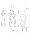
FIG. 1 is a schematic representation of a device for two-dimensional separation and ESI of automatically loaded samples according to one embodiment. The
基板102は、ガラス、石英、溶融シリカ、プラスチック、ポリカーボネート、ポリテトラフルオロエチレン(PTFE)、ポリジメチルシロキサン(PDMS)、シリコン、ポリフッ素化ポリエチレン、ポリメタクリレート、環状オレフィンコポリマー、環状オレフィンポリマー、ポリエーテルエーテルケトン、及び/又は任意の他の好適な材料から製造することができる。平面基板及び/又は任意の他の好適な材料の、異なる層において異なる特性が所望される場合、材料の混合物を利用することができる。平面基板の異なる層において異なる特性が所望される場合、材料の混合物を利用することができる。
The
チャネル106、110、114、116、118、124 122、126、132、136及び140は、マイクロ流体ネットワーク100を形成し、基板102の中に作製される。同様に述べると、基板102は、チャネル106、110、114、116、118、124 122、126、132、136及び/又は140を画定する。
チャネルは、例えばフォトリソグラフィーエッチング、モールディング、機械加工、付加(3D)印刷等の任意のチャネル作製方法によって基板内に作製することができる。 The channels can be formed in the substrate by any channel fabrication method such as photolithography etching, molding, machining, additive (3D) printing and the like.
検体混合物及び外部試薬は、管/導管112を通して装填することができ、過剰な試薬/廃棄物は管/導管130を通して除去することができる。
The sample mixture and external reagents can be loaded through the tube /
管112及び130は、例えば、溶融シリカ、溶融シリカ毛細管、シリコーン管及び/又はPTFE管を含む、実施されるアッセイに適合する任意の材料から製造することができる。
チャネル116及び124は、検体及び/又は検体の一部(例えば、画分)を分離及び/又は富化するために使用することができる。チャネル116及び/又は124は、クロマトグラフィ分離(例えば、逆相、免疫沈降、イオン交換、サイズ排除、リガンド親和性、染色性、疎水性相互作用クロマトグラフィ、親水性相互作用クロマトグラフィ、pH勾配イオン交換、親和性、キャピラリ界面動電クロマトグラフィ、ミセル界面動電クロマトグラフィ、高速液体クロマトグラフィ(HPLC)、アミノ酸分析HPLC、超高速液体クロマトグラフィ、ペプチドマッピングHPLC、フィールドフロー分別−マルチアングル光散乱)、又は電気泳動分離(例えば、等電点電気泳動、キャピラリゲル電気泳動、キャピラリゾーン電気泳動、等速電気泳動、キャピラリ界面動電クロマトグラフィ、ミセル界面動電クロマトグラフィ、フローカウンタバランスキャピラリ電気泳動、電界勾配集束、動的場勾配集束)を実施するために使用することができる。例えば、チャネル116は、誘導体化又は材料で充填して、第1の富化ステップを実施することができる。
チャネル116及び/又は124の中に配置される材料は、例えば、疎水性(逆相)、免疫親和性(免疫沈降)、親和性(有効性)、サイズ(サイズ排除クロマトグラフィ)、電荷(イオン交換)、又は他の形態の液体クロマトグラフィに基づいて検体を採取するように選択することができる。
The materials placed in
富化材料をチャネル116及び/又は124内部に配置するために、多くの異なる方法を使用することができる。壁は、例えば、共有結合分子又は吸着分子で直接誘導体化することができ、又はビーズ、ガラス粒子、ゾルゲルなどを誘導体化してこれらのチャネルの中に充填することができる。
Many different methods can be used to place the enriched material inside
試料がチャネル116の中に充填された後、洗浄液、次いで溶出試薬を管112及びチャネル114を通して導入することができる。
After the sample is filled into the
溶出プロセスは、チャネル116で実施される富化方法に依存する。好適な溶出液を選択して、結合した検体の画分を溶出させることができる。幾つかの富化オプションは、溶出ステップ(例えば、サイズ排除クロマトグラフィ、電気泳動分離など)を必要としない場合がある。
The elution process depends on the enrichment method performed on
溶出液又は貫流(flow-through)は、チャネル118を通ってチャネル124の中に流れる。
チャネル124は、クロマトグラフィ富化ステップ又は電気泳動富化ステップのいずれかを行うために使用することができる。
The eluate or flow-through flows through
電源を使用してリザーバ108とリザーバ120との間に電界を印加することによって、電気泳動分離をチャネル124内で行うことができる。同様に述べると、デバイス100は、リザーバ108及び/又はリザーバ120と電気的に接触する電極を含むことができる。電源の電気的接地は、質量分析計の電気的接地に接続され、チャネル124から質量分析計への電界の連続性を提供することができる。
Electrophoretic separation can be performed within the
IEF、等速電気泳動(ITP)、キャピラリゲル電気泳動(CGE)、キャピラリゾーン電気泳動(CZE)等の任意のキャピラリ電気泳動(CE)電気泳動法を、チャネル124で実施することができる。あるいは、チャネル124内で非電気泳動富化法を実施することができる。
Any capillary electrophoresis ( CE ) electrophoresis such as IEF, isotachophoresis ( ITP ) , capillary gel electrophoresis ( CGE ) , capillary zone electrophoresis ( CZE ) can be performed on
IEF又はITPの場合、濃縮された精製試料バンドは、例えば合流部126への圧力手段又は電気的手段によって移動されるであろう。リザーバ108及び134からのシース溶液は、シース及び陰極液として機能することができる。
In the case of IEF or ITP, the concentrated purified sample band will be transferred, for example, by pressure or electrical means to the
シース/陰極液は、電気泳動分離及び質量分析(例えば、MeOH/N4OH/H2O)と適合する任意の塩基性溶液であり得る。陽極液は、任意の酸性溶液(例えば、l0mMリン酸)であり得る。 The sheath / cathodic solution can be any basic solution compatible with electrophoretic separation and mass spectrometry (eg, MeOH / N 4 OH / H 2 O). The anolyte can be any acidic solution (eg, l0 mM phosphoric acid).
あるいは、電界を逆転させて陰極液(NaOH)をリザーバ120に充填することができ、陽極液をリザーバ108及び134内のシース溶液として使用することができる。
Alternatively, the electric field can be reversed to fill the
合流部126は、富化された検体画分がシース溶液と混合する場所である。チャネル124内の検体画分が移動すると、溶液は合流部126を通してオリフィス128に押し出される。
The
オリフィス128は、基板102の表面127によって画定される凹部内部に配置することができる。例えば、表面127は、皿穴のESI表面とすることができる。例えば、図1に示すように、ウェル108を介して電気的に接地された富化された検体溶液は、表面127によって画定された凹部内部に完全に配置されたオリフィス128から発するテイラーコーンを形成することができる。オリフィス128及び/又は表面127は、ウェル108に対して電位差を有することができる質量分析計の入口に向けることができる。噴霧は、円錐構造から質量分析計に向かって分離するときに、基板102を出る前に、チャネル106及び140を通って供給される噴霧ガスにより隣接され得る。噴霧ガスは、任意の不活性又は非反応性ガス(例えば、アルゴン、窒素等)であり得る。
The
更に、シース液体及び/又は噴霧ガスを使用することにより、最後の「オンデバイス」工程としてイオン欠乏工程の使用を可能にすることができる。シース液は、ESIの前にIEF帯電アッセイ濃縮工程の間に失われたイオンポテンシャルを補充することを可能にし、噴霧は、オフライン分析のために微細な霧でサンプルを提供する。 In addition, the use of sheath liquid and / or spray gas can allow the use of an ion deficiency step as the final "on-device" step. The sheath fluid allows to replenish the ionic potential lost during the IEF charging assay concentration step prior to ESI, and the spray provides the sample in a fine mist for offline analysis.
表面127上にテイラーコーンを生成することによって、コーンは安定したポケット又は凹部内に形成され、撹乱する気流から保護される。加えて、皿穴を取り囲む円錐形状は、広範囲のテイラーコーン径方向断面に適応して自然に広がる接触面を有し、質量分析計の中に入る流量がより広範囲となることを可能にする。
By forming a Taylor cone on the
オリフィス128は、質量分析計の入口ポートに近接させて配置することができる。場合によっては、表面127は、質量分析計の入口ポートが、表面127によって画定される凹部内部に配置され得るように構成することができる。
The
図2は、一実施形態による、3つの層を有するデバイス212の概略分解図である。図2Aは、一実施形態による、デバイス212の上部層202を示す。図2Bは、一実施形態による、デバイス212の中間層206を示す。図2Cは、一実施形態による、デバイス212の底部層210を示す。図2Dは、一実施形態による、組み立てたデバイス212を示す。3つの層202、206、210の各々は、デバイス212が実施しようとするアッセイと適合する任意の材料でできていてもよい。
FIG. 2 is a schematic exploded view of the
幾つかの実施形態では、層202は、光の特定の波長又は波長範囲に対して透明な材料から作製される。本明細書で使用する場合、「透明」とは、材料の一方の側の特定の波長又は波長範囲を有する光の量が、他方の側の検出器によって定量化され得るのに十分な透過率を有することを意味すると理解されたい。場合によっては、透過率が30%、50%、80%、95%、又は100%の材料は透明である。幾つかの実施形態では、関心のある波長範囲は、中間紫外線範囲(例えば、200nm〜300nm)を含み、例えば、ガラス、石英、溶融シリカ、ならびにポリカーボネート、ポリフッ素化ポリエチレン、ポリメタクリレート、環状オレフィンポリマー、環状オレフィンコポリマー及び他の紫外線透過材料など、の材料を透明材料として使用することができる。幾つかの実施形態では、関心のある光スペクトルは、可視スペクトル(例えば、200〜900nm)を超えて拡張される。
In some embodiments, the
貫通孔204が層202内に作製され、デバイスの外部から下層(例えば、層208)内のチャネルネットワークへの圧力及び電気的インタフェースを可能にする。
Through
図2Bは、チャネルネットワーク208を含有するデバイス212の内部中間層206を示す。チャネルネットワークは、上部層202に作製された貫通孔とインタフェースするように設計されている。チャネルネットワーク208は、入口及び出口管/導管209と、富化された検体画分を排出するためのオリフィス205と、視認可能な富化ゾーン207とを含む。富化ゾーン207は、その深さが層206の全体の厚みであるように作製される。他の実施形態では、ゾーン207は、層206の全体の厚み未満であり得る。
FIG. 2B shows the inner
幾つかの実施形態では、層206は、光の特定の波長又は波長範囲に対して不透明及び/又は透明でない材料から作製される。本明細書で使用する場合、「不透明」とは、一方の側の光の量が、他方の側の検出器によって定量化されることを可能にするには不十分な透過率を有し、チャネルネットワーク内のゾーンが層206の全体の厚みと同程度に深い領域以外において、この光を効果的に阻止する材料を意味すると理解されたい。
In some embodiments,
図2Cは、デバイス212の底部層210を示す。底部層210は、例えば、固体基板とすることができる。幾つかの実施形態では、底部層210は、層202と同じ透過率を有する材料から作製することができる。
FIG. 2C shows the
図2Dは、一実施形態による、組み立てられた上部層202、中間層206、及び底部層210を含むデバイス212を示す。入口管及び出口管209、リザーバ204及びオリフィス205は、デバイス210が組み立てられた後でも依然として接近可能である。幾つかの実施形態では、上部層202全体及び/又は底部層210全体を透明にすることができる。他の実施形態では、上部層202の一部及び/又は底部層210の一部は不透明であり、上部層202及び/又は底部層210の別の部分が透明であり得る。例えば、上部層210及び/又は底部層210は、デバイス212が組み立てられたときに富化ゾーン207の少なくとも一部と整列する光学ウィンドウを画定することができる。
FIG. 2D shows the
図3は、一実施形態による、マイクロ流体デバイス302を通る光路の概略図である。図3Aは、マイクロ流体デバイス302の上面図を示す。図3Bは、光源306と検出器308との間に配置されたマイクロ流体デバイス302を示す。検出器308は、デバイス302を通過する光を測定するように配置される。図3には示されていないが、マイクロ流体デバイス302は、図1及び図2で説明したのと同様のチャネル構造を有することができるが、参照しやすいようにチャネル構造は示されていない。幾つかの実施形態では、マイクロ流体デバイス302の上面の一部は不透明であり、光源306から投影された光を完全に又は実質的に覆い隠し、検出器308に到達しないようにする。上面の不透明な部分は、試料の特性の検出が望ましくない部分においてデバイスを通る光の透過を実質的に防止する。例えば、チャネル304が非透明層の厚み全体を横断するので、幾つかの実施形態では、マイクロ流体デバイス302は、1つ以上のチャネル領域304にわたって不透明ではない(例えば、一部の光は通過させる)。
FIG. 3 is a schematic view of an optical path through the
幾つかの実施形態では、この透明な(1つ又は複数の)チャネル領域304は富化ゾーンであってもよく、ここにおいて光学検出を使用して検体を検出し、富化の進行をモニタし、及び/又はデバイスから排出させる、富化された(1つ又は複数の)検体画分をモニタすることができる。幾つかの実施形態では、透明チャネル304を通過する光の量の変化を用いて、検体画分がこのチャネル内にある間に吸光度を測定する。従って、幾つかの実施形態では、(1つ又は複数の)チャネル領域304が光学スリットを画定し、それによりマイクロ流体デバイス302の一方の側に配置された光源306が透明な(1つ又は複数の)チャネル領域304のみを通って検出器308を効果的に照射する。このようにして、迷光(例えば、透明な(1つ又は複数の)チャネル領域及び/又は試料を完全に通過しない光)を検出器308から効果的に遮断することができ、それによりノイズを低減させ、検出器308が透明な(1つ又は複数の)チャネル領域304内部のサンプルを観察する能力を向上させることができる。幾つかの実施形態では、透明な(1つ又は複数の)チャネル領域304は、2つの富化ゾーンの間にあり、上流の富化ゾーンから溶出したときに検体画分を検出するために使用することができる。
In some embodiments, the transparent (s)
(方法)
図6は、一実施形態による、検体混合物富化の方法を示す。この方法は、20において、検体混合物をマイクロ流体デバイスに装填及び/又は導入することを含む。マイクロ流体デバイスは、図1〜図3を参照して上述したマイクロ流体デバイスと同様であり得る。幾つかの実施形態において、検体混合物は、例えば、グリカン、炭水化物、DNA、RNA、インタクトタンパク質、消化されたタンパク質、ペプチド、代謝産物、ワクチン、ウイルス及び小分子であり得る。幾つかの実施形態では、検体混合物は、培養細胞の溶解物、体細胞由来の治療剤、又は腫瘍もしくは他の組織由来の細胞などのタンパク質の混合物、バイオ医薬品を含む組み換えタンパク質、血液由来細胞、灌流又は任意の他のソースからのタンパク質混合物であり得る検体混合物は、デバイスに直接装填することができ、又は複数の混合物の連続分析のためにオートサンプラに装填することができる。
(Method)
FIG. 6 shows a method of enriching the sample mixture according to one embodiment. The method comprises loading and / or introducing the sample mixture into a microfluidic device at 20. The microfluidic device can be similar to the microfluidic device described above with reference to FIGS. 1-3. In some embodiments, the sample mixture can be, for example, glycans, carbohydrates, DNA, RNA, intact proteins, digested proteins, peptides, metabolites, vaccines, viruses and small molecules. In some embodiments, the sample mixture is a lysate of cultured cells, a therapeutic agent derived from somatic cells, or a mixture of proteins such as cells derived from tumors or other tissues, recombinant proteins including biopharmaceuticals, blood-derived cells, The sample mixture, which can be perfusion or a protein mixture from any other source, can be loaded directly into the device or into an autosampler for continuous analysis of multiple mixtures.
マイクロ流体デバイスは、第1の分離チャネル及び/又は富化ゾーンを含むことができる。幾つかの実施形態では、第1の分離チャネル及び/又は富化ゾーンは、クロマトグラフィ分離のために構成することができる。例えば、第1の分離チャネル及び/又は富化ゾーンは、検体混合物からの検体を結合するように構成された媒体を含有することができ、及び/又はそれ以外の場合にはクロマトグラフィ分離を遂行する。21において、第1の富化を実施することができ、例えば、クロマトグラフィ分離を第1の分離チャネル及び/又は富化ゾーンで行うことができる。検体混合物がタンパク質混合物である実施形態などの幾つかの実施形態では、21における第1の富化はタンパク質混合物を単純化することができる。21における第1の富化は、検体の任意の識別可能な性質に基づくことができる。 The microfluidic device can include a first separation channel and / or enrichment zone. In some embodiments, the first separation channel and / or enrichment zone can be configured for chromatographic separation. For example, the first separation channel and / or enrichment zone can contain a medium configured to bind the sample from the sample mixture and / or otherwise perform chromatographic separation. .. At 21, a first enrichment can be performed, for example, a chromatographic separation can be performed in the first separation channel and / or enrichment zone. In some embodiments, such as those in which the sample mixture is a protein mixture, the first enrichment at 21 can simplify the protein mixture. The first enrichment at 21 can be based on any identifiable property of the sample.
この富化された検体画分は次いで、22において溶出される。例えば、溶出液をマイクロ流体デバイスの中に注入して、第1の分離チャネル及び/又は富化ゾーン内部に配置された媒体から富化された検体画分を移動させることができる。幾つかの実施形態では、富化された検体画分の富化及び/又はモビライゼーションを画像化することができる。例えば、上述のように、第1の分離チャネル及び/又は富化ゾーンは、光学スリットを画定することができる。光をマイクロ流体デバイスに投影することができ、検出器が第1の分離チャネル及び/又は富化ゾーンを通過する光を検出することができる。試料又はその一部は、吸光度及び/又は蛍光画像化技術を介して検出することができる。 This enriched sample fraction is then eluted at 22. For example, the eluate can be injected into a microfluidic device to move the enriched sample fraction from a medium located within the first separation channel and / or enrichment zone. In some embodiments, enrichment and / or mobilization of the enriched sample fraction can be imaged. For example, as mentioned above, the first separation channel and / or enrichment zone can define an optical slit. Light can be projected onto the microfluidic device and the detector can detect the light passing through the first isolation channel and / or enrichment zone. The sample or part thereof can be detected via absorbance and / or fluorescence imaging techniques.
マイクロ流体デバイスは、第2の分離チャネル及び/又は富化ゾーンを含むことができる。幾つかの実施形態では、第2の分離チャネル及び/又は富化ゾーンは、電気泳動分離のために構成することができる。23において、例えば溶出液に対して第2の富化を実施することができる。例えば、電界及び/又は電位を第2の分離チャネル及び/又は富化ゾーンを横切って印加することができる。 The microfluidic device can include a second separation channel and / or enrichment zone. In some embodiments, the second separation channel and / or enrichment zone can be configured for electrophoretic separation. At 23, for example, a second enrichment can be performed on the eluate. For example, an electric field and / or potential can be applied across a second separation channel and / or enrichment zone.
幾つかの実施形態では、第2の富化は、23において、検体混合物の画分が第1の分離チャネル及び/又は富化ゾーンと第2の分離チャネル及び/又は富化ゾーンとの交差点に配置されたときに開始することができる。例えば、第1の分離チャネル及び/又は富化ゾーンをモニタ(例えば、画像化)することができ、関心のある画分が交差点に到達したときに電位及び/又は電界を印加することができる。 In some embodiments, the second enrichment is at 23, where the sample mixture fraction is at the intersection of the first separation channel and / or enrichment zone with the second separation channel and / or enrichment zone. Can start when placed. For example, the first separation channel and / or enrichment zone can be monitored (eg, imaged) and a potential and / or electric field can be applied when the fraction of interest reaches the intersection.
幾つかの実施形態では、23における第2の富化は、電荷特性(電荷アイソフォーム)に基づいて富化された画分を提供することができる。そのような富化は、例えば、ゲル等電点電気泳動、モビライゼーションを用いた等電点電気泳動、全カラムイメージングを用いた等電点電気泳動、イオン交換クロマトグラフィ、pH勾配交換クロマトグラフィ、等速電気泳動、キャピラリゾーン電気泳動、キャピラリゲル電気泳動又は他の、例えば電荷に基づいた富化技術、を含むことができる。 In some embodiments, the second enrichment at 23 can provide an enriched fraction based on charge characteristics (charge isoforms). Such enrichment includes, for example, gel isoelectric focusing, isoelectric focusing with mobilization, isoelectric focusing with full column imaging, ion exchange chromatography, pH gradient exchange chromatography, constant velocity electricity. Electrophoresis, capillary zone electrophoresis, capillary gel electrophoresis or other, such as charge-based enrichment techniques, can be included.
21における第1の富化はクロマトグラフィ富化として記載され、23における第2の富化は電気泳動として記載されたが、任意の好適な富化を任意の好適な順序で実施できることを理解されたい。例えば、21における第1の富化及び23における第2の富化は、両方ともクロマトグラフィ又は両方とも電気泳動であり得る。別の例として、21における第1の富化は電気泳動とすることができ、23における第2の富化はクロマトグラフィとすることができる。 Although the first enrichment in 21 has been described as chromatographic enrichment and the second enrichment in 23 has been described as electrophoresis, it should be understood that any suitable enrichment can be performed in any suitable order. .. For example, the first enrichment at 21 and the second enrichment at 23 can both be chromatography or both electrophoresis. As another example, the first enrichment at 21 can be electrophoresis and the second enrichment at 23 can be chromatography.
幾つかの実施形態では、1つ以上の富化は、酸化などの疎水性変化に基づいて富化された画分を提供することができる。そのような富化は、例えば、逆相クロマトグラフィ、疎水性相互作用クロマトグラフィ、親水性相互作用クロマトグラフィ、又は例えば疎水性に基づく他の富化技術を含むことができる。 In some embodiments, one or more enrichments can provide an enriched fraction based on hydrophobic changes such as oxidation. Such enrichment can include, for example, reverse phase chromatography, hydrophobic interaction chromatography, hydrophilic interaction chromatography, or other enrichment techniques based on, for example, hydrophobicity.
幾つかの実施形態では、1つ以上の富化は、翻訳後修飾、ガラクトシル化、フコシル化、シアリル化、マンノース誘導体及び他のグリコシル化、ならびに糖化、酸化、還元、リン酸エステル化、スルファン化(sulphanation)、ジスルフィド結合形成、アミド分解、アシル化、ペギル化、開裂を含むグリコフォーム、抗体−薬物複合体(ADC)、タンパク質−薬物複合体、C末端リジン処理、他の天然及び非天然起因の翻訳後修飾、及びタンパク質の修飾後に導入された他の化学的及び構造的修飾等、に基づいて富化された画分を提供することができる。そのような富化は、例えば、結合アッセイ等を含むことができる。 In some embodiments, one or more enrichments include post-translational modifications, galactosylation, fucosylation, sialylation, mannose derivatives and other glycosylations, as well as saccharification, oxidation, reduction, phosphate esterification, sulfanization. (Sulphanation), disulfide bond formation, amide degradation, acylation, pegylation, glycoforms including cleavage, antibody-drug complex (ADC), protein-drug complex, C-terminal lysine treatment, other natural and non-natural origins It is possible to provide enriched fractions based on post-translational modifications of, and other chemical and structural modifications introduced after protein modifications. Such enrichment can include, for example, binding assays.
幾つかの実施形態では、1つ以上の富化は、酸化などの疎水性変化に基づいて富化された画分を提供することができる。そのような富化は、例えば、逆相クロマトグラフィ、疎水性相互作用クロマトグラフィ、親水性相互作用クロマトグラフィ、又は疎水性に基づく他の富化技術を含むことができる。 In some embodiments, one or more enrichments can provide an enriched fraction based on hydrophobic changes such as oxidation. Such enrichment can include, for example, reverse phase chromatography, hydrophobic interaction chromatography, hydrophilic interaction chromatography, or other enrichment techniques based on hydrophobicity.
幾つかの実施形態では、1つ以上の富化は、突然変異、製造中のアミノ酸置換などによって引き起こされるような、一次アミノ酸配列に基づいて富化された画分を提供することができる。そのような富化は、例えば、電荷アイソフォーム、疎水性変化、又は一次アミノ酸配列の差異を区別することができる他の富化技術による分離を含むことができる。 In some embodiments, one or more enrichments can provide a fraction enriched based on the primary amino acid sequence, such as caused by mutations, amino acid substitutions during production, and the like. Such enrichment can include, for example, charge isoforms, hydrophobic changes, or separation by other enrichment techniques capable of distinguishing differences in primary amino acid sequences.
幾つかの実施形態では、1つ以上の富化は、有効性に基づいて富化された画分を提供することができる。そのような富化は、例えば、バイオアッセイ、酵素阻害アッセイ、酵素活性化アッセイ、競合アッセイ、蛍光偏光アッセイ、シンチレーション近接アッセイ、又は有効性に基づく他の富化技術等を含むことができる。 In some embodiments, one or more enrichments can provide an enriched fraction based on effectiveness. Such enrichments can include, for example, bioassays, enzyme inhibition assays, enzyme activation assays, competitive assays, fluorescence polarization assays, scintillation proximity assays, or other efficacy-based enrichment techniques.
幾つかの実施形態において、1以上の富化は、親和性に基づいて富化された画分を提供することができる。そのような富化は、例えば、溶液相の標的結合、ビーズベースの標的結合、表面結合標的、免疫沈降、プロテインA結合、プロテインG結合等を含むことができる。 In some embodiments, one or more enrichments can provide an affinity-based enriched fraction. Such enrichment can include, for example, solution phase target binding, bead-based target binding, surface binding target, immunoprecipitation, protein A binding, protein G binding and the like.
幾つかの実施形態では、1つ以上の富化は、質量又はサイズに基づいて富化された画分を提供することができる。そのような富化は、例えば、ポリアクリルアミドゲル電気泳動、キャピラリゲル電気泳動、サイズ排除クロマトグラフィ、ゲル浸透クロマトグラフィ、又は質量ベースの他の富化技術を含むことができる。 In some embodiments, one or more enrichments can provide enriched fractions based on mass or size. Such enrichment can include, for example, polyacrylamide gel electrophoresis, capillary gel electrophoresis, size exclusion chromatography, gel permeation chromatography, or other mass-based enrichment techniques.
幾つかの実施形態では、検体混合物は、デバイスから排出される前に3回以上の富化及び/又は富化チャネルを経る。
In some embodiments, the sample mixture goes through three or more enrichment and / or enrichment channels before being excreted from the device.
24において、富化された検体画分をデバイスから排出すことができる。幾つかの実施形態では、富化された検体画分は、IEFを介して排出することができる。24において富化された検体画分を排出することで、排出前に検体画分を濃縮することができる。 At 24, the enriched sample fraction can be ejected from the device. In some embodiments, the enriched sample fraction can be excreted via the IEF. By discharging the sample fraction enriched in No. 24, the sample fraction can be concentrated before the discharge.
幾つかの実施形態では、24において、エレクトロスプレーイオン化、大気圧化学イオン化等のイオン化技術を使用して検体画分が排出される。 In some embodiments, at 24, the sample fraction is ejected using ionization techniques such as electrospray ionization, atmospheric chemical ionization, and the like.
幾つかの実施形態では、24において、動電学的力又は流体力学的力を用いて、検体画分が排出される。 In some embodiments, at 24, a electrokinetic or hydrodynamic force is used to eject the sample fraction.
幾つかの実施形態では、富化されたタンパク質画分は、24において、質量分析計に結合された形態でデバイスから排出される。 In some embodiments, the enriched protein fraction is excreted from the device at 24 in a form coupled to a mass spectrometer.
マイクロ流体デバイスから排出された検体(例えば生物学的又はバイオシミラ)の質量は、例えば、飛行時間型質量分析、四重極型質量分析、イオントラップ又はオービトラップ質量分析、飛行距離型質量分析、フーリエ変換イオンサイクロトロン共鳴、共鳴質量測定、ナノメカニカル質量分析によって測定することができる。 The mass of a sample (eg, biological or biosimilla) ejected from a microfluidic device can be, for example, time-of-flight mass spectrometry, quadrupole mass spectrometry, ion trap or orbitrap mass spectrometry, distance-of-flight mass spectrometry, Fourier. It can be measured by transform ion cyclotron resonance, resonance mass spectrometry, and nanomechanical mass spectrometry.
幾つかの実施形態では、視覚化されたIEFチャネル(例えば、第1の分離チャネル及び/又は富化ゾーン及び/又は第2の分離チャネル及び/又は富化ゾーン)内のpi範囲をマッピングするためにpiマーカが使用される。幾つかの実施形態では、piマーカ又は両性電解質を使用して、下流の質量分析データにおけるpiマーカ又は両性電解質の存在によって、検体のpiを決定することができる。 In some embodiments, to map the pi range within the visualized IEF channel (eg, first isolation channel and / or enrichment zone and / or second isolation channel and / or enrichment zone). The pi marker is used for. In some embodiments, the pi marker or amphoteric electrolyte can be used to determine the pi of the specimen by the presence of the pi marker or amphoteric electrolyte in downstream mass spectrometric data.
幾つかの実施形態では、モビライゼーション及びESI中にIEFをモニタすることができる。このようにして、質量分析データをIEFのピークと相関させることができ、ピーク分解能を維持及び/又は向上させることができる。 In some embodiments, the IEF can be monitored during mobilization and ESI. In this way, the mass spectrometric data can be correlated with the peaks of the IEF and the peak resolution can be maintained and / or improved.
幾つかの実施形態において、検体混合物及び/又はその一部は、圧力源を使用してマイクロ流体デバイス内部で移動させることができる。幾つかの実施形態では、モビライゼーションは静水圧で行われる。幾つかの実施形態では、モビライゼーションは化学的固定化である。幾つかの実施形態では、モビライゼーションは動電学的モビライゼーションである。 In some embodiments, the sample mixture and / or a portion thereof can be moved within the microfluidic device using a pressure source. In some embodiments, mobilization is performed at hydrostatic pressure. In some embodiments, the mobilization is a chemical immobilization. In some embodiments, the mobilization is an electrokinetic mobilization.
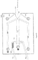
図7は、一実施形態による、マイクロ流体デバイスの概略図である。マイクロ流体ネットワーク800は、基板802内に配置され、及び/又は基板802によって画定される。基板は、実施される富化ステップと適合する材料から製造される。例えば、材料の選択に関連して、化学的適合性、pH安定性、温度、光の様々な波長における透明性、機械的強度等は、材料を選択する際に重要であり得る。
FIG. 7 is a schematic diagram of a microfluidic device according to one embodiment. The
基板802は、ガラス、石英、溶融シリカ、プラスチック、ポリカーボネート、PTFE、PDMS、シリコン、ポリフッ素化ポリエチレン、ポリメタクリレート、環状オレフィンコポリマー、環状オレフィンポリマー、ポリエーテルエーテルケトン、及び/又は、任意の他の好適な材料から製造することができる。平面基板の異なる層において異なる特性が所望される場合、材料の混合物を利用することができる。
The
チャネル806、808、810、811、817、814、812は、チャネルネットワークを形成し、基板802の中に作製される(例えば、基板により画定される)。
チャネルは、フォトリソグラフィーエッチング、モールディング、機械加工、付加(3D)印刷などの任意のチャネル作製方法によって基板内に作製することができる。 Channels can be formed in the substrate by any channel fabrication method such as photolithography etching, molding, machining, additive (3D) printing.
検体混合物及び外部試薬は、管804を通して装填することができ、過剰な試薬/廃棄物は管810及び818を通して除去することができる。
The sample mixture and external reagents can be loaded through
管804、810、及び/又は818は、溶融シリカ、溶融シリカ毛細管、シリコーン管、PTFE管等を含む、実施されるアッセイに適合する任意の材料から製造することができる。
チャネル806及び814は、分離/富化ゾーンとして指定することができる。チャネル806及び/又は814のいずれかを使用して、クロマトグラフィ分離(逆相、免疫沈降、イオン交換、サイズ排除、リガンド親和性、染色性、疎水性相互作用、親和性、キャピラリ界面動電クロマトグラフィ、ミセル界面動電クロマトグラフィ及び/又は同種のもの)、又は電気泳動分離(等電点電気泳動、キャピラリゲル電気泳動、キャピラリゾーン電気泳動、等速電気泳動、キャピラリ界面動電クロマトグラフィ、ミセル界面動電クロマトグラフィ、フローカウンタバランスキャピラリ電気泳動、電界勾配集束、動的場勾配集束)を実施することができる。例えば、チャネル806は、チャネル806内の暗い円によって表される第1の富化ステップを実施するために、誘導体化又は材料で充填することができる。
チャネル806の中に配置された材料は、疎水性(逆相)、親和性(有効性)、サイズ(サイズ排除クロマトグラフィ)、電荷(イオン交換)、免疫親和性(免疫沈降)、タンパク質−タンパク質相互作用、DNA−タンパク質相互作用、アプタマ−塩基捕捉、小分子−塩基捕捉、又は他の形態の液体クロマトグラフィ等に基づいて検体を採取するように選択することができる。
The materials placed in
富化材料をチャネル806及び/又は814内部に配置するために、多くの異なる方法を使用することができる。壁は、共有結合で結合した分子又は吸着した分子で直接誘導体化することができ、又はビーズ、ガラス粒子、ゾルゲル等を誘導体化してこれらのチャネルの中に充填することができ、又はチャネルを、線状ポリアクリルアミド(LPA)、ポリビニルピロリドン(PVP)、ポリエチレンオキシド(PEO)、デキストランなどの線状ポリマー溶液、ポリアクリルアミドなどの架橋ポリマー溶液、液体クロマトグラフィ用マトリックス、又は他の材料、などのふるい材料で満たすことができる。
Many different methods can be used to place the enriched material inside the
実施される特定のアッセイに依存して、化学的反応性を有する溶液を添加することができる。場合によっては、材料の誘導体化は、充填された材料に吸着又は共有結合するであろう分子又は材料に化学的に架橋することができる分子を添加することによって、材料がチャネル806(又はチャネル814)の中に充填された後に起こり得る。例えば、プロテインA、プロテインG、エポキシなどの抗体結合分子で被覆された材料をチャネル806の中に配置することができる。その後の抗体溶液によるリンスにより、抗体で被覆された材料は残り、免疫親和性捕捉に関与することができる。場合によっては、抗体は標的検体又は溶解物と混合することができ、それにより材料上に被覆される前に、抗体が自由溶液中でその標的に結合することができる。
Depending on the particular assay performed, a chemically reactive solution can be added. In some cases, derivatization of a material allows the material to channel 806 (or channel 814) by adding a molecule that will adsorb or covalently bond to the packed material or a molecule that can be chemically crosslinked to the material. ) Can occur after being filled. For example, a material coated with an antibody-binding molecule such as protein A, protein G, or epoxy can be placed in
富化材料がデバイスに装填された後、試料は管804を介してチャネル806の中に充填される。その後、洗浄液及び溶出試薬を管804を通してチャネル806に導入することができる。
After the enrichment material is loaded into the device, the sample is filled into
場合によっては、捕捉された材料に結合させるために、検出試薬が添加される。蛍光団、発色団(chromophores)又は他の検出分子などの検出部分をポリペプチドの末端において標的タンパク質へ共有結合的に結合することができる、及びリジン、システイン及び他のアミノ酸部分などのアミノ酸側鎖への結合による、多数の標識試薬が利用可能である。共有結合した検出部分によって、蛍光励起、発色団アッセイ(chromophoric assay)、又は他の間接的手段を通じてタンパク質を検出することが可能になる。場合によっては、標的タンパク質は標識化されないまま残り、220nm、280nm又はタンパク質が光を吸収する任意の他の波長による自然吸光度、又は自然蛍光を通じて検出することができる。場合によっては、タンパク質は、SYPRO(登録商標)ruby,Coomassie blueなどの、非共有結合的に結合した発蛍光性、発色性、蛍光性又は発色団の標識を用いて検出される。 In some cases, detection reagents are added to bind to the captured material. Detection moieties such as chromophores, chromophores or other detection molecules can be covalently attached to the target protein at the ends of the polypeptide, and amino acid side chains such as lysine, cysteine and other amino acid moieties. Numerous labeling reagents are available by binding to. The covalently coupled detection moiety allows the protein to be detected through fluorescence excitation, chromophoric assay, or other indirect means. In some cases, the target protein remains unlabeled and can be detected through natural absorbance at 220 nm, 280 nm or any other wavelength at which the protein absorbs light, or autofluorescence. In some cases, proteins are detected using non-covalently bound fluorescent, chromophore, fluorescent or chromophore labels such as SYPRO® ruby, Coomassie blue.
場合によっては、検出を促進するために、検出試薬が直接チャネル814に加えられる
In some cases, detection reagents are added directly to
溶出プロセスは、チャネル806で実施される富化方法に依存する。溶出プロセスは、結合した検体の少なくとも1つの画分を溶出するように選択される。場合によっては、溶出プロセスは、熱及びドデシル硫酸ナトリウム(SDS)、又は他の界面活性剤、グリシン、尿素、又は捕捉された検体の放出を誘導する任意の他の方法の組み合わせによって達成することができる。幾つかの富化オプションでは、直接溶出ステップ(例えば、サイズ排除クロマトグラフィ)を必要としない場合がある。場合によっては、溶出の後に変性が続く。
The elution process depends on the enrichment method performed on
次いで、溶出液は、チャネル808を通って、次の分離/富化ゾーンであるチャネル814の中に流入する。チャネル814は、クロマトグラフィ富化ステップ又は電気泳動富化ステップのいずれかを行うために使用することができる。
The eluate then flows through
電源を使用してリザーバ812とリザーバ816との間に電界を印加することによって、電気泳動分離をチャネル814内で行うことができる。チャネル806からの溶出液がチャネル808と814との交差点を通過するとき、電界を有効にし、検体をチャネル814の中に充填することができる。場合によっては、タンパク質検体がSDSのような負に帯電した界面活性剤で飽和されている標準的なゲル電気泳動モードにおけるように、検体は負に帯電している。しかし、チャネル814の極性は、例えば、タンパク質検体がセチルトリメチルアンモニウムブロマイド(CTAB)などの正に荷電した界面活性剤で飽和しているシステムに対応するために、容易に逆転することができる。他の場合では、タンパク質検体は、天然ゲル電気泳動におけるように、中性界面活性剤で被覆するか、又は界面活性剤なしとすることができる。この場合、選択された緩衝系におけるタンパク質標的の予想される電荷に基づいて極性が選択され、タンパク質検体がチャネル814の中に移動する。
Electrophoretic separation can be performed within
IEF、ITP、CGE、CZE等の任意のCE電気泳動法を、チャネル814内で実施することができる。あるいは、チャネル内で非電気泳動富化方法を実施することができる。
Any CE electrophoresis such as IEF, ITP, CGE, CZE can be performed within
チャネル814内の検体は、全カラム画像化、部分カラム画像化、及び/又は単一点検出によって見ることができる。
Specimens in
場合によっては、チャネル806、814又はその両方の富化材料を除去して新しい物質で補充することができ、それによりデバイスを別の分析対象サンプルに使用することができる。
In some cases,
場合によっては、図7のようなチャネル設計をデバイス上で複数回繰り返すことができるので、2つ以上の検体試料を並行して分析することができる。 In some cases, the channel design as shown in FIG. 7 can be repeated multiple times on the device, allowing two or more sample samples to be analyzed in parallel.
(例)
実施形態の態様は、以下の実施例に照らして更に理解することができるが、これらは決して限定するものと解釈すべきではない。
(example)
Embodiments can be further understood in the light of the following examples, but they should by no means be construed as limiting.
(実施例1)−質量分析(MS)の前にチップ上のタンパク質電荷を特性評価する
この例では、図4に示すチャネルネットワークは、標準フォトリソグラフィーエッチング技術を用いて、ソーダ石灰ガラスのプレートから作製され、280nmの光に対する非常に低い透過率を有する。富化チャネル418の深さは、ガラス層402の厚みと同じであり、すなわち富化チャネル418は、このガラス板402の上部から底部まで全体を通過している。デバイス400は、デバイス400の一方の側に配置された光源によって照射され、デバイス400の反対側に配置された検出器によって画像化することができる。基板402は不透明であるが、富化チャネル418が光学スリットを画定するので、基板402は、富化チャネル418を通過しない光を遮断し、迷光を遮断し、画像化プロセスの分解能を向上させることができる。
(Example 1) -Characterize protein charges on a chip prior to mass spectrometry (MS) In this example, the channel network shown in FIG. 4 is from a plate of soda-lime glass using standard photolithography etching techniques. It is made and has a very low transmittance for 280 nm light. The depth of the enriched
ガラス層402は、280nmの光に対して透過性(例えば透明)である2つの溶融シリカ板の間に挟まれている。図2におけるように、上部板は、機器及び利用者がチャネルネットワークとインタフェースするための貫通孔を含有し、底部板は固体である。3枚のプレートを520℃で30分間接合する。入口管及び出口管は、切断されたキャピラリ(100μm ID、polymicro)から製造され、チャネルネットワークに結合される。
The
このデバイスは、窒素ガス供給源、ヒータ、陽圧ポンプ(例えば、Parker、T5−1IC−03−1EEP)、2つの白金−イリジウム電極(例えば、Sigma−Aldrich,357383)で終端する電気泳動電源(Gamm High Voltage、MC30)、UV光源(例えば、LED、qphotonics、UVTOP280)、CCDカメラ(例えば、ThorLabs、340UV−GE)、及び試料をデバイスに装填するためのオートサンプラ、を含有する機器に搭載される。電源は、質量分析計と共通接地を共有する。機器はソフトウェア(例えば、lab View)を介して制御される。 The device is an electrophoretic power source (eg, Parker, T5-1IC-03-1EEP) terminated with a nitrogen gas source, a heater, a positive pressure pump (eg, Parker, T5-1IC-03-1EEP) and two platinum-iridium electrodes (eg, Sigma-Aldrich, 357383). Installed in equipment containing a Gamm High Voltage, MC30), a UV light source (eg, LED, qphonics, UVTOP280), a CCD camera (eg, ThorLabs, 340UV-GE), and an autosampler for loading samples into the device. NS. The power supply shares a common ground with the mass spectrometer. The device is controlled via software (eg, labView).
タンパク質試料は、バイアル瓶の中に配置されオートサンプラに装填される前に、両性電解質pH勾配及びpiマーカとあらかじめ混合される。それらは、オートサンプラから入口412を介してマイクロ流体デバイス400に装填され、富化チャネル418を通り、出口434を通りデバイスから出て廃棄物430となる。
The protein sample is premixed with the amphoteric electrolyte pH gradient and the pi marker before being placed in a vial and loaded onto the autosampler. They are loaded into the
シース/陰極液(50%MeOH、N4OH/H2O)が2つの陰極液ウェル404、436に、陽極液(10mM H3PO4)が陽極液ウェル426に充填され、加熱窒素ガス供給源が2つのガスウェル408、440に取り付けられる。
Sheath / cathode solution (50% MeOH, N 4 OH / H 2 O) is filled in two
全ての試薬が充填された後、陽極液ウェル426及び陰極液ウェル404、436に電極を接続することで、+600V/cmの電界が陽極液ウェル426から陰極液ウェル404、436に印加され、等電点電気泳動が開始される。UV光源が富化チャネル418の下に整列され、カメラが富化チャネル418の上方に配置されて富化チャネル418を通過する光を測定し、それによって集束しているタンパク質を吸光度によって検出する。ガラス板402は、ソーダ石灰ガラスで作られ、カメラからのあらゆる迷光を遮断するように作用し、富化チャネル418を通過しない光がカメラに到達することを阻止し、測定感度を高めている。
After all the reagents have been filled, by connecting the electrodes to the
集束しているタンパク質の画像は、IEFの間に連続的及び/又は周期的に捕捉することができる。集束が完了すると、低圧が入口412から与えられ、pH勾配をオリフィス424の方向に移動させる。高分解能IEF分離を維持するために、電界をこの時点で維持することができる。ESIプロセス中に富化チャネル418を画像化し続けていることを活用して、タンパク質がオリフィス424から排出されている間に、各タンパク質のpiを決定することができる。
Images of focused proteins can be captured continuously and / or periodically during the IEF. When focusing is complete, a low pressure is applied from the
富化されたタンパク質画分は、富化チャネル418から合流部420の中に移動すると、陰極液ウェル404、436からシース/陰極液チャネル406、438を介して合流部420に流れることができるシース液と混合される。富化されたタンパク質画分をシース液と混合することで、タンパク質画分を質量分析と互換性のある溶液に入れることができるようになり、集束されたタンパク質に電荷を復元させることができる(IEFはタンパク質を非荷電状態にする)。
The enriched protein fraction can move from enriched
富化されたタンパク質画分は次いで、ガラス板402の皿穴表面422によって画定され得るオリフィス424に続く。富化されたタンパク質画分は、シース液ウェルと質量分析計陰極との間の電界にいったん捕捉されると、テイラーコーンを生成することができる。
The enriched protein fraction then follows an
溶液が富化チャネル418からテイラーコーンを押し続けると、流体の小さな液滴がテイラーコーンから排出され、質量分析計入口に向かって飛行する。窒素ガス(例えば、150℃)は、ガスウェル408、440から流れてガスチャネル410、432を通り窒素ガスジェットを形成することができ、これがテイラーコーンに隣接し、それによりテイラーコーンから放出される液滴をマイクロ流体デバイスから出る前に細かい霧に変換することができ、それにより質量分析計での検出を補助することができる。入口412からの圧力を調整することにより、テイラーコーンのサイズを必要に応じて適合させ、質量分析計における検出を改善することができる。
As the solution continues to push the Taylor cone through the
(実施例2)−逆相→IEF→MS
実施例2は実施例1と同様であり得るが、図1を参照して説明する。チャネル116は、C18で誘導体化されたゾルゲルが充填された第1の富化ゾーンであり得る。タンパク質を装填した後、一定量の溶出液(IEF両性電解質及び標準を有するMeCN/H2O)がチャネル116の中に充填されて、ゾルゲルに捕捉された最も疎水性の低いタンパク質を溶出することができる。溶出液は、実施例1に記載したように、IEF、UV吸光度モニタリング及び最後にESIが行われる第2の富化ゾーンであり得るチャネル124に向けられる。第1の溶出液のESIがいったん完了すると、次に一定量のより高い濃度のMeCNが使用され、2番目に低い疎水性を有するタンパク質画分が溶出される。
(Example 2) -Reverse phase->IEF-> MS
The second embodiment may be the same as the first embodiment, but will be described with reference to FIG.
(実施例3)−有効性→IEF→MS
実施例3は実施例2に類似であり得るが、生物学的薬物標的誘導体化ビーズをチャネル116の中に充填し、タンパク質を捕捉するために使用することができる。反応の親和性は、溶液相標的(競合的)、塩、pH等による溶出を通して特性評価される。
(Example 3) -Effectiveness->IEF-> MS
Example 3 can be similar to Example 2, but biological drug-targeted derivatized beads can be packed into
(実施例4)−逆相→キャピラリゾーン電気泳動→MS
実施例4は実施例2と同様であり得るが、図5を参照して説明する。タンパク質混合物は、入口521を通って充填され移動し富化ゾーン510に至ることができ、タンパク質混合物は、逆相クロマトグラフィのためにC18で誘導体化されたビーズを含有することができる。装填の間、流体はゾーン510を通過し、視認領域511を通って出口522から出て廃棄物となる。視認領域510は、280nmのUV光に対して不透明なソーダ石灰ガラスでできている内部層を横断し、上部層及び底部層は280nmの光に対して透明な溶融シリカからできている。
(Example 4) -Reverse phase-> Capillary zone electrophoresis-> MS
Example 4 may be similar to Example 2, but will be described with reference to FIG. The protein mixture can be filled and migrated through the
280nmの光源が視認領域511の下方に配置され、CCD検出器が視認領域511の上方に配置される。 A 280 nm light source is located below the visible region 511 and a CCD detector is located above the visible region 511.
20%のMeCN/H2O溶液が入口521を通して充填され富化ゾーン510を通る。この溶液は、混合物中の最も疎水性が低いタンパク質に対して富化された画分を溶出する。富化されたタンパク質画分が富化ゾーン510から出口522に移動する際に、視認領域511において、富化されたタンパク質画分の280nmでの吸光度がモニタされる。画分が富化ゾーン510と富化ゾーン515との交差点に位置したとき、電源がオンにされて、リザーバ514の正電極とリザーバ504の接地との間に電界が生成される。この極性は、電源の極性を切り替えることによって容易に逆にすることができる。いったん電界が存在すると、富化されたタンパク質画分は富化ゾーン515を移動し、キャピラリゾーン電気泳動によってタンパク質が分離される。分離されたタンパク質は、合流部516でシース、電解質溶液と混合し、表面518上にテイラーコーンを形成する。
噴霧窒素ガスラインは、ポート508及び528でデバイスに接続され、チャネル512及び530を通って移動し、エレクトロスプレーからの材料がオリフィス520を介してデバイスから出る際に、その材料に隣接(flank)する。
20% MeCN / H 2 O solution passes through the
The atomized nitrogen gas line is connected to the device at
或いはまた、流体力学的圧力を使用して、富化されたタンパク質画分を富化ゾーン515の中に充填することができる。
Alternatively, hydrodynamic pressure can be used to fill the enriched protein fraction into the enriched
(実施例5)−免疫沈降→タンパク質溶解物のキャピラリゲル電気泳動
この例では、図7のレイアウトによって表されるマイクロ流体チャネル層は、環状オレフィンコポリマーから作製される。同様に述べると、マイクロ流体デバイス800の基板802はチャネルネットワークを画定する。多くの用途、例えば、蛍光検出が使用される用途では、この材料が検体を検出するために必要な波長範囲の光を透過するならば、単一の材料を用いてマイクロ流体デバイス800を製造することができる。
(Example 5) -Immunoprecipitation-> Capillary gel electrophoresis of protein lysates In this example, the microfluidic channel layer represented by the layout of FIG. 7 is made from a cyclic olefin copolymer. Similarly, the
プロテインA被覆ビーズがチャネル806の中に充填される。これらのビーズは、プロテインAビーズに結合する関心のある標的に対する抗体の溶液でリンスされる。検体検出を妨害する抗体シェディングを減少させるために、抗体は次いで、ジメチルピメリミデート(DMP)、ビス(スルホスクシンイミジル)スベレート(BS3)などの市販の架橋試薬を用いてビーズに対する抗体に共有結合的に架橋される。免疫沈降ビーズが調製され、チャネル806に充填された後、溶解物検体試料を管804を介して充填することができる。検体が固定化抗体によって捕捉されるのに十分な時間が与えられた後、未結合タンパク質は洗浄され、管822を介して廃棄物として除去される。
Protein A coated beads are filled into
次に、タンパク質を抗体ビーズから溶出させて分析することができる。溶出は、ドデシル硫酸ナトリウム(SDS)の溶液を装填し、10分間50Cに加熱することによって達成される。いったん放出されると、溶出された検体は、チャネル808を通ってチャネル808と814との交差点に向かって流れる。検体プラグがチャネル808と814の交差点に到達したとき、リザーバ812の負極とリザーバ816の正極との間で電界をオンにすると、負に荷電したタンパク質は、発蛍光性タンパク質色素SYPRO(登録商標)rubyが充填されているチャネル814内のデキストラン線状ポリマー溶液を介して移動する。
The protein can then be eluted from the antibody beads for analysis. Elution is achieved by loading a solution of sodium dodecyl sulfate (SDS) and heating to 50 C for 10 minutes. Once released, the eluted sample flows through
蛍光標識された標的タンパク質は、チャネル814内でのCGEの間に、全カラム画像化を使用して視覚化することができる。同様に述べると、SYPRO(登録商標)ruby色素が280nmの光で励起され、618nmで放射された光が検出器によって測定される間、チャネル814の全体を画像化することができる。
Fluorescently labeled target proteins can be visualized using full column imaging during CGE within
(実施例6)−質量分析計インタフェースのないマイクロ流体設計の変形
場合によっては、質量分析計インタフェースの有無によって異なるマイクロ流体層の2つの設計を有することが有利である。いったん検体の特性評価がなされると、確認の特性評価は質量分析データなしで行うことができる。確認の特性評価を、ほとんど同じ設計のマイクロ流体で行うことにより、異常が認識されたとき、質量同定のために質量分析計インタフェースを用いてアッセイをチップに戻すことが簡単になる。これにより、さもなければ、確認データの異常が質量分析データで分析されていることを示すために必要な作業を省略することができる。
(Example 6) -Modification of microfluidic design without mass spectrometer interface In some cases, it is advantageous to have two designs of microfluidic layers that differ depending on the presence or absence of a mass spectrometer interface. Once the specimen characterization is done, the confirmation characterization can be done without mass spectrometric data. Performing confirmation characterization on microfluidics of almost the same design simplifies the assay to be returned to the chip using a mass spectrometer interface for mass identification when anomalies are identified. Thereby, otherwise, the work required to show that the anomaly in the confirmation data is being analyzed in the mass spectrometric data can be omitted.
一例として、図8は、図4に示すマイクロ流体デバイス400と同様であって、オリフィス424及び皿穴表面422のないマイクロ流体設計を示す。検体は、依然としての入口904及びチャネル906を介して富化チャネル908へとチップに導入されるが、分析後、オリフィスでエレクトロスプレーイオン化を実施するのではなく、出口チャネル910を通して流れ出る。この設計は通常操作のために実行することができ、その後、質量同定が必要なときには、図4に示すマイクロ流体デバイス400で同じ富化を行うことができ、図8のマイクロ流体デバイス900で見られた検体の変種の同定が確保される。
As an example, FIG. 8 shows a microfluidic design similar to the
本発明の特定の実施形態の前述の説明は、例示及び説明のために提示されたものである。それらは、網羅的であることを意図しておらず、又は本発明を開示された厳密な形態に限定することを意図しておらず、上述の教示を考慮照すれば多くの修正形態及び変形形態が可能であることは明らかである。様々な実施形態が、特定の特徴及び/又は構成要素の組み合わせを有するものとして説明してきたが、必要に応じて、任意の実施形態からの任意の特徴及び/又は構成要素の組み合わせを有する他の実施形態も可能である。実施形態は、本発明の原理及びその実用的応用を最もよく説明し、それによって当業者が本発明及び様々な実施形態を、企図される特定の用途に適した様々な変更と共に最もよく活用することを可能にするために、選択され記載されている。本発明の範囲は、添付の特許請求の範囲及びそれらの等価物によって定義されることが意図される。 The above description of a particular embodiment of the invention is provided for illustration and explanation. They are not intended to be exhaustive or to limit the invention to the disclosed strict forms, and in light of the above teachings many modifications and variations. It is clear that the morphology is possible. Although various embodiments have been described as having a particular feature and / or component combination, other embodiments having any feature and / or component combination from any embodiment, as required. Embodiments are also possible. The embodiments best describe the principles of the invention and its practical applications, whereby those skilled in the art will best utilize the invention and various embodiments with various modifications suitable for the particular application intended. Selected and listed to enable that. The scope of the invention is intended to be defined by the appended claims and their equivalents.
上述の方法及び/又は概略図が、特定の順序で生じる特定のイベント及び/又はフローパターンを示す場合、特定のイベント及び/又はフローパターンの順序を変更することができる。加えて、特定のイベントは、可能な場合には並行プロセスで同時に実行することもでき、順次実行することもできる。実施形態を詳細に示し説明してきたが、形式及び詳細において様々な変更を行うことができると理解されよう。 If the methods and / or schematics described above show specific events and / or flow patterns that occur in a specific order, the order of the specific events and / or flow patterns can be changed. In addition, specific events can be executed concurrently in parallel processes, if possible, or sequentially. Although the embodiments have been shown and described in detail, it will be appreciated that various changes can be made in form and detail.
本明細書中に引用された全ての特許、特許出願、刊行物及び参考文献は、個々の刊行物又は特許出願が参照として組み込まれることを具体的かつ個別に指示したことと同程度に、参照として明示的に組み込まれる。 All patents, patent applications, publications and references cited herein are referenced to the same extent as they specifically and individually indicate that an individual publication or patent application is incorporated as a reference. Explicitly incorporated as.
Claims (14)
(b)前記分離チャネルの間に電界を印加して、等電点電気泳動により、前記検体混合物を富化された検体のフラクションに分離する段階と、
(c)前記検体混合物の分離、及び、この後の前記分離チャネルの内部における前記富化された検体のフラクションの移動を、前記マイクロ流体デバイスの透明な部分を介して、画像化する段階と、
(d)分離された検体混合物にシース流体電解質を導入して、前記富化された検体のフラクションの実質的にすべてを、移動させ、前記分離チャネルと直線状に並ぶ単一のオリフィスからエレクトロスプレーイオン化を介して質量分析計に排出する段階と、
(e)前記(c)における前記分離チャネルの画像化により検出された特定の富化された検体のフラクションに対する吸収ピークと、該特定の富化された検体のフラクションに対する質量分析計のデータと、を関連付ける段階と、
を含む、
ことを特徴とする方法。 (A) Introducing the sample mixture into a microfluidic device containing a separation channel, and
By applying electric field between the (b) said separation channel, by isoelectric focusing, comprising the steps of separating the sample mixture into fractions of the sample enriched,
(C) The step of imaging the separation of the sample mixture and the subsequent movement of the enriched sample fraction within the separation channel via the transparent portion of the microfluidic device.
( D ) A sheath fluid electrolyte is introduced into the separated sample mixture to move substantially all of the enriched sample fraction and electrospray from a single orifice linearly aligned with the separation channel. The stage of discharging to the mass spectrometer via ionization and
(E) Absorption peaks for the fraction of the specific enriched sample detected by imaging the separation channel in (c), and mass spectrometer data for the fraction of the specific enriched sample. And the stage of associating
The including,
A method characterized by that.
The method of claim 9, wherein the microfluidic device further comprises a channel for introducing a sample and a nebulized gas transfer channel for ionization.
Priority Applications (2)
| Application Number | Priority Date | Filing Date | Title |
|---|---|---|---|
| JP2021107723A JP7323576B2 (en) | 2015-11-30 | 2021-06-29 | Device and method for sample characterization |
| JP2023122384A JP2023139239A (en) | 2015-11-30 | 2023-07-27 | Devices and methods for sample characterization |
Applications Claiming Priority (5)
| Application Number | Priority Date | Filing Date | Title |
|---|---|---|---|
| US201562260944P | 2015-11-30 | 2015-11-30 | |
| US62/260,944 | 2015-11-30 | ||
| US201662338074P | 2016-05-18 | 2016-05-18 | |
| US62/338,074 | 2016-05-18 | ||
| PCT/US2016/064013 WO2017095813A1 (en) | 2015-11-30 | 2016-11-29 | Devices and methods for sample characterization |
Related Child Applications (1)
| Application Number | Title | Priority Date | Filing Date |
|---|---|---|---|
| JP2021107723A Division JP7323576B2 (en) | 2015-11-30 | 2021-06-29 | Device and method for sample characterization |
Publications (3)
| Publication Number | Publication Date |
|---|---|
| JP2019503493A JP2019503493A (en) | 2019-02-07 |
| JP2019503493A5 JP2019503493A5 (en) | 2020-01-16 |
| JP6906542B2 true JP6906542B2 (en) | 2021-07-21 |
Family
ID=58798061
Family Applications (3)
| Application Number | Title | Priority Date | Filing Date |
|---|---|---|---|
| JP2018547858A Active JP6906542B2 (en) | 2015-11-30 | 2016-11-29 | Devices and methods for sample characterization |
| JP2021107723A Active JP7323576B2 (en) | 2015-11-30 | 2021-06-29 | Device and method for sample characterization |
| JP2023122384A Pending JP2023139239A (en) | 2015-11-30 | 2023-07-27 | Devices and methods for sample characterization |
Family Applications After (2)
| Application Number | Title | Priority Date | Filing Date |
|---|---|---|---|
| JP2021107723A Active JP7323576B2 (en) | 2015-11-30 | 2021-06-29 | Device and method for sample characterization |
| JP2023122384A Pending JP2023139239A (en) | 2015-11-30 | 2023-07-27 | Devices and methods for sample characterization |
Country Status (10)
| Country | Link |
|---|---|
| US (6) | US20170176386A1 (en) |
| EP (2) | EP3957986A1 (en) |
| JP (3) | JP6906542B2 (en) |
| KR (1) | KR20180101350A (en) |
| CN (1) | CN108603828A (en) |
| AU (2) | AU2016365121B2 (en) |
| CA (1) | CA3006200A1 (en) |
| DE (1) | DE202016008838U1 (en) |
| DK (1) | DK3384274T3 (en) |
| WO (1) | WO2017095813A1 (en) |
Families Citing this family (14)
| Publication number | Priority date | Publication date | Assignee | Title |
|---|---|---|---|---|
| EP3957986A1 (en) | 2015-11-30 | 2022-02-23 | Intabio, Llc | Methods for sample characterization |
| EP3398201A4 (en) * | 2015-12-31 | 2019-11-06 | University of Notre Dame du Lac | Esi-ms via an electrokinetically pumped interface |
| CA3011620A1 (en) | 2016-02-01 | 2017-08-10 | Li-Cor, Inc. | Capillary electrophoresis inkjet dispensing |
| WO2018031483A1 (en) * | 2016-08-08 | 2018-02-15 | Li-Cor, Inc. | Microchip electrophoresis inkjet dispensing |
| AU2017311105A1 (en) * | 2016-08-08 | 2019-02-21 | Li-Cor, Inc. | Multi-sheath flow and on-chip terminating electrode for microfluidic direct-blotting |
| JP7333326B2 (en) | 2018-01-29 | 2023-08-24 | インタバイオ, エルエルシー | Devices, methods and kits for sample characterization |
| JP7352579B2 (en) * | 2018-05-31 | 2023-09-28 | インタバイオ, エルエルシー | Software for microfluidic systems to interface with mass spectrometry |
| AU2019354730A1 (en) * | 2018-10-03 | 2021-05-13 | The Regents Of The University Of Michigan | Integrated micro-photoionization detector with an ultrathin ultraviolet transmission window |
| CA3125040A1 (en) * | 2019-01-25 | 2020-07-30 | Regeneron Pharmaceuticals, Inc. | Online chromatography and electrospray ionization mass spectrometer |
| US11285484B2 (en) | 2019-08-12 | 2022-03-29 | Intabio, Llc | Multichannel isoelectric focusing devices and high voltage power supplies |
| CN114728213A (en) * | 2019-10-09 | 2022-07-08 | 普诺森公司 | Method for single channel free flow electrophoresis with sequential pH adjustment |
| JP2023511641A (en) * | 2019-11-25 | 2023-03-22 | インタバイオ, エルエルシー | Software for microfluidic systems interfacing with mass spectrometry |
| GB202103194D0 (en) * | 2020-06-23 | 2021-04-21 | Micromass Ltd | Nebuliser outlet |
| CN113838738A (en) * | 2021-09-14 | 2021-12-24 | 清华大学深圳国际研究生院 | Mass spectrum combined multi-channel electrospray micro-fluidic chip ion source |
Family Cites Families (107)
| Publication number | Priority date | Publication date | Assignee | Title |
|---|---|---|---|---|
| US5468359A (en) | 1988-11-14 | 1995-11-21 | Anthony R. Torres | Method of determining presence of an analyte by isoelectric focusing |
| EP0484850B1 (en) | 1990-11-08 | 1996-03-13 | Alcatel Fibres Optiques | Process of fabrication of multiferrules with a series of channels with parallel axes and multiferrule thus produced |
| US5110434A (en) | 1990-12-20 | 1992-05-05 | Bio-Rad Laboratories, Inc. | Use of zwitterions to mobilize isoelectrically focused ampholyte zones |
| US5259939A (en) | 1991-08-30 | 1993-11-09 | Beckman Instruments, Inc. | Capillary electrophoresis buffer |
| US5784154A (en) | 1992-01-13 | 1998-07-21 | Anthony R. Torres | Electrophoresis separation in a capillary passage |
| US5423964A (en) | 1993-08-02 | 1995-06-13 | Battelle Memorial Institute | Combined electrophoresis-electrospray interface and method |
| US6001229A (en) | 1994-08-01 | 1999-12-14 | Lockheed Martin Energy Systems, Inc. | Apparatus and method for performing microfluidic manipulations for chemical analysis |
| GB9509905D0 (en) | 1995-05-11 | 1995-07-12 | Watson Arthur H | Fast sample device for capillary isoelectric focusing |
| US5942443A (en) | 1996-06-28 | 1999-08-24 | Caliper Technologies Corporation | High throughput screening assay systems in microscale fluidic devices |
| US6547942B1 (en) | 1996-06-28 | 2003-04-15 | Caliper Technologies Corp. | Electropipettor and compensation means for electrophoretic bias |
| US5779868A (en) | 1996-06-28 | 1998-07-14 | Caliper Technologies Corporation | Electropipettor and compensation means for electrophoretic bias |
| US5800690A (en) | 1996-07-03 | 1998-09-01 | Caliper Technologies Corporation | Variable control of electroosmotic and/or electrophoretic forces within a fluid-containing structure via electrical forces |
| US6110343A (en) | 1996-10-04 | 2000-08-29 | Lockheed Martin Energy Research Corporation | Material transport method and apparatus |
| US5876675A (en) | 1997-08-05 | 1999-03-02 | Caliper Technologies Corp. | Microfluidic devices and systems |
| US5842787A (en) | 1997-10-09 | 1998-12-01 | Caliper Technologies Corporation | Microfluidic systems incorporating varied channel dimensions |
| AU2021099A (en) | 1997-12-30 | 1999-07-19 | Caliper Technologies Corporation | Software for the display of chromatographic separation data |
| US6167910B1 (en) | 1998-01-20 | 2001-01-02 | Caliper Technologies Corp. | Multi-layer microfluidic devices |
| JP3887963B2 (en) | 1998-08-07 | 2007-02-28 | 株式会社島津製作所 | Isoelectric focusing device |
| CN100435900C (en) | 1998-09-17 | 2008-11-26 | 阿德文生物科学公司 | Liquid chromatography system, chemical separating arrangement and apparatus and method for mass spectrometric analysis |
| US6149787A (en) | 1998-10-14 | 2000-11-21 | Caliper Technologies Corp. | External material accession systems and methods |
| JP2000162184A (en) | 1998-11-30 | 2000-06-16 | Hitachi Ltd | Small-sized electrophoretic device and mass spectrometer using it |
| US6521687B2 (en) | 1999-01-22 | 2003-02-18 | Lord Corporation | Autodepositable adhesive |
| ATE556149T1 (en) | 1999-02-23 | 2012-05-15 | Caliper Life Sciences Inc | MANIPULATION OF MICROPARTICLES IN MICROFLUIDIC SYSTEMS |
| US6764817B1 (en) * | 1999-04-20 | 2004-07-20 | Target Discovery, Inc. | Methods for conducting metabolic analyses |
| US7329388B2 (en) | 1999-11-08 | 2008-02-12 | Princeton Biochemicals, Inc. | Electrophoresis apparatus having staggered passage configuration |
| US6974527B2 (en) | 2000-06-06 | 2005-12-13 | Spectrumedix Llc | Multidimensional separations employing an array of electrophoresis channels |
| US20020079220A1 (en) | 2000-11-09 | 2002-06-27 | Pawliszyn Janusz B. | Micromachining using printing technology |
| US20050189225A1 (en) | 2001-02-09 | 2005-09-01 | Shaorong Liu | Apparatus and method for small-volume fluid manipulation and transportation |
| AU2002256998A1 (en) | 2001-02-09 | 2002-09-19 | Microchem Solutions | Apparatus and method for small-volume fluid manipulation and transportation |
| US20020139751A1 (en) * | 2001-02-20 | 2002-10-03 | Sheng Zhang | Microchip electrospray device and column with affinity adsorbents and use of the same |
| US6974526B2 (en) * | 2001-05-01 | 2005-12-13 | Calibrant Biosystems, Inc. | Plastic microfluidics enabling two-dimensional protein separations in proteome analysis |
| US7601251B2 (en) | 2001-05-10 | 2009-10-13 | Life Technologies Corporation | Methods and apparatus for low resistance electrophoresis of prior-cast, hydratable separation media |
| DE02744176T1 (en) | 2001-05-24 | 2005-01-13 | New Objective, Inc., Woburn | METHOD AND DEVICE FOR ELECTROSPRAY WITH FEEDBACK CONTROL |
| EP1270073B1 (en) | 2001-06-28 | 2005-02-16 | Agilent Technologies, Inc. (a Delaware corporation) | Microfluidic system with controller |
| DK1410029T3 (en) | 2001-07-16 | 2008-01-07 | Protein Forest Inc | Arrays of buffers for analysis of biomolecules at their isoelectric point |
| US6803568B2 (en) | 2001-09-19 | 2004-10-12 | Predicant Biosciences, Inc. | Multi-channel microfluidic chip for electrospray ionization |
| WO2003044221A1 (en) * | 2001-10-19 | 2003-05-30 | West Virginia University Research Corporation | Microfluidic system for proteome analysis |
| US6831274B2 (en) | 2002-03-05 | 2004-12-14 | Battelle Memorial Institute | Method and apparatus for multispray emitter for mass spectrometry |
| JP2004031757A (en) | 2002-06-27 | 2004-01-29 | Matsushita Electric Ind Co Ltd | Mounting method of semiconductor element |
| JP2004069430A (en) | 2002-08-05 | 2004-03-04 | Mitsubishi Kagaku Iatron Inc | Chip for electrophoresis, method for production thereof and method for separating substance |
| US7381317B2 (en) | 2002-08-12 | 2008-06-03 | Beckman Coulter, Inc. | Methods and compositions for capillary electrophoresis (CE) |
| US20040112751A1 (en) * | 2002-08-26 | 2004-06-17 | Jongyoon Han | Multidimensional electrophoresis and methods of making and using thereof |
| EP1548429A4 (en) * | 2002-09-05 | 2009-06-17 | Katayanagi Inst | Method for separating substances |
| GB0226160D0 (en) * | 2002-11-08 | 2002-12-18 | Diagnoswiss Sa | Apparatus for dispensing a sample in electrospray mass spectrometers |
| US8080145B2 (en) | 2003-01-15 | 2011-12-20 | Protasis Corporation | Method and apparatus determining the isoelectric point of charged analyte |
| US20040202994A1 (en) * | 2003-02-21 | 2004-10-14 | West Virginia University Research Corporation | Apparatus and method for on-chip concentration using a microfluidic device with an integrated ultrafiltration membrane structure |
| US7655477B1 (en) | 2003-02-26 | 2010-02-02 | Science Applications International Corporation | System and method for the separation of analytes |
| JP3969654B2 (en) | 2003-03-07 | 2007-09-05 | インターナショナル・ビジネス・マシーンズ・コーポレーション | SOAP message creation method and processing method, information processing method, information processing apparatus, and program |
| US7425700B2 (en) | 2003-05-22 | 2008-09-16 | Stults John T | Systems and methods for discovery and analysis of markers |
| US20050072915A1 (en) | 2003-10-07 | 2005-04-07 | Biospect Inc. | Methods and apparatus for self-optimization of electrospray ionization devices |
| US8267914B1 (en) | 2003-10-16 | 2012-09-18 | University Of Notre Dame Du Lac | Method and apparatus for AC electrospray |
| CN1616958A (en) * | 2003-11-11 | 2005-05-18 | 中国科学院大连化学物理研究所 | Cell quantitative analysis method based on micro fluid control chip |
| US7022214B2 (en) | 2004-01-21 | 2006-04-04 | Bio-Rad Laboratories, Inc. | Carrier ampholytes of high pH range |
| US20060060769A1 (en) | 2004-09-21 | 2006-03-23 | Predicant Biosciences, Inc. | Electrospray apparatus with an integrated electrode |
| JP2006220551A (en) * | 2005-02-10 | 2006-08-24 | Toray Ind Inc | Microchip |
| US8021611B2 (en) | 2005-04-09 | 2011-09-20 | ProteinSimple | Automated micro-volume assay system |
| EP1715348B2 (en) | 2005-07-15 | 2019-05-08 | Agilent Technologies, Inc. | Handling unit for microfluidic devices with clamping means |
| US7825375B2 (en) | 2005-11-14 | 2010-11-02 | Nec Corporation | Microchip, method for using such microchip and mass spectrometry system |
| US7329865B2 (en) | 2005-11-14 | 2008-02-12 | Agilent Technologies, Inc. | Mass spectrometry system and method with window assembly |
| US7339166B2 (en) | 2006-02-24 | 2008-03-04 | Battelle Memorial Institute | Interface and process for enhanced transmission of non-circular ion beams between stages at unequal pressure |
| US7495210B2 (en) | 2006-05-04 | 2009-02-24 | Agilent Technologies, Inc. | Micro fluidic gas assisted ionization device and method |
| EP2049233A4 (en) | 2006-07-10 | 2011-08-31 | Convergent Bioscience Ltd | Method and apparatus for precise selection and extraction of a focused component in isoelectric focusing performed in micro-channels |
| US8841116B2 (en) | 2006-10-25 | 2014-09-23 | The Regents Of The University Of California | Inline-injection microdevice and microfabricated integrated DNA analysis system using same |
| US20080318334A1 (en) * | 2007-06-20 | 2008-12-25 | Robotti Karla M | Microfluidic devices comprising fluid flow paths having a monolithic chromatographic material |
| US8329016B1 (en) | 2007-07-30 | 2012-12-11 | Sandia Corporation | Microfluidic device having an immobilized pH gradient and PAGE gels for protein separation and analysis |
| US10107782B2 (en) * | 2008-01-25 | 2018-10-23 | ProteinSimple | Method to perform limited two dimensional separation of proteins and other biologicals |
| US8173080B2 (en) | 2008-02-14 | 2012-05-08 | Illumina, Inc. | Flow cells and manifolds having an electroosmotic pump |
| CN102016559B (en) | 2008-03-07 | 2014-11-26 | 不列颠哥伦比亚大学 | Self-contained capillary electrophoresis system for interfacing with mass spectrometry |
| FR2934179B1 (en) * | 2008-07-24 | 2010-09-17 | Commissariat Energie Atomique | LABORATORY ON CHIP COMPRISING A MICRO-FLUIDIC NETWORK AND A COPLANAR ELECTRONEBULATING NOSE. |
| CN101344518B (en) * | 2008-08-15 | 2012-04-11 | 东南大学 | Multi-mode set integration dielectric characterization apparatus and method of micro-nano biological particle |
| CN201247242Y (en) * | 2008-08-15 | 2009-05-27 | 东南大学 | Dielectric characterization device for micro-nano biology particle |
| JP5164163B2 (en) * | 2008-10-20 | 2013-03-13 | 独立行政法人産業技術総合研究所 | Isoelectric marker protein |
| US7939798B2 (en) * | 2009-01-30 | 2011-05-10 | Agilent Technologies, Inc. | Tandem ionizer ion source for mass spectrometer and method of use |
| GB0905575D0 (en) * | 2009-03-31 | 2009-05-13 | Stfc Science & Technology | Electrospinning nozzle |
| CN101692048B (en) * | 2009-10-27 | 2012-04-25 | 浙江大学 | Microchip analysis system for capillary electrophoresis separation and chemiluminescence detection |
| US20110243813A1 (en) * | 2010-03-30 | 2011-10-06 | Jackinsky Steve W | Diagnostic card with micro-fluidic channels and method of construction thereof |
| US20160084805A1 (en) | 2010-09-23 | 2016-03-24 | Battelle Memorial Institute | System and method of preconcentrating analytes in a microfluidic device |
| EP2684207B1 (en) | 2011-03-11 | 2018-07-11 | The University of North Carolina At Chapel Hill | Microchips with integrated multiple electrospray ionization emitters and related methods, systems and devices |
| US9234880B2 (en) | 2011-06-03 | 2016-01-12 | University Of Washington Through Its Center For Commercialization | Sheath-flow electrospray interface |
| GB201112726D0 (en) * | 2011-07-22 | 2011-09-07 | Molecular Vision Ltd | An optical device |
| US9103754B2 (en) * | 2011-08-01 | 2015-08-11 | Denovo Sciences, Inc. | Cell capture system and method of use |
| EP2812708B1 (en) | 2012-02-10 | 2019-09-04 | The University of North Carolina At Chapel Hill | Method of analysing an analyte with fluidic nanofunnels |
| US9804079B2 (en) | 2012-04-19 | 2017-10-31 | ProteinSimple | Dual wavelength isoelectric focusing for determining drug load in antibody drug conjugates |
| WO2013166297A2 (en) * | 2012-05-03 | 2013-11-07 | Medimmune, Llc | Method for analyzing sample components |
| US9500621B2 (en) | 2012-06-04 | 2016-11-22 | Beckman Coulter, Inc. | Leakage current sense circuit for error detection in an improved capillary electrophoresis-electrospray ionization-mass spectrometry system |
| US9502225B2 (en) | 2012-06-20 | 2016-11-22 | The University Of North Carolina At Chapel Hill | Integrated sample processing for electrospray ionization devices |
| EP2971136B1 (en) | 2013-03-15 | 2019-11-27 | Lariat Biosciences, Inc. | Microfluidic methods for manipulating dna |
| JP6601819B2 (en) | 2013-08-29 | 2019-11-06 | ユニヴァーシティー オブ ノートル ダム デュ ラック | High sensitivity electrospray interface |
| US20150093757A1 (en) | 2013-09-27 | 2015-04-02 | Protein Simple | Methods. apparatus and systems for detection of total protein using capillary electrophoresis |
| US9766206B2 (en) | 2013-09-27 | 2017-09-19 | ProteinSimple | Apparatus, systems, and methods for capillary electrophoresis |
| US10031104B2 (en) | 2014-06-13 | 2018-07-24 | Yes Way Intellectual Holdings, Llc | Mobile micro-lab for chemical analysis of fluids |
| CN106999797B (en) | 2014-12-05 | 2020-02-11 | 先进电泳方案有限公司 | Apparatus and method for separating molecules |
| US9606082B2 (en) | 2015-05-11 | 2017-03-28 | The University Of North Carolina At Chapel Hill | Pressure driven microfluidic injection for chemical separations |
| US9255905B1 (en) | 2015-05-11 | 2016-02-09 | The University Of North Carolina At Chapel Hill | Pressure driven microfluidic injection for chemical separations |
| MA56416A (en) | 2015-05-12 | 2022-05-04 | Regeneron Pharma | PURITY DETERMINATION OF MULTIMERIC PROTEINS |
| EP3298395B1 (en) | 2015-05-20 | 2020-07-29 | ProteinSimple | System and methods for electrophoretic separation and analysis of analytes |
| CN106374981B (en) | 2015-07-20 | 2021-01-08 | 索尼公司 | Electronic device and wireless communication method in wireless communication system |
| US9728387B2 (en) | 2015-10-20 | 2017-08-08 | The University Of North Carolina At Chapel Hill | Solid phase extraction with capillary electrophoresis |
| EP3957986A1 (en) | 2015-11-30 | 2022-02-23 | Intabio, Llc | Methods for sample characterization |
| CN108780061B (en) | 2016-01-13 | 2021-08-10 | 普诺森公司 | Systems and methods for capillary electrophoresis, isoelectric point and molecular weight analysis |
| WO2018031483A1 (en) | 2016-08-08 | 2018-02-15 | Li-Cor, Inc. | Microchip electrophoresis inkjet dispensing |
| AU2017311105A1 (en) | 2016-08-08 | 2019-02-21 | Li-Cor, Inc. | Multi-sheath flow and on-chip terminating electrode for microfluidic direct-blotting |
| US20180088080A1 (en) | 2016-09-26 | 2018-03-29 | University Of Notre Dame Du Lac | Methods and apparatus for mitigation of current reversal in capillary zone electrophoresis-electrospray device |
| WO2018183622A1 (en) | 2017-03-30 | 2018-10-04 | 908 Devices Inc. | Microfluidic analysis of biological samples |
| JP7333326B2 (en) | 2018-01-29 | 2023-08-24 | インタバイオ, エルエルシー | Devices, methods and kits for sample characterization |
| JP7352579B2 (en) | 2018-05-31 | 2023-09-28 | インタバイオ, エルエルシー | Software for microfluidic systems to interface with mass spectrometry |
| US11285484B2 (en) | 2019-08-12 | 2022-03-29 | Intabio, Llc | Multichannel isoelectric focusing devices and high voltage power supplies |
-
2016
- 2016-11-29 EP EP21200433.7A patent/EP3957986A1/en active Pending
- 2016-11-29 DE DE202016008838.7U patent/DE202016008838U1/en active Active
- 2016-11-29 KR KR1020187018180A patent/KR20180101350A/en not_active Application Discontinuation
- 2016-11-29 EP EP16871360.0A patent/EP3384274B1/en active Active
- 2016-11-29 DK DK16871360.0T patent/DK3384274T3/en active
- 2016-11-29 JP JP2018547858A patent/JP6906542B2/en active Active
- 2016-11-29 WO PCT/US2016/064013 patent/WO2017095813A1/en active Application Filing
- 2016-11-29 CA CA3006200A patent/CA3006200A1/en active Pending
- 2016-11-29 US US15/363,908 patent/US20170176386A1/en not_active Abandoned
- 2016-11-29 CN CN201680080047.0A patent/CN108603828A/en active Pending
- 2016-11-29 AU AU2016365121A patent/AU2016365121B2/en active Active
-
2017
- 2017-09-19 US US15/709,158 patent/US10209217B2/en active Active
-
2018
- 2018-12-18 US US16/224,558 patent/US10401324B2/en active Active
-
2019
- 2019-11-19 US US16/688,141 patent/US10782264B2/en active Active
-
2020
- 2020-08-03 US US16/983,293 patent/US11573200B2/en active Active
-
2021
- 2021-06-29 JP JP2021107723A patent/JP7323576B2/en active Active
-
2022
- 2022-02-11 AU AU2022200939A patent/AU2022200939B2/en active Active
- 2022-12-30 US US18/091,651 patent/US20230213478A1/en active Pending
-
2023
- 2023-07-27 JP JP2023122384A patent/JP2023139239A/en active Pending
Also Published As
| Publication number | Publication date |
|---|---|
| AU2016365121A1 (en) | 2018-06-07 |
| US20180003674A1 (en) | 2018-01-04 |
| CN108603828A (en) | 2018-09-28 |
| US20190128843A1 (en) | 2019-05-02 |
| JP2023139239A (en) | 2023-10-03 |
| US20210181148A1 (en) | 2021-06-17 |
| DK3384274T3 (en) | 2021-12-13 |
| EP3384274B1 (en) | 2021-11-10 |
| AU2022200939B2 (en) | 2023-08-17 |
| DE202016008838U1 (en) | 2020-01-20 |
| US10782264B2 (en) | 2020-09-22 |
| US20200110055A1 (en) | 2020-04-09 |
| US10209217B2 (en) | 2019-02-19 |
| AU2022200939A1 (en) | 2022-03-10 |
| EP3384274A4 (en) | 2019-07-31 |
| US20170176386A1 (en) | 2017-06-22 |
| US20230213478A1 (en) | 2023-07-06 |
| BR112018011132A2 (en) | 2018-11-21 |
| CA3006200A1 (en) | 2017-06-08 |
| JP2021170013A (en) | 2021-10-28 |
| US11573200B2 (en) | 2023-02-07 |
| AU2016365121B2 (en) | 2022-03-03 |
| KR20180101350A (en) | 2018-09-12 |
| US10401324B2 (en) | 2019-09-03 |
| EP3384274A1 (en) | 2018-10-10 |
| WO2017095813A1 (en) | 2017-06-08 |
| JP2019503493A (en) | 2019-02-07 |
| JP7323576B2 (en) | 2023-08-08 |
| EP3957986A1 (en) | 2022-02-23 |
Similar Documents
| Publication | Publication Date | Title |
|---|---|---|
| JP6906542B2 (en) | Devices and methods for sample characterization | |
| Toraño et al. | Advances in capillary electrophoresis for the life sciences | |
| US10866246B2 (en) | Devices, methods and kits for sample characterization | |
| Zhou et al. | Advances in capillary electrophoresis-mass spectrometry for cell analysis | |
| Buszewski et al. | Electromigration techniques | |
| BR112018011132B1 (en) | METHOD FOR SAMPLE CHARACTERIZATION | |
| JP2007040816A (en) | Analytical method and apparatus used for the same | |
| US20040163961A1 (en) | Apparatus and method for using bi-directional capillary electrophoresis | |
| Risley | Analysis of human erythropoietin and erythropoietin N-linked glycans using capillary electrophoresis and mass spectrometry | |
| Beutner | Selectivity enhancement in capillary electrophoresis–development of a two-dimensional separation and a dual detection system | |
| Black | Development and Application of Microfluidic Capillary Electrophoresis-Electrospray Ionization Devices for the Analysis of Biological Samples |
Legal Events
| Date | Code | Title | Description |
|---|---|---|---|
| A529 | Written submission of copy of amendment under article 34 pct |
Free format text: JAPANESE INTERMEDIATE CODE: A529 Effective date: 20180704 |
|
| A521 | Request for written amendment filed |
Free format text: JAPANESE INTERMEDIATE CODE: A523 Effective date: 20191126 |
|
| A621 | Written request for application examination |
Free format text: JAPANESE INTERMEDIATE CODE: A621 Effective date: 20191126 |
|
| A977 | Report on retrieval |
Free format text: JAPANESE INTERMEDIATE CODE: A971007 Effective date: 20200929 |
|
| A131 | Notification of reasons for refusal |
Free format text: JAPANESE INTERMEDIATE CODE: A131 Effective date: 20201006 |
|
| A601 | Written request for extension of time |
Free format text: JAPANESE INTERMEDIATE CODE: A601 Effective date: 20201216 |
|
| A521 | Request for written amendment filed |
Free format text: JAPANESE INTERMEDIATE CODE: A523 Effective date: 20210325 |
|
| TRDD | Decision of grant or rejection written | ||
| A01 | Written decision to grant a patent or to grant a registration (utility model) |
Free format text: JAPANESE INTERMEDIATE CODE: A01 Effective date: 20210601 |
|
| A61 | First payment of annual fees (during grant procedure) |
Free format text: JAPANESE INTERMEDIATE CODE: A61 Effective date: 20210629 |
|
| R150 | Certificate of patent or registration of utility model |
Ref document number: 6906542 Country of ref document: JP Free format text: JAPANESE INTERMEDIATE CODE: R150 |
|
| S533 | Written request for registration of change of name |
Free format text: JAPANESE INTERMEDIATE CODE: R313533 |
|
| R350 | Written notification of registration of transfer |
Free format text: JAPANESE INTERMEDIATE CODE: R350 |
|
| RD02 | Notification of acceptance of power of attorney |
Free format text: JAPANESE INTERMEDIATE CODE: R3D02 |