JP6905323B2 - Image processing equipment, image processing methods, and programs - Google Patents
Image processing equipment, image processing methods, and programs Download PDFInfo
- Publication number
- JP6905323B2 JP6905323B2 JP2016207259A JP2016207259A JP6905323B2 JP 6905323 B2 JP6905323 B2 JP 6905323B2 JP 2016207259 A JP2016207259 A JP 2016207259A JP 2016207259 A JP2016207259 A JP 2016207259A JP 6905323 B2 JP6905323 B2 JP 6905323B2
- Authority
- JP
- Japan
- Prior art keywords
- image
- deformation
- interest
- region
- approximate
- Prior art date
- Legal status (The legal status is an assumption and is not a legal conclusion. Google has not performed a legal analysis and makes no representation as to the accuracy of the status listed.)
- Active
Links
- 238000012545 processing Methods 0.000 title claims description 132
- 238000003672 processing method Methods 0.000 title claims description 4
- 238000006073 displacement reaction Methods 0.000 claims description 130
- 230000009466 transformation Effects 0.000 claims description 125
- 238000000034 method Methods 0.000 claims description 118
- 238000011156 evaluation Methods 0.000 claims description 76
- 230000008569 process Effects 0.000 claims description 48
- 230000014759 maintenance of location Effects 0.000 claims description 30
- 230000008859 change Effects 0.000 claims description 10
- 238000003384 imaging method Methods 0.000 claims description 10
- 238000006243 chemical reaction Methods 0.000 description 78
- 239000013598 vector Substances 0.000 description 57
- 238000012423 maintenance Methods 0.000 description 38
- 230000003902 lesion Effects 0.000 description 36
- 238000012986 modification Methods 0.000 description 21
- 230000004048 modification Effects 0.000 description 21
- 210000000056 organ Anatomy 0.000 description 19
- 239000011159 matrix material Substances 0.000 description 14
- 210000003205 muscle Anatomy 0.000 description 13
- 210000000062 pectoralis major Anatomy 0.000 description 13
- 238000004364 calculation method Methods 0.000 description 12
- PXFBZOLANLWPMH-UHFFFAOYSA-N 16-Epiaffinine Natural products C1C(C2=CC=CC=C2N2)=C2C(=O)CC2C(=CC)CN(C)C1C2CO PXFBZOLANLWPMH-UHFFFAOYSA-N 0.000 description 11
- 238000010586 diagram Methods 0.000 description 11
- 238000005457 optimization Methods 0.000 description 10
- 230000000694 effects Effects 0.000 description 8
- 210000001519 tissue Anatomy 0.000 description 8
- 206010028980 Neoplasm Diseases 0.000 description 7
- 210000000988 bone and bone Anatomy 0.000 description 7
- 210000000481 breast Anatomy 0.000 description 7
- 238000002591 computed tomography Methods 0.000 description 7
- 210000004185 liver Anatomy 0.000 description 6
- 238000013459 approach Methods 0.000 description 5
- 239000000284 extract Substances 0.000 description 5
- 201000011510 cancer Diseases 0.000 description 4
- 238000003745 diagnosis Methods 0.000 description 4
- 238000002595 magnetic resonance imaging Methods 0.000 description 4
- 230000004044 response Effects 0.000 description 4
- 238000004088 simulation Methods 0.000 description 4
- 238000000354 decomposition reaction Methods 0.000 description 3
- 230000005484 gravity Effects 0.000 description 3
- 238000013507 mapping Methods 0.000 description 3
- WZFUQSJFWNHZHM-UHFFFAOYSA-N 2-[4-[2-(2,3-dihydro-1H-inden-2-ylamino)pyrimidin-5-yl]piperazin-1-yl]-1-(2,4,6,7-tetrahydrotriazolo[4,5-c]pyridin-5-yl)ethanone Chemical class C1C(CC2=CC=CC=C12)NC1=NC=C(C=N1)N1CCN(CC1)CC(=O)N1CC2=C(CC1)NN=N2 WZFUQSJFWNHZHM-UHFFFAOYSA-N 0.000 description 2
- 208000037396 Intraductal Noninfiltrating Carcinoma Diseases 0.000 description 2
- 238000002059 diagnostic imaging Methods 0.000 description 2
- 208000028715 ductal breast carcinoma in situ Diseases 0.000 description 2
- 238000010191 image analysis Methods 0.000 description 2
- 238000012014 optical coherence tomography Methods 0.000 description 2
- 238000002600 positron emission tomography Methods 0.000 description 2
- 238000000513 principal component analysis Methods 0.000 description 2
- 210000000952 spleen Anatomy 0.000 description 2
- 210000000779 thoracic wall Anatomy 0.000 description 2
- 238000003325 tomography Methods 0.000 description 2
- NAWXUBYGYWOOIX-SFHVURJKSA-N (2s)-2-[[4-[2-(2,4-diaminoquinazolin-6-yl)ethyl]benzoyl]amino]-4-methylidenepentanedioic acid Chemical compound C1=CC2=NC(N)=NC(N)=C2C=C1CCC1=CC=C(C(=O)N[C@@H](CC(=C)C(O)=O)C(O)=O)C=C1 NAWXUBYGYWOOIX-SFHVURJKSA-N 0.000 description 1
- LDXJRKWFNNFDSA-UHFFFAOYSA-N 2-(2,4,6,7-tetrahydrotriazolo[4,5-c]pyridin-5-yl)-1-[4-[2-[[3-(trifluoromethoxy)phenyl]methylamino]pyrimidin-5-yl]piperazin-1-yl]ethanone Chemical compound C1CN(CC2=NNN=C21)CC(=O)N3CCN(CC3)C4=CN=C(N=C4)NCC5=CC(=CC=C5)OC(F)(F)F LDXJRKWFNNFDSA-UHFFFAOYSA-N 0.000 description 1
- JQMFQLVAJGZSQS-UHFFFAOYSA-N 2-[4-[2-(2,3-dihydro-1H-inden-2-ylamino)pyrimidin-5-yl]piperazin-1-yl]-N-(2-oxo-3H-1,3-benzoxazol-6-yl)acetamide Chemical compound C1C(CC2=CC=CC=C12)NC1=NC=C(C=N1)N1CCN(CC1)CC(=O)NC1=CC2=C(NC(O2)=O)C=C1 JQMFQLVAJGZSQS-UHFFFAOYSA-N 0.000 description 1
- AFCARXCZXQIEQB-UHFFFAOYSA-N N-[3-oxo-3-(2,4,6,7-tetrahydrotriazolo[4,5-c]pyridin-5-yl)propyl]-2-[[3-(trifluoromethoxy)phenyl]methylamino]pyrimidine-5-carboxamide Chemical class O=C(CCNC(=O)C=1C=NC(=NC=1)NCC1=CC(=CC=C1)OC(F)(F)F)N1CC2=C(CC1)NN=N2 AFCARXCZXQIEQB-UHFFFAOYSA-N 0.000 description 1
- 241000270295 Serpentes Species 0.000 description 1
- 230000003187 abdominal effect Effects 0.000 description 1
- 238000004458 analytical method Methods 0.000 description 1
- 230000002308 calcification Effects 0.000 description 1
- 238000004422 calculation algorithm Methods 0.000 description 1
- 230000006835 compression Effects 0.000 description 1
- 238000007906 compression Methods 0.000 description 1
- 230000003247 decreasing effect Effects 0.000 description 1
- 238000003708 edge detection Methods 0.000 description 1
- 238000000605 extraction Methods 0.000 description 1
- 230000001771 impaired effect Effects 0.000 description 1
- 210000003734 kidney Anatomy 0.000 description 1
- 239000004973 liquid crystal related substance Substances 0.000 description 1
- 210000004072 lung Anatomy 0.000 description 1
- 210000005075 mammary gland Anatomy 0.000 description 1
- 238000013421 nuclear magnetic resonance imaging Methods 0.000 description 1
- 230000003287 optical effect Effects 0.000 description 1
- 230000002093 peripheral effect Effects 0.000 description 1
- 238000002603 single-photon emission computed tomography Methods 0.000 description 1
- 210000004872 soft tissue Anatomy 0.000 description 1
- 230000001225 therapeutic effect Effects 0.000 description 1
- 230000001131 transforming effect Effects 0.000 description 1
- 230000007704 transition Effects 0.000 description 1
- 230000002792 vascular Effects 0.000 description 1
Images


Landscapes
- Apparatus For Radiation Diagnosis (AREA)
- Image Processing (AREA)
- Image Analysis (AREA)
Description
本発明は、核磁気共鳴映像装置(MRI)、X線コンピュータ断層撮影装置(X線CT)、超音波画像診断装置(US)など、種々の撮像装置(モダリティ)で撮像した3次元画像を処理する画像処理装置、画像処理方法、およびプログラムに関する。 The present invention processes three-dimensional images captured by various imaging devices (modality) such as a nuclear magnetic resonance imaging device (MRI), an X-ray computed tomography device (X-ray CT), and an ultrasonic diagnostic imaging device (US). It relates to an image processing apparatus, an image processing method, and a program.
3次元画像(被検体内部の情報を表す3次元断層画像)を用いた画像診断において、医師は、複数の撮像装置(モダリティ)、異なる体位、時刻、撮像パラメータ等で撮像した画像を対比しながら診断を行う。しかし、画像間で被検体の形状が異なるため、病変部の同定や対比を行うことが困難である。そこで、複数画像間の変形位置合わせ(変形推定)を行うことが試みられている。これにより、一方の画像に変形を施して、画像中に描出されている被検体の位置や形状を他方の画像に略一致させた変形画像を生成することが可能となる。また、一方の画像上で注目した点の、他方の画像上における対応点の位置を算出して提示することが可能となる。その結果、医師は、複数画像間における病変部の同定や対比を容易に行うことが可能となる。医療以外の分野においても、3次元画像を用いて物体の内部状態を検査する目的において、同様の作業が実施される場合がある。 In image diagnosis using a three-dimensional image (three-dimensional tomographic image showing information inside a subject), a doctor compares images taken with multiple imaging devices (modality), different positions, times, imaging parameters, and the like. Make a diagnosis. However, since the shape of the subject differs between the images, it is difficult to identify and compare the lesions. Therefore, it is attempted to perform deformation alignment (deformation estimation) between a plurality of images. As a result, it is possible to deform one image and generate a deformed image in which the position and shape of the subject drawn in the image are substantially matched with the other image. Further, it is possible to calculate and present the position of the corresponding point on the other image of the point of interest on one image. As a result, the doctor can easily identify and compare the lesions between the plurality of images. In fields other than medical treatment, similar work may be performed for the purpose of inspecting the internal state of an object using a three-dimensional image.
このとき、画像には、様々な臓器や体組織が含まれており、種類によって組織の硬さが異なる。例えば、骨は非常に硬いため、比較する画像間で被検体の姿勢や形状が変わっても、殆ど形状が変形しない。また、腫瘍などの病変部も種類によっては周囲の組織よりも硬く、形状が変形しづらいものが存在する。従って、このような硬い組織を周囲の柔らかい組織と同様に扱って変形位置合わせ(変形推定)を行うと、実際には変形していない硬い領域が変形していると推定されて、誤った位置合わせ結果が得られてしまう場合がある。 At this time, the image includes various organs and body tissues, and the hardness of the tissues differs depending on the type. For example, since the bone is very hard, the shape hardly deforms even if the posture or shape of the subject changes between the images to be compared. In addition, depending on the type of lesion such as a tumor, there are some that are harder than the surrounding tissue and whose shape is difficult to deform. Therefore, when such a hard tissue is treated in the same manner as the surrounding soft tissue and deformation alignment (deformation estimation) is performed, it is estimated that the hard region that is not actually deformed is deformed, and the position is incorrect. The combined result may be obtained.
この問題に対する解決手段として、特許文献1では、非剛体位置合わせによって得られた変位場において、剛体であるべき硬い関心領域の変位場のみを剛体変換に近付けることで、関心領域が変形しているという誤った推定を回避する技術が提案されている。より具体的には、特許文献1には、関心領域の変形のみを剛体変換に近似し、関心領域に関しては近似した剛体変換の変位場を生成し、非関心領域に関しては元の変形位置合わせの変位場を生成し、それらを空間的に結合した変位場を生成する技術が記載されている。ここで、変位場とは2画像間の各位置の間の変換(変位)を保持した場のことである。このように、特許文献1では、画像内の領域によって性質の異なる変換モデルを用いて、画像間の変形位置合わせ(変形推定)を行う技術が開示されている。ここで、変換モデルとは、位置合わせにおいて画像上の各位置の座標を変換させるためのモデルを表す。 As a solution to this problem, in Patent Document 1, in the displacement field obtained by non-rigid body alignment, the region of interest is deformed by bringing only the displacement field of the hard region of interest, which should be rigid, closer to the rigid transformation. A technique has been proposed to avoid the false estimation. More specifically, in Patent Document 1, only the deformation of the region of interest is approximated to the rigid body transformation, the displacement field of the approximate rigid body transformation is generated for the region of interest, and the original deformation alignment is performed for the region of non-interest. A technique for generating a displacement field and spatially connecting them to generate a displacement field is described. Here, the displacement field is a field that holds the transformation (displacement) between each position between the two images. As described above, Patent Document 1 discloses a technique for performing deformation alignment (deformation estimation) between images by using a conversion model having different properties depending on a region in the image. Here, the conversion model represents a model for converting the coordinates of each position on the image in the alignment.
しかし、特許文献1の技術では、関心領域と非関心領域とで性質の異なる変換モデルで座標変換を表し、その間を補間してつなぎ合わせることで全体の変形位置合わせを行っている。そのため、特にそのつなぎ目で整合の取れた変形が得られない場合があるという課題があった。 However, in the technique of Patent Document 1, coordinate transformation is represented by a transformation model having different properties in the region of interest and the region of non-interest, and the entire deformation is aligned by interpolating and connecting the coordinates. Therefore, there is a problem that a consistent deformation may not be obtained especially at the joint.
本発明は、上記課題に鑑みてなされたものであり、画像全体として整合の取れた変形を推定することを目的とする。 The present invention has been made in view of the above problems, and an object of the present invention is to estimate consistent deformation of the entire image.
上記目的を達成するための一手段として、本発明の画像処理装置は以下の構成を備える。すなわち、画像処理装置は、被検体を異なる条件で撮像することにより得られた第1の画像と第2の画像を取得するデータ取得手段と、前記第1の画像内の関心領域を取得する関心領域取得手段と、前記第1の画像と前記第2の画像の間の第1の変形変位場を取得する第1の変形取得手段と、前記第1の変形変位場を、前記第1の変形変位場より自由度が少ない近似変換モデルを用いて近似して近似変位場を生成する変形近似手段と、前記関心領域に関して、前記第1の画像と前記第1の画像が前記近似変位場に基づいて変位される画像との間の対応情報を生成する対応情報生成手段と、前記対応情報を用いて、前記第1の画像と前記第2の画像の間の第2の変形変位場を取得する第2の変形取得手段と、を備えることを特徴とする。 As one means for achieving the above object, the image processing apparatus of the present invention has the following configuration. That is, the image processing apparatus has a data acquisition means for acquiring the first image and the second image obtained by imaging the subject under different conditions, and an interest in acquiring the region of interest in the first image. The region acquisition means, the first deformation acquisition means for acquiring the first deformation displacement field between the first image and the second image, and the first deformation displacement field are subjected to the first deformation. The first image and the first image are based on the approximate displacement field with respect to the deformation approximation means for generating the approximate displacement field by approximating using an approximate transformation model having less freedom than the displacement field and the region of interest. Using the correspondence information generating means for generating the correspondence information between the images to be displaced and the correspondence information, the second deformation displacement field between the first image and the second image is acquired. It is characterized by comprising a second deformation acquisition means.
本発明によれば、関心領域と非関心領域とをひとつの変換モデルでシームレスに記述できるので、画像全体として整合の取れた変形を推定できる。 According to the present invention, since the region of interest and the region of non-interest can be seamlessly described by one conversion model, it is possible to estimate a consistent deformation of the entire image.
以下、添付図面に従って本発明における画像処理装置の好ましい実施形態について詳説する。ただし、発明の範囲は図示例に限定されるものではない。 Hereinafter, preferred embodiments of the image processing apparatus according to the present invention will be described in detail with reference to the accompanying drawings. However, the scope of the invention is not limited to the illustrated examples.
<第1の実施形態>
本実施形態における画像処理装置は、3次元画像である第1の画像と第2の画像の変形位置合わせを行う。このとき、硬い病変や骨などの硬くあるべき領域が関心領域として第1の画像上で与えられた場合には、画像処理装置は、関心領域を剛体として維持したまま、画像全体として整合性の取れた変形位置合わせを行う。また、画像処理装置は、剛体に限らず、全体よりも自由度が小さい変形を関心領域に適用させた変形位置合わせを行うことができる。ここで、変形位置合わせとは、第1の画像中の披検体の形状が第2の画像中の披検体の形状に合致するように第1の画像に施す変形を推定することを意味する。また、そのように第1の画像を変形させた変形画像を生成することを意味する。
<First Embodiment>
The image processing apparatus in the present embodiment deforms and aligns the first image and the second image, which are three-dimensional images. At this time, when a region to be hard such as a hard lesion or a bone is given as a region of interest on the first image, the image processing apparatus maintains the region of interest as a rigid body and the image as a whole is consistent. Perform the deformed alignment. Further, the image processing device is not limited to a rigid body, and can perform deformation positioning by applying a deformation having a smaller degree of freedom than the whole to a region of interest. Here, the deformation positioning means estimating the deformation applied to the first image so that the shape of the specimen in the first image matches the shape of the specimen in the second image. It also means that a deformed image obtained by deforming the first image in this way is generated.
本実施形態における画像処理装置は、具体的には、まず、位置合わせの適切さを評価する所定の評価関数に基づき、2つの画像間の第1の変形位置合わせを行う。次に、画像処理装置は、第1の変形位置合わせで得た第1の画像内の関心領域の局所的な変形を、剛体変換のような自由度の小さい変換で近似する。そして、画像処理装置は、関心領域上の複数の代表点の夫々について、近似した変換を用いて代表点を第1の画像から第2の画像に変位させた点(変位点)を得て、代表点と変位点とからなる2画像間で仮想的に対応する対応点(対応する点の対)を生成する。最後に、画像処理装置は、生成した複数の仮想的な対応点を2つの画像間の位置合わせの拘束条件として位置合わせの評価関数に追加し、再度、2つの画像間の第2の変形位置合わせを行う。これにより、硬い病変や骨などの硬くあるべき領域を関心領域(変形を抑制したい領域)として設定することで、評価関数に基づく適切な変形を画像全体に適用しつつ、関心領域の形状を維持した変形を推定できる。つまり、画像全体として整合が取れた変形を推定できる。 Specifically, the image processing apparatus according to the present embodiment first performs a first deformation alignment between two images based on a predetermined evaluation function for evaluating the appropriateness of alignment. Next, the image processing apparatus approximates the local deformation of the region of interest in the first image obtained by the first deformation positioning by a transformation with a small degree of freedom such as a rigid transformation. Then, the image processing apparatus obtains points (displacement points) in which the representative points are displaced from the first image to the second image by using an approximate transformation for each of the plurality of representative points on the region of interest. A virtually corresponding corresponding point (a pair of corresponding points) is generated between two images consisting of a representative point and a displacement point. Finally, the image processing device adds the generated plurality of virtual correspondence points to the alignment evaluation function as a constraint condition for alignment between the two images, and again, the second deformation position between the two images. Make a match. As a result, by setting the region that should be hard such as a hard lesion or bone as the region of interest (the region where deformation is desired to be suppressed), the shape of the region of interest is maintained while applying appropriate deformation based on the evaluation function to the entire image. The deformation can be estimated. That is, it is possible to estimate the deformation that is consistent with the entire image.
以下、図1から図7を用いて、本実施形態の構成及び処理を説明する。図1は、本実施形態における画像処理装置100の構成を示す図である。同図に示すように、画像処理装置100は、データサーバ110および表示部120と接続されている。なお、画像処理装置100は、データサーバ110と表示部120を含む構成としてもよい。
Hereinafter, the configuration and processing of the present embodiment will be described with reference to FIGS. 1 to 7. FIG. 1 is a diagram showing a configuration of an
データサーバ110が保持する第1および第2の画像は、異なる条件(異なるモダリティ、撮像モード、日時、体位等)で被検体を予め撮像して得られた3次元断層画像(ボリュームデータ)である。3次元断層画像を撮像するモダリティは、MRI(Magnetic Resonance Imaging)装置、X線CT(Computed Tomography)装置、3次元超音波撮影装置、光音響トモグラフィ装置、PET(Positron Emission Tomography)/SPECT(Single Photon Emission Computed Tomography)、OCT(Optical Coherence Tomography)装置などであってもよい。第1および第2の画像は、例えば、異なるモダリティや異なる撮像モードで同時期に撮像されたものであってもよい。また、経過観察のために同一患者を同一モダリティ、同一体位で異なる日時に撮像した画像であってもよい。第1および第2の画像は、データ取得部1010を介して画像処理装置100に入力される。
The first and second images held by the
表示部120は液晶モニタ等であり、画像処理装置100が生成する表示画像等の各種の情報を表示する。また、表示部120には、ユーザからの指示を取得するためのGUI(Graphical User Interface)も配置されている。このGUIは、以下の説明における操作部としても機能する。
The
画像処理装置100は、データ取得部1010、関心領域取得部1020、第1の変形取得部1030、変形近似部1040、対応情報生成部1050、第2の変形取得部1060、表示制御部1070から構成される。
The
データ取得部1010は、画像処理装置100へと入力される第1および第2の画像をデータサーバ110から取得する。関心領域取得部1020は、第1の画像上の変形を抑制したい領域(以下、関心領域)の情報を取得する。第1の変形取得部1030は、第1の画像と第2の画像との間の第1の変形位置合わせを行い、第1の画像を変形させるための第1の変形変位場を取得する。変形近似部1040は、関心領域における第1の変形変位場を、この変位場よりも自由度の小さい近似変換モデルを用いて近似することで、近似変位場を生成する。対応情報生成部1050は、画像間における仮想的な対応情報(仮想対応情報)として、近似変位場に基づき、関心領域上における仮想的な対応点(近似仮想対応点)の情報を生成する。第2の変形取得部1060は、画像間の一致度を評価する評価関数に仮想対応情報に基づく拘束条件を追加した評価関数に基づき、第1の画像と第2の画像との間で第2の変形位置合わせを行い、第1の画像を変形させるための第2の変形変位場を取得する。表示制御部1070は、第1の画像、第2の画像、位置合わせ結果に基づく変形画像の断層画像などの情報を表示部120に表示させる制御を行う。
The
図2は、画像処理装置100が行う全体の処理手順を示すフローチャートである。
FIG. 2 is a flowchart showing the entire processing procedure performed by the
(S2000)(データの取得)
ステップS2000において、データ取得部1010は、データサーバ110から、第1の画像と第2の画像を取得する。そして、データ取得部1010は、第1および第2の画像を、関心領域取得部1020、第1の変形取得部1030、第2の変形取得部1060、および表示制御部1070へと出力する。
(S2000) (Acquisition of data)
In step S2000, the
図3は、同一の被検体に関する第1の画像3000と第2の画像3030を示す図である。図3の例では、第1の画像と第2の画像は異なる種類のモダリティの撮像画像であり、被写体が人体における乳房である場合を示している。それぞれの画像は、例えばCTやMRI、3D超音波画像などの3次元のボリュームデータを表すが、紙面が2次元である都合上、ボリュームデータからx−y平面に平行に切り出された断面画像の形式で示されている。
FIG. 3 is a diagram showing a
第1の画像3000には、被写体の領域3010と病変領域3020が示されている。同様に、第2の画像3030には、被写体の領域3040と病変領域3050が示されている。病変領域3020と病変領域3050は、それぞれ解剖学的に対応する領域である。図3の例では、第1の画像と第2の画像の間で、乳房である被検体の領域3010と3040は大きく変形しているが、病変領域3020と3050は、解剖学的に硬い病変であるため、あまり変形していない状況を表している。
In the
(S2010)(関心領域の取得)
ステップS2010において、関心領域取得部1020は、データ取得部1010から取得した画像上において、関心領域の情報(変形を抑制したい病変部等の情報)を取得する。そして、関心領域取得部1020は、取得した関心領域の情報を、対応情報生成部1050へと出力する。
(S2010) (Acquisition of area of interest)
In step S2010, the region of
ここで、関心領域は、例えば、硬い病変部等の領域や骨の領域、胸壁、大胸筋など、撮像画像間で変形しづらい領域であってもよい。さらには、第1の画像と第2の画像が異なる日時に撮像された経時画像である場合には、関心領域は、経過観察の対象となる病変領域であってもよい。これは、治療効果の判定等を目的として、経時画像間を変形位置合わせした上で病変領域の経過観察をしたい場合に、病変領域まで変形してしまっては、経時変化による病変の大きさ等の変化が観察できないためである。そこで、実際には剛体ではない病変であっても、画像間で病変領域を剛体(形状を変化させない領域)として扱うことで、大きさ等の変化の観察が容易となる。 Here, the region of interest may be, for example, a region such as a hard lesion, a region of bone, a chest wall, a pectoralis major muscle, or the like, which is difficult to deform between captured images. Furthermore, when the first image and the second image are time-lapse images taken at different dates and times, the region of interest may be the lesion region to be followed up. This is because, for the purpose of determining the therapeutic effect, etc., when it is desired to perform follow-up observation of the lesion area after aligning the deformation positions between the images over time, if the lesion area is deformed, the size of the lesion due to the change over time, etc. This is because the change in is not observable. Therefore, even if the lesion is not actually a rigid body, by treating the lesion region as a rigid body (region that does not change the shape) between images, it becomes easy to observe changes in size and the like.
本実施形態では、例えば、関心領域取得部1020は、図3の第1の画像3000上で輪郭が明瞭に描出されている病変領域3020を関心領域として取得する。本実施形態では、ユーザが不図示の操作部を操作して画像上の病変部の輪郭形状を手動で抽出することにより、関心領域取得部1020は、関心領域の情報を取得する。取得された関心領域としての病変領域3020は例えば、関心領域内外が2値化されたマスク画像IROIで表現される。なお、関心領域は、関心領域の内外が区別できる形式であれば、どのような形式で表現されてもよい。また、関心領域は必ずしも1箇所である必要はなく、複数の関心領域が取得されてもよい。
In the present embodiment, for example, the region of
なお、関心領域取得部1020は、関心領域を取得する処理を、一般的に用いられている画像解析技術により行ってもよい。例えば、変形を抑制する病変領域内の座標をユーザがシード点として与えた後に、関心領域取得部1020は、領域拡張法によって領域を抽出してもよい。なお、病変領域の抽出方法はこれに限られるものではなく、SNAKESやLevelSet法などの公知の領域分割手法で行ってもよい。また、関心領域取得部1020が複数の病変候補領域を検出する一般的な画像処理を第1または第2の画像に施した後に、変形を制御する領域をユーザが不図示の操作部を操作して指定(選択)することにより、関心領域取得部1020は関心領域を取得してもよい。
The region of
(S2020)(第1の変形の取得)
ステップS2020において、第1の変形取得部1030は、データ取得部1010から取得した第1の画像と第2の画像との間の第1の変形位置合わせを実行し、第1の変形変位場を取得する。そして、第1の変形取得部1030は、取得した第1の変形変位場を対応情報生成部1050へと出力する。さらに、第1の変形取得部1030は、第1の変形変位場に基づいて第1の画像を変形させた第1の変形画像を生成して、表示制御部1070へと出力する。
(S2020) (Acquisition of the first deformation)
In step S2020, the first
このとき、第1の変形取得部1030は、変形Φによる位置合わせの適切さを評価する評価関数(コスト関数)を定義し、該評価関数を最小化するような変形Φを推定する。このとき推定された変形Φを第1の変形と称する。変形Φは変位場(変形変位場)によって表現される。ここで、変位場の形態は、画像上の各位置を変位させる変位ベクトルからなる変位ベクトル場であってもよいし、空間的な場で表現されておらずとも、画像上の任意の位置を変位可能な所定の変換モデルが有する変換パラメータの形で表わされていてもよい。
At this time, the first
ここで、本ステップで定義する評価関数を第1の評価関数E1(Φ)と称する。本実施形態では、第1の評価関数を構成する指標として、変形による画像間の一致度を適用する。例えば、第1の画像と第2の画像の間における解剖学的に対応する特徴点(対応点)の位置の誤差を適用する。後述する仮想対応点と区別するために、このような画像間で実際に対応する対応点を実対応点と称する。特に、上述のように解剖学的に画像間で対応する実対応点をランドマーク対応点と称する。すなわち、第1の変形取得部1030は、ランドマーク対応点の位置を極力一致させるような変形を推定する。
Here, the evaluation function defined in this step is referred to as the first evaluation function E1 (Φ). In the present embodiment, the degree of matching between images due to deformation is applied as an index constituting the first evaluation function. For example, the error in the position of the anatomically corresponding feature point (corresponding point) between the first image and the second image is applied. In order to distinguish from the virtual correspondence points described later, the correspondence points that actually correspond between such images are referred to as actual correspondence points. In particular, the actual correspondence points that anatomically correspond between the images as described above are referred to as landmark correspondence points. That is, the first
第1の変形取得部1030は、対応点を取得するために、例えば、まず第1の画像、第2の画像に、それぞれインタレストオペレータ等の公知の画像特徴点抽出処理を施して、それぞれの画像から血管分岐等の解剖学的な特徴点を抽出する。その後、第1の変形取得部1030は、抽出されたそれぞれの特徴点の間で、1対1に対応付けすることによってランドマーク対応点の組を生成する処理を行う。この処理は、各画像上の特徴点ごとに特徴点近傍に関心領域を設定し、画像間で関心領域の画像類似度が高くなる特徴点同士を対応付けすることで行われる。
In order to acquire the corresponding points, the first
なお、ランドマーク対応点の取得方法は、上記の方法に限られるものではない。例えば、表示部120上に表示された第1の画像と第2の画像に対して、ユーザが不図示の操作部を用いて手動で入力した対応点により、ランドマーク対応点が取得されてもよい。また、第1の評価関数E1(Φ)は、上記のように実対応点位置の誤差に限られるものではなく、例えば、変形させた第1の画像と第2の画像との間の画像類似度を指標としてもよい。また、評価関数E1(Φ)として、上述の画像全体の類似度や実対応点位置の誤差の何れか一方ではなく、両方を併用してもよい。
The method of acquiring landmark corresponding points is not limited to the above method. For example, even if the landmark correspondence points are acquired by the correspondence points manually input by the user using the operation unit (not shown) for the first image and the second image displayed on the
第1の変形取得部1030は、第1の評価関数E1を最小化するように、変形Φを表現する所定の変換モデルの変換パラメータを最適化する。これにより、画像内の被検体全体の位置合わせとして望ましい最適な変形が推定される。ここで、所定の変換モデルで表現された変換パラメータをpと定義する。本実施形態では、所定の変換モデルとして、変形の基底関数がBスプライン関数で表されるFFD(Free Form Deformation)を適用する。FFDにおける変換パラメータpは、画像内に規則的に配置された制御点の制御量で表現される。なお、本ステップで推定された変換パラメータpを第1の変換パラメータp1と表記する。なお、適用する変換モデルは、FFDに限定されるものではない。例えば、TPS(Thin Plate Spline)などの放射基底関数や、LDDMM(Large Deformation Diffeomorphic Metric Mapping)など、変形を表現できる公知の何れの変換モデルであってもよい。
The first
このように、第1の変形取得部1030は、第1の変形変位場として、変換パラメータp1を生成する。そして、第1の変形取得部1030は、生成した第1の変形変位場に基づき、第2の画像に形状が一致するように第1の画像を変形させた第1の変形画像を生成する。また、必要に応じて、第1の画像の形状に一致するように第2の画像を変形させた変形画像(逆変形画像)を、第1の変形変位場に基づいて生成する。
In this way, the first
(S2030)(関心領域における第1の変形を近似変換で近似)
ステップS2030において、対応情報生成部1050および変形近似部1040は、関心領域における第1の変形変位場よりも自由度の小さい変換モデルで近似した近似変位場を生成する。そして、対応情報生成部1050は、生成した近似変位場を、第2の変形取得部1060へと出力する。
(S2030) (Approximate the first deformation in the region of interest by approximate transformation)
In step S2030, the corresponding
以下では、近似変位場を生成するための変換モデル(すなわち、第1の変形変位場よりも自由度の小さい変換モデル)を、近似変換モデルと称する。例えば、近似変換モデルとして、剛体変換モデルを適用することができる。第1の変形変位場は非剛体の変形位置合わせの結果であるため、剛体変換モデルは、第1の変形変位場よりも自由度が小さいモデルといえる。より具体的な処理を以下に説明する。 Hereinafter, the transformation model for generating the approximate displacement field (that is, the transformation model having a smaller degree of freedom than the first deformation displacement field) is referred to as an approximate transformation model. For example, a rigid transformation model can be applied as an approximate transformation model. Since the first deformation displacement field is the result of the deformation alignment of the non-rigid body, it can be said that the rigid transformation model has a smaller degree of freedom than the first deformation displacement field. More specific processing will be described below.
まず、対応情報生成部1050は、関心領域上の複数の代表点の夫々について、代表点と、それを第1の変形変位場を用いて変位させた変位点とからなる、画像間の仮想的な対応点(変形仮想対応点)を生成する。そして、対応情報生成部1050は、生成した変形仮想対応点を変形近似部1040へと出力する。
First, the corresponding
この、対応情報生成部1050の処理について、具体的な処理を説明する。まず、対応情報生成部1050は、関心領域上に代表点を設定する。ここで、代表点を設定する領域は、関心領域の内部領域のみであってもよいし、関心領域を囲む所定範囲内の領域であってもよい。例えば、代表点を設定する領域を、関心領域の輪郭から周囲5mm以内の領域に設定できる。また、対応情報生成部1050は、代表点を、領域内に均等な間隔(0.25mm等)で配置してもよいし、ランダムに配置してもよい。例えば、対応情報生成部1050は、関心領域上に等間隔に複数の代表点を設定する。次に、対応情報生成部1050は、第1の変形変位場を用いて夫々の代表点の位置を変位させて、夫々の代表点に対応する変位点の位置を算出する。算出した変位点を変形代表点と称する。本実施形態では、代表点とそれに対応する変形代表点とを、第1の変形による画像間の仮想的な対応点と定義し、以下ではこれを、変形仮想対応点と称する。
Specific processing will be described with respect to the processing of the corresponding
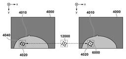
図4は、第1の変形変位場に基づいて変形仮想対応点を生成する様子を示す図である。図4には、第1の変形変位場に基づいて第1の画像3000を変形させた第1の変形画像4000が表されている。第1の変形画像4000には、変形後の被写体の領域4010と変形後の関心領域4020が示されている。また、代表点4030は、関心領域としての病変領域3020上に設定された代表点、変形代表点4040は、代表点4030を第1の変形場に基づいて変形させた代表点を表す。図4の例では、第1の変形位置合わせによって、関心領域4020が被検体の領域4010と同様に押しつぶされると同時に、並進移動と回転が生じているように推定された様子が示されている。このとき、変形代表点4040の分布も、関心領域4020と同様に、代表点4030が全体的に押しつぶされて、さらに並進移動と回転が生じたような分布として算出される。
FIG. 4 is a diagram showing how a deformation virtual correspondence point is generated based on the first deformation displacement field. FIG. 4 shows a first
次に、変形近似部1040は、生成した変形仮想対応点に基づき、変形仮想対応点の変位を近似変換モデルで近似した近似変位場を生成する。より具体的には、変形近似部1040は、式(1)に示す誤差の和eを最小にする近似変換モデルΦ’のパラメータ(近似変換パラメータ)qを算出する。近似変換モデルとして剛体変換モデルを用いる場合には、物体の移動と回転を表す3×4の剛体変換行列Tを規定する位置と姿勢の6パラメータが、近似変換パラメータqに相当する。すなわち、式(2)のように、変形近似部1040は、剛体変換行列及び代表点の積と、変形代表点との差のノルムの総和eを算出し、総和eが最小となる剛体変換行列Tを剛体変換の制約下で算出する。
Next, the

このようにして、変形近似部1040は、関心領域における第1の変形変位場の近似変位場を取得する。最後に、変形近似部1040は、取得した近似変換パラメータqを、近似変位場の情報として対応情報生成部1050へと出力する。
In this way, the
図5は、関心領域としての病変領域3020における第1の変形を剛体変換で近似した様子を説明する図である。図5において、座標軸5000は、関心領域としての病変領域3020上の代表点(図4の代表点4030)の重心位置を原点とし、第1の画像3000のx‐y軸に平行な座標軸を表している。座標軸5010は、剛体変換行列Tを用いて座標軸5000を変換した後の座標軸を表している。但し、紙面が平面である都合上、説明を分かりやすくするためにz軸に平行な軸に関しては省略している。また、座標軸5010のx‐y軸がなす面は第1の変形画像4000のx‐y軸がなす面と必ずしも平行になるものではないが、簡略化して図示している。図に示すように、座標軸5010が、図4の代表点4030から変形代表点4040への変換(第1の変形変位場)から、領域を押しつぶすような変形成分のみを除いた、並進移動・回転成分を抽出した変換に一致することが分かる。
FIG. 5 is a diagram for explaining how the first deformation in the
(S2040)(近似変換に基づく近似仮想対応情報の生成)
ステップS2040において、対応情報生成部1050は、画像間における仮想的な対応情報として、関心領域上に近似変位場に基づく複数の仮想的な対応点(仮想対応情報)を生成する。本実施形態において、以下ではこれを、近似仮想対応点と称する。そして、生成した近似仮想対応点を第2の変形取得部1060へと出力する。
(S2040) (Generation of approximate virtual correspondence information based on approximate transformation)
In step S2040, the correspondence
以下に、具体的な処理を説明する。まず、対応情報生成部1050は、ステップS2030の処理と同様に、関心領域上に設定した複数の代表点の夫々の位置を、近似変位場Φ’を用いて変位させて、夫々の代表点に対応する変位点の位置を算出する。算出した変位点を近似代表点と称する。そして、代表点とそれに対応する近似代表点とを、近似変換モデルによる画像間の仮想的な対応点と定義し、以下ではこれを、近似仮想対応点と称する。
Specific processing will be described below. First, the corresponding
図6は、近似変位場に基づいて近似仮想対応点を生成する様子を示す図である。近似代表点6000は、代表点4030を近似変形場に基づいて変換させた近似代表点を表す。図に示すように、近似代表点6000の分布が、変形は生じずに、図5の座標軸5000から座標軸5010への変換が示す並進移動と回転のみが生じた分布になっていることが分かる。
FIG. 6 is a diagram showing how an approximate virtual correspondence point is generated based on the approximate displacement field. The approximate
(S2050)(近似仮想対応点に基づく第2の変形の取得)
ステップS2050において、第2の変形取得部1060は、ステップS2040で取得した近似仮想対応点(仮想対応情報)を拘束条件として用いて、第1の画像と第2の画像との間の第2の変形位置合わせを実行する。そして、第2の変形取得部1060は、第1の画像と第2の画像との間の変形推定の結果として、生成した第2の変形変位場をデータサーバ110へと出力する。データサーバ110への出力は、不図示の出力部を用いて行われ得る。また、第2の変形取得部1060は、第2の変形変位場に基づいて第1の画像を変形させた第2の変形画像を生成して、表示制御部1070へと出力する。
(S2050) (Acquisition of the second deformation based on the approximate virtual correspondence point)
In step S2050, the second
このとき、第2の変形取得部1060は、ステップS2020と同様に、変形Φによる位置合わせの適切さを評価する評価関数を最小化するような変形Φを推定する。このとき推定された変形Φを第2の変形と称する。また、本ステップで定義する評価関数を第2の評価関数E2(Φ)と称する。本実施形態では、第2の評価関数として、ステップS2020で用いた第1の評価関数E1(Φ)に対して近似仮想対応点の対応点位置の誤差項を追加した評価関数を適用する。
At this time, the second
ここで、変形Φによる近似仮想対応点の対応点位置の誤差項をR(Φ)と定義すると、第2の評価関数E2(Φ)は以下の式で表される。
![]()
![]()
第2の変形取得部1060は、第2の評価関数E2(Φ)を最小化するように、変形Φを表現する所定の変換モデルの変換パラメータp2を最適化する。これにより、画像内の被検体全体の位置合わせとして望ましい最適な変形が推定される。本実施形態では、所定の変換モデルとして、ステップS2020で用いたものと同じ変換モデルを適用する。すなわち、ステップS2020でFFDを適用した場合は、本ステップにおいてもFFDを適用する。ここで、変換モデルがFFDであって、第2の評価関数E2(Φ)が、実対応点(ランドマーク対応点)位置の誤差項と近似仮想対応点位置の誤差項のみによって表現される場合を考える。この場合、FFDのパラメータと対応点間の位置の誤差との関係は、線形方程式で表すことができる。したがって、第2の変形取得部1060は、対応点間の位置の誤差を最小化する変換パラメータp2を公知の線形最適化手法によって推定する。これにより、高速に変換パラメータp2を算出可能である。また、変換モデルがTPSの場合も同様に、第2の変形取得部1060は、公知の線形最適化手法によってパラメータp2が算出できる。なお、評価関数E2(Φ)として画像間の類似度や非線形な正則化項を考慮する場合や、変換モデルとしてLDDMMを用いる場合には、第2の変形取得部1060は、公知の非線形最適化によってパラメータp2を推定する。このとき、第2の変形取得部1060は、ステップS2020で第1の変形取得部1030が算出したパラメータp1を、パラメータp2の初期値として用いることができる。これによると、パラメータp2の算出をより少ない反復処理で行うことができる。
The second
このように、第2の変形取得部1060は、第2の変形変位場として、変換パラメータp2を生成する。そして、第2の変形取得部1060は、生成した第2の変形変位場に基づき、第2の画像に形状が一致するように第1の画像を変形させた第2の変形画像を生成する。また、必要に応じて、第2の変形取得部1060は、第1の画像の形状に一致するように第2の画像を変形させた変形画像(逆変形画像)を、第2の変形変位場に基づいて生成する。
In this way, the second
このように、本実施形態では、第1の評価関数E1(Φ)に基づくことで被検体全体として適切な位置合わせを実現しつつ、近似仮想対応点位置の誤差項R(Φ)に基づくことで関心領域をなるべく近似変換モデルが表す形状(例えば剛体)に保つような変形を推定できる。さらに、画像全体の変形が単一の変換モデル(FFD)で表現されるので、全体として整合性のとれた変形が推定できる。 As described above, in the present embodiment, it is based on the error term R (Φ) of the approximate virtual correspondence point position while realizing appropriate alignment of the entire subject by being based on the first evaluation function E1 (Φ). It is possible to estimate the deformation that keeps the region of interest in the shape (for example, rigid body) represented by the approximate transformation model as much as possible. Furthermore, since the deformation of the entire image is represented by a single transformation model (FFD), it is possible to estimate the deformation that is consistent as a whole.
また、本ステップで得られた第2の変形は、関心領域以外の領域を評価する評価関数内の指標、および変換モデルともに、第1の変形と同条件となる。従って、関心領域以外の領域の変形を第1の変形に類似した変形にすることができる。これにより、第2の変形において関心領域の周囲の近似変換成分も第1の変形に類似するものとなる。従って、関心領域の変形に対して、近似仮想対応点の拘束により第1の変形の関心領域の近似変換成分がそのまま適用される結果となっても、近似変換成分が関心領域の周囲と略合致するため、違和感のない整合の取れた位置合わせ結果を取得することができる。 Further, the second transformation obtained in this step has the same conditions as the first transformation for both the index in the evaluation function for evaluating the region other than the region of interest and the transformation model. Therefore, the deformation of the region other than the region of interest can be made into a deformation similar to the first deformation. As a result, in the second deformation, the approximate conversion component around the region of interest also becomes similar to the first deformation. Therefore, even if the approximate conversion component of the interest region of the first deformation is applied as it is due to the constraint of the approximate virtual correspondence point for the deformation of the region of interest, the approximate conversion component substantially matches the periphery of the region of interest. Therefore, it is possible to obtain a consistent alignment result without a sense of discomfort.
図7は、第1の画像を第2の変形変位場に基づいて変形させた第2の変形画像を生成する様子を示す図である。第2の変形画像7000には、変形後の被写体の領域7010、変形後の関心領域7020が示されている。図に示すように、変形後の被検体の領域7010は、図4における変形後の被検体の領域4010とほぼ同じような形状となる。一方で、変形後の関心領域7020は、図4における変形後の関心領域4020のような押しつぶされた変形は生じずに、関心領域としての病変領域3020の形状が剛体に保たれたまま、並進移動と回転のみ関心領域4020と同様の変換が行われた結果になることを示している。これは、第2の位置合わせにおいて、代表点4030と近似代表点6000からなる近似仮想対応点位置の誤差項による、関心領域の変換を近似変換モデル(ここでは剛体)に拘束する拘束条件の効果が発揮されていることを示している。
FIG. 7 is a diagram showing how a second deformed image is generated by deforming the first image based on the second deformed displacement field. In the second
(S2060)(変形画像の表示)
ステップS2060において、表示制御部1070は、ユーザによる不図示の操作部への操作に応じて、取得した変形画像と第2の画像の断面画像を、表示部120へと表示する制御を行う。このとき、表示制御部1070は、変形画像として、第1の変形変位場に基づく第1の変形画像と、第2の変形変位場に基づく第2の変形画像と、第2の画像の同一断面を、並べて表示するように構成することができる。また、表示制御部1070は、第1の変形画像と第2の変形画像を、ユーザの操作に応じて、1つの表示画面領域内で切り替えて表示するように制御を行ってもよい。なお、表示制御部1070は、第1の変形画像の生成や表示を行わなくてもよい。以上が、本実施形態における画像処理装置100の処理の説明である。
(S2060) (Display of deformed image)
In step S2060, the
本実施形態によれば、画像処理装置100は、単一の変換モデルを用いて、画像全体を適切に一致させる指標と、関心領域の変形をより小さい自由度(例えば剛体)に留めるための指標とに基づいて変形を推定する。これにより、画像処理装置100は、被検体内の関心領域以外の領域を適切に変形させつつ、関心領域に対してはより自由度の小さい変換(例えば剛体変換)を施した上で、画像全体として整合の取れた変形を推定することができる。
According to the present embodiment, the
(変形例1−1)(近似変換モデルは剛体変換でなくともよい)
第1の実施形態では、ステップS2030で関心領域の変形を近似する近似変換モデルとして、剛体変換を適用していたが、近似変換モデルは、第1の変形よりも自由度が小さければどのようなモデルであってもよい。例えば、変形近似部1040は、アフィン変換によって第1の変形を近似してもよい。
(Modification 1-1) (The approximate transformation model does not have to be a rigid transformation)
In the first embodiment, the rigid body transformation is applied as an approximate transformation model for approximating the deformation of the region of interest in step S2030, but what if the approximate transformation model has a smaller degree of freedom than the first deformation? It may be a model. For example, the
具体的には、まず、対応情報生成部1050は、第1の実施形態と同様に、変形仮想対応点を生成する。次に、変形近似部1040は、生成した変形仮想対応点の変位をアフィン変換で近似したアフィン変位場を生成する。より具体的には、変形近似部1040は、式(2)に示す誤差の和eを最小にする3×4の行列Tを、アフィン変換の制約化で算出する。この式において、アフィン変換行列Tと上記のノルムの間の関係を線形方程式で表せることが一般的に知られている。従って、行列Tは、LU分解やQR分解などの公知の方法で算出することができる。この方法の説明は公知の技術であるため、説明は省略する。これにより、例えば、関心領域が完全に剛体ではないが、複雑な変形はしないような場合に、関心領域の変形を実際に近い形で推定できる。
Specifically, first, the correspondence
また、変形近似部1040は、関心領域の変形を単なるアフィン変換ではなく、体積保存の拘束条件が加わったアフィン変換で近似するようにしてもよい。このとき、体積保存の拘束条件は、アフィン変換行列Tにおける、x、y、z方向のスケールファクター成分をそれぞれ、sx、sy、szとすると、以下の式で表される。
![]()
![]()
(変形例1−2)(拘束条件は近似仮想対応点を面状に拘束するものであってもよい)
第1の実施形態では、ステップS2050において、近似仮想対応点を構成する各対応点間の位置関係が一致する拘束条件を、第2の評価関数E2(Φ)に適用した。しかし、第2の評価関数E2(Φ)に追加する拘束条件は、必ずしもこれに限定されない。
(Modification 1-2) (The constraint condition may constrain the approximate virtual correspondence point in a planar manner)
In the first embodiment, in step S2050, a constraint condition in which the positional relationship between the corresponding points constituting the approximate virtual corresponding points is the same is applied to the second evaluation function E2 (Φ). However, the constraint condition added to the second evaluation function E2 (Φ) is not necessarily limited to this.
例えば、関心領域が胸壁や大胸筋面などの面状の領域である場合に、近似仮想対応点を関心領域の面上に拘束する(面上にあれば位置が一致せずともよい)拘束条件を、第2の評価関数E2(Φ)に適用してもよい。これにより、以下のような場合に効果を期待できる。 For example, when the region of interest is a planar region such as the chest wall or the pectoralis major muscle surface, the approximate virtual correspondence point is constrained on the plane of the region of interest (the positions do not have to match if they are on the plane). The condition may be applied to the second evaluation function E2 (Φ). As a result, the effect can be expected in the following cases.
例えば、乳房を圧迫するような変形において、乳房に外力が与えられると、乳房内の乳腺や脂肪の組織はその奥にある大胸筋面上を滑って変形していくことが知られている。このとき、大胸筋面は殆ど変形しないため、大胸筋面を関心領域として、大胸筋面を剛体に保つような変形を行うことを想定する。このとき、ステップS2050において、近似仮想対応点の位置そのものが一致するような拘束条件を第2の評価関数E2(Φ)に適用すると、大胸筋近傍の組織は、そのまま大胸筋面上の位置に拘束されてしまうため、大胸筋面上を滑るような変形にはならない。そこで、本変形例では、近似仮想対応点を関心領域(大胸筋面)の面上のみに拘束するという条件を第2の評価関数E2(Φ)に追加する。これにより、近似仮想対応点が関心領域の面上を滑る場合を許容できる。すなわち、関心領域の外面を含む関心領域上に設定された代表点は、近似変位場による変位後も、関心領域の面上を沿って動くことを許容される。これにより、大胸筋近傍の組織が大胸筋面上を滑ることを許容できるようにすることが可能となる。 For example, in a deformation that presses on the breast, it is known that when an external force is applied to the breast, the mammary glands and fat tissues in the breast slide on the pectoralis major muscle surface behind the breast and deform. .. At this time, since the pectoralis major muscle surface is hardly deformed, it is assumed that the pectoralis major muscle surface is deformed so as to keep the pectoralis major muscle surface rigid. At this time, in step S2050, when the constraint condition that the positions of the approximate virtual correspondence points themselves match is applied to the second evaluation function E2 (Φ), the tissue near the pectoralis major muscle is directly on the pectoralis major muscle surface. Since it is constrained to the position, it does not become a deformation that slides on the pectoralis major muscle surface. Therefore, in this modification, the condition that the approximate virtual correspondence point is constrained only on the surface of the region of interest (pectoralis major muscle surface) is added to the second evaluation function E2 (Φ). As a result, it is possible to allow the approximate virtual correspondence point to slide on the surface of the region of interest. That is, the representative point set on the region of interest including the outer surface of the region of interest is allowed to move along the surface of the region of interest even after displacement by the approximate displacement field. This makes it possible to allow the tissue near the pectoralis major muscle to slide on the surface of the pectoralis major muscle.
以下に具体的な方法を説明する。まず、近似仮想対応点を構成する代表点は、面領域である関心領域上に均等に配置されているものとする。このとき、ステップS2050において、近似仮想対応点を関心領域の面上に拘束する拘束条件は、評価関数E2(Φ)を構成する関数R(Φ)として、以下の式で表わされる。
本変形例の場合、共分散Covは、例えば、i番目の近似代表点xR2i近傍の法線方向には狭く、それに直交する平面の方向には非常に広い分布を有するガウス分布を表す共分散を返す関数にできる。ここで、近似代表点xR2i近傍の法線方向とは、面状に分布している近似代表点の中で、近似代表点xR2i近傍の近似代表点の集合によって張られる平面の法線ベクトルの方向を意味する。この法線ベクトルは、例えば、公知の手法である、近似代表点xR2i近傍の近似代表点の集合の位置を主成分分析し、その第3主成分ベクトルとして算出できる。 In the case of this modification, the covariance Cov represents, for example, a Gaussian distribution having a narrow distribution in the normal direction near the i-th approximate representative point x R2i and a very wide distribution in the direction of the plane orthogonal to it. Can be a function that returns. Here, the normal direction of the approximate representative point x R2i vicinity, in approximate representative points are distributed in the planar, the plane spanned by the set of approximate representative points of the approximate representative point x R2i near normal vector Means the direction of. This normal vector can be calculated as a third principal component vector by performing principal component analysis on the position of a set of approximate representative points in the vicinity of the approximate representative point x R2i, which is a known method.
なお、法線ベクトルの算出方法は、これに限られるものではなく、公知の何れの方法を採ってもよい。ここで、(6)式において、第2の変形Φによる変位後の代表点と、対応する近似代表点の間の誤差を表す3次元ベクトルをeと定義する。(6)式により、入力ベクトルにおける法線成分が大きい場合には、Cov−1と誤差ベクトルeの積は大きい値を返し、それ以外の成分が大きい場合には非常に小さい値を返す。従って、(6)式により、R(Φ)は、第2の変形Φによる変位後の代表点と、対応する近似代表点の間の誤差eのうち、近似代表点の法線方向の成分にのみペナルティをかけることができる。すなわち、R(Φ)は、変位後の代表点が、対応する近似代表点から法線方向にのみずれないようにするための項として機能する。 The method for calculating the normal vector is not limited to this, and any known method may be adopted. Here, in the equation (6), the three-dimensional vector representing the error between the representative point after the displacement due to the second deformation Φ and the corresponding approximate representative point is defined as e. According to the equation (6), when the normal component in the input vector is large, the product of Cov -1 and the error vector e returns a large value, and when the other components are large, a very small value is returned. Therefore, according to Eq. (6), R (Φ) is a component of the error e between the representative point after displacement due to the second deformation Φ and the corresponding approximate representative point in the normal direction of the approximate representative point. Only can be penalized. That is, R (Φ) functions as a term for preventing the representative point after displacement from shifting only in the normal direction from the corresponding approximate representative point.
このように定義された評価関数E2(Φ)を最小化するような変換パラメータp2の算出方法としては、ステップS2050と同様に公知の非線形最適化手法で算出することができる。また、非特許文献1に記載された、上記共分散Covに基づく線形最適化手法によっても算出することができる。 As a method for calculating the conversion parameter p2 that minimizes the evaluation function E2 (Φ) defined in this way, it can be calculated by a known nonlinear optimization method as in step S2050. It can also be calculated by the linear optimization method based on the covariance Cov described in Non-Patent Document 1.
(変形例1−3)
第1の実施形態では、ステップS2040およびステップS2050で利用する画像間における仮想対応情報として、仮想的な対応点を適用していた。しかし、利用する仮想対応情報は、必ずしも対応点ではなくてもよい。
(Modification 1-3)
In the first embodiment, virtual correspondence points are applied as virtual correspondence information between the images used in step S2040 and step S2050. However, the virtual correspondence information to be used does not necessarily have to be the correspondence point.
例えば、仮想対応情報として、関心領域の形状に関する情報の、画像間における仮想的な対応情報を用いてもよい。具体的には、ステップS2040において、対応情報生成部1050は、関心領域そのものを、近似変形場Φ’を用いて変位させて、対応する変位後の関心領域(近似関心領域)を取得する。より具体的には、対応情報生成部1050は、関心領域を表すマスク画像IROIを、近似変形場Φ’を用いて変位させて、近似関心領域のマスク画像IA_ROIを取得する。そして、対応情報生成部1050は、関心領域と近似関心領域とを、近似変換モデルによる画像間の仮想的な対応領域として生成する。仮想的な対応領域の情報は、関心領域の輪郭形状の情報を保持しているため、本変形例における画像間の仮想対応情報として、これを近似仮想対応形状と称する。
For example, as the virtual correspondence information, the virtual correspondence information between the images of the information regarding the shape of the region of interest may be used. Specifically, in step S2040, the corresponding
そして、対応情報生成部1050は、生成した近似仮想対応形状を第2の変形取得部1060へ出力する。そして、ステップS2050において、第2の変形取得部1060は、ステップS2040で取得した近似仮想対応形状を拘束条件として用いて、第1の画像と第2の画像との間の第2の変形位置合わせを実行する。このとき、本ステップで最小化する第2の評価関数E2(Φ)において、本変形例では、第1の実施形態における近似仮想対応点の対応点位置の誤差項R(Φ)の代わりに、近似仮想対応形状の誤差項R’(Φ)を適用する。近似仮想対応形状の誤差項R’(Φ)は以下の式で表される。
![]()
関心領域の輪郭形状を近似変換モデルが表す形状に保つような変形を推定できる。
Then, the correspondence
![]()
It is possible to estimate the deformation that keeps the contour shape of the region of interest in the shape represented by the approximate transformation model.
また、仮想対応情報として、次の情報を適用してもよい。まず、対応情報生成部1050は、関心領域のマスク画像IROIと近似関心領域のマスク画像IA_ROIの夫々から、画像中の関心領域の輪郭位置からの距離場を生成する。続いて、対応情報生成部1050は、夫々の距離場内の各距離値を輝度値に変換して画像化した距離場画像を夫々生成する。ここで、IROIに対応する距離場画像をIDIST、IA_ROIに対応する距離場画像をIA_DISTと定義し、それらを、近似変換モデルによる画像間の仮想対応情報とする。この場合、(6)式において、IROI、IA_ROIの代わりに、IDIST、IA_DISTを適用することで、関心領域の輪郭だけでなく、内部まで輝度情報を類似させることができる。これにより、関心領域内部も含めて関心領域IROIの形状を近似変換モデルが表す形状に保つような変形を推定できる。
In addition, the following information may be applied as virtual correspondence information. First, the corresponding
(変形例1−4)
第1の実施形態では、ステップS2030で生成する変形仮想対応点と、ステップS2040で生成する近似仮想対応点は、第1の画像上の同じ代表点から生成するものであった。しかし、それらは同じ代表点から生成されるものである必要はなく、変形仮想対応点と近似仮想対応点とが別々の代表点から生成されるものであってもよい。例えば、変形仮想対応点に関しては、関心領域を囲む所定範囲内(周囲5mm以内)の領域上に設定された代表点から生成し、近似仮想対応点に関しては、厳密に関心領域上に設定された代表点から生成する方法を採ってもよい。これにより、第2の変形において、関心領域の周囲の領域により整合した近似変換成分を抽出でき、かつ厳密に関心領域に対してのみ形状を維持させる拘束条件を与えることができる。
(Modification 1-4)
In the first embodiment, the deformation virtual correspondence point generated in step S2030 and the approximate virtual correspondence point generated in step S2040 are generated from the same representative points on the first image. However, they do not have to be generated from the same representative point, and the deformed virtual correspondence point and the approximate virtual correspondence point may be generated from different representative points. For example, the deformed virtual correspondence point is generated from the representative points set on the region within a predetermined range (within 5 mm around) surrounding the region of interest, and the approximate virtual correspondence point is strictly set on the region of interest. A method of generating from a representative point may be adopted. Thereby, in the second modification, the approximate conversion component more consistent with the region around the region of interest can be extracted, and the constraint condition for maintaining the shape strictly only for the region of interest can be given.
(変形例1−5)(第1の変形推定と第2の変形推定でE1(Φ)は同じでなくてもよい)
第1の実施形態では、ステップS2050における第2の評価関数E2(Φ)は、(3)式に示すように第1の評価関数E1(Φ)を用いていた。しかし、ステップS2050で、第1の評価関数E1(Φ)を必ずしも用いる必要はない。例えば、ステップS2050では、より多くの計算コストを要して高精度な評価を行う評価関数を、E1(Φ)として用いるようにしてもよい。例えば、第1の変形推定ではランドマーク対応点位置の誤差をE1(Φ)として用いて、第2の変形推定では画像全体の画像類似度をE1(Φ)として用いるようにできる。これは、第1の変形推定は近似変形場を求めるための中間処理に過ぎないが、第2の変形推定は位置合わせの結果を得ることを目的としているからである。
(Modification example 1-5) (E1 (Φ) does not have to be the same in the first deformation estimation and the second deformation estimation)
In the first embodiment, the second evaluation function E2 (Φ) in step S2050 uses the first evaluation function E1 (Φ) as shown in the equation (3). However, it is not always necessary to use the first evaluation function E1 (Φ) in step S2050. For example, in step S2050, an evaluation function that requires more calculation cost and performs highly accurate evaluation may be used as E1 (Φ). For example, in the first deformation estimation, the error of the landmark corresponding point position can be used as E1 (Φ), and in the second deformation estimation, the image similarity of the entire image can be used as E1 (Φ). This is because the first deformation estimation is only an intermediate process for obtaining an approximate deformation field, but the second deformation estimation aims to obtain the alignment result.
(変形例1−6)(第2の変形における変換モデルは第1の変形と同じでなくてもよい)
第1の実施形態では、ステップS2050の第2の変形における変換モデルは、ステップS2020における第1の変形と同じ変形モデルを用いていた。しかし、関心領域の周囲の近似変換成分が第1の変形と類似する結果になるのであれば、第2の変形で利用する変換モデルは、必ずしもステップS2020と一致する必要はない。
(Modification example 1-6) (The transformation model in the second transformation does not have to be the same as the first transformation)
In the first embodiment, the transformation model in the second transformation of step S2050 uses the same transformation model as the first transformation in step S2020. However, if the approximate transformation component around the region of interest yields similar results to the first transformation, the transformation model used in the second transformation does not necessarily have to match step S2020.
例えば、本実施形態では、ステップS2020においてFFDを変換モデルとして採用しているが、FFDのモデルを構成するパラメータの一つである、制御点の間隔を変えたFFDをステップS2050で採用してもよい。具体的には、ステップS2020において、制御点を20mm間隔で配置している場合に、ステップS2050において、その半分の10mm間隔で配置するようにしてもよい。これにより、Bスプライン基底関数により滑らかな変形が得られるという特性は変えずに、変形の自由度を増やすことができる。つまり、より詳細な変形を表現できる。さらに、画像全体の概略の変形を第1の変形と第2の変形の間で類似させるために、例えば、第2の変形では段階的に変形の自由度を上げていく変換モデルを適用する。具体的には、第1の変形と同様の変形の自由度の低い「荒い制御点(20mm間隔)」で表現されたFFDから変形の自由度の高い「細かい制御点(10mm間隔)」で表現されるFFDの順に適用する、公知の技術である多重解像度FFDを、変換モデルとして適用する。 For example, in the present embodiment, the FFD is adopted as the conversion model in step S2020, but even if the FFD with different control point intervals, which is one of the parameters constituting the FFD model, is adopted in step S2050. good. Specifically, when the control points are arranged at intervals of 20 mm in step S2020, they may be arranged at intervals of 10 mm, which is half of the control points in step S2050. As a result, the degree of freedom of deformation can be increased without changing the characteristic that smooth deformation can be obtained by the B-spline basis function. That is, more detailed transformation can be expressed. Further, in order to make the approximate deformation of the entire image similar between the first deformation and the second deformation, for example, in the second deformation, a transformation model in which the degree of freedom of deformation is gradually increased is applied. Specifically, the FFD expressed by "rough control points (20 mm intervals)" having a low degree of freedom of deformation similar to the first deformation is expressed by "fine control points (10 mm intervals)" having a high degree of freedom of deformation. A multi-resolution FFD, which is a known technique to be applied in the order of FFDs, is applied as a conversion model.
これにより、第2の変形において、第1の変形よりもより詳細な位置合わせを実現しながら、概略の変形としては第1の変形の状態が保持されるため、関心領域の周囲の近似変換成分が第1の変形と類似する結果になる。また、関心領域の周囲の近似変換成分が大きく変わらないのであれば、第1の変形と第2の変形の組み合わせとして、FFDとTPS、FFDとLDDMMなど、性質の異なる変換モデルを適用してもよい。また、仮想対応点の対応点位置の誤差項R(Φ)を第2の変形の評価関数E2(Φ)の一部として用いるものであれば、何れの変換モデルや評価関数を用いてもよい。 As a result, in the second deformation, the state of the first deformation is maintained as a rough deformation while realizing more detailed alignment than the first deformation, so that the approximate conversion component around the region of interest is maintained. Has a result similar to that of the first modification. Further, if the approximate conversion component around the region of interest does not change significantly, even if a conversion model having different properties such as FFD and TPS and FFD and LDDMM is applied as a combination of the first deformation and the second deformation. good. Further, any conversion model or evaluation function may be used as long as the error term R (Φ) of the corresponding point position of the virtual corresponding point is used as a part of the evaluation function E2 (Φ) of the second deformation. ..
<第2の実施形態>
第1の実施形態では、予め定められた近似変換モデルを用いて関心領域の第1の変形を近似していた。しかし、関心領域の性質に応じて適応的に近似変換モデルを選択できるようにしてもよい。本実施形態における画像処理装置は、関心領域に対応する部位(臓器や病変等)の種類に応じて適切な近似変換モデルを選択し、選択された近似変換モデルを用いて関心領域の第1の変形を近似する。これにより、予め定められた近似変換モデルが使用されることで、本来関心領域の変形とは異なる性質の近似変換モデルが適用されてしまい、位置合わせ精度が低下することを防ぐことができる。以下、本実施形態における画像処理装置について、第1の実施形態との相違部分について説明する。
<Second embodiment>
In the first embodiment, a predetermined approximate transformation model is used to approximate the first deformation of the region of interest. However, the approximate transformation model may be adaptively selected according to the nature of the region of interest. The image processing apparatus in the present embodiment selects an appropriate approximate transformation model according to the type of the site (organ, lesion, etc.) corresponding to the region of interest, and uses the selected approximate transformation model to obtain the first approximation of the region of interest. Approximate the deformation. As a result, by using a predetermined approximate conversion model, it is possible to prevent the approximate conversion model having properties different from the deformation of the region of interest from being applied and the alignment accuracy from being lowered. Hereinafter, the image processing apparatus in the present embodiment will be described with respect to the differences from the first embodiment.
図8は、本実施形態における画像処理装置800の構成を示す図であり、新たに近似変換モデル選択部8000が追加された点以外は、第1の実施形態における画像処理装置100(図1)と同様である。また、関心領域取得部1020と変形近似部1040に関しては、第1の実施形態と機能が異なるため以下でその機能を説明する。その他の構成については第1の実施形態と機能が同じであるため、同じ機能に関しては説明を省略する。
FIG. 8 is a diagram showing the configuration of the
関心領域取得部1020は、第1の画像から関心領域の取得と、関心領域に対応する部位の種類の分類(識別)を行う。近似変換モデル選択部8000は、分類(識別)された部位の種類に応じて、当該部位の変形表現に適切な近似変換モデルを選択する。変形近似部1040は、関心領域における第1の変形変位場を、選択された近似変換モデルを用いて近似することで、近似変位場を生成する。
The region of
図9は、画像処理装置800が行う全体の処理手順を示すフローチャートである。但し、本フローチャートにおいて、ステップS9000、ステップS9020、およびステップS9040からS9060までの処理はそれぞれ、図2におけるステップS2000、ステップS2020、およびステップS2040からS2060までの処理と同じであるため説明は省略する。以下、図2のフローチャートとの相違部分についてのみ説明する。
FIG. 9 is a flowchart showing the entire processing procedure performed by the
(S9010)(関心領域の取得と対応する部位の種類の分類)
ステップS9010において、関心領域取得部1020は、データ取得部1010から取得した画像上において、変形を抑制したい関心領域を表す情報を取得し、該関心領域に対応する部位の種類を分類(識別)する。そして、取得された関心領域とその分類情報を近似変換モデル選択部8000へ出力する。
(S9010) (Acquisition of region of interest and classification of corresponding site type)
In step S9010, the region of
本ステップの具体的な処理を説明する。例えば、関心領域が臓器である場合を考える。関心領域取得部1020は、臓器の種類ごとの統計アトラスの当てはめ等の公知の画像解析処理によって、第1の画像から、臓器領域の抽出と、対応する臓器の種類の分類を行う。そして、関心領域取得部1020は、抽出・分類された臓器領域に基づいて、関心領域を取得する。関心領域として、抽出された臓器領域の少なくとも一つの領域が設定される。これは、ユーザによる画像上の領域の指定などの入力により設定されてもよいし、予め定められた変形を近似すべき臓器の種類(骨や肝臓など)に対応する領域が、抽出された臓器領域の中から設定されてもよい。なお、関心領域が複数存在する場合には、関心領域取得部1020は、これらの処理を夫々の関心領域に対して実行する。
The specific processing of this step will be described. For example, consider the case where the area of interest is an organ. The region of
なお、関心領域取得部1020は、データサーバに格納された被検体の臨床情報に記載された情報に基づいて、臓器領域の分類を行ってもよい。例えば、撮影された画像が腹部造影CT画像である場合は、画像内に写る臓器は、肝臓や脾臓の領域等であるため、関心領域取得部1020は、臓器の種類を絞りこむことができる。そして、例えば、関心領域取得部1020は、抽出された領域の体積が大きければ肝臓、小さければ脾臓のように分類できる。
The region of
また、関心領域が病変部である場合に、第1の画像に付随する情報として所見情報が記載されている場合に、関心領域取得部1020は、該所見情報に応じて病変部の分類情報を取得するようにしてもよい。例えば、「硬癌」「良性腫瘍」「DCIS」やそれに類する記載がある場合には、関心領域取得部1020は、その情報を部位の分類情報と設定することができる。また、それらの記載がない場合には、関心領域取得部1020は、分類情報を「不明」とすることができる。
Further, when the region of interest is a lesion and the finding information is described as the information accompanying the first image, the region of
(S9015)(近似変換モデルの選択)
ステップS9015において、近似変換モデル選択部8000は、関心領域に対応する臓器の種類や性質に応じて、近似変換モデルの種類を選択する。例えば、近似変換モデル選択部8000は、骨に分類された領域には剛体変換モデルを適用し、肝臓に分類された領域には体積保存のアフィン変換モデルを適用することができる。なお、関心領域が複数存在する場合には、近似変換モデル選択部8000は、これらの処理を夫々の関心領域に対して実行する。また、近似変換モデル選択部8000は、「硬癌」には剛体変換モデル、「良性腫瘍」には体積保存のアフィン変換モデル、「DCIS」や「不明」には「近似なし」を適用することができる。なお、近似変換モデル選択部8000は、「近似なし」を適用した関心領域については、以降の近似処理を行う処理の対象から除外することができる。そして、近似変換モデル選択部8000は、選択した近似変換モデルの種類を、対応情報生成部1050へ出力する。
(S9015) (Selection of approximate conversion model)
In step S9015, the approximate transformation
(S9030)(関心領域における第1の変形を近似変換で近似)
ステップS9030において、変形近似部1040は、関心領域における第1の変形変位場を、この変位場よりも自由度の小さい、近似変換モデル選択部8000から取得した近似変換モデルで近似した近似変位場を生成する。そして、変形近似部1040は、生成した近似変位場を、第2の対応情報生成部1050へと出力する。
(S9030) (Approximate the first deformation in the region of interest by approximate transformation)
In step S9030, the
本ステップの処理は、以下の点についてのみ第1の実施形態のステップS2030と異なる。すなわち、第1の実施形態のステップS2030では、変形近似部1040は、予め定められた近似変換モデルを用いていた。それに対し、本ステップでは、変形近似部1040は、近似変換モデル選択部8000から取得した近似変換モデルを用いるようにしている。それ以外は、ステップS2030の処理と同様であるため、詳細な説明は省略する。なお、関心領域が複数存在する場合には、変形近似部1040は、これらの処理を夫々の関心領域に対して実行する。以上によって、画像処理装置800の処理が実施される。
The processing of this step is different from step S2030 of the first embodiment only in the following points. That is, in step S2030 of the first embodiment, the
このように、本実施形態における画像処理装置は、関心領域に対応する臓器の種類に応じて適切な近似変換モデルを選択し、選択された近似変換モデルを用いて関心領域の第1の変形を近似する。これにより、予め定められた近似変換モデルが使用されることで、本来関心領域の変形とは異なる性質の近似変換モデルが適用されてしまい、位置合わせ精度が低下することを防ぐことができる。 As described above, the image processing apparatus in the present embodiment selects an appropriate approximate transformation model according to the type of organ corresponding to the region of interest, and uses the selected approximate transformation model to perform the first deformation of the region of interest. Approximate. As a result, by using a predetermined approximate conversion model, it is possible to prevent the approximate conversion model having properties different from the deformation of the region of interest from being applied and the alignment accuracy from being lowered.
<第3の実施形態>
第1の実施形態では、関心領域の第1の変形を自由度が小さい近似変換で近似して得た仮想的な対応情報を、そのまま第2の変形位置合わせの位置合わせ指標として利用していた。しかし、近似変換から得た仮想的な対応情報を直接、第2の変形位置合わせの位置合わせ指標として利用しなくてもよい。本実施形態では、第1の変形から得た仮想的な対応情報と、近似変換から得た仮想的な対応情報と、の間に位置する中間的な対応情報を、第2の変形位置合わせの位置合わせ指標として利用する。以下、本実施形態における画像処理装置について、第1の実施形態との相違部分について説明する。
<Third embodiment>
In the first embodiment, the virtual correspondence information obtained by approximating the first deformation of the region of interest by an approximate transformation with a small degree of freedom is used as it is as the alignment index of the second deformation alignment. .. However, it is not necessary to directly use the virtual correspondence information obtained from the approximate transformation as the alignment index of the second deformation alignment. In the present embodiment, the intermediate correspondence information located between the virtual correspondence information obtained from the first deformation and the virtual correspondence information obtained from the approximate transformation is converted into the second deformation alignment. It is used as an alignment index. Hereinafter, the image processing apparatus in the present embodiment will be described with respect to the differences from the first embodiment.
図10は、本実施形態における画像処理装置1000の構成を示す図であり、新たに形状維持度取得部10010が追加された点以外は、第1の実施形態における画像処理装置100と同様である。しかし、対応情報生成部1050、第2の変形取得部1060、表示制御部1070に関しては、第1の実施形態と機能が異なるため、以下でその機能を説明する。その他の構成については第1の実施形態と機能が同じであるため、同じ機能に関しては説明を省略する。
FIG. 10 is a diagram showing the configuration of the
形状維持度取得部10010は、ユーザによる不図示の操作部からの入力により、変形位置合わせにおいて関心領域にどの程度形状を維持させるかを表す形状維持度の値を取得する。言い換えると、形状維持度とは、関心領域に関しての前記第1の変形変位場から前記第2の変形変位場への変化の程度を示す指標である。対応情報生成部1050は、第1実施形態と同様に変形仮想対応点と近似仮想対応点を生成する機能に加え、形状維持度取得部10010から取得した形状維持度に基づき変形仮想対応点と近似仮想対応点との間に位置する仮想対応点を生成する。これを中間仮想対応点と称する。第2の変形取得部1060は、第1実施形態において近似仮想対応点に基づいて行う変形位置合わせの処理を、近似仮想対応点に限定せずに、近似仮想対応点または中間仮想対応点の何れかの仮想対応点に基づくように置き換えた処理を行う。それ以外の機能は第1実施形態と同様であるため、詳細な説明は省略する。表示制御部1070は、第1実施形態と同様の機能に加え、ユーザによる不図示の操作部から処理を終了するか否かの命令を取得し、命令“終了する”を取得した場合には、処理は終了する。命令“終了しない”を取得した場合には、ユーザによる入力待ちの状態を維持する。
The shape maintenance
図11は、画像処理装置1000が行う全体の処理手順を示すフローチャートである。但し、本フローチャートにおいて、ステップS11000からS11020、S11050、S11060、およびステップS11100の処理はそれぞれ、図2のフローチャートにおけるステップS2000からS2020、S2030、S2040、およびステップS2060の処理と同じであるため説明は省略する。なお、本実施形態において、仮想対応情報は、第1の実施形態において述べたような近似仮想対応点であるとする。以下、図2のフローチャートとの相違部分について説明する。
FIG. 11 is a flowchart showing the entire processing procedure performed by the
(S11025)(第1の変形画像の表示)
ステップS11025において、表示制御部1070は、ユーザによる不図示の操作部への操作に応じて、取得した第1の変形画像と第2の画像の断面画像を、表示部120へと表示する制御を行う。このとき、表示制御部1070は、第1の変形画像と第2の画像の同一断面を、並べて表示部120へ表示するように制御することができる。
(S11025) (Display of the first deformed image)
In step S11025, the
(S11030)(形状維持度の取得)
ステップS11030において、形状維持度取得部10010は、ユーザが不図示の操作部から入力した形状維持度を取得する。そして、取得した形状維持度の値を、対応情報生成部1050および表示制御部1070へと出力する。
(S11030) (Acquisition of shape retention)
In step S11030, the shape maintenance
以下では、形状維持度の値をλRと表記する。本ステップで取得された形状維持度の値λRに基づいて、ステップS11090の第2の変形位置合わせが実施される。形状維持度の値λRは、0≦λR≦1の範囲を満たす。λRが0に近いほど、中間仮想対応点が変形仮想対応点の位置に近付き、関心領域の変形は周囲と変わらない変形に近付く。すなわち、関心領域は、周囲と変わらず特に拘束のない変形しやすい状態に近付く。一方、λRが1に近いほど、中間仮想対応点の位置が近似仮想対応点の位置に近付き、関心領域の変形は近似変換に近付く。すなわち、関心領域は、周囲とは異なり変形しづらい状態に近付く。 In the following, the value of the shape retention degree is expressed as λ R. Based on the shape retention value λ R acquired in this step, the second deformation alignment in step S11090 is performed. The shape retention value λ R satisfies the range of 0 ≦ λ R ≦ 1. The closer λ R is to 0, the closer the intermediate virtual correspondence point is to the position of the deformation virtual correspondence point, and the deformation of the region of interest approaches the same deformation as the surroundings. That is, the region of interest approaches a deformable state without any particular restraint, which is the same as the surrounding area. On the other hand, the closer λ R is to 1, the closer the position of the intermediate virtual correspondence point is to the position of the approximate virtual correspondence point, and the closer the deformation of the region of interest is to the approximate transformation. That is, the region of interest approaches a state in which it is difficult to deform unlike the surroundings.
形状維持度取得部10010は、λRを、例えば、予め定められた複数の値の中からユーザが選択することで取得できる。例えば、予め設定された複数のλRのリスト(例えば、{0、0.25、0.5、0.75、1.0})が、表示部120上に表示されている場合を考える。この場合、ユーザは不図示の操作部を通じて、リストの中の何れかの値(例えば、0.5)を選択すると、形状維持度取得部10010は、その選択された値をλRとして取得する。
The shape maintenance
なお、形状維持度の取得方法はこれに限られるものではなく、どのような方法であってもよい。例えば、ユーザが不図示の操作部を通じて直接値を入力し、形状維持度取得部10010は、その値を取得するようにしてもよい。この場合、例えばユーザが値1.0と入力すれば、形状維持度取得部10010は、λR=1.0を取得する。
The method for obtaining the degree of shape retention is not limited to this, and any method may be used. For example, the user may directly input a value through an operation unit (not shown), and the shape maintenance
また、ユーザは、ステップS11030において表示部120上に表示された第1の変形画像と第2の画像とを観察し、その結果に基づいて判断した形状維持度の値を入力することができる。例えば、表示部120上に表示された第1の変形画像上の関心領域が第2の画像上の対応する領域にある程度近い場合には、ユーザは、関心領域の変形が第1の変形の変換モデルである程度正確に表現できていると判断して、形状維持度を小さく設定できる。一方、形状が大きくかけ離れている場合には、ユーザは、関心領域の変形が第1の変形の変換モデルからかけ離れていると判断して、形状維持度を大きく設定できる。
Further, the user can observe the first deformed image and the second image displayed on the
前述したように、本実施形態における画像処理装置1000は、形状維持度に応じて、関心領域の変形のしにくさを調整できる。例えば、近似変換モデルとして剛体変換を適用する場合には、画像処理装置1000は、形状維持度によって関心領域の大よその硬さを調整することができる。そこで、例えば、予め作成された、定性的な硬さの「度合い」と形状維持度の値「λR」との対応テーブルにおいて、ユーザが定性的な硬さの度合いを選択してもよい。形状維持度取得部10010は、選択された「度合い」それに対応するλRを取得するようにしてもよい。より具体的には、例えば、“柔らかい”=0.0、“やや柔らかい”=0.25、“中間”=0.25、“やや硬い”=0.75、“硬い”=1.0のようなマッピングを行う対応テーブルが予め画像処理装置1000に保持されているとする。そして、表示制御部1070が、表示部120上に定性的な硬さの度合いのリスト(例えば、{“柔らかい”、“やや柔らかい”、“中間”、“やや硬い”、“硬い”})を表示する。そして、ユーザが不図示の操作部を通じていずれかの度合い(例えば、“硬い”)を選択した場合に、形状維持度取得部10010は、対応テーブルを参照して、該度合いに対応する値(例えば、1.0)をλRとして取得することができる。
As described above, the
なお、形状維持度λRの取得方法は、ユーザによる手動入力による方法に限定されない。例えば、形状維持度取得部10010は、事前に画像処理装置800内の不図示の記憶部に記憶された所定の値をλRとして取得するようにしてもよい。また、形状維持度取得部10010は、データサーバ110に格納された被検体の臨床情報に基づいてλRを取得するようにしてもよい。
The method of acquiring the shape retention degree λ R is not limited to the method of manual input by the user. For example, the shape maintenance
例えば、読影レポート等の臨床情報に“病変部が硬い”あるいは“硬癌”、”石灰化”といった意味を示す所見や診断名が記載されている場合は、形状維持度取得部10010は、λR=1.0を設定する。同様に、“病変部が周囲の組織と変わらず柔らかい”あるいは“非浸潤性癌”といった意味を示す所見や診断名が記載されている場合は、形状維持度取得部10010は、λR=0.0を設定する。また、不図示の解析部が、第1の画像における関心領域に相当する領域の画像特徴を解析することで関心領域の定性的な硬さの度合いを判定し、それに基づいて、形状維持度取得部10010が、上述したマッピングによりλRを取得するようにしてもよい。また、第2の実施形態において説明した図9のステップS9010と同様の方法で、関心領域取得部1020が第1の画像から臓器領域の抽出を行い、形状維持度取得部10010が、夫々の臓器に予め定めた形状維持度の値を夫々の領域に設定するようにしてもよい。例えば、形状維持度取得部10010は、骨と分類された領域にはλR=1.0を、肝臓や肺と分類された領域にはλR=0.75を設定するといった処理を行うことができる。
For example, when clinical information such as an interpretation report contains findings or diagnosis names indicating meanings such as "hard lesion", "hard cancer", and "calcification", the shape maintenance
(S11040)(形状維持度が0か否かの判定)
ステップS11040において、形状維持度取得部10010は、形状維持度の値λRが0か否かを判定する。そして、λR≠0の場合は、処理はステップS11050へ進む。一方、λR=0の場合は、処理はステップS11100へ進む。これにより、形状維持度λRが0以外の場合は、画像処理装置1000は、ステップS11050からS11090の処理により、形状維持度の値λRに基づいて関心領域の形状が維持された第2の変形画像を最終的な位置合わせ結果として取得できる。一方、λRが0の場合は関心領域の形状を維持する必要がないため、画像処理装置1000は、ステップS11020で生成された第1の変形画像をそのまま最終的な位置合わせ結果として取得できる。これにより、不要に第2の画像を生成する処理を削減でき、全体の処理フローを効率化することができる。
(S11040) (Determination of whether or not the shape retention degree is 0)
In step S11040, the shape maintenance
(S11070)(形状維持度が1か否かの判定)
ステップS11070において、形状維持度取得部10010は、形状維持度の値λRが1か否かを判定する。そして、λR≠1の場合は、処理はステップS11080へ進む。一方、λR=1の場合は、処理はステップS11090へ進む。これにより、λRが1以外の場合は、画像処理装置1000は、ステップS11080の処理によって中間仮想対応点を生成し、ステップS11090においてそれを仮想対応点位置の誤差項に適用して位置合わせした第2の変形画像を最終的な位置合わせ結果として取得できる。一方、λRが1の場合は、画像処理装置1000は、ステップS11060で生成した近似仮想対応点を、そのままステップS11090における仮想対応点位置の誤差項に適用して位置合わせした第2の変形画像を最終的な位置合わせ結果として取得できる。従って、不要に中間仮想対応点を生成する処理を削減でき、全体の処理フローを効率化することができる。
(S11070) (Determination of whether or not the shape retention degree is 1)
In step S11070, the shape maintenance
(S11080)(形状維持度に基づき中間仮想対応点を生成)
ステップS11080において、対応情報生成部1050は、形状維持度取得部10010から取得した形状維持度の値λRに基づき、関心領域DROI上の変形仮想対応点と近似仮想対応点の間に位置する中間仮想対応点を生成する。そして、対応情報生成部1050は、生成した中間仮想対応点を第2の変形取得部1060へと出力する。
(S11080) (Intermediate virtual correspondence points are generated based on the degree of shape maintenance)
In step S11080, the correspondence
中間仮想対応点の位置は、λRが0に近い場合は変形仮想対応点に近付き、λRが1に近い場合は近似仮想対応点に近付く。近似仮想対応点は、関心領域の変形を近似変換モデルに従うように拘束するの。それに対し、中間仮想対応点は、関心領域の変形を周囲の変形と変わらない状態と近似変換モデルに従う状態の間の状態に拘束する特徴を持つ。以下に中間仮想対応点の具体的な生成方法を説明する。 The position of the intermediate virtual correspondence point approaches the deformation virtual correspondence point when λ R is close to 0, and approaches the approximate virtual correspondence point when λ R is close to 1. The approximate virtual correspondence points constrain the deformation of the region of interest to follow the approximate transformation model. On the other hand, the intermediate virtual correspondence point has a feature of constraining the deformation of the region of interest to a state between a state that is not different from the surrounding deformation and a state that follows the approximate transformation model. A specific method for generating intermediate virtual correspondence points will be described below.
まず、対応情報生成部1050は、変形仮想対応点と近似仮想対応点とを夫々構成する、第1の画像上の代表点を夫々変換した先の対応する代表点、つまり変形代表点と近似代表点との間に位置する代表点を生成する。これを、中間代表点と称する。次に、対応情報生成部1050は、代表点とそれに対応する中間代表点から、中間仮想対応点として、画像間の仮想的な対応点を生成する。
First, the correspondence
中間代表点の具体的な生成方法として、本実施形態では以下の方法を採用する。変形代表点と近似代表点におけるi番目の点を夫々、PDi、PRiと定義する。点PDi、PRiの座標は、前述の通り夫々、xD2i、xR2iで表される。iは、1≦i≦ND=NRを満たす。このとき、中間代表点のi番目の点PMiを、PDiとPRiの間を結んだ線分PDiPRi上に位置し、かつ点PDiからの距離が線分PDiPRiの距離に対して比率がλRとなる位置として算出する。つまり、点PMiの座標をxM2iとすると、xM2iは以下の式で表される。
![]()
![]()
図12は、中間代表点12000を示す図である。図に示すように、中間代表点12000は、元の代表点の分布が斜めにつぶれたような分布の変形代表点4040と、つぶれていない分布の剛体代表点(近似代表点)6000の間の分布となっていることが分かる。
FIG. 12 is a diagram showing an intermediate
(S11090)(取得した仮想対応点に基づき第2の変形を取得)
ステップS11090において、第2の変形取得部1060は、取得した仮想対応点に基づき、データ取得部1010から取得した第1の画像を第2の画像に対して変形位置合わせする。第1実施形態のステップS2050で用いる仮想対応点が近似仮想対応点に限定されていたのに対し、本実施形態では、近似仮想対応点と中間仮想対応点の何れかの仮想対応点を用いる点が異なる。すなわち、λR=1の場合はステップS11060で生成した近似仮想対応点を用い、λR≠1の場合はステップS11080で生成した近似仮想対応点を用いる。但し、取得された仮想対応点に基づく変形位置合わせ処理に関しては、ステップS2050と同様であるため、詳細な説明は省略する。
(S11090) (Acquire the second transformation based on the acquired virtual correspondence point)
In step S11090, the second
(S11110)(終了判定)
ステップS11110において、表示制御部1070は、ユーザによる不図示の操作部から処理を終了するか否かの命令を取得する。そして、命令“終了する”を取得した場合には、処理は終了、命令“終了しない”を取得した場合には、処理はステップS11030へ進み、ユーザによる入力待ちの状態が維持される。これにより、ユーザがステップS11100において位置合わせ結果として第1の変形画像または第2の変形画像を観察した結果、位置合わせを完了したと判断した場合には、不図示の操作部を通じて命令“終了する”を与えることで、画像処理装置1000は処理を終了できる。一方、ユーザが位置合わせ結果の画像を観察した結果、形状維持度を変更して再度結果を観察したいと考えた場合には、不図示の操作部を通じて命令“終了しない”を与えることで、画像処理装置1000は、再度、新たな形状維持度を与えて位置合わせ結果を生成し表示させることができる。
(S11110) (End determination)
In step S11110, the
以上によって、画像処理装置800の処理が実施される。本処理フローにより、例えば、ステップS11020およびステップS11090において、線形最適化で変換パラメータが算出できる場合は、高速に夫々の位置合わせが可能である。そのため、ユーザがインタラクティブに形状維持度を画像処理装置1000に入力した場合に、該入力に対応する第2の変形画像の表示が可能となる。より具体的には、不図示の操作部が、形状維持度を0から1まで調整可能なスライダーであるとする。このとき、ユーザがスライダーを動かした場合は、命令“終了しない”を画像処理装置1000に与えるようにすることで、画像処理装置1000は、スライダー位置の形状維持度に基づく変形画像を生成し表示できる。これにより、例えば、ユーザがスライダー位置を0から1に向けて徐々に動かしていくと、画像処理装置1000は、それに連動して徐々に形状が維持された第2の変形画像をほぼリアルタイムに表示部120に表示できる。従って、ユーザは表示部120に表示された第2の画像と第2の変形画像を観察しながら、適切な形状維持度に基づく第2の変形画像を容易に決めることができる。なお、ユーザがインタラクティブに形状維持度の入力を行うための不図示の操作部のインターフェースは、スライダーに限られるものではなく、例えば直接数値を入力するようなものであってもよい。
As described above, the processing of the
本実施形態によれば、画像処理装置1000は、関心領域の変形仮想的対応点と近似仮想対応点との間に位置する中間仮想対応点を、画像間の位置合わせ指標に利用する。これにより、関心領域の変形に関して、第1の変形と近似変換の間の変形状態となるような位置合わせ結果が得られる。そのため、周囲より硬いが変形は生じるような病変部を含む画像であっても、被検体全体を適切に位置合わせできる。
According to the present embodiment, the
(変形例3−1)(中間仮想対応点を非線形の補間で生成)
第3の実施形態では、ステップS11080において、中間仮想対応点を構成する中間代表点を、変形代表点と近似代表点とを結ぶ線分上の点としていた。言い換えると、変形代表点と近似代表点の座標間を線形補間した座標としていた。しかし、中間代表点の生成方法はこれに限られるものではなく、変形代表点と近似代表点の座標間を非線形に補間した座標としてもよい。すなわち、関心領域に関しての第1の変形変位場から第2の変形変位場への変化は線形であっても、非線形であってもよい。
(Modification 3-1) (Intermediate virtual correspondence points are generated by non-linear interpolation)
In the third embodiment, in step S11080, the intermediate representative points constituting the intermediate virtual correspondence points are set as points on the line segment connecting the deformation representative points and the approximate representative points. In other words, the coordinates between the deformed representative point and the approximate representative point are linearly interpolated. However, the method of generating the intermediate representative point is not limited to this, and the coordinates may be non-linearly interpolated between the coordinates of the modified representative point and the approximate representative point. That is, the change from the first deformation displacement field to the second deformation displacement field with respect to the region of interest may be linear or non-linear.
例えば、以下の方法を採ってもよい。まず、対応情報生成部1050は、関心領域の変形代表点と近似体表点の夫々から、関心領域の表面上に設定されたもののみを抽出する。それらを、それぞれ変形表面代表点、近似表面代表点と称する。次に、対応情報生成部1050は、変形表面代表点と近似表面代表点の間に位置する中間的な表面代表点を、ステップS11080と同様に形状維持度の値λRに基づいて線形補間によって生成する。これを中間表面代表点と称する。そして、対応情報生成部1050は、近似表面代表点と中間表面代表点の位置を境界条件とし、近似表面代表点から中間表面代表点へ向かう方向へ、関心領域内部の変形を物理変形シミュレーションによって推定する。
For example, the following method may be adopted. First, the corresponding
ここで、近似表面代表点を基準としてシミュレーションを行っているのは、関心領域が近似変換モデルに従っている状態を、仮想的に外力が生じていない状態であるとしたためである。そして、変形表面代表点に対応する関心領域が最も外力が生じている状態であり、中間表面代表点に対応する関心領域がその中間的な外力が生じている状態であると仮定している。また、シミュレーションに必要な関心領域のヤング率・ポアソン比の値は、予め所定の値を設定する。例えば、画像処理装置1000は、関心領域の種類ごとに予め対応するヤング率・ポアソン比の値のテーブルを用意しておき、対応情報生成部1050は、当該症例の関心領域の種類を臨床データ等から取得することで、テーブルから対応するヤング率・ポアソン比の値を取得し、設定する。関心領域の種類の情報は、データサーバ110から、データ取得部1010、関心領域取得部1020を通じて、対応情報生成部1050が取得するものとする。そして、対応情報生成部1050は、シミュレーションにより得られた変位場を用いて、近似代表点を変換することで、中間表面代表点に対応する、関心領域内部の代表点が取得できる。これを中間内部代表点と称する。そして、対応情報生成部1050は、中間表面代表点と中間内部代表点を合わせると、関心領域全体に関する中間的な変換後の代表点が得られるため、これを中間代表点として取得する。
Here, the reason why the simulation is performed with reference to the approximate surface representative point is that the state in which the region of interest follows the approximate conversion model is regarded as a state in which no external force is virtually generated. Then, it is assumed that the region of interest corresponding to the representative point of the deformed surface is in the state in which the most external force is generated, and the region of interest corresponding to the representative point of the intermediate surface is in the state in which the intermediate external force is generated. Further, the values of Young's modulus and Poisson's ratio of the region of interest required for the simulation are set to predetermined values in advance. For example, the
これにより、関心領域の表面に関しては近似代表点と変形代表点との座標を線形補間した座標となる。一方、内部領域に関しては、近似代表点と変形代表点との座標を非線形に(より、物理的に整合性のとれた位置に)補間した座標として取得できる。なお、例えば、関心領域内部のヤング率を領域によって変えることで、領域によって異なった非線形な補間を行うことができる。例えば、関心領域の重心に近いほどヤング率を大きくし、関心領域の表面に近いほどヤング率を小さくすることで、関心領域の重心近くは硬くなり変位量が小さくなる。一方、関心領域の表面近くは柔らかくなり変位量が大きくなる。これにより、中心部が硬く周辺部が柔らかい病変などに関して、現実に近い変形を取得することができる。 As a result, with respect to the surface of the region of interest, the coordinates of the approximate representative point and the deformation representative point are linearly interpolated. On the other hand, with respect to the internal region, the coordinates of the approximate representative point and the deformation representative point can be obtained as non-linearly interpolated coordinates (to a more physically consistent position). For example, by changing the Young's modulus inside the region of interest depending on the region, it is possible to perform non-linear interpolation different depending on the region. For example, by increasing the Young's modulus closer to the center of gravity of the region of interest and decreasing the Young's modulus closer to the surface of the region of interest, the region near the center of gravity of the region of interest becomes harder and the amount of displacement becomes smaller. On the other hand, the area near the surface of the region of interest becomes soft and the amount of displacement increases. As a result, it is possible to obtain a deformation close to reality for a lesion having a hard central portion and a soft peripheral portion.
(変形例3−2)(一度に複数の形状維持度を取得し複数の第2の画像を生成)
第3の実施形態では、ステップS11030において、形状維持度取得部10010は、形状維持度を1つだけ取得した。そして、ステップS11040からS11090を経て、その値に対応する変形画像を1つだけ生成されていた。また、必要であれば、形状維持度を再取得しそれに対応する変形画像を取得する、という処理を繰り返していた。しかしながら、形状維持度取得部10010は、形状維持度の値を1度に複数取得し、それに対応する変形画像を1度に複数生成されるようにしてもよい。
(Modification example 3-2) (Acquire multiple shape retention degrees at once and generate multiple second images)
In the third embodiment, in step S11030, the shape maintenance
例えば、ステップS11000からS11025の後のステップS11030において、形状維持度取得部10010は、予め定めた複数の形状維持度の値λRを取得する。例えば、形状維持度取得部10010は、{0、0.25、0.5、0.75、1.0}の値すべてをλRとして取得する。このとき、画像処理装置1000は、ステップS11040及びステップS11070の処理は行わない。次に、変形近似部1040と対応情報生成部1050は、ステップS11050およびS11060の処理を行い、近似仮想対応点を生成する。次に、ステップS11080において、対応情報生成部1050は、λR≠0かつλR≠1である全ての形状維持度の夫々に対応する中間仮想対応点を生成する。前記の例では、対応情報生成部1050は、{0.25、0.5、0.75}の夫々に対応する中間仮想対応点3種類を生成する。そして、ステップS11090において、第2の変形取得部1060は、ステップS11060で生成した近似仮想対応点と、ステップS11080で生成した全ての中間仮想対応点の夫々に基づいて、対応する第2の変形画像を生成する。前記の例では、中間仮想対応点3種類(λR=0.25、0.5、0.75に対応)と、近似仮想対応点(λR=1に対応)の、合計4種類に対応する第2の変形画像が生成される。
For example, in step S11030 after steps S11000 to S11025, the shape maintenance
そして、ステップS11100において、表示制御部1070は、生成された全ての変形画像を表示する。前記の例では、第1の変形画像(λR=0に対応)と、第2の変形画像4種類(λR=0.25、0.5、0.75、1.0に対応)の、合計5種類の変形画像が表示される。表示方法として、例えば、全ての変形画像を並べて表示してもよいし、ユーザの不図示の操作部からの入力に応じて、同じ表示領域上で切り替えて表示するようにしてもよい。
Then, in step S11100, the
本変形例によると、画像処理装置1000は、予めステップS11000からS11090までの処理を、ユーザの入力を介さずオフラインで処理することができる。この場合、画像処理装置1000は、生成した全ての変形画像を不図示の記憶部に保存しておく。そして、ステップS11100において、記憶部から変形画像を読み込んで表示するようにする。第3の実施形態では、異なる形状維持度の結果を表示するためには、その度にステップS11040からS11090までの処理を行う必要があり、ユーザに待ち時間を与えてしまっていた。しかし、本変形例の処理は、ステップS11100では予め生成された複数の変形画像を読み込んで表示するだけである。そのため、ユーザは待ち時間なく変形画像を観察でき、効率的に作業を行うことができる。
According to this modification, the
<第4の実施形態>
第1の実施形態では、位置合わせの評価関数の例として、ランドマーク対応点位置の誤差を採用していた。しかし、評価関数には、予め1対1に対応する点として取得されない情報の誤差を含むようにしてもよい。本実施形態における画像処理装置は、夫々の画像から抽出した被検体の表面形状の情報に基づいて、ある変換パラメータに対する画像間での表面形状の一致度を求め、これを評価関数の誤差項として併用する。これにより、表面形状が一致するような変換パラメータを算出することができる。以下、本実施形態における画像処理装置について、第1の実施形態との相違部分について説明する。
<Fourth Embodiment>
In the first embodiment, the error of the landmark corresponding point position is adopted as an example of the evaluation function of alignment. However, the evaluation function may include an error in information that is not acquired in advance as a point having a one-to-one correspondence. The image processing apparatus in the present embodiment obtains the degree of matching of the surface shape between the images with respect to a certain conversion parameter based on the information on the surface shape of the subject extracted from each image, and uses this as the error term of the evaluation function. Combined. This makes it possible to calculate conversion parameters that match the surface shapes. Hereinafter, the image processing apparatus in the present embodiment will be described with respect to the differences from the first embodiment.
図13は、本実施形態における画像処理装置1300の構成を示す図であり、新たに表面形状取得部13010が追加された点以外は、第1の実施形態における画像処理装置100(図1)と同様である。また、第1の変形取得部1030及び第2の変形取得部1060に関しては、第1の実施形態と機能が異なるため以下でその機能を説明する。その他の構成については第1の実施形態と機能が同じであるため、同じ機能に関しては説明を省略する。
FIG. 13 is a diagram showing the configuration of the
表面形状取得部13010は、第1の画像および第2の画像から被検体の表面形状を夫々取得する。第1の変形取得部1030及び第2の変形取得部1060の機能は第1の実施形態とほぼ同じであるが、取得された夫々の表面形状にさらに基づいて変形位置合わせを行う点のみが、第1の実施形態と異なっている。
The surface
図14は、画像処理装置1300が行う全体の処理手順を示すフローチャートである。但し、本フローチャートにおいて、ステップS14000、S14010、S14030、S14040、S14060の処理はそれぞれ、図2におけるステップS2000、S2010、S2030、S2040、S2060の処理と同じであるため説明は省略する。以下、図2のフローチャートとの相違部分についてのみ説明する。
FIG. 14 is a flowchart showing the entire processing procedure performed by the
(S14015)(表面形状の取得)
ステップS14015において、表面形状取得部13010は、データ取得部1010から取得した第1の画像と第2の画像の夫々において、被検体の表面形状を表す情報を取得する。ここで、被検体の表面とは、例えば、被検体が乳房の場合には、体表や大胸筋面である。また、被検体が肝臓や腎臓などの臓器の場合には、表面とは当該臓器の表面のことである。ここで、表面形状は、例えば画像に対して面強調フィルタやエッジ検出等の画像処理を行うことで自動的に取得するようにできる。また、画像をユーザが観察できるようにして、ユーザによる入力操作等に基づいて表面形状を取得するようにしてもよい。取得した第1の画像および第2の画像の表面形状を夫々、第1の表面形状および第2の表面形状と表記する。本実施例では表面形状は点群により構成される。但し、表面形状は必ずしも点群である必要はなく、形状を表現できる形式であれば何であってもよい。例えば、表面形状は、多項式などの曲面を表現可能な数式で近似された関数(以降、曲面関数と称する)であってもよい。そして、取得された第1の表面形状および第2の表面形状を第1の変形取得部1030及び第2の変形取得部1060へと出力する。
(S14015) (Acquisition of surface shape)
In step S14015, the surface
(S14020)(表面形状に基づく第1の変形の取得)
ステップS14020において、第1の変形取得部1030は、取得した第1の表面形状および第2の表面形状に基づき、取得した第1の画像と第2の画像との間の第1の変形位置合わせを実行し、第1の変形変位場を取得する。そして、第1の変形取得部1030は、取得した第1の変形変位場を対応情報生成部1050へと出力する。さらに、第1の変形取得部1030は、第1の変形変位場に基づいて第1の画像を変形させた第1の変形画像を生成して、表示制御部1070へと出力する。
(S14020) (Acquisition of first deformation based on surface shape)
In step S14020, the first
このとき、第1の変形取得部1030は、第1の実施形態のステップS2020と同様、変形Φによる位置合わせの適切さを評価する評価関数E1(Φ)を定義し、該評価関数を最小化するような変形Φを推定する。本ステップとステップS2020との処理の違いは、評価関数E1(Φ)の計算方法のみであり、それ以外の処理はステップS2020と同様であるため、説明を省略する。ステップS2020では、評価関数E1(Φ)において、実対応点位置の誤差はランドマーク対応点位置の誤差で表わされていたのに対し、本ステップでは実対応点位置の誤差は、ランドマーク対応点位置の誤差に加え、画像間の表面形状の誤差も含めた関数で表わされる点で異なる。ここで、表面形状の誤差は、画像間の表面形状を表す点群同士が対応付けられた対応点(表面対応点)の位置の誤差として表現される。
At this time, the first
以下に、具体的な算出方法を説明する。表面対応点位置の誤差項は、夫々点群によって表現されている第1の表面形状と第2の表面形状の間で、1対1に対応付けられた表面対応点を生成し、生成された表面対応点の誤差として算出する。しかし、第1の表面形状と第2の表面形状は夫々を構成する点群同士が最初から対応付けられているわけではない。そのため、第1の表面形状を構成する点群により表現される表面形状の曲面と、第2の表面形状を構成する点群により表現される表面形状の曲面との間の位置合わせを行い、点群間の対応付けを行う必要がある。この処理は、例えば、Iterative Closest Point(ICP)法などを公知の手法を用いて実行することができる。また、画像間で元々の表面形状が大きく異なる場合には、まずステップS2020と同様の処理によってランドマーク対応点の誤差のみを用いた変形変位場を算出し、この変形変位場を第1の表面形状に適用することで、一旦、第2の表面形状に形状を近付けた変形後の第1の表面形状を取得する。そして、変形後の第1の表面形状を表す点群と第2の表面形状を表す点群の間でICP法などで対応付けるようにしてもよい。これにより、画像間で元々の表面形状が大きく異なる場合でも、第1の表面形状と第2の表面形状との間で適切に点群を対応付けることができる。なお、表面形状の対応付け方法はこれに限られるものではない。例えば、一方の表面形状を点群として、他方の表面形状を曲面関数として取得し、これらの点群と曲面関数との間で、一方の点群に対応する他方の曲面関数上の最近傍点を探索しながらICP法などで点群の対応付けを行ってもよい。これにより、一方の表面形状を表す点群は、他方の連続的な形式で表現された表面形状上の点と対応付けられることになる。そのため、両方の画像の表面形状を点群として離散化した場合に生じる、一方の表面形状上の点に厳密に対応する他方の表面形状上の点が存在せず、誤差が発生してしまうという問題が起こらない。 The specific calculation method will be described below. The error term of the surface correspondence point position is generated by generating a surface correspondence point having a one-to-one correspondence between the first surface shape and the second surface shape represented by the point cloud, respectively. Calculated as the error of the surface correspondence point. However, the point clouds constituting the first surface shape and the second surface shape are not associated with each other from the beginning. Therefore, the curved surface of the surface shape represented by the point cloud forming the first surface shape and the curved surface of the surface shape represented by the point cloud forming the second surface shape are aligned and the points are aligned. It is necessary to make a correspondence between the groups. This process can be performed, for example, by using a known method such as the Iterative Closest Point (ICP) method. When the original surface shape differs greatly between the images, first, a deformation displacement field using only the error of the landmark corresponding point is calculated by the same processing as in step S2020, and this deformation displacement field is used as the first surface. By applying it to the shape, the first surface shape after deformation is once obtained by bringing the shape closer to the second surface shape. Then, the point cloud representing the first surface shape after deformation and the point cloud representing the second surface shape may be associated with each other by the ICP method or the like. As a result, even when the original surface shapes differ greatly between the images, it is possible to appropriately associate the point cloud between the first surface shape and the second surface shape. The method of associating the surface shapes is not limited to this. For example, one surface shape is obtained as a point cloud, the other surface shape is obtained as a curved surface function, and the nearest points on the other curved surface function corresponding to one point cloud are obtained between these point clouds and the curved surface function. Point clouds may be associated with each other by the ICP method or the like while searching. As a result, the point cloud representing one surface shape is associated with the points on the surface shape represented by the other continuous form. Therefore, there is no point on the other surface shape that exactly corresponds to the point on one surface shape, which occurs when the surface shapes of both images are discretized as a point cloud, and an error occurs. No problem occurs.
次に、表面対応点の誤差項Surf(Φ)は次式で表わされる。
このように、評価関数E1(Φ)は対応点位置の誤差項のみによって表されるため、第1の実施形態のステップS2050に記載した通り、変換パラメータと対応点間の誤差(誤差)との関係は、線形方程式で表すことができる。従って、対応点間の誤差を最小化する変換パラメータp1を線形最適化手法で推定できる。 As described above, since the evaluation function E1 (Φ) is represented only by the error term of the corresponding point position, as described in step S2050 of the first embodiment, the error (error) between the conversion parameter and the corresponding point The relationship can be expressed by a linear equation. Therefore, the conversion parameter p1 that minimizes the error between the corresponding points can be estimated by the linear optimization method.
(S14050)(表面形状に基づく第2の変形の取得)
ステップS14050において、第2の変形取得部1060は、ステップS2040で取得した近似仮想対応点(仮想対応情報)を拘束条件として用いて第2の変形変位場を取得する。このとき、第2の評価関数E2(Φ)の算出において、ステップS14020の処理と同様に、ステップS14015で取得した第1の表面形状および第2の表面形状の一致度を考慮する点が第1の実施形態とは異なっている。ここで、第2の評価関数E2(Φ)の算出において、第1の評価関数E1(Φ)に追加される近似仮想対応点の誤差項R(Φ)も対応点位置の誤差項である。従って、最終的な位置合わせの評価関数E2(Φ)も対応点位置の誤差項のみで表わされるため、変換パラメータと対応点間の誤差との関係を線形方程式で表わすことができる。従って、対応点間の誤差を最小化する変換パラメータp2を線形最適化手法によって推定できる。
(S14050) (Acquisition of second deformation based on surface shape)
In step S14050, the second
以上によって、画像処理装置1300の処理が実施される。本実施形態によれば、被検体の表面形状が一致するような位置合わせを行うことができる。このとき、予め対応点として取得されていない画像間の表面形状の一致度(誤差)を評価関数に含む場合でも、線形最適化によって変換パラメータを算出可能となり、高速に位置合わせの結果を取得することができる。さらに、本実施形態によれば、位置合わせにおいて、被検体の表面形状上に設定された表面対応点は、表面形状の面上に沿って動くことを許容される。これにより、以下のような効果が得られる。本実施形態では、表面形状間をICP法などの方法で対応付けを行っているが、アルゴリズムの不安定さや精度面での不十分さなどにより各画像の表面形状の面上で解剖学的に厳密に正しい位置が常に対応付けられるわけではない。そのため、多少なりとも対応付けの誤りが生じる。従って、表面形状の面上の位置の対応の誤りにより、表面形状上の近傍に存在する対応点間の距離が画像間で大きく食い違ってしまうことがある。これにより、単純に対応点の位置そのものをなるべく一致させるような評価関数で位置合わせすると、表面形状が局所的に不自然に伸び縮みしてしまう。これに対して、表面形状の面上に動くことを許容する評価関数で位置合わせすることで、変形を表現する変換モデルの性質に基づいて、表面形状の面上に沿って誤差を許した状態で位置合わせが行われる。これにより、本実施形態のように滑らかな変形を表現することが知られているFFDやTPSのような変換モデルを適用することで、被検体の表面形状が局所的に不自然な変形にならないような位置合わせ結果を得ることができる。
As described above, the processing of the
(変形例4−1)
上記の実施形態では、第1の実施形態から第3の実施形態と同様に、関心領域の変形を制御するための第2の変形を取得していた。しかし、関心領域の変形を制御しない(制御する必要がない)場合であっても、被検体の表面形状を一致させるための処理を位置合わせに用いる上記処理の効果は損なわれるものではない。すなわち、ステップS14010、および、S14030からステップS14050の処理は実行せずに、第1の変形を変形結果として用いるようにしてもよい。
(Modification 4-1)
In the above embodiment, similarly to the first to third embodiments, the second deformation for controlling the deformation of the region of interest has been acquired. However, even when the deformation of the region of interest is not controlled (it is not necessary to control it), the effect of the above-mentioned treatment using the treatment for matching the surface shapes of the subjects for alignment is not impaired. That is, the first transformation may be used as the transformation result without executing the processes of steps S14010 and S14030 to S14050.
<第5の実施形態>
上述の第4の実施形態の変形例4−1では、被検体の表面形状に基づき、画像間の表面形状の一致度を、位置合わせの評価関数の誤差項として用いる場合について説明した。しかし、これらの実施形態は本発明の実施のおける一例に過ぎない。本実施形態では変形例4−1とは異なる形態の例について説明する。
<Fifth Embodiment>
In the modified example 4-1 of the fourth embodiment described above, a case where the degree of coincidence of the surface shapes between the images is used as an error term of the evaluation function of the alignment based on the surface shape of the subject has been described. However, these embodiments are only examples in the practice of the present invention. In this embodiment, an example of a form different from the modified example 4-1 will be described.
図15は、本実施形態における画像処理装置1500の構成を示す図である。本実施形態における画像処理装置1500は、第4の実施形態で説明した画像処理装置1300の構成要素の一部と同じ構成要素で構成されている。同様の機能を有する構成要素には同一の番号を付し、詳細な説明は省略する。
FIG. 15 is a diagram showing the configuration of the
図16は、本実施形態における画像処理装置1500が行う全体の処理手順を示すフローチャートである。
FIG. 16 is a flowchart showing the entire processing procedure performed by the
(S15000)データの取得
ステップS15000において、データ取得部1010は、データサーバ110から、第1の画像と第2の画像を取得する。この処理は第4の実施形態におけるステップS14000と同様であるため説明を省略する。
(S15000) Data Acquisition In step S15000, the
(S15015)表面形状の取得
ステップS15015において、表面形状取得部13010は、データ取得部1010から取得した第1の画像と第2の画像の夫々において、被検体の表面形状を表す情報を取得する。この処理は第4の実施形態におけるステップS14015と同様であるため説明を省略する。
(S15015) Acquisition of Surface Shape In step S15015, the surface
(S15020)表面形状に基づく第1の変形の取得
ステップS15020において、第1の変形取得部1030は、取得した第1の表面形状および第2の表面形状に基づき、取得した第1の画像と第2の画像との間の第1の変形位置合わせを実行し、第1の変形変位場を取得する。さらに、第1の変形取得部1030は、第1の変形変位場に基づいて第1の画像を変形させた第1の変形画像を生成して、表示制御部1070へと出力する。
(S15020) Acquisition of First Deformation Based on Surface Shape In step S15020, the first
図17は、本処理ステップにおいて第1の変形取得部1030が実行する処理をより詳細に説明するためのフローチャートである。
FIG. 17 is a flowchart for explaining in more detail the process executed by the first
(S15022)対応関係取得
ステップS15022において、第1の変形取得部1030は、第1の表面形状および第2の表面形状を構成する点群の間の対応付け処理を実行する。具体的な処理方法は、第4の実施形態におけるステップS14020に一例として記載したICP法などを用いることができる。この処理により、表面対応点(xS1i,xS2i)、1≦i≦NSを取得する。ここで、NSは表面対応点の総数である。
(S15022) Correspondence relationship acquisition In step S15022, the first
(S15024)法線方向取得
ステップS15024において、第1の変形取得部1030は、ステップS15022で取得した表面対応点の夫々について、当該位置における表面形状に関する法線方向の算出処理を実行する。ここで、表面対応点(xS1i,xS2i)を構成するxS1iおよびxS2iは、夫々、第1の表面形状および第2の表面形状を構成する点である。本処理ステップでは、位置xS1iにおける第1の表面形状の法線方向を表すベクトル(第1の法線ベクトル)n1iおよび、位置xS2iにおける第2の表面形状の法線方向を表すベクトル(第2の法線ベクトル)n2iを夫々算出して取得する。表面形状から法線ベクトルを算出する方法は、変形例1−2に記載した方法(当該位置の近傍の点群の位置を主成分分析して得る方法)で算出できる。法線ベクトルの算出方法は、他にも表面形状の距離場を算出し、その距離場の空間勾配に基づいて法線ベクトルを算出するようにしても良い。以上の方法により得た第1の表面形状の位置xS1iにおける法線ベクトルn1iおよび、第2の表面形状の位置xS2iにおける法線ベクトルn2iを得る。なお、n1iおよびn2iは夫々、ノルムが1.0に正規化された3次元ベクトルである。
(S15024) Acquisition of normal direction In step S15024, the first
(S15026)変形算出
ステップS15026において第1の変形取得部1030は、ステップS15022およびステップS15024の処理結果に基づいて、第1の変形変位場を取得する。
(S15026) Deformation calculation In step S15026, the first
このとき、第1の変形取得部1030は、第4の実施形態のステップS14020と同様、変形Φによる位置合わせの適切さを評価する評価関数E1(Φ)を定義し、該評価関数を最小化するような変形Φを推定する。
![]()
![]()
(S15028)変形画像生成
ステップS15028において第1の変形取得部1030は、ステップS15026で取得した第1の変形変位場に基づいて第1の画像を変形させた第1の変形画像を生成して、表示制御部1070へと出力する。
(S15028) Deformation image generation In step S15028, the first
以上に説明したステップS15022からステップS15028により、本実施形態におけるステップS15020の処理が実行される。 The process of step S15020 in the present embodiment is executed by steps S15022 to S15028 described above.
(S15060)変形画像の表示
ステップS15060において、表示制御部1087は、ユーザによる不図示の操作部への操作に応じて、取得した変形画像と第2の画像の断面画像を、表示部120へと表示する制御を行う。この処理は第4の実施形態におけるステップS14060と同様であるため詳細な説明を省略する。
(S15060) Display of deformed image In step S15060, the display control unit 1087 transfers the acquired deformed image and the cross-sectional image of the second image to the
以上によって、第6の実施形態における画像処理装置1500の処理が実施される。本実施形態によれば、第1の表面形状に関する法線ベクトルおよび、第2の表面形状に関する法線ベクトルの双方に基づいて第1の変形変位場を取得することができる。これにより、第1の表面形状と第2の表面形状の違い等に対して安定的に動作させることができる効果がある。
As described above, the processing of the
(変形例5−1):法線方向の算出方法(画像の輝度勾配も用いる)
上記の実施形態では、第1の表面形状に基づいて第1の法線ベクトルを算出する場合を例として説明した。しかし、本発明の実施はこれに限らない。例えば、第1の法線ベクトルn1iは、第1の画像の表面対応点位置xS1iの近傍の輝度勾配に基づいて算出するようにしても良い。同様に、第2の法線ベクトルn2iは第2の画像の表面対応点位置xS2iの近傍の輝度勾配に基づいて算出するようにしても良い。表面形状を表す点群の分布が空間的に疎な場合など、表面形状に関する情報から法線ベクトルを高精度に算出するのが困難な場合であっても以降の処理を実行することができる。
(Modification 5-1): Calculation method in normal direction (also using the brightness gradient of the image)
In the above embodiment, the case where the first normal vector is calculated based on the first surface shape has been described as an example. However, the implementation of the present invention is not limited to this. For example, the first normal vector n 1i may be calculated based on the luminance gradient in the vicinity of the surface correspondence point position x S1i of the first image. Similarly, the second normal vector n 2i may be calculated based on the luminance gradient in the vicinity of the surface correspondence point position x S2i of the second image. Even when it is difficult to calculate the normal vector with high accuracy from the information on the surface shape, such as when the distribution of the point cloud representing the surface shape is spatially sparse, the subsequent processing can be executed.
また、法線ベクトルの算出は、表面形状と画像の輝度勾配の両方に基づいて算出するようにしても良い。例えば、表面形状に基づいて算出した法線ベクトルと、画像の輝度勾配に基づいて算出した法線ベクトルとの中間ベクトルを算出し、そのベクトルを用いて以後の処理を実行するようにしても良い。また、表面形状の粗密度合いに基づいて、表面形状から法線ベクトルを算出するか、画像の輝度勾配から法線ベクトルを算出するかを切り替えるようにしても良い。例えば、表面形状を表す点群の空間密度が所定の閾値よりも大きい場合には表面形状に基づいて法線ベクトルを算出し、そうでない場合には画像の輝度勾配に基づいて法線ベクトルを算出するようにできる。また、画像の輝度勾配の大きさによって上記の切り替えを行うようにしても良い。これらの方法によれば、表面形状を表す点群データや画像の輝度分布に対して、より安定的に法線ベクトルを算出できる効果がある。 Further, the normal vector may be calculated based on both the surface shape and the brightness gradient of the image. For example, an intermediate vector between the normal vector calculated based on the surface shape and the normal vector calculated based on the brightness gradient of the image may be calculated, and the subsequent processing may be executed using the vector. .. Further, it may be switched between calculating the normal vector from the surface shape and calculating the normal vector from the brightness gradient of the image based on the roughness density of the surface shape. For example, if the spatial density of the point cloud representing the surface shape is larger than a predetermined threshold value, the normal vector is calculated based on the surface shape, and if not, the normal vector is calculated based on the brightness gradient of the image. Can be done. Further, the above switching may be performed depending on the magnitude of the brightness gradient of the image. According to these methods, there is an effect that the normal vector can be calculated more stably with respect to the point cloud data representing the surface shape and the brightness distribution of the image.
(変形例5−2):2つの法線方向を統合して用いる場合
上記の実施形態では、第1の法線ベクトルおよび第2の法線ベクトルを算出し、それらに基づいて式(10)に記載した評価関数を用いる場合を例として説明した。しかし、本発明の実施はこれに限らない。例えば、第1の法線ベクトルおよび第2の法線ベクトルの双方に基づいて、これらを統合した法線ベクトルを算出するようにしても良い。そして、統合した法線ベクトルに基づいて第4の実施形態で説明した式(9)に記載した評価関数を用いて第1の変形変換を取得するようにしても良い。具体的には、ステップS15015で取得した第1の画像の座標系で定義される第1の法線ベクトルを座標変換Φ(x|p1)に基づいて、第2の画像座標系の法線ベクトルへと変換する。より具体的にはn1i’=Φ(x1i+n1i|p1)−Φ(x1i|p1)により法線ベクトルを計算する。そして、n1i’とn2iから中間ベクトルnmiを算出する。そして、第4の実施形態のステップS14020で説明した方法により共分散行列Cov(x)を算出し、同実施形態の式(9)に記載し評価関数を用いて第1の変形変位場を取得するようにできる。以上に説明した方法によれば、式(10)を用いる第6の実施形態に記載の方法に比べて、より簡易な計算により本発明を実施することができる。
(Modification Example 5-2): When two normal directions are integrated and used In the above embodiment, the first normal vector and the second normal vector are calculated, and the equation (10) is based on them. The case where the evaluation function described in the above is used has been described as an example. However, the implementation of the present invention is not limited to this. For example, a normal vector in which these are integrated may be calculated based on both the first normal vector and the second normal vector. Then, the first transformation transformation may be obtained by using the evaluation function described in the equation (9) described in the fourth embodiment based on the integrated normal vector. Specifically, the first normal vector defined in the coordinate system of the first image acquired in step S15015 is the normal vector of the second image coordinate system based on the coordinate transformation Φ (x | p1). Convert to. More specifically, the normal vector is calculated by n 1i '= Φ (x 1i + n 1i | p1) −Φ (x 1i | p1). Then, to calculate the intermediate vector n mi from n 1i 'and n 2i. Then, the covariance matrix Cov (x) is calculated by the method described in step S14020 of the fourth embodiment, described in the equation (9) of the same embodiment, and the first deformation displacement field is obtained by using the evaluation function. Can be done. According to the method described above, the present invention can be carried out by a simpler calculation as compared with the method described in the sixth embodiment using the formula (10).
また、第2の画像の座標系に変換した第1の法線ベクトルn1i’と第2の法線ベクトルn2iとの中間ベクトルを算出する際に、これらのベクトルに対して異なる重み付けをしても良い。例えば、第1の画像および第2の画像の撮影装置(モダリティ)の種別に基づいて、この重みを設定するようにできる。例えば、第1の画像が第2の画像と比べて被検体の表面形状を高い信頼度で算出できるモダリティで撮影されている場合には、第1の法線ベクトルに対する重みを大きくするようにできる。これによれば、より信頼できる表面形状に関する情報を重視して法線ベクトルを算出できるため、第1の変形変位場を高い精度で取得できる効果がある。また前記の重みづけは、モダリティの種別に基づく場合に限らず、例えば第1の表面形状および第2の表面形状の信頼度を取得し、それに基づいて重みを設定するようにしても良い。この信頼度は、例えばユーザによる入力操作によって取得するようにしても良いし、これ以外にも第1および第2の体表形状を表す点群の空間密度や、第1および第2の画像のノイズレベル等に基づいて取得するようにしても良い。この場合、体表対応点の全てに対して同一の重みを設定しても良いし、体表対応点の各々に関して個別に重みを設定するようにしても良い。また設定する重みは0から1までの連続値であっても良いし、0または1といった二値の重みであっても良い。 Further, when calculating the intermediate vector between the first normal vector n 1i'converted to the coordinate system of the second image and the second normal vector n 2i , different weights are applied to these vectors. You may. For example, this weight can be set based on the type of the photographing device (modality) of the first image and the second image. For example, when the first image is taken with a modality that can calculate the surface shape of the subject with higher reliability than the second image, the weight with respect to the first normal vector can be increased. .. According to this, since the normal vector can be calculated with an emphasis on more reliable information on the surface shape, there is an effect that the first deformation displacement field can be acquired with high accuracy. Further, the weighting is not limited to the case based on the type of modality, and for example, the reliability of the first surface shape and the second surface shape may be acquired and the weight may be set based on the reliability. This reliability may be acquired by, for example, an input operation by the user, or in addition to this, the spatial density of the point cloud representing the first and second body surface shapes, and the first and second images. It may be acquired based on the noise level or the like. In this case, the same weight may be set for all the body surface correspondence points, or the weight may be set individually for each body surface correspondence point. Further, the weight to be set may be a continuous value from 0 to 1, or may be a binary weight such as 0 or 1.
(変形例5−3):夫々の法線方向で評価値を統合して評価値を算出する
第6の実施形態では、式(10)に示す通り、第1の法線ベクトルに基づいて算出される評価値と、第2の法線ベクトルに基づいて算出される評価値との合算により全体の評価値を計算する場合を例として説明した。しかし本発明の実施はこれに限らない。例えば、式(11)に示すようにして評価関数を構成するようにしても良い。
![]()
![]()
<第6の実施形態>
本発明は、上述の実施形態の1以上の機能を実現するプログラムを、ネットワーク又は記憶媒体を介してシステム又は装置に供給し、そのシステム又は装置のコンピュータにおける1つ以上のプロセッサーがプログラムを読出し実行する処理でも実現可能である。また、1以上の機能を実現する回路(例えば、ASIC)によっても実現可能である。
<Sixth Embodiment>
The present invention supplies a program that realizes one or more functions of the above-described embodiment to a system or device via a network or storage medium, and one or more processors in the computer of the system or device reads and executes the program. It is also possible to realize the processing. It can also be realized by a circuit (for example, ASIC) that realizes one or more functions.
100 画像処理装置 110 データサーバ 120 表示部 1010 データ取得部 1020 関心領域取得部 1030 第1の変形取得部 1040 変形近似部 1050 対応情報生成部 1060 第2の変形取得部 1070 表示制御部
100
Claims (19)
前記第1の画像内の関心領域を取得する関心領域取得手段と、
前記第1の画像と前記第2の画像の間の第1の変形変位場を取得する第1の変形取得手段と、
前記関心領域における前記第1の変形変位場を、前記第1の変形変位場より自由度が少ない近似変換モデルを用いて近似して近似変位場を生成する変形近似手段と、
前記関心領域に関して、前記第1の画像と、前記第1の画像が前記近似変位場に基づいて変位される画像との間の対応情報を生成する対応情報生成手段と、
前記対応情報を用いて、前記第1の画像と前記第2の画像の間の第2の変形変位場を取得する第2の変形取得手段と、
を備えることを特徴とする画像処理装置。 A data acquisition means for acquiring a first image and a second image obtained by imaging a subject under different conditions, and
An area of interest acquisition means for acquiring an area of interest in the first image,
A first deformation acquisition means for acquiring a first deformation displacement field between the first image and the second image, and
A deformation approximation means for generating an approximate displacement field by approximating the first deformation displacement field in the region of interest using an approximate transformation model having less freedom than the first deformation displacement field.
Correspondence information generating means for generating correspondence information between the first image and an image in which the first image is displaced based on the approximate displacement field with respect to the region of interest.
Using the correspondence information, a second deformation acquisition means for acquiring a second deformation displacement field between the first image and the second image, and
An image processing device comprising.
前記第2の変形取得手段は、前記第2の変形変位場に基づいて、前記第1の画像を変位させた第2の変形画像を生成することを特徴とする請求項1に記載の画像処理装置。 The first deformation acquisition means generates a first deformation image in which the first image is displaced based on the first deformation displacement field.
The image processing according to claim 1, wherein the second deformation acquisition means generates a second deformed image in which the first image is displaced based on the second deformation displacement field. Device.
前記対応情報生成手段は、前記第1の画像と、前記第1の画像が前記近似変位場と前記形状維持度とに基づいて変位される画像との間の対応情報を生成することを特徴とする請求項1から8のいずれか1項に記載の画像処理装置。 Further provided with a shape retention degree acquisition means for acquiring a shape retention degree indicating the degree of change from the first deformation displacement field to the second deformation displacement field with respect to the region of interest.
The correspondence information generation means is characterized in that it generates correspondence information between the first image and an image in which the first image is displaced based on the approximate displacement field and the shape retention degree. The image processing apparatus according to any one of claims 1 to 8.
前記第2の変形変位場は、前記実対応点の位置の誤差と前記仮想的な対応点の位置の誤差の評価とに基づいて算出されることを特徴とする請求項3に記載の画像処理装置。 The first deformation displacement field is calculated based on an evaluation of an error in the position of an actual corresponding point that actually corresponds between the first image and the second image.
The image processing according to claim 3, wherein the second deformation displacement field is calculated based on an evaluation of an error in the position of the actual corresponding point and an error in the position of the virtual corresponding point. Device.
前記実対応点は、前記第1の表面形状と前記第2の表面形状との間で対応する表面対応点であることを特徴とする請求項12に記載の画像処理装置。 Further provided with a surface shape acquisition means for acquiring the first surface shape of the subject depicted in the first image and acquiring the second surface shape of the subject depicted in the second image. ,
The image processing apparatus according to claim 12, wherein the actual corresponding point is a surface corresponding point corresponding between the first surface shape and the second surface shape.
前記第1の画像内の関心領域を取得する関心領域取得工程と、
前記第1の画像と前記第2の画像の間の第1の変形変位場を取得する第1の変形取得工程と、
前記関心領域における前記第1の変形変位場を、前記第1の変形変位場より自由度が少ない近似変換モデルを用いて近似して近似変位場を生成する変形近似工程と、
前記関心領域に関して、前記第1の画像と、前記第1の画像が前記近似変位場に基づいて変位される画像との間の対応情報を生成する対応情報生成工程と、
前記対応情報を用いて、前記第1の画像と前記第2の画像の間の第2の変形変位場を取得する第2の変形取得工程と、
を備えることを特徴とする画像処理方法。 A data acquisition process for acquiring a first image and a second image obtained by imaging a subject under different conditions, and
The area of interest acquisition step of acquiring the area of interest in the first image, and
A first deformation acquisition step of acquiring a first deformation displacement field between the first image and the second image, and
A deformation approximation step of generating an approximate displacement field by approximating the first deformation displacement field in the region of interest using an approximate transformation model having less freedom than the first deformation displacement field.
A correspondence information generation step of generating correspondence information between the first image and an image in which the first image is displaced based on the approximate displacement field with respect to the region of interest.
A second deformation acquisition step of acquiring a second deformation displacement field between the first image and the second image using the corresponding information,
An image processing method comprising.
Priority Applications (3)
| Application Number | Priority Date | Filing Date | Title |
|---|---|---|---|
| EP18191466.4A EP3444781B1 (en) | 2016-01-15 | 2016-12-29 | Image processing apparatus and image processing method |
| EP16002762.9A EP3206189B1 (en) | 2016-01-15 | 2016-12-29 | Image processing apparatus, image processing method, and program |
| US15/400,074 US10417777B2 (en) | 2016-01-15 | 2017-01-06 | Image processing apparatus, image processing method, and non-transitory computer-readable storage medium |
Applications Claiming Priority (2)
| Application Number | Priority Date | Filing Date | Title |
|---|---|---|---|
| JP2016006556 | 2016-01-15 | ||
| JP2016006556 | 2016-01-15 |
Publications (3)
| Publication Number | Publication Date |
|---|---|
| JP2017127623A JP2017127623A (en) | 2017-07-27 |
| JP2017127623A5 JP2017127623A5 (en) | 2019-11-07 |
| JP6905323B2 true JP6905323B2 (en) | 2021-07-21 |
Family
ID=59394203
Family Applications (1)
| Application Number | Title | Priority Date | Filing Date |
|---|---|---|---|
| JP2016207259A Active JP6905323B2 (en) | 2016-01-15 | 2016-10-21 | Image processing equipment, image processing methods, and programs |
Country Status (1)
| Country | Link |
|---|---|
| JP (1) | JP6905323B2 (en) |
Families Citing this family (5)
| Publication number | Priority date | Publication date | Assignee | Title |
|---|---|---|---|---|
| JP7179521B2 (en) * | 2018-08-02 | 2022-11-29 | キヤノンメディカルシステムズ株式会社 | MEDICAL IMAGE PROCESSING APPARATUS, IMAGE GENERATION METHOD, AND IMAGE GENERATION PROGRAM |
| EP3903281A4 (en) * | 2018-12-28 | 2022-09-07 | Activ Surgical, Inc. | Generation of synthetic three-dimensional imaging from partial depth maps |
| DE102019109789A1 (en) * | 2019-04-12 | 2020-10-15 | Fraunhofer-Gesellschaft zur Förderung der angewandten Forschung e.V. | Method and computer program for time-resolved calculation of a deformation of a body |
| CN114111610A (en) * | 2020-08-26 | 2022-03-01 | Ykk株式会社 | Method and computer system for dynamically measuring deformation of conveyed fabric |
| CN114187338B (en) * | 2021-12-08 | 2023-04-28 | 卡本(深圳)医疗器械有限公司 | Organ deformation registration method based on estimated 2d displacement field |
Family Cites Families (13)
| Publication number | Priority date | Publication date | Assignee | Title |
|---|---|---|---|---|
| US7239321B2 (en) * | 2003-08-26 | 2007-07-03 | Speech Graphics, Inc. | Static and dynamic 3-D human face reconstruction |
| WO2005059831A1 (en) * | 2003-12-11 | 2005-06-30 | Philips Intellectual Property & Standards Gmbh | Elastic image registration |
| JP5159301B2 (en) * | 2007-12-28 | 2013-03-06 | 株式会社東芝 | Medical image display apparatus and image display method |
| GB0913930D0 (en) * | 2009-08-07 | 2009-09-16 | Ucl Business Plc | Apparatus and method for registering two medical images |
| JP5586917B2 (en) * | 2009-10-27 | 2014-09-10 | キヤノン株式会社 | Information processing apparatus, information processing method, and program |
| US8675944B2 (en) * | 2012-01-12 | 2014-03-18 | Kabushiki Kaisha Toshiba | Method of registering image data |
| US9384555B2 (en) * | 2012-07-02 | 2016-07-05 | Kabushiki Kaisha Toshiba | Motion correction apparatus and method |
| CN104603836A (en) * | 2012-08-06 | 2015-05-06 | 范德比尔特大学 | Enhanced method for correcting data for deformations during image guided procedures |
| CN103854276B (en) * | 2012-12-04 | 2018-02-09 | 东芝医疗系统株式会社 | Image registration and segmenting device and method, and medical image equipment |
| US20160117797A1 (en) * | 2013-06-06 | 2016-04-28 | Hitachi, Ltd. | Image Processing Apparatus and Image Processing Method |
| US9547894B2 (en) * | 2013-10-08 | 2017-01-17 | Toshiba Medical Systems Corporation | Apparatus for, and method of, processing volumetric medical image data |
| JP6182045B2 (en) * | 2013-10-11 | 2017-08-16 | キヤノン株式会社 | Image processing apparatus and method |
| JP6208535B2 (en) * | 2013-10-25 | 2017-10-04 | 株式会社日立製作所 | Radiotherapy apparatus and system and method |
-
2016
- 2016-10-21 JP JP2016207259A patent/JP6905323B2/en active Active
Also Published As
| Publication number | Publication date |
|---|---|
| JP2017127623A (en) | 2017-07-27 |
Similar Documents
| Publication | Publication Date | Title |
|---|---|---|
| EP3206189B1 (en) | Image processing apparatus, image processing method, and program | |
| EP3625768B1 (en) | Determining a clinical target volume | |
| JP6905323B2 (en) | Image processing equipment, image processing methods, and programs | |
| JP6598452B2 (en) | Medical image processing apparatus and medical image processing method | |
| EP1695287B1 (en) | Elastic image registration | |
| Wang et al. | A review of deformation models in medical image registration | |
| JP7214434B2 (en) | MEDICAL IMAGE PROCESSING APPARATUS AND MEDICAL IMAGE PROCESSING PROGRAM | |
| JP2011092263A (en) | Information processor, information processing method, and program | |
| Chartrand et al. | Semi-automated liver CT segmentation using Laplacian meshes | |
| EP2186058A2 (en) | Anatomically constrained image registration | |
| US20230260129A1 (en) | Constrained object correction for a segmented image | |
| EP3424017A1 (en) | Automatic detection of an artifact in patient image data | |
| JP6747785B2 (en) | Medical image processing apparatus and medical image processing method | |
| JP6934734B2 (en) | Image processing device, control method and program of image processing device | |
| JP6827707B2 (en) | Information processing equipment and information processing system | |
| Duan et al. | Surface function actives | |
| US10832423B1 (en) | Optimizing an atlas | |
| JP2022052210A (en) | Information processing device, information processing method, and program | |
| Maris et al. | Deformable surface registration for breast tumors tracking: a phantom study | |
| Mihaylova | Segmentation of Spleen with Pathology from abdominal MRI | |
| JP2017080157A (en) | Image processing device | |
| JP2022111706A (en) | Image processing apparatus, image processing method, medical imaging apparatus, and program | |
| Almeida et al. | 3D shape prior active contours for an automatic segmentation of a patient specific femur from a CT scan | |
| Kouamé | Mapping Endometrial Implants by Registering Transvaginal Ultrasound to Pelvic Magnetic Resonance Images |
Legal Events
| Date | Code | Title | Description |
|---|---|---|---|
| A521 | Request for written amendment filed |
Free format text: JAPANESE INTERMEDIATE CODE: A523 Effective date: 20190920 |
|
| A621 | Written request for application examination |
Free format text: JAPANESE INTERMEDIATE CODE: A621 Effective date: 20190920 |
|
| A977 | Report on retrieval |
Free format text: JAPANESE INTERMEDIATE CODE: A971007 Effective date: 20201014 |
|
| A131 | Notification of reasons for refusal |
Free format text: JAPANESE INTERMEDIATE CODE: A131 Effective date: 20201106 |
|
| A521 | Request for written amendment filed |
Free format text: JAPANESE INTERMEDIATE CODE: A523 Effective date: 20201202 |
|
| RD01 | Notification of change of attorney |
Free format text: JAPANESE INTERMEDIATE CODE: A7421 Effective date: 20210103 |
|
| A521 | Request for written amendment filed |
Free format text: JAPANESE INTERMEDIATE CODE: A523 Effective date: 20210113 |
|
| A131 | Notification of reasons for refusal |
Free format text: JAPANESE INTERMEDIATE CODE: A131 Effective date: 20210215 |
|
| A521 | Request for written amendment filed |
Free format text: JAPANESE INTERMEDIATE CODE: A523 Effective date: 20210316 |
|
| TRDD | Decision of grant or rejection written | ||
| A01 | Written decision to grant a patent or to grant a registration (utility model) |
Free format text: JAPANESE INTERMEDIATE CODE: A01 Effective date: 20210528 |
|
| A61 | First payment of annual fees (during grant procedure) |
Free format text: JAPANESE INTERMEDIATE CODE: A61 Effective date: 20210625 |
|
| R151 | Written notification of patent or utility model registration |
Ref document number: 6905323 Country of ref document: JP Free format text: JAPANESE INTERMEDIATE CODE: R151 |