JP6904586B2 - Pachinko machine - Google Patents
Pachinko machine Download PDFInfo
- Publication number
- JP6904586B2 JP6904586B2 JP2018245613A JP2018245613A JP6904586B2 JP 6904586 B2 JP6904586 B2 JP 6904586B2 JP 2018245613 A JP2018245613 A JP 2018245613A JP 2018245613 A JP2018245613 A JP 2018245613A JP 6904586 B2 JP6904586 B2 JP 6904586B2
- Authority
- JP
- Japan
- Prior art keywords
- effect
- symbol
- image
- control unit
- sound
- Prior art date
- Legal status (The legal status is an assumption and is not a legal conclusion. Google has not performed a legal analysis and makes no representation as to the accuracy of the status listed.)
- Active
Links
Images


Description
本発明は、遊技機に関するものである。 The present invention relates to a gaming machine.
例えば、特許文献1には、次のような技術が開示されている。すなわち、遊技制御部による第1回目の開放1Rの開始に伴って、楽曲データによる楽曲の出力を開始する。特別遊技が進んで第4回目の開放4Rが終了する際には、楽曲の出力を停止する。特別遊技が8Rの開放パターンで行われる場合、楽曲の出力を停止した楽曲データの停止ポイントを特定する情報を取得し、取得した情報を基に、楽曲データの読み出しポイントを選択した後に、長インターバルに伴う演出を行う。その後、第5回目の開放5Rの開始に伴って読み出しポイントから楽曲の出力を再開し、第8回目の開放8Rが終了する際に楽曲の出力を停止する。
For example,
本発明は、遊技の興趣性を向上可能な遊技機を提供することを目的とする。 An object of the present invention is to provide a gaming machine capable of improving the enjoyment of gaming.
上記の目的を達成する本発明は、次のような遊技機として実現される。この遊技機(例えば、パチンコ遊技機100)は、所定条件の成立により遊技者に有利な特別遊技を実行するか否かを判定する特別遊技判定手段(例えば、遊技制御部200)と、前記特別遊技判定手段による判定結果に基づいて、図柄を変動させた後に当該判定結果を示す態様で停止表示させる図柄表示手段(例えば、遊技制御部200)と、音を出力する音出力手段(例えば、スピーカ156)と、画像を画面に表示させる画像表示手段(例えば、画像表示部114)と、発光可能な発光体(例えば、盤ランプ116)とを備え、前記画像表示手段は、前記図柄の変動開始後の所定期間において所定画像(例えば、単色画像)を表示し、前記図柄表示手段による当該図柄の変動表示および停止表示にともなって演出図柄の変動表示および停止表示を行い、前記音出力手段は、前記図柄の変動中に第1演出音を出力し、前記所定期間が開始される際に、前記図柄の変動開始から当該所定期間の開始までとは異なる音である開始音(例えば、導入音)を出力するとともに、当該所定期間において音を抑制した状態を維持し、当該所定期間の終了後に当該第1演出音と異なる第2演出音を出力し、前記発光体は、前記所定期間において、当該所定期間開始前よりも暗い状態に維持され、当該所定期間の終了後に当該所定期間よりも明るい状態になり、前記特別遊技を実行すると判定される場合において、前記所定期間の終了後に前記第2演出音が出力された後、前記図柄の停止表示にともなって、前記音出力手段が特定音を出力し、前記画像表示手段が前記演出図柄を停止表示させ、前記特別遊技を実行しないと判定される場合において、前記所定期間の終了後に前記第2演出音が出力された後、前記図柄の停止表示にともなって、前記音出力手段が前記特定音を出力せずに前記音の音量を抑制した状態で、前記画像表示手段が前記演出図柄を停止表示させることを特徴とすることができる。 The present invention that achieves the above object is realized as the following gaming machine. The game machine (for example, the pachinko game machine 100) includes a special game determination means (for example, a game control unit 200) for determining whether or not to execute a special game advantageous to the player when a predetermined condition is satisfied, and the special game machine (for example, the game control unit 200). A symbol display means (for example, a game control unit 200) that changes a symbol based on a determination result by the game determination means and then stops and displays the determination result, and a sound output means (for example, a speaker) that outputs a sound. 156), an image display means for displaying an image on a screen (for example, an image display unit 114), and a light emitting body capable of emitting light (for example, a panel lamp 116) are provided, and the image display means starts to change the symbol. In a predetermined period after that, a predetermined image (for example, a single color image) is displayed, and the variation display and the stop display of the effect symbol are performed along with the variation display and the stop display of the symbol by the symbol display means . A first effect sound is output during the fluctuation of the symbol, and when the predetermined period is started, a start sound (for example, an introduction sound) which is a sound different from the start of the fluctuation of the symbol to the start of the predetermined period. Is output, the state in which the sound is suppressed during the predetermined period is maintained, and after the end of the predetermined period, a second production sound different from the first production sound is output, and the light emitting body is said to have the said light emitting body during the predetermined period. When it is maintained in a darker state than before the start of the predetermined period, becomes brighter than the predetermined period after the end of the predetermined period, and it is determined that the special game is to be executed, the second effect is performed after the end of the predetermined period. After the sound is output, it is determined that the sound output means outputs a specific sound, the image display means stops and displays the effect symbol, and the special game is not executed, along with the stop display of the symbol. In this case, after the second effect sound is output after the end of the predetermined period, the sound output means suppresses the volume of the sound without outputting the specific sound in accordance with the stop display of the symbol. Therefore, the image display means can stop and display the effect symbol.
なお、本欄における上記符号は、本発明の説明に際して例示的に付したものであり、この符号により本発明が減縮されるものではない。 It should be noted that the above-mentioned reference numerals in this column are exemplarily attached in the description of the present invention, and the present invention is not reduced by these reference numerals.
本発明によれば、遊技の興趣性を向上可能な遊技機を提供することができる。 According to the present invention, it is possible to provide a gaming machine capable of improving the enjoyment of gaming.
以下、添付図面を参照して、本発明の実施の形態について詳細に説明する。
〔遊技機の基本構成〕
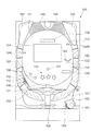
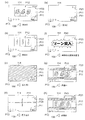
図1は、本実施の形態に係るパチンコ遊技機100の概略正面図である。
図1に示す遊技機の一例としてのパチンコ遊技機100は、遊技者の指示操作により打ち出された遊技球が入賞すると賞球を払い出すように構成されたものである。このパチンコ遊技機100は、遊技球が打ち出される遊技盤110と、遊技盤110を囲む枠部材150とを備えている。遊技盤110は、枠部材150に着脱自在に取り付けられている。
Hereinafter, embodiments of the present invention will be described in detail with reference to the accompanying drawings.
[Basic configuration of gaming machines]
FIG. 1 is a schematic front view of the
The
遊技盤110は、前面に、遊技球により遊技を行うための遊技領域111と、下方から発射された遊技球が上昇して遊技領域111の上部位置へ向かう通路を形成するレール部材112と、遊技領域111の右側に遊技球を案内する案内部材113とを備えている。
本実施の形態では、遊技者により視認され易い遊技領域111の位置に、演出のための各種の画像を表示する画像表示部114が配設されている。この画像表示部114は、液晶ディスプレイ等による表示画面を備え、遊技者によるゲームの進行に伴い、例えば、図柄抽選結果(図柄変動結果)を遊技者に報知するための装飾図柄を表示したり、キャラクタの登場やアイテムの出現による演出画像や後述の保留表示を用いた演出画像を表示したりする。
また、遊技盤110の前面に、各種の演出に用いられる可動役物115および盤ランプ116を備えている。可動役物115は、遊技盤110上で動作することにより各種の演出を行い、また、盤ランプ116は、発光することで各種の演出を行う。
The
In the present embodiment, an
Further, on the front surface of the
遊技領域111には、遊技球が落下する方向に変化を与えるための図示しない遊技くぎおよび風車等が配設されている。また、遊技領域111には、入賞や抽選に関する種々の役物が所定の位置に配設されている。また、遊技領域111には、遊技領域111に打ち出された遊技球のうち入賞口に入賞しなかったものを遊技領域111の外に排出する排出口117が配設されている。
The
本実施の形態では、入賞や抽選に関する種々の役物として、遊技球が入賞すると特別図柄抽選(大当たり抽選)が始動する第1始動口121および第2始動口122と、遊技球が通過すると普通図柄抽選(開閉抽選)が始動する始動ゲート(以下、単にゲートと呼ぶ)124と、が遊技盤110に配設されている。なお、図1において、ゲート124は、遊技領域111の左右にそれぞれ設けられており、左側のゲート124は124Lと記載し、右側のゲート124は124Rと記載している。また、ここにいう第1始動口121および第2始動口122とは、予め定められた1の特別図柄表示器の作動契機となる入賞口をいう。具体的には、第1始動口121および第2始動口122には、入賞の際に遊技球の通過を検知するスイッチ(後述の第1始動口スイッチ211および第2始動口スイッチ212)が設けられている。そして、第1始動口121または第2始動口122に遊技球が入賞した際にこのスイッチが遊技球の通過を検知することが、特別図柄表示器を作動させる契機となる。
In the present embodiment, as various accessories related to winning and lottery, the
第2始動口122は、チューリップの花の形をした一対の羽根が電動ソレノイドにより開閉すると共に点灯する普通電動役物としての電動チューリップ(開閉部材)123を備えている。電動チューリップ123は、羽根が閉じていると、遊技球が第2始動口122へ入り難い一方で、羽根が開くと第2始動口122の入口が拡大して遊技球が第2始動口122へ入り易くなるように構成されている。そして、電動チューリップ123は、普通図柄抽選に当選すると、点灯ないし点滅しながら羽根が規定時間(例えば0.15秒ないし1.8秒間)および規定回数(例えば1回ないし3回)だけ開く。
The
パチンコ遊技機100は、遊技状態として、大当たり抽選の当選確率に基づき、当選確率の低い低確率状態と、低確率状態よりも当選確率の高い高確率状態とを有している。そして、所定の条件において低確率状態と高確率状態とのいずれかの状態に制御される。また、パチンコ遊技機100は、第2始動口122への入賞機会が少ない時短無状態と、時短無状態よりも第2始動口122への入賞機会が多い時短状態とを有している。そして、所定の条件において、時短無状態と、時短状態とのいずれかの状態に制御される。時短状態とは、たとえば、普通図柄抽選の当たり当選確率を高確率にする、普通図柄変動時間を短縮する、あるいは電動チューリップ123の開時間を延長する、のいずれか一つまたは複数の組合せによって制御される遊技状態である。なお、時短状態では、特別図柄の特別図柄変動時間が短縮されていてもよい。
The
また、本実施の形態では、入賞や抽選に関するその他の役物として、特別図柄抽選の結果に応じて開放する特別電動役物としての大入賞口125と、遊技球が入賞しても抽選を行わない普通入賞口126と、が遊技盤110に配設されている。
本実施の形態では、遊技盤110の右下の位置に、抽選結果や保留数に関する表示を行う表示器130が配設されている。
Further, in the present embodiment, as other accessories related to winning and lottery, a
In the present embodiment, a
また、遊技盤110の裏面には、特別図柄の当選の判定等を行う遊技制御基板、演出を統括的に制御する演出制御基板、画像および音による演出を制御する画像制御基板、各種のランプおよび可動役物115による演出を制御するランプ制御基板などの図示しない各種の基板等が取り付けられる。また、遊技盤110の裏面には、供給された24VのAC電源をDC電源に変換して各種の基板等に出力するスイッチング電源(不図示)が配設されている。
Further, on the back surface of the
枠部材150は、遊技者がハンドル151に触れてレバー152を時計方向に回転させる操作を行うとその操作角度に応じた打球力にて遊技球を所定の時間間隔(例えば1分間に100個)で電動発射する発射装置(不図示)を備えている。また、枠部材150は、遊技者のレバー152による操作と連動したタイミングで発射装置に遊技球を1つずつ順に供給する供給装置(不図示)と、供給装置が発射装置に供給する遊技球を一時的に溜めておく皿153と、を備えている。この皿153には、例えば払い出しユニットによる払出球が払い出される。
なお、本実施の形態では、皿153を上下皿一体で構成しているが、上皿と下皿とを分離する構成例も考えられる。また、発射装置のハンドル151を所定条件下で発光させる構成例も考えられる。
When the player touches the
In the present embodiment, the
また、枠部材150は、発射装置のハンドル151に遊技者が触れている状態であっても遊技球の発射を一時的に停止させるための停止ボタン154と、皿153に溜まっている遊技球を箱(不図示)に落下させて取り出すための取り出しボタン155と、を備えている。
また、枠部材150は、パチンコ遊技機100の遊技状態や状況を告知したり各種の演出を行ったりするスピーカ156および枠ランプ157を備えている。スピーカ156は、楽曲や音声、効果音による各種の演出を行う。枠ランプ157は、LED等の発光体で構成され、点灯・点滅によるパターンや発光色の違い等で光による各種の演出を行う。なお、枠ランプ157については、光の照射方向を変更する演出を行うことを可能にする構成例が考えられる。
また、枠部材150は、遊技盤110を遊技者と隔てるための透明板(不図示)を備えている。
Further, the
Further, the
Further, the
図2は、本実施の形態に係るパチンコ遊技機100を説明する図であり、図2(a)は、遊技盤110の右下に配設された表示器130の一例を示す拡大図であり、図2(b)は、パチンコ遊技機100の部分平面図である。
パチンコ遊技機100の表示器130は、図2(a)に示すように、第1始動口121の入賞に対応して作動する第1特別図柄表示器221と、第2始動口122の入賞に対応して作動する第2特別図柄表示器222と、ゲート124の通過に対応して作動する普通図柄表示器223と、を備えている。第1特別図柄表示器221は、第1始動口121の入賞に基づき、特別図柄を変動表示した後に停止させて抽選結果を表示する。第2特別図柄表示器222は、第2始動口122の入賞に基づき、特別図柄を変動表示した後に停止させて抽選結果を表示する。普通図柄表示器223は、遊技球がゲート124を通過したことに基づき、普通図柄を変動表示した後に停止させて抽選結果を表示する。本実施の形態では、第1特別図柄表示器221、第2特別図柄表示器222は、各々LEDを配列した表示装置で構成され、その点灯態様によって特別図柄抽選の抽選結果が表示される。同様に、普通図柄表示器223も、LEDを配列した表示装置で構成され、その点灯態様によって普通図柄抽選の抽選結果が表示される。
FIG. 2 is a diagram illustrating the
As shown in FIG. 2A, the
また、表示器130は、第1特別図柄表示器221での保留に対応して作動する第1特別図柄保留表示器218と、第2特別図柄表示器222での保留に対応して作動する第2特別図柄保留表示器219と、普通図柄表示器223での保留に対応して作動する普通図柄保留表示器220と、を備えている。本実施の形態では、第1特別図柄保留表示器218、第2特別図柄保留表示器219および普通図柄保留表示器220は、各々LEDを配列した表示装置で構成され、その点灯態様によって保留数が表示される。
Further, the
ここで、保留について説明する。特別図柄の変動表示動作中(入賞1回分の変動表示が行なわれている間)にさらに第1始動口121または第2始動口122に遊技球が入賞した場合、特別図柄が変動中であるために、後の入賞に基づく特別図柄の変動表示動作を開始することができない。そのため、後の入賞は規定個数(例えば4個)を限度に記憶され、その入賞した遊技球に対する特別図柄を始動させるための権利が、先に入賞した遊技球に対する変動表示動作が終了するまで、保留される。なお、普通図柄に関しても、特別図柄と同様の処理を行う。このような保留がなされていることおよびその保留の数(未変動数)が、第1特別図柄保留表示器218、第2特別図柄保留表示器219および普通図柄保留表示器220に表示される。
Here, the hold will be described. If a game ball wins a prize in the
さらに、表示器130は、パチンコ遊技機100の状態を表示する状態表示器224を備えている。本実施の形態では、状態表示器224は、3個のLEDを配列した表示装置で構成されている。3個のLEDのうち1つは、パチンコ遊技機100の状態が、特別図柄抽選の当選確率が高確率である高確率状態となっているか否かを点灯により報知するものである。また、他の1つは、パチンコ遊技機100の状態が、第2始動口122に入賞しやすい時短状態となっているか否かを点灯により報知するものである。さらに他の1つは、右打ちすることによって(遊技球の打球力を変更することによって)遊技者に有利な状態となっているか否かを点灯により報知するものである。
なお、状態表示器224が表示するパチンコ遊技機100の状態は上記の例に限らず、他の状態を表示することができる。例えばパチンコ遊技機100の状態として低確率状態よりも当選確率が高く高確率状態よりは当選確率が低い中確率状態が設定される場合、状態表示器224は、中確率状態となっているか否かを点灯により報知しても良い。
Further, the
The state of the
また、表示器130は、特別図柄抽選の抽選結果に応じて行われる大当たり遊技において大入賞口125が作動される際のラウンド数を表示するラウンド数表示器225を備えている。なお、大当たり遊技については後述する。ラウンド数表示器225は、LEDを配列した表示装置で構成され、その点灯態様によって大当たり遊技における大入賞口125の作動ラウンド数が表示される。
Further, the
パチンコ遊技機100の枠部材150は、遊技者が演出に対する入力を行うための入力装置を備えている。図2(b)に示すように、本実施の形態では、入力装置の一例として、演出ボタン161と、演出ボタン161に隣接し、略十字に配列された複数のキーからなる演出キー162と、が枠部材150に配設されている。図示の例において、遊技者は、例えば、十字に配列された4つのキーからなる演出キー162を操作することにより、画像表示部114に表示されている複数の画像の何れかを指示することが可能であり、また、演出ボタン161を操作することにより、指示した画像を選択することが可能である。また、入力装置の形態としては、図示した演出ボタン161および演出キー162の他、レバーやダイヤル等、演出の内容等に応じて様々な入力形態を採用することができる。
The
〔制御ユニットの構成〕
次に、パチンコ遊技機100での動作制御や信号処理を行う制御ユニットについて説明する。
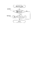
図3は、制御ユニットの内部構成を示すブロック図である。図3に示すように、制御ユニットは、メイン制御手段として、特別図柄の当選の判定等を行う遊技制御部200を備えている。また、サブ制御手段として、演出を統括的に制御する演出制御部300と、画像および音響を用いた演出を制御する画像/音響制御部310と、各種のランプおよび可動役物115を用いた演出を制御するランプ制御部320と、払出球の払い出し制御を行う払出制御部330と、を備えている。
[Control unit configuration]
Next, a control unit that performs operation control and signal processing in the
FIG. 3 is a block diagram showing an internal configuration of the control unit. As shown in FIG. 3, the control unit includes a
前述したように、遊技制御部200、演出制御部300、画像/音響制御部310、ランプ制御部320、および払出制御部330各々は、遊技盤110の後面に配設されたメイン基板としての遊技制御基板、サブ基板としての演出制御基板、画像制御基板、ランプ制御基板、および払出制御基板において個別に構成されている。
As described above, each of the
〔遊技制御部の構成・機能〕
遊技制御部200は、特別図柄の当選の判定等を行う際の演算処理を行うCPU201と、CPU201にて実行されるプログラムや各種データ等が記憶されたROM202と、CPU201の作業用メモリ等として用いられるRAM203と、を備えている。
遊技制御部200は、第1始動口121または第2始動口122に遊技球が入賞すると特別図柄抽選を行い、その抽選結果を演出制御部300に送る。また、高確率状態と低確率状態の変更情報、時短無状態と時短状態の変更情報を演出制御部300に送る。
さらに、遊技制御部200は、普通図柄抽選の当たり当選確率を高確率にする、普通図柄変動時間を短縮する、あるいは電動チューリップ123の開時間を延長する制御を行う。また、遊技制御部200は、遊技球が連続的に第1始動口121または第2始動口122へ入賞したときの未変動分の限度個数(例えば4個)までの保留や、遊技球が連続的にゲート124を通過したときの未変動分の限度個数(例えば4個)までの保留を設定する。
さらにまた、遊技制御部200は、特別図柄抽選の結果に応じて、特別電動役物である大入賞口125が所定条件(例えば29.5秒経過または遊技球10個の入賞)を満たすまで開状態を維持するラウンドを所定回数だけ繰り返すように制御する。さらには、大入賞口125が開く際の開閉動作間隔を制御する。
[Configuration / function of game control unit]
The
When the game ball wins a prize in the
Further, the
Furthermore, the
さらに、遊技制御部200は、第1始動口121、第2始動口122、大入賞口125および普通入賞口126に遊技球が入賞すると、遊技球が入賞した場所に応じて1つの遊技球当たり所定数の賞球を払い出すように、払出制御部330に対する指示を行う。例えば、第1始動口121に遊技球が入賞すると3個の賞球、第2始動口122に遊技球が入賞すると4個の賞球、大入賞口125に遊技球が入賞すると13個の賞球、普通入賞口126に遊技球が入賞すると10個の賞球をそれぞれ払い出すように、払出制御部330に指示命令(コマンド)を送る。なお、ゲート124を遊技球が通過したことを検出しても、それに連動した賞球の払い出しは払出制御部330に指示しない。
払出制御部330が遊技制御部200の指示に従って賞球の払い出しを行った場合には、遊技制御部200は、払い出した賞球の個数に関する情報を払出制御部330から取得する。それにより、払い出した賞球の個数を管理する。
Further, when a game ball wins in the
When the
遊技制御部200には、検知手段として、図3に示すように、第1始動口121への遊技球の入賞を検出する第1始動口検出部(第1始動口スイッチ(SW))211と、第2始動口122への遊技球の入賞を検出する第2始動口検出部(第2始動口スイッチ(SW))212と、電動チューリップ123を開閉する電動チューリップ開閉部213と、ゲート124への遊技球の通過を検出するゲート検出部(ゲートスイッチ(SW))214と、が接続されている。
さらに、遊技制御部200には、大入賞口125への遊技球の入賞を検出する大入賞口検出部(大入賞口スイッチ(SW))215と、大入賞口125を閉状態と突出傾斜した開状態とに設定する大入賞口開閉部216と、普通入賞口126への遊技球の入賞を検出する普通入賞口検出部(普通入賞口スイッチ(SW))217と、が接続されている。
As a detection means, the
Further, in the
また、遊技制御部200には、特別図柄の変動中に第1始動口121へ入賞した未変動分の保留個数を限度個数内(例えば4個)で表示する第1特別図柄保留表示器218と、特別図柄の変動中に第2始動口122へ入賞した未変動分の保留個数を限度個数内で表示する第2特別図柄保留表示器219と、普通図柄の変動中にゲート124を通過した未変動分の保留個数を限度個数内で表示する普通図柄保留表示器220と、が接続されている。
さらに、遊技制御部200には、第1始動口121への遊技球の入賞により行われる特別図柄の変動表示および特別図柄抽選の結果を表示する第1特別図柄表示器221と、第2始動口122への遊技球の入賞により行われる特別図柄の変動表示および特別図柄抽選の結果を表示する第2特別図柄表示器222と、普通図柄の変動表示および普通図柄抽選の結果を表示する普通図柄表示器223と、パチンコ遊技機100の状態を表示する状態表示器224と、が接続されている。
In addition, the
Further, the
そして、第1始動口スイッチ211、第2始動口スイッチ212、ゲートスイッチ214、大入賞口スイッチ215および普通入賞口スイッチ217にて検出された検出信号が、遊技制御部200に送られる。また、遊技制御部200からの制御信号が、電動チューリップ開閉部213、大入賞口開閉部216、第1特別図柄保留表示器218、第2特別図柄保留表示器219、普通図柄保留表示器220、第1特別図柄表示器221、第2特別図柄表示器222、普通図柄表示器223および状態表示器224に送られる。それにより、遊技制御部200は、上記した払い出し賞球数に関連する各種制御を行う。
Then, the detection signals detected by the first
さらに、遊技制御部200には、ホールに設置されたホストコンピュータ(不図示)に対して各種の情報を送信する盤用外部情報端子基板350が接続されている。そして、遊技制御部200は、払出制御部330から取得した、払い出した賞球数に関する情報や遊技制御部200の状態等を示す情報を、盤用外部情報端子基板350を介してホストコンピュータに送信する。
Further, the
〔演出制御部の構成・機能〕
演出制御部300は、演出を制御する際の演算処理を行うCPU301と、CPU301にて実行されるプログラムや各種データ等が記憶されたROM302と、CPU301の作業用メモリ等として用いられるRAM303と、日時を計測するリアルタイムクロック(RTC)304と、を備えている。
演出制御部300は、例えば遊技制御部200から送られる特別図柄抽選での当選か否かの判定結果および変動パターンに基づいて、演出内容を設定する。その際、演出ボタン161または演出キー162を用いたユーザからの操作入力を受けて、操作入力に応じた演出内容を設定する場合もある。この場合、例えば演出ボタン161等のコントローラ(不図示)から操作に応じた信号(操作信号)を受け付け、この操作信号により識別される操作内容を演出の設定に反映させる。
また、演出制御部300は、遊技が所定期間中断された場合には、演出の一つとして客待ち用の画面表示の設定を指示する。
さらには、演出制御部300は、遊技制御部200より受信した高確率状態と低確率状態の変更情報、時短無状態と時短状態の変更情報に基づいて演出内容を設定する。
また、演出制御部300は、設定した演出内容の実行を指示するコマンドを画像/音響制御部310およびランプ制御部320に送る。
[Structure / function of production control unit]
The
The
Further, when the game is interrupted for a predetermined period, the
Further, the
Further, the
〔画像/音響制御部の構成・機能〕
画像/音響制御部310は、演出内容を表現する画像および音響を制御する際の演算処理を行うCPU311と、CPU311にて実行されるプログラムや各種データ等が記憶されたROM312と、CPU311の作業用メモリ等として用いられるRAM313と、を備えている。
そして、画像/音響制御部310は、演出制御部300から送られたコマンドに基づいて、画像表示部114に表示する画像およびスピーカ156から出力する音響を制御する。
具体的には、画像/音響制御部310のROM312には、画像表示部114において遊技中に表示する図柄画像や背景画像、遊技者に抽選結果を報知するための装飾図柄、遊技者に予告演出を表示するためのキャラクタやアイテム等といった画像データが記憶されている。
ROM312には、さらに、画像データと同期させて、または画像データとは独立にスピーカ156から出力させる楽曲や音声、さらにはジングル等の効果音等といった各種音響データが記憶されている。CPU311は、ROM312に記憶された画像データや音響データの中から、演出制御部300から送られたコマンドに対応したものを選択して読み出す。さらには、読み出した画像データを用いて背景画像表示、図柄画像表示、図柄画像変動、およびキャラクタ/アイテム表示等のための画像処理と、読み出した音響データを用いた音声処理とを行う。
そして、画像/音響制御部310は、画像処理された画像データにより画像表示部114での画面表示を制御する。また、音声処理された音響データによりスピーカ156から出力される音響を制御する。
[Configuration / function of image / acoustic control unit]
The image /
Then, the image /
Specifically, the
The
Then, the image /
〔ランプ制御部の構成・機能〕
ランプ制御部320は、盤ランプ116や枠ランプ157の発光、および可動役物115の動作を制御する際の演算処理を行うCPU321と、CPU321にて実行されるプログラムや各種データ等が記憶されたROM322と、CPU321の作業用メモリ等として用いられるRAM323と、を備えている。
そして、ランプ制御部320は、演出制御部300から送られたコマンドに基づいて、盤ランプ116や枠ランプ157の点灯/点滅や発光色等を制御する。また、可動役物115の動作を制御する。
具体的には、ランプ制御部320のROM322には、演出制御部300にて設定される演出内容に応じた盤ランプ116や枠ランプ157での点灯/点滅パターンデータおよび発光色パターンデータ(発光パターンデータ)が記憶されている。CPU321は、ROM322に記憶された発光パターンデータの中から、演出制御部300から送られたコマンドに対応したものを選択して読み出す。そして、ランプ制御部320は、読み出した発光パターンデータにより盤ランプ116や枠ランプ157の発光を制御する。
また、ランプ制御部320のROM322には、演出制御部300にて設定される演出内容に応じた可動役物115の動作パターンデータが記憶されている。CPU321は、可動役物115に対しては、読み出した動作パターンデータによりその動作を制御する。
[Configuration / function of lamp control unit]
The
Then, the
Specifically, the
Further, the
〔払出制御部の構成・機能〕
払出制御部330は、払出球の払い出しを制御する際の演算処理を行うCPU331と、CPU331にて実行されるプログラムや各種データ等が記憶されたROM332と、CPU331の作業用メモリ等として用いられるRAM333と、を備えている。
そして、払出制御部330は、遊技制御部200から送られたコマンドに基づいて、払出球の払い出しを制御する。
具体的には、払出制御部330は、遊技制御部200から、遊技球が入賞した場所(第1始動口121等)に応じた所定数の賞球を払い出すコマンドを取得する。そして、コマンドに指定された数だけの賞球を払い出すように払出駆動部334を制御する。ここでの払出駆動部334は、遊技球の貯留部から遊技球を送り出す駆動モータで構成される。
[Configuration / function of payout control unit]
The
Then, the
Specifically, the
また、払出制御部330には、払出駆動部334により遊技球の貯留部から実際に払い出された賞球の数を検出する払出球検出部335と、貯留部(不図示)での遊技球の貯留の有無を検出する球有り検出部336と、遊技者が遊技する際に使用する遊技球や払い出された賞球が保持される皿153が満タン状態に有るか否かを検出する満タン検出部337と、が接続されている。そして、払出制御部330は、払出球検出部335、球有り検出部336および満タン検出部337にて検出された検出信号を受け取り、これらの検出信号に応じた所定の処理を行う。
さらに、払出制御部330には、ホールに設置されたホストコンピュータに対して各種の情報を送信する枠用外部情報端子基板340が接続されている。そして、払出制御部330は、例えば払出駆動部334に対して払い出すように指示した賞球数に関する情報や払出球検出部335にて検出された実際に払い出された賞球数に関する情報等を枠用外部情報端子基板340を介してホストコンピュータに送信する。また、遊技制御部200に対しても、同様の情報を送信する。
Further, the
Further, a frame external
〔遊技制御部の機能構成〕
続いて、遊技制御部200の機能構成を説明する。
図4は、遊技制御部200の機能構成を示すブロック図である。図4に示すように、遊技制御部200は、各種抽選処理を実行する機能部として、乱数取得部231と、普通図柄判定部232と、特別図柄変動制御部233と、特別図柄判定部234と、普通図柄変動制御部236と、を備えている。
また、遊技制御部200は、特別図柄変動に伴う処理を実行する機能部として、変動パターン選択部235を備えている。
さらに、遊技制御部200は、各種役物の動作制御や賞球等に関するデータ処理を実行する機能部として、大入賞口動作制御部237と、電動チューリップ動作制御部238と、賞球処理部239と、出力制御部240と、乱数制御部241と、を備えている。
[Functional configuration of game control unit]
Subsequently, the functional configuration of the
FIG. 4 is a block diagram showing a functional configuration of the
In addition, the
Further, the
乱数取得部231は、第1始動口121や第2始動口122に遊技球が入賞した場合に、特別図柄に関する乱数の取得を行う。具体的には、所定の範囲の数値の中から一つの数値(乱数値)が選択(取得)されて、特別図柄判定部234による判定に用いられる。
乱数取得部231は、ゲート124を遊技球が通過した場合に、普通図柄に関する乱数の取得を行う。具体的には、所定の範囲の数値の中から一つの数値(乱数値)が選択(取得)されて、普通図柄判定部232による判定に用いられる。
特別図柄変動制御部233は、特別図柄の抽選が行われた場合に、その抽選結果に応じて特別図柄の変動を制御する。
The random
The random
When a special symbol lottery is performed, the special symbol
特別図柄判定部234は、特別図柄の変動開始時に、図17に示すような乱数テーブルを用いて、その抽選結果が「大当たりか否か」、「大当たりに当選した場合の大当たりの種類」、「大当たりに当選していない場合での小当たりかはずれか」を判定する。すなわち、乱数取得部231は、検知手段である第1始動口スイッチ211または第2始動口スイッチ212により遊技球の通過が検知されたことを契機として特別図柄に関する乱数値を取得し、特別図柄判定部234は、取得した乱数値に基づいて、遊技者にとって有利な特別遊技(大当たり遊技等)を行うか否かを判定する。なお、前述した特別図柄の抽選(大当たり抽選)は、乱数取得部231および特別図柄判定部234における処理のことをいう。
The special
ここで、「大当たり」は、大当たり遊技の終了後に発生する遊技状態に応じて複数の種類に分けられる。具体的には、時短無状態か時短状態か、および高確率状態か低確率状態かの組み合わせによって大当たりの種類が決まる。すなわち、大当たり遊技の終了後に発生する遊技状態に基づく大当たりの種類としては、大当たり遊技の終了後に、時短状態および高確率状態の両方の状態を有する高確率時短遊技状態となる大当たり(以下、高確率時短遊技状態の大当たり)、時短状態および低確率状態の両方の状態を有する低確率時短遊技状態となる大当たり(以下、低確率時短遊技状態の大当たり)、時短無状態および高確率状態の両方の状態を有する高確率時短無遊技状態となる大当たり(以下、高確率時短無遊技状態の大当たり)、時短無状態および低確率状態の両方の状態を有する低確率時短無遊技状態となる大当たり(以下、低確率時短無遊技状態の大当たり)が有り得る。これらの大当たりは、各々個別の特別図柄に対応付けられており、特別図柄抽選において当選した特別図柄の種類に応じて大当たりの種類が確定する。 Here, the "big hit" is divided into a plurality of types according to the game state generated after the end of the big hit game. Specifically, the type of jackpot is determined by the combination of the time saving no state or the time saving state, and the high probability state or the low probability state. That is, as a type of jackpot based on the game state generated after the end of the jackpot game, after the end of the jackpot game, the jackpot becomes a high-probability time-saving game state having both a time-saving state and a high-probability state (hereinafter, high probability). A jackpot in a time-saving game state), a jackpot in a low-probability time-saving game state having both a time-saving state and a low-probability state (hereinafter, a jackpot in a low-probability time-saving game state), a state in both a time-saving no state and a high-probability state. A jackpot that becomes a high-probability time-saving no-game state (hereinafter, a jackpot in a high-probability time-saving no-game state), and a jackpot that becomes a low-probability time-saving no-game state that has both a time-saving no state and a low-probability state (hereinafter, low) Probability time saving No game state jackpot) is possible. Each of these jackpots is associated with an individual special symbol, and the type of jackpot is determined according to the type of the special symbol won in the special symbol lottery.
また、「大当たり」は、大当たり遊技の時間が長く多量の遊技球の払い出しが期待できる大当たりと、大当たり遊技の時間が短く遊技球の払出がほとんど期待できない大当たりとに分けられる場合がある。前者は「長当たり」と呼ばれ、後者は「短当たり」と呼ばれる。例えば、「長当たり」では、大入賞口125の開状態が所定条件(例えば29.5秒経過または10個の遊技球の入賞)を満たすまで維持されるラウンドが所定回数(例えば15回)繰り返される。また、「短当たり」では、一定時間(例えば0.1秒)だけ大入賞口125が開状態となるラウンドが所定回数(例えば15回)繰り返される。
Further, the "big hit" may be divided into a jackpot in which the jackpot game time is long and a large amount of game balls can be expected to be paid out, and a jackpot in which the jackpot game time is short and the payout of the game balls can hardly be expected. The former is called "long hit" and the latter is called "short hit". For example, in "long hit", a round in which the open state of the large winning
また、大当たりに当選していない場合の「小当たり」は、例えば0.1秒だけ大入賞口125が開状態となる態様が所定回数(例えば15回)行われる小当たり遊技が行われる。なお、小当たり当選時には、小当たり遊技が終了した後においても小当たり当選前の遊技状態を継続する。すなわち、小当たり当選時の遊技状態が高確率時短遊技状態である場合には、小当たり遊技の終了後においても高確率時短遊技状態が継続され、遊技状態は移行しない。同様に、小当たりの当選時の遊技状態が低確率時短無遊技状態である場合には、小当たり遊技の終了後においても低確率時短無遊技状態が継続され、遊技状態は移行しない。
また、「小当たり」は、「はずれ」の一種であり、遊技者に有利となる上記の遊技状態の何れも設定されない。
Further, in the "small hit" when the big hit is not won, a small hit game is performed in which the large winning
Further, the "small hit" is a kind of "missing", and none of the above-mentioned gaming states that are advantageous to the player is set.
変動パターン選択部235は、第1特別図柄表示器221や第2特別図柄表示器222にて表示する特別図柄の変動パターン(変動時間)を選択する。ここでは、変動パターン選択部235は、大当たり遊技を行うか否かの判定結果およびリーチを行うか否かの判定結果等に基づいて、変動パターンを決定する。そして、変動パターン選択部235により選択された変動パターンに基づいて、特別図柄変動制御部233が特別図柄の変動を制御する。変動パターン選択部235および特別図柄変動制御部233の動作の詳細については後述する。
ここで、「リーチ」とは、後述する装飾図柄において遊技者に大当たりを期待させるための演出である。
The variation
Here, the "reach" is an effect for making the player expect a big hit in the decorative design described later.
普通図柄判定部232は、普通図柄の抽選が行われた場合に、普通図柄の抽選結果が「当選かはずれであるか」を判定する。
普通図柄変動制御部236は、普通図柄の抽選結果に応じて、普通図柄の変動を制御する。
電動チューリップ動作制御部238は、普通図柄の抽選により「当選」と判定された場合には、電動チューリップ123を規定時間および規定回数だけ開放し、第2始動口122に遊技球が入賞容易となる状態を発生させる。また、「はずれ」と判定された場合には、電動チューリップ123のこのような開放状態を発生させない。
The ordinary
The normal symbol
When the electric tulip
大入賞口動作制御部237は、大入賞口125の開放動作を制御する。
賞球処理部239は、入賞や抽選に関する種々の役物への入賞個数の管理および入賞に応じた賞球の払い出しの制御用コマンドをセットする。
出力制御部240は、遊技制御部200から演出制御部300および払出制御部330へ制御用コマンドの出力を制御する。
乱数制御部241は、メイン制御手段による処理で用いられる各種の乱数値の更新を制御する。
The large winning opening
The prize
The
The random
〔遊技機の基本動作〕
次に、パチンコ遊技機100の基本動作を説明する。
パチンコ遊技機100の遊技制御部200は、電源が投入されると、起動時の基本処理として、各種装置の初期化や初期設定を行う。そして、基本処理を行った後、遊技制御部200は、遊技の進行に関する一連の処理である主制御処理を繰り返し実行する。また、電源を遮断する際には、遊技制御部200は、一連の電源遮断時処理を実行する。
[Basic operation of gaming machines]
Next, the basic operation of the
When the power is turned on, the
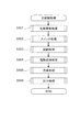
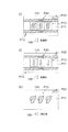
図5−1は、遊技制御部200による基本処理の動作を示すフローチャートである。
遊技制御部200は、パチンコ遊技機100の電源が投入されると、まず、RAM203(図3参照)へのアクセスを許可する(ステップ(以下、ステップを「S」と記載する)101)。そして、遊技制御部200は、RAM203をクリアするためのRAMクリアスイッチがONとなっているか否かを判断する(S102)。
RAMクリアスイッチがOFFである場合(S102でNo)、次に、遊技制御部200は、電源遮断時の動作に関するバックアップフラグがONとなっているか否かを判断する(S103)。
バックアップフラグがONである場合(S103でYes)、次に、遊技制御部200は、電源遮断時に作成されたチェックサムが正常か否かを判断する(S104)。
チェックサムが正常である場合(S104でYes)、次に、遊技制御部200は、復帰処理を実行する(S105)。この復帰処理において、遊技制御部200は、電源が遮断された状態からの復帰に伴う、演出制御部300等のサブ制御手段の設定を行う。具体的には、遊技制御部200は、電源が遮断される際におけるパチンコ遊技機100の内部状態(大当たり遊技中か否か、高確率状態と低確率状態のいずれか、時短状態と時短無状態のいずれか)を反映させるように、サブ制御手段を設定するためのコマンドを演出制御部300へ出力する。また、この復帰処理において、遊技制御部200は、バックアップフラグをOFFにする。
FIG. 5-1 is a flowchart showing the operation of the basic processing by the
When the power of the
When the RAM clear switch is OFF (No in S102), the
When the backup flag is ON (Yes in S103), the
When the checksum is normal (Yes in S104), the
一方、RAMクリアスイッチがON(S102でYes)、バックアップフラグがOFF(S103でNo)、チェックサムが異常(S104でNo)のいずれかに該当する場合、次に遊技制御部200は、初期化処理として、RAM203の記憶内容をクリアし(S106)、RAM203の作業領域を設定する(S107)。そして、遊技制御部200は、サブ制御手段を設定(初期化)するためのコマンドを演出制御部300へ出力し、サブ基板(サブ制御手段)の設定を行う(S108)。サブ基板の設定には、各サブ基板に搭載されているRAM303、313、323をクリアすること等が含まれる。
On the other hand, if the RAM clear switch is ON (Yes in S102), the backup flag is OFF (No in S103), or the checksum is abnormal (No in S104), then the
復帰処理(S105参照)が終了した後、またはサブ基板の設定(S108参照)が終了した後、遊技制御部200は、遊技制御に用いられる各種のカウンタおよびタイマーを設定する(S109)。そして、遊技制御部200は、割り込み許可(S110)、割り込み禁止(S111)、図柄乱数制御処理(S112)、初期値乱数更新処理(S113)、電源遮断フラグがONとなっているか否かの判断(S114)をループ処理として繰り返し実行する。
ここで、割り込み許可(S110)および割り込み禁止(S111)は、このループ処理(S110〜S114)の実行中に割り込み処理の実行を可能とするために設けられている。本実施の形態では、この割り込み処理により、遊技制御における主制御処理が実行される。主制御処理の詳細については後述する。
図柄乱数制御処理(S112)において、遊技制御部200は、特別図柄抽選で用いられる変動パターン乱数の更新を行う。
初期値乱数更新処理(S113)において、遊技制御部200は、遊技制御において用いられる各種の乱数値の初期値を更新する。
電源遮断フラグの判断において、電源遮断フラグがOFFである場合(S114でNo)、パチンコ遊技機100の電源は遮断されず、遊技制御部200は、ループ処理(S110〜S114)と共に割り込みによる主制御処理を繰り返し実行する。一方、電源遮断フラグがONである場合(S114でYes)、遊技制御部200は、パチンコ遊技機100の電源を遮断するための処理(電源遮断時処理)を開始する。
After the return process (see S105) is completed or the sub-board setting (see S108) is completed, the
Here, the interrupt enable (S110) and the interrupt disable (S111) are provided to enable the execution of the interrupt process during the execution of the loop process (S110 to S114). In the present embodiment, the main control process in the game control is executed by this interrupt process. The details of the main control process will be described later.
In the symbol random number control process (S112), the
In the initial value random number update process (S113), the
In the determination of the power cutoff flag, when the power cutoff flag is OFF (No in S114), the power supply of the
図5−2は、遊技制御部200による電源遮断時処理の動作を示すフローチャートである。
電源遮断時処理において、遊技制御部200は、まず、各種の出力を行うための出力ポートの設定をクリアする(S115)。次に、遊技制御部200は、チェックサムを作成し、RAM203に格納する(S116)。次に、遊技制御部200は、バックアップフラグをONにし(S117)、RAM203へのアクセスを禁止して(S118)、無限ループに移行する。
FIG. 5-2 is a flowchart showing the operation of the power cutoff process by the
In the power cutoff process, the
〔遊技機の主制御処理〕
次に、パチンコ遊技機100の主制御処理を説明する。
遊技制御部200は、主制御処理において、パチンコ遊技機100における遊技を制御すると共に、サブ制御手段である演出制御部300に対して演出の制御を指示し、払出制御部330に対して賞球の払い出しの制御を指示する。
[Main control processing of gaming machines]
Next, the main control process of the
In the main control process, the
図5−3は、遊技制御部200の主制御処理を示すフローチャートである。
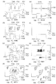
主制御処理は、遊技制御における一連の処理からなり、予め設定された一定時間(例えば4ミリ秒)ごとに繰り返し実行される。本実施の形態において、遊技制御部200は、予め設定された一定時間ごとに割り込みを発生させ、図5−1に示すループ処理の中で割り込みが許可(S110参照)されると、割り込み処理として主制御処理を実行する。図7に示すように、主制御処理では、乱数更新処理、スイッチ処理、図柄処理、電動役物処理、賞球処理、出力処理が順次実行される(S501〜S506)。
FIG. 5-3 is a flowchart showing the main control process of the
The main control process consists of a series of processes in game control, and is repeatedly executed at predetermined fixed time (for example, 4 milliseconds). In the present embodiment, the
乱数更新処理(S501)では、遊技制御部200は、乱数制御部241の機能(サブルーチン)を呼び出し、遊技制御部200による遊技制御で用いられる各種の乱数の値を更新する。乱数の設定および乱数値の更新の詳細については後述する。
In the random number update process (S501), the
スイッチ処理(S502)としては、始動口スイッチ処理、ゲートスイッチ処理が行われる。
始動口スイッチ処理では、遊技制御部200は、乱数取得部231の機能(サブルーチン)を呼び出し、図3の第1始動口スイッチ211および第2始動口スイッチ212の状態を監視し、スイッチがONとなった場合に、特別図柄抽選のための処理を実行する。
ゲートスイッチ処理では、遊技制御部200は、普通図柄判定部232の機能(サブルーチン)を呼び出し、図3のゲートスイッチ214の状態を監視し、スイッチがONとなった場合に、普通図柄抽選のための処理を実行する。
これらのスイッチ処理の詳細な内容については後述する。
As the switch process (S502), a start port switch process and a gate switch process are performed.
In the start port switch process, the
In the gate switch process, the
The detailed contents of these switch processes will be described later.
図柄処理(S503)としては、特別図柄処理、普通図柄処理が行われる。
特別図柄処理では、遊技制御部200は、特別図柄変動制御部233、特別図柄判定部234、変動パターン選択部235の各機能(サブルーチン)を呼び出し、特別図柄変動およびこの図柄変動に伴う処理を実行する。
普通図柄処理では、遊技制御部200は、普通図柄変動制御部236の機能(サブルーチン)を呼び出し、普通図柄変動およびこの図柄変動に伴う処理を実行する。
これらの図柄処理の詳細な内容については後述する。
As the symbol processing (S503), a special symbol processing and a normal symbol processing are performed.
In the special symbol processing, the
In the normal symbol processing, the
The detailed contents of these symbol processing will be described later.
電動役物処理(S504)としては、大入賞口処理、電動チューリップ処理が行われる。
大入賞口処理では、遊技制御部200は、大入賞口動作制御部237の機能(サブルーチン)を呼び出し、所定の条件に基づいて大入賞口125の開放動作を制御する。
電動チューリップ処理では、遊技制御部200は、電動チューリップ動作制御部238の機能(サブルーチン)を呼び出し、所定の条件に基づいて電動チューリップ123の開放動作を制御する。
これらの電動役物処理の詳細な内容については後述する。
As the electric accessory processing (S504), a large winning opening processing and an electric tulip processing are performed.
In the big winning opening process, the
In the electric tulip processing, the
The detailed contents of these electric accessory processing will be described later.
賞球処理(S505)では、遊技制御部200は、賞球処理部239の機能(サブルーチン)を呼び出し、入賞個数の管理および入賞に応じた賞球の払い出しの制御用コマンドをセットする。
In the prize ball processing (S505), the
出力処理(S506)では、遊技制御部200は、出力制御部240の機能(サブルーチン)を呼び出し、演出制御用のコマンドを演出制御部300へ出力し、払い出し制御用のコマンドを払出制御部330へ出力する。演出制御用コマンドは、S502からS504までの各処理において生成され、RAM203に設けられた制御用コマンドの格納領域に格納(セット)される。払い出し制御用コマンドは、S505の処理において生成され、RAM203に設けられた制御用コマンドの格納領域に格納(セット)される。RAM203には、制御用コマンドの種類ごとに格納領域が設定されている。
In the output process (S506), the
出力制御部240は、RAM203の各制御用コマンドの格納領域を順に調べ、個々の格納領域に制御用コマンドが格納されていれば(すなわち、S502〜S505の処理で制御用コマンドが生成されていれば)、その制御用コマンドを読み出し、出力先(演出制御部300または払出制御部330へ出力する。
The
本実施の形態では、図5−3に示したように、一連の主制御処理の最後に出力処理を行う。すなわち、第1の処理手段としての上記各機能によるS502〜S505の各処理において生成されたコマンドを、その各処理においてはRAM203の対応する格納領域に格納しておく。そして、これらの処理の後に、第2の処理手段としての出力制御部240が、RAM203の格納領域に蓄積された、各処理で生成されたコマンドをまとめて出力する。言い換えれば、本実施の形態では、主制御処理を1サイクル実行すると、その1サイクルの実行において生成されたコマンドが、その1サイクルの実行における最後のコマンド生成が行われた後に、出力される。
In the present embodiment, as shown in FIG. 5-3, the output process is performed at the end of the series of main control processes. That is, the commands generated in each of the processes S502 to S505 by each of the above functions as the first processing means are stored in the corresponding storage area of the
〔遊技機の基本動作の変形例〕
なお、図5−1乃至図5−3を参照して説明した動作例では、基本処理におけるループ処理の部分で割り込みを許可し、割り込み処理として一連の処理からなる主制御処理を実行した。しかしながら、主制御処理は、一定時間ごとに繰り返し実行されるように構成されていれば良く、具体的な実現手段(実行手順)は、図5−1乃至図5−3に示した例には限定されない。例えば、基本処理の一連の動作の中に主制御処理を組み入れておき、所定のタイミングで経過時間を計測し、一定時間(例えば4ミリ秒)ごとに主制御処理へ戻る構成としても良い。また、基本処理の一連の動作の中に主制御処理を組み入れる一方で、図5−1乃至図5−3を参照して説明した動作と同様に、一定時間ごとに割り込みを発生させ、割り込みが発生したならば基本処理中に組み入れられた主制御処理へ戻る構成としても良い。
また、基本処理で生成されたコマンドを出力する場合は、原則として、コマンドを生成する度に、RAM203のコマンド格納領域に格納し、第2の処理手段である出力制御部240の機能を呼び出して出力する。基本処理は、電源投入時に行われる初期動作等の特別処理であり、電源投入時のパチンコ遊技機100の状態等の条件に基づく分岐により処理手順が変動する場合があるため、出力処理に漏れが無いように、生成したコマンドを速やかに出力するためである。なお、関連する複数の処理により連続的にコマンドが生成される場合等、具体的な処理の要請に応じて、複数のコマンドをRAM203のコマンド格納領域に格納し、まとめて出力する処理手順を採っても良い。
[Modification example of basic operation of gaming machine]
In the operation example described with reference to FIGS. 5-1 to 5-3, an interrupt is permitted in the loop processing portion of the basic processing, and the main control processing including a series of processing is executed as the interrupt processing. However, the main control process may be configured to be repeatedly executed at regular intervals, and specific realization means (execution procedure) are shown in the examples shown in FIGS. 5-1 to 5-3. Not limited. For example, the main control process may be incorporated into a series of operations of the basic process, the elapsed time may be measured at a predetermined timing, and the process may be returned to the main control process at regular time intervals (for example, 4 milliseconds). Further, while incorporating the main control process into a series of operations of the basic process, an interrupt is generated at regular intervals and the interrupt is generated as in the operation described with reference to FIGS. 5-1 to 5-3. If it occurs, it may be configured to return to the main control process incorporated in the basic process.
Further, when outputting the command generated in the basic processing, as a general rule, each time the command is generated, it is stored in the command storage area of the
〔遊技制御部での始動口スイッチ処理〕
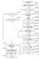
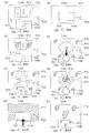
図6は、図5−3のS502に示したスイッチ処理のうちの始動口スイッチ処理の内容を示すフローチャートである。
この始動口スイッチ処理は、第1始動口121における入賞に対する処理と、第2始動口122における入賞に対する処理とが順次行われる。図6を参照すると、遊技制御部200は、まず、第1始動口121に遊技球が入賞して第1始動口スイッチ211がONとなったか否かを判断する(S601)。第1始動口スイッチ211がONとなったならば、次に遊技制御部200は、第1始動口121の入賞における未変動分の保留数U1が上限値未満か否かを判断する(S602)。図6に示す例では、上限値を4個としている。保留数U1が上限値に達している場合は(S602でNo)、それ以上未変動分の入賞を保留することができないので、第1始動口121における入賞に対する処理を終了する。
[Starting port switch processing in the game control unit]
FIG. 6 is a flowchart showing the contents of the start port switch process among the switch processes shown in S502 of FIG. 5-3.
In this start port switch process, a process for winning a prize at the
一方、保留数U1が上限値未満である場合(S602でYes)、次に遊技制御部200は、保留数U1の値を1加算する(S603)。そして、遊技制御部200の乱数取得部231は、今回の入賞による抽選のための乱数値を取得し、RAM203に格納する(S604)。ここでは、第1始動口121の入賞なので、特別図柄抽選のための乱数値が取得される。このとき取得される乱数値は、S501の乱数更新処理で更新された値である。そして、この乱数値により、後の特別図柄処理において特別図柄抽選の結果が確定される。ここにいう乱数値としては、大当たり、小当たりまたははずれを決定する大当たり乱数値、大当たりの種類(大当たり遊技の終了後における時短状態か時短無状態、高確率状態と低確率状態、長当たり、短当たり)を決定する図柄乱数値(大当たり図柄乱数値)、図柄変動における変動パターンを特定するための変動パターン乱数値、はずれのときにリーチ有り演出をするか否かを決定するリーチ乱数値、等が含まれる。
On the other hand, when the hold number U1 is less than the upper limit value (Yes in S602), the
次に、遊技制御部200は、特別図柄の変動表示動作が保留されている(すなわち未抽選の)入賞球(保留球)に対して、抽選結果の予告演出を行うための事前判定処理を行う(S605)。この事前判定処理は、抽選結果の判定を図柄変動開始時ではなく始動口入賞時に(すなわちS605において)行うものである。なお、事前判定に基づく予告演出を行わない遊技機においては、この事前判定処理を省略する場合がある。
この後、遊技制御部200は、S603による保留数U1の増加を演出制御部300に通知するための保留数増加コマンドをRAM203にセットし(S606)、第1始動口121における入賞に対する処理を終了する。S605の事前判定処理が行われた場合は、保留数増加コマンドには、S605で得られた事前判定の判定結果の情報が含まれる。
Next, the
After that, the
次に、第2始動口122における入賞に対する処理が行われる。図6を参照すると、次に遊技制御部200は、第2始動口122に遊技球が入賞して第2始動口スイッチ212がONとなったか否かを判断する(S607)。第2始動口スイッチ212がONとなったならば、次に遊技制御部200は、第2始動口122の入賞における未変動分の保留数U2が上限値未満か否かを判断する(S608)。図6に示す例では、上限値を4個としている。保留数U2が上限値に達している場合は(S608でNo)、それ以上未変動分の入賞を保留することができないので、第2始動口122における入賞に対する処理を終了する。
Next, processing for winning a prize at the
一方、保留数U2が上限値未満である場合(S608でYes)、次に遊技制御部200は、保留数U2の値を1加算する(S609)。そして、遊技制御部200の乱数取得部231は、今回の入賞による抽選のための乱数値を取得し、RAM203に格納する(S610)。ここでは、第2始動口122の入賞なので、上記のS604と同様に、特別図柄抽選のための乱数値(大当たり乱数値、大当たり図柄乱数値)、リーチ乱数値、変動パターン乱数値など)が取得される。このとき取得される乱数値は、S501の乱数更新処理で更新された値である。そして、この乱数値により後の特別図柄処理において特別図柄抽選の結果が確定される。
On the other hand, when the hold number U2 is less than the upper limit value (Yes in S608), the
次に、遊技制御部200は、特別図柄の変動表示動作が保留されている(すなわち未抽選の)入賞球(保留球)に対して、抽選結果の予告演出を行うための事前判定処理を行う(S611)。この事前判定処理の内容は、上記のS605と同様である。この事前判定処理も、事前判定に基づく予告演出を行わない遊技機においては、この事前判定処理を省略する場合がある。
この後、遊技制御部200は、S609による保留数U2の増加を演出制御部300に通知するための保留数増加コマンドをRAM203にセットし(S612)、第2始動口122における入賞に対する処理を終了する。S611の事前判定処理が行われた場合は、保留数増加コマンドには、S611で得られた事前判定の判定結果の情報が含まれる。
Next, the
After that, the
〔遊技制御部でのゲートスイッチ処理〕
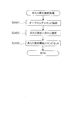
図7は、ゲート124を遊技球が通過した場合のゲートスイッチ処理の内容を示すフローチャートである。
このゲートスイッチ処理において、遊技制御部200は、まず、ゲート124を遊技球が通過してゲートスイッチ214がONとなったか否かを判断する(S701)。ゲートスイッチ214がONとなったならば、次に遊技制御部200は、未変動分の保留数Gが上限値未満か否かを判断する(S702)。図7に示す例では、上限値を4個としている。保留数Gが上限値に達している場合は(S702でNo)、それ以上未変動分の入賞を保留することができないので、ゲートスイッチ処理を終了する。
[Gate switch processing in the game control unit]
FIG. 7 is a flowchart showing the contents of the gate switch processing when the game ball passes through the
In this gate switch process, the
一方、保留数Gが上限値未満である場合(S702でYes)、次に遊技制御部200は、保留数Gの値を1加算する(S703)。そして、遊技制御部200の乱数取得部231は、今回の入賞による抽選のための乱数値を取得し、RAM203に格納する(S704)。ここでは、ゲート124の入賞なので、普通図柄抽選のための乱数値(当たり乱数値など)が取得される。
On the other hand, when the hold number G is less than the upper limit value (Yes in S702), the
S704で乱数値が取得された後、遊技制御部200は、S703による保留数Gの増加を演出制御部300に通知するための保留数G増加コマンドをRAM203にセットし(S705)、ゲート124における入賞に対する処理を終了する。
After the random number value is acquired in S704, the
〔遊技制御部での特別図柄処理〕
図8は、図5−3のS503に示した図柄処理のうちの特別図柄処理の内容を示すフローチャートである。
この特別図柄処理において、遊技制御部200の特別図柄変動制御部233は、まず、RAM203においてセットされるフラグの設定(以下、フラグ設定)において当たり遊技フラグがONになっているか否かを調べる(S801)。ここで、当たり遊技フラグは、特別図柄抽選の結果が大当たりであることを識別するためにセットされるフラグである。当たりの種類に応じて、長当たり遊技フラグ、短当たり遊技フラグの何れかがセットされる。本実施の形態では、これらを総称して当たり遊技フラグと呼ぶ。
[Special symbol processing in the game control unit]
FIG. 8 is a flowchart showing the contents of the special symbol processing among the symbol processing shown in S503 of FIG. 5-3.
In this special symbol processing, the special symbol
当たり遊技フラグがONである場合、既にパチンコ遊技機100は大当たり中であるので、特別図柄変動を開始することなく特別図柄処理を終了する(S801でYes)。一方、当たり遊技フラグがOFFである場合(S801でNo)、次に特別図柄変動制御部233は、パチンコ遊技機100の現在の状態が特別図柄変動中か否かを判断する(S802)。特別図柄変動中でない場合(S802でNo)、次に特別図柄変動制御部233は、特別図柄の未変動分の保留数U1、U2(図6参照)に関する処理を行う(S803〜S806)。本実施の形態では、第1始動口121の入賞に係る保留数U1と第2始動口122の入賞に係る保留数U2とを区別しているので、この処理も対応する始動口ごとに個別に行う。
When the winning game flag is ON, the
具体的には、特別図柄変動制御部233は、まず第2始動口122の入賞に係る保留数U2が1以上か判断する(S803)。保留数U2が1以上である場合(S803でYes)、特別図柄変動制御部233は、保留数U2の値を1減算する(S804)。一方、保留数U2=0である場合は(S803でNo)、特別図柄変動制御部233は、次に第1始動口121の入賞に係る保留数U1が1以上か判断する(S805)。保留数U1が1以上である場合(S805でYes)、特別図柄変動制御部233は、保留数U1の値を1減算する(S806)。一方、保留数U1=0である場合は(S805でNo)、特別図柄の抽選を始動するための入賞が無いことを意味するため、特別図柄変動を開始せず、別ルーチンの客待ち設定処理を実行して処理を終了する(S816)。
Specifically, the special symbol
S804またはS806で保留数U1または保留数U2を減算した後、特別図柄変動制御部233は、RAM203のフラグ設定においてセットされた客待ちフラグをOFFとする(S807)。客待ちフラグは、パチンコ遊技機100が客待ち状態であることを識別するためのフラグであり、客待ち設定処理(S816、図12参照)においてセットされる。
After subtracting the hold number U1 or the hold number U2 in S804 or S806, the special symbol
次に、特別図柄変動制御部233は、別ルーチンによる大当たり判定処理および変動パターン選択処理を実行する(S808、S809)。詳しくは後述するが、この大当たり判定処理および変動パターン選択処理によって、第1特別図柄表示器221に変動表示される特別図柄の変動用の設定情報(大当たり図柄、遊技状態、変動パターン等)が決定される。なお、これらの情報は演出制御部300に送られる変動開始コマンドに含まれる。
Next, the special symbol
この後、特別図柄変動制御部233は、大当たり判定処理および変動パターン選択処理で決定された設定内容に基づき、図2に示す第1特別図柄表示器221、第2特別図柄表示器222により表示される特別図柄の変動を開始する(S810)。そして、この設定内容を示す設定情報(大当たり図柄、遊技状態、変動パターン等)を含んだ変動開始コマンドを生成し、RAM203にセットする(S811)。S811でセットされた変動開始コマンドは、図5−3のS506に示した出力処理で演出制御部300へ送信される。
After that, the special symbol
S802で特別図柄変動中と判断された場合(S802でYes)、またはS811で変動開始コマンドがセットされた後、特別図柄変動制御部233は、変動時間を経過したか否かを判断する(S812)。すなわち、S810で特別図柄の変動を開始してからの経過時間がS809の変動パターン選択処理で設定された変動時間に達したか否かが判断される。変動時間を経過していなければ(S812でNo)、特別図柄変動が継続されるので、そのまま特別図柄処理が終了する。
When it is determined in S802 that the special symbol is changing (Yes in S802), or after the change start command is set in S811, the special symbol
一方、変動時間を経過した場合(S812でYes)、特別図柄変動制御部233は、まず、第1特別図柄表示器221、第2特別図柄表示器222における特別図柄の変動をS808の大当たり判定処理で決定された図柄で停止する(S813)。後述する装飾図柄を停止させるための変動停止コマンドをRAM203にセットする(S814)。そして、別ルーチンの停止中処理を実行する(S815)。停止中処理の内容については後述する。S814でセットされた変動停止コマンドは、図5−3のS506に示した出力処理で演出制御部300へ送信される。
On the other hand, when the fluctuation time has elapsed (Yes in S812), the special symbol
〔遊技制御部による大当たり判定処理〕
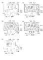
図9は、大当たり判定処理(図8のS808)の内容を示すフローチャートである。
この大当たり判定処理において、遊技制御部200の特別図柄判定部234は、まず、今回の特別図柄抽選における大当たり乱数値の判定を行い(S901)、大当たりまたは小当たりしたか否かを判断する(S902、S905)。大当たりまたは小当たりしたか否かは、図6のS604またはS610で取得した大当たり乱数の値が、大当たりの当選値として設定された値または小当たりの当選値として設定された値と一致したか否かを判断することによって決定される(図17(a)参照)。
[Big hit judgment processing by the game control unit]
FIG. 9 is a flowchart showing the contents of the jackpot determination process (S808 in FIG. 8).
In this jackpot determination process, the special
S901の乱数判定の結果が大当たりだった場合(S902でYes)、次に特別図柄判定部234は、大当たり図柄乱数値の判定を行う(S903)。この判定の結果に応じて、大当たりの種類(高確率状態か低確率状態、時短状態か時短無状態、長当たり、短当たり)が決定される。何れの大当たりとなるかは、図6のS604またはS610で取得した大当たり図柄乱数の値が、大当たりの種類ごとに予め設定された値のうちの何れと一致したかによって決定される(図17(b)参照)。
When the result of the random number determination in S901 is a big hit (Yes in S902), the special
以上の判定の後、特別図柄判定部234は、大当たり図柄乱数の判定により決定された大当たりの種類を表す図柄(大当たり図柄)を設定情報としてRAM203にセットする(S904)。
After the above determination, the special
S901の乱数判定の結果が小当たりだった場合(S902でNo、S905でYes)、次に特別図柄判定部234は、小当たりであることを表す図柄(以下、小当たり図柄)を設定情報としてRAM203にセットする(S906)。
When the result of the random number determination in S901 is a small hit (No in S902, Yes in S905), then the special
S901の乱数判定の結果が大当たりでも小当たりでもない場合(S902、S905でNo)、次に特別図柄判定部234は、抽選にはずれたことを表す図柄(以下、はずれ図柄)を設定情報としてRAM203にセットする(S907)。
When the result of the random number determination in S901 is neither a big hit nor a small hit (No in S902 and S905), then the special
〔遊技制御部による変動パターン選択処理〕
図10は、変動パターン選択処理(図8のS809)の内容を示すフローチャートである。
この変動パターン選択処理において、遊技制御部200の変動パターン選択部235は、まず、大当たり判定処理(図9)のS902の判断結果を用いて今回の特別図柄抽選で大当たりしたか否かを判断する(S1001)。そして、大当たりだった場合(S1001でYes)、変動パターン選択部235は、大当たり用の変動パターンテーブルをROM202から読み出してRAM203にセットする(S1002)。
[Variation pattern selection process by the game control unit]
FIG. 10 is a flowchart showing the contents of the variation pattern selection process (S809 in FIG. 8).
In this variation pattern selection process, the variation
一方、大当たりしなかった場合(S1001でNo)、次に変動パターン選択部235は、遊技者に大当たりを期待させるためのいわゆるリーチ演出を行うか否かを決定するための乱数値の判定を行う(S1003)。リーチ演出を行うか否かは、図6のS604またはS610で取得したリーチ乱数の値が予め設定された値と一致したか否かを判断することによって決定される(図17(c)参照)。
乱数値を用いた判定の結果、リーチ演出を行う場合(S1004でYes)、変動パターン選択部235は、リーチ用の変動パターンテーブルをROM202から読み出してRAM203にセットする(S1005)。また、リーチ演出を行わない場合(S1004でNo)、変動パターン選択部235は、はずれ用の変動パターンテーブルをROM202から読み出してRAM203にセットする(S1006)。
ここで、変動パターンテーブルとは、予め用意されている複数の変動パターン(変動時間10秒、30秒、60秒、90秒など)と変動パターン乱数の値とを対応付けたテーブルである。
On the other hand, if there is no big hit (No in S1001), then the fluctuation
When the reach effect is performed as a result of the determination using the random value (Yes in S1004), the variation
Here, the fluctuation pattern table is a table in which a plurality of fluctuation patterns (variation time 10 seconds, 30 seconds, 60 seconds, 90 seconds, etc.) prepared in advance are associated with the value of the fluctuation pattern random number.
次に、変動パターン選択部235は、図6のS604またはS610で取得した変動パターン乱数値およびS1002、1005、1006でセットされた変動パターンテーブルを用いて、変動パターン乱数値の判定を行う(S1007)。すなわち、変動パターン選択部235は、RAM203にセットされた変動パターンテーブルを参照し、変動パターン乱数の乱数値に応じた変動パターンを選択する。したがって、同じ乱数値が取得された場合でも、特別図柄抽選の結果が、大当たりしたか否か、大当たりしていない場合はリーチ演出を行うか否か、といった状態の違いに応じて参照される変動パターンテーブルが異なるので、決定される変動パターンが異なる。
Next, the fluctuation
この後、変動パターン選択部235は、S1007で選択した変動パターンを設定情報としてRAM203にセットする(S1008)。S1008でセットされた変動パターンの設定情報は、図8のS811でセットされる変動開始コマンドに含まれ、図5−3のS506に示した出力処理で演出制御部300へ送信される。本実施の形態で選択される変動パターンおよびその設定の詳細については後述する。
After that, the fluctuation
〔遊技制御部による停止中処理〕
図11は、停止中処理(図8のS815)の内容を示すフローチャートである。
この停止中処理において、遊技制御部200は、まず、RAM203のフラグ設定において時短状態であることを示すフラグ(以下、時短フラグ)がONになっているか否かを調べる(S1101)。時短フラグがONである場合(S1101でYes)、遊技制御部200は、時短状態での抽選回数(変動回数)Jの値を1減算し(S1102)、抽選回数Jが0になったか否かを調べる(S1103)。そして、抽選回数J=0であれば(S1103でYes)、時短フラグをOFFにする(S1104)。なお、時短フラグをONにする操作と、抽選回数Jの初期値の設定は、後述の大入賞口処理(図14)における遊技状態設定処理(図15)で行われる。
[Processing during stop by the game control unit]
FIG. 11 is a flowchart showing the contents of the stopped processing (S815 in FIG. 8).
In this stopped processing, the
時短フラグがOFFであった場合(S1101でNo)またはS1104で時短フラグをOFFにした後、あるいは抽選回数Jの値が0でない場合(S1103でNo)、次に遊技制御部200は、RAM203のフラグ設定において高確率状態であることを示すフラグ(以下、確変フラグ)がONになっているか否かを調べる(S1105)。なお、この確変フラグと先の時短フラグが共にONである場合は、高確率時短遊技状態であり、確変フラグがONであり時短フラグがOFFである場合は、高確率時短無遊技状態である。
When the time saving flag is OFF (No in S1101), after turning off the time saving flag in S1104, or when the value of the lottery number J is not 0 (No in S1103), the
確変フラグがONである場合(S1105でYes)、遊技制御部200は、高確率状態での抽選回数(変動回数)Xの値を1減算し(S1106)、抽選回数Xが0になったか否かを調べる(S1107)。そして、抽選回数X=0であれば(S1107でYes)、確変フラグをOFFにする(S1108)。なお、確変フラグをONにする操作と、抽選回数Xの初期値の設定は、後述の大入賞口処理(図14)における遊技状態設定処理(図15)で行われる。
When the probability change flag is ON (Yes in S1105), the
確変フラグがOFFであった場合(S1105でNo)またはS1108で確変フラグをOFFにした後、あるいは抽選回数Xの値が0でない場合(S1107でNo)、次に遊技制御部200は、今回の特別図柄抽選で大当たりしたか否かを判断する(S1109)。そして、大当たりだった場合(S1109でYes)、次に遊技制御部200は、大当たりの種類が長当たりか否かを判断する(S1110)。
When the probability change flag is OFF (No in S1105), after the probability change flag is turned OFF in S1108, or when the value of the lottery number X is not 0 (No in S1107), then the
ここで、大当たりか否かの判断は、大当たり判定処理(図9)の判定結果に基づいて判断することができる。例えば、後述する図17(b)の図表に示す図柄の何れかがセットされているならば、S1109でYesである。大当たり判定処理によりRAM203に、はずれ図柄または小当たり図柄がセットされているならば、S1109でNoである。
Here, the determination of whether or not the jackpot is a jackpot can be determined based on the determination result of the jackpot determination process (FIG. 9). For example, if any of the symbols shown in the chart of FIG. 17B, which will be described later, is set, S1109 is Yes. If a missed symbol or a small hit symbol is set in the
大当たりの種類が長当たりであった場合(S1110でYes)、遊技制御部200は、長当たり遊技フラグをONにする(S1111)。これにより、RAM203の遊技状態の設定が、大当たりの種類が長当たりである大当たり遊技状態(長当たり遊技状態)となる。なお、ここでは長当たりにおいて、高確率状態か低確率状態かを区別していない。高確率状態となるか低確率状態となるかは、後述の大入賞口処理(図14)における遊技状態設定処理(図15)で該当するフラグをONにすることによって特定される。
When the type of jackpot is a long hit (Yes in S1110), the
大当たりの種類が長当たりでなかった場合(S1110でNo)、遊技制御部200は、短当たり遊技フラグをONにする(S1112)。これにより、RAM203の遊技状態の設定が、大当たりの種類が短当たりである大当たり遊技状態(短当たり遊技状態)となる。長当たりの場合と同様、短当たりの場合も高確率状態か低確率状態かを区別していない。
When the type of big hit is not a long hit (No in S1110), the
S1111またはS1112で当たり遊技フラグをONにした後、遊技制御部200は、抽選回数J、Xの値を初期化する(S1113)。また、遊技制御部200は、S1101において時短フラグがONであって、S1103において抽選回数Jが0でなかった場合に、時短フラグをOFFにする(S1114)。同様に、S1105において確変フラグがONであって、S1107において抽選回数Xが0でなかった場合に、確変フラグをOFFにする(S1114)。
After turning on the winning game flag in S1111 or S1112, the
一方、今回の特別図柄抽選の結果が大当たりでなかった場合(S1109でNo)、次に遊技制御部200は、今回の特別図柄抽選の結果が小当たりであったか否かを判断する(S1115)。小当たりでなかった場合は(S1115でNo)、停止中処理を終了する。
一方、小当たりであった場合(S1115でYes)、遊技制御部200は、小当たり遊技を開始する(S1116)。これにより、RAM203の遊技状態の設定が小当たり遊技状態となる。なお、小当たり遊技では、前述したように、大入賞口125を所定回数開閉し、所定時間経過後に終了する。
On the other hand, if the result of the special symbol lottery this time is not a big hit (No in S1109), then the
On the other hand, if it is a small hit (Yes in S1115), the
S1113で抽選回数J、Xの値を初期化した後、遊技制御部200は、オープニング動作を開始する(S1117)。ここで、オープニング動作の内容は、S1111、S1112の何れで当たり遊技フラグがONとなったかに応じて異なる。すなわち、当たり遊技フラグの状態に応じて、長当たり遊技、短当たり遊技の各遊技状態において設定されたオープニング動作の何れかが行われることとなる。
この後、遊技制御部200は、演出制御部300において当たり遊技フラグに応じたオープニング動作における演出を行うためのオープニングコマンドをRAM203にセットして(S1118)、停止中処理を終了する。このオープニングコマンドは、図5−3のS506に示した出力処理で演出制御部300へ送信される。
After initializing the values of the lottery times J and X in S1113, the
After that, the
〔遊技制御部による客待ち設定処理〕
図12は、客待ち設定処理(図8のS816)の内容を示すフローチャートである。
この客待ち設定処理において、遊技制御部200は、まず、RAM203のフラグ設定において客待ちフラグがONになっているか否かを調べる(S1201)。ここで、客待ちフラグは、パチンコ遊技機100が客待ち状態であることを識別するためにセットされるフラグである。
[Customer waiting setting processing by the game control unit]
FIG. 12 is a flowchart showing the contents of the customer waiting setting process (S816 in FIG. 8).
In this customer waiting setting process, the
客待ちフラグがONである場合、パチンコ遊技機100は客待ち状態であるので、そのまま処理を終了する(S1201でYes)。一方、客待ちフラグがOFFである場合、遊技制御部200は、客待ちコマンドを生成してRAM203にセットし(S1202)、客待ちフラグをONにする(S1203)。S1202でセットされた客待ちコマンドは、図5−3のS506に示した出力処理で演出制御部300へ送信される。なお、客待ちフラグとは、特別図柄の変動が停止して、保留が無い状態でセットされるものである。
When the customer waiting flag is ON, the
〔遊技制御部による普通図柄処理〕
図13は、図5−3のS503に示した図柄処理のうちの普通図柄処理の内容を示すフローチャートである。
この普通図柄処理において、遊技制御部200の普通図柄変動制御部236は、まず、RAM203のフラグ設定において補助遊技フラグがONになっているか否かを調べる(S1301)。ここで、補助遊技フラグは、普通図柄抽選で当選した場合にセットされるフラグである。補助遊技フラグが設定されている状態は、電動チューリップ123が後述の電動チューリップ処理(図16)にしたがって開放され、第2始動口122に入賞し易い状態である(補助遊技状態)。
[Normal symbol processing by the game control unit]
FIG. 13 is a flowchart showing the contents of the normal symbol processing among the symbol processing shown in S503 of FIG. 5-3.
In this normal symbol processing, the normal symbol
補助遊技フラグがONである場合、既に補助遊技状態となっており、普通図柄が停止している状態なので、普通図柄変動を開始することなく普通図柄処理を終了する(S1301でYes)。一方、補助遊技フラグがOFFである場合(S1301でNo)、次に普通図柄変動制御部236は、パチンコ遊技機100の現在の状態が普通図柄変動中か否かを判断する(S1302)。普通図柄変動中でない場合(S1302でNo)、次に普通図柄変動制御部236は、普通図柄の未変動分の保留数G(図7参照)が1以上か判断する(S1303)。保留数G=0である場合は(S1303でNo)、普通図柄の抽選を始動するための入賞が無いことを意味するため、普通図柄変動を開始せずに処理を終了する。
When the auxiliary game flag is ON, the auxiliary game state is already in effect and the normal symbol is stopped. Therefore, the normal symbol processing is terminated without starting the normal symbol change (Yes in S1301). On the other hand, when the auxiliary game flag is OFF (No in S1301), the normal symbol
これに対し、保留数Gが1以上である場合(S1303でYes)、普通図柄変動制御部236は、保留数Gの値を1減算し(S1304)、今回の普通図柄抽選における当たり乱数の判定を行って、普通図柄抽選に当選したか否かを判断する(S1305)。当選したか否かは、図7のS704で取得した当たり乱数の値が、後述する図17(d)に示すテーブル等において当選値として設定された値と一致したか否かを判断することによって決定される。
On the other hand, when the hold number G is 1 or more (Yes in S1303), the normal symbol
次に、普通図柄変動制御部236は、普通図柄抽選の結果に応じて普通図柄の設定を行う(S1306)。すなわち、普通図柄抽選に当選した場合は、当選したことを表す図柄(以下、当たり図柄)を設定情報としてRAM203にセットする。一方、普通図柄抽選に当選しなかった場合は、抽選にはずれたことを表す図柄(以下、はずれ図柄)を設定情報としてRAM203にセットする。
Next, the normal symbol
次に、普通図柄変動制御部236は、普通図柄の変動時間の設定を行う(S1307)。この変動時間は、図11におけるS1104、S1114、後述の図15におけるS1504、S1507等の処理で設定される時短フラグに基づいて設定される。すなわち、S1307による設定の際に時短フラグがONである場合は、短時間(例えば1.5秒)に設定され、時短フラグがOFFである場合は、長時間(例えば4.0秒)に設定される。この設定の後、普通図柄変動制御部236は、S1307の設定内容に基づき、図2(a)および図3に示す普通図柄表示器223における普通図柄の変動を開始する(S1308)。
Next, the normal symbol
S1308で普通図柄の変動を開始した後、またはS1302で普通図柄変動中と判断された場合(S1302でYes)、普通図柄変動制御部236は、変動時間を経過したか否かを判断する(S1309)。すなわち、S1308で普通図柄の変動を開始してからの経過時間がS1307で設定された変動時間に達したか否かが判断される。変動時間を経過していなければ(S1309でNo)、普通図柄変動が継続されるので、そのまま普通図柄処理が終了する。
After starting the fluctuation of the normal symbol in S1308, or when it is determined in S1302 that the normal symbol is changing (Yes in S1302), the normal symbol
一方、変動時間が終了した場合(S1309でYes)、普通図柄変動制御部236は、普通図柄表示器223における普通図柄の変動を停止する(S1310)。そして、普通図柄変動制御部236は、停止した普通図柄に基づき普通図柄抽選に当選したか否かを判断する(S1311)。当選したならば(S1311でYes)、補助遊技フラグをONにする(S1312)。一方、抽選にはずれたならば(S1311でNo)、補助遊技フラグをONにすること無く普通図柄処理を終了する。
On the other hand, when the fluctuation time ends (Yes in S1309), the normal symbol
〔遊技制御部による大入賞口処理〕
図14は、図5−3のS504に示した電動役物処理のうちの大入賞口処理の内容を示すフローチャートである。
この大入賞口処理において、遊技制御部200の大入賞口動作制御部237は、まず、RAM203のフラグ設定において当たり遊技フラグがONになっているか否かを調べる(S1401)。当たり遊技フラグがOFFである場合、大入賞口125への入賞はないので、大入賞口処理を終了する(S1401でNo)。一方、当たり遊技フラグがONである場合(S1401でYes)、次に大入賞口動作制御部237は、パチンコ遊技機100が停止中処理(図11)で開始された大当たり時の動作制御におけるオープニング動作の最中か否かを判断する(S1402)。
[Large winning opening processing by the game control unit]
FIG. 14 is a flowchart showing the contents of the large winning opening processing among the electric accessory processing shown in S504 of FIG. 5-3.
In this big winning opening process, the big winning opening
パチンコ遊技機100がオープニング中である場合(S1402でYes)、次に大入賞口動作制御部237は、予め設定されたオープニング動作が行われるべき時間(オープニング時間)を経過したか否かを判断する(S1403)。オープニング時間を経過していないならば、大入賞口125でのオープニング動作が継続されるので、大入賞口処理を終了する(S1403でNo)。一方、オープニング時間を経過したならば(S1403でYes)、次に大入賞口動作制御部237は、大入賞口125の作動設定を行い(S1404)、入賞個数Cを初期化(C=0)し(S1405)、大入賞口125の作動のラウンド数Rの値を現在の値から1加算して(S1406)、大入賞口125を作動開始(開放)する(S1407)。
When the
S1404の作動設定では、大入賞口125の作動パターンと、その作動パターンで作動させるラウンド数(作動ラウンド数)とが設定される。大入賞口125が作動する場合としては、特別図柄抽選で、長当たりまたは短当たりの大当たりであった場合と、小当たりであった場合がある。作動パターンおよびラウンド数は、これらの当たりの種類に応じて様々に設定される。一例としては、長当たりの場合、例えば、15ラウンド(15R)作動させ、1ラウンドでは29.5秒の開放を1回行う。短当たりの場合、例えば、15ラウンド(15R)作動させ、1ラウンドでは0.1秒の開放を1回行う。小当たりの場合、例えば、1ラウンド(1R)作動させ、この1ラウンドで0.1秒の開放を15回行う。ここで、短当たりでの作動と小当たりでの作動を上記の例で比較すると、共に0.1秒の開放が15回行われることとなる。すなわち、遊技者から見える大入賞口125の動作は、短当たりの場合と小当たりの場合とで同じであり、遊技盤110上の大入賞口125の動作のみから短当たりと小当たりとを区別することはできない。
In the operation setting of S1404, the operation pattern of the large winning
また、別の例としては、長当たりでは、15ラウンド(15R)作動させ、1ラウンドでは29.5秒の開放を1回行い、短当たりでは、2ラウンド(2R)作動させ、1ラウンドでは0.9秒の開放を2回行い、小当たりでは、1ラウンド(1R)作動させ、この1ラウンドで0.9秒の開放を2回行う。この場合も、短当たりでの作動と小当たりでの作動を比較すると、共に0.9秒の開放が2回行われることとなり、遊技者から見える大入賞口125の動作は、短当たりの場合と小当たりの場合とで同様となる。
As another example, in the long hit, 15 rounds (15R) are operated, in 1 round, 29.5 seconds are opened once, in the short hit, 2 rounds (2R) are operated, and 0 in 1 round. Open for .9 seconds twice, and for small hits, operate for 1 round (1R), and open for 0.9 seconds twice in this 1 round. In this case as well, when comparing the operation with a short hit and the operation with a small hit, the opening of 0.9 seconds is performed twice, and the operation of the large winning
なお、小当たりの際には、大入賞口125の開放累積時間が1.8秒以内に設定されなければならないことが法令により定められている。一方で、大当たり(長当たりまたは短当たり)の際には、大入賞口125を複数回連続開放させなければならない。そこで、上記のように小当たりでの作動と短当たりでの作動を外見上区別し難くしようとする場合、小当たりでは、1作動での開放累積時間が1.8秒以内を満たす範囲で、大入賞口125が2回以上開放する作動形態が設定され、短当たりでは、小当たりの開放回数と同数のラウンド数が設定される。
In the case of a small hit, the law stipulates that the cumulative opening time of the large winning
次に、大入賞口動作制御部237は、S1404で設定された作動パターンにおける開放時間を経過したか否かを判断する(S1408)。大入賞口125での開放状態が開放時間を経過していない場合(S1408でNo)、次に大入賞口動作制御部237は、大入賞口125への入賞個数Cが規定の個数(例えば9個)以上か否かを判断する(S1409)。開放時間を経過しておらず、かつ入賞個数Cが規定個数未満である場合は、大入賞口125の作動状態(開放状態)が継続されるので、大入賞口処理を終了する(S1409でNo)。一方、開放時間を経過したか(S1408でYes)、または入賞個数Cが規定個数に達した場合(S1409でYes)、大入賞口動作制御部237は、大入賞口125を作動終了(閉口)する(S1410)。
Next, the large winning opening
次に、大入賞口動作制御部237は、大入賞口125の作動のラウンド数RがS1404で設定された最大値に達したか否かを判断する(S1411)。そして、最大値に達していないならば、残りの作動が行われるため、大入賞口処理を終了する(S1411でNo)。
Next, the large winning opening
大入賞口125の作動のラウンド数Rが最大値に達したならば(S1411でYes)、次に大入賞口動作制御部237は、エンディング動作を開始する(S1412)。ここで、エンディング動作の内容は、長当たり遊技、短当たり遊技の各遊技状態において設定されたエンディング動作のうち、当たり遊技フラグの状態に対応するものとなる。
この後、大入賞口動作制御部237は、演出制御部300において当たり遊技フラグに応じたエンディング動作における演出を行うためのエンディングコマンドをRAM203にセットする(S1413)。このエンディングコマンドは、図5−3のS506に示した出力処理で演出制御部300へ送信される。
When the number of rounds R of operation of the large winning
After that, the large winning opening
次に、大入賞口動作制御部237は、大入賞口125の作動のラウンド数Rを0にリセットした後(S1414)、エンディング動作の開始からの経過時間が予め設定されたエンディング動作が行われるべき時間(エンディング時間)を経過したか否かを判断する(S1417)。エンディング時間を経過していないならば、エンディング動作が継続されるので、大入賞口処理を終了する(S1417でNo)。一方、エンディング時間を経過したならば(S1417でYes)、次に大入賞口動作制御部237は、遊技制御部200による遊技状態設定処理を経た後(S1418)、当たり遊技フラグをOFFにして、大入賞口処理を終了する(S1419)。遊技状態設定処理の内容については後述する。
Next, the large winning opening
S1402で、パチンコ遊技機100がオープニング中ではないと判断した場合(S1402でNo)、次に大入賞口動作制御部237は、エンディング中か否かを判断する(S1415)。そして、エンディング中であるならば(S1415でYes)、上記S1417以降の動作を実行する。
When it is determined in S1402 that the
一方、パチンコ遊技機100がエンディング中でもないならば(S1415でNo)、次に大入賞口動作制御部237は、大入賞口125が作動(開放)中か否かを判断する(S1416)。そして、作動中でないならば(S1416でNo)、上記S1405以降の動作を実行し、作動中であるならば(S1416でYes)、上記S1408以降の動作を実行する。
なお、前述した小当たり遊技で行われる演出は、短当たり遊技で行われる演出と同様であり、演出から短当たりと小当たりとを区別することはできない。
On the other hand, if the
It should be noted that the effect performed in the small hit game described above is the same as the effect performed in the short hit game, and it is not possible to distinguish between the short hit and the small hit from the effect.
〔遊技状態設定処理〕
エンディング時間が経過した場合(S1417でYes)に実行される、遊技制御部200による遊技状態設定処理(S1418)の内容を図15に示す。
遊技状態設定処理が行われる場合、前提として、図14のS1401で当たり遊技フラグがONとなっている。そこで、図15に示すように、遊技制御部200は、まず、その当たりの種類を判断する(S1501、S1502、S1503、S1506)。これらの判断は、例えば大当たり判定処理(図9)でRAM203に設定情報としてセットされた図柄の種類に基づいて判断することができる。なお、これらの判断は大当たり判定処理(図9)のS902、S903、S905と概ね同様であるので、S902、S903、S905の判断結果を用いても良い。
[Game state setting process]
FIG. 15 shows the contents of the game state setting process (S1418) by the
When the game state setting process is performed, the winning game flag is ON in S1401 of FIG. 14 as a premise. Therefore, as shown in FIG. 15, the
小当たりである場合(S1501でYes)、遊技状態(パチンコ遊技機100の内部状態)は変更しないので、遊技状態設定処理を終了する。
当たりの種類が低確率時短遊技状態の大当たりである場合(S1501でNo、S1502、S1503でYes)、遊技制御部200は、時短フラグをONにする(S1504)。これにより、RAM203の遊技状態の設定が低確率時短遊技状態となる。また、遊技制御部200は、抽選回数Jの初期値を設定し(S1505)、遊技状態設定処理を終了する。抽選回数Jの初期値は、図示の例では100回である。したがって、低確率時短遊技状態における抽選が100回行われたならば、低確率時短遊技状態が終了し、低確率時短無遊技状態となる。
In the case of a small hit (Yes in S1501), the gaming state (internal state of the pachinko gaming machine 100) is not changed, so the gaming state setting process is terminated.
When the type of hit is a big hit in a low-probability time-saving game state (No in S1501, Yes in S1502, Yes in S1503), the
一方、当たりの種類が低確率時短無遊技状態の大当たりである場合(S1501でNo、1502でYes、S1503でNo)、遊技制御部200は、時短フラグ、確変フラグともONにせずに処理を終了する。したがって、この大当たりの後の遊技に対するRAM203の遊技状態の設定は、低確率時短無遊技状態となる。
On the other hand, when the type of hit is a big hit in a low-probability time-saving non-game state (No in S1501, Yes in 1502, No in S1503), the
当たりの種類が高確率時短遊技状態の大当たりである場合(S1501、S1502でNo、S1506でYes)、遊技制御部200は、時短フラグをONにし(S1507)、抽選回数Jの初期値を設定する(S1508)。この場合の抽選回数Jの初期値は、図示の例では10000回である。また、遊技制御部200は、確変フラグをONにし(S1509)、抽選回数Xの初期値を設定する(S1510)。抽選回数Xの初期値は、図示の例では10000回である。これにより、RAM203の遊技状態の設定が高確率時短遊技状態となる。そして、この高確率時短遊技状態における抽選が10000回行われたならば、高確率時短遊技状態が終了し、低確率時短無遊技状態となる。
When the type of hit is a big hit in a high-probability time-saving game state (No in S1501 and S1502, Yes in S1506), the
一方、当たりの種類が高確率時短無遊技状態の大当たりである場合(S1501、S1502、S1506でNo)、遊技制御部200は、確変フラグのみをONにし(S1509)、抽選回数Xの初期値(10000回)を設定する(S1510)。これにより、RAM203の遊技状態の設定が高確率時短無遊技状態となる。そして、この高確率時短無遊技状態における抽選が10000回行われたならば、高確率時短無遊技状態が終了し、低確率時短無遊技状態となる。
On the other hand, when the type of hit is a big hit in a high-probability time-saving non-game state (No in S1501, S1502, S1506), the
〔遊技制御部による電動チューリップ処理〕
図16は、図5−3のS504に示した電動役物処理のうちの電動チューリップ処理の内容を示すフローチャートである。
電動チューリップ処理において、遊技制御部200の電動チューリップ動作制御部238は、まず、RAM203のフラグ設定において補助遊技フラグがONになっているか否かを調べる(S1601)。補助遊技フラグがOFFである場合、電動チューリップ123は開放しないため、電動チューリップ処理を終了する(S1601でNo)。一方、補助遊技フラグがONである場合(S1601でYes)、次に電動チューリップ動作制御部238は、電動チューリップ123が作動中か否かを判断する(S1602)。
[Electric tulip processing by the game control unit]
FIG. 16 is a flowchart showing the contents of the electric tulip processing among the electric accessory processing shown in S504 of FIG. 5-3.
In the electric tulip processing, the electric tulip
電動チューリップ123が作動中でない場合(S1602でNo)、電動チューリップ動作制御部238は、電動チューリップ123の作動パターンの設定を行い(S1603)、設定した作動パターンで電動チューリップ123を作動させる(S1604)。ここで、作動パターンは、図11におけるS1104、S1114、図15におけるS1504、S1507等の処理で設定される時短フラグに基づいて設定される。例えば、S1603による設定の際に時短フラグがOFFである場合は、0.15秒の開放時間で1回開放する作動パターンが設定され、時短フラグがONである場合は、1.80秒の開放時間で3回開放する作動パターンが設定される。このように、通常、時短フラグがONであるとき(時短状態のとき)は、電動チューリップ123が長時間、複数回開放され、第2始動口122に入賞し易くなる入賞サポート(電チューサポート)が行われる。
When the
S1602で電動チューリップ123が作動中と判断された場合(S1602でYes)、またはS1604で電動チューリップ123を作動させた後、電動チューリップ動作制御部238は、設定されている作動パターンにおける開放時間が経過したか否かを判断する(S1605)。開放時間を経過していなければ、電動チューリップ123の作動状態(開放状態)が継続されるので、電動チューリップ処理を終了する(S1605でNo)。一方、開放時間を経過したならば(S1605でYes)、電動チューリップ動作制御部238は、補助遊技フラグをOFFとして、電動チューリップ処理を終了する(S1606)。
When it is determined in S1602 that the
〔乱数による判定の手法〕
ここで、大当たり判定処理(図9)、変動パターン選択処理(図10)、普通図柄処理(図13)等で行われる、乱数による判定の手法について詳細に説明する。
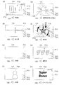
図17は、本実施の形態において特別図柄抽選および普通図柄抽選で用いられる乱数(判定テーブル)の構成例を示す図である。
図17(a)には特別図柄抽選で用いられる大当たり乱数の構成例、図17(b)には特別図柄抽選で用いられる大当たり図柄乱数の構成例、図17(c)には特別図柄抽選で用いられるリーチ乱数の構成例、図17(d)には普通図柄抽選で用いられる当たり乱数の構成例が、それぞれ示されている。
[Random number judgment method]
Here, a random number determination method performed in the jackpot determination process (FIG. 9), the variation pattern selection process (FIG. 10), the normal symbol process (FIG. 13), and the like will be described in detail.
FIG. 17 is a diagram showing a configuration example of a random number (determination table) used in the special symbol lottery and the ordinary symbol lottery in the present embodiment.
FIG. 17 (a) shows a configuration example of a jackpot random number used in a special symbol lottery, FIG. 17 (b) shows a configuration example of a jackpot symbol random number used in a special symbol lottery, and FIG. A configuration example of the reach random number used and a configuration example of the winning random number used in the ordinary symbol lottery are shown in FIG. 17 (d), respectively.
図17(a)を参照すると、大当たり乱数の判定値として、パチンコ遊技機100の遊技状態が低確率状態の大当たりと高確率状態の大当たりの2種類と、小当たりとが設定されている。乱数(大当たり乱数)の値の範囲は、何れも0〜299の300個である。低確率状態の特別図柄抽選(大当たり抽選)の場合、当選値は1つだけが設定され、当選確率は1/300である。また高確率状態の特別図柄抽選の場合、当選値は10個設定され、当選確率は10/300(=1/30)である。すなわち図示の例では、高確率状態で始動口121、122に入賞し特別図柄抽選が行われると、低確率状態で特別図柄抽選が行われる場合に比べて、当選確率が10倍となる。また、小当たりの当選値は、低確率状態か高確率状態かに関わらず3個設定され、当選確率は3/300(=1/100)である。
With reference to FIG. 17A, two types of jackpots, a jackpot in which the gaming state of the
図17(b)を参照すると、大当たり図柄には、低確率図柄A、低確率図柄B、高確率図柄A、高確率図柄B、潜確図柄の5種類が用意されている。ここで、低確率図柄Aおよび低確率図柄Bは、低確率状態の大当たりであることを表す図柄であり、このうち低確率図柄Aは長当たり(低確率時短遊技状態)、低確率図柄Bは短当たり(低確率時短無遊技状態)をそれぞれ表す。高確率図柄Aおよび高確率図柄Bは、高確率状態の大当たりであることを表す図柄であり、このうち高確率図柄Aは長当たり(高確率時短遊技状態)、高確率図柄Bは短当たり(高確率時短無遊技状態)をそれぞれ表す。潜確図柄は、高確率時短無遊技状態の大当たりであることを表す図柄である。したがって、高確率図柄Bと潜確図柄とは大当たり遊技後の遊技状態が同じであるが、潜確図柄は、高確率状態であることを遊技者に明確に報知しない潜伏演出を行う条件とするために高確率図柄Bとは分けて設けられている。乱数の値の範囲は0〜249の250個である。また、大当たり図柄乱数では、特別図柄抽選が行われる契機となる第1始動口121と第2始動口122の各々について当選値が設定される。
With reference to FIG. 17B, five types of jackpot symbols are prepared: low-probability symbol A, low-probability symbol B, high-probability symbol A, high-probability symbol B, and latent symbol. Here, the low-probability symbol A and the low-probability symbol B are symbols indicating that they are big hits in the low-probability state, of which the low-probability symbol A is a long hit (low-probability time-short game state) and the low-probability symbol B is. Each represents a short hit (low probability time saving no game state). High-probability symbol A and high-probability symbol B are symbols indicating that they are big hits in a high-probability state. Among them, high-probability symbol A is a long hit (high-probability time-short game state), and high-probability symbol B is a short hit (high-probability short-time game state). High probability time saving no game state) is represented respectively. The latent symbol is a symbol indicating that it is a big hit in a high-probability time-saving non-game state. Therefore, the high-probability symbol B and the latent probability symbol have the same gaming state after the jackpot game, but the latent probability symbol is a condition for performing a latent effect that does not clearly notify the player that the high-probability symbol is in the high-probability state. Therefore, it is provided separately from the high-probability symbol B. The range of random number values is 250 from 0 to 249. Further, in the jackpot symbol random number, winning values are set for each of the
低確率図柄Aでは、第1始動口121および第2始動口122ともに、当選値として35個の値が割り当てられている。したがって、大当たりに当選した場合に低確率図柄Aでの当選となる確率は、35/250(=7/50)である。
低確率図柄Bでは、第1始動口121および第2始動口122ともに、当選値として15個の値が割り当てられている。したがって、大当たりに当選した場合に低確率図柄Bでの当選となる確率は、15/250(=3/50)である。
In the low-probability symbol A, 35 values are assigned as winning values to both the
In the low-probability symbol B, 15 values are assigned as winning values to both the
高確率図柄Aでは、第1始動口121に入賞した場合の当選値として25個の値が割り当てられている。したがって、第1始動口121に入賞したことによって開始された特別図柄抽選において大当たりに当選した場合に高確率図柄Aでの当選となる確率は、25/250(=1/10)である。
一方、第2始動口122に入賞した場合の当選値として175個の値が割り当てられている。したがって、第2始動口122に入賞したことによって開始された特別図柄抽選において大当たりに当選した場合に高確率図柄Aでの当選となる確率は、175/250(=7/10)である。
In the high-probability symbol A, 25 values are assigned as winning values when the
On the other hand, 175 values are assigned as winning values when the
高確率図柄Bでは、第1始動口121に入賞した場合の当選値として75個の値が割り当てられている。したがって、第1始動口121に入賞したことによって開始された特別図柄抽選において大当たりに当選した場合に高確率図柄Bでの当選となる確率は、75/250(=3/10)である。
一方、第2始動口122に入賞した場合の当選値として25個の値が割り当てられている。したがって、第2始動口122に入賞したことによって開始された特別図柄抽選において大当たりに当選した場合に高確率図柄Bでの当選となる確率は、25/250(=1/10)である。
In the high-probability symbol B, 75 values are assigned as winning values when the
On the other hand, 25 values are assigned as winning values when the
潜確図柄では、第1始動口121に入賞した場合の当選値として100個の値が割り当てられている。したがって、第1始動口121に入賞したことによって開始された特別図柄抽選において大当たりに当選した場合に潜確図柄での当選となる確率は、100/250(=2/5)である。
一方、第2始動口122には潜確図柄での当選値が割り当てられておらず、第2始動口122に入賞した場合に潜確図柄での当選となることはない。
In the latent probability symbol, 100 values are assigned as winning values when the
On the other hand, the winning value in the latent probability symbol is not assigned to the
以上のように、図17(b)に示す例では、第1始動口121に入賞した場合の大当たりは、高確率時短無遊技状態の大当たり(高確率図柄B、潜確図柄)となる確率が高く、第2始動口122に入賞した場合の大当たりは、高確率時短遊技状態の大当たり(高確率図柄A)となる確率が高い。このように、第1始動口121に入賞した場合と第2始動口122に入賞した場合における大当たりの種類の当選確率を相違させることにより、様々な遊技性を持たせることができる。また、遊技盤110における第1始動口121と第2始動口122の配置を工夫し、特定の状態(モード)では第1始動口121と第2始動口122の何れか一方を狙い易くなるように構成することによって、遊技者にさらに積極的な遊技への参加を促すことも可能である。
As described above, in the example shown in FIG. 17B, the jackpot when the
次に、リーチ乱数の判定について説明する。
図17(c)を参照すると、乱数の値の範囲は0〜249の250個であり、リーチ演出を行う抽選結果(リーチ有)に22個の乱数値が割り当てられ、リーチ演出を行わない抽選結果(リーチ無)に228個の乱数値が割り当てられている。すなわち図示の例では、特別図柄抽選で大当たりしなかった場合に、22/250(=11/125)の確率でリーチ演出が行われる。
Next, the determination of the reach random number will be described.
With reference to FIG. 17 (c), the range of random number values is 250 from 0 to 249, and 22 random number values are assigned to the lottery result (with reach) for performing reach effect, and the lottery without reach effect is performed. 228 random numbers are assigned to the result (no reach). That is, in the illustrated example, if a big hit is not made in the special symbol lottery, the reach effect is performed with a probability of 22/250 (= 11/125).
なお、リーチ乱数によって決定されるリーチ有り演出、リーチ無し演出というのは、画像表示部114において行われる演出の態様を示すものである。すなわち、特別図柄の変動表示中には、例えば1〜9の数字が縦方向に連続して記された数列からなる図柄が三列表示されており、特別図柄の変動表示が開始されるのと同時に、これら図柄がスクロールを開始する。
そして、リーチ有り演出においては、スクロールの開始後、所定時間経過後にスクロールが停止して各図柄を停止表示する際に、まず、いずれか2つの図柄(数列)が先に停止する。このとき、横または斜めにわたる一直線上に同一の数字が停止表示するとともに、最後の一列がスクロール速度を徐々に遅くして、一直線上に同一の数字が3つ揃うのではないかという期待感を遊技者に与える。このようなリーチ有り演出のなかには、最後の1列のスクロールが停止する前に、さまざまなキャラクタが登場したり、ストーリーが展開したりするいわゆるスーパーリーチ演出が含まれている。一方、リーチ無し演出は、リーチ有り演出とは異なり、遊技者に期待感を与えるような演出がなされることなく、横または斜めにわたる一直線上に同一の数字が揃わない状態で図柄が停止表示するものである。
このように、リーチ乱数は、大当たり乱数の判定の結果がハズレであった場合に、画像表示部114においてリーチ有り演出を行うか、リーチ無し演出を行うかを決定するためのもので、所定の確率でリーチ有り演出が出現するようにして、遊技者に対して適度に期待感を与えるようにしている。
付言すると、大当たりに当選した場合には、リーチ有り演出が必ず行われ、最終的に横または斜めにわたる一直線上に、同一の数字が揃った状態で装飾図柄が停止表示する。これに対して、小当たりに当選した場合やハズレの場合のリーチ有り演出は、上記一直線上に、同一の数字が揃わない状態で装飾図柄が停止表示する。
It should be noted that the effect with reach and the effect without reach determined by the reach random number indicate the mode of the effect performed by the
Then, in the effect with reach, when the scrolling is stopped and each symbol is stopped and displayed after a lapse of a predetermined time after the start of scrolling, first, any two symbols (sequential sequence) are stopped first. At this time, the same number is stopped and displayed on a straight line extending horizontally or diagonally, and the scroll speed is gradually slowed down in the last row, and there is a feeling of expectation that three identical numbers will be aligned on the straight line. Give to the player. Such a reach production includes a so-called super reach production in which various characters appear and the story unfolds before the scrolling of the last row stops. On the other hand, unlike the production with reach, the production without reach does not give a feeling of expectation to the player, and the symbols are stopped and displayed in a state where the same numbers are not aligned on a straight line extending horizontally or diagonally. It is a thing.
As described above, the reach random number is for determining whether the
In addition, if the jackpot is won, the effect with reach is always performed, and finally, the decorative symbols are stopped and displayed with the same numbers aligned on a straight line extending horizontally or diagonally. On the other hand, in the case of winning a small hit or losing, the decorative symbol is stopped and displayed on the above straight line in a state where the same numbers are not aligned.
次に、普通図柄抽選に用いられる当たり乱数の判定について説明する。
図17(d)を参照すると、乱数の値の範囲は0〜9の10個であり、時短フラグOFFのときの当選値として1個の値が割り当てられ、時短フラグONのときの当選値として9個の値が割り当てられている。したがって、時短無状態のときにゲート124を遊技球が通過して普通図柄抽選(開閉抽選)が行われると、1/10の確率で当選する。これに対し、時短状態のときにゲート124を遊技球が通過して普通図柄抽選(開閉抽選)が行われると、9/10の確率で当選する。
Next, the determination of the winning random number used in the ordinary symbol lottery will be described.
With reference to FIG. 17D, the range of random numbers is 10 from 0 to 9, and one value is assigned as the winning value when the time saving flag is OFF, and as the winning value when the time saving flag is ON. Nine values are assigned. Therefore, if the game ball passes through the
各種の抽選に用いられる判定情報としての乱数値は、所定の初期値から始まって、図5−3に示す乱数更新処理(S501)が行われるたびに1ずつ加算される。そして、各抽選が行われた時点の値が始動口スイッチ処理(図6)およびゲートスイッチ処理(図7)で取得され、特別図柄処理(図8)や普通図柄処理(図13)で使用される。なお、この乱数値のカウンタは無限ループカウンタであり、設定されている乱数の最大値(例えば図17(a)に示した大当たり乱数では299)に達した後は再び0に戻る。また、乱数更新処理は一定時間ごとに行われるため、各乱数の初期値が特定されてしまうと、これらの情報に基づいて当選値が推定される恐れがある。そこで、一般に、適当なタイミングで各乱数の初期値をランダムに変更する仕組みが導入されている。
なお、図17の各乱数の構成例に示した乱数の範囲、当選値の割合、当選値の各値は例示に過ぎず、図示の値に限定されるものではない。
The random number value as the determination information used in various lottery starts from a predetermined initial value and is added by 1 each time the random number update process (S501) shown in FIG. 5-3 is performed. Then, the value at the time when each lottery is performed is acquired by the start port switch process (FIG. 6) and the gate switch process (FIG. 7), and is used in the special symbol process (FIG. 8) and the normal symbol process (FIG. 13). NS. The random number counter is an infinite loop counter, and returns to 0 again after reaching the maximum value of the set random numbers (for example, 299 for the jackpot random number shown in FIG. 17A). Further, since the random number update process is performed at regular intervals, if the initial value of each random number is specified, the winning value may be estimated based on this information. Therefore, in general, a mechanism has been introduced in which the initial value of each random number is randomly changed at an appropriate timing.
The range of random numbers, the ratio of winning values, and the values of winning values shown in the configuration example of each random number in FIG. 17 are merely examples, and are not limited to the values shown in the drawings.
〔変動パターンの設定例〕
次に、図10に示した変動パターン選択処理において用いられる変動パターンの設定例について説明する。
図18は、図10に示した変動パターン選択処理において用いられる変動パターンの設定例を示す図である。
図18に示す例では、特別図柄抽選の判定結果が大当たりであった場合(図10のS1001でYesの場合)の変動パターンとして、3種類の変動パターンA〜Cが設定されている。また、特別図柄抽選の判定結果がはずれ(図10のS1001でNoの場合)であった場合の変動パターンとして、6種類の変動パターンD〜Iが設定されている。変動時間は、変動パターンAが90秒、変動パターンBが60秒、変動パターンCが30秒、変動パターンDが60秒、変動パターンEが30秒、変動パターンFが15秒、変動パターンGが13秒、変動パターンHが7秒、変動パターンIが3秒にそれぞれ設定されている。すなわち、特別図柄の変動パターンは、特別図柄抽選における判定結果および特別図柄の変動時間を定める。
[Example of setting fluctuation pattern]
Next, a setting example of the fluctuation pattern used in the fluctuation pattern selection process shown in FIG. 10 will be described.
FIG. 18 is a diagram showing a setting example of a fluctuation pattern used in the fluctuation pattern selection process shown in FIG.
In the example shown in FIG. 18, three types of fluctuation patterns A to C are set as fluctuation patterns when the determination result of the special symbol lottery is a big hit (in the case of Yes in S1001 of FIG. 10). In addition, six types of fluctuation patterns D to I are set as fluctuation patterns when the determination result of the special symbol lottery is incorrect (when No in S1001 of FIG. 10). The fluctuation time is 90 seconds for the fluctuation pattern A, 60 seconds for the fluctuation pattern B, 30 seconds for the fluctuation pattern C, 60 seconds for the fluctuation pattern D, 30 seconds for the fluctuation pattern E, 15 seconds for the fluctuation pattern F, and 15 seconds for the fluctuation pattern G. The fluctuation pattern H is set to 13 seconds, the fluctuation pattern H is set to 7 seconds, and the fluctuation pattern I is set to 3 seconds. That is, the fluctuation pattern of the special symbol determines the determination result in the special symbol lottery and the fluctuation time of the special symbol.
また、変動パターンD〜Fは、リーチ演出が行われる場合(図10のS1004でYesの場合)に選択される変動パターンであり、変動パターンG〜Iは、リーチ演出が行われない場合(図10のS1004でNoの場合)に選択される変動パターンとして設定されている。なお、特別図柄抽選の判定結果が大当たりのときには必ずリーチ演出を行うように構成しているため、変動パターンA〜Cが選択される場合においてリーチ演出の有無は参照されない。 Further, the fluctuation patterns D to F are fluctuation patterns selected when the reach effect is performed (Yes in S1004 of FIG. 10), and the fluctuation patterns G to I are when the reach effect is not performed (FIG. 10). It is set as the fluctuation pattern selected in (No in S1004 of 10). Since the reach effect is always performed when the determination result of the special symbol lottery is a big hit, the presence or absence of the reach effect is not referred to when the fluctuation patterns A to C are selected.
さらに、変動パターンG〜Iのうち、変動パターンGは保留数が0個であるとき、変動パターンHは保留数が1個または2個であるとき、変動パターンIは保留数が3個または4個であるときにそれぞれ選択される変動パターンとして設定されている。すなわち、特別図柄抽選における判定の保留数が多いほど、特別図柄変動の平均時間が短くなるように設定されている。 Further, among the fluctuation patterns G to I, when the fluctuation pattern G has 0 hold numbers, the fluctuation pattern H has 1 or 2 hold numbers, and the fluctuation pattern I has 3 or 4 hold numbers. It is set as a fluctuation pattern that is selected when there are individual pieces. That is, the larger the number of pending judgments in the special symbol lottery, the shorter the average time of the special symbol fluctuation is set.
遊技制御部200は、遊技球が始動口121、122に入賞した際に取得した変動パターン乱数値(図6のS604、S610参照)と、図18の設定例に示す判定結果、リーチ演出の有無、保留数等の条件とに基づいて特別図柄の変動パターンを決定する。そして、決定された特別図柄の変動パターンの情報は、変動開始コマンドに含まれて、遊技制御部200から演出制御部300へ送られる。演出制御部300では、後述するように、特別図柄変動時の演出として、変動開始コマンドに含まれる変動パターンの情報に基づいて特定される変動時間に対応する(その変動時間で実行可能な)演出が選択されて実行される。
The
なお、図示はしていないが、特別図柄抽選の判定結果が大当たりであった場合に選択される変動パターンA〜Cのうち、最も高い割合で変動パターンAが選択され、次に高い割合で変動パターンBが選択され、最も低い割合で変動パターンCが選択されるように設定することができる。
また、図18に示した例では、遊技球が第1始動口121に入賞した場合と第2始動口122に入賞した場合とを区別していないが、第1始動口121と第2始動口122の何れに入賞したかに応じて変動パターンの設定を異ならせることもできる。
Although not shown, the fluctuation pattern A is selected at the highest ratio among the fluctuation patterns A to C selected when the judgment result of the special symbol lottery is a big hit, and the fluctuation pattern A is the next highest ratio. It can be set so that the pattern B is selected and the variation pattern C is selected at the lowest rate.
Further, in the example shown in FIG. 18, the case where the game ball wins the
〔コマンドの構成および伝送方式〕
ここで、遊技制御部200から演出制御部300へ出力されるコマンド(演出制御用コマンドおよび設定用コマンド)の構成および伝送方式について説明する。
図19−1は、コマンドの構成を示す図である。図19−1(a)はコマンドのデータ構造を示し、図19−1(b)はコマンドのビット列としての構造を示す。
[Command configuration and transmission method]
Here, the configuration and transmission method of commands (commands for effect control and commands for setting) output from the
FIG. 19-1 is a diagram showing a command configuration. FIG. 19-1 (a) shows the data structure of the command, and FIG. 19-1 (b) shows the structure as a bit string of the command.
図19−1(a)に示すように、遊技制御部200から演出制御部300へ出力されるコマンドは、1コマンドが2バイトで構成される。このコマンドは、第1データ部としての1バイトの「コード」と、第2データ部としての1バイトの「データ」で構成されている。「コード」は、コマンドの種類を示し、「データ」は、コマンドの値を示す。このコマンドは、1本のシリアル信号により調歩同期を用いて、遊技制御部200から演出制御部300へ送信される。なお、より一般的には、第1データ部である「コード」は、aビット(aは2以上の整数)のサイズで、先頭の1ビットの値が1または0の何れか一方に特定され、第2データ部である「データ」は、n×aビット(nは1以上の整数)のサイズで、先頭の1ビットの値が前記第1データ部の先頭の1ビットの値とは異なる値に特定されている。
As shown in FIG. 19-1 (a), one command is composed of two bytes in the command output from the
調歩同期を用いるため、コマンドを構成する「コード」および「データ」の各々の先頭には1ビットのスタートビット(図中、「S」と記載されたビット)が設けられ、最後尾には1ビットのエンドビット(図中、「E」と記載されたビット)が設けられる。また、コマンドを構成する「コード」および「データ」の各々には1ビットのパリティビット(図中、「P」と記載されたビット)が設けられる。 Since the pace synchronization is used, a 1-bit start bit (bit described as "S" in the figure) is provided at the beginning of each of the "code" and "data" constituting the command, and 1 is provided at the end. The end bit of the bit (the bit described as "E" in the figure) is provided. Further, each of the "code" and the "data" constituting the command is provided with a 1-bit parity bit (a bit described as "P" in the figure).
図19−1(a)に示したように、コマンドを構成する「コード」と「データ」とは、どちらも1バイト(8ビット)のデータサイズを有する。そして、伝送される際、「コード」および「データ」には、それぞれ、スタートビット、エンドビットおよびパリティビットが設けられる。そのため、コマンドを受信する演出制御部300において、受信したデータ列がコマンドの「コード」であるのか「データ」であるのかを、データ列の外形から識別することは容易ではない。そこで、本実施の形態では、「コード」と「データ」とを識別するためのフラグを設定する。具体的には、「コード」を構成する8ビット値の特定箇所の値と、「データ」を構成する8ビット値のうち「コード」の特定箇所に対応する箇所の値とが異なるようにする。
As shown in FIG. 19-1 (a), both the "code" and the "data" constituting the command have a data size of 1 byte (8 bits). Then, when transmitted, the "code" and the "data" are provided with a start bit, an end bit, and a parity bit, respectively. Therefore, in the
図19−1(b)に示す例では、「コード」および「データ」のそれぞれの先頭の1ビットをフラグとして用いている。すなわち、「コード」を構成する8ビット値においては、先頭の1ビットの値を「1」とし、「データ」を構成する8ビット値においては、先頭の1ビットの値を「0」とする。これにより、演出制御部300は、受信したデータ列のスタートビットに続く先頭の1ビットの値を調べることにより、そのデータ列が「コード」か「データ」かを識別することができる。なお、フラグの具体的な値は例示に過ぎず、「コード」と「データ」とを識別可能であれば、上記に示す値とは異なる値を用いても良い。
In the example shown in FIG. 19-1 (b), the first bit of each of the "code" and the "data" is used as a flag. That is, in the 8-bit value constituting the "code", the value of the first 1 bit is set to "1", and in the 8-bit value constituting the "data", the value of the first 1 bit is set to "0". .. As a result, the
ここで、「コード」は先頭の1ビットの値が「1」に特定されているので、「コード」が取り得る値の範囲は、10000000B(=80H)から11111111B(=FFH)までの128個である。なお、各値に付された文字「B」は2進数表記であることを示し、文字「H」は16進数表記であることを示す。また、「データ」は先頭の1ビットの値が「0」に特定されているので、「データ」が取り得る値の範囲は、00000000B(=00H)から01111111B(=7FH)までの128個である。すなわち、図19−1(a)、(b)に示す構成によれば、各々128種類の値を取り得る、128種類のコマンドを設定することができる。 Here, since the value of the first bit of the "code" is specified as "1", the range of values that the "code" can take is 128 from 10000000B (= 80H) to 11111111B (= FFH). Is. The letter "B" attached to each value indicates that it is in binary notation, and the letter "H" indicates that it is in hexadecimal notation. Further, since the value of the first bit of "data" is specified as "0", the range of values that "data" can take is 128 from 00000000000B (= 00H) to 01111111B (= 7FH). be. That is, according to the configurations shown in FIGS. 19-1 (a) and 19-1 (b), 128 types of commands that can take 128 types of values can be set.
ところで、パチンコ遊技機100では、遊技状態や特別図柄抽選の判定結果等に応じて多くの種類の演出が実行される。そのため、演出制御用のコマンドも多くのコマンド数が用意される。特に、コマンドの具体的な内容を示す値である「データ」は、上記の128個では不足することもあり得る。一方、コマンドの種類を示す「コード」は、通常、上記の128個よりも小さい数で足りる。そこで、「コード」のビット列の一部を、「データ」の値を記述するために用いることが考えられる。
By the way, in the
例えば、「コード」の最後尾の1ビットを「データ」の値の記述に用いる場合を考える。以下、「コード」および「データ」を構成する8ビットのビット列における各ビットを、第1ビット〜第8ビットと呼ぶ。また、「コード」を構成するビット列とは別に、実際にコマンドの種類を示す「コード」の値を「コード値」と呼び、「データ」を構成するビット列とは別に、実際にコマンドの値を示す「データ」の値を「データ値」と呼ぶ。すると、コード値は、「コード」のビット列のうち、第1ビットから第7ビットまでを用いて記述され、データ値は、「データ」のビット列の全て(第1ビットから第8ビットまで)と、「コード」の第8ビットとを用いて記述される。 For example, consider the case where the last 1 bit of the "code" is used to describe the value of the "data". Hereinafter, each bit in the 8-bit bit string constituting the "code" and "data" will be referred to as a first bit to an eighth bit. In addition, the value of "code" that actually indicates the type of command is called "code value" separately from the bit string that constitutes "code", and the value of the command is actually set separately from the bit string that constitutes "data". The value of the indicated "data" is called a "data value". Then, the code value is described using the 1st to 7th bits of the "code" bit string, and the data value is the entire bit string of the "data" (1st to 8th bits). , Is described using the 8th bit of the "code".
このように構成すれば、コード値の取り得る範囲は、第1ビットの値が「1」に特定されており、全体で7ビットのサイズであるので、1000000B(=40H)から1111111B(=7FH)までの64個である。また、データ値の取り得る範囲は、第1ビットの値が「0」に特定された「データ」の8ビットで表現される128個と「コード」の第8ビットの値「0」、「1」とを合わせて、256個である。したがって、データ値として256種類の値を持つコマンドを設定することが可能となる。 With this configuration, the possible range of the code value is 1000000B (= 40H) to 1111111B (= 7FH) because the value of the first bit is specified as "1" and the size is 7 bits as a whole. ) Up to 64. In addition, the range of data values that can be taken is 128, in which the value of the first bit is represented by 8 bits of "data" specified as "0", and the values of the 8th bit of "code" are "0" and ". In total, there are 256 pieces. Therefore, it is possible to set a command having 256 kinds of values as data values.
なお、「コード」の一部を用いてデータ値を記述する場合における上記の構成は例示に過ぎず、具体的なビット数や値は上記の構成例には限定されない。例えば、「コード」の第7ビットおよび第8ビットを用いてデータ値を記述するように構成しても良い。より一般的には、第1データ部である「コード」を構成する所定のビットと、第2データ部である「データ」を構成するビットとを用いて、所定の種類のデータ(データ値)が記録される。そして、第1データ部である「コード」における上記の所定のビットを除く残りのビットを用いて、所定の種類のデータ(データ値)とは異なる他の種類のデータ(コード値)が記録される。言い換えると、第2データ部である「データ」を構成するaビットと、第1データ部である「コード」を構成するbビット(bはa−1よりも小さく、1以上の整数)とを用いて、(a+b)ビットのサイズのデータ値が記録される。 It should be noted that the above configuration in the case of describing the data value using a part of the "code" is merely an example, and the specific number of bits and the value are not limited to the above configuration example. For example, it may be configured to describe the data value using the 7th bit and the 8th bit of the "code". More generally, a predetermined type of data (data value) is used by using a predetermined bit constituting the "code" which is the first data unit and a bit constituting the "data" which is the second data unit. Is recorded. Then, other types of data (code values) different from the predetermined types of data (data values) are recorded by using the remaining bits other than the above-mentioned predetermined bits in the "code" which is the first data unit. NS. In other words, the a bit that constitutes the second data part "data" and the b bit that constitutes the first data part "code" (b is smaller than a-1 and is an integer of 1 or more). In use, data values of the size of the (a + b) bits are recorded.
また、扱うことができるデータ値の数を増やす手段としては、データ値を記述する「データ」のビット列を増やすことも考えられる。例えば、データ値を記述するビット列として、「第1データ」と「第2データ」とを用意することが考えられる。この場合、各ビット列を8ビットとすれば、合計で16ビットのビット列によりデータ値を記述することが可能となる。「第1データ」と「第2データ」とを識別するために、8ビットのビット列のうち第2ビットをフラグとして用いることにすると、例えば、「第1データ」の第1ビットおよび第2ビットを「00B」とし、「第2データ」の第1ビットおよび第2ビットは「01B」とすることができる。なお、第1ビットは、「コード」と識別するためのフラグとして値「0」となっている。すなわち、第2データ部である「データ」は、個々のデータ値を表すビット列(「第1データ」、「第2データ」、……)のサイズである8ビットごとに(より一般的には、上記aビットごとに)、先頭の1ビットの値と同じ値が設定される。 Further, as a means for increasing the number of data values that can be handled, it is conceivable to increase the bit string of "data" that describes the data values. For example, it is conceivable to prepare "first data" and "second data" as bit strings for describing data values. In this case, if each bit string is 8 bits, the data value can be described by a total of 16 bits. If the second bit of the 8-bit bit string is used as a flag in order to distinguish between the "first data" and the "second data", for example, the first bit and the second bit of the "first data" Can be set to "00B", and the first and second bits of the "second data" can be set to "01B". The first bit has a value of "0" as a flag for identifying the "code". That is, the "data" which is the second data part is every 8 bits (more generally) which is the size of the bit strings ("first data", "second data", ...) Representing individual data values. , For each a bit above), the same value as the value of the first 1 bit is set.
このように構成すると、「第1データ」の取り得る値の範囲は、00000000B(=00H)から00111111B(=3FH)までの64個であり、「第2データ」の取り得る値の範囲は、01000000B(=40H)から01111111B(=7FH)までの64個であるので、合計で4096(=64×64)個となる。なお、ここでは、「コード」と「データ」(「第1データ」および「第2データ」)を識別するためのフラグとして第1ビットを用い、「第1データ」と「第2データ」とを識別するためのフラグとして第2ビットを用いることとしたが、第1、第2ビットを用いて4種類のビット列を識別するためのフラグを設定しても良い。例えば、「コード」は第1、第2ビットの値を「11B」とし、「データ」は第1、第2ビットの値を「00B」、「01B」、「10B」の何れかとすることが考えられる。 With this configuration, the range of possible values for the "first data" is 64 from 0000000000B (= 00H) to 001111111B (= 3FH), and the range of possible values for the "second data" is Since there are 64 pieces from 01000000B (= 40H) to 01111111B (= 7FH), the total number is 4096 (= 64 × 64). Here, the first bit is used as a flag for distinguishing the "code" and the "data" (the "first data" and the "second data"), and the "first data" and the "second data" are used. Although the second bit is used as the flag for identifying the above, the flag for identifying the four types of bit strings may be set by using the first and second bits. For example, the "code" may have the values of the first and second bits set to "11B", and the "data" may have the values of the first and second bits set to any of "00B", "01B", and "10B". Conceivable.
〔演出制御部の動作〕
次に、演出制御部300の動作を説明する。
図19−2は、演出制御部300の動作を示すフローチャートである。
演出制御部300の動作は、図19−2(a)に示すメイン処理と、図19−2(b)に示す割り込み処理とからなる。図19−2(a)を参照すると、演出制御部300は、まず起動時に初期設定を行い(S1901)、CTC(Counter/Timer Circuit)の周期設定を行った後(S1902)、設定された周期にしたがって、演出制御において用いられる乱数を更新しながら(S1903)、割り込み処理を受け付ける。
[Operation of production control unit]
Next, the operation of the
FIG. 19-2 is a flowchart showing the operation of the
The operation of the
割り込み処理は、S1902で設定された周期にしたがって定期的に行われる。図19−2(b)を参照すると、この割り込み処理において、演出制御部300は、遊技制御部200からのコマンドを受信してコマンド受信処理を行う(S1911)。このコマンド受信処理において、演出パターンが選択される。また、演出制御部300は、遊技者による演出ボタン161等の操作を受け付けるための演出ボタン処理を行う(S1912)。この後、演出制御部300は、選択した演出パターンの情報を含むコマンドを画像/音響制御部310およびランプ制御部320に送信するコマンド送信処理を行う(S1913)。これにより、画像表示部114への画像表示や音響出力、可動役物115の動作、盤ランプ116や枠ランプ157の発光等による演出が行われる。
The interrupt processing is periodically performed according to the cycle set in S1902. Referring to FIG. 19-2 (b), in this interrupt process, the
〔演出制御部によるコマンド受信処理〕
図20は、コマンド受信処理(図19−2(b)のS1911)の内容を示すフローチャートである。
このコマンド受信処理において、演出制御部300は、まず、受信したコマンドが保留数を増加するためのコマンド(保留数増加コマンド)か否かを判断する(S2001)。この保留数増加コマンドは、遊技制御部200において、図6に示した始動口スイッチ処理においてセットされ(S606、S612)、図5−3に示した出力処理(S506)で演出制御部300へ送信される。保留数増加コマンドであった場合(S2001でYes)、演出制御部300は、RAM303に保持されている保留数の値を1加算し(S2002)、加算後の保留数の値を示す保留数コマンドをRAM303にセットする(S2003)。
[Command reception processing by the production control unit]
FIG. 20 is a flowchart showing the contents of the command reception process (S1911 in FIG. 19-2 (b)).
In this command reception process, the
受信したコマンドが保留数増加コマンドでない場合(S2001でNo)、またはS2003の保留数増加コマンドのセット後にコマンドを受信した場合、演出制御部300は、受信したコマンドが変動開始コマンドか否かを判断する(S2004)。この変動開始コマンドは、遊技制御部200において、図8に示した特別図柄処理においてセットされ(S811)、図5−3に示した出力処理(S506)で演出制御部300へ送信される。
受信したコマンドが変動開始コマンドであった場合(S2004でYes)、演出制御部300は、演出選択処理を実行する(S2005)。演出選択処理の詳細については後述する。
If the received command is not a hold number increase command (No in S2001), or if a command is received after the hold number increase command is set in S2003, the
When the received command is a fluctuation start command (Yes in S2004), the
受信したコマンドが変動開始コマンドでない場合(S2001およびS2004でNo)、またはS2005の演出選択処理の実行後にコマンドを受信した場合、演出制御部300は、受信したコマンドが変動停止コマンドか否かを判断する(S2006)。この変動停止コマンドは、遊技制御部200において、図8に示した特別図柄処理においてセットされ(S814)、図5−3に示した出力処理(S506)で演出制御部300へ送信される。
受信したコマンドが変動停止コマンドであった場合(S2006でYes)、演出制御部300は、変動演出終了中処理を実行する(S2007)。変動演出終了中処理の詳細については後述する。
If the received command is not a fluctuation start command (No in S2001 and S2004), or if a command is received after executing the effect selection process of S2005, the
When the received command is a fluctuation stop command (Yes in S2006), the
受信したコマンドが変動開始コマンドおよび変動停止コマンドでない場合(S2001、S2004およびS2006でNo)、またはS2007の変動演出終了中処理の実行後にコマンドを受信した場合、演出制御部300は、受信したコマンドが大当たり演出におけるオープニングを開始するためのオープニングコマンドか否かを判断する(S2008)。このオープニングコマンドは、図11に示した停止中処理においてセットされ(S1118)、図5−3に示した出力処理(S506)で演出制御部300へ送信される。
受信したコマンドがオープニングコマンドであった場合(S2008でYes)、演出制御部300は、当たり演出選択処理を実行する(S2009)。当たり演出選択処理の詳細については後述する。
When the received command is not the fluctuation start command and the fluctuation stop command (No in S2001, S2004 and S2006), or when the command is received after the execution of the fluctuation production end processing of S2007, the
When the received command is an opening command (Yes in S2008), the
受信したコマンドが変動開始コマンド、変動停止コマンドおよびオープニングコマンドでない場合(S2001、S2004、S2006およびS2008でNo)、またはS2009の当たり演出選択処理の実行後にコマンドを受信した場合、演出制御部300は、受信したコマンドが大当たり演出におけるエンディングを開始するためのエンディングコマンドか否かを判断する(S2010)。このエンディングコマンドは、図14に示した大入賞口処理においてセットされ(S1413)、図5−3に示した出力処理(S506)で演出制御部300へ送信される。
受信したコマンドがエンディングコマンドであった場合(S2010でYes)、演出制御部300は、エンディング演出選択処理を実行する(S2011)。エンディング演出選択処理の詳細については後述する。
If the received command is not a fluctuation start command, a fluctuation stop command, or an opening command (No in S2001, S2004, S2006, and S2008), or if a command is received after executing the hit effect selection process of S2009, the
When the received command is an ending command (Yes in S2010), the
受信したコマンドが変動開始コマンド、変動停止コマンド、オープニングコマンドおよびエンディングコマンドでない場合(S2001、S2004、S2006、S2008およびS2010でNo)、またはS2011のエンディング演出選択処理の終了後にコマンドを受信した場合、次に演出制御部300は、受信したコマンドが客待ち状態に移行するための客待ちコマンド受信処理を実行する(S2012)。客待ちコマンド受信処理の詳細については後述する。
If the received command is not a fluctuation start command, fluctuation stop command, opening command and ending command (No in S2001, S2004, S2006, S2008 and S2010), or if a command is received after the ending effect selection process of S2011 is completed, the following In addition, the
図21は、モードフラグの設定例を示す図である。
演出制御部300により演出が行われる場合、設定される演出モードに基づき、種々の演出パターンが選択されて実行される。この演出モードは、RAM303にセットされるモードフラグによって決定される。ここで、モードフラグは、0〜4の値のいずれかが設定されており、それぞれAモードからEモードまでの5種類の演出モードが割り当てられている。なお、モードフラグは、特別図柄抽選の抽選結果または特別図柄抽選の抽選回数に応じて設定される。
高確率図柄Aの大当たりにはモードフラグ1が、低確率図柄Aの大当たりにはモードフラグ2が、高確率図柄Bおよび低確率図柄Bの大当たりにはモードフラグ3が、潜確図柄の大当たりおよび小当たりにはモードフラグ4が、それぞれ割り当てられている。ここで、これらの図柄の種類は、図17(b)に示したものと同様である。何れの当たりにもモードフラグ0は割り当てられていない。なお、モードフラグ1〜4において、特別図柄抽選を所定回数実行することでモードフラグ0が設定される。
さらに、図21に示す例では、変動演出終了中処理で用いられるパラメータM(M値)が、Aモードを除く各モードに対して個別に設定されている。
FIG. 21 is a diagram showing a setting example of the mode flag.
When the effect is performed by the
The
Further, in the example shown in FIG. 21, the parameter M (M value) used in the processing during the end of the variation effect is individually set for each mode except the A mode.
図22は、図20の演出選択処理(S2005)の内容を示すフローチャートである。
この演出選択処理において、演出制御部300は、まず受信した変動開始コマンドを解析する(S2201)。また、演出制御部300は、RAM303の設定からパチンコ遊技機100の現在のモードフラグを参照し(S2202)、RAM303に保持されている保留数の値を1減算する(S2203)。そして、演出制御部300は、変動開始コマンドの解析結果から得られる各種の設定情報(大当たりの種類、大当たり遊技後の遊技状態、変動パターン等の情報)およびモードフラグにより決定される演出モードに基づき、その演出モードで画像表示部114に表示する画像による図柄変動の演出パターン(変動演出パターン)を選択する(S2204)。最後に、演出制御部300は、選択した演出パターンによる演出に用いられる画像データや音響データをROM302から読み出し、これらのデータと共に、選択した演出の実行開始を指示する変動演出開始コマンドをRAM303にセットして、演出選択処理を終了する(S2205)。
FIG. 22 is a flowchart showing the contents of the effect selection process (S2005) of FIG.
In this effect selection process, the
詳述しないが、S2204における図柄変動の演出パターンの選択処理では、演出モードと変動パターンと演出乱数(図19−2のS1903において更新されている乱数の一つであり、変動開始コマンド受信時に演出乱数値を取得している)とに基づいて演出パターンが決定される。ここで決定された演出パターンに基づいて、装飾図柄の変動表示、背景演出および予告演出が決定される。なお、装飾図柄の変動表示とは、第1特別図柄表示器221または第2特別図柄表示器222で行われる特別図柄の変動表示に伴い、画像表示部114にて行われる演出表示である。この装飾図柄の変動表示において、リーチ演出等が実行される。
Although not described in detail, in the effect pattern selection process of the symbol variation in S2204, the effect mode, the variation pattern, and the effect random number (one of the random numbers updated in S1903 of FIG. 19-2, and are produced when the variation start command is received. The effect pattern is determined based on (obtaining a random number value). Based on the effect pattern determined here, the variable display of the decorative pattern, the background effect, and the notice effect are determined. The decorative symbol variation display is an effect display performed by the
図23は、図20の変動演出終了中処理(S2007)の内容を示すフローチャートである。
この変動演出終了中処理において、演出制御部300は、まず受信した変動停止コマンドを解析する(S2301)。また、演出制御部300は、RAM303の設定からパチンコ遊技機100の現在のモードフラグを参照する(S2302)。そして、演出制御部300は、変動停止コマンドの解析の結果から得られる特別図柄変動が停止した際の図柄の種類を示す情報に基づいて特別図柄抽選の抽選結果が当たり(大当たりまたは小当たり)か否かを判断する(S2303)。何らかの当たりである場合は(S2303でYes)、その当たりの種類に応じて、図21に示した設定例に基づきRAM303にセットされているモードフラグを変更する(S2304)。
FIG. 23 is a flowchart showing the contents of the process during the end of the variation effect (S2007) of FIG.
In the process during the end of the variation effect, the
一方、特別図柄抽選の抽選結果が当たりでない場合(S2303でNo)、次に演出制御部300は、モードフラグの値が0か否かを調べる(S2305)。モードフラグが0でない場合(S2305でNo)、演出制御部300は、パラメータMを1減算し(S2306)、Mの値が0になったか否かを調べる(S2307)。Mの値が0になったならば(S2307でYes)、演出制御部300は、モードフラグを0に設定する(S2308)。
On the other hand, when the lottery result of the special symbol lottery is not a hit (No in S2303), the
S2305でモードフラグが0であった場合(S2305でYes)、S2307でパラメータMの値が0にならなかった場合(S2307でNo)、またはS2308でモードフラグを0に設定した後、あるいはS2304でモードフラグを変更した後、演出制御部300は、図柄変動の演出の終了を指示するための変動演出終了コマンドをRAM303にセットして、変動演出終了中処理を終了する(S2309)。ここで、図21を参照すると、S2304でモードフラグを変更した場合は、変動演出終了後の演出モードは当たりの種類に応じた演出モードとなる。また、S2305でモードフラグが0であった場合およびS2308でモードフラグを0に設定した場合は、変動演出終了後の演出モードはAモードとなる。また、S2307でパラメータMの値が0にならなかった場合は、これまでの演出モードが継続される。
If the mode flag is 0 in S2305 (Yes in S2305), if the value of parameter M does not become 0 in S2307 (No in S2307), or after setting the mode flag to 0 in S2308, or in S2304 After changing the mode flag, the
図24は、図20の当たり演出選択処理(S2009)の内容を示すフローチャートである。
この当たり演出選択処理において、演出制御部300は、まず受信したオープニングコマンドを解析し(S2401)、モードフラグに基づく演出モードの内容に応じて演出のパターン(当たり演出パターン)を選択する(S2402)。そして、演出制御部300は、選択した演出パターンによる演出に用いられる画像データや音響データをROM302から読み出し、これらのデータと共に、選択した演出を指示する当たり演出開始コマンドをRAM303にセットして、当たり演出選択処理を終了する(S2403)。これにより、大当たり中の演出が決定される。
FIG. 24 is a flowchart showing the contents of the hit effect selection process (S2009) of FIG.
In this hit effect selection process, the
図25は、図20のエンディング演出選択処理(S2011)の内容を示すフローチャートである。
このエンディング演出選択処理において、演出制御部300は、まず受信したエンディングコマンドを解析し(S2501)、モードフラグに基づく演出モードの内容に応じて演出のパターン(エンディング演出パターン)を選択する(S2502)。そして、演出制御部300は、選択した演出パターンによる演出に用いられる画像データや音響データをROM302から読み出し、これらのデータと共に、選択した演出を指示するエンディング演出開始コマンドをRAM303にセットして、エンディング演出選択処理を終了する(S2503)。
FIG. 25 is a flowchart showing the contents of the ending effect selection process (S2011) of FIG.
In this ending effect selection process, the
図26は、図20の客待ちコマンド受信処理(S2012)の内容を示すフローチャートである。
演出制御部300は、客待ち状態に移行するための客待ちコマンドを受信したか否かを判断する(S2601)。客待ちコマンドを受信した場合(S2601でYes)、演出制御部300は、経過時間の計測を開始し(S2602)、RAM303において計測フラグをONにする(S2603)。一方、受信したコマンドが客待ちコマンドでなかった場合(S2601でNo)、演出制御部300は、RAM303に保持されている計測フラグがONになっているか否かを判断する(S2604)。計測フラグがOFFであれば(S2604でNo)、客待ちコマンド受信処理を終了する。
FIG. 26 is a flowchart showing the contents of the customer waiting command reception process (S2012) of FIG.
The
計測フラグがONである場合(S2604でYesまたはS2603でONにした後)、次に演出制御部300は、計測時間があらかじめ定められたタイムアップ時間に達したか否かを判断する(S2605)。タイムアップしていない場合(S2605でNo)、客待ちコマンド受信処理を終了する。一方、タイムアップした場合(S2605でYes)、演出制御部300は、RAM303に保持されている計測フラグをOFFにし(S2606)、客待ち演出を行うための客待ち演出コマンドをRAM303にセットして客待ちコマンド受信処理を終了する(S2607)。
When the measurement flag is ON (after turning it ON in Yes or S2603 in S2604), the
以上のようにしてコマンド受信処理が完了すると、RAM303には、変動演出開始コマンド、変動演出終了コマンド、当たり演出開始コマンド、エンディング演出開始コマンド、客待ち演出コマンドの何れかがセットされている。
When the command reception process is completed as described above, any one of the variable effect start command, the variable effect end command, the hit effect start command, the ending effect start command, and the customer waiting effect command is set in the
図27は、演出ボタン処理(図19−2(b)のS1912)の内容を示すフローチャートである。
この演出ボタン処理において、演出制御部300は、まず遊技者による演出ボタン161等の操作手段が操作されたか否かを判断する(S2701)。ここで、操作手段の操作とは、演出ボタン161が押下されてONとなること、演出キー162の中央キーや周囲キーが押下されてONとなることを含む。また、タッチパネル等、演出ボタン161および演出キー162以外の操作用デバイスがパチンコ遊技機100に設けられている場合は、そのデバイスの操作を検知したことを含む。演出制御部300は、これらのデバイスのコントローラから操作信号を受け付けて、操作が行われたことを検知する。
FIG. 27 is a flowchart showing the contents of the effect button processing (S1912 in FIG. 19-2 (b)).
In this effect button process, the
演出ボタン161等の操作手段が操作されたならば(S2701でYes)、演出制御部300は、操作手段の操作内容を示す情報を含む演出ボタンコマンドをRAM303にセットして演出ボタン処理を終了する(S2702)。
If the operation means such as the
この後、演出制御部300は、図19−2(b)のコマンド送信処理(S1913)を行って、上記のコマンド受信処理および演出ボタン処理でRAM303にセットされたコマンドを画像/音響制御部310およびランプ制御部320に送信する。そして、画像/音響制御部310およびランプ制御部320が、受信したコマンドに基づき、画像表示部114への画像表示、音響出力、可動役物115の動作、盤ランプ116や枠ランプ157の発光等を制御して、設定された演出を実行する。
After that, the
〔図柄変動中の出力音〕
図28は、図柄変動中の出力音を説明するタイミングチャートである。
次に、図28を参照しながら、特別図柄変動を開始してから停止するまでの間に、スピーカ156により出力される音の演出(変動期間音演出)について説明をする。
[Output sound during symbol fluctuation]
FIG. 28 is a timing chart for explaining the output sound during the symbol variation.
Next, with reference to FIG. 28, the sound effect (fluctuation period sound effect) output by the
まず、本実施形態においては、図柄変動が開始されると、演出制御部300の画像/音響制御部310が、画像表示部114に装飾図柄を表示させるとともに、スピーカ156に予め定められた音を出力させる。そして、このスピーカ156により出力される音を変化させることにより、図柄変動が実行されている際の演出を盛り上げる。
First, in the present embodiment, when the symbol variation is started, the image /
さらに説明をすると、本実施形態においては、スピーカ156が音を出力する期間と、音を出力しない期間とを組み合わせて演出を実行する。
また、スピーカ156は、予め定められた音として、楽曲A、楽曲B、および楽曲Aおよび楽曲Bとは異なる専用音を出力する。ここで、楽曲Aおよび楽曲Bは、互いに異なる楽曲であり、大当たりすることを期待させる程度である期待度(信頼度)に応じて、各々割り当てられている。図示の例においては、楽曲Bが出力される(演奏される)場合の期待度は、楽曲Aが出力される場合よりも高いものとする。
To further explain, in the present embodiment, the effect is executed by combining the period in which the
Further, the
さて、図28に示す例においては、スピーカ156により実行される演出のパターンとして、パターン1およびパターン2を有する。ここで、パターン1は、期待度がより高い演出(高期待度演出)であり、パターン2は、期待度がより低い演出(低期待度演出)である。以下、各々の態様について説明をする。
By the way, in the example shown in FIG. 28, the
まず、高期待度演出であるパターン1について説明をする。
図28に示すように、パターン1においては、図柄変動の開始とともにスピーカ156は楽曲Aを出力(再生)する。この楽曲Aが予め定めた期間出力された後、スピーカ156は専用音(後述)を出力する。ここで、この専用音の出力とともに楽曲Aの出力は停止される。そして、スピーカ156は、無音期間(後述)を経て、楽曲Bを出力する。
First,
As shown in FIG. 28, in the
ここで、専用音とは、無音期間が開始される際、言い替えるとそれまでの楽曲Aの出力が終了する際に、出力される楽曲Aとは異なる音である。専用音は、この変動期間音演出においてのみ出力される音、すなわち変動期間音演出専用の音である。 Here, the dedicated sound is a sound different from the music A that is output when the silence period starts, in other words, when the output of the music A up to that point ends. The dedicated sound is a sound that is output only in this variable period sound effect, that is, a sound dedicated to the variable period sound effect.
専用音が出力される時間は、遊技者の注意を喚起できる程度の長さであり、かつ短時間である。言い替えると、専用音が出力される時間は、楽曲Aが出力される時間、すなわち図柄変動開始から専用音が出力されるまで(楽曲Aが開始してから停止するまで)の時間よりも短時間である。具体的には、約0.1秒間〜3秒間、より好ましくは約0.1秒間〜1秒間の範囲で、出力される音である。図示の例における専用音としては、電子音で「ピンポーン」という効果音が出力されるものとする。なお、この専用音は、楽曲Aで出される音とは異質な音であることが好ましい。言い替えると、専用音は、楽曲Aには含まれない音であることが好ましい。なお、図示の例とは異なり、専用音は、楽曲Aと重なって再生されてもよい。すなわち、再生されている楽曲Aに重ねて、専用音が再生されてもよい。 The time during which the dedicated sound is output is long enough to draw the player's attention and is short. In other words, the time for which the dedicated sound is output is shorter than the time for which the music A is output, that is, the time from the start of the symbol variation to the output of the dedicated sound (from the start of the music A to the stop). Is. Specifically, it is a sound that is output in the range of about 0.1 seconds to 3 seconds, more preferably about 0.1 seconds to 1 second. As the dedicated sound in the illustrated example, it is assumed that a sound effect of "ping pong" is output as an electronic sound. It is preferable that this dedicated sound is a sound different from the sound produced in the music A. In other words, the dedicated sound is preferably a sound that is not included in the music A. Note that, unlike the illustrated example, the dedicated sound may be reproduced so as to overlap with the music A. That is, the dedicated sound may be reproduced on top of the reproduced music A.
無音期間(音停止演出)は、スピーカ156から音が出力されない期間である。この無音期間は、遊技者が、楽曲Aが停止したことを認識できる程度の時間の長さである。また、無音期間は、図柄変動開始から楽曲Aが停止するまでの時間よりも短時間である。また、図示の例においては、無音期間は、専用音が出力される時間よりも長い。この無音期間は、例えば、約0.5秒間〜5秒間の範囲、より好ましくは約1秒間〜3秒間の範囲である。なお、この無音期間は、画像表示部114に特定の画像(無音時画像、後述)が表示される期間を含むように設定されている。
付言すると、無音期間は、常に一定の長さに設定する(制御する)態様の他、予め定められた条件に応じて、無音期間の長さを変更する制御例も考えられる。例えば、期待度に応じて、無音期間の長さを設定してもよい。具体的には、期待度が高い場合は、期待度が低い場合と比較して、無音期間をより長く設定してもよい。このように設定することにより、無音期間が長いほど、遊技者の期待感(ドキドキ感)が煽られ得る。言い替えると、遊技者が、無音期間がより長くなることを期待するという演出効果が得られる。
The silent period (sound stop effect) is a period during which no sound is output from the
In addition to the mode in which the silence period is always set (controlled) to a constant length, a control example in which the length of the silence period is changed according to a predetermined condition can be considered. For example, the length of the silence period may be set according to the degree of expectation. Specifically, when the degree of expectation is high, the silence period may be set longer than when the degree of expectation is low. By setting in this way, the longer the silence period, the more the player's expectation (feeling of excitement) can be fueled. In other words, the effect is obtained that the player expects the silence period to be longer.
次に、低期待度演出であるパターン2について説明をする。
図28に示すように、パターン2においては、パターン1と同様に、図柄変動の開始とともにスピーカ156が楽曲Aを出力する。この楽曲Aが予め定めた期間出力された後、スピーカ156は専用音を出力する。そして、スピーカ156は、無音期間を経て、楽曲Aを出力する。この無音期間を経た後に出力される楽曲が、楽曲Aである点で、上述のように楽曲Bが出力されるパターン1とは異なる。
Next,
As shown in FIG. 28, in the
本実施の形態においては、上述のように、変動期間音演出としてパターン1およびパターン2を有することにより、遊技者の興趣を高め得る。すなわち、図柄変動が開始され出力された楽曲Aが、専用音の出力とともに唐突に終了するように演出を行うことにより、遊技者に驚きを提供し得る。また、無音期間を経てスピーカ156による音の出力が再開される際に、楽曲Aおよび楽曲Bのいずれが出力されたかにより、遊技者が期待度を推量する楽しみを提供し得る。付言すると、パターン1においては、無音期間の前後で出力される楽曲が変化することで、遊技者を煽ることができる。
In the present embodiment, as described above, by having the
また、本実施の形態においては、無音期間を設けることにより、楽曲が変更されたことを遊技者がより確実に認識できる。さらに説明をすると、上記パターン1とは異なり、例えば楽曲Aから楽曲Bへ、無音期間を設けることなく突然楽曲が変わると、遊技者が違和感を持ち得る。しかしながら、上記パターン1においては、遊技者がこのような違和感を持つことが抑制される。また、本実施の形態においては、無音期間を設けることにより、楽曲が変わる可能性があると遊技者に期待をさせることができる。
Further, in the present embodiment, by providing the silence period, the player can more surely recognize that the music has been changed. To further explain, unlike the
ここで、無音期間は、上述のようにスピーカ156が音を出力しない期間であるが、遊技者が聞き取れない程度の音量あるいは音域などであれば、スピーカ156が音を出力していてもよい。さらに説明をすると、上記無音期間に変えて、スピーカ156が音を抑制する期間である抑音期間を設けてもよい。
さらに説明すると、パチンコ遊技機100(図1参照)がホールに設置された状態で遊技した際に、遊技者が聞き取れない程度の音であれば、スピーカ156が音を出力してもよい。また、一部の遊技者には聞き取り容易で、他の遊技者には聞き取り難い音を出力してもよい。例えば、年齢が20代前半の遊技者には聴くことが容易であるがそれ上の年齢の遊技者には聴き難い非常に高い周波数の音(モスキート音)、をスピーカ156が音を出力してもよい。
Here, the silent period is a period in which the
Further, when the pachinko gaming machine 100 (see FIG. 1) is installed in the hall and the game is played, the
なお、無音期間中には、変動期間音演出以外の演出のための音、例えば第1始動口121などへの入球音(入賞音)、保留が発生したことを示す保留発生音、保留が変化したことを示す保留変化音、あるいはエラーが発生したことを示すエラー音などは、スピーカ156から出力されない(禁止される)。
あるいは、上述のように変動期間音演出以外の演出のための音が出力されない(禁止される)態様とは反対に、上述の変動期間音演出以外の演出のための音が、無音期間に出力される(許可される)態様であってもよい。
During the silent period, there are sounds for effects other than the variable period sound effect, for example, a ball entry sound (winning sound) to the
Alternatively, contrary to the above-mentioned mode in which the sound for the effect other than the variable period sound effect is not output (prohibited), the sound for the effect other than the above-mentioned variable period sound effect is output during the silent period. It may be a mode to be (permitted).
また、無音期間は、遊技者の操作をともなわずに予め定められたタイミングで開始される。このことにより、無音期間が唐突に開始された印象を遊技者に与え得る。
また、上記パターン2において無音期間後に出力される楽曲Aは、無音期間よりも前に出力されていた楽曲Aに継続するように出力される。すなわち、出力されていた楽曲Aを、無音期間の間停止させた後に、この停止された箇所から楽曲Aの出力が再開される。
In addition, the silence period is started at a predetermined timing without any operation by the player. This can give the player the impression that the silence period has suddenly started.
Further, the music A output after the silence period in the
なお、無音期間中に、楽曲Aを音量ゼロ(消音)で出力しながら楽曲Aを進行させ、無音期間経過後に再び音量を大きくしてもよい。あるいは、無音期間後に、楽曲Aを冒頭から出力し直してもよい。
付言すると、上記出力音の制御は、外部からの指示がなくても内部的な制御で音量を変更する所謂ソフトボリュームにより行われ得る。すなわち、ソフトボリュームは、演出制御CPU301の制御によりなされるものであり、例えばソフトウェアにより実現される。また、ソフトボリュームを、音量制御を司る不図示のASIC(Application Specific IC。特定用途向け集積回路)により実現する構成例も考えられる。
In addition, during the silence period, the music A may be advanced while outputting the music A at zero volume (silence), and the volume may be increased again after the silence period elapses. Alternatively, the music A may be output again from the beginning after the silence period.
In addition, the output sound can be controlled by a so-called soft volume that changes the volume by internal control without any external instruction. That is, the soft volume is controlled by the
〔変動期間音演出の表示画像〕
図29(a)乃至(c)は、変動期間音演出において画像表示部114へ表示される画像を説明する図である。
図29(a)に示すように、図柄変動が開始されるとともにスピーカ156が楽曲Aを出力している際には、画像表示部114に以下の画像が表示される。すなわち、画像表示部114に、背景P11、装飾図柄P12、保留表示P13などの要素画像によって構成される遊技演出画像が表示される。なお、保留表示P13は、大当たり判定の権利が保留されていることを示す画像である。また、本実施の形態では、画面における保留表示P13の表示態様は、事前判定処理による事前判定結果に基づいて決定される。さらに説明をすると、例えば色や模様や形状等(以下、「色など」と記載)の表示態様が変化することによって、事前判定処理による事前判定結果に基づいて、大当たりの当選の期待度を報知または示唆する。
[Display image of variable period sound production]
29 (a) to 29 (c) are diagrams for explaining an image displayed on the
As shown in FIG. 29A, when the symbol variation is started and the
次に、図29(b)に示すように、専用音が出力されるとともに、画像表示部114に表示される画像が、上記の遊技演出画像から無音時画像に切り替わる。なお、この無音時画像が表示されている期間は、上記無音期間に対応する。
この無音時画像は、背景P11およびキャラクタ画像P14を含む。なお、図示の例におけるキャラクタ画像P14は、音を立てないよう注意を促すジェスチャーのキャラクタを示す画像とともに、「シー!」という文字画像を含む。
なお、この無音時画像は、図示の例に限定されない。例えば、「楽曲が変われば期待大!」などの文字列(説明)を画像表示部114に表示する態様であってもよい。
Next, as shown in FIG. 29B, the dedicated sound is output, and the image displayed on the
This silent image includes a background P11 and a character image P14. The character image P14 in the illustrated example includes a character image of "see!" Along with an image showing a character of a gesture that calls attention not to make a noise.
The silent image is not limited to the illustrated example. For example, a character string (explanation) such as "Expectations are high if the music changes!" May be displayed on the
さて、無音時画像が表示された後に画像表示部114に表示される画像は、上記のパターン1およびパターン2のいずれであるかに応じて変化する。
図29(c−1)に示すように、高期待度演出であるパターン1の場合には、無音時画像の後に、リーチ演出画像が表示される。このリーチ演出画像は、リーチを示す装飾図柄P12、背景P11、保留表示P13などの要素画像を含む。なお、このリーチ演出画像が表示される際には、スピーカ156が楽曲Bを出力している(図28のパターン1参照)。
By the way, the image displayed on the
As shown in FIG. 29 (c-1), in the case of the
一方、図29(c−2)に示すように、低期待度演出であるパターン2の場合には、無音時画像の後に、ハズレ演出画像が表示される。このハズレ演出画像は、リーチではないことが確定した状態で変動している装飾図柄P12、背景P11、保留表示P13などの要素画像を含む。なお、このハズレ演出画像が表示される際には、スピーカ156が楽曲Aを出力している(図28のパターン2参照)。すなわち、無音期間後に楽曲が変わらない場合は、ハズレ確定となる。
On the other hand, as shown in FIG. 29 (c-2), in the case of the
本実施の形態においては、上記のようにスピーカ156による音の演出と同期させて、画像表示部114に表示される画像を変化させる。特に、無音期間において、画像表示部114で無音時画像を表示することにより、無音期間後に行われる演出に対する遊技者の期待感を煽ることが可能となる。
In the present embodiment, the image displayed on the
なお、画像表示部114に無音時画像を表示させる前後、言い替えると無音期間の前後に画像表示部114に表示される画像は、同一の表示であることが好ましい。本実施の形態においては、上記のように無音期間の前後で楽曲が変わったか否かにより期待度を示唆していることから、無音期間後の表示は同一である方が好ましい。
It is preferable that the images displayed on the
例えば、図29(a)に示す遊技演出画像が、図29(b)に示す無音時画像に切り替わった後に、図示の例とは異なり、一旦図29(a)に示す遊技演出画像に切り替わり、その後、図29(c−1)に示すリーチ演出画像、あるいは図29(c−2)に示すハズレ演出画像が表示されてもよい。このように無音期間後の表示を同一とすることにより、遊技者がより確実に楽曲の変化を認識し得る。 For example, after the game effect image shown in FIG. 29 (a) is switched to the silent image shown in FIG. 29 (b), unlike the illustrated example, the game effect image is once switched to the game effect image shown in FIG. 29 (a). After that, the reach effect image shown in FIG. 29 (c-1) or the loss effect image shown in FIG. 29 (c-2) may be displayed. By making the display after the silence period the same in this way, the player can more reliably recognize the change in the music.
〔変形例1〕
図30は、出力音の変形例を説明するタイミングチャートである。
上記図28の説明においては、無音期間が開始される際に、専用音が出力されることを説明した。この専用音は、スピーカ156から出力される音であれば、特に限定されない。例えば、発砲音、爆発音、ベル音、金属音、ブザー音、ガラスが割れる音などの破壊音、キャラクタの発話、高音でキュイーンという効果音などでもよい。
[Modification 1]
FIG. 30 is a timing chart for explaining a modified example of the output sound.
In the above description of FIG. 28, it has been explained that the dedicated sound is output when the silence period is started. This dedicated sound is not particularly limited as long as it is a sound output from the
また、図30におけるパターン11に示すように、専用音が出力されない態様であってもよい。すなわち、楽曲Aが出力された後に、唐突に楽曲Aが終了し、無音期間となる。また、図示の例においては、無音期間終了後に楽曲Bが出力される。なお、楽曲Bが開始される際の態様としては、音量が次第に大きくなるフェードインにより楽曲Bを開始してもよいし、唐突に楽曲Bが開始されてもよい。 Further, as shown in the pattern 11 in FIG. 30, the mode may be such that the dedicated sound is not output. That is, after the music A is output, the music A suddenly ends, and the silence period is reached. Further, in the illustrated example, the music B is output after the end of the silence period. As a mode when the music B is started, the music B may be started by a fade-in in which the volume gradually increases, or the music B may be started suddenly.
また、図30におけるパターン12に示すように、無音期間が開始される際に加えて、無音期間が終了する際に専用音が出力される態様であってもよい。すなわち、楽曲Aが出力された後に、専用音(1回目)が出力され、無音期間となる。そして、専用音(2回目)が出力された後に、図示の例においては楽曲Bが出力される。この専用音(1回目)および専用音(2回目)は、同一であってもよいし、互いに異なってもよい。なお、図示は省略するが、無音期間が開始される際には専用音が出力されず、無音期間が終了する際にのみ専用音が出力される態様であってもよい。 Further, as shown in the pattern 12 in FIG. 30, a dedicated sound may be output at the end of the silence period in addition to the start of the silence period. That is, after the music A is output, the dedicated sound (first time) is output, and the silence period is set. Then, after the dedicated sound (second time) is output, the music B is output in the illustrated example. The dedicated sound (first time) and the dedicated sound (second time) may be the same or different from each other. Although not shown, the dedicated sound may not be output when the silent period starts, and the dedicated sound may be output only when the silent period ends.
さて、上記図28の説明においては、特別図柄変動を開始してから停止するまでの間、すなわち1回の特別図柄変動において無音期間を1回設ける態様を説明したが、無音期間が複数回設けられる態様であってもよい。言い替えると、特別図柄変動中に無音期間が繰り返される態様であってもよい。
例えば、図30におけるパターン13に示すように、楽曲Aが出力された後に、専用音が出力され無音期間(1回目)となる。そして、楽曲Aが再開された後に、再び専用音が出力され無音期間(2回目)となる。そして、予め定めた期間が経過した後に、図示の例においては楽曲Bが出力される。
この例においては、1回目の無音期間後に、期待度が低い楽曲Aが出力されたことで落胆した遊技者を、2回目の無音期間を経ることにより興奮させることができる。なお、無音期間(1回目)および無音期間(2回目)の開始時に出力される専用音(1回目)および専用音(2回目)は、同一であってもよいし、互いに異なってもよい。
By the way, in the above description of FIG. 28, the mode in which the silence period is provided once from the start to the stop of the special symbol change, that is, in one special symbol change is provided, but the silence period is provided a plurality of times. It may be the mode. In other words, the silence period may be repeated during the special symbol variation.
For example, as shown in pattern 13 in FIG. 30, after the music A is output, a dedicated sound is output and the silence period (first time) is set. Then, after the music A is restarted, the dedicated sound is output again and the silence period (second time) is set. Then, after the predetermined period has elapsed, the music B is output in the illustrated example.
In this example, after the first silence period, the player who is disappointed by the output of the music A having a low expectation can be excited by the second silence period. The dedicated sound (first time) and the dedicated sound (second time) output at the start of the silence period (first time) and the silence period (second time) may be the same or different from each other.
また、上記図28のパターン1の説明においては、1回の特別図柄変動にて、無音期間を経ながら楽曲Aから楽曲Bに出力される楽曲が変化することを説明した。この楽曲の変化が、特別図柄変動を開始してから停止するまでの間に複数回実行されてもよい。言い替えると、特別図柄変動中に無音期間を経ながら楽曲の変化が繰り返される態様であってもよい。
Further, in the explanation of the
例えば、図30におけるパターン14に示すように、楽曲Aが出力された後に、専用音が出力され無音期間(1回目)となる。そして、楽曲Bが出力された後に、再び専用音が出力され無音期間(2回目)となる。そして、予め定めた期間が経過した後に、楽曲Aおよび楽曲Bとは異なる楽曲Cが出力される。なお、楽曲Cは、楽曲Aおよび楽曲Bよりも期待度が高いものとする。
この例においては、無音期間を経るたびに楽曲が変化することにより、さらに説明をすると、より期待度が高い楽曲が出力されることにより、遊技者の期待感を高めることができる。
For example, as shown in the pattern 14 in FIG. 30, after the music A is output, the dedicated sound is output and the silence period (first time) is set. Then, after the music B is output, the dedicated sound is output again, and the silence period (second time) is set. Then, after a predetermined period has elapsed, the music C different from the music A and the music B is output. It is assumed that the music C has a higher degree of expectation than the music A and the music B.
In this example, the music changes each time the silence period elapses, and more specifically, the music with a higher degree of expectation is output, so that the player's expectation can be increased.
なお、上記の説明においては、楽曲A,B,Cを互いに異なる楽曲として説明をしたが、遊技者がその差異を感じられる程度に、互いに異なる態様であればよい。例えば、楽曲自体は同一で、各々を変調させた態様や、各々のテンポや音量が異なる態様であってもよい。さらに説明をすると、期待度が高くなるほど、楽曲のテンポが速くなる態様であってもよい。なお、上記の楽曲A,B,Cに替えて、楽曲以外の音、例えばキャラクタのセリフや効果音などを出力する態様であってもよい。 In the above description, the songs A, B, and C have been described as different songs, but the forms may be different from each other to the extent that the player can feel the difference. For example, the music itself may be the same, and each may be modulated, or the tempo and volume of each may be different. To further explain, the higher the degree of expectation, the faster the tempo of the music may be. In addition, instead of the above-mentioned songs A, B, and C, sounds other than the songs, such as character lines and sound effects, may be output.
〔変形例2〕
図31(a)乃至(c)は、変動期間音演出において画像表示部114に表示される画像の変形例を説明する図である。
上記図29(a)乃至(c)の説明においては、期待度に応じて、無音期間を経た後にリーチ演出画像が表示されるか否かが変化することを説明した。しかしながら、無音期間を経た後に、相対的に遊技者に有利な状態と、相対的に遊技者に有利でない状態とのいずれかを示唆する態様であれば、これに限定されない。
[Modification 2]
31 (a) to 31 (c) are diagrams for explaining a modified example of the image displayed on the
In the description of FIGS. 29 (a) to 29 (c), it has been explained that whether or not the reach effect image is displayed changes after the silence period has passed, depending on the degree of expectation. However, the present invention is not limited to this as long as it suggests either a state that is relatively advantageous to the player or a state that is relatively unfavorable to the player after the silence period has passed.
例えば、図31(a)乃至(c)に示すように、リーチ演出画像が表示された後に、無音期間となり、その後にリーチ演出画像が再び表示されるか否かが変化する態様であってもよい。
具体的に説明をすると、図31(a)に示すように、図柄変動が開始されるとともにスピーカ156が楽曲Aを出力している際(図28参照)には、リーチを示す装飾図柄P12、背景P11、保留表示P13などの要素画像によって構成されるリーチ演出画像が表示される。
そして、図31(b)に示すように、専用音が出力されるとともに、画像表示部114に表示される画像が、リーチ演出画像から無音時画像に切り替わる。
For example, as shown in FIGS. 31 (a) to 31 (c), even if the reach effect image is displayed, there is a silent period, and then whether or not the reach effect image is displayed again changes. good.
More specifically, as shown in FIG. 31A, when the symbol variation is started and the
Then, as shown in FIG. 31B, the dedicated sound is output, and the image displayed on the
次に、上述のパターン1(図28参照)の場合には、図31(c−1)に示すように、無音時画像の後にリーチ演出画像が再び表示される。なお、このときスピーカ156は楽曲Bを出力している(図28のパターン1参照)。
一方、上述のパターン2(図28参照)の場合には、図31(c−2)に示すように、無音時画像の後にハズレ演出画像が表示される。このハズレ演出画像は、ハズレであることが確定した状態の装飾図柄P12、背景P11、保留表示P13などの要素画像を含む。なお、このハズレ演出画像が表示される際には、スピーカ156は楽曲Aを出力している(図28のパターン2参照)。
Next, in the case of the above-mentioned pattern 1 (see FIG. 28), as shown in FIG. 31 (c-1), the reach effect image is displayed again after the silent image. At this time, the
On the other hand, in the case of the above-mentioned pattern 2 (see FIG. 28), as shown in FIG. 31 (c-2), a loss effect image is displayed after the silent image. This loss effect image includes element images such as a decorative pattern P12, a background P11, and a hold display P13 in a state where the loss is confirmed. When this loss effect image is displayed, the
さて、上記では説明を省略したが、図31(b)に示す無音時画像は、装飾図柄P12に加えて、キャラクタの格闘シーンを通常よりも低速で表示する所謂スローモーション画像P15を含む。すなわち、この無音時画像は、図29(b)に示す無音時画像とは異なる画像である。
なお、無音時画像は、図29(b)および図31(b)に示すものに限定されない。無音時画像は、無音期間が開始するまでに表示される画像とは異なる画像であればよく、例えば背景P11として、単色背景画像、宇宙空間あるいは砂漠の画像、回想シーンの画像などを表示してもよい。
Although the description is omitted above, the silent image shown in FIG. 31B includes, in addition to the decorative symbol P12, a so-called slow motion image P15 that displays the fighting scene of the character at a lower speed than usual. That is, this silent image is different from the silent image shown in FIG. 29 (b).
The silent image is not limited to the one shown in FIGS. 29 (b) and 31 (b). The silent image may be an image different from the image displayed by the start of the silent period. For example, as the background P11, a monochromatic background image, an image of outer space or desert, an image of a flashback scene, or the like is displayed. May be good.
ここで、図31(b)に示す無音時画像は、装飾図柄P12を含む。この装飾図柄P12は、図31(a)の装飾図柄P12とは異なる。
具体的には、図31(a)に示すリーチ演出画像における寸法とは異なり、より小さく表示される。また、装飾図柄P12は、図31(a)に示すリーチ演出画像における位置とは異なり、より画像表示部114の外周側に表示される。
なお、図31(b)に示す無音時画像とは異なり、無音時画像が装飾図柄P12および保留表示P13の両者を含む態様や、装飾図柄P12および保留表示P13の両者を含まない態様でもよい。
Here, the silent image shown in FIG. 31B includes the decorative symbol P12. This decorative symbol P12 is different from the decorative symbol P12 of FIG. 31 (a).
Specifically, it is displayed smaller than the dimensions in the reach effect image shown in FIG. 31 (a). Further, the decorative symbol P12 is displayed on the outer peripheral side of the
In addition, unlike the silent image shown in FIG. 31B, the silent image may include both the decorative symbol P12 and the hold display P13, or may not include both the decorative symbol P12 and the hold display P13.
〔変形例3〕
図32(a)乃至(e)は、無音期間終了後の演出の変形例を説明する図である。
上記図29(a)乃至(c)の説明においては、無音期間を経た後に実行される高期待度演出として、リーチ演出画像(図29(c−1)参照)が表示されることを説明したが、期待度がより高いことを示唆する態様であれば、これに限定されない。
[Modification 3]
32 (a) to 32 (e) are diagrams for explaining a modified example of the effect after the end of the silence period.
In the above description of FIGS. 29 (a) to 29 (c), it has been explained that the reach effect image (see FIG. 29 (c-1)) is displayed as the high expectation effect executed after the silence period. However, the present invention is not limited to this as long as it suggests that the degree of expectation is higher.
具体的に説明をすると、図32(a)に示すように、図柄変動が開始されるとともにスピーカ156が楽曲Aを出力している際には、画像表示部114に遊技演出画像が表示される。そして、図32(b)に示すように、無音期間には無音時画像が表示される。
More specifically, as shown in FIG. 32 (a), when the symbol variation is started and the
次に、図32(c)に示すように、無音期間終了後に、期待度がより高いことを示唆するため、可動役物115が稼働する。図示の例においては、可動役物115が、画像表示部114の前面に移動してくるとともに、画像表示部114の前面で回転する。なお、可動役物115が稼働する際、画像表示部114においては、可動役物115によって隠されることを回避すべく、装飾図柄P12が画像表示部114の外周部側に小さく表示される。また、図示の例においては、保留表示P13は表示されないが、保留表示P13が表示される態様であってもよい。
Next, as shown in FIG. 32 (c), after the end of the silence period, the
また、他の期待度がより高いことを示唆する態様としては、無音期間終了後に、画像表示部114に無音時画像とは異なる画像を表示する態様であってもよい。
例えば、図32(d)に示すように、画像表示部114に、演出ボタン161を押すことを指示する操作指示画像P16を表示させてもよい。あるいは、図32(e)に示すように、期待度が高いことを示唆する画像(図示の例においては「GO!」の文字)を示す示唆画像P17を表示させてもよい。なお、図32(d)および(e)に示す例においても、装飾図柄P12が、画像表示部114の外周部側に小さく表示される。また、図示の例においては、保留表示P13は表示されないが、保留表示P13が表示される態様であってもよい。
Further, as another mode suggesting that the degree of expectation is higher, a mode in which an image different from the silent image is displayed on the
For example, as shown in FIG. 32 (d), the
〔変形例4〕
図33(a)乃至(h)は、変動期間音演出において実行される演出の変形例を説明する図である。
次に、図33(a)乃至(h)を参照しながら、変動期間音演出において実行される演出の変形例を説明する。なお、図33(a)乃至(h)においては、画像表示部114として、メイン液晶114Aおよびサブ液晶114Bが設けられているものとする。
[Modification example 4]
FIGS. 33 (a) to 33 (h) are diagrams for explaining a modified example of the effect executed in the variable period sound effect.
Next, a modified example of the effect executed in the variable period sound effect will be described with reference to FIGS. 33 (a) to 33 (h). In FIGS. 33 (a) to 33 (h), it is assumed that the main
図33(a)に示すように、図柄変動が開始された状態においては、メイン液晶114Aに背景P11、装飾図柄P12、保留表示P13、第4図柄P23、および保留数表示P24が表示される。また、サブ液晶114Bにおいては、サブ背景P21およびサブキャラクタ画像P22が表示される。また、スピーカ156は楽曲Aを出力する。
As shown in FIG. 33A, in the state where the symbol variation is started, the background P11, the decorative symbol P12, the hold display P13, the fourth symbol P23, and the hold number display P24 are displayed on the main
ここで、第4図柄P23は、特別図柄変動制御部233(図4参照)により第1始動口121(図1参照)または第2始動口122(図1参照)への入賞に基づいて特別図柄が変動中(装飾図柄P12の変動表示中)であることを示す画像である。この第4図柄P23は、演出制御部300により制御されて、特別図柄の変動および停止に応じて異なる態様で表示される。
Here, the fourth symbol P23 is a special symbol based on the winning of the first starting port 121 (see FIG. 1) or the second starting port 122 (see FIG. 1) by the special symbol fluctuation control unit 233 (see FIG. 4). Is an image showing that is being changed (during display of change of the decorative symbol P12). The fourth symbol P23 is controlled by the
第4図柄P23は、各々上記装飾図柄P12と対応する3つの画像である。図33(a)に示す第4図柄P23は、装飾図柄P12よりも寸法の小さい画像として表示される。また、第4図柄P23は、第1始動口121または第2始動口122への入賞にともない特別図柄が変動中であることを示す態様で表示(例えば、縦スクロール)される。そして、第4図柄P23は、特別図柄の変動停止とともに停止する。図示の例においては、停止表示した第4図柄P23が示す数字は、装飾図柄P12が示す数字と一致する。なお、第4図柄P23は、特別図柄の変動および停止を示唆する演出として行われる点において、装飾図柄41と同様の役割を担う。
The fourth symbol P23 is three images corresponding to the decorative symbol P12, respectively. The fourth symbol P23 shown in FIG. 33A is displayed as an image having a smaller dimension than the decorative symbol P12. Further, the fourth symbol P23 is displayed (for example, vertically scrolled) in an manner indicating that the special symbol is changing with the winning of the
また、保留数表示P24は、保留数を示す画像である。保留数表示P24は、第1始動口121および第2始動口122それぞれへの入賞についての保留数に応じて、画像表示部114に表示される数が変化する。図33(a)に示す保留数表示P24は、第1始動口121の入賞についての保留数として「4」の数字を示し、第2始動口122の入賞についての保留数として「0」の数字を示す。なお、保留数表示P24は、第1始動口121および第2始動口122それぞれへの入賞についての保留数を示唆する演出として行われる点において、保留表示P13と同様の役割を担う。
Further, the hold number display P24 is an image showing the hold number. The number displayed on the
サブ背景P21は、サブ液晶114Bに表示される画像において背景となる画像である。また、サブキャラクタ画像P22は、サブ液晶114Bに表示される演出画像である。図33(a)に示す例においては、サブキャラクタ画像P22は、キャラクタ画像を含む画像である。このサブキャラクタ画像P22は、サブ背景P21の手前側(上のレイヤ)に重ねて表示される。
The sub-background P21 is an image that serves as a background in the image displayed on the
そして、図33(b)に示すように、メイン液晶114Aでは、装飾図柄P12における両側の図柄を揃えたリーチ演出が実行される。このとき、サブ液晶114Bでは、サブ背景P21およびサブキャラクタ画像P22が表示される。また、スピーカ156においては楽曲Aが出力される。
Then, as shown in FIG. 33 (b), in the main
そして、図33(c)に示すように、SPリーチ演出が実行される。また、スピーカ156においては楽曲Aが出力される。
Then, as shown in FIG. 33 (c), the SP reach effect is executed. Further, the music A is output from the
なお、SPリーチ演出は、一般にスーパーリーチやスペシャルリーチと呼ばれ、リーチよりも大当たりすることを期待させる演出であり、さまざまなキャラクタが登場したり、ストーリーが展開したりする画像(動画像)による演出である。
図示の例では、メイン液晶114Aにおいては、背景P11、装飾図柄P12、第4図柄P23、保留数表示P24、およびSP画像P25が表示され、サブ液晶114Bにおいては、サブ背景P21およびサブSP画像P35が表示される。
In addition, SP reach production is generally called super reach or special reach, and it is a production that expects a big hit rather than reach, and it depends on images (moving images) in which various characters appear and the story develops. It is a production.
In the illustrated example, the background P11, the decorative symbol P12, the fourth symbol P23, the hold number display P24, and the SP image P25 are displayed on the main
ここで、装飾図柄P12は、メイン液晶114Aにおける画像表示領域の隅(左上および右上の隅)に小さな寸法で表示される。
また、SP画像P25およびサブSP画像P35の各々は、キャラクタ画像を含む画像である。このSP画像P25およびサブSP画像P35の各々は、SPリーチ演出が実行される際にのみ表示される画像である。また、図示の例においては、SP画像P25およびサブSP画像P35は、互いに類似(関連)する画像である。
Here, the decorative symbol P12 is displayed in small dimensions in the corners (upper left and upper right corners) of the image display area on the main
Further, each of the SP image P25 and the sub SP image P35 is an image including a character image. Each of the SP image P25 and the sub SP image P35 is an image displayed only when the SP reach effect is executed. Further, in the illustrated example, the SP image P25 and the sub SP image P35 are images that are similar (related) to each other.
そして、図33(d)に示すように、ボタン操作演出が実行される。また、スピーカ156においては楽曲Aが出力される。
図示の例では、メイン液晶114Aにおいては、背景P11、装飾図柄P12、操作指示画像P16、第4図柄P23、および保留数表示P24が表示される。また、サブ液晶114Bにおいては、サブ背景P21およびサブSP画像P35が表示される。なお、このサブSP画像P35は、操作指示画像P16と類似しない画像である。
Then, as shown in FIG. 33 (d), the button operation effect is executed. Further, the music A is output from the
In the illustrated example, the background P11, the decorative symbol P12, the operation instruction image P16, the fourth symbol P23, and the hold number display P24 are displayed on the main
そして、図33(e)に示すように、導入演出が実行される。また、スピーカ156においては専用音(特殊音、導入音)が出力される。この導入音としては、例えば「プシュン」などの効果音が出力される。
Then, as shown in FIG. 33 (e), the introduction effect is executed. Further, the
なお、導入演出とは、ブラックアウト演出(後述)が実行されることを示唆する演出である。言い替えると、導入演出は、ブラックアウト演出が実行されることを予告(報知)する演出として捉えることができる。また、導入演出は、高期待度演出への切り替え演出(煽り演出)として捉えることができる。 The introduction effect is an effect that suggests that a blackout effect (described later) is executed. In other words, the introductory effect can be regarded as an effect that announces (notifies) that the blackout effect will be executed. In addition, the introductory production can be regarded as a switching production (fanning production) to a high-expectation production.
図示の例では、図33(e)に示すように、メイン液晶114Aにおいては、背景P11、第4図柄P23、保留数表示P24、および水平画像P26が表示される。また、サブ液晶114Bにおいては、サブ背景P21およびサブ水平画像P27が表示される。なお、このサブ水平画像P27は、水平画像P26と類似する画像である。
In the illustrated example, as shown in FIG. 33 (e), the background P11, the fourth symbol P23, the hold number display P24, and the horizontal image P26 are displayed on the main
図示の例における水平画像P26およびサブ水平画像P27の各々は、一方向(左右方向)に延びる線状の画像である。また、この一方向に延びる線状の画像は、メイン液晶114Aあるいはサブ液晶114Bの画像表示領域全体の長さにわたって延びて表示される。また図示の例においては、一方向における中央の部分の幅が、他の部分よりも太い形状で構成されている。そして、この一方向に延びる線状の画像の幅(上下方向の長さ)は時間の経過とともに狭くなる(減少する)。
Each of the horizontal image P26 and the sub-horizontal image P27 in the illustrated example is a linear image extending in one direction (horizontal direction). Further, the linear image extending in one direction is displayed so as to extend over the entire length of the image display area of the main
水平画像P26およびサブ水平画像P27は、背景P11およびサブ背景P21とは異なる色で表示される。図示の例における背景P11およびサブ背景P21は、単色画像として表示される。例えば、背景P11およびサブ背景P21は、黒色で表示される。そして、この黒色画像で表示される背景P11およびサブ背景P21に重ねて表示される水平画像P26およびサブ水平画像P27は、白色で表示される。 The horizontal image P26 and the sub-horizontal image P27 are displayed in a different color from the background P11 and the sub-background P21. The background P11 and the sub-background P21 in the illustrated example are displayed as a monochromatic image. For example, the background P11 and the sub-background P21 are displayed in black. The horizontal image P26 and the sub-horizontal image P27 displayed on the background P11 and the sub-background P21 displayed in the black image are displayed in white.
そして、図33(f)に示すように、ブラックアウト演出が実行される。また、スピーカ156は、抑音期間(無音期間)となるように制御される。
Then, as shown in FIG. 33 (f), the blackout effect is executed. Further, the
ここで、ブラックアウト演出とは、メイン液晶114A(サブ液晶114B)の表示領域全体に単色画像(例えば、黒色)を表示する演出である。なお、メイン液晶114A(サブ液晶114B)の表示領域を単色画像にするとは、メイン液晶114A(サブ液晶114B)の表示領域全体に単色画像が表示されたと遊技者が認識可能であればよく、単色画像以外の他の画像が表示されることを排除するものではない。例えば、メイン液晶114A(サブ液晶114B)の表示領域全体に背景画像として単色画像が表示され、その背景画像に重ねて、左右方向に延びる一本の線の画像を表示したり、キャラクタ画像を表示したりしてもよい。
Here, the blackout effect is an effect of displaying a single color image (for example, black) in the entire display area of the main
図示の例では、メイン液晶114Aにおいては、単色画像である背景P11に加えて、第4図柄P23および保留数表示P24が表示される。一方、サブ液晶114Bにおいては、単色画像であるサブ背景P21のみが表示される。なお、図示の例における背景P11およびサブ背景P21は、メイン液晶114Aあるいはサブ液晶114Bの表示領域全体に表示される黒色画像である。この黒色画像は、図33(e)に示す導入演出の背景P11およびサブ背景P21と同様である。付言すると、図示の例における背景P11およびサブ背景P21の黒色画像は画像の濃淡が均一であるが、画像内で濃淡の分布があってもよい。
In the illustrated example, in the main
そして、図33(g)に示すように、高期待度演出が実行される。また、図示の高期待度演出においては、スピーカ156が楽曲Bを出力する。すなわち、スピーカ156は、抑音期間(図33(f)参照)よりも前に出力されていた楽曲Aと異なる楽曲Bを出力する。言い替えると、スピーカ156から出力される音が、抑音期間の前後で変化する。
Then, as shown in FIG. 33 (g), the high expectation effect is executed. Further, in the illustrated high expectation effect, the
図示の例では、メイン液晶114Aにおいては、背景P11、第4図柄P23、保留数表示P24、および次回画像P28が表示される。また、サブ液晶114Bにおいては、サブ背景P21およびサブ次回画像P29が表示される。ここで、次回画像P28およびサブ次回画像P29は、「次回!」の文字列を含む画像である。また、次回画像P28およびサブ次回画像P29により、大当たり遊技が行われる可能性が高いことが示唆される。
In the illustrated example, the background P11, the fourth symbol P23, the hold number display P24, and the next image P28 are displayed on the main
そして、図33(h)に示すように、装飾図柄P12を用いた確定停止演出が実行される。また、スピーカ156は確定音を出力する。例えば、スピーカ156が「ズシャーン!」という音を出力する。
図示の例においては、メイン液晶114Aに背景P11、装飾図柄P12、第4図柄P23、および保留数表示P24が表示される。また、サブ液晶114Bにサブ背景P21およびサブ装飾図柄P18が表示される。ここで、サブ装飾図柄P18は、装飾図柄P12に対応する画像である。図示の例における装飾図柄P12およびサブ装飾図柄P18は、「777」の数字を含む画像である。この装飾図柄P12およびサブ装飾図柄P18は、特別図柄抽選の抽選結果が大当たりの場合の組み合わせである。
Then, as shown in FIG. 33 (h), the fixed stop effect using the decorative symbol P12 is executed. Further, the
In the illustrated example, the background P11, the decorative symbol P12, the fourth symbol P23, and the hold number display P24 are displayed on the main
さて、図示の例においては、上記のように図33(d)に示すボタン操作演出から図33(e)に示す導入演出に移行する際に、装飾図柄P12の表示態様が切り替わる。すなわち、装飾図柄P12が表示から非表示へと切り替わる。一方で、図33(d)に示すボタン操作演出から図33(e)に示す導入演出に移行する際に、第4図柄P23の表示は維持される。 By the way, in the illustrated example, when shifting from the button operation effect shown in FIG. 33 (d) to the introduction effect shown in FIG. 33 (e) as described above, the display mode of the decorative symbol P12 is switched. That is, the decorative symbol P12 is switched from display to non-display. On the other hand, when shifting from the button operation effect shown in FIG. 33 (d) to the introduction effect shown in FIG. 33 (e), the display of the fourth symbol P23 is maintained.
なお、上記では図33(e)に示す導入演出において装飾図柄P12が非表示となること、すなわち消えることを説明したが、この態様に限定されない。例えば、装飾図柄P12の透明度が高くなる、装飾図柄P12の寸法が小さくなるなど、装飾図柄P12が目立たないよう表示態様を切り替える態様であってもよい。さらに説明をすると、この目立たないような表示態様を、図33(f)に示すブラックアウト演出において維持してもよい。 Although it has been described above that the decorative symbol P12 is hidden, that is, disappears in the introduction effect shown in FIG. 33 (e), the present invention is not limited to this mode. For example, the display mode may be switched so that the decorative symbol P12 is inconspicuous, such as the decorative symbol P12 becoming more transparent and the decorative symbol P12 becoming smaller in size. More specifically, this inconspicuous display mode may be maintained in the blackout effect shown in FIG. 33 (f).
また、上記では図33(e)に示す導入演出において第4図柄P23の表示を維持することを説明したが、この態様に限定されない。例えば、図示の例とは異なり、図33(e)に示す導入演出において第4図柄P23を非表示としてもよい。また、第4図柄P23の表示自体は維持されるものの、第4図柄P23の視認性を低下させるよう、あるいは視認困難となるように第4図柄P23の透明度や色彩を変化させてもよい。さらに説明をすると、その視認性を低下させた(非表示とした)表示態様を、図33(f)に示すブラックアウト演出において維持してもよい。ここで、第4図柄P23の視認性を低下させる態様としては、第4図柄P23よりも上位のレイヤにおいて第4図柄P23を覆う画像を表示してもよい。 Further, although it has been described above that the display of the fourth symbol P23 is maintained in the introduction effect shown in FIG. 33 (e), the present invention is not limited to this aspect. For example, unlike the illustrated example, the fourth symbol P23 may be hidden in the introduction effect shown in FIG. 33 (e). Further, although the display itself of the fourth symbol P23 is maintained, the transparency and color of the fourth symbol P23 may be changed so as to reduce the visibility of the fourth symbol P23 or make it difficult to see. Further explaining, the display mode in which the visibility is reduced (hidden) may be maintained in the blackout effect shown in FIG. 33 (f). Here, as an aspect of reducing the visibility of the fourth symbol P23, an image covering the fourth symbol P23 may be displayed in a layer higher than the fourth symbol P23.
また、保留数表示P24についても第4図柄P23と同様に、図33(e)に示す導入演出および図33(f)に示すブラックアウト演出において、視認性を低下させる態様や、非表示とする態様としてもよい。
上記のように第4図柄P23および保留数表示P24の表示を制御することにより、遊技者を導入演出やブラックアウト演出に対してより集中させることができる。
Further, with respect to the hold number display P24, as in the case of the fourth symbol P23, in the introduction effect shown in FIG. 33 (e) and the blackout effect shown in FIG. 33 (f), the visibility is reduced or the display is hidden. It may be an embodiment.
By controlling the display of the fourth symbol P23 and the hold number display P24 as described above, the player can be more concentrated on the introduction effect and the blackout effect.
さて、上記の例においては、図33(b)に示すリーチ演出から図33(c)に示すSPリーチ演出に移行する際に、保留表示P13は非表示とされる一方で、保留数表示P24は表示される。このことにより、SPリーチ演出に対して遊技者をより集中させることができる。
また、上記の例においては、図33(f)に示すブラックアウト演出に移行する直前に、図33(e)に示す導入演出が実行される。静的な演出であるブラックアウト演出の直前に、動的な導入演出を実行することで、ブラックアウト演出をより効果的に実行し得る。なお、図示の例とは異なり、図33(e)に示す導入演出を実行せずに、図33(f)に示すブラックアウト演出に移行する態様であってもよい。
By the way, in the above example, when shifting from the reach effect shown in FIG. 33 (b) to the SP reach effect shown in FIG. 33 (c), the hold display P13 is hidden while the hold number display P24. Is displayed. As a result, the player can be more concentrated on the SP reach effect.
Further, in the above example, the introduction effect shown in FIG. 33 (e) is executed immediately before the transition to the blackout effect shown in FIG. 33 (f). By executing a dynamic introduction effect immediately before the blackout effect, which is a static effect, the blackout effect can be executed more effectively. Note that, unlike the illustrated example, the mode may shift to the blackout effect shown in FIG. 33 (f) without executing the introduction effect shown in FIG. 33 (e).
ここで、ブラックアウト演出は、暗転演出として捉えることができる。また、ブラックアウト演出は、メイン液晶114A(サブ液晶114B)に表示される画像の視認性を所定の状態(基準状態)よりも低い視認困難状態に変化させる演出として捉えることができる。また、ブラックアウト演出は、メイン液晶114A(サブ液晶114B)に表示される画像全体の輝度を低下させる演出として捉えることができる。なお、ブラックアウト演出は、メイン液晶114Aおよびサブ液晶114Bのいずれか一方でのみ実行されてもよい。すなわち、メイン液晶114Aでブラックアウト演出を実行する際に、サブ液晶114Bでブラックアウト演出を実行しない態様でもよい。また、サブ液晶114Bでブラックアウト演出を実行する際に、メイン液晶114Aでブラックアウト演出を実行しない態様でもよい。
Here, the blackout effect can be regarded as a darkening effect. Further, the blackout effect can be regarded as an effect of changing the visibility of the image displayed on the main
また、このブラックアウト演出に替えて、ホワイトアウト演出を実行してもよい。このホワイトアウト演出においては、メイン液晶114A(サブ液晶114B)に表示される画像の視認性を基準状態よりも高い視認困難状態に変化させる演出として捉えることができる。また、ホワイトアウト演出は、メイン液晶114A(サブ液晶114B)に表示される画像全体の輝度を増加させる演出として捉えることとができる。例えば、ホワイトアウト演出においては、背景P11(サブ背景P21)として、メイン液晶114A(サブ液晶114B)の表示領域全体に白色画像が表示される。
Further, instead of this blackout effect, a whiteout effect may be executed. In this whiteout effect, the visibility of the image displayed on the main
なお、図示の例とは異なり、演出ボタン161が通常の状態である非突出状態と、非突出状態よりも突出した状態である突出状態との間で変形する態様との間で切り替わる(変形する)ことがある。このように、演出ボタン161が変形する場合においては、ブラックアウト演出後に実行される演出の期待度に応じて、図33(d)におけるボタン操作演出を実行してもよい。例えば、ブラックアウト演出後に実行される演出が低期待度である場合には、非突出状態の演出ボタン161を示す操作指示画像P16が表示され、ブラックアウト演出後に実行される演出が高期待度である場合には、突出状態の演出ボタン161を示す操作指示画像P16が表示されるようにしてもよい。
Note that, unlike the illustrated example, the
また、図示の例とは異なり、演出ボタン161が複数設けられることがある。この場合においても、ブラックアウト演出後に実行される演出の期待度に応じて、ボタン操作演出を実行してもよい。例えば、ブラックアウト演出後に実行される演出が低期待度である場合には、第1の演出ボタン161を示す操作指示画像P16が表示され、ブラックアウト演出後に実行される演出が高期待度である場合には、第2の演出ボタン161を示す操作指示画像P16が表示されるようにしてもよい。
Further, unlike the illustrated example, a plurality of
〔変形例5〕
図34(a)乃至(h)は、変動期間音演出において実行される演出の変形例を説明する図である。
次に、図34(a)乃至(h)を参照しながら、変動期間音演出において実行される演出の変形例を説明する。なお、この図34に示す変形例から後述する図40に示す変形例までの説明においては、主として上記図33の演出と相違する点を説明し、上記図33の演出と一致する点については説明を省略することがある。
[Modification 5]
FIGS. 34 (a) to 34 (h) are diagrams for explaining a modified example of the effect executed in the variable period sound effect.
Next, a modified example of the effect executed in the variable period sound effect will be described with reference to FIGS. 34 (a) to 34 (h). In the description from the modified example shown in FIG. 34 to the modified example shown in FIG. 40 described later, the points different from the effect of FIG. 33 will be mainly described, and the points corresponding to the effect of FIG. 33 will be described. May be omitted.
まず、図34(a)乃至図34(f)に示すように、図柄変動が開始された後に、リーチ演出、SPリーチ演出、ボタン操作演出、導入演出、ブラックアウト演出が実行される。なお、図34(a)乃至図34(f)に示す演出は、図33(a)乃至図33(f)に示す演出と同様である。 First, as shown in FIGS. 34 (a) to 34 (f), after the symbol variation is started, the reach effect, the SP reach effect, the button operation effect, the introduction effect, and the blackout effect are executed. The effect shown in FIGS. 34 (a) to 34 (f) is the same as the effect shown in FIGS. 33 (a) to 33 (f).
そして、図34(g)に示すように、低期待度演出が実行される。また、スピーカ156においては楽曲Aが出力される。このとき、メイン液晶114Aにおいては、背景P11、装飾図柄P12、第4図柄P23、および保留数表示P24が表示される。また、サブ液晶114Bにおいては、サブ背景P21およびサブキャラクタ画像P22が表示される。すなわち、図34(b)に示すリーチ演出によって表示された画像と同様の画像が表示される。
Then, as shown in FIG. 34 (g), the low expectation degree effect is executed. Further, the music A is output from the
そして、図34(h)に示すように、装飾図柄P12を用いた確定停止演出が実行される。スピーカ156は停止音を出力する。例えば、スピーカ156が「チュン!」という音を出力する。
図示の例の確定停止演出においては、メイン液晶114Aに背景P11、装飾図柄P12、第4図柄P23、および保留数表示P24が表示される。また、サブ液晶114Bにサブ背景P21およびサブ装飾図柄P18が表示される。図示の例においては、装飾図柄P12およびサブ装飾図柄P18は、「787」の数字を含む画像である。この装飾図柄P12およびサブ装飾図柄P18は、特別図柄抽選の抽選結果がハズレの場合の組み合わせである。
Then, as shown in FIG. 34 (h), the fixed stop effect using the decorative symbol P12 is executed. The
In the fixed stop effect of the illustrated example, the background P11, the decorative symbol P12, the fourth symbol P23, and the hold number display P24 are displayed on the main
ここで、図33に示す演出と図34に示す演出との比較について説明をする。
まず、図33に示す演出においては、図33(e)に示す導入演出および図33(f)に示すブラックアウト演出が実行された後に、図33(g)に示すように高期待度演出が実行される。一方で、図34に示す演出においては、図34(e)に示す導入演出および図34(f)に示すブラックアウト演出が実行された後に、図34(g)に示すように低期待度演出が実行される。
したがって、高期待度演出が実行されることを望む遊技者は、導入演出およびブラックアウト演出が実行されると、期待感が煽られる。
Here, a comparison between the effect shown in FIG. 33 and the effect shown in FIG. 34 will be described.
First, in the effect shown in FIG. 33, after the introduction effect shown in FIG. 33 (e) and the blackout effect shown in FIG. 33 (f) are executed, the high expectation effect is produced as shown in FIG. 33 (g). Will be executed. On the other hand, in the effect shown in FIG. 34, after the introduction effect shown in FIG. 34 (e) and the blackout effect shown in FIG. 34 (f) are executed, the low expectation effect is shown as shown in FIG. 34 (g). Is executed.
Therefore, a player who desires to execute a high-expectation effect will be excited when the introduction effect and the blackout effect are executed.
ここで、図33(g)に示す高期待度演出においては、期待度がより高い次回画像P28が表示され、期待度がより高い楽曲Bが出力され、保留表示P13は非表示とされる。
一方、図34(g)に示す低期待度演出においては、期待度がより低いリーチを示す装飾図柄P12が表示され、期待度がより低い楽曲Aが出力され、保留表示P13が表示される。
Here, in the high expectation effect shown in FIG. 33 (g), the next image P28 having a higher expectation is displayed, the music B having a higher expectation is output, and the hold display P13 is hidden.
On the other hand, in the low expectation effect shown in FIG. 34 (g), the decorative symbol P12 showing the reach with the lower expectation is displayed, the music A with the lower expectation is output, and the hold display P13 is displayed.
また、図33(h)に示す高期待度演出においては、期待度がより高い確定音が出力される。なお、この確定音の音量は、遊技者の高揚感を煽るため大きい。
一方、図34(h)に示す低期待度演出においては、期待度がより低い停止音が表示される。なお、この停止音の音量は、確定音と比較して小さい。
Further, in the high expectation effect shown in FIG. 33 (h), a definite sound having a higher expectation is output. The volume of this fixed sound is loud because it arouses the player's uplifting feeling.
On the other hand, in the low expectation effect shown in FIG. 34 (h), a stop sound having a lower expectation is displayed. The volume of this stop sound is lower than that of the fixed sound.
〔変形例6〕
図35(a)乃至(h)は、変動期間音演出において実行される演出の変形例を説明する図である。
次に、図35(a)乃至(h)を参照しながら、変動期間音演出において実行される演出の変形例を説明する。
[Modification 6]
35 (a) to 35 (h) are diagrams for explaining a modified example of the effect executed in the variable period sound effect.
Next, a modified example of the effect executed in the variable period sound effect will be described with reference to FIGS. 35 (a) to 35 (h).
ここで、図35(a)乃至(h)に示す変形例においては、画像表示部114として、メイン液晶114Aおよびサブ液晶114Bが設けられており、さらにサブ液晶114Bは可動式である。具体的には、サブ液晶114Bは上下方向において移動可能に設けられている。また、図35に示す変形例においては、上記図33に示す変形例とは異なり、保留数表示P24は表示されない。また、この変形例においては、保留数を示すランプ(図示せず)が複数設けられており、第1始動口121(図1参照)および第2始動口122(図1参照)それぞれへの入賞についての保留数に応じて、ランプの表示態様(例えば点灯するランプの数)が変化する。
Here, in the modified examples shown in FIGS. 35 (a) to 35 (h), the main
まず、図35(a)乃至図35(c)に示すように、図柄変動が開始された後に、リーチ演出、およびSPリーチ演出が実行される。なお、図35(a)乃至図35(c)に示す演出は、図33(a)乃至図33(c)に示す演出と同様である。 First, as shown in FIGS. 35 (a) to 35 (c), the reach effect and the SP reach effect are executed after the symbol variation is started. The effect shown in FIGS. 35 (a) to 35 (c) is the same as the effect shown in FIGS. 33 (a) to 33 (c).
そして、図35(d)に示すように、導入演出が実行される。また、スピーカ156においては導入音が出力される。この導入音としては、例えば「ドカン」などの効果音が出力される。また、この導入音の出力にともない、サブ液晶114Bが上昇する(図中矢印A1参照)。なお、このサブ液晶114Bは、上昇することにより、上昇前(図35(c)参照)と比較して、メイン液晶114Aの画像表示領域をより多く(広く)覆う配置となる。
Then, as shown in FIG. 35 (d), the introduction effect is executed. Further, the introduction sound is output from the
図示の例では、図35(d)に示すように、メイン液晶114Aにおいては、背景P11および第4図柄P23が表示される。また、サブ液晶114Bにおいては、サブ背景P21が表示される。図示の例における背景P11は、メイン液晶114Aの表示領域全体に表示される白色画像である。また、サブ背景P21は、サブ液晶114Bの表示領域全体に表示される黒色画像である。このサブ背景P21は、背景P11と類似する一方で互いに色が異なる画像である。
In the illustrated example, as shown in FIG. 35 (d), the background P11 and the fourth symbol P23 are displayed on the main
そして、図35(e)に示すように、ブラックアウト演出が実行される。また、スピーカ156は、抑音期間(無音期間)となるように制御される。
Then, as shown in FIG. 35 (e), the blackout effect is executed. Further, the
図示の例のメイン液晶114Aにおいては、単色画像である背景P11および第4図柄P23が表示される。一方、サブ液晶114Bにおいては、単色画像であるサブ背景P21のみが表示される。なお、図示の例における背景P11(サブ背景P21)は、メイン液晶114A(サブ液晶114B)の表示領域全体に表示される黒色画像である。このサブ背景P21は、背景P11と同一の画像である。
In the main
そして、図35(f)に示すように、高期待度演出が実行される。また、図示の高期待度演出においては、スピーカ156が楽曲Bを出力する。すなわち、スピーカ156は、抑音期間(図35(e)参照)よりも前に出力されていた楽曲Aと異なる楽曲Bを出力する。言い替えると、スピーカ156から出力される音が、抑音期間の前後で変化する。
Then, as shown in FIG. 35 (f), the high expectation effect is executed. Further, in the illustrated high expectation effect, the
図示の高期待度演出では、メイン液晶114Aにおいては、背景P11、装飾図柄P12、第4図柄P23、および爆発画像P31が表示される。また、サブ液晶114Bにおいては、サブ装飾図柄P18、サブ背景P21、およびサブ爆発画像P32が表示される。ここで、爆発画像P31(サブ爆発画像P32)は、メイン液晶114A(サブ液晶114B)の中央部からメイン液晶114A(サブ液晶114B)の外周に向けて広がる炎を示す画像である。また、爆発画像P31およびサブ爆発画像P32により、大当たり遊技が行われる可能性が高いことが示唆される。また、図示の例においては、爆発画像P31およびサブ爆発画像P32は、互いに類似(関連)する画像である。
In the illustrated high expectation effect, the background P11, the decorative symbol P12, the fourth symbol P23, and the explosion image P31 are displayed on the main
そして、図35(g)に示すように、ボタン操作演出が実行される。また、スピーカ156においては楽曲Bが出力される。
図示の例では、メイン液晶114Aにおいては、背景P11、装飾図柄P12、操作指示画像P16、および爆発画像P31が表示される。また、サブ液晶114Bにおいては、サブ装飾図柄P18、サブ背景P21およびサブ爆発画像P32が表示される。なお、このサブ液晶114Bに表示される画像は、操作指示画像P16に対応する画像を含まない点で、メイン液晶114Aに表示される画像と類似しない。また、このボタン操作演出においては、第4図柄P23が表示されない。このことにより、ボタン操作演出に対して遊技者をより集中させることができる。
Then, as shown in FIG. 35 (g), the button operation effect is executed. Further, the music B is output from the
In the illustrated example, the background P11, the decorative symbol P12, the operation instruction image P16, and the explosion image P31 are displayed on the main
そして、図35(h)に示すように、装飾図柄P12を用いた確定停止演出が実行される。また、スピーカ156は確定音を出力する。例えば、「ズシャーン!」という音が出力される。
図示の確定停止演出においては、メイン液晶114Aに背景P11、装飾図柄P12が表示される。また、サブ液晶114Bにサブ背景P21およびサブ装飾図柄P18が表示される。図示の例における装飾図柄P12およびサブ装飾図柄P18は、「777」の数字を含む画像である。なお、この確定停止演出においては、第4図柄P23が表示されない。
Then, as shown in FIG. 35 (h), the fixed stop effect using the decorative symbol P12 is executed. Further, the
In the illustrated fixed stop effect, the background P11 and the decorative symbol P12 are displayed on the main
さて、上記の説明では、図35(g)に示すボタン操作演出、および図35(h)に示す確定停止演出において、第4図柄P23を表示しないことを説明したが、一方または両方の演出において第4図柄P23を表示してもよい。 By the way, in the above description, it has been explained that the fourth symbol P23 is not displayed in the button operation effect shown in FIG. 35 (g) and the fixed stop effect shown in FIG. 35 (h). The fourth symbol P23 may be displayed.
〔変形例7〕
図36(a)乃至(h)は、変動期間音演出において実行される演出の変形例を説明する図である。
次に、図36(a)乃至(h)を参照しながら、変動期間音演出において実行される演出の変形例を説明する。なお、この変形例においては、2つの画像表示部(メイン液晶114Aおよびサブ液晶114B)ではなく、1つの画像表示部114が設けられている。
[Modification 7]
36 (a) to 36 (h) are diagrams for explaining a modified example of the effect executed in the variable period sound effect.
Next, a modified example of the effect executed in the variable period sound effect will be described with reference to FIGS. 36 (a) to 36 (h). In this modified example, one
図36(a)に示すように、図柄変動が開始された状態においては、画像表示部114に背景P11、装飾図柄P12、保留表示P13、右打ち表示P19、第4図柄P23、および保留数表示P24が表示される。また、スピーカ156は楽曲Aを出力する。
As shown in FIG. 36 (a), in the state where the symbol variation is started, the background P11, the decorative symbol P12, the hold display P13, the right-handed display P19, the fourth symbol P23, and the hold number display are displayed on the
ここで、右打ち表示P19は、パチンコ遊技機100が右打ちすることによって(遊技球の打球力を変更することによって)遊技者に有利な状態(右打ち状態)となっていることを示唆する画像である。
Here, the right-handed display P19 suggests that the
そして、図36(b)に示すように、導入演出が実行される。具体的には、画像表示部114に背景P11、第4図柄P23、保留数表示P24、および水平画像P26が表示される。また、スピーカ156においては導入音が出力される。また、盤ランプ116(図1参照)は消灯している。また、可動役物115(図36(f)参照)は消灯し、かつ停止している。
Then, as shown in FIG. 36B, the introduction effect is executed. Specifically, the background P11, the fourth symbol P23, the hold number display P24, and the horizontal image P26 are displayed on the
そして、図36(c)に示すように、ブラックアウト演出が実行される。具体的には、スピーカ156は、抑音期間となるように制御される。また、画像表示部114に単色画像である背景P11、第4図柄P23および保留数表示P24が表示される。また、盤ランプ116(図1参照)は消灯している。また、可動役物115(図36(f)参照)は消灯し、かつ停止している。なお、このとき表示器130(図1参照)に設けられたLEDは予め定めた点灯態様で点灯した状態である。言い替えると、盤ランプ116は消灯する一方で、表示器130に設けられたLEDの全てが消えた状態(消えた状態のまま)にならない。このように、ブラックアウト演出においては、パチンコ遊技機100に設けられたランプのうち、一部のランプは消灯し、他のランプは点灯した状態となる。
Then, as shown in FIG. 36 (c), the blackout effect is executed. Specifically, the
そして、図36(d)に示すように、高期待度演出が実行される。また、この高期待度演出においては、スピーカ156は、抑音期間となるように制御される。
図示の例の高期待度演出では、画像表示部114において、背景P11、第4図柄P23、保留数表示P24、および特殊キャラクタ画像P36が表示される。また、盤ランプ116(図1参照)は消灯している。また、可動役物115(図36(f)参照)は消灯し、かつ停止している。なお、特殊キャラクタ画像P36は、キャラクタが登場する画像である。この特殊キャラクタ画像P36は、高期待度演出が実行される際にのみ表示される画像である。
Then, as shown in FIG. 36 (d), the high expectation effect is executed. Further, in this high expectation effect, the
In the high expectation effect of the illustrated example, the background P11, the fourth symbol P23, the hold number display P24, and the special character image P36 are displayed on the
そして、図36(e)に示すように、高期待度演出が継続して実行される。また、図示の高期待度演出においては、スピーカ156は、大当たり遊技が行われる可能性が高いことを報知する演出音である高期待度音を出力した後、楽曲Bを出力する。すなわち、スピーカ156は、抑音期間(図36(c)参照)よりも前に出力されていた楽曲Aと異なる音を出力する。言い替えると、スピーカ156から出力される音が、抑音期間の前後で変化する。図示の例においては、スピーカ156が、高期待度音として、特殊キャラクタ画像P38で示すキャラクタの音声で「チャーンス!」という音を出力する。また、図36(e)に示す高期待度演出においては、盤ランプ116(図1参照)は消灯している。また、可動役物115(図36(f)参照)は消灯し、かつ停止している。
Then, as shown in FIG. 36 (e), the high expectation effect is continuously executed. Further, in the illustrated high-expectation effect, the
図示の高期待度演出では、画像表示部114において、背景P11、第4図柄P23、保留数表示P24、および特殊キャラクタ画像P38が表示される。なお、特殊キャラクタ画像P38は、キャラクタが登場する画像である。また、特殊キャラクタ画像P38は、図36(d)に示す特殊キャラクタ画像P36に、エフェクト画像が追加された画像である。この特殊キャラクタ画像P38および特殊キャラクタ画像P36に含まれるキャラクタは同一である。また、特殊キャラクタ画像P38は、特殊キャラクタ画像P36に類似する画像として捉えることができる。また、第4図柄P23は、図柄をそろえて停止して表示される。具体的には、「777」の数字を含む画像である。この第4図柄P23は、特別図柄抽選の抽選結果が大当たりの場合の組み合わせである。
In the illustrated high expectation effect, the background P11, the fourth symbol P23, the hold number display P24, and the special character image P38 are displayed on the
そして、図36(f)に示すように、高期待度演出がさらに継続して実行される。また、図示の高期待度演出においては、スピーカ156が楽曲Bを出力する。また、盤ランプ116(図1参照)は点灯(点滅)する。また、可動役物115は動作を開始する。
Then, as shown in FIG. 36 (f), the high expectation effect is further continuously executed. Further, in the illustrated high expectation effect, the
具体的には、可動役物115が、画像表示部114の前面に移動してくる(矢印A3参照)。このとき、可動役物115は、画像表示部114の画像表示領域の一部を覆う配置となる。また、可動役物115は、画像表示部114の前面で回転する(矢印A4参照)。
Specifically, the
また、可動役物115が、例えば単色で発光する通常の発光態様とは異なる特殊な態様(特殊発光)で発光する。図示の例においては、発光色が多色(7色)に変化するいわゆるレインボー柄で発光する。ここで、レインボー柄での発光とは、虹を構成する複数の色、例えば赤色、橙色、黄色、緑色、青色、藍色、紫色の各色が順に発光する態様である。
Further, the
また、画像表示部114において、背景P11、第4図柄P23、保留数表示P24、およびエフェクト画像P39が表示される。なお、エフェクト画像P39は、遊技者からみて可動役物115の外周領域に表示され、可動役物115による演出を盛り上げる画像である。このエフェクト画像P39は、例えばレインボー柄で表示される。
In addition, the background P11, the fourth symbol P23, the hold number display P24, and the effect image P39 are displayed on the
そして、図36(g)に示すように、可動役物115が上昇するとともに、装飾図柄P12を用いた確定停止演出が実行される。また、スピーカ156は確定音を出力する。例えば、「ズシャーン!」という音が出力される。
図示の確定停止演出においては、画像表示部114に背景P11、装飾図柄P12、第4図柄P23、および保留数表示P24が表示される。また、図示の例における装飾図柄P12は、「777」の数字を含む画像である。
Then, as shown in FIG. 36 (g), the
In the illustrated fixed stop effect, the background P11, the decorative symbol P12, the fourth symbol P23, and the hold number display P24 are displayed on the
そして、図36(h)に示すように、特別図柄抽選の判定結果に応じたオープニング演出が実行される。また、スピーカ156はオープニング音を出力する。
ここで、オープニング演出は上述のオープニング動作において実行される演出である。図示のオープニング演出では、画像表示部114において、背景P11、右打ち表示P19、およびオープニング画像P37が表示される。なお、オープニング画像P37は、大当たり遊技の種別を示す「Super Bonus」の文字列を含む画像である。
Then, as shown in FIG. 36 (h), the opening effect is executed according to the determination result of the special symbol lottery. In addition, the
Here, the opening effect is an effect executed in the above-mentioned opening operation. In the illustrated opening effect, the background P11, the right-handed display P19, and the opening image P37 are displayed on the
さて、上記の例においては、図36(e)に示す高期待度演出で、第4図柄P23において図柄を揃えて停止することで大当たりが報知される。第4図柄P23において図柄を揃える演出は、図36(g)に示す装飾図柄P12を用いた確定停止演出よりも前に実行される。 By the way, in the above example, in the high expectation effect shown in FIG. 36 (e), the jackpot is notified by aligning the symbols and stopping at the fourth symbol P23. The effect of aligning the symbols in the fourth symbol P23 is executed before the fixed stop effect using the decorative symbol P12 shown in FIG. 36 (g).
また、上記の例においては、図36(b)に示す導入演出、図36(c)に示すブラックアウト演出、および図36(d)に示す高期待度演出において、盤ランプ116および可動役物115が消灯することで遊技盤110(図1参照)が暗い状態に維持される。このことにより、導入演出あるいはブラックアウト演出をより効果的に実行し得る。
Further, in the above example, in the introduction effect shown in FIG. 36 (b), the blackout effect shown in FIG. 36 (c), and the high expectation effect shown in FIG. 36 (d), the
また、上記の例においては、図36(b)に示す導入演出において、右打ち表示P19が消える。すなわち、水平画像P26の表示を契機として右打ち表示P19が消える。また、オープニング動作が開始されるまで右打ち表示P19の表示が制限される。このことにより、導入演出やブラックアウト演出などの演出に遊技者をより集中させ得る。 Further, in the above example, the right-handed display P19 disappears in the introduction effect shown in FIG. 36 (b). That is, the right-handed display P19 disappears when the horizontal image P26 is displayed. Further, the display of the right-handed display P19 is restricted until the opening operation is started. As a result, the player can be more concentrated on the production such as the introduction production and the blackout production.
ここで、上記の例においては、図柄変動の開始(図36(a)参照)から抑音期間が開始(図36(c)参照)されるまでの時間は、抑音期間が開始されてから抑音期間が終了するまでの時間よりも短い。また、変動開始から導入演出が開始(図36(b)参照)されるまでの時間は、抑音期間が開始されてから抑音期間が終了するまでの時間よりも短い。また、抑音期間が終了(図36(c)参照)してから、装飾図柄P12が確定停止(図36(g)参照)するまでの時間は、抑音期間が開始されてから抑音期間が終了するまでの時間よりも長い。これらのことにより、図柄変動が行われる期間の冒頭(前半)に抑音期間を設けることで、その図柄変動に対して遊技者をより集中させることができる。また、図柄変動の開始直後(開始早々)に遊技盤110(図1参照)を暗転させることにより、意外性のある演出を実行し得る。 Here, in the above example, the time from the start of the symbol variation (see FIG. 36 (a)) to the start of the sound suppression period (see FIG. 36 (c)) is from the start of the sound suppression period. It is shorter than the time until the end of the sound suppression period. Further, the time from the start of the fluctuation to the start of the introduction effect (see FIG. 36B) is shorter than the time from the start of the sound suppression period to the end of the sound suppression period. The time from the end of the sound suppression period (see FIG. 36 (c)) to the final stop of the decorative symbol P12 (see FIG. 36 (g)) is the sound suppression period from the start of the sound suppression period. Is longer than the time it takes to finish. As a result, by providing a sound suppression period at the beginning (first half) of the period in which the symbol change is performed, the player can be more concentrated on the symbol change. Further, by darkening the game board 110 (see FIG. 1) immediately after the start of the symbol variation (early after the start), it is possible to perform an unexpected effect.
また、上記図36(c)に示すブラックアウト演出および図36(e)に示す高期待度演出において抑音期間を維持した後、図36(e)に示すように高期待度音としてキャラクタ音声の出力が実行される。このように、スピーカ156から音が出力されない状態から、キャラクタ音声を出力することにより、遊技者を高期待度音により集中させることができる。
Further, after maintaining the sound suppression period in the blackout effect shown in FIG. 36 (c) and the high expectation effect shown in FIG. 36 (e), the character voice is generated as the high expectation sound as shown in FIG. 36 (e). Output is executed. In this way, by outputting the character sound from the state where the sound is not output from the
なお、図示の例とは異なり、可動式のサブ液晶114B(図35(d)参照)を有する構成の場合、図36(c)に示すブラックアウト演出におけるサブ液晶114Bは、サブ背景P21として黒色画像を表示し、かつ停止した状態となるように制御される。
In addition, unlike the illustrated example, in the case of the configuration having the movable
また、上記の説明においては、ブラックアウト演出が実行される際に右打ち表示P19が非表示となることを説明したが、ブラックアウト演出が実行される際に右打ち表示P19の表示を維持してもよい。また、ブラックアウト演出が実行される際に右打ち表示P19の表示を維持する場合において、右打ち表示P19の大きさや位置あるいは色彩や透明度を変化させてもよい。例えば、ブラックアウト演出が開始される際に、右打ち表示P19を小さくしたり、右打ち表示P19を移動させたり、右打ち表示P19を視認困難な色彩にしてもよい。ここで、右打ち表示P19の視認性を低下させる態様としては、右打ち表示P19よりも上位のレイヤにおいて右打ち表示P19を覆う画像を表示してもよい。 Further, in the above description, it has been explained that the right-handed display P19 is hidden when the blackout effect is executed, but the display of the right-handed display P19 is maintained when the blackout effect is executed. You may. Further, when the display of the right-handed display P19 is maintained when the blackout effect is executed, the size, position, color, and transparency of the right-handed display P19 may be changed. For example, when the blackout effect is started, the right-handed display P19 may be made smaller, the right-handed display P19 may be moved, or the right-handed display P19 may be made into a color that is difficult to see. Here, as a mode for reducing the visibility of the right-handed display P19, an image covering the right-handed display P19 may be displayed in a layer higher than the right-handed display P19.
また、図示の例とは異なり、予め決められた所定の特別図柄の変動回数の間、確変や時短の状態を維持するST(スペシャル・タイム)の残り回数が表示されている場合において、ブラックアウト演出が実行される際にこのSTの残り回数を非表示としてもよい。また、ブラックアウト演出が実行される際にSTの残り回数の表示を維持してもよい。さらに、STの残り回数の表示を維持する際に、STの残り回数の表示の大きさや位置あるいは色彩や透明度を変化させてもよい。例えば、ブラックアウト演出が開始される際に、STの残り回数の表示を小さくしたり、STの残り回数の表示を移動させたり、STの残り回数の表示を視認困難な色彩にしてもよい。ここで、STの残り回数の表示の視認性を低下させる態様としては、STの残り回数の表示よりも上位のレイヤにおいてSTの残り回数の表示を覆う画像を表示してもよい。 Further, unlike the illustrated example, blackout occurs when the remaining number of STs (special times) for maintaining a probabilistic change or a time saving state is displayed during a predetermined number of fluctuations of a special symbol. The remaining number of times of this ST may be hidden when the effect is executed. Further, the display of the remaining number of STs may be maintained when the blackout effect is executed. Further, when maintaining the display of the remaining number of STs, the size and position of the display of the remaining number of STs, or the color and transparency may be changed. For example, when the blackout effect is started, the display of the remaining number of STs may be reduced, the display of the remaining number of STs may be moved, or the display of the remaining number of STs may be displayed in a color that is difficult to see. Here, as a mode for reducing the visibility of the display of the remaining number of STs, an image covering the display of the remaining number of STs may be displayed in a layer higher than the display of the remaining number of STs.
〔変形例8〕
図37(a)乃至(h)は、変動期間音演出において実行される演出の変形例を説明する図である。
次に、図37(a)乃至(h)を参照しながら、変動期間音演出において実行される演出の変形例を説明する。なお、この変形例においては、2つの画像表示部(メイン液晶114Aおよびサブ液晶114B)ではなく、1つの画像表示部114が設けられている。
[Modification 8]
FIGS. 37 (a) to 37 (h) are diagrams for explaining a modification of the effect executed in the variable period sound effect.
Next, a modified example of the effect executed in the variable period sound effect will be described with reference to FIGS. 37 (a) to 37 (h). In this modified example, one
図37(a)に示すように、図柄変動が開始された状態においては、画像表示部114に背景P11、装飾図柄P12、保留表示P13、右打ち表示P19、第4図柄P23、および保留数表示P24が表示される。また、スピーカ156は楽曲Aを出力する。
As shown in FIG. 37 (a), in the state where the symbol variation is started, the background P11, the decorative symbol P12, the hold display P13, the right-handed display P19, the fourth symbol P23, and the number of holds are displayed on the
そして、図37(b)に示すように、ボタン操作演出が実行される。また、スピーカ156においては楽曲Aが出力される。図示の例では、画像表示部114においては、背景P11、操作指示画像P16、右打ち表示P19、第4図柄P23、および保留数表示P24が表示される。
Then, as shown in FIG. 37 (b), the button operation effect is executed. Further, the music A is output from the
そして、図37(c)に示すように、役物動作演出が実行される。また、スピーカ156においては楽曲Aが出力される。
図示の例では、画像表示部114においては、背景P11、右打ち表示P19、第4図柄P23、および保留数表示P24が表示される。また、可動役物115が、画像表示部114の前面に移動してくる(矢印A3参照)とともに、画像表示部114の前面で回転する(矢印A4参照)。また、可動役物115は、白色で点滅するなど通常の発光態様で発光する。
Then, as shown in FIG. 37 (c), the accessory movement effect is executed. Further, the music A is output from the
In the illustrated example, the background P11, the right-handed display P19, the fourth symbol P23, and the hold number display P24 are displayed on the
そして、図37(d)に示すように、可動役物115は上昇し、リーチ演出が実行される。また、スピーカ156においては楽曲Aが出力される。
図示の例では、画像表示部114においては、背景P11、装飾図柄P12、右打ち表示P19、第4図柄P23、および保留数表示P24が表示される。また、可動役物115は上昇し、上側の位置で停止して、かつ通常の発光態様で発光する。
Then, as shown in FIG. 37 (d), the
In the illustrated example, the background P11, the decorative symbol P12, the right-handed display P19, the fourth symbol P23, and the hold number display P24 are displayed on the
そして、図37(e)に示すように、導入演出が実行される。具体的には、画像表示部114に背景P11、右打ち表示P19、第4図柄P23、保留数表示P24、および水平画像P26が表示される。また、スピーカ156においては導入音が出力される。また、盤ランプ116(図1参照)は消灯している。また、可動役物115(図37(c)参照)は消灯し、かつ停止している。
Then, as shown in FIG. 37 (e), the introduction effect is executed. Specifically, the background P11, the right-handed display P19, the fourth symbol P23, the hold number display P24, and the horizontal image P26 are displayed on the
そして、図37(f)に示すように、ブラックアウト演出が実行される。具体的には、スピーカ156は、抑音期間となるように制御される。また、画像表示部114に単色画像である背景P11、右打ち表示P19、第4図柄P23および保留数表示P24が表示される。また、盤ランプ116(図1参照)は消灯している。また、可動役物115(図37(c)参照)は消灯し、かつ停止している。
Then, as shown in FIG. 37 (f), the blackout effect is executed. Specifically, the
そして、図37(g)に示すように、高期待度演出が実行される。また、図示の高期待度演出においては、スピーカ156が楽曲Bを出力する。また、盤ランプ116(図1参照)は点灯(点滅)している。また、可動役物115は、画像表示部114の前面に移動する(矢印A3参照)とともに、画像表示部114の前面で回転する(矢印A4参照)。また、可動役物115が、通常の発光態様とは異なる特殊な態様(特殊発光)で発光する。なお、画像表示部114には、背景P11およびエフェクト画像P39が表示され、右打ち表示P19、第4図柄P23および保留数表示P24は表示されない。
Then, as shown in FIG. 37 (g), the high expectation effect is executed. Further, in the illustrated high expectation effect, the
そして、図37(h)に示すように、可動役物115が上昇し、装飾図柄P12を用いた確定停止演出が実行される。また、スピーカ156は確定音を出力する。例えば、「ズシャーン!」という音が出力される。なお、画像表示部114には、背景P11、右打ち表示P19、第4図柄P23および保留数表示P24が表示される。
Then, as shown in FIG. 37 (h), the
さて、上記の例においては、図37(e)に示す導入演出および図37(f)に示すブラックアウト演出にて盤ランプ116および可動役物115が消灯することで、遊技盤110(図1参照)が暗い状態に維持される。このことにより、ブラックアウト演出をより効果的に実行し得る。
By the way, in the above example, the
また、図37(g)に示す高期待度演出において、画像表示部114に右打ち表示P19、第4図柄P23および保留数表示P24が表示されない。言い替えると、可動役物115の動作開始(ブラックアウト演出の終了)において、画像表示部114に右打ち表示P19、第4図柄P23および保留数表示P24の表示が抑制される。このことにより、高期待度演出に対してより遊技者を集中させ得る。
Further, in the high expectation effect shown in FIG. 37 (g), the right-handed display P19, the fourth symbol P23, and the hold number display P24 are not displayed on the
ここで、図示の例とは異なる演出例として、特別図柄抽選の抽選結果がハズレの場合、図37(f)に示すブラックアウト演出実行後に、可動役物115を動作させなくともよい。このことにより、図37(f)に示すブラックアウト演出が実行されると、次に可動役物115が実行されるか否かを遊技者に期待させることが可能となる。
Here, as an effect example different from the illustrated example, when the lottery result of the special symbol lottery is lost, it is not necessary to operate the
〔変形例9〕
図38−1(a)乃至(h)および図38−2(i)乃至(k)は、変動期間音演出において実行される演出の変形例を説明する図である。
次に、図38−1(a)乃至(h)および図38−2(i)乃至(k)を参照しながら、変動期間音演出において実行される演出の変形例を説明する。
[Modification 9]
38-1 (a) to (h) and 38-2 (i) to (k) are diagrams for explaining a modification of the effect executed in the variable period sound effect.
Next, a modified example of the effect executed in the variable period sound effect will be described with reference to FIGS. 38-1 (a) to (h) and FIGS. 38-2 (i) to (k).
なお、この変形例においては、2つの画像表示部(メイン液晶114Aおよびサブ液晶114B)ではなく、1つの画像表示部114が設けられているものとする。また、上記図33に示す例とは異なり、保留数表示P24は表示されない。また、この変形例においては、保留数を示すランプ(図示せず)が複数設けられており、第1始動口121(図1参照)および第2始動口122(図1参照)それぞれへの入賞についての保留数に応じて、ランプの表示態様(例えば点灯するランプの数)が変化する。
In this modification, it is assumed that one
図38−1(a)に示すように、1つ前の特別図柄の変動が終了することにともない、確定停止演出が実行されているものとする。このとき、画像表示部114に背景P11、装飾図柄P12、保留表示P13、第4図柄P23、およびゾーン予告画像P41が表示される。また、スピーカ156は楽曲Aを出力する。なお、保留表示P13においては、左から4番目の保留表示が、左から1番目乃至3番目の保留表示と比較して、高期待度の表示態様である。
As shown in FIG. 38-1 (a), it is assumed that the fixed stop effect is executed when the change of the previous special symbol is completed. At this time, the background P11, the decorative symbol P12, the hold display P13, the fourth symbol P23, and the zone notice image P41 are displayed on the
ここで、ゾーン予告画像P41は、ゾーン演出が実行されることを予告(報知)する画像である。なお、ゾーン演出とは、事前判定処理による事前判定結果に基づき実行される予告演出(先読み演出)の一例である。このゾーン演出は、例えば次の特別図柄の変動表示開始から先読対象保留(図示の例では左から4番目の保留表示)にかかる特別図柄の変動まで背景P11が特別な画像に変化する演出であり、この背景P11が特別な画像に変化している間の変動表示において大当たりとなる可能性が高いことを示唆する演出である。図示の例においては、ゾーン画像P43(後述)が表示されている間の変動表示において、大当たりとなる可能性が高いことを示唆する。なお、図示の例のゾーン予告画像P41は、「ゾーン待機中!」という文字列を含む。 Here, the zone notice image P41 is an image that gives notice (notification) that the zone effect will be executed. The zone effect is an example of a notice effect (look-ahead effect) executed based on the pre-determination result of the pre-determination process. In this zone effect, for example, the background P11 changes to a special image from the start of the variation display of the next special symbol to the variation of the special symbol related to the pre-reading target hold (the fourth hold display from the left in the illustrated example). This is an effect suggesting that there is a high possibility that the background P11 will be a big hit in the variable display while the background P11 is changing to a special image. In the illustrated example, it is suggested that there is a high possibility of a big hit in the variable display while the zone image P43 (described later) is displayed. The zone notice image P41 in the illustrated example includes the character string "Waiting for zone!".
図38−1(b)に示すように、図柄変動が開始された状態においては、画像表示部114に背景P11、装飾図柄P12、保留表示P13、第4図柄P23、およびゾーン予告画像P41が表示される。また、スピーカ156は楽曲Aを出力する。
As shown in FIG. 38-1 (b), in the state where the symbol variation is started, the background P11, the decorative symbol P12, the hold display P13, the fourth symbol P23, and the zone notice image P41 are displayed on the
そして、図38−1(c)に示すように、導入演出が実行される。具体的には、画像表示部114に背景P11、保留表示P13、第4図柄P23、およびゾーン予告画像P41が表示される。また、スピーカ156においては導入音1が出力される。この導入音1としては、例えば「ズヒューン」などの効果音が出力される。また、図示の例における背景P11は、単色画像(黒色画像)として表示される。
Then, as shown in FIG. 38-1 (c), the introduction effect is executed. Specifically, the background P11, the hold display P13, the fourth symbol P23, and the zone notice image P41 are displayed on the
そして、図38−1(d)に示すように、導入演出が継続して実行される。具体的には、画像表示部114に背景P11、保留表示P13、第4図柄P23、水平画像P26、およびゾーン予告画像P41が表示される。また、スピーカ156においては導入音2が出力される。この導入音2としては、導入音1とは異なり、例えば「プシュン」などの効果音が出力される。
Then, as shown in FIG. 38-1 (d), the introduction effect is continuously executed. Specifically, the background P11, the hold display P13, the fourth symbol P23, the horizontal image P26, and the zone notice image P41 are displayed on the
そして、図38−1(e)に示すように、ブラックアウト演出が実行される。具体的には、スピーカ156は、抑音期間となるように制御される。また、画像表示部114に単色画像である背景P11、保留表示P13、第4図柄P23、およびゾーン予告画像P41が表示される。
Then, as shown in FIG. 38-1 (e), the blackout effect is executed. Specifically, the
そして、図38−1(f)に示すように、高期待度演出が実行される。また、図示の高期待度演出においては、スピーカ156が楽曲Bを出力するとともに、高期待度音が出力される。この高期待度音としては、例えば「キュインキュイン」などの効果音が出力される。
Then, as shown in FIG. 38-1 (f), the high expectation effect is executed. Further, in the illustrated high-expectation effect, the
図示の高期待度演出では、画像表示部114において、背景P11、保留表示P13、第4図柄P23、およびゾーン開始画像P42が表示される。なお、ゾーン開始画像P42は、ゾーン演出が開始されることを報知する画像である。図示のゾーン開始画像P42は、「ゾーン突入」の文字列を含む。
In the illustrated high expectation effect, the background P11, the hold display P13, the fourth symbol P23, and the zone start image P42 are displayed on the
そして、図38−1(g)に示すように、装飾図柄P12を用いた確定停止演出が実行される。また、スピーカ156は楽曲Bを出力する。なお、画像表示部114に背景P11、装飾図柄P12、保留表示P13、第4図柄P23、およびゾーン画像P43が表示される。なお、ゾーン画像P43は、ゾーン演出が実行されていることを報知する画像である。図示のゾーン画像P43は、画像表示部114の画像表示領域に表示される帯状の画像である。また、図示の例においては、装飾図柄P12は「543」の数字を含み、特別図柄抽選の抽選結果がハズレの場合の組み合わせである。
Then, as shown in FIG. 38-1 (g), the fixed stop effect using the decorative symbol P12 is executed. Further, the
そして、次(2番目)の特別図柄の変動が開始された後、図38−1(h)に示すように確定停止演出が実行される。また、スピーカ156は楽曲Bを出力する。なお、画像表示部114に背景P11、装飾図柄P12、保留表示P13、第4図柄P23、およびゾーン画像P43が表示される。また、図示の例においては、装飾図柄P12は「124」の数字を含み、特別図柄抽選の抽選結果がハズレの場合の組み合わせである。
Then, after the next (second) variation of the special symbol is started, the fixed stop effect is executed as shown in FIG. 38-1 (h). Further, the
そして、さらに次(3番目)の特別図柄の変動が開始された後、図38−2(i)に示すように確定停止演出が実行される。また、スピーカ156は楽曲Bを出力する。なお、画像表示部114に背景P11、装飾図柄P12、保留表示P13、第4図柄P23、およびゾーン画像P43が表示される。また、図示の例においては、装飾図柄P12は「611」の数字を含み、特別図柄抽選の抽選結果がハズレの場合の組み合わせである。
Then, after the next (third) variation of the special symbol is started, the fixed stop effect is executed as shown in FIG. 38-2 (i). Further, the
そして、図38−2(j)に示すように、その次(4番目)の特別図柄の変動が開始された状態においては、画像表示部114に背景P11、装飾図柄P12、保留表示P13、第4図柄P23、およびゾーン画像P43が表示される。また、スピーカ156は楽曲Bを出力する。
Then, as shown in FIG. 38-2 (j), in the state where the next (fourth) special symbol change is started, the
そして、図38−2(k)に示すように、装飾図柄P12を用いた確定停止演出が実行される。また、スピーカ156は確定音を出力する。例えば、「ズシャーン!」という音が出力される。
図示の確定停止演出においては、画像表示部114に背景P11、装飾図柄P12、および第4図柄P23が表示される。図示の例における装飾図柄P12および第4図柄P23は、「777」の数字を含む画像である。
Then, as shown in FIG. 38-2 (k), the fixed stop effect using the decorative symbol P12 is executed. Further, the
In the illustrated fixed stop effect, the background P11, the decorative symbol P12, and the fourth symbol P23 are displayed on the
さて、上記の例においては、図38−1(a)乃至図38−1(e)に示すように、ゾーン予告画像P41の表示が維持される。このことにより、ゾーン演出が実行されることを遊技者に確実に報知し得る。
また、上記の例においては、図38−1(c)および図38−1(d)に示すように、導入演出が2段階で実行される。このことにより、導入演出に続いて実行されるブラックアウト演出をより盛り上げ得る。
By the way, in the above example, as shown in FIGS. 38-1 (a) to 38-1 (e), the display of the zone notice image P41 is maintained. As a result, the player can be surely notified that the zone effect is executed.
Further, in the above example, as shown in FIGS. 38-1 (c) and 38-1 (d), the introduction effect is executed in two stages. As a result, the blackout effect executed following the introduction effect can be further excited.
また、上記の例においては、図38−1(e)に示すブラックアウト演出は、図38−1(f)以降で実行されるゾーン演出に先立ち実行される。このブラックアウト演出は、ゾーン演出が実行されることを報知する演出として捉えることができる。また、図示のブラックアウト演出は、高期待度演出(確定演出)が実行されることを報知する演出として捉えることができる。 Further, in the above example, the blackout effect shown in FIG. 38-1 (e) is executed prior to the zone effect executed in FIGS. 38-1 (f) and later. This blackout effect can be regarded as an effect that notifies that the zone effect is executed. Further, the illustrated blackout effect can be regarded as an effect for notifying that a high expectation effect (fixed effect) is executed.
また、上記の説明においては、保留数表示P24を表示しないことを説明したが、保留数表示P24を表示する態様であってもよい。
また、上記の説明においては、ゾーン演出が実行される際にブラックアウト演出を実行することを説明したが、例えばモード演出が実行される際にブラックアウト演出を実行してもよい。ここで、モード演出は、複数設定される演出上の場面(モード)に応じて実行される演出である。このモード演出においては、モード移行条件の成立を契機として、複数のモードのうちのいずれかのモードに移行して、そのモードに固有の演出が実行される。
Further, in the above description, it has been explained that the hold number display P24 is not displayed, but the hold number display P24 may be displayed.
Further, in the above description, it has been described that the blackout effect is executed when the zone effect is executed, but for example, the blackout effect may be executed when the mode effect is executed. Here, the mode effect is an effect executed according to a plurality of set scenes (modes) on the effect. In this mode effect, when the mode transition condition is satisfied, the mode shifts to one of the plurality of modes, and the effect unique to that mode is executed.
〔変形例10〕
図39(a)乃至(h)は、変動期間音演出において実行される演出の変形例を説明する図である。
次に、図39(a)乃至(h)を参照しながら、変動期間音演出において実行される演出の変形例を説明する。なお、この変形例においては、装飾図柄P12が複数の表示態様を有する。すなわち、数字や英数字などの文字に加えてキャラクタの画像などが表示された装飾性の高い表示態様の装飾図柄P12(図39(b)参照)と、数字や英数字などの文字のみを表示する装飾性の低い表示態様の装飾図柄P12(図39(f)参照)とで切り替えて表示される。
[Modification 10]
39 (a) to 39 (h) are diagrams for explaining a modification of the effect executed in the variable period sound effect.
Next, a modified example of the effect executed in the variable period sound effect will be described with reference to FIGS. 39 (a) to 39 (h). In this modification, the decorative symbol P12 has a plurality of display modes. That is, only the decorative design P12 (see FIG. 39 (b)) in which the image of the character is displayed in addition to the characters such as numbers and alphanumeric characters and the characters such as numbers and alphanumeric characters are displayed. It is displayed by switching between the decorative symbol P12 (see FIG. 39 (f)) in the display mode having low decorativeness.
まず、図39(a)に示すように、図柄変動が開始された状態においては、メイン液晶114Aに背景P11、装飾図柄P12、保留表示P13、第4図柄P23、および保留数表示P24が表示される。また、サブ液晶114Bにおいては、サブ背景P21およびサブキャラクタ画像P22が表示される。また、スピーカ156は楽曲Aを出力する。
First, as shown in FIG. 39A, in the state where the symbol variation is started, the background P11, the decorative symbol P12, the hold display P13, the fourth symbol P23, and the hold number display P24 are displayed on the main
そして、図39(b)に示すように、メイン液晶114Aでは、装飾図柄P12における両側の図柄を揃えたリーチ演出が実行される。このとき、装飾図柄P12は、装飾性の高い表示態様である。また、サブ液晶114Bでは、サブ背景P21およびサブキャラクタ画像P22が表示される。また、スピーカ156においては楽曲Aが出力される。
Then, as shown in FIG. 39B, in the main
そして、図39(c)に示すように、SPリーチ演出が実行される。また、スピーカ156においては楽曲Aが出力される。このとき、装飾図柄P12は、メイン液晶114Aにおける画像表示領域の隅(左上および右上の隅)に小さな寸法で表示される。また、この装飾図柄P12は、装飾性の低い表示態様である。言い替えると、SPリーチ演出が実行されることを契機として、装飾図柄P12が移動するとともに、装飾性の高い表示態様から装飾性の低い表示態様へと切り替わる。
Then, as shown in FIG. 39 (c), the SP reach effect is executed. Further, the music A is output from the
そして、図39(d)に示すように、導入演出が実行される。また、スピーカ156においては導入音が出力される。さらに、可動役物115が、消灯した状態を維持しながら画像表示部114の前面に移動してくる(矢印A3参照)。そして、可動役物115は、画像表示部114の前面で停止した状態となる。なお、メイン液晶114Aにおいては、背景P11、第4図柄P23、保留数表示P24、および水平画像P26が表示される。また、サブ液晶114Bにおいては、サブ背景P21およびサブ水平画像P27が表示される。
Then, as shown in FIG. 39 (d), the introduction effect is executed. Further, the introduction sound is output from the
そして、図39(e)に示すように、ブラックアウト演出が実行される。また、スピーカ156は、抑音期間(無音期間)となるように制御される。このとき、可動役物115は消灯し、かつ画像表示部114の前面で停止している状態が維持される。また、メイン液晶114Aにおいては単色画像である背景P11、第4図柄P23および保留数表示P24が表示され、サブ液晶114Bにおいては単色画像であるサブ背景P21のみが表示される。
Then, as shown in FIG. 39 (e), the blackout effect is executed. Further, the
そして、図39(f)に示すように、消灯した状態を維持しながら可動役物115が上昇し、低期待度演出が実行される。また、スピーカ156においては楽曲Aが出力される。このとき、装飾図柄P12は、装飾性の低い表示態様である。
Then, as shown in FIG. 39 (f), the
そして、図39(g)に示すように、装飾図柄P12を用いた仮停止演出が実行される。このとき、装飾図柄P12は、装飾性の低い表示態様である。スピーカ156は停止音を出力する。例えば、スピーカ156が「チュン!」という音を出力する。
Then, as shown in FIG. 39 (g), a temporary stop effect using the decorative symbol P12 is executed. At this time, the decorative symbol P12 is a display mode with low decorativeness. The
そして、図39(h)に示すように、装飾図柄P12を用いた確定停止演出が実行される。このとき、装飾図柄P12は、装飾性の高い表示態様である。また、スピーカ156は例えば無音状態となる。
Then, as shown in FIG. 39 (h), the fixed stop effect using the decorative symbol P12 is executed. At this time, the decorative symbol P12 is a highly decorative display mode. Further, the
さて、上記の例においては、図39(d)に示す導入演出にて可動役物115を動作させる。このことにより、ブラックアウト演出をより盛り上げ得る。また、図39(d)に示す導入演出および図39(e)に示すブラックアウト演出において、可動役物115が消灯した状態に維持されることで、ブラックアウト演出をより効果的に実行し得る。
By the way, in the above example, the
なお、上記の例においては、低期待度演出として、図39(f)において可動役物115が上昇する際に消灯した状態が維持されることを説明した。なお、図示の例とは異なり、図39(e)に示すブラックアウト演出後に高期待度演出を実行する場合には、可動役物115を発光させながら上昇させてもよい。例えば、可動役物115をレインボー柄で発光させてもよい。
In the above example, as a low expectation effect, it was explained in FIG. 39 (f) that the state in which the
〔変形例11〕
図40(a)乃至(e)は、変動期間音演出において実行される演出の変形例を説明する図である。
次に、図40(a)乃至(e)を参照しながら、変動期間音演出において実行される演出の変形例を説明する。なお、この変形例においては、ホワイトアウト演出として、メイン液晶114A(サブ液晶114B)の表示領域全体に単色画像(例えば、白色)を表示するとともに、装飾図柄P12や操作指示画像P16などの他の画像を合わせて表示する。
[Modification 11]
40 (a) to 40 (e) are diagrams for explaining a modification of the effect executed in the variable period sound effect.
Next, a modified example of the effect executed in the variable period sound effect will be described with reference to FIGS. 40 (a) to 40 (e). In this modification, as a whiteout effect, a monochromatic image (for example, white) is displayed in the entire display area of the main
まず、図40(a)に示すように、図柄変動が開始された状態においては、メイン液晶114Aに背景P11、装飾図柄P12、保留表示P13、第4図柄P23、および保留数表示P24が表示される。また、サブ液晶114Bにおいては、サブ背景P21およびサブキャラクタ画像P22が表示される。また、スピーカ156は楽曲Aを出力する。
First, as shown in FIG. 40A, in the state where the symbol variation is started, the background P11, the decorative symbol P12, the hold display P13, the fourth symbol P23, and the hold number display P24 are displayed on the main
そして、図40(b)に示すように、メイン液晶114Aにおいては、ホワイトアウト演出が実行される。具体的には、メイン液晶114Aに単色画像である背景P11が表示される。また、メイン液晶114Aにおいては第4図柄P23および保留数表示P24が表示される。さらに、図示の例においては、操作指示画像P16が表示される。このとき、サブ液晶114Bでは、サブ背景P21およびサブキャラクタ画像P22が表示される。なお、このサブ背景P21は、単色画像以外の画像である。また、スピーカ156は、抑音期間となるように制御される。
Then, as shown in FIG. 40 (b), the whiteout effect is executed in the main
そして、図40(c)に示すようにメイン液晶114Aでは、装飾図柄P12における左側の図柄が仮停止させられる。このとき、背景P11は、単色画像以外の画像である。また、サブ液晶114Bでは、サブ背景P21およびサブキャラクタ画像P22が表示される。なお、このサブ背景P21は、単色画像以外の画像である。また、スピーカ156においては楽曲Aが出力される。
Then, as shown in FIG. 40 (c), in the main
そして、図40(d)に示すようにメイン液晶114Aでは、装飾図柄P12における中央の図柄が仮停止させられる。このとき、メイン液晶114Aに単色画像である背景P11が表示される。また、サブ液晶114Bでは、サブ背景P21およびサブキャラクタ画像P22が表示される。なお、このサブ背景P21は、単色画像以外の画像である。また、スピーカ156においては楽曲Aが出力される。
Then, as shown in FIG. 40 (d), in the main
そして、図40(e)に示すようにメイン液晶114Aでは、装飾図柄P12における右図柄が仮停止させられた後、装飾図柄P12が確定停止する。またこのとき、背景P11は単色画像が維持される。また、サブ液晶114Bでは、サブ背景P21およびサブ装飾図柄P18が表示される。なお、このサブ背景P21は、単色画像以外の画像である。また、サブ装飾図柄P18は、装飾図柄P12に対応する画像である。また、スピーカ156においては確定音が出力される。
Then, as shown in FIG. 40 (e), in the main
ここで、図40(e)に示す装飾図柄P12はチャンス目で仮停止する。ここで、チャンス目とは、装飾図柄P12が特定の組み合わせ(例えば、同色の異なる図柄の組み合わせ)で停止表示する態様のことであり、予告演出の一態様である。
そして、図示の例においては、図40(d)に示すように、装飾図柄P12における中央の図柄が仮停止させられ、チャンス目で停止することを期待させる場合に、煽り演出として、ホワイトアウト演出が実行される。
Here, the decorative symbol P12 shown in FIG. 40 (e) temporarily stops at the chance. Here, the chance eye is a mode in which the decorative symbol P12 is stopped and displayed in a specific combination (for example, a combination of different symbols of the same color), and is an aspect of the advance notice effect.
Then, in the illustrated example, as shown in FIG. 40 (d), when the central symbol in the decorative symbol P12 is temporarily stopped and expected to be stopped at the chance, a whiteout effect is produced as a fanning effect. Is executed.
なお、上記の図40(d)などに示すように、単色画像である背景P11に重ねて装飾図柄P12を表示する場合においては、装飾図柄P12を視認困難な態様で表示させてもよい。 As shown in FIG. 40D and the like, when the decorative symbol P12 is displayed on the background P11 which is a monochromatic image, the decorative symbol P12 may be displayed in a mode that is difficult to see.
〔その他〕
さて、上記導入演出の実行態様を、期待度に応じて変化させてもよい。例えば、期待度が高いほど、導入演出の実行時間(尺)をより長くしてもよい。また、スピーカ156が出力する音を期待度ごとに異ならせてもよい。また、画像表示部114などに表示される水平画像P26を、期待度ごとに異ならせてもよい。例えば、水平画像P26を期待度が高い場合と低い場合とで異なる色としてもよい。
〔others〕
By the way, the execution mode of the introduction effect may be changed according to the degree of expectation. For example, the higher the degree of expectation, the longer the execution time (scale) of the introduction effect may be. Further, the sound output by the
同様に、上記ブラックアウト演出の実行態様を、期待度に応じて変化させてもよい。例えば、期待度が高いほど、ブラックアウト演出の実行時間(尺)をより長くしてもよい。また、スピーカ156が出力する音を期待度ごとに異ならせてもよい。また、画像表示部114などに表示される背景P11を、期待度ごとに異ならせてもよい。
Similarly, the execution mode of the blackout effect may be changed according to the degree of expectation. For example, the higher the degree of expectation, the longer the execution time (scale) of the blackout effect may be. Further, the sound output by the
ここで、導入演出の実行時間(尺)は、短時間である。例えば、導入演出の実行時間は、ブラックアウト演出の実行時間よりも短い。具体的には、導入演出の実行時間は、ブラックアウト演出の実行時間の半分以下、より好ましくは10分の1以下である。なお、ブラックアウト演出の実行時間は、図柄変動の開始から導入演出までの時間よりも短くてもよい。 Here, the execution time (scale) of the introduction effect is short. For example, the execution time of the introduction effect is shorter than the execution time of the blackout effect. Specifically, the execution time of the introduction effect is half or less, more preferably one tenth or less of the execution time of the blackout effect. The execution time of the blackout effect may be shorter than the time from the start of the symbol variation to the introduction effect.
また、上記の説明とは異なり、導入演出の実行時において、保留表示P13、右打ち表示P19、第4図柄P23、および保留数表示P24の各々は、画像表示部114などに表示する態様であっても、表示しない態様であってもよい。
Further, unlike the above description, each of the hold display P13, the right-handed display P19, the fourth symbol P23, and the hold number display P24 is displayed on the
また、導入演出の実行時において、可動役物115は消灯および停止していることを説明したが、これに限定されない。例えば可動役物115は点灯および移動していてもよい。また、導入演出の実行時において、盤ランプ116は消灯していることを説明したが、これに限定されない。例えば盤ランプ116は点灯していてもよい。
Further, it has been explained that the
また、上記の説明においては、図36(b)などに示す導入演出や、図36(c)などに示すブラックアウト演出などにおいて盤ランプ116の発光態様を制御することを説明した。ここで、枠ランプ157(図1参照)を、盤ランプ116と同様に制御してもよい。例えば、図36(b)に示す導入演出および図36(c)に示すブラックアウト演出において、盤ランプ116および枠ランプ157を消灯させてもよい。
Further, in the above description, it has been described that the light emitting mode of the
また、上記の説明においては、背景P11を単色画像とすることでブラックアウト演出を行うことを説明したが、これに限定されない。例えば、装飾図柄P12の上のレイヤに、画像表示部114の画像表示領域全体を覆うような単色画像を重ねて表示させてもよい。このことにより、単色画像が、背景P11や装飾図柄P12よりも手前側に見えるように表示される。
Further, in the above description, it has been described that the blackout effect is performed by using the background P11 as a single color image, but the present invention is not limited to this. For example, a monochromatic image that covers the entire image display area of the
なお、図示は省略するが、高期待度演出の他の例としては、ブラックアウト演出終了後、画像表示部114に文字画像を1つずつ順に表示する態様であってもよい。すなわち、この文字画像が順に表示する演出が実行されることにより、この演出が実行されない場合よりも期待度が高いことを示唆する態様であってもよい。
Although not shown, as another example of the high expectation effect, the character images may be displayed one by one on the
また、変動時間に応じて、ブラックアウト演出後にスピーカ156が出力する楽曲が変化する確率を設定してもよい。具体的には、長い特別図柄変動時間が設定されている場合には、短い特別図柄変動時間が設定されている場合よりも、ブラックアウト演出後に楽曲が変化し易くなるよう設定してもよい。このように設定することにより、特別図柄変動時間が長い演出を実行し、遊技者の期待感を高めることができる。
Further, the probability that the music output by the
さて、上記説明においては、図柄変動の際に実行される音の演出として説明をしたが、これに限定されない。具体的には、大当たり遊技の際、例えば大入賞口125のラウンド中に、上記のような音の演出を実行してもよい。例えば、大当たり遊技の際に、確変状態を終了させる転落抽選を行い、この転落抽選に当選すると通常モードに移行させる態様を採用している場合には、この転落抽選の結果に応じて、スピーカ156から出力される音を変化させてもよい。言い換えると、転落することを、スピーカ156から出力される音により報知してもよい。
By the way, in the above description, the description is given as the effect of the sound executed when the symbol changes, but the present invention is not limited to this. Specifically, during the jackpot game, for example, during the round of the
また、上記の実施態様および変形例は、例えば遊技媒体の投入の際の抽選結果を複数リールの停止時に図柄の組み合わせで表示するスロットマシンなど他の遊技機にも適用可能である。
また、上記では種々の実施形態および変形例を説明したが、これらの実施形態や変形例同士を組み合わせて構成してももちろんよい。
また、本開示は上記の実施形態に何ら限定されるものではなく、本開示の要旨を逸脱しない範囲で種々の形態で実施することができる。
Further, the above-described embodiment and modification can be applied to other gaming machines such as a slot machine that displays a lottery result at the time of inserting a gaming medium in a combination of symbols when a plurality of reels are stopped.
Further, although various embodiments and modifications have been described above, it is of course possible to combine these embodiments and modifications.
Further, the present disclosure is not limited to the above-described embodiment, and can be implemented in various forms without departing from the gist of the present disclosure.
100…パチンコ遊技機(遊技機の一例)
114…画像表示部(画像表示手段の一例)
156…スピーカ(音出力手段の一例)
200…遊技制御部(特別遊技判定手段、図柄表示手段の一例)
300…演出制御部(演出制御手段の一例)
100 ... Pachinko game machine (an example of a game machine)
114 ... Image display unit (an example of image display means)
156 ... Speaker (an example of sound output means)
200 ... Game control unit (example of special game determination means, symbol display means)
300 ... Production control unit (an example of production control means)
Claims (1)
前記特別遊技判定手段による判定結果に基づいて、図柄を変動させた後に当該判定結果を示す態様で停止表示させる図柄表示手段と、
音を出力する音出力手段と、
画像を画面に表示させる画像表示手段と、
発光可能な発光体と
を備え、
前記画像表示手段は、前記図柄の変動開始後の所定期間において所定画像を表示し、前記図柄表示手段による当該図柄の変動表示および停止表示にともなって演出図柄の変動表示および停止表示を行い、
前記音出力手段は、前記図柄の変動中に第1演出音を出力し、前記所定期間が開始される際に、前記図柄の変動開始から当該所定期間の開始までとは異なる音である開始音を出力するとともに、当該所定期間において音を抑制した状態を維持し、当該所定期間の終了後に当該第1演出音と異なる第2演出音を出力し、
前記発光体は、前記所定期間において、当該所定期間開始前よりも暗い状態に維持され、当該所定期間の終了後に当該所定期間よりも明るい状態になり、
前記特別遊技を実行すると判定される場合において、前記所定期間の終了後に前記第2演出音が出力された後、前記図柄の停止表示にともなって、前記音出力手段が特定音を出力し、前記画像表示手段が前記演出図柄を停止表示させ、
前記特別遊技を実行しないと判定される場合において、前記所定期間の終了後に前記第2演出音が出力された後、前記図柄の停止表示にともなって、前記音出力手段が前記特定音を出力せずに前記音の音量を抑制した状態で、前記画像表示手段が前記演出図柄を停止表示させる
ことを特徴とする遊技機。 A special game determination means for determining whether or not to execute a special game that is advantageous to the player when a predetermined condition is satisfied, and
A symbol display means for changing the symbol based on the determination result by the special game determination means and then stopping and displaying the determination result in a mode indicating the determination result.
Sound output means to output sound and
Image display means for displaying images on the screen,
Equipped with a luminous body that can emit light,
The image display means displays a predetermined image in a predetermined period after the start of the variation of the symbol, and displays the variation and the stop of the effect symbol along with the variation display and the stop display of the symbol by the symbol display means.
The sound output means outputs a first effect sound during the fluctuation of the symbol, and when the predetermined period is started, the start sound is a sound different from the start of the fluctuation of the symbol to the start of the predetermined period. Is output, the state in which the sound is suppressed during the predetermined period is maintained, and after the end of the predetermined period, a second production sound different from the first production sound is output.
The luminous body is maintained in a darker state than before the start of the predetermined period in the predetermined period, and becomes brighter than the predetermined period after the end of the predetermined period.
When it is determined that the special game is to be executed, after the second effect sound is output after the end of the predetermined period, the sound output means outputs a specific sound along with the stop display of the symbol, and the above-mentioned The image display means stops and displays the effect symbol,
When it is determined that the special game is not executed, after the second effect sound is output after the end of the predetermined period, the sound output means can output the specific sound along with the stop display of the symbol. A gaming machine characterized in that the image display means stops and displays the effect symbol while suppressing the volume of the sound.
Priority Applications (1)
| Application Number | Priority Date | Filing Date | Title |
|---|---|---|---|
| JP2018245613A JP6904586B2 (en) | 2017-03-29 | 2018-12-27 | Pachinko machine |
Applications Claiming Priority (2)
| Application Number | Priority Date | Filing Date | Title |
|---|---|---|---|
| JP2017066286A JP2018166742A (en) | 2017-03-29 | 2017-03-29 | Game machine |
| JP2018245613A JP6904586B2 (en) | 2017-03-29 | 2018-12-27 | Pachinko machine |
Related Parent Applications (1)
| Application Number | Title | Priority Date | Filing Date |
|---|---|---|---|
| JP2017066286A Division JP2018166742A (en) | 2017-03-29 | 2017-03-29 | Game machine |
Publications (3)
| Publication Number | Publication Date |
|---|---|
| JP2019048218A JP2019048218A (en) | 2019-03-28 |
| JP2019048218A5 JP2019048218A5 (en) | 2019-11-28 |
| JP6904586B2 true JP6904586B2 (en) | 2021-07-21 |
Family
ID=65905242
Family Applications (1)
| Application Number | Title | Priority Date | Filing Date |
|---|---|---|---|
| JP2018245613A Active JP6904586B2 (en) | 2017-03-29 | 2018-12-27 | Pachinko machine |
Country Status (1)
| Country | Link |
|---|---|
| JP (1) | JP6904586B2 (en) |
Family Cites Families (5)
| Publication number | Priority date | Publication date | Assignee | Title |
|---|---|---|---|---|
| JP5418625B2 (en) * | 2012-04-05 | 2014-02-19 | 株式会社三洋物産 | Game machine |
| JP6385217B2 (en) * | 2014-09-17 | 2018-09-05 | 株式会社大一商会 | Game machine |
| JP6230565B2 (en) * | 2015-04-22 | 2017-11-15 | 株式会社三共 | Game machine |
| JP6326096B2 (en) * | 2016-06-24 | 2018-05-16 | 京楽産業.株式会社 | Game machine |
| JP6479876B2 (en) * | 2017-03-29 | 2019-03-06 | 京楽産業.株式会社 | Game machine |
-
2018
- 2018-12-27 JP JP2018245613A patent/JP6904586B2/en active Active
Also Published As
| Publication number | Publication date |
|---|---|
| JP2019048218A (en) | 2019-03-28 |
Similar Documents
| Publication | Publication Date | Title |
|---|---|---|
| JP5986262B1 (en) | Game machine | |
| JP2018166740A (en) | Game machine | |
| JP6479876B2 (en) | Game machine | |
| JP6301284B2 (en) | Game machine | |
| JP6856274B2 (en) | Game machine | |
| JP6326096B2 (en) | Game machine | |
| JP2017006241A (en) | Game machine | |
| JP2018166745A (en) | Game machine | |
| JP2019069293A (en) | Game machine | |
| JP6856273B2 (en) | Game machine | |
| JP6856272B2 (en) | Game machine | |
| JP6904586B2 (en) | Pachinko machine | |
| JP6904588B2 (en) | Pachinko machine | |
| JP6904587B2 (en) | Pachinko machine | |
| JP6117854B2 (en) | Game machine | |
| JP2019030776A (en) | Game machine | |
| JP2016221296A (en) | Game machine | |
| JP2018166742A (en) | Game machine | |
| JP2017006242A (en) | Game machine | |
| JP2016202350A (en) | Game machine | |
| JP2016202349A (en) | Game machine | |
| JP2019030775A (en) | Game machine | |
| JP2019030774A (en) | Game machine | |
| JP2018166741A (en) | Game machine | |
| JP2018166744A (en) | Game machine |
Legal Events
| Date | Code | Title | Description |
|---|---|---|---|
| A521 | Written amendment |
Free format text: JAPANESE INTERMEDIATE CODE: A523 Effective date: 20191008 |
|
| A621 | Written request for application examination |
Free format text: JAPANESE INTERMEDIATE CODE: A621 Effective date: 20191008 |
|
| A131 | Notification of reasons for refusal |
Free format text: JAPANESE INTERMEDIATE CODE: A131 Effective date: 20201124 |
|
| A521 | Written amendment |
Free format text: JAPANESE INTERMEDIATE CODE: A523 Effective date: 20210122 |
|
| TRDD | Decision of grant or rejection written | ||
| A01 | Written decision to grant a patent or to grant a registration (utility model) |
Free format text: JAPANESE INTERMEDIATE CODE: A01 Effective date: 20210601 |
|
| A61 | First payment of annual fees (during grant procedure) |
Free format text: JAPANESE INTERMEDIATE CODE: A61 Effective date: 20210617 |
|
| R150 | Certificate of patent or registration of utility model |
Ref document number: 6904586 Country of ref document: JP Free format text: JAPANESE INTERMEDIATE CODE: R150 |