JP6902789B2 - Electric valve - Google Patents
Electric valve Download PDFInfo
- Publication number
- JP6902789B2 JP6902789B2 JP2018028011A JP2018028011A JP6902789B2 JP 6902789 B2 JP6902789 B2 JP 6902789B2 JP 2018028011 A JP2018028011 A JP 2018028011A JP 2018028011 A JP2018028011 A JP 2018028011A JP 6902789 B2 JP6902789 B2 JP 6902789B2
- Authority
- JP
- Japan
- Prior art keywords
- valve body
- valve
- sub
- main valve
- main
- Prior art date
- Legal status (The legal status is an assumption and is not a legal conclusion. Google has not performed a legal analysis and makes no representation as to the accuracy of the status listed.)
- Active
Links
Images


Classifications
-
- F—MECHANICAL ENGINEERING; LIGHTING; HEATING; WEAPONS; BLASTING
- F16—ENGINEERING ELEMENTS AND UNITS; GENERAL MEASURES FOR PRODUCING AND MAINTAINING EFFECTIVE FUNCTIONING OF MACHINES OR INSTALLATIONS; THERMAL INSULATION IN GENERAL
- F16K—VALVES; TAPS; COCKS; ACTUATING-FLOATS; DEVICES FOR VENTING OR AERATING
- F16K1/00—Lift valves or globe valves, i.e. cut-off apparatus with closure members having at least a component of their opening and closing motion perpendicular to the closing faces
- F16K1/32—Details
- F16K1/34—Cutting-off parts, e.g. valve members, seats
- F16K1/44—Details of seats or valve members of double-seat valves
-
- F—MECHANICAL ENGINEERING; LIGHTING; HEATING; WEAPONS; BLASTING
- F16—ENGINEERING ELEMENTS AND UNITS; GENERAL MEASURES FOR PRODUCING AND MAINTAINING EFFECTIVE FUNCTIONING OF MACHINES OR INSTALLATIONS; THERMAL INSULATION IN GENERAL
- F16K—VALVES; TAPS; COCKS; ACTUATING-FLOATS; DEVICES FOR VENTING OR AERATING
- F16K31/00—Actuating devices; Operating means; Releasing devices
- F16K31/02—Actuating devices; Operating means; Releasing devices electric; magnetic
- F16K31/04—Actuating devices; Operating means; Releasing devices electric; magnetic using a motor
-
- Y—GENERAL TAGGING OF NEW TECHNOLOGICAL DEVELOPMENTS; GENERAL TAGGING OF CROSS-SECTIONAL TECHNOLOGIES SPANNING OVER SEVERAL SECTIONS OF THE IPC; TECHNICAL SUBJECTS COVERED BY FORMER USPC CROSS-REFERENCE ART COLLECTIONS [XRACs] AND DIGESTS
- Y02—TECHNOLOGIES OR APPLICATIONS FOR MITIGATION OR ADAPTATION AGAINST CLIMATE CHANGE
- Y02B—CLIMATE CHANGE MITIGATION TECHNOLOGIES RELATED TO BUILDINGS, e.g. HOUSING, HOUSE APPLIANCES OR RELATED END-USER APPLICATIONS
- Y02B30/00—Energy efficient heating, ventilation or air conditioning [HVAC]
- Y02B30/70—Efficient control or regulation technologies, e.g. for control of refrigerant flow, motor or heating
Description
本発明は、ヒートポンプ式冷暖房システム等に使用するのに好適な電動弁に係り、特に、流通する流体(冷媒)中に含まれる金属粉等の異物に起因する不具合が生じ難くされた電動弁に関する。 The present invention relates to an electric valve suitable for use in a heat pump type air-conditioning system or the like, and more particularly to an electric valve in which problems caused by foreign substances such as metal powder contained in a flowing fluid (refrigerant) are less likely to occur. ..
従来より、電動弁として、弁室、複数の入出口、弁シート、及び弁口等が設けられた弁本体と、前記弁室に上下動可能に配在された弁体と、該弁体を前記弁シートに対して接離させるための、例えば雄ねじが設けられた弁軸及び雌ねじが設けられたガイドステム等からなるねじ送り機構と、前記弁本体に密封接合された円筒状のキャンと、該キャンの内側に回転可能に配在されたロータ及び該キャンの外側に配在されたステータからなるステッピングモータとを備え、前記ロータの回転をねじ送り機構により弁体の上下動に変換して、弁体のリフト量(弁開度)を変化させることにより、弁口を通過する流体(冷媒)の流量を調整するようにされたものが知られている(例えば特許文献1参照)。 Conventionally, as an electric valve, a valve body provided with a valve chamber, a plurality of inlets / outlets, a valve seat, a valve opening, etc., a valve body movably arranged in the valve chamber, and the valve body have been used. A screw feed mechanism including, for example, a valve shaft provided with a male screw and a guide stem provided with a female screw for contacting and separating from the valve seat, and a cylindrical can sealed and joined to the valve body. A stepping motor including a rotor rotatably arranged inside the can and a stator arranged outside the can is provided, and the rotation of the rotor is converted into vertical movement of the valve body by a screw feed mechanism. , It is known that the flow rate of the fluid (refrigerant) passing through the valve port is adjusted by changing the lift amount (valve opening degree) of the valve body (see, for example, Patent Document 1).
かかる電動弁では、通常、ロータの回転を減速することなくねじ送り機構に伝達するようされているが(このタイプを直動式の電動弁と称する)、近年においては、シール圧を上げるべく、例えば特許文献2に見られるように、ロータとねじ送り機構との間に遊星歯車式減速機構を介装し、ロータの回転を減速してねじ送り機構に伝達し、もって、弁体の軸力、すなわち、弁体の弁シートへの押し付け力を増大するようにしたものが知られている(このタイプを歯車減速式の電動弁と称する)。
In such an electric valve, normally, the rotation of the rotor is transmitted to the screw feed mechanism without decelerating (this type is called a direct acting electric valve), but in recent years, in order to increase the sealing pressure, For example, as seen in
しかしながら、上記のような従来の電動弁では、弁体のリフト量が微小(微開)であるとき、流体(冷媒)中に含まれる異物(金属粉、削りカス、研磨材、スラッジ等)が弁体部分に詰まり気味となり、この微開状態から閉弁すると、詰まり気味の異物が弁体と弁シートとの間に噛み込まれ、この異物噛み込みにより弁漏れしやすくなるという問題がある。 However, in the conventional electric valve as described above, when the lift amount of the valve body is very small (slightly opened), foreign substances (metal powder, shavings, abrasives, sludge, etc.) contained in the fluid (refrigerant) are present. When the valve body is clogged and the valve is closed from this slightly opened state, there is a problem that a clogged foreign substance is caught between the valve body and the valve seat, and the foreign substance is easily caught and the valve leaks easily.
特に、弁体の弁シートへの押し付け力を増大するようにした歯車減速式の電動弁では、閉弁時に、異物が弁体と弁シートとの間に噛み込まれると、その噛み込まれた異物が弁体により弁シートに強く押し付けられるので、弁シートや弁体(のシール面)に傷、打痕等がつき、弁漏れが生じやすくなる。 In particular, in a gear reduction type electric valve designed to increase the pressing force of the valve body against the valve seat, when a foreign substance is caught between the valve body and the valve seat when the valve is closed, the foreign matter is caught. Since the foreign matter is strongly pressed against the valve seat by the valve body, the valve sheet and the valve body (seal surface) are scratched, dented, etc., and valve leakage is likely to occur.
そこで、従来、上記した如くの歯車減速式の電動弁を例えば緊急遮断弁として使用する場合には、当該電動弁を直列に2台繋いで安全性を高めるようにしているが、かかる方策では、システムへの弁の組み込みや配管等を考慮すると、電動弁を1台だけで済ます場合と比べてコストが大幅に増大し、しかも、異物噛み込み自体は発生し得るので、費用対効果の面で良策ではない。 Therefore, conventionally, when the gear reduction type electric valve as described above is used as an emergency shutoff valve, for example, two electric valves are connected in series to improve safety. Considering the incorporation of valves into the system and piping, etc., the cost will increase significantly compared to the case where only one electric valve is required, and foreign matter biting itself may occur, so in terms of cost effectiveness. Not a good idea.
本発明は、上記事情に鑑みてなされたもので、その目的とするところは、流通する流体(冷媒)中に含まれる異物が弁体と弁シートとの間に噛み込まれてそれらに強く押し付けられないようにでき、もって、弁シートや弁体に傷、打痕等がつかず、弁漏れを生じ難くできる信頼性の高い電動弁を提供することにある。 The present invention has been made in view of the above circumstances, and an object of the present invention is that a foreign substance contained in a flowing fluid (refrigerant) is bitten between a valve body and a valve seat and strongly pressed against them. It is an object of the present invention to provide a highly reliable electric valve which can prevent the valve seat and the valve body from being scratched or dented and can prevent valve leakage.
前記目的を達成すべく、本発明に係る電動弁は、基本的には、弁室、複数の入出口、及び弁口が設けられた弁本体と、前記弁口を開閉すべく前記弁室に上下動可能に配在された主弁体と、前記弁本体に接合された筒状のキャンと、該キャンの内側に回転可能に配在されたロータ及び該キャンの外側に配在されたステータからなるステッピングモータと、前記ロータの回転を前記主弁体の上下動に変換するねじ送り機構とを備え、前記主弁体の外周側に、前記弁口を開閉するための副弁体が上下動可能に配設され、該副弁体は、前記主弁体が前記弁口を閉弁する際、前記弁口を前記主弁体より先に閉弁するようにされており、前記主弁体に、抜止係止部とばね受け部とを兼ねる上側鍔状部が設けられるとともに、該上側鍔状部より下側に、下側鍔状部付き円筒状の副弁体が摺動自在に外挿され、該副弁体の外周側に、前記上側鍔状部に係止される内鍔状引っ掛け部が設けられるとともに、前記下側鍔状部に固着された円筒状抜止部材が配設されており、前記上側鍔状部と前記下側鍔状部との間に前記副弁体を閉弁方向に付勢する圧縮コイルばねが縮装されていることを特徴としている。また、本発明に係る電動弁は、基本的には、弁室、複数の入出口、及び弁口が設けられた弁本体と、前記弁口を開閉すべく前記弁室に上下動可能に配在された主弁体と、前記弁本体に接合された筒状のキャンと、該キャンの内側に回転可能に配在されたロータ及び該キャンの外側に配在されたステータからなるステッピングモータと、前記ロータの回転を前記主弁体の上下動に変換するねじ送り機構とを備え、前記主弁体の外周側に、前記弁口を開閉するための副弁体が上下動可能に配設され、該副弁体は、前記主弁体が前記弁口を閉弁する際、前記弁口を前記主弁体より先に閉弁するようにされており、前記主弁体は、前記弁口を開閉する大径の主弁体部と、該主弁体部より上側の小径の胴部とを有し、前記副弁体は、前記主弁体部に摺動自在又は隙間を空けて外挿される大径外挿部と、前記胴部に摺動自在に外挿される小径外挿部と、前記大径外挿部と前記小径外挿部との間の、抜止係止部とばね受け部とを兼ねる段差部とを有し、前記段差部と前記弁本体に設けられた該段差部より上側の不動部分との間に前記副弁体を閉弁方向に付勢する圧縮コイルばねが縮装されていることを特徴としている。 In order to achieve the above object, the electric valve according to the present invention is basically provided in a valve chamber, a valve body provided with a plurality of inlets and outlets, and a valve opening, and in the valve chamber to open and close the valve opening. A main valve body movably arranged up and down, a tubular can joined to the valve body, a rotor rotatably arranged inside the can, and a stator arranged outside the can. A stepping motor comprising a stepping motor and a screw feed mechanism for converting the rotation of the rotor into vertical movement of the main valve body are provided, and an auxiliary valve body for opening and closing the valve port is moved up and down on the outer peripheral side of the main valve body. rotatably to be arranged, the sub valve body, when the main valve body is closed the valve port, and is adapted to close the valve port prior to said main valve body, the main valve The body is provided with an upper flange-shaped portion that also serves as a retaining locking portion and a spring receiving portion, and a cylindrical sub-valve body with a lower flange-shaped portion is slidable below the upper flange-shaped portion. An inner flange-shaped hook portion that is externally inserted and locked to the upper flange-shaped portion is provided on the outer peripheral side of the auxiliary valve body, and a cylindrical retaining member fixed to the lower flange-shaped portion is arranged. A compression coil spring for urging the sub-valve body in the valve closing direction is compressed between the upper flange-shaped portion and the lower flange-shaped portion . Further, the electric valve according to the present invention is basically a valve body provided with a valve chamber, a plurality of inlets and outlets, and a valve opening, and is arranged so as to be movable up and down in the valve chamber to open and close the valve opening. A stepping motor consisting of an existing main valve body, a tubular can joined to the valve body, a rotor rotatably arranged inside the can, and a stator arranged outside the can. A screw feed mechanism that converts the rotation of the rotor into vertical movement of the main valve body is provided, and an auxiliary valve body for opening and closing the valve opening is arranged on the outer peripheral side of the main valve body so as to be movable up and down. When the main valve body closes the valve port, the sub-valve body closes the valve port before the main valve body, and the main valve body closes the valve. It has a large-diameter main valve body that opens and closes the mouth, and a small-diameter body above the main valve body, and the sub-valve body is slidable or has a gap in the main valve body. A retaining locking portion and a spring between the large-diameter external part to be externally inserted, the small-diameter external part that is slidably externally attached to the body portion, and the large-diameter external part and the small-diameter external part. A compression coil spring having a stepped portion that also serves as a receiving portion, and urging the sub-valve body in the valve closing direction between the stepped portion and an immovable portion above the stepped portion provided on the valve body. Is characterized by being reduced.
好ましい態様では、前記弁本体における前記弁口に、前記主弁体が接離する主弁シートと前記副弁体が接離する副弁シートとが別個に設けられる。 In a preferred embodiment, a main valve seat with which the main valve body is brought into contact with and separated from the main valve body and a sub valve seat with which the sub valve body is brought into contact with and separated from each other are separately provided at the valve opening in the valve body.
更に好ましい態様では、前記主弁体は、前記主弁シートに対して垂直方向に上下動して前記弁口を開閉するようにされ、前記副弁体は、前記副弁シートに対して垂直方向に上下動して前記弁口を開閉するようにされる。 In a more preferred embodiment, the main valve body moves up and down in the direction perpendicular to the main valve seat to open and close the valve opening, and the sub-valve body moves in the direction perpendicular to the sub-valve seat. It moves up and down to open and close the valve opening.
他の好ましい態様では、前記主弁体に前記副弁体が上下方向に摺動可能かつ抜止係止されて配在される。 In another preferred embodiment, the sub-valve body is arranged on the main valve body so as to be slidable in the vertical direction and retracted and locked.
他の好ましい態様では、前記主弁体の内周側に前記副弁体が上下動可能に配在される。 In another preferred embodiment, the sub-valve body is arranged so as to be vertically movable on the inner peripheral side of the main valve body.
更に好ましい態様では、前記主弁体は、円筒状の主弁体部を有し、前記副弁体は、前記主弁体部の内周側に摺動自在かつ前記主弁体に設けられた抜止係止部に抜止係止されて配在されており、前記副弁体と前記主弁体との間に該副弁体を閉弁方向に付勢する圧縮コイルばねが縮装される。 In a more preferred embodiment, the main valve body has a cylindrical main valve body portion, and the sub valve body is slidable on the inner peripheral side of the main valve body portion and is provided on the main valve body. A compression coil spring that is locked and arranged in the retaining locking portion and that urges the sub-valve body in the valve closing direction is compressed between the sub-valve body and the main valve body.
更に好ましい態様では、前記副弁体は、前記主弁体に固着された前記抜止係止部を持つ副弁体支持棒に摺動自在に外挿される。 In a more preferred embodiment, the sub-valve body is slidably externally attached to the sub-valve body support rod having the retaining locking portion fixed to the main valve body.
更に好ましい態様では、前記副弁体は、前記主弁体及び前記抜止係止部を持つ円筒状胴部に摺動自在に内挿される。 In a more preferred embodiment, the sub-valve body is slidably inserted into the main valve body and the cylindrical body portion having the retaining locking portion.
別の好ましい態様では、前記ロータと前記ねじ送り機構との間に遊星歯車式減速機構が設けられる。 In another preferred embodiment, a planetary gear type speed reduction mechanism is provided between the rotor and the screw feed mechanism.
本発明に係る電動弁では、主弁体に、弁口を主弁体より先に閉弁する副弁体が設けられているので、副弁体が微開状態にあるとき、流体(冷媒)中に含まれる異物が副弁体により堰き止められ、そこから副弁体が閉弁すると流体(冷媒)が実質的に流れなくなるため、異物が主弁体と主弁シートとの間に噛み込まれることはなく、したがって、主弁体が閉弁して主弁シートに強く押し付けられても、主弁体や主弁シートに傷、打痕等はつくことはない。 In the electric valve according to the present invention, the main valve body is provided with a sub-valve body that closes the valve port before the main valve body. The foreign matter contained in the valve body is blocked by the auxiliary valve body, and when the auxiliary valve body is closed, the fluid (hydrogen) substantially stops flowing, so that the foreign matter is caught between the main valve body and the main valve seat. Therefore, even if the main valve body is closed and strongly pressed against the main valve seat, the main valve body and the main valve seat are not scratched or dented.
また、異物は副弁体と副弁シートとの間に噛み込まれるおそれがあるが、副弁体は圧縮コイルばねにより付勢されているだけであるので、その押し付け力はさほど強くなく、したがって、副弁体と副弁シートに傷、打痕等はつかない。 In addition, foreign matter may be caught between the auxiliary valve body and the auxiliary valve seat, but since the auxiliary valve body is only urged by the compression coil spring, its pressing force is not so strong, and therefore. , The sub-valve body and sub-valve seat are not scratched or dented.
また、異物が副弁体と副弁シートとの間に噛み込まれて、それらの間に隙間が生じても、主弁体は閉弁しているので、弁漏れは生じない。 Further, even if a foreign substance is caught between the auxiliary valve body and the auxiliary valve seat and a gap is formed between them, the main valve body is closed, so that valve leakage does not occur.
このように、本発明によれば、流体(冷媒)中に含まれる異物が主弁体と主弁シートとの間に噛み込まれてそれらに強く押し付けられるような事態を生じ難くでき、そのため、弁シートや弁体に傷、打痕等がつかないようにでき、その結果、弁漏れを効果的に防止して、閉弁の信頼性を向上させることができる。 As described above, according to the present invention, it is possible to prevent a situation in which foreign matter contained in the fluid (refrigerant) is caught between the main valve body and the main valve seat and strongly pressed against them. The valve seat and valve body can be prevented from being scratched or dented, and as a result, valve leakage can be effectively prevented and the reliability of valve closing can be improved.
以下、本発明の実施形態を図面を参照しながら説明する。 Hereinafter, embodiments of the present invention will be described with reference to the drawings.
[第1実施形態]
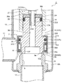
図1は、本発明に係る電動弁の第1実施形態の全閉状態を示す全体縦断面図、図2は、図1に示される電動弁の要部拡大縦断面図である。また、図3〜図8は、図1及び図2に示される電動弁の構成並びに動作説明に供される要部拡大縦断面図である。
[First Embodiment]
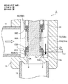
FIG. 1 is an overall vertical sectional view showing a fully closed state of the first embodiment of the electric valve according to the present invention, and FIG. 2 is an enlarged vertical sectional view of a main part of the electric valve shown in FIG. 3 to 8 are enlarged vertical cross-sectional views of the main parts provided for explaining the configuration and operation of the electric valve shown in FIGS. 1 and 2.
なお、本明細書において、上下、左右、前後等の位置、方向を表わす記述は、説明が煩瑣になるのを避けるために図面に従って便宜上付けたものであり、実際にシステムに組み込まれた状態での位置、方向を指すとは限らない。 In this specification, the descriptions indicating the positions and directions such as up / down, left / right, front / back, etc. are added for convenience according to the drawings in order to avoid complicated explanations, and are actually incorporated in the system. It does not always point to the position and direction of.
また、各図において、部材間に形成される隙間や部材間の離隔距離等は、発明の理解を容易にするため、また、作図上の便宜を図るため、各構成部材の寸法に比べて大きくあるいは小さく描かれている場合がある。 Further, in each drawing, the gap formed between the members, the separation distance between the members, etc. are larger than the dimensions of each constituent member in order to facilitate understanding of the invention and for convenience in drawing. Or it may be drawn small.
図示実施形態の電動弁1は、例えばヒートポンプ式冷暖房システムにおいて膨張弁として使用するのに好適なもので、流体(冷媒)が双方向(横から下への第1流れ方向と下から横への第2流れ方向)に流されるようになっている。また、本実施形態の電動弁1は、後述するように、ロータとねじ送り機構との間に遊星歯車式減速機構を介装し、主弁体の軸力を高めてシール性を向上させるようになっている。
The
電動弁1は、板金製の有底の筒状基体10Aを有する弁本体10と、この弁本体10内に上下動可能に配在された主弁体20と、この主弁体20を上下動させるべく、弁本体10の上側に取り付けられたステッピングモータ50とを備える。
The
弁本体10の筒状基体10Aには、弁室7が形成されるとともに、その側部に、弁室7に開口する横向きの第1入出口(導管継手)11が取り付けられ、その底部に、下側から弁室7に開口する縦向きの弁口9、該弁口9の上端内周角部からなる主弁シート8a、該弁口9の上部外周円錐台面からなる副弁シート8bが形成された段付きの弁座部材8が固着され、この弁座部材8に、前記弁口9に連なる第2入出口(導管継手)12が取り付けられている。
A
筒状基体10Aの上面開口部には、段付きの筒状基台13が取着され、この筒状基台13の上端部には、ステッピングモータ50の一部を構成する天井部付き円筒状のキャン58の下端部が溶接等により密封接合されている。筒状基台13の内周側には隔壁14c付き筒状保持部材14が圧入等により固定され、この筒状保持部材14の上部には、下部内周にめねじ15iが設けられた軸受部材15がかしめ係止固定されている。筒状保持部材14の隔壁14cの直上は、圧縮コイルばねからなる開弁ばね25が収納されるばね室14aとされている。
A stepped
また、前記主弁体20は、段付き円筒状を有し、主弁シート8aに対して垂直方向に上下動して弁口9を開閉するポペット弁とされている。この主弁体20は、図2を参照すればよくわかるように、前記弁座部材8の主弁シート8aに接離して弁口9を開閉する若干大径の主弁体部20Aと、この主弁体部20Aより上側の胴部20Bとを有し、胴部20Bの上部が筒状保持部材14における隔壁14cより下側の弁体ガイド穴14bに摺動自在に嵌挿されている。主弁体部20Aの下面外周部には、所要のシール性が得られるように、前記主弁シート8aに対して実質的に線接触する逆円錐台状のシール面20aが設けられている。
Further, the
そして、本実施形態では、前記主弁体20の下部外周側に、弁口9を開閉するための副弁体30が上下方向に摺動可能に配設されている。すなわち、上記した如くに、弁本体10における弁座部材8(弁口9)の上部内周側(角部)に、主弁体部20A(のシール面20a)が接離する主弁シート8aが設けられ、この主弁シート8aとは別個に、弁座部材8の上部外周側に、副弁体30のシール面(下端内周側角部)30aが接離する円錐台状の副弁シート8bが設けられている。この副弁体30は、主弁体20の下部外周に摺動自在に外挿された円筒状部30Aを有し、当該円筒状部30A(のシール面(下端内周側角部)30a)が前記副弁シート8bに対して垂直方向に上下動して弁口9を開閉するようにされている。
Then, in the present embodiment, the
より詳細には、主弁体部20Aに、抜止係止部とばね受け部とを兼ねる(詳しくは、上面が抜止係止部とされ、下面がばね受け部とされる)上側鍔状部20Cが設けられるとともに、この上側鍔状部20Cより下側に、下側鍔状部30B付き円筒状の(言い換えれば、下側鍔状部30B付きの円筒状部30Aを持つ)副弁体30が摺動自在に外挿されている。この副弁体30の外周側には、上側鍔状部20Cに係止される内鍔状引っ掛け部32Bがその上端部に設けられるとともに、前記下側鍔状部30Bの上面外周部にその下端部が溶接等で固着された円筒状抜止部材32が配設され、前記上側鍔状部20C(の下面)と前記下側鍔状部30B(の上面)との間に前記副弁体30を常時下方(閉弁方向)に付勢する付勢部材としての圧縮コイルばね33が縮装されている。
More specifically, the main
また、円筒状抜止部材32の円筒部32Aと上側鍔状部20Cとの間(詳細には、上側鍔状部20Cの外周に形成された環状溝)には、シール部材としてのOリング34が介装されている。
Further, an O-
前記副弁体30は、主弁体20が開弁状態から閉弁せしめられる際、弁口9を主弁体20より先に閉弁するように、各部の寸法形状が設定されている(後で詳述)。
The dimensions and shape of each part of the
一方、弁本体10(の筒状基体10A)の上側に配置されたステッピングモータ50は、ヨーク51、ボビン52、コイル53、樹脂モールド54等からなる2相のコイル部を有し、キャン58に外嵌固定されたステータ55と、キャン58内に回転自在に配在され、ロータ支持部材56がその上部内側に固着されたロータ57とを有している。また、ロータ57の内周側には、ロータ支持部材56に一体的に設けられた太陽歯車41、筒状保持部材14の上端部に固着された筒状体14dの先端に固定された固定リング歯車47、前記太陽歯車41及び固定リング歯車47に歯合する遊星歯車42、該遊星歯車42を回転自在に支持するキャリア44、前記遊星歯車42に歯合するリング状の出力歯車45、該出力歯車45に固着された出力軸46等からなる不思議遊星歯車式減速機構40が付設されている。前記固定リング歯車47の歯数は、前記出力歯車45の歯数とは異なるようにされている。
On the other hand, the stepping
前記出力軸46の上部に設けられた穴に支持軸49の下部が挿通されており、該支持軸49に前記キャリア44、太陽歯車41(ロータ支持部材56)が挿通されている。
The lower part of the
キャン58内部において、該キャン58の天井部とロータ支持部材56との間には、該キャン58の内径とほぼ同一径を有する支持部材48が配置され、前記支持軸49の上部は、支持部材48の中心部に設けられた穴に挿通されている。
Inside the
前記不思議遊星歯車式減速機構40の出力軸46は、軸受部材15の上部に回転自在に嵌挿され、この出力軸46の回転が、前記軸受部材15に設けられためねじ15iに螺合するおねじ17eが設けられた回転上下動軸17に伝達される。出力軸46の下部にはスリット状嵌合部46aが設けられ、回転上下動軸17の上部には前記スリット状嵌合部46aに摺動自在に嵌合する板状部17aが突設されており、出力軸46が回転すると、前記めねじ15iとおねじ17eによるねじ送りにより回転上下動軸17が回転しながら上下動せしめられる。
The
回転上下動軸17の下方には、該回転上下動軸17の下方への推力がボール18、ボール受座19を介して伝達される段付き筒状の推力伝達部材23が配在されている。なお、ボール18を介在させていることにより、回転上下動軸17が回転しながら下降しても、回転上下動軸17から推力伝達部材23へは下方への推力のみが伝達され、回転力は伝達されない。
Below the rotary
推力伝達部材23は、上から順に、内周に前記ボール受座19が嵌め込まれた大径上部23a、前記筒状保持部材14の隔壁14cに摺動自在に挿通せしめられる中間胴部23b、該中間胴部23bより小径の小径下部23cからなっており、その内部に、後述する均圧通路26の上部を構成する貫通孔26d及び後述する背圧室27に開口する複数個の横孔26eが設けられている。なお、貫通孔26dの上端開口はボール受座19により閉塞されている。
The
推力伝達部材23の小径下部23cは、段付き円筒状の主弁体20の上部嵌合穴20dに圧入等により嵌合固定され、主弁体20と推力伝達部材23とは一体に上下動せしめられる。主弁体20の上端面と推力伝達部材23の中間胴部23bの下端段差部との間には、前記小径下部23cの圧入時において押さえ部材24が挟み込まれて固定されており、この押さえ部材24と主弁体20の上端部に設けられた環状溝と前記筒状保持部材14の弁体ガイド穴14bとの間には、Oリング、リング状パッキンからなるシール部材29が装着されている。
The small-diameter
また、筒状保持部材14の隔壁14cより上側のばね室14aには、圧縮コイルばねからなる開弁ばね25がその下端を隔壁14cに当接させた状態で縮装されるとともに、この開弁ばね25の付勢力(引き上げ力)を推力伝達部材23を介して主弁体20に伝達すべく、上下に鍔状引っ掛け部(上引っ掛け部28a、下引っ掛け部28b)を有する引き上げばね受け体28が配在されている。引き上げばね受け体28の上引っ掛け部28aは、開弁ばね25の上に乗せられ、下引っ掛け部28bは推力伝達部材23の大径上部23aの下端段差部を掛止するようになっている。
Further, in the
したがって、本実施形態では、めねじ15iが設けられた軸受部材15とおねじ17eが設けられた回転上下動軸17等でねじ送り機構が構成され、ステッピングモータ50(ロータ57)が一方向に回転せしめられるとき、前記めねじ15iとおねじ17eによるねじ送りにより回転上下動軸17が回転しながら例えば下動せしめられ、回転上下動軸17の推力により、推力伝達部材23及び主弁体20が開弁ばね25の付勢力に抗して押し下げられ、最終的には主弁体部20Aのシール面20aが主弁シート8aに押し付けられて弁口9が閉じられる。
Therefore, in the present embodiment, the screw feed mechanism is configured by the bearing
それに対し、ステッピングモータ50(ロータ57)が他方向に回転せしめられるときには、前記めねじ15iとおねじ17eによるねじ送りにより回転上下動軸17が回転しながら例えば上動せしめられ、それに伴い推力伝達部材23及び主弁体20が開弁ばね25の付勢力によって引き上げられ、主弁体部20Aのシール面20aが主弁シート8aからリフト(上昇)して弁口9を開くようにされている。
On the other hand, when the stepping motor 50 (rotor 57) is rotated in the other direction, the rotary
なお、副弁体30を含めた詳細な動作説明は後述する。
A detailed operation description including the
本実施形態では、前記主弁体20の上方で押さえ部材24と筒状保持部材14の隔壁14cとの間に、背圧室27が画成されている。また、主弁体20内には、該主弁体20の先端部(下端部)と背圧室27とを連通させる段付きの均圧通路26が設けられている。この均圧通路26は、前記した推力伝達部材23の縦穴26d及び横孔26eとともに背圧室27に連通している。ここでは、閉弁状態において主弁体20に作用する押し下げ力(閉弁方向に働く力)と主弁体20に作用する押し上げ力(開弁方向に働く力)とをバランス(差圧をキャンセル)させるべく、背圧室27の室径Daと弁口9の口径Dcとは略同一に設定されている。
In the present embodiment, the
次に、上記した如くの構成を有する電動弁1における副弁体30を含めた開閉動作を図2〜図8を参照しながら説明する。
Next, the opening / closing operation of the
まず、図2及び図5に示される如くに、閉弁動作が完了して主弁体20及び副弁体30が最も下方に位置する状態、すなわち、主弁体20が主弁シート8aに着座して押し付けられ、副弁体30が副弁シート8bに着座して押し付けられ、共に閉弁しているとき(全閉時)には、圧縮コイルばね33が上側鍔状部20Cに押し下げられて該上側鍔状部20Cの下面と副弁体30の円筒状部30Aの上端との間には間隙Laが空けられるとともに、上側鍔状部20Cの上面と円筒状抜止部材32の内鍔状引っ掛け部32Bの下面との間に間隙Lbが空けられる。
First, as shown in FIGS. 2 and 5, the valve closing operation is completed and the
一方、図3に示される如くに、横から下への第1流れ時において、ステッピングモータ50(ロータ57)が一方向に回転せしめられて、主弁体20が副弁体30を伴って下動しているとき、すなわち、主弁体20及び副弁体30が共に開状態の閉弁動作中(1)においては、圧縮コイルばね33の付勢力により副弁体30が押し下げられて、上側鍔状部20C(の上面)に円筒状抜止部材32の内鍔状引っ掛け部32B(の下面)が当接係止され、上側鍔状部20Cの下面と副弁体30の円筒状部30Aの上端との間には間隙La+Lbが空けられている。
On the other hand, as shown in FIG. 3, during the first flow from the side to the bottom, the stepping motor 50 (rotor 57) is rotated in one direction, and the
この閉弁動作中(1)において、本例では、主弁体20の下端より副弁体30の下端の方が下側に位置し、冷媒及びその中に含まれる異物(金属粉、削りカス、研磨材、スラッジ等)は、副弁体30と副弁シート8bとの間、及び、主弁体20と主弁シート8aとの間を通って流される。
During this valve closing operation (1), in this example, the lower end of the
続いて、図3に示される、主弁体20が小開、副弁体30が微開している状態から、図4に示される如くに、主弁体20がさらに下動せしめられて、副弁体30が副弁シート8bに着座して閉弁するまでの閉弁動作中(2)、すなわち、副弁体30と副弁シート8bとの間に形成される隙間が次第に小さくなって最終的に0になるときには、冷媒中に含まれる異物が副弁体30と副弁シート8bとの間に形成される微小隙間に堰き止められ、図4においてE1矢印で示される部位、すなわち、副弁体30と副弁シート8bとの間に形成される微小隙間の上流側(外周側)に溜まって詰まり気味となる。副弁体30が副弁シート8bに着座して閉弁したときには、異物は副弁体30によりブロックされて下流側(ここでは、内周側の主弁体20及び主弁シート8a側)には流れなくなる。
Subsequently, from the state shown in FIG. 3 in which the
このようにして副弁体30が微開状態から閉弁するまでの閉弁動作中(2)においては、主弁体20は小開状態から微開状態へと下動し、主弁体20を通過する冷媒流量が次第に小量となり、副弁体30が閉弁すると、冷媒は流れなくなり、流量が実質的に0となる。
In this way, during the valve closing operation (2) from the slightly opened state to the slightly opened state of the
続いて、主弁体20が図4に示される微開状態からさらに下動せしめられると、図5に示される如くに、主弁体20のシール面20aが主弁シート8aに着座して閉弁する。この場合、主弁体20は、不思議遊星歯車式減速機構40による高い軸力で主弁シート8aに強く押し付けられる。このとき、前述したように、圧縮コイルばね33が上側鍔状部20Cにより間隙Lb分だけ押し下げられて該上側鍔状部20Cの下面と副弁体30の円筒状部30Aの上端との間に形成される間隙がLa+LbからLaのみになるとともに、上側鍔状部20Cの上面と円筒状抜止部材32の内鍔状引っ掛け部32Bの下面との間に間隙Lbが空けられ、副弁体30が圧縮コイルばね33の付勢力により副弁シート8bに押し付けられる。
Subsequently, when the
ここで、副弁体30が副弁シート8bに着座して閉弁した際(図4に示される状態)、異物が副弁体30と副弁シート8bとの間に噛み込まれている場合には、Lb分圧縮される圧縮コイルばね33の付勢力により異物が副弁体30と副弁シート8bとに押し付けられるが、その押し付け力はさほど強くなく、したがって、副弁体30と副弁シート8bに傷、打痕等はつかない。
Here, when the
また、このときは、主弁体20が微開状態から閉弁しても、異物は副弁体30でブロックされていて、冷媒は実質的に流れなくなっているので、主弁体20と主弁シート8aとの間に異物を噛み込むことはなく、したがって、主弁体20が主弁シート8aに不思議遊星歯車式減速機構40による高い軸力で強く押し付けられても、主弁体20や主弁シート8aに傷、打痕等はつくことはない。
Further, at this time, even if the
図5に示される全閉状態から開弁するにあたっては、ステッピングモータ50(ロータ57)が他方向に回転せしめられ、これによって、図6に示される如くに、主弁体20が引き上げられる。この場合、主弁体20が間隙Lb分引き上げられると、主弁体20が閉弁状態から微開し、これによって、圧縮コイルばね33の付勢力により上側鍔状部20Cの上面に円筒状抜止部材32の内鍔状引っ掛け部32Bの下面が当接係止されるとともに、上側鍔状部20Cの下面と副弁体30の円筒状部30Aの上端との間に形成される間隙がLaからLa+Lbになり、副弁体30は閉弁したままであるが、圧縮コイルばね33による押し付け力は小さくなる。
When opening the valve from the fully closed state shown in FIG. 5, the stepping motor 50 (rotor 57) is rotated in the other direction, whereby the
この状態からさらに主弁体20が引き上げられると、副弁体30のシール面30aが副弁シート8bから離れ、図3に示される如くの、主弁体20が小開、副弁体30が微開している状態となる。
When the
以上は、横から下への第1流れ時についての説明であるが、下から横への第2流れ時においても、図7、図8(図3、図4に対応する状態)に示される如くに、主弁体20が小開、副弁体30が微開している状態から、主弁体20が下動せしめられて、副弁体30と副弁シート8bとの間に形成される隙間が次第に小さくなって最終的に0になるときには、冷媒中に含まれる異物が副弁体30と副弁シート8bとの間に形成される微小隙間に堰き止められ、図8においてE2矢印で示される部位、すなわち、主弁体20と主弁シート8aとの間に形成される隙間より下流側(外周側)で、副弁体30と副弁シート8bとの間に形成される微小隙間の上流側(内周側)に溜まって詰まり気味となる。
The above is the description of the first flow from the side to the bottom, but it is also shown in FIGS. 7 and 8 (states corresponding to FIGS. 3 and 4) even during the second flow from the bottom to the side. As described above, from the state where the
かかる副弁体30が微開状態から閉弁するまでの閉弁動作中(2)においては、主弁体20は小開状態から微開状態へと下動し、主弁体20を通過する冷媒流量が次第に小量となり、副弁体30が閉弁すると、冷媒は流れなくなるので、異物が主弁体20と主弁シート8aとの間の隙間に詰まることはない。
During the valve closing operation (2) from the slightly opened state to the slightly opened state of the
続いて、主弁体20が図8に示される微開状態からさらに下動せしめられると、主弁体20が主弁シート8aに着座して閉弁する。このとき、前述したように、圧縮コイルばね33が上側鍔状部20Cにより間隙Lb分だけ押し下げられて該上側鍔状部20Cの下面と副弁体30の円筒状部30Aの上端との間に形成される間隙がLa+LbからLaのみになるとともに、上側鍔状部20Cの上面と円筒状抜止部材32の内鍔状引っ掛け部32Bの下面との間に間隙Lbが空けられ、副弁体30が圧縮コイルばね33の付勢力により副弁シート8bに押し付けられる。
Subsequently, when the
ここで、本第2流れ時においても、副弁体30が副弁シート8bに着座して閉弁した際(図8に示される状態)、異物が副弁体30と副弁シート8bとの間に噛み込まれている場合には、Lb分圧縮される圧縮コイルばね33により異物が副弁体30と副弁シート8bとに押し付けられるが、その押し付け力はさほど強くなく、したがって、副弁体30と副弁シート8bに傷、打痕等はつかない。
Here, even during the second flow, when the
また、このときは、主弁体20が微開状態から閉弁しても、冷媒は実質的に流れなくなっているので、主弁体20と主弁シート8aとの間に異物を噛み込むことはほとんどなく、したがって、主弁体20が主弁シート8aに強く押し付けられても、主弁体20や主弁シート8aに傷、打痕等はつくことはない。
Further, at this time, even if the
このように、本実施形態の電動弁1においては、主弁体20の外周に、弁口9を主弁体20より先に閉弁する副弁体30が設けられているので、副弁体30が微開状態にあるとき、流体(冷媒)中に含まれる異物が副弁体30により堰き止められ、そこから副弁体30が閉弁すると流体(冷媒)が実質的に流れなくなるため、異物が主弁体20と主弁シート8aとの間に噛み込まれることはなく、したがって、主弁体20が閉弁して主弁シート8aに強く押し付けられても、主弁体20や主弁シート8aに傷、打痕等はつくことはない。
As described above, in the
また、異物は副弁体30と副弁シート8bとの間に噛み込まれるおそれがあるが、副弁体30は圧縮コイルばね33により付勢されているだけであるので、その押し付け力はさほど強くなく、したがって、副弁体30と副弁シート8bに傷、打痕等はつかない。
Further, foreign matter may be caught between the
また、異物が副弁体30と副弁シート8bとの間に噛み込まれて、それらの間に隙間が生じても、主弁体20は閉弁しているので、弁漏れは生じない。
Further, even if a foreign substance is caught between the
このように、本第1実施形態の歯車減速式の電動弁1では、シール性を高めて弁漏れを確実に防ぐべく、ロータ57とねじ送り機構(めねじ15iが設けられた軸受部材15、おねじ17eが設けられた回転上下動軸17)との間に不思議遊星歯車式減速機構40を介装し、主弁体20の軸力、すなわち、主弁体20の主弁シート8aへの押し付け力を増大するようにしたものにおいて、流体(冷媒)中に含まれる異物が主弁体20と主弁シート8aとの間に噛み込まれてそれらに強く押し付けられるような事態を生じ難くでき、そのため、主弁シート8a、副弁シート8bや主弁体20、副弁体30に傷、打痕等がつかないようにでき、その結果、弁漏れを効果的に防止して、閉弁の信頼性を向上させることができる。
As described above, in the gear reduction type
[第2実施形態]
図9は、本発明に係る電動弁の第2実施形態の全閉状態を示す全体縦断面図である。また、図10〜図13は、図9に示される電動弁の構成並びに動作説明に供される要部拡大縦断面図である。
[Second Embodiment]
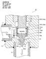
FIG. 9 is an overall vertical sectional view showing a fully closed state of the second embodiment of the electric valve according to the present invention. 10 to 13 are enlarged vertical cross-sectional views of the main parts provided for explaining the configuration and operation of the electric valve shown in FIG. 9.
図示第2実施形態の電動弁2は、図1〜図8に示される第1実施形態の電動弁1と、主弁体及び副弁体周り以外は略同様な構成である。そのため、第1実施形態の電動弁1の各部に対応する部分並びに同様の機能を有する部分には共通の符号を付して重複説明を省略し、以下においては、主弁体及び副弁体周りを中心に説明する。
The
図示実施形態の電動弁2において、弁本体10を構成する筒状基体10Bは、底部付き大径の下部円筒部10a、中間厚肉部10b、及びキャン58に挿入された上部円筒部10cを有する。筒状基体10Bの下部円筒部10aには、弁室7が形成されるとともに、その側部に、弁室7に開口する横向きの第1入出口(導管継手)11が取り付けられ、その底部に、下側から弁室7に開口する縦向きの弁口9、該弁口9の上端内周角部からなる主弁シート8a、及び該弁口9の上部外周円錐台面からなる副弁シート8bが形成された弁座部8が一体に設けられ(図10〜図13参照)、この弁座部8に、前記弁口9に連なる第2入出口(導管継手)12が取り付けられている。
In the
筒状基体10Bの中間厚肉部10bの外周段差部には、リング状基台13が取着され、このリング状基台13の上端外周部には、天井部付き円筒状のキャン58の下端部が溶接等により密封接合されている。リング状基台13の内周側には筒状基体10Bの上部円筒部10cの基部が圧入等により固定され、この筒状基体10Bの上部円筒部10cに、下部内周にめねじ15iが設けられた軸受部材15がかしめ係止固定されている。
A ring-shaped
この軸受部材15の下面と筒状基体10Bの中間厚肉部10bの内周段差部との間には、ばね受け部と主弁体案内部とを兼ねる板金製の段付き円筒体65の上端鍔状部65Dが挟持されている。段付き円筒体65は、間に円環状の段差(段丘)部65Cを介して、主弁体70(の胴部70B)が摺動自在に嵌挿された下部小径案内部65Aと、前記上端鍔状部65Dが設けられた上部大径部65Bとを有し、該段差部65Cと推力伝達部材23の大径上部23aとの間に、圧縮コイルばねからなる開弁ばね25が縮装されている。
Between the lower surface of the bearing
また、前記主弁体70は、主弁シート8aに対して垂直方向に上下動して弁口9を開閉するポペット弁とされている。この主弁体70は、前記弁座部8の主弁シート8aに接離して弁口9を開閉する大径の主弁体部70Aと、この主弁体部70Aより上側の小径の胴部70Bと、前記推力伝達部材23の小径下部23cに圧入等で固着された上凸部70Cとを有し、胴部70Bが段付き円筒体65の下部小径案内部65Aに摺動自在に嵌挿されている。主弁体部70Aの下面外周部には、所要のシール性が得られるように、前記主弁シート8aに対して実質的に線接触する逆円錐台状のシール面70aが設けられている(図10〜図13参照)。
Further, the
そして、本実施形態では、前記主弁体70の下部外周側に、弁口9を開閉するための副弁体80が上下方向に摺動可能に配設されている。すなわち、上記した如くに、弁本体10における弁座部8(弁口9)の上部内周側(角部)に、主弁体部70Aのシール面70aが接離する主弁シート8aが設けられ、この主弁シート8aとは別個に、弁座部8の上部外周側に、副弁体80のシール面(下端内周側角部)80aが接離する円錐台状の副弁シート8bが設けられている。
Then, in the present embodiment, a
副弁体80は、主弁体70の主弁体部70Aの外周に摺動自在に外挿される大径外挿部80Aと、主弁体70の胴部70Bに摺動自在に外挿される小径外挿部80Bと、大径外挿部80Aと小径外挿部80Bとの間の、抜止係止部とばね受け部とを兼ねる(詳しくは、下面が抜止係止部とされ、上面がばね受け部とされる)円環状の段差(段丘)部80Cと、からなる段付き円筒状とされ、段差部80Cと弁本体10に設けられた該段差部80Cより上側の不動部分である段付き円筒体65の段差部65Cとの間に副弁体80を常時下方(閉弁方向)に付勢する付勢部材としての圧縮コイルばね73が縮装されている。ここでは、大径外挿部80A(のシール面(下端内周側角部)80a)が前記副弁シート8bに対して垂直方向に上下動して弁口9を開閉するようにされている。
The
なお、副弁体84の小径外挿部80Bと主弁体70の胴部70Bとの摺動面間にOリング等のシール部材を介装してもよい。
A seal member such as an O-ring may be interposed between the sliding surfaces of the small
次に、上記した如くの構成を有する電動弁2における副弁体80を含めた開閉動作を図10〜図13を参照しながら説明する。
Next, the opening / closing operation of the
まず、図12に示される如くに、閉弁動作が完了した状態、すなわち、主弁体70が主弁シート8aに着座して押し付けられ、副弁体80が副弁シート8bに着座して押し付けられ、共に閉弁しているとき(全閉時)には、主弁体部70Aの上面と副弁体80の段差部80Cの下面との間には間隙Lcが空けられる。
First, as shown in FIG. 12, the valve closing operation is completed, that is, the
一方、図10に示される如くに、横から下への第1流れ時において、ステッピングモータ50(ロータ57)が一方向に回転せしめられて、主弁体70が副弁体80を伴って下動している閉弁動作中(1)においては、圧縮コイルばね73の付勢力により副弁体80が押し下げられて、主弁体部70Aの上面に副弁体80の段差部80Cが当接係止され、本例では、主弁体70の下端より副弁体80の下端の方が下側に位置し、冷媒及びその中に含まれる異物(金属粉、削りカス、研磨材、スラッジ等)は、副弁体80と副弁シート8bとの間、及び、主弁体70と主弁シート8aとの間を通って流される。
On the other hand, as shown in FIG. 10, during the first flow from the side to the bottom, the stepping motor 50 (rotor 57) is rotated in one direction, and the
続いて、図10に示される、主弁体70が小開、副弁体80が微開している状態から、図11に示される如くに、主弁体70がさらに下動せしめられて、副弁体80が副弁シート8bに着座して閉弁するまでの閉弁動作中(2)、すなわち、副弁体80と副弁シート8bとの間に形成される隙間が次第に小さくなって最終的に0になるときには、冷媒中に含まれる異物が副弁体80と副弁シート8bとの間に形成される微小隙間に堰き止められ、図11においてE1矢印で示される部位、すなわち、副弁体80と副弁シート8bとの間に形成される微小隙間の上流側(外周側)に溜まって詰まり気味となる。副弁体80が副弁シート8bに着座して閉弁したときには、異物は副弁体80によりブロックされて下流側(ここでは、内周側の主弁体70及び主弁シート8a側)には流れなくなる。
Subsequently, from the state shown in FIG. 10 in which the
このようにして副弁体80が微開状態から閉弁するまでの閉弁動作中(2)においては、主弁体70は小開状態から微開状態へと下動し、主弁体70を通過する冷媒流量が次第に小量となり、副弁体80が閉弁すると、冷媒は流れなくなり、流量が実質的に0となる。
In this way, during the valve closing operation (2) from the slightly opened state to the slightly opened state of the
続いて、主弁体70が図11に示される微開状態からさらに下動せしめられると、図12に示される如くに、副弁体80が圧縮コイルばね73の付勢力により副弁シート8bに押し付けられ、主弁体70が主弁シート8aに着座して不思議遊星歯車式減速機構40による高い軸力で主弁シート8aに強く押し付けられ、全閉状態となる。この全閉時には、前述したように、主弁体部70Aの上面と副弁体80の段差部80Cの下面との間には間隙Lcが空けられる。
Subsequently, when the
ここで、副弁体80が副弁シート8bに着座して閉弁した際(図11に示される状態)、異物が副弁体80と副弁シート8bとの間に噛み込まれている場合には、圧縮コイルばね73の付勢力により異物が副弁体80と副弁シート8bとに押し付けられるが、その押し付け力はさほど強くなく、したがって、副弁体80と副弁シート8bに傷、打痕等はつかない。
Here, when the
また、このときは、主弁体70が微開状態から閉弁しても、異物は副弁体80でブロックされていて、冷媒は実質的に流れなくなっているので、主弁体70と主弁シート8aとの間に異物を噛み込むことはなく、したがって、主弁体70が主弁シート8aに不思議遊星歯車式減速機構40による高い軸力で強く押し付けられても、主弁体70や主弁シート8aに傷、打痕等はつくことはない。
Further, at this time, even if the
図12に示される全閉状態から開弁するにあたっては、ステッピングモータ50(ロータ57)が他方向に回転せしめられ、これによって、図13に示される如くに、主弁体70が引き上げられて開弁する。この場合、主弁体70が間隙Lc分引き上げられると、主弁体部70Aの上面が副弁体80の段差部80Cの下面に当接し、これ以上主弁体70が引き上げられると、それに伴って副弁体80が引き上げられ、副弁体80のシール面80aが副弁シート8bから離れて、副弁体80も開弁する。
When opening the valve from the fully closed state shown in FIG. 12, the stepping motor 50 (rotor 57) is rotated in the other direction, whereby the
以上は、横から下への第1流れ時についての説明であるが、下から横への第2流れ時においても、上記第1流れ時と同様の動作となり、図7、図8を用いて前述した第1実施形態の第2流れ時の作用効果と同様の作用効果が得られる。 The above is the description of the first flow from the side to the bottom, but the operation is the same as the first flow from the bottom to the side during the second flow, and FIGS. 7 and 8 are used. The same effect as that of the second flow of the first embodiment described above can be obtained.
このように、本第2実施形態の電動弁2においても、主弁体70の外周に、弁口9を主弁体70より先に閉弁する副弁体80が設けられているので、副弁体80が微開状態にあるとき、流体(冷媒)中に含まれる異物が副弁体80により堰き止められ、そこから副弁体80が閉弁すると流体(冷媒)が実質的に流れなくなるため、異物が主弁体70と主弁シート8aとの間に噛み込まれることはなく、したがって、主弁体70が閉弁して主弁シート8aに強く押し付けられても、主弁体70や主弁シート8aに傷、打痕等はつくことはない。
As described above, also in the
また、異物は副弁体80と副弁シート8bとの間に噛み込まれるおそれがあるが、副弁体80は圧縮コイルばね73により付勢されているだけであるので、その押し付け力はさほど強くなく、したがって、副弁体80と副弁シート8bに傷、打痕等はつかない。
Further, foreign matter may be caught between the
また、異物が副弁体80と副弁シート8bとの間に噛み込まれて、それらの間に隙間が生じても、主弁体70は閉弁しているので、弁漏れは生じない。
Further, even if a foreign substance is caught between the
このように、本第2実施形態の歯車減速式の電動弁2においても、流体(冷媒)中に含まれる異物が主弁体70と主弁シート8aとの間に噛み込まれてそれらに強く押し付けられるような事態を生じ難くでき、そのため、主弁シート8a、副弁シート8bや主弁体70、副弁体80に傷、打痕等がつかないようにでき、その結果、弁漏れを効果的に防止して、閉弁の信頼性を向上させることができる。
As described above, even in the gear reduction type
[第3実施形態]
図14〜図17は、本発明に係る電動弁の第3実施形態の構成並びに動作説明に供される要部拡大縦断面図である。
[Third Embodiment]
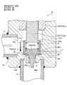
14 to 17 are enlarged vertical cross-sectional views of main parts provided for the configuration and operation description of the third embodiment of the electric valve according to the present invention.
図示第3実施形態の電動弁3は、図9〜図13に示される第2実施形態の電動弁2と主弁体及び副弁体周り以外は略同様な構成である。そのため、第2実施形態の電動弁2の各部に対応する部分並びに同様の機能を有する部分には共通の符号を付して重複説明を省略し、以下においては、主弁体及び副弁体周りを中心に説明する。
The
図示実施形態の電動弁3においては、上記第2実施形態の電動弁2とは逆に、弁座部8の外周側(角部)に主弁シート8aが設けられ、弁座部8の内周側(角部)に副弁シート8bが設けられている。また、主弁体72が円筒状とされ、副弁体82が逆円錐台状とされ、主弁体72(の主弁体部72Aの逆円錐台状のシール面72a)が副弁体82(の逆円錐台状のシール面82a)より外周側(換言すれば、副弁体82が主弁体72より内側)に位置している。
In the
詳細には、主弁体72は、円筒状胴部72Bと、円筒状胴部72Bの下端から外向きに突設され、逆円錐台状のシール面72aを有する鍔状の主弁体部72Aと、円筒状胴部72Bの上端から内向きに突設され、第2実施形態における胴部70Bの下端部に圧入等により固着される上端内鍔状部72Cとを有する。
Specifically, the
前記胴部70Bの下部中央には、副弁体82が摺動自在に外挿された副弁体支持棒75の上端部が圧入等により固着されている。この副弁体支持棒75の下端部には、副弁体82の先端面(下端面)に設けられた下端凹部83に嵌り込んで該副弁体82を抜止係止する大径の抜止係止部75aが設けられている。ここでは、副弁体82の先端面(下端面)が、主弁シート8aの内側で副弁シート8bに対して垂直方向に上下動して弁口9を開閉する逆円錐台状のシール面82aとなっている。
The upper end of the
また、主弁体72の上端内鍔状部72Cと副弁体82との間には、副弁体82を常時下方(閉弁方向)に付勢する圧縮コイルばね77が縮装されている。
Further, a
次に、上記した如くの構成を有する電動弁3における副弁体82を含めた開閉動作を図14〜図17を参照しながら説明する。
Next, the opening / closing operation of the
まず、図16に示される如くに、閉弁動作が完了した状態、すなわち、主弁体72が主弁シート8aに着座して押し付けられ、副弁体82が副弁シート8bに着座して押し付けられ、共に閉弁しているとき(全閉時)には、副弁体82の下端凹部83の上面と副弁体支持棒75の抜止係止部75aの上面との間には間隙Ldが空けられる。
First, as shown in FIG. 16, the valve closing operation is completed, that is, the
一方、図14に示される如くに、横から下への第1流れ時において、ステッピングモータ50(ロータ57)が一方向に回転せしめられて、主弁体72が副弁体82を伴って下動している閉弁動作中(1)においては、圧縮コイルばね77の付勢力により副弁体82が押し下げられて、副弁体82が副弁体支持棒75の抜止係止部75aに当接係止され、本例では、主弁体72の下端より副弁体82の下端の方が下側に位置し、冷媒及びその中に含まれる異物(金属粉、削りカス、研磨材、スラッジ等)は、副弁体82と副弁シート8bとの間、及び、主弁体72と主弁シート8aとの間を通って流される。
On the other hand, as shown in FIG. 14, during the first flow from the side to the bottom, the stepping motor 50 (rotor 57) is rotated in one direction, and the
続いて、図14に示される、主弁体72が小開、副弁体82が微開している状態から、図15に示される如くに、主弁体72がさらに下動せしめられて、副弁体82が副弁シート8bに着座して閉弁するまでの閉弁動作中(2)、すなわち、副弁体82と副弁シート8bとの間に形成される隙間が次第に小さくなって最終的に0になるときには、冷媒中に含まれる異物が副弁体82と副弁シート8bとの間に形成される微小隙間に堰き止められ、副弁体82と副弁シート8bとの間に形成される微小隙間の上流側(外周側)に溜まって詰まり気味となる。副弁体82が副弁シート8bに着座して閉弁したときには、異物は副弁体82によりブロックされて下流側(ここでは、内周側の弁口9側)には流れなくなる。
Subsequently, from the state shown in FIG. 14 in which the
このようにして副弁体82が微開状態から閉弁するまでの閉弁動作中(2)においては、主弁体72は小開状態から微開状態へと下動し、主弁体72を通過する冷媒流量が次第に小量となり、副弁体82が閉弁すると、冷媒は流れなくなり、流量が実質的に0となる。
In this way, during the valve closing operation (2) from the slightly opened state to the slightly opened state of the
続いて、主弁体72が図15に示される微開状態からさらに下動せしめられると、図16に示される如くに、副弁体82が圧縮コイルばね77の付勢力により副弁シート8bに押し付けられ、主弁体72が主弁シート8aに着座して不思議遊星歯車式減速機構40による高い軸力で主弁シート8aに強く押し付けられ、全閉状態となる。この全閉時には、前述したように、副弁体82の下端凹部83の上面と副弁体支持棒75の抜止係止部75aの上面との間には間隙Ldが空けられる。
Subsequently, when the
ここで、副弁体82が副弁シート8bに着座して閉弁した際(図15に示される状態)、異物が副弁体82と副弁シート8bとの間に噛み込まれている場合には、圧縮コイルばね77の付勢力により異物が副弁体82と副弁シート8bとに押し付けられるが、その押し付け力はさほど強くなく、したがって、副弁体82と副弁シート8bに傷、打痕等はつかない。
Here, when the
また、このときは、主弁体72が微開状態から閉弁しても、異物は副弁体82でブロックされるとともに、冷媒は実質的に流れなくなっているので、主弁体72と主弁シート8aとの間に異物を噛み込むことはほとんどなく、したがって、主弁体72が主弁シート8aに不思議遊星歯車式減速機構40による高い軸力で強く押し付けられても、主弁体72や主弁シート8aに傷、打痕等はつくことはない(図7、図8を用いて前述した第1実施形態の第2流れ時の動作説明を併せて参照)。
Further, at this time, even if the
図16に示される全閉状態から開弁するにあたっては、ステッピングモータ50(ロータ57)が他方向に回転せしめられ、これによって、図17に示される如くに、主弁体72が引き上げられて開弁する。この場合、主弁体72が間隙Ld分引き上げられると、副弁体82の下端凹部83の上面に副弁体支持棒75の抜止係止部75aの上面が当接し、これ以上主弁体72が引き上げられると、それに伴って副弁体82が引き上げられ、副弁体82のシール面82aが副弁シート8bから離れて、副弁体82も開弁する。
When opening the valve from the fully closed state shown in FIG. 16, the stepping motor 50 (rotor 57) is rotated in the other direction, whereby the
以上は、横から下への第1流れ時についての説明であるが、下から横への第2流れ時においても、上記第1流れ時と同様の動作となり、図7、図8を用いて前述した第1実施形態の第2流れ時や図9〜図13を用いて前述した第2実施形態の第1流れ時の作用効果と同様の作用効果が得られる。 The above is the description of the first flow from the side to the bottom, but the operation is the same as the first flow from the bottom to the side during the second flow, and FIGS. 7 and 8 are used. The same effects as those at the time of the second flow of the above-mentioned first embodiment and at the time of the first flow of the above-mentioned second embodiment can be obtained by using FIGS. 9 to 13.
なお、図14〜図17に示される例では、弁座部8の外周側角部に主弁シート8aが設けられ、弁座部8の内周側角部に副弁シート8bが設けられているが、例えば、図18に示されるように、弁座部8の上面を傾斜面とし、その傾斜面に主弁シート8aを設けるとともに、その傾斜面の内端(角部)に副弁シート8bを設けてもよい。また、この場合、主弁体72の円筒状胴部72Bの下端部を、シール面72aを有する主弁体部72Aとしてもよい。
In the examples shown in FIGS. 14 to 17, the
このように、本第3実施形態の電動弁3においても、第1実施形態及び第2実施形態の電動弁1、2と同様に、主弁体72の内周に、弁口9を主弁体72より先に閉弁する副弁体82が設けられているので、副弁体82が微開状態にあるとき、流体(冷媒)中に含まれる異物が副弁体82により堰き止められ、そこから副弁体82が閉弁すると流体(冷媒)が実質的に流れなくなるため、異物が主弁体72と主弁シート8aとの間に噛み込まれることはなく、したがって、主弁体72が閉弁して主弁シート8aに強く押し付けられても、主弁体72や主弁シート8aに傷、打痕等はつくことはない。
As described above, also in the
また、異物は副弁体82と副弁シート8bとの間に噛み込まれるおそれがあるが、副弁体82は圧縮コイルばね73により付勢されているだけであるので、その押し付け力はさほど強くなく、したがって、副弁体82と副弁シート8bに傷、打痕等はつかない。
Further, foreign matter may be caught between the
また、異物が副弁体82と副弁シート8bとの間に噛み込まれて、それらの間に隙間が生じても、主弁体72は閉弁しているので、弁漏れは生じない。
Further, even if a foreign substance is caught between the
このように、本第3実施形態の歯車減速式の電動弁3においても、流体(冷媒)中に含まれる異物が主弁体72と主弁シート8aとの間に噛み込まれてそれらに強く押し付けられるような事態を生じ難くでき、そのため、主弁シート8a、副弁シート8bや主弁体72、副弁体82に傷、打痕等がつかないようにでき、その結果、弁漏れを効果的に防止して、閉弁の信頼性を向上させることができる。
As described above, even in the gear reduction type
[第4実施形態]
図19は、本発明に係る電動弁の第4実施形態の全閉状態を示す全体縦断面図である。また、図20〜図23は、図19に示される電動弁の構成並びに動作説明に供される要部拡大縦断面図である。
[Fourth Embodiment]
FIG. 19 is an overall vertical sectional view showing a fully closed state of the fourth embodiment of the electric valve according to the present invention. 20 to 23 are enlarged vertical cross-sectional views of the main parts provided for explaining the configuration and operation of the electric valve shown in FIG.
図示第4実施形態の電動弁4は、直動式のものであり、主に、図9〜図13に示される第2実施形態の電動弁2から不思議遊星歯車式減速機構40及びそれに関連する部分を取り除いた構成とされ、主弁体及び副弁体等は第2実施形態のものに類似した形状とされている。そのため、第2実施形態の電動弁2の各部に対応する部分並びに同様の機能を有する部分には共通の符号を付して重複説明を省略し、以下においては、相違点を中心に説明する。すなわち、まず、副弁体を除く基本の全体構成を説明し、その後に、副弁体を含む本発明の特徴部分を説明する。なお、本第4実施形態の電動弁4において、詳細構造及び動作の説明は、必要なら前記した特許文献1等を参照されたい。
The
図示実施形態の電動弁4は、基本的には、主弁体74が一体に設けられた弁軸125と、弁室7、弁口9、弁座部8等が設けられた有底の筒状基体10Bを有する弁本体10と、この弁本体10にその下端部が溶接等により密封接合された天井部付き円筒状のキャン58と、このキャン58の内周に所定の間隙をあけて配在されたロータ57、及び、このロータ57を回転駆動すべく前記キャン58に外嵌されたステータ55からなるステッピングモータ50と、前記ロータ57と前記主弁体74との間に配在され、前記ロータ57の回転を利用して主弁体74を弁座部8に形成された主弁シート8aに接離させるねじ送り機構とを備える。
The
前記ロータ57には、支持リング136が一体的に結合されるとともに、この支持リング136に、前記弁軸125及びガイドブッシュ126の外周に配在された下方開口で筒状の弁軸ホルダ132の上部突部がかしめ固定され、これにより、ロータ57、支持リング136及び弁軸ホルダ132が一体的に連結されている。
A
前記ねじ送り機構は、弁本体10の筒状基体10Bに設けられた嵌合穴142にその下端部126aが圧入固定されるとともに、弁軸125(の下部大径部125a)が摺動自在に内挿された筒状のガイドブッシュ126の外周に形成された固定ねじ部(おねじ部)128と、前記弁軸ホルダ132の内周に形成されて前記固定ねじ部128に螺合せしめられた移動ねじ部(めねじ部)138とから構成されている。
In the screw feed mechanism, the
また、前記ガイドブッシュ126の上部小径部126bが弁軸ホルダ132の上部に内挿されるとともに、弁軸ホルダ132の天井部中央(に形成された通し穴)に弁軸125の上部小径部125bが挿通せしめられている。弁軸125の上部小径部125bの上端部(弁軸ホルダ132の通し穴から上側に突出する部分)にはプッシュナット133が圧入固定されている。
Further, the upper
また、前記弁軸125は、該弁軸125の上部小径部125bに外挿され、かつ、弁軸ホルダ132の天井部と弁軸125における下部大径部125aの上端段丘面との間に縮装された圧縮コイルばねからなる閉弁ばね134によって、常時下方(閉弁方向)に付勢されている。弁軸ホルダ132の天井部上でプッシュナット133の外周には、コイルばねからなる復帰ばね135が設けられている。
Further, the
前記ガイドブッシュ126には、前記ロータ57が所定の閉弁位置まで回転下降せしめられた際、それ以上の回転下降を阻止するための回転下降ストッパ機構の一方を構成する下ストッパ体(固定ストッパ)127が固着され、弁軸ホルダ132には前記回転下降ストッパ機構の他方を構成する上ストッパ体(移動ストッパ)137が外装されて固着されている。
The
このような構成とされた直動式の電動弁4においても、ステッピングモータ50(ロータ57)が一方向に回転せしめられるときには、固定ねじ部(おねじ部)128とこれに螺合せしめられた移動ねじ部(めねじ部)138とからなるねじ送りにより弁軸125が回転しながら例えば下動せしめられ、最終的には主弁体74のシール面74aが主弁シート8aに押し付けられて(図20〜図23参照)弁口9が閉じられる。
Even in the linear-acting
それに対し、ステッピングモータ50(ロータ57)が他方向に回転せしめられるときには、固定ねじ部(おねじ部)128とこれに螺合せしめられた移動ねじ部(めねじ部)138とからなるねじ送りにより弁軸125が回転しながら例えば上動せしめられ、それに伴い主弁体74のシール面74aが主弁シート8aから離れて(図20〜図23参照)弁口9を開くようにされている。
On the other hand, when the stepping motor 50 (rotor 57) is rotated in the other direction, the screw feed is composed of the fixing screw portion (male screw portion) 128 and the moving screw portion (female screw portion) 138 screwed to the fixing screw portion (male screw portion) 128. The
次に、上記電動弁4の主弁体74及び副弁体84周りの構成を図20〜図23を参照しながら説明する。
Next, the configurations around the
本実施形態の電動弁4において、主弁体74は、弁軸125の下部に連設された、該弁軸125より若干大径の係止用大径部74Cと、逆円錐台面からなるシール面74aを持つ主弁体部74Aと、該主弁体部74Aの下側に連設されて弁口9に挿通された逆円錐台状の先細り下部74Bとを有する。この弁軸125の下部及び主弁体74の外周側に、弁口9を開閉するための副弁体84が上下方向に摺動可能に配設されている。
In the
副弁体84は、主弁体部74Aの外周側に(隙間を空けて)配在された大径弁体部(大径外挿部)84Aと、弁軸125の下部に摺動自在に外挿される小径外挿部84Bと、大径弁体部84Aと小径外挿部84Bとの間の、抜止係止部とばね受け部とを兼ねる(詳しくは、下面が抜止係止部とされ、上面がばね受け部とされる)円環状の段差(段丘)部84Cと、からなる段付き円筒状とされている。つまり、段差部84Cが主弁体74の係止用大径部74Cに抜止係止されるようになっている。ここでは、大径弁体部84A(のシール面(下端平坦面)84a)が前記弁座部8の上面に形成された平坦面からなる副弁シート8bに対して垂直方向に上下動して弁口9を開閉するようにされている。
The
また、副弁体84の段差部84Cと弁本体10に設けられた該段差部80Cより上側の不動部分であるガイドブッシュ126の下端部126aとの間には、副弁体84を常時下方(閉弁方向)に付勢する付勢部材としての圧縮コイルばね73が縮装されている。
Further, between the stepped
なお、副弁体84の小径外挿部84Bと弁軸125の下部との摺動面間にOリング等のシール部材を介装してもよい。
A seal member such as an O-ring may be interposed between the sliding surfaces of the small diameter extrapolated
上記した如くの構成のもとでは、図22に示される如くに、閉弁動作が完了した状態、すなわち、主弁体74が主弁シート8aに着座して押し付けられ、副弁体84が副弁シート8bに着座して押し付けられ、共に閉弁しているとき(全閉時)には、係止用大径部74Cの上面と段差部84Cの下面との間には間隙Leが空けられる。
Under the configuration as described above, as shown in FIG. 22, the valve closing operation is completed, that is, the
このような構成を有する本第4実施形態の電動弁4においても、図20〜図23を参照すればよくわかるように、第2実施形態の電動弁2と同様に、主弁体74の外周に、弁口9を主弁体74より先に閉弁する副弁体84が設けられているので、副弁体84が微開状態にあるとき、流体(冷媒)中に含まれる異物が副弁体84により堰き止められ、そこから副弁体84が閉弁すると流体(冷媒)が実質的に流れなくなるため、異物が主弁体74と主弁シート8aとの間に噛み込まれることはなく、したがって、主弁体74が閉弁して主弁シート8aに強く押し付けられても、主弁体74や主弁シート8aに傷、打痕等はつくことはない。
Also in the
また、異物は副弁体84と副弁シート8bとの間に噛み込まれるおそれがあるが、副弁体84は圧縮コイルばね73により付勢されているだけであるので、その押し付け力はさほど強くなく、したがって、副弁体84と副弁シート8bに傷、打痕等はつかない。
Further, foreign matter may be caught between the
また、異物が副弁体84と副弁シート8bとの間に噛み込まれて、それらの間に隙間が生じても、主弁体74は閉弁しているので、弁漏れは生じない。
Further, even if a foreign substance is caught between the
このように、本第4実施形態の直動式の電動弁4においても、流体(冷媒)中に含まれる異物が主弁体74と主弁シート8aとの間に噛み込まれてそれらに強く押し付けられるような事態を生じ難くでき、そのため、主弁シート8a、副弁シート8bやシ弁体74、副弁体84に傷、打痕等がつかないようにでき、その結果、弁漏れを効果的に防止して、閉弁の信頼性を向上させることができる。
As described above, even in the linearly driven
[第5実施形態]
図24〜図27は、本発明に係る電動弁の第5実施形態の構成並びに動作説明に供される要部拡大縦断面図である。
[Fifth Embodiment]
24 to 27 are enlarged vertical cross-sectional views of main parts provided for the configuration and operation description of the fifth embodiment of the electric valve according to the present invention.
図示第5実施形態の電動弁5は、主弁体及び副弁体周りを除く全体構成は上記第4実施形態の電動弁4と同じ(図19参照)であり、また、主弁体及び副弁体周りは図14〜図17に示される第3実施形態の電動弁3と類似した構成である。そのため、第3及び第4実施形態の電動弁3、4の各部に対応する部分並びに同様の機能を有する部分には共通の符号を付して重複説明を省略し、以下においては、主弁体及び副弁体周りを簡潔に説明する。
The
図示実施形態の電動弁5においては、上記第4実施形態の電動弁4とは逆、かつ、上記第3実施形態の電動弁3と同様の構成とされ、弁座部8の外周側(角部)に主弁シート8aが設けられ、弁座部8の内周側(角部)に副弁シート8bが設けられている。また、主弁体76が円筒状とされ、副弁体86が段付き逆円錐台状とされ、主弁体76(の主弁体部76Aの逆円錐台状のシール面76a)が副弁体86(の副弁体部86Aの逆円錐台状のシール面86a)より外周側(換言すれば、副弁体86が主弁体76より内側)に位置している。
The
詳細には、主弁体76は、円筒状胴部76Bと、この円筒状胴部76Bの下端部と内周突部とからなる逆円錐台状のシール面76aを有する主弁体部76Aと、弁軸125に形成された下端鍔状部125dに圧入等により固着された上端固定部76Cとを有する。ここでは、主弁体部76Aを構成する内周突部が、円筒状胴部76Bに摺動自在に内挿された副弁体86(の上部鍔状部86C)を抜止係止する抜止係止部となっている。
Specifically, the
前記主弁体76の内周側には、副弁体86の上部が摺動自在に内挿されている。すなわち、副弁体86は、上から順に、前記主弁体70の円筒状胴部76Bに摺動自在に内挿された、抜止係止部とばね受け部とを兼ねる(詳しくは、下面が抜止係止部とされ、上面がばね受け部とされる)上部鍔状部86Cと、主弁体部76Aの内側に(隙間を空けて)配在された、逆円錐台状シール面86aが形成された副弁体部86Aと、該副弁体部86Aの下側に連設されて弁口9に挿通された逆円錐台状の先細り状下部86Bとを有する。また、弁軸125の下端鍔状部125d(主弁体76の上端固定部76Cに連結される部分)と副弁体86の上部鍔状部86Cとの間には、副弁体86を常時下方(閉弁方向)に付勢する付勢部材としての圧縮コイルばね77が縮装されている。
The upper part of the
上記した如くの構成のもとでは、図26に示される如くに、閉弁動作が完了した状態、すなわち、主弁体76が主弁シート8aに着座して押し付けられ、副弁体86が副弁シート8bに着座して押し付けられ、共に閉弁しているとき(全閉時)には、主弁体部76Aの内周突部(抜止係止部)の上面と上部鍔状部86Cの下面との間には間隙Lfが空けられる。
Under the configuration as described above, as shown in FIG. 26, the valve closing operation is completed, that is, the
このような構成を有する本第5実施形態の電動弁5においても、図24〜図27を参照すればよくわかるように、第3実施形態の電動弁3と同様に、主弁体76の内周に、弁口9を主弁体76より先に閉弁する副弁体86が設けられているので、副弁体86が微開状態にあるとき、流体(冷媒)中に含まれる異物が副弁体86により堰き止められ、そこから副弁体86が閉弁すると流体(冷媒)が実質的に流れなくなるため、異物が主弁体76と主弁シート8aとの間に噛み込まれることはなく、したがって、主弁体76が閉弁して主弁シート8aに強く押し付けられても、主弁体76や主弁シート8aに傷、打痕等はつくことはない。
Also in the
また、異物は副弁体86と副弁シート8bとの間に噛み込まれるおそれがあるが、副弁体86は圧縮コイルばね77により付勢されているだけであるので、その押し付け力はさほど強くなく、したがって、副弁体86と副弁シート8bに傷、打痕等はつかない。
Further, foreign matter may be caught between the
また、異物が副弁体86と副弁シート8bとの間に噛み込まれて、それらの間に隙間が生じても、主弁体76は閉弁しているので、弁漏れは生じない。
Further, even if a foreign substance is caught between the
このように、本第5実施形態の直動式の電動弁5においても、異物が主弁体76と主弁シート8aとの間に噛み込まれてそれらに強く押し付けられるような事態を生じ難くでき、そのため、主弁シート8a、副弁シート8bや主弁体76、副弁体86に傷、打痕等がつかないようにでき、その結果、弁漏れを効果的に防止して、閉弁の信頼性を向上させることができる。
As described above, even in the direct-acting
なお、本発明に係る電動弁は、上記した各実施形態の構成に限られないことは勿論であり、例えば主弁体及び副弁体周りの構成等は様々に変更可能である。 Needless to say, the electric valve according to the present invention is not limited to the configuration of each of the above-described embodiments, and for example, the configuration around the main valve body and the sub valve body can be changed in various ways.
1、2、3、4、5 電動弁(第1〜第5実施形態)
7 弁室
8 弁座部材
8a 主弁シート
8b 副弁シート
9 弁口
10 弁本体
10A、10B 筒状基体
11 第1入出口
12 第2入出口
20、70、72、74、76 主弁体(第1〜第5実施形態)
30、80、82、84、86 副弁体(第1〜第5実施形態)
33、73、77 圧縮コイルばね
40 不思議遊星歯車式減速機構
50 ステッピングモータ
55 ステータ
57 ロータ
58 キャン
1, 2, 3, 4, 5 electric valves (1st to 5th embodiments)
7
30, 80, 82, 84, 86 auxiliary valve bodies (first to fifth embodiments)
33, 73, 77
Claims (10)
前記主弁体の外周側に、前記弁口を開閉するための副弁体が上下動可能に配設され、該副弁体は、前記主弁体が前記弁口を閉弁する際、前記弁口を前記主弁体より先に閉弁するようにされており、
前記主弁体に、抜止係止部とばね受け部とを兼ねる上側鍔状部が設けられるとともに、該上側鍔状部より下側に、下側鍔状部付き円筒状の副弁体が摺動自在に外挿され、該副弁体の外周側に、前記上側鍔状部に係止される内鍔状引っ掛け部が設けられるとともに、前記下側鍔状部に固着された円筒状抜止部材が配設されており、
前記上側鍔状部と前記下側鍔状部との間に前記副弁体を閉弁方向に付勢する圧縮コイルばねが縮装されていることを特徴とする電動弁。 A valve body provided with a valve chamber, a plurality of inlets and outlets, and a valve port, a main valve body movably arranged in the valve chamber to open and close the valve port, and a valve body joined to the valve body. A stepping motor consisting of a tubular can, a rotor rotatably arranged inside the can, and a stator arranged outside the can, and the rotation of the rotor is converted into vertical movement of the main valve body. It is an electric valve equipped with a screw feed mechanism.
On the outer peripheral side of the main valve body, a sub-valve body for opening and closing the valve port is arranged so as to be movable up and down, and the sub-valve body is said to be said when the main valve body closes the valve port. The valve opening is closed before the main valve body .
The main valve body is provided with an upper flange-shaped portion that also serves as a retaining locking portion and a spring receiving portion, and a cylindrical sub-valve body with a lower flange-shaped portion is slid below the upper flange-shaped portion. An inner flange-shaped hook portion that is movably externally inserted and locked to the upper collar-shaped portion is provided on the outer peripheral side of the auxiliary valve body, and a cylindrical retaining member fixed to the lower collar-shaped portion. Is arranged,
An electric valve characterized in that a compression coil spring for urging the auxiliary valve body in the valve closing direction is compressed between the upper flange-shaped portion and the lower flange-shaped portion.
前記主弁体の外周側に、前記弁口を開閉するための副弁体が上下動可能に配設され、該副弁体は、前記主弁体が前記弁口を閉弁する際、前記弁口を前記主弁体より先に閉弁するようにされており、
前記主弁体は、前記弁口を開閉する大径の主弁体部と、該主弁体部より上側の小径の胴部とを有し、
前記副弁体は、前記主弁体部に摺動自在又は隙間を空けて外挿される大径外挿部と、前記胴部に摺動自在に外挿される小径外挿部と、前記大径外挿部と前記小径外挿部との間の、抜止係止部とばね受け部とを兼ねる段差部とを有し、
前記段差部と前記弁本体に設けられた該段差部より上側の不動部分との間に前記副弁体を閉弁方向に付勢する圧縮コイルばねが縮装されていることを特徴とする電動弁。 A valve body provided with a valve chamber, a plurality of inlets and outlets, and a valve port, a main valve body movably arranged in the valve chamber to open and close the valve port, and a valve body joined to the valve body. A stepping motor consisting of a tubular can, a rotor rotatably arranged inside the can, and a stator arranged outside the can, and the rotation of the rotor is converted into vertical movement of the main valve body. It is an electric valve equipped with a screw feed mechanism.
On the outer peripheral side of the main valve body, a sub-valve body for opening and closing the valve port is arranged so as to be movable up and down, and the sub-valve body is said to be said when the main valve body closes the valve port. The valve opening is closed before the main valve body .
The main valve body has a large-diameter main valve body portion that opens and closes the valve opening, and a small-diameter body portion above the main valve body portion.
The sub-valve body includes a large-diameter extrapolated portion that is slidably attached to the main valve body portion or is extrapolated with a gap, a small-diameter extrapolated portion that is slidably externally attached to the body portion, and the large-diameter extrapolated portion. It has a stepped portion between the extrapolated portion and the small-diameter extrapolated portion, which also serves as a retaining locking portion and a spring receiving portion.
An electric compression coil spring for urging the sub-valve body in the valve closing direction is compressed between the stepped portion and an immovable portion above the stepped portion provided on the valve body. valve.
前記副弁体は、前記主弁体部の内周側に摺動自在かつ前記主弁体に設けられた抜止係止部に抜止係止されて配在されており、
前記副弁体と前記主弁体との間に該副弁体を閉弁方向に付勢する圧縮コイルばねが縮装されていることを特徴とする請求項6に記載の電動弁。 The main valve body has a cylindrical main valve body portion, and has a cylindrical main valve body portion.
The sub-valve body is slidable on the inner peripheral side of the main valve body portion and is arranged so as to be retract-locked to a retaining locking portion provided on the main valve body.
The electric valve according to claim 6, wherein a compression coil spring for urging the sub-valve body in the valve closing direction is compressed between the sub-valve body and the main valve body.
Priority Applications (3)
| Application Number | Priority Date | Filing Date | Title |
|---|---|---|---|
| JP2018028011A JP6902789B2 (en) | 2018-02-20 | 2018-02-20 | Electric valve |
| CN201980014366.5A CN111742169B (en) | 2018-02-20 | 2019-01-11 | Electric valve |
| PCT/JP2019/000714 WO2019163319A1 (en) | 2018-02-20 | 2019-01-11 | Electrically operated valve |
Applications Claiming Priority (1)
| Application Number | Priority Date | Filing Date | Title |
|---|---|---|---|
| JP2018028011A JP6902789B2 (en) | 2018-02-20 | 2018-02-20 | Electric valve |
Publications (3)
| Publication Number | Publication Date |
|---|---|
| JP2019143704A JP2019143704A (en) | 2019-08-29 |
| JP2019143704A5 JP2019143704A5 (en) | 2020-06-25 |
| JP6902789B2 true JP6902789B2 (en) | 2021-07-14 |
Family
ID=67687607
Family Applications (1)
| Application Number | Title | Priority Date | Filing Date |
|---|---|---|---|
| JP2018028011A Active JP6902789B2 (en) | 2018-02-20 | 2018-02-20 | Electric valve |
Country Status (3)
| Country | Link |
|---|---|
| JP (1) | JP6902789B2 (en) |
| CN (1) | CN111742169B (en) |
| WO (1) | WO2019163319A1 (en) |
Families Citing this family (2)
| Publication number | Priority date | Publication date | Assignee | Title |
|---|---|---|---|---|
| EP4011518A4 (en) | 2019-08-05 | 2022-09-28 | Nippon Steel Corporation | Method for manufacturing press-formed product, press-formed product, and press-forming device |
| CN112413136B (en) * | 2020-10-15 | 2021-06-25 | 深圳市安保科技有限公司 | Proportional flow valve |
Family Cites Families (16)
| Publication number | Priority date | Publication date | Assignee | Title |
|---|---|---|---|---|
| JPS58101057U (en) * | 1981-12-29 | 1983-07-09 | 株式会社ノーリツ | solenoid valve |
| FR2520835A1 (en) * | 1982-02-01 | 1983-08-05 | Jeumont Schneider | DOUBLE SHUT-OFF VALVE PROVIDING ABSOLUTE SEALING |
| DE10114175C1 (en) * | 2001-03-23 | 2002-08-29 | Dungs Karl Gmbh & Co | Koaxialmagnetventil |
| JP3846287B2 (en) * | 2001-11-27 | 2006-11-15 | 三浦工業株式会社 | valve |
| DE102004004708B3 (en) * | 2004-01-30 | 2005-04-21 | Karl Dungs Gmbh & Co. Kg | Magnetically-operated double-seat valve for shutting off fluid flow has armature moving circular seal engaging triangular-section seat and surrounding inner valve with triangular-section seal |
| CA2459088C (en) * | 2004-02-27 | 2012-08-21 | Dana Canada Corporation | Leak-resistant solenoid valve |
| CN2906226Y (en) * | 2006-04-19 | 2007-05-30 | 黄依华 | Leakproof valve structure |
| JP4881137B2 (en) * | 2006-11-24 | 2012-02-22 | 株式会社不二工機 | Flow control valve and refrigeration cycle |
| CN102345743B (en) * | 2010-07-28 | 2015-06-17 | 赵诗华 | Self-locking double stop valve |
| JP2012172749A (en) * | 2011-02-21 | 2012-09-10 | Fuji Koki Corp | Valve apparatus |
| DE102011120287B3 (en) * | 2011-12-03 | 2012-11-15 | Gea Tuchenhagen Gmbh | Drive for shifting double seat valve, has drive piston that is moved from closed position to partially open position toward open position, so that valve is operated using seat plate during specific configuration of drive |
| JP5926552B2 (en) * | 2011-12-12 | 2016-05-25 | 株式会社不二工機 | Motorized valve |
| JP5901960B2 (en) * | 2011-12-22 | 2016-04-13 | 株式会社不二工機 | Motorized valve |
| JP6058028B2 (en) * | 2012-12-21 | 2017-01-11 | 三菱日立パワーシステムズ株式会社 | Steam valve and steam turbine |
| DE202013100643U1 (en) * | 2013-02-13 | 2013-02-21 | Bürkert Werke GmbH | magnetic valve |
| JP6692215B2 (en) * | 2016-05-26 | 2020-05-13 | 株式会社不二工機 | Flow control valve |
-
2018
- 2018-02-20 JP JP2018028011A patent/JP6902789B2/en active Active
-
2019
- 2019-01-11 WO PCT/JP2019/000714 patent/WO2019163319A1/en active Application Filing
- 2019-01-11 CN CN201980014366.5A patent/CN111742169B/en active Active
Also Published As
| Publication number | Publication date |
|---|---|
| CN111742169A (en) | 2020-10-02 |
| WO2019163319A1 (en) | 2019-08-29 |
| CN111742169B (en) | 2023-06-23 |
| JP2019143704A (en) | 2019-08-29 |
Similar Documents
| Publication | Publication Date | Title |
|---|---|---|
| JP6902789B2 (en) | Electric valve | |
| JP6684599B2 (en) | Flow path switching valve | |
| EP3336396A1 (en) | Electronic expansion valve | |
| JP5597468B2 (en) | Air operated valve | |
| EP2933540A1 (en) | Electronic expansion valve | |
| CA2824675A1 (en) | Bonnet for three-way valve | |
| EP2395267B1 (en) | Valve with shut-off trim | |
| CN107435757A (en) | Flow control valve | |
| JP6043152B2 (en) | Flow control valve | |
| JP7369815B2 (en) | electronic expansion valve | |
| EP0811122B1 (en) | Pump having relief valve seat free of direct structural restraint | |
| CN108223473B (en) | One-way sequence valve | |
| JP7333976B2 (en) | electric valve | |
| US20080072967A1 (en) | Self-sealing floor drain | |
| EP1724402A1 (en) | Self-sealing floor drainage | |
| CN110500424B (en) | Three-way switching valve | |
| CN112728169A (en) | Check valve with adjusting function | |
| CA2456326A1 (en) | Fitting | |
| CN108266420B (en) | Plug-in type brake control valve | |
| CN110939625A (en) | Valve body of unloading overflow valve | |
| CN107366750B (en) | Stop valve for refrigerating system | |
| US11628527B2 (en) | Work support | |
| JP7105489B2 (en) | Flow switching valve | |
| CN208311564U (en) | A kind of one-way conduction valve body | |
| CN112360991A (en) | Double-seat regulating valve |
Legal Events
| Date | Code | Title | Description |
|---|---|---|---|
| A521 | Request for written amendment filed |
Free format text: JAPANESE INTERMEDIATE CODE: A523 Effective date: 20200507 |
|
| A621 | Written request for application examination |
Free format text: JAPANESE INTERMEDIATE CODE: A621 Effective date: 20200507 |
|
| TRDD | Decision of grant or rejection written | ||
| A01 | Written decision to grant a patent or to grant a registration (utility model) |
Free format text: JAPANESE INTERMEDIATE CODE: A01 Effective date: 20210518 |
|
| A61 | First payment of annual fees (during grant procedure) |
Free format text: JAPANESE INTERMEDIATE CODE: A61 Effective date: 20210615 |
|
| R150 | Certificate of patent or registration of utility model |
Ref document number: 6902789 Country of ref document: JP Free format text: JAPANESE INTERMEDIATE CODE: R150 |