JP6902546B2 - Drug delivery device - Google Patents
Drug delivery device Download PDFInfo
- Publication number
- JP6902546B2 JP6902546B2 JP2018535090A JP2018535090A JP6902546B2 JP 6902546 B2 JP6902546 B2 JP 6902546B2 JP 2018535090 A JP2018535090 A JP 2018535090A JP 2018535090 A JP2018535090 A JP 2018535090A JP 6902546 B2 JP6902546 B2 JP 6902546B2
- Authority
- JP
- Japan
- Prior art keywords
- dose
- drug delivery
- delivery device
- sensor
- sleeve
- Prior art date
- Legal status (The legal status is an assumption and is not a legal conclusion. Google has not performed a legal analysis and makes no representation as to the accuracy of the status listed.)
- Active
Links
- 238000012377 drug delivery Methods 0.000 title claims description 100
- 230000033001 locomotion Effects 0.000 claims description 62
- 239000003814 drug Substances 0.000 claims description 47
- 229940079593 drug Drugs 0.000 claims description 46
- 101000976075 Homo sapiens Insulin Proteins 0.000 description 21
- PBGKTOXHQIOBKM-FHFVDXKLSA-N insulin (human) Chemical compound C([C@@H](C(=O)N[C@@H](CC(C)C)C(=O)N[C@H]1CSSC[C@H]2C(=O)N[C@H](C(=O)N[C@@H](CO)C(=O)N[C@H](C(=O)N[C@H](C(N[C@@H](CO)C(=O)N[C@@H](CC(C)C)C(=O)N[C@@H](CC=3C=CC(O)=CC=3)C(=O)N[C@@H](CCC(N)=O)C(=O)N[C@@H](CC(C)C)C(=O)N[C@@H](CCC(O)=O)C(=O)N[C@@H](CC(N)=O)C(=O)N[C@@H](CC=3C=CC(O)=CC=3)C(=O)N[C@@H](CSSC[C@H](NC(=O)[C@H](C(C)C)NC(=O)[C@H](CC(C)C)NC(=O)[C@H](CC=3C=CC(O)=CC=3)NC(=O)[C@H](CC(C)C)NC(=O)[C@H](C)NC(=O)[C@H](CCC(O)=O)NC(=O)[C@H](C(C)C)NC(=O)[C@H](CC(C)C)NC(=O)[C@H](CC=3NC=NC=3)NC(=O)[C@H](CO)NC(=O)CNC1=O)C(=O)NCC(=O)N[C@@H](CCC(O)=O)C(=O)N[C@@H](CCCNC(N)=N)C(=O)NCC(=O)N[C@@H](CC=1C=CC=CC=1)C(=O)N[C@@H](CC=1C=CC=CC=1)C(=O)N[C@@H](CC=1C=CC(O)=CC=1)C(=O)N[C@@H]([C@@H](C)O)C(=O)N1[C@@H](CCC1)C(=O)N[C@@H](CCCCN)C(=O)N[C@@H]([C@@H](C)O)C(O)=O)C(=O)N[C@@H](CC(N)=O)C(O)=O)=O)CSSC[C@@H](C(N2)=O)NC(=O)[C@H](CCC(N)=O)NC(=O)[C@H](CCC(O)=O)NC(=O)[C@H](C(C)C)NC(=O)[C@@H](NC(=O)CN)[C@@H](C)CC)[C@@H](C)CC)[C@@H](C)O)NC(=O)[C@H](CCC(N)=O)NC(=O)[C@H](CC(N)=O)NC(=O)[C@@H](NC(=O)[C@@H](N)CC=1C=CC=CC=1)C(C)C)C1=CN=CN1 PBGKTOXHQIOBKM-FHFVDXKLSA-N 0.000 description 20
- 230000003287 optical effect Effects 0.000 description 19
- 238000000034 method Methods 0.000 description 18
- 238000006073 displacement reaction Methods 0.000 description 16
- 102000004196 processed proteins & peptides Human genes 0.000 description 13
- 108090000765 processed proteins & peptides Proteins 0.000 description 13
- 150000003839 salts Chemical class 0.000 description 11
- 239000000427 antigen Substances 0.000 description 10
- 102000036639 antigens Human genes 0.000 description 10
- 108091007433 antigens Proteins 0.000 description 10
- 229920001184 polypeptide Polymers 0.000 description 10
- 238000002347 injection Methods 0.000 description 9
- 239000007924 injection Substances 0.000 description 9
- HTQBXNHDCUEHJF-XWLPCZSASA-N Exenatide Chemical compound C([C@@H](C(=O)N[C@@H]([C@@H](C)CC)C(=O)N[C@@H](CCC(O)=O)C(=O)N[C@@H](CC=1C2=CC=CC=C2NC=1)C(=O)N[C@@H](CC(C)C)C(=O)N[C@@H](CCCCN)C(=O)N[C@@H](CC(N)=O)C(=O)NCC(=O)NCC(=O)N1[C@@H](CCC1)C(=O)N[C@@H](CO)C(=O)N[C@@H](CO)C(=O)NCC(=O)N[C@@H](C)C(=O)N1[C@@H](CCC1)C(=O)N1[C@@H](CCC1)C(=O)N1[C@@H](CCC1)C(=O)N[C@@H](CO)C(N)=O)NC(=O)[C@H](CC(C)C)NC(=O)[C@H](CCCNC(N)=N)NC(=O)[C@@H](NC(=O)[C@H](C)NC(=O)[C@H](CCC(O)=O)NC(=O)[C@H](CCC(O)=O)NC(=O)[C@H](CCC(O)=O)NC(=O)[C@H](CCSC)NC(=O)[C@H](CCC(N)=O)NC(=O)[C@H](CCCCN)NC(=O)[C@H](CO)NC(=O)[C@H](CC(C)C)NC(=O)[C@H](CC(O)=O)NC(=O)[C@H](CO)NC(=O)[C@@H](NC(=O)[C@H](CC=1C=CC=CC=1)NC(=O)[C@@H](NC(=O)CNC(=O)[C@H](CCC(O)=O)NC(=O)CNC(=O)[C@@H](N)CC=1NC=NC=1)[C@@H](C)O)[C@@H](C)O)C(C)C)C1=CC=CC=C1 HTQBXNHDCUEHJF-XWLPCZSASA-N 0.000 description 8
- 108010011459 Exenatide Proteins 0.000 description 8
- 150000001875 compounds Chemical class 0.000 description 8
- 108010021625 Immunoglobulin Fragments Proteins 0.000 description 7
- 102000008394 Immunoglobulin Fragments Human genes 0.000 description 7
- 238000012986 modification Methods 0.000 description 7
- 230000004048 modification Effects 0.000 description 7
- -1 human insulin Chemical compound 0.000 description 6
- DDYAPMZTJAYBOF-ZMYDTDHYSA-N (3S)-4-[[(2S)-1-[[(2S)-1-[[(2S)-5-amino-1-[[(2S)-1-[[(2S)-1-[[(2S)-1-[[(2S)-4-amino-1-[[(2S,3R)-1-[[(2S)-6-amino-1-[[(2S)-1-[[(2S)-4-amino-1-[[(2S)-1-[[(2S)-4-amino-1-[[(2S)-4-amino-1-[[(2S,3S)-1-[[(1S)-1-carboxyethyl]amino]-3-methyl-1-oxopentan-2-yl]amino]-1,4-dioxobutan-2-yl]amino]-1,4-dioxobutan-2-yl]amino]-5-carbamimidamido-1-oxopentan-2-yl]amino]-1,4-dioxobutan-2-yl]amino]-5-carbamimidamido-1-oxopentan-2-yl]amino]-1-oxohexan-2-yl]amino]-3-hydroxy-1-oxobutan-2-yl]amino]-1,4-dioxobutan-2-yl]amino]-4-methylsulfanyl-1-oxobutan-2-yl]amino]-4-methyl-1-oxopentan-2-yl]amino]-3-(1H-indol-3-yl)-1-oxopropan-2-yl]amino]-1,5-dioxopentan-2-yl]amino]-3-methyl-1-oxobutan-2-yl]amino]-1-oxo-3-phenylpropan-2-yl]amino]-3-[[(2S)-5-amino-2-[[(2S)-2-[[(2S)-2-[[(2S)-2-[[(2S)-2-[[(2S)-2-[[(2S)-2-[[(2S)-2-[[(2S)-6-amino-2-[[(2S)-2-[[(2S)-2-[[(2S)-2-[[(2S)-2-[[(2S,3R)-2-[[(2S)-2-[[(2S,3R)-2-[[2-[[(2S)-5-amino-2-[[(2S)-2-[[(2S)-2-amino-3-(1H-imidazol-4-yl)propanoyl]amino]-3-hydroxypropanoyl]amino]-5-oxopentanoyl]amino]acetyl]amino]-3-hydroxybutanoyl]amino]-3-phenylpropanoyl]amino]-3-hydroxybutanoyl]amino]-3-hydroxypropanoyl]amino]-3-carboxypropanoyl]amino]-3-(4-hydroxyphenyl)propanoyl]amino]-3-hydroxypropanoyl]amino]hexanoyl]amino]-3-(4-hydroxyphenyl)propanoyl]amino]-4-methylpentanoyl]amino]-3-carboxypropanoyl]amino]-3-hydroxypropanoyl]amino]-5-carbamimidamidopentanoyl]amino]-5-carbamimidamidopentanoyl]amino]propanoyl]amino]-5-oxopentanoyl]amino]-4-oxobutanoic acid Chemical class [H]N[C@@H](CC1=CNC=N1)C(=O)N[C@@H](CO)C(=O)N[C@@H](CCC(N)=O)C(=O)NCC(=O)N[C@@H]([C@@H](C)O)C(=O)N[C@@H](CC1=CC=CC=C1)C(=O)N[C@@H]([C@@H](C)O)C(=O)N[C@@H](CO)C(=O)N[C@@H](CC(O)=O)C(=O)N[C@@H](CC1=CC=C(O)C=C1)C(=O)N[C@@H](CO)C(=O)N[C@@H](CCCCN)C(=O)N[C@@H](CC1=CC=C(O)C=C1)C(=O)N[C@@H](CC(C)C)C(=O)N[C@@H](CC(O)=O)C(=O)N[C@@H](CO)C(=O)N[C@@H](CCCNC(N)=N)C(=O)N[C@@H](CCCNC(N)=N)C(=O)N[C@@H](C)C(=O)N[C@@H](CCC(N)=O)C(=O)N[C@@H](CC(O)=O)C(=O)N[C@@H](CC1=CC=CC=C1)C(=O)N[C@@H](C(C)C)C(=O)N[C@@H](CCC(N)=O)C(=O)N[C@@H](CC1=CNC2=C1C=CC=C2)C(=O)N[C@@H](CC(C)C)C(=O)N[C@@H](CCSC)C(=O)N[C@@H](CC(N)=O)C(=O)N[C@@H]([C@@H](C)O)C(=O)N[C@@H](CCCCN)C(=O)N[C@@H](CCCNC(N)=N)C(=O)N[C@@H](CC(N)=O)C(=O)N[C@@H](CCCNC(N)=N)C(=O)N[C@@H](CC(N)=O)C(=O)N[C@@H](CC(N)=O)C(=O)N[C@@H]([C@@H](C)CC)C(=O)N[C@@H](C)C(O)=O DDYAPMZTJAYBOF-ZMYDTDHYSA-N 0.000 description 5
- YSDQQAXHVYUZIW-QCIJIYAXSA-N Liraglutide Chemical compound C([C@@H](C(=O)N[C@@H](CC(C)C)C(=O)N[C@@H](CCC(O)=O)C(=O)NCC(=O)N[C@@H](CCC(N)=O)C(=O)N[C@@H](C)C(=O)N[C@@H](C)C(=O)N[C@@H](CCCCNC(=O)CC[C@H](NC(=O)CCCCCCCCCCCCCCC)C(O)=O)C(=O)N[C@@H](CCC(O)=O)C(=O)N[C@@H](CC=1C=CC=CC=1)C(=O)N[C@@H]([C@@H](C)CC)C(=O)N[C@@H](C)C(=O)N[C@@H](CC=1C2=CC=CC=C2NC=1)C(=O)N[C@@H](CC(C)C)C(=O)N[C@@H](C(C)C)C(=O)N[C@@H](CCCNC(N)=N)C(=O)NCC(=O)N[C@@H](CCCNC(N)=N)C(=O)NCC(O)=O)NC(=O)[C@H](CO)NC(=O)[C@H](CO)NC(=O)[C@@H](NC(=O)[C@H](CC(O)=O)NC(=O)[C@H](CO)NC(=O)[C@@H](NC(=O)[C@H](CC=1C=CC=CC=1)NC(=O)[C@@H](NC(=O)CNC(=O)[C@H](CCC(O)=O)NC(=O)[C@H](C)NC(=O)[C@@H](N)CC=1NC=NC=1)[C@@H](C)O)[C@@H](C)O)C(C)C)C1=CC=C(O)C=C1 YSDQQAXHVYUZIW-QCIJIYAXSA-N 0.000 description 5
- 239000012634 fragment Substances 0.000 description 5
- 230000006870 function Effects 0.000 description 5
- 239000000203 mixture Substances 0.000 description 5
- 102100035360 Cerebellar degeneration-related antigen 1 Human genes 0.000 description 4
- 208000002249 Diabetes Complications Diseases 0.000 description 4
- 108010019598 Liraglutide Proteins 0.000 description 4
- 208000037265 diseases, disorders, signs and symptoms Diseases 0.000 description 4
- 229960001519 exenatide Drugs 0.000 description 4
- NOESYZHRGYRDHS-UHFFFAOYSA-N insulin Chemical compound N1C(=O)C(NC(=O)C(CCC(N)=O)NC(=O)C(CCC(O)=O)NC(=O)C(C(C)C)NC(=O)C(NC(=O)CN)C(C)CC)CSSCC(C(NC(CO)C(=O)NC(CC(C)C)C(=O)NC(CC=2C=CC(O)=CC=2)C(=O)NC(CCC(N)=O)C(=O)NC(CC(C)C)C(=O)NC(CCC(O)=O)C(=O)NC(CC(N)=O)C(=O)NC(CC=2C=CC(O)=CC=2)C(=O)NC(CSSCC(NC(=O)C(C(C)C)NC(=O)C(CC(C)C)NC(=O)C(CC=2C=CC(O)=CC=2)NC(=O)C(CC(C)C)NC(=O)C(C)NC(=O)C(CCC(O)=O)NC(=O)C(C(C)C)NC(=O)C(CC(C)C)NC(=O)C(CC=2NC=NC=2)NC(=O)C(CO)NC(=O)CNC2=O)C(=O)NCC(=O)NC(CCC(O)=O)C(=O)NC(CCCNC(N)=N)C(=O)NCC(=O)NC(CC=3C=CC=CC=3)C(=O)NC(CC=3C=CC=CC=3)C(=O)NC(CC=3C=CC(O)=CC=3)C(=O)NC(C(C)O)C(=O)N3C(CCC3)C(=O)NC(CCCCN)C(=O)NC(C)C(O)=O)C(=O)NC(CC(N)=O)C(O)=O)=O)NC(=O)C(C(C)CC)NC(=O)C(CO)NC(=O)C(C(C)O)NC(=O)C1CSSCC2NC(=O)C(CC(C)C)NC(=O)C(NC(=O)C(CCC(N)=O)NC(=O)C(CC(N)=O)NC(=O)C(NC(=O)C(N)CC=1C=CC=CC=1)C(C)C)CC1=CN=CN1 NOESYZHRGYRDHS-UHFFFAOYSA-N 0.000 description 4
- 229960002701 liraglutide Drugs 0.000 description 4
- 239000000126 substance Substances 0.000 description 4
- 102000009109 Fc receptors Human genes 0.000 description 3
- 108010087819 Fc receptors Proteins 0.000 description 3
- 108010088406 Glucagon-Like Peptides Proteins 0.000 description 3
- 102000006771 Gonadotropins Human genes 0.000 description 3
- 108010086677 Gonadotropins Proteins 0.000 description 3
- 108060003951 Immunoglobulin Proteins 0.000 description 3
- 241001465754 Metazoa Species 0.000 description 3
- 238000007792 addition Methods 0.000 description 3
- 150000001413 amino acids Chemical class 0.000 description 3
- 238000001514 detection method Methods 0.000 description 3
- 208000035475 disorder Diseases 0.000 description 3
- 238000009472 formulation Methods 0.000 description 3
- 150000004676 glycans Chemical class 0.000 description 3
- 239000002622 gonadotropin Substances 0.000 description 3
- 229940088597 hormone Drugs 0.000 description 3
- 239000005556 hormone Substances 0.000 description 3
- 102000018358 immunoglobulin Human genes 0.000 description 3
- 238000007689 inspection Methods 0.000 description 3
- 239000003055 low molecular weight heparin Substances 0.000 description 3
- 229940127215 low-molecular weight heparin Drugs 0.000 description 3
- 230000007246 mechanism Effects 0.000 description 3
- 108020004707 nucleic acids Proteins 0.000 description 3
- 102000039446 nucleic acids Human genes 0.000 description 3
- 150000007523 nucleic acids Chemical class 0.000 description 3
- 229920001282 polysaccharide Polymers 0.000 description 3
- 239000005017 polysaccharide Substances 0.000 description 3
- KIUKXJAPPMFGSW-DNGZLQJQSA-N (2S,3S,4S,5R,6R)-6-[(2S,3R,4R,5S,6R)-3-Acetamido-2-[(2S,3S,4R,5R,6R)-6-[(2R,3R,4R,5S,6R)-3-acetamido-2,5-dihydroxy-6-(hydroxymethyl)oxan-4-yl]oxy-2-carboxy-4,5-dihydroxyoxan-3-yl]oxy-5-hydroxy-6-(hydroxymethyl)oxan-4-yl]oxy-3,4,5-trihydroxyoxane-2-carboxylic acid Chemical compound CC(=O)N[C@H]1[C@H](O)O[C@H](CO)[C@@H](O)[C@@H]1O[C@H]1[C@H](O)[C@@H](O)[C@H](O[C@H]2[C@@H]([C@@H](O[C@H]3[C@@H]([C@@H](O)[C@H](O)[C@H](O3)C(O)=O)O)[C@H](O)[C@@H](CO)O2)NC(C)=O)[C@@H](C(O)=O)O1 KIUKXJAPPMFGSW-DNGZLQJQSA-N 0.000 description 2
- 208000004476 Acute Coronary Syndrome Diseases 0.000 description 2
- 208000005189 Embolism Diseases 0.000 description 2
- 229940089838 Glucagon-like peptide 1 receptor agonist Drugs 0.000 description 2
- 102000002265 Human Growth Hormone Human genes 0.000 description 2
- 108010000521 Human Growth Hormone Proteins 0.000 description 2
- 239000000854 Human Growth Hormone Substances 0.000 description 2
- 108091034117 Oligonucleotide Proteins 0.000 description 2
- ONIBWKKTOPOVIA-UHFFFAOYSA-N Proline Chemical group OC(=O)C1CCCN1 ONIBWKKTOPOVIA-UHFFFAOYSA-N 0.000 description 2
- 108020004459 Small interfering RNA Proteins 0.000 description 2
- 208000001435 Thromboembolism Diseases 0.000 description 2
- 239000002253 acid Substances 0.000 description 2
- 230000004913 activation Effects 0.000 description 2
- 239000004480 active ingredient Substances 0.000 description 2
- 150000001447 alkali salts Chemical class 0.000 description 2
- 229910052784 alkaline earth metal Inorganic materials 0.000 description 2
- 230000000692 anti-sense effect Effects 0.000 description 2
- 239000003795 chemical substances by application Substances 0.000 description 2
- 238000010586 diagram Methods 0.000 description 2
- 229940090124 dipeptidyl peptidase 4 (dpp-4) inhibitors for blood glucose lowering Drugs 0.000 description 2
- 239000003937 drug carrier Substances 0.000 description 2
- 230000001747 exhibiting effect Effects 0.000 description 2
- 239000012530 fluid Substances 0.000 description 2
- 229920002674 hyaluronan Polymers 0.000 description 2
- 108091060283 mipomersen Proteins 0.000 description 2
- 238000002156 mixing Methods 0.000 description 2
- 239000008194 pharmaceutical composition Substances 0.000 description 2
- 239000000825 pharmaceutical preparation Substances 0.000 description 2
- 108090000623 proteins and genes Proteins 0.000 description 2
- 230000009467 reduction Effects 0.000 description 2
- 230000002829 reductive effect Effects 0.000 description 2
- 150000003384 small molecules Chemical class 0.000 description 2
- 239000012453 solvate Substances 0.000 description 2
- 229960004532 somatropin Drugs 0.000 description 2
- MSFZPBXAGPYVFD-NFBCFJMWSA-N (2r)-2-amino-3-[1-[3-[2-[2-[2-[4-[[(5s)-5,6-diamino-6-oxohexyl]amino]butylamino]-2-oxoethoxy]ethoxy]ethylamino]-3-oxopropyl]-2,5-dioxopyrrolidin-3-yl]sulfanylpropanoic acid Chemical compound NC(=O)[C@@H](N)CCCCNCCCCNC(=O)COCCOCCNC(=O)CCN1C(=O)CC(SC[C@H](N)C(O)=O)C1=O MSFZPBXAGPYVFD-NFBCFJMWSA-N 0.000 description 1
- 125000004169 (C1-C6) alkyl group Chemical group 0.000 description 1
- 108091032973 (ribonucleotides)n+m Proteins 0.000 description 1
- 208000035285 Allergic Seasonal Rhinitis Diseases 0.000 description 1
- QGZKDVFQNNGYKY-UHFFFAOYSA-O Ammonium Chemical compound [NH4+] QGZKDVFQNNGYKY-UHFFFAOYSA-O 0.000 description 1
- 206010002383 Angina Pectoris Diseases 0.000 description 1
- 108020004491 Antisense DNA Proteins 0.000 description 1
- 108020005544 Antisense RNA Proteins 0.000 description 1
- 201000001320 Atherosclerosis Diseases 0.000 description 1
- 125000000882 C2-C6 alkenyl group Chemical group 0.000 description 1
- 108090000994 Catalytic RNA Proteins 0.000 description 1
- 102000053642 Catalytic RNA Human genes 0.000 description 1
- 208000017667 Chronic Disease Diseases 0.000 description 1
- 108010047041 Complementarity Determining Regions Proteins 0.000 description 1
- 108020004414 DNA Proteins 0.000 description 1
- 102000053602 DNA Human genes 0.000 description 1
- 108010000437 Deamino Arginine Vasopressin Proteins 0.000 description 1
- URRAHSMDPCMOTH-LNLFQRSKSA-N Denagliptin Chemical compound C=1C=C(F)C=CC=1C([C@H](N)C(=O)N1[C@@H](C[C@H](F)C1)C#N)C1=CC=C(F)C=C1 URRAHSMDPCMOTH-LNLFQRSKSA-N 0.000 description 1
- 206010012655 Diabetic complications Diseases 0.000 description 1
- 206010012689 Diabetic retinopathy Diseases 0.000 description 1
- 102000004190 Enzymes Human genes 0.000 description 1
- 108090000790 Enzymes Proteins 0.000 description 1
- 102000012673 Follicle Stimulating Hormone Human genes 0.000 description 1
- 108010079345 Follicle Stimulating Hormone Proteins 0.000 description 1
- 230000005355 Hall effect Effects 0.000 description 1
- HTTJABKRGRZYRN-UHFFFAOYSA-N Heparin Chemical compound OC1C(NC(=O)C)C(O)OC(COS(O)(=O)=O)C1OC1C(OS(O)(=O)=O)C(O)C(OC2C(C(OS(O)(=O)=O)C(OC3C(C(O)C(O)C(O3)C(O)=O)OS(O)(=O)=O)C(CO)O2)NS(O)(=O)=O)C(C(O)=O)O1 HTTJABKRGRZYRN-UHFFFAOYSA-N 0.000 description 1
- 208000000563 Hyperlipoproteinemia Type II Diseases 0.000 description 1
- 108010054477 Immunoglobulin Fab Fragments Proteins 0.000 description 1
- 102000001706 Immunoglobulin Fab Fragments Human genes 0.000 description 1
- 206010061218 Inflammation Diseases 0.000 description 1
- 108090001061 Insulin Proteins 0.000 description 1
- 102000004877 Insulin Human genes 0.000 description 1
- 108010057186 Insulin Glargine Proteins 0.000 description 1
- COCFEDIXXNGUNL-RFKWWTKHSA-N Insulin glargine Chemical compound C([C@@H](C(=O)N[C@@H](CC(C)C)C(=O)N[C@H]1CSSC[C@H]2C(=O)N[C@H](C(=O)N[C@@H](CO)C(=O)N[C@H](C(=O)N[C@H](C(N[C@@H](CO)C(=O)N[C@@H](CC(C)C)C(=O)N[C@@H](CC=3C=CC(O)=CC=3)C(=O)N[C@@H](CCC(N)=O)C(=O)N[C@@H](CC(C)C)C(=O)N[C@@H](CCC(O)=O)C(=O)N[C@@H](CC(N)=O)C(=O)N[C@@H](CC=3C=CC(O)=CC=3)C(=O)N[C@@H](CSSC[C@H](NC(=O)[C@H](C(C)C)NC(=O)[C@H](CC(C)C)NC(=O)[C@H](CC=3C=CC(O)=CC=3)NC(=O)[C@H](CC(C)C)NC(=O)[C@H](C)NC(=O)[C@H](CCC(O)=O)NC(=O)[C@H](C(C)C)NC(=O)[C@H](CC(C)C)NC(=O)[C@H](CC=3NC=NC=3)NC(=O)[C@H](CO)NC(=O)CNC1=O)C(=O)NCC(=O)N[C@@H](CCC(O)=O)C(=O)N[C@@H](CCCNC(N)=N)C(=O)NCC(=O)N[C@@H](CC=1C=CC=CC=1)C(=O)N[C@@H](CC=1C=CC=CC=1)C(=O)N[C@@H](CC=1C=CC(O)=CC=1)C(=O)N[C@@H]([C@@H](C)O)C(=O)N1[C@@H](CCC1)C(=O)N[C@@H](CCCCN)C(=O)N[C@@H]([C@@H](C)O)C(=O)N[C@@H](CCCNC(N)=N)C(=O)N[C@@H](CCCNC(N)=N)C(O)=O)C(=O)NCC(O)=O)=O)CSSC[C@@H](C(N2)=O)NC(=O)[C@H](CCC(N)=O)NC(=O)[C@H](CCC(O)=O)NC(=O)[C@H](C(C)C)NC(=O)[C@@H](NC(=O)CN)[C@@H](C)CC)[C@@H](C)CC)[C@@H](C)O)NC(=O)[C@H](CCC(N)=O)NC(=O)[C@H](CC(N)=O)NC(=O)[C@@H](NC(=O)[C@@H](N)CC=1C=CC=CC=1)C(C)C)C1=CN=CN1 COCFEDIXXNGUNL-RFKWWTKHSA-N 0.000 description 1
- 241000270322 Lepidosauria Species 0.000 description 1
- 108010000817 Leuprolide Proteins 0.000 description 1
- XVVOERDUTLJJHN-UHFFFAOYSA-N Lixisenatide Chemical compound C=1NC2=CC=CC=C2C=1CC(C(=O)NC(CC(C)C)C(=O)NC(CCCCN)C(=O)NC(CC(N)=O)C(=O)NCC(=O)NCC(=O)N1C(CCC1)C(=O)NC(CO)C(=O)NC(CO)C(=O)NCC(=O)NC(C)C(=O)N1C(CCC1)C(=O)N1C(CCC1)C(=O)NC(CO)C(=O)NC(CCCCN)C(=O)NC(CCCCN)C(=O)NC(CCCCN)C(=O)NC(CCCCN)C(=O)NC(CCCCN)C(=O)NC(CCCCN)C(N)=O)NC(=O)C(CCC(O)=O)NC(=O)C(C(C)CC)NC(=O)C(NC(=O)C(CC(C)C)NC(=O)C(CCCNC(N)=N)NC(=O)C(NC(=O)C(C)NC(=O)C(CCC(O)=O)NC(=O)C(CCC(O)=O)NC(=O)C(CCC(O)=O)NC(=O)C(CCSC)NC(=O)C(CCC(N)=O)NC(=O)C(CCCCN)NC(=O)C(CO)NC(=O)C(CC(C)C)NC(=O)C(CC(O)=O)NC(=O)C(CO)NC(=O)C(NC(=O)C(CC=1C=CC=CC=1)NC(=O)C(NC(=O)CNC(=O)C(CCC(O)=O)NC(=O)CNC(=O)C(N)CC=1NC=NC=1)C(C)O)C(C)O)C(C)C)CC1=CC=CC=C1 XVVOERDUTLJJHN-UHFFFAOYSA-N 0.000 description 1
- 102100024640 Low-density lipoprotein receptor Human genes 0.000 description 1
- 102000009151 Luteinizing Hormone Human genes 0.000 description 1
- 108010073521 Luteinizing Hormone Proteins 0.000 description 1
- 241000699666 Mus <mouse, genus> Species 0.000 description 1
- 241000699670 Mus sp. Species 0.000 description 1
- 108010021717 Nafarelin Proteins 0.000 description 1
- 206010028980 Neoplasm Diseases 0.000 description 1
- 108010047386 Pituitary Hormones Proteins 0.000 description 1
- 102000006877 Pituitary Hormones Human genes 0.000 description 1
- 208000010378 Pulmonary Embolism Diseases 0.000 description 1
- 229920002385 Sodium hyaluronate Polymers 0.000 description 1
- 206010045261 Type IIa hyperlipidaemia Diseases 0.000 description 1
- JLCPHMBAVCMARE-UHFFFAOYSA-N [3-[[3-[[3-[[3-[[3-[[3-[[3-[[3-[[3-[[3-[[3-[[5-(2-amino-6-oxo-1H-purin-9-yl)-3-[[3-[[3-[[3-[[3-[[3-[[5-(2-amino-6-oxo-1H-purin-9-yl)-3-[[5-(2-amino-6-oxo-1H-purin-9-yl)-3-hydroxyoxolan-2-yl]methoxy-hydroxyphosphoryl]oxyoxolan-2-yl]methoxy-hydroxyphosphoryl]oxy-5-(5-methyl-2,4-dioxopyrimidin-1-yl)oxolan-2-yl]methoxy-hydroxyphosphoryl]oxy-5-(6-aminopurin-9-yl)oxolan-2-yl]methoxy-hydroxyphosphoryl]oxy-5-(6-aminopurin-9-yl)oxolan-2-yl]methoxy-hydroxyphosphoryl]oxy-5-(6-aminopurin-9-yl)oxolan-2-yl]methoxy-hydroxyphosphoryl]oxy-5-(6-aminopurin-9-yl)oxolan-2-yl]methoxy-hydroxyphosphoryl]oxyoxolan-2-yl]methoxy-hydroxyphosphoryl]oxy-5-(5-methyl-2,4-dioxopyrimidin-1-yl)oxolan-2-yl]methoxy-hydroxyphosphoryl]oxy-5-(4-amino-2-oxopyrimidin-1-yl)oxolan-2-yl]methoxy-hydroxyphosphoryl]oxy-5-(5-methyl-2,4-dioxopyrimidin-1-yl)oxolan-2-yl]methoxy-hydroxyphosphoryl]oxy-5-(5-methyl-2,4-dioxopyrimidin-1-yl)oxolan-2-yl]methoxy-hydroxyphosphoryl]oxy-5-(6-aminopurin-9-yl)oxolan-2-yl]methoxy-hydroxyphosphoryl]oxy-5-(6-aminopurin-9-yl)oxolan-2-yl]methoxy-hydroxyphosphoryl]oxy-5-(4-amino-2-oxopyrimidin-1-yl)oxolan-2-yl]methoxy-hydroxyphosphoryl]oxy-5-(4-amino-2-oxopyrimidin-1-yl)oxolan-2-yl]methoxy-hydroxyphosphoryl]oxy-5-(4-amino-2-oxopyrimidin-1-yl)oxolan-2-yl]methoxy-hydroxyphosphoryl]oxy-5-(6-aminopurin-9-yl)oxolan-2-yl]methoxy-hydroxyphosphoryl]oxy-5-(4-amino-2-oxopyrimidin-1-yl)oxolan-2-yl]methyl [5-(6-aminopurin-9-yl)-2-(hydroxymethyl)oxolan-3-yl] hydrogen phosphate Polymers Cc1cn(C2CC(OP(O)(=O)OCC3OC(CC3OP(O)(=O)OCC3OC(CC3O)n3cnc4c3nc(N)[nH]c4=O)n3cnc4c3nc(N)[nH]c4=O)C(COP(O)(=O)OC3CC(OC3COP(O)(=O)OC3CC(OC3COP(O)(=O)OC3CC(OC3COP(O)(=O)OC3CC(OC3COP(O)(=O)OC3CC(OC3COP(O)(=O)OC3CC(OC3COP(O)(=O)OC3CC(OC3COP(O)(=O)OC3CC(OC3COP(O)(=O)OC3CC(OC3COP(O)(=O)OC3CC(OC3COP(O)(=O)OC3CC(OC3COP(O)(=O)OC3CC(OC3COP(O)(=O)OC3CC(OC3COP(O)(=O)OC3CC(OC3COP(O)(=O)OC3CC(OC3COP(O)(=O)OC3CC(OC3COP(O)(=O)OC3CC(OC3CO)n3cnc4c(N)ncnc34)n3ccc(N)nc3=O)n3cnc4c(N)ncnc34)n3ccc(N)nc3=O)n3ccc(N)nc3=O)n3ccc(N)nc3=O)n3cnc4c(N)ncnc34)n3cnc4c(N)ncnc34)n3cc(C)c(=O)[nH]c3=O)n3cc(C)c(=O)[nH]c3=O)n3ccc(N)nc3=O)n3cc(C)c(=O)[nH]c3=O)n3cnc4c3nc(N)[nH]c4=O)n3cnc4c(N)ncnc34)n3cnc4c(N)ncnc34)n3cnc4c(N)ncnc34)n3cnc4c(N)ncnc34)O2)c(=O)[nH]c1=O JLCPHMBAVCMARE-UHFFFAOYSA-N 0.000 description 1
- 239000013543 active substance Substances 0.000 description 1
- 229960004733 albiglutide Drugs 0.000 description 1
- OGWAVGNOAMXIIM-UHFFFAOYSA-N albiglutide Chemical compound O=C(O)C(NC(=O)CNC(=O)C(NC(=O)C(NC(=O)C(NC(=O)C(NC(=O)C(NC(=O)C(NC(=O)C(NC(=O)C(NC(=O)C(NC(=O)C(NC(=O)C(NC(=O)C(NC(=O)CNC(=O)C(NC(=O)C(NC(=O)C(NC(=O)C(NC(=O)C(NC(=O)C(NC(=O)C(NC(=O)C(NC(=O)C(NC(=O)C(NC(=O)C(NC(=O)CNC(=O)C(NC(=O)CNC(=O)C(N)CC=1(N=CNC=1))CCC(=O)O)C(O)C)CC2(=CC=CC=C2))C(O)C)CO)CC(=O)O)C(C)C)CO)CO)CC3(=CC=C(O)C=C3))CC(C)C)CCC(=O)O)CCC(=O)N)C)C)CCCCN)CCC(=O)O)CC4(=CC=CC=C4))C(CC)C)C)CC=6(C5(=C(C=CC=C5)NC=6)))CC(C)C)C(C)C)CCCCN)CCCNC(=N)N OGWAVGNOAMXIIM-UHFFFAOYSA-N 0.000 description 1
- 229960004539 alirocumab Drugs 0.000 description 1
- 239000003513 alkali Substances 0.000 description 1
- 150000001342 alkaline earth metals Chemical class 0.000 description 1
- 239000003708 ampul Substances 0.000 description 1
- 239000005557 antagonist Substances 0.000 description 1
- 239000003816 antisense DNA Substances 0.000 description 1
- 229940093265 berberine Drugs 0.000 description 1
- YBHILYKTIRIUTE-UHFFFAOYSA-N berberine Chemical compound C1=C2CC[N+]3=CC4=C(OC)C(OC)=CC=C4C=C3C2=CC2=C1OCO2 YBHILYKTIRIUTE-UHFFFAOYSA-N 0.000 description 1
- QISXPYZVZJBNDM-UHFFFAOYSA-N berberine Natural products COc1ccc2C=C3N(Cc2c1OC)C=Cc4cc5OCOc5cc34 QISXPYZVZJBNDM-UHFFFAOYSA-N 0.000 description 1
- 229940014641 bydureon Drugs 0.000 description 1
- 229940084891 byetta Drugs 0.000 description 1
- 201000011510 cancer Diseases 0.000 description 1
- 239000003990 capacitor Substances 0.000 description 1
- 239000002775 capsule Substances 0.000 description 1
- 150000001720 carbohydrates Chemical class 0.000 description 1
- 235000014633 carbohydrates Nutrition 0.000 description 1
- 230000015556 catabolic process Effects 0.000 description 1
- 150000001768 cations Chemical class 0.000 description 1
- 230000008859 change Effects 0.000 description 1
- 239000013522 chelant Substances 0.000 description 1
- TZRFSLHOCZEXCC-HIVFKXHNSA-N chembl2219536 Chemical compound N1([C@H]2C[C@@H]([C@H](O2)COP(O)(=O)S[C@@H]2[C@H](O[C@H](C2)N2C3=C(C(NC(N)=N3)=O)N=C2)COP(O)(=O)S[C@@H]2[C@H](O[C@H](C2)N2C(NC(=O)C(C)=C2)=O)COP(O)(=O)S[C@@H]2[C@H](O[C@H](C2)N2C(N=C(N)C(C)=C2)=O)COP(O)(=O)S[C@@H]2[C@H](O[C@H](C2)N2C(NC(=O)C(C)=C2)=O)COP(O)(=O)S[C@@H]2[C@H](O[C@H](C2)N2C3=C(C(NC(N)=N3)=O)N=C2)COP(O)(=O)S[C@@H]2[C@H](O[C@H](C2)N2C3=NC=NC(N)=C3N=C2)COP(O)(=O)S[C@H]2[C@H]([C@@H](O[C@@H]2COP(O)(=O)S[C@H]2[C@H]([C@@H](O[C@@H]2COP(O)(=O)S[C@H]2[C@H]([C@@H](O[C@@H]2COP(O)(=O)S[C@H]2[C@H]([C@@H](O[C@@H]2COP(O)(=O)S[C@H]2[C@H]([C@@H](O[C@@H]2CO)N2C3=C(C(NC(N)=N3)=O)N=C2)OCCOC)N2C(N=C(N)C(C)=C2)=O)OCCOC)N2C(N=C(N)C(C)=C2)=O)OCCOC)N2C(NC(=O)C(C)=C2)=O)OCCOC)N2C(N=C(N)C(C)=C2)=O)OCCOC)SP(O)(=O)OC[C@H]2O[C@H](C[C@@H]2SP(O)(=O)OC[C@H]2O[C@H](C[C@@H]2SP(O)(=O)OC[C@H]2O[C@H](C[C@@H]2SP(O)(=O)OC[C@@H]2[C@H]([C@H]([C@@H](O2)N2C3=C(C(NC(N)=N3)=O)N=C2)OCCOC)SP(O)(=O)OC[C@H]2[C@@H]([C@@H]([C@H](O2)N2C(N=C(N)C(C)=C2)=O)OCCOC)SP(O)(=O)OC[C@H]2[C@@H]([C@@H]([C@H](O2)N2C3=NC=NC(N)=C3N=C2)OCCOC)SP(O)(=O)OC[C@H]2[C@@H]([C@@H]([C@H](O2)N2C(N=C(N)C(C)=C2)=O)OCCOC)SP(O)(=O)OC[C@H]2[C@H](O)[C@@H]([C@H](O2)N2C(N=C(N)C(C)=C2)=O)OCCOC)N2C(N=C(N)C(C)=C2)=O)N2C(NC(=O)C(C)=C2)=O)N2C(NC(=O)C(C)=C2)=O)C=C(C)C(N)=NC1=O TZRFSLHOCZEXCC-HIVFKXHNSA-N 0.000 description 1
- 230000000295 complement effect Effects 0.000 description 1
- 239000002299 complementary DNA Substances 0.000 description 1
- 239000003184 complementary RNA Substances 0.000 description 1
- 230000003247 decreasing effect Effects 0.000 description 1
- 238000012217 deletion Methods 0.000 description 1
- 230000037430 deletion Effects 0.000 description 1
- 229950010300 denagliptin Drugs 0.000 description 1
- 230000001419 dependent effect Effects 0.000 description 1
- 239000007933 dermal patch Substances 0.000 description 1
- 229960004281 desmopressin Drugs 0.000 description 1
- NFLWUMRGJYTJIN-NXBWRCJVSA-N desmopressin Chemical compound C([C@H]1C(=O)N[C@H](C(N[C@@H](CC(N)=O)C(=O)N[C@@H](CSSCCC(=O)N[C@@H](CC=2C=CC(O)=CC=2)C(=O)N1)C(=O)N1[C@@H](CCC1)C(=O)N[C@@H](CCCNC(N)=N)C(=O)NCC(N)=O)=O)CCC(=O)N)C1=CC=CC=C1 NFLWUMRGJYTJIN-NXBWRCJVSA-N 0.000 description 1
- 239000003085 diluting agent Substances 0.000 description 1
- 238000007599 discharging Methods 0.000 description 1
- 201000010099 disease Diseases 0.000 description 1
- 239000013583 drug formulation Substances 0.000 description 1
- 230000009977 dual effect Effects 0.000 description 1
- 229950003468 dupilumab Drugs 0.000 description 1
- 239000012636 effector Substances 0.000 description 1
- 230000000694 effects Effects 0.000 description 1
- 229960005153 enoxaparin sodium Drugs 0.000 description 1
- HHFAWKCIHAUFRX-UHFFFAOYSA-N ethoxide Chemical compound CC[O-] HHFAWKCIHAUFRX-UHFFFAOYSA-N 0.000 description 1
- 201000001386 familial hypercholesterolemia Diseases 0.000 description 1
- 102000037865 fusion proteins Human genes 0.000 description 1
- 108020001507 fusion proteins Proteins 0.000 description 1
- 210000001035 gastrointestinal tract Anatomy 0.000 description 1
- 239000003877 glucagon like peptide 1 receptor agonist Substances 0.000 description 1
- 229940094892 gonadotropins Drugs 0.000 description 1
- 239000003102 growth factor Substances 0.000 description 1
- 229960002897 heparin Drugs 0.000 description 1
- 229920000669 heparin Polymers 0.000 description 1
- 125000001072 heteroaryl group Chemical group 0.000 description 1
- 229960003160 hyaluronic acid Drugs 0.000 description 1
- 229910052739 hydrogen Inorganic materials 0.000 description 1
- 239000001257 hydrogen Substances 0.000 description 1
- 125000004435 hydrogen atom Chemical class [H]* 0.000 description 1
- 239000000960 hypophysis hormone Substances 0.000 description 1
- 210000003016 hypothalamus Anatomy 0.000 description 1
- 230000003100 immobilizing effect Effects 0.000 description 1
- 239000007943 implant Substances 0.000 description 1
- 230000004054 inflammatory process Effects 0.000 description 1
- 239000004615 ingredient Substances 0.000 description 1
- 229940125396 insulin Drugs 0.000 description 1
- 229960002869 insulin glargine Drugs 0.000 description 1
- 238000007918 intramuscular administration Methods 0.000 description 1
- 229940098262 kynamro Drugs 0.000 description 1
- GFIJNRVAKGFPGQ-LIJARHBVSA-N leuprolide Chemical compound CCNC(=O)[C@@H]1CCCN1C(=O)[C@H](CCCNC(N)=N)NC(=O)[C@H](CC(C)C)NC(=O)[C@@H](CC(C)C)NC(=O)[C@@H](NC(=O)[C@H](CO)NC(=O)[C@H](CC=1C2=CC=CC=C2NC=1)NC(=O)[C@H](CC=1N=CNC=1)NC(=O)[C@H]1NC(=O)CC1)CC1=CC=C(O)C=C1 GFIJNRVAKGFPGQ-LIJARHBVSA-N 0.000 description 1
- 229960004338 leuprorelin Drugs 0.000 description 1
- 230000000670 limiting effect Effects 0.000 description 1
- 239000002502 liposome Substances 0.000 description 1
- 239000007788 liquid Substances 0.000 description 1
- 229960001093 lixisenatide Drugs 0.000 description 1
- 108010004367 lixisenatide Proteins 0.000 description 1
- 230000007774 longterm Effects 0.000 description 1
- 210000004072 lung Anatomy 0.000 description 1
- 229920002521 macromolecule Polymers 0.000 description 1
- 208000002780 macular degeneration Diseases 0.000 description 1
- 238000005259 measurement Methods 0.000 description 1
- NBTOZLQBSIZIKS-UHFFFAOYSA-N methoxide Chemical compound [O-]C NBTOZLQBSIZIKS-UHFFFAOYSA-N 0.000 description 1
- 229960004778 mipomersen Drugs 0.000 description 1
- OSGPYAHSKOGBFY-KMHHXCEHSA-A mipomersen sodium Chemical compound [Na+].[Na+].[Na+].[Na+].[Na+].[Na+].[Na+].[Na+].[Na+].[Na+].[Na+].[Na+].[Na+].[Na+].[Na+].[Na+].[Na+].[Na+].[Na+].N1([C@H]2C[C@@H]([C@H](O2)COP([O-])(=O)S[C@@H]2[C@H](O[C@H](C2)N2C3=C(C(NC(N)=N3)=O)N=C2)COP([O-])(=O)S[C@@H]2[C@H](O[C@H](C2)N2C(NC(=O)C(C)=C2)=O)COP([O-])(=O)S[C@@H]2[C@H](O[C@H](C2)N2C(N=C(N)C(C)=C2)=O)COP([O-])(=O)S[C@@H]2[C@H](O[C@H](C2)N2C(NC(=O)C(C)=C2)=O)COP([O-])(=O)S[C@@H]2[C@H](O[C@H](C2)N2C3=C(C(NC(N)=N3)=O)N=C2)COP([O-])(=O)S[C@@H]2[C@H](O[C@H](C2)N2C3=NC=NC(N)=C3N=C2)COP([O-])(=O)S[C@H]2[C@H]([C@@H](O[C@@H]2COP([O-])(=O)S[C@H]2[C@H]([C@@H](O[C@@H]2COP([O-])(=O)S[C@H]2[C@H]([C@@H](O[C@@H]2COP([O-])(=O)S[C@H]2[C@H]([C@@H](O[C@@H]2COP([O-])(=O)S[C@H]2[C@H]([C@@H](O[C@@H]2CO)N2C3=C(C(NC(N)=N3)=O)N=C2)OCCOC)N2C(N=C(N)C(C)=C2)=O)OCCOC)N2C(N=C(N)C(C)=C2)=O)OCCOC)N2C(NC(=O)C(C)=C2)=O)OCCOC)N2C(N=C(N)C(C)=C2)=O)OCCOC)SP([O-])(=O)OC[C@H]2O[C@H](C[C@@H]2SP([O-])(=O)OC[C@H]2O[C@H](C[C@@H]2SP([O-])(=O)OC[C@H]2O[C@H](C[C@@H]2SP([O-])(=O)OC[C@@H]2[C@H]([C@H]([C@@H](O2)N2C3=C(C(NC(N)=N3)=O)N=C2)OCCOC)SP([O-])(=O)OC[C@H]2[C@@H]([C@@H]([C@H](O2)N2C(N=C(N)C(C)=C2)=O)OCCOC)SP([O-])(=O)OC[C@H]2[C@@H]([C@@H]([C@H](O2)N2C3=NC=NC(N)=C3N=C2)OCCOC)SP([O-])(=O)OC[C@H]2[C@@H]([C@@H]([C@H](O2)N2C(N=C(N)C(C)=C2)=O)OCCOC)SP([O-])(=O)OC[C@H]2[C@H](O)[C@@H]([C@H](O2)N2C(N=C(N)C(C)=C2)=O)OCCOC)N2C(N=C(N)C(C)=C2)=O)N2C(NC(=O)C(C)=C2)=O)N2C(NC(=O)C(C)=C2)=O)C=C(C)C(N)=NC1=O OSGPYAHSKOGBFY-KMHHXCEHSA-A 0.000 description 1
- 208000010125 myocardial infarction Diseases 0.000 description 1
- RWHUEXWOYVBUCI-ITQXDASVSA-N nafarelin Chemical compound C([C@@H](C(=O)N[C@H](CC=1C=C2C=CC=CC2=CC=1)C(=O)N[C@@H](CC(C)C)C(=O)N[C@@H](CCCN=C(N)N)C(=O)N1[C@@H](CCC1)C(=O)NCC(N)=O)NC(=O)[C@H](CO)NC(=O)[C@H](CC=1C2=CC=CC=C2NC=1)NC(=O)[C@H](CC=1NC=NC=1)NC(=O)[C@H]1NC(=O)CC1)C1=CC=C(O)C=C1 RWHUEXWOYVBUCI-ITQXDASVSA-N 0.000 description 1
- 229960002333 nafarelin Drugs 0.000 description 1
- 238000012015 optical character recognition Methods 0.000 description 1
- 230000003204 osmotic effect Effects 0.000 description 1
- 230000037361 pathway Effects 0.000 description 1
- 230000010412 perfusion Effects 0.000 description 1
- 230000002093 peripheral effect Effects 0.000 description 1
- 230000035699 permeability Effects 0.000 description 1
- 230000002085 persistent effect Effects 0.000 description 1
- 239000013612 plasmid Substances 0.000 description 1
- 230000002265 prevention Effects 0.000 description 1
- 230000008569 process Effects 0.000 description 1
- 102000004169 proteins and genes Human genes 0.000 description 1
- 108700027806 rGLP-1 Proteins 0.000 description 1
- 230000001105 regulatory effect Effects 0.000 description 1
- 230000004044 response Effects 0.000 description 1
- 206010039073 rheumatoid arthritis Diseases 0.000 description 1
- 108091092562 ribozyme Proteins 0.000 description 1
- 210000003079 salivary gland Anatomy 0.000 description 1
- 229950006348 sarilumab Drugs 0.000 description 1
- 229960004937 saxagliptin Drugs 0.000 description 1
- QGJUIPDUBHWZPV-SGTAVMJGSA-N saxagliptin Chemical compound C1C(C2)CC(C3)CC2(O)CC13[C@H](N)C(=O)N1[C@H](C#N)C[C@@H]2C[C@@H]21 QGJUIPDUBHWZPV-SGTAVMJGSA-N 0.000 description 1
- 108010033693 saxagliptin Proteins 0.000 description 1
- 229960004034 sitagliptin Drugs 0.000 description 1
- MFFMDFFZMYYVKS-SECBINFHSA-N sitagliptin Chemical compound C([C@H](CC(=O)N1CC=2N(C(=NN=2)C(F)(F)F)CC1)N)C1=CC(F)=C(F)C=C1F MFFMDFFZMYYVKS-SECBINFHSA-N 0.000 description 1
- 238000004513 sizing Methods 0.000 description 1
- 239000011734 sodium Substances 0.000 description 1
- 229940010747 sodium hyaluronate Drugs 0.000 description 1
- YWIVKILSMZOHHF-QJZPQSOGSA-N sodium;(2s,3s,4s,5r,6r)-6-[(2s,3r,4r,5s,6r)-3-acetamido-2-[(2s,3s,4r,5r,6r)-6-[(2r,3r,4r,5s,6r)-3-acetamido-2,5-dihydroxy-6-(hydroxymethyl)oxan-4-yl]oxy-2-carboxy-4,5-dihydroxyoxan-3-yl]oxy-5-hydroxy-6-(hydroxymethyl)oxan-4-yl]oxy-3,4,5-trihydroxyoxane-2- Chemical compound [Na+].CC(=O)N[C@H]1[C@H](O)O[C@H](CO)[C@@H](O)[C@@H]1O[C@H]1[C@H](O)[C@@H](O)[C@H](O[C@H]2[C@@H]([C@@H](O[C@H]3[C@@H]([C@@H](O)[C@H](O)[C@H](O3)C(O)=O)O)[C@H](O)[C@@H](CO)O2)NC(C)=O)[C@@H](C(O)=O)O1 YWIVKILSMZOHHF-QJZPQSOGSA-N 0.000 description 1
- 238000007920 subcutaneous administration Methods 0.000 description 1
- 229940036220 synvisc Drugs 0.000 description 1
- 239000003826 tablet Substances 0.000 description 1
- CIJQTPFWFXOSEO-NDMITSJXSA-J tetrasodium;(2r,3r,4s)-2-[(2r,3s,4r,5r,6s)-5-acetamido-6-[(1r,2r,3r,4r)-4-[(2r,3s,4r,5r,6r)-5-acetamido-6-[(4r,5r,6r)-2-carboxylato-4,5-dihydroxy-6-[[(1r,3r,4r,5r)-3-hydroxy-4-(sulfonatoamino)-6,8-dioxabicyclo[3.2.1]octan-2-yl]oxy]oxan-3-yl]oxy-2-(hydroxy Chemical compound [Na+].[Na+].[Na+].[Na+].O([C@@H]1[C@@H](COS(O)(=O)=O)O[C@@H]([C@@H]([C@H]1O)NC(C)=O)O[C@@H]1C(C[C@H]([C@@H]([C@H]1O)O)O[C@@H]1[C@@H](CO)O[C@H](OC2C(O[C@@H](OC3[C@@H]([C@@H](NS([O-])(=O)=O)[C@@H]4OC[C@H]3O4)O)[C@H](O)[C@H]2O)C([O-])=O)[C@H](NC(C)=O)[C@H]1C)C([O-])=O)[C@@H]1OC(C([O-])=O)=C[C@H](O)[C@H]1O CIJQTPFWFXOSEO-NDMITSJXSA-J 0.000 description 1
- 229940124597 therapeutic agent Drugs 0.000 description 1
- 230000001225 therapeutic effect Effects 0.000 description 1
- 238000012549 training Methods 0.000 description 1
- 238000012546 transfer Methods 0.000 description 1
- 239000013598 vector Substances 0.000 description 1
- 210000003462 vein Anatomy 0.000 description 1
- 229960001254 vildagliptin Drugs 0.000 description 1
- SYOKIDBDQMKNDQ-XWTIBIIYSA-N vildagliptin Chemical compound C1C(O)(C2)CC(C3)CC1CC32NCC(=O)N1CCC[C@H]1C#N SYOKIDBDQMKNDQ-XWTIBIIYSA-N 0.000 description 1
- 238000001429 visible spectrum Methods 0.000 description 1
Images


Classifications
-
- A—HUMAN NECESSITIES
- A61—MEDICAL OR VETERINARY SCIENCE; HYGIENE
- A61M—DEVICES FOR INTRODUCING MEDIA INTO, OR ONTO, THE BODY; DEVICES FOR TRANSDUCING BODY MEDIA OR FOR TAKING MEDIA FROM THE BODY; DEVICES FOR PRODUCING OR ENDING SLEEP OR STUPOR
- A61M5/00—Devices for bringing media into the body in a subcutaneous, intra-vascular or intramuscular way; Accessories therefor, e.g. filling or cleaning devices, arm-rests
- A61M5/178—Syringes
- A61M5/31—Details
- A61M5/315—Pistons; Piston-rods; Guiding, blocking or restricting the movement of the rod or piston; Appliances on the rod for facilitating dosing ; Dosing mechanisms
- A61M5/31533—Dosing mechanisms, i.e. setting a dose
- A61M5/31545—Setting modes for dosing
- A61M5/31548—Mechanically operated dose setting member
- A61M5/3155—Mechanically operated dose setting member by rotational movement of dose setting member, e.g. during setting or filling of a syringe
- A61M5/31553—Mechanically operated dose setting member by rotational movement of dose setting member, e.g. during setting or filling of a syringe without axial movement of dose setting member
-
- A—HUMAN NECESSITIES
- A61—MEDICAL OR VETERINARY SCIENCE; HYGIENE
- A61M—DEVICES FOR INTRODUCING MEDIA INTO, OR ONTO, THE BODY; DEVICES FOR TRANSDUCING BODY MEDIA OR FOR TAKING MEDIA FROM THE BODY; DEVICES FOR PRODUCING OR ENDING SLEEP OR STUPOR
- A61M5/00—Devices for bringing media into the body in a subcutaneous, intra-vascular or intramuscular way; Accessories therefor, e.g. filling or cleaning devices, arm-rests
- A61M5/178—Syringes
- A61M5/20—Automatic syringes, e.g. with automatically actuated piston rod, with automatic needle injection, filling automatically
- A61M5/2033—Spring-loaded one-shot injectors with or without automatic needle insertion
-
- A—HUMAN NECESSITIES
- A61—MEDICAL OR VETERINARY SCIENCE; HYGIENE
- A61M—DEVICES FOR INTRODUCING MEDIA INTO, OR ONTO, THE BODY; DEVICES FOR TRANSDUCING BODY MEDIA OR FOR TAKING MEDIA FROM THE BODY; DEVICES FOR PRODUCING OR ENDING SLEEP OR STUPOR
- A61M5/00—Devices for bringing media into the body in a subcutaneous, intra-vascular or intramuscular way; Accessories therefor, e.g. filling or cleaning devices, arm-rests
- A61M5/178—Syringes
- A61M5/24—Ampoule syringes, i.e. syringes with needle for use in combination with replaceable ampoules or carpules, e.g. automatic
-
- A—HUMAN NECESSITIES
- A61—MEDICAL OR VETERINARY SCIENCE; HYGIENE
- A61M—DEVICES FOR INTRODUCING MEDIA INTO, OR ONTO, THE BODY; DEVICES FOR TRANSDUCING BODY MEDIA OR FOR TAKING MEDIA FROM THE BODY; DEVICES FOR PRODUCING OR ENDING SLEEP OR STUPOR
- A61M5/00—Devices for bringing media into the body in a subcutaneous, intra-vascular or intramuscular way; Accessories therefor, e.g. filling or cleaning devices, arm-rests
- A61M5/178—Syringes
- A61M5/20—Automatic syringes, e.g. with automatically actuated piston rod, with automatic needle injection, filling automatically
- A61M2005/2006—Having specific accessories
- A61M2005/202—Having specific accessories cocking means, e.g. to bias the main drive spring of an injector
-
- A—HUMAN NECESSITIES
- A61—MEDICAL OR VETERINARY SCIENCE; HYGIENE
- A61M—DEVICES FOR INTRODUCING MEDIA INTO, OR ONTO, THE BODY; DEVICES FOR TRANSDUCING BODY MEDIA OR FOR TAKING MEDIA FROM THE BODY; DEVICES FOR PRODUCING OR ENDING SLEEP OR STUPOR
- A61M5/00—Devices for bringing media into the body in a subcutaneous, intra-vascular or intramuscular way; Accessories therefor, e.g. filling or cleaning devices, arm-rests
- A61M5/178—Syringes
- A61M5/31—Details
- A61M2005/3125—Details specific display means, e.g. to indicate dose setting
- A61M2005/3126—Specific display means related to dosing
-
- A—HUMAN NECESSITIES
- A61—MEDICAL OR VETERINARY SCIENCE; HYGIENE
- A61M—DEVICES FOR INTRODUCING MEDIA INTO, OR ONTO, THE BODY; DEVICES FOR TRANSDUCING BODY MEDIA OR FOR TAKING MEDIA FROM THE BODY; DEVICES FOR PRODUCING OR ENDING SLEEP OR STUPOR
- A61M2205/00—General characteristics of the apparatus
- A61M2205/33—Controlling, regulating or measuring
- A61M2205/3306—Optical measuring means
-
- A—HUMAN NECESSITIES
- A61—MEDICAL OR VETERINARY SCIENCE; HYGIENE
- A61M—DEVICES FOR INTRODUCING MEDIA INTO, OR ONTO, THE BODY; DEVICES FOR TRANSDUCING BODY MEDIA OR FOR TAKING MEDIA FROM THE BODY; DEVICES FOR PRODUCING OR ENDING SLEEP OR STUPOR
- A61M2205/00—General characteristics of the apparatus
- A61M2205/33—Controlling, regulating or measuring
- A61M2205/3317—Electromagnetic, inductive or dielectric measuring means
-
- A—HUMAN NECESSITIES
- A61—MEDICAL OR VETERINARY SCIENCE; HYGIENE
- A61M—DEVICES FOR INTRODUCING MEDIA INTO, OR ONTO, THE BODY; DEVICES FOR TRANSDUCING BODY MEDIA OR FOR TAKING MEDIA FROM THE BODY; DEVICES FOR PRODUCING OR ENDING SLEEP OR STUPOR
- A61M2205/00—General characteristics of the apparatus
- A61M2205/33—Controlling, regulating or measuring
- A61M2205/3327—Measuring
-
- A—HUMAN NECESSITIES
- A61—MEDICAL OR VETERINARY SCIENCE; HYGIENE
- A61M—DEVICES FOR INTRODUCING MEDIA INTO, OR ONTO, THE BODY; DEVICES FOR TRANSDUCING BODY MEDIA OR FOR TAKING MEDIA FROM THE BODY; DEVICES FOR PRODUCING OR ENDING SLEEP OR STUPOR
- A61M2205/00—General characteristics of the apparatus
- A61M2205/35—Communication
- A61M2205/3546—Range
- A61M2205/3561—Range local, e.g. within room or hospital
-
- A—HUMAN NECESSITIES
- A61—MEDICAL OR VETERINARY SCIENCE; HYGIENE
- A61M—DEVICES FOR INTRODUCING MEDIA INTO, OR ONTO, THE BODY; DEVICES FOR TRANSDUCING BODY MEDIA OR FOR TAKING MEDIA FROM THE BODY; DEVICES FOR PRODUCING OR ENDING SLEEP OR STUPOR
- A61M2205/00—General characteristics of the apparatus
- A61M2205/50—General characteristics of the apparatus with microprocessors or computers
- A61M2205/502—User interfaces, e.g. screens or keyboards
-
- A—HUMAN NECESSITIES
- A61—MEDICAL OR VETERINARY SCIENCE; HYGIENE
- A61M—DEVICES FOR INTRODUCING MEDIA INTO, OR ONTO, THE BODY; DEVICES FOR TRANSDUCING BODY MEDIA OR FOR TAKING MEDIA FROM THE BODY; DEVICES FOR PRODUCING OR ENDING SLEEP OR STUPOR
- A61M5/00—Devices for bringing media into the body in a subcutaneous, intra-vascular or intramuscular way; Accessories therefor, e.g. filling or cleaning devices, arm-rests
- A61M5/178—Syringes
- A61M5/31—Details
- A61M5/315—Pistons; Piston-rods; Guiding, blocking or restricting the movement of the rod or piston; Appliances on the rod for facilitating dosing ; Dosing mechanisms
- A61M5/31533—Dosing mechanisms, i.e. setting a dose
- A61M5/31545—Setting modes for dosing
- A61M5/31548—Mechanically operated dose setting member
- A61M5/3155—Mechanically operated dose setting member by rotational movement of dose setting member, e.g. during setting or filling of a syringe
- A61M5/31551—Mechanically operated dose setting member by rotational movement of dose setting member, e.g. during setting or filling of a syringe including axial movement of dose setting member
-
- A—HUMAN NECESSITIES
- A61—MEDICAL OR VETERINARY SCIENCE; HYGIENE
- A61M—DEVICES FOR INTRODUCING MEDIA INTO, OR ONTO, THE BODY; DEVICES FOR TRANSDUCING BODY MEDIA OR FOR TAKING MEDIA FROM THE BODY; DEVICES FOR PRODUCING OR ENDING SLEEP OR STUPOR
- A61M5/00—Devices for bringing media into the body in a subcutaneous, intra-vascular or intramuscular way; Accessories therefor, e.g. filling or cleaning devices, arm-rests
- A61M5/178—Syringes
- A61M5/31—Details
- A61M5/315—Pistons; Piston-rods; Guiding, blocking or restricting the movement of the rod or piston; Appliances on the rod for facilitating dosing ; Dosing mechanisms
- A61M5/31565—Administration mechanisms, i.e. constructional features, modes of administering a dose
- A61M5/31576—Constructional features or modes of drive mechanisms for piston rods
- A61M5/31583—Constructional features or modes of drive mechanisms for piston rods based on rotational translation, i.e. movement of piston rod is caused by relative rotation between the user activated actuator and the piston rod
Landscapes
- Health & Medical Sciences (AREA)
- Vascular Medicine (AREA)
- Engineering & Computer Science (AREA)
- Anesthesiology (AREA)
- Biomedical Technology (AREA)
- Heart & Thoracic Surgery (AREA)
- Hematology (AREA)
- Life Sciences & Earth Sciences (AREA)
- Animal Behavior & Ethology (AREA)
- General Health & Medical Sciences (AREA)
- Public Health (AREA)
- Veterinary Medicine (AREA)
- Infusion, Injection, And Reservoir Apparatuses (AREA)
Description
本発明は、薬剤送達デバイスに関する。 The present invention relates to a drug delivery device.
慢性疾患は通常、薬学的に活性な物質の濃度レベルを所定のレベルに保つために所定の時間スケジュールに従って薬剤または薬物を投与することを必要とする。多くの薬剤は、シリンジまたはシリンジ様の薬物送達デバイスを利用した注射による投与を必要とする。そのようなデバイスは広く一般に適用可能であるべきであり、正式な医療訓練を受けていない人でも操作可能であるべきである。 Chronic diseases usually require the administration of the drug or drug according to a predetermined time schedule in order to keep the concentration level of the pharmaceutically active substance at a predetermined level. Many drugs require administration by injection using a syringe or syringe-like drug delivery device. Such devices should be widely applicable to the general public and should be operable by persons without formal medical training.
さらにそのような、ペン型注射器のようなデバイスは、用量を正確、精密、かつ確実に設定し、その後、それぞれの薬剤を投薬する必要がある。一般に、投薬され注射される予定の薬剤は、バイアル、アンプル、または薬物送達デバイスの駆動機構のピストンロッドもしくは親ねじに動作可能に係合される摺動可能に配設されたピストンを含むカープルなどの使い捨て可能または取り変え可能なカートリッジ内に供給されている。駆動機構は、それぞれの流体圧力を上昇させるためにカートリッジのピストンに対して遠位方向に推力をかけるように適用され、次いでこの推力は、通常は注射針のような穿孔要素と流体連結しているカートリッジの投薬端または遠位端を介して液体薬剤の投薬を実現する。 Moreover, such devices, such as pen-type syringes, require accurate, precise, and reliable dose setting, followed by administration of the respective drug. Generally, the drug to be dosed and injected is a vial, ampoule, or carple containing a slidable piston that is operably engaged with a piston rod or lead screw of the drive mechanism of the drug delivery device. Supplied in disposable or replaceable cartridges. The drive mechanism is applied to apply a distal thrust to the piston of the cartridge to increase the pressure of each fluid, which is then fluid-coupled to a perforation element, usually such as a needle. Achieve liquid drug dosing through the dosing end or distal end of the cartridge.
ペン注射デバイスの1つのタイプとしては、たとえばSanofiからのSoloStar(RTM)デバイスが挙げられる。これらのペン注射器タイプの場合、数字スリーブは、用量がデバイスにダイヤル設定されるときに螺旋状に回転する。螺旋回転によって、数字スリーブに取り付けられた用量セレクタダイヤルおよび用量ボタンがデバイスから軸方向に近位方向に延び、それによってペン注射器の全長が増加する。用量を送達するには、使用者は、用量ボタンを押し、数字スリーブをペン注射器のハウジング内へと戻す。特許文献1には、そのような注射ペンに取り付けられるように構成された補助デバイスが開示されている。補助デバイスは、注射ペンに連結し、注射ペンが動作しているときに数字スリーブ上に示される数字のイメージの光学文字認識を実施することによって、ダイヤル設定され送達されている用量を判定する。
One type of pen injection device includes, for example, the SoloStar (RTM) device from Sanofi. For these pen syringe types, the number sleeve rotates spirally when the dose is dialed to the device. The spiral rotation causes the dose selector dial and dose button attached to the number sleeve to extend axially proximally from the device, thereby increasing the overall length of the pen syringe. To deliver the dose, the user presses the dose button and returns the number sleeve into the pen syringe housing.
他のタイプのペン注射デバイスには、用量がデバイスにダイヤル設定されるときの用量セレクタおよび用量ボタンの軸方向運動はない。その代わりに、用量ボタンは、駆動軸に連結され、数字スリーブに直接的には連結されていない。用量のダイヤル設定および送達の間、数字スリーブは、ハウジング内で螺旋状に動くが、用量セレクタは、同じ軸方向位置に留まる。用量ボタンは、用量ダイヤル設定の間、固定された軸方向位置に留まる。 Other types of pen injection devices do not have axial movement of the dose selector and dose button when the dose is dialed on the device. Instead, the dose button is connected to the drive shaft and not directly to the numeric sleeve. During dose dialing and delivery, the numeric sleeve spirals within the housing, while the dose selector remains in the same axial position. The dose button remains in a fixed axial position during the dose dial setting.
本発明の第1の態様は、薬物送達デバイスであって:
ハウジングと;
ハウジング内に配置された用量スリーブであって、薬剤用量が薬物送達デバイスにダイヤル設定されるか、またはそこから送達されるときにハウジング内で螺旋状に動くように構成された用量スリーブと;
用量スリーブに連結され、用量設定構成要素の一部を形成する用量ダイヤルの回転によって薬物送達デバイスに薬剤用量がダイヤル設定されるときに用量スリーブの螺旋運動を引き起こすように構成された、用量設定装置と;
用量スリーブに連結された用量ボタンを含み、用量ボタンが作動されると用量ダイヤルの回転のない用量スリーブの螺旋運動により薬剤の送達を引き起こすように構成された、用量送達装置と;
ハウジングに対する用量ダイヤルの回転を検出する第1のセンサ装置と;
ハウジングに対する用量スリーブの動きを検出する第2のセンサ装置と;
第1および第2のセンサ装置からの入力を受けるように接続(couple)され、それから薬物送達デバイスによって投薬された薬剤用量のサイズを算出するように構成された、プロセッサ装置と
を含む、薬物送達デバイスを提供する。
A first aspect of the invention is a drug delivery device:
With housing;
A dose sleeve placed within the housing that is configured to spiral within the housing when the drug dose is dialed to or delivered from the drug delivery device;
A dose setting device configured to cause a spiral movement of the dose sleeve when the drug dose is dialed to the drug delivery device by rotation of the dose dial, which is coupled to the dose sleeve and forms part of the dose setting component. When;
With a dose delivery device that includes a dose button linked to a dose sleeve and is configured to trigger drug delivery by spiraling the dose sleeve without rotation of the dose dial when the dose button is activated;
With a first sensor device that detects the rotation of the dose dial with respect to the housing;
With a second sensor device that detects the movement of the dose sleeve with respect to the housing;
Drug delivery, including a processor device, coupled to receive input from first and second sensor devices and then configured to calculate the size of the drug dose administered by the drug delivery device. Provide a device.
第1および第2のセンサ装置を設けることによって、ハウジングに対する、薬物送達デバイスの少なくとも1つの用量投与(dosing)装置(arrangement)の回転だけでなく長手方向または軸方向の変位も正確に判定することができるようになる。このように、用量設定だけでなく、特に薬物送達デバイスによって実行可能な用量投薬手順は、重複するように検出および記録される。さらに、少なくとも用量投与装置と、薬物送達デバイスのハウジングまたは締結部材との間の様々なタイプの相対運動を検出するように適用された第1および第2のセンサ装置によって、薬剤送達デバイスは、用量投薬手順と用量設定手順を正確に区別することが可能になる。 By providing the first and second sensor devices, it is possible to accurately determine not only the rotation of at least one dosing device (arrangement) of the drug delivery device with respect to the housing, but also the longitudinal or axial displacement. Will be able to. Thus, dose setting, as well as dose dosing procedures that can be performed specifically by drug delivery devices, are detected and recorded in an overlapping manner. In addition, the drug delivery device is dosed by at least the first and second sensor devices applied to detect various types of relative motion between the dose dosing device and the housing or fastening member of the drug delivery device. It is possible to accurately distinguish between the dosing procedure and the dose setting procedure.
第1および第2のセンサ装置を用いて、薬物送達デバイスの1つの同じ用量設定構成要素の軸方向変位と回転変位を独立して測定し、定量的に決定することができる。特定の重複(reundancy)をもたらすのに加えて、2つのセンサによってもたらされる信号は、薬物送達デバイスの異なる構成同士を区別するため、具体的には、用量設定手順と用量投薬手順を区別するために比較することができる。 The first and second sensor devices can be used to independently measure and quantitatively determine the axial and rotational displacements of one and the same dose setting component of the drug delivery device. In addition to providing a particular reundancy, the signals provided by the two sensors distinguish between different configurations of drug delivery devices, specifically to distinguish between dose setting procedures and dose dosing procedures. Can be compared to.
さらに、第1および第2のセンサ装置の使用によって、薬剤送達デバイスの内部機械構造を簡素化することができ、それによって、薬剤送達デバイスが非常に頑丈で、信頼性が高く、耐久性があり故障の心配のないものになる。 In addition, the use of first and second sensor devices can simplify the internal mechanical structure of the drug delivery device, which makes the drug delivery device extremely sturdy, reliable and durable. There is no need to worry about breakdowns.
薬剤送達デバイスは、使い捨てまたは再使用可能なペン型注射器とすることができる。 The drug delivery device can be a disposable or reusable pen-type syringe.
第1のセンサ装置は、薬物送達デバイスの回転可能用量ダイヤル部材に取り付け可能な第1のスケールを含むことができ、摺動部材上に配置され第1のスケールと協働する第1のセンサを含むことができる。 The first sensor device can include a first scale that can be attached to the rotatable dose dial member of the drug delivery device, a first sensor that is located on the sliding member and cooperates with the first scale. Can include.
第1のセンサは、用量ダイヤル部材の回転を視覚的に検出することが可能である。 The first sensor can visually detect the rotation of the dose dial member.
第1のセンサは、用量ダイヤル部材に向けられた光学送信/検出トランスデューサ(optical transmitting and detecting transducer)を含むことができる。 The first sensor can include an optical transmitting and detecting transducer directed at the dose dial member.
用量ダイヤル部材は、特徴部(feature)を含むことができ、第1のセンサは、用量ダイヤル部材が回転したときに用量ダイヤル部材の特徴部を検出するように配置された第1および第2のセンサ構成要素を含むことができる。ここで、プロセッサ装置は、第1および第2のセンサ構成要素によってもたらされる信号の位相から、用量ダイヤル部材の回転方向を算出するように構成される。 The dose dial member can include a feature portion, and the first sensor is arranged to detect the feature portion of the dose dial member when the dose dial member is rotated. It can include sensor components. Here, the processor device is configured to calculate the direction of rotation of the dose dial member from the phases of the signals provided by the first and second sensor components.
第1のスケールは、インクリメンタルエンコーダを含むことができる。 The first scale can include an incremental encoder.
第2のセンサ装置は、ハウジングに対する用量スリーブの軸方向運動を検出するように構成される。 The second sensor device is configured to detect the axial movement of the dose sleeve with respect to the housing.
第2のセンサ装置は、ハウジングに対する用量スリーブの回転運動を検出するように構成される。 The second sensor device is configured to detect the rotational movement of the dose sleeve with respect to the housing.
第2のセンサ装置は、第2のスケールと、スケールと協働する第2のセンサとを含むことができ、センサおよび対応するスケールは、用量スリーブがハウジングに対して動くと、相対変位する。第2のスケールは、たとえば数字スリーブである、用量スリーブ上に設けられる。第2のスケールは、目盛を含むことができる。 The second sensor device can include a second scale and a second sensor that cooperates with the scale, and the sensor and the corresponding scale are displaced relative to each other as the dose sleeve moves relative to the housing. A second scale is provided on the dose sleeve, for example a number sleeve. The second scale can include a scale.
薬物送達デバイスは、現在ダイヤル設定されている用量を表示するように構成されたディスプレイを含むことができる。プロセッサ装置は、送達された用量を示すデータを不揮発性メモリに記憶するように構成される。 The drug delivery device can include a display configured to display the dose currently dialed. The processor device is configured to store data indicating the delivered dose in a non-volatile memory.
薬物送達デバイスは、薬剤が少なくとも部分的に充填されたカートリッジをさらに含むことができる。 The drug delivery device can further include a cartridge that is at least partially filled with the drug.
有利には、第1のセンサ装置および/または第2のセンサ装置は、薬物送達デバイスのハウジングに対する、および/または薬剤送達デバイスの締結部材に対する、薬物送達デバイスの用量投与装置の回転および/または軸方向の変位を定量的に決定するように適用される。したがって、2つのセンサ装置のうちの少なくとも1つは、薬物送達デバイスの用量投与装置とハウジングとの間の相対的な軸方向および/または回転の変位のサイズまたは経路長を決定するように適用される。ここで、軸方向変位および回転変位は、単独では、それぞれ設定用量または投薬容量のサイズを直接示すことができる。さらに、用量のサイズは、測定された軸方向変位と回転変位の組み合わせに基づいて決定することができる。 Advantageously, the first sensor device and / or the second sensor device is the rotation and / or axis of the dose-dosing device of the drug delivery device to the housing of the drug delivery device and / or to the fastening member of the drug delivery device. It is applied to quantitatively determine the displacement in the direction. Therefore, at least one of the two sensor devices is applied to determine the size or path length of the relative axial and / or rotational displacement between the dose-dosing device and the housing of the drug delivery device. To. Here, the axial displacement and the rotational displacement, alone, can directly indicate the size of the set dose or dosage volume, respectively. In addition, the size of the dose can be determined based on the combination of measured axial and rotational displacements.
具体的に、第1のセンサ装置は、薬物送達デバイスのハウジングに対する用量設定構成要素の回転変位を定量的に決定するように適用される。第2のセンサ装置は、次に、薬物送達デバイスのハウジングに対する用量スリーブの軸方向変位を定量的に決定するように適用されるが、軸方向変位は、回転運動または螺旋運動から推察することもできる。 Specifically, the first sensor device is applied to quantitatively determine the rotational displacement of the dose setting component with respect to the housing of the drug delivery device. The second sensor device is then applied to quantitatively determine the axial displacement of the dose sleeve with respect to the housing of the drug delivery device, but the axial displacement can also be inferred from rotational or spiral motion. it can.
有利には、第1および第2のセンサ装置のうちの少なくとも1つは、スケールまたはそうしたスケールを含むスケール部材と協働する、センサを含む。ここで、それぞれのセンサおよびその対応するスケールは、用量スリーブが薬物送達デバイスのハウジングに対して動かされると、相対変位するように意図されている。センサは、触覚、光学、磁気または電気的なセンサ原理に基づくものとすることができる。したがって、スケールは、検出可能な信号がスケールとその対応するセンサとの間の相対運動に応答して少なくとも1つのセンサによって生成されるように、対応するように符号化される。典型的には、スケールおよびその対応するセンサの両方が、それぞれのセンサ装置に属するまたはそれぞれのセンサ装置を構成する。 Advantageously, at least one of the first and second sensor devices includes a sensor that works with the scale or a scale member that includes such a scale. Here, each sensor and its corresponding scale are intended to be displaced relative to the housing of the drug delivery device as the dose sleeve is moved. The sensor can be based on tactile, optical, magnetic or electrical sensor principles. Therefore, the scale is correspondingly encoded so that the detectable signal is generated by at least one sensor in response to the relative motion between the scale and its corresponding sensor. Typically, both the scale and its corresponding sensors belong to or constitute their respective sensor devices.
少なくとも1つのセンサ装置は、センサとその対応するスケールとの間の絶対的または相対的な位置または向きを決定するように適用されるか、センサとその対応するスケールとの間の相対的な位置または向きの増分的(incremental)変化だけを決定するように構成されるかのどちらかとすることができる。 At least one sensor device is applied to determine the absolute or relative position or orientation between the sensor and its corresponding scale, or the relative position between the sensor and its corresponding scale. Alternatively, it can be configured to determine only incremental changes in orientation.
実際には、第1および第2のセンサ装置によって、用量スリーブの長手方向または軸方向の変位の観点および用量設定装置の回転変位の観点で、薬剤の用量のダイヤル設定または設定が別々に検出され測定される。重複をもたらすことの他に、この用量設定装置の角運動および並進運動の別々の検出は、さらに、用量サイズ決定の精度を向上させることに利用することができる。 In practice, the first and second sensor devices detect the dial setting or setting of the dose of the drug separately in terms of longitudinal or axial displacement of the dose sleeve and rotational displacement of the dose setting device. Be measured. In addition to providing duplication, the separate detection of angular and translational movements of this dose setting device can be further utilized to improve the accuracy of dose sizing.
薬物送達デバイスの用量ダイヤルの回転運動が第1のセンサ装置によって検出されるので、薬剤送達デバイスと薬物送達デバイスの用量ダイヤル部材との間の摩擦係合は、概ね必要なくなる。その結果、薬物送達デバイスの用量ダイヤル部材は、使用者にとって直接的にアクセス可能であり、したがって薬剤送達デバイスを使用することへの患者の受け入れが促進される。 Since the rotational movement of the dose dial of the drug delivery device is detected by the first sensor device, frictional engagement between the drug delivery device and the dose dial member of the drug delivery device is largely eliminated. As a result, the dose dial member of the drug delivery device is directly accessible to the user and thus facilitates patient acceptance of using the drug delivery device.
第1および第2のセンサ装置のどちらかまたは両方のスケールは、第1および/または第2のセンサに対する動きの方向に増分的に符号化される。このように、第1および/または第2のセンサ装置のセンサは、第1および/または第2のセンサとそれらの対応する第1および/または第2のスケールとの間のそれぞれの増分的変位の決定を可能にすることができる。 The scales of either or both of the first and second sensor devices are incrementally encoded in the direction of movement with respect to the first and / or second sensor. Thus, the sensors of the first and / or second sensor device are their respective incremental displacements between the first and / or second sensors and their corresponding first and / or second scales. Can be made possible.
プロセッサ装置は、第1および第2のセンサ装置から得られる第1および第2の信号の比較に基づいて薬物送達デバイスの用量設定手順と用量投薬手順を区別するように適用される。 The processor device is applied to distinguish between the dose setting procedure and the dose dosing procedure of the drug delivery device based on the comparison of the first and second signals obtained from the first and second sensor devices.
薬剤送達デバイスは、特に、用量投薬手順、具体的には用量投薬手順の時間ならびに投薬された用量のサイズを監視し記録するように適用される。用量設定手順と用量投薬手順を正確に区別することによって、さらに、用量投薬手順を実行する前の用量設定の修正を検出し、考慮することができるようになる。 Drug delivery devices are specifically applied to monitor and record the dose dosing procedure, specifically the time of the dose dosing procedure and the size of the dose administered. Accurate distinction between dose-setting procedures and dose-dosing procedures also allows the detection and consideration of dose-setting modifications prior to performing the dose-dosing procedure.
本発明の主旨および範囲から逸脱することなく本発明に様々な修正および変更を加えることができることが当業者には、さらに明らかであろう。さらに、添付の特許請求の範囲で使用されるいかなる参照記号も、本発明の範囲を限定するものと解釈されるべきではないことに留意されたい。 It will be further apparent to those skilled in the art that various modifications and modifications can be made to the invention without departing from the spirit and scope of the invention. Furthermore, it should be noted that any reference symbols used in the appended claims should not be construed as limiting the scope of the invention.
以下において、本発明の好ましい実施形態を図面を参照して述べる。 Hereinafter, preferred embodiments of the present invention will be described with reference to the drawings.
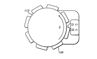
図1には、本発明の実施形態によるペン型注射器の形態の薬物または薬剤の送達デバイス100が概略的に示されている。デバイス100は、細長い、または実質的に管状の形状のものである。デバイス100は、3つのハウジング構成要素である、近位主ハウジングまたは本体101と、遠位に位置するカートリッジホルダ102と、薬物送達デバイス100が使用されていないときにカートリッジホルダ102を覆う解放可能保護キャップ(図示せず)とを含む。カートリッジホルダ102は、薬物送達デバイス100によって投薬予定の薬剤が少なくとも部分的に充填されたカートリッジ103を収容し支持するように適用される。
FIG. 1 schematically shows a drug or
カートリッジ103は、典型的には、遠位端(図示せず)に穿孔可能封止部またはセプタムを有するバイアルまたはカープルを含む。カートリッジ103は、近位端に、本体101内に収容され支持されている駆動機構の親ねじに係合する栓104をさらに含む。親ねじ106を遠位方向(図面に示される左)に変位させると、カートリッジ103内に提供されている薬剤の明確な量がニードルアセンブリ(図示せず)を通って投薬される。典型的には、両頭針アセンブリが、カートリッジホルダ102の遠位端に示されるようなねじ付きソケットに着脱可能に螺着される。
ガラス質タイプとすることができるカートリッジ103の充填レベルの検査のために、カートリッジホルダ102は、少なくとも1つの側面検査窓(図示せず)を含む。
For inspection of the filling level of the
近位方向において(図面では右)、薬物送達デバイス100は、使用者が薬剤の用量を個別に設定し引き続いて投薬することができる用量投与装置で終端している。用量ダイヤル部材または用量セレクタ113によって、患者に送達するために薬剤の用量を薬物送達デバイス100にダイヤル設定することができる。ダイヤル設定用量は、使用者が薬物送達デバイス100の近位端から見て時計回りとは反対の方向(反時計回り方向)に用量セレクタ113を回転させることによって増加させることができる。
In the proximal direction (right in the drawing), the
用量セレクタ113を回転させることによって用量を設定した後で、用量のサイズは、用量投与セレクタ113を適切に回転させることでいつでも修正することができる。反対方向の回転(この例では時計回り方向)は、ダイヤル設定用量を減少させる。
After setting the dose by rotating the
次いで、ダイヤル設定用量を調節するかどうかに関わらず、延ばされた用量投与装置114、113、112は、使用者が近位方向に位置する用量ボタン112に対して遠位方向(図面では左)の力を加えることによって導かれ誘起される、遠位方向の押し下げを受けることができるようになる。
The extended
薬物送達デバイス100の内部には、協働して用量ダイヤル設定および送達機能を提供するいくつかの構成要素がある。用量ダイヤル設定は、主に、用量スリーブ114およびラチェットスリーブ115と協働する用量セレクタ113によって実行される。用量送達は、主に、駆動軸110、駆動ばね108、親ねじ106および栓104と協働する用量ボタン112によって実行される。支承部は、親ねじ106と栓104との間に位置する。支承部によって、これらの構成要素の互いに対する回転が容易になる。親ねじ106は、ねじナット107およびスプラインナット117ならびにロッキングナット116の中を通っている。ゼロ止め具109は、用量スリーブ114の螺旋運動をゼロ用量位置までに制限し、その点を越える動きを阻止する。WO02/053214および米国特許出願第2009/318865号に記載の注射デバイスは、若干の修正により、または修正なしで、薬物送達デバイス100として使用することができる。
Within the
用量ボタンが押されるとクラッチ(図示せず)の動作が起動されるので、用量セレクタ113は、用量が薬物送達デバイス100によって送達されているときは用量スリーブと一緒に回転することはない。
Since the clutch (not shown) operation is activated when the dose button is pressed, the
カートリッジホルダ102は、さらなるハウジング構成要素であり、近位ハウジング101の遠位端に配置される。カートリッジホルダ102は、内部に配置されるカートリッジ103を有する。カートリッジ103には、注射予定の薬剤が少なくとも部分的に充填されている。特に使い捨て薬物送達デバイスの場合、バイアルまたはカープルのようなタイプの充填済みカートリッジが薬物送達デバイス内に容易に配置される。
The
用量スリーブ114は、数字スリーブである。用量スリーブ114は、螺旋状に形成された数字のスケールを有する。数字には、目盛が添付されている。図9には、数字およびメモリが示されている。数字は、薬物送達デバイス100に現在ダイヤル設定されているいくつかの用量の単位を示す。現在ダイヤル設定されている用量は、用量標示窓119から使用者が見ることができる。用量標示窓119は、図1に示されるように、本体101の近位部分に位置する。用量標示窓119に現在示されている数字を識別することによって、使用者は、実際に設定またはダイヤル設定されている用量の、標準的な単位でのサイズを識別することができる。
The
前もって設定した用量を投薬するために遠位方向の圧力を用量ボタン112に及ぼすと、薬剤の用量が送達される。これは、親ねじ106の軸方向運動を伴い、それによって栓104に圧力が及ぼされ、こうして薬物送達デバイス100から薬剤が排出される。
Distal pressure is applied to the
薬物送達デバイス100は、第1のセンサ装置136、146と、第2のセンサ装置138、148とをさらに含む。各センサ装置136、146、138、148は、センサ136、138と、対応するスケールまたは他の検出可能特徴部146、148とを含み、それらを用いて用量ダイヤル設定送達装置のねじ様(螺旋)回転および軸方向変位が別個に検出され定量的に決定される。センサ装置136、146、138、148からの信号は、図7を参照して以下に述べる薬物送達デバイスの電子構成要素によって処理される。
The
第1のセンサ装置は、本体101上に設けられるセンサ136と、一式の特徴部146とを含む。一式の特徴部は、薬物送達デバイス100の用量ダイヤル部材113上、具体的には、用量ダイヤル部材113の外周上に設けられる。一式の特徴部のタイプおよび形態は、たとえば光学、触覚、電気または磁気的なセンサとして実現されるセンサ136のタイプに応じて決めることができる。第1のセンサ136は、たとえばその円周面の光学検査に基づいて、たとえば用量ダイヤル部材113の回転を視覚的に検出することを可能にする。たとえば、第1のセンサ136は、たとえば用量ダイヤル部材113の比較的粗い表面によってもたらされる反射スペックルパターンを評価するように適用された、用量ダイヤル部材113に向けられた光学送信/検出トランスデューサを含むことができる。図2〜図6には、第1のセンサ装置についての他の例示的な装置が示されている。
The first sensor device includes a
一式の特徴部146は、用量ダイヤル部材113上もしくは内部に一体に形成されるもしくは埋め込まれる、または円周面上に別個に配置される、インクリメンタルエンコーダを構成することができる。
The set of
用量ダイヤル部材113の軸方向位置が固定されていることから、第1のセンサ136と第1のスケール146の相対的な軸方向位置は、実質的に固定され、薬物送達デバイス100にダイヤル設定される用量に関わりなく一定のままとなる。したがって、第1のセンサ装置136、146は、本体101に対する用量ダイヤル部材113の任意の回転運動を増分的に検出することができる。
Since the axial position of the
第2のセンサ装置138、148は、第2のセンサ138と、スケール148とを含む。第2のセンサ138は、本体101上または内部に配置される。スケール148は、用量スリーブ114上に設けられる。第2のセンサ装置138、148によって、本体101内における用量スリーブ114の軸方向の相対的な変位を定量的に検出することができる。
The
スケール148は、数字スリーブ上の目盛によって構成される。それによって、用量設定の間および/または用量投薬手順の間に用量スリーブ114が動く軸方向経路長を正確に決定することができるようにする増分的に符号化されたスケール148が構成される。
スケール148が増分的に符号化されたスケール148、たとえば目盛の形態の場合、第2のセンサは、スケールの動きおよび動きの方向を検出するように構成される。動きの方向は、異なる位置にある2つの感知要素を用いて、それらの感知要素によってもたらされる信号同士の位相差を検出することによって実行される。
If the
図2には、第1の感知装置136、146の一形態が示されている。ここで、用量設定ダイヤル113は、その円周に、こぶ、突起またはリブを含む一式の特徴部146を含む。センサ136は、センサ136を通過する特徴部の動きの存在および方向を感知するように構成された近接センサを含む。センサ136の出力から、プロセッサ装置は、特徴部の動きの方向および距離を検出することができる。動きの方向は、プロセッサ装置によって、時計回り方向の動きまたは反時計回り方向の動きに解釈される。
FIG. 2 shows one form of the
図3には、第1の感知装置136、146の他の形態が示されている。ここで、用量設定ダイヤル113は、その円周に、こぶ、突起またはリブを含む一式の特徴部146を含む。センサ136は、特徴部146の動きの存在および方向を感知するようにそれぞれ構成された2つの近接センサ136a、136bを含む。センサ136a、136bは、用量ダイヤル113に対して互いに反対に位置する。センサ136a、136bの出力から、プロセッサ装置は、特徴部の動きの方向および距離を検出することができる。動きの方向は、プロセッサ装置によって、時計回り方向の動きまたは反時計回り方向の動きに解釈される。センサ136a、136bを互いに若干オフセットさせることによって、センサ136a、136bによってもたらされる信号の位相をプロセッサ装置が検出し、回転方向の識別または確認に使用することができるようになる。
FIG. 3 shows another form of the
図4a〜図4dには、第1の感知装置136、146のさらなる形態が示されている。ここで、用量設定ダイヤル113は、その円周に、こぶ、突起またはリブを含む一式の特徴部146を含む。センサ136は、センサ136を通過する特徴部の動きの存在および方向を感知するように互いに構成された第1および第2の電子機械スイッチ、マイクロスイッチ、ウルトラマイクロスイッチ(ultra microswitch)または超小型マイクロスイッチ136a−S1、136b−S2を含む。マイクロスイッチ136a−S1、136b−S2は、特徴部146がそれらを通過したときに特徴部によって作動されるように配置される。マイクロスイッチ136a−S1、136b−S2は、特徴部146がそれらを通過したときに特徴部によって、最初に一方のマイクロスイッチ、次いで両方、そして他方のマイクロスイッチが起動されるように配置される。マイクロスイッチの起動のシーケンスは、マイクロスイッチを通過する特徴部の動きの方向を示している。センサ136の出力から、プロセッサ装置は、特徴部の動きの方向および距離を検出することができる。動きの方向は、マイクロスイッチ136a−S1、136b−S2によってもたらされる信号の位相から検出される。動きの方向は、プロセッサ装置によって、時計回り方向の動きまたは反時計回り方向の動きに解釈される。反時計回り方向に動くときのシーケンスは、図4a、次いで図4c、図4d、最後に図4bである。時計回り方向に動くときのシーケンスは、図4a、次いで図4b、図4d、最後に図4cである。
4a-4d show a further form of the
図5には、第1の感知装置136、146のさらなる形態が示されている。ここで、用量設定ダイヤル113は、その円周に、こぶ、突起またはリブを含む一式の特徴部146を含む。センサ136は、センサ136を通過する特徴部の動きの存在および方向を感知するように互いに構成された第1および第2の光学検出器136a−S1、136b−S2を含む。光学検出器136a−S1、136b−S2は、フォトダイオード、光依存性抵抗器などとすることができる。光学検出器136a−S1、136b−S2は、特徴部
146がそれらを通過したときに特徴部によって完全または部分的に隠されるように配置される。光学検出器136a−S1、136b−S2は、隠されると、それらに当たる周囲光が減少する。それによって、光学検出器136a−S1、136b−S2の位置に特徴部があることが検出される。光学検出器136a−S1、136b−S2は、特徴部146がそれらを通過したときに特徴部によって、最初に一方の光学検出器、次いで両方、そして他方の光学検出器が隠されるように、配置される。光学検出器の起動のシーケンスは、光学検出器136a−S1、136b−S2を通過する特徴部の動きの方向を示している。センサ136の出力から、プロセッサ装置は、特徴部の動きの方向および距離を検出することができる。動きの方向は、光学検出器136a−S1、136b−S2によってもたらされる信号の位相から検出される。動きの方向は、プロセッサ装置によって、時計回り方向の動きまたは反時計回り方向の動きに解釈される。
FIG. 5 shows a further form of the
図6には、第1の感知装置136、146のさらなる形態が示されている。ここで、用量設定ダイヤル113は、その円周に、こぶ、突起またはリブを含む一式の特徴部146を含む。特徴部は、磁気特性を有し、大気とは全く異なる磁性であるか透磁率を有し特徴部の近くで測定可能な地球の磁場に影響を及ぼす。センサ136は、ホール効果センサのような第1および第2の磁気センサ136−S1、136−S2を含む。第1および第2の磁気センサ136−S1、136−S2は、センサ136を通過する特徴部の動きの存在および方向を感知するように互いに構成される。第1および第2の磁気センサ136−S1、136−S2は、特徴部146がそれらを通過しセンサが磁場の変化を受けると出力信号が変化するように、配置される。第1および第2の磁気センサ136−S1、136−S2の磁場変化のシーケンスは、センサを通過する特徴部の動きの方向を示している。センサ136の出力から、プロセッサ装置は、特徴部の動きの方向および距離を検出することができる。動きの方向は、第1および第2の磁気センサ136−S1、136−S2によってもたらされる信号の位相から検出される。動きの方向は、プロセッサ装置によって、時計回り方向の動きまたは反時計回り方向の動きに解釈される。反時計回り方向に動くときのシーケンスは、図4a、次いで図4c、図4d、最後に図4bである。時計回り方向に動くときのシーケンスは、図4a、次いで図4b、図4d、最後に図4cである。
FIG. 6 shows a further form of the
図2〜図6のすべてにおいて、一式の特徴部146の一部として8つの特徴部が示されているが、特徴部の数をより多くすれば、達成可能な測定分解能もより高くなる。
In all of FIGS. 2 to 6, eight feature parts are shown as part of the set of
用量設定および用量ダイヤル設定中、両方のセンサ136、138は、それぞれの第1および第2の信号をプロセッサ装置134に対して生成し提供する。
During dose setting and dose dial setting, both
第1および第2のセンサ136、138から得られる信号を比較し続けることで、プロセッサ部材134は、前記信号を処理し、用量設定手順または用量ダイヤル設定手順の開始および終了、ならびに用量投薬手順の開始および終了を正確に区別し認識することができる。
By continuing to compare the signals obtained from the first and
このように、薬剤送達デバイス100は、薬物送達デバイス100によって実際に投薬された薬剤の量を反映するそうした投薬パラメータを正確に検出、監視および記憶することができる。さらに、これは、使用者の承認または他の入力の必要なくして、完全に自動的に実行可能である。
In this way, the
図7は、薬物送達デバイス100の電子構成要素の簡略化された概略ブロック線図である。上述したセンサ136、146、138、148は、回路21に信号を出力するように構成される。
FIG. 7 is a simplified schematic block diagram of the electronic components of the
回路21は、任意の適当な構成とすることができ、本明細書に記載の機能の実施に適した1つまたはそれ以上のプロセッサおよび/またはマイクロプロセッサ210の任意の組み合わせ(簡単にするために、以降、「少なくとも1つのプロセッサ」と呼ぶ)を含むことができる。回路21は加えて、または別法として、(図7に示されない)ASIC、FPGAなど1つまたはそれ以上のハードウェアだけの構成要素の任意の組み合わせを含むこともできる。
The
回路21はさらに、ROMおよびRAMの一方または両方などの、1つまたはそれ以上の持続性コンピュータ可読メモリ媒体211の任意の組合せを含み、これは、少なくとも1つのプロセッサ210に接続される。メモリ211は、コンピュータ可読命令211Aをその上に記憶することができる。コンピュータ可読命令211Aは、少なくとも1つのプロセッサ210で実行されると、センサデバイス2に、センサ136、146、138、148の動作を制御し、それらから受けた信号を解読するような、本明細書に記載の機能を実施させることができる。
薬物送達デバイス100は、ディスプレイスクリーン24(LEDまたはLCDスクリーンなど)およびデータポート25の一方または両方をさらに含むことができる。ディスプレイスクリーン24は、薬物送達デバイス100の動作に関する情報を使用者に対して表示するように、回路21の制御下で動作可能である。たとえば、薬物送達デバイス100によって判定されたダイヤル設定用量が、使用者に対して表示される。薬物送達デバイス100によって判定可能な他の情報には、投薬されている薬物、および/または先に投薬された用量の履歴が含まれる。
The
データポート25は、薬物送達デバイス100の動作に関する記憶情報をメモリ211からPC、タブレットコンピュータ、またはスマートフォンなどの遠隔のデバイスへ転送するのに使用される。同様に、新しいソフトウェア/ファームウェアが、データポート25を介してセンサデバイスへ転送される。データポート25は、USBポートなどの物理的ポート、またはIR、WiFiもしくはBluetooth(登録商標)トランシーバなどの仮想もしくは無線ポートとすることができる。
The
薬物送達デバイス100は、さらに、着脱可能または恒久的な(好ましくは、たとえば光電池を用いて再充電可能な)電池26を、薬物送達デバイス100の他の構成要素に電力供給するために含む。電池26の代わりに、光起電力電源またはキャパシタ電源を使用することもできる。図7に示されないがそれでもなお薬物送達デバイス100に含まれる他の電気構成要素には、トリガバッファ、レギュレータ、電圧制御装置、もし存在する場合は充電式電池を再充填するための充電器チップが含まれる。
The
次に、図8を参照して動作について述べる。図8は、第1および第2のセンサ装置136、138からの入力に基づいたプロセッサ装置の動作を示す流れ図である。
Next, the operation will be described with reference to FIG. FIG. 8 is a flow chart showing the operation of the processor device based on the input from the first and
動作は、ステップS1から始まる。ステップS2で、プロセッサ装置は、薬剤送達デバイス100がゼロ用量位置にあるかどうか、すなわちゼロ用量が薬剤送達デバイス100にダイヤル設定されているかどうかを判定する。否定判定の場合、ステップS3で、プロセッサ装置は、ステップS2に戻る前に、「ゼロにダイヤル設定してください」:と読み取れるメッセージを表示させる。ダイヤル設定された用量がゼロだと判定されたら、動作はステップS4に進む。ここで、プロセッサ装置は、ゼロ用量が薬剤送達デバイス100にダイヤル設定されたことを示すメッセージ:「0」を表示させる。
The operation starts from step S1. In step S2, the processor device determines if the
ステップS5で、プロセッサ装置は、第1のセンサ装置が用量設定構成要素113の時計回り方向運動を示しているだけでなく第2のセンサ装置が本体101内での用量スリーブ114の時計回り方向回転を示しているかどうかを判定する。そうでない場合、動作は、ステップS6に進む。
In step S5, the processor device not only shows the clockwise movement of the
ステップS6で、プロセッサ装置は、第1のセンサ装置が用量設定構成要素113の反時計回り方向運動を示しているだけでなく第2のセンサ装置が本体101内での用量スリーブ114の反時計回り方向回転を示しているかどうかを判定する。そうでない場合、動作は、ステップS7に進む。
In step S6, the processor device not only shows the counterclockwise movement of the
ステップS7で、プロセッサ装置は、第1のセンサ装置が用量設定構成要素113の反時計回り方向運動を示しているだけでなく第2のセンサ装置が本体101内で用量スリーブ114が回転していないことを示しているかどうかを判定する。そうでない場合、動作は、ステップS5に戻る。
In step S7, in the processor device, not only is the first sensor device exhibiting counterclockwise movement of the
ステップS5でプロセッサ装置が第1のセンサ装置が用量設定構成要素113の時計回り方向運動を示しているだけでなく第2のセンサ装置が本体101内での用量スリーブ114の時計回り方向回転を示していると判定した場合、動作は、ステップS8に進む。これは、プロセッサ装置が薬剤送達デバイス100に設定またはダイヤル設定された用量が増加していることを検出したため、行われる。ステップS8で、表示用量の値が増加する。増加は、表示用量値が設定された用量を示すように、連続的になされる。設定用量の増加量は、センサ装置136、138のうちの一方または両方からの出力に基づいてプロセッサ装置によって決定される。ステップS8の後、動作は、ステップS5に戻る。
In step S5, the processor device not only shows the first sensor device the clockwise movement of the
ステップS6でプロセッサ装置が第1のセンサ装置が用量設定構成要素113の反時計回り方向運動を示しているだけでなく第2のセンサ装置が本体101内での用量スリーブ114の反時計回り方向回転を示していると判定した場合、動作は、ステップS9に進む。これは、プロセッサ装置が、薬剤送達デバイス100に設定またはダイヤル設定された用量が減少していることを検出したため、行われる。ステップS9で、表示用量の値が減少する。減少は、表示用量値が設定された用量を示すように、連続的になされる。設定用量の減少量は、センサ装置136、138のうちの一方または両方からの出力に基づいてプロセッサ装置によって決定される。ステップS9の後、動作は、ステップS5に戻る。
In step S6, not only is the processor device the first sensor device exhibiting counterclockwise motion of the
ステップS7でプロセッサ装置が第1のセンサ装置が用量設定構成要素113の反時計回り方向運動を示しているだけでなく第2のセンサ装置が本体101内の用量スリーブ114が回転していないことを示していると判定した場合、動作はステップS10に進む。ここで、プロセッサ装置は、ゼロ用量位置が達成されるまで待つ。ステップS7からの肯定的な判定は、設定またはダイヤル設定された用量が送達されていることを示している。用量送達は、一旦開始されると、止らない。したがって、プロセッサ装置は、設定用量が送達されるであろうと判定することはできるが、それにはステップS10でのその検出が必要となる。
In step S7, the processor device not only indicates that the first sensor device shows counterclockwise movement of the
ステップS10の後、プロセッサ装置は、ステップS11で、送達された用量を示すデータを記憶する。送達された用量は、不揮発性メモリに記憶される。次いで、送達された用量は、後で必要に応じて通信、表示または別のやり方で使用することができる。 After step S10, the processor device stores data indicating the delivered dose in step S11. The delivered dose is stored in non-volatile memory. The delivered dose can then be communicated, labeled or otherwise used as needed later.
当業者には様々な代替実施形態が明らかであろう。次に、いくつかのそうした代替実施形態について述べる。 Various alternative embodiments will be apparent to those skilled in the art. Next, some such alternative embodiments will be described.
上記では、第2の感知装置138、148は、用量スリーブ114上の目盛の動きを検出することによって、用量スリーブ114の回転を検出する。したがって、第2の感知装置は、用量スリーブ114の螺旋運動を検出するが、これは、センサ138に対する並進運動のように現れる。この感知は、低解像度カメラまたはより単純な光検知装置によって行うことができる。第2の感知装置138、148は、あらゆる適当な形態をとることができる。たとえば、第2の感知装置138、148は、コンピュータ周辺機器タイプの光学式マウスでよく見られるタイプの光学センサを含むことができる。あるいは、第2の感知装置138、148は、たとえば、赤外線または紫外線である可視スペクトルの範囲外で動作する光学検出器を含むことができる。第2の感知装置138、148は、光学装置以外とすることもできる。第2の感知装置138、148は、用量スリーブ114の純粋な軸方向運動、純粋な回転運動、または螺旋運動(回転および軸方向の両方)を検出するように構成することもできる。
In the above, the
いくつかの実施形態を図示し述べてきたが、当業者には、その範囲が特許請求の範囲において定められる本発明の原理から逸脱することなくこれらの実施形態に変更を加えることができると理解されよう。 Although some embodiments have been illustrated and described, those skilled in the art will appreciate that modifications can be made to these embodiments without departing from the principles of the invention as defined in the claims. Will be done.
本明細書で使用する用語「薬物」または「薬剤」は、1つまたはそれ以上の薬学的に活性な化合物を説明するために本明細書において使用される。以下に説明されるように、薬物または薬剤は、1つまたはそれ以上の疾患を処置するための、さまざまなタイプの製剤の少なくとも1つの低分子もしくは高分子、またはその組み合わせを含むことができる。例示的な薬学的に活性な化合物は、低分子;ポリペプチド、ペプチド、およびタンパク質(たとえばホルモン、成長因子、抗体、抗体フラグメント、および酵素);炭水化物および多糖類;ならびに核酸、二本鎖または一本鎖DNA(裸およびcDNAを含む)、RNA、アンチセンスDNAおよびRNAなどのアンチセンス核酸、低分子干渉RNA(siRNA)、リボザイム、遺伝子、およびオリゴヌクレオチドを含むことができる。核酸は、ベクター、プラスミド、またはリポソームなどの分子送達システムに組み込むことができる。これらの薬物の1つまたはそれ以上の混合物もまた、企図される。 As used herein, the term "drug" or "drug" is used herein to describe one or more pharmaceutically active compounds. As described below, a drug or agent can include at least one small molecule or macromolecule of various types of formulations, or a combination thereof, for treating one or more diseases. Exemplary pharmaceutically active compounds are small molecules; polypeptides, peptides, and proteins (eg, hormones, growth factors, antibodies, antibody fragments, and enzymes); carbohydrates and polysaccharides; and nucleic acids, double-stranded or single-stranded. It can include double-stranded DNA (including bare and cDNA), RNA, antisense nucleic acids such as antisense DNA and RNA, small interfering RNAs (siRNAs), ribozymes, genes, and oligonucleotides. Nucleic acids can be integrated into molecular delivery systems such as vectors, plasmids, or liposomes. Mixtures of one or more of these drugs are also contemplated.
用語「薬物送達デバイス」は、薬物をヒトまたは動物の体内に投薬するように構成されたあらゆるタイプのデバイスまたはシステムを包含するものである。限定されることなく、薬物送達デバイスは、注射デバイス(たとえばシリンジ、ペン型注射器、自動注射器、大容量デバイス、ポンプ、かん流システム、または眼内、皮下、筋肉内、もしくは血管内送達にあわせて構成された他のデバイス)、皮膚パッチ(たとえば、浸透圧性、化学的、マイクロニードル)、吸入器(たとえば鼻用または肺用)、埋め込み(たとえば、コーティングされたステント、カプセル)、または胃腸管用の供給システムとすることができる。ここに説明される薬物は、針、たとえば小ゲージ針を含む注射デバイスで特に有用であることができる。 The term "drug delivery device" includes any type of device or system configured to administer a drug into the human or animal body. Without limitation, drug delivery devices can be adapted to injection devices such as syringes, pen-type injectors, automatic injectors, high volume devices, pumps, perfusion systems, or intraocular, subcutaneous, intramuscular, or intravascular delivery. For other configured devices), skin patches (eg osmotic, chemical, microneedles), inhalers (eg for nasal or lung), implants (eg coated stents, capsules), or gastrointestinal tract It can be a supply system. The drugs described herein can be particularly useful in injection devices that include needles, such as small gauge needles.
薬物または薬剤は、薬物送達デバイスで使用するように適用された主要パッケージまたは「薬物容器」内に含むことができる。薬物容器は、たとえば、カートリッジ、シリンジ、リザーバ、または1つまたはそれ以上の薬学的に活性な化合物の保存(たとえば短期または長期保存)に適したチャンバを提供するように構成された他の容器とすることができる。たとえば、一部の場合、チャンバは、少なくとも1日(たとえば1日から少なくとも30日まで)の間薬物を保存するように設計することができる。一部の場合、チャンバは、約1カ月から約2年の間薬物を保存するように設計することができる。保存は、室温(たとえば約20℃)または冷蔵温度(たとえば約−4℃から約4℃まで)で行うことができる。一部の場合、薬物容器は、薬物製剤の2つまたはそれ以上の成分(たとえば薬物および希釈剤、または2つの異なるタイプの薬物)を別々に、各チャンバに1つずつ保存するように構成された二重チャンバカートリッジとすることができ、またはこれを含むことができる。そのような場合、二重チャンバカートリッジの2つのチャンバは、ヒトまたは動物の体内に投薬する前、および/または投薬中に薬物または薬剤の2つまたはそれ以上の成分間で混合することを可能にするように構成することができる。たとえば、2つのチャンバは、これらが(たとえば2つのチャンバ間の導管によって)互いに流体連通し、所望の場合、投薬の前にユーザによって2つの成分を混合することを可能にするように構成することができる。代替的に、またはこれに加えて、2つのチャンバは、成分がヒトまたは動物の体内に投薬されているときに混合することを可能にするように構成することができる。 The drug or drug can be contained within a major package or "drug container" applied for use with the drug delivery device. Drug containers are, for example, with cartridges, syringes, reservoirs, or other containers configured to provide a chamber suitable for storage of one or more pharmaceutically active compounds (eg, short-term or long-term storage). can do. For example, in some cases, the chamber can be designed to store the drug for at least one day (eg, from 1 to at least 30 days). In some cases, the chamber can be designed to store the drug for about 1 month to about 2 years. Storage can be performed at room temperature (eg, about 20 ° C.) or refrigerating temperature (eg, from about -4 ° C. to about 4 ° C.). In some cases, drug containers are configured to store two or more components of the drug formulation (eg, drugs and diluents, or two different types of drugs) separately, one in each chamber. Can be, or can include, a double chamber cartridge. In such cases, the two chambers of the dual chamber cartridge allow mixing between two or more components of the drug or drug before and / or during dosing into the human or animal body. Can be configured to: For example, the two chambers are configured to allow them to fluidize with each other (eg by a conduit between the two chambers) and, if desired, allow the user to mix the two components prior to dosing. Can be done. Alternatively, or in addition to this, the two chambers can be configured to allow the ingredients to be mixed when being administered into the human or animal body.
本明細書において説明される薬物送達デバイスおよび薬物は、数多くの異なるタイプの障害の処置および/または予防に使用することができる。例示的な障害は、たとえば、糖尿病、または糖尿病性網膜症などの糖尿病に伴う合併症、深部静脈血栓塞栓症または肺血栓塞栓症などの血栓塞栓症を含む。さらなる例示的な障害は、急性冠症候群(ACS)、狭心症、心筋梗塞、がん、黄斑変性症、炎症、枯草熱、アテローム性動脈硬化症および/または関節リウマチである。 The drug delivery devices and drugs described herein can be used to treat and / or prevent a number of different types of disorders. Exemplary disorders include, for example, diabetes, or diabetic complications such as diabetic retinopathy, and thromboembolism such as deep vein thromboembolism or pulmonary thromboembolism. Further exemplary disorders are acute coronary syndrome (ACS), angina, myocardial infarction, cancer, macular degeneration, inflammation, hay fever, atherosclerosis and / or rheumatoid arthritis.
糖尿病または糖尿病に伴う合併症の処置および/または予防のための例示的な薬物は、インスリン、たとえばヒトインスリン、またはヒトインスリン類似体もしくは誘導体、グルカゴン様ペプチド(GLP−1)、GLP−1類似体もしくはGLP−1受容体アゴニスト、またはその類似体もしくは誘導体、ジペプチジルペプチダーゼ−4(DPP4)阻害剤、または薬学的に許容される塩もしくはその溶媒和物、またはそれらの任意の混合物を含む。本明細書において使用される用語「誘導体」は、元の物質と構造的に十分同様のものであり、それによって同様の機能または活性(たとえば治療効果性)を有することができる任意の物質を指す。 Exemplary drugs for the treatment and / or prevention of diabetes or diabetes-related complications are insulin, such as human insulin, or human insulin analogs or derivatives, glucagon-like peptides (GLP-1), GLP-1 analogs. Alternatively, it comprises a GLP-1 receptor agonist, or analog or derivative thereof, a dipeptidyl peptidase-4 (DPP4) inhibitor, or a pharmaceutically acceptable salt or solvate thereof, or any mixture thereof. As used herein, the term "derivative" refers to any substance that is structurally sufficiently similar to the original substance and thereby capable of having similar function or activity (eg, therapeutic efficacy). ..
例示的なインスリン類似体は、Gly(A21),Arg(B31),Arg(B32)ヒトインスリン(インスリングラルギン);Lys(B3),Glu(B29)ヒトインスリン;Lys(B28),Pro(B29)ヒトインスリン;Asp(B28)ヒトインスリン;B28位におけるプロリンがAsp、Lys、Leu、Val、またはAlaで置き換えられており、B29位において、LysがProで置き換えられていてもよいヒトインスリン;Ala(B26)ヒトインスリン;Des(B28−B30)ヒトインスリン;Des(B27)ヒトインスリンおよびDes(B30)ヒトインスリンである。 Exemplary insulin analogs are Gly (A21), Arg (B31), Arg (B32) human insulin (insulin glargine); Lys (B3), Glu (B29) human insulin; Lys (B28), Pro (B29). Human insulin; Asp (B28) Human insulin; Prolin at position B28 is replaced with Asp, Lys, Leu, Val, or Ala, and Lys may be replaced with Pro at position B29 Human insulin; Ala ( B26) Human Insulin; Des (B28-B30) Human Insulin; Des (B27) Human Insulin and Des (B30) Human Insulin.
例示的なインスリン誘導体は、たとえば、B29−N−ミリストイル−des(B30)ヒトインスリン;B29−N−パルミトイル−des(B30)ヒトインスリン;B29−N−ミリストイルヒトインスリン;B29−N−パルミトイルヒトインスリン;B28−N−ミリストイルLysB28ProB29ヒトインスリン;B28−N−パルミトイル−LysB28ProB29ヒトインスリン;B30−N−ミリストイル−ThrB29LysB30ヒトインスリン;B30−N−パルミトイル−ThrB29LysB30ヒトインスリン;B29−N−(N−パルミトイル−γ−グルタミル)−des(B30)ヒトインスリン;B29−N−(N−リトコリル−γ−グルタミル)−des(B30)ヒトインスリン;B29−N−(ω−カルボキシヘプタデカノイル)−des(B30)ヒトインスリン、およびB29−N−(ω−カルボキシヘプタデカノイル)ヒトインスリンである。例示的なGLP−1、GLP−1類似体およびGLP−1受容体アゴニストは、たとえば:リキシセナチド(Lixisenatide)/AVE0010/ZP10/リキスミア(Lyxumia)、エキセナチド(Exenatide)/エクセンディン−4(Exendin−4)/バイエッタ(Byetta)/ビデュリオン(Bydureon)/ITCA650/AC−2993(アメリカドクトカゲの唾液腺によって産生される39アミノ酸ペプチド)、リラグルチド(Liraglutide)/ビクトザ(Victoza)、セマグルチド(Semaglutide)、タスポグルチド(Taspoglutide)、シンクリア(Syncria)/アルビグルチド(Albiglutide)、デュラグルチド(Dulaglutide)、rエクセンディン−4、CJC−1134−PC、PB−1023、TTP−054、ラングレナチド(Langlenatide)/HM−11260C、CM−3、GLP−1エリゲン、ORMD−0901、NN−9924、NN−9926、NN−9927、ノデキセン(Nodexen)、ビアドール(Viador)−GLP−1、CVX−096、ZYOG−1、ZYD−1、GSK−2374697、DA−3091、MAR−701、MAR709、ZP−2929、ZP−3022、TT−401、BHM−034、MOD−6030、CAM−2036、DA−15864、ARI−2651、ARI−2255、エキセナチド(Exenatide)−XTENおよびグルカゴン−Xtenである。 Exemplary insulin derivatives are, for example, B29-N-myristoyl-des (B30) human insulin; B29-N-palmitoyl-des (B30) human insulin; B29-N-myristoyl human insulin; B29-N-palmitoyl human insulin. B28-N-Millitoyl LysB28ProB29 Human Insulin; B28-N-Palmitoyle-LysB28ProB29 Human Insulin; B30-N-Millitoyl-ThrB29LysB30 Human Insulin; -Glutamil) -des (B30) human insulin; B29-N- (N-lithocholyl-γ-glutamyl) -des (B30) human insulin; B29-N- (ω-carboxyheptadecanoyl) -des (B30) human Insulin, and B29-N- (ω-carboxyheptadecanoyl) human insulin. Exemplary GLP-1, GLP-1 analogs and GLP-1 receptor agonists include: for example: Liraglutide / AVE0010 / ZP10 / Liraglutide, Exenatide / Exenatide-4. ) / Byetta / Bydureon / ITCA650 / AC-2993 (39 amino acid peptides produced by the salivary glands of the American doctor lizard), Liraglutide / Victorza, Exenatide, Exenatide , Syncria / Albiglutide, Duraglutide, r Exenatide-4, CJC-1134-PC, PB-1023, TTP-054, Liraglutide / HM-11260C, CM-3G -1 Eligen, ORMD-0901, NN-9924, NN-9926, NN-9927, Nodexen, Viador-GLP-1, CVX-096, ZYOG-1, ZYD-1, GSK-2374697, DA-3091, MAR-701, MAR709, ZP-2929, ZP-3022, TT-401, BHM-034, MOD-6030, CAM-2036, DA-15864, ARI-2651, ARI-2255, Exenatide. -XTEN and Glucagon-Xten.
例示的なオリゴヌクレオチドは、たとえば:家族性高コレステロール血症の処置のためのコレステロール低下アンチセンス治療薬である、ミポメルセン(mipomersen)/キナムロ(Kynamro)である。 An exemplary oligonucleotide is, for example: mipomersen / Kynamro, a cholesterol-lowering antisense therapeutic agent for the treatment of familial hypercholesterolemia.
例示的なDPP4阻害剤は、ビルダグリプチン(Vildagliptin)、シタグリプチン(Sitagliptin)、デナグリプチン(Denagliptin)、サキサグリプチン(Saxagliptin)、ベルベリン(Berberine)である。 Exemplary DPP4 inhibitors are Vildagliptin, Sitagliptin, Denagliptin, Saxagliptin, Berberine.
例示的なホルモンは、ゴナドトロピン(フォリトロピン、ルトロピン、コリオンゴナドトロピン、メノトロピン)、ソマトロピン(ソマトロピン)、デスモプレシン、テルリプレシン、ゴナドレリン、トリプトレリン、ロイプロレリン、ブセレリン、ナファレリン、およびゴセレリンなどの、脳下垂体ホルモンまたは視床下部ホルモンまたは調節性活性ペプチドおよびそれらのアンタゴニストを含む。 Exemplary hormones are pituitary hormones or hypothalamus, such as gonadotropins (follitropin, lutropin, corion gonadotropin, menotropin), somatropin (somatropin), desmopressin, telllipresin, gonadotropin, triptolerin, leuprorelin, busererin, nafarelin, and goseleline. Includes lower hormones or regulatory active peptides and their antagonists.
例示的な多糖類は、グルコサミノグリカン、ヒアルロン酸、ヘパリン、低分子量ヘパリン、もしくは超低分子量ヘパリン、またはそれらの誘導体、または上述の多糖類の硫酸化形態、たとえば、ポリ硫酸化形態、および/または、薬学的に許容されるそれらの塩を含む。ポリ硫酸化低分子量ヘパリンの薬学的に許容される塩の例としては、エノキサパリンナトリウムがある。ヒアルロン酸誘導体の例としては、HylanG−F20/Synvisc、ヒアルロン酸ナトリウムがある。 Exemplary polysaccharides are glucosaminoglycans, hyaluronic acid, heparin, low molecular weight heparin, or ultra low molecular weight heparin, or derivatives thereof, or sulfated forms of the above-mentioned polysaccharides, such as polysulfated forms, and / Or include those pharmaceutically acceptable salts. An example of a pharmaceutically acceptable salt of polysulfated low molecular weight heparin is enoxaparin sodium. Examples of hyaluronic acid derivatives include HylanG-F20 / Synvisc and sodium hyaluronate.
本明細書において使用する用語「抗体」は、免疫グロブリン分子またはその抗原結合部分を指す。免疫グロブリン分子の抗原結合部分の例は、抗原を結合する能力を保持するF(ab)およびF(ab’)2フラグメントを含む。抗体は、ポリクローナル、モノクローナル、組換え型、キメラ型、非免疫型またはヒト化、完全ヒト型、非ヒト型(たとえばマウス)、または一本鎖抗体とすることができる。いくつかの実施形態では、抗体はエフェクター機能を有し、補体を固定することができる。いくつかの実施形態では、抗体は、Fc受容体と結合する能力が低く、または結合することはできない。たとえば、抗体は、アイソタイプもしくはサブタイプ、抗体フラグメントまたは変異体とすることができ、Fc受容体との結合を支持せず、たとえば、これは、突然変異したまたは欠失したFc受容体結合領域を有する。 As used herein, the term "antibody" refers to an immunoglobulin molecule or antigen-binding portion thereof. Examples of the antigen-binding portion of an immunoglobulin molecule include F (ab) and F (ab') 2 fragments that retain the ability to bind the antigen. The antibody can be polyclonal, monoclonal, recombinant, chimeric, non-immune or humanized, fully human, non-human (eg, mouse), or single chain antibody. In some embodiments, the antibody has effector function and is capable of immobilizing complement. In some embodiments, the antibody has a low ability to bind or is unable to bind to the Fc receptor. For example, the antibody can be an isotype or subtype, an antibody fragment or variant and does not support binding to the Fc receptor, eg, it has a mutated or deleted Fc receptor binding region. Have.
用語「フラグメント」または「抗体フラグメント」は、全長抗体ポリペプチドを含まないが、抗原と結合することができる全長抗体ポリペプチドの少なくとも一部分を依然として含む、抗体ポリペプチド分子(たとえば、抗体重鎖および/または軽鎖ポリペプチド)由来のポリペプチドを指す。抗体フラグメントは、全長抗体ポリペププチドの切断された部分を含むことができるが、この用語はそのような切断されたフラグメントに限定されない。本発明に有用である抗体フラグメントは、たとえば、Fabフラグメント、F(ab’)2フラグメント、scFv(一本鎖Fv)フラグメント、直鎖抗体、二重特異性、三重特異性、および多重特異性抗体(たとえば、ダイアボディ、トリアボディ、テトラボディ)などの単一特異性または多重特異性抗体フラグメント、ミニボディ、キレート組換え抗体、トリボディまたはバイボディ、イントラボディ、ナノボディ、小モジュラー免疫薬(SMIP)、結合ドメイン免疫グロブリン融合タンパク質、ラクダ化抗体、およびVHH含有抗体を含む。抗原結合抗体フラグメントのさらなる例は、当技術分野で知られている。 The term "fragment" or "antibody fragment" does not include a full-length antibody polypeptide, but still contains at least a portion of a full-length antibody polypeptide capable of binding an antigen, such as an antibody polypeptide molecule (eg, antibody heavy chain and /). Or a polypeptide derived from (light chain polypeptide). The antibody fragment can include a cleaved portion of the full-length antibody polypeptide, but the term is not limited to such cleaved fragments. Antibody fragments useful in the present invention include, for example, Fab fragment, F (ab') 2 fragment, scFv (single chain Fv) fragment, linear antibody, bispecific, trispecific, and multispecific antibody. Unispecific or multispecific antibody fragments such as (eg, diabody, tribody, tetrabody), minibody, chelate recombinant antibody, tribody or bibody, intrabody, nanobody, small modular immune agent (SMIP), Includes binding domain immunoglobulin fusion proteins, camelized antibodies, and VHH-containing antibodies. Further examples of antigen-binding antibody fragments are known in the art.
用語「相補性決定領域」または「CDR」は、特異的抗原認識を仲介する役割を主に担う重鎖および軽鎖両方のポリペプチドの可変領域内の短いポリペプチド配列を指す。用語「フレームワーク領域」は、CDR配列ではなく、CDR配列の正しい位置決めを維持して抗原結合を可能にする役割を主に担う重鎖および軽鎖両方のポリペプチドの可変領域内のアミノ酸配列を指す。フレームワーク領域自体は、通常、当技術分野で知られているように、抗原結合に直接的に関与しないが、特定の抗体のフレームワーク領域内の特定の残基が、抗原結合に直接的に関与することができ、またはCDR内の1つまたはそれ以上のアミノ酸が抗原と相互作用する能力に影響を与えることができる。 The term "complementarity determining regions" or "CDRs" refers to short polypeptide sequences within the variable regions of both heavy and light chain polypeptides that are primarily responsible for mediating specific antigen recognition. The term "framework region" refers to the amino acid sequences within the variable regions of both heavy and light chain polypeptides that are primarily responsible for maintaining the correct positioning of the CDR sequences and allowing antigen binding, rather than the CDR sequences. Point to. The framework region itself is usually not directly involved in antigen binding, as is known in the art, but certain residues within the framework region of a particular antibody are directly involved in antigen binding. It can be involved, or it can affect the ability of one or more amino acids in the CDR to interact with the antigen.
例示的な抗体は、アンチPCSK−9mAb(たとえばアリロクマブ(Alirocumab))、アンチIL−6mAb(たとえばサリルマブ(Sarilumab))、およびアンチIL−4mAb(たとえばデュピルマブ(Dupilumab))である。 Exemplary antibodies are anti-PCSK-9mAb (eg, Alirocumab), anti-IL-6mAb (eg, Sarilumab), and anti-IL-4mAb (eg, Dupilumab).
本明細書において説明される化合物は、(a)化合物または薬学的に許容されるその塩、および(b)薬学的に許容される担体を含む医薬製剤において使用することができる。化合物はまた、1つまたはそれ以上の他の医薬品有効成分を含む医薬製剤、または存在する化合物またはその薬学的に許容される塩が唯一の有効成分である医薬製剤において使用することもできる。したがって、本開示の医薬製剤は、本明細書において説明される化合物および薬学的に許容される担体を混合することによって作られる任意の製剤を包含する。 The compounds described herein can be used in pharmaceutical formulations that include (a) a compound or a pharmaceutically acceptable salt thereof, and (b) a pharmaceutically acceptable carrier. The compound can also be used in a pharmaceutical preparation containing one or more other pharmaceutical active ingredients, or in a pharmaceutical preparation in which the existing compound or a pharmaceutically acceptable salt thereof is the only active ingredient. Accordingly, the pharmaceutical formulations of the present disclosure include any formulation made by mixing the compounds described herein with a pharmaceutically acceptable carrier.
本明細書において説明される任意の薬物の薬学的に許容される塩もまた、薬物送達デバイスにおける使用に企図される。薬学的に許容される塩は、たとえば酸付加塩および塩基性塩である。酸付加塩は、たとえば、HClまたはHBr塩である。塩基性塩は、たとえば、アルカリもしくはアルカリ土類金属、たとえばNa+、もしくはK+、もしくはCa2+、またはアンモニウムイオンN+(R1)(R2)(R3)(R4)(式中、R1からR4は互いに独立して:水素、場合により置換されたC1〜C6−アルキル基、場合により置換されたC2〜C6−アルケニル基、場合により置換されたC6〜C10−アリル基、または場合により置換されたC6〜C10−ヘテロアリール基を意味する)から選択されるカチオンを有する塩である。薬学的に許容される塩のさらなる例は、当業者に知られている。 Pharmaceutically acceptable salts of any of the drugs described herein are also contemplated for use in drug delivery devices. Pharmaceutically acceptable salts are, for example, acid addition salts and basic salts. The acid addition salt is, for example, an HCl or HBr salt. The basic salt is, for example, an alkali or alkaline earth metal such as Na + or K +, or Ca2 +, or ammonium ion N + (R1) (R2) (R3) (R4) (in the formula, R1 to R4 are independent of each other. : Hydrogen, optionally substituted C1-C6-alkyl group, optionally substituted C2-C6-alkenyl group, optionally substituted C6-C10-allyl group, or optionally substituted C6-C10- A salt having a cation selected from (meaning a heteroaryl group). Further examples of pharmaceutically acceptable salts are known to those of skill in the art.
薬学的に許容される溶媒和物は、たとえば、水和物またはメタノラート(methanolate)またはエタノラート(ethanolate)などのアルカノラート(alkanolate)である。 A pharmaceutically acceptable solvate is, for example, a hydrate or an alkanolate such as methoxide or ethanolate.
本明細書に記載の物質、配合、装置、方法、システムおよび実施形態の様々な構成要素の修正(追加および/または削除)は、本発明の全範囲および趣旨から逸脱することなく行うことができ、本発明は、そのような修正、および本発明のあらゆる均等物もすべて包含することが当業者には理解されよう。 Modifications (additions and / or deletions) of various components of the substances, formulations, devices, methods, systems and embodiments described herein can be made without departing from the scope and gist of the present invention. It will be appreciated by those skilled in the art that the present invention also includes all such modifications, and all equivalents of the present invention.
Claims (9)
ハウジング(101)と;
該ハウジング内に配置された用量スリーブ(114)であって、薬剤用量が薬物送達デバイスにダイヤル設定されるか、またはそこから送達されるときにハウジング内で螺旋状に動くように構成された用量スリーブと;
該用量スリーブに連結され、用量設定構成装置の一部を形成する用量ダイヤル部材(113)の回転によって薬物送達デバイスに薬剤用量がダイヤル設定されるときに用量スリーブの螺旋運動を引き起こすように構成された、用量設定装置と;
用量スリーブに連結された用量ボタン(112)を含み、該用量ボタンが作動されると用量ダイヤル部材の回転のない用量スリーブの螺旋運動により薬剤の送達を引き起こすように構成された、用量送達装置と;
ハウジングに対する用量ダイヤル部材の回転を検出する第1のセンサ装置(136、146)と;
ハウジングに対する用量スリーブの動きを検出する第2のセンサ装置(138、148)と;
該第1および該第2のセンサ装置からの入力を受けるように接続され、それから薬物送達デバイスによって投薬された薬剤用量のサイズを算出するように構成された、プロセッサ装置とを含み、
ここで、用量ダイヤル部材は、特徴部(146)を含み、
第1のセンサ装置(136)は、用量ダイヤル部材が回転したときに用量ダイヤル部材の特徴部を検出するように配置された第1および第2のセンサ構成要素(136a、136b)を含み、
プロセッサ装置は、第1および第2のセンサ構成要素(136a、136b)によってもたらされる信号の位相から、用量ダイヤル部材の回転方向を算出するように構成されており、
第1および第2のセンサ構成要素(136a、136b)は、用量ダイヤル部材の周囲に互いに直径方向逆向きに配置される近接センサであって、用量ダイヤル部材が回転したときに用量ダイヤル部材の特徴部の存在を感知するように構成される、
前記薬物送達デバイス。 A drug delivery device:
With housing (101);
A dose sleeve (114) disposed within the housing that is configured to spiral within the housing when the drug dose is dialed to or delivered from the drug delivery device. With a sleeve;
The rotation of the dose dial member (113) , which is coupled to the dose sleeve and forms part of the dose setting configuration device , is configured to cause a spiral movement of the dose sleeve when the drug dose is dialed to the drug delivery device. It was, and the dose set equipment;
With a dose delivery device comprising a dose button (112) coupled to a dose sleeve and configured to trigger drug delivery by spiral movement of the dose sleeve without rotation of the dose dial member when the dose button is activated. ;
With a first sensor device (136, 146) that detects the rotation of the dose dial member with respect to the housing;
With a second sensor device (138, 148) that detects the movement of the dose sleeve with respect to the housing;
Connected to receive inputs from said first and second sensor devices, and then configured to calculate the size of the drug dose dosed by the drug delivery device, seen including a processor device,
Here, the dose dial member includes a feature portion (146).
The first sensor device (136) includes first and second sensor components (136a, 136b) arranged to detect features of the dose dial member as it rotates.
The processor device is configured to calculate the direction of rotation of the dose dial member from the phase of the signals provided by the first and second sensor components (136a, 136b).
The first and second sensor components (136a, 136b) are proximity sensors arranged around the dose dial member in opposite directions in the radial direction, which are features of the dose dial member when the dose dial member is rotated. Constructed to detect the presence of a part,
The drug delivery device.
Applications Claiming Priority (3)
| Application Number | Priority Date | Filing Date | Title |
|---|---|---|---|
| EP16150290.1 | 2016-01-06 | ||
| EP16150290 | 2016-01-06 | ||
| PCT/EP2017/050222 WO2017118705A1 (en) | 2016-01-06 | 2017-01-05 | Medicament delivery device |
Publications (3)
| Publication Number | Publication Date |
|---|---|
| JP2019500968A JP2019500968A (en) | 2019-01-17 |
| JP2019500968A5 JP2019500968A5 (en) | 2020-01-30 |
| JP6902546B2 true JP6902546B2 (en) | 2021-07-14 |
Family
ID=55070870
Family Applications (1)
| Application Number | Title | Priority Date | Filing Date |
|---|---|---|---|
| JP2018535090A Active JP6902546B2 (en) | 2016-01-06 | 2017-01-05 | Drug delivery device |
Country Status (6)
| Country | Link |
|---|---|
| US (1) | US11285268B2 (en) |
| EP (1) | EP3400045B1 (en) |
| JP (1) | JP6902546B2 (en) |
| CN (1) | CN108697855B (en) |
| DK (1) | DK3400045T3 (en) |
| WO (1) | WO2017118705A1 (en) |
Families Citing this family (9)
| Publication number | Priority date | Publication date | Assignee | Title |
|---|---|---|---|---|
| EP3672668A1 (en) * | 2017-08-21 | 2020-07-01 | Eli Lilly and Company | Medication delivery device with sensing system |
| EP3545989A1 (en) * | 2018-03-28 | 2019-10-02 | Sanofi | Injection device |
| EP3545994A1 (en) * | 2018-03-28 | 2019-10-02 | Sanofi | Injection device comprising a detector |
| US20210290841A1 (en) * | 2018-08-17 | 2021-09-23 | Eli Lilly And Company | Medication delivery device with dose detection system |
| EP3930801A1 (en) * | 2019-02-27 | 2022-01-05 | Eli Lilly and Company | Medication delivery device with sensing system |
| US10729860B1 (en) * | 2019-05-22 | 2020-08-04 | Berkshire Biomedical, LLC | Computerized oral prescription administration for securely dispensing a medication and associated systems and methods |
| EP3976140A1 (en) * | 2019-05-29 | 2022-04-06 | Sanofi | Drug delivery device |
| CA3144322A1 (en) * | 2019-06-20 | 2020-12-24 | Patients Pending Ltd. | Liquid delivery cap with alignment verification |
| CN118355250A (en) * | 2021-09-24 | 2024-07-16 | 赛诺菲 | Measuring system for a drug delivery device, drug delivery device having such a measuring system, and method for measuring a dispensed dose and/or a set dose of a drug delivery device |
Family Cites Families (21)
| Publication number | Priority date | Publication date | Assignee | Title |
|---|---|---|---|---|
| JPH11267206A (en) | 1998-03-24 | 1999-10-05 | Miyota Kk | Portable injector |
| US6899699B2 (en) | 2001-01-05 | 2005-05-31 | Novo Nordisk A/S | Automatic injection device with reset feature |
| DE10330985A1 (en) * | 2003-07-09 | 2005-02-17 | Tecpharma Licensing Ag | Device for administering a fluid product with optical scanning |
| EP2073871B1 (en) | 2006-09-29 | 2013-03-20 | Novo Nordisk A/S | An injection device with electronic detecting means |
| WO2010052275A2 (en) * | 2008-11-06 | 2010-05-14 | Novo Nordisk A/S | Electronically assisted drug delivery device |
| DK2509662T3 (en) | 2009-12-07 | 2019-08-05 | Sanofi Aventis Deutschland | DRIVE DEVICE FOR A PHARMACEUTICAL ADMINISTRATION DEVICE AND PHARMACEUTICAL ADMINISTRATION DEVICE |
| EP2696918A2 (en) | 2011-04-11 | 2014-02-19 | Novo Nordisk A/S | Injection device incorporating dose monitoring |
| US9504793B2 (en) | 2011-05-25 | 2016-11-29 | Sanofi-Aventis Deutschland Gmbh | Medicament delivery device with cartridge sensor and cartridge holder door sensor and method of controlling the device |
| CN104203315B (en) * | 2012-02-13 | 2017-07-25 | 赛诺菲-安万特德国有限公司 | Pen type medicament injection apparatus and the additional monitoring module of electronics for monitoring and recording dosage setting and administration |
| CN107456620B (en) | 2012-02-13 | 2020-12-11 | 赛诺菲-安万特德国有限公司 | Auxiliary device for attachment to an injection device |
| JP6385927B2 (en) | 2012-08-03 | 2018-09-05 | サノフィ−アベンティス・ドイチュラント・ゲゼルシャフト・ミット・ベシュレンクテル・ハフツング | Supplementary device for attachment to an injection device |
| EP2698180A1 (en) | 2012-08-15 | 2014-02-19 | Sanofi-Aventis Deutschland GmbH | Autoinjector |
| EP2722065A1 (en) * | 2012-10-18 | 2014-04-23 | Sanofi-Aventis Deutschland GmbH | Auto-injector |
| US20150290396A1 (en) * | 2012-10-23 | 2015-10-15 | Insuline Medical Ltd. | Drug dispensing-tracking device, system and method |
| WO2014111335A1 (en) | 2013-01-15 | 2014-07-24 | Sanofi-Aventis Deutschland Gmbh | Pen type drug injection device with friction reducing dose encoder mechanism |
| US10434260B2 (en) | 2013-01-15 | 2019-10-08 | Sanofi-Aventis Deutschland Gmbh | Pen type drug injection device with dose encoder mechanism and dose setting/dose delivery mode switch |
| CN109381776B (en) | 2013-01-15 | 2021-10-26 | 赛诺菲-安万特德国有限公司 | System comprising a decoding system and a drug delivery device |
| TR201903053T4 (en) * | 2013-01-15 | 2019-03-21 | Sanofi Aventis Deutschland | A decoding system. |
| JP6301448B2 (en) | 2013-04-05 | 2018-03-28 | ノボ・ノルデイスク・エー/エス | Drug delivery device and recording module assembly |
| EP2994179B1 (en) | 2013-05-07 | 2018-03-14 | Sanofi-Aventis Deutschland GmbH | A supplemental device for attachment to an injection device |
| CN204563169U (en) | 2014-01-13 | 2015-08-19 | 深圳市生活智能科技有限公司 | Drug injection information monitoring system and cartridge syringe |
-
2017
- 2017-01-05 US US16/068,027 patent/US11285268B2/en active Active
- 2017-01-05 CN CN201780014077.6A patent/CN108697855B/en active Active
- 2017-01-05 JP JP2018535090A patent/JP6902546B2/en active Active
- 2017-01-05 DK DK17700083.3T patent/DK3400045T3/en active
- 2017-01-05 WO PCT/EP2017/050222 patent/WO2017118705A1/en active Application Filing
- 2017-01-05 EP EP17700083.3A patent/EP3400045B1/en active Active
Also Published As
| Publication number | Publication date |
|---|---|
| CN108697855A (en) | 2018-10-23 |
| WO2017118705A1 (en) | 2017-07-13 |
| DK3400045T3 (en) | 2020-08-10 |
| CN108697855B (en) | 2022-04-22 |
| JP2019500968A (en) | 2019-01-17 |
| EP3400045A1 (en) | 2018-11-14 |
| EP3400045B1 (en) | 2020-05-06 |
| US20190217016A1 (en) | 2019-07-18 |
| US11285268B2 (en) | 2022-03-29 |
Similar Documents
| Publication | Publication Date | Title |
|---|---|---|
| JP6902546B2 (en) | Drug delivery device | |
| JP7005484B2 (en) | Sensor device for drug delivery device | |
| JP6930974B2 (en) | Sensor device that can be attached to and detached from the drug delivery device | |
| JP6901398B2 (en) | Injection device sensor device | |
| JP6310862B2 (en) | Pen-type drug injection device and electronic add-on monitoring module for monitoring and logging dose setting and administration | |
| JP6993406B2 (en) | Reading devices, drug delivery devices, and drug delivery devices in combination with reading devices | |
| JP7000351B2 (en) | Auxiliary devices attached to drug delivery devices, numeric sleeves for drug delivery devices, and drug delivery devices | |
| JP2021500102A (en) | Drug delivery device | |
| JP6703492B2 (en) | Dose marking mechanism and drug delivery device for drug delivery device | |
| JP7387626B2 (en) | injection device | |
| US20220105276A1 (en) | Methods and systems for tracking dosage information of electronically enabled injection devices | |
| JP2021500103A (en) | Drug administration device and data collection device | |
| US20240304298A1 (en) | Data Collection Apparatus for Dose Determination | |
| US20230166045A1 (en) | Injection Device with an Electronic Detector | |
| JP2024535081A (en) | Components of drug delivery device and drug delivery device | |
| JP2021506544A (en) | Dose recording device | |
| TW202245857A (en) | A dose counting system | |
| JP2024535080A (en) | Electronic system, user interface member, drug delivery device, and method for detecting whether a drug delivery device is or has been exposed to a fluid - Patents.com | |
| CN118354804A (en) | Electronic system, user interface member, drug delivery device, and method for detecting whether a drug delivery device is exposed to or has been exposed to a fluid | |
| CN118043091A (en) | Electronic component for drug delivery device | |
| CN117981007A (en) | Determining data related to proximity of end-of-life of a drug delivery device |
Legal Events
| Date | Code | Title | Description |
|---|---|---|---|
| A521 | Request for written amendment filed |
Free format text: JAPANESE INTERMEDIATE CODE: A523 Effective date: 20191216 |
|
| A621 | Written request for application examination |
Free format text: JAPANESE INTERMEDIATE CODE: A621 Effective date: 20191216 |
|
| A977 | Report on retrieval |
Free format text: JAPANESE INTERMEDIATE CODE: A971007 Effective date: 20201130 |
|
| A131 | Notification of reasons for refusal |
Free format text: JAPANESE INTERMEDIATE CODE: A131 Effective date: 20201208 |
|
| A521 | Request for written amendment filed |
Free format text: JAPANESE INTERMEDIATE CODE: A523 Effective date: 20210225 |
|
| TRDD | Decision of grant or rejection written | ||
| A01 | Written decision to grant a patent or to grant a registration (utility model) |
Free format text: JAPANESE INTERMEDIATE CODE: A01 Effective date: 20210608 |
|
| A61 | First payment of annual fees (during grant procedure) |
Free format text: JAPANESE INTERMEDIATE CODE: A61 Effective date: 20210621 |
|
| R150 | Certificate of patent or registration of utility model |
Ref document number: 6902546 Country of ref document: JP Free format text: JAPANESE INTERMEDIATE CODE: R150 |
|
| R250 | Receipt of annual fees |
Free format text: JAPANESE INTERMEDIATE CODE: R250 |