JP6902420B2 - Measuring device and measuring method - Google Patents
Measuring device and measuring method Download PDFInfo
- Publication number
- JP6902420B2 JP6902420B2 JP2017144381A JP2017144381A JP6902420B2 JP 6902420 B2 JP6902420 B2 JP 6902420B2 JP 2017144381 A JP2017144381 A JP 2017144381A JP 2017144381 A JP2017144381 A JP 2017144381A JP 6902420 B2 JP6902420 B2 JP 6902420B2
- Authority
- JP
- Japan
- Prior art keywords
- time
- series data
- signal
- pulse wave
- data
- Prior art date
- Legal status (The legal status is an assumption and is not a legal conclusion. Google has not performed a legal analysis and makes no representation as to the accuracy of the status listed.)
- Active
Links
- 238000000034 method Methods 0.000 title claims description 33
- 230000036772 blood pressure Effects 0.000 claims description 51
- 238000012545 processing Methods 0.000 claims description 50
- 238000004364 calculation method Methods 0.000 claims description 31
- 238000001914 filtration Methods 0.000 claims description 13
- 238000005259 measurement Methods 0.000 claims description 13
- 230000000630 rising effect Effects 0.000 claims description 13
- 238000012546 transfer Methods 0.000 claims description 13
- 238000013500 data storage Methods 0.000 claims description 12
- 210000001367 artery Anatomy 0.000 claims description 10
- 230000008569 process Effects 0.000 claims description 10
- 238000000691 measurement method Methods 0.000 claims description 2
- 238000003825 pressing Methods 0.000 description 40
- 210000000707 wrist Anatomy 0.000 description 40
- 230000006835 compression Effects 0.000 description 36
- 238000007906 compression Methods 0.000 description 36
- 238000001514 detection method Methods 0.000 description 27
- 230000006870 function Effects 0.000 description 23
- 230000002093 peripheral effect Effects 0.000 description 19
- 238000009530 blood pressure measurement Methods 0.000 description 17
- 230000008859 change Effects 0.000 description 14
- 238000010586 diagram Methods 0.000 description 12
- 239000012530 fluid Substances 0.000 description 12
- 210000002321 radial artery Anatomy 0.000 description 12
- 239000007787 solid Substances 0.000 description 9
- 238000004891 communication Methods 0.000 description 6
- 230000010355 oscillation Effects 0.000 description 5
- 238000005070 sampling Methods 0.000 description 5
- 238000002847 impedance measurement Methods 0.000 description 4
- 230000010363 phase shift Effects 0.000 description 4
- 230000008901 benefit Effects 0.000 description 3
- 230000017531 blood circulation Effects 0.000 description 3
- 230000035487 diastolic blood pressure Effects 0.000 description 3
- 230000000694 effects Effects 0.000 description 3
- 238000005401 electroluminescence Methods 0.000 description 3
- 230000004044 response Effects 0.000 description 3
- PEDCQBHIVMGVHV-UHFFFAOYSA-N Glycerine Chemical compound OCC(O)CO PEDCQBHIVMGVHV-UHFFFAOYSA-N 0.000 description 2
- 230000005540 biological transmission Effects 0.000 description 2
- 238000006243 chemical reaction Methods 0.000 description 2
- 238000007599 discharging Methods 0.000 description 2
- 239000007788 liquid Substances 0.000 description 2
- 229920002635 polyurethane Polymers 0.000 description 2
- 239000004814 polyurethane Substances 0.000 description 2
- 239000011343 solid material Substances 0.000 description 2
- 239000000126 substance Substances 0.000 description 2
- 230000035488 systolic blood pressure Effects 0.000 description 2
- 238000003466 welding Methods 0.000 description 2
- 239000004743 Polypropylene Substances 0.000 description 1
- 210000003423 ankle Anatomy 0.000 description 1
- 210000004204 blood vessel Anatomy 0.000 description 1
- 230000006837 decompression Effects 0.000 description 1
- 210000004247 hand Anatomy 0.000 description 1
- 210000003141 lower extremity Anatomy 0.000 description 1
- 239000000463 material Substances 0.000 description 1
- 238000012986 modification Methods 0.000 description 1
- 230000004048 modification Effects 0.000 description 1
- 239000004033 plastic Substances 0.000 description 1
- 229920003023 plastic Polymers 0.000 description 1
- -1 polypropylene Polymers 0.000 description 1
- 229920001155 polypropylene Polymers 0.000 description 1
- 230000001902 propagating effect Effects 0.000 description 1
- 239000011347 resin Substances 0.000 description 1
- 229920005989 resin Polymers 0.000 description 1
- 210000001364 upper extremity Anatomy 0.000 description 1
- 210000000689 upper leg Anatomy 0.000 description 1
- XLYOFNOQVPJJNP-UHFFFAOYSA-N water Substances O XLYOFNOQVPJJNP-UHFFFAOYSA-N 0.000 description 1
Images


Classifications
-
- A—HUMAN NECESSITIES
- A61—MEDICAL OR VETERINARY SCIENCE; HYGIENE
- A61B—DIAGNOSIS; SURGERY; IDENTIFICATION
- A61B5/00—Measuring for diagnostic purposes; Identification of persons
- A61B5/02—Detecting, measuring or recording pulse, heart rate, blood pressure or blood flow; Combined pulse/heart-rate/blood pressure determination; Evaluating a cardiovascular condition not otherwise provided for, e.g. using combinations of techniques provided for in this group with electrocardiography or electroauscultation; Heart catheters for measuring blood pressure
- A61B5/021—Measuring pressure in heart or blood vessels
- A61B5/02108—Measuring pressure in heart or blood vessels from analysis of pulse wave characteristics
- A61B5/02125—Measuring pressure in heart or blood vessels from analysis of pulse wave characteristics of pulse wave propagation time
-
- A—HUMAN NECESSITIES
- A61—MEDICAL OR VETERINARY SCIENCE; HYGIENE
- A61B—DIAGNOSIS; SURGERY; IDENTIFICATION
- A61B5/00—Measuring for diagnostic purposes; Identification of persons
- A61B5/02—Detecting, measuring or recording pulse, heart rate, blood pressure or blood flow; Combined pulse/heart-rate/blood pressure determination; Evaluating a cardiovascular condition not otherwise provided for, e.g. using combinations of techniques provided for in this group with electrocardiography or electroauscultation; Heart catheters for measuring blood pressure
- A61B5/021—Measuring pressure in heart or blood vessels
- A61B5/022—Measuring pressure in heart or blood vessels by applying pressure to close blood vessels, e.g. against the skin; Ophthalmodynamometers
- A61B5/02225—Measuring pressure in heart or blood vessels by applying pressure to close blood vessels, e.g. against the skin; Ophthalmodynamometers using the oscillometric method
-
- A—HUMAN NECESSITIES
- A61—MEDICAL OR VETERINARY SCIENCE; HYGIENE
- A61B—DIAGNOSIS; SURGERY; IDENTIFICATION
- A61B5/00—Measuring for diagnostic purposes; Identification of persons
- A61B5/24—Detecting, measuring or recording bioelectric or biomagnetic signals of the body or parts thereof
- A61B5/316—Modalities, i.e. specific diagnostic methods
- A61B5/318—Heart-related electrical modalities, e.g. electrocardiography [ECG]
- A61B5/339—Displays specially adapted therefor
-
- A—HUMAN NECESSITIES
- A61—MEDICAL OR VETERINARY SCIENCE; HYGIENE
- A61B—DIAGNOSIS; SURGERY; IDENTIFICATION
- A61B5/00—Measuring for diagnostic purposes; Identification of persons
- A61B5/68—Arrangements of detecting, measuring or recording means, e.g. sensors, in relation to patient
- A61B5/6801—Arrangements of detecting, measuring or recording means, e.g. sensors, in relation to patient specially adapted to be attached to or worn on the body surface
- A61B5/6802—Sensor mounted on worn items
- A61B5/681—Wristwatch-type devices
-
- A—HUMAN NECESSITIES
- A61—MEDICAL OR VETERINARY SCIENCE; HYGIENE
- A61B—DIAGNOSIS; SURGERY; IDENTIFICATION
- A61B5/00—Measuring for diagnostic purposes; Identification of persons
- A61B5/02—Detecting, measuring or recording pulse, heart rate, blood pressure or blood flow; Combined pulse/heart-rate/blood pressure determination; Evaluating a cardiovascular condition not otherwise provided for, e.g. using combinations of techniques provided for in this group with electrocardiography or electroauscultation; Heart catheters for measuring blood pressure
- A61B5/026—Measuring blood flow
- A61B5/0295—Measuring blood flow using plethysmography, i.e. measuring the variations in the volume of a body part as modified by the circulation of blood therethrough, e.g. impedance plethysmography
-
- A—HUMAN NECESSITIES
- A61—MEDICAL OR VETERINARY SCIENCE; HYGIENE
- A61B—DIAGNOSIS; SURGERY; IDENTIFICATION
- A61B5/00—Measuring for diagnostic purposes; Identification of persons
- A61B5/05—Detecting, measuring or recording for diagnosis by means of electric currents or magnetic fields; Measuring using microwaves or radio waves
- A61B5/053—Measuring electrical impedance or conductance of a portion of the body
- A61B5/0535—Impedance plethysmography
-
- A—HUMAN NECESSITIES
- A61—MEDICAL OR VETERINARY SCIENCE; HYGIENE
- A61B—DIAGNOSIS; SURGERY; IDENTIFICATION
- A61B5/00—Measuring for diagnostic purposes; Identification of persons
- A61B5/24—Detecting, measuring or recording bioelectric or biomagnetic signals of the body or parts thereof
- A61B5/316—Modalities, i.e. specific diagnostic methods
- A61B5/318—Heart-related electrical modalities, e.g. electrocardiography [ECG]
- A61B5/332—Portable devices specially adapted therefor
Landscapes
- Health & Medical Sciences (AREA)
- Life Sciences & Earth Sciences (AREA)
- Molecular Biology (AREA)
- Surgery (AREA)
- Biophysics (AREA)
- Pathology (AREA)
- Engineering & Computer Science (AREA)
- Biomedical Technology (AREA)
- Heart & Thoracic Surgery (AREA)
- Medical Informatics (AREA)
- Cardiology (AREA)
- Physics & Mathematics (AREA)
- Animal Behavior & Ethology (AREA)
- General Health & Medical Sciences (AREA)
- Public Health (AREA)
- Veterinary Medicine (AREA)
- Vascular Medicine (AREA)
- Physiology (AREA)
- Ophthalmology & Optometry (AREA)
- Measuring Pulse, Heart Rate, Blood Pressure Or Blood Flow (AREA)
- Measurement And Recording Of Electrical Phenomena And Electrical Characteristics Of The Living Body (AREA)
Description
本開示は、測定装置、および測定方法に関し、特に、脈波伝播時間を測定するための測定装置、および測定方法に関する。 The present disclosure relates to a measuring device and a measuring method, and more particularly to a measuring device and a measuring method for measuring a pulse wave velocity.
従来、動脈を伝播する脈波の伝播時間(脈波伝播時間;Pulse Transit Time;PTT)を測定する方法が知られている。例えば、国際公開第2014/132713号(特許文献1)には、脈波伝播時間計測装置が開示されている。脈波伝播時間計測装置は、フィルタリング処理を含む信号処理が施された心電信号、フィルタリング処理を含む信号処理が施された光電脈波信号それぞれのピークを検出し、心電信号の遅延時間および光電脈波信号の遅延時間に基づいて、心電信号のピークおよび光電脈波信号のピークを補正し、補正された光電脈波信号のピークと心電信号のピークとの時間差から脈波伝播時間を求める。 Conventionally, a method of measuring the propagation time of a pulse wave propagating in an artery (Pulse Transit Time; PTT) has been known. For example, International Publication No. 2014/132713 (Patent Document 1) discloses a pulse wave velocity measuring device. The pulse wave propagation time measuring device detects the peaks of each of the electrocardiographic signal subjected to signal processing including filtering processing and the photoelectric pulse wave signal subjected to signal processing including filtering processing, and detects the delay time of the electrocardiographic signal and the delay time of the electrocardiographic signal. Based on the delay time of the photoelectric pulse wave signal, the peak of the electrocardiographic signal and the peak of the photoelectric pulse wave signal are corrected, and the pulse wave propagation time is calculated from the time difference between the corrected peak of the photoelectric pulse wave signal and the peak of the electrocardiographic signal. Ask for.
特許文献1では、脈波伝播時間を高精度に求めるために、心電信号のピークと光電脈波信号のピークを高精度に検出する方式を検討している。具体的には、特許文献1に係る脈波伝播時間計測装置は、心電信号、および光電脈波信号それぞれの周波数成分を解析し、周波数成分と遅延時間(ピークのズレ量)との関係を定めたテーブルを用いて、心電信号の遅延時間、および光電脈波信号の遅延時間を求め、この遅延時間に基づいて補正された光電脈波信号のピークと心電信号のピークとの時間差から脈波伝播時間を算出する。
しかしながら、特許文献1に係る方式によると、事前にデータベースを用意しなければならない。また、データベースに誤差が有る場合、遅延時間しいては脈波伝播時間にも誤差として影響すると考えられる。
However, according to the method according to
本開示のある局面における目的は、脈波伝播時間を簡易に精度よく測定することが可能な測定装置、および測定方法を提供することである。 An object of the present disclosure in a certain aspect is to provide a measuring device and a measuring method capable of measuring the pulse wave velocity easily and accurately.
ある実施の形態に従う測定装置は、被験者の脈波を示す第1信号を検出する第1センサと、被験者の脈波または心電を示す第2信号を検出する第2センサと、第1センサにより検出された第1信号、および第2センサにより検出された第2信号の各々に対して、所定の伝達関数を有するアナログフィルタによりフィルタ処理を施し、ディジタルデータに変換する第1信号処理部と、第1信号処理部によりディジタルデータに変換された第1信号の第1時系列データ、および第1信号処理部によりディジタルデータに変換された第2信号の第2時系列データの各々に対して、信号処理を施す第2信号処理部とを備える。第2信号処理部は、第1時系列データを、時系列的に逆方向から並べた第3時系列データを生成し、第2時系列データを、時系列的に逆方向から並べた第4時系列データを生成し、第3時系列データおよび第4時系列データの各々に対して、所定の伝達関数を有するディジタルフィルタによりフィルタ処理を施し、ディジタルフィルタによりフィルタ処理が施された第3時系列データを、時系列順に並べ替えた第5時系列データを生成し、ディジタルフィルタによりフィルタ処理が施された第4時系列データを、時系列順に並べ替えた第6時系列データを生成する。測定装置は、第5時系列データにより示される信号と、第6時系列データにより示される信号とに基づいて、脈波伝播時間を算出する時間算出部をさらに備える。 A measuring device according to an embodiment comprises a first sensor that detects a first signal indicating a subject's pulse wave, a second sensor that detects a second signal indicating a subject's pulse wave or electrocardiogram, and a first sensor. A first signal processing unit that filters each of the detected first signal and the second signal detected by the second sensor by an analog filter having a predetermined transmission function and converts them into digital data. For each of the first time-series data of the first signal converted into digital data by the first signal processing unit and the second time-series data of the second signal converted into digital data by the first signal processing unit. It is provided with a second signal processing unit that performs signal processing. The second signal processing unit generates a third time-series data in which the first time-series data is arranged in reverse direction in time series, and a fourth signal processing unit in which the second time-series data is arranged in reverse direction in time series. Time-series data is generated, and each of the third time-series data and the fourth time-series data is filtered by a digital filter having a predetermined transfer function, and the third time is filtered by the digital filter. The fifth time-series data in which the series data is rearranged in chronological order is generated, and the sixth time-series data in which the fourth time-series data filtered by the digital filter is rearranged in chronological order is generated. The measuring device further includes a time calculation unit that calculates the pulse wave propagation time based on the signal indicated by the fifth time series data and the signal indicated by the sixth time series data.
好ましくは、第2信号は、脈波を示す信号である。第1センサおよび第2センサは、被験者の被測定部位を通る動脈のうちそれぞれ対向する部分の脈波を検出する。 Preferably, the second signal is a signal indicating a pulse wave. The first sensor and the second sensor detect the pulse wave of the opposite portion of the artery passing through the measurement site of the subject.
好ましくは、時間算出部は、第5時系列データにより示される信号の立ち上がり時点と、第6時系列データにより示される信号の立ち上がり時点との時間差を脈波伝播時間として算出する、または、第5時系列データにより示される信号のピーク時点と、第6時系列データにより示される信号のピーク時点との時間差を脈波伝播時間として算出する。 Preferably, the time calculation unit calculates the time difference between the rising time of the signal indicated by the fifth time series data and the rising time of the signal indicated by the sixth time series data as the pulse wave propagation time, or the fifth. The time difference between the peak time point of the signal indicated by the time series data and the peak time point of the signal indicated by the sixth time series data is calculated as the pulse wave propagation time.
好ましくは、第2信号は、心電を示す信号である。時間算出部は、第5時系列データにより示される信号の立ち上がり時点と、第6時系列データにより示される信号のピーク時点とを比較することにより、脈波伝播時間を算出する。 Preferably, the second signal is a signal indicating an electrocardiogram. The time calculation unit calculates the pulse wave propagation time by comparing the rising time of the signal indicated by the 5th time series data with the peak time of the signal indicated by the 6th time series data.
好ましくは、測定装置は、第1時系列データおよび第2時系列データを格納するためのデータ格納部をさらに備える。第2信号処理部は、所定時間分の第1時系列データおよび第2時系列データがデータ格納部に蓄積された場合に、信号処理を実行する。 Preferably, the measuring device further includes a data storage unit for storing the first time series data and the second time series data. The second signal processing unit executes signal processing when the first time-series data and the second time-series data for a predetermined time are stored in the data storage unit.
好ましくは、測定装置は、時間算出部により算出された脈波伝播時間に基づく血圧を算出する血圧算出部をさらに備える。 Preferably, the measuring device further includes a blood pressure calculation unit that calculates the blood pressure based on the pulse wave velocity calculated by the time calculation unit.
好ましくは、測定装置は、表示器と、血圧算出部により算出された血圧値を表示器に表示させる表示制御部をさらに備える。 Preferably, the measuring device further includes a display and a display control unit that displays the blood pressure value calculated by the blood pressure calculation unit on the display.
他の実施の形態に従う測定方法は、被験者の脈波を示す第1信号を検出するステップと、被験者の脈波または心電を示す第2信号を検出するステップと、第1信号および第2信号の各々に対して、所定の伝達関数を有するアナログフィルタによりフィルタ処理を施し、ディジタルデータに変換するステップと、ディジタルデータに変換された第1信号の第1時系列データを、時系列的に逆方向から並べた第3時系列データを生成するステップと、ディジタルデータに変換された第2信号の第2時系列データを、時系列的に逆方向から並べた第4時系列データを生成するステップと、第3時系列データおよび第4時系列データの各々に対して、所定の伝達関数を有するディジタルフィルタによりフィルタ処理を施すステップと、ディジタルフィルタによりフィルタ処理が施された第3時系列データを、時系列順に並べ替えた第5時系列データを生成するステップと、ディジタルフィルタによりフィルタ処理が施された第4時系列データを、時系列順に並べ替えた第6時系列データを生成するステップと、第5時系列データにより示される信号と、第6時系列データにより示される信号とに基づいて、脈波伝播時間を算出するステップとを含む。 The measurement methods according to other embodiments include a step of detecting a first signal indicating a subject's pulse wave, a step of detecting a second signal indicating a subject's pulse wave or electrocardiogram, and a first signal and a second signal. Each of the above is filtered by an analog filter having a predetermined transfer function and converted into digital data, and the first time-series data of the first signal converted into digital data is reversed in time series. A step of generating a third time series data arranged from the direction and a step of generating a fourth time series data in which the second time series data of the second signal converted into digital data is arranged in a time series from the opposite direction. And the step of filtering each of the 3rd time series data and the 4th time series data by a digital filter having a predetermined transfer function, and the 3rd time series data filtered by the digital filter. , A step of generating the fifth time-series data sorted in chronological order, and a step of generating the sixth time-series data in which the fourth time-series data filtered by the digital filter is sorted in chronological order. , A step of calculating the pulse wave propagation time based on the signal indicated by the fifth time series data and the signal indicated by the sixth time series data.
本開示によると、脈波伝播時間を簡易に精度よく測定することが可能となる。 According to the present disclosure, it is possible to measure the pulse wave velocity easily and accurately.
以下、図面を参照しつつ、本発明の実施の形態について説明する。以下の説明では、同一の部品には同一の符号を付してある。それらの名称および機能も同じである。したがって、それらについての詳細な説明は繰り返さない。 Hereinafter, embodiments of the present invention will be described with reference to the drawings. In the following description, the same parts are designated by the same reference numerals. Their names and functions are the same. Therefore, the detailed description of them will not be repeated.
以下では、血圧計を、脈波伝播時間を測定するための「測定装置」の代表例として説明を行なう。ただし、測定装置は、脈波信号(あるいは心電信号)を検出するセンサと、当該センサにより検出された信号を処理する処理装置とを含む装置であればよく、血圧計に限られない。 Hereinafter, the sphygmomanometer will be described as a typical example of a "measuring device" for measuring the pulse wave velocity. However, the measuring device may be a device including a sensor for detecting a pulse wave signal (or an electrocardiographic signal) and a processing device for processing the signal detected by the sensor, and is not limited to a sphygmomanometer.
<血圧計の構成>
(外観および断面構成)
図1は、血圧計1の外観斜視図である。図2は、血圧計1が左手首90に装着された状態(以下、「装着状態」とも称する。)で、左手首90の長手方向に対して垂直な断面を模式的に示す図である。本実施の形態では、左手首90が被測定部位となる。なお、血圧計1により測定される「被測定部位」は、動脈が通っている部位であればよい。被測定部位は、例えば、手首、上腕などの上肢であってもよいし、足首、大腿などの下肢であってもよい。
<Structure of blood pressure monitor>
(Appearance and cross-sectional structure)
FIG. 1 is an external perspective view of the
図1および図2を参照して、ベルト20は、左手首90を周方向に沿って取り巻いて装着される細長い帯状の部材である。ベルト20の幅方向Yの寸法(幅寸法)は、例えば、約30mmである。ベルト20は、外周面20bを有する帯状体23と、圧迫カフ21とを含む。
With reference to FIGS. 1 and 2, the
圧迫カフ21は、帯状体23の内周面23aに沿って取り付けられ、左手首90に接する内周面20aを有する。圧迫カフ21は、伸縮可能な2枚のポリウレタンシートを厚さ方向に対向させ、それらの周縁部を溶着して、流体袋として構成されている。流体袋は、流体を収容可能な袋状の部材であればよい。「流体」は、液体と気体の両方を含み、例えば、水、空気などを用いることができる。
The
本体10は、ベルト20のうちの一方の端部20eと一体に設けられる。なお、ベルト20と本体10とを別々に形成し、ベルト20に対して本体10を係合部材(例えば、ヒンジ)を介して、一体に取り付ける構成でもよい。本実施の形態では、本体10が配置された部位は、装着状態において左手首90の背側面(手の甲側の面)90bに対応する(図2参照)。図2中には、左手首90内で掌側面(手の平側の面)90a近傍を通る橈骨動脈91が示されている。
The
図1に示すように、本体10は、ベルト20の外周面20bに対して垂直な方向に厚さを有する立体的形状を有する。本体10は、被験者(ユーザ)の日常活動を妨げないように、小型で、薄厚に形成される。本体10は、ベルト20から外向きに突起した四角錐台状の輪郭を有する。
As shown in FIG. 1, the
本体10の頂面(被測定部位から最も遠い側の面)10aには、表示器50が設けられる。本体10の側面(図1における左手前側の側面)10fに沿って、ユーザからの指示を入力するための操作部52が設けられる。
A
ベルト20の一方の端部20eと他方の端部20fとの間の部位であって、ベルト20の内周面20a(すなわち、圧迫カフ21の内周面20a)上には、インピーダンス測定部40が設けられる。
An
インピーダンス測定部40が配置された部位の内周面20aには、電極群40Eが配置される。電極群40Eは、ベルト20の幅方向Yに関して互いに離間した状態で配置された6個の板状(またはシート状)の電極41〜46を有する。電極群40Eが配置された部位は、装着状態において左手首90の橈骨動脈91に対応する。
The
内周面20aとは反対の外周面21aにおける、電極群40Eに対応する位置には、固形物22が配置される。固形物22の外周側には、押圧カフ24が配置される。押圧カフ24は、圧迫カフ21の周方向に関して電極群40Eに対応する領域を局所的に抑圧する拡張部材である。押圧カフ24は、ベルト20を構成する帯状体23の内周面23a(左手首90に近い側の面)に配置される(図2参照)。帯状体23は、厚さ方向に関して可撓性を有し、周方向(長手方向)に関して非伸縮性を有するプラスチック材料から構成される。
The
押圧カフ24は、ベルト20の厚さ方向に伸縮する流体袋である。具体的には、押圧カフ24は、左手首90を取り巻いて装着され、流体の供給により加圧状態となり、流体の排出により非加圧状態となる。押圧カフ24は、例えば、伸縮可能な2枚のポリウレタンシートを厚さ方向に対向させ、それらの周縁部を溶着して、流体袋として構成される。
The
押圧カフ24の内周面24a(左手首90に近い側の面)のうち、電極群40Eに対応する位置には、固形物22が配置されている。固形物22は、例えば、厚さ1〜2mm程度の板状の樹脂(例えば、ポリプロピレン)で構成されている。本実施の形態では、押圧部として、ベルト20、押圧カフ24、および固形物22を用いている。
A
図1に示すように、本体10の底面(被測定部位に最も近い側の面)10bと、ベルト20の端部20fとは、三つ折れバックル15(以下、単に「バックル15」とも称する。)によって接続されている。
As shown in FIG. 1, the bottom surface (the surface closest to the part to be measured) 10b of the
バックル15は、外周側に配置された板状部材25と、内周側に配置された板状部材26とを含む。板状部材25の一方の端部25eは、幅方向Yに沿って延びる連結棒27を介して本体10に対して回動自在に取り付けられる。板状部材25の他方の端部25fは、幅方向Yに沿って延びる連結棒28を介して、板状部材26の一方の端部26eに対して回動自在に取り付けられる。板状部材26の他方の端部26fは、固定部29によってベルト20の端部20f近傍に固定されている。
The
ベルト20の周方向に関して、固定部29の取り付け位置は、ユーザの左手首90の周囲長に合わせて予め可変して設定されている。これにより、血圧計1(ベルト20)は、全体として略環状に構成されるとともに、本体10の底面10bとベルト20の端部20fとが、バックル15によって図1中の矢印B方向に開閉可能に構成される。
With respect to the circumferential direction of the
ユーザは、血圧計1を左手首90に装着する際、バックル15を開いてベルト20の環の径を大きくした状態で、図1中の矢印Aで示す方向からベルト20に左手を通す。次に、図2に示すように、ユーザは、左手首90の周りのベルト20の角度位置を調節して、左手首90を通る橈骨動脈91上にベルト20のインピーダンス測定部40を位置させる。これにより、インピーダンス測定部40の電極群40Eは、左手首90の掌側面90aのうち橈骨動脈91に対応する部分90a1に当接する状態となる。この状態で、ユーザは、バックル15を閉じて固定する。このようにして、ユーザは血圧計1(ベルト20)を左手首90に装着する。
When the
図3は、血圧計1が左手首90に装着された状態における、インピーダンス測定用の電極群の平面レイアウトを示す図である。図3を参照して、装着状態においては、インピーダンス測定部40の電極群40Eは、左手首90の橈骨動脈91に対応して、手首の長手方向に沿って並んだ状態となる。電極群40Eは、幅方向Yに関して、両側に配置された通電用の電流電極対41,46と、当該電流電極対41,46の間に配置された検出電極対42,43および検出電極対44,45とを含む。脈波センサ401は検出電極対42,43を含み、脈波センサ402は検出電極対44,45を含む。
FIG. 3 is a diagram showing a planar layout of an electrode group for impedance measurement in a state where the
検出電極対42,43に対して、橈骨動脈91の血流のより下流側の部分に対応して、検出電極対44,45が配置されている。幅方向Yに関して、検出電極対42,43の中央と検出電極対44,45の中央との間の距離D(後述する図5(A)参照)は、例えば、20mmに設定される。距離Dは、脈波センサ401と脈波センサ402との間隔に相当する。また、幅方向Yに関して、検出電極対42,43間の間隔、および検出電極対44,45の間隔は、例えば、いずれも20mmに設定される。
With respect to the detection electrode pairs 42 and 43, the detection electrode pairs 44 and 45 are arranged so as to correspond to the portion of the
このような電極群40Eは偏平に構成され得るため、血圧計1では、ベルト20を全体として薄厚に構成できる。また、電極群40Eは、柔軟に構成され得るため、電極群40Eは、圧迫カフ21による左手首90の圧迫を妨げず、後述のオシロメトリック法による血圧測定の精度を損なわない。
Since such an
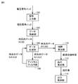
(ハードウェア構成)
図4は、血圧計1の制御系のハードウェア構成を示すブロック図である。図4を参照して、本体10は、制御部として機能するCPU(Central Processing Unit)100と、表示器50と、記憶部として機能するメモリ51と、操作部52と、電池53と、通信部59とを含む。また、本体10は、圧力センサ31と、ポンプ32と、弁33と、圧力センサ34と、切替弁35とを含む。切替弁35は、ポンプ32および弁33の接続先を、圧迫カフ21または押圧カフ24に切り替える。
(Hardware configuration)
FIG. 4 is a block diagram showing a hardware configuration of the control system of the
さらに、本体10は、圧力センサ31および圧力センサ34のそれぞれからの出力を周波数に変換する発振回路310および発振回路340と、ポンプ32を駆動するポンプ駆動回路320とを含む。インピーダンス測定部40は、電極群40Eと、電圧検出回路49とを含む。
Further, the
表示器50は、例えば、有機EL(Electro Luminescence)ディスプレイで構成され、CPU100からの制御信号に従って、血圧測定結果などの血圧測定に関する情報、その他の情報を表示する。なお、表示器50は、有機ELディスプレイに限られず、例えば、LCD(Liquid Cristal Display)など、他のタイプのディスプレイで構成されてもよい。
The
操作部52は、例えば、プッシュ式スイッチで構成され、ユーザによる血圧測定開始または停止の指示に応じた操作信号をCPU100に入力する。なお、操作部52は、プッシュ式スイッチに限られず、例えば、感圧式(抵抗式)または近接式(静電容量式)のタッチパネル式スイッチなどであってもよい。また、本体10がマイクロフォン(図示しない)を含んでおり、ユーザの音声によって血圧測定開始の指示を受け付けてもよい。
The
メモリ51は、血圧計1を制御するためのプログラムのデータ、血圧計1を制御するために用いられるデータ、血圧計1の各種機能を設定するための設定データ、血圧値の測定結果のデータなどを非一時的に記憶する。また、メモリ51は、プログラムが実行されるときのワークメモリなどとして用いられる。
The
CPU100は、メモリ51に記憶された血圧計1を制御するためのプログラムに従って、制御部として各種機能を実行する。例えば、オシロメトリック法による血圧測定を実行する場合、CPU100は、操作部52からの血圧測定開始の指示に応じて、圧力センサ31からの信号に基づいて、ポンプ32(および弁33)を駆動する制御を行なう。また、CPU100は、圧力センサ31からの信号に基づいて、血圧値を算出する制御を行なう。
The
CPU100は、脈波伝播時間に基づく血圧測定を実行する場合、操作部52からの血圧測定開始の指示に応じて、圧迫カフ21内の空気を排出させるために弁33を駆動する制御を行なう。また、CPU100は、切替弁35を駆動して、ポンプ32(および弁33)の接続先を押圧カフ24に切り替える制御を行なう。さらに、CPU100は、圧力センサ34からの信号に基づいて、血圧値を算出する制御を行なう。
When the blood pressure measurement based on the pulse wave propagation time is executed, the
通信部59は、CPU100によって制御されて所定の情報を、ネットワーク900を介して外部の装置に送信したり、外部の装置からの情報を、ネットワーク900を介して受信してCPU100に受け渡したりする。ネットワーク900を介した通信は、無線、有線のいずれでもよい。例えば、ネットワーク900は、インターネットであるが、これに限定されず、LAN(Local Area Network)のような他の種類のネットワークであってもよいし、USBケーブルなどを用いた1対1の通信であってもよい。通信部59は、マイクロUSBコネクタを含んでいてもよい。
The
ポンプ32および弁33は、切替弁35、エア配管39a,39bを介して、圧迫カフ21および押圧カフ24に接続されている。圧力センサ31はエア配管38aを介して、圧力センサ34はエア配管38bを介して、それぞれ圧迫カフ21および押圧カフ24に接続されている。圧力センサ31は、エア配管38aを介して、圧迫カフ21内の圧力を検出する。切替弁35は、CPU100から与えられる制御信号に基づいて駆動し、ポンプ32および弁33の接続先を圧迫カフ21または押圧カフ24に切り替える。
The
ポンプ32は、例えば、圧電ポンプで構成される。切替弁35により、ポンプ32および弁33の接続先が圧迫カフ21に切り替えられている場合には、ポンプ32は、圧迫カフ21内の圧力(カフ圧)を加圧するために、エア配管39aを通して圧迫カフ21に加圧用の流体としての空気を供給する。切替弁35により、ポンプ32および弁33の接続先が押圧カフ24に切り替えられている場合には、ポンプ32は、押圧カフ24内の圧力(カフ圧)を加圧するために、エア配管39bを通して押圧カフ24に加圧用の流体としての空気を供給する。
The
弁33は、ポンプ32に搭載され、ポンプ32のオン/オフに伴って開閉が制御されるように構成される。具体的には、切替弁35により、ポンプ32および弁33の接続先が圧迫カフ21に切り替えられている場合には、弁33は、ポンプ32がオンされると閉じて、圧迫カフ21内に空気を封入する一方、ポンプ32がオフされると開いて、圧迫カフ21の空気をエア配管39aを通して大気中へ排出させる。
The
切替弁35により、ポンプ32および弁33の接続先が押圧カフ24に切り替えられている場合には、弁33は、ポンプ32がオンされると閉じて、押圧カフ24内に空気を封入する一方、ポンプ32がオフされると開いて、押圧カフ24の空気をエア配管39bを通して大気中へ排出させる。弁33は、逆止弁の機能を有し、排出されるエアが逆流することはない。ポンプ駆動回路320は、ポンプ32をCPU100から与えられる制御信号に基づいて駆動する。
When the connection destination of the
圧力センサ31は、例えば、ピエゾ抵抗式圧力センサであり、エア配管38aを介して、ポンプ32、弁33および圧迫カフ21に接続されている。圧力センサ31は、エア配管38aを介して、ベルト20(圧迫カフ21)の圧力、例えば、大気圧を基準(ゼロ)とした圧力を検出して時系列の信号として出力する。
The
発振回路310は、圧力センサ31からのピエゾ抵抗効果による電気抵抗の変化に基づく電気信号値に応じた周波数を有する周波数信号をCPU100に出力する。圧力センサ31の出力は、圧迫カフ21の圧力を制御するため、および、オシロメトリック法によって血圧値(収縮期血圧(Systolic Blood Pressure; SBP)と拡張期血圧(Diastolic Blood Pressure; DBP)とを含む。)を算出するために用いられる。
The
圧力センサ34は、例えば、ピエゾ抵抗式圧力センサであり、エア配管38bを介して、ポンプ32、弁33および押圧カフ24に接続されている。圧力センサ34は、エア配管38bを介して、押圧カフ24の庄力、例えば、大気圧を基準(ゼロ)とした圧力を検出して時系列の信号として出力する。
The
発振回路340は、圧力センサ34からのピエゾ抵抗効果による電気抵抗の変化に基づく電気信号値に応じて発振し、圧力センサ34の電気信号値に応じた周波数を有する周波数信号をCPU100に出力する。圧力センサ34の出力は、押圧カフ24の圧力を制御するため、および、脈波伝播時間に基づく血圧を算出するために用いられる。脈波伝播時間に基づく血圧測定のために押圧カフ24の圧力を制御する場合には、CPU100は、ポンプ32および弁33を制御して、種々の条件に応じてカフ圧の加圧と減圧を行なう。
The
電池53は、本体10に搭載された各種要素に電力を供給する。電池53は、配線71を通して、インピーダンス測定部40の電圧検出回路49に電力を供給する。配線71は、信号用の配線72とともに、ベルト20の帯状体23と圧迫カフ21との間に挟まれた状態で、ベルト20の周方向に沿って本体10とインピーダンス測定部40との間に延在して設けられている。
The
インピーダンス測定部40の電圧検出回路49は、CPU100の指示に従って動作する。具体的には、電圧検出回路49は、アナログフィルタ403と、増幅器404と、A/D(Analog/Digital)コンバータ405とを含む。電圧検出回路49は、電源電圧を昇圧する昇圧回路と、昇圧された電圧を所定の電圧に調整する電圧調整回路とをさらに含んでいてもよい。
The
(脈波伝播時間に基づく血圧測定の概要)
図5は、脈波伝播時間に基づく血圧測定を説明するための模式図である。具体的には、図5(A)は、血圧計1が左手首90に装着された状態における、脈波伝播時間に基づく血圧測定を行う際の手首の長手方向に沿った模式断面図である。図5(B)は、脈波信号PS1,PS2の波形を示す図である。
(Outline of blood pressure measurement based on pulse wave velocity)
FIG. 5 is a schematic diagram for explaining blood pressure measurement based on pulse wave velocity. Specifically, FIG. 5A is a schematic cross-sectional view taken along the longitudinal direction of the wrist when measuring blood pressure based on the pulse wave velocity in a state where the
図5(A)を参照して、電圧検出回路49は、昇圧回路および電圧調整回路等を用いて、所定電圧を電流電極対41,46間に印加することにより、例えば、周波数50kHz、電流値1mAの高周波定電流iを流す。
With reference to FIG. 5A, the
電圧検出回路49は、脈波センサ401を構成する検出電極対42,43間の電圧信号v1と、脈波センサ402を構成する検出電極対44,45間の電圧信号v2とを検出する。具体的には、電圧検出回路49は、脈波センサ401により検出された電圧信号v1の入力を受け付け、脈波センサ402により検出された電圧信号v2の入力を受け付ける。各電圧信号v1,v2は、被験者の脈波を示す信号である。具体的には、電圧信号v1,v2は、左手首90の掌側面90aのうち、それぞれ脈波センサ401、402が対向する部分における、橈骨動脈91の血流の脈波による電気インピーダンスの変化を表す。
The
電圧検出回路49のアナログフィルタ403は、伝達関数Gを有し、増幅された電圧信号v1,v2に対してフィルタ処理を行なう。具体的には、アナログフィルタ403は、電圧信号v1,v2(脈波信号)を特徴づける周波数以外のノイズを除去し、S/Nを向上するためのフィルタ処理を行なう。増幅器404は、例えば、オペアンプ等により構成され、フィルタ処理された電圧信号v1,v2を増幅する。A/Dコンバータ405は、増幅された電圧信号v1,v2をアナログデータからディジタルデータに変換して、配線72を介してCPU100へ出力する。
The
CPU100は、入力された電圧信号v1,v2(ディジタルデータ)に対して、所定の信号処理を施して、図5(B)中に示すような山状の波形を有する脈波信号PS1,PS2を生成する。当該所定の信号処理の詳細については後述する。
The
なお、電圧信号v1,v2は、例えば、1mv程度である。また、脈波信号PS1,PS2のそれぞれのピークA1,A2は、例えば、約1Vである。橈骨動脈91の血流の脈波伝播速度(Pulse Wave Velocity ; PWV)が1000cm/s〜2000cm/sの範囲であるとすると、脈波センサ401と脈波センサ402との間の距離D=20mmであることから、脈波信号PS1および脈波信号PS2間の時間差Δtは、1.0ms〜2.0msの範囲となる。
The voltage signals v1 and v2 are, for example, about 1 mv. Further, the peaks A1 and A2 of the pulse wave signals PS1 and PS2 are, for example, about 1V. Assuming that the pulse wave velocity (PWV) of the blood flow in the
図5(A)に示すように、押圧カフ24は加圧状態となっており、圧迫カフ21は内部の空気が排出されて非加圧状態になっている。押圧カフ24および固形物22は、橈骨動脈91の動脈方向に関して、脈波センサ401、脈波センサ402、および電流電極対41,46に跨って配置されている。そのため、押圧カフ24は、ポンプ32により加圧されると、脈波センサ401、脈波センサ402、および電流電極対41,46を固形物22を介して左手首90の掌側面90aに押圧する。
As shown in FIG. 5A, the
左手首90の掌側面90aに対する、電流電極対4l,46、脈波センサ401、および脈波センサ402のそれぞれの押圧力は、適宜の値に設定することができる。本実施の形態では、押圧部として流体袋の押圧カフ24を用いているため、ポンプ32および弁33を圧迫カフ21と共通に使用することができ、構成の簡略化を図ることができる。また、固形物22を介して脈波センサ401、脈波センサ402、および電流電極対41,46を押圧できるため、被測定部位に対する押圧力が均一になり、精度よく脈波伝播時間に基づく血圧測定を行なうことができる。
The pressing pressures of the
(オシロメトリック法による血圧測定の概要)
図6は、オシロメトリック法による血圧測定を行なう場合において、血圧計1が左手首90に装着された状態での、手首の長手方向に沿った模式断面図である。
(Outline of blood pressure measurement by the oscillometric method)
FIG. 6 is a schematic cross-sectional view taken along the longitudinal direction of the wrist when the
図6を参照して、押圧カフ24は、内部の空気が排出されて非加圧状態となっており、圧迫カフ21は空気が供給された加圧状態になっている。圧迫カフ21は、左手首90の周方向に延在しており、ポンプ32により加圧されると、左手首90の周方向を一様に圧迫する。圧迫カフ21の内周面と左手首90との間には、電極群40Eしか存在していないので、圧迫カフ21による圧迫が他の部材により阻害されることがなく、血管を充分に閉じることができる。したがって、オシロメトリック法による血圧測定を精度よく行なうことができる。
With reference to FIG. 6, the
オシロメトリック法による血圧測定を行なう際の血圧計1の動作は概ね、以下のようになる。具体的には、血圧計1のCPU100は、操作部52を介して血圧測定の指示を受け付けると、ポンプ駆動回路320を介してポンプ32をオフし、弁33を開いて、圧迫カフ21内の空気を排出する。なお、圧力センサ31の現時点の出力値が大気圧に相当する値として設定される。
The operation of the
続いて、CPU100は、弁33を閉鎖し、ポンプ駆動回路320を介してポンプ32を駆動して、圧迫カフ21に空気を送る。これにより、圧迫カフ21を膨張させるとともにカフ圧を徐々に加圧する。加圧過程において、CPU100は、血圧値を算出するために、圧力センサ31によって、カフ圧をモニタし、左手首90の橈骨動脈91で発生する動脈容積の変動成分を、脈波信号として取得する。
Subsequently, the
CPU100は、取得された脈波信号に基づいて、オシロメトリック法により公知のアルゴリズムを適用して血圧値(収縮期血圧および拡張期血圧)の算出を試みる。CPU100は、データ不足のために未だ血圧値を算出できない場合は、カフ圧が上限圧力(例えば、300mmHg)に達していない限り、カフ圧を上昇させて血圧値の算出を再度試みる。
Based on the acquired pulse wave signal, the
CPU100は、血圧値を算出できた場合、ポンプ駆動回路320を介してポンプ32を停止し、弁33を開いて、圧迫カフ21内の空気を排出する。CPU100は、血圧値の測定結果を表示器50に表示するとともに、メモリ51に記録する。なお、血圧値の算出は、加圧過程に限られず、減圧過程において行なわれてもよい。
When the
<脈波伝播時間の詳細な算出方式>
脈波信号PS1および脈波信号PS2間の時間差である脈波伝播時間を精度よく測定するためには、各脈波信号PS1,PS2を精度よく抽出する必要がある。そのためには、まず、電圧信号v1,v2(脈波信号)を特徴づける周波数以外のノイズを除去し、S/N比の高い(すなわち、ダイナミックレンジの広い)データを得る必要がる。
<Detailed calculation method of pulse wave velocity>
In order to accurately measure the pulse wave propagation time, which is the time difference between the pulse wave signal PS1 and the pulse wave signal PS2, it is necessary to accurately extract each pulse wave signal PS1 and PS2. For that purpose, it is first necessary to remove noises other than the frequencies that characterize the voltage signals v1 and v2 (pulse wave signals) to obtain data having a high S / N ratio (that is, a wide dynamic range).
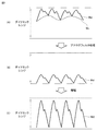
図7は、アナログフィルタの必要性を説明するための図である。図7(A)に示すように、検出電極対により検出された電圧信号(アナログデータ)に、所望の周波数成分(所望波成分Wd)以外の不要な周波数成分(ノイズ波成分Wn)が重畳されている状態を想定する。 FIG. 7 is a diagram for explaining the necessity of an analog filter. As shown in FIG. 7A, an unnecessary frequency component (noise wave component Wn) other than the desired frequency component (desired wave component Wd) is superimposed on the voltage signal (analog data) detected by the detection electrode pair. Imagine that you are in a state of being.
このアナログデータを、A/D変換によりディジタルデータに変換した後、ディジタルフィルタによりノイズ波成分Wnを取り除くことは可能である。しかしながら、その場合、所望波成分Wdのダイナミックレンジが小さいため、ディジタル変換後の所望波成分Wdに関するデータのS/N比は小さくなってしまう。 After converting this analog data into digital data by A / D conversion, it is possible to remove the noise wave component Wn by a digital filter. However, in that case, since the dynamic range of the desired wave component Wd is small, the S / N ratio of the data relating to the desired wave component Wd after digital conversion becomes small.
そこで、アナログフィルタによりノイズ波成分Wnを取り除いた後(図7(B)参照)、所望波成分Wdを増幅することにより(図7(C)参照)、所望波成分Wdのダイナミックレンジを大きくする。当該所望波成分WdをCPU100に入力することにより、脈波信号を精度よく取得できる。
Therefore, after removing the noise wave component Wn with an analog filter (see FIG. 7 (B)), the desired wave component Wd is amplified (see FIG. 7 (C)) to increase the dynamic range of the desired wave component Wd. .. By inputting the desired wave component Wd to the
次に、脈波伝播時間を精度よく測定するためには、フィルタの周波数特性(周波数依存性)を考慮する必要がある。 Next, in order to measure the pulse wave velocity accurately, it is necessary to consider the frequency characteristics (frequency dependence) of the filter.
図8は、フィルタの位相特性を説明するための図である。図8では、右側の縦軸は位相変化量を示しており、左側の縦軸は遅延時間を示しており、横軸は周波数を示している。図8の例では、アナログフィルタとして、遮断周波数が10Hzのローパスフィルタと、遮断周波数が0.5Hzのハイパスフィルタとを用いた例を示している。 FIG. 8 is a diagram for explaining the phase characteristics of the filter. In FIG. 8, the vertical axis on the right side shows the amount of phase change, the vertical axis on the left side shows the delay time, and the horizontal axis shows the frequency. In the example of FIG. 8, an example using a low-pass filter having a cutoff frequency of 10 Hz and a high-pass filter having a cutoff frequency of 0.5 Hz is shown as the analog filter.
図8を参照して、グラフ801はフィルタの周波数特性(位相特性)を示している。グラフ803は、グラフ801により示される位相特性を時間に変換した遅延時間特性を示している。グラフ805は、脈波信号である電圧信号(例えば、電圧信号v1)の周波数特性を示している。図8では、例えば、約1.2Hzにおいて、電圧信号のピークが存在し、そのときの位相変化量は約10°である。 With reference to FIG. 8, Graph 801 shows the frequency characteristics (phase characteristics) of the filter. Graph 803 shows the delay time characteristic obtained by converting the phase characteristic shown by the graph 801 into time. Graph 805 shows the frequency characteristics of a voltage signal (for example, voltage signal v1) which is a pulse wave signal. In FIG. 8, for example, at about 1.2 Hz, a peak of the voltage signal exists, and the amount of phase change at that time is about 10 °.
ここで、電圧信号v1,v2はともに脈波信号であるが、測定位置等が異なることから、各電圧信号v1,v2の波形の周波数成分は完全に一致しない。そのため、上記のようなフィルタ処理を電圧信号v1,v2に施すと、電圧信号v1および電圧信号v2にそれぞれ異なる量の位相変化が生じてしまう。したがって、脈波伝播時間を精度よく測定するためには、電圧信号v1および電圧信号v2の位相変化の差を小さくする必要がある。以下、この位相変化の差を小さくするための構成および処理について、具体的に説明する。 Here, although the voltage signals v1 and v2 are both pulse wave signals, the frequency components of the waveforms of the voltage signals v1 and v2 do not completely match because the measurement positions and the like are different. Therefore, when the above-mentioned filter processing is applied to the voltage signals v1 and v2, different amounts of phase changes occur in the voltage signals v1 and the voltage signals v2. Therefore, in order to measure the pulse wave velocity accurately, it is necessary to reduce the difference in phase change between the voltage signal v1 and the voltage signal v2. Hereinafter, the configuration and processing for reducing the difference in the phase change will be specifically described.
図9は、血圧計1の機能構成を示すブロック図である。具体的には、図9には、脈波伝播時間の測定に用いられる血圧計1の機能構成が示されている。
FIG. 9 is a block diagram showing a functional configuration of the
図9を参照して、血圧計1は、主たる機能構成として、信号入力部102と、データ生成部106と、ディジタルフィルタ部108と、時間算出部110と、血圧算出部112と、出力制御部114とを含む。これらの機能は、例えば、血圧計1のCPU100がメモリ51に格納されたプログラムを実行することによって実現される。なお、これらの機能の一部または全部はハードウェアで実現されるように構成されていてもよい。血圧計1は、メモリ51により実現されるデータ格納部104をさらに含む。
With reference to FIG. 9, the
信号入力部102は、A/Dコンバータ405から、予め定められたサンプリング周期ごとに出力される電圧信号v1,v2(ディジタルデータ)の入力を受け付ける。信号入力部102は、受け付けた電圧信号v1,v2をデータ格納部104に順次格納する。
The
データ格納部104は、電圧信号v1の時系列データと、電圧信号v2の時系列データとを格納する。具体的には、データ格納部104は、現時点から所定サイクル前までの各電圧信号v1,v2の時系列データを格納する。例えば、現時点の電圧信号v1の信号値(電圧信号のディジタル値)をv1(m)とし、1サンプリング周期前の信号値をv1(m−1)とし、2サンプリング周期前の信号値をv1(m−2)とする。以下同様に、nサンプリング周期前の信号値をv1(m−n)とする。
The
ディジタル信号処理部として機能するデータ生成部106およびディジタルフィルタ部108が、現時点からnサンプリング周期前までの信号値を利用する場合、v1(m)、v1(m−1)、v1(m−2)、…、v1(m−n)のn+1個の信号値を含む時系列データがデータ格納部104に格納される。すなわち、電圧信号v1の時系列データK1(信号値v1(m−n)〜v1(m))が格納される。同様に、電圧信号v2の時系列データK2(信号値v2(m−n)〜v2(m)がデータ格納部104に格納される。
When the data generation unit 106 and the
データ生成部106は、電圧信号v1の時系列データK1を、時系列的に逆方向から並べた時系列データKr1(信号値v1(m)〜v1(m−n))を生成する。同様に、データ生成部106は、電圧信号v2の時系列データK2を、時系列的に逆方向から並べた時系列データKr2(信号値v2(m)〜v2(m−n)を生成する。なお、データ生成部106は、所定時間分(例えば、5秒間分)の時系列データK1および時系列データK2がデータ格納部104に蓄積された場合に、当該生成を行なう。
The data generation unit 106 generates time-series data Kr1 (signal values v1 (m) to v1 (mn)) in which the time-series data K1 of the voltage signal v1 is arranged in the reverse direction in time series. Similarly, the data generation unit 106 generates time-series data Kr2 (signal values v2 (m) to v2 (mn)) in which the time-series data K2 of the voltage signal v2 is arranged in the reverse direction in time series. The data generation unit 106 generates the time-series data K1 and the time-series data K2 for a predetermined time (for example, for 5 seconds) when they are stored in the
ディジタルフィルタ部108は、時系列データKr1,Kr2の各々に対して、アナログフィルタ403と同一の伝達関数Gを有するディジタルフィルタによりフィルタ処理を実行し、時系列データKd1(信号値vd1(m)〜vd1(m−n))および時系列データKd2(信号値vd2(m)〜vd2(m−n))を生成する。時系列データKd1および時系列データKd2は、それぞれ次の式(1)および式(2)を用いて表される。
The
Kd1=Kr1×G・・・(1)
Kd2=Kr2×G・・・(2)
そして、データ生成部106は、時系列データKd1を、時系列的に順方向に並べ替えた時系列データKf1(信号値vd1(m−n)〜vd1(m))を生成する。また、データ生成部106は、時系列データKd2を、時系列的に順方向に並べ替えた時系列データKf2(信号値vd2(m−n)〜vd2(m))を生成する。
Kd1 = Kr1 × G ... (1)
Kd2 = Kr2 × G ... (2)
Then, the data generation unit 106 generates time-series data Kf1 (signal values vd1 (mn) to vd1 (m)) in which the time-series data Kd1 is rearranged in the forward direction in time series. Further, the data generation unit 106 generates time-series data Kf2 (signal values vd2 (mn) to vd2 (m)) in which the time-series data Kd2 is rearranged in the forward direction in time series.
このように、本実施の形態では、1)時系列データK1,K2を時系列的に逆方向から並べた時系列データKr1,Kr2が生成され、2)時系列データKr1,Kr2の各々に対して、伝達関数G(アナログフィルタ403と同一の伝達関数)を用いたディジタルフィルタ処理により時系列データKd1,Kd2が生成され、3)時系列データKd1,Kd2を時系列順に再度並べ直した時系列データKf1,Kf2が生成される。 As described above, in the present embodiment, 1) time-series data Kr1 and Kr2 in which the time-series data K1 and K2 are arranged in the opposite direction in time series are generated, and 2) for each of the time-series data Kr1 and Kr2. Then, the time series data Kd1 and Kd2 are generated by the digital filter processing using the transfer function G (the same transfer function as the analog filter 403), and 3) the time series data Kd1 and Kd2 are rearranged in chronological order. Data Kf1 and Kf2 are generated.
上記2)のディジタルフィルタ処理により、アナログフィルタ403によるフィルタ処理時とは逆方向にほぼ同じ量の位相ずれが発生し、3)により時系列順にデータが戻される。その結果、時系列データKf1,Kf2は、アナログフィルタ403によるフィルタ処理時の位相ずれが軽減されたデータとなる。
By the digital filter processing of 2) above, substantially the same amount of phase shift occurs in the direction opposite to that of the filtering by the
図10は、本実施の形態に従うディジタル信号処理の利点を説明するための図である。図10の縦軸は電圧を示しており、横軸は時間を示している。図10を参照して、波形901は、アナログフィルタによるフィルタ処理を施す前の脈波信号(例えば、電圧信号v1)の波形を示している。波形902は、アナログフィルタによるフィルタ処理を施した後、上記1)〜3)のディジタル信号処理を実行した脈波信号の波形を示している。波形903は、アナログフィルタによるフィルタ処理を施したのみであり、上記1)〜3)のディジタル信号処理を施していない脈波信号の波形を示している。
FIG. 10 is a diagram for explaining the advantages of digital signal processing according to the present embodiment. The vertical axis of FIG. 10 shows the voltage, and the horizontal axis shows the time. With reference to FIG. 10, the
図10に示すように、波形903は、アナログフィルタによる位相変化により、波形901からの変化量が大きい。一方、波形902は、波形901と非常に類似しており、アナログフィルタ処理による位相変化量が軽減されていることがわかる。具体的には、波形901および波形902の立ち上がり時点はいずれも時刻t1であり、波形901および波形902のピーク時点はいずれも時刻t2である。一方、波形901および波形903の立ち上がり時点およびピーク時点はいずれも異なるタイミングであることがわかる。立ち上がり時点は、例えば、時間の経過に伴って信号の瞬時値(電圧値)が増加するタイミングである。
As shown in FIG. 10, the
再び、図9を参照して、時間算出部110は、時系列データKf1により示される脈波信号PS1と、時系列データKf2により示される脈波信号PS2とに基づいて、脈波信号PS1と脈波信号PS2との間の時間差Δtを脈波伝播時間として算出する。
Again, referring to FIG. 9, the
例えば、時間算出部110は、脈波信号PS1のピークA1の時点と、脈波信号PS2のピークA2の時点との間の時間差Δtを脈波伝播時間として算出する。また、時間算出部110は、脈波信号PS1の立ち上がり時点と、脈波信号PS2の立ち上がり時点との間の時間差Δt1を脈波伝播時間として算出してもよい。あるいは、時間算出部110は、時間差Δtおよび時間差Δt1の平均値を脈波伝播時間として算出してもよい。これにより、脈波伝播時間の精度をより高めることができる。
For example, the
血圧算出部112は、時間算出部110により算出された脈波伝播時間に基づく血圧値を算出する。具体的には、血圧算出部112は、脈波伝播時間と血圧値との間の予め定められた対応式を用いて、脈波伝播時間に基づいて、血圧値を算出(推定)する。脈波伝播時間と血圧との間の予め定められた対応式は、例えば、公知の分数関数として以下の式(3)のように表わされる(例えば、特開平10−201724号公報参照)。ここで、DTは脈波伝播時間、EBPは血圧値、α,βはそれぞれ既知の係数または定数である。
The blood pressure calculation unit 112 calculates a blood pressure value based on the pulse wave velocity calculated by the
EBP=(α/DT2)+β・・・(3)
なお、対応式は、上記(3)に限られず、例えば、1/DT2の項に加えて、1/DTの項と、DTの項とを含む式を用いてもよい。また、これら以外の公知の対応式を用いてもよい。
EBP = (α / DT 2 ) + β ... (3)
The corresponding expression is not limited to (3) above, and for example, an expression including a 1 / DT term and a DT term may be used in addition to the 1 / DT 2 term. Further, a known corresponding formula other than these may be used.
出力制御部114は、血圧算出部112により算出された血圧値を表示器50に表示させる。また、出力制御部114は、血圧計1に搭載されたスピーカ(図示しない)を介して、血圧値を音声出力する構成であってもよい。
The
<脈波伝播時間に基づく血圧値の測定処理手順>
図11は、脈波伝播時間に基づく血圧値の測定処理手順を示すフローチャートである。図11を参照して、血圧計1のCPU100は、操作部52を介して脈波伝播時間に基づく血圧測定の指示を受け付ける(ステップS10)。CPU100は、切替弁35を駆動し、ポンプ32および弁33の接続先を押圧カフ24に切り替える(ステップS12)。
<Procedure for measuring blood pressure value based on pulse wave velocity>
FIG. 11 is a flowchart showing a blood pressure value measurement processing procedure based on the pulse wave velocity. With reference to FIG. 11, the
CPU100は、押圧カフ24を膨張させるとともにカフ圧Pcを大きくする(ステップS14)。具体的には、CPU100は、弁33を閉鎖するとともに、ポンプ駆動回路320を介してポンプ32を駆動して、押圧カフ24に空気を送ることによりカフ圧Pcを大きくする。続いて、CPU100は、カフ圧Pcが予め定められた圧力に達するとポンプ32を停止する(ステップS16)。これにより、カフ圧Pcは、予め定められた圧力に設定される。この状態で、CPU100は、以下のステップのように脈波伝播時間の取得を開始する。
The
具体的には、CPU100は、電圧信号v1,v2の入力を受け付けて、電圧信号v1,v2の各々の時系列データをメモリ51に蓄積する(ステップS18)。CPU100は、所定時間分の時系列データが蓄積されたか否かを判断する(ステップS20)。所定時間分の時系列データが蓄積されていない場合には(ステップS20においてNO)、CPU100はステップS18の処理を実行する。
Specifically, the
所定時間分の時系列データが蓄積された場合には(ステップS20においてYES)、CPU100は、ディジタル信号処理を実行する(ステップS22)。具体的には、CPU100は、電圧信号v1の時系列データK1を逆方向に並べた時系列データKr1と、電圧信号v2の時系列データK2を逆方向に並べた時系列データKr2とを生成する。CPU100は、時系列データKr1,Kr2の各々に対して、伝達関数Gに応じたディジタルフィルタ処理を施した時系列データKd1,Kd2を生成する。CPU100は、時系列データKd1,Kd2を時系列順に並べ替えた時系列データKf1,Kf2を生成する。これにより、CPU100は、時系列データKf1に対応する脈波信号PS1と、時系列データをKf2に対応する脈波信号PS2を生成する。
When the time-series data for a predetermined time is accumulated (YES in step S20), the
続いて、CPU100は、脈波信号PS1と、脈波信号PS2との間の時間差Δtを脈波伝播時間として算出する(ステップS24)。CPU100は、脈波伝播時間と血圧値との対応式(例えば、式(3))を用いて、脈波伝播時間に基づく血圧値を算出する(ステップS26)。CPU100は、算出した血圧値を表示器50に表示して(ステップS28)、処理を終了する。
Subsequently, the
<利点>
本実施の形態によると、各脈波信号における、フィルタ処理に伴う位相ずれを低減できる。そのため、各脈波信号の比較により算出される脈波伝播時間を精度よく測定できる。また、その結果、脈波伝播時間に基づく血圧測定の精度も向上する。
<Advantage>
According to this embodiment, it is possible to reduce the phase shift due to the filtering process in each pulse wave signal. Therefore, the pulse wave velocity calculated by comparing each pulse wave signal can be measured accurately. As a result, the accuracy of blood pressure measurement based on the pulse wave velocity is also improved.
また、本実施の形態によると、各脈波信号の波形全体を精度よく取得できる。そのため、一方の脈波信号の波形全体と、他方の脈波信号の波形全体とを比較(例えば、立ち上がり時点、ピーク時点等の比較)することにより脈波伝播時間を算出できる。 Further, according to the present embodiment, the entire waveform of each pulse wave signal can be acquired with high accuracy. Therefore, the pulse wave propagation time can be calculated by comparing the entire waveform of one pulse wave signal with the entire waveform of the other pulse wave signal (for example, comparison of rising time, peak time, etc.).
<その他の実施の形態>
1)上述の実施形態では、脈波センサ401および脈波センサ402は、被測定部位(左手首90)を通る動脈(橈骨動脈91)の脈波をインピーダンスの変化として検出する構成について説明したが、当該構成に限られない。
<Other embodiments>
1) In the above-described embodiment, the configuration in which the
例えば、各脈波センサは、被測定部位のうち対応する部分を通る動脈へ向けて光を照射する発光素子と、その光の反射光(または透過光)を受光する受光素子とを備えて、動脈の脈波を容積の変化として検出してもよい(光電方式)。または、各脈波センサは、被測定部位に当接された圧電センサを備えて、被測定部位のうち対応する部分を通る動脈の圧力による歪みを電気抵抗の変化として検出してもよい(圧電方式)。さらに、各脈波センサは、被測定部位のうち対応する部分を通る動脈へ向けて電波(送信波)を送る送信素子と、その電波の反射波を受信する受信素子とを備えて、動脈の脈波による動脈とセンサとの間の距離の変化を送信波と反射波との間の位相のずれとして検出してもよい(電波照射方式)。 For example, each pulse wave sensor includes a light emitting element that irradiates an artery passing through a corresponding portion of the measured portion with light, and a light receiving element that receives the reflected light (or transmitted light) of the light. The pulse wave of the artery may be detected as a change in volume (photoelectric method). Alternatively, each pulse wave sensor may be provided with a piezoelectric sensor abutting on the site to be measured, and may detect strain due to pressure of an artery passing through the corresponding portion of the site to be measured as a change in electrical resistance (piezoelectricity). method). Further, each pulse wave sensor includes a transmitting element that sends a radio wave (transmitted wave) toward the artery passing through the corresponding portion of the measured portion, and a receiving element that receives the reflected wave of the radio wave. The change in the distance between the artery and the sensor due to the pulse wave may be detected as the phase shift between the transmitted wave and the reflected wave (radio wave irradiation method).
2)上述した実施の形態では、押圧部の例として、ベルト20、押圧カフ24、および固形物22を挙げたが、これに限られない。例えば、脈波センサ401、脈波センサ402を非加圧状態の圧迫カフ21の外周面から機械式に厚さ方向に拡張する押圧部でもよい。また、上述の実施形態では、拡張部材の例として、流体袋の押圧カフ24を挙げたが、これに限られない。例えば、機械式に厚さ方向に拡張する拡張部材によって固形物22を介して脈波センサ401、脈波センサ402を押圧してもよい。
2) In the above-described embodiment, the
3)上述した実施の形態では、2つの脈波センサにより得られた2つの脈波信号を比較して、脈波伝播時間を算出する構成について説明したが、当該構成に限られない。例えば、1つの脈波センサ(例えば、脈波センサ401または402)により得られた脈波信号と、心電センサにより得られた心電信号とを比較して、脈波伝播時間を算出する構成であってもよい。この場合、心電信号についても、上記と同様のアナログ信号処理およびディジタル信号処理が施される。
3) In the above-described embodiment, the configuration for calculating the pulse wave velocity by comparing the two pulse wave signals obtained by the two pulse wave sensors has been described, but the present invention is not limited to this configuration. For example, a configuration in which a pulse wave signal obtained by one pulse wave sensor (for example,
心電センサは、一対の心電電極を有し、一方の心電電極と他方の心電電極によって心電信号を検出する。各心電電極は、例えば、人体の左右の手、腕等に接触させて取り付けられる。各心電電極は、ケーブルを通して電圧検出回路49と接続される。電圧検出回路49は、当該ケーブルを介して、心電信号を検出し、配線72を介してCPU100へ当該心電信号を出力する。なお、心電信号をフィルタ処理するアナログフィルタは、脈波信号をフィルタ処理するアナログフィルタと同じであってもよいし、異なっていてもよい。心電信号をフィルタ処理するための専用のアナログフィルタを別途用意する場合には、心電信号をディジタル信号処理する際に、当該専用のアナログフィルタの伝達関数と同一の伝達関数を有するディジタルフィルタによりフィルタ処理が施される。
The electrocardiographic sensor has a pair of electrocardiographic electrodes, and detects an electrocardiographic signal by one electrocardiographic electrode and the other electrocardiographic electrode. Each electrocardiographic electrode is attached, for example, in contact with the left and right hands, arms, etc. of the human body. Each electrocardiographic electrode is connected to the
典型的には、CPU100(時間算出部110)は、脈波信号の立ち上がり時点と、心電信号のピーク時点の時間差を脈波伝播時間として算出する。ただし、CPU100は、ディジタル信号処理済の時系列データにより示される脈波信号のピーク時点と、ディジタル信号処理済の時系列データにより示される心電信号のピーク時点の時間差を脈波伝播時間として算出してもよい。
Typically, the CPU 100 (time calculation unit 110) calculates the time difference between the rising time of the pulse wave signal and the peak time of the electrocardiographic signal as the pulse wave propagation time. However, the
4)上述の実施形態では、血圧計1に搭載されたCPU100がデータ生成部、ディジタルフィルタ部、時間算出部、血圧算出部および出力制御部として機能する構成について説明したが、当該構成に限られない。例えば、血圧計1と通信可能に構成されたコンピュータ装置(例えば、スマートフォン等)が、ネットワーク900を介して、電圧信号v1,v2(ディジタルデータ)を順次受信し、データ生成部、ディジタルフィルタ部、時間算出部、血圧算出部、出力制御部として機能することにより、脈波伝播時間および血圧値を算出し、血圧値を表示する構成であってもよい。
4) In the above-described embodiment, the configuration in which the
5)上述した実施の形態において、コンピュータを機能させて、上述のフローチャートで説明したような制御を実行させるプログラムを提供することもできる。このようなプログラムは、コンピュータに付属するフレキシブルディスク、CD(Compact Disk Read Only Memory)、二次記憶装置、主記憶装置およびメモリカードなどの一時的でないコンピュータ読取り可能な記録媒体にて記録させて、プログラム製品として提供することもできる。あるいは、コンピュータに内蔵するハードディスクなどの記録媒体にて記録させて、プログラムを提供することもできる。また、ネットワークを介したダウンロードによって、プログラムを提供することもできる。 5) In the above-described embodiment, it is also possible to provide a program that causes the computer to function and execute the control as described in the above-mentioned flowchart. Such programs are recorded on non-temporary computer-readable recording media such as flexible disks, CDs (Compact Disk Read Only Memory), secondary storage devices, main storage devices, and memory cards attached to computers. It can also be provided as a program product. Alternatively, the program can be provided by recording on a recording medium such as a hard disk built in the computer. The program can also be provided by downloading via the network.
プログラムは、コンピュータのオペレーティングシステム(OS)の一部として提供されるプログラムモジュールのうち、必要なモジュールを所定の配列で所定のタイミングで呼出して処理を実行させるものであってもよい。その場合、プログラム自体には上記モジュールが含まれずOSと協働して処理が実行される。このようなモジュールを含まないプログラムも、本実施の形態にかかるプログラムに含まれ得る。 The program may be a program module provided as a part of a computer operating system (OS), in which necessary modules are called in a predetermined array at a predetermined timing to execute processing. In that case, the program itself does not include the above module and the process is executed in cooperation with the OS. A program that does not include such a module may also be included in the program according to the present embodiment.
また、本実施の形態にかかるプログラムは他のプログラムの一部に組込まれて提供されるものであってもよい。その場合にも、プログラム自体には上記他のプログラムに含まれるモジュールが含まれず、他のプログラムと協働して処理が実行される。このような他のプログラムに組込まれたプログラムも、本実施の形態にかかるプログラムに含まれ得る。 Further, the program according to the present embodiment may be provided by being incorporated into a part of another program. Even in that case, the program itself does not include the modules included in the other programs, and the processing is executed in cooperation with the other programs. A program incorporated in such another program may also be included in the program according to the present embodiment.
上述の実施の形態として例示した構成は、本発明の構成の一例であり、別の公知の技術と組み合わせることも可能であるし、本発明の要旨を逸脱しない範囲で、一部を省略する等、変更して構成することも可能である。また、上述した実施の形態において、その他の実施の形態で説明した処理や構成を適宜採用して実施する場合であってもよい。 The configuration exemplified as the above-described embodiment is an example of the configuration of the present invention, can be combined with another known technique, and a part thereof is omitted as long as the gist of the present invention is not deviated. , Can be modified and configured. Further, in the above-described embodiment, the process or configuration described in the other embodiments may be appropriately adopted and carried out.
今回開示された実施の形態はすべての点で例示であって制限的なものではないと考えられるべきである。本発明の範囲は、上記した説明ではなく、特許請求の範囲によって示され、特許請求の範囲と均等の意味および範囲内でのすべての変更が含まれることが意図される。 It should be considered that the embodiments disclosed this time are exemplary in all respects and not restrictive. The scope of the present invention is shown by the scope of claims, not the above description, and is intended to include all modifications within the meaning and scope of the claims.
1 血圧計、41,46 電流電極対、10 本体、10b 底面、15 バックル、20 ベルト、21 圧迫カフ、22 固形物、23 帯状体、24 押圧カフ、25,26 板状部材、27,28 連結棒、29 固定部、31,34 圧力センサ、32 ポンプ、33 弁、35 切替弁、38a,38b,39a,39b エア配管、40 インピーダンス測定部、40E 電極群、42,43,44,45 検出電極対、49 電圧検出回路、50 表示器、51 メモリ、52 操作部、53 電池、59 通信部、71,72 配線、90 左手首、91 橈骨動脈、100 CPU、102 信号入力部、104 データ格納部、106 データ生成部、108 ディジタルフィルタ部、110 時間算出部、112 血圧算出部、114 出力制御部、310,340 発振回路、320 ポンプ駆動回路、401,402 脈波センサ、403 アナログフィルタ、404 増幅器、405 A/Dコンバータ、900 ネットワーク。 1 Blood pressure sensor, 41,46 current electrode pair, 10 body, 10b bottom surface, 15 buckle, 20 belt, 21 compression cuff, 22 solid matter, 23 strip, 24 compression cuff, 25,26 plate-shaped member, 27,28 connection Rod, 29 fixed part, 31,34 pressure sensor, 32 pump, 33 valve, 35 switching valve, 38a, 38b, 39a, 39b air piping, 40 impedance measuring part, 40E electrode group, 42, 43, 44, 45 detection electrode Pair, 49 voltage detection circuit, 50 display, 51 memory, 52 operation unit, 53 battery, 59 communication unit, 71, 72 wiring, 90 left wrist, 91 radial artery, 100 CPU, 102 signal input unit, 104 data storage unit , 106 data generator, 108 digital filter, 110 hour calculation, 112 blood pressure calculation, 114 output control, 310,340 oscillation circuit, 320 pump drive circuit, 401,402 pulse wave sensor, 403 analog filter, 404 amplifier , 405 A / D converter, 900 networks.
Claims (8)
前記被験者の脈波または心電を示す第2信号を検出する第2センサと、
前記第1センサにより検出された前記第1信号、および前記第2センサにより検出された前記第2信号の各々に対して、所定の伝達関数を有するアナログフィルタによりフィルタ処理を施し、ディジタルデータに変換する第1信号処理部と、
前記第1信号処理部によりディジタルデータに変換された前記第1信号の第1時系列データ、および前記第1信号処理部によりディジタルデータに変換された前記第2信号の第2時系列データの各々に対して、ディジタルフィルタによるフィルタ処理を含む信号処理を施す第2信号処理部とを備え、
前記第2信号処理部は、
前記ディジタルフィルタによるフィルタ処理前の前記第1時系列データを、時系列的に逆方向から並べた第3時系列データを生成し、
前記ディジタルフィルタによるフィルタ処理前の前記第2時系列データを、時系列的に逆方向から並べた第4時系列データを生成し、
前記第3時系列データおよび前記第4時系列データの各々に対して、前記所定の伝達関数を有する前記ディジタルフィルタによりフィルタ処理を施し、
前記ディジタルフィルタによりフィルタ処理が施された前記第3時系列データを、時系列順に並べ替えた第5時系列データを生成し、
前記ディジタルフィルタによりフィルタ処理が施された前記第4時系列データを、時系列順に並べ替えた第6時系列データを生成し、
前記第5時系列データにより示される信号と、前記第6時系列データにより示される信号とに基づいて、脈波伝播時間を算出する時間算出部をさらに備える、測定装置。 The first sensor that detects the first signal indicating the pulse wave of the subject, and
A second sensor that detects a second signal indicating the pulse wave or electrocardiogram of the subject, and
Each of the first signal detected by the first sensor and the second signal detected by the second sensor is filtered by an analog filter having a predetermined transfer function and converted into digital data. 1st signal processing unit and
Each of the first time-series data of the first signal converted into digital data by the first signal processing unit and the second time-series data of the second signal converted into digital data by the first signal processing unit. On the other hand, it is provided with a second signal processing unit that performs signal processing including filter processing by a digital filter.
The second signal processing unit
A third time-series data in which the first time-series data before filtering by the digital filter is arranged in chronological order from the opposite direction is generated.
A fourth time-series data in which the second time-series data before filtering by the digital filter is arranged in chronological order from the opposite direction is generated.
For each of said third time-series data and the fourth time-series data, performs a filtering process by the digital filter having a predetermined transfer function,
The third time-series data filtered by the digital filter is rearranged in chronological order to generate fifth time-series data.
The sixth time-series data obtained by rearranging the fourth time-series data filtered by the digital filter in chronological order is generated.
A measuring device further comprising a time calculation unit that calculates a pulse wave propagation time based on the signal indicated by the fifth time series data and the signal indicated by the sixth time series data.
前記第1センサおよび第2センサは、前記被験者の被測定部位を通る動脈のうちそれぞれ対向する部分の脈波を検出する、請求項1に記載の測定装置。 The second signal is a signal indicating a pulse wave, and is a signal indicating a pulse wave.
The measuring device according to claim 1, wherein the first sensor and the second sensor detect pulse waves in opposite portions of an artery passing through a measurement site of the subject.
前記第5時系列データにより示される信号の立ち上がり時点と、前記第6時系列データにより示される信号の立ち上がり時点との時間差を脈波伝播時間として算出する、または、
前記第5時系列データにより示される信号のピーク時点と、前記第6時系列データにより示される信号のピーク時点との時間差を脈波伝播時間として算出する、請求項2に記載の測定装置。 The time calculation unit
The time difference between the rising time of the signal indicated by the 5th time series data and the rising time of the signal indicated by the 6th time series data is calculated as the pulse wave propagation time, or
The measuring device according to claim 2, wherein the time difference between the peak time point of the signal indicated by the fifth time series data and the peak time point of the signal indicated by the sixth time series data is calculated as the pulse wave propagation time.
前記時間算出部は、
前記第5時系列データにより示される信号の立ち上がり時点と、前記第6時系列データにより示される信号のピーク時点との時間差を脈波伝播時間として算出する、請求項1に記載の測定装置。 The second signal is a signal indicating an electrocardiogram, and is a signal indicating an electrocardiogram.
The time calculation unit
The measuring device according to claim 1, wherein the time difference between the rising time of the signal indicated by the fifth time series data and the peak time of the signal indicated by the sixth time series data is calculated as the pulse wave propagation time.
前記第2信号処理部は、所定時間分の前記第1時系列データおよび前記第2時系列データが前記データ格納部に蓄積された場合に、前記信号処理を実行する、請求項1〜4のいずれか1項に記載の測定装置。 A data storage unit for storing the first time series data and the second time series data is further provided.
The second signal processing unit executes the signal processing when the first time series data and the second time series data for a predetermined time are accumulated in the data storage unit, according to claims 1 to 4. The measuring device according to any one item.
前記血圧算出部により算出された血圧値を前記表示器に表示させる表示制御部をさらに備える、請求項6に記載の測定装置。 Display and
The measuring device according to claim 6, further comprising a display control unit for displaying the blood pressure value calculated by the blood pressure calculation unit on the display.
前記被験者の脈波または心電を示す第2信号を検出するステップと、
前記第1信号および前記第2信号の各々に対して、所定の伝達関数を有するアナログフィルタによりフィルタ処理を施し、ディジタルデータに変換するステップと、
ディジタルデータに変換された前記第1信号の第1時系列データ、およびディジタルデータに変換された前記第2信号の第2時系列データの各々に対して、ディジタルフィルタによるフィルタ処理を含む信号処理を実行するステップとを含み、
前記実行するステップは、
前記ディジタルフィルタによるフィルタ処理前の前記第1信号の第1時系列データを、時系列的に逆方向から並べた第3時系列データを生成するステップと、
前記ディジタルフィルタによるフィルタ処理前の前記第2信号の第2時系列データを、時系列的に逆方向から並べた第4時系列データを生成するステップと、
前記第3時系列データおよび前記第4時系列データの各々に対して、前記所定の伝達関数を有する前記ディジタルフィルタによりフィルタ処理を施すステップと、
前記ディジタルフィルタによりフィルタ処理が施された前記第3時系列データを、時系列順に並べ替えた第5時系列データを生成するステップと、
前記ディジタルフィルタによりフィルタ処理が施された前記第4時系列データを、時系列順に並べ替えた第6時系列データを生成するステップとを含み、
前記第5時系列データにより示される信号と、前記第6時系列データにより示される信号とに基づいて、脈波伝播時間を算出するステップをさらに含む、測定方法。 The step of detecting the first signal indicating the pulse wave of the subject, and
The step of detecting the second signal indicating the pulse wave or the electrocardiogram of the subject, and
A step of filtering each of the first signal and the second signal by an analog filter having a predetermined transfer function and converting them into digital data.
Signal processing including filtering by a digital filter is performed on each of the first time-series data of the first signal converted into digital data and the second time-series data of the second signal converted into digital data. Including steps to perform
The step to be performed is
A step of generating a third time-series data in which the first time-series data of the first signal before filtering by the digital filter is arranged in chronological order from the opposite direction.
A step of generating a fourth time-series data in which the second time-series data of the second signal before filtering by the digital filter is arranged in chronological order from the opposite direction.
A step of performing filter processing by the for each of the third time-series data and the fourth time-series data, said digital filter having a predetermined transfer function,
A step of generating a fifth time-series data in which the third time-series data filtered by the digital filter is rearranged in chronological order.
A step of generating a sixth time-series data in which the fourth time-series data filtered by the digital filter is rearranged in chronological order is included.
A measurement method further comprising a step of calculating a pulse wave velocity based on the signal indicated by the fifth time series data and the signal indicated by the sixth time series data.
Priority Applications (5)
| Application Number | Priority Date | Filing Date | Title |
|---|---|---|---|
| JP2017144381A JP6902420B2 (en) | 2017-07-26 | 2017-07-26 | Measuring device and measuring method |
| PCT/JP2018/022026 WO2019021649A1 (en) | 2017-07-26 | 2018-06-08 | Measurement device and measurement method |
| CN201880045153.4A CN110891480B (en) | 2017-07-26 | 2018-06-08 | Measuring apparatus and measuring method |
| DE112018003290.6T DE112018003290T5 (en) | 2017-07-26 | 2018-06-08 | MEASURING DEVICE AND MEASURING METHOD |
| US16/748,888 US20200221962A1 (en) | 2017-07-26 | 2020-01-22 | Measurement device and measurement method |
Applications Claiming Priority (1)
| Application Number | Priority Date | Filing Date | Title |
|---|---|---|---|
| JP2017144381A JP6902420B2 (en) | 2017-07-26 | 2017-07-26 | Measuring device and measuring method |
Publications (3)
| Publication Number | Publication Date |
|---|---|
| JP2019024602A JP2019024602A (en) | 2019-02-21 |
| JP2019024602A5 JP2019024602A5 (en) | 2020-08-06 |
| JP6902420B2 true JP6902420B2 (en) | 2021-07-14 |
Family
ID=65040601
Family Applications (1)
| Application Number | Title | Priority Date | Filing Date |
|---|---|---|---|
| JP2017144381A Active JP6902420B2 (en) | 2017-07-26 | 2017-07-26 | Measuring device and measuring method |
Country Status (5)
| Country | Link |
|---|---|
| US (1) | US20200221962A1 (en) |
| JP (1) | JP6902420B2 (en) |
| CN (1) | CN110891480B (en) |
| DE (1) | DE112018003290T5 (en) |
| WO (1) | WO2019021649A1 (en) |
Families Citing this family (1)
| Publication number | Priority date | Publication date | Assignee | Title |
|---|---|---|---|---|
| JP2023004383A (en) * | 2021-06-25 | 2023-01-17 | オムロンヘルスケア株式会社 | Biological information measuring system, biological information measuring program, and biological information measuring device |
Family Cites Families (18)
| Publication number | Priority date | Publication date | Assignee | Title |
|---|---|---|---|---|
| US5318036A (en) * | 1992-03-17 | 1994-06-07 | Hewlett-Packard Company | Method and apparatus for removing baseline wander from an ECG signal |
| JPH07308295A (en) * | 1994-05-19 | 1995-11-28 | Omron Corp | Blood pressure measuring device |
| JP3348660B2 (en) * | 1998-10-09 | 2002-11-20 | 双葉電子工業株式会社 | Symbol synchronizer and frequency hopping receiver |
| JP3988674B2 (en) * | 2003-04-21 | 2007-10-10 | オムロンヘルスケア株式会社 | Pulse wave velocity information measuring device |
| JP2004321438A (en) * | 2003-04-24 | 2004-11-18 | Colin Medical Technology Corp | Apparatus for evaluating degree of arteriosclerosis |
| JP4644011B2 (en) * | 2005-03-15 | 2011-03-02 | パナソニック株式会社 | Ultrasonic Doppler blood flow meter |
| JP4645331B2 (en) * | 2005-07-07 | 2011-03-09 | ソニー株式会社 | Signal processing apparatus and signal processing method |
| CN100466968C (en) * | 2006-09-29 | 2009-03-11 | 北京新兴阳升科技有限公司 | Detection method with blood pressure monitor and korotkoff sound delaying and pulse wave conducting time signal generator |
| US20100152600A1 (en) * | 2008-04-03 | 2010-06-17 | Kai Sensors, Inc. | Non-contact physiologic motion sensors and methods for use |
| US9339209B2 (en) * | 2010-04-19 | 2016-05-17 | Sotera Wireless, Inc. | Body-worn monitor for measuring respiratory rate |
| US9408542B1 (en) * | 2010-07-22 | 2016-08-09 | Masimo Corporation | Non-invasive blood pressure measurement system |
| JP6003470B2 (en) * | 2012-09-25 | 2016-10-05 | オムロンヘルスケア株式会社 | Blood pressure measurement device and pulse wave detection method |
| JP6090424B2 (en) * | 2013-02-26 | 2017-03-08 | 株式会社村田製作所 | Pulse wave propagation time measurement device |
| CN104825140A (en) * | 2014-02-11 | 2015-08-12 | 瞿浩正 | Digital filter method for pulse wave extraction, and digital filter |
| CN107106054B (en) * | 2014-09-08 | 2021-11-02 | 苹果公司 | Blood pressure monitoring using multifunctional wrist-worn device |
| US9693738B2 (en) * | 2015-05-22 | 2017-07-04 | Panasonic Corporation | Heartbeat measuring apparatus, heartbeat measuring method, and recording medium |
| JP6583427B2 (en) * | 2015-11-17 | 2019-10-02 | 株式会社村田製作所 | Pulse wave propagation time measurement device and biological state estimation device |
| CN106108864B (en) * | 2016-06-23 | 2018-10-19 | 成都理工大学 | A kind of device and method measuring pulse velocity of wave in a small range based on reflection method |
-
2017
- 2017-07-26 JP JP2017144381A patent/JP6902420B2/en active Active
-
2018
- 2018-06-08 CN CN201880045153.4A patent/CN110891480B/en active Active
- 2018-06-08 WO PCT/JP2018/022026 patent/WO2019021649A1/en active Application Filing
- 2018-06-08 DE DE112018003290.6T patent/DE112018003290T5/en active Pending
-
2020
- 2020-01-22 US US16/748,888 patent/US20200221962A1/en not_active Abandoned
Also Published As
| Publication number | Publication date |
|---|---|
| WO2019021649A1 (en) | 2019-01-31 |
| CN110891480A (en) | 2020-03-17 |
| DE112018003290T5 (en) | 2020-04-09 |
| US20200221962A1 (en) | 2020-07-16 |
| CN110891480B (en) | 2022-10-21 |
| JP2019024602A (en) | 2019-02-21 |
Similar Documents
| Publication | Publication Date | Title |
|---|---|---|
| JP6761337B2 (en) | Pulse wave measuring device and pulse wave measuring method, and blood pressure measuring device | |
| US11622694B2 (en) | Pulse wave measurement device, pulse wave measurement method, and blood pressure measurement device | |
| JP6777535B2 (en) | Sphygmomanometer and blood pressure measurement method and equipment | |
| JP7124552B2 (en) | measuring device | |
| JP2019516416A (en) | Cardiovascular characteristic extraction device and method | |
| WO2019124025A1 (en) | Measurement device and program | |
| JP2020006208A (en) | Watch-type blood pressure measurement device | |
| JP6965066B2 (en) | Pulse wave measuring device, blood pressure measuring device, equipment, pulse wave measuring method, and blood pressure measuring method | |
| US11317818B2 (en) | Blood pressure measurement device and blood pressure measurement method | |
| JP6902420B2 (en) | Measuring device and measuring method | |
| JP2004305268A (en) | Cardiac sound detector | |
| WO2018123245A1 (en) | Pulse wave measurement device, pulse wave measurement method, and blood pressure measurement device | |
| US11457828B2 (en) | Pulse wave measurement electrode unit and pulse wave measurement device | |
| JP7023751B2 (en) | Biometric information measuring device | |
| JP6894330B2 (en) | Flow path forming member for health equipment, flow path forming unit for health equipment, and health equipment | |
| JP2010131247A (en) | Blood pressure measuring apparatus | |
| JP2012152372A (en) | Blood pressure measurement device and blood pressure measurement method | |
| JP6970605B2 (en) | Blood pressure estimator | |
| JP7102176B2 (en) | Biological information measuring device | |
| US9848782B2 (en) | Blood pressure estimation device, blood pressure estimation method, blood pressure measurement device, and recording medium | |
| KR20100128067A (en) | The apparatus and method for estimating blood pressure | |
| EP4221578B1 (en) | Estimating central blood pressure |
Legal Events
| Date | Code | Title | Description |
|---|---|---|---|
| A521 | Request for written amendment filed |
Free format text: JAPANESE INTERMEDIATE CODE: A523 Effective date: 20200608 |
|
| A621 | Written request for application examination |
Free format text: JAPANESE INTERMEDIATE CODE: A621 Effective date: 20200608 |
|
| TRDD | Decision of grant or rejection written | ||
| A01 | Written decision to grant a patent or to grant a registration (utility model) |
Free format text: JAPANESE INTERMEDIATE CODE: A01 Effective date: 20210608 |
|
| A61 | First payment of annual fees (during grant procedure) |
Free format text: JAPANESE INTERMEDIATE CODE: A61 Effective date: 20210621 |
|
| R150 | Certificate of patent or registration of utility model |
Ref document number: 6902420 Country of ref document: JP Free format text: JAPANESE INTERMEDIATE CODE: R150 |
|
| R250 | Receipt of annual fees |
Free format text: JAPANESE INTERMEDIATE CODE: R250 |