JP6777535B2 - Sphygmomanometer and blood pressure measurement method and equipment - Google Patents
Sphygmomanometer and blood pressure measurement method and equipment Download PDFInfo
- Publication number
- JP6777535B2 JP6777535B2 JP2016255262A JP2016255262A JP6777535B2 JP 6777535 B2 JP6777535 B2 JP 6777535B2 JP 2016255262 A JP2016255262 A JP 2016255262A JP 2016255262 A JP2016255262 A JP 2016255262A JP 6777535 B2 JP6777535 B2 JP 6777535B2
- Authority
- JP
- Japan
- Prior art keywords
- pulse wave
- blood pressure
- fluid bag
- fluid
- pressing
- Prior art date
- Legal status (The legal status is an assumption and is not a legal conclusion. Google has not performed a legal analysis and makes no representation as to the accuracy of the status listed.)
- Active
Links
Images


Classifications
-
- A—HUMAN NECESSITIES
- A61—MEDICAL OR VETERINARY SCIENCE; HYGIENE
- A61B—DIAGNOSIS; SURGERY; IDENTIFICATION
- A61B5/00—Measuring for diagnostic purposes; Identification of persons
- A61B5/02—Detecting, measuring or recording for evaluating the cardiovascular system, e.g. pulse, heart rate, blood pressure or blood flow
- A61B5/021—Measuring pressure in heart or blood vessels
- A61B5/02108—Measuring pressure in heart or blood vessels from analysis of pulse wave characteristics
- A61B5/02125—Measuring pressure in heart or blood vessels from analysis of pulse wave characteristics of pulse wave propagation time
-
- A—HUMAN NECESSITIES
- A61—MEDICAL OR VETERINARY SCIENCE; HYGIENE
- A61B—DIAGNOSIS; SURGERY; IDENTIFICATION
- A61B5/00—Measuring for diagnostic purposes; Identification of persons
- A61B5/02—Detecting, measuring or recording for evaluating the cardiovascular system, e.g. pulse, heart rate, blood pressure or blood flow
- A61B5/021—Measuring pressure in heart or blood vessels
- A61B5/02108—Measuring pressure in heart or blood vessels from analysis of pulse wave characteristics
-
- A—HUMAN NECESSITIES
- A61—MEDICAL OR VETERINARY SCIENCE; HYGIENE
- A61B—DIAGNOSIS; SURGERY; IDENTIFICATION
- A61B5/00—Measuring for diagnostic purposes; Identification of persons
- A61B5/02—Detecting, measuring or recording for evaluating the cardiovascular system, e.g. pulse, heart rate, blood pressure or blood flow
- A61B5/021—Measuring pressure in heart or blood vessels
- A61B5/02141—Details of apparatus construction, e.g. pump units or housings therefor, cuff pressurising systems, arrangements of fluid conduits or circuits
-
- A—HUMAN NECESSITIES
- A61—MEDICAL OR VETERINARY SCIENCE; HYGIENE
- A61B—DIAGNOSIS; SURGERY; IDENTIFICATION
- A61B5/00—Measuring for diagnostic purposes; Identification of persons
- A61B5/02—Detecting, measuring or recording for evaluating the cardiovascular system, e.g. pulse, heart rate, blood pressure or blood flow
- A61B5/021—Measuring pressure in heart or blood vessels
- A61B5/022—Measuring pressure in heart or blood vessels by applying pressure to close blood vessels, e.g. against the skin; Ophthalmodynamometers
- A61B5/02225—Measuring pressure in heart or blood vessels by applying pressure to close blood vessels, e.g. against the skin; Ophthalmodynamometers using the oscillometric method
-
- A—HUMAN NECESSITIES
- A61—MEDICAL OR VETERINARY SCIENCE; HYGIENE
- A61B—DIAGNOSIS; SURGERY; IDENTIFICATION
- A61B5/00—Measuring for diagnostic purposes; Identification of persons
- A61B5/02—Detecting, measuring or recording for evaluating the cardiovascular system, e.g. pulse, heart rate, blood pressure or blood flow
- A61B5/021—Measuring pressure in heart or blood vessels
- A61B5/022—Measuring pressure in heart or blood vessels by applying pressure to close blood vessels, e.g. against the skin; Ophthalmodynamometers
- A61B5/0225—Measuring pressure in heart or blood vessels by applying pressure to close blood vessels, e.g. against the skin; Ophthalmodynamometers the pressure being controlled by electric signals, e.g. derived from Korotkoff sounds
-
- A—HUMAN NECESSITIES
- A61—MEDICAL OR VETERINARY SCIENCE; HYGIENE
- A61B—DIAGNOSIS; SURGERY; IDENTIFICATION
- A61B5/00—Measuring for diagnostic purposes; Identification of persons
- A61B5/68—Arrangements of detecting, measuring or recording means, e.g. sensors, in relation to patient
- A61B5/6801—Arrangements of detecting, measuring or recording means, e.g. sensors, in relation to patient specially adapted to be attached to or worn on the body surface
- A61B5/6802—Sensor mounted on worn items
- A61B5/681—Wristwatch-type devices
-
- A—HUMAN NECESSITIES
- A61—MEDICAL OR VETERINARY SCIENCE; HYGIENE
- A61B—DIAGNOSIS; SURGERY; IDENTIFICATION
- A61B5/00—Measuring for diagnostic purposes; Identification of persons
- A61B5/68—Arrangements of detecting, measuring or recording means, e.g. sensors, in relation to patient
- A61B5/6801—Arrangements of detecting, measuring or recording means, e.g. sensors, in relation to patient specially adapted to be attached to or worn on the body surface
- A61B5/6813—Specially adapted to be attached to a specific body part
- A61B5/6824—Arm or wrist
-
- A—HUMAN NECESSITIES
- A61—MEDICAL OR VETERINARY SCIENCE; HYGIENE
- A61B—DIAGNOSIS; SURGERY; IDENTIFICATION
- A61B5/00—Measuring for diagnostic purposes; Identification of persons
- A61B5/68—Arrangements of detecting, measuring or recording means, e.g. sensors, in relation to patient
- A61B5/6801—Arrangements of detecting, measuring or recording means, e.g. sensors, in relation to patient specially adapted to be attached to or worn on the body surface
- A61B5/683—Means for maintaining contact with the body
- A61B5/6831—Straps, bands or harnesses
-
- A—HUMAN NECESSITIES
- A61—MEDICAL OR VETERINARY SCIENCE; HYGIENE
- A61B—DIAGNOSIS; SURGERY; IDENTIFICATION
- A61B5/00—Measuring for diagnostic purposes; Identification of persons
- A61B5/72—Signal processing specially adapted for physiological signals or for diagnostic purposes
- A61B5/7203—Signal processing specially adapted for physiological signals or for diagnostic purposes for noise prevention, reduction or removal
- A61B5/7207—Signal processing specially adapted for physiological signals or for diagnostic purposes for noise prevention, reduction or removal of noise induced by motion artifacts
- A61B5/721—Signal processing specially adapted for physiological signals or for diagnostic purposes for noise prevention, reduction or removal of noise induced by motion artifacts using a separate sensor to detect motion or using motion information derived from signals other than the physiological signal to be measured
-
- A—HUMAN NECESSITIES
- A61—MEDICAL OR VETERINARY SCIENCE; HYGIENE
- A61B—DIAGNOSIS; SURGERY; IDENTIFICATION
- A61B2562/00—Details of sensors; Constructional details of sensor housings or probes; Accessories for sensors
- A61B2562/02—Details of sensors specially adapted for in-vivo measurements
- A61B2562/0219—Inertial sensors, e.g. accelerometers, gyroscopes, tilt switches
-
- A—HUMAN NECESSITIES
- A61—MEDICAL OR VETERINARY SCIENCE; HYGIENE
- A61B—DIAGNOSIS; SURGERY; IDENTIFICATION
- A61B2562/00—Details of sensors; Constructional details of sensor housings or probes; Accessories for sensors
- A61B2562/02—Details of sensors specially adapted for in-vivo measurements
- A61B2562/0247—Pressure sensors
-
- A—HUMAN NECESSITIES
- A61—MEDICAL OR VETERINARY SCIENCE; HYGIENE
- A61B—DIAGNOSIS; SURGERY; IDENTIFICATION
- A61B5/00—Measuring for diagnostic purposes; Identification of persons
- A61B5/02—Detecting, measuring or recording for evaluating the cardiovascular system, e.g. pulse, heart rate, blood pressure or blood flow
- A61B5/021—Measuring pressure in heart or blood vessels
- A61B5/022—Measuring pressure in heart or blood vessels by applying pressure to close blood vessels, e.g. against the skin; Ophthalmodynamometers
- A61B5/02233—Occluders specially adapted therefor
-
- A—HUMAN NECESSITIES
- A61—MEDICAL OR VETERINARY SCIENCE; HYGIENE
- A61B—DIAGNOSIS; SURGERY; IDENTIFICATION
- A61B5/00—Measuring for diagnostic purposes; Identification of persons
- A61B5/02—Detecting, measuring or recording for evaluating the cardiovascular system, e.g. pulse, heart rate, blood pressure or blood flow
- A61B5/021—Measuring pressure in heart or blood vessels
- A61B5/022—Measuring pressure in heart or blood vessels by applying pressure to close blood vessels, e.g. against the skin; Ophthalmodynamometers
- A61B5/0235—Valves specially adapted therefor
Landscapes
- Health & Medical Sciences (AREA)
- Life Sciences & Earth Sciences (AREA)
- Cardiology (AREA)
- Engineering & Computer Science (AREA)
- Vascular Medicine (AREA)
- Molecular Biology (AREA)
- Animal Behavior & Ethology (AREA)
- Pathology (AREA)
- Physics & Mathematics (AREA)
- Biomedical Technology (AREA)
- Heart & Thoracic Surgery (AREA)
- Medical Informatics (AREA)
- Veterinary Medicine (AREA)
- Surgery (AREA)
- Biophysics (AREA)
- General Health & Medical Sciences (AREA)
- Public Health (AREA)
- Physiology (AREA)
- Ophthalmology & Optometry (AREA)
- Signal Processing (AREA)
- Artificial Intelligence (AREA)
- Computer Vision & Pattern Recognition (AREA)
- Psychiatry (AREA)
- Measuring Pulse, Heart Rate, Blood Pressure Or Blood Flow (AREA)
Description
この発明は血圧計および血圧測定方法に関し、より詳しくは、動脈を伝播する脈波の伝播時間(脈波伝播時間;Pulse Transit Time;PTT)に基づく血圧測定と、オシロメトリック法による血圧測定とが可能な血圧計および血圧測定方法に関する。さらに、この発明は、血圧測定機能を備えた機器に関する。 The present invention relates to a sphygmomanometer and a blood pressure measuring method, and more particularly, a blood pressure measurement based on a pulse wave propagation time (Pulse Transit Time; PTT) propagating through an artery and a blood pressure measurement by an oscillometric method. Regarding possible blood pressure monitors and blood pressure measurement methods. Furthermore, the present invention relates to a device having a blood pressure measuring function.
従来、例えば特許文献1(特開平10−328151号公報)に開示されているように、橈骨動脈に沿って第1、2圧力センサを配置し、これらの第1、2圧力センサを、空気袋により押圧板を介して手首に向かって押圧する技術が知られている。この技術では、第1、2圧力センサからそれぞれ検出された脈波信号の時間差である脈波伝播時間を測定し、脈波伝播時間に基づいて血圧の測定を行っている。 Conventionally, for example, as disclosed in Patent Document 1 (Japanese Unexamined Patent Publication No. 10-328151), first and second pressure sensors are arranged along the radial artery, and these first and second pressure sensors are used as air bags. There is known a technique of pressing toward the wrist via a pressing plate. In this technique, the pulse wave velocity, which is the time difference between the pulse wave signals detected by the first and second pressure sensors, is measured, and the blood pressure is measured based on the pulse wave velocity.
特許文献1のように脈波伝播時間に基づいて血圧の測定を行う場合には、安静時において血圧の算出に必要なパラメータを被験者ごとに最適化することが必要になる。また、このような最適化を行ったとしても、測定条件によって脈波伝播時間と血圧との関係が異なるため、オシロメトリック法を用いた血圧計で測定した血圧により、キャリブレーションを行うことが必要になる。
When the blood pressure is measured based on the pulse wave velocity as in
従来は、キャリブレーションのために、脈波伝播時間に基づいて血圧の測定を行う装置とは別に、オシロメトリック法の血圧計を用意して血圧の測定を行っており、被験者にとって非常に不便であった。したがって、これらの異なる種類の血圧測定を一つの装置で行うことが従来から望まれていた。 Conventionally, for calibration, a sphygmomanometer of the oscillometric method is prepared separately from the device that measures the blood pressure based on the pulse wave propagation time, and the blood pressure is measured, which is very inconvenient for the subject. there were. Therefore, it has been conventionally desired to measure these different types of blood pressure with one device.
例えば、特許文献1に記載された第1、2圧力センサ、押圧板、および空気袋の外周に、オシロメトリック法の血圧計で用いられる手首を取り巻いて装着されるカフを設け、このカフを用いてオシロメトリック法による血圧測定を行うことも考えられる。
For example, a cuff worn around the wrist used in an sphygmomanometer of the oscillometric method is provided on the outer periphery of the first and second pressure sensors, the pressing plate, and the air bag described in
しかしながら、この場合には、カフと手首との間に、第1、2圧力センサ、および押圧板が存在しているため、これらの硬い部材が手首に対する圧迫を阻害して血管を充分に閉じることができず、血圧の測定精度が低下するという問題があった。 However, in this case, since the first and second pressure sensors and the pressing plate are present between the cuff and the wrist, these hard members inhibit the pressure on the wrist and sufficiently close the blood vessel. There was a problem that the blood pressure measurement accuracy was lowered.
そこで、この発明の課題は、脈波伝播時間に基づく血圧測定と、オシロメトリック法による血圧測定とを、簡単な構成でそれぞれ精度良く測定できる血圧計および血圧測定方法並びに機器を提供することにある。 Therefore, an object of the present invention is to provide a sphygmomanometer, a blood pressure measuring method, and an apparatus capable of accurately measuring blood pressure based on pulse wave propagation time and blood pressure measurement by an oscillometric method with a simple configuration. ..
上記課題を解決するため、この発明の血圧計は、
被測定部位を取り巻いて装着され、流体の供給または排出により加圧状態または非加圧状態となる第1の流体袋と、
上記第1の流体袋に、この第1の流体袋の幅方向に関して互いに離間した状態で搭載され、上記被測定部位を通る動脈のうちそれぞれ対向する部分の脈波を検出する第1、第2の脈波センサと、
上記第1の流体袋における上記第1、第2の脈波センサが搭載された内周側とは反対の外周側から、上記第1の流体袋の周方向に関して上記第1、第2の脈波センサに対応する領域を局所的に押圧する押圧部と、
上記第1の流体袋を非加圧状態にして、上記押圧部の押圧力で上記第1、第2の脈波センサを押圧し、その状態で上記第1、第2の脈波センサの出力から求めた脈波伝播時間に基づく血圧を算出する第1の血圧算出部と、
オシロメトリック法による血圧測定のために、上記第1の流体袋を加圧状態にして、上記第1の流体袋内の圧力に基づいて血圧を算出する第2の血圧算出部と、
を備えたことを特徴とする。
In order to solve the above problems, the sphygmomanometer of the present invention
A first fluid bag that is attached around the part to be measured and is in a pressurized or non-pressurized state by supplying or discharging a fluid.
The first and second fluid bags are mounted on the first fluid bag in a state of being separated from each other in the width direction of the first fluid bag, and detect pulse waves of opposite portions of the arteries passing through the measurement site. Pulse wave sensor and
From the outer peripheral side of the first fluid bag opposite to the inner peripheral side on which the first and second pulse wave sensors are mounted, the first and second pulses in the circumferential direction of the first fluid bag A pressing part that locally presses the area corresponding to the wave sensor,
The first fluid bag is put into a non-pressurized state, the first and second pulse wave sensors are pressed by the pressing force of the pressing portion, and the outputs of the first and second pulse wave sensors in that state. The first blood pressure calculation unit that calculates the blood pressure based on the pulse wave velocity obtained from
For blood pressure measurement by the oscillometric method, a second blood pressure calculation unit that pressurizes the first fluid bag and calculates the blood pressure based on the pressure in the first fluid bag,
It is characterized by being equipped with.
本明細書で、「被測定部位」とは、動脈が通っている部位を指す。被測定部位は、例えば手首、上腕などの上肢であっても良いし、足首、大腿などの下肢であっても良い。 As used herein, the term "measured site" refers to a site through which an artery passes. The measurement site may be, for example, an upper limb such as a wrist or an upper arm, or a lower limb such as an ankle or a thigh.
また、「流体袋」とは、名称の如何を問わず、流体を収容可能な袋状の部材を指す。例えば、流体袋に代えて、「カフ」などの名称であっても良い。「流体」は、液体と気体の両方を含み、例えば、水、空気などを用いることができる。 Further, the "fluid bag" refers to a bag-shaped member capable of accommodating a fluid regardless of the name. For example, instead of the fluid bag, a name such as "cuff" may be used. The "fluid" includes both a liquid and a gas, and for example, water, air and the like can be used.
また、流体袋の「幅方向」とは、被測定部位の長手方向に相当する。 Further, the "width direction" of the fluid bag corresponds to the longitudinal direction of the part to be measured.
この発明の血圧計では、第1の流体袋に、この第1の流体袋の幅方向に関して互いに離間した状態で第1、第2の脈波センサが搭載されている。また、上記第1の流体袋における上記第1、第2の脈波センサが搭載された内周側とは反対の外周側には、上記第1の流体袋の周方向に関して上記第1、第2の脈波センサに対応する領域を局所的に押圧する押圧部が設けられている。脈波伝播時間に基づく血圧測定が行われる場合には、上記第1の流体袋から流体が排出されることにより上記第1の流体袋は非加圧状態となる。ここで、上記押圧部が、被測定部位に対して上記第1、第2の脈波センサを、例えば或る押圧力で押圧する。この状態で、第1の血圧算出部は、上記第1、第2の脈波センサの出力から求めた脈波伝播時間に基づく血圧を算出する。この場合には、上記押圧部と上記第1、第2の脈波センサとの間には、上記第1の流体袋が介在しているが、上記第1の流体袋は非加圧状態となっているので、上記押圧部による上記第1、第2の脈波センサの押圧は上記第1の流体袋により妨げられることがない。その結果、適切な測定条件で上記第1、第2の脈波信号の測定を行うことができ、脈波伝播時間に基づく血圧測定を精度良く行うことができる。一方、オシロメトリック法による血圧測定が行われる場合には、上記第1の流体袋が被測定部位を取り巻いて装着された状態で、上記第1の流体袋に流体を供給することにより上記第1の流体袋は加圧状態となり、被測定部位に対して上記第1、第2の脈波センサを、例えば或る押圧力で押圧する。この状態で、第2の血圧算出部は、上記流体内の圧力に基づいて血圧を算出する。ここで、上記第1の流体袋と上記第1、第2の脈波センサとの間には、他の部材(例えば、押圧板)が介在していないので、被測定部位は上記第1の流体袋により充分に圧迫され、血管を充分に閉じることができる。その結果、オシロメトリック法による血圧測定が精度良く行われる。したがって、この発明によれば、簡単な構成で、一つの血圧計で脈波伝播時間に基づく血圧測定とオシロメトリック法による血圧測定とを精度良く行うことができ、脈波伝播時間に基づく血圧測定に必要なキャリブレーションを適切に行うことができる。 In the sphygmomanometer of the present invention, the first fluid bag is equipped with the first and second pulse wave sensors in a state of being separated from each other in the width direction of the first fluid bag. Further, on the outer peripheral side of the first fluid bag opposite to the inner peripheral side on which the first and second pulse wave sensors are mounted, the first and first fluid bags are located in the circumferential direction of the first fluid bag. A pressing portion that locally presses the region corresponding to the pulse wave sensor of 2 is provided. When the blood pressure is measured based on the pulse wave propagation time, the first fluid bag is put into a non-pressurized state by discharging the fluid from the first fluid bag. Here, the pressing portion presses the first and second pulse wave sensors against the measured portion with, for example, a certain pressing force. In this state, the first blood pressure calculation unit calculates the blood pressure based on the pulse wave propagation time obtained from the outputs of the first and second pulse wave sensors. In this case, the first fluid bag is interposed between the pressing portion and the first and second pulse wave sensors, but the first fluid bag is in a non-pressurized state. Therefore, the pressing of the first and second pulse wave sensors by the pressing portion is not hindered by the first fluid bag. As a result, the first and second pulse wave signals can be measured under appropriate measurement conditions, and the blood pressure can be accurately measured based on the pulse wave propagation time. On the other hand, when the blood pressure is measured by the oscillometric method, the first fluid bag is supplied to the first fluid bag in a state where the first fluid bag is attached around the measurement site. The fluid bag is in a pressurized state, and presses the first and second pulse wave sensors against the part to be measured with, for example, a certain pressing force. In this state, the second blood pressure calculation unit calculates the blood pressure based on the pressure in the fluid. Here, since no other member (for example, a pressing plate) is interposed between the first fluid bag and the first and second pulse wave sensors, the part to be measured is the first It is sufficiently compressed by the fluid bag and the blood vessels can be sufficiently closed. As a result, blood pressure measurement by the oscillometric method is performed with high accuracy. Therefore, according to the present invention, it is possible to accurately perform blood pressure measurement based on pulse wave propagation time and blood pressure measurement by the oscillometric method with one sphygmomanometer with a simple configuration, and blood pressure measurement based on pulse wave propagation time. The necessary calibration can be performed properly.
一実施形態の血圧計では、
上記押圧部は、
上記被測定部位を取り巻いて装着されるべきベルトと、
上記ベルトよりも上記被測定部位に近い上記ベルトの内周側に配置され、上記ベルトの厚さ方向に伸縮する拡張部材と、
上記拡張部材よりも上記被測定部位に近い上記拡張部材の内周側の、上記第1、第2の脈波センサに対応する位置に配置された固形物と、
を備えたことを特徴とする。
In one embodiment of the sphygmomanometer
The pressing part is
The belt that should be worn around the part to be measured and
An expansion member arranged on the inner peripheral side of the belt, which is closer to the part to be measured than the belt and expands and contracts in the thickness direction of the belt,
A solid substance arranged at a position corresponding to the first and second pulse wave sensors on the inner peripheral side of the expansion member closer to the measurement site than the expansion member.
It is characterized by being equipped with.
この実施形態において、「ベルト」とは、名称の如何を問わず、被測定部位を取り巻いて装着される帯状の部材を指す。例えば、ベルトに代えて、「バンド」、「カフ」などの名称であっても良い。 In this embodiment, the "belt" refers to a band-shaped member that surrounds and is attached to the part to be measured, regardless of the name. For example, instead of the belt, names such as "band" and "cuff" may be used.
この一実施形態の血圧計では、脈波伝播時間に基づく血圧測定が行われる場合に、上記ベルトが被測定部位を取り巻いて装着され、上記第1の流体袋から流体が排出されることにより上記第1の流体袋が非加圧になった状態で、押圧部が上記ベルトの内周側に配置された上記拡張部材を拡張させると、上記第1、第2の脈波センサのそれぞれは、上記ベルト、上記拡張部材、および上記拡張部材の内周側の上記第1、第2の脈波センサに対応する位置に配置された上記固形物により局所的に押圧される。したがって、上記第1、第2の脈波センサのそれぞれを適切な押圧力で押圧することができ、精度良く脈波伝播時間に基づく血圧測定を行うことができる。 In the sphygmomanometer of this embodiment, when the blood pressure is measured based on the pulse wave velocity, the belt is worn around the measurement site, and the fluid is discharged from the first fluid bag. When the expansion member whose pressing portion is arranged on the inner peripheral side of the belt is expanded in a state where the first fluid bag is not pressurized, the first and second pulse wave sensors, respectively, are expanded. It is locally pressed by the belt, the expansion member, and the solid material arranged at positions corresponding to the first and second pulse wave sensors on the inner peripheral side of the expansion member. Therefore, each of the first and second pulse wave sensors can be pressed with an appropriate pressing force, and blood pressure can be measured accurately based on the pulse wave propagation time.
一実施形態の脈波測定装置では、
上記拡張部材は、流体の供給または排出により加圧状態または非加圧状態となる第2の流体袋であることを特徴とする。
In the pulse wave measuring device of one embodiment,
The expansion member is a second fluid bag that is in a pressurized state or a non-pressurized state by supplying or discharging a fluid.
この一実施形態の血圧計では、上記拡張部材としての第2の流体袋に流体を供給することにより、上記拡張部材は加圧状態となり、上記固形物を介して上記第1、第2の脈波センサを局所的に押圧する。したがって、脈波伝播時間に基づく血圧測定が精度良く行われる。一方、上記拡張部材としての第2の流体袋から流体が排出されることにより、上記拡張部材は非加圧状態となる。ここで、上記ベルトが被測定部位を取り巻いて装着された状態で、上記第1、第2の脈波センサが搭載された上記第1の流体袋に流体を供給することにより、この第1の流体袋は加圧状態となり、被測定部位を充分に圧迫する。したがって、オシロメトリック法による血圧測定が精度良く行われる。また、上記拡張部材として第2の流体袋を用いることにより、この第2の流体袋と、被測定部位を取り巻いて装着される上記第1の流体袋とを、ポンプの切り替えで使用することができ、制御の共通化を図ることができる。 In the sphygmomanometer of this one embodiment, by supplying a fluid to the second fluid bag as the expansion member, the expansion member is in a pressurized state, and the first and second pulses are passed through the solid matter. Press the wave sensor locally. Therefore, blood pressure measurement based on the pulse wave velocity is performed with high accuracy. On the other hand, when the fluid is discharged from the second fluid bag as the expansion member, the expansion member is put into a non-pressurized state. Here, the first fluid is supplied to the first fluid bag on which the first and second pulse wave sensors are mounted in a state where the belt is attached around the portion to be measured. The fluid bag is in a pressurized state and sufficiently presses the part to be measured. Therefore, blood pressure measurement by the oscillometric method is performed with high accuracy. Further, by using the second fluid bag as the expansion member, the second fluid bag and the first fluid bag mounted around the part to be measured can be used by switching the pump. It is possible to standardize control.
一実施形態の血圧計では、
上記第1、第2の脈波センサはそれぞれ上記対向する部分の電圧を検出する検出電極対を含むことを特徴とする。
In one embodiment of the sphygmomanometer
The first and second pulse wave sensors are characterized by including a detection electrode pair for detecting the voltage of the opposite portions, respectively.
この一実施形態の血圧計では、上記第1、第2の脈波センサの検出電極対により、被測定部位を通る動脈のうち、検出電極対のそれぞれ対向する部分の電圧が検出され、いわゆるインピーダンス法により、脈波信号を得ることができる。したがって、簡単な構成で、脈波伝播時間に基づく血圧測定が行われる。また、このような検出電極対は、例えば板状またはシート状の柔軟な電極によって偏平に構成され得る。その場合、上記検出電極対は、上記第1の流体袋による被測定部位の圧迫を妨げず、オシロメトリック法による血圧測定の精度を損なうことがない。 In the sphygmomanometer of this one embodiment, the voltage of each of the detection electrode pairs of the artery passing through the measurement site is detected by the detection electrode pairs of the first and second pulse wave sensors, so-called impedance. By the method, a pulse wave signal can be obtained. Therefore, blood pressure measurement based on pulse wave velocity is performed with a simple configuration. Further, such a detection electrode pair may be formed flat by, for example, a plate-shaped or sheet-shaped flexible electrode. In that case, the detection electrode pair does not interfere with the compression of the measurement site by the first fluid bag, and does not impair the accuracy of blood pressure measurement by the oscillometric method.
一実施形態の血圧計では、
上記第1、第2の脈波センサがそれぞれ時系列で出力する第1、第2の脈波信号を取得して、それらの第1、第2の脈波信号の波形間の相互相関係数を算出する相互相関係数算出部と、
上記拡張部材による押圧力を、上記相互相関係数算出部により算出された上記相互相関係数が予め定められた閾値を超えるように設定する押圧力設定部と、
を備えたことを特徴とする。
In one embodiment of the sphygmomanometer
The first and second pulse wave sensors output the first and second pulse wave signals in time series, respectively, and the mutual correlation coefficient between the waveforms of the first and second pulse wave signals is acquired. The mutual correlation coefficient calculation unit that calculates
A pressing force setting unit that sets the pressing force by the expanding member so that the intercorrelation coefficient calculated by the intercorrelation coefficient calculating unit exceeds a predetermined threshold value.
It is characterized by being equipped with.
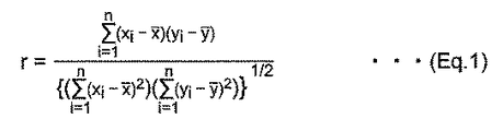
本明細書では、「相互相関係数」とは、標本相関係数(sample correlation coefficient)を意味する(ピアソン(Pearson)の積率相関係数とも呼ばれる。)。例えば、2組の数値からなるデータ列{xi}、データ列{yi}(ここで、i=1,2,…,nとする。)が与えられたとき、データ列{xi}とデータ列{yi}との間の相互相関係数rは、図12に示す式(Eq.1)によって定義される。式(Eq.1)中の、上バーが付されたx,yは、それぞれx,yの平均値を表している。 As used herein, the term "mutual correlation coefficient" means a sample correlation coefficient (also referred to as a Pearson product-moment correlation coefficient). For example, given a data string {x i } consisting of two sets of numerical values and a data string {y i } (here, i = 1, 2, ..., N), the data string {x i } The intercorrelation coefficient r between the data string and the data string {y i } is defined by the equation (Eq.1) shown in FIG. In the formula (Eq.1), x and y with an upper bar represent the average values of x and y, respectively.
この一実施形態の血圧計では、流体袋が被測定部位を取り巻いて装着された状態で、押圧部材が被測定部位に対して上記第1、第2の脈波センサを、例えば或る押圧力で押圧する。この状態で、上記第1、第2の脈波センサが上記被測定部位を通る動脈のうちそれぞれ対向する部分の脈波を検出する。相互相関係数算出部は、上記第1、第2の脈波センサがそれぞれ時系列で出力する第1、第2の脈波信号を取得して、それらの脈波信号の波形間の相互相関係数を算出する。ここで、押圧力設定部は、上記押圧部材のうち、上記拡張部材による押圧力を、上記相互相関係数算出部により算出された上記相互相関係数が予め定められた閾値を超えるように設定する。この状態で、第1の血圧算出部は、上記第1、第2の脈波センサの出力から求めた脈波伝播時間に基づく血圧を算出する。これにより、脈波伝播時間の測定精度を高め、脈波伝播時間に基づく血圧測定が精度良く行われる。また、被測定部位を圧迫する押圧力を無用に大きくすることなく、脈波伝播時間を取得できる。これにより、ユーザの身体的負担を軽くすることができる。 In the sphygmomanometer of this embodiment, the pressing member presses the first and second pulse wave sensors on the measured portion, for example, a certain pressing pressure, while the fluid bag is attached around the measured portion. Press with. In this state, the first and second pulse wave sensors detect the pulse waves of the opposing portions of the arteries passing through the measurement site. The mutual correlation coefficient calculation unit acquires the first and second pulse wave signals output by the first and second pulse wave sensors in time series, respectively, and the mutual phase between the waveforms of those pulse wave signals. Calculate the number of relationships. Here, the pressing force setting unit sets the pressing force of the expanding member among the pressing members so that the intercorrelation coefficient calculated by the intercorrelation coefficient calculating unit exceeds a predetermined threshold value. To do. In this state, the first blood pressure calculation unit calculates the blood pressure based on the pulse wave propagation time obtained from the outputs of the first and second pulse wave sensors. As a result, the measurement accuracy of the pulse wave velocity is improved, and the blood pressure measurement based on the pulse wave velocity is performed with high accuracy. In addition, the pulse wave velocity can be obtained without unnecessarily increasing the pressing force that presses the part to be measured. As a result, the physical burden on the user can be reduced.
別の局面では、この発明の血圧測定方法は、
被測定部位を取り巻いて装着され、流体の供給または排出により加圧状態または非加圧状態となる流体袋と、
上記流体袋に、この流体袋の幅方向に関して互いに離間した状態で搭載され、上記被測定部位を通る動脈のうちそれぞれ対向する部分の脈波を検出する第1、第2の脈波センサと、
上記流体袋における上記第1、第2の脈波センサが搭載された内周側とは反対の外周側から、上記流体袋の周方向に関して上記第1、第2の脈波センサに対応する領域を局所的に押圧する押圧部と、
を備えて、血圧を測定する血圧測定方法であって、
脈波伝播時間に基づく血圧測定を行う場合には、上記流体袋を非加圧状態にして、上記押圧部の押圧力で上記第1、第2の脈波センサを押圧し、その状態で上記第1、第2の脈波センサの出力から求めた脈波伝播時間に基づいて血圧を算出し、
オシロメトリック法による血圧測定を行う場合には、上記流体袋を加圧状態にして、上記流体袋内の圧力に基づいて血圧を算出する、ことを特徴とする。
In another aspect, the blood pressure measuring method of the present invention
A fluid bag that is attached around the part to be measured and is in a pressurized or non-pressurized state by supplying or discharging fluid.
The first and second pulse wave sensors, which are mounted on the fluid bag in a state of being separated from each other in the width direction of the fluid bag and detect the pulse waves of the opposing portions of the arteries passing through the measurement site,
A region corresponding to the first and second pulse wave sensors in the circumferential direction of the fluid bag from the outer peripheral side opposite to the inner peripheral side on which the first and second pulse wave sensors are mounted in the fluid bag. And the pressing part that locally presses
It is a blood pressure measurement method that measures blood pressure.
When measuring blood pressure based on the pulse wave velocity, the fluid bag is placed in a non-pressurized state, the first and second pulse wave sensors are pressed by the pressing force of the pressing portion, and the above state is performed. The blood pressure is calculated based on the pulse wave velocity obtained from the outputs of the first and second pulse wave sensors.
When the blood pressure is measured by the oscillometric method, the fluid bag is put into a pressurized state, and the blood pressure is calculated based on the pressure in the fluid bag.
この発明の血圧測定方法によれば、脈波伝播時間に基づく血圧測定とオシロメトリック法による血圧測定とを精度良く行うことができる。 According to the blood pressure measuring method of the present invention, blood pressure measurement based on the pulse wave propagation time and blood pressure measurement by the oscillometric method can be performed with high accuracy.
また、別の局面では、この発明の機器は、
血圧測定要素を含む機器であって、
上記血圧測定要素は、
被測定部位を取り巻いて装着され、流体の供給または排出により加圧状態または非加圧状態となる第1の流体袋と、
上記第1の流体袋に、この第1の流体袋の幅方向に関して互いに離間した状態で搭載され、上記被測定部位を通る動脈のうちそれぞれ対向する部分の脈波を検出する第1、第2の脈波センサと、
上記第1の流体袋における上記第1、第2の脈波センサが搭載された内周側とは反対の外周側から、上記第1の流体袋の周方向に関して上記第1、第2の脈波センサに対応する領域を局所的に押圧する押圧部と、
上記第1の流体袋を非加圧状態にして、上記押圧部の押圧力で上記第1、第2の脈波センサを押圧し、その状態で上記第1、第2の脈波センサの出力から求めた脈波伝播時間に基づく血圧を算出する第1の血圧算出部と、
オシロメトリック法による血圧測定のために、上記第1の流体袋を加圧状態にして、上記第1の流体袋内の圧力に基づいて血圧を算出する第2の血圧算出部と、を備える、
ことを特徴とする。
Also, in another aspect, the device of the present invention
A device that includes a blood pressure measuring element
The above blood pressure measurement element is
A first fluid bag that is attached around the part to be measured and is in a pressurized or non-pressurized state by supplying or discharging a fluid.
The first and second fluid bags are mounted on the first fluid bag in a state of being separated from each other in the width direction of the first fluid bag, and detect pulse waves of opposite portions of the arteries passing through the measurement site. Pulse wave sensor and
From the outer peripheral side of the first fluid bag opposite to the inner peripheral side on which the first and second pulse wave sensors are mounted, the first and second pulses in the circumferential direction of the first fluid bag A pressing part that locally presses the area corresponding to the wave sensor,
The first fluid bag is put into a non-pressurized state, the first and second pulse wave sensors are pressed by the pressing force of the pressing portion, and the outputs of the first and second pulse wave sensors in that state. The first blood pressure calculation unit that calculates the blood pressure based on the pulse wave velocity obtained from
For blood pressure measurement by the oscillometric method, the first fluid bag is in a pressurized state, and a second blood pressure calculation unit for calculating blood pressure based on the pressure in the first fluid bag is provided.
It is characterized by that.
この発明の「機器」は、血圧測定機能を備えた機器を広く含み、例えば、スマートウォッチ等の腕時計型ウェアラブルデバイスとして構成されてもよい。 The "device" of the present invention broadly includes a device having a blood pressure measuring function, and may be configured as a wristwatch-type wearable device such as a smart watch.
この発明の機器によれば、簡単な構成で、一つの血圧計で脈波伝播時間に基づく血圧測定とオシロメトリック法による血圧測定とを精度良く行うことができ、脈波伝播時間に基づく血圧測定に必要なキャリブレーションを適切に行うことができる。 According to the device of the present invention, it is possible to accurately perform blood pressure measurement based on pulse wave propagation time and blood pressure measurement by the oscillometric method with one sphygmomanometer with a simple configuration, and blood pressure measurement based on pulse wave propagation time. The necessary calibration can be performed properly.
以上より明らかなように、この発明の血圧計および血圧測定方法並びに機器によれば、簡単な構成で、脈波伝播時間に基づく血圧測定と、オシロメトリック法による血圧測定とを、それぞれ精度良く測定できる。 As is clear from the above, according to the sphygmomanometer, the blood pressure measuring method, and the device of the present invention, the blood pressure measurement based on the pulse wave propagation time and the blood pressure measurement by the oscillometric method can be accurately measured with a simple configuration. it can.
以下、この発明の実施の形態を、図面を参照しながら詳細に説明する。 Hereinafter, embodiments of the present invention will be described in detail with reference to the drawings.
(血圧計の構成)
図1は、一実施形態の手首式血圧計(全体を符号1で示す。)の外観を斜めから見たところ示している。また、図2は、血圧計1が被測定部位としての左手首90に装着された状態(以下「装着状態」と呼ぶ。)で、左手首90の長手方向に対して垂直な断面を模式的に示している。
(Structure of blood pressure monitor)
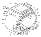
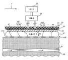
FIG. 1 shows the appearance of the wrist-type sphygmomanometer of one embodiment (the whole is indicated by reference numeral 1) when viewed from an angle. Further, FIG. 2 schematically shows a cross section perpendicular to the longitudinal direction of the
これらの図に示すように、この血圧計1は、大別して、ユーザの左手首90を取り巻いて装着されるべきベルト20と、このベルト20に一体に取り付けられた本体10とを備えている。
As shown in these figures, the
図1によって良く分かるように、ベルト20は、左手首90を周方向に沿って取り巻くように、細長い帯状の形状を有している。ベルト20の幅方向Yの寸法(幅寸法)は、この例では約30mmに設定されている。ベルト20は、外周面20bをなす帯状体23と、この帯状体23の内周面23aに沿って取り付けられ、左手首90に接すべき内周面20aをなす第1の流体袋としての圧迫カフ21とを含んでいる(図2参照)。圧迫カフ21は。ベルト20と同様に、左手首90を周方向に沿って取り巻くように、細長い帯状の形状を有している。
As can be clearly seen from FIG. 1, the
本体10は、ベルト20のうち、周方向に関して一方の端部20eに、この例では一体成形により一体に設けられている。なお、ベルト20と本体10とを別々に形成し、ベルト20に対して本体10を係合部材(例えばヒンジなど)を介して一体に取り付けても良い。この例では、本体10が配置された部位は、装着状態で左手首90の背側面(手の甲側の面)90bに対応することが予定されている(図2参照)。図2中には、左手首90内で掌側面(手の平側の面)90a近傍を通る橈骨動脈91が示されている。
The
図1によって良く分かるように、本体10は、ベルト20の外周面20bに対して垂直な方向に厚さを有する立体的形状を有している。この本体10は、ユーザの日常活動の邪魔にならないように、小型で、薄厚に形成されている。この例では、本体10は、ベルト20から外向きに突起した四角錐台状の輪郭を有している。
As can be clearly seen from FIG. 1, the
本体10の頂面(被測定部位から最も遠い側の面)10aには、表示画面をなす表示器50が設けられている。また、本体10の側面(図1における左手前側の側面)10fに沿って、ユーザからの指示を入力するための操作部52が設けられている。
A
ベルト20のうち、周方向に関して一方の端部20eと他方の端部20fとの間の部位であって、ベルト20の内周面20aをなす圧迫カフ21の内周面20a上には、第1、第2の脈波センサを構成するインピーダンス測定部40が設けられている。ベルト20のうち、インピーダンス測定部40が配置された部位の内周面20aには、ベルト20の幅方向Yに関して互いに離間した状態で6個の板状(またはシート状)の電極41〜46(これらの全体を「電極群」と呼び、符号40Eで表す。)が配置されている(後に詳述する。)。この例では、電極群40Eが配置された部位は、装着状態で左手首90の橈骨動脈91に対応することが予定されている(図2参照)。
A portion of the
上記圧迫カフ21における電極群40Eが配置された内周面20aとは反対の外周面21aには、固形物22が、電極群40Eに対応する位置に配置されている(図2参照)。また、固形物22の外周側には、圧迫カフ21の周方向に関して電極群40Eに対応する領域を局所的に押圧する拡張部材として、第2の流体袋としての押圧カフ24が配置されている。押圧カフ24は、ベルト20を構成する帯状体23の内周面23aに配置されている(図2参照)。押圧カフ24は、ベルト20の厚さ方向に伸縮する流体袋であり、流体の供給または排出により加圧状態または非加圧状態となる。
A
図1中に示すように、本体10の底面(被測定部位に最も近い側の面)10bとベルト20の端部20fとは、三つ折れバックル15によって接続されている。このバックル15は、外周側に配置された第1の板状部材25と、内周側に配置された第2の板状部材26とを含んでいる。第1の板状部材25の一方の端部25eは、幅方向Yに沿って延びる連結棒27を介して本体10に対して回動自在に取り付けられている。第1の板状部材25の他方の端部25fは、幅方向Yに沿って延びる連結棒28を介して第2の板状部材26の一方の端部26eに対して回動自在に取り付けられている。第2の板状部材26の他方の端部26fは、固定部29によってベルト20の端部20f近傍に固定されている。なお、ベルト20の周方向に関して固定部29の取り付け位置は、ユーザの左手首90の周囲長に合わせて予め可変して設定されている。これにより、この血圧計1(ベルト20)は、全体として略環状に構成されるとともに、本体10の底面10bとベルト20の端部20fとが、バックル15によって矢印B方向に開閉可能になっている。
As shown in FIG. 1, the bottom surface of the main body 10 (the surface closest to the part to be measured) 10b and the
この血圧計1を左手首90に装着する際には、バックル15を開いてベルト20の環の径を大きくした状態で、図1中に矢印Aで示す向きに、ユーザがベルト20に左手を通す。そして、図2に示すように、ユーザは、左手首90の周りのベルト20の角度位置を調節して、左手首90を通っている橈骨動脈91上にベルト20のインピーダンス測定部40を位置させる。これにより、インピーダンス測定部40の電極群40Eが左手首90の掌側面90aのうち橈骨動脈91に対応する部分90a1に当接する状態になる。この状態で、ユーザが、バックル15を閉じて固定する。このようにして、ユーザは血圧計1(ベルト20)を左手首90に装着する。
When the
図2中に示すように、帯状体23は、この例では、厚さ方向に関して可撓性を有し、かつ、周方向(長手方向)に関して実質的に非伸縮性のプラスチック材料からなっている。圧迫カフ21は、この例では、伸縮可能な2枚のポリウレタンシートを厚さ方向に対向させ、それらの周縁部を溶着して、流体袋として構成されている。圧迫カフ21(ベルト20)の内周面20aのうち、左手首90の橈骨動脈91に対応する部位には、既述のようにインピーダンス測定部40の電極群40Eが配置されている。
As shown in FIG. 2, in this example, the
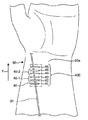
図3に示すように、装着状態では、インピーダンス測定部40の電極群40Eは、左手首90の橈骨動脈91に対応して、手首の長手方向(ベルト20の幅方向Yに相当)に沿って並んだ状態になる。電極群40Eは、幅方向Yに関して、両側に配置された通電用の電流電極対41,46と、これらの電流電極対41,46の間に配置された電圧検出用の、第1の脈波センサ40−1をなす第1の検出電極対42,43、および、第2の脈波センサ40−2をなす第2の検出電極対44,45とを含んでいる。第1の検出電極対42,43に対して、橈骨動脈91の血流のより下流側の部分に対応して、第2の検出電極対44,45が配置されている。幅方向Yに関して、第1の検出電極対42,43の中央と第2の検出電極対44,45の中央との間の距離D(図5(A)参照)は、この例では20mmに設定されている。この距離Dは、第1の脈波センサ40−1と第2の脈波センサ40−2との間の実質的な間隔に相当する。また、幅方向Yに関して、第1の検出電極対42,43間の間隔、第2の検出電極対44,45間の間隔は、この例ではいずれも2mmに設定されている。
As shown in FIG. 3, in the mounted state, the
このような電極群40Eは、偏平に構成され得る。したがって、この血圧計1では、ベルト20を全体として薄厚に構成できる。また、このような電極群40Eは、柔軟に構成され得る。したがって、これらの電極群40Eは、圧迫カフ21による左手首90の圧迫を妨げず、後述のオシロメトリック法による血圧測定の精度を損なうことがない。
Such an
図2中に示すように、ベルト20を構成する帯状体23の内周面23aには、既述のように、拡張部材としての押圧カフ24が配置されている。押圧カフ24は、この例では、伸縮可能な2枚のポリウレタンシートを厚さ方向に対向させ、それらの周縁部を溶着して、流体袋として構成されている。押圧カフ24の内周面24aのうち、電極群40Eに対応する位置には、固形物22が配置されている。固形物22は、この例では、厚さ1〜2mm程度の板状の樹脂(この例では、ポリプロピレン)からなっている。本実施形態では、押圧部として、ベルト20、押圧カフ24、および固形物22を用いている。
As shown in FIG. 2, a
図4は、血圧計1の制御系のブロック構成を示している。血圧計1の本体10には、既述の表示器50、操作部52に加えて、制御部としてのCPU(Central Processing Unit)100、記憶部としてのメモリ51、および通信部59が搭載されている。また、本体10には、第1圧力センサ31、ポンプ32、弁33、および第2圧力センサ34が搭載されている。さらに、本体10には、第1圧力センサ31および第2圧力センサ34のそれぞれからの出力を周波数に変換する発振回路310および発振回路340、ポンプ32を駆動するポンプ駆動回路320が搭載されている。また、インピーダンス測定部40には、既述の電極群40Eに加えて、通電および電圧検出回路49が搭載されている。また、ポンプ32および弁33の接続先を、圧迫カフ21または押圧カフ24に切り替える切替弁35が搭載されている。
FIG. 4 shows a block configuration of the control system of the
表示器50は、この例では有機EL(Electro Luminescence)ディスプレイからなり、CPU100からの制御信号に従って、血圧測定結果などの血圧測定に関する情報、その他の情報を表示する。なお、表示器50は、有機ELディスプレイに限られるものではなく、例えばLCD(Liquid Cristal Display)など、他のタイプの表示器からなっていてもよい。
In this example, the
操作部52は、この例ではプッシュ式スイッチからなり、ユーザによる血圧測定開始または停止の指示に応じた操作信号をCPU100に入力する。なお、操作部52は、プッシュ式スイッチに限られるものではなく、例えば感圧式(抵抗式)または近接式(静電容量式)のタッチパネル式スイッチなどであってもよい。また、図示しないマイクロフォンを備えて、ユーザの音声によって血圧測定開始の指示を入力するようにしてもよい。
In this example, the
メモリ51は、血圧計1を制御するためのプログラムのデータ、血圧計1を制御するために用いられるデータ、血圧計1の各種機能を設定するための設定データ、血圧値の測定結果のデータなどを非一時的に記憶する。また、メモリ51は、プログラムが実行されるときのワークメモリなどとして用いられる。
The
CPU100は、メモリ51に記憶された血圧計1を制御するためのプログラムに従って、制御部として各種機能を実行する。例えば、オシロメトリック法による血圧測定を実行する場合は、CPU100は、操作部52からの血圧測定開始の指示に応じて、第1圧力センサ31からの信号に基づいて、ポンプ32(および弁33)を駆動する制御を行う。また、CPU100は、この例では第1圧力センサ31からの信号に基づいて、血圧値を算出する制御を行う。
The
CPU100は、脈波伝播時間に基づく血圧測定を実行する場合は、CPU100は、操作部52からの血圧測定開始の指示に応じて、圧迫カフ21内の空気を排出させるために弁33を駆動する制御を行う。また、CPU100は、切替弁35を駆動して、ポンプ32(および弁33)の接続先を押圧カフ24に切り替える制御を行う。さらに、CPU100は、第2圧力センサ34からの信号に基づいて、血圧値を算出する制御を行う。
When the
通信部59は、CPU100によって制御されて所定の情報を、ネットワーク900を介して外部の装置に送信したり、外部の装置からの情報を、ネットワーク900を介して受信してCPU100に受け渡したりする。このネットワーク900を介した通信は、無線、有線のいずれでも良い。この実施形態において、ネットワーク900は、インターネットであるが、これに限定されず、病院内LAN(Local Area Network)のような他の種類のネットワークであってもよいし、USBケーブルなどを用いた1対1の通信であってもよい。この通信部59は、マイクロUSBコネクタを含んでいてもよい。
The
ポンプ32および弁33は、切替弁35、エア配管39a,39bを介して、圧迫カフ21および押圧カフ24に接続されている。また、第1圧力センサ31はエア配管38aを介して、第2圧力センサ34はエア配管38bを介して、それぞれ圧迫カフ21および押圧カフ24に接続されている。第1圧力センサ31は、エア配管38aを介して、圧迫カフ21内の圧力を検出する。切替弁35は、CPU100から与えられる制御信号に基づいて駆動し、ポンプ32および弁33の接続先を圧迫カフ21または押圧カフ24に切り替える。ポンプ32は、この例では圧電ポンプからなる。切替弁35により、ポンプ32および弁33の接続先が圧迫カフ21に切り替えられている場合には、ポンプ32は、圧迫カフ21内の圧力(カフ圧)を加圧するために、エア配管39aを通して圧迫カフ21に加圧用の流体としての空気を供給する。また、切替弁35により、ポンプ32および弁33の接続先が圧迫カフ21に切り替えられている場合には、ポンプ32は、押圧カフ24内の圧力(カフ圧)を加圧するために、エア配管39bを通して押圧カフ24に加圧用の流体としての空気を供給する。
The
弁33は、ポンプ32に搭載され、ポンプ32のオン/オフに伴って開閉が制御される構成になっている。すなわち、切替弁35により、ポンプ32および弁33の接続先が圧迫カフ21に切り替えられている場合には、弁33は、ポンプ32がオンされると閉じて、圧迫カフ21内に空気を封入する一方、ポンプ32がオフされると開いて、圧迫カフ21の空気をエア配管39aを通して大気中へ排出させる。切替弁35により、ポンプ32および弁33の接続先が押圧カフ24に切り替えられている場合には、弁33は、ポンプ32がオンされると閉じて、押圧カフ24内に空気を封入する一方、ポンプ32がオフされると開いて、押圧カフ24の空気をエア配管39bを通して大気中へ排出させる。なお、弁33は、逆止弁の機能を有し、排出されるエアが逆流することはない。ポンプ駆動回路320は、ポンプ32をCPU100から与えられる制御信号に基づいて駆動する。
The
第1圧力センサ31は、この例ではピエゾ抵抗式圧力センサであり、エア配管38aを介して、ポンプ32、弁33および圧迫カフ21に接続されている。第1圧力センサ31は、エア配管38aを介して、ベルト20(圧迫カフ21)の圧力、この例では大気圧を基準(ゼロ)とした圧力を検出して時系列の信号として出力する。発振回路310は、第1圧力センサ31からのピエゾ抵抗効果による電気抵抗の変化に基づく電気信号値に基づき発振して、第1圧力センサ31の電気信号値に応じた周波数を有する周波数信号をCPU100に出力する。この例では、第1圧力センサ31の出力は、圧迫カフ21の圧力を制御するため、および、オシロメトリック法によって血圧値(収縮期血圧(Systolic Blood Pressure;SBP)と拡張期血圧(Diastolic Blood Pressure;DBP)とを含む。)を算出するために用いられる。
The
一般的なオシロメトリック法に従って血圧を測定する場合、概ね、次のような動作が行なわれる。すなわち、被験者の被測定部位(腕など)に予めカフを巻き付けておき、測定時には、CPU100は、ポンプ32および弁33を制御して、カフ圧を最高血圧より高く加圧し、その後徐々に減圧していく。この減圧する過程において、カフ圧を圧力センサで検出し、被測定部位の動脈で発生する動脈容積の変動を脈波信号として取り出す。その時のカフ圧の変化に伴う脈波信号の振幅の変化(主に立ち上がりと立ち下がり)に基づいて、最高血圧(収縮期血圧:Systolic Blood Pressure)と最低血圧(拡張期血圧:Diastolic Blood Pressure)とを算出する。
When measuring blood pressure according to a general oscillometric method, the following operations are generally performed. That is, the cuff is wrapped around the subject's measurement site (arm, etc.) in advance, and at the time of measurement, the
第2圧力センサ34は、この例ではピエゾ抵抗式圧力センサであり、エア配管38bを介して、ポンプ32、弁33および押圧カフ24に接続されている。第2圧力センサ34は、エア配管38bを介して、押圧カフ24の圧力、この例では大気圧を基準(ゼロ)とした圧力を検出して時系列の信号として出力する。発振回路340は、第2圧力センサ34からのピエゾ抵抗効果による電気抵抗の変化に基づく電気信号値に基づき発振して、第2圧力センサ34の電気信号値に応じた周波数を有する周波数信号をCPU100に出力する。この例では、第2圧力センサ34の出力は、押圧カフ24の圧力を制御するため、および、脈波伝播時間に基づく血圧を算出するために用いられる。脈波伝播時間に基づく血圧測定のたに押圧カフ24の圧力を制御する場合には、CPU100は、ポンプ32および弁33を制御して、種々の条件に応じてカフ圧の加圧と減圧を行う。詳細については後述する。
The second pressure sensor 34 is a piezoresistive pressure sensor in this example, and is connected to the
電池53は、本体10に搭載された要素、この例では、CPU100、圧力センサ31、ポンプ32、弁33、表示器50、メモリ51、通信部59、発振回路310、ポンプ駆動回路320の各要素へ電力を供給する。また、電池53は、配線71を通して、インピーダンス測定部40の通電および電圧検出回路49へも電力を供給する。この配線71は、信号用の配線72とともに、ベルト20の帯状体23と圧迫カフ21との間に挟まれた状態で、ベルト20の周方向に沿って本体10とインピーダンス測定部40との間に延在して設けられている。
The
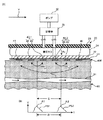
図5(A)は、脈波伝播時間に基づく血圧測定を行う場合において、血圧計1が左手首90に装着された状態での、手首の長手方向に沿った断面を模式的に示している。図5(B)は、第1の脈波センサ40−1、第2の脈波センサ40−2がそれぞれ出力する第1の脈波信号PS1、第2の脈波信号PS2の波形を示している。インピーダンス測定部40の通電および電圧検出回路49は、CPU100によって制御され、その動作時に、図5(A)中に示すように、手首の長手方向(ベルト20の幅方向Yに相当)に関して両側に配置された電流電極対41,46間に、この例では、周波数50kHz、電流値1mAの高周波定電流iを流す。この状態で、通電および電圧検出回路49は、第1の脈波センサ40−1をなす第1の検出電極対42,43間の電圧信号v1と、第2の脈波センサ40−2をなす第2の検出電極対44,45間の電圧信号v2とを検出する。これらの電圧信号v1,v2は、左手首90の掌側面90aのうち、それぞれ第1の脈波センサ40−1、第2の脈波センサ40−2が対向する部分における、橈骨動脈91の血流の脈波による電気インピーダンスの変化を表す(インピーダンス方式)。通電および電圧検出回路49は、これらの電圧信号v1,v2を整流、増幅および濾波して、図5(B)中に示すような山状の波形をもつ第1の脈波信号PS1,第2の脈波信号PS2を時系列で出力する。この例では、電圧信号v1,v2は、約1mV程度になっている。また、第1の脈波信号PS1,第2の脈波信号PS2のそれぞれのピークA1,A2は、この例では約1Vになっている。
FIG. 5A schematically shows a cross section along the longitudinal direction of the wrist when the
なお、橈骨動脈91の血流の脈波伝播速度(Pulse Wave Velocity;PWV)が1000cm/s〜2000cm/sの範囲であるとすると、第1の脈波センサ40−1と第2の脈波センサ40−2との間の実質的な間隔D=20mmであることから、第1の脈波信号PS1,第2の脈波信号PS2間の時間差Δtは1.0ms〜2.0msの範囲となる。
Assuming that the pulse wave velocity (PWV) of the blood flow in the
図5(A)に示すように、押圧カフ24は加圧状態となっており、圧迫カフ21は内部の空気が排出されて非加圧状態になっている。押圧カフ24は橈骨動脈91の動脈方向に関して、第1の脈波センサ40−1、第2の脈波センサ40−2、および電流電極対41,46にまたがって配置されている。また、固形物22も、橈骨動脈91の動脈方向に関して、第1の脈波センサ40−1、第2の脈波センサ40−2、および電流電極対41,46にまたがって配置されている。したがって、押圧カフ24は、ポンプ32により加圧されると、第1の脈波センサ40−1、第2の脈波センサ40−2、および電流電極対41,46を固形物22を介して左手首90の掌側面90aに押圧する。左手首90の掌側面90aに対する、電流電極対41,46、第1の脈波センサ40−1、および第2の脈波センサ40−2のそれぞれの押圧力は、適宜の値に設定することができる。本実施形態では、押圧部として流体袋の押圧カフ24を用いているので、ポンプ32および弁33を圧迫カフ21と共通に使用することができ、構成の簡略化を図ることができる。また、固形物22を介して第1の脈波センサ40−1、第2の脈波センサ40−2、および電流電極対41,46を押圧することができるので、被測定部位に対する押圧力が均一になり、精度良く脈波伝播時間に基づく血圧測定を行うことができる。
As shown in FIG. 5A, the
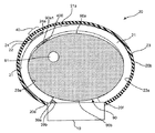
図6は、オシロメトリック法による血圧測定を行う場合において、血圧計1が左手首90に装着された状態での、手首の長手方向に沿った断面を模式的に示している。この場合には、押圧カフ24は内部の空気が排出されて非加圧状態となっており、圧迫カフ21は空気が供給された加圧状態になっている。圧迫カフ21は手首90の周方向に延在しており、ポンプ32により加圧されると、手首90の周方向を一様に圧迫する。ここで、圧迫カフ21の内周面と、手首90との間には、電極群40Eしか存在していないので、圧迫カフ21による圧迫が他の部材により阻害されることがなく、血管を充分に閉じることができる。したがって、オシロメトリック法による血圧測定を精度良く行うことができる。
FIG. 6 schematically shows a cross section along the longitudinal direction of the wrist when the blood pressure monitor 1 is attached to the
(オシロメトリック法による血圧測定の動作)
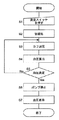
図7は、一実施形態の血圧測定方法を実行して血圧計1がオシロメトリック法による血圧測定を行う際の動作フローを示している。
(Operation of blood pressure measurement by oscillometric method)
FIG. 7 shows an operation flow when the blood pressure measuring method of one embodiment is executed and the
ユーザが本体10に設けられた操作部52としてのプッシュ式スイッチによってオシロメトリック法による血圧測定を指示すると(ステップS1)、CPU100は動作を開始して、処理用メモリ領域を初期化する(ステップS2)。また、CPU100は、ポンプ駆動回路320を介してポンプ32をオフし、弁33を開いて、圧迫カフ21内の空気を排出する。続いて、第1圧力センサ31の現時点の出力値を大気圧に相当する値として設定する制御を行う(0mmHg調整)。
When the user instructs the blood pressure measurement by the oscillometric method by the push type switch as the
続いて、CPU100は、弁33を閉鎖し、その後、ポンプ駆動回路320を介してポンプ32を駆動して、圧迫カフ21に空気を送る制御を行う。これにより、圧迫カフ21を膨張させるとともにカフ圧Pc(図8参照)を徐々に加圧していく(図7のステップS3)。
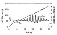
Subsequently, the
この加圧過程で、CPU100は、血圧値を算出するために、第1圧力センサ31によって、カフ圧Pcをモニタし、被測定部位としての左手首90の橈骨動脈91で発生する動脈容積の変動成分を、図8中に示すような脈波信号Pmとして取得する。
In this pressurization process, the
次に、図7中のステップS4で、CPU100は、第2の血圧算出部として働いて、この時点で取得されている脈波信号Pmに基づいて、オシロメトリック法により公知のアルゴリズムを適用して血圧値(収縮期血圧SBPと拡張期血圧DBP)の算出を試みる。
Next, in step S4 in FIG. 7, the
この時点で、データ不足のために未だ血圧値を算出できない場合は(ステップS5でNO)、カフ圧Pcが上限圧力(安全のために、例えば300mmHgというように予め定められている。)に達していない限り、ステップS3〜S5の処理を繰り返す。 At this point, if the blood pressure value cannot be calculated yet due to lack of data (NO in step S5), the cuff pressure Pc reaches the upper limit pressure (for safety, for example, 300 mmHg is predetermined). Unless otherwise specified, the processes of steps S3 to S5 are repeated.
このようにして血圧値の算出ができたら(ステップS5でYES)、CPU100は、ポンプ駆動回路320を介してポンプ32を停止し、弁33を開いて、圧迫カフ21内の空気を排出する制御を行う(ステップS6)。そして最後に、血圧値の測定結果を表示器50に表示するとともに、メモリ51に記録する(ステップS7)。
When the blood pressure value can be calculated in this way (YES in step S5), the
なお、血圧値の算出は、加圧過程に限らず、減圧過程において行われてもよい。 The calculation of the blood pressure value is not limited to the pressurization process, and may be performed in the decompression process.
(脈波伝播時間に基づく血圧測定の動作)
図9は、一実施形態の血圧測定方法を実行して血圧計1が脈波伝播時間(Pulse Transit Time;PTT)を取得し、その脈波伝播時間に基づく血圧測定(推定)を行う際の動作フローを示している。
(Blood pressure measurement operation based on pulse wave velocity)
FIG. 9 shows a case where the
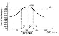
この動作フローは、本発明者による実験結果に基づいて作成された。すなわち、本発明者による実験よると、図10に示すように、被測定部位としての左手首90に対する第1の脈波センサ40−1(第1の検出電極対42,43を含む。)、第2の脈波センサ40−2(第2の検出電極対44,45を含む。)の押圧力(押圧カフ24によるカフ圧Pcに等しい。)がゼロから徐々に大きくなると、それに伴って第1、第2の脈波信号PS1,PS2の波形間の相互相関係数rが徐々に大きくなり、極大値rmaxを示し、それから徐々に小さくなることが発見された。この動作フローは、相互相関係数rが予め定められた閾値Th(この例では、Th=0.99)を超えている範囲が、押圧力の適正な範囲(これを「適正押圧範囲」と呼ぶ。)であるとの考え方に基づいている。この例では、適正押圧範囲は、押圧力(カフ圧Pc)が下限値P1≒72mmHgから上限値P2≒135mmHgまでの範囲になっている。
This operation flow was created based on the experimental results by the present inventor. That is, according to the experiment by the present inventor, as shown in FIG. 10, the first pulse wave sensor 40-1 (including the first detection electrode pairs 42, 43) for the
ユーザが本体10に設けられた操作部52としてのプッシュ式スイッチによってPTTに基づく血圧測定を指示すると(図9のステップS10)、CPU100は、切替弁35を駆動して、ポンプ32および弁33の接続先を押圧カフ24に切り替える(図8のステップS11)。次に、CPU100は、弁33を閉鎖するとともに、ポンプ駆動回路320を介してポンプ32を駆動して、押圧カフ24に空気を送る制御を行う。これにより、押圧カフ24を膨張させるとともにカフ圧Pc(図5(A)参照)を徐々に加圧してゆく。(図9のステップS12)この例では、カフ圧Pcを一定速度(=5mmHg/s)で連続的に高くしてゆく。なお、次に述べる相互相関係数rを算出するための時間を容易に確保できるように、カフ圧Pcを段階的に高くしてもよい。
When the user instructs blood pressure measurement based on PTT by a push-type switch as an
この加圧過程で、CPU100は、相互相関係数算出部として働いて、第1の脈波センサ40−1、第2の脈波センサ40−2がそれぞれ時系列で出力する第1、第2の脈波信号PS1,PS2を取得して、それらの第1、第2の脈波信号PS1,PS2の波形間の相互相関係数rをリアルタイムで算出する(図9のステップS13)。
In this pressurization process, the
それとともに、CPU100は、押圧力設定部として働いて、算出した相互相関係数rが予め定められた閾値Th(=0.99)を超えているか否かを判断する(図8のステップS14)。ここで、相互相関係数rが閾値Th以下であれば(図9のステップS14でNO)、相互相関係数rが閾値Thを超えるまでステップS12〜S14の処理を繰り返す。そして、相互相関係数rが閾値Thを超えたら(図9のステップS14でYES)、CPU100は、ポンプ32を停止して(図9のステップS15)、カフ圧Pcをその時点、つまり、相互相関係数rが閾値Thを超えた時点の値に設定する。この例では、カフ圧Pcは、相互相関係数rが閾値Thを超えた時点の値、つまり、図10中に示すP1(≒72mmHg)に設定される。
At the same time, the
この状態で、CPU100は、第1、第2の脈波信号PS1,PS2の間の時間差Δt(図5(B)参照)を脈波伝播時間(PTT)として取得する(図9のステップS16)。より詳しくは、この例では、第1脈波信号PS1のピークA1と第2の脈波信号PS2のピークA2との間の時間差Δtを脈波伝播時間(PTT)として取得する。
In this state, the
このようにした場合、脈波伝播時間の測定精度を高めることができる。また、カフ圧Pcを相互相関係数rが閾値Thを超えた時点の値に設定するので、カフ圧Pcを無用に大きくすることなく、脈波伝播時間を取得できる。これにより、ユーザの身体的負担を軽くすることができる。 In this case, the measurement accuracy of the pulse wave velocity can be improved. Further, since the cuff pressure Pc is set to the value at the time when the mutual correlation coefficient r exceeds the threshold value Th, the pulse wave propagation time can be obtained without unnecessarily increasing the cuff pressure Pc. As a result, the physical burden on the user can be reduced.
次に、CPU100は第1の血圧算出部として働いて、脈波伝播時間と血圧との間の予め定められた対応式Eqを用いて、ステップS16で取得された脈波伝播時間(PTT)に基づいて、血圧を算出(推定)する(図9のステップS17)。ここで、脈波伝播時間と血圧との間の予め定められた対応式Eqは、それぞれ脈波伝播時間をDT、血圧をEBPと表すとき、例えば図13の式(Eq.2)で示すような、1/DT2の項を含む公知の分数関数として提供される(例えば、特開平10−201724号公報参照)。式(Eq.2)において、α、βはそれぞれ既知の係数または定数を表している。
Next, the
このようにして血圧を算出(推定)する場合、既述のように脈波伝播時間の測定精度を高めているので、血圧の測定精度を高めることができる。なお、血圧値の測定結果は、表示器50に表示されるとともに、メモリ51に記録される。
When the blood pressure is calculated (estimated) in this way, the measurement accuracy of the pulse wave propagation time is improved as described above, so that the measurement accuracy of the blood pressure can be improved. The blood pressure value measurement result is displayed on the
この例では、図9のステップS18において操作部52としてのプッシュ式スイッチによって測定停止が指示されていなければ(図8のステップS18でNO)、脈波伝播時間(PTT)の算出(図9のステップS16)と、血圧の算出(推定)(図9のステップS17)とを、脈波に応じて第1、第2の脈波信号PS1,PS2が入力されるごとに周期的に繰り返す。CPU100は、血圧値の測定結果を、表示器50に更新して表示するとともに、メモリ51に蓄積して記録する。そして、図9のステップS18において測定停止が指示されると(図9のステップS18でYES)、測定動作を終了する。
In this example, if the measurement stop is not instructed by the push-type switch as the
この血圧計1によれば、この脈波伝播時間(PTT)に基づく血圧測定によって、ユーザの身体的負担が軽い状態で、血圧を長期間にわたって連続的に測定することができる。
According to the
また、この血圧計1によれば、脈波伝播時間に基づく血圧測定(推定)と、オシロメトリック法による血圧測定とを一体の装置で行うことができる。したがって、ユーザの利便性を高めることができる。
Further, according to this
(押圧力設定による効果の検証)
図11Aの散布図は、様々なユーザ(被験者)について、血圧計1によって押圧力(カフ圧Pc)が40mmHg(図10中に示した下限値P1未満である)に設定された条件下で取得された脈波伝播時間(PTT)と、オシロメトリック法による血圧測定(図7のステップS5)で得られた収縮期血圧(SBP)との関係を示している。その押圧力設定条件下での第1、第2の脈波信号PS1,PS2の波形間の相互相関係数rは、r=0.971であり、閾値Th(=0.99)を下回っていた。この図11Aから分かるように、脈波伝播時間(PTT)と収縮期血圧(SBP)との間の相関は殆ど無い。図13の式(Eq.2)でフィッティングを行って相関係数を算出したところ、相関係数は−0.07であった。
(Verification of effect by setting pressing pressure)
The scatter plot of FIG. 11A is obtained for various users (subjects) under the condition that the pressing pressure (cuff pressure Pc) is set to 40 mmHg (less than the lower limit value P1 shown in FIG. 10) by the
これに対して、図11Bの散布図は、上述の様々なユーザについて、血圧計1によって押圧力(カフ圧Pc)が130mmHg(図10中に示した下限値P1と上限値P2との間の適正押圧範囲内である)に設定された条件下で取得された脈波伝播時間(PTT)と、オシロメトリック法による血圧測定(図7のステップS5)で得られた収縮期血圧(SBP)との関係を示している。その押圧力設定条件下での第1、第2の脈波信号PS1,PS2の波形間の相互相関係数rは、r=0.9901であり、閾値Th(=0.99)を上回っていた。この図11Bから分かるように、脈波伝播時間(PTT)と収縮期血圧(SBP)との間の相関は強い。図13の式(Eq.2)でフィッティングを行って相関係数を算出したところ、相関係数は−0.90であった。 On the other hand, in the scatter plot of FIG. 11B, the pressing pressure (cuff pressure Pc) is 130 mmHg (between the lower limit value P1 and the upper limit value P2 shown in FIG. 10) by the blood pressure monitor 1 for the various users described above. The pulse wave velocity (PTT) obtained under the conditions set to (within the proper pressing range) and the systolic blood pressure (SBP) obtained by blood pressure measurement by the oscillometric method (step S5 in FIG. 7). Shows the relationship. The mutual correlation coefficient r between the waveforms of the first and second pulse wave signals PS1 and PS2 under the pressing pressure setting condition is r = 0.9901, which exceeds the threshold value Th (= 0.99). It was. As can be seen from FIG. 11B, there is a strong correlation between pulse wave velocity (PTT) and systolic blood pressure (SBP). When the correlation coefficient was calculated by performing fitting with the formula (Eq.2) of FIG. 13, the correlation coefficient was −0.90.
これらの図11A,図11Bの結果により、押圧力(カフ圧Pc)を相互相関係数rが閾値Th(=0.99)を超える値に設定して脈波伝播時間(PTT)を取得することにより、脈波伝播時間(PTT)と収縮期血圧(SBP)との間の相関を高められる、ということを検証できた。このように脈波伝播時間(PTT)と収縮期血圧(SBP)との間の相関を高められた理由は、本発明による押圧力の設定により、脈波伝播時間(PTT)の測定精度が高まったからであると考えられる。これにより、血圧の測定精度を高めることができる。 Based on the results of FIGS. 11A and 11B, the pressing force (cuff pressure Pc) is set to a value at which the mutual correlation coefficient r exceeds the threshold value Th (= 0.99), and the pulse wave velocity (PTT) is acquired. This made it possible to verify that the correlation between pulse wave velocity (PTT) and systolic blood pressure (SBP) could be enhanced. The reason why the correlation between the pulse wave velocity (PTT) and the systolic blood pressure (SBP) is enhanced in this way is that the measurement accuracy of the pulse wave velocity (PTT) is improved by setting the pressing force according to the present invention. It is thought that this is because of the fact. As a result, the accuracy of blood pressure measurement can be improved.
(変形例)
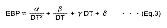
上述した実施形態では、図9のステップS17において、脈波伝播時間(PTT)に基づいて血圧を算出(推定)するために、脈波伝播時間と血圧との間の対応式Eqとして、図13の式(Eq.2)を用いた。しかしながら、これに限られるものではない。脈波伝播時間と血圧との間の対応式Eqとしては、それぞれ脈波伝播時間をDT、血圧をEBPと表すとき、例えば図14の式(Eq.3)に示すように、1/DT2の項に加えて、1/DTの項と、DTの項とを含む式を用いてもよい。式(Eq.3)において、α、β、γ、δはそれぞれ既知の係数または定数を表している。
(Modification example)
In the above-described embodiment, in step S17 of FIG. 9, in order to calculate (estimate) the blood pressure based on the pulse wave velocity (PTT), as a correspondence Eq between the pulse wave propagation time and the blood pressure, FIG. (Eq.2) was used. However, it is not limited to this. As the correspondence Eq between the pulse wave velocity and the blood pressure, when the pulse wave velocity is expressed as DT and the blood pressure is expressed as EBP, for example, as shown in the equation (Eq.3) of FIG. 14, 1 / DT 2 In addition to the term of, an equation including the term of 1 / DT and the term of DT may be used. In the equation (Eq.3), α, β, γ, and δ represent known coefficients or constants, respectively.
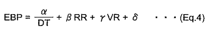
さらに、例えば図15の式(Eq.4)に示すように、1/DTの項と、心拍周期RRの項と、容積脈波面積比VRの項とを含む式を用いてもよい(例えば、特開2000−33078公報参照)。式(Eq.4)において、α、β、γ、δはそれぞれ既知の係数または定数を表している。なお、この場合、心拍周期RR、容積脈波面積比VRは、脈波信号PS1,PS2に基づいて、CPU100が算出する。
Further, for example, as shown in the equation (Eq.4) of FIG. 15, an equation including a term of 1 / DT, a term of heart rate cycle RR, and a term of volume pulse wave area ratio VR may be used (for example). , JP-A-2000-33078). In equation (Eq.4), α, β, γ, and δ represent known coefficients or constants, respectively. In this case, the heartbeat cycle RR and the volume pulse wave area ratio VR are calculated by the
脈波伝播時間と血圧との間の対応式Eqとして、これらの式(Eq.3)、式(Eq.4)を用いる場合も、式(Eq.2)を用いる場合と同様に、血圧の測定精度を高めることができる。当然ながら、これらの式(Eq.2)、(Eq.3)、(Eq.4)以外の対応式を用いてもよい。 When these equations (Eq.3) and (Eq.4) are used as the corresponding equations Eq between the pulse wave velocity and the blood pressure, the blood pressure is the same as when the equations (Eq.2) are used. The measurement accuracy can be improved. Of course, corresponding equations other than these equations (Eq.2), (Eq.3), and (Eq.4) may be used.
上述の実施形態では、第1の脈波センサ40−1、第2の脈波センサ40−2は、被測定部位(左手首90)を通る動脈(橈骨動脈91)の脈波をインピーダンスの変化として検出した(インピーダンス方式)。しかしながら、これに限られるものではない。第1、第2の脈波センサは、それぞれ、被測定部位のうち対応する部分を通る動脈へ向けて光を照射する発光素子と、その光の反射光(または透過光)を受光する受光素子とを備えて、動脈の脈波を容積の変化として検出してもよい(光電方式)。または、第1、第2の脈波センサは、それぞれ、被測定部位に当接された圧電センサを備えて、被測定部位のうち対応する部分を通る動脈の圧力による歪みを電気抵抗の変化として検出してもよい(圧電方式)。さらに、第1、第2の脈波センサは、それぞれ、被測定部位のうち対応する部分を通る動脈へ向けて電波(送信波)を送る送信素子と、その電波の反射波を受信する受信素子とを備えて、動脈の脈波による動脈とセンサとの間の距離の変化を送信波と反射波との間の位相のずれとして検出してもよい(電波照射方式)。 In the above-described embodiment, the first pulse wave sensor 40-1 and the second pulse wave sensor 40-2 change the impedance of the pulse wave of the artery (radial artery 91) passing through the measurement site (left wrist 90). Detected as (impedance method). However, it is not limited to this. The first and second pulse wave sensors are a light emitting element that irradiates light toward an artery passing through the corresponding part of the measured portion and a light receiving element that receives the reflected light (or transmitted light) of the light. The pulse wave of the artery may be detected as a change in volume (photoelectric method). Alternatively, the first and second pulse wave sensors are each provided with a piezoelectric sensor that is in contact with the part to be measured, and the strain due to the pressure of the artery passing through the corresponding part of the part to be measured is treated as a change in electrical resistance. It may be detected (piezoelectric method). Further, the first and second pulse wave sensors are a transmitting element that sends a radio wave (transmitted wave) toward an artery passing through the corresponding part of the measured portion and a receiving element that receives the reflected wave of the radio wave, respectively. The change in the distance between the artery and the sensor due to the pulse wave of the artery may be detected as the phase shift between the transmitted wave and the reflected wave (radio wave irradiation method).
また、上述の実施形態では、血圧計1は、被測定部位として左手首90に装着されることが予定されているものとした。しかしながら、これに限られるものではない。被測定部位は、動脈が通っていれば良く、手首以外の上腕などの上肢であっても良いし、足首、大腿などの下肢であっても良い。
Further, in the above-described embodiment, the
上述の実施形態では、押圧部の例として、ベルト20、押圧カフ24、および固形物22を挙げたが、本発明はこの例に限られず、第1の脈波センサ40−1、第2の脈波センサ40−2を非加圧状態の圧迫カフ21の外周面から機械式に厚さ方向に拡張する押圧部でもよい。また、上述の実施形態では、拡張部材の例として、流体袋の押圧カフ24を挙げたが、本発明はこの例に限られず、機械式に厚さ方向に拡張する拡張部材によって固形物22を介して第1の脈波センサ40−1、第2の脈波センサ40−2を押圧してもよい。
In the above embodiment, as an example of the pressing unit, a
また、上述の実施形態では、血圧計1に搭載されたCPU100が相互相関係数算出部、押圧力設定部、第1および第2の血圧算出部として働いて、オシロメトリック法による血圧測定(図7の動作フロー)およびPTTに基づく血圧測定(推定)(図9の動作フロー)を実行するものとした。しかしながら、これに限られるものではない。例えば、血圧計1の外部に設けられたスマートフォンなどの実質的なコンピュータ装置が、波形比較部、脈波センサ押圧力設定部、電流電極押圧力設定部、測定処理部、第1および第2の血圧算出部として働いて、ネットワーク900を介して、血圧計1にオシロメトリック法による血圧測定(図7の動作フロー)およびPTTに基づく血圧測定(推定)(図9の動作フロー)を実行させるようにしてもよい。
Further, in the above-described embodiment, the
上に述べた実施形態では、ポンプ30を含む本体10がベルト20と一体に設けられた例について説明したが、本発明はこの例に限られず、ベルト20を含む圧迫カフ21および押圧カフ24と、卓上に置かれる本体とを備え、この本体にポンプを備えてもよい。この場合には、カフと、本体とを、細長いチューブを介して接続し、本体からカフに流体を供給すればよい。
In the embodiment described above, an example in which the
上に述べた実施形態の血圧計1は、腕時計型ウェアラブルデバイスの態様をもつ多機能の機器として構成してもよい。
The
以上の実施形態は例示であり、この発明の範囲から離れることなく様々な変形が可能である。上述した複数の実施の形態は、それぞれ単独で成立し得るものであるが、実施の形態同士の組みあわせも可能である。また、異なる実施の形態の中の種々の特徴も、それぞれ単独で成立し得るものであるが、異なる実施の形態の中の特徴同士の組みあわせも可能である。 The above embodiment is an example, and various modifications can be made without departing from the scope of the present invention. Each of the plurality of embodiments described above can be established independently, but combinations of the embodiments are also possible. Further, although various features in different embodiments can be established independently, it is also possible to combine features in different embodiments.
1 血圧計
10 本体
20 ベルト
21 圧迫カフ
22 固形物
23 帯状体
24 押圧カフ
40 インピーダンス測定部
40E 電極群
49 通電および電圧検出回路
100 CPU
1 Sphygmomanometer 10
Claims (7)
上記第1の流体袋に、この第1の流体袋の幅方向に関して互いに離間した状態で搭載され、上記被測定部位を通る動脈のうちそれぞれ対向する部分の脈波を検出する第1、第2の脈波センサと、
上記第1の流体袋における上記第1、第2の脈波センサが搭載された内周側とは反対の外周側から、上記第1の流体袋の周方向に関して上記第1、第2の脈波センサに対応する領域を局所的に押圧する押圧部と、
上記第1の流体袋を非加圧状態にして、上記押圧部の押圧力で上記第1、第2の脈波センサを押圧し、その状態で上記第1、第2の脈波センサの出力から求めた脈波伝播時間に基づく血圧を算出する第1の血圧算出部と、
オシロメトリック法による血圧測定のために、上記第1の流体袋を加圧状態にして、上記第1の流体袋内の圧力に基づいて血圧を算出する第2の血圧算出部と、
を備えたことを特徴とする血圧計。 A first fluid bag that is attached around the part to be measured and is in a pressurized or non-pressurized state by supplying or discharging a fluid.
The first and second fluid bags are mounted on the first fluid bag in a state of being separated from each other in the width direction of the first fluid bag, and detect pulse waves of opposite portions of the arteries passing through the measurement site. Pulse wave sensor and
From the outer peripheral side of the first fluid bag opposite to the inner peripheral side on which the first and second pulse wave sensors are mounted, the first and second pulses in the circumferential direction of the first fluid bag A pressing part that locally presses the area corresponding to the wave sensor,
The first fluid bag is put into a non-pressurized state, the first and second pulse wave sensors are pressed by the pressing force of the pressing portion, and the outputs of the first and second pulse wave sensors in that state. The first blood pressure calculation unit that calculates the blood pressure based on the pulse wave velocity obtained from
For blood pressure measurement by the oscillometric method, a second blood pressure calculation unit that pressurizes the first fluid bag and calculates the blood pressure based on the pressure in the first fluid bag,
A sphygmomanometer characterized by being equipped with.
上記押圧部は、
上記被測定部位を取り巻いて装着されるべきベルトと、
上記ベルトよりも上記被測定部位に近い上記ベルトの内周側に配置され、上記ベルトの厚さ方向に伸縮する拡張部材と、
上記拡張部材よりも上記被測定部位に近い上記拡張部材の内周側の、上記第1、第2の脈波センサに対応する位置に配置された固形物と、
を備えたことを特徴とする血圧計。 In the sphygmomanometer according to claim 1.
The pressing part is
The belt that should be worn around the part to be measured and
An expansion member arranged on the inner peripheral side of the belt, which is closer to the part to be measured than the belt and expands and contracts in the thickness direction of the belt,
A solid substance arranged at a position corresponding to the first and second pulse wave sensors on the inner peripheral side of the expansion member closer to the measurement site than the expansion member.
A sphygmomanometer characterized by being equipped with.
上記第1、第2の脈波センサがそれぞれ時系列で出力する第1、第2の脈波信号を取得して、それらの第1、第2の脈波信号の波形間の相互相関係数を算出する相互相関係数算出部と、
上記拡張部材による押圧力を、上記相互相関係数算出部により算出された上記相互相関係数が予め定められた閾値を超えるように設定する押圧力設定部と、
を備えたことを特徴とする血圧計。 In the blood pressure monitor according to claim 2.
The first and second pulse wave sensors output the first and second pulse wave signals in time series, respectively, and the mutual correlation coefficient between the waveforms of the first and second pulse wave signals is acquired. The mutual correlation coefficient calculation unit that calculates
A pressing force setting unit that sets the pressing force by the expanding member so that the intercorrelation coefficient calculated by the intercorrelation coefficient calculating unit exceeds a predetermined threshold value.
A sphygmomanometer characterized by being equipped with .
上記拡張部材は、流体の供給または排出により加圧状態または非加圧状態となる第2の流体袋である、
ことを特徴とする血圧計。 In the sphygmomanometer according to claim 2 or 3 .
The expansion member is a second fluid bag that is in a pressurized state or a non-pressurized state by supplying or discharging a fluid.
A sphygmomanometer characterized by that.
上記第1、第2の脈波センサはそれぞれ上記対向する部分の電圧を検出する検出電極対を含む、
ことを特徴とする血圧計。 In the sphygmomanometer according to any one of claims 1 to 4.
The first and second pulse wave sensors each include a pair of detection electrodes that detect the voltage of the opposite portions.
Blood pressure meter which is characterized a call.
上記第1の流体袋に、この第1の流体袋の幅方向に関して互いに離間した状態で搭載され、上記被測定部位を通る動脈のうちそれぞれ対向する部分の脈波を検出する第1、第2の脈波センサと、
上記第1の流体袋における上記第1、第2の脈波センサが搭載された内周側とは反対の外周側から、上記第1の流体袋の周方向に関して上記第1、第2の脈波センサに対応する領域を局所的に押圧する押圧部と、
を備えて、血圧を測定する血圧測定方法であって、
脈波伝播時間に基づく血圧測定を行う場合には、上記第1の流体袋を非加圧状態にして、上記押圧部の押圧力で上記第1、第2の脈波センサを押圧し、その状態で上記第1、第2の脈波センサの出力から求めた脈波伝播時間に基づいて血圧を算出し、
オシロメトリック法による血圧測定を行う場合には、上記第1の流体袋を加圧状態にして、上記第1の流体袋内の圧力に基づいて血圧を算出する、
ことを特徴とする血圧測定方法。 A first fluid bag that is attached around the part to be measured and is in a pressurized or non-pressurized state by supplying or discharging a fluid.
The first and second fluid bags are mounted on the first fluid bag in a state of being separated from each other in the width direction of the first fluid bag, and detect pulse waves of opposite portions of the arteries passing through the measurement site. Pulse wave sensor and
From the outer peripheral side of the first fluid bag opposite to the inner peripheral side on which the first and second pulse wave sensors are mounted, the first and second pulses in the circumferential direction of the first fluid bag A pressing part that locally presses the area corresponding to the wave sensor,
It is a blood pressure measurement method that measures blood pressure.
When measuring blood pressure based on the pulse wave velocity, the first fluid bag is placed in a non-pressurized state, and the first and second pulse wave sensors are pressed by the pressing force of the pressing portion, and the pressure is pressed. In the state, the blood pressure is calculated based on the pulse wave velocity obtained from the outputs of the first and second pulse wave sensors.
When the blood pressure is measured by the oscillometric method, the first fluid bag is put into a pressurized state, and the blood pressure is calculated based on the pressure in the first fluid bag.
A blood pressure measurement method characterized by this.
上記血圧測定要素は、
被測定部位を取り巻いて装着され、流体の供給または排出により加圧状態または非加圧状態となる第1の流体袋と、
上記第1の流体袋に、この第1の流体袋の幅方向に関して互いに離間した状態で搭載され、上記被測定部位を通る動脈のうちそれぞれ対向する部分の脈波を検出する第1、第2の脈波センサと、
上記第1の流体袋における上記第1、第2の脈波センサが搭載された内周側とは反対の外周側から、上記第1の流体袋の周方向に関して上記第1、第2の脈波センサに対応する領域を局所的に押圧する押圧部と、
上記第1の流体袋を非加圧状態にして、上記押圧部の押圧力で上記第1、第2の脈波センサを押圧し、その状態で上記第1、第2の脈波センサの出力から求めた脈波伝播時間に基づく血圧を算出する第1の血圧算出部と、
オシロメトリック法による血圧測定のために、上記第1の流体袋を加圧状態にして、上記第1の流体袋内の圧力に基づいて血圧を算出する第2の血圧算出部と、を備える、
ことを特徴とする機器。 A device that includes a blood pressure measuring element
The above blood pressure measurement element is
A first fluid bag that is attached around the part to be measured and is in a pressurized or non-pressurized state by supplying or discharging a fluid.
The first and second fluid bags are mounted on the first fluid bag in a state of being separated from each other in the width direction of the first fluid bag, and detect pulse waves of opposite portions of the arteries passing through the measurement site. Pulse wave sensor and
From the outer peripheral side of the first fluid bag opposite to the inner peripheral side on which the first and second pulse wave sensors are mounted, the first and second pulses in the circumferential direction of the first fluid bag A pressing part that locally presses the area corresponding to the wave sensor,
The first fluid bag is put into a non-pressurized state, the first and second pulse wave sensors are pressed by the pressing force of the pressing portion, and the outputs of the first and second pulse wave sensors in that state. The first blood pressure calculation unit that calculates the blood pressure based on the pulse wave velocity obtained from
For blood pressure measurement by the oscillometric method, the first fluid bag is in a pressurized state, and a second blood pressure calculation unit for calculating blood pressure based on the pressure in the first fluid bag is provided.
A device that features that.
Priority Applications (5)
| Application Number | Priority Date | Filing Date | Title |
|---|---|---|---|
| JP2016255262A JP6777535B2 (en) | 2016-12-28 | 2016-12-28 | Sphygmomanometer and blood pressure measurement method and equipment |
| CN201780075967.8A CN110062600A (en) | 2016-12-28 | 2017-11-07 | Sphygmomanometer, blood pressure measuring method and equipment |
| PCT/JP2017/040053 WO2018123275A1 (en) | 2016-12-28 | 2017-11-07 | Sphygmomanometer, and method and device for blood pressure measurement |
| DE112017006660.3T DE112017006660T5 (en) | 2016-12-28 | 2017-11-07 | BLOOD PRESSURE METER, METHOD AND DEVICE FOR MEASURING BLOOD PRESSURE |
| US16/441,066 US11712166B2 (en) | 2016-12-28 | 2019-06-14 | Sphygmomanometer, and method and device for blood pressure measurement |
Applications Claiming Priority (1)
| Application Number | Priority Date | Filing Date | Title |
|---|---|---|---|
| JP2016255262A JP6777535B2 (en) | 2016-12-28 | 2016-12-28 | Sphygmomanometer and blood pressure measurement method and equipment |
Publications (2)
| Publication Number | Publication Date |
|---|---|
| JP2018102818A JP2018102818A (en) | 2018-07-05 |
| JP6777535B2 true JP6777535B2 (en) | 2020-10-28 |
Family
ID=62707062
Family Applications (1)
| Application Number | Title | Priority Date | Filing Date |
|---|---|---|---|
| JP2016255262A Active JP6777535B2 (en) | 2016-12-28 | 2016-12-28 | Sphygmomanometer and blood pressure measurement method and equipment |
Country Status (5)
| Country | Link |
|---|---|
| US (1) | US11712166B2 (en) |
| JP (1) | JP6777535B2 (en) |
| CN (1) | CN110062600A (en) |
| DE (1) | DE112017006660T5 (en) |
| WO (1) | WO2018123275A1 (en) |
Families Citing this family (7)
| Publication number | Priority date | Publication date | Assignee | Title |
|---|---|---|---|---|
| US20220104710A1 (en) * | 2020-10-06 | 2022-04-07 | Smart Meter Corporation | Blood pressure device |
| JP7669667B2 (en) * | 2020-11-06 | 2025-04-30 | オムロンヘルスケア株式会社 | Sphygmomanometer |
| CN112641433B (en) * | 2020-12-21 | 2023-05-05 | 上海连尚网络科技有限公司 | Method and device for measuring pulse information by pulse feeling equipment |
| CN112842293B (en) * | 2021-01-29 | 2022-11-08 | 清华大学深圳国际研究生院 | Wearable pulse real-time detection device |
| KR102564545B1 (en) | 2021-03-19 | 2023-08-07 | 삼성전자주식회사 | Apparatus and method for estimating bio-information |
| TWI776523B (en) * | 2021-05-25 | 2022-09-01 | 友達光電股份有限公司 | Pulse detection device |
| CN116269280A (en) * | 2023-02-16 | 2023-06-23 | 徐州市永康电子科技有限公司 | An oscillometric sphygmomanometer with real-time display of cuff pressure waveform and pulse waveform |
Family Cites Families (28)
| Publication number | Priority date | Publication date | Assignee | Title |
|---|---|---|---|---|
| JPH10201724A (en) | 1997-01-20 | 1998-08-04 | Nippon Colin Co Ltd | Automatic sphygmometer |
| JPH10328151A (en) * | 1997-06-04 | 1998-12-15 | Sony Corp | Arterial medical information testing device |
| JP2000003307A (en) | 1998-06-12 | 2000-01-07 | Nec Eng Ltd | Memory controller and control method |
| JP3385262B2 (en) * | 2000-05-29 | 2003-03-10 | 日本コーリン株式会社 | Blood pressure measurement device |
| JP3616061B2 (en) * | 2002-03-01 | 2005-02-02 | コーリンメディカルテクノロジー株式会社 | Atherosclerosis inspection device |
| JP3667326B2 (en) * | 2003-04-21 | 2005-07-06 | コーリンメディカルテクノロジー株式会社 | Double cuff for blood pressure measurement |
| JP4166665B2 (en) * | 2003-10-24 | 2008-10-15 | 日本精密測器株式会社 | Wrist blood pressure monitor and cuff spring |
| JP4764674B2 (en) * | 2005-08-11 | 2011-09-07 | 株式会社エー・アンド・デイ | Blood pressure pulse wave inspection device |
| US9433358B2 (en) * | 2006-02-21 | 2016-09-06 | Uscom Ltd. | Method and apparatus for producing a central pressure waveform in an oscillometric blood pressure system |
| JP2008136655A (en) * | 2006-12-01 | 2008-06-19 | Omron Healthcare Co Ltd | Pulse wave measurement electrode unit and pulse wave measurement device |
| WO2009054382A1 (en) * | 2007-10-25 | 2009-04-30 | Terumo Kabushiki Kaisha | Blood pressure measuring device and method for controlling the blood pressure measuring device |
| JP5092707B2 (en) * | 2007-11-15 | 2012-12-05 | オムロンヘルスケア株式会社 | Arteriosclerosis determination device |
| JP2009284965A (en) * | 2008-05-27 | 2009-12-10 | Omron Healthcare Co Ltd | Blood pressure information measuring instrument |
| JP2011177249A (en) * | 2010-02-26 | 2011-09-15 | Omron Healthcare Co Ltd | Blood pressure information measurement device, and method for determining attachment state of cuff for blood pressure information measurement device |
| JP5584077B2 (en) * | 2010-09-29 | 2014-09-03 | 株式会社エー・アンド・デイ | Automatic blood pressure measurement device |
| JP5619593B2 (en) * | 2010-12-17 | 2014-11-05 | 株式会社エー・アンド・デイ | Arterial blood vessel inspection device |
| JP2012200410A (en) * | 2011-03-25 | 2012-10-22 | Omron Healthcare Co Ltd | Cuff for blood pressure information measuring device, and blood pressure information measuring device having the same |
| JP5694032B2 (en) * | 2011-03-30 | 2015-04-01 | 日本光電工業株式会社 | Venous pressure measuring device |
| JP2013146539A (en) * | 2011-12-21 | 2013-08-01 | Nippon Koden Corp | Cuff and method for observing tissue under pressure by using the same |
| JP5821657B2 (en) * | 2012-01-25 | 2015-11-24 | オムロンヘルスケア株式会社 | Measuring apparatus and measuring method |
| JP6686888B2 (en) * | 2014-08-27 | 2020-04-22 | 日本電気株式会社 | Pulse wave measuring device and blood pressure measuring device |
| CN107106054B (en) * | 2014-09-08 | 2021-11-02 | 苹果公司 | Blood pressure monitoring with a multifunctional wrist-worn device |
| KR102390369B1 (en) * | 2015-01-21 | 2022-04-25 | 삼성전자주식회사 | Apparatus for detecting information of the living body |
| US20170188846A1 (en) * | 2016-01-05 | 2017-07-06 | Tosense, Inc. | Physiological monitoring system featuring floormat and wired handheld sensor |
| JP6635842B2 (en) * | 2016-03-25 | 2020-01-29 | 京セラ株式会社 | Blood pressure estimation device, blood pressure monitor, blood pressure estimation system, and blood pressure estimation method |
| JP6750294B2 (en) * | 2016-04-28 | 2020-09-02 | オムロンヘルスケア株式会社 | Pulse wave detection device and biological information measurement device |
| WO2018043692A1 (en) * | 2016-09-05 | 2018-03-08 | 日本電気株式会社 | Blood pressure measuring device, blood pressure measuring method and recording medium having blood pressure measuring program recorded therein |
| KR101945960B1 (en) * | 2016-11-23 | 2019-02-08 | (주)참케어 | Wrist wearable blood pressure monitor |
-
2016
- 2016-12-28 JP JP2016255262A patent/JP6777535B2/en active Active
-
2017
- 2017-11-07 WO PCT/JP2017/040053 patent/WO2018123275A1/en not_active Ceased
- 2017-11-07 CN CN201780075967.8A patent/CN110062600A/en active Pending
- 2017-11-07 DE DE112017006660.3T patent/DE112017006660T5/en active Pending
-
2019
- 2019-06-14 US US16/441,066 patent/US11712166B2/en active Active
Also Published As
| Publication number | Publication date |
|---|---|
| WO2018123275A1 (en) | 2018-07-05 |
| JP2018102818A (en) | 2018-07-05 |
| US20190290141A1 (en) | 2019-09-26 |
| CN110062600A (en) | 2019-07-26 |
| DE112017006660T5 (en) | 2019-09-26 |
| US11712166B2 (en) | 2023-08-01 |
Similar Documents
| Publication | Publication Date | Title |
|---|---|---|
| JP6777535B2 (en) | Sphygmomanometer and blood pressure measurement method and equipment | |
| JP6761337B2 (en) | Pulse wave measuring device and pulse wave measuring method, and blood pressure measuring device | |
| JP6829599B2 (en) | Pulse wave measuring device and pulse wave measuring method, and blood pressure measuring device | |
| CN111093489A (en) | blood pressure estimation device | |
| US20190290142A1 (en) | Pulse wave measurement device, pulse wave measurement method, and blood pressure measurement device | |
| US11317818B2 (en) | Blood pressure measurement device and blood pressure measurement method | |
| JP6869152B2 (en) | Electrode unit for pulse wave measurement and pulse wave measurement device | |
| US12161444B2 (en) | Health device flow path formation member, health device flow path formation unit, and health device | |
| JP7023751B2 (en) | Biometric information measuring device | |
| US20200221962A1 (en) | Measurement device and measurement method | |
| JP6970605B2 (en) | Blood pressure estimator | |
| JP7102176B2 (en) | Biological information measuring device | |
| JP6866251B2 (en) | Biological measurement antenna device, pulse wave measurement device, blood pressure measurement device, equipment, biological information measurement method, pulse wave measurement method, and blood pressure measurement method |
Legal Events
| Date | Code | Title | Description |
|---|---|---|---|
| A621 | Written request for application examination |
Free format text: JAPANESE INTERMEDIATE CODE: A621 Effective date: 20191121 |
|
| A131 | Notification of reasons for refusal |
Free format text: JAPANESE INTERMEDIATE CODE: A131 Effective date: 20200630 |
|
| A521 | Request for written amendment filed |
Free format text: JAPANESE INTERMEDIATE CODE: A523 Effective date: 20200824 |
|
| TRDD | Decision of grant or rejection written | ||
| A01 | Written decision to grant a patent or to grant a registration (utility model) |
Free format text: JAPANESE INTERMEDIATE CODE: A01 Effective date: 20200929 |
|
| A61 | First payment of annual fees (during grant procedure) |
Free format text: JAPANESE INTERMEDIATE CODE: A61 Effective date: 20201008 |
|
| R150 | Certificate of patent or registration of utility model |
Ref document number: 6777535 Country of ref document: JP Free format text: JAPANESE INTERMEDIATE CODE: R150 |
|
| R250 | Receipt of annual fees |
Free format text: JAPANESE INTERMEDIATE CODE: R250 |
|
| R250 | Receipt of annual fees |
Free format text: JAPANESE INTERMEDIATE CODE: R250 |