JP6902016B2 - Electronic clock - Google Patents
Electronic clock Download PDFInfo
- Publication number
- JP6902016B2 JP6902016B2 JP2018500179A JP2018500179A JP6902016B2 JP 6902016 B2 JP6902016 B2 JP 6902016B2 JP 2018500179 A JP2018500179 A JP 2018500179A JP 2018500179 A JP2018500179 A JP 2018500179A JP 6902016 B2 JP6902016 B2 JP 6902016B2
- Authority
- JP
- Japan
- Prior art keywords
- drive pulse
- coil
- drive
- magnetic pole
- rotor
- Prior art date
- Legal status (The legal status is an assumption and is not a legal conclusion. Google has not performed a legal analysis and makes no representation as to the accuracy of the status listed.)
- Active
Links
Images


Classifications
-
- G—PHYSICS
- G04—HOROLOGY
- G04C—ELECTROMECHANICAL CLOCKS OR WATCHES
- G04C3/00—Electromechanical clocks or watches independent of other time-pieces and in which the movement is maintained by electric means
- G04C3/14—Electromechanical clocks or watches independent of other time-pieces and in which the movement is maintained by electric means incorporating a stepping motor
- G04C3/143—Means to reduce power consumption by reducing pulse width or amplitude and related problems, e.g. detection of unwanted or missing step
-
- G—PHYSICS
- G04—HOROLOGY
- G04C—ELECTROMECHANICAL CLOCKS OR WATCHES
- G04C13/00—Driving mechanisms for clocks by primary clocks
- G04C13/08—Secondary clocks actuated intermittently
- G04C13/10—Secondary clocks actuated intermittently by electromechanical step-advancing mechanisms
- G04C13/11—Secondary clocks actuated intermittently by electromechanical step-advancing mechanisms with rotating armature
-
- G—PHYSICS
- G04—HOROLOGY
- G04C—ELECTROMECHANICAL CLOCKS OR WATCHES
- G04C3/00—Electromechanical clocks or watches independent of other time-pieces and in which the movement is maintained by electric means
- G04C3/14—Electromechanical clocks or watches independent of other time-pieces and in which the movement is maintained by electric means incorporating a stepping motor
-
- H—ELECTRICITY
- H02—GENERATION; CONVERSION OR DISTRIBUTION OF ELECTRIC POWER
- H02P—CONTROL OR REGULATION OF ELECTRIC MOTORS, ELECTRIC GENERATORS OR DYNAMO-ELECTRIC CONVERTERS; CONTROLLING TRANSFORMERS, REACTORS OR CHOKE COILS
- H02P8/00—Arrangements for controlling dynamo-electric motors rotating step by step
- H02P8/02—Arrangements for controlling dynamo-electric motors rotating step by step specially adapted for single-phase or bi-pole stepper motors, e.g. watch-motors, clock-motors
Landscapes
- Physics & Mathematics (AREA)
- General Physics & Mathematics (AREA)
- Engineering & Computer Science (AREA)
- Power Engineering (AREA)
- Control Of Stepping Motors (AREA)
- Electromechanical Clocks (AREA)
Description
本発明は、2コイルステップモータを用いたアナログ表示方式の電子時計に関する。 The present invention relates to an analog display type electronic clock using a two-coil step motor.
従来、アナログ表示手段を備えた電子時計は、指針をステップモータによって駆動することが一般的である。このステップモータは、コイルによって磁化されるステータと、2極磁化された円盤状の回転体であるロータで構成され、たとえば1秒毎にロータが180度回転駆動されることで指針によって時刻を表示している。 Conventionally, in an electronic clock provided with analog display means, the pointer is generally driven by a step motor. This step motor is composed of a stator magnetized by a coil and a rotor which is a disk-shaped rotating body magnetized by two poles. For example, the rotor is rotated 180 degrees every second to display the time by a pointer. doing.
このようなステップモータによるアナログ表示方式の電子時計は、指針を動かす輪列のバックラッシュ等により、秒針などで表示位置ずれが起き、文字板目盛とのずれが発生していた。また、ステップモータの小型化を優先するために、表示車の保有トルクが小さくなり、衝撃などによって指針位置が狂う等の問題もあった。 In such an analog display type electronic clock using a step motor, the display position shifts due to the backlash of the train wheel that moves the pointer, etc., and the shift from the dial scale occurs. Further, in order to give priority to the miniaturization of the step motor, there is a problem that the torque held by the display vehicle becomes small and the pointer position is deviated due to an impact or the like.
このような問題を解決するために、ステップモータを駆動する駆動パルスを第1の駆動パルスと第2の駆動パルスで成る2ステップ構成とし、第1の駆動パルスと第2の駆動パルスの出力間隔を50mS以下としたモータ制御回路を備えた電子時計が提案されている(たとえば特許文献1参照)。 In order to solve such a problem, the drive pulse for driving the step motor has a two-step configuration consisting of a first drive pulse and a second drive pulse, and the output interval between the first drive pulse and the second drive pulse is set. An electronic clock having a motor control circuit having a pulse rate of 50 mS or less has been proposed (see, for example, Patent Document 1).
この特許文献1の電子時計によれば、出力間隔が50mS以下の第1の駆動パルスと第2の駆動パルスを出力することで、ロータの回転速度を通常より高速、例えば倍の回転速度にすることができ、これにより、ロータから秒表示車までの減速比が大きくできることで、指針の保有トルクが上がり、且つ、バックラッシュによる指針の表示位置ずれを改善できることが示されている。
According to the electronic clock of
また、アナログ表示方式の電子時計に用いられるステップモータの駆動方式として、第1及び第2のコイルが共通の接続点に対して接続され、3つのフェーズごとに印加する電流を切り替えるものが提案されている(例えば特許文献2参照)。 Further, as a drive method of a step motor used in an analog display type electronic clock, it has been proposed that the first and second coils are connected to a common connection point and the current applied is switched every three phases. (See, for example, Patent Document 2).
しかしながら、特許文献1で提示されている電子時計は、ロータの1回転(360度)が2ステップ駆動となるので、第1の駆動パルスと第2の駆動パルスの間に時間的な間隔があり、ロータの動きに減速、振動、停止、再加速等が生じ、その結果、指針の動きがぎこちなく不自然であり、見栄えの悪い動きとなって、電子時計の使用者に不快感を与える課題がある。
However, in the electronic clock presented in
また、この問題を回避するために、第1の駆動パルスと第2の駆動パルスの間を時間的に狭めると、ロータの回転後の振動が収束しない状態で次の駆動が行われるので、ロータが逆転してしまう異常動作の頻度が増して、ステップモータが誤動作する危険性がある。また、1回転(360度)が従来の駆動と同様に2ステップ駆動であるので、ロータを高速に回転させるには限界があり、ステップモータの高速駆動には不向きである。 Further, in order to avoid this problem, if the time between the first drive pulse and the second drive pulse is narrowed in time, the next drive is performed in a state where the vibration after the rotation of the rotor does not converge, so that the rotor There is a risk that the step motor will malfunction due to an increase in the frequency of abnormal operations in which the speed is reversed. Further, since one rotation (360 degrees) is a two-step drive as in the conventional drive, there is a limit to rotating the rotor at high speed, and it is not suitable for high-speed drive of a step motor.
本発明の目的は上記課題を解決し、2コイルステップモータを1ステップ360度単位で回転駆動することで、指針の動きが滑らかに、且つ、高速に駆動できる電子時計を提供することである。 An object of the present invention is to solve the above problems and to provide an electronic clock capable of driving a two-coil step motor in units of 360 degrees per step so that the pointer moves smoothly and at high speed.
上記課題を解決するために、本発明の電子時計は下記記載の構成を採用する。 In order to solve the above problems, the electronic clock of the present invention adopts the configuration described below.
本発明の電子時計は、径方向に2極以上着磁されたロータと、該ロータを介して対向して設けられる第1のステータ磁極部及び第2のステータ磁極部と、該第1のステータ磁極部と該第2のステータ磁極部の間にあって、ロータに向き合って設けられる第3のステータ磁極部と、を有するステータと、第1のステータ磁極部と第3のステータ磁極部に磁気的に結合する第1のコイルと、第2のステータ磁極部と第3のステータ磁極部に磁気的に結合する第2のコイルと、を有する2コイルステップモータと、第1のコイル又は第2のコイルに、ロータを駆動するための駆動パルスを出力する駆動パルス発生回路と、を有し、複数の駆動パルスで構成される駆動パルス列によって、ロータが360度単位で回転駆動されることを特徴とする。 The electronic clock of the present invention includes a rotor magnetized with two or more poles in the radial direction, a first stator magnetic pole portion and a second stator magnetic pole portion provided facing each other via the rotor, and the first stator. A stator having a third stator magnetic pole portion between the magnetic pole portion and the second stator magnetic pole portion and provided facing the rotor, and magnetically on the first stator magnetic pole portion and the third stator magnetic pole portion. A two-coil step motor having a first coil to be coupled and a second coil magnetically coupled to a second stator magnetic pole portion and a third stator magnetic pole portion, and a first coil or a second coil. It also has a drive pulse generation circuit that outputs a drive pulse for driving the rotor, and is characterized in that the rotor is rotationally driven in 360-degree units by a drive pulse train composed of a plurality of drive pulses. ..
本発明の電子時計により、複数の駆動パルスで構成される駆動パルス列によって、1ステップ360度単位での回転駆動が可能となり、ステップモータの高速駆動が実現できる。また、ロータが一回転(360度)を短時間に停止することなく回転するので、指針の動きが滑らかになり、ぎこちなさがなく、見栄えの良い電子時計を提供できる。また、ステップモータの駆動が1ステップ360度単位であるので、従来のステップモータの1ステップ180度回転で輪列の歯車減速比1/30と比較した場合、歯車減速比を2倍(1/60)にでき、指針のトルクアップが可能となって、指針の耐衝撃性が向上する。
According to the electronic clock of the present invention, a drive pulse train composed of a plurality of drive pulses enables rotational drive in units of 360 degrees per step, and high-speed drive of a step motor can be realized. Further, since the rotor rotates one rotation (360 degrees) without stopping in a short time, the movement of the pointer becomes smooth, and it is possible to provide an electronic clock that is not awkward and looks good. Further, since the step motor is driven in units of 360 degrees per step, the gear reduction ratio is doubled (1 /) when compared with the
また、駆動パルス列が3個の駆動パルスで構成されることを特徴とする。 Further, the drive pulse train is characterized by being composed of three drive pulses.
これにより、1ステップ360度の回転駆動をわずか3個の駆動パルスで実現できるので、従来の2ステップ駆動と比較して高速駆動が可能となり、指針の早送り動作において、従来よりも高速に指針を動かすことが可能となる。 As a result, one-step 360-degree rotation drive can be realized with only three drive pulses, so high-speed drive is possible compared to conventional two-step drive, and the pointer can be moved faster than before in the fast-forward operation of the pointer. It becomes possible to move.
また、ロータが360度単位で回転駆動される高速駆動と、ロータが180度単位で回転駆動される通常駆動が切り替え可能に構成され、高速駆動のときは、通常駆動のときよりも速い周波数でロータが駆動されることを特徴とする。 In addition, the high-speed drive in which the rotor is rotationally driven in 360-degree units and the normal drive in which the rotor is rotationally driven in 180-degree units can be switched, and the high-speed drive has a higher frequency than the normal drive. It is characterized in that the rotor is driven.
これにより、ロータが360度単位で回転する高速駆動と、ロータが180度単位で回転する通常駆動とが切り替え可能であるので、たとえば、指針を早送り運針させる場合は、1ステップ360度回転の高速駆動をすることができ、1秒運針などの通常運針の場合は、1ステップ180度単位の通常駆動をすることができる。 As a result, it is possible to switch between a high-speed drive in which the rotor rotates in 360-degree units and a normal drive in which the rotor rotates in 180-degree units. It can be driven, and in the case of normal hand movement such as 1-second hand movement, normal drive can be performed in units of 180 degrees per step.
また、高速駆動される第1の2コイルステップモータと、通常駆動される第2の2コイルステップモータと、を有し、第2の2コイルステップモータの駆動周波数は、第1の2コイルステップモータの駆動周波数より低いことを特徴とする。 Further, it has a first two-coil step motor that is driven at high speed and a second two-coil step motor that is normally driven, and the drive frequency of the second two-coil step motor is the first two-coil step. It is characterized by being lower than the drive frequency of the motor.
これにより、高速駆動される第1の2コイルステップモータは、針形状が比較的大きく、駆動頻度が低い分時針駆動用として使用できる。分時針は形状が比較的大きいので耐衝撃性が重要であるが、駆動頻度が低いので低消電駆動は重要ではない。従って、ロータが360度単位で回転することで歯車減速比を2倍にして指針をトルクアップし、耐衝撃性を向上できる高速駆動の第1の2コイルステップモータが分時針駆動用に適している。また、通常駆動される第2のステップモータは、針形状が比較的小さく駆動頻度が高い秒針駆動用として使用できる。秒針は形状が比較的小さいので耐衝撃性は重要でなく、一方、駆動頻度が高いので低消電駆動が重要である。従って、通常駆動される第2の2コイルステップモータが秒針駆動用に適している。 As a result, the first two-coil step motor driven at high speed can be used for driving the minute and hour hands, which has a relatively large needle shape and is driven infrequently. Impact resistance is important because the minute and hour hands are relatively large in shape, but low static elimination drive is not important because the drive frequency is low. Therefore, the high-speed drive first two-coil step motor, which can double the gear reduction ratio to increase the torque of the pointer and improve the impact resistance by rotating the rotor in 360-degree units, is suitable for driving the minute hand. There is. Further, the second step motor that is normally driven can be used for driving the second hand, which has a relatively small hand shape and a high driving frequency. Impact resistance is not important because the shape of the second hand is relatively small, while low static elimination drive is important because it is driven frequently. Therefore, the normally driven second two-coil step motor is suitable for driving the second hand.
また、駆動パルス列から特定の駆動パルスを選択するタイミングを切り替えることで、高速駆動パルス列又は通常駆動パルスを選択することを特徴とする。 Further, it is characterized in that a high-speed drive pulse train or a normal drive pulse is selected by switching the timing of selecting a specific drive pulse from the drive pulse train.
これにより、一つの駆動パルス発生回路を配置し、出力される駆動パルス列から特定の駆動パルスを選択するタイミングを切り替えることで、高速駆動パルス列又は通常駆動パルスを選択して出力できるので、駆動パルス発生回路を一つのみで構成でき、電子時計の回路規模を縮小できるメリットがある。 As a result, by arranging one drive pulse generation circuit and switching the timing of selecting a specific drive pulse from the output drive pulse train, the high-speed drive pulse train or the normal drive pulse can be selected and output, so that the drive pulse is generated. There is an advantage that the circuit scale of the electronic clock can be reduced because the circuit can be configured with only one.
また、第1のコイルの1の端子と、第2コイルの1の端子が短絡されることを特徴とする。
Further, the
これにより、供給すべき駆動波形が3つで済み、またトランジスタの数も少なくて済むため、回路規模の小型化やコスト削減効果が見込める。 As a result, only three drive waveforms should be supplied and the number of transistors can be reduced, so that the circuit scale can be reduced and the cost can be reduced.
また、駆動パルス列に含まれる駆動パルスのうち、少なくとも1つは、第1のコイルを励磁するパルスと、第2のコイルを励磁するパルスを交互に繰り返して構成されることを特徴とする。 Further, at least one of the drive pulses included in the drive pulse train is characterized in that a pulse for exciting the first coil and a pulse for exciting the second coil are alternately repeated.
これにより、2つのコイルが同時に励磁されることがなく、消費電流の最大値を低く抑えることができるため、外気温が低い場合や、電源電圧が低下している状態など、電源条件が厳しい場合でも1ステップ360度回転駆動による高速駆動が可能である。 As a result, the two coils are not excited at the same time, and the maximum value of the current consumption can be suppressed to a low value. Therefore, when the power supply conditions are severe such as when the outside temperature is low or the power supply voltage is low. However, high-speed drive by rotating 360 degrees in one step is possible.
さらに、ロータの回転を検出するための検出パルスを発生する検出パルス発生回路と、検出パルスを第1のコイル又は第2のコイルに印加することにより検出される検出信号に基づいて、ロータの回転/非回転を判定する回転検出判定回路と、を有し、駆動パルス列に含まれる駆動パルスの一部により構成される可変駆動パルスを有し、可変駆動パルスは、回転検出判定回路によるロータの回転/非回転の結果に応じて、その長さが可変されることを特徴とする。 Further, the rotation of the rotor is based on a detection pulse generation circuit that generates a detection pulse for detecting the rotation of the rotor and a detection signal detected by applying the detection pulse to the first coil or the second coil. / Has a rotation detection determination circuit for determining non-rotation, and has a variable drive pulse composed of a part of drive pulses included in the drive pulse train. The variable drive pulse is the rotation of the rotor by the rotation detection determination circuit. / It is characterized in that its length is variable according to the result of non-rotation.
これにより、1ステップで360度の回転駆動をさせる場合において、ロータの回転/非回転の検出ができ、非回転の場合に補正パルスを出力することで、ロータを確実に回転させることができる。また、出力される高速駆動パルス列の長さは、ロータの回転に必要な分のみで済むため、消費電力が削減されるとともに、無駄時間が排除されて高速駆動が可能である。 As a result, the rotation / non-rotation of the rotor can be detected when the rotation is driven by 360 degrees in one step, and the rotor can be reliably rotated by outputting the correction pulse in the case of non-rotation. Further, since the length of the output high-speed drive pulse train is only required for the rotation of the rotor, the power consumption is reduced, the wasted time is eliminated, and the high-speed drive is possible.
また、すくなくとも、電源電圧及び温度のいずれかに基づいて、前記駆動パルス列のデューティを切り替えることを特徴とする。 Further, it is characterized in that the duty of the drive pulse train is switched based on at least one of the power supply voltage and the temperature.
これにより、電力消費及び出力の異なる複数種類の駆動パルスをステップモータに印加することができる。 As a result, it is possible to apply a plurality of types of drive pulses having different power consumption and output to the step motor.
さらに、回転開始からの経過時間に応じて、前記駆動パルス列のデューティを変更することを特徴とする。 Further, the duty of the drive pulse train is changed according to the elapsed time from the start of rotation.
これにより、駆動力に余裕がある場合には、無駄な消費電力を削減し、駆動力に余裕がない場合には非回転となることで生じる無駄な電力消費を抑えるから、消費電力の低減と、ロータの安定した回転とをバランスよく実現できる。 As a result, wasteful power consumption is reduced when there is a margin in driving force, and wasteful power consumption caused by non-rotation when there is no margin in driving force is suppressed, so that power consumption is reduced. , Stable rotation of the rotor can be achieved in a well-balanced manner.
また、第1のコイルと第2のコイルを同時に励磁する第1の駆動パルス列と、第1のコイルと第2のコイルを同時に励磁しない第2の駆動パルス列を有し、すくなくとも、電源電圧及び温度のいずれかに基づいて、駆動パルス列として、第1の駆動パルス列と第2の駆動パルス列のいずれかを用いるか選択することを特徴とする。 It also has a first drive pulse train that simultaneously excites the first and second coils and a second drive pulse train that does not simultaneously excite the first and second coils, at least the power supply voltage and temperature. It is characterized in that either of the first drive pulse train and the second drive pulse train is used as the drive pulse train based on any of the above.
これにより、大電流の消費による一時的な電圧低下が懸念される条件下では電流値を抑えて電源電圧の低下を抑え、その心配がない条件下では高速な1ステップ360度回転駆動を実現できる。 As a result, under conditions where there is a concern about a temporary voltage drop due to consumption of a large current, the current value can be suppressed to suppress a drop in the power supply voltage, and under conditions where there is no concern, high-speed 1-step 360-degree rotation drive can be realized. ..
また、可変駆動パルスは、第1のコイルと第2のコイルを同時に励磁しない駆動パルス列であり、駆動パルス列に含まれる駆動パルスの残りにより構成される固定駆動パルスとして、第1のコイルと第2のコイルを同時に励磁する第1の固定駆動パルスと前記第1のコイルと前記第2のコイルを同時に励磁しない第2の固定駆動パルスを有し、前記可変駆動パルスは、条件によらず用いられ、前記固定駆動パルスは、回転開始からの経過時間に応じて、前記第1の固定駆動パルスと前記第2の固定駆動パルスのいずれを用いるか選択することを特徴とする。 The variable drive pulse is a drive pulse train that does not excite the first coil and the second coil at the same time, and is a fixed drive pulse composed of the rest of the drive pulses included in the drive pulse train, that is, the first coil and the second coil. It has a first fixed drive pulse that simultaneously excites the first coil and a second fixed drive pulse that does not simultaneously excite the first coil and the second coil, and the variable drive pulse is used regardless of conditions. The fixed drive pulse is characterized in that it selects whether to use the first fixed drive pulse or the second fixed drive pulse according to the elapsed time from the start of rotation.
これにより、回転検出のタイミングを検出するのみで、電源電圧の値や、電子時計の温度を直接検出することなく、一時的な電源電圧の低下が問題となりうる条件を判別し、大電流の消費による一時的な電源電圧の低下の問題を回避しつつ、1ステップ360度回転による高速回転を安定して実現でき、小型化・低コスト化を図ることができる。 As a result, it is possible to determine the conditions under which a temporary drop in the power supply voltage may be a problem without directly detecting the value of the power supply voltage or the temperature of the electronic clock by only detecting the timing of rotation detection, and consuming a large amount of current. While avoiding the problem of a temporary drop in the power supply voltage due to the above, high-speed rotation by 360-degree rotation in one step can be stably realized, and miniaturization and cost reduction can be achieved.
また、可変駆動パルスは、第1のコイルと第2のコイルを同時に励磁しない駆動パルス列であり、駆動パルス列に含まれる駆動パルスの残りにより構成される固定駆動パルスと、可変駆動パルスが印加されるコイルに対し、異なるコイルに印加される第2の可変駆動パルスと、を有し、可変駆動パルスは、条件によらず用いられ、回転開始からの経過時間に応じて、固定駆動パルスと第2の可変駆動パルスのいずれを用いるか選択することを特徴とする。 Further, the variable drive pulse is a drive pulse train that does not excite the first coil and the second coil at the same time, and a fixed drive pulse composed of the rest of the drive pulses included in the drive pulse train and a variable drive pulse are applied. It has a second variable drive pulse applied to different coils with respect to the coil, and the variable drive pulse is used regardless of the conditions, and a fixed drive pulse and a second variable drive pulse are used according to the elapsed time from the start of rotation. It is characterized by selecting which of the variable drive pulses of the above is used.
これにより、回転検出のタイミングを検出するのみで、電源電圧の値や、電子時計の温度を直接検出することなく、一時的な電源電圧の低下が問題となりうる条件を判別し、大電流の消費による一時的な電源電圧の低下の問題を回避しつつ、1ステップ360度回転による高速回転を安定して実現できる。 As a result, it is possible to determine the conditions under which a temporary drop in the power supply voltage may be a problem without directly detecting the value of the power supply voltage or the temperature of the electronic clock by only detecting the timing of rotation detection, and consuming a large amount of current. It is possible to stably realize high-speed rotation by rotating 360 degrees in one step while avoiding the problem of temporary drop in power supply voltage due to the above.
上記の如く本発明によれば、複数の駆動パルスで構成される駆動パルス列によって、1ステップ360度単位での回転駆動が可能となり、ステップモータの高速駆動が実現できる。また、ロータが一回転を短時間に停止することなく回転するので、指針の動きが滑らかになり、ぎこちなさがなく、見栄えの良い電子時計を提供できる。また、ステップモータの駆動が1ステップ360度単位であるので、従来のステップモータの1ステップ180度回転と比較した場合、歯車減速比を2倍にでき、指針のトルクアップが可能となり、指針の耐衝撃性が向上する。 As described above, according to the present invention, a drive pulse train composed of a plurality of drive pulses enables rotational drive in units of 360 degrees per step, and high-speed drive of the step motor can be realized. Further, since the rotor rotates one rotation without stopping in a short time, the movement of the pointer becomes smooth, and it is possible to provide an electronic clock that is not awkward and looks good. In addition, since the step motor is driven in units of 360 degrees per step, the gear reduction ratio can be doubled and the torque of the pointer can be increased when compared with the rotation of 180 degrees per step of the conventional step motor. Impact resistance is improved.
以下図面により本発明の実施の形態を詳述する。 Hereinafter, embodiments of the present invention will be described in detail with reference to the drawings.
[各実施形態の特徴]
第1の実施形態の特徴は本発明の基本構成であり、一つの2コイルステップモータを有し、2コイルステップモータが1ステップ360度回転し、電子時計の秒針を1ステップで1秒運針する構成である。第2の実施形態の特徴は、分時針駆動用と秒針駆動用に二つの2コイルステップモータを有し、分時針駆動用の2コイルステップモータが1ステップ360度回転することで電子時計の分針が1ステップで1分運針し、秒針駆動用の2コイルステップモータが1ステップ180度回転することで電子時計の秒針が1ステップで1秒運針する構成である。第3の実施形態の特徴は、一つの2コイルステップモータと、高速駆動パルス発生回路と通常駆動パルス発生回路の二つの駆動パルス発生回路を有する構成である。[Characteristics of each embodiment]
The feature of the first embodiment is the basic configuration of the present invention, which has one 2-coil step motor, the 2-coil step motor rotates 360 degrees in one step, and the second hand of the electronic clock is moved in one step for one second. It is a composition. The feature of the second embodiment is that it has two 2-coil step motors for driving the minute and hour hands and driving the second hand, and the 2-coil step motor for driving the minute and hour hands rotates 360 degrees in one step to rotate the minute hand of the electronic clock. Moves the hand for 1 minute in 1 step, and the 2-coil step motor for driving the second hand rotates 180 degrees in 1 step, so that the second hand of the electronic clock moves for 1 second in 1 step. A feature of the third embodiment is a configuration having one two-coil step motor and two drive pulse generation circuits, a high-speed drive pulse generation circuit and a normal drive pulse generation circuit.
[第1の実施形態]
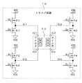
[第1の実施形態の電子時計の構成説明:図1]
第1の実施形態の電子時計の概略構成について図1を用いて説明する。符号1は第1の実施形態のアナログ表示方式の電子時計である。電子時計1は、水晶振動子(図示せず)によって所定の基準信号P1を出力する発振回路2、基準信号P1を入力して制御信号CN1を出力する制御回路3、高速駆動パルス発生回路4、ドライバ回路10、および、2コイルステップモータ20(以下、「ステップモータ20」と略す)を有している。[First Embodiment]
[Structure of the Electronic Clock of the First Embodiment: FIG. 1]
The schematic configuration of the electronic clock of the first embodiment will be described with reference to FIG.
なお、電子時計1は、指針や文字板を備えた表示部、輪列、電源、操作部材等を含むが、本発明には直接係わらないので図示は省略する。
The
高速駆動パルス発生回路4は、制御回路3からの制御信号CN1を入力して、ステップモータ20を駆動する複数の高速駆動パルスで構成される高速駆動パルス列SP10を生成し、ドライバ回路10に出力する。なお、高速駆動パルス列SP10は、後述するドライバ回路10の4つのバッファ回路を制御して駆動波形O1〜O4を出力するために、一例として4ビットで構成される。
The high-speed drive
また、高速駆動パルス列SP10は、ステップモータ20を1ステップ360度単位で回転させる駆動パルスであるが、指針を動かす輪列の歯車減速比によっては、必ずしも指針を高速駆動できるものではないが、高速駆動が可能な駆動パルスであるので高速駆動パルス列と称する。
Further, the high-speed drive pulse train SP10 is a drive pulse that rotates the
ドライバ回路10は、高速駆動パルス列SP10を入力し、複数の駆動パルスに基づいた駆動波形O1、O2、O3、O4をステップモータ20に供給し、ステップモータ20を駆動する。なお、ドライバ回路10の詳細な構成は後述する。
The
ステップモータ20は、コイルA、コイルBの二つのコイルを有している。なお、ステップモータ20の詳細は後述する。
The
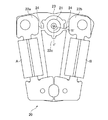
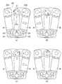
[ステップモータの構成説明:図2]
次に、ステップモータ20の構成について図2を用いて説明する。ステップモータ20は、ロータ21、ステータ22、二つのコイルA、コイルBなどによって構成される。ロータ21は2極磁化された円盤状の回転体であり、径方向にN極、S極が着磁されている。[Structure explanation of step motor: Fig. 2]
Next, the configuration of the
ステータ22は、軟磁性材によって成り、ロータ21が挿入されるロータ穴22dが設けられ、このロータ穴22dにロータ21が配置されている。ステータ22は、ロータ21に略対向して第1のステータ磁極部22a(以下、「第1磁極部22a」と略す)と第2のステータ磁極部22b(以下、「第2磁極部22b」と略す)が設けられている。また、第1磁極部22aと第2磁極部22bの間にあってロータ21に向き合う位置に第3のステータ磁極部22c(以下、「第3磁極部22c」と略す)が設けられている。
The
また、第1磁極部22aと第3磁極部22cに磁気的に結合する第1のコイルとしてのコイルAと、第2磁極部22bと第3磁極部22cに磁気的に結合する第2のコイルとしてのコイルBが設けられている。
Further, a coil A as a first coil that is magnetically coupled to the first
コイルAは絶縁基板23a上にコイル端子O1、O2を有しており、コイルAの巻線の両端が接続されている。また、コイルBは絶縁基板23b上にコイル端子O3、O4を有しており、コイルBの巻線の両端が接続されている。この各コイル端子O1〜O4に、前述したドライバ回路20から出力される駆動波形O1〜O4がそれぞれ供給される。
The coil A has coil terminals O1 and O2 on the insulating substrate 23a, and both ends of the winding of the coil A are connected to each other. Further, the coil B has coil terminals O3 and O4 on the insulating substrate 23b, and both ends of the winding of the coil B are connected to each other. Drive waveforms O1 to O4 output from the
なお、説明をわかりやすくするために、各コイル端子と供給される各駆動波形の符号を共通にしている。また、一例としてコイル端子O1がコイルAの巻始めであり、コイル端子O4がコイルBの巻始めである。 In addition, in order to make the explanation easy to understand, the code of each coil terminal and each drive waveform supplied is made common. Further, as an example, the coil terminal O1 is the start of winding of the coil A, and the coil terminal O4 is the start of winding of the coil B.
また、図2で示すロータ21は静止状態であり、図面の上方を0度と規定し、その位置から反時計回りに90度、180度、270度と規定する。ロータ21は、N極が0度に位置するときと、180度に位置するときが静止位置(静的安定点)である。よって、図2で示すロータ21は、N極が静止位置0度にある。
Further, the
[ドライバ回路の回路構成の説明:図3]
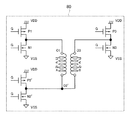
次に、ステップモータ20を駆動するためのドライバ回路10の回路構成の一例について図3を用いて説明する。ドライバ回路10は、ステップモータ20のコイルA、コイルBに高速駆動バルス列SP10による駆動波形O1〜O4を供給する4つのバッファ回路によって構成される。[Explanation of circuit configuration of driver circuit: Fig. 3]
Next, an example of the circuit configuration of the
この4つのバッファ回路の構成を説明すると、まず、低ON抵抗のPチャンネルMOSトランジスタであるトランジスタP1と、低ON抵抗のNチャンネルMOSトランジスタであるトランジスタN1と、のコンプリメンタリ接続でなるバッファ回路が、駆動波形O1を出力してコイルAのコイル端子O1に供給される。 Explaining the configuration of these four buffer circuits, first, a buffer circuit formed by a complementary connection of a transistor P1 which is a P-channel MOS transistor having a low ON resistance and a transistor N1 which is an N-channel MOS transistor having a low ON resistance is described. The drive waveform O1 is output and supplied to the coil terminal O1 of the coil A.
また同様に、それぞれ低ON抵抗のトランジスタP2とトランジスタN2とのコンプリメンタリ接続でなるバッファ回路が、駆動波形O2を出力してコイルAのコイル端子O2に供給される。 Similarly, a buffer circuit formed by complementary connection of the low ON resistance transistor P2 and the transistor N2 outputs the drive waveform O2 and supplies the drive waveform O2 to the coil terminal O2 of the coil A.
また同様に、それぞれ低ON抵抗のトランジスタP3とトランジスタN3とのコンプリメンタリ接続でなるバッファ回路が、駆動波形O3を出力してコイルBのコイル端子O3に供給される。 Similarly, a buffer circuit formed by complementary connection of the low ON resistance transistor P3 and the transistor N3 outputs the drive waveform O3 and supplies the drive waveform O3 to the coil terminal O3 of the coil B.
また同様に、それぞれ低ON抵抗のトランジスタP4とトランジスタN4とのコンプリメンタリ接続でなるバッファ回路が、駆動波形O4を出力してコイルBのコイル端子O4に供給される。 Similarly, a buffer circuit formed by complementary connection of the low ON resistance transistor P4 and the transistor N4 outputs the drive waveform O4 and supplies the drive waveform O4 to the coil terminal O4 of the coil B.
各トランジスタP1〜P4、N1〜N4のそれぞれゲート端子Gは、図示しないが、前述した高速駆動パルス発生回路4からの高速駆動パルス列SP10を入力し、各トランジスタは高速駆動パルス列SP10に基づいてON/OFF制御され、駆動波形O1〜O4が出力される。ここで、高速駆動パルス列SP10が前述したように4ビットで構成されれば、図示しないが、各ビットの高速駆動パルス列SP10が4つのバッファ回路のトランジスタのゲート端子Gにそれぞれ入力される。なお、各トランジスタのON/OFF動作の詳細は後述する。
Although the gate terminals G of the transistors P1 to P4 and N1 to N4 are not shown, the high-speed drive pulse train SP10 from the high-speed drive
[従来の2コイルステップモータの駆動説明:図4、図5]
次に、2コイルステップモータを1ステップ180度単位で回転駆動する駆動波形は公知であるが、本発明を理解する上で必要であるので、図2で示したステップモータ20と図3のドライバ回路10を用いて、1ステップ180度回転駆動を2ステップで行って360度回転駆動する従来の駆動波形の一例と従来のステップモータの回転動作の概要を図4と図5を用いて説明する。[Explanation of driving a conventional 2-coil step motor: FIGS. 4 and 5]
Next, a drive waveform for rotationally driving a two-coil step motor in units of 180 degrees per step is known, but since it is necessary for understanding the present invention, the
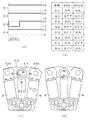
まず、ステップモータ20のロータ21のN極を静止位置0度(図2参照)から正転方向(反時計回り)に180度回転させる第1ステップの駆動パルスSP01とロータ21の回転動作について図4を用いて説明する。
First, the rotational operation of the drive pulse SP01 and the
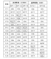
図4(a)は、ステップモータ20のロータ21のN極を静止位置0度から1ステップ180度正転させるための駆動パルスSP01による駆動波形であり、ドライバ回路10の駆動波形O1〜O4を示している。ここで、駆動波形O1〜O4は、通常状態で電圧0V(VDD)に保たれ、駆動パルスによって電圧−V(VSS)となる。なお、駆動波形O1〜O4の表示形態は、後述するすべての駆動波形に共通である。
FIG. 4A is a drive waveform obtained by the drive pulse SP01 for rotating the north pole of the
また、図4(b)は、ステップモータ20の第1ステップの駆動パルスSP01と、後述する第2ステップの駆動パルスSP02と、によって動作するドライバ回路10の各トランジスタの動作表(ON/OFF動作)である。また、図4(c)と図4(d)は、第1ステップでの駆動パルスSP01によるステップモータ20の回転動作を示している。
Further, FIG. 4B shows an operation table (ON / OFF operation) of each transistor of the
図4(a)において、第1ステップでロータ21のN極を静止位置0度から正転させる場合、駆動パルスSP01によって駆動波形O3は電圧−Vとなり、他の駆動波形O1、O2、O4は電圧0Vとなる。また、駆動パルスSP01の出力が終了すると、次の駆動パルスの到来まで、すべての駆動波形O1〜O4は電圧0Vが維持される。
In FIG. 4A, when the north pole of the
次に、第1ステップの駆動パルスSP01によるドライバ回路10の各トランジスタの動作を図4(b)の動作表で説明する。ここで、駆動パルスSP01によって駆動波形O3が電圧−Vとなるので、ドライバ回路10のトランジスタN3とトランジスタP4がON、トランジスタP3とトランジスタN4がOFFし、駆動電流がコイル端子O4からコイル端子O3に流れ、コイルBが励磁される。
Next, the operation of each transistor of the
また、第1ステップの駆動パルスSP01によってドライバ回路10の駆動波形O1、O2は、共に電圧0Vとなるので、トランジスタP1、P2がON、トランジスタN1、N2がOFFして、コイルAのコイル端子O1、O2は共にVDDに接続されて電圧0Vとなり、コイルAには駆動電流が流れず、コイルAは励磁されない。
Further, since the drive waveforms O1 and O2 of the
次に、図4(c)と図4(d)を用いて、ステップモータ20の第1ステップの回転動作を説明する。図4(c)において、駆動パルスSP01によって駆動波形O3が電圧−Vになると、前述したように、図示しないが駆動電流がコイル端子O4からコイル端子O3に流れ、コイルBが励磁される(コイルBの矢印は励磁方向を示す)。これにより、第2磁極部22bがN極、第3磁極部22cがS極に磁化され、また、コイルAは励磁されないので、第1磁極部22aは第3磁極部22cと同じS極となる。
Next, the rotation operation of the first step of the
その結果、ロータ21のN極と、第1磁極部22a及び第3磁極部22cのS極が引き合い、また、ロータ21のS極と第2磁極部22bのN極が引き合い、ロータ21は静止位置0度から反時計回りに約135度回転する。
As a result, the north pole of the
次に、図4(d)において、駆動パルスSP01が終了すると、コイルBの励磁が無くなり、第1〜第3磁極部22a〜22cの磁化が消えるが、ロータ21は、N極が約135度の位置から180度の静的安定点まで回転を継続し、その位置で保持される。この結果、ロータ21は、第1ステップの駆動パルスSP01によって180度回転駆動される。
Next, in FIG. 4D, when the drive pulse SP01 ends, the excitation of the coil B disappears and the magnetization of the first to third
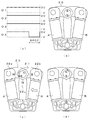
次に、ステップモータ20のロータ21のN極を静止位置180度から正転(反時計回り)させる第2ステップの駆動パルスSP02とロータ21の回転動作について図5を用いて説明する。図5(a)は、ステップモータ20のロータ21のN極を静止位置180度から1ステップ180度正転させるための駆動パルスSP02による駆動波形であり、ドライバ回路10の駆動波形O1〜O4を示している。また、図5(b)〜図5(d)は、第2ステップでの駆動パルスSP02によるステップモータ20の回転動作を示している。
Next, the rotational operation of the drive pulse SP02 and the
図5(a)において、第2ステップでロータ21のN極を静止位置180度から正転させる場合、駆動パルスSP02によって駆動波形O4は電圧−Vとなり、他の駆動波形O1、O2、O3は電圧0Vとなる。また、駆動パルスSP02の出力が終了すると、次の駆動パルスの到来まで、すべての駆動波形O1〜O4は電圧0Vが維持される。
In FIG. 5A, when the north pole of the
次に、第2ステップの駆動パルスSP02によるドライバ回路10の各トランジスタの動作を図4(b)で説明する。ここで、駆動パルスSP02によって、駆動波形O4が電圧−Vとなるので、ドライバ回路10のトランジスタN4とトランジスタP3がON、トランジスタP4とトランジスタN3がOFFし、駆動電流がコイル端子O3からコイル端子O4に流れ、コイルBは第1ステップとは逆向きに励磁される。
Next, the operation of each transistor of the
また、第2ステップの駆動パルスSP02によって駆動波形O1、O2は、第1ステップと同様に共に電圧0Vとなるので、トランジスタP1、P2がON、トランジスタN1、N2がOFFして、コイルAのコイル端子O1、O2は共にVDDに接続されて電圧0Vとなり、コイルAには駆動電流が流れず、コイルAは励磁されない。 Further, since the drive waveforms O1 and O2 are both set to 0 V by the drive pulse SP02 in the second step as in the first step, the transistors P1 and P2 are turned on, the transistors N1 and N2 are turned off, and the coil of the coil A is turned off. Both terminals O1 and O2 are connected to VDD to have a voltage of 0 V, no drive current flows through the coil A, and the coil A is not excited.
次に、図5(b)〜図5(d)を用いて、ステップモータ20の第2ステップの回転動作を説明する。図5(b)は、第2ステップのロータ21の初めの位置を示し、ロータ21のN極が、静止位置180度(図面上の下向き)に位置して保持されている状態である。
Next, the rotation operation of the second step of the
この状態から図5(c)において、駆動パルスSP02によって駆動波形O4が電圧−Vになると、前述したように、図示しないが駆動電流がコイル端子O3からコイル端子O4に流れ、コイルBが励磁される(コイルBの矢印は励磁方向を示す)。これにより、第2磁極部22bがS極、第3磁極部22cがN極に磁化され、また、コイルAは励磁されないので、第1磁極部22aは第3磁極部22cと同じN極となる。
From this state, in FIG. 5C, when the drive waveform O4 becomes a voltage −V due to the drive pulse SP02, as described above, a drive current flows from the coil terminal O3 to the coil terminal O4, and the coil B is excited. (The arrow of coil B indicates the exciting direction). As a result, the second
その結果、ロータ21のS極と、第1磁極部22a及び第3磁極部22cのN極が引き合い、また、ロータ21のN極と第2磁極部22bのS極が引き合い、ロータ21は静止位置180度から反時計回りに回転し、ロータ21のN極は0度を起点にして約315度の位置まで回転する。
As a result, the S pole of the
次に、図5(d)において、駆動パルスSP02が終了すると、コイルBの励磁が無くなり、第1〜第3磁極部22a〜22cの磁化が消えるが、ロータ21は、N極が約315度の位置から0度の静的安定点まで回転を継続し、その位置で保持される。この結果、ロータ21は、第2ステップの駆動パルスSP02によって180度回転駆動される。
Next, in FIG. 5D, when the drive pulse SP02 ends, the excitation of the coil B disappears and the magnetization of the first to third
このように、従来の2コイルステップモータは、通常、単発の駆動パルスによって1ステップ180度単位で回転駆動され、従って、2ステップによって360度回転駆動されるのである。この従来の2ステップによる360度回転駆動では、第1ステップの駆動パルスSP01と第2ステップの駆動パルスSP02との間に時間的な間隔があり、2コイルステップモータであっても、前述したように、ロータ21の動きに減速、振動、停止、再加速等が生じ、指針の動きがぎこちなく不自然であり、滑らかさがなく、見栄えの悪い動きとなって問題である。
As described above, the conventional two-coil step motor is usually rotationally driven by a single drive pulse in units of 180 degrees per step, and is therefore rotationally driven by 360 degrees by two steps. In this conventional 360-degree rotation drive by two steps, there is a time interval between the drive pulse SP01 of the first step and the drive pulse SP02 of the second step, and even if it is a two-coil step motor, as described above. In addition, the movement of the
[第1の実施形態の高速駆動パルスとドライバ回路の各トランジスタの動作説明:図6]
次に、第1の実施形態のステップモータを1ステップ360度単位で回転駆動する高速駆動パルスの駆動波形の一例とドライバ回路の各トランジスタの動作について図6を用いて説明する。[Explanation of operation of each transistor of the high-speed drive pulse and the driver circuit of the first embodiment: FIG. 6]
Next, an example of a drive waveform of a high-speed drive pulse that rotationally drives the step motor of the first embodiment in units of 360 degrees per step and the operation of each transistor of the driver circuit will be described with reference to FIG.
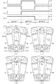
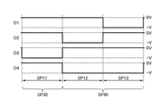
まず、ステップモータ20のロータ21のN極を静止位置0度(図2参照)から正転方向(反時計回り)に360度単位で回転駆動する高速駆動パルス列SP10の駆動波形について図6(a)を用いて説明する。図6(a)は、ステップモータ20のロータ21を1ステップ360度単位で回転させるための高速駆動パルス列SP10による駆動波形であり、ドライバ回路10から出力される4つの駆動波形O1〜O4の一例を示している。
First, FIG. 6 (a) describes the drive waveform of the high-speed drive pulse train SP10 that rotationally drives the north pole of the
図6(a)において、高速駆動パルス列SP10は、第1駆動パルスSP11、第2駆動パルスSP12、第3駆動パルスSP13の3個の駆動パルスが順次出力される構成である。 In FIG. 6A, the high-speed drive pulse train SP10 has a configuration in which three drive pulses of the first drive pulse SP11, the second drive pulse SP12, and the third drive pulse SP13 are sequentially output.
第1駆動パルスSP11は、駆動波形O3が電圧−Vであり、他の駆動波形O1、O2、O4は電圧0Vである。これにより、駆動波形O3とO4に接続されるステップモータ20のコイルBに駆動電流が流れて励磁される。
In the first drive pulse SP11, the drive waveform O3 has a voltage −V, and the other drive waveforms O1, O2, and O4 have a voltage of 0 V. As a result, a drive current flows through the coil B of the
また、第2駆動パルスSP12は、駆動波形O2、O4が電圧−Vであり、駆動波形O1、O3が電圧0Vである。これにより、ステップモータ20のコイルA、コイルBの両方に駆動電流が流れて、両方のコイルA、コイルBが励磁される。
Further, in the second drive pulse SP12, the drive waveforms O2 and O4 have a voltage −V, and the drive waveforms O1 and O3 have a voltage of 0V. As a result, a drive current flows through both the coil A and the coil B of the
また、第3駆動パルスSP13は、駆動波形O4が電圧−Vであり、他の駆動波形O1、O2、O3は電圧0Vである。これにより、ステップモータ20のコイルBが第2駆動パルスSP12と同じ方向に励磁される。
Further, in the third drive pulse SP13, the drive waveform O4 has a voltage −V, and the other drive waveforms O1, O2, and O3 have a voltage of 0 V. As a result, the coil B of the
なお、高速駆動パルス列SP10の周期、すなわち、第1〜第3駆動パルスSP11〜SP13の合計のパルス幅は任意である。また、駆動波形O1〜O4は、連続するフルパルスとして図示しているが、複数の細かいパルス群によるチョッパ形の駆動パルスでもよい。 The period of the high-speed drive pulse train SP10, that is, the total pulse width of the first to third drive pulses SP11 to SP13 is arbitrary. Further, although the drive waveforms O1 to O4 are shown as continuous full pulses, they may be chopper-shaped drive pulses composed of a plurality of fine pulse groups.
次に、高速駆動パルス列SP10によるドライバ回路10の各トランジスタの動作を図6(b)の動作表を用いて説明する。なお、ドライバ回路10は図3を参照する。図6(b)において、第1駆動パルスSP11は、駆動波形O3が電圧−V、駆動波形O4が電圧0Vとなるので、トランジスタN3とトランジスタP4がON、トランジスタP3とトランジスタN4がOFFし、駆動電流がコイルBのコイル端子O4からコイル端子O3に流れ、コイルBが励磁される。
Next, the operation of each transistor of the
また、駆動波形O1、O2は、共に電圧0Vとなるので、トランジスタP1、P2がON、トランジスタN1、N2がOFFし、コイルAには駆動電流が流れず、コイルAは励磁されない。 Further, since the drive waveforms O1 and O2 both have a voltage of 0 V, the transistors P1 and P2 are turned on, the transistors N1 and N2 are turned off, the drive current does not flow through the coil A, and the coil A is not excited.
また、第2駆動パルスSP12は、駆動波形O1が電圧0V、駆動波形O2が電圧−Vとなるので、トランジスタP1とトランジスタN2がON、トランジスタN1とトランジスタP2がOFFし、駆動電流がコイル端子O1からコイル端子O2に流れ、コイルAが励磁される。また、駆動波形O3が電圧0V、駆動波形O4が電圧−Vとなるので、トランジスタP3とトランジスタN4がON、トランジスタN3とトランジスタP4がOFFし、駆動電流がコイル端子O3からコイル端子O4に流れ、コイルBが励磁される。 Further, in the second drive pulse SP12, since the drive waveform O1 has a voltage of 0 V and the drive waveform O2 has a voltage −V, the transistor P1 and the transistor N2 are turned ON, the transistor N1 and the transistor P2 are turned OFF, and the drive current is the coil terminal O1. Flows from the coil terminal O2 to the coil terminal O2, and the coil A is excited. Further, since the drive waveform O3 has a voltage of 0 V and the drive waveform O4 has a voltage −V, the transistor P3 and the transistor N4 are turned on, the transistor N3 and the transistor P4 are turned off, and the drive current flows from the coil terminal O3 to the coil terminal O4. The coil B is excited.
また、第3駆動パルスSP13は、駆動波形O3が電圧0V、駆動波形O4が電圧−Vとなるので、トランジスタP3とトランジスタN4がON、トランジスタN3とトランジスタP4がOFFし、駆動電流がコイル端子O3からコイル端子O4に流れ、コイルBが励磁される。また、駆動波形O1、O2は、共に電圧0Vとなるので、トランジスタP1、P2がON、トランジスタN1、N2がOFFし、コイルAには駆動電流が流れず、コイルAは励磁されない。 Further, in the third drive pulse SP13, since the drive waveform O3 has a voltage of 0 V and the drive waveform O4 has a voltage −V, the transistor P3 and the transistor N4 are turned ON, the transistor N3 and the transistor P4 are turned OFF, and the drive current is the coil terminal O3. Flows from the coil terminal O4 to the coil terminal O4, and the coil B is excited. Further, since the drive waveforms O1 and O2 both have a voltage of 0 V, the transistors P1 and P2 are turned on, the transistors N1 and N2 are turned off, the drive current does not flow through the coil A, and the coil A is not excited.
このように、高速駆動パルス列SP10の3個の第1〜第3駆動パルスSP11〜SP13によって、ドライバ回路10の各トランジスタがON/OFF制御され、ステップモータ20のコイルA、Bを励磁するのである。
In this way, each transistor of the
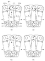
[第1の実施形態の1ステップ360度回転駆動の説明:図7]
次に、第1の実施形態のステップモータ20の1ステップ360度単位の高速回転駆動について図7を用いて説明する。なお、説明の条件として、駆動パルスは、図6に示した高速駆動パルス列SP10であり、ステップモータ20の最初の状態は、前述した図2に示すように、ロータ21のN極が静止位置0度にあるとする。また、ステップモータ20の各部材の符号は、図7(a)にのみ記して他は省略する。[Explanation of 1-step 360-degree rotary drive of the first embodiment: FIG. 7]
Next, a high-speed rotary drive in units of 360 degrees per step of the
図7(a)は、高速駆動パルス列SP10の第1駆動パルスSP11がステップモータ20に供給された状態であり、この場合、前述したように、駆動電流(図示せず)がコイル端子O4からコイル端子O3に流れ、コイルBが矢印の方向に励磁される。これにより、第2磁極部22bがN極、第3磁極部22cがS極に磁化され、また、コイルAは励磁されないので、第1磁極部22aは第3磁極部22cと同じS極となる。
FIG. 7A shows a state in which the first drive pulse SP11 of the high-speed drive pulse train SP10 is supplied to the
その結果、ロータ21のN極と、第1磁極部22a及び第3磁極部22cのS極が引き合い、また、ロータ21のS極と第2磁極部22bのN極が引き合い、ロータ21は反時計回りに回転し、ロータ21のN極は静止位置0度から約135度の位置まで回転する。
As a result, the north pole of the
次に、図7(b)において、第2駆動パルスSP12が供給されると、前述したように、駆動電流(図示せず)がコイル端子O1からコイル端子O2に流れ、コイルAが矢印の方向に励磁される。また同様に駆動電流(図示せず)がコイル端子O3からコイル端子O4に流れ、コイルBが矢印の方向(コイルAと反対方向)に励磁される。 Next, in FIG. 7B, when the second drive pulse SP12 is supplied, a drive current (not shown) flows from the coil terminal O1 to the coil terminal O2, and the coil A moves in the direction of the arrow, as described above. Is excited by. Similarly, a drive current (not shown) flows from the coil terminal O3 to the coil terminal O4, and the coil B is excited in the direction of the arrow (direction opposite to the coil A).
これにより、第1磁極部22aがN極に磁化され、第2磁極部22bがS極に磁化され、第3磁極部22cは磁化が打ち消し合って磁化されない。その結果、ロータ21のN極と第2磁極部22bのS極が引き合い、また、ロータ21のS極と第1磁極部22aのN極が引き合い、ロータ21は停止することなく更に反時計回りに回転し、ロータ21のN極は約270度の位置まで回転する。
As a result, the first
次に、図7(c)において、第3駆動パルスSP13が供給されると、前述したように、駆動電流(図示せず)がコイル端子O3からコイル端子O4に流れ、コイルBが矢印の方向に励磁される。これにより、第2磁極部22bがS極、第3磁極部22cがN極に磁化され、また、コイルAは励磁されないので、第1磁極部22aは第3磁極部22cと同じN極となる。その結果、ロータ21のS極と、第1磁極部22a及び第3磁極部22cのN極が引き合い、ロータ21は停止することなく更に反時計回りに回転し、ロータ21のN極は約315度の位置まで回転する。
Next, in FIG. 7C, when the third drive pulse SP13 is supplied, a drive current (not shown) flows from the coil terminal O3 to the coil terminal O4, and the coil B moves in the direction of the arrow, as described above. Is excited by. As a result, the second
次に、図7(d)において、高速駆動パルス列SP10の供給が終了すると、駆動波形O1〜O4はすべて電圧0Vとなるので、ステップモータ20のコイルA、コイルBの励磁が無くなり、第1〜第3磁極部22a〜22cの磁化が消えるが、ロータ21は、N極が約315度の位置から停止することなく360度(0度)の静的安定点まで回転を継続し、その位置で保持される。このように、ステップモータ20は、3個の駆動パルスSP11〜SP13で構成される高速駆動パルス列SP10による1ステップ駆動で360度回転駆動される。すなわち、1ステップ360度単位の回転駆動が実現できる。
Next, in FIG. 7D, when the supply of the high-speed drive pulse train SP10 is completed, all the drive waveforms O1 to O4 have a voltage of 0 V, so that the coils A and B of the
以上のように、第1の実施形態の電子時計によれば、ステップモータ20に3個の駆動パルスSP11〜SP13で構成される高速駆動パルス列SP10を供給することで、1ステップで360度単位の回転駆動ができる。これにより、従来は、1ステップ180度回転で輪列の歯車減速比を1/30として1秒運針していたが、本実施形態では、ステップモータが1ステップ360度回転で駆動されるので、歯車減速比を2倍の1/60に増やして1秒運針することが可能となり、指針のトルクアップを実現でき、指針の耐衝撃性が大きく向上する。
As described above, according to the electronic clock of the first embodiment, by supplying the
また、ロータ21が回転途中に停止することなく360度単位で回転するので、指針の動きが滑らかになり、ぎこちなさがなく、見栄えの良い電子時計を提供できる。また、ステップモータが1ステップ360度回転することで、輪列のバックラッシュなどによる指針の表示位置ずれを改善することができる。
Further, since the
なお、ステップモータ20のロータ21のN極が静止位置0度にあるとき(図2参照)、ロータ21を1ステップ360度回転で逆転(時計回り)させる場合は、図示しないが、図6(a)で示した駆動波形O1〜O4において、駆動波形O1とO4を入れ替え、且つ、駆動波形O2とO3を入れ替えてステップモータ20を駆動することで、ロータ21を逆転させることができる。この逆転駆動においても、ロータ21を1ステップ360度単位で回転できるので、同様の効果を得ることができる。
When the north pole of the
また、ステップモータ20のロータ21のN極が静止位置180度(S極が0度)にある場合は、図6(a)で示した駆動波形O1〜O4において、駆動波形O1とO2を入れ替え、且つ、駆動波形O3とO4を入れ替えることで、ロータ21を1ステップ360度単位で同様に駆動することができる。
When the north pole of the
[第2の実施形態]
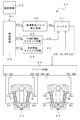
[第2の実施形態の電子時計の構成説明:図8]
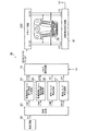
次に、第2の実施形態の電子時計の概略構成について図8を用いて説明する。符号30は第2の実施形態のアナログ表示方式の電子時計である。電子時計30は、水晶振動子(図示せず)によって所定の基準信号P1を出力する発振回路32、基準信号P1を入力して制御信号CN1、CN2、CN3を出力する制御回路33、高速駆動パルス発生回路34、分時針駆動タイミング回路35、秒針駆動タイミング回路36、セレクタ37、ドライバ回路40、第1の2コイルステップモータ41(以下、「ステップモータ41」と略す)と、第2の2コイルステップモータ42(以下、「ステップモータ42」と略す)を有している。[Second Embodiment]
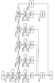
[Structure of the Electronic Clock of the Second Embodiment: FIG. 8]
Next, the schematic configuration of the electronic clock of the second embodiment will be described with reference to FIG.
なお、電子時計30は、指針等による表示部、輪列、電源、操作部材等を含むが、本発明には直接係わらないので図示は省略する。
The
高速駆動パルス発生回路34は、制御信号CN1を入力して、ステップモータ41、42を駆動するための複数の駆動パルスで構成される高速駆動パルス列SPを生成し出力する。
The high-speed drive pulse generation circuit 34 inputs the control signal CN1 to generate and output a high-speed drive pulse train SP composed of a plurality of drive pulses for driving the
分時針駆動タイミング回路35は、制御信号CN2を入力して、分時針を駆動のための高速駆動パルスを選択する高速駆動タイミング信号P2を生成し出力する。 The minute / hour hand drive timing circuit 35 inputs the control signal CN2 to generate and output a high-speed drive timing signal P2 that selects a high-speed drive pulse for driving the minute / hour hand.
秒針駆動タイミング回路36は、制御信号CN3を入力して、秒針を駆動のための通常駆動パルスを選択する通常駆動タイミング信号P3を生成し出力する。 The second hand drive timing circuit 36 inputs the control signal CN3 to generate and output the normal drive timing signal P3 that selects the normal drive pulse for driving the second hand.
セレクタ37は、高速駆動パルス列SPを入力し、高速駆動タイミング信号P2に基づいて高速駆動パルス列SPをそのまま通過させて高速駆動パルス列SP10として出力する。また、セレクタ37は、通常駆動タイミング信号P3に基づいて高速駆動パルス列SPの特定の駆動パルスを選択し、通常駆動パルスSP00として出力する。なお、高速駆動パルス列SP10が出力される場合を高速駆動モードと称し、通常駆動パルスSP00が出力される場合を通常駆動モードと称する。 The selector 37 inputs the high-speed drive pulse train SP, passes the high-speed drive pulse train SP as it is based on the high-speed drive timing signal P2, and outputs the high-speed drive pulse train SP10. Further, the selector 37 selects a specific drive pulse of the high-speed drive pulse train SP based on the normal drive timing signal P3, and outputs it as the normal drive pulse SP00. The case where the high-speed drive pulse train SP10 is output is referred to as a high-speed drive mode, and the case where the normal drive pulse SP00 is output is referred to as a normal drive mode.
ドライバ回路40は、セレクタ37からの高速駆動パルス列SP10または通常駆動パルスSP00を入力し、各駆動パルスに基づいた駆動波形O1〜O8を二つのステップモータ41、42のそれぞれのコイルA、コイルBに供給し、ステップモータ41、42を駆動する。なお、ドライバ回路40の詳細な構成は後述する。
The driver circuit 40 inputs the high-speed drive pulse train SP10 or the normal drive pulse SP00 from the selector 37, and outputs the drive waveforms O1 to O8 based on each drive pulse to the coils A and B of the two
ステップモータ41、42は、それぞれコイルA、コイルBを有し、その構成は第1の実施形態のステップモータ20(図2参照)と同様であるので詳細な説明は省略する。ここで、ステップモータ41は、一例として電子時計30の分時針(図示せず)を駆動するために配置され、ステップモータ42は、一例として電子時計30の秒針(図示せず)を駆動するために配置される。
The
ステップモータ41のコイルAのコイル端子O1、O2は、ドライバ回路40からの駆動波形O1、O2にそれぞれ接続され、コイルBのコイル端子O3、O4は、ドライバ回路40の駆動波形O3、O4にそれぞれ接続される。また、もう一方のステップモータ42のコイルAのコイル端子O1、O2は、ドライバ回路40の駆動波形O5、O6にそれぞれ接続され、コイルBのコイル端子O3、O4は、ドライバ回路40の駆動波形O7、O8にそれぞれ接続される。このように、第2の実施形態の電子時計30は、分時針駆動用と秒針駆動用に二つのステップモータ41、42を有することが特徴である。
The coil terminals O1 and O2 of the coil A of the
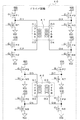
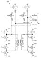
[第2の実施形態のドライバ回路の回路構成の説明:図9]
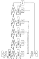
次に、ステップモータ41、42を駆動するためのドライバ回路40の回路構成の一例について図9を用いて説明する。ドライバ回路40は、ステップモータ41、42のそれぞれのコイルA、コイルBに8つの駆動波形を供給する8個のバッファ回路によって構成される。[Explanation of the circuit configuration of the driver circuit of the second embodiment: FIG. 9]
Next, an example of the circuit configuration of the driver circuit 40 for driving the
ここで、ステップモータ41に対しては、低ON抵抗のPチャンネルMOSトランジスタであるトランジスタP1と、低ON抵抗のNチャンネルMOSトランジスタであるトランジスタN1と、のコンプリメンタリ接続でなるバッファ回路が、駆動波形O1を出力してコイルAのコイル端子O1に接続される。 また同様に、それぞれ低ON抵抗のトランジスタP2とトランジスタN2とでなるバッファ回路が、駆動波形O2を出力してコイルAのコイル端子O2に接続される。
Here, for the
また同様に、それぞれ低ON抵抗のトランジスタP3とトランジスタN3とでなるバッファ回路が、駆動波形O3を出力してコイルBのコイル端子O3に接続される。 Similarly, a buffer circuit composed of a transistor P3 and a transistor N3 having a low ON resistance respectively outputs a drive waveform O3 and is connected to the coil terminal O3 of the coil B.
また同様に、それぞれ低ON抵抗のトランジスタP4とトランジスタN4とでなるバッファ回路が、駆動波形O4を出力してコイルBのコイル端子O4に接続される。 Similarly, a buffer circuit composed of a transistor P4 and a transistor N4 having a low ON resistance respectively outputs a drive waveform O4 and is connected to the coil terminal O4 of the coil B.
また、ステップモータ42に対しては、低ON抵抗のトランジスタP5と低ON抵抗のトランジスタN5とのコンプリメンタリ接続でなるバッファ回路が、駆動波形O5を出力してコイルAのコイル端子O1に接続される。 Further, for the step motor 42, a buffer circuit formed by a complementary connection of the low ON resistance transistor P5 and the low ON resistance transistor N5 outputs the drive waveform O5 and is connected to the coil terminal O1 of the coil A. ..
また同様に、それぞれ低ON抵抗のトランジスタP6とトランジスタN6とでなるバッファ回路が、駆動波形O6を出力してコイルAのコイル端子O2に接続される。 Similarly, a buffer circuit composed of a transistor P6 and a transistor N6 having low ON resistance outputs a drive waveform O6 and is connected to the coil terminal O2 of the coil A.
また同様に、それぞれ低ON抵抗のトランジスタP7とトランジスタN7とでなるバッファ回路が、駆動波形O7を出力してコイルBのコイル端子O3に接続される。 Similarly, a buffer circuit composed of a transistor P7 having a low ON resistance and a transistor N7 outputs a drive waveform O7 and is connected to the coil terminal O3 of the coil B, respectively.
また同様に、それぞれ低ON抵抗のトランジスタP8とトランジスタN8とでなるバッファ回路が、駆動波形O8を出力してコイルBのコイル端子O4に接続される。 Similarly, a buffer circuit composed of a transistor P8 having a low ON resistance and a transistor N8 outputs a drive waveform O8 and is connected to the coil terminal O4 of the coil B, respectively.
また、各トランジスタP1〜P8、N1〜N8の各ゲート端子Gは、図示しないが、前述したセレクタ37からの高速駆動パルス列SP10または通常駆動パルスSP00を入力し、各トランジスタは駆動パルスに基づいてON/OFF制御され、ステップモータ41、42の各コイルA、コイルBに駆動波形O1〜O8を供給する。
Further, although not shown, the gate terminals G of the transistors P1 to P8 and N1 to N8 input the high-speed drive pulse train SP10 or the normal drive pulse SP00 from the selector 37 described above, and each transistor is turned on based on the drive pulse. / OFF control is performed, and the drive waveforms O1 to O8 are supplied to the coils A and B of the
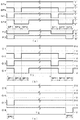
[第2の実施形態の駆動パルスの生成と駆動波形の説明:図10]
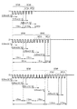
次に、第2の実施形態の駆動パルスの生成と駆動波形の一例について図10を用いて説明する。図10(a)は、高速駆動パルス発生回路34から出力される高速駆動パルス列SPと、高速駆動タイミング信号P2、通常駆動タイミング信号P3の一例である。図10(b)は、高速駆動モードで分時針を駆動するための高速駆動パルス列SP10の駆動波形の一例である。図10(c)は、通常駆動モードで秒針を駆動するための通常駆動パルスSP00の駆動波形の一例である。図10(a)〜図10(c)は、時間軸を揃えて記述している。なお、電子時計30の構成は、図8の構成図を参照する。[Description of drive pulse generation and drive waveform of the second embodiment: FIG. 10]
Next, an example of the generation of the drive pulse and the drive waveform of the second embodiment will be described with reference to FIG. FIG. 10A is an example of the high-speed drive pulse train SP output from the high-speed drive pulse generation circuit 34, the high-speed drive timing signal P2, and the normal drive timing signal P3. FIG. 10B is an example of the drive waveform of the high-speed drive pulse train SP10 for driving the minute and hour hands in the high-speed drive mode. FIG. 10C is an example of the drive waveform of the normal drive pulse SP00 for driving the second hand in the normal drive mode. 10 (a) to 10 (c) are described with the time axis aligned. For the configuration of the
図10(a)において、高速駆動パルス発生回路34から出力される高速駆動パルス列SPは、一例として4ビットのSPa〜SPdでなり、時系列的に第1駆動パルスSP1、第2駆動パルスSP2、第3駆動パルスSP3の3個の駆動パルスで構成され、ドライバ回路40の各トランジスタをON/OFF制御するために論理“1”または論理“0”でなるパルス列である。 In FIG. 10A, the high-speed drive pulse train SP output from the high-speed drive pulse generation circuit 34 is, for example, 4-bit SPA to SPd, and the first drive pulse SP1 and the second drive pulse SP2 are arranged in chronological order. A pulse train composed of three drive pulses of the third drive pulse SP3 and having logic "1" or logic "0" for ON / OFF control of each transistor of the driver circuit 40.
第1駆動パルスSP1は、SPa、SPb、SPdが論理“1”であり、SPcが論理“0”である。また、第2駆動パルスSP2は、SPa、SPcが論理“1”であり、SPb、SPdが論理“0”である。また、第3駆動パルスSP3は、SPa、SPb、SPcが論理“1”であり、SPdが論理“0”である。この高速駆動パルス列SPは制御回路33の制御によって、任意の期間、所定の周期で繰り返し出力され、図10(a)では、少なくとも2回繰り返し出力されたことを示している。
In the first drive pulse SP1, SPa, SPb, and SPd are logic "1", and SPc is logic "0". Further, in the second drive pulse SP2, SPa and SPc are logic "1", and SPb and SPd are logic "0". Further, in the third drive pulse SP3, SPa, SPb, and SPc are logic "1", and SPd is logic "0". The high-speed drive pulse train SP is repeatedly output at a predetermined cycle for an arbitrary period under the control of the
また、高速駆動タイミング信号P2は、高速駆動パルス列SPの第1〜第3駆動パルスSP1〜SP3のタイミングで、一例として論理“0”となり、他のタイミングでは論理“1”となる信号である。セレクタ37は、高速駆動モードにおいて、この高速駆動タイミング信号P2の論理“0”のタイミングで高速駆動パルス列SPを通過させ、高速駆動パルス列SP10としてドライバ回路40に供給する。
Further, the high-speed drive timing signal P2 is a signal that becomes logic "0" at the timing of the first to third drive pulses SP1 to SP3 of the high-speed drive pulse train SP as an example, and becomes logic "1" at other timings. In the high-speed drive mode, the selector 37 passes the high-speed drive pulse train SP at the timing of the logic “0” of the high-speed drive timing signal P2 and supplies the high-speed drive
また、通常駆動タイミング信号P3は、二つのステップを有し、最初の第1ステップでは、高速駆動パルス列SPの第1駆動パルスSP1のタイミングに合わせて論理“0”となり、次の第2ステップでは、第3駆動パルスSP3のタイミングに合わせて論理“0”となる信号である。セレクタ37は、通常駆動モードにおいて、この通常駆動タイミング信号P3の論理“0”のタイミングで高速駆動パルス列SPの第1駆動パルスSP1(第1ステップ)と第3駆動パルスSP3(第2ステップ)を通過させ、通常駆動パルスSP00としてドライバ回路40に供給する。 Further, the normal drive timing signal P3 has two steps, and in the first first step, the logic becomes “0” in accordance with the timing of the first drive pulse SP1 of the high-speed drive pulse train SP, and in the next second step, the logic becomes “0”. , This is a signal that becomes logic “0” in accordance with the timing of the third drive pulse SP3. In the normal drive mode, the selector 37 sets the first drive pulse SP1 (first step) and the third drive pulse SP3 (second step) of the high-speed drive pulse train SP at the timing of the logic “0” of the normal drive timing signal P3. It is passed through and supplied to the driver circuit 40 as a normal drive pulse SP00.
次に図10(b)において、高速駆動モードでの駆動パルスを説明する。制御回路33が高速駆動モードに選択されると、制御信号CN2を出力し、分時針駆動タイミング回路35は、制御信号CN2によって高速駆動タイミング信号P2を出力する。セレクタ37は、高速駆動タイミング信号P2によって、4ビットの高速駆動パルス列SPが通過して出力するように動作する。
Next, in FIG. 10B, the drive pulse in the high-speed drive mode will be described. When the
これにより、高速駆動モードでは、前述したように、4ビットの高速駆動パルス列SPがそのままセレクタ37を通過し、高速駆動パルス列SP10としてドライバ回路40に供給される。なお、セレクタ37から出力される高速駆動パルス列SP10は、第1の実施形態の高速駆動パルス列SP10と同様であるので同一符号とし、構成する第1、第2、第3駆動パルスSP11、SP12、SP13も同一符号とする。 As a result, in the high-speed drive mode, as described above, the 4-bit high-speed drive pulse train SP passes through the selector 37 as it is and is supplied to the driver circuit 40 as the high-speed drive pulse train SP10. Since the high-speed drive pulse train SP10 output from the selector 37 is the same as the high-speed drive pulse train SP10 of the first embodiment, the same reference numerals are used, and the first, second, and third drive pulses SP11, SP12, and SP13 are configured. Have the same code.
ドライバ回路40は、入力する4ビットの高速駆動パルス列SP10の第1〜第3駆動パルスSP11〜SP13に基づいて、各トランジスタが順次ON/OFF動作し、図10(b)に示す駆動波形O1〜O4を出力する。 In the driver circuit 40, each transistor sequentially turns ON / OFF based on the first to third drive pulses SP11 to SP13 of the input 4-bit high-speed drive pulse train SP10, and the drive waveforms O1 to 2 shown in FIG. Output O4.
ステップモータ41のコイルA、コイルBは、この駆動波形O1〜O4を入力し、1ステップ360度単位で高速回転駆動される。なお、ステップモータ41による高速回転駆動は、前述した第1の実施形態の1ステップ360度単位の高速回転駆動(図7参照)と同様であるので、ステップモータの動作説明は省略する。
The coils A and B of the
ここで、高速駆動パルス列SP10の繰り返し周期T1(図10(b)参照)を60秒とし、ステップモータ41の1ステップ360度回転によって、分針が1分進むように輪列(図示せず)の歯車減速比を大きく設定(1/60)すれば、ステップモータ41は、60秒毎に360度回転し、分針を1分運針することができる。
Here, the repetition period T1 of the high-speed drive pulse train SP10 (see FIG. 10B) is set to 60 seconds, and the train wheel (not shown) is rotated so that the minute hand advances by 1 minute by rotating the
次に図10(c)において、通常駆動モードでの駆動パルスを説明する。制御回路33が通常駆動モードに選択されると、制御信号CN3を出力し、秒針駆動タイミング回路36は、制御信号CN3によって、通常駆動タイミング信号P3を出力する。セレクタ37は、通常駆動タイミング信号P3が論理“0”の期間に、4ビットの高速駆動パルス列SPが通過して出力するように動作する。
Next, in FIG. 10 (c), the drive pulse in the normal drive mode will be described. When the
これにより、通常駆動モードでは、前述したように、セレクタ37によって選択された4ビットの通常駆動パルスSP00が出力し、ドライバ回路40に供給される。なお、通常駆動パルスSP00の第1ステップの駆動パルスを第1駆動パルスSP01と称し、第2ステップの駆動パルスを第2駆動パルスSP02と称する。 As a result, in the normal drive mode, as described above, the 4-bit normal drive pulse SP00 selected by the selector 37 is output and supplied to the driver circuit 40. The drive pulse of the first step of the normal drive pulse SP00 is referred to as the first drive pulse SP01, and the drive pulse of the second step is referred to as the second drive pulse SP02.
ドライバ回路40は、入力する4ビットの通常駆動パルスSP00の第1駆動パルスSP01と第2駆動パルスSP02に基づいて、各トランジスタがON/OFF動作し、図10(c)に示す駆動波形O5〜O8を出力する。 In the driver circuit 40, each transistor operates ON / OFF based on the first drive pulse SP01 and the second drive pulse SP02 of the 4-bit normal drive pulse SP00 to be input, and the drive waveforms O5 to 5 shown in FIG. 10 (c) are operated. Output O8.
ここで、通常駆動パルスSP00の第1ステップである第1駆動パルスSP01は、選択された高速駆動パルス列SPcが論理“0”であるので(図10(a)参照)、駆動波形O7が電圧−Vとなるように制御され、他の駆動波形O5、O6、O8は電圧0Vとなる。また、通常駆動パルスSP00の第2ステップである第2駆動パルスSP02は、選択された高速駆動パルス列SPdが論理“0”であるので(図10(a)参照)、駆動波形O8が電圧−Vとなるように制御され、他の駆動波形O5、O6、O7は電圧0Vとなる。ステップモータ42のコイルA、コイルBは、この駆動波形O5〜O8を入力し、通常駆動される。 Here, in the first drive pulse SP01, which is the first step of the normal drive pulse SP00, since the selected high-speed drive pulse train SPc is logic “0” (see FIG. 10A), the drive waveform O7 has a voltage −. It is controlled to be V, and the other drive waveforms O5, O6, and O8 have a voltage of 0V. Further, in the second drive pulse SP02, which is the second step of the normal drive pulse SP00, since the selected high-speed drive pulse train SPd is logic “0” (see FIG. 10A), the drive waveform O8 has a voltage −V. The other drive waveforms O5, O6, and O7 have a voltage of 0V. The coils A and B of the step motor 42 input the drive waveforms O5 to O8 and are normally driven.
この通常駆動パルスSP00による駆動波形O5〜O8は、図4と図5で前述した従来の1ステップ180度回転の駆動波形と同様であり、従って、ステップモータ42の通常駆動動作は、図4、図5で示した従来の1ステップ180度回転駆動と同様であるので、ここでの説明は省略する。 The drive waveforms O5 to O8 by the normal drive pulse SP00 are the same as the conventional one-step 180-degree rotation drive waveform described in FIGS. 4 and 5, and therefore, the normal drive operation of the step motor 42 is shown in FIGS. Since it is the same as the conventional one-step 180-degree rotation drive shown in FIG. 5, the description here will be omitted.
このように、通常駆動モードの通常駆動パルスSP00は、秒針を駆動するステップモータ42を1ステップ180度回転させることができる。そして、第1駆動パルスSP01と第2駆動パルスSP02の周期T2(図10(c))を一例として1秒とするならば、ステップモータ42は、1秒毎に180度回転し、秒針を1秒運針することができる。すなわち、第2の実施形態は、高速駆動モードでは、高速駆動パルス列SP10によってステップモータ41を1ステップ360度回転駆動して分針を1分運針し、また、通常駆動モードでは、従来のように通常駆動パルスSP00によってステップモータ42を1ステップ180度回転駆動して秒針を1秒運針するのである。
In this way, the normal drive pulse SP00 in the normal drive mode can rotate the step motor 42 that drives the second hand by 180 degrees per step. If the period T2 (FIG. 10 (c)) of the first drive pulse SP01 and the second drive pulse SP02 is set to 1 second as an example, the step motor 42 rotates 180 degrees every second and the second hand is set to 1 second. You can move the hands for seconds. That is, in the second embodiment, in the high-speed drive mode, the
なお、図10(b)に示す高速駆動モードでの高速駆動パルス列SP10による駆動波形O1〜O4は、この駆動波形に限定されず。2コイルステップモータを1ステップ360度回転駆動できるどのような駆動波形でもよい。 The drive waveforms O1 to O4 by the high-speed drive pulse train SP10 in the high-speed drive mode shown in FIG. 10B are not limited to these drive waveforms. Any drive waveform that can drive the two-coil step motor to rotate 360 degrees in one step may be used.
[第2の実施形態のドライバ回路の動作説明:図11]
次に、第2の実施形態のドライバ回路40の各トランジスタのON/OFF動作によって、高速駆動パルス列SP10と通常駆動パルスSP00の各駆動波形がどのように作られるかを図11の各トランジスタの動作表を用いて説明する。[Explanation of operation of the driver circuit of the second embodiment: FIG. 11]
Next, the operation of each transistor in FIG. 11 shows how the drive waveforms of the high-speed drive pulse train SP10 and the normal drive pulse SP00 are created by the ON / OFF operation of each transistor of the driver circuit 40 of the second embodiment. This will be described using a table.
第2の実施形態のドライバ回路40は、前述したように、8個のトランジスタP1〜P8と、8個のトランジスタN1〜N8と、によるコンプリメンタリ接続の8個のバッファ回路で構成され、各バッファ回路から駆動波形O1〜O8が出力される(図9参照)。 As described above, the driver circuit 40 of the second embodiment is composed of eight buffer circuits of complementary connection by eight transistors P1 to P8 and eight transistors N1 to N8, and each buffer circuit is composed of eight buffer circuits. Drive waveforms O1 to O8 are output from (see FIG. 9).
まず、図11の動作表左側から高速駆動モードでの各トランジスタのON/OFF動作を説明する。高速駆動モードで駆動されるステップモータ41(分時針駆動)は、駆動波形O1〜O4によって駆動され、従って高速駆動モードでは、ドライバ回路40のトランジスタP1〜P4とトランジスタN1〜N4が動作することで駆動波形O1〜O4が出力される。 First, the ON / OFF operation of each transistor in the high-speed drive mode will be described from the left side of the operation table of FIG. The step motor 41 (minute and hour hand drive) driven in the high-speed drive mode is driven by the drive waveforms O1 to O4. Therefore, in the high-speed drive mode, the transistors P1 to P4 and the transistors N1 to N4 of the driver circuit 40 operate. The drive waveforms O1 to O4 are output.
ここで、図11において、高速駆動パルス列SP10の第1駆動パルスSP11では、駆動波形O3が電圧−Vであり、他の駆動波形O1、O2、O4は電圧0Vであるので(図10(b)参照)、トランジスタN3がON、トランジスタP3がOFFとなり、他のトランジスタP1、P2、P4はON、トランジスタN1、N2、N4はOFFとなるように制御される。 Here, in FIG. 11, in the first drive pulse SP11 of the high-speed drive pulse train SP10, the drive waveform O3 has a voltage −V, and the other drive waveforms O1, O2, and O4 have a voltage of 0 V (FIG. 10B). (See), the transistor N3 is turned ON, the transistor P3 is turned OFF, the other transistors P1, P2, and P4 are controlled to be ON, and the transistors N1, N2, and N4 are controlled to be OFF.
また、第2駆動パルスSP12では、駆動波形O2、O4が電圧−Vであり、他の駆動波形O1、O3は電圧0Vであるので(図10(b)参照)、トランジスタN2、N4がON、トランジスタP2、P4がOFFとなり、他のトランジスタP1、P3はON、トランジスタN1、N3はOFFとなるように制御される。 Further, in the second drive pulse SP12, since the drive waveforms O2 and O4 have a voltage −V and the other drive waveforms O1 and O3 have a voltage of 0 V (see FIG. 10B), the transistors N2 and N4 are turned on. The transistors P2 and P4 are controlled to be OFF, the other transistors P1 and P3 are controlled to be ON, and the transistors N1 and N3 are controlled to be OFF.
また、第3駆動パルスSP13では、駆動波形O4が電圧−Vであり、他の駆動波形O1、O2、O3は電圧0Vであるので(図10(b)参照)、トランジスタN4がON、トランジスタP4がOFFとなり、他のトランジスタP1、P2、P3はON、トランジスタN1、N2、N3はOFFとなるように制御される。 Further, in the third drive pulse SP13, since the drive waveform O4 has a voltage −V and the other drive waveforms O1, O2, and O3 have a voltage of 0 V (see FIG. 10B), the transistor N4 is ON and the transistor P4. Is turned OFF, the other transistors P1, P2, and P3 are controlled to be ON, and the transistors N1, N2, and N3 are controlled to be OFF.
また、後述する通常駆動モードでは、ステップモータ41は駆動されず、駆動波形O1〜O4は、すべて電圧V0となるので、トランジスタP1〜P4がすべてON、トランジスタN1〜N4がすべてOFFとなるように制御される。
Further, in the normal drive mode described later, the
次に、図11の動作表右側から通常駆動モードでの各トランジスタのON/OFF動作を説明する。通常駆動モードで駆動されるステップモータ42(秒針駆動)は、駆動波形O5〜O8によって駆動され、従って通常駆動モードでは、ドライバ回路40のトランジスタP5〜P8とトランジスタN5〜N8が動作することで駆動波形O5〜O8が出力される。 Next, the ON / OFF operation of each transistor in the normal drive mode will be described from the right side of the operation table of FIG. The step motor 42 (second hand drive) driven in the normal drive mode is driven by the drive waveforms O5 to O8. Therefore, in the normal drive mode, the step motor 42 (second hand drive) is driven by the operation of the transistors P5 to P8 and the transistors N5 to N8 of the driver circuit 40. Waveforms O5 to O8 are output.
ここで、図11において、通常駆動パルスSP00の第1ステップの第1駆動パルスSP01では、駆動波形O7が電圧−Vであり、他の駆動波形O5、O6、O8は電圧0Vであるので(図10(c)参照)、トランジスタN7がON、トランジスタP7がOFFとなり、他のトランジスタP5、P6、P8はON、トランジスタN5、N6、N8はOFFとなるように制御される。 Here, in FIG. 11, in the first drive pulse SP01 of the first step of the normal drive pulse SP00, the drive waveform O7 has a voltage −V, and the other drive waveforms O5, O6, and O8 have a voltage of 0V (FIG. 11). 10 (c)), the transistor N7 is turned ON, the transistor P7 is turned OFF, the other transistors P5, P6, P8 are turned ON, and the transistors N5, N6, N8 are controlled to be OFF.
また、通常駆動パルスSP00の第2ステップの第2駆動パルスSP02では、駆動波形O8が電圧−Vであり、他の駆動波形O5、O6、O7は電圧0Vであるので(図10(c)参照)、トランジスタN8がON、トランジスタP8がOFFとなり、他のトランジスタP5、P6、P7はON、トランジスタN5、N6、N7はOFFとなるように制御される。 Further, in the second drive pulse SP02 of the second step of the normal drive pulse SP00, the drive waveform O8 has a voltage −V, and the other drive waveforms O5, O6, and O7 have a voltage of 0 V (see FIG. 10C). ), Transistor N8 is ON, transistor P8 is OFF, other transistors P5, P6, P7 are ON, and transistors N5, N6, N7 are OFF.
また、前述した高速駆動モードでは、ステップモータ42は駆動されず、駆動波形O5〜O8は、すべて電圧V0となるので、トランジスタP5〜P8がすべてON、トランジスタN5〜N8がすべてOFFとなるように制御される。 Further, in the high-speed drive mode described above, the step motor 42 is not driven and all the drive waveforms O5 to O8 have a voltage V0, so that all the transistors P5 to P8 are ON and all the transistors N5 to N8 are OFF. Be controlled.
なお、図11の動作表において、各駆動パルスで各トランジスタのON/OFF動作が切り替えられる位置を楕円で囲んで示している。たとえば、高速駆動モードにおいて、第1駆動パルスSP11では駆動波形O3が電圧−Vとなるので、トランジスタP3がONからOFFに切り替わり、トランジスタN3がOFFからONに切り替わるため、トランジスタP3のOFFとトランジスタN3のONを楕円で囲み、第1駆動パルスSP11によってトランジスタP3、N3の動作が切り替わることを表している。 In the operation table of FIG. 11, the position where the ON / OFF operation of each transistor is switched by each drive pulse is shown by enclosing it with an ellipse. For example, in the high-speed drive mode, in the first drive pulse SP11, the drive waveform O3 becomes a voltage −V, so that the transistor P3 is switched from ON to OFF and the transistor N3 is switched from OFF to ON. Is surrounded by an ellipse, and the operation of the transistors P3 and N3 is switched by the first drive pulse SP11.
また、高速駆動パルス列SP10によるステップモータ41の1ステップ360度回転の動作は、前述した第1の実施形態のステップモータ20の動作(図7参照)と同様であり、また、通常駆動パルスSP00によるステップモータ42の動作は、前述した従来のステップモータの動作(図4、図5参照)と同様であるので、ここでの説明は省略する。
Further, the operation of one-step 360-degree rotation of the
以上のように、第2の実施形態の電子時計によれば、分時針駆動用に1ステップ360度回転で高速駆動を行うステップモータ41と、秒針駆動用に1ステップ180度回転で通常駆動を行うステップモータ42と、の二つのステップモータを有している。また、秒針を動かすステップモータ42を駆動する通常駆動パルスSP00の駆動周波数(駆動パルスの出力間隔)は、分時針を動かすステップモータ41を駆動する高速駆動パルス列SP10の駆動周波数より低く設定される。これにより、二つのステップモータによって駆動周波数が異なる運針を実現できる。
As described above, according to the electronic clock of the second embodiment, the
ここで、秒針は一般的に他の指針に比べて針形状が小さく軽いので、耐衝撃性はそれほど重視されないが、秒針は通常1秒運針であるために駆動頻度が高く、低消電駆動が重視される。また、分時針は一般的に秒針に比べて針形状が大きく重いので、耐衝撃性が重視されるが、駆動頻度は低いので低消電駆動は重視されない。 Here, since the second hand is generally smaller and lighter than other pointers, impact resistance is not so important, but since the second hand is usually a 1-second hand movement, the drive frequency is high and low static elimination drive is possible. It is emphasized. Further, since the minute and hour hands are generally larger and heavier than the second hand, impact resistance is emphasized, but since the drive frequency is low, low static elimination drive is not emphasized.
従って、分時針駆動用に1ステップ360度回転のステップモータ41を配置することで、分針の歯車減速比を大きく(1/60)できるので、分時針のトルクアップを実現でき、分時針の耐衝撃性が向上し、分時針に求められる性能を満たすことができる。また、秒針駆動用に1ステップ180度回転の通常駆動のステップモータ42を配置することで、秒針の歯車減速比は従来通り1/30であるが、1ステップの駆動パルスを単発で実現でき(図10(c)参照)、低消電駆動が可能となる。
Therefore, by arranging the
また、第2の実施形態では、高速駆動パルス発生回路34を配置し、一つの駆動パルス列から特定の駆動パルスを選択するタイミングを切り替えることで、高速駆動パルス列SP10と通常駆動パルスSP00を生成するので、駆動パルス発生回路を一つのみで構成でき、電子時計の回路規模を縮小できるメリットがある。 Further, in the second embodiment, the high-speed drive pulse train SP10 and the normal drive pulse SP00 are generated by arranging the high-speed drive pulse generation circuit 34 and switching the timing of selecting a specific drive pulse from one drive pulse train. , The drive pulse generation circuit can be configured with only one, and there is an advantage that the circuit scale of the electronic clock can be reduced.
[第3の実施形態]
[第3の実施形態の電子時計の構成説明:図12]
次に、第3の実施形態の電子時計の概略構成について図12を用いて説明する。符号50は第3の実施形態のアナログ表示方式の電子時計である。電子時計50は、水晶振動子(図示せず)によって所定の基準信号P1を出力する発振回路52、基準信号P1を入力して制御信号CN4、CN5、CN6を出力する制御回路53、高速駆動パルス発生回路54、通常駆動パルス発生回路55、切替制御回路56、セレクタ57、ドライバ回路60、および、2コイルステップモータ20(以下、「ステップモータ20」と略す)を有している。[Third Embodiment]
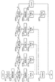
[Structure of the Electronic Clock of the Third Embodiment: FIG. 12]
Next, the schematic configuration of the electronic clock of the third embodiment will be described with reference to FIG. Reference numeral 50 is an analog display type electronic clock of the third embodiment. The electronic clock 50 includes an oscillation circuit 52 that outputs a predetermined reference signal P1 by a crystal oscillator (not shown), a
なお、電子時計50は、指針等による表示部、輪列、電源、操作部材等を含むが、本発明には直接係わらないので図示は省略する。 The electronic clock 50 includes a display unit with pointers and the like, a train wheel, a power supply, an operating member, and the like, but the illustration is omitted because it is not directly related to the present invention.
高速駆動パルス発生回路54は、制御信号CN4を入力して、ステップモータ20を高速に駆動するための高速駆動パルス列SP20を生成し出力する。なお、高速駆動パルス列SP20は、前述した第1及び第2の実施形態の高速駆動パルス列SP10と駆動波形が異なる例を示すので別符号とした。また、高速駆動パルス列SP20は、高速駆動パルス列SP10と同様に3個の駆動パルスで構成されるが、詳細は後述する。
The high-speed drive pulse generation circuit 54 inputs the control signal CN4 to generate and output the high-speed drive pulse train SP20 for driving the
通常駆動パルス発生回路55は、制御信号CN5を入力して、ステップモータ20を通常駆動するための通常駆動パルスSP00を生成し出力する。なお、第3の実施形態の通常駆動パルスSP00は、前述した第2の実施形態の通常駆動パルスSP00と駆動波形が同一なので同一符号とした。
The normal drive
切替制御回路56は、制御信号CN6を入力して、駆動モードに応じて高速駆動パルス列SP20と通常駆動パルスSP00を切り替えるための切替信号P4を出力する。 The switching control circuit 56 inputs the control signal CN6 and outputs a switching signal P4 for switching between the high-speed drive pulse train SP20 and the normal drive pulse SP00 according to the drive mode.
セレクタ57は、高速駆動パルス列SP20と通常駆動パルスSP00との2種類の駆動パルスを入力し、切替信号P4によって2種類の駆動パルスのいずれかを選択し出力する。 The selector 57 inputs two types of drive pulses, that is, a high-speed drive pulse train SP20 and a normal drive pulse SP00, and selects and outputs one of the two types of drive pulses by the switching signal P4.
ドライバ回路60は、セレクタ57からの高速駆動パルス列SP20または通常駆動パルスSP00のいずれかの駆動パルスを入力し、駆動パルスに基づいた駆動波形O1〜O4をステップモータ20のコイルA、コイルBに供給し、ステップモータ20を駆動する。なお、ドライバ回路60の回路構成は、前述した第1の実施形態のドライバ回路10(図3参照)と同様であるので回路構成及び各トランジスタの動作説明は省略する。
The driver circuit 60 inputs a drive pulse of either the high-speed drive pulse train SP20 or the normal drive pulse SP00 from the selector 57, and supplies drive waveforms O1 to O4 based on the drive pulse to the coils A and B of the
ステップモータ20は、第1のコイルとしてコイルA、第2のコイルとしてコイルBの二つのコイルを有しており、前述した第1の実施形態のステップモータ20(図2参照)と同様であるので、同一符号として構成の詳細は省略する。
The
[第3の実施形態の電子時計の動作説明:図12]
次に、第3の実施形態の電子時計の概略動作について図12を用いて説明する。電子時計50は前述したように、一つのステップモータ20を有し、高速駆動パルス発生回路54と通常駆動パルス発生回路55の二つの駆動パルス発生回路を有する構成である。[Explanation of operation of the electronic clock of the third embodiment: FIG. 12]
Next, the schematic operation of the electronic clock of the third embodiment will be described with reference to FIG. As described above, the electronic clock 50 has one
電子時計50は、1秒運針等を行う通常駆動モードと、時刻修正などで高速運針を行う高速駆動モードと、を備えている。ここで、電子時計50が高速駆動モードである場合、制御回路53は制御信号CN4を出力して高速駆動パルス発生回路54を起動し、高速駆動パルス列SP20を出力する。また、電子時計50が通常駆動モードである場合、制御回路53は制御信号CN5を出力して通常駆動パルス発生回路55を起動し、通常駆動パルスSP00を出力する。
The electronic clock 50 includes a normal drive mode in which the hand is moved for 1 second and the like, and a high-speed drive mode in which the hand is moved at high speed by adjusting the time. Here, when the electronic clock 50 is in the high-speed drive mode, the
また、電子時計50が高速駆動モードを選択すると、制御回路53は制御信号CN6を出力して切替制御回路56を動作させ、高速駆動モードの切替信号P4を出力してセレクタ57に伝達する。セレクタ57は切替信号P4を入力し、高速駆動パルス列SP20を選択してドライバ回路60に出力する。
When the electronic clock 50 selects the high-speed drive mode, the
ドライバ回路60は、複数の駆動パルスでなる高速駆動パルス列SP20によって、内部のバッファ回路を動作させ、高速駆動に対応した駆動波形O1〜O4を順次出力して、ステップモータ20を1ステップ360度単位で高速回転駆動を行う。
The driver circuit 60 operates an internal buffer circuit by a high-speed drive pulse train SP20 composed of a plurality of drive pulses, sequentially outputs drive waveforms O1 to O4 corresponding to high-speed drive, and steps the
また、電子時計50が通常駆動モードを選択すると、制御回路53は制御信号CN6を出力して切替制御回路56を動作させ、通常駆動モードの切替信号P4を出力してセレクタ57に伝達する。セレクタ57は、切替信号P4を入力し、通常駆動パルスSP00を選択してドライバ回路60に出力する。
When the electronic clock 50 selects the normal drive mode, the
ドライバ回路60は、通常駆動パルスSP00によって内部のバッファ回路を動作させ、通常駆動に対応した駆動波形O1〜O4を出力し、ステップモータ20を1ステップ180度単位で通常回転駆動(たとえば1秒運針)を行う。
The driver circuit 60 operates an internal buffer circuit by the normal drive pulse SP00, outputs drive waveforms O1 to O4 corresponding to the normal drive, and normally rotates the
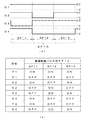
[従来の2コイルステップモータの2ステップ360度回転駆動の説明:図13]
次に、第3の実施形態のステップモータの高速駆動動作を説明する前に、比較のために、2コイルステップモータによる従来の高速駆動動作の一例を図13を用いて説明する。なお、2コイルステップモータとドライバ回路は、図12に示した第3の実施形態の構成図を適用する。[Explanation of 2-step 360-degree rotary drive of a conventional 2-coil step motor: FIG. 13]
Next, before explaining the high-speed drive operation of the step motor of the third embodiment, an example of the conventional high-speed drive operation by the two-coil step motor will be described with reference to FIG. 13 for comparison. The configuration diagram of the third embodiment shown in FIG. 12 is applied to the two-coil step motor and the driver circuit.
図13(a)は、ステップモータ20を従来の1ステップ180度回転を連続して2ステップで行い、ロータを高速に2ステップ360度回転駆動させる駆動波形の一例である。図13(a)において、第1ステップの第1駆動パルスSP1−1は、駆動波形O3が電圧−Vであり、他の駆動波形O1、O2、O4は電圧0Vである。これにより、駆動波形O3とO4に接続されるステップモータ20のコイルBに駆動電流が流れて励磁される。
FIG. 13A is an example of a drive waveform in which the
次に、第1ステップの第2駆動パルスSP1−2は、駆動波形O2、O3が電圧−Vであり、駆動波形O1、O4が電圧0Vである。これにより、ステップモータ20のコイルA、コイルBの両方に駆動電流が流れて、両方のコイルA、コイルBが同じ方向に励磁される。
Next, in the second drive pulse SP1-2 of the first step, the drive waveforms O2 and O3 have a voltage −V, and the drive waveforms O1 and O4 have a voltage of 0V. As a result, a drive current flows through both the coil A and the coil B of the
次に、第2ステップの第1駆動パルスSP2−1は、駆動波形O4が電圧−Vであり、他の駆動波形O1、O2、O3は電圧0Vである。これにより、駆動波形O3とO4に接続されるステップモータ20のコイルBに駆動電流が流れて第1ステップと逆の方向に励磁される。
Next, in the first drive pulse SP2-1 of the second step, the drive waveform O4 has a voltage −V, and the other drive waveforms O1, O2, and O3 have a voltage of 0 V. As a result, a drive current flows through the coil B of the
次に、第2ステップの第2駆動パルスSP2−2は、駆動波形O1、O4が電圧−Vであり、駆動波形O2、O3が電圧0Vである。これにより、ステップモータ20のコイルA、コイルBに駆動電流が流れて、両方のコイルA、コイルBが第1ステップと逆の方向に励磁される。
Next, in the second drive pulse SP2-2 of the second step, the drive waveforms O1 and O4 have a voltage −V, and the drive waveforms O2 and O3 have a voltage of 0V. As a result, a drive current flows through the coils A and B of the
次に、従来の2ステップによる360度回転駆動のステップモータの動作を図13(b)〜図13(e)によって説明する。なお、ステップモータ20の各部材の符号は、図13(b)にのみ記して他は省略する。図13(b)は、ステップモータ20に第1ステップの第1駆動パルスSP1−1が供給された場合の動作である。ここで、第1駆動パルスSP1−1が供給されると、駆動電流(図示せず)がコイル端子O4からコイル端子O3に流れ、コイルBが矢印の方向に励磁される。
Next, the operation of the conventional step motor driven by 360-degree rotation by two steps will be described with reference to FIGS. 13 (b) to 13 (e). The reference numerals of the respective members of the
これにより、第2磁極部22bがN極、第3磁極部22cがS極に磁化され、また、コイルAは励磁されないので、第1磁極部22aは第3磁極部22cと同じS極となる。その結果、ロータ21のN極と、第1磁極部22a及び第3磁極部22cのS極が引き合い、また、ロータ21のS極と第2磁極部22bのN極が引き合い、ロータ21は反時計回りに回転し、ロータ21のN極は静止位置0度から約135度の位置まで回転する。
As a result, the second
次に、図13(c)において、第1ステップの第2駆動パルスSP1−2が供給されると、駆動電流がコイル端子O1からコイル端子O2に流れ、コイルAが矢印の方向に励磁される。また同様に駆動電流がコイル端子O4からコイル端子O3に流れ、コイルBが矢印の方向に励磁される。 Next, in FIG. 13C, when the second drive pulse SP1-2 of the first step is supplied, a drive current flows from the coil terminal O1 to the coil terminal O2, and the coil A is excited in the direction of the arrow. .. Similarly, a drive current flows from the coil terminal O4 to the coil terminal O3, and the coil B is excited in the direction of the arrow.
これにより、第1磁極部22aと第2磁極部22bがN極に磁化され、第3磁極部22cはS極に磁化される。その結果、ロータ21のN極と第3磁極部22cのS極が引き合い、また、ロータ21のS極は、第1磁極部22aと第2磁極部22bの両方のN極と引き合うので、ロータ21はさらに反時計回りに回転し、ロータ21のN極は180度の位置まで回転し静止する。すなわち、第1ステップでロータ21は180度回転する。
As a result, the first
次に、図13(d)において、第2ステップの第1駆動パルスSP2−1が続けて供給されると、駆動電流がコイル端子O3からコイル端子O4に流れ、コイルBが矢印の方向に励磁される。これにより、第2磁極部22bがS極、第3磁極部22cがN極に磁化され、また、コイルAは励磁されないので、第1磁極部22aは第3磁極部22cと同じN極となる。
Next, in FIG. 13D, when the first drive pulse SP2-1 of the second step is continuously supplied, a drive current flows from the coil terminal O3 to the coil terminal O4, and the coil B is excited in the direction of the arrow. Will be done. As a result, the second
その結果、ロータ21のN極と第2磁極部22bのS極が引き合い、また、ロータ21のS極と、第1磁極部22a及び第3磁極部22cのN極が引き合い、ロータ21は反時計回りに回転し、ロータ21のN極は約315度の位置まで回転する。
As a result, the north pole of the
次に、図13(e)において、第2ステップの第2駆動パルスSP2−2が供給されると、駆動電流がコイル端子O2からコイル端子O1に流れ、コイルAが矢印の方向に励磁される。また同様に駆動電流がコイル端子O3からコイル端子O4に流れ、コイルBが矢印の方向に励磁される。 Next, in FIG. 13E, when the second drive pulse SP2-2 of the second step is supplied, a drive current flows from the coil terminal O2 to the coil terminal O1, and the coil A is excited in the direction of the arrow. .. Similarly, a drive current flows from the coil terminal O3 to the coil terminal O4, and the coil B is excited in the direction of the arrow.
これにより、第1磁極部22aと第2磁極部22bがS極に磁化され、第3磁極部22cはN極に磁化される。その結果、ロータ21のS極と第3磁極部22cのN極が引き合い、また、ロータ21のN極は、第1磁極部22aと第2磁極部22bの両方のS極と引き合うので、ロータ21はさらに反時計回りに回転し、ロータ21のN極は360度(0度)の位置まで回転し静止する。すなわち、第2ステップでロータ21は180度回転し、合計2ステップで360度回転駆動される。
As a result, the first
このように、従来の1ステップ180度回転駆動を連続で行えば、ロータ21は比較的高速に360度回転するが、2ステップによる駆動であって、第1ステップで第1駆動パルスSP1−1と第1駆動パルスSP1−2、第2ステップで第1駆動パルスSP1−1と第2駆動パルスSP2−2の合計4個の駆動パルスが必要であり、ステップモータの高速回転性能を最大限に引き出した駆動とは言えない。また、ドライバ回路は360度回転駆動で合計4個の駆動パルスをステップモータに供給するので、駆動消費電力が大きいという課題もある。
In this way, if the conventional one-step 180-degree rotation drive is continuously performed, the
[第3の実施形態の高速駆動の説明:図14]
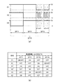
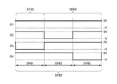
次に、第3の実施形態の高速駆動モードにおける1ステップ360度単位の高速回転駆動について図14を用いて説明する。図14(a)は、ステップモータ20を1ステップ360度単位で回転駆動させる高速駆動パルス列SP20の駆動波形の一例である。ここで、第3の実施形態の高速駆動パルス列SP20は、第1駆動パルスSP21、第2駆動パルスSP22、第3駆動パルスSP23の3個の駆動パルスで構成される。[Explanation of high-speed drive according to the third embodiment: FIG. 14]
Next, the high-speed rotary drive in units of 360 degrees per step in the high-speed drive mode of the third embodiment will be described with reference to FIG. FIG. 14A is an example of the drive waveform of the high-speed drive pulse train SP20 that rotationally drives the
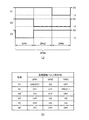
図14(a)において、第1駆動パルスSP21は、駆動波形O3が電圧−Vであり、他の駆動波形O1、O2、O4は電圧0Vである。これにより、駆動波形O3とO4に接続されるステップモータ20のコイルBに駆動電流が流れて励磁される。
In FIG. 14A, in the first drive pulse SP21, the drive waveform O3 has a voltage −V, and the other drive waveforms O1, O2, and O4 have a voltage of 0 V. As a result, a drive current flows through the coil B of the
次に、第2駆動パルスSP22は、駆動波形O2、O4が電圧−Vであり、駆動波形O1、O3が電圧0Vである。これにより、ステップモータ20のコイルA、コイルBの両方に駆動電流が流れて、両方のコイルA、コイルBが向き合う方向に励磁される。
Next, in the second drive pulse SP22, the drive waveforms O2 and O4 have a voltage −V, and the drive waveforms O1 and O3 have a voltage of 0V. As a result, a drive current flows through both the coil A and the coil B of the
次に、第3駆動パルスSP23は、駆動波形O1、O4が電圧−Vであり、駆動波形O2、O3が電圧0Vである。これにより、ステップモータ20のコイルA、コイルBの両方に駆動電流が流れて、両方のコイルA、コイルBが同じ方向に励磁される。
Next, in the third drive pulse SP23, the drive waveforms O1 and O4 have a voltage −V, and the drive waveforms O2 and O3 have a voltage of 0V. As a result, a drive current flows through both the coil A and the coil B of the
次に、第3の実施形態の高速駆動モードにおける1ステップ360度回転のステップモータの高速駆動について図14(b)〜図14(e)を用いて説明する。なお、ステップモータ20の各部材の符号は、図14(b)にのみ記して他は省略する。図14(b)は、ステップモータ20の静止状態であり、ステップモータ20のロータ21のN極が、静止位置0度(図面上の上向き)に位置して保持されている状態を示している。
Next, the high-speed drive of the step motor rotated by 360 degrees in one step in the high-speed drive mode of the third embodiment will be described with reference to FIGS. 14 (b) to 14 (e). The reference numerals of the respective members of the
次に、図14(c)は、ステップモータ20の静止状態から第1駆動パルスSP21が供給された場合の動作である。ここで、第1駆動パルスSP21が供給されると、駆動電流(図示せず)がコイル端子O4からコイル端子O3に流れ、コイルBが矢印の方向に励磁される。
Next, FIG. 14C shows an operation when the first drive pulse SP21 is supplied from the stationary state of the
これにより、第2磁極部22bがN極、第3磁極部22cがS極に磁化され、また、コイルAは励磁されないので、第1磁極部22aは第3磁極部22cと同じS極となる。その結果、ロータ21のN極と、第1磁極部22a及び第3磁極部22cのS極が引き合い、また、ロータ21のS極と第2磁極部22bのN極が引き合い、ロータ21は反時計回りに回転し、ロータ21のN極は静止位置0度から約135度の位置まで回転する。
As a result, the second
次に、図14(d)において、ロータ21のN極が約135度付近の位置で次の第2駆動パルスSP22が供給されると、駆動電流がコイル端子O1からコイル端子O2に流れ、コイルAが矢印の方向に励磁される。また同様に駆動電流がコイル端子O3からコイル端子O4に流れ、コイルBが矢印の方向に励磁される。
Next, in FIG. 14D, when the next second drive pulse SP22 is supplied at a position where the north pole of the
これにより、第1磁極部22aがN極に磁化され、第2磁極部22bがS極に磁化され、第3磁極部22cは磁化が打ち消し合って磁化されない。その結果、ロータ21のN極と第2磁極部22bのS極が引き合い、また、ロータ21のS極と第1磁極部22aのN極が引き合い、ロータ21はさらに反時計回りに回転し、ロータ21のN極は約270度の位置まで回転する。
As a result, the first
次に、図14(e)において、ロータ21のN極が約270度付近の位置で次の第3駆動パルスSP23が供給されると、駆動電流がコイル端子O2からコイル端子O1に流れ、コイルAが矢印の方向に励磁される。また同様に駆動電流がコイル端子O3からコイル端子O4に流れ、コイルBが矢印の方向に励磁される。
Next, in FIG. 14E, when the next third drive pulse SP23 is supplied at a position where the north pole of the
これにより、第1磁極部22aと第2磁極部22bがS極に磁化され、第3磁極部22cはN極に磁化される。その結果、ロータ21のS極と第3磁極部22cのN極が引き合い、また、ロータ21のN極は、第1磁極部22aと第2磁極部22bの両方のS極と引き合うので、ロータ21はさらに反時計回りに回転し、ロータ21のN極は約360度(0度)の位置まで回転する。このように、3個の駆動パルスで構成される高速駆動パルス列SP20によって、ステップモータ20は1ステップ360度単位で高速回転駆動を実現できる。
As a result, the first
ここで、図14(e)に示すように、ロータ21が360度(0度)位置に戻った時点で、連続して高速駆動パルス列SP20が供給されると、先頭の第1駆動パルスSP21によって、図14(c)に示すように、再び第2磁極部22bがN極、第3磁極部22cと第1磁極部22aがS極に磁化される。その結果、ロータ21のN極と、第1磁極部22a及び第3磁極部22cのS極が引き合い、また、ロータ21のS極と第2磁極部22bのN極が引き合い、ロータ21は反時計回りに回転を継続し、ロータ21のN極は静止位置0度から約135度の位置まで回転する。
Here, as shown in FIG. 14 (e), when the high-speed drive pulse train SP20 is continuously supplied when the
以降、高速駆動パルス列SP20の各駆動パルスが連続して供給されれば、ステップモータ20のロータ21は図14(c)〜図14(e)で示す回転動作を繰り返すことになる。すなわち、高速駆動パルス列SP20の連続出力によって、ステップモータ20は1ステップ360度単位の高速回転駆動が継続される。
After that, if each drive pulse of the high-speed drive pulse train SP20 is continuously supplied, the
なお、第3の実施形態の通常駆動モードでの通常駆動は、図4、図5で示した従来の1ステップ180度回転駆動と同様であるので、ここでの説明は省略する。そして、通常駆動モードでの通常駆動パルスSP00を、たとえば、1秒周期で出力することで、秒針を1秒運針することができる。 The normal drive in the normal drive mode of the third embodiment is the same as the conventional one-step 180-degree rotation drive shown in FIGS. 4 and 5, and thus the description thereof is omitted here. Then, by outputting the normal drive pulse SP00 in the normal drive mode, for example, at a cycle of 1 second, the second hand can be moved for 1 second.
以上のように、第3の実施形態によれば、1ステップ360度の回転駆動をわずか3個の駆動パルスで実現できるので、従来の2ステップ駆動(図13参照)と比較して、ステップモータの回転限界に迫る速さで高速駆動が可能となる。 As described above, according to the third embodiment, the rotational drive of 360 degrees in one step can be realized with only three drive pulses, so that the step motor is compared with the conventional two-step drive (see FIG. 13). High-speed drive is possible at a speed approaching the rotation limit of.
また、高速駆動パルス列SP20を連続して出力することで、ステップモータ20を連続して高速回転することが可能である。これにより、たとえば指針の早送り動作において、従来よりも高速に早送り動作が可能となり、指針の時刻修正等を素早く短時間で行うことができる。
Further, by continuously outputting the high-speed drive pulse train SP20, the
また、従来の2ステップ駆動では、4個の駆動パルスが必要であったが(図13参照)、本実施形態では、わずか3個の駆動パルスによって1ステップ360度回転駆動を実現できるので、駆動パルス数が少ない分、低消電駆動が実現できる。 Further, in the conventional two-step drive, four drive pulses are required (see FIG. 13), but in the present embodiment, one-step 360-degree rotational drive can be realized by only three drive pulses, so that the drive can be driven. Since the number of pulses is small, low static elimination drive can be realized.
また、駆動パルスは、ステップモータ20の個体差や電源変動等を考慮して駆動力に余裕を持たせる必要があり、そのため、ステップモータ20のロータ21は、駆動パルス毎に、電磁的安定点をオーバーラップして回転することが多い。このオーバーラップが存在すると、ロータ21は僅かに回転が戻ったり微振動したりすることがあるが、ロータ21のこのような動きは、ステップモータ20の損失となって駆動効率が低下する原因となる。しかし、本実施形態では、高速駆動パルス列SP20のわずか3個の駆動パルスによって360度回転駆動を実現しているので、ロータ21のオーバーラップ回数が減り、結果としてステップモータの駆動効率が向上する効果がある。
Further, the drive pulse needs to have a margin in the driving force in consideration of individual differences of the
このように、第3の実施形態では、高速駆動モードにおいて、高速駆動パルス列SP20を連続して出力することで、通常駆動モード(たとえば1秒運針)での通常駆動パルスSP00より速い駆動周波数でステップモータのロータが駆動され、指針を高速駆動できるのである。 As described above, in the third embodiment, by continuously outputting the high-speed drive pulse train SP20 in the high-speed drive mode, the step is performed at a drive frequency faster than the normal drive pulse SP00 in the normal drive mode (for example, 1-second hand movement). The rotor of the motor is driven, and the pointer can be driven at high speed.
なお、第3の実施形態では、高速駆動パルス発生回路54と通常駆動パルス発生回路55の二つの駆動パルス発生回路を備えているが、この構成に限定されず、第2の実施形態のように、一つの駆動パルス発生回路からの高速駆動パルス列と通常駆動パルスをタイミングによって選択して切り替える構成でもよい。
In the third embodiment, two drive pulse generation circuits, a high-speed drive pulse generation circuit 54 and a normal drive
[第3の実施形態の変形例1による高速駆動の説明:図15]
次に、第3の実施形態の変形例1による2コイルステップモータの高速駆動について図15を用いて説明する。なお、後述する他の変形例を含めて各変形例は、高速駆動パルス列の駆動波形のみが異なるだけであるので、高速駆動モードでの駆動波形とステップモータの高速駆動動作についてのみ説明し、各変形例の構成図や通常駆動モードの説明は省略する。[Explanation of high-speed driving according to the first modification of the third embodiment: FIG. 15]
Next, the high-speed drive of the two-coil step motor according to the first modification of the third embodiment will be described with reference to FIG. Since each modification, including other modifications described later, differs only in the drive waveform of the high-speed drive pulse train, only the drive waveform in the high-speed drive mode and the high-speed drive operation of the step motor will be described. The configuration diagram of the modified example and the description of the normal drive mode will be omitted.
図15(a)は、第3の実施形態の変形例1による1ステップ360度回転駆動させる高速駆動パルス列SP30の駆動波形の一例である。図15(a)において、高速駆動パルス列SP30は、第1駆動パルスSP31、第2駆動パルスSP32、第3駆動パルスSP33の3個の駆動パルスによって構成される。 FIG. 15A is an example of the drive waveform of the high-speed drive pulse train SP30 that is driven to rotate 360 degrees in one step according to the first modification of the third embodiment. In FIG. 15A, the high-speed drive pulse train SP30 is composed of three drive pulses of a first drive pulse SP31, a second drive pulse SP32, and a third drive pulse SP33.
第1駆動パルスSP31は、駆動波形O3が電圧−Vであり、他の駆動波形O1、O2、O4は電圧0Vである。これにより、駆動波形O3とO4に接続されるステップモータ20のコイルBに駆動電流が流れて励磁される。
In the first drive pulse SP31, the drive waveform O3 has a voltage −V, and the other drive waveforms O1, O2, and O4 have a voltage of 0 V. As a result, a drive current flows through the coil B of the
次に、第2駆動パルスSP32は、駆動波形O2が電圧−Vであり、駆動波形O1、O3、O4が電圧0Vである。これにより、駆動波形O1とO2に接続されるステップモータ20のコイルAに駆動電流が流れて励磁される。
Next, in the second drive pulse SP32, the drive waveform O2 has a voltage −V, and the drive waveforms O1, O3, and O4 have a voltage of 0 V. As a result, a drive current flows through the coil A of the
次に、第3駆動パルスSP33は、駆動波形O1、O4が電圧−Vであり、駆動波形O2、O3が電圧0Vである。これにより、ステップモータ20のコイルA、コイルBの両方に駆動電流が流れて、両方のコイルA、コイルBが同じ方向に励磁される。
Next, in the third drive pulse SP33, the drive waveforms O1 and O4 have a voltage −V, and the drive waveforms O2 and O3 have a voltage of 0V. As a result, a drive current flows through both the coil A and the coil B of the
次に、変形例1による1ステップ360度回転のステップモータの高速駆動について図15(b)〜図15(e)を用いて説明する。なお、ステップモータ20の各部材の符号は、図15(b)にのみ記して他は省略する。図15(b)は、ステップモータ20の静止状態であり、ステップモータ20のロータ21のN極が、静止位置0度(図面上の上向き)に位置して保持されている状態を示している。
Next, the high-speed drive of the step motor rotated by 360 degrees in one step according to the first modification will be described with reference to FIGS. 15 (b) to 15 (e). The reference numerals of the respective members of the
次に、図15(c)は、ステップモータ20の静止状態から第1駆動パルスSP31が供給された場合の動作である。ここで、第1駆動パルスSP31が供給されると、駆動電流(図示せず)がコイル端子O4からコイル端子O3に流れ、コイルBが矢印の方向に励磁される。
Next, FIG. 15C shows an operation when the first drive pulse SP31 is supplied from the stationary state of the
これにより、第2磁極部22bがN極、第3磁極部22cがS極に磁化され、また、コイルAは励磁されないので、第1磁極部22aは第3磁極部22cと同じS極となる。その結果、ロータ21のN極と、第1磁極部22a及び第3磁極部22cのS極が引き合い、また、ロータ21のS極と第2磁極部22bのN極が引き合い、ロータ21は反時計回りに回転し、ロータ21のN極は静止位置0度から約135度の位置まで回転する。
As a result, the second
次に、図15(d)において、ロータ21のN極が約135度付近の位置で次の第2駆動パルスSP32が供給されると、駆動電流がコイル端子O1からコイル端子O2に流れ、コイルAが矢印の方向に励磁される。
Next, in FIG. 15D, when the next second drive pulse SP32 is supplied at a position where the north pole of the
これにより、第1磁極部22aがN極、第3磁極部22cがS極に磁化され、また、コイルBは励磁されないので、第2磁極部22bは第3磁極部22cと同じS極となる。その結果、ロータ21のN極と、第2磁極部22b及び第3磁極部22cのS極が引き合い、また、ロータ21のS極と第1磁極部22aのN極が引き合い、ロータ21は反時計回りにさらに回転し、ロータ21のN極は約225度の位置まで回転する。
As a result, the first
次に、図15(e)において、ロータ21のN極が約225度付近の位置で次の第3駆動パルスSP33が供給されると、駆動電流がコイル端子O2からコイル端子O1に流れ、コイルAが矢印の方向に励磁される。また同様に駆動電流がコイル端子O3からコイル端子O4に流れ、コイルBがコイルAと同じ方向に励磁される。
Next, in FIG. 15E, when the next third drive pulse SP33 is supplied at a position where the north pole of the
これにより、第1磁極部22aと第2磁極部22bがS極に磁化され、第3磁極部22cはN極に磁化される。その結果、ロータ21のS極と第3磁極部22cのN極が引き合い、また、ロータ21のN極は、第1磁極部22aと第2磁極部22bの両方のS極と引き合うので、ロータ21はさらに反時計回りに回転し、ロータ21のN極は約360度(0度)の位置まで回転する。このように、変形例1においても、3個の駆動パルスで構成される高速駆動パルス列SP30によって、ステップモータ20は1ステップ360度単位で高速回転駆動を実現できる。
As a result, the first
以上のように、第3の実施形態の変形例1によれば、1ステップ360度の回転駆動をわずか3個の駆動パルスで実現できるので、第3の実施形態と同様の優れた効果を得ることができる。 As described above, according to the first modification of the third embodiment, the rotational drive of 360 degrees in one step can be realized with only three drive pulses, so that the same excellent effect as that of the third embodiment can be obtained. be able to.
[第3の実施形態の変形例2による高速駆動の説明:図16]
次に、第3の実施形態の変形例2による2コイルステップモータの高速駆動について図16を用いて説明する。図16(a)は、第3の実施形態の変形例2による1ステップ360度回転駆動させる高速駆動パルス列SP40の駆動波形の一例である。[Explanation of high-speed drive according to the second modification of the third embodiment: FIG. 16]
Next, the high-speed drive of the two-coil step motor according to the second modification of the third embodiment will be described with reference to FIG. FIG. 16A is an example of the drive waveform of the high-speed drive pulse train SP40 that is driven to rotate 360 degrees in one step according to the second modification of the third embodiment.
図16(a)において、高速駆動パルス列SP40は、第1駆動パルスSP41、第2駆動パルスSP42、第3駆動パルスSP43の3個の駆動パルスによって構成される。第1駆動パルスSP41は、駆動波形O3が電圧−Vであり、他の駆動波形O1、O2、O4は電圧0Vである。これにより、駆動波形O3とO4に接続されるステップモータ20のコイルBに駆動電流が流れて励磁される。
In FIG. 16A, the high-speed drive pulse train SP40 is composed of three drive pulses of a first drive pulse SP41, a second drive pulse SP42, and a third drive pulse SP43. In the first drive pulse SP41, the drive waveform O3 has a voltage −V, and the other drive waveforms O1, O2, and O4 have a voltage of 0 V. As a result, a drive current flows through the coil B of the
次に、第2駆動パルスSP42は、駆動波形O2、O4が電圧−Vであり、駆動波形O1、O3が電圧0Vである。これにより、ステップモータ20のコイルAとコイルBの両方に駆動電流が流れて対向して励磁される。
Next, in the second drive pulse SP42, the drive waveforms O2 and O4 have a voltage −V, and the drive waveforms O1 and O3 have a voltage of 0V. As a result, a drive current flows through both the coil A and the coil B of the
次に、第3駆動パルスSP43は、駆動波形O1が電圧−Vであり、駆動波形O2、O3、O4が電圧0Vである。これにより、ステップモータ20のコイルAに駆動電流が流れて励磁される。
Next, in the third drive pulse SP43, the drive waveform O1 has a voltage −V, and the drive waveforms O2, O3, and O4 have a voltage of 0 V. As a result, a drive current flows through the coil A of the
次に、変形例2による1ステップ360度回転のステップモータの高速駆動について図16(b)〜図16(e)を用いて説明する。なお、ステップモータ20の各部材の符号は、図16(b)にのみ記して他は省略する。図16(b)は、ステップモータ20の静止状態であり、ステップモータ20のロータ21のN極が、静止位置0度(図面上の上向き)に位置して保持されている状態を示している。
Next, the high-speed drive of the step motor rotated by 360 degrees in one step according to the second modification will be described with reference to FIGS. 16 (b) to 16 (e). The reference numerals of the respective members of the
次に、図16(c)は、ステップモータ20の静止状態から第1駆動パルスSP41が供給された場合の動作である。ここで、第1駆動パルスSP41が供給されると、駆動電流がコイル端子O4からコイル端子O3に流れ、コイルBが矢印の方向に励磁される。
Next, FIG. 16C shows an operation when the first drive pulse SP41 is supplied from the stationary state of the
これにより、第2磁極部22bがN極、第3磁極部22cがS極に磁化され、また、コイルAは励磁されないので、第1磁極部22aは第3磁極部22cと同じS極となる。その結果、ロータ21のN極と、第1磁極部22a及び第3磁極部22cのS極が引き合い、また、ロータ21のS極と第2磁極部22bのN極が引き合い、ロータ21は反時計回りに回転し、ロータ21のN極は静止位置0度から約135度の位置まで回転する。
As a result, the second
次に、図16(d)において、ロータ21のN極が約135度付近の位置で次の第2駆動パルスSP42が供給されると、駆動電流がコイル端子O1からコイル端子O2に流れ、コイルAが矢印の方向に励磁される。また同様に駆動電流がコイル端子O3からコイル端子O4に流れ、コイルBが矢印の方向に励磁される。
Next, in FIG. 16D, when the next second drive pulse SP42 is supplied at a position where the north pole of the
これにより、第1磁極部22aがN極に磁化され、第2磁極部22bがS極に磁化され、第3磁極部22cは磁化が打ち消し合って磁化されない。その結果、ロータ21のN極と第2磁極部22bのS極が引き合い、また、ロータ21のS極と第1磁極部22aのN極が引き合い、ロータ21はさらに反時計回りに回転し、ロータ21のN極は約270度の位置まで回転する。
As a result, the first
次に、図16(e)において、ロータ21のN極が約270度付近の位置で次の第3駆動パルスSP43が供給されると、駆動電流がコイル端子O2からコイル端子O1に流れ、コイルAが矢印の方向に励磁される。
Next, in FIG. 16E, when the next third drive pulse SP43 is supplied at a position where the north pole of the
これにより、第1磁極部22aがS極、第3磁極部22cがN極に磁化され、また、コイルBは励磁されないので、第2磁極部22bは第3磁極部22cと同じN極となる。その結果、ロータ21のN極と第1磁極部22aのS極が引き合い、また、ロータ21のS極と、第2磁極部22b及び第3磁極部22cのN極が引き合い、ロータ21は反時計回りにさらに回転し、ロータ21のN極は図示するように約360度(0度)を超える位置まで回転し、その後、第3駆動パルスSP43が終了すると、ロータ21のN極は静止位置360度(0度)の位置に戻って静止する。
As a result, the first
なお、高速駆動パルス列SP40が連続して出力されれば、ロータ21のN極は約360度(0度)を超える位置から戻ることなく、次の第1駆動パルスSP41によってロータ21のN極は約135度の位置まで回転し(図16(c)参照)、以降、高速回転駆動が継続される。このように、変形例2においても、3個の駆動パルスで構成される高速駆動パルス列SP40によって、ステップモータ20は1ステップ360度単位で高速回転駆動を実現できる。
If the high-speed drive pulse train SP40 is continuously output, the north pole of the
以上のように、第3の実施形態の変形例2によれば、1ステップ360度の回転駆動をわずか3個の駆動パルスで実現できるので、第3の実施形態と同様の優れた効果を得ることができる。 As described above, according to the second modification of the third embodiment, the rotational drive of 360 degrees in one step can be realized with only three drive pulses, so that the same excellent effect as that of the third embodiment can be obtained. be able to.
[第3の実施形態の変形例3による高速駆動の説明:図17]
次に、第3の実施形態の変形例3による2コイルステップモータの高速駆動について図17を用いて説明する。図17(a)は、第3の実施形態の変形例3による1ステップ360度回転駆動させる高速駆動パルス列SP50の駆動波形の一例である。[Explanation of high-speed drive according to the third modification of the third embodiment: FIG. 17]
Next, the high-speed drive of the two-coil step motor according to the third modification of the third embodiment will be described with reference to FIG. FIG. 17A is an example of the drive waveform of the high-speed drive pulse train SP50 that is driven to rotate 360 degrees in one step according to the third modification of the third embodiment.
図17(a)において、高速駆動パルス列SP50は、第1駆動パルスSP51、第2駆動パルスSP52、第3駆動パルスSP53の3個の駆動パルスによって構成される。第1駆動パルスSP51は、駆動波形O1、O3が電圧−Vであり、駆動波形O2、O4は電圧0Vである。これにより、ステップモータ20のコイルAとコイルBの両方に駆動電流が流れて励磁される。
In FIG. 17A, the high-speed drive pulse train SP50 is composed of three drive pulses of a first drive pulse SP51, a second drive pulse SP52, and a third drive pulse SP53. In the first drive pulse SP51, the drive waveforms O1 and O3 have a voltage −V, and the drive waveforms O2 and O4 have a voltage of 0 V. As a result, a drive current flows through both the coil A and the coil B of the
次に、第2駆動パルスSP52は、駆動波形O2が電圧−Vであり、駆動波形O1、O3、O4が電圧0Vである。これにより、ステップモータ20のコイルAに駆動電流が流れて励磁される。
Next, in the second drive pulse SP52, the drive waveform O2 has a voltage −V, and the drive waveforms O1, O3, and O4 have a voltage of 0 V. As a result, a drive current flows through the coil A of the
次に、第3駆動パルスSP53は、駆動波形O1、O4が電圧−Vであり、駆動波形O2、O3が電圧0Vである。これにより、ステップモータ20のコイルA、コイルBの両方に駆動電流が流れて、コイルAとコイルBの両方が同じ向きに励磁される。
Next, in the third drive pulse SP53, the drive waveforms O1 and O4 have a voltage −V, and the drive waveforms O2 and O3 have a voltage of 0V. As a result, a drive current flows through both the coil A and the coil B of the
次に、変形例3による1ステップ360度回転のステップモータの高速駆動を図17(b)〜図17(e)によって説明する。なお、ステップモータ20の各部材の符号は、図17(b)にのみ記して他は省略する。図17(b)は、ステップモータ20の静止状態であり、ステップモータ20のロータ21のN極が、静止位置0度(図面上の上向き)に位置して保持されている状態を示している。
Next, the high-speed drive of the step motor rotated by 360 degrees in one step according to the
次に、図17(c)は、ステップモータ20の静止状態から第1駆動パルスSP51が供給された場合の動作である。ここで、第1駆動パルスSP51が供給されると、駆動電流がコイル端子O2からコイル端子O1に流れ、コイルAが矢印の方向に励磁される。また同様に、駆動電流がコイル端子O4からコイル端子O3に流れ、コイルBが矢印の方向に励磁される。
Next, FIG. 17C shows an operation when the first drive pulse SP51 is supplied from the stationary state of the
これにより、第1磁極部22aがS極に磁化され、第2磁極部22bがN極に磁化され、第3磁極部22cは磁化が打ち消し合って磁化されない。その結果、ロータ21のN極と第1磁極部22aのS極が引き合い、また、ロータ21のS極と第2磁極部22bのN極が引き合い、ロータ21は反時計回りに回転し、ロータ21のN極は静止位置0度から約90度の位置まで回転する。
As a result, the first
次に、図17(d)において、ロータ21のN極が約90度付近の位置で次の第2駆動パルスSP52が供給されると、駆動電流がコイル端子O1からコイル端子O2に流れ、コイルAが矢印の方向に励磁される。
Next, in FIG. 17D, when the next second drive pulse SP52 is supplied at a position where the north pole of the
これにより、第1磁極部22aがN極、第3磁極部22cがS極に磁化され、また、コイルBは励磁されないので、第2磁極部22bは第3磁極部22cと同じS極となる。その結果、ロータ21のN極と、第2磁極部22b及び第3磁極部22cのS極が引き合い、また、ロータ21のS極と第1磁極部22aのN極が引き合い、ロータ21は反時計回りにさらに回転し、ロータ21のN極は約225度の位置まで回転する。
As a result, the first
次に、図17(e)において、ロータ21のN極が約225度付近の位置で次の第3駆動パルスSP53が供給されると、駆動電流がコイル端子O2からコイル端子O1に流れ、コイルAが矢印の方向に励磁される。また同様に駆動電流がコイル端子O3からコイル端子O4に流れ、コイルBがコイルAと同じ方向に励磁される。
Next, in FIG. 17E, when the next third drive pulse SP53 is supplied at a position where the north pole of the
これにより、第1磁極部22aと第2磁極部22bが共にS極に磁化され、第3磁極部22cはN極に磁化される。その結果、ロータ21のS極と第3磁極部22cのN極が引き合い、また、ロータ21のN極は、第1磁極部22aと第2磁極部22bの両方のS極と引き合うので、ロータ21はさらに反時計回りに回転し、ロータ21のN極は360度(0度)の位置まで回転する。このように、変形例3においても、3個の駆動パルスで構成される高速駆動パルス列SP50によって、ステップモータ20は1ステップ360度単位で高速回転駆動を実現できる。
As a result, both the first
以上のように、第3の実施形態の変形例3によれば、1ステップ360度の回転駆動をわずか3個の駆動パルスで実現できるので、第3の実施形態と同様の優れた効果を得ることができる。 As described above, according to the third modification of the third embodiment, the rotational drive of 360 degrees in one step can be realized with only three drive pulses, so that the same excellent effect as that of the third embodiment can be obtained. be able to.
[第4の実施形態]
[第4の実施形態の電子時計の構成説明:図18]
次に、第4の実施形態の電子時計の概略構成について図18を用いて説明する。符号70は第4の実施形態のアナログ表示方式の電子時計である。電子時計70は基本的な構成として、基準信号P1を出力する発振回路72、基準信号P1を入力して制御信号CN1を出力する制御回路73、高速駆動パルス発生回路74、ドライバ回路80、および、ステップモータ20を有している点は先の第1の実施形態と同様である。[Fourth Embodiment]
[Structure of the Electronic Clock of the Fourth Embodiment: FIG. 18]
Next, the schematic configuration of the electronic clock of the fourth embodiment will be described with reference to FIG.
本実施形態では、ステップモータ20の2つのコイルA及びコイルBとドライバ回路80とを接続する際に、第1の実施形態において図1に示したコイル端子O2及びコイル端子O4に相当するコイル端子が短絡されるように接続されている。そのため、ドライバ回路80からは、駆動波形としてO1、O2’、O3の3つが供給される。駆動波形O1は、コイルAのコイル端子O1に、駆動波形O3は、コイルBのコイル端子O3にそれぞれ供給され、駆動波形O2’は、コイルAとコイルBのコイル端子O2’に共通に供給される。
In the present embodiment, when connecting the two coils A and B of the
高速駆動パルス発生回路74は、制御信号CN1を入力して、ステップモータ20を高速に駆動するための高速駆動パルス列SP60を生成し出力する。なお、高速駆動パルス列SP60は、前述した各実施形態の高速駆動パルス列SP10、SP20と駆動波形が異なる例を示すので別符号とした。また、高速駆動パルス列SP60もまた、3個の駆動パルスで構成される。
The high-speed drive
[ドライバ回路の回路構成の説明:図19]
次に、ステップモータ20を駆動するためのドライバ回路80の回路構成の一例について図19を用いて説明する。ドライバ回路80は、ステップモータ20のコイルA、コイルBに3つの駆動波形を供給する3つのバッファ回路によって構成される。[Explanation of circuit configuration of driver circuit: FIG. 19]
Next, an example of the circuit configuration of the
コイルAのコイル端子O1に対しては、PチャンネルMOSトランジスタであるトランジスタP1と、NチャンネルMOSトランジスタであるトランジスタN1と、のコンプリメンタリ接続でなるバッファ回路が接続され、駆動波形O1が出力される。 A buffer circuit formed by a complementary connection of a transistor P1 which is a P-channel MOS transistor and a transistor N1 which is an N-channel MOS transistor is connected to the coil terminal O1 of the coil A, and a drive waveform O1 is output.
コイルBのコイル端子O3に対しては、PチャンネルMOSトランジスタであるトランジスタP3と、NチャンネルMOSトランジスタであるトランジスタN3と、のコンプリメンタリ接続でなるバッファ回路が接続され、駆動波形O3が出力される。 A buffer circuit formed by a complementary connection of a transistor P3 which is a P-channel MOS transistor and a transistor N3 which is an N-channel MOS transistor is connected to the coil terminal O3 of the coil B, and a drive waveform O3 is output.
そして、コイルA及びコイルBに共通に設けられるコイル端子O2’に対しては、PチャンネルMOSトランジスタであるトランジスタP2’と、NチャンネルMOSトランジスタであるトランジスタN2’と、のコンプリメンタリ接続でなるバッファ回路が接続され、コイルAとコイルBとに共通して駆動波形O2’が出力されるようになっている。 Then, for the coil terminal O2'commonly provided in the coil A and the coil B, a buffer circuit formed by a complementary connection of a transistor P2'which is a P-channel MOS transistor and a transistor N2' which is an N-channel MOS transistor. Is connected, and the drive waveform O2'is output in common to the coil A and the coil B.
[第4の実施形態の駆動パルスの生成と駆動波形の説明:図20]
次に、第4の実施形態のステップモータを1ステップ360度単位で回転駆動する高速駆動パルスの駆動波形の一例とドライバ回路の各トランジスタの動作について図20を用いて説明する。[Generation of drive pulse and description of drive waveform of the fourth embodiment: FIG. 20]
Next, an example of a drive waveform of a high-speed drive pulse that rotationally drives the step motor of the fourth embodiment in units of 360 degrees per step and the operation of each transistor of the driver circuit will be described with reference to FIG.
まず、高速駆動パルス列SP60は、図18のステップモータ20のロータを静止位置0度から正転方向(反時計回り)に360度単位で回転駆動するものである。図20(a)は、かかる高速駆動パルスSP60による駆動波形であり、ドライバ回路80から出力される3つの駆動波形O1、O2’、O3を示している。
First, the high-speed drive pulse train SP60 rotates and drives the rotor of the
図20(a)において、高速駆動パルス発生回路74から出力される高速駆動パルス列SP60は、本例では3ビットのSP61〜SP63でなり、時系列的に第1駆動パルスSP61、第2駆動パルスSP62、第3駆動パルスSP63の3個の駆動パルスで構成され、ドライバ回路80の各トランジスタをON/OFFするために論理“1”または論理“0”でなるパルス列である。
In FIG. 20A, the high-speed drive pulse train SP60 output from the high-speed drive
第1駆動パルスSP1は、駆動波形O3が電圧−Vであり、他の駆動波形O1、O2’は電圧0Vである。これにより、コイル端子O2’とO3に接続されるステップモータ20のコイルBに駆動電流が流れて励磁される。
In the first drive pulse SP1, the drive waveform O3 has a voltage −V, and the other drive waveforms O1 and O2 ′ have a voltage of 0 V. As a result, a drive current flows through the coil B of the
また、第2駆動パルスSP62は、駆動波形O2’が電圧−Vであり、駆動波形O1、O3が電圧0Vである。そして、駆動波形O2’はコイルAとコイルBの両方に印加されるため、これにより、ステップモータ20のコイルA、コイルBの両方に駆動電流が流れて、両方のコイルA、コイルBが励磁される。
Further, in the second drive pulse SP62, the drive waveform O2'is a voltage −V, and the drive waveforms O1 and O3 are a voltage 0V. Then, since the drive waveform O2'is applied to both the coil A and the coil B, a drive current flows through both the coil A and the coil B of the
また、第3駆動パルスSP63は、駆動波形O1、O2’が電圧−Vであり、他の駆動波形O3は電圧0Vである。これにより、駆動波形O2’とO3に接続されるステップモータ20のコイルBに駆動電流が流れ、第1駆動パルスSP61の逆方向に励磁される。
Further, in the third drive pulse SP63, the drive waveforms O1 and O2'are voltage −V, and the other drive waveforms O3 are voltage 0V. As a result, a drive current flows through the coil B of the
次に、高速駆動パルス列SP60によるドライバ回路80の各トランジスタの動作を図20(b)の動作表を用いて説明する。なお、ドライバ回路は図19を参照する。図20(b)において、第1駆動パルスSP61は、駆動波形O3が電圧−V、他の駆動波形O1、O2’が電圧0Vとなるので、トランジスタP2’とN3がON、トランジスタN2’、P3がOFFし、駆動電流がコイルBのコイル端子O2’からコイル端子O3に流れ、コイルBが励磁される。
Next, the operation of each transistor of the
また、トランジスタN1がOFF、トランジスタP1がONとなり、駆動波形O1及びO2’がともに電圧0Vとなるので、コイルAには駆動電流が流れず、コイルAは励磁されない。なお、トランジスタP1は、ここではONとしているが、これをOFFとしても差し支えない。図20(b)では、このことを指して、括弧内にOFFと記載している。 Further, since the transistor N1 is turned off, the transistor P1 is turned on, and the drive waveforms O1 and O2'are both voltage 0 V, no drive current flows through the coil A and the coil A is not excited. Although the transistor P1 is turned on here, it may be turned off. In FIG. 20B, this is pointed out and is described as OFF in parentheses.
また、第2駆動パルスSP62は、駆動波形O2’が電圧−V、他の駆動波形O1、O3が電圧0Vとなるので、トランジスタP1、N2’及びP3がON、トランジスタN1、P2’、N3がOFFし、駆動電流がコイルAのコイル端子O1からコイル端子O2’に流れるとともに、コイルBのコイル端子O3からコイル端子O2’にも流れるので、コイルAとコイルBがともに励磁される。 Further, in the second drive pulse SP62, since the drive waveform O2'is the voltage −V and the other drive waveforms O1 and O3 are the voltage 0V, the transistors P1, N2'and P3 are ON, and the transistors N1, P2'and N3 are turned on. When it is turned off, the drive current flows from the coil terminal O1 of the coil A to the coil terminal O2'and also flows from the coil terminal O3 of the coil B to the coil terminal O2', so that both the coil A and the coil B are excited.
さらに、第3駆動パルスSP63は、駆動波形O1が電圧−V、他の駆動波形O2’、O3が電圧0Vとなるので、トランジスタN2’とP3がON、トランジスタP2’、N3がOFFし、駆動電流がコイルBのコイル端子O3からコイル端子O2’に流れ、コイルBが励磁される。 Further, in the third drive pulse SP63, since the drive waveform O1 has a voltage of −V and the other drive waveforms O2 ′ and O3 have a voltage of 0 V, the transistors N2 ′ and P3 are ON, and the transistors P2 ′ and N3 are OFF, and are driven. A current flows from the coil terminal O3 of the coil B to the coil terminal O2', and the coil B is excited.
また、トランジスタP1がOFF、トランジスタN1がONとなり、駆動波形O1及びO2’がともに電圧−Vとなるので、コイルAには駆動電流が流れず、コイルAは励磁されない。なお、トランジスタN1は、ここではONとしているが、これをOFFとしても差し支えない。 Further, since the transistor P1 is turned off, the transistor N1 is turned on, and the drive waveforms O1 and O2'are both voltage-V, no drive current flows through the coil A and the coil A is not excited. Although the transistor N1 is turned on here, it may be turned off.
このように、高速駆動パルス列SP60の3個の第1〜第3駆動パルスSP61〜63によって、ドライバ回路80の各トランジスタがON/OFF制御され、ステップモータ20のコイルA、Bを励磁する。
In this way, each transistor of the
[第4の実施形態の1ステップ360度回転駆動の説明:図7]
第4の実施形態のステップモータ20の1ステップ360度単位の高速回転駆動は、第1の実施形態におけるものと同じであるから、図7を参照して説明する。まず、図7(a)に示すのは、高速駆動パルス列SP60の第1駆動パルスSP61がステップモータ20に供給された状態であり、コイルBが矢印の方向に励磁されるから、第2磁極部22bがN極、第3磁極部22cがS極に磁化され、またコイルAは磁化されないから、第1磁極部22aは第3磁極部22cと同じくS極となる。そのため、ロータ21は反時計回りに回転し、ロータ21のN極は反時計回りに回転し、静止位置0度から約135度の位置まで回転する。[Explanation of 1-step 360-degree rotation drive of the 4th embodiment: FIG. 7]
Since the high-speed rotary drive of the
次に、図7(b)に示すように、第2駆動パルスSP62が供給されると、コイルA及びコイルBの両方が矢印の方向に励磁されるから、第1磁極部22aがN極に、第2磁極部22bがS極に磁化され、第3磁極部22cは磁化されない。その結果、ロータ21はさらに反時計回りに回転し、ロータ21のN極は約270度の位置まで回転する。
Next, as shown in FIG. 7B, when the second drive pulse SP62 is supplied, both the coil A and the coil B are excited in the direction of the arrow, so that the first
さらに、図7(c)に示すように、第3駆動パルスSP63が供給されると、コイルBが矢印の方向に励磁されるから、第2磁極部22bがS極、第3磁極部22cがN極に磁化され、またコイルAは励磁されないから、第1磁極部22aは第3磁極部22cと同じくN極となる。その結果、ロータ21は停止することなく更に反時計回りに回転し、ロータ21のN極は約315度の位置まで回転する。
Further, as shown in FIG. 7C, when the third drive pulse SP63 is supplied, the coil B is excited in the direction of the arrow, so that the second
その後、図7(d)に示すように、高速駆動パルス列SP60の供給が終了すると、駆動波形O1、O2’、O3はすべて電圧0Vとなるので、コイルA及びコイルBの励磁はなくなり、第1〜第3磁極部の磁化が消え、ロータ21は、停止することなく360度(0度)の静的安定点まで回転を継続し、その位置で保持される。このようにして、3個の駆動パルスSP61〜SP63で構成される高速駆動パルス列60による、1ステップ駆動での360度回転駆動が実現できる。
After that, as shown in FIG. 7D, when the supply of the high-speed drive pulse train SP60 is completed, the drive waveforms O1, O2', and O3 all have a voltage of 0 V, so that the excitation of the coil A and the coil B disappears, and the first The magnetization of the third magnetic pole portion disappears, and the
このように、第4の実施形態の電子時計によれば、コイルAとコイルBのコイル端子O2’を短絡し、共通とした場合においても、3個の駆動パルスSP61〜63で構成される高速駆動パルス列SP60を供給することで、1ステップで360度の回転駆動ができる。この場合、供給すべき駆動波形が3つで済み、またトランジスタの数も第1の実施形態のものに比して少なくて済むため、回路規模の小型化やコスト削減効果がある。 As described above, according to the electronic clock of the fourth embodiment, even when the coil terminal O2'of the coil A and the coil B is short-circuited and shared, the high speed composed of the three drive pulses SP61 to 63 is formed. By supplying the drive pulse train SP60, a rotation drive of 360 degrees can be performed in one step. In this case, only three drive waveforms should be supplied, and the number of transistors is smaller than that of the first embodiment, so that the circuit scale can be reduced and the cost can be reduced.
もちろん、歯車減速比を1/60とすることによる、指針のトルクアップの効果、耐衝撃性の向上の効果が得られるとともに、指針の動きが滑らかで見栄えが良いものとなる点についても第1の実施形態のものと同様である。 Of course, by setting the gear reduction ratio to 1/60, the effect of increasing the torque of the pointer and the effect of improving the impact resistance can be obtained, and the movement of the pointer becomes smooth and looks good. It is the same as that of the embodiment of.
なお、第4の実施形態に係る1ステップ駆動での360度回転駆動を、第2の実施形態における高速駆動モードでの1ステップ360度回転駆動に用いてもよいことは、言うまでもない。 Needless to say, the 360-degree rotation drive in the one-step drive according to the fourth embodiment may be used for the one-step 360-degree rotation drive in the high-speed drive mode in the second embodiment.
[第5の実施形態]
[第5の実施形態の電子時計の構成及びドライバ回路の回路構成の説明:図18、19]
次に、第5の実施形態の電子時計について説明する。第5の実施形態に係る電子時計70の概略構成は、先の第4の実施形態のものと同様であり、図18に示した通りである。電子時計70の基本的な構成である、基準信号P1を出力する発振回路72、基準信号P1を入力して制御信号CN1を出力する制御回路73、高速駆動パルス発生回路74、ドライバ回路80、および、ステップモータ20を有している点についても同様であるが、高速駆動パルス発生回路74から出力される高速駆動パルスが相違するので、同図における符号SP60は、本実施形態では符号SP70として読み替えるものとする。[Fifth Embodiment]
[Explanation of the configuration of the electronic clock and the circuit configuration of the driver circuit of the fifth embodiment: FIGS. 18 and 19]
Next, the electronic clock of the fifth embodiment will be described. The schematic configuration of the
また、第5の実施形態における、ステップモータ20を駆動するためのドライバ回路80の回路構成についても、先の第4の実施形態のものと同様であるから、図19を参照するものとする。
Further, since the circuit configuration of the
[第5の実施形態の駆動パルスの生成と駆動波形の説明:図21]
次に、第5の実施形態のステップモータを1ステップ360度単位で回転駆動する高速駆動パルスの駆動波形の一例とドライバ回路の各トランジスタの動作について図21を用いて説明する。[Description of drive pulse generation and drive waveform of the fifth embodiment: FIG. 21]
Next, an example of a drive waveform of a high-speed drive pulse that rotationally drives the step motor of the fifth embodiment in units of 360 degrees per step and the operation of each transistor of the driver circuit will be described with reference to FIG.
まず、高速駆動パルス列SP70は、図18のステップモータ20のロータを静止位置0度から正転方向(反時計回り)に360度単位で回転駆動するものである。図21(a)は、かかる高速駆動パルスSP60による駆動波形であり、ドライバ回路80から出力される3つの駆動波形O1、O2’、O3を示している。
First, the high-speed drive pulse train SP70 rotates and drives the rotor of the
図21(a)において、高速駆動パルス発生回路74から出力される高速駆動パルス列SP70は、本例では3ビットのSP71〜SP73でなり、事例列的に第1駆動パルスSP71、第2駆動パルスSP72、第3駆動パルスSP73の3個の駆動パルスで構成され、ドライバ回路80の各トランジスタをON/OFFするために論理“1”または論理“0”でなるパルス列である。
In FIG. 21A, the high-speed drive pulse train SP70 output from the high-speed drive
第1駆動パルスSP1は、駆動波形O3が電圧−Vであり、他の駆動波形O1、O2’は電圧0Vである。これにより、駆動波形O2’とO3に接続されるステップモータ20のコイルBに駆動電流が流れて励磁される。
In the first drive pulse SP1, the drive waveform O3 has a voltage −V, and the other drive waveforms O1 and O2 ′ have a voltage of 0 V. As a result, a drive current flows through the coil B of the
また、第2駆動パルスSP72は、駆動波形O2’が電圧−Vであり、駆動波形O1、O3が電圧0Vである。そして、駆動波形O2’はコイルAとコイルBの両方に印加されるため、これにより、ステップモータ20のコイルA、コイルBの両方に駆動電流が流れて、両方のコイルA、コイルBが励磁される。
Further, in the second drive pulse SP72, the drive waveform O2'is a voltage −V, and the drive waveforms O1 and O3 are a voltage 0V. Then, since the drive waveform O2'is applied to both the coil A and the coil B, a drive current flows through both the coil A and the coil B of the
第3駆動パルスSP73は、駆動波形O1が電圧−Vであり、駆動波形O2’が電圧0Vである駆動パルスSP73aと、駆動波形O1と駆動波形O2’がともに電圧−Vである駆動パルスSP73bとを含み、この駆動パルスSP73aと駆動パルス73bが一定のパターンで繰り返されて、全体として駆動パルスSP73を構成する。なお、他の駆動波形O3は電圧0Vである。これにより、駆動パルスSP73aが印加されている際は、コイル端子O2’とO1に接続されるステップモータ20のコイルAに駆動電流が流れ励磁され、駆動パルスSP73bが印加されている際は、コイル端子O2’とO3に接続されるステップモータ20のコイルBに駆動電流が流れ励磁される。
The third drive pulse SP73 includes a drive pulse SP73a in which the drive waveform O1 is a voltage −V and a drive waveform O2 ′ a voltage 0V, and a drive pulse SP73b in which both the drive waveform O1 and the drive waveform O2 ′ are a voltage −V. The drive pulse SP73a and the drive pulse 73b are repeated in a constant pattern to form the drive pulse SP73 as a whole. The other drive waveform O3 has a voltage of 0 V. As a result, when the drive pulse SP73a is applied, a drive current flows through the coil A of the
次に、高速駆動パルス列SP70によるドライバ回路80の各トランジスタの動作を図21(b)の動作表を用いて説明する。図21(b)において、第1駆動パルスSP71は、駆動波形O3が電圧−V、他の駆動波形O1、O2’が電圧0Vとなるので、トランジスタP2’とN3がON、トランジスタN2’、P3がOFFし、駆動電流がコイルBのコイル端子O2’からコイル端子O3に流れ、コイルBが励磁される。
Next, the operation of each transistor of the
また、トランジスタN1がOFF、トランジスタP1がONとなり、駆動波形O1及びO2’がともに電圧0Vとなるので、コイルAには駆動電流が流れず、コイルAは励磁されない。なお、トランジスタP1は、ここではONとしているが、これをOFFとしても差し支えない。 Further, since the transistor N1 is turned off, the transistor P1 is turned on, and the drive waveforms O1 and O2'are both voltage 0 V, no drive current flows through the coil A and the coil A is not excited. Although the transistor P1 is turned on here, it may be turned off.
また、第2駆動パルスSP72は、駆動波形O2’が電圧−V、他の駆動波形O1、O3が電圧0Vとなるので、トランジスタP1、N2’及びP3がON、トランジスタN1、P2’、N3がOFFし、駆動電流がコイルAのコイル端子O1からコイル端子O2’に流れるとともに、コイルBのコイル端子O3からコイル端子O2’にも流れるので、コイルAとコイルBがともに励磁される。 Further, in the second drive pulse SP72, since the drive waveform O2'is the voltage −V and the other drive waveforms O1 and O3 are the voltage 0V, the transistors P1, N2'and P3 are ON, and the transistors N1, P2'and N3 are turned on. When it is turned off, the drive current flows from the coil terminal O1 of the coil A to the coil terminal O2'and also flows from the coil terminal O3 of the coil B to the coil terminal O2', so that both the coil A and the coil B are excited.
さらに、第3駆動パルスSP73では、駆動波形O1が電圧−V、駆動波形O3が電圧0Vに維持され、駆動波形O2’の電圧が区間により異なる。第3駆動パルスSP73aの区間では、駆動波形O2’が電圧0Vとなるので、トランジスタP2’がON、トランジスタN2’がOFFとなる。そして、トランジスタP1、N3はOFFであり、トランジスタN1、P3はONであるから、駆動電流がコイルAのコイル端子O1からコイル端子O2’に流れ、コイルAが励磁される。一方、第3駆動パルスSP73bの区間では、駆動波形O2’が電圧−Vとなるので、トランジスタP2’がOFF、トランジスタN2’がONとなる。そして、やはりトランジスタP1、N3はOFFであり、トランジスタN1、P3はONであるから、駆動電流がコイルBのコイル端子O2’からコイル端子O3に流れ、コイルBが励磁される。 Further, in the third drive pulse SP73, the drive waveform O1 is maintained at a voltage −V, the drive waveform O3 is maintained at a voltage 0V, and the voltage of the drive waveform O2 ′ differs depending on the section. In the section of the third drive pulse SP73a, the drive waveform O2'has a voltage of 0 V, so that the transistor P2'is ON and the transistor N2'is OFF. Since the transistors P1 and N3 are OFF and the transistors N1 and P3 are ON, a drive current flows from the coil terminal O1 of the coil A to the coil terminal O2', and the coil A is excited. On the other hand, in the section of the third drive pulse SP73b, since the drive waveform O2'is the voltage −V, the transistor P2'is OFF and the transistor N2'is ON. Since the transistors P1 and N3 are also OFF and the transistors N1 and P3 are ON, a drive current flows from the coil terminal O2'of the coil B to the coil terminal O3, and the coil B is excited.
なお、第3駆動パルスSP73aの区間では、コイル端子O3及びO2’がともに電圧0Vとなるので、コイルBには駆動電流が流れず、コイルBは励磁されない。このとき、トランジスタP3は、ここではONとしているが、これをOFFとしても差し支えない。 In the section of the third drive pulse SP73a, the voltage of both the coil terminals O3 and O2'is 0 V, so that no drive current flows through the coil B and the coil B is not excited. At this time, the transistor P3 is turned on here, but it may be turned off.
また、第3駆動パルスSP73bの区間では、コイル端子O1及びO2’がともに電圧−Vとなるので、コイルAには駆動電流が流れず、コイルAは励磁されない。このとき、トランジスタN1は、ここではONとしているが、これをOFFとしても差し支えない。 Further, in the section of the third drive pulse SP73b, since both the coil terminals O1 and O2'are voltage −V, no drive current flows through the coil A and the coil A is not excited. At this time, the transistor N1 is turned on here, but it may be turned off.
第3駆動パルスSP73において、第3駆動パルスSP73aと第3駆動パルス73bが繰り返される順番は特に限定されず、ここで示した例では、最初に第3駆動パルスSP73aが印加され、続いて第3駆動パルス73bが印加され、以下繰り返すものとしているが、この順を逆順としてもよい。さらに、第3駆動パルスSP73a、第3駆動パルスSP73b、第3駆動パルスSP73b、第3駆動パルスSP73aのような順として以下これを繰り返すようにしてもよい。コイルAとコイルBに励磁される磁力が均等となるよう、第3駆動パルスSP73の区間において、第3駆動パルスSP73aが占める合計期間と、第3駆動パルス73bが占める合計期間が等しくなるようにすることが望ましいが、コイルAとコイルBに励磁される磁力が実用上均等となる範囲で、この合計期間が異なっていてもよい。また、第3駆動パルスSP73aと第3駆動パルス73bの長さは等しい方が、第3駆動パルスSP73を構成しやすく望ましいが、必ずしも一致していなくともよい。 In the third drive pulse SP73, the order in which the third drive pulse SP73a and the third drive pulse 73b are repeated is not particularly limited. In the example shown here, the third drive pulse SP73a is applied first, and then the third drive pulse SP73a is applied. The drive pulse 73b is applied, and the following is repeated, but this order may be reversed. Further, this may be repeated in the order of the third drive pulse SP73a, the third drive pulse SP73b, the third drive pulse SP73b, the third drive pulse SP73a, and so on. In the section of the third drive pulse SP73, the total period occupied by the third drive pulse SP73a and the total period occupied by the third drive pulse 73b are equal so that the magnetic forces excited by the coil A and the coil B are equal. However, the total period may be different as long as the magnetic forces excited by the coil A and the coil B are practically equal. Further, it is desirable that the lengths of the third drive pulse SP73a and the third drive pulse 73b are the same because it is easy to form the third drive pulse SP73, but they do not necessarily have to be the same.
このように、高速駆動パルス列SP70の3個の第1〜第3駆動パルスSP71〜73によって、ドライバ回路80の各トランジスタがON/OFF制御され、ステップモータ20のコイルA、Bを励磁する。
In this way, each transistor of the
[第5の実施形態の1ステップ360度回転駆動の説明:図22]
第5の実施形態のステップモータ20の1ステップ360度単位の高速回転駆動を、図22を参照して説明する。まず、図22(a)に示すのは、高速駆動パルス列SP70の第1駆動パルスSP71がステップモータ20に供給された状態であり、コイルBが矢印の方向に励磁されるから、第2磁極部22bがN極、第3磁極部22cがS極に磁化され、またコイルAは磁化されないから、第1磁極部22aは第3磁極部22cと同じくS極となる。そのため、ロータ21は反時計回りに回転し、ロータ21のN極は反時計回りに回転し、静止位置0度から約135度の位置まで回転する。[Explanation of 1-step 360-degree rotary drive according to the fifth embodiment: FIG. 22]
The high-speed rotary drive of the
次に、図22(b)に示すように、第2駆動パルスSP72が供給されると、コイルA及びコイルBの両方が矢印の方向に励磁されるから、第1磁極部22aがN極に、第2磁極部22bがS極に磁化され、第3磁極部22cは磁化されない。その結果、ロータ21はさらに反時計回りに回転し、ロータ21のN極は約270度の位置まで回転する。
Next, as shown in FIG. 22B, when the second drive pulse SP72 is supplied, both the coil A and the coil B are excited in the direction of the arrow, so that the first
さらに、第3駆動パルスSP73が供給されるが、第3駆動パルスSP73は、第3駆動パルスSP73aと第3駆動パルスSP73bからなっている。図22(c)は、第3駆動パルスSP73aが供給された状態であり、コイルAが矢印の方向に励磁されるから、第1磁極部22aがS極に、第2磁極部22b及び第3磁極部22cがN極に磁化される。また、図22(d)は、第3駆動パルスSP73bが供給された状態であり、コイルBが矢印の方向に励磁されるから、第2磁極部22bがS極に、第1磁極部22a及び第3磁極部22cがN極に磁化される。
Further, a third drive pulse SP73 is supplied, and the third drive pulse SP73 includes a third drive pulse SP73a and a third drive pulse SP73b. FIG. 22 (c) shows a state in which the third drive pulse SP73a is supplied, and the coil A is excited in the direction of the arrow. Therefore, the first
そして、第3駆動パルスSP73の区間では、第3駆動パルスSP73aと第3駆動パルスSP73bが短い間隔で繰り返し印加印加されるから、図22(c)に示した磁化状態と、図22(d)に示した磁化状態が繰り返し現れることになり、ステップモータ20に現れる実効的な磁化状態は、この2つの磁化状態を合成したものとみなすことができる。その結果、第3磁極部22cは、図22(c)と図22(d)に示した磁化状態に共通してN極に磁化されるため、第3駆動パルスSP73の全区間にわたってN極となる。一方、第1磁極部22aと第2磁極部22bは、異なる極が交互に出現するため、磁化状態は見かけの上で相殺され、実効的に無磁化あるいは、弱い磁化状態となる。これにより、ロータ21はさらに反時計回りに回転し、ロータ21のN極は約360度の位置まで回転する。
Then, in the section of the third drive pulse SP73, the third drive pulse SP73a and the third drive pulse SP73b are repeatedly applied and applied at short intervals, so that the magnetization state shown in FIG. 22C and FIG. 22D are shown. The magnetization state shown in the above appears repeatedly, and the effective magnetization state appearing in the
このようにして、3個の駆動パルスSP71〜SP73で構成される高速駆動パルス列70による、1ステップ駆動での360度回転駆動が実現できる。
In this way, a 360-degree rotary drive in one-step drive can be realized by a high-speed
なお、この時の図22(c)に示した磁化状態と、図22(d)に示した磁化状態の合成による第3駆動パルスSP73の磁化状態は、第3の実施形態において、図14(e)に示したものとおおむね等しいものとなる。しかしながら、図22より明らかなように、コイルAとコイルBを同時に励磁するものではないため、ロータ21に十分な回転力を与えるため、第3駆動パルスSP73の長さは、先の第1駆動パルスSP71及び第2駆動パルスSP72よりも長いものとしてよい。
At this time, the magnetization state of the third drive pulse SP73 by combining the magnetization state shown in FIG. 22 (c) and the magnetization state shown in FIG. 22 (d) is shown in FIG. 14 (3). It is almost the same as the one shown in e). However, as is clear from FIG. 22, since the coil A and the coil B are not excited at the same time, a sufficient rotational force is given to the
このように、第5の実施形態の電子時計によれば、コイルAとコイルBのコイル端子O2’を短絡し、共通とした場合においても、3個の駆動パルスSP71〜73で構成される高速駆動パルス列SP70を供給することで、1ステップで360度の回転駆動ができる。この場合、供給すべき駆動波形が3つで済み、またトランジスタの数も第1の実施形態のものに比して少なくて済むため、回路規模の小型化やコスト削減効果がある。 As described above, according to the electronic clock of the fifth embodiment, even when the coil terminals O2'of the coil A and the coil B are short-circuited and shared, the high speed is composed of three drive pulses SP71 to 73. By supplying the drive pulse train SP70, a rotation drive of 360 degrees can be performed in one step. In this case, only three drive waveforms should be supplied, and the number of transistors is smaller than that of the first embodiment, so that the circuit scale can be reduced and the cost can be reduced.
また、第5の実施形態に係る1ステップ駆動での360度回転駆動を、第3の実施形態における高速駆動モードでの1ステップ360度回転駆動に用いてもよい。このようにすることにより、通常駆動モードでの1ステップ180度回転駆動に加えて、高速駆動モードでの1ステップ360度回転駆動を実現できる。さらに、第5の実施形態に係る1ステップ駆動での360度回転駆動では、コイルAとコイルBを同時に励磁することがなく、消費電流の最大値を低く抑えることができるため、外気温が低い場合や、電源電圧が低下している状態など、電源条件が厳しい場合でも1ステップ360度回転駆動による高速駆動が可能である。 Further, the 360-degree rotation drive in the one-step drive according to the fifth embodiment may be used for the one-step 360-degree rotation drive in the high-speed drive mode in the third embodiment. By doing so, in addition to the one-step 180-degree rotary drive in the normal drive mode, the one-step 360-degree rotary drive in the high-speed drive mode can be realized. Further, in the 360-degree rotation drive in the one-step drive according to the fifth embodiment, the coil A and the coil B are not excited at the same time, and the maximum value of the current consumption can be suppressed to a low value, so that the outside air temperature is low. Even when the power supply conditions are severe, such as when the power supply voltage is low, high-speed drive by 360-degree rotation drive in one step is possible.
[第6の実施形態]
[第6の実施形態の電子時計の構成説明:図23]
次に、第6の実施形態の電子時計の概略構成について図23を用いて説明する。符号90は第6の実施形態のアナログ表示方式の電子時計である。電子時計90は基本的な構成として、基準信号P1を出力する発振回路92、基準信号P1を入力して制御信号CN7、CN8、CN9及びCN10を出力する制御回路93、高速駆動パルス発生回路(可変部)94及び高速駆動パルス発生回路(固定部)95の2つの高速駆動パルス発生回路、補正パルス発生回路96、検出パルス発生回路97、パルス選択回路16、ドライバ回路100、及び、ステップモータ20を有している他、回転検出判定回路91を有している。[Sixth Embodiment]
[Structure of the Electronic Clock of the Sixth Embodiment: FIG. 23]
Next, the schematic configuration of the electronic clock of the sixth embodiment will be described with reference to FIG. 23.
高速駆動パルス発生回路(可変部)94及び高速駆動パルス発生回路(固定部)95は、制御信号CN7及びCN8をそれぞれ入力され、ステップモータ20を駆動するための複数の駆動パルスで構成される高速駆動パルス列の一部分であるSP30及びSP40を生成し出力する。
The high-speed drive pulse generation circuit (variable unit) 94 and the high-speed drive pulse generation circuit (fixed unit) 95 receive control signals CN7 and CN8, respectively, and are composed of a plurality of drive pulses for driving the
補正パルス発生回路96は、制御信号CN9を入力され、ステップモータ20を駆動するための補正パルスFPを生成し出力する。
The correction
検出パルス発生回路97は、制御信号CN10を入力され、ステップモータ20のロータ21が正常に回転したことを検出するための検出パルスCPを生成し出力する。
The detection
パルス選択回路16は、高速駆動パルス発生回路(可変部)94及び高速駆動パルス発生回路(固定部)95、補正パルス発生回路96及び検出パルス発生回路97により生成され出力されたパルスSP30、SP40、FP及びCPを選択し、適切なタイミングでドライバ回路100へと出力する。
The
ドライバ回路100は、パルス選択回路16から入力されたパルスに基づき、ステップモータ20のコイルA、コイルBに駆動波形O1〜O4を供給し、ステップモータ20を駆動する。
The
回転検出判定回路91は、ステップモータ20のコイルA、コイルBに検出パルスCPが供給されることにより検出される検出信号CSにより、ステップモータ20のロータ21の自由回転による誘起電流を検出し、ロータ21の回転の有無を判定し、判定結果CKを出力する。出力された判定結果CKは、パルス選択回路16に入力され、パルスの切り替え制御に使用される。
The rotation
[第6の実施形態のドライバ回路の回路構成の説明:図24]
次に、ステップモータ20を駆動するためのドライバ回路100の回路構成の一例について図24を用いて説明する。ドライバ回路100は、ステップモータ20のコイルA、コイルBに4つの駆動波形を供給する4つのバッファ回路によって構成される。[Explanation of the circuit configuration of the driver circuit of the sixth embodiment: FIG. 24]
Next, an example of the circuit configuration of the
コイルA及びコイルBのコイル端子O1〜O4に対しては、図24に示すように、PチャンネルMOSトランジスタであるトランジスタP1〜4と、NチャンネルMOSトランジスタであるトランジスタN1〜4と、のコンプリメンタリ接続でなるバッファ回路がそれぞれ接続され、駆動波形O1〜O4が出力される。 As shown in FIG. 24, the coil terminals O1 to O4 of the coil A and the coil B are complementaryly connected to the transistors P1 to 4 which are P-channel MOS transistors and the transistors N1 to 4 which are N-channel MOS transistors. The buffer circuits made of are connected to each other, and the drive waveforms O1 to O4 are output.
さらにコイルAのコイル端子O1、O2に対しては、それぞれ検出抵抗を介してPチャンネルMOSトランジスタであるトランジスタTP1及びTP2がそれぞれ接続され、コイルBのコイル端子O3、O4に対しては、それぞれ検出抵抗を介してPチャンネルMOSトランジスタであるトランジスタTP3及びTP4がそれぞれ接続される。トランジスタTP1〜TP4に対しては、検出パルスCPが出力され、それにより得られた検出信号CSは回転検出判定回路91に入力される。
Further, the transistors TP1 and TP2, which are P-channel MOS transistors, are connected to the coil terminals O1 and O2 of the coil A, respectively, via detection resistors, and the coil terminals O3 and O4 of the coil B are detected, respectively. Transistors TP3 and TP4, which are P-channel MOS transistors, are connected via resistors, respectively. A detection pulse CP is output to the transistors TP1 to TP4, and the detection signal CS obtained thereby is input to the rotation
[第6の実施形態の回転検出の説明:図25、図26]
ここで、検出パルスCP及び回転検出判定回路91によるステップモータ20のロータ21の回転検出について図25、図26を参照して説明する。[Explanation of rotation detection according to the sixth embodiment: FIGS. 25 and 26]
Here, the rotation detection of the
図25は、ステップモータ20の構造を示す図である。ステップモータ20のステータには、ロータ21をはさんで対向する第1磁極部22aと第2磁極部22b、さらに第1磁極部22aと第2磁極部22bの間にロータ21に対抗するように第3磁極部22cが設けられ、第1磁極部22aと第3磁極部22cとの間に磁気回路を形成するようにコイルAが、第2磁極部22bと第3磁極部22cとの間に磁気回路を形成するようにコイルBがそれぞれ設けられる。
FIG. 25 is a diagram showing the structure of the
ロータ21をはさんで第3磁極部22cの反対側となる、第1磁極部22aと第2磁極部22bの間には、ステータの幅が狭くなる狭窄部23が設けられる。また、ロータ21の中心から見て、第3磁極部22cの方向を0度とし、左右おおむね75度の位置にスリット24が設けられ、第1磁極部22aと第3磁極部22c、第2磁極部22bと第3磁極部22cが直接磁気的に接続されないよう、スリット24が設けられる。なお、このスリット24は、ここで示したように間隙であってもよいし、細幅の非磁性材料をスリット24の位置に挿入し、ステータと結合させたものであってもよい。
A narrowed
このように、狭窄部23及びスリット24を設けることにより、ロータ21に駆動パルスが与えられ回転している間および、ロータ21の慣性により自由回転している間に、電磁誘導によりステータに発生する磁気は、磁気抵抗の大きい狭窄部23及びスリット24を通過しにくくなるため、その大部分がコイルA又はコイルBを通過する経路をとることになる。これにより、コイルA又はコイルBを用いて、ロータ21の回転により誘起される誘起電流をコイルA、Bを用いて検出する際の検出感度が高まる。
By providing the narrowed
すなわち、検出パルスCPにより、所定のタイミングで図24に示したトランジスタTP1〜TP4をONとすることで、各トランジスタに対応するコイル端子O1〜O4に発生する誘起電流の大きさを電圧信号である検出信号CSとして取り出すことができる。回転検出判定回路91は、検出信号CSに基づいて、ロータ21の回転及び非回転の判定を行い、判定結果CKを出力する。
That is, by turning on the transistors TP1 to TP4 shown in FIG. 24 at a predetermined timing by the detection pulse CP, the magnitude of the induced current generated in the coil terminals O1 to O4 corresponding to each transistor is a voltage signal. It can be taken out as a detection signal CS. The rotation
ここで、ロータ21の回転と非回転について説明する。図26は、ステップモータ20のロータ21の回転と非回転を説明する図である。図26(a)は、ロータ21が非回転、すなわち、駆動パルスが印加されたにもかかわらず、ロータ21が所望の角度回転せず、回転に失敗した場合を示している。この場合、駆動パルスが出力され、ロータ21が反時計回りにいったん回転するが、駆動力が不足しているためロータ21が保持トルクにより時計回りに逆回転して初期位置である0度に戻されてしまう。この場合は最終的にロータ21はなんら回転しなかったこととなるので、これを非回転と称する。同図中、駆動パルスが出力されている期間におけるロータ21の回転は破線で示している。
Here, the rotation and non-rotation of the
図26(b)はロータ21が回転、すなわち、印加された駆動パルスによりロータ21が所望の角度回転して、回転に成功した場合である。この場合、駆動パルスが出力され、ロータ21が反時計回りにある一定角度以上回転することにより、駆動パルスの出力停止後も、さらに保持トルクにより反時計回りに回転し、1ステップの回転目標位置である180度まで回転する。この場合は、最終的にロータ21は1ステップ分の目標回転位置まで回転したこととなるので、これを回転と称する。
FIG. 26B shows a case where the
このように、ロータ21が回転の場合と非回転の場合とでは、駆動パルス出力後のロータ21の挙動が異なり、そのため、コイルA、コイルBに発生する誘起電流の波形も異なる。この波形の違いを検出パルスCPにより、検出信号CSとして取り出し、回転検出判定回路91はロータの回転/非回転を判定している。
As described above, the behavior of the
[第6の実施形態の駆動パルスの生成と駆動波形の説明:図27]
第6の実施形態のステップモータを1ステップ360度単位で回転駆動する高速駆動パルスの駆動波形の一例を図27を用いて説明する。なお、ここで説明する駆動波形それ自体は、第1の実施形態において、図6を参照して説明したものと同じである。[Generation of drive pulse and description of drive waveform of the sixth embodiment: FIG. 27]
An example of the drive waveform of the high-speed drive pulse for rotationally driving the step motor of the sixth embodiment in units of 360 degrees per step will be described with reference to FIG. 27. The drive waveform itself described here is the same as that described with reference to FIG. 6 in the first embodiment.
ただし、本実施形態では、高速駆動パルス列を前半の可変駆動パルスSP30と、後半の固定駆動パルスSP40とに分けて取り扱う。図27に示した高速駆動パルス列全体は図6に示したものと同じであり、また、高速駆動パルス列を構成する3個の駆動パルスSP11、SP12及びSP13は第1の実施形態のものと同じであるから、同符号を付して示した。 However, in the present embodiment, the high-speed drive pulse train is divided into a variable drive pulse SP30 in the first half and a fixed drive pulse SP40 in the second half. The entire high-speed drive pulse train shown in FIG. 27 is the same as that shown in FIG. 6, and the three drive pulses SP11, SP12, and SP13 constituting the high-speed drive pulse train are the same as those in the first embodiment. Therefore, they are shown with the same reference numerals.
ここで、可変駆動パルスSP30は、駆動パルス11に相当している。そして、可変駆動パルスSP30は、後述するように、条件によってその長さ(期間)が変更される。これに対し、固定駆動パルスSP40は、駆動パルス12及び駆動パルスSP13に相当している。固定駆動パルスSP40の長さは固定であり、あらかじめ定められている。
Here, the variable drive pulse SP30 corresponds to the
なお、可変駆動パルスSP30及び固定駆動パルスSP40を構成する駆動パルスSP11〜13を出力するためのドライバ回路80の各トランジスタの動作は、第1の実施形態において図6を参照して説明したものと同様であるから、ここでは重複する説明は省略する。
The operation of each transistor of the
[第6の実施形態のパルス波形の説明:図28]
図28は、第6の実施形態のパルス波形を説明する図である。同図中、(1)〜(3)で示したパルス波形は、ロータ21が回転と判定された時にステップモータ20に印加される駆動パルス、すなわち、可変駆動パルスSP30と固定駆動パルスSP40の例を示している。(1)〜(3)に示したものの他、どのパルス波形が選択されるかは、回転検出の結果に依存して変化する。また、(4)は、ロータ21が非回転と判定されたときにステップモータ20に印加される補正パルスFPを示している。(5)は、回転検出を行うための検出パルスCPを印加するタイミングを示している。[Explanation of the pulse waveform of the sixth embodiment: FIG. 28]
FIG. 28 is a diagram illustrating a pulse waveform of the sixth embodiment. In the figure, the pulse waveforms shown in (1) to (3) are examples of drive pulses applied to the
本実施形態では、可変駆動パルスSP30の長さを、1ms刻みで1ms〜5msの5つより選択できるようにしており、固定駆動パルスSP40は、可変駆動パルスSP30の直後に3.5msの間出力されるようになっている。どの長さの可変駆動パルスが選択されるかは、回転検出を行い、その結果に基づいて選択される。より詳しくはこの後説明するが、基本的な考え方は、回転と判断されるまで可変駆動パルスSP30を出力し続けるというものである。
In the present embodiment, the length of the variable drive pulse SP30 can be selected from 5 of 1 ms to 5 ms in 1 ms increments, and the fixed drive pulse SP 40 is output for 3.5 ms immediately after the variable
そして、最長の長さ(5ms)の可変駆動パルスSP30を出力しても回転との判断が得られない場合、(4)に示す補正パルスFPを出力し、ロータ21を確実に回転させる。なお、補正パルスFPは、ロータ21が非回転と判断された場合に、ロータ21を確実に回転させるために出力されるものであり、強い駆動力を持つようにその波形が設定される。ここでは、5msの間の連続出力に続き、デューティ8/16による、0.25ms毎のパルス出力を4msの間継続する波形となっている。
Then, if it cannot be determined that the rotation is rotating even if the variable drive pulse SP30 having the longest length (5 ms) is output, the correction pulse FP shown in (4) is output to reliably rotate the
検出パルスCPは、可変駆動パルスSP30の出力開始後、0.25ms経過後から4.75ms経過するまで0.5ms毎に出力される、16μs幅のパルスとしている。 The detection pulse CP is a 16 μs wide pulse that is output every 0.5 ms from the start of the output of the variable drive pulse SP30 to the elapse of 4.75 ms from the lapse of 0.25 ms.
なお、以上の説明での可変駆動パルスSP30、固定駆動パルスSP40、補正パルスFPの長さや形状、検出パルスCPの出力タイミングなどは一例であり、ステップモータ20の形状や大きさ、ステップモータ20に取り付けられる付加など種々の構成に応じて変更されてよい。
The variable drive pulse SP30, the fixed drive pulse SP40, the length and shape of the correction pulse FP, the output timing of the detection pulse CP, etc. in the above description are examples, and the shape and size of the
[第6の実施形態の高速駆動パルス列出力のフローの説明:図29]
図29は、第6の実施形態の高速駆動パルス列出力の動作を説明するフロー図である。以下、このフロー図に従って、制御回路93により制御される本実施形態に係る電子時計90の動作を説明する。[Explanation of the flow of the high-speed drive pulse train output of the sixth embodiment: FIG. 29]
FIG. 29 is a flow chart illustrating the operation of the high-speed drive pulse train output of the sixth embodiment. Hereinafter, the operation of the
まず、運針のタイミングで、可変駆動パルスSP30を高速駆動パルス発生回路(可変部)より出力される可変駆動パルスSP30をパルス選択回路16により選択し、ドライバ回路100に出力する(ST1)。これにより、ステップモータ20のロータ21が回転を開始する。そして、0.25ms経過後より5ms毎に、検出パルス発生回路から出力される検出パルスCPがパルス選択回路16により選択され、ドライバ回路100に出力され、回転検出を開始する(ST2)。この結果得られる検出信号CSに基づいて、回転検出判定回路91は、判定結果CKを出力する。
First, at the timing of hand movement, the variable drive pulse SP30 output from the high-speed drive pulse generation circuit (variable unit) is selected by the
ここで、回転検出判定回路91による回転/非回転の判定について図30を参照して説明する。図30は、可変駆動パルスSP30が印加された際の、コイルA及びコイルBに発生する誘起電流の波形と、コイル端子O1〜O4に印加されるパルス及び検出信号を示す図である。
Here, the determination of rotation / non-rotation by the rotation
時刻0msより、可変駆動パルスSP30がコイル端子O3に印加され、コイルBのコイル端子O3−O4間に電圧が印加され、コイルBが励磁される。これによりロータ21が回転を始め、コイルA及びBには、正の向きの誘導電流が発生する。
From
検出パルスCPは、可変駆動パルスSP30が印加されたコイルとは異なるコイルである、コイルAに印加される。具体的には、コイル端子O1に開始後0.25ms後から0.5ms毎に印加され、これにより各検出パルスCPに応じた検出信号CSが得られる。 The detection pulse CP is applied to the coil A, which is a coil different from the coil to which the variable drive pulse SP30 is applied. Specifically, it is applied to the coil terminal O1 every 0.5 ms from 0.25 ms after the start, whereby a detection signal CS corresponding to each detection pulse CP is obtained.
図30のコイルAに生じる誘導電流の波形より明らかなように、ロータ21の回転当初は、コイルAに生じる誘導電流は正の符号をもつあまり大きくない値となる。条件にもよるが、ここで示した例では、回転開始からおおよそ2.5ms経過した時点でこの誘導電流の符号が反転し、負の符号となり、ある一定以上の値を示す波形の山が生じる。
As is clear from the waveform of the induced current generated in the coil A of FIG. 30, at the beginning of the rotation of the
この負の値を持つ波形の山は、ロータ21がポテンシャルの山を乗り越え、目標となる静的安定点に向かって回転していることを示しており、図30でハッチングで示したこの負の符号を持つ波形の山を検出することにより、回転の検出ができる。
The peaks of the waveform with this negative value indicate that the
コイル端子O1から検出される検出信号CSは、負の所定の閾値thと比較される。そして、図30に示すように、この例では回転開始から2.75ms経過後のCP2.75までは、この閾値thを下回ることがなく、検出信号CSは得られないが、3.25ms経過後の検出パルスCP3.25により、閾値thを下回る検出信号CSが得られる。 The detection signal CS detected from the coil terminal O1 is compared with a negative predetermined threshold value th. Then, as shown in FIG. 30, in this example, CP 2.75 after 2.75 ms from the start of rotation does not fall below this threshold value th, and the detection signal CS cannot be obtained, but after 3.25 ms has elapsed. A detection signal CS below the threshold value th is obtained by the detection pulse CP 3.25 of.
そして、本実施形態では、連続して2回の検出信号CSが得られることにより回転と判断するようにしているので、さらに続けて回転開始から3.75ms経過後の検出パルスCP3.75による検出信号CSが検出された時点で、回転検出判定回路91は回転と判定し、判定結果CKを出力するようにしている。また、回転開始から4.75ms経過しても連続する2回の検出信号CSが得られなかった場合は、非回転と判定し、判定結果CKを出力する。
Then, in the present embodiment, since the rotation is determined by obtaining the detection signal CS twice in succession, the detection by the detection pulse CP 3.75 after 3.75 ms from the start of rotation is continued. When the signal CS is detected, the rotation
なお、連続する検出信号CSが得られるタイミングは、電源電圧や負荷の大きさ、電子時計90の姿勢など種々の条件により異なる。また、判定の条件は2回の連続する信号には限定されず、1回とするか、3回以上とするか、また、連続して得られた場合とするか、所定期間内で得られた信号の数を加算するかなど、その設定は任意である。
The timing at which the continuous detection signal CS is obtained differs depending on various conditions such as the power supply voltage, the magnitude of the load, and the posture of the
図29に戻り、回転検出開始後、回転判定が得られたタイミングを監視する。すなわち、まず、回転開始より0.75ms経過までに検出信号CSが2回得られたかを判定する(ST31)。検出信号CSが2回得られた場合(ST31:Y)、回転検出を終了し(ST41)検出パルスCPの出力を停止し、可変駆動パルスSP30の幅を1msに設定する(ST51)。これにより、可変駆動パルスSP30の出力は1msで終了し、続けて固定駆動パルスSP40が出力され(ST7)、ロータ21の1ステップの回転は終了する。
Returning to FIG. 29, after the rotation detection is started, the timing at which the rotation determination is obtained is monitored. That is, first, it is determined whether the detection signal CS is obtained twice within 0.75 ms from the start of rotation (ST31). When the detection signal CS is obtained twice (ST31: Y), the rotation detection is finished (ST41), the output of the detection pulse CP is stopped, and the width of the variable drive pulse SP30 is set to 1 ms (ST51). As a result, the output of the variable drive pulse SP30 ends in 1 ms, the fixed drive pulse SP40 is subsequently output (ST7), and the one-step rotation of the
回転開始より0.75ms経過までに検出信号CSが2回得らなかった場合(ST31:N)、次は1.75ms経過までに検出信号CSが2回得られたかを判定する(ST32)。得られた場合(ST32:Y)、回転検出を終了し(ST42)、可変駆動パルスSP30の幅を2msに設定し(ST53)、可変駆動パルスSP30の出力終了後、続けて固定駆動パルスSP40を出力する(ST7)。 When the detection signal CS is not obtained twice by 0.75 ms from the start of rotation (ST31: N), it is next determined whether the detection signal CS is obtained twice by 1.75 ms (ST32). When obtained (ST32: Y), rotation detection is completed (ST42), the width of the variable drive pulse SP30 is set to 2 ms (ST53), and after the output of the variable drive pulse SP30 is completed, the fixed drive pulse SP40 is continuously applied. Output (ST7).
同様に、回転開始より1.75ms経過までに検出信号CSが2回得らなかった場合(ST32:N)、次は2.75ms経過までに検出信号CSが2回得られたかを判定する(ST33)。得られた場合(ST33:Y)、回転検出を終了し(ST43)、可変駆動パルスSP30の幅を3msに設定し(ST53)、可変駆動パルスSP30の出力終了後、続けて固定駆動パルスSP40を出力する(ST7)。 Similarly, when the detection signal CS is not obtained twice by the elapse of 1.75 ms from the start of rotation (ST32: N), it is next determined whether the detection signal CS is obtained twice by the elapse of 2.75 ms (ST32: N). ST33). When obtained (ST33: Y), rotation detection is completed (ST43), the width of the variable drive pulse SP30 is set to 3 ms (ST53), and after the output of the variable drive pulse SP30 is completed, the fixed drive pulse SP40 is continuously applied. Output (ST7).
同様に、回転開始より2.75ms経過までに検出信号CSが2回得らなかった場合(ST33:N)、次は3.75ms経過までに検出信号CSが2回得られたかを判定する(ST34)。得られた場合(ST34:Y)、回転検出を終了し(ST44)、可変駆動パルスSP30の幅を4msに設定し(ST54)、可変駆動パルスSP30の出力終了後、続けて固定駆動パルスSP40を出力する(ST7)。 Similarly, when the detection signal CS is not obtained twice by the elapse of 2.75 ms from the start of rotation (ST33: N), it is next determined whether the detection signal CS is obtained twice by the elapse of 3.75 ms (ST33: N). ST34). When obtained (ST34: Y), rotation detection is completed (ST44), the width of the variable drive pulse SP30 is set to 4 ms (ST54), and after the output of the variable drive pulse SP30 is completed, the fixed drive pulse SP40 is continuously applied. Output (ST7).
同様に、回転開始より3.75ms経過までに検出信号CSが2回得らなかった場合(ST34:N)、次は4.75ms経過までに検出信号CSが2回得られたかを判定する(ST35)。得られた場合(ST35:Y)、回転検出を終了し(ST45)、可変駆動パルスSP30の幅を5msに設定し(ST55)、可変駆動パルスSP30の出力終了後、続けて固定駆動パルスSP40を出力する(ST7)。 Similarly, when the detection signal CS is not obtained twice by the elapse of 3.75 ms from the start of rotation (ST34: N), it is next determined whether the detection signal CS is obtained twice by the elapse of 4.75 ms (ST34: N). ST35). When obtained (ST35: Y), rotation detection is completed (ST45), the width of the variable drive pulse SP30 is set to 5 ms (ST55), and after the output of the variable drive pulse SP30 is completed, the fixed drive pulse SP40 is continuously applied. Output (ST7).
そして、回転開始より4.75ms経過までに検出信号CSが2回得らなかった場合(ST54:N)は、非回転と判定されたことになるため、補正パルスFPを出力し(ST6)、ロータ21を確実に回転させる。
If the detection signal CS is not obtained twice within 4.75 ms from the start of rotation (ST54: N), it is determined that the rotation is non-rotation, so the correction pulse FP is output (ST6). Make sure that the
なお、ここで示した例では可変駆動パルスSP30の幅は1ms〜5msの間で、1ms刻みの5段階で設定したが、これをより細かく(または粗く)設定してもよいし、回転判定がなされれば直ちに可変駆動パルスSP30の出力を停止して固定駆動パルスSP40を出力するようにしてもよい。また、固定駆動パルスSP40の出力後直ちに又は一定期間(例えば1ms)経過後に再度可変駆動パルスSP30を出力するようにして、無駄時間を排除して高速にロータ21を回転させるようにしてもよい。
In the example shown here, the width of the variable drive pulse SP30 is set between 1 ms and 5 ms in 5 steps in 1 ms increments, but this may be set more finely (or coarsely), and the rotation determination can be made. If this is done, the output of the variable drive pulse SP30 may be stopped immediately to output the fixed drive pulse SP40. Further, the variable drive pulse SP30 may be output again immediately after the output of the fixed drive pulse SP40 or after a lapse of a certain period (for example, 1 ms) to eliminate wasted time and rotate the
このように、第6の実施形態の電子時計によれば、1ステップで360度の回転駆動をさせる場合において、ロータ21の回転/非回転の検出ができ、非回転の場合に補正パルスFPを出力することで、ロータ21を確実に回転させることができる。また、出力される高速駆動パルス列の長さは、ロータ21の回転に必要な分のみで済むため、消費電力が削減されるとともに、無駄時間が排除されて高速駆動が可能である。
As described above, according to the electronic clock of the sixth embodiment, the rotation / non-rotation of the
[第6の実施形態の変形例1:図31]
第6の実施形態において、可変駆動パルスSP30と固定駆動パルス40の出力波形は、図28に示した通りであるが、さらに、電源電圧に応じて、この波形のパルス形状を変形してもよい。図31は変形後のパルス波形を示しており、(1)〜(3)に示す可変駆動パルスSP30と固定駆動パルス40が、連続出力によるもの(フルパルス)ではなく、一定周期でON/OFFを切り替えるもの(チョッパーパルス)となっている。図31に示した例では、このチョッパーパルスのデューティは8/16となっており、0.25ms周期で出力のON/OFFが繰り返し切り替わるようになっている。[Modification Example 1: FIG. 31 of the sixth embodiment]
In the sixth embodiment, the output waveforms of the variable drive pulse SP30 and the fixed drive pulse 40 are as shown in FIG. 28, but the pulse shape of these waveforms may be further deformed according to the power supply voltage. .. FIG. 31 shows the pulse waveform after deformation, and the variable drive pulse SP30 and the fixed drive pulse 40 shown in (1) to (3) are turned ON / OFF at regular intervals, not by continuous output (full pulse). It is a switch (chopper pulse). In the example shown in FIG. 31, the duty of this chopper pulse is 8/16, and the output ON / OFF is repeatedly switched at a cycle of 0.25 ms.
このチョッパーパルスによるパルス波形は、出力が抑えられる分電力消費が少なくなる。一方で、出力が低下するため非回転となりやすい。そこで、電源電圧が高い、すなわち、所定値以上である場合に(例えば、2.5V以上)は駆動力に余裕があるため、図31で示したチョッパーパルスを用いて消費電力の削減を図り、電源電圧が所定地未満の場合に(例えば、2.5V未満)、図28で示したフルパルスを用いて安定的にロータ21を回転させるとよい。
The pulse waveform generated by this chopper pulse consumes less power because the output is suppressed. On the other hand, since the output is reduced, it tends to be non-rotating. Therefore, when the power supply voltage is high, that is, when it is equal to or higher than a predetermined value (for example, 2.5 V or higher), there is a margin in the driving force. Therefore, the chopper pulse shown in FIG. 31 is used to reduce the power consumption. When the power supply voltage is less than the predetermined value (for example, less than 2.5 V), it is preferable to stably rotate the
このようにすることで、ドライバ回路へのパルスを出力する最終段において、信号のON/OFFを所定の周期で行うだけで、電力消費及び出力の異なる複数種類の駆動パルスをステップモータ20に印加することができ、可変駆動パルスSP30と固定駆動パルスSP40を個別に用意する必要がない。なお、チョッパーパルスのデューティは任意であるし、電源電圧に応じて3種類以上のパルス波形を用意してもよい。また、可変駆動パルスSP30と固定駆動パルスSP40のデューティ及び周期を異なるものとしてもよい。
By doing so, in the final stage of outputting the pulse to the driver circuit, a plurality of types of drive pulses having different power consumption and output are applied to the
なお、補正パルスFPは、ロータ21を確実に回転させるため強い駆動力が必要となるため、チョッパーパルスとすることによる出力の制限は望ましくないが、電源電圧等の条件により、確実にロータ21の回転が見込める場合には、その範囲内において、可変駆動パルスSP30と固定駆動パルスSP40と同様にチョッパーパルスとしてもよい。
Since the correction pulse FP requires a strong driving force to reliably rotate the
[第6の実施形態の変形例2:図32]
第6の実施形態の変形例1において、さらに、電源電圧に応じて変形されたパルス波形であるチョッパーパルスのデューティを、時間経過に応じて変更してもよい。図32は第6の実施形態の変形例2のパルス波形の一部を示しており、(1)が可変駆動パルスSP30の長さが1msのもの、(2)が可変駆動パルスSP30の長さが2msのもの、(3)が可変駆動パルスSP30の長さが3msのものとなっている。可変駆動パルスSP30の長さが4msのものと5msのものは、図示を省略している。[
In the first modification of the sixth embodiment, the duty of the chopper pulse, which is a pulse waveform deformed according to the power supply voltage, may be changed according to the passage of time. FIG. 32 shows a part of the pulse waveform of the second modification of the sixth embodiment, in which (1) is the variable drive pulse SP30 having a length of 1 ms, and (2) is the length of the variable drive pulse SP30. Is 2 ms, and (3) is the variable drive pulse SP30 having a length of 3 ms. The variable drive pulse SP30 having a length of 4 ms and 5 ms is not shown.
ここでの基本的な考え方は、回転判定が得られるまでの時間が長くなるほど、より強い駆動力を生じる駆動パルスを与えるというものである。すなわち、電源電圧が高く、駆動力に余裕がある場合には早いタイミングで回転判定がえられ、不要な電力消費を避けるため、デューティを低くして消費電力を削減しても差し支えないと考えられるのに対し、電源電圧が低下して駆動力の余裕がなくなってくると、回転判定が得られるまでの時間が長くなり、また非回転とならないよう、十分な駆動力をもつ駆動パルスを与える必要があると考えられる。 The basic idea here is that the longer the time until the rotation determination is obtained, the stronger the driving force is given to the driving pulse. That is, if the power supply voltage is high and the driving force is sufficient, the rotation can be determined at an early timing, and in order to avoid unnecessary power consumption, it is considered that the duty may be lowered to reduce the power consumption. On the other hand, when the power supply voltage drops and there is no room for driving force, it takes a long time to obtain the rotation judgment, and it is necessary to give a driving pulse with sufficient driving force so that the rotation does not occur. It is thought that there is.
そこで、本変形例では、まず、回転開始から最初の1msの間は、低いデューティである8/16のチョッパーパルスによる可変駆動パルスSP30をステップモータ20に印加する。これにより回転判定が得られれば(1)の波形となり、駆動力に余裕があることがわかるので、固定駆動パルスSP40のデューティも2/16と低いものとなる。また、固定駆動パルスSP40の期間自体も、第2駆動パルス12が0.75ms、第3駆動パルスが0.25msの合計1msと短いものとしてよい。
Therefore, in this modification, first, the variable drive pulse SP30 by the chopper pulse of 8/16, which is a low duty, is applied to the
回転開始から1msで回転判定が得られなければ、可変駆動パルスSP30のデューティを上げ、駆動力を増加する。具体的には、チョッパーパルスのデューティを10/16とする。これにより回転判定が得られれば(2)の波形となる。この場合は、駆動力を考慮して、固定駆動パルスSP40のデューティを4/16と(1)の場合より強いものとする。また、固定駆動パルスSP40の期間は、第2駆動パルス12が1ms、第3駆動パルスが0.5msの合計1.5msと(1)の場合より長いものとしてよい。
If the rotation is not determined within 1 ms from the start of rotation, the duty of the variable drive pulse SP30 is increased to increase the driving force. Specifically, the duty of the chopper pulse is set to 10/16. If the rotation determination is obtained by this, the waveform of (2) is obtained. In this case, the duty of the fixed drive pulse SP40 is set to be stronger than that in the case of 4/16 and (1) in consideration of the driving force. Further, the period of the fixed drive pulse SP40 may be longer than the case of (1), with the
さらに回転開始から2msで回転判定が得られなければ、さらに可変駆動パルスSP30のデューティを上げ、駆動力を増加する。具体的には、チョッパーパルスのデューティを12/16とする。これにより回転判定が得られれば(3)の波形となる。そして、駆動力を考慮して、固定駆動パルスSP40のデューティは6/16と(2)の場合よりさらに強いものとする。さらに、固定駆動パルスSP40の期間は、第2駆動パルス12が1.25ms、第3駆動パルスが0.75msの合計2msと(2)の場合よりさらに長いものとしてよい。
Further, if the rotation determination cannot be obtained within 2 ms from the start of rotation, the duty of the variable drive pulse SP30 is further increased to increase the driving force. Specifically, the duty of the chopper pulse is set to 12/16. If the rotation determination is obtained by this, the waveform of (3) is obtained. Then, in consideration of the driving force, the duty of the fixed drive pulse SP40 is made stronger than that in the case of 6/16 and (2). Further, the period of the fixed drive pulse SP40 may be 1.25 ms for the
以下同様に、回転開始より3ms、4ms経過するごとに可変駆動パルスSP30のデューティを上げ同時に固定駆動パルスSP40のデューティも上げていく。このとき、固定駆動パルスSP40の長さも同時に上げていくようにしてもよい。このようにすることで、駆動力に余裕がある場合には、無駄な消費電力を削減し、電源電圧の低下などに伴い駆動力の余裕がなくなるにしたがって、回転開始から回転判定が得られるまでに時間がかかるようになるので、回転開始からの時間の経過に伴って印加する駆動パルスのデューティを増加させて駆動力を増すことで、非回転となるリスクを低減する。すなわち、チョッパーパルス化による駆動力低下による回転の失敗により、補正パルスFPが頻繁に出力され、かえって消費電力が増加するといった事態を防止できる。これにより、消費電力の低減と、ロータ21の安定した回転とをバランスよく実現できる。
Similarly, the duty of the variable drive pulse SP30 is increased every 3 ms and 4 ms after the start of rotation, and at the same time, the duty of the fixed drive pulse SP40 is also increased. At this time, the length of the fixed drive pulse SP40 may be increased at the same time. By doing so, when there is a margin in the driving force, unnecessary power consumption is reduced, and as the margin in the driving force disappears due to a decrease in the power supply voltage, etc., from the start of rotation until the rotation judgment is obtained. Therefore, the risk of non-rotation is reduced by increasing the duty of the drive pulse applied with the passage of time from the start of rotation to increase the driving force. That is, it is possible to prevent a situation in which the correction pulse FP is frequently output due to a rotation failure due to a decrease in the driving force due to the chopper pulse, and the power consumption is rather increased. As a result, reduction of power consumption and stable rotation of the
なお、図32で示した例では、固定駆動パルスSP40のデューティと長さの両方を変化させていたが、これをいずれか片方のみ、例えば長さは一定でデューティのみ変化させたり、デューティは一定で長さのみ変化させるようにしてもよい。 In the example shown in FIG. 32, both the duty and the length of the fixed drive pulse SP40 are changed, but only one of them, for example, the length is constant and only the duty is changed, or the duty is constant. You may change only the length with.
[第7の実施形態]
第7の実施形態に係る電子時計は、第1の実施形態に係る電子時計1と基本的に構造、制御は共通である。そのため、図1〜7を参照して説明された事項は本実施形態に係る電子時計にも共通である。[7th Embodiment]
The electronic clock according to the seventh embodiment basically has the same structure and control as the
第7の実施形態では、電源電圧や電子時計の温度に応じて、1ステップ360度駆動時の駆動パルスを切り替える。すなわち、図7を参照すると、1ステップ360度駆動による高速駆動において、図7(b)の状態は、コイルAとコイルBの両方を励磁していることになる。この場合、コイルA又はコイルBを単独で励磁する場合に比べ、おおよそ2倍程度の電流が必要となる。 In the seventh embodiment, the drive pulse during one-step 360-degree drive is switched according to the power supply voltage and the temperature of the electronic clock. That is, referring to FIG. 7, in the high-speed drive by one-step 360-degree drive, the state of FIG. 7B excites both the coil A and the coil B. In this case, about twice as much current is required as compared with the case where the coil A or the coil B is excited alone.
一方で、図4及び5に示されるように、1ステップ180度駆動による通常駆動では、コイルAとコイルBが同時に励磁されることはない。 On the other hand, as shown in FIGS. 4 and 5, in the normal drive by driving 180 degrees in one step, the coil A and the coil B are not excited at the same time.
ここで、瞬間的に大きな電量を消費すると、電源電圧の一時的な低下を招来する。条件が良く、電源電圧に十分な余裕があれば問題はないが、蓄電量が減少し、電源電圧自体が低下している場合や、温度が低く、電源電圧の一時的な低下が生じやすい条件では、図7に示した1ステップ360度駆動による高速駆動時における一時的な電源電圧の低下が問題となる可能性がある。 Here, if a large amount of electric charge is consumed momentarily, the power supply voltage is temporarily lowered. There is no problem if the conditions are good and the power supply voltage has a sufficient margin, but if the amount of electricity stored is reduced and the power supply voltage itself is low, or if the temperature is low and the power supply voltage is likely to temporarily drop. Then, there is a possibility that a temporary drop in the power supply voltage at the time of high-speed driving by one-step 360-degree driving shown in FIG. 7 becomes a problem.
そこで、第7の実施形態では、1ステップ360度駆動による高速駆動時の波形を、図7に示したものと、電源電圧が一定値以下あるいは電子時計の温度が一定以下など、電源電圧の一時的な低下が懸念される場合に使用すべき、低電流用駆動波形との2通りを用意し、電源電圧又は電子時計の温度に応じて両者を切り替えるように構成している。 Therefore, in the seventh embodiment, the waveform at the time of high-speed driving by one-step 360-degree driving is shown in FIG. 7, and the power supply voltage is temporarily set such that the power supply voltage is below a certain value or the temperature of the electronic clock is below a certain value. Two types of low-current drive waveforms, which should be used when there is a concern about a drop in voltage, are prepared, and both are switched according to the power supply voltage or the temperature of the electronic clock.
[第7の実施形態の駆動パルスの低電流用駆動波形の説明:図33]
図33は、第7の実施形態の駆動パルスの駆動波形の一例である、高速駆動パルス列SP80を説明する図である。まず、高速駆動パルス列SP80は、図2のステップモータ20のロータを静止位置0度から正転方向(反時計回り)に360度単位で回転駆動するものである。図33は、かかる高速駆動パルスSP80による駆動波形であり、ドライバ回路10から出力される4つの駆動波形O1、O2、O3及びO4を示している。[Explanation of drive waveform for low current of drive pulse of the seventh embodiment: FIG. 33]
FIG. 33 is a diagram illustrating a high-speed drive pulse train SP80, which is an example of a drive waveform of the drive pulse of the seventh embodiment. First, the high-speed drive pulse train SP80 rotates and drives the rotor of the
図33において、高速駆動パルス発生回路4から出力される高速駆動パルス列SP80は、本例では3ビットのSP81〜SP83でなり、時系列的に第1駆動パルスSP81、第2駆動パルスSP82、第3駆動パルスSP83の3個の駆動パルスで構成され、ドライバ回路80の各トランジスタをON/OFFするために論理“1”または論理“0”でなるパルス列である。
In FIG. 33, the high-speed drive pulse train SP80 output from the high-speed drive
第1駆動パルスSP81は、駆動波形O3が電圧−Vであり、他の駆動波形O1〜O3は電圧0Vである。これにより、コイル端子O3とO4に接続されるステップモータ20のコイルBに駆動電流が流れて励磁される。
In the first drive pulse SP81, the drive waveform O3 has a voltage −V, and the other drive waveforms O1 to O3 have a voltage of 0 V. As a result, a drive current flows through the coil B of the
また、第2駆動パルスSP82は、駆動波形O2が電圧−Vであり、駆動波形O1、O3及びO4が電圧0Vである。これにより、コイル端子O1とO2に接続されるステップモータ20のコイルAに駆動電流が流れて励磁される。
Further, in the second drive pulse SP82, the drive waveform O2 has a voltage −V, and the drive waveforms O1, O3 and O4 have a voltage of 0 V. As a result, a drive current flows through the coil A of the
また、第3駆動パルスSP83は、駆動波形O4が電圧−Vであり、他の駆動波形O1〜O3は電圧0Vである。これにより、コイル端子O3とO4に接続されるステップモータ20のコイルBに駆動電流が流れて励磁される。
Further, in the third drive pulse SP83, the drive waveform O4 has a voltage −V, and the other drive waveforms O1 to O3 have a voltage of 0 V. As a result, a drive current flows through the coil B of the
[第7の実施形態の低電流用駆動波形による1ステップ360度回転駆動の説明:図34]
第7の実施形態のステップモータ20の低電流用駆動波形による1ステップ360度単位の高速回転駆動を、図34を参照して説明する。まず、図34(a)に示すのは、高速駆動パルス列SP80の第1駆動パルスSP81がステップモータ20に供給された状態であり、コイルBが矢印の方向に励磁されるから、第2磁極部22bがN極、第3磁極部22cがS極に磁化され、またコイルAは磁化されないから、第1磁極部22aは第3磁極部22cと同じくS極となる。そのため、ロータ21は反時計回りに回転し、ロータ21のN極は反時計回りに回転し、静止位置0度から約135度の位置まで回転する。[Explanation of 1-step 360-degree rotation drive by the low-current drive waveform of the 7th embodiment: FIG. 34]
A high-speed rotary drive in units of 360 degrees per step based on the low-current drive waveform of the
次に、図34(b)に示すように、第2駆動パルスSP62が供給されると、コイルAが矢印の方向に励磁されるから、第1磁極部22aがN極に、第2磁極部22bと第3磁極部22cがS極に磁化される。その結果、ロータ21はさらに反時計回りに回転し、ロータ21のN極は約225度の位置まで回転する。
Next, as shown in FIG. 34 (b), when the second drive pulse SP62 is supplied, the coil A is excited in the direction of the arrow, so that the first
さらに、図34(c)に示すように、第3駆動パルスSP83が供給されると、コイルBが矢印の方向に励磁されるから、第2磁極部22bがS極、第1磁極部22aと第3磁極部22cがN極に磁化される。その結果、ロータ21は停止することなく更に反時計回りに回転し、ロータ21のN極は約315度の位置まで回転する。
Further, as shown in FIG. 34 (c), when the third drive pulse SP83 is supplied, the coil B is excited in the direction of the arrow, so that the second
その後、図34(d)に示すように、高速駆動パルス列SP80の供給が終了すると、コイル端子O1〜O4はすべて電圧0Vとなるので、コイルA及びコイルBの励磁はなくなり、第1〜第3磁極部の磁化が消え、ロータ21は、停止することなく360度(0度)の静的安定点まで回転を継続し、その位置で保持される。このようにして、3個の駆動パルスSP81〜SP83で構成される高速駆動パルス列80による、1ステップ駆動での360度回転駆動が実現できる。
After that, as shown in FIG. 34 (d), when the supply of the high-speed drive pulse train SP80 is completed, all the coil terminals O1 to O4 have a voltage of 0 V, so that the coils A and B are not excited, and the first to third coils are eliminated. The magnetization of the magnetic pole portion disappears, and the
この第7の実施形態の低電流用駆動波形である高速駆動パルス列SP80による駆動では、図34の(b)から(c)にかけて、ロータ21を225度の位置から315度の位置まで90度回転させる必要があるが、この回転を単独のコイルの励磁により行うため、図6に示した高速駆動用の高速駆動パルス列SP10に比して、駆動力がやや劣る。そのため、高速駆動パルス列SP80によるロータ21の回転にはやや時間を要する傾向がある。
In the drive by the high-speed drive pulse train SP80, which is the drive waveform for low current of the seventh embodiment, the
一方で、図34より明らかなように、低電流用駆動波形である高速駆動パルス列SP80では、2つのコイルを同時に励磁することがないため、電流の最大値は図6に示した高速駆動パルス列SP10に比して約1/2である。そのため、大電流の消費による一時的な電圧低下が懸念される条件における高速駆動においては、低電流用駆動波形である高速駆動パルス列SP80を使用し、そうでない場合には、図6に示した高速駆動パルス列SP10を使用するとよい。 On the other hand, as is clear from FIG. 34, in the high-speed drive pulse train SP80, which is a drive waveform for low current, two coils are not excited at the same time, so that the maximum value of the current is the high-speed drive pulse train SP10 shown in FIG. It is about 1/2 of that. Therefore, the high-speed drive pulse train SP80, which is the low-current drive waveform, is used in the high-speed drive under the condition where there is a concern about a temporary voltage drop due to the consumption of a large current, and in other cases, the high-speed drive shown in FIG. 6 is used. The drive pulse train SP10 may be used.
なお、この高速駆動パルス列SP80は、第1の実施形態のみならず、第3の実施形態に適用してもよい。その場合、例えば、図14に示した高速駆動パルス列SP20を、条件に応じて本実施形態の低電流用駆動波形である高速駆動パルス列SP80と切り替えて用いればよい。 The high-speed drive pulse train SP80 may be applied not only to the first embodiment but also to the third embodiment. In that case, for example, the high-speed drive pulse train SP20 shown in FIG. 14 may be used by switching to the high-speed drive pulse train SP80, which is the low-current drive waveform of the present embodiment, depending on the conditions.
[第8の実施形態]
第8の実施形態に係る電子時計は、第6の実施形態と、第7の実施形態との組み合わせにより、低消費電力と、電源電圧低下や低温などの電源条件が悪い場合の回転の安定性を、さらに高い信頼性で両立させた例である。[8th Embodiment]
The electronic clock according to the eighth embodiment has low power consumption and rotational stability when the power supply conditions such as a decrease in the power supply voltage and a low temperature are bad due to the combination of the sixth embodiment and the seventh embodiment. Is an example of achieving both with higher reliability.
図27に示す第6の実施形態に係る高速駆動パルス列SPと、図33に示す第7の実施形態に係る低電流用駆動波形による高速駆動パルス列SP80とを比較すると、第1駆動パルスSP11及びSP81は共通である。すなわち、第7の実施形態に係る低電流用駆動波形による高速駆動パルス列SP80を第1駆動パルスSP81からなる可変駆動パルスSP30と第2、第3駆動パルスSP82、SP83からなる固定駆動パルスSP90とに分けると、可変駆動パルスSP30は第6の実施形態と、第7の実施形態とで共通である。 Comparing the high-speed drive pulse train SP according to the sixth embodiment shown in FIG. 27 with the high-speed drive pulse train SP80 based on the low-current drive waveform according to the seventh embodiment shown in FIG. 33, the first drive pulses SP11 and SP81 are compared. Is common. That is, the high-speed drive pulse train SP80 based on the low-current drive waveform according to the seventh embodiment is divided into a variable drive pulse SP30 composed of the first drive pulse SP81 and a fixed drive pulse SP90 composed of the second and third drive pulses SP82 and SP83. Separately, the variable drive pulse SP30 is common to the sixth embodiment and the seventh embodiment.
一方、第6の実施形態の固定駆動パルスSP40と第7の実施形態の固定駆動パルスSP90とは異なる駆動パルスとなっている。 On the other hand, the fixed drive pulse SP40 of the sixth embodiment and the fixed drive pulse SP90 of the seventh embodiment have different drive pulses.
そこで、本実施形態は、第6の実施形態のように、回転判定がなされるまでの時間に応じて可変駆動パルスSP30の長さを変更するとともに、回転判定がなされるまでの時間が長く、電源条件が良くないと判断される場合に、固定駆動パルスを低電流用駆動波形による固定駆動パルスSP90に切り替えるようにするものである。 Therefore, in the present embodiment, as in the sixth embodiment, the length of the variable drive pulse SP30 is changed according to the time until the rotation determination is made, and the time until the rotation determination is made is long. When it is determined that the power supply condition is not good, the fixed drive pulse is switched to the fixed drive pulse SP90 based on the low current drive waveform.
[第8の実施形態の高速駆動パルス列出力のフローの説明:図35]
図35は、第8の実施形態の高速駆動パルス列出力のフローを説明するフロー図である。以下、このフロー図に従って、制御回路により制御される本実施形態に係る電子時計の動作を説明する。[Explanation of flow of high-speed drive pulse train output according to the eighth embodiment: FIG. 35]
FIG. 35 is a flow chart illustrating the flow of the high-speed drive pulse train output of the eighth embodiment. Hereinafter, the operation of the electronic clock according to the present embodiment controlled by the control circuit will be described with reference to this flow chart.
この動作フローでは、ST1、ST2、ST31〜ST35、ST41〜ST45、ST51〜ST55、ST6及びST7で行われる動作は図29に示した第6の実施形態に係るフローと同じである。そして、ST55ののち、図29に示したフローでは、ST7へと進んでいたところ、これに変えてST71へと進むようになっている点のみが異なっている。 In this operation flow, the operations performed in ST1, ST2, ST31 to ST35, ST41 to ST45, ST51 to ST55, ST6 and ST7 are the same as the flow according to the sixth embodiment shown in FIG. 29. Then, in the flow shown in FIG. 29 after ST55, the only difference is that the flow proceeds to ST7, but instead proceeds to ST71.
すなわち、運針のタイミングで、可変駆動パルスSP30をドライバ回路100に出力し(ST1)ステップモータ20のロータ21を回転開始させ、続いて回転検出を開始する(ST2)。そしてST31〜ST35により、回転判定が得られると、ST41〜45にて回転検出を終了し、ST51〜ST55にて、回転判定が得られるまでの時間に応じて可変駆動パルスSP30の長さを設定する。ST51〜ST54の実行後は、ST7にて固定駆動パルスSP40を出力する。また、ST35にて非回転との判定となった場合(ST35:N)は、ST6にて補正パルスFPを出力し、これにより1ステップ360度回転駆動が実現される。
That is, at the timing of hand movement, the variable drive pulse SP30 is output to the driver circuit 100 (ST1), the
ここで、ST35にて回転開始から4.75ms経過するまでに回転判定が得られた場合は、電源電圧が低いなどの理由により、駆動力が低下している条件であることが推測される。このような条件下では、大電流の消費による一時的な電源電圧の低下によりなんらかの問題が生じることが懸念される。 Here, if the rotation determination is obtained in ST35 within 4.75 ms from the start of rotation, it is presumed that the driving force is reduced due to a low power supply voltage or the like. Under such conditions, there is a concern that some problems may occur due to a temporary drop in the power supply voltage due to the consumption of a large current.
そこで、ST55による5msの可変駆動パルスSP30の出力後は、ST71へと進み、図33に示した低電流用駆動波形による固定駆動パルスSP90に切り替え出力する。固定駆動パルスSP90による駆動では、2つのコイルを同時に励磁することがなく、一時的な電圧低下を生じにくい。 Therefore, after the output of the variable drive pulse SP30 of 5 ms by ST55, the process proceeds to ST71, and the fixed drive pulse SP90 based on the low current drive waveform shown in FIG. 33 is switched and output. In the drive by the fixed drive pulse SP90, the two coils are not excited at the same time, and a temporary voltage drop is unlikely to occur.
[第8の実施形態のパルス波形の説明:図36]
図36は、第8の実施形態のパルス波形を説明する図である。同図中、(1)〜(3)で示したパルス波形は、ロータ21が回転と判定された時にステップモータ20に印加される駆動パルスを示している。また、(4)は補正パルスFP、(5)は検出パルスCPを印加するタイミングを示している。[Explanation of pulse waveform of eighth embodiment: FIG. 36]
FIG. 36 is a diagram illustrating a pulse waveform of the eighth embodiment. In the figure, the pulse waveforms shown in (1) to (3) indicate the drive pulse applied to the
ここで、(1)、(2)に示すように、回転判定が回転開始から3.75msまでに得られ、可変駆動パルスSP30の長さが4ms以下の場合は、可変駆動パルスSP30の出力後直ちに固定駆動パルスSP40が出力され、2つのコイルを同時に励磁することによる1ステップ360度駆動がなされる。 Here, as shown in (1) and (2), when the rotation determination is obtained from the start of rotation to 3.75 ms and the length of the variable drive pulse SP30 is 4 ms or less, after the output of the variable drive pulse SP30 Immediately, a fixed drive pulse SP40 is output, and one step 360 degree drive is performed by simultaneously exciting two coils.
これに対し、(3)に示すように、回転判定が回転開始から3.75ms以降に得られ、可変駆動パルスSP30の長さが5msと長い場合には、可変駆動パルスSP30の後出力される固定駆動パルスは低電流用駆動波形による固定駆動パルスSP90となり、2つのコイルを同時に励磁することなく1ステップ360度駆動がなされるようになっている。この場合、(1)、(2)に示す固定駆動パルスSP40はその長さが3.5msであるのに対し、(3)に示す固定駆動パルスSP90はその長さが7.0msと長くなっており、低電流であっても確実にロータ21を回転させることができるようになっている。
On the other hand, as shown in (3), when the rotation determination is obtained after 3.75 ms from the start of rotation and the length of the variable drive pulse SP30 is as long as 5 ms, it is output after the variable drive pulse SP30. The fixed drive pulse is a fixed drive pulse SP90 based on a low current drive waveform, and is driven 360 degrees in one step without exciting two coils at the same time. In this case, the fixed drive pulse SP40 shown in (1) and (2) has a length of 3.5 ms, whereas the fixed drive pulse SP90 shown in (3) has a length of 7.0 ms. Therefore, the
こうすることにより、回転検出のタイミングを検出するのみで、電源電圧の値や、電子時計の温度を直接検出することなく、一時的な電源電圧の低下が問題となりうる条件を判別し、大電流の消費による一時的な電源電圧の低下の問題を回避しつつ、1ステップ360度回転による高速回転を安定して実現できる。これにより、電源電圧の検出回路や温度の判定回路などの回路規模を小さくし、小型化・低コスト化を図ることができる。 By doing so, it is possible to determine the conditions under which a temporary drop in the power supply voltage may be a problem without directly detecting the value of the power supply voltage or the temperature of the electronic clock by only detecting the timing of rotation detection, and a large current. It is possible to stably realize high-speed rotation by rotating 360 degrees in one step while avoiding the problem of temporary decrease in power supply voltage due to consumption of. As a result, the scale of circuits such as the power supply voltage detection circuit and the temperature determination circuit can be reduced, and the size and cost can be reduced.
なお、固定駆動パルスとして、固定駆動パルスSP40に切り替えて低電流用駆動波形による固定駆動パルスSP90を用いる条件は、ここで示したように、回転開始から3.75msまでに回転判定が得られなかった場合に限定されるものではなく、これを適宜変更してもよい。例えば、回転開始から2.75msまでに回転判定が得られなかった場合に(図35のST34:Y)、ST71へと進み固定駆動パルスSP90を用いるようにしてもよい。 As a condition for switching to the fixed drive pulse SP40 and using the fixed drive pulse SP90 with the low current drive waveform as the fixed drive pulse, as shown here, the rotation determination cannot be obtained within 3.75 ms from the start of rotation. However, this is not limited to the case, and this may be changed as appropriate. For example, if the rotation determination is not obtained within 2.75 ms from the start of rotation (ST34: Y in FIG. 35), the process may proceed to ST71 and the fixed drive pulse SP90 may be used.
[第8の実施形態の変形例:図36]
以上説明した第8の実施形態では、一時的な電源電圧の低下が問題となりうる条件であると推定された場合に、低電流用駆動波形による固定駆動パルスSP90を用いるようにしているが、これに変えて、印加する端子を反転させた可変駆動パルスSP30’を出力するようにしてもよい。[Modified example of the eighth embodiment: FIG. 36]
In the eighth embodiment described above, when it is presumed that a temporary drop in the power supply voltage is a condition that may cause a problem, the fixed drive pulse SP90 based on the low current drive waveform is used. The variable drive pulse SP30'with the applied terminal inverted may be output instead of.
[第8の実施形態の変形例の高速駆動パルス列出力のフローの説明:図37]
図37は、第8の実施形態の変形例の高速駆動パルス列出力のフローを説明するフロー図である。このフローは、第8の実施形態のものとして示した図35のものに対し、ST71に変えて、ST72が使用されている点のみ異なっており、他の点は同一である。[Explanation of flow of high-speed drive pulse train output of a modified example of the eighth embodiment: FIG. 37]
FIG. 37 is a flow chart illustrating the flow of the high-speed drive pulse train output of the modified example of the eighth embodiment. This flow differs from that of FIG. 35 shown as that of the eighth embodiment only in that ST72 is used instead of ST71, and the other points are the same.
すなわち、ST35にて回転開始から4.75ms経過するまでに回転判定が得られた場合に(ST35:Y)、回転検出を終了し(ST45)、可変駆動パルスSPの幅を5msに設定して出力したのち、印加するコイルを切り替えた可変駆動パルスSP30’を出力する。 That is, when the rotation determination is obtained in ST35 by the time 4.75 ms elapses from the start of rotation (ST35: Y), the rotation detection is finished (ST45), and the width of the variable drive pulse SP is set to 5 ms. After the output, the variable drive pulse SP30'with the applied coil switched is output.
ここで、印加するコイルを切り替えた可変駆動パルスSP30’とは、通常の可変駆動パルスがコイルA又はコイルBのいずれかに印加されるものであることから、(この場合はコイルB)、これを他方のコイル(この場合はコイルA)に印加するものとなるように印加するコイル端子を入れ替えたものである。 Here, the variable drive pulse SP30'in which the coil to be applied is switched means that the normal variable drive pulse is applied to either the coil A or the coil B (in this case, the coil B). Is applied to the other coil (coil A in this case) by exchanging the coil terminals to be applied.
より具体的には、可変駆動パルスSP30の駆動波形O1及びO2を駆動波形O3及びO4にそれぞれ入れ替え、また駆動波形O3及び4を駆動波形O1及びO2にそれぞれ入れ替えたものが可変駆動パルスSP30’である。そして、可変駆動パルスSP30’は、ロータ21が180度の位置にある場合に、さらに180度ロータ21を反時計回りに360度(0度)の位置まで回転させる駆動パルスである。
More specifically, the variable drive pulse SP30'is the one in which the drive waveforms O1 and O2 of the variable drive pulse SP30 are replaced with the drive waveforms O3 and O4, respectively, and the drive waveforms O3 and 4 are replaced with the drive waveforms O1 and O2, respectively. is there. The variable drive pulse SP30'is a drive pulse that further rotates the 180-
すなわち、ST55にて幅5msの通常の可変駆動パルスSP30が出力された状態で、ロータ21は135度まで回転しており、その後保持トルクにより静的安定点である180度の位置まで回転すると考えられるから、その状態からさらに可変駆動パルスSP30’を印加することにより、ロータ21を315度の位置まで回転させ、さらにその後保持トルクにより静的安定点である360度(0度)の位置まで回転させることができるのである。
That is, it is considered that the
[第8の実施形態の変形例のパルス波形の説明:図38]
図38は、第8の実施形態の変形例のパルス波形を説明する図である。このフローは、第8の実施形態のものとして示した図37のものに対し、(3)の波形のみ異なっており、他の点は同一である。[Explanation of pulse waveform of modified example of eighth embodiment: FIG. 38]
FIG. 38 is a diagram illustrating a pulse waveform of a modified example of the eighth embodiment. This flow differs from that of FIG. 37 shown as that of the eighth embodiment only in the waveform of (3), and is the same in other points.
すなわち、(3)に示した、回転判定が回転開始から3.75ms以降に得られた場合では、幅5msの可変駆動パルスSP30に続き、ロータ21が静的安定位置に到達するまでの期間として、パルスを印加しない期間を8ms設け、その後可変駆動パルスSP30’を出力するようにしている。そして、可変駆動パルスSP30及び、可変駆動パルスSP30’は2つのコイルを同時に励磁するものではないため、この変形例においても、先の第8の実施形態で説明した場合と同様に、回転検出のタイミングを検出するのみで、電源電圧の値や、電子時計の温度を直接検出することなく、一時的な電源電圧の低下が問題となりうる条件を判別し、大電流の消費による一時的な電源電圧の低下の問題を回避しつつ、1ステップ360度回転による高速回転を安定して実現できる。
That is, when the rotation determination is obtained after 3.75 ms from the start of rotation as shown in (3), the period until the
なお、本発明の各実施形態で示した構成図、回路図、波形図等は、これに限定されるものではなく、本発明の要旨を満たすものであれば、任意に変更することができる。
The configuration diagram, circuit diagram, waveform diagram, etc. shown in each embodiment of the present invention are not limited to these, and can be arbitrarily changed as long as they satisfy the gist of the present invention.
Claims (12)
該ロータを介して対向して設けられる第1のステータ磁極部及び第2のステータ磁極部と、該第1のステータ磁極部と該第2のステータ磁極部の間にあって、前記ロータに向き合って設けられる第3のステータ磁極部と、を有するステータと、
前記第1のステータ磁極部と前記第3のステータ磁極部に磁気的に結合する第1のコイルと、
前記第2のステータ磁極部と前記第3のステータ磁極部に磁気的に結合する第2のコイルと、
を有する2コイルステップモータと、
前記第1のコイル又は前記第2のコイルに、前記ロータを駆動するための駆動パルスを出力する駆動パルス発生回路と、
を有し、
複数の前記駆動パルスで構成される駆動パルス列によって、前記ロータが360度単位で回転駆動され、
前記ロータが360度単位で回転駆動される高速駆動と、前記ロータが180度単位で回転駆動される通常駆動が切り替え可能に構成され、
前記高速駆動のときは、前記通常駆動のときよりも速い周波数で前記ロータが駆動されることを特徴とする電子時計。 A rotor magnetized with two or more poles in the radial direction,
A first stator magnetic pole portion and a second stator magnetic pole portion provided so as to face each other via the rotor, and between the first stator magnetic pole portion and the second stator magnetic pole portion, and provided facing the rotor. A stator having a third stator magnetic pole portion,
A first coil magnetically coupled to the first stator magnetic pole portion and the third stator magnetic pole portion,
A second coil magnetically coupled to the second stator magnetic pole portion and the third stator magnetic pole portion,
2 coil step motor with
A drive pulse generation circuit that outputs a drive pulse for driving the rotor to the first coil or the second coil.
Have,
The rotor is rotationally driven in 360-degree units by a drive pulse train composed of the plurality of drive pulses .
It is configured to be switchable between high-speed drive in which the rotor is rotationally driven in 360-degree units and normal drive in which the rotor is rotationally driven in 180-degree units.
An electronic timepiece characterized in that the rotor is driven at a frequency faster than that of the normal drive during the high-speed drive.
該ロータを介して対向して設けられる第1のステータ磁極部及び第2のステータ磁極部と、該第1のステータ磁極部と該第2のステータ磁極部の間にあって、前記ロータに向き合って設けられる第3のステータ磁極部と、を有するステータと、
前記第1のステータ磁極部と前記第3のステータ磁極部に磁気的に結合する第1のコイルと、
前記第2のステータ磁極部と前記第3のステータ磁極部に磁気的に結合する第2のコイルと、
を有する2コイルステップモータと、
前記第1のコイル又は前記第2のコイルに、前記ロータを駆動するための駆動パルスを出力する駆動パルス発生回路と、
を有し、
複数の前記駆動パルスで構成される駆動パルス列によって、前記ロータが360度単位で回転駆動され、
前記駆動パルス列から特定の駆動パルスを選択するタイミングを切り替えることで、高速駆動パルス列又は通常駆動パルスを選択することを特徴とする電子時計。 A rotor magnetized with two or more poles in the radial direction,
A first stator magnetic pole portion and a second stator magnetic pole portion provided so as to face each other via the rotor, and between the first stator magnetic pole portion and the second stator magnetic pole portion, and provided facing the rotor. A stator having a third stator magnetic pole portion,
A first coil magnetically coupled to the first stator magnetic pole portion and the third stator magnetic pole portion,
A second coil magnetically coupled to the second stator magnetic pole portion and the third stator magnetic pole portion,
2 coil step motor with
A drive pulse generation circuit that outputs a drive pulse for driving the rotor to the first coil or the second coil.
Have,
The rotor is rotationally driven in 360-degree units by a drive pulse train composed of the plurality of drive pulses .
An electronic clock characterized in that a high-speed drive pulse train or a normal drive pulse is selected by switching the timing of selecting a specific drive pulse from the drive pulse train.
該ロータを介して対向して設けられる第1のステータ磁極部及び第2のステータ磁極部と、該第1のステータ磁極部と該第2のステータ磁極部の間にあって、前記ロータに向き合って設けられる第3のステータ磁極部と、を有するステータと、
前記第1のステータ磁極部と前記第3のステータ磁極部に磁気的に結合する第1のコイルと、
前記第2のステータ磁極部と前記第3のステータ磁極部に磁気的に結合する第2のコイルと、
を有する2コイルステップモータと、
前記第1のコイル又は前記第2のコイルに、前記ロータを駆動するための駆動パルスを出力する駆動パルス発生回路と、
を有し、
複数の前記駆動パルスで構成される駆動パルス列によって、前記ロータが360度単位で回転駆動され、
さらに前記ロータの回転を検出するための検出パルスを発生する検出パルス発生回路と、
前記検出パルスを前記第1のコイル又は前記第2のコイルに印加することにより検出される検出信号に基づいて、前記ロータの回転/非回転を判定する回転検出判定回路と、を有し、
前記駆動パルス列に含まれる駆動パルスの一部により構成される可変駆動パルスを有し、前記可変駆動パルスは、前記回転検出判定回路による前記ロータの回転/非回転の結果に応じて、その長さが可変されることを特徴とする電子時計。 A rotor magnetized with two or more poles in the radial direction,
A first stator magnetic pole portion and a second stator magnetic pole portion provided so as to face each other via the rotor, and between the first stator magnetic pole portion and the second stator magnetic pole portion, and provided facing the rotor. A stator having a third stator magnetic pole portion,
A first coil magnetically coupled to the first stator magnetic pole portion and the third stator magnetic pole portion,
A second coil magnetically coupled to the second stator magnetic pole portion and the third stator magnetic pole portion,
2 coil step motor with
A drive pulse generation circuit that outputs a drive pulse for driving the rotor to the first coil or the second coil.
Have,
The rotor is rotationally driven in 360-degree units by a drive pulse train composed of the plurality of drive pulses .
Further, a detection pulse generation circuit that generates a detection pulse for detecting the rotation of the rotor, and a detection pulse generation circuit.
It has a rotation detection determination circuit that determines rotation / non-rotation of the rotor based on a detection signal detected by applying the detection pulse to the first coil or the second coil.
It has a variable drive pulse composed of a part of the drive pulse included in the drive pulse train, and the variable drive pulse has a length depending on the result of rotation / non-rotation of the rotor by the rotation detection determination circuit. An electronic clock characterized by being variable.
該ロータを介して対向して設けられる第1のステータ磁極部及び第2のステータ磁極部と、該第1のステータ磁極部と該第2のステータ磁極部の間にあって、前記ロータに向き合って設けられる第3のステータ磁極部と、を有するステータと、
前記第1のステータ磁極部と前記第3のステータ磁極部に磁気的に結合する第1のコイルと、
前記第2のステータ磁極部と前記第3のステータ磁極部に磁気的に結合する第2のコイルと、
を有する2コイルステップモータと、
前記第1のコイル又は前記第2のコイルに、前記ロータを駆動するための駆動パルスを出力する駆動パルス発生回路と、
を有し、
複数の前記駆動パルスで構成される駆動パルス列によって、前記ロータが360度単位で回転駆動され、
前記第1のコイルと前記第2のコイルを同時に励磁する第1の駆動パルス列と、前記第1のコイルと前記第2のコイルを同時に励磁しない第2の駆動パルス列を有し、すくなくとも、電源電圧及び温度のいずれかに基づいて、前記駆動パルス列として、前記第1の駆動パルス列と前記第2の駆動パルス列のいずれかを用いるか選択することを特徴とする電子時計。 A rotor magnetized with two or more poles in the radial direction,
A first stator magnetic pole portion and a second stator magnetic pole portion provided so as to face each other via the rotor, and between the first stator magnetic pole portion and the second stator magnetic pole portion, and provided facing the rotor. A stator having a third stator magnetic pole portion,
A first coil magnetically coupled to the first stator magnetic pole portion and the third stator magnetic pole portion,
A second coil magnetically coupled to the second stator magnetic pole portion and the third stator magnetic pole portion, and a second coil.
2 coil step motor with
A drive pulse generation circuit that outputs a drive pulse for driving the rotor to the first coil or the second coil.
Have,
The rotor is rotationally driven in 360-degree units by a drive pulse train composed of the plurality of drive pulses .
It has a first drive pulse train that simultaneously excites the first coil and the second coil, and a second drive pulse train that does not simultaneously excite the first coil and the second coil, and at least the power supply voltage. An electronic clock characterized in that it selects whether to use either the first drive pulse train or the second drive pulse train as the drive pulse train based on any of the temperature and the temperature.
ことを特徴とする請求項1〜4のいずれか1項に記載の電子時計。 The electronic clock according to any one of claims 1 to 4, wherein the drive pulse train is composed of three drive pulses.
前記通常駆動される第2の2コイルステップモータと、を有し、
前記第2の2コイルステップモータの駆動周波数は、前記第1の2コイルステップモータの駆動周波数より低い
ことを特徴とする請求項1に記載の電子時計。 The first two-coil step motor driven at high speed and
It has a second two-coil step motor that is normally driven.
The driving frequency of the second second coil stepper motor, an electronic timepiece according to claim 1, wherein the lower drive frequency of the first 2 coil stepping motor.
請求項1〜8のいずれか1項に記載の電子時計。 Switching the duty of the drive pulse train, at least based on either the power supply voltage or the temperature.
The electronic clock according to any one of claims 1 to 8.
請求項9に記載の電子時計。 Further, the duty of the drive pulse train is changed according to the elapsed time from the start of rotation.
The electronic clock according to claim 9.
前記駆動パルス列に含まれる駆動パルスの残りにより構成される固定駆動パルスとして、前記第1のコイルと前記第2のコイルを同時に励磁する第1の固定駆動パルスと前記第1のコイルと前記第2のコイルを同時に励磁しない第2の固定駆動パルスを有し、
前記可変駆動パルスは、条件によらず用いられ、前記固定駆動パルスは、回転開始からの経過時間に応じて、前記第1の固定駆動パルスと前記第2の固定駆動パルスのいずれを用いるか選択する、
請求項3に記載の電子時計。 The variable drive pulse is the drive pulse train that does not excite the first coil and the second coil at the same time.
As a fixed drive pulse composed of the rest of the drive pulses included in the drive pulse train, the first fixed drive pulse that simultaneously excites the first coil and the second coil, the first coil, and the second coil. Has a second fixed drive pulse that does not simultaneously excite the coil of
The variable drive pulse is used regardless of the conditions, and the fixed drive pulse selects whether to use the first fixed drive pulse or the second fixed drive pulse according to the elapsed time from the start of rotation. To do,
The electronic clock according to claim 3.
前記駆動パルス列に含まれる駆動パルスの残りにより構成される固定駆動パルスと、前記可変駆動パルスが印加されるコイルに対し、異なるコイルに印加される第2の可変駆動パルスと、を有し、
前記可変駆動パルスは、条件によらず用いられ、回転開始からの経過時間に応じて、前記固定駆動パルスと前記第2の可変駆動パルスのいずれを用いるか選択する、
請求項3に記載の電子時計。 The variable drive pulse is the drive pulse train that does not excite the first coil and the second coil at the same time.
It has a fixed drive pulse composed of the rest of the drive pulses included in the drive pulse train, and a second variable drive pulse applied to a different coil with respect to the coil to which the variable drive pulse is applied.
The variable drive pulse is used regardless of the conditions, and whether the fixed drive pulse or the second variable drive pulse is used is selected according to the elapsed time from the start of rotation.
The electronic clock according to claim 3.
Applications Claiming Priority (3)
| Application Number | Priority Date | Filing Date | Title |
|---|---|---|---|
| JP2016025978 | 2016-02-15 | ||
| JP2016025978 | 2016-02-15 | ||
| PCT/JP2017/005596 WO2017141994A1 (en) | 2016-02-15 | 2017-02-15 | Electronic clock |
Publications (2)
| Publication Number | Publication Date |
|---|---|
| JPWO2017141994A1 JPWO2017141994A1 (en) | 2018-12-06 |
| JP6902016B2 true JP6902016B2 (en) | 2021-07-14 |
Family
ID=59625106
Family Applications (1)
| Application Number | Title | Priority Date | Filing Date |
|---|---|---|---|
| JP2018500179A Active JP6902016B2 (en) | 2016-02-15 | 2017-02-15 | Electronic clock |
Country Status (5)
| Country | Link |
|---|---|
| US (2) | US10754299B2 (en) |
| EP (1) | EP3418818B1 (en) |
| JP (1) | JP6902016B2 (en) |
| CN (1) | CN108700847B (en) |
| WO (1) | WO2017141994A1 (en) |
Families Citing this family (9)
| Publication number | Priority date | Publication date | Assignee | Title |
|---|---|---|---|---|
| JP6855868B2 (en) * | 2017-03-23 | 2021-04-07 | セイコーエプソン株式会社 | Electronic clock |
| JP2019047559A (en) * | 2017-08-30 | 2019-03-22 | カシオ計算機株式会社 | Rotation control device, electronic watch and rotation control method |
| CN108233800B (en) * | 2017-12-20 | 2019-10-01 | 东莞理工学院 | Stepping motor driver suitable for mechanical engineering |
| JP7005412B2 (en) * | 2018-03-30 | 2022-02-10 | シチズン時計株式会社 | Analog electronic clock |
| JP7455503B2 (en) * | 2018-07-12 | 2024-03-26 | セイコーインスツル株式会社 | Motor drive device and motor control method |
| JP7295650B2 (en) * | 2019-02-06 | 2023-06-21 | セイコーインスツル株式会社 | Clock and motor control method |
| JP7193396B2 (en) * | 2019-03-27 | 2022-12-20 | セイコーインスツル株式会社 | Motor drive device, motor drive program and clock |
| JP7290527B2 (en) * | 2019-09-24 | 2023-06-13 | セイコーインスツル株式会社 | Stepping motor controller, clock and stepping motor control method |
| JP7460511B2 (en) * | 2020-12-11 | 2024-04-02 | シチズン時計株式会社 | step motor drive device |
Family Cites Families (11)
| Publication number | Priority date | Publication date | Assignee | Title |
|---|---|---|---|---|
| JP3166654B2 (en) | 1993-03-29 | 2001-05-14 | セイコーエプソン株式会社 | Electronic clock |
| WO1995027926A1 (en) * | 1994-04-06 | 1995-10-19 | Citizen Watch Co., Ltd. | Electronic timepiece |
| JP3996414B2 (en) * | 2002-03-12 | 2007-10-24 | シチズンホールディングス株式会社 | Actuator device |
| JP4619081B2 (en) * | 2004-09-29 | 2011-01-26 | シチズンホールディングス株式会社 | Reversible stepping motor |
| JP4502023B2 (en) | 2008-02-20 | 2010-07-14 | カシオ計算機株式会社 | Step motor driving device, step motor driving program and step motor driving method |
| JP2010043949A (en) * | 2008-08-12 | 2010-02-25 | Seiko Instruments Inc | Stepping motor control circuit and analog electronic timepiece |
| JP6084008B2 (en) * | 2012-01-11 | 2017-02-22 | セイコーインスツル株式会社 | Stepping motor control circuit, movement and analog electronic timepiece |
| JP6167584B2 (en) * | 2013-03-21 | 2017-07-26 | カシオ計算機株式会社 | Stepping motor |
| JP2015061467A (en) * | 2013-09-20 | 2015-03-30 | カシオ計算機株式会社 | Stepping motor and clock |
| JP6515454B2 (en) * | 2013-09-20 | 2019-05-22 | カシオ計算機株式会社 | Stepper motor and watch |
| JP6423745B2 (en) | 2015-03-19 | 2018-11-14 | カシオ計算機株式会社 | Stepping motor driving device and timepiece |
-
2017
- 2017-02-15 JP JP2018500179A patent/JP6902016B2/en active Active
- 2017-02-15 US US16/076,690 patent/US10754299B2/en active Active
- 2017-02-15 EP EP17753250.4A patent/EP3418818B1/en active Active
- 2017-02-15 WO PCT/JP2017/005596 patent/WO2017141994A1/en not_active Ceased
- 2017-02-15 CN CN201780011495.XA patent/CN108700847B/en active Active
-
2020
- 2020-06-29 US US16/914,498 patent/US11422511B2/en active Active
Also Published As
| Publication number | Publication date |
|---|---|
| EP3418818B1 (en) | 2025-04-23 |
| HK1261404A1 (en) | 2020-01-03 |
| US10754299B2 (en) | 2020-08-25 |
| EP3418818A1 (en) | 2018-12-26 |
| US11422511B2 (en) | 2022-08-23 |
| CN108700847A (en) | 2018-10-23 |
| US20190041804A1 (en) | 2019-02-07 |
| CN108700847B (en) | 2020-10-02 |
| JPWO2017141994A1 (en) | 2018-12-06 |
| EP3418818A4 (en) | 2019-10-23 |
| WO2017141994A1 (en) | 2017-08-24 |
| US20200333749A1 (en) | 2020-10-22 |
Similar Documents
| Publication | Publication Date | Title |
|---|---|---|
| JP6902016B2 (en) | Electronic clock | |
| JP6728454B2 (en) | Drive circuit for 2-coil step motor | |
| JP5647613B2 (en) | Electronic clock | |
| CN109696819B (en) | Timepiece movement, timepiece, and method for judging the reference position of the hands of the timepiece | |
| JP6199469B2 (en) | Electronic clock | |
| JP7126315B2 (en) | step motor drive | |
| JP2018057076A (en) | Stepping motor, rotation detection device, and electronic clock | |
| JP6699361B2 (en) | Motor drive circuits, movements and electronic watches | |
| JP5950603B2 (en) | Electronic circuit and electronic clock | |
| JP2019124681A (en) | Clock movement and clock | |
| JP6916688B2 (en) | Drive device | |
| HK1261404B (en) | Electronic clock | |
| CN111525854B (en) | Electronic clocks, movements and motor control circuits for clocks | |
| JP2012018080A (en) | Step motor and step motor device using the same | |
| JP6995524B2 (en) | Clock drive | |
| JP7460511B2 (en) | step motor drive device | |
| JP7012551B2 (en) | Watch movements and watches | |
| JP2022032330A (en) | Electronic watch | |
| JP2021110608A (en) | Watch motor control circuits, movements, electronic watches and watch motor control methods | |
| JPH09238497A (en) | Method for driving pm type stepper motor | |
| JP2012026874A (en) | Step motor apparatus | |
| JPH0358073B2 (en) | ||
| JP2017207384A (en) | Electronic clock |
Legal Events
| Date | Code | Title | Description |
|---|---|---|---|
| A621 | Written request for application examination |
Free format text: JAPANESE INTERMEDIATE CODE: A621 Effective date: 20191203 |
|
| A131 | Notification of reasons for refusal |
Free format text: JAPANESE INTERMEDIATE CODE: A131 Effective date: 20210302 |
|
| A521 | Request for written amendment filed |
Free format text: JAPANESE INTERMEDIATE CODE: A523 Effective date: 20210317 |
|
| TRDD | Decision of grant or rejection written | ||
| A01 | Written decision to grant a patent or to grant a registration (utility model) |
Free format text: JAPANESE INTERMEDIATE CODE: A01 Effective date: 20210601 |
|
| A61 | First payment of annual fees (during grant procedure) |
Free format text: JAPANESE INTERMEDIATE CODE: A61 Effective date: 20210618 |
|
| R150 | Certificate of patent or registration of utility model |
Ref document number: 6902016 Country of ref document: JP Free format text: JAPANESE INTERMEDIATE CODE: R150 |
|
| R250 | Receipt of annual fees |
Free format text: JAPANESE INTERMEDIATE CODE: R250 |