JP6901626B2 - Scatter correction for darkfield imaging - Google Patents
Scatter correction for darkfield imaging Download PDFInfo
- Publication number
- JP6901626B2 JP6901626B2 JP2020503273A JP2020503273A JP6901626B2 JP 6901626 B2 JP6901626 B2 JP 6901626B2 JP 2020503273 A JP2020503273 A JP 2020503273A JP 2020503273 A JP2020503273 A JP 2020503273A JP 6901626 B2 JP6901626 B2 JP 6901626B2
- Authority
- JP
- Japan
- Prior art keywords
- compton scattering
- image data
- data
- image
- darkfield
- Prior art date
- Legal status (The legal status is an assumption and is not a legal conclusion. Google has not performed a legal analysis and makes no representation as to the accuracy of the status listed.)
- Active
Links
- 238000003384 imaging method Methods 0.000 title claims description 69
- 238000012937 correction Methods 0.000 title claims description 58
- 238000000034 method Methods 0.000 claims description 44
- 238000012545 processing Methods 0.000 claims description 34
- 230000005540 biological transmission Effects 0.000 claims description 30
- 238000004590 computer program Methods 0.000 claims description 19
- 239000000463 material Substances 0.000 claims description 15
- 210000000988 bone and bone Anatomy 0.000 description 35
- 230000000694 effects Effects 0.000 description 15
- 230000005855 radiation Effects 0.000 description 15
- 210000001519 tissue Anatomy 0.000 description 14
- 210000004872 soft tissue Anatomy 0.000 description 10
- XLYOFNOQVPJJNP-UHFFFAOYSA-N water Substances O XLYOFNOQVPJJNP-UHFFFAOYSA-N 0.000 description 8
- 210000004072 lung Anatomy 0.000 description 7
- 238000010521 absorption reaction Methods 0.000 description 6
- 230000008859 change Effects 0.000 description 6
- 230000001427 coherent effect Effects 0.000 description 6
- 238000013016 damping Methods 0.000 description 6
- 238000003672 processing method Methods 0.000 description 6
- 230000002829 reductive effect Effects 0.000 description 6
- 210000000038 chest Anatomy 0.000 description 5
- 230000002238 attenuated effect Effects 0.000 description 4
- 238000010586 diagram Methods 0.000 description 4
- 230000003993 interaction Effects 0.000 description 4
- 238000005259 measurement Methods 0.000 description 4
- 230000015654 memory Effects 0.000 description 4
- 239000011575 calcium Substances 0.000 description 3
- 238000004891 communication Methods 0.000 description 3
- 230000001419 dependent effect Effects 0.000 description 3
- 230000002452 interceptive effect Effects 0.000 description 3
- 238000002601 radiography Methods 0.000 description 3
- 230000006978 adaptation Effects 0.000 description 2
- 230000008901 benefit Effects 0.000 description 2
- 230000000670 limiting effect Effects 0.000 description 2
- 230000003287 optical effect Effects 0.000 description 2
- 230000000737 periodic effect Effects 0.000 description 2
- 238000000926 separation method Methods 0.000 description 2
- 239000000126 substance Substances 0.000 description 2
- 230000003936 working memory Effects 0.000 description 2
- OYPRJOBELJOOCE-UHFFFAOYSA-N Calcium Chemical compound [Ca] OYPRJOBELJOOCE-UHFFFAOYSA-N 0.000 description 1
- 208000006545 Chronic Obstructive Pulmonary Disease Diseases 0.000 description 1
- 206010014561 Emphysema Diseases 0.000 description 1
- 206010016654 Fibrosis Diseases 0.000 description 1
- 208000019693 Lung disease Diseases 0.000 description 1
- 238000007476 Maximum Likelihood Methods 0.000 description 1
- OAICVXFJPJFONN-UHFFFAOYSA-N Phosphorus Chemical compound [P] OAICVXFJPJFONN-UHFFFAOYSA-N 0.000 description 1
- XUIMIQQOPSSXEZ-UHFFFAOYSA-N Silicon Chemical compound [Si] XUIMIQQOPSSXEZ-UHFFFAOYSA-N 0.000 description 1
- 230000009471 action Effects 0.000 description 1
- 239000000654 additive Substances 0.000 description 1
- 230000000996 additive effect Effects 0.000 description 1
- 230000004931 aggregating effect Effects 0.000 description 1
- 230000008033 biological extinction Effects 0.000 description 1
- 229910052791 calcium Inorganic materials 0.000 description 1
- 230000015556 catabolic process Effects 0.000 description 1
- 230000000295 complement effect Effects 0.000 description 1
- 239000013078 crystal Substances 0.000 description 1
- 238000006731 degradation reaction Methods 0.000 description 1
- 238000001514 detection method Methods 0.000 description 1
- 238000003745 diagnosis Methods 0.000 description 1
- 238000002405 diagnostic procedure Methods 0.000 description 1
- 238000009792 diffusion process Methods 0.000 description 1
- 201000010099 disease Diseases 0.000 description 1
- 208000037265 diseases, disorders, signs and symptoms Diseases 0.000 description 1
- 238000011156 evaluation Methods 0.000 description 1
- 230000004761 fibrosis Effects 0.000 description 1
- PCHJSUWPFVWCPO-UHFFFAOYSA-N gold Chemical compound [Au] PCHJSUWPFVWCPO-UHFFFAOYSA-N 0.000 description 1
- 239000010931 gold Substances 0.000 description 1
- 229910052737 gold Inorganic materials 0.000 description 1
- 229910052588 hydroxylapatite Inorganic materials 0.000 description 1
- 229910052500 inorganic mineral Inorganic materials 0.000 description 1
- 239000011159 matrix material Substances 0.000 description 1
- 239000011707 mineral Substances 0.000 description 1
- 239000000203 mixture Substances 0.000 description 1
- 230000001151 other effect Effects 0.000 description 1
- 230000037361 pathway Effects 0.000 description 1
- XYJRXVWERLGGKC-UHFFFAOYSA-D pentacalcium;hydroxide;triphosphate Chemical compound [OH-].[Ca+2].[Ca+2].[Ca+2].[Ca+2].[Ca+2].[O-]P([O-])([O-])=O.[O-]P([O-])([O-])=O.[O-]P([O-])([O-])=O XYJRXVWERLGGKC-UHFFFAOYSA-D 0.000 description 1
- 239000011574 phosphorus Substances 0.000 description 1
- 229910052698 phosphorus Inorganic materials 0.000 description 1
- 238000000206 photolithography Methods 0.000 description 1
- 230000000704 physical effect Effects 0.000 description 1
- 230000008569 process Effects 0.000 description 1
- 238000011158 quantitative evaluation Methods 0.000 description 1
- 238000012552 review Methods 0.000 description 1
- 229910052710 silicon Inorganic materials 0.000 description 1
- 239000010703 silicon Substances 0.000 description 1
- 230000002195 synergetic effect Effects 0.000 description 1
- 210000000115 thoracic cavity Anatomy 0.000 description 1
Images


Classifications
-
- G06T5/70—
-
- A—HUMAN NECESSITIES
- A61—MEDICAL OR VETERINARY SCIENCE; HYGIENE
- A61B—DIAGNOSIS; SURGERY; IDENTIFICATION
- A61B6/00—Apparatus for radiation diagnosis, e.g. combined with radiation therapy equipment
- A61B6/52—Devices using data or image processing specially adapted for radiation diagnosis
- A61B6/5258—Devices using data or image processing specially adapted for radiation diagnosis involving detection or reduction of artifacts or noise
- A61B6/5282—Devices using data or image processing specially adapted for radiation diagnosis involving detection or reduction of artifacts or noise due to scatter
-
- A—HUMAN NECESSITIES
- A61—MEDICAL OR VETERINARY SCIENCE; HYGIENE
- A61B—DIAGNOSIS; SURGERY; IDENTIFICATION
- A61B6/00—Apparatus for radiation diagnosis, e.g. combined with radiation therapy equipment
- A61B6/48—Diagnostic techniques
- A61B6/484—Diagnostic techniques involving phase contrast X-ray imaging
-
- G—PHYSICS
- G06—COMPUTING; CALCULATING OR COUNTING
- G06T—IMAGE DATA PROCESSING OR GENERATION, IN GENERAL
- G06T2207/00—Indexing scheme for image analysis or image enhancement
- G06T2207/10—Image acquisition modality
- G06T2207/10116—X-ray image
Description
本発明は画像処理のシステム、画像処理の方法、コンピュータ可読媒体及びコンピュータプログラム要素に関する。 The present invention relates to image processing systems, image processing methods, computer-readable media and computer program elements.
暗視野撮像は、特に医療分野において大きな関心を集めてきた。暗視野撮像は1つのタイプのX線撮像である。暗視野撮像におけるコントラストは、X線放射が受ける小角散乱の量に関連する。 Darkfield imaging has received a great deal of attention, especially in the medical field. Darkfield imaging is one type of radiography. Contrast in darkfield imaging is related to the amount of small-angle scattering that X-ray radiation receives.
マウスを使った実験的な暗視野撮像が、A.Yaroshenkoらの「Pulmonary Emphysema Diagnosis with a Preclinical Small−Animal X−ray Dark−Field Scatter−Contrast Scanner」(Radiology、vol.269、 No 2、November 2013)において報告されている。 Experimental darkfield imaging using a mouse is described in A.I. Yaroshenko et al., "Pulmonary Emphysema Diagnosis with a Preclinical Small-Animal X-ray Dark-Field Scatter-Contrast Scanner, reported in November 26.
暗視野撮像を改善することが必要とされる。 There is a need to improve darkfield imaging.
本発明の目的は、独立請求項の主題によって解決され、更なる実施形態が従属請求項に組み込まれる。本発明の以下に説明される態様は、画像処理方法、コンピュータプログラム要素及びコンピュータ可読媒体に等しく当てはまることに留意されたい。 An object of the present invention is settled by the subject matter of the independent claims, and further embodiments are incorporated into the dependent claims. It should be noted that the embodiments described below of the present invention apply equally to image processing methods, computer program elements and computer readable media.
本発明の第1の態様によれば、画像処理システムが提供され、そのシステムは、
X線撮像装置を用いて物体を撮像することから取得された暗視野画像データを受信するための入力インターフェースと、
コンプトン散乱補正済み画像データを取得するために、暗視野画像データをコンプトン散乱に関して補正する補正動作を実行するように構成される補正器モジュールであって、補正器モジュールは、
物体に関連する透過画像データに基づいて、コンプトン散乱推定データを推定することと、
コンプトン散乱推定データを、暗視野画像データに又は基本的な投影データに適用することとによって、コンプトン散乱補正済み画像データを取得するように構成される、補正器モジュールであって、暗視野画像データ及び透過データが投影データから再構成される、補正器モジュールと、
コンプトン散乱補正済みデータを出力するための出力インターフェースとを備える。
According to the first aspect of the present invention, an image processing system is provided, the system of which is:
An input interface for receiving darkfield image data obtained by imaging an object using an X-ray imager, and
A corrector module configured to perform a correction operation for correcting darkfield image data with respect to Compton scattering in order to acquire Compton scattering corrected image data.
Estimating Compton scattering estimation data based on transparent image data related to an object,
A corrector module configured to acquire Compton scatter-corrected image data by applying Compton scatter estimation data to dark-field image data or basic projection data, the dark-field image data. And the corrector module, in which the transmission data is reconstructed from the projection data,
It is equipped with an output interface for outputting Compton scattering-corrected data.
補正器モジュールによって実行される補正動作は、物体に関連する透過データに基づく。 The correction action performed by the corrector module is based on the transparent data associated with the object.
言い換えると、本明細書において提案されるのは、画像取得中に記録されるような、暗視野信号へのコンプトン散乱のクロストークを少なくとも低減するか、又は解消することによって、暗視野画像に関する定量的評価を改善することである。言い換えると、暗視野信号内の残存コンプトン散乱寄与が、提案される補正によって、計算を用いて除去されるか、又は少なくとも低減される。これは、一実施形態において、同じ物体から取得された透過データのような、関連付けられる透過データに基づいてコンプトン散乱を推定することによって行うことができる。詳細には、コンプトン散乱信号から暗視野信号へのこのクロストークは、弱い信号強度又は弱い信号識別性のような、暗視野信号に関連する画質低下の原因になると推測される。コンプトン散乱の存在時に、詳細には、物体の通り抜ける経路長が長いほど、暗視野信号識別性が低下することが観測されている。提案される画像処理システムは、小角散乱の根本的な影響をより良好に定量化するために、暗視野信号へのコンプトン散乱クロストークを低減するか、更には除去することによって、暗視野信号識別性を高めるのを助長する。また、補正済み暗視野信号画像によれば、透過画像内に既に存在するコンプトン散乱寄与が暗視野画像内で除去されるか、又は少なくとも著しく低減されるので、透過画像とより良好に比較できるようになる。本明細書において提案されるような補正済み暗視野信号及び透過画像信号は、それゆえ、相補的であり、それにより、2つの信号をより良好に解釈し、定量的に評価できるようになる。 In other words, it is proposed herein to quantify the darkfield image by at least reducing or eliminating the crosstalk of Compton scattering to the darkfield signal, as recorded during image acquisition. It is to improve the evaluation. In other words, the residual Compton scattering contribution in the darkfield signal is computationally eliminated or at least reduced by the proposed correction. This can be done in one embodiment by estimating Compton scattering based on the associated transmission data, such as transmission data obtained from the same object. In particular, this crosstalk from Compton scattered signals to darkfield signals is presumed to cause image quality degradation associated with darkfield signals, such as weak signal strength or weak signal discrimination. In the presence of Compton scattering, in detail, it has been observed that the longer the path length through an object, the lower the darkfield signal discrimination. The proposed image processing system identifies darkfield signals by reducing or even eliminating Compton scattering crosstalk to darkfield signals in order to better quantify the underlying effects of small angle scattering. Helps to improve sex. Also, the corrected darkfield signal image allows better comparison with the transmitted image because the Compton scattering contributions already present in the transmitted image are removed or at least significantly reduced in the darkfield image. become. The corrected darkfield and transmitted image signals as proposed herein are therefore complementary, which allows the two signals to be better interpreted and evaluated quantitatively.
一実施形態において、暗視野画像データは、その物体から取得された投影画像データから再構成される画像データを含む。 In one embodiment, the darkfield image data includes image data reconstructed from projected image data acquired from the object.
この実施形態において、補正器モジュールは、
その物体に関連する透過データに基づいて、コンプトン散乱推定データを推定することと、
暗視野画像データにコンプトン散乱推定データを適用することとによって、コンプトン散乱補正済み画像データを取得するように構成される。
In this embodiment, the corrector module
Estimating Compton scattering estimation data based on the transmission data associated with the object,
By applying the Compton scattering estimation data to the dark field image data, it is configured to acquire the Compton scattering corrected image data.
言い換えると、補正モジュールは画像領域において動作する。 In other words, the correction module operates in the image area.
代替の実施形態では、補正は投影データを処理することを含む。言い換えると、暗視野画像データは、その物体から取得された投影画像データを含む。この実施形態では、補正器モジュールによる補正動作は、
投影データから再構成可能な透過画像データに基づいて、又は別のやり方で取得された物体の透過データに基づいてコンプトン散乱を推定することと、
コンプトン散乱推定値に基づいて投影データを補正することとを含む。
In an alternative embodiment, the correction involves processing the projection data. In other words, the darkfield image data includes the projected image data acquired from the object. In this embodiment, the correction operation by the corrector module is
Estimating Compton scattering based on transmissible image data that can be reconstructed from projected data, or based on the transmissive data of an object obtained otherwise.
Includes correcting projection data based on Compton scattering estimates.
補正器モジュールによる補正動作は更に、
補正済み投影データから新たな暗視野画像データを再構成することを含む。
The correction operation by the corrector module is further
Includes reconstructing new darkfield image data from the corrected projection data.
言い換えると、この実施形態では、2パス方式が想定される。 In other words, in this embodiment, a two-pass method is assumed.
実施形態において、物体の材料又は組織タイプに基づいて、補正器モジュールによるコンプトン散乱の推定を適応させる。 In embodiments, Compton scattering estimates by the corrector module are adapted based on the material or texture type of the object.
第2の態様によれば、画像処理方法が提供され、その方法は、
X線撮像装置を用いて物体を撮像することから取得された暗視野画像データを受信するステップと、
コンプトン散乱補正済み画像データを取得するために、暗視野画像データをコンプトン散乱に関して補正する補正動作を実行するステップと、
コンプトン散乱補正済み画像データを出力するステップとを有する。
According to the second aspect, an image processing method is provided, the method of which is:
The step of receiving the dark field image data acquired from imaging an object using an X-ray image pickup device, and
In order to acquire Compton scattering corrected image data, a step of performing a correction operation for correcting darkfield image data with respect to Compton scattering, and a step of performing a correction operation.
It has a step of outputting Compton scattering-corrected image data.
一実施形態によれば、補正動作は、その物体に関連する透過データに基づく。 According to one embodiment, the correction operation is based on the transmission data associated with the object.
一実施形態によれば、暗視野画像データは、その物体から取得された投影画像データから再構成される画像データを含む。 According to one embodiment, the darkfield image data includes image data reconstructed from projected image data acquired from the object.
この実施形態において、補正を実行するステップは、
その物体に関連する透過データに基づいて、散乱推定値を推定するステップと、
暗視野画像データに散乱推定値を適用するステップとを有する。
In this embodiment, the step of performing the correction is
Steps to estimate the scattering estimate based on the transmission data associated with the object,
It has a step of applying a scattering estimate to the darkfield image data.
代替的には、暗視野画像データは、その物体から取得された投影画像データを含む。干渉撮像装置が使用される場合には、投影データは位相ステップ動作において取得されることが好ましく、その場合、干渉計と物体及び/又はX線ビームとの間に相対運動が引き起こされる。しかしながら、他の、詳細には非干渉撮像システムも想定され、その場合、そのような位相ステップ動作は不要である。例えば、開口マスクを用いる符号化開口撮像では、開口マスクが検出器ピクセルに対して空間的に適切に配置される場合には、位相ステップ処理は不要である(ただし、所望により、依然としてこれを行うことができる)。 Alternatively, the darkfield image data includes projected image data obtained from the object. When an interferometric imaging device is used, the projection data is preferably acquired in a phase step operation, in which case a relative motion is caused between the interferometer and the object and / or the X-ray beam. However, other, more specifically, non-interfering imaging systems are also envisioned, in which case such phase stepping operation is unnecessary. For example, coded aperture imaging with aperture masks does not require phase stepping if the aperture masks are spatially properly placed relative to the detector pixels (although, if desired, it is still done). be able to).
暗視野画像データが投影画像データを含む、これらの実施形態では、補正動作を実行するステップは、投影領域において部分的に実行され、
投影データから再構成可能な透過画像データに基づいて、又は別のやり方で取得された物体の透過データに基づいて、コンプトン散乱推定値を推定するステップと、
コンプトン散乱推定値に基づいて投影データを補正するステップとを有する。
In these embodiments, where the darkfield image data includes projected image data, the step of performing the correction operation is partially performed in the projected area.
A step of estimating Compton scattering estimates based on transmissible image data that can be reconstructed from projected data, or based on the transmissive data of an object obtained otherwise.
It has a step of correcting the projection data based on the Compton scattering estimate.
一実施形態において、補正動作を実行するステップは更に、
補正済み投影データから新たな暗視野画像データを再構成するステップを含む。
In one embodiment, the step of performing the correction operation further
Includes steps to reconstruct new darkfield image data from the corrected projection data.
言い換えると、この実施形態では、2パス方式が使用される。 In other words, in this embodiment, the two-pass method is used.
実施形態において、物体の材料又は組織タイプに基づいて、コンプトン散乱の推定を適応させる。具体的には、異なるコンプトン散乱特性を考慮に入れるために、組織又は材料タイプに従って、コンプトン散乱推定値が区別される。具体的には、全減衰量に対する対象とする特定の材料/組織のコンプトン散乱への寄与が特定され、その後、コンプトン散乱推定のためにこれが使用される。実施形態において、補正値(例えば、係数又はオフセット値)が推定され、これを用いて、最初のコンプトン散乱推定値が精緻化される。本明細書において提案されるように、この材料特有の、コンプトン散乱寄与への差が考慮に入れられ、散乱推定値の精度が達成される。詳細には、改善された暗視野信号が取得される。 In embodiments, Compton scattering estimates are adapted based on the material or texture type of the object. Specifically, Compton scattering estimates are distinguished according to structure or material type to take into account different Compton scattering properties. Specifically, the contribution of the particular material / structure of interest to Compton scattering for total attenuation is identified, which is then used for Compton scattering estimation. In embodiments, correction values (eg, coefficients or offset values) are estimated and used to refine the first Compton scattering estimates. As proposed herein, the material-specific differences in Compton scattering contributions are taken into account and the accuracy of the scattering estimates is achieved. In particular, an improved darkfield signal is acquired.
上記の実施形態において、関連付けられる透過画像/データも同様に、同じ再構成において暗視野信号とともに、及び/又は同じ投影データから取得されることが好ましい。しかしながら、これは全ての実施形態において必須というわけではなく、すなわち、同じ物体に関する透過データが、例えば、異なる再構成において暗視野信号から、及び/又は異なるデータから、及び/又は異なる撮像装置を使用することによってなど、異なるようにして取得されてもよい。 In the above embodiments, it is preferred that the associated transmission image / data is also obtained with the darkfield signal and / or from the same projection data in the same reconstruction. However, this is not essential in all embodiments, i.e., transmission data for the same object, eg, from darkfield signals in different reconstructions and / or from different data, and / or using different imaging devices. It may be acquired differently, such as by doing so.
上記の全てにおいて、コンプトン散乱推定値(データ)は、散乱フラクションの形で供給されるが、本明細書では、他のフォーマットも除外されない。補正を達成するために、暗視野画像データにコンプトン散乱推定値を「適用すること」は、任意の適切な算術演算(減算、除算など)を含む。 In all of the above, Compton scattering estimates (data) are provided in the form of scattering fractions, but other formats are not excluded herein. "Applying" Compton scattering estimates to darkfield image data to achieve correction includes any suitable arithmetic operations (subtraction, division, etc.).
撮像を実行するための撮像装置は、限定はしないが、i)全視野X線撮像装置、又はii)スロットスキャニングX線撮像装置を含む。 The imaging apparatus for performing imaging includes, but is not limited to, i) a full-field X-ray imaging apparatus or ii) a slot scanning X-ray imaging apparatus.
第3の態様では、撮像機器が提供され、その構成は、上記で言及された実施形態のいずれか1つによる画像処理システムと、X線撮像装置とを備える。 In a third aspect, an imaging device is provided, the configuration of which comprises an image processing system according to any one of the embodiments mentioned above and an X-ray imaging device.
第4の態様によれば、処理ユニットによって実行されるときに、その方法のステップを実行するように構成されるコンピュータプログラム要素が提供される。 According to a fourth aspect, a computer program element configured to perform a step of the method when executed by a processing unit is provided.
第5の態様によれば、プログラム要素を記憶しているコンピュータ可読媒体が提供される。 According to a fifth aspect, a computer-readable medium that stores program elements is provided.
ここで、本発明の例示的な実施形態が、以下の図面を参照しながら説明される。 Here, exemplary embodiments of the present invention will be described with reference to the following drawings.
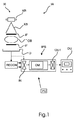
図1を参照すると、コンピュータ制御画像処理システムIPS及びX線撮像装置IAを含む、画像処理構成IAの概略的なブロック図が示される。X線撮像装置は、暗視野撮像用に構成される。 Referring to FIG. 1, a schematic block diagram of an image processing configuration IA including a computer controlled image processing system IPS and an X-ray imaging device IA is shown. The X-ray imaging apparatus is configured for dark field imaging.
画像処理システムIPSは、1つ若しくは複数のコンピュータ、サーバなどの、1つ若しくは複数の処理ユニットPU上で1つ若しくは複数のソフトウェアモジュール又はルーチンとして実行される。IPSは、撮像装置XIの外部に、遠隔して配置されるか、又はIPSは、撮像装置XIの中に、例えば、ワークステーションのような、撮像装置XIのコンピューティングユニットPUの中に組み込まれる。画像処理システムIPSは、通信ネットワークを介して一群の撮像装置を適切にサービングする分散アーキテクチャにおいて実現される。代替的には、IPSのいくつか、又は全ての構成要素が、適切にプログラムされたFPGA(フィールドプログラマブルゲートアレイ)又はハードワイヤードICチップなどのハードウェアにおいて構成される。 The image processing system IPS is executed as one or more software modules or routines on one or more processing unit PUs such as one or more computers and servers. The IPS is remotely located outside the imaging device XI, or the IPS is integrated within the imaging device XI, eg, into the computing unit PU of the imaging device XI, such as a workstation. .. The image processing system IPS is realized in a distributed architecture that appropriately serves a group of image pickup devices via a communication network. Alternatively, some or all components of the IPS are configured in hardware such as a properly programmed FPGA (Field Programmable Gate Array) or hard-wired IC chip.
概して、撮像処理システムIPSは、コンプトン散乱補正済み暗視野画像を生成するために、撮像装置IAによって生成される暗視野画像を特に処理する。補正済み画像は、その後、ディスプレイユニットDU上に表示することができるか、後に再検討するためにメモリに記憶することができるか、又は別のやり方で更に処理することができる。 In general, the imaging processing system IPS specifically processes the darkfield image produced by the imaging apparatus IA in order to generate a Compton scattering corrected darkfield image. The corrected image can then be displayed on the display unit DU, stored in memory for later review, or otherwise further processed.
図1では、撮像装置IAが、ワイヤレス接続又は有線接続を介して直接、画像を画像処理システムIPSに供給すると想定されるが、これは、全ての実施形態においてそうでなくてもよい。例えば、画像は最初に、HISのPACSのようなメモリに、又は別のやり方で記憶され、IPSによって後の段階において(例えば、ユーザ要求時に)、処理されることになる画像が引き出され、その後、処理される。 In FIG. 1, it is assumed that the image pickup apparatus IA feeds the image directly to the image processing system IPS via a wireless or wired connection, but this may not be the case in all embodiments. For example, the image is first stored in memory such as HIS's PACS, or otherwise, and the IPS pulls out the image that will be processed at a later stage (eg, at the user's request), and then. ,It is processed.
画像処理システムIPSによって取得可能な画像は、コンプトン散乱寄与から暗視野信号へのクロストーク(残存する信号寄与を意味する)を低減できるという利点を有する。言い換えると、提案されるIPSによって供給されるような処理済み画像では、コンプトン散乱とレイリー散乱との間のより良好な分離を達成することができる。入力画像(暗視野画像及び減衰画像)は、干渉撮像装置AIによって供給されることが好ましい。しかしながら、代わりに、同じく少なくとも暗視野信号を生成することができ、それに加えて、好ましくは、透過画像信号を生成することができる、符号化開口システムのような他の非干渉撮像システムが使用されてもよい。暗視野信号は、撮像システムによって直接生成されるか、又は撮像システムによって取得される適切な投影データ若しくは他のデータから少なくとも再構成可能である。 The image that can be acquired by the image processing system IPS has the advantage that the crosstalk from the Compton scattering contribution to the darkfield signal (meaning the remaining signal contribution) can be reduced. In other words, in processed images such as those supplied by the proposed IPS, better separation between Compton scattering and Rayleigh scattering can be achieved. The input images (dark field image and attenuated image) are preferably supplied by the interference imaging device AI. However, instead, other non-interfering imaging systems, such as coded aperture systems, which can also generate at least a darkfield signal and, preferably, a transmitted image signal, are used. You may. The darkfield signal can be at least reconstructable from suitable projection data or other data generated directly by the imaging system or acquired by the imaging system.
好ましい実施形態において、干渉撮像装置AIは、X線源XR及びX線放射検知検出器Dを含む。撮像装置IAは、2D又は3D(CTスキャナなど)とすることができる。X線源XRと検出器Dとの間に、撮像されることになる物体OB(例えば、対象者の胸部)が撮像中に存在する撮像領域が画定される。撮像領域には、単一の、2つの、又は3つ以上の格子構造を含む干渉計IFも配置される。格子の周期性、アスペクト比などは、格子がX線ビームの回折を引き起こすように、及び/又は小角散乱を検出若しくは導出できるのに足りるだけのコヒーレンスが達成されるようになされる。吸収格子及び位相格子が使用されてもよい。一実施形態において、格子は、周期的なパターンのトレンチを画定するように、フォトリソグラフィによって、又はシリコンウェハに切り込みを入れることによって形成される。トレンチ間の間隔は、吸収格子の場合、鉛又は金で満たされる。そのような格子の代わりに、結晶構造が使用されてもよい。 In a preferred embodiment, the interference imaging device AI includes an X-ray source XR and an X-ray radiation detector D. The imaging device IA can be 2D or 3D (such as a CT scanner). An imaging region in which the object OB (for example, the subject's chest) to be imaged is present during imaging is defined between the X-ray source XR and the detector D. An interferometer IF containing a single, two, or three or more lattice structures is also arranged in the imaging region. The periodicity, aspect ratio, etc. of the lattice are such that the lattice causes diffraction of the X-ray beam and / or coherence sufficient to detect or derive small angle scattering is achieved. Absorption grids and phase grids may be used. In one embodiment, the grid is formed by photolithography or by making a cut in a silicon wafer so as to define a trench with a periodic pattern. The spacing between the trenches is filled with lead or gold in the case of absorption grids. Instead of such a lattice, a crystal structure may be used.
一実施形態において、検出器Dと物体OBとの間に付加的な格子構造が配置され、一方、物体OBとX線源XRとの間に他の格子が配置される。また、いくつかの実施形態では、X線源が、本来コヒーレントな放射を生成できない場合に、X線源に付加的な格子が配置される。X線源が非コヒーレント放射を生成する場合には(それが通例である)、X線源における(吸収)格子(線源格子とも呼ばれる)が、X線源から出てくるX線放射を、少なくとも部分的にコヒーレントな放射ビームXBに変換する。 In one embodiment, an additional lattice structure is placed between the detector D and the object OB, while another lattice is placed between the object OB and the X-ray source XR. Also, in some embodiments, additional grids are placed on the X-ray source when the X-ray source is unable to produce inherently coherent radiation. When an X-ray source produces non-coherent radiation (which is customary), the (absorption) grid at the X-ray source (also called the source grid) emits the X-ray radiation coming out of the X-ray source. Converts to at least partially coherent radiation beam XB.
少なくとも部分的にコヒーレントな放射ビームXBは、撮像領域を通って伝搬し、干渉計及び物体OBと相互作用する。その相互作用後に、その放射は、その後、検出器Dの放射検知ピクセル要素において電気信号の形で検出される。データ取得回路が電気信号を投影(生の)画像データにデジタル化し、投影画像データは、その後、後により詳細に説明されるようにしてIPSによって処理される。撮像装置XIは、図1に示されるような全視野(FoV)タイプからなることができ、その場合、検出器はフラットパネルタイプからなる。全視野FoV撮像システムでは、検出器Dのサイズは、所望のFoVに対応する。代替的には、スロットスキャニングシステムなどの場合、検出器は意図したFoVより小さくすることができる。何らかのこれらのシステムにおいて、検出器は、離散的な一連の検出器ラインを備える。検出器ラインは、異なるスロット位置において意図したFoVにわたって走査されることになるスキャンアーム上に取り付けられる。スロットスキャニングシステムは、必要とする検出器が小さく、格子IFが小さいので、全視野FoVシステムよりコスト効率が良い。格子は、検出器の上方にあるスキャンアーム上に取り付けられ、同じくFoVにわたって走査される。代替のスロットスキャニングシステムでは、検出器Dは所望のFoVと同じサイズを有するが、格子は小さく、コリメーションによりいつの時点でもFoVの一部のみ(「スロット」内)を走査するために、コリメーションが使用される。全視野FoVシステムでは、撮像幾何を画定するために、ピクセル位置と、撮像領域を通り抜ける仮想幾何学的光線との間に単純な一対一の関係がある。その光線はX線源XRの焦点スポットから延在し、それぞれのピクセル位置において検出器面と交差する。幾何学的光線はそれぞれ、ピクセルのうちの個々の異なる単一のピクセルに対応する。スロットスキャニングシステムでは、そのような単純な関係は存在せず、各幾何学的光線は、走査中に異なる「スロット」内の数多くの異なるピクセルによって視認される。異なるピクセルからの信号が、その後、任意の単一の幾何学的光線を得るのに適したロジックによってまとめて処理される。 The radiated beam XB, which is at least partially coherent, propagates through the imaging region and interacts with the interferometer and the object OB. After that interaction, the radiation is then detected in the form of an electrical signal at the radiation detection pixel element of detector D. The data acquisition circuit digitizes the electrical signal into projected (raw) image data, which is then processed by the IPS as described in more detail later. The imaging device XI can consist of a full field of view (FoV) type as shown in FIG. 1, in which case the detector will consist of a flat panel type. In a full-field FoV imaging system, the size of the detector D corresponds to the desired FoV. Alternatively, in the case of slot scanning systems and the like, the detector can be smaller than the intended FoV. In some of these systems, the detector comprises a discrete set of detector lines. The detector line is mounted on a scan arm that will be scanned over the intended FoV at different slot positions. Slot scanning systems are more cost effective than full-field FoV systems because they require smaller detectors and smaller grid IFs. The grid is mounted on a scan arm above the detector and is also scanned over the FoV. In an alternative slot scanning system, detector D has the same size as the desired FoV, but the grid is smaller and collimation is used to scan only part of the FoV (inside the "slot") at any given time. Will be done. In a full-field FoV system, there is a simple one-to-one relationship between the pixel position and the virtual geometric rays passing through the imaging region to define the imaging geometry. The ray extends from the focal spot of the X-ray source XR and intersects the detector surface at each pixel position. Each geometric ray corresponds to a single, distinct pixel of the pixel. In a slot scanning system, such a simple relationship does not exist, and each geometric ray is visible by a number of different pixels in different "slots" during scanning. Signals from different pixels are then processed together by logic suitable for obtaining any single geometric ray.
一般に、X線放射が材料と相互作用するとき、X線放射は減衰及び屈折の両方を受ける。減衰は、一方で、光電吸収から生じる減衰と、散乱に由来する減衰とに分けることができる。散乱寄与は更に、コンプトン散乱とレイリー散乱とに分解することができる。この場合、対象となるのはレイリー散乱である(又は小角散乱と呼ばれる場合もある)。レイリー散乱の量が暗視野信号内に変調される。 In general, when X-ray radiation interacts with a material, it undergoes both attenuation and refraction. Attenuation, on the other hand, can be divided into attenuation resulting from photoelectric absorption and attenuation resulting from scattering. The scattering contribution can be further decomposed into Compton scattering and Rayleigh scattering. In this case, the target is Rayleigh scattering (or sometimes called small-angle scattering). The amount of Rayleigh scattering is modulated within the darkfield signal.
減衰は、

暗視野寄与は視認性
従来のラジオグラフィシステムは一般に、被検出信号を暗視野寄与に分解できない。しかし、図1に示されるような干渉計を使用することによって、これらの寄与を縞の強度パターンに変換することができ、それを再構成器RECONによって解析することができる。再構成器RECONは、投影データ内の被検出干渉縞を3つの寄与又は信号、すなわち、屈折寄与(位相コントラスト信号とも呼ばれる)、暗視野信号成分及び残存減衰成分に計算によって分解する。理想的には、減衰チャネルにおいて取り込まれるようなコンプトン散乱及び吸収から、暗視野信号内のレイリー散乱を明確に分離すべきである。 Conventional radiography systems generally cannot decompose the detected signal into darkfield contributions. However, by using an interferometer as shown in FIG. 1, these contributions can be converted into a fringe intensity pattern, which can be analyzed by the reconstructor RECON. The reconstructor RECON computationally decomposes the detected interference fringes in the projected data into three contributions or signals, namely refraction contributions (also called phase contrast signals), darkfield signal components and residual attenuation components. Ideally, Rayleigh scattering in the darkfield signal should be clearly separated from Compton scattering and absorption as captured in the decay channel.
検出器において検出された強度を再構成器RECONによって3つの信号(位相コントラスト、暗視野及び減衰)に信号処理することは、F Pfeifferら「Hard−X−ray dark−field imaging using a grating interferometer」(Nature Materials7、pp134−137(2008))などによって、他の文献においても論じられている。本明細書のいくつかの実施形態において想定されるような、Pfeifferら及び他の類似の技法では、検出器Dにおいて検出されるような投影データ内の干渉縞が、フーリエ技法を用いて解析される。これらのタイプの撮像システムでは、暗視野撮像の能力は以下のように達成される。位相ステップ動作中に、検出器Dにおいて投影データが取得される。位相ステップ動作は、X線ビームと干渉計及び/又は物体OBとの間に運動を引き起こす。例えば、一実施形態において、解析器格子(すなわち、物体と検出器との間に配置される格子)が、X線ビームの光軸に対して横方向に動かされる(「走査される」)。代替的には、位相ステップ処理は、物体OBを動かすこと、又はX線源を動かすことなどによって達成することもできる。この運動は、干渉縞の変化を引き起こし、それにより、その変化を運動のステップごとに対応する系列内に記録することができる(「位相ステップ処理」)。この測定系列は、幾何学的光線ごとに、関連付けられる位相曲線を形成する。位相曲線は一般に正弦曲線の形状からなり、それぞれが、減衰及び位相変化とともに、対象となる量、詳細には、暗視野信号を符号化することがわかった。図2がこれを示す。具体的には、図2は、X線放射と物質との相互作用の種々の態様の概略図である。図2は行列に配置される9個のペインを含み、3つの行は「1」、「2」、「3」を付され、3つの列は「A」、「B」、「C」を付されている。 Signal processing the intensity detected by the detector into three signals (phase contrast, darkfield and attenuation) by the reconstructor RECON is described by F Pfeiffer et al., "Hard-X-ray dark-field imaging using interferometer". (Nature Materials 7, pp134-137 (2008)) and the like are also discussed in other literature. In Pfeiffer et al. And other similar techniques, as envisioned in some embodiments herein, interference fringes in the projected data as detected by detector D are analyzed using Fourier techniques. To. In these types of imaging systems, darkfield imaging capabilities are achieved as follows: Projection data is acquired by the detector D during the phase step operation. The phase stepping motion causes motion between the X-ray beam and the interferometer and / or object OB. For example, in one embodiment, the analyzer grid (ie, the grid placed between the object and the detector) is moved laterally (“scanned”) with respect to the optical axis of the X-ray beam. Alternatively, the phase step processing can also be achieved by moving the object OB, moving the X-ray source, and so on. This motion causes a change in the interference fringes, which allows the change to be recorded in the corresponding sequence for each step of motion (“phase stepping”). This measurement sequence forms an associated phase curve for each geometric ray. It has been found that the phase curve generally consists of a sinusoidal shape, each encoding a quantity of interest, and more specifically, a dark-field signal, along with attenuation and phase change. FIG. 2 shows this. Specifically, FIG. 2 is a schematic diagram of various aspects of the interaction between X-ray radiation and a substance. Figure 2 contains nine panes arranged in a matrix, with three rows labeled "1", "2", "3" and three columns labeled "A", "B", "C". It is attached.
ペイン1A(左上位置)は、線形減衰係数によって表される減衰の影響を示す。この量は、物質内の密度及び実効原子番号に関連する。 Pane 1A (upper left position) shows the effect of damping represented by the linear damping coefficient. This amount is related to the density and effective atomic number in the material.
ペイン1Bは、位相曲線に及ぼす減衰の影響と、減衰の変化が位相ステップ曲線にいかに影響を及ぼすかとを示す。位相ステップ曲線は、垂直方向に強度を、水平方向に格子位置をグラフ表示する。図から明らかなように、減衰が変化する結果として、曲線が水平方向にシフトし、すなわち、全体にわたって減衰が減少する。 Pane 1B shows the effect of damping on the phase curve and how changes in damping affect the phase step curve. The phase step curve graphs the intensity in the vertical direction and the grid position in the horizontal direction. As is clear from the figure, as a result of the change in damping, the curve shifts horizontally, i.e., the damping is reduced throughout.
ペイン1Cは、例示的な減衰画像、この場合には、マウス胸郭から撮影された画像を示す。 Pain 1C shows an exemplary attenuated image, in this case an image taken from the mouse thorax.
ここで、第2の行、詳細には、ペイン2Aを参照すると、これは、ペイン2B内の屈折の物理的影響と、位相曲線に及ぼすその影響とを示す。屈折の変化(位相勾配)の結果として、位相曲線が水平方向にシフトする。X線放射が受ける屈折は、屈折率減少量δによって表され、屈折率減少量は電子密度ρeに関連する。 Seeing the second row, in detail, pane 2A, here shows the physical effect of refraction in pane 2B and its effect on the phase curve. As a result of the change in refraction (phase gradient), the phase curve shifts horizontally. The refraction received by X-ray radiation is represented by the amount of decrease in refractive index δ, and the amount of decrease in refractive index is related to the electron density ρ e.
ペイン2Cはマウス胸郭の例示的な位相コントラスト画像を示す。 Pain 2C shows an exemplary phase contrast image of the mouse thorax.
最後の行(行3)では、ペイン3Aが、暗視野撮像においてコントラストを与える効果がある小角散乱を示す。小角散乱は、数ある効果の中でも、一般に解像限界未満である小さい微細構造によって引き起こされると仮定される。そのような微細構造は、例えば、肺組織内などの海綿状組織又は多孔性組織内で見ることができる。図から明らかであるように、位相曲線に及ぼす影響は、ペイン3Bにおいて表されるように、小角散乱が振幅を増加させることである。最後に、ペイン3Cは、マウス胸郭の例示的な暗視野画像を示す。 In the last row (row 3), pane 3A shows small-angle scattering, which has the effect of giving contrast in darkfield imaging. Small-angle scattering is assumed to be caused by small microstructures, which are generally below the resolution limit, among other effects. Such microstructures can be found in spongy or porous tissues, such as in lung tissue. As is clear from the figure, the effect on the phase curve is that small angle scattering increases the amplitude, as shown in pane 3B. Finally, Pain 3C shows an exemplary darkfield image of the mouse thorax.
再構成を達成するために、例えば、Pfeifferらにおいて記述されるように正弦曲線モデルに当てはめることによって、位相曲線をそれぞれ解析することができる。好ましくは、正弦曲線モデルには、少なくとも3つの当てはめパラメータが含まれる。3つの当てはめパラメータはそれぞれ3つの寄与、位相コントラスト、暗視野信号及び透過を表す。正弦曲線モデルは再構成器RECONによって位相曲線に当てはめられ、それにより、暗視野画像及び透過「(「減衰」とも呼ばれる)画像が特に計算される。具体的には、全視野FoVシステムにおける再構成中に、ピクセル/幾何学的光線ごとの位相曲線を直接用いて、ピクセルごとの透過及び暗視野情報を取得することが好ましい。最小二乗法、勾配降下法、最尤法などの任意の曲線当てはめ数値技法をこのために使用することができる。位相コントラスト信号は、多くの場合にそれ自体で対象になるが、ここでは無視されることになる。実際には、透過画像及び暗視野画像も位相回復において同じく再構成され、本明細書では暗視野画像が主に対象になるので、このタイプの再構成アルゴリズムは、多くの場合に「位相回復」と呼ばれるが、この場合、これは誤称である。本明細書では、格子に基づくX線撮像が好ましいが、符号化開口システムなどの、暗視野信号、及び好ましくは、関連付けられる透過画像信号を与えることができる他の技法、詳細には、非干渉技法も本明細書において想定される。一般に、格子/マスクに基づく撮像技法では、暗視野撮像は、到来する撮像X線ビームに周期的な波面変調を与えることを通して取得され、X線検出器Dによる測定値は、撮像されることになる物体によって引き起こされる、結果として生じる波面の変動である。更に、本明細書では、非格子撮像技法も想定される。 To achieve reconstruction, each phase curve can be analyzed, for example, by fitting it into a sinusoidal model as described in Pfeiffer et al. Preferably, the sinusoidal model contains at least three fitting parameters. Each of the three fitting parameters represents three contributions, phase contrast, darkfield signal and transmission. The sinusoidal model is fitted to the phase curve by the reconstructor RECON, which specifically calculates darkfield and transmission "(also referred to as" attenuation ") images. Specifically, it is preferable to directly use the phase curve for each pixel / geometric ray to acquire the transmission and darkfield information for each pixel during the reconstruction in the full-field FoV system. Any curve fitting numerical technique such as least squares, gradient descent, or maximum likelihood can be used for this. The phase contrast signal is often the subject of its own, but will be ignored here. In practice, transparent and darkfield images are also reconstructed in phase retrieval, and this type of reconstruction algorithm is often "phase-retrieved" because darkfield images are primarily of interest herein. In this case, this is a misnomer. Although grid-based radiography is preferred herein, other techniques such as coded aperture systems that can provide darkfield signals and preferably associated transmitted image signals, in particular non-interfering. Techniques are also envisioned herein. In general, in lattice / mask based imaging techniques, dark field imaging is acquired by applying periodic wavefront modulation to the incoming imaging X-ray beam, and the measurements taken by the X-ray detector D are imaged. The resulting wavefront variation caused by the object. Further, non-grid imaging techniques are also envisioned herein.
再構成器RECONは、それぞれの一連の画像値として暗視野信号及び減衰信号を出力し、それらの画像値はそれぞれ、暗視野画像及び透過画像を形成する。これらの画像値又はピクセル値はそれぞれ、幾何学的光線ごとの、暗視野信号、及びX放射が受ける減衰に関するコントラストを表す。より詳細には、全視野FoVシステムの場合、特定のピクセル位置(x,y)において、暗視野画像内の特定の値が関連付けられ、その値は理想的には、検出器面のそれぞれ位置x、yにおいて観測される小角散乱の量を表すはずである。一方、透過画像内の同じピクセル位置x、yは、コンプトン散乱及び光電吸収に起因して受ける減衰量を表すと予想される。 The reconstructor RECON outputs a dark field signal and an attenuation signal as a series of image values, respectively, and these image values form a dark field image and a transmission image, respectively. Each of these image or pixel values represents the contrast of the darkfield signal and the attenuation received by the X radiation for each geometric ray. More specifically, in the case of a full-field FoV system, at specific pixel positions (x, y), specific values in the dark-field image are associated, and the values are ideally at each position x on the detector surface. , Y should represent the amount of small angle scattering observed at y. On the other hand, the same pixel positions x and y in the transmitted image are expected to represent the amount of attenuation received due to Compton scattering and photoelectric absorption.
しかしながら、コンプトン散乱信号と暗視野信号との間の分離は、望むほど明確でないことに気が付いた。詳細には、コンプトン散乱は非コヒーレントであり、干渉装置の精度の多くはコヒーレント放射の仮定に厳密に基づくので、コンプトン散乱を受けた光子の信号は、付加的な擬似暗視野信号を生成することになることがわかった。この擬似暗視野信号は、コンプトン散乱からのクロストーク寄与によって引き起こされる。暗視野信号への望ましくないコンプトンクロストークは、重ね合わせられた干渉縞を生成する。このクロストークは、肺組織の小角特性の定量的評価を妨げるが、その定量的評価は、例えば、慢性閉塞性肺疾患(COPD:Chronic Obstructive Pulmonary Disease)及び線維症などの肺疾患の画像に基づく診断検査において重要である。 However, I have noticed that the separation between the Compton scattered signal and the darkfield signal is not as clear as desired. In particular, Compton scattering is non-coherent, and much of the interferor's accuracy is strictly based on the assumption of coherent radiation, so the signal of a photon subjected to Compton scattering produces an additional pseudo-darkfield signal. It turned out to be. This pseudo-darkfield signal is caused by a crosstalk contribution from Compton scattering. Undesirable Compton crosstalk to darkfield signals produces superposed interference fringes. This crosstalk interferes with the quantitative evaluation of the small angle characteristics of lung tissue, which is based on images of lung diseases such as chronic obstructive pulmonary disease (COPD) and fibrosis, for example. It is important in diagnostic tests.
提案される画像処理システムIPSは、これらの問題に対処し、コンプトン散乱の影響に関して補正された暗視野画像を生成するように構成される。言い換えると、提案される画像処理システムによって生成されるコンプトン散乱補正済み暗視野画像は、コンプトン散乱の妨害クロストークが低減されているか、又は更には除去されているので、より良好な信号識別性を有する。 The proposed image processing system IPS addresses these issues and is configured to produce a darkfield image corrected for the effects of Compton scattering. In other words, the Compton scattering-corrected darkfield image produced by the proposed image processing system has better signal discrimination because the Compton scattering jamming crosstalk is reduced or even eliminated. Have.
ここで、提案される画像処理IPSをより詳細に参照し、引き続き図1を参照すると、これは、コンプトン信号からの暗視野信号(DAX)クロストークを低減するか、又は理想的には除去する補正モジュールCMを含む。概して、入力画像が、信号処理システムIPSの入力インターフェースINにおいて受信される。入力画像は、好ましくは、いずれも再構成器RECONによって再構成されるような、暗視野画像及び透過画像を含む。 Here, with reference to the proposed image processing IPS in more detail and continuing with reference to FIG. 1, this reduces or ideally eliminates darkfield signal (DAX) crosstalk from the Compton signal. Includes correction module CM. Generally, the input image is received at the input interface IN of the signal processing system IPS. The input image preferably includes a darkfield image and a transmission image, both of which are reconstructed by the reconstructor RECON.
補正モジュールCMは、その後、受信された暗視野画像に関する補正動作を実行し、補正済み暗視野画像を生成する。補正済み暗視野画像は、その後、出力ポートOUTにおいて出力される。 The correction module CM then executes a correction operation on the received dark-field image to generate a corrected dark-field image. The corrected darkfield image is then output at the output port OUT.
補正モジュールCMに関して、少なくとも2つの異なる実施形態が想定される。1つの実施形態では、補正モジュールは、透過画像からコンプトン散乱の量を推定する。これは、ピクセル単位で散乱フラクションを確立することによって行うことができる。散乱フラクションは、その後、入力INにおいて受信されるような、まだコンプトン散乱により劣化している暗視野画像に算術的に適用される。より詳細には、1つの実施形態では、透過画像内の異なるピクセルロケーションからそれぞれの散乱フラクションが推定され、その後、減算によって、対応するピクセルにおいて暗視野画像にピクセル単位で適用される。言い換えると、透過画像から取得された散乱フラクションマップが、暗視野画像から減算され、補正済み暗視野画像が生成される。除算、乗算などの他の算術演算も想定される。 At least two different embodiments are envisioned for the correction module CM. In one embodiment, the correction module estimates the amount of Compton scattering from the transmitted image. This can be done by establishing a scattering fraction on a pixel-by-pixel basis. The scattering fraction is then arithmetically applied to a darkfield image that is still degraded by Compton scattering, such as received at the input IN. More specifically, in one embodiment, each scattering fraction is estimated from different pixel locations in the transmitted image and then subtracted, pixel by pixel, applied to the darkfield image at the corresponding pixels. In other words, the scattered fraction map obtained from the transmitted image is subtracted from the darkfield image to generate a corrected darkfield image. Other arithmetic operations such as division and multiplication are also envisioned.
補正モジュールCMに関する代替の実施形態も想定され、これが図1において破線で示される。この実施形態において、補正モジュールCMは投影画像データに作用する。より詳細には、この実施形態における補正モジュールCMは、再構成器RECONと協働して、2パス再構成を実施し、コンプトン散乱補正を達成する。より詳細には、第1の実施形態において上記で説明されたように、散乱寄与が再び推定される。しかしながら、散乱情報(例えば、散乱フラクション)は再構成済み暗視野画像にここで適用されるのではなく、代わりに、入力ポートINにおいて受信された2つの画像が基本的な投影データから再構成される、当該基本的な投影データに適用される。そのように補正された投影データは、その後、再構成器RECONに再び転送され、第2のパスにおいて再び再構成され、他のチャネル、透過及び位相コントラストに関する画像とともに、補正済み暗視野画像が取得され、後者の2つはここでは関連性は低い。 An alternative embodiment for the correction module CM is also envisioned, which is shown by the dashed line in FIG. In this embodiment, the correction module CM acts on the projected image data. More specifically, the correction module CM in this embodiment performs a two-pass reconstruction in cooperation with the reconstructor RECON to achieve Compton scattering correction. More specifically, the scattering contribution is re-estimated as described above in the first embodiment. However, the scattering information (eg, the scattering fraction) is not applied here to the reconstructed darkfield image, but instead the two images received at the input port IN are reconstructed from the basic projection data. It is applied to the basic projection data. The such corrected projection data is then transferred back to the reconstructor RECON and reconstructed in the second pass to obtain a corrected darkfield image along with images for other channels, transmission and phase contrast. The latter two are less relevant here.
ここで、図3を参照すると、図1の画像処理システムIPSの動作の根底をなし、その動作の更なる詳細を与える、提案される画像処理方法のフローチャートが示される。しかしながら、以下に説明される方法のステップはそれ自体で1つの教示を構成し、必ずしも図1に示される具体的なアーキテクチャに結び付けられるとは限らないことは理解されよう。 Here, with reference to FIG. 3, a flowchart of a proposed image processing method that underlies the operation of the image processing system IPS of FIG. 1 and provides further details of the operation is shown. However, it will be understood that the steps of the method described below constitute one teaching by themselves and are not necessarily tied to the specific architecture shown in FIG.
概して、暗視野画像内のコンプトン散乱の影響の補正、すなわち、低減又は除去のための提案される新規の画像処理方法は、ステップS310を含み、そのステップでは、入力暗視野画像データが受信される。入力DAX画像はおそらく、コンプトン散乱により劣化している。 In general, a proposed novel image processing method for compensating, i.e., reducing or eliminating the effects of Compton scattering in a darkfield image comprises step S310, in which input darkfield image data is received. .. The input DAX image is probably degraded by Compton scattering.
人間又は動物の患者の肺などの、対象物OBの暗視野画像データが、X線撮像装置の動作によって取得されている。 Dark-field image data of an object OB, such as the lungs of a human or animal patient, is acquired by the operation of an X-ray imaging apparatus.
ステップS320において、暗視野画像データに関する補正動作が実行され、コンプトン散乱補正済み暗視野画像データが取得される。このコンプトン散乱補正済み暗視野画像データでは、コンプトン散乱画像から生じる擬似信号が除去されているか、又は少なくとも低減されている。 In step S320, the correction operation related to the dark field image data is executed, and the Compton scattering corrected dark field image data is acquired. In this Compton scattering-corrected darkfield image data, the pseudo-signals generated from the Compton scattering image are removed, or at least reduced.
ステップS330において、そのようなコンプトン散乱補正済み暗視野画像データが、その後、出力され、記憶又は表示など、更に処理することができる。 In step S330, such Compton scattering-corrected darkfield image data can then be output and further processed, such as stored or displayed.
本明細書において、2つの基本的な実施形態が区別される。受信された暗視野画像データは、あらかじめ取得されている投影データから再構成されるか、又は暗視野画像データは、投影データに含まれる。いずれの実施形態でも、関連付けられる透過画像を用いて、コンプトン散乱の量に関する情報が取得される。好ましくは、この透過画像は、例えば、上記で言及された位相回復アルゴリズムの場合と同様に、暗視野画像データに関連付けられ、それは式(7)〜(12)において後に更に詳細に説明される。しかしながら、他の実施形態では、透過画像は依然として、暗視野画像データと同じ物体から取得されるが、他の点では、暗視野画像データとは何の関係もない。透過画像は、全く異なる方法及び/又は撮像装置によってあらかじめ取得しておくことができるが、それでも、好ましくは暗視野画像データの場合と同じ撮像幾何において、同じ物体から取得されることが好ましい。 Two basic embodiments are distinguished herein. The received dark-field image data is reconstructed from the projection data acquired in advance, or the dark-field image data is included in the projection data. In either embodiment, the associated transmission image is used to obtain information about the amount of Compton scattering. Preferably, this transparent image is associated with darkfield image data, for example, as in the case of the phase retrieval algorithm mentioned above, which will be described in more detail later in equations (7)-(12). However, in other embodiments, the transmitted image is still obtained from the same object as the darkfield image data, but in other respects it has nothing to do with the darkfield image data. The transmitted image can be pre-acquired by a completely different method and / or imaging apparatus, but it is still preferably acquired from the same object in the same imaging geometry as in the case of darkfield image data.
再構成された暗視野画像データに関して補正ステップが実行される第1の実施形態では、補正ステップS320は、図4のフローチャートによる、以下のサブステップを含む。 In the first embodiment in which the correction step is executed for the reconstructed darkfield image data, the correction step S320 includes the following sub-steps according to the flowchart of FIG.
ステップS320Aにおいて、コンプトン散乱に関連する散乱フラクション又は他の量が、同じ物体に関する透過画像に基づいて推定される。 In step S320A, scattering fractions or other quantities associated with Compton scattering are estimated based on transmitted images for the same object.
ステップS320Bにおいて、散乱推定値、例えば、散乱フラクションが、その後、暗視野画像データに適用され、それにより、補正が達成される。散乱フラクション情報の適用は、ピクセル単位の減算又は他の適切な算術演算を含む。例えば、好ましい場合として、画像データが対数領域内にある場合には、被測定暗視野画像データからの散乱フラクションの減算が実行される。そうでない場合には、対数は使用されず、受信された暗視野画像データが、それぞれのピクセルに関するそれぞれの散乱フラクション量によってピクセル単位で除算される。 In step S320B, the scattering estimate, eg, the scattering fraction, is then applied to the darkfield image data, whereby the correction is achieved. Application of scattered fraction information includes subtraction on a pixel-by-pixel basis or other suitable arithmetic operations. For example, preferably, when the image data is in the logarithmic region, the subtraction of the scattering fraction from the darkfield image data to be measured is executed. Otherwise, the logarithm is not used and the received darkfield image data is divided pixel by pixel by the amount of scattering fraction for each pixel.
早期に留意されたように、散乱防止格子を使用するときでも、DAX撮像に一般にコンプトン散乱が関与する。コンプトン散乱は一般に透過画像におけるコントラスト損失につながるが、同じ要因によって、視認性V及び暗視野信号Dも低下することがわかった。それゆえ、以下のように、両方のデータチャネルを補正することができる。
IScatterCorrected=Imeasured−S (1)
(IScatterCorrected=P;すなわち、IScatterCorrected=Imeasured*(1−SF)) (2)
及び
TScatterCorrected=IScatterCorrected/I0 (3)
又は
log(TScatterCorrected)=log(Tmeasured)+log(1−SF)(TScatterCorrected<Tmeasured) (4)
DScatterCorrected=Dmeasured/SF (DScatterCorrected>Dmeasured) (5)
又は
log(DScatterCorrected)=log(Dmeasured)−log(SF) (6)
As noted earlier, Compton scattering is generally involved in DAX imaging, even when using anti-scattering grids. It has been found that Compton scattering generally leads to contrast loss in transmitted images, but the same factors also reduce visibility V and darkfield signal D. Therefore, both data channels can be corrected as follows.
I Scatter Selected = I measured −S (1)
(I ScatterSelected = P; that is, IScatterSelected = I measured * (1-SF)) (2)
And T Scatter Selected = I Scatter Selected / I 0 (3)
Or log (T ScatterCorrected) = log ( T measured) + log (1-SF) (T ScatterCorrected <T measured) (4)
D Scatter Selected = D measured / SF (D Scatter Selected > D measured ) (5)
Or log (D ScatterCorrected) = log ( D measured) -log (SF) (6)
言い換えると、対数領域内にないとき、散乱フラクションは暗視野画像Dのピクセル値によってピクセル単位で除算又は乗算され、補正が達成される(式(5))。対数領域内にあるとき(式(6))、散乱フラクション寄与がピクセル単位で減算される。上記の補正アルゴリズムでは、式(1)〜(4)における透過画像の(更なる)補正は、本明細書において任意選択である。上記の補正アルゴリズム(1)〜(6)の任意の代数的に等価な再定式化も本明細書において同様に想定される。 In other words, when not in the logarithmic region, the scattered fraction is divided or multiplied pixel by pixel by the pixel value of the darkfield image D to achieve the correction (Equation (5)). When in the logarithmic domain (Equation (6)), the scattering fraction contribution is subtracted on a pixel-by-pixel basis. In the above correction algorithm, the (further) correction of the transparent image in the equations (1) to (4) is optional in the present specification. Any algebraically equivalent reformulation of the above correction algorithms (1)-(6) is similarly assumed herein.
散乱フラクションSF自体は、既知の散乱推定技法によって透過画像から推定することができる。例えば、一実施形態において、散乱フラクションSFは、放射の物理モデル、被測定透過量、及び被測定強度I内の局所的勾配から推定される。一般に、コンプトン散乱補正は、コンプトン散乱に起因するコントラスト損失を補償するために、log(P)=log(I)+log(1−SF)のように行われる。付表の用語の説明/定義も参照されたい。散乱フラクション推定に関する更なる詳細は、国際公開第2007/148263号パンフレットにおいて見ることができ、散乱は水球ファントムに基づいて推定される。水以外の材料を代わりに使用することもできる。更に、ファントムに基づく方式以外の散乱補正方式も想定される。これらの、又は類似のタイプの散乱推定技法では、散乱カーネルがあらかじめ計算され、データベースに保持される。散乱カーネルは、(言及された水球などの)異なるサイズ及び/又は向きの異なるファントム体に関連する散乱を表す。ファントム体の透過特性を透過画像と(局所的に、又は全体として)照合して、最も適合するものを見つけることができる。適合するファントム体に関連付けられるカーネルは、その後、(コンプトン)散乱推定値として使用される。以下の実施形態において、このタイプのファントムに基づく散乱推定を使用することもできる。 The scattering fraction SF itself can be estimated from a transmitted image by a known scattering estimation technique. For example, in one embodiment, the scattering fraction SF is estimated from the physical model of radiation, the amount of transmission to be measured, and the local gradient within the intensity I to be measured. Generally, Compton scattering correction is performed as log (P) = log (I) + log (1-SF) in order to compensate for the contrast loss caused by Compton scattering. See also the explanation / definition of terms in the attached table. Further details regarding the scattering fraction estimation can be found in WO 2007/148263, where the scattering is estimated based on the water polo phantom. Materials other than water can be used instead. Further, a scattering correction method other than the method based on the phantom is also assumed. In these or similar types of scattering estimation techniques, the scattering kernel is precomputed and stored in a database. Scatter kernels represent scatter associated with phantom bodies of different sizes and / or orientations (such as the water polo mentioned). The transmission characteristics of the phantom body can be compared (locally or as a whole) with the transmission image to find the most suitable one. The kernel associated with the matching phantom body is then used as the (Compton) scattering estimate. Scattering estimates based on this type of phantom can also be used in the following embodiments.
ここで、ステップS320の補正が投影データに少なくとも部分的に基づいて行われる第2の実施形態を参照する。上記で言及されたように、この実施形態における補正ステップは「2パス/ステップ」アルゴリズムである。より具体的には、第1のパスでは、おそらくコンプトン散乱から生じる従来の中間の透過画像が、投影データからの再構成によって生成される。その後、この第1のパスの画像を用いて、既知のコンプトン散乱補正技法(上記で言及された技法など)によって、中間画像内のコンプトン散乱信号を推定する。非常に良好な近似では、コンプトン散乱信号は相対的な格子位置に依存しないことがわかった。それゆえ、この推定値を用いて、投影データを補正することができ、後続の再構成を用いて、改善されたDAX信号を取得することができる。干渉方式では、補正されることになる投影データは、位相ステップ走査において取得された位相曲線から形成され、再構成は、言及された位相回復アルゴリズムに対応する。図5のフローチャートは、この2パス補正ステップに関与するサブステップを要約する。 Here, we refer to a second embodiment in which the correction in step S320 is performed at least partially based on the projection data. As mentioned above, the correction step in this embodiment is a "two-pass / step" algorithm. More specifically, in the first pass, a conventional intermediate transmission image, probably resulting from Compton scattering, is generated by reconstruction from the projected data. The image of this first pass is then used to estimate the Compton scattering signal in the intermediate image by a known Compton scattering correction technique (such as the technique mentioned above). A very good approximation shows that the Compton scattered signal does not depend on the relative grid position. Therefore, this estimate can be used to correct the projection data and subsequent reconstruction can be used to obtain an improved DAX signal. In the interference scheme, the projected data to be corrected is formed from the phase curve acquired in the phase step scan, and the reconstruction corresponds to the phase retrieval algorithm mentioned. The flowchart of FIG. 5 summarizes the substeps involved in this two-pass correction step.
最初に、X線に暴露し、X線検出器Dにおいて検出することによって、対象物からX線投影データが取得される。 First, the X-ray projection data is acquired from the object by exposing it to X-rays and detecting it with the X-ray detector D.
ステップS320_10において、投影データから再構成された透過データに関して、最初にコンプトン散乱が推定される。 In step S320_10, Compton scattering is first estimated for the transmitted data reconstructed from the projection data.
ステップS320_20において、ステップS320_10において推定されるようなコンプトン散乱情報に基づいて、その後、投影データに関して補正が実行される。 In step S320_20, corrections are then performed on the projected data based on the Compton scattering information as estimated in step S320_10.
ステップS320_30において、その後、別の再構成が実行され、そのように補正された投影データに基づいて、補正済み暗視野画像が取得される。 In step S320_30, another reconstruction is then performed to obtain a corrected darkfield image based on the projected data so corrected.
上記で言及されたように、再構成は、上記で説明されたような当てはめ演算を用いて行うことができる。代替的には、暗視野画像を計算することができる任意の他の再構成方法を代わりに使用することができる。図1に関連して上記で説明されたように、干渉方式と同様に位相ステップ動作が関与する場合には、投影データは位相曲線を含む。 As mentioned above, the reconstruction can be performed using the fitting operation as described above. Alternatively, any other reconstruction method capable of calculating the darkfield image can be used instead. As described above in connection with FIG. 1, the projected data includes a phase curve when the phase step operation is involved as in the interference scheme.
また、上記の実施形態の全てから、本明細書において、上記のステップが実行される前に投影データ取得が直接行われる必要はなく、これは依然としてリアルタイムに、又はオンライン設定において行うことができることが明らかなはずである。代替的には、投影データは、上記のステップが実行される(数分、数時間又は数日)前に十分に取得されており、投影データは、その後、必要に応じて記憶装置から引き出される。 Also, from all of the above embodiments, it is not necessary in this specification that the projection data acquisition be performed directly before the above steps are performed, which can still be done in real time or in an online setup. It should be obvious. Alternatively, the projection data is well captured before the above steps are performed (minutes, hours or days), and the projection data is then retrieved from the storage as needed. ..
全視野システムを特に参照すると、図5のフローチャートによる補正ステップは、以下のように、より詳細に理解することができる。全視野FoVの場合、信号D及びTは、ピクセルごとに信号に以下のモデルを当てはめることによって、生データRiから第1のパスにおいて導出される(「i」は位相ステップインデックスである)。
Ri=TI0(1+DV0cos(α0+iΔα))(7)
With particular reference to the panoramic system, the correction steps according to the flowchart of FIG. 5 can be understood in more detail as follows. For full-field FoV, signals D and T, by fitting the following model to the signal for each pixel is derived in the first pass from the raw data R i ( "i" is the phase step index).
R i = TI 0 (1 + DV 0 cos (α 0 + iΔα)) (7)
標準的な正弦曲線モデルは、透過(T)、暗視野(D)及び位相変化(
![]()
Ri=TI0(1+DV0cos(α0+iΔα))+S ただし、T*I0=P(8)
Standard sinusoidal models include transmission (T), darkfield (D) and phase change (
![]()
R i = TI 0 (1 + DV 0 cos (α 0 + iΔα)) + S , however, T * I 0 = P ( 8)
式(8)による、コンプトン散乱寄与を伴う新たなモデルは、
![]()
![]()
散乱の絶対量を考慮するのではなく、以下のように定義される、いわゆる散乱フラクションを考慮することが好都合である。
この定義を使用するとき、式(9)内のDV0の前にある係数は、以下のように書くことができる。
![]()
![]()
それゆえ、(8)への当てはめを伴う第1のパスの再構成によるDに関する最初の推定値は、(1−SF倍)だけ外れている。その際、平均信号(TI0+S)に関する散乱補正の結果を用いて、補正を単純に適用できることを提案する。言い換えると、Riは、
RiscatterCorrected=Ri−S (11)
により、iごとに補正されるか、又は散乱情報Sは、別のやり方で、元の投影データRiとピクセル単位で適切に算術的に結合される。
Therefore, the initial estimate for D by reconstructing the first path with the fit to (8) deviates by (1-SF times). At that time, it is proposed that the correction can be simply applied by using the result of the scattering correction for the average signal (TI 0 + S). In other words, Ri is
Ri scatter Selected = Ri-S (11)
Is corrected for each i, or the scatter information S is, in another way , appropriately arithmetically combined with the original projection data Ri on a pixel-by-pixel basis.
式(11)による補正済み投影データRiscatterCorrectedは、その後、第2のパスの補正において、
RiscatterCorrected=TI0(1+DV0cos(α0+iΔα) (12)
により、新たな正弦曲線モデルに当てはめられる。
The corrected projection data RiscatterSelected according to the equation (11) is then subjected to the correction of the second pass.
Ri scatter Selected = TI 0 (1 + DV 0 cos (α 0 + iΔα) (12)
Applies to the new sinusoidal curve model.
上記の式において、一般に、基準データ(I0、V0及びα0)はピクセル位置「i」に依存するが、表記をより簡単にするために、上記の式ではインデックスが省略されている。 In the above equation, the reference data (I 0 , V 0 and α 0 ) generally depends on the pixel position “i”, but the index is omitted in the above equation for the sake of simplicity.
上記の数学的表現は、処理がピクセル位置iごとではなく、幾何学的光線ごとに行われるスロットスキャニングシステムに適用することもでき、それは、異なるピクセルによって検知されるが、同じ所与の幾何学的光線に関連付けられる全ての投影データを集約することを含む。とりわけ、この実施形態において、再構成された透過画像に関して、スロット位置ごとに別々に散乱推定が実行されるが、全視野FoVに関して実行されない。上記で言及されたのと同じ散乱推定技法を使用することができる。種々のスロット位置に関して推定されるような取得された散乱は、その後、スロット位置ごとに投影生データから減算されるか、又は別のやり方で算術的に結合され、補正済み投影データが取得される。そのように補正された投影データ及び式8において与えられるモデルを用いて、その後、第2のパスの再構成が実行される。暗視野、透過及び位相画像が同じアルゴリズム(位相回復)によって生成されるが、これは全ての実施形態において必ずしもそうとは限らない場合があることは、上記のことから理解されたい。他の実施形態も想定され、その場合、関連付けられる透過画像が、異なるアルゴリズム、及び/又は異なる撮像装置などによって生成される。しかしながら、暗視野画像及び透過画像は同じ物体から、好ましくは、同時に及び同じ撮像幾何において取得されることを確実にすべきである。しかしながら、透過画像及び補正されることになる暗視野画像は異なる時点において取得又は生成することもでき、その時点の暗視野画像がコンプトン散乱補正されることになるときに、透過画像が、画像メモリ、(病院情報システム(HIS)などのPACE(画像保存通信システム)の)データベースから引き出される。 The above mathematical representation can also be applied to slot scanning systems where the processing is done on a geometric ray basis rather than on a pixel position i basis, which is detected by different pixels but with the same given geometry. Includes aggregating all projection data associated with the target ray. In particular, in this embodiment, the scatter estimation is performed separately for each slot position for the reconstructed transmission image, but not for the full field FoV. The same scattering estimation techniques mentioned above can be used. The acquired scatter, as estimated for the various slot positions, is then subtracted from the raw projection data for each slot position or otherwise arithmetically combined to obtain the corrected projection data. .. With such corrected projection data and the model given in Equation 8, the reconstruction of the second path is then performed. It should be understood from the above that darkfield, transmission and phase images are produced by the same algorithm (phase retrieval), but this may not always be the case in all embodiments. Other embodiments are also envisioned, in which case the associated transmission image is generated by different algorithms and / or different imaging devices and the like. However, it should be ensured that darkfield and transmitted images are obtained from the same object, preferably simultaneously and in the same imaging geometry. However, the transmission image and the darkfield image to be corrected can also be acquired or generated at different time points, and when the darkfield image at that time is to be Compton scattering corrected, the transmission image becomes an image memory. , Derived from a database (of a PACE (Image Archiving and Communication System) such as a Hospital Information System (HIS)).
上記において、「再構成」という用語は、位相ステップデータへの曲線当てはめを伴う位相回復アルゴリズムを参照しながら主に使用されたが、暗視野信号をもたらすことができる他の再構成アルゴリズムも本明細書において想定される。これらの他の再構成アルゴリズムは、関連付けられる透過画像をもたらしても、もたらさなくてもよく、それらのアルゴリズムは、位相ステップ処理を伴っても、伴わなくてもよく、及び/又はそれらのアルゴリズムは、干渉計などの格子構造を伴っても、伴わなくてもよい。関連付けられる透過データは、他の再構成アルゴリズム及び/又は他の撮像装置を通して取得されてもよい。 In the above, the term "reconstruction" has been used primarily with reference to a phase retrieval algorithm with curve fitting to phase step data, but other reconstruction algorithms that can result in a dark field signal are also described herein. Assumed in the book. These other reconstruction algorithms may or may not result in an associated transmissive image, they may or may not be accompanied by phase stepping, and / or their algorithms , With or without a lattice structure such as an interferometer. The associated transmission data may be acquired through other reconstruction algorithms and / or other imaging devices.
一実施形態において、上記から取得されるような散乱補正済み暗視野画像は、それに加えて、ビーム硬化補正アルゴリズム、及び/又は「バイアシング効果(biasing effect)」を考慮に入れる更なるアルゴリズムとともに使用することもできる。バイアシング効果は、量子雑音の影響が相対的に高い場合に低いX線量において、視認性を測定する結果として、Vに関する値、それゆえ、Dに関する値が高くなりすぎるという事実に関連する。言い換えると、提案される補正システムIPS及び方法は、暗視野信号識別性を好ましくないほど弱くする3つの既知の影響:コンプトン散乱(本明細書において提案される)、ビーム硬化及びバイアシングを考慮に入れるために、言及された他の2つの補正アルゴリズムと組み合わせて用いて、暗視野信号識別性を更に改善することができる。 In one embodiment, the scatter-corrected darkfield image as obtained from the above is used in addition to a beam hardening correction algorithm and / or an additional algorithm that takes into account the "biasing effect". You can also do it. The visoring effect is related to the fact that the value for V, and therefore the value for D, becomes too high as a result of measuring visibility at low X doses when the effect of quantum noise is relatively high. In other words, the proposed correction system IPS and method take into account three known effects that unfavorably weaken darkfield signal discrimination: Compton scattering (suggested herein), beam hardening and biasing. Therefore, it can be used in combination with the other two correction algorithms mentioned to further improve the darkfield signal discrimination.
図1〜図5において上記で言及された実施形態のいずれか1つにおけるコンプトン散乱推定は、組織タイプを区別することによって精緻化することができる。より具体的には、コンプトン散乱推定は、所与の画像ロケーションにおける具体的な組織タイプを考慮に入れる。更に具体的には、実施形態において、骨量を測定して、骨分画を確立し、その後、(局所的な)骨分画測定値に基づいて、画像ロケーションごとにコンプトン散乱推定値を適応させる。骨分画(数)は、本出願人の米国特許出願公開第2012/0257810号に記述されるような現存骨識別技法(extant bone identification technique)を用いて推定することができる。 The Compton scattering estimation in any one of the embodiments mentioned above in FIGS. 1 to 5 can be refined by distinguishing the tissue types. More specifically, Compton scattering estimation takes into account the specific tissue type at a given image location. More specifically, in embodiments, bone mass is measured to establish a bone fraction, and then Compton scattering estimates are applied for each image location based on (local) bone fraction measurements. Let me. The bone fraction (number) can be estimated using an extant bone identification technique as described in Applicant's US Patent Application Publication No. 2012/0257810.
骨分画適応に基づくコンプトン散乱推定によれば、更に正確な暗視野撮像結果を達成できるようになる。これは、異なる組織タイプ/材料が異なる量のコンプトン散乱を引き起こすためである。詳細には、軟組織及び骨は、著しく異なる量のコンプトン散乱を引き起こす。更に具体的には、例えば、水の場合より、骨の場合の減衰に対して、光電効果が大きく寄与する。言い換えると、全減衰量が同じである場合に、水対象物が骨対象物より大きいコンプトン散乱を生成する。この効果は、光電効果が全減衰量に大きく寄与する低エネルギーの場合に更に顕著である。このタイプの低エネルギー環境は、暗視野撮像の場合に特に当てはまる可能性があり、撮像装置IAは通常、70KeV付近及びそれ以下の管電圧において動作する。言い換えると、ファントムに基づく散乱推定技法(上記で言及された水球法など)では、コンプトン散乱を系統的に誤って推定する(詳細には、過大に推定する)傾向がある。 Compton scattering estimation based on bone fraction adaptation makes it possible to achieve more accurate darkfield imaging results. This is because different tissue types / materials cause different amounts of Compton scattering. In particular, soft tissue and bone cause significantly different amounts of Compton scattering. More specifically, for example, the photoelectric effect contributes more to the attenuation in the case of bone than in the case of water. In other words, the water object produces Compton scattering larger than the bone object when the total attenuation is the same. This effect is even more pronounced at low energies where the photoelectric effect contributes significantly to the total amount of attenuation. This type of low energy environment may be particularly applicable for darkfield imaging, where the imaging device IA typically operates at tube voltages around 70 KeV and below. In other words, phantom-based scattering estimation techniques (such as the water polo method mentioned above) tend to systematically mis-estimate (more specifically, overestimate) Compton scattering.
一実施形態において、全減衰量に対して骨が寄与する画像エリアを識別するために、X線画像による画像処理によって骨の1つ又は複数のロケーションを識別することが本明細書において提案される。このステップは、本出願人による米国特許出願公開第2012/0257810号などの仮想(すなわち、画像に基づく)胸郭除去技法、又は米国特許出願公開第2009/0060372号若しくは米国特許出願公開第2009/0290779号に記述されるような他の画像処理技法を使用することによって実施することもできる。米国特許出願公開第2012/0257810号による本出願人の骨除去アルゴリズムは肋骨のみを除去するように構成される。好ましくは、ただし、任意選択であるが、椎骨などの他の骨部分は検出されず、画像から除去されない。それも本明細書において想定され、それにより、特定の材料又は組織タイプ(骨など)が、所定の領域又は対象物(胸部など)においてのみ、画像処理において仮想的に除去される。 In one embodiment, it is proposed herein to identify one or more locations of bone by image processing with x-ray images to identify the image area in which the bone contributes to the total amount of attenuation. .. This step is a virtual (ie, image-based) thoracic removal technique by the Applicant, such as US Patent Application Publication No. 2012/0257810, or US Patent Application Publication No. 2009/0060372 or US Patent Application Publication No. 2009/0290779. It can also be done by using other image processing techniques as described in the issue. Applicant's bone removal algorithm according to US Patent Application Publication No. 2012/0257810 is configured to remove only the ribs. Preferably, but optionally, other bone portions such as vertebrae are not detected and are not removed from the image. It is also envisioned herein, whereby a particular material or tissue type (such as bone) is virtually removed in image processing only in a given area or object (such as the chest).
どの骨除去アルゴリズムが使用されるにしても、本明細書において、これらのアルゴリズムによれば、全減衰量に対する軟組織及び骨のそれぞれの寄与を推定できるようになることが想定される。この知識を用いて、ここで、軟組織及び骨に関して独立して、コンプトン散乱を推定し、補正することができる。この結果は、疾病重症度を推定するために使用することができる、より良好な定量値をもたらすことになる。より詳細には、上記の補正モジュールCMによって、又はステップS320A、S320_10において実行されるようなコンプトン散乱推定は、実施形態において以下のサブステップを含むことができる。
a)骨を表す透過画像内(画像領域又は投影領域内)のエリアを識別するサブステップ。
b)画像全体に関して、又は画像ロケーション(ボクセル又はピクセル)ごとに、骨分画値に達するために、透過画像において測定されるような全透過量に対して骨が寄与する量(例えば、パーセンテージ)を推定するサブステップ。
c)それぞれの骨貫通経路長を、水−ファントムに基づく散乱補正/推定のために使用される、水を貫通するコンプトン散乱等価経路長に置き換えるサブステップ。このサブステップでは、被測定強度に関する補正係数(すなわち、ビームの散乱のない減衰量)を特定するために、骨と水との既知の光電減衰の差を使用することができる。
d)好ましくは所定のデータベースから、(ステップcにおいて)特定された水−厚さ等価量に最も適合する、あらかじめ計算された散乱カーネルを選択するサブステップ。
Regardless of which bone removal algorithm is used, it is envisaged herein that these algorithms will be able to estimate the respective contributions of soft tissue and bone to total attenuation. This knowledge can now be used to estimate and correct Compton scattering independently for soft tissue and bone. This result will result in better quantitative values that can be used to estimate disease severity. More specifically, the Compton scattering estimation as performed by the correction module CM described above or in steps S320A, S320_10 can include the following substeps in embodiments.
a) A substep that identifies an area within a transparent image (in an image or projection area) that represents bone.
b) The amount (eg, percentage) that bone contributes to the total transmission as measured in the transmission image to reach the bone fraction value for the entire image or for each image location (voxel or pixel). Substep to estimate.
c) A substep that replaces each bone-penetrating path length with a water-penetrating Compton scattering equivalent path length used for water-phantom-based scattering correction / estimation. In this substep, the known photoelectric attenuation difference between bone and water can be used to identify the correction factor for the intensity to be measured (ie, the amount of attenuation without beam scattering).
d) A sub-step of selecting a pre-computed scattering kernel that best fits the identified water-thickness equivalent (in step c), preferably from a given database.
大きく厚い骨が関与するときに、これらのステップはコンプトン散乱補正をより正確にする。具体的には、骨は水様組織及び骨塩(ヒドロキシルアパタイトCa5(PO4)3OHなど)の混合物からなるので、カルシウム(Ca)及びリン(P)成分は、全減衰量に対する光電吸収のより高い寄与を引き起こす。したがって、散乱補正を適応させる結果として、より低い(しかし、より正確な)コンプトン散乱推定値がもたらされると予想される。 These steps make Compton scattering correction more accurate when large and thick bones are involved. Specifically, since bone consists of a mixture of watery tissue and bone minerals (hydroxyl apatite Ca 5 (PO 4 ) 3 OH, etc.), the calcium (Ca) and phosphorus (P) components are photoelectrically absorbed with respect to the total attenuation. Causes a higher contribution of. Therefore, it is expected that the adaptation of scattering correction will result in lower (but more accurate) Compton scattering estimates.
サブステップc)、d)は任意選択であり、詳細には、水球に基づく方法などのファントム体に基づく散乱推定技法の場合に適用可能である。全透過量に対する骨(又は対象とする他の材料/組織タイプ)の寄与を、場所を特定することなく、別のやり方で推定できる場合には、ステップa)も任意選択である。 Substeps c) and d) are optional and, in detail, are applicable to phantom-based scattering estimation techniques such as water polo-based methods. Step a) is also optional if the contribution of bone (or other material / tissue type of interest) to total permeation can be estimated in another way without locating it.
ステップc)における補正係数は、見いだされる骨量に比例して計算することができる。 The correction factor in step c) can be calculated in proportion to the bone mass found.
代替の実施形態では、軟組織及び骨からの散乱が良好な近似において相加的であるという観測結果を利用することを提案する。この観測結果を使用するとき、散乱寄与は、(それぞれ軟組織及び骨に関する)異なる散乱カーネルを用いて独立して軟組織画像及び骨画像から推定することができ、その後、2つの寄与が加算される。上記で参照された骨識別アルゴリズムのいずれかによって、軟組織画像及び骨画像を取得することができる。骨画像が得られると、これが入力透過画像全体から減算され、それにより、軟組織画像が導出される。 In an alternative embodiment, it is proposed to utilize the observation that scattering from soft tissue and bone is additive in a good approximation. When using this observation, the scattering contributions can be independently estimated from the soft and bone images using different scattering kernels (for soft tissue and bone, respectively), after which the two contributions are added. Soft tissue images and bone images can be obtained by any of the bone identification algorithms referenced above. When a bone image is obtained, it is subtracted from the entire input transmission image, thereby deriving a soft tissue image.
上記において、骨分画対軟組織が肺撮像に特に関連するので、コンプトン散乱推定に関連して骨分画対軟組織を主に参照してきたことは理解されよう。しかしながら、他の撮像状況において、コンプトン散乱推定に関する上記の区別及び精緻化は、骨/軟組織以外の材料/組織にも容易に適用することができ、そのような実施形態も本明細書において想定される。同じく、上記はファントムに基づく散乱推定技法を特に参照しながら説明されてきたが、他の散乱推定手法も本明細書において想定される。 It will be appreciated that in the above, since bone fraction vs. soft tissue is particularly relevant for lung imaging, we have mainly referred to bone fraction vs. soft tissue in relation to Compton scattering estimation. However, in other imaging situations, the above distinction and refinement regarding Compton scattering estimation can be readily applied to materials / tissues other than bone / soft tissue, and such embodiments are also envisioned herein. To. Similarly, although the above has been described with particular reference to phantom-based scattering estimation techniques, other scattering estimation techniques are also envisioned herein.
本明細書において開示されるようなIPSの1つ若しくは複数の特徴又は構成要素は、コンピュータ可読媒体内に符号化される回路及び/又はその組合せとして/を用いて構成又は実現することができる。回路は、個別回路及び/又は集積回路、特定用途向け集積回路(ASIC)、システムオンチップ(SOC)及びその組合せ、マシン、コンピュータシステム、プロセッサ及びメモリ、コンピュータプログラムを含むことができる。 One or more features or components of an IPS as disclosed herein can be configured or implemented using a circuit encoded in a computer-readable medium and / or / as a combination thereof. Circuits can include individual and / or integrated circuits, application specific integrated circuits (ASICs), system-on-chip (SOC) and combinations thereof, machines, computer systems, processors and memories, computer programs.
本発明の別の例示的な実施形態では、適切なシステムPU上で、先行する実施形態のうちの1つによる方法のステップを実行するように構成されることを特徴するコンピュータプログラム又はコンピュータプログラム要素が提供される。 In another exemplary embodiment of the invention, a computer program or computer program element is configured to perform the steps of the method according to one of the preceding embodiments on a suitable system PU. Is provided.
コンピュータプログラム要素は、それゆえ、コンピュータユニット上に記憶することができ、コンピュータユニットも本発明の一実施形態の一部とすることができる。このコンピューティングユニットは、上記の方法のステップを実行するか、又は実行させるように構成することができる。更に、コンピューティングユニットは、上記の装置の構成要素を動作させるように構成することができる。コンピューティングユニットPUは、自動的に動作するように、及び/又はユーザの命令を実行するように構成することができる。コンピュータプログラムは、データプロセッサの作業メモリの中にロードすることができる。それゆえ、データプロセッサは、本発明の方法を実行する能力を備えることができる。本発明のこの例示的な実施形態は、当初から本発明を使用するコンピュータプログラム、及びアップデートによって、既存のプログラムを本発明を使用するプログラムに変換するコンピュータプログラムの両方をカバーする。 Computer program elements can therefore be stored on the computer unit, and the computer unit can also be part of an embodiment of the invention. The computing unit may perform or be configured to perform the steps of the above method. Further, the computing unit can be configured to operate the components of the above device. The computing unit PU can be configured to operate automatically and / or execute user instructions. Computer programs can be loaded into the working memory of the data processor. Therefore, the data processor can be equipped with the ability to carry out the methods of the invention. This exemplary embodiment of the invention covers both a computer program that uses the invention from the beginning and a computer program that converts an existing program into a program that uses the invention by updating.
更に、コンピュータプログラム要素は、上記のような方法の例示的な実施形態の手順を実現する全ての必要なステップを提供することができる。 In addition, computer program elements can provide all the necessary steps to implement the procedures of exemplary embodiments of the methods as described above.
本発明の更なる例示的な実施形態によれば、CD−ROMのようなコンピュータ可読媒体が提供され、コンピュータ可読媒体は、その上に記憶されたコンピュータプログラム要素を有し、コンピュータプログラム要素は前節において説明された。 According to a further exemplary embodiment of the present invention, a computer-readable medium such as a CD-ROM is provided, the computer-readable medium has a computer program element stored on it, and the computer program element is described in the previous section. Explained in.
コンピュータプログラムは、他のハードウェアの一部とともに、又は一部として供給される光記憶媒体若しくはソリッドステート媒体などの適切な媒体(必ずしもそうではないが、詳細には、非一時的媒体)上に記憶し、及び/又は分散させることができるが、インターネット又は他の有線若しくはワイヤレス通信システムを介してなどの、他の形式において分散させることもできる。 The computer program is on a suitable medium (but not necessarily, but in detail, a non-temporary medium) such as an optical storage medium or a solid-state medium supplied with or as part of other hardware. It can be stored and / or distributed, but it can also be distributed in other forms, such as via the Internet or other wired or wireless communication systems.
しかしながら、コンピュータプログラムは、ワールドワイドウェブなどのネットワークを介して提供することもでき、そのようなネットワークからデータプロセッサの作業メモリの中にダウンロードすることができる。本発明の更なる例示的な実施形態によれば、コンピュータプログラム要素をダウンロードできるようにするための媒体が提供され、コンピュータプログラム要素は、本発明のこれまでに説明された実施形態のうちの1つによる方法を実行するように構成される。 However, computer programs can also be provided via networks such as the World Wide Web and can be downloaded from such networks into the working memory of the data processor. According to a further exemplary embodiment of the invention, a medium is provided for making the computer program element downloadable, the computer program element being one of the previously described embodiments of the invention. It is configured to perform one method.
本発明の実施形態が、異なる主題を参照しながら説明されることに留意されたい。詳細には、いくつかの実施形態は方法タイプの請求項を参照しながら説明され、一方、他の実施形態はデバイスタイプの請求項を参照しながら説明される。しかしながら、当業者であれば、上記及び以下の説明から、他に通知されない限り、1つのタイプの主題に属する特徴の任意の組合せに加えて、異なる主題に関連する特徴間の任意の組合せも、本出願とともに開示されるものと見なされると推測するであろう。しかしながら、全ての特徴を組み合わせて、全ての特徴の単純な足し合わせより広い相乗効果を与えることができる。 It should be noted that embodiments of the present invention will be described with reference to different subjects. In detail, some embodiments are described with reference to method type claims, while other embodiments are described with reference to device type claims. However, one of ordinary skill in the art will appreciate any combination of features belonging to one type of subject, as well as any combination of features related to different subjects, unless otherwise notified. It would be speculated that it would be deemed to be disclosed with this application. However, all features can be combined to provide a broader synergistic effect than the simple addition of all features.
本発明は図面及びこれまでの説明において詳細に図示及び説明されてきたが、そのような図示及び説明は、説明的又は例示であると見なされるべきであり、限定するものと見なされるべきではない。本発明は開示される実施形態には限定されない。特許請求される発明を実施する際に、図面、開示及び従属請求項を調べることから、当業者は、開示される実施形態に対する他の変形形態を理解し、達成することができる。 Although the present invention has been illustrated and described in detail in the drawings and previous description, such illustration and description should be considered descriptive or exemplary and should not be considered limiting. .. The present invention is not limited to the disclosed embodiments. By examining the drawings, disclosures and dependent claims in carrying out the claimed invention, one of ordinary skill in the art can understand and achieve other variants of the disclosed embodiments.
特許請求の範囲において、「備える」という用語は、他の要素又はステップを除外するものではなく、単数形は複数を除外するものではない。単一のプロセッサ又は他のユニットが、特許請求の範囲において列挙されるいくつかの項目の機能を実現することができる。特定の方策が互いに異なる従属請求項において列挙されるという事実だけで、利益を得るためにこれらの方策の組合せを使用できないことを示すものではない。特許請求の範囲における任意の参照符号は、その範囲を制限するものと解釈されるべきではない。 In the claims, the term "provide" does not exclude other elements or steps, and the singular does not exclude the plural. A single processor or other unit can implement the functionality of several items listed in the claims. The fact that certain measures are listed in different dependent claims does not indicate that a combination of these measures cannot be used to benefit. Any reference code in the claims should not be construed as limiting its scope.
Claims (9)
コンプトン散乱補正済み画像データを取得するために、前記暗視野画像データをコンプトン散乱に関して補正する補正動作を実行する補正器モジュールであって、前記補正器モジュールは、
前記物体に関連する透過画像データに基づいて、コンプトン散乱推定データを推定することと、
前記暗視野画像データに、又は基本的な投影データに、前記コンプトン散乱推定データを適用することとによって、前記コンプトン散乱補正済み画像データを取得する、補正器モジュールであって、前記暗視野画像データ及び/又は前記透過画像データは前記投影データから再構成される、補正器モジュールと、
前記コンプトン散乱補正済み画像データを出力するための出力インターフェースとを備える、画像処理システム。 An input interface for receiving darkfield image data acquired by imaging an object using an X-ray imaging device, and
A corrector module that executes a correction operation for correcting the dark field image data with respect to Compton scattering in order to acquire Compton scattering-corrected image data.
To estimate Compton scattering estimation data based on the transmitted image data related to the object,
A corrector module that acquires the Compton scattering corrected image data by applying the Compton scattering estimation data to the dark field image data or basic projection data, and is the dark field image data. And / or the corrector module, wherein the transmitted image data is reconstructed from the projected data.
An image processing system including an output interface for outputting the Compton scattering-corrected image data.
推定された前記コンプトン散乱推定データに基づいて前記投影データを補正し、補正された前記投影データからコンプトン散乱補正済み画像データを再構成することを含む、請求項1に記載の画像処理システム。 The correction operation by the corrector module is
The image processing system according to claim 1, wherein the projection data is corrected based on the estimated Compton scattering estimation data, and the Compton scattering corrected image data is reconstructed from the corrected projection data.
X線撮像装置を用いて物体を撮像することから取得される暗視野画像データを受信するステップと、
コンプトン散乱補正済み画像データを取得するために、前記暗視野画像データをコンプトン散乱に関して補正する補正動作を実行するステップであって、前記実行するステップは、
前記物体に関連する透過画像データに基づいて、コンプトン散乱推定データを推定するステップと、
前記暗視野画像データに、又は基本的な投影データに前記コンプトン散乱推定データを適用するステップであって、前記暗視野画像データ及び/又は前記透過画像データが前記投影データから再構成される、ステップとを含む、実行するステップと、
前記コンプトン散乱補正済み画像データを出力するステップとを有する、画像処理の方法。 A computer-implemented method of image processing, wherein the method is
A step of receiving dark field image data obtained by imaging an object using an X-ray image pickup device, and
In order to acquire the Compton scattering corrected image data, the step of executing the correction operation of correcting the dark field image data with respect to the Compton scattering, and the step to be executed is
A step of estimating Compton scattering estimation data based on the transmission image data related to the object, and
A step of applying the Compton scattering estimation data to the darkfield image data or basic projection data, wherein the darkfield image data and / or the transmitted image data is reconstructed from the projection data. And the steps to take, including
A method of image processing comprising the step of outputting the Compton scattering corrected image data.
Applications Claiming Priority (3)
| Application Number | Priority Date | Filing Date | Title |
|---|---|---|---|
| EP17183174.6 | 2017-07-26 | ||
| EP17183174.6A EP3435325A1 (en) | 2017-07-26 | 2017-07-26 | Scatter correction for dark field imaging |
| PCT/EP2018/070295 WO2019020748A1 (en) | 2017-07-26 | 2018-07-26 | Scatter correction for dark field imaging |
Publications (3)
| Publication Number | Publication Date |
|---|---|
| JP2020527989A JP2020527989A (en) | 2020-09-17 |
| JP2020527989A5 JP2020527989A5 (en) | 2021-02-25 |
| JP6901626B2 true JP6901626B2 (en) | 2021-07-14 |
Family
ID=59631555
Family Applications (1)
| Application Number | Title | Priority Date | Filing Date |
|---|---|---|---|
| JP2020503273A Active JP6901626B2 (en) | 2017-07-26 | 2018-07-26 | Scatter correction for darkfield imaging |
Country Status (5)
| Country | Link |
|---|---|
| US (1) | US10912532B2 (en) |
| EP (2) | EP3435325A1 (en) |
| JP (1) | JP6901626B2 (en) |
| CN (1) | CN110998653A (en) |
| WO (1) | WO2019020748A1 (en) |
Families Citing this family (4)
| Publication number | Priority date | Publication date | Assignee | Title |
|---|---|---|---|---|
| EP3427664A1 (en) | 2017-07-13 | 2019-01-16 | Koninklijke Philips N.V. | A device for scatter correction in an x-ray image and a method for scatter correction in an xray image |
| EP3576047A1 (en) * | 2018-05-29 | 2019-12-04 | Koninklijke Philips N.V. | Scatter correction for x-ray imaging |
| KR102543990B1 (en) * | 2021-02-26 | 2023-06-15 | 주식회사 뷰웍스 | Method and apparatus for compensating scatter of X-ray image |
| WO2023223871A1 (en) * | 2022-05-18 | 2023-11-23 | 株式会社島津製作所 | X-ray phase imaging device, x-ray image processing device, x-ray image processing method, and correction curve generating method |
Family Cites Families (20)
| Publication number | Priority date | Publication date | Assignee | Title |
|---|---|---|---|---|
| DE102004060608B4 (en) * | 2004-12-16 | 2007-02-22 | Yxlon International Security Gmbh | Method for correcting the attenuation of Compton scattering quanta |
| CN101473348A (en) | 2006-06-22 | 2009-07-01 | 皇家飞利浦电子股份有限公司 | Method and system for error compensation |
| US20090060372A1 (en) | 2007-08-27 | 2009-03-05 | Riverain Medical Group, Llc | Object removal from images |
| US8204292B2 (en) | 2008-05-21 | 2012-06-19 | Riverain Medical Group, Llc | Feature based neural network regression for feature suppression |
| EP2168488B1 (en) | 2008-09-30 | 2013-02-13 | Siemens Aktiengesellschaft | X-ray CT system for x-ray phase contrast and/or x-ray dark field imaging |
| CN101510298B (en) * | 2009-03-17 | 2010-12-29 | 西北工业大学 | Synthesis correction method for CT pseudo-shadow |
| US8121249B2 (en) * | 2009-06-04 | 2012-02-21 | Virginia Tech Intellectual Properties, Inc. | Multi-parameter X-ray computed tomography |
| CN101943668B (en) | 2009-07-07 | 2013-03-27 | 清华大学 | X-ray dark-field imaging system and method |
| CN102667857B (en) | 2009-12-22 | 2016-02-10 | 皇家飞利浦电子股份有限公司 | Bone in X-ray photographs suppresses |
| CN102313752B (en) * | 2010-06-30 | 2014-07-23 | 清华大学 | Article detection equipment and method |
| DE102011006660A1 (en) * | 2011-04-01 | 2012-10-04 | Siemens Aktiengesellschaft | Method and device for correcting artifacts in X-ray imaging, in particular computed tomography, with moving modulator field |
| CN202994690U (en) * | 2012-11-19 | 2013-06-12 | 四川大学 | Single-source X-ray transmission and Compton scattering security check device in L-shaped structure |
| WO2014206841A1 (en) | 2013-06-28 | 2014-12-31 | Koninklijke Philips N.V. | Correction in phase contrast imaging |
| JP6150940B2 (en) | 2013-07-30 | 2017-06-21 | コーニンクレッカ フィリップス エヌ ヴェKoninklijke Philips N.V. | Monochromatic attenuated contrast image generation using phase contrast CT |
| US9155510B2 (en) * | 2013-10-12 | 2015-10-13 | Wisconsin Alumni Research Foundation | Systems and methods for generating x-ray phase contrast images using a conventional x-ray imaging system |
| US9719947B2 (en) * | 2013-10-31 | 2017-08-01 | Sigray, Inc. | X-ray interferometric imaging system |
| EP3065642B1 (en) | 2013-11-08 | 2020-01-08 | Koninklijke Philips N.V. | Empirical beam hardening correction for differential phase contrast ct |
| CN106232008B (en) * | 2014-06-16 | 2018-01-16 | 皇家飞利浦有限公司 | Computer tomography (CT) blended data gathers |
| JP6637485B2 (en) | 2014-08-13 | 2020-01-29 | コーニンクレッカ フィリップス エヌ ヴェKoninklijke Philips N.V. | Darkfield imaging in tomography |
| WO2016177875A1 (en) | 2015-05-06 | 2016-11-10 | Koninklijke Philips N.V. | X-ray imaging |
-
2017
- 2017-07-26 EP EP17183174.6A patent/EP3435325A1/en not_active Withdrawn
-
2018
- 2018-07-26 WO PCT/EP2018/070295 patent/WO2019020748A1/en unknown
- 2018-07-26 JP JP2020503273A patent/JP6901626B2/en active Active
- 2018-07-26 CN CN201880048946.1A patent/CN110998653A/en active Pending
- 2018-07-26 US US16/633,719 patent/US10912532B2/en active Active
- 2018-07-26 EP EP18742823.0A patent/EP3659107B1/en active Active
Also Published As
| Publication number | Publication date |
|---|---|
| US20200205765A1 (en) | 2020-07-02 |
| EP3435325A1 (en) | 2019-01-30 |
| EP3659107B1 (en) | 2021-03-03 |
| JP2020527989A (en) | 2020-09-17 |
| US10912532B2 (en) | 2021-02-09 |
| EP3659107A1 (en) | 2020-06-03 |
| CN110998653A (en) | 2020-04-10 |
| WO2019020748A1 (en) | 2019-01-31 |
Similar Documents
| Publication | Publication Date | Title |
|---|---|---|
| JP6901626B2 (en) | Scatter correction for darkfield imaging | |
| US9613441B2 (en) | Joint reconstruction of electron density images | |
| US9036771B2 (en) | System and method for denoising medical images adaptive to local noise | |
| JP5043017B2 (en) | Quantitative material decomposition for spectral CT | |
| US10779789B2 (en) | Empirical beam hardening correction for differential phase contrast CT | |
| RU2541860C2 (en) | Device and method of processing projection data | |
| JP6066596B2 (en) | Method and system for scatter correction in X-ray imaging | |
| US20140133729A1 (en) | Image processing for spectral ct | |
| US10593070B2 (en) | Model-based scatter correction for computed tomography | |
| US20090086883A1 (en) | Method for creating material-selective volume images | |
| JPWO2019083014A1 (en) | Methods and devices for processing photon counting type X-ray detection data, and X-ray devices | |
| JP2011529765A (en) | Spectral X-ray imaging system and method | |
| JP5924232B2 (en) | Scattered ray correction method, image processing apparatus, and tomography apparatus | |
| JP2015118074A (en) | X-ray tomography apparatus and x-ray tomography method | |
| US11039807B2 (en) | System and method for dark-field-imaging | |
| US11096645B2 (en) | Bone mineral information acquisition apparatus, bone mineral information acquisition method, and bone mineral information acquisition program | |
| CN107533766B (en) | Image improvement method for image data from dental image generation system | |
| US20110075899A1 (en) | Efficient correction of polychromy effects in image reconstruction | |
| CN115398471A (en) | Bias correction for dark field imaging based on sliding window phase recovery | |
| EP3893205A1 (en) | Suppression of motion artifacts in computed tomography imaging | |
| US20120134466A1 (en) | Galactography process and mammograph |
Legal Events
| Date | Code | Title | Description |
|---|---|---|---|
| A521 | Request for written amendment filed |
Free format text: JAPANESE INTERMEDIATE CODE: A523 Effective date: 20210108 |
|
| A621 | Written request for application examination |
Free format text: JAPANESE INTERMEDIATE CODE: A621 Effective date: 20210108 |
|
| A871 | Explanation of circumstances concerning accelerated examination |
Free format text: JAPANESE INTERMEDIATE CODE: A871 Effective date: 20210108 |
|
| A975 | Report on accelerated examination |
Free format text: JAPANESE INTERMEDIATE CODE: A971005 Effective date: 20210127 |
|
| A131 | Notification of reasons for refusal |
Free format text: JAPANESE INTERMEDIATE CODE: A131 Effective date: 20210205 |
|
| A521 | Request for written amendment filed |
Free format text: JAPANESE INTERMEDIATE CODE: A523 Effective date: 20210422 |
|
| TRDD | Decision of grant or rejection written | ||
| A01 | Written decision to grant a patent or to grant a registration (utility model) |
Free format text: JAPANESE INTERMEDIATE CODE: A01 Effective date: 20210521 |
|
| A61 | First payment of annual fees (during grant procedure) |
Free format text: JAPANESE INTERMEDIATE CODE: A61 Effective date: 20210617 |
|
| R150 | Certificate of patent or registration of utility model |
Ref document number: 6901626 Country of ref document: JP Free format text: JAPANESE INTERMEDIATE CODE: R150 |