JP6637485B2 - Darkfield imaging in tomography - Google Patents
Darkfield imaging in tomography Download PDFInfo
- Publication number
- JP6637485B2 JP6637485B2 JP2017507434A JP2017507434A JP6637485B2 JP 6637485 B2 JP6637485 B2 JP 6637485B2 JP 2017507434 A JP2017507434 A JP 2017507434A JP 2017507434 A JP2017507434 A JP 2017507434A JP 6637485 B2 JP6637485 B2 JP 6637485B2
- Authority
- JP
- Japan
- Prior art keywords
- signal
- dark
- image
- dark field
- phase contrast
- Prior art date
- Legal status (The legal status is an assumption and is not a legal conclusion. Google has not performed a legal analysis and makes no representation as to the accuracy of the status listed.)
- Active
Links
Images


Classifications
-
- G—PHYSICS
- G01—MEASURING; TESTING
- G01N—INVESTIGATING OR ANALYSING MATERIALS BY DETERMINING THEIR CHEMICAL OR PHYSICAL PROPERTIES
- G01N23/00—Investigating or analysing materials by the use of wave or particle radiation, e.g. X-rays or neutrons, not covered by groups G01N3/00 – G01N17/00, G01N21/00 or G01N22/00
- G01N23/02—Investigating or analysing materials by the use of wave or particle radiation, e.g. X-rays or neutrons, not covered by groups G01N3/00 – G01N17/00, G01N21/00 or G01N22/00 by transmitting the radiation through the material
- G01N23/04—Investigating or analysing materials by the use of wave or particle radiation, e.g. X-rays or neutrons, not covered by groups G01N3/00 – G01N17/00, G01N21/00 or G01N22/00 by transmitting the radiation through the material and forming images of the material
- G01N23/041—Phase-contrast imaging, e.g. using grating interferometers
-
- A—HUMAN NECESSITIES
- A61—MEDICAL OR VETERINARY SCIENCE; HYGIENE
- A61B—DIAGNOSIS; SURGERY; IDENTIFICATION
- A61B6/00—Apparatus for radiation diagnosis, e.g. combined with radiation therapy equipment
- A61B6/48—Diagnostic techniques
- A61B6/484—Diagnostic techniques involving phase contrast X-ray imaging
-
- A—HUMAN NECESSITIES
- A61—MEDICAL OR VETERINARY SCIENCE; HYGIENE
- A61B—DIAGNOSIS; SURGERY; IDENTIFICATION
- A61B6/00—Apparatus for radiation diagnosis, e.g. combined with radiation therapy equipment
- A61B6/52—Devices using data or image processing specially adapted for radiation diagnosis
- A61B6/5258—Devices using data or image processing specially adapted for radiation diagnosis involving detection or reduction of artifacts or noise
-
- G—PHYSICS
- G01—MEASURING; TESTING
- G01N—INVESTIGATING OR ANALYSING MATERIALS BY DETERMINING THEIR CHEMICAL OR PHYSICAL PROPERTIES
- G01N23/00—Investigating or analysing materials by the use of wave or particle radiation, e.g. X-rays or neutrons, not covered by groups G01N3/00 – G01N17/00, G01N21/00 or G01N22/00
- G01N23/02—Investigating or analysing materials by the use of wave or particle radiation, e.g. X-rays or neutrons, not covered by groups G01N3/00 – G01N17/00, G01N21/00 or G01N22/00 by transmitting the radiation through the material
- G01N23/04—Investigating or analysing materials by the use of wave or particle radiation, e.g. X-rays or neutrons, not covered by groups G01N3/00 – G01N17/00, G01N21/00 or G01N22/00 by transmitting the radiation through the material and forming images of the material
- G01N23/046—Investigating or analysing materials by the use of wave or particle radiation, e.g. X-rays or neutrons, not covered by groups G01N3/00 – G01N17/00, G01N21/00 or G01N22/00 by transmitting the radiation through the material and forming images of the material using tomography, e.g. computed tomography [CT]
-
- G—PHYSICS
- G06—COMPUTING; CALCULATING OR COUNTING
- G06T—IMAGE DATA PROCESSING OR GENERATION, IN GENERAL
- G06T11/00—2D [Two Dimensional] image generation
- G06T11/003—Reconstruction from projections, e.g. tomography
-
- G—PHYSICS
- G01—MEASURING; TESTING
- G01N—INVESTIGATING OR ANALYSING MATERIALS BY DETERMINING THEIR CHEMICAL OR PHYSICAL PROPERTIES
- G01N2223/00—Investigating materials by wave or particle radiation
- G01N2223/40—Imaging
- G01N2223/401—Imaging image processing
-
- G—PHYSICS
- G01—MEASURING; TESTING
- G01N—INVESTIGATING OR ANALYSING MATERIALS BY DETERMINING THEIR CHEMICAL OR PHYSICAL PROPERTIES
- G01N2223/00—Investigating materials by wave or particle radiation
- G01N2223/40—Imaging
- G01N2223/419—Imaging computed tomograph
Description
本発明は、画像信号処理装置、画像信号処理方法、コンピュータプログラムプロダクト、及びコンピュータ読み取り可能媒体に関する。 The present invention relates to an image signal processing device, an image signal processing method, a computer program product, and a computer-readable medium.
微分位相コントラストイメージングは、回折格子を有する干渉計を用いて、撮像したいと望む物体によって誘起される位相変化を画像化する撮像技法である。位相コントラスト画像データを処理するとき、最近になって研究団体の注目を集めた別の信号が出現する。これは、撮像対象物を通り抜ける際に電磁波が被るコヒーレンスの損失に関係する暗視野(ダークフィールド)信号である。しかしながら、観察されていることには、(このような暗視野信号からトモグラフィ再構成可能なような)暗視野画像は時々、アーチファクトに苦しめられる。 Differential phase contrast imaging is an imaging technique that uses an interferometer with a diffraction grating to image the phase change induced by the object that one wants to image. When processing phase contrast image data, another signal has emerged that has recently attracted the attention of research organizations. This is a dark field signal related to the loss of coherence experienced by the electromagnetic wave as it passes through the imaging object. However, what has been observed is that dark-field images (such as those that can be tomographically reconstructed from such dark-field signals) sometimes suffer from artifacts.
故に、暗視野画像の忠実性又は正確性を改善するための方法及び関連システムに対するニーズが存在し得る。 Thus, there may be a need for a method and associated system for improving the fidelity or accuracy of dark field images.
本発明の上記目的は、独立請求項の事項によって解決され、更なる実施形態が従属請求項に組み入れられる。 The above object of the present invention is solved by the subject matter of the independent claims and further embodiments are embodied in the dependent claims.
なお、以下に記載される本発明の態様は、画像信号処理方法、コンピュータプログラム要素、及びコンピュータ読み取り可能媒体にも等しくあてはまる。 Note that aspects of the invention described below apply equally to image signal processing methods, computer program elements, and computer readable media.
本発明の第1の態様によれば、画像信号処理装置が提供され、当該装置は、
撮像される試料中へのX線ビームの投影後に検出器に入射する該X線ビームに応答して検出器で検出された干渉測定データ、を受信する入力ポートであり、該データは、位相コントラスト信号及び暗視野信号を含む、入力ポートと、
画像再構成アルゴリズムを実行して少なくとも暗視野信号を暗視野画像εへと再構成するように構成された再構成部であり、該再構成アルゴリズムは、暗視野信号への位相コントラスト信号のクロストークを捕捉するように構成されたモデルコンポーネントを組み入れた順モデルに基づく、再構成部と、
少なくとも再構成された暗視野画像εを出力する出力ポートと
を有する。
According to a first aspect of the present invention, there is provided an image signal processing device, the device comprising:
An input port for receiving interferometric data detected by a detector in response to the X-ray beam incident on the detector after projection of the X-ray beam into a sample to be imaged, the data comprising a phase contrast; An input port including a signal and a dark field signal;
A reconstruction unit configured to execute an image reconstruction algorithm to reconstruct at least the dark-field signal into a dark-field image ε, the reconstruction algorithm comprising a crosstalk of the phase contrast signal to the dark-field signal. A reconstruction unit based on a forward model incorporating model components configured to capture
And an output port for outputting at least the reconstructed dark-field image ε.
特に、位相コントラスト信号は微分位相コントラスト信号とし得る。これらの信号は、X線ビームが、試料と、干渉計構成の少なくとも2つの回折格子とを通り抜けることを可能にすることによって取得される。 In particular, the phase contrast signal can be a differential phase contrast signal. These signals are acquired by allowing the x-ray beam to pass through the sample and at least two diffraction gratings in an interferometer configuration.
提案する方法は、特に特定の(又は、一実施形態において、明確な)クロストークコンポーネントを使用することによって、これらの画像信号間のクロストークに具体的に対処するので、導出される暗視野イメージが被るアーチファクトがいっそう少ない(又は存在しない)。 The proposed method specifically addresses the crosstalk between these image signals by using specific (or, in one embodiment, explicit) crosstalk components, so that the derived darkfield image Have less (or no) artifacts.
一実施形態によれば、順モデルは、i)微分位相コントラスト信号に特化した順モデルと、ii)暗視野信号に特化した順モデルとの組み合わせから形成された合成順モデルである。この組み合わせの形成は、非線形演算子を伴い得るが、他の実施形態では線形演算子のみを伴ってもよい。一実施形態によれば、クロストークのモデルコンポーネントは、微分位相コントラスト信号に特化した順モデルの空間偏微分係数の絶対値に比例する。 According to one embodiment, the forward model is a composite forward model formed from a combination of i) a forward model specialized for differential phase contrast signals and ii) a forward model specialized for dark field signals. The formation of this combination may involve a non-linear operator, but in other embodiments may involve only a linear operator. According to one embodiment, the model component of the crosstalk is proportional to the absolute value of the spatial partial derivative of the forward model specific to the differential phase contrast signal.
他の一実施形態によれば、これら2つの信号の各々に特化した順モデルから構成された合成順モデルを持つのではなく、順モデルは、位相コントラスト信号及び暗視野信号の双方に共通の順モデルである。 According to another embodiment, rather than having a combined forward model composed of forward models specific to each of these two signals, the forward model is common to both the phase contrast signal and the dark field signal. It is a forward model.
共通順モデル又は合成順モデルの選択肢を持つことは、測定データ(サイノグラム)を処理する際の高められた柔軟性を提供する。サイノグラムは、2つのチャネル(それぞれ、位相コントラスト及び暗視野)に関するそれぞれのサイノグラムへと(好適な信号処理によって)予め分析され、次いで、提案する方法の一実施形態により処理されることができ、あるいは、サイノグラムは、ここで代替提案するように共通順モデルを用いることによって、直接的に処理されることができる。 Having the choice of a common or synthetic order model provides increased flexibility in processing the measurement data (sinogram). The sinograms can be pre-analyzed (by suitable signal processing) into respective sinograms for the two channels (phase contrast and dark field, respectively) and then processed by one embodiment of the proposed method, or , Sinograms can be processed directly by using a common order model as an alternative proposal here.
一実施形態によれば、共通順モデルは、位相コントラスト信号に関するモデルコンポーネントと、暗視野信号に関するモデルコンポーネントとを含み、クロストークのモデルコンポーネントは、位相コントラスト信号に関するモデルコンポーネントの空間偏微分係数の絶対値に比例する。一実施形態によれば、再構成アルゴリズムは繰り返し(イテラティブ)である。一実施形態によれば、この繰り返し再構成アルゴリズムは、目的関数の最適化によって進められる。 According to one embodiment, the common order model includes a model component for the phase contrast signal and a model component for the dark field signal, wherein the model component of the crosstalk is the absolute partial derivative of the model component for the phase contrast signal. Proportional to the value. According to one embodiment, the reconstruction algorithm is iterative. According to one embodiment, this iterative reconstruction algorithm proceeds by optimizing the objective function.
一実施形態によれば、目的関数は、順モデルのそれぞれにおける残差を組み入れる。 According to one embodiment, the objective function incorporates the residual in each of the forward models.
一実施形態において、目的関数は、双方の信号に関して共通のものであり、2つの信号が一緒に解かれる。故に、目的関数への双方のチャネルの寄与が説明付けられ、それによって高い忠実性のイメージが生み出されることが観察されている。 In one embodiment, the objective function is common for both signals and the two signals are solved together. Thus, it has been observed that the contribution of both channels to the objective function is accounted for, thereby producing a high fidelity image.
一実施形態によれば、ビームのジオメトリは平行又は発散(例えば、コーンビーム)である。ジオメトリが発散ジオメトリである場合、順モデルは補正コンポーネントを含んでいてもよい。 According to one embodiment, the geometry of the beam is parallel or divergent (eg, a cone beam). If the geometry is a divergent geometry, the forward model may include a correction component.
暗視野信号は、散乱と屈折からの寄与との重ね合わせである。提案するシステムは、再構成において暗視野信号への非散乱寄与分を推定し、そしてそれ故に、実際の材料散乱特性を再構成したものに専らでないにしても大きく対応する再構成暗視野画像を提供する。 The dark field signal is the superposition of the contribution from scattering and refraction. The proposed system estimates the non-scattering contribution to the dark-field signal in the reconstruction, and therefore produces a reconstructed dark-field image that largely corresponds, if not exclusively, to the reconstruction of the actual material scattering properties. provide.
FBPベース又は繰り返しの何れかである暗視野信号に関する以前の再構成アルゴリズムは、深刻なアーチファクトにつながる。FBP法におけるアーチファクトの存在の理由のうちの1つは、暗視野信号への屈折寄与(すなわち、クロストーク)それ自体が、従来からの“線積分”のモデル仮定に従わないことである。提案するクロストークのモデル化を有する繰り返し再構成は、この線積分パラダイムとの不適合の回避法を提供する。 Previous reconstruction algorithms on darkfield signals, either FBP-based or repetitive, lead to severe artifacts. One of the reasons for the presence of artifacts in the FBP method is that the refractive contribution (ie, crosstalk) to the dark field signal itself does not follow the traditional "line integral" model assumption. The iterative reconstruction with the proposed crosstalk modeling provides a way to avoid inconsistencies with this line integration paradigm.
図1を参照するに、干渉装備を含むx線撮像システム(IM)のコンポーネントが示されている。この撮像システムは、コンピュータ断層撮影スキャナ(CT)又はその他のX線撮像モダリティ(例えば、回転C/Uアーム型若しくはその他のもの)とし得る。 Referring to FIG. 1, components of an x-ray imaging system (IM) including interferometric equipment are shown. The imaging system may be a computed tomography scanner (CT) or other x-ray imaging modality (eg, a rotating C / U arm or other).
広く、x線源XRから放たれたx線放射が、検査領域を通り抜け、次いで検出器Dに入射する。 Broadly, x-ray radiation emitted from the x-ray source XR passes through the examination area and then strikes the detector D.
検査領域内に、撮像される対象物PBが存在する。x線ビームは、それを光学的に波(ウェーブ)として見るとき、検査領域中を伝播して撮像対象の試料PB内の物質と相互作用する電磁波を画成する。 An object PB to be imaged exists in the inspection area. The x-ray beam, when viewed optically as a wave, defines an electromagnetic wave that propagates through the examination region and interacts with the material in the sample PB to be imaged.
CTでは、複数の投影方向に沿って試料PB中にx線ウェーブを投影するために、少なくともx線源XRが回転式ガントリー上に搭載される。 In CT, at least an x-ray source XR is mounted on a rotating gantry to project an x-ray wave into a sample PB along a plurality of projection directions.
物質との波の相互作用は、波が改変されることをもたらす。この改変は、一方で、伝統的なx線イメージングで通常に研究されているものである減衰を含む。減衰は、波が吸収されること及びコンプトン散乱されることの結果である。他の改変は、波が物質を通り抜けるときの波の位相変化に関係する。この波変化は、波面の向きの変化によって理解されることができる。最後に、ここでの主たる興味であるが、波はまた、一般的に小角散乱と呼ばれる別タイプの散乱をも受ける。これが、局所的な小角散乱にコントラストが対応するものである暗視野イメージングで画像化することを望む散乱タイプである。小角散乱は、波が、先ず干渉装備を通り抜け、次いで物質を通り抜けるときの、コヒーレンスの損失として理解されることができる。光学的な波として、コヒーレンスの損失は、波面を曲げたりゆがませたりする形態で物質によって波に与えられる乱れとして理解されることができる。伝統的な吸収ベースのx線イメージングは、試料内の線形減衰係数の乱れを調べるが、位相コントラストイメージングでは、試料内の屈折率の乱れを調べる。暗視野イメージングでは、波が被るコヒーレンスの損失に対して試料PB内の個々の体積点がどのように寄与するかを問う。この寄与は、可視性Vと呼ばれる量によって測定される。より具体的には、暗視野イメージングは、位相回折格子G1によって作り出される縞模様の可視性の損失に関係する。 The interaction of the wave with the substance results in the wave being modified. This modification, on the other hand, involves attenuation that is commonly studied in traditional x-ray imaging. Attenuation is the result of waves being absorbed and Compton scattered. Another modification relates to the phase change of a wave as it passes through matter. This wave change can be understood by a change in the direction of the wavefront. Finally, of primary interest here, waves also undergo another type of scattering, commonly referred to as small angle scattering. This is the type of scattering that one wishes to image with dark field imaging, where the contrast corresponds to local small angle scattering. Small-angle scattering can be understood as a loss of coherence as the wave first passes through the interference equipment and then through the material. As an optical wave, loss of coherence can be understood as a disturbance imparted to a wave by matter in a manner that bends or distort the wavefront. Traditional absorption-based x-ray imaging looks for disturbances in the linear decay coefficient in the sample, while phase contrast imaging looks for refractive index disturbances in the sample. Dark field imaging asks how individual volume points in the sample PB contribute to the loss of coherence experienced by the wave. This contribution is measured by a quantity called visibility V. More specifically, dark field imaging is related to visibility loss of fringe pattern produced by the phase grating G 1.
CTでは、検査領域を、複数の体積要素すなわち“ボクセル”に分割された空間の一部として考える。試料は検査領域内に存在するので、このボクセルのグリッドが、試料PBそれ自体のボクセル化を与える。コンピュータ断層撮影では、1つが、ボクセルからなる“画像空間”であり、もう1つが、検出器にレジストレーションされる投影データからなる“投影空間”である、2つの異なる空間を見る。コンピュータ断層撮影では、再構成すること、すなわち、投影空間における投影データから画像空間におけるボクセルの値を計算することを望む。これは逆問題として理解される。より具体的には、ここでの最たる興味であるが、暗視野画像の再構成は基本的に、投影データから暗視野画像のボクセルごとの関心ある関連量(このケースでは可視性V)を計算する作業である。再構成されたボクセルの集合が、暗視野信号に関する試料を通るそれぞれの平面における、(ここで暗視野画像と称される)1つ以上の断面画像を表現する。 In CT, an examination area is considered as a part of a space divided into a plurality of volume elements, or “voxels”. Since the sample is in the examination area, this grid of voxels gives the voxelization of the sample PB itself. In computed tomography, two different spaces are viewed, one being an "image space" consisting of voxels and the other being a "projection space" consisting of projection data registered to a detector. In computed tomography, one wants to reconstruct, that is, calculate voxel values in image space from projection data in projection space. This is understood as the inverse problem. More specifically, the reconstruction of the dark field image, which is of utmost interest here, basically calculates the relevant amount of interest (visibility V in this case) for each voxel of the dark field image from the projection data. Work. The reconstructed collection of voxels represents one or more cross-sectional images (referred to herein as dark-field images) at each plane through the sample for dark-field signals.
見出されたことには、干渉装備及び試料PBの双方との波の相互作用後に検出器でx線ウェーブを検出する場合、関心ある3つの信号、すなわち、減衰、位相、及び暗視野信号の何れも全て、衝突する波によって生じる(1つ以上の)検出器信号から復元可能である。 It has been found that when detecting an x-ray wave at the detector after the wave interaction with both the interferometer and the sample PB, the three signals of interest are: attenuation, phase, and darkfield signal. All are recoverable from the detector signal (s) caused by the impinging waves.
干渉装備は基本的に回折格子のシステムである。ここで、1つの例示的な干渉構成について、図1を更に参照して簡潔に説明する。ここで説明する干渉装備(“干渉計”)は、単なる例示的な一実施形態であり、他の構成も想定される。 Interference equipment is basically a diffraction grating system. One exemplary interference configuration will now be briefly described with further reference to FIG. The interferometer described herein ("interferometer") is merely an exemplary embodiment, and other configurations are envisioned.
干渉計(これは、非限定的な一実施形態において、タルボ(Talbot)型又はタルボ−・ロー(Talbot−Lau)型のものである)は、2つの回折格子G1、G2(タルボ型)又はそれより多く、好ましくは、3つの回折格子G0、G1、G2(タルボ・ロー型)を含んでいる。X線源側の第1の減衰回折格子(“ソース回折格子”)G0は、X線源XRで放射されたX線放射波面の空間的コヒーレンスに合致してそれを生じさせる周期p0を持つ。 An interferometer (which in one non-limiting embodiment is of the Talbot or Talbot-Lau type) comprises two diffraction gratings G 1 , G 2 (Talbot type). ) Or more, preferably three diffraction gratings G 0 , G 1 , G 2 (Talbot-Lau type). A first attenuating diffraction grating (“source diffraction grating”) G 0 on the X-ray source side has a period p 0 that matches and produces the spatial coherence of the X-ray radiation wavefront emitted by the X-ray source XR. Have.
回折格子G0から距離dに位相回折格子G1(周期p1を持つ)が配置され、それが、更なる下流に、周期p2を持つ干渉縞を生じさせる。この干渉縞を検出器Dによって検出することができる。ここで、X線源と検出器との間の検査領域に(撮像される)試料PBが導入されるとき、干渉縞の位相がシフトされる。 A phase grating G 1 (having a period p 1 ) is arranged at a distance d from the grating G 0 , which produces an interference fringe further downstream having a period p 2 . This interference fringe can be detected by the detector D. Here, when the sample PB (to be imaged) is introduced into the examination region between the X-ray source and the detector, the phase of the interference fringes is shifted.
残念ながら、干渉縞の位相シフトは典型的に小さすぎて直接的に空間的に分解されることができない。大抵のX線検出器の分解能はこれを可能にしていない。故に、この干渉縞位相シフトを“サンプリング”するために、干渉縞と同じ周期p2を持つ第2の減衰回折格子G2が、回折格子G1から距離lに配置される。 Unfortunately, the phase shift of the fringes is typically too small to be directly spatially resolved. The resolution of most X-ray detectors does not make this possible. Therefore, in order to "sampling" the fringe phase shift, the second damping diffraction grating G 2 with the same period p 2 and the interference fringes are arranged at a distance l from the diffraction grating G 1.
位相シフトのサンプリングは、複数の異なる手法で達成されることができ、それらの全てがここで想定される。 Sampling of the phase shift can be achieved in a number of different ways, all of which are envisioned here.
例えば、一実施形態において、これらの回折格子のうちの少なくとも1つと検出器Dと間での相対的な動きが可能にされ得る。これは、一実施形態において、“位相ステッピング”によって達成されることができ、位相ステッピングにおいては、アクチュエータを用いて、例えばアナライザ回折格子G2を、横方向に複数の異なる離散的な回折格子位置に移動させ、各回折格子位置で各ピクセルpxでの強度を測定する。“横方向”移動は、ここでは、z方向(図1参照)に沿うこと、すなわち、波XBの伝播方向と回折格子の“溝”方向とに垂直な方向での移動を意味する。位相ステッピング手法は、F.Pfeiffer等によって“Phase retrieval and differential phase−contrast imaging with low−brilliance X−ray sources”,Nature Phys. Lett. 2,pp.258−261(2006年)に記述されている。このPfeifferの文献にて説明されているように、正確な結果のためには、回折格子間の距離d、l(“タルボ距離”)を注意深く調節しなければならない。 For example, in one embodiment, relative movement between at least one of these diffraction gratings and detector D may be enabled. This, in one embodiment, can be achieved by "phase stepping" in the phase-stepping, using an actuator, for example, an analyzer grating G 2, a plurality of different laterally discrete diffraction grating position And measure the intensity at each pixel px at each diffraction grating position. The “lateral” movement here means along the z-direction (see FIG. 1), that is, movement in a direction perpendicular to the direction of propagation of the wave XB and the “groove” direction of the diffraction grating. The phase stepping technique is described in F.A. Pfeiffer et al., "Phase retrieval and differential phase-contrast imaging with low-brilliance X-ray sources", Nature Phys. Lett. 2, pp. 258-261 (2006). As explained in this Pfeiffer reference, the distance d, l ("Talbot distance") between diffraction gratings must be carefully adjusted for accurate results.
他の実施形態において、その他の回折格子の一部(G0又はG1)が、G2に対して移動され、且つ/或いは、試料それ自体が移動される。他の選択肢は、X線源における焦点シフトを可能にすることである。 In other embodiments, a portion of the other grating (G 0 or G 1 ) is moved relative to G 2 and / or the sample itself is moved. Another option is to allow for a focus shift in the X-ray source.
使用されるサンプリング方法を問わず、結論は一般に、各ピクセルでの強度Iがその検出器−ピクセル経路に関する局所的な強度カーブを形成するように振動することが見出されることになるというものである。換言すれば、各ピクセルが、アナライザ回折格子G2の移動中に時間の関数として(よりふさわしくは、異なる回折格子位置の関数として)異なる強度(それぞれのピクセルでの)の時系列を記録する。先述のように、数ある量の中でもとりわけ位相シフト(又は屈折)及び暗視野信号(又は可視性)を“エンコード”するのは、この各ピクセルpxでの振動する強度信号Iである。 Regardless of the sampling method used, the conclusion is that it will generally be found that the intensity I at each pixel oscillates to form a local intensity curve for its detector-pixel path. . In other words, each pixel records a time series of different intensities (at each pixel) as a function of time (more suitably as a function of different grating positions) during the movement of the analyzer grating G2. As mentioned above, it is this oscillating intensity signal I at each pixel px that "encodes" the phase shift (or refraction) and dark field signal (or visibility), among other things.
x線撮像システムがCTスキャナ型のものである場合、各ピクセルに関する強度信号が、複数の異なる投影方向から記録されることになる。 If the x-ray imaging system is of the CT scanner type, the intensity signal for each pixel will be recorded from several different projection directions.
ピクセルごとに(また、CTでは、投影方向ごとに)記録された強度の集合を、ここでは、干渉投影ロー(未加工)データ又は“共通”サイノグラムmと称する。 The set of intensities recorded for each pixel (and for CT, for each projection direction) is referred to herein as interferometric projection raw (raw) data or "common" sinogram m.
共通サイノグラムは、検出器出力エレクトロニクスから、再構成部モジュールRECONを含んだ信号処理チェインSPSへと転送される。 The common sinogram is transferred from the detector output electronics to a signal processing chain SPS that includes the reconstruction module RECON.
再構成部モジュールRECONは、複数の方向からの強度信号を試料の断面画像へと再構成するように動作する。 The reconstruction module RECON operates to reconstruct the intensity signals from a plurality of directions into a cross-sectional image of the sample.
一実施形態において、全ての実施形態において必ずしもそうであるわけではないが、信号処理チェインは、検出器Dと再構成部RECONとの間に入れられた解析部モジュールSPを含む。解析部モジュールSPは、例えばフーリエ解析部(好ましくは、高速フーリエ変換部FFTとして構成される)であり、共通サイノグラムmを、関心ある画像信号チャネルの各々に関して1つずつの、2つ又は3つの別々のサイノグラムへと分解するように動作する。特に、解析部モジュールSPは、共通サイノグラムを、位相コントラストサイノグラムmδと暗視野サイノグラムmεとに分離する。画素ごとの振動する強度を2つ又は3つの信号/サイノグラム(減衰信号が第3の成分である)とするこの解析は、別のところ、例えば、M.Bech等の“Quantitative X−ray dark−field computed tomography”,Phys.Med.Biol.55(2010年),pp.5529−5539の、p.5531の式(1),(4)にいっそう十分に記述されている。なお、この文献の全体をここに援用する。簡潔に言えば、位相信号及び暗視野信号(すなわち可視性)に関するサイノグラムは、それぞれの検出器ピクセルによって検出されたそれぞれの強度I振動のゼロ次成分及び一次成分から計算されることができる。換言すれば、フーリエ解析部SPは、2つの特化したサイノグラムmδ及びmεへの分解を達成するために、それぞれの強度信号についてピクセルごと及び投影方向ごとに処理を行う。 In one embodiment, but not necessarily in all embodiments, the signal processing chain comprises an analyzer module SP interposed between the detector D and the reconstruction unit RECON. The analyzer module SP is, for example, a Fourier analyzer (preferably configured as a Fast Fourier Transformer FFT), and converts the common sinogram m, two or three, one for each of the image signal channels of interest. Operates to break into separate sinograms. In particular, the analysis unit module SP is a common sinogram is separated into a phase contrast sinogram m [delta] and dark sinogram m epsilon. This analysis of two or three signals / sinograms (the decay signal being the third component) with an oscillating intensity for each pixel is described elsewhere, e.g. Bech et al., "Quantitative X-ray dark-field computed Tomography", Phys. Med. Biol. 55 (2010) pp. 5529-5538, p. 5531, Equations (1) and (4) are more fully described. The entirety of this document is incorporated herein. Briefly, sinograms for the phase signal and the dark field signal (ie, visibility) can be calculated from the zeroth and first order components of each intensity I oscillation detected by each detector pixel. In other words, the Fourier analysis unit SP, in order to achieve a decomposition of two specialized to sinogram m [delta] and m epsilon, performed for each of the intensity signals processed for each pixel and per projection direction.
故に、実施形態に応じて、再構成部RECONは、共通サイノグラムを受け取って、それから特に暗視野画像を再構成するか、あるいは他の一実施形態において、再構成部は、少なくとも2つのサイノグラムmδ及びmεを受け取り、ここで一実施形態にて提案されるように、これら双方を使用して特に暗視野画像を再構成するか、の何れかである。そして、それぞれの断面再構成結果をモニタ又はディスプレイMT上で可視化するように、好適な可視化/レンダリングモジュールが動作し得る。 Thus, depending on the embodiment, the reconstruction unit RECON receives the common sinogram and then reconstructs, in particular, a dark-field image, or in another embodiment, the reconstruction unit comprises at least two sinograms m δ And m ε , and either are used here to reconstruct a dark-field image, in particular, as proposed in one embodiment. Then, a suitable visualization / rendering module can operate so as to visualize the respective cross-section reconstruction results on the monitor or the display MT.
ここで提案するのは、繰り返し再構成スキームを用いることであり、提案する方法は、繰り返し(イテレーション)を進める(ドライブする)のに使用される新しい目的関数を含む。特に、この目的関数の最適化手順が、再構成画像の当初推定がそれぞれの画像に到達するように繰り返し更新されるのに使用される更新関数を生み出す。理解されるべきことには、ここでは主に暗視野画像に注目するが、再構成は常に、その他2つの信号のうちの少なくとも一方(多くのケースで双方)の推定、特に、位相コントラスト画像の推定を同様に含む。実際、一実施形態によれば、これらのチャネルのうちの2つからの(すなわち、位相コントラストチャネル及び暗視野画像チャネルからの)情報を統合する共通目的関数が提案される。 What we propose here is to use an iterative reconstruction scheme, and the proposed method involves a new objective function that is used to drive the iteration. In particular, this objective function optimization procedure yields an update function that is used to repeatedly update the initial estimate of the reconstructed image to reach each image. It should be understood that although we focus primarily on dark-field images, the reconstruction is always an estimation of at least one (and in many cases both) of the other two signals, in particular the phase contrast image. Estimates are also included. Indeed, according to one embodiment, a common objective function that integrates information from two of these channels (ie, from the phase contrast channel and the dark field image channel) is proposed.
我々の手法における1つのキーポイントは、再構成において暗視野信号への非散乱寄与分を推定し、そしてそれ故に、試料PB内の材料散乱特性を単独に、又は単独でないにしても少なくとも主に、再構成したものである再構成散乱画像を提供することである。観察されていることには、提案する方法に従った再構成データの正確性及び忠実性は、暗視野画像信号のこれまでの再構成結果よりも優れている。それらの再構成結果は、アーチファクトだらけになることが頻繁に見受けられたものである。 One key point in our approach is to estimate the non-scattering contribution to the dark-field signal in the reconstruction, and therefore to at least mainly, if not solely, material scattering properties within the sample PB. , To provide a reconstructed scatter image that is a reconstructed one. It has been observed that the accuracy and fidelity of the reconstructed data according to the proposed method is better than the previous reconstruction results of the dark field image signal. The results of those reconstructions have often been found to be full of artifacts.
提案する再構成部についての更なる詳細を提供する前に、提案するアルゴリズムをより十分に動機付けるために、続く図2−4をここで参照する。図2−4にて、我々は、暗視野イメージの特定の視覚特性及びそれらのサイノグラムフェーズを調べている。 Before providing further details about the proposed reconstructor, to further motivate the proposed algorithm, reference is now made to the following FIGS. 2-4. In FIGS. 2-4, we are examining certain visual characteristics of darkfield images and their sinogram phases.
これまた報告されていることには、例えば物体のエッジによって引き起こされるようなx線波面における急変は、暗視野信号応答を生じさせ得る。換言すれば、位相コントラスト信号から暗視野信号への或る一定のクロストークが存在する。 It has also been reported that sudden changes in the x-ray wavefront, such as those caused by object edges, can result in a dark-field signal response. In other words, there is some crosstalk from the phase contrast signal to the dark field signal.
図2は、ファントムスキャンに関して、3つの信号、すなわち、列Aの減衰、列Bの位相(すなわち、屈折率)、及び列Cの暗視野信号を示している。上段はサイノグラムを示しており、下段は再構成画像を示している。明らかなように、暗視野信号は、(物体のエッジのトレースのみが視認できるので)一貫性あるサイノグラムを形成せず、純粋なエッジ画像をもたらすが、これは、負の散乱がコヒーレンスの増大につながるので、物体の局所的な散乱特性を表さない。 FIG. 2 shows three signals for the phantom scan: the attenuation of row A, the phase (ie, refractive index) of row B, and the dark field signal of row C. The upper part shows a sinogram, and the lower part shows a reconstructed image. As is evident, the dark field signal does not form a consistent sinogram (since only the edge trace of the object is visible) and results in a pure edge image, but this is because negative scatter can lead to increased coherence. Because they are connected, they do not represent the local scattering properties of the object.
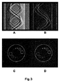
図3及び4は、散乱信号への“エッジ寄与”が実際に微分位相コントラスト信号から排除され得ることを例示するための2〜3の画像実験を示している。 Figures 3 and 4 show a few image experiments to illustrate that the "edge contribution" to the scatter signal can indeed be excluded from the differential phase contrast signal.
より具体的には、図3の上段はやはり、微分位相サイノグラムA(図2においてと同じ)と、その導関数の絶対値Bとを示している。図から見て取れるように、エッジサイノグラムは定性的に、暗視野サイノグラム(列C、図2の右上)と非常に似ているように見え、このエッジサイノグラムのフィルタ補正逆投影(FBP)は、再構成された散乱画像とほとんどそっくりに見える(図3の下段のC及びD参照)。 More specifically, the upper part of FIG. 3 also shows the differential phase sinogram A (the same as in FIG. 2) and the absolute value B of its derivative. As can be seen, the edge sinogram qualitatively looks very similar to the dark field sinogram (column C, top right of FIG. 2), and the filtered back projection (FBP) of this edge sinogram is the reconstruction It looks almost exactly like the scattered image obtained (see C and D in the lower part of FIG. 3).
より詳細な現実の例を、マウスのスキャンからの画像データを示した図4に示す。列A、B、Cの上段は、それぞれ、暗視野サイノグラム、微分位相サイノグラム、及び微分によって微分位相サイノグラム(B)から導出された“エッジ”である。それぞれの列A−Cの下段は、(FBPによって得られた)それぞれのトモグラフィック再構成結果を示している。再構成された位相画像との暗視野画像の視覚的比較が、やはり、多くの画像フィーチャ(造形部)が位相コントラスト画像内のエッジと一致することを裏付けている。実際、暗視野画像の数多くのフィーチャが、微分位相コントラストサイノグラムから、その微分係数の絶対値を取った後にFBP再構成を行うことによって導出されたエッジ画像によっても良好に再現され得る。しかしながら、エッジ画像内では視認できない一定のフィーチャ(図4の左下、列Aの下段中に矢印、破線の楕円、及び円によって指し示している)が暗視野画像内に存在しており、故に、これらは、マウスの局所的な散乱特性に起因し得る。 A more detailed real-world example is shown in FIG. 4 which shows image data from a mouse scan. The top row of columns A, B, and C are darkfield sinograms, differential phase sinograms, and "edges" derived from the differential phase sinogram (B) by differentiation, respectively. The lower row of each column AC shows the respective tomographic reconstruction results (obtained by FBP). A visual comparison of the dark field image with the reconstructed phase image again confirms that many image features (features) coincide with edges in the phase contrast image. In fact, many features of the dark-field image can be well reproduced by an edge image derived by taking the absolute value of its derivative from the differential phase contrast sinogram and then performing an FBP reconstruction. However, certain features that are not visible in the edge image (indicated by arrows, dashed ellipses, and circles in the lower left of FIG. 4, lower row of column A) are present in the dark-field image and are therefore May be due to the local scattering properties of the mouse.
再構成暗視野イメージで以前に報告されたアーチファクトは、少なくとも部分的にクロストークの量に関係することが見出されており、これは、トモグラフィック再構成を行うときに通常仮定する通常の線積分モデルには合わないものである。線積分モデルは、検出される投影データが、その線積分の経路である特定の経路に沿った関心量の累積に対応すると仮定する。線積分モデルの仮定は、減衰信号及び位相コントラスト信号に関して妥当なものであるが、暗視野信号中の位相信号誘起のクロストークに関しては状況が異なる。というのは、このクロストークは、検討される投影経路に沿って累積するとは言えないからである。しかしながら、提案する繰り返し再構成法を介して、暗視野信号に関する線積分仮定がもはや必要とされないように暗視野画像信号を好適に表現することができる系統的論述が見出された。 Previously reported artifacts in reconstructed dark-field images have been found to be related, at least in part, to the amount of crosstalk, which is the normal line normally assumed when performing tomographic reconstruction. It does not fit the integral model. The line integral model assumes that the detected projection data corresponds to the accumulation of the amount of interest along a particular path that is the path of the line integral. While the line integral model assumption is valid for attenuated and phase contrast signals, the situation is different for phase signal induced crosstalk in dark field signals. This is because this crosstalk cannot be said to accumulate along the considered projection path. However, through the proposed iterative reconstruction method, a systematic discussion has been found that can suitably represent the dark-field image signal such that the line integral assumption on the dark-field signal is no longer needed.
次に、図5を参照して、再構成部RECONの動作を更に詳細に説明する。 Next, the operation of the reconstruction unit RECON will be described in more detail with reference to FIG.
好適な一実施形態において、再構成部は繰り返し再構成アルゴリズムを実装する。繰り返し再構成は、順モデル関数に基づき、又は単に順モデルとして参照される。線形設定において、順モデルは、(基本的に、後に投影空間内でそれぞれのピクセル位置にマッピングされる線積分に沿ったボクセル値の和である)幾何学的順投影を実装する使いやすいシステム行列に帰着する。しかし、ここで提案する再構成アルゴリズムは、線形な順問題に限定されるものではなく、非線形な順問題にも有利に使用され得る。 In a preferred embodiment, the reconstruction unit implements an iterative reconstruction algorithm. Iterative reconstruction is based on a forward model function or simply referred to as a forward model. In the linear setting, the forward model is an easy-to-use system matrix that implements geometric forward projection (essentially the sum of voxel values along the line integral that is subsequently mapped to each pixel location in projection space). To come back to. However, the reconstruction algorithm proposed here is not limited to a linear forward problem, but can be advantageously used for a nonlinear forward problem.
先に簡潔に示唆したように、順モデルは、画像空間内の関心量の特定の分布を所与として投影空間内の要素を説明付ける。順モデルは、繰り返し再構成アルゴリズムの主たるコンポーネントである。概念的に、順モデルは、実測定された投影データ(すなわち、サイノグラム)と、順モデルによって推定された“模造”投影データとの間の逸脱を測定する所謂“残差”を形成することを可能にする。そして、残差に関して目的関数を設定することができる。このとき、再構成は、選択された順モデルの下でサイノグラムを最も良く説明する又はそれに最も良く“フィット”する“最適”画像を見出すために、この目的関数を最適化することに狙いを定める。一実施形態において、目的関数は、状況に応じて、コスト関数又は効用関数の何れかとして表現され得る。そして、最適化は、1)コスト関数を最小にするものを見出すこと、又は2)効用関数を最大にするものを見出すことの何れかである。以下では、単に例として、最小化されるコスト関数に関して、繰り返し再構成の基礎にある最適化を説明する。しかしながら、これは、ここに記載される方法を限定するものとして解されるべきでない。何故なら、数値的考察は、コスト関数から効用関数への最適化問題の定式化の変更を必要とすることがあり、故に、最小化問題が最大化の問題になることがあるからである。 As suggested briefly above, the forward model accounts for elements in projection space given a particular distribution of the amount of interest in image space. The forward model is a major component of the iterative reconstruction algorithm. Conceptually, the forward model forms a so-called “residual” that measures the deviation between the actually measured projection data (ie, the sinogram) and the “fake” projection data estimated by the forward model. enable. Then, an objective function can be set for the residual. The reconstruction then aims at optimizing this objective function to find the "best" image that best describes or best "fits" the sinogram under the selected forward model . In one embodiment, the objective function may be expressed as either a cost function or a utility function, depending on the situation. And the optimization is either 1) finding the one that minimizes the cost function, or 2) finding the one that maximizes the utility function. In the following, the optimization underlying the iterative reconstruction is described by way of example only, with respect to the cost function to be minimized. However, this should not be construed as limiting the method described herein. This is because numerical considerations may require a change in the formulation of the optimization problem from a cost function to a utility function, so that the minimization problem can be a maximization problem.
上記2つの画像信号、すなわち、位相画像及び暗視野画像に関する順モデルを設定する一手法は、以下: One technique for setting forward models for the two image signals, namely the phase image and the dark field image, is as follows:
![]()
![]()
数学的に、図2−4の例示イメージに従って上述したような観察される効果は、散乱画像と位相画像との間のクロストークである。そこで、好適なモデルコンポーネントを通じてクロストークを繰り返し再構成手順に含めることによって、このクロストークに対処することを、ここに提案する。 Mathematically, the observed effect as described above according to the example images of FIGS. 2-4 is the crosstalk between the scatter image and the phase image. Thus, it is proposed here to address this crosstalk by repeatedly including it in the reconstruction procedure through a suitable model component.
(1)から明らかなように、以下の実施形態では、検出器にて記録された強度が、先述の信号フーリエ解析部又はその他好適な分解部若しくは解析部の処理によって、位相コントラストサイノグラムmδ及び暗視野サイノグラムmεである2つのサイノグラムへと分離又は分解されていると仮定する。そして、これらチャネルの各々について、式(1)の左手側又は右手側のように順投影子Aが策定され得る。以前の手法と異なり、ここではここで、次式(又はこれと数学的に等価なもの): (1) As is clear from the following embodiments, the recorded intensity at the detector, the processing of the signal Fourier analyzer or other suitable decomposition unit or analysis unit of the foregoing, the phase contrast sinogram m [delta] and It assumed to be separated or decomposed into two sinograms a dark field sinogram m epsilon. Then, for each of these channels, a forward projector A can be formulated as the left hand side or the right hand side of Equation (1). Unlike the previous approach, here, here, the following equation (or its mathematical equivalent):
![]()
![]()
特に、測定された暗視野投影データmεに対する位相画像内のエッジの信号寄与を受け入れるために、位相コントラスト順投影子が暗視野順投影子と融合又は結合されて、暗視野画像信号mεに関する合成的な順モデル((2)の右側の式)を形成する。更に別の言い方をすれば、位相コントラスト信号と暗視野信号とを混合することが提案される。暗視野信号に関するこの順モデルは、位相画像の順モデルと暗視野画像の順モデルとの線形又は非線形な組み合わせによって形成されるという意味で合成順モデルを含む。式(2)の実施形態において、この合成物を形成することは、位相信号の順モデルの加算及びその半径方向偏微分係数を取ることを含んでいる。その他の組み合わせも好適であることがあり、ここで想定される。微分係数を取ることは、位相信号からのクロストークを捕捉するように構成されたモデルコンポーネントであるα|∂2 rAδ|を生じさせる。換言すれば、関連する平面内のボクセルが線積分として投影空間に順投影され、そして、この線積分が現半径方向r(図1のzとして示す)に沿って二階微分される。式(2)の実施形態において、この合成物を形成することは、半径方向で、すなわち、回折格子の溝が走っている方向に垂直な方向で、二次偏導関数を取ることを含んでいる。これは、図1中の方向zに対応する。当然ながら、rは投影方向とともに変化することになり、故に、サイノグラム上の各行でrは一般に異なるものとなる。このクロストークモデルコンポーネントの構造は、以下のように理解され得る。すなわち、一次偏導関数∂rは、位相変化すなわち波面の伝播方向の変化に関するモデル化アプローチに対応し、そして、二次偏導関数は、波面の湾曲の変化に対応する。換言すれば、暗視野信号への位相コントラスト(“エッジ”信号)の寄与が、“二重の微分”的にモデル化される。 In particular, in order to accept the measured dark projected edge signal contribution in the phase image to the data m epsilon, phase contrast forward projection element is fused or coupled with dark-field forward projection element relates to the dark-field image signal m epsilon Form a synthetic forward model (the equation on the right side of (2)). Stated another way, it is proposed to mix the phase contrast signal and the dark field signal. This forward model for the darkfield signal includes a synthetic forward model in the sense that it is formed by a linear or non-linear combination of the forward model of the phase image and the forward model of the darkfield image. In the embodiment of equation (2), forming this composite includes adding a forward model of the phase signal and taking its radial partial derivative. Other combinations may also be suitable and are contemplated here. Taking the derivative yields α | ∂ 2 r Aδ |, which is a model component configured to capture crosstalk from the phase signal. In other words, the voxels in the relevant plane are forward-projected into the projection space as line integrals, and the line integrals are second-order differentiated along the current radial direction r (shown as z in FIG. 1). In the embodiment of equation (2), forming this composite includes taking the second order derivative in the radial direction, ie, in a direction perpendicular to the direction in which the grooves of the grating run. I have. This corresponds to the direction z in FIG. Of course, r will change with the direction of projection, and therefore r will generally be different for each row on the sinogram. The structure of this crosstalk model component can be understood as follows. That is, the first partial derivative ∂ r corresponds to a modeling approach for phase changes, ie, changes in the propagation direction of the wavefront, and the second partial derivative corresponds to changes in the curvature of the wavefront. In other words, the contribution of the phase contrast ("edge" signal) to the dark field signal is modeled "double differential".
モデル(2)において、Aは、(1)で先に導入されたシステム行列又は幾何学的順投影演算子を表す。Aそれ自体は線形であるが、合成順モデル((2)の右側の式)それ自体は、非線形である絶対値演算子||のために非線形である。ここでも、Aは、平行(パラレル)ビームに合わせて構成されてもよいし、発散(ダイバージェント)ビーム(例えば、ファン又はコーン)に合わせて構成されてもよく、これについては更に後述する。 In model (2), A represents the system matrix or geometric forward projection operator introduced earlier in (1). A itself is linear, but the synthesis order model (the equation on the right side of (2)) itself is non-linear due to the non-linear absolute value operator ||. Again, A may be configured for a parallel beam or a divergent beam (e.g., a fan or cone), as further described below.
そして、提案する繰り返し再構成は、一実施形態において、特にコスト関数: And the proposed iterative reconstruction is, in one embodiment, especially a cost function:
![]()
![]()
ボクセル画像δ及びεの関数としての(3)の最適化は、例えば、標準的な非線形共役勾配アルゴリズム、又は例えば拡張ラグランジュ法若しくは反復座標降下などといったその他好適な最適化方法を用いて実行され得る。 The optimization of (3) as a function of the voxel images δ and ε may be performed using, for example, a standard non-linear conjugate gradient algorithm or any other suitable optimization method such as, for example, extended Lagrangian or iterative coordinate descent. .
このコスト関数は、位相及び暗視野の2つの信号チャネルに関する残差の項にて表現されており、暗視野信号に関する残差が、クロストーク成分を有する新たな合成順モデルを用いて形成されている。2つのチャネルからの残差が、単一の目的関数又はコスト関数Δへと二乗和結合されており、故に、各イテレーションステップで2つの画像ε、δが共に再構成される。 This cost function is expressed in terms of the residual with respect to the two signal channels of phase and dark field. The residual with respect to the dark field signal is formed using a new synthesis order model having a crosstalk component. I have. The residuals from the two channels have been sum-of-squares combined into a single objective or cost function Δ, so that at each iteration step both images ε, δ are reconstructed together.
そして、一実施形態において、コスト関数Δを最小化するための好適な数値手法(例えば、共役勾配アルゴリズムなど)の適用が、繰り返し再構成のための更新関数を規定する繰り返し表現をもたらす。暗視野画像に関する当初推定(これは、各ボクセルをゼロに設定する程度に単純とし得る)を用いて、繰り返しを通じて更新関数を用いて更新し続ける。そして、一実施形態において、必ずしも各繰り返しに関してではないが、反復的にコスト関数を評価して、コストΔが閾値を下回るまで低下したかをチェックする。低下している場合、繰り返しが中止し、そして、最後の画像が暗視野画像として出力される。他の実施形態において、固定された予め定められた回数閾値の繰り返しが存在し、この閾値に達すると繰り返し再構成が終了する。一部の状況において、位相コントラスト画像も関心のあるものであり、これら2つは共に再構成されているので、位相コントラスト画像も同様に出力され得る。 And, in one embodiment, application of a suitable numerical technique (eg, a conjugate gradient algorithm, etc.) to minimize the cost function Δ results in an iterative representation that defines an update function for iterative reconstruction. Using the initial estimate for the dark-field image (which can be as simple as setting each voxel to zero), continue to update with the update function throughout the iteration. Then, in one embodiment, the cost function is evaluated iteratively, but not necessarily for each iteration, to check if the cost Δ has fallen below a threshold. If so, the repetition is stopped and the last image is output as a dark field image. In another embodiment, there is a fixed predetermined number of repetitions of a threshold, at which point repetitive reconstruction ends. In some situations, the phase contrast image is also of interest, and since the two have been reconstructed together, the phase contrast image may be output as well.
この新たな繰り返し再構成アルゴリズムは、図5のフローチャートによって、以下のようにまとめられ得る。 This new iterative reconstruction algorithm can be summarized as follows according to the flowchart of FIG.
概して、ステップS505にて、干渉投影データが受け取られる。干渉投影データは、検出器にて、複数の異なる視角で受け取られ、信号処理の後に、位相コントラストmδ及び暗視野mεである2つの信号チャネルに関する2つのサイノグラムmδ及びmεとして記録される。 Generally, at step S505, interferometric projection data is received. Interferometric projection data is received at a detector at a plurality of different viewing angles and, after signal processing, is recorded as two sinograms m δ and m ε for two signal channels, a phase contrast m δ and a dark field m ε. You.
ステップS510にて、測定されたサイノグラムと、式(3)に従った目的関数又はそれと数学的に等価なものとに基づいて、繰り返し再構成アルゴリズムが実行される。 In step S510, an iterative reconstruction algorithm is executed based on the measured sinogram and the objective function according to equation (3) or its mathematical equivalent.
(例えばコスト関数を評価することなどの予め定められた中止基準によって設立されるような)十分な回数の繰り返しの後、ステップS515にて、検討したスキャン位置での再構成断面暗視野が出力される。加えて、位相コントラスト画像も、更なる参照のために出力又は格納されてもよい。 After a sufficient number of iterations (as established, for example, by a predetermined stopping criterion such as evaluating a cost function), in step S515, the reconstructed cross-section dark field at the considered scan location is output. You. In addition, a phase contrast image may be output or stored for further reference.
理解されるように、上で規定したステップは、1つのスキャン位置に関する断面画像を生み出すものであり、ボリューム全体を取得するためには、上述のステップが異なるスキャン位置に関して反復される必要がある。 As will be appreciated, the steps defined above produce a cross-sectional image for one scan location, and the above steps need to be repeated for different scan locations to obtain the entire volume.
式(3)により、重みwは、ここで想定されるような統計的な意味を必ずしも有していなくてもよく、単に、総コストΔに対するそれぞれのチャネルの相対的な優位性を定める重みとしてモデル化の視点から選定されてもよい。 According to equation (3), the weight w may not necessarily have a statistical significance as assumed here, but simply as a weight that determines the relative superiority of each channel to the total cost Δ. It may be selected from the viewpoint of modeling.
しかし、時にして統計的繰り返し再構成として参照される統計的アプローチが使用されるとき、重みは、測定の不確定性、すなわち、それぞれの検出器画素pxでの分散及び/又は標準偏差を表すように選定され得る。統計的な重みwの形態は、測定に関する選択された統計モデルの関数である。特に、ポアソン分布を仮定し得る。そして、目的関数は、この統計的設定において、(負の)最大尤度関数として理解され得る。これは、例えば、T.Koehler等の“Iterative reconstruction for differential phase contrast imaging”,pp.4542−4545,Med.Phys.38(8),2011年8月(例えば、p.4543の左欄の式(3)を参照)に記載されるような、最大尤度(ML)アプローチである。なお、この文献の全体をここに援用する。 However, when a statistical approach, sometimes referred to as statistical iterative reconstruction, is used, the weights represent the measurement uncertainty, ie, the variance and / or standard deviation at each detector pixel px. Can be selected as follows. The form of the statistical weight w is a function of the selected statistical model for the measurement. In particular, a Poisson distribution may be assumed. And the objective function can be understood as a (negative) maximum likelihood function in this statistical setting. This is for example the case in T.S. Koehler et al., "Iterative reconstruction for differential phase contrast imaging", pp. 147-64. 4542-4545, Med. Phys. 38 (8), August 2011 (see, for example, Equation (3) on the left column on p. 4543) is a maximum likelihood (ML) approach. The entirety of this document is incorporated herein.
好適な一実施形態において、統計的であろうとなかろうと、基底関数に関するボクセル値の展開が使用される。この基底関数アプローチでは、各ボクセルが、複数の基底関数の線形結合(時々、2Dカイザー−ベッセル関数のファミリに関係する“ブロブ”としても参照される)として考えられる。このアプローチの詳細については、T.Koehler等の“Iterative reconstruction for differential phase contrast imaging”,pp.4542−4545,Med.Phys.38(8),2011年8月に見出すことができる。換言すれば、特定のボクセルにおける各値を、基底関数及び対応するスカラーから形成される重みの線形結合として考えることができる。その場合、繰り返し再構成は、それぞれの線形結合の最適なスカラー成分を見出すことの行使となる。これは、式(2)、(3)による導関数∂rの有限差分近似を使用する必要がないという利点を有する。基底関数アプローチでは、基底関数が解析的に微分可能に選択されるとき基底関数の導関数の投影を正確に計算することができるので、有限差分による近似を回避することができる。換言すれば、導関数を取ることは、有限差分による近似を用いるというよりも、予め定められた解析的表現を形成することを意味する。 In a preferred embodiment, whether statistical or not, an expansion of voxel values with respect to the basis function is used. In this basis function approach, each voxel is considered as a linear combination of a plurality of basis functions (sometimes also referred to as "blobs" related to a family of 2D Kaiser-Bessel functions). For more information on this approach, see T.W. Koehler et al., "Iterative reconstruction for differential phase contrast imaging", pp. 147-64. 4542-4545, Med. Phys. 38 (8), found in August 2011. In other words, each value at a particular voxel can be considered as a linear combination of the weights formed from the basis functions and the corresponding scalars. In that case, iterative reconstruction is an exercise in finding the optimal scalar component of each linear combination. This has the advantage that it is not necessary to use a finite difference approximation of the derivative r r according to equations (2) and (3). The basis function approach avoids the finite difference approximation because the projection of the derivative of the basis function can be accurately calculated when the basis function is analytically selected to be differentiable. In other words, taking a derivative means forming a predetermined analytical expression, rather than using an approximation by finite differences.
ここで、異なる一実施形態に話を変えるに、共通順モデルが、次式(又はこれと数学的に等価なもの): Here, turning to a different embodiment, the common order model is given by the following equation (or its mathematical equivalent):

Ii:位相ステップiでラインliに沿って物体中で測定された強度のモデル
I0i:ラインliに沿って物体なしで測定された強度
V0i:ラインliに沿った可視性
ψ0i:ラインliに沿った当初位相
μ(x):物体の吸収
ε(x):物体の小角散乱
δ(x):物体の屈折率
z:回折格子に対して垂直な方向
x:ラインliに沿った位置。
I i: phase step i in line l model intensities measured in the object along the i I 0i: line l i strength was measured without an object along a V 0i: line l i visibility ψ along the 0i: initially along line l i phase mu (x): absorption of the object epsilon (x): the object of small-angle scattering [delta] (x): the refractive index of the object z: direction perpendicular to the grating x: line l Position along i .
この順モデルでは、記録された強度の、暗視野サイノグラムmε及び位相コントラストサイノグラムmδへの分離は必要ない。換言すれば、この実施形態によれば、位相ステッピングにて検出器で記録されたそれぞれの時系列で各エントリーが構成される共通サイノグラムmによって、入力が形成される。 This forward model, the recorded intensity, is not required separation into the darkfield sinogram m epsilon and phase contrast sinogram m [delta]. In other words, according to this embodiment, the input is formed by a common sinogram m, in which each entry is formed in a respective time series recorded by the detector in phase stepping.
式(4)による信号モデルは、式(2)に従って(2)中の左式及び右式に対応する2つのチャネル(位相及び暗視野)に特化した順モデルが存在する先の実施形態と比較して、共通サイノグラムに関する共通順モデルを形成する。共通順モデルはなおも、2つの信号に関するモデルコンポーネント、すなわち、位相信号に関するモデルコンポーネント: The signal model according to equation (4) is based on the previous embodiment in which there is a forward model specialized for two channels (phase and dark field) corresponding to the left equation and right equation in (2) according to equation (2). The comparison forms a common order model for the common sinogram. The common order model is still the model component for the two signals, that is, the model component for the phase signal:
![]()
![]()
![]()
![]()
![]()
![]()
暗視野信号に関するモデルコンポーネントが、式(4)に従って、式(5)のクロストークコンポーネントと結合される。先の実施形態(2)によるシステム行列アプローチに話を戻すに、共通モデルの信号モデル(4)との構造的な類似性を引き出すことが有益であり得る。Aの行(又は表現に応じて列)は、(中間的な)位相信号モデルコンポーネント: The model component for the dark field signal is combined with the crosstalk component of equation (5) according to equation (4). Returning to the system matrix approach according to the previous embodiment (2), it may be beneficial to derive the structural similarity of the common model with the signal model (4). The rows (or columns, depending on the representation) of A are the (intermediate) phase signal model components:
![]()
![]()
そして、この非線形順モデルに関するコスト関数は、次式(又はこれと数学的に等価なもの): Then, the cost function for this nonlinear forward model is: (or its mathematical equivalent):
換言すれば、この実施形態では、ステップS505にて、2つの特化されたサイノグラムの代わりに、それぞれの投影方向に関するそれぞれの強度系列を有する共通サイノグラムが受け取られる。 In other words, in this embodiment, at step S505, instead of two specialized sinograms, a common sinogram having respective intensity sequences for respective projection directions is received.
残りのステップS510及びS515は、先に説明した実施形態と同様であり、コスト関数は、やはり残差に関して策定されるが、今回は、共通順モデル並びに信号解析部SAによる前処理なしの記録されたままの強度miに対して策定される。式(2)による専用順モデルを持つ先の実施形態の式(3)においてのように、式(6)は、最適化問題、特に、最小にするもの(μ,ε,δ)を発見することに関する最適化問題を規定する。そして、この最適化問題の解が、特に、暗視野画像εを生み出す。 The remaining steps S510 and S515 are the same as in the previously described embodiment, and the cost function is also formulated for the residual, but this time, the common order model and the recorded data without preprocessing by the signal analysis unit SA are used. It is developed for the remains of strength m i was. As in equation (3) of the previous embodiment with a dedicated forward model according to equation (2), equation (6) finds the optimization problem, especially the one that minimizes (μ, ε, δ). Stipulates an optimization problem. The solution of this optimization problem, in particular, produces a dark-field image ε.
コスト関数(6)に関する好適な反復的数値最適化(例えば、共役勾配法又は上述したその他)を用いることで、更新関数に到達し得る。この更新関数は、特に暗視野画像ε問題に関する(しかしまた、その他の2つの画像μ、δも概して暗視野画像εと一緒に解かれるので、μ及びδにも関する)繰り返し再構成アルゴリズムを規定する。 Using a suitable iterative numerical optimization for the cost function (6) (eg, conjugate gradient method or others as described above), an update function can be reached. This update function defines an iterative reconstruction algorithm specifically for the dark-field image ε problem (but also for μ and δ since the other two images μ, δ are also generally solved together with the dark-field image ε). I do.
先の実施形態(3)においてと同様に、例えばMLなどの統計的アプローチを選択してもよい。特に、測定データに関して例えばポアソン又はガウシアンといった基本的な統計分布を仮定した統計的な重みとして、wiを選定することができる。 As in the previous embodiment (3), a statistical approach such as ML may be selected. In particular, w i can be selected as a statistical weight assuming a basic statistical distribution such as Poisson or Gaussian for the measurement data.
式(6)でのコスト関数は、特定のスキャン位置及びピクセル位置に関して策定されており、インデックスiは、複数の異なる位相ステップiにわたる該ピクセルに関する複数の異なる強度測定に広がる。対応する最適化問題は、関心ボリューム全体をカバーするように関心ある全てのスキャン位置に関して解かれる必要がある。 The cost function in equation (6) has been developed for a particular scan location and pixel location, and the index i spans multiple different intensity measurements for that pixel over multiple different phase steps i. The corresponding optimization problem needs to be solved for all scan positions of interest to cover the entire volume of interest.
順モデルに関する2つの実施形態(2)、(4)の何れかにて、正則化又はペナルティ付けの項Rは、例えば解の滑らかさなどの特定の所望の性質を強いるために使用され得る。例えば、一実施形態において、チホノフ(Tikhonov)の正則化を行うものが使用されるが、ここではその他の正則化を行うRも想定される。実施形態において、正則化項の応答を調節するための係数βが存在する。 In either of the two embodiments (2), (4) for the forward model, the regularization or penalty term R may be used to impose certain desired properties, such as, for example, the smoothness of the solution. For example, in one embodiment, one that performs Tikhonov regularization is used, but R that performs other regularization is also envisaged here. In an embodiment, there is a coefficient β for adjusting the response of the regularization term.
この第2の実施形態においてもやはり、第1の実施形態に関して先述したように、提案する方法の正確性を向上させるために、有限差分によって導関数を近似しなければならないのではなく導関数を解析的に表現するよう、基底関数が使用され得る。 Again in this second embodiment, as described above with respect to the first embodiment, to improve the accuracy of the proposed method, rather than having to approximate the derivative by finite differences, Basis functions can be used to represent analytically.
理解されるように、双方の実施形態において、順投影演算子は非線形である。しかしながら、順投影が線形であるような他の実施形態も想定され得る。 As will be appreciated, in both embodiments, the forward projection operator is non-linear. However, other embodiments can be envisioned in which the forward projection is linear.
ここで、ビームジオメトリに話を戻すに、上述の実施形態の一部において、ビームジオメトリが平行であることが仮定されている。例えばコーンビーム又はファンビームなどの発散ジオメトリでは、例えば本出願人の国際公開第2013/171657号に記載されているように、補正が適用される。この補正は順モデルに適用される。位相信号及び暗視野信号にそれぞれ特化した順モデルを用いる実施形態(2)では、好適な一実施形態において、暗視野信号に特化した順モデル(すなわち、(2)中の右式)のみに発散ビームジオメトリ補正を適用することが想定され、当然ながら、この追加のモデル化には、系の拡大に対する暗視野信号の特別な依存性が関与する。例えば、上で引用した国際公開第2013/171657号中の式(7)による補正項d=a/Mを参照されたい。当然ながら、平行ビームから発散ビームに移すときのジオメトリにおけるこの単なる幾何学的変化はなおも、対応する線積分の数値実行をシステム行列Aの行が依然として提供するように、双方の信号に関する順モデル策定において考慮に入れられる必要がある。他の実施形態において、この補正は、特化したモデルの双方に適用されてもよい。 Turning now to beam geometry, in some of the embodiments described above, it is assumed that the beam geometries are parallel. For divergent geometries, such as cone or fan beams, for example, corrections are applied as described in the applicant's WO 2013/171657. This correction is applied to the forward model. In the embodiment (2) using a forward model specialized for each of the phase signal and the dark field signal, in a preferred embodiment, only the forward model specialized for the dark field signal (that is, the right formula in (2)) is used. It is envisaged to apply a divergent beam geometry correction to, and of course, this additional modeling involves the special dependence of the dark field signal on the magnification of the system. See, for example, the correction term d = a / M according to equation (7) in WO 2013/171657 cited above. Of course, this mere geometric change in geometry when moving from a parallel beam to a diverging beam is still a forward model for both signals so that the rows of the system matrix A still provide a corresponding numerical implementation of the line integral. Need to be taken into account in the development. In other embodiments, this correction may be applied to both specialized models.
共通順モデルに関しては、発散ビームジオメトリに合わせて、以下の変更: For the common order model, the following changes have been made to match the diverging beam geometry:
(6)によるモデル化アプローチにおいて、(平行ビームジオメトリを仮定する)実施形態(5)に対する唯一の違いは、暗視野信号に関するモデル化コンポーネントに更なる重み係数x/Lが含められることである。これは散乱のためであり、L(図1にdとして示される)は、ソースから位相回折格子までの距離である。なお、この重み付けは、通常の線積分の対称性を“破り”、故に、積分は、線積分の値が積分方向とは無関係である伝統的な線積分とは対照的に、ソースから検出器まで(又はその逆に、検出器からソースまででもよく、その場合、重み付けは(L−x)/Lとして取られる)ラインliに沿って行われる必要がある。 In the modeling approach according to (6), the only difference to embodiment (5) (assuming a parallel beam geometry) is that a further weighting factor x / L is included in the modeling component for the dark field signal. This is due to scattering, and L (shown as d in FIG. 1) is the distance from the source to the phase grating. It should be noted that this weighting "breaks" the symmetry of the ordinary line integral, and therefore, the integral is a source-to-detector as opposed to a traditional line integral where the value of the line integral is independent of the direction of integration. (Or vice versa, from the detector to the source, in which case the weighting needs to be done along line l i , taken as (L−x) / L).
再構成部RECONは、撮像システム用のオペレータコンソール(図示せず)として、又は画像レビュー用のワークステーションとして機能する汎用コンピュータ上で実行され得る。他の一実施形態において、再構成部は、専用モジュールとして、特に、例えばFPGAチップといった専用プログラマブルチップとして構成され、あるいは配線接続されたチップとして実装され得る。 The reconstruction unit RECON may be executed as an operator console (not shown) for the imaging system or on a general-purpose computer functioning as a workstation for image review. In another embodiment, the reconfiguration unit can be configured as a dedicated module, in particular as a dedicated programmable chip, for example an FPGA chip, or implemented as a hardwired chip.
本発明の他の例示的な一実施形態において、以上の実施形態のうちの1つに従った方法の方法ステップ群を適当なシステム上で実行するように適応されていることによって特徴付けられた、コンピュータプログラム又はコンピュータプログラム要素が提供される。 In another exemplary embodiment of the invention, the method is characterized in that the method steps of the method according to one of the above embodiments are adapted to be performed on a suitable system. , A computer program or a computer program element is provided.
コンピュータプログラム要素は、故に、これまた本発明の一実施形態の一部とし得るコンピュータユニットに格納され得る。このコンピューティングユニットは、上述の方法のステップ群を実行するように、又はその実行を起こすように適応され得る。また、それは、上述の装置のコンポーネント群を動作させるように適応されてもよい。コンピューティングユニットは、自動的に動作するように適応され、且つ/或いはユーザの指令を実行するように適応され得る。コンピュータプログラムは、データプロセッサの作業メモリにロードされ得る。故に、データプロセッサは、本発明の方法を実行するように装備され得る。 Computer program elements may therefore be stored in a computer unit, which may also be part of one embodiment of the present invention. The computing unit may be adapted to perform or cause the steps of the method described above. It may also be adapted to operate the components of the device described above. The computing unit may be adapted to operate automatically and / or to execute user commands. The computer program can be loaded into the working memory of the data processor. Thus, a data processor can be equipped to perform the method of the invention.
本発明のこの例示的な実施形態は、最初から本発明を使用するコンピュータプログラムと、アップデートによって、既存のプログラムを、本発明を使用するプログラムへと変化させるコンピュータプログラムとの双方に及ぶ。 This exemplary embodiment of the invention extends to both computer programs that use the invention from the beginning and computer programs that, by updating, convert existing programs to programs that use the invention.
さらに、コンピュータプログラム要素は、上述の方法の例示的実施形態の手順を果たすのに必要な全てのステップを提供することができてもよい。 Further, the computer program element may be able to provide all the steps necessary to perform the steps of the exemplary embodiment of the method described above.
本発明の例示的な更なる一実施形態によれば、例えばCD−ROMなどのコンピュータ読み取り可能媒体が提供され、該コンピュータ読み取り可能媒体は、先行するセクションで述べたコンピュータプログラム要素を格納して有する。 According to a further exemplary embodiment of the present invention, there is provided a computer readable medium, such as a CD-ROM, having the computer program elements described in the preceding section stored therein. .
コンピュータプログラムは、他のハードウェアとともに供給されるか、他のハードウェアの一部として供給されるかする例えば光記憶媒体又は半導体媒体などの好適な媒体にて格納及び/又は配布され得るが、例えばインターネット又はその他の有線若しくは無線の遠隔通信システムを介してなど、その他の形態で配布されてもよい。 The computer program may be stored and / or distributed on a suitable medium, such as an optical storage medium or a semiconductor medium, supplied with or as part of the other hardware, It may be distributed in other forms, such as via the Internet or other wired or wireless telecommunications systems.
しかしながら、コンピュータプログラムはまた、ワールドワイドウェブのようなネットワーク上で提示されてもよく、また、そのようなネットワークからデータプロセッサの作業メモリにダウンロードされることができる。本発明の例示的な更なる一実施形態によれば、本発明の上述の実施形態のうちの1つに従った方法を実行するように構成されたコンピュータプログラム要素をダウンロードに利用可能にする媒体が提供される。 However, the computer program may also be presented on a network such as the World Wide Web and may be downloaded from such a network to the working memory of the data processor. According to a further exemplary embodiment of the present invention, a medium for making available for download a computer program element adapted to perform a method according to one of the above-mentioned embodiments of the present invention. Is provided.
なお、様々な主題を参照して本発明の実施形態を説明した。特に、一部の実施形態は方法タイプのクレームを参照して説明し、他の実施形態は装置タイプのクレームを参照して説明した。しかしながら、当業者は、上述及び以下の記載から、別のことが告知されていない限り、1つのタイプの主題に属する特徴の組合せだけでなく、相異なる主題に関する特徴間の組み合わせも、本願で開示されていると見なされることを認識するであろう。しかしながら、何れの特徴も、組み合わされて、それらの特徴の単純な和を超える相乗効果をもたらし得る。 The embodiments of the present invention have been described with reference to various subjects. In particular, some embodiments have been described with reference to method type claims and other embodiments have been described with reference to device type claims. However, one of ordinary skill in the art will appreciate from the foregoing and following description that unless otherwise stated, combinations of features belonging to one type of subject matter, as well as combinations between features relating to different subjects, are disclosed herein. You will recognize that it is considered to be. However, any of the features can be combined to provide a synergistic effect that goes beyond a simple sum of those features.
図面及び以上の記載にて本発明を詳細に図示して説明してきたが、これらの図示及び説明は、限定的なものではなく、例示的あるいは典型的なものとみなされるべきである。本発明は、開示の実施形態に限定されるものではない。開示の実施形態へのその他の変形が、図面、本開示及び添付の請求項の検討から、請求項に係る発明を実施する当業者によって理解されて実現され得る。 While the invention has been illustrated and described in detail in the drawings and foregoing description, these illustrations and description should not be construed as limiting, but merely as being illustrative or typical. The invention is not limited to the disclosed embodiments. Other variations to the disclosed embodiments can be understood and effected by those skilled in the art in practicing the claimed invention, from a study of the drawings, the disclosure, and the appended claims.
請求項において、用語“有する”はその他の要素又はステップを排除するものではなく、不定冠詞“a”又は“an”は複数であることを排除するものではない。単一のプロセッサ又はその他のユニットが、請求項に記載される複数のアイテムの機能を果たしてもよい。特定の複数の手段が相互に異なる従属項に記載されているという単なる事実は、それらの手段の組合せが有利に使用され得ないということを指し示すものではない。請求項中の如何なる参照符号も、範囲を限定するものとして解されるべきでない。 In the claims, the term "comprising" does not exclude other elements or steps, and the indefinite article "a" or "an" does not exclude a plurality. A single processor or other unit may fulfill the functions of several items recited in the claims. The mere fact that certain measures are recited in mutually different dependent claims does not indicate that a combination of these measures cannot be used to advantage. Any reference signs in the claims shall not be construed as limiting the scope.
Claims (13)
撮像される試料中へのX線ビームの投影後に検出器に入射する前記X線ビームに応答して前記検出器によって検出された干渉測定データ、を前記検出器から受信するように構成された信号入力ポートであり、前記干渉測定データは、位相コントラスト信号及び暗視野信号を含む、入力ポートと、
画像再構成アルゴリズムを実行して少なくとも前記暗視野信号を暗視野画像へと再構成するように構成されたプロセッサであり、少なくとも前記暗視野信号を前記暗視野画像へと前記再構成することは、前記暗視野信号への前記位相コントラスト信号のクロストークを捕捉するように構成されたクロストークモデルコンポーネントを組み入れた順モデルに基づく、プロセッサと、
少なくとも前記再構成された暗視野画像を表示装置に出力するように構成された画像出力ポートと、
を有する装置。 An image signal processing apparatus configured to improve the fidelity or accuracy of a dark-field image in differential X-ray phase contrast imaging,
A signal configured to receive, from the detector, interferometric data detected by the detector in response to the X-ray beam incident on the detector after projection of the X-ray beam into a sample to be imaged. An input port, wherein the interference measurement data includes a phase contrast signal and a dark field signal,
A processor configured to execute an image reconstruction algorithm to reconstruct at least the dark field signal into a dark field image, wherein the reconstructing at least the dark field signal into the dark field image comprises: A processor based on a forward model incorporating a crosstalk model component configured to capture crosstalk of the phase contrast signal to the dark field signal;
An image output port configured to output at least the reconstructed dark field image to a display device;
An apparatus having
撮像される試料中へのX線ビームの投影後に検出器に入射する前記X線ビームに応答して前記検出器によって検出された干渉測定データ、を前記検出器から受信するように構成された信号入力ポートであり、前記干渉測定データは、位相コントラスト信号及び暗視野信号を含む、入力ポートと、
画像再構成アルゴリズムを実行して少なくとも前記暗視野信号を暗視野画像へと再構成するように構成されたプロセッサであり、少なくとも前記暗視野信号を前記暗視野画像へと前記再構成することは、前記暗視野信号への前記位相コントラスト信号のクロストークを捕捉するように構成されたモデルコンポーネントを組み入れた順モデルに基づく、プロセッサと、
少なくとも前記再構成された暗視野画像を表示装置に出力するように構成された画像出力ポートと、
を有する装置を有する、
干渉X線撮像システム。 An interferometric x-ray imaging system configured to improve the fidelity or accuracy of a dark field image in differential x-ray phase contrast imaging,
A signal configured to receive, from the detector, interferometric data detected by the detector in response to the X-ray beam incident on the detector after projection of the X-ray beam into a sample to be imaged. An input port, wherein the interference measurement data includes a phase contrast signal and a dark field signal,
A processor configured to execute an image reconstruction algorithm to reconstruct at least the dark field signal into a dark field image, wherein the reconstructing at least the dark field signal into the dark field image comprises: A processor based on a forward model incorporating model components configured to capture crosstalk of the phase contrast signal to the dark field signal; and
An image output port configured to output at least the reconstructed dark field image to a display device;
Having an apparatus having
Interferometric X-ray imaging system.
撮像される試料中へのX線ビームの投影後に検出器に入射する前記X線ビームに応答して前記検出器で検出された干渉測定データ、を受信するステップであり、前記干渉測定データは、位相コントラスト信号及び暗視野信号を含む、ステップと、
再構成アルゴリズムを用いて、少なくとも前記暗視野信号を暗視野画像へと再構成するステップであり、少なくとも前記暗視野信号を前記暗視野画像へと前記再構成することは、前記暗視野信号への前記位相コントラスト信号のクロストークを捕捉するように構成されたモデルコンポーネントを組み入れた順投影モデルに基づく、ステップと、
少なくとも前記再構成された暗視野画像を出力するステップと、
を有する方法。 An image signal processing method for improving the fidelity or accuracy of a dark field image in differential X-ray phase contrast imaging,
Receiving interference measurement data detected by the detector in response to the X-ray beam incident on a detector after projection of the X-ray beam into a sample to be imaged, wherein the interference measurement data comprises: Including a phase contrast signal and a dark field signal;
Reconstructing at least the dark-field signal into a dark-field image using a reconstruction algorithm, wherein the reconstructing at least the dark-field signal into the dark-field image comprises: Based on a forward projection model incorporating a model component configured to capture crosstalk of the phase contrast signal;
Outputting at least the reconstructed dark-field image;
Having a method.
Applications Claiming Priority (3)
| Application Number | Priority Date | Filing Date | Title |
|---|---|---|---|
| EP14180751.1 | 2014-08-13 | ||
| EP14180751 | 2014-08-13 | ||
| PCT/EP2015/067864 WO2016023782A1 (en) | 2014-08-13 | 2015-08-04 | Quantitative dark–field imaging in tomography |
Publications (3)
| Publication Number | Publication Date |
|---|---|
| JP2017524139A JP2017524139A (en) | 2017-08-24 |
| JP2017524139A5 JP2017524139A5 (en) | 2019-06-20 |
| JP6637485B2 true JP6637485B2 (en) | 2020-01-29 |
Family
ID=51357741
Family Applications (1)
| Application Number | Title | Priority Date | Filing Date |
|---|---|---|---|
| JP2017507434A Active JP6637485B2 (en) | 2014-08-13 | 2015-08-04 | Darkfield imaging in tomography |
Country Status (5)
| Country | Link |
|---|---|
| US (1) | US10339674B2 (en) |
| EP (1) | EP3180603B8 (en) |
| JP (1) | JP6637485B2 (en) |
| CN (1) | CN106659449B (en) |
| WO (1) | WO2016023782A1 (en) |
Families Citing this family (11)
| Publication number | Priority date | Publication date | Assignee | Title |
|---|---|---|---|---|
| CN104318536B (en) * | 2014-10-21 | 2018-03-20 | 沈阳东软医疗系统有限公司 | The bearing calibration of CT images and device |
| EP3510563B1 (en) | 2016-09-08 | 2021-11-10 | Koninklijke Philips N.V. | Improved phase-contrast and dark-field ct reconstruction algorithm |
| US20190250030A1 (en) * | 2016-09-26 | 2019-08-15 | Lavision Biotec Gmbh | Measuring device and methods for characterization of a radiation field |
| JP6753342B2 (en) * | 2017-03-15 | 2020-09-09 | 株式会社島津製作所 | Radiation grid detector and X-ray inspection equipment |
| CN107238616B (en) * | 2017-06-22 | 2019-10-11 | 合肥工业大学 | Dark-field imaging method based on neutron grating interferometer |
| EP3435325A1 (en) | 2017-07-26 | 2019-01-30 | Koninklijke Philips N.V. | Scatter correction for dark field imaging |
| JP6943090B2 (en) * | 2017-09-05 | 2021-09-29 | 株式会社島津製作所 | X-ray imaging device |
| CN108896588B (en) * | 2018-06-08 | 2020-11-20 | 中北大学 | Method for measuring microstructure of porous medium |
| JP6992902B2 (en) * | 2018-08-24 | 2022-01-13 | 株式会社島津製作所 | X-ray phase imaging device |
| WO2020090168A1 (en) * | 2018-10-31 | 2020-05-07 | 株式会社島津製作所 | X-ray phase difference imaging system |
| US10679385B1 (en) * | 2018-12-17 | 2020-06-09 | General Electric Company | System and method for statistical iterative reconstruction and material decomposition |
Family Cites Families (12)
| Publication number | Priority date | Publication date | Assignee | Title |
|---|---|---|---|---|
| US6990420B2 (en) * | 2004-05-10 | 2006-01-24 | Lsi Logic Corporation | Method of estimating a local average crosstalk voltage for a variable voltage output resistance model |
| US8121249B2 (en) | 2009-06-04 | 2012-02-21 | Virginia Tech Intellectual Properties, Inc. | Multi-parameter X-ray computed tomography |
| CN101943668B (en) | 2009-07-07 | 2013-03-27 | 清华大学 | X-ray dark-field imaging system and method |
| JP5915645B2 (en) * | 2011-03-23 | 2016-05-11 | コニカミノルタ株式会社 | Medical image display system |
| CN102360498B (en) * | 2011-10-27 | 2013-09-18 | 江苏省邮电规划设计院有限责任公司 | Reconstruction method for image super-resolution |
| EP2850595B1 (en) | 2012-05-14 | 2016-04-06 | Koninklijke Philips N.V. | Dark field computed tomography imaging |
| WO2013187150A1 (en) * | 2012-06-11 | 2013-12-19 | コニカミノルタ株式会社 | Medical image system and medical image processing device |
| CN104428659B (en) | 2012-06-27 | 2017-10-27 | 皇家飞利浦有限公司 | Dark-field imaging |
| JP6079204B2 (en) * | 2012-12-18 | 2017-02-15 | コニカミノルタ株式会社 | Medical imaging system |
| US8989347B2 (en) * | 2012-12-19 | 2015-03-24 | General Electric Company | Image reconstruction method for differential phase contrast X-ray imaging |
| US10096098B2 (en) * | 2013-12-30 | 2018-10-09 | Carestream Health, Inc. | Phase retrieval from differential phase contrast imaging |
| JP2014140632A (en) | 2012-12-27 | 2014-08-07 | Canon Inc | Computation apparatus, image acquisition method, program, and x-ray imaging system |
-
2015
- 2015-08-04 JP JP2017507434A patent/JP6637485B2/en active Active
- 2015-08-04 WO PCT/EP2015/067864 patent/WO2016023782A1/en active Application Filing
- 2015-08-04 EP EP15744252.6A patent/EP3180603B8/en active Active
- 2015-08-04 US US15/328,645 patent/US10339674B2/en active Active
- 2015-08-04 CN CN201580043288.3A patent/CN106659449B/en active Active
Also Published As
| Publication number | Publication date |
|---|---|
| EP3180603B1 (en) | 2020-02-12 |
| CN106659449A (en) | 2017-05-10 |
| JP2017524139A (en) | 2017-08-24 |
| EP3180603B8 (en) | 2020-04-01 |
| US20170213365A1 (en) | 2017-07-27 |
| WO2016023782A1 (en) | 2016-02-18 |
| US10339674B2 (en) | 2019-07-02 |
| EP3180603A1 (en) | 2017-06-21 |
| CN106659449B (en) | 2020-11-24 |
Similar Documents
| Publication | Publication Date | Title |
|---|---|---|
| JP6637485B2 (en) | Darkfield imaging in tomography | |
| JP6150940B2 (en) | Monochromatic attenuated contrast image generation using phase contrast CT | |
| EP3050028B1 (en) | Joint reconstruction of electron density images. | |
| EP2850595B1 (en) | Dark field computed tomography imaging | |
| JP6214819B1 (en) | Optimal energy weighting of dark field signals in differential phase contrast X-ray imaging | |
| EP3170148B1 (en) | Iterative reconstruction method for spectral, phase-contrast imaging | |
| Croton et al. | In situ phase contrast X-ray brain CT | |
| Brendel et al. | Penalized maximum likelihood reconstruction for x‐ray differential phase‐contrast tomography | |
| JP2018524077A (en) | Robust reconstruction for dark field and phase contrast CT | |
| CA2821145A1 (en) | A method and a system for image integration using constrained optimization for phase contrast imaging with an arrangement of gratings | |
| EP3510563B1 (en) | Improved phase-contrast and dark-field ct reconstruction algorithm | |
| Mechlem et al. | Spectral differential phase contrast x-ray radiography | |
| JP6148415B1 (en) | Computed tomography (CT) hybrid data collection | |
| De Marco et al. | X-ray dark-field signal reduction due to hardening of the visibility spectrum | |
| JP6546201B2 (en) | Imaging system for generating an image of an object | |
| Deng et al. | A method for material decomposition and quantification with grating based phase CT | |
| EP4152266A1 (en) | Dark-field and phase-contrast tomography reconstruction algorithm | |
| Vijayalakshmi et al. | Comparison of algebraic reconstruction methods in computed tomography |
Legal Events
| Date | Code | Title | Description |
|---|---|---|---|
| A621 | Written request for application examination |
Free format text: JAPANESE INTERMEDIATE CODE: A621 Effective date: 20180802 |
|
| A521 | Request for written amendment filed |
Free format text: JAPANESE INTERMEDIATE CODE: A523 Effective date: 20190515 |
|
| A871 | Explanation of circumstances concerning accelerated examination |
Free format text: JAPANESE INTERMEDIATE CODE: A871 Effective date: 20190515 |
|
| A975 | Report on accelerated examination |
Free format text: JAPANESE INTERMEDIATE CODE: A971005 Effective date: 20190705 |
|
| A131 | Notification of reasons for refusal |
Free format text: JAPANESE INTERMEDIATE CODE: A131 Effective date: 20190709 |
|
| A977 | Report on retrieval |
Free format text: JAPANESE INTERMEDIATE CODE: A971007 Effective date: 20190710 |
|
| A521 | Request for written amendment filed |
Free format text: JAPANESE INTERMEDIATE CODE: A523 Effective date: 20190927 |
|
| TRDD | Decision of grant or rejection written | ||
| A01 | Written decision to grant a patent or to grant a registration (utility model) |
Free format text: JAPANESE INTERMEDIATE CODE: A01 Effective date: 20191210 |
|
| A61 | First payment of annual fees (during grant procedure) |
Free format text: JAPANESE INTERMEDIATE CODE: A61 Effective date: 20191220 |
|
| R150 | Certificate of patent or registration of utility model |
Ref document number: 6637485 Country of ref document: JP Free format text: JAPANESE INTERMEDIATE CODE: R150 |
|
| R250 | Receipt of annual fees |
Free format text: JAPANESE INTERMEDIATE CODE: R250 |