JP6901481B2 - Magnetic resonance (MR) systems with increased radio channel throughput and how they operate - Google Patents
Magnetic resonance (MR) systems with increased radio channel throughput and how they operate Download PDFInfo
- Publication number
- JP6901481B2 JP6901481B2 JP2018528060A JP2018528060A JP6901481B2 JP 6901481 B2 JP6901481 B2 JP 6901481B2 JP 2018528060 A JP2018528060 A JP 2018528060A JP 2018528060 A JP2018528060 A JP 2018528060A JP 6901481 B2 JP6901481 B2 JP 6901481B2
- Authority
- JP
- Japan
- Prior art keywords
- antenna
- coil
- antennas
- radio
- transmission method
- Prior art date
- Legal status (The legal status is an assumption and is not a legal conclusion. Google has not performed a legal analysis and makes no representation as to the accuracy of the status listed.)
- Expired - Fee Related
Links
Images


Classifications
-
- G—PHYSICS
- G01—MEASURING; TESTING
- G01R—MEASURING ELECTRIC VARIABLES; MEASURING MAGNETIC VARIABLES
- G01R33/00—Arrangements or instruments for measuring magnetic variables
- G01R33/20—Arrangements or instruments for measuring magnetic variables involving magnetic resonance
- G01R33/28—Details of apparatus provided for in groups G01R33/44 - G01R33/64
- G01R33/32—Excitation or detection systems, e.g. using radio frequency signals
- G01R33/36—Electrical details, e.g. matching or coupling of the coil to the receiver
- G01R33/3692—Electrical details, e.g. matching or coupling of the coil to the receiver involving signal transmission without using electrically conductive connections, e.g. wireless communication or optical communication of the MR signal or an auxiliary signal other than the MR signal
-
- G—PHYSICS
- G01—MEASURING; TESTING
- G01R—MEASURING ELECTRIC VARIABLES; MEASURING MAGNETIC VARIABLES
- G01R33/00—Arrangements or instruments for measuring magnetic variables
- G01R33/20—Arrangements or instruments for measuring magnetic variables involving magnetic resonance
- G01R33/28—Details of apparatus provided for in groups G01R33/44 - G01R33/64
- G01R33/32—Excitation or detection systems, e.g. using radio frequency signals
- G01R33/34—Constructional details, e.g. resonators, specially adapted to MR
- G01R33/341—Constructional details, e.g. resonators, specially adapted to MR comprising surface coils
-
- G—PHYSICS
- G01—MEASURING; TESTING
- G01R—MEASURING ELECTRIC VARIABLES; MEASURING MAGNETIC VARIABLES
- G01R33/00—Arrangements or instruments for measuring magnetic variables
- G01R33/20—Arrangements or instruments for measuring magnetic variables involving magnetic resonance
- G01R33/28—Details of apparatus provided for in groups G01R33/44 - G01R33/64
- G01R33/32—Excitation or detection systems, e.g. using radio frequency signals
- G01R33/36—Electrical details, e.g. matching or coupling of the coil to the receiver
- G01R33/3642—Mutual coupling or decoupling of multiple coils, e.g. decoupling of a receive coil from a transmission coil, or intentional coupling of RF coils, e.g. for RF magnetic field amplification
-
- H—ELECTRICITY
- H04—ELECTRIC COMMUNICATION TECHNIQUE
- H04B—TRANSMISSION
- H04B5/00—Near-field transmission systems, e.g. inductive or capacitive transmission systems
- H04B5/20—Near-field transmission systems, e.g. inductive or capacitive transmission systems characterised by the transmission technique; characterised by the transmission medium
- H04B5/24—Inductive coupling
- H04B5/26—Inductive coupling using coils
-
- H—ELECTRICITY
- H04—ELECTRIC COMMUNICATION TECHNIQUE
- H04B—TRANSMISSION
- H04B7/00—Radio transmission systems, i.e. using radiation field
- H04B7/02—Diversity systems; Multi-antenna system, i.e. transmission or reception using multiple antennas
- H04B7/04—Diversity systems; Multi-antenna system, i.e. transmission or reception using multiple antennas using two or more spaced independent antennas
- H04B7/06—Diversity systems; Multi-antenna system, i.e. transmission or reception using multiple antennas using two or more spaced independent antennas at the transmitting station
- H04B7/0686—Hybrid systems, i.e. switching and simultaneous transmission
- H04B7/0689—Hybrid systems, i.e. switching and simultaneous transmission using different transmission schemes, at least one of them being a diversity transmission scheme
Landscapes
- Physics & Mathematics (AREA)
- Engineering & Computer Science (AREA)
- Computer Networks & Wireless Communication (AREA)
- Condensed Matter Physics & Semiconductors (AREA)
- General Physics & Mathematics (AREA)
- Signal Processing (AREA)
- Magnetic Resonance Imaging Apparatus (AREA)
Description
本発明のシステムは、システム・コントローラを含む磁気共鳴(magnetic resonance:MR)システムとコイルとの間の通信に高スループット無線通信を使用するMRシステムに関し、より具体的には、MR画像化(MR imaging:MRI)システム用及びMRスペクトロスコピー(MR spectroscopy:MRS)システム用の高スループット無線通信システムであって、MRIシステムのRFコイルとシステム・コントローラを含むシステムとの間でデータを転送する高スループット無線通信システム、及び該高スループット無線通信システムの動作方法に関する。 The system of the present invention relates to an MR system that uses high throughput wireless communication for communication between a magnetic resonance (MR) system including a system controller and a coil, and more specifically, MR imaging (MR). A high-throughput wireless communication system for imaging (MRI) systems and MR spectralcopy (MRS) systems that transfers data between the RF coil of an MRI system and the system including the system controller. The present invention relates to a wireless communication system and an operation method of the high-throughput wireless communication system.
MRIは、陽子の周波数エンコード及び位相エンコードを使用して画像を再構成する画像化技法である。最近、無線型MRIRFコイルが使用可能となった。この無線型MRI RFコイルは、無線通信に依拠して、獲得された情報(例えば画像情報)を、さらなる処理、レンダリング及び/又は記憶のためにシステム・コントローラに転送する。 MRI is an imaging technique that reconstructs an image using proton frequency encoding and phase encoding. Recently, wireless MRI RF coils have become available. The wireless MRI RF coil relies on wireless communication to transfer the acquired information (eg, image information) to the system controller for further processing, rendering and / or storage.
より具体的には、無線型RFコイルは、MR信号を獲得し、その後に、獲得したMR信号をサンプリング及びディジタル化して、ディジタル化された信号を形成するために、複数の変換器(例えば変換器列(transducer array)又は変換器ループ)を含む。ディジタル化された信号は、未処理のMR信号又は再構成された画像情報を含む。さらに、無線型RFコイルは、獲得したMR信号から再構成された画像情報を形成する画像処理部(image processing portion:IPP)を含む。このディジタル化された(未処理の又は再構成された)信号は次いで、さらなる処理、記憶及び/又はシステムのディスプレイ上への出力のために、結合された1つ又は複数のアンテナから、システム・コントローラに結合された1つ又は複数のアンテナに送信される。 More specifically, the wireless RF coil acquires an MR signal and then samples and digitizes the acquired MR signal to form a digitized signal by a plurality of transducers (eg, converters). Includes a transducer array or a transducer loop). The digitized signal includes unprocessed MR signal or reconstructed image information. Further, the wireless RF coil includes an image processing unit (IPP) that forms image information reconstructed from the acquired MR signal. This digitized (unprocessed or reconstructed) signal is then transferred from one or more coupled antennas to the system for further processing, storage and / or output on the system display. It is transmitted to one or more antennas coupled to the controller.
無線型RFコイルの利点は、ディジタル化された情報を無線伝送することができ、したがって、RFケーブルなどの流電ケーブル(galvanic cable)を必要としないことである。流電ケーブルは、特に損傷したときに、信号雑音を導入したり、望ましくない加熱及び放射放出を引き起こしたりする。さらに、物理的なケーブルは、取扱い、保管、安全性及び見た目の視点から望ましくない。さらに、MRシステムのボア(bore)内の混雑した及び/又は制限された物理環境のため、対応するアンテナ間(例えば無線型RFコイル・アンテナと対応するコントローラ・アンテナの間)の見通し線(line−of−sight:LOS)通信信号を確立することが難しく、その結果、再構成されたMR画像の鮮明さが低下することがある。 The advantage of a wireless RF coil is that digitized information can be transmitted wirelessly and therefore does not require a galvanic cable such as an RF cable. Galvanic cables introduce signal noise and cause unwanted heating and radiant emissions, especially when damaged. Moreover, physical cables are undesirable from a handling, storage, safety and aesthetic point of view. In addition, due to the congested and / or restricted physical environment within the bore of the MR system, the line of sight (line) between the corresponding antennas (eg, between the wireless RF coil antenna and the corresponding controller antenna). -Of-sight: LOS) It is difficult to establish a communication signal, and as a result, the sharpness of the reconstructed MR image may be reduced.
したがって、無線型RFコイルを使用することが望ましいことがあるが、無線タイプRFコイルでは、システム・コントローラと適正に通信するために、しばしばチャネルあたり20Mbpsを超える高帯域幅通信、又は32チャネル・コイルの下流側では例えば最高640Mbpsの高帯域幅通信が必要となる。例えば、神経画像化技法、パラレル画像化技法を含む高分解能MR手法など、多くの用途が、例えば心臓画像化、小児画像化などに運動補正を適用するために高いSNR/分解能を必要としている。容易に理解されることだが、画像化のために無線コイルが制御される用途では、無線コイルとシステム・コントローラの間で大量のデータが伝達される。さらに、パッケージング、プリアンブル(preamble)、誤り訂正及びデータ再送のための追加のオーバヘッドがある場合、32チャネル・コイルでは、必要な全体の通信チャネル容量が1Gbpsを超えることがありうる。 Therefore, it may be desirable to use wireless RF coils, but wireless RF coils often have high bandwidth communications in excess of 20 Mbps per channel, or 32 channel coils, in order to properly communicate with the system controller. On the downstream side of, for example, high bandwidth communication of up to 640 Mbps is required. Many applications, such as high-resolution MR techniques, including neuroimaging techniques, parallel imaging techniques, etc., require high SNR / resolution to apply motion correction, for example to cardiac imaging, pediatric imaging, and the like. As is easily understood, in applications where the radio coil is controlled for imaging, a large amount of data is transmitted between the radio coil and the system controller. In addition, with additional overheads for packaging, preamble, error correction and data retransmission, 32 channel coils can require more than 1 Gbps of total communication channel capacitance.
加えて、コイルに制御情報を転送するための上流側要件は、適正な同期のために短い待ち時間(latency)を必要とする。動作中、無線コイルを適正にサポートするためには、対応するアンテナ間の制御情報の伝達が適時且つ正確である必要がある。しかしながら、対応するアンテナ間のLOS通信を保証することはできないため、無線コイルの適正な制御は難しい。 In addition, the upstream requirement for transferring control information to the coil requires a short latency for proper synchronization. In order to properly support the wireless coil during operation, the transmission of control information between the corresponding antennas needs to be timely and accurate. However, proper control of the wireless coil is difficult because LOS communication between the corresponding antennas cannot be guaranteed.
したがって、システム雑音、干渉、無線型RFの移動及び物理的な制約などの多くの理由から、MR環境内でこれらの通信特性を確立及び/又は維持することはしばしば難しい。例えば、信号エンコード法が、ある最大値までのビット誤り率(Bit−Error−Rate:BER)を許容しうると仮定すると、チャネル容量は、帯域幅及び信号対雑音比(SNR)によって制限される。これらの理由及びその他の理由から、所望のスループットを有する無線通信チャネルをMR環境内で確立することは難しい。 Therefore, it is often difficult to establish and / or maintain these communication characteristics within an MR environment for many reasons such as system noise, interference, radio RF movement and physical constraints. For example, assuming that the signal encoding method can tolerate a bit error rate (Bit-Error-Rate: BER) up to a certain maximum, the channel capacitance is limited by bandwidth and signal-to-noise ratio (SNR). .. For these and other reasons, it is difficult to establish a wireless communication channel with the desired throughput in an MR environment.
さらに、無線型RFコイルは、アーチフステップなどによる望ましくない画像劣化を回避するために、システム・クロックとの正確な同期を必要とする。加えて、制御信号などの通信信号の待ち時間は、適切な画像捕捉及びコイル制御を保証するために、短く且つ予測可能であるべきである。 In addition, wireless RF coils require precise synchronization with the system clock to avoid unwanted image degradation due to archef steps and the like. In addition, the latency of communication signals such as control signals should be short and predictable to ensure proper image capture and coil control.
したがって、本発明のシステムの実施形態は、従来のMRIシステム及びMRSシステムのこれらの欠点及びその他の欠点を解決する。 Therefore, embodiments of the system of the present invention solve these and other drawbacks of conventional MRI and MRS systems.
本明細書に記載されたシステム、装置、方法、配列、ユーザ・インタフェース、コンピュータ・プログラム、プロセスなど(以後、コンテキストに反しない限り、これらはそれぞれシステムと呼ばれる)は、先行技術のシステムの課題に対処する。 The systems, devices, methods, arrays, user interfaces, computer programs, processes, etc. described herein (these are referred to as systems, respectively, unless contrary to context) are the challenges of prior art systems. deal with.
本発明のシステムの実施形態によれば、磁気共鳴(MR)システムが開示される。この磁気共鳴(MR)システムは、誘導MR信号(induced MR signal)を受信するアンテナ・ループと、送信(WTx)アンテナ及び受信(WRx)アンテナを含むアンテナ列(anntenna array)とを備える少なくとも1つの無線RFコイルと、複数の送信(BTx)アンテナ及び受信(BRx)アンテナを含むアンテナ列を有するベース送信器システム(base transmitter system:BTS)であり、選択された空間ダイバーシチ(spatial diversity:SD)伝送法を使用して少なくとも1つの無線RFコイルと通信するように構成されたBTSと、少なくとも1つのコントローラとを備え、この少なくとも1つのコントローラは、BTS及び少なくとも1つの無線RFコイルを制御し、BTSと少なくとも1つの無線RFコイルとの間の通信に使用可能な送信アンテナと受信アンテナのうちの少なくとも一方のアンテナの数を決定し、BTSの複数の送信(BTx)アンテナ及び受信(BRx)アンテナを、少なくとも1つの無線RFコイルの送信(WTx)アンテナ及び受信(WRx)アンテナに結合して、対応するアンテナ・ペアリングを形成し、それぞれのアンテナ・ペアリングの信号特性情報(signal characteristic information:SCI)を決定し、BTSと少なくとも1つの無線RFコイルとの間の所与のタイプの情報の通信を可能にするために、少なくとも1つの無線RFコイルと通信するためのSD伝送法を、決定された送信アンテナ及び受信アンテナの数並びに決定されたSCIに基づいて選択し、BTSと少なくとも1つの無線RFコイルとの間の少なくとも1つの通信チャネルを、選択されたSD伝送法に従って確立するように構成されている。さらに、BTSと少なくとも1つの無線RFコイルとの間の通信を可能にする少なくとも1つの無線RFコイルにおける決定されたアンテナの数に従って、選択されたSD伝送法を、多入力多出力(multiple−input multiple−output:MIMO)、多入力単出力(multiple−input single−output:MISO)、単入力多出力(single−input multiple−output:SIMO)及び単入力単出力(single−input single−output:SISO)伝送法のうちの少なくとも1つの伝送法から決定するように、少なくとも1つのコントローラを構成することもできる。少なくとも1つのコントローラは、BTSと少なくとも1つの無線RFコイルとの間の通信を可能にする少なくとも1つの無線RFコイルにおけるアンテナの数が1よりも大きいかどうかを決定する。 According to embodiments of the system of the present invention, a magnetic resonance (MR) system is disclosed. This magnetic resonance (MR) system includes at least one antenna loop that receives an induced MR signal and an antenna array that includes a transmit (WTx) antenna and a receive (WRx) antenna. A base transmitter system (BTS) with a wireless RF coil and an antenna array that includes multiple transmit (BTx) and receive (BRx) antennas, and selected spatial diversity transmission (SD). It comprises a BTS configured to communicate with at least one radio RF coil using the method and at least one controller, the at least one controller controlling the BTS and at least one radio RF coil. Determine the number of transmit and receive antennas available for communication between and at least one radio RF coil, and select multiple transmit (BTx) and receive (BRx) antennas for the BTS. , Combined with the transmit (WTx) and receive (WRx) antennas of at least one radio RF coil to form the corresponding antenna pairing, and the signal characteristic information (SCI) of each antenna pairing. ), And the SD transmission method for communicating with at least one radio RF coil is determined to allow communication of a given type of information between the BTS and at least one radio RF coil. Selected based on the number of transmitting and receiving antennas and the determined SCI, at least one communication channel between the BTS and at least one radio RF coil is configured to be established according to the selected SD transmission method. Has been done. In addition, the SD transmission method selected according to the determined number of antennas in at least one radio RF coil that allows communication between the BTS and at least one radio RF coil is multi-input multi-input. multi-input (MIMO), multi-input single-output (MISO), single-input multi-output (SIMO) and single-input single-output (SIMO) and single-input single-out (SIMO) ) At least one controller may be configured to determine from at least one of the transmission methods. At least one controller determines if the number of antennas in at least one radio RF coil that allows communication between the BTS and at least one radio RF coil is greater than one.
さらに、使用可能な送信アンテナ及び受信アンテナの数が1以下であると決定されたときにはMISO通信法とSISO通信法のうちの一方の通信法を選択し、使用可能な送信アンテナ及び受信アンテナの数が1よりも大きいと決定されたときにはMIMO通信法とSIMO通信法とのうちの一方の通信法を選択するように、少なくとも1つのコントローラを構成することもできる。さらに、使用可能なアンテナ・ペアリングを分類し、使用可能なアンテナ・ペアリングのこの分類に基づいてアンテナ・ペアリングを選択するように、少なくとも1つのコントローラを構成することもできる。さらに、BTSと少なくとも1つの無線RFコイルとの間で送信される情報のタイプを決定し、決定されたタイプの情報を送信するのに適した、所与の分類を有する使用可能なアンテナ・ペアリングを選択するように、少なくとも1つのコントローラを構成することもできる。リアルタイム・オペレーティング・システム(real−time−operating−system:RTOS)情報を伝送する目的には、見通し線と分類された1つ又は複数のアンテナ・ペアリングを選択することができ、高データ速度(high−data−rate:HDR)情報を伝送する目的には、障害物(obstruction)を有する直接経路/直接信号と分類された1つ又は複数のアンテナ・ペアリングを選択することができる。 Further, when it is determined that the number of usable transmitting antennas and receiving antennas is 1 or less, one of the MISO communication method and the SISO communication method is selected, and the number of usable transmitting antennas and receiving antennas is selected. At least one controller may be configured to select one of the MIMO and SIMO communication methods when is determined to be greater than one. In addition, at least one controller can be configured to classify the available antenna pairings and select antenna pairings based on this classification of available antenna pairings. In addition, an available antenna pair with a given classification suitable for determining the type of information transmitted between the BTS and at least one radio RF coil and transmitting the determined type of information. At least one controller can be configured to select the ring. For the purpose of transmitting real-time operating system (RTOS) information, one or more antenna pairings classified as line-of-sight can be selected and high data rates (RTOS). For the purpose of transmitting high-data-rate (HDR) information, one or more antenna pairings classified as direct paths / direct signals with obstacles can be selected.
本発明のシステムの実施形態によれば、磁気共鳴(MR)システムを動作させる方法が開示される。この方法は、少なくとも1つのコントローラによって制御され、この方法は、アンテナ・ループと送信(WTx)アンテナ及び受信(WRx)アンテナを含むアンテナ列とを備える少なくとも1つの無線RFコイルから、誘導MR信号を受信するステップ(act)と、少なくとも1つの無線RFコイルと、複数の送信(BTx)アンテナ及び受信(BRx)アンテナを含むアンテナ列を有するベース送信器システム(BTS)との間で、選択された空間ダイバーシチ(SD)伝送法を使用して通信するステップと、BTSと少なくとも1つの無線RFコイルとの間の通信に使用可能な送信アンテナと受信アンテナのうちの少なくとも一方のアンテナの数を決定するステップと、BTSの複数の送信(BTx)アンテナ及び受信(BRx)アンテナを、少なくとも1つの無線RFコイルの送信(WTx)アンテナ及び受信(WRx)アンテナに結合して、対応するアンテナ・ペアリングを形成するステップと、それぞれのアンテナ・ペアリングの信号特性情報(SCI)を決定するステップと、BTSと少なくとも1つの無線RFコイルとの間の所与のタイプの情報の通信を可能にするために、少なくとも1つの無線RFコイルと通信するためのSD伝送法を、決定された送信アンテナ及び受信アンテナの数並びに決定されたSCIに基づいて選択するステップと、BTSと少なくとも1つの無線RFコイルとの間の少なくとも1つの通信チャネルを、選択されたSD伝送法に従って確立するステップとを有する。この方法は、BTSと少なくとも1つの無線RFコイルとの間の通信を可能にする少なくとも1つの無線RFコイルにおける決定されたアンテナの数に従って、選択されたSD伝送法を、多入力多出力(MIMO)、多入力単出力(MISO)、単入力多出力(SIMO)及び単入力単出力(SISO)伝送法のうちの少なくとも1つの伝送法から決定するするステップを含むことができる。この方法は、BTSと少なくとも1つの無線RFコイルとの間の通信を可能にする少なくとも1つの無線RFコイルにおけるアンテナの数が1よりも大きいかどうかを決定するステップ、使用可能な送信アンテナ及び受信アンテナの数が1以下であると決定されたときにMISO通信法とSISO通信法のうちの一方の通信法を選択するステップ、並びに使用可能な送信アンテナ及び受信アンテナの数が1よりも大きいと決定されたときにMIMO通信法とSIMO通信法のうちの一方の通信法を選択するステップのうちの1つ又は複数のステップを含むことができる。この方法は、使用可能なアンテナ・ペアリングを分類するステップ、使用可能なアンテナ・ペアリングのこの分類に基づいてアンテナ・ペアリングを選択するステップ、BTSと少なくとも1つの無線RFコイルとの間で送信される情報のタイプを決定するステップ、決定されたタイプの情報を送信するのに適した、所与の分類を有する使用可能なアンテナ・ペアリングを選択するステップ、リアルタイム・オペレーティング・システム(RTOS)情報を伝送するために、見通し線と分類された1つ又は複数のアンテナ・ペアリングを選択するステップ、並びに高データ速度(HDR)情報を伝送するために、障害物を有する直接経路/直接信号と分類された1つ又は複数のアンテナ・ペアリングを選択するステップのうちの1つ又は複数のステップを含むことができる。 According to an embodiment of the system of the present invention, a method of operating a magnetic resonance (MR) system is disclosed. The method is controlled by at least one controller, which produces an inductive MR signal from at least one radio RF coil comprising an antenna loop and a train of antennas including a transmit (WTx) antenna and a receive (WRx) antenna. Selected between the receiving step (act) and a base transmitter system (BTS) having at least one radio RF coil and a train of antennas including multiple transmit (BTx) and receive (BRx) antennas. Determine the number of transmit and receive antennas available for communication between the BTS and at least one radio RF coil and the steps of communicating using the spatial diversity (SD) transmission method. The step and the multiple transmit (BTx) and receive (BRx) antennas of the BTS are combined with the transmit (WTx) and receive (WRx) antennas of at least one radio RF coil to achieve the corresponding antenna pairing. To enable communication of a given type of information between the BTS and at least one radio RF coil, with steps to form and to determine the signal characteristic information (SCI) for each antenna pairing. The step of selecting the SD transmission method for communicating with at least one radio RF coil based on the determined number of transmitting and receiving antennas and the determined SCI, and the BTS and at least one wireless RF coil. It has a step of establishing at least one communication channel between them according to the selected SD transmission method. This method uses multiple inputs and multiple outputs (MIMO) of selected SD transmission methods according to a determined number of antennas in at least one radio RF coil that allows communication between the BTS and at least one radio RF coil. ), Multi-input single-output (MISO), single-input multi-output (SIMO), and single-input single-output (SISO) transmission methods can include a step of determining from at least one transmission method. This method determines if the number of antennas in at least one radio RF coil that allows communication between the BTS and at least one radio RF coil is greater than one, the transmit antennas available and the receive. When it is determined that the number of antennas is 1 or less, the step of selecting one of the MISO communication method and the SISO communication method, and the number of available transmitting and receiving antennas is greater than 1. It can include one or more steps of selecting one of the MIMO and SIMO communication methods when determined. This method involves classifying the available antenna pairings, selecting antenna pairings based on this classification of available antenna pairings, between the BTS and at least one radio RF coil. Steps to determine the type of information transmitted, steps to select available antenna pairings with a given classification suitable for transmitting the determined type of information, real-time operating system (RTOS) ) Steps to select one or more antenna pairings classified as line-of-sight to transmit information, and direct path / direct with obstacles to transmit high data velocity (HDR) information It can include one or more steps of selecting one or more antenna pairings classified as a signal.
本発明のシステムの実施形態によれば、コンピュータ可読の非一時的メモリ媒体上に記憶された、磁気共鳴(MR)システム用のコンピュータ・プログラムが開示される。このコンピュータ・プログラムはコンピュータ・プログラム命令を含み、このコンピュータ・プログラム命令は、プロセッサによって実行されたときに、アンテナ・ループと送信(WTx)アンテナ及び受信(WRx)アンテナを含むアンテナ列とを備える少なくとも1つの無線RFコイルから、誘導MR信号を受信するステップと、少なくとも1つの無線RFコイルと、複数の送信(BTx)アンテナ及び受信(BRx)アンテナを含むアンテナ列を有するベース送信器システム(BTS)との間で、選択された空間ダイバーシチ(SD)伝送法を使用して通信するステップと、BTSと少なくとも1つの無線RFコイルとの間の通信に使用可能な送信アンテナと受信アンテナのうちの少なくとも一方のアンテナの数を決定するステップと、BTSの複数の送信(BTx)アンテナ及び受信(BRx)アンテナを、少なくとも1つの無線RFコイルの送信(WTx)アンテナ及び受信(WRx)アンテナに結合して、対応するアンテナ・ペアリングを形成するステップと、それぞれのアンテナ・ペアリングの信号特性情報(SCI)を決定するステップと、BTSと少なくとも1つの無線RFコイルとの間の所与のタイプの情報の通信を可能にするために、少なくとも1つの無線RFコイルと通信するためのSD伝送法を、決定された送信アンテナ及び受信アンテナの数並びに決定されたSCIに基づいて選択するステップと、BTSと少なくとも1つの無線RFコイルとの間の少なくとも1つの通信チャネルを、選択されたSD伝送法に従って確立するステップとを有するステップとを有する方法を、プロセッサに実行させる。このコンピュータ・プログラムは、BTSと少なくとも1つの無線RFコイルとの間の通信を可能にする少なくとも1つの無線RFコイルにおける決定されたアンテナの数に従って、選択されたSD伝送法を、多入力多出力(MIMO)、多入力単出力(MISO)、単入力多出力(SIMO)及び単入力単出力(SISO)伝送法のうちの少なくとも1つの伝送法から決定するするステップを含むことができる。 According to embodiments of the system of the present invention, a computer program for a magnetic resonance (MR) system stored on a computer-readable non-temporary memory medium is disclosed. This computer program contains computer program instructions, which, when executed by the processor, include at least an antenna loop and a train of antennas including a transmit (WTx) antenna and a receive (WRx) antenna. A base transmitter system (BTS) having a step of receiving an inductive MR signal from one radio RF coil, at least one radio RF coil, and a train of antennas including multiple transmit (BTx) and receive (BRx) antennas. At least of the transmit and receive antennas available for communication between the BTS and at least one radio RF coil with the step of communicating using the selected spatial diversity (SD) transmission method. The step of determining the number of one antenna and the combination of multiple transmit (BTx) and receive (BRx) antennas of the BTS with the transmit (WTx) and receive (WRx) antennas of at least one radio RF coil. , The step of forming the corresponding antenna pairing, the step of determining the signal characteristic information (SCI) of each antenna pairing, and the given type of information between the BTS and at least one radio RF coil. The step of selecting the SD transmission method for communicating with at least one radio RF coil based on the determined number of transmitting and receiving antennas and the determined SCI, and the BTS and The processor is made to perform a method having a step of establishing at least one communication channel with the at least one radio RF coil according to the selected SD transmission method and a step of having. This computer program provides multiple inputs and multiple outputs of SD transmission methods selected according to a determined number of antennas in at least one radio RF coil that allows communication between the BTS and at least one radio RF coil. It can include determining from at least one transmission method of (MIMO), multi-input single-output (MISO), single-input multi-output (SIMO) and single-input single-output (SISO) transmission methods.
このプロセッサは、プログラムを実行するときに、BTSと少なくとも1つの無線RFコイルとの間の通信を可能にする少なくとも1つの無線RFコイルにおけるアンテナの数が1よりも大きいかどうかを決定するステップ、使用可能な送信アンテナ及び受信アンテナの数が1以下であると決定されたときにMISO通信法とSISO通信法のうちの一方の通信法を選択するステップ、並びに使用可能な送信アンテナ及び受信アンテナの数が1よりも大きいと決定されたときにMIMO通信法とSIMO通信法のうちの一方の通信法を選択するステップのうちの1つ又は複数のステップをさらに実行することができる。このコンピュータ・プログラムは、使用可能なアンテナ・ペアリングを分類するステップ、使用可能なアンテナ・ペアリングのこの分類に基づいてアンテナ・ペアリングを選択するステップ、BTSと少なくとも1つの無線RFコイルとの間で送信される情報のタイプを決定するステップ、決定されたタイプの情報を送信するのに適した、所与の分類を有する使用可能なアンテナ・ペアリングを選択するステップ、リアルタイム・オペレーティング・システム(RTOS)情報を伝送するために、見通し線と分類された1つ又は複数のアンテナ・ペアリングを選択するステップ、並びに高データ速度(HDR)情報を伝送するために、障害物を有する直接経路/直接信号と分類された1つ又は複数のアンテナ・ペアリングを選択するステップのうちの1つ又は複数のステップを含むことができる。 This processor determines if the number of antennas in at least one radio RF coil that allows communication between the BTS and at least one radio RF coil is greater than one when executing the program. The step of selecting one of the MIMO communication method and the SIPO communication method when it is determined that the number of available transmitting antennas and receiving antennas is 1 or less, and the available transmitting antennas and receiving antennas. One or more steps of selecting one of the MIMO and SIMO communication methods when the number is determined to be greater than 1 can be further performed. This computer program includes a step of classifying available antenna pairings, a step of selecting antenna pairings based on this classification of available antenna pairings, with a BTS and at least one radio RF coil. Steps to determine the type of information transmitted between, steps to select available antenna pairings with a given classification suitable for transmitting the determined type of information, real-time operating system Steps to select one or more antenna pairings classified as line-of-sight to transmit (RTOS) information, and a direct path with obstacles to transmit high data frequency (HDR) information. / Can include one or more steps of selecting one or more antenna pairings classified as direct signals.
以下の例示的な実施形態では、図を参照して本発明をさらに詳細に説明する。それらの図では、同一の要素又は類似の要素が、部分的に、同じ参照符号又は類似の参照符号によって示されている。さまざまな例示的な実施形態の特徴は組み合わせることができる。 In the following exemplary embodiments, the invention will be described in more detail with reference to the figures. In those figures, the same or similar elements are partially represented by the same or similar reference codes. The features of various exemplary embodiments can be combined.
以下は、上記の図面とともに検討したときに上述の特徴及び利点並びに追加の特徴及び利点を示す例示的な実施形態の説明である。以下の説明では、限定のためではなく説明のために、アーキテクチャ、インタフェース、技法、要素属性などの例示的な詳細が示される。しかしながら、当業者には、それらの詳細から逸脱する他の実施形態も添付の特許請求の範囲に含まれることが依然として理解されることが明らかである。さらに、分かりやすくするため、本発明のシステムの説明を不明瞭にすることがないように、よく知られている装置、回路、ツール、技法及び方法の詳細な説明は省かれている。図面は、例示のために含まれているのであって、本発明のシステムの完全な範囲を表すものではないことを特に理解すべきである。添付図面では、異なる図面の同様の参照符号が同様の要素を示していることがある。用語「及び/又は」並びにその形式素(formative)は、特許請求の範囲及び本発明のシステムの1つ又は複数の実施形態に従って、(例えば、列挙された1つの要素だけが存在する、列挙された要素のうちの2つの要素が存在するなど、列挙された全ての要素が存在するまで)列挙された要素のうちの1つ又は複数の要素だけがシステム内に適切に存在すればよいことを意味すると理解すべきである。 The following is a description of exemplary embodiments that show the above features and advantages as well as additional features and advantages when considered with the above drawings. In the following description, exemplary details such as architecture, interfaces, techniques, element attributes, etc. are provided for illustration purposes, not for limitation. However, it will be apparent to those skilled in the art that other embodiments that deviate from those details are still included in the appended claims. Further, for clarity, detailed description of well-known devices, circuits, tools, techniques and methods has been omitted so as not to obscure the description of the system of the present invention. It should be especially understood that the drawings are included for illustration purposes only and do not represent the full scope of the system of the invention. In the accompanying drawings, similar reference numerals in different drawings may indicate similar elements. The terms "and / or" and their formative are listed according to the claims and one or more embodiments of the system of the invention (eg, only one of the listed elements is present). Only one or more of the listed elements need to be properly present in the system (until all of the listed elements are present, for example, two of the listed elements are present). It should be understood to mean.
本発明のシステムの実施形態は、多入力多出力(MIMO)法などの空間ダイバーシチ(SD)法(以後、ダイバーシチ法)を使用して無線チャネル容量を増大させる無線型通信システムを提供する。空間ダイバーシチ法は、空間ダイバーシチを使用して、同じ周波数及び帯域幅を使用するが異なる空間分布を有する同じチャネルに沿って伝搬する信号を使用する。本発明のシステムの実施形態は、空間ダイバーシチ法を使用して、データの直交系(orthogonal set)を形づくる空間的に直交するデータ・ストリームを生成する。このデータの直交系は、例えば、程度の異なる光学角運動量(optical angular momentum:OAM)を有するデータ・ストリームを生成し、且つ/又は伝送ビームの直交系を形づくることなどによる適当な方法を使用して形づくられる。本発明のシステムの実施形態は、制御及び画像送信アンテナと制御及び画像受信アンテナとの間(例えばアンテナ対間)の伝送特性を利用して、無線型RFコイルの決定性制御(deterministic control)(例えば制御情報の適時の到着)を可能にし、同時に、無線型RFコイルからシステム・コントローラへの画像情報の無線転送もサポートする通信用のアンテナを選択する。 Embodiments of the system of the present invention provide a wireless communication system that increases the radio channel capacity by using a spatial diversity (SD) method (hereinafter, diversity method) such as a multi-input multi-output (MIMO) method. The spatial diversity method uses spatial diversity to use signals that propagate along the same channel with the same frequency and bandwidth but with different spatial distributions. Embodiments of the system of the present invention use the spatial diversity method to generate spatially orthogonal data streams that form an orthogonal set of data. Orthonormal systems of this data use appropriate methods, such as generating data streams with varying degrees of optical angular momentum (OAM) and / or forming orthogonal systems of transmitted beams. Is shaped. Embodiments of the system of the present invention utilize the transmission characteristics between a control and image transmitting antenna and a control and image receiving antenna (eg, between antenna pairs) to determine the deterministic control of a radio RF coil (eg, antenna pair). Select an antenna for communication that enables timely arrival of control information) and at the same time supports wireless transfer of image information from the wireless RF coil to the system controller.
図1は、本発明のシステムの実施形態に基づくMRシステム100(分かりやすくするため、以後、システム100と言う)の一部分の概略ブロック図を示す。システム100は、本体102、MRIシステム・コントローラ(コントローラ)104、支持部115、メモリ110、ユーザ・インタフェース(UI)112及びセンサ114のうちの1つ又は複数を含む。コントローラ104は、システム100の全体動作を制御する。
FIG. 1 shows a schematic block diagram of a part of an MR system 100 (hereinafter referred to as a
本体102は、ボア126(例えば主ボア)を有する主磁石120、傾斜磁場コイル122及びRF部124のうちの1つ又は複数を含み、これらのうちの1つ又は複数は、コントローラ104の制御下で動作する。本体102は、開放型又は閉鎖型のMRI本体を含む(これらはそれぞれ例えば開放型又は閉鎖型のMRIシステムに対応する)。しかしながら、以下では、分かりやすくするため、(例えばスキャン・ボリューム(scanning volume)がボア126内に位置する)閉鎖型のMRI本体について論じる。以下の議論は、開放型MRI本体についても言えることを理解すべきである。本体102はさらに、ボア126に通じる少なくとも1つの開口128を含む。しかしながら、開放型MRIシステムでは、スキャン・ボリュームが、開放型主磁石である主磁石のボアの外側にある。
The main body 102 includes one or more of a
主磁石120は、主磁場(B0)を発生させる1つ又は複数の主磁石を含む。主磁場(B0)は、スキャン・ボリューム内において実質的に均一であり、コントローラ104によって制御される。RF部124は、RFコイル123及び125などの1つ又は複数のRFコイルを含む。より具体的には、RFコイル123は、固定されたRFコイル及び/又はハード・ワイヤード(hard−wired)RFコイルを含む送信及び/又は受信(TRX)RFコイルを含む。RFコイル125は、本明細書で論じられる1つ又は複数の無線RFコイル(WRF)125−xを含む。WRF125は、WRF125−1から125−M(一般に125−x)などの1つ又は複数のWRFを含む。Mは整数である。例えば伝送されるデータのタイプ、決定性タイミング要件、システム設定、サポートされている通信法、通信に使用可能なアンテナの数、アンテナ間の通信の質などに応じて、これらのRFコイルのうちの1つ又は複数のRFコイル(例えば123及び/又は125−x)が選択される。これについては後にさらに説明する。分かりやすくするため、WRF125−xはそれぞれ互いに同様であると仮定する。そのため、コンテキストに反しない限り、1つのWRF125−xだけについて説明する。しかしながら、限定はされないが、1つ若しくは複数のWRF125−xが互いに同じであること、又は1つ若しくは複数のWRF125−xが互いに異なることも仮定すべきである。例えば、1つのWRF125−xを4チャネルの膝コイルとすることができ、別のWRF125−xを32チャネルの頭コイルとすることができる。
The
傾斜磁場コイル122は、1つ又は複数の軸(例えばGx、Gy及びGz)に沿った1つ又は複数の傾斜磁場(例えば傾斜励振パルス)をコントローラ104の制御下で発生させる少なくとも1つのコイルを含む。これらの傾斜磁場は、スキャン・ボリュームの少なくとも一部分の内部において患者101などの関心の物体(object−of−interest:OOI)に印加されるエンコード・シーケンスの少なくとも一部を構成する。
The gradient
ベース・トランシーバ・ステーション(BTS)135は、動作中に、例えばスキャン前、スキャン中及び/又はスキャン後に、1つ又は複数のWRF125−xと選択的に通信する。BTS135は、本発明のシステムの実施形態に従って1つ又は複数のWRF125−xの1つ又は複数のアンテナと選択的に通信する複数のアンテナ、例えばL個のアンテナ(例えばANT(1)からANT(L)、一般にANT)を含む。Lは整数である。これらのL個のアンテナに関して、これらのアンテナは一緒にアンテナ列(AA)を形成する。AAの全てのANTが1つのグループを形成していると仮定すると、これらのANTのうちの1つ又は複数のANTを一緒にグループ化して、AAのアンテナのグループのサブグループを形成することができる。スキャン中に対応するWRF125−xと通信する目的に使用されるアンテナANTを選択するために(例えばグループ、サブグループ又は単一のアンテナを形成するために)、アンテナ・セレクタ(SEL)を提供することができる。いくつかの実施形態によれば、BTS135の選択された1つ又は複数のアンテナANTが、選択されたWRF125−xの選択された1つ又は複数のアンテナANTと通信し、例えばアンテナ・ペアリング(対)を形成する。
The Base Transceiver Station (BTS) 135 selectively communicates with one or more WRF125-x during operation, eg, before, during, and / or after scanning. The
本発明のシステムの実施形態によれば、WRF125−xの部分を位置合せする目的に、BTS135の1つ又は複数のアンテナANTが使用される。例えば、BTS135の受信アンテナANT−2が、(例えば後述するANT−1によって無線型RFコイルから送信された)位置信号を受信し、この信号を、ISOに対するWRF125−1のANT−1の位置の決定及び/又はANT−1とISOとの位置合せなどのさらなる処理のためにコントローラ104に送信する。RFコイルのアンテナの位置を決定する方法は、Philips Docket Number 2015PF00594に対応する同時係属の米国特許出願(「2015PF00594出願」)で論じられている。この文献の内容は、参照によって本明細書に組み込まれている。
According to embodiments of the system of the present invention, one or more antenna ANTs of the
位置合せに関しては、BTS135の1つ又は複数のアンテナ(例えばANT−2)が、システム100の主磁場(B0)のアイソセンタ軸(iso−center axis:ISO)などの所望の位置に実質的に置かれる。分かりやすくするため、このアンテナをISOアンテナと呼ぶ。アイソセンタ軸(ISO)は、システム100の主磁場(B0)に対して実質的に垂直な軸又は平面と定義される。本発明のシステムの実施形態によれば、例えば2015PF00594出願に記載されているアイソセンタ軸(ISO)との位置合せのために、ISOアンテナが、選択されたWRF125−xから送信された位置信号を受信する。 With respect to alignment, one or more antennas of the BTS 135 (eg, ANT-2) are substantially in the desired position, such as the iso-center axis (ISO) of the main magnetic field (B 0) of the system 100. Be placed. For the sake of clarity, this antenna is called an ISO antenna. An isocenter axis (ISO) is defined as an axis or plane that is substantially perpendicular to the main magnetic field (B 0) of system 100. According to embodiments of the system of the invention, the ISO antenna receives a position signal transmitted from the selected WRF125-x, for example for alignment with the isocenter axis (ISO) described in the 2015PF00594 application. To do.
BTS135のこの1つ又は複数のアンテナANTは、主磁石120のボア126のところに、又は主磁石120のボア126に隣接して位置する。例えば、本発明のシステムの実施形態によれば、BTS135の1つ又は複数のアンテナANTが、主ボア126内の本体102の内面に結合される。しかしながら、BTS135の1つ又は複数のアンテナが、主ボア126及び/又は本体102の外側に位置することも構想される。
This one or more antenna ANTs of the
BTS135は、コントローラ104との通信を可能にする適当な方法を使用してコントローラ104に結合される。したがって、コントローラ104から受信した送信用の信号は、BTS135の1つ又は複数のアンテナ(例えば全てのアンテナANT又は選択されたアンテナANT)によって送信され、BTS135の1つ又は複数のアンテナ(例えば全てのアンテナ又は選択されたアンテナ)ANTから受信された信号は、さらなる処理のためにコントローラ104に送信される。
The
TRX RFコイル123は、送信用のRFシーケンス信号をコントローラ104から受信し、対応するRF場(例えばエンコード・シーケンスの部分を形成するRFエンコード・シーケンスの部分を形成するRF励振パルス)を発する。TRX RFコイル123はさらに、誘導MR信号を患者101から受信し、これらの信号を(未処理の形態又は処理された形態で)コントローラに送信し、且つ/又はこれらの信号を処理して画像データを再構成し、再構成された画像情報をさらなる処理のためにコントローラ104に送信する。
The
WRF125−xは、可動コイルである無線型ディジタルRFコイルなどの適当なモバイル・コイルを含む。コントローラ104によって、1つ又は複数のWRF125−xの位置が直接に又は間接的に制御される。例えば、後に論じる支持プラットホーム106(例えば患者支持器)などの支持部若しくは支持部の部分に1つ若しくは複数のWRF125−xが結合され、又は他の方式で、支持部若しくは支持部の部分上に1つ若しくは複数のWRF125−xが置かれる。しかしながら、動作の間、レール及び/又はユーザ101に1つ又は複数のWRF125−xを結合することも構想される。例えば、頭部、膝、肩コイルなどのボリューム・コイルとして動作しているとき、WRF125−xは支持プラットホーム106上に置かれ、患者101の対応するスキャン対象の体部(例えば膝、頭部、肩など)を取り囲む。その1つ又は複数のWRF125−xをレール上に置いて、主ボア126内の対応するWRF125−x位置が手動で、及び/又はコントローラ104の制御下で自動的に調整されるようにすることも構想される。これらのレールはボア126内に位置し、図示されている主磁場(B0)又はz軸に対して平行である。
WRF125-x includes suitable mobile coils such as wireless digital RF coils that are movable coils. The position of one or more WRF125-x is controlled directly or indirectly by the
1つ又は複数のWRF125−xは、平面型及び/又はボリューム型のRFコイルを含み、1つ又は複数のコイル列(coil array)を含む。この1つ又は複数のコイル列は、患者101から誘導MR信号を受信し、画像信号などの対応する信号をさらなる処理のために生成するように調整された1つ又は複数の受信ループを含む。1つ又は複数のWRF125−xは、スキャン中に患者101から誘導MR信号を受信するためにコイル列の対応する受信ループにそれぞれ関連づけられた1つ又は複数のチャネル(CH)を含む。
One or more WRF125-x includes planar and / or volume type RF coils and includes one or more coil arrays. The one or more coil trains include one or more reception loops tuned to receive an induced MR signal from
1つ又は複数のWRF125−xは、互いに同じでもよく、又は互いに異なっていてもよい。例えば、WRF125−1を頭部コイル、WRF−2を膝コイル、WRF125−Mを肩コイルとすることができる。また、BTS135を介してコントローラ104と通信するそれぞれのWRF125−xのアンテナANTxの数は同じでもよく、又は異なっていてもよい。いくつかの実施形態によれば、WRF125−xはそれぞれ、BTS135とのアップリンク方向及び/又はダウンリンク方向の通信を確立する目的に使用可能なアンテナをコントローラに対して識別する。
One or more WRF125-x may be the same as or different from each other. For example, WRF125-1 can be a head coil, WRF-2 can be a knee coil, and WRF125-M can be a shoulder coil. Further, the number of antenna ANTx of each WRF125-x communicating with the
分かりやすくするため、WRF125−xはそれぞれ互いに同様であると仮定する。これに従って、限定はされないが、分かりやすくするために、本発明のシステムの実施形態は単一のWRF125−1だけに関して説明される。WRF125−1に関して実行される操作は、1つ若しくは複数の他のWRF125−xを追加することによって、且つ/又は1つ若しくは複数の他のWRF125−xを代わりに使用することによって、同様に実行される。 For clarity, it is assumed that the WRF125-x are similar to each other. Accordingly, without limitation, for clarity, embodiments of the system of the invention are described with respect to only a single WRF125-1. Operations performed on WRF125-1 are similarly performed by adding one or more other WRF125-x and / or by using one or more other WRF125-x instead. Will be done.
WRF125−1は、コントローラ132、RFコイル列、メモリ及びANT−1などの少なくとも1つのアンテナANTのうちの1つ又は複数を含む。この1つ又は複数のアンテナは、送信及び/又は受信アンテナであり、アンテナ列を形成するために2つ以上のアンテナが使用可能であるときには、この1つ又は複数のアンテナをグループ及び/又はサブグループに分けることができる。
WRF125-1 includes one or more of at least one antenna ANT such as
コントローラ132は、WRF125−1の全体動作を制御する。WRF125−1は、患者101から誘導MR信号を受信し、これらの信号を再構成して、再構成されたMR情報を生成する。この情報は、例えば画像情報及び/又は分光写真(spectrographic)情報を含む。この再構成されたMR情報は次いでコントローラ104に送信される。しかしながら、WRF125−1が、誘導MR信号に関する信号を、適当なフォーマット(例えば未処理のディジタル化されたフォーマットなど)で、さらなる処理及び/又は再構成のためにコントローラ104に送信することも構想される。したがって、再構成は、WRF125−1において局所的に実行され、且つ/又はWRF125−1とは別の場所で遠隔的に実行される。
The
WRF125−1は、空間ダイバーシチ法などの適当な伝送法を使用してコントローラ104と通信する。例えば、WRF125−1は、多入力多出力(MIMO)、多入力単出力(MISO)、単入力多出力(SIMO)及び単入力単出力(SISO)伝送法のうちの少なくとも1つの伝送法を使用してコントローラ104と通信する。WRF−1 125−1とBTS135の間の通信に使用可能な送信及び/若しくは受信アンテナANTの数、又はWRF−1 125−1とBTS135の間の通信のために選択された送信及び/若しくは受信アンテナANTの数に従って、これらの通信法のうちの1つ又は複数の通信法が選択される。しかしながら、システム特性、動作パラメータ、スキャン・タイプ、システム設定及び/又は通信特性、例えばWRF125−xとコントローラ104の間の見通し線(LOS)に従って通信法を選択することも構想される。例えば、通信特性は、使用可能な無線通信法、アンテナ、グループなどの数及び/又はタイプに関するアプリオリ(a priori)情報などのチャネル知識を含む。
The WRF125-1 communicates with the
システム・スキャン・タイプに関して言うと、それぞれのスキャン・タイプ(例えば膝スキャン、頭部スキャン、肩スキャン、足首スキャン、胴スキャンなど)は、スキャン・タイプに関連づけられた対応する1つ又は複数の通信法を有し、それらの通信法は、さらなる使用のためにシステムのメモリに記憶されている。同様に、システム設定は、システム及び/又はユーザによって設定され、使用するスキャン・タイプを規定する。システム設定は、ユーザによって設定/リセットされ、且つ/又はさらなる使用のためにシステムのメモリに記憶される。システム特性は、BTS135のタイプ(例えばWRF125−xと通信する送信及び/又は受信アンテナの数)、並びにWRF125−xのタイプ(例えばBTSと通信する送信及び/又は受信アンテナの数)を示す。 When it comes to system scan types, each scan type (eg knee scan, head scan, shoulder scan, ankle scan, torso scan, etc.) has one or more corresponding communications associated with the scan type. It has laws, and those communication methods are stored in the system's memory for further use. Similarly, system settings are set by the system and / or user and specify the scan type to use. System settings are set / reset by the user and / or stored in system memory for further use. The system characteristics indicate the type of BTS135 (eg, the number of transmit and / or receive antennas that communicate with WRF125-x), and the type of WRF125-x (eg, the number of transmit and / or receive antennas that communicate with BTS).
WRF125−xを配置する前にこれらの知識が分かっていない実施形態では、スキャンを実行する前に、コントローラ104が、BTS135及び/若しくはWRF125−xに問い合わせて、(例えばサポートされている空間ダイバーシチ法のタイプ(例えばSISO、MISO、SIMO若しくはMIMO通信法)に関する情報を含む)動作特性を決定し、且つ/又は、この情報が、スキャン・タイプ(例えば頭部スキャン、MIMO通信の使用など)に基づいて入力され、且つ/若しくは他の手法で提供される(例えばメモリに記憶されている)。
In embodiments where these knowledge is not known prior to deploying WRF125-x,
さらに他の実施形態によれば、システム及び/又はユーザによってデフォルトの通信法(例えばMIMO)が設定され、さらなる使用のためにシステムのメモリに記憶される。動作パラメータに関して言うと、例えば、しきいスループット、品質、ビット誤り率(BER)などを超えて、1つ若しくは複数のアンテナが動作不能であること、及び/又は1つ若しくは複数のアンテナが信号を受信することができないこと(このことは例えば、対応するアンテナへの伝送経路が遮断されていることを示し、このことは、その経路が見通し線(LOS)経路でないこと示す)をシステムが検出すると、システムは、アンテナ(ANT)を切り換えて、且つ/又は他の手法でアンテナ(ANT)を選択して、選択された通信法(例えばSISO、MISO、SIMO又はMIMO)、しきい通信速度などをサポートする1つ若しくは複数の他のアンテナ及び/又はアンテナのグループが選択されるようにする。 According to yet another embodiment, a default communication method (eg MIMO) is set by the system and / or the user and stored in the system's memory for further use. In terms of operating parameters, for example, one or more antennas are inoperable beyond threshold throughput, quality, bit error rate (BER), and / or one or more antennas signal. When the system detects that it cannot receive (for example, this indicates that the transmission path to the corresponding antenna is blocked, which indicates that the path is not a line-of-sight (LOS) path). , The system switches the antenna (ANT) and / or selects the antenna (ANT) in some other way to determine the selected communication method (eg SISO, MISO, SIMO or MIMO), threshold communication speed, etc. Allow one or more other antennas and / or groups of antennas to be selected to be selected.
支持部115は、支持プラットホーム106及び少なくとも1つのアクチュエータ108を含む。アクチュエータ108は支持プラットホーム106の位置を制御する。支持部106は、スキャンのために患者101を支持する。支持部106は、コントローラ104の制御下で、この少なくとも1つのアクチュエータ108によって配置される。これにより、支持部106は、コントローラ104の制御下で、患者及びWRF125−xを、磁石120のボア126内のMR場のアイソセンタ内などの所望の位置及び/又は向きに、患者101の少なくとも一部分が所望の位置でスキャンされるような態様で配置する。スキャン中におけるISOなどのシステムの部分に対するWRF125−xの位置に基づいて、1つ若しくは複数のWRF125−xが選択され、又はその逆のことも行われる。
The
この少なくとも1つのアクチュエータ108は、コントローラ104の制御下で支持部106を所望の位置に配置する適当な源、例えば電動機(例えばリニア、回転、ステッパ・モータなど)、空気圧アクチュエータ及び/又は液圧アクチュエータを含む。例えば、少なくとも1つのアクチュエータ108は、コントローラ104の制御下で、支持部106を、z軸などの1つ又は複数の軸に沿って、矢印105で示されているように移動させる。
The at least one
動作時、コントローラ104は、スキャン・ボリューム内の患者101に印加される(傾斜磁場及び/又はRF励振パルスを含む)エンコード・シーケンスを生成するように動作可能である。エンコード・シーケンスの印加に応答して患者101がMR信号を発し、このMR信号が、RF部124によって、例えばWRF125−xによって受信される。
During operation, the
WRF125−xは次いで、受信された誘導MR信号をディジタル化して、ディジタル化されたMR情報を形成する。本発明のシステムの実施形態によれば、WRF125−xは、このディジタル化されたMR情報を圧縮して、圧縮されたデータ・ストリームを形成する。圧縮されたデータ・ストリームに、順方向誤り訂正を追加することによって又は他の手法で全体のビット誤り率(BER)を低下させ、データ・ストリーム中の訂正できないビット誤りの検出を可能にする。このデータ・ストリーム、例えば圧縮、誤り訂正などが実施されたデータ・ストリームは次いで、IEEE802.11規格などの適当な無線伝送法に従って、例えばデータ・パケットに入れて受信器に送信される。実施形態によれば、この無線伝送法は、本発明のシステムの実施形態に基づく空間ダイバーシチ法を使用する。十分なチャネル容量が与えられるため、例えば破損したデータ・パケットの再伝送により、BERのさらなる改善が可能である。本発明のシステムの実施形態は、データ・ストリームが高データ速度データ及び決定性データをサポートするような態様で、データ・パケットのサイズを決定する。 The WRF125-x then digitizes the received induction MR signal to form the digitized MR information. According to an embodiment of the system of the present invention, the WRF125-x compresses this digitized MR information to form a compressed data stream. Adding forward error correction to the compressed data stream or otherwise lowering the overall bit error rate (BER) allows detection of uncorrectable bit errors in the data stream. This data stream, eg, a compressed, error-corrected data stream, is then transmitted to the receiver, eg, in a data packet, according to a suitable wireless transmission method such as the IEEE 802.11 standard. According to embodiments, this wireless transmission method uses a spatial diversity method based on embodiments of the system of the present invention. Given sufficient channel capacity, further improvement in BER is possible, for example by retransmitting corrupted data packets. Embodiments of the system of the present invention determine the size of a data packet in such a way that the data stream supports high data velocity data and deterministic data.
MRIの画像品質要件は非常に高いため、本発明のシステムの実施形態によって使用される信号エンコード法はエンコード前のある最大BERを許容すること、さらに、伝送チャネルが、ある帯域幅及び信号対雑音比(SNR)を有することを仮定すると、ディジタル化された無線MRデータの忠実度(fidelity)要件も非常に高く、その結果、チャネル容量は制限される。忠実度要件を満たすため、本発明のシステムは、運ばれるRF信号の数を増やすこと、及び/又は本明細書でさらに説明するようにしてそれらの信号の忠実度をさらに向上させることなどによってチャネル容量を増大させるシステムを提供する。 Due to the very high image quality requirements of MRI, the signal encoding method used by embodiments of the system of the present invention allows a maximum BER before encoding, and the transmission channel has a certain bandwidth and signal-to-noise ratio. Assuming that it has a signal-to-noise ratio (SNR), the fidelity requirement of the digitized radio MR data is also very high, resulting in limited channel capacitance. To meet fidelity requirements, the systems of the invention channel by increasing the number of RF signals carried and / or by further improving the fidelity of those signals as described further herein. Provide a system that increases capacity.
センサ114は、1つ又は複数のANTxの送信及び/又は受信電力、チャネル状態情報(channel state information:CSI)、支持プラットホーム106の位置、少なくとも1つのアクチュエータ108の位置、システム・パラメータなど、システムの1つ又は複数のさまざまな状態及び/又はパラメータを感知する。例えば、センサ114は、固定された基準(例えばISO)に対する支持プラットホームの位置を感知し、この情報を、さらなる処理のためにコントローラ104に送信する位置センサを含む。この意味では、ANTxも、例えば送信/受信パワーなどに関する情報を決定する1つ又は複数のセンサとして動作する。コントローラ104は次いで、決定された位置に基づいて、1つ又は複数のWRF125−xと選択的に通信し、且つ/又は1つ又は複数のWRF125−xを選択的に制御する。したがって、それぞれのWRF125−xが所望のスキャン位置に入ったときに、コントローラ104は、再構成に使用する誘導MR情報を獲得するよう1つ又は複数のWRF125−xを制御するように動作可能である。
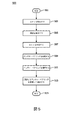
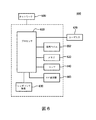
図2は、本発明のシステムの実施形態に従って実行されるプロセス200の機能流れ図を示す。プロセス200は、ネットワークを介して通信する1つ又は複数のコンピュータを使用して実行される。プロセス200は、1つ若しくは複数のメモリから情報を取得し、且つ/又は1つ若しくは複数のメモリに情報を記憶する。この1つ若しくは複数のメモリは、互いに関して局所メモリであり、且つ/又は互いに関して遠隔メモリである。プロセス200は、以下のステップのうちの1つ又は複数のステップを含み、本発明のシステムの実施形態に従ってBTSと1つ又は複数のWRFとの間に通信法を確立するように動作可能である。さらに、これらのステップのうちの1つ若しくは複数のステップを結合すること、及び/又はこれらのステップのうちの1つ若しくは複数のステップをサブステップ(sub−act)に分離することができる。さらに、設定によっては、これらのステップのうちの1つ又は複数のステップが省略される。動作時、このプロセスは、ステップ201から始まり、次いでステップ203に進む。
FIG. 2 shows a functional flow chart of a
ステップ203中に、1つ又は複数のアップリンク・チャネル及びダウンリンク・チャネルのためのベース送信器システム(BTS)と少なくとも1つの無線RF(WRF)コイルとの間の(SD通信などの)通信に使用可能なアンテナの数を決定する。しかしながら、単純にするため、コンテキストに反しない限り、アップリンク・チャネルとダウンリンク・チャネルは、同様の設定及び伝送法を使用すると仮定する。本発明のシステムの実施形態によれば、アップリンク・チャネルとダウンリンク・チャネルは、異なる設定及び/又は異なる伝送法を使用することができる。本発明のシステムの実施形態によれば、BTS及び/又はWRFに問い合わせてこの情報を取得するが、いくつかの実施形態によれば、本明細書で論じられているとおり、この情報が予め分かっており(例えばメモリに予め記憶されており)、且つ/又はアンテナ間の通信によってこの情報が決定される。 During step 203, communication (such as SD communication) between the base transmitter system (BTS) for one or more uplink and downlink channels and at least one radio frequency RF (WRF) coil. Determine the number of antennas available for. However, for simplicity, it is assumed that uplink and downlink channels use similar configuration and transmission methods, as long as they do not go against the context. According to embodiments of the system of the present invention, uplink and downlink channels can use different settings and / or different transmission methods. According to embodiments of the system of the invention, the BTS and / or WRF is queried to obtain this information, but according to some embodiments, this information is known in advance, as discussed herein. This information is determined by communication (eg, stored in memory) and / or between antennas.
問合せが提供される実施形態では、この問合せに応答して、BTS及び/又は少なくとも1つのWRFが、1つ又は複数のアップリンク・チャネル及びダウンリンク・チャネルでの通信に使用可能なアンテナの数に関する情報を提供する。この情報を取得した後、このプロセスは、後の使用に備えてこの情報をシステムのメモリに記憶する。同様に、このプロセスが、システムのメモリから、例えばシステム構成情報表から、この情報を取得することも構想される。これを下表1を参照して論じる。

表1に関しては、1つ若しくは複数のRFコイル(例えばWRF)及び/又はBTSに対するシステム構成情報が規定されている。RFコイルに関して、RFコイルは、スキャン・タイプに従って選択される。本発明のシステムの実施形態によれば、1つのスキャン・タイプが2つ以上のWRFを有する場合には、表1の「×」によって例示的に示されているように、これらのWRFのうちの1つ又は複数のWRFがデフォルトのWRFとして選択される。システムは次いで、選択されたWRF及び/又はデフォルトのWRFに対応するシステム構成情報に対する設定を使用する。コイルのタイプは、例えば相互参照を可能にするために、コイル伝送タイプを識別するタイプI、タイプIIなどの識別子を含む。例えば、同じ送信タイプのコイルは、予め決められた同じ数の送信アンテナ及び/又は受信アンテナを有する。空間ダイバーシチ(SD)欄は、対応するコイルが空間ダイバーシチをサポートしているかどうかを示す。コイルごとに、送信アンテナ及び/又は受信アンテナの数が記載されている。これらの数は例示的に示されているが、同様に他の数を規定することもできる。BTSに関して、送信アンテナ及び/又は受信アンテの数が例示的に示されている。サポートされたMIMO通信モードを表に記載することも構想される。システム構成情報は、システムによって更新され(例えば新たなWRFを発見したときなど)、及び/又はユーザによって更新される。(更新された)システム構成は次いで、使用に備えてシステムのメモリに記憶される。 With respect to Table 1, system configuration information for one or more RF coils (eg WRF) and / or BTS is specified. For RF coils, RF coils are selected according to scan type. According to embodiments of the system of the invention, if one scan type has more than one WRF, of these WRFs, as exemplified by the "x" in Table 1. One or more WRFs of are selected as the default WRFs. The system then uses the settings for the system configuration information corresponding to the selected WRF and / or the default WRF. The coil type includes identifiers such as type I, type II, etc. that identify the coil transmission type, eg, to allow cross-reference. For example, coils of the same transmission type have a predetermined number of transmit and / or receive antennas. The Spatial Diversity (SD) column indicates whether the corresponding coil supports spatial diversity. The number of transmit and / or receive antennas is listed for each coil. These numbers are shown exemplary, but other numbers can be specified as well. For BTS, the number of transmitting antennas and / or receiving ante is shown exemplary. It is also envisioned to list the supported MIMO communication modes in the table. The system configuration information is updated by the system (eg, when a new WRF is discovered) and / or by the user. The (updated) system configuration is then stored in system memory for use.
さらに他の実施形態によれば、このシステムは、(例えばユーザ設定及び/又は問合せによって)カレント・スキャンに使用する少なくとも1つのWRFのタイプ(表1のタイプ欄に示されている)を決定し、次いで、その少なくとも1つのWRFにおいて使用可能なアンテナの数及び/又はアンテナのタイプを、タイプ情報に基づいて決定する。したがって、アンテナ情報は、1つ又は複数のWRFタイプに対して対応するアンテナの数及び/又はタイプが決定されるような態様で、WRF伝送タイプ情報を関連づける(例えば、タイプ1の頭部コイルは1つのアンテナに関連づけられ、タイプ2の頭部コイルは2つのアンテナに関連づけられ、タイプ3の頭部コイルは5つのアンテナに関連づけられ、タイプ4のアンテナはSDをサポートしないなど)。これらのタイプは、ユーザ定義及び/又はシステム定義である。
According to yet another embodiment, the system determines the type of at least one WRF (shown in the type column of Table 1) to use for the current scan (eg, by user configuration and / or query). Then, the number of antennas available in the at least one WRF and / or the type of antenna is determined based on the type information. Thus, the antenna information correlates the WRF transmission type information in such a way that the number and / or type of corresponding antennas for one or more WRF types is determined (eg, a
さらに、スキャン中の通信に使用するアンテナの数を、ユーザが、BTS及び/又はWRFごとに選択することも構想される。このアンテナの数は、ユーザ設定に応じて、対応するBTS及び/又はWRFにおいて使用可能なアンテナの数よりも少なくし、又は使用可能なアンテナの数と同じにすることができる。例えば、ユーザは、送信用に2つのアンテナ、3つのアンテナ、単一のアンテナなどを選択することができる。さらに、設定によっては、このプロセスが、アンテナ情報から取得されたデフォルトのアンテナ設定に基づくデフォルトのアンテナ構成を選択することも構想される。例えば、ユーザは、送信用に(例えば上アンテナ列、下アンテナ列、いくつかのアンテナなど)あるアンテナを選択することができる。ステップ203を完了した後、このプロセスはステップ205に進む。 It is also envisioned that the user chooses the number of antennas to use for communication during scanning for each BTS and / or WRF. The number of antennas can be less than or equal to the number of antennas available in the corresponding BTS and / or WRF, depending on user settings. For example, the user can select two antennas, three antennas, a single antenna, etc. for transmission. In addition, depending on the configuration, it is envisioned that this process will select a default antenna configuration based on the default antenna configuration obtained from the antenna information. For example, the user can select an antenna for transmission (eg, upper antenna row, lower antenna row, some antennas, etc.). After completing step 203, the process proceeds to step 205.
ステップ205中に、このプロセスは、BTSと前記少なくとも1つのWRFとの間の通信を適当な方法を使用して確立する(例えばSDモードと呼ばれる)SD伝送法を選択する。SD伝送法は例えば、SISO、SIMO、MISO及びMIMO通信法を含む。例えば、このプロセスは、SD通信法を選択するためのSD伝送情報をシステムのメモリから取得する。このSD伝送情報は、例えばBTSとWRFのうちの少なくとも一方の決定されたアンテナの数及び/又は伝送能力に基づく予め決められたSD通信法及び/又は設定を示す。このプロセスは、スキャン中に使用される対応するそれぞれのWRF(例えば頭部コイル、肩コイル、膝コイル、足首コイルなど)について、SD通信法を、SD伝送情報と、BTSと対応するWRFのうちの1つ又は複数における通信に使用可能なアンテナの数とに基づいて選択する。さらに、SD伝送対を(例えば見通し線などに)分類し、SD通信法を選択するとともに、アンテナ対を、本明細書で論じられているとおりに、伝送される情報の分類及びタイプに基づいて選択する。分かりやすくするため、単一のWRFだけをさらに詳細に論じるが、2つ以上のWRFが選択されており、又は他の態様で2つ以上のWRFが使用可能であるときには、他の1つ又は複数のWRFにも同様に当てはまることが理解される。
During
SD伝送情報は、システムのメモリ内のSDモード表に記憶されており、下表2に示されているように、SD伝送情報は、BTS及び/又は少なくとも1つのWRFのうちの1つ又は複数において使用可能なアンテナの数及び/又はタイプに関する情報並びに対応するSD通信法を含む。SD伝送情報はさらに、コイル・タイプ情報(コイル・タイプI、コイル・タイプII)を含む。
表2を参照すると、BTSが、1つの送信アンテナ及び1つの受信アンテナを有し、WRFが、送信用及び受信用の2つのアンテナを有する(2+/2+)ときには、選択されるSD通信法(モード)がSIMO通信法であると決定されることが分かる。同様に、BTSが、2つ以上の送信及び受信アンテナを有し、WRFが、2+個の送信及び受信アンテナを有するときには、選択されるSD通信法(モード)がMIMO通信法である。このプロセスは、送信及び/又は受信(例えばアップリンク及びダウンリンク)通信ごとに通信法を選択する。 Referring to Table 2, when the BTS has one transmitting antenna and one receiving antenna and the WRF has two antennas for transmitting and receiving (2 + / 2 +), the SD communication method selected (2 + / 2 +). It can be seen that the mode) is determined to be the SIMO communication method. Similarly, when the BTS has two or more transmit and receive antennas and the WRF has 2+ transmit and receive antennas, the SD communication method (mode) selected is the MIMO communication method. This process selects a communication method for each transmit and / or receive (eg, uplink and downlink) communication.
分かりやすくするため、BTS及びWRFにおいて、アップリンク・チャネルとダウンリンク・チャネルに対して使用可能なアンテナの数が同じであると仮定する。しかしながら、限定はされないが、送信アンテナと受信アンテナの数が互いに異なることも構想される。このプロセスは次いで、アンテナを整合させることによって、及び/又は使用可能なアンテナがサポートしている通信法の中から最も高い容量の通信法を選択することによって、SD通信法(例えばSIMO、SISO、MISO、MIMO)を整合させる。例えば、ダウンリンク・チャネルに対して、単一の送信アンテナだけ及び単一の受信アンテナだけが使用可能であるとき、このプロセスは、この通信チャネルに対してSISO(SD)通信法を選択する。しかしながら、受信チャネルに対して2つ以上の受信アンテナが使用可能であるとき、このプロセスは、ダウンリンク・チャネルに対してSIMO(SD)通信法を選択する。SD通信法のタイプは図4Aから図4Dに示されており、これらの図については後により詳細に論じる。 For clarity, it is assumed that the number of antennas available for uplink and downlink channels is the same in BTS and WRF. However, although not limited, it is conceivable that the numbers of transmitting antennas and receiving antennas are different from each other. This process then involves matching the antennas and / or selecting the highest capacity communication method from the communication methods supported by the available antennas (eg MIMO, SOISO, etc.). MISO, MIMO) are matched. For example, when only a single transmit antenna and a single receive antenna are available for a downlink channel, the process chooses the SISO (SD) communication method for this communication channel. However, when more than one receive antenna is available for the receive channel, this process chooses the SIMO (SD) communication method for the downlink channel. The types of SD communication methods are shown in FIGS. 4A-4D, and these figures will be discussed in more detail later.
アンテナ情報はさらに、BTS及び/又はWRFに対する1つ又は複数のデフォルトのアンテナ設定を含む。例えば、デフォルトのアンテナ設定は、2であるBTS(示されている)及び/又はWRFのアンテナの数などを設定する。この場合、デフォルトの設定では、WRFが2つのアンテナを有する場合、選択されるSD通信法が、表2に示されているように、例示的にはMIMO通信法である。デフォルトのアンテナ設定は、ユーザ及び/又はシステムによって設定される。さらに、タイプ情報に関して言うと、WRFは、固有の識別子及び/又はタイプIコイル、IIコイルなどのタイプによって識別され、それぞれのタイプは、SD通信用の使用可能なアンテナの数、サポートされている通信のタイプ、アンテナのグループ化などを識別する。ステップ205を完了した後、このプロセスはステップ207に進む。
Antenna information further includes one or more default antenna settings for BTS and / or WRF. For example, the default antenna setting sets the number of BTS (shown) and / or WRF antennas, which is 2. In this case, in the default setting, if the WRF has two antennas, the SD communication method selected is, by way, MIMO communication, as shown in Table 2. The default antenna settings are set by the user and / or the system. Further, when it comes to type information, the WRF is identified by a unique identifier and / or type such as type I coil, type II coil, etc., each type supporting the number of antennas available for SD communication. Identify communication types, antenna grouping, etc. After completing
ステップ207中に、このプロセスは、アップリンク及び/又はダウンリンク通信チャネルのうちの対応する通信チャネル、通信チャネル・グループなどに対する選択されたSD伝送法に従って、BTSとWRFの間の少なくとも1つの通信チャネルを確立する。例えば、選択されたSD伝送法が、それぞれのアップリンク・チャネル及びダウンリンク・チャネルに対してMIMO伝送法であるとき、このプロセスは、対応するWRFとBTSの間に、アップリンク・チャネル及びダウンリンク・チャネルのためのMIMO通信チャネルを確立する。この例示的な手法では、ディジタル・データが、BTSとWRFの間の双方向伝送法を使用して伝送され、システム・コントローラと対応するWRFの間の双方向通信を確立する。他の実施形態では、アップリンク・チャネルとダウンリンク・チャネルが、互いに異なるSD通信法(例えばアップリンクがMISO、ダウンリンクがMIMO)を使用することも構想される。ステップ207を完了した後、このプロセスはステップ209に進み、そこで終了となる。
During
図3は、本発明のシステムの実施形態に基づくMRシステム300(分かりやすくするため、以後、システム300と言う)の一部分の概略ブロック図を示す。システム300は、システム100と同様のシステムであり、ボア126を有するMRI本体、MRIシステム・コントローラ(コントローラ)304、患者101を支持する支持部、BTS335及びRF部323のうちの1つ又は複数を含む。一般に、コントローラ304、BTS335及びRF部323はそれぞれ、システム100のコントローラ104、BTS135及びRF部123と同様である。本発明のシステムの実施形態によれば、コントローラ304は、システム300の全体動作を制御し、BTS335として例示的に示された1つ又は複数のBTSを含む。分かりやすくするため、本明細書では例示的にBTS335について論じる。しかしながら、本発明によれば、本明細書で論じる例は、BTS335と同じか又はBTS335と同様の複数のBTSに当てはまることが理解され、このことは、特段の言及がない限り、追加の詳細なしで適用可能である。
FIG. 3 shows a schematic block diagram of a part of the MR system 300 (hereinafter referred to as the
BTSは、アンテナ・セレクタ(SEL)装置340、並びにANT(1)からANT(L)(一般にANTx)などのL個の送信及び/又は受信(TRX)アンテナを含む。Lは整数である。SEL340は、システム300の他の部分、例えばRF部324への送信のために、コントローラ304の制御下で、SEL340に結合された1つ又は複数のアンテナANTを選択する。さらに、セレクタ340は、セレクタ340に結合された1つ又は複数のアンテナANTxから受信した信号を選択的に切り換え、これらの受信信号を、さらなる処理のためにコントローラ304に送信する。これらの受信信号は、RF部323から受信した信号を含む。
The BTS includes an antenna selector (SEL)
RF部323は、WRF325−1から325−M(一般に325−x)などの複数のWRFを含む。Mは整数である。1つ又は複数のWRF325−xが互いに同様であってもよく、又は互いに異なっていてもよい。そのため、分かりやすくするため、コンテキストに反しない限り、残りのWRF325−xはWRF325−1と同様であるとの仮定の下、WRF325−1だけについて説明する。
The
WRF325−1は、コントローラ350、MRアンテナ・ループ列352、アンテナ・セレクタ(SEL)354、並びにANT(1)からANT(N)(一般にANTx)などのN個の送信及び/又は受信(TRX)アンテナANT(n)を含む。Nは整数である。コントローラ350は、WRF325−1の全体動作を制御する。
The WRF325-1 is a
アンテナ・ループ列352は、患者101から誘導MR信号を受信し、受信した誘導MR信号を、ディジタル化などのさらなる処理のためにコントローラ350に送信するように調整された複数の受信ループ356を含む。このディジタル化では、アナログ−ディジタルA/D変換器358を使用して、ディジタル化されたMR情報(未処理の情報)及び/又は再構成されたMR情報を希望に応じて形成する。受信ループ356の数、形状、サイズ及び/又は位置は、RFコイルの意図された用途(例えば頭部コイル、肩コイル、膝コイル、足首コイル、胴体コイルなど)に基づいて決定されるが、2つ以上の用途に適用することができる汎用的な形状も構想される。受信のために、コントローラ350の制御下で、いつでも1つまた複数の受信ループ356を選択することができる。
The
セレクタ354は、コントローラ350の制御下で、信号を受信及び/又は送信する1つ又は複数のアンテナANTを選択する。例えば、セレクタ354は、選択された1つ又は複数のANTxが受信した信号(例えばBTS335から送信された制御情報、同期情報及び/又はシーケンス情報)を受け取り、これらの信号を、さらなる処理のためにコントローラ350に送信する。同様に、セレクタ354は、コントローラ350の制御下で制御情報、同期情報及び/又はディジタル化されたMR情報(例えばディジタル化されたMR情報及び/又は再構成されたMR情報)をBTS335に送信するために、1つ又は複数のANTxを選択する。
The
BTS335では、セレクタ340が、セレクタ340に結合された選択された1つ又は複数のANTxが受信した信号を受け取り、これらの信号を、さらなる処理のためにコントローラ304に送信する。同様に、セレクタ340は、コントローラ350の制御下で制御情報、同期情報及び/又はシーケンス情報をWRF325−1に送信するために、1つ又は複数のANTxを選択する。したがって、本発明のシステムの実施形態によれば、セレクタ(例えば340、354)は、それらのセレクタの対応するそれぞれのコントローラ(例えば304、350)の制御下で信号を送信及び/又は受信するために、1つ又は複数のアンテナを制御可能に選択する。
In the
点線h11からhLNによって示されているように、動作中は、BTS335の選択された1つ又は複数のアンテナANTxが、選択されたWRF325−xの1つのアンテナ又は選択されたアンテナANTxに通信可能に結合されている。これらの点線は、通信カップリング(communication coupling)(カップル)又は伝送行列(transmission matrix)を表す。BTSがL個のアンテナを有し、それぞれのWRF325−xがN個のアンテナを有すると仮定すると、N×M個の通信カップリングがあることになる。これらのカップリングは、コントローラ304などのコントローラの制御下でいつでも選択及び/又は変更することができる。本明細書で利用されるとき、カップリングという用語は、他の経路を排除しない通信経路(例えば、選択されたWRF325−xの2つのANTxに結合されたBTS335の1つのANTxなど)を示すことが意図されている。本発明のシステムの実施形態によれば、原信号は分割されて、1つ又は複数のアンテナ間で伝送される。その後、1つ又は複数のアンテナが、この伝送された信号を受信し、次いでこの信号は結合されて、原信号を形成する。このようにすると、使用可能なカップリング、使用可能なカップリングの帯域幅、及び伝送されている特定のタイプの信号の要件(例えばタイミング、伝送されるデータ量など)に基づいて、送信/受信能力が最適化及び選択される。これに応じて、選択されたアンテナANTxに対する通信カップリングを評価して、サポートされている伝送法及びアンテナ間の通信品質を決定する。例えば、アンテナ・ペアリングを、(a)カップリングh11などの見通し線(LOS)ペアリング(例えばスループットが潜在的に最も高い経路)、(b)カップリングh22などの障害物を有する直接経路/直接信号、(c)カップリングhLNなどの実質的に信号損失がない多経路/間接経路、及び(d)BTS335とWRF325−2とのいくつかのアンテナ・ペアリングに対するWRF325−1によるものなど、物体から反射された/散乱した経路(例えばスループットが潜在的に最も低い経路)であると評価し、次いで、この評価に応じて、対応するアンテナ・ペアリングを分類する。この分類を利用して、例えば伝送されているデータ・タイプに対するアンテナ・ペアリング及び通信法を、要件(例えばタイミング、伝送されるデータ量など)をサポートするように選択する。例えば、使用可能なペアリングの中から、制御情報を伝送するためにLOSペアリングを選択し、画像データなどの高データ速度データの転送を満足のいくものにするために、障害物ペアリングを有する複数の直接経路/直接信号を選択する。さらに、誤り訂正データ、例えば画像データをサポートするための誤り訂正データが、多経路/間接ペアリング経路上で伝送される。容易に理解されるとおり、当然ながら、スループット要件及び決定性要件をサポートするために所望のアンテナ・ペアリングが使用可能である限り、伝送される2つ以上のデータ・タイプ(例えば制御データ及び画像データ)をサポートする目的には、例えばLOS通信経路が利用される。さらに、本発明のシステムの実施形態によれば、2つ以上のペアリング分類によって所与のデータ・タイプがサポートされる(例えば、一部がLOS、一部が障害物がある経路;一部がLOS、一部が多経路/間接経路;一部がLOS、一部が物体からの反射/散乱経路、及びLOS、障害物を有する直接経路/直接信号、多経路/間接経路及び反射/散乱ペアリングの他の組合せ)。
During operation, one or more selected antennas ANTx of the
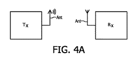
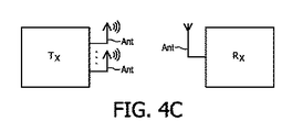
アンテナ対の選択に関する分類のさらなる議論は、分かりやすくするために、例えば図5を参照して下記に提供されている。以下では、図4Aから図4Dを参照して、本発明のシステムの実施形態によって使用されるSD通信法のグラフィカル表現を示し、説明する。図4Aは、本発明のシステムの実施形態に従って動作する単入力単出力(SISO)通信法のグラフィカル表現を示す。図4Bは、本発明のシステムの実施形態に従って動作する単入力多出力(SIMO)通信法のグラフィカル表現を示す。図4Cは、本発明のシステムの実施形態に従って動作する多入力単出力(MISO)通信法のグラフィカル表現を示す。図4Dは、本発明のシステムの実施形態に従って動作する多入力多出力(MIMO)通信法のグラフィカル表現を示す。図4Aから図4Cのそれぞれの図には、議論を単純にするために、1つの送信器(Tx)、1つの受信器(Rx)、及び対応するアンテナ(ANT)が示されているが、本明細書で論じらているとおり、本発明のシステムは、2つ以上の送信器及び受信器が使用可能な実施形態に容易に適用される。 A further discussion of the classification of antenna pair selection is provided below for clarity, eg, with reference to FIG. In the following, with reference to FIGS. 4A to 4D, a graphical representation of the SD communication method used by embodiments of the system of the present invention will be shown and described. FIG. 4A shows a graphical representation of a single input single output (SISO) communication method operating according to embodiments of the system of the present invention. FIG. 4B shows a graphical representation of a single-input multi-output (SIMO) communication method operating according to an embodiment of the system of the present invention. FIG. 4C shows a graphical representation of a multi-input single-output (MISO) communication method operating according to an embodiment of the system of the present invention. FIG. 4D shows a graphical representation of a multi-input, multi-output (MIMO) communication method that operates according to embodiments of the system of the present invention. Each of the figures in FIGS. 4A-4C shows one transmitter (Tx), one receiver (Rx), and the corresponding antenna (ANT) for simplicity of discussion. As discussed herein, the systems of the invention are readily applicable to embodiments in which two or more transmitters and receivers are available.
図5は、例えば記載されているようにプロセッサによって実行される、本発明のシステムの実施形態に基づくプロセス500の機能流れ図を示す。プロセス500は、ネットワークを介して通信する1つ又は複数のコンピュータ、プロセッサ、マイクロコントローラなどを使用して実行される。プロセス500は、1つ若しくは複数のメモリから情報を取得し、且つ/又は1つ若しくは複数のメモリに情報を記憶する。この1つ若しくは複数のメモリは、互いに関して局所メモリであり、且つ/又は互いに関して遠隔メモリである。プロセス500は、以下のステップのうちの1つ又は複数のステップを含み、本発明のシステムの実施形態に従ってBTSと1つ又は複数のWRFとの間に通信法を確立するように動作可能である。さらに、所望ならば、これらのステップのうちの1つ若しくは複数のステップを結合すること、及び/又はこれらのステップのうちの1つ若しくは複数のステップをサブステップ(sub−act)に分離することができる。さらに、設定によっては、これらのステップのうちの1つ又は複数のステップが省略される。動作時、このプロセスは、ステップ501から始まり、次いでステップ503に進む。さらに、プロセス500のステップは、分かりやすくするために、単一のWRFに関して説明されるが、スキャンを実行するために使用されるMRIシステム内の複数のWRF(例えば頭部、膝、肩RFコイルなど)のうちの2つ以上のWRFのそれぞれに対して、このプロセスのステップを繰り返すことができる。
FIG. 5 shows a functional flow chart of a
ステップ503中に、カレント・スキャンのためのシステム・プロセスに関するシステム・プロセス情報(system process information:SPI)を取得する。例えば、このシステム・プロセスは、同期プロセス、シーケンス生成プロセス、画像獲得プロセス及びデータ転送プロセスのうちの1つ又は複数のプロセスを含む。SPIは、対応するタイミング情報を含み、システムのメモリから取得される。このタイミング時間情報は、本明細書で論じられているBTSと前記1つ又は複数のWRFとの間の同期を、本発明のシステムの実施形態に従って設定又は補正し、或いは他の手法で促進する目的に利用される。さらに、SPIは、対応するそれぞれのシステム・プロセスの伝送設定を含む。例えば、同期プロセスは、見通し線(LOS)通信法を使用してコイル同期を設定する目的に利用される。見通し線(LOS)通信法は、しきい信号遅延、例えば0.01ミリ秒未満のしきい信号遅延を利用し(例えば許容し)、一方、(例えばディジタル化されたMR情報を転送するための)データ転送プロセスは、(スループットに関して)最速の3つのアンテナ・ペアリング又はいくつかのアンテナ・ペアリングを使用する通信法を利用して、スループットしきい値(例えば1Gbps)によって規定されるスループットを提供する。
During
本発明のシステムの実施形態によれば、SPIは、SISO、SIMO、MISO及びMIMO通信法のうちの1つ又は複数の通信法の中から選択された所望のSD通信法を含む。システム・プロセス情報は、ユーザ及び/又はシステムによって設定され、後の使用に備えてシステムのメモリに記憶される。分かりやすくするため、及び議論を容易にするために、シーケンス生成プロセスのためのSPI、画像獲得プロセスのためのSPI及びデータ転送プロセスのためのSPIは同じか又は同様であると仮定するが、本発明のシステムの実施形態によれば、これらが異なっていてもよい。ステップ503を完了した後、このプロセスはステップ505に進む。
According to embodiments of the system of the invention, the SPI comprises a desired SD communication method selected from one or more of the SISO, SIMO, MISO and MIMO communication methods. System process information is set by the user and / or the system and stored in system memory for later use. For the sake of clarity and for ease of discussion, the SPI for the sequence generation process, the SPI for the image acquisition process, and the SPI for the data transfer process are assumed to be the same or similar, but the book. According to embodiments of the system of the invention, these may be different. After completing
ステップ505中に、複数のアンテナANTSBTSを有するBTSと複数のアンテナANTSRFを有するWRFとの間の通信を確立し、又はそのような通信を試みる。MIMO通信法など、アンテナ・ペアリングによってサポートされている適当なSP通信法が利用される。ステップ503を完了した後、このプロセスはステップ505に進む。
During
ステップ505中に、BTSの前記複数のアンテナANTSBTSのうちのいくつかのアンテナと、WRFの前記複数のアンテナANTSRF(例えば対の試験カップリング)のうちのいくつかのアンテナとの間の無線カップリングを確立し、且つ/又は試験する。したがって、図3に関して、BTSがL個のアンテナを有し、WRFがN個のアンテナを有すると仮定すると、L×N個のアンテナ・カップリング(例えばアンテナ・ペアリング)があることになり、それらは、論じられているとおり、アンテナ・ペアリングと呼ばれる。したがって、例えば図3に関して、BTSのL個のアンテナのうちの1つのアンテナと対応するWRFのN個のアンテナのうちの1つのアンテナとの間のそれぞれのアンテナ・ペアリング(hnl)は、N×L個の潜在的なアンテナ・ペアリングを形成するために、示されているように、対応する添数(例えばhnl)を有する。したがって、アンテナ・ペアリング(h)は、N×Lペアリング行列を形成する。ステップ505を完了した後、このプロセスはステップ507に進む。
During
ステップ507中に、それぞれのアンテナ・ペアリングhnlの1つ又は複数に対して信号特性情報(SCI)を決定する。SCIは、信号電力損、信号スループット、信号遅延、(タイミングに関する)信号安定性などのうちの1つ又は複数の特性など、それぞれのアンテナ・ペアリング(hnl)の信号特性を含む。信号特性を決定するため、それぞれのペアリングの送信アンテナと受信アンテナの間で、1つ又は複数の信号を1つ又は複数の方向に伝送する。その後、これらの信号を解析してSCIを決定する。ステップ507を完了した後、このプロセスはステップ509に進む。
During
ステップ509中に、それぞれのアンテナ・ペアリングhnlの1つ又は複数を分類する。これに応じて、このプロセスは、SCIを解析して、アンテナ・ペアリングが、(スループットに関して潜在的に降順で提供された)(a)見通し線(LOS)ペアリング(例えばスループットが潜在的に最も高い経路)、(b)障害物を有する直接経路/直接信号、(c)実質的に信号損失がない多経路/間接経路、及び(d)物体から反射された/散乱した経路(例えばスループットが潜在的に最も低い経路)のうちの1つ又は複数であるかどうかを決定し、次いで、この決定に応じて、対応するアンテナ・ペアリングhnlを分類する。アンテナ・ペアリングhnlのうちの1つ若しくは複数のアンテナ・ペアリングhnlに関して、SCIを、この情報を反映するように更新し、且つ/又は、この情報を利用して、アンテナ対を選択するために、個々のアンテナ対を、本明細書で論じた所与のタイプの情報を伝送する適合性(suitability)に基づいて分類する。ステップ509を完了した後、このプロセスはステップ511に進む。ステップ511中に、このプロセスは、SPIによって規定されるシステム・プロセスごとに、通信のためのアンテナ・ペアリングhnl及び/又はSD通信法を選択する。 During step 509, one or more of each antenna pairing h nl is classified. In response, this process analyzes the SCI and the antenna pairing is (potentially provided in descending order with respect to throughput) (a) line-of-sight (LOS) pairing (eg throughput is potentially). Highest path), (b) direct path / direct signal with obstacles, (c) multi-path / indirect path with virtually no signal loss, and (d) path reflected / scattered from the object (eg throughput). Determines if is one or more of (potentially the lowest paths), and then classifies the corresponding antenna pairing h nl according to this determination. With respect to one or more antenna pairing h nl of antenna pairing h nl, the SCI, and updated to reflect this information, and / or, by utilizing this information, selects an antenna pair To do so, the individual antenna pairs are classified based on the suitability of transmitting the given type of information discussed herein. After completing step 509, the process proceeds to step 511. During step 511, this process selects the antenna pairing hnl and / or SD communication method for communication for each system process specified by the SPI.
例えば、同期プロセスに関して言うと、同期プロセスのSPIは、例えば0.01ミリ秒未満のしきい信号遅延を有するLOS通信法を要求する。この遅延は、無線コイルの動作及び/又はタイミングを制御するなどのために例えば無線コイルのリアルタイム・オペレーティング・システム(RTOS)制御が要求する決定性タイミング要件を提供する。それに応じて、このプロセスは、アンテナ・ペアリングの決定された信号特性(例えばLOS、妨害ありなどのアンテナ・ペアリングの分類)に基づくシステム・プロセス情報に従って0.01ミリ秒未満の信号遅延を有するLOSペアリングと分類された1つ又は複数のアンテナ・ペアリングhnlを選択する。 For example, with respect to the synchronization process, the SPI of the synchronization process requires a LOS communication method with a threshold signal delay of, for example, less than 0.01 milliseconds. This delay provides the deterministic timing requirements required by, for example, a real-time operating system (RTOS) control of a radio coil, such as to control the operation and / or timing of the radio coil. Accordingly, this process results in a signal delay of less than 0.01 ms according to system process information based on the determined signal characteristics of the antenna pairing (eg LOS, antenna pairing classification such as jamming). Select one or more antenna pairing h nl classified as having LOS pairing.
同様に、所与の信号タイプのスループット及びタイミング要件を満たす使用可能なアンテナ・ペアリングhnlを選択することによって、データ転送プロセスのためのアンテナ・ペアリングhnl及び/又はSD通信モードを決定する。例えば、(スループットに関して)最速の3つのアンテナ・ペアリングhnlを、画像データなどの高データ速度(HDR)データを伝送するためのHDRペアリングとして選択する。本明細書で使用されるとき、HDRデータは、>1Gb/秒などのデータしきい値を超えるデータ速度を利用する。さらに、最速の3つのアンテナ・ペアリングが、データしきい値を満たすデータ速度又はデータしきい値よりも大きなデータ速度を提供することができるかどうかをこのプロセスが決定することも構想される。これらの最速の3つのアンテナ・ペアリングが、データしきい値を満たすデータ速度又はデータしきい値よりも大きなデータ速度を提供することができると決定された場合、このプロセスは、これらの最速の3つのアンテナ・ペアリングをHDRペアリングとして選択する。しかしながら、これらの最速の3つのアンテナ・ペアリングが、データしきい値を満たすデータ速度又はデータしきい値よりも大きなデータ速度を提供しないと決定された場合、このプロセスは、このグループにペアリングさらに追加して、そのグループが、データしきい値を満たすデータ速度又はデータしきい値よりも大きなデータ速度を提供するようにする。このようにして、このプロセスは、例えば伝送する所与の情報タイプのあるスループットしきい値及び/又はあるタイミング要件を満たすアンテナ・ペアリング(単一のペアリング又はペアリングの組合せ)を選択する。 Similarly, the antenna pairing h nl and / or SD communication mode for the data transfer process is determined by selecting an available antenna pairing h nl that meets the throughput and timing requirements of a given signal type. To do. For example, the fastest three antenna pairing h nl (in terms of throughput) is selected as the HDR pairing for transmitting high data rate (HDR) data such as image data. As used herein, HDR data utilizes data rates that exceed data thresholds, such as> 1 Gb / sec. It is also envisioned that this process will determine if the fastest three antenna pairings can provide a data rate that meets or exceeds the data threshold. If it is determined that these three fastest antenna pairings can provide a data rate that meets or exceeds the data threshold, then this process is the fastest of these. Select three antenna pairings as HDR pairings. However, if it is determined that these three fastest antenna pairings do not provide a data rate that meets or exceeds the data threshold, then this process pairs to this group. In addition, ensure that the group provides a data rate that meets or exceeds the data threshold. In this way, the process selects, for example, antenna pairing (single pairing or combination of pairings) that meets certain throughput thresholds and / or certain timing requirements for a given type of information to be transmitted. ..
このプロセスはさらに、SCI及び/又は選択されたアンテナ・ペアリングhnlに基づいて、(例えばMIMO、SIMO、SISO及びMISO通信法のうちの1つ又は複数の通信法から選択された)SD通信法(例えば通信モード)を決定する。例えば、BTSとWRFの間のアップリンク・ダイレクトとダウンリンク・ダイレクトのそれぞれで2つ以上の送信アンテナ及び2つ以上の受信アンテナが選択されている場合には、MIMO通信モードが選択される。 This process is further based on SCI and / or selected antenna pairing h nl , SD communication (eg selected from one or more of the MIMO, MIMO, SISO and MISO communication methods). Determine the method (eg communication mode). For example, if two or more transmit antennas and two or more receive antennas are selected for each of the uplink direct and downlink direct between the BTS and WRF, the MIMO communication mode is selected.
したがって、データ転送プロセスに関しては、選択されたアンテナ・ペアリングhnlに従って、このプロセスに対するSD通信法が決定される。例えば、これらの最速の3つのアンテナ・ペアリングhnlが、少なくとも2つの異なる送信アンテナ及び少なくとも2つの異なる受信アンテナを使用する場合、このプロセスはMIMO通信法を選択する。しかしながら、これらの最速の3つのアンテナ・ペアリングhnlが、同じ送信アンテナ及び少なくとも2つの異なる受信アンテナを使用する場合、このプロセスはSIMO通信法を選択する。同様に、これらの最速の3つのアンテナ・ペアリングhnlが、同じ送信アンテナ及び同じ受信アンテナを使用する場合、このプロセスはSISO通信法を選択する。また、これらの最速の3つのアンテナ・ペアリングhnlが、少なくとも2つの異なる送信アンテナ及び単一の受信アンテナを使用する場合、このプロセスはMISO通信法を選択する。図4Aから図4Dに関して上に示したこれらの例示的な方法は、排他的な考慮事項として意図されていない。これは、アンテナ対とシステムの間の伝送を容易にする他の方法も適当に適用することができるためである。さらに、伝送要件(例えばスループット)を満たすために、1つ又は複数のLOSペアリングを、障害物対を有する1つ又は複数の直接経路/直接信号とともに選択するなど、混合された通信を選択することもできる。ステップ511を完了した後、このプロセスはステップ513に進む。 Therefore, for the data transfer process, the SD communication method for this process is determined according to the selected antenna pairing h nl. For example, if these fastest three antenna pairing h nl use at least two different transmitting antennas and at least two different receiving antennas, this process chooses MIMO communication. However, if these fastest three antenna pairing h nl use the same transmitting antenna and at least two different receiving antennas, this process chooses the SIMO communication method. Similarly, three antenna pairings h nl of these fastest, when using the same transmit antenna and the same receiving antenna, the process selects the SISO communication method. Also, if these fastest three antenna pairing h nl use at least two different transmitting antennas and a single receiving antenna, this process chooses the MISO communication method. These exemplary methods shown above with respect to FIGS. 4A-4D are not intended as exclusive considerations. This is because other methods of facilitating transmission between the antenna pair and the system can also be appropriately applied. In addition, mixed communications are selected, such as selecting one or more LOS pairings with one or more direct paths / direct signals with obstacle pairs to meet transmission requirements (eg, throughput). You can also do it. After completing step 511, the process proceeds to step 513.
ステップ513中に、選択されたアンテナ・ペアリングhnl及び/又は選択されたSD通信法を使用して、通信を確立する。それに応じて、対応するそれぞれのシステム・プロセス(例えば同期、シーケンス生成、画像獲得及びデータ転送プロセスなど)に対する選択されたアンテナ・ペアリング及び選択されたSD通信法に従って、BTSとWRFの間の通信を確立する。次いで、それぞれのシステム・プロセスに対する確立されたアンテナ・ペアリング及び/又は選択されたSD通信法を使用して、スキャンを実行する。例えば、本発明の実施形態では、このプロセスが、決定されたアンテナ・ペアリングを用いたSISO通信モードを使用して同期プロセスを実行し、決定されたアンテナ・ペアリング間でMIMO通信モードを使用して、シーケンス生成、画像獲得及びデータ転送プロセスを実行することができる。さらに、制御プロセス及び/又は同期プロセスが、RTOSペアリングであると決定されたアンテナ・ペアリングを使用し、HDRペアリングであると決定されたペアリングを使用してHDRデータを伝送することも構想される。
During
容易に理解されることだが、アンテナ・ペアリングの変更を例えば使用中に実施することができる。そのため、本発明のシステムの実施形態によれば、ペアリングの特性が変化した場合には、このプロセスの1つ又は複数のステップ(例えばステップ503、505、507、509、511及び513のうちの1つ又は複数のステップ)を繰り返して、アンテナ・ペアリングを更新することができる。加えて、アンテナ・ペアリング間で伝送されているデータも時間の経過とともに変化するため、変化が生じた(例えばLOSが妨害ありに変化した)とき、例えば計装(instrumentaiton)が導入されたとき、又はスキャン中に患者は移動したときには、アンテナ・ペアリングを分類し直すことができる。 As is easily understood, antenna pairing changes can be made, for example, during use. Therefore, according to an embodiment of the system of the present invention, if the characteristics of pairing change, one or more steps of this process (eg, steps 503, 505, 507, 509, 511 and 513). The antenna pairing can be updated by repeating one or more steps). In addition, the data transmitted between the antenna pairings also changes over time, so when changes occur (eg LOS changes with interference), for example when instrumentation is introduced. Or, if the patient moves during the scan, the antenna pairing can be reclassified.
ステップ513を完了した後、このプロセスはステップ515に進み、そこでこのプロセスは終了となる。
After completing
したがって、本発明のシステムの実施形態は、空間ダイバーシチを使用することによってチャネル容量を増大させる。これはしばしば、多入力多出力(MIMO)通信法と呼ばれ、本発明のシステムの実施形態に従って動作しているMIMO通信モードによって使用される。それに応じて、本発明のシステムの実施形態は、同じ周波数及び帯域幅を使用するが異なる空間分布を有する同じチャネルに沿って伝搬するいくつかの信号を生成する通信システムを使用する。本発明のシステムの実施形態はさらに、受信器及び送信器のうちの1つ又は複数におけるチャネル状態情報(CSI)を決定する。 Therefore, embodiments of the system of the present invention increase channel capacitance by using spatial diversity. This is often referred to as multi-input multi-output (MIMO) communication methods and is used by MIMO communication modes operating according to embodiments of the systems of the invention. Accordingly, embodiments of the system of the invention use a communication system that produces several signals that use the same frequency and bandwidth but propagate along the same channel with different spatial distributions. Embodiments of the system of the present invention further determine channel state information (CSI) in one or more of the receiver and transmitter.
本発明のシステムの実施形態はさらに、プレコーディング(precoding)、ビーム形成、空間多重化及びダイバーシチ・コーディング法のうちの1つ又は複数を通信中に使用する。これらの方法は、インターネット上のen.wikipedia.org/wiki/MIMOにおいてさらに詳細に論じられている。この文献の内容は、参照によって本明細書に組み込まれている。本発明のシステムの実施形態によれば、これらの通信法は、アンテナ対及びアンテナ対間の通信法を、多様な通信要件、例えば本明細書に記載された1つ又は複数のWRF(例えばWRF125−x)の多様な通信要件を満たすように選択/混合することによって最適化される。 Embodiments of the system of the present invention further use one or more of recording, beam forming, spatial multiplexing and diversity coding methods during communication. These methods are available on the Internet. wikipedia. It is discussed in more detail in org / wiki / MIMO. The contents of this document are incorporated herein by reference. According to embodiments of the system of the invention, these communication methods make antenna pairs and communication methods between antenna pairs a variety of communication requirements, such as one or more WRFs described herein (eg, WRF125). -X) Optimized by selecting / mixing to meet the various communication requirements.
図6は、本発明のシステムの実施形態に基づくシステム600の一部分を示す。例えば、このシステムの一部分は、プロセッサ610(例えばコントローラ)を含み、プロセッサ610は、メモリ620と、ディスプレイ630などのレンダリング装置を含むユーザ・インタフェース(UI)と、センサ640と、RF部660と、磁気コイル692と、ユーザ入力装置670とに動作可能に結合されている。メモリ620は、アプリケーション・データ及び記載された動作に関する他のデータを記憶する任意のタイプの装置である。このアプリケーション・データ及び他のデータは、プロセッサ610によって受け取られて、プロセッサ610を、本発明のシステムに基づく動作ステップを実行するように構成する(例えばプログラムする)。このように構成されたプロセッサ610は、本発明のシステムの実施形態に従って実行するのに特に適した専用マシンとなる。
FIG. 6 shows a portion of a
これらの動作ステップは、例えば磁気コイル692及び/又はRF部660をシステム設定に従って制御することによってMRIシステムを構成することを含む、本明細書に記載された方法を含む。任意選択の位置決め機構が、患者及び/又はRF部660の(例えばx、y及びz軸に関する)物理的な位置を所望のとおりに制御する。RF部660は、RF送信コイル及びRF受信コイルなどのRF変換器並びに同調/離調状態及び同期状態などのRF状態(モード)を制御するために、プロセッサ610によって制御される。RF部660は、有線型のRF部及び/又は無線型のRF部を含み、それらのRF部は、互いに関して局所RF部であり、且つ/又は互いに関して遠隔RF部である。実施形態によれば、RF部660は、基部、ポジショナ(positioner)部及び/又は頂部のうちの1つ又は複数の部分に提供されたものなどの無線受信型RFコイルを含む。磁気コイル692は、主磁気コイル、傾斜磁場コイル(GR)(例えばx、y及びz傾斜磁場コイル)、及び任意選択の傾斜磁場シミング・コイル(gradient shimming coil)を含み、主磁場(B0)並びに/又は所望の方向及び/若しくは強度の傾斜磁場(例えばGx、Gy及びGz)を発するように制御される。プロセッサ610は、磁気コイル692に電力を供給する1つ又は複数の電源を、所望の時点で所望の磁場が発せられるように制御する。この制御は、同期、画像情報の伝送、制御情報の伝送などの動作うちの1つ又は複数の動作などのMRIの動作が満足のいくものになるように、1つ若しくは複数のアンテナ対及び/又は本明細書に記載された通信法を選択することを含む。
These operating steps include the methods described herein, including, for example, configuring an MRI system by controlling the
さらに、RF部660は、RFパルスを送信し、誘導MR信号を受信するように制御される。適当に構成された再構成器(例えばプロセッサ104、コントローラ350、遠隔システムなど)として動作するプロセッサ又はプロセッサの部分が、誘導MR信号などの受信信号を処理し、これらの信号を、(例えば本発明のシステムの実施形態の1つ又は複数の再構成技法を使用して)コンテンツ(content)に変換する。このコンテンツは、例えばディスプレイ630、スピーカなどのシステムのUI上でレンダリングされる画像情報(例えば静止画像又はビデオ画像(例えばビデオ情報))、データ及び/又はグラフ(例えば分光写真情報)を含む。さらに、このコンテンツは次いで、後の使用に備えてメモリ620などのシステムのメモリに記憶される。したがって、動作ステップは、1つ又は複数のアンテナ対(図5参照)のセットアップ、無線RFコイルのセットアップ及び制御、画像情報の獲得/伝送、例えば誘導MR情報から取得された再構成された画像情報などのコンテンツの再構成及び/又はレンダリングを含む。プロセッサ610は、画像情報などのコンテンツを、システムのディスプレイなどのシステムのUI上にレンダリングする。
Further, the
ユーザ入力670は、キーボード、マウス、トラックボール又は他の装置、例えばタッチセンシティブ・ディスプレイを含み、これらの装置は、独立型の装置とすることができ、或いは、有線及び/又は無線通信リンクなどの動作可能リンクを介してプロセッサ610と通信するシステムの部分、例えばパーソナル・コンピュータ、パーソナル・ディジタル・アシスタント(PDA)、モバイル・ホン(例えばスマート・ホン)、モニタ、スマート端末若しくはダム(dumb)端末又は他の装置の部分とすることができる。ユーザ入力装置670は、本明細書に記載されたUI内での対話を可能にすることを含め、プロセッサ610と対話するように動作可能である。明らかに、プロセッサ610、メモリ620、ディスプレイ630及び/又はユーザ入力装置670の全体又は部分は、コンピュータ・システムの部分、又はクライアント及び/若しくはサーバなどの他の装置の部分である。
本発明のシステムの方法は、コンピュータ・ソフトウェア・プログラムによって実施されるのに特に適しており、このようなプログラムは、本発明のシステムによって記述及び/又は構想される個々のステップ又はステップのうちの1つ又は複数のステップ又はステップに対応するモジュールを含む。このようなプログラムは、言うまでもなく、集積回路チップなどのコンピュータ可読媒体内、メモリ620又はプロセッサ610に結合された他のメモリなどの周辺装置又はメモリ内で実施される。
The methods of the system of the invention are particularly suitable for implementation by computer software programs, such programs of which are individual steps or steps described and / or envisioned by the system of the invention. Includes one or more steps or modules corresponding to the steps. Needless to say, such a program is carried out in a computer-readable medium such as an integrated circuit chip, or in a peripheral device or memory such as
メモリ620に含まれるプログラム及び/又はプログラム部分は、本明細書に開示された方法、動作ステップ及び機能を実施するようにプロセッサ610を構成する。メモリは、例えばクライアント及び/若しくはサーバ間に分散されていてもよく、又は局所メモリであってもよく、追加のプロセッサが提供されている場合、プロセッサ610も分散されていてもよく、又は単独で存在してもよい。メモリは、電気、磁気若しくは光学メモリとして実施され、又はこれらのタイプの記憶装置若しくは他のタイプの記憶装置の組合せとして実施される。さらに、用語「メモリ」は、プロセッサ610によってアクセス可能なアドレス指定可能な空間内のアドレスから読み出したり、又はこのようなアドレスに書き込んだりすることができる一切の情報を包含するように十分に広く解釈されるべきである。この定義によれば、プロセッサ610は、本発明のシステムに従って動作するネットワークから情報を取り出すことができるため、例えばネットワークを通してアクセス可能な情報もメモリ内にある。
The program and / or program portion contained in the
プロセッサ610は、ユーザ入力装置670からの入力信号に応答して、及びネットワークの他の装置がメモリ620に記憶された命令を実行したことに応答して、制御信号を提供し且つ/又は動作を実行するように動作可能である。プロセッサ610は、マイクロプロセッサ、特定用途向け集積回路、汎用集積回路、論理装置などのうちの1つ又は複数を含む。さらに、プロセッサ610は、本発明のシステムに従って実行する専用プロセッサであり、又は本発明のシステムに従って実行するために多くの機能のうちの1つの機能だけが機能する汎用プロセッサである。プロセッサ610は、プログラム部分、多数のプログラム・セグメントを利用して動作することができ、又は専用集積回路若しくは多目的集積回路を利用するハードウェア装置とすることができる。本発明のシステムの実施形態は、画像を獲得及び/又は再構成する高速画像化法を提供する。適当な用途は、MRIシステムなどの画像化システムを含む。
The
本発明のシステムの実施形態は、例えばMRIシステム及び/若しくはMRSシステムのボア内の無線RFコイル又は他の無線装置などの無線MRIコイルを制御及び/又は動作するためのディジタル・データの一方向伝送又は双方向伝送を提供する。 Embodiments of the system of the present invention are one-way transmission of digital data for controlling and / or operating a radio MRI coil, such as a radio RF coil or other radio device in the bore of an MRI system and / or MRS system. Or provide bidirectional transmission.
例えば、本発明のシステムの実施形態は、誘導MR信号(例えば未処理のデータ)、ディジタル化された誘導MR信号、及び/又は再構成されたMR情報などのMRIデータを、MR RFコイル(例えばWRF)からMRIシステム及び/又はMRSシステムのシステム・コントローラ(例えばMRIスキャナ)に無線で転送する方法を提供する。無線MRコイルを使用することによって流電ケーブルが不要となり、このことは、ワークフローを単純にし、安全性及び信頼性を向上させ、且つ/又は全体コストを低減させる。さらに、見た目が改善される。 For example, embodiments of the system of the present invention combine MRI data such as induced MR signals (eg, unprocessed data), digitized guided MR signals, and / or reconstructed MR information with MR RF coils (eg, reconstructed MR information). Provides a method of wirelessly transferring from a WRF) to a system controller (eg, an MRI scanner) of an MRI system and / or an MRS system. The use of wireless MR coils eliminates the need for galvanic cables, which simplifies workflows, improves safety and reliability, and / or reduces overall costs. In addition, the appearance is improved.
したがって、本発明のシステムの実施形態は、MRIシステムのボア内の無線チャネル容量を増大させ、同時に必要な忠実度を提供する。さらに、チャネルを横切って必要な忠実度で運ばれる無線MRI RF信号の総数が増える。本発明のシステムの実施形態は、例えば伝送することができるRF信号の数を増やすとによってチャネル容量を増大させ、且つ/又はそれらの信号の忠実度を向上させる。 Therefore, embodiments of the system of the present invention increase the radio channel capacitance within the bore of the MRI system while at the same time providing the required fidelity. In addition, the total number of radio MRI RF signals carried across the channel with the required fidelity increases. Embodiments of the system of the present invention increase the channel capacitance and / or improve the fidelity of those signals, for example by increasing the number of RF signals that can be transmitted.
本発明のシステムの実施形態によれば、帯域幅が増大することによりチャネル容量が増大する。しかしながら、技術的及び/又は規制上の限界のため、これが常に可能であるわけではない。これに応じて、本発明のシステムの実施形態は、1シンボル(symbol)あたりより多くのビットをエンコードする1つ又は複数のより高次の変調スキームを使用することによってチャネル容量を増大させる。例えば、本発明のシステムの実施形態は、伝送要件をサポートするなどのために、BPSK(1ビット/シンボル)から、QPSK(2ビット/シンボル)、16QAM(4ビット/シンボル)、64QAM(6ビット/シンボル)へ所望のとおりに切り換わる。より高次の変調スキームを使用することができるが、これは、同じBERに対してより高いチャネルSNRを必要とし、又は同じチャネルSNRに対してより低いBERに帰着する。当業者には、本発明のシステムのさらなる変更が容易に思い浮かぶであろう。このような本発明のシステムのさらなる変更は以下の特許請求の範囲によって包含される。 According to embodiments of the system of the present invention, increased bandwidth increases channel capacitance. However, this is not always possible due to technical and / or regulatory limitations. Accordingly, embodiments of the system of the present invention increase channel capacitance by using one or more higher order modulation schemes that encode more bits per symbol. For example, embodiments of the system of the present invention may vary from BPSK (1 bit / symbol) to QPSK (2 bits / symbol), 16QAM (4 bits / symbol), 64QAM (6 bits) to support transmission requirements and the like. Switch to / symbol) as desired. Higher-order modulation schemes can be used, but this requires a higher channel SNR for the same BER or results in a lower BER for the same channel SNR. Further modifications of the system of the present invention will be readily apparent to those skilled in the art. Such further modifications of the system of the present invention are covered by the following claims.
最後に、以上の議論の目的は単に、本発明のシステムを例示することであり、以上の議論が、添付の特許請求の範囲を、特定の実施形態又は一群の実施形態に限定すると解釈すべきではない。したがって、例示的な実施形態に関して本発明のシステムを説明したが、以下の特許請求の範囲に記載された本発明のシステムのより幅広い意図された趣旨及び範囲を逸脱しない多数の変更及び代替実施形態が当業者によって考案される可能性があることも理解すべきである。したがって、本明細書及び図面は、例示のためのものであるとみなすべきであり、本明細書及び図面が、添付の特許請求の範囲を限定することは意図されていない。 Finally, the purpose of the above discussion is merely to illustrate the system of the present invention, which should be construed as limiting the scope of the appended claims to a particular embodiment or group of embodiments. is not it. Therefore, although the system of the present invention has been described with respect to exemplary embodiments, a number of modifications and alternative embodiments that do not deviate from the broader intended purpose and scope of the system of the invention described in the claims below. It should also be understood that may be devised by one of ordinary skill in the art. Therefore, the specification and drawings should be considered as exemplary only, and the specification and drawings are not intended to limit the scope of the appended claims.
添付の特許請求の範囲を解釈する際には、以下のことを理解しておくべきである。
a)語「備える(comprising)」は、所与の請求項に記載された要素又はステップ以外の要素又はステップの存在を排除しない。
b)要素の前の語「a」又は「an」は、そのような要素が複数存在することを排除しない。
c)請求項中の参照符号は、その請求項の範囲を限定しない。
d)同じアイテムによって、又はハードウェア若しくはソフトウェアで実施された同じ構造若しくは機能によって、いくつかの「手段」が表現されることがある。
e)開示された要素は、ハードウェア部分(例えば別々の電子回路及び集積電子回路を含む)、ソフトウェア部分(例えばコンピュータ・プログラミング)、及びこれらの任意の組合せからなることがある。
f)ハードウェア部分は、アナログ部分とディジタル部分のうちの一方又は両方からなることがある。
g)特段の記載なしに、開示された装置又は開示された装置の部分が、一体に結合されたり、又はさらなる部分に分離されたりすることがある。
h)特段の言及がない限り、ステップ又はステップの特定の順序が必須となることは意図されていない。
i)用語「複数の」要素は、記載された2つ以上の要素を含み、特定の要素数範囲を暗示しない。すなわち、複数の要素は、2つの要素でしかなくてもよく、計り知れない数の要素を含んでもよい。
j)用語「及び/又は」並びにその形式素は、特許請求の範囲及び本発明のシステムの1つ又は複数の実施形態に従って、列挙された要素のうちの1つ又は複数の要素だけがシステム内に適切に存在すればよいことを意味すると理解すべきである。
When interpreting the appended claims, the following should be understood.
a) The term "comprising" does not preclude the existence of an element or step other than the element or step described in a given claim.
b) The word "a" or "an" before an element does not preclude the existence of more than one such element.
c) The reference code in the claim does not limit the scope of the claim.
d) Several "means" may be represented by the same item or by the same structure or function implemented in hardware or software.
e) The disclosed elements may consist of hardware parts (including, for example, separate and integrated electronic circuits), software parts (eg, computer programming), and any combination thereof.
f) The hardware portion may consist of one or both of an analog portion and a digital portion.
g) Unless otherwise stated, the disclosed device or parts of the disclosed device may be integrally combined or separated into additional parts.
h) Unless otherwise stated, it is not intended that a step or a specific sequence of steps is required.
i) The term "plurality" of elements includes the two or more elements described and does not imply a particular element number range. That is, the plurality of elements may be only two elements and may include an immeasurable number of elements.
j) The term "and / or" and its formal elements are such that only one or more of the listed elements are in the system according to the claims and one or more embodiments of the system of the invention. It should be understood that it means that it should exist properly.
Claims (15)
複数の送信(BTx)アンテナ及び受信(BRx)アンテナを含むアンテナ列(ANT)を有するベース送信器システムであって、選択された空間ダイバーシチ伝送法を使用して前記少なくとも1つの無線RFコイルと通信するベース送信器システムと、
前記ベース送信器システム及び前記少なくとも1つの無線RFコイルを制御する少なくとも1つのコントローラとを備える磁気共鳴システムであって、
前記少なくとも1つのコントローラは、
前記ベース送信器システムと前記少なくとも1つの無線RFコイルとの間の通信に使用可能な送信アンテナ及び受信アンテナのうちの少なくとも一方のアンテナの数を決定し、
前記ベース送信器システムの前記複数の送信(BTx)アンテナ及び前記受信(BRx)アンテナを、前記少なくとも1つの無線RFコイルの前記送信(WTx)アンテナ及び前記受信(WRx)アンテナに結合して、対応するアンテナ・ペアリングを形成し、それぞれのアンテナ・ペアリングの信号特性情報を決定し、
前記ベース送信器システムと前記少なくとも1つの無線RFコイルとの間の所与のタイプの情報の通信を可能にするために、前記少なくとも1つの無線RFコイルと通信するための前記空間ダイバーシチ伝送法を、決定された送信アンテナ及び受信アンテナの前記数並びに決定された前記信号特性情報に基づいて選択し、
前記ベース送信器システムと前記少なくとも1つの無線RFコイルとの間の少なくとも1つの通信チャネルを、選択された前記空間ダイバーシチ伝送法に従って確立する、
磁気共鳴システム。 At least one radio RF coil comprising an antenna loop for receiving an inductive magnetic resonance signal and a train of antennas including a transmit (WTx) antenna and a receive (WRx) antenna.
A base transmitter system having an antenna array (ANT) including multiple transmit (BTx) antennas and receive (BRx) antennas that communicate with at least one radio frequency RF coil using a selected spatial diversity transmission method. Base transmitter system and
A magnetic resonance system comprising the base transmitter system and at least one controller controlling the at least one radio RF coil.
The at least one controller
Determine the number of at least one of the transmit and receive antennas available for communication between the base transmitter system and the at least one radio RF coil.
The plurality of transmit (BTx) antennas and the receive (BRx) antennas of the base transmitter system are coupled to the transmit (WTx) antenna and the receive (WRx) antenna of the at least one radio RF coil to correspond. Form the antenna pairing to be performed, determine the signal characteristic information of each antenna pairing, and
The spatial diversity transmission method for communicating with the at least one radio RF coil to allow communication of a given type of information between the base transmitter system and the at least one radio RF coil. , Select based on the determined number of transmitting and receiving antennas and the determined signal characteristic information.
At least one communication channel between the base transmitter system and the at least one radio RF coil is established according to the spatial diversity transmission method selected.
Magnetic resonance system.
前記使用可能な送信アンテナ及び受信アンテナの数が1以下であると決定されたときには多入力単出力伝送法と単入力単出力伝送法とのうちの一方の伝送法を選択し、
前記使用可能な送信アンテナ及び受信アンテナの数が1よりも大きいと決定されたときには多入力多出力伝送法と単入力多出力伝送法とのうちの一方の伝送法を選択する、請求項1に記載の磁気共鳴システム。 The at least one controller
When it is determined that the number of usable transmitting antennas and receiving antennas is 1 or less, one of the multi-input single-output transmission method and the single-input single-output transmission method is selected.
A claim that when it is determined that the number of available transmit and receive antennas is greater than one, one of the multi-input multi-output transmission method and the single-input multi-output transmission method is selected. The magnetic resonance system according to 1.
アンテナ・ループと送信(WTx)アンテナ及び受信(WRx)アンテナを含むアンテナ列とを備える少なくとも1つの無線RFコイルから、誘導磁気共鳴信号を受信するステップと、
前記少なくとも1つの無線RFコイルと、複数の送信(BTx)アンテナ及び受信(BRx)アンテナを含むアンテナ列を有するベース送信器システムとの間で、選択された空間ダイバーシチ伝送法を使用して通信するステップと、
前記ベース送信器システムと前記少なくとも1つの無線RFコイルとの間の通信に使用可能な前記送信アンテナと前記受信アンテナのうちの少なくとも一方のアンテナの数を決定するステップと、
前記ベース送信器システムの前記複数の送信(BTx)アンテナ及び前記受信(BRx)アンテナを、前記少なくとも1つの無線RFコイルの前記送信(WTx)アンテナ及び前記受信(WRx)アンテナに結合して、対応するアンテナ・ペアリングを形成するステップと、
それぞれの前記アンテナ・ペアリングの信号特性情報を決定するステップと、
前記ベース送信器システムと前記少なくとも1つの無線RFコイルとの間の所与のタイプの情報の通信を可能にするために、前記少なくとも1つの無線RFコイルと通信するための前記空間ダイバーシチ伝送法を、決定された送信アンテナ及び受信アンテナの前記数並びに決定された前記信号特性情報に基づいて選択するステップと、
前記ベース送信器システムと前記少なくとも1つの無線RFコイルとの間の少なくとも1つの通信チャネルを、選択された前記空間ダイバーシチ伝送法に従って確立するステップと、
を有する、方法。 A method of operating a magnetic resonance system, wherein the method is controlled by at least one controller.
A step of receiving an induced magnetic resonance signal from at least one radio RF coil comprising an antenna loop and an antenna array including a transmit (WTx) antenna and a receive (WRx) antenna.
Communicate using the spatial diversity transmission method of choice between the at least one radio RF coil and a base transmitter system having an antenna array that includes multiple transmit (BTx) and receive (BRx) antennas. Steps and
A step of determining the number of at least one of the transmitting antenna and the receiving antenna that can be used for communication between the base transmitter system and the at least one radio RF coil.
The plurality of transmit (BTx) antennas and the receive (BRx) antennas of the base transmitter system are coupled to the transmit (WTx) antenna and the receive (WRx) antenna of the at least one radio RF coil. Steps to form antenna pairing and
Steps to determine the signal characteristic information of each of the antenna pairings,
The spatial diversity transmission method for communicating with the at least one radio RF coil to allow communication of a given type of information between the base transmitter system and the at least one radio RF coil. , A step of selection based on the determined number of transmitting and receiving antennas and the determined signal characteristic information.
A step of establishing at least one communication channel between the base transmitter system and the at least one radio RF coil according to the spatial diversity transmission method of choice.
The method.
使用可能な送信アンテナ及び受信アンテナの数が1よりも大きいと決定されたときに多入力多出力伝送法と単入力多出力伝送法のうちの一方の伝送法を選択するステップと、
を有する、請求項7に記載の方法。 A step of selecting one of the multi-input single-output transmission method and the single-input single-output transmission method when it is determined that the number of available transmitting antennas and receiving antennas is 1 or less.
A step of selecting one of the multi-input multi-output transmission method and the single-input multi-output transmission method when it is determined that the number of available transmit and receive antennas is greater than one, and
7. The method of claim 7.
前記使用可能なアンテナ・ペアリングの前記分類に基づいてアンテナ・ペアリングを選択するステップと、
を有する、請求項7に記載の方法。 Steps to classify the available antenna pairings and
The step of selecting an antenna pairing based on the classification of the available antenna pairings, and
7. The method of claim 7.
決定された前記タイプの情報を送信するのに適した、所与の分類を有する前記使用可能なアンテナ・ペアリングを選択するステップと、
を有する、請求項10に記載の方法。 A step of determining the type of information to be transmitted between the base transmitter system and the at least one radio RF coil.
With the step of selecting the available antenna pairing with a given classification suitable for transmitting the determined type of information.
10. The method of claim 10.
高データ速度情報を伝送するために、障害物を有する直接経路/直接信号と分類された1つ又は複数のアンテナ・ペアリングを選択するステップと、
を有する、請求項11に記載の方法。 Steps to select one or more antenna pairings classified as line-of-sight to transmit real-time operating system information,
The step of selecting one or more antenna pairings classified as direct path / direct signal with obstacles to transmit high data velocity information.
11. The method of claim 11.
アンテナ・ループと送信(WTx)アンテナ及び受信(WRx)アンテナを含むアンテナ列とを備える少なくとも1つの無線RFコイルから、誘導磁気共鳴信号を受信するステップと、
前記少なくとも1つの無線RFコイルと、複数の送信(BTx)アンテナ及び受信(BRx)アンテナを含むアンテナ列を有するベース送信器システムとの間で、選択された空間ダイバーシチ伝送法を使用して通信するステップと、
前記ベース送信器システムと前記少なくとも1つの無線RFコイルとの間の通信に使用可能な前記送信アンテナと前記受信アンテナのうちの少なくとも一方のアンテナの数を決定するステップと、
前記ベース送信器システムの前記複数の送信(BTx)アンテナ及び前記受信(BRx)アンテナを、前記少なくとも1つの無線RFコイルの前記送信(WTx)アンテナ及び前記受信(WRx)アンテナに結合して、対応するアンテナ・ペアリングを形成するステップと、
それぞれの前記アンテナ・ペアリングの信号特性情報を決定するステップと、
前記ベース送信器システムと前記少なくとも1つの無線RFコイルとの間の所与のタイプの情報の通信を可能にするために、前記少なくとも1つの無線RFコイルと通信するための前記空間ダイバーシチ伝送法を、決定された送信アンテナ及び受信アンテナの前記数並びに決定された前記信号特性情報に基づいて選択するステップと、
前記ベース送信器システムと前記少なくとも1つの無線RFコイルとの間の少なくとも1つの通信チャネルを、選択された前記空間ダイバーシチ伝送法に従って確立するステップと、
を有する方法を、前記プロセッサに実行させる、コンピュータ・プログラム。 A computer program for a magnetic resonance system stored on a computer-readable non-temporary memory medium, said computer program containing computer program instructions, the computer program instructions being executed by a processor. sometimes,
A step of receiving an induced magnetic resonance signal from at least one radio RF coil comprising an antenna loop and an antenna array including a transmit (WTx) antenna and a receive (WRx) antenna.
Communicate using the spatial diversity transmission method of choice between the at least one radio RF coil and a base transmitter system having a sequence of antennas including multiple transmit (BTx) and receive (BRx) antennas. Steps and
A step of determining the number of at least one of the transmitting antenna and the receiving antenna that can be used for communication between the base transmitter system and the at least one radio RF coil.
The plurality of transmit (BTx) antennas and the receive (BRx) antennas of the base transmitter system are coupled to the transmit (WTx) antenna and the receive (WRx) antenna of the at least one radio RF coil to correspond. Steps to form antenna pairing and
Steps to determine the signal characteristic information of each of the antenna pairings,
The spatial diversity transmission method for communicating with the at least one radio RF coil to allow communication of a given type of information between the base transmitter system and the at least one radio RF coil. , A step of selection based on the determined number of transmitting and receiving antennas and the determined signal characteristic information.
A step of establishing at least one communication channel between the base transmitter system and the at least one radio RF coil according to the spatial diversity transmission method of choice.
A computer program that causes the processor to execute a method having the above.
前記使用可能な送信アンテナ及び受信アンテナの数が1以下であると決定されたときに多入力単出力伝送法と単入力単出力伝送法のうちの一方の伝送法を選択するステップと、
前記使用可能な送信アンテナ及び受信アンテナの数が1よりも大きいと決定されたときに多入力多出力伝送法と単入力多出力伝送法のうちの一方の伝送法を選択するステップと、
を有する、請求項13に記載のコンピュータ・プログラム。 The method is
A step of selecting one of the multi-input single-output transmission method and the single-input single-output transmission method when it is determined that the number of usable transmitting antennas and receiving antennas is 1 or less,
The step of selecting one of the multi-input multi-output transmission method and the single-input multi-output transmission method when the number of available transmitting antennas and receiving antennas is determined to be larger than 1.
13. The computer program of claim 13.
Applications Claiming Priority (3)
| Application Number | Priority Date | Filing Date | Title |
|---|---|---|---|
| US201562262411P | 2015-12-03 | 2015-12-03 | |
| US62/262,411 | 2015-12-03 | ||
| PCT/IB2016/057147 WO2017093873A1 (en) | 2015-12-03 | 2016-11-28 | Magnetic resonance (mr) system with increased wireless channel throughput and method of operation thereof |
Publications (3)
| Publication Number | Publication Date |
|---|---|
| JP2019505252A JP2019505252A (en) | 2019-02-28 |
| JP2019505252A5 JP2019505252A5 (en) | 2020-01-16 |
| JP6901481B2 true JP6901481B2 (en) | 2021-07-14 |
Family
ID=57517940
Family Applications (1)
| Application Number | Title | Priority Date | Filing Date |
|---|---|---|---|
| JP2018528060A Expired - Fee Related JP6901481B2 (en) | 2015-12-03 | 2016-11-28 | Magnetic resonance (MR) systems with increased radio channel throughput and how they operate |
Country Status (5)
| Country | Link |
|---|---|
| US (1) | US10852374B2 (en) |
| EP (1) | EP3384305B1 (en) |
| JP (1) | JP6901481B2 (en) |
| CN (1) | CN108541303B (en) |
| WO (1) | WO2017093873A1 (en) |
Families Citing this family (6)
| Publication number | Priority date | Publication date | Assignee | Title |
|---|---|---|---|---|
| CN109155660B (en) * | 2016-05-12 | 2022-08-30 | 交互数字专利控股公司 | System and method for beamforming feedback in millimeter wave wireless local area networks |
| GB2563677B (en) * | 2017-06-23 | 2019-10-02 | Elekta ltd | Communication apparatus for radiation therapy device |
| WO2019086312A1 (en) * | 2017-11-01 | 2019-05-09 | Koninklijke Philips N.V. | Systems and methods for wireless communication in magnetic resonance imaging (mri) systems |
| EP3581954B1 (en) | 2018-06-12 | 2023-03-08 | Siemens Healthcare GmbH | Sensor and magnetic resonance tomographic device with wireless near-field transmission of power and data |
| JP7300305B2 (en) * | 2019-04-24 | 2023-06-29 | キヤノンメディカルシステムズ株式会社 | Magnetic resonance imaging device |
| CN116938290B (en) * | 2023-06-21 | 2024-05-31 | 西安工业大学 | MISO magnetic communication transmission method based on precoding in transmitting coil array |
Family Cites Families (26)
| Publication number | Priority date | Publication date | Assignee | Title |
|---|---|---|---|---|
| US5666055A (en) * | 1995-10-02 | 1997-09-09 | Jones; Randall W. | Surface coil system for a single channel NMR receiver |
| US8644907B2 (en) * | 1999-10-28 | 2014-02-04 | Medtronic Navigaton, Inc. | Method and apparatus for surgical navigation |
| US20020193146A1 (en) | 2001-06-06 | 2002-12-19 | Mark Wallace | Method and apparatus for antenna diversity in a wireless communication system |
| ATE551784T1 (en) * | 2005-04-29 | 2012-04-15 | Koninkl Philips Electronics Nv | METHOD AND CIRCUIT ARRANGEMENT FOR OPERATION OF MULTI-CHANNEL TRANSMIT/RECEIVE ANTENNA DEVICES |
| US7807981B2 (en) | 2005-09-22 | 2010-10-05 | Koninklijke Philips Electronics N.V. | Data processing device, tomography apparatus for examination of an object of interest, method of examining an object of interest, computer-readable medium and program element |
| CN101283286A (en) * | 2005-10-07 | 2008-10-08 | 皇家飞利浦电子股份有限公司 | Multi-Channel Emission Magnetic Resonance |
| US8155101B2 (en) | 2005-12-23 | 2012-04-10 | Koninklijke Philips Electronics N.V. | Method and arrangement for wireless communication of signals in a MR system |
| MX2008014883A (en) * | 2006-05-25 | 2008-12-05 | Koninl Philips Electronics Nv | Ultra wide band wireless radio transmission in mri systems involving channel estimation. |
| DE102007047020B4 (en) | 2007-10-01 | 2012-07-12 | Siemens Ag | Arrangement for transmitting magnetic resonance signals |
| GB0820687D0 (en) | 2008-11-12 | 2008-12-17 | Siemens Ag | Upconversion method |
| GB0820689D0 (en) * | 2008-11-12 | 2008-12-17 | Siemens Ag | Antenna arrangement |
| US8831318B2 (en) | 2009-07-06 | 2014-09-09 | The Board Of Trustees Of The University Of Illinois | Auto-calibrating parallel MRI technique with distortion-optimal image reconstruction |
| EP2499752B1 (en) * | 2009-11-13 | 2018-05-23 | Koninklijke Philips N.V. | Quick re-connect diversity radio system |
| US8244192B2 (en) * | 2009-11-25 | 2012-08-14 | General Electric Company | System and method for wireless communication of magnetic resonance data |
| US8854042B2 (en) * | 2010-08-05 | 2014-10-07 | Life Services, LLC | Method and coils for human whole-body imaging at 7 T |
| WO2012095753A1 (en) * | 2011-01-14 | 2012-07-19 | Koninklijke Philips Electronics N.V. | Diverse radio receiver system |
| US10141770B2 (en) * | 2011-01-18 | 2018-11-27 | Mojo Mobility, Inc. | Powering and/or charging with a plurality of protocols |
| DE102011006497B4 (en) | 2011-03-31 | 2014-07-03 | Siemens Aktiengesellschaft | Local coil system, magnetic resonance system and method for transmitting signals from a local coil |
| DE102012200599A1 (en) * | 2012-01-17 | 2013-07-18 | Siemens Aktiengesellschaft | Elastic antenna system for a magnetic resonance imaging system |
| US9449757B2 (en) * | 2012-11-16 | 2016-09-20 | Witricity Corporation | Systems and methods for wireless power system with improved performance and/or ease of use |
| JP6104712B2 (en) * | 2013-05-28 | 2017-03-29 | 東芝メディカルシステムズ株式会社 | Magnetic resonance imaging system |
| DE102013210381B3 (en) * | 2013-06-05 | 2014-05-28 | Siemens Aktiengesellschaft | Local coil e.g. head coil, of magnetic resonance system, has adapter device provided for coupling of signals or decoupling of signals from meta-material signal conductor with high-pass or band-pass characteristic |
| DE102014200043A1 (en) | 2014-01-07 | 2015-07-09 | Siemens Aktiengesellschaft | Receiving device for receiving a useful signal |
| EP3073915A4 (en) * | 2014-01-17 | 2017-08-16 | Arterys Inc. | Apparatus, methods and articles for four dimensional (4d) flow magnetic resonance imaging |
| US20160064943A1 (en) * | 2014-08-28 | 2016-03-03 | Konkuk University Industrial Cooperation Corp. | Controlling method and system of power transmission system |
| KR102487525B1 (en) * | 2014-09-04 | 2023-01-12 | 삼성전자주식회사 | Apparatus and method for transmitting feedback information in wireless communication system |
-
2016
- 2016-11-28 JP JP2018528060A patent/JP6901481B2/en not_active Expired - Fee Related
- 2016-11-28 WO PCT/IB2016/057147 patent/WO2017093873A1/en not_active Ceased
- 2016-11-28 EP EP16808810.2A patent/EP3384305B1/en not_active Not-in-force
- 2016-11-28 CN CN201680077717.3A patent/CN108541303B/en not_active Expired - Fee Related
- 2016-11-28 US US15/779,868 patent/US10852374B2/en not_active Expired - Fee Related
Also Published As
| Publication number | Publication date |
|---|---|
| JP2019505252A (en) | 2019-02-28 |
| CN108541303A (en) | 2018-09-14 |
| WO2017093873A1 (en) | 2017-06-08 |
| US10852374B2 (en) | 2020-12-01 |
| EP3384305A1 (en) | 2018-10-10 |
| EP3384305B1 (en) | 2022-03-23 |
| CN108541303B (en) | 2021-05-18 |
| US20180356478A1 (en) | 2018-12-13 |
Similar Documents
| Publication | Publication Date | Title |
|---|---|---|
| JP6901481B2 (en) | Magnetic resonance (MR) systems with increased radio channel throughput and how they operate | |
| AU2020202343B2 (en) | Method and apparatus for reduced feedback FD-MIMO | |
| JP2023162272A (en) | Method, measurement environment and equipment under test | |
| KR102382603B1 (en) | Method and apparatus for obtaining downlink and uplink channel state information | |
| US20220006496A1 (en) | Method for reporting channel state information in wireless communication system, and device for same | |
| RU2446575C2 (en) | Adaptive beam control methods for maximisation wireless communication link and decrease in delay dispersion using multiple transmitting and receiving antennas | |
| WO2019229095A1 (en) | Explicit channel information feedback based on high-order pca decomposition or pca composition | |
| JP2019146180A (en) | Mimo training method and radio device | |
| US9794009B1 (en) | Method for testing a radio frequency (RF) data packet signal transceiver for proper implicit beamforming operation | |
| KR102273752B1 (en) | Method of generating transmission signal using preprocessing filter of mimo transmitter | |
| KR20210153118A (en) | Method and communication device for displaying and determining precoding matrix | |
| US20250381773A1 (en) | Switched analog-digital architecture for wireless antenna arrays and methods for use thereof | |
| JP2014519214A (en) | Method and apparatus for determining a plurality of MIMO layers | |
| TW201815095A (en) | Wireless communication method and wireless communication device | |
| CN102405603A (en) | Multi-point opportunistic beamforming with selective beam attenuation | |
| JP7721640B2 (en) | Method and apparatus for port selection codebook-based CSI reporting | |
| JP2013537023A (en) | Method and apparatus for communicating with blind interference alignment using power allocation and / or transmission architecture | |
| WO2015184927A1 (en) | Method and system for processing downlink pilot signal | |
| CN114629614A (en) | Method and arrangement relating to selective enhancement of radio signals | |
| CN109391305A (en) | A kind of communication processing method and device | |
| US20180041260A1 (en) | Adaptive user-specific beam forming | |
| US9214993B2 (en) | Method and apparatus for transmitting and receiving channel related information | |
| CN120303884A (en) | Apparatus and method for channel estimation in IRS-assisted wireless networks | |
| KR20140050569A (en) | Method and apparatus for using channel output feedback in multi user wireless systems and hybrid-arq | |
| KR102215381B1 (en) | Method and device for wireless communicating based on heterogeneous interference alignment scheme in wlan |
Legal Events
| Date | Code | Title | Description |
|---|---|---|---|
| A521 | Request for written amendment filed |
Free format text: JAPANESE INTERMEDIATE CODE: A523 Effective date: 20191126 |
|
| A621 | Written request for application examination |
Free format text: JAPANESE INTERMEDIATE CODE: A621 Effective date: 20191126 |
|
| A977 | Report on retrieval |
Free format text: JAPANESE INTERMEDIATE CODE: A971007 Effective date: 20201118 |
|
| A131 | Notification of reasons for refusal |
Free format text: JAPANESE INTERMEDIATE CODE: A131 Effective date: 20201208 |
|
| TRDD | Decision of grant or rejection written | ||
| A01 | Written decision to grant a patent or to grant a registration (utility model) |
Free format text: JAPANESE INTERMEDIATE CODE: A01 Effective date: 20210521 |
|
| A61 | First payment of annual fees (during grant procedure) |
Free format text: JAPANESE INTERMEDIATE CODE: A61 Effective date: 20210617 |
|
| R150 | Certificate of patent or registration of utility model |
Ref document number: 6901481 Country of ref document: JP Free format text: JAPANESE INTERMEDIATE CODE: R150 |
|
| LAPS | Cancellation because of no payment of annual fees |